Strebenprofile Strut profiles Profilés d'étayage Profilati ... - GASP
Upload
khangminh22Category
view
2download
0

Meet Mr. StrutMr. Strut has symbolized unistrut innovation for over 50 years and he’s still coming up with fresh ideas and new ways to help you work easier, faster and smarter! So watch for Mr. Strut. When
he’s around you’re never far from the unistrut
World of Support. the product ApplicAtion ShoWcASe
Allows you to build a strong reputation with a World of Support from Unistrut. It’s packed with examples and application photos of the Unistrut Framing System in action. Call for your copy today.
The UnisTrUT® Metal Framing system
…engineered solutions you can count on!
Registered Trademarks of UNISTRUT:
“AXENT”, “UNISTRUT”, “P1000”, “TELESPAR”, “TELESTRUT”, “UNI-CLIP”, “UNICUSHION”, “UNIROD”, “GRAB BAG”, “PRImE ANGLE” and the cartoon character “mr. Strut”.
“SPF” is a Registered Trademarks of Lord & Sons.
“Cush-A-Grip” is a Registered Trademarks of ZSi.
Products of UNISTRUT are manufactured un-der one or more of the following United States patents:
3,362,738 3,388,809 3,415,554
3,417,951 3,421,280 3,437,779
3,443,348 3,468,567 3,601,347
3,617,076 3,618,882 3,628,296
3,721,463 3,861,107 3,877,275
3,888,440 3,888,441 3,914,063
3,927,499 3,928,930 3,948,012
3,968,624 3,994,111 4,073,114
4,277,923 4,278,288 4,289,415
Foreign patents and other patents pending
Marketing throughout the world by Unistrut: Tel: (800) 521-7730 • www.unistrut.com
When there’s work to be done, build with the leader…
uniStrut®

The Unistrut World of Supportstarts with our network of UnistrutService Centers across the nation.
The Unistrut World of Support starts with our network of Unistrut
Service Centers across North America. They go far beyond
providing local product inventories... by offering complete applica-
tion solutions, based on experience gained from thousands of
projects worldwide.
It’s the kind of knowledgeable assistance that can help save time
and cost now, and simplify change in the future.
Technical help? No one knows the engineering side of Unistrut
support systems like your local Unistrut team. And if it’s special
fabrication, cutting or custom finishing you want, the pros at your
local Unistrut Service Center will make it happen...quickly, efficiently,
economically.
So when it’s help you need, call your Unistrut Service Center—
the quickest way to unlock Unistrut’s World of Support.

®
INTRODUCTION . . . . . . . . . . . . . 1-20Unistrut Metal Framing Systems . . . . . . . . . . 6-9Quality Assurance . . . . . . . . . . . . . . . . . . . . . . 10Materials and Finishes . . . . . . . . . . . . . . . . 11-13Design Fundamentals . . . . . . . . . . . . . . . . 14-15Conversion Factors . . . . . . . . . . . . . . . . . . . . . 16Reference Tables and Data . . . . . . . . . . . . 17-18Guide Specification . . . . . . . . . . . . . . . . . . . . 19New Products . . . . . . . . . . . . . . . . . . . . . . . . . 20
15
⁄8" CHANNEL . . . . . . . . . . . . . . 21-62Channel Pictorial Index . . . . . . . . . . . . . . 22-23Channel Selection Chart . . . . . . . . . . . . . . . . . 24Channels & Combinations . . . . . . . . . . . . 25-58Closure Strips . . . . . . . . . . . . . . . . . . . . . . . . . 59End Caps & Frame Caps . . . . . . . . . . . . . . . . . 60Load Reduction Charts . . . . . . . . . . . . . . . . . . 61Bearing Loads . . . . . . . . . . . . . . . . . . . . . . . . . 62
TABLE OF CONTENTS
TELESTRUT® SYSTEM . . . . . . . . 63-74Telestrut Pictorial Index . . . . . . . . . . . . . . 64-66Channels & Combinations . . . . . . . . . . . . 67-69Telestrut Connection Methods . . . . . . . . . . . . 70Wing Shape Fittings . . . . . . . . . . . . . . . . . . . . 71Post Bases . . . . . . . . . . . . . . . . . . . . . . . . . . . . 72Cutting Chart . . . . . . . . . . . . . . . . . . . . . . . . . 73
NUTS & HARDWARE . . . . . . . . 75-84Nuts & Hardware Pictorial Index . . . . . . . . . . 76Channel Nut Loads . . . . . . . . . . . . . . . . . . . . . 77Channel Nuts . . . . . . . . . . . . . . . . . . . . . . 78-80Hardware . . . . . . . . . . . . . . . . . . . . . . . . . 81-84
GENERAL FITTINGS . . . . . . . . 85-144General Fittings Pictorial Index . . . . . . . . 86-88Design Load Data . . . . . . . . . . . . . . . . . . . . . . 89Fittings . . . . . . . . . . . . . . . . . . . . . . . . . . 90-112Post Bases . . . . . . . . . . . . . . . . . . . . . . . 113-114Brackets . . . . . . . . . . . . . . . . . . . . . . . . 115-120Brace Fittings . . . . . . . . . . . . . . . . . . . . 121-122Beam Clamps . . . . . . . . . . . . . . . . . . . . 123-135Trolley Assemblies . . . . . . . . . . . . . . . . 136-137Special Application Fittings . . . . . . . . . 138-139Seismic Retrofit Fittings . . . . . . . . . . . . 140-144
PIPE/CONDUIT SUPPORTS . . 145-170Pipe & Conduit Pictorial Index . . . . . . . . . . 146Pipe & Conduit Clamps . . . . . . . . . . . . 147-151Unicushion
®
. . . . . . . . . . . . . . . . . . . . . 152-153Pipe & Tubing (Cush-A-Clamps
®
) Clamps 154-157Pipe Hangers . . . . . . . . . . . . . . . . . . . . . . . . . 158Pipe Rollers . . . . . . . . . . . . . . . . . . . . . . 159-161Pipe Brackets . . . . . . . . . . . . . . . . . . . . 162-163Pipe & Conduit Reference Data . . . . . . 164-170
ELECTRICAL FITTINGS . . . . . 171-192Electrical Fittings Pictorial Index . . . . . . . . . 172Electrical Fittings . . . . . . . . . . . . . . . . . 173-175Receptacles . . . . . . . . . . . . . . . . . . . . . . . . . . 176Fluorescent Fixture Hangers . . . . . . . . . . . . 177Electrical Accessories . . . . . . . . . . . . . . 178-181Junction Boxes . . . . . . . . . . . . . . . . . . . . . . . 182In-Channel Joiners . . . . . . . . . . . . . . . . . . . . 183Swivel Hangers . . . . . . . . . . . . . . . . . . . . . . . 184Cable Entrance Tubing . . . . . . . . . . . . . 185-186Cable Entrance Fittings . . . . . . . . . . . . . 187-188Electrical Technical Data . . . . . . . . . . . 189-191

CONCRETE INSERTS . . . . . . . 193-202Concrete Inserts Pictorial Index . . . . . . . . . 194Installation & Heavy Duty Inserts . . . . . . . . . 195Standard Duty & Accessories . . . . . . . . 196-197Light Duty . . . . . . . . . . . . . . . . . . . . . . . . . . . 198Spot Inserts . . . . . . . . . . . . . . . . . . . . . . . . . . 199Deck Inserts . . . . . . . . . . . . . . . . . . . . . . . . . 200Components . . . . . . . . . . . . . . . . . . . . . . . . . 201Concrete Inserts Technical Data . . . . . . . . . 202
11
⁄4" FRAMING SYSTEM . . . . 203-2241
1
⁄4" Framing System Pictorial Index . . . 204-205Channels . . . . . . . . . . . . . . . . . . . . . . . . 206-213Nut Selection and Load Data . . . . . . . . . . . . 214Unistrut Nuts . . . . . . . . . . . . . . . . . . . . . . . . 215Channel End Caps & Closure Strips . . . . . . . 216Fittings . . . . . . . . . . . . . . . . . . . . . . . . . 217-222Tubing Clips . . . . . . . . . . . . . . . . . . . . . . . . . 223Brackets . . . . . . . . . . . . . . . . . . . . . . . . . . . . 224
13
⁄16" FRAMING SYSTEM . . . . . 225-24613
⁄16" Framing System Pictorial Index . . . 226-227Channels . . . . . . . . . . . . . . . . . . . . . . . . 228-232Channel Nuts, Caps & Closures . . . . . . . . . . 233Fittings . . . . . . . . . . . . . . . . . . . . . . . . . 234-244Special Applications . . . . . . . . . . . . . . . . . . . 245Beam Clamps & Tubing Clips . . . . . . . . . . . . 246
FIBERGLASS SYSTEM . . . . . . 247-270Fiberglass Pictorial Index . . . . . . . . . . . 248-249Fiberglass Channel . . . . . . . . . . . . . . . . 250-255Fiberglass Channel Nuts & Accessories . . . . 256Fiberglass Hardware and Accessories . 257-259Fittings . . . . . . . . . . . . . . . . . . . . . . . . . 260-264Fiberglass Pipe Clamps . . . . . . . . . . . . . 265-266Fiberglass Clevis Hangers . . . . . . . . . . . . . . . 267Fiberglass Beam Clamps, Power-Rack Stanchions . . . . . . . . . . . . . . 268Fiberglass Technical Data . . . . . . . . . . . . . . . 269Fiberglass Sample Specifications . . . . . . . . . 270
SPECIAL METALS . . . . . . . . . 271-278Special Metals Pictorial Index . . . . . . . . . . . 272Stainless Steel . . . . . . . . . . . . . . . . . . . . 273-274Stainless Steel Channel Nuts . . . . . . . . . . . . . 275Extruded Aluminum Channels . . . . . . . 276-278
PRIMEANGLE™
. . . . . . . . . . . . . . . . . . . . . . . . . . . . . . . . 279-284PrimeAngle & Accessories . . . . . . . . . . 280-281PrimeAngle Beam Loads . . . . . . . . . . . . 282-283PrimeAngle Column Loads . . . . . . . . . . . . . . 284
INDEX . . . . . . . . . . . . . . . . . . 285-288Subject Index . . . . . . . . . . . . . . . . . . . . 285-288
6
®
Unistrut – The Original Metal Framing
UNISTRUT METAL FRAMING – THE ORIGINAL STRUT SYSTEM
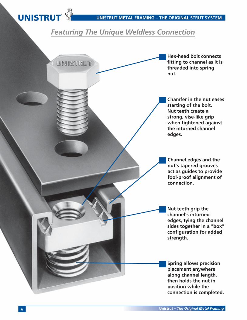
Featuring The Unique Weldless Connection
Hex-head bolt connectsfitting to channel as it isthreaded into springnut.
Chamfer in the nut easesstarting of the bolt.Nut teeth create astrong, vise-like gripwhen tightened againstthe inturned channeledges.
Channel edges and thenut's tapered groovesact as guides to providefool-proof alignment ofconnection.
Nut teeth grip thechannel's inturnededges, tying the channelsides together in a "box"configuration for addedstrength.
Spring allows precisionplacement anywherealong channel length,then holds the nut inposition while theconnection is completed.

7Unistrut – The Original Metal Framing
Strong, Fast, Economical and Adjustable
13
2
4
Unistrut ConnectionTHE ORIGINAL STRUT SYSTEM
1
5
■ 100% Adjustable
■ 100% Reusable
■ No Welding
■ No Drilling
■ No Special Tools
Insert the spring nut anywherealong the continuous slotted
channel. The rounded nut endspermit easy insertion.
A 90° clockwise turn aligns thegrooves in the nut with the inturnededges of the channel.
Fittings can be placed anywherealong the channel opening,permitting complete freedom ofadjustment. The need for drillingholes is eliminated.
Insert the bolt through thefitting and into the springnut. (See illustration 5 forend view showing the nut inplace)
Additional channel sections cannow be bolted to the fittingalready in place by followingprocedure described in steps 1–3.
Tightening with a wrenchlocks the serrated teeth of thenut into the inturned edges of
the channel, to complete astrong, vise-like connection.

8
®
Unistrut – The Original Metal Framing
Serving DesignProfessionals forOver 60 Years
Unistrut products have beenhelping to build a betterworld since 1924. Used exten-sively in nuclear, industrialand commercial constructionmarkets for over 75 years,Unistrut Metal Framing has setthe standard for productdesign, quality and perfor-mance. The initial Unistrutconcept — a simple spring nutand bolt connecting a fittingto a continuous slotted chan-nel — has evolved into acomprehensive engineeredbuilding and support system.
Unistrut® — The OriginalMetal Framing System
Unistrut Service CentersTHE ORIGINAL STRUT SYSTEM
distribution centers, Unistrutprovides customers with total-resource capability.
A North American network ofUnistrut Service Centers— stocking standard Unistrutcomponents — are located inprincipal cities to serve youquickly and directly. ManyService Centers are equippedto design and supply drawingsfor any type of metal framingapplication and also offerfabrication and installationservices.
This catalog is a comprehen-sive presentation of UnistrutMetal Framing componentsplus technical data required bydesign, specification andconstruction professionals.
There is only one UnistrutMetal Framing System. Itincorporates the innovativeproduct improvements that ourresearch and developmentgroup has created to give youthe most complete and flexiblesupport system available.Backed by our worldwidenetwork of engineering and
®

9Unistrut – The Original Metal Framing
The Most Complete Metal Framing System — Three Channel-Width Options
Adjustability, demountability and reusability are engineered into each of the three Unistrut channel series.Each series offers channels of varying depth and gage plus a complete line of fittings and accessories.
1 5⁄8"
VARIOUSHEIGHTS
AVAILABLE
1 1⁄4"
VARIOUSHEIGHTS
AVAILABLE
13⁄16"
VARIOUSHEIGHTS
AVAILABLE
Unistrut Framing SystemsTHE ORIGINAL STRUT SYSTEM
15⁄8” (41mm) width
Designed to carry the heaviestloads and provide the widestvariety of applications, the 15⁄8"series has become the acceptedstandard for use in mechanical,electrical and general construc-tion applications where supportsand attachments must meet thehighest strength requirements.
11⁄4” (32mm) width
A framing system designed formedium loads, the 11⁄4" series isespecially suitable for use in theOEM, commercial and displaymarkets. It maintains a lightnessin scale and a clean line thatmakes it aesthetically pleasing aswell as functional.
13⁄16” (21mm) width
A unique half-size reduction ofthe 15⁄8" channel-width series, thissmaller channel size can be usedto carry light loads economicallyin applications such as instrumen-tation, retail displays and light-duty laboratory supports. It alsoprovides the flexibility found inall Unistrut framing systems.
13⁄16" width Series Channel
11⁄4" width Series Channel
15⁄8" width Series Channel

10
®
Unistrut – The Original Metal Framing
Quality Program
Quality Assurance and Traceability
Product testing is an importantPart of Unistrut’s Quality Assur-ance Program. We utilize our owntesting facilities, as well as thoseof independent testing laborato-ries, to determine design loadswith proper and adequate safetyfactors. These design loads areindicated, where applicable,throughout the catalog. Loads arebased on AISI Specification ForThe Design Of Cold-Formed SteelStructural Members, 2001 Edition.
Product Load Testing
Destructive and non-destructivetesting procedures are used totest for variables such as corro-sion, conductivity, electro-staticdissipation, ultra-violet resistance,wind resistance, dimensionalaccuracy, material integrity andslip resistance.
In short, if there’s a specificationto meet, Unistrut will develop atest to quantify and verify it.Using design properties of theUnistrut framing members, load
data given in this catalog, and/ordesign procedures of theAmerican Iron & Steel InstituteSpecification For The Design OfCold-Formed Steel StructuralMembers, 2001 Edition, it ispossible to design any type ofstructure within the capabilitiesof the system.
Assemblies or connections thatcannot be calculated usingprovisions of the AISI specifica-tions must be established byapplication-specific tests.
Unistrut is committed to beingthe “best” in the metal framingindustry. In order to meet thisgoal, Unistrut has adopted thephilosophy of “Zero Defects andContinuous Improvement”. Thismeans on-going reviews of ourmanufacturing processes,
operating procedures and qualitysystems to find ways of improvingefficiency, productivity andquality. It means establishingprocess controls and problem-prevention techniques to ensurethat superior quality is built intoevery Unistrut product.
Traceability
UNISTRUT CHANNEL IS STAMPED WITH A
NUMERIC CODE THAT ALLOWS TRACEABILITY
TO THE ORIGIN OF THE STEEL
Our drive to be the best includesnot just quality products, buton-time delivery and promptresolution of customer needs andconcerns. At Unistrut, quality isnumber one.

11Unistrut – The Original Metal Framing
Materials and Finishes
Fittings
Unistrut fittings, unless notedotherwise, are punch-press madefrom hot rolled, pickled and oiledsteel plates, strip or coil, andconform to ASTM specificationsA575, A576, A635 or A36. Thefitting steel also meets thephysical requirement of ASTMA1011 SS GR 33. The pickling ofthe steel produces a smoothsurface free from scale.
Framing Members
Unistrut channels and continuousinserts are accurately and carefullycold-formed to size from lowcarbon strip steel. One side of thechannel has a continuous slot withinturned edges. Secure attach-ments may be made to the fram-ing member with the use ofhardened, toothed, slotted nutswhich engage the inturned edges.
Raw steel shall conform to thefollowing ASTM specifications:
GAGE FINISH ASTM NO.12 GR & HG A1011 SS GR 33
PG A653 GR 33
14 GR & HG A1011 SS GR 33PG A653 GR 33
16 GR & HG A1011 SS GR 33PG A653 GR 33
19 GR A1008
Material
Nuts and Bolts
Unistrut nuts are made from steelbars. After all machiningoperations are complete, they arethoroughly case hardened. Nutsare rectangular with ends shapedto permit a quarter turn clockwisein the framing member afterinsertion through the slottedopening in the channel. Twotoothed grooves in the top of thenut engage the inturned edges ofthe channel and, after boltingoperations are completed, willprevent any movement of the boltand nut within the framingmember. All bolts and nuts haveUnified coarse screw threads.The standard framing nut is 1⁄2"and conforms to ASTM Specifica-tion A1011 SS GR 33 (materialonly). Screws conform to SAE J429GR 2 (also meets and exceedsASTM A307).
Weights given for all materials areapproximate shipping weights.All dimensions are subject tocommercial tolerance withinpublished specifications.
Weights and Dimensions
WE RESERVE THE RIGHT TO MAKE SPECIFICATION CHANGESWITHOUT NOTICE.
WHILE EVERY EFFORT HAS BEEN MADE TO ASSURE THE ACCURACYOF INFORMATION CONTAINED IN THIS CATALOG AT THE TIME OFPUBLICATION, WE CANNOT ACCEPT RESPONSIBILITY FORINACCURACIES RESULTING FROM UNDETECTED ERRORS OR OMISSIONS.
THE BLUE COLOR USED ON UNISTRUT COMPONENTS ILLUSTRATEDIN THIS CATALOG IS FOR GRAPHIC ENHANCEMENT ONLY, AND DOESNOT REPRESENT ACTUAL PRODUCT COLOR.
®

12
®
Unistrut – The Original Metal Framing
Perma-Green® III
SealerZinc Phosphate
E-Coat
PreparedSteel
Materials and Finishes
thoroughly cleaned and coated withan zinc phosphate conversioncoating. Unistrut’s unique, custom-designed “prep” process consists often separate steps, the most thoroughin the industry. The cleaning,phosphating and electrodepositioncoating processes are continuousand, unlike “batch” processing, resultin a uniform coating quality.
Production samples are tested on acontinuous basis for corrosionresistance. Unistrut Perma-Green IIIexceeds 400 hours salt spray(1⁄8" creep from scribe) when testedto ASTM B117. Unscribed samplesexceed 600 hours salt spray. (6% redrust)
Unistrut Perma-Green III is afactory applied, electro-deposition acrylic coating withsuperior rust protection andfade-resistance. The acryliccoating is a proprietary formula-tion and is essentially “heavy-metal” free. The electrodeposi-tion coating process provides asmooth, hard, durable surfacewhich is completely cured. Thisinhibits introduction of airbornecontaminates which canadversely affect sensitivemanufacturing environments.
Before the electrodepositionacrylic coating is applied,Unistrut channel and fittings are
The performance of Unistrut’s Perma-Green III farexceeds that of conventional finishes. And comparedto competitive “high-performance” coatings, Perma-Green III provides superior resistance to chalking,checking and fading and is far less vulnerable to
common acidic atmospheres, solvents and alkalis.Just as important, Perma-Green III is the result of anenvironmentally neutral process that virtuallyeliminates the toxic metals commonly found incompetitive paint-based finishes.
TANK 1First stage hot alkaline cleaning of channel.
TANK 2Second stage hot alkaline cleaning of channel.
TANK 3Channel is rinsed with clean water to remove cleaning solution.
TANK 4Conditioning rinse.
TANK 5Channel is phosphated to produce a zinc phosphate coating.
TANK 6Channel is rinsed to remove excess phosphate solution.
TANK 7Sealer is applied.
TANK 8First stage deionizer water rinse to remove excess sealer.
TANK 9Second stage deionized water rinse to prepare channel for E-Coating.
TANK 10Final deionizer water rinse.
TANK 11Electro-deposition tank applies the acrylic Perma-Green III to all surfaces.
TANK 12Post rinse spray.
TANK 13Post rinse dip tray.
TANK 14Post rinse spray.
TANK 15Virgin deionized water halo rinse.
OVENThe cure process dries the channel and cross links the acrylic thermoset resins at 375° F.

13Unistrut – The Original Metal Framing
Electroplated Zinc–ASTM B633, Type III SC1In the electroplating process, thepart to be zinc coated is immersedin a solution of zinc ions. An electriccurrent causes the zinc to bedeposited on the part.
Zinc plated parts typically have a zinccoating of .2 to .5 MIL and arerecommended for dry indoor use.
Pregalvanized Zinc-ASTM A653Pregalvanized steel is zinc coated by ahot dip process. Steel strip from acoil is fed through a continuous zinccoater which cleans, fluxes and coatsthe steel with molten zinc. Aftercooling, the steel is recoiled.
The pregalvanized zinc coatingconforms to a G-90 thicknessdesignation per ASTM A653.The zinc thickness is .75 MIL or.45 oz./sq. ft. of surface area.
This coating is offered on Unistrutchannel and tubing and is a well-proven, time-tested performer forindoor and outdoor applications. Forsevere corrosion applications, hot dipgalvanizing, as described below, is agood alternative.
HOT DIP GALVANIZED (HG)ASTM A123 OR A153In hot dip galvanizing, the finishedpart is immersed in a bath of moltenzinc. This method results in com-plete zinc coverage and a thickercoating than pregalvanized or platedzinc.
The zinc coating is typically 2.6 MILor 1.5 oz./sq. ft. of surface area.
This is the coating of choice forapplications where severe corrosionis a design factor.
SPECIAL COATINGWhen specific applications requireother than standard available finishes,special finishes can be supplied percustomer requirements.
Materials and Finishes
PERMA-GREEN® III (GR)TECHNICAL DATA
STEEL SUBSTRATE PREPARATIONTen stage continuous cleaning,
phosphate process.
Substrate after “prep”: sealed zincphosphate conversion coating.
COATINGThermoset acrylic
Color:Federal Highway GreenColor Tolerance ChartPR Color No. 4
Hardness: 2H.
Coating Process:Cathodic Electrodeposition.
PERFORMANCESalt Spray:
Scribed: exceeds 400 hoursper ASTM B117. (1⁄8" creep)Unscribed: exceeds 600 hoursper ASTM B117. (6% red rust)
Chalk:Nominal at 1,000 hours perweatherometer G-23 test.
Checking:None at 1,000 hours perweatherometer G-23 test.
Fade:Less than 50% compared tostandard epoxy E.C. coatings.
ENVIRONMENTAL ISSUESFormulated as a “heavy metal”-
free coating (trace elementsonly).
Outgassing in service: essentiallynone at 350°F for 24 hours.
PLAIN (PL)Plain finish designation means thatthe channel retains the oiled surfaceapplied to the raw steel during therolling process. The fittings have theoriginal oiled surface of the bar-stock
material.
Zinc CoatingUnistrut products are available inthree types of zinc coatings:
• Electroplated• Pregalvanized• Hot Dip Galvanized.
Zinc coatings offer two types ofprotection:
• Barrier: The zinc coating protectsthe steel substrate from directcontact with the environment.
• Sacrificial: The zinc coating willprotect scratches, cut edges, etc.through an anodic sacrificialprocess.
The service life of zinc coating isdirectly related to the zinc coatingthicknessas shown below.
COMPARISON OF ZINCGALVANIZED FINISHES
Finish Zinc Thickness
Hot Dip Galvanized 2.6 MILPregalvanized .75 MILElectro-Galvanized .2 to .5 MILPerma-Gold .5 MIL
As shown in the graph, when the zinccoating is double, the service life isdouble under most conditions.
80
.50 .75 1.00 1.25 1.50 1.75 2.00 2.25 2.50 2.75 3.00
* Service Life is defined as the time to 5% rusting of the steel surface
70
60
50
40
30
20
10
.25
0.8 1.3 1.7 2.1 2.6 3.0 3.4 3.8 4.2 4.7 5.10.4
21 32 43 54 65 75 86 97 108 118 12911
Oz. of Zinc/Sq. Ft. of Surface
Serv
ice
Life
, Yea
rs*
Thickness of Zinc in Mils
RURAL
TROPICAL MARINE
TEMPERATE MARINE
SUBURBAN
MODERATELY INDUSTRIAL
HEAVY INDUSTRIAL
Life of Protection vs. Thickness of Zincand Type of Atmosphere
14
®
Unistrut – The Original Metal Framing
Design Fundamentals
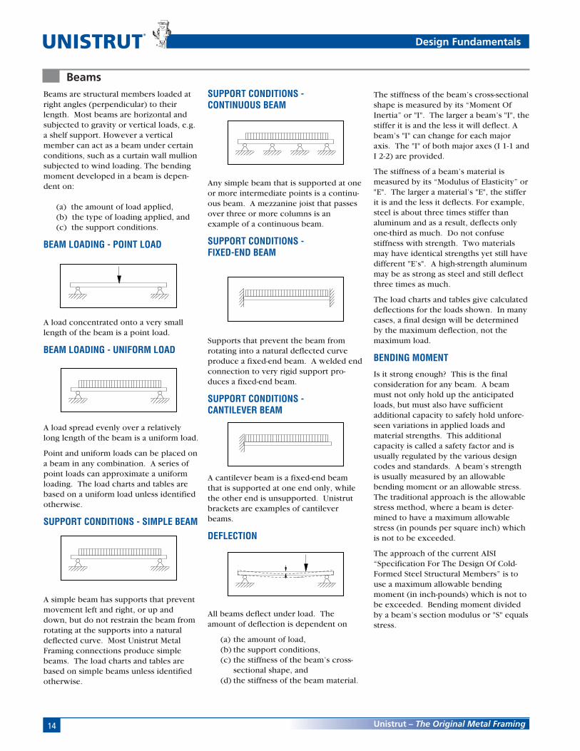
Beams are structural members loaded atright angles (perpendicular) to theirlength. Most beams are horizontal andsubjected to gravity or vertical loads, e.g.a shelf support. However a verticalmember can act as a beam under certainconditions, such as a curtain wall mullionsubjected to wind loading. The bendingmoment developed in a beam is depen-dent on:
(a) the amount of load applied,(b) the type of loading applied, and(c) the support conditions.
BEAM LOADING - POINT LOAD
A load concentrated onto a very smalllength of the beam is a point load.
BEAM LOADING - UNIFORM LOAD
A load spread evenly over a relativelylong length of the beam is a uniform load.
Point and uniform loads can be placed ona beam in any combination. A series ofpoint loads can approximate a uniformloading. The load charts and tables arebased on a uniform load unless identifiedotherwise.
SUPPORT CONDITIONS - SIMPLE BEAM
A simple beam has supports that preventmovement left and right, or up anddown, but do not restrain the beam fromrotating at the supports into a naturaldeflected curve. Most Unistrut MetalFraming connections produce simplebeams. The load charts and tables arebased on simple beams unless identifiedotherwise.
SUPPORT CONDITIONS -CONTINUOUS BEAM
Any simple beam that is supported at oneor more intermediate points is a continu-ous beam. A mezzanine joist that passesover three or more columns is anexample of a continuous beam.
SUPPORT CONDITIONS -FIXED-END BEAM
Supports that prevent the beam fromrotating into a natural deflected curveproduce a fixed-end beam. A welded endconnection to very rigid support pro-duces a fixed-end beam.
SUPPORT CONDITIONS -CANTILEVER BEAM
A cantilever beam is a fixed-end beamthat is supported at one end only, whilethe other end is unsupported. Unistrutbrackets are examples of cantileverbeams.
DEFLECTION
All beams deflect under load. Theamount of deflection is dependent on
(a) the amount of load,(b) the support conditions,(c) the stiffness of the beam’s cross-
sectional shape, and(d) the stiffness of the beam material.
BeamsThe stiffness of the beam’s cross-sectionalshape is measured by its “Moment OfInertia” or "I". The larger a beam’s "I", thestiffer it is and the less it will deflect. Abeam’s "I" can change for each majoraxis. The "I" of both major axes (I 1-1 andI 2-2) are provided.
The stiffness of a beam’s material ismeasured by its “Modulus of Elasticity” or"E". The larger a material’s "E", the stifferit is and the less it deflects. For example,steel is about three times stiffer thanaluminum and as a result, deflects onlyone-third as much. Do not confusestiffness with strength. Two materialsmay have identical strengths yet still havedifferent "E’s". A high-strength aluminummay be as strong as steel and still deflectthree times as much.
The load charts and tables give calculateddeflections for the loads shown. In manycases, a final design will be determinedby the maximum deflection, not themaximum load.
BENDING MOMENT
Is it strong enough? This is the finalconsideration for any beam. A beammust not only hold up the anticipatedloads, but must also have sufficientadditional capacity to safely hold unfore-seen variations in applied loads andmaterial strengths. This additionalcapacity is called a safety factor and isusually regulated by the various designcodes and standards. A beam’s strengthis usually measured by an allowablebending moment or an allowable stress.The traditional approach is the allowablestress method, where a beam is deter-mined to have a maximum allowablestress (in pounds per square inch) whichis not to be exceeded.
The approach of the current AISI“Specification For The Design Of Cold-Formed Steel Structural Members” is touse a maximum allowable bendingmoment (in inch-pounds) which is not tobe exceeded. Bending moment dividedby a beam’s section modulus or "S" equalsstress.
15Unistrut – The Original Metal Framing
Columns
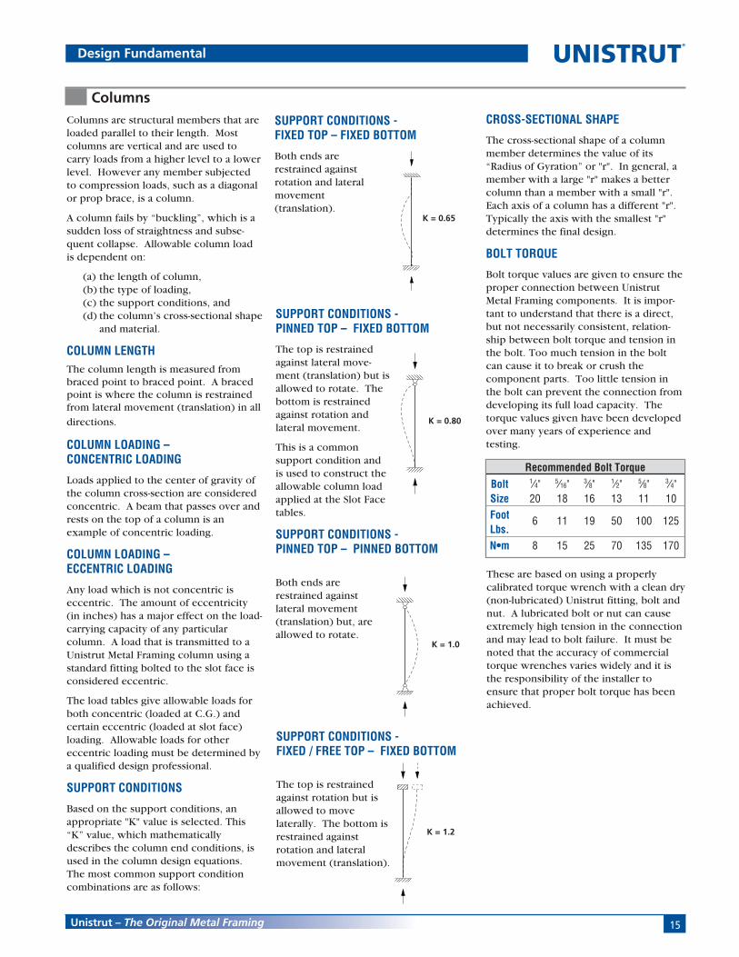
SUPPORT CONDITIONS -FIXED TOP – FIXED BOTTOM
Both ends arerestrained againstrotation and lateralmovement(translation).
CROSS-SECTIONAL SHAPE
The cross-sectional shape of a columnmember determines the value of its“Radius of Gyration” or "r". In general, amember with a large "r" makes a bettercolumn than a member with a small "r".Each axis of a column has a different "r".Typically the axis with the smallest "r"determines the final design.
BOLT TORQUE
Bolt torque values are given to ensure theproper connection between UnistrutMetal Framing components. It is impor-tant to understand that there is a direct,but not necessarily consistent, relation-ship between bolt torque and tension inthe bolt. Too much tension in the boltcan cause it to break or crush thecomponent parts. Too little tension inthe bolt can prevent the connection fromdeveloping its full load capacity. Thetorque values given have been developedover many years of experience andtesting.
Design Fundamental
Columns are structural members that areloaded parallel to their length. Mostcolumns are vertical and are used tocarry loads from a higher level to a lowerlevel. However any member subjectedto compression loads, such as a diagonalor prop brace, is a column.
A column fails by “buckling”, which is asudden loss of straightness and subse-quent collapse. Allowable column loadis dependent on:
(a) the length of column,(b) the type of loading,(c) the support conditions, and(d) the column’s cross-sectional shape
and material.
COLUMN LENGTHThe column length is measured frombraced point to braced point. A bracedpoint is where the column is restrainedfrom lateral movement (translation) in all
directions.
COLUMN LOADING –CONCENTRIC LOADING
Loads applied to the center of gravity ofthe column cross-section are consideredconcentric. A beam that passes over andrests on the top of a column is anexample of concentric loading.
COLUMN LOADING –ECCENTRIC LOADING
Any load which is not concentric iseccentric. The amount of eccentricity(in inches) has a major effect on the load-carrying capacity of any particularcolumn. A load that is transmitted to aUnistrut Metal Framing column using astandard fitting bolted to the slot face isconsidered eccentric.
The load tables give allowable loads forboth concentric (loaded at C.G.) andcertain eccentric (loaded at slot face)loading. Allowable loads for othereccentric loading must be determined bya qualified design professional.
SUPPORT CONDITIONS
Based on the support conditions, anappropriate "K" value is selected. This“K” value, which mathematicallydescribes the column end conditions, isused in the column design equations.The most common support conditioncombinations are as follows:
K = 0.65
K = 0.80
K = 1.0
K = 1.2
SUPPORT CONDITIONS -PINNED TOP – FIXED BOTTOM
The top is restrainedagainst lateral move-ment (translation) but isallowed to rotate. Thebottom is restrainedagainst rotation andlateral movement.
This is a commonsupport condition andis used to construct theallowable column loadapplied at the Slot Facetables.
SUPPORT CONDITIONS -PINNED TOP – PINNED BOTTOM
Both ends arerestrained againstlateral movement(translation) but, areallowed to rotate.
SUPPORT CONDITIONS -FIXED / FREE TOP – FIXED BOTTOM
The top is restrainedagainst rotation but isallowed to movelaterally. The bottom isrestrained againstrotation and lateralmovement (translation).
Recommended Bolt TorqueBolt 1⁄4" 5⁄16" 3⁄8" 1⁄2" 5⁄8" 3⁄4"Size 20 18 16 13 11 10Foot 6 11 19 50 100 125Lbs.N•m 8 15 25 70 135 170
These are based on using a properlycalibrated torque wrench with a clean dry(non-lubricated) Unistrut fitting, bolt andnut. A lubricated bolt or nut can causeextremely high tension in the connectionand may lead to bolt failure. It must benoted that the accuracy of commercialtorque wrenches varies widely and it isthe responsibility of the installer toensure that proper bolt torque has beenachieved.

16
®
Unistrut – The Original Metal Framing
Conversion Factors
English To MetricTo Convert From To Multiply By
LengthInch [in] Millimeter [mm] 25.400 000Foot [ft] Meter [m] 0.304 800Yard [yd] Meter [m] 0.914 400Mile [mi] (U.S. Statute) Kilometer [km] 1.609 347
AreaSquare Inch [in2] Square Millimeter [mm2] 645.16Square Foot [ft2] Square Meter [m2] 0.092 903Square Yard [yd2] Sqare Meter [m2] 0.836 127Square Mile [mi2] (U.S. Statute) Square Kilometer [km2] 2.589 998Acre Square Meter [m2] 4046.873Acre Hectare 0.404 687
VolumeCubic Inch [in3] Cubic Millimeter [mm3] 16387.06Cubic Foot [ft3] Cubic Meter [m3] 0.028 317Cubic Yard [yd3] Cubic Meter [m3] 0.764 555Gallon [gal] (U.S. Liquid) Litre [l] 3.785 412Quart [qt] (U.S. Liquid) Litre [l] 0.946 353
MassOunce (Avoirdupois) [oz] Gram [g] 28.349 520Pound (Avoirdupois) [lb] Kilogram [kg] 0.453 592Short Ton Kilogram [kg] 907.185
ForceOunce-Force Newton [N] 0.278 014Pound-Force [lbf] Newton [N] 4.448 222
Bending MomentPound-Force-Inch [lbf-in] Netwon-Meter [N-m] 0.112 985Pound-Force-Foot [lbf-ft] Newton-Meter [N-m] 1.355 818
Pressure, StressPound-Force per Kilopascal [kPa] 6.894 757 Square Inch [lbf/in2]Foot of Water (39.2 F) Kilopascal [kPa] 2.988 980Inch of Mercury (32 F) Kilopascal [kPa] 3.386 380
Energy, Work, HeatFoot-Pound-Force [ft-lbf] Joule [J] 1.355 818British Thermal Unit [Btu] Joule [J] 1055.056Calorie [cal] Joule [J] 4.186 800Kilowatt Hour [kW-h] Joule [J] 3,600,000
PowerFoot-Pound-Force Watt [W] 1.355 818 /Second [ft-lbs/s]British Thermal Unit Watt [W] 0.293 071 /Hour [Btu/h]Horsepower [hp] (550 Ft. Lbf/s) Kilowatt [kW] 0.745 700
AngleDegree Radian [rad] 0.017 453
TemperatureDegree Fahrenheit [°F] Degree Celsius [°C] (F° -32)/1.8
Metric to EnglishTo Convert From To Multiply By
LengthMillimeter [mm] Inch [in] 0.039 370Meter [m] Foot [ft] 3.280 840Meter [m] Yard [yd] 1.093 613Kilometer [km] Mile [mi] (U.S. Statute) 0.621 370
AreaSquare Millimeter [mm2] Square Inch [in2] 0.001550Square Meter [m2] Square Foot [ft2] 10.763 915Sqare Meter [m2] Square Yard [yd2] 1.195 991Square Kilometer [km2] Square Mile [mi2](U.S. Statute) 0.386 101Square Meter [m2] Acre 0.000 247Hectare Acre 2.471 046
VolumeCubic Millimeter [mm3] Cubic Inch [in3] 0.000061Cubic Meter [m3] Cubic Foot [ft3] 35.314 662Cubic Meter [m3] Cubic Yard [yd3] 1.307 950Litre [l] Gallon [gal] (U.S. Liquid) 0.264 172Litre [l] Quart [qt] (U.S. Liquid) 1.056 688
MassGram [g] Ounce (Avoirdupois) [oz] 0.035 274Kilogram [kg] Pound (Avoirdupois) [lb] 2.204 624Kilogram [kg] Short Ton 0.00110
ForceNewton [N] Ounce-Force 3.596 941Newton [N] Pound-Force [lbf] 0.224 809
Bending MomentNetwon-Meter [N-m] Pound-Force-Inch [lbf-in] 8.850 732Newton-Meter [N-m] Pound-Force-Foot [lbf-ft] 0.737 562
Pressure, StressKilopascal [kPa] Pound-Force per 0.145 038 Square Inch [lbf/in2]Kilopascal [kPa] Foot of Water (39.2 F) 0.334 562Kilopascal [kPa] Inch of Mercury (32 F) 0.295 301
Energy, Work, HeatJoule [J] Foot-Pound-Force [ft-lbf] 0.737 562Joule [J] British Thermal Unit [Btu] 0.000948Joule [J] Calorie [cal] 0.238 846Joule [J] Kilowatt Hour [kW-h] 2.78-7
PowerWatt [W] Foot-Pound-Force 0.737 562 /Second [ft-lbs/s]Watt [W] British Thermal Unit 3.412 142 /Hour [Btu/h]Kilowatt [kW] Horsepower (550 Ft. Lbf/s) [hp]1.341 022
AngleRadian [rad] Degree 57.295 788
TemperatureDegree Celsius [°C] Degree Fahrenheit [°F] 1.8xC°+32
Unit Conversions
17Unistrut – The Original Metal Framing
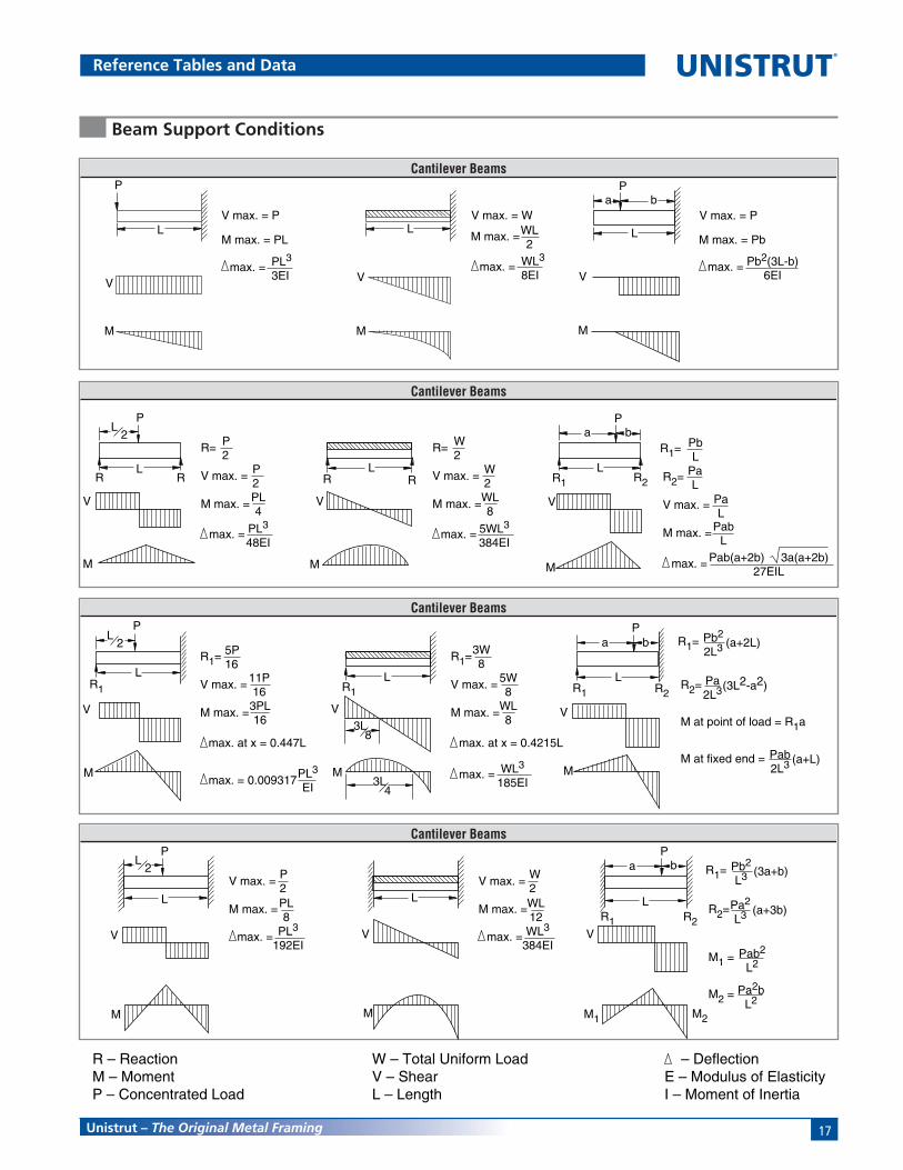
Reference Tables and DataFORMULAE ON COMMON BEAM LOADINGS
Beam Support Conditions
Cantilever BeamsP
L
V
M
L
a bP
M
V
M
V
V max. = P
M max. = PL
max. = PL3
3EI
V max. = W
max. = WL3
8EI
WL2
M max. =
V max. = P
max. = Pb2(3L-b)6EI
M max. = Pb L
Cantilever Beams
LR1 R2
a bP
V
M
LR1
PL
2
V
M
L
V
M
3L8
3L4
R2=
M at point of load = R1a
M at fixed end =
Pb2
2L3R1=
Pa2L3
(a+2L)
(3L2-a2)
Pab2L3 (a+L)
R1=
V max. =
M max. =
max. at x = 0.447L
5P16
11P163PL16
max. = 0.009317 PL3
EI
R1=
V max. =
M max. =
max. at x = 0.4215L
3W8
5W8
WL8
max. = WL3
185EI
R1
Cantilever Beams
V
M2
LR1 R2
a bP
V
M
L
PL
2
V
M
L
M1
R2=
M1 =
M2 =
Pb2
L3R1=
Pa2
L3
(3a+b)
(a+3b)
Pab2
L2
Pa2bL2
V max. =
M max. =
max. = PL3
192EI
P2PL8
V max. =
M max. =
max. = WL3
384EI
W2WL12
Cantilever Beams
M
V
L
PL
2
R R
M
V
LR R
LR1 R2
M
V
a bP
R=
V max. =
M max. =
max. = PL3
48EI
P2
P2PL4
R=
V max. =
M max. =
max. = 5WL3
384EI
W2
W2WL8
R2=
V max. =
M max. =
PbL
R1=
PaL
PaL
PabL
Pab(a+2b) 3a(a+2b)27EIL
max. =
R – ReactionM – MomentP – Concentrated Load
W – Total Uniform LoadV – ShearL – Length
– DeflectionE – Modulus of ElasticityI – Moment of Inertia

18
®
Unistrut – The Original Metal Framing
EXAMPLE I:Determine load and deflection of aP 1000 beam continuous over onesupport and loaded uniformly on one span.
SOLUTION:A. From load table for P1000 on page 26 load for a 5'-0" span is
680# and deflection is .35".B. Multiply by factors from Table above.
Load = 680# x 1.30 = 884#Deflection = .35" x .92 = .32"
Reference Tables and Data
CONVERSION FACTORS FOR BEAMS WITH VARIOUS STATIC LOADING CONDITIONS
All Beam Load tables are for single-span (simple) beams supported at the ends. These can be used in the majority ofthe cases. However, there are times when it is necessary to know what happens with other loading and supportconditions. Some common arrangements are shown below. Simply multiply the values from the Beam Load tables byfactors given below
5' -0" 5' -0"
EXAMPLE IIDetermine load and deflection of a P 5500cantilever beam with a concentrated load onthe end.
SOLUTION:A. From load table P5500 on page 57 load for a 3'-0" span is
2180# and deflection is .09".B. Multiply by factors from Table above.
Load = 2180# x .12 = 262#Deflection = .09" x 3.20 = .29"
3' -0"
Continuous Beam, Two Equal Spans,Concentrated Load at Center of Each Span .67 .48
SPAN
1.00
1.00
.50
.25
1.50
1.00
1.00
.12
1.30
.62
1.10
1.00
.80
2.40
.30
.40
.42
3.20
.92
.71
1. Simple Beam,Uniform Load
2. Simple Beam,Concentrated Load at Center
3. Simple Beam,Two Equal Concentrated Loadcs at 1/4 pts
4. Beam Fixed at Both Ends,Uniform Load
5. Beam Fixed at Both Ends,Concentrated Load at Center
6. Cantilever Beam,Uniform Load
7. Cantilever Beam,Concentrated Load at End
8. Continuous Beam, Two Equal Spans,Uniform Load on One Span
9. Continuous Beam, Two Equal Spans,Uniform Load on Both Ends
10. Continuous Beam, Two Equal Spans,Concentrated Load at Center of One Span
11.
SPAN SPAN
Load DeflectionLoad and Support Condition Factor Factor

19Unistrut – The Original Metal Framing
Guide Specification
PART I - GENERAL
1.01 SCOPE OF WORKA. Provide all Unistrut Metal Framing
material, fittings and relatedaccessories (Strut System) asindicated on the Contract Drawings.
B. Provide all labor, supervision,engineering, and fabricationrequired for installation of the StrutSystem in accordance with theContract Drawings and as specifiedherein.
C. Related work specified elsewhere.
1.02 QUALITY ASSURANCEA. Manufacturer’s qualifications:
1. The manufacturer shall nothave had less than 10 year’sexperience in manufacturingStrut Systems.
2. The manufacturer must certifyin writing all componentssupplied have been produced inaccordance with an establishedquality assurance program.
B. Installer’s qualifications:1. Installer must be a Unistrut
trained manufacturer’s autho-rized representative/installerwith not less than 5 yearsexperience in the installation ofStrut Systems of this size andconformation.
2. All Strut System componentsmust be supplied by a singlemanufacturer.
C. Standards:1. Work shall meet the require-
ments of the followingstandards:a. Federal, State and Local
codes.b. American Iron and Steel
Institute (AISI) Specificationfor the Design of Cold-Formed Steel StructuralMembers 2001 Edition.
c. American Society for TestingAnd Materials (ASTM).
1.03 SUBMITTALSA. Structural Calculations and Shop
Drawings1. Submit structural calculations
for approval by the projectengineer. Calculations mayinclude, but are not limited to:
a. Description of designcriteria.
b. Stress and deflectionanalysis.
c. Selection of Unistrut framingmembers, fittings, andaccessories.
ance Chart PR Color No. 4.Finish to withstand minimum400 hours salt spray when testedin accordance with ASTM B117.
2. ELECTRO-GALVANIZED (EG)Electrolytically zinc coated perASTM B 633 Type III SC 1
3. PRE-GALVANIZED (PG)Zinc coated by hot-dippedprocess prior to roll forming. Thezinc weight shall be G90conforming to ASTM A 653.
4. HOT-DIPPED GALVANIZED (HG)Zinc coated after all manufactur-ing operations are complete.Coating shall conform to ASTM A123 or A 153.
5. SPECIAL COATING / MATERIAL(Describe as applicable)
PART 3 - EXECUTION
3.01 EXAMINATIONA. The installer shall inspect the work
area prior to installation. If workarea conditions are unsatisfactory,installation shall not proceed untilsatisfactory corrections arecompleted.
3.02 INSTALLATIONA. Installation shall be accomplished by a
fully trained manufacturer autho-rized installer.
B. Set Strut System components intofinal position true to line, level andplumb, in accordance withapproved shop drawings.
C. Anchor material firmly in place.Tighten all connections to theirrecommended torques.
3.03 CLEANUPA. Upon completion of this section of
work, remove all protective wrapsand debris. Repair any damage dueto installation of this section ofwork.
3.04 PROTECTIONA. During installation, it shall be the
responsibility of the installer toprotect this work from damage.
B. Upon completion of this scopeof work, it shall become theresponsibility of the generalcontractor to protect this workfrom damage during the remainderof construction on the project anduntil substantial completion.
2. Submit all shop/assemblydrawings necessary to com-pletely install the Strut Systemin compliance withthe Contract Drawings.
3. Submit all pertinent manufactur-ers published data.
1.04 PRODUCT DELIVERY,STORAGE, AND HANDLING
A. All material is to be delivered tothe work site in original factorypackaging to avoid damage to thefinish.
B. Upon delivery to the work site,all components shall be protectedfrom the elements by a shelter orother covering.
1.05 GUARANTEEA. Separate guarantees shall be issued
from the erector and manufacturer,valid for a period of 1 year, againstany defects that may arise from theinstallation or manufacture of theStrut System components.
PART 2 - PRODUCTS
2.01 ACCEPTABLE MANUFACTURERSA. All Strut System components shall
be as manufactured by UNISTRUTCORPORATION or approved equalas determined by the Architect orEngineer of record in writing 10days prior to bid date.
2.02 MATERIALSA. All channel members shall be
fabricated from structural gradesteel conforming to one of thefollowing ASTM specifications:A 1011 SS GR 33, A 653 GR 33.
B. All fittings shall be fabricated fromsteel conforming to one of thefollowing ASTM specifications:A 575, A 576, A 36 or A 635.
C. SubstitutionsAny substitutions of product ormanufacturer must be approved inwriting ten days prior to bid date,by Architect or Engineer of record.
2.03 FINISHESA. Strut System components shall be
finished in accordance with one ofthe following standards:
1. PERMA-GREEN® III (GR)Rust inhibiting acrylic enamelpaint applied by electro-deposition, after cleaning andphosphating, and thoroughlybaked. Color is per FederalHighway Green, Color Toler-

20
®
Unistrut – The Original Metal Framing
New Products
Slot Adapter™
See Page 84
P3001 T P3301 T P4101 T
P5501 T Swiftgrip
See Page 40 See Page 43 See Page 50
See Page 56 See Page 123
SPF® 100 SPF® 200
SPF® 300
See Page 140 See Page 141
See Page 142
SPF® 400 LS 410
LS 500
See Page 143 See Page 144
See Page 144
P3088
See Page 133
CUSH–A–GRIP®CUSH–A–THERM™
UniPier™
See Page 157See Page 157
See Page 163
DECK INSERT
See Page 200
P1354A
See Page 138
P2867B P2868B
See Page 131See Page 130
UniPier™ Trapeze
See Page 163
21
®
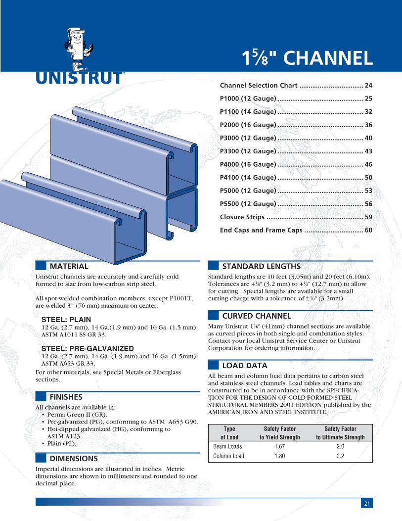
MATERIALUnistrut channels are accurately and carefully coldformed to size from low-carbon strip steel.
All spot-welded combination members, except P1001T,are welded 3" (76 mm) maximum on center.
STEEL: PLAIN12 Ga. (2.7 mm), 14 Ga.(1.9 mm) and 16 Ga. (1.5 mm)ASTM A1011 SS GR 33.
STEEL: PRE-GALVANIZED12 Ga. (2.7 mm), 14 Ga. (1.9 mm) and 16 Ga. (1.5mm)ASTM A653 GR 33.
For other materials, see Special Metals or Fiberglasssections.
FINISHESAll channels are available in:
• Perma Green II (GR).• Pre-galvanized (PG), conforming to ASTM A653 G90.• Hot-dipped galvanized (HG), conforming to
ASTM A123.• Plain (PL).
DIMENSIONSImperial dimensions are illustrated in inches. Metricdimensions are shown in millimeters and rounded to onedecimal place.
STANDARD LENGTHSStandard lengths are 10 feet (3.05m) and 20 feet (6.10m).Tolerances are +1⁄8" (3.2 mm) to +1⁄2" (12.7 mm) to allowfor cutting. Special lengths are available for a smallcutting charge with a tolerance of ±1⁄8" (3.2mm).
CURVED CHANNELMany Unistrut 15⁄8" (41mm) channel sections are availableas curved pieces in both single and combination styles.Contact your local Unistrut Service Center or UnistrutCorporation for ordering information.
LOAD DATAAll beam and column load data pertains to carbon steeland stainless steel channels. Load tables and charts areconstructed to be in accordance with the SPECIFICA-TION FOR THE DESIGN OF COLD-FORMED STEELSTRUCTURAL MEMBERS 2001 EDITION published by theAMERICAN IRON AND STEEL INSTITUTE.
Channel Selection Chart ................................... 24
P1000 (12 Gauge) ............................................... 25
P1100 (14 Gauge) ............................................... 32
P2000 (16 Gauge) ............................................... 36
P3000 (12 Gauge) ............................................... 40
P3300 (12 Gauge) ............................................... 43
P4000 (16 Gauge) ............................................... 46
P4100 (14 Gauge) ............................................... 50
P5000 (12 Gauge) ............................................... 53
P5500 (12 Gauge) ............................................... 56
Closure Strips ..................................................... 59
End Caps and Frame Caps ................................ 60
15⁄8" CHANNEL
Type Safety Factor Safety Factorof Load to Yield Strength to Ultimate Strength
Beam Loads 1.67 2.0
Column Load 1.80 2.2
15 ⁄8"
Chan
nel
Nuts
&Ha
rdw
are
Gene
ral
Fitti
ngs
Pipe
/Con
duit
Supp
orts
Elec
trica
lFi
tting
sCo
ncre
teIn
serts
11 ⁄4" F
ram
ing
Syst
em13
⁄16" F
ram
ing
Syst
emFi
berg
lass
Syst
emSp
ecia
lM
etal
sTe
lest
rut
Syst
emPr
imeA
ngle
Syst
emPr
oduc
tIn
dex
22
®
15⁄8" Framing System
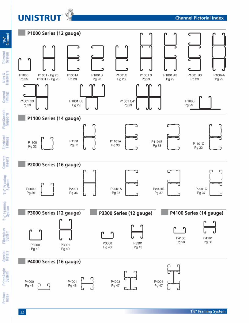
Channel Pictorial Index
P1001 C3Pg 29
P1001 D3Pg 29
P1001 C41Pg 29
P1003Pg 29
P1004APg 29
P1100Pg 32
P4000Pg 46
P1001 B3Pg 29
P1000Pg 25
P1001 - Pg 25P1001T - Pg 28
P1001APg 28
P1001BPg 28
P1001 A3Pg 29
P1001 3Pg 29
P1001CPg 28
P1101Pg 32
P1101APg 33
P1101BPg 33
P1101CPg 33
P3000Pg 40
P3001Pg 40
P2000Pg 36
P2001Pg 36
P2001APg 37
P2001BPg 37
P2001CPg 37
P3300Pg 43
P3301Pg 43
P4001Pg 46
P4003Pg 47
P4004Pg 47
P4100Pg 50
P4101Pg 50
P1000 Series (12 gauge)
P1100 Series (14 gauge)
P2000 Series (16 gauge)
P3000 Series (12 gauge) P3300 Series (12 gauge) P4100 Series (14 gauge)
P4000 Series (16 gauge)

15 ⁄8"
Chan
nel
Nuts
&Ha
rdw
are
Gene
ral
Fitti
ngs
Pipe
/Con
duit
Supp
orts
Elec
trica
lFi
tting
sCo
ncre
teIn
serts
11 ⁄4" F
ram
ing
Syst
em13
⁄16" F
ram
ing
Syst
emFi
berg
lass
Syst
emSp
ecia
lM
etal
sTe
lest
rut
Syst
emPr
imeA
ngle
Syst
emPr
oduc
tIn
dex
2315⁄8" Framing System
Combinations not shown in catalog are available on special order. Consult factory for details.
Channel Pictorial Index
P5000Pg 53
A3300Pg 209
P6000Pg 228
P6001Pg 228
P6001APg 228
P6001CPg 228
P7001Pg 231
P7000Pg 231P6001B
Pg 228
A3301Pg 209
A4000Pg 211
A4001Pg 211
A5000Pg 213
P5001Pg 53
P5500Pg 56
P5501Pg 56
P9200Pg 67
P9000Pg 67
A1001CPg 206
P3184PPg 59
P3184FPg 59
P3712PPg 59
P1280Pg 60
P1280 A, P2280 APg 60
P1180, P2280P4280, P5280, P5580
Pg 60
P1184PPg 59
P1184Pg 59
P3184Pg 59
P2860 SeriesPg 60
P2859Pg 60
A1001BPg 206
A1001APg 206
A1001Pg 206
A1000Pg 206
A1000 Series (14 gauge) – 11⁄4" Channel
15⁄8" Channel Closure Strips End Caps and Frame Caps
A3300 Series (14 gauge)11⁄4" Channel
A4000 Series (19 gauge)11⁄4" Channel
A5000 Series (14 gauge)11⁄4" Channel
P7000 Series (19 gauge)13⁄16" Channel
P9000 Series (12 gauge)Telestrut Channel
P6000 Series (19 gauge) – 13⁄16" Channel
P5000 Series (12 gauge) P5500 Series (12 gauge)
Alternate Framing Systems

15 ⁄8"
Chan
nel
Nuts
&Ha
rdw
are
Gene
ral
Fitti
ngs
Pipe
/Con
duit
Supp
orts
Elec
trica
lFi
tting
sCo
ncre
teIn
serts
11 ⁄4" F
ram
ing
Syst
em13
⁄16" F
ram
ing
Syst
emFi
berg
lass
Syst
emSp
ecia
lM
etal
sTe
lest
rut
Syst
emPr
imeA
ngle
Syst
emPr
oduc
tIn
dex
24
®
15⁄8" Framing System
Channel Selection
Channel Selection Chart
SteelStainless
SteelAlum.
Width Height
Channels & Combinations in Descending Order of StrengthArea Weight I s Allow. Moment
Channel In2 (cm2) lbs/ft (kg/m) In4 (cm4) In3(cm3) In-lbs (N•m)P5001 1.793 6.10 6.227 1.916 48,180
11.57 9.1 259.2 31.4 5,440P1004A 1.965 6.68 4.068 1.669 41,980
12.68 9.9 169.3 27.4 4,740P5501 1.452 4.94 2.805 1.151 28,940
9.37 7.3 116.8 18.9 3,270P1001C41 2.221 7.55 1.856 1.142 28,720
14.33 11.2 77.2 18.7 3,250P5000 0.897 3.05 1.098 0.627 15,770
5.78 4.5 45.7 10.3 1,780P1001 1.111 3.78 0.928 0.571 14,360
7.16 5.6 38.6 9.4 1,620P1101 0.835 2.84 0.733 0.451 11,340
5.39 4.2 30.5 7.4 1,280P3001 1.000 3.40 0.591 0.430 10,810
6.45 5.1 24.6 7.0 1,220P5500 0.726 2.47 0.522 0.390 9,820
4.68 3.7 21.7 6.4 1,110P2001 0.684 2.32 0.618 0.381 9,570
4.41 3.5 25.7 6.2 1,080P9200 0.489 2.23 0.279 0.297 7,480
3.16 3.3 11.6 4.9 850A5000 0.492 1.67 0.358 0.265 6,670
3.17 2.5 14.9 4.3 750A1001 0.609 2.07 0.302 0.242 6,070
3.93 3.1 12.6 4.0 690P9000 0.387 1.88 0.166 0.205 5,150
2.50 2.8 6.9 3.4 580P1000 0.555 1.89 0.185 0.202 5,070
3.58 2.8 7.7 3.3 570P3301 0.790 2.69 0.176 0.201 5,060
5.10 4.0 7.3 3.3 570
Area Weight I s Allow. MomentChannel In2 (cm2) lbs/ft (kg/m) In4 (cm4) In3(cm3) In-lbs (N•m)P1100 0.418 1.42 0.145 0.162 4,060
2.69 2.1 6.0 2.6 460P3000 0.500 1.70 0.120 0.153 3,850
3.23 2.5 5.0 2.5 430P4101 0.579 1.97 0.117 0.143 3,610
3.74 2.9 4.9 2.4 410P2000 0.342 1.16 0.125 0.140 3,520
2.21 1.7 5.2 2.3 400P4001 0.478 1.66 0.104 0.128 3,210
3.14 2.5 4.3 2.1 360A3301 0.459 1.56 0.077 0.103 2,590
2.96 2.3 3.2 1.7 290A1000 0.305 1.04 0.061 0.086 2,170
1.96 1.5 2.5 1.4 250P3300 0.395 1.34 0.037 0.072 1,800
2.55 2.0 1.5 1.2 200A4001 0.264 0.90 0.037 0.058 1,470
1.70 1.3 1.5 1.0 170P6001 0.213 0.73 0.045 0.055 1,400
1.38 1.1 1.9 0.9 160P4100 0.290 0.98 0.026 0.054 1,360
1.87 1.5 1.1 0.9 150P4000 0.244 0.83 0.023 0.049 1,230
1.57 1.2 0.9 0.8 140A3300 0.230 0.78 0.017 0.038 950
1.48 1.2 0.7 0.6 110A4000 0.132 0.45 0.008 0.022 560
0.85 0.7 0.3 0.4 60P6000 0.107 0.36 0.009 0.020 510
0.69 0.5 0.4 0.3 60P7001 0.148 0.50 0.007 0.018 460
0.96 0.8 0.3 0.3 50P7000 0.074 0.25 0.002 0.007 170
0.48 0.4 0.1 0.1 20
Channel Dimensions Material & Thickness Hole Pattern Styles
Width Height Steel Stainless Alum. HS T KO SL DS H3Channel In (mm) In (mm) gauge gauge In (mm) ............................ Steel Only ..........................
P1000 15⁄8 15⁄8 12 ga 12 ga 0.109 ■ ■ ■ ■ ■ ■41 41 2.8
P1100 15⁄8 15⁄8 14 ga 14 ga — ■ ■ ■ ■ – –41 41
P2000 15⁄8 15⁄8 16 ga — — ■ ■ ■ ■ – –41 41
P3000 15⁄8 13⁄8 12 ga — — ■ ■ ■ ■ – –41 35
P3300 15⁄8 7⁄8 12 ga 12 ga — ■ ■ – ■ – –41 22
P4000 15⁄8 13⁄16 16 ga 16 ga 0.078 ■ ■ – ■ – –41 21 2.0
P4100 15⁄8 13⁄16 14 ga — — ■ ■ – ■ – –41 21
P5000 15⁄8 31⁄4 12 ga — — ■ ■ ■ ■ – –41 83
P5500 15⁄8 27⁄16 12 ga — 0.109 ■ ■ ■ ■ – –41 62 2.8
Combinations not shown in catalog are available on special order.Consult factory for more details.

15 ⁄8"
Chan
nel
Nuts
&Ha
rdw
are
Gene
ral
Fitti
ngs
Pipe
/Con
duit
Supp
orts
Elec
trica
lFi
tting
sCo
ncre
teIn
serts
11 ⁄4" F
ram
ing
Syst
em13
⁄16" F
ram
ing
Syst
emFi
berg
lass
Syst
emSp
ecia
lM
etal
sTe
lest
rut
Syst
emPr
imeA
ngle
Syst
emPr
oduc
tIn
dex
2515⁄8" Framing System
.915"
.710"
2
1
9⁄32"
1 5⁄8"3⁄8"3⁄8"
1 5⁄8"
7⁄8"
41.3
41.3
18.0
23.3
7.1
1
22.29.5 9.5
2
P1000®
Channel Finishes: PL, GR, HG, PG; Standard Lengths: 10' & 20'
Wt/100 Ft:189 Lbs (281 kg/100 m)Allowable Moment 5,070 In-Lbs (570 N•m)12 Gauge Nominal Thickness .105" (2.7mm)
41.3
82.6 1
22
1 5⁄8"
3 1⁄4" 1
P1001
(12.7)1⁄2"
1"(25.4)
Slots are 3" (76.2) x 13⁄32" (10.3)4" (101.6) on Center
(30.2)1 3⁄16"
7⁄8"(22.2)
Slots are 11⁄8" (28.6) x 9⁄16" (14.3)2" (51) on Center
7⁄8" (22.2) Knockouts6" (152.4) on Center
P1000 TWt/100 Ft: 185 Lbs (275 kg/100 m)
P1000 SLWt/100 Ft: 185 Lbs (275 kg/100 m)
P1000 KOWt/100 Ft: 190 Lbs (283 kg/100 m)
9⁄16" (14.3) Dia. Holes1 7⁄8" (47.6) on Center
9⁄16" (14.3) Dia. Holes1 7⁄8" (47.6) on Center
3⁄4"(19.1)
Slots are 2 3⁄4" (69.9) x 7⁄8" (22.2)3 1⁄2" (88.9) on Center
Pipe Clamps can beMounted on Both Sides
P1000 DSWt/100 Ft: 173 Lbs (257 kg/100 m)
P1000 HSWt/100 Ft:185 Lbs (275 kg/100 m)
P1000 H3Wt/100 Ft: 175 Lbs (260 kg/100 m)
Channel Nuts (Refer to Hardware Section for Details)
Wt/100 Ft: 378 Lbs (562 kg/100 m)Allowable Moment 14,360 In-Lbs (1,620 N•m)
12 Gauge Nominal Thickness .105" (2.7mm)
UNISTRUT
UNISTRUT
P1012P1023P1024S
P1000® & P1001 Channels
P1006-0832P1006-1024P1006-1420P1007P1008P1009P1010
P1024P1012SP1023S
P1008TP1006T1420P1010T
P3016-0632P3016-0832P3016-1024P3016-1420
P3006-0832P3006-1024P3006-1420P3007P3008P3009P3010

15 ⁄8"
Chan
nel
Nuts
&Ha
rdw
are
Gene
ral
Fitti
ngs
Pipe
/Con
duit
Supp
orts
Elec
trica
lFi
tting
sCo
ncre
teIn
serts
11 ⁄4" F
ram
ing
Syst
em13
⁄16" F
ram
ing
Syst
emFi
berg
lass
Syst
emSp
ecia
lM
etal
sTe
lest
rut
Syst
emPr
imeA
ngle
Syst
emPr
oduc
tIn
dex
26
®
15⁄8" Framing System
ELEMENTS OF SECTIONP1000/P1001
MaximumUnbraced Allowable Load Maximum Column Load Applied at C.G.
Height at Slot Face K = 0.65 K = 0.80 K =1.0 K = 1.2In Lbs Lbs Lbs Lbs Lbs24 3,550 10,740 9,890 8,770 7,74036 3,190 8,910 7,740 6,390 5,31048 2,770 7,260 6,010 4,690 3,80060 2,380 5,910 4,690 3,630 2,96072 2,080 4,840 3,800 2,960 2,40084 1,860 4,040 3,200 2,480 1,98096 1,670 3,480 2,750 2,110 1,660
108 1,510 3,050 2,400 1,810 **120 1,380 2,700 2,110 ** **144 1,150 2,180 1,660 ** **
MaximumUnbraced Allowable Load Maximum Column Load Applied at C.G.
Height at Slot Face K = 0.65 K = 0.80 K =1.0 K = 1.2In Lbs Lbs Lbs Lbs Lbs24 6,430 24,280 23,610 22,700 21,82036 6,290 22,810 21,820 20,650 19,67048 6,160 21,410 20,300 18,670 16,16060 6,000 20,210 18,670 15,520 12,39072 5,620 18,970 16,160 12,390 8,95084 5,170 16,950 13,630 9,470 6,58096 4,690 14,890 11,190 7,250 5,040
108 4,170 12,850 8,950 5,730 3,980120 3,690 10,900 7,250 4,640 **144 2,930 7,630 5,040 ** **
Parameter P1000 P1001Area of Section 0.555 In2 1.111 In2
Axis 1-1Moment of Inertia (I) 0.185 In4 0.928 In4
Section Modulus (S) 0.202 In3 0.571 In3
Radius of Gyration (r) 0.577 In 0.914 InAxis 2-2
Moment of Inertia (I) 0.236 In4 0.471 In4
Section Modulus (S) 0.290 In3 0.580 In3
Radius of Gyration (r) 0.651 In 0.651 In
Notes:
* Load limited by spot weld shear.
** KL⁄r > 200
NR = Not Recommended.
1. Above loads include the weight of the member. This weight must bededucted to arrive at the net allowable load the beam will support.
2. Long span beams should be supported in such a manner as toprevent rotation and twist.
3. Allowable uniformly distributed loads are listed for various simplespans, that is, a beam on two supports. If load is concentrated atthe center of the span, multiply load from the table by 0.5 andcorresponding deflection by 0.8.
4. See page 61 for lateral bracing reduction charts.
5. For Pierced Channel, Beam Load Values in the tables are multipliedby the following factor:
"DS" Series 70% "T" Series 85%"KO" Series 95% "H3" Series 90%"SL" Series 85% "HS" Series 90%
BEAM LOADING – P1000 BEAM LOADING – P1001Max Defl. at
Allowable Uniform Uniform Loading at DeflectionSpan Uniform Load Load Span/180 Span/240 Span/360
In Lbs In Lbs Lbs Lbs24 3,500 * 0.02 3,500 * 3,500 * 3,500 *36 3,190 0.07 3,190 3,190 3,19048 2,390 0.13 2,390 2,390 2,39060 1,910 0.20 1,910 1,910 1,62072 1,600 0.28 1,600 1,600 1,13084 1,370 0.39 1,370 1,240 83096 1,200 0.51 1,200 950 630
108 1,060 0.64 1,000 750 500120 960 0.79 810 610 410144 800 1.14 560 420 280168 680 1.53 410 310 210192 600 2.02 320 240 160216 530 2.54 250 190 130240 480 3.16 200 150 100
P1000 & P1001 Channels
COLUMN LOADING – P1000 COLUMN LOADING – P1001
Max Defl. atAllowable Uniform Uniform Loading at Deflection
Span Uniform Load Load Span/180 Span/240 Span/360In Lbs In Lbs Lbs Lbs24 1,690 0.06 1,690 1,690 1,69036 1,130 0.13 1,130 1,130 90048 850 0.22 850 760 50060 680 0.35 650 480 32072 560 0.50 450 340 22084 480 0.68 330 250 16096 420 0.89 250 190 130
108 380 1.14 200 150 100120 340 1.40 160 120 80144 280 2.00 110 80 60168 240 2.72 80 60 40192 210 3.55 60 50 NR216 190 4.58 50 40 NR240 170 5.62 40 NR NR
15 ⁄8"
Chan
nel
Nuts
&Ha
rdw
are
Gene
ral
Fitti
ngs
Pipe
/Con
duit
Supp
orts
Elec
trica
lFi
tting
sCo
ncre
teIn
serts
11 ⁄4" F
ram
ing
Syst
em13
⁄16" F
ram
ing
Syst
emFi
berg
lass
Syst
emSp
ecia
lM
etal
sTe
lest
rut
Syst
emPr
imeA
ngle
Syst
emPr
oduc
tIn
dex
2715⁄8" Framing System
MaximumUnbraced Allowable Load Maximum Column Load Applied at C.G.
Height at Slot Face K = 0.65 K = 0.80 K =1.0 K = 1.2mm kg kg kg kg kg600 1,615 4,899 4,522 4,019 3,552750 1,547 4,491 4,019 3,443 2,944
1,000 1,393 3,819 3,266 2,658 2,1681,250 1,234 3,225 2,658 2,068 1,6781,500 1,093 2,726 2,168 1,678 1,3651,750 980 2,313 1,814 1,411 1,1482,000 885 1,973 1,560 1,211 9752,250 807 1,728 1,365 1,057 8392,500 739 1,533 1,211 925 **2,750 685 1,379 1,084 821 **
MaximumUnbraced Allowable Load Maximum Column Load Applied at C.G.
Height at Slot Face K = 0.65 K = 0.80 K =1.0 K = 1.2mm kg kg kg kg kg600 2,917 11,031 10,737 10,328 9,934750 2,889 10,709 10,328 9,838 9,403
1,000 2,835 10,160 9,689 9,144 8,5551,250 2,785 9,652 9,144 8,328 7,1531,500 2,731 9,208 8,555 7,153 5,7521,750 2,595 8,836 7,629 5,978 4,4362,000 2,436 8,097 6,681 4,863 3,3932,250 2,263 7,330 5,752 3,865 2,6812,500 2,077 6,563 4,863 3,130 2,1732,750 1,887 5,806 4,042 2,585 1,796
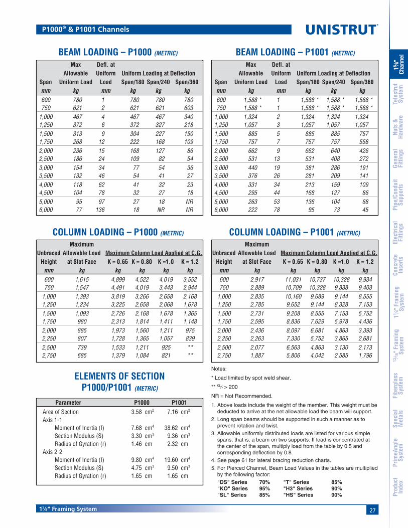
ELEMENTS OF SECTIONP1000/P1001 (METRIC)
P1000® & P1001 Channels
Max Defl. atAllowable Uniform Uniform Loading at Deflection
Span Uniform Load Load Span/180 Span/240 Span/360mm kg mm kg kg kg600 780 1 780 780 780750 621 2 621 621 603
1,000 467 4 467 467 3401,250 372 6 372 327 2181,500 313 9 304 227 1501,750 268 12 222 168 1092,000 236 15 168 127 862,500 186 24 109 82 543,000 154 34 77 54 363,500 132 46 54 41 274,000 118 62 41 32 234,500 104 78 32 27 185,000 95 97 27 18 NR6,000 77 136 18 NR NR
Max Defl. atAllowable Uniform Uniform Loading at Deflection
Span Uniform Load Load Span/180 Span/240 Span/360mm kg mm kg kg kg600 1,588 * 1 1,588 * 1,588 * 1,588 *750 1,588 * 1 1,588 * 1,588 * 1,588 *
1,000 1,324 2 1,324 1,324 1,3241,250 1,057 3 1,057 1,057 1,0571,500 885 5 885 885 7571,750 757 7 757 757 5582,000 662 9 662 640 4262,500 531 13 531 408 2723,000 440 19 381 286 1913,500 376 26 281 209 1414,000 331 34 213 159 1094,500 295 44 168 127 865,000 263 53 136 104 686,000 222 78 95 73 45
BEAM LOADING – P1000 (METRIC) BEAM LOADING – P1001 (METRIC)
COLUMN LOADING – P1000 (METRIC) COLUMN LOADING – P1001 (METRIC)
Notes:
* Load limited by spot weld shear.
** KL⁄r > 200
NR = Not Recommended.
1. Above loads include the weight of the member. This weight must bededucted to arrive at the net allowable load the beam will support.
2. Long span beams should be supported in such a manner as toprevent rotation and twist.
3. Allowable uniformly distributed loads are listed for various simplespans, that is, a beam on two supports. If load is concentrated atthe center of the span, multiply load from the table by 0.5 andcorresponding deflection by 0.8.
4. See page 61 for lateral bracing reduction charts.
5. For Pierced Channel, Beam Load Values in the tables are multipliedby the following factor:
"DS" Series 70% "T" Series 85%"KO" Series 95% "H3" Series 90%"SL" Series 85% "HS" Series 90%
Parameter P1000 P1001Area of Section 3.58 cm2 7.16 cm2
Axis 1-1Moment of Inertia (I) 7.68 cm4 38.62 cm4
Section Modulus (S) 3.30 cm3 9.36 cm3
Radius of Gyration (r) 1.46 cm 2.32 cmAxis 2-2
Moment of Inertia (I) 9.80 cm4 19.60 cm4
Section Modulus (S) 4.75 cm3 9.50 cm3
Radius of Gyration (r) 1.65 cm 1.65 cm
28
®
15⁄8" Framing System
15 ⁄8"
Chan
nel
Nuts
&Ha
rdw
are
Gene
ral
Fitti
ngs
Pipe
/Con
duit
Supp
orts
Elec
trica
lFi
tting
sCo
ncre
teIn
serts
11 ⁄4" F
ram
ing
Syst
em13
⁄16" F
ram
ing
Syst
emFi
berg
lass
Syst
emSp
ecia
lM
etal
sTe
lest
rut
Syst
emPr
imeA
ngle
Syst
emPr
oduc
tIn
dex
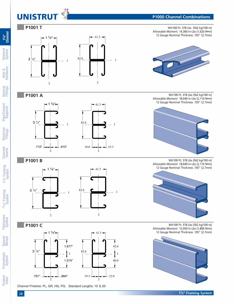
P1001 A
P1001 B
P1001 C
Wt/100 Ft: 378 Lbs (562 kg/100 m)Allowable Moment 18,640 In-Lbs (2,110 N•m)
12 Gauge Nominal Thickness .105" (2.7mm)41.3
82.61
23.32
18.0
Wt/100 Ft: 378 Lbs (562 kg/100 m)Allowable Moment 18,640 In-Lbs (2,110 N•m)
12 Gauge Nominal Thickness .105" (2.7mm)41.3
82.61
2
41.3
82.6
22.019.3
40.0
42.6
1
2
Wt/100 Ft: 378 Lbs (562 kg/100 m)Allowable Moment 15,950 In-Lbs (1,800 N•m)
12 Gauge Nominal Thickness .105" (2.7mm)
2
1 5⁄8"
3 1⁄4"1
.915".710"
2
1 5⁄8"
3 1⁄4"1
2
1 5⁄8"
3 1⁄4"1
1.677"
1.574"
.761" .864"
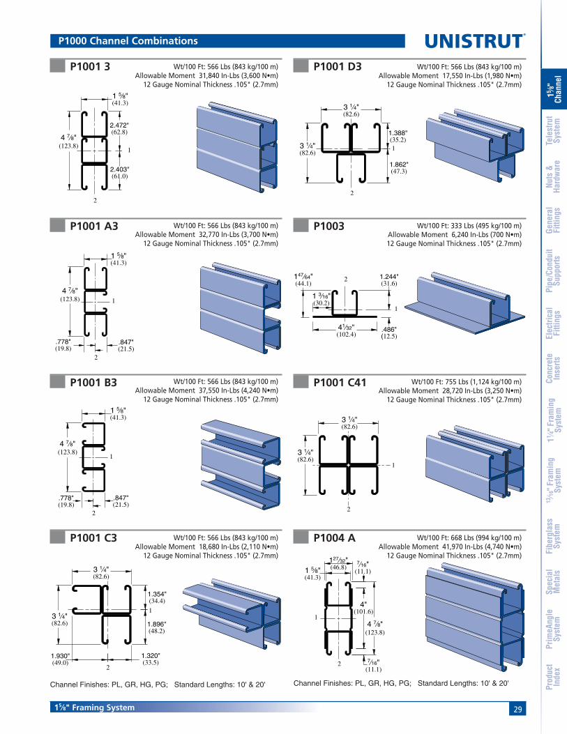
Channel Finishes: PL, GR, HG, PG; Standard Lengths: 10' & 20'
P1000 Channel Combinations
P1001 T
41.3
82.6 1
22
1 5⁄8"
3 1⁄4" 1
Wt/100 Ft: 378 Lbs (562 kg/100 m)Allowable Moment 14,360 In-Lbs (1,620 N•m)
12 Gauge Nominal Thickness .105" (2.7mm)
2915⁄8" Framing System
15 ⁄8"
Chan
nel
Nuts
&Ha
rdw
are
Gene
ral
Fitti
ngs
Pipe
/Con
duit
Supp
orts
Elec
trica
lFi
tting
sCo
ncre
teIn
serts
11 ⁄4" F
ram
ing
Syst
em13
⁄16" F
ram
ing
Syst
emFi
berg
lass
Syst
emSp
ecia
lM
etal
sTe
lest
rut
Syst
emPr
imeA
ngle
Syst
emPr
oduc
tIn
dex
P1000 Channel Combinations
P1001 3 Wt/100 Ft: 566 Lbs (843 kg/100 m)Allowable Moment 31,840 In-Lbs (3,600 N•m)
12 Gauge Nominal Thickness .105" (2.7mm)
P1001 A3
P1001 B3
Wt/100 Ft: 566 Lbs (843 kg/100 m)Allowable Moment 32,770 In-Lbs (3,700 N•m)
12 Gauge Nominal Thickness .105" (2.7mm)
Wt/100 Ft: 566 Lbs (843 kg/100 m)Allowable Moment 37,550 In-Lbs (4,240 N•m)
12 Gauge Nominal Thickness .105" (2.7mm)
P1001 C3
P1001 D3
Wt/100 Ft: 566 Lbs (843 kg/100 m)Allowable Moment 18,680 In-Lbs (2,110 N•m)
12 Gauge Nominal Thickness .105" (2.7mm)
Wt/100 Ft: 566 Lbs (843 kg/100 m)Allowable Moment 17,550 In-Lbs (1,980 N•m)
12 Gauge Nominal Thickness .105" (2.7mm)
Channel Finishes: PL, GR, HG, PG; Standard Lengths: 10' & 20'
2
1 5⁄8"(41.3)
4 7⁄8"(123.8) 1
.847"(21.5)
.778"(19.8)
2
1
1 5⁄8"(41.3)
4 7⁄8"(123.8)
.847"(21.5)
.778"(19.8)
2
1
1.320"(33.5)
1.354"(34.4)
1.896"(48.2)
1.930"(49.0)
3 1⁄4"(82.6)
3 1⁄4"(82.6)
2
1
3 1⁄4"(82.6)
3 1⁄4"(82.6)
1.388"(35.2)
1.862"(47.3)
P1003
P1004 A
Wt/100 Ft: 333 Lbs (495 kg/100 m)Allowable Moment 6,240 In-Lbs (700 N•m)12 Gauge Nominal Thickness .105" (2.7mm)
Wt/100 Ft: 668 Lbs (994 kg/100 m)Allowable Moment 41,970 In-Lbs (4,740 N•m)
12 Gauge Nominal Thickness .105" (2.7mm)
P1001 C41 Wt/100 Ft: 755 Lbs (1,124 kg/100 m)Allowable Moment 28,720 In-Lbs (3,250 N•m)
12 Gauge Nominal Thickness .105" (2.7mm)
Channel Finishes: PL, GR, HG, PG; Standard Lengths: 10' & 20'
2
1
.486"(12.5)
1 3⁄16"(30.2)
147⁄64"(44.1)
41⁄32"(102.4)
1.244"(31.6)
1
2
3 1⁄4"(82.6)
3 1⁄4"(82.6)
127⁄32"(46.8)
2
1
4"(101.6)
7⁄16"(11.1)
7⁄16"(11.1)1 5⁄8"
(41.3)
4 7⁄8"(123.8)
1
2
2.403"(61.0)
2.472"(62.8)
1 5⁄8"(41.3)
4 7⁄8"(123.8)
30
®
15⁄8" Framing System
15 ⁄8"
Chan
nel
Nuts
&Ha
rdw
are
Gene
ral
Fitti
ngs
Pipe
/Con
duit
Supp
orts
Elec
trica
lFi
tting
sCo
ncre
teIn
serts
11 ⁄4" F
ram
ing
Syst
em13
⁄16" F
ram
ing
Syst
emFi
berg
lass
Syst
emSp
ecia
lM
etal
sTe
lest
rut
Syst
emPr
imeA
ngle
Syst
emPr
oduc
tIn
dex
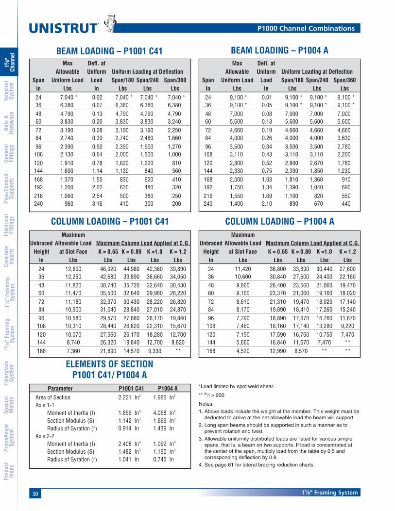
COLUMN LOADING – P1001 C41
ELEMENTS OF SECTIONP1001 C41/ P1004 A
MaximumUnbraced Allowable Load Maximum Column Load Applied at C.G.
Height at Slot Face K = 0.65 K = 0.80 K =1.0 K = 1.2In Lbs Lbs Lbs Lbs Lbs24 12,690 46,920 44,980 42,360 39,89036 12,250 42,680 39,890 36,660 34,05048 11,820 38,740 35,720 32,640 30,43060 11,470 35,500 32,640 29,980 28,22072 11,180 32,970 30,430 28,220 26,82084 10,900 31,040 28,840 27,010 24,87096 10,580 29,570 27,680 26,170 19,840
108 10,310 28,440 26,820 22,310 15,670120 10,070 27,560 26,170 18,280 12,700144 8,740 26,320 19,840 12,700 8,820168 7,360 21,890 14,570 9,330 **
COLUMN LOADING – P1004 AMaximum
Unbraced Allowable Load Maximum Column Load Applied at C.G.Height at Slot Face K = 0.65 K = 0.80 K =1.0 K = 1.2
In Lbs Lbs Lbs Lbs Lbs24 11,420 36,800 33,890 30,440 27,60036 10,600 30,840 27,600 24,400 22,16048 9,860 26,400 23,560 21,060 19,47060 9,160 23,370 21,060 19,160 18,02072 8,610 21,310 19,470 18,020 17,14084 8,170 19,890 18,410 17,260 15,24096 7,790 18,890 17,670 16,760 11,670
108 7,460 18,160 17,140 13,280 9,220120 7,150 17,590 16,760 10,750 7,470144 5,660 16,840 11,670 7,470 **168 4,520 12,990 8,570 ** **
*Load limited by spot weld shear.
** KL⁄r > 200
Notes:
1. Above loads include the weight of the member. This weight must bededucted to arrive at the net allowable load the beam will support.
2. Long span beams should be supported in such a manner as toprevent rotation and twist.
3. Allowable uniformly distributed loads are listed for various simplespans, that is, a beam on two supports. If load is concentrated atthe center of the span, multiply load from the table by 0.5 andcorresponding deflection by 0.8.
4. See page 61 for lateral bracing reduction charts.
BEAM LOADING – P1001 C41 BEAM LOADING – P1004 AMax Defl. at
Allowable Uniform Uniform Loading at DeflectionSpan Uniform Load Load Span/180 Span/240 Span/360
In Lbs In Lbs Lbs Lbs24 7,040 * 0.02 7,040 * 7,040 * 7,040 *36 6,380 0.07 6,380 6,380 6,38048 4,790 0.13 4,790 4,790 4,79060 3,830 0.20 3,830 3,830 3,24072 3,190 0.28 3,190 3,190 2,25084 2,740 0.39 2,740 2,480 1,66096 2,390 0.50 2,390 1,900 1,270
108 2,130 0.64 2,000 1,500 1,000120 1,910 0.78 1,620 1,220 810144 1,600 1.14 1,130 840 560168 1,370 1.55 830 620 410192 1,200 2.02 630 480 320216 1,060 2.54 500 380 250240 960 3.16 410 300 200
Max Defl. atAllowable Uniform Uniform Loading at Deflection
Span Uniform Load Load Span/180 Span/240 Span/360In Lbs In Lbs Lbs Lbs24 9,100 * 0.01 9,100 * 9,100 * 9,100 *36 9,100 * 0.05 9,100 * 9,100 * 9,100 *48 7,000 0.08 7,000 7,000 7,00060 5,600 0.13 5,600 5,600 5,60072 4,660 0.19 4,660 4,660 4,66084 4,000 0.26 4,000 4,000 3,63096 3,500 0.34 3,500 3,500 2,780
108 3,110 0.43 3,110 3,110 2,200120 2,800 0.52 2,800 2,670 1,780144 2,330 0.75 2,330 1,850 1,230168 2,000 1.03 1,810 1,360 910192 1,750 1.34 1,390 1,040 690216 1,550 1.69 1,100 820 550240 1,400 2.10 890 670 440
P1000 Channel Combinations
Parameter P1001 C41 P1004 AArea of Section 2.221 In2 1.965 In2
Axis 1-1Moment of Inertia (I) 1.856 In4 4.068 In4
Section Modulus (S) 1.142 In3 1.669 In3
Radius of Gyration (r) 0.914 In 1.439 InAxis 2-2
Moment of Inertia (I) 2.408 In4 1.092 In4
Section Modulus (S) 1.482 In3 1.190 In3
Radius of Gyration (r) 1.041 In 0.745 In
3115⁄8" Framing System
15 ⁄8"
Chan
nel
Nuts
&Ha
rdw
are
Gene
ral
Fitti
ngs
Pipe
/Con
duit
Supp
orts
Elec
trica
lFi
tting
sCo
ncre
teIn
serts
11 ⁄4" F
ram
ing
Syst
em13
⁄16" F
ram
ing
Syst
emFi
berg
lass
Syst
emSp
ecia
lM
etal
sTe
lest
rut
Syst
emPr
imeA
ngle
Syst
emPr
oduc
tIn
dex
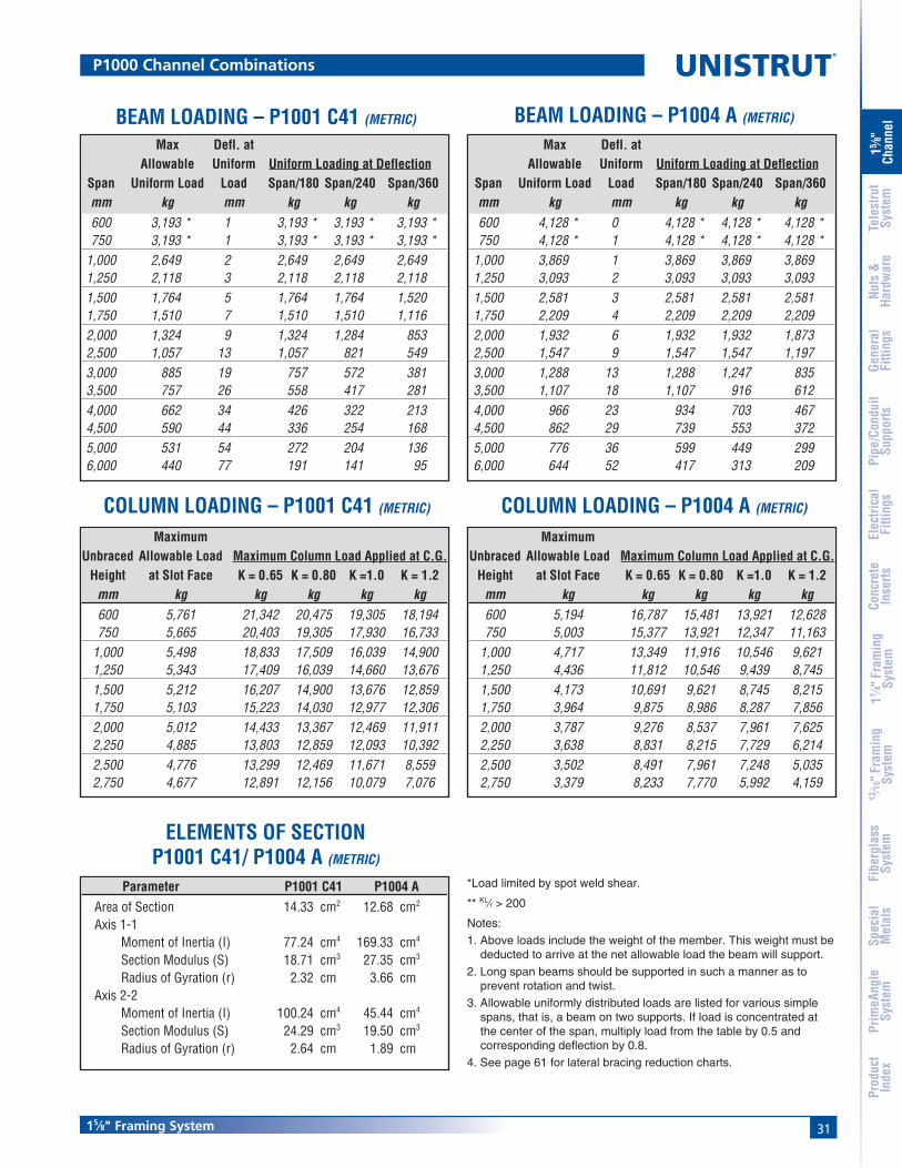
MaximumUnbraced Allowable Load Maximum Column Load Applied at C.G.
Height at Slot Face K = 0.65 K = 0.80 K =1.0 K = 1.2mm kg kg kg kg kg600 5,761 21,342 20,475 19,305 18,194750 5,665 20,403 19,305 17,930 16,733
1,000 5,498 18,833 17,509 16,039 14,9001,250 5,343 17,409 16,039 14,660 13,6761,500 5,212 16,207 14,900 13,676 12,8591,750 5,103 15,223 14,030 12,977 12,3062,000 5,012 14,433 13,367 12,469 11,9112,250 4,885 13,803 12,859 12,093 10,3922,500 4,776 13,299 12,469 11,671 8,5592,750 4,677 12,891 12,156 10,079 7,076
MaximumUnbraced Allowable Load Maximum Column Load Applied at C.G.
Height at Slot Face K = 0.65 K = 0.80 K =1.0 K = 1.2mm kg kg kg kg kg600 5,194 16,787 15,481 13,921 12,628750 5,003 15,377 13,921 12,347 11,163
1,000 4,717 13,349 11,916 10,546 9,6211,250 4,436 11,812 10,546 9,439 8,7451,500 4,173 10,691 9,621 8,745 8,2151,750 3,964 9,875 8,986 8,287 7,8562,000 3,787 9,276 8,537 7,961 7,6252,250 3,638 8,831 8,215 7,729 6,2142,500 3,502 8,491 7,961 7,248 5,0352,750 3,379 8,233 7,770 5,992 4,159
P1000 Channel Combinations
Max Defl. atAllowable Uniform Uniform Loading at Deflection
Span Uniform Load Load Span/180 Span/240 Span/360mm kg mm kg kg kg600 3,193 * 1 3,193 * 3,193 * 3,193 *750 3,193 * 1 3,193 * 3,193 * 3,193 *
1,000 2,649 2 2,649 2,649 2,6491,250 2,118 3 2,118 2,118 2,1181,500 1,764 5 1,764 1,764 1,5201,750 1,510 7 1,510 1,510 1,1162,000 1,324 9 1,324 1,284 8532,500 1,057 13 1,057 821 5493,000 885 19 757 572 3813,500 757 26 558 417 2814,000 662 34 426 322 2134,500 590 44 336 254 1685,000 531 54 272 204 1366,000 440 77 191 141 95
Max Defl. atAllowable Uniform Uniform Loading at Deflection
Span Uniform Load Load Span/180 Span/240 Span/360mm kg mm kg kg kg600 4,128 * 0 4,128 * 4,128 * 4,128 *750 4,128 * 1 4,128 * 4,128 * 4,128 *
1,000 3,869 1 3,869 3,869 3,8691,250 3,093 2 3,093 3,093 3,0931,500 2,581 3 2,581 2,581 2,5811,750 2,209 4 2,209 2,209 2,2092,000 1,932 6 1,932 1,932 1,8732,500 1,547 9 1,547 1,547 1,1973,000 1,288 13 1,288 1,247 8353,500 1,107 18 1,107 916 6124,000 966 23 934 703 4674,500 862 29 739 553 3725,000 776 36 599 449 2996,000 644 52 417 313 209
Parameter P1001 C41 P1004 AArea of Section 14.33 cm2 12.68 cm2
Axis 1-1Moment of Inertia (I) 77.24 cm4 169.33 cm4
Section Modulus (S) 18.71 cm3 27.35 cm3
Radius of Gyration (r) 2.32 cm 3.66 cmAxis 2-2
Moment of Inertia (I) 100.24 cm4 45.44 cm4
Section Modulus (S) 24.29 cm3 19.50 cm3
Radius of Gyration (r) 2.64 cm 1.89 cm
COLUMN LOADING – P1001 C41 (METRIC)
ELEMENTS OF SECTIONP1001 C41/ P1004 A (METRIC)
COLUMN LOADING – P1004 A (METRIC)
BEAM LOADING – P1001 C41 (METRIC) BEAM LOADING – P1004 A (METRIC)
*Load limited by spot weld shear.
** KL⁄r > 200
Notes:
1. Above loads include the weight of the member. This weight must bededucted to arrive at the net allowable load the beam will support.
2. Long span beams should be supported in such a manner as toprevent rotation and twist.
3. Allowable uniformly distributed loads are listed for various simplespans, that is, a beam on two supports. If load is concentrated atthe center of the span, multiply load from the table by 0.5 andcorresponding deflection by 0.8.
4. See page 61 for lateral bracing reduction charts.

32
®
15⁄8" Framing System
15 ⁄8"
Chan
nel
Nuts
&Ha
rdw
are
Gene
ral
Fitti
ngs
Pipe
/Con
duit
Supp
orts
Elec
trica
lFi
tting
sCo
ncre
teIn
serts
11 ⁄4" F
ram
ing
Syst
em13
⁄16" F
ram
ing
Syst
emFi
berg
lass
Syst
emSp
ecia
lM
etal
sTe
lest
rut
Syst
emPr
imeA
ngle
Syst
emPr
oduc
tIn
dex
P1100
P1101
1
7.1
23.1
41.322.2
9.59.5
41.318.3
2
Wt/100 Ft: 142 Lbs (211 kg/100 m)Allowable Moment 4,060 In-Lbs (460 N•m)14 Gauge Nominal Thickness .075" (1.9mm)
1 5⁄8"
3 1⁄4" 1
2
41.3
82.6
2
1
Wt/100 Ft: 284 Lbs (423 kg/100 m)Allowable Moment 11,340 In-Lbs (1,280 N•m)
14 Gauge Nominal Thickness .075" (1.9mm)
1
2
9⁄32"
1 5⁄8"7⁄8" 3⁄8"3⁄8"
.903"
.722"1 5⁄8"
P1100 TWt/100 Ft: 136 Lbs (202 kg/100 m)
P1100 SLWt/100 Ft: 136 Lbs (202 kg/100 m)
P1100 KOWt/100 Ft: 140 Lbs (208 kg/100 m)
P1100 HSWt/100 Ft: 136 Lbs (202 kg/100 m)
Channel Finishes: PL, GR, HG, PG; Standard Lengths: 10' & 20'
Channel Nuts (Refer to Hardware Section for Details)
P1012P1023P1024S
P1006-0832P1006-1024P1006-1420P1007P1008P1009P1010
P1024P1012SP1023S
P1008TP1006T1420P1010T
P3016-0632P3016-0832P3016-1024P3016-1420
P3006-0832P3006-1024P3006-1420P3007P3008P3009P3010
P1100 & P1101 Channels
7⁄8" (22.2) Knockouts6" (152.4) on Center
1⁄2"(12.7)
1"(25.4)
Slots are3" (76.2) x 13⁄32" (10.3)4" (101.6) on Center 1 3⁄16"
(30.2)
Slots are11⁄8" (28.6) x 9⁄16" (14.3)2" (51) on Center 7⁄8"
(22.2)
9⁄16" (14.3) Dia. Holes1 7⁄8" (47.6) on Center
UNISTRUT
UNISTRUT
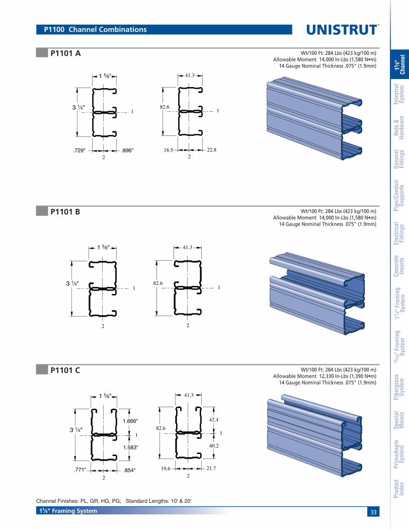
3315⁄8" Framing System
15 ⁄8"
Chan
nel
Nuts
&Ha
rdw
are
Gene
ral
Fitti
ngs
Pipe
/Con
duit
Supp
orts
Elec
trica
lFi
tting
sCo
ncre
teIn
serts
11 ⁄4" F
ram
ing
Syst
em13
⁄16" F
ram
ing
Syst
emFi
berg
lass
Syst
emSp
ecia
lM
etal
sTe
lest
rut
Syst
emPr
imeA
ngle
Syst
emPr
oduc
tIn
dex
P1101 A
P1101 B
P1101 C
Wt/100 Ft: 284 Lbs (423 kg/100 m)Allowable Moment 14,000 In-Lbs (1,580 N•m)
14 Gauge Nominal Thickness .075" (1.9mm)
Wt/100 Ft: 284 Lbs (423 kg/100 m)Allowable Moment 14,000 In-Lbs (1,580 N•m)
14 Gauge Nominal Thickness .075" (1.9mm)
Wt/100 Ft: 284 Lbs (423 kg/100 m)Allowable Moment 12,330 In-Lbs (1,390 N•m)
14 Gauge Nominal Thickness .075" (1.9mm)
1 5⁄8"
3 1⁄4"1
2.729" .896"
41.3
82.61
22.818.52
41.3
82.6
2
1
1
2
41.3
82.6
40.2
42.4
19.6 21.7
1 5⁄8"
3 1⁄4"1
2
1 5⁄8"
3 1⁄4"1
2
1.666"
1.583"
.854".771"
Channel Finishes: PL, GR, HG, PG; Standard Lengths: 10' & 20'
P1100 Channel Combinations
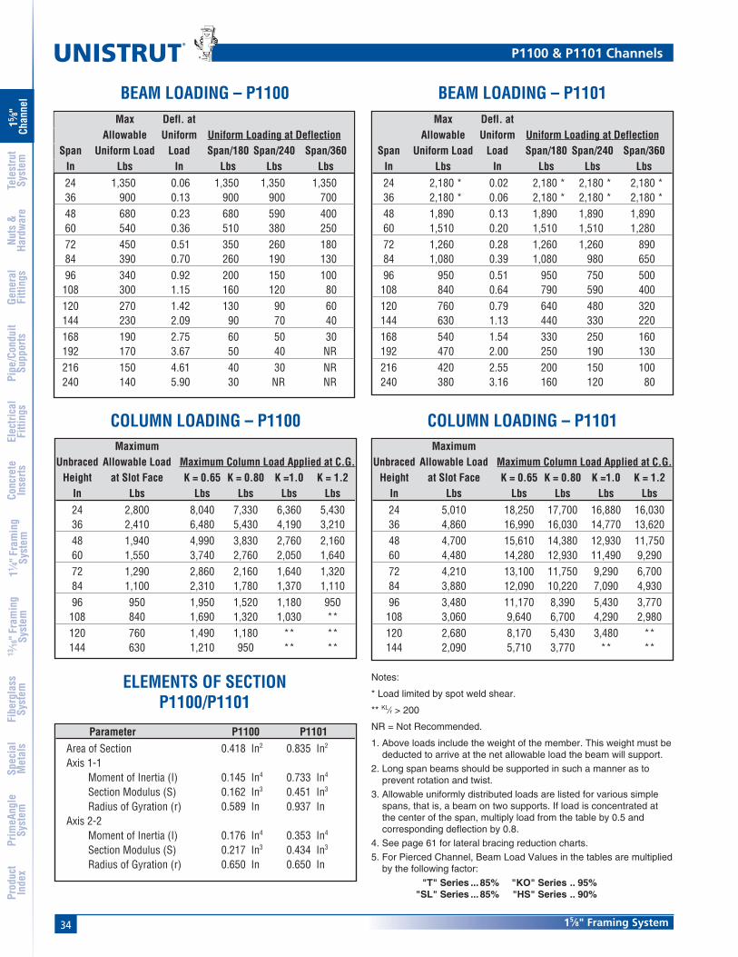
34
®
15⁄8" Framing System
15 ⁄8"
Chan
nel
Nuts
&Ha
rdw
are
Gene
ral
Fitti
ngs
Pipe
/Con
duit
Supp
orts
Elec
trica
lFi
tting
sCo
ncre
teIn
serts
11 ⁄4" F
ram
ing
Syst
em13
⁄16" F
ram
ing
Syst
emFi
berg
lass
Syst
emSp
ecia
lM
etal
sTe
lest
rut
Syst
emPr
imeA
ngle
Syst
emPr
oduc
tIn
dex
COLUMN LOADING – P1100
ELEMENTS OF SECTIONP1100/P1101
MaximumUnbraced Allowable Load Maximum Column Load Applied at C.G.
Height at Slot Face K = 0.65 K = 0.80 K =1.0 K = 1.2In Lbs Lbs Lbs Lbs Lbs24 2,800 8,040 7,330 6,360 5,43036 2,410 6,480 5,430 4,190 3,21048 1,940 4,990 3,830 2,760 2,16060 1,550 3,740 2,760 2,050 1,64072 1,290 2,860 2,160 1,640 1,32084 1,100 2,310 1,780 1,370 1,11096 950 1,950 1,520 1,180 950
108 840 1,690 1,320 1,030 **120 760 1,490 1,180 ** **144 630 1,210 950 ** **
COLUMN LOADING – P1101Maximum
Unbraced Allowable Load Maximum Column Load Applied at C.G.Height at Slot Face K = 0.65 K = 0.80 K =1.0 K = 1.2
In Lbs Lbs Lbs Lbs Lbs24 5,010 18,250 17,700 16,880 16,03036 4,860 16,990 16,030 14,770 13,62048 4,700 15,610 14,380 12,930 11,75060 4,480 14,280 12,930 11,490 9,29072 4,210 13,100 11,750 9,290 6,70084 3,880 12,090 10,220 7,090 4,93096 3,480 11,170 8,390 5,430 3,770
108 3,060 9,640 6,700 4,290 2,980120 2,680 8,170 5,430 3,480 **144 2,090 5,710 3,770 ** **
Notes:
* Load limited by spot weld shear.
** KL⁄r > 200
NR = Not Recommended.
1. Above loads include the weight of the member. This weight must bededucted to arrive at the net allowable load the beam will support.
2. Long span beams should be supported in such a manner as toprevent rotation and twist.
3. Allowable uniformly distributed loads are listed for various simplespans, that is, a beam on two supports. If load is concentrated atthe center of the span, multiply load from the table by 0.5 andcorresponding deflection by 0.8.
4. See page 61 for lateral bracing reduction charts.
5. For Pierced Channel, Beam Load Values in the tables are multipliedby the following factor:
"T" Series ... 85% "KO" Series .. 95%"SL" Series ... 85% "HS" Series .. 90%
BEAM LOADING – P1100 BEAM LOADING – P1101Max Defl. at
Allowable Uniform Uniform Loading at DeflectionSpan Uniform Load Load Span/180 Span/240 Span/360
In Lbs In Lbs Lbs Lbs24 1,350 0.06 1,350 1,350 1,35036 900 0.13 900 900 70048 680 0.23 680 590 40060 540 0.36 510 380 25072 450 0.51 350 260 18084 390 0.70 260 190 13096 340 0.92 200 150 100108 300 1.15 160 120 80120 270 1.42 130 90 60144 230 2.09 90 70 40168 190 2.75 60 50 30192 170 3.67 50 40 NR216 150 4.61 40 30 NR240 140 5.90 30 NR NR
Max Defl. atAllowable Uniform Uniform Loading at Deflection
Span Uniform Load Load Span/180 Span/240 Span/360In Lbs In Lbs Lbs Lbs24 2,180 * 0.02 2,180 * 2,180 * 2,180 *36 2,180 * 0.06 2,180 * 2,180 * 2,180 *48 1,890 0.13 1,890 1,890 1,89060 1,510 0.20 1,510 1,510 1,28072 1,260 0.28 1,260 1,260 89084 1,080 0.39 1,080 980 65096 950 0.51 950 750 500
108 840 0.64 790 590 400120 760 0.79 640 480 320144 630 1.13 440 330 220168 540 1.54 330 250 160192 470 2.00 250 190 130216 420 2.55 200 150 100240 380 3.16 160 120 80
P1100 & P1101 Channels
Parameter P1100 P1101Area of Section 0.418 In2 0.835 In2
Axis 1-1Moment of Inertia (I) 0.145 In4 0.733 In4
Section Modulus (S) 0.162 In3 0.451 In3
Radius of Gyration (r) 0.589 In 0.937 InAxis 2-2
Moment of Inertia (I) 0.176 In4 0.353 In4
Section Modulus (S) 0.217 In3 0.434 In3
Radius of Gyration (r) 0.650 In 0.650 In

3515⁄8" Framing System
15 ⁄8"
Chan
nel
Nuts
&Ha
rdw
are
Gene
ral
Fitti
ngs
Pipe
/Con
duit
Supp
orts
Elec
trica
lFi
tting
sCo
ncre
teIn
serts
11 ⁄4" F
ram
ing
Syst
em13
⁄16" F
ram
ing
Syst
emFi
berg
lass
Syst
emSp
ecia
lM
etal
sTe
lest
rut
Syst
emPr
imeA
ngle
Syst
emPr
oduc
tIn
dex
ELEMENTS OF SECTIONP1100/P1101 (METRIC)
P1100 & P1101 Channels
MaximumUnbraced Allowable Load Maximum Column Load Applied at C.G.
Height at Slot Face K = 0.65 K = 0.80 K =1.0 K = 1.2mm kg kg kg kg kg600 1,275 3,665 3,352 2,921 2,499750 1,207 3,329 2,921 2,400 1,941
1,000 1,034 2,744 2,241 1,674 1,2791,250 862 2,200 1,674 1,207 9481,500 717 1,737 1,279 948 7571,750 608 1,379 1,034 785 6302,000 531 1,143 875 667 5442,250 472 980 757 585 4762,500 417 857 667 517 **2,750 381 762 599 463 **
MaximumUnbraced Allowable Load Maximum Column Load Applied at C.G.
Height at Slot Face K = 0.65 K = 0.80 K =1.0 K = 1.2mm kg kg kg kg kg600 2,272 8,296 8,051 7,688 7,307750 2,241 8,029 7,688 7,212 6,745
1,000 2,186 7,530 7,053 6,450 5,9101,250 2,123 7,017 6,450 5,788 5,2571,500 2,041 6,523 5,910 5,257 4,3141,750 1,941 6,069 5,457 4,486 3,3202,000 1,837 5,674 5,012 3,642 2,5452,250 1,692 5,330 4,314 2,894 2,0092,500 1,538 4,926 3,642 2,345 1,6282,750 1,383 4,354 3,025 1,937 1,343
Max Defl. atAllowable Uniform Uniform Loading at Deflection
Span Uniform Load Load Span/180 Span/240 Span/360mm kg mm kg kg kg600 626 1 626 626 626750 499 2 499 499 476
1,000 376 4 376 376 2681,250 299 6 299 254 1721,500 249 9 236 177 1181,750 213 12 172 132 862,000 186 15 132 100 682,500 150 24 86 64 413,000 127 36 59 45 323,500 109 49 45 32 234,000 95 64 32 27 184,500 82 77 27 18 145,000 77 100 23 18 NR6,000 64 143 14 NR NR
Max Defl. atAllowable Uniform Uniform Loading at Deflection
Span Uniform Load Load Span/180 Span/240 Span/360mm kg mm kg kg kg600 989 * 0 989 * 989 * 989 *750 989 * 1 989 * 989 * 989 *
1,000 989 * 2 989 * 989 * 989 *1,250 835 3 835 835 8351,500 699 5 699 699 5991,750 599 7 599 599 4402,000 522 9 522 508 3362,500 417 13 417 322 2183,000 349 19 299 227 1503,500 299 26 222 163 1094,000 263 35 168 127 864,500 231 43 132 100 685,000 209 54 109 82 546,000 172 77 77 54 36
COLUMN LOADING – P1100 (METRIC) COLUMN LOADING – P1101 (METRIC)
BEAM LOADING – P1100 (METRIC) BEAM LOADING – P1101 (METRIC)
Parameter P1100 P1101Area of Section 2.69 cm2 5.39 cm2
Axis 1-1Moment of Inertia (I) 6.03 cm4 30.51 cm4
Section Modulus (S) 2.65 cm3 7.39 cm3
Radius of Gyration (r) 1.50 cm 2.38 cmAxis 2-2
Moment of Inertia (I) 7.34 cm4 14.69 cm4
Section Modulus (S) 3.56 cm3 7.12 cm3
Radius of Gyration (r) 1.65 cm 1.65 cm
Notes:
* Load limited by spot weld shear.
** KL⁄r > 200
NR = Not Recommended.
1. Above loads include the weight of the member. This weight must bededucted to arrive at the net allowable load the beam will support.
2. Long span beams should be supported in such a manner as toprevent rotation and twist.
3. Allowable uniformly distributed loads are listed for various simplespans, that is, a beam on two supports. If load is concentrated atthe center of the span, multiply load from the table by 0.5 andcorresponding deflection by 0.8.
4. See page 61 for lateral bracing reduction charts.
5. For Pierced Channel, Beam Load Values in the tables are multipliedby the following factor:
"T" Series ... 85% "KO" Series .. 95%"SL" Series ... 85% "HS" Series .. 90%
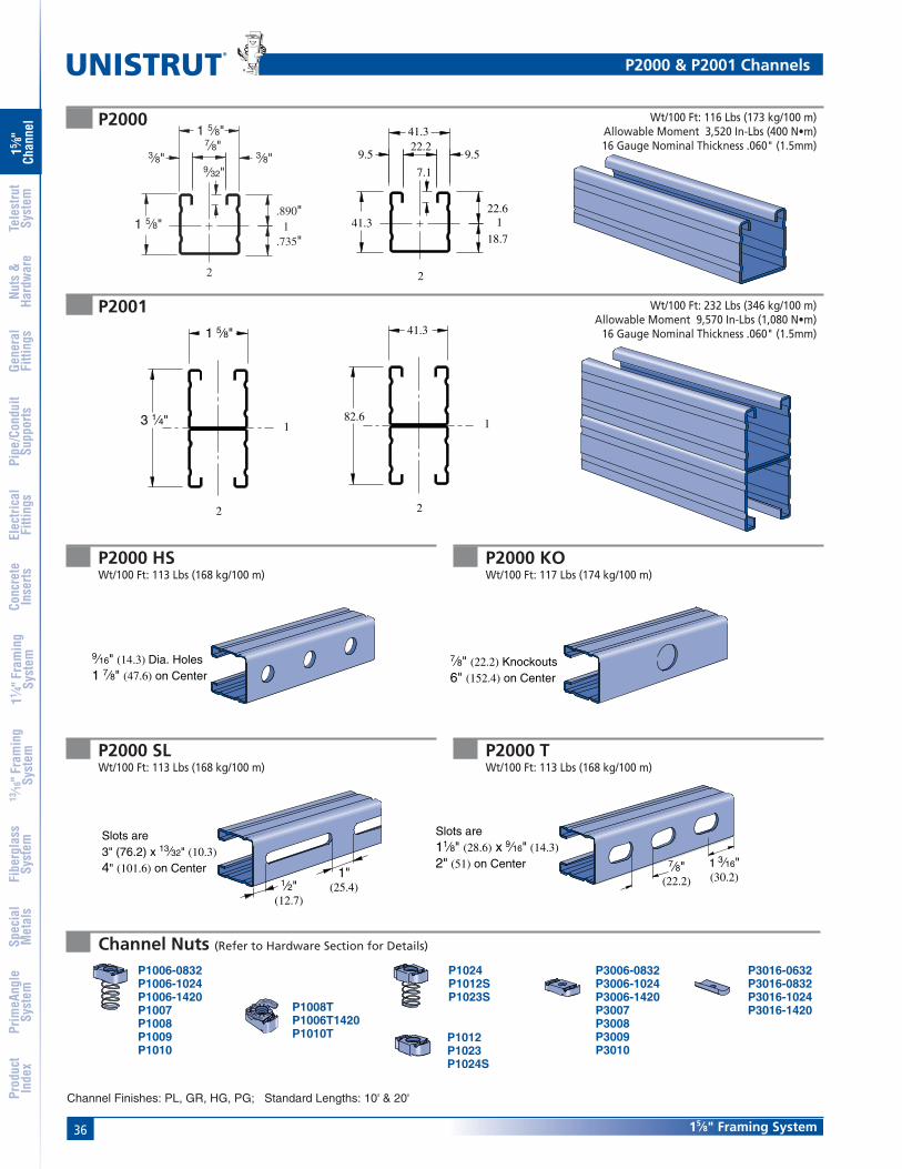
36
®
15⁄8" Framing System
15 ⁄8"
Chan
nel
Nuts
&Ha
rdw
are
Gene
ral
Fitti
ngs
Pipe
/Con
duit
Supp
orts
Elec
trica
lFi
tting
sCo
ncre
teIn
serts
11 ⁄4" F
ram
ing
Syst
em13
⁄16" F
ram
ing
Syst
emFi
berg
lass
Syst
emSp
ecia
lM
etal
sTe
lest
rut
Syst
emPr
imeA
ngle
Syst
emPr
oduc
tIn
dex
P2000 Wt/100 Ft: 116 Lbs (173 kg/100 m)Allowable Moment 3,520 In-Lbs (400 N•m)16 Gauge Nominal Thickness .060" (1.5mm)
7.1
18.7
22.6
41.3
41.3
22.29.5 9.5
2
1
1 5⁄8"
3 1⁄4"
2
1
41.3
82.61
2
P2001
P2000 TWt/100 Ft: 113 Lbs (168 kg/100 m)
P2000 SLWt/100 Ft: 113 Lbs (168 kg/100 m)
P2000 KOWt/100 Ft: 117 Lbs (174 kg/100 m)
P2000 HSWt/100 Ft: 113 Lbs (168 kg/100 m)
Channel Finishes: PL, GR, HG, PG; Standard Lengths: 10' & 20'
Channel Nuts (Refer to Hardware Section for Details)
P1012P1023P1024S
P1006-0832P1006-1024P1006-1420P1007P1008P1009P1010
P1024P1012SP1023S
P1008TP1006T1420P1010T
P3016-0632P3016-0832P3016-1024P3016-1420
P3006-0832P3006-1024P3006-1420P3007P3008P3009P3010
P2000 & P2001 Channels
9⁄16" (14.3) Dia. Holes1 7⁄8" (47.6) on Center
7⁄8" (22.2) Knockouts6" (152.4) on Center
1⁄2"(12.7)
1"(25.4)
Slots are3" (76.2) x 13⁄32" (10.3)4" (101.6) on Center 1 3⁄16"
(30.2)
Slots are11⁄8" (28.6) x 9⁄16" (14.3)2" (51) on Center 7⁄8"
(22.2)
Wt/100 Ft: 232 Lbs (346 kg/100 m)Allowable Moment 9,570 In-Lbs (1,080 N•m)
16 Gauge Nominal Thickness .060" (1.5mm)
UNISTRUT
UNISTRUT
1 5⁄8"
1 5⁄8"
7⁄8"3⁄8"3⁄8"
9⁄32"
2
1.735"
.890"

3715⁄8" Framing System
15 ⁄8"
Chan
nel
Nuts
&Ha
rdw
are
Gene
ral
Fitti
ngs
Pipe
/Con
duit
Supp
orts
Elec
trica
lFi
tting
sCo
ncre
teIn
serts
11 ⁄4" F
ram
ing
Syst
em13
⁄16" F
ram
ing
Syst
emFi
berg
lass
Syst
emSp
ecia
lM
etal
sTe
lest
rut
Syst
emPr
imeA
ngle
Syst
emPr
oduc
tIn
dex
P2001 A
P2001 B
P2001 C
41.3
82.61
22.618.72
41.3
82.6
221.619.7
1
40.3
42.3
Wt/100 Ft: 232 Lbs (346 kg/100 m)Allowable Moment 11,660 In-Lbs (1,320 N•m)
16 Gauge Nominal Thickness .060" (1.5mm)
Wt/100 Ft: 232 Lbs (346 kg/100 m)Allowable Moment 11,660 In-Lbs (1,320 N•m)
16 Gauge Nominal Thickness .060" (1.5mm)
Wt/100 Ft: 232 Lbs (346 kg/100 m)Allowable Moment 10,350 In-Lbs (1,170 N•m)
16 Gauge Nominal Thickness .060" (1.5mm)1 5⁄8"
3 1⁄4"
2
1
.774" .851"
1.664"
1.586"
1 5⁄8"
3 1⁄4"
2
1
.735" .890"
1 5⁄8"
3 1⁄4"
2
1
41.3
82.61
2
Channel Finishes: PL, GR, HG, PG; Standard Lengths: 10' & 20'
P2000 Channel Combinations

38
®
15⁄8" Framing System
15 ⁄8"
Chan
nel
Nuts
&Ha
rdw
are
Gene
ral
Fitti
ngs
Pipe
/Con
duit
Supp
orts
Elec
trica
lFi
tting
sCo
ncre
teIn
serts
11 ⁄4" F
ram
ing
Syst
em13
⁄16" F
ram
ing
Syst
emFi
berg
lass
Syst
emSp
ecia
lM
etal
sTe
lest
rut
Syst
emPr
imeA
ngle
Syst
emPr
oduc
tIn
dex
COLUMN LOADING – P2000
ELEMENTS OF SECTIONP2000/P2001
MaximumUnbraced Allowable Load Maximum Column Load Applied at C.G.
Height at Slot Face K = 0.65 K = 0.80 K =1.0 K = 1.2In Lbs Lbs Lbs Lbs Lbs24 2,400 6,650 6,080 5,280 4,47036 2,050 5,380 4,470 3,370 2,50048 1,600 4,090 3,040 2,100 1,59060 1,230 2,960 2,100 1,500 1,16072 970 2,190 1,590 1,160 91084 790 1,720 1,270 950 76096 660 1,410 1,060 800 650
108 570 1,200 910 700 **120 510 1,040 800 620 **144 420 830 650 ** **
COLUMN LOADING – P2001
MaximumUnbraced Allowable Load Maximum Column Load Applied at C.G.
Height at Slot Face K = 0.65 K = 0.80 K =1.0 K = 1.2In Lbs Lbs Lbs Lbs Lbs24 4,200 15,030 14,600 13,940 13,22036 4,070 14,030 13,220 12,090 10,99048 3,920 12,850 11,720 10,290 9,04060 3,700 11,630 10,290 8,760 7,53072 3,410 10,460 9,040 7,530 5,74084 3,140 9,410 7,990 6,080 4,22096 2,890 8,490 7,120 4,650 3,230
108 2,530 7,700 5,740 3,680 2,550120 2,210 6,950 4,650 2,980 **144 1,690 4,890 3,230 ** **
BEAM LOADING – P2000 BEAM LOADING – P2001 CHANNEL
Notes:
* Load limited by spot weld shear.
** KL⁄r > 200
NR = Not Recommended.
1. Above loads include the weight of the member. This weight must bededucted to arrive at the net allowable load the beam will support.
2. Long span beams should be supported in such a manner as toprevent rotation and twist.
3. Allowable uniformly distributed loads are listed for various simplespans, that is, a beam on two supports. If load is concentrated atthe center of the span, multiply load from the table by 0.5 andcorresponding deflection by 0.8.
4. See page 61 for lateral bracing reduction charts.
5. For Pierced Channel, Beam Load Values in the tables are multipliedby the following factor:
"T" Series ... 85% "KO" Series .. 95%"SL" Series ... 85% "HS" Series .. 90%
Max Defl. atAllowable Uniform Uniform Loading at Deflection
Span Uniform Load Load Span/180 Span/240 Span/360In Lbs In Lbs Lbs Lbs24 1,170 0.06 1,170 1,170 1,17036 780 0.13 780 780 61048 590 0.23 590 510 34060 470 0.36 440 330 22072 390 0.52 300 230 15084 340 0.71 220 170 11096 290 0.91 170 130 90
108 260 1.16 130 100 70120 230 1.41 110 80 50144 200 2.12 80 60 40168 170 2.86 60 40 30192 150 3.76 40 30 20216 130 4.64 30 30 NR240 120 5.88 30 NR NR
Max Defl. atAllowable Uniform Uniform Loading at Deflection
Span Uniform Load Load Span/180 Span/240 Span/360In Lbs In Lbs Lbs Lbs24 1,610 * 0.02 1,610 * 1,610 * 1,610 *36 1,610 * 0.05 1,610 * 1,610 * 1,610 *48 1,600 0.13 1,600 1,600 1,60060 1,280 0.20 1,280 1,280 1,08072 1,060 0.28 1,060 1,060 75084 910 0.38 910 830 55096 800 0.51 800 630 420
108 710 0.64 670 500 330120 640 0.79 540 410 270144 530 1.13 380 280 190168 460 1.56 280 210 140192 400 2.02 210 160 110216 350 2.52 170 130 80240 320 3.16 140 100 70
P2000 & P2001 Channels
Parameter P2000 P2001Area of Section 0.342 In2 0.684 In2
Axis 1-1Moment of Inertia (I) 0.125 In4 0.618 In4
Section Modulus (S) 0.140 In3 0.381 In3
Radius of Gyration (r) 0.604 In 0.951 InAxis 2-2
Moment of Inertia (I) 0.151 In4 0.302 In4
Section Modulus (S) 0.186 In3 0.372 In3
Radius of Gyration (r) 0.665 In 0.665 In

3915⁄8" Framing System
15 ⁄8"
Chan
nel
Nuts
&Ha
rdw
are
Gene
ral
Fitti
ngs
Pipe
/Con
duit
Supp
orts
Elec
trica
lFi
tting
sCo
ncre
teIn
serts
11 ⁄4" F
ram
ing
Syst
em13
⁄16" F
ram
ing
Syst
emFi
berg
lass
Syst
emSp
ecia
lM
etal
sTe
lest
rut
Syst
emPr
imeA
ngle
Syst
emPr
oduc
tIn
dex
ELEMENTS OF SECTIONP2000/P2001 (METRIC)
P2000 & P2001 Channels
MaximumUnbraced Allowable Load Maximum Column Load Applied at C.G.
Height at Slot Face K = 0.65 K = 0.80 K =1.0 K = 1.2mm kg kg kg kg kg600 1,089 3,035 2,781 2,422 2,064750 1,030 2,758 2,422 1,973 1,565
1,000 871 2,272 1,833 1,320 9801,250 708 1,796 1,320 916 6941,500 567 1,379 980 694 5351,750 467 1,066 771 558 4402,000 390 862 630 467 3722,250 336 721 535 404 3222,500 290 617 467 354 2862,750 259 540 413 318 **
MaximumUnbraced Allowable Load Maximum Column Load Applied at C.G.
Height at Slot Face K = 0.65 K = 0.80 K =1.0 K = 1.2mm kg kg kg kg kg600 1,905 6,831 6,641 6,346 6,028750 1,878 6,622 6,346 5,947 5,525
1,000 1,828 6,219 5,806 5,248 4,7171,250 1,769 5,770 5,248 4,590 4,0231,500 1,687 5,316 4,717 4,023 3,4651,750 1,583 4,881 4,237 3,547 2,8442,000 1,479 4,472 3,819 3,103 2,1772,250 1,383 4,100 3,465 2,477 1,7192,500 1,279 3,774 3,103 2,009 1,3932,750 1,148 3,484 2,595 1,660 1,152
Max Defl. atAllowable Uniform Uniform Loading at Deflection
Span Uniform Load Load Span/180 Span/240 Span/360mm kg mm kg kg kg600 540 1 540 540 540750 431 2 431 431 408
1,000 327 4 327 327 2311,250 259 6 259 222 1451,500 218 9 204 154 1001,750 186 12 150 113 772,000 163 16 113 86 592,500 132 25 73 54 363,000 109 36 50 36 273,500 91 47 36 27 184,000 82 63 27 23 144,500 73 80 23 18 95,000 64 96 18 14 96,000 54 142 14 NR NR
Max Defl. atAllowable Uniform Uniform Loading at Deflection
Span Uniform Load Load Span/180 Span/240 Span/360mm kg mm kg kg kg600 730 * 0 730 * 730 * 730 *750 730 * 1 730 * 730 * 730 *
1,000 730 * 2 730 * 730 * 730 *1,250 708 3 708 708 7081,500 590 5 590 590 5081,750 503 7 503 503 3722,000 440 9 440 426 2862,500 354 13 354 272 1813,000 295 19 254 191 1273,500 254 27 186 141 914,000 222 35 141 109 734,500 195 43 113 86 545,000 177 54 91 68 456,000 145 76 64 45 32
COLUMN LOADING – P2000 (METRIC) COLUMN LOADING – P2001 (METRIC)
BEAM LOADING – P2000 (METRIC) BEAM LOADING – P2001 CHANNEL (METRIC)
Parameter P2000 P2001Area of Section 2.21 cm2 4.41 cm2
Axis 1-1Moment of Inertia (I) 5.19 cm4 25.74 cm4
Section Modulus (S) 2.29 cm3 6.24 cm3
Radius of Gyration (r) 1.53 cm 2.42 cmAxis 2-2
Moment of Inertia (I) 6.29 cm4 12.58 cm4
Section Modulus (S) 3.05 cm3 6.10 cm3
Radius of Gyration (r) 1.69 cm 1.69 cm
Notes:
* Load limited by spot weld shear.
** KL⁄r > 200
NR = Not Recommended.
1. Above loads include the weight of the member. This weight must bededucted to arrive at the net allowable load the beam will support.
2. Long span beams should be supported in such a manner as toprevent rotation and twist.
3. Allowable uniformly distributed loads are listed for various simplespans, that is, a beam on two supports. If load is concentrated atthe center of the span, multiply load from the table by 0.5 andcorresponding deflection by 0.8.
4. See page 61 for lateral bracing reduction charts.
5. For Pierced Channel, Beam Load Values in the tables are multipliedby the following factor:
"T" Series ... 85% "KO" Series .. 95%"SL" Series ... 85% "HS" Series .. 90%

40
®
15⁄8" Framing System
15 ⁄8"
Chan
nel
Nuts
&Ha
rdw
are
Gene
ral
Fitti
ngs
Pipe
/Con
duit
Supp
orts
Elec
trica
lFi
tting
sCo
ncre
teIn
serts
11 ⁄4" F
ram
ing
Syst
em13
⁄16" F
ram
ing
Syst
emFi
berg
lass
Syst
emSp
ecia
lM
etal
sTe
lest
rut
Syst
emPr
imeA
ngle
Syst
emPr
oduc
tIn
dex
P3000
P3001
7.1
19.934.9
41.322.29.5 9.5
1
2
15.01 3⁄8"
9⁄32"
1 5⁄8"7⁄8"3⁄8" 3⁄8"
.784"
2
1.591"
Wt/100 Ft: 170 Lbs (253 kg/100 m)Allowable Moment 3,840 In-Lbs (430 N•m)12 Gauge Nominal Thickness .105" (2.7mm)
Wt/100 Ft: 340 Lbs (506 kg/100 m)Allowable Moment 10,810 In-Lbs (1,220 N•m)
12 Gauge Nominal Thickness .105" (2.7mm)
2 3⁄4"
1 5⁄8"
2
169.9
41.3
1
2
P3000 TWt/100 Ft: 165 Lbs (246 kg/100 m)
P3000 SLWt/100 Ft: 165 Lbs (246 kg/100 m)
P3000 KOWt/100 Ft: 170 Lbs (253 kg/100 m)
P3000 HSWt/100 Ft: 165 Lbs (246 kg/100 m)
Channel Finishes: PL, GR, HG, PG; Standard Lengths: 10' & 20'
Channel Nuts (Refer to Hardware Section for Details)
UNISTRUT
UNISTRUT
P1012P1023P1024S
P1006-0832P1006-1024P1006-1420P1007P1008P1009P1010
P1024P1012SP1023S
P1008TP1006T1420P1010T
P3016-0632P3016-0832P3016-1024P3016-1420
P3006-0832P3006-1024P3006-1420P3007P3008P3009P3010
P3000 & P3001 Channels
9⁄16" (14.3) Dia. Holes1 7⁄8" (47.6) on Center
7⁄8" (22.2) Knockouts6" (152.4) on Center 1⁄2"
(12.7)
1"(25.4)
Slots are3" (76.2) x 13⁄32" (10.3)4" (101.6) on Center
1 3⁄16"(30.2)
Slots are11⁄8" (28.6) x 9⁄16" (14.3)2" (51) on Center
7⁄8"(22.2)
P3001 TWt/100 Ft: 340 Lbs (506 kg/100 m)
1 3⁄16"(30.2)
Slots are11⁄8" (28.6) x 9⁄16" (14.3)2" (51) on Center
7⁄8"(22.2)
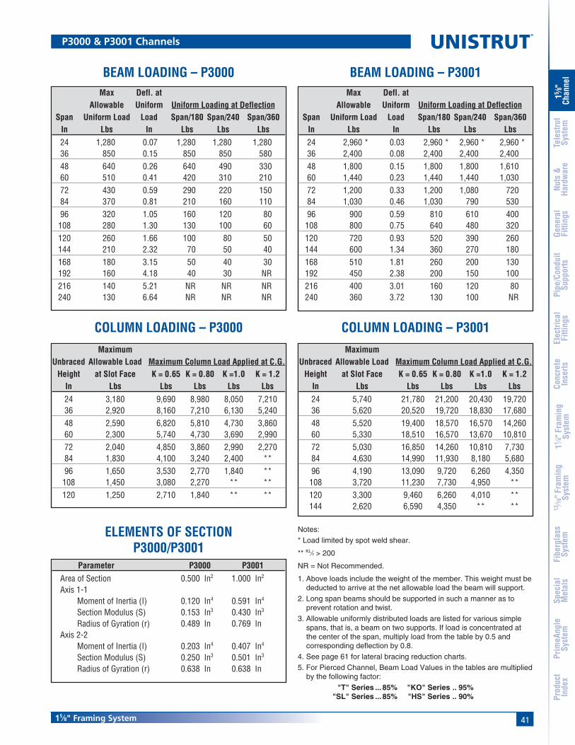
4115⁄8" Framing System
15 ⁄8"
Chan
nel
Nuts
&Ha
rdw
are
Gene
ral
Fitti
ngs
Pipe
/Con
duit
Supp
orts
Elec
trica
lFi
tting
sCo
ncre
teIn
serts
11 ⁄4" F
ram
ing
Syst
em13
⁄16" F
ram
ing
Syst
emFi
berg
lass
Syst
emSp
ecia
lM
etal
sTe
lest
rut
Syst
emPr
imeA
ngle
Syst
emPr
oduc
tIn
dex
Notes:
* Load limited by spot weld shear.
** KL⁄r > 200
NR = Not Recommended.
1. Above loads include the weight of the member. This weight must bededucted to arrive at the net allowable load the beam will support.
2. Long span beams should be supported in such a manner as toprevent rotation and twist.
3. Allowable uniformly distributed loads are listed for various simplespans, that is, a beam on two supports. If load is concentrated atthe center of the span, multiply load from the table by 0.5 andcorresponding deflection by 0.8.
4. See page 61 for lateral bracing reduction charts.
5. For Pierced Channel, Beam Load Values in the tables are multipliedby the following factor:
"T" Series ... 85% "KO" Series .. 95%"SL" Series ... 85% "HS" Series .. 90%
BEAM LOADING – P3000 BEAM LOADING – P3001Max Defl. at
Allowable Uniform Uniform Loading at DeflectionSpan Uniform Load Load Span/180 Span/240 Span/360
In Lbs In Lbs Lbs Lbs24 1,280 0.07 1,280 1,280 1,28036 850 0.15 850 850 58048 640 0.26 640 490 33060 510 0.41 420 310 21072 430 0.59 290 220 15084 370 0.81 210 160 11096 320 1.05 160 120 80
108 280 1.30 130 100 60120 260 1.66 100 80 50144 210 2.32 70 50 40168 180 3.15 50 40 30192 160 4.18 40 30 NR216 140 5.21 NR NR NR240 130 6.64 NR NR NR
Max Defl. atAllowable Uniform Uniform Loading at Deflection
Span Uniform Load Load Span/180 Span/240 Span/360In Lbs In Lbs Lbs Lbs24 2,960 * 0.03 2,960 * 2,960 * 2,960 *36 2,400 0.08 2,400 2,400 2,40048 1,800 0.15 1,800 1,800 1,61060 1,440 0.23 1,440 1,440 1,03072 1,200 0.33 1,200 1,080 72084 1,030 0.46 1,030 790 53096 900 0.59 810 610 400
108 800 0.75 640 480 320120 720 0.93 520 390 260144 600 1.34 360 270 180168 510 1.81 260 200 130192 450 2.38 200 150 100216 400 3.01 160 120 80240 360 3.72 130 100 NR
P3000 & P3001 Channels
COLUMN LOADING – P3000Maximum
Unbraced Allowable Load Maximum Column Load Applied at C.G.Height at Slot Face K = 0.65 K = 0.80 K =1.0 K = 1.2
In Lbs Lbs Lbs Lbs Lbs24 3,180 9,690 8,980 8,050 7,21036 2,920 8,160 7,210 6,130 5,24048 2,590 6,820 5,810 4,730 3,86060 2,300 5,740 4,730 3,690 2,99072 2,040 4,850 3,860 2,990 2,27084 1,830 4,100 3,240 2,400 **96 1,650 3,530 2,770 1,840 **
108 1,450 3,080 2,270 ** **120 1,250 2,710 1,840 ** **
COLUMN LOADING – P3001Maximum
Unbraced Allowable Load Maximum Column Load Applied at C.G.Height at Slot Face K = 0.65 K = 0.80 K =1.0 K = 1.2
In Lbs Lbs Lbs Lbs Lbs24 5,740 21,780 21,200 20,430 19,72036 5,620 20,520 19,720 18,830 17,68048 5,520 19,400 18,570 16,570 14,26060 5,330 18,510 16,570 13,670 10,81072 5,030 16,850 14,260 10,810 7,73084 4,630 14,990 11,930 8,180 5,68096 4,190 13,090 9,720 6,260 4,350
108 3,720 11,230 7,730 4,950 **120 3,300 9,460 6,260 4,010 **144 2,620 6,590 4,350 ** **
ELEMENTS OF SECTIONP3000/P3001
Parameter P3000 P3001Area of Section 0.500 In2 1.000 In2
Axis 1-1Moment of Inertia (I) 0.120 In4 0.591 In4
Section Modulus (S) 0.153 In3 0.430 In3
Radius of Gyration (r) 0.489 In 0.769 InAxis 2-2
Moment of Inertia (I) 0.203 In4 0.407 In4
Section Modulus (S) 0.250 In3 0.501 In3
Radius of Gyration (r) 0.638 In 0.638 In
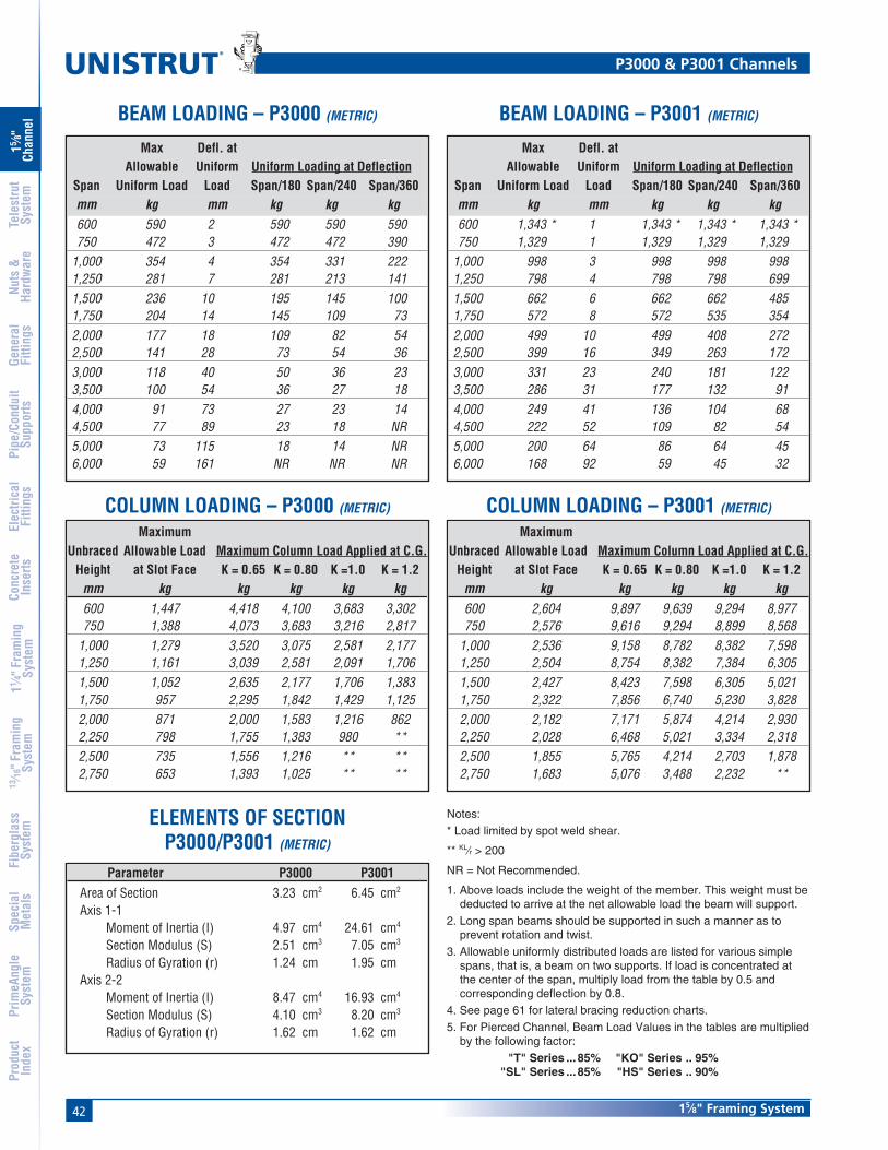
42
®
15⁄8" Framing System
15 ⁄8"
Chan
nel
Nuts
&Ha
rdw
are
Gene
ral
Fitti
ngs
Pipe
/Con
duit
Supp
orts
Elec
trica
lFi
tting
sCo
ncre
teIn
serts
11 ⁄4" F
ram
ing
Syst
em13
⁄16" F
ram
ing
Syst
emFi
berg
lass
Syst
emSp
ecia
lM
etal
sTe
lest
rut
Syst
emPr
imeA
ngle
Syst
emPr
oduc
tIn
dex
MaximumUnbraced Allowable Load Maximum Column Load Applied at C.G.
Height at Slot Face K = 0.65 K = 0.80 K =1.0 K = 1.2mm kg kg kg kg kg600 1,447 4,418 4,100 3,683 3,302750 1,388 4,073 3,683 3,216 2,817
1,000 1,279 3,520 3,075 2,581 2,1771,250 1,161 3,039 2,581 2,091 1,7061,500 1,052 2,635 2,177 1,706 1,3831,750 957 2,295 1,842 1,429 1,1252,000 871 2,000 1,583 1,216 8622,250 798 1,755 1,383 980 **2,500 735 1,556 1,216 ** **2,750 653 1,393 1,025 ** **
MaximumUnbraced Allowable Load Maximum Column Load Applied at C.G.
Height at Slot Face K = 0.65 K = 0.80 K =1.0 K = 1.2mm kg kg kg kg kg600 2,604 9,897 9,639 9,294 8,977750 2,576 9,616 9,294 8,899 8,568
1,000 2,536 9,158 8,782 8,382 7,5981,250 2,504 8,754 8,382 7,384 6,3051,500 2,427 8,423 7,598 6,305 5,0211,750 2,322 7,856 6,740 5,230 3,8282,000 2,182 7,171 5,874 4,214 2,9302,250 2,028 6,468 5,021 3,334 2,3182,500 1,855 5,765 4,214 2,703 1,8782,750 1,683 5,076 3,488 2,232 **
P3000 & P3001 Channels
Max Defl. atAllowable Uniform Uniform Loading at Deflection
Span Uniform Load Load Span/180 Span/240 Span/360mm kg mm kg kg kg600 590 2 590 590 590750 472 3 472 472 390
1,000 354 4 354 331 2221,250 281 7 281 213 1411,500 236 10 195 145 1001,750 204 14 145 109 732,000 177 18 109 82 542,500 141 28 73 54 363,000 118 40 50 36 233,500 100 54 36 27 184,000 91 73 27 23 144,500 77 89 23 18 NR5,000 73 115 18 14 NR6,000 59 161 NR NR NR
Max Defl. atAllowable Uniform Uniform Loading at Deflection
Span Uniform Load Load Span/180 Span/240 Span/360mm kg mm kg kg kg600 1,343 * 1 1,343 * 1,343 * 1,343 *750 1,329 1 1,329 1,329 1,329
1,000 998 3 998 998 9981,250 798 4 798 798 6991,500 662 6 662 662 4851,750 572 8 572 535 3542,000 499 10 499 408 2722,500 399 16 349 263 1723,000 331 23 240 181 1223,500 286 31 177 132 914,000 249 41 136 104 684,500 222 52 109 82 545,000 200 64 86 64 456,000 168 92 59 45 32
Parameter P3000 P3001Area of Section 3.23 cm2 6.45 cm2
Axis 1-1Moment of Inertia (I) 4.97 cm4 24.61 cm4
Section Modulus (S) 2.51 cm3 7.05 cm3
Radius of Gyration (r) 1.24 cm 1.95 cmAxis 2-2
Moment of Inertia (I) 8.47 cm4 16.93 cm4
Section Modulus (S) 4.10 cm3 8.20 cm3
Radius of Gyration (r) 1.62 cm 1.62 cm
BEAM LOADING – P3000 (METRIC) BEAM LOADING – P3001 (METRIC)
COLUMN LOADING – P3000 (METRIC) COLUMN LOADING – P3001 (METRIC)
ELEMENTS OF SECTIONP3000/P3001 (METRIC)
Notes:
* Load limited by spot weld shear.
** KL⁄r > 200
NR = Not Recommended.
1. Above loads include the weight of the member. This weight must bededucted to arrive at the net allowable load the beam will support.
2. Long span beams should be supported in such a manner as toprevent rotation and twist.
3. Allowable uniformly distributed loads are listed for various simplespans, that is, a beam on two supports. If load is concentrated atthe center of the span, multiply load from the table by 0.5 andcorresponding deflection by 0.8.
4. See page 61 for lateral bracing reduction charts.
5. For Pierced Channel, Beam Load Values in the tables are multipliedby the following factor:
"T" Series ... 85% "KO" Series .. 95%"SL" Series ... 85% "HS" Series .. 90%
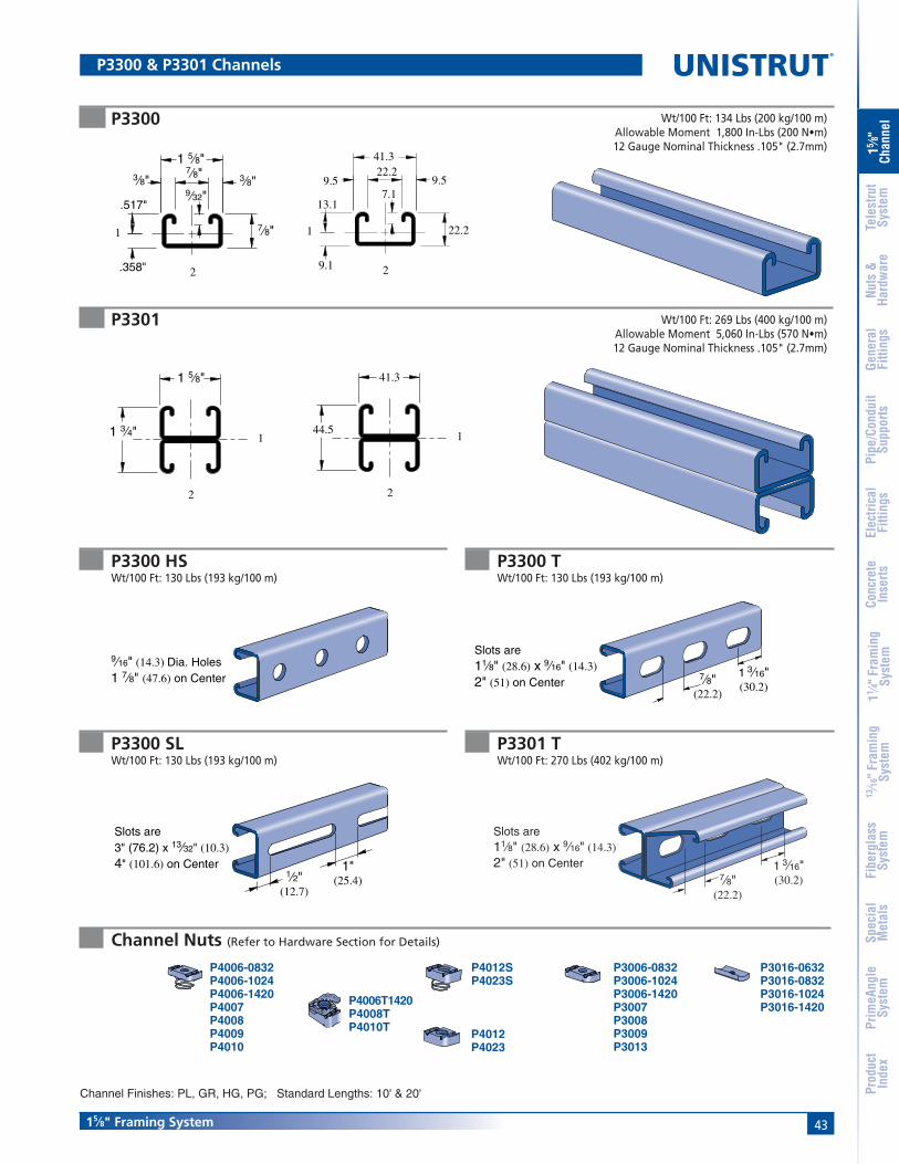
4315⁄8" Framing System
15 ⁄8"
Chan
nel
Nuts
&Ha
rdw
are
Gene
ral
Fitti
ngs
Pipe
/Con
duit
Supp
orts
Elec
trica
lFi
tting
sCo
ncre
teIn
serts
11 ⁄4" F
ram
ing
Syst
em13
⁄16" F
ram
ing
Syst
emFi
berg
lass
Syst
emSp
ecia
lM
etal
sTe
lest
rut
Syst
emPr
imeA
ngle
Syst
emPr
oduc
tIn
dex
P3300
P3301
9.1
13.17.1
22.2
41.322.2
9.5 9.5
2
1
41.3
44.51
2
7⁄8"
1 5⁄8"3⁄8" 3⁄8"
7⁄8"
.517"
.358"
9⁄32"
2
1
1 3⁄4"
1 5⁄8"
2
1
Wt/100 Ft: 134 Lbs (200 kg/100 m)Allowable Moment 1,800 In-Lbs (200 N•m)12 Gauge Nominal Thickness .105" (2.7mm)
Wt/100 Ft: 269 Lbs (400 kg/100 m)Allowable Moment 5,060 In-Lbs (570 N•m)12 Gauge Nominal Thickness .105" (2.7mm)
P3006-0832P3006-1024P3006-1420P3007P3008P3009P3013
P3016-0632P3016-0832P3016-1024P3016-1420
P3300 TWt/100 Ft: 130 Lbs (193 kg/100 m)
P3300 SLWt/100 Ft: 130 Lbs (193 kg/100 m)
P3300 HSWt/100 Ft: 130 Lbs (193 kg/100 m)
P4006-0832P4006-1024P4006-1420P4007P4008P4009P4010
P4006T1420P4008TP4010T
P4012SP4023S
P4012P4023
Channel Finishes: PL, GR, HG, PG; Standard Lengths: 10' & 20'
Channel Nuts (Refer to Hardware Section for Details)
P3300 & P3301 Channels
9⁄16" (14.3) Dia. Holes1 7⁄8" (47.6) on Center
1⁄2"(12.7)
1"(25.4)
Slots are3" (76.2) x 13⁄32" (10.3)4" (101.6) on Center
1 3⁄16"(30.2)
Slots are 11⁄8" (28.6) x 9⁄16" (14.3)2" (51) on Center
7⁄8"(22.2)
UNISTRUT
UNISTRUT
P3301 TWt/100 Ft: 270 Lbs (402 kg/100 m)
1 3⁄16"(30.2)
Slots are11⁄8" (28.6) x 9⁄16" (14.3)2" (51) on Center
7⁄8"(22.2)
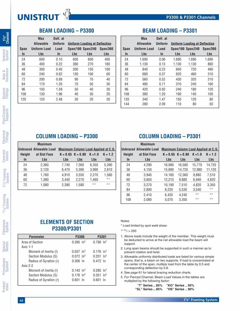
44
®
15⁄8" Framing System
15 ⁄8"
Chan
nel
Nuts
&Ha
rdw
are
Gene
ral
Fitti
ngs
Pipe
/Con
duit
Supp
orts
Elec
trica
lFi
tting
sCo
ncre
teIn
serts
11 ⁄4" F
ram
ing
Syst
em13
⁄16" F
ram
ing
Syst
emFi
berg
lass
Syst
emSp
ecia
lM
etal
sTe
lest
rut
Syst
emPr
imeA
ngle
Syst
emPr
oduc
tIn
dex
COLUMN LOADING – P3300
ELEMENTS OF SECTIONP3300/P3301
MaximumUnbraced Allowable Load Maximum Column Load Applied at C.G.
Height at Slot Face K = 0.65 K = 0.80 K =1.0 K = 1.2In Lbs Lbs Lbs Lbs Lbs24 2,360 7,740 7,260 6,350 5,39036 2,120 6,470 5,390 3,990 2,81048 1,760 4,910 3,550 2,270 1,58060 1,380 3,440 2,270 1,460 **72 1,080 2,390 1,580 ** **
COLUMN LOADING – P3301Maximum
Unbraced Allowable Load Maximum Column Load Applied at C.G.Height at Slot Face K = 0.65 K = 0.80 K =1.0 K = 1.2
In Lbs Lbs Lbs Lbs Lbs24 4,290 16,990 16,580 15,770 14,72036 4,150 15,890 14,720 12,980 11,12048 3,940 14,160 12,360 9,880 7,51060 3,650 12,210 9,880 6,940 4,82072 3,270 10,190 7,510 4,820 3,35084 2,800 8,220 5,530 3,540 **96 2,410 6,420 4,240 ** **
108 2,080 5,070 3,350 ** **
Notes:
* Load limited by spot weld shear.
** KL⁄r > 200
1. Above loads include the weight of the member. This weight mustbe deducted to arrive at the net allowable load the beam willsupport.
2. Long span beams should be supported in such a manner as toprevent rotation and twist.
3. Allowable uniformly distributed loads are listed for various simplespans, that is, a beam on two supports. If load is concentrated atthe center of the span, multiply load from the table by 0.5 andcorresponding deflection by 0.8.
4. See page 61 for lateral bracing reduction charts.
5. For Pierced Channel, Beam Load Values in the tables aremultiplied by the following factor:
"T" Series ... 85% "KO" Series .. 95%"SL" Series ... 85% "HS" Series .. 90%
BEAM LOADING – P3300 BEAM LOADING – P3301Max Defl. at
Allowable Uniform Uniform Loading at DeflectionSpan Uniform Load Load Span/180 Span/240 Span/360
In Lbs In Lbs Lbs Lbs24 600 0.10 600 600 40036 400 0.22 360 270 18048 300 0.40 200 150 10060 240 0.62 130 100 6072 200 0.89 90 70 4084 170 1.20 70 50 3096 150 1.59 50 40 30
108 130 1.96 40 30 20120 120 2.48 30 20 20
Max Defl. atAllowable Uniform Uniform Loading at Deflection
Span Uniform Load Load Span/180 Span/240 Span/360In Lbs In Lbs Lbs Lbs24 1,690 0.06 1,690 1,690 1,69036 1,130 0.13 1,130 1,130 86048 840 0.23 840 720 48060 680 0.37 620 460 31072 560 0.52 430 320 21084 480 0.71 310 240 16096 420 0.93 240 180 120
108 380 1.20 190 140 100120 340 1.47 150 120 80144 280 2.09 110 80 50
P3300 & P3301 Channels
Parameter P3300 P3301Area of Section 0.395 In2 0.790 In2
Axis 1-1Moment of Inertia (I) 0.037 In4 0.176 In4
Section Modulus (S) 0.072 In3 0.201 In3
Radius of Gyration (r) 0.306 In 0.472 InAxis 2-2
Moment of Inertia (I) 0.143 In4 0.285 In4
Section Modulus (S) 0.176 In3 0.351 In3
Radius of Gyration (r) 0.601 In 0.601 In

4515⁄8" Framing System
15 ⁄8"
Chan
nel
Nuts
&Ha
rdw
are
Gene
ral
Fitti
ngs
Pipe
/Con
duit
Supp
orts
Elec
trica
lFi
tting
sCo
ncre
teIn
serts
11 ⁄4" F
ram
ing
Syst
em13
⁄16" F
ram
ing
Syst
emFi
berg
lass
Syst
emSp
ecia
lM
etal
sTe
lest
rut
Syst
emPr
imeA
ngle
Syst
emPr
oduc
tIn
dex
P3300 & P3301 Channels
MaximumUnbraced Allowable Load Maximum Column Load Applied at C.G.
Height at Slot Face K = 0.65 K = 0.80 K =1.0 K = 1.2mm kg kg kg kg kg600 1,075 3,524 3,320 2,917 2,486750 1,030 3,293 2,917 2,381 1,860
1,000 925 2,740 2,204 1,533 1,0661,250 780 2,159 1,533 980 6801,500 640 1,615 1,066 680 **1,750 522 1,184 780 ** **
MaximumUnbraced Allowable Load Maximum Column Load Applied at C.G.
Height at Slot Face K = 0.65 K = 0.80 K =1.0 K = 1.2mm kg kg kg kg kg600 1,946 7,720 7,539 7,185 6,727750 1,923 7,521 7,185 6,600 5,951
1,000 1,860 6,999 6,391 5,493 4,5681,250 1,778 6,337 5,493 4,341 3,2521,500 1,669 5,611 4,568 3,252 2,2591,750 1,533 4,858 3,674 2,386 1,6602,000 1,361 4,114 2,858 1,828 **2,250 1,202 3,406 2,259 1,442 **2,500 1,057 2,771 1,828 ** **2,750 939 2,291 1,510 ** **
Max Defl. atAllowable Uniform Uniform Loading at Deflection
Span Uniform Load Load Span/180 Span/240 Span/360mm kg mm kg kg kg600 277 2 277 277 191750 222 4 222 181 122
1,000 168 7 136 100 681,250 132 10 86 64 451,500 109 15 59 45 321,750 95 21 45 32 232,000 82 27 32 27 182,500 68 43 23 18 93,000 54 60 14 9 93,500 45 79 9 9 NR
Max Defl. atAllowable Uniform Uniform Loading at Deflection
Span Uniform Load Load Span/180 Span/240 Span/360mm kg mm kg kg kg600 776 1 776 776 776750 621 2 621 621 576
1,000 467 4 467 467 3271,250 372 6 372 313 2091,500 313 9 290 218 1451,750 268 12 213 159 1042,000 231 16 163 122 822,500 186 25 104 77 503,000 154 36 73 54 363,500 132 48 54 41 274,000 118 65 41 32 18
Parameter P3300 P3301Area of Section 2.55 cm2 5.10 cm2
Axis 1-1Moment of Inertia (I) 1.54 cm4 7.33 cm4
Section Modulus (S) 1.18 cm3 3.30 cm3
Radius of Gyration (r) 0.78 cm 1.20 cmAxis 2-2
Moment of Inertia (I) 5.94 cm4 11.87 cm4
Section Modulus (S) 2.88 cm3 5.75 cm3
Radius of Gyration (r) 1.53 cm 1.53 cm
Notes:
* Load limited by spot weld shear.
** KL⁄r > 200
1. Above loads include the weight of the member. This weight mustbe deducted to arrive at the net allowable load the beam willsupport.
2. Long span beams should be supported in such a manner as toprevent rotation and twist.
3. Allowable uniformly distributed loads are listed for various simplespans, that is, a beam on two supports. If load is concentrated atthe center of the span, multiply load from the table by 0.5 andcorresponding deflection by 0.8.
4. See page 61 for lateral bracing reduction charts.
5. For Pierced Channel, Beam Load Values in the tables aremultiplied by the following factor:
"T" Series ... 85% "KO" Series .. 95%"SL" Series ... 85% "HS" Series .. 90%
COLUMN LOADING – P3300 (METRIC)
ELEMENTS OF SECTIONP3300/P3301 (METRIC)
COLUMN LOADING – P3301 (METRIC)
BEAM LOADING – P3300 (METRIC) BEAM LOADING – P3301 (METRIC)

46
®
15⁄8" Framing System
15 ⁄8"
Chan
nel
Nuts
&Ha
rdw
are
Gene
ral
Fitti
ngs
Pipe
/Con
duit
Supp
orts
Elec
trica
lFi
tting
sCo
ncre
teIn
serts
11 ⁄4" F
ram
ing
Syst
em13
⁄16" F
ram
ing
Syst
emFi
berg
lass
Syst
emSp
ecia
lM
etal
sTe
lest
rut
Syst
emPr
imeA
ngle
Syst
emPr
oduc
tIn
dex
P4000
P4001
8.7
20.6
41.3
6.49.5
22.29.5
11.9
2
1
13⁄16"
1 5⁄8"3⁄8"3⁄8"
7⁄8"
.343"2
1
.470"1⁄4"
1 5⁄8"
1 5⁄8"
2
1
41.3
41.3 1
2
Wt/100 Ft: 83 Lbs (123 kg/100 m)Allowable Moment 1,230 In-Lbs (140 N•m)16 Gauge Nominal Thickness .060" (1.5mm)
Wt/100 Ft: 166 Lbs (246 kg/100 m)Allowable Moment 3,210 In-Lbs (360 N•m)16 Gauge Nominal Thickness .060" (1.5mm)
P4000 TWt/100 Ft: 79 Lbs (118 kg/100 m)
P4000 SLWt/100 Ft: 79 Lbs (118 kg/100 m)
P4000 HSWt/100 Ft: 79 Lbs (118 kg/100 m)
P3006-0832P3006-1024P3006-1420P3007P3008P3009P3013
P3016-0632P3016-0832P3016-1024P3016-1420
P4006-0832P4006-1024P4006-1420P4007P4008P4009P4010
P4006T1420P4008TP4010T
P4012SP4023S
P4012P4023
Channel Finishes: PL, GR, HG, PG; Standard Lengths: 10' & 20'
Channel Nuts (Refer to Hardware Section for Details)
P4000 & P4001 Channels
9⁄16" (14.3) Dia. Holes1 7⁄8" (47.6) on Center
1⁄2"(12.7)
1"(25.4)
Slots are3" (76.2) x 13⁄32" (10.3)4" (101.6) on Center
1 3⁄16"(30.2)
Slots are11⁄8" (28.6) x 9⁄16" (14.3)2" (51) on Center 7⁄8"
(22.2)
UNISTRUT
UNISTRUT

4715⁄8" Framing System
15 ⁄8"
Chan
nel
Nuts
&Ha
rdw
are
Gene
ral
Fitti
ngs
Pipe
/Con
duit
Supp
orts
Elec
trica
lFi
tting
sCo
ncre
teIn
serts
11 ⁄4" F
ram
ing
Syst
em13
⁄16" F
ram
ing
Syst
emFi
berg
lass
Syst
emSp
ecia
lM
etal
sTe
lest
rut
Syst
emPr
imeA
ngle
Syst
emPr
oduc
tIn
dex
P4003
P4004
2 7⁄16"
1 5⁄8"
2
1
1.240"
1.198"
3 1⁄4"
1 5⁄8"
2
1
41.3
82.6
2
1
Wt/100 Ft: 248 Lbs (370 kg/100 m)Allowable Moment 8,600 In-Lbs (970 N•m)16 Gauge Nominal Thickness .060" (1.5mm)
41.3
61.9
2
1
30.4
31.5
Wt/100 Ft: 331 Lbs (493 kg/100 m)Allowable Moment 13,650 In-Lbs (1,540 N•m)
16 Gauge Nominal Thickness .060" (1.5mm)
P4000 Channel Combinations

48
®
15⁄8" Framing System
15 ⁄8"
Chan
nel
Nuts
&Ha
rdw
are
Gene
ral
Fitti
ngs
Pipe
/Con
duit
Supp
orts
Elec
trica
lFi
tting
sCo
ncre
teIn
serts
11 ⁄4" F
ram
ing
Syst
em13
⁄16" F
ram
ing
Syst
emFi
berg
lass
Syst
emSp
ecia
lM
etal
sTe
lest
rut
Syst
emPr
imeA
ngle
Syst
emPr
oduc
tIn
dex
COLUMN LOADING – P4000
ELEMENTS OF SECTIONP4000/P4001
MaximumUnbraced Allowable Load Maximum Column Load Applied at C.G.
Height at Slot Face K = 0.65 K = 0.80 K =1.0 K = 1.2In Lbs Lbs Lbs Lbs Lbs24 1,630 4,670 4,290 3,780 3,31036 1,450 3,840 3,310 2,460 1,73048 1,160 3,030 2,190 1,400 97060 870 2,120 1,400 900 **72 670 1,470 970 ** **
COLUMN LOADING – P4001Maximum
Unbraced Allowable Load Maximum Column Load Applied at C.G.Height at Slot Face K = 0.65 K = 0.80 K =1.0 K = 1.2
In Lbs Lbs Lbs Lbs Lbs24 2,830 10,390 10,000 9,470 8,96036 2,740 9,530 8,960 7,870 6,70048 2,590 8,620 7,480 5,910 4,44060 2,340 7,380 5,910 4,090 2,84072 2,020 6,110 4,440 2,840 1,97084 1,700 4,880 3,260 2,090 **96 1,440 3,780 2,500 ** **
108 1,230 2,990 1,970 ** **
Notes:
* Load limited by spot weld shear.
** KL⁄r > 200
1. Above loads include the weight of the member. This weight must bededucted to arrive at the net allowable load the beam will support.
2. Long span beams should be supported in such a manner as toprevent rotation and twist.
3. Allowable uniformly distributed loads are listed for various simplespans, that is, a beam on two supports. If load is concentrated atthe center of the span, multiply load from the table by 0.5 andcorresponding deflection by 0.8.
4. See page 61 for lateral bracing reduction charts.
5. For Pierced Channel, Reduce Beam Load Values as Follows:
"T" Series ... 85% "SL" Series .. 85%"HS" Series ... 90%
BEAM LOADING – P4000 BEAM LOADING – P4001Max Defl. at
Allowable Uniform Uniform Loading at DeflectionSpan Uniform Load Load Span/180 Span/240 Span/360
In Lbs In Lbs Lbs Lbs24 410 0.11 410 370 25036 270 0.24 220 170 11048 200 0.43 120 90 6060 160 0.67 80 60 4072 140 1.01 60 40 3084 120 1.38 40 30 2096 100 1.72 30 20 20
108 90 2.20 20 20 10120 80 2.68 20 10 10
Max Defl. atAllowable Uniform Uniform Loading at Deflection
Span Uniform Load Load Span/180 Span/240 Span/360In Lbs In Lbs Lbs Lbs24 810 * 0.05 810 * 810 * 810 *36 710 0.14 710 710 50048 540 0.25 540 430 28060 430 0.40 360 270 18072 360 0.57 250 190 13084 310 0.78 190 140 9096 270 1.02 140 110 70
108 240 1.29 110 80 60120 210 1.54 90 70 50144 180 2.29 60 50 30
P4000 & P4001 Channels
Parameter P4000 P4001Area of Section 0.244 In2 0.487 In2
Axis 1-1Moment of Inertia (I) 0.023 In4 0.104 In4
Section Modulus (S) 0.049 In3 0.128 In3
Radius of Gyration (r) 0.306 In 0.462 InAxis 2-2
Moment of Inertia (I) 0.092 In4 0.183 In4
Section Modulus (S) 0.113 In3 0.225 In3
Radius of Gyration (r) 0.613 In 0.613 In

4915⁄8" Framing System
15 ⁄8"
Chan
nel
Nuts
&Ha
rdw
are
Gene
ral
Fitti
ngs
Pipe
/Con
duit
Supp
orts
Elec
trica
lFi
tting
sCo
ncre
teIn
serts
11 ⁄4" F
ram
ing
Syst
em13
⁄16" F
ram
ing
Syst
emFi
berg
lass
Syst
emSp
ecia
lM
etal
sTe
lest
rut
Syst
emPr
imeA
ngle
Syst
emPr
oduc
tIn
dex
P4000 & P4001 Channels
MaximumUnbraced Allowable Load Maximum Column Load Applied at C.G.
Height at Slot Face K = 0.65 K = 0.80 K =1.0 K = 1.2mm kg kg kg kg kg600 739 2,132 1,960 1,733 1,524750 708 1,946 1,733 1,470 1,148
1,000 626 1,642 1,356 943 6581,250 508 1,329 943 603 4221,500 404 993 658 422 **1,750 327 730 481 ** **
MaximumUnbraced Allowable Load Maximum Column Load Applied at C.G.
Height at Slot Face K = 0.65 K = 0.80 K =1.0 K = 1.2mm kg kg kg kg kg600 1,288 4,726 4,550 4,314 4,082750 1,266 4,536 4,314 4,028 3,611
1,000 1,229 4,214 3,892 3,320 2,7401,250 1,166 3,856 3,320 2,595 1,9141,500 1,070 3,393 2,740 1,914 1,3291,750 957 2,921 2,177 1,406 9752,000 830 2,454 1,683 1,075 **2,250 726 2,014 1,329 853 **2,500 630 1,633 1,075 ** **2,750 553 1,347 889 ** **
Max Defl. atAllowable Uniform Uniform Loading at Deflection
Span Uniform Load Load Span/180 Span/240 Span/360mm kg mm kg kg kg600 191 3 191 177 118750 150 4 150 113 73
1,000 113 8 82 64 411,250 91 12 54 41 271,500 77 17 36 27 181,750 64 23 27 23 142,000 54 29 23 14 92,500 45 47 14 9 53,000 36 65 9 9 5
Max Defl. atAllowable Uniform Uniform Loading at Deflection
Span Uniform Load Load Span/180 Span/240 Span/360mm kg mm kg kg kg600 367 * 1 367 * 367 * 367 *750 367 * 2 367 * 367 * 340
1,000 295 4 295 286 1911,250 236 7 236 181 1221,500 200 10 168 127 861,750 168 13 127 95 642,000 150 17 95 73 502,500 118 27 59 45 323,000 100 39 41 32 233,500 86 54 32 23 14
Parameter P4000 P4001Area of Section 1.57 cm2 3.14 cm2
Axis 1-1Moment of Inertia (I) 0.95 cm4 4.32 cm4
Section Modulus (S) 0.80 cm3 2.09 cm3
Radius of Gyration (r) 0.78 cm 1.17 cmAxis 2-2
Moment of Inertia (I) 3.81 cm4 7.62 cm4
Section Modulus (S) 1.85 cm3 3.69 cm3
Radius of Gyration (r) 1.56 cm 1.56 cm
COLUMN LOADING – P4000 (METRIC)
ELEMENTS OF SECTIONP4000/P4001 (METRIC)
COLUMN LOADING – P4001 (METRIC)
BEAM LOADING – P4000 (METRIC) BEAM LOADING – P4001 (METRIC)
Notes:
* Load limited by spot weld shear.
** KL⁄r > 200
1. Above loads include the weight of the member. This weight must bededucted to arrive at the net allowable load the beam will support.
2. Long span beams should be supported in such a manner as toprevent rotation and twist.
3. Allowable uniformly distributed loads are listed for various simplespans, that is, a beam on two supports. If load is concentrated atthe center of the span, multiply load from the table by 0.5 andcorresponding deflection by 0.8.
4. See page 61 for lateral bracing reduction charts.
5. For Pierced Channel, Reduce Beam Load Values as Follows:
"T" Series ... 85% "SL" Series .. 85%"HS" Series ... 90%

50
®
15⁄8" Framing System
15 ⁄8"
Chan
nel
Nuts
&Ha
rdw
are
Gene
ral
Fitti
ngs
Pipe
/Con
duit
Supp
orts
Elec
trica
lFi
tting
sCo
ncre
teIn
serts
11 ⁄4" F
ram
ing
Syst
em13
⁄16" F
ram
ing
Syst
emFi
berg
lass
Syst
emSp
ecia
lM
etal
sTe
lest
rut
Syst
emPr
imeA
ngle
Syst
emPr
oduc
tIn
dex
P4100
P4101
1
9.59.5
41.3
20.6
6.4
8.4
12.2
2
22.27⁄8"
.333"
.480"
13⁄16"
1 5⁄8"3⁄8" 3⁄8"
1
2
1⁄4"
41.3
41.320.6
20.6
1
2
Wt/100 Ft: 98 Lbs (147 kg/100 m)Allowable Moment 1,360 In-Lbs (150 N•m)14 Gauge Nominal Thickness .075" (1.9mm)
Wt/100 Ft: 197 Lbs (293 kg/100 m)Allowable Moment 3,610 In-Lbs (410 N•m)14 Gauge Nominal Thickness .075" (1.9mm)
13⁄16"
13⁄16"1 5⁄8"
1 5⁄8"1
2
P4100 TWt/100 Ft: 87 Lbs (129 kg/100 m)
P4100 SLWt/100 Ft: 87 Lbs (129 kg/100 m)
P4100 HSWt/100 Ft: 87 Lbs (129 kg/100 m)
P3006-0832P3006-1024P3006-1420P3007P3008P3009P3013
P3016-0632P3016-0832P3016-1024P3016-1420
P4006-0832P4006-1024P4006-1420P4007P4008P4009P4010
P4006T1420P4008TP4010T
P4012SP4023S
P4012P4023
Channel Finishes: PL, GR, HG, PG; Standard Lengths: 10' & 20'
Channel Nuts (Refer to Hardware Section for Details)
P4100 & P4101 Channels
9⁄16" (14.3) Dia. Holes1 7⁄8" (47.6) on Center
1⁄2"(12.7)
1"(25.4)
Slots are3" (76.2) x 13⁄32" (10.3)4" (101.6) on Center
1 3⁄16"(30.2)
Slots are11⁄8" (28.6) x 9⁄16" (14.3)2" (51) on Center 7⁄8"
(22.2)
UNISTRUT
UNISTRUT
P4101 TWt/100 Ft: 174 Lbs (259 kg/100 m)
1 3⁄16"(30.2)
Slots are11⁄8" (28.6) x 9⁄16" (14.3)2" (51) on Center
7⁄8"(22.2)

5115⁄8" Framing System
15 ⁄8"
Chan
nel
Nuts
&Ha
rdw
are
Gene
ral
Fitti
ngs
Pipe
/Con
duit
Supp
orts
Elec
trica
lFi
tting
sCo
ncre
teIn
serts
11 ⁄4" F
ram
ing
Syst
em13
⁄16" F
ram
ing
Syst
emFi
berg
lass
Syst
emSp
ecia
lM
etal
sTe
lest
rut
Syst
emPr
imeA
ngle
Syst
emPr
oduc
tIn
dex
Notes:
* Load limited by spot weld shear.
** KL⁄r > 200
1. Above loads include the weight of the member. This weight must bededucted to arrive at the net allowable load the beam will support.
2. Long span beams should be supported in such a manner as toprevent rotation and twist.
3. Allowable uniformly distributed loads are listed for various simplespans, that is, a beam on two supports. If load is concentrated atthe center of the span, multiply load from the table by 0.5 andcorresponding deflection by 0.8.
4. See page 61 for lateral bracing reduction charts.
5. For Pierced Channel, Beam Load Values in the tables are multipliedby the following factor:
"T" Series ... 85% "SL" Series .. 85%"HS" Series ... 90%
BEAM LOADING – P4100 BEAM LOADING – P4101Max Defl. at
Allowable Uniform Uniform Loading at DeflectionSpan Uniform Load Load Span/180 Span/240 Span/360
In Lbs In Lbs Lbs Lbs24 450 0.11 450 420 28036 300 0.24 250 190 13048 230 0.44 140 110 7060 180 0.67 90 70 5072 150 0.96 60 50 3084 130 1.32 50 30 2096 110 1.67 40 30 20
108 100 2.16 30 20 10120 90 2.67 20 20 10144 80 4.09 20 NR NR168 60 4.88 NR NR NR192 60 7.28 NR NR NR216 50 8.64 NR NR NR240 50 11.85 NR NR NR
Max Defl. atAllowable Uniform Uniform Loading at Deflection
Span Uniform Load Load Span/180 Span/240 Span/360In Lbs In Lbs Lbs Lbs24 1,090 * 0.06 1,090 * 1,090 * 1,090 *36 800 0.14 800 800 57048 600 0.25 600 480 32060 480 0.39 410 310 20072 400 0.57 280 210 14084 340 0.76 210 160 10096 300 1.00 160 120 80
108 270 1.29 130 90 60120 240 1.57 100 80 50144 200 2.26 70 50 40168 170 3.05 50 40 30192 150 4.02 40 NR NR216 130 4.96 NR NR NR240 120 6.28 NR NR NR
P4100 & P4101 Channels
COLUMN LOADING – P4100Maximum
Unbraced Allowable Load Maximum Column Load Applied at C.G.Height at Slot Face K = 0.65 K = 0.80 K =1.0 K = 1.2
In Lbs Lbs Lbs Lbs Lbs24 1,840 5,610 5,210 4,570 3,85036 1,640 4,660 3,850 2,800 1,96048 1,310 3,490 2,480 1,590 1,10060 1,000 2,400 1,590 ** **72 770 1,670 1,100 ** **
COLUMN LOADING – P4101Maximum
Unbraced Allowable Load Maximum Column Load Applied at C.G.Height at Slot Face K = 0.65 K = 0.80 K =1.0 K = 1.2
In Lbs Lbs Lbs Lbs Lbs24 3,240 12,370 11,950 11,370 10,54036 3,120 11,470 10,540 9,160 7,72048 2,940 10,090 8,680 6,770 4,98060 2,680 8,560 6,770 4,590 3,19072 2,310 7,010 4,980 3,190 2,22084 1,950 5,530 3,660 2,340 **96 1,650 4,250 2,800 ** **
108 1,410 3,360 2,220 ** **
Parameter P4100 P4101Area of Section 0.290 In2 0.579 In2
Axis 1-1Moment of Inertia (I) 0.026 In4 0.117 In4
Section Modulus (S) 0.054 In3 0.143 In3
Radius of Gyration (r) 0.298 In 0.449 InAxis 2-2
Moment of Inertia (I) 0.107 In4 0.214 In4
Section Modulus (S) 0.132 In3 0.264 In3
Radius of Gyration (r) 0.609 In 0.608 In
ELEMENTS OF SECTIONP4100/P4101

52
®
15⁄8" Framing System
15 ⁄8"
Chan
nel
Nuts
&Ha
rdw
are
Gene
ral
Fitti
ngs
Pipe
/Con
duit
Supp
orts
Elec
trica
lFi
tting
sCo
ncre
teIn
serts
11 ⁄4" F
ram
ing
Syst
em13
⁄16" F
ram
ing
Syst
emFi
berg
lass
Syst
emSp
ecia
lM
etal
sTe
lest
rut
Syst
emPr
imeA
ngle
Syst
emPr
oduc
tIn
dex
P4100 & P4101 Channels
MaximumUnbraced Allowable Load Maximum Column Load Applied at C.G.
Height at Slot Face K = 0.65 K = 0.80 K =1.0 K = 1.2mm kg kg kg kg kg600 835 2,558 2,377 2,100 1,778750 798 2,363 2,100 1,696 1,306
1,000 708 1,964 1,565 1,070 7441,250 576 1,529 1,070 685 4761,500 463 1,125 744 476 **1,750 372 826 544 ** **
MaximumUnbraced Allowable Load Maximum Column Load Applied at C.G.
Height at Slot Face K = 0.65 K = 0.80 K =1.0 K = 1.2mm kg kg kg kg kg600 1,470 5,620 5,439 5,185 4,817750 1,451 5,425 5,185 4,717 4,205
1,000 1,397 5,035 4,554 3,851 3,1391,250 1,324 4,509 3,851 2,966 2,1501,500 1,225 3,942 3,139 2,150 1,4921,750 1,093 3,361 2,463 1,579 1,0982,000 953 2,794 1,891 1,211 **2,250 830 2,263 1,492 957 **
Max Defl. atAllowable Uniform Uniform Loading at Deflection
Span Uniform Load Load Span/180 Span/240 Span/360mm kg mm kg kg kg600 209 3 209 200 132750 168 4 168 127 86
1,000 127 7 95 73 451,250 100 11 59 45 321,500 82 16 41 32 231,750 73 23 32 23 142,000 64 30 23 18 142,500 50 46 14 14 93,000 41 65 9 9 5
Max Defl. atAllowable Uniform Uniform Loading at Deflection
Span Uniform Load Load Span/180 Span/240 Span/360mm kg mm kg kg kg600 494 * 1 494 * 494 * 494 *750 445 2 445 445 381
1,000 331 4 331 322 2131,250 268 7 268 204 1361,500 222 10 191 145 951,750 191 13 141 104 682,000 168 17 109 82 542,500 132 27 68 50 363,000 109 38 50 36 233,500 95 53 36 27 18
Parameter P4100 P4101Area of Section 1.87 cm2 3.74 cm2
Axis 1-1Moment of Inertia (I) 1.07 cm4 4.85 cm4
Section Modulus (S) 0.88 cm3 2.35 cm3
Radius of Gyration (r) 0.76 cm 1.14 cmAxis 2-2
Moment of Inertia (I) 4.46 cm4 8.93 cm4
Section Modulus (S) 2.16 cm3 4.32 cm3
Radius of Gyration (r) 1.55 cm 1.55 cm
BEAM LOADING – P4100 (METRIC) BEAM LOADING – P4101 (METRIC)
COLUMN LOADING – P4100 (METRIC) COLUMN LOADING – P4101 (METRIC)
ELEMENTS OF SECTIONP4100/P4101
Notes:
* Load limited by spot weld shear.
** KL⁄r > 200
1. Above loads include the weight of the member. This weight must bededucted to arrive at the net allowable load the beam will support.
2. Long span beams should be supported in such a manner as toprevent rotation and twist.
3. Allowable uniformly distributed loads are listed for various simplespans, that is, a beam on two supports. If load is concentrated atthe center of the span, multiply load from the table by 0.5 andcorresponding deflection by 0.8.
4. See page 61 for lateral bracing reduction charts.
5. For Pierced Channel, Beam Load Values in the tables are multipliedby the following factor:
"T" Series ... 85% "SL" Series .. 85%"HS" Series ... 90%

5315⁄8" Framing System
15 ⁄8"
Chan
nel
Nuts
&Ha
rdw
are
Gene
ral
Fitti
ngs
Pipe
/Con
duit
Supp
orts
Elec
trica
lFi
tting
sCo
ncre
teIn
serts
11 ⁄4" F
ram
ing
Syst
em13
⁄16" F
ram
ing
Syst
emFi
berg
lass
Syst
emSp
ecia
lM
etal
sTe
lest
rut
Syst
emPr
imeA
ngle
Syst
emPr
oduc
tIn
dex
P5000
P5001
82.6
44.5
38.1
1
41.3
22.2 9.59.5
7.1
2
13 1⁄4"
1 5⁄8"3⁄8" 3⁄8"
7⁄8"
9⁄32" 1.750"
1.500"
2
6 1⁄2"
1 5⁄8"
2
1
41.3
165.1
1
2
Wt/100 Ft: 610 Lbs (907 kg/100 m)Allowable Moment 48,180 In-Lbs (5,440 N•m)
12 Gauge Nominal Thickness .105" (2.7mm)
Wt/100 Ft: 305 Lbs (454 kg/100 m)Allowable Moment 15,770 In-Lbs (1,780 N•m)
12 Gauge Nominal Thickness .105" (2.7mm)
P5000 TWt/100 Ft: 300 Lbs (446 kg/100 m)
P5000 SLWt/100 Ft: 300 Lbs (446 kg/100 m)
P5000 KOWt/100 Ft: 305 Lbs (454 kg/100 m)
P5000 HSWt/100 Ft: 300 Lbs (446 kg/100 m)
P3006-0832P3006-1024P3006-1420P3007P3008P3009P3010
P3016-0632P3016-0832P3016-1024P3016-1420
P1006T1420P1008TP1010T
P1012P1023P1024
Channel Finishes: PL, GR, HG, PG; Standard Lengths: 10' & 20'
Channel Nuts (Refer to Hardware Section for Details)
P5000 & P5001 Channels
9⁄16" (14.3) Dia. Holes1 7⁄8" (47.6) on Center
7⁄8" (22.2) Knockouts6" (152.4) on Center
1⁄2"(12.7)
1"(25.4)
Slots are3" (76.2) x 13⁄32" (10.3)4" (101.6) on Center
1 3⁄16"(30.2)
7⁄8"(22.2)
Slots are11⁄8" (28.6) x 9⁄16" (14.3)2" (51) on Center
UNISTRUT
UNISTRUT

54
®
15⁄8" Framing System
15 ⁄8"
Chan
nel
Nuts
&Ha
rdw
are
Gene
ral
Fitti
ngs
Pipe
/Con
duit
Supp
orts
Elec
trica
lFi
tting
sCo
ncre
teIn
serts
11 ⁄4" F
ram
ing
Syst
em13
⁄16" F
ram
ing
Syst
emFi
berg
lass
Syst
emSp
ecia
lM
etal
sTe
lest
rut
Syst
emPr
imeA
ngle
Syst
emPr
oduc
tIn
dex
COLUMN LOADING – P5000
ELEMENTS OF SECTIONP5000/P5001
MaximumUnbraced Allowable Load Maximum Column Load Applied at C.G.
Height at Slot Face K = 0.65 K = 0.80 K =1.0 K = 1.2In Lbs Lbs Lbs Lbs Lbs24 5,650 16,870 15,180 12,850 10,60036 4,690 13,140 10,600 7,650 5,66048 3,560 9,550 6,860 4,790 3,66060 2,730 6,680 4,790 3,450 2,71072 2,160 4,980 3,660 2,710 2,17084 1,760 3,950 2,960 2,240 1,82096 1,500 3,270 2,500 1,930 1,580
108 1,310 2,800 2,170 1,690 1,390120 1,170 2,450 1,930 1,510 **144 980 1,980 1,580 ** **168 850 1,670 1,340 ** **
COLUMN LOADING – P5001Maximum
Unbraced Allowable Load Maximum Column Load Applied at C.G.Height at Slot Face K = 0.65 K = 0.80 K =1.0 K = 1.2
In Lbs Lbs Lbs Lbs Lbs24 10,670 39,230 38,030 36,210 34,24036 10,350 36,450 34,240 31,200 28,26048 9,940 33,220 30,200 26,430 23,19060 9,290 29,950 26,430 22,470 19,38072 8,560 26,880 23,190 19,380 16,45084 7,860 24,140 20,520 17,040 12,09096 7,220 21,790 18,370 13,330 9,250
108 6,600 19,790 16,450 10,530 7,310120 5,760 18,130 13,330 8,530 **144 4,390 14,020 9,250 ** **168 3,420 10,300 6,800 ** **
BEAM LOADING – P5000 BEAM LOADING – P5001
Notes:
* Load limited by spot weld shear.
** KL⁄r > 200
1. Above loads include the weight of the member. This weight must bededucted to arrive at the net allowable load the beam will support.
2. Long span beams should be supported in such a manner as toprevent rotation and twist.
3. Allowable uniformly distributed loads are listed for various simplespans, that is, a beam on two supports. If load is concentrated atthe center of the span, multiply load from the table by 0.5 andcorresponding deflection by 0.8.
4. See page 61 for lateral bracing reduction charts.
5. For Pierced Channel, Beam Load Values in the tables are multipliedby the following factor:
"T" Series ... 85% "KO" Series .. 95%"SL" Series ... 85% "HS" Series .. 90%
Max Defl. atAllowable Uniform Uniform Loading at Deflection
Span Uniform Load Load Span/180 Span/240 Span/360In Lbs In Lbs Lbs Lbs24 5,260 0.03 5,260 5,260 5,26036 3,500 0.07 3,500 3,500 3,50048 2,630 0.12 2,630 2,630 2,63060 2,100 0.18 2,100 2,100 1,92072 1,750 0.26 1,750 1,750 1,33084 1,500 0.36 1,500 1,470 98096 1,310 0.47 1,310 1,120 750
108 1,170 0.59 1,170 890 590120 1,050 0.73 960 720 480144 880 1.06 670 500 330168 750 1.43 490 370 240192 660 1.88 370 280 190216 580 2.35 300 220 150240 530 2.95 240 180 120
Max Defl. atAllowable Uniform Uniform Loading at Deflection
Span Uniform Load Load Span/180 Span/240 Span/360In Lbs In Lbs Lbs Lbs24 6,890 * 0.01 6,890 * 6,890 * 6,890 *36 6,890 * 0.02 6,890 * 6,890 * 6,890 *48 6,890 * 0.05 6,890 * 6,890 * 6,890 *60 6,420 0.10 6,420 6,420 6,42072 5,350 0.14 5,350 5,350 5,35084 4,590 0.19 4,590 4,590 4,59096 4,020 0.25 4,020 4,020 4,020
108 3,570 0.32 3,570 3,570 3,360120 3,210 0.39 3,210 3,210 2,720144 2,680 0.57 2,680 2,680 1,890168 2,290 0.77 2,290 2,080 1,390192 2,010 1.01 2,010 1,590 1,060216 1,780 1.27 1,680 1,260 840240 1,610 1.58 1,360 1,020 680
P5000 & P5001 Channels
Parameter P5000 P5001Area of Section 0.897 In2 1.793 In2
Axis 1-1Moment of Inertia (I) 1.098 In4 6.227 In4
Section Modulus (S) 0.627 In3 1.916 In3
Radius of Gyration (r) 1.107 In 1.864 InAxis 2-2
Moment of Inertia (I) 0.433 In4 0.866 In4
Section Modulus (S) 0.533 In3 1.066 In3
Radius of Gyration (r) 0.695 In 0.695 In

5515⁄8" Framing System
15 ⁄8"
Chan
nel
Nuts
&Ha
rdw
are
Gene
ral
Fitti
ngs
Pipe
/Con
duit
Supp
orts
Elec
trica
lFi
tting
sCo
ncre
teIn
serts
11 ⁄4" F
ram
ing
Syst
em13
⁄16" F
ram
ing
Syst
emFi
berg
lass
Syst
emSp
ecia
lM
etal
sTe
lest
rut
Syst
emPr
imeA
ngle
Syst
emPr
oduc
tIn
dex
MaximumUnbraced Allowable Load Maximum Column Load Applied at C.G.
Height at Slot Face K = 0.65 K = 0.80 K =1.0 K = 1.2mm kg kg kg kg kg600 2,572 7,702 6,949 5,910 4,899750 2,400 6,886 5,910 4,663 3,565
1,000 1,982 5,479 4,277 2,985 2,2271,250 1,569 4,182 2,985 2,091 1,6011,500 1,261 3,112 2,227 1,601 1,2561,750 1,039 2,422 1,769 1,302 1,0392,000 866 1,973 1,465 1,098 8892,250 748 1,660 1,256 957 7802,500 658 1,433 1,098 848 6992,750 590 1,266 980 767 630
MaximumUnbraced Allowable Load Maximum Column Load Applied at C.G.
Height at Slot Face K = 0.65 K = 0.80 K =1.0 K = 1.2mm kg kg kg kg kg600 4,844 17,831 17,300 16,493 15,617750 4,776 17,250 16,493 15,390 14,256
1,000 4,645 16,134 15,014 13,517 12,1151,250 4,491 14,919 13,517 11,789 10,3191,500 4,241 13,698 12,115 10,319 8,9091,750 3,969 12,537 10,873 9,117 7,8342,000 3,701 11,476 9,807 8,160 6,2412,250 3,452 10,523 8,909 7,099 4,9312,500 3,221 9,684 8,160 5,752 3,9922,750 2,985 8,958 7,430 4,754 3,302
P5000 & P5001 Channels
Max Defl. atAllowable Uniform Uniform Loading at Deflection
Span Uniform Load Load Span/180 Span/240 Span/360mm kg mm kg kg kg600 2,422 1 2,422 2,422 2,422750 1,937 1 1,937 1,937 1,937
1,000 1,451 2 1,451 1,451 1,4511,250 1,161 3 1,161 1,161 1,1611,500 971 5 971 971 8981,750 830 6 830 830 6622,000 726 8 726 726 5032,500 581 12 581 485 3223,000 485 18 449 336 2273,500 417 25 331 249 1634,000 363 32 254 191 1274,500 322 40 200 150 1005,000 290 50 163 122 826,000 240 71 113 86 54
Max Defl. atAllowable Uniform Uniform Loading at Deflection
Span Uniform Load Load Span/180 Span/240 Span/360mm kg mm kg kg kg600 3,125 * 0 3,125 * 3,125 * 3,125 *750 3,125 * 0 3,125 * 3,125 * 3,125 *
1,000 3,125 * 1 3,125 * 3,125 * 3,125 *1,250 3,125 * 1 3,125 * 3,125 * 3,125 *1,500 2,962 2 2,962 2,962 2,9621,750 2,536 3 2,536 2,536 2,5362,000 2,223 4 2,223 2,223 2,2232,500 1,778 7 1,778 1,778 1,7783,000 1,479 10 1,479 1,479 1,2753,500 1,270 13 1,270 1,270 9344,000 1,111 17 1,111 1,075 7174,500 989 22 989 848 5675,000 889 27 889 689 4586,000 739 39 635 476 318
Parameter P5000 P5001Area of Section 5.78 cm2 11.57 cm2
Axis 1-1Moment of Inertia (I) 45.70 cm4 259.17 cm4
Section Modulus (S) 10.28 cm3 31.40 cm3
Radius of Gyration (r) 2.81 cm 4.73 cmAxis 2-2
Moment of Inertia (I) 18.02 cm4 36.04 cm4
Section Modulus (S) 8.73 cm3 17.46 cm3
Radius of Gyration (r) 1.77 cm 1.77 cm
COLUMN LOADING – P5000 (METRIC)
ELEMENTS OF SECTIONP5000/P5001 (METRIC)
COLUMN LOADING – P5001 (METRIC)
BEAM LOADING – P5000 (METRIC) BEAM LOADING – P5001 (METRIC)
Notes:
* Load limited by spot weld shear.
** KL⁄r > 200
1. Above loads include the weight of the member. This weight must bededucted to arrive at the net allowable load the beam will support.
2. Long span beams should be supported in such a manner as toprevent rotation and twist.
3. Allowable uniformly distributed loads are listed for various simplespans, that is, a beam on two supports. If load is concentrated atthe center of the span, multiply load from the table by 0.5 andcorresponding deflection by 0.8.
4. See page 61 for lateral bracing reduction charts.
5. For Pierced Channel, Beam Load Values in the tables are multipliedby the following factor:
"T" Series ... 85% "KO" Series .. 95%"SL" Series ... 85% "HS" Series .. 90%
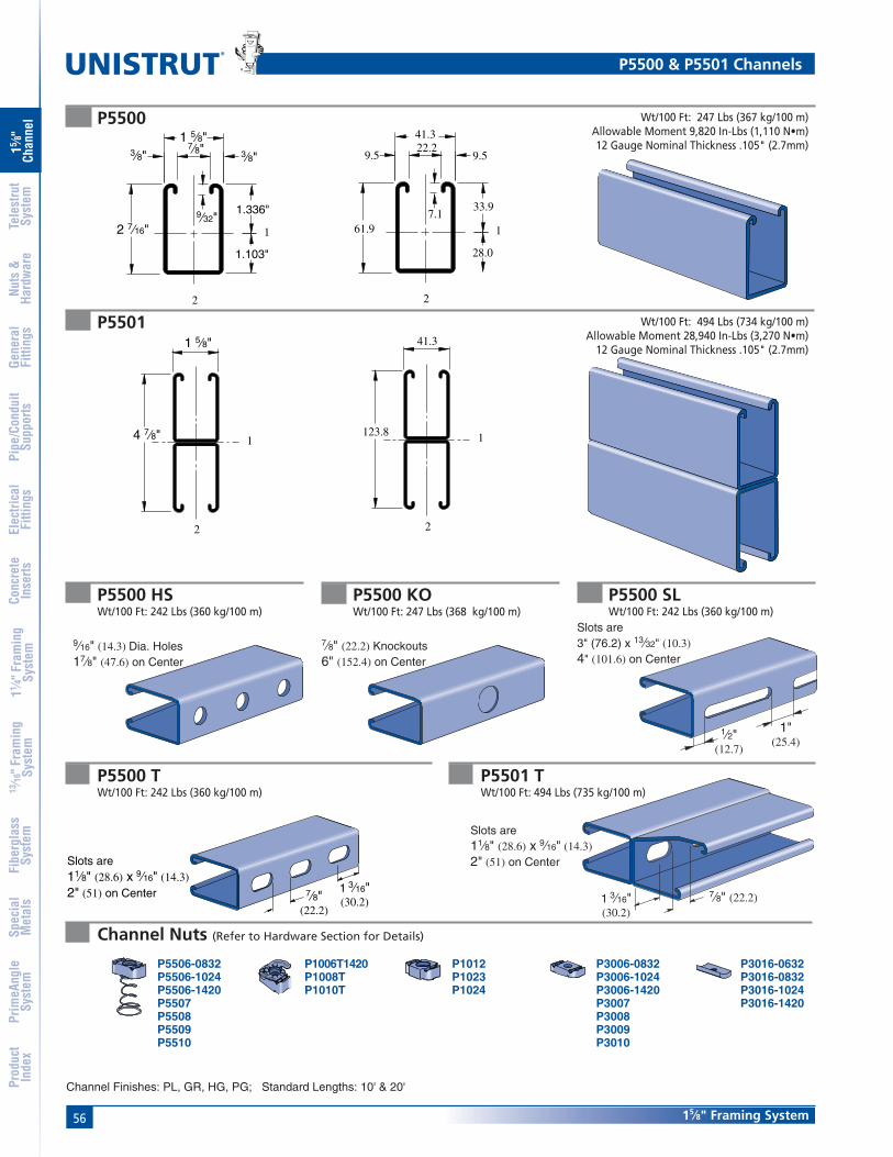
56
®
15⁄8" Framing System
15 ⁄8"
Chan
nel
Nuts
&Ha
rdw
are
Gene
ral
Fitti
ngs
Pipe
/Con
duit
Supp
orts
Elec
trica
lFi
tting
sCo
ncre
teIn
serts
11 ⁄4" F
ram
ing
Syst
em13
⁄16" F
ram
ing
Syst
emFi
berg
lass
Syst
emSp
ecia
lM
etal
sTe
lest
rut
Syst
emPr
imeA
ngle
Syst
emPr
oduc
tIn
dex
P5500
P5501
1
28.0
33.9
61.97.1
9.522.2
9.5
41.3
2
4 7⁄8"
1 5⁄8"
2
1
Wt/100 Ft: 247 Lbs (367 kg/100 m)Allowable Moment 9,820 In-Lbs (1,110 N•m)12 Gauge Nominal Thickness .105" (2.7mm)
Wt/100 Ft: 494 Lbs (734 kg/100 m)Allowable Moment 28,940 In-Lbs (3,270 N•m)
12 Gauge Nominal Thickness .105" (2.7mm)
12 7⁄16"9⁄32"
1.103"
1.336"
1 5⁄8"3⁄8" 3⁄8"
7⁄8"
2
41.3
123.8 1
2
P5500 TWt/100 Ft: 242 Lbs (360 kg/100 m)
P5500 SLWt/100 Ft: 242 Lbs (360 kg/100 m)
P5500 KOWt/100 Ft: 247 Lbs (368 kg/100 m)
P5500 HSWt/100 Ft: 242 Lbs (360 kg/100 m)
P3006-0832P3006-1024P3006-1420P3007P3008P3009P3010
P3016-0632P3016-0832P3016-1024P3016-1420
P1006T1420P1008TP1010T
P1012P1023P1024
Channel Finishes: PL, GR, HG, PG; Standard Lengths: 10' & 20'
Channel Nuts (Refer to Hardware Section for Details)
P5506-0832P5506-1024P5506-1420P5507P5508P5509P5510
P5500 & P5501 Channels
9⁄16" (14.3) Dia. Holes17⁄8" (47.6) on Center
7⁄8" (22.2) Knockouts6" (152.4) on Center
1⁄2"(12.7)
1"(25.4)
Slots are3" (76.2) x 13⁄32" (10.3)4" (101.6) on Center
1 3⁄16"(30.2)
7⁄8"(22.2)
Slots are11⁄8" (28.6) x 9⁄16" (14.3)2" (51) on Center
UNISTRUT
UNISTRUT
P5501 TWt/100 Ft: 494 Lbs (735 kg/100 m)
1 3⁄16"(30.2)
7⁄8" (22.2)
Slots are11⁄8" (28.6) x 9⁄16" (14.3)2" (51) on Center

5715⁄8" Framing System
15 ⁄8"
Chan
nel
Nuts
&Ha
rdw
are
Gene
ral
Fitti
ngs
Pipe
/Con
duit
Supp
orts
Elec
trica
lFi
tting
sCo
ncre
teIn
serts
11 ⁄4" F
ram
ing
Syst
em13
⁄16" F
ram
ing
Syst
emFi
berg
lass
Syst
emSp
ecia
lM
etal
sTe
lest
rut
Syst
emPr
imeA
ngle
Syst
emPr
oduc
tIn
dex
Notes:
* Load limited by spot weld shear.
** KL⁄r > 200
1. Above loads include the weight of the member. This weight must bededucted to arrive at the net allowable load the beam will support.
2. Long span beams should be supported in such a manner as toprevent rotation and twist.
3. Allowable uniformly distributed loads are listed for various simplespans, that is, a beam on two supports. If load is concentrated at thecenter of the span, multiply load from the table by 0.5 and corre-sponding deflection by 0.8.
4. See page 61 for lateral bracing reduction charts.
5. For Pierced Channel, Beam Load Values in the tables are multipliedby the following factor:
"T" Series ... 85% "KO" Series .. 95%"SL" Series ... 85% "HS" Series .. 90%
BEAM LOADING – P5500 BEAM LOADING – P5501Max Defl. at
Allowable Uniform Uniform Loading at DeflectionSpan Uniform Load Load Span/180 Span/240 Span/360
In Lbs In Lbs Lbs Lbs24 3,270 0.04 3,270 3,270 3,27036 2,180 0.09 2,180 2,180 2,18048 1,640 0.15 1,640 1,640 1,42060 1,310 0.24 1,310 1,310 91072 1,090 0.34 1,090 950 63084 940 0.47 930 700 47096 820 0.61 710 530 360
108 730 0.78 560 420 280120 650 0.95 460 340 230144 550 1.39 320 240 160168 470 1.89 230 170 120192 410 2.46 180 130 90216 360 3.07 140 110 70240 330 3.86 110 90 60
Max Defl. atAllowable Uniform Uniform Loading at Deflection
Span Uniform Load Load Span/180 Span/240 Span/360In Lbs In Lbs Lbs Lbs24 5,220 * 0.01 5,220 * 5,220 * 5,220 *36 5,220 * 0.04 5,220 * 5,220 * 5,220 *48 4,820 0.08 4,820 4,820 4,82060 3,860 0.13 3,860 3,860 3,86072 3,220 0.19 3,220 3,220 3,22084 2,760 0.26 2,760 2,760 2,50096 2,410 0.34 2,410 2,410 1,920
108 2,140 0.42 2,140 2,140 1,510120 1,930 0.52 1,930 1,840 1,230144 1,610 0.76 1,610 1,280 850168 1,380 1.03 1,250 940 630192 1,210 1.35 960 720 480216 1,070 1.70 760 570 380240 960 2.09 610 460 310
P5500 & P5501 Channels
COLUMN LOADING – P5500Maximum
Unbraced Allowable Load Maximum Column Load Applied at C.G.Height at Slot Face K = 0.65 K = 0.80 K =1.0 K = 1.2
In Lbs Lbs Lbs Lbs Lbs24 4,640 13,840 12,570 10,840 9,19036 3,970 11,050 9,190 7,030 5,37048 3,180 8,420 6,390 4,620 3,63060 2,550 6,250 4,620 3,450 2,78072 2,120 4,790 3,630 2,780 2,26084 1,810 3,890 3,010 2,330 1,91096 1,580 3,290 2,580 2,020 1,650
108 1,400 2,860 2,260 1,770 1,440120 1,270 2,530 2,020 1,580 **144 1,060 2,070 1,650 ** **168 920 1,750 1,380 ** **
COLUMN LOADING – P5501Maximum
Unbraced Allowable Load Maximum Column Load Applied at C.G.Height at Slot Face K = 0.65 K = 0.80 K =1.0 K = 1.2
In Lbs Lbs Lbs Lbs Lbs24 8,580 31,810 30,880 29,520 28,10036 8,350 29,700 28,100 26,000 24,07048 8,080 27,390 25,330 22,910 20,94060 7,720 25,170 22,910 20,510 17,17072 7,270 23,190 20,940 17,170 12,70084 6,780 21,510 18,740 13,430 9,33096 6,130 20,110 15,630 10,290 7,150
108 5,450 17,750 12,700 8,130 5,650120 4,800 15,260 10,290 6,590 **144 3,760 10,830 7,150 ** **168 2,970 7,950 5,250 ** **
Parameter P5500 P5501Area of Section 0.726 In2 1.452 In2
Axis 1-1Moment of Inertia (I) 0.522 In4 2.805 In4
Section Modulus (S) 0.390 In3 1.151 In3
Radius of Gyration (r) 0.848 In 1.390 InAxis 2-2
Moment of Inertia (I) 0.334 In4 0.669 In4
Section Modulus (S) 0.411 In3 0.823 In3
Radius of Gyration (r) 0.679 In 0.679 In
ELEMENTS OF SECTIONP5500/P5501

58
®
15⁄8" Framing System
15 ⁄8"
Chan
nel
Nuts
&Ha
rdw
are
Gene
ral
Fitti
ngs
Pipe
/Con
duit
Supp
orts
Elec
trica
lFi
tting
sCo
ncre
teIn
serts
11 ⁄4" F
ram
ing
Syst
em13
⁄16" F
ram
ing
Syst
emFi
berg
lass
Syst
emSp
ecia
lM
etal
sTe
lest
rut
Syst
emPr
imeA
ngle
Syst
emPr
oduc
tIn
dex
MaximumUnbraced Allowable Load Maximum Column Load Applied at C.G.
Height at Slot Face K = 0.65 K = 0.80 K =1.0 K = 1.2mm kg kg kg kg kg600 2,109 6,314 5,752 4,976 4,237750 1,996 5,702 4,976 4,060 3,257
1,000 1,701 4,663 3,778 2,794 2,1411,250 1,411 3,710 2,794 2,028 1,5971,500 1,175 2,903 2,141 1,597 1,2841,750 1,002 2,309 1,742 1,324 1,0802,000 875 1,923 1,474 1,139 9302,250 776 1,647 1,284 998 8162,500 699 1,447 1,139 889 7302,750 635 1,293 1,025 803 653
MaximumUnbraced Allowable Load Maximum Column Load Applied at C.G.
Height at Slot Face K = 0.65 K = 0.80 K =1.0 K = 1.2mm kg kg kg kg kg600 3,892 14,429 14,007 13,390 12,746750 3,787 13,472 12,746 11,793 10,918
1,000 3,665 12,424 11,489 10,392 9,4981,250 3,502 11,417 10,392 9,303 7,7881,500 3,298 10,519 9,498 7,788 5,7611,750 3,075 9,757 8,500 6,092 4,2322,000 2,781 9,122 7,090 4,667 3,2432,500 2,472 8,051 5,761 3,688 2,5633,000 2,177 6,922 4,667 2,989 **3,500 1,706 4,912 3,243 ** **4,000 1,347 3,606 2,381 ** **
P5500 & P5501 Channels
Max Defl. atAllowable Uniform Uniform Loading at Deflection
Span Uniform Load Load Span/180 Span/240 Span/360mm kg mm kg kg kg600 1,510 1 1,510 1,510 1,510750 1,207 1 1,207 1,207 1,207
1,000 907 3 907 907 9071,250 726 4 726 726 6171,500 603 6 603 603 4261,750 517 8 517 472 3132,000 454 10 454 358 2402,500 363 16 308 231 1543,000 304 24 213 159 1093,500 259 32 159 118 774,000 227 42 118 91 594,500 200 53 95 73 455,000 181 66 77 59 366,000 150 94 54 41 27
Max Defl. atAllowable Uniform Uniform Loading at Deflection
Span Uniform Load Load Span/180 Span/240 Span/360mm kg mm kg kg kg600 2,368 * 0 2,368 * 2,368 * 2,368 *750 2,368 * 1 2,368 * 2,368 * 2,368 *
1,000 2,368 * 1 2,368 * 2,368 * 2,368 *1,250 2,132 2 2,132 2,132 2,1321,500 1,778 3 1,778 1,778 1,7781,750 1,524 4 1,524 1,524 1,5242,000 1,334 6 1,334 1,334 1,2932,500 1,066 9 1,066 1,066 8263,000 889 13 889 862 5763,500 762 18 762 630 4224,000 667 23 644 485 3224,500 594 29 508 381 2545,000 535 36 413 308 2096,000 445 52 286 213 145
Parameter P5500 P5501Area of Section 4.68 cm2 9.37 cm2
Axis 1-1Moment of Inertia (I) 21.71 cm4 116.76 cm4
Section Modulus (S) 6.40 cm3 18.86 cm3
Radius of Gyration (r) 2.15 cm 3.53 cmAxis 2-2
Moment of Inertia (I) 13.91 cm4 27.83 cm4
Section Modulus (S) 6.74 cm3 13.48 cm3
Radius of Gyration (r) 1.72 cm 1.72 cm
BEAM LOADING – P5500 (METRIC) BEAM LOADING – P5501 (METRIC)
COLUMN LOADING – P5500 (METRIC) COLUMN LOADING – P5501 (METRIC)
ELEMENTS OF SECTIONP5500/P5501 (METRIC)
Notes:
* Load limited by spot weld shear.
** KL⁄r > 200
1. Above loads include the weight of the member. This weight must bededucted to arrive at the net allowable load the beam will support.
2. Long span beams should be supported in such a manner as toprevent rotation and twist.
3. Allowable uniformly distributed loads are listed for various simplespans, that is, a beam on two supports. If load is concentrated at thecenter of the span, multiply load from the table by 0.5 and corre-sponding deflection by 0.8.
4. See page 61 for lateral bracing reduction charts.
5. For Pierced Channel, Beam Load Values in the tables are multipliedby the following factor:
"T" Series ... 85% "KO" Series .. 95%"SL" Series ... 85% "HS" Series .. 90%

5915⁄8" Framing System
15 ⁄8"
Chan
nel
Nuts
&Ha
rdw
are
Gene
ral
Fitti
ngs
Pipe
/Con
duit
Supp
orts
Elec
trica
lFi
tting
sCo
ncre
teIn
serts
11 ⁄4" F
ram
ing
Syst
em13
⁄16" F
ram
ing
Syst
emFi
berg
lass
Syst
emSp
ecia
lM
etal
sTe
lest
rut
Syst
emPr
imeA
ngle
Syst
emPr
oduc
tIn
dex
Finish: Pregalvanized, plain.
.020"
1 5⁄8"(41.3)
(0.5)
.085"
1 5⁄8"
(2.2)
(41.3)
.085"
1 5⁄8"
(2.2)
(41.3)
.040"
1 1⁄16"
(1.0)
(27.0)
.040"
1 5⁄8"(1.0)
(41.3)
(76.2)3"
.040"
1 5⁄8"
(1.0)
(41.3)
Material: Paintable PVC.Color: Green, Grey.
Material : G.E. Noryl® Plastic.Color: Green, Grey and White.
Finish: Green, pre-galvanized, plain.
Finish: Green, pre-galvanized, plain. Material: Plastic.Color: Black.Note: Use with P3170, P3270, and P3370 series concrete insert.
P3184 P3184 P
P3712 PP3184 F Wt/100 Ft: 90 Lbs (134 kg/100 m)Standard length: 16' (4.9m)
Wt/100 Ft: 5.4 Lbs (8.0 kg/100 m)Standard length: 10' (3m)
Wt/100 Ft: 9.4 Lbs (14.0 kg/100 m)Standard length: 10' (3m)
Wt/100 Ft: 47 Lbs (69.9 kg/100 m)Standard length: 10' (3m)
P1184 PP1184 Wt/100 Ft: 11 Lbs (16.5 kg/100 m)Standard length: 10' (3m)
Wt/100 Ft: 27 Lbs (40.2 kg/100 m)Standard length: 10' (3m)
Closure Strips for 15⁄8" (41mm) Channel

60
®
15⁄8" Framing System
15 ⁄8"
Chan
nel
Nuts
&Ha
rdw
are
Gene
ral
Fitti
ngs
Pipe
/Con
duit
Supp
orts
Elec
trica
lFi
tting
sCo
ncre
teIn
serts
11 ⁄4" F
ram
ing
Syst
em13
⁄16" F
ram
ing
Syst
emFi
berg
lass
Syst
emSp
ecia
lM
etal
sTe
lest
rut
Syst
emPr
imeA
ngle
Syst
emPr
oduc
tIn
dex
End Caps and Frame Caps
P1280
P2860-10Use with P1000, P1100, P2000channels & P9000 Telestrut.Wt/100 pcs 3.4 Lbs (1.5 kg)
P1180, P2280,P4280, P5280, P5580
P1280 A, P2280 A
P2860-33Use with P3300 channel.Wt/100 pcs 2.5 Lbs (1.1 kg)
P2860-50Use with P5000 & P1001channels.Wt/100 pcs 5 Lbs (2.3 kg)
P2860-55Use with P5500 channel.Wt/100 pcs 4.7 Lbs (2.1 kg)
Use with P1000Material: .060" (1.5)
Material: .075" (1.9)
P2860 PLASTIC WHITE END CAPS
(25.4)1"1"
(25.4) (25.4)1"1"
(25.4)
P2859 Frame Caps
Part Use With Wt/100 pcsNumber Channel Lbs (kg)
P1280A P1000 115.0
P2280A P2000 115.0
Part Use With Wt/100 pcsNumber Channel Lbs (kg)
P1180 P1100 125.4
P2280 P2000 115.0
P4280 P4000 52.3
P5280 P5000 2210.0
P5580 P5500 177.7
Material: .075" (1.9)
Part Use With Wt/100 pcsNumber* Channel Lbs (kg)
P2859-10 P1000 125.4
P2859-11 P1001 125.4
P2859-12 P3300 52.3
P2859-13 P5000 2210.0
P2859-14 P5500 177.7
* Add color suffix:GR - Green WH - White GY - Grey"A" series frame caps available
Wt/100 pcs: 11 Lbs (5.0 Kg.)
Note: For P3000 and P3300See Page 201

6115⁄8" Framing System
15 ⁄8"
Chan
nel
Nuts
&Ha
rdw
are
Gene
ral
Fitti
ngs
Pipe
/Con
duit
Supp
orts
Elec
trica
lFi
tting
sCo
ncre
teIn
serts
11 ⁄4" F
ram
ing
Syst
em13
⁄16" F
ram
ing
Syst
emFi
berg
lass
Syst
emSp
ecia
lM
etal
sTe
lest
rut
Syst
emPr
imeA
ngle
Syst
emPr
oduc
tIn
dex
Lateral Bracing Reduction
Lateral Bracing Load Reduction ChartsLateral Bracing Factors
Span Single ChannelFt. (m) In. (cm) P1000 P1100 P2000 P3000 P3300 P4000 P4100 P5000 P5500
2 24 1.00 1.00 1.00 1.00 1.00 1.00 1.00 0.98 0.990.61 61.0
3 36 0.94 0.89 0.88 0.96 1.00 0.94 0.98 0.85 0.890.91 91.4
4 48 0.88 0.78 0.75 0.91 1.00 0.88 0.94 0.70 0.771.22 121.9
5 60 0.82 0.68 0.61 0.88 0.98 0.83 0.91 0.55 0.671.52 152.4
6 72 0.78 0.59 0.48 0.84 0.97 0.79 0.89 0.44 0.581.83 182.9
7 84 0.75 0.52 0.41 0.82 0.96 0.75 0.86 0.38 0.512.13 213.4
8 96 0.71 0.47 0.35 0.79 0.94 0.72 0.84 0.33 0.462.44 243.8
9 108 0.69 0.43 0.32 0.77 0.93 0.69 0.82 0.30 0.422.74 274.310 120 0.66 0.40 0.29 0.75 0.92 0.66 0.80 0.28 0.40
3.05 304.812 144 0.61 0.36 0.25 0.70 0.89 0.60 0.76 0.24 0.36
3.66 365.814 168 0.55 0.32 0.23 0.66 0.86 0.55 0.73 0.22 0.32
4.27 426.716 192 0.51 0.30 0.21 0.62 0.84 0.50 0.69 0.21 0.30
4.88 487.718 216 0.47 0.28 0.19 0.58 0.81 0.47 0.65 0.19 0.28
5.49 548.620 240 0.44 0.26 0.18 0.54 0.78 0.43 0.61 0.18 0.26
6.10 609.6
Lateral Bracing FactorsSpan Double Channel
Ft. (m) In. (cm) P1001 P1101 P2001 P3001 P3301 P4001 P4101 P5001 P5501
2 24 1.00 1.00 1.00 1.00 1.00 1.00 1.00 1.00 1.000.61 61.0
3 36 1.00 1.00 1.00 1.00 1.00 1.00 1.00 1.00 1.000.91 91.4
4 48 1.00 0.98 0.98 1.00 1.00 0.98 1.00 0.97 0.981.22 121.9
5 60 0.97 0.93 0.92 0.98 1.00 0.93 0.96 0.90 0.931.52 152.4
6 72 0.93 0.87 0.85 0.95 0.97 0.88 0.92 0.83 0.871.83 182.9
7 84 0.89 0.82 0.78 0.92 0.95 0.83 0.89 0.76 0.812.13 213.7
8 96 0.85 0.76 0.71 0.88 0.92 0.79 0.85 0.68 0.762.434 243.8
9 108 0.81 0.70 0.64 0.85 0.90 0.74 0.81 0.61 0.702.74 274.310 120 0.78 0.65 0.57 0.82 0.87 0.69 0.78 0.54 0.64
3.05 304.812 144 0.70 0.54 0.45 0.76 0.82 0.60 0.71 0.43 0.53
3.66 365.814 168 0.63 0.45 0.38 0.70 0.78 0.51 0.64 0.35 0.45
4.28 426.716 192 0.56 0.39 0.32 0.64 0.73 0.44 0.57 0.30 0.39
4.88 487.718 216 0.49 0.34 0.28 0.58 0.68 0.39 0.50 0.27 0.34
5.49 548.620 240 0.44 0.31 0.25 0.52 0.63 0.35 0.45 0.24 0.30
6.10 609.6

62
®
15⁄8" Framing System
15 ⁄8"
Chan
nel
Nuts
&Ha
rdw
are
Gene
ral
Fitti
ngs
Pipe
/Con
duit
Supp
orts
Elec
trica
lFi
tting
sCo
ncre
teIn
serts
11 ⁄4" F
ram
ing
Syst
em13
⁄16" F
ram
ing
Syst
emFi
berg
lass
Syst
emSp
ecia
lM
etal
sTe
lest
rut
Syst
emPr
imeA
ngle
Syst
emPr
oduc
tIn
dex
Bearing Length 15⁄8" (41 mm) Bearing Length 15⁄8" (41 mm) Bearing Length 31⁄4" (82 mm)Maximum Allowable Loads Maximum Allowable Loads Maximum Allowable Loads
Channel Lbs (kg) Lbs (kg) Lbs (kg)
P1000 6,700 3,100 7,700(3,000) (1,400) (9,400)
P1100 3,500 1,700 4,000(1,500) (700) (1,800)
P2000 2,500 1,200 3,000(1,100) (500) (1,300)
P3000 6,700 3,200 7,700(3,000) (1,400) (3,500)
P3300 6,800 3,200 7,800(3,000) (1,400) (3,500)
P4000 2,600 1,200 3,000(900) (500) (1,300)
P4100 3,500 1,800 4,100(1,600) (800) (1,800)
P5000 6,500 3,000 7,500(2,900) (1,300) (3,400)
P5500 6,600 3,100 7,600(3,000) (1,400) (3,400)
Bearing Loads on Unistrut Channel
LOAD LOAD LOAD
Safety Factor— 21⁄2
Bearing Loads

63
®
MATERIALUnistrut channels are accurately and carefully coldformed to size from low-carbon strip steel.
STEEL: PLAIN12 Ga. (2.7 mm), 14 Ga.(1.9 mm) and 16 Ga. (1.5 mm)ASTM A1011 SS GR 33.
STEEL: PRE-GALVANIZED12 Ga. (2.7 mm), 14 Ga. (1.9 mm) and 16 Ga. (1.5mm)ASTM A653 GR 33.
FINISHESFittings are available in: Perma-Green II (GR), electro-galvanized (EG), conforming to ASTM B633 Type III SC1;Hot-dipped galvanized (HG), conforming to ASTM A123 orA153 and plain (PL).
DIMENSIONSImperial dimensions are illustrated in inches. Metricdimensions are shown in parenthesis or as noted. Unlessnoted, all metric dimensions are in millimeters and roundedto one decimal place.
DESIGN BOLT TORQUE
DESIGN LOADLoad tables and charts are constructed to be in accor-dance with the SPECIFICATION FOR THE DESIGN OFCOLD-FORMED STEEL STRUCTURAL MEMBERS 2001EDITION published by the AMERICAN IRON AND STEELINSTITUTE.
Telescoping Tube ................................................ 67
Connection Methods .......................................... 70
Specialized Fittings ............................................. 71
Post Bases ............................................................ 72
Cutting Chart ....................................................... 73
TELESTRUT® SYSTEM
Type Safety Factor Safety Factorof Load to Yield Strength to Ultimate Strength
Beam Loads 1.67 2.0
Column Load 1.80 2.2
BOLT SIZE
Rec. TorqueFt/Lbs (N•m)
Max TorqueFt/Lbs (N•m)
1⁄4"-20
6(8)
5⁄16"-18
11(15)
3⁄8"-16
19(26)
5⁄8"-11
50(68)
1⁄2"-13
100(136)
3⁄4"-10
125(170)
7(9)
15(20)
25(34)
70(95)
125(170)
150(203)

64 Telestrut
®
15 ⁄8"
Chan
nel
Nuts
&Ha
rdw
are
Gene
ral
Fitti
ngs
Pipe
/Con
duit
Supp
orts
Elec
trica
lFi
tting
sCo
ncre
teIn
serts
11 ⁄4" F
ram
ing
Syst
em13
⁄16" F
ram
ing
Syst
emFi
berg
lass
Syst
emSp
ecia
lM
etal
sTe
lest
rut
Syst
emPr
imeA
ngle
Syst
emPr
oduc
tIn
dex
Telestrut Pictorial Index
P9012-Pg 72 P9014-Pg 72P9013-Pg 72P9324-Pg 71
P9000-Pg 67 P9200-Pg 67
P9011-Pg 72
P9209-Pg 70 P9010-Pg 70P9207-Pg 71
Telestrut Telescoping Tubing
Special Fittings and Connection Hardware for Telestrut Telescoping Tubing
15⁄8" x 15⁄8"12 Ga.
17⁄8" x 17⁄8"12 Ga.
P2079-Pg 91P1065-Pg 90 P1066-Pg 91 P1067-Pg 91P1925-Pg 91
Standard 15⁄8" Metal Framing – Flat Plate Fittings
P1924-Pg 90
P1873-Pg 92P1941-Pg 91 P1036-Pg 92 P1334-Pg 92 P1380-Pg 92P1380A-Pg 92
P1726-Pg 93
P1950-Pg 93
P1953-Pg 93
P2324-Pg 91P2325-Pg 90
P1028-Pg 93P1031-Pg 92 P1356-Pg 93 P1358-Pg 93
Many of the standard metal framing componentsare compatible with the Telestrut telescopingtubing. Refer to the appropriate page in othersections of the catalog for information on the
particular fittings shown here.

65Telestrut
15 ⁄8"
Chan
nel
Nuts
&Ha
rdw
are
Gene
ral
Fitti
ngs
Pipe
/Con
duit
Supp
orts
Elec
trica
lFi
tting
sCo
ncre
teIn
serts
11 ⁄4" F
ram
ing
Syst
em13
⁄16" F
ram
ing
Syst
emFi
berg
lass
Syst
emSp
ecia
lM
etal
sTe
lest
rut
Syst
emPr
imeA
ngle
Syst
emPr
oduc
tIn
dex
Telestrut Pictorial Index
P1498-Pg 95P1538A-Pg 95
P1747-Pg 95
P1750-Pg 95
P1822-Pg 96
P1823-Pg 96 P1934-Pg 99P1821-Pg 96
Standard 15⁄8" Metal Framing – Ninety Degree Fittings
P1026-Pg 94
P1029-Pg 97
P1033-Pg 97
P1034-Pg 97 P1035-Pg 97
P1068-Pg 94
P1326-Pg 96 P1346-Pg 96 P1325-Pg 96
P1037-Pg 97 P1038-Pg 97
P1281-Pg 94
P1458-Pg 95
P1357-Pg 98 P1359-Pg 98 P1381-Pg 98
P1130-Pg 100
P1290-Pg 98 P1291-Pg 98 P1579-Pg 99
P1713-Pg 99
P1727-Pg 99 P1728-Pg 99
P1956-Pg 100 P1957-Pg 100
P2235-Pg 99
P1045-Pg 102 P1047-Pg 106 P1048-Pg 107P1347-Pg 102 P1479-Pg 103
Standard 15⁄8" Metal Framing – "Z" and "U" Shape Fittings
P2326-Pg 109

66 Telestrut
®
15 ⁄8"
Chan
nel
Nuts
&Ha
rdw
are
Gene
ral
Fitti
ngs
Pipe
/Con
duit
Supp
orts
Elec
trica
lFi
tting
sCo
ncre
teIn
serts
11 ⁄4" F
ram
ing
Syst
em13
⁄16" F
ram
ing
Syst
emFi
berg
lass
Syst
emSp
ecia
lM
etal
sTe
lest
rut
Syst
emPr
imeA
ngle
Syst
emPr
oduc
tIn
dex
P1204-Pg 139P1201-Pg 138
P1271S-Pg 128
P1354-Pg 138
P1796S-Pg 128
P1843-Pg 138 P1944-Pg 139
P2223-Pg 110 P2224-Pg 110 P2225-Pg 110
P2226-Pg 111
P2231-Pg 119
P2343-Pg 110
P2344-Pg 111P2345-Pg 111 P2346-Pg 111 P2347-Pg 111
P2348-Pg 112
P2354L-Pg 138 P2354R-Pg 138
P2655-Pg 139
Standard 15⁄8" Metal Framing – Wing Shape Fittings
Standard 15⁄8" Metal Framing – Misc. Fittings
P2227-Pg 110 P2228-Pg 110
P2229-Pg 111
P2230-Pg 112 P2245-Pg 112 P2341-Pg 109
P2233-Pg 119
P1887-Pg 112 P2072A-Pg 113 P2072-Pg 113
P2472-Pg 109
P2785-Pg 129
P2860-10-Pg 60
P2867-Pg 130 P2868-Pg 130
Telestrut Pictorial Index

67Telestrut
15 ⁄8"
Chan
nel
Nuts
&Ha
rdw
are
Gene
ral
Fitti
ngs
Pipe
/Con
duit
Supp
orts
Elec
trica
lFi
tting
sCo
ncre
teIn
serts
11 ⁄4" F
ram
ing
Syst
em13
⁄16" F
ram
ing
Syst
emFi
berg
lass
Syst
emSp
ecia
lM
etal
sTe
lest
rut
Syst
emPr
imeA
ngle
Syst
emPr
oduc
tIn
dex
P9000
Channel Finishes: PL, GR, PG; Standard Length: 20'
Wt/100 Ft: 188 Lbs (279 kg/100 m)Allowable Moment 5,140 In-Lbs (580 N•m)12 Gauge Nominal Thickness .105" (2.7mm)
P9200 Wt/100 Ft: 223 Lbs (331 kg/100 m)Allowable Moment 7,480 In-Lbs (850 N•m)12 Gauge Nominal Thickness .105" (2.7mm)
P9000 & P9200 Telestrut Channels
1
2
1 5⁄8"
1 5⁄8" 41.3
41.3
2
1
1 7⁄8"(47.6)
9⁄16" (14.3) Dia. Holes1 7⁄8" (47.6) on Center
2
11 7⁄8"
1 7⁄8" 47.6
47.6
2
1
1 7⁄8"(47.6)
9⁄16" (14.3) Dia. Holes1 7⁄8" (47.6) on Center
Telestrut's Telescoping Power
P9000
P9200
9⁄16" (14.3) Dia. Holes1 7⁄8" (47.6) on Center
Telestrut can be combined with metalframing channel
P1000 Series P1100 Series
P4001 Series P4101 Series
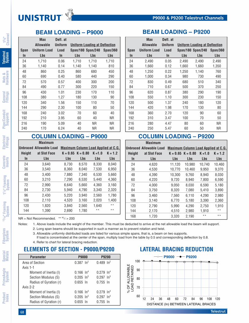
68 Telestrut
®
15 ⁄8"
Chan
nel
Nuts
&Ha
rdw
are
Gene
ral
Fitti
ngs
Pipe
/Con
duit
Supp
orts
Elec
trica
lFi
tting
sCo
ncre
teIn
serts
11 ⁄4" F
ram
ing
Syst
em13
⁄16" F
ram
ing
Syst
emFi
berg
lass
Syst
emSp
ecia
lM
etal
sTe
lest
rut
Syst
emPr
imeA
ngle
Syst
emPr
oduc
tIn
dex
MaximumUnbraced Allowable Load Maximum Column Load Applied at C.G.
Height at Slot Face K = 0.65 K = 0.80 K =1.0 K = 1.2In Lbs Lbs Lbs Lbs Lbs24 3,640 8,730 8,570 8,330 8,04036 3,540 8,360 8,040 7,530 6,95048 3,400 7,880 7,340 6,530 5,66060 3,210 7,290 6,530 5,440 4,36072 2,990 6,640 5,660 4,360 3,16084 2,730 5,940 4,790 3,340 2,32096 2,430 5,220 3,940 2,560 1,780
108 2,110 4,520 3,160 2,020 1,400120 1,820 3,840 2,560 1,640 **144 1,390 2,690 1,780 ** **
MaximumUnbraced Allowable Load Maximum Column Load Applied at C.G.
Height at Slot Face K = 0.65 K = 0.80 K =1.0 K = 1.2In Lbs Lbs Lbs Lbs Lbs24 4,620 11,120 10,980 10,740 10,46036 4,530 10,770 10,460 9,950 9,37048 4,390 10,300 9,760 8,940 8,03060 4,220 9,720 8,940 7,800 6,59072 4,000 9,050 8,030 6,590 5,18084 3,750 8,320 7,080 5,410 3,89096 3,460 7,560 6,110 4,290 2,980
108 3,140 6,770 5,180 3,390 2,360120 2,790 5,990 4,290 2,750 1,910144 2,170 4,510 2,980 1,910 **168 1,720 3,320 2,190 ** **
NR = Not Recommended. ** KL⁄r > 200
Notes: 1. Above loads include the weight of the member. This must be deducted to arrive at the net allowable load the beam will support.
2. Long span beams should be supported in such a manner as to prevent rotation and twist.
3. Allowable uniformly distributed loads are listed for various simple spans, that is, a beam on two supports.If load is concentrated at the center of the span, multiply load from the table by 0.5 and corresponding deflection by 0.8.
4. Refer to chart for lateral bracing reduction.
BEAM LOADING – P9000Max Defl. at
Allowable Uniform Uniform Loading at DeflectionSpan Uniform Load Load Span/180 Span/240 Span/360
In Lbs In Lbs Lbs Lbs24 1,710 0.06 1,710 1,710 1,71036 1,140 0.14 1,140 1,140 81048 860 0.25 860 680 45060 690 0.40 580 440 29072 570 0.57 400 300 20084 490 0.77 300 220 15096 430 1.01 230 170 110
108 380 1.27 180 130 90120 340 1.56 150 110 70144 290 2.30 100 80 50168 240 3.02 70 60 40192 210 3.95 60 40 NR216 190 5.09 40 NR NR240 170 6.24 40 NR NR
Max Defl. atAllowable Uniform Uniform Loading at Deflection
Span Uniform Load Load Span/180 Span/240 Span/360In Lbs In Lbs Lbs Lbs24 2,490 0.05 2,490 2,490 2,49036 1,660 0.12 1,660 1,660 1,35048 1,250 0.22 1,250 1,140 76060 1,000 0.34 980 730 49072 830 0.49 680 510 34084 710 0.67 500 370 25096 620 0.87 380 290 190
108 550 1.10 300 230 150120 500 1.37 240 180 120144 420 1.98 170 130 80168 360 2.70 120 90 60192 310 3.47 100 70 50216 280 4.47 80 60 NR240 250 5.47 60 50 NR
P9000 & P9200 Telestrut Channels
BEAM LOADING – P9200
COLUMN LOADING – P9000 COLUMN LOADING – P9200
ELEMENTS OF SECTION - P9000/P9200Parameter P9000 P9200
Area of Section 0.387 In2 0.489 In2
Axis 1-1Moment of Inertia (I) 0.166 In4 0.279 In4
Section Modulus (S) 0.205 In3 0.297 In3
Radius of Gyration (r) 0.655 In 0.755 InAxis 2-2
Moment of Inertia (I) 0.166 In4 0.279 In4
Section Modulus (S) 0.205 In3 0.297 In3
Radius of Gyration (r) 0.655 In 0.755 In1201089684726048362412
DISTANCE (In) BETWEEN LATERAL BRACES
P9200P9000▲▲
▲▲▲▲▲▲▲▲▲▲▲▲▲▲▲▲▲▲▲▲
60
80
100
70
90
% O
F A
LLO
WA
BLE
LOA
D R
ET
AIN
ED
LATERAL BRACING REDUCTION
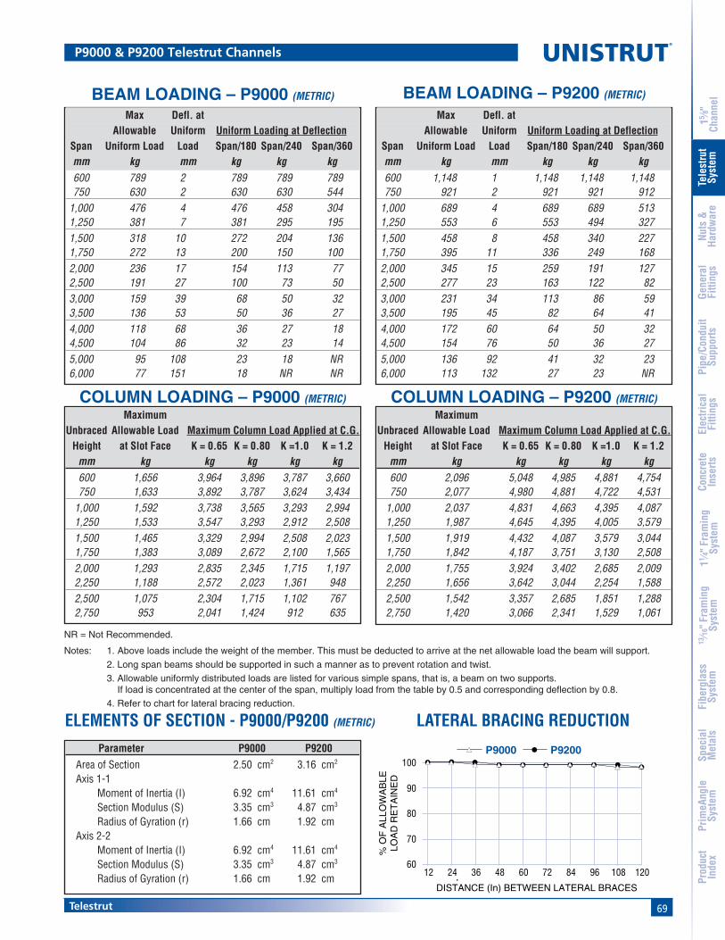
69Telestrut
15 ⁄8"
Chan
nel
Nuts
&Ha
rdw
are
Gene
ral
Fitti
ngs
Pipe
/Con
duit
Supp
orts
Elec
trica
lFi
tting
sCo
ncre
teIn
serts
11 ⁄4" F
ram
ing
Syst
em13
⁄16" F
ram
ing
Syst
emFi
berg
lass
Syst
emSp
ecia
lM
etal
sTe
lest
rut
Syst
emPr
imeA
ngle
Syst
emPr
oduc
tIn
dex
MaximumUnbraced Allowable Load Maximum Column Load Applied at C.G.
Height at Slot Face K = 0.65 K = 0.80 K =1.0 K = 1.2mm kg kg kg kg kg600 1,656 3,964 3,896 3,787 3,660750 1,633 3,892 3,787 3,624 3,434
1,000 1,592 3,738 3,565 3,293 2,9941,250 1,533 3,547 3,293 2,912 2,5081,500 1,465 3,329 2,994 2,508 2,0231,750 1,383 3,089 2,672 2,100 1,5652,000 1,293 2,835 2,345 1,715 1,1972,250 1,188 2,572 2,023 1,361 9482,500 1,075 2,304 1,715 1,102 7672,750 953 2,041 1,424 912 635
MaximumUnbraced Allowable Load Maximum Column Load Applied at C.G.
Height at Slot Face K = 0.65 K = 0.80 K =1.0 K = 1.2mm kg kg kg kg kg600 2,096 5,048 4,985 4,881 4,754750 2,077 4,980 4,881 4,722 4,531
1,000 2,037 4,831 4,663 4,395 4,0871,250 1,987 4,645 4,395 4,005 3,5791,500 1,919 4,432 4,087 3,579 3,0441,750 1,842 4,187 3,751 3,130 2,5082,000 1,755 3,924 3,402 2,685 2,0092,250 1,656 3,642 3,044 2,254 1,5882,500 1,542 3,357 2,685 1,851 1,2882,750 1,420 3,066 2,341 1,529 1,061
P9000 & P9200 Telestrut Channels
Max Defl. atAllowable Uniform Uniform Loading at Deflection
Span Uniform Load Load Span/180 Span/240 Span/360mm kg mm kg kg kg600 789 2 789 789 789750 630 2 630 630 544
1,000 476 4 476 458 3041,250 381 7 381 295 1951,500 318 10 272 204 1361,750 272 13 200 150 1002,000 236 17 154 113 772,500 191 27 100 73 503,000 159 39 68 50 323,500 136 53 50 36 274,000 118 68 36 27 184,500 104 86 32 23 145,000 95 108 23 18 NR6,000 77 151 18 NR NR
Max Defl. atAllowable Uniform Uniform Loading at Deflection
Span Uniform Load Load Span/180 Span/240 Span/360mm kg mm kg kg kg600 1,148 1 1,148 1,148 1,148750 921 2 921 921 912
1,000 689 4 689 689 5131,250 553 6 553 494 3271,500 458 8 458 340 2271,750 395 11 336 249 1682,000 345 15 259 191 1272,500 277 23 163 122 823,000 231 34 113 86 593,500 195 45 82 64 414,000 172 60 64 50 324,500 154 76 50 36 275,000 136 92 41 32 236,000 113 132 27 23 NR
BEAM LOADING – P9000 (METRIC) BEAM LOADING – P9200 (METRIC)
COLUMN LOADING – P9000 (METRIC) COLUMN LOADING – P9200 (METRIC)
Parameter P9000 P9200Area of Section 2.50 cm2 3.16 cm2
Axis 1-1Moment of Inertia (I) 6.92 cm4 11.61 cm4
Section Modulus (S) 3.35 cm3 4.87 cm3
Radius of Gyration (r) 1.66 cm 1.92 cmAxis 2-2
Moment of Inertia (I) 6.92 cm4 11.61 cm4
Section Modulus (S) 3.35 cm3 4.87 cm3
Radius of Gyration (r) 1.66 cm 1.92 cm
ELEMENTS OF SECTION - P9000/P9200 (METRIC)
1201089684726048362412
DISTANCE (In) BETWEEN LATERAL BRACES
P9200P9000▲▲
▲▲▲▲▲▲▲▲▲▲▲▲▲▲▲▲▲▲▲▲
60
80
100
70
90
% O
F A
LLO
WA
BLE
LOA
D R
ET
AIN
ED
LATERAL BRACING REDUCTION
NR = Not Recommended.
Notes: 1. Above loads include the weight of the member. This must be deducted to arrive at the net allowable load the beam will support.
2. Long span beams should be supported in such a manner as to prevent rotation and twist.
3. Allowable uniformly distributed loads are listed for various simple spans, that is, a beam on two supports.If load is concentrated at the center of the span, multiply load from the table by 0.5 and corresponding deflection by 0.8.
4. Refer to chart for lateral bracing reduction.

70 Telestrut
Standard Dimensions for 15⁄8" (41 mm) width series channel Fittings (Unless Otherwise Shown on Drawing)
Hole Diameter: 9⁄16" (14.3mm); Hole Spacing - From End: 13⁄16" (20.6 mm); Hole Spacing - On Center: 17⁄8" (47.6 mm); Width: 15⁄8"(41mm); Thickness: 1⁄4" (6.4mm)
®
15 ⁄8"
Chan
nel
Nuts
&Ha
rdw
are
Gene
ral
Fitti
ngs
Pipe
/Con
duit
Supp
orts
Elec
trica
lFi
tting
sCo
ncre
teIn
serts
11 ⁄4" F
ram
ing
Syst
em13
⁄16" F
ram
ing
Syst
emFi
berg
lass
Syst
emSp
ecia
lM
etal
sTe
lest
rut
Syst
emPr
imeA
ngle
Syst
emPr
oduc
tIn
dex
P9010 Multi-grip RivetWt/100 pcs: 10 Lbs (4.5 kg)
P9209 Gravity PinWt/100 pcs: 47 Lbs (21.3 kg)
Telestrut Connection Methods
Channel Nut ConnectionInfinite Adjustment
Through-Bolt ConnectionIncremental Adjustment
P9000 InsideP9200
Fitting Attachedto Tube Section
or Channel
Fitting Attachedto Tube Section
with Tube Sectionor Channel Inside
Any of the 15⁄8" (41 mm) channel can be connected tothe P9000 using standard channel nuts.
P1000 H3
P9200
Nut &Bolt
Channel Nut
Bolt
P9200
750 Lbs.(340 Kg)Pullout
1,200 Lbs.(544 Kg)
P9000
P9200
Nut &Bolt

71Telestrut
Standard Dimensions for 15⁄8" (41 mm) width series channel Fittings (Unless Otherwise Shown on Drawing)
Hole Diameter: 9⁄16" (14.3mm); Hole Spacing - From End: 13⁄16" (20.6 mm); Hole Spacing - On Center: 17⁄8" (47.6 mm); Width: 15⁄8"(41mm); Thickness: 1⁄4" (6.4mm)
15 ⁄8"
Chan
nel
Nuts
&Ha
rdw
are
Gene
ral
Fitti
ngs
Pipe
/Con
duit
Supp
orts
Elec
trica
lFi
tting
sCo
ncre
teIn
serts
11 ⁄4" F
ram
ing
Syst
em13
⁄16" F
ram
ing
Syst
emFi
berg
lass
Syst
emSp
ecia
lM
etal
sTe
lest
rut
Syst
emPr
imeA
ngle
Syst
emPr
oduc
tIn
dex
Wing Shape Fittings
P9324 Wt/100 pcs: 78 Lbs (35.0 kg)
327⁄32"(97.6)
(97.6)327⁄32"
(36.5)17⁄16"
17⁄8"(47.6)
P9207 Cutting Alignment Gauge
17⁄8"(47.6)
15⁄16"(23.8)
11⁄16"(27.0) The cutting alignment guide ensures correct
cutting of branch members when used withfittings to make connections. Refer to thetable of page 73 for the appropriate valuefor "A" for cutting.
Trunk
BranchA

72 Telestrut
Standard Dimensions for 15⁄8" (41 mm) width series channel Fittings (Unless Otherwise Shown on Drawing)
Hole Diameter: 9⁄16" (14.3mm); Hole Spacing - From End: 13⁄16" (20.6 mm); Hole Spacing - On Center: 17⁄8" (47.6 mm); Width: 15⁄8"(41mm); Thickness: 1⁄4" (6.4mm)
®
15 ⁄8"
Chan
nel
Nuts
&Ha
rdw
are
Gene
ral
Fitti
ngs
Pipe
/Con
duit
Supp
orts
Elec
trica
lFi
tting
sCo
ncre
teIn
serts
11 ⁄4" F
ram
ing
Syst
em13
⁄16" F
ram
ing
Syst
emFi
berg
lass
Syst
emSp
ecia
lM
etal
sTe
lest
rut
Syst
emPr
imeA
ngle
Syst
emPr
oduc
tIn
dex
P9012P9011
P9013 P9014Wt/100 pcs: 318 Lbs (144.7 kg) Wt/100 pcs: 303 Lbs (137.5 kg)
Wt/100 pcs: 332 Lbs (150.7 kg) Wt/100 pcs: 340 Lbs (154 kg)
P90001⁄4"(6.4)
53⁄8"(136.5)
P9200(Slides over)
Cut to11⁄16"(17.5)
P92001⁄4"(6.4)
53⁄8"(136.5)
Any 15⁄8"Section
(Slides Inside)
Cut to13⁄16"(20.6)
P4101
P9200(Slides over)
1⁄4"(6.4)
Cut toany
length
53⁄8"(136.5)P1000 H3
P9200(Slides over)
1⁄4"(6.4)
53⁄8"(136.5)
Cut to13⁄16"(20.6)
P9000
6"(152.4)
(76.2)3"
(76.2)3"
(152.4)6"
3"(76.2)
3"(76.2)
6"(152.4)
4 Holes3⁄4" (19.1) Dia.
P9200
6"(152.4)
(76.2)3"
(76.2)3"
(152.4)6"
3"(76.2)
3"(76.2)
6"(152.4)
4 Holes3⁄4" (19.1) Dia.
P1000 H3
6"(152.4)
(76.2)3"
(76.2)3"
(152.4)6"
3"(76.2)
3"(76.2)
6"(152.4)
4 Holes3⁄4" (19.1) Dia.
P4101
6"(152.4)
(76.2)3"
(76.2)3"
(152.4)6"
3"(76.2)
3"(76.2)
6"(152.4)
4 Holes3⁄4" (19.1) Dia.
Post Bases

73Telestrut
15 ⁄8"
Chan
nel
Nuts
&Ha
rdw
are
Gene
ral
Fitti
ngs
Pipe
/Con
duit
Supp
orts
Elec
trica
lFi
tting
sCo
ncre
teIn
serts
11 ⁄4" F
ram
ing
Syst
em13
⁄16" F
ram
ing
Syst
emFi
berg
lass
Syst
emSp
ecia
lM
etal
sTe
lest
rut
Syst
emPr
imeA
ngle
Syst
emPr
oduc
tIn
dex
Cutting Chart
15⁄8" (41.3) Branch 17⁄8" (47.6) BranchTrunk Trunk Trunk Trunk
Fitting 15⁄8" (41.3) 17⁄8" (47.6) 15⁄8" (41.3) 17⁄8" (47.6)P1026 A A A BP1028 A A A BP1029 † † † †P1031 A A A BP1033 B A A BP1034 † † † †P1035 A † † †P1036 A A A BP1037 † † † †P1038 † † † †P1045 † † † †P1047 † † † †P1048 † † † †P1049 † † † †P1050 † † † †P1065 A A A BP1066 A A A BP1068 C NR NR NRP1130 A A A CP1131 A A A CP1290 A NR NR NRP1291 A NR NR NRP1325 A NR NR NRP1326 C NR NR NRP1334 A A A BP1346 A A A BP1347 C NR NR NRP1354 D D D DP1356 A A A BP1357 A NR NR NRP1358 A A A BP1359 A NR NR NRP1380 A A A B
P1380 A A A A BP1381 † † † †P1382 † † † †P1458 A NR NR NRP1498 † † † †P1499 † † † †
P1538 A C A A CP1538 B C A A CP1538 C C A A CP1538 D C A A CP1579 A NR NR NRP1713 † † † †
15⁄8" (41.3) Branch 17⁄8" (47.6) BranchTrunk Trunk Trunk Trunk
Fitting 15⁄8" (41.3) 17⁄8" (47.6) 15⁄8" (41.3) 17⁄8" (47.6)
P1726 A A A BP1727 B NR NR NRP1728 † † † †P1747 † † † †P1750 † † † †P1821 † † † †P1822 † † † †P1823 † † † †P1843 D D D DP1873 † † † †P1834 † NR NR NRP1941 A A A BP1950 A A A BP1953 A A A BP1956 † † † †P1957 † † † †P2223 A NR A NRP2224 A NR A NRP2225 A NR A NRP2226 A NR A NRP2227 A NR A NRP2228 A NR A NRP2229 A NR A NRP2230 A NR A NRP2235 A NR NR NRP2245 A NR A NRP2324 E NR NR FP2325 E A A FP2326 E NR NR F
P2341 R-L A NR A NRP2343 R-L A NR A NRP2344 R-L A NR A NR
P2345 A NR A NRP2346 A NR A NRP2347 A NR A NRP2348 A NR A NR
P2472 R-L C NR A NRP2815 C NR NR NR
P2815 D C NR NR NRP9324 G G G GP9325 A A A AP9484 A A A A
Designator "A"
A 11⁄16"26.9
B 15⁄16"23.8
C 13⁄16"20.6
D 11⁄4"31.8
E 5⁄8" *15.9
Designator "A"
F 7⁄16" *11.1
G 15⁄32"26.6
NR NotRecommended
† SpecialCutting Req'd(See part dwg)
This table shows the value for "A" when using the specified fitting to connectthe branch and trunk. Sizes "A" and "B" can be cut with the cutting alignmentgauge (P9207). Other sizes require special cutting. Those marked NR are notrecommended.
Trunk
BranchA
Cutting Chart
Legend

74 Telestrut
®
15 ⁄8"
Chan
nel
Nuts
&Ha
rdw
are
Gene
ral
Fitti
ngs
Pipe
/Con
duit
Supp
orts
Elec
trica
lFi
tting
sCo
ncre
teIn
serts
11 ⁄4" F
ram
ing
Syst
em13
⁄16" F
ram
ing
Syst
emFi
berg
lass
Syst
emSp
ecia
lM
etal
sTe
lest
rut
Syst
emPr
imeA
ngle
Syst
emPr
oduc
tIn
dex
Telestrut
Preferred Three-Piece Assembly P9000 (15⁄8")
P9200 (17⁄8")
P9000 (15⁄8")
P9200 (17⁄8")
P9000 (15⁄8")or any other 15⁄8"
Metal Framing Channel(e.g., P1000 H3)
P9200 (17⁄8")
P9000 (15⁄8")
P9200 (17⁄8")
A
A + 1 ⁄8"
P9000 (15⁄8")
In most applications, telescoping assemblies shouldbe made from three sections of Telestrut material.The simplest construction utilizes a center section of17⁄8" material (P9200) into which a 15⁄8" member(P9000) is telescoped from each end. In this way, allintersecting verticals and horizontals are formed from15⁄8" members assuring maximum compatibility andease of assembly
Alternate Three-Piece Assembly
A similar technique is to use a center 15⁄8" centermember (P9000) which can be telescoped into 17⁄8"members used at both ends. With this method, allintersecting connections should be formed fromcompatible 17⁄8" members.
Two-Piece Assembly
Two-piece telescoping assemblies can be used, butspecial cutting of one or both telescoping members isneeded to achieve proper alignment of fittings at theintersecting connections.
In addition, the right-angle members to whichtelescoping pieces are attached must be cut accordingto the illustration at right to insure smooth movementof telescoping members.
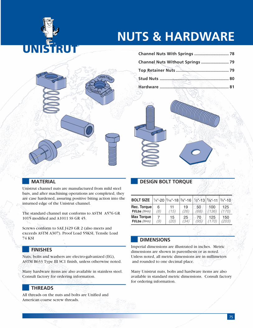
75
®
MATERIALUnistrut channel nuts are manufactured from mild steelbars, and after machining operations are completed, theyare case hardened, assuring positive biting action into theinturned edge of the Unistrut channel.
The standard channel nut conforms to ASTM A576 GR1015 modified and A1011 SS GR 45.
Screws conform to SAE J429 GR 2 (also meets andexceeds ASTM A307). Proof Load 55KSI, Tensile Load74 KSI
FINISHESNuts, bolts and washers are electro-galvanized (EG),ASTM B633 Type III SC1 finish, unless otherwise noted.
Many hardware items are also available in stainless steel.Consult factory for ordering information.
THREADSAll threads on the nuts and bolts are Unified andAmerican coarse screw threads.
DESIGN BOLT TORQUE
DIMENSIONSImperial dimensions are illustrated in inches. Metricdimensions are shown in parenthesis or as noted.Unless noted, all metric dimensions are in millimeters and rounded to one decimal place.
Many Unistrut nuts, bolts and hardware items are alsoavailable in standard metric dimensions. Consult factoryfor ordering information.
NUTS & HARDWAREChannel Nuts With Springs .............................. 78
Channel Nuts Without Springs ........................ 79
Top Retainer Nuts .............................................. 79
Stud Nuts ............................................................ 80
Hardware ............................................................ 81
UNISTRUT
UNISTRUT
BOLT SIZE
Rec. TorqueFt/Lbs (N•m)
Max TorqueFt/Lbs (N•m)
1⁄4"-20
6(8)
5⁄16"-18
11(15)
3⁄8"-16
19(26)
5⁄8"-11
50(68)
1⁄2"-13
100(136)
3⁄4"-10
125(170)
7(9)
15(20)
25(34)
70(95)
125(170)
150(203)

76
®
Nuts & Hardware
15 ⁄8"
Chan
nel
Nuts
&Ha
rdw
are
Gene
ral
Fitti
ngs
Pipe
/Con
duit
Supp
orts
Elec
trica
lFi
tting
sCo
ncre
teIn
serts
11 ⁄4" F
ram
ing
Syst
em13
⁄16" F
ram
ing
Syst
emFi
berg
lass
Syst
emSp
ecia
lM
etal
sTe
lest
rut
Syst
emPr
imeA
ngle
Syst
emPr
oduc
tIn
dex
Nuts & Hardware Pictorial Index
Channel Nuts With Spring
Channel Nuts Without Spring
Hardware
P1006 - P1010Pg 78
P1012S - P1024SPg 78
P4006 - P4010Pg 78
P4012S - P4023SPg 78
P5506 - P5510Pg 78
P2378 - P2382Pg 80
P3016Pg 79
P3006 - P3013Pg 79
P1012 - P1024Pg 79
P4012 - P4023Pg 79
P4908Pg 79
P1006T - P1010T, P4010TPg 79
HHCSPg 81
HFMSPg 81
HRMSPg 81
HSHSPg 81
HCSSPg 81
HTHRPg 83
HRCNPg 84
P9209Pg 82
P2485Pg 84
HOCWPg 84
HFLWPg 82
HSQNPg 82
HLKWPg 82
HHXNPg 82
P9010Pg 82

77Nuts & Hardware
15 ⁄8"
Chan
nel
Nuts
&Ha
rdw
are
Gene
ral
Fitti
ngs
Pipe
/Con
duit
Supp
orts
Elec
trica
lFi
tting
sCo
ncre
teIn
serts
11 ⁄4" F
ram
ing
Syst
em13
⁄16" F
ram
ing
Syst
emFi
berg
lass
Syst
emSp
ecia
lM
etal
sTe
lest
rut
Syst
emPr
imeA
ngle
Syst
emPr
oduc
tIn
dex
1⁄2" -13 12 1,500 1,500 50680 680 70
3⁄8" -16 12 1,000 800 19454 363 25
5⁄16" -18 12 800 500 11363 227 15
1⁄4" -20 12 600 300 6272 136 8
1⁄2" -13 14 1,400 1,000 50635 454 70
3⁄8" -16 14 1,000 750 19454 340 25
5⁄16" -18 14 800 400 11363 181 15
1⁄4" -20 14 600 300 6272 136 8
1⁄2" -13 16 1,000 1,000 50454 454 70
3⁄8" -16 16 1,000 750 19454 340 25
5⁄16" -18 16 800 400 11363 181 15
1⁄4" -20 16 600 300 6272 136 8
Channel Nut Loads
Maximum Allowable Pull-out And Slip Loads
Allowable Resistance toChannel Nut Pull-Out Strength Slip TorqueSize-Thread Gauge Channel Lbs (kg) Lbs (kg) Ft-Lbs (N•m)
3⁄4" -10 12 2,500 1,700 *1251,134 771 170
5⁄8" -11 12 2,500 1,500 *1001,134 680 135
1⁄2" -13 12 2,000 1,500 50907 680 70
7⁄16" -14 12 1,400 1,000 35635 454 50
3⁄8" -16 12 1,000 800 19454 363 25
5⁄16" -18 12 800 500 11363 227 15
1⁄4" -20 12 600 300 6272 136 8
P1000P3000P5000P5500
P3300
P1100&
P4100
P2000&
P4000
* May require 3⁄8" or 1⁄2" thick fitting.Nut design loads include a minimum safety factor of 3.Note: Refer to the Channel Nut Selection Chart on the following two pages for the part number.
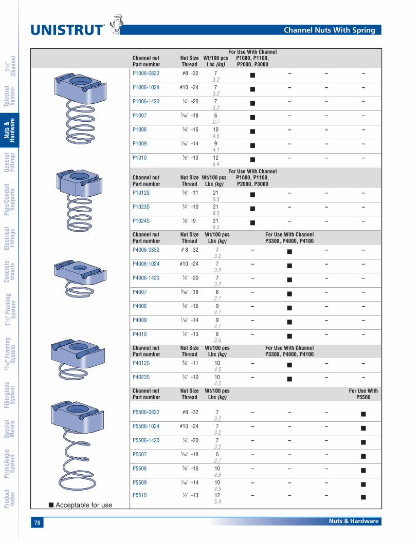
78
®
Nuts & Hardware
15 ⁄8"
Chan
nel
Nuts
&Ha
rdw
are
Gene
ral
Fitti
ngs
Pipe
/Con
duit
Supp
orts
Elec
trica
lFi
tting
sCo
ncre
teIn
serts
11 ⁄4" F
ram
ing
Syst
em13
⁄16" F
ram
ing
Syst
emFi
berg
lass
Syst
emSp
ecia
lM
etal
sTe
lest
rut
Syst
emPr
imeA
ngle
Syst
emPr
oduc
tIn
dex
For Use With ChannelChannel nut Nut Size Wt/100 pcs P1000, P1100,Part number Thread Lbs (kg) P2000, P3000
P1006-0832 #8 -32 7 ■ – – –3.2
P1006-1024 #10 -24 7 ■ – – –3.2
P1006-1420 1⁄4" -20 7 ■ – – –3.2
P1007 5⁄16" -18 6 ■ – – –2.7
P1008 3⁄8" -16 10 ■ – – –4.5
P1009 7⁄16" -14 9 ■ – – –4.1
P1010 1⁄2" -13 12 ■ – – –5.4
For Use With ChannelChannel nut Nut Size Wt/100 pcs P1000, P1100,Part number Thread Lbs (kg) P2000, P3000
P1012S 5⁄8" -11 21 ■ – – –9.5
P1023S 3⁄4" -10 21 ■ – – –9.5
P1024S 7⁄8" -9 21 ■ – – –9.5
Channel nut Nut Size Wt/100 pcs For Use With ChannelPart number Thread Lbs (kg) P3300, P4000, P4100
P4006-0832 # 8 -32 7 – ■ – –3.2
P4006-1024 #10 -24 7 – ■ – –3.2
P4006-1420 1⁄4" -20 7 – ■ – –3.2
P4007 5⁄16" -18 6 – ■ – –2.7
P4008 3⁄8" -16 9 – ■ – –4.1
P4009 7⁄16" -14 9 – ■ – –4.1
P4010 1⁄2" -13 8 – ■ – –3.6
Channel nut Nut Size Wt/100 pcs For Use With ChannelPart number Thread Lbs (kg) P3300, P4000, P4100
P4012S 5⁄8" -11 10 – ■ – –4.5
P4023S 3⁄4" -10 10 – ■ – –4.5
Channel nut Nut Size Wt/100 pcs For Use WithPart number Thread Lbs (kg) P5500
P5506-0832 #8 -32 7 – – – ■3.2
P5506-1024 #10 -24 7 – – – ■3.2
P5506-1420 1⁄4" -20 7 – – – ■3.2
P5507 5⁄16" -18 6 – – – ■2.7
P5508 3⁄8" -16 10 – – – ■4.5
P5509 7⁄16" -14 10 – – – ■4.5
P5510 1⁄2" -13 12 – – – ■5.4
Channel Nuts With Spring
■ Acceptable for use
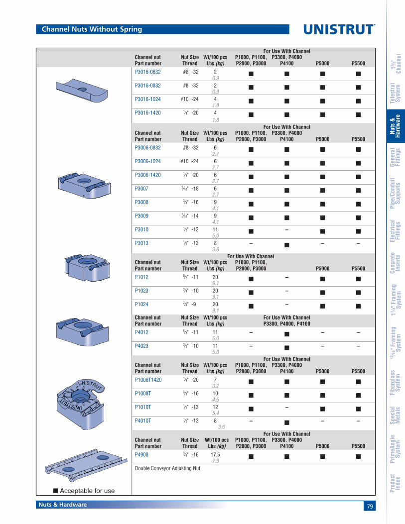
79Nuts & Hardware
15 ⁄8"
Chan
nel
Nuts
&Ha
rdw
are
Gene
ral
Fitti
ngs
Pipe
/Con
duit
Supp
orts
Elec
trica
lFi
tting
sCo
ncre
teIn
serts
11 ⁄4" F
ram
ing
Syst
em13
⁄16" F
ram
ing
Syst
emFi
berg
lass
Syst
emSp
ecia
lM
etal
sTe
lest
rut
Syst
emPr
imeA
ngle
Syst
emPr
oduc
tIn
dex
For Use With ChannelChannel nut Nut Size Wt/100 pcs P1000, P1100, P3300, P4000Part number Thread Lbs (kg) P2000, P3000 P4100 P5000 P5500
P3016-0632 #6 -32 2 ■ ■ ■ ■0.9
P3016-0832 #8 -32 2 ■ ■ ■ ■0.9
P3016-1024 #10 -24 4 ■ ■ ■ ■1.8
P3016-1420 1⁄4" -20 4 ■ ■ ■ ■1.8
For Use With ChannelChannel nut Nut Size Wt/100 pcs P1000, P1100, P3300, P4000Part number Thread Lbs (kg) P2000, P3000 P4100 P5000 P5500
P3006-0832 #8 -32 6 ■ ■ ■ ■2.7
P3006-1024 #10 -24 6 ■ ■ ■ ■2.7
P3006-1420 1⁄4" -20 6 ■ ■ ■ ■2.7
P3007 5⁄16" -18 6 ■ ■ ■ ■2.7
P3008 3⁄8" -16 9 ■ ■ ■ ■4.1
P3009 7⁄16" -14 9 ■ ■ ■ ■4.1
P3010 1⁄2" -13 11 ■ – ■ ■5.0
P3013 1⁄2" -13 8 – ■ – –3.6
For Use With ChannelChannel nut Nut Size Wt/100 pcs P1000, P1100,Part number Thread Lbs (kg) P2000, P3000 P5000 P5500
P1012 5⁄8" -11 20 ■ – ■ ■9.1
P1023 3⁄4" -10 20 ■ – ■ ■9.1
P1024 7⁄8" -9 20 ■ – ■ ■9.1
Channel nut Nut Size Wt/100 pcs For Use With ChannelPart number Thread Lbs (kg) P3300, P4000, P4100
P4012 5⁄8" -11 11 – ■ – –5.0
P4023 3⁄4" -10 11 – ■ – –5.0
For Use With ChannelChannel nut Nut Size Wt/100 pcs P1000, P1100, P3300, P4000Part number Thread Lbs (kg) P2000, P3000 P4100 P5000 P5500
P1006T1420 1⁄4" -20 7 ■ ■ ■ ■3.2
P1008T 3⁄8" -16 10 ■ ■ ■ ■4.5
P1010T 1⁄2" -13 12 ■ – ■ ■5.4
P4010T 1⁄2" -13 8 – ■ – –3.6
For Use With ChannelChannel nut Nut Size Wt/100 pcs P1000, P1100, P3300, P4000Part number Thread Lbs (kg) P2000, P3000 P4100 P5000 P5500
P4908 3⁄8" -16 17.5 ■ ■ ■ ■7.9
Double Conveyor Adjusting Nut
UNISTRUT
UNISTRUT
Channel Nuts Without Spring
■ Acceptable for use

80
®
Nuts & Hardware
15 ⁄8"
Chan
nel
Nuts
&Ha
rdw
are
Gene
ral
Fitti
ngs
Pipe
/Con
duit
Supp
orts
Elec
trica
lFi
tting
sCo
ncre
teIn
serts
11 ⁄4" F
ram
ing
Syst
em13
⁄16" F
ram
ing
Syst
emFi
berg
lass
Syst
emSp
ecia
lM
etal
sTe
lest
rut
Syst
emPr
imeA
ngle
Syst
emPr
oduc
tIn
dex
"A" For Use With ChannelChannel nut Nut Size Stud Wt/100 pcs P1000, P1100,Part number Thread In (mm) Lbs (kg) P2000, P3000
P2378-1 1⁄4" -20 1 8 ■25.4 3.6
P2378-2 11⁄4 9 ■31.8 4.1
P2378-3 11⁄2 9 ■38.1 4.1
P2379-1 5⁄16" -18 1 12 ■25.4 5.4
P2379-2 11⁄4 12 ■31.8 5.4
P2379-3 11⁄2 13 ■38.1 5.9
P2380-1 3⁄8" -16 1 13 ■25.4 5.9
P2380-2 11⁄4 13 ■31.8 5.9
P2380-3 11⁄2 13 ■38.1 5.9
P2380-4 13⁄4 15 ■44.5 6.8
P2380-5 2 16 ■50.8 7.3
P2380-6 21⁄4 16 ■57.2 7.3
P2381-2 1⁄2" -13 1 14 ■25.4 6.4
P2381-3 11⁄4 15 ■31.8 6.8
P2381-4 11⁄2 17 ■38.1 7.7
P2381-5 13⁄4 18 ■44.5 8.2
P2381-6 2 19 ■50.8 8.6
P2381-7 21⁄4 20 ■57.2 9.1
P2382-2 5⁄8" -11 11⁄4 18 ■31.8 8.2
P2382-3 11⁄2 20 ■38.1 9.1
All Stud Nut grooves areserrated.
Special stud lengths andthread lengths can besupplied upon request.
A
Channel Stud Nut With Spring
Channel Nuts With Spring
■ Acceptable for use

81Nuts & Hardware
15 ⁄8"
Chan
nel
Nuts
&Ha
rdw
are
Gene
ral
Fitti
ngs
Pipe
/Con
duit
Supp
orts
Elec
trica
lFi
tting
sCo
ncre
teIn
serts
11 ⁄4" F
ram
ing
Syst
em13
⁄16" F
ram
ing
Syst
emFi
berg
lass
Syst
emSp
ecia
lM
etal
sTe
lest
rut
Syst
emPr
imeA
ngle
Syst
emPr
oduc
tIn
dex
Hex Head Cap Screws
Flat Head Machine Screws
Round Head Machine ScrewsWt/100 pcs
Part No. Size Lbs (kg)
HHCS025044EG 1⁄4" x 7⁄16" 1.00.5
HHCS025075EG 1⁄4" x 3⁄4" 1.30.6
HHCS025150EG 1⁄4" x 11⁄2" 2.61.2
HHCS031125EG 5⁄16" x 11⁄4" 3.61.6
HHCS037075EG 3⁄8" x 3⁄4" 4.01.8
HHCS037087EG 3⁄8" x 7⁄8" 4.42.0
HHCS037100EG 3⁄8" x 1" 4.52.0
HHCS037125EG 3⁄8" x 11⁄4" 5.32.4
HHCS037150EG 3⁄8" x 11⁄2" 6.02.7
HHCS037200EG 3⁄8" x 2" 7.63.4
HHCS037225EG 3⁄8" x 21⁄4" 8.43.8
HHCS037250EG 3⁄8" x 21⁄2" 9.24.2
HHCS050094EG 1⁄2" x 15⁄16" 9.14.1
HHCS050119EG 1⁄2" x 13⁄16" 10.24.6
HHCS050150EG 1⁄2" x 11⁄2" 11.65.3
HHCS050175EG 1⁄2" x 13⁄4" 13.15.9
HHCS050200EG 1⁄2" x 2" 14.66.6
HHCS050225EG 1⁄2" x 21⁄4" 167.3
HHCS050250EG 1⁄2" x 21⁄2" 17.57.9
Wt/100 pcsPart No. Size Lbs (kg)
HFMS025062EG 1⁄4" x 5⁄8" 1.20.5
HFMS031100EG 5⁄16" x 1" 2.61.2
HFMS050100EG 1⁄2" x 1" 9.34.2
Wt/100 pcsPart No. Size Lbs (kg)
HRMS025050EG 1⁄4" x 1⁄2" 10.5
HRMS025075EG 1⁄4" x 3⁄4" 1.20.5
HRMS025100EG 1⁄4" x 1" 1.50.7
HRMS031100EG 5⁄16" x 1" 2.61.2
HRMS031125EG 5⁄16" x 11⁄4" 31.4
HRMS037100EG 3⁄8" x 1" 4.11.9
HRMS037125EG 3⁄8" x 11⁄4" 4.72.1
HRMS037150EG 3⁄8" x 11⁄2" 5.32.4
Wt/100 pcsPart No. Size Lbs (kg)
HSHS025050EG 1⁄4" x 1⁄2" 1.40.6
HSHS025062EG 1⁄4" x 5⁄8" 1.50.7
HSHS025075EG 1⁄4" x 3⁄4" 1.70.8
HSHS031100EG 5⁄16" x 1" 2.61.2
HSHS031125EG 5⁄16" x 11⁄4" 31.4
HSHS031150EG 5⁄16" x 11⁄2" 3.41.5
HSHS037125EG 3⁄8" x 11⁄4" 5.32.4
Hex Slotted Machine Screws
Wt/100 pcsPart No. Size Lbs (kg)
HCSS025100EG 1⁄4" x 1" 2.81.3
HCSS031150EG 5⁄16" x 11⁄2" 3.91.8
HCSS037150EG 3⁄8" x 11⁄2" 4.52.0
HCSS037200EG 3⁄8" x 2" 6.12.8
HCSS050150EG 1⁄2" x 11⁄2" 8.53.9
HCSS050200EG 1⁄2" x 2" 11.45.2
HCSS062150EG 5⁄8" x 11⁄2" 14.56.6
HCSS062200EG 5⁄8" x 2" 23.010.4
Cone Point Set Screws
Hardware
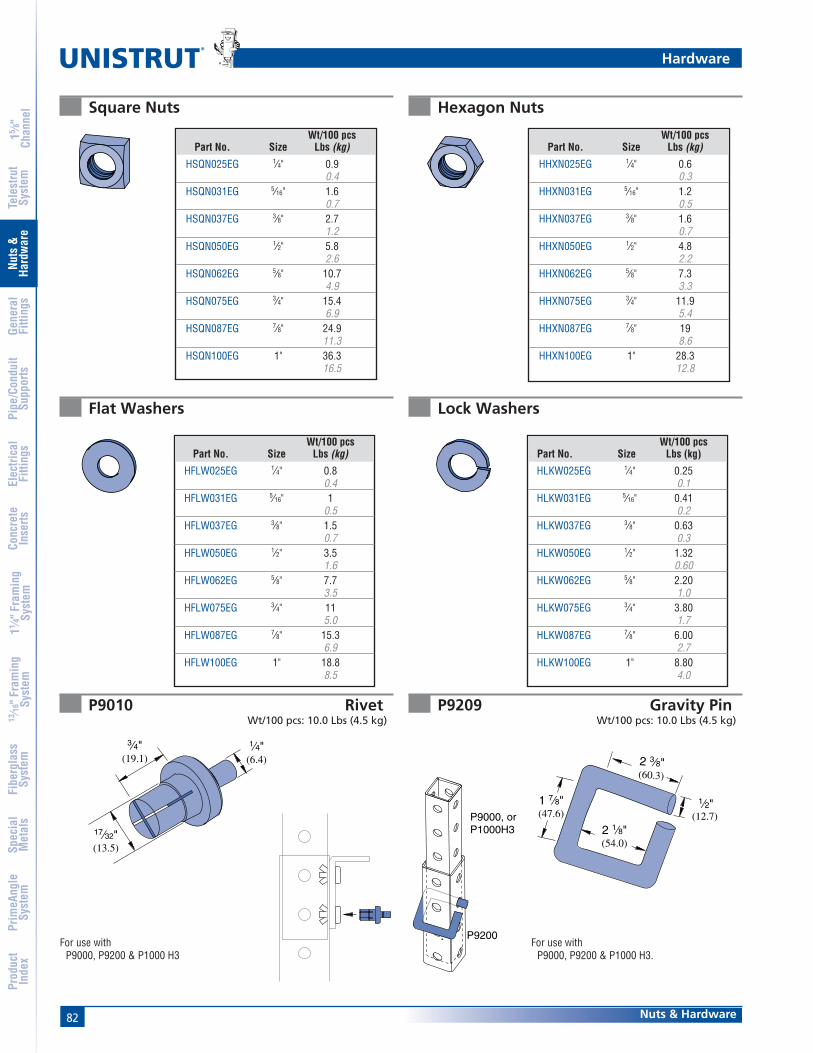
82
®
Nuts & Hardware
15 ⁄8"
Chan
nel
Nuts
&Ha
rdw
are
Gene
ral
Fitti
ngs
Pipe
/Con
duit
Supp
orts
Elec
trica
lFi
tting
sCo
ncre
teIn
serts
11 ⁄4" F
ram
ing
Syst
em13
⁄16" F
ram
ing
Syst
emFi
berg
lass
Syst
emSp
ecia
lM
etal
sTe
lest
rut
Syst
emPr
imeA
ngle
Syst
emPr
oduc
tIn
dex
Flat Washers Lock Washers
P9010 RivetWt/100 pcs: 10.0 Lbs (4.5 kg)
P9209 Gravity PinWt/100 pcs: 10.0 Lbs (4.5 kg)
1⁄4"(6.4)
3⁄4"(19.1)
17⁄32"(13.5)
P9000, or P1000H3
P9200
Square Nuts Hexagon Nuts
(12.7)
1⁄2"
2 3⁄8"(60.3)
2 1⁄8"(54.0)
1 7⁄8"(47.6)
For use withP9000, P9200 & P1000 H3.
For use withP9000, P9200 & P1000 H3
Wt/100 pcsPart No. Size Lbs (kg)
HSQN025EG 1⁄4" 0.90.4
HSQN031EG 5⁄16" 1.60.7
HSQN037EG 3⁄8" 2.71.2
HSQN050EG 1⁄2" 5.82.6
HSQN062EG 5⁄8" 10.74.9
HSQN075EG 3⁄4" 15.46.9
HSQN087EG 7⁄8" 24.911.3
HSQN100EG 1" 36.316.5
Wt/100 pcsPart No. Size Lbs (kg)
HFLW025EG 1⁄4" 0.80.4
HFLW031EG 5⁄16" 10.5
HFLW037EG 3⁄8" 1.50.7
HFLW050EG 1⁄2" 3.51.6
HFLW062EG 5⁄8" 7.73.5
HFLW075EG 3⁄4" 115.0
HFLW087EG 7⁄8" 15.36.9
HFLW100EG 1" 18.88.5
Wt/100 pcsPart No. Size Lbs (kg)
HHXN025EG 1⁄4" 0.60.3
HHXN031EG 5⁄16" 1.20.5
HHXN037EG 3⁄8" 1.60.7
HHXN050EG 1⁄2" 4.82.2
HHXN062EG 5⁄8" 7.33.3
HHXN075EG 3⁄4" 11.95.4
HHXN087EG 7⁄8" 198.6
HHXN100EG 1" 28.312.8
Wt/100 pcsPart No. Size Lbs (kg)
HLKW025EG 1⁄4" 0.250.1
HLKW031EG 5⁄16" 0.410.2
HLKW037EG 3⁄8" 0.630.3
HLKW050EG 1⁄2" 1.320.60
HLKW062EG 5⁄8" 2.201.0
HLKW075EG 3⁄4" 3.801.7
HLKW087EG 7⁄8" 6.002.7
HLKW100EG 1" 8.804.0
Hardware

83Nuts & Hardware
15 ⁄8"
Chan
nel
Nuts
&Ha
rdw
are
Gene
ral
Fitti
ngs
Pipe
/Con
duit
Supp
orts
Elec
trica
lFi
tting
sCo
ncre
teIn
serts
11 ⁄4" F
ram
ing
Syst
em13
⁄16" F
ram
ing
Syst
emFi
berg
lass
Syst
emSp
ecia
lM
etal
sTe
lest
rut
Syst
emPr
imeA
ngle
Syst
emPr
oduc
tIn
dex
Steel Threaded Rod
Load Carrying Capacity Of Threaded Hot Rolled SteelConforming To ASTM A575 And A576
* Based on MSS SP-58
Wt/100 Ft.Part No. Size Lbs (kg)
HTHR025 1⁄4" x 20 135.9
HTHR031 5⁄16" x 18 209.1
HTHR037 3⁄8" x 16 3013.6
HTHR044 7⁄16" x 14 3013.6
HTHR050 1⁄2" x 13 5324.0
HTHR062 5⁄8" x 11 8438.1
HTHR075 3⁄4" x 10 12456.2
HTHR087 7⁄8" x 9 17077.1
HTHR100 1" x 8 223101.2
Hardware
Low Carbon SteelFy = 32,000 psiFt = 52,000 psi
MaximumSafe Load
Nominal Root Area at 650°F (343°C)Diameter In2 (mm2) Lbs (kg)
3⁄8 0.068 73043.9 331
1⁄2 0.126 1,35081.3 612
5⁄8 0.202 2,160130.3 980
3⁄4 0.302 3,230194.8 1,465
7⁄8 0.419 4,480270.3 2,032
1 0.552 5,900356.1 2,676
AllowedNominal Tension
Nominal Area LoadDiameter In2 (mm2) Lbs (kg)
1⁄4 0.049 84031.6 381
3⁄8 0.110 1,89071.0 857
7⁄16 0.150 2,57096.8 1,166
1⁄2 0.196 3,360126.5 1,524
5⁄8 0.307 5,260198.2 2,386
3⁄4 0.442 7,580285.4 3,438
7⁄8 0.601 10,310388.0 4,677
1 0.785 13,470506.8 6,110
Threaded Rod Loads for Piping Applications * Threaded Rod Loads for Structural Applications *
* Based on AISC, Steel Construction Manual,ASD, 9th Edition
Per AISC, Allowed Tensile Stress = 0.33 * Fu
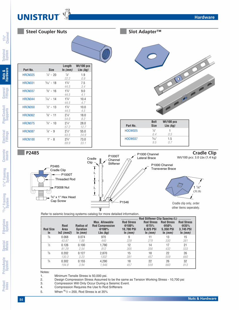
84
®
Nuts & Hardware
15 ⁄8"
Chan
nel
Nuts
&Ha
rdw
are
Gene
ral
Fitti
ngs
Pipe
/Con
duit
Supp
orts
Elec
trica
lFi
tting
sCo
ncre
teIn
serts
11 ⁄4" F
ram
ing
Syst
em13
⁄16" F
ram
ing
Syst
emFi
berg
lass
Syst
emSp
ecia
lM
etal
sTe
lest
rut
Syst
emPr
imeA
ngle
Syst
emPr
oduc
tIn
dex
P2485 Cradle ClipWt/100 pcs: 3.0 Lbs (1.4 kg)
P2485Cradle Clip
Threaded Rod
P1000T
P3008 Nut
3⁄8" x 1" Hex Head Cap Screw
P1000T Channel Stiffener
P1000 Channel Lateral Brace
P1000 Channel Transverse Brace
CradleClip
L
L
P1546
1 1⁄4"(31.8)
Refer to seismic bracing systems catalog for more detailed information.
Steel Coupler Nuts
Cradle clip only, orderother items seperately.
Length Wt/100 pcsPart No. Size In (mm) Lbs (kg)
HRCN025 1⁄4" - 20 7⁄8" 1.922.2 0.9
HRCN031 5⁄16" - 18 13⁄4" 7.544.5 3.4
HRCN037 3⁄8" - 16 13⁄4" 9.044.5 4.1
HRCN044 7⁄16" - 14 13⁄4" 10.444.5 4.7
HRCN050 1⁄2" - 13 13⁄4" 10.044.5 4.5
HRCN062 5⁄8" - 11 21⁄8" 18.054.0 8.2
HRCN075 3⁄4" - 10 21⁄4" 28.057.2 12.7
HRCN087 7⁄8" - 9 21⁄2" 55.063.5 24.9
HRCN100 1" - 8 23⁄4" 73.069.9 33.1
................ Rod Stiffener Clip Spacing (L) ............Max. Allowable Rod Stress Rod Stress Rod Stress Rod Stress
Root Radius of Rod Compression @100% @75% @50% @35%Rod Size Area Gyration @100% 10,700 PSI 8,025 PSI 5,350 PSI 3,745 PSI
In In2 (mm2) In (mm) Lbs (kg) In (mm) In (mm) In (mm) In (mm)3⁄8 0.068 0.074 970 9 11 13 15
43.87 1.88 440 229 279 330 3811⁄2 0.126 0.100 1,790 12 14 17 21
81.29 2.54 812 305 356 432 5335⁄8 0.202 0.127 2,870 15 18 22 26
130.3 3.23 1302 381 457 559 6603⁄4 0.302 0.155 4,290 18 22 26 32
194.8 3.94 1,946 457 559 660 813
Hardware
Slot Adapter™
Bolt Wt/100 pcsPart No. Size Lbs (kg)
HOCW025 1⁄4" 16.4 0.5
HOCW037 5⁄16" 1.59.5 0.7
Notes:1. Minimum Tensile Stress is 50,000 psi.2. Design Compression Stress Assumed to be the same as Tension Working Stress - 10,700 psi3. Compression Will Only Occur During a Seismic Event.4. Compression Requires the Use fo Rod Sriffeners
5. When KL/r = 200, Rod Stress is at 35%
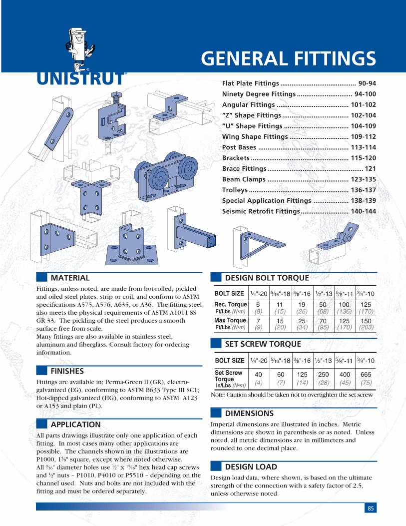
85
®
MATERIALFittings, unless noted, are made from hot-rolled, pickledand oiled steel plates, strip or coil, and conform to ASTMspecifications A575, A576, A635, or A36. The fitting steelalso meets the physical requirements of ASTM A1011 SSGR 33. The pickling of the steel produces a smoothsurface free from scale.Many fittings are also available in stainless steel,aluminum and fiberglass. Consult factory for orderinginformation.
FINISHESFittings are available in: Perma-Green II (GR), electro-galvanized (EG), conforming to ASTM B633 Type III SC1;Hot-dipped galvanized (HG), conforming to ASTM A123or A153 and plain (PL).
APPLICATIONAll parts drawings illustrate only one application of eachfitting. In most cases many other applications arepossible. The channels shown in the illustrations areP1000, 15⁄8" square, except where noted otherwise.All 9⁄16" diameter holes use 1⁄2" x 15⁄16" hex head cap screwsand 1⁄2" nuts – P1010, P4010 or P5510 – depending on thechannel used. Nuts and bolts are not included with thefitting and must be ordered separately.
DESIGN BOLT TORQUE
SET SCREW TORQUE
Note: Caution should be taken not to overtighten the set screw
DIMENSIONSImperial dimensions are illustrated in inches. Metricdimensions are shown in parenthesis or as noted. Unlessnoted, all metric dimensions are in millimeters androunded to one decimal place.
DESIGN LOADDesign load data, where shown, is based on the ultimatestrength of the connection with a safety factor of 2.5,unless otherwise noted.
GENERAL FITTINGSFlat Plate Fittings ......................................... 90-94
Ninety Degree Fittings .............................. 94-100
Angular Fittings ....................................... 101-102
“Z” Shape Fittings .................................... 102-104
“U” Shape Fittings ................................... 104-109
Wing Shape Fittings ................................ 109-112
Post Bases ................................................. 113-114
Brackets ..................................................... 115-120
Brace Fittings .................................................... 121
Beam Clamps ............................................ 123-135
Trolleys ...................................................... 136-137
Special Application Fittings ................... 138-139
Seismic Retrofit Fittings.......................... 140-144
BOLT SIZE
Rec. TorqueFt/Lbs (N•m)
Max TorqueFt/Lbs (N•m)
1⁄4"-20
6(8)
5⁄16"-18
11(15)
3⁄8"-16
19(26)
5⁄8"-11
50(68)
1⁄2"-13
100(136)
3⁄4"-10
125(170)
7(9)
15(20)
25(34)
70(95)
125(170)
150(203)
Set ScrewTorqueIn/Lbs (N•m)
40(4)
60(7)
125(14)
250(28)
400(45)
665(75)
BOLT SIZE 1⁄4"-20 5⁄16"-18 3⁄8"-16 5⁄8"-11 1⁄2"-13 3⁄4"-10

86 General Fittings
®
15 ⁄8"
Chan
nel
Nuts
&Ha
rdw
are
Gene
ral
Fitti
ngs
Pipe
/Con
duit
Supp
orts
Elec
trica
lFi
tting
sCo
ncre
teIn
serts
11 ⁄4" F
ram
ing
Syst
em13
⁄16" F
ram
ing
Syst
emFi
berg
lass
Syst
emSp
ecia
lM
etal
sTe
lest
rut
Syst
emPr
imeA
ngle
Syst
emPr
oduc
tIn
dex
General Fittings Pictorial Index
Flat Plate Fittings
Angle Fittings
P1062-Pg 90 P1959-Pg 90 P2862-Pg 90 P1065-Pg 90 P1924-Pg 90 P2325-Pg 90 P2324-Pg 91 P1066-Pg 91 P1925-Pg 91
P1067-Pg 91 P2079-Pg 91 P1941-Pg 91 P1036-Pg 92 P1380 A-Pg 92 P1334-Pg 92 P1380-Pg 92 P1873-Pg 92 P1031-Pg 92
P1028-Pg 93 P1356-Pg 93 P1358-Pg 93 P1726-Pg 93 P1953-Pg 93 P1950-Pg 93 P1962-Pg 94
P2626-Pg 94 P1026-Pg 94 P1723-Pg 94 P1068-Pg 94 P1281-Pg 94 P1315-Pg 95 P1538A-Pg 95P1458-Pg 95 P1750-Pg 95
P1325-Pg 96 P1823-Pg 96P1822-Pg 96 P1033-Pg 97P1747-Pg 95P1498-Pg 95 P1821-Pg 96P1326-Pg 96 P1346-Pg 96
P1290-Pg 98 P1291-Pg 98 P1357-Pg 98 P1359-Pg 98
P2235-Pg 99 P1956-Pg 100
P1038- Pg 97P1037-Pg 97 P1029-Pg 97P1034-Pg 97 P1035-Pg 97
P1727-Pg 99 P1728-Pg 99P1382- Pg 98P1381-Pg 98 P1713-Pg 99P1934-Pg 99 P1579-Pg 99
P2101-Pg 101 P1186-Pg 101 P2260-Pg 102P2484-Pg 100P1957-Pg 100 P1130-Pg 100P2484W-Pg 100 P1546-Pg 101
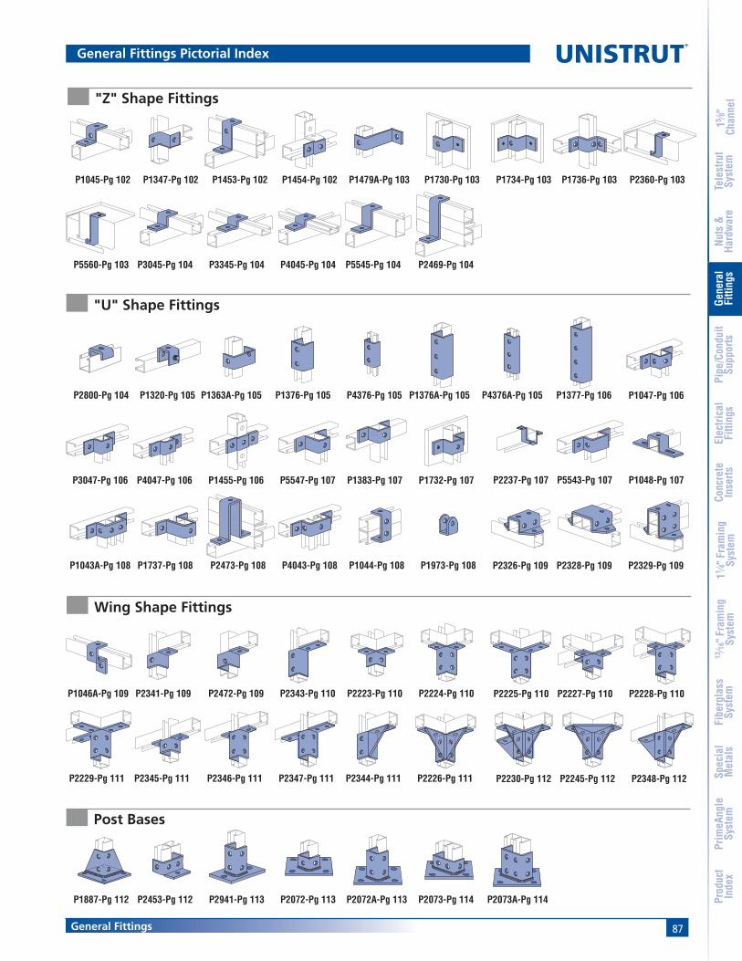
87General Fittings
15 ⁄8"
Chan
nel
Nuts
&Ha
rdw
are
Gene
ral
Fitti
ngs
Pipe
/Con
duit
Supp
orts
Elec
trica
lFi
tting
sCo
ncre
teIn
serts
11 ⁄4" F
ram
ing
Syst
em13
⁄16" F
ram
ing
Syst
emFi
berg
lass
Syst
emSp
ecia
lM
etal
sTe
lest
rut
Syst
emPr
imeA
ngle
Syst
emPr
oduc
tIn
dex
General Fittings Pictorial Index
P2469-Pg 104P3045-Pg 104P5560-Pg 103 P4045-Pg 104P3345-Pg 104 P5545-Pg 104
P1383-Pg 107 P1732-Pg 107
P4376A-Pg 105 P1377-Pg 106P1363A-Pg 105P1320-Pg 105P2800-Pg 104 P4376-Pg 105P1376-Pg 105 P1376A-Pg 105
P1455-Pg 106 P5547-Pg 107
P1047-Pg 106
P3047-Pg 106 P4047-Pg 106
P1044-Pg 108 P1973-Pg 108
P2223-Pg 110 P2224-Pg 110
P2473-Pg 108 P4043-Pg 108
P5543-Pg 107P2237-Pg 107
P1043A-Pg 108
P1048-Pg 107
P1737-Pg 108
P2472-Pg 109 P2343-Pg 110
P2328-Pg 109P2326-Pg 109
P1046A-Pg 109
P2329-Pg 109
P2341-Pg 109
P2344-Pg 111 P2226-Pg 111P2346-Pg 111 P2347-Pg 111
P2227-Pg 110P2225-Pg 110
P2229-Pg 111
P2228-Pg 110
P2345-Pg 111 P2245-Pg 112P2230-Pg 112 P2348-Pg 112
P2073-Pg 114 P2073A-Pg 114P2453-Pg 112P1887-Pg 112 P2072-Pg 113P2941-Pg 113 P2072A-Pg 113
P2360-Pg 103P1736-Pg 103P1730-Pg 103 P1734-Pg 103P1347-Pg 102P1045-Pg 102 P1454-Pg 102P1453-Pg 102 P1479A-Pg 103
"Z" Shape Fittings
"U" Shape Fittings
Wing Shape Fittings
Post Bases

88 General Fittings
®
15 ⁄8"
Chan
nel
Nuts
&Ha
rdw
are
Gene
ral
Fitti
ngs
Pipe
/Con
duit
Supp
orts
Elec
trica
lFi
tting
sCo
ncre
teIn
serts
11 ⁄4" F
ram
ing
Syst
em13
⁄16" F
ram
ing
Syst
emFi
berg
lass
Syst
emSp
ecia
lM
etal
sTe
lest
rut
Syst
emPr
imeA
ngle
Syst
emPr
oduc
tIn
dex
General Fittings Pictorial Index
Brackets and Brace Fittings
P2491-Pg 117
P2494-Pg 117 P2500-Pg 117 P2547-Pg 118 P2231-Pg 119
P1075-Pg 116 P1593-Pg 116P1771-Pg 115P1769-Pg 115 P1775-Pg 115P1773-Pg 115 P1777-Pg 116
P2944-Pg118 P2542-Pg 118 P2513-Pg 119P2233-Pg 119
P2233A-Pg 120P2231A-Pg 120 P2513A-Pg 120
P2398S-Pg 127 P1654A-Pg 128
P2458-Pg 121P2452-Pg 121 P2815-Pg 122P2459-Pg 122 P2815D-Pg 122
P2679-Pg 126 P1648S-Pg 127
P2676-Pg 124P2675-Pg 124P2784-Pg 123 PFL2-Pg 123P2897-Pg 123 P2677-Pg 126P2682-Pg 126P2898-Pg 125 P2899-Pg 125
P2868-Pg 130 P2868A-Pg 131 P2868B-Pg 131
P3087-Pg 133 P3088-Pg 133
P2867-Pg 130 P2867A-Pg 130 P2867B-Pg 130
P1796S-Pg 128P1271S-Pg 128 P2786-Pg 129 P2787-Pg 129P2785-Pg 129 P2824-Pg 129
P1379S-Pg 132 P1272S-Pg 133
P2894-Pg 131P2893-Pg 131 P2895-Pg 132
P1386-Pg 132 PFLO37-Pg134PLLCO25-Pg134 PLF9037-Pg135PLF3037-Pg135
P2950-Pg 137 P1834-Pg 137P2749-Pg 136 P2751-Pg 136P2750-Pg 136 P2949-Pg 137
P2470-Pg 139 P2454-Pg 139P1944-Pg 139 P2655-Pg 139P1354-Pg 138P1354A-Pg 138P1843-Pg 138 P2354-Pg 138P1201-Pg 138 P1204-Pg 139
LS500-Pg 144SPF 200-Pg 141SPF 100-Pg 140 SPF 400-Pg 143SPF 300-Pg 142 LS 410-Pg 144
Beam Clamps
Trolley Assemblies
Special Applications Fittings
Seismic Retrofit Fittings
P1834A-Pg 137
P2674-Pg 126
P2896-Pg 132

89General Fittings
15 ⁄8"
Chan
nel
Nuts
&Ha
rdw
are
Gene
ral
Fitti
ngs
Pipe
/Con
duit
Supp
orts
Elec
trica
lFi
tting
sCo
ncre
teIn
serts
11 ⁄4" F
ram
ing
Syst
em13
⁄16" F
ram
ing
Syst
emFi
berg
lass
Syst
emSp
ecia
lM
etal
sTe
lest
rut
Syst
emPr
imeA
ngle
Syst
emPr
oduc
tIn
dex
DESIGN LOAD DATA FOR TYPICAL UNISTRUT CHANNEL CONNECTIONS90° Fittings (When used in position shown)
Design Load Data
Note:(1) Both ends of beams supported.(2) Load data is based on P1010 nut and 1⁄2" bolt.(3) Safety factor = 21⁄2 based on ultimate strength of connection.
LOAD
LOAD
LOAD LOAD
LOAD
LOAD
LOAD
LOAD
LOAD
LOAD
Channel ThicknessLoad – P1026 12 ga. 14 ga. 16 ga.
Lbs 1,500 1,000 750kg 680.4 453.6 340.2
Channel ThicknessLoad – P1026 12 ga. 14 ga. 16 ga.
Lbs 1,000 650 500kg 453.6 294.8 226.8
Channel ThicknessLoad – P1325, P2235 12 ga. 14 ga. 16 ga.
Lbs 2,000 2,000 1,500kg 907.2 907.2 680.4
Channel ThicknessLoad – P1458, P1579 12 ga. 14 ga. 16 ga.
Lbs 1,500 1,000 1,000kg 680.4 453.6 453.6
Channel ThicknessLoad – P1346 12 ga. 14 ga. 16 ga.
Lbs 2,000 1,500 900kg 907.2 680.4 408.2
Channel ThicknessLoad – P2484 12 ga. 14 ga. 16 ga.
Lbs 3,000 2,000 1,500kg 1,360.8 907.2 680.4
Channel ThicknessLoad – P1068 12 ga. 14 ga. 16 ga.
Lbs 500 500 500kg 226.8 226.8 226.8
Channel ThicknessLoad – P1326 12 ga. 14 ga. 16 ga.
Lbs 500 500 500kg 226.8 226.8 226.8
Channel ThicknessLoad – P1346 12 ga. 14 ga. 16 ga.
Lbs 1,200 1,200 1,000kg 544.3 544.3 453.6
Channel ThicknessLoad – P1065 12 ga. 14 ga. 16 ga.
Lbs 1,000 800 600kg 453.6 362.9 272.2

90 General Fittings
Standard Dimensions for 15⁄8" (41 mm) width series channel fittings (Unless Otherwise Shown on Drawing)
Hole Diameter: 9⁄16" (14.3mm); Hole Spacing - From End: 13⁄16" (20.6 mm); Hole Spacing - On Center: 17⁄8" (47.6 mm); Width: 15⁄8"(41mm); Thickness: 1⁄4" (6.4mm)
®
15 ⁄8"
Chan
nel
Nuts
&Ha
rdw
are
Gene
ral
Fitti
ngs
Pipe
/Con
duit
Supp
orts
Elec
trica
lFi
tting
sCo
ncre
teIn
serts
11 ⁄4" F
ram
ing
Syst
em13
⁄16" F
ram
ing
Syst
emFi
berg
lass
Syst
emSp
ecia
lM
etal
sTe
lest
rut
Syst
emPr
imeA
ngle
Syst
emPr
oduc
tIn
dex
P1065
P1924 P2325 Wt/100 pcs: 55 Lbs (24.9 kg)Wt/100 pcs: 35 Lbs (15.9 kg)
Wt/100 pcs: 38 Lbs (17.2 kg)
(133.4)5 1⁄4"
3 5⁄8"(92.1)
31⁄2"(88.9)
1 5⁄8"(41.3)
(82.6)3 1⁄4"
1 1⁄2"(38.1) (34.9)
1 3⁄8"
Tapped Hole
1 5⁄8"(41.3)
P1062, P1063, P1064, P1964, P2471, P2490
1 5⁄8"(41.3)
Flat Plate Fittings
P1959, P1960, P1961
P2862, 2863, 2864
MATERIAL: 3⁄8" (9.5 mm) thick
Part U.S. Std. Wt/100 pcsNumber Thd Size Lbs (kg)P1959 3⁄8"-16 21
9.5P1960 1⁄2"-13 20
9.1P1961 5⁄8"-11 19
8.6
Part Bolt Hole Wt/100 pcsNumber Size Size Lbs (kg)
P1062 5⁄16" 11⁄32" 188.2
P1063 3⁄8" 7⁄16" 188.2
P1064 1⁄2" 9⁄16" 177.7
P1964 5⁄8" 11⁄16" 167.3
P2471 3⁄4" 13⁄16" 156.8
P2490 7⁄8" 15⁄16" 146.4
Part Bolt Hole Wt/100 pcsNumber Size Size Lbs (kg)
P2862 5⁄16" 11⁄32" 188.2
P2863 3⁄8" 7⁄16" 188.2
P2864 1⁄2" 9⁄16" 177.7
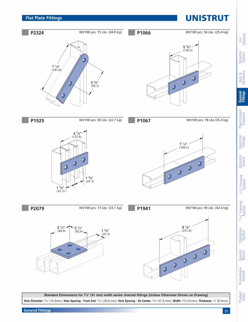
91General Fittings
Standard Dimensions for 15⁄8" (41 mm) width series channel fittings (Unless Otherwise Shown on Drawing)
Hole Diameter: 9⁄16" (14.3mm); Hole Spacing - From End: 13⁄16" (20.6 mm); Hole Spacing - On Center: 17⁄8" (47.6 mm); Width: 15⁄8"(41mm); Thickness: 1⁄4" (6.4mm)
15 ⁄8"
Chan
nel
Nuts
&Ha
rdw
are
Gene
ral
Fitti
ngs
Pipe
/Con
duit
Supp
orts
Elec
trica
lFi
tting
sCo
ncre
teIn
serts
11 ⁄4" F
ram
ing
Syst
em13
⁄16" F
ram
ing
Syst
emFi
berg
lass
Syst
emSp
ecia
lM
etal
sTe
lest
rut
Syst
emPr
imeA
ngle
Syst
emPr
oduc
tIn
dex
P1067P1925
P1066P2324
Flat Plate Fittings
Wt/100 pcs: 75 Lbs (34.0 kg)
Wt/100 pcs: 78 Lbs (35.4 kg)
Wt/100 pcs: 56 Lbs (25.4 kg)
7 1⁄4"(184.2)
9 1⁄8"(231.8)
5 3⁄8"(136.5)
3 1⁄2"(88.9) (82.6)
3 1⁄4"1 5⁄8"(41.3)
7 1⁄8"(181.0)
(92.1)3 5⁄8"
4 7⁄8"(123.8)
(41.3)1 5⁄8"
(41.3)1 5⁄8"
P1941 Wt/100 pcs: 94 Lbs (42.6 kg)P2079 Wt/100 pcs: 73 Lbs (33.1 kg)
Wt/100 pcs: 50 Lbs (22.7 kg)

92 General Fittings
Standard Dimensions for 15⁄8" (41 mm) width series channel fittings (Unless Otherwise Shown on Drawing)
Hole Diameter: 9⁄16" (14.3mm); Hole Spacing - From End: 13⁄16" (20.6 mm); Hole Spacing - On Center: 17⁄8" (47.6 mm); Width: 15⁄8"(41mm); Thickness: 1⁄4" (6.4mm)
®
15 ⁄8"
Chan
nel
Nuts
&Ha
rdw
are
Gene
ral
Fitti
ngs
Pipe
/Con
duit
Supp
orts
Elec
trica
lFi
tting
sCo
ncre
teIn
serts
11 ⁄4" F
ram
ing
Syst
em13
⁄16" F
ram
ing
Syst
emFi
berg
lass
Syst
emSp
ecia
lM
etal
sTe
lest
rut
Syst
emPr
imeA
ngle
Syst
emPr
oduc
tIn
dex
P1036 P1380 A
P1380P1334
P1031P1873
Flat Plate Fittings
Wt/100 pcs: 58 Lbs (26.3 kg) Wt/100 pcs: 80 Lbs (36.3 kg)
Wt/100 pcs: 70 Lbs (31.8 kg) Wt/100 pcs: 105 Lbs (47.6 kg)
Wt/100 pcs: 150 Lbs (68.0 kg) Wt/100 pcs: 80 Lbs (36.3 kg)
(88.9)3 1⁄2"
3 1⁄2"(88.9)
(88.9)3 1⁄2"
3 1⁄2"(88.9)
(136.5)5 3⁄8"
5 3⁄8"(136.5)
(88.9)3 1⁄2"
5 3⁄8"(136.5)
5 3⁄8"(136.5)
3 1⁄2"(88.9)
(136.5)5 3⁄8"
3 1⁄2"(88.9)

93General Fittings
Standard Dimensions for 15⁄8" (41 mm) width series channel fittings (Unless Otherwise Shown on Drawing)
Hole Diameter: 9⁄16" (14.3mm); Hole Spacing - From End: 13⁄16" (20.6 mm); Hole Spacing - On Center: 17⁄8" (47.6 mm); Width: 15⁄8"(41mm); Thickness: 1⁄4" (6.4mm)
15 ⁄8"
Chan
nel
Nuts
&Ha
rdw
are
Gene
ral
Fitti
ngs
Pipe
/Con
duit
Supp
orts
Elec
trica
lFi
tting
sCo
ncre
teIn
serts
11 ⁄4" F
ram
ing
Syst
em13
⁄16" F
ram
ing
Syst
emFi
berg
lass
Syst
emSp
ecia
lM
etal
sTe
lest
rut
Syst
emPr
imeA
ngle
Syst
emPr
oduc
tIn
dex
P1028 P1356
P1726P1358
P1950P1953
Flat Plate Fittings
Wt/100 pcs: 105 Lbs (47.6 kg) Wt/100 pcs: 70 Lbs (31.8 kg)
Wt/100 pcs: 105 Lbs (47.6 kg) Wt/100 pcs: 148 Lbs (67.1 kg)
Wt/100 pcs: 240 Lbs (108.9 kg)Wt/100 pcs: 176 Lbs (79.8 kg)
5 3⁄8"(136.5)
(88.9)3 1⁄2"
9 1⁄8"
3 1⁄2"(88.9)
(231.8)
(136.5)5 3⁄8"
5 3⁄8"(136.5)
3 1⁄2"(88.9)
3 1⁄2"(88.9)
(136.5)5 3⁄8"
5 3⁄8"(136.5)
5 3⁄8"(136.5)
9 1⁄8"(231.8)

94 General Fittings
Standard Dimensions for 15⁄8" (41 mm) width series channel fittings (Unless Otherwise Shown on Drawing)
Hole Diameter: 9⁄16" (14.3mm); Hole Spacing - From End: 13⁄16" (20.6 mm); Hole Spacing - On Center: 17⁄8" (47.6 mm); Width: 15⁄8"(41mm); Thickness: 1⁄4" (6.4mm)
®
15 ⁄8"
Chan
nel
Nuts
&Ha
rdw
are
Gene
ral
Fitti
ngs
Pipe
/Con
duit
Supp
orts
Elec
trica
lFi
tting
sCo
ncre
teIn
serts
11 ⁄4" F
ram
ing
Syst
em13
⁄16" F
ram
ing
Syst
emFi
berg
lass
Syst
emSp
ecia
lM
etal
sTe
lest
rut
Syst
emPr
imeA
ngle
Syst
emPr
oduc
tIn
dex
Flat Plate & Ninety Degree Angle Fittings
P1026 P1723
P1281, P1282, P1283P1068
P2626
Wt/100 pcs: 38 Lbs (17.2 kg) Wt/100 pcs: 34 Lbs (15.4 kg)
Wt/100 pcs: 38 Lbs (17.2 kg)
Wt/100 pcs: 40 Lbs (18.1 kg)
2 1⁄8"(54.0)
(54.0)2 1⁄8"
1 7⁄8"(47.6)
(50.8)2"
1 5⁄8"(41.3)
2 1⁄4"(57.2)
1 7⁄8"(47.6)
A
Tapped5⁄16" - 18 Thd.
1 5⁄8"(41.3)
(41.3)1 5⁄8"
(47.6)1 7⁄8"
Part “A” Wt/100 pcsNumber In (mm) Lbs (kg)P1281 3 49
76.2 22.2P1282 31/2 54
88.9 24.5P1283 4 61
101.6 27.7
P1962 Wt/100 pcs: 112 Lbs (50.8 kg)
41⁄2"(114.3)
27⁄8"(73.0)
15⁄8"(41.3)

95General Fittings
Standard Dimensions for 15⁄8" (41 mm) width series channel fittings (Unless Otherwise Shown on Drawing)
Hole Diameter: 9⁄16" (14.3mm); Hole Spacing - From End: 13⁄16" (20.6 mm); Hole Spacing - On Center: 17⁄8" (47.6 mm); Width: 15⁄8"(41mm); Thickness: 1⁄4" (6.4mm)
15 ⁄8"
Chan
nel
Nuts
&Ha
rdw
are
Gene
ral
Fitti
ngs
Pipe
/Con
duit
Supp
orts
Elec
trica
lFi
tting
sCo
ncre
teIn
serts
11 ⁄4" F
ram
ing
Syst
em13
⁄16" F
ram
ing
Syst
emFi
berg
lass
Syst
emSp
ecia
lM
etal
sTe
lest
rut
Syst
emPr
imeA
ngle
Syst
emPr
oduc
tIn
dex
Ninety Degree Angle Fittings
P1315
P1538A thru P1538D P1750
P1747P1498, P1499
P1458Wt/100 pcs: 45 Lbs (20.4 kg)
1 7⁄8"(47.6)
1 7⁄8"(47.6)
3⁄4"(19.1)
1⁄2" - 13 Stud
Wt/100 pcs: 66 Lbs (29.9 kg)
Wt/100 pcs: 58 Lbs (26.3 kg)
Wt/100 pcs: 38 Lbs (17.2 kg)
A
1 7⁄8"(47.6)
B
A
(63.5)2 1⁄2"
1 7⁄8"(47.6)
(57.2)2 1⁄4"
3 1⁄2"(88.9)
(98.4)3 7⁄8"
1 1⁄2"(38.1)
(66.7)2 5⁄8"
1 5⁄16"(33.3)
2 5⁄8"(66.7)
1 5⁄8"(41.3)
(33.3)1 5⁄16"
(38.1)1 1⁄2"
Part “A” Wt/100 pcsNumber In (mm) Lbs (kg)P1538A 37⁄8 61
98.4 27.7P1538B 57⁄8 84
149.2 38.1P1538C 77⁄8 107
200.0 48.5P1538D 97⁄8 130
250.8 59.0
Part “A” “B” Wt/100 pcsNumber In (mm) In (mm) Lbs (kg)
P1498 47⁄8 21⁄2 65123.8 63.5 29.5
P1499 67⁄8 41⁄2 85174.6 114.3 38.6

96 General Fittings
Standard Dimensions for 15⁄8" (41 mm) width series channel fittings (Unless Otherwise Shown on Drawing)
Hole Diameter: 9⁄16" (14.3mm); Hole Spacing - From End: 13⁄16" (20.6 mm); Hole Spacing - On Center: 17⁄8" (47.6 mm); Width: 15⁄8"(41mm); Thickness: 1⁄4" (6.4mm)
®
15 ⁄8"
Chan
nel
Nuts
&Ha
rdw
are
Gene
ral
Fitti
ngs
Pipe
/Con
duit
Supp
orts
Elec
trica
lFi
tting
sCo
ncre
teIn
serts
11 ⁄4" F
ram
ing
Syst
em13
⁄16" F
ram
ing
Syst
emFi
berg
lass
Syst
emSp
ecia
lM
etal
sTe
lest
rut
Syst
emPr
imeA
ngle
Syst
emPr
oduc
tIn
dex
P1346 P1325
P1823P1822
P1821
Ninety Degree Angle Fittings
Wt/100 pcs: 58 Lbs (26.3 kg) Wt/100 pcs: 78 Lbs (35.4 kg)
Wt/100 pcs: 55 Lbs (24.9 kg) Wt/100 pcs: 55 Lbs (24.9 kg)
Wt/100 pcs: 71 Lbs (32.2 kg)
3 7⁄8"(98.4)
(47.6)1 7⁄8"
(82.6)3 1⁄4"1 7⁄8"
(47.6)
(50.8)2"
(41.3)1 5⁄8"
(82.6)3 1⁄4"
(41.3)1 5⁄8" 1 7⁄8"
(47.6)
2"(50.8)
4 1⁄8"(104.8)
(88.9)3 1⁄2"
(36.5)1 7⁄16"
(50.8)2"
(123.8)4 7⁄8"
(41.3)1 5⁄8"
P1326 Wt/100 pcs: 58 Lbs (26.3 kg)
4 1⁄8"(104.8)
1 5⁄8"(41.3)
(36.5)1 7⁄16"

97General Fittings
Standard Dimensions for 15⁄8" (41 mm) width series channel fittings (Unless Otherwise Shown on Drawing)
Hole Diameter: 9⁄16" (14.3mm); Hole Spacing - From End: 13⁄16" (20.6 mm); Hole Spacing - On Center: 17⁄8" (47.6 mm); Width: 15⁄8"(41mm); Thickness: 1⁄4" (6.4mm)
15 ⁄8"
Chan
nel
Nuts
&Ha
rdw
are
Gene
ral
Fitti
ngs
Pipe
/Con
duit
Supp
orts
Elec
trica
lFi
tting
sCo
ncre
teIn
serts
11 ⁄4" F
ram
ing
Syst
em13
⁄16" F
ram
ing
Syst
emFi
berg
lass
Syst
emSp
ecia
lM
etal
sTe
lest
rut
Syst
emPr
imeA
ngle
Syst
emPr
oduc
tIn
dex
P1033 P1037
P1034P1038
P1035
Ninety Degree Angle Fittings
Wt/100 pcs: 58 Lbs (26.3 kg)Wt/100 pcs: 80 Lbs (36.3 kg)
Wt/100 pcs: 58 Lbs (26.3 kg) Wt/100 pcs: 80 Lbs (36.3 kg)
Wt/100 pcs: 80 Lbs (36.3 kg)
2"(50.8) 3 1⁄2"
(88.9)
(50.8)2"
(136.5)5 3⁄8"
2"(50.8)3 1⁄2"
(88.9)
(88.9)3 1⁄2"
3 1⁄2"(88.9)
2"(50.8)
(88.9)3 1⁄2"
3 1⁄2"(88.9)
2"(50.8)
P1029 Wt/100 pcs: 105 Lbs (47.6 kg)
(50.8)2"
5 3⁄8"(136.5)
(88.9)3 1⁄2"

98 General Fittings
Standard Dimensions for 15⁄8" (41 mm) width series channel fittings (Unless Otherwise Shown on Drawing)
Hole Diameter: 9⁄16" (14.3mm); Hole Spacing - From End: 13⁄16" (20.6 mm); Hole Spacing - On Center: 17⁄8" (47.6 mm); Width: 15⁄8"(41mm); Thickness: 1⁄4" (6.4mm)
®
15 ⁄8"
Chan
nel
Nuts
&Ha
rdw
are
Gene
ral
Fitti
ngs
Pipe
/Con
duit
Supp
orts
Elec
trica
lFi
tting
sCo
ncre
teIn
serts
11 ⁄4" F
ram
ing
Syst
em13
⁄16" F
ram
ing
Syst
emFi
berg
lass
Syst
emSp
ecia
lM
etal
sTe
lest
rut
Syst
emPr
imeA
ngle
Syst
emPr
oduc
tIn
dex
P1357 P1359
P1382P1381
P1291P1290
Ninety Degree Angle Fittings
Wt/100 pcs: 101 Lbs (45.8 kg)
Wt/100 pcs: 70 Lbs (31.8 kg) Wt/100 pcs: 105 Lbs (47.6 kg)
Wt/100 pcs: 105 Lbs (47.6 kg)Wt/100 pcs: 105 Lbs (47.6 kg)
Wt/100 pcs: 101 Lbs (45.8 kg)
(104.8)4 1⁄8"
1 7⁄16"(36.5)
1 5⁄8"(41.3)
(88.9)3 1⁄2"
(104.8)4 1⁄8"
1 7⁄16"(36.5)
1 5⁄8"(41.3)
(88.9)3 1⁄2"
1 7⁄8"(47.6)
3 7⁄8"(98.4)
3 1⁄2"(88.9)
1 7⁄8"(47.6)
3 7⁄8"(98.4)
(88.9)3 1⁄2"
(88.9)3 1⁄2"
(57.2)2 1⁄4"
1 5⁄8"(41.3)
(41.3)1 5⁄8"
4 1⁄8"(104.8)
3 1⁄2"(88.9)

99General Fittings
Standard Dimensions for 15⁄8" (41 mm) width series channel fittings (Unless Otherwise Shown on Drawing)
Hole Diameter: 9⁄16" (14.3mm); Hole Spacing - From End: 13⁄16" (20.6 mm); Hole Spacing - On Center: 17⁄8" (47.6 mm); Width: 15⁄8"(41mm); Thickness: 1⁄4" (6.4mm)
15 ⁄8"
Chan
nel
Nuts
&Ha
rdw
are
Gene
ral
Fitti
ngs
Pipe
/Con
duit
Supp
orts
Elec
trica
lFi
tting
sCo
ncre
teIn
serts
11 ⁄4" F
ram
ing
Syst
em13
⁄16" F
ram
ing
Syst
emFi
berg
lass
Syst
emSp
ecia
lM
etal
sTe
lest
rut
Syst
emPr
imeA
ngle
Syst
emPr
oduc
tIn
dex
P1579 P1727
P2235P1728
P1713
Ninety Degree Angle Fittings
Wt/100 pcs: 97 Lbs (44.0 kg)
Wt/100 pcs: 103 Lbs (46.7 kg) Wt/100 pcs: 154 Lbs (69.9 kg)
Wt/100 pcs: 154 Lbs (69.9 kg) Wt/100 pcs: 135 Lbs (61.2 kg)
(63.5)2 1⁄2"(12.7)
1⁄2"
(88.9)3 1⁄2"
3 1⁄2"(88.9)
2 1⁄4"(57.2)
1⁄2"(12.7)
(136.5)5 3⁄8"
(30.2)1 3⁄16"
(98.4)3 7⁄8"1 7⁄8"
(47.6)
4 1⁄8"(104.8)
3 1⁄2"(88.9) (88.9)
3 1⁄2"
(104.8)4 1⁄8"
(41.3)1 5⁄8"
(36.5)1 7⁄16"
(136.5)5 3⁄8"
3 1⁄2"(88.9)
(57.2)2 1⁄4"
(88.9)3 1⁄2"
P1934 Wt/100 pcs: 75 Lbs (34.0 kg)
(41.3)1 5⁄8"
(82.6)3 1⁄4"
(41.3)1 5⁄8"
(57.2)2 1⁄4"

100 General Fittings
Standard Dimensions for 15⁄8" (41 mm) width series channel fittings (Unless Otherwise Shown on Drawing)
Hole Diameter: 9⁄16" (14.3mm); Hole Spacing - From End: 13⁄16" (20.6 mm); Hole Spacing - On Center: 17⁄8" (47.6 mm); Width: 15⁄8"(41mm); Thickness: 1⁄4" (6.4mm)
®
15 ⁄8"
Chan
nel
Nuts
&Ha
rdw
are
Gene
ral
Fitti
ngs
Pipe
/Con
duit
Supp
orts
Elec
trica
lFi
tting
sCo
ncre
teIn
serts
11 ⁄4" F
ram
ing
Syst
em13
⁄16" F
ram
ing
Syst
emFi
berg
lass
Syst
emSp
ecia
lM
etal
sTe
lest
rut
Syst
emPr
imeA
ngle
Syst
emPr
oduc
tIn
dex
P1956 P1957
P2484WP2484 Wt/100 pcs: 134 Lbs (60.8 kg) Wt/100 pcs: 134 Lbs (60.8 kg)
Wt/100 pcs: 230 Lbs (104.3 kg) Wt/100 pcs: 230 Lbs (104.3 kg)
13⁄16"(20.6)
(101.6)4"
(22.2)7⁄8"
1 9⁄16"(39.7)
(101.6)4"
(20.6)13⁄16"
(136.5)5 3⁄8"(88.9)
3 1⁄2"
(36.5)1 7⁄16"
4 1⁄8"(104.8)
Continuous Weld
(20.6)
13⁄16"
(136.5)5 3⁄8"
(88.9)3 1⁄2"
(36.5)1 7⁄16"
4 1⁄8"(104.8) Continuous
Weld
13⁄16"(20.6)
(101.6)4"
(22.2)7⁄8"
1 9⁄16"(39.7)
(101.6)4"
Continuous Weld
Ninety Degree Angle Fittings
P1130, P1131
(47.6)1 7⁄8"
(95.3)3 3⁄4"
A
(38.1)1 1⁄2"
1 1⁄2"(38.1)
B
Part “A” “B” Wt/100 pcsNumber In (mm) In (mm) Lbs (kg)
P1130 65⁄8 4 190168.3 101.6 86.2
P1131 85⁄8 6 242219.1 152.4 109.8

101General Fittings
Standard Dimensions for 15⁄8" (41 mm) width series channel fittings (Unless Otherwise Shown on Drawing)
Hole Diameter: 9⁄16" (14.3mm); Hole Spacing - From End: 13⁄16" (20.6 mm); Hole Spacing - On Center: 17⁄8" (47.6 mm); Width: 15⁄8"(41mm); Thickness: 1⁄4" (6.4mm)
15 ⁄8"
Chan
nel
Nuts
&Ha
rdw
are
Gene
ral
Fitti
ngs
Pipe
/Con
duit
Supp
orts
Elec
trica
lFi
tting
sCo
ncre
teIn
serts
11 ⁄4" F
ram
ing
Syst
em13
⁄16" F
ram
ing
Syst
emFi
berg
lass
Syst
emSp
ecia
lM
etal
sTe
lest
rut
Syst
emPr
imeA
ngle
Syst
emPr
oduc
tIn
dex
P1546, P2094 thru P2100
Angular Fittings
P2101 thru P2104 Wt/100 pcs: 58 Lbs (26.3 kg)
P1186, P2105 thru P2110 Wt/100 pcs: 58 Lbs (26.3 kg)
Wt/100 pcs: 58 Lbs (26.3 kg)
(63.5)2 1⁄2"
A
B
B
(27.0)1 1⁄16"
1 1⁄16"
(52.4)2 1⁄16"
A(27.0)
(27.0)1 1⁄16"
(27.0)1 1⁄16"
B
C
A
Part “A” “B” “C”Number Degree (rad) In (mm) In (mm)
P2094 821⁄2° 39⁄16 111⁄16
1.44 90.5 42.9P2095 75° 39⁄16 111⁄16
1.31 90.5 42.9P2096 671⁄2° 31⁄2 13⁄4
1.18 88.9 44.5P2097 60° 33⁄8 17⁄8
1.05 85.7 47.6P2098 521⁄2° 31⁄4 21⁄16
0.92 82.6 52.4P1546 45° 3 25⁄16
0.79 76.2 58.7P2099 371⁄2° 31⁄2 113⁄16
0.65 88.9 46.0P2100 371⁄2° 211⁄16 25⁄8
0.65 68.3 66.7
Part “A” “B”Number Degree (rad) In (mm)P2101 30° 31⁄4
0.52 82.6P2102 221⁄2° 35⁄16
0.39 84.1P2103 15° 35⁄16
0.26 84.1P2104 71⁄2° 35⁄16
0.13 84.1
Part “A” “B”Number Degree (rad) In (mm)P2105 821⁄2° 33⁄16
1.44 81.0P2106 75° 33⁄16
1.31 81.0P2107 671⁄2° 31⁄8
1.18 79.4P2108 60° 31⁄8
1.05 79.4P2109 521⁄2° 31⁄16
0.92 77.8P1186 45° 31⁄8
0.79 79.4P2110 371⁄2° 3
0.65 76.2
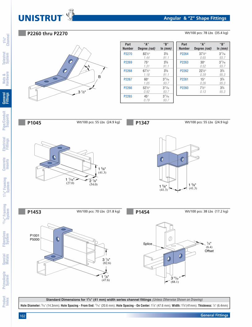
102 General Fittings
Standard Dimensions for 15⁄8" (41 mm) width series channel fittings (Unless Otherwise Shown on Drawing)
Hole Diameter: 9⁄16" (14.3mm); Hole Spacing - From End: 13⁄16" (20.6 mm); Hole Spacing - On Center: 17⁄8" (47.6 mm); Width: 15⁄8"(41mm); Thickness: 1⁄4" (6.4mm)
®
15 ⁄8"
Chan
nel
Nuts
&Ha
rdw
are
Gene
ral
Fitti
ngs
Pipe
/Con
duit
Supp
orts
Elec
trica
lFi
tting
sCo
ncre
teIn
serts
11 ⁄4" F
ram
ing
Syst
em13
⁄16" F
ram
ing
Syst
emFi
berg
lass
Syst
emSp
ecia
lM
etal
sTe
lest
rut
Syst
emPr
imeA
ngle
Syst
emPr
oduc
tIn
dex
P1045 P1347
P1454P1453
Angular & “Z” Shape Fittings
Wt/100 pcs: 55 Lbs (24.9 kg)
(41.3)1 5⁄8"
(41.3)1 5⁄8"
Wt/100 pcs: 38 Lbs (17.2 kg)
Wt/100 pcs: 55 Lbs (24.9 kg)
Wt/100 pcs: 70 Lbs (31.8 kg)
(27.0)1 1⁄16"
(54.0)2 1⁄8"
1 5⁄8"(41.3)
(82.6)3 1⁄4"
(47.6)1 7⁄8"
P1001P5000
(6.4)Offset
1⁄4"
3 "(88.1)
32
Splice
15
A
B
3 1⁄2"
P2260 thru P2270 Wt/100 pcs: 78 Lbs (35.4 kg)
Part “A” “B”Number Degree (rad) In (mm)
P2270 821⁄2° 35⁄81.44 91.1
P2269 75° 35⁄81.31 91.1
P2268 671⁄2° 35⁄81.18 91.1
P2267 60° 311⁄16
1.05 93.7P2266 521⁄2° 311⁄16
0.92 93.7P2265 45° 311⁄16
0.79 93.7
Part “A” “B”Number Degree (rad) In (mm)
P2264 371⁄2° 311⁄16
0.65 93.7P2263 30° 311⁄16
0.52 93.7P2262 221⁄2° 33⁄4
0.39 95.3P2261 15° 33⁄4
0.26 95.3P2260 71⁄2° 33⁄4
0.13 95.3

103General Fittings
Standard Dimensions for 15⁄8" (41 mm) width series channel fittings (Unless Otherwise Shown on Drawing)
Hole Diameter: 9⁄16" (14.3mm); Hole Spacing - From End: 13⁄16" (20.6 mm); Hole Spacing - On Center: 17⁄8" (47.6 mm); Width: 15⁄8"(41mm); Thickness: 1⁄4" (6.4mm)
15 ⁄8"
Chan
nel
Nuts
&Ha
rdw
are
Gene
ral
Fitti
ngs
Pipe
/Con
duit
Supp
orts
Elec
trica
lFi
tting
sCo
ncre
teIn
serts
11 ⁄4" F
ram
ing
Syst
em13
⁄16" F
ram
ing
Syst
emFi
berg
lass
Syst
emSp
ecia
lM
etal
sTe
lest
rut
Syst
emPr
imeA
ngle
Syst
emPr
oduc
tIn
dex
P1734 P1736
P5560P2360
“Z” Shape Fittings
Wt/100 pcs: 9 Lbs (4.1 kg) Wt/100 pcs: 11 Lbs (5.0 kg)
Wt/100 pcs: 70 Lbs (31.8 kg) Wt/100 pcs: 70 Lbs (31.8 Kg)
(47.6) (47.6 )1 7⁄8"
(88.9)3 1⁄2"3 1⁄2"
(88.9)
1 7⁄8"
(41.3)1 5⁄8"
(47.6)1 7⁄8"1 7⁄8"
(47.6)
1 5⁄8"(41.3)
Tapped5⁄16" - 18 Thd.
(20.6)13⁄16"
9⁄32" (7.1) Hole1⁄8" (3.2) Thick
P1000P1100P2000
(20.6)
13⁄16"
P5500
9⁄32" (7.1) Hole1⁄8" (3.2) Thick
P1730P1479A thru P1479E Wt/100 pcs: 54 Lbs (24.5 kg)
Tapped5⁄16" - 18 Thd.
(41.3)1 5⁄8"
1 7⁄8"(41.3)1 5⁄8"
(47.6)
A
1 5⁄8"(41.3)
Part “A” Wt/100 pcsNumber In (mm) Lbs (kg)P1479A 4 81
101.6 36.7P1479B 5 92
127.0 41.7P1479C 6 104
152.4 47.2P1479D 7 115
177.8 52.2P1479E 8 127
203.2 57.6
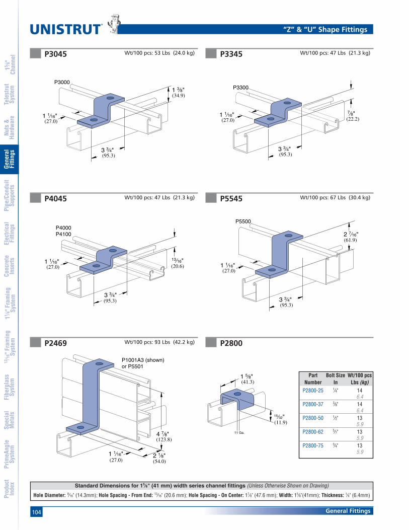
104 General Fittings
Standard Dimensions for 15⁄8" (41 mm) width series channel fittings (Unless Otherwise Shown on Drawing)
Hole Diameter: 9⁄16" (14.3mm); Hole Spacing - From End: 13⁄16" (20.6 mm); Hole Spacing - On Center: 17⁄8" (47.6 mm); Width: 15⁄8"(41mm); Thickness: 1⁄4" (6.4mm)
®
15 ⁄8"
Chan
nel
Nuts
&Ha
rdw
are
Gene
ral
Fitti
ngs
Pipe
/Con
duit
Supp
orts
Elec
trica
lFi
tting
sCo
ncre
teIn
serts
11 ⁄4" F
ram
ing
Syst
em13
⁄16" F
ram
ing
Syst
emFi
berg
lass
Syst
emSp
ecia
lM
etal
sTe
lest
rut
Syst
emPr
imeA
ngle
Syst
emPr
oduc
tIn
dex
P4045 P5545
P2800P2469
“Z” & “U” Shape Fittings
Wt/100 pcs: 47 Lbs (21.3 kg) Wt/100 pcs: 67 Lbs (30.4 kg)
Wt/100 pcs: 93 Lbs (42.2 kg)
(20.6)13⁄16"
(27.0)1 1⁄16"
(95.3)3 3⁄4"
P4000P4100
(61.9)2 7⁄16"
P5500
1 1⁄16"(27.0)
3 3⁄4"(95.3)
(27.0)1 1⁄16"
(54.0)2 1⁄8"
(123.8)4 7⁄8"
P1001A3 (shown)or P5501
P3345P3045 Wt/100 pcs: 47 Lbs (21.3 kg)Wt/100 pcs: 53 Lbs (24.0 kg)
1 1⁄16"(27.0) (22.2)
7⁄8"
3 3⁄4"(95.3)
P3300
(34.9)1 3⁄8"
P3000
1 1⁄16"
3 3⁄4"(95.3)
(27.0)
Part Bolt Size Wt/100 pcsNumber In Lbs (kg)
P2800-25 1⁄4" 146.4
P2800-37 3⁄8" 146.4
P2800-50 1⁄2" 135.9
P2800-62 5⁄7" 135.9
P2800-75 3⁄4" 135.9
15⁄32"
11 Ga.
1 5⁄8"(41.3)
(11.9)

105General Fittings
Standard Dimensions for 15⁄8" (41 mm) width series channel fittings (Unless Otherwise Shown on Drawing)
Hole Diameter: 9⁄16" (14.3mm); Hole Spacing - From End: 13⁄16" (20.6 mm); Hole Spacing - On Center: 17⁄8" (47.6 mm); Width: 15⁄8"(41mm); Thickness: 1⁄4" (6.4mm)
15 ⁄8"
Chan
nel
Nuts
&Ha
rdw
are
Gene
ral
Fitti
ngs
Pipe
/Con
duit
Supp
orts
Elec
trica
lFi
tting
sCo
ncre
teIn
serts
11 ⁄4" F
ram
ing
Syst
em13
⁄16" F
ram
ing
Syst
emFi
berg
lass
Syst
emSp
ecia
lM
etal
sTe
lest
rut
Syst
emPr
imeA
ngle
Syst
emPr
oduc
tIn
dex
P1376 P4376
P4376AP1376A
“U” Shape Fittings
Wt/100 pcs: 128 Lbs (58.1 kg) Wt/100 pcs: 85 Lbs (38.6 kg)
Wt/100 pcs: 197 Lbs (89.4 kg) Wt/100 pcs: 130 Lbs (59.0 kg)
5 3⁄8"(136.5)
3 1⁄2"(88.9)
P3300P4000P4100
5 3⁄8"(136.5)
P3300P4000P4100
3 1⁄2"(88.9)
P1363A thru P1363E
A
1 7⁄8"(47.6)
Part “A” Wt/100 pcsNumber In (mm) Lbs (kg)P1363A 4 78
101.6 35.4P1363B 5 89
127.0 40.4P1363C 6 101
152.4 45.8P1363D 7 112
177.8 50.8P1363E 8 124
203.2 56.2
P1320 Wt/100 pcs: 63 Lbs (28.6 kg)
1 7⁄8"(47.6)
(19.1)
3⁄4"
(54.8)2 5⁄32"
1⁄2" - 13 Thd.

106 General Fittings
Standard Dimensions for 15⁄8" (41 mm) width series channel fittings (Unless Otherwise Shown on Drawing)
Hole Diameter: 9⁄16" (14.3mm); Hole Spacing - From End: 13⁄16" (20.6 mm); Hole Spacing - On Center: 17⁄8" (47.6 mm); Width: 15⁄8"(41mm); Thickness: 1⁄4" (6.4mm)
®
15 ⁄8"
Chan
nel
Nuts
&Ha
rdw
are
Gene
ral
Fitti
ngs
Pipe
/Con
duit
Supp
orts
Elec
trica
lFi
tting
sCo
ncre
teIn
serts
11 ⁄4" F
ram
ing
Syst
em13
⁄16" F
ram
ing
Syst
emFi
berg
lass
Syst
emSp
ecia
lM
etal
sTe
lest
rut
Syst
emPr
imeA
ngle
Syst
emPr
oduc
tIn
dex
P1455 Wt/100 pcs: 58 Lbs (26.3 kg)
5 5⁄16"(134.9)
1⁄4" (6.4) Offset
1⁄4" (6.4) Plate
P1047 P3047
P4047
“U” Shape Fittings
Wt/100 pcs: 88 Lbs (39.9 kg) Wt/100 pcs: 84 Lbs (38.1 kg)
1 "
(136.5)5 3⁄8"
(34.9)1 3⁄8"
2132
P3000
(42.1)
Wt/100 pcs: 71 Lbs (32.2 kg)
(136.5)5 3⁄8"
(20.6)13⁄16"
1 "(42.1)
2132
P3300P4000P4100
(41.3)1 5⁄8"
(136.5)5 3⁄8"
1 "(42.1)
2132
P1377, P4377, P5077, P5577
7 1⁄4"
A
(184.2)
Part For Use Wt/100 pcsNumber With Lbs (kg)P1377 P1000, P1100, P2000 265
120.2P4377 P3300, P4000, P4100 176
79.8P5077 P5000 390
176.9P5577 P5500 310
140.6
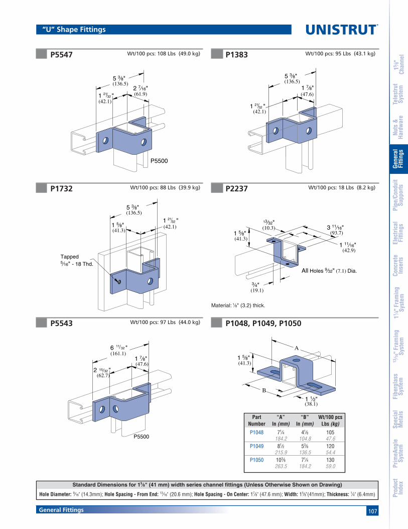
107General Fittings
Standard Dimensions for 15⁄8" (41 mm) width series channel fittings (Unless Otherwise Shown on Drawing)
Hole Diameter: 9⁄16" (14.3mm); Hole Spacing - From End: 13⁄16" (20.6 mm); Hole Spacing - On Center: 17⁄8" (47.6 mm); Width: 15⁄8"(41mm); Thickness: 1⁄4" (6.4mm)
15 ⁄8"
Chan
nel
Nuts
&Ha
rdw
are
Gene
ral
Fitti
ngs
Pipe
/Con
duit
Supp
orts
Elec
trica
lFi
tting
sCo
ncre
teIn
serts
11 ⁄4" F
ram
ing
Syst
em13
⁄16" F
ram
ing
Syst
emFi
berg
lass
Syst
emSp
ecia
lM
etal
sTe
lest
rut
Syst
emPr
imeA
ngle
Syst
emPr
oduc
tIn
dex
P5547
P1732
P1383
P5543
P2237
“U” Shape Fittings
Wt/100 pcs: 95 Lbs (43.1 kg)
Wt/100 pcs: 88 Lbs (39.9 kg) Wt/100 pcs: 18 Lbs (8.2 kg)
Wt/100 pcs: 97 Lbs (44.0 kg)
5 3⁄8"(136.5)
(42.1)1 "
1 7⁄8"(47.6)
2132
(41.3)1 5⁄8"
5 3⁄8"(136.5)
Tapped5⁄16" - 18 Thd.
(42.1)1 "21
32
(62.7)2 "
(161.1)1 7⁄8"(47.6)
15 32
6 "1132
P5500
Material: 1⁄8" (3.2) thick.
(41.3)1 5⁄8"
(19.1)3⁄4"
(10.3)(93.7)
3 11⁄16"
(42.9)1 11⁄16"
All Holes 9⁄32" (7.1) Dia.
13⁄32"
Wt/100 pcs: 108 Lbs (49.0 kg)
2 7⁄16"(61.9)
(136.5)5 3⁄8"
1 "(42.1)
2132
P5500
P1048, P1049, P1050
1 5⁄8"(41.3)
B
1 1⁄2"(38.1)
A
Part “A” “B” Wt/100 pcsNumber In (mm) In (mm) Lbs (kg)
P1048 71⁄4 41⁄8 105184.2 104.8 47.6
P1049 81⁄2 53⁄8 120215.9 136.5 54.4
P1050 103⁄8 71⁄4 130263.5 184.2 59.0
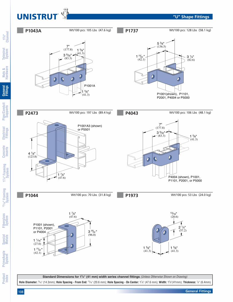
108 General Fittings
Standard Dimensions for 15⁄8" (41 mm) width series channel fittings (Unless Otherwise Shown on Drawing)
Hole Diameter: 9⁄16" (14.3mm); Hole Spacing - From End: 13⁄16" (20.6 mm); Hole Spacing - On Center: 17⁄8" (47.6 mm); Width: 15⁄8"(41mm); Thickness: 1⁄4" (6.4mm)
®
15 ⁄8"
Chan
nel
Nuts
&Ha
rdw
are
Gene
ral
Fitti
ngs
Pipe
/Con
duit
Supp
orts
Elec
trica
lFi
tting
sCo
ncre
teIn
serts
11 ⁄4" F
ram
ing
Syst
em13
⁄16" F
ram
ing
Syst
emFi
berg
lass
Syst
emSp
ecia
lM
etal
sTe
lest
rut
Syst
emPr
imeA
ngle
Syst
emPr
oduc
tIn
dex
P1973P1044
1 5⁄8"(41.3)
1 5⁄8"(41.3)
13⁄16"(20.6)
2 1⁄4"(57.2)
(96.0)
1 7⁄8"(47.6)
1 1⁄16"(27.0)
3 "2532
1 "(42.1)
2132
P1001 (shown),P1101, P2001or P4004
Wt/100 pcs: 70 Lbs (31.8 kg) Wt/100 pcs: 53 Lbs (24.0 kg)
P1043A P1737
P4043P2473
“U” Shape Fittings
Wt/100 pcs: 128 Lbs (58.1 kg)
Wt/100 pcs: 197 Lbs (89.4 kg)
Wt/100 pcs: 105 Lbs (47.6 kg)
Wt/100 pcs: 106 Lbs (48.1 kg)
7"(177.8)
(83.3)3 9⁄32"
1 5⁄8"(41.3)
(41.3)1 5⁄8"
P1001A
(47.6)1 7⁄8"
4 7⁄8"(123.8)
P1001A3 (shown)or P5501
(136.5)5 3⁄8"
1 "2132
P1001(shown), P1101,P2001, P4004 or P5000
(82.6)3 1⁄4"
(42.1)
7"(177.8)
3 9⁄32"(83.3)
(41.3)1 5⁄8"
P4004 (shown), P1001, P1101, P2001, or P5000
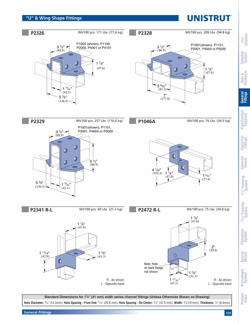
109General Fittings
Standard Dimensions for 15⁄8" (41 mm) width series channel fittings (Unless Otherwise Shown on Drawing)
Hole Diameter: 9⁄16" (14.3mm); Hole Spacing - From End: 13⁄16" (20.6 mm); Hole Spacing - On Center: 17⁄8" (47.6 mm); Width: 15⁄8"(41mm); Thickness: 1⁄4" (6.4mm)
15 ⁄8"
Chan
nel
Nuts
&Ha
rdw
are
Gene
ral
Fitti
ngs
Pipe
/Con
duit
Supp
orts
Elec
trica
lFi
tting
sCo
ncre
teIn
serts
11 ⁄4" F
ram
ing
Syst
em13
⁄16" F
ram
ing
Syst
emFi
berg
lass
Syst
emSp
ecia
lM
etal
sTe
lest
rut
Syst
emPr
imeA
ngle
Syst
emPr
oduc
tIn
dex
P2326 P2328
P1046AP2329
“U” & Wing Shape Fittings
Wt/100 pcs: 76 Lbs (34.5 kg)
Wt/100 pcs: 171 Lbs (77.6 kg) Wt/100 pcs: 209 Lbs (94.8 kg)
Wt/100 pcs: 257 Lbs (116.6 kg)
5 3⁄8"(136.5)
3 1⁄2"(88.9)
1 7⁄8"(47.6)
1 "(42.1)
2132
P1000 (shown), P1100, P2000, P4001 or P4101
5 3⁄8"(136.5)
1 "(42.1)
2132
3 1⁄2"P1001(shown), P1101, P2001, P4004 or P5000
3 1⁄2"(88.9)
(88.9)
4 1⁄32"(102.4) 1 7⁄8"
(47.6) "(27.4)
5641
7"(177.8)
3 1⁄2"(88.9)
1 7⁄8"
P1001(shown), P1101, P2001, P4004 or P5000
3 9⁄32"(83.3)
(47.6)
P2472 R-LP2341 R-L
R - As shownL - Opposite hand
Wt/100 pcs: 75 Lbs (34.0 kg)
R - As shownL - Opposite hand
Wt/100 pcs: 60 Lbs (27.2 kg)
(41.3)1 11⁄16"
(42.9)
(47.6)1 7⁄8"
1 5⁄8"
2"(50.8)
(41.3)
Note: Holeon back flangenot shown 1 5⁄8"
(47.6)1 7⁄8"
(42.1)1 "21
32

110 General Fittings
Standard Dimensions for 15⁄8" (41 mm) width series channel fittings (Unless Otherwise Shown on Drawing)
Hole Diameter: 9⁄16" (14.3mm); Hole Spacing - From End: 13⁄16" (20.6 mm); Hole Spacing - On Center: 17⁄8" (47.6 mm); Width: 15⁄8"(41mm); Thickness: 1⁄4" (6.4mm)
®
15 ⁄8"
Chan
nel
Nuts
&Ha
rdw
are
Gene
ral
Fitti
ngs
Pipe
/Con
duit
Supp
orts
Elec
trica
lFi
tting
sCo
ncre
teIn
serts
11 ⁄4" F
ram
ing
Syst
em13
⁄16" F
ram
ing
Syst
emFi
berg
lass
Syst
emSp
ecia
lM
etal
sTe
lest
rut
Syst
emPr
imeA
ngle
Syst
emPr
oduc
tIn
dex
P2228P2227 Wt/100 pcs: 113 Lbs (51.3 kg) Wt/100 pcs: 177 Lbs (80.3 kg)
2"(50.8)
5 "(137.3)
1 7⁄8"(47.6)
(41.3)1 5⁄8"
(42.1)
1332
1 "2132
(47.6)1 7⁄8"
(98.4)3 7⁄8"
1 5⁄8"(41.3)
5 "(137.3)
1332
(42.1)1 "21
32
P2343 R-L P2223
P2225P2224
Wing Shape Fittings
Wt/100 pcs: 115 Lbs (52.2 kg) Wt/100 pcs: 155 Lbs (70.3 kg)
Wt/100 pcs: 76 Lbs (34.5 kg)
R - As shownL - Opposite hand
Wt/100 pcs: 119 Lbs (54.0 kg)
(88.9)3 1⁄2"
(95.3)3 3⁄4"
2"(50.8)
(47.6)1 7⁄8"
3 7⁄8"(98.4)
1 7⁄8"(47.6)
3 7⁄8"(98.4)
3 3⁄4"(95.3)

111General Fittings
Standard Dimensions for 15⁄8" (41 mm) width series channel fittings (Unless Otherwise Shown on Drawing)
Hole Diameter: 9⁄16" (14.3mm); Hole Spacing - From End: 13⁄16" (20.6 mm); Hole Spacing - On Center: 17⁄8" (47.6 mm); Width: 15⁄8"(41mm); Thickness: 1⁄4" (6.4mm)
15 ⁄8"
Chan
nel
Nuts
&Ha
rdw
are
Gene
ral
Fitti
ngs
Pipe
/Con
duit
Supp
orts
Elec
trica
lFi
tting
sCo
ncre
teIn
serts
11 ⁄4" F
ram
ing
Syst
em13
⁄16" F
ram
ing
Syst
emFi
berg
lass
Syst
emSp
ecia
lM
etal
sTe
lest
rut
Syst
emPr
imeA
ngle
Syst
emPr
oduc
tIn
dex
P2229 P2345
P2347P2346
Wing Shape Fittings
Wt/100 pcs: 230 Lbs (104.3 kg) Wt/100 pcs: 93 Lbs (42.2 kg)
Wt/100 pcs: 150 Lbs (68.0 kg) Wt/100 pcs: 193 Lbs (87.5 kg)
(41.3)1 5⁄8"
9 5⁄32"(232.6)
3 7⁄8"(98.4)
(95.3)3 3⁄4"
(42.1)1 "21
32
2"(50.8)
(137.3)
1 7⁄8"(47.6)
(41.3)1 5⁄8"
(42.1)1 "21
32
5 "1332
(41.3)1 5⁄8"
3 7⁄8"(98.4)
9 5⁄32"(232.6)
(95.3)3 3⁄4"
(42.1)1 "32
21
3 7⁄8"(98.4)
(137.3)
(41.3)1 5⁄8"
(42.1)1 "21
32
5 "1332
1 7⁄8"(47.6)
P2226P2344 R-L Wt/100 pcs: 217 Lbs (98.4 kg)
R - As shownL - Opposite hand
Wt/100 pcs: 176 Lbs (79.8 kg)
3 7⁄8"(98.4)
(95.3)3 3⁄4"
3 7⁄8"(98.4)
(95.3)3 3⁄4"

112 General Fittings
Standard Dimensions for 15⁄8" (41 mm) width series channel fittings (Unless Otherwise Shown on Drawing)
Hole Diameter: 9⁄16" (14.3mm); Hole Spacing - From End: 13⁄16" (20.6 mm); Hole Spacing - On Center: 17⁄8" (47.6 mm); Width: 15⁄8"(41mm); Thickness: 1⁄4" (6.4mm)
®
15 ⁄8"
Chan
nel
Nuts
&Ha
rdw
are
Gene
ral
Fitti
ngs
Pipe
/Con
duit
Supp
orts
Elec
trica
lFi
tting
sCo
ncre
teIn
serts
11 ⁄4" F
ram
ing
Syst
em13
⁄16" F
ram
ing
Syst
emFi
berg
lass
Syst
emSp
ecia
lM
etal
sTe
lest
rut
Syst
emPr
imeA
ngle
Syst
emPr
oduc
tIn
dex
P1887
P2453
Wt/100 pcs: 297 Lbs (134.8 kg)
Wt/100 pcs: 116 Lbs (52.6 kg)
5"(127.0)
5"(127.0)
(15.9)(15.9)
4 Holes7⁄16" (11.1) Dia.
1 5⁄8"(41.3)
1 5⁄8"(41.3)
3 1⁄2"(88.9)
5⁄8"5⁄8"
1 11⁄16"(42.9)
(49.2)1 15⁄16"
3 1⁄8"(79.4)
P2230 P2245
P2348
Wing Shape Fittings
Wt/100 pcs: 310 Lbs (140.6 kg)
(232.6)
3 7⁄8"(98.4)
(95.3)3 3⁄4"
1 5⁄8"
9 5⁄32"
(41.3)(42.1)1 "21
32
(95.3)3 3⁄4"
5 3⁄8"(136.5)
(95.3)3 3⁄4"
1 5⁄8"(41.3)(42.1)
1 "2132
(98.4)3 7⁄8"
(95.3)3 3⁄4"
(232.6)9 5⁄32"
Wt/100 pcs: 274 Lbs (124.3 kg)
Wt/100 pcs: 315 Lbs (142.9 kg)
Fitting notched forcontinuous vertical.

113General Fittings
Standard Dimensions for 15⁄8" (41 mm) width series channel fittings (Unless Otherwise Shown on Drawing)
Hole Diameter: 9⁄16" (14.3mm); Hole Spacing - From End: 13⁄16" (20.6 mm); Hole Spacing - On Center: 17⁄8" (47.6 mm); Width: 15⁄8"(41mm); Thickness: 1⁄4" (6.4mm)
15 ⁄8"
Chan
nel
Nuts
&Ha
rdw
are
Gene
ral
Fitti
ngs
Pipe
/Con
duit
Supp
orts
Elec
trica
lFi
tting
sCo
ncre
teIn
serts
11 ⁄4" F
ram
ing
Syst
em13
⁄16" F
ram
ing
Syst
emFi
berg
lass
Syst
emSp
ecia
lM
etal
sTe
lest
rut
Syst
emPr
imeA
ngle
Syst
emPr
oduc
tIn
dex
P2072, P2072 SQ
Post Bases
Wt/100 pcs: 307 Lbs (139.3 kg)
1 5⁄8"(41.3)
1⁄4"(6.4)
6"(152.4)
(76.2)3"
(76.2)3"
(152.4)6"
3"(76.2)
3"(76.2)
6"(152.4)
4 Holes3⁄4" (19.1) Dia.
6"(152.4)
6"(152.4)
7⁄8"(22.2)
7⁄8"(22.2)
7⁄8"(22.2)
7⁄8"(22.2)
3"(76.2)
3"(76.2)
3"(76.2)
3"(76.2)
4 Holes3⁄4" (19.1) Dia.
P2072
P2072 SQ
P2072A, P2072A SQ Wt/100 pcs: 373 Lbs (169.2 kg)
6"(152.4)
(76.2)3"
(76.2)3"
(152.4)6"
3"(76.2)
3"(76.2)
6"(152.4)
4 Holes3⁄4" (19.1) Dia.
1⁄4"(6.4)
3 1⁄2"(88.9)
6"(152.4)
6"(152.4)
7⁄8"(22.2)
7⁄8"(22.2)
7⁄8"(22.2)
7⁄8"(22.2)
3"(76.2)
3"(76.2)
3"(76.2)
3"(76.2)
4 Holes3⁄4" (19.1) Dia.
P2072AP2072A SQ
P2941, P2942 Wt/100 pcs: 358 Lbs (162.4 kg)
P2941 P2942
2"(50.8)
2"(50.8)
1"(25.4)
1"(25.4)
1"(25.4)
1"(25.4)
2 Holes 11⁄16" (17.5) Dia.
3 1⁄2"(88.9)
6"(152.4)
4"(101.6)
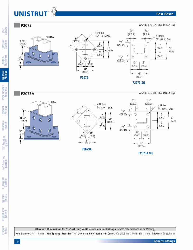
114 General Fittings
Standard Dimensions for 15⁄8" (41 mm) width series channel fittings (Unless Otherwise Shown on Drawing)
Hole Diameter: 9⁄16" (14.3mm); Hole Spacing - From End: 13⁄16" (20.6 mm); Hole Spacing - On Center: 17⁄8" (47.6 mm); Width: 15⁄8"(41mm); Thickness: 1⁄4" (6.4mm)
®
15 ⁄8"
Chan
nel
Nuts
&Ha
rdw
are
Gene
ral
Fitti
ngs
Pipe
/Con
duit
Supp
orts
Elec
trica
lFi
tting
sCo
ncre
teIn
serts
11 ⁄4" F
ram
ing
Syst
em13
⁄16" F
ram
ing
Syst
emFi
berg
lass
Syst
emSp
ecia
lM
etal
sTe
lest
rut
Syst
emPr
imeA
ngle
Syst
emPr
oduc
tIn
dex
P2073A
P2073 Wt/100 pcs: 325 Lbs (147.4 kg)
Wt/100 pcs: 408 Lbs (185.1 kg)
6"(152.4)
(76.2) (76.2)
(152.4)6"
3"(76.2)
3"(76.2)
6"(152.4)
4 Holes3⁄4" (19.1) Dia.
3" 3"
1 5⁄8"(41.3)
1⁄4"(6.4)
P1001A
1⁄4"(6.4)
3 1⁄2"(88.9)
P1001A
6"(152.4)
(76.2) (76.2)
(152.4)6"
3"(76.2)
3"(76.2)
6"(152.4)
4 Holes3⁄4" (19.1) Dia.
3" 3"
Post Bases
6"(152.4)
6"(152.4)
7⁄8"(22.2)
7⁄8"(22.2)
7⁄8"(22.2)
7⁄8"(22.2)
3"(76.2)
3"(76.2)
3"(76.2)
3"(76.2)
4 Holes3⁄4" (19.1) Dia.
P2073
P2073 SQ
P2073AP2073A SQ
6"(152.4)
6"(152.4)
7⁄8"(22.2)
7⁄8"(22.2)
7⁄8"(22.2)
7⁄8"(22.2)
3"(76.2)
3"(76.2)
3"(76.2)
3"(76.2)
4 Holes3⁄4" (19.1) Dia.
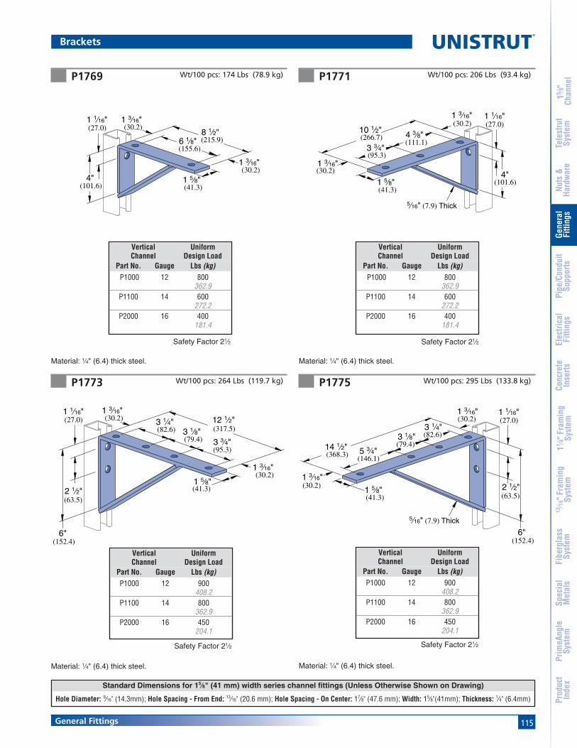
115General Fittings
Standard Dimensions for 15⁄8" (41 mm) width series channel fittings (Unless Otherwise Shown on Drawing)
Hole Diameter: 9⁄16" (14.3mm); Hole Spacing - From End: 13⁄16" (20.6 mm); Hole Spacing - On Center: 17⁄8" (47.6 mm); Width: 15⁄8"(41mm); Thickness: 1⁄4" (6.4mm)
15 ⁄8"
Chan
nel
Nuts
&Ha
rdw
are
Gene
ral
Fitti
ngs
Pipe
/Con
duit
Supp
orts
Elec
trica
lFi
tting
sCo
ncre
teIn
serts
11 ⁄4" F
ram
ing
Syst
em13
⁄16" F
ram
ing
Syst
emFi
berg
lass
Syst
emSp
ecia
lM
etal
sTe
lest
rut
Syst
emPr
imeA
ngle
Syst
emPr
oduc
tIn
dex
P1769 P1771
P1773 Wt/100 pcs: 264 Lbs (119.7 kg)
Material: 1⁄4" (6.4) thick steel. Material: 1⁄4" (6.4) thick steel.
Wt/100 pcs: 206 Lbs (93.4 kg)Wt/100 pcs: 174 Lbs (78.9 kg)
Material: 1⁄4" (6.4) thick steel.
Safety Factor 21⁄2
(101.6)4"
10 1⁄2"(266.7)
(30.2)1 3⁄16"
4 3⁄8"(111.1)
3 3⁄4"
(30.2)
(41.3)1 5⁄8"
1 3⁄16"
(95.3)
5⁄16" (7.9) Thick
1 1⁄16"(27.0)
6 1⁄8"
1 3⁄16"(30.2)
1 3⁄16"1 1⁄16"
4"(101.6)
(215.9)8 1⁄2"
(155.6)
1 5⁄8"(41.3)
(30.2)(27.0)
(152.4)6"
(30.2)1 3⁄16"
(30.2)1 3⁄16"
(41.3)1 5⁄8"
(95.3)3 3⁄4"
(82.6)3 1⁄4"
(63.5)2 1⁄2"
(317.5)12 1⁄2"
3 1⁄8"(79.4)
1 1⁄16"(27.0)
Vertical UniformChannel Design Load
Part No. Gauge Lbs (kg) P1000 12 800
362.9P1100 14 600
272.2P2000 16 400
181.4
Safety Factor 21⁄2
Safety Factor 21⁄2
Vertical UniformChannel Design Load
Part No. Gauge Lbs (kg)P1000 12 900
408.2P1100 14 800
362.9P2000 16 450
204.1
P1775 Wt/100 pcs: 295 Lbs (133.8 kg)
Material: 1⁄4" (6.4) thick steel.
3 1⁄8"(79.4)
(146.1)5 3⁄4"
(82.6)3 1⁄4"
(30.2)1 3⁄16"
(368.3)14 1⁄2"
1 3⁄16"(30.2)
(41.3)1 5⁄8"
5⁄16" (7.9) Thick
(152.4)6"
(63.5)2 1⁄2"
1 1⁄16"(27.0)
Safety Factor 21⁄2
Brackets
Vertical UniformChannel Design Load
Part No. Gauge Lbs (kg)P1000 12 900
408.2P1100 14 800
362.9P2000 16 450
204.1
Vertical UniformChannel Design Load
Part No. Gauge Lbs (kg) P1000 12 800
362.9P1100 14 600
272.2P2000 16 400
181.4

116 General Fittings
Note
When used for mechanical supports, load capacities of brackets and fittings should be in compliance with the American Standard Code for Pressure Piping.
®
15 ⁄8"
Chan
nel
Nuts
&Ha
rdw
are
Gene
ral
Fitti
ngs
Pipe
/Con
duit
Supp
orts
Elec
trica
lFi
tting
sCo
ncre
teIn
serts
11 ⁄4" F
ram
ing
Syst
em13
⁄16" F
ram
ing
Syst
emFi
berg
lass
Syst
emSp
ecia
lM
etal
sTe
lest
rut
Syst
emPr
imeA
ngle
Syst
emPr
oduc
tIn
dex
Brackets
P1593P1075 Wt/100 pcs: 229 Lbs (103.9 kg) Wt/100 pcs: 272 Lbs (123.4 kg)
* Allowable moment for fitting only.Channel may determine overall capacity.
* Allowable moment for fitting only.Channel may determine overall capacity.
P1001P1101P5000P2001
Material: 1⁄4" (6.4) thick steel.
Material: 1⁄4" (6.4) thick steel.
4 3⁄4"(120.7)
7 1⁄2"(190.5)
(117.5)4 5⁄8"
1 1⁄16"(27.0)
4 3⁄4"(120.7)
5 7⁄8"(149.2)
(76.2)3"
1 1⁄16"(27.0)
P1000P1100P2000P4001
Safety Factor 21⁄2
Vertical AllowableChannel Moment*
Part No. Gauge In-Lbs (N•M)P1000 12 5,100
576P1100 14 4,400
497P2000 16 3,200
362
Vertical AllowableChannel Moment*
Part No. Gauge In-Lbs (N•M)P1000 12 13,000
1,469P1100 14 9,100
1,028P2000 16 6,500
734
P1777 Wt/100 pcs: 385 Lbs (174.6 kg)
Material: 1⁄4" (6.4) thick steel.
(41.3)1 5⁄8"
1 3⁄16"
16 1⁄2"(419.1)
5 3⁄4"(146.1)
(79.4)3 1⁄8"
5 1⁄4"(133.4)
1 3⁄16"(30.2)
(152.4)6"
(63.5)2 1⁄2"
1 1⁄16"(27.0)
(30.2)
Vertical UniformChannel Design Load
Part No. Gauge Lbs (kg)P1000 12 1,200
544.3P1100 14 900
408.2P2000 16 600
272.2
Safety Factor 21⁄2
Safety Factor 21⁄2

117General Fittings
Standard Dimensions for 15⁄8" (41 mm) width series channel fittings (Unless Otherwise Shown on Drawing)
Hole Diameter: 9⁄16" (14.3mm); Hole Spacing - From End: 13⁄16" (20.6 mm); Hole Spacing - On Center: 17⁄8" (47.6 mm); Width: 15⁄8"(41mm); Thickness: 1⁄4" (6.4mm)
15 ⁄8"
Chan
nel
Nuts
&Ha
rdw
are
Gene
ral
Fitti
ngs
Pipe
/Con
duit
Supp
orts
Elec
trica
lFi
tting
sCo
ncre
teIn
serts
11 ⁄4" F
ram
ing
Syst
em13
⁄16" F
ram
ing
Syst
emFi
berg
lass
Syst
emSp
ecia
lM
etal
sTe
lest
rut
Syst
emPr
imeA
ngle
Syst
emPr
oduc
tIn
dex
Material : 12 Gauge Steel.
R - As shown; L - Opposite hand
Safety Factor - 21⁄2
Part Stamped “A” “B” Wt/100 pcsNumber Ident. No. In (mm) In (mm) Lbs (kg)
P2491 R-L 121892 R-L 6 115⁄16 6752.4 49.2 30.4
P2492 R-L 121893 R-L 8 27⁄16 92203.2 61.9 41.7
P2493 R-L 121894 R-L 10 215⁄16 120254.0 74.6 54.4
Part Stamped “A” “B” Wt/100 pcsNumber Ident. No. In (mm) In (mm) Lbs (kg)
P2494 R-L 121895 R-L 12 37⁄16 152304.8 87.3 68.9
P2495 R-L 121896 R-L 14 315⁄16 173355.6 100.0 78.5
P2496 R-L 121897 R-L 16 47⁄16 223406.4 112.7 101.2
P2497 R-L 121898 R-L 18 415⁄16 266457.2 125.4 120.7
P2498 R-L 121899 R-L 20 57⁄16 308508.0 138.1 139.7
P2499 R-L 121900 R-L 22 515⁄16 355558.8 150.8 161.0
Part Stamped “A” “B” Wt/100 pcsNumber Ident. No. In (mm) In (mm) Lbs (kg)
P2500 R-L 121901 R-L 24 67⁄16 400609.6 163.5 181.4
P2501 R-L 121902 R-L 26 615⁄16 445660.4 176.2 201.8
P2502 R-L 121903 R-L 28 77⁄16 493711.2 188.9 223.6
P2503 R-L 121904 R-L 30 715⁄16 545762.0 201.6 247.2
Brackets
P2491 R-L thru P2493 R-L
P2494 R-L thru P2499 R-L
P2500 R-L thru P2503 R-L
R - As shown; L - Opposite hand
R - As shown; L - Opposite hand
Safety Factor - 21⁄2
Vertical UniformChannel Design Load
Part No. Gauge Lbs (kg)P1000 12 300
136.1P1100 14 250
113.4P2000 16 200
90.7
Material : 12 Gauge Steel.
Material : 12 Gauge Steel.
Safety Factor - 21⁄2
Vertical UniformChannel Design Load
Part No. Gauge Lbs (kg)P1000 12 300
136.1P1100 14 250
113.4P2000 16 200
90.7
Vertical UniformChannel Design Load
Part No. Gauge Lbs (kg)P1000 12 300
136.1P1100 14 250
113.4P2000 16 200
90.7
A
B
(15.9)5⁄8"
1"(25.4)
9⁄32" (7.1) Dia.
13⁄16"(20.6)
(41.3)1 5⁄8"
7⁄16" (11.1) Dia.
3⁄8" x 1"(9.5 x 25.4)
B(15.9)
(41.3)1 5⁄8"
9⁄32" (7.1) Dia.
7⁄16" (11.1) Dia.
5⁄8"(25.4)1"
13⁄16"(20.6)
A3⁄8" x 1"
(9.5 x 25.4)
B
(15.9)
(41.3)1 5⁄8"
(20.6)7⁄16" (11.1) Dia.
9⁄32" (7.1) Dia.
5⁄8"
A
3⁄8" x 1"
1"(9.5 x 25.4)
13⁄16"

118 General Fittings
Note
When used for mechanical supports, load capacities of brackets and fittings should be in compliance with the American Standard Code for Pressure Piping.
®
15 ⁄8"
Chan
nel
Nuts
&Ha
rdw
are
Gene
ral
Fitti
ngs
Pipe
/Con
duit
Supp
orts
Elec
trica
lFi
tting
sCo
ncre
teIn
serts
11 ⁄4" F
ram
ing
Syst
em13
⁄16" F
ram
ing
Syst
emFi
berg
lass
Syst
emSp
ecia
lM
etal
sTe
lest
rut
Syst
emPr
imeA
ngle
Syst
emPr
oduc
tIn
dex
P2542 thru P2546 Vertical UniformPart “A” Wt/100 pcs Channel Design Load
Number In (mm) Lbs (kg) Part No. Gauge Lbs (kg)
P1000 12 2,000907.2
P2542 12 502 P1100 14 1,400304.8 227.7 635.0
P2000 16 1,000453.6
P1000 12 1,300589.7
P2543 18 692 P1100 14 900457.2 313.9 408.2
P2000 16 650294.8
P1000 12 1,000453.6
P2544 24 882 P1100 14 700609.6 400.1 317.5
P2000 16 500226.8
P1000 12 800362.9
P2545 30 1,072 P1100 14 560762.0 486.3 254.0
P2000 16 400181.4
P1000 12 650294.8
P2546 36 1,262 P1100 14 450914.4 572.4 204.1
P2000 16 320145.1
Safety Factor 21⁄2* Mounted on 12 Ga. Channel
Brackets
P2944, P2945, P2946, P2947
UniformPart “A” Wt/100 pcs Load*
Number In (mm) Lbs (kg) Lbs (kg)
P2944 6 185 1200152.4 83.9 544.3
P2945 12 293 600304.8 132.9 272.2
P2946 18 401 400457.2 181.9 181.4
P2947 24 509 300609.6 230.9 136.1
3⁄8"(9.5)
9⁄16"(14.3)
A
2"(50.8)
11⁄16"(17.5)
11⁄16"(17.5)
45⁄8"(117.5)
31⁄4"(82.6)
P2547 thru P2551 Cable Tray Bracket
UniformPart “A” “B” Wt/100 pcs Load*
Number In (mm) In (mm) Lbs (kg) Lbs (kg)
P2547 15 83⁄4 420 1,000381.0 222.3 190.5 453.6
P2548 21 83⁄4 628 1,000533.4 222.3 284.9 453.6
P2549 27 111⁄4 860 900685.8 285.8 390.1 408.2
P2550 33 111⁄4 1010 900838.2 285.8 458.1 408.2
P2551 39 16 1257 800990.6 406.4 683.3 362.9
B
A
3⁄8"(9.5)
9⁄16"(14.3)
13⁄16"(20.6)
13⁄16"(20.6)
61⁄4"(158.8)
45⁄8"(117.5)
A
2" (50.8)
P1001
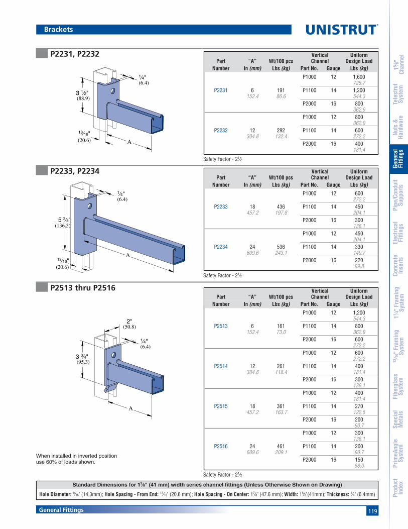
119General Fittings
Standard Dimensions for 15⁄8" (41 mm) width series channel fittings (Unless Otherwise Shown on Drawing)
Hole Diameter: 9⁄16" (14.3mm); Hole Spacing - From End: 13⁄16" (20.6 mm); Hole Spacing - On Center: 17⁄8" (47.6 mm); Width: 15⁄8"(41mm); Thickness: 1⁄4" (6.4mm)
15 ⁄8"
Chan
nel
Nuts
&Ha
rdw
are
Gene
ral
Fitti
ngs
Pipe
/Con
duit
Supp
orts
Elec
trica
lFi
tting
sCo
ncre
teIn
serts
11 ⁄4" F
ram
ing
Syst
em13
⁄16" F
ram
ing
Syst
emFi
berg
lass
Syst
emSp
ecia
lM
etal
sTe
lest
rut
Syst
emPr
imeA
ngle
Syst
emPr
oduc
tIn
dex
P2231, P2232
P2233, P2234
Brackets
Safety Factor - 21⁄2
3 1⁄2"(88.9)
13⁄16"(20.6)
1⁄4"(6.4)
A
(20.6)
13⁄16"
(136.5)5 3⁄8"
(6.4)1⁄4"
A
Safety Factor - 21⁄2
Vertical UniformPart “A” Wt/100 pcs Channel Design Load
Number In (mm) Lbs (kg) Part No. Gauge Lbs (kg)
P1000 12 1,600725.7
P2231 6 191 P1100 14 1,200152.4 86.6 544.3
P2000 16 800362.9
P1000 12 800362.9
P2232 12 292 P1100 14 600304.8 132.4 272.2
P2000 16 400181.4
Vertical UniformPart “A” Wt/100 pcs Channel Design Load
Number In (mm) Lbs (kg) Part No. Gauge Lbs (kg)
P1000 12 600272.2
P2233 18 436 P1100 14 450457.2 197.8 204.1
P2000 16 300136.1
P1000 12 450204.1
P2234 24 536 P1100 14 330609.6 243.1 149.7
P2000 16 22099.8
P2513 thru P2516
When installed in inverted positionuse 60% of loads shown.
(95.3)3 3⁄4"
(6.4)1⁄4"
A
2"(50.8)
Vertical UniformPart “A” Wt/100 pcs Channel Design Load
Number In (mm) Lbs (kg) Part No. Gauge Lbs (kg)
P1000 12 1,200544.3
P2513 6 161 P1100 14 800152.4 73.0 362.9
P2000 16 600272.2
P1000 12 600272.2
P2514 12 261 P1100 14 400304.8 118.4 181.4
P2000 16 300136.1
P1000 12 400181.4
P2515 18 361 P1100 14 270457.2 163.7 122.5
P2000 16 20090.7
P1000 12 300136.1
P2516 24 461 P1100 14 200609.6 209.1 90.7
P2000 16 15068.0
Safety Factor - 21⁄2

120 General Fittings
Note
When used for mechanical supports, load capacities of brackets and fittings should be in compliance with the American Standard Code for Pressure Piping.
®
15 ⁄8"
Chan
nel
Nuts
&Ha
rdw
are
Gene
ral
Fitti
ngs
Pipe
/Con
duit
Supp
orts
Elec
trica
lFi
tting
sCo
ncre
teIn
serts
11 ⁄4" F
ram
ing
Syst
em13
⁄16" F
ram
ing
Syst
emFi
berg
lass
Syst
emSp
ecia
lM
etal
sTe
lest
rut
Syst
emPr
imeA
ngle
Syst
emPr
oduc
tIn
dex
P2231A, P2232A
Brackets
Safety Factor - 21⁄2
Vertical UniformPart “A” Wt/100 pcs Channel Design Load
Number In (mm) Lbs (kg) Part No. Gauge Lbs (kg)
P1000 12 1,600725.7
P2231A 6 191 P1100 14 1,200152.4 86.6 544.3
P2000 16 800362.9
P1000 12 800362.9
P2232A 12 292 P1100 14 600304.8 132.4 272.2
P2000 16 400181.4
P2513A thru P2516A
Safety Factor 21⁄2
Vertical UniformPart “A” Wt/100 pcs Channel Design Load
Number In (mm) Lbs (kg) Part No. Gauge Lbs (kg)
P1000 12 1,200544.3
P2513A 6 161 P1100 14 800152.4 73.0 362.9
P2000 16 600272.2
P1000 12 600272.2
P2514A 12 261 P1100 14 400304.8 118.4 181.4
P2000 16 300136.1
P1000 12 400181.4
P2515A 18 361 P1100 14 270457.2 163.7 122.5
P2000 16 20090.7
P1000 12 300136.1
P2516A 24 461 P1100 14 200609.6 209.1 90.7
P2000 16 15068.0
When installed in inverted positionuse 60% of loads shown.
(95.3)3 3⁄4"
(6.4)1⁄4"
A
2"(50.8)
P2233A, P2234A Vertical UniformPart “A” Wt/100 pcs Channel Design Load
Number In (mm) Lbs (kg) Part No. Gauge Lbs (kg)
P1000 12 600272.2
P2233A 18 436 P1100 14 450457.2 197.8 204.1
P2000 16 300136.1
P1000 12 450204.1
P2234A 24 536 P1100 14 330609.6 243.1 149.7
P2000 16 22099.8
(136.5)5 3⁄8"
(20.6)13⁄16"
(6.4)1⁄4"
A
(20.6)13⁄16"
(88.9)3 1⁄2"
(6.4)1⁄4"
A
Safety Factor 21⁄2
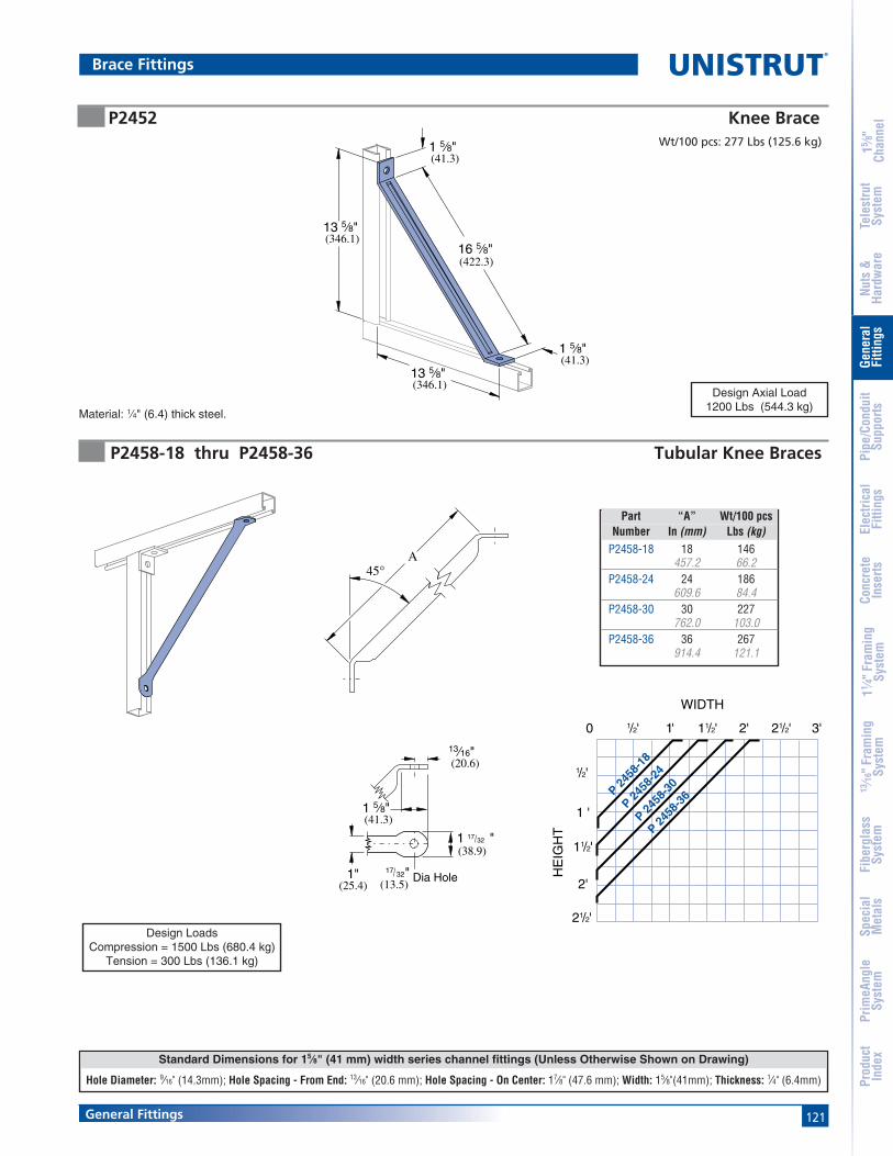
121General Fittings
Standard Dimensions for 15⁄8" (41 mm) width series channel fittings (Unless Otherwise Shown on Drawing)
Hole Diameter: 9⁄16" (14.3mm); Hole Spacing - From End: 13⁄16" (20.6 mm); Hole Spacing - On Center: 17⁄8" (47.6 mm); Width: 15⁄8"(41mm); Thickness: 1⁄4" (6.4mm)
15 ⁄8"
Chan
nel
Nuts
&Ha
rdw
are
Gene
ral
Fitti
ngs
Pipe
/Con
duit
Supp
orts
Elec
trica
lFi
tting
sCo
ncre
teIn
serts
11 ⁄4" F
ram
ing
Syst
em13
⁄16" F
ram
ing
Syst
emFi
berg
lass
Syst
emSp
ecia
lM
etal
sTe
lest
rut
Syst
emPr
imeA
ngle
Syst
emPr
oduc
tIn
dex
45°A
(20.6)13⁄16"
1 5⁄8"(41.3)
1 "(38.9)
1"(25.4)
Dia Hole(13.5)
17 32
"17 32
0 1/2' 1' 11/2' 2' 21/2' 3'
1/2'
11/2'
1 '
2'
21/2'
WIDTH
HE
IGH
T
P 2458
-18
P 2458
-24
P 2458
-30
P 2458
-36
P2458-18 thru P2458-36 Tubular Knee Braces
Part “A” Wt/100 pcsNumber In (mm) Lbs (kg)
P2458-18 18 146457.2 66.2
P2458-24 24 186609.6 84.4
P2458-30 30 227762.0 103.0
P2458-36 36 267914.4 121.1
Brace Fittings
P2452 Knee BraceWt/100 pcs: 277 Lbs (125.6 kg)
13 5⁄8"(346.1)
16 5⁄8"(422.3)
1 5⁄8"(41.3)
1 5⁄8"(41.3)
13 5⁄8"(346.1)
Material: 1⁄4" (6.4) thick steel.
Design Axial Load1200 Lbs (544.3 kg)
Design LoadsCompression = 1500 Lbs (680.4 kg)
Tension = 300 Lbs (136.1 kg)

122 General Fittings
Note
When used for mechanical supports, load capacities of brackets and fittings should be in compliance with the American Standard Code for Pressure Piping.
®
15 ⁄8"
Chan
nel
Nuts
&Ha
rdw
are
Gene
ral
Fitti
ngs
Pipe
/Con
duit
Supp
orts
Elec
trica
lFi
tting
sCo
ncre
teIn
serts
11 ⁄4" F
ram
ing
Syst
em13
⁄16" F
ram
ing
Syst
emFi
berg
lass
Syst
emSp
ecia
lM
etal
sTe
lest
rut
Syst
emPr
imeA
ngle
Syst
emPr
oduc
tIn
dex
P2815 Adjustable Brace Fitting P2815D Adjustable Brace Fitting
P2459-36 thru P2459-96 Tubular Back Braces
Wt/100 pcs: 497 Lbs (225.4 kg)Wt/100 pcs: 307 Lbs (139.3 kg)
5 7⁄8"
1 7⁄8"(47.6)
(20.6)13⁄16"
(47.6)
(20.6)13⁄16"
13⁄16"(20.6)
(101.6)4"
(27.0)1 1⁄16"
2 3⁄8"(60.3)
(149.2)
30°(.17π)Min.
1 7⁄8"
(136.5)5 3⁄8"
3 3⁄4"(95.3)
13⁄16"(20.6)1 1⁄16"
(27.0)
(149.2)5 7⁄8" 1 7⁄8"
(47.6)
13⁄16"(20.6)
13⁄16"(20.6)
30° (.17π)Min.
(46.7)1 7⁄8"
1. The vertical lines of the graph correspond to the center tocenter line dimension of the uprights.
2. Along this vertical line locate the (maximum usable)horizontal bracing height line.
3. The arc line that intersects the point formed by theintersection of the two lines, indicates the brace required.
4. 60° - 30° maximum, minimum brace angles are indicated formaximum effect.
A
(25.4)1"
17⁄32" (13.5) Dia. Hole
13⁄16"(20.6)
1 17⁄32"(38.9)
1 5⁄8"(41.3)
CENTER TO CENTER OF UPRIGHT
BR
AC
ING
HE
IGH
T
2'
1'
1'
3'
4'
5'
6'
7'
8'
2' 3' 4' 5' 6' 7'
8
7
6
541/24
331/2
60°
30°
P 2459-96P 2459-84
P 2459-72P 2459-54
P 2459-48
P 2459-42P 2459-36
P 2459-60
Part “A” Wt/100 pcsNumber In (mm) Lbs (kg)
P2459-36 36 255914.4 115.7
P2459-42 42 2961,066.8 134.3
P2459-48 48 3361,219.2 152.4
P2459-54 54 3771,371.6 171.0
P2459-60 60 4181,524.0 189.6
P2459-72 72 4991,828.8 226.3
P2459-84 84 5802,133.6 263.1
P2459-96 96 6612,438.4 299.8
Brace Fittings
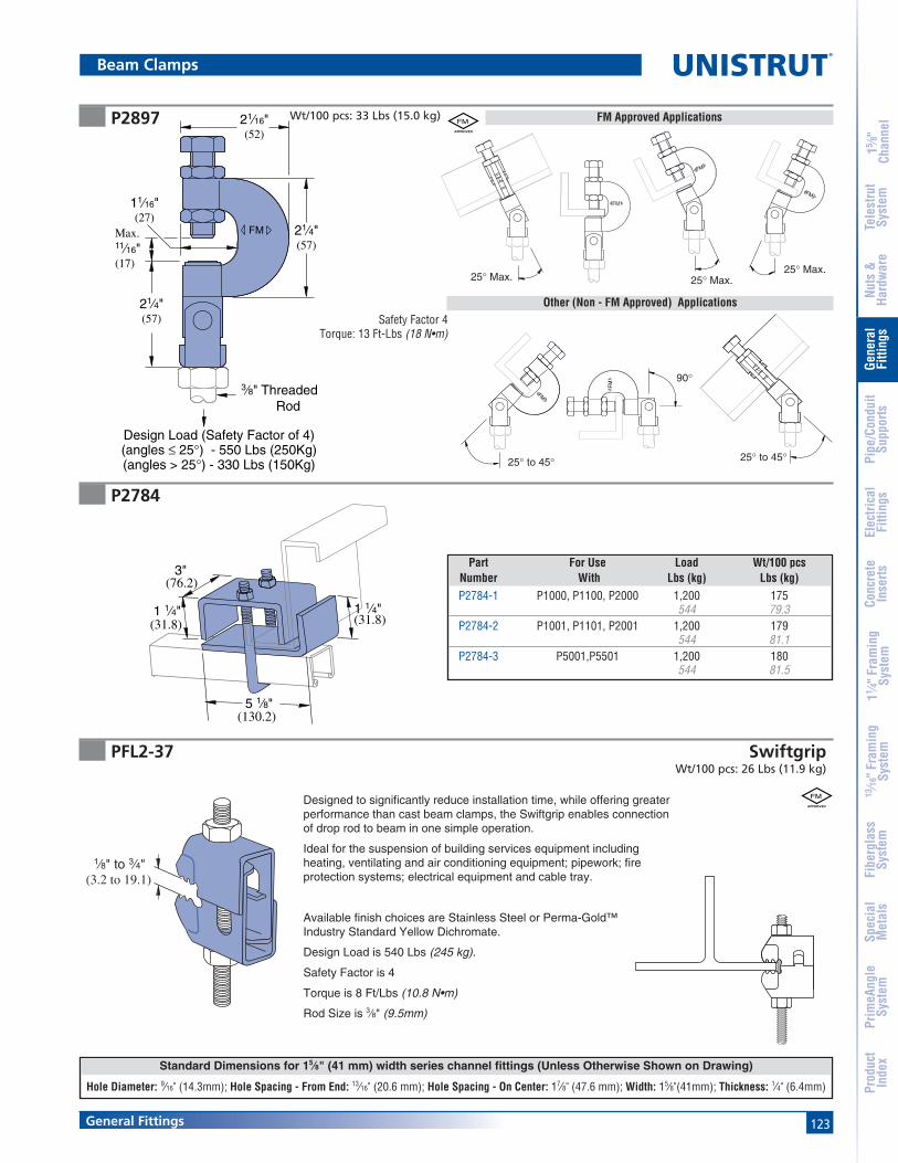
123General Fittings
Standard Dimensions for 15⁄8" (41 mm) width series channel fittings (Unless Otherwise Shown on Drawing)
Hole Diameter: 9⁄16" (14.3mm); Hole Spacing - From End: 13⁄16" (20.6 mm); Hole Spacing - On Center: 17⁄8" (47.6 mm); Width: 15⁄8"(41mm); Thickness: 1⁄4" (6.4mm)
15 ⁄8"
Chan
nel
Nuts
&Ha
rdw
are
Gene
ral
Fitti
ngs
Pipe
/Con
duit
Supp
orts
Elec
trica
lFi
tting
sCo
ncre
teIn
serts
11 ⁄4" F
ram
ing
Syst
em13
⁄16" F
ram
ing
Syst
emFi
berg
lass
Syst
emSp
ecia
lM
etal
sTe
lest
rut
Syst
emPr
imeA
ngle
Syst
emPr
oduc
tIn
dex
Beam Clamps
P2897 Wt/100 pcs: 33 Lbs (15.0 kg)
FMMax.11⁄16"(17)
11⁄16"(27)
21⁄16"(52)
21⁄4"(57)
21⁄4"(57)
3⁄8" ThreadedRod
Design Load (Safety Factor of 4)(angles ≤ 25°) - 550 Lbs (250Kg)(angles > 25°) - 330 Lbs (150Kg)
FM
25° Max.25° Max.
25° Max.
25° to 45°25° to 45°
90°
FM Approved Applications
Other (Non - FM Approved) Applications
P2784
3"(76.2)
(31.8) (31.8)
(130.2)
1 1⁄4"
5 1⁄8"
1 1⁄4"
Part For Use Load Wt/100 pcsNumber With Lbs (kg) Lbs (kg)P2784-1 P1000, P1100, P2000 1,200 175
544 79.3P2784-2 P1001, P1101, P2001 1,200 179
544 81.1P2784-3 P5001,P5501 1,200 180
544 81.5
Safety Factor 4Torque: 13 Ft-Lbs (18 N•m)
PFL2-37 SwiftgripWt/100 pcs: 26 Lbs (11.9 kg)
(3.2 to 19.1)
1⁄8" to 3⁄4"
Designed to significantly reduce installation time, while offering greaterperformance than cast beam clamps, the Swiftgrip enables connectionof drop rod to beam in one simple operation.
Ideal for the suspension of building services equipment includingheating, ventilating and air conditioning equipment; pipework; fireprotection systems; electrical equipment and cable tray.
Available finish choices are Stainless Steel or Perma-Gold™Industry Standard Yellow Dichromate.
Design Load is 540 Lbs (245 kg).
Safety Factor is 4
Torque is 8 Ft/Lbs (10.8 N•m)
Rod Size is 3⁄8" (9.5mm)
FM

124 General Fittings
Note
When used for mechanical supports, load capacities of brackets and fittings should be in compliance with the American Standard Code for Pressure Piping.
®
15 ⁄8"
Chan
nel
Nuts
&Ha
rdw
are
Gene
ral
Fitti
ngs
Pipe
/Con
duit
Supp
orts
Elec
trica
lFi
tting
sCo
ncre
teIn
serts
11 ⁄4" F
ram
ing
Syst
em13
⁄16" F
ram
ing
Syst
emFi
berg
lass
Syst
emSp
ecia
lM
etal
sTe
lest
rut
Syst
emPr
imeA
ngle
Syst
emPr
oduc
tIn
dex
P2675
P2676
Clamp Materials: .105" (2.7) thick steel.Clamp P2675 is designed for light duty rod suspension.It also may be used with P3016-1024 or P3016-1420 nut asillustrated above for mounting insulators, etc.
Design Load150 Lbs (68.0 kg)
Wt/100 pcs: 33 Lbs (15.0 kg)
P3016-1024, orP3016-1420 Channel Nut
Insulator
Design Load250 Lbs (113.4 kg)
Rod Size up to 3⁄8"
2 Holes 9⁄32" (7.1) Dia.
2 1⁄16"(52.4)
5⁄8"
4 Holes 13⁄32" (10.3) Dia.
(15.9)
1 7⁄8"(47.6)
3⁄8" X 1 1⁄2" Set Screwand Nut Included
7⁄8"(22.2)
Rod Sizeup to 3⁄8"
Beam Clamps
Design Load500 Lbs (226.8 kg)
Design Load300 Lbs (136.1 kg)
Rod Sizeup to 1⁄2"
Rod Size up to 1⁄2"Rod Swivel 15° (0.8π)All Directions
2 Holes9⁄16" (14.3) Dia.
2 7⁄8"(73.0)
7⁄8"
2 Holes 7⁄16" (11.1) Dia.
(22.2)
2 5⁄8"(66.7)
1 7⁄8"(49.2)
1⁄2" X 2" Set Screwand Nut Included
1⁄8"(3.2) Thick
Swivel Nut andJam Nut notIncluded
Clamp P2676 provides a means of rod suspension where a free swingof up to 15° (0.8π) is required. Clamp will accommodate 1⁄4" (6.4),3⁄8" (9.5), or 1⁄2" (12.7) rods. Order swivel nuts P2679-4,-6, or -8 asrequired. Clamp may also be used with P2677 as illustrated inapplication drawings on page 126.
Wt/100 pcs: 72 Lbs (32.7 kg)
Clamp Materials: 1⁄8" (3.2) thick steel.

125General Fittings
Standard Dimensions for 15⁄8" (41 mm) width series channel fittings (Unless Otherwise Shown on Drawing)
Hole Diameter: 9⁄16" (14.3mm); Hole Spacing - From End: 13⁄16" (20.6 mm); Hole Spacing - On Center: 17⁄8" (47.6 mm); Width: 15⁄8"(41mm); Thickness: 1⁄4" (6.4mm)
15 ⁄8"
Chan
nel
Nuts
&Ha
rdw
are
Gene
ral
Fitti
ngs
Pipe
/Con
duit
Supp
orts
Elec
trica
lFi
tting
sCo
ncre
teIn
serts
11 ⁄4" F
ram
ing
Syst
em13
⁄16" F
ram
ing
Syst
emFi
berg
lass
Syst
emSp
ecia
lM
etal
sTe
lest
rut
Syst
emPr
imeA
ngle
Syst
emPr
oduc
tIn
dex
Beam Clamps
P2898
P2899
A
G
F
E
B
D
C
A
D
B
E
C11⁄4"
3⁄4"
(31.8)
(19.1)
Universal Beam Clamp
• Maximum temperature of 450˚ F (232° C)
Rod Size Max.A B C D E Load Wt/100 pcsin In (mm) In (mm) In (mm) In (mm) Lbs (kg) Lbs (kg)
P2899-37 3⁄8 15⁄8 2 1 78 400 28
41.3 50.8 25.4 22.2 184.4 12.7P2899-50 1⁄2 15⁄8 2 1 7
8 500 3441.3 50.8 25.4 22.2 227.3 15.4
P2899-62 5⁄8 13⁄4 21⁄4 11⁄4 1 600 6644.5 57.2 31.8 25.4 272.7 30.0
P2899-75 3⁄4 17⁄8 23⁄8 13⁄8 11⁄4 800 8347.6 60.3 34.9 31.8 363.6 37.7
WIDE THROAT TOP BEAM CLAMP
• Maximum temperature of 450˚ F (232° C)• At least one full thread must be exposed
A B C D E F G Max Load Wt/100 pcsin In (mm) In (mm) In (mm) In (mm) In (mm) In (mm) Lbs (kg) Lbs (kg)
P2898-37 3⁄8 1 11⁄2 1⁄2 1 3⁄4 7⁄8 400 3325.4 38.1 12.7 25.4 19.1 22.2 181.8 15.0
P2898-50 1⁄2 1 11⁄2 1⁄2 1 3⁄4 7⁄8 500 3325.4 38.1 12.7 25.4 19.1 22.2 227.3 15.0
P2898-62 5⁄8 11⁄2 11⁄2 1⁄2 1 3⁄4 1 600 2238.1 38.1 12.7 25.4 19.1 25.4 272.7 10.0
P2898-75 3⁄4 17⁄8 13⁄4 5⁄8 13⁄8 1 11⁄4 800 8847.6 44.5 15.9 34.9 25.4 31.8 363.6 40.0
P2898-87 7⁄8 2 13⁄4 5⁄8 11⁄2 1 11⁄4 1,200 7950.8 44.5 15.9 38.1 25.4 31.8 545.5 35.9
FM
FM

126 General Fittings
®
15 ⁄8"
Chan
nel
Nuts
&Ha
rdw
are
Gene
ral
Fitti
ngs
Pipe
/Con
duit
Supp
orts
Elec
trica
lFi
tting
sCo
ncre
teIn
serts
11 ⁄4" F
ram
ing
Syst
em13
⁄16" F
ram
ing
Syst
emFi
berg
lass
Syst
emSp
ecia
lM
etal
sTe
lest
rut
Syst
emPr
imeA
ngle
Syst
emPr
oduc
tIn
dex
P2679-4, -6 & -8P2674
P2677P2682 Wt/100 pcs: 55 Lbs (24.9 kg) Wt/100 pcs: 30 Lbs (13.6 kg)
Wt/100 pcs: 17 Lbs (7.7 kg)
Hanger clevis for up to 1⁄2" (12.7)rod suspension from wood ceilings.May also be used with P2677 asillustrated in application drawings.
Clevis hanger to be used with P2675to provide angle adjustment for up to3⁄8" rod suspension as illustrated.
3⁄16"(4.8)
1 3⁄4"(44.5)
Rod Size up to 1⁄2"
4 Holes7⁄16" (11.1) Dia.
1⁄2"(12.7)
1 5⁄8"(41.3)
3 25⁄32"(96.0)
3⁄8" X 2"Screw, Nut,and Lock WasherIncluded
1⁄8" (3.2) Thick
2 1⁄2"(63.5)
1 1⁄4"(31.8)
1 3⁄8" (34.9)
Clevis hanger to be used withP2676 or P2682 to provide angleadjustment and 15° (0.08 π) freeswing for up to 1⁄2" (12.7) rodsuspension. Order swivel nutsP2679-4, -6, or -8 as required.
SWIVEL NUT
• Use with P2676 and P2677.• Order size as required.
Rod Size up to 1⁄2"
Rod Swivel 15° (0.08π)All Directions
P2682
P2677
1⁄4" X 1 1⁄2"
1 3⁄4"(44.5)
(20.6)
Hole 13⁄32" (10.3) Dia.
1⁄8" (3.2) Thick
7⁄8" (22.2)
Screw, Nut,and Lock WasherIncluded
13⁄16"P2675
Rod Sizeup to 3⁄8"
Rod Sizeup to 1⁄2"
Rod Swivel 15° (0.08π)All Directions
P2676
Design Load500 Lbs (226.8 kg)
Part Thread Wt/100 pcsNumber Size Lbs (kg)P2679-4 1⁄4"-20 4
1.8P2679-6 3⁄8"-16 5
2.3P2679-8 1⁄2"-13 6
2.7
Beam Clamps
Design Load250 Lbs (113.4 kg)

127General Fittings
15 ⁄8"
Chan
nel
Nuts
&Ha
rdw
are
Gene
ral
Fitti
ngs
Pipe
/Con
duit
Supp
orts
Elec
trica
lFi
tting
sCo
ncre
teIn
serts
11 ⁄4" F
ram
ing
Syst
em13
⁄16" F
ram
ing
Syst
emFi
berg
lass
Syst
emSp
ecia
lM
etal
sTe
lest
rut
Syst
emPr
imeA
ngle
Syst
emPr
oduc
tIn
dex
P1648S thru P1653S
P2398S, P2401S, P2403S
For beams under 7⁄8" (22.2) thick flange.
Weld
7⁄8"(22.2)
Tapped HoleSize A
Set ScrewSize CIncluded
2 1⁄2"(63.5)
(63.5)2 1⁄2"
B
D
For beams between 3⁄4" (19.1) to 15⁄8" (41.3) thick flanges.
DesignPart “A” “B” “C” “D” Wt/100 pcs Load
Number In In (mm) In In (mm) Lbs (kg) Lbs (kg)P1648S 1⁄4 -20 1⁄8 3⁄8 x 11⁄2 7⁄8 67 650
3.2 22.2 30.4 294.8P1649S 5⁄16 -18 1⁄8 3⁄8 x 11⁄2 7⁄8 67 650
3.2 22.2 30.4 294.8P1649AS 3⁄8 -16 1⁄8 3⁄8 x 11⁄2 7⁄8 67 650
3.2 22.2 30.4 294.8P1650S 3⁄8 -16 3⁄16
1⁄2 x 11⁄2 15⁄16 100 1,1004.8 23.8 45.4 499.0
P1650AS 1⁄2 -13 3⁄161⁄2 x 11⁄2 15⁄16 100 1,100
4.8 23.8 45.4 499.0P1651S 1⁄2 -13 1⁄4 1⁄2 x 11⁄2 15⁄16 130 1,600
6.4 23.8 59.0 725.7P1651AS 5⁄8 -11 1⁄4 1⁄2 x 11⁄2 15⁄16 130 1,600
6.4 23.8 59.0 725.7P1652S 5⁄8 -11 5⁄16
5⁄8 x 11⁄2 15⁄16 160 2,4007.9 33.3 72.6 1,088.6
P1653S 3⁄4 -10 5⁄165⁄8 x 11⁄2 15⁄16 160 2,400
7.9 33.3 72.6 1,088.6
DesignPart “A” “B” “C” “D” “E” Wt/100 pcs Load
Number In In (mm) In In (mm) In (mm) Lbs (kg) Lbs (kg)P2398S 1⁄4 -20 1⁄8 3⁄8 x 2 121⁄32
7⁄8 109 8003.2 42.1 22.2 49.4 362.9
P2401S 3⁄8 -16 3⁄161⁄2 x 2 111⁄16
29⁄32 156 1,3004.8 42.9 23.0 70.8 589.7
P2403S 1⁄2 -13 1⁄4 1⁄2 x 2 111⁄1615⁄16 201 1,900
6.4 42.9 23.8 91.2 861.8P2405S 5⁄8 -11 5⁄16
5⁄8 x 2 111⁄16 15⁄16 311 2,4007.9 42.9 33.3 141.1 1,088.6
Beam Clamps
Weld is not continuous it is either 11⁄4"(31.8) - 13⁄4" (44.5) long or 2 spot welds.All welds are on the top and bottom.
Weld is not continuous it is either 11⁄4"(31.8) - 13⁄4" (44.5) long or 2 spot welds.All welds are on the top and bottom.
3 1⁄4"
Tapped HoleSize A
D
Weld
B
E
(92.1)3 5⁄8"
(82.6)
Set ScrewSize C Included

128 General Fittings
Note
When used for mechanical supports, load capacities of brackets and fittings should be in compliance with the American Standard Code for Pressure Piping.
®
15 ⁄8"
Chan
nel
Nuts
&Ha
rdw
are
Gene
ral
Fitti
ngs
Pipe
/Con
duit
Supp
orts
Elec
trica
lFi
tting
sCo
ncre
teIn
serts
11 ⁄4" F
ram
ing
Syst
em13
⁄16" F
ram
ing
Syst
emFi
berg
lass
Syst
emSp
ecia
lM
etal
sTe
lest
rut
Syst
emPr
imeA
ngle
Syst
emPr
oduc
tIn
dex
P1796SP1271S
P1654A thru P1661A Retainer Strap
Beam Clamps
For beams under7⁄8" (22.2) thickflange.
(44.5)1 3⁄4"
7⁄8"(22.2)
1⁄4"(6.4)
3 1⁄2"(88.9)
1⁄2" - 13 X 11⁄2" Set Screw Included
3 1⁄2"(88.9)
3⁄8"(9.5)
7⁄8"(22.2)
1 5⁄8"(41.3)
1 1⁄2"(38.1)
1⁄2" - 13 X 11⁄2" Set Screw Included
2 Holes 9⁄16" (14.3) Dia.
A
(25.4)1"
(22.2)
7⁄16" (11.1) Hole12 Gage
7⁄8"
P1654 A & P1655 A
(12.7)
A
17⁄32" (13.5) Hole
1 3⁄8"(34.9)
1⁄2"
P1656 A thru P1661 A
Design Load Each500 Lbs (226.8 kg)Use in Pairs Only
Design Load Each500 Lbs (226.8 kg)Use in Pairs Only
Strap Flange BeamPart Width “A” Wt/100 pcs Clamp
Number In (mm) In (mm) Lbs (kg) Used With
P1654 A 6 7 25 P2675152.4 177.8 11.3
P1655 A 9 10 34 P2675228.6 254.0 15.4
P1656 A 6 9 35 P1648 S Thru152.4 228.6 15.9
P1657 A 9 12 47 P1651 AS, and228.6 304.8 21.3
P1658 A 12 15 59 P2398 S Series304.8 381.0 26.8
P1659 A 6 9 33 P2676152.4 228.6 15.0
P1660 A 9 12 45 P2676228.6 304.8 20.4
P1661 A 12 15 57 P2676304.8 381.0 25.9
Wt/100 pcs: 95 Lbs (43.1 kg) Wt/100 pcs: 91 Lbs (41.3 kg)
Note: Requires P1010 Channel Nutand bolt.

129General Fittings
Note
When used for mechanical supports, load capacities of brackets and fittings should be in compliance with the American Standard Code for Pressure Piping.
15 ⁄8"
Chan
nel
Nuts
&Ha
rdw
are
Gene
ral
Fitti
ngs
Pipe
/Con
duit
Supp
orts
Elec
trica
lFi
tting
sCo
ncre
teIn
serts
11 ⁄4" F
ram
ing
Syst
em13
⁄16" F
ram
ing
Syst
emFi
berg
lass
Syst
emSp
ecia
lM
etal
sTe
lest
rut
Syst
emPr
imeA
ngle
Syst
emPr
oduc
tIn
dex
P2786
P2785
Beam Clamps
P2824-6,-9,-12 Wt/100 pcs: 83 Lbs (37.6 kg)
Wt/100 pcs: 92 Lbs (41.7 kg)
• For use with Beams up to 3⁄4" (19.1) Flanges and withChannels P1000, P1100, P2000, P3000, P3300, P3301,P4000, P4001, P4100, and P4101.
• For use with Beams up to 3⁄4" (19.1) Flanges and withChannels P1001, P1101, P2001, P3001, P5000, and P5500.
7⁄8"
3⁄8" Hex Nuts and"U" Bolt Included
(22.2)
3"(76.2)
3 3⁄8"(85.7)
1⁄4"(6.4)
1⁄4"(6.4)
5"
3"(76.2)
7⁄8"(22.2)
3⁄8" Hex Nuts and"U" Bolt Included
(127)
A
3⁄16"(4.8)
3⁄16"(4.8)
Clamp Requires1⁄2" Diameter Rod and2 Hex Nuts (Sold Seperately)
DesignPart “A” Wt/100 pcs Load
Number In (mm) Lbs (kg) Lbs (kg)
P2824-6 21⁄2 - 6 125 50063.5 - 152.4 56.7 226.8
P2824-9 51⁄2 - 9 140 500139.7 - 228.6 63.5 226.8
P2824-12 81⁄2 - 12 171 500215.9 - 304.8 77.6 226.8
Design Load Each1000 Lbs (453.6 kg)
Use in Pairs Only
Design Load Each1000 Lbs (453.6 kg)
Use in Pairs Only
P2787
• For use with Beams up to 3⁄4" (19.1) Flanges and withChannels P5001 and P5501.
Design Load Each1000 Lbs (453.6 kg)
Use in Pairs Only
1⁄4"(6.4)
81⁄4"
3"(76.2)
7⁄8"(22.2)
3⁄8" Hex Nuts and"U" Bolt Included
(209.6)
Wt/100 pcs: 112 Lbs (50.8 kg)
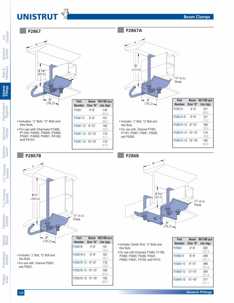
130 General Fittings
®
15 ⁄8"
Chan
nel
Nuts
&Ha
rdw
are
Gene
ral
Fitti
ngs
Pipe
/Con
duit
Supp
orts
Elec
trica
lFi
tting
sCo
ncre
teIn
serts
11 ⁄4" F
ram
ing
Syst
em13
⁄16" F
ram
ing
Syst
emFi
berg
lass
Syst
emSp
ecia
lM
etal
sTe
lest
rut
Syst
emPr
imeA
ngle
Syst
emPr
oduc
tIn
dex
P2867A
P2868
• Includes: "J" Bolt, "U" Bolt andHex Nuts.
• For use with Channel P1001,P1101, P2001, P3001, P5000,and P5500.
• Includes: Center Rod, "U" Bolts andHex Nuts.
• For use with Channels P1000, P1100,P2000, P3000, P3300, P3301,P4000, P4001, P4100, and P4101.
Beam Clamps
Part Beam Wt/100 pcsNumber Size "A" Lbs (kg)
P2867A 4"-6" 15168.5
P2867A-9 6"-9" 15771.2
P2867A-12 9"-12" 16675.3
P2867A-15 12"-15" 17679.8
P2867A-18 15"-18" 18583.9
Part Beam Wt/100 pcsNumber Size "A" Lbs (kg)
P2868 4"-6" 282127.9
P2868-9 6"-9" 289131.1
P2868-12 9"-12" 296134.3
P2868-15 12"-15" 304137.9
P2868-18 15"-18" 311141.1
P2867
(76.2)3"
3 3⁄8" (85.7)
A
• Includes: "J" Bolt, "U" Bolt andHex Nuts.
• For use with Channels P1000,P1100, P2000, P3000, P3300,P3301, P4000, P4001, P4100,and P4101.
Part Beam Wt/100 pcsNumber Size "A" Lbs (kg)P2867 4"-6" 142
64.4P2867-9 6"-9" 151
68.5P2867-12 9"-12" 160
72.6P2867-15 12"-15" 170
77.1P2867-18 15"-18" 179
81.2
P2867B
Part Beam Wt/100 pcsNumber Size "A" Lbs (kg)
P2867B 4"-6" 16173.0
P2867B-9 6"-9" 16775.7
P2867B-12 9"-12" 17679.8
P2867B-15 12"-15" 18684.4
P2867B-18 15"-18" 19588.5
• Includes: "J" Bolt, "U" Bolt andHex Nuts.
• For use with Channel P5001,and P5501.
(76.2)3"
81⁄4"(209.6)
1⁄4" (6.4)Thick
A
(76.2)3"
5"(127.0)
1⁄4" (6.4)Thick
A
A
(76.2)3"
3 3⁄8" (85.7)
1⁄4" (6.4)Thick
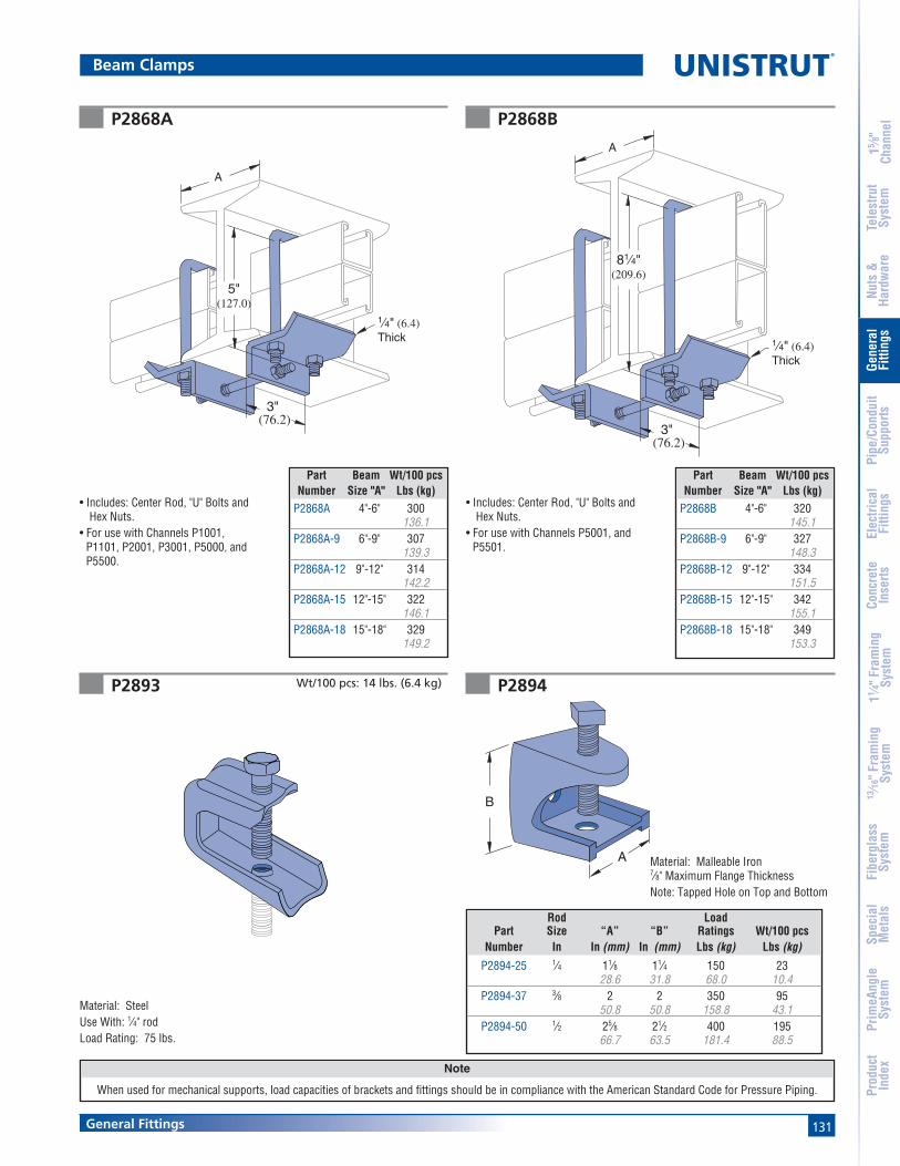
131General Fittings
Note
When used for mechanical supports, load capacities of brackets and fittings should be in compliance with the American Standard Code for Pressure Piping.
15 ⁄8"
Chan
nel
Nuts
&Ha
rdw
are
Gene
ral
Fitti
ngs
Pipe
/Con
duit
Supp
orts
Elec
trica
lFi
tting
sCo
ncre
teIn
serts
11 ⁄4" F
ram
ing
Syst
em13
⁄16" F
ram
ing
Syst
emFi
berg
lass
Syst
emSp
ecia
lM
etal
sTe
lest
rut
Syst
emPr
imeA
ngle
Syst
emPr
oduc
tIn
dex
P2894
Material: Malleable Iron7⁄8" Maximum Flange ThicknessNote: Tapped Hole on Top and Bottom
Rod LoadPart Size “A” “B” Ratings Wt/100 pcs
Number In In (mm) In (mm) Lbs (kg) Lbs (kg)
P2894-25 1⁄4 11⁄8 11⁄4 150 2328.6 31.8 68.0 10.4
P2894-37 3⁄8 2 2 350 9550.8 50.8 158.8 43.1
P2894-50 1⁄2 25⁄8 21⁄2 400 19566.7 63.5 181.4 88.5
P2893
Material: SteelUse With: 1⁄4" rodLoad Rating: 75 lbs.
Wt/100 pcs: 14 lbs. (6.4 kg)
P2868A
• Includes: Center Rod, "U" Bolts andHex Nuts.
• For use with Channels P1001,P1101, P2001, P3001, P5000, andP5500.
Part Beam Wt/100 pcsNumber Size "A" Lbs (kg)
P2868A 4"-6" 300136.1
P2868A-9 6"-9" 307139.3
P2868A-12 9"-12" 314142.2
P2868A-15 12"-15" 322146.1
P2868A-18 15"-18" 329149.2
A
(76.2)3"
1⁄4" (6.4)Thick
5"(127.0)
P2868B
• Includes: Center Rod, "U" Bolts andHex Nuts.
• For use with Channels P5001, andP5501.
Part Beam Wt/100 pcsNumber Size "A" Lbs (kg)
P2868B 4"-6" 320145.1
P2868B-9 6"-9" 327148.3
P2868B-12 9"-12" 334151.5
P2868B-15 12"-15" 342155.1
P2868B-18 15"-18" 349153.3
A
(76.2)3"
1⁄4" (6.4)Thick
81⁄4"(209.6)
Beam Clamps
B
A

132 General Fittings
®
15 ⁄8"
Chan
nel
Nuts
&Ha
rdw
are
Gene
ral
Fitti
ngs
Pipe
/Con
duit
Supp
orts
Elec
trica
lFi
tting
sCo
ncre
teIn
serts
11 ⁄4" F
ram
ing
Syst
em13
⁄16" F
ram
ing
Syst
emFi
berg
lass
Syst
emSp
ecia
lM
etal
sTe
lest
rut
Syst
emPr
imeA
ngle
Syst
emPr
oduc
tIn
dex
P1386
(47.6)
(6.4)1⁄4"
(12.7)1⁄2"
Clamp Requires1⁄2" - 13 X 11⁄2" Hex Head Cap Screwand 1⁄2" Channel Nut Not Included.
1 7⁄8"
DesignLoad Each
Channel (Use in Pairs Only)Style Lbs (kg)P1000 600
272.2P1100 500
226.8P2000 450
204.1
Wt/100 pcs: 27 Lbs (12.2 kg)
P2896P2895
Beam Clamps
Material: Steel Material: Malleable Iron, Steel Set Screw
3⁄4"(19.1)
2 1⁄4"(57.2)
A
B
3⁄4"(19.1)
1⁄2"(12.7)
3⁄8"(9.5)
A
B
Rod LoadPart Size “A” “B” Ratings Wt/100 pcs
Number In In (mm) In (mm) Lbs (kg) Lbs (kg)
P2895-37 3⁄8 25⁄163⁄8 330 35
58.7 9.5 149.7 15.9P2895-50 1⁄2 21⁄4 1⁄2 380 41
57.2 12.7 172.4 18.6P2895-62 5⁄8 23⁄8 5⁄8 450 67
60.3 15.9 204.1 30.4P2895-75 3⁄4 21⁄4 1⁄2 500 72
57.2 12.7 226.8 32.7
Rod LoadPart Size “A” “B” Ratings Wt/100 pcs
Number In In (mm) In (mm) Lbs (kg) Lbs (kg)
P2896-37 3⁄8 111⁄16 13⁄4 400 3842.9 44.5 181.4 17.2
P2896-50 1⁄2 123⁄32 13⁄4 400 5243.7 44.5 181.4 23.6
P2896-62 5⁄8 115⁄16 2 450 6849.2 50.8 204.1 30.8
P2896-75 3⁄4 21⁄32 2 600 12851.6 50.8 272.2 58.1
P1379S
(82.6)3 1⁄4"
(25.4)1"
(9.5)3⁄8"
1⁄2" - 13 X 11⁄2" Set Screw Included
Clamp Requires1⁄2" x 13⁄16" Hex Head Cap Screwand 1⁄2" Channel Nut Not Included.
DesignLoad Each
Channel (Use in Pairs Only)Style Lbs (kg)
P1000 600272.2
P1100 500226.8
P2000 450217.7
Wt/100 pcs: 75 Lbs (34.0kg)

133General Fittings
15 ⁄8"
Chan
nel
Nuts
&Ha
rdw
are
Gene
ral
Fitti
ngs
Pipe
/Con
duit
Supp
orts
Elec
trica
lFi
tting
sCo
ncre
teIn
serts
11 ⁄4" F
ram
ing
Syst
em13
⁄16" F
ram
ing
Syst
emFi
berg
lass
Syst
emSp
ecia
lM
etal
sTe
lest
rut
Syst
emPr
imeA
ngle
Syst
emPr
oduc
tIn
dex
P1272S, P1985S, P1986S
DA
1 1⁄4"(31.8)
Design LoadFlange “D” Set Per Pair
Part “A” Thickness Screw Wt/100 pcs (Use in Pairs Only)
Number In (mm) In (mm) Included Lbs (kg) Lbs (kg)
P1272S 1⁄4 Up to 3⁄4 3⁄8-16 x 11⁄2 39 4506.4 Up to 19.1 17.7 204.1
P1985S 3⁄8 Up to 3⁄4 1⁄2-13 x 11⁄2 62 1,0009.5 Up to 19.1 28.1 453.6
P1986S 3⁄8 7⁄8 to 2 1⁄2-13 x 11⁄2 74 9009.5 22.2 - 50.8 33.6 408.2
Beam Clamps
P3087 Column Insert
Safety factor of 3.
Wt/100 pcs: 136 Lbs (61.7 kg)
A - 1"(A - 25.4)
A
• Adjusting Screws Included.• Unistrut channel not included.• Part number P3087 consists of: (1) piece P3087A, (1) piece P3087B and
(2) set screws
P3087A
P3087B
Adjusting ScrewsIncluded
Channel
Channel Design Pull DesignPart Out Load Slip Load
Number Lbs (kg) Lbs (kg)P1000 1,000 800
453.6 362.9P1100 700 500
317.5 226.8P2000 500 300
226.8 136.1
P3088 Column InsertWt/100 pcs: 120 Lbs (54.4 kg)
• Adjusting Screws Included.• Unistrut channel not included.• Part number P3088 consists of: (1) piece P3088A, (1) piece P3088B and
(2) set screws
Safety factor of 3.
Channel Design Pull DesignPart Out Load Slip Load
Number Lbs (kg) Lbs (kg)P3300 1,000 800
453.6 362.9P4100 700 500
317.5 226.8P4000 500 300
226.8 136.1
P3088A
P3088B
Adjusting ScrewsIncluded
Channel
A - 1"(A - 25.4)
A

134 General Fittings
®
15 ⁄8"
Chan
nel
Nuts
&Ha
rdw
are
Gene
ral
Fitti
ngs
Pipe
/Con
duit
Supp
orts
Elec
trica
lFi
tting
sCo
ncre
teIn
serts
11 ⁄4" F
ram
ing
Syst
em13
⁄16" F
ram
ing
Syst
emFi
berg
lass
Syst
emSp
ecia
lM
etal
sTe
lest
rut
Syst
emPr
imeA
ngle
Syst
emPr
oduc
tIn
dex
PLLC025 Flange Clamp
PFL037 thru PFL050T Flange Clamp
Beam Clamps
S
UW
X
Y
Z
T
V
X, Y are threaded holes.
Material: Malleable Iron.
Set Screw Torque = 3 Ft-LbLock Nut Torque = 3.5 Ft-Lb
135 Lbs.
40 Lbs.
“Z” SetPart Rod Screw Wt/100 pcs
Number Size Size Lbs (kg)PLLC025 1⁄4" 1⁄4" 16
7.3
DimensionsPart “S” “T” “U” “V”,“W” “X”,“Y”
Number In (mm) In (mm) In (mm) In (mm) In
PLLC025 5⁄8 1 17⁄163⁄4 1⁄4 X 20
15.9 25.4 36.5 19.1
Material: Malleable Iron.
“Z” Set Max. AllowablePart Type of Rod Screw Wt/100 pcs Load
Number Hole Size Size Lbs (kg) Lbs (kg)PFL037 Clear 3⁄8" 3⁄8" 28 540
12.7 244.9PFL037T Tapped 3⁄8" 3⁄8" 28 540
12.7 244.9PFL050 Clear 1⁄2" 3⁄8" 40 700
18.1 317.5PFL050T Tapped 1⁄2" 3⁄8" 40 700
18.1 317.5
DimensionsPart “T” “U” “V” “W” “X” “Y”
Number In (mm) In (mm) In (mm) In(mm) In (mm) In (mm)PFL037 111⁄16 19⁄16
7⁄8 3⁄4 1 7⁄16
42.9 39.7 22.2 19.1 25.4 11.1PFL037T 111⁄16 19⁄16
7⁄8 3⁄4 1 3⁄8 Tapped Hole42.9 39.7 22.2 19.1 25.4
PFL050 2 123⁄32 1 29⁄32 13⁄329⁄16
50.8 43.7 25.4 23.0 27.8 14.3PFL050T 2 123⁄32 1 29⁄32 13⁄32
1⁄2 Tapped Hole50.8 43.7 25.4 23.0 27.8
FM (When used for sprinklersystems only.)
Safety Factor: 5
V
T
W
X Y
Z
U
Cup point set screwand lock nut included.
Cup point set screwand lock nut included.
Set Screw Torque = 6 Ft-LbLock Nut Torque = 16 Ft-Lb

135General Fittings
15 ⁄8"
Chan
nel
Nuts
&Ha
rdw
are
Gene
ral
Fitti
ngs
Pipe
/Con
duit
Supp
orts
Elec
trica
lFi
tting
sCo
ncre
teIn
serts
11 ⁄4" F
ram
ing
Syst
em13
⁄16" F
ram
ing
Syst
emFi
berg
lass
Syst
emSp
ecia
lM
etal
sTe
lest
rut
Syst
emPr
imeA
ngle
Syst
emPr
oduc
tIn
dex
PLF3037 thru PLF3075 Flange Clamp
PLF9037 thru PLF9100 Flange Clamp
Beam Clamps
Max. Allowable
Part Rod Wt/100 pcs Load TorqueNumber Size Lbs (kg) Lbs (kg) Ft-Lbs
PLF3037 3⁄8" 53 270 1524.0 122.5
PLF3050 1⁄2" 91 450 2941.3 204.1
PLF3062 5⁄8" 186 900 6984.4 408.2
PLF3075 3⁄4" 334 1,350 130151.5 612.3
DimensionsPart “X” “W” “V” “T“ “R” “S”
Number In (mm) In (mm) In (mm) In (mm) In (mm) In (mm)PLF3037 1 0 - 13⁄16
3⁄8 9⁄32 11⁄2 7⁄825.4 0 - 30.2 9.5 7.1 38.1 22.2
PLF3050 13⁄8 0 - 19⁄161⁄2 11⁄32 115⁄16 15⁄32
34.9 0 - 39.7 12.7 8.7 49.2 29.4PLF3062 113⁄16 0 - 23⁄16
5⁄8 1⁄2 211⁄32 17⁄16
46.0 0 - 55.6 15.9 12.7 59.5 36.5PLF3075 23⁄16 0 - 13⁄4 3⁄4 5⁄8 3 13⁄4
55.6 0 - 44.5 19.1 15.9 76.2 44.5
DimensionsPart “X” “W” “V” “T” “S”
Number In (mm) In (mm) In (mm) In (mm) In (mm)PLF9037 1 3⁄4 - 111⁄16
1⁄2 3⁄4 125.4 19.1 - 42.9 12.7 19.1 25.4
PLF9050 13⁄8 1 - 23⁄8 21⁄3215⁄16 13⁄16
34.9 25.4 - 60.3 16.7 23.8 30.2PLF9062 111⁄16 11⁄8 - 23⁄4 13⁄16 11⁄8 13⁄8
42.9 28.6 - 69.9 20.6 28.6 34.9PLF9075 2 11⁄4 - 31⁄4 1 13⁄8 13⁄4
50.8 31.8 - 182.6 25.4 34.9 44.5PLF9100 3 13⁄4 - 33⁄4 11⁄2 23⁄16 21⁄2
76.2 44.5 - 95.3 38.1 55.6 63.5
FM
Material: Malleable Iron
T
SR
Threaded Rod & NutNot Included
V
W
V
X
Z
Safety Factor: 4
(When used forsprinkler systems only.)
S
Material: Malleable Iron
Threaded Rod & NutNot Included
Safety Factor: 5
V
XW
V
Z T
Max. Allowable
Part Rod Wt/100 pcs Load TorqueNumber Size Lbs (kg) Lbs (kg) Ft-Lbs
PLF9037 3⁄8" 55 440 1524.9 199.6
PLF9050 1⁄2" 122 630 2955.3 285.8
PLF9062 5⁄8" 200 1,260 6990.7 571.5
PLF9075 3⁄4" 367 1,880 131166.5 852.8
PLF9100 1" 1,101 3,150 173499.4 1428.8

136 General Fittings
®
15 ⁄8"
Chan
nel
Nuts
&Ha
rdw
are
Gene
ral
Fitti
ngs
Pipe
/Con
duit
Supp
orts
Elec
trica
lFi
tting
sCo
ncre
teIn
serts
11 ⁄4" F
ram
ing
Syst
em13
⁄16" F
ram
ing
Syst
emFi
berg
lass
Syst
emSp
ecia
lM
etal
sTe
lest
rut
Syst
emPr
imeA
ngle
Syst
emPr
oduc
tIn
dex
Trolley Assemblies
3⁄4" (19.1) Dia.
1"(25.4)1"
(25.4)
1"(25.4)
3 1⁄8"(79.4)
Clevis Material: 12 gauge.*Wheel bearings are stainless steel, and should not be lubricated.† "N" indicates acetal wheels.
1"(25.4)1"
(25.4)
1"(25.4)
3 1⁄8"(79.4)
9⁄32" (7.1) Dia. Hole
9⁄16"x 9⁄32" (14.3 x 7.1) Slots
1 3⁄16"(30.2)
9⁄32"(7.1)
1 23⁄32"(43.7)
(31.8)1 1⁄4"
1⁄4"(6.4)
7⁄16"(11.1)
(61.9)2 7⁄16"
1 23⁄32"(43.7)
(105.6)4 23⁄32"
1 1⁄4"(31.8)
(6.4)1⁄4"
(37.3)1 15⁄32"
(6.4)1⁄4"
(11.1)7⁄16"
(42.1)1 21⁄32"
(4.8)3⁄16" 9⁄32"
(7.1)
(30.2)1 3⁄16"1 1⁄4"
(31.8)
(31.8)1 1⁄4"
3⁄4"(19.1)
9⁄32" (7.1) Dia. Hole
Clevis Material: 12 gauge.*Wheel bearings are stainless steel, and should not be lubricated.† "N" indicates acetal wheels.
Clevis Material: 12 gauge.*Wheel bearings are stainless steel, and should not be lubricated.† "N" indicates acetal wheels.
P2749*, P2749N†
P2750*, P2750N†
P2751*, P2751 N†
DesignPart Load Wt/100 pcs
Number Lbs (kg) Lbs (kg)P2749 50 21
22.7 9.5P2749N 10 13
4.5 5.9
DesignPart Load Wt/100 pcs
Number Lbs (kg) Lbs (kg)P2750 100 55
45.4 24.9P2750N 20 32
9.1 14.5
DesignPart Load Wt/100 pcs
Number Lbs (kg) Lbs (kg)P2751 100 63
45.4 28.6P2751N 20 40
9.1 18.1

137General Fittings
15 ⁄8"
Chan
nel
Nuts
&Ha
rdw
are
Gene
ral
Fitti
ngs
Pipe
/Con
duit
Supp
orts
Elec
trica
lFi
tting
sCo
ncre
teIn
serts
11 ⁄4" F
ram
ing
Syst
em13
⁄16" F
ram
ing
Syst
emFi
berg
lass
Syst
emSp
ecia
lM
etal
sTe
lest
rut
Syst
emPr
imeA
ngle
Syst
emPr
oduc
tIn
dex
P2949
P2950
Trolley Assemblies
Wt/100 pcs: 46 Lbs (20.9 kg)
Wt/100 pcs: 110 Lbs (49.9 kg)
Wheel bearings are stainless steel.Do not lubricate.
(31.8)1 1⁄4"(15.9)
5⁄8"
5⁄8"(15.9)
Hole9⁄16" (14.3) Dia.
(88.9)3 1⁄2"(20.6)
13⁄16"
15⁄16"(23.8)15⁄16"
(23.8)
(20.6)13⁄16"
3 Holes9⁄16" (14.3) Dia.
Wheel bearings are stainless steel.Do not lubricate.
(49.2)1 15⁄16"
(33.3)1 5⁄16"
9⁄32"(7.1)
(30.2)1 3⁄16"
(20.6)13⁄16"
3 13⁄32"(86.5)
(6.4)1⁄4"
Design Load In P1000
FPM RPM Lbs (kg)180 600 150
68.090 300 225
102.130 100 437
198.2
Design Load In P1000
FPM RPM Lbs (kg)180 600 300
136.190 300 450
204.130 100 600
272.2
P1834A Channel Trolley SupportP1834 Channel Trolley SupportWt/100 pcs: 102 Lbs (46.3 kg) Wt/100 pcs: 220 Lbs (99.8 kg)
Requires 3⁄8" x 21⁄2" Boltand 3⁄8" Nut
(not included)
Requires 3⁄8" x 21⁄2" Boltand 3⁄8" Nut
(not included)
Design Load1200 Lbs (544.3 kg)
Design Load2500 Lbs (1,134.0 kg)
(49.2)1 15⁄16"
(33.3)1 5⁄16"
9⁄32"(7.1)
(30.2)1 3⁄16"
(20.6)13⁄16"
3 13⁄32"(86.5)
(6.4)1⁄4"
3 3⁄4"(95.3)
1 5⁄8"(41.3)
2 Holes 7⁄16" (11.1) Dia.
1 Hole 9⁄16" (14.3) Dia.
1"(25.4)
3 3⁄4"(95.3)
3 1⁄2"(88.9)
(25.4)
2 Holes 7⁄16" (11.1) Dia.
1 Hole 9⁄16" (14.3) Dia.
1"

138 General Fittings
Standard Dimensions for 15⁄8" (41 mm) width series channel fittings (Unless Otherwise Shown on Drawing)
Hole Diameter: 9⁄16" (14.3mm); Hole Spacing - From End: 13⁄16" (20.6 mm); Hole Spacing - On Center: 17⁄8" (47.6 mm); Width: 15⁄8"(41mm); Thickness: 1⁄4" (6.4mm)
®
15 ⁄8"
Chan
nel
Nuts
&Ha
rdw
are
Gene
ral
Fitti
ngs
Pipe
/Con
duit
Supp
orts
Elec
trica
lFi
tting
sCo
ncre
teIn
serts
11 ⁄4" F
ram
ing
Syst
em13
⁄16" F
ram
ing
Syst
emFi
berg
lass
Syst
emSp
ecia
lM
etal
sTe
lest
rut
Syst
emPr
imeA
ngle
Syst
emPr
oduc
tIn
dex
Special Application Fittings
P1354 Adjustable Hinge ConnectionP1843 Adjustable Hinge Connection
P1201, P1202, P1203 Ladder Rung
Wt/100 pcs: 109 Lbs (49.4 kg)Wt/100 pcs: 68 Lbs (30.8 kg)
(101.6)4"
4"(101.6)
1 5⁄8"(41.3)
13⁄16"(20.6)
A
13⁄16"(20.6)
2 1⁄8"(54.0)
2 1⁄8"(54.0)
Part “A” Wt/100 pcsNumber In (mm) Lbs (kg)
P1201 12 186304.8 84.4
P1202 15 221381.0 100.2
P1203 18 254457.2 115.2
P2354 R-L, P2355 R-L Reel Rack Supports for 11⁄4" and 2" Pipe
5 3⁄8"(136.5)
A
5 3⁄8"(136.5)
A
Right HandLeft Hand
Vertical Max.Channel Allowable Load
Part No. Gauge Lbs (kg)P1000 12 3,000
1360.8P1100 14 2,000
907.2P2000 16 2,000
907.2
Std.Part “A” Pipe Size Wt/100 pcs
Number In (mm) In (mm) Lbs (kg)
P2354 R-L 3 11⁄4 22076.2 31.8 99.8
P2355 R-L 35⁄8 2 25292.1 50.8 114.3
P1354A Adjustable Hinge ConnectionWt/100 pcs: 109 Lbs (49.4 kg)
4"(101.6)
2 1⁄8"(54.0)

139General Fittings
Standard Dimensions for 15⁄8" (41 mm) width series channel fittings (Unless Otherwise Shown on Drawing)
Hole Diameter: 9⁄16" (14.3mm); Hole Spacing - From End: 13⁄16" (20.6 mm); Hole Spacing - On Center: 17⁄8" (47.6 mm); Width: 15⁄8"(41mm); Thickness: 1⁄4" (6.4mm)
15 ⁄8"
Chan
nel
Nuts
&Ha
rdw
are
Gene
ral
Fitti
ngs
Pipe
/Con
duit
Supp
orts
Elec
trica
lFi
tting
sCo
ncre
teIn
serts
11 ⁄4" F
ram
ing
Syst
em13
⁄16" F
ram
ing
Syst
emFi
berg
lass
Syst
emSp
ecia
lM
etal
sTe
lest
rut
Syst
emPr
imeA
ngle
Syst
emPr
oduc
tIn
dex
Special Application Fittings
P2454 Double Pipe Axle SupportP2470-50, -75, -100 Pipe Coupling Fitting
Wt/100 pcs: 213 Lbs (96.6 kg)Wt/100 pcs: 220 Lbs (99.8 kg)
(88.9)3 1⁄2"
13⁄16"(20.6)
8 7⁄8"(225.4) 3 1⁄2"
(88.9)
1 1⁄16"(27.0) 37 1⁄2°
(0.21π)
3 3⁄4"(95.3)
(47.6)1 7⁄8"
(88.9)3 1⁄2"
13⁄16"(20.6)
8 7⁄8"(225.4)
45°(0.25π)
3 3⁄4"(95.3)
1 7⁄8"(47.6)
1 1⁄16"(27.0)
3 1⁄2"(88.9)
P2655 371⁄2° (.21π) Stair Tread SupportP1944 45° (.25π) Stair Tread Support
P1204 thru P1208 Wall Ladder Bracket
Part “A” “B” Wt/100 pcsNumber In (mm) In (mm) Lbs (kg)
P1204 23⁄8 6 11360.3 152.4 51.3
P1205 43⁄8 8 164111.1 203.2 74.4
P1206 63⁄8 10 216161.9 254.0 98.0
P1207 83⁄8 12 267212.7 304.8 121.1
P1208 103⁄8 14 318263.5 355.6 144.2
(136.5)5 3⁄8"
Wt/100 pcs: 310 Lbs (140.6 kg)
Pipe CouplingPart Size Wt/100 pcs
Number In Lbs (kg)P2470-50 1⁄2 77
34.9P2470-75 3⁄4 93
42.2P2470-100 1 103
46.7 For 11⁄4" (31.8) Standard Pipe
75⁄8"
3"(76.2)
3"(76.2)
(193.7)
Load Rating 4,000 Lbs (1,814 kg)
B
13⁄16"(20.6)
2"(50.8)
A13⁄16"(20.6)

140 General Fittings
®
15 ⁄8"
Chan
nel
Nuts
&Ha
rdw
are
Gene
ral
Fitti
ngs
Pipe
/Con
duit
Supp
orts
Elec
trica
lFi
tting
sCo
ncre
teIn
serts
11 ⁄4" F
ram
ing
Syst
em13
⁄16" F
ram
ing
Syst
emFi
berg
lass
Syst
emSp
ecia
lM
etal
sTe
lest
rut
Syst
emPr
imeA
ngle
Syst
emPr
oduc
tIn
dex
Seismic Retrofit Fittings
SPF® 100 Seismic Pivot Fittings
Rod “R” - HolePart Size Diameter
Number In (mm) In (mm)
SPF 100-037 3⁄8 7⁄16
9.5 11.1SPF 100-050 1⁄2 9⁄16
12.7 14.3SPF 100-062 5⁄8 11⁄16
15.9 17.5SPF 100-075 3⁄4 13⁄16
19.1 20.6
15⁄8"(41.3)
1⁄4"(6.4)
25⁄8"(66.7)
41⁄8"(104.8)
11⁄8"(28.6)
17⁄8"
135°
(47.6)
Fitting ShownClosed
"R"
13⁄4"(44.5)
1⁄2"(12.7)
7⁄8"(22.2)
(TYP)
9⁄16"(14.3)
RIVET
Rotate to CloseAround Rod
Fitting Open Fitting Closed
45°
SQUAREWASHER
Notes:1. The load capacity of the fitting exceeds the slip and pull-out capacity of the
channel nut.2. Allowable loads have been determined by the manufacturers testing, analysis
and technical specifications.3. For retrofit application, engineer of record must verify.4. Patented.5. Square washer provided with fitting.6. When a hanger rod is thru-bolted (in lieu of channel nut installation),
higher transverse loads may be transmitted due to the higher allowed rodshear loads compared to channel nut slip values. This higher load may beused with verification through engineering calculations.
FINISHElectro-galvanized (EG), conforming to ASTM B633 Type III SC1.

141General Fittings
15 ⁄8"
Chan
nel
Nuts
&Ha
rdw
are
Gene
ral
Fitti
ngs
Pipe
/Con
duit
Supp
orts
Elec
trica
lFi
tting
sCo
ncre
teIn
serts
11 ⁄4" F
ram
ing
Syst
em13
⁄16" F
ram
ing
Syst
emFi
berg
lass
Syst
emSp
ecia
lM
etal
sTe
lest
rut
Syst
emPr
imeA
ngle
Syst
emPr
oduc
tIn
dex
Seismic Retrofit Fittings
SPF® 200 Adjustable Seismic Pivot Fittings
Rod “R” - HolePart Size Diameter
Number In (mm) In (mm)
SPF 200-037 3⁄8 7⁄16
9.5 11.1SPF 200-050 1⁄2 9⁄16
12.7 14.3SPF 200-062 5⁄8 11⁄16
15.9 17.5SPF 200-075 3⁄4 13⁄16
19.1 20.6
2"(50.8)
1⁄2"(12.7)
3⁄4"(19.1)
9⁄16"(14.3)
25⁄8"(66.7)
13⁄4"(44.5)
135°
R
135°
RIVET
SQUAREWASHER
Rotate to CloseAround Rod
15⁄8"(41.3)
1⁄4"(6.4) 1⁄2"
(12.7)
9⁄16"(14.3)
33⁄8"(85.7)
17⁄8"(47.6)
13⁄4"(44.5)
135°
Notes:1. The load capacity of the fitting exceeds the slip and pull-out capacity of the
channel nut.2. Allowable loads have been determined by the manufacturers testing,
analysis and technical specifications.3. For retrofit application, engineer of record must verify.4. Patented.5. Square washer provided with fitting.6. When a hanger rod is thru-bolted (in lieu of channel nut installation),
higher transverse loads may be transmitted due to the higher allowed rodshear loads compared to channel nut slip values. This higher load may beused with verification through engineering calculations.
FINISHElectro-galvanized (EG), conforming to ASTM B633 Type III SC1.

142 General Fittings
®
15 ⁄8"
Chan
nel
Nuts
&Ha
rdw
are
Gene
ral
Fitti
ngs
Pipe
/Con
duit
Supp
orts
Elec
trica
lFi
tting
sCo
ncre
teIn
serts
11 ⁄4" F
ram
ing
Syst
em13
⁄16" F
ram
ing
Syst
emFi
berg
lass
Syst
emSp
ecia
lM
etal
sTe
lest
rut
Syst
emPr
imeA
ngle
Syst
emPr
oduc
tIn
dex
Seismic Retrofit Fittings
SPF® 300 Seismic Pivot Fittings
Rod “R” - HolePart Size Diameter
Number In (mm) In (mm)
SPF 300-037 3⁄8 7⁄16
9.5 11.1SPF 300-050 1⁄2 9⁄16
12.7 14.3SPF 300-062 5⁄8 11⁄16
15.9 17.5SPF 300-075 3⁄4 13⁄16
19.1 20.6
WELDEDEYE
SQUAREWASHER
Rotate to CloseAround Rod
WELDED EYE2"
(50.8)
2"(50.8)
3⁄8"(9.5)
3⁄8"(9.5)
9⁄16"(14.3)
13⁄16"(20.6)
13⁄4"(44.5)
13⁄4"(44.5)
135°
R
Notes:1. The load capacity of the fitting exceeds the slip and
pull-out capacity of the channel nut2. Allowable loads have been determined by the
manufacturers testing, analysis and technicalspecifications.
3. For retrofit application, engineer of record mustverify.
4. Patented.5. Square washer provided with fitting.6. When a hanger rod is thru-bolted (in lieu of channel
nut installation), higher transverse loads may betransmitted due to the higher allowed rod shear loadscompared to channel nut slip values. This higherload may be used with verification throughengineering calculations.
FINISHElectro-galvanized (EG), conforming to ASTM
B633 Type III SC1.

143General Fittings
15 ⁄8"
Chan
nel
Nuts
&Ha
rdw
are
Gene
ral
Fitti
ngs
Pipe
/Con
duit
Supp
orts
Elec
trica
lFi
tting
sCo
ncre
teIn
serts
11 ⁄4" F
ram
ing
Syst
em13
⁄16" F
ram
ing
Syst
emFi
berg
lass
Syst
emSp
ecia
lM
etal
sTe
lest
rut
Syst
emPr
imeA
ngle
Syst
emPr
oduc
tIn
dex
SPF® 400 Seismic Pivot Fittings
Engagement Tab
135°
R
2"(50.8)
2"(50.8)
3⁄8"(9.5)
3⁄8"(9.5)
13⁄4"(44.5)
9⁄16"(14.3)
NUT
GRIPPER
3⁄16" GALVANIZEDCABLE
SLOTTEDBOLT
LOAD
LOAD
LOAD
LOAD
SLOTTEDSPACER
SQUAREWASHER
Rotate to CloseAround Rod
FINISHElectro-galvanized (EG), conforming to
ASTM B633 Type III SC1.
Notes:1. The load capacity of the fitting exceeds the slip and
pull-out capacity of the channel nut.2. Allowable loads have been determined by the
manufacturers testing, analysis and technicalspecifications.
3. For retrofit application, engineer of record must verify.4. When a hanger rod is thru-bolted (in lieu of channel
nut installation), higher transverse loads may betransmitted due to the higher allowed rod shear loadscompared to channel nut slip values. This higher loadmay be used with verification through engineeringcalculations.
Rod “R” - HolePart Size Diameter
Number In (mm) In (mm)
SPF 400-037 3⁄8 7⁄16
9.5 11.1SPF 400-050 1⁄2 9⁄16
12.7 14.3SPF 400-062 5⁄8 11⁄16
15.9 17.5SPF 400-075 3⁄4 13⁄16
19.1 20.6
Notes:1. Allowable loads have been determined by the manufacturer’s
testing, analysis, and technical specifications.2. Galvanized Wire Rope, 7 x 19 IWSC, RHRL (PRESTRETCHED).3. Torque on nut/spacer: 50 ft-lbs.4. Safety Factor of 3 for prestretched cable.
Wire 4-Way Splayed Single CableRope Transverse Longitudinal Transverse
Diameter Load Load LoadIn (mm) lbs (kg) lbs (kg) lbs (kg)
3⁄16 1050 1116 6504.8 476 506 295
Seismic Retrofit Fittings

144 General Fittings
®
15 ⁄8"
Chan
nel
Nuts
&Ha
rdw
are
Gene
ral
Fitti
ngs
Pipe
/Con
duit
Supp
orts
Elec
trica
lFi
tting
sCo
ncre
teIn
serts
11 ⁄4" F
ram
ing
Syst
em13
⁄16" F
ram
ing
Syst
emFi
berg
lass
Syst
emSp
ecia
lM
etal
sTe
lest
rut
Syst
emPr
imeA
ngle
Syst
emPr
oduc
tIn
dex
Seismic Retrofit Fittings
LS 410 Seismic Pivot Fittings
LS 500 Seismic Pivot Fittings
FINISHElectro-galvanized (EG), conforming to
ASTM B633 Type III SC1.
FINISHElectro-galvanized (EG), conforming to
ASTM B633 Type III SC1.
R
R
135°
2"(50.8)
9⁄16"(14.3)
15⁄8"(41.3)
21⁄2"(63.5)
Cable Length096 8' (2.4M) 120 10' (3.0M)144 12' (3.6M)180 15' (4.5M)240 20' (6.1M)300 25' (7.6M)360 30' (9.1M)480 40' (12.2M)
ExampleLS500-037-096
Cable LengthAnchor SizeFitting Number
Cable, Fixed
R
R
15⁄8"(41.3)
2"(50.8)
21⁄2"(63.5)
Anchor “R” - HolePart Size Diameter
Number In (mm) In (mm)
LS 410-037 3⁄8 7⁄16
9.5 11.1LS 410-050 1⁄2 9⁄16
12.7 14.3LS 410-062 5⁄8 11⁄16
15.9 17.5LS 410-075 3⁄4 13⁄16
19.1 20.6
Note:1. Allowable loads have been determined by the
manufacturers testing, analysis and technicalspecifications.
2. For retrofit application, engineer of record must verify.3. Torque on nut/spacer: 50 ft-lbs.4. Square washer provided with fitting.5. Loads are the same as the SPF 400
Note:1. Allowable loads have been determined by the
manufacturers testing, analysis and technicalspecifications.
2. For retrofit application, engineer of record must verify.3. Patented4. Square washer provided with fitting.5. Loads are the same as the SPF 400
Anchor “R” - HolePart Size Diameter
Number In (mm) In (mm)
LS 500-037 3⁄8 7⁄16
9.5 11.1LS 500-050 1⁄2 9⁄16
12.7 14.3LS 500-062 5⁄8 11⁄16
15.9 17.5LS 500-075 3⁄4 13⁄16
19.1 20.6

145
®
MATERIALUnistrut pipe clamps, unless noted, are punch-press madefrom hot-rolled, pickled and oiled steel plates, strip or coil,and conform to ASTM specifications A1008, A575, A576,A635, or A36. The fitting steel also meets the physicalrequirements of ASTM A1011 SS GR 33. The pickling of thesteel produces a smooth surface free from scale.
Many items are also available in stainless steel.Consult factory for ordering information.
FINISHESPipe supports are available in:
• Electro-galvanized (EG), conforming toASTM B633 Type III SC1
• Hot-dipped galvanized (HG), conforming toASTM A123 or A153 (hardware)
• Perma-Green II (GR), and plain (PL).
APPLICATIONUnistrut pipe clamps, pipe hangers, brackets and rollers aredesigned for the support of electrical and mechanicalservices. Supports to meet nearly every requirement can beattained using Unistrut Metal Framing components.
DIMENSIONSImperial dimensions are illustrated in inches. Metricdimensions are shown in parenthesis or as noted. Unlessnoted, all metric dimensions are in millimeters and roundedto one decimal place.
DESIGN BOLT TORQUE
Note: When tightening 1⁄4" screws used with a two piecepipe clamp, a torque of 5 foot pounds (60 inch-pounds)should be used.
DESIGN LOADDesign load data, where shown, is based on the ultimatestrength of the connection with a safety factor of 5.0,unless otherwise noted.
Pipe Clamps In Special Materials (P1109, P1211, P1425, P2024 Series)
Material Add Suffix to P/N Example
Steel Strap, Everdur Hardware E P1109 ECopper Coated Steel Strap & Hardware CC P1109 CCAluminum AL P1109 ALStainless Steel 304 or 316 SS or ST P1109 SSPlastic Coated Steel Straps PC P1109 PC
145
PIPE/CONDUIT SUPPORTSPipe/Conduit Clamps ............................... 147-151
Unicushion® .............................................. 152-153
Pipe & Tubing (Cush-A-Clamp®) Clamps .. 154-157
Pipe Hangers .................................................... 158
Pipe Rollers ............................................... 159-161
Pipe Brackets ............................................ 162-163
Reference Tables ...................................... 164-170
BOLT SIZE
Rec. TorqueFt/Lbs (N•m)
Max TorqueFt/Lbs (N•m)
1⁄4"-20
6(8)
5⁄16"-18
11(15)
3⁄8"-16
19(26)
5⁄8"-11
50(68)
1⁄2"-13
100(136)
3⁄4"-10
125(170)
7(9)
15(20)
25(34)
70(95)
125(170)
150(203)

146
®
15 ⁄8"
Chan
nel
Nuts
&Ha
rdw
are
Gene
ral
Fitti
ngs
Pipe
/Con
duit
Supp
orts
Elec
trica
lFi
tting
sCo
ncre
teIn
serts
11 ⁄4" F
ram
ing
Syst
em13
⁄16" F
ram
ing
Syst
emFi
berg
lass
Syst
emSp
ecia
lM
etal
sTe
lest
rut
Syst
emPr
imeA
ngle
Syst
emPr
oduc
tIn
dex
Pipe/Conduit Supports
Pipe & Conduit Pictorial Index
P1109 - Pg 147 P1211 - Pg 149 P1425 - Pg 147 P2024 - Pg 148 P1563 - Pg 149 P2008 - Pg 149
P2558 - Pg 150 P2609 - Pg 150 P3409 - Pg 151 M5025 - Pg 151 P2600 - Pg 152 004T008 - Pg 154
004M007 - Pg 155 UB1⁄2PA - Pg 156 CG-10 - Pg 157 PUX3834 - Pg 157 J1205 - Pg 158 J1205 - Pg 158
P2474 - Pg 159 P2474-1 - Pg 160 P2475 - Pg 161 P2476 - Pg 161
P2481 - Pg 162 P2482 - Pg 162 P2243 - Pg 162 UP-BK - Pg 163
Pipe & Conduit Clamps
Pipe Rollers
Pipe Brackets
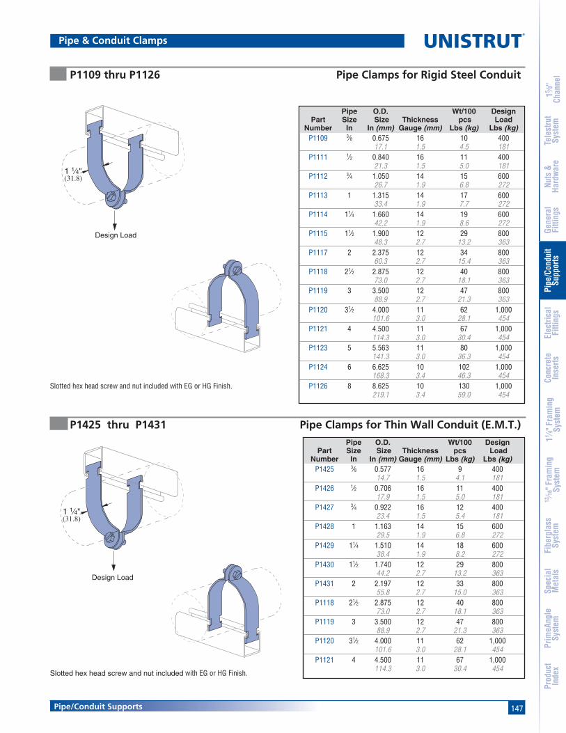
147
15 ⁄8"
Chan
nel
Nuts
&Ha
rdw
are
Gene
ral
Fitti
ngs
Pipe
/Con
duit
Supp
orts
Elec
trica
lFi
tting
sCo
ncre
teIn
serts
11 ⁄4" F
ram
ing
Syst
em13
⁄16" F
ram
ing
Syst
emFi
berg
lass
Syst
emSp
ecia
lM
etal
sTe
lest
rut
Syst
emPr
imeA
ngle
Syst
emPr
oduc
tIn
dex
Pipe/Conduit Supports
Pipe & Conduit Clamps
Slotted hex head screw and nut included with EG or HG Finish.
P1109 thru P1126 Pipe Clamps for Rigid Steel Conduit
Pipe O.D. Wt/100 DesignPart Size Size Thickness pcs Load
Number In In (mm) Gauge (mm) Lbs (kg) Lbs (kg)P1109 3⁄8 0.675 16 10 400
17.1 1.5 4.5 181P1111 1⁄2 0.840 16 11 400
21.3 1.5 5.0 181P1112 3⁄4 1.050 14 15 600
26.7 1.9 6.8 272P1113 1 1.315 14 17 600
33.4 1.9 7.7 272P1114 11⁄4 1.660 14 19 600
42.2 1.9 8.6 272P1115 11⁄2 1.900 12 29 800
48.3 2.7 13.2 363P1117 2 2.375 12 34 800
60.3 2.7 15.4 363P1118 21⁄2 2.875 12 40 800
73.0 2.7 18.1 363P1119 3 3.500 12 47 800
88.9 2.7 21.3 363P1120 31⁄2 4.000 11 62 1,000
101.6 3.0 28.1 454P1121 4 4.500 11 67 1,000
114.3 3.0 30.4 454P1123 5 5.563 11 80 1,000
141.3 3.0 36.3 454P1124 6 6.625 10 102 1,000
168.3 3.4 46.3 454P1126 8 8.625 10 130 1,000
219.1 3.4 59.0 454
Slotted hex head screw and nut included with EG or HG Finish.
P1425 thru P1431 Pipe Clamps for Thin Wall Conduit (E.M.T.)Pipe O.D. Wt/100 Design
Part Size Size Thickness pcs LoadNumber In In (mm) Gauge (mm) Lbs (kg) Lbs (kg)
P1425 3⁄8 0.577 16 9 40014.7 1.5 4.1 181
P1426 1⁄2 0.706 16 11 40017.9 1.5 5.0 181
P1427 3⁄4 0.922 16 12 40023.4 1.5 5.4 181
P1428 1 1.163 14 15 60029.5 1.9 6.8 272
P1429 11⁄4 1.510 14 18 60038.4 1.9 8.2 272
P1430 11⁄2 1.740 12 29 80044.2 2.7 13.2 363
P1431 2 2.197 12 33 80055.8 2.7 15.0 363
P1118 21⁄2 2.875 12 40 80073.0 2.7 18.1 363
P1119 3 3.500 12 47 80088.9 2.7 21.3 363
P1120 31⁄2 4.000 11 62 1,000101.6 3.0 28.1 454
P1121 4 4.500 11 67 1,000114.3 3.0 30.4 454
1 1⁄4"(31.8)
Design Load
1 1⁄4"(31.8)
Design Load

148
®
15 ⁄8"
Chan
nel
Nuts
&Ha
rdw
are
Gene
ral
Fitti
ngs
Pipe
/Con
duit
Supp
orts
Elec
trica
lFi
tting
sCo
ncre
teIn
serts
11 ⁄4" F
ram
ing
Syst
em13
⁄16" F
ram
ing
Syst
emFi
berg
lass
Syst
emSp
ecia
lM
etal
sTe
lest
rut
Syst
emPr
imeA
ngle
Syst
emPr
oduc
tIn
dex
Pipe/Conduit Supports
O.D. Wt/100 DesignPart Size pcs Load
Number In (mm) Lbs (kg) Lbs (kg)
P2024 1⁄4 86.4 3.6
P2025 3⁄8 8 4009.5 3.6 181
P2026 1⁄2 912.7 4.1
P2027 5⁄8 1015.9 4.5
P2028 3⁄4 1119.1 5.0
P2029 7⁄8 1222.2 5.4
P2030 1 1425.4 6.4
P2031 11⁄8 15 60028.6 6.8 272
P2032 11⁄4 1631.8 7.3
P2033 13⁄8 1734.9 7.7
P2034 11⁄2 1838.1 8.2
P2035 15⁄8 1941.3 8.6
P1430 13⁄4 2944.5 13.2
P2037 17⁄8 2847.6 12.7
P2038 2 31 80050.8 14.1 363
P2039 21⁄8 3254.0 14.5
P2040 21⁄4 3357.2 15.0
P1117 23⁄8 3460.3 15.4
P2042 21⁄2 3563.5 15.9
P2043 25⁄8 3766.7 16.8
P2044 23⁄4 3869.9 17.2
P1118 27⁄8 4073.0 18.1
P2046 3 4176.2 18.6
O.D. Wt/100 DesignPart Size pcs Load
Number In (mm) Lbs (kg) Lbs (kg)
P2047 31⁄8 4379.4 19.5
P2048 31⁄4 45 80082.6 20.4 363
P2049 33⁄8 4685.7 20.9
P1119 31⁄2 4788.9 21.3
P2051 35⁄8 5692.1 25.4
P2052 33⁄4 5895.3 26.3
P2053 37⁄8 60 1,00098.4 27.2 454
P1120 4 62101.6 28.1
P2055 41⁄8 62104.8 28.1
P2056 41⁄4 64108.0 29.0
P2057 43⁄8 66111.1 29.9
P1121 41⁄2 67114.3 30.4
P2059 45⁄8 70117.5 31.8
P2060 43⁄4 72120.7 32.7
P2061 47⁄8 73123.8 33.1
P2062 5 74127.0 33.6
P2063 51⁄8 76130.2 34.5
P2064 51⁄4 77133.4 34.9
P2065 53⁄8 78136.5 35.4
P2066 51⁄2 79139.7 35.8
P2067 55⁄8 88142.9 39.9
P2068 53⁄4 90146.1 40.8
P2069 57⁄8 92149.2 41.7
O.D. Wt/100 DesignPart Size pcs Load
Number In (mm) Lbs (kg) Lbs (kg)
P2070 6 94152.4 42.6
P2070-61 61⁄8 96155.6 43.5
P2070-62 61⁄4 98158.8 44.5
P2070-63 63⁄8 99 1,000161.9 44.9 454
P2070-64 61⁄2 100165.1 45.4
P1124 65⁄8 102168.3 46.3
P2070-66 63⁄4 104171.5 47.2
P2070-67 67⁄8 106174.6 48.1
P2070-70 7 108177.8 49.0
P2070-71 71⁄8 110181.0 49.9
P2070-72 71⁄4 112184.2 50.8
P2070-73 73⁄8 114187.3 51.7
P2070-74 71⁄2 116190.5 52.6
P2070-75 75⁄8 117193.7 53.1
P2070-76 73⁄4 119196.9 54.0
P2070-77 77⁄8 121200.0 54.9
P2070-80 8 123203.2 55.8
P2070-81 81⁄8 125206.4 56.7
P2070-82 81⁄4 126209.6 57.2
P2070-83 83⁄8 128212.7 58.1
P2070-84 81⁄2 129215.9 58.5
P1126 85⁄8 130219.1 59.0
P2024 thru P2070-84 Pipe Clamps for O.D. Tubing
P2024 - P2029 16 ga.P2030 - P2035 14 ga.P2037 - P2052 12 ga.P2053 - P2066 11 ga.P2067 - P2070-84 10 ga.
Slotted hex head screw and nut included withEG or HG Finish.
Pipe & Conduit Clamps
1 1⁄4"(31.8)
Design Load

149
15 ⁄8"
Chan
nel
Nuts
&Ha
rdw
are
Gene
ral
Fitti
ngs
Pipe
/Con
duit
Supp
orts
Elec
trica
lFi
tting
sCo
ncre
teIn
serts
11 ⁄4" F
ram
ing
Syst
em13
⁄16" F
ram
ing
Syst
emFi
berg
lass
Syst
emSp
ecia
lM
etal
sTe
lest
rut
Syst
emPr
imeA
ngle
Syst
emPr
oduc
tIn
dex
Pipe/Conduit Supports
P1563 thru P1573 Parallel Clamps for Rigid Conduit and Pipe
P2008 thru P2020 One Hole Clamp for O.D. Tubing
Finish: Electro-galvanized and Aluminum
Slotted hex head screw and nut included.Finish: Electro-galvanized.
1 3⁄8"(34.9)
1⁄4" X 3⁄4" Round Head Machine Screw and Channel Nut Not Included
Slotted hex head screw and nut included with EG or HG Finish.
P1211 thru P1217 Universal Clamps for Rigid or Thinwall Conduit
Part Pipe/Conduit Size Thickness Wt/100 pcs Design LoadNumber In Gauge (mm) Lbs (kg) Lbs (kg)
P1211 1⁄2 16 10 4001.5 4.5 181
P1212 3⁄4 16 11 4001.5 5.0 181
P1213 1 16 12 4001.5 5.4 181
P1214 11⁄4 14 18 6001.9 8.2 272
P1215 11⁄2 14 20 6001.9 9.1 272
P1217 2 14 22 6001.9 10.0 272
Part Pipe Size O.D. Size Thickness Wt/100 pcsNumber In In (mm) Gauge (mm) Lbs (kg)
P1563 3⁄8 0.675 14 2717.1 1.9 12.2
P1564 1⁄2 0.840 14 2921.3 1.9 13.2
P1565 3⁄4 1.050 14 3026.7 1.9 13.6
P1566 1 1.315 14 3133.4 1.9 14.1
P1567 11⁄4 1.660 14 3842.2 1.9 17.2
P1568 11⁄2 1.900 12 4048.3 2.7 18.1
P1569 2 2.375 12 4760.3 2.7 21.3
P1570 21⁄2 2.875 12 6673.0 2.7 29.9
P1571 3 3.500 12 7888.9 2.7 35.4
P1572 31⁄2 4.000 12 87101.6 2.7 39.5
P1573 4 4.500 12 90114.3 2.7 40.8
Part O.D. Tube Size Thickness Wt/100 pcsNumber In (mm) Gauge (mm) Lbs (kg)
P2008 1⁄4 16 46.4 1.5 1.8
P2009 5⁄16 16 57.9 1.5 2.3
P2010 3⁄8 16 59.5 1.5 2.3
P2012 1⁄2 16 612.7 1.5 2.7
P2014 5⁄8 14 815.9 1.9 3.6
P2016 3⁄4 14 919.1 1.9 4.1
P2018 7⁄8 14 1022.2 1.9 4.5
P2020 1 14 1125.4 1.9 5.0
Pipe & Conduit Clamps
1 1⁄4"(31.8)
Design Load
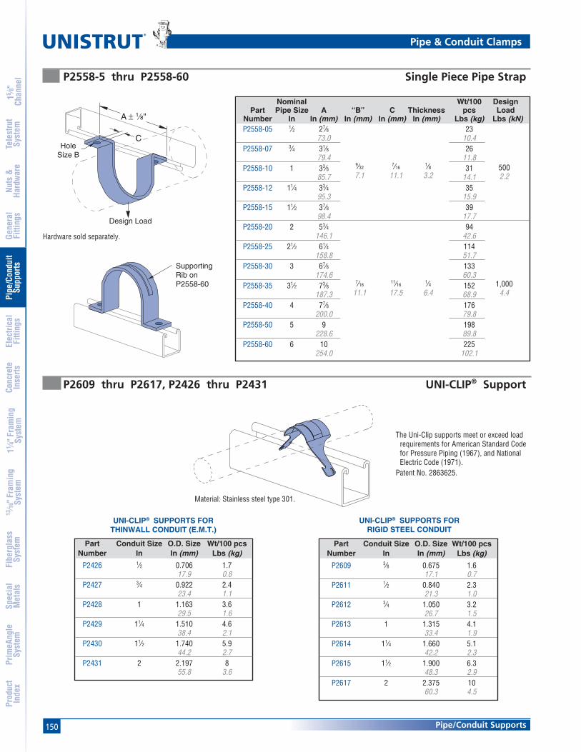
150
®
15 ⁄8"
Chan
nel
Nuts
&Ha
rdw
are
Gene
ral
Fitti
ngs
Pipe
/Con
duit
Supp
orts
Elec
trica
lFi
tting
sCo
ncre
teIn
serts
11 ⁄4" F
ram
ing
Syst
em13
⁄16" F
ram
ing
Syst
emFi
berg
lass
Syst
emSp
ecia
lM
etal
sTe
lest
rut
Syst
emPr
imeA
ngle
Syst
emPr
oduc
tIn
dex
Pipe/Conduit Supports
P2558-5 thru P2558-60 Single Piece Pipe Strap
P2609 thru P2617, P2426 thru P2431 UNI-CLIP® Support
UNI-CLIP® SUPPORTS FORRIGID STEEL CONDUIT
Material: Stainless steel type 301.
Hardware sold separately.
UNI-CLIP® SUPPORTS FORTHINWALL CONDUIT (E.M.T.)
Nominal Wt/100 DesignPart Pipe Size A “B” C Thickness pcs Load
Number In In (mm) In (mm) In (mm) In (mm) Lbs (kg) Lbs (kN)P2558-05 1⁄2 27⁄8 23
73.0 10.4P2558-07 3⁄4 31⁄8 26
79.4 11.8P2558-10 1 33⁄8 9⁄32
7⁄161⁄8 31 500
85.7 7.1 11.1 3.2 14.1 2.2P2558-12 11⁄4 33⁄4 35
95.3 15.9P2558-15 11⁄2 37⁄8 39
98.4 17.7P2558-20 2 53⁄4 94
146.1 42.6P2558-25 21⁄2 61⁄4 114
158.8 51.7P2558-30 3 67⁄8 133
174.6 60.3P2558-35 31⁄2 73⁄8 7⁄16
11⁄161⁄4 152 1,000
187.3 11.1 17.5 6.4 68.9 4.4P2558-40 4 77⁄8 176
200.0 79.8P2558-50 5 9 198
228.6 89.8P2558-60 6 10 225
254.0 102.1
Part Conduit Size O.D. Size Wt/100 pcsNumber In In (mm) Lbs (kg)
P2609 3⁄8 0.675 1.617.1 0.7
P2611 1⁄2 0.840 2.321.3 1.0
P2612 3⁄4 1.050 3.226.7 1.5
P2613 1 1.315 4.133.4 1.9
P2614 11⁄4 1.660 5.142.2 2.3
P2615 11⁄2 1.900 6.348.3 2.9
P2617 2 2.375 1060.3 4.5
Part Conduit Size O.D. Size Wt/100 pcsNumber In In (mm) Lbs (kg)
P2426 1⁄2 0.706 1.717.9 0.8
P2427 3⁄4 0.922 2.423.4 1.1
P2428 1 1.163 3.629.5 1.6
P2429 11⁄4 1.510 4.638.4 2.1
P2430 11⁄2 1.740 5.944.2 2.7
P2431 2 2.197 855.8 3.6
Pipe & Conduit Clamps
9⁄327⁄16
1⁄87.1 11.1 3.2
7⁄1611⁄16
1⁄411.1 17.5 6.4
The Uni-Clip supports meet or exceed loadrequirements for American Standard Codefor Pressure Piping (1967), and NationalElectric Code (1971).
Patent No. 2863625.
A ± 1⁄8"
CHole
Size B
Design Load
5002.2
1,0004.4
SupportingRib onP2558-60

151
15 ⁄8"
Chan
nel
Nuts
&Ha
rdw
are
Gene
ral
Fitti
ngs
Pipe
/Con
duit
Supp
orts
Elec
trica
lFi
tting
sCo
ncre
teIn
serts
11 ⁄4" F
ram
ing
Syst
em13
⁄16" F
ram
ing
Syst
emFi
berg
lass
Syst
emSp
ecia
lM
etal
sTe
lest
rut
Syst
emPr
imeA
ngle
Syst
emPr
oduc
tIn
dex
Pipe/Conduit Supports
Hardware included.Finish: Electro-galvanized.Pipe Clamp 11⁄4" WidePatent No. 3417951.Safety factor of 5
Finish: Electro-galvanized and Aluminum.
CA
B
C
D
E
A
B
P3409 thru P3417 Stand-off Pipe Clamps
M5025 thru M5060 One-piece Cable and Conduit Clamps
Part Load “D” Load “E”Number Lbs (kN) Lbs (kN)
P3409 100 2545.4 11.3
P3411 150 3568.0 15.9
P3412 175 4079.4 18.1
P3413 200 5090.7 22.7
P3414 300 70136.1 31.8
P3415 400 80181.4 36.3
P3417 500 120226.8 54.4
Part Pipe Size O.D. Size A B C Wt/100 pcs Number In In (mm) In (mm) In (mm) Gauge (mm) Lbs (kg)
P3409 3⁄8 0.675 11⁄8 21⁄8 14 1417.1 28.6 54.0 1.9 6.4
P3411 1⁄2 0.840 11⁄4 25⁄16 14 1521.3 31.8 58.7 1.9 6.8
P3412 3⁄4 1.050 15⁄16 21⁄2 14 1926.7 33.3 63.5 1.9 8.6
P3413 1 1.315 11⁄2 23⁄4 14 2233.4 38.1 69.9 1.9 10.0
P3414 11⁄4 1.660 111⁄16 31⁄4 12 3442.2 42.9 82.6 2.7 15.4
P3415 11⁄2 1.900 13⁄4 31⁄2 11 4948.3 44.5 88.9 3.0 22.2
P3417 2 2.375 2 4 10 5560.3 50.8 101.6 3.4 24.9
Part Max O.D. Size “A” “B” “C” Wt/100 pcs Number In (mm) In (mm) In (mm) Gauge (mm) Lbs (kg)
M5025 3⁄8 7⁄16 15⁄8 14 69.5 11.1 41.3 1.9 2.7
M5026 1⁄2 9⁄16 13⁄4 14 712.7 14.3 44.5 1.9 3.2
M5028 3⁄4 13⁄16 2 14 1219.1 20.6 50.8 1.9 5.4
M5030 1 11⁄16 21⁄4 14 1525.4 27.0 57.2 1.9 6.8
M5032 11⁄4 15⁄16 21⁄2 14 1931.8 33.3 63.5 1.9 8.6
M5034 11⁄2 19⁄16 23⁄4 14 2038.1 39.7 69.9 1.9 9.1
M5036 13⁄4 113⁄16 3 12 2544.5 46.0 76.2 2.7 11.3
M5038 2 21⁄16 31⁄4 12 3550.8 52.4 82.6 2.7 15.9
M5041 23⁄8 27⁄16 35⁄8 12 4160.3 61.9 92.1 2.7 18.6
M5044 23⁄4 213⁄16 4 12 6069.9 71.4 101.6 2.7 27.2
M5048 31⁄4 35⁄16 41⁄2 12 7482.6 84.1 114.3 2.7 33.6
M5052 33⁄4 313⁄16 5 12 9195.3 96.8 127.0 2.7 41.3
M5054 4 41⁄16 51⁄4 12 100101.6 103.2 133.4 2.7 45.4
M5057 43⁄8 47⁄16 55⁄8 10 115111.1 112.7 142.9 3.4 52.2
M5060 43⁄4 413⁄16 6 10 125120.7 122.2 152.4 3.4 56.7
Pipe & Conduit Clamps

152
®
15 ⁄8"
Chan
nel
Nuts
&Ha
rdw
are
Gene
ral
Fitti
ngs
Pipe
/Con
duit
Supp
orts
Elec
trica
lFi
tting
sCo
ncre
teIn
serts
11 ⁄4" F
ram
ing
Syst
em13
⁄16" F
ram
ing
Syst
emFi
berg
lass
Syst
emSp
ecia
lM
etal
sTe
lest
rut
Syst
emPr
imeA
ngle
Syst
emPr
oduc
tIn
dex
Pipe/Conduit Supports
P2600 UNICUSHION®: Isolation Material
COPPER TUBING TYPE K OR LSTANDARD PIPE ORRIGID CONDUITEMT CONDUIT
Clamp Selection & Cutting Guide UNICUSHION®
• 25 feet per carton.• Cut to length as shown in charts.
Wt/Carton: 2.5 Lbs (1.1 kg)
UNICUSHION FEATURES
• Shock absorption• Protection from corrosion and abrasion• Allowance for expansion and contraction• Sound and vibration isolation• Stability in use from - 50° F (-47° C) to + 350°F (+177° C)• Flexible elastomer material• Will not support combustion
Use UNICUSHIONNominal with Length
Size Clamp In (mm)3⁄8" P1426 13⁄4
44.51⁄2" P1111 21⁄8
54.03⁄4" P1112 23⁄4
69.91" P2032 35⁄8
92.111⁄4" P2035 43⁄4
120.711⁄2" P2037 51⁄2
139.72" P1117 63⁄4
171.5
Use UNICUSHIONNominal with Length
Size Clamp In (mm)3⁄8" P1111 21⁄8
54.01⁄2" P2030 3
76.23⁄4" P2031 31⁄4
82.61" P2034 41⁄4
108.011⁄4" P2037 51⁄4
133.411⁄2" P2038 6
152.42" P2042 71⁄2
190.521⁄2" P2046 9
228.63" P2051 11
279.431⁄2" P2055 121⁄4
311.24" P2059 14
355.65" P2067 171⁄2
444.56" P2070-66 203⁄4
527.1
Use UNICUSHIONNominal with Length
Size Clamp In (mm)1⁄4" P2026 11⁄16
27.03⁄8" P2027 11⁄2
38.11⁄2" P2028 21⁄8
54.05⁄8" P2029 21⁄4
57.23⁄4" P2030 3
76.21" P2032 35⁄8
92.111⁄4" P2034 41⁄2
114.311⁄2" P1430 51⁄4
133.42" P2040 63⁄4
171.521⁄2" P2044 81⁄4
209.63" P2048 10
254.031⁄2" P2052 111⁄4
285.84" P2056 121⁄2
317.55" P2064 16
406.46" P2070-62 19
482.68" P2070-82 25
635.0
UNICUSHION®

153
15 ⁄8"
Chan
nel
Nuts
&Ha
rdw
are
Gene
ral
Fitti
ngs
Pipe
/Con
duit
Supp
orts
Elec
trica
lFi
tting
sCo
ncre
teIn
serts
11 ⁄4" F
ram
ing
Syst
em13
⁄16" F
ram
ing
Syst
emFi
berg
lass
Syst
emSp
ecia
lM
etal
sTe
lest
rut
Syst
emPr
imeA
ngle
Syst
emPr
oduc
tIn
dex
Pipe/Conduit Supports
Clamp Selection & Cutting Guide (continued) UNICUSHION®
O. D. Use UNICUSHIONSize With Length
In (mm) Clamp In (mm)1⁄4 P2025 7⁄86.4 22.23⁄8 P2026 11⁄16
9.5 27.01⁄2 P2027 11⁄2
12.7 38.15⁄8 P2028 21⁄8
15.9 54.03⁄4 P2029 21⁄4
19.1 57.27⁄8 P2030 3
22.2 76.21 P2031 31⁄4
25.4 82.611⁄8 P2032 35⁄828.6 92.111⁄4 P2033 431.8 101.613⁄8 P2034 41⁄234.9 114.311⁄2 P2035 47⁄838.1 123.815⁄8 P1430 51⁄441.3 133.413⁄4 P2037 51⁄244.5 139.717⁄8 P2038 647.6 152.4
2 P2039 61⁄250.8 165.121⁄8 P2040 63⁄454.0 171.521⁄4 P1117 71⁄457.2 184.223⁄8 P2042 71⁄260.3 190.521⁄2 P2043 863.5 203.225⁄8 P2044 81⁄466.7 209.623⁄4 P1118 83⁄469.9 222.327⁄8 P2046 91⁄473.0 235.0
3 P2047 91⁄276.2 241.3
O. D. Use UNICUSHIONSize With Length
In (mm) Clamp In (mm)
31⁄8 P2048 1079.4 254.031⁄4 P2049 101⁄282.6 266.733⁄8 P1119 103⁄485.7 273.131⁄2 P2051 1188.9 279.435⁄8 P2052 111⁄492.1 285.833⁄4 P2053 111⁄295.3 292.137⁄8 P1120 113⁄498.4 298.5
4 P2055 12101.6 304.841⁄8 P2056 121⁄2
104.8 317.541⁄4 P2057 13
108.0 330.243⁄8 P1121 131⁄2
111.1 342.941⁄2 P2059 14
114.3 355.645⁄8 P2060 141⁄4
117.5 362.043⁄4 P2061 143⁄4
120.7 374.747⁄8 P2062 15
123.8 381.05 P2063 151⁄2
127.0 393.751⁄8 P2064 16
130.2 406.451⁄4 P2065 161⁄4
133.4 412.853⁄8 P2066 161⁄2
136.5 419.151⁄2 P2067 17
139.7 431.855⁄8 P2068 171⁄2
142.9 444.553⁄4 P2069 173⁄4
146.1 450.957⁄8 P2070 181⁄4
149.2 463.6
O. D. Use UNICUSHIONSize With Length
In (mm) Clamp In (mm)
6 P2070-61 181⁄2152.4 469.961⁄8 P2070-62 19
155.6 482.661⁄4 P2070-63 191⁄4
158.8 489.063⁄8 P2070-64 193⁄4
161.9 501.761⁄2 P1124 20
165.1 508.065⁄8 P2070-66 201⁄2
168.3 520.763⁄4 P2070-67 21
171.5 533.467⁄8 P2070-70 211⁄4
174.6 539.87 P2070-71 213⁄4
177.8 552.571⁄8 P2070-72 22
181.0 558.871⁄4 P2070-73 221⁄2
184.2 571.573⁄8 P2070-74 223⁄4
187.3 577.971⁄2 P2070-75 231⁄4
190.5 590.675⁄8 P2070-76 231⁄2
193.7 596.973⁄4 P2070-77 24
196.9 609.677⁄8 P2070-80 241⁄2
200.0 622.38 P2070-81 243⁄4
203.2 628.781⁄8 P2070-82 25
206.4 635.081⁄4 P2070-83 251⁄2
209.6 647.783⁄8 P2070-84 26
212.7 660.481⁄2 P1126 261⁄4
215.9 666.8
UNICUSHION®
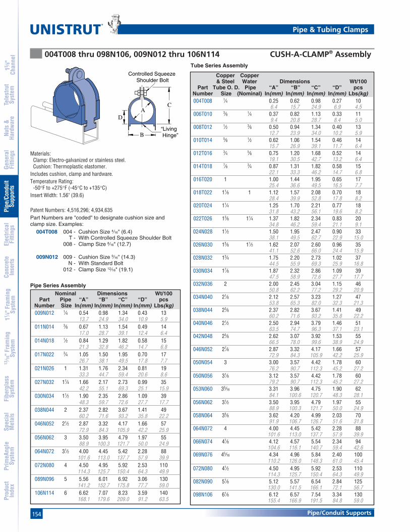
154
®
15 ⁄8"
Chan
nel
Nuts
&Ha
rdw
are
Gene
ral
Fitti
ngs
Pipe
/Con
duit
Supp
orts
Elec
trica
lFi
tting
sCo
ncre
teIn
serts
11 ⁄4" F
ram
ing
Syst
em13
⁄16" F
ram
ing
Syst
emFi
berg
lass
Syst
emSp
ecia
lM
etal
sTe
lest
rut
Syst
emPr
imeA
ngle
Syst
emPr
oduc
tIn
dex
Pipe/Conduit Supports
004T008 thru 098N106, 009N012 thru 106N114 CUSH-A-CLAMP® Assembly
PIPE/TUBING CLAMPSFOR 15⁄8" (41 MM) WIDTH SERIES CHANNEL
Tube Series Assembly
Part Numbers are "coded" to designate cushion size andclamp size. Examples:
004T008 004 - Cushion Size 4⁄16" (6.4)T - With Controlled Squeeze Shoulder Bolt
008 - Clamp Size 8⁄16" (12.7)
009N012 009 - Cushion Size 9⁄16" (14.3)N - With Standard Bolt
012 - Clamp Size 12⁄16" (19.1)
C
B
D
Controlled Squeeze Shoulder Bolt
“Living Hinge”
A
Materials:Clamp: Electro-galvanized or stainless steel.Cushion: Thermoplastic elastomer.
Includes cushion, clamp and hardware.Temperature Rating:
-50°F to +275°F (-45°C to +135°C)Insert Width: 1.56" (39.6)
Patent Numbers: 4,516,296; 4,934,635
Pipe Series Assembly
Nominal Dimensions Wt/100Part Pipe “A” “B” “C” “D” pcs
Number Size In(mm) In(mm) In(mm) In(mm) Lbs(kg)009N012 1⁄4 0.54 0.98 1.34 0.43 13
13.7 24.9 34.0 10.9 5.9011N014 3⁄8 0.67 1.13 1.54 0.49 14
17.0 28.7 39.1 12.4 6.4014N018 1⁄2 0.84 1.29 1.82 0.58 15
21.3 32.8 46.2 14.7 6.8017N022 3⁄4 1.05 1.50 1.95 0.70 17
26.7 38.1 49.5 17.8 7.7021N026 1 1.31 1.76 2.34 0.81 19
33.3 44.7 59.4 20.6 8.6027N032 11⁄4 1.66 2.17 2.73 0.99 35
42.2 55.1 69.3 25.1 15.9030N034 11⁄2 1.90 2.35 2.86 1.09 39
48.3 59.7 72.6 27.7 17.7038N044 2 2.37 2.82 3.67 1.41 49
60.2 71.6 93.2 35.8 22.2046N052 21⁄2 2.87 3.32 4.17 1.66 57
72.9 84.3 105.9 42.2 25.9056N062 3 3.50 3.95 4.79 1.97 55
88.9 100.3 121.7 50.0 24.9064N072 31⁄2 4.00 4.45 5.42 2.28 88
101.6 113.0 137.7 57.9 39.9072N080 4 4.50 4.95 5.92 2.53 110
114.3 125.7 150.4 64.3 49.9089N096 5 5.56 6.01 6.92 3.06 130
141.2 152.7 175.8 77.7 59.0106N114 6 6.62 7.07 8.23 3.59 140
168.1 179.6 209.0 91.2 63.5
Copper Copper& Steel Water Dimensions Wt/100
Part Tube O. D. Pipe “A” “B” “C” “D” pcsNumber Size (Nominal) In(mm) In(mm) In(mm) In(mm) Lbs(kg)004T008 1⁄4 0.25 0.62 0.98 0.27 10
6.4 15.7 24.9 6.9 4.5006T010 3⁄8 1⁄4 0.37 0.82 1.13 0.33 11
9.4 20.8 28.7 8.4 5.0008T012 1⁄2 3⁄8 0.50 0.94 1.34 0.40 13
12.7 23.9 34.0 10.2 5.9010T014 5⁄8 1⁄2 0.62 1.06 1.54 0.46 14
15.7 26.9 39.1 11.7 6.4012T016 3⁄4 5⁄8 0.75 1.20 1.68 0.52 14
19.1 30.5 42.7 13.2 6.4014T018 7⁄8 3⁄4 0.87 1.31 1.82 0.58 15
22.1 33.3 46.2 14.7 6.8016T020 1 1.00 1.44 1.95 0.65 17
25.4 36.6 49.5 16.5 7.7018T022 11⁄8 1 1.12 1.57 2.08 0.70 18
28.4 39.9 52.8 17.8 8.2020T024 11⁄4 1.25 1.70 2.21 0.77 18
31.8 43.2 56.1 19.6 8.2022T026 13⁄8 11⁄4 1.37 1.82 2.34 0.83 20
34.8 46.2 59.4 21.1 9.1024N028 11⁄2 1.50 1.95 2.47 0.90 33
38.1 49.5 62.7 22.9 15.0026N030 15⁄8 11⁄2 1.62 2.07 2.60 0.96 35
41.1 52.6 66.0 24.4 15.9028N032 13⁄4 1.75 2.20 2.73 1.02 37
44.5 55.9 69.3 25.9 16.8030N034 17⁄8 1.87 2.32 2.86 1.09 39
47.5 58.9 72.6 27.7 17.7032N036 2 2.00 2.45 3.04 1.15 46
50.8 62.2 77.2 29.2 20.9034N040 21⁄8 2.12 2.57 3.23 1.27 47
53.8 65.3 82.0 32.3 21.3038N044 23⁄8 2.37 2.82 3.67 1.41 49
60.2 71.6 93.2 35.8 22.2040N046 21⁄2 2.50 2.94 3.79 1.46 51
63.5 74.7 96.3 37.1 23.1042N048 25⁄8 2.62 3.07 3.92 1.53 55
66.5 78.0 99.6 38.9 24.9046N052 27⁄8 2.87 3.32 4.17 1.66 57
72.9 84.3 105.9 42.2 25.9050N054 3 3.00 3.57 4.42 1.78 60
76.2 90.7 112.3 45.2 27.2050N056 31⁄8 3.12 3.57 4.42 1.78 60
79.2 90.7 112.3 45.2 27.2053N060 35⁄16 3.31 3.96 4.75 1.90 62
84.1 100.6 120.7 48.3 28.1056N062 31⁄2 3.50 3.95 4.79 1.97 55
88.9 100.3 121.7 50.0 24.9058N064 35⁄8 3.62 4.20 4.99 2.03 70
91.9 106.7 126.7 51.6 31.8064N072 4 4.00 4.45 5.42 2.28 88
101.6 113.0 137.7 57.9 39.9066N074 41⁄8 4.12 4.57 5.54 2.34 94
104.6 116.1 140.7 59.4 42.6069N076 45⁄16 4.34 4.96 5.84 2.40 100
110.2 126.0 148.3 61.0 45.4072N080 41⁄2 4.50 4.95 5.92 2.53 110
114.3 125.7 150.4 64.3 49.9082N090 51⁄8 5.12 5.57 6.54 2.84 125
130.0 141.5 166.1 72.1 56.7098N106 61⁄8 6.12 6.57 7.54 3.34 130
155.4 166.9 191.5 84.8 59.0
Pipe & Tubing Clamps

155
15 ⁄8"
Chan
nel
Nuts
&Ha
rdw
are
Gene
ral
Fitti
ngs
Pipe
/Con
duit
Supp
orts
Elec
trica
lFi
tting
sCo
ncre
teIn
serts
11 ⁄4" F
ram
ing
Syst
em13
⁄16" F
ram
ing
Syst
emFi
berg
lass
Syst
emSp
ecia
lM
etal
sTe
lest
rut
Syst
emPr
imeA
ngle
Syst
emPr
oduc
tIn
dex
Pipe/Conduit Supports
004M007 thru 034M040 CUSH-A-CLAMP® Assembly Omega Series™
Note: Cannot be mounted on the slotted side of metal framing channel. Can be mounted to any flat surface.
A
B
F
G
D
C
E HE
JIncludes clamp and cushion.Materials: Clamp: ZD or stainless steel.
Cushion: Thermoplastic elastomer..
Copper Copper& Steel Water PipeTubing Pipe Size Dimensions Wt/100
Part O. D. (Nominal)(Nominal) “A” “B” “C” “D” “E” “F” “G” “H” “J” pcsNumber In In In In (mm) In (mm) In (mm) In (mm) In (mm) In (mm) In (mm) In (mm) In (mm) Lbs (kg)004M007 1⁄4 0.25 1.81 0.06 0.60 0.20 0.53 0.48 0.62 0.78 3.4
6.4 46.0 1.5 15.2 5.1 13.5 12.2 15.7 19.8 1.5006M008 3⁄8 1⁄4 0.37 1.90 0.06 0.65 0.20 0.62 0.62 0.62 0.81 4.0
9.4 48.3 1.5 16.5 5.1 15.7 15.7 15.7 20.6 1.8008M011 1⁄2 3⁄8 1⁄4 0.50 2.20 0.06 0.80 0.26 0.82 0.75 0.75 0.98 5.5
12.7 55.9 1.5 20.3 6.6 20.8 19.1 19.1 24.9 2.5010M013 5⁄8 1⁄2 3⁄8 0.62 2.32 0.06 0.86 0.26 0.94 0.87 0.75 0.98 6.0
15.7 58.9 1.5 21.8 6.6 23.9 22.1 19.1 24.9 2.7012M015 3⁄4 5⁄8 0.75 2.41 0.06 0.90 0.26 1.03 1.01 0.75 0.98 6.5
19.1 61.2 1.5 22.9 6.6 26.2 25.7 19.1 24.9 2.9014M017 7⁄8 3⁄4 1⁄2 0.87 2.56 0.06 0.98 0.26 1.18 1.03 0.75 0.98 7.1
22.1 65.0 1.5 24.9 6.6 30.0 26.2 19.1 24.9 3.2016M019 1 1.00 2.68 0.06 1.04 0.26 1.31 1.25 0.75 0.98 7.8
25.4 68.1 1.5 26.4 6.6 33.3 31.8 19.1 24.9 3.5018M020 3⁄4 1.05 2.68 0.06 1.04 0.26 1.31 1.25 0.75 0.98 8.1
26.7 68.1 1.5 26.4 6.6 33.3 31.8 19.1 24.9 3.7018M021 11⁄8 1 1.12 2.82 0.06 1.11 0.26 1.44 1.33 0.75 0.98 8.4
28.4 71.6 1.5 28.2 6.6 36.6 33.8 19.1 24.9 3.8020M024 11⁄4 1.25 3.00 0.08 1.20 0.26 1.65 1.47 1.25 1.56 17
31.8 76.2 2.0 30.5 6.6 41.9 37.3 31.8 39.6 7.7021M026 1 1.31 3.12 0.08 1.26 0.26 1.76 1.71 1.25 1.56 20
33.3 79.2 2.0 32.0 6.6 44.7 43.4 31.8 39.6 9.1022M026 13⁄8 11⁄4 1.37 3.12 0.08 1.26 0.26 1.76 1.71 1.25 1.56 19
34.8 79.2 2.0 32.0 6.6 44.7 43.4 31.8 39.6 8.6024M028 11⁄2 1.50 3.65 0.08 1.42 0.26 1.93 1.88 1.25 1.56 20
38.1 92.7 2.0 36.1 6.6 49.0 47.8 31.8 39.6 9.1026M030 15⁄8 11⁄2 1.62 3.77 0.08 1.48 0.26 2.07 2.00 1.25 1.56 23
41.1 95.8 2.0 37.6 6.6 52.6 50.8 31.8 39.6 10.4027M032 11⁄4 1.66 3.90 0.10 1.55 0.33 2.21 2.12 1.25 1.56 32
42.2 99.1 2.5 39.4 8.4 56.1 53.8 31.8 39.6 14.5028M032 13⁄4 1.75 3.90 0.10 1.55 0.33 2.21 2.12 1.25 1.56 32
44.5 99.1 2.5 39.4 8.4 56.1 53.8 31.8 39.6 14.5030M034 17⁄8 11⁄2 1.87 4.02 0.10 1.61 0.33 2.33 2.25 1.25 1.56 34
47.5 102.1 2.5 40.9 8.4 59.2 57.2 31.8 39.6 15.4032M036 2 2.00 4.15 0.10 1.67 0.33 2.46 2.38 1.25 1.56 36
50.8 105.4 2.5 42.4 8.4 62.5 60.5 31.8 39.6 16.3034M040 21⁄8 2.12 4.40 0.10 1.80 0.33 2.71 2.62 1.25 1.56 41
53.8 111.8 2.5 45.7 8.4 68.8 66.5 31.8 39.6 18.6038M044 2 2.37 4.71 0.10 1.94 0.33 2.96 2.88 1.25 1.56 44
60.2 119.6 2.5 49.3 8.4 75.2 73.2 31.8 39.6 20.0082M090 51⁄8 5.12 7.64 0.10 3.41 0.40 5.83 6.75 1.25 1.56 120
130.0 194.1 2.5 86.6 10.2 148.1 171.5 31.8 39.6 54.4
Pipe & Tubing Clamps

156
®
15 ⁄8"
Chan
nel
Nuts
&Ha
rdw
are
Gene
ral
Fitti
ngs
Pipe
/Con
duit
Supp
orts
Elec
trica
lFi
tting
sCo
ncre
teIn
serts
11 ⁄4" F
ram
ing
Syst
em13
⁄16" F
ram
ing
Syst
emFi
berg
lass
Syst
emSp
ecia
lM
etal
sTe
lest
rut
Syst
emPr
imeA
ngle
Syst
emPr
oduc
tIn
dex
Pipe/Conduit Supports
UB1⁄2PA thru UB12PA CUSH–A–CLAMP® Assembly U-Bolt Series
Includes U bolt, cushion, and hardware.Materials:
U Bolt: Electro-galvanized finish or Type 316SSCushion: Thermoplastic elastomer.
Note: Not intended for use with metal framing components due to the lengthof the thread.
CHB
D
E 30°(0.17π)
A
1⁄2" thru 6" assembly.
B H
30°(0.17π)
C
A
DE
8" thru 12" assembly.
PipeSize Dimensions Wt/100
Part (Nominal) “A” “B” “C” “D” “E” “F” pcsNumber In In (mm) In (mm) In (mm) In (mm) In (mm) In (mm) H Lbs (kg)UB1⁄2PA 1⁄2 0.84 1.60 0.68 1.5 0.67 1⁄4 1⁄4-20 UNC-2B 9
21.3 40.6 17.3 38.1 17.0 6.4 4.1UB3⁄4PA 3⁄4 1.05 1.80 0.68 1.6 0.78 1⁄4 1⁄4-20 UNC-2B 10
26.7 45.7 17.3 40.6 19.8 6.4 4.5UB1PA 1 1.31 2.05 0.68 1.7 0.91 1⁄4 1⁄4-20 UNC-2B 12
33.3 52.1 17.3 43.2 23.1 6.4 5.4UB11⁄4PA 11⁄4 1.66 2.54 1.24 2.1 1.08 3⁄8 3⁄8-16 UNC-2B 36
42.2 64.5 31.5 53.3 27.4 9.5 16.3UB11⁄2PA 11⁄2 1.90 2.78 1.24 2.2 1.19 3⁄8 3⁄8-16 UNC-2B 32
48.3 70.6 31.5 55.9 30.2 9.5 14.5UB2PA 2 2.37 3.32 1.24 2.5 1.45 3⁄8 3⁄8-16 UNC-2B 42
60.2 84.3 31.5 63.5 36.8 9.5 19.1UB21⁄2PA 21⁄2 2.87 3.88 1.24 3.0 1.69 1⁄2 1⁄2-13 UNC-2B 72
72.9 98.6 31.5 76.2 42.9 12.7 32.7UB3PA 3 3.50 4.50 1.24 3.3 2.00 1⁄2 1⁄2-13 UNC-2B 84
88.9 114.3 31.5 83.8 50.8 12.7 38.1UB31⁄2PA 31⁄2 4.00 5.00 1.24 3.7 2.25 1⁄2 1⁄2-13 UNC-2B 93
101.6 127.0 31.5 94.0 57.2 12.7 42.2UB4PA 4 4.50 5.50 1.24 3.9 2.5 1⁄2 1⁄2-13 UNC-2B 102
114.3 139.7 31.5 99.1 63.5 12.7 46.3UB5PA 5 5.56 6.59 1.24 4.5 3.03 1⁄2 1⁄2-13 UNC-2B 123
141.2 167.4 31.5 114.3 77.0 12.7 55.8UB6PA 6 6.62 7.81 1.44 5.4 3.56 5⁄8 5⁄8-11 UNC-2B 123
168.1 198.4 36.6 137.2 90.4 15.9 55.8UB8PA 8 8.62 9.84 1.44 6.4 4.56 5⁄8 5⁄8-11 UNC-2B 243
218.9 249.9 36.6 162.6 115.8 15.9 110.2UB10PA 10 10.75 12.25 1.65 7.7 5.68 3⁄4 3⁄4-10 UNC-2B 492
273.1 311.2 41.9 195.6 144.3 19.1 223.2UB12PA 12 12.75 14.25 1.65 8.7 6.68 3⁄4 3⁄4-10 UNC-2B 563
323.9 362.0 41.9 221.0 169.7 19.1 255.4
Pipe & Tubing Clamps

157
15 ⁄8"
Chan
nel
Nuts
&Ha
rdw
are
Gene
ral
Fitti
ngs
Pipe
/Con
duit
Supp
orts
Elec
trica
lFi
tting
sCo
ncre
teIn
serts
11 ⁄4" F
ram
ing
Syst
em13
⁄16" F
ram
ing
Syst
emFi
berg
lass
Syst
emSp
ecia
lM
etal
sTe
lest
rut
Syst
emPr
imeA
ngle
Syst
emPr
oduc
tIn
dex
Pipe/Conduit Supports
PUX3834 thru PUX41810 CUSH–A–THERM™
Part Hole CopperNumber Size Nom. I.D. O.D. IPS O.D. Length
In(mm) In(mm) In(mm) In(mm) In(mm) In(mm)PUX3834 3⁄8 ID 1⁄4 3⁄8 - 1.81 2.17
9.5 6.4 9.5 46.0 55.1PUX1234 1⁄2 ID 3⁄8 1⁄2 1⁄4 1.89 2.17
12.7 9.8 12.7 6.4 48.0 55.1PUX5834 5⁄8 ID 1⁄2 5⁄8 3⁄8 2.05 2.17
15.9 12.7 15.9 9.5 52.1 55.1PUX3434 3⁄4 ID 5⁄8 3⁄4 - 2.22 2.17
19.1 15.9 19.1 56.4 55.1PUX7834 7⁄8 ID 3⁄4 7⁄8 1⁄2 2.44 2.17
22.2 19.1 22.2 12.7 62.0 55.1PUX11834 11⁄8 ID 1 11⁄8 3⁄4 2.76 2.17
28.6 25.4 28.6 29.1 70.1 55.1PUX13834 13⁄8 ID 11⁄4 13⁄8 1 3.19 2.56
34.9 31.8 34.9 25.4 81.0 65.0PUX15834 15⁄8 ID 11⁄2 15⁄8 11⁄4 3.35 2.58
41.3 38.1 41.3 31.8 85.1 65.5PUX21834 21⁄8 ID 2 21⁄8 - 3.86 2.56
54.0 50.8 54.0 98.0 65.0PUX23834 23⁄8 ID 21⁄4 23⁄8 2 4.29 2.96
60.3 57.2 60.3 50.8 109.0 75.2PUX25834 25⁄8 ID 21⁄2 25⁄8 - 4.87 2.96
66.7 63.5 66.7 123.7 75.2PUX31834 31⁄8 ID 3 31⁄8 - 5.00 3.35
79.4 76.2 79.4 127.0 85.1PUX35834 35⁄8 ID 31⁄2 35⁄8 - 5.94 3.94
92.1 88.9 92.1 150.9 100.1PUX41834 41⁄8 ID 4 41⁄8 31⁄2 6.14 3.94
104.8 101.6 104.8 88.9 156.0 100.1
Part Hole CopperNumber Size Nom. I.D. O.D. IPS O.D. Length
In(mm) In(mm) In(mm) In(mm) In(mm) In(mm)PUX5810 5⁄8 ID 1⁄2 5⁄8 3⁄8 2.54 2.17
15.9 12.7 15.9 9.5 64.5 55.1PUX3410 3⁄4 ID 5⁄8 3⁄4 - 2.82 2.17
19.1 15.9 19.1 71.6 55.1PUX7810 7⁄8 ID 3⁄4 7⁄8 1⁄2 2.82 2.17
22.2 19.1 22.2 12.7 71.6 55.1PUX11810 11⁄8 ID 1 11⁄8 3⁄4 3.06 2.17
28.6 25.4 28.6 19.1 77.7 55.1PUX13810 13⁄8 ID 11⁄4 13⁄8 1 3.33 2.56
34.9 31.8 34.9 25.4 84.6 65.0PUX15810 15⁄8 ID 11⁄2 15⁄8 11⁄4 3.65 2.56
41.3 38.1 41.3 31.8 92.7 65.0PUX21810 21⁄8 ID 2 21⁄8 - 4.16 2.56
54.0 50.8 54.0 105.7 65.0PUX23810 23⁄8 ID 21⁄4 23⁄8 2 3.92 2.56
60.3 57.2 60.3 50.8 99.6 65.0PUX25810 25⁄8 ID 21⁄2 25⁄8 4.87 2.96
66.7 63.5 66.7 123.7 75.2PUX31810 31⁄8 ID 3 31⁄8 - 5.14 3.35
79.4 76.2 79.4 130.6 85.1PUX35810 35⁄8 ID 31⁄2 35⁄8 - 6.48 3.94
92.1 88.9 92.1 164.6 100.1PUX41810 41⁄8 ID 4 41⁄8 31⁄2 6.48 3.94
104.8 101.6 104.8 88.9 164.6 100.1
Nominal 3⁄4" Wall
Nominal 1" Wall
The only airtight, crush-resistant insulation clamp on the market.• Maintains thermal barrier protection• Prevents condensation• Properly supports pipe and tube• Absorbs vibration
CG-10 thru CG-40 CUSH–A–GRIP®
Includes Cushion, V-pad, and Hardware.Materials: Cushion: Thermoplastic elastomer.Hardware: Stainless Steel with Captured Nylon LocknutTemperature Rating:
-40°F to +275°F (-40°C to 135°C)
O.D. Nominal PullOut SlipPart Tube Sizes Pipe Sizes Diameters Load Load
Number In(mm) In(mm) In(mm) Lbs(kg) Lbs(kg)CG-10 1⁄4 3⁄8 1⁄2 1⁄4 0.25 - 0.54 500 40
6.4 9.5 12.7 6.4 6.4 - 13.7 226.8 18.1CG-20 5⁄8 3⁄4 7⁄8 3⁄8 1⁄2 0.62 - 0.87 500 40
15.9 19.1 22.2 9.5 12.7 15.7 - 22.1 226.8 18.1CG-30 7⁄8 1 11⁄8 3⁄4 0.87 - 1.12 500 40
22.2 25.4 28.6 19.1 22.1 - 28.5 226.8 18.1CG-40 1 11⁄8 11⁄4 3⁄4 1 1.00 - 1.31 500 40
25.4 28.6 31.8 19.1 25.4 25.4 - 33.3 226.8 18.1
Nominal Dimensions Hex Head Wt/100Part Pipe “A” “B” “C” “D” Cap Screw pcs
Number Size In(mm) In(mm) In(mm) In(mm) & Lock Nut Lbs(kg)CG-10 1⁄4 115⁄16 13⁄8 3⁄8 3⁄16
1⁄4-20 x 11⁄2" 449.2 34.9 9.5 4.8 1.8
CG-20 3⁄8 23⁄8 15⁄8 7⁄161⁄4 1⁄4-20 x 2" 6
60.3 41.3 11.1 6.4 2.7CG-30 1⁄2 29⁄16 113⁄16
7⁄165⁄16
1⁄4-20 x 2" 865.1 46.0 11.1 7.9 3.6
CG-40 3⁄4 211⁄16 115⁄167⁄16
5⁄161⁄4-20 x 2" 8
68.3 49.2 11.1 7.9 3.6
B
C
D
V-Pad
17⁄16"(36.5)
A
Pipe & Tubing Clamps

158
®
15 ⁄8"
Chan
nel
Nuts
&Ha
rdw
are
Gene
ral
Fitti
ngs
Pipe
/Con
duit
Supp
orts
Elec
trica
lFi
tting
sCo
ncre
teIn
serts
11 ⁄4" F
ram
ing
Syst
em13
⁄16" F
ram
ing
Syst
emFi
berg
lass
Syst
emSp
ecia
lM
etal
sTe
lest
rut
Syst
emPr
imeA
ngle
Syst
emPr
oduc
tIn
dex
Pipe/Conduit Supports
J1205 thru J1280, J1205 N thru J 1280 N (Plastic Coated) "J" Conduit & Pipe Hanger
*Standard glass drainline and glass process pipe sizes.Minimum safety factor of five (5) on ultimate load.
Hex Bolt Size as Listed
Rod Size A Listed
"T" Bolt and Nut Included
Plastic Coated
Hanger Rod Suspended
Hole Diameter E
B D
C
RodSize A
BoltSize F
Plastic Coated("N" Suffix)
Wt/100 Wt/100 Pipe LoadPart pcs Part pcs Size “A” “B” “C” “D” “E” “F” LbsNumber Lbs (kg) Number Lbs (kg) In In (mm) In (mm) In (mm) In (mm) In (mm) In (mm) Lbs (kg) J1205 20 J1205N 21 1⁄2 3⁄8 25⁄8 1 2 13⁄32
1⁄4 x 21⁄4 4009.1 9.5 9.5 66.7 25.4 50.8 10.3 6.4 x 57.2 181
J1207 21 J1207N 22 3⁄4 3⁄8 27⁄8 1 21⁄4 13⁄321⁄4 x 21⁄4 400
9.5 10.0 9.5 73.0 25.4 57.2 10.3 6.4 x 57.2 181 J1210 24 J1210N* 25 1 3⁄8 3 1 23⁄8 13⁄32
1⁄4 x 21⁄2 40010.9 11.3 9.5 76.2 25.4 60.3 10.3 6.4 x 63.5 181
J1212 27 J1212N 29 11⁄4 3⁄8 31⁄4 1 21⁄2 13⁄321⁄4 x 23⁄4 400
12.2 13.2 9.5 82.6 25.4 63.5 10.3 6.4 x 69.9 181 J1215 29 J1215N* 31 11⁄2 3⁄8 31⁄2 1 25⁄8 13⁄32
1⁄4 x 3 40013.2 14.1 9.5 88.9 25.4 66.7 10.3 6.4 x 76.2 181
J1220 33 J1220N* 35 2 3⁄8 33⁄4 11⁄8 25⁄8 13⁄321⁄4 x 31⁄2 400
15.0 15.9 9.5 95.3 28.6 66.7 10.3 6.4 x 88.9 181 J1225 71 J1225N 74 21⁄2 1⁄2 43⁄8 11⁄8 35⁄8 9⁄16
3⁄8 x 41⁄2 80032.2 33.6 12.7 111.1 28.6 92.1 14.3 9.5 x 114.3 363
J1230 78 J1230N* 81 3 1⁄2 47⁄8 11⁄8 4 9⁄163⁄8 x 5 800
35.4 36.7 12.7 123.8 28.6 101.6 14.3 9.5 x 127.0 363 J1235 85 J1235N 88 31⁄2 1⁄2 51⁄8 11⁄8 41⁄4 9⁄16
3⁄8 x 6 80038.6 39.9 12.7 127.1 28.6 108.0 14.3 9.5 x 152.4 363
J1240 178 J1240N* 182 4 5⁄8 61⁄8 11⁄8 51⁄8 9⁄163⁄8 x 6 800
80.7 82.6 15.9 155.6 28.6 130.2 14.3 9.5 x 152.4 363 J1250 199 J1250N 203 5 5⁄8 63⁄4 11⁄8 53⁄4 9⁄16
3⁄8 x 71⁄2 80090.3 92.1 15.9 171.5 28.6 146.1 14.3 9.5 x 190.5 363
J1260 231 J1260N* 236 6 3⁄4 73⁄4 11⁄4 61⁄2 9⁄163⁄8 x 81⁄2 1,000
104.8 107.0 19.1 196.9 31.8 165.1 14.3 9.5 x 215.9 454 J1280 449 J1280N 458 8 7⁄8 91⁄4 11⁄4 8 9⁄16
3⁄8 x 10 1,200203.7 207.7 22.2 235.0 31.8 203.2 14.3 9.5 x 254.0 544
NOTE: Maximum operatingtemperature is 300°F (148.8°C)
Pipe Hangers
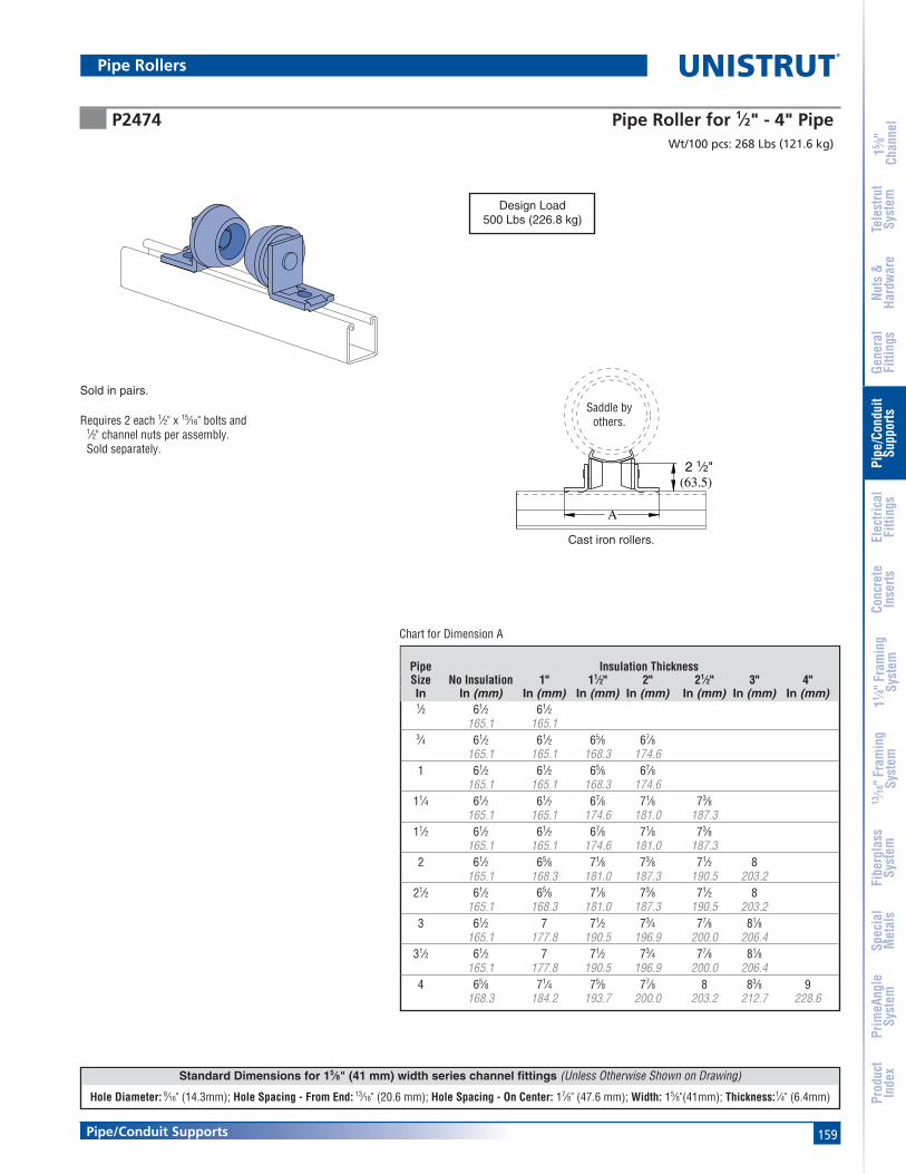
159
Standard Dimensions for 15⁄8" (41 mm) width series channel fittings (Unless Otherwise Shown on Drawing)
Hole Diameter: 9⁄16" (14.3mm); Hole Spacing - From End: 13⁄16" (20.6 mm); Hole Spacing - On Center: 17⁄8" (47.6 mm); Width: 15⁄8"(41mm); Thickness:1⁄4" (6.4mm)
Pipe/Conduit Supports
15 ⁄8"
Chan
nel
Nuts
&Ha
rdw
are
Gene
ral
Fitti
ngs
Pipe
/Con
duit
Supp
orts
Elec
trica
lFi
tting
sCo
ncre
teIn
serts
11 ⁄4" F
ram
ing
Syst
em13
⁄16" F
ram
ing
Syst
emFi
berg
lass
Syst
emSp
ecia
lM
etal
sTe
lest
rut
Syst
emPr
imeA
ngle
Syst
emPr
oduc
tIn
dex
Sold in pairs.
Chart for Dimension A
Requires 2 each 1⁄2" x 15⁄16" bolts and1⁄2" channel nuts per assembly.Sold separately.
Wt/100 pcs: 268 Lbs (121.6 kg)
Cast iron rollers.
A
2 1⁄2"(63.5)
Saddle byothers.
UL
P2474 Pipe Roller for 1⁄2" - 4" Pipe
Design Load500 Lbs (226.8 kg)
Pipe Insulation ThicknessSize No Insulation 1" 11⁄2" 2" 21⁄2" 3" 4"In In (mm) In (mm) In (mm) In (mm) In (mm) In (mm) In (mm)1⁄2 61⁄2 61⁄2
165.1 165.13⁄4 61⁄2 61⁄2 65⁄8 67⁄8
165.1 165.1 168.3 174.61 61⁄2 61⁄2 65⁄8 67⁄8
165.1 165.1 168.3 174.611⁄4 61⁄2 61⁄2 67⁄8 71⁄8 73⁄8
165.1 165.1 174.6 181.0 187.311⁄2 61⁄2 61⁄2 67⁄8 71⁄8 73⁄8
165.1 165.1 174.6 181.0 187.32 61⁄2 65⁄8 71⁄8 73⁄8 71⁄2 8
165.1 168.3 181.0 187.3 190.5 203.221⁄2 61⁄2 65⁄8 71⁄8 73⁄8 71⁄2 8
165.1 168.3 181.0 187.3 190.5 203.23 61⁄2 7 71⁄2 73⁄4 77⁄8 81⁄8
165.1 177.8 190.5 196.9 200.0 206.431⁄2 61⁄2 7 71⁄2 73⁄4 77⁄8 81⁄8
165.1 177.8 190.5 196.9 200.0 206.44 65⁄8 71⁄4 75⁄8 77⁄8 8 83⁄8 9
168.3 184.2 193.7 200.0 203.2 212.7 228.6
Pipe Rollers

160
Standard Dimensions for 15⁄8" (41 mm) width series channel fittings (Unless Otherwise Shown on Drawing)
Hole Diameter: 9⁄16" (14.3mm); Hole Spacing - From End: 13⁄16" (20.6 mm); Hole Spacing - On Center: 17⁄8" (47.6 mm); Width: 15⁄8"(41mm); Thickness:1⁄4" (6.4mm)
®
Pipe/Conduit Supports
15 ⁄8"
Chan
nel
Nuts
&Ha
rdw
are
Gene
ral
Fitti
ngs
Pipe
/Con
duit
Supp
orts
Elec
trica
lFi
tting
sCo
ncre
teIn
serts
11 ⁄4" F
ram
ing
Syst
em13
⁄16" F
ram
ing
Syst
emFi
berg
lass
Syst
emSp
ecia
lM
etal
sTe
lest
rut
Syst
emPr
imeA
ngle
Syst
emPr
oduc
tIn
dex
P2474-1 thru P2474-4 Pipe Roller for 1" - 8" Pipe
Chart for Roller Part Number Selection
Parts are shipped loose and are easily assembled during installation.
• Pipe roller will fit standard saddles.• Select proper roller from chart.• Requires 2 each 1⁄2" x 15⁄16" bolts and 1⁄2"
channel nuts per assembly. Sold separately.
A
2 1⁄2"(63.5)
Saddle by others.
Part A Wt/100 pcsNumber In (mm) Lbs (kg)
P2474-1 63⁄4 299171.5 135.6
P2474-2 71⁄2 304190.5 137.9
P2474-3 81⁄2 311215.9 141.1
P2474-4 99⁄16 319242.9 144.7
Design Load750 Lbs (340 Kg)
Pipe Size Insulation ThicknessIn No Insulation 1" (25.4) 11⁄2" (38.1) 2" (50.8) 21⁄2" (63.5) 3" (76.2) 4" (101.6)1⁄2 P2474-1 P2474-1 P2474-1 P2474-23⁄4 P2474-1 P2474-1 P2474-1 P2474-21 P2474-1 P2474-1 P2474-1 P2474-2
11⁄4 P2474-1 P2474-1 P2474-1 P2474-211⁄2 P2474-1 P2474-1 P2474-2 P2474-2 P2474-22 P2474-1 P2474-1 P2474-2 P2474-2 P2474-2
21⁄2 P2474-1 P2474-1 P2474-2 P2474-2 P2474-23 P2474-1 P2474-2 P2474-2 P2474-3 P2474-3 P2474-3
31⁄2 P2474-1 P2474-2 P2474-2 P2474-3 P2474-3 P2474-34 P2474-1 P2474-2 P2474-2 P2474-3 P2474-3 P2474-35 P2474-2 P2474-3 P2474-3 P2474-3 P2474-3 P2474-4 P2474-46 P2474-2 P2474-3 P2474-3 P2474-3 P2474-3 P2474-4 P2474-48 P2474-2 P2474-3 P2474-4 P2474-4 P2474-4 P2474-4 P2474-4
Pipe Rollers

161
Standard Dimensions for 15⁄8" (41 mm) width series channel fittings (Unless Otherwise Shown on Drawing)
Hole Diameter: 9⁄16" (14.3mm); Hole Spacing - From End: 13⁄16" (20.6 mm); Hole Spacing - On Center: 17⁄8" (47.6 mm); Width: 15⁄8"(41mm); Thickness:1⁄4" (6.4mm)
Pipe/Conduit Supports
15 ⁄8"
Chan
nel
Nuts
&Ha
rdw
are
Gene
ral
Fitti
ngs
Pipe
/Con
duit
Supp
orts
Elec
trica
lFi
tting
sCo
ncre
teIn
serts
11 ⁄4" F
ram
ing
Syst
em13
⁄16" F
ram
ing
Syst
emFi
berg
lass
Syst
emSp
ecia
lM
etal
sTe
lest
rut
Syst
emPr
imeA
ngle
Syst
emPr
oduc
tIn
dex
A
3 1⁄2"(88.9) (95.3)
3 3⁄4"TO
3"(76.2)
Chart for Dimension A
Saddle byothers.
• Requires 2 each 1⁄2" x 15⁄16" bolts and 1⁄2" channel nuts per assembly. Sold separately.
Sold in pairs.
Wt/100 pcs: 1046 Lbs (474.5 kg)
Chart for Dimension A
Wt/100 pcs: 680 Lbs (308.4 kg)
Material: Cast iron rollers.
Material: Cast iron rollers.
A
3 1⁄4"(82.6)
3"(76.2)
• Requires 4 each1⁄2" x 15⁄16" boltsand 1⁄2" channel nuts per assembly.
Sold separately.
2"(50.8)
Saddle byothers.
P2475 Pipe Roller for 6" - 16" Pipe
P2476 Pipe Roller for 16" - 24" Pipe
Design Load2000 Lbs (907 kg)
Pipe No Insulation Thickness Size Insulation 1" 11⁄2" 2" 21⁄2" 3" 4"
In In (mm) In (mm) In (mm) In (mm) In (mm) In (mm) In (mm)6 91⁄2 101⁄4 101⁄2 103⁄4 11 113⁄8 117⁄8
241.3 260.4 266.7 273.1 279.4 288.9 301.68 101⁄8 * 11 113⁄8 113⁄4 12 121⁄2
257.2 279.4 288.9 298.5 304.8 317.510 103⁄4 * 115⁄8 12 121⁄4 121⁄2 13
273.1 295.3 304.8 311.2 317.5 330.212 111⁄4 * 121⁄8 121⁄2 123⁄4 13 131⁄2
285.8 308.0 317.5 323.9 330.2 342.914 115⁄8 * 121⁄2 127⁄8 13 133⁄8 14
295.3 317.5 327.0 330.2 339.7 355.616 121⁄8 * 13 133⁄8 137⁄8 14 141⁄2
308.0 330.2 339.7 352.4 355.6 368.3
Design Load1500 Lbs (680 Kg)
Pipe Insulation Thickness Size 11⁄2" 2" 21⁄2" 3" 4"In In (mm) In (mm) In (mm) In (mm) In (mm)
16 137⁄8 14 141⁄2352.4 355.6 368.3
18 135⁄8 14 141⁄8 141⁄2 15346.1 355.6 358.8 368.3 381.0
20 141⁄8 141⁄2 143⁄4 15 151⁄2358.8 368.3 374.7 381.0 393.7
24 151⁄4 151⁄2 157⁄8 161⁄8 165⁄8387.4 393.7 403.2 409.6 422.3
Pipe Rollers
2"(50.8)
(*Not used for this size)

162
Standard Dimensions for 15⁄8" (41 mm) width series channel fittings (Unless Otherwise Shown on Drawing)
Hole Diameter: 9⁄16" (14.3mm); Hole Spacing - From End: 13⁄16" (20.6 mm); Hole Spacing - On Center: 17⁄8" (47.6 mm); Width: 15⁄8"(41mm); Thickness:1⁄4" (6.4mm)
®
Pipe/Conduit Supports
15 ⁄8"
Chan
nel
Nuts
&Ha
rdw
are
Gene
ral
Fitti
ngs
Pipe
/Con
duit
Supp
orts
Elec
trica
lFi
tting
sCo
ncre
teIn
serts
11 ⁄4" F
ram
ing
Syst
em13
⁄16" F
ram
ing
Syst
emFi
berg
lass
Syst
emSp
ecia
lM
etal
sTe
lest
rut
Syst
emPr
imeA
ngle
Syst
emPr
oduc
tIn
dex
For 2" pipe to 3" pipe.Design Load (Channel Upright Listed)
For 1⁄2" pipe to 11⁄2" pipe.Design Load (Channel Upright Listed)
Wt/100 pcs: 40 Lbs (18.1 kg)
For 2" (50.8) to 8" (203.2) Pipes
Hole Size 7⁄16" (11.1)
1"(25.4)
3"(76.2)
Clamp Requires bolt and channel nut.Sold seperately
3 1⁄2"(88.9)
4"(101.6)
1⁄4"(6.4)
4 3⁄8"
(111.1)
4"(101.6)
3⁄8"(9.5)
P2481 Pipe Support Bracket
P2482 Pipe Support Bracket
P2243 Pipe Block
Wt/100 pcs P1000 P1100 P2000Lbs (kg) Lbs (kg) Lbs (kg) Lbs (kg)
90 85 85 8540.8 38.6 38.6 38.6
Wt/100 pcs P1000 P1100 P2000Lbs (kg) Lbs (kg) Lbs (kg) Lbs (kg)
139 185 120 9563.0 83.9 54.4 43.1
Pipe Brackets

163
15 ⁄8"
Chan
nel
Nuts
&Ha
rdw
are
Gene
ral
Fitti
ngs
Pipe
/Con
duit
Supp
orts
Elec
trica
lFi
tting
sCo
ncre
teIn
serts
11 ⁄4" F
ram
ing
Syst
em13
⁄16" F
ram
ing
Syst
emFi
berg
lass
Syst
emSp
ecia
lM
etal
sTe
lest
rut
Syst
emPr
imeA
ngle
Syst
emPr
oduc
tIn
dex
Pipe/Conduit Supports
Pipe Brackets
UP-BK thru UP-MPDS UniPier™
8"(203.2)
3"(76.2)
8"(203.2)
13⁄16"(20.6)
Part UniPier BasesNumber Qty. Description
UP-BK 4 UniPier Base Only (4 Bases & Hardware)
UP-SPSS-6 HG 4 UP-BK + 4 Pcs P4100T HG @ 6" (152.4mm) Long for up to 31⁄2" (88.9mm) PipeUP-SPSS-10HG 4 UP-BK + 4 Pcs P4100T HG @ 10" (254.0mm) Long for 4" to 8" (101.6 to 203.2mm)Pipe
UP-MPDS-26HG 2 UP-BK + 2 Pcs P1000T HG @ 26" (66.0cm) Long for TrapezeUP-MPDS-38HG 2 UP-BK + 2 Pcs P1000T HG @ 38" (96.5cm) Long for TrapezeUP-MPDS-50HG 2 UP-BK + 2 Pcs P1000T HG @ 50" (127.0cm) Long for TrapezeUP-MPDS-62HG 2 UP-BK + 2 Pcs P1000T HG @ 62" (157.5cm) Long for Trapeze
P2484
P1000
P1006
P1326
P1109
P1000 P1006
ThreadedRod
P2484 P1109
P1006
P2474P1000
P1006
PA-138P1000T
P1326
The UniPier Rooftop support system provides a simple andversatile way to support and manage pipe, tubing, conduit,HVAC systems, and the like. The UniPier system supportswithout roof surface penetration and allows the parts to remainoff the surface
P1109P4100
P1109
P4100

164
®
15 ⁄8"
Chan
nel
Nuts
&Ha
rdw
are
Gene
ral
Fitti
ngs
Pipe
/Con
duit
Supp
orts
Elec
trica
lFi
tting
sCo
ncre
teIn
serts
11 ⁄4" F
ram
ing
Syst
em13
⁄16" F
ram
ing
Syst
emFi
berg
lass
Syst
emSp
ecia
lM
etal
sTe
lest
rut
Syst
emPr
imeA
ngle
Syst
emPr
oduc
tIn
dex
Pipe/Conduit Supports
Nominal Centerline to Centerline (In/mm)Pipe Dia. 3⁄4" (19mm) 1" (25mm) 11⁄4" (32mm) 11⁄2" (38mm) 2" (51mm) 21⁄2" (64mm)
T S T F S T F S T F S T F S T F S3⁄4" T 43⁄4 – – – – – – – – – – – – – – – –
19mm 121 – – – – – – – – – – – – – – – –S 41⁄2 43⁄4 – – – – – – – – – – – – – – –
114 108 – – – – – – – – – – – – – – –1" T 5 43⁄4 51⁄4 – – – – – – – – – – – – – –
25mm 127 121 133 – – – – – – – – – – – – – –F 6 53⁄4 61⁄4 71⁄4 – – – – – – – – – – – – –
152 146 159 184 – – – – – – – – – – – – –S 43⁄4 41⁄2 5 6 41⁄2 – – – – – – – – – – – –
121 114 127 152 114 – – – – – – – – – – – –11⁄4" T 51⁄4 5 51⁄2 61⁄2 5 51⁄2 – – – – – – – – – – –
32mm 133 127 140 165 127 140 – – – – – – – – – – –F 61⁄4 6 61⁄2 71⁄2 61⁄4 63⁄4 73⁄4 – – – – – – – – – –
159 152 165 191 159 171 197 – – – – – – – – – –S 43⁄4 41⁄2 5 6 41⁄2 51⁄4 61⁄4 43⁄4 – – – – – – – – –
121 114 127 152 114 133 159 121 – – – – – – – – –11⁄2" T 51⁄4 5 51⁄2 61⁄2 51⁄4 53⁄4 63⁄4 51⁄4 53⁄4 – – – – – – – –
38mm 133 127 140 165 133 146 171 133 146 – – – – – – – –F 61⁄2 61⁄4 63⁄4 73⁄4 61⁄4 63⁄4 8 61⁄2 7 8 – – – – – – –
165 159 171 197 159 171 203 165 178 203 – – – – – – –S 5 43⁄4 51⁄4 61⁄4 43⁄4 51⁄4 6 5 51⁄2 61⁄2 5 – – – – – –
127 121 133 159 121 133 152 127 140 165 127 – – – – – –2" T 53⁄4 51⁄2 6 7 51⁄2 6 71⁄4 53⁄4 61⁄4 71⁄4 53⁄4 61⁄2 – – – – –
51mm 146 140 152 178 140 152 184 146 159 184 146 165 – – – – –F 7 63⁄4 71⁄4 81⁄4 63⁄4 71⁄4 81⁄2 7 71⁄2 81⁄2 7 73⁄4 9 – – – –
178 171 184 210 171 184 216 178 191 216 178 197 229 – – – –S 51⁄4 5 51⁄2 61⁄2 5 51⁄2 63⁄4 51⁄4 53⁄4 63⁄4 51⁄4 6 71⁄4 51⁄2 – – –
133 127 140 165 127 140 171 133 146 171 133 152 184 140 – – –21⁄2" T 6 53⁄4 61⁄4 71⁄4 6 61⁄2 71⁄2 6 61⁄2 73⁄4 61⁄4 7 81⁄4 61⁄2 71⁄4 – –
64mm 152 146 159 184 152 165 191 152 165 197 159 178 210 165 184 – –F 71⁄2 71⁄4 73⁄4 83⁄4 71⁄4 73⁄4 9 71⁄2 8 9 71⁄2 81⁄4 91⁄2 73⁄4 83⁄4 10 –
191 184 197 222 184 197 229 191 203 229 191 210 241 197 222 254 –S 51⁄2 51⁄4 53⁄4 63⁄4 51⁄4 53⁄4 7 51⁄2 6 7 51⁄2 61⁄4 71⁄2 53⁄4 63⁄4 8 6
140 133 146 171 133 146 178 140 152 178 140 159 191 146 171 203 1523" T 61⁄4 6 61⁄2 71⁄2 61⁄4 63⁄4 73⁄4 61⁄4 63⁄4 8 61⁄2 71⁄4 81⁄2 63⁄4 71⁄2 9 7
76mm 159 152 165 191 159 171 197 159 171 203 165 184 216 171 191 229 178F 73⁄4 71⁄2 8 9 71⁄2 8 91⁄4 73⁄4 81⁄4 91⁄4 73⁄4 81⁄2 93⁄4 8 9 101⁄4 81⁄4
197 191 203 229 191 203 235 197 210 235 197 216 248 203 229 260 210S 53⁄4 51⁄2 6 7 51⁄2 6 71⁄4 53⁄4 61⁄4 71⁄4 53⁄4 61⁄2 73⁄4 6 7 81⁄4 61⁄4
146 140 152 178 140 152 184 146 159 184 146 165 197 152 178 210 1594" T 71⁄2 71⁄4 73⁄4 83⁄4 71⁄4 73⁄4 9 71⁄2 8 9 71⁄2 81⁄4 91⁄2 73⁄4 83⁄4 10 8
102mm 191 184 197 222 184 197 229 191 203 229 191 210 241 197 222 254 203F 9 83⁄4 91⁄4 101⁄4 83⁄4 91⁄4 101⁄2 9 91⁄2 101⁄2 9 93⁄4 11 91⁄4 101⁄4 111⁄2 91⁄2
229 222 235 260 222 235 267 229 241 267 229 248 279 235 260 292 241S 63⁄4 61⁄2 7 8 61⁄2 7 81⁄4 63⁄4 71⁄4 81⁄4 63⁄4 71⁄2 83⁄4 7 8 91⁄4 71⁄4
171 165 178 203 165 178 210 171 184 210 171 191 222 178 203 235 1845" T 8 73⁄4 81⁄4 91⁄4 73⁄4 81⁄4 91⁄2 8 81⁄2 91⁄2 8 83⁄4 10 81⁄4 91⁄4 101⁄2 81⁄2
127mm 203 197 210 235 197 210 241 203 216 241 203 222 254 210 235 267 216F 91⁄2 91⁄4 93⁄4 103⁄4 91⁄4 93⁄4 11 91⁄2 10 11 91⁄2 101⁄4 111⁄2 93⁄4 103⁄4 12 10
241 235 248 273 235 248 279 241 254 279 241 260 292 248 273 305 254S 71⁄4 7 71⁄2 81⁄4 7 71⁄2 83⁄4 71⁄4 73⁄4 83⁄4 71⁄4 8 91⁄4 71⁄2 81⁄2 93⁄4 73⁄4
184 178 191 210 178 191 222 184 197 222 184 203 235 191 216 248 1976" T 83⁄4 81⁄2 9 10 81⁄2 9 101⁄4 83⁄4 91⁄4 101⁄4 83⁄4 91⁄2 103⁄4 9 10 111⁄4 91⁄4
152mm 222 216 229 254 216 229 260 222 235 260 222 241 273 229 254 286 235F 10 93⁄4 101⁄4 111⁄4 93⁄4 101⁄4 111⁄2 10 101⁄2 111⁄2 10 103⁄4 12 101⁄4 111⁄4 121⁄2 101⁄2
254 248 260 286 248 260 292 254 267 292 254 273 305 260 286 318 267S 73⁄4 71⁄2 8 9 71⁄2 8 91⁄4 73⁄4 81⁄4 91⁄4 73⁄4 81⁄2 93⁄4 8 9 101⁄4 81⁄4
197 191 203 229 191 203 235 197 210 235 197 216 248 203 229 260 2108" T 83⁄4 91⁄2 10 11 93⁄4 101⁄2 111⁄4 93⁄4 101⁄4 111⁄2 10 103⁄4 12 101⁄2 11 121⁄2 101⁄2
203mm 222 241 254 279 248 267 286 248 260 292 254 273 305 267 279 318 267F 111⁄4 11 111⁄2 121⁄2 11 111⁄2 123⁄4 111⁄4 113⁄4 123⁄4 111⁄4 12 131⁄4 111⁄2 121⁄2 133⁄4 113⁄4
286 279 292 318 279 292 324 286 298 324 286 305 337 292 318 349 29810" T 111⁄4 11 111⁄2 121⁄2 11 111⁄2 123⁄4 111⁄4 113⁄4 123⁄4 111⁄4 12 131⁄4 111⁄2 121⁄2 133⁄4 113⁄4
254mm 286 279 292 318 279 292 324 286 298 324 286 305 337 292 318 349 298F 121⁄2 121⁄4 123⁄4 133⁄4 121⁄4 123⁄4 14 121⁄2 13 14 121⁄2 131⁄4 141⁄2 123⁄4 133⁄4 15 13
318 311 324 349 311 324 356 318 330 356 318 337 368 324 349 381 33012" T 121⁄4 12 121⁄2 131⁄2 12 121⁄2 133⁄4 121⁄4 123⁄4 133⁄4 121⁄4 13 141⁄4 121⁄2 131⁄2 143⁄4 123⁄4
305mm 311 305 318 343 305 318 349 311 324 349 311 330 362 318 343 375 324F 14 133⁄4 141⁄4 151⁄4 133⁄4 141⁄4 151⁄2 14 141⁄2 151⁄2 14 143⁄4 16 141⁄4 151⁄4 161⁄2 141⁄2
356 349 362 387 349 362 394 356 368 394 356 375 406 362 387 419 368
Pipe & Conduit Reference Data

165
15 ⁄8"
Chan
nel
Nuts
&Ha
rdw
are
Gene
ral
Fitti
ngs
Pipe
/Con
duit
Supp
orts
Elec
trica
lFi
tting
sCo
ncre
teIn
serts
11 ⁄4" F
ram
ing
Syst
em13
⁄16" F
ram
ing
Syst
emFi
berg
lass
Syst
emSp
ecia
lM
etal
sTe
lest
rut
Syst
emPr
imeA
ngle
Syst
emPr
oduc
tIn
dex
Pipe/Conduit Supports
Pipe Spacing TableThis chart, developed by Julius Getlan of Seelye Stevenson Value & Knect, consulting engineers, New York City, enables one to quicklydetermine the centerline-to-centerline dimension between any two size pipes on a rack.
Select the smaller pipe size at top and select the other at the side of the table. Where the appropriate columns intersect, the dimension is given.
These factors are included in the dimensions given:
• O.D. of flanges and fittings.
• 1" insulation over flanges and fittings.
• All fractional dimensions less than 1⁄4" were
increased to the next larger 1⁄4".
• Clear space between fittings as follows:
1. 1" between piping 3" and smaller.
2. 11⁄2" between a pipe 3" and smaller and a pipe 4" or larger.
3. 2" between piping 4" and larger.
T – denotes threaded IPS pipe. F – denotes flanged fittings on pipe. S – denotes soldered or brazed tubing.
Centerline to Centerline (In/mm) Nominal3" (76mm) 4" (102mm) 5" (127mm) 6" (152mm) 8" (203mm) 10" (254mm) 12" (305mm) Pipe Dia.
T F S T F S T F S T F S T F T F T F73⁄4 – – – – – – – – – – – – – – – – – T 3"197 – – – – – – – – – – – – – – – – – 76mm91⁄4 101⁄2 – – – – – – – – – – – – – – – – F235 267 – – – – – – – – – – – – – – – –71⁄4 81⁄2 61⁄2 – – – – – – – – – – – – – – – S184 216 165 – – – – – – – – – – – – – – –9 101⁄4 81⁄4 10 – – – – – – – – – – – – – – T 4"
229 260 210 254 – – – – – – – – – – – – – – 102mm101⁄2 113⁄4 93⁄4 111⁄2 13 – – – – – – – – – – – – – F267 298 248 292 330 – – – – – – – – – – – – –81⁄4 91⁄2 71⁄2 91⁄4 103⁄4 81⁄2 – – – – – – – – – – – – S210 241 191 235 273 216 – – – – – – – – – – – –91⁄2 103⁄4 83⁄4 101⁄4 12 93⁄4 11 – – – – – – – – – – – T 5"241 273 222 260 305 248 279 – – – – – – – – – – – 127mm11 121⁄4 101⁄4 12 131⁄2 111⁄4 121⁄2 14 – – – – – – – – – – F279 311 260 305 343 286 318 356 – – – – – – – – – –83⁄4 10 8 93⁄4 111⁄4 9 101⁄4 113⁄4 91⁄2 – – – – – – – – – S222 254 203 248 286 229 260 298 241 – – – – – – – – –101⁄4 111⁄2 91⁄2 111⁄4 123⁄4 101⁄2 113⁄4 131⁄4 11 121⁄2 – – – – – – – – T 6"260 292 241 286 324 267 298 337 279 318 – – – – – – – – 152mm111⁄2 121⁄4 103⁄4 121⁄2 14 113⁄4 13 141⁄2 121⁄4 131⁄4 15 – – – – – – – F292 311 273 318 356 298 330 368 311 337 381 – – – – – – –91⁄4 101⁄2 81⁄2 101⁄4 113⁄4 91⁄2 103⁄4 121⁄4 10 111⁄2 123⁄4 101⁄2 – – – – – – S235 267 216 260 298 241 273 311 254 292 324 267 – – – – – –111⁄4 123⁄4 103⁄4 121⁄2 14 113⁄4 13 141⁄2 121⁄4 133⁄4 15 123⁄4 143⁄4 – – – – – T 8"286 324 273 318 356 298 330 368 311 349 381 324 375 – – – – – 203mm123⁄4 14 12 133⁄4 151⁄4 13 141⁄4 153⁄4 131⁄2 15 161⁄4 14 161⁄4 17 .5 – – – – F324 356 305 349 387 330 362 400 343 381 413 356 413 17 .5 – – – –123⁄4 14 12 133⁄4 151⁄4 13 141⁄4 153⁄4 131⁄2 15 161⁄4 14 161⁄4 171⁄2 171⁄2 – – – T 10"324 356 305 349 387 330 362 400 343 381 413 356 413 445 445 – – – 254mm14 151⁄4 131⁄4 15 161⁄2 141⁄4 151⁄2 17 143⁄4 161⁄4 171⁄2 151⁄4 171⁄2 183⁄4 183⁄4 20 – – F356 387 337 381 419 362 394 432 375 413 445 387 445 476 476 508 – –133⁄4 15 13 143⁄4 161⁄4 14 151⁄4 163⁄4 141⁄2 16 171⁄4 15 171⁄4 181⁄2 181⁄2 193⁄4 191⁄2 – T 12"349 381 330 375 413 356 387 425 368 406 438 381 438 470 470 502 495 – 305mm151⁄2 163⁄4 143⁄4 161⁄2 18 153⁄4 17 181⁄4 161⁄4 173⁄4 19 163⁄4 14 201⁄4 201⁄4 211⁄2 211⁄4 29 F394 425 375 419 457 400 432 464 413 451 483 425 356 514 514 546 540 737
Pipe & Conduit Reference Data

166
®
15 ⁄8"
Chan
nel
Nuts
&Ha
rdw
are
Gene
ral
Fitti
ngs
Pipe
/Con
duit
Supp
orts
Elec
trica
lFi
tting
sCo
ncre
teIn
serts
11 ⁄4" F
ram
ing
Syst
em13
⁄16" F
ram
ing
Syst
emFi
berg
lass
Syst
emSp
ecia
lM
etal
sTe
lest
rut
Syst
emPr
imeA
ngle
Syst
emPr
oduc
tIn
dex
Pipe/Conduit Supports
Note: Based on NFPA-13-1996 Section Modulus Table 3-10.1.7(a). Each of thefollowing tables indicate the allowable span of the trapeeze and the nominalpipe size for the specified channel . An entry of “–” indicates that the channelcannot be used for this span/pipe size combination. The table is based on amaximum allowable bending stress of 15 KSI and a midspan concentratedload from 15 ft of water-filled pipe, plus 250 lb.
Channel Selection for Schedule 10 Sprinkler Pipe Trapeze Hangers
Pipe & Conduit Reference Data
SCHEDULE 10 PIPENominal Wall Pipe Water TotalPipe Dia. O.D. Thickness I. D. Weight Weight Weight
(in) (in) (in) (in) (p/f) (p/f) (p/f)
1 1.315 0.109 1.097 1.41 0.42 1.8311⁄4 1.660 0.109 1.442 1.81 0.73 2.5411⁄2 1.900 0.109 1.682 2.09 0.99 3.082 2.375 0.109 2.157 2.64 1.63 4.28
21⁄2 2.875 0.120 2.635 3.53 2.44 5.973 3.500 0.120 3.260 4.34 3.73 8.07
31⁄2 4.000 0.120 3.760 4.98 4.97 9.954 4.500 0.120 4.260 5.62 6.38 12.005 5.563 0.134 5.295 7.78 9.85 17.636 6.625 0.134 6.357 9.30 14.20 23.508 8.625 0.188 8.249 16.96 23.91 40.8710 10.750 0.188 10.374 21.23 37.82 59.04
SINGLE CHANNEL TRAPEZE FOR SCH 10 PIPETrapeze Pipe Diameter
Span 1" 11⁄4" 11⁄2" 2" 21⁄2" 3" 31⁄2" 4" 5" 6" 8" 10"
1' - 6" P3000 P3000 P3000 P3000 P3000 P3000 P3000 P3000 P3000 P1000 P5500 P55002' - 0" P3000 P3000 P3000 P3000 P3000 P3000 P1000 P1000 P1000 P5500 P5500 P50002' - 6" P3000 P3000 P3000 P1000 P1000 P1000 P1000 P5500 P5500 P5500 P5000 P50003' - 0" P1000 P1000 P1000 P1000 P1000 P5500 P5500 P5500 P5500 P5500 P5000 N/A4' - 0" P5500 P5500 P5500 P5500 P5500 P5500 P5500 P5500 P5000 P5000 N/A N/A5' - 0" P5500 P5500 P5500 P5500 P5500 P5500 P5000 P5000 P5000 P5000 N/A N/A6' - 0" P5500 P5500 P5500 P5500 P5000 P5000 P5000 P5000 P5000 N/A N/A N/A7' - 0" P5500 P5000 P5000 P5000 P5000 P5000 P5000 P5000 N/A N/A N/A N/A8' - 0" P5000 P5000 P5000 P5000 P5000 P5000 N/A N/A N/A N/A N/A N/A9' - 0" P5000 P5000 P5000 P5000 P5000 N/A N/A N/A N/A N/A N/A N/A10' - 0" P5000 P5000 P5000 N/A N/A N/A N/A N/A N/A N/A N/A N/A
DOUBLE CHANNEL TRAPEZE FOR SCH 10 PIPETrapeze Pipe Diameter
Span 1" 11⁄4" 11⁄2" 2" 21⁄2" 3" 31⁄2" 4" 5" 6" 8" 10"
1' - 6" P3001 P3001 P3001 P3001 P3001 P3001 P3001 P3001 P3001 P3001 P3001 P30012' - 0" P3001 P3001 P3001 P3001 P3001 P3001 P3001 P3001 P3001 P3001 P3001 P30012' - 6" P3001 P3001 P3001 P3001 P3001 P3001 P3001 P3001 P3001 P3001 P3001 P10013' - 0" P3001 P3001 P3001 P3001 P3001 P3001 P3001 P3001 P3001 P3001 P1001 P55014' - 0" P3001 P3001 P3001 P3001 P3001 P3001 P3001 P3001 P3001 P1001 P5501 P55015' - 0" P3001 P3001 P3001 P3001 P3001 P3001 P3001 P3001 P1001 P5501 P5501 P55016' - 0" P3001 P3001 P3001 P3001 P3001 P1001 P1001 P1001 P5501 P5501 P5501 P50017' - 0" P3001 P3001 P3001 P1001 P1001 P1001 P1001 P5501 P5501 P5501 P5501 P50018' - 0" P1001 P1001 P1001 P1001 P1001 P5501 P5501 P5501 P5501 P5501 P5001 N/A9' - 0" P1001 P1001 P1001 P1001 P5501 P5501 P5501 P5501 P5501 P5501 P5001 N/A10' - 0" P1001 P5501 P5501 P5501 P5501 P5501 P5501 P5501 P5501 P5001 P5001 N/A
Values taken from NFPA 13 (1994 Edition), Table 2-6.1.5(a)
NFPA 13 REQUIRED TRAPEZE SECTION MODULUS FOR SCH 10 PIPETrapeze Pipe Diameter
Span 1" 11⁄4" 11⁄2" 2" 21⁄2" 3" 31⁄2" 4" 5" 6" 8" 10"
1' - 6" 0.08 0.09 0.09 0.09 0.10 0.11 0.12 0.13 0.15 0.18 0.24 0.322' - 0" 0.11 0.12 0.12 0.13 0.13 0.15 0.16 0.17 0.20 0.24 0.32 0.432' - 6" 0.14 0.14 0.15 0.16 0.17 0.18 0.20 0.21 0.25 0.30 0.40 0.543' - 0" 0.17 0.17 0.18 0.19 0.20 0.22 0.24 0.26 0.31 0.36 0.48 0.654' - 0" 0.22 0.23 0.24 0.25 0.27 0.29 0.32 0.34 0.41 0.48 0.64 0.875' - 0" 0.28 0.29 0.30 0.31 0.34 0.37 0.40 0.43 0.51 0.59 0.80 1.086' - 0" 0.33 0.35 0.36 0.38 0.41 0.44 0.48 0.51 0.61 0.71 0.97 1.307' - 0" 0.39 0.40 0.41 0.44 0.47 0.52 0.55 0.60 0.71 0.83 1.13 1.528' - 0" 0.44 0.46 0.47 0.50 0.54 0.59 0.63 0.68 0.81 0.95 1.29 1.739' - 0" 0.50 0.52 0.53 0.56 0.61 0.66 0.71 0.77 0.92 1.07 1.45 1.9510' - 0" 0.56 0.58 0.59 0.63 0.68 0.74 0.79 0.85 1.02 1.19 1.61 2.17
Unistrut SectionChannel Modulus
in3 (cm3)
P3000 0.1542.52
P1000 0.2023.31
P5500 0.3916.41
P5000 0.62810.29
Unistrut SectionChannel Modulus
in3 (cm3)
P3001 0.4317.06
P1001 0.5729.37
P5501 1.15318.89
P5001 1.91631.40
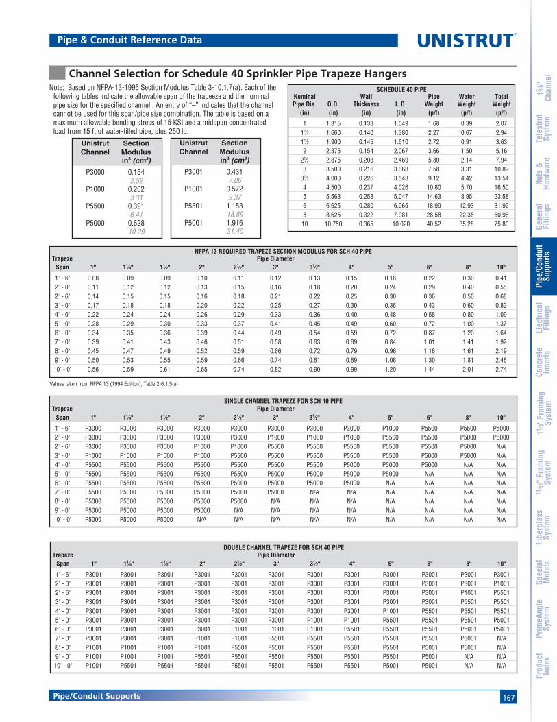
167
15 ⁄8"
Chan
nel
Nuts
&Ha
rdw
are
Gene
ral
Fitti
ngs
Pipe
/Con
duit
Supp
orts
Elec
trica
lFi
tting
sCo
ncre
teIn
serts
11 ⁄4" F
ram
ing
Syst
em13
⁄16" F
ram
ing
Syst
emFi
berg
lass
Syst
emSp
ecia
lM
etal
sTe
lest
rut
Syst
emPr
imeA
ngle
Syst
emPr
oduc
tIn
dex
Pipe/Conduit Supports
Pipe & Conduit Reference Data
Channel Selection for Schedule 40 Sprinkler Pipe Trapeze HangersNote: Based on NFPA-13-1996 Section Modulus Table 3-10.1.7(a). Each of the
following tables indicate the allowable span of the trapeeze and the nominalpipe size for the specified channel . An entry of “–” indicates that the channelcannot be used for this span/pipe size combination. The table is based on amaximum allowable bending stress of 15 KSI and a midspan concentratedload from 15 ft of water-filled pipe, plus 250 lb.
Values taken from NFPA 13 (1994 Edition), Table 2-6.1.5(a)
NFPA 13 REQUIRED TRAPEZE SECTION MODULUS FOR SCH 40 PIPETrapeze Pipe Diameter
Span 1" 11⁄4" 11⁄2" 2" 21⁄2" 3" 31⁄2" 4" 5" 6" 8" 10"
1' - 6" 0.08 0.09 0.09 0.10 0.11 0.12 0.13 0.15 0.18 0.22 0.30 0.412' - 0" 0.11 0.12 0.12 0.13 0.15 0.16 0.18 0.20 0.24 0.29 0.40 0.552' - 6" 0.14 0.15 0.15 0.16 0.18 0.21 0.22 0.25 0.30 0.36 0.50 0.683' - 0" 0.17 0.18 0.18 0.20 0.22 0.25 0.27 0.30 0.36 0.43 0.60 0.824' - 0" 0.22 0.24 0.24 0.26 0.29 0.33 0.36 0.40 0.48 0.58 0.80 1.095' - 0" 0.28 0.29 0.30 0.33 0.37 0.41 0.45 0.49 0.60 0.72 1.00 1.376' - 0" 0.34 0.35 0.36 0.39 0.44 0.49 0.54 0.59 0.72 0.87 1.20 1.647' - 0" 0.39 0.41 0.43 0.46 0.51 0.58 0.63 0.69 0.84 1.01 1.41 1.928' - 0" 0.45 0.47 0.49 0.52 0.59 0.66 0.72 0.79 0.96 1.16 1.61 2.199' - 0" 0.50 0.53 0.55 0.59 0.66 0.74 0.81 0.89 1.08 1.30 1.81 2.4610' - 0" 0.56 0.59 0.61 0.65 0.74 0.82 0.90 0.99 1.20 1.44 2.01 2.74
SCHEDULE 40 PIPENominal Wall Pipe Water TotalPipe Dia. O.D. Thickness I. D. Weight Weight Weight
(in) (in) (in) (in) (p/f) (p/f) (p/f)
1 1.315 0.133 1.049 1.68 0.39 2.0711⁄4 1.660 0.140 1.380 2.27 0.67 2.9411⁄2 1.900 0.145 1.610 2.72 0.91 3.632 2.375 0.154 2.067 3.66 1.50 5.16
21⁄2 2.875 0.203 2.469 5.80 2.14 7.943 3.500 0.216 3.068 7.58 3.31 10.89
31⁄2 4.000 0.226 3.548 9.12 4.42 13.544 4.500 0.237 4.026 10.80 5.70 16.505 5.563 0.258 5.047 14.63 8.95 23.586 6.625 0.280 6.065 18.99 12.93 31.928 8.625 0.322 7.981 28.58 22.38 50.9610 10.750 0.365 10.020 40.52 35.28 75.80
SINGLE CHANNEL TRAPEZE FOR SCH 40 PIPETrapeze Pipe Diameter
Span 1" 11⁄4" 11⁄2" 2" 21⁄2" 3" 31⁄2" 4" 5" 6" 8" 10"
1' - 6" P3000 P3000 P3000 P3000 P3000 P3000 P3000 P3000 P1000 P5500 P5500 P50002' - 0" P3000 P3000 P3000 P3000 P3000 P1000 P1000 P1000 P5500 P5500 P5000 P50002' - 6" P3000 P3000 P3000 P1000 P1000 P5500 P5500 P5500 P5500 P5500 P5000 N/A3' - 0" P1000 P1000 P1000 P1000 P5500 P5500 P5500 P5500 P5500 P5000 P5000 N/A4' - 0" P5500 P5500 P5500 P5500 P5500 P5500 P5500 P5000 P5000 P5000 N/A N/A5' - 0" P5500 P5500 P5500 P5500 P5500 P5000 P5000 P5000 P5000 N/A N/A N/A6' - 0" P5500 P5500 P5500 P5500 P5000 P5000 P5000 P5000 N/A N/A N/A N/A7' - 0" P5500 P5000 P5000 P5000 P5000 P5000 N/A N/A N/A N/A N/A N/A8' - 0" P5000 P5000 P5000 P5000 P5000 N/A N/A N/A N/A N/A N/A N/A9' - 0" P5000 P5000 P5000 P5000 N/A N/A N/A N/A N/A N/A N/A N/A10' - 0" P5000 P5000 P5000 N/A N/A N/A N/A N/A N/A N/A N/A N/A
DOUBLE CHANNEL TRAPEZE FOR SCH 40 PIPETrapeze Pipe Diameter
Span 1" 11⁄4" 11⁄2" 2" 21⁄2" 3" 31⁄2" 4" 5" 6" 8" 10"
1' - 6" P3001 P3001 P3001 P3001 P3001 P3001 P3001 P3001 P3001 P3001 P3001 P30012' - 0" P3001 P3001 P3001 P3001 P3001 P3001 P3001 P3001 P3001 P3001 P3001 P10012' - 6" P3001 P3001 P3001 P3001 P3001 P3001 P3001 P3001 P3001 P3001 P1001 P55013' - 0" P3001 P3001 P3001 P3001 P3001 P3001 P3001 P3001 P3001 P3001 P5501 P55014' - 0" P3001 P3001 P3001 P3001 P3001 P3001 P3001 P3001 P1001 P5501 P5501 P55015' - 0" P3001 P3001 P3001 P3001 P3001 P3001 P1001 P1001 P5501 P5501 P5501 P50016' - 0" P3001 P3001 P3001 P3001 P1001 P1001 P1001 P5501 P5501 P5501 P5001 P50017' - 0" P3001 P3001 P3001 P1001 P1001 P5501 P5501 P5501 P5501 P5501 P5001 N/A8' - 0" P1001 P1001 P1001 P1001 P5501 P5501 P5501 P5501 P5501 P5001 P5001 N/A9' - 0" P1001 P1001 P1001 P5501 P5501 P5501 P5501 P5501 P5501 P5001 N/A N/A10' - 0" P1001 P5501 P5501 P5501 P5501 P5501 P5501 P5501 P5001 P5001 N/A N/A
Unistrut SectionChannel Modulus
in3 (cm3)
P3000 0.1542.52
P1000 0.2023.31
P5500 0.3916.41
P5000 0.62810.29
Unistrut SectionChannel Modulus
in3 (cm3)
P3001 0.4317.06
P1001 0.5729.37
P5501 1.15318.89
P5001 1.91631.40
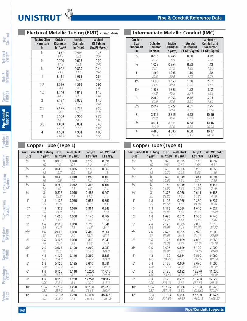
168
®
15 ⁄8"
Chan
nel
Nuts
&Ha
rdw
are
Gene
ral
Fitti
ngs
Pipe
/Con
duit
Supp
orts
Elec
trica
lFi
tting
sCo
ncre
teIn
serts
11 ⁄4" F
ram
ing
Syst
em13
⁄16" F
ram
ing
Syst
emFi
berg
lass
Syst
emSp
ecia
lM
etal
sTe
lest
rut
Syst
emPr
imeA
ngle
Syst
emPr
oduc
tIn
dex
Pipe/Conduit Supports
Tubing Size Outside Inside Weight(Nominal) Diameter Diameter Of Tubing
In In (mm) In (mm) Lbs/Ft (kg/m)3⁄8 0.577 0.497 0.23
14.7 12.6 0.341⁄2 0.706 0.626 0.29
17.9 15.9 0.433⁄4 0.922 0.830 0.44
23.4 21.1 0.651 1.163 1.055 0.64
29.5 26.8 0.9511⁄4 1.510 1.388 0.95
38.4 35.3 1.4111⁄2 1.740 1.618 1.10
44.2 41.1 1.642 2.197 2.075 1.40
55.8 52.7 2.0821⁄2 2.875 2.731 2.30
73.0 69.4 3.423 3.500 3.356 2.70
88.9 85.2 4.0231⁄2 4.000 3.834 3.40
101.6 97.4 5.064 4.500 4.334 4.00
114.3 110.1 5.95
Electrical Metallic Tubing (EMT) - Thin Wall Intermediate Metallic Conduit (IMC)Conduit Weight of
Size Outside Inside Weight Conduit and(Nominal) Diameter Diameter Of Conduit Conductor
In In (mm) In (mm) Lbs/Ft (kg/m) Lbs/Ft (kg/m)1⁄2 0.815 0.745 0.60 0.12
20.7 18.9 0.89 0.183⁄4 1.029 0.954 0.82 1.13
26.1 24.2 1.22 1.681 1.290 1.205 1.16 1.82
32.8 30.6 1.73 2.7111⁄4 1.638 1.553 1.50 2.67
41.6 39.4 2.23 3.9711⁄2 1.883 1.793 1.82 3.42
47.8 45.5 2.71 5.092 2.360 2.266 2.42 5.04
59.9 57.6 3.60 7.5021⁄2 2.857 2.727 4.01 7.75
72.6 69.3 5.97 11.533 3.476 3.346 4.43 10.69
88.3 85.0 6.59 15.9131⁄2 3.971 3.841 5.73 13.46
100.9 97.6 8.53 20.034 4.466 4.336 6.38 16.37
113.4 110.1 9.49 24.36
Pipe & Conduit Reference Data
Nom. Tube O.D. Tubing O.D. Wall Thick. Wt./Ft. Wt. Water/FtSize In (mm) In (mm) In (mm) Lbs (kg) Lbs (kg)1⁄4" 3⁄8 0.375 0.030 0.126 0.034
10 9.5 0.8 3.2 0.93⁄8" 1⁄2 0.500 0.035 0.198 0.062
13 12.7 0.9 5.0 1.61⁄2" 5⁄8 0.625 0.040 0.285 0.100
16 15.9 1.0 7.2 2.55⁄8" 3⁄4 0.750 0.042 0.362 0.151
19 19.1 1.1 9.2 3.83⁄4" 7⁄8 0.875 0.045 0.455 0.209
22 22.2 1.1 11.6 5.31" 11⁄8 1.125 0.050 0.655 0.357
29 28.6 1.3 16.6 9.111⁄4" 13⁄8 1.375 0.055 0.884 0.546
35 34.9 1.4 22.5 13.911⁄2" 15⁄8 1.625 0.060 1.140 0.767
41 41.3 1.5 29.0 19.52" 21⁄8 2.125 0.070 1.750 1.341
54 54.0 1.8 44.5 34.121⁄2" 25⁄8 2.625 0.080 2.480 2.064
67 66.7 2.0 63.0 52.43" 31⁄8 3.125 0.090 3.330 2.949
79 79.4 2.3 84.6 74.931⁄2" 35⁄8 3.625 0.100 4.290 3.989
92 92.1 2.5 109.0 101.34" 41⁄8 4.125 0.110 5.380 5.188
105 104.8 2.8 136.7 131.85" 51⁄8 5.125 0.125 7.610 8.081
130 130.2 3.2 193.3 205.36" 61⁄8 6.125 0.140 10.200 11.616
156 155.6 3.6 259.1 295.08" 81⁄8 8.125 0.200 19.290 20.289
206 206.4 5.1 490.0 515.310" 101⁄8 10.125 0.250 30.100 31.590
257 257.2 6.4 764.5 802.412" 121⁄8 12.125 0.280 40.400 45.426
308 308.0 7.1 1,026.2 1,153.8
Copper Tube (Type L)Nom. Tube O.D. Tubing O.D. Wall Thick. Wt./Ft. Wt. Water/Ft
Size In (mm) In (mm) In (mm) Lbs (kg) Lbs (kg)1⁄4" 3⁄8 0.375 0.035 0.145 0.032
10 9.53 0.89 3.68 0.813⁄8" 1⁄2 0.500 0.005 0.269 0.055
13 12.70 0.13 6.83 1.401⁄2" 5⁄8 0.625 0.049 0.344 0.094
16 15.88 1.24 8.74 2.395⁄8" 3⁄4 0.750 0.049 0.418 0.144
19 19.05 1.24 10.62 3.663⁄4" 7⁄8 0.875 0.065 0.641 0.188
22 22.23 1.65 16.28 4.781" 11⁄8 1.125 0.065 0.839 0.337
29 28.58 1.65 21.31 8.5611⁄4" 13⁄8 1.375 0.065 1.040 0.527
35 34.93 1.65 26.42 13.3911⁄2" 15⁄8 1.625 0.072 1.360 0.743
41 41.28 1.83 34.54 18.872" 21⁄8 2.125 0.083 2.060 1.310
54 53.98 2.11 52.32 33.2721⁄2" 25⁄8 2.625 0.095 2.920 2.000
67 66.68 2.41 74.17 50.803" 31⁄8 3.125 0.109 4.000 2.960
79 79.38 2.77 101.60 75.1831⁄2" 35⁄8 3.625 0.120 5.120 3.900
92 92.08 3.05 130.05 99.064" 41⁄8 4.125 0.134 6.510 5.060
105 104.78 3.40 165.35 128.525" 51⁄8 5.125 0.160 9.670 8.000
130 130.18 4.06 245.62 203.206" 61⁄8 6.125 0.192 13.870 11.200
156 155.58 4.88 352.30 284.488" 81⁄8 8.125 0.271 25.900 19.500
206 206.38 6.88 657.86 495.3010" 101⁄8 10.125 0.338 40.300 30.423
257 257.18 8.59 1,023.62 772.7412" 121⁄8 12.125 0.405 57.800 43.675
308 307.98 10.29 1,468.12 1,109.35
Copper Tube (Type K)
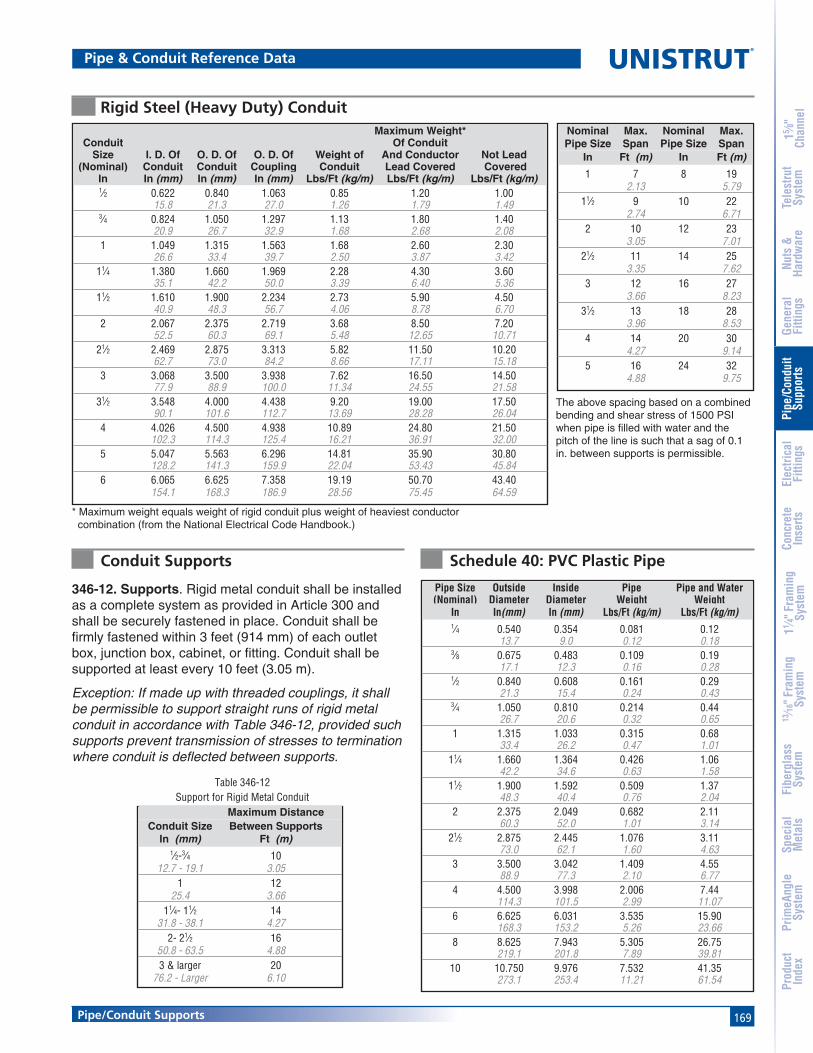
169
15 ⁄8"
Chan
nel
Nuts
&Ha
rdw
are
Gene
ral
Fitti
ngs
Pipe
/Con
duit
Supp
orts
Elec
trica
lFi
tting
sCo
ncre
teIn
serts
11 ⁄4" F
ram
ing
Syst
em13
⁄16" F
ram
ing
Syst
emFi
berg
lass
Syst
emSp
ecia
lM
etal
sTe
lest
rut
Syst
emPr
imeA
ngle
Syst
emPr
oduc
tIn
dex
Pipe/Conduit Supports
Table 346-12Support for Rigid Metal Conduit
* Maximum weight equals weight of rigid conduit plus weight of heaviest conductor combination (from the National Electrical Code Handbook.)
346-12. Supports. Rigid metal conduit shall be installedas a complete system as provided in Article 300 andshall be securely fastened in place. Conduit shall befirmly fastened within 3 feet (914 mm) of each outletbox, junction box, cabinet, or fitting. Conduit shall besupported at least every 10 feet (3.05 m).
Exception: If made up with threaded couplings, it shallbe permissible to support straight runs of rigid metalconduit in accordance with Table 346-12, provided suchsupports prevent transmission of stresses to terminationwhere conduit is deflected between supports.
The above spacing based on a combinedbending and shear stress of 1500 PSIwhen pipe is filled with water and thepitch of the line is such that a sag of 0.1in. between supports is permissible.
Rigid Steel (Heavy Duty) ConduitMaximum Weight*
Conduit Of ConduitSize I. D. Of O. D. Of O. D. Of Weight of And Conductor Not Lead
(Nominal) Conduit Conduit Coupling Conduit Lead Covered CoveredIn In (mm) In (mm) In (mm) Lbs/Ft (kg/m) Lbs/Ft (kg/m) Lbs/Ft (kg/m)1⁄2 0.622 0.840 1.063 0.85 1.20 1.00
15.8 21.3 27.0 1.26 1.79 1.493⁄4 0.824 1.050 1.297 1.13 1.80 1.40
20.9 26.7 32.9 1.68 2.68 2.081 1.049 1.315 1.563 1.68 2.60 2.30
26.6 33.4 39.7 2.50 3.87 3.4211⁄4 1.380 1.660 1.969 2.28 4.30 3.60
35.1 42.2 50.0 3.39 6.40 5.3611⁄2 1.610 1.900 2.234 2.73 5.90 4.50
40.9 48.3 56.7 4.06 8.78 6.702 2.067 2.375 2.719 3.68 8.50 7.20
52.5 60.3 69.1 5.48 12.65 10.7121⁄2 2.469 2.875 3.313 5.82 11.50 10.20
62.7 73.0 84.2 8.66 17.11 15.183 3.068 3.500 3.938 7.62 16.50 14.50
77.9 88.9 100.0 11.34 24.55 21.5831⁄2 3.548 4.000 4.438 9.20 19.00 17.50
90.1 101.6 112.7 13.69 28.28 26.044 4.026 4.500 4.938 10.89 24.80 21.50
102.3 114.3 125.4 16.21 36.91 32.005 5.047 5.563 6.296 14.81 35.90 30.80
128.2 141.3 159.9 22.04 53.43 45.846 6.065 6.625 7.358 19.19 50.70 43.40
154.1 168.3 186.9 28.56 75.45 64.59
Nominal Max. Nominal Max.Pipe Size Span Pipe Size Span
In Ft (m) In Ft (m)
1 7 8 192.13 5.79
11⁄2 9 10 222.74 6.71
2 10 12 233.05 7.01
21⁄2 11 14 253.35 7.62
3 12 16 273.66 8.23
31⁄2 13 18 283.96 8.53
4 14 20 304.27 9.14
5 16 24 324.88 9.75
Maximum DistanceConduit Size Between Supports
In (mm) Ft (m)1⁄2-3⁄4 10
12.7 - 19.1 3.051 12
25.4 3.6611⁄4- 11⁄2 14
31.8 - 38.1 4.272- 21⁄2 16
50.8 - 63.5 4.883 & larger 20
76.2 - Larger 6.10
Pipe & Conduit Reference Data
Pipe Size Outside Inside Pipe Pipe and Water(Nominal) Diameter Diameter Weight Weight
In In(mm) In (mm) Lbs/Ft (kg/m) Lbs/Ft (kg/m)1⁄4 0.540 0.354 0.081 0.12
13.7 9.0 0.12 0.183⁄8 0.675 0.483 0.109 0.19
17.1 12.3 0.16 0.281⁄2 0.840 0.608 0.161 0.29
21.3 15.4 0.24 0.433⁄4 1.050 0.810 0.214 0.44
26.7 20.6 0.32 0.651 1.315 1.033 0.315 0.68
33.4 26.2 0.47 1.0111⁄4 1.660 1.364 0.426 1.06
42.2 34.6 0.63 1.5811⁄2 1.900 1.592 0.509 1.37
48.3 40.4 0.76 2.042 2.375 2.049 0.682 2.11
60.3 52.0 1.01 3.1421⁄2 2.875 2.445 1.076 3.11
73.0 62.1 1.60 4.633 3.500 3.042 1.409 4.55
88.9 77.3 2.10 6.774 4.500 3.998 2.006 7.44
114.3 101.5 2.99 11.076 6.625 6.031 3.535 15.90
168.3 153.2 5.26 23.668 8.625 7.943 5.305 26.75
219.1 201.8 7.89 39.8110 10.750 9.976 7.532 41.35
273.1 253.4 11.21 61.54
Schedule 40: PVC Plastic PipeConduit Supports

170
®
15 ⁄8"
Chan
nel
Nuts
&Ha
rdw
are
Gene
ral
Fitti
ngs
Pipe
/Con
duit
Supp
orts
Elec
trica
lFi
tting
sCo
ncre
teIn
serts
11 ⁄4" F
ram
ing
Syst
em13
⁄16" F
ram
ing
Syst
emFi
berg
lass
Syst
emSp
ecia
lM
etal
sTe
lest
rut
Syst
emPr
imeA
ngle
Syst
emPr
oduc
tIn
dex
Pipe/Conduit Supports
Data for Schedule Steel Pipe
Pipe & Conduit Reference Data
Nom. Pipe Outside Inside Pipe Pipe and WaterSize Schedule Dia. Dia. Weight WeightIn In(mm) In (mm) Lbs/Ft (kg/m) Lbs/Ft (kg/m)1⁄8 40 0.405 0.269 0.24 0.27
10.3 6.8 0.11 0.1280 0.405 0.215 0.31 0.33
10.3 5.5 0.14 0.151⁄4 40 0.540 0.364 0.42 0.47
13.7 9.2 0.19 0.2180 0.540 0.302 0.53 0.57
13.7 7.7 0.24 0.263⁄8 40 0.675 0.493 0.57 0.65
17.1 12.5 0.26 0.2980 0.675 0.423 0.74 0.80
17.1 10.7 0.33 0.361⁄2 40 0.840 0.622 0.85 0.98
21.3 15.8 0.39 0.4580 0.840 0.546 1.09 1.19
21.3 13.9 0.49 0.54160 0.840 0.464 1.31 1.38
21.3 11.8 0.59 0.633⁄4 40 1.050 0.824 1.13 1.36
26.7 20.9 0.51 0.6280 1.050 0.742 1.47 1.66
26.7 18.8 0.67 0.75160 1.050 0.612 1.94 2.07
26.7 15.5 0.88 0.941 40 1.315 1.049 1.68 2.05
33.4 26.6 0.76 0.9380 1.315 0.957 2.17 2.48
33.4 24.3 0.98 1.13160 1.315 0.815 2.84 3.07
33.4 20.7 1.29 1.3911⁄4 40 1.660 1.380 2.27 2.92
42.2 35.1 1.03 1.3280 1.660 1.278 2.99 3.55
42.2 32.5 1.36 1.61160 1.660 1.160 3.76 4.22
42.2 29.5 1.71 1.9111⁄2 40 1.900 1.610 2.71 3.60
48.3 40.9 1.23 1.6380 1.900 1.500 3.63 4.39
48.3 38.1 1.65 1.99160 1.900 1.338 4.85 5.46
48.3 34.0 2.20 2.482 40 2.375 2.067 3.65 5.10
60.3 52.5 1.66 2.3280 2.375 1.939 5.02 6.30
60.3 49.3 2.28 2.86160 2.375 1.687 7.45 8.42
60.3 42.8 3.38 3.8221⁄2 40 2.875 2.469 5.79 7.86
73.0 62.7 2.62 3.5780 2.875 2.323 7.65 9.49
73.0 59.0 3.47 4.30160 2.875 2.125 10.00 11.54
73.0 54.0 4.54 5.233 40 3.500 3.068 7.57 10.77
88.9 77.9 3.43 4.8980 3.500 2.900 10.24 13.11
88.9 73.7 4.65 5.94160 3.500 2.624 14.31 16.65
88.9 66.6 6.49 7.5531⁄2 40 4.000 3.548 9.10 13.39
101.6 90.1 4.13 6.0780 4.000 3.364 12.49 16.35
101.6 85.4 5.67 7.41
Nom. Pipe Outside Inside Pipe Pipe and WaterSize Schedule Dia. Dia. Weight WeightIn In(mm) In (mm) Lbs/Ft (kg/m) Lbs/Ft (kg/m)
4 40 4.500 4.026 10.78 16.30114.3 102.3 4.89 7.39
80 4.500 3.826 14.97 19.95114.3 97.2 6.79 9.05
120 4.500 3.624 18.98 23.45114.3 92.0 8.61 10.64
160 4.500 3.438 22.48 26.51114.3 87.3 10.20 12.02
5 40 5.563 5.047 14.60 23.27141.3 128.2 6.62 10.56
80 5.563 4.813 20.75 28.64141.3 122.2 9.41 12.99
120 5.563 4.563 27.01 34.09141.3 115.9 12.25 15.46
160 5.563 4.313 32.92 39.26141.3 109.5 14.93 17.81
6 40 6.625 6.065 18.95 31.48168.3 154.1 8.60 14.28
80 6.625 5.761 28.54 39.84168.3 146.3 12.95 18.07
120 6.625 5.501 36.35 46.66168.3 139.7 16.49 21.16
160 6.625 5.187 45.30 54.47168.3 131.7 20.55 24.71
8 20 8.625 8.125 22.34 44.82219.1 206.4 10.13 20.33
30 8.625 8.071 24.67 46.85219.1 205.0 11.19 21.25
40 8.625 7.981 28.52 50.21219.1 202.7 12.94 22.78
60 8.625 7.813 35.60 56.39219.1 198.5 16.15 25.58
80 8.625 7.625 43.34 63.14219.1 193.7 19.66 28.64
100 8.625 7.437 50.89 69.73219.1 188.9 23.09 31.63
120 8.625 7.187 60.65 78.23219.1 182.5 27.51 35.49
140 8.625 7.001 67.68 84.37219.1 177.8 30.70 38.27
160 8.625 6.813 74.61 90.42219.1 173.1 33.84 41.01
10 20 10.750 10.250 28.01 63.78273.1 260.4 12.70 28.93
30 10.750 10.136 34.20 69.19273.1 257.5 15.51 31.38
40 10.750 10.020 40.44 74.63273.1 254.5 18.34 33.85
60 10.750 9.750 54.68 87.05273.1 247.7 24.80 39.48
80 10.750 9.562 64.36 95.50273.1 242.9 29.19 43.32
100 10.750 9.312 76.95 106.47273.1 236.5 34.90 48.30
120 10.750 9.062 89.20 117.16273.1 230.2 40.46 53.14
140 10.750 8.750 104.02 130.09273.1 222.3 47.18 59.01
160 10.750 8.500 115.52 140.13273.1 215.9 52.40 63.56

171
®
MATERIALUnistrut fittings, unless noted, are made from hot-rolled,pickled and oiled steel plates, strip or coil, and conform toASTM specifications A575, A576, A635, or A36. The fittingsteel also meets the physical requirements of ASTM A1011SS GR 33. The pickling of the steel produces a smoothsurface free from scale.
Maple cable saddles, cable clamps and bus bar clamps aremade from kiln-dry maple treated with paraffin to a depth of1⁄16" (1.6mm). Special sizes of clamps can be fabricated uponrequest. Porcelain cable clamps are made by the dryprocess and white glazed. Cable saddles are fiberglass-reinforced polyester.
CHANNEL RACEWAYSThe Unistrut Metal Framing System includes an exclusivecombination of channel, fittings and hardware listed undernew UL classification 5B. This classification covers strut-typechannel raceways and fittings for use in accordance withArticle 352 of the National Electrical Code, NFPA 70.Included are metal strut-type channel raceways at least .071inch (1.81mm) thick and metal or non-metal closure strips atleast .040 inch (1.02mm) thick.
The Unistrut system requires no welding, drilling or othercomplex fabrication techniques. This means faster, easiersolutions for virtually any electrical support problem.
Unistrut channel offers structural and spanning capabilitiesnot available with conventional surface raceway products
and is available in continuous lengths of up to 20 feet. Just asimportant, it is part of an integrated system that can be usedfor raceways, trapeze hangers, cable-tray supports, lightinggrids, fluorescent-fixture supports and countless otherelectrical applications.
CHANNEL COMPATABILITYAll of the electrical components in this section are intendedfor use with any of the 15⁄8" wide channel. They are notintended for use with 11⁄4" or 13⁄16" framing systems.
FINISHESComponents listed in this section are available in: electro-galvanized (EG), conforming to ASTM B633 Type III SC1;Hot-dipped galvanized (HG), conforming to ASTM A123 orA153, Perma-Green II (GR), and plain (PL).Note: Many Unistrut Metal Framing components, when usedwith appropriate closures, are UL® listed, and CSA approved.
DESIGN LOADDesign load data, where shown, is based on the ultimatestrength of the connection with a safety factor of 2.5, unlessotherwise noted.
DIMENSIONSImperial dimensions are illustrated in inches. Metricdimensions are shown in parenthesis or as noted. Unlessnoted, all metric dimensions are in millimeters and roundedto one decimal place.
ELECTRICAL FITTINGSElectrical Fittings ........................................ 173-175
Receptacles ........................................................ 176
Fixture Hangers ................................................. 177
Accessories and Connectors ..................... 178-181
Junction Boxes .................................................. 182
In-Channel Joiners ............................................. 183
Swivel Hangers ................................................. 184
Cable EntranceTubing and Accessories ............................. 185-188
Electrical Fittings Technical Data .............. 189-191

172
®
Electrical Fittings
15 ⁄8"
Chan
nel
Nuts
&Ha
rdw
are
Gene
ral
Fitti
ngs
Pipe
/Con
duit
Supp
orts
Elec
trica
lFi
tting
sCo
ncre
teIn
serts
11 ⁄4" F
ram
ing
Syst
em13
⁄16" F
ram
ing
Syst
emFi
berg
lass
Syst
emSp
ecia
lM
etal
sTe
lest
rut
Syst
emPr
imeA
ngle
Syst
emPr
oduc
tIn
dex
Electrical Fittings Pictorial Index
P1753-Pg 173 P2649 A-Pg 173 P2645 A-Pg 173 P2647 A-Pg 174 P1690-Pg 174 P1787-Pg 175
P2557-Pg 176 P2567-Pg 176 P2537-Pg 177 P2539-Pg 177 P2755-Pg 177 P2855-Pg 177
P3922-Pg 178 P2534-50-Pg 178 P2535-Pg 179 P2536-Pg 179 P2522-Pg 179 P3521-50-Pg 179
P2521-50-Pg 179 P5521-50-Pg 179 P5021-50-Pg 180 P2521-100-Pg 180 P5021-100-Pg 180 P5521-100-Pg 180
P1180 W-Pg 180 P2541-Pg 180 P2540-Pg 181 P2603-Pg 181 P3116-125-Pg 181
P2602-Pg 182
P2552-Pg 181
P2801-Pg 182 P2802-Pg 182 P2803-Pg 182 P2900-Pg 183 P2901-Pg 183
M2137-Pg 184 M2250-Pg 184
M2350-Pg 184
P2902-Pg 183 P2903-Pg 183 P2904-Pg 183 M2037-Pg 184
Electrical Fittings
P16F-Pg 185 P21H-Pg 185 P2822-Pg 187 P2823-Pg 187
P2821-Pg 187
P2820-Pg 187
P2920-Pg 188 P2928-Pg 188
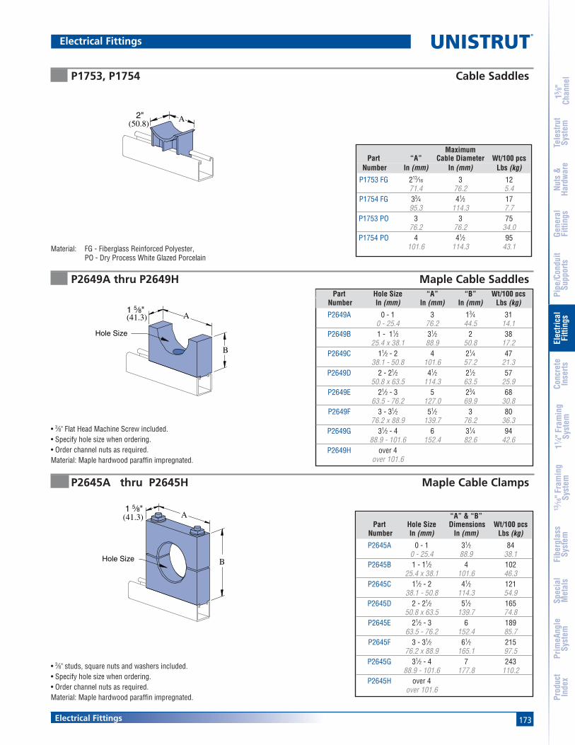
173Electrical Fittings
15 ⁄8"
Chan
nel
Nuts
&Ha
rdw
are
Gene
ral
Fitti
ngs
Pipe
/Con
duit
Supp
orts
Elec
trica
lFi
tting
sCo
ncre
teIn
serts
11 ⁄4" F
ram
ing
Syst
em13
⁄16" F
ram
ing
Syst
emFi
berg
lass
Syst
emSp
ecia
lM
etal
sTe
lest
rut
Syst
emPr
imeA
ngle
Syst
emPr
oduc
tIn
dex
Electrical Fittings
P2649A thru P2649H Maple Cable Saddles
P2645A thru P2645H Maple Cable Clamps
P1753, P1754 Cable Saddles
• 3⁄8" studs, square nuts and washers included.• Specify hole size when ordering.• Order channel nuts as required.Material: Maple hardwood paraffin impregnated.
• 3⁄8" Flat Head Machine Screw included.• Specify hole size when ordering.• Order channel nuts as required.Material: Maple hardwood paraffin impregnated.
A(50.8)
2"
Material: FG - Fiberglass Reinforced Polyester,PO - Dry Process White Glazed Porcelain
A(41.3)1 5⁄8"
B
Hole Size
Hole Size
A1 5⁄8"
B
(41.3)
MaximumPart “A” Cable Diameter Wt/100 pcs
Number In (mm) In (mm) Lbs (kg)
P1753 FG 213⁄16 3 1271.4 76.2 5.4
P1754 FG 33⁄4 41⁄2 1795.3 114.3 7.7
P1753 PO 3 3 7576.2 76.2 34.0
P1754 PO 4 41⁄2 95101.6 114.3 43.1
Part Hole Size “A” “B” Wt/100 pcs Number In (mm) In (mm) In (mm) Lbs (kg)
P2649A 0 - 1 3 13⁄4 310 - 25.4 76.2 44.5 14.1
P2649B 1 - 11⁄2 31⁄2 2 3825.4 x 38.1 88.9 50.8 17.2
P2649C 11⁄2 - 2 4 21⁄4 4738.1 - 50.8 101.6 57.2 21.3
P2649D 2 - 21⁄2 41⁄2 21⁄2 5750.8 x 63.5 114.3 63.5 25.9
P2649E 21⁄2 - 3 5 23⁄4 6863.5 - 76.2 127.0 69.9 30.8
P2649F 3 - 31⁄2 51⁄2 3 8076.2 x 88.9 139.7 76.2 36.3
P2649G 31⁄2 - 4 6 31⁄4 9488.9 - 101.6 152.4 82.6 42.6
P2649H over 4over 101.6
“A” & “B”Part Hole Size Dimensions Wt/100 pcs
Number In (mm) In (mm) Lbs (kg)
P2645A 0 - 1 31⁄2 840 - 25.4 88.9 38.1
P2645B 1 - 11⁄2 4 10225.4 x 38.1 101.6 46.3
P2645C 11⁄2 - 2 41⁄2 12138.1 - 50.8 114.3 54.9
P2645D 2 - 21⁄2 51⁄2 16550.8 x 63.5 139.7 74.8
P2645E 21⁄2 - 3 6 18963.5 - 76.2 152.4 85.7
P2645F 3 - 31⁄2 61⁄2 21576.2 x 88.9 165.1 97.5
P2645G 31⁄2 - 4 7 24388.9 - 101.6 177.8 110.2
P2645H over 4over 101.6

174
®
Electrical Fittings
15 ⁄8"
Chan
nel
Nuts
&Ha
rdw
are
Gene
ral
Fitti
ngs
Pipe
/Con
duit
Supp
orts
Elec
trica
lFi
tting
sCo
ncre
teIn
serts
11 ⁄4" F
ram
ing
Syst
em13
⁄16" F
ram
ing
Syst
emFi
berg
lass
Syst
emSp
ecia
lM
etal
sTe
lest
rut
Syst
emPr
imeA
ngle
Syst
emPr
oduc
tIn
dex
Material: Paraffin impregnated maple hardwood.
• 1⁄2" studs, square nuts and washers are included.• Channel nuts must be ordered separately.• Bus bar maple clamps also available in
1⁄4" (6.4) x 2" (50.8) and 1⁄4" (6.4) x 6" (152.4).
• Use with steel clamp and Everdur hardware.Order clamp separately.
• Specify hole size when ordering.
Material: Paraffin impregnated maple hardwood.
Hole Size
A
P1690 thru P1697 Maple Cable Clamps
P2647A thru P2647F 4" (101.6) Bus Bar Maple Clamps
Part “A” “B” No. Bus No. Bars Wt/100 pcsNumber In (mm) In (mm) Separators Per Leg Lbs (kg)
P2647A 81⁄2 9⁄32 0 1 421215.9 7.1 191.0
P2647B 91⁄2 13⁄16 2 2 465241.3 20.6 210.9
P2647C 101⁄2 15⁄16 4 3 509266.7 33.3 230.9
P2647D 111⁄2 113⁄16 6 4 553292.1 46.0 250.8
P2647E 121⁄2 23⁄8 8 5 597317.5 60.3 270.8
P2647F 131⁄2 27⁄8 10 6 631342.9 73.0 286.2
Order SteelPart Clamp Hole Size “A” Wt/100 pcs
Number Number In (mm) In (mm) Lbs (kg)
P1690 P1113 E 0 -5⁄8 11⁄2 240 - 15.9 38.1 10.9
P1691 P1115 E 1⁄2 - 1 21⁄8 4212.7- 25.4 54.0 19.1
P1692 P1117 E 3⁄4 - 11⁄2 25⁄8 5419.1 x 38.1 66.7 24.5
P1693 P1118 E 11⁄4 - 13⁄4 3 6531.8 x 44.5 76.2 29.5
P1694 P1119 E 11⁄2 - 21⁄4 35⁄8 8438.1 x 57.2 92.1 38.1
P1695 P1120 E 2 - 21⁄2 41⁄8 10750.8 x 63.5 104.8 48.5
P1696 P1121 E 21⁄4 - 3 45⁄8 12357.2 - 76.2 117.5 55.8
P1697 P1123 E 3 - 4 53⁄4 16376.2 - 101.6 146.1 73.9
Electrical Fittings
(41.3)1 5⁄8"
A
4"(101.6)
1⁄4" (5.4) MapleSeparator
7 3⁄8"(187.3)
B

175Electrical Fittings
15 ⁄8"
Chan
nel
Nuts
&Ha
rdw
are
Gene
ral
Fitti
ngs
Pipe
/Con
duit
Supp
orts
Elec
trica
lFi
tting
sCo
ncre
teIn
serts
11 ⁄4" F
ram
ing
Syst
em13
⁄16" F
ram
ing
Syst
emFi
berg
lass
Syst
emSp
ecia
lM
etal
sTe
lest
rut
Syst
emPr
imeA
ngle
Syst
emPr
oduc
tIn
dex
P1787 thru P1795 Porce-A-Clamp™
HolePart Size “A” “B” Wt/100 pcs
Number In (mm) In (mm) In (mm) Lbs (kg)
P1787A 3⁄8 1.36 1.82 259.5 34.5 46.2 11.3
P1787B 1⁄212.7
P1787C 5⁄815.9
P1788 3⁄4 1.86 2.34 3719.1 47.2 59.4 16.8
P1788A 7⁄822.2
P1788B 125.4
P1788C 11⁄828.6
P1789 11⁄4 2.36 2.86 5831.8 59.9 72.6 16.8
P1789A 13⁄834.9
P1789B 11⁄238.1
P1789C 15⁄841.3
P1790 13⁄4 2.86 3.50 7644.5 72.6 88.9 34.5
P1790A 17⁄847.6
P1790B 250.8
P1790C 21⁄854.0
P1791 21⁄4 3.36 4.05 9057.2 85.3 102.9 40.8
P1791A 23⁄860.3
Patents PendingStrap Material: Electro-galvanized Steel (EG) or Stainless Steel (SS)Use With: All 15⁄8" channel
Porce-A-Clamp™• Non-Breakable TPE Material.• U.V. Resistant.• U.L. Listed.• Optional Stainless Steel Clamps.• Tapered Flange to Protect Cable.• Dielectric Strength 640 Volts Per Mil.• One Piece Insulator.• Replaces Porcelain & Maple Cable Clamp.• For use in accordance with National Electrical Code ANSI/NFPA 70.• Includes Pipe Strap.• Temperature Rating -50°F to +275°F (-45°C to +135°C)
HolePart Size “A” “B” Wt/100 pcs
Number In (mm) In (mm) In (mm) Lbs (kg)
P1791B 21⁄263.5
P1791C 25⁄866.7
P1792 23⁄4 3.86 4.75 10969.9 98.0 120.7 49.4
P1792A 27⁄873.0
P1792B 376.2
P1792C 31⁄879.4
P1793 31⁄4 4.36 5.125 13082.6 110.7 130.2 59.0
P1793A 33⁄885.7
P1793B 31⁄288.9
P1793C 35⁄892.1
P1794 33⁄4 4.86 5.54 16095.3 184.2 140.7 72.6
P1794A 37⁄898.4
P1794B 4101.6
P1794C 41⁄8104.8
P1795 41⁄4 5.24 5.92 160108.0 133.1 150.4 72.6
P1795A 43⁄8111.1
P1795B 41⁄2114.3
Electrical Fittings
Hole Size
A
B

176
®
Electrical Fittings
15 ⁄8"
Chan
nel
Nuts
&Ha
rdw
are
Gene
ral
Fitti
ngs
Pipe
/Con
duit
Supp
orts
Elec
trica
lFi
tting
sCo
ncre
teIn
serts
11 ⁄4" F
ram
ing
Syst
em13
⁄16" F
ram
ing
Syst
emFi
berg
lass
Syst
emSp
ecia
lM
etal
sTe
lest
rut
Syst
emPr
imeA
ngle
Syst
emPr
oduc
tIn
dex
P2567 Outlet Box
P2557 Duplex Grounded ReceptacleWt/100 pcs: 38 Lbs (17.2 kg)
• 125 V, 15 amp receptacle, NEMA configuration 5-15R, cover plate.• #6 screws, nuts and wire connectors included.• Leads are 14 gauge 105°C plastic covered.• Ground wire is green 16 gauge.
6"(152.4)
P3016-0632
19 Gauge
P2553Wire Connectors
Finish: White powder coat.
Oval Head#6-32 X 1"
P3184 Closure
Material: 14 Gauge (.075)Assembly: 1 Box, 2 Screws, 2 Channel Nuts
(47.6)17⁄8"
(101.6)4"
(146.1)53⁄4"
(57.2)21⁄4"
Receptacles
Wt/100 pcs: 88 Lbs (47.8 kg)

177Electrical Fittings
15 ⁄8"
Chan
nel
Nuts
&Ha
rdw
are
Gene
ral
Fitti
ngs
Pipe
/Con
duit
Supp
orts
Elec
trica
lFi
tting
sCo
ncre
teIn
serts
11 ⁄4" F
ram
ing
Syst
em13
⁄16" F
ram
ing
Syst
emFi
berg
lass
Syst
emSp
ecia
lM
etal
sTe
lest
rut
Syst
emPr
imeA
ngle
Syst
emPr
oduc
tIn
dex
P2537, P5537Fluorescent Fixture Hangers
P2539, P3539, P5539Fluorescent Fixture Hangers
P2755, P2756, P2757 Raceway Hangers P2855, P2856, P2857 Raceway Hangers
• Hanger provides more than1⁄2" (12.7) space betweenchannel and fixtures.
Materials: 18 gauge (1.2).
• Hanger provides 1⁄8" (3.2)space between channeland fixtures.
Materials: 18 gauge (1.2).
Use with Channels:P1001, P1101, P2001, P5000, & P5500.
Material: 14 gauge (1.9).
Use with Channels:P1000, P1100, P3000, P3300
Material: 14 gauge (1.9).
1⁄4" X 1" RHMS and Sq. Nut Included
A
9⁄32" (7.1) Dia. Hole
1 5⁄8"(41.3)
(108.0)4 1⁄4"
A
9⁄32" (7.1)Sq. Hole
9⁄32" (7.1)Sq. Hole
2 3⁄4"(69.9)
A
A
(41.3)1 5⁄8"
1⁄4" X 3⁄4"Carriage Boltand Sq. Nut Included
1⁄4" X 1" RHMS and Sq. Nut Included
Design Load120 Lbs (54.4 kg)
Design Load120 Lbs (54.4 kg)
Design Load120 Lbs (54.4 kg)
Design Load120 Lbs (54.4 kg)
UsePart With “A” Wt/100 pcs
Number Channel In (mm) Lbs (kg)
P1000P2537 P1100 27⁄16 19
P3000 61.9 8.6P5537 P5500 31⁄4 22
82.6 10.0
UsePart With “A” Wt/100 pcs
Number Channel In (mm) Lbs (kg)
P1000P2539 P1100 13⁄4 17
44.5 7.7P3539 P3000 11⁄2 15
38.1 6.8P5539 P5500 29⁄16 18
65.1 8.2
Part “A” Wt/100 pcsNumber In (mm) Lbs (kg)
P2755 9⁄16 4414.3 20.0
P2756 7⁄8 4422.2 20.0
P2757 13⁄32 4410.3 20.0
Part “A” Wt/100 pcsNumber In (mm) Lbs (kg)
P2855 9⁄16 3214.3 14.5
P2856 7⁄8 3222.2 14.5
P2857 13⁄32 3210.3 14.5
Fluorescent Fixture Hangers
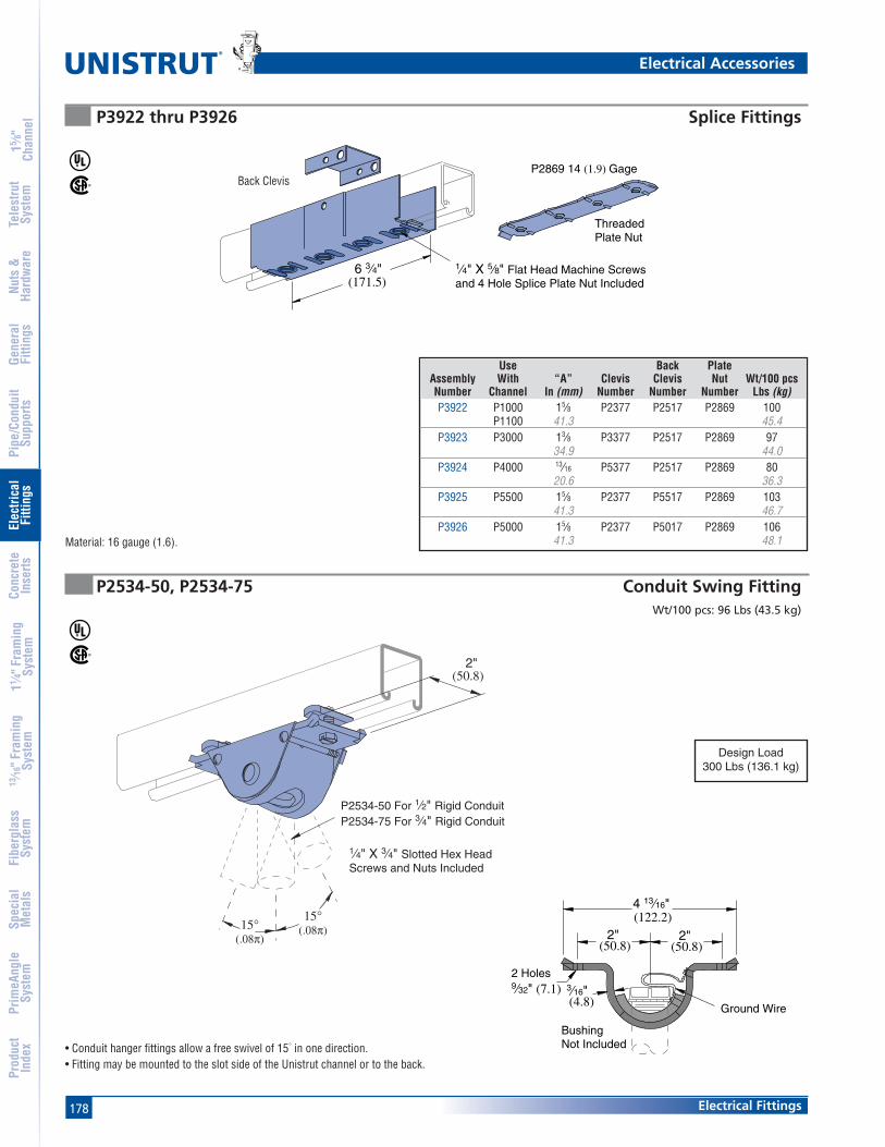
178
®
Electrical Fittings
15 ⁄8"
Chan
nel
Nuts
&Ha
rdw
are
Gene
ral
Fitti
ngs
Pipe
/Con
duit
Supp
orts
Elec
trica
lFi
tting
sCo
ncre
teIn
serts
11 ⁄4" F
ram
ing
Syst
em13
⁄16" F
ram
ing
Syst
emFi
berg
lass
Syst
emSp
ecia
lM
etal
sTe
lest
rut
Syst
emPr
imeA
ngle
Syst
emPr
oduc
tIn
dex
P2534-50, P2534-75 Conduit Swing Fitting
P3922 thru P3926 Splice Fittings
Wt/100 pcs: 96 Lbs (43.5 kg)
Material: 16 gauge (1.6).
• Conduit hanger fittings allow a free swivel of 15° in one direction.• Fitting may be mounted to the slot side of the Unistrut channel or to the back.
Ground Wire
2 Holes9⁄32" (7.1)
2"(50.8)
2"(50.8)
4 13⁄16"(122.2)
(4.8)3⁄16"
BushingNot Included
Design Load300 Lbs (136.1 kg)
Use Back PlateAssembly With “A” Clevis Clevis Nut Wt/100 pcsNumber Channel In (mm) Number Number Number Lbs (kg)P3922 P1000 15⁄8 P2377 P2517 P2869 100
P1100 41.3 45.4P3923 P3000 13⁄8 P3377 P2517 P2869 97
34.9 44.0P3924 P4000 13⁄16 P5377 P2517 P2869 80
20.6 36.3P3925 P5500 15⁄8 P2377 P5517 P2869 103
41.3 46.7P3926 P5000 15⁄8 P2377 P5017 P2869 106
41.3 48.1
Electrical Accessories
6 3⁄4"(171.5)
1⁄4" X 5⁄8" Flat Head Machine Screwsand 4 Hole Splice Plate Nut Included
P2869 14 (1.9) Gage
Threaded Plate Nut
Back Clevis
15°(.08π)
2"(50.8)
P2534-50 For 1⁄2" Rigid ConduitP2534-75 For 3⁄4" Rigid Conduit
1⁄4" X 3⁄4" Slotted Hex HeadScrews and Nuts Included
15°(.08π)
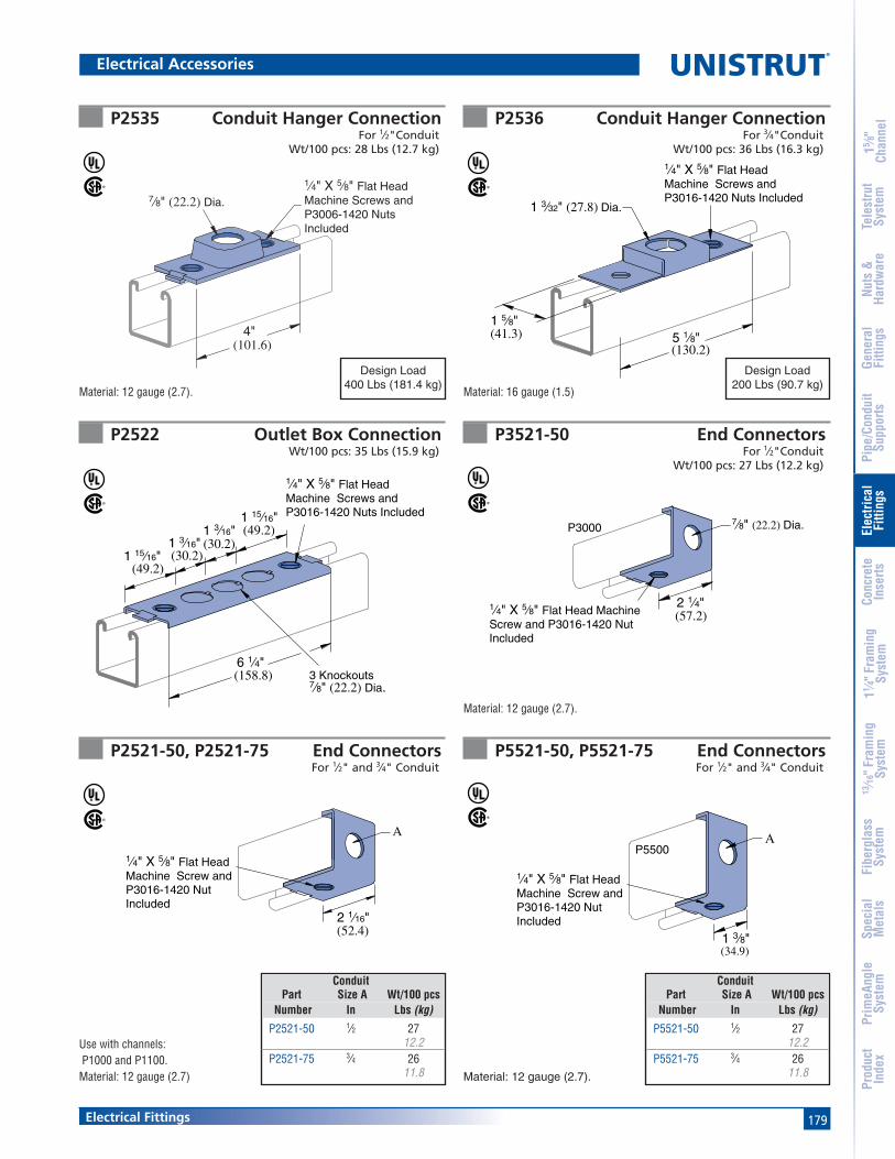
179Electrical Fittings
15 ⁄8"
Chan
nel
Nuts
&Ha
rdw
are
Gene
ral
Fitti
ngs
Pipe
/Con
duit
Supp
orts
Elec
trica
lFi
tting
sCo
ncre
teIn
serts
11 ⁄4" F
ram
ing
Syst
em13
⁄16" F
ram
ing
Syst
emFi
berg
lass
Syst
emSp
ecia
lM
etal
sTe
lest
rut
Syst
emPr
imeA
ngle
Syst
emPr
oduc
tIn
dex
P2535 Conduit Hanger ConnectionFor 1⁄2"Conduit
Wt/100 pcs: 28 Lbs (12.7 kg)
P2536 Conduit Hanger ConnectionFor 3⁄4"Conduit
Wt/100 pcs: 36 Lbs (16.3 kg)
P2522 Outlet Box ConnectionWt/100 pcs: 35 Lbs (15.9 kg)
P3521-50 End ConnectorsFor 1⁄2"Conduit
Wt/100 pcs: 27 Lbs (12.2 kg)
P2521-50, P2521-75 End ConnectorsFor 1⁄2" and 3⁄4" Conduit
P5521-50, P5521-75 End ConnectorsFor 1⁄2" and 3⁄4" Conduit
2 1⁄16"(52.4)
A
1⁄4" X 5⁄8" Flat HeadMachine Screw andP3016-1420 NutIncluded
1 15⁄16"(49.2)
1⁄4" X 5⁄8" Flat Head Machine Screws and P3016-1420 Nuts Included
1 3⁄16"(30.2)1 3⁄16"
(30.2)1 15⁄16"(49.2)
6 1⁄4"(158.8) 3 Knockouts
7⁄8" (22.2) Dia.
Material: 12 gauge (2.7). Material: 16 gauge (1.5)
Material: 12 gauge (2.7).
Material: 12 gauge (2.7).
Use with channels: P1000 and P1100.Material: 12 gauge (2.7)
1 3⁄32" (27.8) Dia.
(130.2)
1 5⁄8"(41.3)
1⁄4" X 5⁄8" Flat HeadMachine Screws andP3016-1420 Nuts Included
5 1⁄8"
7⁄8" (22.2) Dia.
2 1⁄4"(57.2)
1⁄4" X 5⁄8" Flat Head Machine Screw and P3016-1420 Nut Included
P3000
1 3⁄8"(34.9)
AP5500
1⁄4" X 5⁄8" Flat HeadMachine Screw andP3016-1420 NutIncluded
Design Load400 Lbs (181.4 kg)
Design Load200 Lbs (90.7 kg)
ConduitPart Size A Wt/100 pcs
Number In Lbs (kg)
P2521-50 1⁄2 2712.2
P2521-75 3⁄4 2611.8
ConduitPart Size A Wt/100 pcs
Number In Lbs (kg)
P5521-50 1⁄2 2712.2
P5521-75 3⁄4 2611.8
Electrical Accessories
7⁄8" (22.2) Dia.
(101.6)
1⁄4" X 5⁄8" Flat HeadMachine Screws andP3006-1420 NutsIncluded
4"
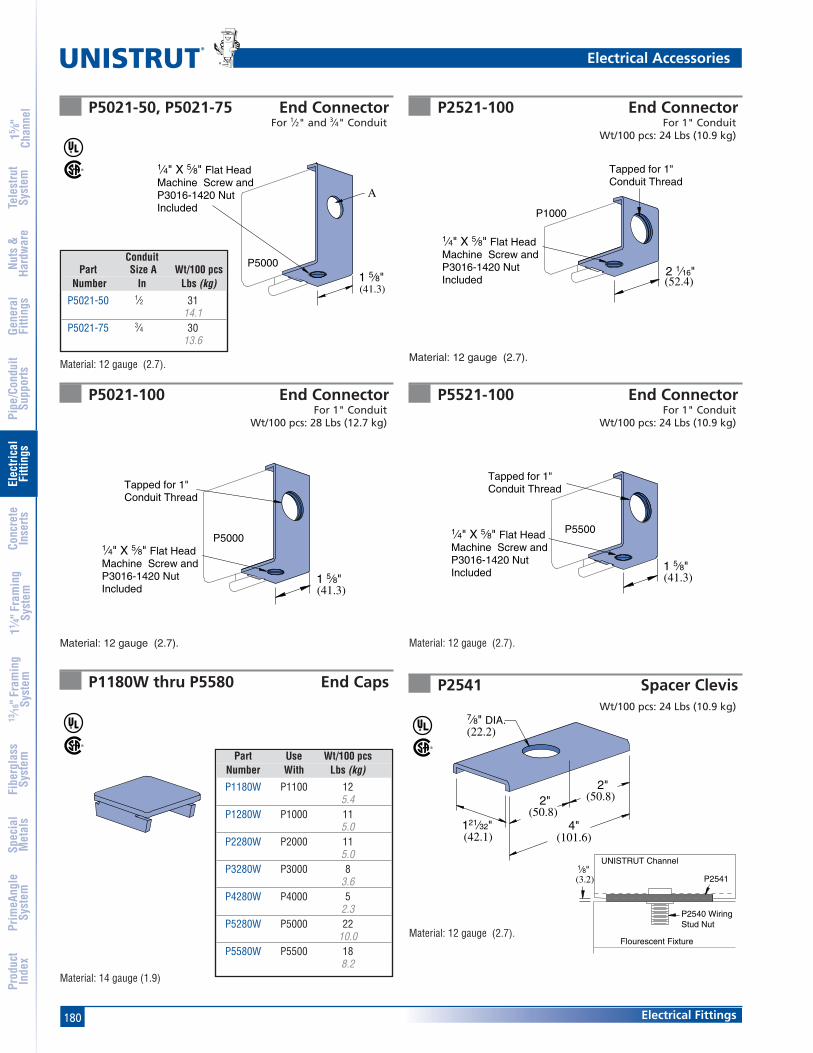
180
®
Electrical Fittings
15 ⁄8"
Chan
nel
Nuts
&Ha
rdw
are
Gene
ral
Fitti
ngs
Pipe
/Con
duit
Supp
orts
Elec
trica
lFi
tting
sCo
ncre
teIn
serts
11 ⁄4" F
ram
ing
Syst
em13
⁄16" F
ram
ing
Syst
emFi
berg
lass
Syst
emSp
ecia
lM
etal
sTe
lest
rut
Syst
emPr
imeA
ngle
Syst
emPr
oduc
tIn
dex
P5021-50, P5021-75 End ConnectorFor 1⁄2" and 3⁄4" Conduit
P2521-100 End ConnectorFor 1" Conduit
Wt/100 pcs: 24 Lbs (10.9 kg)
P5021-100 End ConnectorFor 1" Conduit
Wt/100 pcs: 28 Lbs (12.7 kg)
P5521-100 End ConnectorFor 1" Conduit
Wt/100 pcs: 24 Lbs (10.9 kg)
P1180W thru P5580 End Caps
Material: 12 gauge (2.7).Material: 12 gauge (2.7).
Material: 12 gauge (2.7). Material: 12 gauge (2.7).
(41.3)1 5⁄8"
A
P5000
1⁄4" X 5⁄8" Flat HeadMachine Screw andP3016-1420 NutIncluded
1 5⁄8"(41.3)
P5000
Tapped for 1"Conduit Thread
1⁄4" X 5⁄8" Flat HeadMachine Screw andP3016-1420 NutIncluded
Tapped for 1"Conduit Thread
(52.4)
P1000
1⁄4" X 5⁄8" Flat HeadMachine Screw andP3016-1420 NutIncluded
2 1⁄16"
1 5⁄8"(41.3)
P5500
Tapped for 1"Conduit Thread
1⁄4" X 5⁄8" Flat HeadMachine Screw andP3016-1420 NutIncluded
Material: 14 gauge (1.9)
Part Use Wt/100 pcsNumber With Lbs (kg)
P1180W P1100 125.4
P1280W P1000 115.0
P2280W P2000 115.0
P3280W P3000 83.6
P4280W P4000 52.3
P5280W P5000 2210.0
P5580W P5500 188.2
ConduitPart Size A Wt/100 pcs
Number In Lbs (kg)
P5021-50 1⁄2 3114.1
P5021-75 3⁄4 3013.6
Electrical Accessories
P2541 Spacer ClevisWt/100 pcs: 24 Lbs (10.9 kg)
Material: 12 gauge (2.7).
2"(50.8)
(101.6)121⁄32"(42.1)
7⁄8" DIA.(22.2)
(50.8)
4"
2"
1⁄8"(3.2)
UNISTRUT Channel
Flourescent Fixture
P2541
P2540 Wiring Stud Nut

181Electrical Fittings
15 ⁄8"
Chan
nel
Nuts
&Ha
rdw
are
Gene
ral
Fitti
ngs
Pipe
/Con
duit
Supp
orts
Elec
trica
lFi
tting
sCo
ncre
teIn
serts
11 ⁄4" F
ram
ing
Syst
em13
⁄16" F
ram
ing
Syst
emFi
berg
lass
Syst
emSp
ecia
lM
etal
sTe
lest
rut
Syst
emPr
imeA
ngle
Syst
emPr
oduc
tIn
dex
P2552 Polypropylene Wire Retainer P2540, P2540A Wiring Stud Nut
P2603 Fixture Wiring Nipple P3116-125 Fixture Stud NutWt/100 pcs: 11 Lbs (5.0 kg)
Material: Sintered metal.
Retainer may be easily pushed intochannel to support wires untilclosure strip is installed.
Wt/100 pcs: .30 Lbs (.1 kg)
A
1 1⁄2"(38.1)
1 1⁄2"(38.1)
1⁄2" American StandardStraight Pipe Thread
1 3⁄16"(30.2)
1⁄4" x 20 Thd.
Design Load320 Lbs (145.1 kg) Part “A” Wt/100 pcs
Number In (mm) Lbs (kg)
P2540 15⁄64 10.028.6 4.5
P2540A 5⁄8 815.9 3.6
2 1⁄8"(54.0)
1.10"(27.9)
.80"(20.3)
Hole Dia..600" (15.2)
Wt/100 pcs: 14 Lbs (6.4 kg)
Assembly: 1⁄2" x 2" rigid conduit nippleBushing Locknut
Electrical Accessories
Stamped Ident. No.P2540 – 121961P2540A – 121960

182
®
Electrical Fittings
15 ⁄8"
Chan
nel
Nuts
&Ha
rdw
are
Gene
ral
Fitti
ngs
Pipe
/Con
duit
Supp
orts
Elec
trica
lFi
tting
sCo
ncre
teIn
serts
11 ⁄4" F
ram
ing
Syst
em13
⁄16" F
ram
ing
Syst
emFi
berg
lass
Syst
emSp
ecia
lM
etal
sTe
lest
rut
Syst
emPr
imeA
ngle
Syst
emPr
oduc
tIn
dex
P2602 Mecury Vapor Fixture Hanger
6 3⁄4"(171.5)
Hole Size1 1⁄16"(27.0)
Wt/100 pcs: 154 Lbs (69.9 kg)
Use with 15⁄8" ChannelFinish: Electro-galvanizedStock Size: 1⁄4"NOTE: Supports fixture in slot up or down system.
Junction Boxes
Requires P2603wiring nipple
P2803 Hub AssemblyWt/100 pcs: 32 Lbs (14.5 kg)1 11⁄16"3"
2"
(76.2)
(50.8)
(42.9)
2 1⁄4"4"
(101.6)(57.2)
4"(101.6)
4 3⁄16"(106.4)4 3⁄16"
(106.4)
P2802 Junction Box CoverP2801 Junction BoxWt/100 pcs: 30 Lbs (13.6kg)Wt/100 pcs: 113 Lbs (51.4 kg)
Note: Combine junction box (P2801) andhub assemblies (P2803) to make1, 2, 3, or 4 way junction box.
P2801Junction Box
P2803 Hub
P1000Channel
Stamp ID No. 122022
P2801

183Electrical Fittings
15 ⁄8"
Chan
nel
Nuts
&Ha
rdw
are
Gene
ral
Fitti
ngs
Pipe
/Con
duit
Supp
orts
Elec
trica
lFi
tting
sCo
ncre
teIn
serts
11 ⁄4" F
ram
ing
Syst
em13
⁄16" F
ram
ing
Syst
emFi
berg
lass
Syst
emSp
ecia
lM
etal
sTe
lest
rut
Syst
emPr
imeA
ngle
Syst
emPr
oduc
tIn
dex
P2900 P2901
P2902 P2903
Wt/100 pcs: 35 Lbs (15.9 kg)
P1000
P1000
P1000
P1000
Wt/100 pcs: 45 Lbs (20.4 kg)Wt/100 pcs: 27 Lbs (12.2 kg)
Material: Cast aluminum.Material: Cast aluminum.
Material: Cast aluminum. Material: Cast aluminum.
Wt/100 pcs: 20 Lbs (9.1 kg)
In-Channel Joiners
P2904 Wt/100 pcs: 12 Lbs (5.4kg)
P3300, P4000, P4100
3/8"-16 x 1/4"Socket Cup Point
Set Screws IncludedExtruded Aluminum
3/8"-16 x 1/4"Socket Cup Point
Set Screws Included
3/8"-16 x 1/4"Socket Cup Point
Set Screws Included
3/8"-16 x 1/4"Socket Cup Point
Set Screws Included
3/8"-16 x 1/4"Socket Cup Point
Set Screws Included
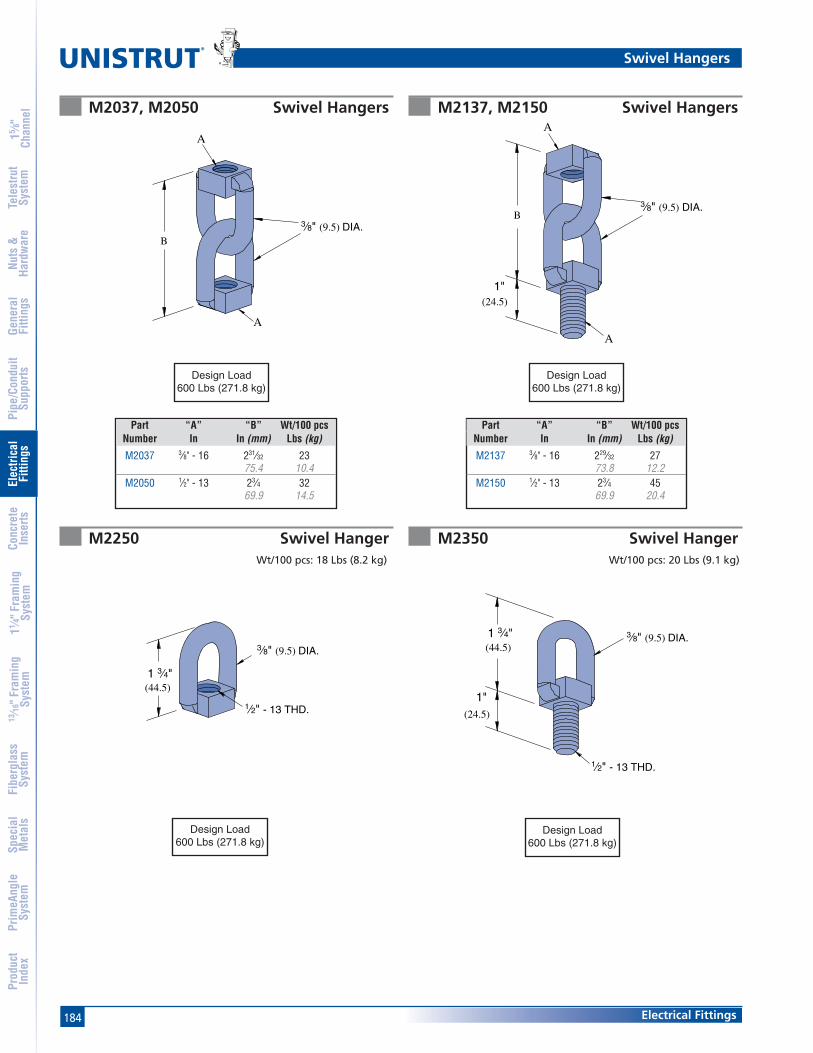
184
®
Electrical Fittings
15 ⁄8"
Chan
nel
Nuts
&Ha
rdw
are
Gene
ral
Fitti
ngs
Pipe
/Con
duit
Supp
orts
Elec
trica
lFi
tting
sCo
ncre
teIn
serts
11 ⁄4" F
ram
ing
Syst
em13
⁄16" F
ram
ing
Syst
emFi
berg
lass
Syst
emSp
ecia
lM
etal
sTe
lest
rut
Syst
emPr
imeA
ngle
Syst
emPr
oduc
tIn
dex
M2037, M2050 Swivel Hangers M2137, M2150 Swivel Hangers
M2250 Swivel Hanger M2350 Swivel HangerWt/100 pcs: 18 Lbs (8.2 kg)
A
3⁄8" (9.5) DIA.
A
B
3⁄8" (9.5) DIA.
1⁄2" - 13 THD.
1 3⁄4"(44.5)
A
3⁄8" (9.5) DIA.
A
B
(24.5)
1"
3⁄8" (9.5) DIA.1 3⁄4"(44.5)
(24.5)
1"
1⁄2" - 13 THD.
Wt/100 pcs: 20 Lbs (9.1 kg)
Part “A” “B” Wt/100 pcsNumber In In (mm) Lbs (kg)
M2037 3⁄8" - 16 231⁄32 2375.4 10.4
M2050 1⁄2" - 13 23⁄4 3269.9 14.5
Part “A” “B” Wt/100 pcsNumber In In (mm) Lbs (kg)
M2137 3⁄8" - 16 229⁄32 2773.8 12.2
M2150 1⁄2" - 13 23⁄4 4569.9 20.4
Swivel Hangers
Design Load600 Lbs (271.8 kg)
Design Load600 Lbs (271.8 kg)
Design Load600 Lbs (271.8 kg)
Design Load600 Lbs (271.8 kg)
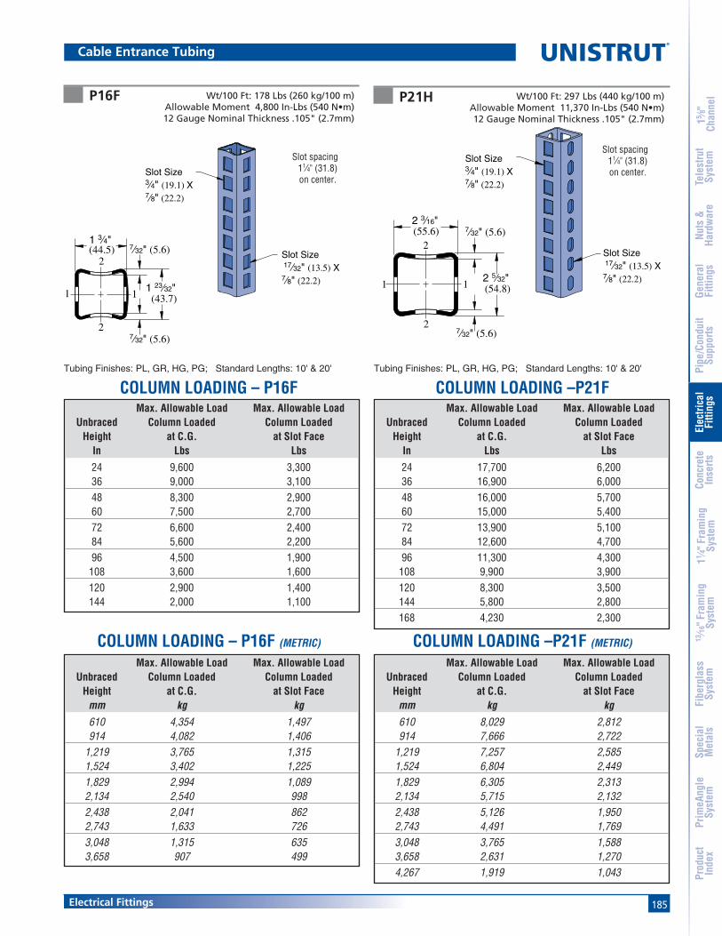
185Electrical Fittings
15 ⁄8"
Chan
nel
Nuts
&Ha
rdw
are
Gene
ral
Fitti
ngs
Pipe
/Con
duit
Supp
orts
Elec
trica
lFi
tting
sCo
ncre
teIn
serts
11 ⁄4" F
ram
ing
Syst
em13
⁄16" F
ram
ing
Syst
emFi
berg
lass
Syst
emSp
ecia
lM
etal
sTe
lest
rut
Syst
emPr
imeA
ngle
Syst
emPr
oduc
tIn
dex
P16F P21H
Slot Size 17⁄32" (13.5) X 7⁄8" (22.2)
Slot Size3⁄4" (19.1) X 7⁄8" (22.2)
Slot Size 17⁄32" (13.5) X 7⁄8" (22.2)
Slot Size3⁄4" (19.1) X 7⁄8" (22.2)
11
2
27⁄32" (5.6)
7⁄32" (5.6)2 3⁄16"(55.6)
2 5⁄32"(54.8)1
2
1
27⁄32" (5.6)
7⁄32" (5.6)1 3⁄4"(44.5)
1 23⁄32"(43.7)
Cable Entrance Tubing
Slot spacing11⁄4" (31.8)on center.
Slot spacing11⁄4" (31.8)on center.
Max. Allowable Load Max. Allowable LoadUnbraced Column Loaded Column Loaded
Height at C.G. at Slot FaceIn Lbs Lbs
24 9,600 3,30036 9,000 3,10048 8,300 2,90060 7,500 2,70072 6,600 2,40084 5,600 2,20096 4,500 1,900
108 3,600 1,600120 2,900 1,400144 2,000 1,100
Max. Allowable Load Max. Allowable LoadUnbraced Column Loaded Column Loaded
Height at C.G. at Slot Facemm kg kg610 4,354 1,497914 4,082 1,406
1,219 3,765 1,3151,524 3,402 1,2251,829 2,994 1,0892,134 2,540 9982,438 2,041 8622,743 1,633 7263,048 1,315 6353,658 907 499
Max. Allowable Load Max. Allowable LoadUnbraced Column Loaded Column Loaded
Height at C.G. at Slot FaceIn Lbs Lbs
24 17,700 6,20036 16,900 6,00048 16,000 5,70060 15,000 5,40072 13,900 5,10084 12,600 4,70096 11,300 4,300
108 9,900 3,900120 8,300 3,500144 5,800 2,800168 4,230 2,300
Max. Allowable Load Max. Allowable LoadUnbraced Column Loaded Column Loaded
Height at C.G. at Slot Facemm kg kg610 8,029 2,812914 7,666 2,722
1,219 7,257 2,5851,524 6,804 2,4491,829 6,305 2,3132,134 5,715 2,1322,438 5,126 1,9502,743 4,491 1,7693,048 3,765 1,5883,658 2,631 1,2704,267 1,919 1,043
Wt/100 Ft: 178 Lbs (260 kg/100 m)Allowable Moment 4,800 In-Lbs (540 N•m)12 Gauge Nominal Thickness .105" (2.7mm)
Wt/100 Ft: 297 Lbs (440 kg/100 m)Allowable Moment 11,370 In-Lbs (540 N•m)12 Gauge Nominal Thickness .105" (2.7mm)
Tubing Finishes: PL, GR, HG, PG; Standard Lengths: 10' & 20' Tubing Finishes: PL, GR, HG, PG; Standard Lengths: 10' & 20'
COLUMN LOADING – P16F COLUMN LOADING –P21F
COLUMN LOADING – P16F (METRIC) COLUMN LOADING –P21F (METRIC)

186
®
Electrical Fittings
15 ⁄8"
Chan
nel
Nuts
&Ha
rdw
are
Gene
ral
Fitti
ngs
Pipe
/Con
duit
Supp
orts
Elec
trica
lFi
tting
sCo
ncre
teIn
serts
11 ⁄4" F
ram
ing
Syst
em13
⁄16" F
ram
ing
Syst
emFi
berg
lass
Syst
emSp
ecia
lM
etal
sTe
lest
rut
Syst
emPr
imeA
ngle
Syst
emPr
oduc
tIn
dex
Cable Entrance Tubing
ELEMENTS OF SECTION – P16FParameter P16F P16F (metric)Area of Section 0.416 In2 2.68 cm2
Axis 1-1Moment of Inertia (I) 0.168 In4 7.0 cm4
Section Modulus (S) 0.192 In3 3.1 cm3
Radius of Gyration (r) 0.650 In 1.7 cmAxis 2-2
Moment of Inertia (I) 0.210 In4 8.7 cm4
Section Modulus (S) 0.240 In3 3.9 cm3
Radius of Gyration (r) 0.725 In 1.8 cm
Parameter P21H P21H (metric)Area of Section 0.749 In2 4.83 cm2
Axis 1-1Moment of Inertia (I) 0.490 In4 20.4 cm4
Section Modulus (S) 0.455 In3 7.5 cm3
Radius of Gyration (r) 0.820 In 2.1 cmAxis 2-2
Moment of Inertia (I) 0.590 In4 24.6 cm4
Section Modulus (S) 0.540 In3 8.8 cm3
Radius of Gyration (r) 0.900 In 2.3 cm
ELEMENTS OF SECTION – P21H
Notes:
1. Above loads include the weight of the member. This weight must be deducted to arrive at the net allowable load the beam will support.
2. Long span beams should be supported in such a manner as to prevent rotation and twist.
3. Allowable uniformly distributed loads are listed for various simple spans, that is, a beam on two supports. If load is concentrated at the centerof the span, multiply load from the table by 0.5 and corresponding deflection by 0.8.
Max Defl. atAllowable Uniform Uniform Loading at Deflection
Span Uniform Load Load Span/180 Span/240 Span/360In Lbs In Lbs Lbs Lbs
24 1,600 0.06 1,600 1,600 1,60036 1,070 0.13 1,070 1,070 82048 800 0.23 800 690 46060 640 0.36 590 440 29072 530 0.52 410 310 20084 460 0.71 300 220 15096 400 0.93 230 170 110
108 360 1.18 180 140 90120 320 1.45 150 110 70144 270 2.09 100 80 50168 230 2.85 70 60 40
Max Defl. atAllowable Uniform Uniform Loading at Deflection
Span Uniform Load Load Span/180 Span/240 Span/360mm kg mm kg kg kg600 737 1 737 737 737750 590 2 590 590 550
1,000 442 4 442 442 3091,250 354 6 354 297 1981,500 295 9 275 206 1381,750 253 12 202 152 1012,000 221 16 155 116 772,500 177 25 99 74 503,000 148 36 69 52 343,500 126 49 51 38 254,000 111 64 39 29 19
Max Defl. atAllowable Uniform Uniform Loading at Deflection
Span Uniform Load Load Span/180 Span/240 Span/360In Lbs In Lbs Lbs Lbs
24 3,790 0.05 3,790 3,790 3,79036 2,530 0.11 2,530 2,530 2,38048 1,900 0.19 1,900 1,900 1,34060 1,520 0.29 1,520 1,280 86072 1,260 0.42 1,190 890 59084 1,080 0.58 870 660 44096 950 0.76 670 500 330
108 840 0.96 530 400 260120 760 1.18 430 320 210144 630 1.70 300 220 150168 540 2.31 220 160 110
Max Defl. atAllowable Uniform Uniform Loading at Deflection
Span Uniform Load Load Span/180 Span/240 Span/360mm kg mm kg kg kg600 1747 1 1747 1747 1747750 1397 2 1397 1397 1397
1,000 1048 3 1048 1048 9021,250 838 5 838 838 5781,500 699 7 699 602 4011,750 599 10 589 442 2952,000 524 13 451 338 2262,500 419 20 289 217 1443,000 349 29 201 150 1003,500 299 40 147 111 744,000 262 52 113 85 56
BEAM LOADING – P16F BEAM LOADING – P21F
BEAM LOADING – P16F (METRIC) BEAM LOADING – P21F (METRIC)
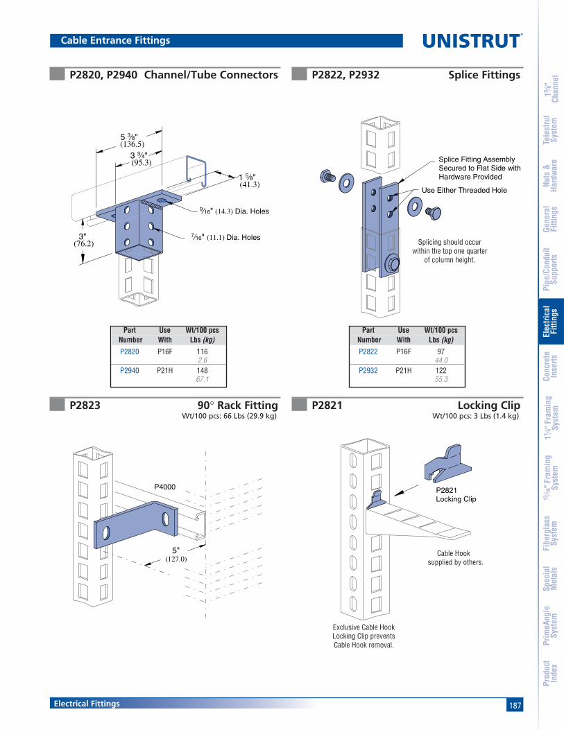
187Electrical Fittings
15 ⁄8"
Chan
nel
Nuts
&Ha
rdw
are
Gene
ral
Fitti
ngs
Pipe
/Con
duit
Supp
orts
Elec
trica
lFi
tting
sCo
ncre
teIn
serts
11 ⁄4" F
ram
ing
Syst
em13
⁄16" F
ram
ing
Syst
emFi
berg
lass
Syst
emSp
ecia
lM
etal
sTe
lest
rut
Syst
emPr
imeA
ngle
Syst
emPr
oduc
tIn
dex
Cable Entrance Fittings
P2822, P2932 Splice Fittings
P2823 90° Rack FittingWt/100 pcs: 66 Lbs (29.9 kg)
P2821 Locking ClipWt/100 pcs: 3 Lbs (1.4 kg)
Splicing should occurwithin the top one quarter
of column height.
Exclusive Cable HookLocking Clip preventsCable Hook removal.
P2821Locking Clip
3"(76.2)
5 3⁄8"(136.5)
3 3⁄4"(95.3)
1 5⁄8"(41.3)
9⁄16" (14.3) Dia. Holes
7⁄16" (11.1) Dia. Holes
P2820, P2940 Channel/Tube Connectors
Cable Hooksupplied by others.(127.0)
5"
P4000
Splice Fitting AssemblySecured to Flat Side withHardware Provided
Use Either Threaded Hole
Part Use Wt/100 pcs Number With Lbs (kg)
P2820 P16F 1162.6
P2940 P21H 14867.1
Part Use Wt/100 pcs Number With Lbs (kg)
P2822 P16F 9744.0
P2932 P21H 12255.3

188
®
Electrical Fittings
15 ⁄8"
Chan
nel
Nuts
&Ha
rdw
are
Gene
ral
Fitti
ngs
Pipe
/Con
duit
Supp
orts
Elec
trica
lFi
tting
sCo
ncre
teIn
serts
11 ⁄4" F
ram
ing
Syst
em13
⁄16" F
ram
ing
Syst
emFi
berg
lass
Syst
emSp
ecia
lM
etal
sTe
lest
rut
Syst
emPr
imeA
ngle
Syst
emPr
oduc
tIn
dex
Cable Entrance Fittings
P2928, P2929 and P2930 Cable Brackets
P2920 thru P2924 Cable Brackets
L
A
1 5⁄8"(41.3)
B
3⁄16" (4.8) x 3⁄4" (19.1) Slots2 3⁄4" (69.9) on Center
L
A
1 5⁄8"(41.3)
B
Safety factor of 3.
Safety factor of 3.
Material: 12 gauge steel.
Material: 12 gauge steel.
Use with P16F or P21H.
Use with P16F or P21H.
UniformPart Wt/100 pcs Design Load
Number “L” “A” “B” Lbs (kg) Lbs (kg)
P2928 6 31⁄2 7⁄8 92 500152.4 88.9 22.2 41.7 2.2
P2929 12 31⁄2 15⁄8 320 250304.8 88.9 41.3 145.1 1.1
P2930 18 31⁄2 15⁄8 420 170457.2 88.9 41.3 190.5 0.8
UniformPart Wt/100 pcs Design Load
Number “L” “A” “B” Lbs (kg) Lbs (kg)
P2920 51⁄2 31⁄2 7⁄8 90 500139.7 88.9 22.2 40.8 2.2
P2921 81⁄4 31⁄2 7⁄8 120 325209.6 88.9 22.2 54.4 1.4
P2922 11 31⁄2 15⁄8 300 275279.4 88.9 41.3 136.1 1.2
P2923 133⁄4 31⁄2 15⁄8 340 220349.3 88.9 41.3 154.2 1.0
P2924 191⁄4 31⁄2 15⁄8 430 160489.0 88.9 41.3 195.0 0.7

189Electrical Fittings
15 ⁄8"
Chan
nel
Nuts
&Ha
rdw
are
Gene
ral
Fitti
ngs
Pipe
/Con
duit
Supp
orts
Elec
trica
lFi
tting
sCo
ncre
teIn
serts
11 ⁄4" F
ram
ing
Syst
em13
⁄16" F
ram
ing
Syst
emFi
berg
lass
Syst
emSp
ecia
lM
etal
sTe
lest
rut
Syst
emPr
imeA
ngle
Syst
emPr
oduc
tIn
dex
U.L. Listed
C.S.A. APPROVED
Electrical Technical Data
Unistrut channels are also certified by Canadian Standards Association.
Unistrut channel is listed by Underwriters' Laboratories as asurface metal raceway. Snap-in closure strip is used tocomplete the raceway. Accessory parts listed by Underwritersare noted on drawings.
The following tables represent maximum number of conduc-tors when raceway is not employed with fixtures or where theclearance between fixtures and raceway is greater than 1⁄2"(12.7). In all cases the snap-in cover is required to completeraceway enclosure.
P3300
P3000, & -KO
P5500, & -KO
P5000, & -KOP1000, & -KO, P1100 & -KO
Suitable for number of wires in Column A when installed tosupport and supply electric discharge type lighting fixtureswhen raceway wiring is suitable for at least 75° C except wiresuitable for 60° C may be used when clearance betweenfixtures and raceways is at least 1⁄2" (12.7). Also suitable fornumber of wires in column B when installed to support electric
Number and Conductor Size (AWG)Gauge 14 12 10 8 6
THWN, THHN 72 54 34 17 12XHHW 48 37 29 13 10T, TW 46 36 28 13 7THW 30 25 20 10 7RH 27 22 13 7 5RHH, RHW 19 16 13 7 5
Number and Conductor Size (AWG)Gauge 14 12 10 8 6
THWN, THHN 141 105 66 33 23XHHW 93 73 57 27 19T, TW 91 58 55 26 15THW 59 49 39 20 15RH 53 44 26 14 10RHH, RHW 37 32 26 14 10
Number and Conductor Size (AWG)Gauge 14 12 10 8 6
THWN, THHN 40 30 19 9 6XHHW 26 21 16 7 5T, TW 26 20 15 7 4THW 17 14 11 6 4RH 15 12 7 4 3RHH, RHW 10 9 7 4 2
Number and Conductor Size (AWG)Gauge 14 12 10 8 6
THWN, THHN 88 66 42 20 14XHHW 58 46 35 16 12T, TW 57 44 34 16 9THW 37 30 24 12 9RH 33 27 16 9 6RHH, RHW 23 20 16 9 6
Number and Conductor Size (AWG)Gauge 14 12 10 8 6
THWN, THHN 193 105 91 45 32XHHW 128 101 78 37 27T, TW 125 98 75 35 20THW 81 67 54 28 20RH 73 60 36 19 13RHH, RHW 51 44 36 19 13
Raceway Wire P1000, &-KOSize P1100, &-KO P3000, &-KO P3300 P5000 &-KO P5500, &-KOAWG A B A B A B A B A B
14 6 10 5 10 4 6 10 10 10 1012 6 10 4 10 3 6 10 10 10 1010 5 8 4 6 - - 8 10 8 108 4 6 3 4 - - 6 9 6 86 2 3 2 2 - - 4 6 4 6
discharge type lighting fixtures when raceway wiring is suitablefor at least 75° C and clearance between fixtures and racewayis at least 1⁄8" (3.2).
Maximum number of wires for types T, THHN,THW, THWN, TW, R, RH, RHH, RHW or XHHW
Channel Size and Inside AreaChannel Part Number Size Area 40% Area 25% AreaP3300 & KO 15⁄8" x 7⁄8" 0.975 0.390 0.244
629 252 157P3000 & KO 15⁄8" x 13⁄8" 1.677 0.671 0.419
1,082 433 270P1000 & KO, P1100 & KO 15⁄8" x 15⁄8" 2.028 0.811 0.507
1,308 523 327P5500 & KO 15⁄8" x 27⁄16" 3.169 1.268 0.792
2,045 818 511P5000 & KO 15⁄8" x 31⁄4" 4.308 1.723 1.077
Note: Raceways with external joiners shall use a 40% wire fillcalculation to determine the number of conductorspermitted.
Raceways with internal joiners shall use a 25% wire fillcalculation to determine the number of conductorspermitted

190
®
Electrical Fittings
15 ⁄8"
Chan
nel
Nuts
&Ha
rdw
are
Gene
ral
Fitti
ngs
Pipe
/Con
duit
Supp
orts
Elec
trica
lFi
tting
sCo
ncre
teIn
serts
11 ⁄4" F
ram
ing
Syst
em13
⁄16" F
ram
ing
Syst
emFi
berg
lass
Syst
emSp
ecia
lM
etal
sTe
lest
rut
Syst
emPr
imeA
ngle
Syst
emPr
oduc
tIn
dex
Fluorescent Fixtures - Support Applications
Electrical Technical Data
Spring-Nut attachment systemSlotted channel attachment system
Conduit connects through knockout in fixture. Fixtureis supported by P1006-1420 spring nut and 1/4" roundhead machine screw. Assembly is supported byP2855 hinged hanger.
Conduit connects through knockout in fixture. Fixture issupported by HCSS series hex bolt and hex nut. Racewayis supported by P2855 hanger. To splice a continuous run,use P3922.
Recommended Support Spacing for FixturesDeflections are based on continuity of span and use of 4 ft.fixtures weighing approximately 30 lbs. each. Do not use joinerfittings between supporting hangers. When using knock-out orslotted channels deflections will be increased approximately5%. With fixtures spaced 2' - 0" apart, deflection is 60-70% oftable. When spaced 4' - 0" apart, deflection is 50-60% of table.
Distance Between Supports8' (2.4m) 10' (3m) 12' (3.7m) 14' (4.3m) 16' (4.9m) 18' (5.5m) 20' (6.1m) 22' (6.7m) 24' (7.3m)
Channel In (mm) In (mm) In (mm) In (mm) In (mm) In (mm) In (mm) In (mm) In (mm)
P3300 0.1874.7
P3000 0.100 0.250 0.5002.5 6.4 12.7
P1100 0.088 0.250 0.437 0.8752.2 6.4 11.1 22.2
P1000 0.180 0.312 0.625 1.000 1.6254.6 7.9 15.9 25.4 41.3
P5500 0.250 0.500 0.812 1.6206.4 12.7 20.6 41.1
P5000 0.310 0.625 1.000 1.800 2.5007.9 15.9 25.4 45.7 63.5
P1001 0.310 0.625 1.000 1.800 2.5007.9 15.9 25.4 45.7 63.5
P5001 0.200 0.250 0.400 0.5005.1 6.4 10.2 12.7
Deflection Table
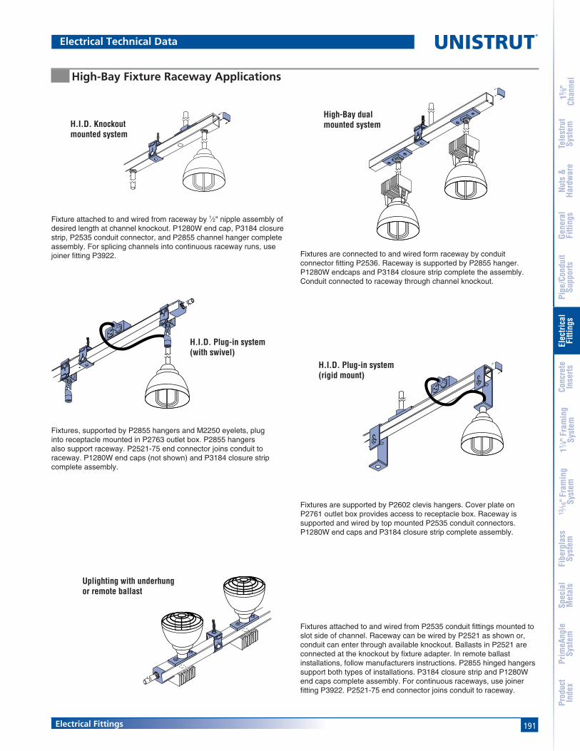
191Electrical Fittings
15 ⁄8"
Chan
nel
Nuts
&Ha
rdw
are
Gene
ral
Fitti
ngs
Pipe
/Con
duit
Supp
orts
Elec
trica
lFi
tting
sCo
ncre
teIn
serts
11 ⁄4" F
ram
ing
Syst
em13
⁄16" F
ram
ing
Syst
emFi
berg
lass
Syst
emSp
ecia
lM
etal
sTe
lest
rut
Syst
emPr
imeA
ngle
Syst
emPr
oduc
tIn
dex
High-Bay Fixture Raceway Applications
Fixtures are supported by P2602 clevis hangers. Cover plate onP2761 outlet box provides access to receptacle box. Raceway issupported and wired by top mounted P2535 conduit connectors.P1280W end caps and P3184 closure strip complete assembly.
Fixture attached to and wired from raceway by 1⁄2" nipple assembly ofdesired length at channel knockout. P1280W end cap, P3184 closurestrip, P2535 conduit connector, and P2855 channel hanger completeassembly. For splicing channels into continuous raceway runs, usejoiner fitting P3922.
Fixtures, supported by P2855 hangers and M2250 eyelets, pluginto receptacle mounted in P2763 outlet box. P2855 hangersalso support raceway. P2521-75 end connector joins conduit toraceway. P1280W end caps (not shown) and P3184 closure stripcomplete assembly.
Fixtures are connected to and wired form raceway by conduitconnector fitting P2536. Raceway is supported by P2855 hanger.P1280W endcaps and P3184 closure strip complete the assembly.Conduit connected to raceway through channel knockout.
Uplighting with underhungor remote ballast
High-Bay dualmounted systemH.I.D. Knockout
mounted system
H.I.D. Plug-in system(rigid mount)
H.I.D. Plug-in system(with swivel)
Fixtures attached to and wired from P2535 conduit fittings mounted toslot side of channel. Raceway can be wired by P2521 as shown or,conduit can enter through available knockout. Ballasts in P2521 areconnected at the knockout by fixture adapter. In remote ballastinstallations, follow manufacturers instructions. P2855 hinged hangerssupport both types of installations. P3184 closure strip and P1280Wend caps complete assembly. For continuous raceways, use joinerfitting P3922. P2521-75 end connector joins conduit to raceway.
Electrical Technical Data

192
®
Electrical Fittings
15 ⁄8"
Chan
nel
Nuts
&Ha
rdw
are
Gene
ral
Fitti
ngs
Pipe
/Con
duit
Supp
orts
Elec
trica
lFi
tting
sCo
ncre
teIn
serts
11 ⁄4" F
ram
ing
Syst
em13
⁄16" F
ram
ing
Syst
emFi
berg
lass
Syst
emSp
ecia
lM
etal
sTe
lest
rut
Syst
emPr
imeA
ngle
Syst
emPr
oduc
tIn
dex
Electrical Technical Data

193
®
MATERIALCold-formed inserts are manufactured from standard 12gauge (2.7 mm) Unistrut channel sections conforming toASTM A1011 SS GR 33 or ASTM A653 GR 33, unless other-wise noted.
Hot-rolled inserts, as noted, are manufactured from carbonsteel meeting physical requirements of ASTM A283 GR D.
To inhibit concrete seepage, all inserts (except spot inserts)are provided with closure strips and end caps or foam filler,unless otherwise requested.
Most concrete inserts are available in stainless steel onspecial order. Consult factory for ordering information.
APPLICATIONA wide range of heavy-duty to light-duty “continuous” and“spot” concrete inserts are available for use in pre-cast, pre-stressed or poured-in-place concrete floors, walls or ceilings.
FINISHESCold-formed, standard-duty, light-duty and spot concreteinserts are available in Perma-Green II (GR), hot dippedgalvanized (HG), conforming to ASTM A123 or A153;pre-galvanized (PG), conforming to ASTM A653 GR 33
and plain (PL).
DESIGN LOADDesign loads, where shown, are based on 3,000 PSIconcrete, unless noted.
STANDARD LENGTHSInsert lengths range from 3 inches (76 mm) to 20 feet(6.10m) with a tolerance of ±1⁄4-inch (6.4mm).
DIMENSIONSImperial dimensions are illustrated in inches. Metricdimensions are shown in parentheses or as noted. Unlessnoted, all metric dimensions are in millimeters and roundedto one decimal place.
Custom-designed inserts are available on special order.Consult factory for ordering information.
CONCRETE INSERTSHeavy-Duty Inserts .......................................... 195
Standard-Duty Inserts ............................. 196-197
Light-Duty Inserts ............................................ 198
Spot Inserts ....................................................... 199
Deck Inserts ...................................................... 200
Components ..................................................... 201
Technical Data .................................................. 202
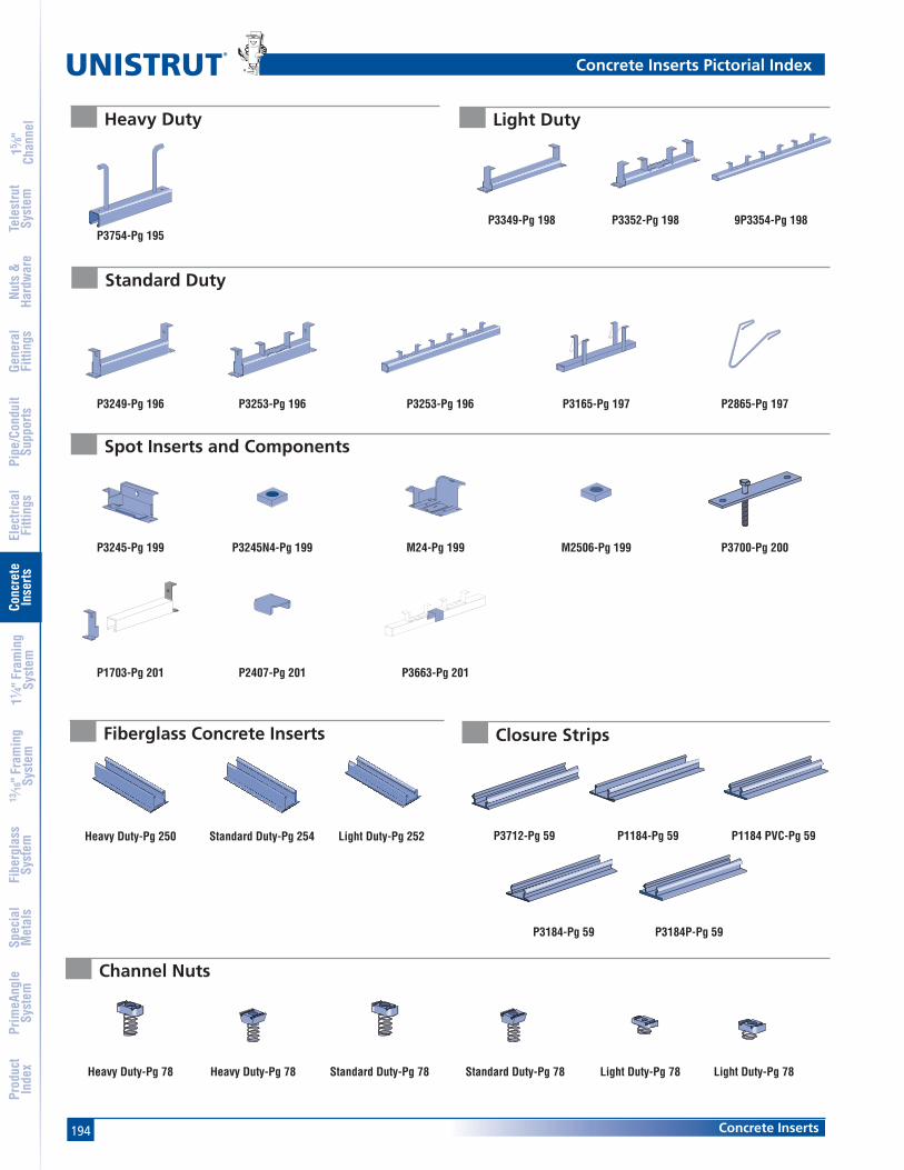
194
®
Concrete Inserts
15 ⁄8"
Chan
nel
Nuts
&Ha
rdw
are
Gene
ral
Fitti
ngs
Pipe
/Con
duit
Supp
orts
Elec
trica
lFi
tting
sCo
ncre
teIn
serts
11 ⁄4" F
ram
ing
Syst
em13
⁄16" F
ram
ing
Syst
emFi
berg
lass
Syst
emSp
ecia
lM
etal
sTe
lest
rut
Syst
emPr
imeA
ngle
Syst
emPr
oduc
tIn
dex
Concrete Inserts Pictorial Index
P3754-Pg 195
P3249-Pg 196 P3253-Pg 196 P3253-Pg 196 P3165-Pg 197 P2865-Pg 197
P3349-Pg 198 P3352-Pg 198 9P3354-Pg 198
P3245-Pg 199 P3245N4-Pg 199 M24-Pg 199
P1703-Pg 201 P2407-Pg 201 P3663-Pg 201
M2506-Pg 199 P3700-Pg 200
Heavy Duty
Standard Duty
Light Duty
Spot Inserts and Components
Heavy Duty-Pg 250 Standard Duty-Pg 254 Light Duty-Pg 252
Fiberglass Concrete Inserts
Heavy Duty-Pg 78 Heavy Duty-Pg 78 Light Duty-Pg 78 Light Duty-Pg 78
Channel Nuts
Standard Duty-Pg 78 Standard Duty-Pg 78
P3712-Pg 59 P1184-Pg 59 P1184 PVC-Pg 59
P3184P-Pg 59P3184-Pg 59
Closure Strips
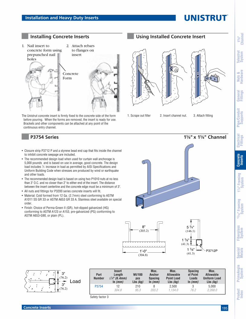
195Concrete Inserts
15 ⁄8"
Chan
nel
Nuts
&Ha
rdw
are
Gene
ral
Fitti
ngs
Pipe
/Con
duit
Supp
orts
Elec
trica
lFi
tting
sCo
ncre
teIn
serts
11 ⁄4" F
ram
ing
Syst
em13
⁄16" F
ram
ing
Syst
emFi
berg
lass
Syst
emSp
ecia
lM
etal
sTe
lest
rut
Syst
emPr
imeA
ngle
Syst
emPr
oduc
tIn
dex
Installation and Heavy Duty Inserts
The Unistrut concrete insert is firmly fixed to the concrete side of the formbefore pouring. When the forms are removed, the insert is ready for use.Brackets and other components can be attached at any point of thecontinuous entry channel.
ConcreteForm
Installing Concrete Inserts
1. Scrape out filler 2. Insert channel nut. 3. Attach fitting
Using Installed Concrete Insert
• Closure strip P3712 P and a styrene bead end cap that fits inside the channelto inhibit concrete seepage are included.
• The recommended design load when used for curtain wall anchorage is5,000 pounds and is based on use in average, good concrete. The designload includes 1⁄3 increase in load as permitted by AISI Specifications andUniform Building Code when stresses are produced by wind or earthquakeand other loads.
• The recommended design load is based on using two P1010 nuts at no lessthan 3" O.C. and no closer than 2" to either end of the insert. The distancebetween the insert centerline and the concrete edge must be a minimum of 3".
• All nuts and fittings for P3200 series concrete inserts will fit.• Material: Cold formed from 12 Ga. (2.7mm) steel conforming to ASTM
A1011 SS GR 33 or ASTM A653 GR 33 A. Stainless steel available on specialorder.
• Finish: Choice of Perma-Green II (GR), hot-dipped galvanized (HG)conforming to ASTM A123 or A153, pre-galvanized (PG) conforming toASTM A653-G90, or plain (PL).
3"(76.2)
3"(76.2)
Load
P3754 Series 15⁄8" x 15⁄8" Channel
Insert Max. Max. Spacing Max.Part Length Wt/100 Anchor Allowable of Point Allowable
Number ±1⁄4" (6.4mm) pcs Spacing Point Load Loads Uniform LoadIn (mm) Lbs (kg) In (mm) Lbs (kg) In (mm) Lbs (kg)
P3754 12 210 8 2,500 3 5,000304.8 95.3 203.2 1,134.0 76.2 2,268.0
1. Nail insert toconcrete form usingprepunched nailholes
2. Attach rebarsto flanges oninsert
(203.2)8"
1'-0"(304.8)
1 5⁄8"(41.3)
5 3⁄4"(146.1)
1 5⁄8"(41.3)
P3712P
Safety factor 3

196
®
Concrete Inserts
15 ⁄8"
Chan
nel
Nuts
&Ha
rdw
are
Gene
ral
Fitti
ngs
Pipe
/Con
duit
Supp
orts
Elec
trica
lFi
tting
sCo
ncre
teIn
serts
11 ⁄4" F
ram
ing
Syst
em13
⁄16" F
ram
ing
Syst
emFi
berg
lass
Syst
emSp
ecia
lM
etal
sTe
lest
rut
Syst
emPr
imeA
ngle
Syst
emPr
oduc
tIn
dex
P3200 Series 15⁄8" x 13⁄8" Channel
Standard Duty
8"(203.2)
2 7⁄8"(73.0)
1 1⁄2"(38.1)
1 5⁄8"(41.3)
12 Ga.(2.7)
(20.6)
13⁄16"
P3712P
1 3⁄8"(34.9)
3"(76.2)
>2"(>50.8)
2 7⁄8"(73.0)
P37041"(25.4)
P3712P
Max. Min. Max.Insert Wt/100 Allowable Spacing Allowable
Part Length pcs Point Load of Pt. Loads Uniform LoadNumber In/Ft (mm) Lbs (kg) Lbs (kg) In (mm) Lbs (kg)P3249 3" 85 500 — 500
76.2 38.6 226.8 226.8P3250 4" 100 800 — 800
101.6 45.4 362.9 362.9P3251 6" 130 1,000 — 1,000
152.4 59.0 453.6 453.6P3252 8" 159 1,200 — 1,200
203.2 72.1 544.3 544.3P3253 12" 227 2,000 — 2,000
304.8 103.0 907.2 907.2P3254 16" 270 2,000 12 4,000
406.4 122.5 907.2 304.8 1,814.4P3255 20" 357 2,000 12 4,000
508.0 161.9 907.2 304.8 1,814.4P3256 24" 399 2,000 12 4,000
609.6 181.0 907.2 304.8 1,814.4P3257 32" 527 2,000 12 2,000 Lbs./Ft.
812.8 239.0 907.2 304.8 2,976.3 (kg/m)P3257A 36" 616 2,000 12 2,000 Lbs./Ft.
914.4 279.4 907.2 304.8 2,976.3 (kg/m)P3258 40" 661 2,000 12 2,000 Lbs./Ft.
1,016.0 299.8 907.2 304.8 2,976.3 (kg/m)P3259 4' 786 2,000 12 2,000 Lbs./Ft.
1,219.2 356.5 907.2 304.8 2,976.3 (kg/m)P3260 5' 1,003 2,000 12 2,000 Lbs./Ft.
1,524.0 455.0 907.2 304.8 2,976.3 (kg/m)P3261 6' 1,173 2,000 12 2,000 Lbs./Ft.
1,828.8 532.1 907.2 304.8 2,976.3 (kg/m)P3262 7' 1,390 2,000 12 2,000 Lbs./Ft.
2,133.6 630.5 907.2 304.8 2,976.3 (kg/m)P3263 8' 1,560 2,000 12 2,000 Lbs./Ft.
2,438.4 707.6 907.2 304.8 2,976.3 (kg/m)P3264 9' 1,741 2,000 12 2,000 Lbs./Ft.
2,743.2 789.7 907.2 304.8 2,976.3 (kg/m)P3265 10' 1,947 2,000 12 2,000 Lbs./Ft.
3,048.0 883.1 907.2 304.8 2,976.3 (kg/m)P3266 12' 2,334 2,000 12 2,000 Lbs./Ft.
3,657.6 1,058.7 907.2 304.8 2,976.3 (kg/m)P3267 14' 2,717 2,000 12 2,000 Lbs./Ft.
4,267.2 1,232.4 907.2 304.8 2,976.3 (kg/m)P3268 16' 3,116 2,000 12 2,000 Lbs./Ft.
4,876.8 1,413.4 907.2 304.8 2,976.3 (kg/m)P3269 18' 3,530 2,000 12 2,000 Lbs./Ft.
5,486.4 1,601.2 907.2 304.8 2,976.3 (kg/m)P3270 20' 3,882 2,000 12 2,000 Lbs./Ft.
6,096.0 1,760.8 907.2 304.8 2,976.3 (kg/m)
• when used for sprinkler systems.• Includes closure and end caps unless otherwise requested.• P3280 end cap used when distance to first anchor is up to 2" (50.8 mm).• P3704 end cap is used when end distance to first anchor is over 2" (50.8 mm).• Nail or anchor inserts to forms every 16" (406 mm) to 24" (610 mm).• Anchors are 8" (203.2 mm) on center.• Material: Cold formed from 12 Ga. (2.7 mm) steel conforming to
ASTM A1011 SS GR 33 or ASTM A653 GR 33. A. Stainless steelavailable on special order.
• Finish: Choice of Perma-Green II (GR), hot-dipped galvanized (HG)conforming to ASTM A123 or A153, pre-galvanized (PG) conforming toASTM A653-G90, or plain (PL).
FM
P3253
P3249 thru P3252
P3254 thru P3270
"NC" Suffix – No Closure Strip, With End Caps"WC" Suffix – With Closure Strip & End Caps
"NC" Suffix – No Closure Strip, With End Caps & Back Plates"WC" Suffix – With Closure Strip, End Caps & Back Plates
"NC" Suffix – No Closure Strip, W/End Caps & Back Plates"WC" Suffix – W/Closure Strip, End Caps & Back Plates"X" – No Closure Strip, No End Caps, W/Back Plates
Safety factor 3.

197Concrete Inserts
15 ⁄8"
Chan
nel
Nuts
&Ha
rdw
are
Gene
ral
Fitti
ngs
Pipe
/Con
duit
Supp
orts
Elec
trica
lFi
tting
sCo
ncre
teIn
serts
11 ⁄4" F
ram
ing
Syst
em13
⁄16" F
ram
ing
Syst
emFi
berg
lass
Syst
emSp
ecia
lM
etal
sTe
lest
rut
Syst
emPr
imeA
ngle
Syst
emPr
oduc
tIn
dex
(101.6)4"
Anchors 8" (203.2) On Center
• Designed for use in prestressed concrete.• Anchors 8" (203.2 mm) on center; first anchor 4" (101.6 mm) from end.• Includes closure and end caps unless otherwise requested.• Material: Cold formed from 12 Ga. (2.7 mm) streel conforming to ASTM A1011 SS GR 33 or
ASTM A653 GR 33. A. Stainless steel available on special order.• Finish: Choice of Perma-Green II (GR), hot-dipped galvanized (HG) conforming to ASTM A123 or
A153, pre-galvanized (PG) conforming to ASTM A653-G90, or plain (PL).
P3165 Series 15⁄8" x 7⁄8" Channel
Standard Duty and Accessories
A
(41.3)1 5⁄8"
(73.0)2 7⁄8"
(15.9)
5⁄8"
(101.6)4"
(22.2)7⁄8"
P3712P
Finish: Plain
P2865-10, -15, -20 Hold-Down Springs
3 3⁄4"A
Load
BLoad
(95.3)
(101.6)4"
Maximum allowable load/ft.
Safety factor 3.
A BConcrete Lbs (kg) Lbs (kg)
Light Weight 425 800192.8 362.9
Normal Weight 500 1,000226.8 453.6
Safety factor 3.
Part Length Wt/100 pcsNumber Ft (M) Lbs (kg)
P3165 10 1,6503.05 748.4
P3170 20 3,2806.10 1,487.8
Part A Wt/100 pcsNumber In (mm) Lbs (kg)
P2865-10 1 225.4 0.9
P2865-15 11⁄2 238.1 0.9
P2865-20 2 250.8 0.9
"X" Suffix – No Closure Strip, No End Caps"WC" Suffix – With Closure Strip & End Caps

198
®
Concrete Inserts
15 ⁄8"
Chan
nel
Nuts
&Ha
rdw
are
Gene
ral
Fitti
ngs
Pipe
/Con
duit
Supp
orts
Elec
trica
lFi
tting
sCo
ncre
teIn
serts
11 ⁄4" F
ram
ing
Syst
em13
⁄16" F
ram
ing
Syst
emFi
berg
lass
Syst
emSp
ecia
lM
etal
sTe
lest
rut
Syst
emPr
imeA
ngle
Syst
emPr
oduc
tIn
dex
Light Duty
2 7⁄16"(61.9)
1"(25.4)
(60.3)2 3⁄8"
P3703
>2"(>50.8)
P3380
≤2"(≤50.8)1⁄8"
(3.2)
(22.2)7⁄8"
1 1⁄2"
(60.3)2 3⁄8" (38.1)
1 5⁄8"(41.3)
12 Ga.
(20.6)
(2.7)
13⁄16"
P3712P
P3712P
P3352 thru P3353
P3300 Series 15⁄8 x 7⁄8 ChannelFM• when used for sprinkler systems.
• Includes closure and end caps unless otherwise requested.• P3380 end cap used when distance to first anchor is up to 2" (50.8 mm).• P3703 end cap is used when end distance to first anchor is over 2" (50.8 mm).• Nail or anchor inserts to forms every 16" (406 mm) to 24" (610 mm).• Anchors are 8" (203.2mm) on center.• Material: Cold formed from 12 Ga. (2.7 mm) steel conforming to
ASTM A1011 SS GR. 33 or A653 GR 33. A. Stainless steel availableon special order.
• Finish: Choice of Perma-Green II (GR), hot-dipped galvanized (HG)conforming to ASTM A123 or A153, pre-galvanized (PG) conformingto ASTM A653-G90, or plain (PL).
Max. Min. Max.Insert Wt/100 Allowable Spacing Allowable
Part Length pcs Point Load of Pt. Loads Uniform LoadNumber In/Ft. (mm) Lbs (kg) Lbs (kg) In (mm) Lbs (kg)P3349 3" 68 400 — 400
76.2 30.8 181.4 181.4P3350 4" 81 500 — 500
101.6 36.7 226.8 226.8P3351 6" 102 750 — 750
152.4 46.3 340.2 340.2P3352 8" 122 1,000 — 1,000
203.2 55.3 453.6 453.6P3353 12" 174 1,500 — 1,500
304.8 78.9 680.4 680.4P3354 16" 185.0 1,500 12 3,000
406.4 83.9 680.4 304.8 1,360.8P3355 20" 231 1,500 12 3,000
508.0 104.8 680.4 304.8 1,360.8P3356 24" 277 1,500 12 3,000
609.6 125.6 680.4 304.8 1,360.8P3357 32" 370 1,500 12 1,500 Lbs./Ft.
812.8 167.8 680.4 304.8 2,232.2 (kg/m)P3357A 36" 416 1,500 12 1,500 Lbs./Ft.
914.4 188.7 680.4 304.8 2,232.2 (kg/m)P3358 40" 463 1,500 12 1,500 Lbs./Ft.
1,016.0 210.0 680.4 304.8 2,232.2 (kg/m)P3359 4' 555 1,500 12 1,500 Lbs./Ft.
1,219.2 251.7 680.4 304.8 2,232.2 (kg/m)P3360 5' 694 1,500 12 1,500 Lbs./Ft.
1,524.0 314.8 680.4 304.8 2,232.2 (kg/m)P3361 6' 832 1,500 12 1,500 Lbs./Ft.
1,828.8 377.4 680.4 304.8 2,232.2 (kg/m)P3362 7' 971 1,500 12 1,500 Lbs./Ft.
2,133.6 440.4 680.4 304.8 2,232.2 (kg/m)P3363 8' 1,110 1,500 12 1,500 Lbs./Ft.
2,438.4 503.5 680.4 304.8 2,232.2 (kg/m)P3364 9' 1,249 1,500 12 1,500 Lbs./Ft.
2,743.2 566.5 680.4 304.8 2,232.2 (kg/m)P3365 10' 1,387 1,500 12 1,500 Lbs./Ft.
3,048.0 629.1 680.4 304.8 2,232.2 (kg/m)P3366 12' 1,665.0 1,500 12 1,500 Lbs./Ft.
3,657.6 755.2 680.4 304.8 2,232.2 (kg/m)P3367 14' 1,942 1,500 12 1,500 Lbs./Ft.
4,267.2 880.9 680.4 304.8 2,232.2 (kg/m)P3368 16' 2,220 1,500 12 1,500 Lbs./Ft.
4,876.8 1,007.0 680.4 304.8 2,232.2 (kg/m)P3369 18' 2,497 1,500 12 1,500 Lbs./Ft.
5,486.4 1,132.6 680.4 304.8 2,232.2 (kg/m)P3370 20' 2,775 1,500 12 1,500 Lbs./Ft.
6,096.0 1,258.7 680.4 304.8 2,232.2 (kg/m)
P3349 thru P3351
8"(203.2)
P3354 thru P3370
"NC" Suffix – No Closure Strip, With End Caps"WC" Suffix – With Closure Strip & End Caps
"NC" Suffix – No Closure Strip, With End Caps & Back Plates"WC" Suffix – With Closure Strip, End Caps & Back Plates
"NC" Suffix – No Closure Strip, W/End Caps & Back Plates"WC" Suffix – W/Closure Strip, End Caps & Back Plates"X" – No Closure Strip, No End Caps, W/Back Plates
Safety factor 3.
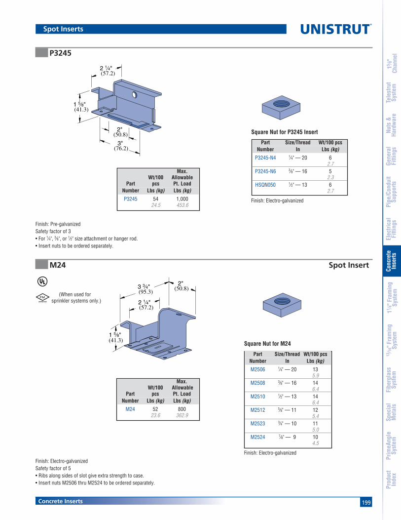
199Concrete Inserts
15 ⁄8"
Chan
nel
Nuts
&Ha
rdw
are
Gene
ral
Fitti
ngs
Pipe
/Con
duit
Supp
orts
Elec
trica
lFi
tting
sCo
ncre
teIn
serts
11 ⁄4" F
ram
ing
Syst
em13
⁄16" F
ram
ing
Syst
emFi
berg
lass
Syst
emSp
ecia
lM
etal
sTe
lest
rut
Syst
emPr
imeA
ngle
Syst
emPr
oduc
tIn
dex
Spot Inserts
Square Nut for P3245 Insert
Finish: Electro-galvanized
2 1⁄4"(57.2)
3 3⁄4"(95.3)
2"(50.8)
1 5⁄8"(41.3)
2"(50.8)
2 1⁄4"(57.2)
3"(76.2)
1 5⁄8"(41.3)
Finish: Electro-galvanizedSafety factor of 5• Ribs along sides of slot give extra strength to case.• Insert nuts M2506 thru M2524 to be ordered separately.
Finish: Pre-galvanizedSafety factor of 3• For 1⁄4", 3⁄8", or 1⁄2" size attachment or hanger rod.• Insert nuts to be ordered separately.
(When used forsprinkler systems only.)
FM
Square Nut for M24
Finish: Electro-galvanized
P3245
M24 Spot Insert
Max.Wt/100 Allowable
Part pcs Pt. LoadNumber Lbs (kg) Lbs (kg)
P3245 54 1,00024.5 453.6
Part Size/Thread Wt/100 pcsNumber In Lbs (kg)
P3245-N4 1⁄4" — 20 62.7
P3245-N6 3⁄8" — 16 52.3
HSQN050 1⁄2" — 13 62.7
Max.Wt/100 Allowable
Part pcs Pt. LoadNumber Lbs (kg) Lbs (kg)
M24 52 80023.6 362.9
Part Size/Thread Wt/100 pcsNumber In Lbs (kg)
M2506 1⁄4" — 20 135.9
M2508 3⁄8" — 16 146.4
M2510 1⁄2" — 13 146.4
M2512 5⁄8" — 11 125.4
M2523 3⁄4" — 10 115.0
M2524 7⁄8" — 9 104.5
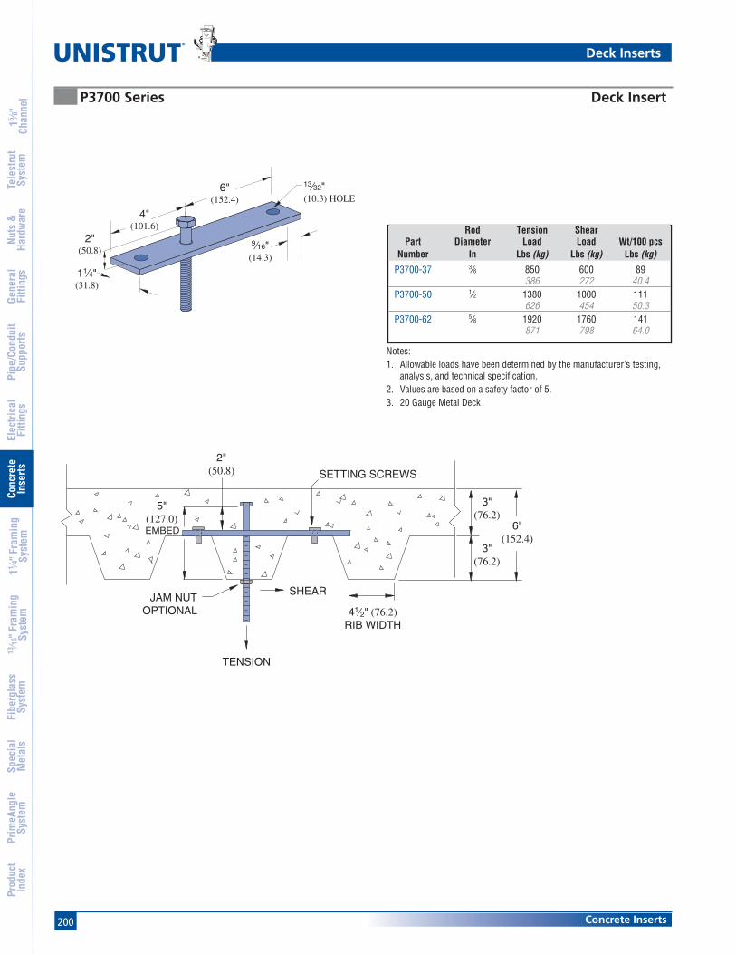
200
®
Concrete Inserts
15 ⁄8"
Chan
nel
Nuts
&Ha
rdw
are
Gene
ral
Fitti
ngs
Pipe
/Con
duit
Supp
orts
Elec
trica
lFi
tting
sCo
ncre
teIn
serts
11 ⁄4" F
ram
ing
Syst
em13
⁄16" F
ram
ing
Syst
emFi
berg
lass
Syst
emSp
ecia
lM
etal
sTe
lest
rut
Syst
emPr
imeA
ngle
Syst
emPr
oduc
tIn
dex
Deck Inserts
P3700 Series Deck Insert
Rod Tension ShearPart Diameter Load Load Wt/100 pcs
Number In Lbs (kg) Lbs (kg) Lbs (kg)
P3700-37 3⁄8 850 600 89386 272 40.4
P3700-50 1⁄2 1380 1000 111626 454 50.3
P3700-62 5⁄8 1920 1760 141871 798 64.0
6"(152.4)
4"(101.6)
2"(50.8)
11⁄4"(31.8)
9⁄16"(14.3)
13⁄32"(10.3) HOLE
TENSION
SHEAR
SETTING SCREWS
EMBED
JAM NUTOPTIONAL 41⁄2" (76.2)
RIB WIDTH
5"(127.0)
2"(50.8)
6"(152.4)
3"(76.2)
3"(76.2)
Notes:1. Allowable loads have been determined by the manufacturer’s testing,
analysis, and technical specification.2. Values are based on a safety factor of 5.3. 20 Gauge Metal Deck
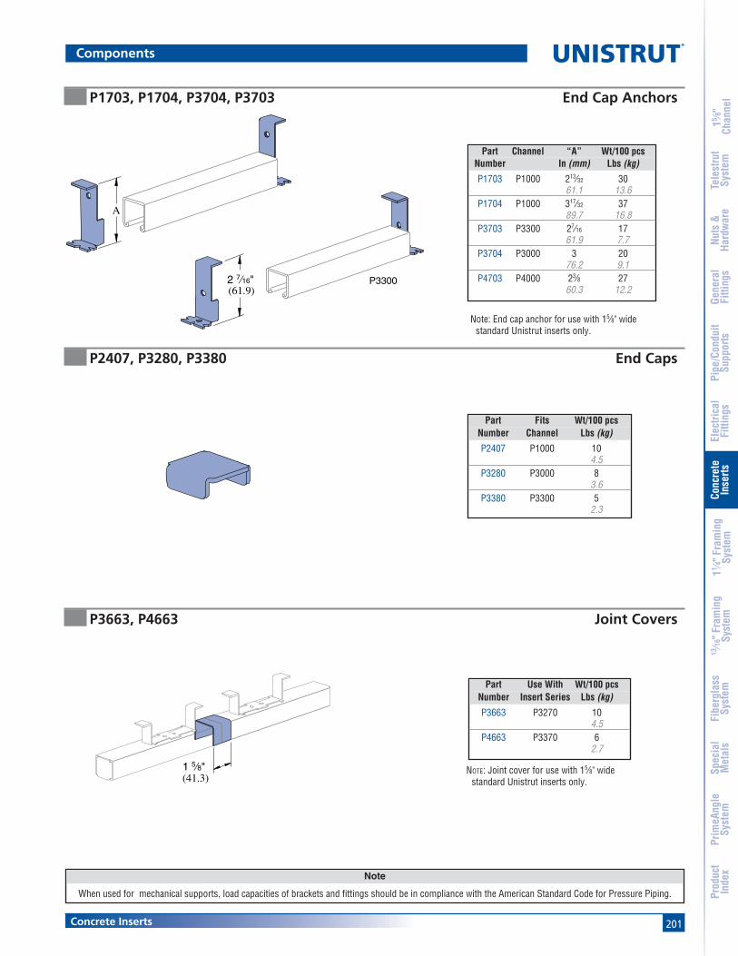
201
Note
When used for mechanical supports, load capacities of brackets and fittings should be in compliance with the American Standard Code for Pressure Piping.
Concrete Inserts
15 ⁄8"
Chan
nel
Nuts
&Ha
rdw
are
Gene
ral
Fitti
ngs
Pipe
/Con
duit
Supp
orts
Elec
trica
lFi
tting
sCo
ncre
teIn
serts
11 ⁄4" F
ram
ing
Syst
em13
⁄16" F
ram
ing
Syst
emFi
berg
lass
Syst
emSp
ecia
lM
etal
sTe
lest
rut
Syst
emPr
imeA
ngle
Syst
emPr
oduc
tIn
dex
Components
A
2 7⁄16"(61.9)
P3300
1 5⁄8"(41.3)
P1703, P1704, P3704, P3703 End Cap Anchors
P2407, P3280, P3380 End Caps
P3663, P4663 Joint Covers
Part Fits Wt/100 pcsNumber Channel Lbs (kg)
P2407 P1000 104.5
P3280 P3000 83.6
P3380 P3300 52.3
NOTE: Joint cover for use with 15⁄8" widestandard Unistrut inserts only.
Part Use With Wt/100 pcsNumber Insert Series Lbs (kg)
P3663 P3270 104.5
P4663 P3370 62.7
Note: End cap anchor for use with 15⁄8" widestandard Unistrut inserts only.
Part Channel “A” Wt/100 pcsNumber In (mm) Lbs (kg)
P1703 P1000 213⁄32 3061.1 13.6
P1704 P1000 317⁄32 3789.7 16.8
P3703 P3300 27⁄16 1761.9 7.7
P3704 P3000 3 2076.2 9.1
P4703 P4000 23⁄8 2760.3 12.2

202
®
Concrete Inserts
15 ⁄8"
Chan
nel
Nuts
&Ha
rdw
are
Gene
ral
Fitti
ngs
Pipe
/Con
duit
Supp
orts
Elec
trica
lFi
tting
sCo
ncre
teIn
serts
11 ⁄4" F
ram
ing
Syst
em13
⁄16" F
ram
ing
Syst
emFi
berg
lass
Syst
emSp
ecia
lM
etal
sTe
lest
rut
Syst
emPr
imeA
ngle
Syst
emPr
oduc
tIn
dex
Concrete Inserts Technical Data
Spot Insert Load Chart
Max. Min. Max.Allowable Spacing Allowable
Wt/100 Anchor Point Between UniformPart pcs Spacing Load Pt. Loads Load
Number Lbs (kg) In (mm) Lbs (kg) In (mm) Lbs/Ft (kg/m)
M26/M2812 54 – 1,500 – 1,50024.5 680.4 680.4
M3245 52 – 1,000 – 1,00023.6 453.6 453.6
M24/M2512 52 – 800 – 80023.6 362.9 362.9
P3712P
Insert
A = 17⁄8" (48mm); P31703" (76mm); all others
A
A
A
Max. Allowable Uniform Load
Pt. Loads
12 in.
Maximum Allowable Uniform Load
The maximum allowable uniformload must be placed as a seriesof point loads.
The maximum allowable point load may beplaced anywhere along the insert.
All loads placed less than 2" from the end ofan insert must be reduced by 50%.
Max. AllowablePoint Load
Spacing of Multiple Point Loads
Max. Allowable Uniform Load
Max. AllowablePt. Loads
Min. Load Spacing
Pull-Out LoadMinimum Edge Distance to Achieve Rated Pull-Out Capacity
Maximum Allowable Point Load
Max. Min. Max.Allowable Spacing Allowable
Wt/100 Anchor Point Between UniformPart ft Spacing Load Pt. Loads Load
Number Lbs (kg) In (mm) Lbs (kg) In (mm) Lbs/Ft (kg/m)
P3270 194 4 2,000 12 2,00088.0 101.6 907.2 304.8 2,976.3
P3370 139 4 1,500 12 1,50063.0 101.6 680.4 304.8 2,232.2
P3170* 165 8 1,000 12 1,00074.8 203.2 453.6 304.8 1,488.2
Max. Min. Max.Allowable Spacing Allowable
Insert Wt/100 Anchor Point Between UniformPart Length ft Spacing Load Pt. Loads Load
Number In (mm) Lbs (kg) In (mm) Lbs (kg) In (mm) Lbs (kg)P3249 3 85 3 500 – 500
76.2 38.6 76.2 226.8 226.8P3349 68 3 400 – 400
30.8 76.2 181.4 181.4P3250 4 100 4 800 – 800
101.6 45.4 101.6 362.9 362.9P3350 81 4 500 – 500
36.7 101.6 226.8 226.8P3251 6 130 6 1,000 – 1,000
152.4 59.0 152.4 453.6 453.6P3351 102 6 750 – 750
46.3 152.4 340.2 340.2P3252 8 159 8 1,200 – 1,200
203.2 72.1 203.2 544.3 544.3P3352 122 8 1,000 – 1,000
55.3 203.2 453.6 453.6P3754 12 210 8 2,500 3 5,000
304.8 95.3 203.2 1,134.0 76.2 2,268.0P3253 227 4 2,000 – 2,000
103.0 101.6 907.2 907.2P3353 174 4 1,500 – 1,500
78.9 101.6 680.4 680.4P3254 16 270 4 2,000 12 4,000
406.4 122.5 101.6 907.2 304.8 1,814.4P3354 185 4 1,500 12 3,000
83.9 101.6 680.4 304.8 1,360.8P3255 20 357 4 2,000 12 4,000
508.0 161.9 101.6 907.2 304.8 1,814.4P3355 231 4 1,500 12 3,000
104.8 101.6 680.4 304.8 1,360.8P3256 24 399 4 2,000 12 4,000
609.6 181.0 101.6 907.2 304.8 1,814.4P3356 277 4 1,500 12 3,000
125.6 101.6 680.4 304.8 1,360.8
Load Chart by Length
Continuous Concrete Insert Load Chart Up to 20 Ft. (6.10m)
*When used in prestressed concrete “T” Beam.Load data is based on use of 3000 PSI concrete.

203
®
MATERIALUnistrut channels are accurately and carefully cold formedto size from low-carbon strip steel.
STEEL: PLAIN14 Gauge (1.9 mm), ASTM A1011 SS GR 3319 Gauge (1.0 mm) ASTM A1008
STEEL: PRE-GALVANIZED14 Gauge (1.9 mm),19 Gauge (1.0 mm) ASTM A653 GR 33
Channel nuts are manufactured from mild steel bars con-forming to ASTM A576, GR 1015, and are case hardened.
Fittings are made from hot rolled, pickled and oiled steelplate or strip and conform to ASTM A1011 SS GR 33.
Many framing channels are available in special metal onrequest. Consult factory for ordering information.
FINISHESAll channels and fittings are available in: Perma-Green II(GR), Pre-galvanized (PG), conforming to ASTM A653 GR 33and plain (PL).
Nuts are available in plain or electro-galvanized (EG) finish.
Fittings are available in Perma-Green II or plain.
STANDARD LENGTHSStandard lengths are 10 feet (3.05M) and 20 feet (6.10M).Tolerances are: +1⁄8" (3.2 mm) to +1⁄2" (12.7 mm) to allow forcutting. Special lengths are available for a small cuttingcharge with a tolerance of ±1⁄8" (3.2mm).
APPLICATIONA framing system designed for medium loads, the 11⁄4" seriesis especially suitable for use in the OEM, commercial and
display markets. It maintains a lightness in scale and a cleanline that makes it aesthetically pleasing as well as functional.
THREADSAll threads on the nuts and bolts are Unified and Americancoarse screw threads.
DESIGN BOLT TORQUE
DIMENSIONSImperial dimensions are illustrated in inches. Metricdimensions are shown in parenthesis or as noted. Unlessnoted, all metric dimensions are in millimeters and roundedto one decimal place.
LOAD DATAAll beam and column load data pertains to carbon steeland stainless steel channels. Load tables and charts areconstructed to be in accordance with the SPECIFICA-TION FOR THE DESIGN OF COLD-FORMED STEELSTRUCTURAL MEMBERS 2001 EDITION published by theAMERICAN IRON AND STEEL INSTITUTE.
11⁄4" FRAMING SYSTEMA1000 (14 Gauge) .................................... 206-208
A3300 (14 Gauge) .................................... 209-210
A4000 (19 Gauge) .................................... 211-212
A5000 (14 Gauge) ............................................ 213
Channel Nuts and Closure Strips ........... 214-216
Flat Plate Fittings ..................................... 217-218
Ninety Degree Fittings ............................ 218-220
“Z” Shape Fittings .................................... 220-221
Angle and Wing Shape Fittings ............. 221-222
“U” Shape Fittings ................................... 222-223
Tubing Clips ...................................................... 223
Brackets ............................................................. 224
Type Safety Factor Safety Factorof Load to Yield Strength to Ultimate Strength
Beam Loads 1.67 2.0
Column Load 1.80 2.2
BOLT SIZE
Rec. TorqueFt/Lbs (N•m)Max TorqueFt/Lbs (N•m)
1⁄4" - 20
6(8)
5⁄16" - 18
11(15)
3⁄8" - 16
19(26)
7(9)
15(20)
25(34)
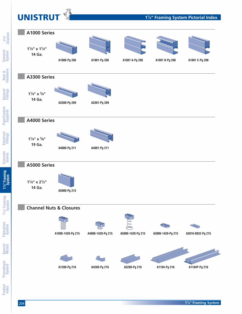
204
®
11⁄4" Framing System
15 ⁄8"
Chan
nel
Nuts
&Ha
rdw
are
Gene
ral
Fitti
ngs
Pipe
/Con
duit
Supp
orts
Elec
trica
lFi
tting
sCo
ncre
teIn
serts
11 ⁄4" F
ram
ing
Syst
em13
⁄16" F
ram
ing
Syst
emFi
berg
lass
Syst
emSp
ecia
lM
etal
sTe
lest
rut
Syst
emPr
imeA
ngle
Syst
emPr
oduc
tIn
dex
11⁄4" Framing System Pictorial Index
A1000-Pg 206 A1001-Pg 206 A1001 A-Pg 206 A1001 B-Pg 206 A1001 C-Pg 206
A3300-Pg 209 A3301-Pg 209
A4000-Pg 211 A4001-Pg 211
A5000-Pg 213
A1006-1420-Pg 215 A4006-1420-Pg 215 A5006-1420-Pg 215 A3006-1420-Pg 215 A3016-0832-Pg 215
A1280-Pg 216 A4280-Pg 216 A5280-Pg 216 A1184-Pg 216 A1184P-Pg 216
A1000 Series
A4000 Series
A3300 Series
A5000 Series
Channel Nuts & Closures
11⁄4" x 11⁄4"14 Ga.
11⁄4" x 3⁄4"14 Ga.
11⁄4" x 5⁄8"19 Ga.
11⁄4" x 21⁄2"14 Ga.

20511⁄4" Framing System
15 ⁄8"
Chan
nel
Nuts
&Ha
rdw
are
Gene
ral
Fitti
ngs
Pipe
/Con
duit
Supp
orts
Elec
trica
lFi
tting
sCo
ncre
teIn
serts
11 ⁄4" F
ram
ing
Syst
em13
⁄16" F
ram
ing
Syst
emFi
berg
lass
Syst
emSp
ecia
lM
etal
sTe
lest
rut
Syst
emPr
imeA
ngle
Syst
emPr
oduc
tIn
dex
A1063-Pg 217 A1065-Pg 217 A1191-Pg Pg 217 A1066-Pg 217 A2324-Pg 217 A1036-Pg 217
A1031-Pg 218 A1026-Pg 218 A1068-Pg 218 A1326-Pg 218 A1458-Pg 218 A1325-Pg 218
A1033-Pg 219 A1037-Pg 219 A1038-Pg 219 A1357-Pg 219 A1331-Pg 219 A1332-Pg 219
A1579-Pg 220 A2235-Pg 220 A2120-Pg 220 A4120-Pg 220 A5120-Pg 220 A1045-Pg 220
A3345-Pg 222 A4045-Pg 221 A5045-Pg 221 A2109-Pg 221 A2125-Pg 221 A2084-Pg 221
A2341 R-L-Pg 222 A2472 R-L-Pg 222 A2223-Pg 222 A2345-Pg 222 A2227-Pg 222 A1047-Pg 222
A3347-Pg 223 A4047-Pg 223 A5047-Pg 223 A5043-Pg 223 A2608-Pg 223 A2491 R-Pg 224
A2491 L-Pg 224 A2494 R-Pg 224 A2494 L-Pg 224
A Series Fittings
11⁄4" Framing System Pictorial Index

206
®
11⁄4" Framing System
15 ⁄8"
Chan
nel
Nuts
&Ha
rdw
are
Gene
ral
Fitti
ngs
Pipe
/Con
duit
Supp
orts
Elec
trica
lFi
tting
sCo
ncre
teIn
serts
11 ⁄4" F
ram
ing
Syst
em13
⁄16" F
ram
ing
Syst
emFi
berg
lass
Syst
emSp
ecia
lM
etal
sTe
lest
rut
Syst
emPr
imeA
ngle
Syst
emPr
oduc
tIn
dex
A1001 – 11⁄4" x 21⁄2"
A1000 – 11⁄4" x 11⁄4"
.706"
.544"
2
13⁄16"
1 1⁄4"
1 1⁄4"
11⁄16" 9⁄32"9⁄32"31.8
31.813.8
18.04.8
17.57.1 7.1
2
1
31.8
63.5
31.8
31.8
2
1
2
2 1⁄2" 1
1 1⁄4"
1 1⁄4"
1 1⁄4"
Finishes: PL, GR, HG, PG Standard Lengths: 10' & 20'
2
1 1⁄4"
2 1⁄2" 1
1 1⁄4"
1 1⁄4"
.705.544
.625.625
2 1⁄2"
1 1⁄4"
1 1⁄4"
1 1⁄4"
2
1
1.210"
1.290"
.665.585
2 1⁄2"
1 1⁄4"
2
1
A1001B – 11⁄4" x 21⁄2"
A1001C – 11⁄4" x 21⁄2"
A1001A – 11⁄4" x 21⁄2"31.8
63.5
31.8
31.8
13.9 17.92
1
15.9 15.92
31.8
63.5
31.8
31.8
1
31.8
63.5
14.9 16.9
32.8
30.7
2
1
A1000 & A1001 Channels
Wt/100 Ft: 104 Lbs(154 kg/100m)Allowable Moment 2,170 In-Lbs (240 N•m)
14 Gauge Nominal Thickn,ess .075" (1.9mm)
Wt/100 Ft: 207 Lbs (308 kg/100m)Allowable Moment 6,070 In-Lbs (690 N•m)14 Gauge Nominal Thickness .075" (1.9mm)
Wt/100 Ft: 207 Lbs (308 kg/100m)Allowable Moment 7,930 In-Lbs (900 N•m)14 Gauge Nominal Thickness .075" (1.9mm)
Wt/100 Ft: 207 Lbs (308 kg/100m)Allowable Moment 7,930 In-Lbs (900 N•m)14 Gauge Nominal Thickness .075" (1.9mm)
Wt/100 Ft: 207 Lbs (308 kg/100m)Allowable Moment 6,760 In-Lbs (760 N•m)14 Gauge Nominal Thickness .075" (1.9mm)

20711⁄4" Framing System
15 ⁄8"
Chan
nel
Nuts
&Ha
rdw
are
Gene
ral
Fitti
ngs
Pipe
/Con
duit
Supp
orts
Elec
trica
lFi
tting
sCo
ncre
teIn
serts
11 ⁄4" F
ram
ing
Syst
em13
⁄16" F
ram
ing
Syst
emFi
berg
lass
Syst
emSp
ecia
lM
etal
sTe
lest
rut
Syst
emPr
imeA
ngle
Syst
emPr
oduc
tIn
dex
BEAM LOADING – A1000 BEAM LOADING – A1001
Notes:
* Load limited by spot weld shear.
** KL⁄r > 200
1. Above loads include the weight of the member. This weight must bededucted to arrive at the net allowable load the beam will support.
2. Long span beams should be supported in such a manner as toprevent rotation and twist.
3. Allowable uniformly distributed loads are listed for various simplespans, that is, a beam on two supports. If load is concentrated atthe center of the span, multiply load from the table by 0.5 andcorresponding deflection by 0.8.
Max Defl. atAllowable Uniform Uniform Loading at Defl.
Span Uniform Load Load Span/180 Span/240 Span/360In Lbs In Lbs Lbs Lbs18 960 0.04 960 960 96024 720 0.07 720 720 66036 480 0.16 480 440 30048 360 0.29 330 250 17060 290 0.45 210 160 11072 240 0.65 150 110 7084 210 0.90 110 80 5096 180 1.16 80 60 40
108 160 1.46 70 50 30120 140 1.75 50 40 30
Max Defl. atAllowable Uniform Uniform Loading at Defl.
Span Uniform Load Load Span/180 Span/240 Span/360In Lbs In Lbs Lbs Lbs18 1,650 * 0.01 1,650 * 1,650 * 1,650 *24 1,650 * 0.03 1,650 * 1,650 * 1,650 *36 1,350 0.09 1,350 1,350 1,35048 1,010 0.16 1,010 1,010 82060 810 0.26 810 790 53072 670 0.37 670 550 37084 580 0.50 540 400 27096 510 0.66 410 310 210
108 450 0.83 330 240 160120 400 1.01 260 200 130
A1000 & A1001 Channels
COLUMN LOADING – A1000Maximum
Unbraced Allowable Load Maximum Column Load Applied at C.G.Height at Slot Face K = 0.65 K = 0.80 K =1.0 K = 1.2
In Lbs Lbs Lbs Lbs Lbs18 1,960 5,900 5,430 4,800 4,21024 1,840 5,210 4,590 3,850 3,22036 1,500 3,940 3,220 2,480 2,01048 1,220 2,950 2,300 1,790 1,46060 1,020 2,260 1,790 1,400 1,13072 880 1,840 1,460 1,130 91084 780 1,550 1,230 940 **96 690 1,340 1,050 ** **
108 620 1,170 910 ** **
COLUMN LOADING – A1001Maximum
Unbraced Allowable Load Maximum Column Load Applied at C.G.Height at Slot Face K = 0.65 K = 0.80 K =1.0 K = 1.2
In Lbs Lbs Lbs Lbs Lbs18 3,530 13,300 12,920 12,400 11,88024 3,480 12,750 12,220 11,550 10,95036 3,370 11,630 10,950 10,220 9,15048 3,260 10,680 10,020 8,260 6,50060 2,960 9,930 8,260 6,080 4,27072 2,630 8,480 6,500 4,270 2,97084 2,260 7,040 4,900 3,140 2,18096 1,940 5,680 3,750 2,400 **
108 1,670 4,490 2,970 ** **120 1,440 3,640 2,400 ** **
ELEMENTS OF SECTIONA1000/A1001
Parameter A1000 A1001Area of Section 0.305 In2 0.609 In2
Axis 1-1Moment of Inertia (I) 0.061 In4 0.302 In4
Section Modulus (S) 0.086 In3 0.242 In3
Radius of Gyration (r) 0.447 In 0.704 InAxis 2-2
Moment of Inertia (I) 0.078 In4 0.156 In4
Section Modulus (S) 0.125 In3 0.250 In3
Radius of Gyration (r) 0.506 In 0.506 In

208
®
11⁄4" Framing System
15 ⁄8"
Chan
nel
Nuts
&Ha
rdw
are
Gene
ral
Fitti
ngs
Pipe
/Con
duit
Supp
orts
Elec
trica
lFi
tting
sCo
ncre
teIn
serts
11 ⁄4" F
ram
ing
Syst
em13
⁄16" F
ram
ing
Syst
emFi
berg
lass
Syst
emSp
ecia
lM
etal
sTe
lest
rut
Syst
emPr
imeA
ngle
Syst
emPr
oduc
tIn
dex
MaximumUnbraced Allowable Load Max. Column Load Applied at C.G.
Height at Slot Face K = 0.65 K = 0.80 K =1.0 K = 1.2mm kg kg kg kg kg600 839 2,386 2,109 1,769 1,488750 762 2,087 1,769 1,424 1,148
1,000 640 1,647 1,324 1,012 8261,250 540 1,302 1,012 789 6441,500 472 1,043 826 644 5261,750 417 875 694 540 4352,000 372 753 599 463 **2,250 336 662 526 399 **2,500 304 590 463 ** **2,750 277 526 408 ** **
MaximumUnbraced Allowable Load Max. Column Load Applied at C.G.
Height at Slot Face K = 0.65 K = 0.80 K =1.0 K = 1.2mm kg kg kg kg kg600 1,579 5,801 5,561 5,262 4,990750 1,551 5,543 5,262 4,931 4,658
1,000 1,515 5,144 4,831 4,472 3,8101,250 1,465 4,808 4,472 3,642 2,8351,500 1,356 4,545 3,810 2,835 2,0001,750 1,234 4,019 3,152 2,114 1,4702,000 1,102 3,479 2,531 1,619 1,1252,250 966 2,953 2,000 1,279 **2,500 853 2,454 1,619 1,039 **2,750 753 2,028 1,338 ** **
A1000 & A1001 Channels
Max Defl. atAllowable Uniform Uniform Loading at Deflection
Span Uniform Load Load Span/180 Span/240 Span/360mm kg mm kg kg kg600 331 2 331 331 313750 268 3 268 268 200
1,000 200 5 200 168 1131,250 159 8 145 109 731,500 132 11 100 73 501,750 113 15 73 54 362,000 100 20 54 41 272,500 82 32 36 27 183,000 68 46 23 18 14
Max Defl. atAllowable Uniform Uniform Loading at Deflection
Span Uniform Load Load Span/180 Span/240 Span/360mm kg mm kg kg kg600 748 * 1 748 * 748 * 748 *750 748 * 2 748 * 748 * 748 *
1,000 558 3 558 558 5581,250 449 4 449 449 3541,500 372 6 372 372 2451,750 322 9 322 272 1812,000 281 11 277 209 1412,500 222 17 177 132 913,000 186 25 122 91 643,500 159 34 91 68 45
BEAM LOADING – A1000 (METRIC) BEAM LOADING – A1001 (METRIC)
Notes:
* Load limited by spot weld shear.
** KL⁄r > 200
1. Above loads include the weight of the member. This weight must bededucted to arrive at the net allowable load the beam will support.
2. Long span beams should be supported in such a manner as toprevent rotation and twist.
3. Allowable uniformly distributed loads are listed for various simplespans, that is, a beam on two supports. If load is concentrated atthe center of the span, multiply load from the table by 0.5 andcorresponding deflection by 0.8.
COLUMN LOADING – A1000 (METRIC) COLUMN LOADING – A1001 (METRIC)
ELEMENTS OF SECTIONA1000/A1001 (METRIC)
Parameter A1000 A1001Area of Section 1.96 cm2 3.93 cm2
Axis 1-1Moment of Inertia (I) 2.53 cm4 12.57 cm4
Section Modulus (S) 1.41 cm3 3.96 cm3
Radius of Gyration (r) 1.14 cm 1.79 cmAxis 2-2
Moment of Inertia (I) 3.25 cm4 6.50 cm4
Section Modulus (S) 2.05 cm3 4.09 cm3
Radius of Gyration (r) 1.29 cm 1.29 cm
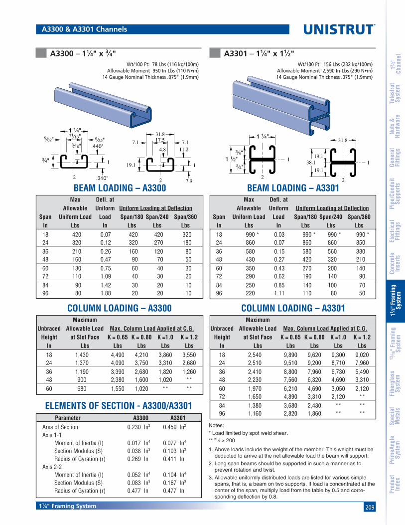
20911⁄4" Framing System
15 ⁄8"
Chan
nel
Nuts
&Ha
rdw
are
Gene
ral
Fitti
ngs
Pipe
/Con
duit
Supp
orts
Elec
trica
lFi
tting
sCo
ncre
teIn
serts
11 ⁄4" F
ram
ing
Syst
em13
⁄16" F
ram
ing
Syst
emFi
berg
lass
Syst
emSp
ecia
lM
etal
sTe
lest
rut
Syst
emPr
imeA
ngle
Syst
emPr
oduc
tIn
dex
A3300 – 11⁄4" x 3⁄4"Wt/100 Ft: 78 Lbs (116 kg/100m)
Allowable Moment 950 In-Lbs (110 N•m)14 Gauge Nominal Thickness .075" (1.9mm)
Wt/100 Ft: 156 Lbs (232 kg/100m)Allowable Moment 2,590 In-Lbs (290 N•m)14 Gauge Nominal Thickness .075" (1.9mm)
11⁄16"
.440"
9⁄32"
1 1⁄4"9⁄32"
3⁄4"
.310"
3⁄16"
2
11
2
19.1
7.1
31.8
7.111.2
7.9
4.8
17.5
1
31.8
38.1
19.1
19.1
2
A3301 – 11⁄4" x 11⁄2"
1 1⁄2"
1 1⁄4"
3⁄4"
3⁄4"
2
1
BEAM LOADING – A3300 BEAM LOADING – A3301
Notes:
* Load limited by spot weld shear.** KL⁄r > 200
1. Above loads include the weight of the member. This weight must bededucted to arrive at the net allowable load the beam will support.
2. Long span beams should be supported in such a manner as toprevent rotation and twist.
3. Allowable uniformly distributed loads are listed for various simplespans, that is, a beam on two supports. If load is concentrated at thecenter of the span, multiply load from the table by 0.5 and corre-sponding deflection by 0.8.
Max Defl. atAllowable Uniform Uniform Loading at Deflection
Span Uniform Load Load Span/180 Span/240 Span/360In Lbs In Lbs Lbs Lbs18 420 0.07 420 420 32024 320 0.12 320 270 18036 210 0.26 160 120 8048 160 0.47 90 70 5060 130 0.75 60 40 3072 110 1.09 40 30 2084 90 1.42 30 20 1096 80 1.88 20 20 10
Max Defl. atAllowable Uniform Uniform Loading at Deflection
Span Uniform Load Load Span/180 Span/240 Span/360In Lbs In Lbs Lbs Lbs18 990 * 0.03 990 * 990 * 990 *24 860 0.07 860 860 85036 580 0.15 580 560 38048 430 0.27 420 320 21060 350 0.43 270 200 14072 290 0.62 190 140 9084 250 0.85 140 100 7096 220 1.11 110 80 50
A3300 & A3301 Channels
MaximumUnbraced Allowable Load Max. Column Load Applied at C.G.
Height at Slot Face K = 0.65 K = 0.80 K =1.0 K = 1.2In Lbs Lbs Lbs Lbs Lbs18 1,430 4,490 4,210 3,860 3,55024 1,370 4,090 3,750 3,310 2,68036 1,190 3,390 2,680 1,820 1,26048 900 2,380 1,600 1,020 **60 680 1,550 1,020 ** **
MaximumUnbraced Allowable Load Max. Column Load Applied at C.G.
Height at Slot Face K = 0.65 K = 0.80 K =1.0 K = 1.2In Lbs Lbs Lbs Lbs Lbs18 2,540 9,890 9,620 9,300 9,02024 2,510 9,510 9,200 8,710 7,96036 2,410 8,800 7,960 6,730 5,49048 2,230 7,560 6,320 4,690 3,31060 1,970 6,210 4,690 3,050 2,12072 1,650 4,890 3,310 2,120 **84 1,380 3,680 2,430 ** **96 1,160 2,820 1,860 ** **
COLUMN LOADING – A3300 COLUMN LOADING – A3301
Parameter A3300 A3301Area of Section 0.230 In2 0.459 In2
Axis 1-1Moment of Inertia (I) 0.017 In4 0.077 In4
Section Modulus (S) 0.038 In3 0.103 In3
Radius of Gyration (r) 0.269 In 0.411 InAxis 2-2
Moment of Inertia (I) 0.052 In4 0.104 In4
Section Modulus (S) 0.083 In3 0.167 In3
Radius of Gyration (r) 0.477 In 0.477 In
ELEMENTS OF SECTION - A3300/A3301
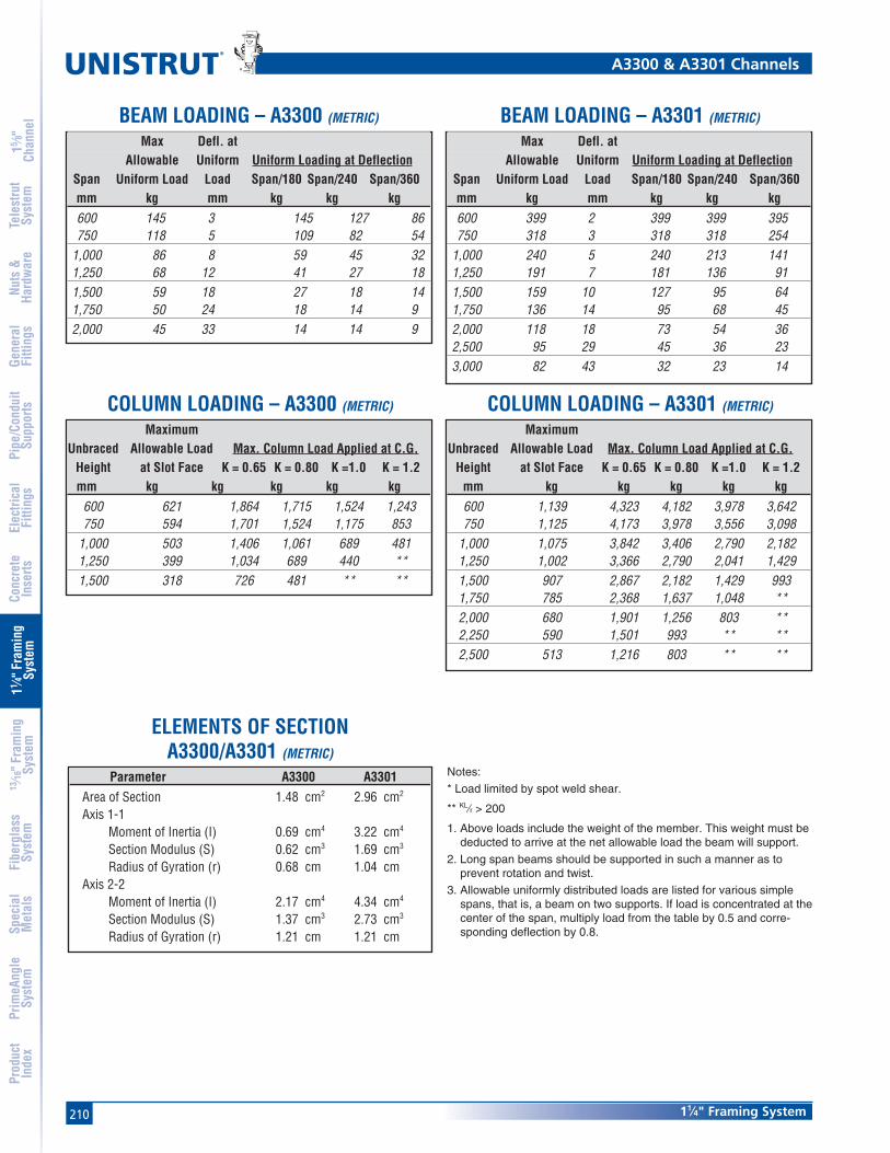
210
®
11⁄4" Framing System
15 ⁄8"
Chan
nel
Nuts
&Ha
rdw
are
Gene
ral
Fitti
ngs
Pipe
/Con
duit
Supp
orts
Elec
trica
lFi
tting
sCo
ncre
teIn
serts
11 ⁄4" F
ram
ing
Syst
em13
⁄16" F
ram
ing
Syst
emFi
berg
lass
Syst
emSp
ecia
lM
etal
sTe
lest
rut
Syst
emPr
imeA
ngle
Syst
emPr
oduc
tIn
dex
MaximumUnbraced Allowable Load Max. Column Load Applied at C.G.
Height at Slot Face K = 0.65 K = 0.80 K =1.0 K = 1.2mm kg kg kg kg kg
600 621 1,864 1,715 1,524 1,243750 594 1,701 1,524 1,175 853
1,000 503 1,406 1,061 689 4811,250 399 1,034 689 440 **1,500 318 726 481 ** **
MaximumUnbraced Allowable Load Max. Column Load Applied at C.G.
Height at Slot Face K = 0.65 K = 0.80 K =1.0 K = 1.2mm kg kg kg kg kg600 1,139 4,323 4,182 3,978 3,642750 1,125 4,173 3,978 3,556 3,098
1,000 1,075 3,842 3,406 2,790 2,1821,250 1,002 3,366 2,790 2,041 1,4291,500 907 2,867 2,182 1,429 9931,750 785 2,368 1,637 1,048 **2,000 680 1,901 1,256 803 **2,250 590 1,501 993 ** **2,500 513 1,216 803 ** **
A3300 & A3301 Channels
Max Defl. atAllowable Uniform Uniform Loading at Deflection
Span Uniform Load Load Span/180 Span/240 Span/360mm kg mm kg kg kg600 145 3 145 127 86750 118 5 109 82 54
1,000 86 8 59 45 321,250 68 12 41 27 181,500 59 18 27 18 141,750 50 24 18 14 92,000 45 33 14 14 9
Max Defl. atAllowable Uniform Uniform Loading at Deflection
Span Uniform Load Load Span/180 Span/240 Span/360mm kg mm kg kg kg600 399 2 399 399 395750 318 3 318 318 254
1,000 240 5 240 213 1411,250 191 7 181 136 911,500 159 10 127 95 641,750 136 14 95 68 452,000 118 18 73 54 362,500 95 29 45 36 233,000 82 43 32 23 14
BEAM LOADING – A3300 (METRIC) BEAM LOADING – A3301 (METRIC)
COLUMN LOADING – A3300 (METRIC) COLUMN LOADING – A3301 (METRIC)
Notes:
* Load limited by spot weld shear.
** KL⁄r > 200
1. Above loads include the weight of the member. This weight must bededucted to arrive at the net allowable load the beam will support.
2. Long span beams should be supported in such a manner as toprevent rotation and twist.
3. Allowable uniformly distributed loads are listed for various simplespans, that is, a beam on two supports. If load is concentrated at thecenter of the span, multiply load from the table by 0.5 and corre-sponding deflection by 0.8.
ELEMENTS OF SECTIONA3300/A3301 (METRIC)
Parameter A3300 A3301Area of Section 1.48 cm2 2.96 cm2
Axis 1-1Moment of Inertia (I) 0.69 cm4 3.22 cm4
Section Modulus (S) 0.62 cm3 1.69 cm3
Radius of Gyration (r) 0.68 cm 1.04 cmAxis 2-2
Moment of Inertia (I) 2.17 cm4 4.34 cm4
Section Modulus (S) 1.37 cm3 2.73 cm3
Radius of Gyration (r) 1.21 cm 1.21 cm

21111⁄4" Framing System
15 ⁄8"
Chan
nel
Nuts
&Ha
rdw
are
Gene
ral
Fitti
ngs
Pipe
/Con
duit
Supp
orts
Elec
trica
lFi
tting
sCo
ncre
teIn
serts
11 ⁄4" F
ram
ing
Syst
em13
⁄16" F
ram
ing
Syst
emFi
berg
lass
Syst
emSp
ecia
lM
etal
sTe
lest
rut
Syst
emPr
imeA
ngle
Syst
emPr
oduc
tIn
dex
Wt/100 Ft: 90 Lbs (134 kg/100m)Allowable Moment 1,470 In-Lbs (170 N•m)
19 Gauge Nominal Thickness .040" (1.0mm)
Wt/100 Ft: 45 Lbs (67 kg/100m)Allowable Moment 560 In-Lbs (60 N•m)
19 Gauge Nominal Thickness .040" (1.0mm)
1
31.8
31.8
15.9
15.9
2
1 1⁄4"
1 1⁄4"
5⁄8"
5⁄8"
1
2
31.8
2
9.2
15.9
4.87.1
17.57.1
6.7
15⁄8"
1 1⁄4"
9⁄32"9⁄32"3⁄16"
.262"
.363"
2
1
11⁄16"
A4000 – 11⁄4" x 5⁄8" A4001– 11⁄4" x 11⁄4"
Notes:
* Load limited by spot weld shear.
** KL⁄r > 200
1. Above loads include the weight of the member. This weight must bededucted to arrive at the net allowable load the beam will support.
2. Long span beams should be supported in such a manner as toprevent rotation and twist.
3. Allowable uniformly distributed loads are listed for various simplespans, that is, a beam on two supports. If load is concentrated at thecenter of the span, multiply load from the table by 0.5 and corre-sponding deflection by 0.8.
Max Defl. atAllowable Uniform Uniform Loading at Deflection
Span Uniform Load Load Span/180 Span/240 Span/360In Lbs In Lbs Lbs Lbs18 250 0.08 250 220 15024 190 0.15 170 120 8036 120 0.32 70 60 4048 90 0.58 40 30 2060 70 0.88 30 20 1072 60 1.30 20 10 10
Max Defl. atAllowable Uniform Uniform Loading at Deflection
Span Uniform Load Load Span/180 Span/240 Span/360In Lbs In Lbs Lbs Lbs18 350 * 0.02 350 * 350 * 350 *24 350 * 0.06 350 * 350 * 350 *36 330 0.19 330 270 18048 240 0.32 200 150 10060 200 0.52 130 100 6072 160 0.72 90 70 4084 140 1.00 70 50 30
A4000 & A4001 Channels
MaximumUnbraced Allowable Load Max. Column Load Applied at C.G.
Height at Slot Face K = 0.65 K = 0.80 K =1.0 K = 1.2In Lbs Lbs Lbs Lbs Lbs18 880 2,510 2,290 1,990 1,70024 880 2,190 1,890 1,530 1,23036 670 1,570 1,230 830 58048 470 1,110 730 470 **60 340 710 470 ** **
MaximumUnbraced Allowable Load Max. Column Load Applied at C.G.
Height at Slot Face K = 0.65 K = 0.80 K =1.0 K = 1.2In Lbs Lbs Lbs Lbs Lbs18 1,640 5,640 5,420 5,110 4,80024 1,600 5,320 5,000 4,600 4,24036 1,510 4,650 4,240 3,500 2,73048 1,330 4,030 3,240 2,250 1,56060 1,090 3,170 2,250 1,440 1,00072 870 2,370 1,560 1,000 **84 700 1,740 1,150 ** **
Parameter A4000 A4001Area of Section 0.132 In2 0.264 In2
Axis 1-1Moment of Inertia (I) 0.008 In4 0.037 In4
Section Modulus (S) 0.022 In3 0.058 In3
Radius of Gyration (r) 0.240 In 0.372 InAxis 2-2
Moment of Inertia (I) 0.029 In4 0.058 In4
Section Modulus (S) 0.046 In3 0.093 In3
Radius of Gyration (r) 0.469 In 0.469 In
BEAM LOADING – A4000 BEAM LOADING – A4001
COLUMN LOADING – A4000 COLUMN LOADING – A4001
ELEMENTS OF SECTIONA4000/A4001

212
®
11⁄4" Framing System
15 ⁄8"
Chan
nel
Nuts
&Ha
rdw
are
Gene
ral
Fitti
ngs
Pipe
/Con
duit
Supp
orts
Elec
trica
lFi
tting
sCo
ncre
teIn
serts
11 ⁄4" F
ram
ing
Syst
em13
⁄16" F
ram
ing
Syst
emFi
berg
lass
Syst
emSp
ecia
lM
etal
sTe
lest
rut
Syst
emPr
imeA
ngle
Syst
emPr
oduc
tIn
dex
MaximumUnbraced Allowable Load Max. Column Load Applied at C.G.
Height at Slot Face K = 0.65 K = 0.80 K =1.0 K = 1.2mm kg kg kg kg kg600 399 1,002 866 708 572750 354 857 708 540 390
1,000 281 649 494 318 2181,250 209 481 318 ** **1,500 154 331 218 ** **
MaximumUnbraced Allowable Load Max. Column Load Applied at C.G.
Height at Slot Face K = 0.65 K = 0.80 K =1.0 K = 1.2mm kg kg kg kg kg600 726 2,422 2,282 2,100 1,937750 708 2,272 2,100 1,901 1,615
1,000 671 2,028 1,810 1,420 1,0521,250 590 1,787 1,420 971 6761,500 503 1,470 1,052 676 4671,750 417 1,166 776 494 **2,000 349 898 594 ** **2,250 295 708 467 ** **
A4000 & A4001 Channels
Max Defl. atAllowable Uniform Uniform Loading at Deflection
Span Uniform Load Load Span/180 Span/240 Span/360mm kg mm kg kg kg600 86 4 77 59 41750 68 6 50 36 27
1,000 50 10 27 23 141,250 41 16 18 14 91,500 36 24 14 9 5
Max Defl. atAllowable Uniform Uniform Loading at Deflection
Span Uniform Load Load Span/180 Span/240 Span/360mm kg mm kg kg kg600 159 * 1 159 * 159 * 159 *750 159 * 3 159 * 159 * 118
1,000 136 6 136 100 681,250 109 9 86 64 411,500 91 13 59 45 321,750 77 17 45 32 232,000 68 22 32 27 18
Parameter A4000 A4001Area of Section 0.85 cm2 1.70 cm2
Axis 1-1Moment of Inertia (I) 0.32 cm4 1.52 cm4
Section Modulus (S) 0.37 cm3 0.96 cm3
Radius of Gyration (r) 0.61 cm 0.94 cmAxis 2-2
Moment of Inertia (I) 1.21 cm4 2.42 cm4
Section Modulus (S) 0.76 cm3 1.52 cm3
Radius of Gyration (r) 1.19 cm 1.19 cm
Notes:
* Load limited by spot weld shear.
** KL⁄r > 200
1. Above loads include the weight of the member. This weight must bededucted to arrive at the net allowable load the beam will support.
2. Long span beams should be supported in such a manner as toprevent rotation and twist.
3. Allowable uniformly distributed loads are listed for various simplespans, that is, a beam on two supports. If load is concentrated at thecenter of the span, multiply load from the table by 0.5 and corre-sponding deflection by 0.8.
BEAM LOADING – A4000 (METRIC) BEAM LOADING – A4001 (METRIC)
COLUMN LOADING – A4000 (METRIC) COLUMN LOADING – A4001 (METRIC)
ELEMENTS OF SECTIONA4000/A4001 (METRIC)

21311⁄4" Framing System
15 ⁄8"
Chan
nel
Nuts
&Ha
rdw
are
Gene
ral
Fitti
ngs
Pipe
/Con
duit
Supp
orts
Elec
trica
lFi
tting
sCo
ncre
teIn
serts
11 ⁄4" F
ram
ing
Syst
em13
⁄16" F
ram
ing
Syst
emFi
berg
lass
Syst
emSp
ecia
lM
etal
sTe
lest
rut
Syst
emPr
imeA
ngle
Syst
emPr
oduc
tIn
dex
63.5
34.3
29.2
31.817.5
7.17.1
4.8
2
12 1⁄2"
1 1⁄4"11⁄16"
3⁄16" 1.349"
1.151"
9⁄32"9⁄32"
1
2
A5000 – 11⁄4" x 21⁄2"
Notes:
* Load limited by spot weld shear.
** KL⁄r > 200
1. Above loads include the weight of the member.This weight must be deducted to arrive at the netallowable load the beam will support.
2. Long span beams should be supported in such amanner as to prevent rotation and twist.
3. Allowable uniformly distributed loads are listedfor various simple spans, that is, a beam on twosupports. If load is concentrated at the center ofthe span, multiply load from the table by 0.5 andcorresponding deflection by 0.8.
Max Defl. atAllowable Uniform Uniform Loading at Deflection
Span Uniform Load Load Span/180 Span/240 Span/360In Lbs Lbs Lbs Lbs Lbs24 2,220 0.04 2,220 2,220 2,22036 1,480 0.09 1,480 1,480 1,48048 1,110 0.15 1,110 1,110 98060 890 0.24 890 890 63072 740 0.34 740 650 43084 640 0.47 640 480 32096 560 0.61 490 370 240108 490 0.76 390 290 190120 440 0.94 310 230 160
MaximumUnbraced Allowable Load Max. Column Load Applied at C.G.
Height at Slot Face K = 0.65 K = 0.80 K =1.0 K = 1.2In Lbs Lbs Lbs Lbs Lbs24 2,790 7,950 6,670 5,080 3,76036 1,950 5,270 3,760 2,600 1,97048 1,360 3,290 2,350 1,690 1,33060 990 2,300 1,690 1,260 1,01072 790 1,750 1,330 1,010 83084 660 1,420 1,100 860 71096 570 1,200 940 740 **
108 510 1,040 830 ** **120 460 930 740 ** **
A5000 Channels
Max Defl. atAllowable Uniform Uniform Loading at Deflection
Span Uniform Load Load Span/180 Span/240 Span/360mm kg mm kg kg kg600 1,025 1 1,025 1,025 1,025750 821 1 821 821 821
1,000 617 3 617 617 6171,250 490 4 490 490 4221,500 408 6 408 408 2951,750 349 8 349 322 2132,000 308 10 308 249 1632,500 245 16 213 159 1043,000 204 23 145 109 73
MaximumUnbraced Allowable Load Max. Column Load Applied at C.G.
Height at Slot Face K = 0.65 K = 0.80 K =1.0 K = 1.2mm kg kg kg kg kg600 1,275 3,647 3,075 2,359 1,751750 1,089 3,025 2,359 1,633 1,211
1,000 794 2,091 1,465 1,025 7851,250 594 1,429 1,025 744 5851,500 463 1,066 785 585 4671,750 376 848 635 485 3952,000 322 703 540 417 3402,250 281 603 467 367 3042,500 254 531 417 327 **
Parameter A5000Area of Section 0.492 In2
Axis 1-1Moment of Inertia (I) 0.358 In4
Section Modulus (S) 0.265 In3
Radius of Gyration (r) 0.853 InAxis 2-2
Moment of Inertia (I) 0.143 In4
Section Modulus (S) 0.229 In3
Radius of Gyration (r) 0.539 In
BEAM LOADING – A5000 BEAM LOADING – A5000 (METRIC)
COLUMN LOADING – A5000 COLUMN LOADING – A5000 (METRIC)
ELEM. OF SECTION A5000 ELEM. OF SECTION A5000 (METRIC)
Wt/100 Ft: 167 Lbs (249 kg/100m)Allowable Moment 6,670 In-Lbs (750 N•m)14 Gauge Nominal Thickness .075" (1.9mm)
Parameter A5000Area of Section 3.17 cm2
Axis 1-1Moment of Inertia (I) 14.91 cm4
Section Modulus (S) 4.35 cm3
Radius of Gyration (r) 2.17 cmAxis 2-2
Moment of Inertia (I) 5.94 cm4
Section Modulus (S) 3.74 cm3
Radius of Gyration (r) 1.37 cm
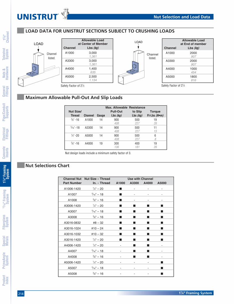
214
®
11⁄4" Framing System
15 ⁄8"
Chan
nel
Nuts
&Ha
rdw
are
Gene
ral
Fitti
ngs
Pipe
/Con
duit
Supp
orts
Elec
trica
lFi
tting
sCo
ncre
teIn
serts
11 ⁄4" F
ram
ing
Syst
em13
⁄16" F
ram
ing
Syst
emFi
berg
lass
Syst
emSp
ecia
lM
etal
sTe
lest
rut
Syst
emPr
imeA
ngle
Syst
emPr
oduc
tIn
dex
Nut Selections Chart
Maximum Allowable Pull-Out And Slip Loads
LOAD DATA FOR UNISTRUT SECTIONS SUBJECT TO CRUSHING LOADS
Safety Factor of 21⁄2Safety Factor of 21⁄2
LOADLOAD
Channellisted.
Channellisted.
Allowable Loadat Center of Member
Channel Lbs (kg)
A1000 3,0001,361
A3300 3,0001,361
A4000 1,400635
A5000 2,5001,134
Allowable Loadat End of member
Channel Lbs (kg)
A1000 2000907
A3300 2000907
A4000 1000454
A5000 1800816
Max. Allowable ResistanceNut Size/ Pull-Out to Slip Torque
Thread Channel Gauge Lbs (kg) Lbs (kg) Ft-Lbs (N•m)3⁄8" -16 A1000 14 900 500 19
408 227 265⁄16" -18 A3300 14 900 500 11
408 227 151⁄4" -20 A5000 14 900 500 6
408 227 83⁄8" -16 A4000 19 300 400 19
136 181 26
Nut design loads include a minimum safety factor of 3.
Channel Nut Nut Size – Thread Use with ChannelPart Number In. - Thread A1000 A3300 A4000 A5000
A1006-1420 1⁄4" – 20 ■ - - -
A1007 5⁄16" – 18 ■ - - -
A1008 3⁄8" – 16 ■ - - -
A3006-1420 1⁄4" – 20 ■ ■ ■ ■
A3007 5⁄16" – 18 ■ ■ ■ ■
A3008 3⁄8" – 16 ■ ■ ■ ■
A3016-0832 #8 – 32 ■ ■ ■ ■
A3016-1024 #10 – 24 ■ ■ ■ ■
A3016-1032 #10 – 32 ■ ■ ■ ■
A3016-1420 1⁄4" – 20 ■ ■ ■ ■
A4006-1420 1⁄4" – 20 - ■ ■ -
A4007 5⁄16" – 18 - ■ ■ -
A4008 3⁄8" – 16 - ■ ■ -
A5006-1420 1⁄4" – 20 - - - ■
A5007 5⁄16" – 18 - - - ■
A5008 3⁄8" – 16 - - - ■
Nut Selection and Load Data

21511⁄4" Framing System
15 ⁄8"
Chan
nel
Nuts
&Ha
rdw
are
Gene
ral
Fitti
ngs
Pipe
/Con
duit
Supp
orts
Elec
trica
lFi
tting
sCo
ncre
teIn
serts
11 ⁄4" F
ram
ing
Syst
em13
⁄16" F
ram
ing
Syst
emFi
berg
lass
Syst
emSp
ecia
lM
etal
sTe
lest
rut
Syst
emPr
imeA
ngle
Syst
emPr
oduc
tIn
dex
A1006-1420, A1007, A1008Channel Nuts with Springs
Note: Use with A5000 channel. Note: Use with A1000, A3300,A4000 & A5000 channels.
Note: Use with A1000, A3300, A4000 & A5000 channels.
Note: Use with A1000 channel. Note: Use with A3300 & A4000 channels.
A4006-1420, A4007, A4008Channel Nuts with Springs
A5006-1420, A5007, A5008Channel Nuts with Springs
A3006-1420, A3007, A3008Channel Nuts without Springs
A3016-0832 thru A3016-1420 Channel Nuts without Springs
Part Thread Size Wt/100 pcsNumber In Lbs (kg)
A1006-1420 1⁄4"-20 62.7
A1007 5⁄16"-18 62.7
A1008 3⁄8"-16 62.7
Part Thread Size Wt/100 pcsNumber In Lbs (kg)
A4006-1420 1⁄4"-20 52.3
A4007 5⁄16"-18 52.3
A4008 3⁄8"-16 52.3
Part Thread Size Wt/100 pcsNumber In Lbs (kg)
A5006-1420 1⁄4"-20 62.7
A5007 5⁄16"-18 62.7
A5008 3⁄8"-16 62.7
Part Thread Size Wt/100 pcsNumber In Lbs (kg)
A3006-1420 1⁄4"-20 52.3
A3007 5⁄16"-18 52.3
A3008 3⁄8"-16 52.3
Part Thread Size Wt/100 pcsNumber In Lbs (kg)
A3016-0832 #8 - 32 10.5
A3016-1024 #10 - 24 10.5
A3016-1032 #10 - 32 10.5
A3016-1420 1⁄4" - 20 10.5
Unistrut Nuts
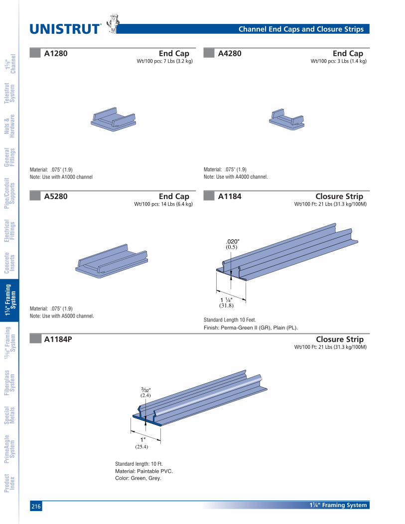
216
®
11⁄4" Framing System
15 ⁄8"
Chan
nel
Nuts
&Ha
rdw
are
Gene
ral
Fitti
ngs
Pipe
/Con
duit
Supp
orts
Elec
trica
lFi
tting
sCo
ncre
teIn
serts
11 ⁄4" F
ram
ing
Syst
em13
⁄16" F
ram
ing
Syst
emFi
berg
lass
Syst
emSp
ecia
lM
etal
sTe
lest
rut
Syst
emPr
imeA
ngle
Syst
emPr
oduc
tIn
dex
A1280 End CapWt/100 pcs: 7 Lbs (3.2 kg)
A4280 End CapWt/100 pcs: 3 Lbs (1.4 kg)
A5280 End CapWt/100 pcs: 14 Lbs (6.4 kg)
A1184 Closure StripWt/100 Ft: 21 Lbs (31.3 kg/100M)
A1184P Closure StripWt/100 Ft: 21 Lbs (31.3 kg/100M)
(0.5).020"
(31.8)1 1⁄4"
Material: .075" (1.9)Note: Use with A1000 channel
Material: .075" (1.9)Note: Use with A4000 channel.
Material: .075" (1.9)Note: Use with A5000 channel.
3⁄32"
1"
(2.4)
(25.4)
Standard Length 10 Feet.Finish: Perma-Green II (GR), Plain (PL).
Channel End Caps and Closure Strips
Standard length: 10 Ft.Material: Paintable PVC.Color: Green, Grey.

217
Standard Dimensions for 11⁄4" (32 mm) width series channel fittings (Unless Otherwise Shown on Drawing)
Hole Diameter: 13⁄32" (10.3mm); Hole Spacing - From End: 5⁄8" (15.9 mm); Hole Spacing - On Center: 11⁄2" (38.1 mm); Width: 11⁄4"(31.8mm); Thickness: 3⁄16" (4.8mm)
11⁄4" Framing System
15 ⁄8"
Chan
nel
Nuts
&Ha
rdw
are
Gene
ral
Fitti
ngs
Pipe
/Con
duit
Supp
orts
Elec
trica
lFi
tting
sCo
ncre
teIn
serts
11 ⁄4" F
ram
ing
Syst
em13
⁄16" F
ram
ing
Syst
emFi
berg
lass
Syst
emSp
ecia
lM
etal
sTe
lest
rut
Syst
emPr
imeA
ngle
Syst
emPr
oduc
tIn
dex
A1063 A1065
A1191
A2324 A1036
A1066
Wt/100 pcs: 39 Lbs (17.7 kg) Wt/100 pcs: 27 Lbs (12.2 kg)
Wt/100 pcs: 8 Lbs (3.6 kg) Wt/100 pcs: 17 Lbs (7.7 kg)
Wt/100 pcs: 87 Lbs (39.5 kg) Wt/100 pcs: 26 Lbs (11.8 kg)
2 3⁄4"(69.9)
4 1⁄4"(108.0)
(69.9)2 3⁄4"
2 3⁄4"(69.9)
5 3⁄4"(146.1)
(76.2)3"
(336.6)13 1⁄4"
1 1⁄4"(31.8)
Flat Plate Fittings
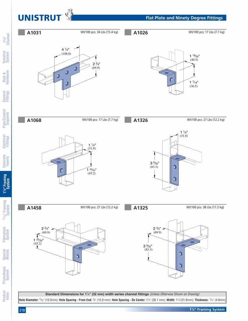
218
Standard Dimensions for 11⁄4" (32 mm) width series channel fittings (Unless Otherwise Shown on Drawing)
Hole Diameter: 13⁄32" (10.3mm); Hole Spacing - From End: 5⁄8" (15.9 mm); Hole Spacing - On Center: 11⁄2" (38.1 mm); Width: 11⁄4"(31.8mm); Thickness: 3⁄16" (4.8mm)
®
11⁄4" Framing System
15 ⁄8"
Chan
nel
Nuts
&Ha
rdw
are
Gene
ral
Fitti
ngs
Pipe
/Con
duit
Supp
orts
Elec
trica
lFi
tting
sCo
ncre
teIn
serts
11 ⁄4" F
ram
ing
Syst
em13
⁄16" F
ram
ing
Syst
emFi
berg
lass
Syst
emSp
ecia
lM
etal
sTe
lest
rut
Syst
emPr
imeA
ngle
Syst
emPr
oduc
tIn
dex
A1031 A1026
A1068 A1326
A1458 A1325
Wt/100 pcs: 34 Lbs (15.4 kg) Wt/100 pcs: 17 Lbs (7.7 kg)
Wt/100 pcs: 27 Lbs (12.2 kg)Wt/100 pcs: 17 Lbs (7.7 kg)
Wt/100 pcs: 38 Lbs (17.2 kg)Wt/100 pcs: 27 Lbs (12.2 kg)
(69.9)2 3⁄4"
4 1⁄4"(108.0)
1 1⁄4"(31.8)
1 25/32"(45.2)
(45.2)1 25⁄32"
2 3⁄4"(69.9)
1 7⁄16"(36.5)
1 19⁄32"(40.5)
3 9⁄32"(83.3)
1 1⁄4"(31.8)
3 9⁄32"(83.3)
(69.9)2 3⁄4"
Flat Plate and Ninety Degree Fittings

219
Standard Dimensions for 11⁄4" (32 mm) width series channel fittings (Unless Otherwise Shown on Drawing)
Hole Diameter: 13⁄32" (10.3mm); Hole Spacing - From End: 5⁄8" (15.9 mm); Hole Spacing - On Center: 11⁄2" (38.1 mm); Width: 11⁄4"(31.8mm); Thickness: 3⁄16" (4.8mm)
11⁄4" Framing System
15 ⁄8"
Chan
nel
Nuts
&Ha
rdw
are
Gene
ral
Fitti
ngs
Pipe
/Con
duit
Supp
orts
Elec
trica
lFi
tting
sCo
ncre
teIn
serts
11 ⁄4" F
ram
ing
Syst
em13
⁄16" F
ram
ing
Syst
emFi
berg
lass
Syst
emSp
ecia
lM
etal
sTe
lest
rut
Syst
emPr
imeA
ngle
Syst
emPr
oduc
tIn
dex
A1033 A1037
A1038
A1331 A1332
A1357Wt/100 pcs: 30 Lbs (13.6 kg)
Wt/100 pcs: 30 Lbs (13.6 kg)Wt/100 pcs: 34 Lbs (15.4 kg)
(40.5)119⁄32"
(108.0)4 1⁄4"
Wt/100 pcs: 30 Lbs (13.6 kg)
(63.5)2 1⁄2"
(45.2)125⁄32"
1 1⁄4"(31.8)
3 9⁄32"(83.3)
(69.9)2 3⁄4"
(29.4)1 5⁄32"
Wt/100 pcs: 75 Lbs (34.0 kg)
3 9⁄32"(83.3)
(69.9)2 3⁄4"
(29.4)1 5⁄32"
Wt/100 pcs: 75 Lbs (34.0 kg)
1 19⁄32"(40.5)
2 3⁄4"(69.9)
1 19⁄32"(40.5)
2 3⁄4"(69.9)
Ninety Degree Fittings
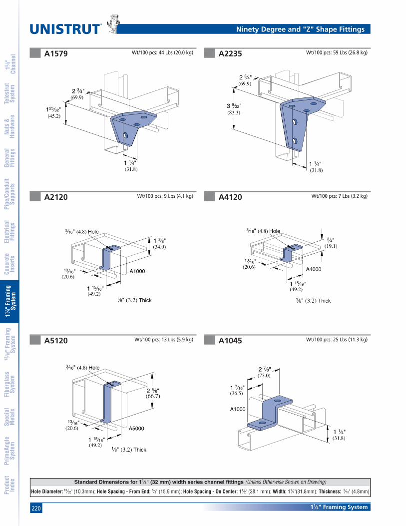
220
Standard Dimensions for 11⁄4" (32 mm) width series channel fittings (Unless Otherwise Shown on Drawing)
Hole Diameter: 13⁄32" (10.3mm); Hole Spacing - From End: 5⁄8" (15.9 mm); Hole Spacing - On Center: 11⁄2" (38.1 mm); Width: 11⁄4"(31.8mm); Thickness: 3⁄16" (4.8mm)
®
11⁄4" Framing System
15 ⁄8"
Chan
nel
Nuts
&Ha
rdw
are
Gene
ral
Fitti
ngs
Pipe
/Con
duit
Supp
orts
Elec
trica
lFi
tting
sCo
ncre
teIn
serts
11 ⁄4" F
ram
ing
Syst
em13
⁄16" F
ram
ing
Syst
emFi
berg
lass
Syst
emSp
ecia
lM
etal
sTe
lest
rut
Syst
emPr
imeA
ngle
Syst
emPr
oduc
tIn
dex
A1579 A2235
A2120 A4120
A5120 A1045
Wt/100 pcs: 44 Lbs (20.0 kg) Wt/100 pcs: 59 Lbs (26.8 kg)
Wt/100 pcs: 9 Lbs (4.1 kg) Wt/100 pcs: 7 Lbs (3.2 kg)
Wt/100 pcs: 13 Lbs (5.9 kg) Wt/100 pcs: 25 Lbs (11.3 kg)
2 3⁄4"(69.9)
(45.2)125⁄32"
(31.8)1 1⁄4"
3 9⁄32"(83.3)
(69.9)2 3⁄4"
(31.8)1 1⁄4"
(34.9)1 3⁄8"
13⁄16"(20.6)
(49.2)1 15⁄16"
1⁄8" (3.2) Thick
A1000
3⁄16" (4.8) Hole
(19.1)
3⁄4"
13⁄16"(20.6)
(49.2)1 15⁄16"
1⁄8" (3.2) Thick
A4000
3⁄16" (4.8) Hole
(66.7)2 5⁄8"
13⁄16"(20.6)
(49.2)1 15⁄16"
1⁄8" (3.2) Thick
A5000
3⁄16" (4.8) Hole
(73.0)2 7⁄8"
1 7⁄16"(36.5)
1 1⁄4"(31.8)
A1000
Ninety Degree and "Z" Shape Fittings

221
Standard Dimensions for 11⁄4" (32 mm) width series channel fittings (Unless Otherwise Shown on Drawing)
Hole Diameter: 13⁄32" (10.3mm); Hole Spacing - From End: 5⁄8" (15.9 mm); Hole Spacing - On Center: 11⁄2" (38.1 mm); Width: 11⁄4"(31.8mm); Thickness: 3⁄16" (4.8mm)
11⁄4" Framing System
15 ⁄8"
Chan
nel
Nuts
&Ha
rdw
are
Gene
ral
Fitti
ngs
Pipe
/Con
duit
Supp
orts
Elec
trica
lFi
tting
sCo
ncre
teIn
serts
11 ⁄4" F
ram
ing
Syst
em13
⁄16" F
ram
ing
Syst
emFi
berg
lass
Syst
emSp
ecia
lM
etal
sTe
lest
rut
Syst
emPr
imeA
ngle
Syst
emPr
oduc
tIn
dex
A3345 A4045
A5045
A2125, A2126, A2127 A2084
A2109, A2110, A2111
Wt/100 pcs: 23 Lbs (10.4 kg) Wt/100 pcs: 21 Lbs (9.5 kg)
Wt/100 pcs: 23 Lbs (10.4 kg)Wt/100 pcs: 33 Lbs (15.0 kg)
Wt/100 pcs: 17 Lbs (7.7 kg) Wt/100 pcs: 90 Lbs (40.8 kg)
1 7⁄16"(36.5)
2 7⁄8"(73.0)
A3300 (19.1)3⁄4"
(73.0)2 7⁄8"
A4000 (15.9)5⁄8"
(36.5)1 7⁄16"
(73.0)2 7⁄8"
A5000
(63.5)2 1⁄2"
B
A2 1⁄4"(57.2)
(36.5)1 7⁄16"
B
A
(31.8)1 1⁄4"
(74.6)2 15⁄16"
1 1⁄4"(31.8)
(67.5)2 21⁄32"
Part A BNumber Degree (rad) In (mm)
A2109 521⁄2° 125⁄32
0.92 45.2A2110 45° 13⁄4
0.79 44.5A2111 371⁄2° 13⁄4
0.65 44.5
Part A BNumber Degree (rad) In (mm)
A2125 521⁄2° 11⁄40.92 31.8
A2126 45° 11⁄40.79 31.8
A2127 371⁄2° 19⁄32
0.65 32.5
"Z", Angular and Wing Shape Fittings

222
Standard Dimensions for 11⁄4" (32 mm) width series channel fittings (Unless Otherwise Shown on Drawing)
Hole Diameter: 13⁄32" (10.3mm); Hole Spacing - From End: 5⁄8" (15.9 mm); Hole Spacing - On Center: 11⁄2" (38.1 mm); Width: 11⁄4"(31.8mm); Thickness: 3⁄16" (4.8mm)
®
11⁄4" Framing System
15 ⁄8"
Chan
nel
Nuts
&Ha
rdw
are
Gene
ral
Fitti
ngs
Pipe
/Con
duit
Supp
orts
Elec
trica
lFi
tting
sCo
ncre
teIn
serts
11 ⁄4" F
ram
ing
Syst
em13
⁄16" F
ram
ing
Syst
emFi
berg
lass
Syst
emSp
ecia
lM
etal
sTe
lest
rut
Syst
emPr
imeA
ngle
Syst
emPr
oduc
tIn
dex
A2341 R-L A2472 R-L
A2223 A2345
A2227 A1047Wt/100 pcs: 52 Lbs (23.6 kg)
Wt/100 pcs: 41 Lbs (18.6 kg)Wt/100 pcs: 34 Lbs (15.4 kg)
Wt/100 pcs: 26 Lbs (11.8 kg) Wt/100 pcs: 33 Lbs (15.0 kg)
R-As shownL-Opposite hand
R-As shownL-Opposite hand
1 19⁄32"(40.5)
(36.5)1 7⁄16"
1 19⁄32"(40.5)
(36.5)1 7⁄16"
1 19⁄32"(40.5)
(36.5)1 7⁄16"
1 19⁄32"(40.5)
1 7⁄16"(36.5)
1 19⁄32"(40.5)
(36.5)1 7⁄16"
Wt/100 pcs: 43 Lbs (19.5 kg)
(114.3)4 1⁄2"
3 1⁄4"(82.6)
A1000
1 1⁄4"(31.8)
Wing and "U" Shape Fittings

223
Standard Dimensions for 11⁄4" (32 mm) width series channel fittings (Unless Otherwise Shown on Drawing)
Hole Diameter: 13⁄32" (10.3mm); Hole Spacing - From End: 5⁄8" (15.9 mm); Hole Spacing - On Center: 11⁄2" (38.1 mm); Width: 11⁄4"(31.8mm); Thickness: 3⁄16" (4.8mm)
11⁄4" Framing System
15 ⁄8"
Chan
nel
Nuts
&Ha
rdw
are
Gene
ral
Fitti
ngs
Pipe
/Con
duit
Supp
orts
Elec
trica
lFi
tting
sCo
ncre
teIn
serts
11 ⁄4" F
ram
ing
Syst
em13
⁄16" F
ram
ing
Syst
emFi
berg
lass
Syst
emSp
ecia
lM
etal
sTe
lest
rut
Syst
emPr
imeA
ngle
Syst
emPr
oduc
tIn
dex
A3347 A4047
A5047
A2608 thru A2617 UNI-CLIP®
A5043
Wt/100 pcs: 34 Lbs (15.4 kg)
Wt/100 pcs: 50 Lbs (22.7 kg)Wt/100 pcs: 58 Lbs (26.3 kg)
Stainless steel, Type 301.Patent No. 2863625.
1"(25.4)
Wt/100 pcs: 37 Lbs (16.8 kg)
(114.3)4 1⁄2"
A3300
(19.1)3⁄4"
(114.3)4 1⁄2"
A5000
2 1⁄2"(63.5)
(31.8)1 1⁄4"
(146.1)5 3⁄4"
A5000
1 1⁄4"(31.8)
(114.3)4 1⁄2"
A4000
(15.9)5⁄8"
Part Pipe Size O.D. Size Wt/100 pcsNumber In (mm) In (mm) Lbs (kg)
A2608 1⁄4 0.540 0.66.4 13.7 0.3
A2609 3⁄8 0.675 0.79.5 17.1 0.3
A2611 1⁄2 0.840 1.012.7 21.3 0.5
A2612 3⁄4 1.050 1.419.1 26.7 0.6
A2613 1 1.315 2.025.4 33.4 0.9
A2614 11⁄4 1.660 2.431.8 42.2 1.1
A2615 11⁄2 1.900 3.238.1 48.3 1.5
A2617 2 2.375 4.750.8 60.3 2.1
"U" Shape Fittings and Tubing Clips

224
®
11⁄4" Framing System
15 ⁄8"
Chan
nel
Nuts
&Ha
rdw
are
Gene
ral
Fitti
ngs
Pipe
/Con
duit
Supp
orts
Elec
trica
lFi
tting
sCo
ncre
teIn
serts
11 ⁄4" F
ram
ing
Syst
em13
⁄16" F
ram
ing
Syst
emFi
berg
lass
Syst
emSp
ecia
lM
etal
sTe
lest
rut
Syst
emPr
imeA
ngle
Syst
emPr
oduc
tIn
dex
Right
(76.2)C
3"
1"(25.4)
B
(15.9)5⁄8"
(14.3)9⁄16"
A
C
(50.8)2"
3⁄16" (4.8) Holes13⁄32" (10.3) Dia.
A2491 R-L, A2492 R-L, A2493 R-L
A2494 R-L thru A2497 R-L
A
(50.8)2"
B
C
(25.4)1"
(15.9)5⁄8"
3⁄16" (4.8) Holes13⁄32" (10.3) Dia.
(14.3)9⁄16"
A
(50.8)2"
B
C
(25.4)1"
(15.9)5⁄8"
3⁄16" (4.8) Holes13⁄32" (10.3) Dia.
(14.3)9⁄16"
Material: 14 Gauge Steel.
LeftRight
Material: 14 Gauge Steel.
Design Uniform Load(Channel Upright Listed)
A1000 200 Lbs (.9 kN)A4000 130 Lbs (.6 kN)
Safety Factor of 21⁄2
Design Uniform Load(Channel Upright Listed)
A1000 200 Lbs (.9 kN)A4000 130 Lbs (.6 kN)
Safety Factor of 21⁄2
Left
(76.2)C
3"
1"(25.4)
B
(15.9)
5⁄8"
A
C
(50.8)2"
3⁄16" (4.8) Holes13⁄32" (10.3) Dia.
(14.3)9⁄16"
Part A B C Wt/100 pcsNumber In (mm) In (mm) In (mm) Lbs (kg)
A2491 R-L 6 2 3 38152.4 50.8 76.2 17.2
A2492 R-L 8 21⁄2 5 56203.2 63.5 127.0 25.4
A2493 R-L 10 3 7 73254.0 76.2 177.8 33.1
Part A B C Wt/100 pcsNumber In (mm) In (mm) In (mm) Lbs (kg)
A2494 R-L 12 31⁄2 3 94304.8 88.9 76.2 42.6
A2495 R-L 14 4 4 105355.6 101.6 101.6 47.6
A2496 R-L 16 41⁄2 5 145406.4 114.3 127.0 65.8
A2497 R-L 18 5 6 175457.2 127.0 152.4 79.4
Brackets
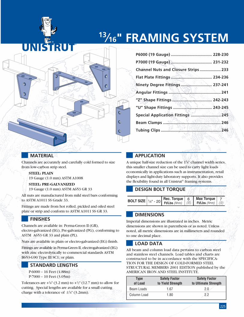
225
®
MATERIALChannels are accurately and carefully cold formed to sizefrom low-carbon strip steel.
STEEL: PLAIN19 Gauge (1.0 mm) ASTM A1008
STEEL: PRE-GALVANIZED19 Gauge (1.0 mm) ASTM A653 GR 33
All nuts are manufactured from mild steel bars conformingto ASTM A1011 SS Grade 33.
Fittings are made from hot rolled, pickled and oiled steelplate or strip and conform to ASTM A1011 SS GR 33.
FINISHESChannels are available in: Perma-Green II (GR),electro-galvanized (EG), Pre-galvanized (PG), conforming toASTM A653 GR 33 and plain (PL).
Nuts are available in plain or electro-galvanized (EG) finish.
Fittings are available in Perma-Green II, electrogalvanized (EG)with zinc electrolytically to commercial standards ASTMB653-G90 Type III SC1; or plain.
STANDARD LENGTHSP-6000 – 16 Feet (4.88m)P-7000 – 10 Feet (3.05m)
Tolerances are +1⁄8" (3.2 mm) to +1⁄2" (12.7 mm) to allow forcutting. Special lengths are available for a small cuttingcharge with a tolerance of ±1⁄8" (3.2mm).
APPLICATIONA unique half-size reduction of the 15⁄8" channel width series,this smaller channel size can be used to carry light loadseconomically in applications such as instrumentation, retaildisplays and light-duty laboratory supports. It also providesthe flexibility found in all Unistrut® framing systems.
DESIGN BOLT TORQUE
DIMENSIONSImperial dimensions are illustrated in inches. Metricdimensions are shown in parenthesis or as noted. Unlessnoted, all metric dimensions are in millimeters and roundedto one decimal place.
LOAD DATAAll beam and column load data pertains to carbon steeland stainless steel channels. Load tables and charts areconstructed to be in accordance with the SPECIFICA-TION FOR THE DESIGN OF COLD-FORMED STEELSTRUCTURAL MEMBERS 2001 EDITION published by theAMERICAN IRON AND STEEL INSTITUTE.
P6000 (19 Gauge) ..................................... 228-230
P7000 (19 Gauge) ..................................... 231-232
Channel Nuts and Closure Strips ................... 233
Flat Plate Fittings ..................................... 234-236
Ninety Degree Fittings ............................ 237-241
Angular Fittings ............................................... 241
“Z” Shape Fittings .................................... 242-243
“U” Shape Fittings ................................... 243-245
Special Application Fittings ........................... 245
Beam Clamps .................................................... 246
Tubing Clips ...................................................... 246
13⁄16" FRAMING SYSTEM
Type Safety Factor Safety Factorof Load to Yield Strength to Ultimate Strength
Beam Loads 1.67 2.0
Column Load 1.80 2.2
BOLT SIZE Rec. TorqueFt/Lbs (N•m)
Max TorqueFt/Lbs (N•m) 1⁄4" - 20
6(8)
7(9)

226
®
13⁄16" Framing System
15 ⁄8"
Chan
nel
Nuts
&Ha
rdw
are
Gene
ral
Fitti
ngs
Pipe
/Con
duit
Supp
orts
Elec
trica
lFi
tting
sCo
ncre
teIn
serts
11 ⁄4" F
ram
ing
Syst
em13
⁄16" F
ram
ing
Syst
emFi
berg
lass
Syst
emSp
ecia
lM
etal
sTe
lest
rut
Syst
emPr
imeA
ngle
Syst
emPr
oduc
tIn
dex
13⁄16" Framing System Pictorial Index
P6000 - Pg 228 P6001 - Pg 228 P6001 A - Pg 228 P6001 B - Pg 228 P6001 C - Pg 228
P7000 - Pg 231 P7001 - Pg 231
P6000-0832 - Pg 233 P7006-0832 - Pg 233 P6280 - Pg 233 P7280 - Pg 233 P6184P - Pg 233
P6062 - Pg 234 P6065 - Pg 234 P6924 - Pg 234 P7325 - Pg 234 P7324 - Pg 234 P6925 - Pg 234
P6066 - Pg 235 P6067 - Pg 235 P6962 - Pg 235 P6356 A - Pg 235 P6358 A - Pg 235 P6726 A - Pg 235
P6334 - Pg 236 P6380 - Pg 236 P6036 - Pg 236 P6380 A - Pg 236 P6031 - Pg 236 P6028 - Pg 236
P6026 - Pg 237 P6068 - Pg 237 P6281 - Pg 237 P6069 - Pg 237 P6326 - Pg 237 P6346 - Pg 237
P6458 - Pg 238 P6325 - Pg 238 P6033 - Pg 238 P6037 - Pg 238 P6038 - Pg 238 P6357 - Pg 238
P6000 Series
P7000 Series
Channel Nuts & Closures
13⁄16" Series Fittings
13⁄16" x 13⁄16"19 Ga.
13⁄16" x 13⁄32"19 Ga.

22713⁄16" Framing System
15 ⁄8"
Chan
nel
Nuts
&Ha
rdw
are
Gene
ral
Fitti
ngs
Pipe
/Con
duit
Supp
orts
Elec
trica
lFi
tting
sCo
ncre
teIn
serts
11 ⁄4" F
ram
ing
Syst
em13
⁄16" F
ram
ing
Syst
emFi
berg
lass
Syst
emSp
ecia
lM
etal
sTe
lest
rut
Syst
emPr
imeA
ngle
Syst
emPr
oduc
tIn
dex
P6359-Pg 239 P6579-Pg 239 P6728-Pg 239 P6917-Pg 239 P6918-Pg 239 P7235-Pg 239
P6130-Pg 240 P6290-Pg 240 P6291-Pg 240 P6381-Pg 240 P6382-Pg 240 P6887-Pg 240
P6331-Pg 241 P6332-Pg 241 P6546-Pg 241 P6186-Pg 241 P6045-Pg 242 P7045-Pg 242
P6347-Pg 242 P7347-Pg 242 P6453-Pg 242 P6454-Pg 242 P6758-Pg 243 P7758-Pg 243
P6047-Pg 243 P6737-Pg 243 P6048-Pg 243 P7048-Pg 243 P6376-Pg 244 P7376-Pg 244
P6376 A-Pg 244 P7376 A-Pg 244 P6377-Pg 244 P7377-Pg 244 P6044-Pg 245 P6455-Pg 245
P6973-Pg 245 P6349-Pg 245 P6353-Pg 245 P6127-Pg 245 P6379 S-Pg 246 P6386-Pg 246
P6805-Pg 246 P7008-Pg 246
13⁄16" Series Fittings
13⁄16" Framing System Pictorial Index

228
®
13⁄16" Framing System
15 ⁄8"
Chan
nel
Nuts
&Ha
rdw
are
Gene
ral
Fitti
ngs
Pipe
/Con
duit
Supp
orts
Elec
trica
lFi
tting
sCo
ncre
teIn
serts
11 ⁄4" F
ram
ing
Syst
em13
⁄16" F
ram
ing
Syst
emFi
berg
lass
Syst
emSp
ecia
lM
etal
sTe
lest
rut
Syst
emPr
imeA
ngle
Syst
emPr
oduc
tIn
dex
P6001
P6001A
P6000
1
11.14.8 4.8
20.6
20.6
11.8
8.4
2.4
22
1
7⁄16"3⁄16"3⁄16"
13⁄16"
13⁄16"
3⁄32".463"
.350"
41.3
20.6
20.6
20.6
2
1
2
11 5⁄8"
13⁄16"
13⁄16"
13⁄16"
Wt/100 Ft: 36 Lbs (54 kg/100 m)Allowable Moment 510 In-Lbs (60 N•m)
19 Gauge Nominal Thickness .040" (1.0 mm)
P6001B
P6001C
P6000 & P6001 Channel
1 5⁄8"
13⁄16"
13⁄16"
13⁄16"
41.3
20.6
20.6
20.6
1 5⁄8"
13⁄16"
13⁄16"
13⁄16"
41.3
20.6
20.6
20.6
1 5⁄8"
13⁄16"
13⁄16"
13⁄16"
41.3
20.6
20.6
20.6
Wt/100 Ft: 73 Lbs (108 kg/100 m)Allowable Moment 1,390 In-Lbs (160 N•m)
19 Gauge Nominal Thickness .040" (1.0 mm)
Wt/100 Ft: 73 Lbs (108 kg/100 m)Allowable Moment 1,820 In-Lbs (210 N•m)
19 Gauge Nominal Thickness .040" (1.0 mm)
Wt/100 Ft: 73 Lbs (108 kg/100 m)Allowable Moment 1,820 In-Lbs (210 N•m)
19 Gauge Nominal Thickness .040" (1.0 mm)
Wt/100 Ft: 73 Lbs (108 kg/100 m)Allowable Moment 1,550 In-Lbs (180 N•m)
19 Gauge Nominal Thickness .040" (1.0 mm)

22913⁄16" Framing System
15 ⁄8"
Chan
nel
Nuts
&Ha
rdw
are
Gene
ral
Fitti
ngs
Pipe
/Con
duit
Supp
orts
Elec
trica
lFi
tting
sCo
ncre
teIn
serts
11 ⁄4" F
ram
ing
Syst
em13
⁄16" F
ram
ing
Syst
emFi
berg
lass
Syst
emSp
ecia
lM
etal
sTe
lest
rut
Syst
emPr
imeA
ngle
Syst
emPr
oduc
tIn
dex
BEAM LOADING – P6000
Notes:
* Load limited by spot weld shear.
** KL⁄r > 200
NR = Not Recommended.
1. Above loads include the weight of the member. This weight must bededucted to arrive at the net allowable load the beam will support.
2. Long span beams should be supported in such a manner as toprevent rotation and twist.
3. Allowable uniformly distributed loads are listed for various simplespans, that is, a beam on two supports. If load is concentrated atthe center of the span, multiply load from the table by 0.5 andcorresponding deflection by 0.8.
Max Defl. atAllowable Uniform Uniform Loading at Deflection
Span Uniform Load Load Span/180 Span/240 Span/360In Lbs In Lbs Lbs Lbs
18 230 0.06 230 230 18024 170 0.11 170 150 10030 140 0.18 130 100 7036 110 0.24 90 70 5042 100 0.35 70 50 3048 80 0.42 50 40 3054 80 0.60 40 30 2060 70 0.72 30 20 2066 60 0.82 30 20 1072 60 1.06 20 20 10
P6000 & P6001 Channels
Max Defl. atAllowable Uniform Uniform Loading at Deflection
Span Uniform Load Load Span/180 Span/240 Span/360In Lbs In Lbs Lbs Lbs
18 620 0.04 620 620 62024 460 0.06 460 460 46030 370 0.10 370 370 32036 310 0.14 310 310 22042 270 0.20 270 240 16048 230 0.25 230 180 12054 210 0.32 190 150 10060 190 0.40 160 120 8066 170 0.48 130 100 7072 150 0.55 110 80 50
BEAM LOADING – P6001
COLUMN LOADING – P6000Maximum
Unbraced Allowable Load Maximum Column Load Applied at C.G.Height at Slot Face K = 0.65 K = 0.80 K =1.0 K = 1.2
In Lbs Lbs Lbs Lbs Lbs
18 600 1,660 1,400 1,100 86024 490 1,300 1,010 740 59030 420 990 740 560 45036 340 770 590 450 37042 300 630 490 380 31048 260 540 420 330 27054 240 470 370 290 **60 210 410 330 ** **66 210 370 300 ** **72 180 340 270 ** **
MaximumUnbraced Allowable Load Maximum Column Load Applied at C.G.
Height at Slot Face K = 0.65 K = 0.80 K =1.0 K = 1.2In Lbs Lbs Lbs Lbs Lbs
18 1,210 4,320 4,080 3,770 3,50024 1,170 3,980 3,680 3,330 3,06030 1,130 3,650 3,330 3,000 2,46036 1,070 3,370 3,060 2,460 1,80042 1,020 3,140 2,690 1,900 1,32048 900 2,930 2,230 1,460 1,01054 820 2,550 1,800 1,150 80060 700 2,180 1,460 930 **66 700 1,830 1,210 770 **72 550 1,530 1,010 ** **
COLUMN LOADING – P6001
Parameter P6000 P6001
Area of Section 0.107 In2 0.213 In2
Axis 1-1Moment of Inertia (I) 0.009 In4 0.045 In4
Section Modulus (S) 0.020 In3 0.055 In3
Radius of Gyration (r) 0.295 In 0.460 InAxis 2-2
Moment of Inertia (I) 0.012 In4 0.024 In4
Section Modulus (S) 0.029 In3 0.058 In3
Radius of Gyration (r) 0.333 In 0.333 In
ELEMENTS OF SECTIONP6000 & P6001

230
®
13⁄16" Framing System
15 ⁄8"
Chan
nel
Nuts
&Ha
rdw
are
Gene
ral
Fitti
ngs
Pipe
/Con
duit
Supp
orts
Elec
trica
lFi
tting
sCo
ncre
teIn
serts
11 ⁄4" F
ram
ing
Syst
em13
⁄16" F
ram
ing
Syst
emFi
berg
lass
Syst
emSp
ecia
lM
etal
sTe
lest
rut
Syst
emPr
imeA
ngle
Syst
emPr
oduc
tIn
dex
METRIC ELEMENTS OF SECTIONP6000 & P6001 (METRIC)
MaximumUnbraced Allowable Load Maximum Column Load Applied at C.G.
Height at Slot Face K = 0.65 K = 0.80 K =1.0 K = 1.2mm kg kg kg kg kg
300 295 * 0 295 * 295 * 295 *450 286 1 286 286 286600 213 2 213 213 213750 172 2 172 172 150
1,000 127 4 127 122 821,250 104 7 104 82 541,500 86 10 73 54 361,750 73 13 54 41 272,000 64 17 41 32 23
MaximumUnbraced Allowable Load Maximum Column Load Applied at C.G.
Height at Slot Face K = 0.65 K = 0.80 K =1.0 K = 1.2mm kg kg kg kg kg300 562 2,114 2,050 1,955 1,860450 549 1,969 1,860 1,724 1,597600 531 1,814 1,678 1,524 1,402750 513 1,669 1,524 1,374 1,143
1,000 467 1,470 1,315 971 6851,250 399 1,293 971 630 4351,500 327 1,012 685 435 **1,750 268 762 503 ** **2,000 222 581 386 ** **
P6000 & P6001 Channel
Max Defl. atAllowable Uniform Uniform Loading at Deflection
Span Uniform Load Load Span/180 Span/240 Span/360mm kg mm kg kg kg300 154 1 154 154 154450 104 2 104 104 86600 77 3 77 73 50750 64 4 59 45 32
1,000 45 7 36 27 181,250 36 11 23 18 91,500 32 17 14 14 91,750 27 24 9 9 5
Max Defl. atAllowable Uniform Uniform Loading at Deflection
Span Uniform Load Load Span/180 Span/240 Span/360mm kg mm kg kg kg
300 318 934 857 748 644450 277 762 644 508 399600 227 599 467 345 272750 186 458 345 259 209
1,000 141 308 240 186 1541,250 113 236 186 145 1181,500 95 191 154 118 **1,750 82 163 127 ** **
BEAM LOADING – P6000 (METRIC) BEAM LOADING – P6001 (METRIC)
Notes:
* Load limited by spot weld shear.
** KL⁄r > 200
NR = Not Recommended.
1. Above loads include the weight of the member. This weight must bededucted to arrive at the net allowable load the beam will support.
2. Long span beams should be supported in such a manner as toprevent rotation and twist.
3. Allowable uniformly distributed loads are listed for various simplespans, that is, a beam on two supports. If load is concentrated atthe center of the span, multiply load from the table by 0.5 andcorresponding deflection by 0.8.
COLUMN LOADING – P6000 (METRIC) COLUMN LOADING – P6001 (METRIC)
Parameter P6000 P6001
Area of Section 0.69 cm2 1.38 cm2
Axis 1-1Moment of Inertia (I) 0.39 cm4 1.88 cm4
Section Modulus (S) 0.33 cm3 0.91 cm3
Radius of Gyration (r) 0.75 cm 1.17 cmAxis 2-2
Moment of Inertia (I) 0.49 cm4 0.99 cm4
Section Modulus (S) 0.48 cm3 0.96 cm3
Radius of Gyration (r) 0.85 cm 0.85 cm

23113⁄16" Framing System
15 ⁄8"
Chan
nel
Nuts
&Ha
rdw
are
Gene
ral
Fitti
ngs
Pipe
/Con
duit
Supp
orts
Elec
trica
lFi
tting
sCo
ncre
teIn
serts
11 ⁄4" F
ram
ing
Syst
em13
⁄16" F
ram
ing
Syst
emFi
berg
lass
Syst
emSp
ecia
lM
etal
sTe
lest
rut
Syst
emPr
imeA
ngle
Syst
emPr
oduc
tIn
dex
P7000
P7001
7⁄16" 3⁄16"
13⁄16"3⁄16"
3⁄32" .243"
.163"
13⁄32" 1
2
10.3
4.811.120.6
4.86.2
4.1
2.4
2
1
1
2
13⁄16"
13⁄32"13⁄16"
13⁄32"
120.610.3
10.3
20.6
2
Notes:
1. Above loads include the weight of the member. This weight must bededucted to arrive at the net allowable load the beam will support.
2. Long span beams should be supported in such a manner as toprevent rotation and twist.
3. Allowable uniformly distributed loads are listed for various simplespans, that is, a beam on two supports. If load is concentrated atthe center of the span, multiply load from the table by 0.5 andcorresponding deflection by 0.8.
Max Defl. atAllowable Uniform Uniform Loading at Deflection
Span Uniform Load Load Span/180 Span/240 Span/360In Lbs In Lbs Lbs Lbs
18 80 0.12 60 50 3024 60 0.22 40 30 2030 50 0.36 20 20 1036 40 0.50 20 10 10
Max Defl. atAllowable Uniform Uniform Loading at Deflection
Span Uniform Load Load Span/180 Span/240 Span/360In Lbs In Lbs Lbs Lbs
18 420 1,200 990 720 51024 330 900 640 410 28030 260 620 410 ** **36 200 430 280 ** **
P7000 & P7001 Channels
Wt/100 Ft: 25 Lbs (38 kg/100m)Allowable Moment 170 In-Lbs (20 N•m)
19 Gauge Nominal Thickness .040" (1.0 mm)
Wt/100 Ft: 50 Lbs (75 kg/100m)Allowable Moment 450 In-Lbs (50 N•m)
19 Gauge Nominal Thickness .040" (1.0 mm)
BEAM LOADING – P7000 BEAM LOADING – P7001
COLUMN LOADING – P7000 COLUMN LOADING – P7001
MaximumUnbraced Allowable Load Maximum Column Load Applied at C.G.
Height at Slot Face K = 0.65 K = 0.80 K =1.0 K = 1.2In Lbs Lbs Lbs Lbs Lbs
18 200 0.07 200 200 14024 150 0.12 150 120 8030 120 0.19 100 80 5036 100 0.28 70 50 4042 90 0.40 50 40 3048 80 0.53 40 30 20
MaximumUnbraced Allowable Load Maximum Column Load Applied at C.G.
Height at Slot Face K = 0.65 K = 0.80 K =1.0 K = 1.2In Lbs Lbs Lbs Lbs Lbs
18 790 2,930 2,690 2,330 1,96024 740 2,570 2,210 1,720 1,26030 680 2,180 1,720 1,160 80036 580 1,780 1,260 800 56042 500 1,400 920 590 **48 420 1,070 710 ** **54 360 850 560 ** **
ELEMENTS OF SECTIONP7000 & P7001
Parameter P7000 P7001
Area of Section 0.074 In2 0.148 In2
Axis 1-1Moment of Inertia (I) 0.002 In4 0.007 In4
Section Modulus (S) 0.007 In3 0.018 In3
Radius of Gyration (r) 0.150 In 0.222 InAxis 2-2
Moment of Inertia (I) 0.007 In4 0.014 In4
Section Modulus (S) 0.017 In3 0.034 In3
Radius of Gyration (r) 0.307 In 0.307 In
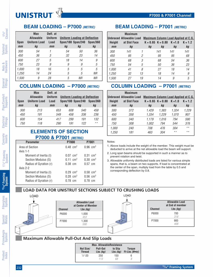
232
®
13⁄16" Framing System
15 ⁄8"
Chan
nel
Nuts
&Ha
rdw
are
Gene
ral
Fitti
ngs
Pipe
/Con
duit
Supp
orts
Elec
trica
lFi
tting
sCo
ncre
teIn
serts
11 ⁄4" F
ram
ing
Syst
em13
⁄16" F
ram
ing
Syst
emFi
berg
lass
Syst
emSp
ecia
lM
etal
sTe
lest
rut
Syst
emPr
imeA
ngle
Syst
emPr
oduc
tIn
dex
LOAD DATA FOR UNISTRUT SECTIONS SUBJECT TO CRUSHING LOADSLOAD LOAD
MaximumUnbraced Allowable Load Maximum Column Load Applied at C.G.
Height at Slot Face K = 0.65 K = 0.80 K =1.0 K = 1.2mm kg kg kg kg kg
300 141 1 141 141 141450 95 2 95 95 68600 68 3 68 54 36750 54 5 50 36 23
1,000 41 8 27 18 141,250 32 13 18 14 91,500 27 19 14 9 5
MaximumUnbraced Allowable Load Maximum Column Load Applied at C.G.
Height at Slot Face K = 0.65 K = 0.80 K =1.0 K = 1.2mm kg kg kg kg kg300 372 1,429 1,383 1,324 1,229450 358 1,334 1,229 1,070 907600 340 1,179 1,016 794 590750 308 1,002 794 544 376
1,000 240 708 476 304 **1,250 181 463 304 ** **
Allowable Loadat Center of Member
Channel Lbs (kg)
P6000 1,000453
P7000 1,300590
Allowable Loadat End of member
Channel Lbs (kg)
P6000 700318
P7000 900408
Max. AllowableResistanceNut Size/ Pull-Out to Slip TorqueThread Lbs (kg) Lbs (kg) Ft-Lbs (N•m)1⁄4"-20 250 150 6
113 68 8
Maximum Allowable Pull-Out And Slip Loads
P7000 & P7001 Channel
BEAM LOADING – P7000 (METRIC) BEAM LOADING – P7001 (METRIC)
COLUMN LOADING – P7000 (METRIC) COLUMN LOADING – P7001 (METRIC)
Max Defl. atAllowable Uniform Uniform Loading at Deflection
Span Uniform Load Load Span/180 Span/240 Span/360mm kg mm kg kg kg300 54 1 54 50 36450 36 3 32 23 14600 27 5 18 14 9750 23 9 9 9 5
1,000 18 16 5 5 51,250 14 24 5 5 NR1,500 9 28 5 NR NR
Max Defl. atAllowable Uniform Uniform Loading at Deflection
Span Uniform Load Load Span/180 Span/240 Span/360mm kg mm kg kg kg
300 213 653 608 540 458450 191 549 458 336 236600 154 417 299 191 132750 118 290 191 122 **
Notes:
1. Above loads include the weight of the member. This weight must bededucted to arrive at the net allowable load the beam will support.
2. Long span beams should be supported in such a manner as toprevent rotation and twist.
3. Allowable uniformly distributed loads are listed for various simplespans, that is, a beam on two supports. If load is concentrated atthe center of the span, multiply load from the table by 0.5 andcorresponding deflection by 0.8.
ELEMENTS OF SECTIONP7000 & P7001 (METRIC)
Parameter P7000 P7001
Area of Section 0.48 cm2 0.96 cm2
Axis 1-1Moment of Inertia (I) 0.07 cm4 0.31 cm4
Section Modulus (S) 0.11 cm3 0.30 cm3
Radius of Gyration (r) 0.38 cm 0.57 cmAxis 2-2
Moment of Inertia (I) 0.29 cm4 0.58 cm4
Section Modulus (S) 0.28 cm3 0.56 cm3
Radius of Gyration (r) 0.78 cm 0.78 cm

23313⁄16" Framing System
15 ⁄8"
Chan
nel
Nuts
&Ha
rdw
are
Gene
ral
Fitti
ngs
Pipe
/Con
duit
Supp
orts
Elec
trica
lFi
tting
sCo
ncre
teIn
serts
11 ⁄4" F
ram
ing
Syst
em13
⁄16" F
ram
ing
Syst
emFi
berg
lass
Syst
emSp
ecia
lM
etal
sTe
lest
rut
Syst
emPr
imeA
ngle
Syst
emPr
oduc
tIn
dex
P6006-0832 thru P6006-1420Channel Nut With Spring
P7006-0832 thru P7006-1420Channel Nut With Spring
P6280 End Cap for P6000 P7280 End Cap for P7000
P6184 P Closure StripWt/100 Ft: 4 Lbs (6.0 kg/100m)
Wt/100 pcs: 3 Lbs (1.4 kg) Wt/100 pcs: 1 Lbs (0.5 kg)
Material: .060" (1.5) Material: .048" (1.2)
Material: PVC, Plastic.Standard Length: 10 Feet (3.05 m).
.706"(17.9)
1⁄16"(1.6)
Part Thread Size Wt/100 pcsNumber In Lbs (kg)
P6006-0836 #8 - 36 10.5
P6006-0832 #8 - 32 10.5
P6006-1032 #10 - 32 10.5
P6006-1024 #10 - 24 10.5
P6006-1420 1⁄4"- 20 10.5
Part Thread Size Wt/100 pcsNumber In Lbs (kg)
P7006-0836 #8 - 36 10.5
P7006-0832 #8 - 32 10.5
P7006-1032 #10 - 32 10.5
P7006-1024 #10 - 24 10.5
P7006-1420 1⁄4"- 20 10.5
Channel Nuts, Caps & Closures

234
Standard Dimensions for 13⁄16" (21 mm) width series channel fittings (Unless Otherwise Shown on Drawing)
Hole Diameter: 9⁄32" (7.1mm); Hole Spacing - From End: 13⁄32" (10.3mm); Hole Spacing - On Center: 11⁄16" (27.0 mm); Width: 13⁄16"(20.6mm); Thickness: 1⁄8" (3.2mm)
®
13⁄16" Framing System
15 ⁄8"
Chan
nel
Nuts
&Ha
rdw
are
Gene
ral
Fitti
ngs
Pipe
/Con
duit
Supp
orts
Elec
trica
lFi
tting
sCo
ncre
teIn
serts
11 ⁄4" F
ram
ing
Syst
em13
⁄16" F
ram
ing
Syst
emFi
berg
lass
Syst
emSp
ecia
lM
etal
sTe
lest
rut
Syst
emPr
imeA
ngle
Syst
emPr
oduc
tIn
dex
P6062 P6065
P6924
P7324 P6925
P7325
Wt/100 pcs: 5 Lbs (2.3 kg)Wt/100 pcs: 2 Lbs (0.9 kg)
Wt/100 pcs: 5 Lbs (2.3 kg) Wt/100 pcs: 7 Lbs (3.2 kg)
Wt/100 pcs: 10 Lbs (4.5 kg) Wt/100 pcs: 7 Lbs (3.2 kg)
13⁄16"(20.6)
2 11⁄16"
1 7⁄8"(47.6)
(68.3)
3 3⁄4"(95.3)
(47.6)1 7⁄8"
2 7⁄16"(61.9)
(20.6)
13⁄16"(20.6)13⁄16"
13⁄16"(20.6)
(41.3)1 5⁄8"
1 7⁄8"(47.6)
Flat Plate Fittings

235
Standard Dimensions for 13⁄16" (21 mm) width series channel fittings (Unless Otherwise Shown on Drawing)
Hole Diameter: 9⁄32" (7.1mm); Hole Spacing - From End: 13⁄32" (10.3mm); Hole Spacing - On Center: 11⁄16" (27.0 mm); Width: 13⁄16"(20.6mm); Thickness: 1⁄8" (3.2mm)
13⁄16" Framing System
15 ⁄8"
Chan
nel
Nuts
&Ha
rdw
are
Gene
ral
Fitti
ngs
Pipe
/Con
duit
Supp
orts
Elec
trica
lFi
tting
sCo
ncre
teIn
serts
11 ⁄4" F
ram
ing
Syst
em13
⁄16" F
ram
ing
Syst
emFi
berg
lass
Syst
emSp
ecia
lM
etal
sTe
lest
rut
Syst
emPr
imeA
ngle
Syst
emPr
oduc
tIn
dex
P6066 P6067
P6962 P6356A
P6358A P6726A
Wt/100 pcs: 11 Lbs (5.0 kg)Wt/100 pcs: 8 Lbs (3.6 kg)
2 15⁄16"(74.6)
4"(101.6)
Wt/100 pcs: 22 Lbs (10.0 kg)Wt/100 pcs: 15 Lbs (6.8 kg)
Wt/100 pcs: 19 Lbs (8.6 kg) Wt/100 pcs: 10 Lbs (4.5 kg)
(58.7)2 5⁄16"
2 5⁄16"(58.7)
2 15⁄16"(74.6)
1 7⁄8"(47.6)
(74.6)2 15⁄16"
2 15⁄16"(74.6)
1 7⁄8"(47.6)
1 7⁄8"(47.6)
Flat Plate Fittings

236
Standard Dimensions for 13⁄16" (21 mm) width series channel fittings (Unless Otherwise Shown on Drawing)
Hole Diameter: 9⁄32" (7.1mm); Hole Spacing - From End: 13⁄32" (10.3mm); Hole Spacing - On Center: 11⁄16" (27.0 mm); Width: 13⁄16"(20.6mm); Thickness: 1⁄8" (3.2mm)
®
13⁄16" Framing System
15 ⁄8"
Chan
nel
Nuts
&Ha
rdw
are
Gene
ral
Fitti
ngs
Pipe
/Con
duit
Supp
orts
Elec
trica
lFi
tting
sCo
ncre
teIn
serts
11 ⁄4" F
ram
ing
Syst
em13
⁄16" F
ram
ing
Syst
emFi
berg
lass
Syst
emSp
ecia
lM
etal
sTe
lest
rut
Syst
emPr
imeA
ngle
Syst
emPr
oduc
tIn
dex
P6334 P6380
P6036
P6031 P6028
P6380A
Wt/100 pcs: 11 Lbs (5.0 kg) Wt/100 pcs: 15 Lbs (6.8 kg)
Wt/100 pcs: 11 Lbs (5.0 kg) Wt/100 pcs: 14 Lbs (6.4 kg)
Wt/100 pcs: 8 Lbs (3.6 kg) Wt/100 pcs: 11 Lbs (5.0 kg)
(47.6)1 7⁄8"
1 7⁄8"(47.6) 2 15⁄16"
(74.6)
1 7⁄8"(47.6)
(47.6)1 7⁄8"
1 7⁄8"(47.6)
2 15⁄16"(74.6)
(74.6)2 15⁄16"
(74.6)2 15⁄16"
1 7⁄8"(47.6)
(47.6)1 7⁄8"
2 15⁄16"(74.6)
Flat Plate Fittings

237
Standard Dimensions for 13⁄16" (21 mm) width series channel fittings (Unless Otherwise Shown on Drawing)
Hole Diameter: 9⁄32" (7.1mm); Hole Spacing - From End: 13⁄32" (10.3mm); Hole Spacing - On Center: 11⁄16" (27.0 mm); Width: 13⁄16"(20.6mm); Thickness: 1⁄8" (3.2mm)
13⁄16" Framing System
15 ⁄8"
Chan
nel
Nuts
&Ha
rdw
are
Gene
ral
Fitti
ngs
Pipe
/Con
duit
Supp
orts
Elec
trica
lFi
tting
sCo
ncre
teIn
serts
11 ⁄4" F
ram
ing
Syst
em13
⁄16" F
ram
ing
Syst
emFi
berg
lass
Syst
emSp
ecia
lM
etal
sTe
lest
rut
Syst
emPr
imeA
ngle
Syst
emPr
oduc
tIn
dex
P6026 P6068
P6281 , P6282, P6283 P6069
P6326 P6346 Wt/100 pcs: 8 Lbs (3.6 kg)Wt/100 pcs: 8 Lbs (3.6 kg)
Wt/100 pcs: 8 Lbs (3.6 kg)
Wt/100 pcs: 5 Lbs (2.3 kg) Wt/100 pcs: 5 Lbs (2.3 kg)
15⁄16"(23.8)
A
15⁄16"(23.8)
1 1⁄8"(28.6)
13⁄16"(20.6)
1 1⁄4"(31.8)
2 3⁄16"(55.6)
(23.8)15⁄16"
2 5⁄16"(58.7)
(21.4)
27⁄32"
2"(50.8)
(28.6)1 1⁄8"
Part A Wt/100 pcsNumber In (mm) Lbs (kg)
P6281 2 850.8 3.6
P6282 21⁄2 963.5 4.1
P6283 3 1076.2 4.5
Ninety Degree Fittings

238
Standard Dimensions for 13⁄16" (21 mm) width series channel fittings (Unless Otherwise Shown on Drawing)
Hole Diameter: 9⁄32" (7.1mm); Hole Spacing - From End: 13⁄32" (10.3mm); Hole Spacing - On Center: 11⁄16" (27.0 mm); Width: 13⁄16"(20.6mm); Thickness: 1⁄8" (3.2mm)
®
13⁄16" Framing System
15 ⁄8"
Chan
nel
Nuts
&Ha
rdw
are
Gene
ral
Fitti
ngs
Pipe
/Con
duit
Supp
orts
Elec
trica
lFi
tting
sCo
ncre
teIn
serts
11 ⁄4" F
ram
ing
Syst
em13
⁄16" F
ram
ing
Syst
emFi
berg
lass
Syst
emSp
ecia
lM
etal
sTe
lest
rut
Syst
emPr
imeA
ngle
Syst
emPr
oduc
tIn
dex
P6458 P6325
P6033
P6038 P6357
P6037
Wt/100 pcs: 11 Lbs (5.0 kg)Wt/100 pcs: 8 Lbs (3.6 kg)
Wt/100 pcs: 8 Lbs (3.6 kg) Wt/100 pcs: 10 Lbs (4.5 kg)
Wt/100 pcs: 11 Lbs (5.0 kg) Wt/100 pcs: 8 Lbs (3.6 kg)
(47.6)1 7⁄8"
(31.8)1 1⁄4"
(31.8)1 1⁄4"
1 7⁄8"(47.6)
2 5⁄16"(58.7)
(47.6)1 7⁄8"
(21.4)27⁄32"
(28.6)1 1⁄8"
(74.6)2 15⁄16"
1 1⁄8"(28.6)
1 15⁄16"(49.2)
1 1⁄8"(28.6)
1 15⁄16"(49.2)
Ninety Degree Fittings

239
Standard Dimensions for 13⁄16" (21 mm) width series channel fittings (Unless Otherwise Shown on Drawing)
Hole Diameter: 9⁄32" (7.1mm); Hole Spacing - From End: 13⁄32" (10.3mm); Hole Spacing - On Center: 11⁄16" (27.0 mm); Width: 13⁄16"(20.6mm); Thickness: 1⁄8" (3.2mm)
13⁄16" Framing System
15 ⁄8"
Chan
nel
Nuts
&Ha
rdw
are
Gene
ral
Fitti
ngs
Pipe
/Con
duit
Supp
orts
Elec
trica
lFi
tting
sCo
ncre
teIn
serts
11 ⁄4" F
ram
ing
Syst
em13
⁄16" F
ram
ing
Syst
emFi
berg
lass
Syst
emSp
ecia
lM
etal
sTe
lest
rut
Syst
emPr
imeA
ngle
Syst
emPr
oduc
tIn
dex
P6359 P6579
P6728 P6917
P6918 P7235
Wt/100 pcs: 15 Lbs (6.8 kg) Wt/100 pcs: 15 Lbs (6.8 kg)
Wt/100 pcs: 21 Lbs (9.5 kg) Wt/100 pcs: 18 Lbs (8.2 kg)
Wt/100 pcs: 22 Lbs (10.0 kg) Wt/100 pcs: 21 Lbs (9.5 kg)
2 5⁄16"(58.7)
1 7⁄8"(47.6)
1 7⁄8"(47.6)
(31.8)1 1⁄4"
(47.6)1 7⁄8"
(58.7)2 5⁄16"
(20.6)13⁄16"
(21.4)27⁄32"
(74.6)2 15⁄16"
(21.4)27⁄32" (47.6)
1 7⁄8"
(58.7)2 5⁄16"
1 7⁄8"(47.6)
2 5⁄16"(58.7)
(47.6)1 7⁄8"
(47.6)1 7⁄8"
(21.4)27⁄32"
(47.6)1 7⁄8"
(58.7)2 5⁄16"
1 7⁄8"(47.6)
Ninety Degree Fittings
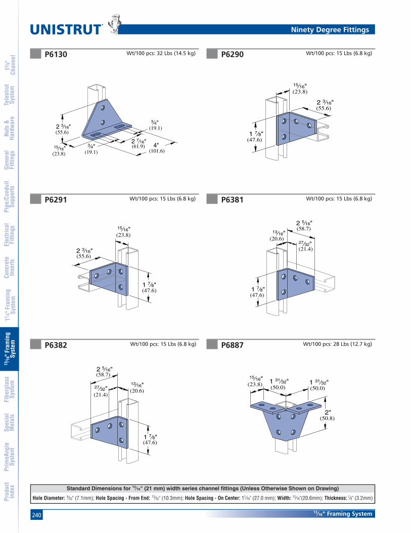
240
Standard Dimensions for 13⁄16" (21 mm) width series channel fittings (Unless Otherwise Shown on Drawing)
Hole Diameter: 9⁄32" (7.1mm); Hole Spacing - From End: 13⁄32" (10.3mm); Hole Spacing - On Center: 11⁄16" (27.0 mm); Width: 13⁄16"(20.6mm); Thickness: 1⁄8" (3.2mm)
®
13⁄16" Framing System
15 ⁄8"
Chan
nel
Nuts
&Ha
rdw
are
Gene
ral
Fitti
ngs
Pipe
/Con
duit
Supp
orts
Elec
trica
lFi
tting
sCo
ncre
teIn
serts
11 ⁄4" F
ram
ing
Syst
em13
⁄16" F
ram
ing
Syst
emFi
berg
lass
Syst
emSp
ecia
lM
etal
sTe
lest
rut
Syst
emPr
imeA
ngle
Syst
emPr
oduc
tIn
dex
P6130 P6290
P6291
P6382 P6887
P6381
Wt/100 pcs: 32 Lbs (14.5 kg) Wt/100 pcs: 15 Lbs (6.8 kg)
Wt/100 pcs: 15 Lbs (6.8 kg)
Wt/100 pcs: 15 Lbs (6.8 kg) Wt/100 pcs: 15 Lbs (6.8 kg)
(23.8)15⁄16"
(55.6)2 3⁄16"
(19.1)3⁄4"
(19.1)
4"(101.6)
2 7⁄16"(61.9)
3⁄4"
15⁄16"(23.8)
2 3⁄16"(55.6)
1 7⁄8"(47.6)
(58.7)2 5⁄16"
27⁄32"(21.4)
13⁄16"(20.6)
(47.6)1 7⁄8"
(58.7)2 5⁄16"
27⁄32"(21.4)
13⁄16"(20.6)
(47.6)1 7⁄8"
15⁄16"(23.8)
2 3⁄16"(55.6)
1 7⁄8"(47.6)
(23.8)15⁄16"
(50.8)2"
1 31⁄32"(50.0) (50.0)
1 31⁄32"
Wt/100 pcs: 28 Lbs (12.7 kg)
Ninety Degree Fittings
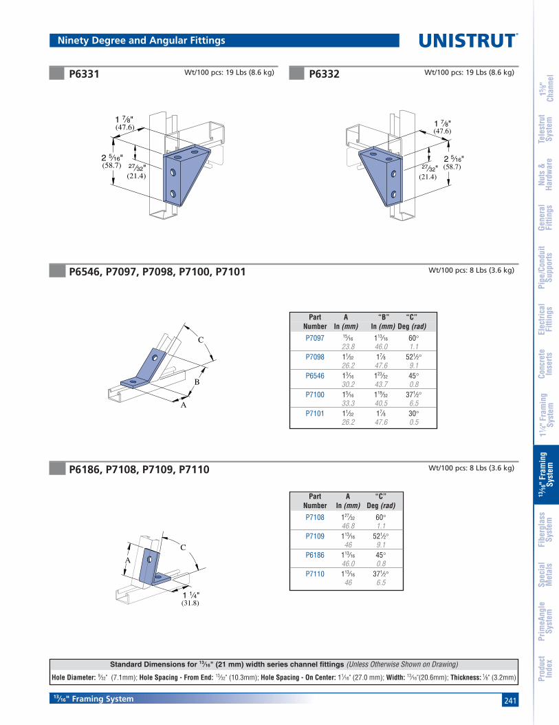
241
Standard Dimensions for 13⁄16" (21 mm) width series channel fittings (Unless Otherwise Shown on Drawing)
Hole Diameter: 9⁄32" (7.1mm); Hole Spacing - From End: 13⁄32" (10.3mm); Hole Spacing - On Center: 11⁄16" (27.0 mm); Width: 13⁄16"(20.6mm); Thickness: 1⁄8" (3.2mm)
13⁄16" Framing System
15 ⁄8"
Chan
nel
Nuts
&Ha
rdw
are
Gene
ral
Fitti
ngs
Pipe
/Con
duit
Supp
orts
Elec
trica
lFi
tting
sCo
ncre
teIn
serts
11 ⁄4" F
ram
ing
Syst
em13
⁄16" F
ram
ing
Syst
emFi
berg
lass
Syst
emSp
ecia
lM
etal
sTe
lest
rut
Syst
emPr
imeA
ngle
Syst
emPr
oduc
tIn
dex
P6331 P6332
P6546, P7097, P7098, P7100, P7101
P6186, P7108, P7109, P7110
Wt/100 pcs: 8 Lbs (3.6 kg)
Wt/100 pcs: 19 Lbs (8.6 kg)Wt/100 pcs: 19 Lbs (8.6 kg)
2 5⁄16"(58.7)
(47.6)1 7⁄8"
(21.4)27⁄32"
2 5⁄16"(58.7)
(47.6)1 7⁄8"
(21.4)
27⁄32"
A
(31.8)1 1⁄4"
C
B
A
C
Part A “B” “C”Number In (mm) In (mm) Deg (rad)
P7097 15⁄16 113⁄16 60°23.8 46.0 1.1
P7098 11⁄32 17⁄8 521⁄2°26.2 47.6 9.1
P6546 13⁄16 123⁄32 45°30.2 43.7 0.8
P7100 15⁄16 119⁄32 371⁄2°33.3 40.5 6.5
P7101 11⁄32 17⁄8 30°26.2 47.6 0.5
Part A “C”Number In (mm) Deg (rad)
P7108 127⁄32 60°46.8 1.1
P7109 113⁄16 521⁄2°46 9.1
P6186 113⁄16 45°46.0 0.8
P7110 113⁄16 371⁄2°46 6.5
Ninety Degree and Angular Fittings
Wt/100 pcs: 8 Lbs (3.6 kg)

242
Standard Dimensions for 13⁄16" (21 mm) width series channel fittings (Unless Otherwise Shown on Drawing)
Hole Diameter: 9⁄32" (7.1mm); Hole Spacing - From End: 13⁄32" (10.3mm); Hole Spacing - On Center: 11⁄16" (27.0 mm); Width: 13⁄16"(20.6mm); Thickness: 1⁄8" (3.2mm)
®
13⁄16" Framing System
15 ⁄8"
Chan
nel
Nuts
&Ha
rdw
are
Gene
ral
Fitti
ngs
Pipe
/Con
duit
Supp
orts
Elec
trica
lFi
tting
sCo
ncre
teIn
serts
11 ⁄4" F
ram
ing
Syst
em13
⁄16" F
ram
ing
Syst
emFi
berg
lass
Syst
emSp
ecia
lM
etal
sTe
lest
rut
Syst
emPr
imeA
ngle
Syst
emPr
oduc
tIn
dex
P6045 P7045
P6347
P6453 P6454
P7347
Wt/100 pcs: 7 Lbs (3.2 kg)
Wt/100 pcs: 7 Lbs (3.2 kg)
(41.3)1 5⁄8"
(23.8)15⁄16"
P6001
Wt/100 pcs: 6 Lbs (2.7 kg)
(23.8)
(13.5)17⁄32"
P7000
15⁄16"
Wt/100 pcs: 9 Lbs (4.1 kg) Wt/100 pcs: 5 Lbs (2.3 kg)
Wt/100 pcs: 6 Lbs (2.7 kg)
(10.3)13⁄32"
(10.3)13⁄32"
(47.6)1 7⁄8"
P7000
(20.6)13⁄16"
(23.8)
P6000
15⁄16"
(27.0)1 1⁄16"
(20.6)
13⁄16"
P6000
(3.2)1⁄8"
(46.8)1 27⁄32"
“Z” Shape Fittings
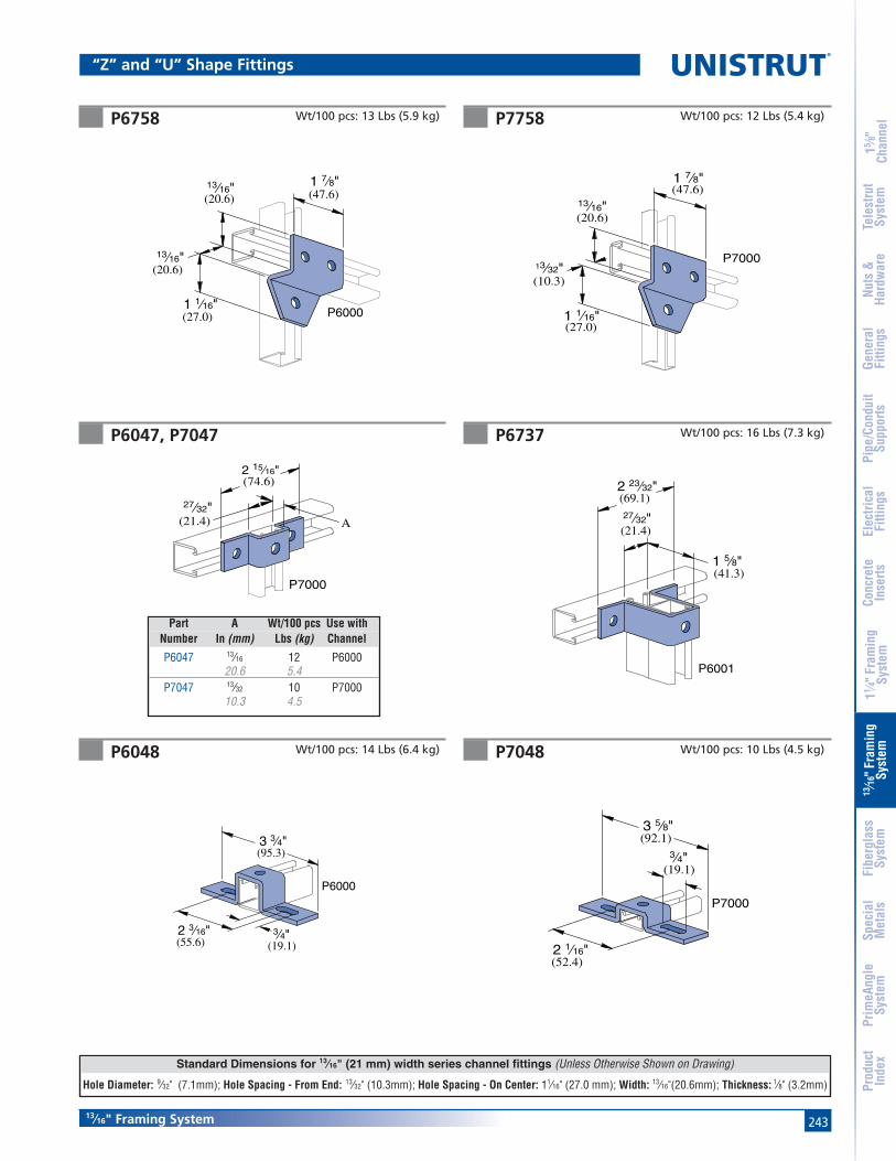
243
Standard Dimensions for 13⁄16" (21 mm) width series channel fittings (Unless Otherwise Shown on Drawing)
Hole Diameter: 9⁄32" (7.1mm); Hole Spacing - From End: 13⁄32" (10.3mm); Hole Spacing - On Center: 11⁄16" (27.0 mm); Width: 13⁄16"(20.6mm); Thickness: 1⁄8" (3.2mm)
13⁄16" Framing System
15 ⁄8"
Chan
nel
Nuts
&Ha
rdw
are
Gene
ral
Fitti
ngs
Pipe
/Con
duit
Supp
orts
Elec
trica
lFi
tting
sCo
ncre
teIn
serts
11 ⁄4" F
ram
ing
Syst
em13
⁄16" F
ram
ing
Syst
emFi
berg
lass
Syst
emSp
ecia
lM
etal
sTe
lest
rut
Syst
emPr
imeA
ngle
Syst
emPr
oduc
tIn
dex
P6758 P7758
P6047, P7047 P6737
P6048 P7048
Wt/100 pcs: 13 Lbs (5.9 kg) Wt/100 pcs: 12 Lbs (5.4 kg)
Wt/100 pcs: 16 Lbs (7.3 kg)
(41.3)1 5⁄8"
27⁄32"(21.4)
(69.1)2 23⁄32"
P6001
Wt/100 pcs: 14 Lbs (6.4 kg) Wt/100 pcs: 10 Lbs (4.5 kg)
(27.0)1 1⁄16"
13⁄16"(20.6)
(20.6)13⁄16" (47.6)
1 7⁄8"
P6000(27.0)1 1⁄16"
13⁄32"(10.3)
(20.6)13⁄16"
(47.6)1 7⁄8"
P7000
3⁄4"(19.1)
(92.1)3 5⁄8"
2 1⁄16"(52.4)
P7000
27⁄32"(21.4)
(74.6)2 15⁄16"
P7000
A
3⁄4"(19.1)
(95.3)3 3⁄4"
2 3⁄16"(55.6)
P6000
“Z” and “U” Shape Fittings
Part A Wt/100 pcs Use withNumber In (mm) Lbs (kg) Channel
P6047 13⁄16 12 P600020.6 5.4
P7047 13⁄32 10 P700010.3 4.5

244
Standard Dimensions for 13⁄16" (21 mm) width series channel fittings (Unless Otherwise Shown on Drawing)
Hole Diameter: 9⁄32" (7.1mm); Hole Spacing - From End: 13⁄32" (10.3mm); Hole Spacing - On Center: 11⁄16" (27.0 mm); Width: 13⁄16"(20.6mm); Thickness: 1⁄8" (3.2mm)
®
13⁄16" Framing System
15 ⁄8"
Chan
nel
Nuts
&Ha
rdw
are
Gene
ral
Fitti
ngs
Pipe
/Con
duit
Supp
orts
Elec
trica
lFi
tting
sCo
ncre
teIn
serts
11 ⁄4" F
ram
ing
Syst
em13
⁄16" F
ram
ing
Syst
emFi
berg
lass
Syst
emSp
ecia
lM
etal
sTe
lest
rut
Syst
emPr
imeA
ngle
Syst
emPr
oduc
tIn
dex
P6376 P7376
P6376A
P6377 P7377
P7376A
Wt/100 pcs: 24 Lbs (10.9 kg)Wt/100 pcs: 36 Lbs (16.3 kg)
Wt/100 pcs: 17 Lbs (7.7 kg) Wt/100 pcs: 11 Lbs (5.0 kg)
Wt/100 pcs: 16 Lbs (7.3 kg)Wt/100 pcs: 26 Lbs (11.8 kg)
13⁄16"(20.6)
4"(101.6)
P6000
2 15⁄16"(74.6)
P6000
13⁄16"(20.6)
13⁄16"(20.6)
1 7⁄8"(47.6)
P6000
1 7⁄8"(47.6)
P7000
13⁄32"(10.3)
2 15⁄16"(74.6)
P7000
13⁄32"(10.3)
4"(101.6)
P7000
13⁄32"(10.3)
“U” Shape Fittings
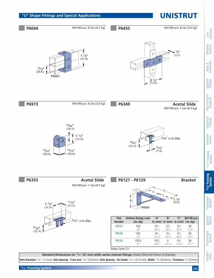
245
Standard Dimensions for 13⁄16" (21 mm) width series channel fittings (Unless Otherwise Shown on Drawing)
Hole Diameter: 9⁄32" (7.1mm); Hole Spacing - From End: 13⁄32" (10.3mm); Hole Spacing - On Center: 11⁄16" (27.0 mm); Width: 13⁄16"(20.6mm); Thickness: 1⁄8" (3.2mm)
13⁄16" Framing System
15 ⁄8"
Chan
nel
Nuts
&Ha
rdw
are
Gene
ral
Fitti
ngs
Pipe
/Con
duit
Supp
orts
Elec
trica
lFi
tting
sCo
ncre
teIn
serts
11 ⁄4" F
ram
ing
Syst
em13
⁄16" F
ram
ing
Syst
emFi
berg
lass
Syst
emSp
ecia
lM
etal
sTe
lest
rut
Syst
emPr
imeA
ngle
Syst
emPr
oduc
tIn
dex
P6044 P6455
P6973 P6349 Acetal SlideWt/100 pcs: 1 Lbs (0.5 kg)
P6353 Acetal Slide
Wt/100 pcs: 8 Lbs (3.6 kg)
1 7⁄8"
13⁄16"(20.6)
(47.6)
P6001
13⁄16"(20.6)
13⁄16"(20.6)
13⁄32"(10.3)
1 1⁄4"(31.8)
Wt/100 pcs: 8 Lbs (3.6 kg)
Wt/100 pcs: 9 Lbs (4.1 kg)
2 7⁄8"(73.0)
(3.2)
1⁄8"
Wt/100 pcs: 1 Lbs (0.5 kg)
3⁄16" (4.8) Dia.
(31.8)1 1⁄4" (17.5)
11⁄16"
27⁄32"(21.4)
5⁄16"(7.9)
13⁄32"(21.4)
3⁄16" (4.8) Dia.
“U” Shape Fittings and Special Applications
Safety Factor 21⁄2
P6127 - P6129 Bracket
ACC
(28.6)1 1⁄8"B
P6000
Part Uniform Design Load “A” “B” “C” Wt/100 pcsNumber Lbs (kg) In (mm) In (mm) In (mm) Lbs (kg)
P6127 150 61⁄2 21⁄2 21⁄2 3068 165.1 63.5 63.5 13.6
P6128 150 81⁄2 31⁄4 31⁄2 4068 215.9 82.6 88.9 18.1
P6129 130.0 101⁄2 4 41⁄2 5059 266.7 101.6 114.3 22.7
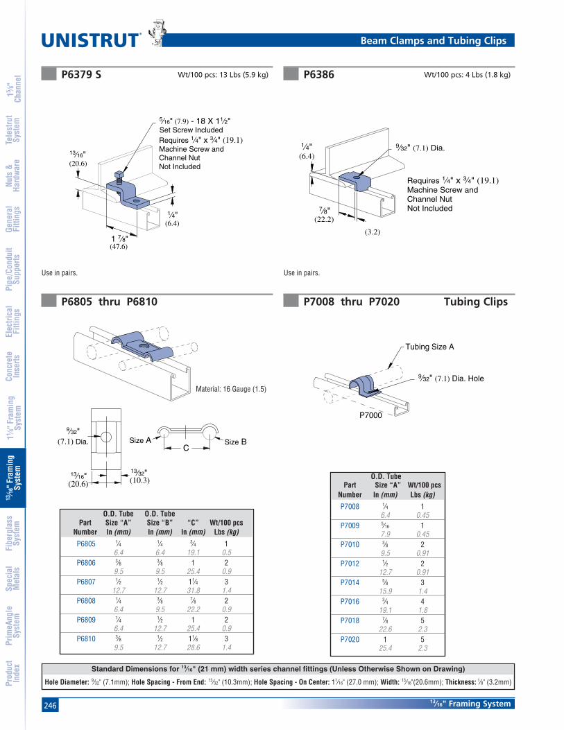
246
Standard Dimensions for 13⁄16" (21 mm) width series channel fittings (Unless Otherwise Shown on Drawing)
Hole Diameter: 9⁄32" (7.1mm); Hole Spacing - From End: 13⁄32" (10.3mm); Hole Spacing - On Center: 11⁄16" (27.0 mm); Width: 13⁄16"(20.6mm); Thickness: 1⁄8" (3.2mm)
®
13⁄16" Framing System
15 ⁄8"
Chan
nel
Nuts
&Ha
rdw
are
Gene
ral
Fitti
ngs
Pipe
/Con
duit
Supp
orts
Elec
trica
lFi
tting
sCo
ncre
teIn
serts
11 ⁄4" F
ram
ing
Syst
em13
⁄16" F
ram
ing
Syst
emFi
berg
lass
Syst
emSp
ecia
lM
etal
sTe
lest
rut
Syst
emPr
imeA
ngle
Syst
emPr
oduc
tIn
dex
9⁄32" (7.1) Dia. Hole
Tubing Size A
P7000
C
13⁄32"(10.3)
13⁄16"(20.6)
Size A Size B
9⁄32"(7.1) Dia.
Material: 16 Gauge (1.5)
P6805 thru P6810 P7008 thru P7020 Tubing Clips
(3.2)
(6.4)
1⁄4" 9⁄32" (7.1) Dia.
(22.2)
7⁄8"
Requires 1⁄4" x 3⁄4" (19.1)Machine Screw and Channel NutNot Included
Use in pairs.
(6.4)
1⁄4"
5⁄16" (7.9) - 18 X 11⁄2"Set Screw IncludedRequires 1⁄4" x 3⁄4" (19.1)Machine Screw and Channel NutNot Included(20.6)
13⁄16"
(47.6)1 7⁄8"
Use in pairs.
P6379 S P6386
O.D. Tube O.D. TubePart Size “A” Size “B” “C” Wt/100 pcs
Number In (mm) In (mm) In (mm) Lbs (kg)
P6805 1⁄4 1⁄4 3⁄4 16.4 6.4 19.1 0.5
P6806 3⁄8 3⁄8 1 29.5 9.5 25.4 0.9
P6807 1⁄2 1⁄2 11⁄4 312.7 12.7 31.8 1.4
P6808 1⁄4 3⁄8 7⁄8 26.4 9.5 22.2 0.9
P6809 1⁄4 1⁄2 1 26.4 12.7 25.4 0.9
P6810 3⁄8 1⁄2 11⁄8 39.5 12.7 28.6 1.4
O.D. TubePart Size “A” Wt/100 pcs
Number In (mm) Lbs (kg)
P7008 1⁄4 16.4 0.45
P7009 5⁄16 17.9 0.45
P7010 3⁄8 29.5 0.91
P7012 1⁄2 212.7 0.91
P7014 5⁄8 315.9 1.4
P7016 3⁄4 419.1 1.8
P7018 7⁄8 522.6 2.3
P7020 1 525.4 2.3
Beam Clamps and Tubing Clips
Wt/100 pcs: 13 Lbs (5.9 kg) Wt/100 pcs: 4 Lbs (1.8 kg)

247
®
POLYESTER AND VINYL ESTER MATERIALSPolyester and vinyl ester channels are manufactured fromthe pultrusion process and are color coded gray and beigerespectively. Components are made by reinforcing apolymer resin (polyester or vinyl ester) with multiple strandsof glass filament, alternating layers of glass mat and U.V.resistant surfacing veils. The glass is drawn through theliquid resin, which coats and saturates the fibers. Thecombination of resin, glass and veil is then continuouslyguided and pulled (pultruded) through a heated die thatdetermines the shape of the component.
In the die, the resin is cured to form a reinforced part whichcan be cut to length. The hardened fiberglass pultrusion isreinforced with an internal arrangement of permanentlybonded continuous glass fibers to increase its strength.
INSTALLATIONFabrication requires just three simple operations: cutting,drilling and sealing as described below.
Cutting – Hand held saws, such as hack saws (24 to 32teeth per inch) are suitable when a few cuts are required.For frequent cutting, a circular power saw with a carbide-tipped masonry blade yields the best results. When using apower saw, dust filter masks, gloves and long sleeve cloth-ing should be worn.
Drilling – Any standard twist bit, even when used withbattery-powered drills will work well. Carbide-tipped drillbits are recommended.
Sealing – To protect against future migration of corrosiveelements into the cut sections, all cuts and holes should beproperly sealed with clear urethane sealer.
OPERATING ENVIRONMENTTemperature Ranges – Fiberglass parts are supplied in fivedifferent materials covering distinct temperature ranges.The temperature ranges indicated are meant to be used onlyas a general guideline. Continual exposure to elevatedtemperatures reduces thestrength properties of plasticsand glass-reinforced fiberglass.Actual resin test data confirmsthat a 50% reduction instrength occurs at the extremehigh temperature levels.
Chemical Resistance – See the chart on page 269 forcorrosion resistance. The results are based upon immersionfor a 24 hour period. This is typically the “worst case”exposure to corrosion. Less severe contact such as spills,splashes and vapor condensate will exceed the performanceresults listed in the table.
Loading – Channel loading is defined with description ofeach type of channel. Additional loading and designlimitations for fittings and accessories are described in theappropriate section for that part.
Material Low HighCode Temp. Temp.
E -25°F 130°FP -35°F 200°FV -35°F 200°F
PU -40°F 140°FN -20°F 150°F
FIBERGLASS SYSTEMSHeavy Duty Channel (Flange Profile) ... 250-251
Light Duty Channel (Flange Profile) ..... 252-253
Heavy Duty Channel (SST Profile) ......... 254-255
Nuts & Hardware ..................................... 256-259
Fittings ...................................................... 260-264
Pipe Clamps .............................................. 265-266
Clevis Hangers .................................................. 267
Beam Clamps .................................................... 268
Chemical Compatibility ................................... 269
Specifications ................................................... 270

248
15 ⁄8"
Chan
nel
Nuts
&Ha
rdw
are
Gene
ral
Fitti
ngs
Pipe
/Con
duit
Supp
orts
Elec
trica
lFi
tting
sCo
ncre
teIn
serts
11 ⁄4" F
ram
ing
Syst
em13
⁄16" F
ram
ing
Syst
emFi
berg
lass
Syst
emSp
ecia
lM
etal
sTe
lest
rut
Syst
emPr
imeA
ngle
Syst
emPr
oduc
tIn
dex
Fiberglass
® Fiberglass Pictorial Index
F20P/V-2000-Pg 250 F20P/V-2100-Pg 250 F20P/V-2200-Pg 250 F20P/V-2300-Pg 250
F20P/V-1000-Pg 252 F20P/V-1100-Pg 252 F20P/V-1200-Pg 252 F20P/V-1300-Pg 252
F20P/V-2000 SST-Pg 254F20P/V-2100 SST-Pg 254
F20P/V-2200 SST-Pg 254F20P/V-23000 SST-Pg 254
Heavy Duty-Pg 256 Standard Duty-Pg 256 Saddle Clip-Pg 256 Stop Lock-Pg 256 Hex Flange Bolt-Pg 257 Hex Bolt-Pg 257
Hex Flange Nut-Pg 257 Hex Nut -Pg 257 Flat Washer-Pg 258 Spacer -Pg 258 Threaded Rod-Pg 258 Rod Coupler-Pg 258
End Cap-Pg 259 Capping Strip-Pg 259 U-Bolt-Pg 259
Channel - Patented Flange Profile
Channel - SST Profile
Hardware & Accessories
Heavy DutyPatented
Flange Profile15⁄8" x 15⁄8"
Heavy DutySST Profile15⁄8" x 15⁄8"
Light DutyPatented
Flange Profile11⁄2" x 11⁄8"
SSTFlange
PatentedFlange
Unistrut fiberglass channels, except the SST series, incorporate a patented flange design which provides reliable fastening and interlocking of components and accessories.It is important to note that standard metal framing components such as pipe clamps and strut nuts will not work with the flange design.
The Unistrut SST profile is similar to the profile of standard metal channel. The Unistrut SST profile will accommodate standard 15⁄8" metal channel fittings and components. This profile is available in polyester or vinyl ester resin.
The Unistrut SST profile is not compatible with the fiberglass pipe clamps and channel nuts shown in this section. Typically, stainless steel clamps and strut nuts (listed elsewhere in this catalog) are used with this profile.

249
15 ⁄8"
Chan
nel
Nuts
&Ha
rdw
are
Gene
ral
Fitti
ngs
Pipe
/Con
duit
Supp
orts
Elec
trica
lFi
tting
sCo
ncre
teIn
serts
11 ⁄4" F
ram
ing
Syst
em13
⁄16" F
ram
ing
Syst
emFi
berg
lass
Syst
emSp
ecia
lM
etal
sTe
lest
rut
Syst
emPr
imeA
ngle
Syst
emPr
oduc
tIn
dex
Fiberglass
Fiberglass Pictorial Index
F20P/V-2500-Pg 260 F20P/V-2502-Pg 260 F20P/V-2504-Pg 260 F20P/V-2506-Pg 260 F20P/V-2508-Pg 261 F20P/V-2510-Pg 261
F20P/V-2512-Pg 261 F20P/V-2514-Pg 261 F20P/V-2516-Pg 261 F20P/V-2518-Pg 261 F20P/V-2520-Pg 262 F20P/V-2522-Pg 262
F20P/V-2524-Pg 262 F20P/V-2526-Pg 262 F20P/V-2528-Pg 262 F20P/V-2530-Pg 262 F20P/V-2534-Pg 263 F20P/V-2540-Pg 263
F20PU-2538-Pg 263 F20PU-2611-Pg 263 F20PU-2613-Pg 263 F50PU-1508F50PU-2008-Pg 263
F50PU-2045-Pg 264 F50PU-2636-Pg 264
F50PU-2090-Pg 264 F50PU-2616-Pg 264 F20PU-5853F20PU-5855-Pg 264
F20PU-5903F20PU-5095-Pg 264
Adj. Pipe Clamp-Pg 265 Rigid Pipe Clamp-Pg 266 Pipe Strap-Pg 266 Fabricated Clevis Hanger-Pg 267
Molded ClevisHanger-Pg 267
Channel Insert-Pg 267 Molded Beam Clamp Assembly-Pg 268
MoldedBeam Clamp-Pg 268
Rack Stanchion-Pg 268
Fittings
Pipe Clamps, Beam Clamps and Stanchions
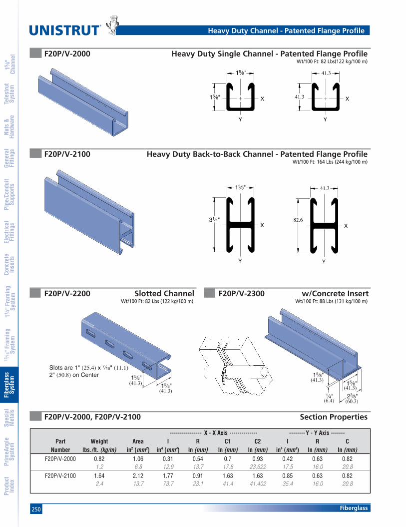
250
15 ⁄8"
Chan
nel
Nuts
&Ha
rdw
are
Gene
ral
Fitti
ngs
Pipe
/Con
duit
Supp
orts
Elec
trica
lFi
tting
sCo
ncre
teIn
serts
11 ⁄4" F
ram
ing
Syst
em13
⁄16" F
ram
ing
Syst
emFi
berg
lass
Syst
emSp
ecia
lM
etal
sTe
lest
rut
Syst
emPr
imeA
ngle
Syst
emPr
oduc
tIn
dex
Fiberglass
®
F20P/V-2000 Heavy Duty Single Channel - Patented Flange ProfileWt/100 Ft: 82 Lbs(122 kg/100 m)
---------------- X - X Axis -------------- --------Y - Y Axis -------Part Weight Area I R C1 C2 I R C
Number lbs./ft. (kg/m) in2 (mm2) in4 (mm4) In (mm) In (mm) In (mm) in4 (mm4) In (mm) In (mm)F20P/V-2000 0.82 1.06 0.31 0.54 0.7 0.93 0.42 0.63 0.82
1.2 6.8 12.9 13.7 17.8 23.622 17.5 16.0 20.8F20P/V-2100 1.64 2.12 1.77 0.91 1.63 1.63 0.85 0.63 0.82
2.4 13.7 73.7 23.1 41.4 41.402 35.4 16.0 20.8
F20P/V-2100 Heavy Duty Back-to-Back Channel - Patented Flange ProfileWt/100 Ft: 164 Lbs (244 kg/100 m)
15⁄8"
1⁄4"
15⁄8"
23⁄8"(6.4) (60.3)
(41.3)
(41.3)
F20P/V-2300 w/Concrete InsertWt/100 Ft: 88 Lbs (131 kg/100 m)
F20P/V-2200 Slotted ChannelWt/100 Ft: 82 Lbs (122 kg/100 m)
15⁄8"
15⁄8" X
Y
41.3
41.3 X
Y
15⁄8"
31⁄4"X
Y
41.3
82.6X
Y
F20P/V-2000, F20P/V-2100 Section Properties
Heavy Duty Channel - Patented Flange Profile
15⁄8"
Slots are 1" (25.4) x 7⁄16" (11.1)2" (50.8) on Center
15⁄8"(41.3)
(41.3)

251
15 ⁄8"
Chan
nel
Nuts
&Ha
rdw
are
Gene
ral
Fitti
ngs
Pipe
/Con
duit
Supp
orts
Elec
trica
lFi
tting
sCo
ncre
teIn
serts
11 ⁄4" F
ram
ing
Syst
em13
⁄16" F
ram
ing
Syst
emFi
berg
lass
Syst
emSp
ecia
lM
etal
sTe
lest
rut
Syst
emPr
imeA
ngle
Syst
emPr
oduc
tIn
dex
Fiberglass
F20P/V-2000 Channel Beam/Column Loading
FLANGE LOAD
Max. Uniform Beam Load Uniform Load at(Safety Factor - 3:1) Deflection of 1/360 Span Maximum
Span Load Deflection Load Deflection Column LoadIn (mm) Lbs (kg) In (mm) Lbs (kg) In (mm) Lbs (kg)
12 5,559 0.028 5,559 0.033 9,454305 2,522 0.7 2,522 0.8 4,28818 3,706 0.064 2,914 0.050 8,866
457 1,681 1.6 1,322 1.3 4,02224 2,780 0.113 1,639 0.067 8,181
610 1,261 2.9 743 1.7 3,71130 2,224 0.177 1,049 0.083 7,405
762 1,009 4.5 476 2.1 3,35936 1,853 0.254 730 0.100 6,451
914 841 6.5 331 2.5 2,92648 1,390 0.452 410 0.133 4,534
1,219 630 11.5 186 3.4 2,05760 1,112 0.707 262 0.167 2,902
1,524 504 18.0 119 4.2 1,31672 927 1.018 182 0.200 2,015
1,829 420 25.9 83 5.1 914
F20P/V-2100 Channel Beam/Column Loading
Max. Uniform Beam Load Uniform Load at(Safety Factor - 3:1) Deflection of 1/360 Span Maximum
Span Load Deflection Load Deflection Column LoadIn (mm) Lbs (kg) In (mm) Lbs (kg) In (mm) Lbs (kg)
12 3,561 0.102 1,159 0.033 5,160305 1,615 2.6 526 0.8 2,34118 2,374 0.230 515 0.050 4,704457 1,077 5.8 234 1.3 2,13424 1,781 0.410 290 0.067 4,168610 808 10.4 132 1.7 1,89130 1,424 0.640 185 0.083 3,553762 646 16.3 84 2.1 1,61236 1,187 0.922 129 0.100 2,859914 538 23.4 59 2.5 1,29748 890 1.638 72 0.133 1,636
1,219 404 41.6 33 3.4 74260 712 2.560 46 0.167 1,047
1,524 323 65.0 21 4.2 47572 594 3.686 32 0.200 727
1,829 269 93.6 15 5.1 330
F20P/V-2000, F20P/V-2100 Flange Loading
Part Pull-Out Strength* Number Lbs (kg)
F20V-2000/2100 449204
F20P-2000/2100 360163
*Values shown represent a3:1 safety factor
Heavy Duty Channel - Flange Profile

252
15 ⁄8"
Chan
nel
Nuts
&Ha
rdw
are
Gene
ral
Fitti
ngs
Pipe
/Con
duit
Supp
orts
Elec
trica
lFi
tting
sCo
ncre
teIn
serts
11 ⁄4" F
ram
ing
Syst
em13
⁄16" F
ram
ing
Syst
emFi
berg
lass
Syst
emSp
ecia
lM
etal
sTe
lest
rut
Syst
emPr
imeA
ngle
Syst
emPr
oduc
tIn
dex
Fiberglass
®
---------------- X - X Axis -------------- --------Y - Y Axis -------Part Weight Area I R C1 C2 I R C
Number lbs./ft. (kg/m) in2 (mm2) in4 (mm4) In (mm) In (mm) In (mm) in4 (mm4) In (mm) In (mm)F20P/V-1000 0.47 0.61 0.1 0.4 0.51 0.62 0.22 0.6 0.75
0.7 3.9 4.2 10.2 13.0 15.748 9.2 15.2 19.1F20P/V-1100 0.94 1.22 0.42 0.59 1.13 1.13 0.44 0.6 0.75
1.4 7.9 17.5 15.0 28.7 28.702 18.3 15.2 19.1
F20P/V-1000 Light Duty Single Channel - Patented Flange ProfileWt/100 Ft: 47 Lbs (70 kg/100 m)
11⁄2"
21⁄4" X
Y
38.1
57.2 X
Y
11⁄2"
11⁄8" X
Y
38.1
28.6 X
Y
11⁄8"
1⁄4"
11⁄2"
23⁄8"
(28.6)
(6.4)
(38.1)
(60.3)
F20P/V-1100 Light Duty Back-to-Back Channel - Patented Flange ProfileWt/100 Ft: 94 Lbs (140 kg/100 m)
F20P/V-1300 w/Concrete InsertWt/100 Ft: 53 Lbs (79 kg/100 m)
F20P/V-1200 Slotted ChannelWt/100 Ft: 47 Lbs (70 kg/100 m)
F20P/V-1000, F20P/V-1100 Section Properties
Light Duty Channel - Patented Flange Profile
11⁄2"11⁄8"
(38.1)
(28.6)
Slots are 1" (25.4) x 7⁄16" (11.1)2" (50.8) on Center

253
15 ⁄8"
Chan
nel
Nuts
&Ha
rdw
are
Gene
ral
Fitti
ngs
Pipe
/Con
duit
Supp
orts
Elec
trica
lFi
tting
sCo
ncre
teIn
serts
11 ⁄4" F
ram
ing
Syst
em13
⁄16" F
ram
ing
Syst
emFi
berg
lass
Syst
emSp
ecia
lM
etal
sTe
lest
rut
Syst
emPr
imeA
ngle
Syst
emPr
oduc
tIn
dex
Fiberglass
F20P/V-1000 Channel Beam/Column Loading
FLANGE LOAD
F20P/V-1100 Channel Beam/Column Loading
F20P/V-1000, F20P/V-1100 Flange Loading
Max. Uniform Beam Load Uniform Load at(Safety Factor - 3:1) Deflection of 1/360 Span Maximum
Span Load Deflection Load Deflection Column LoadIn (mm) Lbs (kg) In (mm) Lbs (kg) In (mm) Lbs (kg)
12 3,804 0.082 1,556 0.033 5,961305 1,725 2.1 706 0.8 2,70418 2,536 0.183 691 0.050 5,509457 1,150 4.6 313 1.3 2,49924 1,902 0.326 389 0.067 4,979610 863 8.3 176 1.7 2,25830 1,522 0.509 249 0.083 4,375762 690 12.9 113 2.1 1,98436 1,268 0.734 173 0.100 3,698914 575 18.6 78 2.5 1,67748 951 1.304 97 0.133 2,254
1,219 431 33.1 44 3.4 1,02260 761 2.038 62 0.167 1,442
1,524 345 51.8 28 4.2 65472 634 2.935 43 0.200 1,001
1,829 288 74.5 20 5.1 454
Max. Uniform Beam Load Uniform Load at(Safety Factor - 3:1) Deflection of 1/360 Span Maximum
Span Load Deflection Load Deflection Column LoadIn (mm) Lbs (kg) In (mm) Lbs (kg) In (mm) Lbs (kg)
12 1,629 0.151 359 0.033 2,759305 739 3.8 163 0.8 1,25118 1,086 0.340 160 0.050 2,351
457 493 8.6 73 1.3 1,06624 815 0.605 90 0.067 1,862
610 370 15.4 41 1.7 84530 652 0.945 57 0.083 1,298
762 296 24.0 26 2.1 58936 543 1.360 40 0.100 901
914 246 34.5 18 2.5 40948 407 2.418 22 0.133 507
1,219 185 61.4 10 3.4 23060 326 3.779 14 0.167 324
1,524 148 96.0 6 4.2 14772 272 5.441 10 0.200 225
1,829 123 138.2 5 5.1 102
Pull-Out Strength*Part Number Lbs (kg)
F20V-1000/1100 21397
F20P-1000/1100 21397
*Values shown represent a3:1 safety factor
Light Duty Channel - Flange Profile
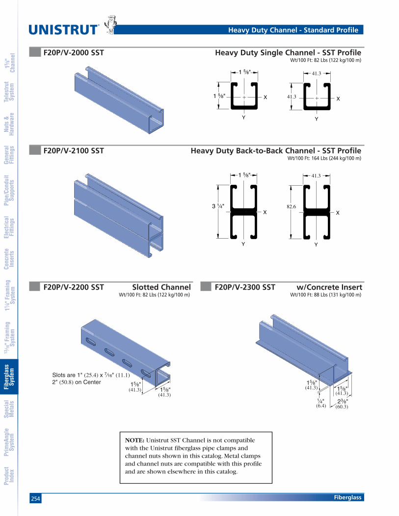
254
15 ⁄8"
Chan
nel
Nuts
&Ha
rdw
are
Gene
ral
Fitti
ngs
Pipe
/Con
duit
Supp
orts
Elec
trica
lFi
tting
sCo
ncre
teIn
serts
11 ⁄4" F
ram
ing
Syst
em13
⁄16" F
ram
ing
Syst
emFi
berg
lass
Syst
emSp
ecia
lM
etal
sTe
lest
rut
Syst
emPr
imeA
ngle
Syst
emPr
oduc
tIn
dex
Fiberglass
®
F20P/V-2000 SST Heavy Duty Single Channel - SST ProfileWt/100 Ft: 82 Lbs (122 kg/100 m)
F20P/V-2100 SST Heavy Duty Back-to-Back Channel - SST ProfileWt/100 Ft: 164 Lbs (244 kg/100 m)
F20P/V-2300 SST w/Concrete InsertWt/100 Ft: 88 Lbs (131 kg/100 m)
F20P/V-2200 SST Slotted ChannelWt/100 Ft: 82 Lbs (122 kg/100 m)
(6.4)
(41.3)(41.3)
(60.3)
15⁄8"
1⁄4"
15⁄8"
23⁄8"
1 5⁄8"
1 5⁄8" X
Y
41.3
41.3 X
Y
1 5⁄8"
3 1⁄4"X
Y
41.3
82.6X
Y
NOTE: Unistrut SST Channel is not compatiblewith the Unistrut fiberglass pipe clamps andchannel nuts shown in this catalog. Metal clampsand channel nuts are compatible with this profileand are shown elsewhere in this catalog.
Heavy Duty Channel - Standard Profile
15⁄8"15⁄8"
(41.3)(41.3)
Slots are 1" (25.4) x 7⁄16" (11.1)2" (50.8) on Center

255
15 ⁄8"
Chan
nel
Nuts
&Ha
rdw
are
Gene
ral
Fitti
ngs
Pipe
/Con
duit
Supp
orts
Elec
trica
lFi
tting
sCo
ncre
teIn
serts
11 ⁄4" F
ram
ing
Syst
em13
⁄16" F
ram
ing
Syst
emFi
berg
lass
Syst
emSp
ecia
lM
etal
sTe
lest
rut
Syst
emPr
imeA
ngle
Syst
emPr
oduc
tIn
dex
Fiberglass
F20P/V-2000 SST Channel Beam/Column Loading
Maximum Uniform Deflection Deflection Uniform LoadBeam Load @ Max. Allowable @ Max. Deflection @ Max. Deflection
(Safety Factor - 3:1) Beam Load = 0.25 In (Lbs) = 0.50 In (Lbs) MaximumSpan Poly Vinyl Poly Vinyl Poly Vinyl Poly Vinyl Column Load
In (mm) Lbs (kg) Lbs(kg) In (mm) In (mm) Lbs(kg) Lbs (kg) Lbs (kg) Lbs (kg) Lbs (kg)12 5,080 6,350 0.04 0.04 — — — — 7,300305 2,304 2,880 1.0 1.0 — — — — 3,311.218 3,390 4,240 0.09 0.10 — — — — 6,740457 1,538 1,923 2.3 2.5 — — — — 3,057.224 2,540 3,180 0.16 0.17 — — — — 5,920610 1,152 1,442 4.1 4.3 — — — — 2,685.330 2,040 2,550 0.24 0.27 — 2,350 — — 4,900762 925 1,157 6.1 6.9 — 1,065.9 — — 2,222.636 1,700 2,130 0.35 0.39 1,220 1,370 — — 3,600914 771 966 8.9 9.9 553.4 621.4 — — 1,632.948 1,270 1,590 0.62 0.69 520 590 1,040 1,170 2,020
1,219 576 721 15.7 17.5 235.9 267.6 471.7 530.7 916.360 1,020 1,280 0.97 1.09 270 310 540 610 520
1,524 463 581 24.6 27.7 122.5 140.6 244.9 276.7 235.972 850 1,070 1.40 1.57 160 180 320 360 NR
1,829 386 485 35.6 39.9 72.6 81.6 145.1 163.3 NR
F20P/V-2100 SST Channel Beam/Column Loading
Maximum Uniform Deflection Deflection Uniform LoadBeam Load @ Max. Allowable @ Max. Deflection @ Max. Deflection
(Safety Factor - 3:1) Beam Load = 0.25 In (Lbs) = 0.50 In (Lbs) MaximumSpan Poly Vinyl Poly Vinyl Poly Vinyl Poly Vinyl Column Load
In (mm) Lbs (kg) Lbs(kg) In (mm) In (mm) Lbs(kg) Lbs (kg) Lbs (kg) Lbs (kg) Lbs (kg)12 1,720 2,150 0.07 0.07 — — — — 3,650
305 780 975 1.8 1.8 — — — — 1,655.618 1,150 1,440 0.15 0.17 — — — — 3,370
457 522 653 3.8 4.3 — — — — 1,528.624 860 1,080 0.27 0.30 810 910 — — 2,960
610 390 490 6.9 7.6 367.4 412.8 — — 1,342.630 690 870 0.42 0.48 410 460 — — 2,450
762 313 395 10.7 12.2 186.0 208.7 — — 1,111.336 580 730 0.61 0.69 240 270 480 540 1,800
914 263 331 15.5 17.5 108.9 122.5 217.7 244.9 816.548 430 540 1.07 1.20 100 115 200 230 1,010
1,219 195 245 27.2 30.5 45.4 52.2 90.7 104.3 458.160 350 440 1.70 1.91 60 70 120 135 260
1,524 159 200 43.2 48.5 27.2 31.8 54.4 61.2 117.972 290 370 2.44 2.78 30 34 60 70 NR
1,829 132 168 62.0 70.6 13.6 15.4 27.2 31.8 NR
Heavy Duty Channel - Standard Profile

256
15 ⁄8"
Chan
nel
Nuts
&Ha
rdw
are
Gene
ral
Fitti
ngs
Pipe
/Con
duit
Supp
orts
Elec
trica
lFi
tting
sCo
ncre
teIn
serts
11 ⁄4" F
ram
ing
Syst
em13
⁄16" F
ram
ing
Syst
emFi
berg
lass
Syst
emSp
ecia
lM
etal
sTe
lest
rut
Syst
emPr
imeA
ngle
Syst
emPr
oduc
tIn
dex
Fiberglass
®
Standard Duty Channel Nuts
Heavy Duty Channel Nuts
Stop-Lock Assemblies
Saddle ClipsSaddle clips mate with the exterior of the channel flanges and are
secured with threaded rods and nuts.
Material: glass-reinforced polyurethane.
Stop-Lock Assemblies reduce the chance of pipe slippage whenrunning supports vertically and are recommended for applicationsthat are subject to vibration, haveregular contact with fluids or arevertically mounted. The Stop-Locks fitboth sizes of channel.
Material: glass-reinforcedpolyurethane.
Heavy duty channel nuts are designed tobe used where high thread shear valuesor spring nuts are required. They cannot be used with light duty 1000 serieschannel or SST profile channel.
Material: glass-reinforced polyurethane.
Standard Duty channel nuts are designed forlight duty applications that do not requirehigh thread shear values. They can beused with both light duty series 1000 andheavy duty series 2000 fiberglass channel.
Not for use with SST profile channel.
Material: glass-reinforced polyurethane.
Hex HeadFlange Bolt
Saddle Clip
Channel Nut
*Thread shear values shown represent a 3:1 safety factor.
Part Thread Shear Torque Wt/100 pcsNumber Size Lbs (kg)* Ft/Lbs (N•m ) Lbs (kg)
F375PU-CNHD 3⁄8"-16 1,400 8 5.7635 11 2.6
F500PU-CNHD 1⁄2"-13 1,400 8 5.3635 11 2.4
F625PU-CNHD 5⁄8"-11 1,400 10 5.1635 14 2.3
F750PU-CNHD 3⁄4"-10 1,400 10 4.4635 14 2.0
F10PU-CNMHD 10 mm 1,400 8 5.8635 11 2.6
F12PU-CNMHD 12 mm 1,400 8 5.5635 11 2.5
F16PU-CNMHD 16 mm 1,400 10 5.3635 14 2.4
F20PU-CNMHD 20 mm 1,400 10 4.4635 14 2.0
Part Size Wt/100 pcsNumber (In.) Lbs (kg)
F200-4226 3⁄8 3.51.6
F200-4217 1⁄2 2.51.1
F200-4341 5⁄8 3.01.4
F200-4342 3⁄4 2.51.1
* Force resistance values shown represents a 3:1 safetyfactor.
** Supplied with a heavy duty channel nut for use onlywith the heavy duty series 2000 channel.
ForcePart Size Resistance Torque Wt/100 pcs
Number (in.) Lbs (kg)* Ft/Lbs (N•m ) Lbs (kg)
F200-4227 3⁄8" 200 7 6.391 9 2.9
F200-4219 1⁄2" 220 12 6.4100 16 2.9
F200-4343 5⁄8"** 250 15 11.0113 20 5.0
*Thread shear values shown represent a 3:1 safety factor.
Fiberglass Channel Nuts & Accessories
Part Thread Shear Torque Wt/100 pcsNumber Size Lbs (kg)* Ft/Lbs (N•m ) Lbs (kg)
F250PU-CN 1⁄4"-20 460 2 1.8209 3 0.8
F312PU-CN 5⁄16"-18 460 2 1.7209 3 0.8
F375PU-CN 3⁄8"-16 460 3 1.8209 4 0.8
F500PU-CN 1⁄2"-13 460 3 1.4209 4 0.6
F10PU-CN 10 mm 460 3 1.7209 4 0.8
F12PU-CN 12 mm 460 3 1.4209 4 0.6
F10PU-CNS #10 Screw 460 N/A 1.9209 0.9

257
15 ⁄8"
Chan
nel
Nuts
&Ha
rdw
are
Gene
ral
Fitti
ngs
Pipe
/Con
duit
Supp
orts
Elec
trica
lFi
tting
sCo
ncre
teIn
serts
11 ⁄4" F
ram
ing
Syst
em13
⁄16" F
ram
ing
Syst
emFi
berg
lass
Syst
emSp
ecia
lM
etal
sTe
lest
rut
Syst
emPr
imeA
ngle
Syst
emPr
oduc
tIn
dex
Fiberglass
Hex BoltsHex Flange Bolts
Hex NutsHex Flange Nuts
ShoulderLength
ShoulderLength
Fiberfast bolts are ideal for mechanicalconnections that require a highdegree of corrosion resistance. The3⁄8" diameter fasteners are recom-mended for all channel fittingmechanical connections.
Material: glass-reinforced polyurethane.
Fiberfast bolts are ideal for mechani-cal connections that require a highdegree of corrosion resistance. The3⁄8" diameter fasteners are recom-mended for all channel fittingmechanical connections.
Material: glass-reinforced polyure-thane.
*Thread shear values shown represent a 3:1 safety factor.
*Thread shear values shown represent a 3:1 safety factor.
Thread Shank ShoulderPart Size Shear Shear Length Torque Wt/100 pcs
Number (in.) Lbs (kg)* Lbs (kg)* In (mm) Ft/Lbs (N•m ) Lbs (kg)
F375PU-125 3⁄8 x 11⁄4 250 470 Full Thread 3 1.0113 213 4 0.5
F375PU-150 3⁄8 x 11⁄2 250 470 1⁄4 3 1.1113 213 6 4 0.5
F375PU-200 3⁄8 x 2 250 470 1⁄2 3 1.3113 213 13 4 0.6
F375PU-250 3⁄8 x 21⁄2 250 470 3⁄4 3 1.6113 213 19 4 0.7
F375PU-300 3⁄8 x 3 250 470 1 3 1.8113 213 25 4 0.8
F625PU-125 5⁄8 x 11⁄4 700 1,360 1⁄4 12 2.5318 617 6 16 1.1
F625PU-150 5⁄8 x 11⁄2 700 1,360 1⁄4 12 2.8318 617 6 16 1.3
F625PU-200 5⁄8 x 2 700 1,360 1⁄4 12 3.2318 617 6 16 1.5
F625PU-250 5⁄8 x 21⁄2 700 1,360 1⁄4 12 3.4318 617 6 16 1.5
F625PU-300 5⁄8 x 3 700 1,360 1⁄4 12 3.9318 617 6 16 1.8
F625PU-350 5⁄8 x 31⁄2 700 1,360 11⁄4 12 5.5318 617 6 16 2.5
*Thread shear values shown represent a 3:1 safety factor. *Thread shear values shown represent a 3:1 safety factor.
ThreadPart Size Shear Height Torque Wt/100 pcs
Number (in.) Lbs (kg)* In (mm) Ft/Lbs (N•m ) Lbs (kg)
F250PU-000 1⁄4-20 150 0.218 0.8 0.168 5.5 1 0.05
F375PU-000 3⁄8-16 460 0.328 3 0.3209 8.3 4 0.1
F500PU-000 1⁄2-13 800 0.437 8 0.5363 11.1 11 0.2
F625PU-000 5⁄8-11 1,000 0.546 12 1.5454 13.9 16 0.7
ThreadPart Size Shear Height Torque Wt/100 pcs
Number (in.) Lbs (kg)* In (mm) Ft/Lbs (N•m ) Lbs (kg)
F375PU-FN-000 3⁄8-16 500 0.750 3 0.8227 19.1 4 0.4
F500PU-FN-000 1⁄2-13 1,200 0.855 8 1.6544 21.7 11 0.7
F625PU-FN-000 5⁄8-11 2,200 1.220 12 3.5998 31.0 16 1.6
F750PU-FN-000 3⁄4-10 2,900 1.590 15 5.51,315 40.4 20 2.5
Fiberglass Hardware
The hex flange nut is preferred for applica-tions that require additional threadengagement (such as with all-thread rod)or maximum thread shear strength.
Material: glass-reinforced polyurethane.
Thread Shank ShoulderPart Size Shear Shear Length Torque Wt/100 pcs
Number (in.) Lbs (kg)* Lbs (kg)* In (mm) Ft/Lbs (N•m ) Lbs (kg)
F250PU-075 1⁄4 x3⁄4 110 210 Full Thread 0.8 .450 95 1 0.2
F250PU-100 1⁄4 x 1 110 210 Full Thread 0.8 .550 95 1 .02
F250PU-150 1⁄4 x 11⁄2 110 210 1⁄2 0.8 .650 95 13 1 0.3
F500PU-125 1⁄2 x 11⁄4 450 870 Full Thread 8 1.0204 395 11 0.5
F500PU-150 1⁄2 x 11⁄2 450 870 Full Thread 8 1.1204 395 11 .05
F500PU-200 1⁄2 x 2 450 870 3⁄4 8 1.3204 395 19 11 0.6
F500PU-250 1⁄2 x 21⁄2 450 870 Full Thread 8 1.6204 395 11 0.7
F500PU-300 1⁄2 x 3 450 870 1 8 1.8204 395 25 11 0.8
F500PU-350 1⁄2 x 31⁄2 450 870 23⁄16 8 2.0204 395 56 11 0.9
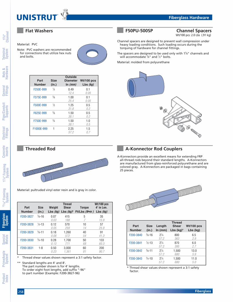
258
15 ⁄8"
Chan
nel
Nuts
&Ha
rdw
are
Gene
ral
Fitti
ngs
Pipe
/Con
duit
Supp
orts
Elec
trica
lFi
tting
sCo
ncre
teIn
serts
11 ⁄4" F
ram
ing
Syst
em13
⁄16" F
ram
ing
Syst
emFi
berg
lass
Syst
emSp
ecia
lM
etal
sTe
lest
rut
Syst
emPr
imeA
ngle
Syst
emPr
oduc
tIn
dex
Fiberglass
®
A-Konnector Rod CouplersThreaded Rod
Flat Washers
Material: PVC
Note: PVC washers are recommendedfor connections that utilize hex nutsand bolts.
Material: pultruded vinyl ester resin and is gray in color.
A-Konnectors provide an excellent means for extending FRPall-thread rods beyond their standard lengths. A-Konnectorsare manufactured from glass-reinforced polyurethane and arecolored gray. A-Konnectors are packaged in bags containing25 pieces.
* Thread shear values shown represent a 3:1 safety factor.
** Standard lengths are 4' and 8'.The part number shown is for 4' lengths.To order eight foot lengths, add suffix “-96”to part number (Example: F200-3827-96)
Thread Wt/100 pcsPart Size Weight Shear Torque 4' in Len.
Number (in.) Lbs (kg) Lbs (kg)* Ft/Lbs (N•m ) Lbs (kg)
F200-3827 3⁄8-16 0.07 415 5 350.03 188 7 15.9
F200-3828 1⁄2-13 0.12 570 10 570.05 259 14 25.9
F200-3829 5⁄8-11 0.18 1,260 40 910.08 572 54 41.3
F200-3830 3⁄4-10 0.28 1,700 50 1330.13 771 68 60.3
F200-3831 1-8 0.50 3,000 60 2000.23 1,361 81 90.7
OutsidePart Size Diameter Wt/100 pcs
Number (in.) In (mm) Lbs (kg)
F250E-999 1⁄4 0.49 0.112.4 0.05
F375E-999 3⁄8 1.00 0.125.4 0.05
F500E-999 1⁄2 1.25 0.531.8 0.2
F625E-999 5⁄8 1.50 0.538.1 0.2
F750E-999 3⁄4 1.50 1.038.1 0.5
F1000E-999 1 2.25 1.557.2 0.7
* Thread shear values shown represent a 3:1 safetyfactor.
ThreadPart Size Length Shear Wt/100 pcs
Number (in.) In (mm) Lbs (kg)* Lbs (kg)
F200-3840 3⁄8-16 21⁄4 800 6.557.2 363 2.9
F200-3841 1⁄2-13 21⁄4 870 6.057.2 395 2.7
F200-3842 5⁄8-11 21⁄4 1,500 13.057.2 680 5.9
F200-3843 3⁄4-10 21⁄4 1,500 11.057.2 680 5.0
F50PU-500SP Channel SpacersWt/100 pcs: 2.0 Lbs (.91 kg)
Channel spacers are designed to prevent wall compression underheavy loading conditions. Such loading occurs during thetorquing of hardware for channel fittings.
The spacers are designed to be used only with 15⁄8" channels andwill accommodate 3⁄8" and 1⁄2" bolts.
Material: molded from polyurethane
Fiberglass Hardware

259
15 ⁄8"
Chan
nel
Nuts
&Ha
rdw
are
Gene
ral
Fitti
ngs
Pipe
/Con
duit
Supp
orts
Elec
trica
lFi
tting
sCo
ncre
teIn
serts
11 ⁄4" F
ram
ing
Syst
em13
⁄16" F
ram
ing
Syst
emFi
berg
lass
Syst
emSp
ecia
lM
etal
sTe
lest
rut
Syst
emPr
imeA
ngle
Syst
emPr
oduc
tIn
dex
Fiberglass
Material: red PVC and designed for 15⁄8" channel.
End caps are desired when the ends of the channelneed to be enclosed. The cap easily installs bypressing it onto the end of the channel opening.
FAIC-EC Channel End CapWt/100 pcs: 3.4 Lbs (1.5 kg)
Supplied in 10foot lengths.
Material: PVC
Installs simply by pressing it onto thechannel opening. It is designed to be usedwhen a cover is desired for the channelopening (such as concrete embedmentchannel).
Nonmetallic U-BoltsUnistrut Nonmetallic U-Bolts provide a corrosion resistant alterna-
tive to traditional metallic U-Bolts. They have oversized diameterswhich allow them to hold steel conduit and plastic pipe. Thesebolts will outlast stainless steel in most corrosive applications.
Each U-Bolt comes with two polyurethane hex nuts. Additional nutsand washers can be purchased separately.
Material: glass-reinforced polyurethane C
B A
TL
D
Fiberglass Hardware and Accessories
F20E-5000 Channel Capping StripWt/100 Ft: 5 Lbs (7.4 kg/100 m)
Part Size “A” Dim. “B” Dim. “C” Dim. “D” Dim. “TL” Dim. Load Torque Wt/100 pcsNumber In In (mm) In (mm) In (mm) In (mm) In (mm) Lbs (kg)* In/Lbs (N•m ) Lbs (kg)
FUB-050 1⁄2 0.937 0.375 1.568 2.412 1.25 135 40 323.8 9.5 39.8 61.3 31.8 61 5 1.4
FUB-075 3⁄4 1.125 0.375 1.662 2.600 1.25 135 40 328.6 9.5 42.2 66.0 31.8 61 5 1.4
FUB-100 1 1.375 0.375 1.787 2.850 1.25 135 40 434.9 9.5 45.4 72.4 31.8 61 5 1.8
FUB-125 11⁄4 1.687 0.375 1.943 3.162 1.25 135 40 442.8 9.5 49.4 80.3 31.8 61 5 1.8
FUB-150 11⁄2 2.000 0.375 2.100 3.475 1.25 135 40 550.8 9.5 53.3 88.3 31.8 61 5 2.3
FUB-200 2 2.437 0.500 2.468 4.187 1.50 135 80 1061.9 12.7 62.7 106.3 38.1 61 9 4.5
FUB-250 21⁄2 2.937 0.500 2.718 4.687 1.50 135 80 1174.6 12.7 69.0 119.0 38.1 61 9 5.0
FUB-300 3 3.562 0.500 3.031 5.312 1.50 135 80 1490.5 12.7 77.0 134.9 38.1 61 9 6.4
FUB-350 31⁄2 4.062 0.500 3.281 5.812 1.50 135 80 15103.2 12.7 83.3 147.6 38.1 61 9 6.8
FUB-400 4 4.562 0.500 3.531 6.312 1.50 135 80 16115.9 12.7 89.7 160.3 38.1 61 9 7.3
FUB-600 6 6.750 0.625 5.750 9.875 3.25 135 120 17171.5 15.9 146.1 250.8 82.6 61 14 7.7
*Torque and load values shown represent a 3:1 safety factor.
Note: Plate not included.Illustration purpose only

260 Fiberglass
Standard Dimensions for 15⁄8" (41 mm) width series channel fittings (Unless Otherwise Shown on Drawing)
Hole Diameter: 13⁄32" (10.3 mm) , Accommodates 3⁄8" hardware; Hole Spacing - On Center: 15⁄8" (41 mm); Width: 15⁄8"(41mm); Thickness: 3⁄8" (9.5mm)
®
15 ⁄8"
Chan
nel
Nuts
&Ha
rdw
are
Gene
ral
Fitti
ngs
Pipe
/Con
duit
Supp
orts
Elec
trica
lFi
tting
sCo
ncre
teIn
serts
11 ⁄4" F
ram
ing
Syst
em13
⁄16" F
ram
ing
Syst
emFi
berg
lass
Syst
emSp
ecia
lM
etal
sTe
lest
rut
Syst
emPr
imeA
ngle
Syst
emPr
oduc
tIn
dex
F20P-2502, F20V-2502F20P-2500, F20V-2500
Channel Fittings
Wt/100 pcs: 17 Lbs (7.7 kg)
F20P-2506, F20V-2506 Wt/100 pcs: 32 Lbs (14.5 kg)F20P-2504, F20V-2504 Wt/100 pcs: 24 Lbs (10.9 kg)
Wt/100 pcs: 12 Lbs (5.4 kg)
31⁄4"(82.6)
47⁄8"(123.8)
61⁄2"(165.1) 81⁄8"
(206.4)
Channel Fittings are required to fabricate structures and are easilyattached to Channels with channel nuts and polyurethanefasteners. The fittings are offered in two types; fabricated (cutfrom flat stock) or molded.
Material (Fabricated Fittings): Either polyester (P Series) orvinyl ester (V Series) material.
Material (Molded Fittings): All molded fittings with the exceptionof the post bases are molded in polyurethane.
Note: The drawings for all fittings are shown with the patentedflange profile, however they can be used with either channelprofile.
Flat Fiberglass Fittings
PatentedFlange
SSTFlange
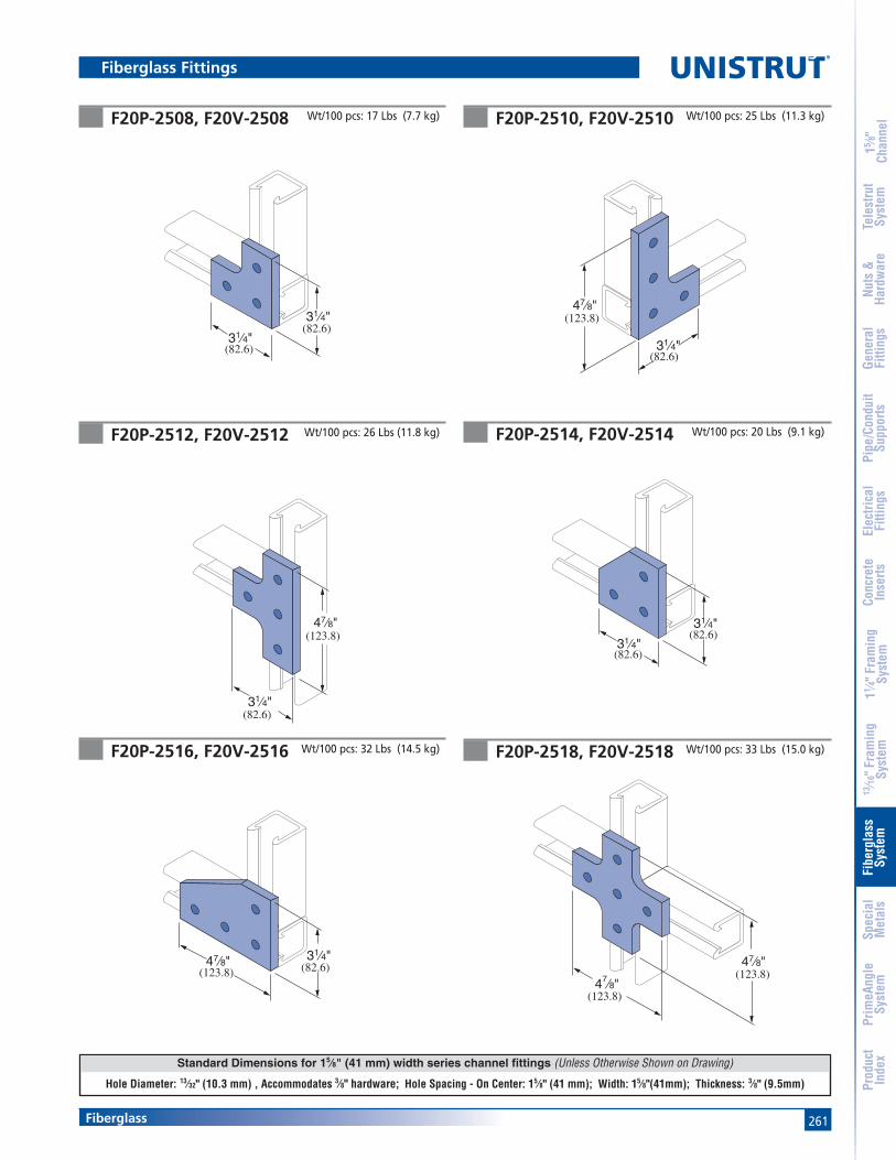
261Fiberglass
Standard Dimensions for 15⁄8" (41 mm) width series channel fittings (Unless Otherwise Shown on Drawing)
Hole Diameter: 13⁄32" (10.3 mm) , Accommodates 3⁄8" hardware; Hole Spacing - On Center: 15⁄8" (41 mm); Width: 15⁄8"(41mm); Thickness: 3⁄8" (9.5mm)
15 ⁄8"
Chan
nel
Nuts
&Ha
rdw
are
Gene
ral
Fitti
ngs
Pipe
/Con
duit
Supp
orts
Elec
trica
lFi
tting
sCo
ncre
teIn
serts
11 ⁄4" F
ram
ing
Syst
em13
⁄16" F
ram
ing
Syst
emFi
berg
lass
Syst
emSp
ecia
lM
etal
sTe
lest
rut
Syst
emPr
imeA
ngle
Syst
emPr
oduc
tIn
dex
F20P-2518, F20V-2518 Wt/100 pcs: 33 Lbs (15.0 kg)
47⁄8"
47⁄8"(123.8)
(123.8)
F20P-2512, F20V-2512
F20P-2510, F20V-2510F20P-2508, F20V-2508
Wt/100 pcs: 26 Lbs (11.8 kg)
Wt/100 pcs: 17 Lbs (7.7 kg)
F20P-2516, F20V-2516 Wt/100 pcs: 32 Lbs (14.5 kg)
F20P-2514, F20V-2514 Wt/100 pcs: 20 Lbs (9.1 kg)
Wt/100 pcs: 25 Lbs (11.3 kg)
31⁄4"
31⁄4"(82.6)
(82.6)
47⁄8"
31⁄4"(82.6)
(123.8)
47⁄8"
31⁄4"
(123.8)
(82.6)
31⁄4"
31⁄4"(82.6)
(82.6)
31⁄4"47⁄8" (82.6)(123.8)
Flat Fiberglass Fittings Fiberglass Fittings

262 Fiberglass
Standard Dimensions for 15⁄8" (41 mm) width series channel fittings (Unless Otherwise Shown on Drawing)
Hole Diameter: 13⁄32" (10.3 mm) , Accommodates 3⁄8" hardware; Hole Spacing - On Center: 15⁄8" (41 mm); Width: 15⁄8"(41mm); Thickness: 3⁄8" (9.5mm)
®
15 ⁄8"
Chan
nel
Nuts
&Ha
rdw
are
Gene
ral
Fitti
ngs
Pipe
/Con
duit
Supp
orts
Elec
trica
lFi
tting
sCo
ncre
teIn
serts
11 ⁄4" F
ram
ing
Syst
em13
⁄16" F
ram
ing
Syst
emFi
berg
lass
Syst
emSp
ecia
lM
etal
sTe
lest
rut
Syst
emPr
imeA
ngle
Syst
emPr
oduc
tIn
dex
F20P-2524, F20V-2524
F20P-2522, F20V-2522F20P-2520, F20V-2520
Wt/100 pcs: 32 Lbs (14.5 kg)
Wt/100 pcs: 45 Lbs (20.4 kg)
F20P-2528, F20V-2528 Wt/100 pcs: 20 Lbs (9.1 kg)
F20P-2526, F20V-2526 Wt/100 pcs: 45 Lbs (20.4 kg)
Wt/100 pcs: 21 Lbs (9.5 kg)
31⁄4"
31⁄4"(82.6)
(82.6)
31⁄4"
47⁄8"(123.8)
(82.6)
47⁄8"
47⁄8"
(149.2)
(149.2)
51⁄4"
35⁄8"(92.1)
(133.4)
47⁄8"
47⁄8"
(123.8)
(123.8)
F20P-2530, F20V-2530 Wt/100 pcs: 50 Lbs (22.7 kg)
81⁄8"
31⁄4"(136.5)
(206.4)
Fiberglass Fittings

263Fiberglass
Standard Dimensions for 15⁄8" (41 mm) width series channel fittings (Unless Otherwise Shown on Drawing)
Hole Diameter: 13⁄32" (10.3 mm) , Accommodates 3⁄8" hardware; Hole Spacing - On Center: 15⁄8" (41 mm); Width: 15⁄8"(41mm); Thickness: 3⁄8" (9.5mm)
15 ⁄8"
Chan
nel
Nuts
&Ha
rdw
are
Gene
ral
Fitti
ngs
Pipe
/Con
duit
Supp
orts
Elec
trica
lFi
tting
sCo
ncre
teIn
serts
11 ⁄4" F
ram
ing
Syst
em13
⁄16" F
ram
ing
Syst
emFi
berg
lass
Syst
emSp
ecia
lM
etal
sTe
lest
rut
Syst
emPr
imeA
ngle
Syst
emPr
oduc
tIn
dex
47⁄8"
47⁄8"
(123.8)
(123.8)
F50PU-2611F50PU-2538
F20P-2540, F20V-2540F20P-2534, F20V-2534 Wt/100 pcs: 77 Lbs (34.9 kg)
Wt/100 pcs: 9 Lbs (4.1 kg)
Wt/100 pcs: 41 Lbs (18.6 kg)
F50PU-1508 (11⁄2"), F50PU-2008 (15⁄8")Wt/100 pcs: 27 Lbs (12.2 kg)
F50PU-2613 Wt/100 pcs: 16 Lbs (7.3 kg)
81⁄8"
47⁄8"
(206.4)
(123.8)
4"
5"15⁄8"(127.0)
(41.3)
(101.6)
51⁄4"
51⁄4"
45° (133.4)
(133.4)
17⁄8"
31⁄2"(88.9)
(47.6)
17⁄8"
513⁄32"
25⁄32"
(137.3)
(47.6)
(54.8)
Fiberglass Fittings
Wt/100 pcs: 57 Lbs (26.0 kg)
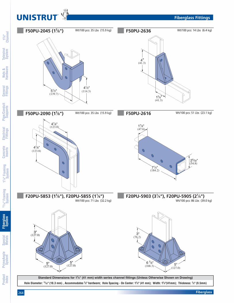
264 Fiberglass
Standard Dimensions for 15⁄8" (41 mm) width series channel fittings (Unless Otherwise Shown on Drawing)
Hole Diameter: 13⁄32" (10.3 mm) , Accommodates 3⁄8" hardware; Hole Spacing - On Center: 15⁄8" (41 mm); Width: 15⁄8"(41mm); Thickness: 3⁄8" (9.5mm)
®
15 ⁄8"
Chan
nel
Nuts
&Ha
rdw
are
Gene
ral
Fitti
ngs
Pipe
/Con
duit
Supp
orts
Elec
trica
lFi
tting
sCo
ncre
teIn
serts
11 ⁄4" F
ram
ing
Syst
em13
⁄16" F
ram
ing
Syst
emFi
berg
lass
Syst
emSp
ecia
lM
etal
sTe
lest
rut
Syst
emPr
imeA
ngle
Syst
emPr
oduc
tIn
dex
F50PU-2090 (15⁄8")
F50PU-2636F50PU-2045 (15⁄8") Wt/100 pcs: 35 Lbs (15.9 kg) Wt/100 pcs: 14 Lbs (6.4 kg)
F20PU-5903 (31⁄4"), F20PU-5905 (21⁄4")Wt/100 pcs: 86 Lbs (39.0 kg)
F20PU-5853 (15⁄8"), F20PU-5855 (11⁄8")Wt/100 pcs: 71 Lbs (32.2 kg)
Wt/100 pcs: 35 Lbs (15.9 kg)
4"
15⁄8"(41.3)
(41.3)
47⁄8"
47⁄8"
(123.8)
(123.8)
3"
5" 5"(127.0)
(127.0)
(127.0)
3"
5"6 5⁄8"(127.0)
(168.3)
(76.2)
41⁄2"51⁄2"
(139.7)(114.3)
F50PU-2616 Wt/100 pcs: 51 Lbs (23.1 kg)
17⁄8"
71⁄4"
25⁄32"
(47.6)
(54.8)
(184.2)
Fiberglass Fittings
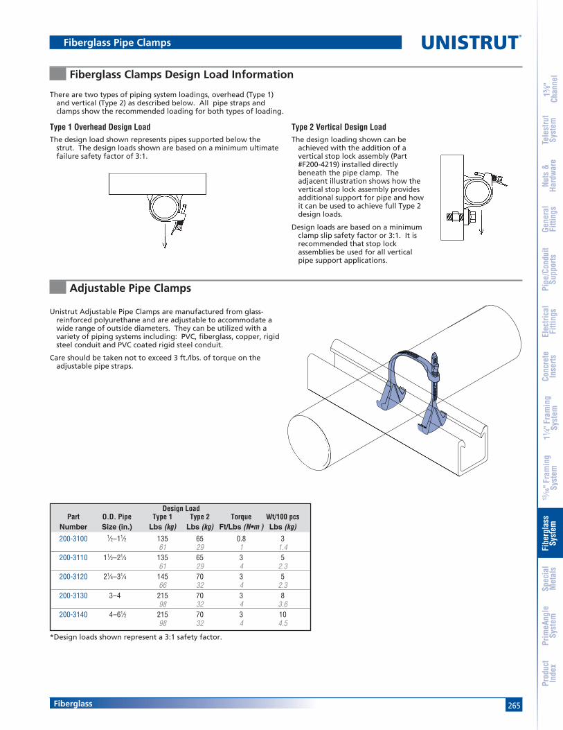
265
15 ⁄8"
Chan
nel
Nuts
&Ha
rdw
are
Gene
ral
Fitti
ngs
Pipe
/Con
duit
Supp
orts
Elec
trica
lFi
tting
sCo
ncre
teIn
serts
11 ⁄4" F
ram
ing
Syst
em13
⁄16" F
ram
ing
Syst
emFi
berg
lass
Syst
emSp
ecia
lM
etal
sTe
lest
rut
Syst
emPr
imeA
ngle
Syst
emPr
oduc
tIn
dex
Fiberglass
Adjustable Pipe Clamps
Fiberglass Clamps Design Load Information
Type 2 Vertical Design LoadThe design loading shown can be
achieved with the addition of avertical stop lock assembly (Part#F200-4219) installed directlybeneath the pipe clamp. Theadjacent illustration shows how thevertical stop lock assembly providesadditional support for pipe and howit can be used to achieve full Type 2design loads.
Design loads are based on a minimumclamp slip safety factor or 3:1. It isrecommended that stop lockassemblies be used for all verticalpipe support applications.
There are two types of piping system loadings, overhead (Type 1)and vertical (Type 2) as described below. All pipe straps andclamps show the recommended loading for both types of loading.
Unistrut Adjustable Pipe Clamps are manufactured from glass-reinforced polyurethane and are adjustable to accommodate awide range of outside diameters. They can be utilized with avariety of piping systems including: PVC, fiberglass, copper, rigidsteel conduit and PVC coated rigid steel conduit.
Care should be taken not to exceed 3 ft./lbs. of torque on theadjustable pipe straps.
*Design loads shown represent a 3:1 safety factor.
Design LoadPart O.D. Pipe Type 1 Type 2 Torque Wt/100 pcs
Number Size (in.) Lbs (kg) Lbs (kg) Ft/Lbs (N•m ) Lbs (kg)
200-3100 1⁄2–11⁄2 135 65 0.8 361 29 1 1.4
200-3110 11⁄2–21⁄4 135 65 3 561 29 4 2.3
200-3120 21⁄4–31⁄4 145 70 3 566 32 4 2.3
200-3130 3–4 215 70 3 898 32 4 3.6
200-3140 4–61⁄2 215 70 3 1098 32 4 4.5
Fiberglass Pipe Clamps
Type 1 Overhead Design LoadThe design load shown represents pipes supported below the
strut. The design loads shown are based on a minimum ultimatefailure safety factor of 3:1.

266
15 ⁄8"
Chan
nel
Nuts
&Ha
rdw
are
Gene
ral
Fitti
ngs
Pipe
/Con
duit
Supp
orts
Elec
trica
lFi
tting
sCo
ncre
teIn
serts
11 ⁄4" F
ram
ing
Syst
em13
⁄16" F
ram
ing
Syst
emFi
berg
lass
Syst
emSp
ecia
lM
etal
sTe
lest
rut
Syst
emPr
imeA
ngle
Syst
emPr
oduc
tIn
dex
Fiberglass
®
Two Hole Pipe Straps
Rigid Pipe Clamps
Rigid Pipe Clamps resemble the moretraditional style of pipe clamps and aresized based on the pipe inside diameteror nominal size.
Polyurethane clamps are recommendedfor applications up to 160°F. For hightemperature applications (up to 230°F).
Care should be taken not to exceed therecommended torque values of therigid pipe clamps.
Material: glass-reinforced polyurethane.
Two Hole Pipe Straps are designed for use insecuring pipe, conduit and ducts to Channel.Two hole fiberglass straps can also be usedindependently from the channel for surfacemounting. All sizes of the straps are suitable forload bearing applications.
Material: fire-retardant, glass-reinforced polyesterresin.
For extreme chemical environments, the straps canbe manufactured from vinyl ester resin. Largerdiameter straps for special applications are alsoavailable. Contact the factory for pricing andavailability of vinyl ester and large diameterstraps. Two hole pipe straps should not betorqued above recommended values.
AB
*Design loads shown represent a 3:1 safety factor.
*Design loads shown represent a 3:1 safety factor.
Bolt Material Design LoadPart Dim. A Dim. B Size Thick. Type 1 Type2 Torque Wt/100 pcsNo. In (mm) In (mm) (in.) In (mm) Lbs (kg) Lbs (kg) Ft/Lbs (N•m ) Lbs (kg)
FPS200 2.375 6.375 1⁄2 1⁄4 135 50 4 1460.33 161.93 6.4 61 23 5 6.4
FPS250 2.875 6.875 1⁄2 1⁄4 135 50 4 1773.03 174.63 6.4 61 23 5 7.7
FPS300 3.500 7.500 1⁄2 1⁄4 135 50 4 2088.90 190.50 6.4 61 23 5 9.1
FPS350 4.000 8.000 1⁄2 1⁄4 135 50 4 33101.60 203.20 6.4 61 23 5 15.0
FPS400 4.500 8.500 1⁄2 1⁄4 175 60 4 23114.30 215.90 6.4 79 27 5 10.4
FPS500 5.563 9.563 1⁄2 1⁄4 175 60 4 39141.30 242.90 6.4 79 27 5 17.7
FPS600 6.625 10.625 1⁄2 1⁄4 175 60 4 39168.28 269.88 6.4 79 27 5 17.7
FPS800 8.625 12.625 1⁄2 1⁄4 225 125 4 51219.08 320.68 6.4 102 57 5 23.1
FPS1000 10.750 15.750 5⁄8 1⁄4 225 125 10 77273.05 400.05 6.4 102 57 14 34.9
FPS1200 12.750 16.250 5⁄8 1⁄4 225 125 10 83323.85 412.75 6.4 102 57 14 37.6
FPS1400 14.000 18.000 5⁄8 3⁄8 250 150 10 125355.60 457.20 9.5 113 68 14 56.7
FPS1600 16.000 20.000 5⁄8 3⁄8 250 150 10 143406.40 508.00 9.5 113 68 14 64.9
FPS1800 18.000 23.000 5⁄8 3⁄8 250 150 10 160457.20 584.20 9.5 113 68 14 72.6
PVC, Sch. 80 Design Loads* FRP BoltPart Nominal & Rigid Metal Type 1 Type 2 FRP Bolt Torque Wt/100 pcs
Number Size (in.) In (mm) Lbs (kg) Lbs (kg) Size (in.) Ft/Lbs (N•m ) Lbs (kg)
FPCR-050 1⁄2 0.840 225 90 3⁄8 x 11⁄4 3 321.336 102 41 4 1.4
FPCR-075 3⁄4 1.050 225 90 3⁄8 x 11⁄4 3 326.67 102 41 4 1.4
FPCR-100 1 1.315 225 90 3⁄8 x 11⁄4 3 433.401 102 41 4 1.8
FPCR-125 11⁄4 1.660 225 90 3⁄8 x 11⁄4 3 542.164 102 41 4 2.3
FPCR-150 11⁄2 1.900 225 90 3⁄8 x 11⁄4 3 548.26 102 41 4 2.3
FPCR-200 2 2.375 225 90 3⁄8 x 11⁄4 3 560.325 102 41 4 2.3
FPCR-250 21⁄2 2.875 225 90 3⁄8 x 11⁄4 3 773.025 102 41 4 3.2
FPCR-300 3 3.500 225 90 3⁄8 x 11⁄4 3 1088.9 102 41 4 4.5
FPCR-400 4 4.500 300 125 3⁄8 x 11⁄4 3 12114.3 136 57 4 5.4
FPCR-600 6 6.625 300 125 3⁄8 x 11⁄4 3 15168.275 136 57 4 6.8
FPCR-800 8 8.625 300 125 3⁄8 x 11⁄4 3 18219.075 136 57 4 8.2
Fiberglass Pipe Clamps
Notes:(1) Bolts and channel nuts are sold separately.(2) When bolting onto 15⁄8" channel a 11⁄4" long bolt is req'd.

267
15 ⁄8"
Chan
nel
Nuts
&Ha
rdw
are
Gene
ral
Fitti
ngs
Pipe
/Con
duit
Supp
orts
Elec
trica
lFi
tting
sCo
ncre
teIn
serts
11 ⁄4" F
ram
ing
Syst
em13
⁄16" F
ram
ing
Syst
emFi
berg
lass
Syst
emSp
ecia
lM
etal
sTe
lest
rut
Syst
emPr
imeA
ngle
Syst
emPr
oduc
tIn
dex
Fiberglass
F200-4101 Unisert Channel InsertWt/100 pcs: 1.0 Lbs (.5 kg)
Unisert is a polyurethane nonmetallic insert which can be used withstandard cable ties for securing tubing, conduit and cables tostandard metal channels.
The Unisert works with all 15⁄8" channels that are 13⁄16" deep ormore. One size fits 12, 14 and 16 metal gauge channels.
Note: For use only with metallic channel.
H
H1
W
T
A
B
C
C
Fabricated Clevis Hangers
Molded Clevis Hangers
Material: glass-reinforced polyurethane.
Material: glass-reinforcedpolyester resin.
*Design load values shown represent a 3:1 safety factor.
*Design load values shownrepresent a 3:1 safety factor.
Nominal Max. HangerPart Diameter Pipe O.D. “A” Dim. “B” Dim. “C” Dim. Rod Load* Wt/100 pcs
Number In (mm) In (mm) In (mm) In (mm) In (mm) In (mm) Lbs (kg) Lbs (kg)
FCVHPU-100 1⁄2 - 1 1 1.500 4.25 1.25 1⁄2 670 2912.7 - 25.4 25.4 38.1 108.0 31.8 12.7 304 13.2
FCVHPU-150 11⁄4- 11⁄2 11⁄2 2.000 5.14 1.25 1⁄2 670 4031.8 - 38.1 38.1 50.8 130.6 31.8 12.7 304 18.1
FCVHPU-200 11⁄2 - 2 2 2.500 6.52 1.25 1⁄2 730 4338.1 - 50.8 50.8 63.5 165.6 31.8 12.7 331 19.5
FCVHPU-400 21⁄2 - 4 4 5.125 10.00 1.50 1⁄2 1,150 12963.5 - 101.6 101.6 130.2 254.0 38.1 12.7 522 58.5
FCVHPU-600 41⁄2 - 6 6 6.750 12.33 1.50 1⁄2 1,170 168114.3 - 152.4 152.4 171.5 313.2 38.1 12.7 531 76.2
Size Range Hanger Trans SpreaderPart In (mm) ....... Dimensions - In (mm) ..... Rod Rod Rod O.D. Loads* Wt/100 pcs
Number A T H H1 W In (mm) In (mm) In (mm) Lbs (kg) Lbs (kg)
F100-1500 1–11⁄2 1⁄8 23⁄4 17⁄8 1 1⁄2 1⁄2 3⁄8 1⁄2 60 2125–38 3 70 48 38 13 10 13 27 9.5
F100-1501 11⁄2–2 1⁄8 31⁄2 23⁄8 1 1⁄2 1⁄2 3⁄8 1⁄2 60 2538–51 3 89 60 38 13 10 13 27 11.3
F100-1502 2–25⁄8 1⁄8 43⁄4 3 2 1⁄2 3⁄8 1⁄2 90 5551–67 3 121 76 51 13 10 13 41 24.9
F100-1503 21⁄2–31⁄4 1⁄8 51⁄2 35⁄8 2 1⁄2 3⁄8 1⁄2 120 5764–83 3 140 92 51 13 10 13 54 25.9
F100-1504 3–37⁄8 1⁄8 7 41⁄4 2 5⁄8 3⁄8 1⁄2 160 6176–98 3 178 108 51 16 10 13 73 27.7
F100-1505 4–51⁄8 13⁄16 81⁄2 55⁄8 2 5⁄8 3⁄8 1⁄2 250 82102–130 21 216 143 51 16 10 13 113 37.2
F100-1506 6–71⁄8 13⁄16 107⁄8 71⁄2 3 5⁄8 3⁄8 1⁄2 300 136152–181 21 276 191 76 16 10 13 136 61.7
F100-1507 8–91⁄4 1⁄4 14 93⁄4 3 5⁄8 3⁄8 1⁄2 350 189203–235 6 356 248 76 16 10 13 159 85.7
F100-1508 10–113⁄8 1⁄4 18 12 4 5⁄8 1⁄2 3⁄4 450 333254–289 6 457 305 102 16 13 19 204 151.0
F100-1509 12–131⁄2 1⁄4 211⁄2 141⁄8 5 5⁄8 1⁄2 3⁄4 600 350305–343 6 546 359 127 16 13 19 272 158.8
F100-1510 14–153⁄4 1⁄4 241⁄2 161⁄2 5 3⁄4 1⁄2 3⁄4 700 872356–400 6 622 419 127 19 13 19 318 395.5
F100-1511 16–18 3⁄8 273⁄8 191⁄2 6 3⁄4 3⁄4 1 750 1,023406–457 10 695 495 152 19 19 25 340 464.0
F100-1512 19–21 3⁄8 341⁄2 221⁄2 6 3⁄4 3⁄4 1 800 1,673483–533 10 876 572 152 19 19 25 363 758.9
F100-1513 21–22 1⁄2 351⁄2 24 6 3⁄4 3⁄4 1 850 2,323533-559 13 902 610 152 19 19 25 386 1,053.7
F100-1514 22–24 1⁄2 41 28 6 3⁄4 3⁄4 1 900 2,973533-610 13 1,041 711 152 19 19 25 408 1,348.5
Fiberglass Clevis Hangers

268
15 ⁄8"
Chan
nel
Nuts
&Ha
rdw
are
Gene
ral
Fitti
ngs
Pipe
/Con
duit
Supp
orts
Elec
trica
lFi
tting
sCo
ncre
teIn
serts
11 ⁄4" F
ram
ing
Syst
em13
⁄16" F
ram
ing
Syst
emFi
berg
lass
Syst
emSp
ecia
lM
etal
sTe
lest
rut
Syst
emPr
imeA
ngle
Syst
emPr
oduc
tIn
dex
Fiberglass
®
Material: glass-reinforced polyurethane.
25⁄8"(66.7)
3"(76.2)
3⁄4"(19.0)
F375PU & F500PU Molded Beam Clamps FRGBC Molded Beam Clamp AssemblyMaterial: glass-reinforced
polyurethane
Power-Rack StanchionsThe Power-Rack Stanchion is made entirely from glass-reinforcednylon, these stanchions offer greater corrosion resistance thanclassical metal stanchions. The interlocking design allows thearm to “lock” into nine different levels on the 141⁄4" stanchionsand fourteen on the 171⁄2" stanchion. Glass-reinforced polyure-thane stanchions are available as a special order. ContactUnistrut for pricing and availability.
Dimensions – The stanchion back has 9⁄16" x 15⁄16" holes toaccept fasteners for mounting. There are two mounting holes inthe 213⁄8" long stanchion and three in the 335⁄16" long stanchion.Thickness at the slotted mounting holes is 17⁄8". The mountingholes are spaced on 12" centers and require 1⁄2" diameterfasteners.
Installation – The Stanchions can be anchored into existingconcrete structures using any industrial anchoring system. Fornew concrete structures, the Stanchions can be mounted tofiberglass concrete embedment channel and attached with 1⁄2"channel nuts and 1⁄2"x 3" Fiberfast Bolts.
Fire Retardance – Power-Rack materials meet or exceed therequirements of UL94 HB.
Loading – The recommended allowable loads on Power-RackStanchions vary depending upon the position of the arm. Usethese guidelines for a safe, reliable installation:
• Total load on any one arm should not exceed 800 lbs.
• The sum of the loads on an arm multiplied by their distancesto the wall stanchion should not exceed 1200 in./lbs.
Example: A cable weighing 200 lbs. is positioned on an arm ata distance of 5" from the wall stanchion.
If the total load is less than 800 lbs and the sum of the loadmultiplied by their distances to the wall stanchion does notexceed 1200 in./lbs., then the system is adequate. In this case,
Total load (200<800 lbs) = OKTot. moment (200x5 in. = 1000<1200 in./lbs.) = OK
Fiberglass Beam Clamps, Power-Rack Stanchions
*Design load values shown represent a 3:1 safety factor. *Design load values shown represent a 3:1 safety factor.
Assembly ThreadPart Size Shear Torque Wt/100 pcs
Number In Lbs (kg)* Ft/Lbs (N•m ) Lbs (kg)
F375PU-BC 3⁄8 400 10 30181 14 13.6
F500PU-BC 1⁄2 400 10 30181 14 13.6
ThreadPart Size Shear Torque Wt/100 pcs
Number In Lbs (kg)* Ft/Lbs (N•m ) Lbs (kg)
FRGBC-1 3⁄8 500 10 43227 14 19.5
FRGBC-2 1⁄2 500 10 43227 14 19.5
FRGBC-3 5⁄8 500 10 43227 14 19.5
F375PU-BCCLP (3⁄8")Beam Clip Only
*Design load values shown represent a 3:1 safety factor.
Size Wt/100 pcs Load (lbs.)*Part No. Description In (mm) Lbs (kg) Lbs (kg)
F20N-ARM08 Arm 8 100 800203 45.4 363
F20N-ARM14 Arm 141⁄4 116 800362 52.6 363
F20N-ARM17 Arm 171⁄2 145 800445 65.8 363
F20N-ARM23 Arm 23 7⁄8 186 800606 84.4 363
F20N-STA21 Stanchion 213⁄8 149 N/A543 67.6
F20N-STA33 Stanchion 335⁄16 231 N/A846 104.8
Note: Beam clamp clip mustbe purchased separately.Illustration purpose only
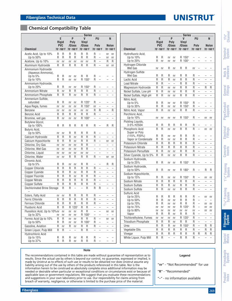
269
15 ⁄8"
Chan
nel
Nuts
&Ha
rdw
are
Gene
ral
Fitti
ngs
Pipe
/Con
duit
Supp
orts
Elec
trica
lFi
tting
sCo
ncre
teIn
serts
11 ⁄4" F
ram
ing
Syst
em13
⁄16" F
ram
ing
Syst
emFi
berg
lass
Syst
emSp
ecia
lM
etal
sTe
lest
rut
Syst
emPr
imeA
ngle
Syst
emPr
oduc
tIn
dex
Fiberglass
Chemical Compatibility Table
Fiberglass Technical Data
...................... Series .....................E P V PU N
Rigid Poly VinylPVC /Glass /Glass Poly Nylon
Chemical 70°-160°F 70°-160°F 70°-160°F 70°-160°F 70°-160°F
Hydrofluoric Acid,Up to 10% R R nr nr R 150° – – – –Up to 20% R nr nr nr R 100° – – – –
Hydrogen ChlorideWet Gas nr nr R nr R R nr – – –
Hydrogen SulfideWet Gas R R R nr R R R – – –
Lactic Acid R R R nr R R R – – –Lead Nitrate R R – – R R R – – –Magnesium Hydroxide R R nr nr R R R – R RNickel Sulfate, Low pH R R nr nr R R R – – –Nickel Sulfate, High pH R R nr nr R R R – – –Nitric Acid,
Up to 5% R R nr nr R 150° R – – –Up to 35% R R nr nr R 150° R – – –
Nitric Acid, Vapor R R nr nr R R R – – –Perchloric Acid,
Up to 10% nr nr nr nr R 150° R – nr nrPickling Liquids,
3-5% H2S04 R R R R R R R – – –Phosphoric Acid R R nr nr R R R – nr nr
Super or Poly(115%, P20%) R R nr nr R R R – – –Vapor or Condensate R R nr nr R R R – – –
Potassium Chloride R R R R R R R – – –Potassium Nitrate R R R R R R R – – –Potassium Persulfate R R nr nr R R R – – –Silver Cyanide, Up to 5% R R nr nr R R R – – –Sodium Hydroxide,
Up to 25% R R nr nr R 150° R – – –Sodium Hydroxide,
Up to 50% R R nr nr R 180° R – R RSodium Hypochlorite,
Up to 15% R R nr nr R 150° R – nr nrSodium Nitrate R R R R R R R – – –Sodium Sulfate R R R nr R R R – – –Sodium Sulfide R R nr nr R R R – – –Sulfuric Acid
Up to 25% R R R R R R R – nr nrUp to 50% R R nr nr R R R – – –Up to 70% R R nr nr R R R – nr nrUp to 75% nr nr nr nr R 120° R – nr nrUp to 80% nr nr nr nr nr nr nr – nr nrVapor R R R nr R R R – – –
Trichlorethylene, Fumes nr nr nr nr R 120° R – – –Trisodium Phosphate R R R nr R R R – – –Urea R R R nr R 150° R – R RVegetable Oils R R R R R R R – R RVinegar R R R R R R R R R RWhite Liquor, Pulp Mill R R – – R R R – – –
...................... Series .....................E P V PU N
Rigid Poly VinylPVC /Glass /Glass Poly Nylon
Chemical 70°-160°F 70°-160°F 70°-160°F 70°-160°F 70°-160°F
Acetic Acid, Up to 10% R R R R R R R – nr nrUp to 50% R R R R R R R – nr nr
Acetone, Up to 10% nr nr nr nr nr nr R – R RAluminum Hydroxide R R R R R R R – nr nrAmmonium Hydroxide
(Aqueous Ammonia),Up to 5% R R nr nr R R R – – –Up to 10% R R nr nr R 150° R – – –
Ammonium Hydroxide,Up to 20% R R nr nr R 150° R – – –
Ammonium Nitrate R nr R R R R R – – –Ammonium Phosphate R R R nr R R R – – –Ammenium Sulfide,
saturated R R nr nr R 120° R – – –Aqua Regia, fumes nr nr nr nr R 150° nr – – –Benzene nr nr nr nr nr nr R R – RBenzoic Acid R R R R R R R – – –Bromine, wet gas R nr nr nr R 100° – – – –Butylene Glycol,
Up to 100% R R R R R R R – R RButyric Acid,
Up to 50% nr nr R R R R R – – –Calcium Hydroxide R R R nr R R R – – –Calcium Hypochlorite R R R nr R R R – nr nrChlorine, Dry Gas nr nr nr nr R R – – – –Chlorine, Wet Gas nr nr nr nr R R – – – –Chlorine, Liquid nr nr nr nr nr nr – – – –Chlorine, Water nr nr R R R R R – nr nrChromic Acid,
Up to 5% R R nr nr R R – – R RCopper Chloride R R R R R R R – – –Copper Cyanide R R R nr R R R – – –Copper Fluoride R R R nr R R R – – –Copper Nitrate R R R R R R R – –Copper Sulfate R R R R R R R – – –Dechlorinated Brine Storage R R – – R R R – –
–Esters, Fatty Acid nr nr R R R R R – – –Ferric Chloride R R R R R R R – – –Ferrous Chloride R R R R R R R – – –Fluoboric Acid R R R 120° R R – – – –Fluosilicic Acid, Up to 10%nr nr nr nr R R – – nr nr
Up to 32% nr nr nr nr R 100° – – – –Formic Acid Up to 10% R R nr nr R R R – nr nr
Up to 50% R R nr nr R 100° R – – –Gasoline, Aviation R nr R nr R R R – – –Green Liquor, Pulp Mill R R – – R R – – – –Hydrochloric Acid
Up to 15% R R R nr R R R – – –Up to 37% R R R nr R R R – – –
Note
The recommendations contained in this table are made without guarantee of representation as toresults. Since the actual use by others is beyond our control, no guarantee, expressed or implied, ismade by Unistrut as to effects of such use or results to be obtained nor does Unistrut assume anyliability arising out of the use by others of the products referenced in this table. Nor is theinformation herein to be construed as absolutely complete since additional information may beneeded or desirable when particular or exceptional conditions or circumstances exist or because ofapplicable laws or government regulations. We suggest that you evaluate these recommendationsand suggestions in your own laboratory prior to use. Our responsibility for claims arising frombreach of warranty, negligence, or otherwise is limited to the purchase price of the material.
Legend
“nr“ - “Not Recommended” for use
“R“ - “Recommended”
“–“ - no information available

270
15 ⁄8"
Chan
nel
Nuts
&Ha
rdw
are
Gene
ral
Fitti
ngs
Pipe
/Con
duit
Supp
orts
Elec
trica
lFi
tting
sCo
ncre
teIn
serts
11 ⁄4" F
ram
ing
Syst
em13
⁄16" F
ram
ing
Syst
emFi
berg
lass
Syst
emSp
ecia
lM
etal
sTe
lest
rut
Syst
emPr
imeA
ngle
Syst
emPr
oduc
tIn
dex
Fiberglass
®
5.0 STANDARDS
5.1 Glass-reinforced channels covered in thisspecification shall have a flame spread rating of25 or less when tested per ASTM E84 and meetthe requirements of UL 94V0 thereby qualifyingthem as Class 1 material in the Uniform BuildingCode.
5.2 Glass-reinforced channels covered in this specifi-cation shall comply with the requirements ofASTM D 3917 and ASTM D 4385 which governthe dimensional tolerance and visual defects ofpultruded shapes.
6.0 GENERAL
6.1 Unistrut nonmetallic Channel Framing shall befurnished as a system which includes all thenecessary fasteners, channel splice plates,brackets, sealants, hangers, pipe clamps, etc.
6.2 Nonmetallic fasteners shall be manufacturedfrom long glass fiber reinforced polyurethane toensure maximum strength and corrosion resis-tance.
6.3 All components of the Unistrut Channel FramingSystem shall be nonmetallic except where type316 stainless steel hardware is used as part of theassembly.
6.4 The manufacturer shall not have had less than 10years experience in manufacturing strut systems.
6.5 All products are manufactured in the UnitedStates of America.
Fiberglass Specifications
1.0 SCOPE
1.1 This specification covers the requirements forthe Unistrut Nonmetallic Channel FramingSystem.
2.0 MATERIAL
2.1 FRP channel shall be of pultruded glass-rein-forced polyester or vinyl ester resin having thephysical property values listed in this catalog.
2.2 Some accessories shall be of injection molded,40% long glass fiber reinforced polyurethane, ornylon.
3.0 COMPOSITION
3.1 Glass-reinforced channel shall have a syntheticsurfacing veil applied on exterior surfaces toimprove weatherability and inhibit ultravioletdegradation. An ultraviolet stabilizer shall beincorporated in the resin formulation to furtherinhibit ultraviolet degradation.
4.0 STRUCTURAL DESIGN
4.1 Channel shall incorporate Unistrut's patentedflange profile design which allows full andpositive interlocking contact of channel accesso-ries and prohibits premature flange failure fromtorqued accessories.
4.2 Channel profile dimensions shall be:
15⁄8" x 15⁄8" x 1⁄4" or11⁄2" x 11⁄8" x 1⁄8".
4.3 All 15⁄8" x 15⁄8" channel profiles shall have aminimum pull out resistance of 1,000 poundswhen load is applied over a 3⁄8" long section ofthe inside flanges.
4.4 Channel section lengths shall be supplied in 10'or 20' lengths (±1⁄8").
4.5 Universal Pipe Clamps shall have full interlockingcontact with interior channel flanges to maxi-mize pull-out resistance and be adjustable toaccommodate a minimum 3⁄4" variance in pipingor conduit O.D. sizes.
Fiberglass Sample Specifications

271
®
MATERIAL
Stainless SteelChannels:ASTM A 240 (Type 304)
Sintered nuts: ASTM B783 (Type 316N2-33)
Fittings:ASTM A240 (Type 304) or ASTM A276 (Type 304)
Type 316 stainless also available for most products.Contact factory for specific material availability.
AluminumChannels (Extruded): ASTM B221 (Type 6063-T6)
Fittings: ASTM B209 (Type 1100F or Type 5052-H32)
Nuts: ASTM B221 (Type 6063-T5)
LOAD DATA (BEAM & COLUMN)To determine maximum allowable beam and columnloading for channels in this section, multiply the load data inthe appropriate mild steel channel sections of this catalog bythe following factors:
LOAD DATA (SLIP & PULL OUT)
Extruded AluminumTo determine nut slip resistance, multiply load data forappropriate nut by 75%. To determine nut pull-outload, multiply load data for appropriate nut by 50%.
Stainless SteelFor design assistance, consult Unistrut customerengineering.
PRODUCT AVAILABILITYMost fittings and channels shown in this catalog, areavailable in aluminum or stainless steel. Consult factory forordering information.
DIMENSIONSImperial dimensions are illustrated in inches. Metricdimensions are shown in parenthesis or as noted. Unlessnoted, all metric dimensions are in millimeters and roundedto one decimal place.
EXTRUDED ALUMINUMSTAINLESS STEEL
33.0%100.0%
33.0%100.0%
CHANNELMATERIAL
COLUMN LOAD% FACTOR
BEAM LOAD% FACTOR
SPECIAL METALSStainless Steel .......................................... 273-275
Aluminum ................................................. 276-278

272
®
Special Metals
15 ⁄8"
Chan
nel
Nuts
&Ha
rdw
are
Gene
ral
Fitti
ngs
Pipe
/Con
duit
Supp
orts
Elec
trica
lFi
tting
sCo
ncre
teIn
serts
11 ⁄4" F
ram
ing
Syst
em13
⁄16" F
ram
ing
Syst
emFi
berg
lass
Syst
emSp
ecia
lM
etal
sTe
lest
rut
Syst
emPr
imeA
ngle
Syst
emPr
oduc
tIn
dex
Special Metals Pictorial Index
P1100 SSPg 273
P4000 SSPg 274
P6000 SSPg 274
P7000 SSPg 274
P1184 SSPg 274
P1000 SSPg 273
P1000 EAPg 276
P6000 EAPg 277
P6001 EAPg 277
P7000 EAPg 278
P7001 EAPg 278
P1280 EA, P4280 EA, P5580 EA Pg 278
P3184 EAPg 278
P1001 EAPg 276
P4000 EAPg 276
P4001 EAPg 276
P5500 EAPg 276
A1000 EAPg 277
A4000 EAPg 277
A4001 EAPg 277
P1006 U - P1010UPg 275
P4006 U - P4010UPg 275
P5506 U - P5510UPg 275
A1006 SS, A1008 SSPg 275
A4006 SS, A4008 SSPg 275
A5506 SS, A5508 SSPg 275
P4010 UTPg 275
P1001 SSPg 273
P1101 SSPg 273
P3000 SSPg 273
P3300 SSPg 273
P3301 SSPg 273
P3300 Series (12 gauge) P4000 Series (16 gauge) P6000 Series (19 gauge)
P7000 Series (19 gauge) Closure Strips and End Caps
Stainless Steel Channel Nuts
Extruded Aluminum Channels
P1000 Series (12 gauge) P1100 Series (14 gauge) P3000 Series (12 gauge)
UNISTRUT
UNISTRU

273Special Metals
15 ⁄8"
Chan
nel
Nuts
&Ha
rdw
are
Gene
ral
Fitti
ngs
Pipe
/Con
duit
Supp
orts
Elec
trica
lFi
tting
sCo
ncre
teIn
serts
11 ⁄4" F
ram
ing
Syst
em13
⁄16" F
ram
ing
Syst
emFi
berg
lass
Syst
emSp
ecia
lM
etal
sTe
lest
rut
Syst
emPr
imeA
ngle
Syst
emPr
oduc
tIn
dex
Stainless Steel
P1100 Series
P1000 Series
P3300 Series
P1000 SSWt/100 Ft: 190 Lbs(283 kg/100m)
P1001 SSWt/100 Ft: 380 Lbs(566 kg/100m)
P1000HS SSWt/100 Ft: 185 Lbs(275 kg/100m)
P1000T SSWt/100 Ft: 185 Lbs(275 kg/100m)
P3300 SSWt/100 Ft: 135 Lbs(201 kg/100m)
P3301 SSWt/100 Ft: 270 Lbs(402 kg/100m)
P1100 SSWt/100 Ft :142 Lbs(211 kg/100m)
P1101 SSWt/100 Ft : 284 Lbs(422 kg/100m)
P1100HS SSWt/100 Ft : 136 Lbs(202 kg/100m)
P1100T SSWt/100 Ft: 136 Lbs(202 kg/100m)
P3300HS SSWt/100 Ft: 130 Lbs(193 kg/100m)
P3300T SSWt/100 Ft: 130 Lbs(193 kg/100m)
P3000 Series
P3000 SSWt/100 Ft: 170 Lbs(253 kg/100m)
P3000HS SSWt/100 Ft: 165 Lbs(112 kg/100m)
P3000T SSWt/100 Ft: 165 Lbs(112 kg/100m)

274
®
Special Metals
15 ⁄8"
Chan
nel
Nuts
&Ha
rdw
are
Gene
ral
Fitti
ngs
Pipe
/Con
duit
Supp
orts
Elec
trica
lFi
tting
sCo
ncre
teIn
serts
11 ⁄4" F
ram
ing
Syst
em13
⁄16" F
ram
ing
Syst
emFi
berg
lass
Syst
emSp
ecia
lM
etal
sTe
lest
rut
Syst
emPr
imeA
ngle
Syst
emPr
oduc
tIn
dex
P6000 SS
P4000 Series
P1184 SS Closure Strip
Stainless Steel
P7000 SS
Standard length 10 Ft.Material: Stainless steel type 304.
W
UsePart With “W” Wt/100 Ft
Number Channel In (mm) Lbs (kg/m)P1000
P1184 SS P1100 15⁄8 27P3300 41.3 40.2P4000
Wt/100 Ft: 37 Lbs (55 kg/100m) Wt/100 Ft: 36 Lbs (54 kg/100m)
P4000 SSWt/100 Ft: 82 Lbs (122 kg/100m)
P4000HS SSWt/100 Ft: 79 Lbs(110 kg/100m)
P4000T SSWt/100 Ft: 79 Lbs(110 kg/100m)
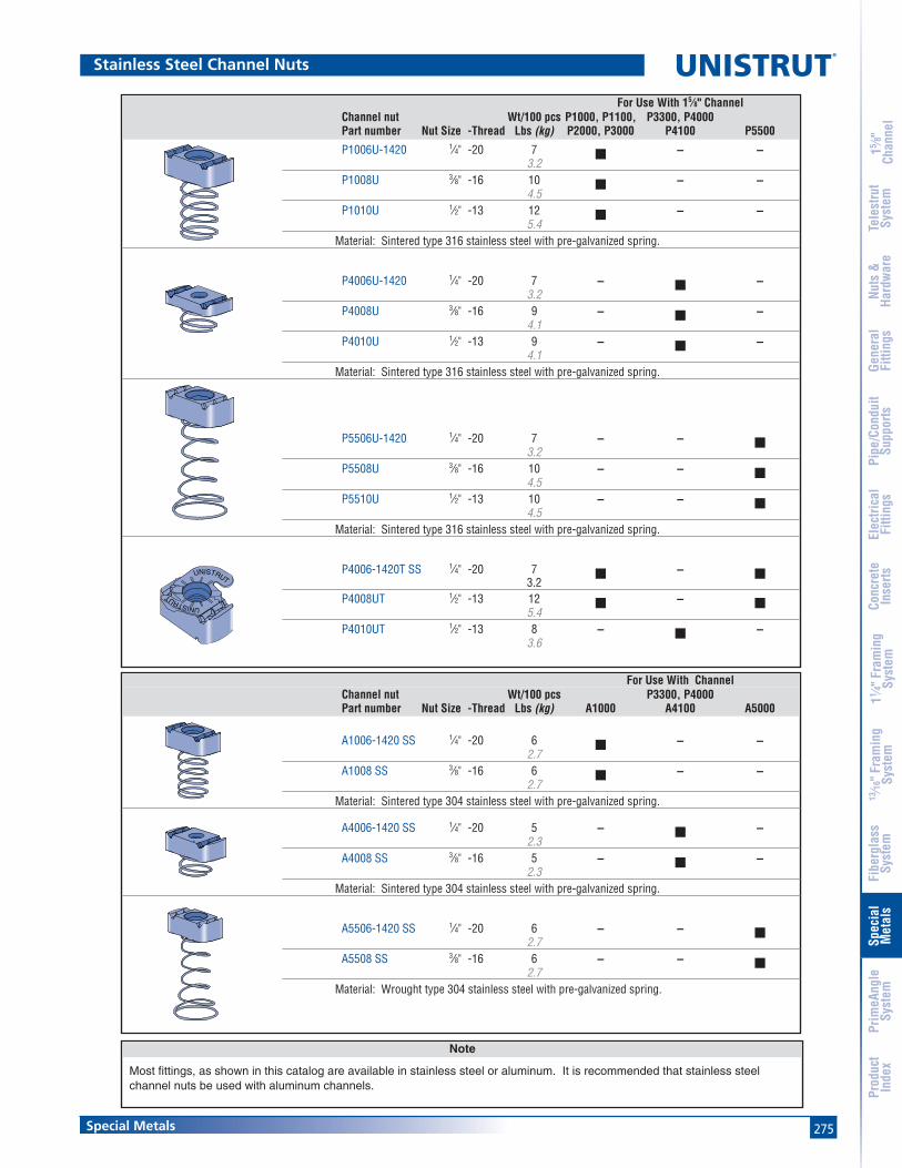
275Special Metals
15 ⁄8"
Chan
nel
Nuts
&Ha
rdw
are
Gene
ral
Fitti
ngs
Pipe
/Con
duit
Supp
orts
Elec
trica
lFi
tting
sCo
ncre
teIn
serts
11 ⁄4" F
ram
ing
Syst
em13
⁄16" F
ram
ing
Syst
emFi
berg
lass
Syst
emSp
ecia
lM
etal
sTe
lest
rut
Syst
emPr
imeA
ngle
Syst
emPr
oduc
tIn
dex
For Use With 15⁄8" ChannelChannel nut Wt/100 pcs P1000, P1100, P3300, P4000Part number Nut Size -Thread Lbs (kg) P2000, P3000 P4100 P5500
P1006U-1420 1⁄4" -20 7 ■ – –3.2
P1008U 3⁄8" -16 10 ■ – –4.5
P1010U 1⁄2" -13 12 ■ – –5.4
Material: Sintered type 316 stainless steel with pre-galvanized spring.
P4006U-1420 1⁄4" -20 7 – ■ –3.2
P4008U 3⁄8" -16 9 – ■ –4.1
P4010U 1⁄2" -13 9 – ■ –4.1
Material: Sintered type 316 stainless steel with pre-galvanized spring.
P5506U-1420 1⁄4" -20 7 – – ■3.2
P5508U 3⁄8" -16 10 – – ■4.5
P5510U 1⁄2" -13 10 – – ■4.5
Material: Sintered type 316 stainless steel with pre-galvanized spring.
P4006-1420T SS 1⁄4" -20 7 ■ – ■3.2
P4008UT 1⁄2" -13 12 ■ – ■5.4
P4010UT 1⁄2" -13 8 – ■ –3.6
For Use With ChannelChannel nut Wt/100 pcs P3300, P4000Part number Nut Size -Thread Lbs (kg) A1000 A4100 A5000
A1006-1420 SS 1⁄4" -20 6 ■ – –2.7
A1008 SS 3⁄8" -16 6 ■ – –2.7
Material: Sintered type 304 stainless steel with pre-galvanized spring.
A4006-1420 SS 1⁄4" -20 5 – ■ –2.3
A4008 SS 3⁄8" -16 5 – ■ –2.3
Material: Sintered type 304 stainless steel with pre-galvanized spring.
A5506-1420 SS 1⁄4" -20 6 – – ■2.7
A5508 SS 3⁄8" -16 6 – – ■2.7
Material: Wrought type 304 stainless steel with pre-galvanized spring.
Note
Most fittings, as shown in this catalog are available in stainless steel or aluminum. It is recommended that stainless steelchannel nuts be used with aluminum channels.
Stainless Steel Channel Nuts
UNISTRUT
UNISTRUT
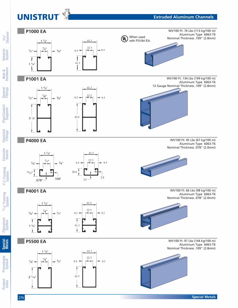
276
®
Special Metals
15 ⁄8"
Chan
nel
Nuts
&Ha
rdw
are
Gene
ral
Fitti
ngs
Pipe
/Con
duit
Supp
orts
Elec
trica
lFi
tting
sCo
ncre
teIn
serts
11 ⁄4" F
ram
ing
Syst
em13
⁄16" F
ram
ing
Syst
emFi
berg
lass
Syst
emSp
ecia
lM
etal
sTe
lest
rut
Syst
emPr
imeA
ngle
Syst
emPr
oduc
tIn
dex
When usedwith P3184 EA.
P1000 EA
Extruded Aluminum Channels
1 5⁄5 8⁄⁄ "
1 5⁄5 8⁄⁄ "
3⁄3 8⁄⁄ "7⁄7 8⁄⁄ "3⁄3 8⁄⁄ "
41.3
41.3
22.29.59.5
Wt/100 Ft: 76 Lbs (113 kg/100 m)Aluminum Type 6063-T6
Nominal Thickness .109" (2.8mm)
P1001 EA Wt/100 Ft: 134 Lbs (199 kg/100 m)Aluminum Type 6063-T6
12 Gauge Nominal Thickness .109" (2.8mm)
3 1⁄1 4⁄⁄ "
1 5⁄5 8⁄⁄ "
3⁄3 8⁄⁄ "7⁄7 8⁄⁄ "3⁄3 8⁄⁄ "
82.6
41.3
22.29.59.5
P4000 EA Wt/100 Ft: 45 Lbs (67 kg/100 m)Aluminum Type 6063-T6
Nominal Thickness .078" (2.0mm)
13⁄3 16⁄⁄ "
.078" .109"
3⁄3 8⁄⁄ "7⁄7 8⁄⁄ "3⁄3 8⁄⁄ "
1 5⁄5 8⁄⁄ "
20.6
2.02.8
22.29.59.5
41.3
P4001 EA Wt/100 Ft: 66 Lbs (98 kg/100 m)Aluminum Type 6063-T6
Nominal Thickness .078" (2.0mm)
1 5⁄5 8⁄⁄ "
1 5⁄5 8⁄⁄ "
3⁄3 8⁄⁄ "7⁄7 8⁄⁄ "3⁄3 8⁄⁄ "
41.3
41.3
22.29.59.5
P5500 EA Wt/100 Ft: 97 Lbs (144 kg/100 m)Aluminum Type 6063-T6
Nominal Thickness .109" (2.8mm)
2 7⁄7 16⁄⁄ "
1 5⁄5 8⁄⁄ "
3⁄3 8⁄⁄ "7⁄7 8⁄⁄ "3⁄3 8⁄⁄ "
61.9
41.3
22.29.59.5

277Special Metals
15 ⁄8"
Chan
nel
Nuts
&Ha
rdw
are
Gene
ral
Fitti
ngs
Pipe
/Con
duit
Supp
orts
Elec
trica
lFi
tting
sCo
ncre
teIn
serts
11 ⁄4" F
ram
ing
Syst
em13
⁄16" F
ram
ing
Syst
emFi
berg
lass
Syst
emSp
ecia
lM
etal
sTe
lest
rut
Syst
emPr
imeA
ngle
Syst
emPr
oduc
tIn
dex
Extruded Aluminum Channels
A1000 EA Wt/100 Ft: 40 Lbs (60 kg/100 m)Aluminum Type 6063-T6
Nominal Thickness .075" (1.9mm)
A4000 EA Wt/100 Ft: 25 Lbs (37 kg/100 m)Aluminum Type 6063-T6
12 Gauge Nominal Thickness .050" (1.3mm)Standard Length 16 Ft.
A4001 EA Wt/100 Ft: 40 Lbs (60 kg/100 m)Aluminum Type 6063-T6
Nominal Thickness .078" (2.0mm)Standard Length 16 Ft.
P6000 EA Wt/100 Ft: 12 Lbs (18 kg/100 m)Aluminum Type 6063-T6
Nominal Thickness .040" (1.0mm)Standard Length 16 Ft.
P6001 EA Wt/100 Ft: 20 Lbs (30 kg/100 m)Aluminum Type 6063-T6
Nominal Thickness .040" (1.0mm)Standard Length 16 Ft.
1⁄1 4⁄⁄ "
1 1⁄1 4⁄⁄ "
11⁄1 16⁄⁄ "9⁄9 32⁄⁄ " 9⁄9 32⁄⁄ "
31.8
31.8
17.57.1 7.1
5⁄5 8⁄⁄ "
.050" .075"
1 1⁄1 4⁄⁄ "
11⁄1 16⁄⁄ "9⁄9 32⁄⁄ " 9⁄9 32⁄⁄ "
15.9
1.3 1.9
31.8
17.57.1 7.1
1 1⁄1 4⁄⁄ "
1 1⁄1 4⁄⁄ "
11⁄1 16⁄⁄ "9⁄9 32⁄⁄ " 9⁄9 32⁄⁄ "
31.8
31.8
17.57.1 7.1
13⁄3 16⁄⁄ "
7⁄7 16⁄⁄ " 3⁄3 16⁄⁄ "
13⁄3 16⁄⁄ "
3⁄3 16⁄⁄ "
20.6
11.14.84.8
20.6
1 5⁄5 8⁄⁄ "
16"3⁄3 16⁄⁄ "
13⁄3 "
3⁄3 16⁄⁄ "
41.3
4.84.8
20.6
11.1

278
®
Special Metals
15 ⁄8"
Chan
nel
Nuts
&Ha
rdw
are
Gene
ral
Fitti
ngs
Pipe
/Con
duit
Supp
orts
Elec
trica
lFi
tting
sCo
ncre
teIn
serts
11 ⁄4" F
ram
ing
Syst
em13
⁄16" F
ram
ing
Syst
emFi
berg
lass
Syst
emSp
ecia
lM
etal
sTe
lest
rut
Syst
emPr
imeA
ngle
Syst
emPr
oduc
tIn
dex
P7000 EA Wt/100 Ft: 9 Lbs (13 kg/100 m)Aluminum Type 6063-T6
Nominal Thickness .040" (1.0mm)Standard Length 10 Ft.
P7001 EA Wt/100 Ft: 17 Lbs (25 kg/100 m)Aluminum Type 6063-T6
12 Gauge Nominal Thickness .040" (1.0mm)Standard Length 10 Ft
P3184 EA Closure Strip
P1280 EA, P4280 EA, P5580 EA End Caps
Extruded Aluminum Channels
13⁄3 32⁄⁄ "
7⁄7 16⁄⁄ " 3⁄3 16⁄⁄ "
13⁄3 16⁄⁄ "
3⁄3 16⁄⁄ "
10.3
4.84.8
20.6
11.1
13⁄3 16⁄⁄ "
7⁄7 16⁄⁄ " 3⁄3 16⁄⁄ "
13⁄3 16⁄⁄ "
3⁄3 16⁄⁄ "
20.6
4.84.8
20.6
11.1
1 5⁄8"(41.3)
Part Use With Wt/100 FtNumber Channel Lbs(kg/m)
P1280 EA P1000 EA 3.51.6
P4280 EA P4000 EA 1.50.7
P5500 EA P5500 EA 4.92.2
Wt/100 Ft: 21 Lbs (31 kg/100 m)Aluminum Type 6063-T6
Standard Length 10 Ft
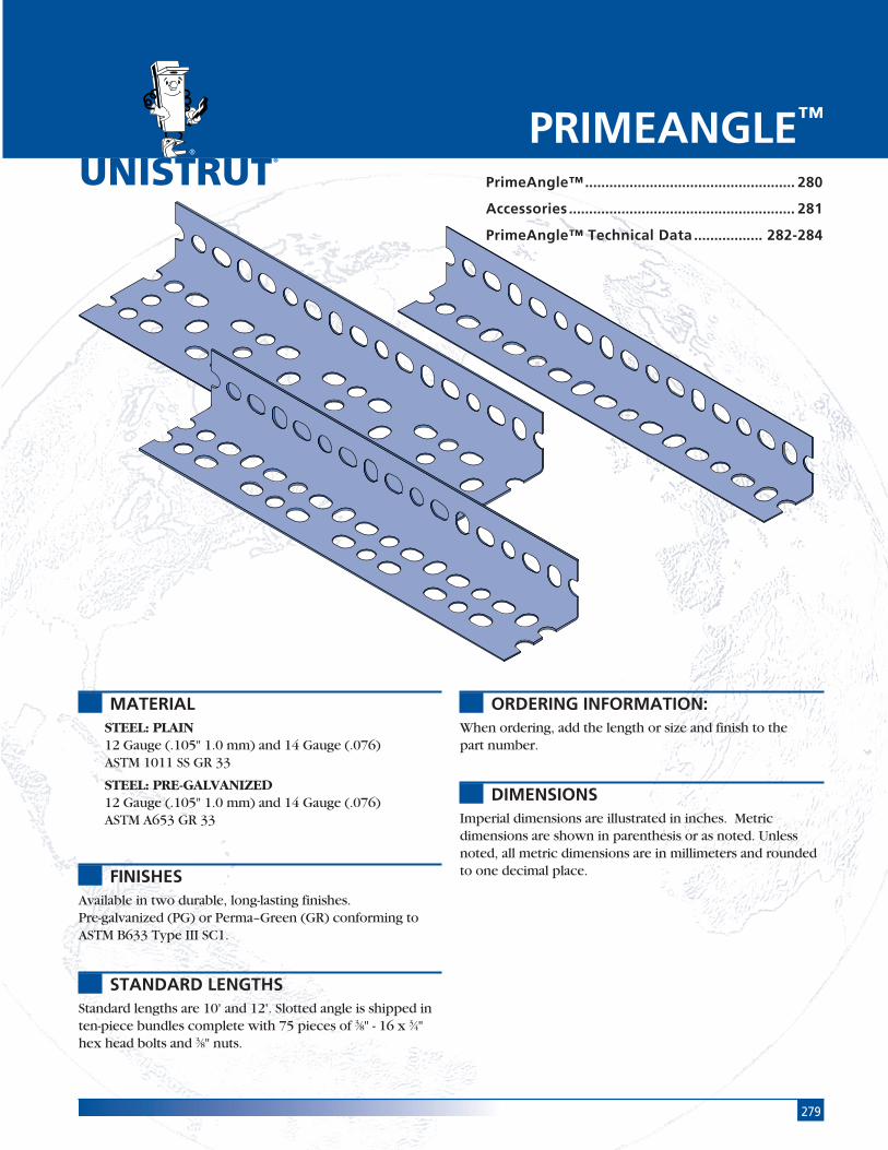
279
®
MATERIALSTEEL: PLAIN12 Gauge (.105" 1.0 mm) and 14 Gauge (.076)ASTM 1011 SS GR 33
STEEL: PRE-GALVANIZED12 Gauge (.105" 1.0 mm) and 14 Gauge (.076)ASTM A653 GR 33
FINISHESAvailable in two durable, long-lasting finishes.Pre-galvanized (PG) or Perma–Green (GR) conforming toASTM B633 Type III SC1.
STANDARD LENGTHSStandard lengths are 10' and 12'. Slotted angle is shipped inten-piece bundles complete with 75 pieces of 3⁄8" - 16 x 3⁄4"hex head bolts and 3⁄8" nuts.
ORDERING INFORMATION:When ordering, add the length or size and finish to thepart number.
DIMENSIONSImperial dimensions are illustrated in inches. Metricdimensions are shown in parenthesis or as noted. Unlessnoted, all metric dimensions are in millimeters and roundedto one decimal place.
PRIMEANGLE™
PrimeAngle™.................................................... 280
Accessories ........................................................ 281
PrimeAngle™ Technical Data ................. 282-284

280 PrimeAngle
®
15 ⁄8"
Chan
nel
Nuts
&Ha
rdw
are
Gene
ral
Fitti
ngs
Pipe
/Con
duit
Supp
orts
Elec
trica
lFi
tting
sCo
ncre
teIn
serts
11 ⁄4" F
ram
ing
Syst
em13
⁄16" F
ram
ing
Syst
emFi
berg
lass
Syst
emSp
ecia
lM
etal
sTe
lest
rut
Syst
emPr
imeA
ngle
Syst
emPr
oduc
tIn
dex
PA 158 Light Duty
(15⁄8" x 15⁄8" x 14 ga.) Wt/100 Ft.: 66 lbs (29.9 kg)
15⁄8"(41.3)
15⁄8"(41.3)11⁄2"
(38.1) 3⁄4"(19.1) 3⁄4"
(19.1)
PA 238 Medium Duty
(15⁄8" x 23⁄8" x 14 ga.) Wt/100 Ft: 80 lbs(36.3 kg)
23⁄8" (60.3)
15⁄8" (41.3)
11⁄2"(38.1)
3⁄4"(19.1)
3⁄4"(19.1)
31⁄8"(79.4)
15⁄8"(41.3)
11⁄2"(38.1)
3⁄4"(19.1)
3⁄4"(19.1)
PA 318 Heavy Duty
(15⁄8" x 31⁄8" x 12 ga.) Wt/100 Ft: 130 lbs (59.0 kg)
Note: Includes SerratedNuts & Bolts
Note: Includes SerratedNuts & Bolts
Note: Includes SerratedNuts & Bolts
Prime Angle and Accessories
For those jobs where extra strength isnot necessary. Ideal for light-dutyshelving or racking.
Perfect for the majority of framingneeds, including shelving, racking andelectrical or mechanical support jobs.
Suitable for balconies, ramps, large racks andshelving systems, as well as other structureswith substantial load requirements.
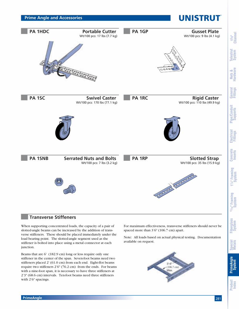
281PrimeAngle
15 ⁄8"
Chan
nel
Nuts
&Ha
rdw
are
Gene
ral
Fitti
ngs
Pipe
/Con
duit
Supp
orts
Elec
trica
lFi
tting
sCo
ncre
teIn
serts
11 ⁄4" F
ram
ing
Syst
em13
⁄16" F
ram
ing
Syst
emFi
berg
lass
Syst
emSp
ecia
lM
etal
sTe
lest
rut
Syst
emPr
imeA
ngle
Syst
emPr
oduc
tIn
dex
PA 1GP Gusset PlateWt/100 pcs: 9 lbs (4.1 kg)
PA 1HDC Portable CutterWt/100 pcs: 17 lbs (7.7 kg)
PA 1RP Slotted StrapWt/100 pcs: 35 lbs (15.9 kg)
PA 1SC Swivel CasterWt/100 pcs: 170 lbs (77.1 kg)
PA 1RC Rigid CasterWt/100 pcs: 110 lbs (49.9 kg)
PA 1SNB Serrated Nuts and BoltsWt/100 pcs: 7 lbs (3.2 kg)
When supporting concentrated loads, the capacity of a pair ofslotted-angle beams can be increased by the addition of trans-verse stiffeners. These should be placed immediately under theload bearing point. The slotted-angle segment used as thestiffener is bolted into place using a metal connector at eachjunction.
Beams that are 6' (182.9 cm) long or less require only onestiffener in the center of the span. Seven-foot beams need twostiffeners placed 2' (61.0 cm) from each end. Eight-ffot beamsrequire two stiffeners 2’6" (76.2 cm) from the ends. For beamswith a nine-foot span, it is necessary to have three stiffeners at2’3" (68.6 cm) intervals. Ten-foot beams need three stiffenerswith 2’6" spacings.
For maximum effectiveness, transverse stiffeners should never bespaced more than 3’6" (106.7 cm) apart.
Note: All loads based on actual physical testing. Documentationavailable on request.
Transverse Stiffeners
Prime Angle and Accessories
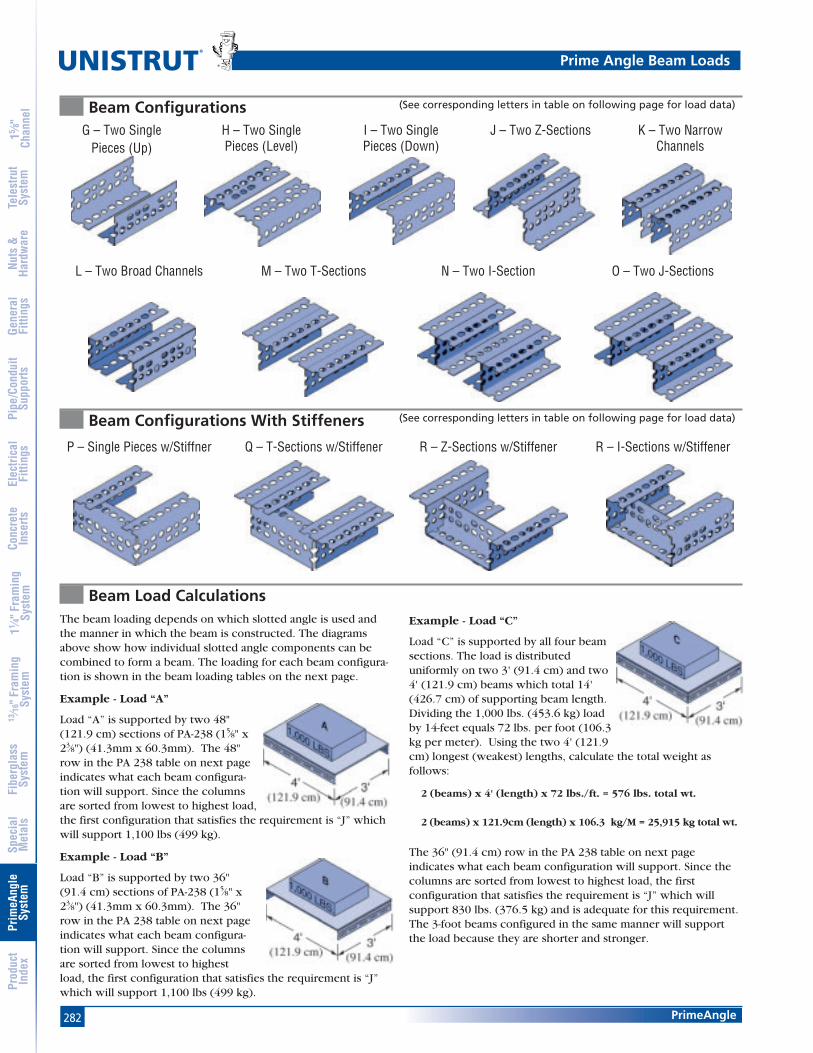
282 PrimeAngle
®
15 ⁄8"
Chan
nel
Nuts
&Ha
rdw
are
Gene
ral
Fitti
ngs
Pipe
/Con
duit
Supp
orts
Elec
trica
lFi
tting
sCo
ncre
teIn
serts
11 ⁄4" F
ram
ing
Syst
em13
⁄16" F
ram
ing
Syst
emFi
berg
lass
Syst
emSp
ecia
lM
etal
sTe
lest
rut
Syst
emPr
imeA
ngle
Syst
emPr
oduc
tIn
dex
Beam Configurations (See corresponding letters in table on following page for load data)
Beam Configurations With Stiffeners (See corresponding letters in table on following page for load data)
G – Two SinglePieces (Up)
H – Two SinglePieces (Level)
I – Two SinglePieces (Down)
J – Two Z-Sections K – Two NarrowChannels
L – Two Broad Channels M – Two T-Sections N – Two I-Section
P – Single Pieces w/Stiffner Q – T-Sections w/Stiffener R – Z-Sections w/Stiffener R – I-Sections w/Stiffener
The beam loading depends on which slotted angle is used andthe manner in which the beam is constructed. The diagramsabove show how individual slotted angle components can becombined to form a beam. The loading for each beam configura-tion is shown in the beam loading tables on the next page.
Example - Load “A”
Load “A” is supported by two 48"(121.9 cm) sections of PA-238 (15⁄8" x23⁄8") (41.3mm x 60.3mm). The 48"row in the PA 238 table on next pageindicates what each beam configura-tion will support. Since the columnsare sorted from lowest to highest load,the first configuration that satisfies the requirement is “J” whichwill support 1,100 lbs (499 kg).
Example - Load “B”
Load “B” is supported by two 36"(91.4 cm) sections of PA-238 (15⁄8" x23⁄8") (41.3mm x 60.3mm). The 36"row in the PA 238 table on next pageindicates what each beam configura-tion will support. Since the columnsare sorted from lowest to highestload, the first configuration that satisfies the requirement is “J”which will support 1,100 lbs (499 kg).
Example - Load “C”
Load “C” is supported by all four beamsections. The load is distributeduniformly on two 3' (91.4 cm) and two4' (121.9 cm) beams which total 14'(426.7 cm) of supporting beam length.Dividing the 1,000 lbs. (453.6 kg) loadby 14-feet equals 72 lbs. per foot (106.3kg per meter). Using the two 4' (121.9cm) longest (weakest) lengths, calculate the total weight asfollows:
2 (beams) x 4' (length) x 72 lbs./ft. = 576 lbs. total wt.
2 (beams) x 121.9cm (length) x 106.3 kg/M = 25,915 kg total wt.
The 36" (91.4 cm) row in the PA 238 table on next pageindicates what each beam configuration will support. Since thecolumns are sorted from lowest to highest load, the firstconfiguration that satisfies the requirement is “J” which willsupport 830 lbs. (376.5 kg) and is adequate for this requirement.The 3-foot beams configured in the same manner will supportthe load because they are shorter and stronger.
O – Two J-Sections
Beam Load Calculations
Prime Angle Beam Loads

283PrimeAngle
15 ⁄8"
Chan
nel
Nuts
&Ha
rdw
are
Gene
ral
Fitti
ngs
Pipe
/Con
duit
Supp
orts
Elec
trica
lFi
tting
sCo
ncre
teIn
serts
11 ⁄4" F
ram
ing
Syst
em13
⁄16" F
ram
ing
Syst
emFi
berg
lass
Syst
emSp
ecia
lM
etal
sTe
lest
rut
Syst
emPr
imeA
ngle
Syst
emPr
oduc
tIn
dex
Beam Loads
PA 158 Light Duty, (15⁄8" x 15⁄8" x 14 ga.)
PA 238 Medium Duty, (15⁄8" x 23⁄8" x 14 ga.)
PA 318 Heavy Duty, (15⁄8" x 31⁄8" x 12 ga.)
Span G H I P L R MIn. (cm) Lbs (kg) Lbs (kg) Lbs (kg) Lbs (kg) Lbs (kg) Lbs (kg) Lbs (kg)
24 550 830 830 920 1,600 1,700 1,84061.0 249 376 376 417 726 771 83536 370 560 560 610 1,070 1,130 1,230
91.4 168 254 254 277 485 513 55848 280 420 420 460 800 850 920
121.9 127 191 191 209 363 386 41760 220 330 330 370 640 680 740
152.4 100 150 150 168 290 308 33672 180 280 280 310 530 570 610
182.9 82 127 127 141 240 259 27784 • 240 240 260 460 490 530
213.4 109 109 118 209 222 24096 • 210 210 230 400 430 460
243.8 95 95 104 181 195 209108 • • • • 360 380 410
274.3 163 172 186120 • • • • 320 340 370
304.8 145 154 168
(See corresponding letters in table on previous page for configurations)
Span G H I P J L R M K Q O NIn. (cm) Lbs (kg) Lbs (kg) Lbs (kg) Lbs (kg) Lbs (kg) Lbs (kg) Lbs (kg) Lbs (kg) Lbs (kg) Lbs (kg) Lbs (kg) Lbs (kg)
24 700 1,020 1,660 1,740 2,220 3,170 3,230 3,490 3,590 3,630 6,060 7,56061.0 318 463 753 789 1,007 1,438 1,465 1,583 1,628 1,647 2,749 3,42936 460 680 1,100 1,160 1,480 2,110 2,150 2,320 2,390 2,420 4,040 5,040
91.4 209 308 499 526 671 957 975 1,052 1,084 1,098 1,833 2,28648 350 510 830 870 1,110 1,580 1,620 1,740 1,800 1,810 3,030 3,780
121.9 159 231 376 395 503 717 735 789 816 821 1,374 1,71560 280 410 660 700 890 1,270 1,290 1,390 1,440 1,450 2,420 3,020
152.4 127 186 299 318 404 576 585 630 653 658 1,098 1,37072 230 340 550 580 740 1,060 1,080 1,160 1,200 1,210 2,020 2,520
182.9 104 154 249 263 336 481 490 526 544 549 916 1,14384 • 290 470 500 630 910 920 1,000 1,030 1,040 1,730 2,160
213.4 132 213 227 286 413 417 454 467 472 785 98096 • 260 410 440 550 790 810 870 900 910 1,520 1,890
243.8 118 186 200 249 358 367 395 408 413 689 857108 • • • • 490 700 720 770 800 810 1,350 1,680
274.3 222 318 327 349 363 367 612 762120 • • • • 440 630 650 700 720 730 1,210 1,510
304.8 200 286 295 318 327 331 549 685
Span G H I P J L R M K Q O NIn. (cm) Lbs (kg) Lbs (kg) Lbs (kg) Lbs (kg) Lbs (kg) Lbs (kg) Lbs (kg) Lbs (kg) Lbs (kg) Lbs (kg) Lbs (kg) Lbs (kg)
24 1,790 1,610 4,300 4,960 6,520 7,910 8,070 9,920 9,990 10,170 14,600 16,12061.0 812 730 1,950 2,250 2,957 3,588 3,660 4,500 4,531 4,613 6,622 7,31236 1,200 1,070 2,870 3,310 4,350 5,270 5,380 6,610 6,660 6,780 9,730 10,750
91.4 544 485 1,302 1,501 1,973 2,390 2,440 2,998 3,021 3,075 4,413 4,87648 900 810 2,150 2,480 3,260 3,950 4,030 4,960 4,990 5,080 7,300 8,060
121.9 408 367 975 1,125 1,479 1,792 1,828 2,250 2,263 2,304 3,311 3,65660 720 640 1,720 1,980 2,610 3,160 3,230 3,970 4,000 4,070 5,840 6,450
152.4 327 290 780 898 1,184 1,433 1,465 1,801 1,814 1,846 2,649 2,92672 600 540 1,430 1,650 2,170 2,640 2,690 3,310 3,330 3,390 4,870 5,370
182.9 272 245 649 748 984 1,197 1,220 1,501 1,510 1,538 2,209 2,43684 • 460 1,230 1,420 1,860 2,260 2,300 2,830 2,850 2,910 4,170 4,610
213.4 209 558 644 844 1,025 1,043 1,284 1,293 1,320 1,891 2,09196 • 400 1,080 1,240 1,630 1,980 2,020 2,480 2,500 2,540 3,650 4,030
243.8 181 490 562 739 898 916 1,125 1,134 1,152 1,656 1,828108 • • • 1,100 1,450 1,760 1,790 2,200 2,220 2,260 3,240 3,580
274.3 499 658 798 812 998 1,007 1,025 1,470 1,624120 • • • 990 1,300 1,580 1,610 1,980 2,000 2,030 2,920 3,220
304.8 449 590 717 730 898 907 921 1,324 1,461
Prime Angle Beam Loads
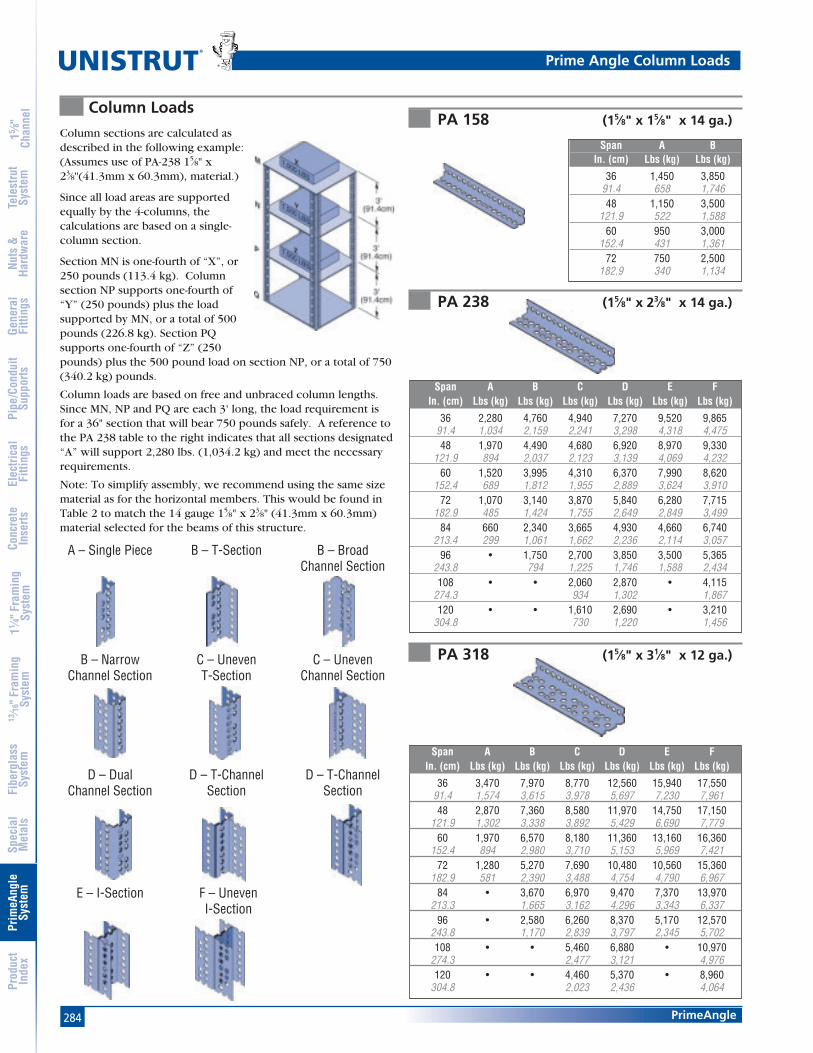
284 PrimeAngle
®
15 ⁄8"
Chan
nel
Nuts
&Ha
rdw
are
Gene
ral
Fitti
ngs
Pipe
/Con
duit
Supp
orts
Elec
trica
lFi
tting
sCo
ncre
teIn
serts
11 ⁄4" F
ram
ing
Syst
em13
⁄16" F
ram
ing
Syst
emFi
berg
lass
Syst
emSp
ecia
lM
etal
sTe
lest
rut
Syst
emPr
imeA
ngle
Syst
emPr
oduc
tIn
dex
Column LoadsPA 158 (15⁄8" x 15⁄8" x 14 ga.)
PA 238 (15⁄8" x 23⁄8" x 14 ga.)
PA 318 (15⁄8" x 31⁄8" x 12 ga.)
A – Single Piece B – T-Section B – BroadChannel Section
B – NarrowChannel Section
C – UnevenT-Section
C – UnevenChannel Section
D – DualChannel Section
D – T-ChannelSection
D – T-ChannelSection
E – I-Section F – UnevenI-Section
Column sections are calculated asdescribed in the following example:(Assumes use of PA-238 15⁄8" x23⁄8"(41.3mm x 60.3mm), material.)
Since all load areas are supportedequally by the 4-columns, thecalculations are based on a single-column section.
Section MN is one-fourth of “X”, or250 pounds (113.4 kg). Columnsection NP supports one-fourth of“Y” (250 pounds) plus the loadsupported by MN, or a total of 500pounds (226.8 kg). Section PQsupports one-fourth of “Z” (250pounds) plus the 500 pound load on section NP, or a total of 750(340.2 kg) pounds.
Column loads are based on free and unbraced column lengths.Since MN, NP and PQ are each 3' long, the load requirement isfor a 36" section that will bear 750 pounds safely. A reference tothe PA 238 table to the right indicates that all sections designated“A” will support 2,280 lbs. (1,034.2 kg) and meet the necessaryrequirements.
Note: To simplify assembly, we recommend using the same sizematerial as for the horizontal members. This would be found inTable 2 to match the 14 gauge 15⁄8" x 23⁄8" (41.3mm x 60.3mm)material selected for the beams of this structure.
Span A BIn. (cm) Lbs (kg) Lbs (kg)
36 1,450 3,85091.4 658 1,74648 1,150 3,500
121.9 522 1,58860 950 3,000
152.4 431 1,36172 750 2,500
182.9 340 1,134
Span A B C D E FIn. (cm) Lbs (kg) Lbs (kg) Lbs (kg) Lbs (kg) Lbs (kg) Lbs (kg)
36 2,280 4,760 4,940 7,270 9,520 9,86591.4 1,034 2,159 2,241 3,298 4,318 4,47548 1,970 4,490 4,680 6,920 8,970 9,330
121.9 894 2,037 2,123 3,139 4,069 4,23260 1,520 3,995 4,310 6,370 7,990 8,620
152.4 689 1,812 1,955 2,889 3,624 3,91072 1,070 3,140 3,870 5,840 6,280 7,715
182.9 485 1,424 1,755 2,649 2,849 3,49984 660 2,340 3,665 4,930 4,660 6,740
213.4 299 1,061 1,662 2,236 2,114 3,05796 • 1,750 2,700 3,850 3,500 5,365
243.8 794 1,225 1,746 1,588 2,434108 • • 2,060 2,870 • 4,115
274.3 934 1,302 1,867120 • • 1,610 2,690 • 3,210
304.8 730 1,220 1,456
Span A B C D E FIn. (cm) Lbs (kg) Lbs (kg) Lbs (kg) Lbs (kg) Lbs (kg) Lbs (kg)
36 3,470 7,970 8,770 12,560 15,940 17,55091.4 1,574 3,615 3,978 5,697 7,230 7,96148 2,870 7,360 8,580 11,970 14,750 17,150
121.9 1,302 3,338 3,892 5,429 6,690 7,77960 1,970 6,570 8,180 11,360 13,160 16,360
152.4 894 2,980 3,710 5,153 5,969 7,42172 1,280 5,270 7,690 10,480 10,560 15,360
182.9 581 2,390 3,488 4,754 4,790 6,96784 • 3,670 6,970 9,470 7,370 13,970
213.3 1,665 3,162 4,296 3,343 6,33796 • 2,580 6,260 8,370 5,170 12,570
243.8 1,170 2,839 3,797 2,345 5,702108 • • 5,460 6,880 • 10,970
274.3 2,477 3,121 4,976120 • • 4,460 5,370 • 8,960
304.8 2,023 2,436 4,064
Prime Angle Column Loads

285
®
PRODUCT INDEX
200-3100 thru 200-3140 .............265
A1000 ..........................................206
A1000 EA .....................................277
A1001 ..........................................206
A1001A thru A1001C ...................206
A1006 thru A1008 .......................215
A1026 ..........................................218
A1031 ..........................................218
A1033 ..........................................219
A1036 ..........................................217
A1037 ..........................................219
A1038 ..........................................219
A1045 ..........................................220
A1047 ..........................................222
A1063 ..........................................217
A1065 ..........................................217
A1066 ..........................................217
A1068 ..........................................218
A1184 ..........................................216
A1184P ........................................216
A1191 ..........................................217
A1280 ..........................................216
A1325 ..........................................218
A1326 ..........................................218
A1331 ..........................................219
A1332 ..........................................219
A1357 ..........................................219
A1458 ..........................................218
A1579 ..........................................220
A2084 ..........................................221
A2109 thru A2111 ......................221
A2120 ..........................................220
A2125 thru A2127 ......................221
A2223 ..........................................222
A2227 ..........................................222
A2235 ..........................................220
A2324 ..........................................217
A2341 R-L ...................................222
A2345 ..........................................222
A2472 R-L ...................................222
A2491 thru A2493 R-L ...............224
A2494 R-L thru A2497 R-L ........224
A2608 thru A2617 .....................223
A3006 thru A3008 ......................215
A3016 thru A3016 ......................215
A3300 ..........................................209
A3301 ..........................................209
A3345 ..........................................221
A3347 ..........................................223
A4000 ..........................................211
A4000 EA .....................................277
A4001 ..........................................211
A4001 EA .....................................277
A4006 thru A4008 ......................215
A4045 ..........................................221
A4047 ..........................................223
A4120 ..........................................220
A4280 ..........................................216
A5000 ..........................................213
A5006 thru A5008 .......................215
A5043 ..........................................223
A5045 ..........................................221
A5047 ..........................................223
A5120 ..........................................220
A5280 ..........................................216
CG-10 thru CG-40 ......................157
F20E-5000 ...................................259
F20N-ARM08 thru F20N-STA33 ..268
F20P/V-1000 ...............................252
F20P/V-1000 ...............................253
F20P/V-1000 thru F20P/V-1100 ..252
F20P/V-1000 thru F20P/V-1100 ..253
F20P/V-1100 ...............................252
F20P/V-1100 ...............................253
F20P/V-1200 ...............................252
F20P/V-1300 ...............................252
F20P/V-2000 ...............................250
F20P/V-2000 ...............................251
F20P/V-2000 SST ........................254
F20P/V-2000 SST ........................255
F20P/V-2000 thru F20P/V-2100 ..250
F20P/V-2000 thru F20P/V-2100 ..251
F20P/V-2100 ...............................250
F20P/V-2100 ...............................251
F20P/V-2100 SST ........................254
F20P/V-2100 SST ........................255
F20P/V-2200 ...............................250
F20P/V-2200 SST ........................254
F20P/V-2300 ...............................250
F20P/V-2300 SST ........................254
F20P-2500 thru F20V-2500 .........260
F20P-2502 thru F20V-2502 .........260
F20P-2504 thru F20V-2504 .........260
F20P-2506 thru F20V-2506 .........260
F20P-2508 thru F20V-2508 .........261
F20P-2510 thru F20V-2510 .........261
F20P-2512 thru F20V-2512 .........261
F20P-2514 thru F20V-2514 .........261
F20P-2516 thru F20V-2516 .........261
F20P-2518 thru F20V-2518 .........261
F20P-2520 thru F20V-2520 .........262
F20P-2522 thru F20V-2522 .........262
F20P-2524 thru F20V-2524 .........262
F20P-2526 thru F20V-2526 .........262
F20P-2528 thru F20V-2528 .........262
F20P-2530 thru F20V-2530 .........262
F20P-2534 thru F20V-2534 .........263
F20P-2540 thru F20V-2540 .........263
F20PU-5853 thru F20PU-5855 ....264
F20PU-5903 thru F20PU-5905 ....264
F50PU-1508 thru F50PU-2008 ....263

286
®
Product Index
15 ⁄8"
Chan
nel
Nuts
&Ha
rdw
are
Gene
ral
Fitti
ngs
Pipe
/Con
duit
Supp
orts
Elec
trica
lFi
tting
sCo
ncre
teIn
serts
11 ⁄4" F
ram
ing
Syst
em13
⁄16" F
ram
ing
Syst
emFi
berg
lass
Syst
emSp
ecia
lM
etal
sTe
lest
rut
Syst
emPr
imeA
ngle
Syst
emPr
oduc
tIn
dex
F50PU-2045 ................................264
F50PU-2090 ................................264
F50PU-2538 ................................263
F50PU-2611 ................................263
F50PU-2613 ................................263
F50PU-2616 ................................264
F50PU-2636 ................................264
F50PU-500SP ..............................258
F100-1500 thru F100-1512 .........267
F200-3827 thru F200-3831 .........258
F200-3840 thru F200-3843 .........258
F200-4101 ...................................267
F200-4226 thru F200-4343 .........256
F250E thru F1000E ......................258
F250PU thru F625PU ...................257
F250PU-075 thru F500PU-350 ....257
F250PU-CN thru F10PU-CNS.......256
F375PU & F500PU.......................268
F375PU-125 thru F625PU-350 ....257
F375PU-CNHD thruF20PU-CNMHD ....................256
F375PU-FN thru F750PU-FN ........257
FAIC-EC .......................................259
FCVHPU-100 thru FCVHPU-600 ..267
FPCR-050 thru FPCR-800 ............266
FPS200 thru FPS1800 .................266
FRGBC .........................................268
FUB-050 thru FUB-600 ................259
HCSS .............................................81
HFLW.............................................82
HFMS.............................................81
HHCS .............................................81
HHXN.............................................82
HLKW ............................................82
HOCW ............................................84
HRCN.............................................84
HRMS ............................................81
HSHS .............................................81
HSQN.............................................82
HTHR .............................................83
J1205 thru J1280 ........................158
LS 410 .........................................144
LS 500 .........................................144
M24 .............................................199
M2037 thru M2050 .....................184
M2137 thru M2150 .....................184
M2250 .........................................184
M2350 .........................................184
M5025 thru M5060 ...................151
P16F ............................................185
P21H ...........................................185
P1000 ............................................25
P1000 DS ......................................25
P1000 EA .....................................276
P1000 H3 ......................................25
P1000 HS ......................................25
P1000 KO ......................................25
P1000 Series ...............................273
P1000 SL .......................................25
P1000 SS ....................................273
P1000 T .........................................25
P1000HS SS ................................273
P1000T SS ..................................273
P1001 ............................................25
P1001 3 .........................................29
P1001 A .........................................28
P1001 A3 .......................................29
P1001 B .........................................28
P1001 B3 .......................................29
P1001 C .........................................28
P1001 C3 .......................................29
P1001 C41 .....................................29
P1001 D3 ......................................29
P1001 EA .....................................276
P1001 SS ....................................273
P1001 T .........................................28
P1003 ............................................29
P1004 A .........................................29
P1006 thru P1010 .........................78
P1006T thru P1010T .....................79
P1012 thru P1024 .........................79
P1012S thru P1024S .....................78
P1026 ............................................94
P1028 ............................................93
Part Number Index
P1029 ............................................97
P1031 ............................................92
P1033 ............................................97
P1034 ............................................97
P1035 ............................................97
P1036 ............................................92
P1037 ............................................97
P1038 ............................................97
P1043A ........................................108
P1044 ..........................................108
P1045 ..........................................102
P1046A ........................................109
P1047 ..........................................106
P1048 thru P1050 .......................107
P1062 thru P1064 .........................90
P1065 ............................................90
P1066 ............................................91
P1067 ............................................91
P1068 ............................................94
P1075 ..........................................116
P1100 ............................................32
P1100 HS ......................................32
P1100 KO ......................................32
P1100 Series ...............................273
P1100 SL .......................................32
P1100 SS ....................................273
P1100 T .........................................32
P1100HS SS ................................273
P1100T SS ..................................273
P1101 ............................................32
P1101 A .........................................33
P1101 B .........................................33
P1101 C .........................................33
P1101 SS ....................................273
P1109 thru P1126 .......................147
P1130 thru P1131 .......................100
P1180 ............................................60
P1180 thru P5580 .........................60
P1180W thru P5580 ....................180
P1184 ............................................59
P1184 P .........................................59
P1184 SS ....................................274
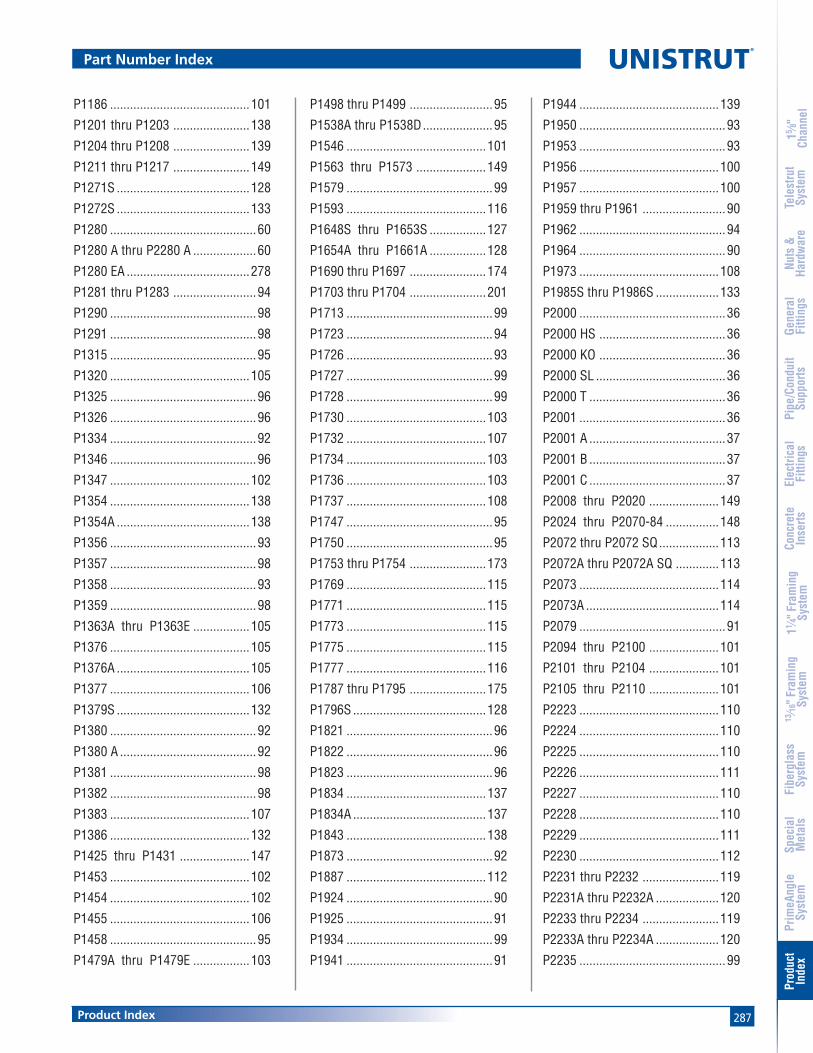
287Product Index
15 ⁄8"
Chan
nel
Nuts
&Ha
rdw
are
Gene
ral
Fitti
ngs
Pipe
/Con
duit
Supp
orts
Elec
trica
lFi
tting
sCo
ncre
teIn
serts
11 ⁄4" F
ram
ing
Syst
em13
⁄16" F
ram
ing
Syst
emFi
berg
lass
Syst
emSp
ecia
lM
etal
sTe
lest
rut
Syst
emPr
imeA
ngle
Syst
emPr
oduc
tIn
dex
P1186 ..........................................101
P1201 thru P1203 .......................138
P1204 thru P1208 .......................139
P1211 thru P1217 .......................149
P1271S ........................................128
P1272S ........................................133
P1280 ............................................60
P1280 A thru P2280 A ...................60
P1280 EA .....................................278
P1281 thru P1283 .........................94
P1290 ............................................98
P1291 ............................................98
P1315 ............................................95
P1320 ..........................................105
P1325 ............................................96
P1326 ............................................96
P1334 ............................................92
P1346 ............................................96
P1347 ..........................................102
P1354 ..........................................138
P1354A ........................................138
P1356 ............................................93
P1357 ............................................98
P1358 ............................................93
P1359 ............................................98
P1363A thru P1363E .................105
P1376 ..........................................105
P1376A ........................................105
P1377 ..........................................106
P1379S ........................................132
P1380 ............................................92
P1380 A .........................................92
P1381 ............................................98
P1382 ............................................98
P1383 ..........................................107
P1386 ..........................................132
P1425 thru P1431 .....................147
P1453 ..........................................102
P1454 ..........................................102
P1455 ..........................................106
P1458 ............................................95
P1479A thru P1479E .................103
P1498 thru P1499 .........................95
P1538A thru P1538D.....................95
P1546 ..........................................101
P1563 thru P1573 .....................149
P1579 ............................................99
P1593 ..........................................116
P1648S thru P1653S .................127
P1654A thru P1661A .................128
P1690 thru P1697 .......................174
P1703 thru P1704 .......................201
P1713 ............................................99
P1723 ............................................94
P1726 ............................................93
P1727 ............................................99
P1728 ............................................99
P1730 ..........................................103
P1732 ..........................................107
P1734 ..........................................103
P1736 ..........................................103
P1737 ..........................................108
P1747 ............................................95
P1750 ............................................95
P1753 thru P1754 .......................173
P1769 ..........................................115
P1771 ..........................................115
P1773 ..........................................115
P1775 ..........................................115
P1777 ..........................................116
P1787 thru P1795 .......................175
P1796S ........................................128
P1821 ............................................96
P1822 ............................................96
P1823 ............................................96
P1834 ..........................................137
P1834A ........................................137
P1843 ..........................................138
P1873 ............................................92
P1887 ..........................................112
P1924 ............................................90
P1925 ............................................91
P1934 ............................................99
P1941 ............................................91
P1944 ..........................................139
P1950 ............................................93
P1953 ............................................93
P1956 ..........................................100
P1957 ..........................................100
P1959 thru P1961 .........................90
P1962 ............................................94
P1964 ............................................90
P1973 ..........................................108
P1985S thru P1986S ...................133
P2000 ............................................36
P2000 HS ......................................36
P2000 KO ......................................36
P2000 SL .......................................36
P2000 T .........................................36
P2001 ............................................36
P2001 A .........................................37
P2001 B .........................................37
P2001 C .........................................37
P2008 thru P2020 .....................149
P2024 thru P2070-84 ................148
P2072 thru P2072 SQ..................113
P2072A thru P2072A SQ .............113
P2073 ..........................................114
P2073A ........................................114
P2079 ............................................91
P2094 thru P2100 .....................101
P2101 thru P2104 .....................101
P2105 thru P2110 .....................101
P2223 ..........................................110
P2224 ..........................................110
P2225 ..........................................110
P2226 ..........................................111
P2227 ..........................................110
P2228 ..........................................110
P2229 ..........................................111
P2230 ..........................................112
P2231 thru P2232 .......................119
P2231A thru P2232A ...................120
P2233 thru P2234 .......................119
P2233A thru P2234A ...................120
P2235 ............................................99
Part Number Index

288
®
Product Index
15 ⁄8"
Chan
nel
Nuts
&Ha
rdw
are
Gene
ral
Fitti
ngs
Pipe
/Con
duit
Supp
orts
Elec
trica
lFi
tting
sCo
ncre
teIn
serts
11 ⁄4" F
ram
ing
Syst
em13
⁄16" F
ram
ing
Syst
emFi
berg
lass
Syst
emSp
ecia
lM
etal
sTe
lest
rut
Syst
emPr
imeA
ngle
Syst
emPr
oduc
tIn
dex
Part Number Index
P2237 ..........................................107
P2243 ..........................................162
P2245 ..........................................112
P2260 thru P2270 .......................102
P2280 ............................................60
P2324 ............................................91
P2325 ............................................90
P2326 ..........................................109
P2328 ..........................................109
P2329 ..........................................109
P2341 R-L ...................................109
P2343 R-L ...................................110
P2344 R-L ...................................111
P2345 ..........................................111
P2346 ..........................................111
P2347 ..........................................111
P2348 ..........................................112
P2354 thru P2355 R-L ................138
P2360 ..........................................103
P2378-P2382 ................................80
P2398S thru P2403S ...................127
P2407 ..........................................201
P2426 thru P2431 .....................150
P2452 ..........................................121
P2453 ..........................................112
P2454 ..........................................139
P2458-18 thru P2458-36...........121
P2459-36 thru P2459-96...........122
P2469 ..........................................104
P2470 ..........................................139
P2471 ............................................90
P2472 R-L ...................................109
P2473 ..........................................108
P2474 ..........................................159
P2474-1 thru P2474-4 ...............160
P2475 ..........................................161
P2476 ..........................................161
P2481 ..........................................162
P2482 ..........................................162
P2484 ..........................................100
P2484W.......................................100
P2485 ............................................84
P2490 ............................................90
P2491 R-L thru P2493 R-L ........117
P2494 R-L thru P2499 R-L ........117
P2500 R-L thru P2503 R-L ........117
P2513 thru P2516 .......................119
P2513A thru P2516A ...................120
P2521-100...................................180
P2521-50 thru P2521-75.............179
P2522 ..........................................179
P2534 ..........................................178
P2535 ..........................................179
P2536 ..........................................179
P2537 ..........................................177
P2539 ..........................................177
P2540 thru P2540A .....................181
P2541 ..........................................180
P2542 thru P2546 .......................118
P2547 thru P2551 .......................118
P2552 ..........................................181
P2557 ..........................................176
P2558-5 thru P2558-60.............150
P2567 ..........................................176
P2600 ..........................................152
P2602 ..........................................182
P2603 ..........................................181
P2609 thru P2617 .....................150
P2626 ............................................94
P2645A thru P2645H................173
P2647A thru P2647F .................174
P2649A thru P2649H...................173
P2655 ..........................................139
P2674 ..........................................126
P2675 ..........................................124
P2676 ..........................................124
P2677 ..........................................126
P2679 ..........................................126
P2682 ..........................................126
P2749 thru P2749N .....................136
P2750 thru P2750N .....................136
P2751 thru P2751 N ....................136
P2755 thru P2757 .......................177
P2784 ..........................................123
P2785 ..........................................129
P2786 ..........................................129
P2787 ..........................................129
P2800 ..........................................104
P2801 ..........................................182
P2802 ..........................................182
P2803 ..........................................182
P2815 ..........................................122
P2815D .......................................122
P2820 ..........................................187
P2821 ..........................................187
P2822 ..........................................187
P2823 ..........................................187
P2824 ..........................................129
P2855 thru P2857 .......................177
P2859 ............................................60
P2860 ............................................60
P2862 thru 2864 ...........................90
P2865 ..........................................197
P2867 ..........................................130
P2867A ........................................130
P2867B ........................................130
P2868 ..........................................130
P2868A ........................................131
P2868B ........................................131
P2893 ..........................................131
P2894 ..........................................131
P2895 ..........................................132
P2896 ..........................................132
P2897 ..........................................123
P2898 ..........................................125
P2899 ..........................................125
P2900 ..........................................183
P2901 ..........................................183
P2902 ..........................................183
P2903 ..........................................183
P2904 ..........................................183
P2920 thru P2924 .....................188
P2928 thru P2930 .......................188
P2932 ..........................................187
P2940 ..........................................187
P2941 thru P2942 .......................113

289Product Index
15 ⁄8"
Chan
nel
Nuts
&Ha
rdw
are
Gene
ral
Fitti
ngs
Pipe
/Con
duit
Supp
orts
Elec
trica
lFi
tting
sCo
ncre
teIn
serts
11 ⁄4" F
ram
ing
Syst
em13
⁄16" F
ram
ing
Syst
emFi
berg
lass
Syst
emSp
ecia
lM
etal
sTe
lest
rut
Syst
emPr
imeA
ngle
Syst
emPr
oduc
tIn
dex
Part Number Index
P2944 thru P2947 .......................118
P2949 ..........................................137
P2950 ..........................................137
P3000 ............................................40
P3000 SS ...................................273
P3000 HS ......................................40
P3000 KO ......................................40
P3000 Series ...............................273
P3000 SL .......................................40
P3000 T .........................................40
P3000HS SS ................................273
P3000T SS ..................................273
P3001 ............................................40
P3001 T .........................................40
P3006 thru P3013 .........................79
P3016-0632 thru P3016-1420.......79
P3045 ..........................................104
P3047 ..........................................106
P3087 ..........................................133
P3088 ..........................................133
P3116-125...................................181
P3165 Series ...............................197
P3184 ............................................59
P3184 EA .....................................278
P3184 F .........................................59
P3184 P .........................................59
P3200 Series ...............................196
P3245 ..........................................199
P3280 ..........................................201
P3300 ............................................43
P3300 HS ......................................43
P3300 Series ...............................198
P3300 Series ...............................273
P3300 SL .......................................43
P3300 SS ....................................273
P3300 T .........................................43
P3300HS SS ................................273
P3300T SS ..................................273
P3301 ............................................43
P3301 SS ....................................273
P3301 T .........................................43
P3345 ..........................................104
P3380 ..........................................201
P3409 thru P3417 .....................151
P3521-50 .....................................179
P3539 ..........................................177
P3663 ..........................................201
P3700 Series ...............................200
P3703 thru P3704 .......................201
P3712 P .........................................59
P3754 Series ...............................195
P3922 thru P3926 .......................178
P4000 ............................................46
P4000 SS ...................................274
P4000 EA .....................................276
P4000 HS ......................................46
P4000 SL .......................................46
P4000 T .........................................46
P4000HS SS ................................274
P4000T SS ..................................274
P4001 ............................................46
P4001 EA .....................................276
P4003 ............................................47
P4004 ............................................47
P4006 thru P4010 .........................78
P4012 thru P4023 .........................79
P4012S thru P4023S .....................78
P4043 ..........................................108
P4045 ..........................................104
P4047 ..........................................106
P4100 ............................................50
P4100 HS ......................................50
P4100 SL .......................................50
P4100 T .........................................50
P4101 ............................................50
P4101 T .........................................50
P4280 ............................................60
P4280 EA .....................................278
P4376 ..........................................105
P4376A ........................................105
P4377 ..........................................106
P4663 ..........................................201
P4908 ............................................79
P5000 ............................................53
P5000 HS ......................................53
P5000 KO ......................................53
P5000 SL .......................................53
P5000 T .........................................53
P5001 ............................................53
P5021-100...................................180
P5021-50 thru P5021-75 .............180
P5077 ..........................................106
P5280 ............................................60
P5500 ............................................56
P5500 EA .....................................276
P5500 HS ......................................56
P5500 KO ......................................56
P5500 SL .......................................56
P5500 T .........................................56
P5501 ............................................56
P5501 T .........................................56
P5506 thru P5510 .........................78
P5521-100...................................180
P5521-50 thru P5521-75 .............179
P5537 ..........................................177
P5539 ..........................................177
P5543 ..........................................107
P5545 ..........................................104
P5547 ..........................................107
P5560 ..........................................103
P5577 ..........................................106
P5580 ............................................60
P5580 EA .....................................278
P6000 ..........................................228
P6000 EA .....................................277
P6000 SS ....................................274
P6001 ..........................................228
P6001 EA .....................................277
P6001A ........................................228
P6001B ........................................228
P6001C ........................................228
P6006-0832 thru P6006-1420.....233
P6026 ..........................................237
P6028 ..........................................236
P6031 ..........................................236
P6033 ..........................................238
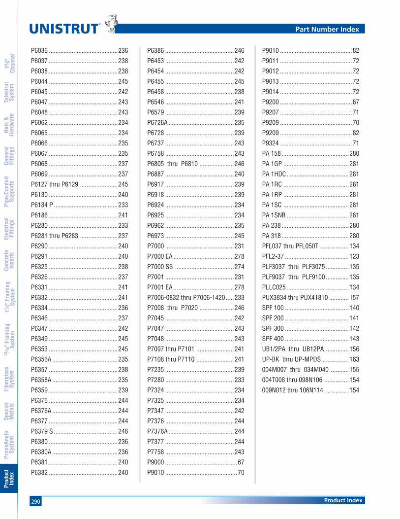
290
®
Product Index
15 ⁄8"
Chan
nel
Nuts
&Ha
rdw
are
Gene
ral
Fitti
ngs
Pipe
/Con
duit
Supp
orts
Elec
trica
lFi
tting
sCo
ncre
teIn
serts
11 ⁄4" F
ram
ing
Syst
em13
⁄16" F
ram
ing
Syst
emFi
berg
lass
Syst
emSp
ecia
lM
etal
sTe
lest
rut
Syst
emPr
imeA
ngle
Syst
emPr
oduc
tIn
dex
P6036 ..........................................236
P6037 ..........................................238
P6038 ..........................................238
P6044 ..........................................245
P6045 ..........................................242
P6047 ..........................................243
P6048 ..........................................243
P6062 ..........................................234
P6065 ..........................................234
P6066 ..........................................235
P6067 ..........................................235
P6068 ..........................................237
P6069 ..........................................237
P6127 thru P6129 .......................245
P6130 ..........................................240
P6184 P .......................................233
P6186 ..........................................241
P6280 ..........................................233
P6281 thru P6283 .......................237
P6290 ..........................................240
P6291 ..........................................240
P6325 ..........................................238
P6326 ..........................................237
P6331 ..........................................241
P6332 ..........................................241
P6334 ..........................................236
P6346 ..........................................237
P6347 ..........................................242
P6349 ..........................................245
P6353 ..........................................245
P6356A ........................................235
P6357 ..........................................238
P6358A ........................................235
P6359 ..........................................239
P6376 ..........................................244
P6376A ........................................244
P6377 ..........................................244
P6379 S .......................................246
P6380 ..........................................236
P6380A ........................................236
P6381 ..........................................240
P6382 ..........................................240
P6386 ..........................................246
P6453 ..........................................242
P6454 ..........................................242
P6455 ..........................................245
P6458 ..........................................238
P6546 ..........................................241
P6579 ..........................................239
P6726A ........................................235
P6728 ..........................................239
P6737 ..........................................243
P6758 ..........................................243
P6805 thru P6810 .....................246
P6887 ..........................................240
P6917 ..........................................239
P6918 ..........................................239
P6924 ..........................................234
P6925 ..........................................234
P6962 ..........................................235
P6973 ..........................................245
P7000 ..........................................231
P7000 EA .....................................278
P7000 SS ....................................274
P7001 ..........................................231
P7001 EA .....................................278
P7006-0832 thru P7006-1420.....233
P7008 thru P7020 .....................246
P7045 ..........................................242
P7047 ..........................................243
P7048 ..........................................243
P7097 thru P7101 .......................241
P7108 thru P7110 .......................241
P7235 ..........................................239
P7280 ..........................................233
P7324 ..........................................234
P7325 ..........................................234
P7347 ..........................................242
P7376 ..........................................244
P7376A ........................................244
P7377 ..........................................244
P7758 ..........................................243
P9000 ............................................67
P9010 ............................................70
Part Number Index
P9010 ............................................82
P9011 ............................................72
P9012 ............................................72
P9013 ............................................72
P9014 ............................................72
P9200 ............................................67
P9207 ............................................71
P9209 ............................................70
P9209 ............................................82
P9324 ............................................71
PA 158 .........................................280
PA 1GP ........................................281
PA 1HDC......................................281
PA 1RC ........................................281
PA 1RP ........................................281
PA 1SC ........................................281
PA 1SNB ......................................281
PA 238 .........................................280
PA 318 .........................................280
PFL037 thru PFL050T ..................134
PFL2-37 .......................................123
PLF3037 thru PLF3075 ..............135
PLF9037 thru PLF9100 ..............135
PLLC025 ......................................134
PUX3834 thru PUX41810 ............157
SPF 100 .......................................140
SPF 200 .......................................141
SPF 300 .......................................142
SPF 400 .......................................143
UB1/2PA thru UB12PA ..............156
UP-BK thru UP-MPDS ................163
004M007 thru 034M040 ...........155
004T008 thru 098N106 ...............154
009N012 thru 106N114 ...............154

Meet Mr. StrutMr. Strut has symbolized unistrut innovation for over 50 years and he’s still coming up with fresh ideas and new ways to help you work easier, faster and smarter! So watch for Mr. Strut. When
he’s around you’re never far from the unistrut
World of Support. the product ApplicAtion ShoWcASe
Allows you to build a strong reputation with a World of Support from Unistrut. It’s packed with examples and application photos of the Unistrut Framing System in action. Call for your copy today.
The UnisTrUT® Metal Framing system
…engineered solutions you can count on!
Registered Trademarks of UNISTRUT:
“AXENT”, “UNISTRUT”, “P1000”, “TELESPAR”, “TELESTRUT”, “UNI-CLIP”, “UNICUSHION”, “UNIROD”, “GRAB BAG”, “PRImE ANGLE” and the cartoon character “mr. Strut”.
“SPF” is a Registered Trademarks of Lord & Sons.
“Cush-A-Grip” is a Registered Trademarks of ZSi.
Products of UNISTRUT are manufactured un-der one or more of the following United States patents:
3,362,738 3,388,809 3,415,554
3,417,951 3,421,280 3,437,779
3,443,348 3,468,567 3,601,347
3,617,076 3,618,882 3,628,296
3,721,463 3,861,107 3,877,275
3,888,440 3,888,441 3,914,063
3,927,499 3,928,930 3,948,012
3,968,624 3,994,111 4,073,114
4,277,923 4,278,288 4,289,415
Foreign patents and other patents pending
Marketing throughout the world by Unistrut: Tel: (800) 521-7730 • www.unistrut.com
When there’s work to be done, build with the leader…
uniStrut®

Gen
eral
Eng
inee
ring
Cat
alog
#15
UnistrUt4205 ElizabethWayne, MI 48184Phone: 800-521-7730Fax: 734-721-4106
www.unistrut.com
© Unistrut Corporation • U-15 • Printed in USA • 9/06
UnistrUt CAnADA585 Finley AvenueAjax, Ontario, L1S-2E4 CanadaTel: (800) 267-4959 (Canada only)Tel: (905) 683-8131Fax: (905) 683-8987
Copyright © 2022 FDOKUMEN