Dual Lock™ Reclosable Fasteners - Piece Parts - Unilog
12
Dual Lock™ Reclosable Fasteners - Piece Parts Technical Data Sheet April 2015 General Description 3M™ Dual Lock™ Reclosable Fasteners are positive-locking, blind fasteners designed for attaching automotive trim components. The products feature mushroom-shaped polyolefin stems that snap together, forming a high tensile closure. Dual Lock™ fasteners are used primarily to secure rigid and semi-rigid surfaces such as trim or door panels, instrument panel bezels, headliners, and other automotive interior and exterior trim. Dual Lock™ Reclosable Fasteners overcome the often difficult alignment and installation problems of screws and hidden fasteners. They offer simple installation with no additional tools required. Applications Dual Lock™ Reclosable Fasteners can replace conventional mechanical fasteners in a wide range of assembly and attachment applications where reclosability is desired. Some examples of applications include: • Vehicle headliners • Attaching accessories and equipment • Attaching window and door trim panels • Vibration and sound dampening control • CHMSL -- Center Hight Mount Stop Lamp -- cover plates • Center console flanges • Interior trim • Sunroof rings Dual Lock™ Reclosable Fasteners provide a firm bond to a wide variety of surfaces, including, but not limited to those listed above. Since product performance will depend on actual conditions within a specific application, it is essential that the user evaluate the 3M product to determine whether it is fit for a particular material purpose and suitable for the user’s method of application. Physical Properties Material Polyolefin Color Black Environmental Stability Excellent moisture resistance Recommended temperature range is -20°F to 220°F (-29°C to 104°C) Flammability Should be tested as a composite with the attached component for FMVSS 302 certification Thickness • Varies based on part and application. • There are two different measurements that should be considered for your application – the individual thickness of a product and the engaged thickness of the two part system. • The individual thickness is listed under “Product Thickness Code” next to the specific product number listed in this selection guide. The product thickness code is the thickness of the additional layer added to the plain- backed version of Dual Lock™ Reclosable Fasteners. • Plain-backed Dual Lock™ Reclosable fasteners have a thickness of 0.101 inches (2.57 mm).
-
Upload
khangminh22 -
Category
Documents
-
view
1 -
download
0
Transcript of Dual Lock™ Reclosable Fasteners - Piece Parts - Unilog
Dual Lock™ Reclosable Fasteners - Piece Parts Technical Data Sheet April 2015 General Description 3M™ Dual Lock™ Reclosable Fasteners are positive-locking, blind fasteners designed for attaching automotive trim components. The products feature mushroom-shaped polyolefin stems that snap together, forming a high tensile closure. Dual Lock™ fasteners are used primarily to secure rigid and semi-rigid surfaces such as trim or door panels, instrument panel bezels, headliners, and other automotive interior and exterior trim.
Dual Lock™ Reclosable Fasteners overcome the often difficult alignment and installation problems of screws and hidden fasteners. They offer simple installation with no additional tools required.
Applications Dual Lock™ Reclosable Fasteners can replace conventional mechanical fasteners in a wide range of assembly and attachment applications where reclosability is desired. Some examples of applications include: • Vehicle headliners • Attaching accessories and equipment • Attaching window and door trim panels • Vibration and sound dampening control • CHMSL -- Center Hight Mount Stop Lamp -- cover plates • Center console flanges • Interior trim • Sunroof rings
Dual Lock™ Reclosable Fasteners provide a firm bond to a wide variety of surfaces, including, but not limited to those listed above. Since product performance will depend on actual conditions within a specific application, it is essential that the user evaluate the 3M product to determine whether it is fit for a particular material purpose and suitable for the user’s method of application.
Physical Properties Material Polyolefin
Color Black
Environmental Stability Excellent moisture resistance Recommended temperature range is -20°F to 220°F (-29°C to 104°C)
Flammability Should be tested as a composite with the attached component for FMVSS 302 certification
Thickness • Varies based on part and application. • There are two different measurements that should be considered for your application – the individual
thickness of a product and the engaged thickness of the two part system. • The individual thickness is listed under “Product Thickness Code” next to the specific product number
listed in this selection guide. The product thickness code is the thickness of the additional layer added to the plain- backed version of Dual Lock™ Reclosable Fasteners.
• Plain-backed Dual Lock™ Reclosable fasteners have a thickness of 0.101 inches (2.57 mm).
Technical Data Sheet 3M™ Dual Lock™ Reclosable Fasteners, Piece Parts Page 2
Product Features
Easy Alignment of Parts:
Designed to eliminate concerns about misalignment and premature or incomplete engagement while providing easy and firm engagement from any direction.
Reclosability: Can be opened and re-closed in high cycle applications. Cycle life is the number of cycles (openings and closings) that the fastener is subjected to while maintaining 50% or greater of the peel values. The cycle life is 1000.
Appearance: Able to attach on the backside of a trim piece allowing for blind fastening and an uninterrupted show surface.
Vibration Resistance: Dramatically reduces the rattling and vibration of components.
Ease of Assembly: Does not require any special tools or equipment; fasteners can be used to attach components before they enter the final assembly plant, thus reducing the number of parts and the length of assembly time.
Multiple Attachment Methods
Available in numerous forms, allowing for the ability to be attached to a variety of surface, using different methods.
Adjustable Engagement and Disengagement Forces:
• Provides a range of engagement and disengagement forces that can be achieved by combining the different stem densities.
• Provides adjustable and proportional engagement and disengagement forces to the engaged area of the fastener.
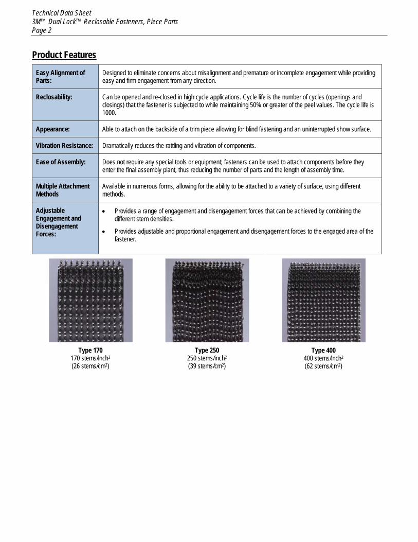
Type 170
170 stems/inch2 (26 stems/cm2)
Type 250
250 stems/inch2 (39 stems/cm2)
Type 400
400 stems/inch2
(62 stems/cm2)
Technical Data Sheet 3M™ Dual Lock™ Reclosable Fasteners, Piece Parts Page 3
3M™ Dual Lock™ Reclosable Fasteners Pop-In Piece Parts
General Description 3M™ Dual Lock™ Reclosable Fasteners Pop-In Parts attach without the use of pressure sensitive adhesive, and come with a variety of bases that can be inserted or slid into holes of precise dimension. They are easy to install and require no special equipment or skills. Pop-ins are a good alternative to pressure sensitive adhesive backed Dual Lock™ reclosable fasteners where there are constraints related to the surface characteristics, material type, temperature and dwell time.
Design Considerations and Suggestions Selection of the Pop-in part should be made based on the following considerations:
1. Dual Lock reclosable fastener strength is proportional to the fastening contact area. 2. Whenever possible, design one side of the Dual Lock reclosable fasteners to be larger than the mating side. This will allow for
variability or mismatch in Dual Lock reclosable fastener alignment positions, and ensure 100% fastening area contact. Another approach would be to design two rectangular shaped fasteners so that they can be engaged in a cross-web/perpendicular pattern.
3. Dual Lock reclosable fastener disengagement strength/performance is strongest in direct tensile. 4. Cleavage mode disengagement greatly reduces the fastening strength. 5. Standard part drawings are available for all Dual Lock reclosable fastener piece parts. These part drawings define key dimensions
which should be used for design purposes. 6. Target Disengagement Strength for part/application (Dual Lock reclosable fasteners combination and fastening area). 7. Pop-in pull-out strength must exceed the Dual Lock reclosable fasteners target disengagement strength for the Dual Lock reclosable
fasteners combination. The target for the Pop-in pull-out strength should be 150% of the target disengagement strength. If the target disengagement strength for the selected fastener combination and area is 43 lb/f, then the pull-out strength for the piece part should be a minimum of 64.5 lb/f.
8. Sheet metal or panel thickness and range 9. Hole size 10. Gap behind the sheet metal for post protrusion, etc. 11. Burr on die punched hole – the burr on a hole affects the effective panel thickness which will have an effect on the performance of
Pop-ins. 12. Stack-up height can be increased for Tree Style Pop-ins with the addition of a foam washer.
Technical Data Sheet 3M™ Dual Lock™ Reclosable Fasteners, Piece Parts Page 4
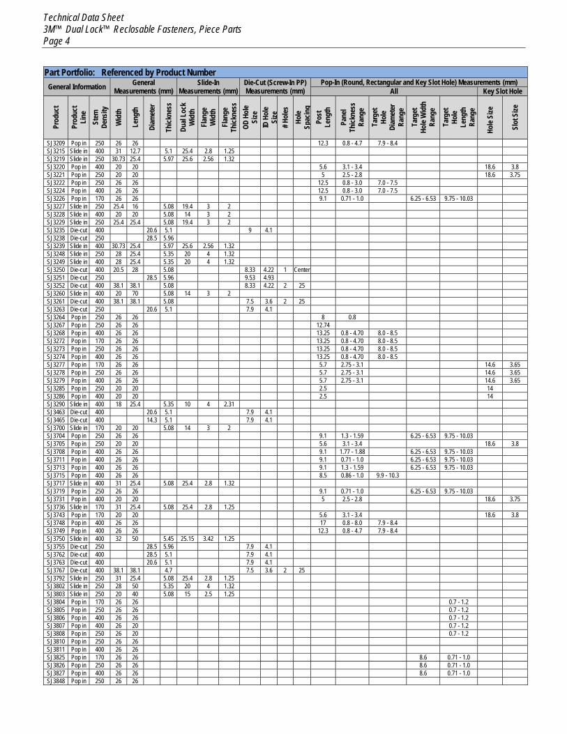
Part Portfolio: Referenced by Product Number General Information General
Measurements (mm) Slide-In
Measurements (mm) Die-Cut (Screw-In PP) Measurements (mm)
Pop-In (Round, Rectangular and Key Slot Hole) Measurements (mm) All Key Slot Hole
Prod
uct
Prod
uct
Line
St
em
Dens
ity
Wid
th
Leng
th
Diam
eter
Thick
ness
Dual
Lock
W
idth
Fl
ange
W
idth
Fl
ange
Th
ickne
ss
OD H
ole
Size
ID
Hol
e Si
ze
# Hol
es
Hole
Spac
ing
Post
Le
ngth
Pane
l Th
ickne
ss
Rang
e
Targ
et
Hole
Diam
eter
Ra
nge
Targ
et
Hole
Wid
th
Rang
e
Targ
et
Hole
Leng
th
Rang
e
Hole
Size
Slot
Size
SJ3209 Pop in 250 26 26 12.3 0.8 - 4.7 7.9 - 8.4 SJ3215 Slide in 400 31 12.7 5.1 25.4 2.8 1.25 SJ3219 Slide in 250 30.73 25.4 5.97 25.6 2.56 1.32 SJ3220 Pop in 400 20 20 5.6 3.1 - 3.4 18.6 3.8 SJ3221 Pop in 250 20 20 5 2.5 - 2.8 18.6 3.75 SJ3222 Pop in 250 26 26 12.5 0.8 - 3.0 7.0 - 7.5 SJ3224 Pop in 400 26 26 12.5 0.8 - 3.0 7.0 - 7.5 SJ3226 Pop in 170 26 26 9.1 0.71 - 1.0 6.25 - 6.53 9.75 - 10.03 SJ3227 Slide in 250 25.4 16 5.08 19.4 3 2 SJ3228 Slide in 400 20 20 5.08 14 3 2 SJ3229 Slide in 250 25.4 25.4 5.08 19.4 3 2 SJ3235 Die-cut 400 20.6 5.1 9 4.1 SJ3238 Die-cut 250 28.5 5.96 SJ3239 Slide in 400 30.73 25.4 5.97 25.6 2.56 1.32 SJ3248 Slide in 250 28 25.4 5.35 20 4 1.32 SJ3249 Slide in 400 28 25.4 5.35 20 4 1.32 SJ3250 Die-cut 400 20.5 28 5.08 8.33 4.22 1 Center SJ3251 Die-cut 250 28.5 5.96 9.53 4.93 SJ3252 Die-cut 400 38.1 38.1 5.08 8.33 4.22 2 25 SJ3260 Slide in 400 20 70 5.08 14 3 2 SJ3261 Die-cut 400 38.1 38.1 5.08 7.5 3.6 2 25 SJ3263 Die-cut 250 20.6 5.1 7.9 4.1 SJ3264 Pop in 250 26 26 8 0.8 SJ3267 Pop in 250 26 26 12.74 SJ3268 Pop in 400 26 26 13.25 0.8 - 4.70 8.0 - 8.5 SJ3272 Pop in 170 26 26 13.25 0.8 - 4.70 8.0 - 8.5 SJ3273 Pop in 250 26 26 13.25 0.8 - 4.70 8.0 - 8.5 SJ3274 Pop in 400 26 26 13.25 0.8 - 4.70 8.0 - 8.5 SJ3277 Pop in 170 26 26 5.7 2.75 - 3.1 14.6 3.65 SJ3278 Pop in 250 26 26 5.7 2.75 - 3.1 14.6 3.65 SJ3279 Pop in 400 26 26 5.7 2.75 - 3.1 14.6 3.65 SJ3285 Pop in 250 20 20 2.5 14 SJ3286 Pop in 400 20 20 2.5 14 SJ3290 Slide in 400 18 25.4 5.35 10 4 2.31 SJ3463 Die-cut 400 20.6 5.1 7.9 4.1 SJ3465 Die-cut 400 14.3 5.1 7.9 4.1 SJ3700 Slide in 170 20 20 5.08 14 3 2 SJ3704 Pop in 250 26 26 9.1 1.3 - 1.59 6.25 - 6.53 9.75 - 10.03 SJ3705 Pop in 250 20 20 5.6 3.1 - 3.4 18.6 3.8 SJ3708 Pop in 400 26 26 9.1 1.77 - 1.88 6.25 - 6.53 9.75 - 10.03 SJ3711 Pop in 400 26 26 9.1 0.71 - 1.0 6.25 - 6.53 9.75 - 10.03 SJ3713 Pop in 400 26 26 9.1 1.3 - 1.59 6.25 - 6.53 9.75 - 10.03 SJ3715 Pop in 400 26 26 8.5 0.86 - 1.0 9.9 - 10.3 SJ3717 Slide in 400 31 25.4 5.08 25.4 2.8 1.32 SJ3719 Pop in 250 26 26 9.1 0.71 - 1.0 6.25 - 6.53 9.75 - 10.03 SJ3731 Pop in 400 20 20 5 2.5 - 2.8 18.6 3.75 SJ3736 Slide in 170 31 25.4 5.08 25.4 2.8 1.25 SJ3743 Pop in 170 20 20 5.6 3.1 - 3.4 18.6 3.8 SJ3748 Pop in 400 26 26 17 0.8 - 8.0 7.9 - 8.4 SJ3749 Pop in 400 26 26 12.3 0.8 - 4.7 7.9 - 8.4 SJ3750 Slide in 400 32 50 5.45 25.15 3.42 1.25 SJ3755 Die-cut 250 28.5 5.96 7.9 4.1 SJ3762 Die-cut 400 28.5 5.1 7.9 4.1 SJ3763 Die-cut 400 20.6 5.1 7.9 4.1 SJ3767 Die-cut 400 38.1 38.1 4.7 7.5 3.6 2 25 SJ3792 Slide in 250 31 25.4 5.08 25.4 2.8 1.25 SJ3802 Slide in 250 28 50 5.35 20 4 1.32 SJ3803 Slide in 250 20 40 5.08 15 2.5 1.25 SJ3804 Pop in 170 26 26 0.7 - 1.2 SJ3805 Pop in 250 26 26 0.7 - 1.2 SJ3806 Pop in 400 26 26 0.7 - 1.2 SJ3807 Pop in 400 26 20 0.7 - 1.2 SJ3808 Pop in 250 26 20 0.7 - 1.2 SJ3810 Pop in 250 26 26 SJ3811 Pop in 400 26 26 SJ3825 Pop in 170 26 26 8.6 0.71 - 1.0 SJ3826 Pop in 250 26 26 8.6 0.71 - 1.0 SJ3827 Pop in 400 26 26 8.6 0.71 - 1.0 SJ3848 Pop in 250 26 26
Technical Data Sheet 3M™ Dual Lock™ Reclosable Fasteners, Piece Parts Page 5
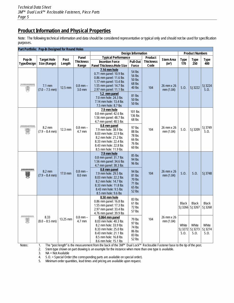
Product Information and Physical Properties Note: The following technical information and data should be considered representative or typical only and should not be used for specification purposes. Part Portfolio: Pop-In Designed for Round Holes
Design Information Product Numbers
Pop-In Type/Design
Target Hole Size (Range)
Post Length
Panel Thickness
Range
Typical Performance Product Thickness
Code Stem Area
(in2) Type 170
Type 250
Type 400 Insertion Force
Panel Thickness/Hole Size Pull-Out
Force
7.1 mm (7.0 – 7.5 mm) 12.5 mm 0.8 mm –
3.0 mm
7.14 mm hole 0.71 mm panel: 10.9 lbs 0.86 mm panel: 11.6 lbs 1.17 mm panel: 13.4 lbs 1.55 mm panel: 14.7 lbs 2.97 mm panel: 11.1 lbs
54 lbs 56 lbs 50 lbs 68 lbs 40 lbs 104 26 mm x 26
mm (1.04) S.O. SJ3222 SJ3224 S.O.
1.2 mm panel 7.0 mm hole: 24.3 lbs
7.14 mm hole: 13.4 lbs 7.5 mm hole: 8.7 lbs
81 lbs 50 lbs 50 lbs
8.2 mm (7.9 – 8.4 mm) 12.3 mm 0.8 mm –
4.7 mm
7.9 mm hole 0.8 mm panel: 42.6 lbs 1.56 mm panel: 48.7 lbs 4.7 mm panel: 48.5 lbs
101 lbs 136 lbs 68 lbs
104 26 mm x 26 mm (1.04) S.O. SJ3209 SJ3749
S.O. 0.8 mm panel
7.9 mm hole: 38.9 lbs 8.03 mm hole: 22.9 lbs 8.2 mm hole: 21.2 lbs
8.33 mm hole: 22.4 lbs 8.43 mm hole: 22.8 lbs 8.5 mm hole: 11.9 lbs
97 lbs 88 lbs 78 lbs 66 lbs 76 lbs 60 lbs
8.2 mm (7.9 – 8.4 mm) 17.0 mm 0.8 mm –
8.0 mm
7.9 mm hole 0.8 mm panel: 31.7 lbs 1.56 mm panel: 34.6 lbs 4.7 mm panel: 38.3 lbs
85 lbs 94 lbs 96 lbs
104 26 mm x 26 mm (1.04) S.O. S.O. SJ3748
0.8 mm panel 7.9 mm hole: 29.5 lbs
8.03 mm hole: 22.2 lbs 8.2 mm hole: 14.7 lbs
8.33 mm hole: 11.8 lbs 8.43 mm hole: 9.5 lbs 8.5 mm hole: 9.6 lbs
94 lbs 81 lbs 70 lbs 71 lbs 65 lbs 52 lbs
8.33 (8.0 – 8.5 mm) 13.25 mm 0.8 mm –
4.7 mm
8.50 mm hole 0.86 mm panel: 16.8 lbs 1.55 mm panel: 17.3 lbs 2.97 mm panel: 33.4 lbs 4.76 mm panel: 39.9 lbs
83 lbs 61 lbs 72 lbs 57 lbs
104 26 mm x 26 mm (1.04)
Black SJ3266
Black SJ3267
Black SJ3268
0.864 mm panel 8.03 mm hole: 40.3 lbs 8.2 mm hole: 33.9 lbs
8.33 mm hole: 25.0 lbs 8.43 mm hole: 21.1 lbs 8.5 mm hole: 16.8 lbs 8.6 mm hole: 15.1 lbs
79 lbs 97 lbs 74 lbs 86 lbs 83 lbs 52 lbs
White SJ3272
S.O.
White SJ3273
S.O.
White SJ3274
S.O.
Notes: 1. The “post length” is the measurement from the back of the 3M™ Dual Lock™ Reclosable Fastener base to the tip of the post. 2. Stem type shown on part drawing is an example for the instance when more than one type is available. 3. NA = Not Available 4. S.O. = Special Order (the corresponding parts are available on special order). 5. Minimum order quantities, lead times and pricing are available upon request.
Technical Data Sheet 3M™ Dual Lock™ Reclosable Fasteners, Piece Parts Page 6
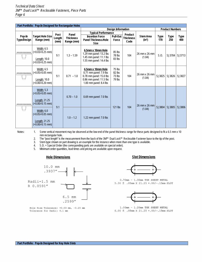
Part Portfolio: Pop-In Designed for Rectangular Holes Design Information Product Numbers
Pop-In Type/Design
Target Hole Size Range (mm)
Post Length (mm)
Panel Thickness
Range (mm)
Typical Performance Product Thickness
Code Stem Area
(in2) Type 170
Type 250
Type 400
Insertion Force Panel Thickness/Hole
Size
Pull-Out Force
Width: 6.5 (+0.03/-0.25 mm)
Length: 10.0
(+0.03/-0.25 mm)
9.1 1.3 – 1.59 6.5mm x 10mm Hole
1.29 mm panel: 13.2 lbs 1.45 mm panel: 11.1 lbs 1.55 mm panel: 14.4 lbs
85 lbs 78 lbs 83 lbs
104 26 mm x 26 mm (1.04) S.O. SJ3704 SJ3713
Width: 6.5 (+0.05/-0.05 mm)
Length: 10.0
(+0.00/-0.20 mm)
9.1 0.71 – 1.0
6.5mm x 10mm Hole 0.71 mm panel: 7.9 lbs 0.78 mm panel: 15.0 lbs 0.86 mm panel: 11.5 lbs 1.00 mm panel: 8.4 lbs
75 lbs 82 lbs 73 lbs 79 lbs
104 26 mm x 26 mm (1.04) SJ3825 SJ3826 SJ3827
Width: 5.3 (+0.05/-0.05 mm)
Length: 21.25
(+0.00/-0.15 mm) 9.1
0.70 – 1.0 0.69 mm panel: 7.0 lbs
121 lbs 104 26 mm x 26 mm (1.04) SJ3804 SJ3805 SJ3806
Width: 6.0 (+0.05/-0.05 mm)
Length: 21.25
(+0.00/-0.15 mm)
1.0 – 1.2 1.22 mm panel: 7.0 lbs
Notes: 1. Some vertical movement may be observed at the low end of the panel thickness range for these parts designed to fit a 6.5 mm x 10 mm rectangular hole.
2. The “post length” is the measurement from the back of the 3M™ Dual Lock™ Reclosable Fastener base to the tip of the post. 3. Stem type shown on part drawing is an example for the instance when more than one type is available. 4. S.O. = Special Order (the corresponding parts are available on special order). 5. Minimum order quantities, lead times and pricing are available upon request.
Hole Dimensions
Slot Dimensions
Part Portfolio: Pop-In Designed for Key Hole Slots
Technical Data Sheet 3M™ Dual Lock™ Reclosable Fasteners, Piece Parts Page 7
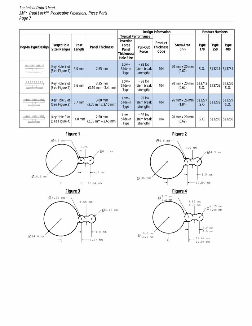
Design Information Product Numbers
Pop-In Type/Design Target Hole Size (Range)
Post Length Panel Thickness
Typical Performance
Product Thickness
Code Stem Area
(in2) Type 170
Type 250
Type 400
Insertion Force Panel
Thickness/ Hole Size
Pull-Out Force
Key Hole Slot (See Figure 1) 5.0 mm 2.65 mm
Low – Slide-in Type
~ 92 lbs (stem break
strength) 104 20 mm x 20 mm
(0.62) S.O. SJ3221 SJ3731
Key Hole Slot (See Figure 2) 5.6 mm 3.25 mm
(3.10 mm – 3.4 mm) Low –
Slide-in Type
~ 92 lbs (stem break
strength) 104 20 mm x 20 mm
(0.62) SJ3743
S.O. SJ3705 SJ3220 S.O.
Key Hole Slot (See Figure 3) 5.7 mm 3.00 mm
(2.75 mm x 3.10 mm) Low –
Slide-in Type
~ 92 lbs (stem break
strength) 104 26 mm x 26 mm
(1.04) SJ3277
S.O SJ3278 SJ3279 S.O.
Key Hole Slot (See Figure 4) 14.0 mm 2.50 mm
(2.35 mm – 2.65 mm) Low –
Slide-in Type
~ 92 lbs (stem break
strength) 104 20 mm x 20 mm
(0.62) S.O SJ3285 SJ3286
Figure 1 Figure 2
Figure 3 Figure 4
Technical Data Sheet 3M™ Dual Lock™ Reclosable Fasteners, Piece Parts Page 8
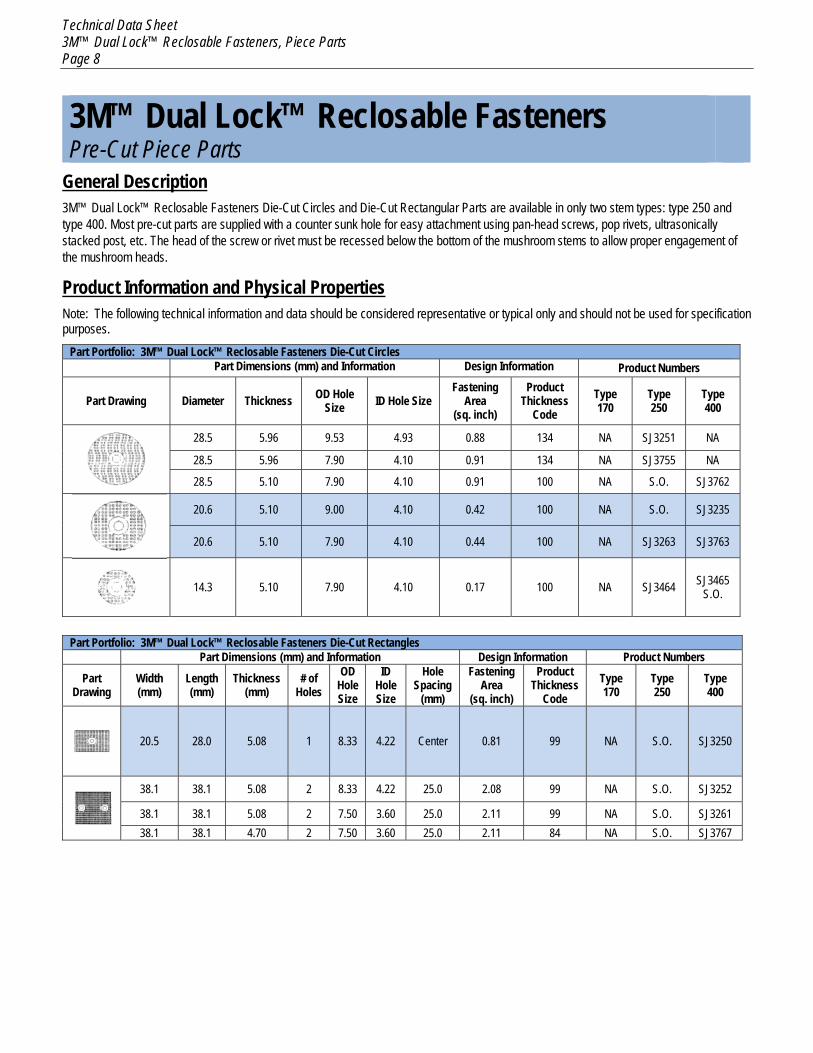
3M™ Dual Lock™ Reclosable Fasteners Pre-Cut Piece Parts
General Description 3M™ Dual Lock™ Reclosable Fasteners Die-Cut Circles and Die-Cut Rectangular Parts are available in only two stem types: type 250 and type 400. Most pre-cut parts are supplied with a counter sunk hole for easy attachment using pan-head screws, pop rivets, ultrasonically stacked post, etc. The head of the screw or rivet must be recessed below the bottom of the mushroom stems to allow proper engagement of the mushroom heads.
Product Information and Physical Properties Note: The following technical information and data should be considered representative or typical only and should not be used for specification purposes.
Part Portfolio: 3M™ Dual Lock™ Reclosable Fasteners Die-Cut Circles Part Dimensions (mm) and Information Design Information Product Numbers
Part Drawing Diameter Thickness OD Hole Size ID Hole Size
Fastening Area
(sq. inch)
Product Thickness
Code Type 170
Type 250
Type 400
28.5 5.96 9.53 4.93 0.88 134 NA SJ3251 NA
28.5 5.96 7.90 4.10 0.91 134 NA SJ3755 NA
28.5 5.10 7.90 4.10 0.91 100 NA S.O. SJ3762
20.6 5.10 9.00 4.10 0.42 100 NA S.O. SJ3235
20.6 5.10 7.90 4.10 0.44 100 NA SJ3263 SJ3763
14.3 5.10 7.90 4.10 0.17 100 NA SJ3464 SJ3465 S.O.
Part Portfolio: 3M™ Dual Lock™ Reclosable Fasteners Die-Cut Rectangles
Part Dimensions (mm) and Information Design Information Product Numbers
Part Drawing
Width (mm)
Length (mm)
Thickness (mm)
# of Holes
OD Hole Size
ID Hole Size
Hole Spacing
(mm)
Fastening Area
(sq. inch)
Product Thickness
Code Type 170
Type 250
Type 400
20.5 28.0 5.08 1 8.33 4.22 Center 0.81 99 NA S.O. SJ3250
38.1 38.1 5.08 2 8.33 4.22 25.0 2.08 99 NA S.O. SJ3252
38.1 38.1 5.08 2 7.50 3.60 25.0 2.11 99 NA S.O. SJ3261 38.1 38.1 4.70 2 7.50 3.60 25.0 2.11 84 NA S.O. SJ3767
Technical Data Sheet 3M™ Dual Lock™ Reclosable Fasteners, Piece Parts Page 9
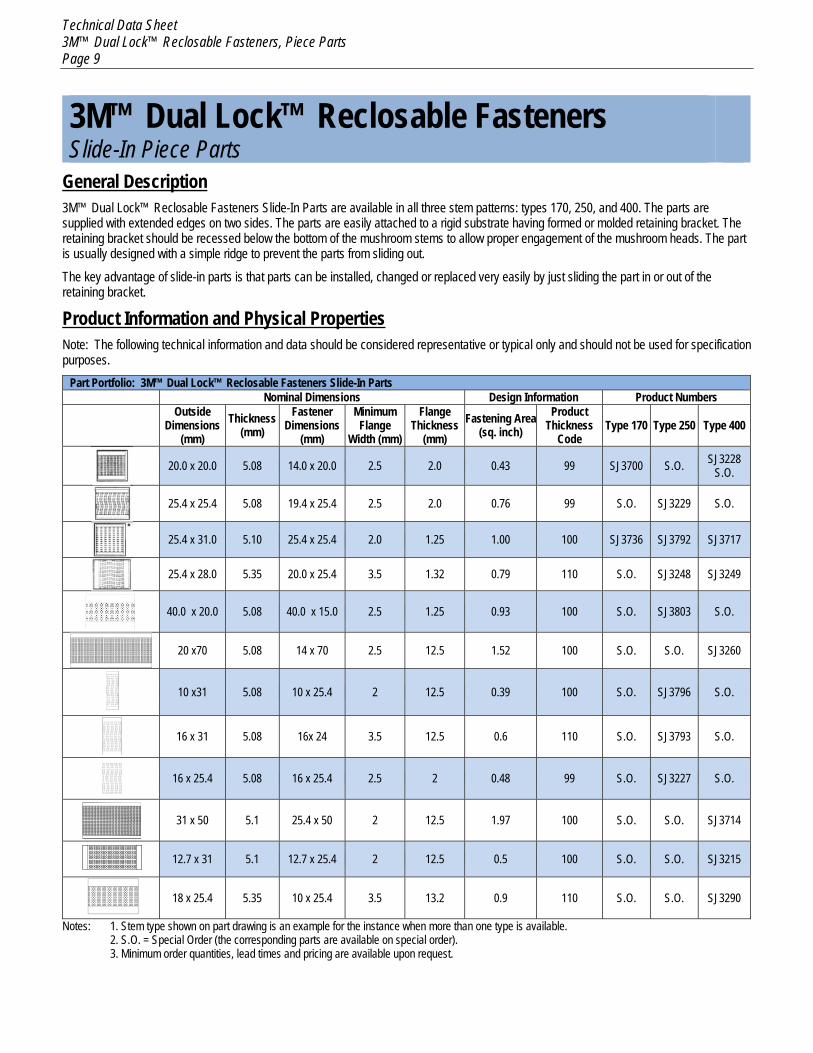
3M™ Dual Lock™ Reclosable Fasteners Slide-In Piece Parts
General Description 3M™ Dual Lock™ Reclosable Fasteners Slide-In Parts are available in all three stem patterns: types 170, 250, and 400. The parts are supplied with extended edges on two sides. The parts are easily attached to a rigid substrate having formed or molded retaining bracket. The retaining bracket should be recessed below the bottom of the mushroom stems to allow proper engagement of the mushroom heads. The part is usually designed with a simple ridge to prevent the parts from sliding out.
The key advantage of slide-in parts is that parts can be installed, changed or replaced very easily by just sliding the part in or out of the retaining bracket.
Product Information and Physical Properties Note: The following technical information and data should be considered representative or typical only and should not be used for specification purposes.
Part Portfolio: 3M™ Dual Lock™ Reclosable Fasteners Slide-In Parts Nominal Dimensions Design Information Product Numbers
Outside
Dimensions (mm)
Thickness (mm)
Fastener Dimensions
(mm)
Minimum Flange
Width (mm)
Flange Thickness
(mm) Fastening Area
(sq. inch) Product
Thickness Code
Type 170 Type 250 Type 400
20.0 x 20.0 5.08 14.0 x 20.0 2.5 2.0 0.43 99 SJ3700 S.O. SJ3228
S.O.
25.4 x 25.4 5.08 19.4 x 25.4 2.5 2.0 0.76 99 S.O. SJ3229 S.O.
25.4 x 31.0 5.10 25.4 x 25.4 2.0 1.25 1.00 100 SJ3736 SJ3792 SJ3717
25.4 x 28.0 5.35 20.0 x 25.4 3.5 1.32 0.79 110 S.O. SJ3248 SJ3249
40.0 x 20.0 5.08 40.0 x 15.0 2.5 1.25 0.93 100 S.O. SJ3803 S.O.
20 x70 5.08 14 x 70 2.5 12.5 1.52 100 S.O. S.O. SJ3260
10 x31 5.08 10 x 25.4 2 12.5 0.39 100 S.O. SJ3796 S.O.
16 x 31 5.08 16x 24 3.5 12.5 0.6 110 S.O. SJ3793 S.O.
16 x 25.4 5.08 16 x 25.4 2.5 2 0.48 99 S.O. SJ3227 S.O.
31 x 50 5.1 25.4 x 50 2 12.5 1.97 100 S.O. S.O. SJ3714
12.7 x 31 5.1 12.7 x 25.4 2 12.5 0.5 100 S.O. S.O. SJ3215
18 x 25.4 5.35 10 x 25.4 3.5 13.2 0.9 110 S.O. S.O. SJ3290
Notes: 1. Stem type shown on part drawing is an example for the instance when more than one type is available. 2. S.O. = Special Order (the corresponding parts are available on special order). 3. Minimum order quantities, lead times and pricing are available upon request.
Technical Data Sheet 3M™ Dual Lock™ Reclosable Fasteners, Piece Parts Page 10
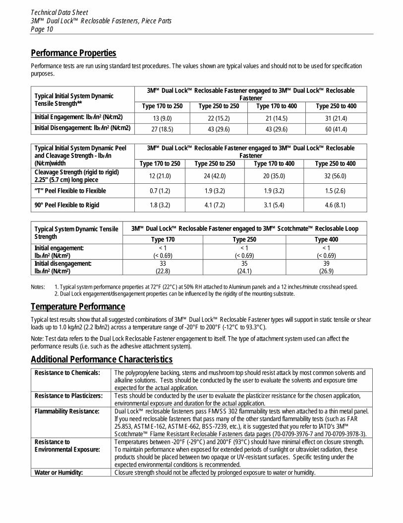
Performance Properties Performance tests are run using standard test procedures. The values shown are typical values and should not to be used for specification purposes.
Typical Initial System Dynamic Tensile Strength**
3M™ Dual Lock™ Reclosable Fastener engaged to 3M™ Dual Lock™ Reclosable Fastener
Type 170 to 250 Type 250 to 250 Type 170 to 400 Type 250 to 400 Initial Engagement: lbF/in2 (N/cm2) 13 (9.0) 22 (15.2) 21 (14.5) 31 (21.4) Initial Disengagement: lbF/in2 (N/cm2) 27 (18.5) 43 (29.6) 43 (29.6) 60 (41.4)
Typical Initial System Dynamic Peel and Cleavage Strength - lbF/in (N/cm)width
3M™ Dual Lock™ Reclosable Fastener engaged to 3M™ Dual Lock™ Reclosable Fastener
Type 170 to 250 Type 250 to 250 Type 170 to 400 Type 250 to 400 Cleavage Strength (rigid to rigid) 2.25” (5.7 cm) long piece 12 (21.0) 24 (42.0) 20 (35.0) 32 (56.0)
“T” Peel Flexible to Flexible 0.7 (1.2) 1.9 (3.2) 1.9 (3.2) 1.5 (2.6)
90° Peel Flexible to Rigid 1.8 (3.2) 4.1 (7.2) 3.1 (5.4) 4.6 (8.1)
Typical System Dynamic Tensile Strength
3M™ Dual Lock™ Reclosable Fastener engaged to 3M™ Scotchmate™ Reclosable Loop Type 170 Type 250 Type 400
Initial engagement: lbF/in2 (N/cm2)
< 1 (< 0.69)
< 1 (< 0.69)
< 1 (< 0.69)
Initial disengagement: lbF/in2 (N/cm2)
33 (22.8)
35 (24.1)
39 (26.9)
Notes: 1. Typical system performance properties at 72°F (22°C) at 50% RH attached to Aluminum panels and a 12 inches/minute crosshead speed.
2. Dual Lock engagement/disengagement properties can be influenced by the rigidity of the mounting substrate.
Temperature Performance Typical test results show that all suggested combinations of 3M™ Dual Lock™ Reclosable Fastener types will support in static tensile or shear loads up to 1.0 kg/in2 (2.2 lb/in2) across a temperature range of -20°F to 200°F (-12°C to 93.3°C).
Note: Test data refers to the Dual Lock Reclosable Fastener engagement to itself. The type of attachment system used can affect the performance results (i.e. such as the adhesive attachment system).
Additional Performance Characteristics Resistance to Chemicals: The polypropylene backing, stems and mushroom top should resist attack by most common solvents and
alkaline solutions. Tests should be conducted by the user to evaluate the solvents and exposure time expected for the actual application.
Resistance to Plasticizers: Tests should be conducted by the user to evaluate the plasticizer resistance for the chosen application, environmental exposure and duration for the actual application.
Flammability Resistance: Dual Lock™ reclosable fasteners pass FMVSS 302 flammability tests when attached to a thin metal panel. If you need reclosable fasteners that pass many of the other standard flammability tests (such as FAR 25.853, ASTM E-162, ASTM E-662, BSS-7239, etc.), it is suggested that you refer to IATD’s 3M™ Scotchmate™ Flame Resistant Reclosable Fasteners data pages (70-0709-3976-7 and 70-0709-3978-3).
Resistance to Environmental Exposure:
Temperatures between -20°F (-29°C) and 200°F (93°C) should have minimal effect on closure strength. To maintain performance when exposed for extended periods of sunlight or ultraviolet radiation, these products should be placed between two opaque or UV-resistant surfaces. Specific testing under the expected environmental conditions is recommended.
Water or Humidity: Closure strength should not be affected by prolonged exposure to water or humidity.
Technical Data Sheet 3M™ Dual Lock™ Reclosable Fasteners, Piece Parts Page 11
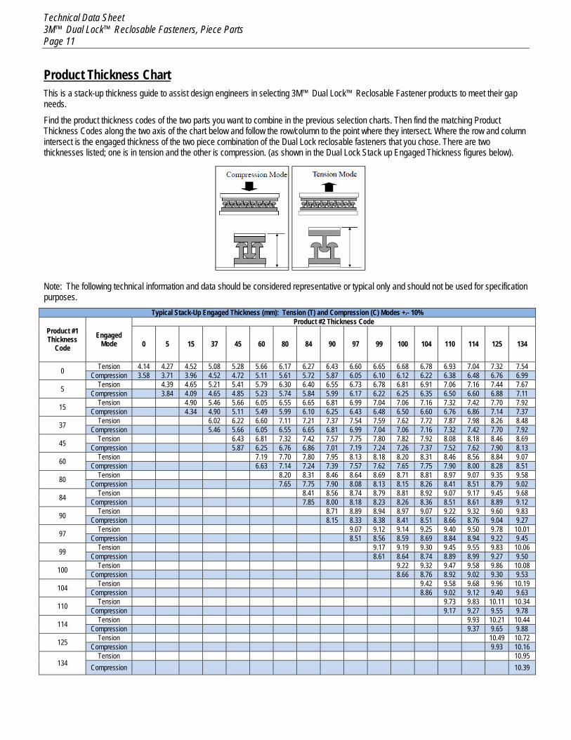
Product Thickness Chart This is a stack-up thickness guide to assist design engineers in selecting 3M™ Dual Lock™ Reclosable Fastener products to meet their gap needs.
Find the product thickness codes of the two parts you want to combine in the previous selection charts. Then find the matching Product Thickness Codes along the two axis of the chart below and follow the row/column to the point where they intersect. Where the row and column intersect is the engaged thickness of the two piece combination of the Dual Lock reclosable fasteners that you chose. There are two thicknesses listed; one is in tension and the other is compression. (as shown in the Dual Lock Stack up Engaged Thickness figures below).
Note: The following technical information and data should be considered representative or typical only and should not be used for specification purposes.
Typical Stack-Up Engaged Thickness (mm): Tension (T) and Compression (C) Modes +/- 10%
Product #1 Thickness
Code Engaged
Mode
Product #2 Thickness Code
0 5 15 37 45 60 80 84 90 97 99 100 104 110 114 125 134
0 Tension 4.14 4.27 4.52 5.08 5.28 5.66 6.17 6.27 6.43 6.60 6.65 6.68 6.78 6.93 7.04 7.32 7.54 Compression 3.58 3.71 3.96 4.52 4.72 5.11 5.61 5.72 5.87 6.05 6.10 6.12 6.22 6.38 6.48 6.76 6.99
5 Tension 4.39 4.65 5.21 5.41 5.79 6.30 6.40 6.55 6.73 6.78 6.81 6.91 7.06 7.16 7.44 7.67 Compression 3.84 4.09 4.65 4.85 5.23 5.74 5.84 5.99 6.17 6.22 6.25 6.35 6.50 6.60 6.88 7.11
15 Tension 4.90 5.46 5.66 6.05 6.55 6.65 6.81 6.99 7.04 7.06 7.16 7.32 7.42 7.70 7.92 Compression 4.34 4.90 5.11 5.49 5.99 6.10 6.25 6.43 6.48 6.50 6.60 6.76 6.86 7.14 7.37
37 Tension 6.02 6.22 6.60 7.11 7.21 7.37 7.54 7.59 7.62 7.72 7.87 7.98 8.26 8.48 Compression 5.46 5.66 6.05 6.55 6.65 6.81 6.99 7.04 7.06 7.16 7.32 7.42 7.70 7.92
45 Tension 6.43 6.81 7.32 7.42 7.57 7.75 7.80 7.82 7.92 8.08 8.18 8.46 8.69 Compression 5.87 6.25 6.76 6.86 7.01 7.19 7.24 7.26 7.37 7.52 7.62 7.90 8.13
60 Tension 7.19 7.70 7.80 7.95 8.13 8.18 8.20 8.31 8.46 8.56 8.84 9.07 Compression 6.63 7.14 7.24 7.39 7.57 7.62 7.65 7.75 7.90 8.00 8.28 8.51
80 Tension 8.20 8.31 8.46 8.64 8.69 8.71 8.81 8.97 9.07 9.35 9.58 Compression 7.65 7.75 7.90 8.08 8.13 8.15 8.26 8.41 8.51 8.79 9.02
84 Tension 8.41 8.56 8.74 8.79 8.81 8.92 9.07 9.17 9.45 9.68 Compression 7.85 8.00 8.18 8.23 8.26 8.36 8.51 8.61 8.89 9.12
90 Tension 8.71 8.89 8.94 8.97 9.07 9.22 9.32 9.60 9.83 Compression 8.15 8.33 8.38 8.41 8.51 8.66 8.76 9.04 9.27
97 Tension 9.07 9.12 9.14 9.25 9.40 9.50 9.78 10.01 Compression 8.51 8.56 8.59 8.69 8.84 8.94 9.22 9.45
99 Tension 9.17 9.19 9.30 9.45 9.55 9.83 10.06 Compression 8.61 8.64 8.74 8.89 8.99 9.27 9.50
100 Tension 9.22 9.32 9.47 9.58 9.86 10.08 Compression 8.66 8.76 8.92 9.02 9.30 9.53
104 Tension 9.42 9.58 9.68 9.96 10.19 Compression 8.86 9.02 9.12 9.40 9.63
110 Tension 9.73 9.83 10.11 10.34 Compression 9.17 9.27 9.55 9.78
114 Tension 9.93 10.21 10.44 Compression 9.37 9.65 9.88
125 Tension 10.49 10.72 Compression 9.93 10.16
134 Tension 10.95
Compression 10.39
Technical Data Sheet 3M™ Dual Lock™ Reclosable Fasteners, Piece Parts Page 12
Contact Information The information provided in this technical document is intended as a guide for this product. For more information, and help selecting a 3M product for an application, please contact a 3M Technical Service Representative.
Regulatory IMDS# is a published material entry on www.mdsystem.com To obtain the IMDS# for a particular 3M™ Dual Lock™ reclosable piece part fastener, please email your request to [email protected]
Technical Information: The technical information, recommendations and other statements contained in this document are based upon tests or experience that 3M believes are reliable, but the accuracy or completeness of such information is not guaranteed.
Product Use: Many factors beyond 3M’s control and uniquely within user’s knowledge and control can affect the use and performance of a 3M product in a particular application Given the variety of factors that can affect the use and performance of a 3M product, user is solely responsible for evaluating the 3M product and determining whether it is fit for a particular purpose and suitable for user’s method of application.
Warranty, Limited Remedy, and Disclaimer: Unless an additional warranty is specifically stated on the applicable 3M product packaging or product literature, 3M warrants that each 3M product meets the applicable 3M product specification at the time 3M ships the product. 3M MAKES NO OTHER WARRANTIES OR CONDITIONS, EXPRESS OR IMPLIED, INCLUDING, BUT NOT LIMITED TO, ANY IMPLIED WARRANTY OR CONDITION OF MERCHANTABILITY OR FITNESS FOR A PARTICULAR PURPOSE OR ANY IMPLIED WARRANTY OR CONDITION ARISING OUT OF A COURSE OF DEALING, CUSTOM OR USAGE OF TRADE. If the 3M product does not conform to this warranty, then the sole and exclusive remedy is, at 3M’s option, replacement of the 3M product or refund of the purchase price.
Limitation of Liability: Except where prohibited by law, 3M will not be liable for any loss or damage arising from the 3M product, whether direct, indirect, special, incidental or consequential, regardless of the legal theory asserted, including warranty, contract, negligence or strict liability.
3
Automotive Division 3M Center St. Paul, MN 55144-1000 www.3M.com/autosolutions 1-800-328-1684
© 3M 2015. All rights reserved. 3M, Dual Lock and Scotchmate are trademarks of 3M Company
Printed in U.S.A.
ISO/TS 9001:2008 FM 545417