Electrical and Low Voltage/ Datacomm Fasteners 2007
228
Electrical and Low Voltage/ Datacomm Fasteners 2007 http://www.computercablestore.com 800-626-6622 (267-354-6012)
-
Upload
khangminh22 -
Category
Documents
-
view
3 -
download
0
Transcript of Electrical and Low Voltage/ Datacomm Fasteners 2007

Electrical andLow Voltage/
DatacommFasteners
2007
http://www.computercablestore.com 800-626-6622 (267-354-6012)

Contact ERICO for a completelist of UL-Listed Fasteners.
12
34
56
78
CADDY® Fasteners areUL® Listed and ISO9001:2000 CertifiedWith our official registration and full compliance with ISO 9001:2000Certification, and our UL Listing,ERICO® is continually striving toexceed industry standards in everyaspect of our business.
http://www.computercablestore.com 800-626-6622 (267-354-6012)

1
Introduction
TABLE OF CONTENTS
New & Featured Products............
Applications.................................
NEC/CEC Compliance................
Conduit/Cable............................
Beam/Purlin..............................
Strut.........................................
Hangers/Hanging Systems...
Stud Wall................................
Drywall....................................
Datacomm ITS.........................
Acoustical................................
Ceiling/Partitions....................
Misc. Components.................
Reference Information..........
The CADDY Fastener Story...
Index.......................................
3-6
7-30
31-48
49-76
77-100
101-112
113-124
125-144
145-150
151-174
175-190
191-200
201-207
208-211
212-216
217-223
Ph: 1-800-25-www.erico.com
http://www.computercablestore.com 800-626-6622 (267-354-6012)

2Ph: 1-800-25-
www.erico.com
Introduction
Look for the BetterMousetrap IconsThroughout this CatalogThe first icon lets you know that we have developed a better fastener to replace the older model which you may be used to workingwith. It also tells you on what page to find it.
The second icon letsyou know you’ve found anew way to increase yourproductivity and boostyour bottom line.
CADDY® COATFor its range of CADDY® fixings,ERICO® has selected the best anti-corrosion protection treatments available according to the material type and the environmental application. As such, the unique ERICO®
CADDY® COAT treatment offers an excellent standard of corrosion resistance.
Look for this icon for
Residential Application
http://www.computercablestore.com 800-626-6622 (267-354-6012)

3Ph: 1-800-25-www.erico.com
Featured Products
CADDY® SPEED LINKThis universal support system isa cost-effective alternative tothreaded rod and associatedhardware and reduces installation time.
SEE PAGE 122
HOT PRODUCTS
HOT PRODUCTS
CADDY® SFCLTThe CADDY SFCLT SeismicFixture Clamps attach luminaires securely to the T-bar.These cost-effective clamps prevent the T-bar from twistingand disconnecting.
SEE PAGE 177
CADDY® SPEED LINK LDCADDY® SPEED LINK LD is idealfor suspending lighting andother applications that use jackchain, threaded rod and hardware. It is cost effective,time saving and easy to install.
SEE PAGE 124
CADDY® PYRAMIDRooftop Pipe &Equipment SupportCADDY® PYRAMID Pipe &Equipment Supports from ERICO®
provide an easy method for supporting pipes, conduit andequipment on roofs and belowraised floors. CADDY PYRAMIDdramatically reduces installationtime by replacing other labor-intensive support methods such as wood blocks, straps and clips. It also replaces steel foot plates,which can seriously damage roofmembranes.
The support design consists of a foam block with a metal top. The polyethylene foam blockabsorbs shock and vibration butwill not absorb water. The metalcover on top of the support offers protection from weatherand other environmental conditions. The electro-galvanizedfinish on the cover offers corrosion protection.
CADDY PYRAMID provides fornumerous mounting options andclamping positions. The foam and metal models offer mountingsupport up to 600 lbs. There is an all-plastic model available for loads up to 25 lbs.
SEE PAGE 62
http://www.computercablestore.com 800-626-6622 (267-354-6012)

4Ph: 1-800-25-
www.erico.com
Featured Products
CADDY® CABLECATPULLEYIncorporates a spring-loaded hook,beam clamp and a link allowing thepulley to be attached anywhere.
SEE PAGE 160
CADDY® CAT-CM Wide Base SupportsA high-performance cable support sys-tem with tremendous installation flexi-bility in applications where cable tray is traditionally used.
SEE PAGE 162
MPVTIProvides a single thread impression for easy installation in low-voltage applications. It can be used in multiple quantities to support multi-gang devices. Size and shape are no longer an issue.
SEE PAGE 150
Mille-TieTM Cable TieEfficient, cost-effective cable management ties that bundle andposition cables, including high per-formance copper and fiber cables, andprotects them from crimping damage.
SEE PAGE 166Mille-Tie is a trademark of Millepede Inc.
AFAB Angle BracketSpecially designed to install CADDY®
CABLECAT J-Hooks to threaded rod or directly to the structure.
SEE PAGES 115
VAFT Tool“From the Floor” installationtool designed to accommodate“J” hooks in addition to existingapplications.
SEE PAGE 85
http://www.computercablestore.com 800-626-6622 (267-354-6012)

5Ph: 1-800-25-www.erico.com
Featured Products
ISSP Strut PlateIdeal for retrofitting sections ofstrut into an existing trapeze.
SEE PAGES 118
CADDY® SLICK Strut NutSpring nut alternative – reducesinventory and installation timeby 50%
SEE PAGE 107
STS Strut-to-Strut ClampMake “back to back” strut fromstandard half slot in seconds
SEE PAGE 109
BCISNBeam Clamp/Smart NutThe lightweight – heavyweightbeam clamp is available with abuilt-in Smart Nut for fast attachment of 3/8-16 threaded rod.
SEE PAGE 79
ISN Smart Nut Snaps anywhere on 3/8-16threaded rod - eliminating extensive threading into place.
SEE PAGE 118
FMBS18 Floor Mount Box SupportPositions electrical boxes 18" above thefloor to comply with ADA Standards.
SEE PAGE 137
http://www.computercablestore.com 800-626-6622 (267-354-6012)

6Ph: 1-800-25-
www.erico.com
Featured Products
MCS Support BracketProperly spaces MC/AC cables to eliminate bundling and NECderating issues.
SEE PAGE 74
WC812 Combination Push-in Conduit ClipsQuickly attaches pipe, conduit,MC/AC and tube to wall surfaces.
SEE PAGE 51
ESC Easy Strut ClipAllows “snap on” attachmentof electrical and low-voltagecabling and components to strut.
SEE PAGES 112
AR812 Anti RattleConduit ClipsInstalls to metal stud withouttools and allows NEC 300-4(d)compliance.
SEE PAGES 143
For more information or to request samples forCADDY® products go to www.erico.com
http://www.computercablestore.com 800-626-6622 (267-354-6012)

7Ph: 1-800-25-www.erico.com
Applications
Pages 7-30
http://www.computercablestore.com 800-626-6622 (267-354-6012)

8Ph: 1-800-25-
www.erico.com
Applications
CONDUIT/CABLE
SEE PAGES 50, 51
SEE PAGES 53, 54
SEE PAGE 55
SEE PAGE 56
SEE PAGE 52
SEE PAGE 57
http://www.computercablestore.com 800-626-6622 (267-354-6012)

9Ph: 1-800-25-www.erico.com
Applications
CONDUIT/CABLE
SEE PAGE 58
SEE PAGE 58
SEE PAGE 59
SEE PAGE 60 SEE PAGE 61
http://www.computercablestore.com 800-626-6622 (267-354-6012)

10Ph: 1-800-25-
www.erico.com
CONDUIT/CABLE
SEE PAGE 70
SEE PAGE 136 SEE PAGES 64, 65
SEE PAGES 66, 67
SEE PAGE 70
Applications
SEE PAGE 72 SEE PAGE 73
http://www.computercablestore.com 800-626-6622 (267-354-6012)

11Ph: 1-800-25-www.erico.com
SEE PAGE 71
SEE PAGES 68, 69
SEE PAGES 68, 69
ApplicationsCONDUIT/CABLE
SEE PAGES 76
SEE PAGE 74
http://www.computercablestore.com 800-626-6622 (267-354-6012)

12Ph: 1-800-25-
www.erico.com
SEE PAGES 50, 51
ApplicationsCONDUIT/CABLE
SEE PAGES 62, 63
http://www.computercablestore.com 800-626-6622 (267-354-6012)

13Ph: 1-800-25-www.erico.com
ApplicationsBEAM/PURLIN
SEE PAGES 78, 79 SEE PAGES 80
SEE PAGES 81, 204
SEE PAGES 82, 116 SEE PAGE 83
SEE PAGE 87
SEE PAGES 88, 89
http://www.computercablestore.com 800-626-6622 (267-354-6012)

14Ph: 1-800-25-
www.erico.com
ApplicationsBEAM/PURLIN
SEE PAGES 84, 85
SEE PAGE 72
SEE PAGE 91
SEE PAGE 94 SEE PAGE 99
SEE PAGE 100
http://www.computercablestore.com 800-626-6622 (267-354-6012)

15Ph: 1-800-25-www.erico.com
ApplicationsSTRUT
SEE PAGE 104
SEE PAGE 59 SEE PAGE 60
SEE PAGE 109 SEE PAGE 112
SEE PAGE 106
SEE PAGE 107
http://www.computercablestore.com 800-626-6622 (267-354-6012)

16Ph: 1-800-25-
www.erico.com
ApplicationsHANGERS/HANGING SYSTEMS
SEE PAGE 118
SEE PAGES 82, 116
SEE PAGE 114
SEE PAGE 119 SEE PAGE 120
http://www.computercablestore.com 800-626-6622 (267-354-6012)

17Ph: 1-800-25-www.erico.com
ApplicationsHANGERS/HANGING SYSTEMS
SEE PAGE 117 SEE PAGE 121
STUD WALL
SEE PAGE 130 SEE PAGE 131
SEE PAGE 126
SEE PAGE 122
http://www.computercablestore.com 800-626-6622 (267-354-6012)

18Ph: 1-800-25-
www.erico.com
ApplicationsSTUD WALL
SEE PAGE 128
SEE PAGE 132
SEE PAGE 133
SEE PAGE 136
SEE PAGE 134
http://www.computercablestore.com 800-626-6622 (267-354-6012)

19Ph: 1-800-25-www.erico.com
ApplicationsSTUD WALL
SEE PAGE 139
SEE PAGE 140 SEE PAGE 141
SEE PAGE 129
SEE PAGE 142
SEE PAGE 144
http://www.computercablestore.com 800-626-6622 (267-354-6012)

20Ph: 1-800-25-
www.erico.com
ApplicationsSTUD WALL
SEE PAGE 138 SEE PAGE 135
SEE PAGE 126
SEE PAGE 127
SEE PAGE 130
http://www.computercablestore.com 800-626-6622 (267-354-6012)

21Ph: 1-800-25-www.erico.com
ApplicationsSTUD WALL
SEE PAGE 131
SEE PAGE 137
SEE PAGE 143
2 1/2
http://www.computercablestore.com 800-626-6622 (267-354-6012)

22Ph: 1-800-25-
www.erico.com
ApplicationsDRYWALL
SEE PAGE 150
SEE PAGE 146
SEE PAGE 147
SEE PAGE 149 SEE PAGE 148, 169
http://www.computercablestore.com 800-626-6622 (267-354-6012)

23Ph: 1-800-25-www.erico.com
ApplicationsLOW VOLTAGE/DATACOMM
SEE PAGES 153-158 SEE PAGE 161
SEE PAGE 164 SEE PAGE 160
SEE PAGES 162-163
http://www.computercablestore.com 800-626-6622 (267-354-6012)

24Ph: 1-800-25-
www.erico.com
ApplicationsLOW VOLTAGE/DATACOMM
SEE PAGE 167 SEE PAGE 171
SEE PAGE 173 SEE PAGE 172
SEE PAGE 166
SEE PAGE 165 SEE PAGES 162-163
http://www.computercablestore.com 800-626-6622 (267-354-6012)

25Ph: 1-800-25-www.erico.com
ApplicationsACOUSTICAL
SEE PAGE 176
SEE PAGE 178
SEE PAGE 179
SEE PAGE 180
http://www.computercablestore.com 800-626-6622 (267-354-6012)

26Ph: 1-800-25-
www.erico.com
ApplicationsACOUSTICAL
SEE PAGE 181
SEE PAGE 182
SEE PAGE 183
SEE PAGE 184
http://www.computercablestore.com 800-626-6622 (267-354-6012)

27Ph: 1-800-25-www.erico.com
ApplicationsACOUSTICAL
SEE PAGE 185
SEE PAGE 186
SEE PAGE 187
SEE PAGE 190
FloatingRivet
➞
http://www.computercablestore.com 800-626-6622 (267-354-6012)

28Ph: 1-800-25-
www.erico.com
ApplicationsACOUSTICAL
SEE PAGE 189
SEE PAGE 178
CEILING/PARTITIONS
SEE PAGE 192
SEE PAGE 194
SEE PAGE 193
http://www.computercablestore.com 800-626-6622 (267-354-6012)

29Ph: 1-800-25-www.erico.com
ApplicationsCEILING/PARTITIONS
SEE PAGE 195
SEE PAGE 196
SEE PAGE 197
SEE PAGE 198 SEE PAGE 199
http://www.computercablestore.com 800-626-6622 (267-354-6012)

30Ph: 1-800-25-
www.erico.com
ApplicationsMISC. COMPONENTS
SEE PAGE 202
SEE PAGE 203
SEE PAGE 204 SEE PAGE 205
http://www.computercablestore.com 800-626-6622 (267-354-6012)

31Ph: 1-800-25-www.erico.com
Code Compliance
2005 National Electrical Code®
2002 Canadian Electrical Code®
A handbook of recommended CADDY® Fasteners for easy compliance to the fastening
requirements of the 2005 NEC®
and 2002 CEC®
NEC (pages 32 -47) is a registered trademark of, and the National Electric Code (NEC) standard is a copyright of
the National Fire Protection Association.
CEC (pages 48-49) is a registered trademark of, and the Canadian Electric Code (CEC) standard is a copyright
of the Canadian Standards Association International.
http://www.computercablestore.com 800-626-6622 (267-354-6012)

32Ph: 1-800-25-
www.erico.com
Code Compliance
2005 NEC Article 90 Introduction
90.3 Code Arrangement. Chapter 8 covers communications systems and is not subject to therequirements of Chapters 1 through 7 except where the requirements are specifically referenced in Chapter 8. [See page 43]
90.4 Enforcement. ...The authority having jurisdiction for enforcement of the Code has the responsibility for making interpretations of the rules, for deciding on the approval of equipment and materials, and for granting the special permission contemplated in a number of the rules.
By special permission, the authority having jurisdiction may waive specific requirements in this Code or permit alternative methods where it is assured that equivalent objectives can be achieved by establishingand maintaining effective safety.
2005 NEC Article 300 Wiring Methods
300.4 Protection Against Physical Damage.Where subject to physical damage, conductors shall be protected.
(B) Nonmetallic-Sheathed Cables and Electrical Nonmetallic Tubingthrough Metal Framing Members.
(1) Nonmetallic-Sheathed Cable. ... the cable shall be protected by listedbushings or listed grommets covering all metal edges that are securelyfastened in the opening prior to installation of the cable. [See Fig. 1]
The intent of this publication is to help the electrical industry meet the2005 National Electrical Code requirements in North America as theyrelate to fastening applications. (See page 48 for 2002 CanadianElectrical Code.) Shown are a variety of solutions. NOTE: Consult the AHJ (authority having jurisdiction) as local codesmay supersede the National Electrical Code®. – ERICO®, Inc.
ReferenceCEC 12-516CEC 12-616
MSP20 MetalStud Punch
ESG1 Grommet for 360° Protection of Nonmetallic SheathedCable and Tubing. (“V” and “U” Shaped Grommets and RetrofitBushings Disallowed. Grommets/Bushings must be listed.)
1
http://www.computercablestore.com 800-626-6622 (267-354-6012)

33Ph: 1-800-25-www.erico.com
Code Compliance
CJ6 Cable Support forMC/AC and NonmetallicSheathed Cable
CG4 Cable Gripperfor Nonmetallic SheathedCable or low-voltage wiringto wood and metal stud
300.4 Protection Against Physical Damage. (continued)
(D) Cables and Raceways Parallel to Framing Members....the cable or raceway shall be installed and supported...not less than 32 mm (11/4 in.) from the nearest edge of the framing member...wherenails or screws are likely to penetrate. [See Fig. 2]
Where this distance cannot be maintained, the cable or raceway shall beprotected from penetration by nails or screws by a steel plate, sleeve, orequivalent at least 1.6 mm (1/16 in.) thick... [See Fig. 3A & 9 on page 37]
Exception No. 3: A listed and marked steel plate less than 1.6 mm(1/16 in.) thick that provides equal or better protection against nail or screw penetration shall be permitted.
3
304B2 Press-onProtection Plates ForWood and Metal Studs
ReferenceCEC 12-516CEC 12-616
ReferenceCEC 12-510CEC 12-516CEC 12-618
MAC2 Seriesfor MC/AC Cable
2
http://www.computercablestore.com 800-626-6622 (267-354-6012)

34Ph: 1-800-25-
www.erico.com
Code Compliance300.11 Securing and Supporting.
(A) Secured in Place. Raceways, cable assemblies, boxes, cabinets andfittings shall be securely fastened in place. Support wires that do not provide secure support shall not be permitted as the sole support. Supportwires and associated fittings that provide secure support and that areinstalled in addition to the ceiling grid support wires shall be permitted asthe sole support. Where independent support wires are used, they shall besecured at both ends. Cables and raceways shall not be supported by ceiling grids.
(1) Fire-Rated Assemblies. Wiring located within the cavity of a fire-ratedfloor-ceiling or roof-ceiling assembly shall not be secured to, or supportedby, the ceiling assembly, including the ceiling support wires. An independentmeans of secure support shall be provided and shall be permitted to beattached to the assembly. Where independent support wires are used, theyshall be distinguishable by color, tagging, or other effective means fromthose that are part of the fire-rated design. [See Fig. 4A and 4B]
(2) Non-Fire-Rated Assemblies. Wiring located within the cavity of a non-fire-rated floor-ceiling or roof-ceiling assembly shall not be secured to, or supported by, the ceiling assembly, including the ceiling support wires.An independent means of secure support shall be provided. [See page 45 for more details relating to 300.11 and fastener solutions.]
B18 Series CombinationBox/Conduit Hanger
4TI24 Hammer-on Rod Hanger
K or PCS Series Drop-WireConduit & Cable Support
4H24 Hammer-on Flange Clip
4A
EC311 Independent Electrical Drop-Wire SecuringClips Distinguishable with Bright Yellow Color
Drop Wire
4B
http://www.computercablestore.com 800-626-6622 (267-354-6012)

35Ph: 1-800-25-www.erico.com
Code Compliance
2005 NEC Article 314 Outlet, Device, Pull, and Junction Boxes; Conduit Bodies; Fittings; and Manholes
314.23 Supports.Enclosures within the scope of this article shall be supported in accordance with one or more of the provisions in 314.23(A) through (H).
(D) Suspended Ceilings. An enclosure mounted to structural or supporting elements of a suspended ceiling shall be not more than 1650 cm.3 (100 in.3) in size and shall be securely fastened in place in accordance with either (D)(1) or (D)(2).
(1) Framing Members. An enclosure shall be fastened to the framing members by mechanical means such as bolts, screws, or rivets, or by the use of clips or other securing means identified for use with the type of ceiling framing member(s) and enclosure(s) employed. The framing members shall be adequately supported and securely fastened to eachother and to the building structure. [See Fig. 6A]
(2) Support Wires. The installation shall comply with the provisions of300.11(A). The enclosure shall be secured, using methods identified forthe purpose, to ceiling support wire(s), including any additional supportwire(s) installed for that purpose. Support wire(s) used for enclosure support shall be fastened at each end so as to be taut within the ceilingcavity. [See Fig. 6B]
512HD T-Grid Box Hanger
6A
512HD T-Grid Box Hanger6B
Support Wire
ReferenceCEC 30-302
2005 NEC Article 310 Conductors for General Wiring
310.15 Ampacities for Conductors Rated 0-2000 Volts310.15(B)(2) Adjustment Factors
Exception No. 5: Adjustment factors shall not apply to Type AC cable or toType MC cable without an overall outer jacket under the following conditions:.
(a) Each cable has not more than three current-carrying conductors.
(b) The conductors are 12 AWG copper.
(c) Not more than 20 current carrying conductors are bundled, stacked, or supported on “bridle rings”.
A 60 percent adjustment factor shall be applied where the current-carryingconductors in these cables that are stacked or bundled longer than 600 mm(24 in.) without maintaining spacing exceeds 20.
(b) More Than One Conduit, Tube, or Raceway. Spacing between conduits, tubing, or raceways shall be maintained.
5
http://www.computercablestore.com 800-626-6622 (267-354-6012)

36Ph: 1-800-25-
www.erico.com
Code Compliance314.23 Supports. (continued)
(E) Raceway Supported Enclosure, Without Devices, Luminaires (Fixtures), or Lampholders. Each conduit shall be secured within 900 mm. (3 ft.) of the enclosure, or within 450 mm. (18 in.) of the enclosure if all conduit entries are on the same side. [See Fig. 7A & 7B]
Consult Current NEC for Exceptions.
(F) Raceway Supported Enclosures, with Devices, Luminaires (Fixtures), or Lampholders. Each conduit shall be secured within 450 mm. (18 in.) of the enclosure. [See Fig. 7C]
Consult Current NEC for Exceptions.
Beam Fasteners forRaceway Support edEnclosures.
Device/Fixture not shown
18”
B18 Series Combinationbox/conduit hanger eliminates conduit bends.
ReferenceCEC 12-510CEC 12-618CEC 12-1010CEC 12-1404
ReferenceCEC 12-1010CEC 12-1404
ReferenceCEC 12-1010CEC 12-1404
314.27 Outlet Boxes.(B) Maximum Luminaire (Fixture) Weight. Outlet boxes or fittings installedas required by 314.23 shall be permitted to support luminaires (lighting fixtures) weighing 23 kg. (50 lb.) or less. A luminaire (lighting fixture) thatweighs more than 23 kg. (50 lb.) shall be supported independently of theoutlet box unless the outlet box is listed for the weight to be supported. [See Fig. 6B on page 35]
7A
MAX
MAX
7B
7C
http://www.computercablestore.com 800-626-6622 (267-354-6012)

37Ph: 1-800-25-www.erico.com
Code Compliance
CS812 Conduit Support.(See 3Bpage 33)
H Series or MEB1Box Mount.
MAX
MAX
ReferenceCEC 12-510CEC 12-618CEC 12-3012
2005 NEC Article 320Armored Cable: Type AC
320.2 Definition.Armored Cable, Type AC. A fabricated assembly of insulated conductors in a flexible metallic enclosure. See 320.100.
320.17 Through or Parallel to Framing Members. Type AC cable shall be protected in accordance within 300.4...whereinstalled through or parallel to framing members.
320.30 Securing and Supporting. General. Type AC cable shall be supported and secured by staples,cable ties, straps, hangers, or similar fittings, designed and installed soas not to damage the cable.
Securing. Unless otherwise provided, Type AC cable shall be securedwithin 300 mm (12 in.) of every outlet box, junction box, cabinet, or fittingand at intervals not exceeding 1.4 m (4-1/2 ft) where installed on oracross framing members.
Supporting. Unless otherwise provided, Type AC cable shall be supported at intervals not exceeding 1.4 m (4-1/2 ft).
Horizontal runs of Type AC cable installed in wooden or metal framingmembers or similar supporting means shall be considered supportedwhere such support does not exceed 1.4-m (4-1/2-ft) intervals.
320.80 Ampacity. The ampacity shall be determined by 310.15. [See Fig. 5 on page 35].
8
2005 NEC Article 330 Metal-Clad Cable: Type MC
330.2 Definition.Metal Clad Cable, Type MC. A factory assembly of one or more insulatedcircuit conductors with or without optical fiber members enclosed in anarmor of interlocking metal tape, or a smooth or corrugated metallicsheath.
330.17 Through or Parallel to Framing Members. Type MC cable shall be protected in accordance with 300.4...whereinstalled through or parallel to framing members.
AR812/459 ThroughStud Cable/ConduitSupport
9
781 Support andAnti-Rattle
Fasteners to maintain proper location,protection, and anti-rattle.
http://www.computercablestore.com 800-626-6622 (267-354-6012)

38Ph: 1-800-25-
www.erico.com
Code Compliance330.30 Securing and Supporting. General. Type MC cable shall be supported and secured by staples, cableties, straps, hangers, or similar fittings or other approved means designedand installed so as not to damage the cable.
Securing. Unless otherwise provided, cables shall be secured at intervalsnot exceeding 1.8 m (6 ft). Cables containing four or fewer conductors sizedno larger than 10 AWG shall be secured within 300 mm (12 in.) of everybox, cabinet, fitting, or other cable termination.
Supporting. Unless otherwise provided, cables shall be supported at intervals not exceeding 1.8 m (6-ft).
Horizontal runs of Type MC cable installed in wooden or metal framingmembers or similar supporting means shall be considered supported andsecured where such support does not exceed 1.8-m (6-ft) intervals.
330.80 Ampacity. The ampacity of Type MC cable shall be determined in accordance with 310.15 or 310.60. [See Fig. 5 on page 35].
812MF Conduit Support
H Series or MEB1Box Mount
10MAX
MAX
ReferenceCEC 12-3012
2005 NEC Article 334 Nonmetallic-Sheathed Cable: Types NM, NMC, and NMS
334.2 Definition. Nonmetallic-Sheathed Cable. A factory assembly of two or more insulated conductors having an outer sheath of nonmetallic material.
334.17 Through or Parallel to Framing Members. Types NM, NMC, or NMS cable shall be protected in accordance with300.4 where installed through or parallel to framing members. Grommetsused as required in 300.4(B)(1) shall remain in place and be listed for thepurpose of cable protection. [See Fig. 1 on page 32]
334.30 Securing and Supporting. Nonmetallic-sheathed cable shall be supported and secured by staples,cable ties, straps, hangers, or similar fittings designed and installed so asnot to damage the cable, at intervals not exceeding 1.4 m (4-1/2 ft) andwithin 300 mm (12 in.) of every outlet box, junction box, cabinet, or fitting.
(A) Horizontal Runs through Holes and Notches. In other than vertical runs,cables installed in accordance with 300.4 shall be considered supportedand secured where such support does not exceed 1.4 m (41/2 ft.) intervals
and the nonmetallic sheathed cable is securely fastened in place byan approved means within 300 mm. (12 in.) of each box, cabinet,conduit body, or other nonmetallic sheathed cable termination.
http://www.computercablestore.com 800-626-6622 (267-354-6012)

10' MAX
39Ph: 1-800-25-www.erico.com
Code ComplianceNEC 2005 Article 342 Intermediate Metal Conduit: Type IMC
342.30 Securing and Supporting. IMC shall be installed as a complete system in accordance with 300.18and shall be securely fastened in place and supported in accordance with 342.30(A) and (B).
(A) Securely Fastened. Each IMC shall be securely fastened within 900 mm. (3 ft.) of each outlet box, junction box, device box, cabinet, conduit body, or other conduit termination. Fastening shall be permitted to be increased to a distance of 1.5 m. (5 ft.) where structural members do not readily permit fastening within 900 mm. (3 ft). Where approved, conduit shall not be required to be securely fastened within 900 mm. (3 ft.) of the service head for above - the - roof termination of a mast. [See Fig. 6 on page 35]
(B) Supports. IMC shall be supported in accordance with one of the following: (1) Conduit shall be supported at intervals not exceeding 3 m. (10 ft). [See Fig. 12A](2) The distance between supports for straight runs of conduit shall be permitted in accordance with Table 344.30(B)(2), provided the conduit ismade up with threaded couplings and such supports prevent transmission of stresses to termination where conduit is deflected between supports.
NEC 2005 Article 344Rigid Metal Conduit: Type RMC
344.30 Securing and Supporting. RMC shall be installed as a complete system in accordance with 300.18 and shall be securely fastened in place and supported in accordance with344.30(A) and (B).
(A) Securely Fastened. RMC shall be securely fastened within 900 mm.(3 ft.) of each outlet box, junction box, device box, cabinet, conduit body,
or other conduit termination. Fastening shall be permitted to be increasedto a distance of 1.5 m. (5 ft.) where structural members do not readily permit fastening within 900 mm. (3 ft.). Where approved, conduit shall notbe required to be securely fastened within 900 mm. (3 ft.) of the servicehead for above-the-roof termination of a mast. [See Fig. 6]
(B) Supports. RMC shall be supported in accordance with one of the following.(1) Conduit shall be supported at intervals not exceeding 3 m. (10 ft.).(2) The distance between supports for straight runs of conduit shall be permitted in accordance with Table 346.30(B)(2), provided the conduit ismade up with threaded couplings, and such supports prevent transmissionof stresses to termination where conduit is deflected between supports. [See Fig. 11]
11CADDY® PYRAMID Pipe & Equipment Supports:Alternative to wood blocks for roof top applications.
ReferenceCEC 12-1216
http://www.computercablestore.com 800-626-6622 (267-354-6012)

40Ph: 1-800-25-
www.erico.com
Code Compliance2005 NEC Article 358 Electrical Metallic Tubing: Type EMT
358.30 Securing and Supporting. EMT shall be installed as a complete system in accordance with 300.18 and shall be securely fastened in place and supported in accordance with358.30(A) and (B).
(A) Securely Fastened. EMT shall be securely fastened in place at leastevery 3 m. (10 ft.). In addition, each EMT run between termination pointsshall be securely fastened within 900 mm. (3 ft.) of each outlet box, junctionbox, device box, cabinet, conduit body, or other tubing termination. [See Fig.12A]
(B) Supports. Horizontal runs of EMT supported by openings through framingmembers at intervals not greater than 3 m. (10 ft.) and securely fastenedwithin 900 mm. (3 ft.) of termination points shall be permitted. [See Fig. 12A& 12B]
Trapeze
MAX
Conduit Support within 3 ft. of Box or Conduit Body.
ReferenceCEC 12-1010CEC 12-1404
12A 12B
2005 NEC Article 362 Electrical Nonmetallic Tubing: Type ENT
362.2 Definition.Electrical Nonmetallic Tubing (ENT). A nonmetallic pliable corrugated racewayof circular cross section with integral or associated couplings, connectors,and fittings for the installation of electric conductors. ENT is composed of a material that is resistant to moisture and chemical atmospheres and isflame retardant. A pliable raceway is a raceway that can be bent by handwith a reasonable force, but without other assistance.
362.30 Securing and Supporting. ENT shall be installed as a complete system in accordance with 300.18and shall be securely fastened in place and supported in accordance with362.30(A) and (B).
(A) Securely Fastened. ENT shall be securely fastened at intervals notexceeding 900 mm. (3 ft.). In addition, ENT shall be securely fas-tened in place within 900 mm. (3 ft.) of each outlet box, device box,junction box, cabinet, or fitting where it terminates. [See Fig. 13]
http://www.computercablestore.com 800-626-6622 (267-354-6012)

41Ph: 1-800-25-www.erico.com
Code Compliance2005 NEC Article 392Cable Trays
392.1 Scope. This article covers cable tray systems, including ladder, ventilated trough,ventilated channel, solid bottom, and other similar structures.
FPN: For further information on cable trays, see ANSI/NEMA-VE 1-1998,Metal Cable Tray Systems; NEMA-VE 2-1996, Metal Cable TrayInstallation Guidelines; and NEMA-FG-1998, Nonmetallic Cable TraySystems.
392.2 Definition. Cable Tray System. A unit or assembly of units or sections and associat-ed fittings forming a structural system used to securely fasten or supportcables and raceways.
Beam Fasteners for Conduit and Box.
13
MAX
MAX
ReferenceCEC 12-1504
2005 NEC Article 410 Luminaires (Lighting Fixtures), Lampholders, and Lamps
410.16 Means of Support. Outlet Boxes. Outlet boxes or fittings installed as required by 314.23 andcomplying with the provisions of 314.27(A) and 314.27(B) shall be permittedto support luminaires (fixtures). [See 6B on page 35]
(C) Suspended Ceilings. Framing members of suspended ceiling systemsused to support luminaires (fixtures) shall be securely fastened to eachother and shall be securely attached to the building structure at appropriateintervals. Luminaires (fixtures) shall be securely fastened to the ceiling framing member by mechanical means such as bolts, screws, or rivets.Listed* clips identified for use with the type of ceiling framing member(s) and luminaire(s) [fixture(s)] shall also be permitted. [See Fig. 14, 15A, 15B & 16]
15A
14
517 or 520 Series High Hat Fixture Support
16IDS Series Independent SupportClip for Surface-mounted Fixture.
ReferenceCEC 30-302
Outlet Box Not Shown
SFCLT
15B
515A Lay-in Fixture Retainer
Clip (4 clips required).
http://www.computercablestore.com 800-626-6622 (267-354-6012)

42Ph: 1-800-25-
www.erico.com
Code Compliance
410.104 Fastening. Lighting track shall be securely mounted so that each fastening will be suitable for supporting the maximum weight of luminaires(fixtures) that can be installed. Unless identified for supports at greater intervals, a single section 1.2 m. (4 ft.) or shorter in length shall have twosupports, and, where installed in a continuous row, each individual sectionof not more than 1.2 m. (4 ft.) in length shall have one additional support.[See Fig. 17A & 17B]
590.4 General.Support. Cable assemblies and flexible cords and cables shall be support-ed in place at intervals that ensure that they will be protected from physicaldamage. Support shall be in the form of staples, cable ties, straps, or simi-lar type fittings installed so as not to cause damage. Vegetation shall not beused for support of overhead spans of branch circuits or feeders.
Exception: For holiday lighting in accordance with 590 .3(B), where theconductors or cables are arranged with proper strain relief devices, tension take-up devices, or other approved means to avoid damage fromthe movement of the live vegetation, trees shall be permitted to be used for support of overhead spans of branch circuit conductors or cables.
604.6 Construction.Securing and Supporting. Manufactured wiring systems shall be securedand supported in accordance with the applicable cable or conduit article forthe cable or conduit type employed.
Luminaires (Fixtures). Installation of listed electric-discharge luminaires(fixtures) complying with 410.30(C) shall be permitted.
17B4G8 Series Twist On Track Lighting ClipsMinimum of 2 clips required for each 4 foot section
IDS IndependentSupport Clips
17A
ReferenceCEC 30-302
410.16 Means of Support. (continued)
[Article 100-Definitions]*Listed. Equipment, materials, or services included in a list published by an organization that is acceptable to the authority having jurisdiction and concerned with evaluation of products or services, that maintains periodic inspection of production of listed equipment or materials or periodic evaluation of services, and whose listing states that the equipment, material, or services either meets appropriate designated standards or has been tested and found suitable for a specified purpose.
FPN: The means for identifying listed equipment may vary for each organization concerned with product evaluation, some of which do not recognize equipment as listed unless it is also labeled. Use of the system employed by the listing organization allows the authority having jurisdiction to identify a listed product.
CADDY®
SPEED LINK
http://www.computercablestore.com 800-626-6622 (267-354-6012)

43Ph: 1-800-25-www.erico.com
Code ComplianceNEC 2005 Article 725Class 1, Class 2, and Class 3 Remote Control, Signaling, and Power-Limited Circuits
725.8 Mechanical Execution of Work. Class 1, Class 2, and Class 3 circuits shall be installed in a neat andworkmanlike manner. Cables and conductors installed exposed on thesurface of ceilings and sidewalls shall be supported by the building structure in such a manner that the cable will not be damaged by normalbuilding use. Such cables shall be supported by straps, staples, hangers,or similar fittings designed and installed so as not to damage the cable.The installation shall also conform with 300.4(D).
NEC 2005 Article 760 Fire Alarms
760.8 Mechanical Execution of Work. Fire alarm circuits shall be installed in a neat workmanlike manner.Cables and conductors installed exposed on the surface of ceilings andsidewalls shall be supported by the building structure in such a mannerthat the cable will not be damaged by normal building use. Such cablesshall be supported by straps, staples, hangers, or similar fittingsdesigned and installed so as not to damage the cable. The installationshall also conform with 300.4(D).
NEC 2005 Article 770 Optical Fiber Cables and Raceways
770.24 Mechanical Execution of Work. Optical fiber cables shall be installed in a neat and workmanlike manner.Cables installed exposed on the surface of ceilings and sidewalls shall besupported by the building structure in such a manner that the cable willnot be damaged by normal building use. Such cables shall be secured bystraps, staples, hangers, or similar fittings designed and installed so asnot to damage the cable. The installation shall also conform with300.4(D) and 300.11.
FPN: Accepted industry practices are described in ANSI/NECA/BICSI568-2001, Standard for Installing Commercial Building TelecommunicationsCabling, and other ANSI-approved installation standards.
NEC 2005 Article 800 Communications Circuits
800.24 Mechanical Execution of Work. Communications circuits and equipment shall be installed in a neat and workmanlike manner. Cables installed exposed on the surface ofceilings and sidewalls shall be supported by the building structure in sucha manner that the cable will not be damaged by normal building use.Such cables shall be secured by straps, staples, hangers, or similar fittings designed and installed so as not to damage the cable. The installation shall also conform with 300.4(D) and 300.11.
FPN: Accepted industry practices are described in ANSI/NECA/BICSI568-2001, Standard for Installing Commercial Building TelecommunicationsCabling, and other ANSI-approved installation standards.
http://www.computercablestore.com 800-626-6622 (267-354-6012)

44Ph: 1-800-25-
www.erico.com
Code ComplianceNEC 2005 Article 800 Communications Circuits (continued)
800.133 Installation of Communications Wires, Cables, and EquipmentSupport of Conductors. Raceways shall be used for their intended purpose. Communications cables or wires shall not be strapped, taped, or attached by any means to the exterior of any conduit or raceway as a means of support.
800.154 Applications of Listed Communications Wires and Cables andCommunications Raceways.(B) Riser. Cables installed in risers shall comply with 800.154(B)(1), (B)(2),or (B)(3).(1) Cables in Vertical Runs. Cables installed in vertical runs and penetratingmore than one floor, or cables installed in vertical runs in a shaft, shall beType CMR. Floor penetrations requiring Type CMR shall contain only cablessuitable for riser or plenum use. Abandoned cables shall not be permitted toremain. Listed riser communications raceways shall be permitted to beinstalled in vertical riser runs in a shaft from floor to floor. Only Type CMRand CMP cables shall be permitted to be installed in these raceways. [SeeFig. 18]
(E) Other Wiring Within Buildings.(2) In Raceways. Listed communications wires that are enclosed in a raceway of a type included in Chapter 3 shall be permitted.
CADDY® CABLECAT Vertical Backbone Cable Supports
Wall Mount
Strut Mount
18
http://www.computercablestore.com 800-626-6622 (267-354-6012)

Ph: 1-800-25-www.erico.com 45
Code Compliance
ERICO® CommentaryArticle 300-11 has resulted in more phone calls to ERICO thanever regarding code compliance. As a result we have discussed the code with electricians and inspectors from coast to coast. Thefollowing is a summation of these conversations. Always check with your local inspectors prior to installation.
Additional Drop-Wire and Drop-Rod Supports:Although wiring can no longer be attached to drop wires/rods that support the suspended ceiling, additional dedicated wires/rods can be dropped separately to support wiring assembly. These dropwires/rods shall be properly secured (anchored) at both ends.
Fig. 21 EC311 Independent Electrical Drop-Wire Securing Clipattaches to the ceiling grid. Its bright yellow color allows itto be distinguished from ceiling wires and easily identifiedby inspectors.
Fig. 22 In case of a fire emergency in which the ceiling grid maybe torn down, ERICO recommends the use of a clip thatwill release without stress on the electrical system.
Fig. 23 B18 Series: Using B18 series will reduce the number ofdrop wires needed. B18 series supports conduit on eitherside of a junction box. Holes in opposite ends of 18” baraccommodate 812M, 16M, 8P, 12P (etc.) conduit clips. A center hole accepts M24S, 4Z34, 6Z34 fasteners forattachment to threaded rod. Also complies with NECArticle 358.30. 2005 code now applies to low voltagecabling [See Fig. 22]
23
22
21
B18 Series Combination Box/ConduitHanger eliminates multiple drops.
ReferenceCEC 12-1010 CEC 12-1404
IndependentDrop Wire
http://www.computercablestore.com 800-626-6622 (267-354-6012)

Code Compliance
46
ERICO® Commentary (continued)Fig. 24 PCS Series: Supports wiring from independent drop
wires/rods. These will support MC/AC, 1/2 in. and 3/4 in. EMT and MC/AC cable. PCS will not bend the dropwire/rod, and is 25% faster to install than other methods.
Fig. 25 Trapeze: First attach threaded rods to the support struc-ture with the CADDY® BC Series. Then, support the tra-peze by using CADDY 16M4I series light weight trapezeclips. Use back-to-back M series to support 3/8 in. MC/ACcable through 1 in. conduits.
Fig. 26 and 27 For purlin applications: AF14 or VF14 series is designed for “C” [Fig. 24] or “Z” [Fig. 25] purlin that fits flanges from 1/16 in. to 1/4 in. There is a special tool, VAFT, designed for installing these fasteners from theground - eliminating the need for ladders.
Fig. 28 Hammer-on clips can be installed directly to I-beams.
Fig. 29 Angle brackets are available for hanging plain or threaded rod to support raceway systems.
24 25
26 2728
29
Ph: 1-800-25- www.erico.com
http://www.computercablestore.com 800-626-6622 (267-354-6012)

47
CEC 2002 Section 12 Wiring Methods
Nonmetallic Sheathed Cable12-510 Running of Cable Between Boxes and Fittings(1) Where the cable is run between boxes and fittings, it shall be
supported by straps or other devices located within 300 mm. of every box or fitting and at intervals of not more than 1.5 m.throughout the run. [See Fig. 2, 6 & 9]
12-516 Protection for Cable in Concealed Installations(1) Where the cable is run through studs, joists, or similar members, the
outer surfaces of the cable shall be kept distant at least 32 mm. fromthe edges of the members or the cable shall be effectively protectedfrom mechanical injury. [See Fig. 1, 3A & 3B]
(2) Where the cable is run through or along metal studs, joists, sheathing, or cladding, it shall be:(b) Protected where it passes through a member by an insertapproved for the purpose and adequately secured in place; and [See Fig. 1](c) Supported where it runs along or parallel to a member by a support of insulating material to ensure isolation from the metal. [See Fig. 2]
(3) Where the cable is installed immediately behind a baseboard, it shallbe effectively protected from mechanical injury from driven nails. [SeeFig. 3A]
Armoured Cable12-616 Concealed Armoured Cable Installation(1) Where armoured cable is run through studs, joists, or similar
members, the outer surfaces of the cable shall be:(a) Located so that the outer circumference is at least 32 mm. from the nearest edge of the members; or (b) Protected from mechanical injury where it passes through the holes in the members. [See Fig. 1 & 3]
(2) Where armoured cable is installed immediately behind baseboards, it shall be protected from injury from driven nails. [See Fig. 3A]
12-618 Running of Cable Between Boxes, Etc.Armoured cable shall be supported between boxes and fittings in accordance with Rule 12-510. [See Fig. 2, 6 & 9]
Rigid and Flexible Metal Conduit12-1010 Maximum Spacing of Conduit Supports(1) All rigid metal conduit of one size shall be securely attached to
hangers or to a solid surface with the maximum spacings of thepoints of support not greater than:(a) 1.5 m. for 16 (1/2) and 21 (3/4) trade size conduit;(b) 2 m. for 27 (1) and 35 (11/4) trade size conduit;(c) 3 m. for 41 (11/2) trade size conduit and larger.
(2) Where rigid metal conduits of mixed sizes are run in a group, the conduit supports shall be so arranged that the maximum support spacing will be that shown in subrule (1) for the smallest conduit.
2002 CANADIAN ELECTRICAL CODE
Ph: 1-800-25-www.erico.com
Code Compliancehttp://www.computercablestore.com 800-626-6622 (267-354-6012)

48
Code Compliance
(3) When flexible metal conduit is installed, it shall be secured at inter-vals not exceeding 1.5 m. and within 300 mm. on each side of everyoutlet box or fitting except where flexible metal conduit is fished andexcept for lengths of not over 900 mm. at terminals where flexibility isnecessary. [See Fig. 6, 7, 8, 12A & 22]
Rigid RTRC Conduit12-1216 Conduit SupportsWhere rigid RTRC conduit Type AG is run in accordance with Rule 12-1202(2) it shall be supported with hangers or clamps:
(a) In such a manner as to permit adequate linear movement to allowfor expansion and contraction due to temperature change; and(b) With spacings of the supports not greater than permitted by Rule12-1010. [See Fig. 11]
Electrical Metallic Tubing12-1404 SupportsElectrical metallic tubing shall be installed as a complete system and shall be securely fastened in place within 1 m. of each outlet box, junction box, cabinet, coupling, or fitting, and the spacing between supports shall be in accordance with those specified in Rule 12-1010. [See Fig. 6, 7, 8, 12A, 12B & 22]
Electrical Non-Metallic Tubing12-1504 SupportsElectrical nonmetallic tubing shall be securely fastened in place within 1 m. of each outlet box, junction box, cabinet, coupling or fitting, and thespacing between supports shall be not more than 1 m. [See Fig. 5 & 13]
Installations of Boxes, Cabinets, Outlets, and Terminal Fittings12-3012 Outlet box Supports(1) Except as permitted by Subrule (6), boxes and fittings shall be firmly
secured to studs, joists, or similar fixed structural units other thanwooden, metal, or composition lath, in accordance with this Rule.
(4) Where boxes are mounted on metal studs, additional support shallbe provided to prevent movement of the box after the drywall isinstalled. [See Fig. 9 & 10]
CEC 2002 Section 30 Installation of Lighting Equipment
30-302 Supports(1) Every luminaire and lampholder shall be securely supported.
[See Fig. 5A, 5B, 14, 15, 16, 17A & 17B](3) Where the weight of a luminaire does not exceed 13 kg., the
luminaire shall be permitted to be supported by a wall outlet boxattached directly to the building structure or by a wall outlet boxattached to a bar hanger. [See Fig. 5A]
(4) Where the weight of a luminaire does not exceed 23 kg., the luminaire shall be permitted to be supported by a ceiling outlet box attached directly to the building structure or by a ceiling outlet box attached to a bar hanger. [See Fig. 5B & 15]
2002 CANADIAN ELECTRICAL CODE
Ph: 1-800-25- www.erico.com
http://www.computercablestore.com 800-626-6622 (267-354-6012)

49Ph: 1-800-25-www.erico.com
Conduit/Cable
Pages 49-76
http://www.computercablestore.com 800-626-6622 (267-354-6012)

50Ph: 1-800-25-
www.erico.com
Conduit/Cable
Conduit ClipsFeatures• Available for M and P series, rigid
and aluminum conduit.
• Can be used with Beam Clampsfor both vertical and horizontal installation of conduit.
• Available with either a plain hole for 1/4" bolt or a 1/4-20 thread impression.
• Clips have finger close capability.6M redesigned to work better withMC & AC cable.
Fig. 1
Fig. 2
Applications
PATENT NUMBER5,533 ,696
CombinationPush-in Wall ClipsFeatures• Quickly attaches pipe, conduit,
MC/AC and tube to wall surfaces
• Just push in - there’s no need to close the clip
• Reduces the need to stock multiple products
• Lightweight, one-piece designs
• Standoff design eliminates conduit bending
• Provides automatic alignment with electrical box knockouts
• Low-profile design minimizes snag potential
• Secure with powder-actuated tools, self-tappingconcrete anchors or screw guns
Applications
Fig. 3
http://www.computercablestore.com 800-626-6622 (267-354-6012)

51Ph: 1-800-25-www.erico.com
Conduit/Cable
Sizing ChartPART FIG. CONDUIT QTY.
NUMBER NO. SIZE MOUNTING HOLE PER BOX
6M 1 For 6M 14-2 thru 9/32" Plain 10012-3 MC/AC and 3/8" Flexible Conduit
812M 1 1/2" to 3/4" 9/32" Plain 100
16M 1 1" 9/32" Plain 100
20M 1 11/4" 9/32" Plain 100
24M 1 11/2" 9/32" Plain 100
32M 1 2" 9/32" Plain 100
812M4I 1 1/2 to 3/4" 1/4-20 100Thread Impression
6M4I 1 For 6M 14-2 thru 1/4-20 10012-3 MC/AC and Thread Impression3/8" Flexible Conduit
16M4I 1 1" 1/4-20 Thread Impression 100
20M4I 1 11/4" 1/4-20 Thread Impression 100
24M4I 1 11/2" 1/4-20 Thread Impression 100
32M4I 1 2" 1/4-20 Thread Impression 100
8P 2 1/2" 9/32" Plain 100
12P 2 3/4" 9/32" Plain 100
16P 2 1" 9/32" Plain 100
8P4I 2 1/2" 1/4-20 Thread Impression 100
12P4I 2 3/4" 1/4-20 Thread Impression 100
16P4I 2 1" 1/4-20 Thread Impression 100
Load: M Series 100 lbs. Vertical • 25 lbs. HorizontalP Series 25 lbs. Vertical • 15 lbs. Horizontal
Sizing ChartPART FIG. DESCRIPTION QTY.
NUMBER NO. PER BOX
WC812 3 Combination Push-in Wall Clip 100• 1⁄2" and 3⁄4" EMT conduit• 1⁄2" Rigid, IMC, PVC SCH 40• 5⁄8" & 3⁄4" Copper tube• MC/AC .700 - .925 O.D.
No load rating - Position Only
http://www.computercablestore.com 800-626-6622 (267-354-6012)

3/8" Mounting Hole Available
Conduit Clampswith BoltsFeatures• Fast and easy installation –
Installs with screwdriver or nut driver.
• Accommodates 1/2" thru 4" EMT orrigid conduit.
• Mounting hole size CD0 thru CD3 for1/4" bolt. CD4 thru CD9 for 5/16" bolt.Available in 3/8" mounting hole for1/2" - 2" pipe. To order add suffix37 (i.e. CD2B37).
• Retained bolt and built-in nut means there are less parts tohandle or drop. Bright zinc finish.
• Can be used in locations whereEMT or rigid conduit is used.
Also available in stainless steel 302.Contact ERICO® for price and delivery.To order add suffix SS (ie. CD2B-SS).Stainless do not have nutless feature.
CD SERIES
Fig. 2
CD0B* 1 1/2" 1/2" 100CD1B* 1 3/4" 3/4" 100CD2B* 1 1 1 100CD2.5B* 1 – 11/4" 100CD3B* 1 11/4" 11/2" 100CD4B* 1 11/2" – 50CD5B* 1 2 2 50CD6B 2 21/2" 21/2" 25CD7B 2 3 3 25CD8B 2 31/2" 31/2" 10CD9B 2 4 4 10
*Manufactured with retained bolt and built-in nut
Applications
Sizing ChartCONDUIT SIZE
Fig. 1
52Ph: 1-800-25-
www.erico.com
Conduit/Cable
See Page 80 for Assemblies (BC200 Series)CD0B through CD5B are UL & cUL Listed and
meet or exceed UL Test Requirements
PART FIG. QTY.NUMBER NO. RIGID EMT PER BOX
http://www.computercablestore.com 800-626-6622 (267-354-6012)

53Ph: 1-800-25-www.erico.com
Conduit/Cable
Flange-MountConduit ClipSnap CloseFeatures• Available with CADDY® CONDUIT CLIP
bottom mounted or side mounted.
• Available for 3/8" thru 2" EMT, rigid and aluminum conduit.
• Requires only hammer and pliers to install.
• Will pivot thru 360˚.
Sizing Chart
Applications
Fig. 2
Fig. 1
FIG. 1 FIG. 2PART PART QTY.
NUMBER NUMBER DESCRIPTION PER BOX
6M24 6M24SM 3/8" MC/AC cable to 1/8" to 1/4" flanges 1006M58 6M58SM 3/8" MC/AC cable to 5/16" to 1/2" flanges1006M912 6M912SM 3/8" MC/AC cable to 9/16" to 3/4" flanges100812M24 812M24SM 1/2" to 3/4" conduit to 1/8" to 1/4" flanges 100812M58 812M58SM 1/2" to 3/4" conduit to 5/16" to 1/2" flanges100812M912 812M912SM 1/2" to 3/4" conduit to 9/16" to 3/4" flanges10016M24 16M24SM 1" conduit to 1/8" to 1/4" flanges 10016M58 16M58SM 1" conduit to 5/16" to 1/2" flanges 10016M912 16M912SM 1" conduit to 9/16" to 3/4" flanges 10020M24 20M24SM 11/4" conduit to 1/8" to 1/4" flanges 10020M58 20M58SM 11/4" conduit to 5/16" to 1/2" flanges 10020M912 20M912SM 11/4" conduit to 9/16" to 3/4" flanges 5024M24 24M24SM 11/2" conduit to 1/8" to 1/4" flanges 5024M58 24M58SM 11/2" conduit to 5/16" to 1/2" flanges 5024M912 24M912SM 11/2" conduit to 9/16" to 3/4" flanges 5032M24 32M24SM 2" conduit to 1/8" to 1/4" flanges 5032M58 32M58SM 2" conduit to 5/16" to 1/2" flanges 5032M912 32M912SM 2" conduit to 9/16" to 3/4" flanges 50
FIG. 1 Load 75 lbs. • FIG. 2 Load 25 lbs.
http://www.computercablestore.com 800-626-6622 (267-354-6012)

54Ph: 1-800-25-
www.erico.com
Flange-MountConduit ClipPush-InFeatures• Available with CADDY® CONDUIT CLIP
bottom mounted or side mounted.
• Available for 1/2" thru 1" EMT, rigidand aluminum conduit.
• Requires only hammer to install.
• Will pivot thru 360˚.NOTE: When using rigid conduit onP series, use next size larger clip(1/2" Rigid use 12P).
Applications
Sizing Chart
Indicated loadsare static andshould not be
combined.
25# 15#
FIG. 1 Load 25 lbs. • FIG. 2 Load 15 lbs.
Fig. 1
Fig. 2
FIG. 1 FIG. 2PART PART QTY.
NUMBER NUMBER DESCRIPTION PER BOX
8P24 8P24SM 1/2" conduit to 1/8" to 1/4" flanges 1008P58 8P58SM 1/2" conduit to 5/16" to 1/2" flanges 1008P912 8P912SM 1/2" conduit to 9/16" to 3/4" flanges 100
12P24 12P24SM 3/4" conduit to 1/8" to 1/4" flanges 10012P58 12P58SM 3/4" conduit to 5/16" to 1/2" flanges 10012P912 12P912SM 3/4" conduit to 9/16" to 3/4" flanges 100
16P24 16P24SM 1" conduit to 1/8" to 1/4" flanges 10016P58 16P58SM 1" conduit to 5/16" to 1/2" flanges 10016P912 16P912SM 1" conduit to 9/16" to 3/4" flanges 50
Conduit/Cablehttp://www.computercablestore.com 800-626-6622 (267-354-6012)
55Ph: 1-800-25-www.erico.com
Conduit/Cable
56
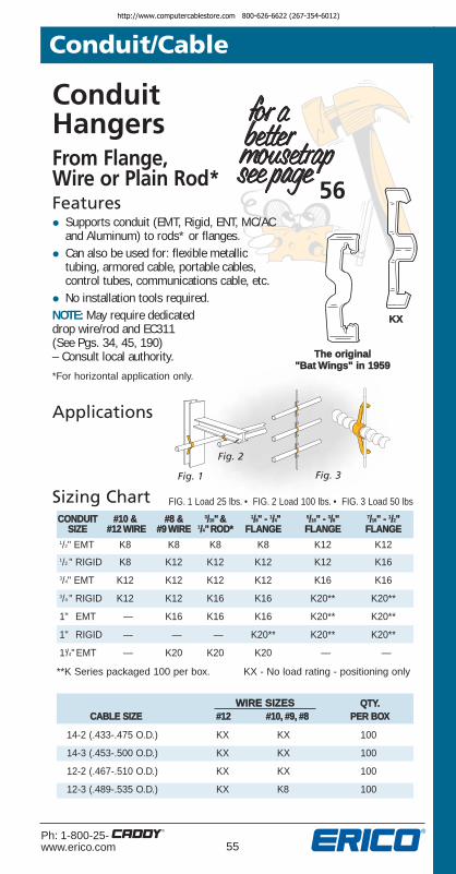
ConduitHangersFrom Flange, Wire or Plain Rod*Features• Supports conduit (EMT, Rigid, ENT, MC/AC
and Aluminum) to rods* or flanges.
• Can also be used for: flexible metallictubing, armored cable, portable cables,control tubes, com mu ni ca tions cable, etc.
• No installation tools required.NOTE: May require dedicated drop wire/rod and EC311(See Pgs. 34, 45, 190)– Consult local authority.*For horizontal application only.
Sizing Chart
The original"Bat Wings" in 1959
Applications
Fig. 1 Fig. 3
CONDUIT #10 & #8 & 3/16"& 1/8" - 1/4" 5/16" - 3/8" 7/16" - 1/2"SIZE #12 WIRE #9 WIRE 1/4"ROD* FLANGE FLANGE FLANGE
1/2" EMT K8 K8 K8 K8 K12 K121/2 " RIGID K8 K12 K12 K12 K12 K163/4" EMT K12 K12 K12 K12 K16 K163/4 " RIGID K12 K12 K16 K16 K20** K20**
1" EMT — K16 K16 K16 K20** K20**
1" RIGID — — — K20** K20** K20**
11/4"EMT — K20 K20 K20 — —
KX
QTY.CABLE SIZE #12 #10, #9, #8 PER BOX
14-2 (.433-.475 O.D.) KX KX 100
14-3 (.453-.500 O.D.) KX KX 100
12-2 (.467-.510 O.D.) KX KX 100
12-3 (.489-.535 O.D.) KX K8 100
**K Series packaged 100 per box. KX - No load rating - positioning only
WIRE SIZES
Fig. 2
FIG. 1 Load 25 lbs. • FIG. 2 Load 100 lbs. • FIG. 3 Load 50 lbs
http://www.computercablestore.com 800-626-6622 (267-354-6012)

56Ph: 1-800-25-
www.erico.com
Cable/ConduitFrom DropWire SupportFeatures• Supports cable and conduit
without bending drop wire.
• Faster installation than traditional methods.
NOTE: May require dedicated drop wire/rod and EC311(See Pgs. 34, 45, 190)– Consult local authority.
Applications
Sizing ChartPART FIG QTY.
NUMBER NO. DESCRIPTION PER BOX
PCS1 1 Flexible cable support from 100#8-#12 drop wire for MC/AC14-2 through 12-3 with groundup to .600 O.D.
PCS2 2 Conduit/cable support from 100#8-#12 drop wire for 1/2" and
3/4" EMT, MC/AC up to .900 O.D.
PCSSeries
Fig. 1
Fig. 2
Conduit/Cable
Ultimate Static Load 25 lbs.
http://www.computercablestore.com 800-626-6622 (267-354-6012)

57Ph: 1-800-25-www.erico.com
Conduit/Cable
Multi-Function ClipFrom Drop Wire, PlainThreaded Rod, or FlangeFeatures• Attaches to #12 wire thru 3/8" rod.
• Fits 1/8" to 3/8" flanges.
• Provides attachment of conduit and boxes.
• Supports #10-24 and 1/4-20 threaded bridle rings.
Fig. 1
Fig. 3
Fig. 4
NOTE: May require dedicated drop wire/rod and EC311 (See Pgs. 34, 45, 190)– Consult local authority.
Load Rating refer to InstructionSheet for desired application.
Eliminates offsetbending conduit
Sizing ChartQTY.
PART FIG. FLANGE PERNUMBER NO. DESCRIPTION WIRE SIZE SIZE BOX
4Z34 1 Multi-function clip #12 wire thru 1/4" 1/8"-3/8" 1004Z4S 2 Multi-function clip with 1/4-20" #12 wire thru 1/4" 1/8"-3/8" 100
stud and hex nut4Z34812M 3 Multi-plus 1/2" or 3/4" conduit #12 wire thru 1/4" 1/8"-3/8" 1004Z3416M 3 Multi-plus 1" conduit #12 wire thru 1/4" 1/8"-3/8" 1004Z348P* 4 Multi-plus 1/2" EMT conduit #12 wire thru 1/4" 1/8"-3/8" 1004Z3412P* 4 Multi-plus 3/4" EMT conduit #12 wire thru 1/4" 1/8"-3/8" 1004Z3416P* 4 Multi-plus 1" EMT conduit #12 wire thru 1/4" 1/8"-3/8" 1006Z34 1 Multi-function clip 3/8" rod 3/8"-7/16" 1006Z4S 2 Multi-function clip with 1/4-20" 3/8" rod 3/8"-7/16" 100
stud and hex nut6Z34812M 3 Multi-plus 1/2" or 3/4" conduit 3/8" rod 3/8"-7/16" 1006Z3416M 3 Multi-plus 1" conduit 3/8" rod 3/8"-7/16" 1006Z348P* 4 Multi-plus 1/2" EMT conduit 3/8" rod 3/8"-7/16" 1006Z3412P* 4 Multi-plus 3/4" EMT conduit 3/8" rod 3/8"-7/16" 1006Z3416P* 4 Multi-plus 1" EMT conduit 3/8" rod 3/8"-7/16" 100*When using rigid conduit on P-Series, use next size larger clip (1/2" Rigid use 12P).
Applications
Fig. 2
http://www.computercablestore.com 800-626-6622 (267-354-6012)

58Ph: 1-800-25-
www.erico.com
Applications
Sizing Chart Total load of trapeze must not exceed 100 lbs.
BC
1/4-20ThreadedRod 16M4I
Scrap 1"Conduit
PART QTY.NUMBER DESCRIPTION PER BOX
166M 14-2 thru 12-3 MC/AC to 1" EMT 10016812M 1/2" or 3/4" Conduit to 1" EMT 1001616M 1" Conduit to 1" EMT 1001620M 11/4" Conduit to 1" EMT 501624M 11/2" Conduit to 1" EMT 501632M 2" Conduit to 1" EMT 50
Conduit/Cable
Conduit To ConduitFeatures• Requires no tools to install.
• Available for conduit 1/2" to 1" EMT and 1/2" to 3/4" Rigid.
• Ideal as spacer between same or different size conduit.
Applications
QTY.PART NUMBER CONDUIT SIZE* PER BOX
8P8P 1/2" to 1/2" 1008P12P 1/2" to 3/4" 1008P16P 1/2" to 1" 5012P12P 3/4" to 3/4" 10012P16P 3/4" to 1" 10016P16P 1" to 1" 50
Sizing Chart Ultimate static load limit 25 lbs.
*EMT. For Rigid conduit use next larger size clip (1/2" rigid use 12P).
Top conduit to be used forsupport only, not a raceway.
Lightweight TrapezeFeatures• Fast, easy assembly for lightweight loads up to 100 lbs.
• Use with 3/8" MC/AC to 2" conduit.
• No screws or boltsrequired.
http://www.computercablestore.com 800-626-6622 (267-354-6012)

59Ph: 1-800-25-www.erico.com
Conduit/Cable
Sizing Chart
One-PieceStrut ClampSCH SeriesFeatures• One-piece installation means no
screws or bolts to drop.
• Installs quickly and easily.Requires only a screwdriveror nut driver for installation.
• Heavy-duty con struc tion witha bright zinc finish.
• Size 3/8" MC/AC to 4" EMT conduit.
• All sizes available with loaddistribution plate attached to screw.
Fig. 1
Fig. 2
Fig. 3
ApplicationsPatent No. 4,429,440
Bright ZincFinish
CABLE STATIC QTY.PART FIG. O .D. LOAD PER
NUMBER NO. EMT RIGID RANGE LIMIT BOX
SCH8 1 1/2" — — 200 100SCH12 1 3/4" 1/2" — 200 100SCH16 1 1" 3/4" — 200 100SCH20 1 11/4" 1" — 200 100SCH6B 2 3/8" MC/AC — .10" – .63" 200 100SCH8B 2 1/2" — .34" – .71" 200 100SCH12B 2 3/4" 1/2" .57" – .92" 200 100SCH16B 2 1" 3/4" .72" – 1.16" 200 100SCH20B 2 11/4" 1" 1.00" – 1.51" 200 100SCH24B 2 11/2" 11/4" 1.25" – 1.74" 350 50SCH32B 2 2" 11/2" 1.74" – 2.20" 350 50SCH40B 3 — 2" 2.00" – 2.38" 350 25SCH48B 3 21/2" 21/2" 2.38" – 2.88" 350 25SCH56B 3 3" 3" 2.72" – 3.50" 350 25SCH64B 3 31/2" 31/2" 3.25" – 4.00" 350 10SCH72B 3 4" 4" 3.85" – 4.50" 350 10
http://www.computercablestore.com 800-626-6622 (267-354-6012)

60Ph: 1-800-25-
www.erico.com
Conduit/Cable
Sizing Chart
Universal
One-PieceStrut ClampSK SeriesFeatures• One-piece construction.
• Retained bolt and built-in nutprevents dropping of loose parts.
• One size fits EMT and Rigid.
• Installs with screwdriver, standardwrench or nut driver.
• Break in half and install.
• Works with most struts.
• Bright zinc finish.
Fig. 1
Fig. 2
* Aluminum SKs do not have a thread impression. An aluminum nut and bolt are provided. Order with no "A" on end for standard steel bolt and nut.
Applications Bright ZincFinish
PART NUMBER STATIC LOAD
QTY.MILD FIG. EMT MILD PER
STEEL ALUMINUM* NO. RIGID STEEL ALUMINUM BOX
SK85I SK8ALA 1 1/2" 200 150 100SK125I SK12ALA 1 3/4" 200 150 100SK165I SK16ALA 1 1" 200 150 100SK205I SK20ALA 1 11/4" 200 150 100SK245I SK24ALA 1 11/2" 200 150 50SK325I SK32ALA 1 2" 200 150 50SK405I SK40ALA 2 21/2" 350 200 50SK485I SK48ALA 2 3" 350 200 50SK565I SK56ALA 2 31/2" 350 200 25SK645I SK64ALA 2 4" 350 200 25
Fig. 1
http://www.computercablestore.com 800-626-6622 (267-354-6012)

61Ph: 1-800-25-www.erico.com
Conduit/Cable
RIGID Pipe ClampOne-PieceFeatures• Supports rigid pipe to strut
• Handles heavy loads
• One -piece design incorporates a retained bolt and built-in nut
• Installs with either a screwdriver or a nut driver
• Full line is available to fit a wide range of pipe sizes
• Available in various materials and finishes
Sizing ChartPART PIPE SIZE LOAD QTY.
NUMBER NOMINAL O.D. (LBS .) PER BOX
RIGD0050XX* 1/2" 0.840 400 100
RIGD0075XX* 3/4" 1.050 400 100
RIGD0100XX* 1" 1.315 600 100
RIGD0125XX* 11/4" 1.660 600 100
RIGD0150XX* 11/2" 1.900 800 100
RIGD0200XX* 2" 2.375 800 100
RIGD0250XX* 21/2" 2.875 800 100
RIGD0300XX* 3" 3.500 800 100
RIGD0350XX* 31/2" 4.000 1000 100
RIGD0400XX* 4" 4.500 1000 100
Applications
* XX denoted finish available : EG - Electro-Galvanized, CG - Yellow Chromate, S4 - Stainless 304, S6 - Stainless 316, HD - Hot Dipped Galvanized, AL - Aluminum.
Contact ERICO for Copper Applications.3/8", 5", 6", 8", 10", 12" available without one -piece design, retained combo-head bolt, or built-in nut.
HeavyDutyClamp
http://www.computercablestore.com 800-626-6622 (267-354-6012)

62Ph: 1-800-25-
www.erico.com
CADDY® PYRAMID Pipe & Equipment Supports
Conduit/Cable
Features
• Dramatically reduces installation time by replacing labor-intensivemethods for supporting pipes, conduits and equipment
• Supports multiple runs of pipe and conduit on roofs and below raised floors
• Supports concentrated loads up to 600 lbs
• Absorbs shock and vibration
• Protects roof membrane
• Metal cover protects from weather and other environmental conditions
• Features an electro-galvanized finish for corrosion protection
Fig. 1
PART FIG. MAX. WORKING STRUTNUMBER NO. LOAD (LB) HEIGHT THREADS FINISH INCLUDED?
PPRPS25H4 1 25 3-5/8” – – –
PPRPS25H6 1 25 5-5/8” – – –
RPS50H4EG 2 50 4” – EG –
RPS50H6EG 2 50 6” – EG –
RPS50AHSV* 2 50 2-1/4” – SV –
RPS150T1 3 150 3-3/16” 3/8”-16 EG NO
RPS150T2 3 150 4” 3/8”-16 EG YES
RPS300T1 4 300 3-3/16” 3/8”-16 EG NO
RPS300T2 4 300 4” 3/8”-16 EG YES
RPS600T2 5 600 4” 3/8”-16 EG YES
EG - Electro-Galvanized SV - CADDY® COAT Silver*For indoor use only.
CADDY® PYRAMID 25• Supports up to 25 lb loads
• Lightweight, all-plastic construction weighs less than 1/3 lb
• Has a small 4” x 5” footprint
• UV-Rated
• Handles up to three 1/2” or two 3/4” or 1” pipes/conduit
• No tools or fasteners needed for installation
http://www.computercablestore.com 800-626-6622 (267-354-6012)

63Ph: 1-800-25-www.erico.com
Conduit/Cable
Fig. 2
Fig. 3
Fig. 4
Fig. 5
CADDY® PYRAMID 50• Supports up to 50 lb loads
• Polyethylene closed-cell foam and16-gauge steel construction
• The 4” high model has a 10-3/8” x 4” footprint
• The 6” high model has a 10-3/8” x 4-3/4” footprint
• Electro-galvanized (EG) finish on the rooftop version and CADDY® COAT Silver (SV) on the plenum version provide superior corrosion protection
• Metal top designed to shed water andminimize water collection on foam base
CADDY® PYRAMID 150• Supports up to 150 lb loads
• Has six 3/8”-16 threaded inserts with captive nuts that allows the product to be used with standard pipe clamps and accessories
• Large 16” x 12” footprint distributes load more evenly than alternative methods
• Polyethylene closed-cell foam and14-gauge steel construction
• Electro-galvanized (EG) finish on top plate for added corrosion protection
CADDY® PYRAMID 300• Supports up to 300 lb loads
• Crosslink polyethylene closed-cell foam supports the additional weight; 14-gauge steel top plate
CADDY® PYRAMID 600• Consists of two CADDY PYRAMID 300
bases tied together with a length of strut
• Footprint is 32” x 12” (24” x 16” optional with cutting of strut) for more even load distribution
• Supports up to 600 lb loads
http://www.computercablestore.com 800-626-6622 (267-354-6012)

64Ph: 1-800-25-
www.erico.com
Snap-InSupportMC/AC CableFlexible ConduitFeatures• Manufactured with stabilizer
legs for “wobble-free” sup port.
• One fastener for cable size 14-4,12-4, 12-3, 12-2, 10-3, 10-2.
• Snaps into place on metal stud and beam flange up to 1/8" thick. No tools required for installation.
• MAC2 snaps in half to accommodate a single run of cable ef fec tive ly making two clips from one.
• Prepunched holes in clip allow itto be screwed to wood stud,concrete or block.
• Factory riveted assemblies areavailable for in stal la tion on flange,purlin, acoustical tee, drop wire,concrete, block or wood andmetal stud.
• Delivers compliance for:NEC Article 300.4(d) allowing cableto be positioned a min i mum of 11/4" from face of stud.CEC Rule 12-618 for support ofMC/AC cable.
Fig. 8Fig. 11 Fig. 9
Fig. 6
Fig. 7
Fig. 5
Fig. 4
Fig. 3
Fig. 1
Fig. 2
Fig. 10
Conduit/Cablehttp://www.computercablestore.com 800-626-6622 (267-354-6012)

65Ph: 1-800-25-www.erico.com
Conduit/Cable
Assemblies allowfor support frommost main andsub struc tures.
Applications
Sizing Chart UL & cUL ListedCable Support
PART FIG. QTY.NUMBER NO. DESCRIPTION PER BOX
1 to 4 RUNS OF MC/AC
MAC2T 2 Support 1 to 4 runs ofMC/AC cable for metal stud 100
DOUBLE RUN OF MC/AC
MAC2 1 Metal or wood stud and 1/8" flange 100MAC2ATA 3 Acoustical Tee 100MAC2BC 4 1/8" thru 1/2" flange 100MAC224SM 5 1/8" thru 1/4" flange 100MAC258SM 5 5/2" thru 1/2" flange 100MAC2912SM 5 1/16" thru 3/4" flange 100MAC2VF14 6 1/16" thru 1/4" C purlin or
vertical flange 100MAC2123 7 Z purlin 100MAC2AO 8 Offset bracket 100MAC224 9 1/8" thru 1/4" flange –
bottom mount rotates 360˚ 100MAC258 9 5/16" thru 1/2" flange –
bottom mount rotates 360˚ 100MAC2912 9 1/2" thru 3/4" flange –
bottom mount rotates 360˚ 100MAC24Z34 10 #12 thru 1/4" wire, plain or
threaded rod & 1/8" thru 3/8" flange 100MAC26Z34 10 3/8" plain or threaded rod and
3/8" thru 9/16" flange 100MAC2FB 11 Through metal stud 100
http://www.computercablestore.com 800-626-6622 (267-354-6012)

66Ph: 1-800-25-
www.erico.com
Romex® ClipFeatures• Supports non-metallic cable.
• When used in combination with other CADDY® Fasteners, RMX can be installedon main or substructures, drop wireand acoustical tee.
NOTE: Not for use in Canada on NMC wireor power application.
Fig. 1
Fig. 2
Fig. 3
Fig. 4
Fig. 5 Fig. 6
Fig. 7Fig. 8
Fig. 9
Fig. 10
RMX SERIES
Conduit/Cablehttp://www.computercablestore.com 800-626-6622 (267-354-6012)

67Ph: 1-800-25-www.erico.com
Conduit/Cable
Applications
® Romex is a registered trademark of General Cable Corp.
Sizing Chart
Assemblies allow support from mostmain and substructures.
QTY.PART FIG. CABLE PER
NUMBER NO. SIZE DESCRIPTION BOX
RMX 1 14-2 and 12-2 Clip for Romex orw/ Ground Wire Non-Metallic Cable 100
RMXDH2 2 14-2 and 12-2 Romex or Non-Metallicw/ Ground Wire Cable to Deck 100
RMXAB 3 14-2 and 12-2 Romex or Non-Metallicw/ Ground Wire Cable to Angle Bracket 100
RMXAO 4 14-2 and 12-2 Romex or Non-Metallicw/ Ground Wire Cable to Offset Bracket 100
RMXVF14 5 14-2 and 12-2 Romex or Non-Metallic Cablew/ Ground Wire to C Purlin 1/16" to 1/4" Thick 100
RMXAF14 6 14-2 and 12-2 Romex or Non-Metallic Cablew/ Ground Wire to Z Purlin 1/16" to 1/4" Thick 100
RMXBC 8 14-2 and 12-2 Romex or Non-Metallicw/ Ground Wire Cable to Beam thru 1/2 Flange 100
RMX4Z34 9 14-2 and 12-2 Romex or Non-Metallic Cablew/ Ground Wire to #12 Wire thru 1/4" Plain Rod
or Beam 1/8" thru 3/8" Flange 100
RMX6Z34 9 14-2 and 12-2 Romex or Non-Metallic Cablew/ Ground Wire 3/8" Plain or Threaded Rod
3/8" thru 7/16" Flange 100
RMXATS 10 14-2 and 12-2 Romex or Non-Metallicw/ Ground Wire Cable to Acoustical "Tee -Bar"
RMX24 7 1/8"-1/4" Thick Flange 100
RMX58 7 5/16"-1/2" Thick Flange 100
RMX912 7 9/16"-3/4" Thick Flange 100
14-2 and 12-2 Romex orwith Ground Non-MetallicWire Cable to
Beam
http://www.computercablestore.com 800-626-6622 (267-354-6012)

68Ph: 1-800-25-
www.erico.com
Combination Box/ConduitHangers FromDrop Wire/RodAnd BeamB18 SeriesFeatures• One riveted assembly.
• No conduit bends(beam application).
• 66% less Drop Wires(rod/wire application).
• Delivers with NEC & CECcompliance, refer to the2005 CADDY Code Compliance Book.
NOTE: May require dedicated drop wire/rod and EC311(See Pgs. 34, 45, 190)– Consult local authority.For single and multiple runsof conduit.
Now AvailableB18CO to SupportMultiple Runs(FIG. 5)
Fig. 1
Drop Wire
Fig. 4
Flange
Fig. 2
Plain Hole
ApplicationsFig. 7
Fig. 8
Fig. 6A
Fig. 6B
Fig. 5
Fig. 31/4-20 x 5/8"
Stud
Conduit/Cablehttp://www.computercablestore.com 800-626-6622 (267-354-6012)

69Ph: 1-800-25-www.erico.com
Conduit/Cable
Sizing ChartPART FIG. DESCRIPTION QTY.
NUMBER NO. MOUNTS 4" SQ. BOXES WITH PER BOX
812MB18 1 1/2" & 3/4" conduit from #12 wire thru 1/4" rod 25
812MB186 1 1/2" & 3/4" conduit to 3/8" plain or threaded rod 25
16MB18 1 1" conduit from #12 wire thru 1/4" rod 25
16MB186 1 1" conduit to 3/8" plain or threaded rod 25
6MB18 1 MC, AC cable from #12 wire 25thru 1/4" flange
6MB186 1 MC, AC cable 3/8" plain or threaded rod 25
812MB18A 2 1/2" & 3/4" conduit plain center 25hole for screw or threaded rod mount
16MB18A 2 1" conduit plain center hole for screw 25or threaded rod mount
6MB18A 2 MC, AC cable plain center hole for 25screw or threaded rod mount
812MB18S 3 1/2" & 3/4" conduit with 251/4-20 x 9/16" stud in center hole
812MB1824 4 1/2" & 3/4" conduit to 1/8" thru 251/4" flange
812MB1858 4 1/2" & 3/4" conduit to 5/16" thru 251/2" flange
16MB1824 4 1" conduit to 1/8" thru 1/4" flange 25
16MB1858 4 1" conduit to 5/16" thru 1/2" flange 25
6MB1824 4 MC, AC cable 1/8" thru 1/4" flange 25
6MB1858 4 MC, AC cable 5/16" thru 1/2" flange 25
*(XXX)CO 5 Factory riveted assembly for multiple conduit 25clips. Includes mounting plate and center conduit clips pre-riveted (additional conduit clips ordered separately). See Fig. 6A.
6M4I 6A 14-2 thru 12-3 MC/AC and 3/8" flexible 100conduit; 1/4"-20 thread impression
812M4I 6A 1/2" to 3/4" conduit; 1001/4-20 thread impression
16M4I 6A 1" conduit; 1/4-20 thread impression 100
S3575BP50 6B 1/4 - 20 x 3/8" round head screw 50
4WN 7 1/4"-20 thread impression washer wing nut 100
4TI24 8 1/4" threaded rod to 5/16" thru 1/4" flange 100
4TI58 8 1/4" threaded rod to 5/16" thru 1/2" flange 100
4TI912 8 1/4" threaded rod to 9/16" thru 3/4" flange 100
6TI24 8 3/8" threaded rod to 5/16" thru 1/4" flange 100
6TI58 8 3/8" threaded rod to 5/16" thru 1/2" flange 100
6TI912 8 3/8" threaded rod to 9/16" thru 3/4" flange 100
UL & cUL ListedBox and Conduit Support
*To order with B18CO, add the suffix “CO” to any catalog number Figure 1 through 4 above.
http://www.computercablestore.com 800-626-6622 (267-354-6012)

70Ph: 1-800-25-
www.erico.com
Conduit/Cable
Metal Deck Conduit Sup portFeatures• Provides spacing between conduit and deck surface.
• Easily attached with screw gun or power tool.
• Permits conduit to be laid out and then attached.
Sizing Chart No Load Rating - Po si tion ing Only
Applications
PART QTY.NUMBER DE SCRIP TION PER BOX
AOL8P Support bracket for 1/2" EMT 100AOL12P Support bracket for 3/4" EMT or 1/2" Rigid 100AOL16P Support bracket for 1" EMT or 3/4" Rigid 100
AOL
Eliminates offsetbending conduit
Nail BracketFeatures• Used to attach conduit to wood, steel or concrete.
• Eliminates the need for offset bends.
• Works with power tools, screw guns or nails.
• May be attached after positioning conduit.
CNB
Sizing ChartPART QTY.
NUMBER DE SCRIP TION PER BOX
CNB812M Nail Bracket, M-Series 1/2" & 3/4" Conduit 100CNB8P Nail Bracket, P-Series for 1/2" EMT 100CNB12P Nail Bracket, P-Series for 3/4" EMT 100
or 1/2" Rigid
Applications
No Load Rating - Po si tion ing Only
Eliminates offset bending conduit
http://www.computercablestore.com 800-626-6622 (267-354-6012)

71Ph: 1-800-25-www.erico.com
Conduit/Cable
MC/AC Cable To Metal StudFeatures• Attaches MC or AC to metal
stud easily.
• Requires no special tools.• Provides fast installation.
Sizing Chart No Load Rating - Po si tion ing Only
Applications
PART QTY.NUMBER CABLE SIZE PER BOX
449 14-2 (.433-.475 O.D.) 100449 14-3 (.453-.500 O.D.) 100449 12-2 (.467-.510 O.D.) 100449 12-3 (.489-.535 O.D.) 100
For concealed work check applicationwith local inspection authorities.
449
65, 75
http://www.computercablestore.com 800-626-6622 (267-354-6012)

72Ph: 1-800-25-
www.erico.com
Conduit/Cable
Cable Snap ClipFeatures• Supports cable from 1/16"-1/2" flange.
• Works effectively with MC and AC cabledimensions 3/8" - 11/4" and low voltagecables from 7/32" and up.
• Clip "snaps" on flange and cable "snaps"into clip. This is "snappy." SC
Sizing ChartPART CABLE QTY.
NUMBER O.D. DESCRIPTION PER BOX
SC2A .218-.281 100SC2B .312 -.375 100SC2C .375-.437 100SC2D .468-.562 100SC2E .500-.718 100SC2F .750-.937 100SC2G .968-1.250 100SC4A .218-.281 100SC4B .312 -.375 100SC4C .375-.437 100SC4D .468-.562 100SC4E .500-.718 100SC4F .750-.937 100SC4G .968-1.250 100
SC8A .218-.281 100SC8B .312 -.375 100SC8C .375-.437 100SC8D .468-.562 100SC8E .500-.718 100SC8F .750-.937 100SC8G .968-1.250 100
Low voltage,data and
MC/AC cable to1/16" thru 3/16"
flange thickness
Low voltage,data and
MC/AC cable to3/16" thru 9/32"
flange thickness
Low voltage,data and
MC/AC cable to5/16" thru 1/2"
flange thickness
Applications
No Load Rating - Po si tion ing Only
http://www.computercablestore.com 800-626-6622 (267-354-6012)

73Ph: 1-800-25-www.erico.com
Conduit/Cable
Flexible Conduitand Cable Hang erFeatures• Bundle runs* of MC or AC or
communications cables.
• Can be used with flange clips or deck clip DH2. Also AO or AB, VF14, AF14, 122-123.
*Refer to local authorities and NEC Article 310for derating ampacity when flexible powercables are used.
Applications
Sizing ChartNUMBER OF RUNS ULTIMATEOF MC/AC CABLE STATIC QTY.
PART FIG. THAT MAY BE "A" LOAD PERNUMBER NO. SUPPORTED DIM. RATING BOX
WMX3 1 3 11/8" 50# 100
WMX6 2 6 13/4" 75# 100
"A"DIM.
Fig. 1
Fig. 2
Ultimate static load limit 75 lbs. - WMX6, 50 lbs. - WMX3
Bridle Rings notrecommendedfor highperformancecables, seeCADDY®
CABLECAT series,Pages 153-165.
http://www.computercablestore.com 800-626-6622 (267-354-6012)

74Ph: 1-800-25-
www.erico.com
Conduit/Cable
Support Bracket for MC/AC CableMCS SeriesFeatures• Neatly isolates, supports and secures MC/AC cables
• Properly spaces MC/AC cable to eliminate bundling and NEC & CEC derating issues
• Results in a “neat and workmanlike” installation
• Reduces inventory
• Holds up to eight MC/AC cables
• cULus Listed for support – not just positioning
PART FIG. DESCRIPTION QTY. PERNUMBER NO. BOX
MCS50 1 MC/AC* cable support spacer for up to 4 runs 50MCS100 2 MC/AC* cable support spacer for up to 9 runs 50MCS101 3 MC/AC** cable support spacer for up to 7 runs 50
* Nominal outside diameters from .430 thru .560. 14-3, 14-4, 12-2, 12-4 and 10-2 MC/AC Cable** Nominal outside diameters from .560 thru .690. Standard MC sizes: 10/3, 10/4, *8/2, *8/3.
Super Neutral Cable: 12/3, 12/4 and *10/2. Isolated Ground: 12/3, 12/4, 10/2, 10/3, 10/4 and 8/2.
Applications
Sizing Chart
Fig. 1
Fig. 1Fig. 2
Fig. 3 Fig. 4
Fig. 5
Fig. 6 Fig. 7
Fig. 8Fig. 9
PATENT NUMBER6,572,058
http://www.computercablestore.com 800-626-6622 (267-354-6012)

75Ph: 1-800-25-www.erico.com
Conduit/CablePART FIG. DESCRIPTION QTY. PER
NUMBER NO. BOX
Pre-Riveted Factory Assemblies for MCS100
MCS10024 4 To beams 1/8"-1/4" 25flange thickness (Hammer-On)
MCS1004Z 9 To #12 wire thru 1/4"plain or threaded rod 25MCS10058 4 To beams 5/16"-1/2" flange thickness 25
(Hammer-On)MCS1006Z 9 To 3/8" plain or threaded rod 25MCS100912 4 To beams 9/16"-3/4" flange thickness 25
(Hammer-On)MCS100AF14 7 Z Purlin 25MCS100BC 5 To beams thru 1/2" flange thickness (Screw-On) 25MCS100BC200 6 To beams 1/8"-5/8" flange thickness (Screw-On) 25MCS100VF14 8 C Purlin or Open Bar Joist 25
Pre-Riveted Factory Assemblies for MCS101
MCS10124 4 To beams 1/8"-1/4" 25flange thickness (Hammer-On)
MCS1014Z 9 To #12 wire thru 1/4" 25plain or threaded rod
MCS10158 4 To beams 5/16"-1/2" flange 25thickness (Hammer-On)
MCS1016Z 9 To 3/8" plain or threaded rod 25MCS101912 4 To beams 9/16"-3/4" flange 25
thickness (Hammer-On)MCS101AF14 7 Z Purlin 25MCS101BC 5 To beams thru 1/2" flange 25
thickness (Screw-On)MCS101BC200 6 To beams 1/8"-5/8" 25
flange thickness (Screw-On)MCS101VF14 8 C Purlin or Open Bar Joist 25
Pre-Riveted Factory Assemblies for MCS50
MCS5024 4 To beams 1/8"-1/4" flange 25thickness (Hammer-On)
MCS504Z 9 To #12 wire thru 1/4" 25plain or threaded rod
MCS5058 4 To beams 5/16"-1/2" flange 25thickness (Hammer-On)
MCS506Z 9 To 3/8" plain or threaded rod 25MCS50912 4 To beams 9/16"-3/4" flange 25
thickness (Hammer-On)MCS50AF14 7 Z Purlin 25MCS50BC 5 To beams thru 1/2" 25
flange thickness (Screw-On)MCS50BC200 6 To beams 1/8"-5/8" flange 25
thickness (Screw-On)MCS50VF14 8 C Purlin or Open Bar Joist 25
http://www.computercablestore.com 800-626-6622 (267-354-6012)

76Ph: 1-800-25-
www.erico.com
Conduit/Cable
SBT18Multiple Conduit Mounting PlateFeatures• Easy “snap-in” attachment of up to three conduit clips
• No tools necessary for installation of clips
• Automatic alignment with standard 1-1/2” electrical box knockouts and mounting holes
• Eliminates conduit bends for 1/2” and 3/4” sizes
• Available in a variety of riveted assemblies Fig. 1
Fig. 2
Fig. 3
Fig. 4
Fig. 5
Fig. 6
LOADRATING QTY.
PART FIG. PER TAB PERNUMBER NO DESCRIPTION (LBS) BOX
SBT18 1 Multi-Run, Conduit Hanger Plate 50 50
SBT1824SM 5 Hammer-on; side mount 1/8"-1/4" flange 50 50
SBT1858SM 5 Hammer-on; side mount 5/16"-1/2" flange 50 50
SBT18912SM 5 Hammer-on; side mount 9/16"-3/4" flange 50 50
SBT1824 6 Hammer-on; underside 1/8"-1/4" flange 25 50
SBT1858 6 Hammer-on; underside 5/16"-1/2" flange 25 50
SBT18912 6 Hammer-on; underside 9/16"-3/4" flange 25 50
SBT184Z34 4 Multi-function clip #12 wire thru 151/4" plain rod 50
SBT186Z34 4 Multi-function clip 3/8" plain or 15threaded rod 50
S3575BP50 1/4-20 x 3/8" round head screw 33 50
SBT18BC 2 Beam clamp thru 1/2" flange 25 50
SBT18BC200 3 Beam clamp 1/8" to 5/8" flanges 33 50
http://www.computercablestore.com 800-626-6622 (267-354-6012)

77Ph: 1-800-25-www.erico.com
Beam/Purlin
Pages 77-100
http://www.computercablestore.com 800-626-6622 (267-354-6012)

78Ph: 1-800-25-
www.erico.com
Beam/Purlin
Applications
Beam ClampsFeatures• Easy installation to beam flanges
up to 1/2".
• Supports 1/4" and 3/8" threaded rod,S-hooks, electrical boxes, conduitand bridle rings.
• Accommodates standard 1/4-20 or #10-24 threaded bridle rings.
NOTE:When using rigid conduit on P Series, use next size larger clip (1/2" rigid use 12P).
Assembliesfor
conduit support
Fig. 3
Fig. 4
Fig. 5Fig. 6
Eliminates offset bending conduit
Fig. 1
Built-in Smart Nutsnaps directly onto 3/8 -16 threaded rod, is adjustableand removable, and eliminates extensive “threading” into place.
Fig. 2
Patent pending
http://www.computercablestore.com 800-626-6622 (267-354-6012)

79Ph: 1-800-25-www.erico.com
Beam/Purlin
Sizing ChartSTATIC QTY.
PART FIG. LOAD PERNUMBER NO. DESCRIPTION LIMIT BOX
BC 1 Beam clamp thru1/2" flange 100 lbs. 100
BCISN375 2 Beam clamp thru1/2" flange 3/8" smart nut 100 lbs. 100
BC812M 3 1/2" to 3/4" conduit tobeam thru 1/2" flange 100 lbs. 100
BC16M 3 1" conduit to beamthru 1/2" flange 100 lbs. 100
BC20M 3 11/4" conduit to beamthru 1/2" flange 100 lbs. 100
BC24M 3 11/2" conduit to beam thru 1/2" flange 100 lbs. 50
BC32M 3 2" conduit to beam thru 1/2" flange 100 lbs. 50
BC812MSM 4 1/2" to 3/4" conduit to beam thru 1/2" flange 25 lbs. 100
BC16MSM 4 1" conduit to beam thru 1/2" flange 25 lbs. 100
BC20MSM 4 11/4" conduit to beam thru 1/2" flange 25 lbs. 100
BC24MSM 4 11/2" conduit to beam thru 1/2" flange 25 lbs. 50
BC32MSM 4 2" conduit to beam thru 1/2" flange 25 lbs. 50
BC8P 5 1/2" conduit to beam thru 1/2" flange 25 lbs.* 100
BC12P 5 3/4" conduit to beam thru 1/2" flange 25 lbs.* 100
BC16P 5 1" conduit to beam thru 1/2" flange 25 lbs.* 100
BC8PSM 6 1/2" conduit to beam thru 1/2" flange 15 lbs.* 100
BC12PSM 6 3/4" conduit to beam thru 1/2" flange 15 lbs.* 100
BC16PSM 6 1" conduit to beam thru 1/2" flange 15 lbs.* 100
*Ultimate static load limit.
http://www.computercablestore.com 800-626-6622 (267-354-6012)

80Ph: 1-800-25-
www.erico.com
Big Beam ClampIdeal for Elec tri cal,Mechanical andHVAC Ap pli ca tions
PART QTY.NUMBER DESCRIPTION PER BOX
BC400 For 3/8" threaded rod or 3/8" - 16 25bolts to beam flange through 3/4"
Static load limit 200 lbs.
Beam/Purlin
Beam ClampsFeatures• Easy installation for beam flanges 1/8" to 5/8".
• Supports 1/4" threaded rod, 1/4" threaded bridle rings and boxes.
• Available riveted to conduit clips 1/2" thru 2".
• Bright zinc finish.NOTE:See Misc. Components section for threaded bridle rings (p.173).Threaded hole on back and bottom.
CONDUIT SIZE
BC200 1 — — 50BC200 CD0B 2 1/2" 1/2" 50BC200 CD1B 2 3/4" 3/4" 50BC200 CD2B 2 1" 1" 50BC200 CD2.5B 2 — 11/4" 50BC200 CD3B 2 11/4" 11/2" 50BC200 CD4B 2 11/2" — 25BC200 CD5B 2 2" 2" 25
Fig. 1
Fig. 2
Sizing Chart
Applications
PART FIG. QTY.NUMBER NO. RIGID EMT PER BOX
Static load limit 100 lbs.
Eliminates offsetbending conduit
http://www.computercablestore.com 800-626-6622 (267-354-6012)

81Ph: 1-800-25-www.erico.com
Beam/Purlin
Hammer-OnFlange ClipFeatures• Locates a "portable" 1/4" hole with just
a hammer.
• Fits most beams and bulb tees.
Fig. 1
Fig. 2
Sizing ChartPART FIG. FLANGE QTY. STATIC
NUMBER NO. THICKNESS PER BOX LOAD LIMIT
2H4 1 3/32"-9/64" 100 160 lbs.4H24 2 1/8"-1/4" 100 200 lbs.4H58 2 5/16"-1/2" 100 200 lbs.4H912 2 9/16"-3/4" 100 200 lbs.
Applications
See page 123 for more information onCADDY® SPEED LINK
http://www.computercablestore.com 800-626-6622 (267-354-6012)

82Ph: 1-800-25-
www.erico.com
Hammer-OnPlain andThreadedRod HangersBeam ClampsFeatures• Used to suspend #8 wire, 1/4", 3/8" plain
rod or 1/4" or 3/8" threaded rod frombeam flanges 1/8" to 3/4" thick.
• Requires only hammerto install.
Fig. 1 Fig. 2
Fig. 3 Fig. 4
Applications
Sizing Chart
PART FIG. FLANGE QTY.NUMBER NO. THICKNESS ROD SIZE PER BOX
70824 1 1/8"-1/4" #8 wire or 1/4" Plain Rod 10070858 1 5/16"-1/2" #8 wire or 1/4" Plain Rod 100708912 1 9/16"-3/4" #8 wire or 1/4" Plain Rod 100
6A24 2 1/8"-1/4" 3/8" (Plain) 1006A58 2 5/16"-1/2" 3/8" (Plain) 1006A912 2 9/16"-3/4" 3/8" (Plain) 100
4TI24 3 1/8"-1/41/4" Threaded 100
4TI58 3 5/16"- 1/2" 1/4" Threaded 1004TI912 3 9/16"-3/4" 1/4" Threaded 100
6TI24 3 1/8"-1/4" 3/8" Threaded 1006TI58 3 5/16"-1/2" 3/8" Threaded 1006TI912 3 9/16"-3/4" 3/8" Threaded 100
6TA24 4 1/8"-1/4" 1/4" or 3/8" Threaded* 1006TA58 4 5/16"-1/2" 1/4" or 3/8" Threaded* 1006TA912 4 9/16"-3/4" 1/4" or 3/8" Threaded* 100*Nuts required
Static load limit 200 lbs.
Beam/Purlinhttp://www.computercablestore.com 800-626-6622 (267-354-6012)

83Ph: 1-800-25-www.erico.com
Beam/Purlin
Hammer-OnFlange ClipFeatures• When used with CADDY® combination
conduit hanger, the conduit run linesup with "knock-outs" in outlet box andeliminates offsets and bends.
• Provided with a 1/4-20 thread impressionso that the box may be quickly andsecurely attached to the clamp.
• Also available with a staked stud,1/4-20 x 3/8" to provide easier attachmentof outlet boxes to beams. Eliminateshaving to use loose screws.
• The CADDY combination washer-wingnut (Part No. 4WN) can be used toattach box. (Not included.)
• New design allows for use with cable ties
1/4-20 x 3/8" screwsP/N S3575BP50
available as separate item.Pack aged 50 per box.Weight 1 lb . per 100.
Fig. 1
Fig. 2
Sizing Chart
Applications
PART FIG. FLANGE QTY.NUMBER NO. THICKNESS PER BOX
M24 1 1/8"-1/4" 100M58 1 5/16"-1/2" 100M912 1 9/16"-3/4" 100M24S 2 1/8"-1/4" 100M58S 2 5/16"-1/2" 100M912S 2 9/16"-3/4" 100
100#
25#
75#
Indicated loads are static load limitsand should not be
combined.
http://www.computercablestore.com 800-626-6622 (267-354-6012)

84Ph: 1-800-25-
www.erico.com
86
Beam/Purlin
"C" And "Z"Purlin ClipsFeatures• One fastener fits flanges
1/16" to 1/4".
• Supports wire or rod from bar joist, C Purlin (VF14) or Z Purlin (AF14).
• Installs from floor with VAFT tool and conduit.
NOTE:VF for vertical flange only.AF for angle flange only.Installation tool part number VAFT.
Fig. 1 Fig. 2 Fig. 3 Fig. 4
Fig. 6 Fig. 7 Fig. 8
Fig. 9
Fig. 5
http://www.computercablestore.com 800-626-6622 (267-354-6012)

85Ph: 1-800-25-www.erico.com
Beam/Purlin
Sizing ChartPART FIG. QTY.
NUMBER NO. DESCRIPTION PER BOX
VF14 1 1/16" to 1/4" vertical flange for 100wrap wire, “S” hooks,bolting straps, WMX6
VF14708 2 1/16" to 1/4" to #8 wire or 1/4" plain rod 100VF146A 3 1/16" to 1/4" to 3/8" plain rod 100VF144TI 4 1/16" to 1/4" to 1/4" threaded rod 100
VF146TI 4 1/16" to 1/4" to 3/8" threaded rod 100
VF146T 4 1/16" to 1/4" to 3/8" threaded rod 100(nuts required)
AF14 5 1/16" to 1/4" Z Purlin for wrap wire, 100"S" hooks, bolting straps, WMX6
AF14708 6 1/16" to 1/4" to #8 wire or 1/4" plain rod 100
AF146A 7 1/16" to 1/4" to 3/8" plain rod 100
AF144TI 8 1/16" to 1/4" to 1/4" threaded rod 100AF146TI 8 1/16" to 1/4" to 3/8" threaded rod 100AF146T 8 1/16" to 1/4" to 3/8" threaded rod 100
(nuts required)
VAFT 9 Installation tool forVF & AF assemblies 1
Static Load Limit: VF14 160 lbs. – AF14 100 lbs.
Applications
http://www.computercablestore.com 800-626-6622 (267-354-6012)

86Ph: 1-800-25-
www.erico.com
Beam/Purlin
Multi-FlangeRod HangerFeatures• C or Z Purlins or up to 1/4" (7mm)
horizontal beam flanges.
• Slotted, Hex, Robertson, Phillips combo head bolt.
• Hardened cup point setscrew for secure grip.
• Fast installation of threaded components; (1/4" or 3/8" ).
• Integrated thread impression eliminates nuts.
• Swivel feature option.
• Electrogalvanized finish for good corrosion protection.
NOTE:Loads up to 200 lbs. (0.90 kN) on C or Z purlins or160 lbs. (0.71 kN) on horizontal beams.
Sizing ChartPART FIG. QTY.
NUMBER NO. DESCRIPTION THREAD PER BOX
PH4 1 Rod Hanger 1/4-20 25PH6 1 Rod Hanger 3/8-16 25PHSW4 2 Rod Hanger with Swivel 1/4-20 25PHSW6 2 Rod Hanger with Swivel 3/8-16 25
Applications
Fig. 1
Fig. 2
http://www.computercablestore.com 800-626-6622 (267-354-6012)

87Ph: 1-800-25-www.erico.com
Beam/Purlin
Sizing Chart
"Z" Purlin ClipsFeatures• Hammer-on clip
compensatesfor angle of purlin.
• Provides method forattaching conduit andboxes to purlin.
NOTE:Loads indicated are forCADDY® Fasteners only.
PART FIG. QTY.NUMBER NO. DESCRIPTION PER BOX
122 1 For wrap wire, "S" hooksbolting straps 100
123 2 1/4" bottom hole to Z purlinfor assembly 100
122708 3 For #8 wire or 1/4" plain rod toZ purlin 100
1226A 4 For 3/8" plain rod to Z purlin 1001224TI 5 For 1/4" threaded rod to Z purlin 1001226TI 5 For 3/8" threaded rod to Z purlin 1001226T 5 For 1/4" and 3/8" threaded rod to 100
Z purlin, nuts required1236M 6 For 3/8" conduit to Z purlin 100123812M 6 For 1/2" to 3/4" conduit to Z purlin 1001238P 7* For 1/2" conduit to Z purlin 10012312P 7* For 3/4" conduit to Z purlin 10012316M 6 For 1" conduit to Z purlin 10012316P 7* For 1" conduit to Z purlin 5012320M 6 For 11/4" conduit to Z purlin 50
* When using rigid conduit on P Series, use next size larger clip(1/2" rigid use 12P).
Fig. 1 Fig. 2 Fig. 4
Fig. 6
Fig. 3
Fig. 5Fig. 7
ApplicationsPurlin thickness 13 to 16 gage
86
Static load limit 100 lbs. except for P Serieswhich is 25 lbs. ultimate static load limit
http://www.computercablestore.com 800-626-6622 (267-354-6012)

88Ph: 1-800-25-
www.erico.com
RetainerStrapAssembliesFeatures• Only one piece to install.
• Fast hammer on installation.
• Riveted retainer strap replacescumbersome assemblies and hardware.
• Retainer strap is easily bentinto position.
• Lightweight design, heavyweight results. Fig. 3
Fig. 4
Fig. 2
4WN Wing Nutincluded
Fig. 1
Applications
Beam/Purlinhttp://www.computercablestore.com 800-626-6622 (267-354-6012)

89Ph: 1-800-25-www.erico.com
Beam/Purlin
Sizing ChartPART FIG. THREADED ROD QTY.
NUMBER NO. FLANGE STUD OR CONDUIT PER BOX
CM24S 1 1/8" - 1/4" 1/4-20 x 3/8" stud 50CM58S 1 5/16" - 1/2" 1/4-20 x 3/8" stud 50CM912S 1 9/16" - 3/4" 1/4-20 x 3/8" stud 50
C4TI24 2 1/8" - 1/4" 1/4-20 threaded rod 50C4TI58 2 5/16" - 1/2" 1/4-20 threaded rod 50C4TI912 2 9/16" - 3/4" 1/4-20 threaded rod 50C6TI24 2 1/8" - 1/4" 3/8-16 threaded rod 50C6TI58 2 5/16" - 1/2" 3/8-16 threaded rod 50C6TI912 2 9/16" - 3/4" 3/8-16 threaded rod 50
CM24812M 3 1/8" - 1/4" 1/2" & 3/4" conduit 50CM2416M 3 1/8" - 1/4" 1" conduit 50CM58812M 3 5/16" - 1/2" 1/2" & 3/4" conduit 50CM5816M 3 5/16" - 1/2" 1" conduit 50CM912812M 3 9/16" - 3/4" 1/2" & 3/4" conduit 50CM91216M 3 9/16" - 3/4" 1" conduit 50
C24812SM 4 1/8" - 1/4" 1/2" & 3/4" conduit 50C2416SM 4 1/8" - 1/4" 1" conduit 50C58812SM 4 5/16" - 1/2" 1/2" & 3/4" conduit 50C5816SM 4 5/16" - 1/2" 1" conduit 50C912812SM 4 9/16" - 3/4" 1/2" & 3/4" conduit 50C91216SM 4 9/16" - 3/4" 1" conduit 50
FIG. 1 Load 75 lbs. • FIG. 2 Load 200 lbs.FIG. 3 Load 75 lbs. • FIG. 4 Load 25 lbs.
http://www.computercablestore.com 800-626-6622 (267-354-6012)

90Ph: 1-800-25-
www.erico.com
Beam/Purlin
Bulb Tee ClipFeatures• Provides means of support from underside
of bulb tee 11/2" thru 23/8" wide.
• Ceiling material not defaced when applied.
• Requires only hammer to install.NOTE:Other stud lengths quoted on request.
Fig. 1
Fig. 2
Fig. 3
Sizing Chart
Applications
PART FIG. QTY.NUMBER NO. CONDUIT SIZE PER BOX
4J2438 1 Jr. Beam Clamp for bulb tees. 100Use standard 1/4" carriage bolt(not furnished)
4NJ2438 2 Jr. Beam Clamp for bulb tees – 1001/4"-20 nut included
6NJ2438 2 Jr. Beam Clamp for bulb tees – 1003/8"-16 nut included
4J2438S 3 Jr. Beam Clamp for bulb tee with 1003/8" long 1/4-20 stud
Will support 135 lbs. static load limit from a11/2" wide flange. Will support 150 lbs. static
load limit from a 23/8" wide flange.
Eliminatesoffsetbendingconduit
http://www.computercablestore.com 800-626-6622 (267-354-6012)

91Ph: 1-800-25-www.erico.com
Beam/Purlin
A = Flange Width
Strut-To-BeamSystemModel 6000Features• Comes assembled in single
profile 15/8”x 15/8”(41 x 41mm)or double profile back to back15/8”x 15/8” (41 x 41mm) 12 gauge.
• For beam flanges up to13/8” (41x41mm) 12 gauge.
• Hot dipped galvanized.
• Clamp sets available separately.
Sizing Chart
Applications
PART COATING QTY.NUMBER PER BOX
6120T6HD HDG 20
NOTE: Packed 10 pair per box.
13/8" Max(35 mm)
3/8 "(10 mm)
A15/8"
(41 mm) L
1-5/8"(41 mm)
13/8" Max(35 mm)
SINGLE PROFILE15/8" x 15/8" • 12 Gauge • Slotted
Hot Dipped Galvanized • Comes with two clamp set assembliesPART L A MAX QTY.
NUMBER IN mm IN mm COATING PER BOX
6A12SL20HD 20" 500 141/2" 370 HDG 1
6A12SL28HD 28" 700 221/2" 570 HDG 1
6A12SL36HD 36" 800 301/2" 775 HDG 1
NOTE: Assembled to fit min. 4-1/2" (115 mm) and max. 10-1/4" (260 mm)
CLAMP 6000 (component)
http://www.computercablestore.com 800-626-6622 (267-354-6012)

92Ph: 1-800-25-
www.erico.com
Wide MouthBeam ClampsModels BC13/BC14Features• BC13 (fig. 1) Heavy duty steel beam clamp
to fit up to 7/8" (22mm) thick flanges.
• BC14 (fig. 2) Heavy duty steel beam clamp to fitflanges from 5/8" (16 mm) to 15/8" (41 mm) thick.
• Threaded to allow quick and easy attachment of threaded rod or bolted components.
• Electrogalvanized finish for enhanced corrosion pro tec tion.
• Available in hot dipped galvanized finish (special order).
• Retaining strap available separately, for more secure attachment.
• Hardened cup point setscrew to provide secure grip on tapered sections.
PART FIG. C MAX QTY.NUMBER NO. RS M IN COATING PER BOX LBS.
BC130025EG 1 1/4" - 20 3/8" - 16 7/8" EG 20 650
BC130037EG 1 3/8" - 16 3/8" - 16 7/8" EG 20 650
BC130050EG 1 1/2" - 13 1/2" - 13 7/8" EG 10 1100
BC130062EG 1 5/8" - 11 1/2" - 13 7/8" EG 10 1600
BC140037EG 2 3/8" - 16 3/8" - 16 15/8" EG 20 800
BC140050EG 2 1/2" - 13 1/2" - 13 15/8" EG 20 1300
BC140062EG 2 5/8" - 11 1/2" - 13 15/8" EG 10 1900
*Minimum flange thickness 5/8" (16 mm).
21/2 " (63.5 mm)
RSC
M
BC132-1/2"
BC143-5/8"1"
(24 mm)
Sizing Chart
See Page 88 for Retainers
Fig. 1
Fig. 2
Applications
Beam/Purlin
7/8"
C = Flange Size M = Bolt SizeRS = Rod Size
http://www.computercablestore.com 800-626-6622 (267-354-6012)

93Ph: 1-800-25-www.erico.com
Beam/Purlin
C = Flange Size H = Fastener HeightM = Bolt Size RS = Rod Size
MalleableBeam ClampModel 255Features• Available for threaded rod sizes 3/8" to 5/8" dia.
• For attachment to beams or angles up to 3/4"(20 mm) thick.
• Hardened cup point setscrew to provide securegrip on tapered sections.
• Malleable iron clamp with electrogalvanized finishfor enhanced corrosion protection.
• Available with optional locknut and/or in hot dipped galvanized finish (special order).
• Retaining strap available separately, for more secure attachment for industrial applications.
H
C
RS
M
W
Sizing ChartPART C MAX H W QTY.
NUMBER RS M IN IN IN COATING PER BOX LBS.
2550037EG 3/8" - 16 3/8" - 16 3/4" 13/4" 111/16" EG 100 400
2550050EG 1/2" - 13 3/8" - 16 3/4" 13/4" 111/16" EG 100 400
2550062EG 5/8" - 11 3/8" - 16 3/4" 215/16" 21/2" EG 50 440
Applications
http://www.computercablestore.com 800-626-6622 (267-354-6012)

94Ph: 1-800-25-
www.erico.com
ReversibleBeam ClampsModel 300 & 310Features• Reversible for attachment to top or bottom flange.
• Malleable iron clamp with electrogalvanizedfinish for enhanced corrosion protection.
• Available in hot dipped galvanized finish (special order).
• Retaining strap available separately
• Hardened cup point setscrew to providesecure grip on tapered sections.
• Ac com mo dates at tach ment of 1/4" dia. threaded rod, bridle rings and boxes from three positions – top,bottom and back. (Figure 3 only)
C = Flange Size H = Fastener HeightP = Fastener Width RS = Rod Size
Sizing ChartPART FIG. C MAX H P QTY. TOP BOTTOM
NUMBER NO. RS IN IN PER BOX LBS. LBS.
3000037EG 1 3/8 - 16 3/4" 19/16" 13/16" 100 500 250
3000050EG 1 1/2 - 13 3/4" 113/16" 11/16" 50 950 760
3000062EG 1 5/8 - 11 3/4" 113/16" 11/16" 50 950 760
3000075EG 1 3/4 - 10 3/4" 13/4" 11/8" 50 950 760
3100037EG 2 3/8 - 16 11/4" 21/16" 13/16" 50 500 250
3100050EG 2 1/2 - 13 11/4" 23/8" 11/16" 50 950 760
BC260025EG 3 1/4 - 20 1/4 -20 100 250 100
Coating - EG NOTE: Safety factor of 3.5. Available in hot dipped galvanized finish (special order).
BOTTOM MOUNT
P
H
RS
TOP MOUNT
C
Fig. 1
Fig. 2
Applications
Fig. 3
RS
C
Beam/Purlinhttp://www.computercablestore.com 800-626-6622 (267-354-6012)

95Ph: 1-800-25-www.erico.com
Beam/Purlin
86
Multi-PurposePurlin ClampModels 315Features• Large mouth opening (15/8"- 41 mm)
to fit large thick flange (bottom flange)steel beams or angles and large lip “C” or “Z” Purlins.
• Available for threaded rod sizes 3/8" dia.
• Attaches to a wide variety of structuralsections including “C” Purlins, angles,channels and beams.
• Locknut and hardened cup point setscrew to provide secure grip on tapered sections.
• Malleable iron clamp with electrogalvanized fin ish for enhanced corrosion protection.
• Available in hot dipped galvanized finish (special order).
C = Flange Size M = Bolt SizeRS = Rod Size
15/8"(41.3 mm)
113/16" (46 mm)
2" (50.8 mm)1" (25.4 mm)
MAX.45˚
M
RS
C
PART C MAX QTY.NUMBER RS M IN COATING PER BOX LBS.
3150037EG 3/8 - 16 3/8 - 16 1" EG 25 400
Sizing Chart
Applications
http://www.computercablestore.com 800-626-6622 (267-354-6012)

96Ph: 1-800-25-
www.erico.com
Beam Clamp with Swivel OptionModel BC10Features• Accommodates rod sizes up to 1/2" dia.
• For attachment to beams or angles up to 3/4" (20 mm) thick.
• Designed to allow swivel up to 15° from bottom holes or with the use of BC15 swivel (avail able sep a rate ly) for attachment to inclined beams without bending the rod.
• Hardened cup point setscrew to provide secure grip on tapered sections.
• Stamped steel with electrogalvanized finish for enhanced cor ro sion protection.
• Available in hot dipped galvanized finish (special order).
• J-Bolt assembly available for more secure attachment in industrial applications.
Fig. 1
Fig. 2
Applications
Beam/Purlinhttp://www.computercablestore.com 800-626-6622 (267-354-6012)

97Ph: 1-800-25-www.erico.com
F1 is load rating from the front hole, F2 is load rating from the back hole
PART C MAX QTY. F1 F2NUMBER RS IN COATING PER BOX LBS. Lbs.
BC100000EG 1/2" 3/4" EG 25 500 300
Swivel Assemblies
C = Flange Size M = Bolt SizeRS = Rod Size
2" (50.8 mm)
F1 F2
C
3"(76.2 mm)
RS
Sizing Chart
PART QTY.NUMBER RS DESCRIPTION COATING PER BOX
BC101500EG 1/2" Beam clamp with swivel assembly EG 25
Beam/Purlin
RS
RS
11/16" (27 mm)
http://www.computercablestore.com 800-626-6622 (267-354-6012)

98Ph: 1-800-25-
www.erico.com
Beam/Purlin
L
14 GAGE
11/4" (32 mm)
Beam RetainerAccessories
Retainer Straps for use with BC13 and BC14 Beam ClampsPART L A MAX QTY.
NUMBER IN mm IN mm COATING PER BOX
BC090009EG 9" 230 6" 150 PG 50BC090012EG 12" 300 9" 230 PG 50BC090015EG 15" 380 12" 300 PG 25
A
See Page 94
A
J-Bolt for use with BC10 Beam ClampPART A
NUMBER DESCRIPTION IN mm
BC110000EG Beam Clamp with 8" J-Bolt 31/2" - 7 90 - 180BC120000EG Beam Clamp with 12" J-Bolt 71/2" - 11 90 - 230
NOTE: Other sizes, coatings and materials available as a Special Order for all RetainerStraps and J-Bolts.
See Pages 98-99
http://www.computercablestore.com 800-626-6622 (267-354-6012)

99Ph: 1-800-25-www.erico.com
104
Rod HangerBeam ClampModel 200Features• Available for threaded rod sizes 3/8" to 1/2" dia.
• For attachment to beams or angles up to 3/4"(20 mm) thick.
• Locknut and hardened cup point setscrew to provide secure grip on tapered sections.
• Stamped steel with electrogalvanized finish for enhanced cor ro sion protection.
• Available in hot dipped galvanized finish or made from AISI 304 stainless (special order).
• Retaining strap available separately, for more secure attachment for industrial applications.
Sizing Chart
C
RS
W
H
PART C MAX H W QTY.NUMBER RS M IN IN IN COATING PER BOX LBS.
2000037EG 3/8 - 16 3/8 - 16 3/4" 23/8" 21/4" EG 100 250
2000050EG 1/2 - 13 1/2 - 13 3/4" 23/8" 21/8" EG 50 760
NOTE: Safety factor of 5.
C = Flange Size H = Fastener Height M = Bolt Size RS = Rod Size
Applications
Beam/Purlinhttp://www.computercablestore.com 800-626-6622 (267-354-6012)

100Ph: 1-800-25-
www.erico.com
Beam/Purlin
Pipe-To-BeamClampsFeatures• Ideal for direct attachment of conduit
to steel structural sections.
• Malleable iron casting with steel hard ware.
• Hot dipped galvanized coating for superiorcorrosion protection.
• Range for 3/8” to 4” diameter pipe.
• Available with stainless steel hardware(special order).
PS
QTY. QTY.PART NUMBER PS PER BOX EXCEPTION
PAR- – RA- 0037HD 3/8" 25PAR- ET- RA- 0050HD 1/2" 25PAR- ET- RA- 0075HD 3/4" 25PAR- ET- RA- 0100HD 1" 25PAR- ET- RA- 0125HD 11/4" 25PAR- ET- RA- 0150HD 11/2" 25 PAR-25PAR- ET- RA- 0200HD 2" 20 ET-10PAR- ET- RA- 0250HD 21/2" 10 RA-20PAR- ET- RA- 0300HD 3" 10 RA-15PAR- – RA- 0350HD 31/2" 10PAR- – RA- 0400HD 4" 10
Sizing Chart
RA
ET
PAR
Applications
PS
CPSC
NOTE: C Max is 1/4”/20mm
http://www.computercablestore.com 800-626-6622 (267-354-6012)

101Ph: 1-800-25-www.erico.com
Strut
Pages 101-112
http://www.computercablestore.com 800-626-6622 (267-354-6012)
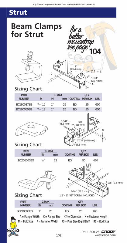
102Ph: 1-800-25-
www.erico.com
Strut
104
Beam Clampsfor Strut
A = Flange Width C = Flange Size ∅ = Diameter H = Fastener Height M = Bolt Size P = Fastener Width PS = Pipe Size Rigid/EMT RS = Rod Size
Sizing Chart
Sizing Chart
Sizing Chart
C
1"(25.4 mm)
1-1/4" (31.7 mm)
1/4" (6.3 mm)
PART C MAX QTY.NUMBER M IN mm COATING PER BOX LBS.
BC180037EG 3/8 - 16 1" 25 EG 25 660
BC180050EG 1/2 - 13 1" 25 EG 25 660
PART C MAX QTY.NUMBER IN mm COATING PER BOX LBS.
BC200000EG 1/2" 13 EG 50 460
1-5/8" (41.3 mm) 5/8"
(16 mm)
C
PART C MAX QTY.NUMBER IN mm COATING PER BOX LBS.
BC210000EG 1" 25 EG 25 460
3/8" (9.5 mm)
3-1/4" (82.5 mm)1/2" - 13 SET SCREW INCLUDED
1-1/2"(38.1mm)
C
1/4" (6.3 mm)
27/32" (46.8 mm)
http://www.computercablestore.com 800-626-6622 (267-354-6012)

103Ph: 1-800-25-www.erico.com
Strut
104
Beam Clampsfor Strut
A = Flange Width C = Flange Size ∅ = Diameter H = Fastener Height M = Bolt Size P = Fastener Width PS = Pipe Size Rigid/EMT RS = Rod Size
PART C MAX QTY.NUMBER IN mm COATING PER BOX LBS.
BC17A000EG 3/4" 20 EG 25 1200
BC17D000EG 3/4" 20 EG 25 1200
BC17PL00EG Plate Only
3-1/16" (77.8 mm) BC17A
4-11/16" (119.1 mm) BC17D
1"(25.4 mm)
2-5/8" (66 mm)
3"(76.2 mm)
1/4"(6.3 mm)
PART C MAX QTY.NUMBER IN mm COATING PER BOX LBS.*
BC16A000EG 7/8" 22 EG 20 740
1-3/4"(44.5 mm)
3-1/2" (88.9 mm)
1-3/4"(44.5 mm)
1/4"(6.3 mm)
3-1/2” (88.9 mm)
C
Sizing Chart
Sizing Chart
*When Used in Pairs
3/4"(18.9 mm)
http://www.computercablestore.com 800-626-6622 (267-354-6012)

104Ph: 1-800-25-
www.erico.com
Strut
Dual PurposeStrut/BeamClampsFeatures• More versatile alternative to window
bracket or standard beam clamp.
• Strut to beam flanges up to 3/4" thickness for15/8" deep strut (up to 15/8" flange thicknessfor 13/16" deep strut for STCB6 only.)
• Fits C purlin with 3/4” lip height (max)when used with 15/8” deep strut.
• Lock nut and hardened cup point setscrewprovide secure grip on tapered sections.
• Corrosive resistant galvanizedfinish. Available hot dippedgalvanized finish (Special order).
• Permits strut channel openingpositioning in any direction.
PART FIG. QTY.NUMBER NO. DESCRIPTION RS C† PER BOX LBS.
STCB6 1 Dual Purpose Strut/Beam Clamp 3/8-16 3/4" to 15/8" 10 400
STCB6 1 Used As Beam Clamp Without Strut 3/8-16 11/2" to 2" 10 400
200RS375 2 Dual Purpose Strut/Beam Clamp 3/8-16 Up to 1" 10 250
200RS500 2 Dual Purpose Strut/Beam Clamp 1/2-13 Up to 1" 10 760
Sizing Chart
3/4 -15/8"Flange
Up to 1"Flange
Coating EG
Note: Load based on single clamp. When used as strut hanger minimum required is 2.† As beam clamp
WidemouthFig. 1
StandardFig. 2
NowAvailable
Strut Clamps
BeamClamps
C = Flange Size RS = Rod Size
http://www.computercablestore.com 800-626-6622 (267-354-6012)

105Ph: 1-800-25-www.erico.com
Strut
ColumnStrut ClampsFeatures• Easy to install, as both parts clip
to strut during installation.
• For attachment of strut inside wide flange column or beams.
• Quick to install – tightening of only one bolt is required.
• Electrogalvanized finish.
Sizing ChartPART FIG. QTY.
NUMBER NO. DESCRIPTION COATING PER BOX
BC23A000EG 1 Fits all 15/8” x 15/8” strut EG 25
Packed in pairs.
PART FIG. QTY.NUMBER NO. COATING PER BOX LBS.*
INC8T5 2 EPZ 100 100
*When Used in Pairs
Fig. 1Heavy Duty
Fig. 2Standard
http://www.computercablestore.com 800-626-6622 (267-354-6012)

106Ph: 1-800-25-
www.erico.com
Strut
Strut Nuts
Fits all strut 15/8" (41 mm) wide1/4
5/163/8
1/25/8
3/4
NUT0025EG NUT0031EG NUT0037EG NUT0050EG NUT0062EG NUT0075EG
Fits 15/8" x 15/8" (41 mm x 41 mm) Fits 15/8" x 13/8" (41 mm x 35 mm)
1/45/16
3/81/2
5/83/4
SO* SO* SPRA0037EG SPRA0050EG SO* N/A
Fits 15/8" x 13/16" (41 mm x 21 mm)1/4
5/163/8
1/25/8
3/4
SPRC0025EG SO* SPRC0037EG SPRC0050EG SO* SO*
Fits 15/8" x 27/16" (41 mm x 62 mm) Fits 15/8" x 31/4" (41 mm x 83 mm)
1/45/16
3/81/2
5/83/4
SPRD0025EG SO* SPRD0037EG SPRD0050EG SO* SO*
Fits all strut 15/8" (41 mm) wide1/4
5/163/8
1/25/8
3/4
TSNT0025EG SO* TSNT0037EG TSNT0050EG SO* SO*
Fits all strut 15/8” (41 mm) wide1/4
5/163/8
1/25/8
3/4
MFA4I N/A N/A N/A N/A N/A
Length (L) 1/43/8
1/2
5/8" (16 mm) MFA625 NA NA
7/8" (22 mm) SPRM2508EG SO* SO*11/8" (28 mm) SPRM2511EG SPRM3711EG SPRM5011EG13/8" (35 mm) SO* SO* SPRM5013EG
*SO = Special Order
109
http://www.computercablestore.com 800-626-6622 (267-354-6012)

107Ph: 1-800-25-www.erico.com
Strut
CADDY® SLICKStrut NutFeatures• Eliminates hard-to-handle spring nuts
• Installs with one hand
• Available in 1/4", 3/8" and 1/2" thread sizes• Provides fast, universal attachment
of threaded rod and hardware to standard strut profiles
• Reduces installation time by up to 50%• Unique one-piece design• Eliminates the need for a washer• Easily fits all standard strut depths –
reducing inventory as much as 75%!
• For use indoors
Applications
Contact ERICO® For Available Metric Sizes Sizing ChartPART THREAD RECOMMENDED F1 LOAD F2 LOAD QTY.
NUMBER SIZE TORQUE 12GA 14GA 12GA 14GA PER BOX
SLICK250 1/4 - 20 5 ft-lbs. 250# 150# 800# 800# 100
SLICK375 3/8 - 16 15 ft-lbs. 400# 300# 1100# 1100# 100
SLICK500 1/2 - 13 20 ft-lbs. 650# 550# 1250# 1100# 100
F2 LOAD
F1 LOAD
Field assemble with 1/4-20 X 1"bolt and 4WN
http://www.computercablestore.com 800-626-6622 (267-354-6012)

108Ph: 1-800-25-
www.erico.com
Strut
Rigid Pipe ClampOne-PieceFeatures• Supports rigid pipe to strut
• Handles heavy loads
• One -piece design incorporates a retained bolt and built-in nut
• Installs with either a screwdriver or a nut driver
• Complete line is available to fit a wide range of pipe sizes
• Available in various materials and finishes
Sizing ChartPART PIPE SIZE LOAD QTY.
NUMBER NOMINAL O.D. (LBS.) PER BOX
RIGD0050XX* 1/2" 0.840 400 100
RIGD0075XX* 3/4" 1.050 400 100
RIGD0100XX* 1" 1.315 600 100
RIGD0125XX* 11/4" 1.660 600 100
RIGD0150XX* 11/2" 1.900 800 100
RIGD0200XX* 2" 2.375 800 100
RIGD0250XX* 21/2" 2.875 800 100
RIGD0300XX* 3" 3.500 800 100
RIGD0350XX* 31/2" 4.000 1000 100
RIGD0400XX* 4" 4.500 1000 100
Applications
* XX denoted finish available : EG - Electro-Galvanized, CG - Yellow Chromate, S4 - Stainless 304, S6 - Stainless 316, HD - Hot Dipped Galvanized, AL - Aluminum.
Contact ERICO® for Copper Applications.3/8", 5", 6", 8", 10", 12" available without one -piece design, retained combo-head bolt, or built-in nut.
http://www.computercablestore.com 800-626-6622 (267-354-6012)

109Ph: 1-800-25-www.erico.com
Strut
STS (Strut-to-Strut)Strut ClampFeatures• Provides fast assembly of back-to-back
half-slot strut as an alternative to welded strut
• Unique one-piece assembly that eliminates the need for bolts, washers, and nuts
• For new or retrofit applications
• Allows joining of dissimilar half-slot channel,regardless of profile size or finish
• Easy installation with a 1⁄2" nut driver
Sizing ChartPART QTY. PER WORKING
NUMBER DESCRIPTION BOX LOAD
STS Strut-to-strut clamp 100 1000 lbs.*
* 1000 lbs. working load per total assembly. (5-to-1 safety factor.) Not to exceed 1000 lbs.Half-slot dimensions vary by manufacturer. Minimum half-slot dimensions 9/16" x 7/8".Strut type and structure need to be evaluated to establish load for assembly. Use 1 STSper 1 ft. of strut, minimum of 2 required.
1/2" nut driver or socket
9/16" min.
7/8" min.
ApplicationsCan be used
on CADDY®
ERISTRUT or any
half-slot st
rut
with minimum half slot
dimensions o
f 9/16” x 7/8”
http://www.computercablestore.com 800-626-6622 (267-354-6012)

110Ph: 1-800-25-
www.erico.com
A-1212 Gauge
1-5/8" x 1-5/8"
A-1414 Gauge
1-5/8" x 1-5/8"
C-1212 Gauge
1-5/8" x 13/16"
C-1414 Gauge
1-5/8" x 13/16"
A-12AWelded Back-to-Back
A-12
CONContinuous
Concrete Insert
Strut
No. 50All Threaded Rod
No. 11Square Channel
Washer
Fig. 1 Fig. 2 Fig. 3
Fig. 4 Fig. 5 Fig. 6
Fig. 7 Fig. 8
http://www.computercablestore.com 800-626-6622 (267-354-6012)

111Ph: 1-800-25-www.erico.com
Strut
PART FIG. QTY.NUMBER DESCRIPTION NO. PER
A121000PG 12GA Solid 1-5/8" 10' Pre-Galv 1 500' bundleA122000GN 12GA Solid 1-5/8" 20' Green 1 500' bundleA122000PG 12GA Solid 1-5/8" 20' Pre-Galv 1 500' bundleA122000PL 12GA Solid 1-5/8" 20' Plain 1 500' bundleA12A1000GN 12GA Welded 1-5/8" 10' Green 2 250' bundleA12A1000PG 12GA Welded 1-5/8" 10' Pre-Galv 2 250' bundleA12A2000GN 12GA Welded 1-5/8" 20' Green 2 200' bundleA12A2000PG 12GA Welded 1-5/8" 20' Pre-Galv 2 200' bundleA12AH100PG 12GA Half Slot Welded 1-5/8" 10' Pre-Galv 2 250' bundleA12AH200GN 12GA Half Slot Welded 1-5/8" 20' Green 2 200' bundleA12AH200PG 12GA Half Slot Welded 1-5/8" 20' Pre-Galv 2 200' bundleA12H1000CG 12GA Half Slot 1-5/8" 10' Chromate (Gold) 1 500' bundleA12H1000GN 12GA Half Slot 1-5/8" 10' Green 1 500' bundleA12H1000PG 12GA Half Slot 1-5/8" 10' Pre-Galv 1 500' bundleA12H2000CG 12GA Half Slot 1-5/8" 20' Chromate (Gold) 1 500' bundleA12H2000GN 12GA Half Slot 1-5/8" 20' Green 1 500' bundleA12H2000PG 12GA Half Slot 1-5/8" 20' Pre-Galv 1 500' bundleA14H1000CG 14GA Half Slot 1-5/8" 10' Chromate (Gold) 8 500' bundleA14H1000GN 14GA Half Slot 1-5/8" 10' Green 8 500' bundleA14H1000PG 14GA Half Slot 1-5/8" 10' Pre-Galv 8 500' bundleA14H2000GN 14GA Half Slot 1-5/8" 20' Green 8 500' bundleA14H2000PG 14GA Half Slot 1-5/8" 20' Pre-Galv 8 500' bundleC12H1000CG 12GA Half Slot 13/16" 10' Chromate (Gold) 3 500' bundleC12H1000GN 12GA Half Slot 13/16" 10' Green 3 500' bundleC12H1000PG 12GA Half Slot 13/16" 10' Pre-Galv 3 500' bundleC12H2000GN 12GA Half Slot 13/16" 20' Green 3 500' bundleC12H2000PG 12GA Half Slot 13/16" 20' Pre-Galv 3 500' bundleC14H1000CG 14GA Half Slot 13/16" 10' Chromate (Gold) 7 500' bundleC14H1000GN 14GA Half Slot 13/16" 10' Green 7 500' bundleC14H1000PG 14GA Half Slot 13/16" 10' Pre-Galv 7 500' bundleC14H2000CG 14GA Half Slot 13/16" 20' Chromate (Gold) 7 500' bundleC14H2000GN 14GA Half Slot 13/16" 20' Green 7 500' bundleC14H2000PG 14GA Half Slot 13/16" 20' Pre-Galv 7 500' bundleCONC122000PG 13/16 Continuous Concrete Insert Pre-Galv 4 500' bundle0502510EG Threaded Rod 1/4" x 10' EG 5 25 PC0503710EG Threaded Rod 3/8" x 10' EG 5 25 PC0505010EG Threaded Rod 1/2" x 10' EG 5 25 PCF140000EG Square Channel Washer 3/8" EG 6 100 boxF150000EG Square Channel Washer 5/8" EG 6 100 box
CADDY® ERISTRUT Channel and Select Accessories
HALF SLOT(1-1/8" x 9/16" slots)
http://www.computercablestore.com 800-626-6622 (267-354-6012)

112Ph: 1-800-25-
www.erico.com
Strut
ESCFeatures• Spring steel permits snap in attachment
without tools.
• Works on industry standard strut profile.
• Provides fast attachment of a 1/4" mountinghole, J-Hook , cable, conduit, or 1/4" threaded rod to strut
Sizing ChartPART FIG. QTY. PER
NUMBER NO. DESCRIPTION BOX
ESC4 1 Easy Strut Clip 100
CAT12ESC 2 Snap-in 3/4" Diameter J-Hook 60
CAT21ESC 2 Snap-in 1-5/16" Diameter J-Hook 60
CAT32ESC 2 Snap-in 2" Diameter J-Hook 40
ESC6M 3 Snap-in MC/AC cable 100
ESC812M 3 Snap-in 1/2"-3/4" conduit 100
ESC8P 4 Snap-in 1/2" conduit 100
ESC12P 4 Snap-in 3/4" conduit 100
ESC4TI 5 Snap-in 1/4- 20 threaded rod 100
ESC6TI 5 Snap-in 3/8-16 threaded rod 100
Applications
Fig. 1
Fig. 2
Fig. 3
Fig. 4Fig. 5
Load limit 50 lbs.
http://www.computercablestore.com 800-626-6622 (267-354-6012)

113Ph: 1-800-25-www.erico.com
Hangers/Hanging Systems
Pages 113-124
http://www.computercablestore.com 800-626-6622 (267-354-6012)

114Ph: 1-800-25-
www.erico.com
Hangers/Hanging Systems
115
Rod AndWire HangersFeatures• ANGLE BRACKET suspends plain
rod, threaded rod or wire drops from laminated wood or concrete beams, joists, ceilings and walls.
• OFFSET BRACKET suspends plain rod, threaded rod or wire drops from laminated wood or concrete beams, joists, ceilings and walls.
NOTE:Loads indicated are for CADDY® Fasteners only. Method ofattachment to structure must be evaluated separately.
Fig. 3
Applications
Sizing ChartPART NO. QTY. PART NO. QTY.
ANGLE FIG. PER OFFSET FIG. PERBRACKET NO. BOX DE SCRIP TION BRACKET NO. BOX
708AB 1 100 For #8 wire or 708AO 5 1001/4" plain rod
6AB 2 100 For 3/8" plain rod 6AO 6 100
4TIB 3 100 For 1/4" threaded 4TIO 7 100rod, with threadimpression
6TIB 3 100 For 3/8" threaded 6TIO 7 100rod, with threadimpression
6TB 4 100 For 1/4" or 3/8" 6TO 8 100threaded rod,
nuts required
Static load limit 160 lbs.
Fig. 8Fig. 7Fig. 6
Fig. 5
Fig. 4Fig. 1Fig. 2
http://www.computercablestore.com 800-626-6622 (267-354-6012)

115Ph: 1-800-25-www.erico.com
Hangers/Hanging Systems
Pin Driven Angle BracketsFeatures• Longer leg angle bracket for tool clearance.
• Designed to fit a variety of pin drivers.
• Improved for easier installationwith pin drivers.
• Pregalvanized steel.
• Preassembly options availablefor Rod, Wire, Strap andCable Applications.
NOTE:Load limits apply to CADDY®
Fasteners only. Pin must be evaluated separately.
Sizing ChartPART FIG. QTY.
NUMBER NO. DESCRIPTION LOAD PER BOX
AFAB3 1 Angle bracket with 1/4" slotted 160 100hole and 3/16" mounting hole.
CAT21AFAB3 2 Cable support hanger 50 50with angle bracket. 15/16" diameter loop.
CAT32AFAB3 2 Cable support hanger 50 40with angle bracket. 2" diameter loop
CAT64AFAB3 2 Cable support hanger 100 25with angle bracket. 4" diameter loop
CAT12AFAB3 2 Cable support hanger 50 50with angle bracket. Holdsup to 16 cables of 4 twisted pair or fiber optic.
MSSAFAB3 3 Strap hanger 200 50to angle bracket.
4TIAFAB3 4 For 1/4" threaded rod, 160 50with thread impression.
6TIAFAB3 4 For 3/8" threaded rod, 160 100with thread impression.
6TAFAB3 4 For 1/4" or 3/8" threaded 160 100rod, nuts required.
6AFAB3 5 For 3/8" plain rod. 160 100708AFAB3 6 For #8 wire or 1/4" rod. 160 100
Fig. 2
Fig. 3
Fig. 4Fig. 5 Fig. 6
Fig. 1
http://www.computercablestore.com 800-626-6622 (267-354-6012)

116Ph: 1-800-25-
www.erico.com
Hangers/Hanging Systems
Hammer-OnPlain AndThreadedRod HangersBeam ClampsFeatures• Used to suspend #8 wire, 1/4", 3/8" plain
rod or 1/4" or 3/8" threaded rod frombeam flanges 1/8" to 3/4" thick.
• Requires only hammer to install.
Fig. 1Fig. 2
Fig. 3Fig. 4
Applications
Sizing Chart
PART FIG. FLANGE QTY.NUMBER NO. THICKNESS ROD SIZE PER BOX
70824 1 1/8"-1/4" #8 wire or 1/4" plain rod 10070858 1 5/16"-1/2" #8 wire or 1/4" plain rod 100708912 1 9/16"-3/4" #8 wire or 1/4" plain rod 100
6A24 2 1/8"-1/4" 3/8" (plain) 1006A58 2 5/16"-1/2" 3/8" (plain) 1006A912 2 9/16"-3/4" 3/8" (plain) 100
4TI24 3 1/8"-1/4" 1/4" threaded 1004TI58 3 5/16"- 1/2" 1/4" threaded 1004TI912 3 9/16"-3/4" 1/4" threaded 100
6TI24 3 1/8"-1/4" 3/8" threaded 1006TI58 3 5/16"-1/2" 3/8" threaded 1006TI912 3 9/16"-3/4" 3/8" threaded 100
6TA24 4 1/8"-1/4" 1/4" or 3/8" threaded* 1006TA58 4 5/16"-1/2" 1/4" or 3/8" threaded* 1006TA912 4 9/16"-3/4" 1/4" or 3/8" threaded* 100
*Nuts re quired.
Static load limit 200 lbs.
See Page 118
http://www.computercablestore.com 800-626-6622 (267-354-6012)

117Ph: 1-800-25-www.erico.com
Hangers/Hanging Systems
Threaded Rod HangerFor Bar JoistsFeatures• Fits open web joists with round bottom chords.
• Permits accurate centering.
• Part No. 6W for threaded rods 3/8" and smaller, nuts required.
• Part No. 4TW for threaded rods or bolts, 1/4-20 thread impression.
Fig. 1
Fig. 2
Applications
Eliminates offset bending conduit
Sizing Chart
Applications
PART QTY.NUMBER SIZE STATIC LOAD LIMIT PER BOX
2EBN #8 wire 100 lbs. thru 3/8" hole 1004EBN 1/4" plain rod 100 lbs. thru 3/8" hole 1006EBN 3/8" plain rod 200 lbs. thru 1/2" hole 100
Sizing ChartPART FIG. QTY.
NUMBER NO. DESCRIPTION PER BOX
6W 1 Wedge hanger 1004TW 2 Threaded wedge hanger 100
4TW static load limit 100 lbs.6W static load limit 200 lbs.
Fixture SupportFrom Plain RodFeatures• Eliminates the use of nut and allows the use of plain rod.
• No installation tools required.
http://www.computercablestore.com 800-626-6622 (267-354-6012)

118Ph: 1-800-25-
www.erico.com
Hangers/Hanging Systems
ISN Smart NutFeatures• Snaps anywhere on 3/8-16 threaded rod
• Adjustable and removable
• Eliminates excessive threading into place
• Supports plumbing, HVAC, electrical
• Reduces installation time
• Ideal when rod ends are not accessible or for retrofit applications
UPC# PART WEIGHT LOAD782856 NUMBER DESCRIPTION PER 100 RATING
45143 ISN375 Smart Nut, 3/8-16 3.1 lbs. 220 lbs.thread
Applications
ISSP Strut PlateFeatures• Allows for easy attachment of strut between existing rods
• Eliminates precise cutting of strut and the need for multiple hardware pieces
• For commercial and industrial applications
• Bolt has locking design to prevent loosening due to vibration
UPC# PART QTY. WEIGHT LOAD782856 NUMBER DESCRIPTION PER BOX PER 100 RATING
45143 ISSPK ISN/ISSP Kit Sets* 10.4 lbs. 220 lbs.(for 3/8-16 threaded rod)*Order in sets of 12 – 1 set includes (2) ISSP375 and (4) ISN375
45144 ISSP375 Strut Plate Only (No Hardware) 100 36 lbs. –
http://www.computercablestore.com 800-626-6622 (267-354-6012)

119Ph: 1-800-25-www.erico.com
Hangers/Hanging Systems
120
Deck HangersFor RodsAnd WiresFrom CellularFloor Deck(H.H. Robertson or
R.C. Mahon)Features• Design to support #8 wire, 1/4" or 3/8"
plain rod, 1/4" or 3/8" threaded rod(with or without nuts) and 1" wide strap from Cellular Floors with hanger tabs.
• Positive locking through deck tab. Prevents twisting or loosening due to vibration.
Fig. 1 Fig. 2
Fig. 3 Fig. 4 Fig. 5
Sizing Chart
Applications
PART FIG. QTY.NUMBER NO. DESCRIPTION PER BOX
DH2 1 For wrapping wire, “S” hooks, 100bolting straps
DH708 2 For #8 wire or 1/4" plain rod 100DH6A 3 For 3/8" plain rod 100DH4TI 4 For 1/4" threaded rod, with 100
thread impressionDH6TI 4 For 3/8" threaded rod, with 100
thread impressionDH6T 5 For 1/4" and 3/8" threaded rod, 100
nuts required
Static load limit 160 lbs. Check with deckmanufacturer for recommended load capacity
http://www.computercablestore.com 800-626-6622 (267-354-6012)

120Ph: 1-800-25-
www.erico.com
Hangers/Hanging Systems
Deck HangerAnd PunchFeatures (Hanger)• Minimum roof decking sheet
thickness 24 gauge.
• Maximum trapeze width 2” (50 mm).
• 1/4" or 3/8" square section nut or 3/8" (10 mm) clearance hole.
NOTE:Not for use with ceiling fans.
Features (Punch)• Easy one step operation.
• Pre-set dimensions.
• No secondary power source required.
Applications
Sizing Chart
Roof Decking Thickness
PART FIG. QTY.NUMBER NO . DESCRIPTION COATING PER BOX
TDH 1 3/8" Plain Hole EPZ 50TDHT4 2 1/4 - 20 Nut EPZ 50TDHT6 2 3/8 - 16 Nut EPZ 50TDHP2 3 Deck Hanger Punch – 1TDHP2PR10 Replacement Punch – 1
(requires 2 per punch)
IN mm GAUGE Lbs. kN.
0.025-0.0276 0.63-0.70 24 130 0.600.0276-0.0315 0.70-0.80 23 150 0.700.0315-0.0394 0.80-1.00 22 180 0.800.0394 1.00 19 200 0.900.0516 1.20 18 240 1.07
Check with deck manufacturer for recommended load capacity.
Fig. 1
Fig. 2
Fig. 3
Deck HangerAnd PunchFeatures (Hanger)• Minimum roof decking sheet
thickness 24 gauge.
• Maximum trapeze width 2” (50 mm).
• 1/4" or 3/8" square section nut or 3/8" (10 mm) clearance hole.
NOTE:Not for use with ceiling fans.
http://www.computercablestore.com 800-626-6622 (267-354-6012)

121Ph: 1-800-25-www.erico.com
StrapHanger ClipsFeatures• Simple solution for supporting of air duct.
• Accepts wider strap widths up to 11/4".
• The new clips are made from galvanized steel instead of spring steel. Thisexpands the use to more applications,especially when used with other platedparts like our BC200 beam clamp.
NOTE:Loads indicated are forCADDY® Fasteners only.
Fig. 1
Fig. 2
Fig. 4Fig. 3Applications
Sizing ChartPART FIG. FLANGE LOAD QTY. PER
NUMBER NO. THICKNESS RATING BOX
MSS24 1 1/8" to 1/4" 200# 50MSS58 1 5/16" to 1/2" 200# 50MSS912 1 9/16" to 3/4" 200# 50MSR24 2 1/8" to 1/4" 200# 50MSR58 2 5/16" to 1/2" 200# 50MSR912 2 9/16" to 3/4" 200# 50MSSBC200 3 1/8" to 5/8" 100# 50MSRBC200 4 1/8" to 5/8" 100# 50MSSAFAB3 5 Strap hanger 160# 50
to angle bracket
Improved Galvanized and Plated Components
for more demandingenvironments .
Hangers/Hanging Systems
Fig. 5
http://www.computercablestore.com 800-626-6622 (267-354-6012)

Hangers/Hanging Systems
122Ph: 1-800-25-
www.erico.com
WIRE ROPE QTY.PART DIMENSIONS PER WORKING
NUMBER Diameter Length BOX LOAD
SLD2L1 2 mm (.079 in) 1 m (3.3 ft) 100 45 kg (100 lbs)SLD2L2 2 mm (.079 in) 2 m (6.6 ft) 100 45 kg (100 lbs)SLD2L3 2 mm (.079 in) 3 m (9.9 ft) 100 45 kg (100 lbs)SLD2L5 2 mm (.079 in) 5 m (16.4 ft) 50 45 kg (100 lbs)SLD2L10 2 mm (.079 in) 10 m (32.8 ft) 25 45 kg (100 lbs)SLD3L1 3 mm (.118 in) 1 m (3.3 ft) 100 90 kg (200 lbs)SLD3L2 3 mm (.118 in) 2 m (6.6 ft) 100 90 kg (200 lbs)SLD3L3 3 mm (.118 in) 3 m (9.9 ft) 50 90 kg (200 lbs)SLD3L5 3 mm (.118 in) 5 m (16.4 ft) 50 90 kg (200 lbs)SLD3L10 3 mm (.118 in) 10 m (32.8 ft) 25 90 kg (200 lbs)
Individually PackagedSLD2L1BP 2 mm (.079 in) 1 m (3.3 ft) 100 45 kg (100 lbs)SLD2L2BP 2 mm (.079 in) 2 m (6.6 ft) 100 45 kg (100 lbs)SLD2L3BP 2 mm (.079 in) 3 m (9.9 ft) 100 45 kg (100 lbs)SLD2L5BP 2 mm (.079 in) 5 m (16.4 ft) 50 45 kg (100 lbs)SLD2L10BP 2 mm (.079 in) 10 m (32.8 ft) 25 45 kg (100 lbs)SLD3L1BP 3 mm (.118 in) 1 m (3.3 ft) 100 90 kg (100 lbs)SLD3L2BP 3 mm (.118 in) 2 m (6.6 ft) 100 90 kg (200 lbs)SLD3L3BP 3 mm (.118 in) 3 m (9.9 ft) 50 90 kg (200 lbs)SLD3L5BP 3 mm (.118 in) 5 m (16.4 ft) 50 90 kg (200 lbs)SLD3L10BP 3 mm (.118 in) 10 m (32.8 ft) 25 90 kg (200 lbs)
Stainless SteelSLD3L2SS 3 mm (.118 in) 2 m (6.6 ft) 100 90 kg (200 lbs)SLD3L3SS 3 mm (.118 in) 3 m (9.9 ft) 50 90 kg (200 lbs)
Sizing Chart
CADDY® SPEED LINKFeatures• Reduces installation time
• Quickly installs as a stand-alone hanging system without drilling into the building structure
• Works with a variety of CADDY® Fasteners
• Meets the fire rating requirements of DIN 4102-2 for 30 minutes at 30 percent of rated load.
• Reduces inventory, storage space and shipping costs
• Increases installation versatility
• Minimizes vibration and system wear & tear
• Improves installation aesthetics
• Unique steel locking device allows for adjustment both during and after installation.
http://www.computercablestore.com 800-626-6622 (267-354-6012)

Hangers/Hanging Systems
123Ph: 1-800-25-www.erico.com
PART FIG. QTY. WT. BOXNUMBER NO. DESCRIPTION PER BOX (LBS .)
SLWC 1 CADDY SPEED LINK Wire Cutter 1 0.7
SLADCP 2 Air Duct Corner Protector 10 0.4
SLEB250 – Eye bolt 1/4-20 by 1-3/16 inches 100 1.5
SLEB375 – Eye bolt 3/8-16 by 1-9/16 inches 100 3.3
SLEBWS – Eye bolt wood screw 100 2.5H6 by 60mm (2-3/8 inches)
SLWPT – Wire insulation protection 82 ft. 3.8tube (25 meters per box)
SLADS – Air duct support 100 1.3
SL1214 – Clip .468 to .562 MC/AC cable 100 1.1to CADDY SPEED LINK wire
SL1518 – Clip .500 to .718 MC/AC cable 100 1.2to CADDY SPEED LINK wire
SLLC250† – CADDY SPEED LINK 200 0.43Lighting clip 1/4 inch
†50 pound ultimate static load limit. Not to be used as a lifting device.
For other CADDY® SPEED LINK tools and accessories, visit the ERICO® website or contact us by phone.
CADDY® SPEED LINK Tools & Accessories
Applications
Fig. 1
Fig. 2
http://www.computercablestore.com 800-626-6622 (267-354-6012)

CADDY® SPEED LINK LDFeatures• Ideal in lighting and other installation projects
• Cost-effective alternative to jack chain, threaded rod and associated hardware
• Safe working load of 20 kg (44 lb)
• 5:1 safety factor
• Sleek low-profile locking device reduces visual impact
• Adjustable after installation
• Available in stainless steel for applications where a higher level of corrosion resistance is required
• Works with a variety of CADDY® Fasteners
• Meets the fire rating requirements of DIN 4102-2 for 30 minutes (for galvanized wire rope) and for 90 minutes (for stainless steel wire rope) at 30 percent of rated load.
Sizing ChartPART WIRE ROPE MATERIAL QTY. WORKING
NUMBER LENGTH PER BOX LOADHOOKSLD1 5L1 1 m (3.3 ft) galvanized steel 100 20 kg (44 lbs.)SLD15L2 2 m (6.6 ft) galvanized steel 100 20 kg (44 lbs.)SLD15L3 3 m (9.9 ft) galvanized steel 100 20 kg (44 lbs.)SLD15L5 5 m (16.4 ft) galvanized steel 100 20 kg (44 lbs.)SLD15L10 10 m (32.8 ft) galvanized steel 100 20 kg (44 lbs.)TOGGLESLD15L1T 1 m (3.3 ft) galvanized steel 20 20 kg (44 lbs.)SLD15L2T 2 m (6.6 ft) galvanized steel 20 20 kg (44 lbs.)SLD15L3T 3 m (9.9 ft) galvanized steel 20 20 kg (44 lbs.)SLD15L5T 5 m (16.4 ft) galvanized steel 20 20 kg (44 lbs.)SLD15L10T 10 m (32.8 ft) galvanized steel 20 20 kg (44 lbs.)Y-TOGGLESLD15Y500 500 mm (20 in) galvanized steel 20 20 kg (44 lbs.)SLD15Y800 800 mm (32 in) galvanized steel 20 20 kg (44 lbs.)2-PACKS - STAINLESS STEEL - HOOKSLD15L2S 2 m (6.6 ft) stainless steel 2 / bag 20 kg (44 lbs.)SLD15L5S 5 m (16.4 ft) stainless steel 2 / bag 20 kg (44 lbs.)SLD15L10S 10 m (32.8 ft) stainless steel 2 / bag 20 kg (44 lbs.)2-PACKS - HOOKSLD15L1TP 1 m (3.3 ft) galvanized steel 2 20 kg (44 lbs.)SLD15L2TP 2 m (6.6 ft) galvanized steel 2 20 kg (44 lbs.)SLD15L3TP 3 m (9.9 ft) galvanized steel 2 20 kg (44 lbs.)SLD15L5TP 5 m (16.4 ft) galvanized steel 2 20 kg (44 lbs.)2-PACKS - TOGGLE SLD15L1TTP 1 m (3.3 ft) galvanized steel 2 20 kg (44 lbs.)SLD15L2TTP 2 m (6.6 ft) galvanized steel 2 20 kg (44 lbs.)SLD15L3TTP 3 m (9.9 ft) galvanized steel 2 20 kg (44 lbs.)SLD15L5TTP 5 m (16.4 ft) galvanized steel 2 20 kg (44 lbs.)SLD15L10TTP 10 m (32.8 ft) galvanized steel 2 20 kg (44 lbs.)2-PACKS - Y-TOGGLE SLD15Y500TP 500 mm (20 in) galvanized steel 2 20 kg (44 lbs.)SLD15Y800TP 800 mm (32 in) galvanized steel 2 20 kg (44 lbs.)
See page 123 for tools & accessories.
124Ph: 1-800-25-
www.erico.com
Hangers/Hanging Systemshttp://www.computercablestore.com 800-626-6622 (267-354-6012)

125Ph: 1-800-25-www.erico.com
Stud Wall
Pages 125-144
http://www.computercablestore.com 800-626-6622 (267-354-6012)

126Ph: 1-800-25-
www.erico.com
Stud Wall
Box MountingBracket ForElectric BoxFeatures• Easily attaches 4" and 411/16" outlet boxes
to metal stud (HS3 switch boxes).
• Support leg reduces movementof box in wall.
• Can be attached to metal or wood stud.
• Offset design and use of CADDY®
#SMS8 low profile self-tapping screws(not included) reduce dry wall bulge.
• Delivers compliance with:NEC Article 300.4(d) when usedfor 4" and 411/16" outlet boxes to metalor wood studs.CEC Rule 12-3012 for 4" and 411/16"outlet boxes to metal or wood studs.
SMS8
Fig. 2
Fig. 1
Sizing Chart UL & cUL ListedPositioning Only
Applications
PART FIG. BOX STUD QTY.NUMBER NO. APPLICATION SIZE(S) DEPTH PER BOX
H23 1 U.S. 4" sq. & 411/16" 21/2" & 31/2" 100H23TC 1 Canada 4" sq. & 411/16" 21/2" & 31/2" 100H4 1 U.S. 4" sq. & 411/16" 4" 50H6 1 U.S. 4" sq. & 411/16" 6" 50H46TC 1 Canada 4" sq. & 411/16" 4" & 6" 100HS3 2 U.S. & Canada Switch 21/2" & 31/2" 100
IMPROVED!NO TOOLS TO ATTACHTO SWITCH BOXES
http://www.computercablestore.com 800-626-6622 (267-354-6012)

36" max.for conduit
127Ph: 1-800-25-www.erico.com
Stud Wall
Screw OnConduitSup portFeatures• Accommodates 1/2", 3/4" and 1”
EMT, Conduit and MC/AC Cable.
• Alignment tab positively locates thefastener on the stud, keeping yourconduit in line with box knock out and CADDY® H-series brackets.
• For wood or metal stud.
• Delivers compliance with: NEC Article 358.30(A)which requires conduit support within 36" of anelectrical box. CEC Rule 12-1404 which requiresconduit support within 1 m (36") of an electrical box.CEC Rule 12-618 which requires support of armouredcable within 300 mm (12") of an electrical box.
Sizing ChartPART QTY.
NUMBER DESCRIPTION PER BOX
CS812 Attaches 1/2" and 3/4" EMT, conduit, 100MC/AC to metal or wood studFor 11/2" deep box
CS812D Attaches 1/2" and 3/4" EMT, conduit, 100MC/AC to metal or wood studFor 2 1/8" deep box
CS16 Attaches 1” EMT, conduit, 100MC/AC to metal or wood studFor 2 1/8" deep box
UL & cUL Listed Positioning Only
GANGABLE FORINCREASED CONDUIT SUPPORT.LONGER TO REACH ALLKNOCKOUTS .
Eliminates offset bending conduitApplications
http://www.computercablestore.com 800-626-6622 (267-354-6012)

128Ph: 1-800-25-
www.erico.com
Stud Wall
“Mounts ElectricalBoxes” HangerFeatures• One bracket works for:
Two box depths (11/2" or 21/8" deep)Two box sizes (4" or 411/16" sq.)Three wall stud depths(21/2", 31/2" & 4" studs)
• All-in-one design simplifies handling,reduces inventory and saves space.
• Requires only a screw gun to install.
• V-notched on center allows forconsistent positioning.
• Built-in support legs reduce box movement when used with EMT and is ideal for flexible conduit, ENT,MC, AC or Romex® non-metallic sheathed cable.
• Offset design of MEB1 and use of CADDY®
#SMS8 low profile self-tapping screws (not included) reduce drywall bulge.
• Can be pre-assembled in the shop to allow forgreater efficiency at the job site.
• Plaster rings can be mounted separatelyeliminating the need for an electrical box forlow-voltage applications.
• MP Series brackets can be attached in-line to theMEB1 for low voltage applications.
• Mounts on either side of stud without need to reposition box
Sizing Chart UL & cUL ListedPositioning Only
Applications
PART QTY.NUMBER DESCRIPTION PER BOX
MEB1 “Mounts Electrical Boxes” Hanger 25
21/2" 31/2" 4"
1 1/2" 2 1/8"
One Size Fits All
One-Piece Design
Boxes
Studs
4" 411/16"
IMPROVED
DESIGN
Romex is a registered trademark of General Cable Corp.
http://www.computercablestore.com 800-626-6622 (267-354-6012)

129Ph: 1-800-25-www.erico.com
Stud Wall
Sizing Chart UL & cUL ListedPositioning Only
Applications
PART QTY.NUMBER DESCRIPTION PER BOX
304B2 Press -on nail plate 100
Face View
Gang Applications
Side View
Press-OnNail PlateFor Wood andMetal StudsFeatures• Fast press-on installation;no tools required.
• Protects electrical, datacomm and plumbing.
• Works on wood or metal studs.
• Meets NEC 300.4(b)(2). Also Designed to meet CEC 12-516 and 12-616.
• Breakable tabs permit multipleplates to be ganged together.
• Corrosion resistant zinc phosphate coating.
http://www.computercablestore.com 800-626-6622 (267-354-6012)

130Ph: 1-800-25-
www.erico.com
Stud Wall
Snap On Box Sup ports forMetal/Wood StudsFeatures• Spring steel for press-on attachment.
• Center hole assists in consistent alignment, exact positioning and screw attachment.
• Delivers compliance with:NEC Romex® Article 300.4(d) when usedfor 4" and 411/16" outlet boxes to metalor wood studs.CEC Rule 12-3012 for 4" and 411/16"outlet boxes to metal or wood studs.
• MSF requires hammer to attach clip to box. DBM2 attaches without hammer.
Sizing Chart
Applications
PART FIG. QTY.NUMBER NO. DESCRIPTION PER BOX
MSF 1 Box support to outside of stud 100
DBM2 2 Double box mount support* 50
SMS8 3 Low profile, self-tapping screws 1000
MSF
Far SideBox Support
Required
Fig. 1 Fig. 2
*Since metal stud widths vary, a CADDY® SMS8 screw is recommended
DBM2
Fig. 3
Romex is a registered trademark of General Cable Corp.
http://www.computercablestore.com 800-626-6622 (267-354-6012)

131Ph: 1-800-25-www.erico.com
Stud Wall
Applications
Sizing ChartPART FIG. QTY.
NUMBER NO. DESCRIPTION PER BOX
J1A35 1 Hammer on for 2 1/2" and 31/2" studs 100
766 2 Lock on for 2 1/2", 31/2" and 4" studs 100
766A 3 Snap on for 2 1/2", 31/2", 4" & 6" studs 100
No Load Rating – Positioning Only
4 312 2
12
Fig. 1 Fig. 3
J1A35
2 1/2
SolidFar Side
Box Support
AdjustableFar Side BoxSup portFeatures• Provides far side electrical
box support in various studwall depths.
• Installs in seconds with simple tools: pliers for 766A, hammer for J1A35.
• Delivers compliance with:NEC Article 300.4(d) when usedfor 4" and 411/16" outlet boxes to metal or wood studs.CEC Rule 12-3012 for 4" and 411/16" outlet boxes to metal or wood studs.
Fig. 1
Fig. 3
Fig. 2
766A
http://www.computercablestore.com 800-626-6622 (267-354-6012)

132Ph: 1-800-25-
www.erico.com
Stud Wall
Sizing Chart
Switch BoxOr ConduitTo Metal StudFeatures• Fits most switch boxes – Figs. 1-3 only.
• Fits most dry wall studding.
• Allows the switch box to protrude through any size dry wall –1/4", 3/8", 1/2", 5/8" or 3/4". Fig. 4
Fig. 2
Fig. 1
Fig. 3
Fig. 5
No Load Rating - Po si tion ing Only
Applications
PART FIG. QTY.NUMBER NO. DESCRIPTION PER BOX
MFI 1 1/4 -20 Thread impressionto metal stud 100
MFS 2 With screw (adjustable 1/4" thru 3/4") 100MFO 3 Riveted flush to stud face 100MF250 3 Riveted for 1/4" dry wall 100MF375 3 Riveted for 3/8" dry wall 100MF500 3 Riveted for 1/2" dry wall 100MF625 3 Riveted for 5/8" dry wall 100MF750 3 Riveted for 3/4" dry wall 1006MF 4 3/8" Conduit or BX to metal stud 100812MF 4 1/2" to 3/4" Conduit to metal stud 10016MF 4 1" Conduit to metal stud 1008PF 5 1/2" Conduit to metal stud 10012PF 5 3/4" Conduit to metal stud 10016PF 5 1" Conduit to metal stud 100
http://www.computercablestore.com 800-626-6622 (267-354-6012)

133Ph: 1-800-25-www.erico.com
Stud Wall
Screw On Box SupportFeatures• Permits positioning of metal electrical
box anywhere on metal or wood stud, regardless of stud size.
• The 350 is securely held in placewith screws.
Fig. 2
Fig. 3
Fig.1
Assemblies forconduit support
Sizing Chart
Applications
No Load Rating - Po si tion ing Only
PART FIG. QTY.NUMBER NO. DESCRIPTION PER BOX
350 1 4" electrical box to metal stud 100350812M 2 1/2" or 3/4" conduit to metal stud 10035016M 2 1" conduit to metal stud 1003508P 3 1/2" conduit to metal stud 10035012P 3 3/4" conduit to metal stud 10035016P 3 1" conduit to metal stud 100
Eliminates offset bending conduit
Far SideBox Support
Required(see 766A page 131)
http://www.computercablestore.com 800-626-6622 (267-354-6012)

134Ph: 1-800-25-
www.erico.com
Stud Wall
Box MountingBracketsFor Between StudsFeatures• Supports electrical boxes, plaster
rings or low voltage devices fromone bracket.
• Accommodates up to four 4" or 411/16" boxes.
• Mounts 11/2" or 21/8" deep boxes.
• Eliminates the need for an electricalbox on low voltage applications.
SMS8
RBS24
RBS16
Sizing Chart
Applications
PART QTY.NUMBER DESCRIPTION PER BOX
RBS16 Mounts up to three 4" or 411/16" 25boxes/plaster rings 16" bracket
RBS24 Mounts up to four 4" or 411/16" 25boxes/plaster rings 24" bracket
Minimum of onemounting screwrequired on eachside of the bracket.
http://www.computercablestore.com 800-626-6622 (267-354-6012)

135Ph: 1-800-25-www.erico.com
Stud Wall
Screw GunBox BracketFor Between StudsFeatures• Can mount multiple 11/2" or 21/8" deep boxes.
Notched and marked for easy identification and bending.
• Improved design with stamped inch markings and pilot holes accelerates precise box and conduit mounting between studs.
• Pilot holes allow easy boxattachment with a screwdriver.
• Requires only a screw gun to install.
• Reduces movement of the box when used with flexible conduit, ENT, MC, AC or ROMEX.®
• Can be mounted on face or inside of stud.SGB (Preset)
• Preset for studs 16" or 24" on center.• Can be preassembled by the contractor to
allow for greater production at the job site.TSGB (Adjustable)
• Adjustable for non-standard stud spacing.
• Unique, one-piece, break apart design.
• Interlocking tab prevents accidental disassembly.
Fig. 1
TSGBAdjustable
Sizing ChartPART FIG. STUD BOX
NUMBER NO. DESCRIPTION SPAC ING DEPTH
SGB16A† 1 Preset 16" OC 11/2" or 21/8"SGB24A†† 1 Preset 24" OC 11/2" or 21/8"TSGB16* 2 Adjustable 11" to 18" 11/2" or 21/8"TSGB24* 2 Adjustable 17" to 26" 11/2" or 21/8"
Quantity 50 per box.† Replaces SGB16 & SGB16D†† Replaces SGB24 & SGB24D* Preassembled brackets available - contact ERICO®
ROMEX is a registered trademark of General Cable Corp.
PATENT NUMBERS4,757,967 & 5,386,959
No more time -consuming field fabrication
with scrap floor track.
Minimum of onemounting screwrequired on eachside of the bracket.
Fig. 2
SGBPreset
SMS8Applications
http://www.computercablestore.com 800-626-6622 (267-354-6012)

136Ph: 1-800-25-
www.erico.com
Stud Wall
Floor MountedBox/ConduitSupportsFor Concrete FormsFeatures• Supports electrical boxes from floor
or concrete forms.
• Available in 12", 16" and 18" heights.
• Slot provides for 8" height adjustment.
• Use FBS with CCS812 to support conduitsin concrete pours.
• CCS812 eliminates offset bending of conduit.
• CCS812 also works with TSGB and SGB
FBS
Sizing Chart UL and cUL Listed - Po si tion ing Only
Applications
PART FIG. QTY.NUMBER NO. DESCRIPTION PER BOX
FBS12 1 12" High box support 50FBS16 1 16" High box support 50FBS18 1 18" High box support 50
CCS812 2 1/2" or 3/4" EMT - 1/2" RIGD 100
CCS812
Fig. 1
Fig. 2
http://www.computercablestore.com 800-626-6622 (267-354-6012)

137Ph: 1-800-25-www.erico.com
Stud Wall
FMBS18Floor Mount Box SupportFeatures• Positions center of electrical box 181⁄2" above
unfinished floor
• Meets ADA (Americans with Disabilities Act) accessibility Guidelines Standards (15" height minimum for “forward reach” from a wheelchair)
• Quick, easy and efficient compliance to construction requirements
• Mounts 4" or 4 11⁄16" U.S. or Canadian boxes; 11⁄2" or 21⁄8" deep
• Mounts plaster rings for low voltage applications
• Mounts inside (use mounting tabs) or under floor track
• Versatile positioning - independent of wall stud location
• Built-in far-side back support for 21⁄2", 31⁄2", and 4" metal or wood studs
• Reduces stocking different size brackets
• Accommodates additional brackets for multiple box and device mounting
Applications
Sizing ChartPART QTY. PER
NUMBER DESCRIPTION BOX
FMBS18 Floor Mount Box Support 25
http://www.computercablestore.com 800-626-6622 (267-354-6012)

138Ph: 1-800-25-
www.erico.com
Stud Wall
Sizing Chart No Load Rating - Po si tion ing Only
Low VoltageMountingBracketFor New ConstructionFeatures• Provides a bracket for mounting low
voltage Class 2 communication outlets.
• Side support provides for arigid in stal la tion.
• May be installed to the front or theside of the metal or wood stud.
• Reduces bulges in the dry wallcaused by plaster rings.
• Attaches with self-tapping screwsor nails.
• Works with 1/2" and 5/8" dry wall.
PART QTY.NUMBER DE SCRIP TION PER BOX
MP1S Plate mounting bracket for new work 25MP2S Double gang plate mounting bracket
for new work 25
MP2S
For low voltageClass 2 use only
MP1S
Bendable tabs provide cable tie off or 3/4" conduit stubbing.
Factory punchedholes allow forhor i zon tal in stal la tion.
Applications
PATENT NUMBER5,448,011
http://www.computercablestore.com 800-626-6622 (267-354-6012)

139Ph: 1-800-25-www.erico.com
Stud Wall
Cable GripperFeatures• Installs easily to metal and wood studs.
• Provides secure installation of multiplecables with unique locking/unlocking system.
• Staples, nails or screws to wood stud.
• Attaches to existing holes in metal studswithout tools.
• Supports four NMC or eight 4-pair UTP,Category 5 and higher (electrical and datacomm cannot be combined).
• Delivers compliance with:NEC 300.4(d), CEC 12-510 and 12-516.
CG4
Sizing Chart UL & cUL ListedPositioning Only
Applications
PART QTY.NUMBER DESCRIPTION PER BAG
CG4 Cable Gripper cable support 100
PATENT NUMBER5,626,316
http://www.computercablestore.com 800-626-6622 (267-354-6012)

140Ph: 1-800-25-
www.erico.com
Stud Wall
CJ6S
SMS8
“Colorado Jim”Cable SupportNEC® Com pli anceFor StudFeatures• New easy-to-use locking tab.
• Cable locating ribs to maintain cable separation.
• Flared edges for cable protection.
Sizing Chart UL & cUL ListedPositioning Only
Applications
Quantity 100 per box/case.
Non-MetallicSheathed Cable
Metal Clad (MC)Cable
Armored Cable (AC)
PART CABLES PERNUMBER CABLE TYPE CABLE SIZE FASTENER
14-2, 12-2, 10-2, 14-3,12-3 and 10-3 w/ground 6 maximum
8-2 and 6-2 w/ground 4 maximum14-2, 12-2, 10-2, 14-3,12-3, 10-3, 14-4, 12-4 4 maximumand 10-4 w/ground14-4, 12-2, 10-2, 8-2,14-3, 12-3, 10-3, 14-4, 4 maximum12-4 and 10-4 w/ground
Flexible Conduit (BX) 5/16, 3/8 4 maximum
CJ6IN to Non-Metallic 14-2, 12-2, 10-2, 14-3,Metal Stud Sheathed Cable 12-3 and 10-3 w/ground 4 maximum
CJ6 to Wood
CJ6to MetalStud
CJ6Sto FurringStrip andHat Channel
CANADA ONLY
PATENT NUMBER5,141,185
CJ6
® National Electric Code (NEC) is a registered trademark of the National Fire Protection Association® National Electric Code (NEC) is a registered trademark of the National Fire Protection Association
http://www.computercablestore.com 800-626-6622 (267-354-6012)

141Ph: 1-800-25-www.erico.com
Stud Wall
ROMEX® NMCAnd MC/AC CableSupport For StudsFeatures• Provides secure support of NMC or
MC/AC to metal/wood stud in seconds.One fastener, four applications.
• No tools required.
• Delivers compliance with:NEC 300.4(d), CEC 12-618 and CEC 12-510.
NOTE: When supporting NMC in Canada,FXC20 can only be used on wood stud.
FXC20
Sizing Chart UL & cUL ListedPositioning Only
Applications
PART QTY.NUMBER DESCRIPTION PER BOX
FXC20 NMC sizes 14-2 with 100ground thru 12-3 with groundMC/AC cable sizes 14-2 thru12-3 to studs
® ROMEX is a registered trademark of General Cable Corp.
http://www.computercablestore.com 800-626-6622 (267-354-6012)

Metal StudPunch AndEasy SnapGrommetGrommet Features• Snap one grommet into standard
111/32" field punched hole, OR snap two together into any shape factory punched hole.
• Provides 360° protection for cableand makes cable pulls easier.
• Delivers compliance with:NEC Article 300.4(b)(1) and CEC Rule 12-516.
Punch Features• Cushioned handles mean less operator fatigue and more
comfortable handling.
• Tool design with offset handles allows punch to work in confined locations and near perpendicular walls.
• Lightweight punch makes accurate location of holes easier.
• Hardened steel components keep tool sharper longer – less replacement.
• Punches up to 20 gauge sheet metal.
• Plastic grommets snap easily into 111/32" hole.
142Ph: 1-800-25-
www.erico.com
Stud Wall
Sizing Chart No Load Rating - Po si tion ing Only
ESG1Fig. 1
Super for ceiling track &tight corners.
MSP20Fig. 3
ESG1 1 Easy snap grommet 100ESG1M 1 Easy snap grommet 1000ESGP 2 Anti-rattle grommet 100ESGPM 2 Anti-rattle grommet 1000MSP20 3 Metal stud punch 1
PART FIG. QTY.NUMBER NO. DESCRIPTION PER BOX
Applications
ESGPFig. 2
http://www.computercablestore.com 800-626-6622 (267-354-6012)

143Ph: 1-800-25-www.erico.com
Stud Wall
Through Stud Cable/Conduit SupportEliminates Conduit RattleFeatures• Provides a quick means of support for
horizontal runs of Rigid, EMT, MC/ACor ENT through metal stud
• Eliminates conduit rattling
“Florida Bob” Series• Available with CADDY® 812M snap shut
conduit support, as well as CADDY push in conduit support
• Installs with screw gun
459/AR812• One-piece spring steel
design snaps onto stud
Fig. 2
Fig. 1
Sizing Chart
Applications
PART FIG. QTY.NUMBER NO. DESCRIPTION PER BOX
FB6M 1 MC/AC 100FB812M 1 1/2" or 3/4" Conduit 100FB8P 2 1/2" Conduit 100FB12P 2 3/4" Conduit 100459 3 MC/AC (14-2, 14-3 , 100
12-2, or 12-3)AR812 3 1/2" and 3/4" EMT Conduit 100
1/2" Rigid, IMC, PVC Sch 405/8" and 3/4" Copper TubeMC/AC .700 - .925 O.D.
No Load Rating - Po si tion ing Only
Fig. 3
SMS8
http://www.computercablestore.com 800-626-6622 (267-354-6012)

144Ph: 1-800-25-
www.erico.com
Stud Wall
Anti-RattleSupportFor Conduit andArmored CableFeatures• Permits ENT, MC and AC to be pulled
thru metal stud.
• Supports ENT, MC/AC, EMTor rigid conduit up to 1".
• Requires a self tapping screw to install.
781
SMS8
Sizing Chart
Applications
No Load Rating - Po si tion ing Only
PART QTY.NUMBER DESCRIPTION PER BOX
781 Supports conduit up to 1" 100
ENT MC/AC
EMT
http://www.computercablestore.com 800-626-6622 (267-354-6012)

145Ph: 1-800-25-www.erico.com
Drywall
Pages 145-150
http://www.computercablestore.com 800-626-6622 (267-354-6012)

146Ph: 1-800-25-
www.erico.com
Drywall
Sizing Chart No Load Rating - Po si tion ing Only
Applications
Old WorkBox MountFeaturesBoth• One-piece, break-apart design is
easier to handle.
• Works on drywall, lathe and plaster;only a drywall saw required.
DSB
• Fastener installs before the box to free upyour hands.
• Accommodates single or multiple gangboxes; for multiple gang boxes,use (2) DSB’s.
• Can be placed at different locations on anelectrical box to allow for more clearance.
DSI2A
2-1/2"
→
→
PART FIG. WALL QTY.NUMBER NO. DESCRIPTION THICKNESS PER BOX
DSI2A 1 Old work box mount Up to 11/2" 100 sets
DSB 2 Old work box mount 1/4" to 11/4" 100 sets
One-PieceBreak-ApartDesign
DSB
Fig. 1
Fig. 1 Fig. 2
Fig. 2
http://www.computercablestore.com 800-626-6622 (267-354-6012)

147Ph: 1-800-25-www.erico.com
Drywall
Device LevelerAnd RetainerFeatures• Use for oversize dry wall openings.
• Prevents broken cover plates.
• Prevents device from being pushedback in wall.
• Makes floating device rigid.
RLCGreat for oversize holes,
tile and panel walls!
Sizing Chart UL & cUL ListedNo Load Rating - Po si tion ing Only
Applications
PART QTY.NUMBER DESCRIPTION PER BOX
RLC Device leveler and retainer 100
http://www.computercablestore.com 800-626-6622 (267-354-6012)

148Ph: 1-800-25-
www.erico.com
Drywall
Mounting Plate Brackets(Non-Metallic)Features• No sharp metal edges with plastic design.
• Fast, easy way to install.
• No installation tools required to securebracket in the drywall opening.
• Serrated interlocking system secures tightly.
• Template points on brackets eliminate multiplemeasurement markings during installation.
• Recessed design assures flush mount of device.
• Only CADDY® provides the industry withthe widest application range 1/4" to 11/4".
• Available in single gang, double gang anda unique 3-4 gang sizes.
• Eliminates the need for electrical boxeson low voltage class 2 applications.
NOTE: For low voltage Class 2 use only.
Sizing Chart
Applications
PART FIG QTY.NUMBER NO. DE SCRIP TION PER BOX
MP1P 1 Single gang mounting plate 100MPAL2 2 Double gang mounting plate 100MP34P 3 3 or 4 gang mounting plate 2
UL & cUL ListedNo Load Rating - Po si tion ing Only
Fig. 1
Fig. 2
Fig. 3
FOR OTHERAPPLICATIONS ,
SEE MPVTI PAGE 150
http://www.computercablestore.com 800-626-6622 (267-354-6012)

149Ph: 1-800-25-www.erico.com
Drywall
148
Mounting Plate Brackets(Metallic)
Screw-On SupportFeatures• Provides positive support with
locking screws (included).
• Mounts any standard low voltagedevice in 1/2" through 11/4" walls.
• Makes wire “fishing” easier.
• Install with a drywall saw and screwdriver.
• Eliminates the need for an electrical boxwhen installing low voltage Class 2 wiring.
NOTE: For low voltage Class 2 use only.
PATENT NUMBERSUS: 4,955,825
Re: 33,305Can: 1,265,230
Sizing ChartPART QTY.
NUMBER DE SCRIP TION PER BOX
MPLS Single gang screws to drywall(screws included) 100
MPLS2 Double gang screws to drywall(screws included) 100
MP1 Single gang(no screws included) 100
MPLS
MPLS2
UL & cUL ListedNo Load Rating - Po si tion ing Only
Fig. 1
Fig. 2
MP1
Applications
http://www.computercablestore.com 800-626-6622 (267-354-6012)

150Ph: 1-800-25-
www.erico.com
Drywall
Versatile Thread ImpressionFor a Wide Variety ofLow Voltage DevicesFeatures• Support point for speakers, audio/video/security
panels, EXIT signs, etc.
• Works in 1/2” and 5/8” drywall.
• Use either #6-32 screw or #6 sheet metal screw.
• Spring steel with corrosion protection finish.
Sizing Chart
Applications
PART QTY.NUMBER DE SCRIP TION PER BOX
MPVT Versatile thread impression 20
No Load Rating - Po si tion ing Only
http://www.computercablestore.com 800-626-6622 (267-354-6012)

151Ph: 1-800-25-www.erico.com
Datacomm ITS
Pages 151-174
http://www.computercablestore.com 800-626-6622 (267-354-6012)

152Ph: 1-800-25-
www.erico.com
Datacomm ITS
Area Capacity (4-pair) Part(sq. in.) Cat. 5e Cat. 6 Number
0.60 16 10 CAT12
2.16 50 32 CAT21
3.17 80 50 CAT32
2 x 1.58 80 50 CAT100CM
15.28 300 185 CAT64
20.43 425 265 CAT425
21.00 500 315 CAT200CMLN
32.00 750 470 CAT300CMLN
32.00 750 470
3.14 75 47 CAT600
CADDY® CABLECAT Capacity Guide
CATTRAX25
http://www.computercablestore.com 800-626-6622 (267-354-6012)

153Ph: 1-800-25-www.erico.com
Datacomm ITS
Applications
Fig. 3
Fig. 2
CADDY® CABLECATWide Base Cable SupportFeatures• Provides proper support of Category 5,
Category 6, fiber optic and innerduct.
• Many sizes and designs available to attach to a variety of structures.
• Cost effective alternative to expensive cable tray.
• Galvanized finish on J-hooks providesmoother cable pull and greatercorrosion resistance.
• Complies with UL®, cUL®, NEC® and EIA/TIASM requirements for structured cabling systems.
Fig. 1
Angle Brackets for Greater Field Assembly OptionsUp to 300 Lb. Loads
Fig. 7Fig. 5
PATENT # 5,740,994
Fig. 4
Fig. 6
http://www.computercablestore.com 800-626-6622 (267-354-6012)

154Ph: 1-800-25-
www.erico.com
Datacomm ITS
*CAT12 J-Hooks and CAT12 assemblies include bend back tab.
Retainers now included with1 5/16", 2" and 4" J-Hook sizes,suitable for air handlingspaces (plenum).
CADDY® CABLECATWide Base Cable Support
Complies with TIA 569
PART FIG. QTY.NUMBER NO. DESCRIPTION PER BOX
CAT12* 1 Up to 16 4-pair UTP CAT 5e or 2-strand fiber optic cable, or 10 CAT 6 - 3/4" dia. loop 50
CAT21✝ 1 Up to 50 4-pair UTP CAT 5e or 2-strand fiber optic cable or innerduct, or 32 CAT 6 - 15/16" dia. loop 80
CAT32✝ 1 Up to 80 4-pair UTP CAT 5e or 2-strand fiber opticcable or innerduct, or 50 CAT 6 - 2" dia. loop 60
CAT64 1 Up to 300 4-pair UTP CAT 5e or 2-strand fiber optic cable, or 185 CAT 6 - 4" dia. loop 25
CATHBA 2 Extended J-Hook angle bracket - 1/4" mounting hole 40CATHBA3 2 Extended J-Hook angle bracket - 3/16" mounting hole 40CATHBA6 2 Extended J-Hook angle bracket - 3/8" mounting hole 40CATHBA8 2 Extended J-Hook angle bracket - 1/2" mounting hole 40S3575BP100 3 1/4 - 20 x 3/8" round head screw 100S3575DP100 3 1/4 - 20 x 3/4" round head screw 100AFAB3 4 3/16" mounting hole 50
(includes 1/4 - 20 x 3/8" round head screw)AFAB4 4 1/4" mounting hole 50
(includes 1/4 - 20 x 3/8" round head screw)AFAB6 4 3/8" mounting hole 50
(includes 1/4 - 20 x 3/8" round head screw)CATMTP 5 Mille-Tie™ for air handling spaces (plenum) 100CATTS* 6 Support from tee grid 100
Kits For Beam Applications (Field Assemblies)
CAT KITA 7 CAT32 – 20 pieces / CATHBA Hanger – 5 piecesBC200 Beam Clamps – 5 pieces 1 Kit
CAT KITB 7 CAT21 – 10 pieces / CAT32 – 10 piecesCATHBA Hanger – 5 piecesBC200 Beam Clamps – 5 pieces(screws included) 1 Kit
CAT KITC 7 CAT21 – 20 pieces / CATHBA Hanger – 5 piecesBC200 Beam Clamps – 5 pieces(screws included) 1 Kit
✝ Available in stainless steel
http://www.computercablestore.com 800-626-6622 (267-354-6012)

155Ph: 1-800-25-www.erico.com
Datacomm ITS
CADDY® CABLECATWide Base Cable Support Clips
*Pre-Riveted Factory Assemblies for 3/4" Diameter LoopCAT12BC 8 Screw-on 1/8" thru 1/2" flange 40CAT12BC200 9 Screw-on 1/8" thru 5/8" flange 40CAT12ESC 10 Easy Strut Clip 60CAT1224SM 11 Hammer-on 1/8" thru 1/4" flange 40 CAT1258SM 11 Hammer-on 5/16" thru 1/2" flange 40 CAT12912SM 11 Hammer-on 1/2" thru 3/4" flange 40CAT1224 12 Hammer-on 1/8" thru 1/4" flange –
bottom mount rotates 360º 40CAT1258 12 Hammer-on 5/16" thru 1/2" flange –
bottom mount rotates 360º 40CAT12912 12 Hammer-on 1/2" thru 3/4" flange –
bottom mount rotates 360º 20CAT12VF14 13 1/16" thru 1/4" vertical flange 40CAT12AF14 14 1/16" thru 1/4" Z purlin 40CAT124Z34 15 #12 thru 1/4" wire, plain or threaded rod
and 1/8" thru 3/8" flange 60CAT126Z34 15 3/8" plain or threaded rod and 3/8" thru 9/16" flange 60CAT12AB 16 Angle bracket - 1/4" mounting hole 40CAT12AFAB3 17 Cable support hanger with angle bracket. Holds 50
up to 16 cables of 4 twisted pair or fiber opticCAT12BCB 18 Screw-on 1/8" thru 1/2" flange – rotates 360º 40CAT12BC200B 19 Screw-on 1/8" thru 5/8" flange – rotates 360º 40CAT12TS 20 Acoustical tee bar 60CAT12CD1B 21 Under floor support to pedestal 40
Sizing ChartPART FIG. QTY.
NUMBER NO. DESCRIPTION PER BOX
cULus ListedCable Support
3/4 " DIAMETER LOOP
Fig. 12 Fig. 14
Fig. 13
Fig. 8Fig. 9
Fig. 11
Fig. 10
http://www.computercablestore.com 800-626-6622 (267-354-6012)

Datacomm ITS
156Ph: 1-800-25-
www.erico.com
CAT21BC 8 Screw-on 1/8" thru 1/2" flange 40CAT21BC200 9 Screw-on 1/8" thru 5/8" flange 40CAT21ESC 10 Easy Strut Clip 60CAT2124SM 11 Hammer-on 1/8" thru 1/4" flange 40CAT2158SM 11 Hammer-on 5/16" thru 1/2" flange 40 CAT21912SM 11 Hammer-on 1/2" thru 3/4" flange 40CAT2124 12 Hammer-on 1/8" thru 1/4" flange – rotates 360º 40CAT2158 12 Hammer-on 5/16" thru 1/2" flange – rotates 360º 40CAT21912 12 Hammer-on 1/2" thru 3/4" flange – rotates 360º 20CAT21VF14 13 1/16" thru 1/4" vertical flange 40CAT21AF14 14 1/16" thru 1/4" Z purlin 40CAT214Z34 15 #12 thru 1/4" wire, plain or threaded rod
and 1/8" thru 3/8" flange 60CAT216Z34 15 3/8" plain or threaded rod and 3/8" thru 9/16" flange 60CAT21AB 16 Angle Bracket Assembly - 1/4" mounting hole 40CAT21AFAB3 17 Angle Bracket Assembly - 3/16" mounting hole 40CAT21AFAB4 17 Angle Bracket Assembly - 1/4" mounting hole 40CAT21AFAB6 17 Angle Bracket Assembly - 3/8" mounting hole 40 CAT21BCB 18 Screw-on 1/8" thru 1/2" flange – rotates 360º 40CAT21BC200B 19 Screw-on 1/8" thru 5/8" flange – rotates 360º 40CAT21CD1B 21 Under floor support to pedestal 40
CADDY® CABLECATWide Base Cable Support Clips Sizing Chart
PART FIG. QTY.NUMBER NO. DESCRIPTION PER BOX
cULus ListedCable Support15/16"DIAMETER LOOP
Fig. 15Fig. 16
Fig. 18
Fig. 19 Fig. 20 Fig. 21
Fig. 17
http://www.computercablestore.com 800-626-6622 (267-354-6012)

Datacomm ITS
CADDY® CABLECATWide Base Cable Support Clips
157Ph: 1-800-25-www.erico.com
Pre-Riveted Factory Assemblies For 2" Diameter LoopCAT32BC 8 Screw-on 1/8" thru 1/2" flange 40CAT32BC200 9 Screw-on 1/8" thru 5/8" flange 20CAT32ESC 10 Easy Strut Clip 40CAT3224SM 11 Hammer-on 1/8" thru 1/4" flange 40 CAT3258SM 11 Hammer-on 5/16" thru 1/2" flange 40 CAT32912SM 11 Hammer-on 1/2" thru 3/4" flange 40CAT3224 12 Hammer-on 1/8" thru 1/4" flange – rotates 360º 20CAT3258 12 Hammer-on 5/16" thru 1/2" flange – rotates 360º 20CAT32912 12 Hammer-on 1/2" thru 3/4" flange – rotates 360º 20CAT32VF14 13 1/16" thru 1/4" vertical flange 40CAT32AF14 14 1/16" thru 1/4" Z purlin 40CAT324Z34 15 #12 thru 1/4" wire, plain or threaded rod
and 1/8" thru 3/8" flange 40CAT326Z34 15 3/8" plain or threaded rod and 3/8" thru 9/16" flange 40CAT32AB 16 Angle Bracket Assembly - 1/4" mounting hole 40CAT32AFAB3 17 Angle Bracket Assembly - 3/16" mounting hole 40CAT32AFAB4 17 Angle Bracket Assembly - 1/4" mounting hole 40CAT32AFAB6 17 Angle Bracket Assembly - 3/8" mounting hole 40CAT32BCB 18 Screw-on 1/8" thru 1/2" flange rotates 360º 20CAT32BC200B 19 Screw-on 1/8" thru 5/8" flange rotates 360º 20CAT32CD1B 21 Under floor support to pedestal 20
Sizing ChartPART FIG. QTY.
NUMBER NO. DESCRIPTION PER BOX
cULus ListedCable Support2" DIAMETER LOOP
Fig. 15
Fig. 12
Fig. 14
Fig. 13
Fig. 8
Fig. 16
Fig. 18Fig. 19
Fig. 20 Fig. 21
Fig. 9
Fig. 11
Fig. 17
Fig. 10
http://www.computercablestore.com 800-626-6622 (267-354-6012)

158Ph: 1-800-25-
www.erico.com
Datacomm ITS
Less Than
12 In.
4-5 Ft.
Tip
CAT64BC 8 Screw-on 1/8" thru 1/2" flange 25CAT64BC200 9 Screw-on 1/8" thru 5/8" flange 25CAT6424SM 11 Hammer-on 1/8" thru 1/4" flange 25CAT6458SM 11 Hammer-on 5/16" thru 1/2" flange 25CAT64912SM 11 Hammer-on 1/2" thru 3/4" flange 25CAT6424 12 Mount rotates 360˚ 25CAT6458 12 Mount rotates 360˚ 25CAT64912 12 Mount rotates 360˚ 25CAT64VF14 13 1/16" thru 1/4" vertical flange 25CAT64AF14 14 1/16" thru 1/4" Z purlin 25CAT64AFAB3 17 Angle Bracket Assembly - 3/16" mounting hole 25CAT64AFAB4 17 Angle Bracket Assembly - 1/4" mounting hole 25CAT64AFAB6 17 Angle Bracket Assembly - 3/8" mounting hole 25CAT64BCB 18 Screw-on 1/8" thru 1/2" flange rotates 360˚ 25CAT64BC200B 19 Screw-on 1/8" thru 5/8" flange rotates 360˚ 25CAT64CD1B 21 J-hook to 3/4” & 1” round or square pedestal 25
CADDY® CABLECATWide Base Cable Support Clips Sizing Chart
PART FIG. QTY.NUMBER NO. DESCRIPTION PER BOX
cULus ListedCable Support4" DIAMETER LOOP
For all CADDY® CABLECAT supports, make sure cable sag between fasteners is no more than 12" at midspan. (Actual cable sag will depend on the number of cables ineach bundle and the weight of the cable.) To achieve this, locate the supports every 4-5 feet to stay within the 12” sag criterion.
http://www.computercablestore.com 800-626-6622 (267-354-6012)

159Ph: 1-800-25-www.erico.com
Datacomm ITS
Pin Driven J-HookAngle Brackets
Sizing ChartPART FIG. WORKING QTY. PER
NUMBER NO. DESCRIPTION LOAD (LBS .) BOX
AFAB3 1 Angle bracket with 1/4" slotted 160 50hole and 3/16" mounting hole(includes 1/4-20 x 3/8 round head screw)
CAT12AFAB3 2 Cable support hanger with angle 50 40bracket. Holds up to 16 cableof 4 twisted pair or fiber optic
CAT21AFAB3 2 15/16" J-Hook angle bracket 50 40pre-riveted assembly
CAT32AFAB3 2 2" J-Hook angle bracket 50 40pre-riveted assembly
CAT64AFAB3 2 4" J-Hook angle bracket 100 25pre-riveted assembly
CATHBA3 3 Extended J-Hook angle 300 40bracket - 3/16" mounting hole
Features• New angle brackets lock on CADDY® CABLECAT
J-Hooks so the assembly will not twist or swivel
• AFAB3 offers greater field assembly options - back-to-back, 90 degree corners, etc.
• CATHBA offers versatile configurations for 1 5/16", 2" and/or 4" J-Hook field assembly - time/material saving cable tray alternative
See page 155-158 for other angle bracket applications,components, assemblies and kits.
NOTE: Load limits apply to CADDY® fasteners only. Pin must be evaluated separately.
Fig. 1
Fig. 2
Fig. 3
Applications
http://www.computercablestore.com 800-626-6622 (267-354-6012)

160Ph: 1-800-25-
www.erico.com
Datacomm ITS
CADDY® CABLECAT PulleyFeatures• Frees up the “second man” on cable pulling.
• CAT32PLR accepts up to 20 four-pair cables.(CAT64PLR • 40 four-pair cables).
• Complies with the TIA standard requirement by minimizing the pull force on the cable.
• Maintains proper bend radius and protects cable during the installation.
• Kit includes spring-loaded J-hook, pin, wheel and retainer, link, and beam clamp.
• When the job is complete, the pulley and pin assembly can be removed leaving the J-hook as a cable support.
• The CAT32PLR pulley components can be used on any current design CAT32 J-hook.
CAT32PLR comes ready to nail orscrew directly to the structure. Whenused with other CADDY clips., it canbe quickly attached to beams, C&Z
purlins, drop wire/rods, etc.
Applications
PART QTY.NUMBER DE SCRIP TION PER BOX
CAT32PLR Pulley kit - CAT32 2" spring-loaded 10J-hook , pin, wheel and retainer, link and beam clamp
CAT64PLR Pulley kit - CAT64 4" spring-loaded 2J-hook, pin, wheel and retainer, link and beam clamp
Sizing Chart
http://www.computercablestore.com 800-626-6622 (267-354-6012)

161Ph: 1-800-25-www.erico.com
Datacomm ITS
CADDY® CABLECATAdjustableCable SupportFeatures• Up to 425 4-pair UTP or 2-strand
fiber optic cable, or 265 CAT6 - 4" or 6" dia. loop.
• Provides proper support of Category 5,fiber optic and innerduct.
• Multiple sizes and designs available to attach to a variety of structures.
• Cost effective alternative toexpensive cable tray.
• Complies with UL®, cUL®, NEC® andEIA/TIA requirements for structuredcabling systems.
• Suitable for air handling spaces (plenum).
Sizing Chart
Fig. 2
Fig. 3
Fig. 1B
Fig. 1A
PATENT# 5,964,434
Fig. 5
Fig. 6
PART FIG. QTY.NUMBER NO. DESCRIPTION PER BOX
Adjustable Cable Support
CAT425WM 1A Wall mount - vertical surface 10CAT425 1B 1/4" Threaded rod or horizontal surface 10CAT425A6 1B 3/8" Threaded rod or horizontal surface 10Hammer On Flange Clip
CAT42524SM 2 Hammer-on 1/8" - 1/4" flange 10CAT42558SM 2 Hammer-on 5/16" - 1/2" flange 10CAT425912SM 2 Hammer-on 9/16" - 3/4" flange 10Beam ClampCAT425BC 3 Screw-on 1/8" - 1/2" flange (rotates 360˚) 10CAT425BC200 4 Screw-on 1/8" - 5/8" flange (rotates 360˚) 10Purlin
CAT425AF14 5 Hammer-on 1/16" - 1/4" Z purlin 10CAT425VF14 6 Hammer-on 1/16" - 1/4" vertical flange 10CAT425WMCD1B 7 Under floor pedestal
Now available for1/4" or 3/8"Threaded Rod
Fig. 7
Applications
Load Rate 100 lbs.
Fig. 4
http://www.computercablestore.com 800-626-6622 (267-354-6012)

162Ph: 1-800-25-
www.erico.com
Datacomm ITS
CADDY® CAT-CMCable Support SystemFeatures• Specially designed U-Hooks and double J-Hooks have large diameter
rounded support surfaces• Two Installation Options
– Rod-Mounted allows for field assembly onto All-Thread Rod.– Cantilever-Mounted allows U-Hooks being mounted with brackets to
walls and columns. • Compliant with NEC® and ANSI®/EIA/TIASM structured cabling systems
standards.• Hooks are UL listed.
PART FIG. QTY. PERNUMBER NO. DESCRIPTION BOX
CAT100CM 1 Double J-Hook 20CAT200CM 2 U-Hook 200 mm/8" with T-nut* 10CAT200CMLN 3 U-Hook 200 mm/8" less nut 10CAT300CM 2 U-Hook 300 mm/12" with T-nut* 10CAT300CMLN 3 U-Hook 300 mm/12" less nut 10CATRL200CM 4 Roller 200 mm/8" (incl. rod & nuts) 10CATRL300CM 4 Roller 300 mm/12" (incl. rod & nuts) 10CATRT200CM 5 Wire Retainer 200 mm/8" 50CATRT300CM 5 Wire Retainer 300 mm/12" 50CATTBCM 6 Protection Tube 30CATWMCM 7 Wall bracket 10
*Quick-attach T-nut for half slot strut
http://www.computercablestore.com 800-626-6622 (267-354-6012)

163Ph: 1-800-25-www.erico.com
Datacomm ITS
CABLE CAT100CM CAT200CMLN CAT300CMLNON ROD ON ROD OR ON ROD OR
CANTILEVER CANTILEVER
4-pair UTP, 80 500 750Cat 5/5e
4-pair UTP, 50 315 470Cat 6
4-pair 40 250 375ScTP/FTP4-pair STP 26 170 250
Fig. 1
Fig. 2
Fig. 3Fig. 4
Fig. 5
Fig. 6
Applications
Fig. 7
http://www.computercablestore.com 800-626-6622 (267-354-6012)

164Ph: 1-800-25-
www.erico.com
Datacomm ITS
CADDY® CABLECATVertical BackboneCable SupportFeatures• Makes vertical cable pulling easier –
locking mechanism opens during pulland re-engages when cable is released.
• Accepts wide range of cable sizes: (75) 4-pair UTP CAT 5E, 47 CAT6 (10) 25-pair UTP, (1) each 100-pair through 600-pair.
• Available as wall-mount (#CAT600WM) or strut-mount (#CAT600R).*
• Strut-mount includes pre-riveted assembly that twist-locks into the strut.
• Rounded edges prevent cable damage.
• Valuable space savings within telecom closets.
• More versatile allowing future additions of cable runs.
• Reduces installation time.
• Allows cable installation to start at the bottom floor.
• Galvanized finish for corrosion protection.* Also available as kits with 18" precut slotted strut.
Applications
PART FIG. QTY.NUMBER NO. DE SCRIP TION PER BOX
CAT600WM 1 Wall mount 2CAT600R 2 Strut mount 2CAT600RKIT 2 Strut mount kit with (1) 18" precut 1
slotted strut & (4) CAT600R
Fig. 1Wall Mount
Comes Pre-assembled
Fig. 2Strut Mount
See CADDY® SCH-B(Page 59) for InnerductApplication Options
Now Includes Foam Inserts forImproved Grip
http://www.computercablestore.com 800-626-6622 (267-354-6012)

165Ph: 1-800-25-www.erico.com
Datacomm ITS
patent pending
CADDY® CAT TRAXContinuous Cable Support SystemFeatures• Lightweight and flexible for easy installation
• Attaches to any main or sub structure when used in concert with other CADDY® Fasteners.
• Compliant with NEC® and ANSI®/EIA/TIASM
structured cabling systems standards.
• Hangers are UL® Listed for 200 lbs. spaced 4 to 5 feet apart; mesh is suitable for internal air handling spaces (plenum).
• Rod and structure attachments sold separately.
• Sold as 25’ rolls in convenient, easy-to-carry “kit” cartons
• Convenient “snap-together” kits
• 32 square inches of cable containment area
• Capacity exceeds a comparable 2” x 12” tray
Sizing Chart
Fig. 1 Fig. 2
Fig. 3
Fig. 4
Fig. 5
Fig. 6
Applications
PART FIG.NUMBER DESCRIPTION INCLUDES NO.
CATTRAX25 CADDY CAT TRAX (5) steel support brackets 1Continuous Cable 25 ft. roll flexible mesh 2Support Kit (15) spring steel bracket clips 3
(10) plastic splice clips 4
(5) steel retaining clips 5
CT128TRK CADDY CAT TRAX (5) wire transition pieces 6Transition Kit (5) steel retaining straps 5
(30) plastic splice clips 4
http://www.computercablestore.com 800-626-6622 (267-354-6012)

166Ph: 1-800-25-
www.erico.com
Datacomm ITS
Mille-TieTM
Features• Protects cable from crimping with “Intelligent Grip Technology.”
• Cushions vibration.
• Maintains cable properties and conductor configuration.
• Reusable.
• No sharp edges.
• One size fits all.
• Available in two versions – suitable for air-handling spaces (Plenum) and Low Smoke/Zero Halogen Certified.
PART QTY. PERNUMBER DE SCRIP TION BAG/BOX
CATMTP Red Mille -Tie 100/1000(suitable for air-handling spaces)
CATMTLS Yellow Mille -Tie 100/1000(Low Smoke - Zero Halogen)
Applications
Mille-Tie is a trademark of Millepede International, Ltd.
http://www.computercablestore.com 800-626-6622 (267-354-6012)

167Ph: 1-800-25-www.erico.com
Datacomm ITS
Cable GripperFeatures• Installs easily to metal and wood studs.
• Provides secure installation of multiplecables with unique locking/unlocking system.
• Staples, nails or screws to wood stud.
• Attaches to existing holes in metal studswithout tools.
• Supports four NMC or eight 4 pair UTP,Category 5 and higher (electrical and datacomm cannot be combined).
• Delivers compliance with:NEC 300.4(d), CEC 12-510 and 12-516.
CG4
Sizing Chart UL & cUL ListedPositioning Only
Applications
PART QTY.NUMBER DESCRIPTION PER BAG
CG4 Cable Gripper cable support 100
PATENT NUMBER5,626,316
2005 NEC
Requirement
http://www.computercablestore.com 800-626-6622 (267-354-6012)

168Ph: 1-800-25-
www.erico.com
Datacomm ITS
Sizing Chart
Low VoltageMountingBracketFor New ConstructionFeatures• Provides a bracket for mounting low
voltage Class 2 communication outlets.
• Side support provides for arigid in stal la tion.
• May be installed to the front or theside of the metal or wood stud.
• Reduces bulges in the dry wallcaused by plaster rings.
• Attaches with self-tapping screwsor nails.
• Works with 1/2" and 5/8" dry wall.
PART QTY.NUMBER DE SCRIP TION PER BOX
MP1S Plate mounting bracket for new work 25MP2S Double gang plate mounting bracket
for new work 25
MP2S
MP1S
Bendabletabs provide cabletie off or 3/4" conduit stubbing.
PATENT NUMBER5,448,011
Applications
For Low Voltage Class 2 Wiring
UL & cUL ListedNo Load Rating - Po si tion ing Only
Factory punchedholes allow forhor i zon tal in stal la tion.
http://www.computercablestore.com 800-626-6622 (267-354-6012)

169Ph: 1-800-25-www.erico.com
Datacomm ITS
Mounting Plate Brackets(Non-Metallic)Features• No sharp metal edges with new plastic design.
• Fast, easy way to install.
• No installation tools required to securebracket in the drywall opening.
• Serrated interlocking system secures tightly.
• Template points on brackets eliminate multiplemeasurement markings during installation.
• Recessed design assures flush mount of device.
• Only CADDY® provides the industry withthe widest application range 1/4" to 11/4".
• Available in single gang, double gang anda unique 3-4 gang sizes.
• Eliminates the need for electrical boxeson low voltage class 2 applications.
NOTE: For low voltage Class 2 use only.
Sizing Chart
Applications
PART FIG QTY.NUMBER NO. DE SCRIP TION PER BOX
MP1P 1 Single gang mounting plate 100MPAL2 2 Double gang mounting plate 100MP34P 3 3 or 4 gang mounting plate 2
UL & cUL ListedNo Load Rating - Po si tion ing Only
Fig. 1
Fig. 2
Fig. 3
FOR OTHERAPPLICATIONS ,
SEE MPVTI PAGE 150
http://www.computercablestore.com 800-626-6622 (267-354-6012)

170Ph: 1-800-25-
www.erico.com
Datacomm ITS
169
Mounting Plate Brackets(Metallic)
Screw-On SupportFeatures• Provides positive support with locking
screws (included).
• Mounts any standard low voltagedevice in 1/2" through 11/4" walls.
• Makes wire “fishing” easier.
• Install with a drywall saw and screwdriver.
• Eliminates the need for an electrical boxwhen installing low voltage Class 2 wiring.
NOTE: For low voltage Class 2 use only.
PATENT NUMBERSUS: 4,955,825
Re: 33 ,305Can: 1,265,230
Sizing ChartPART QTY.
NUMBER DE SCRIP TION PER BOX
MPLS Single gang screws to drywall 100(screws included)
MPLS2 Double gang screws to drywall 100(screws included)
MP1 Single gang 100(no screws included)
MPLS
MPLS2
UL & cUL ListedNo Load Rating - Po si tion ing Only
Applications
Fig. 2
MP1
http://www.computercablestore.com 800-626-6622 (267-354-6012)

171Ph: 1-800-25-www.erico.com
Datacomm ITS
Metal StudPunch AndEasy SnapGrommetGrommet Features• Snap one grommet into standard
111/32" field punched hole, OR snap two together into any shape factory punched hole.
• Provides 360° protection for cableand makes cable pulls easier.
• Delivers compliance with:NEC® Article 300.4(b)(1) and CEC Rule 12-516.
Punch Features• Cushioned handles mean less operator fatigue and more
comfortable handling.
• Tool design with offset handles allows punch to work in confined locations and near perpendicular walls.
• Lightweight punch makes accurate location of holes easier.
• Hardened steel components keep tool sharper longer – less replacement.
• Punches up to 20 gauge sheet metal.
• Plastic grommets snap easily into 111/32" hole.
Sizing Chart No Load Rating - Po si tion ing Only
ESG1Fig. 1
Super for ceiling track &tight corners.
MSP20Fig. 3
ESG1 1 Easy snap grommet 100ESG1M 1 Easy snap grommet 1000ESGP 2 Anti-rattle grommet 100ESGPM 2 Anti-rattle grommet 1000MSP20 3 Metal stud punch 1
PART FIG. QTY.NUMBER NO. DESCRIPTION PER BOX
Applications
ESGPFig. 2
2005 NEC
Requirement
http://www.computercablestore.com 800-626-6622 (267-354-6012)

172Ph: 1-800-25-
www.erico.com
Datacomm ITS
2FMP28
Multi-Purpose Clip Features• Supports drive rings or bridle rings
from flange.
• Ac com mo dates any beam flange from1/8" to 1/2" thickness.
• Accommodates standard 1/4-20 or#10-24 threaded bridle rings, standarddrive rings as well as unthreadedbridle rings.
• Requires only hammer to install.
This clip is also sold to allmajor telephone companies.
For threaded andun threaded bridle rings,
see next page.
Applications
ULTIMATESTATIC LOAD LIMITS
50 LBS.
30 LBS.
50 LBS.
(Drive rings not available from ERICO)
Sizing ChartPART QTY.
NUMBER DESCRIPTION PER BOX
2FMP28 Multi-purpose clip that accommodates 100beam flange from 1/8" to 1/2" thickness,standard 1/4-20 or #10-24 threadedbridle rings, standard drive rings as wellas unthreaded bridle rings
http://www.computercablestore.com 800-626-6622 (267-354-6012)

Datacomm ITS
173Ph: 1-800-25-www.erico.com
Sizing Chart
Plain, ThreadedAnd Wood ScrewBridle RingsFeaturesWhen combined with other CADDY®
Fasteners, Bridle Rings can be located on:
• Beam Flanges up to 3/4" – 2FMP28,BC, BC200, M912.
• Drop Wire – 4Z34 - 6Z34.
• Concrete – 4TIB.
• “C” Purlins – VF144TI.
• “Z” Purlins – 1224TI or AF144TI.
• Acoustical T-Grid – ATS4I or ATA4I.
Fig. 2
Fig. 1
Fig. 3
Applications
Bridle Rings not recommended forhigh performancecables, see CADDY®
CABLECAT series
A
A
A
PART FIG. QTY.NUMBER NO. "A" DIM. STOCK DIA. PER BOX
2BR8 1 1/2" #8 wire (.162) 1002BR12 1 3/4" #8 wire (.162) 1002BR20 1 11/4" #8 wire (.162) 1002BR32 1 2" #8 wire (.162) 1002BRT8 2 1/2" 10-24 threaded 1002BRT12 2 3/4" 10-24 threaded 1002BRT20 2 11/4" 10-24 threaded 1002BRT32 2 2" 10-24 threaded 1004BRT20 2 11/4" 1/4-20 threaded 1004BRT32 2 2" 1/4-20 threaded 1004BRT64 2 4" 1/4-20 threaded 504BRT20WS 3 11/4" #14 wood screw thread 100
4BRT32WS 3 2" #14 wood screw thread 100
Ultimate static load limit 50 lbs.
http://www.computercablestore.com 800-626-6622 (267-354-6012)

174Ph: 1-800-25-
www.erico.com
New Ideas FromLoyal Customers ERICO® Research and Development is continually working with contractor suggestions to develop new fasteners and improve the current product offering. Thanks to your help, our Better Mousetrap program is moving forward. Your suggestions have resulted in exciting improvements to many of our existing fasteners. Look for the icon to see for yourself. The majority of CADDY® Fasteners are the result of providing solutions for customers’ problems. We always welcome your ideas and suggestions.
Datacomm ITS
http://www.computercablestore.com 800-626-6622 (267-354-6012)
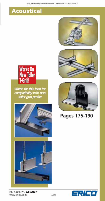
175Ph: 1-800-25-www.erico.com
Acoustical
Pages 175-190
Watch for this icon forcompatibility with new
taller grid profile
http://www.computercablestore.com 800-626-6622 (267-354-6012)

176Ph: 1-800-25-
www.erico.com
Acoustical
Applications
Sizing Chart
Lay InAnd TrofferLight FixtureSupport ClipsFeatures• Complies with The National Electrical
Code, Article 410.16 Means of Support.
• Gives a positive method of supporting troffers and lay-ins.
• Fits round or rectangular head tee bar.
• No installation tools required.
For straightor upturnedlip fixtures.
515A
515
For straightlip fixtures.
4 clips per fixturerequired per UL listing.
PART QTY.NUMBER DE SCRIP TION PER BOX
515 Straight lip fixtures 100515A Upturned or straight lip fixtures 100
UL & cUL ListedNo Load Rating - Po si tion ing Only
http://www.computercablestore.com 800-626-6622 (267-354-6012)

177Ph: 1-800-25-www.erico.com
Acoustical
Seismic FixtureClampFeatures• Cost effective
• Reusable
• Secures flourescent light fixtures to the ceiling frame members
• Requires no additional chains, cables or slack wires attached to the fixture
• Strengthens integrity of the T-Bar system
• Holds in place against the force of standard fire-hose pressure
• Meets U.S. building code and electrical code specifications
• Also satisfies NEC® 410.16(C) positiveattachment for secure fastening ofluminaires (fixtures) complying withAcceptance Criteria 184
Sizing Chart
The SFC has been tested for compliance to the UBC, NEC, NBC, and CEC as well as approved and listed with:• Warnock Hersey (Listed)• ETL (Listed)• Certified to CSA C22.2 No. 9.0-96 Component Only• ID: Seismic Fixture Clamp
Applications
SFC required at each corner
ICC is a registered trademark of the International Code Council.Warnock Hersey & ETL are listing marks of Intertek Testing Services, NA.ICBO standards are a copyright of the International Code Council.
Fig. 2Fig. 1
PART FIG. QTY.NUMBER NO. DESCRIPTION PER BOX
SFCLT 1 Seismic Fixture Lighting Clamp 25 sets(set of 4) for one standard (4 clamps/set)tapered 2’ x 4’ light fixture.
SFCLTE 1 Seismic Fixture Lighting Clamp 25 sets(set of 2) for two standard tapered (2 clamps/set)2’ x 4’ light fixtures end-to-end. In addition, a set of SFCLT is required.
SFCLTS 1 Seismic Fixture Lighting Clamp 25 sets(set of 2) for two standard tapered (2 clamps/set)2’ x 4’ light fixtures side-by-side. In addition, a set of SFCLT is required.
SFCLTCF 1 Seismic Fixture Lighting Clamp 50 sets(set of 2) for one 2’ x 2’ light fixture. (2 clamps/set) In addition, a set of CADDY SFCLTis required.
SFCLTCFS 2 Seismic Fixture Lighting Clamp 100 sets(set of 2) for reinforcement of T-Bar main runner/cross runner connections.
ICC®-ES EvaluationReport No. ESR-1943available atwww.icc-es.org
http://www.computercablestore.com 800-626-6622 (267-354-6012)

178Ph: 1-800-25-
www.erico.com
Acoustical
IndependentSupport ClipsFeatures• Provides a means of independent
support of fixtures• No installation tools required• Mounting hardware included
IDS Series
PART FIG. GRID STUD STATIC QTY.NUMBER NO. SIZE LENGTH LOAD LIMIT PER BOX
1/4-20 STUDIDS 1 15/16" 5/8" 65 lbs. 100IDS15 1 15/16" 11/2" 65 lbs. 100IDS2 1 15/16" 2" 65 lbs. 100IDS9* 1 9/16" 5/8" 65 lbs. 100IDS95✝ 2 9/16" x 5/16" 5/8" 65 lbs. 100
8-32 STUD (For Track Lighting)
IDST▲ 3 15/16" 9/16" 65 lbs. 100IDS9T▲ 3 9/16" 9/16" 65 lbs. 100IDS95T▲ 2 9/16" x 5/16" 9/16" 65 lbs. 100
Applications
UL ListedStatic load limit 65 lbs.
* For Ultra Line 3500, AWW Ultra Line 3600(a trademark product of Chicago Metallics Corp.)
✝ For Fineline and Fineline 1/8" Grids(a trademark product of USG Interiors,® Inc.)
▲Uses identical nuts as Figure 3.
Now For
Track
Lighting
Fig. 2
Fig. 1
Fig. 3
Optional barrel nut:
Order by adding -WB suffix to catalog number.
(IDSTWB)
PlasticSpacer forTegular TileSee page 181
Sizing Chart
PlasticSpacer forTegular TileSee page 181
http://www.computercablestore.com 800-626-6622 (267-354-6012)

179Ph: 1-800-25-www.erico.com
Acoustical
No Load Rating - Po si tion ing Only
Applicable to a wide variety and many types of light fixtures.The 517 series bar replaces the fixture bar.Measure width of bar to find appropriate bar for fixture.
➤ 1/2" ➤
➤
➤
1/8"
3/4" 1/8"
➤
➤
➤
➤
Hat ChannelApplications
517FCSeries
➤
➤5/8"1/4"
➤
➤
PART REPLACEMENTNUMBER BAR TYPE LIGHT FIXTURES
517A‡ Standard CAPRI R-10C517FCA CAPRI R-9X
CAPRI PR-751CXCAPRI R-10XHALO H17JUNO AP, APT, ICJUNO ICT, J, SC,TC, THOMAS RI-IC
517B‡ Narrow HALO H7,517FCB CAPRI HSG
LIGHTOLIER 711
517C‡ Wide Progress P-7517FCC MARCO
Suspension BarFor Light Fixtures517 SeriesFeatures• Reduces installation time.
• No tools required.
• Safe installation.
• Position of fixture adjustable,simply slide to location.
• No center clips required.
• Span adjustable 11" to 26".
T-GridApplications
End clips rotate formounting horizontalor vertical base plates.
‡
Sizing Chart
517 Series
http://www.computercablestore.com 800-626-6622 (267-354-6012)

180Ph: 1-800-25-
www.erico.com
Acoustical
SuspensionBars ForLightolier®
Calculite®
Se ries FixturesFeatures• Reduces installation time.
• Only a screwdriver required.
• Position of fixture adjustable with span.
520
Sizing Chart
Applications
PART QTY.NUMBER DE SCRIP TION PER BOX
520 Suspension bars forLightolier Calculite series fixtures 10
Lightolier and Calculite are registered trademarks of Lightolier, a GENLYTE Company.
UL & cUL ListedNo Load Rating - Po si tion ing Only
http://www.computercablestore.com 800-626-6622 (267-354-6012)

181Ph: 1-800-25-www.erico.com
Acoustical
“Twist On” Track Light ClipsFeatures• Fast, easy installation
• No special tools required
• Will not damage T-bars
• Available in white finish
• Nut included – standard pal nutFor brass hex nut add WB to part number (2G9WB)
Spacer
Optional barrel nut:Order by adding
-WB suffix tocatalog number.
4TGS-1/4" Spacerprovides a mountingsurface even withtegular tile.
Applications
PART #8-32 STUD QTY.NUMBER FINISH LENGTH DESCRIPTION PER BOX
2G9* Silver 7/16" For 9/16" tee 1002G9S10* Silver 5/8" For 9/16" tee 1004G8* Silver 5/8" For 15/16" tee 1004G8WH* White 5/8" For 15/16" tee 1004G8S7* Silver 7/16" For 15/16" tee 1004G8S7WH* White 7/16" For 15/16" tee 100PT16SPCR White — Plastic spacer 1004TGS* Silver — Tee grid spacer 100
for all above* Static load limit 25 lbs.
Now For
11/2"
Tee Grid
PT16SPCRPlastic Spacer
Sizing Chart
http://www.computercablestore.com 800-626-6622 (267-354-6012)

182Ph: 1-800-25-
www.erico.com
Acoustical
Fig. 2
“Twist On”Fixture SupportFeatures• Supports electrical fixtures
from acoustical tee bar 9/16", 15/16" or 11/2" wide
• 1/4-20 stud – 5/8", 11/2",2" or 3" long
• Washer-wing nut(4WN) included
• No installation tools required
Fig. 1
Fig. 3
4TGS-1/4" spacer provides a mounting
surface even with tegular tile.
* Not to exceed the load rating of corresponding fastener.** To be used with studded CADDY® Twist Clips.
Now For
11/2"
Tee Grid
Applications
4G9 1 5/8" For 9/16" tee 40 1004G16 1 5/8" For 15/16" tee 50 1004G1615 1 11/2" For 15/16" tee 50 1004G162 1 2" For 15/16" tee 50 1004G163 1 3" For 15/16" tee 50 100
4WN 1 1/4-20 threadimpression washer * 100
wing nut4G16H 2 Sign Hanger For 15/16" tee 40 1004TGS** 3 1/4" Spacer For recess
T-grid system N/A 1004G24 4 5/8" For 11/2" tee 40 100
with 4WN
Sizing ChartSTATIC QTY.
PART FIG. STUD LOAD PERNUMBER NO. LENGTH DE SCRIP TION LIMIT BOX
Fig. 4
PlasticSpacer forTegular TileSee page 181
http://www.computercablestore.com 800-626-6622 (267-354-6012)

183Ph: 1-800-25-www.erico.com
Acoustical
Fluorescent LightFix ture Hang erFeatures• Provides an easy method of supporting an
industrial class fluorescent light fixturefrom S-Hooks and Jack Chain.
• Fits most fluorescent light fixtures.
• Reduces the need to modify Jack Chain for fixture installation.
• Requires no special tools for installation.
LFC 90Top Mount Clip
LFCSide Mount ClipApplications
Ultimate static load limit 50 lbs.
PART QTY.NUMBER DE SCRIP TION PER BOX
LFC90 Top mount clip 100LFC Side mount clip 100
Sizing Chart
http://www.computercablestore.com 800-626-6622 (267-354-6012)

184Ph: 1-800-25-
www.erico.com
122
Acoustical
Jack ChainAnd S-Hooks• Add Jack Chain and S-Hooks
to your next CADDY® order
771#11 S-Hooks
770#12 SingleJack Chain
Sizing ChartPART QTY.
NUMBER DESCRIPTION PER BOX
770 Jack Chain 100 ft.771 S-Hooks 50
Applications
Static load limit 29 lbs.
http://www.computercablestore.com 800-626-6622 (267-354-6012)

185Ph: 1-800-25-www.erico.com
Acoustical
Snap OnFixture/Box HangerFeatures• Snaps easily onto tee bar.
• Hanger comes complete with boxmounting clip and 1/4-20 screw.
• Supports from acoustical tee bar aswell as main structure with the useof a drop wire.
• Dual height feature permits 11/2" deepelectrical box to be mounted flush with tileor off-set 3/4" for plaster ring.
• 512A is height adjustable up to 8" allowingyou to install double deep boxes, speakercases and emergency light fixtures aboveacoustical tee.
• Not permitted for paddle fans.
512
CHB can be purchasedseparately when more than
one box is required.Screw furnished.
CHB
512A
Sizing Chart
Applications
PART QTY.NUMBER DE SCRIP TION PER BOX
S3575BP50 1/4 - 20 x 3/8" round head screw 50S102438BP* 10-24 1/2" Rnd Hd Robertson screw 50512 Elec tri cal box hanger - 24" span 50512TC* Electrical box hanger - 24" span 5051212 Electrical box hanger - 12" span 5051220 Electrical box hanger - 20" span 5051230 Electrical box hanger - 30" span 50CHB Box mounting clip 100CHBTC* Box mounting clip 100512A 8" height adjustable – 24" span 50512ATC* 8" height adjustable – 24" span 50
186
Not to exceed 20 lbs. without independent wire support to CHB.*For Canadian boxes.
Packaged 50 per box.One CHB mountingclip is included with
each No. 512.
http://www.computercablestore.com 800-626-6622 (267-354-6012)

186Ph: 1-800-25-
www.erico.com
Acoustical
Ultimate load limit 50 lbs. per bar
T-GridBox HangerFeatures• Mounts a box to T-grid
in less than 30 seconds.
• Now height adjustable for various electrical box depths.
• Installs by hand.
• Drop wire for independentsupport from clip and/or bar.
• Screws easily to tee bar foradded stability.
• Multiple box installations.
• Double deep box installations with512HDXT Extension Brackets.
• Not permitted for paddle fans.
Applications
Sizing Chart
PART QTY.NUMBER DE SCRIP TION PER BOX
512HD‡ Heavy-duty electrical box hanger 25with box mounting clip – 24" span
512HDTC* Heavy-duty electrical box hanger 25with box mounting clip – 24"
510HD Box mounting clip can be pur chased 100separately for multiple box requirements
510HDTC* Box mounting clip can be purchased 100separately for multiple box requirements
512HDXT‡ Extension bracket 35/8" height (25 sets) 50512HDEEP‡ Heavy-duty electrical box hanger 25
with extension bracket – 35/8" height512HDEEPTC* Heavy-duty electrical box hanger 25
with extension bracket – 35/8" height
512HDEEP Series512HDEEP with additional
512HDXT mounts 21/8" deepbox with 11/2" extension ring.
510HD SeriesOne 510HD box mountingclip is included with each
512HD and 512HDEEP.
PATENT NUMBER 5,619,263
*For Canadian boxes. ‡Tall grid compatible.
512HD SeriesStandard bar mounts 21/8"
box – break off tabs for11/2" deep box. Mounts flush
with face of tile.
http://www.computercablestore.com 800-626-6622 (267-354-6012)

187Ph: 1-800-25-www.erico.com
Acoustical
ElectricalComponentSupportsFeatures• Provides a positive method of
supporting conduit and outlet boxesabove acoustical tee bar.
• Available for both horizontal andvertical support.
• Clips are available with 1/4-20 threadimpression or plain hole.
• Riveted assemblies accommodateMC/AC to 1" conduit.
• No installation tools required for basic clip.NOTE: Consult local authority for application approval.
Fig. 1
Fig. 2 Fig. 3
Fig. 4
Fig. 5
Fig. 6
Applications
Sizing ChartNo Load Rating - Po si tion ing Only
Eliminates offset bending conduit
PART FIG. SIDE OR TOP QTY.NUMBER NO. MOUNTED DESCRIPTION PER BOX
ATA4I 1 T 1/4-20 thread impression 100ATS4I 2 S 1/4-20 thread impression 1006MATA 3 T for MC/AC cable 100812MATA 3 T for 1/2" - 3/4" conduit 1008PATA 6 T for 1/2" conduit 10012PATA 6 T for 3/4" conduit 10016MATA 3 T for 1" conduit 10016PATA 6 T for 1" conduit 1006MATS 4 S for MC/AC cable 100812MATS 4 S for 1/2" to 3/4" conduit 1008PATS 5 S to 1/2" conduit 10012PATS 5 T for 3/4" conduit 10016MATS 4 T for 1" conduit 10016PATS 5 T for 1" conduit 100
http://www.computercablestore.com 800-626-6622 (267-354-6012)

188Ph: 1-800-25-
www.erico.com
Acoustical
Sizing Chart No Load Rating - Po si tion ing Only
Applications
Adjustable BoxAnd Con duitSupport (DFN)Features• Supports boxes and conduit above
acoustical T-bar with adjustments from41/4" through 71/4".
• Allows attachment of conduit clips withthread impressions at required height.
• Assemblies available for specific conduitlocations.
• No tools required to install.NOTE: Consult local authority forapplication approval.
* Comes with P-series with THD impression screw assembled to top hole loca-tion (adjustable). Also avail able as riveted assembly. Specify hole location.
DFN528
PART FIG. QTY.NUMBER NO. CONDUIT SIZE PER BOX
528 1 — 505288P* 2 For 1/2" EMT 2552812P* 2 For 3/4" EMT 2552816P* 2 For 1" EMT 25
Assemblies for conduit
Optional support wire if needed
Fig. 2Fig. 1
http://www.computercablestore.com 800-626-6622 (267-354-6012)

189Ph: 1-800-25-www.erico.com
Acoustical
Conduit/Box SupportFeatures• Provides a method for attaching above
acoustical tee bars.
• Provided with 1/4-20 screw forattachment to tee bar.
• Has a 1/4-20 thread impression for direct attachment to an outlet box or CADDY®
CONDUIT CLIP.
• When used in combination with a CADDYCONDUIT CLIP and outlet box, it providesexact alignment – eliminating an offsetbend in the conduit.
NOTE: Consult local authority for application approval.
4ACS
Sizing Chart UL & cUL ListedNo Load Rating - Po si tion ing Only
Applications
NOTE:Not to be used
to hang Tee Grid
PART QTY.NUMBER DE SCRIP TION PER BOX
4ACS Conduit/box support on T-grids 100
http://www.computercablestore.com 800-626-6622 (267-354-6012)

190Ph: 1-800-25-
www.erico.com
Acoustical
Sizing Chart
IndependentElectrical DropWire/Rod SecuringClipFeatures• Prevents sway of dedicated electrical
drop wire/rod.
• Doesn't negatively affect ceiling grid systems.
• No tools required. Forgiving design doesn't require exact cutting of rod/wire.
• Painted yellow for easy identificationby the inspector.
NOTE:Consult local authority forapplication approval.
PART FIG. QTY.NUMBER NO. DESCRIPTION PER BOX
EC311 1 Electrical drop wire securingclip #12 thru #8 wire 100
EC3114Z34 2 #12 wire thru 1/4" threaded rod 100
EC3116Z34 2 3/8" threaded rod 100
Fig. 1
Fig. 2Applications
FloatingRivet
➞
2005code solution
NEC 300-11(a)(1)
PART FIG. QTY.NUMBER NO. DESCRIPTION PER BOX
EC311 1 Electrical drop wire securingclip #12 thru #8 wire 100
EC3114Z34 2 #12 wire thru 1/4" threaded rod 100
EC3116Z34 2 3/8" threaded rod 100
http://www.computercablestore.com 800-626-6622 (267-354-6012)

191Ph: 1-800-25-www.erico.com
Ceiling/Partitions
Pages 191-200
http://www.computercablestore.com 800-626-6622 (267-354-6012)

192Ph: 1-800-25-
www.erico.com
Ceiling/Partitions
Sizing Chart
TGE
Applications
PART QTY.NUMBER DESCRIPTION PER BOX
TGE Attaches tee to edge trim 100
TGE Clip T-GridSplicing ClipFeatures• Replaces pop riveting.
• No need to cut and bend “T”.
• Can be used to splice across “T” intothe main “T” (Fig. 1).
• “T” to edge angle (Fig. 2).
Fig. 2
Fig. 1
http://www.computercablestore.com 800-626-6622 (267-354-6012)

193Ph: 1-800-25-www.erico.com
Ceiling/Partitions
Sizing Chart
Applications
Lathers to T-GridHanger ClipFeatures• Allows 6" drop space providing area
for light fixtures.
• Fits 11/2" channel with flange widthsfrom 1/2" to 5/8".
• Installs quickly and easily.
PART QTY.NUMBER DESCRIPTION PER BOX
LTGH Provides 6" space in supportingacoustical tee from 11/2"lathers channel 100
LTGH
6"
http://www.computercablestore.com 800-626-6622 (267-354-6012)

194Ph: 1-800-25-
www.erico.com
Ceiling/Partitions
Sizing Chart
Applications
LathersChan nel HangerFeatures• Attaches 11/2" lathers channel to #8 wire,
1/4" plain rod.
• Attaches 2" lathers channel to 1/4" plain rod.
• Available in both center and sidemountfor 1/4" rod.
• Provides pre-leveling of channel.
• Will fit channel flange widths 7/16" thru 5/8".
• No installation tools required.
FIG. 1 FIG. 2PART PART WIRE LATHERS QTY.
NUMBER NUMBER OR ROD CHANNEL PER BOX
2B1.5LS* — #8 11/2" channel 1004B1.5LS 4B1.5L 1/4" plain rod 11/2" channel 1004B2LS 1/4" plain rod 2" channel 100
*Cannot be used on #9 wire
Not for use inplaster applications
Fig. 1
Fig. 2
Static load limit 160 lbs.
BridgingApplication
Only
SIZE
http://www.computercablestore.com 800-626-6622 (267-354-6012)

195Ph: 1-800-25-www.erico.com
Ceiling/Partitions
LathersChan nel HangerFeatures• Eliminates the major problem of cutouts
for lighting layouts, ducts, obstructionsand architectural changes.
• Provides a method for attaching 11/2"channel to existing #8 wire, #9 wire, 3/16"or 1/4" plain rod, or 1/8"- 3/16" x 1" wide strap.
• No installation tools required.
HRL
Not for use inplaster applications
Sizing Chart
Applications
LATHERSCHANNEL STATIC QTY.
PART FLANGE SUPPORTING LOAD PERNUMBER WIDTH MEMBER LIMIT BOX
HRL1.5A 9/16" to 5/8" #9 and #8 wire, 3/16" and 1/4" plain rod 100 lbs. 1001/8" and 3/16" thick strap 75 lbs. 100
http://www.computercablestore.com 800-626-6622 (267-354-6012)

196Ph: 1-800-25-
www.erico.com
Ceiling/Partitions
Fig. 1PT16
Lock-OnTwist ClipFeatures• Attaches easily to tee bar
• Doesn’t harm acoustical tee
• Fits 15/16" tee bar
• Provides "positive lock" to position fastener
Applications
Static load limit 50 lbs.Sizing ChartPART FIG. QTY.
NUMBER NO. DESCRIPTION PER BOX
PT16 1 Lock-on twist clip for 10015/16" tee, 3/4" stud
PT16FP 1 With felt pad 100
PT16SPCR 2 Plastic spacer for PT16 100
Fig. 2PT16SPCR
http://www.computercablestore.com 800-626-6622 (267-354-6012)

197Ph: 1-800-25-www.erico.com
Ceiling/Partitions
Sizing Chart
Applications
Conduit ClipFeatures• For use as hold-down of 1/2", 3/4", 1", 11/4"
thin wall conduit to 11/2" lathers channel.
• No installation tools required.
PART QTY.NUMBER CON DUIT SIZE PER BOX
8D1.5L 1/2" EMT conduit 10012D1.5L 3/4" EMT conduit 10016D1.5L 1" EMT conduit 10020D1.5L 11/4" EMT conduit 100
Static load limit 50 lbs.(When conduit hangs below lathers channel.)
http://www.computercablestore.com 800-626-6622 (267-354-6012)

198Ph: 1-800-25-
www.erico.com
Ceiling/Partitions
Support Box FromLathers ChannelFeatures• Provides a convenient method of
supporting an electrical box from 3/4"thru 2" lathers channel.
• CADDY® “one piece/two piece” constructionprevents dropping of loose parts.
• Built-in thread impressions eliminate theneed for nuts.
• Multiple pre-punched holes allow for boxheight adjustability and screw and nutare provided.
LCSB12
Sizing Chart
Applications
PART LATHERS CHANNEL QTY.NUMBER SIZE PER BOX
LCSB12 3/4," 1," 11/2" or 2" 50
No Load Rating – Positioning Only
http://www.computercablestore.com 800-626-6622 (267-354-6012)

199Ph: 1-800-25-www.erico.com
Ceiling/Partitions
Lathers ChannelBox MountFeatures• Provides attachment of conduit and
outlet boxes directly to lathers channelwith 1/4-20 x 3/4" screw furnished.
• Can be applied to the top or bottomflange of the channel.
• Fits most lathers channel 3/4", 11/2 "and 2". Maximum flange width 5/8".
4LCB
Sizing Chart
Applications
UL & cUL ListedNo Load Rating – Positioning Only
PART QTY.NUMBER DESCRIPTION PER BOX
4LCB Lathers channel box mount 100
Eliminates offsetbending conduit
http://www.computercablestore.com 800-626-6622 (267-354-6012)

200Ph: 1-800-25-
www.erico.com
ERICO® Online
ERICO® OnlineVisit the ERICO website at www.erico.com for new product information, up-to-date product specifications and applications,CADDY® STUFF specials, a list of upcoming events and industrytradeshow participation and more.
A full literature library provides pertinent literature in an easy-to-download PDF format. This is a great way to stay informed on allthe current publications. New product brochures and datasheetsare posted as soon as they are printed.
In the News & Events section, customers can find new productupdates, press releases and lists of seminars.
Locations and contact information is listed for ERICO officesaround the world.
www.erico.com provides a convenient way to get the answers youneed day or night. Visit ERICO online.
http://www.computercablestore.com 800-626-6622 (267-354-6012)

201Ph: 1-800-25-www.erico.com
Miscellaneous Components
Pages 201-207
http://www.computercablestore.com 800-626-6622 (267-354-6012)

Heavy DutyAngle Bracket
STATIC QTY.PART FIG. LOAD PER
NUMBER NO. DESCRIPTION LIMIT BOX
708 1 For #8 wire or 1/4" plain rod 160 lbs. 1006A 2 For 3/8" plain rod 160 lbs. 100AB 3A Angle bracket w/ 1/4" hole 160 lbs. 100AFAB3 3B Angle bracket with 1/4" slotted 160 lbs. 100
hole and 3/16" mounting hole.AFAB4 3B 1/4" mounting hole 350 lbs. 50
(includes 1/4 - 20 x 3/8" round head screw)
AFAB6 3B 3/8" mounting hole 350 lbs. 50 (includes 1/4 - 20 x 3/8" round head screw)
AO 4 Offset bracket w/ 1/4" hole 160 lbs. 1006T 5 For 1/4" or 3/8" threaded 160 lbs. 100
rod nuts required4TI 5 For 1/4" threaded rod 160 lbs. 100
with thread impression6TI 5 For 3/8" threaded rod 160 lbs. 100
with thread impression
Sizing Chart
HangersFeaturesFig. 1 & 2
• Permits preassembly of wire andplain rod (#8, 1/4" and 3/8").
Fig. 3 & 4
• Permits wire or chain drops fromconcrete or wood.
Fig. 5
• Rod hanger available for 11/4" and3/8" threaded rod with or withoutthread impression.
Fig. 1 Fig. 2 Fig. 3A
Fig. 4
Fig. 5
Applications
Fig. 3B
includes 1⁄4 -20 x 3⁄8" round head screw
202Ph: 1-800-25-
www.erico.com
Miscellaneous Componentshttp://www.computercablestore.com 800-626-6622 (267-354-6012)

203Ph: 1-800-25-www.erico.com
Miscellaneous Components
Strut Clip Features• Fits most 15/8" strut.
• Available with a 1/4-20 threadimpression.
• Available with a 1/4-20 staked stud 5/8".
• Requires only a screwdriver to install, adjust or remove.
• Eliminates nuts and bolts.
• The CADDY® combination washer-wingnut (Part No. 4WN) can be used toattach box or fixture. (Not includedwith strut clip.)
Sizing Chart
Applications
PART FIG. QTY.NUMBER NO. DESCRIPTION PER BOX
MFA4I 1 1/4-20 thread impression 100
MFA625 2 1/4-20 x 5/8" stud 100
Static load limit 100 lbs. with strut in horizontal positionUltimate static load limit 50 lbs. in vertical position
Fig. 1
Fig. 2
http://www.computercablestore.com 800-626-6622 (267-354-6012)

204Ph: 1-800-25-
www.erico.com
Miscellaneous Components
Pipe SleevePositionerFeatures• Provides secure positioning of pipe
sleeve for concrete pouring of walland floor forms.
• Requires only a hammer to install.
• Will accommodate Schedule #40, #80and smaller wall thickness.
740
Fig. 1
Fig. 2
Sizing Chart
Applications
PART FIG. SLEEVE QTY.NUMBER NO. DIAMETER WALL THICKNESS PER BOX
740 1 All Diameters 5/16" and under 100740 1 2"-6" Schedule #40 Pipe 1004H58 2 6" Schedule #80 Pipe 1004H58 2 8"-10" Schedule #40 Pipe 1004H912 2 9"-14" Schedule #80 Pipe 100
No Load Rating - Po si tion ing Only
http://www.computercablestore.com 800-626-6622 (267-354-6012)

205Ph: 1-800-25-www.erico.com
Miscellaneous Components
RGC
Sizing Chart UL & cUL ListedNo Load Rating - Po si tion ing Only
Applications
PART QTY.NUMBER WIRE SIZE POST SIZE PER BOX
RGC #2 Wire, #8 Solid 3/4" to 1" (.146) thru #4 round orStranded (.280) square 100
Signal Ref er enceGrid Wire ClampFor Static GroundingFeatures• Provides a quick method to me chan i cal ly
support a signal reference grid wirebelow computer room floors.
• One fastener will support #2 wire, #8stranded (.146) to #4 stranded (.280).
• Fits post sizes 3/4" to 1" round or square.
• Slots in fastener grip wire to providepositive contact with post.
• Clamps grid wire directly to postallowing a low resistance connectionacross bare metal contacts.
• Installs easily with a screwdriver ornut driver.
http://www.computercablestore.com 800-626-6622 (267-354-6012)

206Ph: 1-800-25-
www.erico.com
Miscellaneous Components
Wafer Head SheetMetal ScrewFeatures• Self-drilling and tapping.
• Minimizes drywall bulge.NOTE:Use to mount CADDY® Fasteners in allmetal stud applications.
Drill pointfor ease ofinstallation.
Sizing Chart
PART QTY.NUMBER DESCRIPTION PER BOX
SMS8 #8 x 1/2" long 1,000
http://www.computercablestore.com 800-626-6622 (267-354-6012)

207Ph: 1-800-25-www.erico.com
Miscellaneous Components
Sizing Chart
Applications
HangerMate® ThreadedRod Anchoring SystemFeatures• Easy installation of 3/8-16
or 1/4 -20 threaded rod
• Installs and taps steel, wood and concrete with drill
• Vertical- or side-mount applications
PART ROD QTY.NUMBER SIZE DESCRIPTION PER BOX
Steel Applications-Vertical Mount (End-Drilled Head)HMZG160 1/4-20 1/4-20 HangerMate Anchor, #3 point 50HMZG471 3/8-16 1/4-20 HangerMate Anchor, #3 point with nut 50HMZG550 3/8-16 5/16-24 X 1-1/8 HangerMate Anchor. #3 point 50
Steel Applications-Horizontal Mount (Cross-Drilled Head)HMZH455 3/8-16 1/4-20 X 1" HangerMate Anchor,
#2 point (.060-.125 steel thickness) 50HMZH475 3/8-16 1/4-20 X 1" HangerMate Anchor,
#3 point (.060-.250 steel thickness) 50HMZH476 3/8-16 1/4-20 X 1" HangerMate Anchor with nut,
#3 point (.060-.250 steel thickness) 50Wood Applications-Vertical Mount (End-Drilled Head)
HMZG315 1/4-20 5/16 X 2-1/4" HangerMate Anchor 50HMZG660 3/8-16 5/16 X 2-1/4" HangerMate Anchor 50
Wood Applications-Horizontal Mount (Cross-Drilled Head)HMZH665 3/8-16 5/16 X 2-1/4" HangerMate Anchor 50
Concrete Applications-Vertical Mount (End-Drilled Head)HMZG365 1/4-20 5/16 X 2-1/4" HangerMate Anchor 50HMZG730 3/8-16 5/16 X 2-1/4" HangerMate Anchor 50
Concrete Applications-Horizontal Mount (Cross-Drilled Head)HMZG735 3/8-16 5/16 X 2-1/4" HangerMate Anchor 50
Installation ToolsHMZE215 — Vert recessed drive socket 1HMZE220 — Concrete recessed drive sleeve 1HMZE240 — Drill Bit Adapter Kit 1HMZE340 — ANSI 1/4" Tanged Drill Bit for Hammer Drills 1HMZE350 — ANSI 1/4" SDS Drill Bit for Rotary Hammer Drills 1
* Nut required for light gauge steel applications (16 GA or .060")® HangerMate is a registered trademark of Textron Inc.
*
*
http://www.computercablestore.com 800-626-6622 (267-354-6012)

208Ph: 1-800-25-
www.erico.com
Reference
RIGID STEEL CON DUIT (Heavy Wall Conduit)
ELECTRICAL METALLIC TUBING (EMT) – THIN WALL CONDUIT
Minimum Wt. Weight OfNominal Nom i nal Per 100 Ft. Conduit &Conduit Outside Inside With Couplings Conductors
Size Diameter Diameter Attached Per 100 Ft.
3/8" 0.675 in. 0.493 in. 51.5 lbs. 65.1 lbs.1/2" 0.840 in. 0.632 in. 79.0 lbs. 101.1 lbs.3/4" 1.050 in. 0.836 in. 105.0 lbs. 145.8 lbs.1" 1.315 in. 1.063 in. 153.0 lbs. 219.3 lbs.
11/4" 1.660 in. 1.394 in. 201.0 lbs. 318.3 lbs.11/2" 1.900 in. 1.624 in. 249.0 lbs. 408.8 lbs.
2" 2.375 in. 2.083 in. 332.0 lbs. 593.8 lbs.21/2" 2.875 in. 2.489 in. 527.0 lbs. 901.0 lbs.
3" 3.500 in. 3.090 in. 682.6 lbs. 1259.0 lbs.31/2" 4.000 in. 3.570 in. 831.0 lbs. 1604.0 lbs.
4" 4.500 in. 4.050 in. 972.3 lbs. 1967.0 lbs.
1/2" 0.815 in. 0.745 in. 60.0 lbs. 82.1 lbs.3/4" 1.029 in. 0.954 in. 82.0 lbs. 122.8 lbs.1" 1.290 in. 1.205 in. 116.0 lbs. 182.3 lbs.
11/4" 1.638 in. 1.553 in. 150.0 lbs. 267.3 lbs.11/2" 1.883 in. 1.793 in. 182.0 lbs. 341.8 lbs.
2" 2.360 in. 2.266 in. 242.0 lbs. 503.8 lbs.21/2" 2.857 in. 2.727 in. 401.0 lbs. 775.0 lbs.
3" 3.476 in. 3.346 in. 493.0 lbs. 1069.0 lbs.31/2" 3.971 in. 3.841 in. 573.0 lbs. 1346.0 lbs.
4" 4.466 in. 4.336 in. 638.0 lbs. 1632.0 lbs.
3/8" 0.577 in. 0.493 in. 23.0 lbs. 36.6 lbs.1/2" 0.706 in. 0.622 in. 28.5 lbs. 50.6 lbs.3/4" 0.922 in. 0.824 in. 43.5 lbs. 84.3 lbs.1" 1.163 in. 1.049 in. 64.0 lbs. 130.3 lbs.
11/4" 1.510 in. 1.380 in. 95.0 lbs. 212.3 lbs.11/2" 1.740 in. 1.610 in. 110.0 lbs. 269.8 lbs.
2" 2.197 in. 2.067 in. 140.0 lbs. 401.8 lbs.21/2" 2.875 in. 2.731 in. 205.0 lbs. 579.0 lbs.
3" 3.500 in. 3.356 in. 250.0 lbs. 826.3 lbs.31/2" 4.000 in. 3.834 in. 325.0 lbs. 1098.0 lbs.
4" 4.500 in. 4.334 in. 370.0 lbs. 1364.0 lbs.
Dimensions taken from ANSITM C80.3-1977.Conduit plus weight of heaviest conductor combination as specified by theNational Electrical Code.
Convenient SizingInformation
INTERMEDIATE METAL CONDUIT
ANSI is a trademark of American National Standards Institute, Inc.
http://www.computercablestore.com 800-626-6622 (267-354-6012)

209Ph: 1-800-25-www.erico.com
Reference
SCHEDULE 40 PVC PLASTIC PIPE
RIGID ALUMINUM CONDUIT
Minimum Wt. Weight OfNominal Nom i nal Per 100 Ft. Conduit &Conduit Outside Inside With Couplings Conductors
Size Diameter Diameter Attached Per 100 Ft.
1/2" 0.840 in. 0.632 in. 27.4 lbs. 49.5 lbs.3/4" 1.050 in. 0.836 in. 36.4 lbs. 77.2 lbs.1" 1.315 in. 1.063 in. 53.0 lbs. 119.3 lbs.
11/4" 1.660 in. 1.394 in. 69.6 lbs. 186.9 lbs.11/2" 1.900 in. 1.624 in. 82.2 lbs. 242.0 lbs.
2" 2.375 in. 2.083 in. 115.7 lbs. 377.5 lbs.21/2" 2.875 in. 2.489 in. 182.5 lbs. 556.5 lbs.
3" 3.500 in. 3.090 in. 238.9 lbs. 815.2 lbs.31/2" 4.000 in. 3.570 in. 287.7 lbs. 1061.0 lbs.
4" 4.500 in. 4.050 in. 340.0 lbs. 1334.0 lbs.5" 5.563 in. 5.073 in. 465.4 lbs. 2028.0 lbs.6" 6.625 in. 6.093 in. 612.5 lbs. 2870.0 lbs.
Dimensions taken from ANSI C80.5-1977.
Conduit plus weight of heaviest conductor combination as specified by theNational Electrical Code.
Nominal Outside Wall Weight WeightPipe Size Diameter Thickness Of Pipe Of Water
1/8" .405 in. .068 in. .04 lbs./ft. .02 lbs./ft.1/4" .540 in. .088 in. .07 lbs./ft. .04 lbs./ft.3/8" .675 in. .091 in. .10 lbs./ft. .08 lbs./ft.1/2" .840 in. .109 in. .15 lbs./ft. .1 lbs./ft.3/4" 1.050 in. .113 in. .2 lbs./ft. .2 lbs./ft.1" 1.315 in. .133 in. .3 lbs./ft. .4 lbs./ft.
11/4" 1.660 in. .140 in. .4 lbs./ft. .6 lbs./ft11/2" 1.900 in. .145 in. .5 lbs./ft. .9 lbs./ft.
2" 2.375 in. .154 in. .6 lbs./ft. 1.4 lbs./ft.21/2" 2.875 in. .203 in. 1.0 lbs./ft. 2.1 lbs./ft.
3" 3.500 in. .216 in. 1.3 lbs./ft. 3.2 lbs./ft.31/2" 4.000 in. .226 in. 1.6 lbs./ft. 4.3 lbs./ft.
4" 4.500 in. .237 in. 1.9 lbs./ft. 5.5 lbs./ft.
http://www.computercablestore.com 800-626-6622 (267-354-6012)

210Ph: 1-800-25-
www.erico.com
INSULATED GROUND BARE GROUNDNominal Outer Nominal Outer
AWG Size Diameter in Inches Diameter in Inches
14-2 Solid .450 .43014-3 Solid .480 .43514-4 Solid .510 .48512-2 Solid .495 .46512-3 Solid .530 .50012-4 Solid .565 .56010-2 Solid .560 .52010-3 Solid .600 .55010-4 Solid .645 .615
8-2 Strd. .710 .6758-3 Strd. .770 .7108-4 Strd. .835 .7706-2 Strd. .795 .7556-3 Strd. .865 .8006-4 Strd. .945 .8654-2 Strd. .945 .8954-3 Strd. 1.035 .9454-4 Strd. 1.135 1.0352-2 Strd. 1.075 1.0152-3 Strd. 1.180 1.0752-4 Strd. 1.295 1.180
MC CABLE
Reference
Nominal Sizeand Thread Root Area Design Load (SF = 5)
1/4" - 20" 0.027 in.2 0.174 cm2 240 lbs. 1.07 kN5/16" - 18" 0.045 in.2 0.290 cm2 400 lbs. 1.78 kN
3/8" - 16" 0.068 in.2 0.438 cm2 610 lbs. 2.71 kN
Dimensions taken from ANSITM B1.1-1982 Unified Inch Screw Threads.All threads are UNCR series.
Tabulated loads are based on an allowable tensile stress of 12000 psi (82.7 MPa)reduced by 25% resulting in 9000 psi (62 MPa). From ANSI®/MSS SP-58, Table 3.
ALL THREADED ROD (ATR)
ANSI is a trademark of American National Standards Institute, Inc.
http://www.computercablestore.com 800-626-6622 (267-354-6012)

211Ph: 1-800-25-www.erico.com
Reference
AC
CA
BLE
Cab
le w
ith T
wo
Cir
cuit
Con
duct
ors
and
No
Gro
undi
ngC
ondu
ctor
Cab
le w
ith T
hree
Cir
cuit
Con
duct
ors
and
No
Gro
undi
ngC
ondu
ctor
and
Cab
lew
ith T
wo
Cir
cuit
Con
duct
ors
and
aG
roun
ding
Con
duct
or
Cab
le w
ith F
our
Cir
cuit
Con
duct
ors
and
No
Gro
undi
ngC
ondu
ctor
and
Cab
lew
ith T
hree
Cir
cuit
Con
duct
o rs
and
aG
roun
ding
Con
duct
or
Cab
le w
ith F
our
Cir
cuit
Con
duct
ors
and
a G
roun
ding
Con
duct
or
MIN
IMU
M E
XTE
RN
AL
DIA
ME
TER
OF
AR
MO
R IN
INC
HE
S
AW
GTy
pe O
fTy
pe O
fS
ize
Of
Arm
ored
Cir
cuit
Cir
cuit
Cab
leC
ondu
ctor
Con
duct
ors
Sol
idS
tran
ded
Sol
idS
tran
ded
Sol
idS
tran
ded
Sol
idS
tran
ded
140.
433
0.45
30.
486
0.52
212
0.46
70.
489
0.52
00.
545
100.
476
0.50
00.
541
0.58
7A
CT
MM
TH
HN
80.
570
0.60
40.
601
0.63
70.
654
0.69
50.
714
0.75
96
0.70
00.
739
0.80
70.
882
40.
836
0.88
50.
970
1.06
62
0.95
61.
014
1.11
51.
228
http://www.computercablestore.com 800-626-6622 (267-354-6012)

212Ph: 1-800-25-
www.erico.com
QUALITY CONTROLCADDY Fasteners, manufactured by ERICO® Inc., are produced from spring steel, galvanized steel, plastic , as well as other materials.We are known in the industry as a leader in the design and pro duc tionof spring steel fasteners. The following is the story of how we man u fac ture these quality spring steel fasteners.
MANUFACTURINGThe steel for CADDY Fasteners is procured in mill lots to AISIand ERICO Standards; other materials are equally controlled.
LOAD RATINGCADDY Fasteners are designed with two load limits:
1) Static load limit is a rated stationary load limit for a fastener.ERICO Standards require that test samples with stand a load equal to three times this catalog rating.
2) The ultimate static load limit is the rated sta tion ary load limitwhich, if exceeded, may cause failure of the fastener. ERICOStandards require that test samples with stand this catalog rating.Some CADDY Fasteners also are designed with an undefined rating and are to be used for po si tion ing only with no loadingon them.
3) Applications and load ratings may change without notice. Referto instruction sheet in box or contact ERICO for current load andapplication information.
Static load limit and ultimate static load limit values specify maximumallowable installed loads for user applications. These values are forloads applied VERTICALLY to the normal fastener installation exceptas may be dia grammed otherwise. Where the load rating of theCADDY Fastener exceeds that of the structural member, the lowestrated item must set the load limit.
NOTE: CADDY Fasteners are intended for support of electrical components at stationary loads. Not to be used for dynamic loadssuch as fluid and gas distribution components, etc.
IMPORTANTCADDY Fasteners used with wire, rod, or threaded rod are designedfor use with coarse round wire, hot rolled carbon steel bar, cold rolledcarbon steel bar and threaded rod all meeting AISI specificationsand tolerances.
QUALITY ASSURANCEIncoming steel is sampled and inspected for conformance to AISIspecifications and ERICO Standards. Test fixtures and procedures for development and quality control are designed to simulate normalfield applications. Fasteners are tested, on a sample basis, to ERICO Standards by certified inspectors.
Testing of specific quantities of fasteners to de struc tion in spe-cial statistical audits ensures a continuous high level of quality.
The CADDY Fastener Story
The CADDY® Fastener Storyhttp://www.computercablestore.com 800-626-6622 (267-354-6012)

213Ph: 1-800-25-www.erico.com
The CADDY® Fastener StoryHEAT TREATINGCADDY® Spring Steel Fasteners are heat treated in modern shakerhearth furnaces. Precision controls maintain heat treat operations within the established limits developed by ERICO® for CADDYFasteners. ERICO Stan dards incorporate consideration of fastenermaterial and application.
CADDY Fasteners are conveyed directly from the high tem per a turefurnace to the quench tank, through a clean ing cycle and into the tempering furnace. The complete heat treat cycle is automatically con trolled.
PRODUCTION PRESSESCADDY Fasteners are produced with modern presses and pre ci siontooling. Presses and tools are designed for close tolerance stamping.
RESEARCH AND DEVELOPMENTERICO Research and Development department is con stantly workingon new fasteners and, at the same time, improving the present line.Starting with six basic fasteners, the line now has several hundredbasic types. The majority of the CADDY Fastener line is the result of ERICO de vel op ment of fasteners to provide a solution for a cus tom er's problem.
NOTE: Special applications not specified MUST be submitted toERICO for engineering approval and load rating.
All cULus Listed CADDY fasteners meet the requirements of one of the following UL standards: UL1565, UL2239 or UL514B.
CADDY Fasteners, manufactured by ERICO, Inc., are produced from a number of different ma te ri als and coat ings to accommodate different applications and environments. Among the materials includedare low carbon steel, spring steel, malleable iron, aluminum and stainless steel. Protective coatings are available in five basic zinccoatings: zinc phosphate, zinc electroplate, pre-galvanized zinc,mechanical gal va nized zinc, hot dipped galvanized and CADDY® COAT.
CADDY® ERISTRUT comes in the following finishes: aluminum, chromate (California) gold, copper, electro galvanized zinc plated,green, hot dip galvanized, pre -galvanized, plain steel, plastic , and stainless steel.
MATERIALSSpring Steel
Spring steel provides light weight fasteners with high grippingpower. These fasteners are designed to support a wide range of products from or to a variety of support members. These fasteners are fabricated from high carbon, annealed, spring steel.
NOTE: Black Spring Steel CADDY Fasteners are designed for indoor and non-corrosive environments. Not to be used in certainareas such as over indoor pools, etc.
Materials/Coatings
http://www.computercablestore.com 800-626-6622 (267-354-6012)

214Ph: 1-800-25-
www.erico.com
The CADDY® Fastener StoryMATERIALS (continued)
Malleable IronANSI/ASTM A 47-77, Grade 32510, annealed.
Aluminum (AL)Aluminum provides a high strength to weight ratio that improvesease of use for reduced installation costs, is nonmagnetic andprovides good corrosion resistance in a variety of en vi ron ments.The aluminum selected is designed to meet the fastener manufacturing process and the intended application to meet the loads as specified.
Aluminum products are recommended for indoor and outdoor applications. They may also be used in select corrosive environments.
Stainless Steel (SS)AISI Type 302 or Type 304 (as noted). Type 316 is available on special request for fasteners as noted.
The above stainless steels belong to the austenitic group and provide many desirable prop er ties including high ambient temperature resistance, corrosion resistance, stable structuralproperties and are nonmagnetic.
Stainless steel products are recommended for indoor and outdoor applications. They are also rec om mend ed for corrosiveenvironments; dependent on the grade of stainless steel.
http://www.computercablestore.com 800-626-6622 (267-354-6012)

215Ph: 1-800-25-www.erico.com
The CADDY® Fastener StoryCOATINGSZinc Electroplate, Electrogalvanized (EG)
ANSI/ASTM B633
This corrosion protective coating is applied after the fabrication of steel or malleable iron parts and uses an electrolytic platingprocess that deposits zinc up to 0.5 mils. A second pas si va tioncoating of chromate is then applied for additional protection.
Zinc electroplate products are recommended for indoor and mildlycorrosive applications.
Zinc Phosphate (ZP)This is the coating system generally used on CADDY springsteel fasteners. It is a two coating system, where the first coatingof crystalline zinc phosphate, of over 1000 milligrams per squarefoot, is designed to increase the adhesion of the second coating.The second coating consists of a synthetic , organic corrosioninhibitor with a particular affinity for zinc compounds. ERICOrates this fastener finish at 30 hours. Salt spray testing is inaccordance with ASTM B117-61, Federal Test Number QQM -151.
NOTE: Black Spring Steel CADDY Fasteners are designed for indoor and non-corrosive environments. Not to be used in certainareas such as over indoor pools, etc. Other finishes are used and may be suitable for indoor and outdoor applications where EMT conduit is used.
Pregalvanized Zinc (PG)ANSI/ASTM A 525 and 526
Pregalvanized zinc is produced by continuously rolling steel coilsor sheets through molten zinc at the mills. The coils or sheetsare slit to size and fabricated by forming, shearing or punching toproduce the finished product. During fabrication cut edges arenot generally zinc coated; however, the zinc near the uncoatedmetal be comes a sacrificial anode to protect the bare areas.
Pregalvanized zinc products are generally recommended forindoor use on mildly corrosive environments.
Mechanical Galvanized Zinc (EPZ)ASTM B 695 -90
Mechanical galvanized zinc is a method of depositing zinc usingmechanical forces. The resulting layer of zinc is approximately 1 mil (25 microns), is passivated with clear chromate and thensealed with a transparent sealer.
Mechanical galvanized zinc products are recommended forindoor, outdoor and mildly corrosive environments.
Hot Dipped Galvanized Zinc (HDG)ASTM A123
After a product has finished its fabrication process, it is dippedinto a bath of molten zinc. The zinc completely coats all edgesand surfaces. Zinc thickness is controlled by the time the part is immersed in the molten zinc bath.
Hot dipped galvanized zinc products are recommended forindoor, outdoor and mildly corrosive environments.
IMPORTANT: For more detailed information on a specific product, application or application environment, please contact ERICO Engineering.
http://www.computercablestore.com 800-626-6622 (267-354-6012)

216Ph: 1-800-25-
www.erico.com
The CADDY® Fastener Story
CADDY® COAT
CADDY COAT is the standard finish used on most spring steeland many mild steel CADDY Fasteners*. The finish consists of a two-part coating, a base coat and a topcoat. The base coat ofzinc phosphate aids in corrosion resistance and increases theadhesion of the topcoat. The organic top coat provides superiorcorrosion resistance.
The system was evaluated in a 500-hour saltspray test per ASTM D610, “Standard Test Methods for Evaluating the Degreeof Rusting on Painted Steel Surfaces”. The testing conformed to ASTM B117, “Standard Method of Salt Spray (Fog) Testing”. In addition, CADDY® COAT exceeds the corrosion requirementsof proposed UL 2239, “Conduit, Tubing and Cable SupportHardware Standard”.
CADDY COAT replaces phosphate and oil, providing a cleanerinstallation and consistent appearance resulting in improved corrosion resistance. *Note : Spring steel fasteners are for indoor use in non-corrosive environments. Mild steel fasteners can be used outdoors in humid or mildly corrosive environments. Not to be used in certain areas such as over indoor pools, etc.
The first full line of spring steel fasteners
to exceed the most stringent corrosion
requirements of UL 2239.
http://www.computercablestore.com 800-626-6622 (267-354-6012)

217Ph: 1-800-25-www.erico.com
Index
0502510EG ............1110503710EG ............1110505010EG ............111
★122 ..........................87★1224TI ......................87★1226A ......................87★1226T ......................87★1226TI ......................87★122708 ....................87★123 ..........................87
12312P ....................87★12316M....................87
12316P ....................87★12320M....................87★1236M ......................87★123812M..................87
1238P ......................87★12D1.5L ..................197
12P ..........................5112P12P......................5812P16P......................5812P24 ......................5412P24SM ..................5412P4I ........................5112P58 ......................5412P58SM ..................5412P912 ....................5412P912SM ................5412PATA....................18712PATS....................18712PF........................132
★1616M ......................58★1620M ......................58★1624M ......................58★1632M ......................58★166M ........................58★16812M....................58★16D1.5L ..................197★16M ..........................51★16M24 ......................53★16M24SM ................53★16M4I ................51, 69★16M58 ......................53★16M58SM ................53★16M912 ....................53★16M912SM ..............53★16MATA..................187
▲ = ★ =
★16MATS ..................187★16MB18 ....................69★16MB1824 ................69★16MB1858 ................69★16MB186 ..................69★16MB18A..................69★16MF ......................132
16P ..........................5116P16P......................5816P24 ......................5416P24SM ..................5416P4I ........................5116P58 ......................5416P58SM ..................5416P912 ....................5416P912SM ................5416PATA....................18716PATS....................18716PF........................1322000037EG ..............992000050EG ..............99200RS375 ..............104200RS500 ..............104
★20D1.5L ..................197★20M ..........................51★20M24 ......................53★20M24SM ................53★20M4I ......................51★20M58 ......................53★20M58SM ................53★20M912 ....................53★20M912SM ..............53★24M ..........................51★24M24 ......................53★24M24SM ................53★24M4I ......................51★24M58 ......................53★24M58SM ................53★24M912 ....................53★24M912SM ..............53
2550037EG ..............932550050EG ..............932550062EG ..............93
★2B1.5LS ..................194★2BR12 ....................173★2BR20 ....................173★2BR32 ....................173
★2BR8 ......................173★2BRT12 ..................173★2BRT20 ..................173★2BRT32 ..................173★2BRT8 ....................173★2EBN ......................117
2FMP28 ..................172▲ 2G9 ........................181▲ 2G9S10 ..................181★2H4 ..........................81
3000037EG ..............943000050EG ..............943000062EG ..............943000075EG ..............94
★304B2 ....................1293100037EG ..............943100050EG ..............943150037EG ..............95
★32M ..........................51★32M24 ......................53★32M24SM ................53★32M4I ......................51★32M58 ......................53★32M58SM ................53★32M912 ....................53★32M912SM ..............53★350 ........................133
35012P ..................133★35016M..................133
35016P ..................133★350812M................133
3508P ....................133★449 ..........................71
459 ........................143★4ACS ......................189★4B1.5LS ..................194★4B2LS......................194★4BRT20 ..................173★4BRT20WS ..............173★4BRT32 ..................173★4BRT32WS ..............173★4BRT64 ..................173
4EBN ......................117▲ 4G16 ......................182▲ 4G1615 ..................182▲ 4G162 ....................182▲ 4G163 ....................182
http://www.computercablestore.com 800-626-6622 (267-354-6012)

218Ph: 1-800-25-
www.erico.com
Index
4G16H ....................1824G24 ......................182
▲ 4G8 ........................181▲ 4G8S7 ....................181▲ 4G8S7WH ..............181▲ 4G8WH ..................181▲ 4G9 ........................182★4H24 ........................81★4H58 ................81, 204★4H912 ..............81, 204
4J2438 ......................904J2438S ....................90
★4LCB ......................1994NJ2438....................904TGS ..............181, 182
★4TI ..........................202★4TI24 ..........69, 82, 116★4TI58 ..........69, 82, 116★4TI912 ........69, 82, 116★4TIAFAB3 ................115★4TIB ........................114★4TW ........................117
4WN ................69, 182★4Z34 ........................57
4Z3412P....................57★4Z3416M ..................57
4Z3416P....................57★4Z34812M ................57
4Z348P......................574Z4S..........................57
★510HD ....................186★510HDTC ................186
512 ........................185★51212 ....................185
51220 ....................18551230 ....................185512A ......................185512ATC ..................185
★512HD ....................186★512HDEEP ..............186★512HDEEPTC ..........186★512HDTC ................186
512HDXT ................186512TC ....................185
▲ 515 ........................176▲ 515A ......................176
517A ......................179
517B ......................179517C ......................179517FCA ..................179517FCB ..................179517FCC ..................179520 ........................180
★528 ........................18852812P ..................18852816P ..................1885288P ....................1886120T6HD ................91
★6A ..........................2026A12SL20HD ............916A12SL28HD ............916A12SL36HD ............91
★6A24 ................82, 116★6A58 ................82, 116★6A912 ..............82, 116★6AB ........................114
6AFAB3 ..................1156EBN ......................117
★6M ............................51★6M24 ........................53★6M24SM ..................53★6M4I ..................51, 69★6M58 ........................53★6M58SM ..................53★6M912 ......................53★6M912SM ................53★6MATA....................187★6MATS ....................187★6MB18 ......................69★6MB1824 ..................69★6MB1858 ..................69★6MB186 ....................69★6MB18A....................69★6MF ........................132
6NJ2438....................90★6T ..........................202★6TA24 ..............82, 116★6TA58 ..............82, 116★6TA912 ............82, 116
6TAFAB3 ................115★6TB ........................114★6TI ..........................202★6TI24 ..........69, 82, 116★6TI58 ..........69, 82, 116
★6TI912 ........69, 82, 1166TIAFAB3 ................115
★6TIB ........................114★6W..........................117★6Z34 ........................57
6Z3412P....................57★6Z3416M ..................57
6Z3416P....................57★6Z34812M ................57
6Z348P......................576Z4S..........................57
★708 ........................202★70824 ..............82, 116★70858 ..............82, 116★708912 ............82, 116★708AB ....................114
708AFAB3 ..............115740 ........................204766 ........................131
★766A ......................131770 ........................184771 ........................184
★781 ........................144812M ........................51
★812M24 ....................53★812M24SM ..............53★812M4I ..............51, 69★812M58 ....................53★812M58SM ..............53★812M912 ..................53★812M912SM ............53★812MATA................187★812MATS ................187★812MB18 ..................69★812MB1824 ..............69★812MB1858 ..............69★812MB186 ................69★812MB18A................69★812MB18S ................69★812MF ....................132★8D1.5L ....................197
8P ............................518P12P........................588P16P........................588P24 ........................548P24SM ....................548P4I ..........................51
▲ = ★ =
http://www.computercablestore.com 800-626-6622 (267-354-6012)

219Ph: 1-800-25-www.erico.com
Index
8P58 ........................548P58SM ....................548P8P..........................588P912 ......................548P912SM ..................548PATA......................1878PATS......................1878PF..........................132A121000PG ............111A122000GN............111A122000PG ............111A122000PL ............111A12A1000PG ..........111A12A1000GN ........111A12A2000GN ........111A12A2000PG ..........111A12AH100PG..........111A12AH200GN ........111A12AH200PG..........111A12H1000CG ........111A12H1000GN ........111A12H1000PG ..........111A12H2000CG ........111A12H2000GN ........111A12H2000PG ..........111A14H1000CG ........111A14H1000GN ........111A14H1000PG ..........111A14H2000GN ........111A14H2000PG ..........111
★AB ..........................202★AF14 ........................85★AF144TI ....................85★AF146A ....................85★AF146T ....................85★AF146TI ....................85★AF14708 ..................85
AFAB3 ..115, 154, 159, 202AFAB4 ............154, 202AFAB6 ............154, 202
★AO ..........................202AOL12P ....................70AOL16P ....................70AOL8P ......................70AR812 ....................143
★ATA4I ......................187★ATS4I ......................187
★BC ............................79BC090009EG ............98BC090012EG ............98BC090015EG ............98BC100000EG ............97BC101500EG ............97BC110000EG ............98BC11JBLTEG ..............98BC120000EG ............98BC12JBLTEG ..............98BC12P ......................79BC12PSM ..................79BC130025EG ............92BC130037EG ............92BC130050EG ............92BC130062EG ............92BC140037EG ............92BC140050EG ............92BC140062EG ............92BC16A000EG ..........103BC8P ........................79BC8PSM ....................79
★BC16M......................79★BC16MSM ................79
BC16P ......................79BC16PSM ..................79BC17A000EG ..........103BC17D000EG ..........103BC17PL00EG ..........103BC180037EG ..........102BC180050EG ..........102
★BC200 ......................80★BC200 CD0B ............80★BC200 CD1B ............80★BC200 CD2.5B..........80★BC200 CD2B ............80★BC200 CD3B ............80★BC200 CD4B ............80★BC200 CD5B ............80★BC20M......................79★BC20MSM ................79
BC200000EG ..........102BC210000EG ..........102BC23A000EG ..........105
★BC24M......................79★BC24MSM ................79
BC260025EG ............94
★BC32M......................79★BC32MSM ................79
BC400 ......................80★BC812M....................79★BC812MSM ..............79
BCISN375..................79C12H1000CG ........111C12H1000GN ........111C12H1000PG ..........111C12H2000GN ........111C12H2000PG ..........111C14H1000CG ........111C14H1000GN ........111C14H1000PG ..........111C14H2000CG ........111C14H2000GN ........111C14H2000PG ..........111
★C2416SM..................89★C24812SM................89★C4TI24 ......................89★C4TI58 ......................89★C4TI912 ....................89★C5816SM..................89★C58812SM................89★C6TI24 ......................89★C6TI58 ......................89★C6TI912 ....................89★C91216SM................89★C912812SM..............89★CAT KITA ................154★CAT KITB ................154★CAT KITC ................154
CAT100CM ............162★CAT12 ....................154★CAT1224 ................155★CAT1224SM............155★CAT124Z34 ............155★CAT1258 ................155★CAT1258SM............155★CAT126Z34 ............155★CAT12912 ..............155★CAT12912SM..........155★CAT12AB ................155★CAT12AF14 ............155
CAT12AFAB3 ..115, 155, 159★CAT12BC ................155★CAT12BC200 ..........155
▲ = ★ =
http://www.computercablestore.com 800-626-6622 (267-354-6012)

220Ph: 1-800-25-
www.erico.com
Index
★CAT12BC200B ........155★CAT12BCB ..............155★CAT12CD1B ............155
CAT12ESC ......112, 155★CAT12TS ................155★CAT12VF14 ............155
CAT200CM ............162CAT200CMLN ........162
★CAT21 ....................154★CAT2124 ................156★CAT2124SM............156★CAT214Z34 ............156★CAT2158 ................156★CAT2158SM............156★CAT216Z34 ............156★CAT21912 ..............156★CAT21912SM..........156★CAT21AB ................156★CAT21AF14 ............156
CAT21AFAB3 ..115, 156, 159CAT21AFAB4 ..........156CAT21AFAB6 ..........156
★CAT21BC ................156★CAT21BC200 ..........156★CAT21BC200B ........156★CAT21BCB ..............156
CAT21CD1B ............156CAT21ESC ......112, 156
★CAT21VF14 ............156CAT300CM ............162CAT300CMLN ........162
★CAT32 ....................154★CAT3224 ................157★CAT3224SM............157★CAT324Z34 ............157★CAT3258 ................157★CAT3258SM............157★CAT326Z34 ............157★CAT32912 ..............157★CAT32912SM..........157★CAT32AB ................157★CAT32AF14 ............157
CAT32AFAB3 ..115, 157, 159CAT32AFAB4 ..........157CAT32AFAB6 ..........157
★CAT32BC ................157★CAT32BC200 ..........157
★CAT32BC200B ........157★CAT32BCB ..............157★CAT32CD1B ............157
CAT32ESC ......112, 157CAT32PLR ..............160
★CAT32VF14 ............157★CAT425 ..................161
CAT425A6 ..............161★CAT42524SM..........161★CAT42558SM..........161★CAT425912SM........161★CAT425AF14 ..........161★CAT425BC ..............161★CAT425BC200 ........161★CAT425VF14 ..........161★CAT425WM ............161
CAT425WMCD1B ..161★CAT600R ................164★CAT600RKIT ............164★CAT600WM ............164★CAT64 ....................154
CAT6424 ................158CAT6424SM............158CAT6458 ................158CAT6458SM............158CAT64912 ..............158CAT64912SM..........158CAT64AF14 ............158CAT64AFAB3 ..115, 158, 159CAT64AFAB4 ..........158CAT64AFAB6 ..........158CAT64BC ................158CAT64BC200 ..........158CAT64BC200B ........158CAT64BCB ..............158CAT64CD1B ............158CAT64PLR ..............160CAT64VF14 ............158CATHBA ..................154CATHBA3........154, 159CATHBA6 ................154CATHBA8 ................154CATMTLS ................166CATMTP..........154, 166CATRL200CM..........162CATRL300CM..........162CATRT200CM ........162
CATRT300CM ........162CATTBCM ..............162
★CATTRAX25 ............162★CATTS ....................154
CATWMCM ............162★CCS812 ..................136★CD0B ........................52★CD1B ........................52★CD2B ........................52★CD2.5B ....................52★CD3B ........................52★CD4B ........................52★CD5B ........................52
CD6B ........................52CD7B ........................52CD8B ........................52CD9B ........................52
★CG4 ................139, 167CHB ........................185CHBTC ....................185
★CJ6..........................140✦ CJ6IN ......................140★CJ6S........................140★CM2416M ................89★CM24812M ..............89★CM24S......................89★CM5816M ................89★CM58812M ..............89★CM58S......................89★CM91216M ..............89★CM912812M ............89★CM912S....................89
CNB12P ....................70★CNB812M ................70
CNB8P ......................70CONC122000PG ....111
★CS812 ....................127★CS812D ..................127★CT128TRK ..............165
DBM2......................130★DH2 ........................119★DH4TI......................119★DH6A ......................119★DH6T ......................119★DH6TI......................119★DH708 ....................119★DSB ........................146
▲ = ★ =
http://www.computercablestore.com 800-626-6622 (267-354-6012)

221Ph: 1-800-25-www.erico.com
Index
★DSI2A......................146★EC311 ....................190★EC3114Z34 ............190★EC3116Z34 ............190
ESC12P ..................112ESC4 ......................112ESC4TI ....................112ESC6M ....................112ESC6TI ....................112ESC812M ................112ESC8P ....................112
★ESG1 ..............142, 171★ESG1M............142, 171
ESGP ..............142, 171ESGPM............142, 171ET0050HD ..............100ET0075HD ..............100ET0100HD ..............100ET0125HD ..............100ET0150HD ..............100ET0200HD ..............100ET0250HD ..............100ET0300HD ..............100F140000EG ............111F150000EG ............111FB12P......................143FB6M ......................143FB812M ..................143FB8P........................143FBS12......................136FBS16......................136FBS18......................136FMBS18 ..................137
★ FXC20 ....................141★H23 ........................126
H23TC ....................126H4 ..........................126H46TC ....................126
★H6 ..........................126HMZE215 ................207HMZE220 ................207HMZE240 ................207HMZE340 ................207HMZE350 ................207HMZG160 ..............207HMZG315 ..............207HMZG365 ..............207
HMZG471 ..............207HMZG550 ..............207HMZG660 ..............207HMZG730 ..............207HMZG735 ..............207HMZH455 ..............207HMZH475 ..............207HMZH476 ..............207HMZH665 ..............207
★HRL1.5A..................195★HS3 ........................126▲ IDS ..........................178▲ IDS15 ......................178▲ IDS2 ........................178▲ IDS9 ........................178
IDS9T ......................178▲ IDS95 ......................178
IDS95T ....................178IDST ........................178INC8T5....................105ISN375 ....................118ISSP375 ..................118ISSPK ......................118J1A35......................131
★K8 ............................55★K12 ..........................55★K16 ..........................55★K20 ..........................55★KX ............................55
LCSB12 ..................198LFC..........................183LFC90......................183LTGH ......................193
★M24 ..........................83★M24S ........................83★M58 ..........................83★M58S ........................83★M912 ........................83★M912S ......................83★MAC2 ......................65★MAC2123 ................65★MAC224 ..................65★MAC224SM ..............65★MAC24Z34 ..............65★MAC258 ..................65★MAC258SM ..............65★MAC26Z34 ..............65
★MAC2912 ................65★MAC2912SM ............65★MAC2AO ..................65★MAC2ATA ................65★MAC2BC ..................65★MAC2FB....................65★MAC2T ....................65★MAC2VF14 ..............65
MCS100....................74MCS10024................75MCS1004Z ................75MCS10058................75MCS1006Z ................75MCS100912..............75MCS100AF14............75MCS100BC ..............75MCS100BC200 ........75MCS100VF14 ............75MCS101....................74MCS10124................75MCS1014Z ................75MCS10158................75MCS1016Z ................75MCS101912..............75MCS101AF14............75MCS101BC ..............75MCS101BC200 ........75MCS101VF14 ............75MCS50......................74MCS5024..................75MCS504Z ..................75MCS5058..................75MCS506Z ..................75MCS50912................75MCS50AF14..............75MCS50BC ................75MCS50BC200 ..........75MCS50VF14 ..............75
★MEB1 ......................128★MF250 ....................132★MF375 ....................132★MF500 ....................132★MF625 ....................132★MF750 ....................132★MFA4I ............106, 203★MFA625 ..........106, 203★MFI..........................132
▲ = ★ =
http://www.computercablestore.com 800-626-6622 (267-354-6012)

222Ph: 1-800-25-
www.erico.com
Index
PPRPS25H6................62PT16........................196PT16FP ....................196PT16SPCR ......181, 196RA0037HD ..............102RA0050HD ..............100RA0075HD ..............100RA0100HD ..............100RA0125HD ..............100RA0150HD ..............100RA0200HD ..............100RA0250HD ..............100RA0300HD ..............100RA0350HD ..............100RA0400HD ..............100
★RBS16 ....................134★RBS24 ....................134
RGC ........................205RIGD0050XX ....61, 108RIGD0075XX ....61, 108RIGD0100XX ....61, 108RIGD0125XX ....61, 108RIGD0150XX ....61, 108RIGD0200XX ....61, 108RIGD0250XX ....61, 108RIGD0300XX ....61, 108RIGD0350XX ....61, 108RIGD0400XX ....61, 108
★RLC ........................147▲ RMX..........................67▲ RMX24......................67▲ RMX4Z34 ..................67▲ RMX58......................67▲ RMX6Z34 ..................67▲ RMX912....................67▲ RMXAB ....................67▲ RMXAF14..................67▲ RMXAO ....................67▲ RMXATS ....................67▲ RMXBC ....................67▲ RMXDH2 ..................67▲ RMXVF14 ..................67
RPS50H4EG ..............62RPS50H6EG ..............62RPS50AHSV ..............62RPS150T1..................62RPS150T2..................62
RPS300T1..................62RPS300T2..................62RPS600T2..................62S102438BP..............185S3575BP100............154S3575BP50....69,76,185S3575DP100 ..........154SBT18........................76SBT1824....................76SBT1824SM ..............76SBT184Z34................76SBT1858....................76SBT1858SM ..............76SBT186Z34................76SBT18912..................76SBT18912SM ............76SBT18BC ..................76SBT18BC200 ............76SC2A ........................72SC2B ........................72SC2C ........................72SC2D ........................72SC2E ........................72SC2F ........................72SC2G ........................72SC4A ........................72SC4B ........................72SC4C ........................72SC4D ........................72SC4E ........................72SC4F ........................72SC4G ........................72SC8A ........................72SC8B ........................72SC8C ........................72SC8D ........................72SC8E ........................72SC8F ........................72SC8G ........................72
★SCH12 ......................59★SCH12B ....................59★SCH16 ......................59★SCH16B ....................59★SCH20 ......................59★SCH20B ....................59★SCH24B ....................59★SCH32B ....................59
▲ = ★ =
★MFO........................132★MFS ........................132★MP1 ................149, 170★MP1P ..............148, 169★MP1S ..............138, 168★MP2S ..............138, 168★MP34P ............148, 169★MPAL2 ............148, 169★MPLS ..............149, 170★MPLS2 ............149, 170
MPVTI ....................150★MSF ........................130
MSP20 ............142, 171MSR24 ....................121MSR58 ....................121MSR912 ..................121MSRBC200..............121MSS24 ....................121MSS58 ....................121MSS912 ..................121MSSAFAB3 ..............115MSSBC200 ..............121MSSCPNA ..............121NUT0025EG ............106NUT0031EG ............106NUT0037EG ............106NUT0050EG ............106NUT0062EG ............106NUT0075EG ............106PAR0037HD ............100PAR0050HD ............100PAR0075HD ............100PAR0100HD ............100PAR0125HD ............100PAR0150HD ............100PAR0200HD ............100PAR0250HD ............100PAR0300HD ............100PAR0350HD ............100PAR0400HD ............100
★PCS1 ........................56PCS2 ........................56
★PH4 ..........................86★PH6 ..........................86★PHSW4......................86★PHSW6......................86
PPRPS25H4................62
http://www.computercablestore.com 800-626-6622 (267-354-6012)

223Ph: 1-800-25-www.erico.com
Index
★SCH40B ....................59★SCH48B ....................59★SCH56B ....................59★SCH64B ....................59★SCH6B ......................59★SCH72B ....................59★SCH8 ........................59★SCH8B ......................59
SFCLT ......................177SFCLTE ....................177SFCLTS ....................177SFCLTCF ..................177SFCLTCFS ................177
★SGB16A ..................135★SGB24A ..................135★SK125I ......................60★SK12ALA ..................60★SK165I ......................60★SK16ALA ..................60★SK205I ......................60★SK20ALA ..................60★SK245I ......................60★SK24ALA ..................60★SK325I ......................60★SK32ALA ..................60★SK405I ......................60★SK40ALA ..................60★SK485I ......................60★SK48ALA ..................60★SK565I ......................60★SK56ALA ..................60★SK645I ......................60★SK64ALA ..................60★SK85I ........................60★SK8ALA ....................60★SL1214....................123★SL1518....................123★SLADCP ..................123★SLADS ....................123★ SLD15L1 ....................124★ SLD15L10 ..................124★ SLD15L10S ................124★ SLD15L10T ................124★ SLD15L10TTP ............124★ SLD15L1T ..................124★ SLD15L1TP ................124★ SLD15L1TTP ..............124★ SLD15L2 ....................124
★ SLD15L2S ..................124★ SLD15L2T ..................124★ SLD15L2TP ................124★ SLD15L2TTP ..............124★ SLD15L3 ....................124★ SLD15L3T ..................124★ SLD15L3TP ................124★ SLD15L3TTP ..............124★ SLD15L5 ....................124★ SLD15L5S ..................124★ SLD15L5T ..................124★ SLD15L5TP ................124★ SLD15L5TTP ..............124★ SLD15Y500 ..............124★ SLD15Y500TP............124★ SLD15Y800 ..............124★ SLD15Y800TP............124★ SLD2L1 ......................122★ SLD2L10 ....................122★ SLD2L10BP ................122★ SLD2L1BP ..................122★ SLD2L2 ......................122★ SLD2L2BP ..................122★ SLD2L3 ......................122★ SLD2L3BP ..................122★ SLD2L5 ......................122★ SLD2L5BP ..................122★ SLD3L1 ......................122★ SLD3L10 ....................122★ SLD3L10BP ................122★ SLD3L1BP ..................122★ SLD3L2 ......................122★ SLD3L2BP ..................122★ SLD3L2SS ..................122★ SLD3L3 ......................122★ SLD3L3BP ..................122★ SLD3L3SS ..................122★ SLD3L5 ......................122★ SLD3L5BP ..................122★SLEB250 ..................123★SLEB375 ..................123★SLEBWS ..................123
SLICK250 ................107SLICK375 ................107SLICK500 ................107
★SLLC250..................123★SLWC ......................123★SLWPT ....................123
SMS8 ..............130, 206SPRA0037EG ..........106SPRA0050EG ..........106SPRC0025EG ..........106SPRC0037EG ..........106SPRC0050EG ..........106SPRD0025EG ..........106SPRD0037EG ..........106SPRD0050EG ..........106SPRM2508EG ..........106SPRM2511EG ..........106SPRM3711EG ..........106SPRM5011EG ..........106SPRM5013EG ..........106
★STCB6 ....................104STS..........................109TDH ........................120TDHP ......................120TDHPR10 ................120TDHT4 ....................120TDHT6 ....................120TGE ........................192
★TSGB16 ..................135★TSGB24 ..................135
TSNT0025EG ..........106TSNT0037EG ..........106TSNT0050EG ..........106VAFT ........................85
★VF14 ........................85★VF144TI ....................85★VF146A ....................85★VF146T......................85★VF146TI ....................85★VF14708 ..................85
WC812 ....................51★WMX3 ......................73★WMX6 ......................73
▲ = ★ =
http://www.computercablestore.com 800-626-6622 (267-354-6012)

224Ph: 1-800-25-
www.erico.com
WARNING ERICO products shall be installed and used only as indicated in ERICO’s product instruction sheets and training materials. Instruction sheets are available at www.erico.com and from your ERICO customer servicerepresentative. Improper installation, misuse, misapplication or other failure to completely follow ERICO’sinstructions and warnings may cause product malfunction, property damage, serious bodily injury and death.
WARRANTYERICO products are warranted to be free from defects in material and workmanship at the time of shipment.NO OTHER WARRANTY, WHETHER EXPRESS OR IMPLIED (INCLUDING ANY WARRANTY OF MERCHANTABILITYOR FITNESS FOR A PARTICULAR PURPOSE), SHALL EXIST IN CONNECTION WITH THE SALE OR USE OF ANYERICO PRODUCTS. Claims for errors, shortages, defects or nonconformities ascertainable upon inspection mustbe made in writing within 5 days after Buyer's receipt of products. All other claims must be made in writing toERICO within 6 months from the date of shipment or transport. Products claimed to be nonconforming ordefective must, upon ERICO's prior written approval in accordance with its standard terms and procedures governing returns, promptly be returned to ERICO for inspection. Claims not made as provided above andwithin the applicable time period will be barred. ERICO shall in no event be responsible if the products havenot been stored or used in accordance with its specifications and recommended procedures. ERICO will, at itsoption, either repair or replace nonconforming or defective products for which it is responsible or return thepurchase price to the Buyer. THE FOREGOING STATES BUYER’S EXCLUSIVE REMEDY FOR ANY BREACH OFERICO WARRANTY AND FOR ANY CLAIM, WHETHER SOUNDING IN CONTRACT, TORT OR NEGLIGENCE, FOR LOSS OR INJURY CAUSED BY THE SALE OR USE OF ANY PRODUCT.
LIMITATION OF LIABILITYERICO excludes all liability except such liability that is directly attributable to the willful or gross negligence of ERICO's employees. Should ERICO be held liable its liability shall in no event exceed the total purchase price under the contract. ERICO SHALL IN NO EVENT BE RESPONSIBLE FOR ANY LOSS OF BUSINESS OR PROFITS, DOWNTIME OR DELAY, LABOR, REPAIR OR MATERIAL COSTS OR ANY SIMILAR OR DISSIMILAR CONSEQUENTIAL LOSS OR DAMAGE INCURRED BY BUYER.
ANSI is a trademark of American National Standards Institute, Inc.cUL is a registered trademark of Underwriters Laboratories of Canada (UL Canada).cULus is a registered trademark of Underwriters Laboratories, Inc.ETL and Warnock Hersey are registered certification marks of ETL Semko.The Canadian Electric Code is a copyright of The Canadian Standards Association International.Canadian Electric Code (CEC) is a registered trademark of The Canadian Standards Association International.ICBO standards are a copyright of the International Code Council.ICC is a registered trademark of the International Code Council.The National Electric Code is a copyright of The National Fire Protection Association.National Electric Code (NEC) is a registered trademark of The National Fire Protection Association.TIA is a registered service mark of the Telecommunications Industry Association.UL is a registered trademark of Underwriters Laboratories, Inc.
http://www.computercablestore.com 800-626-6622 (267-354-6012)

ERICO® is a leading designer, manufacturer and marketer of precision-engineered specialty metal products serving global niche product markets in adiverse range of electrical, construction, utility and railapplications. The company is headquartered in Solon,Ohio, USA with a network of sales locations servingmore than 25 countries and with manufacturing anddistribution facilities worldwide. ERICO’s well-knownbrand names include: CADDY® fixings, fasteners andsupports; CADWELD® welded electrical connections;CRITEC® surge protection devices; ERICO® rail bondsand specialty products; ERIFLEX® low-voltage panelcomponents; ERITECH® electrical products; andLENTON® concrete reinforcement. Visit ERICO online at www.erico.com.
http://www.computercablestore.com 800-626-6622 (267-354-6012)

CFC F1000CT07NAEN 011150M7
AUSTRALIA6 Chilvers RoadP.O. Box 148Thornleigh (Sydney) NSW 2120 AustraliaPhone 61-2-9479-8500Fax 61-2-9484-9188
BELGIUMPostbus 333110 RotselaarBelgiumPhone 32-14-69-96-88Fax 32-14-69-96-90
CANADAP.O. Box 170Mississauga, OntarioCanada L5M 2B8Phone 1-800-677-9089Fax 1-800-677-8131
CHILEAlcantara 200,piso 6 Of. 17Las Condes, SantiagoChilePhone 56-2-370-2908Fax 56-2-370-2914
CHINARm 1204, TomsonFinancial BuildingNo. 710 Dongfang RoadPudong, ShanghaiP.R. China 200122Phone 86-21-5081-3900Fax 86-21-5831-8177
DENMARKBox 211201 22 Malmö SwedenPhone 46-40-611-13-60Fax 46-40-611-94-15
FRANCErue Charles Dallière, BP 3142161 Andrezieux Bouthéon CedexFrancePhone 33-4-77-36-54-32Fax 33-4-77-55-20-10
GERMANY66851 SchwanenmuehleGermanyPhone 49-6307-918-10Fax 49-6307-918-150
HONG KONGUnit 1, 2nd Floor, Block APo Yip Building62-70 Texaco Road Tsuen Wan, New TerritoriesHong KongPhone 852-2764-8808Fax 852-2764-4486
HUNGARYP.f. 1841476 BudapestHungaryPhone 31-13-58-34-547Fax 31-13-58-35-499
INDONESIASampoerna Strategic Square,Tower B 19th Fl.Jalan Jend. Sudirman Kav. 45-46Jakarta 12930IndonesiaPhone 62-21-575-0941Fax 62-21-575-0942
ITALYA&B Business CenterVia Valla 16, nr. 1720141 MilanoItalyPhone 39-02-8474-2250Fax 39-02-8474-2251
MEXICOMelchor Ocampo 193 Torre A piso 13 Col. Veronica Anzures11300 Mexico D.F.MexicoPhone 52-55-5260-5991Fax 52-55-5260-3310
NETHERLANDSJules Verneweg 755015 BG TilburgNetherlandsPhone 31-13-58-35-400Fax 31-13-58-35-499
POLANDul. Krzemieniecka 1754-613 WroclawPolandPhone 48-71-374-40-22Fax 48-71-374-40-43
SINGAPOREJurong Industrial Estate16 Wan Lee RoadSingapore 627 946Phone 65-6-268-3433Fax 65-6-268-1389
SPAINC/Provenza 288, Pral.08008 BarcelonaSpainPhone 34-93-467-7726Fax 34-93-467-7725
SWEDENBox 211201 22 MalmöSwedenPhone 46-40-611-13-60Fax 46-40-611-94-15
SWITZERLANDPostfach 543280 MurtenSwitzerlandPhone 00-800-5000-1090Fax 00-800-6000-1090
UNITED KINGDOM52 Milford RoadReading, Berkshire RG1 8LJUnited KingdomPhone 44-118-955-0900Fax 44-118-955-0925
UNITED STATES34600 Solon RoadSolon, Ohio 44139U.S.A.Phone 1-440-248-0100Fax 1-440-248-0723
NORWAYPostboks 1481366 LysakerNorwayPhone 47-67-53-12-00Fax 47-67-12-42-68
BRAZILR. Dom Pedro Henrique de Orleanse Braganca, 276Vila Jaguara CEP 05117-000 São Paulo, BrazilPhone 55-11-3621-4111Fax 55-11-3621-4066
THAILAND163 Ocean Insurance Bldg.,16th Fl., Unit BSurawongse RoadBangrak Bangkok 10500ThailandPhone 66-2-634-1692Fax 66-2-634-1694
www.erico.com
Copyright ©2007 ERICO International Corporation. All rights reserved. CADDY, CADWELD, CRITEC, ERICO, ERITECH, ERIFLEX, and LENTON are registered trademarks of ERICO International Corporation.
http://www.computercablestore.com 800-626-6622 (267-354-6012)