Huck® - DB Fasteners
68
Industrial Fasteners Division Huck ® Lockbolts, Structural Blind Rivets and Tooling
-
Upload
khangminh22 -
Category
Documents
-
view
0 -
download
0
Transcript of Huck® - DB Fasteners

Industrial Fasteners Division
Huck®
Lockbolts, Structural Blind Rivets and Tooling

1
HuckBolts®
Durable Locking Performance in High Vibration Environments
It’s the proven reliable, vibration-resistant locking performance
that made Alcoa Fastening Systems & Rings famous.
You’ll find it in every HuckBolt®. Delivering uniform, consistent
clamp load and high shear and tensile strength, HuckBolts are
ideal for applications ranging from general manufacturing to
high-vibration environments such as HVAC, trailer and container
assembly, rotating equipment, shopping carts, railroad and
transit cars, geodesic structures, and many others.
HuckBolts feature an exclusive locking groove design that
ensures a tight, permanent fit. In addition to superior fasten-
ing performance regardless of which lockbolt type you require,
HuckBolts have been proven to reduce labor and installation
costs, along with rework and warranty expenses. Stronger,
easier to install, and more durable than welding, adhesives, or
conventional threaded fastening systems, HuckBolts have been
the professionals’ choice for decades.
Table of Contents
HuckBolts® 1
BobTail® 3
C50L® 10
C6L® 19
Magna-Grip® 26
Hucktainer® 31
Huck 360® 35
Huck® Structural Blind Rivets 37
Magna-Lok® 39
Magna-Bulb® 44
HuckLok® 48
Auto-Bulb™ 51
Magna-Tite® 54
BOM® 56
FloorTight® 60
Huck Tools 62
HuckBolt® Tooling
Lightweight and technologically
advanced, HuckBolt tooling makes
the installation process quick
and easy. For instance, this tool
represents our most advanced
installation tool yet.
Model SF20
SWAGEFORWARD®

2
Magna-Grip®
Vibration-resistant, reliable grade 2 fasteners offering high uniform installed values with a wide grip range.
BobTail®
Huck’s swaged-on fastener with no break-off pintail. Corrosion resistant and installs with lightweight ergonomic tooling.
Huck 360®
The engineered nut-and-bolt fastening system with a unique, embedded thread design for superior vibration resistance.
Types
The classic 6-groove locking fastener ideal for a wide range of applications. Available in grades, 2, 5, and 8.
C6L®/C120L/C150L
C50L®
Superior vibration resistance and durability for heavy-duty applications. Meets or exceeds all ASTM A-325 standards for shear, tensile and fatigue life.
Hucktainer®
Panel fastener that installs with consistent pressure, reducing crushing or crazing.
Contact Alcoa Fastening Systems & Rings for availability

3
BobTail®
Huck’s next-generation, pintail-less HuckBolt.
Representing the most advanced fastening technology to date, the BobTail® has been
developed to deliver the highest level of performance and reliability.
Engineered to meet the challenges of a wide range of assembly applications, BobTail offers
safe, quiet, swaged-on installation technology in a unique, pintail-less design. Available in
both Grade 5 and Grade 8 and in an assortment of sizes, BobTail offers 5 times the fatigue
strength of conventional nuts and bolts, and unmatched installation speed – often under
2 seconds per fastener.
Its unique no-break-off pintail offers the highest corrosion-resistance in its class,
while advanced, low-swage technology enables installation with lightweight,
ergonomic tools. When you factor in the cost of fasteners with installation
and inspection labor, BobTail often provides an overall lower installed cost.
1. Pintail-less design means reduced noise, no waste,
and improved corrosion resistance.
2. Visual evidence of successful installation provided
by installation indicator.
3. Collar material swaged into the lockgrooves forms
a permanent, vibration-resistant connection.
4. Low-swage technology allows for faster, lighter,
ergonomic tooling with parts that last longer.
Swage indicators allow easy visual inspection
Available Sizes: 3/16", 1/4", 5/16", 3/8", 1/2", 5/8", 3/4", 7/8", 1" 12mm, 14mm, 16mm, 20mm
Materials: Steel, Aluminum, Stainless Steel
Headstyles: Round, Truss, 90° Flush, Flanged, 98T

4
BobTail® Installation Sequence
The BobTail® System delivers a lightning-quick installation cycle time for greater productivity. This quick cycle is due, in part, to the short time required to apply the tool to the pin and complete the installation cycle. Once the operator engages the trigger, the swage sequence begins. Releasing the trigger ejects the fastener.
The pin is inserted into the prepared hole, and the collar is placed onto the pin.
At a predetermined force, the anvil begins to swage the collar into the pin’s lockgrooves. Continued swaging elongates the collar and pin, developing precise clamp.
When swaging of the collar into the pin lockgrooves is complete, the tool ejects the fastener and releases the puller to complete the sequence.
The installation tool is applied to annular pull grooves. When the tool is activated, a puller in the nose assembly draws the pin into the tool, tension loading the joint and drawing up any sheet gap.
1 3 42

5
Head Style Options
Ordering Information - Small Diameter BobTail®
Follow the form below to construct a part number for ordering BobTail® pins and their respective collars.
Grade Prefix Material Code Diameter Code Finish Suffix
Grade 2 BTC Low Carbon Steel R 1/4" 8 Zinc Plate (Gr 2) GAH
Grade 5 BTC5 Aluminum 2B 5/16" 10 Zinc Plate (Gr 5) UA
Grade 8 BTC8 305 Stainless Steel U 3/8" 12 Zinc Plate (Gr 8) BL
430 Stainless Steel 4U
Collars
BTC (GRADE) - (MATERIAL) (DIAMETER) (FINISH) Example: BTC5-R8UA is a BobTail Collar, Grade 5 Carbon Steel, 1/4" Diameter, Zinc Plated
Head Style Prefix Material Code Diameter Code Grip Finish Suffix
Trazier BT Grade 2 Carbon Steel R 1/4" 8 Refer to Grip Table
Zinc, clear chromate GA
98T BT98T Grade 5 Carbon Steel BR 5/16" 10
90° BT90 2024 Aluminum C 3/8" 12
305 Stainless Steel U
430 Stainless Steel 4U
Pins
BT (HEAD STYLE) - (MATERIAL) (DIAMETER) - (GRIP NUMBER) (FINISH) Example: BT-BR8-8GA is a BobTail Pin, Grade 5 Carbon Steel, 1/4" Diameter, Grip 8, Zinc Plated
Trazier 98T 90°D
C E
B
Small BobTail Grip Tables
Grip Grip Range1/4" (8) 5/16" (10) 3/8" (12)
D E D E D E
4 .125 — .375 0.187 1.000 0.187 1.156 0.187 1.310
6 .250 — .500 0.312 1.125 0.312 1.281 0.312 1.435
8 .375 — .625 0.437 1.250 0.437 1.406 0.437 1.560
10 .500 — .750 0.562 1.375 0.562 1.531 0.562 1.685
12 .625 — .875 0.687 1.500 0.687 1.656 0.687 1.810
14 .750 — 1.000 0.812 1.625 0.812 1.781 0.812 1.935
16 .875 — 1.125 0.937 1.750 0.937 1.906 0.937 2.060
18 1.000 — 1.250 1.062 1.875 1.062 2.031 1.062 2.185
20 1.125 — 1.375 1.187 2.000 1.187 2.156 1.187 2.310

6
Steel
Diameter Part No. Width (G)
1/4" BTC-R8GAHL .396
3/8" BTC-R12GAHL .599
Large and Small Diameter BobTail Collars
430 Stainless Steel
Diameter Part No. Width (G)
1/4" with tab BTC-R8GAHL .396
3/8" with tab BTC-R12GAHL .599
Steel, Zinc Plated
Diameter Part No. Width (G)
16MM MBTC-R16BL 24.1-24.5mm
20MM MBTC-R20BL 30.2-30.6mm
Diameter Part No. Grip RangeMax Hole
Size[B] Head Dia
(max)[C] Head
Height (max)Min Shear
(lbs)Min Clamp
(lbf)Min Tensile
(lbs)
Flanged Head
16MM Grade 10.9
MBT-DT16-15G 10-20mm 17.5mm 33.8mm 12.2mm 116 kN 116 kN 163 kN
MBT-DT16-20G 15-25mm 17.5mm 33.8mm 12.2mm 116 kN 116 kN 163 kN
MBT-DT16-25G 20-30mm 17.5mm 33.8mm 12.2mm 116 kN 116 kN 163 kN
MBT-DT16-30G 25-35mm 17.5mm 33.8mm 12.2mm 116 kN 116 kN 163 kN
MBT-DT16-35G 30-40mm 17.5mm 33.8mm 12.2mm 116 kN 116 kN 163 kN
MBT-DT16-40G 35-45mm 17.5mm 33.8mm 12.2mm 116 kN 116 kN 163 kN
MBT-DT16-45G 40-50mm 17.5mm 33.8mm 12.2mm 116 kN 116 kN 163 kN
MBT-DT16-50G 45-55mm 17.5mm 33.8mm 12.2mm 116 kN 116 kN 163 kN
MBT-DT16-55G 50-60mm 17.5mm 33.8mm 12.2mm 116 kN 116 kN 163 kN
MBT-DT16-60G 55-65mm 17.5mm 33.8mm 12.2mm 116 kN 116 kN 163 kN
MBT-DT16-65G 60-70mm 17.5mm 33.8mm 12.2mm 116 kN 116 kN 163 kN
MBT-DT16-70G 65-75mm 17.5mm 33.8mm 12.2mm 116 kN 116 kN 163 kN
MBT-DT16-80G 75-85mm 17.5mm 33.8mm 12.2mm 116 kN 116 kN 163 kN
20MM Grade 10.9
MBT-DT20-20G 15-25mm 22mm 42.4mm 16.0mm 182 kN 181 kN 255 kN
MBT-DT20-30G 25-35mm 22mm 42.4mm 16.0mm 182 kN 181 kN 255 kN
MBT-DT20-40G 35-45mm 22mm 42.4mm 16.0mm 182 kN 181 kN 255 kN
MBT-DT20-45G 40-50mm 22mm 42.4mm 16.0mm 182 kN 181 kN 255 kN
MBT-DT20-50G 45-55mm 22mm 42.4mm 16.0mm 182 kN 181 kN 255 kN
Large Diameter BobTail Data and Dimensions
Steel - Metric

7
Large BobTail Grip Tables - Inch Series
Grip Grip Range
1/2" 5/8" 3/4" 7/8" 1"
D E D E D E D E D E
4 .25-.62 0.150 1.440 0.150 1.601 0.160 1.850 0.250 2.056 0.250 2.260
8 .50-.87 0.150 1.690 0.150 1.851 0.160 2.100 0.250 2.306 0.250 2.510
12 .75-1.12 0.150 1.940 0.150 2.101 0.160 2.350 0.250 2.556 0.250 2.760
16 1.00-1.37 0.150 2.190 0.150 2.351 0.160 2.600 0.250 2.806 0.250 3.010
20 1.25-1.62 0.150 2.440 0.150 2.601 0.160 2.850 0.250 3.056 0.250 3.260
24 1.50-1.87 0.150 2.690 0.150 2.851 0.160 3.100 0.250 3.306 0.250 3.510
28 1.75-2.12 0.150 2.940 0.150 3.101 0.160 3.350 0.250 3.556 0.250 3.760
32 2.00-2.37 0.150 3.190 0.150 3.351 0.160 3.600 0.500 3.806 0.500 4.010
36 2.25-2.62 0.150 3.440 0.150 3.601 0.160 3.850 0.500 4.056 0.500 4.260
40 2.50-2.87 0.150 3.690 0.150 3.851 0.375 4.100 0.500 4.306 0.500 4.510
44 2.75-3.12 0.150 3.940 0.375 4.101 0.375 4.350 0.500 4.556 0.500 4.760
48 3.00-3.37 0.375 4.190 0.375 4.351 0.375 4.600 0.500 4.806 0.500 5.010
52 3.25-3.62 0.375 4.440 — — 0.375 4.850 0.500 5.056 0.500 5.260
56 3.50-3.87 0.375 4.690 — — 0.375 5.100 0.500 5.306 0.500 5.510
60 3.75-4.12 0.375 4.940 — — 0.375 5.350 0.500 5.556 0.500 5.760
64 4.00-4.37 — — — — 0.375 5.600 0.500 5.806 0.500 6.010
68 4.25-4.62 — — — — 0.375 5.850 0.500 6.056 0.500 6.260
72 4.50-4.87 — — — — 0.375 6.100 0.500 6.306 0.500 6.510
Large BobTail Grip Tables - Metric Series
Grip Grip Range
12mm 14mm 16mm 20mm
D E D E D E D E
10 5-15 3.8 34.2 3.8 37.1 3.8 40.1 3.8 45.9
15 10-20 3.8 39.2 3.8 42.1 3.8 45.1 3.8 50.9
20 15-25 3.8 44.2 3.8 47.1 3.8 50.1 3.8 55.1
25 20-30 3.8 49.2 3.8 52.1 3.8 55.1 3.8 60.9
30 25-35 3.8 54.2 3.8 57.1 3.8 60.1 3.8 65.9
35 30-40 3.8 59.2 3.8 62.1 3.8 65.1 3.8 70.9
40 35-45 3.8 64.2 3.8 67.1 3.8 70.1 3.8 75.9
45 40-50 3.8 69.2 3.8 72.1 3.8 75.1 3.8 80.9
50 45-55 3.8 74.2 3.8 77.1 9.5 80.1 3.8 85.9
55 50-60 3.8 79.2 3.8 82.1 9.5 85.1 3.8 90.9
60 55-65 3.8 84.2 3.8 87.1 9.5 90.1 3.8 95.9
65 60-70 3.8 89.2 3.8 92.1 9.5 95.1 9.5 100.9
70 65-75 3.8 94.2 3.8 97.1 9.5 100.1 9.5 105.9
75 70-80 3.8 99.2 9.5 102.1 9.5 105.1 9.5 110.9
80 75-85 9.5 104.2 9.5 107.1 9.5 110.1 9.5 115.9
85 80-90 — — — — 9.5 115.1 — —
90 85-95 — — — — 9.5 120.1 — —
95 90-100 — — — — 9.5 125.1 — —
100 95-105 — — — — 9.5 130.1 — —
105 100-110 — — — — 9.5 135.1 — —
110 105-115 — — — — 9.5 140.1 — —
115 110-120 — — — — 9.5 145.1 — —
120 115-125 — — — — 9.5 150.1 — —

8
Bolt Head Style Prefix Material Code Diameter Code Finish Suffix
Grade 5 BTC5- Low Carbon Steel R 1/2" 16 Zinc Plate UA
Grade 8 BTC8- Low Carbon Steel R 5/8" 20 Zinc Plate BL
Class 8.8 MBTC- Low Carbon Steel BR 3/4" 24 Zinc Plate UA
Class 10.9 MBTC- Low Carbon Steel R 7/8" 28 Zinc Plate BL
1" 32
12mm 12
14mm 14
16mm 16
20mm 20
Ordering Information - Large Diameter BobTail
Follow the form below to construct a part number for ordering BobTail pins and their respective collars.
Pins BT (HEAD STYLE) - (MATERIAL) (DIAMETER) - (GRIP NUMBER) (FINISH) Example: BTR-BR20-8 is a BobTail Pin, Round Head, Grade 5 Carbon Steel, 5/8" Diameter, Grip 8, Oil Finish
Collars BT (TYPE) - (MATERIAL) (DIAMETER) (FINISH) Example: BTC5-R20UA is a BobTail Collar, Grade 5 Carbon Steel, 5/8" Diameter, Zinc Plated
Bolt Head Style Prefix Bolt Material Code Diameter Code Grip Finish Suffix
Grade 5 1/2" 16
Refer to Grip Tables
Zinc Plate, Clear Chromate G
Round BTRMedium
Carbon Steel BR
5/8" 20 Zinc Plate, Clear Chromate (Heavy) GA
Truss BT30 3/4" 24 Geomet - 1 Coat NP
90° Flush BT90 7/8" 28 Geomet - 2 Coat D1
Grade 8 1" 32 Oil Finish no suffix
Flanged BT Alloy Steel DT
Bolt Head Style Prefix Bolt Material Code Diameter Code Grip Finish Suffix
Class 8.8 12mm 12
Refer to Grip Tables
Zinc Plate, Clear Chromate G
Round MBTR Medium Carbon Steel BR
14mm 14 Zinc Plate, Clear Chromate (Heavy) GA
Flanged MBT 16mm 16 Geomet - 1 Coat NP
Class 10.9 20mm 20 Geomet - 2 Coat D1
Flanged MBT Alloy Steel DT Oil Finish no suffix
Inch Series
Metric Series
Collars
Round Truss
Class 10.9 StandardGrade 8 Standard
5/8", 16mmUpon Request Upon RequestGrade 5 StandardClass 8.8 Available
Flanged 90˚ 30 SS CapD
C E
B
Head Style Options
NOTE: Geomet finish and other special coatings are available on request only.
NOTE: Geomet finish and other special coatings are available on request only.

9
Tooling selection (Metric)Diameter Tool Installation Cutter
10mm256BT 99-7903 -
2503 99-7903 -
12mmSF20 99-7880 99-7880CX
3585 99-7830 99-7830CX
14mmSF20 99-7884 99-7884CX
3585 99-7834 99-7834CX
16mmSF20 99-7881 99-7881CX
3585 99-7831 99-7831CX
20mmSF32 99-7893 99-7894CX
3585 99-7832 99-7832CX
BobTail Installation Tooling
Collar cutter feature
While BobTail fasteners install permanently, BobTail
installation tooling features a collar cutter nosepiece that makes fastener removal easier
than ever.
Tooling Selection (Inch)Diameter Tool Installation Nose Cutter Nose
3/16"244BT 99-7921 99-7921CC
2480 99-7921 99-7921CC
1/4”
244BT 99-7932 99-7932CC
2480 99-7932 99-7932CC
SFBTT8-12 99-7930 99-7930CC
5/16”
256BT 99-7923 99-7923CC
2503 99-7923 99-7923CC
SFBTT8-12 99-7929 99-7929CC
3/8”
256BT 99-7924 99-7924CC
2503 99-7924 99-7924CC
SFBTT8-12 99-7928 99-7928CC
1/2”SF20 99-7882 99-7882CX
3585 99-7835 99-7835CX
5/8”SF20 99-7881 99-7881CX
3585 99-7831 99-7831CX
3/4”SF32 99-7894 99-7894CX
3585 99-7836 99-7832CX
7/8” SF46 99-7863 99-7863CX
1” SF46 99-7867 99-7867CX
Model SF20
SWAGEFORWARD®
Model 256BT
Alternative tooling are available upon request. Refer tooling section at rear of catalogue or contact our sales team for enquiry

10
C50L®
The fastener that has defined HuckBolts® for more than 50 years.
The C50L® offers superior vibration resistance and overall durability for heavy-duty fastening jobs,
and is ideal for use within applications where consistent, uniform high clamp force is required.
Testing has proven that C50L fasteners meet, or exceed the performance of torqued bolts in
both shear and tensile strength, as well as fatigue life. For heavy-duty applications ranging
from railcar to mining equipment manufacturing, the C50L delivers superior vibration
resistance and overall durability.
Available Sizes: 1/2", 5/8", 3/4", 7/8", 1", 1-1/8", 1-3/8"
Materials: Steel, Aluminum
Headstyles: Round, Truss, Large Truss, 90° Flush, Thread Head
1. Swaged-on collar forms a permanent,
vibration-proof connection.
2. Initial long length of fastener enables
pull-out of large gaps.
3. Consistent, repeatable pre-load.
Secure, Fast Installation

11
C50L Installation Sequence
Unlike threaded fasteners, the C50L HuckBolt delivers consistent
installation results. High costs of calibrating, maintaining, and
replacing tools are eliminated. And installation does not require
expensive, highly experienced workers.
The pin is inserted into the prepared hole and the smooth bore collar is placed on the pin.
The nose anvil starts to swage the collar into the lockgrooves on the pin. Continued swaging causes the collar to lengthen and develop clamp.
When swaging of the collar into the lockgrooves is com-plete, the pintail separates from the pin which completes the installation cycle.
The installation tool is applied to the pintail. When the tool is activated, the jaws in the nose assembly pull on the pintail and the nose anvil pushes on the collar to remove any gap.
1 3 42

12
Diameter Part No. Grip RangeMax Hole
Size[B] Head Dia
(max)[C] Head
Height (max)Typical Shear*
(lbs)Typical Clamp*
(lbf)Typical Tensile*
(lbs)
Round Head
1/2"
C50LR-BR16-4 .250-.500 .563 .906 .316 14400 12050 17050
C50LR-BR16-8 .500-.750 .563 .906 .316 14400 12050 17050
C50LR-BR16-12 .750-1.000 .563 .906 .316 14400 12050 17050
C50LR-BR16-16 1.000-1.125 .563 .906 .316 14400 12050 17050
C50LR-BR16-20 1.250-1.500 .563 .906 .316 14400 12050 17050
C50LR-BR16-24 1.500-1.750 .563 .906 .316 14400 12050 17050
C50LR-BR16-28 1.750-2.000 .563 .906 .316 14400 12050 17050
C50LR-BR16-32 2.000-2.250 .563 .906 .316 14400 12050 17050
C50LR-BR16-36 2.250-2.500 .563 .906 .316 14400 12050 17050
5/8"
C50LR-BR20-4 .250-.500 .688 1.141 .397 22500 19200 27100
C50LR-BR20-8 .500-.750 .688 1.141 .397 22500 19200 27100
C50LR-BR20-12 .750-1.000 .688 1.141 .397 22500 19200 27100
C50LR-BR20-16 1.000-1.125 .688 1.141 .397 22500 19200 27100
C50LR-BR20-20 1.250-1.500 .688 1.141 .397 22500 19200 27100
C50LR-BR20-24 1.500-1.750 .688 1.141 .397 22500 19200 27100
C50LR-BR20-28 1.750-2.000 .688 1.141 .397 22500 19200 27100
3/4"
C50LR-BR24-8 .500-.750 .813 1.383 .495 32400 28400 40100
C50LR-BR24-12 .750-1.000 .813 1.383 .495 32400 28400 40100
C50LR-BR24-16 1.000-1.125 .813 1.383 .495 32400 28400 40100
C50LR-BR24-20 1.250-1.500 .813 1.383 .495 32400 28400 40100
C50LR-BR24-24 1.500-1.750 .813 1.383 .495 32400 28400 40100
C50LR-BR24-28 1.750-2.000 .813 1.383 .495 32400 28400 40100
C50LR-BR24-32 2.000-2.250 .813 1.383 .495 32400 28400 40100
C50LR-BR24-36 2.250-2.500 .813 1.383 .495 32400 28400 40100
C50LR-BR24-40 2.500-2.750 .813 1.383 .495 32400 28400 40100
C50LR-BR24-44 2.750-3.000 .813 1.383 .495 32400 28400 40100
7/8"
C50LR-BR28-16 1.000-1.125 .938 1.610 .550 43400 39250 55450
C50LR-BR28-20 1.250-1.500 .938 1.610 .550 43400 39250 55450
C50LR-BR28-24 1.500-1.750 .938 1.610 .550 43400 39250 55450
C50LR-BR28-28 1.750-2.000 .938 1.610 .550 43400 39250 55450
C50LR-BR28-32 2.000-2.250 .938 1.610 .550 43400 39250 55450
C50LR-BR28-36 2.250-2.500 .938 1.610 .550 43400 39250 55450
C50LR-BR28-40 2.500-2.750 .938 1.610 .550 43400 39250 55450
C50L Data and Dimensions
Steel Pin - Black
Truss HeadRound 90 Degree Flush Thread Head

13
Steel Pin - Black
1"
C50LR-BR32-20 1.250-1.500 1.063 1.850 .618 56500 51500 72700
C50LR-BR32-24 1.500-1.750 1.063 1.850 .618 56500 51500 72700
C50LR-BR32-28 1.750-2.000 1.063 1.850 .618 56500 51500 72700
C50LR-BR32-32 2.000-2.250 1.063 1.850 .618 56500 51500 72700
C50LR-BR32-36 2.250-2.500 1.063 1.850 .618 56500 51500 72700
C50LR-BR32-44 2.750-3.000 1.063 1.850 .618 56500 51500 72700
C50LR-BR32-48 3.000-3.250 1.063 1.850 .618 56500 51500 72700
C50LR-BR32-52 3.250-3.500 1.063 1.850 .618 56500 51500 72700
C50LR-BR32-56 3.500-3.750 1.063 1.850 .618 56500 51500 72700
C50LR-BR32-60 3.750-4.000 1.063 1.850 .618 56500 51500 72700
C50LR-BR32-64 4.000-4.250 1.063 1.850 .618 56500 51500 72700
C50LR-BR32-84 5.250-5.500 1.063 1.850 .618 56500 51500 72700
C50LR-BR32-88 5.500-5.750 1.063 1.850 .618 56500 51500 72700
NOTE: Part number listings reflect typical stock. Items not listed require a minimum order. GA plating is also available in stock. *For carbon steel pins.
NOTE: 1-3/8” Diameter Sizes are available on request
Diameter Part No. Grip RangeMax Hole
Size[B] Head Dia
(max)[C] Head
Height (max)Typical Shear*
(lbs)Typical Clamp*
(lbf)Typical Tensile*
(lbs)
Round Head
1-1/8"
C50LR-BR36-52 3.250-3.500 1.188 2.063 .688 69500 58450 82950
C50LR-BR36-56 3.500-3.750 1.188 2.063 .688 69500 58450 82950
C50LR-BR36-60 3.750-4.00 1.188 2.063 .688 69500 58450 82950
C50LR-BR36-64 4.00-4.250 1.188 2.063 .688 69500 58450 82950
C50LR-BR36-68 4.250-4.500 1.188 2.063 .688 69500 58450 82950
C50LR-BR36-72 4.500-4.750 1.188 2.063 .688 69500 58450 82950
C50LR-BR36-76 4.750-5.000 1.188 2.063 .688 69500 58450 82950
C50LR-BR36-80 5.000-5.250 1.188 2.063 .688 69500 58450 82950
C50LR-BR36-84 5.250-5.500 1.188 2.063 .688 69500 58450 82950
C50LR-BR36-88 5.500-5.750 1.188 2.063 .688 69500 58450 82950
C50LR-BR36-92 5.750-6.000 1.188 2.063 .688 69500 58450 82950
C50LR-BR36-6” 5.875-6.500 1.188 2.063 .688 69500 58450 82950
C50LR-BR36-7” 6.875-7.500 1.188 2.063 .688 69500 58450 82950
C50LR-BR36-8” 7.875-8.500 1.188 2.063 .688 69500 58450 82950
C50LR-BR36-9” 8.875-9.500 1.188 2.063 .688 69500 58450 82950
C50LR-BR36-10” 9.875-10.500 1.188 2.063 .688 69500 58450 82950
C50LR-BR36-11” 10.875-11.500 1.188 2.063 .688 69500 58450 82950
C50LR-BR36-12” 11.875-12.500 1.188 2.063 .688 69500 58450 82950
C50LR-BR36-13” 12.875-13.500 1.188 2.063 .688 69500 58450 82950
C50LR-BR36-14” 13.875-14.500 1.188 2.063 .688 69500 58450 82950
C50LR-BR36-15” 14.875-15.500 1.188 2.063 .688 69500 58450 82950
C50LR-BR36-16” 15.875-16.500 1.188 2.063 .688 69500 58450 82950
C50LR-BR36-17” 16.875-17.500 1.188 2.063 .688 69500 58450 82950
C50LR-BR36-18” 17.875-18.500 1.188 2.063 .688 69500 58450 82950
C50LR-BR36-19” 18.875-19.500 1.188 2.063 .688 69500 58450 82950
C50LR-BR36-20” 19.875-20.500 1.188 2.063 .688 69500 58450 82950
C50LR-BR36-21” 20.875-21.500 1.188 2.063 .688 69500 58450 82950
C50LR-BR36-22” 21.875-22.500 1.188 2.063 .688 69500 58450 82950

14
Old HUCK Part NumbersNew “XZ”
Numbers (if replaced)New “XZ”
Grip Ranges Non Flanged “LC” Style CollarNew “XZ”
Grip Ranges Non Flanged “3LC” Style Collar
Grip Min mm
Grip Max mm
Grip Min Inches
Grip Max Inches
Grip Min mm
Grip Max mm
Grip Min Inches
Grip Max Inches
C50LR-BR32- 72C50LR-BR32- 80XZ 114.3 137.3 4.50 5.41 108.3 131.3 4.26 5.17C50LR-BR32- 76
C50LR-BR32- 80C50LR-BR32- 84
C50LR-BR32- 92XZ 133.3 156.3 5.25 6.15 127.3 150.3 5.01 5.92C50LR-BR32- 88C50LR-BR32- 92C50LR-BR32- 96
C50LR-BR32- 104XZ 152.4 175.4 6.00 6.91 146.4 169.4 5.76 6.67C50LR-BR32- 100C50LR-BR32- 104C50LR-BR32- 108
C50LR-BR32- 116XZ 171.4 194.4 6.75 7.65 165.4 188.4 6.51 7.42C50LR-BR32- 112C50LR-BR32- 116C50LR-BR32- 120
C50LR-BR32- 128XZ 190.5 213.5 7.50 8.41 184.5 207.5 7.26 8.17C50LR-BR32- 124C50LR-BR32- 128C50LR-BR32- 132
C50LR-BR32- 140XZ 209.5 232.5 8.25 9.15 203.5 226.5 8.01 8.92C50LR-BR32- 136C50LR-BR32- 140
C50LR-BR32- 144C50LR-BR32- 152XZ 228.6 251.6 9.00 9.91 222.6 245.6 8.76 9.67C50LR-BR32- 148
C50LR-BR32- 152C50LR-BR32- 156
C50LR-BR32- 164XZ 247.6 270.6 9.75 10.65 241.6 264.6 9.51 10.42C50LR-BR32- 160C50LR-BR32- 164C50LR-BR32- 168
C50LR-BR32- 176XZ 266.7 289.7 10.50 11.41 260.7 283.7 10.26 11.17C50LR-BR32- 172C50LR-BR32- 176C50LR-BR32- 180
C50LR-BR32- 188XZ 285.7 308.7 11.25 12.15 279.7 302.7 11.01 11.92C50LR-BR32- 184C50LR-BR32- 188C50LR-BR32- 192
C50LR-BR32- 200XZ 304.8 327.8 12.00 12.91 298.8 321.8 11.76 12.67C50LR-BR32- 196C50LR-BR32- 200C50LR-BR32- 204
C50LR-BR32- 212XZ 323.8 346.8 12.75 13.65 317.8 340.8 12.51 13.42C50LR-BR32- 208C50LR-BR32- 212C50LR-BR32- 216
C50LR-BR32- 224XZ 342.9 365.9 13.50 14.41 336.9 359.9 13.26 14.17C50LR-BR32- 220C50LR-BR32- 224C50LR-BR32- 228
C50LR-BR32- 236XZ 361.9 384.9 14.25 15.15 335.9 378.9 14.01 14.92C50LR-BR32- 232C50LR-BR32- 236C50LR-BR32- 240
C50LR-BR32- 248XZ 381 404 15.00 15.91 375 398 14.76 15.67C50LR-BR32- 244C50LR-BR32- 248C50LR-BR32- 252
C50LR-BR32- 260XZ 400 423 15.75 16.65 394 417 15.51 16.42C50LR-BR32- 256C50LR-BR32- 260C50LR-BR32- 264
C50LR-BR32- 272XZ 419 442 16.50 17.40 413 436 16.26 17.17C50LR-BR32- 268C50LR-BR32- 272C50LR-BR32- 276
C50LR-BR32- 284XZ 438.1 461.1 17.25 18.15 432.1 455.1 17.01 17.92C50LR-BR32- 280C50LR-BR32- 284C50LR-BR32- 288
C50LR-BR32- 296XZ 457.2 480.2 18.00 18.91 451.2 474.2 17.76 18.67C50LR-BR32- 292C50LR-BR32- 296C50LR-BR32- 300
C50LR-BR32- 308XZ 476.2 499.2 18.75 19.65 470.2 493.2 18.51 19.42 C50LR-BR32- 304C50LR-BR32- 308
HUCKbolt XZ

15
Diameter Part No. Grip RangeMax Hole
Size[B] Head Dia
(max)[C] Head
Height (max)Typical Shear*
(lbs)Typical Clamp*
(lbf)Typical Tensile*
(lbs)
90˚ Flush Head
1/2"
C50L90-BR16-8 .500-.750 .563 .906 .25 14400 12050 17050
C50L90-BR16-12 .750-1.000 .563 .906 .25 14400 12050 17050
C50L90-BR16-16 1.000-1.250 .563 .906 .25 14400 12050 17050
C50L90-BR16-20 1.250-1.500 .563 .906 .25 14400 12050 17050
C50L90-BR16-24 1.500-1.750 .563 .906 .25 14400 12050 17050
C50L90-BR16-32 2.000-2.250 .563 .906 .25 14400 12050 17050
5/8"
C50L90-BR20-8 .500-.750 .688 1.140 .313 22500 19200 27100
C50L90-BR20-12 .750-1.000 .688 1.140 .313 22500 19200 27100
C50L90-BR20-16 1.000-1.250 .688 1.140 .313 22500 19200 27100
C50L90-BR20-20 1.250-1.500 .688 1.140 .313 22500 19200 27100
C50L90-BR20-24 1.500-1.750 .688 1.140 .313 22500 19200 27100
C50L90-BR20-28 1.750-2.000 .688 1.140 .313 22500 19200 27100
C50L90-BR20-32 2.000-2.250 .688 1.140 .313 22500 19200 27100
C50L90-BR20-36 2.250-2.500 .688 1.140 .313 22500 19200 27100
C50L90-BR20-40 2.500-2.750 .688 1.140 .313 22500 19200 27100
C50L90-BR20-44 2.750-3.000 .688 1.140 .313 22500 19200 27100
C50L90-BR20-48 3.000-3.250 .688 1.140 .313 22500 19200 27100
3/4"
C50L90-BR24-8 .500-.750 .813 1.370 .375 32400 28400 40100
C50L90-BR24-12 .750-1.000 .813 1.370 .375 32400 28400 40100
C50L90-BR24-16 1.000-1.250 .813 1.370 .375 32400 28400 40100
C50L90-BR24-20 1.250-1.500 .813 1.370 .375 32400 28400 40100
C50L90-BR24-24 1.500-1.750 .813 1.370 .375 32400 28400 40100
C50L90-BR24-28 1.750-2.000 .813 1.370 .375 32400 28400 40100
C50L90-BR24-32 2.000-2.250 .813 1.370 .375 32400 28400 40100
C50L90-BR24-36 2.250-2.500 .813 1.370 .375 32400 28400 40100
C50L90-BR24-40 2.500-2.750 .813 1.370 .375 32400 28400 40100
C50L90-BR24-44 2.750-3.000 .813 1.370 .375 32400 28400 40100
7/8"
C50L90-BR28-16 1.000-1.250 .938 1.594 .430 43400 39250 55450
C50L90-BR28-20 1.250-1.500 .938 1.594 .430 43400 39250 55450
C50L90-BR28-24 1.500-1.750 .938 1.594 .430 43400 39250 55450
C50L90-BR28-28 1.750-2.000 .938 1.594 .430 43400 39250 55450
C50L90-BR28-32 2.000-2.250 .938 1.594 .430 43400 39250 55450
1"
C50L90-BR32-16 1.000-1.250 1.063 1.771 .500 56500 51500 72700
C50L90-BR32-20 1.250-1.500 1.063 1.771 .500 56500 51500 72700
C50L90-BR32-24 1.500-1.750 1.063 1.771 .500 56500 51500 72700
C50L90-BR32-28 1.750-2.000 1.063 1.771 .500 56500 51500 72700
C50L90-BR32-32 2.000-2.250 1.063 1.771 .500 56500 51500 72700
C50L90-BR32-40 2.500-2.750 1.063 1.771 .500 56500 51500 72700
C50L90-BR32-44 2.750-3.000 1.063 1.771 .500 56500 51500 72700
C50L90-BR32-52 3.250-3.500 1.063 1.771 .500 56500 51500 72700
C50L90-BR32-56 3.500-3.750 1.063 1771 .500 56500 51500 72700
Steel Pin - Black
NOTE: Part number listings reflect typical stock. Items not listed require a minimum order. GA plating is also available in stock. *For carbon steel pins.

16
Diameter Part No. Grip RangeMax Hole
Size[B] Head Dia
(max)[C] Head
Height (max)Typical Shear*
(lbs)Typical Clamp*
(lbf)Typical Tensile*
(lbs)
Thread Head
1/2"
C50LH-BR16-12 .750-1.000 .563 .500 .625 14400 12050 17050
C50LH-BR16-16 1.000-1.250 .563 .500 .625 14400 12050 17050
C50LH-BR16-20 1.250-1.500 .563 .500 .625 14400 12050 17050
C50LH-BR16-24 1.500-1.750 .563 .500 .625 14400 12050 17050
C50LH-BR16-40 2.500-2.750 .563 .500 .625 14400 12050 17050
5/8"
C50LH-BR20-12 .750-1.000 .688 .625 .750 22500 19200 27100
C50LH-BR20-16 1.000-1.250 .688 .625 .750 22500 19200 27100
C50LH-BR20-20 1.250-1.500 .688 .625 .750 22500 19200 27100
C50LH-BR20-28 1.750-2.000 .688 .625 .750 22500 19200 27100
3/4"
C50LH-BR24-24 1.500-1.750 .813 .750 .875 32400 28400 40100
C50LH-BR24-32 2.000-2.250 .813 .750 .875 32400 28400 40100
C50LH-BR24-36 2.250-2.500 .813 .750 .875 32400 28400 40100
C50LH-BR24-44 2.750-3.000 .813 .750 .875 32400 28400 40100
C50LH-BR24-48 3.000-3.250 .813 .750 .875 32400 28400 40100
7/8"
C50LH-BR28-24 1.500-1.750 .938 .875 1.062 43400 39250 55450
C50LH-BR28-28 1.750-2.000 .938 .875 1.062 43400 39250 55450
C50LH-BR28-32 2.000-2.250 .938 .875 1.062 43400 39250 55450
C50LH-BR28-36 2.250-2.500 .938 .875 1.062 43400 39250 55450
C50LH-BR28-48 3.000-3.250 .938 .875 1.062 43400 39250 55450
1"
C50LH-BR32-24 1.500-1.750 1.063 1.000 1.220 56500 51500 72700
C50LH-BR32-28 1.750-2.000 1.063 1.000 1.220 56500 51500 72700
C50LH-BR32-32 2.000-2.250 1.063 1.000 1.220 56500 51500 72700
C50LH-BR32-36 2.250-2.500 1.063 1.000 1.220 56500 51500 72700
C50LH-BR32-40 2.500-2.750 1.063 1.000 1.220 56500 51500 72700
C50LH-BR32-44 2.750-3.000 1.063 1.000 1.220 56500 51500 72700
C50LH-BR32-48 3.000-3.250 1.063 1.000 1.220 56500 51500 72700
C50LH-BR32-56 3.500-3.750 1.063 1.000 1.220 56500 51500 72700
C50LH-BR32-60 3.750-4.000 1.063 1.000 1.220 56500 51500 72700
C50LH-BR32-64 4.000-4.250 1.063 1.000 1.220 56500 51500 72700
C50LH-BR32-68 4.250-4.500 1.063 1.000 1.220 56500 51500 72700
C50LH-BR32-80 5.000-5.250 1.063 1.000 1.220 56500 51500 72700
1-1/8”
C50LH-BR36-5 4.875-5.500 1.188 1.125 1.343 69500 58450 82950
C50LH-BR36-6 5.875-6.500 1.188 1.125 1.343 69500 58450 82950
C50LH-BR36-7 6.875-7.500 1.188 1.125 1.343 69500 58450 82950
C50LH-BR36-8 7.875-8.500 1.188 1.125 1.343 69500 58450 82950
C50LH-BR36-9 8.875-9.500 1.188 1.125 1.343 69500 58450 82950
C50LH-BR36-10 9.875-10.500 1.188 1.125 1.343 69500 58450 82950
C50LH-BR36-11 10.875-11.500 1.188 1.125 1.343 69500 58450 82950
C50LH-BR36-12 11.875-12.500 1.188 1.125 1.343 69500 58450 82950
C50LH-BR36-13 12.875-13.500 1.188 1.125 1.343 69500 58450 82950
C50LH-BR36-14 13.875-14.500 1.188 1.125 1.343 69500 58450 82950
C50LH-BR36-15 14.875-15.500 1.188 1.125 1.343 69500 58450 82950
C50LH-BR36-16 15.875-16.500 1.188 1.125 1.343 69500 58450 82950
C50LH-BR36-17 16.875-17.500 1.188 1.125 1.343 69500 58450 82950
C50LH-BR36-18 17.875-18.500 1.188 1.125 1.343 69500 58450 82950
C50LH-BR36-19 18.875-19.500 1.188 1.125 1.343 69500 58450 82950
C50LH-BR36-20 19.875-20.500 1.188 1.125 1.343 69500 58450 82950
Steel Pin - Black
NOTE: Part number listings reflect typical stock. Items not listed require a minimum order. *For carbon steel pins.

17
C50L Lockbolt Collars
Diameter Installation Tool Nose Assembly Type
1/2"2620 99-5000 Hydraulic
2620PT 99-5002 Hydraulic
5/8” 3585 99-5008 Hydraulic
3/4" 3585 99-5010 Hydraulic
7/8" 2630 99-5014 Hydraulic
1" 507 99-5016 Hydraulic
1-1/8" 507 99-5019 Hydraulic
C50L Installation Tooling
Standard Flanged Low Profile
Steel, Zinc Plated
Diameter Part No. Width (G)
Standard, Non-Flanged
1/2" LC-2R16GA .765-.800
5/8" LC-2R20GA .970-.985
3/4" LC-2R24GA 1.165-1.180
7/8" LC-2R28GA 1.360-1.375
1" LC-2R32GA 1.550-1.570
1-1/8" LC-2R36GA 1.750-1.770
Flanged
1/2" 3LC-2R16GA .793-.807
5/8" 3LC-2R20GA .980-.996
3/4" 3LC-2R24GA 1.175-1.195
7/8" 3LC-2R28GA 1.360-1.370
1" 3LC-2R32GA 1.550-1.565
Low Profile
5/8" 8LC-2R20GA .972-.982
7/8" 8LC-2R28GA 1.360-1.375
Model 3585
Grip tables
Grip Grip Range1/2" (16) 5/8" (20) 3/4" (24) 7/8" (28) 1" (32) 1-1/8" (36) 1-3/8" (44)
D E D E D E D E D E D E Grip range
4 .250 - .500 1.213 3.172 1.433 3.656 1.518 4.156 — — — — — — up to
8 .500 - .750 1.463 3.422 1.683 3.906 1.768 4.406 1.921 4.688 2.073 5.375 — — 34.25"
12 .750 - 1.000 1.713 3.672 1.933 4.156 2.018 4.656 2.171 4.938 2.323 5.625 — —
16 1.000 - 1.250 1.963 3.922 2.183 4.406 2.268 4.906 2.421 5.188 2.573 5.875 — — Call for data.
20 1.250 - 1.500 2.213 4.172 2.433 4.656 2.518 5.156 2.671 5.438 2.823 6.125 — —
24 1.500 - 1.750 2.463 4.422 2.683 4.906 2.768 5.406 2.921 5.688 3.073 6.375 — —
28 1.750 - 2.000 2.713 4.672 2.933 5.156 3.018 5.656 3.171 5.938 3.323 6.625 — —
32 2.000 - 2.250 2.963 4.922 3.183 5.406 3.268 5.906 3.421 6.188 3.573 6.875 — —
36 2.250 - 2.500 3.213 5.172 3.433 5.656 3.518 6.156 3.671 6.438 3.823 7.125 — —
40 2.500 - 2.750 3.463 5.422 3.683 5.906 3.768 6.406 3.921 6.688 4.073 7.375 — —
44 2.750 - 3.000 3.713 5.672 3.933 6.156 4.018 6.656 4.171 6.938 4.323 7.625 — —
48 3.000 - 3.250 3.963 5.922 4.183 6.406 4.268 6.906 4.421 7.188 4.573 7.875 — —
52 3.250 - 3.500 4.213 6.172 4.433 6.656 4.518 7.156 4.671 7.438 4.823 8.125 — —
56 3.500 - 3.750 4.463 6.422 4.683 6.906 4.768 7.406 4.921 7.688 5.073 8.375 5.250 8.563
60 3.750 - 4.000 4.713 6.672 4.933 7.156 5.018 7.656 5.171 7.938 5.323 8.625 5.500 8.813
64 4.000 - 4.250 4.963 6.922 5.183 7.406 5.268 7.906 5.421 8.188 5.573 8.875 5.750 9.063
68 4.250 - 4.500 5.213 7.172 5.433 7.656 5.518 8.156 5.671 8.438 5.823 9.125 6.000 9.313
72 4.500 - 4.750 5.463 7.422 5.683 7.906 5.768 8.406 5.921 8.688 6.073 9.375 6.250 9.563
76 4.750 - 5.000 5.713 7.672 5.933 8.156 6.018 8.656 — — 6.323 9.625 6.500 9.813
80 5.000 - 5.250 5.963 7.922 — — — — — — 6.573 9.875 6.750 10.063
84 5.250 - 5.500 — — — — — — — — 6.823 10.125 7.000 10.313
88 5.500 - 5.750 — — — — — — — — 7.073 10.375 7.250 10.563
92 5.750 - 6.000 — — — — — — — — 7.323 10.625 7.500 10.813
Alternative tooling are available upon request. Refer tooling at rear of catalogue or contact our sales team for inquiry.
Model 507
*When using flanged collars add 1/4” to grip

18
Ordering Information - C50L
Follow the form below to construct a part number for ordering C50L pins and their respective collars. Refer to the Grip Tables for grip numbers.
(COLLAR STYLE) - (MATERIAL) (DIAMETER) (FINISH) (OPTIONS) Example: LC-2R16G is a Standard Collar, Low Carbon Steel, 1/2" Diameter, Zinc Finish
Collar Style Prefix Material Code Diameter Code Finish Code Options Suffix
Standard LC-Low Carbon Steel 2R
1/2" 16 Zinc GA Tab-Lok L
Flanged 3LC- 5/8" 20
Low Profile 8LC- Aluminumspecial order only
3/4" 24
Low Profile (44) AC-R44 7/8" 28
1" 32
1-1/8" 36
1-3/8" 44
Bolt Head Style Prefix Bolt Material Code Diameter Code Grip Finish Suffix
Round RCarbon Steel BR
1/2" 16
Refer to Grip Tables
Zinc Plate, Clear Chromate G
Truss T 5/8" 20 Zinc Plate, Clear Chromate (Heavy) GA
Large Truss 30 Aluminum 2024 and 6061 special order only
3/4" 24 Geomet - 1 Coat NP
90° Flush 90 7/8" 28 Geomet - 2 Coat D1
Thread Head H Stainless Steel available on request 1" 32 Geomet - 3 Coat DL
1-1/8" 36 Oil Finish no suffix
1-3/8" 44
Pins
Collars
Tab-Lok™
The Tab-Lok™ feature makes sure the collar stays on the pin, before installation, in overhead and down slanted pin placements. To order Tab-Lok collars refer to adjacent charts.
C50L (HEAD STYLE) - (MATERIAL) (DIAMETER) - (GRIP NUMBER) - (FINISH) Example: C50LR-BR16-4 is a C50L HUCKBOLT fastener, Round Head, Carbon Steel, 1/2" Diameter, Grip 4
* Geomet and other coating options are available on request only
NOTE: Please contact customer service for availability of parts. For non-stocked items, please allow up to 16 weeks for delivery.
* Additional coating options are available on request

19
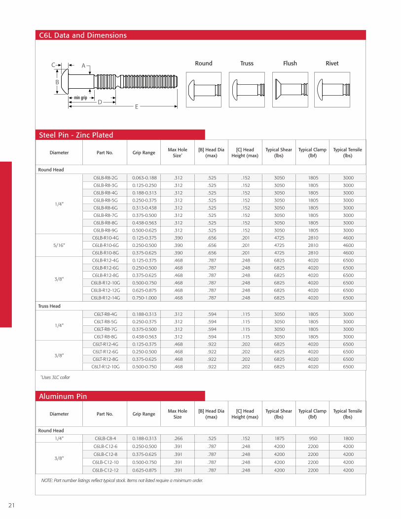
C6L®
The classic 6-groove locking fastener built with staying power.
A result of Huck International innovation a half-century ago, the versatile Alcoa Fastening Systems & Rings C6L®
HuckBolt® remains the number one fastening system for applications that require a strong, vibration-resistant
seal today.
C6L’s exclusive locking groove design ensures a permanent fit that resists loosening. That means it’s ideal
for applications from general manufacturing to such high-vibration applications as HVAC, trailer and
container assembly, rotary and rotating equipment, shopping carts, railroad and transit cars,
geodesic structures, and many others.
In addition to offering superior fastening performance, the C6L system reduces labor and
installation costs, along with rework and warranty expenses. For example, using the C6L
eliminates the need to hire certified welders or specially trained employees, because
workers can be instructed to install these foolproof fasteners in a matter of minutes.
The C6L is available in Grade 2, Grade 5, and Grade 8.
Available Sizes: 3/16", 1/4", 5/16", 3/8"
Materials: Steel, Aluminum, Stainless Steel
Headstyles: Round, Truss, Flush, 98T
Secure, Fast Installation
1. Wide bearing collar and head spread load to ensure
structural integrity.
2. Corrosion resistant coatings can be painted.
3. Excellent gap pull-out and high retained clamp.
4. High fatigue annular lock groove form
extends the life of your structure.

20
The C6L’s unique design virtually eliminates installation errors caused by operator or tool variables. The C6L ensures that once the collar
swage is complete, the pintail breaks off and the fastener is tightly installed. No rework required. And you can count on consistent,
high-uniform clamp force with every C6L installation, time after time.
Installation Sequence
The pin is inserted into the prepared hole and the
smooth bore collar is placed on the pin.
The nose anvil starts to swage the collar into the lockgrooves on the pin.
Continued swaging causes the collar to lengthen and
develop clamp.
When swaging of the collar into the lockgrooves
is complete, the pintail separates from the pin which completes the
installation cycle.
The installation tool is applied to the pintail.
When the tool is activated, the jaws in the nose assembly pull
on the pintail and the nose anvil pushes on the collar to
remove any gap.
1 3 42
21
Diameter Part No. Grip RangeMax Hole
Size[B] Head Dia
(max)[C] Head
Height (max)Typical Shear
(lbs)Typical Clamp
(lbf)Typical Tensile
(lbs)
Round Head
1/4" C6LB-C8-4 0.188-0.313 .266 .525 .152 1875 950 1800
3/8"
C6LB-C12-6 0.250-0.500 .391 .787 .248 4200 2200 4200
C6LB-C12-8 0.375-0.625 .391 .787 .248 4200 2200 4200
C6LB-C12-10 0.500-0.750 .391 .787 .248 4200 2200 4200
C6LB-C12-12 0.625-0.875 .391 .787 .248 4200 2200 4200
NOTE: Part number listings reflect typical stock. Items not listed require a minimum order.
Diameter Part No. Grip RangeMax Hole
Size*
[B] Head Dia (max)
[C] Head Height (max)
Typical Shear (lbs)
Typical Clamp (lbf)
Typical Tensile (lbs)
Round Head
1/4"
C6LB-R8-2G 0.063-0.188 .312 .525 .152 3050 1805 3000
C6LB-R8-3G 0.125-0.250 .312 .525 .152 3050 1805 3000
C6LB-R8-4G 0.188-0.313 .312 .525 .152 3050 1805 3000
C6LB-R8-5G 0.250-0.375 .312 .525 .152 3050 1805 3000
C6LB-R8-6G 0.313-0.438 .312 .525 .152 3050 1805 3000
C6LB-R8-7G 0.375-0.500 .312 .525 .152 3050 1805 3000
C6LB-R8-8G 0.438-0.563 .312 .525 .152 3050 1805 3000
C6LB-R8-9G 0.500-0.625 .312 .525 .152 3050 1805 3000
5/16"
C6LB-R10-4G 0.125-0.375 .390 .656 .201 4725 2810 4600
C6LB-R10-6G 0.250-0.500 .390 .656 .201 4725 2810 4600
C6LB-R10-8G 0.375-0.625 .390 .656 .201 4725 2810 4600
3/8"
C6LB-R12-4G 0.125-0.375 .468 .787 .248 6825 4020 6500
C6LB-R12-6G 0.250-0.500 .468 .787 .248 6825 4020 6500
C6LB-R12-8G 0.375-0.625 .468 .787 .248 6825 4020 6500
C6LB-R12-10G 0.500-0.750 .468 .787 .248 6825 4020 6500
C6LB-R12-12G 0.625-0.875 .468 .787 .248 6825 4020 6500
C6LB-R12-14G 0.750-1.000 .468 .787 .248 6825 4020 6500
Truss Head
1/4"
C6LT-R8-4G 0.188-0.313 .312 .594 .115 3050 1805 3000
C6LT-R8-5G 0.250-0.375 .312 .594 .115 3050 1805 3000
C6LT-R8-7G 0.375-0.500 .312 .594 .115 3050 1805 3000
C6LT-R8-8G 0.438-0.563 .312 .594 .115 3050 1805 3000
3/8"
C6LT-R12-4G 0.125-0.375 .468 .922 .202 6825 4020 6500
C6LT-R12-6G 0.250-0.500 .468 .922 .202 6825 4020 6500
C6LT-R12-8G 0.375-0.625 .468 .922 .202 6825 4020 6500
C6LT-R12-10G 0.500-0.750 .468 .922 .202 6825 4020 6500
*Uses 3LC collar
C6L Data and Dimensions
Aluminum Pin
Steel Pin - Zinc Plated
Round Truss Flush Rivet
min grip
B
DE
C A

22
Diameter Part No. Grip Range
Max Hole Size
[B] Head Dia (max)
[C] Head Height (max)
Typical Shear (lbs)
Typical Clamp (lbf)
Typical Tensile (lbs)
C98LT Head - Polished
3/16"
C98LT-U6-3BR 0.125-0.250 .203 .492 .106 2000 1025 1455
C98LT-U6-5BR 0.250-0.375 .203 .492 .106 2000 1025 1455
C98LT-U6-6BR 0.313-0.438 .203 .492 .106 2000 1025 1455
C98LT-U6-7BR 0.375-0.500 .203 .492 .106 2000 1025 1455
C98LT-U6-9BR 0.500-0.625 .203 .492 .106 2000 1025 1455
C98LT-U6-10BR 0.563-0.688 .203 .492 .106 2000 1025 1455
C98LT-U6-11BR 0.625-0.750 .203 .492 .106 2000 1025 1455
C98LT-U6-12BR 0.688-0.813 .203 .492 .106 2000 1025 1455
Round Head
1/4"
C6LB-U8-3 0.125-0.250 .266 .525 .152 3550 1805 2750
C6LB-U8-4 0.188-0.313 .266 .525 .152 3550 1805 2750
C6LB-U8-5 0.250-0.375 .266 .525 .152 3550 1805 2750
C6LB-U8-6 0.313-0.438 .266 .525 .152 3550 1805 2750
C6LB-U8-8 0.438-0.563 .266 .525 .152 3550 1805 2750
C6LB-U8-9 0.500-0.625 .266 .525 .152 3550 1805 2750
3/8"
C6LB-U12-6 0.250-0.500 .391 .787 .248 7950 4020 6100
C6LB-U12-8 0.375-0.625 .391 .787 .248 7950 4020 6100
C6LB-U12-10 0.500-0.750 .391 .787 .248 7950 4020 6100
Truss Head
3/8"
C6LT-U12-4 0.125-0.375 .391 .922 .202 7950 4020 6100
C6LT-U12-6 0.250-0.500 .391 .922 .202 7950 4020 6100
C6LT-U12-8 0.375-0.625 .391 .922 .202 7950 4020 6100
C6LT-U12-10 0.500-0.750 .391 .922 .202 7950 4020 6100
Stainless Steel Pin
NOTE: Part number listings reflect typical stock. Items not listed require a minimum order.

23
Steel, Zinc Plated
Diameter Part No. Width (G)
Non-Flanged
3/16" 2LC-R6G .304-.311
1/4" 2LC-R8G .402-.409
5/16" 2LC-R10G .485-.494
3/8" 2LC-R12G .590-.600
Flanged
3/16" 3LC-2R6G .304-.311
1/4" 3LC-2R8G .402-.409
5/16" 3LC-2R10G .498-.507
3/8" 3LC-2R12G .599-.610
Wide-Flanged
1/4" 3LCW-2R8G .400-.409
Stainless Steel
Diameter Part No. Width (G)
Non-Flanged
3/16" 2LC-2CU6 .304-.311
1/4" 2LC-2CU8 .402-.409
3/8" 2LC-2CU12 .485-.494
Flanged
3/16" 3LC-2CU6 .304-.311
1/4" 3LC-2CU8 .402-.409
3/8" 3LC-2CU12 .599-.610
Aluminum
Diameter Part No. Width (G)
Non-Flanged
3/16" 2LC-F6 .304-.311
1/4" 2LC-F8 .402-.409
5/16" 2LC-F10 .485-.494
3/8" 2LC-F12 .590-.600
Flanged
1/4" 3LC-F8 .402-.409
5/16" 3LC-F10 .498-.507
3/8" 3LC-F12 .599-.610
C6L Lockbolt Collars
Diameter Installation Tool Nose Assembly Type
3/16"LH-224 99-3201 Pneudraulic
2480 99-3201 Hydraulic
1/4"LH-224 99-3204 Pneudraulic
2480 99-3204 Hydraulic
5/16"
255 99-1439 Pneudraulic
256 99-1439 Pneudraulic
2581 99-1439 Hydraulic
3/8"
255* 99-1440 Pneudraulic
256 99-1440 Hydraulic
2581 99-1440 Hydraulic
Installation Tooling
Flanged 3LC Wide-Flanged
3LCW
Non-Flanged
2LC
* Aluminum Only
Model 256
Model 2581
Model LH-224

24
C6L Grip tables
Grip Grip Range3/16" (6) 1/4" (8)
Grip Grip Range5/16" (10) 3/8" (12)
D E D E D E D E
2 0.063 - 0.188 0.394 1.404 0.485 1.520
3 0.125 - 0.250 0.457 1.466 0.548 1.583
4 0.188 - 0.313 0.519 1.529 0.610 1.645 4 0.125 - 0.375 0.749 1.906 0.809 2.125
5 0.250 - 0.375 0.582 1.591 0.673 1.708
6 0.313 - 0.438 0.644 1.654 0.735 1.770 6 0.250 - 0.500 0.874 2.031 0.934 2.250
7 0.375 - 0.500 0.707 1.716 0.798 1.833
8 0.438 - 0.563 0.769 1.779 0.860 1.895 8 0.375 - 0.625 1.000 2.156 1.059 2.375
9 0.500 - 0.625 0.832 1.841 0.923 1.958
10 0.563 - 0.688 0.894 1.904 0.985 2.020 10 0.500 - 0.750 1.124 2.281 1.184 2.500
11 0.625 - 0.750 0.957 1.966 1.048 2.083
12 0.688 - 0.813 1.019 2.029 1.110 2.145 12 0.625 - 0.875 1.249 2.406 1.309 2.625
13 0.750 - 0.875 1.082 2.091 1.173 2.208
14 0.813 - 0.938 1.144 2.154 1.235 2.270 14 0.750 - 1.000 1.374 2.531 1.434 2.750
15 0.875 - 1.000 1.207 2.216 1.298 2.333
16 0.938 - 1.063 1.269 2.279 1.360 2.395 16 0.875 - 1.125 1.500 2.656 1.559 2.875
17 1.000 - 1.125 1.332 2.341 1.423 2.458
18 1.063 - 1.188 1.394 2.404 1.458 2.520 18 1.000 - 1.250 1.624 2.781 1.684 3.000
19 1.125 - 1.250 1.457 2.466 1.548 2.583
20 1.188 - 1.313 1.519 2.529 1.610 2.645 20 1.125 - 1.375 1.749 2.906 1.809 3.125
21 1.250 - 1.375 1.582 2.591 1.673 2.708
22 1.313 - 1.438 1.644 2.654 1.735 2.770 22 1.250 - 1.500 1.874 3.031 1.934 3.250
23 1.375 - 1.500 1.707 2.716 1.798 2.833
24 1.438 - 1.563 1.866 2.895 24 1.375 - 1.625 2.000 3.156 2.059 3.375
25 1.500 - 1.625 1.923 2.958
26 1.563 - 1.688 1.985 3.020 26 1.500 - 1.750 2.124 3.281 2.184 3.500
27 1.625 - 1.750 2.048 3.083
28 1.688 - 1.813 2.110 3.145 28 1.625 - 1.875 2.249 3.406 2.309 3.625
29 1.750 - 1.875 2.173 3.208
30 1.813 - 1.938 2.235 3.270 30 1.750 - 2.000 2.374 3.531 2.434 3.750
31 1.875 - 2.000 2.298 3.333
32 1.938 - 2.063 2.368 3.395 32 1.875 - 2.125 2.500 3.656 2.559 3.875
37 2.637 3.708

25
Ordering Information - C6L
Follow the form below to construct a part number for ordering C6L pins and their respective collars. Refer to the Grip Data chart for grip numbers.
Head Style Prefix Material Code Diameter Code Grip Finish Suffix
Round C6LB Grade 2 Carbon Steel R 3/16" 6 Refer to Grip Tables
Zinc G
Truss C6LT 2024 Aluminum Alloy C 1/4" 8
Flush C6L90 6061 Aluminum Alloy F 5/16" 10
Rivet C98LT Stainless Steel U 3/8" 12
Pins (Grade 2 Steel, Aluminum, Stainless Steel)
C6L — (MATERIAL) (DIAMETER) — (GRIP NUMBER) (FINISH) Example: C6LT-R8-4G is a C6L HuckBolt Pin, Truss Head, Carbon Steel, 1/4" Diameter, Grip 4, Zinc Finish
Head Style Prefix Material Code Diameter Code Grip Finish Suffix
Round C120B Grade 5 Carbon Steel R 3/16" 6 Refer to Grip Tables
Zinc G
Truss C120T 1/4" 8
Flush C12090 5/16" 10
3/8" 12
Pins (Grade 5)
C120L (HEAD STYLE) — (MATERIAL) (DIAMETER) — (GRIP NUMBER) (FINISH) Example: C120LT-R8-4G is a C120L HuckBolt Pin, Truss Head, Carbon Steel, 1/4" Diameter, Grip 4, Zinc Finish
Head Style Prefix Material Code Diameter Code Finish Suffix
Standard 2LC Carbon Steel 2R/R 3/16" 6 Zinc G
Flange 3LC 6061 Alum Alloy Heat Treated I 1/4" 8
Wide Flange 3LCW 6061 Alum Alloy F 5/16" 10
Stainless Steel 2CU 3/8" 12
Collars (Grade 2 Steel, Aluminum, Stainless Steel)
(TYPE) – (MATERIAL) (DIAMETER) (FINISH) Example: 2LC-R8G is a Standard C6L HuckBolt Collar, Carbon Steel, 1/4" Diameter, Zinc Finish
Grade 5 Prefix Material Code Diameter Code Finish Suffix
Standard 2LC120 Carbon Steel 2R/R 3/16" 6 Zinc G
Flange 3LC120 1/4" 8
5/16" 10
3/8" 12
Collars (Grade 5)
(TYPE) – (MATERIAL) (DIAMETER) (FINISH) Example: 2LC120-R8G is a Standard C120L HuckBolt Collar, Carbon Steel, 1/4 Diameter, Zinc Finish

26
Magna-Grip®
Offering a wide grip range and uniform installed values.
In applications where a wide grip range is required and a flush pin break to the collar is beneficial,
Huck Magna-Grip® is the ideal fastener for the job. In fact, Magna-Grip’s wide grip range can
replace up to 4 traditional HuckBolts.
Like all Huck engineered fasteners, Magna-Grip offers the highest level of vibration resistance
possible. Magna-Grip installs reliably, and consistently provides high, uniform installed values.
Available Sizes: 3/16", 1/4", 5/16", 3/8"
Materials: Steel, Aluminum
Headstyles: Button, Truss, Broad Truss, 90° Flush, 98T
1. Flush-breaking, lock-groove design provides a wide
grip range to reduce inventory requirements.
2. Collar material swaged into the annular pin grooves
forms a permanent, vibration-proof connection that
promotes increased customer satisfaction and
reduced warranty claims.
3. Hole preparation isn’t critical. Built-in system values
yield high, consistent clamp loads, and gap removal.
Secure, Fast Installation

27
Magna-Grip Head Style Options
Perfect installations do not depend upon worker skill or a precisely calibrated impact wrench — and can be achieved with just a few minutes training.
Installation Sequence
The fastener pin is inserted through a prepared hole.
The precision collar is placed over the other end.
The tool moves forward over the collar, molding the collar
material into the grooves of the pin. This process, called “swaging,” causes a precise stretching of the
pin and collar, developing the fastener’s clamping force.
When swaging is complete the pintail is automatically
tensioned off, flush with the end of the collar. The tool then
pushes off from the collar. The result is a permanent,
mechanically locked fastener.
The Huck installation tool is applied and engages the pin.
When the tool is activated, it pulls the pin in a straight line while pushing down on the collar.
1 3 42
B
CButton Head MGPB
B
CTruss Head MGPT
B
C
Broad Truss Head MGP30
B
C 90° Flush Head MGP90
B
C Rivet Head MGP98T

28
Diameter Part No. Grip Range Max Hole
Size[B] Head Dia
(max)[C] Head
Height (max)Typical Shear
(lbs)Typical Clamp
(lbf)
Typical Tensile (lbs)
Button Head
3/16"MGPB-R6-10G .062-.625 .219 .395 .129 2000 1500 2700
MGPB-R6-20G .312-1.250 .219 .395 .129 2000 1500 2700
1/4"MGPB-R8-10G .062-.625 .281 .520 .154 2700 2000 4000
MGPB-R8-20G .312-1.250 .281 .520 .154 2700 2000 4000
5/16"MGPB-R10-12G .125-.750 .359 .655 .206 3900 2900 6200
MGPB-R10-22G .625-1.375 .359 .655 .206 3900 2900 6200
3/8"MGPB-R12-14G .125-.875 .422 .780 .250 6000 4000 9000
MGPB-R12-26G .750-1.625 .422 .780 .250 6000 4000 9000
98T Head
3/16"
MGP98T-R6-10G .062-.625 .219 .488 .105 2000 1500 2700
MGP98T-R6-10GP .062-.625 .219 .488 .105 2000 1500 2700
MGP98T-R6-20G .312-1.250 .219 .488 .105 2000 1500 2700
Truss Head
1/4"
MGPT-R8-10G .062-.625 .281 .582 .120 2700 2000 4000
MGPT-R8-10GP .062-.625 .281 .582 .120 2700 2000 4000
MGPT-R8-20G .312-1.250 .281 .582 .120 2700 2000 4000
5/16" MGPT-R10-12G .125-.750 .359 .802 .149 3900 2900 6200
3/8" MGPT-R12-14G .125-.875 .422 .905 .175 6000 4000 9000
Broad Truss Head
1/4"MGP30-R8-10G .062-.625 .281 .978 .165 2700 2000 4000
MGP30-R8-24G .062-1.500 .281 .978 .165 2700 2000 4000
3/8"MGP30-R12-24G .625-1.500 .422 1.259 .215 6000 4000 9000
MGP30-R12-32G 1.125-2.000 .422 1.259 .215 6000 4000 9000
90º Flush Head
3/16" MGP90-R6-10G .062-.625 .219 .361 .105 2000 1500 2700
1/4" MGP90-R8-10G .062-.625 .281 .475 .130 2700 2000 4000
Steel Pin - Zinc Plated
NOTE: Part number listings reflect typical stock. Items not listed require a minimum order.
Diameter Part No. Grip Range Max Hole Size
[B] Head Dia (max)
[C] Head Height (max)
Typical Shear (lbs)
Typical Clamp (lbf)
Typical Tensile (lbs)
Truss Head
1/4" MGPTC-R8-10G .062-.625 .281 .582 .120 2700 2000 4000
3/8" MGPTC-R12-14G .125-.875 .422 .905 .210 6000 4000 9000
Steel Pin - Zinc Plated - Stainless Steel Cap

29
Diameter Part No. Grip Range Max Hole Size
[B] Head Dia (max)
[C] Head Height (max)
Typical Shear (lbs)
Typical Clamp (lbf)
Typical Tensile (lbs)
Button Head
3/16" MGPB-E6-10 .062-.625 .219 .395 .129 1000 800 1300
1/4"MGPB-E8-10 .062-.625 .281 .520 .154 1600 1400 2500
MGPB-E8-20 .312-1.250 .281 .520 .154 1600 1400 2500
5/16" MGPB-E10-12 .125-.750 .359 .655 .206 2700 2200 4100
3/8" MGPB-E12-14 .125-.875 .422 .780 .250 3900 3200 5500
98T Head
3/16"MGP98T-E6-10 .062-.625 .219 .488 .108 1000 800 1300
MGP98T-E6-20 .312-1.250 .219 .488 .108 1000 800 1300
Truss Head
1/4" MGPT-E8-10 .062-.625 .281 .582 .120 1600 1400 2500
Broad Truss Head
3/8" MGP30-E12-24 .625-1.500 .422 1.259 .215 3900 3200 5500
90º Flush Head
3/16" MGP90-E6-10 .062-.625 .219 .361 .105 1000 800 1300
1/4" MGP90-E8-10 .062-.625 .281 .475 .130 1600 1400 2500
Aluminum Pins
NOTE: Part number listings reflect typical stock. Items not listed require a minimum order.
Medium-Flanged MGCS
Magna-Grip Lockbolt Collars
Diameter Part No. Width(G)Steel - Zinc Plated
Flanged
3/16" MGC-R6U .305-.315
1/4" MGC-R8U .395-.405
5/16" MGC-R10U .500-.510
3/8" MGC-R12U .602-.612
Medium Flange 3/16" MGCS-R6U .305-.315
Wide Flange3/16" MGCW-R6U .305-.315
1/4" MGCW-R8U .395-.405
Aluminum
Flanged
3/16" MGC-F6 .305-.315
1/4" MGC-F8 .395-.405
5/16" MGC-F10 .500-.510
3/8" MGC-F12 .602-.612
Wide Flange 3/16" MGCW-F6 .305-.315
Standard-Flanged MGC
Wide-Flanged MGCW

30
Magna-Grip Installation Tooling
Follow the tables below to construct part numbers for ordering Magna-Grip pins and collars. Refer to the Grip Data chart for grip numbers.
Head Style Prefix Material Code Diameter Code Grip Number Finish Code
Button Head B Steel R 3/16" 6Please refer to the dimensional data chart.
Zinc G
Truss Head T Aluminum E 1/4" 8
Broad Truss Head 30 5/16" 10
Rivet Head 98T 3/8" 12
90° Flush Head 90
MGP (HEAD STYLE) - (MATERIAL) (DIAMETER) - (GRIP NUMBER) (FINISH) Example: MGPB-R8-10G is a Magna-Grip fastener, Button Head, Steel, 1/4" Diameter, Grip 10 with a Zinc Finish
Pins
Ordering Information - Magna Grip
Flange Style Prefix Material Code Diameter Code Finish Code Options Code
Standard MGC Steel R 3/16" 6 Zinc Chromate Gold
UTab Lock L
Medium MGCS Aluminum F 1/4" 8
Wide MGCW 5/16" 10
3/8" 12
(FLANGE STYLE) - (MATERIAL) (DIAMETER) (FINISH) (OPTIONS) Example: MGCW-R8U is a wide Flange Magna-Grip Collar, Steel, 1/4" Diameter, with a Zinc Finish
Collars
* Additional coatings are available upon request
Diameter Installation Tool Nose Assembly Type
3/16”
LH-224 99-3201 Pneudraulic
255 99-3206 Pneudraulic
256 99-3206 Pneudraulic
2480 99-3201 Hydraulic
2581 99-3206 Hydraulic
1/4"
LH-224 99-3204 Pneudraulic
255 99-3207 Pneudraulic
256 99-3207 Pneudraulic
2480 99-3204 Hydraulic
2581 99-3207 Hydraulic
5/16"
255 99-1439 Pneudraulic
256 99-1439 Pneudraulic
2581 99-1439 Pneudraulic
2600 99-3217 Pneudraulic
3/8"
255* 99-1440 Pneudraulic
256 99-1440 Pneudraulic
2581 99-1440 Hydraulic
2600 99-3220 Hydraulic
2620PT H99-1492 Hydraulic
* Additional coatings are available upon request
* Aluminum OnlyModel 2581
Model LH-224

31
Hucktainer®
Two-piece specialty fastener for fiberglass reinforced plywood panels.
The Hucktainer® specialty fastener installs with a consistent pressure, reducing the potential for
crushing or crazing FRP panels and metal-clad applications. Each features a heavy zinc plating
that resists corrosion, and an integral seal that helps keep the elements and other contaminants
from invading the joint. Unlike threaded fasteners, Hucktainer is never over-torqued or
under-torqued. Consistent clamp and fast, foolproof installation is what you’ll get every
time with Hucktainer.
Designed specifically for truck trailers, truck bodies, cargo containers, and other
structures fabricated from fiberglass reinforced plywood, Hucktainer fasteners
provide the consistent clamp and fast, foolproof installation required for
maximum product quality and productivity.
Available Sizes: 3/8"
Materials: Steel
1. Lower profile head design saves cargo space.
2. Heads may be plastic-encapsulated for maximum
corrosion-resistance; UV-resistant head capsules are
colorfast and won’t fade.
3. Integral weather-resistant seal provides
protection from the elements.
4. Heavy-zinc plating protects against corrosion and
preserves good looks.
5. One sleeve fits all pins; no need to mix and match.
Weather-Resistant Seal

32
Installation Sequence
The pin and sleeve are inserted into the
prepared hole.
The sleeve is fully engaged on the pin and locks onto the
pin’s splines to clamp the material tightly together.
Continued pull of the tool causes the pintail to break away, which completes the
installation cycle.
The installation tool is applied to the pintail. When
the tool is activated, the sleeve is forced onto the spiral lock of the pin. The rotating action of the nose
assembly allows the sleeve to turn freely.
Hucktainer Data & Dimensions
Diameter Part No. Grip RangeMax Hole
Size[B] Head Dia (max)
[C] Head Height (max)
Typical Clamp (lbf)
Typical Tensile (lbs)
Min Grip Mid Grip Max Grip
Standard Head
3/8"
HLPP-R12-10PL .562-.687 .421 .830 .160 700 800 1200 1800
HLPP-R12-11PL .625-.750 .421 .830 .160 700 800 1200 1800
HLPP-R12-12PL .687-.812 .421 .830 .160 700 800 1200 1800
HLPP-R12-13PL .750-.875 .421 .830 .160 700 800 1200 1800
HLPP-R12-14PL .812-.937 .421 .830 .160 700 800 1200 1800
HLPP-R12-15PL .875-1.000 .421 .830 .160 700 800 1200 1800
HLPP-R12-16PL .937-1.062 .421 .830 .160 700 800 1200 1800
HLPP-R12-17PL 1.000-1.125 .421 .830 .160 700 800 1200 1800
HLPP-R12-18PL 1.062-1.187 .421 .830 .160 700 800 1200 1800
HLPP-R12-19PL 1.125-1.250 .421 .830 .160 700 800 1200 1800
HLPP-R12-20PL 1.187-1.312 .421 .830 .160 700 800 1200 1800
Standard Wide-Bearing EncapsulatedMedium-Bearing Encapsulated
NOTE: Part number listings reflect typical stock. Items not listed require a minimum order.
Steel Pin - Zinc Plated
1 3 42

33
Diameter Part No. Grip RangeMax Hole
Size[B] Head Dia (max)
[C] Head Height (max)
Typical Clamp (lbf)
Typical Tensile (lbs)
Min Grip Mid Grip Max Grip
Medium Bearing Encapsulated Head - Gray
3/8"
HLPMG-R12-9PL .500-.625 .421 .950 .300 700 800 1200 1800
HLPMG-R12-10PL .562-.687 .421 .950 .300 700 800 1200 1800
HLPMG-R12-11PL .625-.750 .421 .950 .300 700 800 1200 1800
HLPMG-R12-12PL .687-.812 .421 .950 .300 700 800 1200 1800
HLPMG-R12-13PL .750-.875 .421 .950 .300 700 800 1200 1800
HLPMG-R12-14PL .812-.937 .421 .950 .300 700 800 1200 1800
HLPMG-R12-15PL .875-1.000 .421 .950 .300 700 800 1200 1800
HLPMG-R12-16PL .937-1.062 .421 .950 .300 700 800 1200 1800
HLPMG-R12-17PL 1.000-1.125 .421 .950 .300 700 800 1200 1800
HLPMG-R12-18PL 1.062-1.187 .421 .950 .300 700 800 1200 1800
HLPMG-R12-19PL 1.125-1.250 .421 .950 .300 700 800 1200 1800
Medium Bearing Encapsulated Head - White
3/8"
HLPMW-R12-9PL .500-.625 .421 .950 .300 700 800 1200 1800
HLPMW-R12-10PL .562-.687 .421 .950 .300 700 800 1200 1800
HLPMW-R12-11PL .625-.750 .421 .950 .300 700 800 1200 1800
HLPMW-R12-12PL .687-.812 .421 .950 .300 700 800 1200 1800
HLPMW-R12-13PL .750-.875 .421 .950 .300 700 800 1200 1800
HLPMW-R12-14PL .812-.937 .421 .950 .300 700 800 1200 1800
HLPMW-R12-15PL .875-1.000 .421 .950 .300 700 800 1200 1800
HLPMW-R12-16PL .937-1.062 .421 .950 .300 700 800 1200 1800
HLPMW-R12-17PL 1.000-1.125 .421 .950 .300 700 800 1200 1800
HLPMW-R12-18PL 1.062-1.187 .421 .950 .300 700 800 1200 1800
HLPMW-R12-19PL 1.125-1.250 .421 .950 .300 700 800 1200 1800
Steel Pin - Zinc Plated
Medium Bearing Encapsulated Head - Hertz Yellow
3/8"
HLPMHY-R12-9PL .500-.625 .421 .950 .300 700 800 1200 1800
HLPMHY-R12-10PL .562-.687 .421 .950 .300 700 800 1200 1800
HLPMHY-R12-11PL .625-.750 .421 .950 .300 700 800 1200 1800
HLPMHY-R12-12PL .687-.812 .421 .950 .300 700 800 1200 1800
HLPMHY-R12-13PL .750-.875 .421 .950 .300 700 800 1200 1800
HLPMHY-R12-14PL .812-.937 .421 .950 .300 700 800 1200 1800
HLPMHY-R12-15PL .875-1.000 .421 .950 .300 700 800 1200 1800
HLPMHY-R12-16PL .937-1.062 .421 .950 .300 700 800 1200 1800
HLPMHY-R12-17PL 1.000-1.125 .421 .950 .300 700 800 1200 1800
HLPMHY-R12-18PL 1.062-1.187 .421 .950 .300 700 800 1200 1800
HLPMHY-R12-19PL 1.125-1.250 .421 .950 .300 700 800 1200 1800
Medium Bearing Encapsulated Head - Ryder Yellow
3/8"
HLPMRY-R12-9PL .500-.625 .421 .950 .300 700 800 1200 1800
HLPMRY-R12-10PL .562-.687 .421 .950 .300 700 800 1200 1800
HLPMRY-R12-11PL .625-.750 .421 .950 .300 700 800 1200 1800
HLPMRY-R12-12PL .687-.812 .421 .950 .300 700 800 1200 1800
HLPMRY-R12-13PL .750-.875 .421 .950 .300 700 800 1200 1800
HLPMRY-R12-14PL .812-.937 .421 .950 .300 700 800 1200 1800
HLPMRY-R12-15PL .875-1.000 .421 .950 .300 700 800 1200 1800
HLPMRY-R12-16PL .937-1.062 .421 .950 .300 700 800 1200 1800
HLPMRY-R12-17PL 1.000-1.125 .421 .950 .300 700 800 1200 1800
HLPMRY-R12-18PL 1.062-1.187 .421 .950 .300 700 800 1200 1800
HLPMRY-R12-19PL 1.125-1.250 .421 .950 .300 700 800 1200 1800
Wide Bearing Encapsulated Head - Gray
3/8"
HLPEG-R12-9PL .500-.625 .421 1.210 .325 700 800 1200 1800
HLPEG-R12-10PL .562-.687 .421 1.210 .325 700 800 1200 1800
HLPEG-R12-11PL .625-.750 .421 1.210 .325 700 800 1200 1800
HLPEG-R12-12PL .687-.812 .421 1.210 .325 700 800 1200 1800
HLPEG-R12-13PL .750-.875 .421 1.210 .325 700 800 1200 1800
HLPEG-R12-14PL .812-.937 .421 1.210 .325 700 800 1200 1800
HLPEG-R12-15PL .875-1.000 .421 1.210 .325 700 800 1200 1800
NOTE: Part number listings reflect typical stock. Items not listed require a minimum order.

34
Diameter Installation Tool Nose Assembly Type
3/8"
LH-224 99-3465 Pneudraulic
256 99-3438 Pneudraulic
2480 99-3464 Hydraulic
2581 99-3438 Hydraulic
Installation Tooling
Wide Bearing Encapsulated Head - Hertz Yellow
3/8"
HLPEHY-R12-9PL .500-.625 .421 1.210 .325 700 800 1200 1800
HLPEHY-R12-10PL .562-.687 .421 1.210 .325 700 800 1200 1800
HLPEHY-R12-11PL .625-.750 .421 1.210 .325 700 800 1200 1800
HLPEHY-R12-12PL .687-.812 .421 1.210 .325 700 800 1200 1800
HLPEHY-R12-13PL .750-.875 .421 1.210 .325 700 800 1200 1800
HLPEHY-R12-14PL .812-.937 .421 1.210 .325 700 800 1200 1800
HLPEHY-R12-15PL .875-1.000 .421 1.210 .325 700 800 1200 1800
HLPEHY-R12-16PL .937-1.062 .421 1.210 .325 700 800 1200 1800
HLPEHY-R12-17PL 1.000-1.125 .421 1.210 .325 700 800 1200 1800
HLPEHY-R12-18PL 1.062-1.187 .421 1.210 .325 700 800 1200 1800
HLPEHY-R12-19PL 1.125-1.250 .421 1.210 .325 700 800 1200 1800
Wide Bearing Encapsulated Head - Ryder Yellow
3/8"
HLPERY-R12-9PL .500-.625 .421 1.210 .325 700 800 1200 1800
HLPERY-R12-10PL .562-.687 .421 1.210 .325 700 800 1200 1800
HLPERY-R12-11PL .625-.750 .421 1.210 .325 700 800 1200 1800
HLPERY-R12-12PL .687-.812 .421 1.210 .325 700 800 1200 1800
HLPERY-R12-13PL .750-.875 .421 1.210 .325 700 800 1200 1800
HLPERY-R12-14PL .812-.937 .421 1.210 .325 700 800 1200 1800
HLPERY-R12-15PL .875-1.000 .421 1.210 .325 700 800 1200 1800
HLPERY-R12-16PL .937-1.062 .421 1.210 .325 700 800 1200 1800
HLPERY-R12-17PL 1.000-1.125 .421 1.210 .325 700 800 1200 1800
HLPERY-R12-18PL 1.062-1.187 .421 1.210 .325 700 800 1200 1800
HLPERY-R12-19PL 1.125-1.250 .421 1.210 .325 700 800 1200 1800
Minimum orders may apply
Diameter Part No. Grip RangeMax Hole
Size[B] Head Dia (max)
[C] Head Height (max)
Typical Clamp (lbf)
Typical Tensile (lbs)
Min Grip Mid Grip Max Grip
Wide Bearing Encapsulated Head - Gray
3/8"
HLPEG-R12-16PL .937-1.062 .421 1.210 .325 700 800 1200 1800
HLPEG-R12-17PL 1.000-1.125 .421 1.210 .325 700 800 1200 1800
HLPEG-R12-18PL 1.062-1.187 .421 1.210 .325 700 800 1200 1800
HLPEG-R12-19PL 1.125-1.250 .421 1.210 .325 700 800 1200 1800
Wide Bearing Encapsulated Head - White
3/8"
HLPEW-R12-9PL .500-.625 .421 1.210 .325 700 800 1200 1800
HLPEW-R12-10PL .562-.687 .421 1.210 .325 700 800 1200 1800
HLPEW-R12-11PL .625-.750 .421 1.210 .325 700 800 1200 1800
HLPEW-R12-12PL .687-.812 .421 1.210 .325 700 800 1200 1800
HLPEW-R12-13PL .750-.875 .421 1.210 .325 700 800 1200 1800
HLPEW-R12-14PL .812-.937 .421 1.210 .325 700 800 1200 1800
HLPEW-R12-15PL .875-1.000 .421 1.210 .325 700 800 1200 1800
HLPEW-R12-16PL .937-1.062 .421 1.210 .325 700 800 1200 1800
HLPEW-R12-17PL 1.000-1.125 .421 1.210 .325 700 800 1200 1800
HLPEW-R12-18PL 1.062-1.187 .421 1.210 .325 700 800 1200 1800
HLPEW-R12-19PL 1.125-1.250 .421 1.210 .325 700 800 1200 1800
Clearance Sleeve
HLPSC-R12
Medium Bearing Sleeve
HLPSM-R12
Large Bearing Sleeve
HLPS-R12
Hucktainer Sleeves - Zinc Plated
NOTE: Part number listings reflect typical stock. Items not listed require a minimum order.
Steel Pin - Zinc Plated

35
Huck 360®
The engineered nut-and-bolt fastening system from the leader in vibration-resistant fastening, Huck.
The goal was simple: to design a high-strength bolting system that resists vibration loosening,
no matter how extreme the environment. This system should offer quick installation and removal
with conventional tools, deliver superior fatigue strength, and hold tight under high spike loads.
The result is the Huck 360®, the most advanced nut-and-bolt fastening system you’ll find
on the market today. Easy-to-install, the Huck 360 is engineered to be virtually
maintenance-free and resistant to vibration, even under extreme conditions.
Available Sizes: 3/8", 1/2", 5/8", 3/4", 7/8", 1", 1-1/8", 1-3/8" 10mm, 12mm, 16mm, 20mm, and 36mm
Materials: Steel
Contact Alcoa Fastening Systems & Rings for availability.
Conventional thread
Thread flanks can slide.Nut can move relative to bolt.
Huck 360®
Thread flanks are locked.Nut cannot move relative to bolt.
Huck 360® stays tight under severe vibration loading by eliminating
the “gap” around the crest of the bolt. When tightened, the Huck 360
fills this gap, which prevents transverse motion between the 360 nut
and bolt, keeping the assembly in place.
BOLT NUTBOLT NUT
TRANSVERSE
VIBRATION
The Difference is in the Design

36
Transverse Vibration Comparison
This chart shows that once vibration begins, clamp load quickly decays with conventional nuts and bolts, while it holds constant with Huck 360®.
Huck 360® Benefits
■ Resists vibration loosening.
■ Withstands high spike loads.
■ Increases equipment uptime.
■ Installs 300% faster than conventional locknuts.
■ Can be installed and removed with conventional tools.
Reduce Maintenance, Save Time
The Huck 360® installs faster and more easily than the nuts and bolts you’re accustomed to using, and maintenance intervals can be extended. The Huck 360’s superior fatigue strength has proven to increase equipment uptime and productivity.
Because the Huck 360® was designed with shallow, low-notch factor bolt threads (the
grooves aren’t rolled as deep as a conventional bolt), the effective area of the fastener
itself is widened by as much as 20%, increasing tensile and fatigue strength. In fact, the
Huck 360 thread delivers 5 times the fatigue life of a standard thread bolt.
Improved Fatigue Performance
Finite Element Analysis (FEA) reveals that the shallow thread form of the Huck 360® results in 27% less axial stress in the root than conventional bolt threads. Stress concentration is the primary contributing factor leading to fatigue failures.
Huck 360® Conventional thread
Increased Life
27% less stress in the root of
the bolt thread.
CLA
MP
LOA
D (
lbf) ®
* For more information visit www.afsrhuck.net or contact your nearest distributor, listed on the back of the catalogue.

37
Huck Structural Blind Rivets
When High Performance and Holding Power are Critical
Huck Structural Blind Rivets are Alcoa Fastening Systems &
Rings’ answer to loosening and vibration challenges. And it’s
the reason they are the world’s strongest, most reliable, most
consistent blind fastening solution available.
In fact, in fatigue tests, Huck Structural Blind Rivets
outlasted the competition by almost 20-to-1. Engineered
with a unique locking design, many of the Huck Structural
Blind Rivets create an internal lock during installation that
virtually eliminates pin pushout by mechanically locking the
pin to the sleeve. Each locks permanently, reliably into place,
with little effort.
Always accurate and easy to install, Huck Structural Blind
Rivets offer quick one-worker installation. Inspections are
simple to perform; no need for torque inspections or x-rays.
In applications where vibration resistance, reliability, and
strong hold are critical, Huck Structural Blind Rivets offer the
strength and durability needed. No fastening system is
more dependable.
HuckLok’s proprietary solid circle lock
ensures maximum strength and vibration
resistance. Shear ring at sheet line
provides consistent clamp.
Sheet-Line Bulb Comparison
Even in minimum-grip applications, Huck fasteners outperform the
competition. They’re engineered to form a bulb directly on the sheet
line, precisely where it’s needed, to prevent pull-through.
Auto-Bulb™
Bulb forms directly on sheet line.
The Competition
Bulb forms irregularly above sheet line resulting in lower installed values.

38
Types
HuckLok®
Wide 1/4” grip range, double-locking action clamps assembly from both sides for maximum joint integrity.
Magna-Lok®
Hole-filling fastener with excellent gap pull-out and moisture resistance. Solid circle lock creates internal lock that virtually eliminates pin push-out.
BOM®
Blind, Oversize, Mechanically locked fasteners. Unique push-and-pull installation design for ultimate locking strength from blind-side install.
Auto-BulbTM
Features a tapered lead-in point for automated, high-speed assemblies. Forms a bulb directly on the sheet line, preventing pull-through. Available in stainless steel.
FloorTight®
Self-countersinking design for consistent installations in plywood and plymetal vehicle floor applications.
Magna-Tite®
Has water-resistant sealant for oversize holes and repairs. Large blind-side footprint for use in thin or low-strength materials.
Magna-Bulb®
Wide grip range fastener that forms a bulb directly on the sheet line. Offers a broader bearing surface.

39
The 360º solid-circle lock. It’s Alcoa Fastening Systems and Rings’ answer to loosening and
vibration challenges. And it’s the reason Magna-Lok® is the world’s strongest, most reliable, most
consistent blind fastening solution available. The unique locking design creates an internal lock
during installation that virtually eliminates pin pushout by mechanically locking the pin to the
sleeve. So Magna-Lok fasteners lock flush into place reliably. Permanently.
In lab shear fatigue tests, steel Magna-Lok fasteners outlasted the nearest
competitor nearly 20 to 1. Ours lasted 2 million cycles, while theirs lasted
only 100,000. In addition, this strength extends to the solid-circle lock
design. The expanding sleeve creates a tough, long-lasting joint
with a tight, weather-resistant seal. This shield blocks out water
and salt, further ensuring the fastener’s long, reliable life.
Available Sizes: 3/16", 1/4", 3/8", 1/2"
Materials: Steel, Aluminum, Stainless Steel
Headstyles: Protruding, Truss, 100° Flush
Magna-Lok®
The hole-filling fastener with mechanical circle lock and wide grip range.
Secure, Fast Installation
1. Flush pin break eliminates grinding and filling, leaving
an even surface.
2. Unique, solid-circle lock ensures maximum strength
and vibration resistance. The potential for pin push-
out is virtually eliminated.
3. Excellent gap pull-out and high retained clamp.
4. Sleeve expands during installation to fill the hole and
create a moisture-resistant joint.

40
Installation Sequence
Insert the fastener into the hole and slip the installation
tool over the pintail.
Continued pulling on the pintail draws the hollow
pin head inside sleeve. The pin expands inside the sleeve and the work pieces, to completely fill the
hole of the work pieces.
A solid circle lock between the pin and sleeve is formed just prior to the pin breaking flush
with the sleeve head, completing the installation.
Press the trigger to initiate pulling action.
As the tool pulls on the pintail, the pin (mandrel) expands
the sleeve and begins drawing the work pieces together.
1 3 42

41
Diameter Part No. Grip Range Max Hole Size
[B] Head Dia (max)
[C] Head Height (max)
Typical Shear (lbs)
Typical Tensile (lbs)
Protruding Head
3/16"
MGLP-R6-4 .062-.270 .201 .392 .101 1450 1200
MGLP-R6-7 .214-.437 .201 .392 .101 1450 1200
MGLP-R6-10 .455-.665 .201 .392 .101 1450 1200
MGLP-R6-E .062-.437 .201 .392 .101 1450 1200
1/4"
MGLP-R8-6 .080-.375 .272 .530 .120 2750 2200
MGLP-R8-7 .080-.437 .272 .530 .120 2750 2200
MGLP-R8-10 .350-.625 .272 .530 .120 2750 2200
MGLP-R8-14 .580-.875 .272 .530 .120 2750 2200
MGLP-R8-22 1.080-1.375 .272 .530 .120 2570 2200
MGLP-R8-E .080-.625 .272 .530 .120 2750 2200
MGLP-R8-E12.6* .245-.790 .272 .530 .120 2750 2200
3/8" MGLP-R12-12 .120-.625 .408 .793 .175 6300 5000
1/2" MGLP-R16-12 .160-.750 .563 1.060 .240 11200 9400
Truss Head
3/16"MGLT-R6-4 .062-.270 .201 .530 .104 1450 1200
MGLT-R6-E .062-.437 .201 .530 .104 1450 1200
1/4" MGLT-R8-6 .080-.375 .272 .592 .120 2750 2200
100º Flush Head
3/16"MGL100-R6-6 .125-.331 .201 .350 .080 1450 1200
MGL100-R6-9 .305-.500 .201 .350 .080 1450 1200
1/4"MGL100-R8-8 .160-.475 .272 .410 .090 2750 2200
MGL100-R8-12 .415-.725 .272 .410 .090 2750 2200
Diameter Part No. Grip Range Max Hole Size[B] Head Dia
(max)[C] Head Height
(max)Typical Shear
(lbs)Typical Tensile
(lbs)
Protruding Head
3/16"
MGLP-B6-4 .062-.270 .201 .392 .101 700 580
MGLP-B6-7 .214-.437 .201 .392 .101 700 580
MGLP-B6-E .062-.437 .201 .392 .101 700 580
1/4"
MGLP-B8-6 .080-.375 .272 .530 .120 1300 950
MGLP-B8-10 .350-.625 .272 .530 .120 1300 950
MGLP-B8-E .080-.625 .272 .530 .120 1300 950
3/8" MGLP-B12-12 .120-.625 .408 .793 .175 3000 2100
1/2" MGLP-B16-12 .160-.750 .563 1.060 .240 5400 4100
Truss Head
3/16"
MGLT-B6-4 .062-.270 .201 .530 .104 700 580
MGLT-B6-7 .214-.437 .201 .530 .104 700 580
MGLT-B6-E .062-.437 .201 .530 .104 700 580
Magna-Lok Data & Dimensions
Protruding HeadTruss Head 100° Flush Head
100º Flush Head
3/16"
MGL100-B6-6 .125-.331 .201 .350 .080 700 580
MGL100-B6-9 .305-.500 .201 .350 .080 700 580
MGL100-B6-12 .080-.375 .201 .350 .080 700 580
MGL100-B6-14 .080-.375 .201 .350 .080 700 580
1/4"MGL100-B8-8 .160-.475 .272 .410 .090 1300 950
MGL100-B8-12 .415-.725 .272 .410 .090 1300 950
NOTE: Part number listings reflect typical stock. Items not listed require a minimum order.
* Also available in 400 Stainless Steel
Steel Rivet/Steel Mandrel
Aluminum Rivet/Aluminum Mandrel

42
Diameter Part No. Grip Range
Max Hole Size
[B] Head Dia (max)
[C] Head Height (max)
Typical Shear (lbs)
Typical Tensile (lbs)
Protruding Head
3/16"
MGLP-U6-4 .062-.270 .201 .392 .101 1400 1100
MGLP-U6-7 .214-.437 .201 .392 .101 1400 1100
MGLP-U6-E .062-.437 .201 .392 .101 1400 1100
1/4"
MGLP-U8-6 .080-.375 .272 .530 .120 2500 1800
MGLP-U8-7 .080-.375 .272 .530 .120 2500 1800
MGLP-U8-10 .350-.625 .272 .530 .120 2500 1800
MGLP-U8-E .080-.625 .272 .530 .120 2500 1800
Flush Head
3/16"MGL100-U6-6 .125-.331 .201 .350 .080 1400 1100
MGL100-U6-9 .305-.500 .201 .350 .080 1400 1100
1/4"MGL100-U8-8 .160-.475 .272 .410 .090 2500 1800
MGL100-U8-12 .415-.725 .272 .410 .090 2500 1800
NOTE: Part number listings reflect typical stock. Items not listed require a minimum order.
Stainless Sleeve/Stainless Mandrel
Diameter Installation Tool Nose Assembly Type
3/16"LH-224 99-3300 99-3303 Pneudraulic
2480 99-3300 99-3303 Hydraulic
1/4"LH-224 99-3301 99-3305 Pneudraulic
2480 99-3301 99-3305 Hydraulic
3/8"256 99-3318 Pneudraulic
2581 99-3318 Hydraulic
1/2"2620PT 99-3330 Hydraulic - Aluminium
2620PT 99-3331 Hydraulic - Steel Only
Installation Tooling
Model 2480
Model LH-224

43
Ordering Information - Magna-Lok
Follow the form below to construct a part number for ordering Huck Magna-Lok blind fasteners. Refer to the Grip Data chart for grip numbers.
Head Style Prefix Material Code Diameter Code
Protruding Head P Steel R 3/16" 6
Truss Head T Aluminum B 1/4" 8
100° Flush Head 100 Stainless Steel U 3/8" 12
430 Stainless Steel 4U 1/2" 16
Material Sleeve Pin Sleeve Finish* Pin Finish* Code
Steel Low Carbon Steel Medium Carbon Steel
Zinc Plated Clear Chromate
Zinc Plated Clear Chromate R
Aluminum 5000 Series 7000 Series Clear Chromate Clear Chromate B
Stainless Steel 300 Series 300 Series Passivated Dry Lubricated U
400 Series Stainless Steel 430 Series 300 Series Passivated Dry Lubricated 430U
400 Series Stainless Steel 430 Series 410 Series Passivated Dry Lubricated 4U
Materials and Finishes
Ordering Information
MGL (HEAD STYLE) - (MATERIAL) (DIAMETER) - (GRIP NUMBER) Example: MGLP-R6-4 is a Protruding Head Magna-Lok, Steel, 3/16" Diameter.
Contact Manufacturer for other available/possible finishes.

44
Huck Magna-Bulb® is a unique, clamp-type fastener offering high shear strength in specific
applications. Its bulbing action during installation spreads the load over more surface area,
supplying a stronger, longer-lasting connection, while offering superior blind side strength.
This increased bearing area makes Magna-Bulb ideal for pull-out resistance in thin materials,
and oversized or misaligned holes. Positive, mechanical pin-retention ensures structural
integrity no matter what the application.
Available Sizes: 3/16", 1/4", 5/16"
Materials: Steel
Headstyles: Protruding, Truss, 100° Oval Flush
Magna-Bulb®
A unique bulbing fastener with high shear strength.
Secure, Fast Installation
1. Shear ring design promotes bulb formation and grip
adjustment for flush break throughout the grip range.
2. The wide blind footprint (bulb) gives the fastener a
broader bearing surface, spreading the load out for
greater strength and high pull out resistance.
3. Unique solid circle lock ensures maximum strength
and resistance to vibration.
4. Breaking flush throughout the entire grip range,
the Magna-Bulb fastener eliminates costly cosmetic
finish work and ensures ”visually” that the fastener
has been installed correctly.

45
Installation Sequence
Insert the fastener into the hole and slip the installation
tool over the pintail.
Continued pulling on the pintail expands the bulb to maximum
allowable diameter. The shear ring then breaks and catches
on the annular grooves as the pin continues to draw down
inside the sleeve.
A solid circle lock between the pin and sleeve is formed just prior to the pin breaking flush with the sleeve head, completing the installation.
Press the trigger to initiate pulling action. As the tool
pulls on the pintail, the pin (mandrel) expands
the sleeve and begins drawing the work pieces together.
1 3 42
Diameter Part No. Grip Range Max Hole Size[B] Head Dia
(max)[C] Head Height
(max)Typical Shear
(lbs)Typical Tensile
(lbs)
Protruding Head
3/16"
MBP-R6-M3 .087-.150 .201 .395 .101 1900 1050
MBP-R6-M4 .126-.189 .201 .395 .101 1900 1050
MBP-R6-M5 .165-.228 .201 .395 .101 1900 1050
MBP-R6-M6 .205-.268 .201 .395 .101 1900 1050
MBP-R6-M7 .244-.307 .201 .395 .101 1900 1050
MBP-R6-M8 .283-.347 .201 .395 .101 1900 1050
MBP-R6-M10 .362-.425 .201 .395 .101 1900 1050
1/4"
MBP-R8-M3 .110-.189 .272 .530 .125 2700 2000
MBP-R8-M4 .150-.229 .272 .530 .125 2760 2000
MBP-R8-M5 .189-.268 .272 .530 .125 3000 2000
MBP-R8-M6 .229-.308 .272 .530 .125 3200 2000
MBP-R8-M7 .268-.346 .272 .530 .125 3600 2000
MBP-R8-M8 .308-.387 .272 .530 .125 3600 2000
MBP-R8-M9 .346-.425 .272 .530 .125 3600 2000
MBP-R8-M10 .387-.466 .272 .530 .125 3600 2000
MBP-R8-M11 .425-.504 .272 .530 .125 3600 2000
MBP-R8-M12 .466-.545 .272 .530 .125 3600 2000
MBP-R8-M13 .504-.583 .272 .530 .125 3600 2000
Protruding Clearance Oval Flush
Steel Rivet/Steel Mandrel
Magna-Bulb Data & Dimensions

46
Diameter Part No. Grip Range Max Hole Size
[B] Head Dia (max)
[C] Head Height (max)
Typical Shear (lbs)
Typical Tensile (lbs)
Protruding Head
5/16"
MBP-R10-3 .150-.250 .340 .655 .152 5000 3000
MBP-R10-4 .200-.300 .340 .655 .152 5000 3000
MBP-R10-5 .250-.350 .340 .655 .152 5000 3000
MBP-R10-6 .300-.400 .340 .655 .152 5000 3000
MBP-R10-7 .350-.450 .340 .655 .152 5000 3000
MBP-R10-8 .400-.500 .340 .655 .152 5000 3000
MBP-R10-10 .500-.600 .340 .655 .152 5000 3000
Clearance Version*
1/4"
MBCP-R8-M3 .110-.189 .272 .525 .122 3000 3000
MBCP-R8-M4 .189-.268 .272 .525 .122 3000 3000
MBCP-R8-M5 .268-.346 .272 .525 .122 3000 3000
MBCP-R8-M6 .229-.308 .272 .525 .122 3000 3000
MBCP-R8-M7 .268-.346 .272 .525 .122 3000 3000
MBCP-R8-M8 .308-.387 .272 .525 .122 3000 3000
MBCP-R8-M9 .346-.425 .272 .525 .122 3000 3000
MBCP-R8-M11 .425-.504 .272 .525 .122 3000 3000
MBCP-R8-M13 .504-.583 .272 .525 .122 3000 3000
MBCP-R8-M16 .622-.701 .272 .530 .125 3000 3000
* MBCP: Please refer to coordination drawings for specifications. NOTE: Part number listings reflect typical stock. Items not listed require a minimum order.
Steel Rivet/Steel Mandrel
Installation ToolingDiameter Installation Tool Nose Assembly Type
3/16”LH-224 99-3300 99-3303 Pneudraulic
2480 99-3300 99-3303 Hydraulic
1/4”LH-224 99-3301 99-3305 Pneudraulic
2480 99-3301 99-3305 Hydraulic
5/16" 256 99-3307 - Pneudraulic
Wide bulb provides broader bearing surface
Model 2480
Model LH-224

47
Head Style Prefix
Protruding Head P
Oval Head V
Material Code
Steel R
Diameter Code
3/16" 6
1/4" 8
5/16” 10
STANDARD VERSION MB (HEAD STYLE) - (MATERIAL) (DIAMETER) - (GRIP NUMBER) Example: MBP-R6-M4 is a Protruding Head Magna-Bulb, Steel, 3/16" Diameter, M4 Grip.
CLEARANCE VERSION MBC (HEAD STYLE) - (MATERIAL) (DIAMETER) - (GRIP NUMBER) Example: MBCP-R8-M3 is a Protruding Head Clearance Magna-Bulb, Steel, 1/4” Diameter, M3 Grip.
Ordering Information
Follow the form below to construct a part number for ordering Huck Magna-Bulb blind fasteners. Refer to the data and dimensions chart for grip numbers.
Materials and Finishes
Ordering Information
Material Sleeve Pin Sleeve Finish Pin Finish
Steel Low Carbon Steel Medium Carbon Steel
Zinc Plate / Chromate / Gold Dye
Zinc Plated Clear Chromate

48
Featuring a wide grip range and unique double-locking action, the HuckLok® blind rivet combines
high shear strength and high pull-up force. Its double-locking action consistently secures the as-
sembly from both sides, resulting in maximum hold and joint integrity. Its large, blind-side footprint
prevents pull-through, especially when joining thin or lightweight materials, such as plastics,
composites, or any kind of pliable material. Positive mechanical pin retention ensures structural
integrity, while annular grooves keep pressure on the back side.
Available Sizes: 3/16", 1/4"
Materials: Steel
Headstyles: Protruding, Truss, 100° Oval Flush
HuckLok®
Wide grip-range and double-locking action for a secure hold.
Secure, Fast Installation
1. Breaking flush throughout its grip range, HuckLok
allows at-a-glance verification of installation accuracy.
2. Undercut fillet allows seating in burred holes.
3. Solid pin provides exceptionally high strength in the
shear plane.
4. Lock groove on pin engages shoulder on rivet head,
while the extruded support ring ”double locks”
the pin within the bulb.

49
HuckLokHuckLokHuckLokHuckLok
Installation Sequence
Insert the fastener into the hole and slip the installation tool
over the pintail.
Continued pulling on the pintail expands the sleeve to maximum allowable diameter. As the shear ring reaches the backside of the work piece it breaks and catches on the tapered annular grooves, keeping high pressure on the
blind side of the work pieces as the pin continues to draw down
inside the sleeve.
A solid circle lock between the pin and sleeve is formed just prior to the pin breaking flush with the sleeve head, completing the installation.
Press the trigger to initiate pulling action. As the tool pulls on the pintail, the shear ring
feature on the pin pulls inside the sleeve fully expanding the
diameter and drawing the work pieces together.
Diameter Part No. Finish Grip Range
Max Hole Size
[B] Head Dia (max)
[C] Head Height (max)
Typical Shear
Minimum Tensile
Protruding Head
3/16"
HKLP-R6-5 zinc plate clear chromate .062-.312 .201 .388 .101 1900 1000
HKLP-R6-5U zinc plate yellow chromate .062-.312 .201 .388 .101 1900 1000
HKLP-R6-5GAT zinc plate clear chromate plus sealer .062-.312 .201 .388 .101 1900 1000
1/4"
HKLP-R8-6 zinc plate clear chromate .080-.375 .272 .530 .125 3500 1900
HKLP-R8-6U zinc plate yellow chromate .080-.375 .272 .530 .125 3500 1900
HKLP-R8-6S PVC sealant .080-.375 .272 .530 .125 3500 1900
HKLP-R8-7 zinc plate clear chromate .187-.437 .272 .530 .125 3500 1900
HKLP-R8-7U zinc plate yellow chromate .187-.437 .272 .530 .125 3500 1900
HKLP-R8-7BL zinc plate black chromate .187-.437 .272 .530 .125 3500 1900
HKLP-R8-7A3 zinc plate clear chromate with glass seal .187-.437 .272 .530 .125 3500 1900
HKLP-R8-10 zinc plate clear chromate .375-.625 .272 .530 .125 3500 1900
HKLP-R8-10U zinc plate yellow chromate .375-.625 .272 .530 .125 3500 1900
HKLP-R8-12 zinc plate clear chromate .500-.750 .272 .530 .125 3500 1900
HKLP-R8-14 zinc plate clear chromate .625-.875 .272 .530 .125 3500 1900
HKLP-R8-18 zinc plate clear chromate .875-.1.125 .272 .530 .125 3500 1900
Truss Head
1/4" HKLT-R8-6 zinc plate clear chromate .080-.375 .272 .592 .125 3500 1900
Huck-Lok Data & Dimensions
Steel Rivet - Steel Mandrel
Protruding Truss
NOTE: Part number listings reflect typical stock. Items not listed require a minimum order.
1 3 42

50
Installation Tooling
Lock groove on pin engages shoulder on rivet head, while the extruded support ring ”double locks”
the pin within the bulb.
Model 2480
Model LH-224
Diameter Installation Tool Nose Assembly Type
3/16”LH-224 99-3300 99-3303 Pneudraulic
2480 99-3300 99-3303 Hydraulic
1/4"LH-224 99-3301 99-3305 Pneudraulic
2480 99-3301 99-3305 Hydraulic

51
For automated, high-speed assemblies, the Huck Auto-Bulb™ is the perfect solution. Unique to the
structural blind rivet offering from Huck, Auto-Bulb is available in both steel and 400 stainless steel
for ultimate corrosion-resistance.
Auto-Bulb is designed with an easy-to-use lead-in point, which means fast, reliable
installation. It works by clamping the joint with a broad, blind side bulb, which makes it
a good choice for use within thin materials, and within oversized, misaligned, or slotted holes.
Auto-Bulb’s positive mechanical pin retention ensures structural integrity, while its unique
bulbing system creates superior blind side bearing strength.
Available Sizes: 3/16", 1/4"
Materials: Steel, Stainless Steel
Headstyles: Protruding, Flush
Auto-Bulb™
A high-strength bulbing fastener available in stainless steel.
Secure, Fast Installation
1. Tapered hole seeking tip for quick and
easy installation.
2. Unique band annealed bulbing system for
superior blind side strength.
3. Positive mechanical pin retention ensures
structural integrity.

52
Auto-Bulb
Installation Sequence
Insert the fastener into the hole and slip the installation tool
over the pintail.
Continued pulling on the pintail expands the bulb to
maximum allowable diameter.
A spline feature on the pin comes into contact with a
step on the sleeve creating an interference lock between the pin
and sleeve and the pin breaks. The pin will break close to flush
in minimum grip and below flush as the grip increases.
Press the trigger to initiate pulling action. As the tool pulls
on the pintail, the solid pin head captures the end of the sleeve and acts to initiate bulb formation and draws the work
pieces together.
1 3 42
Diameter Part No. Grip Range Max Hole Size[B] Head Dia
(max)[C] Head Height
(max)Typical Shear
(lbs)Typical Tensile
(lbs)
Protruding Head
1/4"
ABP-4U8-M3 .110-.189 .272 .512 .130 2600 1600
ABP-4U8-M4 .150-.299 .272 .512 .130 2600 1600
ABP-4U8-M5 .189-.268 .272 .512 .130 2600 1600
ABP-4U8-M6 .299-.308 .272 .512 .130 2600 1600
ABP-4U8-M7 .268-.346 .272 .512 .130 2600 1600
ABP-4U8-M8 .308-.387 .272 .512 .130 2600 1600
ABP-4U8-M9 .346-.425 .272 .512 .130 2600 1600
ABP-4U8-M10 .387-.466 .272 .512 .130 2600 1600
ABP-4U8-M11 .425-.504 .272 .512 .130 2600 1600
ABP-4U8-M13 .504-.583 .272 .512 .130 2600 1600
Auto-Bulb Data & Dimensions
NOTE: Part number listings reflect typical stock. Items not listed require a minimum order.
430 Stainless Steel
Protruding Flush

53
Diameter Installation Tool Nose Assembly Type
3/16” LH-22499-3300
99-3303Pneudraulic
1/4" LH-22499-3301
99-3305Pneudraulic
Installation ToolingBulb forms directly on the sheet line
Ordering Information
Follow the form below to construct a part number for ordering Huck Auto-Bulb blind fasteners. Refer to the Grip Data chart for grip numbers.
Head Style Code Material Code Diameter Code
Protruding P Steel R 3/16" 6
Countersunk Oval Head V 400 Series Stainless Steel 4U 1/4" 8
3/8” 12
Material Sleeve Pin Sleeve Finish Pin Finish
Steel Low Carbon Steel Medium Carbon Steel Zinc Plated Clear Chromate Zinc Plated Clear Chromate
400 Series Stainless Steel 400 Series 400 Series Passivated/Clear Sealer Zinc Plated Clear Chromate/ Clear Sealer
Materials and Finishes
Ordering Information
AB (HEAD STYLE) - (MATERIAL) (DIAMETER) - (GRIP NUMBER) Example: ABP-R8-M4 is a Protruding Head Auto-Bulb, Steel, 1/4" Diameter, M4 Grip.
Model LH-224

54
The Huck Magna-Tite® is a specialized aluminum structural rivet fastener well-suited for use within oversized
holes and repair applications. Its wide, blind-side bulb makes it ideal for installation in thin or low-strength
materials such as aluminum, fiberglass, and plastic. Unlike other bulbing blind fasteners,
the Huck Magna-Tite has a unique embedded sealant applied between the pin and sleeve.
Available Sizes: 3/16", 1/4"
Materials: Aluminum
Headstyles: Protruding, Shavable, Low Profile, 100° Oval Flush
Magna-Tite®
All-aluminum fastener ideal for thin or low-strength materials.
Secure, Fast Installation
1. Large blind-side footprint for installation in thin
or compressible materials where controlled strength
is required.
2. Unique embedded sealant applied between the
pin and sleeve.
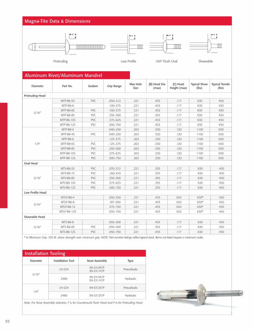
55
Diameter Part No. Sealant Grip RangeMax Hole
Size[B] Head Dia
(max)[C] Head
Height (max)Typical Shear
(lbs)Typical Tensile
(lbs)
Protruding Head
3/16"
MTP-B6-5S PVC .050-.312 .221 .453 .117 630 450
MTP-B6-6 .100-.375 .221 .453 .117 630 450
MTP-B6-6S PVC .100-.375 .221 .453 .117 630 450
MTP-B6-8S PVC .250-.500 .221 .453 .117 630 450
MTP-B6-10S PVC .375-.625 .221 .453 .117 630 450
MTP-B6-12S PVC .500-.750 .221 .453 .117 630 450
1/4"
MTP-B8-4 .040-.250 .263 .530 .120 1100 650
MTP-B8-4S PVC .040-.250 .263 .530 .120 1100 650
MTP-B8-6 .125-.375 .263 .530 .120 1100 650
MTP-B8-6S PVC .125-.375 .263 .530 .120 1100 650
MTP-B8-8S PVC .250-.500 .263 .530 .120 1100 650
MTP-B8-10S PVC .375-.625 .263 .530 .120 1100 650
MTP-B8-12S PVC .500-.750 .263 .530 .120 1100 650
Oval Head
3/16"
MTV-B6-5S PVC .070-.312 .221 .355 .117 630 450
MTV-B6-7S PVC .160-.410 .221 .355 .117 630 450
MTV-B6-8S PVC .250-.500 .221 .355 .117 630 450
MTV-B6-10S PVC .375-.625 .221 .355 .117 630 450
MTV-B6-12S PVC .500-.750 .221 .355 .117 630 450
Low Profile Head
3/16"
MTLP-B6-4 .050-.250 .221 .453 .052 630* 450
MTLP-B6-8 .187-.500 .221 .453 .052 630* 450
MTLP-B6-12 .375-.750 .221 .453 .052 630* 450
MTLP-B6-12X .050-.750 .221 .453 .052 630* 450
Shaveable Head
3/16"
MTS-B6-8 .050-.500 .221 .453 .117 630 450
MTS-B6-8S PVC .050-.500 .221 .453 .117 630 450
MTS-B6-12S PVC .050-.750 .221 .453 .117 630 450
Magna-Tite Data & Dimensions
Protruding ShaveableLow Profile 100º Flush Oval
* In Minimum Grip. 350 lb. shear strength over minimum grip. NOTE: Part number listings reflect typical stock. Items not listed require a minimum order.
Aluminum Rivet/Aluminum Mandrel
Diameter Installation Tool Nose Assembly Type
3/16”
LH-224 99-3310F/P 99-3311F/P Pneudraulic
2480 99-3310F/P 99-3311F/P Hydraulic
1/4”LH-224 99-3312F/P Pneudraulic
2480 99-3312F/P Hydraulic
Note: For Nose Assembly selection, F is for Countersunk Flush Head and P is for Protruding Head
Installation Tooling

56
Often used as a replacement for welding, Huck BOM® is so strong, one BOM (Blind,
Oversized Mechanically locked) fastener can do the work of up to four conventional fasteners.
Its unique push-and-pull installation design makes it ideal for military vehicles, auto suspensions,
rail car assembly, and much more. BOM’s high fatigue thread form extends the life of
any structure. Offering accurate, easy, quick installation, BOM requires no special
training or skills for operators.
Available Sizes: 3/16", 1/4", 5/16", 3/8", 1/2", 5/8", 3/4"
Materials: Steel
BOM®
The highest strength blind oversized fastener available.
Secure, Fast Installation
1. When the pin separates near flush, the BOM fastener
is installed correctly. The BOM fastener does not
require surface preparation, grinding or filling
after installation.
2. The collar is locked to the pin through the ”swaging”
process, creating a high vibration resistant connection
and the highest strength of any blind fastener.
3. Large bearing area on both sides of the work piece
ensures a permanently held, tamper resistant joint.

57
Installation Sequence
Insert the fastener into the hole and slip the installation
tool over the pintail.
Continued pulling on the pintail draws the work pieces together
and the swaging anvil overcomes the standoff and moves down
the length of the collar, securely locking the collar to the pin.
Once the collar is swaged, the pin breaks leaving a high strength, vibration resistant
secured joint.
Press the trigger to initiate pulling action. As the tool pulls on the pintail, the unique collar design ”stands off” the swaging action until the maximum allowable
bulb is formed on the backside.
Diameter Part No. Grip RangeMax Hole
Size[B] Head Dia
(max)[C] Head Height
(max)Typical Shear
(lbs)Typical Tensile
(lbs)
1/4"
BOM-R8-3 .157-.219 .292 .225 .020 5100 3250
BOM-R8-4 .220-.281 .292 .225 .020 5100 3250
BOM-R8-5 .282-.344 .292 .225 .020 5100 3250
BOM-R8-6 .345-.406 .292 .225 .020 5100 3250
BOM-R8-7 .407-.469 .292 .225 .020 5100 3250
BOM-R8-8 .470-.531 .292 .225 .020 5100 3250
BOM-R8-9 .532-.594 .292 .225 .020 5100 3250
BOM-R8-10 .595-.656 .292 .225 .020 5100 3250
BOM-R8-11 .657-.719 .292 .225 .020 5100 3250
BOM-R8-12 .720-.781 .292 .225 .020 5100 3250
5/16"
BOM-R10-4 .188-.312 .368 .278 .025 8050 5200
BOM-R10-6 .313-.437 .368 .278 .025 8050 5200
BOM-R10-8 .438-.562 .368 .278 .025 8050 5200
BOM-R10-10 .563-687 .368 .278 .025 8050 5200
BOM-R10-12 .688-.812 .368 .278 .025 8050 5200
BOM-R10-14 .813-.937 .368 .278 .025 8050 5200
3/8"
BOM-R12-4 .188-.312 .435 .327 .030 11100 7250
BOM-R12-6 .313-.437 .435 .327 .030 11100 7250
BOM-R12-8 .438-.562 .435 .327 .030 11100 7250
BOM-R12-10 .563-.687 .435 .327 .030 11100 7250
BOM-R12-12 .688-.812 .435 .327 .030 11100 7250
BOM-R12-14 .813-.937 .435 .327 .030 11100 7250
1/2"BOM-R16-10 .626-.750 .581 .458 .035 20150 13000
BOM-R16-12 .751-.875 .581 .458 .035 20150 13000
5/8"
BOM-R20-4GA .251-.500 .728 .545 .040 28500 20500
BOM-R20-8GA .501-.750 .728 .545 .040 28500 20500
BOM-R20-12GA .751-1.000 .728 .545 .040 28500 20500
BOM-R20-16GA 1.001-1.250 .728 .545 .040 28500 20500
BOM-R20-20GA 1.251-1.500 .728 .545 .040 28500 20500
3/4"
BOM-R24-4GAG .251-.500 .873 .654 .050 45100 29100
BOM-R24-8GAG .501-.750 .873 1.130 .050 45100 29100
BOM-R24-12GAG .751-1.000 .873 1.130 .050 45100 29100
BOM-R24-16GAG 1.001-1.250 .873 1.130 .050 45100 29100
BOM Data & Dimensions
Steel Pin - Zinc Plated
NOTE: Part number listings reflect typical stock. Items not listed require a minimum order.
1 3 42

58
Grip No. Grip Range M Nom N Max
6 (3/16")
2 .093 -.156 .376 .5003 .157 -.219 .439 .562
4 .220 -.281 .501 .625
5 .282 -.344 .564 .687
6 .345 -.406 .626 .750
7 .407 -.469 .689 .812
8 .470 -.531 .751 .875
9 .532 -.594 .814 .937
10 .595 -.656 .876 1.000
11 .657 -.719 .939 1.06212 .720 -.781 1.001 1.125
8 (1/4")
2 .093 -.156 .460 .625
3 .157 -.219 .523 .688
4 .220 -.281 .585 .750
5 .282 -.344 .648 .813
6 .345 -.406 .710 .875
7 .407 -.469 .773 .938
8 .470 -.531 .835 1.000
9 .532 -.594 .898 1.063
10 .595 -.656 .960 1.12511 .657 -.719 1.023 1.188
12 .720 -.781 1.085 1.250
13 .782 - .843 1.147 1.313
14 .844 - .905 1.209 1.375
10 (5/16")
4 .188 -.312 .695 .8755 .250 - .375 .758 .938
6 .313 -.437 .820 1.000
8 .438 -.562 .945 1.125
10 .563 -.687 1.070 1.250
12 .688 -.812 1.195 1.375
14 .813 -.937 1.320 1.500
16 .938 -1.062 1.445 1.625
Installed Values in Nominal Grip (lbs.)
Diameter Shear Tensile
Note: These are minimum ultimate shear and tensile strengths, in pounds, of installed fastener, when tested in a grip equal to or greater than
one and one half the fastener diameter.
3/16" 2800 1800
1/4" 5100 3250
5/16" 8050 5200
3/8" 11100 7250
1/2" 20150 13000
5/8" 28500 20500
3/4" 45100 29100
Grip No. Grip Range M Nom N Max
12 (3/8")
4 .188 -.312 .766 .9756 .313 - .437 .891 1.100
8 .438 -.562 1.016 1.225
10 .563 - .687 1.141 1.350
12 .688 - .812 1.266 1.475
14 .813 - .937 1.391 1.600
16 .938 - 1.062 1.516 1.725
18 1.063 - 1.187 1.641 1.850
20 1.188 - 1.312 1.766 1.975
16 (1/2")
4 .251 -.375 1.000 1.266
6 .376 -.500 1.125 1.391
8 .501 -.625 1.250 1.516
10 .626 -.750 1.375 1.64112 .751 -.875 1.500 1.766
14 .876 -1.000 1.625 1.891
16 1.001 -1.125 1.750 2.016
18 1.126 -1.250 1.875 2.141
20 1.251 -1.375 2.000 2.266
22 1.376 -1.500 2.125 2.391
24 1.501 -1.625 2.250 2.516
20 (5/8")
4 .251 -.500 1.213 1.531
8 .501 -.750 1.463 1.781
12 .751 -1.000 1.713 2.031
16 1.001 -1.250 1.963 2.281
20 1.251 -1.500 2.213 2.531
24 (3/4")
4 .251 -.500 1.380 1.750
8 .501 -.750 1.630 2.00012 .751 -1.000 1.880 2.25016 1.001 -1.250 2.130 2.500
Grip Data

59
Diameter Installation Tool Nose Assembly Type
3/16"
LH-224 99-994 Pneudraulic
255 99-1053 (heavy duty) Pneudraulic
256 99-1053 (heavy duty) Pneudraulic
2480 99-994 Hydraulic
2581 99-1053 (heavy duty) Hydraulic
1/4"
255 99-830-1 Pneudraulic
256 99-830-1 Pneudraulic
2581 99-830-1 Hydraulic
5/16"
256 99-769 Pneudraulic
2581 99-769 Hydraulic
2600 99-3119 Hydraulic
3/8"256 99-1272 Pneudraulic
2581 99-1272 Hydraulic
1/2"2620 99-5100 Hydraulic
2620PT 99-5101 Hydraulic
5/8"2624 99-5102 Hydraulic
3585 99-5102 Hydraulic
3/4" 3585 99-5103 Hydraulic
Installation Tooling
Ordering Information
Follow the form below to construct a part number for ordering Huck BOM blind fasteners. Refer to the Grip Data chart for grip numbers.
BOM-R (DIAMETER) - (GRIP NUMBER) Example: BOM-R8-6 is a BOM blind rivet, Steel, 1/4" Diameter, Grip 6.
Material Sleeve Pin Sleeve Finish Pin Finish
Steel Low Carbon Steel Medium Carbon Steel Zinc Plated Clear Chromate None (Std)
Materials and Finishes
Diameter Code
3/16" 6
1/4" 8
5/16" 10
3/8" 12
1/2" 16
5/8" 20
3/4" 24
Material Code
Steel R
Additional coatings are available upon request.
Ordering Information
Model LH-224
Model 2581

60
Originally designed for large vehicle flooring installations, Huck FloorTight® is ideal for all
wood-to-metal applications, especially plywood and plymetal. FloorTight’s self-countersinking
head eliminates the secondary counterboring process in plywood, and eliminates dimpling
in metals. Unlike screws that can be over-torqued or under-torqued, FloorTight ensures
consistent, reliable installation every time.
Available Sizes: 1/4", 5/16"
Materials: Steel
Headstyles: Standard, Wide Flange, Plymetal, 90° Flush
FloorTight®
The only controlled, self-countersinking blind fastener commercially available.
Secure, Fast Installation
1. Self-countersinking head eliminates the counter-
boring process in plywood, as well as dimpling
in plymetal floors.
2. A high-strength pin locks in place within the
shear plane for added holding power and durability.
3. 360° internal locking feature creates a solid
mechanical lock to prevent loosening.
4. Expansion within the weather-side stringer,
coupled with the 360° internal lock provides
excellent moisture resistance on the weather side.

61
Installation Sequence
Insert fastener in hole. Apply installation tool.
Continued pulling on the pintail forms a mechanical lock between
the pin and sleeve end. The anvil on the installation tool then countersinks the fastener head into the top of the material to a preset depth set by the anvil. The anvil’s large bearing face
then prevents further travel of the sleeve head into the top material.
The pin is then separated in tension at the break
neck groove.
The Huck installation tool is placed over the pintail. When
the trigger is pressed, the nose assembly jaws pull on the
pintail, drawing the pin though the sleeve, causing the blind
side sleeve to expand, partially setting the sleeve in the top sheet and pulling out all the
sheet gap.
Diameter Part No. Grip RangeMax Hole
Size[B] Head Dia
(max)[C] Head Height
(max)Typical Shear
(lbs)Typical Tensile
(lbs)
Plywood Floor
5/16"PWF-R10-20 .750-1.375 .339 .325 .650 4300 3000
PWFMC-R10-20A3 .750-1.375 .339 .675 .050 4300 3000
Plymetal Floor
5/16"PMF-R10-20 .750-1.375 .339 .325 .590 4300 3000
PMFMC-R10-20 .750-1.375 .339 .325 .590 4300 3000
FloorTight Data & Dimensions
Diameter Installation Tool Nose Assembly Type
1/4"256 99-3441 Pneudraulic
2581 99-3441 Hydraulic
5/16"
255 99-3452-AUS Pneudraulic
256 99-3452-AUS Pneudraulic
2581 99-3452-AUS Hydraulic
Installation Tooling
Plywood Plymetal
NOTE: Part number listings reflect typical stock. Items not listed require a minimum order.
Steel Sleeves - Steel Mandrel
1 3 42

62
A Wide Selection of Tooling Options
Huck offers a broad selection of hydraulic and pneudraulic tools, in addition
to Powerig® hydraulic power sources. Huck hydraulic installation tools are
available to install a wide range of fasteners, from structural blind rivets to
the largest HuckBolts. The Huck line of pneudraulic tools, designed for use
in repair work or in lower volume production applications, can effectively
pull fasteners ranging from 3/32" blind rivets to 3/8" HuckBolts.
Designed to offer the highest levels of ergonomics,
productivity, and long life, the Huck line of installation
tooling reflects the same level of innovation and quality as
its advanced fasteners. Whether it’s a Huck hydraulic
tool employed in high-volume
installation of large diameter
HuckBolts, or a smaller
pneudraulic model used to install
blind rivets and small diameter
HuckBolts, you can count on these
tools to deliver the industry’s best value.
LH-224
Huck ToolsThe industry’s best installation tooling.
SF20Swageforward®
SFBTT8-12256BT
Model 507

63
Huck Hydraulic Tooling
NOTE: For additional tool details, refer to the specific fastener brochure or visit AFSRhuck.net.
This family of tools are designed as limited access tools. Pistons and Swaging areas are offset to the centreline of the tool allowing the tool to access tighter corners, addition-ally the nose assembly is built into the body of the tool making it shorter and
reducing the envelope necessary to allow the tool to operate.NOTE these tools are designed to supple-ment normal production tooling only in situations where the standard tooling is inappropriate.
5304, 6304, 7304, 8304 and 9304
SFBTT8-12Huck’s proprietary, advanced swage forward tooling for BobTail fasteners, the SFBTT series makes the installation process quicker and easier by reducing the force required to install each fastener. More compact and lighter weight than previous Huck lockbolt production tooling, BobTail installation tools also offer greater operator flexibility as well as extended reach into difficult areas. For tight, space-constrained applications, swageforward BobTail tools allow the operator to position his or her hand at a safe distance from the working structure during installation.
SF20 Huck’s proprietary, advanced swage forward tooling for BobTail fasteners, the SF series makes the installation process quicker and easier by reducing the force required to install each fastener. More compact and lighter weight than previous Huck lockbolt production tooling, BobTail installation tools also offer greater operator flexibility as well as extended reach into difficult areas. For tight, space-constrained applications, swageforward BobTail tools allow the operator to position his or her hand at a safe distance from the working structure during installation.
SF46 More compact and lighter weight than previous Huck lockbolt production tooling, Huck’s proprietary SF series Swageforward™ tooling for BobTail fasteners offers greater operator flexibility as well as extended reach into difficult areas. By reducing the force required to install each fastener, the SF series tooling makes the installation process much faster and easier. For tight, space-constrained applications, Swageforward BobTail tools allow the operator to position his or her hand at a safe distance from the working structure during installation.
2480 The Model 2480 is a very lightweight tool which provides for the high-speed installation of a wide range of HuckBolt and Huck blind bolt fasteners. The tool has only one moving part, resulting in outstanding reliability and minimal maintenance. The tight centerline-to-edge measurement of the Model 2480 and its light weight (2.21 pounds) allow for its use in limited clearance areas.
2581 The Model 2581 is a lightweight tool (only 6.58 pounds) designed for use in a wide range of high-speed production applications. With only one moving part, the tool provides for increased reliability and requires minimal maintenance. An offset piston design allows the Model 2581 to easily fit in limited clearance applications.
26202620 tool (shown with Nose assembly) is a light weight hydraulic tool specifically designed to provide the installation force for ½” Huck fasteners of all types.
3585Offering durable construction, advanced hydraulics, and safe, ergonomic design, the 3585 installation tool is easy to hold and efficient to use. An improved piston and cylinder design promote longer life. In addition, the nose adapter can be removed through the back of the tool for ease of repair. Stroke: 1.900"; Weight: 19 lbs.
2630 is a heavy duty Hydraulic tool designed specifically for 7/8”Dia Huck Fasteners
507The 507 tool is a high production tool that will install 1” and 1-1/8” Huck Fasteners when fitted with the correct nose assembly
Huck Hydraulic Tooling

64
NOTE: For additional tool details, refer to the specific fastener brochure or visit AFSRhuck.net.
5304, 6304, 7304, 8304 and 9304
940-220AUSThe Model 940 Powerig® is a portable unit sized for moderate production and repair applications. This unit features rugged construction for durability in the field, and the choice of 115 or 220 Volt AC power. The Model 940 includes a handle for easy transport, simple adjustable hydraulic outputs and quick-connect couplers for connecting installation tool hoses.
940ABThe 940AB is an “AIR” powered unit for use in areas where mains supply would be unsafe. It has similar performance characteristics as the 940-220AUS, but its motive force is pneumatic. Air pressure of 70 – 100 PSI and a flow rate of 6CFM is required to power this unit. The control circuit incorporates a 12DC battery allowing standard Huck Hydraulic tools and switches to be used without
modification. Long battery life between charges is achieved through the use of isolation relays ensuring batteries are only in use during installation cycles.
Huck Powerig® Power Sources
Combining advanced design and quality manufacturing, Huck Powerigs offer both best-in-class performance and long product life. Whether for mobile or factory use, there is a Huck Powerig hydraulic power source for the job, from electric and gasoline powered portable units to larger rigs that can individually power up to three tools.
244BT The 244BT Tool is designed for rapid installation of Huck BobTail 4.8mm and 6.4mm diameters. This lightweight tool provides for fast, uniform installations, and delivers optimum stroke for one- cycle installation of fasteners. Minimal moving parts.
Huck Pneudraulic Tooling
913H913H is a Petrol Powered Hydraulic Powerig for use in areas where there is no provision for electrical or Pneumatic supply. Pull start and 12DC control circuit without battery ensures the 913H is totally self contained and can operate standard Huck tools without modification.
256 The 256 (up to 3/8”Dia) has a slightly larger centre to edge distance than the 246. This has the benefit of using a concentric piston to provide more direct force to install the fastener. All nose assemblies are fully interchangeable with the 246 and 2581 tools.
245 & 246 The 245 (up to 5/16”Dia) and 246 (up to 3/8”Dia ) are designed to provide consistent power and reliability, required to install fasteners larger than ¼”Diameter, when coupled with the correct Nose assembly.
LH-224 This lightweight ergonomically designed tool is intended for fast efficient installation of all Huck fasteners up to and including ¼” Diameter, when coupled with the correct Nose assembly.
256BT Designed for quick installation of Huck BobTail fasteners, the 256BT tool features optimum stroke for one-cycle fastener installation, and minimal moving parts. Comes with standard inline and offset nose assemblies, ranging from 4mm to 10mm.
Width: 409mmLength: 354mmHeight: 470mmWeight: 74.5 lbs. operational, 30kg. w/o hydraulic fluidPower: electric, 115 or 220 volts, single phase
Flow Rate: 70 cu. in./min. @ 5,000 psiReservoir Capacity: 1.5 gallonsOptions: 220V, 60/50 hertz single phase, 250VDC, direct current
SPECIFICATIONS
918 & 918-5 The Model 918 Powerig® is the largest hydraulic unit offered by Huck. Sized for high production applications, the unit can operate up to three tools independently. This electrically powered model also delivers sufficient power to operate the tools up to 100 feet away. A 22-gallon reservoir stores hydraulic fluid, with a filter-strainer in the suction line to assure clean, filtered fluid.

65
NOTES:

66
NOTES:

AFSRHuck.netYoutube.com/AFSIndustrial
© 2016 Alcoa Fastening Systems & Rings. All rights reserved. AFS6127 Aust 0416
Alcoa Fastening Systems & Rings
The information contained in this publication is only for general guidance, and is not intended to create any warranty, express, implied, or statutory; all warranties are contained only in AFSR’s written quotations, acknowledgments, and/or purchase orders. It is recommended that the user secure specific, up-to-date data and information regarding each application and/or use of such products.
For more than 120 years, the name Alcoa has been recognized worldwide as a strong leader in product quality and customer support. These strengths are found in every product manufactured for Alcoa Fastening Systems & Rings, offering the greatest breadth and depth of fastening system solutions in the industry.
Alcoa Fastening Systems & Rings (AFSR) maintains company offices in the United States and in many other countries. AFSR fastener distributors are also located in many of the world’s industrial centers, where they provide a ready source of AFSR fasteners, installation tools, tool parts, and application assistance.
Americas
Industrial Fasteners Division Group Headquarters 8001 Imperial Drive Waco, TX 76712, USA P.O. Box 8117 Waco, TX 76714-8117, USA Tel: 800 388 4825 Fax: 800 798 4825
Fasteners Division 1 Corporate Drive Kingston, NY 12401, USA Tel: 800 278 4825 Fax: 845 334 7333
Industrial Distribution Group 1925 North MacArthur Drive Tracy, CA 95376, USA Tel: 800 826 2884 Fax: 800 573 2645
Industrial Distribution Group 14300 Clay Terrace Blvd. Suite 250 Carmel, IN 46032, USA Tel: 800 826 2884 Fax: 800 573 2645
Industrial Fasteners Division Avenida Parque Lira 79-402 Tacubaya Mexico C P 11850 Tel: +52 55 5515 1776 Fax: +52 55 5277 7564
Industrial Fasteners Division Av. Nações Unidas, 12.901 Torre Oeste, 3º andar São Paulo – SP – Brasil 04578-000 Tel: 0800 015 9888 Fax: +55 11 5509 0200
International Locations
Industrial Fasteners Division Unit no. 28, Chowringhee Court 55/1, Chowringhee Road Kolkata – 700071 India Tel: +91 33 4069 9170/80 Fax: +91 33 4069 9184
Industrial Fasteners Division Alcoa Japan Ltd. #1013 NBF Hibiya Bldg. Uchisaiwai-cho, Chiyoda-ku Tokyo 100-1011 Japan Tel: +81 3 3539 6577 Fax: +81 3 3539 6585
Industrial Fasteners Division 1508 Centre Road Clayton, Victoria, 3168 Australia Tel: +61 3 8545 3333 Fax: +61 3 8545 3390
Fasteners Division 58 Yinsheng Road, Shengpu Suzhou Industrial Park Suzhou Jiangsu 215126 China Tel: 0512 62863800-8888 Fax: 0512 62863810
Industrial Fasteners Division Unit C, Stafford Park 7 Telford, Shropshire TF3, 3BQ United Kingdom Tel: +44 1952 2900 11 Fax: +44 1952 2904 59
Fasteners Division St Cosme Operations 9 rue de Cressonnieres 72110 Saint Cosme en Varais France Tel: +33 0 2.43.31.41.00 Fax: +33 0 2.43.31.41.41
Fasteners Division Kelkheim Operations Industriestr. 6 65779 Kelkheim Germany Tel: +49 [0] 6195 8050 Fax: +49 [0] 6195 2001
TM