Commercially suitable pectin methylesterase from ... - CiteSeerX
Upload
khangminh22Category
view
4download
0
Volume 12 Issue 1 Article 7
Selection of Area Suitable for Performing Partial-Depth Repair of Corner Selection of Area Suitable for Performing Partial-Depth Repair of Corner Damage of Concrete Paving Slab Under Wheel Load Damage of Concrete Paving Slab Under Wheel Load
Chau Lee Professor, Department of Civil-Engineering, National Central University, Chung-Li, Taiwan 32054., [email protected]
Xin-Hua Huang Ph.D. Candidate, Department of Civil-Engineering, National Central University, Chung-Li, Taiwan 32054.
Jhao-Bin Lin M.S., Department of Civil-Engineering, National Central University, Chung-Li, Taiwan 32054.
Follow this and additional works at: https://jmstt.ntou.edu.tw/journal
Part of the Civil and Environmental Engineering Commons
Recommended Citation Recommended Citation Lee, Chau; Huang, Xin-Hua; and Lin, Jhao-Bin (2004) "Selection of Area Suitable for Performing Partial-Depth Repair of Corner Damage of Concrete Paving Slab Under Wheel Load," Journal of Marine Science and Technology: Vol. 12 : Iss. 1 , Article 7. DOI: 10.51400/2709-6998.2220 Available at: https://jmstt.ntou.edu.tw/journal/vol12/iss1/7
This Research Article is brought to you for free and open access by Journal of Marine Science and Technology. It has been accepted for inclusion in Journal of Marine Science and Technology by an authorized editor of Journal of Marine Science and Technology.
Selection of Area Suitable for Performing Partial-Depth Repair of Corner Damage Selection of Area Suitable for Performing Partial-Depth Repair of Corner Damage of Concrete Paving Slab Under Wheel Load of Concrete Paving Slab Under Wheel Load
Acknowledgements Acknowledgements The authors would like to thank the Taiwan Area National Freeway Bureau for financially supporting this research under Contract No. 088B5AS003B5A004.
This research article is available in Journal of Marine Science and Technology: https://jmstt.ntou.edu.tw/journal/vol12/iss1/7
Journal of Marine Science and Technology, Vol. 12, No. 1, pp. 53-61 (2004) 53
SELECTION OF AREA SUITABLE FORPERFORMING PARTIAL-DEPTH REPAIROF CORNER DAMAGE OF CONCRETEPAVING SLAB UNDER WHEEL LOAD
Chau Lee*, Xin-Hua Huang**, and Jhao-Bin Lin***
Paper Submitted 11/05/03, Accepted 12/16/03. Author for Correspondence:Chau Lee. E-mail: [email protected].*Professor, Department of Civil-Engineering, National Central University,
Chung-Li, Taiwan 32054.**Ph.D. Candidate, Department of Civil-Engineering, National Central
University, Chung-Li, Taiwan 32054.***M.S., Department of Civil-Engineering, National Central University,
Chung-Li, Taiwan 32054.
Key words: concrete pavement, repair, finite element.
ABSTRACT
This study reveals the characteristics of using different repairmaterials and different repair outline designs for the partial-depthrepair of the damage to corners of concrete paving slabs under wheelload. 3D finite element models were used to study how the changesto the outlines of the repaired area affect the maximum-stress and low-stress proportions in concrete elements that are attached to repairedinterface when different repairing materials are used. The resultsindicate that the maximum stress increased but the proportion of low-stress shrank as the repaired area became larger. When cementitiousrepair materials were used, the depth of a square shaped repair areaseemed to govern the effectiveness of the repair more strongly thandoes the side length. Epoxy mortar was not appropriate for use insquare repaired areas, but could be used in small spherically shapedrepair areas. Epoxy mortar was more effectively used in shallowrepairs than in deep repairs.
INTRODUCTION
Corner damage is a common problem in jointedconcrete pavements (JCP). It decreases the serviceabil-ity of the pavement and can be hazardous to highwayusers. Unsuitable repairing of such damage may resultin accelerated pavement deterioration [18]. The Fed-eral Highway Administration (FHWA), the AmericanConcrete Pavement Association (ACPA), the NationalCooperative Highway Research Program (NCHRP) andthe Strategic Highway Research Program (SHRP) haveall provided good guidelines for making partial-depthrepairs [17].
In brief, partial-depth spall repair involves remov-ing the deteriorated concrete that is limited to the topone-third of the slab thickness and replacing it with asuitable repair material [6, 18]. The patching materialshould not contact reinforcing steel or load transferdevices [6, 21]. The saw-and-patch procedure is com-monly used in partial-depth repair. It involves firstlysaw-cutting the pavement to the appropriate depth, re-moving the deteriorated concrete, and replacing it withan appropriate patching material [8, 20, 21]. The repairboundaries should be square or rectangular becauseirregular shapes and internal corners tend to cause crack-ing of the patch material [6, 20]. If the spall is locatedat the corner of the slab, then the minimum recom-mended depth is 2 in (51 mm), the minimum patchlength is 10 in (254 mm) and the minimum width is 4 in(102 mm) [6, 21]. A high proportion of repair projectsrequire patches to be opened to traffic within 4 to 6hours, so a wide variety of rapidly setting and/or highearly-strength patching materials are used for suchprojects. Type III cement with or without admixturesand epoxy resin mortar or concrete have been used formaking rapid repairs [8, 10].
Finite element analysis is a powerful tool for re-searching and designing pavements. Two-dimensionalfinite element programs such as ILLI-SLAB andKENSLAB have been used in the past two decades tocalculate stress in concrete pavements. In recent years,three-dimensional finite element analysis has providedresponses of pavements that cannot be revealed bytraditional 2D programs [9]. Many computational stud-ies of JCP behavior have been based on 3D finiteelement analysis. For example, Ioannides and Donelly[12] built a 3D model for analyzing static wheel load.Chatti [4] modeled dowels using beam elements andemployed the contact between the concrete slab and theground to analyze the response under dynamic wheelload. Channakeshava and Bargezar [3] considered theinteraction between the dowels and the concrete. Kuo[15] developed the 3DPAVE model to determine simul-
Journal of Marine Science and Technology, Vol. 12, No. 1 (2004)54
taneously the static wheel load and non-linear effects oftemperature. Massad et al. [16] used solid type founda-tion to study the variation of temperature of JCP. Shoukryet al. [19] modeled dowels using solid elements meshedwithin the solid slab to analyze dynamic wheel load andnon-linear temperature effects.
Although most investigators have developed pio-neering techniques to model pavements, the distribu-tion of stress on repaired areas of concrete paving slabsfollowing partial-depth repair has not been addressed.Suitable patching materials and methods of repair mustbe chosen to ensure that repairs are effective and thusavoid having to repair repeatedly corner damage toconcrete paving slabs. This study attempts to selectappropriate shapes and sizes of partial-depth repairs tocorners by using 3D finite element method in consider-ation of different patching materials under wheel load.
MODELING STRATEGY AND VALIDATION
ANSYS v5.7 was used to develop 3D finite ele-ment models to simulate the response of partial-depthrepair of the corners of JCPs under wheel load. Thevariations of stresses at the interface between the origi-nal concrete and the repairing material, generated bywheel load, were examined. Spring elements withgapping ability were employed to model the Winklerfoundation with partial contact ability. To save CPUtime, the load transfer devices such as dowel bars oraggregate interlocks between adjacent slabs were mod-eled by vertical spring elements that provided a verticalforce without any moment constraint. This conven-tional assumption is based on earlier investigationsrevealed that the primary dowel mechanism of loadtransfer is shear, while the contribution of bending andtorsion is less than 5%, provided the deflection load
transfer efficiency (LTEδ) exceeds approximately 80%[13].
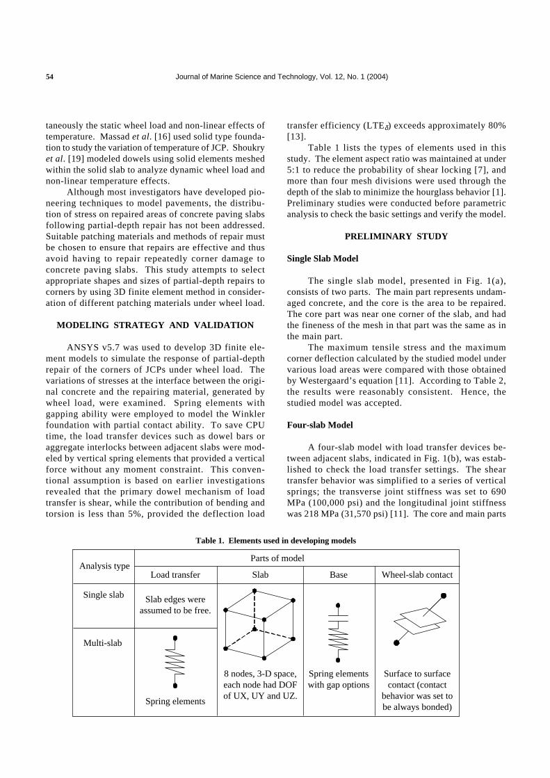
Table 1 lists the types of elements used in thisstudy. The element aspect ratio was maintained at under5:1 to reduce the probability of shear locking [7], andmore than four mesh divisions were used through thedepth of the slab to minimize the hourglass behavior [1].Preliminary studies were conducted before parametricanalysis to check the basic settings and verify the model.
PRELIMINARY STUDY
Single Slab Model
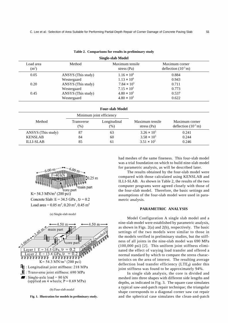
The single slab model, presented in Fig. 1(a),consists of two parts. The main part represents undam-aged concrete, and the core is the area to be repaired.The core part was near one corner of the slab, and hadthe fineness of the mesh in that part was the same as inthe main part.
The maximum tensile stress and the maximumcorner deflection calculated by the studied model undervarious load areas were compared with those obtainedby Westergaard’s equation [11]. According to Table 2,the results were reasonably consistent. Hence, thestudied model was accepted.
Four-slab Model
A four-slab model with load transfer devices be-tween adjacent slabs, indicated in Fig. 1(b), was estab-lished to check the load transfer settings. The sheartransfer behavior was simplified to a series of verticalsprings; the transverse joint stiffness was set to 690MPa (100,000 psi) and the longitudinal joint stiffnesswas 218 MPa (31,570 psi) [11]. The core and main parts
Analysis typeLoad transfer Slab
Parts of model
8 nodes, 3-D space,each node had DOFof UX, UY and UZ.
Base
Spring elementswith gap options
Wheel-slab contact
Surface to surfacecontact (contact
behavior was set tobe always bonded)
Spring elements
Slab edges wereassumed to be free.
Single slab
Multi-slab
Table 1. Elements used in developing models
C. Lee et al.: Selection of Area Suitable for Performing Partial-Depth Repair of Corner Damage of Concrete Paving Slab 55
had meshes of the same fineness. This four-slab modelwas a trial foundation on which to build nine-slab modelfor parametric analysis, as will be described later.
The results obtained by the four-slab model werecompared with those calculated using KENSLAB andILLI-SLAB. As shown in Table 2, the results of the twocomputer programs were agreed closely with those ofthe four-slab model. Therefore, the basic settings andassumptions of the four-slab model were used in para-metric analysis.
PARAMETRIC ANALYSIS
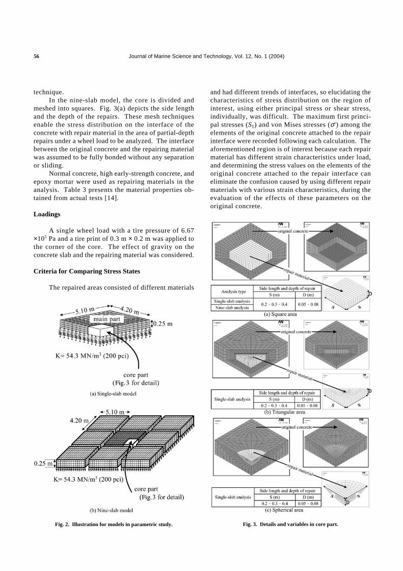
Model Configuration A single slab model and anine-slab model were established by parametric analysis,as shown in Figs. 2(a) and 2(b), respectively. The basicsettings of the two models were similar to those inthe models verified in preliminary studies, but the stiff-ness of all joints in the nine-slab model was 690 MPa(100,000 psi) [2]. This uniform joint stiffness elimi-nated the effect of varying load transfer and offered anormal standard by which to compare the stress charac-teristics on the area of interest. The resulting averagedeflection load transfer efficiency (LTEδ) under thisjoint stiffness was found to be approximately 94%.
In single slab analysis, the core is divided andmeshed into three shapes with different side lengths anddepths, as indicated in Fig. 3. The square case simulatesa typical saw-and-patch repair technique; the triangularshape corresponds to a diagonal corner saw cut repairand the spherical case simulates the clean-and-patchFig. 1. Illustration for models in preliminary study.
Table 2. Comparisons for results in preliminary study
Single-slab Model
Load area Method Maximum tensile Maximum corner(m2) stress (Pa) deflection (10-3 m)
0.05 ANSYS (This study) 1.16 × 10⁶ 0.884Westergaard 1.13 × 10⁶ 0.943
0.20 ANSYS (This study) 7.84 × 10⁵ 0.711Westergaard 7.15 × 10⁵ 0.773
0.45 ANSYS (This study) 4.80 × 10⁵ 0.537Westergaard 4.80 × 10⁵ 0.622
Four-slab Model
Minimum joint efficiency
Method Transverse Longitudinal Maximum tensile Maximum corner(%) (%) stress (Pa) deflection (10-3 m)
ANSYS (This study) 87 63 3.26 × 10⁵ 0.241KENSLAB 84 60 3.58 × 10⁵ 0.244ILLI-SLAB 85 61 3.51 × 10⁵ 0.246
Journal of Marine Science and Technology, Vol. 12, No. 1 (2004)56
technique.In the nine-slab model, the core is divided and
meshed into squares. Fig. 3(a) depicts the side lengthand the depth of the repairs. These mesh techniquesenable the stress distribution on the interface of theconcrete with repair material in the area of partial-depthrepairs under a wheel load to be analyzed. The interfacebetween the original concrete and the repairing materialwas assumed to be fully bonded without any separationor sliding.
Normal concrete, high early-strength concrete, andepoxy mortar were used as repairing materials in theanalysis. Table 3 presents the material properties ob-tained from actual tests [14].
Loadings
A single wheel load with a tire pressure of 6.67×10⁵ Pa and a tire print of 0.3 m × 0.2 m was applied tothe corner of the core. The effect of gravity on theconcrete slab and the repairing material was considered.
Criteria for Comparing Stress States
The repaired areas consisted of different materials
and had different trends of interfaces, so elucidating thecharacteristics of stress distribution on the region ofinterest, using either principal stress or shear stress,individually, was difficult. The maximum first princi-pal stresses (S1) and von Mises stresses (σ') among theelements of the original concrete attached to the repairinterface were recorded following each calculation. Theaforementioned region is of interest because each repairmaterial has different strain characteristics under load,and determining the stress values on the elements of theoriginal concrete attached to the repair interface caneliminate the confusion caused by using different repairmaterials with various strain characteristics, during theevaluation of the effects of these parameters on theoriginal concrete.
Fig. 2. Illustration for models in parametric study. Fig. 3. Details and variables in core part.
C. Lee et al.: Selection of Area Suitable for Performing Partial-Depth Repair of Corner Damage of Concrete Paving Slab 57
The first principal stress (S1) is that with thehighest positive value (algebraically largest value)among the three principal stresses derived fromeach element after the analysis. The first principalstress was considered to study tensile effects on theareas of interest.
Von Mises stress (σ') is derived from
σ' =
(σ1 – σ2)2 + (σ2 – σ3)
2 + (σ3 – σ1)2
2 (1)
where σ1, σ2 and σ3 are the principal stresses. Ac-cording to the distortion energy theory, failure ispredicted to occur in the multiaxial state of stress whenthe distortion energy per unit volume becomes equalto or exceeds the distortion energy per unit volume atthe time of failure in a simple uniaxial stress test on aspecimen of the same material [5]. Von Mises stresseswere taken as references for comparing the relativeshear influence on the elements of the interested area.The primary aim of this work was to study trends in thedistribution of stress among the elements of interest, sofailure of the interested area was not addressed.
The low-stress proportion was measured follow-ing each analysis to estimate the stability of bonding.The low-stress proportion was defined as the percentageof elements in the original concrete attached to thebonding interface with a stress lower than the low-stresslevel. The low-stress level was defined as 8.58 × 10⁵ Pa(8.75 kg/cm2), which was 25% of the tensile strength ofthe original concrete, which was assumed to be 3.43 ×10⁶ Pa (35 kg/cm2), 10% of the supposed concretecompressive strength of 3.43 × 10⁷ Pa (350 kg/cm2).According to test data obtained by several researchers,the original concrete is expected not to fail by fatiguewhen the stress ratio is below 0.5 [11]. Therefore, thelow-stress level, corresponding to a ratio of 0.25 of thetensile strength, assumed herein is conservative. Theproportion of low stress was measured approximatelyfrom the computer screen because the mesh of inter-ested area was formed with brick elements of knownsizes and uniform length. The low-stress proportionwas adopted as a reference to compare the relative
bonding stability of the repaired area. A larger low-stress proportion generates a more stable bondinginterface.
Results of Single-Slab Model
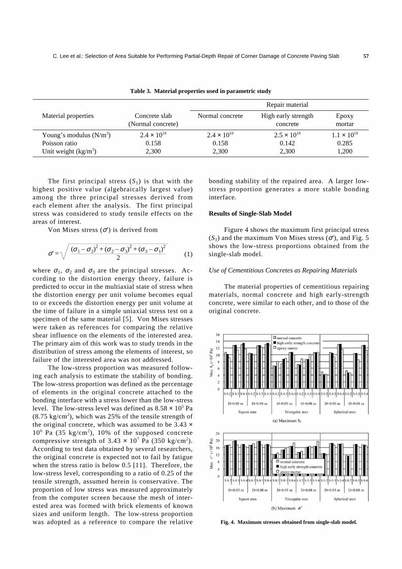
Figure 4 shows the maximum first principal stress(S1) and the maximum Von Mises stress (σ'), and Fig. 5shows the low-stress proportions obtained from thesingle-slab model.
Use of Cementitious Concretes as Repairing Materials
The material properties of cementitious repairingmaterials, normal concrete and high early-strengthconcrete, were similar to each other, and to those of theoriginal concrete.
Table 3. Material properties used in parametric study
Repair material
Material properties Concrete slab Normal concrete High early strength Epoxy(Normal concrete) concrete mortar
Young’s modulus (N/m3) 2.4 × 10¹⁰ 2.4 × 10¹⁰ 2.5 × 10¹⁰ 1.1 × 10¹⁰
Poisson ratio 0.158 0.158 0.142 0.285Unit weight (kg/m3) 2,300 2,300 2,300 1,200
Fig. 4. Maximum stresses obtained from single-slab model.
Journal of Marine Science and Technology, Vol. 12, No. 1 (2004)58
Square Repaired Area
As Fig. 4(a) shows, increasing the side lengthof repair from 0.2 to 0.4 m increased the maximum S1
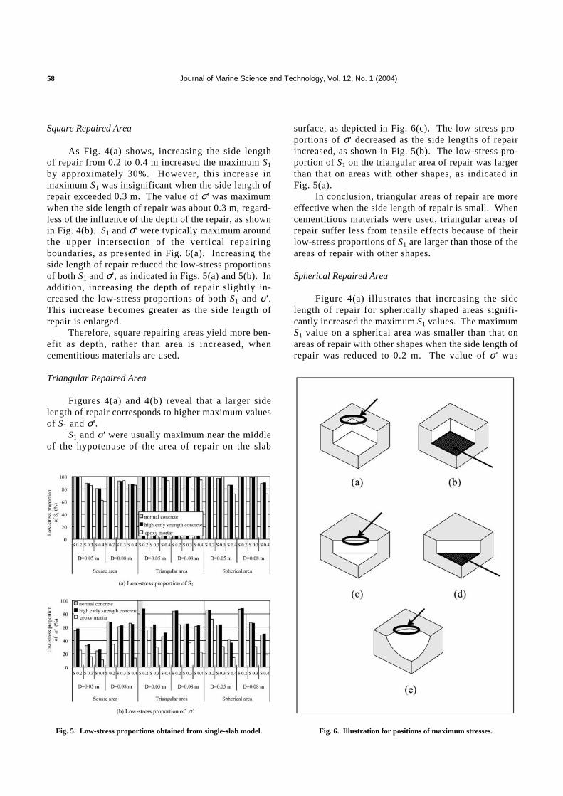
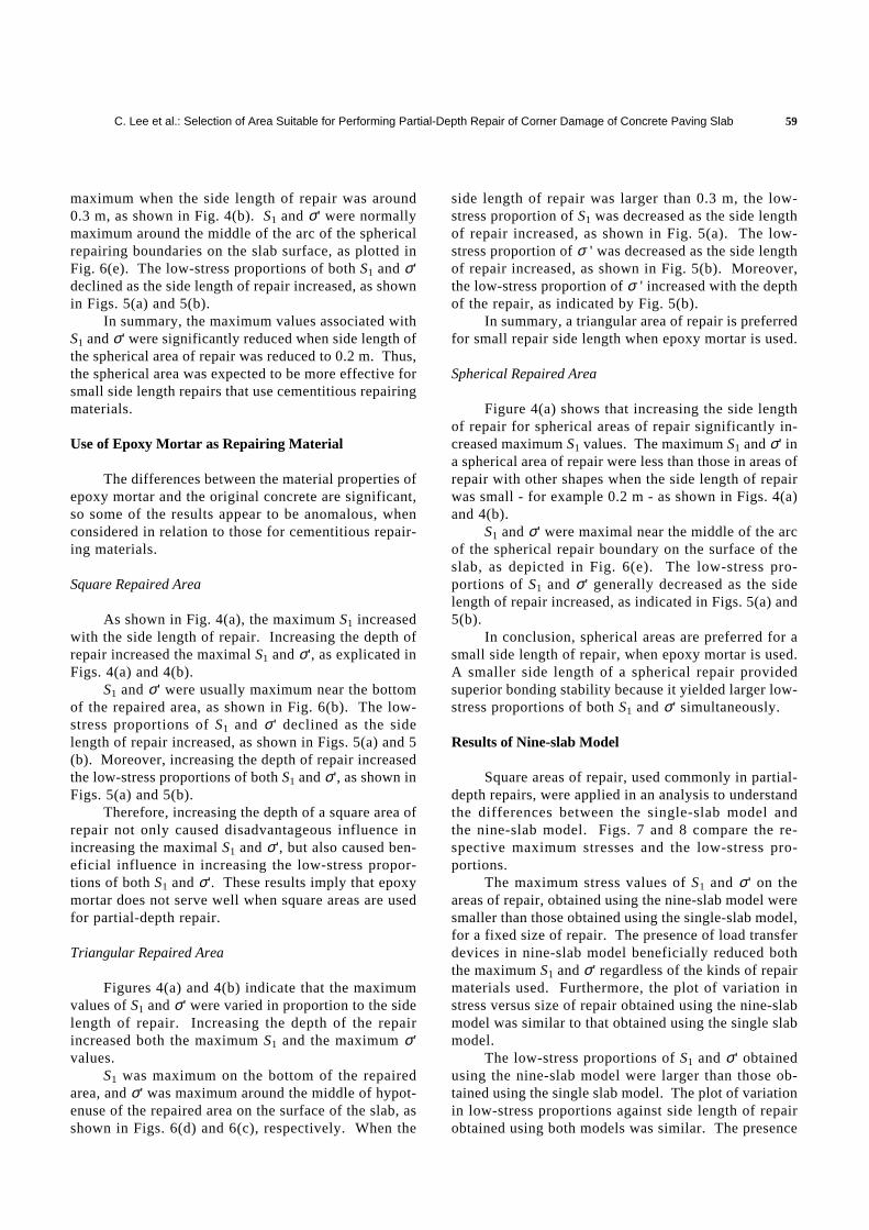
by approximately 30%. However, this increase inmaximum S1 was insignificant when the side length ofrepair exceeded 0.3 m. The value of σ' was maximumwhen the side length of repair was about 0.3 m, regard-less of the influence of the depth of the repair, as shownin Fig. 4(b). S1 and σ' were typically maximum aroundthe upper intersection of the vertical repairingboundaries, as presented in Fig. 6(a). Increasing theside length of repair reduced the low-stress proportionsof both S1 and σ', as indicated in Figs. 5(a) and 5(b). Inaddition, increasing the depth of repair slightly in-creased the low-stress proportions of both S1 and σ'.This increase becomes greater as the side length ofrepair is enlarged.
Therefore, square repairing areas yield more ben-efit as depth, rather than area is increased, whencementitious materials are used.
Triangular Repaired Area
Figures 4(a) and 4(b) reveal that a larger sidelength of repair corresponds to higher maximum valuesof S1 and σ'.
S1 and σ' were usually maximum near the middleof the hypotenuse of the area of repair on the slab
surface, as depicted in Fig. 6(c). The low-stress pro-portions of σ' decreased as the side lengths of repairincreased, as shown in Fig. 5(b). The low-stress pro-portion of S1 on the triangular area of repair was largerthan that on areas with other shapes, as indicated inFig. 5(a).
In conclusion, triangular areas of repair are moreeffective when the side length of repair is small. Whencementitious materials were used, triangular areas ofrepair suffer less from tensile effects because of theirlow-stress proportions of S1 are larger than those of theareas of repair with other shapes.
Spherical Repaired Area
Figure 4(a) illustrates that increasing the sidelength of repair for spherically shaped areas signifi-cantly increased the maximum S1 values. The maximumS1 value on a spherical area was smaller than that onareas of repair with other shapes when the side length ofrepair was reduced to 0.2 m. The value of σ' was
Fig. 5. Low-stress proportions obtained from single-slab model. Fig. 6. Illustration for positions of maximum stresses.
C. Lee et al.: Selection of Area Suitable for Performing Partial-Depth Repair of Corner Damage of Concrete Paving Slab 59
maximum when the side length of repair was around0.3 m, as shown in Fig. 4(b). S1 and σ' were normallymaximum around the middle of the arc of the sphericalrepairing boundaries on the slab surface, as plotted inFig. 6(e). The low-stress proportions of both S1 and σ'declined as the side length of repair increased, as shownin Figs. 5(a) and 5(b).
In summary, the maximum values associated withS1 and σ' were significantly reduced when side length ofthe spherical area of repair was reduced to 0.2 m. Thus,the spherical area was expected to be more effective forsmall side length repairs that use cementitious repairingmaterials.
Use of Epoxy Mortar as Repairing Material
The differences between the material properties ofepoxy mortar and the original concrete are significant,so some of the results appear to be anomalous, whenconsidered in relation to those for cementitious repair-ing materials.
Square Repaired Area
As shown in Fig. 4(a), the maximum S1 increasedwith the side length of repair. Increasing the depth ofrepair increased the maximal S1 and σ', as explicated inFigs. 4(a) and 4(b).
S1 and σ' were usually maximum near the bottomof the repaired area, as shown in Fig. 6(b). The low-stress proportions of S1 and σ' declined as the sidelength of repair increased, as shown in Figs. 5(a) and 5(b). Moreover, increasing the depth of repair increasedthe low-stress proportions of both S1 and σ', as shown inFigs. 5(a) and 5(b).
Therefore, increasing the depth of a square area ofrepair not only caused disadvantageous influence inincreasing the maximal S1 and σ', but also caused ben-eficial influence in increasing the low-stress propor-tions of both S1 and σ'. These results imply that epoxymortar does not serve well when square areas are usedfor partial-depth repair.
Triangular Repaired Area
Figures 4(a) and 4(b) indicate that the maximumvalues of S1 and σ' were varied in proportion to the sidelength of repair. Increasing the depth of the repairincreased both the maximum S1 and the maximum σ'values.
S1 was maximum on the bottom of the repairedarea, and σ' was maximum around the middle of hypot-enuse of the repaired area on the surface of the slab, asshown in Figs. 6(d) and 6(c), respectively. When the
side length of repair was larger than 0.3 m, the low-stress proportion of S1 was decreased as the side lengthof repair increased, as shown in Fig. 5(a). The low-stress proportion of σ ' was decreased as the side lengthof repair increased, as shown in Fig. 5(b). Moreover,the low-stress proportion of σ ' increased with the depthof the repair, as indicated by Fig. 5(b).
In summary, a triangular area of repair is preferredfor small repair side length when epoxy mortar is used.
Spherical Repaired Area
Figure 4(a) shows that increasing the side lengthof repair for spherical areas of repair significantly in-creased maximum S1 values. The maximum S1 and σ' ina spherical area of repair were less than those in areas ofrepair with other shapes when the side length of repairwas small - for example 0.2 m - as shown in Figs. 4(a)and 4(b).
S1 and σ' were maximal near the middle of the arcof the spherical repair boundary on the surface of theslab, as depicted in Fig. 6(e). The low-stress pro-portions of S1 and σ' generally decreased as the sidelength of repair increased, as indicated in Figs. 5(a) and5(b).
In conclusion, spherical areas are preferred for asmall side length of repair, when epoxy mortar is used.A smaller side length of a spherical repair providedsuperior bonding stability because it yielded larger low-stress proportions of both S1 and σ' simultaneously.
Results of Nine-slab Model
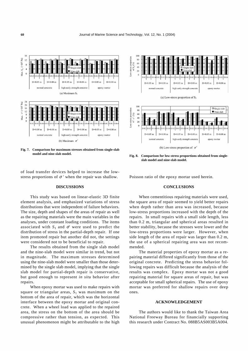
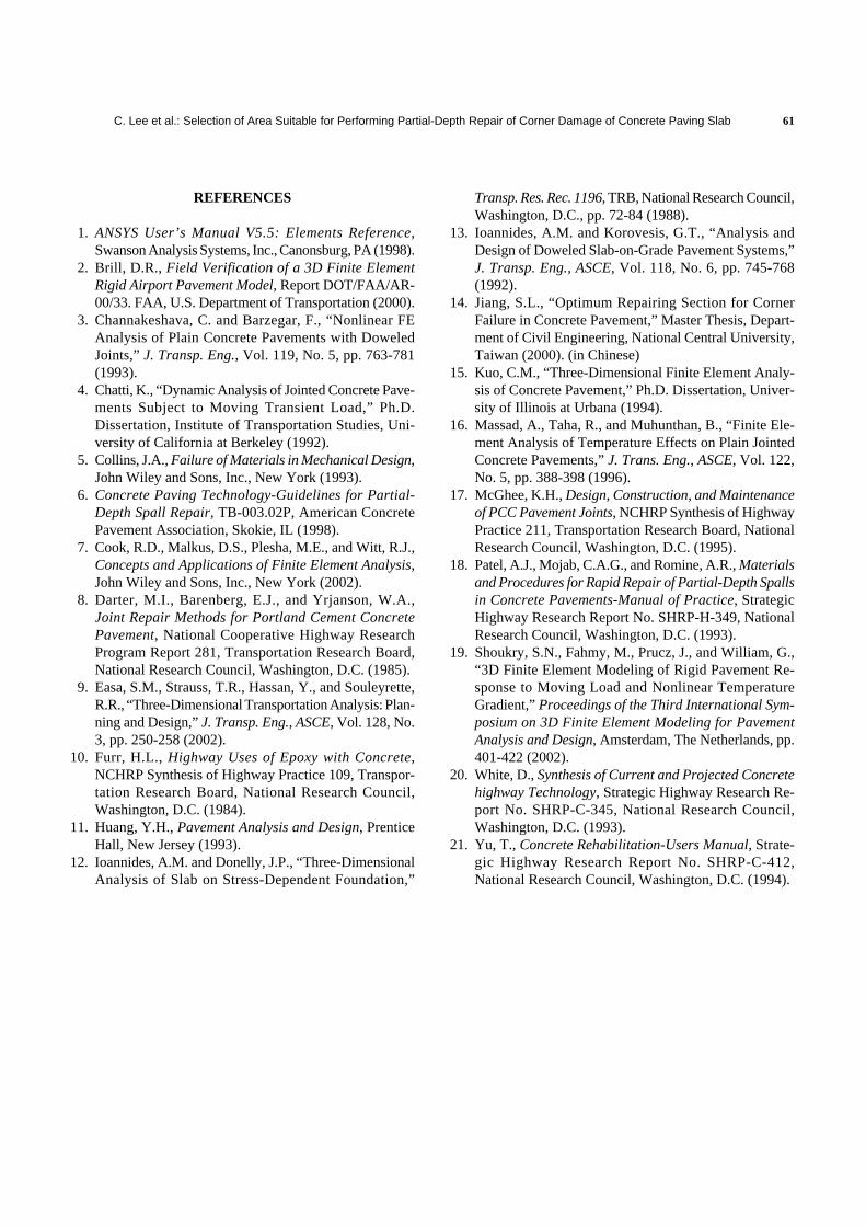
Square areas of repair, used commonly in partial-depth repairs, were applied in an analysis to understandthe differences between the single-slab model andthe nine-slab model. Figs. 7 and 8 compare the re-spective maximum stresses and the low-stress pro-portions.
The maximum stress values of S1 and σ' on theareas of repair, obtained using the nine-slab model weresmaller than those obtained using the single-slab model,for a fixed size of repair. The presence of load transferdevices in nine-slab model beneficially reduced boththe maximum S1 and σ' regardless of the kinds of repairmaterials used. Furthermore, the plot of variation instress versus size of repair obtained using the nine-slabmodel was similar to that obtained using the single slabmodel.
The low-stress proportions of S1 and σ' obtainedusing the nine-slab model were larger than those ob-tained using the single slab model. The plot of variationin low-stress proportions against side length of repairobtained using both models was similar. The presence
Journal of Marine Science and Technology, Vol. 12, No. 1 (2004)60
of load transfer devices helped to increase the low-stress proportions of σ ' when the repair was shallow.
DISCUSSIONS
This study was based on linear-elastic 3D finiteelement analysis, and emphasized variations of stressdistributions that were independent of failure behaviors.The size, depth and shapes of the areas of repair as wellas the repairing materials were the main variables in theanalyses, under constant loading conditions. The itemsassociated with S1 and σ' were used to predict thedistribution of stress in the partial-depth repair. If oneitem promoted repair but another did not, the settingswere considered not to be beneficial to repair.
The results obtained from the single slab modeland the nine-slab model were similar in trend, but notin magnitude. The maximum stresses determinedusing the nine-slab model were smaller than those deter-mined by the single slab model, implying that the singleslab model for partial-depth repair is conservative,but good enough to represent in situ behavior afterrepairs.
When epoxy mortar was used to make repairs withsquare or triangular areas, S1 was maximum on thebottom of the area of repair, which was the horizontalinterface between the epoxy mortar and original con-crete. When a wheel load was applied to the repairedarea, the stress on the bottom of the area should becompressive rather than tension, as expected. Thisunusual phenomenon might be attributable to the high
Poisson ratio of the epoxy mortar used herein.
CONCLUSIONS
When cementitious repairing materials were used,the square area of repair seemed to yield better repairswhen depth rather than area was increased, becauselow-stress proportions increased with the depth of therepairs. In small repairs with a small side length, lessthan 0.2 m, triangular and spherical areas resulted inbetter stability, because the stresses were lower and thelow-stress proportions were larger. However, whenside length of the area of repair was larger than 0.2 m,the use of a spherical repairing area was not recom-mended.
The material properties of epoxy mortar as a re-pairing material differed significantly from those of theoriginal concrete. Predicting the stress behavior fol-lowing repairs was difficult because the analysis of theresults was complex. Epoxy mortar was not a goodrepairing material for square areas of repair, but wasacceptable for small spherical repairs. The use of epoxymortar was preferred for shallow repairs over deepones.
ACKNOWLEDGEMENT
The authors would like to thank the Taiwan AreaNational Freeway Bureau for financially supportingthis research under Contract No. 088B5AS003B5A004.
Fig. 7. Comparison for maximum stresses obtained from single-slabmodel and nine-slab model.
Fig. 8. Comparison for low-stress proportions obtained from single-slab model and nine-slab model.
C. Lee et al.: Selection of Area Suitable for Performing Partial-Depth Repair of Corner Damage of Concrete Paving Slab 61
REFERENCES
1. ANSYS User’s Manual V5.5: Elements Reference,Swanson Analysis Systems, Inc., Canonsburg, PA (1998).
2. Brill, D.R., Field Verification of a 3D Finite ElementRigid Airport Pavement Model, Report DOT/FAA/AR-00/33. FAA, U.S. Department of Transportation (2000).
3. Channakeshava, C. and Barzegar, F., “Nonlinear FEAnalysis of Plain Concrete Pavements with DoweledJoints,” J. Transp. Eng., Vol. 119, No. 5, pp. 763-781(1993).
4. Chatti, K., “Dynamic Analysis of Jointed Concrete Pave-ments Subject to Moving Transient Load,” Ph.D.Dissertation, Institute of Transportation Studies, Uni-versity of California at Berkeley (1992).
5. Collins, J.A., Failure of Materials in Mechanical Design,John Wiley and Sons, Inc., New York (1993).
6. Concrete Paving Technology-Guidelines for Partial-Depth Spall Repair, TB-003.02P, American ConcretePavement Association, Skokie, IL (1998).
7. Cook, R.D., Malkus, D.S., Plesha, M.E., and Witt, R.J.,Concepts and Applications of Finite Element Analysis,John Wiley and Sons, Inc., New York (2002).
8. Darter, M.I., Barenberg, E.J., and Yrjanson, W.A.,Joint Repair Methods for Portland Cement ConcretePavement, National Cooperative Highway ResearchProgram Report 281, Transportation Research Board,National Research Council, Washington, D.C. (1985).
9. Easa, S.M., Strauss, T.R., Hassan, Y., and Souleyrette,R.R., “Three-Dimensional Transportation Analysis: Plan-ning and Design,” J. Transp. Eng., ASCE, Vol. 128, No.3, pp. 250-258 (2002).
10. Furr, H.L., Highway Uses of Epoxy with Concrete,NCHRP Synthesis of Highway Practice 109, Transpor-tation Research Board, National Research Council,Washington, D.C. (1984).
11. Huang, Y.H., Pavement Analysis and Design, PrenticeHall, New Jersey (1993).
12. Ioannides, A.M. and Donelly, J.P., “Three-DimensionalAnalysis of Slab on Stress-Dependent Foundation,”
Transp. Res. Rec. 1196, TRB, National Research Council,Washington, D.C., pp. 72-84 (1988).
13. Ioannides, A.M. and Korovesis, G.T., “Analysis andDesign of Doweled Slab-on-Grade Pavement Systems,”J. Transp. Eng., ASCE, Vol. 118, No. 6, pp. 745-768(1992).
14. Jiang, S.L., “Optimum Repairing Section for CornerFailure in Concrete Pavement,” Master Thesis, Depart-ment of Civil Engineering, National Central University,Taiwan (2000). (in Chinese)
15. Kuo, C.M., “Three-Dimensional Finite Element Analy-sis of Concrete Pavement,” Ph.D. Dissertation, Univer-sity of Illinois at Urbana (1994).
16. Massad, A., Taha, R., and Muhunthan, B., “Finite Ele-ment Analysis of Temperature Effects on Plain JointedConcrete Pavements,” J. Trans. Eng., ASCE, Vol. 122,No. 5, pp. 388-398 (1996).
17. McGhee, K.H., Design, Construction, and Maintenanceof PCC Pavement Joints, NCHRP Synthesis of HighwayPractice 211, Transportation Research Board, NationalResearch Council, Washington, D.C. (1995).
18. Patel, A.J., Mojab, C.A.G., and Romine, A.R., Materialsand Procedures for Rapid Repair of Partial-Depth Spallsin Concrete Pavements-Manual of Practice, StrategicHighway Research Report No. SHRP-H-349, NationalResearch Council, Washington, D.C. (1993).
19. Shoukry, S.N., Fahmy, M., Prucz, J., and William, G.,“3D Finite Element Modeling of Rigid Pavement Re-sponse to Moving Load and Nonlinear TemperatureGradient,” Proceedings of the Third International Sym-posium on 3D Finite Element Modeling for PavementAnalysis and Design, Amsterdam, The Netherlands, pp.401-422 (2002).
20. White, D., Synthesis of Current and Projected Concretehighway Technology, Strategic Highway Research Re-port No. SHRP-C-345, National Research Council,Washington, D.C. (1993).
21. Yu, T., Concrete Rehabilitation-Users Manual, Strate-gic Highway Research Report No. SHRP-C-412,National Research Council, Washington, D.C. (1994).
Copyright © 2022 FDOKUMEN