stemming irregular migration in northern and central ethiopia
Upload
khangminh22Category
view
0download
0
Tenth U.S. National Conference on Earthquake EngineeringFrontiers of Earthquake Engineering July 21-25, 2014 Anchorage, Alaska 10NCEE
SEISMIC VULNERABILITY OF AN IRREGULAR BRIDGE WITH
ELASTOMERIC PADS: A CASE STUDY
Nirav Thakkar1 and Durgesh C. Rai2
ABSTRACT Bridges are lifeline structures and their performance is critical during and after the earthquake. The RC Bridge decks, supported on unanchored elastomeric pad bearings are free to move over substructure during an earthquake. Excessive deck displacement causes unseating and sometimes complete collapse of the deck leading to closure of the bridge for long periods. The problem worsens for irregular bridge with significant variations in the pier/pile heights. For example, decks of 268 m long Chengappa bridge across Austen Strait in Andaman islands was unseated during the 2004 Sumatra-Andaman earthquake, which had taller piers in the middle for navigational purposes. Performance of the bridge was analytically investigated using the finite element (FE) analysis program SAP2000. Nonlinear force–deformation behavior of elastomeric pad bearing was modeled using Friction Isolator link element. The FE model was able to predict the observed response in the 2004 Sumatra-Andaman earthquake for comparable ground motions. Under design level earthquake ground motions, the model predicted that the bridge will experience unseating of the decks and possible collapse indicating higher vulnerability of irregular bridges with unanchored elastomeric pad bearings.
1Frmr. Graduate Student, Dept. of Civil Engineering, Indian Institute of Technology Kanpur, Kanpur 208 016, India 2Professor, Dept. of Civil Engineering, Indian Institute of Technology Kanpur, Kanpur 208 016, India Thakkar N, Rai DC. Seismic vulnerability of bridges with elastomeric pad: A case study. Proceedings of the 10th National Conference in Earthquake Engineering, Earthquake Engineering Research Institute, Anchorage, AK, 2014.

Tenth U.S. National Conference on Earthquake EngineeringFrontiers of Earthquake Engineering July 21-25, 2014 Anchorage, Alaska 10NCEE
Seismic Vulnerability of an Irregular Bridge with Elastomeric Pads: A
Case Study
Nirav Thakkar1 and Durgesh C. Rai2
ABSTRACT Bridges are lifeline structures and their performance is critical during and after the earthquake.
The RC Bridge decks, supported on unanchored elastomeric pad bearings are free to move over substructure during an earthquake. Excessive deck displacement causes unseating and sometimes complete collapse of the deck leading to closure of the bridge for long periods. The problem worsens for irregular bridge with significant variations in the pier/pile heights. For example, decks of 268 m long Chengappa bridge across Austen Strait in Andaman islands was unseated during the 2004 Sumatra-Andaman earthquake, which had taller piers in the middle for navigational purposes. Performance of the bridge was analytically investigated using the finite element (FE) analysis program SAP2000. Nonlinear force–deformation behavior of elastomeric pad bearing was modeled using Friction Isolator link element. The FE model was able to predict the observed response in the 2004 Sumatra-Andaman earthquake for comparable ground motions. Under design level earthquake ground motions, the model predicted that the bridge will experience unseating of the decks and possible collapse indicating higher vulnerability of irregular bridges with unanchored elastomeric pad bearings.
Introduction Bridges with elastomeric pad bearings have not performed well during past earthquakes. It is generally found that damage is limited to excessive displacement of bridge deck causing unseating and sometimes collapse of the superstructure. One such bridge, Chengappa Bridge, suffered from problem like unseating of the bridge deck from its bearings during 2004 Sumatra-Andaman earthquake [1]. There was no noticeable damage to the substructure. A Case Study is performed on Chengappa Bridge with following objectives in mind: • To perform the root cause analysis for the observed behavior of the Chengappa bridge in the
Sumatra Earthquake scenario and to evaluate its performance in design level earthquake shaking, and
• To identify and investigate the effect of restrainer on performance of the study bridge.
1Frmr. Graduate Student, Dept. of Civil Engineering, Indian Institute of Technology Kanpur, Kanpur 208 016, India 2Professor, Dept. of Civil Engineering, Indian Institute of Technology Kanpur, Kanpur 208 016, India Thakkar N, Rai DC. Seismic vulnerability of bridges with elastomeric pad: A case study. Proceedings of the 10th National Conference in Earthquake Engineering, Earthquake Engineering Research Institute, Anchorage, AK, 2014.

Description of the Study Bridge: Chengappa Bridge Chengappa Bridge is the longest bridge in the in the Andaman Archipelago, India. This is the only bridge which is constructed over Austen Strait at Mayabander that connects Middle Andaman Island to North Andaman Island along the Andaman Trunk Route (12°52’57”N and 92°52’28”) (Fig. 1). The bridge is 268 m long RC bridge, simply supported over 12 cast-in-place piers. The length of pile varies along the length of the bridge (Fig. 2). The bridge deck is made of pre-cast girders and cast-in-situ slab. The superstructure merely rested on the pier caps with no fastening between any of them and bearings are simple unanchored neoprene pads [2].
NorthAndaman
MiddleAndaman
AustenStrait
AndamanTrunk Route
ChengappaBridge
Figure 1. Satellite view of Andaman Islands
Bent No 2 3 4 5 6 7 8 9 10 11 12 13 Pile Length (m) 7.5 9.5 9.5 11 11 12 12 11 9.5 8.5 8.5 7.5
Figure 2. Elevation of Chengappa Bridge [2]
The bridge deck is 9.3 m wide and divided into 20.61 m individual spans with an expansion gap of 50 mm. It consists of 200 mm thick RC slab, supported on four 1.35 m deep RC precast I-girders at 2.3 m spacing. The diameter of piers is 1.5 m and they are connected at the top by 1.8 m wide & 0.8 m deep pier cap beam. The foundation consists of four piles of 0.8 m diameter, embedded at least 3.0 m inside the rock giving full fixity to the pile base. The elevation at top of pier cap and top of pile cap is 12.7 m and 3.0 m, respectively. The size of the elastomeric bearing pad used is 500 mm×320 mm and 52 mm thick. The shear modulus of elastomer used in the bearing pad is assumed as 1 MPa.

Seismicity of the region The Andaman Islands have been placed in most severe seismic zone V of the Indian Seismic Zone map, with expected MMI of IX or greater [3]. Many large earthquakes have visited the region in the past. The most significant one in the recent times was M 8.1 event on 26 June 1941 which caused extensive damage in the Andaman Islands, including Port Blair. The Andaman Islands is surrounded by thrust and strike slip faults. Since 1973 nearly a dozen earthquakes have occurred in the region with at least one event greater than M6 which suggests that the region is witnessing a new phase of seismic activity [4]. Moreover, these islands can be affected by large earthquakes in the region occurring on the boundary between Indo-Australian and Eurasian plates, as it happened in the 2004 Great Sumatra-Andaman earthquake [5]. According to Global Seismic Hazard Assessment Program [6], maximum probable earthquake in Andaman Islands is M8.5 event and the PGA with 10% probability of exceedance in 50 years is between 0.35g to 0.40g. The probabilistic seismic hazard map of India, developed by National Disaster Management Authority (NDMA) [7], indicates that maximum probable earthquake in Andaman Islands is M8.4. According to NDMA seismic hazard maps, the PGA with return period of ~500 years, ~2500 years, ~ 5000 years and ~10000 years is between 0.08g to 0.13g, 0.12g to 0.22g, 0.15g to 0.25g and 0.18g to 0.3g, respectively.
Observed behavior in the 2004 Sumatra-Andaman Earthquake The intensity of ground shaking during the 2004 Sumatra-Andaman earthquake in Port Blair was VI–VII on the MSK intensity scale [8]. Rai et al. [2] reported that fifth, sixth, and seventh spans of Chengappa bridge were displaced by about 700 mm horizontally and 220 mm vertically from their original position and fell off the bearings (Figs. 3 and 4). Other spans, including the third, fourth, eighth, ninth, tenth, and eleventh spans moved by about 20–150 mm horizontally. The structural damage was mostly confined to the end beams and the expansion joints above the bearings, pedestals etc. As a result, the bridge was closed immediately after the earthquake and thus, hampered post-earthquake emergency services across the islands. Fortunately, the shaking at the site was rather low (VI–VII on the MSK intensity scale), and girders did not fall off the piers. Due to the remote location of the bridge and the unavailability of required manpower and machinery in the islands, the bridge remained out of operation for about a year.
Figure 3. Displacement of deck slab after 26 December 2004 Sumatra Earthquake [2]

(b)
(a) (c)
Figure 4. Lateral and vertical displacement of deck slab and girders after the 26 December
2004 Sumatra-Andaman Earthquake [2]
Ground Motion at the Bridge Site Pan et al. [9] characterized the 2004 Sumatra-Andaman earthquake ground motion recorded at Singapore, about 910 km from source, with peak ground acceleration (PGA) being 0.0005g. It was reported that the energy of ground motion was concentrated within a frequency band of 0.04 Hz to 0.1 Hz (Fig. 5). According to USGS, the PGA of the ground motion recorded at Port Blair (about 1000 km from source) and Singapore (about 925 km) was about 0.27g and 0.01g, respectively as shown in Fig. 6a [10]. Sorensen et al. [11] modeled the earth space around the source and reported that PGA of the ground motion shall be less than 200 cm/s (~0.2g) in Andaman Islands (Fig. 6b). It was also reported that the peak spectral acceleration can be expected near 4 – 4.5 s period and less than 1 s period. In summary, the intensity of shaking during the 2004 Sumatra-Andaman Earthquake was quite significant in the Andaman Islands as compared to that in Singapore. Also, the ground motion was concentrated with long period waves.
Figure 5. FFT Plot of X & Y Component of ground motions recorded at Singapore [9]

(a) (b)
Figure 6. Expected shaking in Andaman Islands (a) USGS [10] and (b) Sorensen et al. [11]
Dynamic Analysis of the Study Bridge
Finite Element Modeling The size and properties of various components of the study bridge is taken from the available drawings. The 3D model of the study bridge is developed in SAP2000 [12]. The piers and deck support beams are modeled as elastic beam-column elements. It is expected that plastic hinges will be developed in the piers. However, as no damage observed in the piers during the 2004 Sumatra-Andaman earthquake, no plastic hinges were modeled for the purpose of the present study. The pier cap beam is modeled as elastic beam- column element and the deck slab is modeled as thin shell element. Foundation is assumed to provide rigid support to the pile, and hence, all six degrees of freedom at the ends of piles are restrained. The piles are founded on rock and thus, soil-structure interaction is ignored. Abutment structure is assumed rigid and not modeled. Elastomeric pads are modeled as Friction Isolator link element with the coefficient of friction as 0.2. Selected Ground Motions Seismicity of the region indicates that the bridge site can experience earthquake from variety of sources with distance ranging from as near as 15 km to as far as 1200 km. Earthquake may occur in the region with thrust type or strike slip type fault mechanism. The bridge is founded on rock and hence, records shall be selected such that it represents the appropriate scenario for which the response of structure is to be studied.
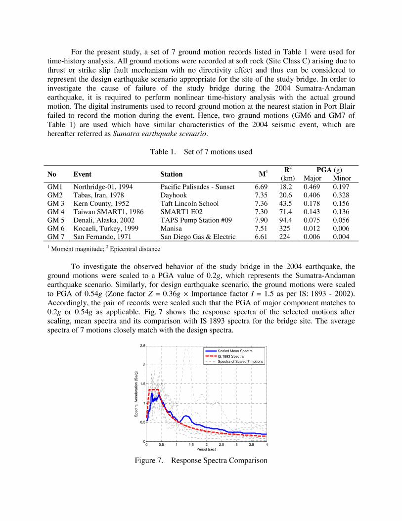
For the present study, a set of 7 ground motion records listed in Table 1 were used for time-history analysis. All ground motions were recorded at soft rock (Site Class C) arising due to thrust or strike slip fault mechanism with no directivity effect and thus can be considered to represent the design earthquake scenario appropriate for the site of the study bridge. In order to investigate the cause of failure of the study bridge during the 2004 Sumatra-Andaman earthquake, it is required to perform nonlinear time-history analysis with the actual ground motion. The digital instruments used to record ground motion at the nearest station in Port Blair failed to record the motion during the event. Hence, two ground motions (GM6 and GM7 of Table 1) are used which have similar characteristics of the 2004 seismic event, which are hereafter referred as Sumatra earthquake scenario.
Table 1. Set of 7 motions used
No Event Station M1 R2
(km) PGA (g)
Major Minor GM1 Northridge-01, 1994 Pacific Palisades - Sunset 6.69 18.2 0.469 0.197 GM2 Tabas, Iran, 1978 Dayhook 7.35 20.6 0.406 0.328 GM 3 Kern County, 1952 Taft Lincoln School 7.36 43.5 0.178 0.156 GM 4 Taiwan SMART1, 1986 SMART1 E02 7.30 71.4 0.143 0.136 GM 5 Denali, Alaska, 2002 TAPS Pump Station #09 7.90 94.4 0.075 0.056 GM 6 Kocaeli, Turkey, 1999 Manisa 7.51 325 0.012 0.006 GM 7 San Fernando, 1971 San Diego Gas & Electric 6.61 224 0.006 0.004 1 Moment magnitude; 2 Epicentral distance To investigate the observed behavior of the study bridge in the 2004 earthquake, the ground motions were scaled to a PGA value of 0.2g, which represents the Sumatra-Andaman earthquake scenario. Similarly, for design earthquake scenario, the ground motions were scaled to PGA of 0.54g (Zone factor Z = 0.36g × Importance factor I = 1.5 as per IS: 1893 - 2002). Accordingly, the pair of records were scaled such that the PGA of major component matches to 0.2g or 0.54g as applicable. Fig. 7 shows the response spectra of the selected motions after scaling, mean spectra and its comparison with IS 1893 spectra for the bridge site. The average spectra of 7 motions closely match with the design spectra.
0 0.5 1 1.5 2 2.5 3 3.5 40
0.5
1
1.5
2
2.5
Period (sec)
Spe
ctra
l Acc
eler
atio
n (S
a/g)
p p
Scaled Mean Spectra
IS:1893 SpectraSpectra of Scaled 7 motions
Figure 7. Response Spectra Comparison

It can be seen that energy of the motions, recorded at an epicentral distance of more than 100 km (GM6 and GM7), is concentrated within range of 1 s to 2.5 s period, similar to the 2004 Sumatra-Andaman earthquake ground motion. Hence, a bridge having fundamental period within the range of 1 s to 2.5 s will be severely affected if earthquake intensity is significant. To investigate the cause of unseating of deck in the transverse direction, the nonlinear time history analysis is performed such that the major component of the pair of records is applied along transverse direction and the minor component is applied along longitudinal direction simultaneously.
Results and Discussion Behavior of Friction Isolator Link Element The lateral force displacement curve and the associated vertical axial force time history of the link element for one of the ground motion is shown in Figs. 8a and 8b, respectively. The friction capacity of the link element is found to vary from 80 kN to 40 kN because the axial force (or the normal force) on the bearing varies from 400 kN to 200 kN. The friction isolator link element is able to simulate the lateral force deformation behavior of the bearing, considering the variation of axial force and, therefore, can be used to predict the overall behavior of the bridges with elastomeric pad bearings.
(a) (b)
Figure 8. Behavior of Friction Isolator link element (a) Lateral Force Displacement Curve and (b) Axial Force Time History
Modal Analysis The fundamental period of the study bridge along transverse direction and longitudinal direction is 1.763 s and 1.795 s and the mode shapes are shown in Figs.9a and 9b, respectively. The local movement of middle three spans is observed in the fundamental mode along the transverse direction. The mass participation of the fundamental mode along transverse direction is only 31%. Such local movement of bridge deck in the fundamental mode can be contributed to uneven distribution of pier stiffness (see Fig. 2). This uneven distribution of stiffness is caused because of increasing height of piers from abutment to mid-span pier while the cross section of piers were kept same. Such local movement in the fundamental mode of bridge compares with

the observed movement of the bridge deck during the 2004 Sumatra-Andaman earthquake, as shown in Fig. 3. Along the longitudinal direction of bridge, the mass participation in the fundamental mode is 61%. Such a bridge of uneven stiffness distribution along bridge length, referred as irregular bridge by various codes and cannot be designed using simplified method based on the fundamental mode only. For the preliminary design, individual piers are considered as single degree of freedom structures with mass concentrated at the deck level and stiffness provided by the pier. Such idealized system is known as Bridge Vibration Unit (BVU). CALTRANS [13] restricts the ratio of period of successive BVUs to 0.7. If this ratio is less than 0.7, the out of phase movement of piers shall be accounted for in the design of bridges. IS:1893-Part III (Draft) restricts the difference in the adjacent pier stiffness to 25% [14]. In order to satisfy CALTRANS and IS:1893-Part III requirements, the ratio of successive pier heights shall be limited to approximately 0.8 and 0.9, respectively. For the study bridge, the ratio of pile/pier height varies from 0.8 to 1 and hence, meets the criteria rather marginally.
(a) (b)
Figure 9. Fundamental mode along (a) transverse and (b) longitudinal direction Performance in Sumatra Earthquake Scenario The study bridge when subjected to two selected ground motions (GM6 and GM7), results in maximum elastomeric pad displacement of 365 mm and 445 mm, with an average of 405 mm, along transverse direction of the bridge. Elastomeric pad was placed such that the 500 mm side was parallel to the transverse direction of the bridge. Hence, bearing instability will occur when the displacement exceeds half the size of pad, i.e., 250 mm. It is also observed that central six spans of the bridge deck will lose contact with elastomeric pad, as indicated by positive axial displacements in the bearing and the deck beam will slip over the bearing pad due to lack of contact. The analysis results in maximum bearing displacement along longitudinal direction of 395 mm and 385 mm, with an average of 390 mm. The seating width provided along longitudinal direction of the bridge was 750 mm and, therefore, the bridge deck may not fall off the pier cap. However, the deck will fall off the bearing pads and due to impact there may be damage to the soffit of beams and pier caps. These results of analysis match well with the observed displacement of the deck after the 2004 Sumatra-Andaman earthquake.

Performance in Design Earthquake Scenario The maximum bearing displacement under design earthquake is found to be varying from 100 mm to 1715 mm, with an average of 600 mm, along the transverse direction of the bridge. Fig. 10 shows the transverse displacement of the deck slab for the selected seven ground motions. The average transverse displacement of deck over all pier is more than the threshold limit of 250 mm, which indicates that if the bridge is subjected to design level earthquakes, all decks will fall from bearings.
0.0
0.2
0.4
0.6
0.8
1.0
1.2
1.4
1.6
1.8
1 2 3 4 5 6 7 8 9 10 11 12 13 14
Dis
pla
cem
ent
(m)
Pier No
GM1
GM2
GM3
GM4
GM5
GM6
GM7
Average
Limit
Figure 10. Transverse displacement profile of deck slab The maximum bearing displacement along the longitudinal direction under design earthquake is found to be varying from 100 mm to 1280 mm, with an average of 470 mm (Fig. 11). The average displacement is less than the seating width of 750 mm. However, for two of the seven selected ground motions (GM6 and GM7 of Table 1), the longitudinal displacement of central six spans is more than the seating width provided, because GM6 and GM7 have energy concentration in long period waves. Hence, there is greater likelihood that the bridge will experience more severe problems when subjected to design level earthquakes. It is also observed that all the spans of the bridge deck lose contact with the elastomeric pads, as indicated by positive axial displacements in bearings, and there is no frictional resistance active to restore the deck to its original position. Hence, it is essential to provide vertical hold down device at every bearing location to prevent uplift and the loss of contact. Effect of Restrainer on Seismic Response In order to study the effect of restrainer on seismic performance of the study bridge, the adjacent slabs are assumed to be connected together with two 20 mm diameter rod to arrest relative movement of deck slabs with no positive connection with the pier cap. It is also assumed that the elastomeric pad is anchored using two 20 mm diameter rod shear pin, to arrest transverse movement of the deck. Slotted holes are provided around the shear pin to allow the longitudinal movement of deck slab. The link rods and shear pins are modeled as plastic-wen element in

SAP2000 with elastic-perfectly plastic behavior having elastic stiffness as 251328 kN/m and 837760 kN/m, respectively. The yield strength is calculated as 415 kN for both link rods and shear pins. Provision of such restrainers adds to overall stiffness of the system and the fundamental period of structure along transverse direction and longitudinal direction decreased to 1.585 s and 1.481 s, respectively.
0.0
0.2
0.4
0.6
0.8
1.0
1.2
1.4
1 2 3 4 5 6 7 8 9 10 11 12 13 14
Dis
pla
cem
ent
(m)
Pier No
GM1
GM2
GM3
GM4
GM5
GM6
GM7
Average
Limit
Figure 11. Longitudinal displacement profile of deck slab Due to restrainers, the dynamic characteristics of the bridge improved significantly as first two modes contribute to most of the dynamic response as opposed to multiple modes in absence of arresters. The bearing displacements with and without restrainers are compared in Table 2. For the Sumatra earthquake scenario, the average of maximum displacement along transverse direction and longitudinal direction is found to be 6 mm and 360 mm, respectively. For design earthquake scenario, the average of maximum displacement along transverse direction and longitudinal direction is found to be 20 mm and 600 mm, respectively. As expected, there is a significant reduction in displacement along the transverse direction of the bridge in the presence of shear pins. However, no appreciable reduction is noted in the bearing displacement along the longitudinal direction of the bridge because the deck slab is free to move over pier cap.
Table 2: Comparison of bearing displacements (Design Earthquake Scenario)
Ground
Motion ID Displacement w/o restrainer (mm) Displacement w/ restrainer (mm)
Transverse Longitudinal Transverse Longitudinal GM1 100 100 2 103 GM2 342 281 2 261 GM3 260 297 4 245 GM4 193 168 2 134 GM5 673 464 2 308 GM6 1713 1396 109 1501 GM7 1678 1927 21 1656

Conclusions The unsatisfactory seismic performance of Chengappa bridge during the 2004 Sumatra-Andaman earthquake was primarily due to uneven distribution of pier/pile stiffness and lack of restrainers to arrest excessive displacement of the bridge deck. Out-of-phase movement is observed due to irregularity which significantly increased the displacement demand on substructure as well as connections. Nonlinear force–deformation behavior of elastomeric pad bearings modeled using Friction Isolator link element of SAP 2000 was able to predict the observed response in the 2004 Sumatra-Andaman earthquake for comparable ground motions. Under design level earthquake ground motions, the model predicted that the bridge will experience unseating of the decks and possible collapse of decks, indicating the higher vulnerability of irregular bridges with elastomeric pad bearings. Due to absence of displacement arresters, there is greater likelihood that the bridge will experience problems like unseating and collapse of more than one decks. For irregular bridges, requirement of minimum seating width shall be addressed separately from regular bridges considering the out-of-phase movement of piers. With the provision of restrainers, dynamic characteristic of the bridge was significantly improved and the shear pin helped in reducing the transverse displacement demand of the deck slab. Bridge codes should emphasize on requirement of anti-dislodgement devices, such as, shear keys and links or cables to arrest excessive displacement of the bridge deck.
Acknowledgments The partial support from the Poonam & Prabhu Goel Foundation at IIT Kanpur for research and outreach activities in earthquake engineering is greatly appreciated.
References 1. Rai DC et al. The Effect of the December 2004 Great Sumatra Earthquake and Indian Ocean Tsunami on
Transportation Systems in India’s Andaman and Nicobar Islands. Earthquake Spectra 2006; 22(S3): S561-S579.
2. Rai DC, Murty CVR. North Andaman Diglipur Earthquake of 14 September 2004. Reconnaissance Report, Department of Civil Engineering, Indian Institute of Technology Kanpur: India, 2003
3. IS 1893-Part 1. Criteria for Earthquake Resistant Design of Structures. Bureau of Indian Standards (BIS): Delhi, 2002.
4. Rajendran CP, Earnest A, Rajendran K, Dev DR, Sreekumari K. The 13 September 2002 North Andaman (Diglipur) earthquake: An analysis in the context of regional seismicity. Current Science 2003; 84(7): 919-924.
5. Kanamori H. Seismological aspect of the December 2004 Great Sumatra-Andaman earthquake. Earthquake Spectra 2006; 22(S3): S1-S12
6. Bhatia SC, Kumar MV, Gupta HK. A probabilistic seismic hazard map of India and adjoining regions. Annali Di Geofisica 1999; 42(6): 1153-1164.
7. Bhattacharjee B. Development of probabilistic seismic hazard map of India. Technical Report, National Disaster Management Authority (NDMA): India, 2011
8. Jain SK, Murty CVR, Rai DC, Malik JN, Sheth AR, Jaiswal A. Effects of M 9 Sumatra earthquake and tsunami of 26 December 2004. Current Science 2005; 88(3): 357–359.

9. Pan T-C, Karim KR, You XT, Lim CL, Leong CL. Far-Field Motions in Singapore during the December 2004 and March 2005 Great Sumatra Earthquake and the March 2005 Nias-Simeulue Earthquake. Earthquake Spectra 2006; 22(S3): S403–S417.
10. Magnitude 9.1 - Off the West Coast of Northen Sumatra. url: http://earthquake.usgs.gov/earthquakes/eqinthe news/2004/us2004slav/. accessed on January 2011.
11. Sørensen MB, Atakan K, Pulido N. Simulated Strong Ground Motions for the Great M 9.3 Sumatra–Andaman Earthquake of 26 December 2004. Bulletin of the Seismological Society of America 2007; 97(1A): S139–S151.
12. CSI. Integrated Software for Structural Analysis and Design, SAP 2000. CSI, 2009.
13. CALTRANS. Seismic Design Criteria v1.6. California Department of Transportation: California, 2010.
14. IS 1893-Part 3 (Draft). Criteria for Earthquake Resistant Design of Structures - Bridges and Retaining Walls. Bureau of Indian Standards (BIS): Delhi, India,
Copyright © 2022 FDOKUMEN