Seismic Upgrades for Concrete Dams - Then and Now, Final, Hansen and Nuss, July 12, 2013
18
SEISMIC UPGRADES FOR CONCRETE DAMS – THEN AND NOW By Kenneth D. Hansen, P.E. 1 and Larry K. Nuss, P.E. 2 ABSTRACT This paper reports on eight case studies of existing concrete dams that have been strengthened to improve their seismic performance. These seismic upgrades were based on the knowledge and analytical tools available at the time. Modifications to these dams improve the seismic performance of the dam were made mainly on the basis of 3-dimensional (3D) linear finite element analysis (FEA) which produced tensile stresses determined to be in excess of the predicted tensile strength capacity of the in-place concrete when the structure is subjected to the Maximum Credible Earthquake (MCE). However, there have been three recent developments that the authors feel should be considered in the future in determining whether existing concrete dams require modification to ensure their earthquake related safety in the future. These developments include 1) whether the finite element models (FEM) previously used considered all factors in predicting high tensile stresses and whether the derived stresses were realistic, 2) whether the structural analysis agrees with historical response of concrete dams subjected to high intensity seismic shaking, and 3) whether risk-based analyses, including Potential Failure Mode Analysis (PFMA) to determine if the concrete dam is actually at risk of failing is more appropriate than stress-based analysis alone. Each of these new developments is summarized and discussed with respect to the main goal of dam safety. This is to prevent loss of life and property damage due to sudden release of reservoir water caused by failure of the dam. INTRODUCTION High intensity earthquakes can produce extensive damage to all types of infrastructure as well as cause a large number of fatalities. They can occur with little or no warning. Therefore, design engineers and dam regulators have taken a conservative approach to evaluating the seismic safety of all types of dams, including concrete dams. In the past, analyzing the seismic resistance of an existing concrete dam usually involved a linear FEA to mainly determine the magnitude, location, extent, and number of excursions of tensile stresses in the structure due to the MCE. The analysis then may have involved tests or a literature search to determine the tensile strength of the parent concrete. If the predicted earthquake induced tensions exceeded the allowable, the regulator or federal owner agency may 1 Kenneth D. Hansen, Consulting Engineer, 6050 Greenwood Plaza Blvd., Suite 100, Greenwood Village, Colorado, 80111, 303-695-6500, [email protected] . 2 Larry K. Nuss, Structural Engineer, (Bureau of Reclamation - retired), Nuss Engineering, LLC, 10065 Silver Maple Circle, Highlands Ranch, Colorado, 80129, 303-517-8504, [email protected].
-
Upload
independent -
Category
Documents
-
view
1 -
download
0
Transcript of Seismic Upgrades for Concrete Dams - Then and Now, Final, Hansen and Nuss, July 12, 2013

SEISMIC UPGRADES FOR CONCRETE DAMS – THEN AND NOW By Kenneth D. Hansen, P.E.1 and Larry K. Nuss, P.E.2
ABSTRACT This paper reports on eight case studies of existing concrete dams that have been strengthened to improve their seismic performance. These seismic upgrades were based on the knowledge and analytical tools available at the time. Modifications to these dams improve the seismic performance of the dam were made mainly on the basis of 3-dimensional (3D) linear finite element analysis (FEA) which produced tensile stresses determined to be in excess of the predicted tensile strength capacity of the in-place concrete when the structure is subjected to the Maximum Credible Earthquake (MCE). However, there have been three recent developments that the authors feel should be considered in the future in determining whether existing concrete dams require modification to ensure their earthquake related safety in the future. These developments include 1) whether the finite element models (FEM) previously used considered all factors in predicting high tensile stresses and whether the derived stresses were realistic, 2) whether the structural analysis agrees with historical response of concrete dams subjected to high intensity seismic shaking, and 3) whether risk-based analyses, including Potential Failure Mode Analysis (PFMA) to determine if the concrete dam is actually at risk of failing is more appropriate than stress-based analysis alone. Each of these new developments is summarized and discussed with respect to the main goal of dam safety. This is to prevent loss of life and property damage due to sudden release of reservoir water caused by failure of the dam.
INTRODUCTION High intensity earthquakes can produce extensive damage to all types of infrastructure as well as cause a large number of fatalities. They can occur with little or no warning. Therefore, design engineers and dam regulators have taken a conservative approach to evaluating the seismic safety of all types of dams, including concrete dams. In the past, analyzing the seismic resistance of an existing concrete dam usually involved a linear FEA to mainly determine the magnitude, location, extent, and number of excursions of tensile stresses in the structure due to the MCE. The analysis then may have involved tests or a literature search to determine the tensile strength of the parent concrete. If the predicted earthquake induced tensions exceeded the allowable, the regulator or federal owner agency may
1 Kenneth D. Hansen, Consulting Engineer, 6050 Greenwood Plaza Blvd., Suite 100, Greenwood Village, Colorado, 80111, 303-695-6500, [email protected] . 2 Larry K. Nuss, Structural Engineer, (Bureau of Reclamation - retired), Nuss Engineering, LLC, 10065 Silver Maple Circle, Highlands Ranch, Colorado, 80129, 303-517-8504, [email protected].

have required lowering of the reservoir or rehabilitation of the dam to improve its seismic resistance. Case studies for eight such concrete dams that were analyzed and subsequently modified are studied in this paper based on the assumption the predicted tensions are sufficient to crack the concrete in the 3D structure. It is further assumed that the predicted cracking over a large extent of the dam could cause a failure of the dam. Potential Failure Mode Analysis (PFMA), being relatively new, was not done prior to about 2000.
CONCRETE DAMS MODIFIED TO IMPROVE SEISMIC RESISTANCE Case studies on eight dams that were strengthened to improve their resistance to seismic shaking are presented in this paper. All the dams are located in the earthquake prone western United States and Canada. The dams studied are three concrete arches, three multiple-arch dams, and two slab-and-buttress dams. The basic information on the dams is contained in Table 1. Table 1 – Concrete Dams Modified to Improve Seismic Resistance Dam Location
Date Built
Modified
Height feet (m)
Crest Length feet (m)
Dam Type Modification Design
EQ
Design PHGA
(g) Big Bear Valley Big Bear Lake, CA
1912 1989 92 (28) 360
(110) Multiple
Arch Mass concrete infill between buttresses
M8.3 at 16 km 0.71
Gibraltar Santa Barbara, CA
1920 1990
169 (52) 194 (59)
600 (183) Arch RCC buttress downstream M7.5 at
2 km 0.68
Stewart Mountain Phoenix, AZ
1930 1991 212 (65) 583
(178) Arch Full height post-tension cables M7.5 at 15 km 0.34
Littlerock Palmdale, CA
1924 1994 175 (53) 720
(219) Multiple
Arch RCC infill between buttresses M8.0 at 2 km 0.7
Weber Placerville, CA
1924 2002 89 (27) 354
(108) Triple Arch
RCC stabilized sides of central buttresses
M6,5 at 18 km 0.3
Stony Gorge Willows, CA
1928 2009 139 (42) 868
(265) Slab & Buttress
Concrete walls and struts between buttresses M6.5 0.71
Seymour Falls Vancouver, BC
1961 2007 98 (30) 771
(235) Slab & Buttress
Inclined post-tensioned anchors for buttresses. Two concrete walls in bays on either side of spillway.
M6.5 0.50
Big Tujunga Los Angeles, CA
1932 2011 244 (74) 830
(253) Arch Concrete buttress downstream M7.5 at 7 km 1.1
Bear Valley Dam The new Bear Valley Dam located in the San Bernardino Mountains about 80 miles east of Los Angeles was the first concrete multiple arch dam to be upgraded to improve its seismic performance. The dam was completed in 1912 as a 92-foot (28-m) high, 360-foot (110-m) long multiple arch dam to replace a slender masonry arch dam built in 1884. In the 1980s, there were concerns over the structural adequacy of the dam with respect to severe earthquake shaking as well as overtopping. Two MCEs were considered for the dam rehabilitation. The most critical shaking was determined to be a M8.3 earthquake caused by a rupture on the San Andreas Fault 10 miles away with a PHGA of 0.45 g and a bracketed duration of 35 seconds (duration between the first and last peaks of 0.5 g or greater).

The structural strengthening was accomplished by infilling the arch bays with conventional mass concrete in order to convert the multiple arch to basically a gravity dam. The downstream slope was formed at 0.25V:1.0H except for the uppermost 47 feet which was vertical (see Figures 1a and 1b). The modification which also included grouting between the old and new concrete to assure monolithic behavior was completed in 1989. On June 28, 1992, the M7.4 Landers Earthquake occurred about 28 miles from the strengthened structure. Then one day later, the closer M6.6 Big Bear Earthquake occurred about 11 miles from the dam on an unnamed fault reportedly in response to the rupture on the Landers Fault. At the Big Bear Lake Civic Center about 2.4 miles from the dam, a strong motion instrument recorded a peak of 0.57 g horizontally and 0.21 g vertically during the Big Bear Earthquake. This recording is about 5 miles closer to the causative fault than the dam. Thus the estimated PHGA at the dam was between 0.4 to 0.5 g. A thorough inspection after the earthquake indicated the dam had not been damaged. The only damage was a slight displacement of the highway bridge at the crest of the dam. The bridge has since been removed from the dam and relocated downstream. Gibraltar Dam Gibraltar Dam was completed in 1920 as a 169-foot (33-m) high concrete arch dam. A thrust block, a radial gated spillway and a short concrete gravity section are located at the left abutment (see Figure 2). In 1948, the arch was raised by about 25 feet (8 m) to make its present height 194.5 feet (59 m). The thickness of the arch varies from 7 feet (2 m) at the crest to 65 feet (20 m) at the base. Located about 9 miles (14 km) north of the City of Santa Barbara, California the dam provides storage for the City’s water supply. On June 29, 1925, the arch was severely shaken by the M6.3
Figure 1 - Bear Valley Dam (a) multiple arch dam, (b) shaded area shows concrete infill between arches to improve seismic stability
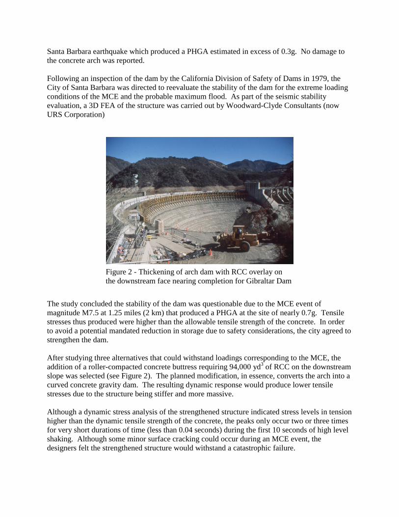
Santa Barbara earthquake which produced a PHGA estimated in excess of 0.3g. No damage to the concrete arch was reported. Following an inspection of the dam by the California Division of Safety of Dams in 1979, the City of Santa Barbara was directed to reevaluate the stability of the dam for the extreme loading conditions of the MCE and the probable maximum flood. As part of the seismic stability evaluation, a 3D FEA of the structure was carried out by Woodward-Clyde Consultants (now URS Corporation) The study concluded the stability of the dam was questionable due to the MCE event of magnitude M7.5 at 1.25 miles (2 km) that produced a PHGA at the site of nearly 0.7g. Tensile stresses thus produced were higher than the allowable tensile strength of the concrete. In order to avoid a potential mandated reduction in storage due to safety considerations, the city agreed to strengthen the dam. After studying three alternatives that could withstand loadings corresponding to the MCE, the addition of a roller-compacted concrete buttress requiring 94,000 yd3 of RCC on the downstream slope was selected (see Figure 2). The planned modification, in essence, converts the arch into a curved concrete gravity dam. The resulting dynamic response would produce lower tensile stresses due to the structure being stiffer and more massive. Although a dynamic stress analysis of the strengthened structure indicated stress levels in tension higher than the dynamic tensile strength of the concrete, the peaks only occur two or three times for very short durations of time (less than 0.04 seconds) during the first 10 seconds of high level shaking. Although some minor surface cracking could occur during an MCE event, the designers felt the strengthened structure would withstand a catastrophic failure.
Figure 2 - Thickening of arch dam with RCC overlay on the downstream face nearing completion for Gibraltar Dam
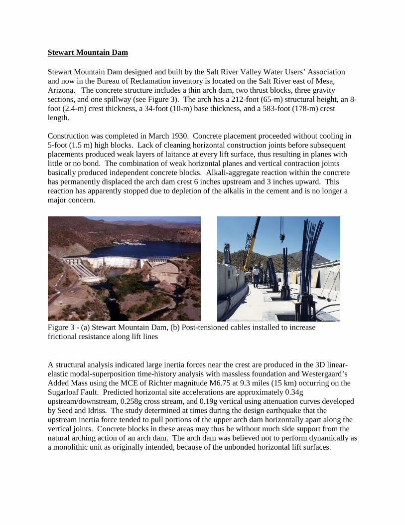
Stewart Mountain Dam Stewart Mountain Dam designed and built by the Salt River Valley Water Users’ Association and now in the Bureau of Reclamation inventory is located on the Salt River east of Mesa, Arizona. The concrete structure includes a thin arch dam, two thrust blocks, three gravity sections, and one spillway (see Figure 3). The arch has a 212-foot (65-m) structural height, an 8-foot (2.4-m) crest thickness, a 34-foot (10-m) base thickness, and a 583-foot (178-m) crest length. Construction was completed in March 1930. Concrete placement proceeded without cooling in 5-foot (1.5 m) high blocks. Lack of cleaning horizontal construction joints before subsequent placements produced weak layers of laitance at every lift surface, thus resulting in planes with little or no bond. The combination of weak horizontal planes and vertical contraction joints basically produced independent concrete blocks. Alkali-aggregate reaction within the concrete has permanently displaced the arch dam crest 6 inches upstream and 3 inches upward. This reaction has apparently stopped due to depletion of the alkalis in the cement and is no longer a major concern. A structural analysis indicated large inertia forces near the crest are produced in the 3D linear-elastic modal-superposition time-history analysis with massless foundation and Westergaard’s Added Mass using the MCE of Richter magnitude M6.75 at 9.3 miles (15 km) occurring on the Sugarloaf Fault. Predicted horizontal site accelerations are approximately 0.34g upstream/downstream, 0.258g cross stream, and 0.19g vertical using attenuation curves developed by Seed and Idriss. The study determined at times during the design earthquake that the upstream inertia force tended to pull portions of the upper arch dam horizontally apart along the vertical joints. Concrete blocks in these areas may thus be without much side support from the natural arching action of an arch dam. The arch dam was believed not to perform dynamically as a monolithic unit as originally intended, because of the unbonded horizontal lift surfaces.
Figure 3 - (a) Stewart Mountain Dam, (b) Post-tensioned cables installed to increase frictional resistance along lift lines

This situation is acceptable for static loadings because of the horizontal arching action transferring loads along the arches and 'wedging' the structure in the canyon. The cantilevers still act as cantilevers because of the transfer of load across the lift surfaces from friction. This situation was determined to not be acceptable for dynamic loadings. Large inertia forces induced in the upstream direction of the dam during an earthquake were greater than the static reservoir load. It was felt that individual concrete blocks moving in the upstream direction without arching action would break the frictional resistance along unbonded lift surfaces causing instability. A progressive failure of the top central section of the dam was postulated. The dam was modified in 1991 with post-tensioned cables adding the necessary normal force across these horizontal planes to increase the frictional resistance for stability. The cable installation consists of 62 epoxy-coated post-tensioned cables varying from 75 to 240 feet (23 to 73 m) in length, inclined between vertical and 8° 40' off vertical. It is believed that this modification was the first time an arch dam had been post-tensioned. Littlerock Dam When Littlerock Dam near Palmdale, California was completed in 1924, it was at 175 feet (53 m) the tallest concrete multiple arch dam in the United States. Designed by James S. Eastwood who pioneered this type of dam, it contained 28 arches (see Figure 4). The 720-foot-long (219-m-long) dam supplies water to the Palmdale Water and Littlerock Creek irrigation districts.
Because the dam is located only 1.5 miles (2.4 km) south of a trace of the San Andreas Fault, there has been concern about the dam’s seismic stability for some time. The MCE originating on this noted fault was determined to be a M8.0 event resulting in a PHGA of 0.7g. The result of a finite element seismic analysis by Woodward-Clyde Consultants (now URS Corp.) indicated higher than allowable tensile stresses in the cross-canyon direction. Due to this predicted lack of lateral stability, the rehabilitation design engineers decided to infill the area between arch buttresses with an RCC gravity dam section (see Figure 4). In addition to placing 115,000 yd3 (87,923 m3) of RCC, the seismic upgrade required 25,000 yd3 (19,114 m3) of conventional concrete as well as resurfacing the faces with steel fiber reinforced
Figure 4- (a) Littlerock multiple arch dam, (b) RCC placed between buttresses to increase seismic stability laterally

silica fume enhanced shotcrete. The spillway of the dam was also raised by 12 feet (4 m) in order to replace storage lost to siltation of the reservoir over it 70 year life. The upgrade which cost nearly $13 million was completed in 1994. Attractive 6-foot (2-m) high conventional concrete faced steps were incorporated on the downstream face (see Figure 4) to discourage climbing and possible injury due to falling from the dam that is accessible to the public due to its location in the Angeles National Forest. A dynamic time-history structural analysis of the rehabilitated structure indicated compressive stresses were well below the allowable for all structural components. Tensile stresses near the tops of the arch barrels exceeded 300 lb/in2 (2 MPa) only for a short time period of time during the synthesized earthquake. All tensile stresses in the RCC buttress were less than 100 lb/in2 (0.69 MPa). Weber Dam Weber Dam is unique in that it is a triple arch concrete buttress dam with the center arch larger than the two-smaller-side arches (see Figure 5). The 89-foot-high (27-m-high) dam completed in 1924 near Placerville, California is owned by the El Dorado Irrigation District.
The original design was by noted multiple arch dam designer James S. Eastwood and later modified by R.W. Hawley. Hawley changed the conical surface of the arches to sloping cylindrical shapes. The seismic design criteria for the site are controlled by two members of the Sierra Foothills fault system, the Rescue Fault and the Melones Fault. The highest magnitude earthquake generated by the two faults is M6.5 at a distance of 11.2 miles. The PHGA used in the seismic analysis by Woodward-Clyde Consultants (now URS Corp.) was 0.30g and vertically 2/3 of the horizontal value or 0.20g.
Figure 5- (a) Triple Arch Weber Dam, (b) RCC placed adjacent to buttress walls to increase lateral stiffness

In order to evaluate the seismic safety for the existing structure, concrete properties needed to be established for both the parent concrete and also a reduced strength across horizontal lift lines. Concrete compressive strengths from cores varied from 2200 to 3850 lb/in2 (15 MPa to 27 MPa) depending on its location in the structure. Based on a site inspection and a review of the literature a limiting dynamic tensile strength of 350 lb/in2 (2.4 MPa) was selected across lift joints in the center arch or about 62 percent of the tensile strength of the intact concrete. Because of the moderate level of shaking from the design earthquake, a response spectrum analysis was used as long as the induced tensile stresses did not exceed the 350 lb/in2 allowable. Adding a downstream buttress of RCC on the inside of the existing buttresses between the arches was selected as the solution to stiffen the center arch in the cross canyon direction and reduce the tensile stresses below the allowable limit. Twenty foot high RCC buttresses constructed on the interior of the central arch (see Figure 5) would keep tensile stresses below the allowable. The RCC arches were stepped to dissipate energy from spillway flows and drains were installed to reduce uplift pressures on the RCC sections. Leveling concrete was placed to provide a uniform platform for starting the RCC. Completed in 2002, the $3 million seismic upgrade required 8,500 yd3 (6,500 m3) of RCC and 3,500 yd3 (2676 m3) of conventional mass concrete. Stony Gorge Dam Stony Gorge Dam completed in 1928 is an Ambursen type slab and buttress concrete dam located 25 miles west of Willows, California on Stony Creek (see Figure 6). The dam has a crest length of 868 feet, a structural height of 139 feet (42 m), has 46 bays with buttresses spaced every 18 feet. All the concrete is reinforced except for the spillway bucket and apron. The buttresses vary in thickness from 45-inches at the base to 18-inches at the crest and the slabs vary in thickness from 50 inches at the base to 15 inches at the crest. Horizontal struts 18 inches wide by 24 inches high span between the buttresses. The upstream slab rests on corbels along the upstream edge of the buttresses. The existing dam was analyzed using 5 sets of earthquake ground motions representing return periods between 2000 and 60,000 years. The 3D nonlinear finite element time-history structural analysis included all the buttresses pin connected at the base, compression only struts, simply-supported upstream slabs, and added mass hydrodynamic interaction. The analysis showed that 90 percent of the struts experiencing loads that exceeded their allowable compressive strength by a factor of 2 and for many excursions. The decision to modify the dam was guided by Reclamation risk guidelines based on PFMA, nonlinear seismic FEA, and numerous team risk analyses. The teams developed event trees of the more critical potential failure modes, postulated loss of life consequences given a dam failure, and assigned (through expert elicitation) probabilities to the event trees. Without adequate side support, it was believed the buttresses would not be stable. The modification design was based on one set of ground motions measured at the Pleasant Valley Pumping Plant during the 1983 M6.5 Coalinga earthquake with peak accelerations of

0.71g in the upstream to downstream direction, 0.65 in the cross-canyon direction, and of 0.53g in the vertical direction. The seismic rehabilitation design used a simply-supported diaphragm wall placed between the buttresses to support the buttresses in the cross-canyon direction typically from the foundation to 37 feet below the crest. Diaphragm walls 6-foot wide were built in 28 interior bays and 10-foot wide walls were built in the 4 end bays on each abutment. Two additional struts were built across the dam to support the upper and downstream edges of the buttresses. Strut walls 10-foot wide were constructed in bays 12-13 and 55-56 to transfer loads from the struts into the foundation. Additional shear strength was added to the top of the buttresses by extending reinforcing dowels into buttress walls. The $24 million seismic modification contract was completed in 2009. Seymour Falls Dam, Canada Seymour Falls Dam located in the mountains north of Vancouver, British Columbia (BC) provides water for the Greater Vancouver Water District. Completed in 1961, the dam is a 98-foot-high composite structure consisting of a 771-foot-long concrete slab and buttress section and a 722-foot-long earthfill embankment section. As indicated by the notches on the vertical downstream faces of the buttresses, provision for a future dam raise was provided (see Figure 7). The slab and buttress section consists of an upstream sloping slab supported by buttresses spaced 22 feet on center. The entire concrete section including the transition block to the earthfill and a concrete gravity wall is founded on bedrock. Although the existing concrete portion of the dam was in good condition, it was determined the structure did not meet current seismic standards. The BC dam safety branch rated the dam as a very high consequence structure or in United States terms a “high hazard dam”. This determination required the dam to resist a MCE determined by the probabilistic method to be the 1 in 10,000 year event. A partial upgrade on the concrete section in 1994 improved its seismic
Figure 6 - Stony Gorge Dam after modification

resistance to meet a Design Basis Earthquake (DBE) or a quake with a return period of 475 years. In addition, the recommended design response spectra for the dam remediation were a M7.5 deep seated inter plate event beneath the Georgia Strait and a M6.5 Britannia local fault. The PHGA for the Georgia Strait quake was targeted at 0.35g and 0.50g for the lesser magnitude but choser focal event.
Figure 7 – Seymour Falls Dam following seismic upgrade The engineering requirements for the upgrade were determined by creating a series of complex 3D FEMs of the structure. A dynamic time history analysis was then completed which incorporated assessing slip displacement techniques to reduce upgrade requirements. It is assumed the analyses showed high tensile stresses in the buttresses. The selected upgrade for the concrete section included installation of inclined post- tensioned strand anchors to strengthen the spillway piers from cracking together with construction of several concrete walls between the buttresses to strengthen the dam in the cross canyon direction The 3-foot-thick vertical reinforced concrete walls were only placed in two bays on either side of the spillway bays. The seismic upgrade completed in 2007 was intended to have the dam survive operationally during the MCE event. Dam failure was not predicted.

Big Tujunga Dam Big Tujunga Dam was a thin-arch concrete dam completed in 1932 on Big Tujunga Creek as a flood control structure northeast from Los Angeles and is now also used for water supply. It has a height of 244 feet (74 m), a crest length of 830 feet (253 m). The arch is 8-feet (2.4 m) thick at the crest and a maximum base thickness of about 74 feet (23 m). It is owned by the Los Angeles County Department of Public Works (LACDPW). The project has required numerous improvement programs, studies, and remedial actions to address seepage and rock stability issues. In 1975, the owner conducted a 3D finite element seismic stability study after the 1971 San Fernando Earthquake damaged Pacoima Dam about 12 miles away from Big Tujunga Dam. The seismic time-history record for the MCE used in the study was a modified recording measured during M7.5 1971 event at Pacoima resulting in a PHGA of 1.1 g on the Sierra Madre fault. The conclusion from the study was that Big Tujunga Dam was unable to adequately resist the MCE with a full reservoir. As a result, the preferred interim alternative was to restrict the reservoir to 77 feet below the spillway crest, a level determined safe for the MCE by limiting peak tensile stresses in the dam to below 750 lb/in2 as determined to be the maximum dynamic tensile capacity in 1975 based on core testing. In 1996, MWH Global reanalyzed the seismic performance of the dam for the MCE and again determined the structure inadequate. In 1999, LACDPW secured funding to rehabilitate the dam for both seismic and flood conditions. Of the various concepts to stabilize the dam for a large seismic event, the preferred alternative was to convert the thin-arch to a thick-arch dam by adding a conventional concrete overlay against the downstream face; adding 12-feet thickness to the crest and 66-feet thickness to the base (see Figure 8).
The 3D linear-elastic seismic finite element analysis of the modified structure showed limited isolated areas at the upstream face of the dam of high stress during a small number of acceleration time history peaks that exceeded the estimated tensile strength of the concrete and thus not deemed critical. Steel dowels grouted into the existing dam and protruding into the
Figure 8 - Big Tujunga Dam after modification

overlay concrete spaced at 10-foot by 10-foot grid pattern provided additional strength, beyond natural cohesion, between the new and overlay concrete, especially in areas where the existing arch has a negative overhand. Foundation consolidation grouting on 10-foot centers in each direction reduced the possibility of differential settlement between the existing and new structures. Summary of Seismic Upgrades of Concrete Dams The eight dams reported above were all modified to improve the seismic response of the dam using the analytic tools available at the time. The structural analyses used to determine if modifications were necessary varied from linear to nonlinear FEA, massless foundations to a pinned foundation, response spectra to time history, and deterministic MCEs to probabilistic based ground motions. Hydrodynamic interaction was accounted for by adding mass to the upstream face of the dam. The decision criterion typically was based on computed tensile stresses exceeding an allowable tensile strength. One project judged concrete blocks high in the dam would move upstream to a potential failure along unbonded lift surfaces from high inertia forces during the MCE. Only one project used PFMA and a risk-based decision-making process.
ACCURACY OF THE ANALYSIS USED TO PREDICT DAM PERFORMANCE In his 2012 paper, Professor Anil K. Chopra of the University of California, Berkeley noted that commercially available 3D FEM software for the seismic analysis of concrete arch dams ignores three important factors: 1) dam-foundation/rock interaction when assuming the foundation to be massless, 2) dam-water hydrodynamic interaction considering the compressibility of reservoir water and partial absorption of hydrodynamic pressure waves by silt deposited on the reservoir bottom and sides, and 3) the semi-unbounded size of the impounded water and foundation rock domains being modeled. Chopra reported on four Bureau of Reclamation concrete arch dams using the computer software EACD-3D-96 with ground motions consistent with each site as input. By considering foundation rock flexibility only, the tensile stresses were overestimated by a factor of about two for the 165-foot-high Deadwood Dam, Idaho, for the 304-foot-high Monticello Dam, California and for the 468-foot-high Morrow Point Dam, Colorado. For the famed 726.4-foot high Hoover Dam, between Nevada and Arizona, the stresses were overestimated by a factor of about 3. It was also shown that when an FEA used mass in the foundation the lower the ratio of foundation to concrete modulus of elasticity (Ef/Ec) the lower the stresses. Then Monticello and Morrow Point Dams were analyzed by neglecting water compressibility and reservoir-boundary absorption. For Morrow Point Dam, the stresses were considerably overestimated while for Monticello Dam the stresses could have been significantly underestimated. Based on his studies, Chopra concluded that dam-foundation rock interaction effects as well as water compressibility and reservoir boundary absorption should be included in the analysis of concrete dams.

While Chopra’s paper focused on concrete arch dams, the same ignored factors also apply to other types of concrete dams. Ignoring the noted factors, tensile stresses (and dam response) in the concrete dam can be significantly overestimated. Chopra’s assertion that previous FEA analyses using massless foundations overestimate the response and tensile stresses in a concrete arch dam was confirmed by Curtis, et al (2013) in a reanalysis of Mossyrock Dam, Washington. A previous model created for the dam computed the horizontal accelerations at the crest of the dam were amplified about 8 times the PHGA. However, when the structure experienced a seismic event in November 2011, the recorded acceleration at the crest was only about three times the recorded PHGA. This raised concerns about the accuracy of the previous analysis. By using LS-DYNA and considering dam-reservoir-foundation interaction a significant reduction in the seismic response of the dam was determined and correlated with the actual seismic performance recordings. Whereas the previous analysis and model indicated significant cracking and lift joint opening would be anticipated during the critical MCE event, the new model indicated tensile stresses to be below the dynamic tensile strength of the concrete. Thus, no cracking or excessive opening of joints was predicted. Because using mass in the foundation has such a potential impact on the computed response of a concrete dam, care must be taken when selecting input material properties for an analysis with mass in the foundation. Input parameters should be validated by comparing forced or ambient vibration testing in the field to the computed response. This was revealed when the Bureau of Reclamation analyzed Morrow Point Dam [15]. Seismically induced stresses in the dam FEA greatly reduced with mass in the foundation instead of a massless foundation. Preliminary FEA used too low foundation modulus and too high concrete modulus. The foundation and concrete moduli were adjusted and validated based on comparisons between forced vibration tests and FEA results. In the future before modifications are performed, the implications of the structural analysis techniques should be understood in relationship to the topics presented here.
STUDY ON THE SEISMIC PERFORMANCE OF CONCRETE DAMS In the 2012 paper by Nuss, Matsumoto, and Hansen, the authors researched and reported on the performance of 19 concrete dams worldwide that had been shaken by earthquakes with recorded or estimated PHGA in excess of 0.3g. The case histories reported upon in the noted paper included concrete gravity (including RCC), arch, and buttress dams and in one case a long, gated spillway structure. Of the 19 dams studied, only five dams suffered extensive damage. In four cases, the damage was repaired and the dam placed back in service with no subsequent problems. In the case of Shih Kang Dam in Taiwan, the gated spillway was so severely damaged due to a fault rupture immediately below the structure that it needed to be abandoned. In addition to confirming that concrete dams have performed very well and that no concrete dam had ever failed due to an earthquake, the referenced paper determined that:

(a) A number of concrete dams have been subjected to accelerations in excess of their design
values without damage or failure. (b) Where earthquake related damage has occurred, it has been high in the dam due to the
following reasons thus limiting the release of water from the reservoir if a partial failure occurred: • Amplification of the PHGA at the dam crest • Added concrete mass at the crest in addition to appurtenances such as gate or control
houses, curbs or railings. • A change in stiffness of the structure where the downstream slope of a gravity section or
buttress intersects a vertical “chimney section” • A reduced dam section near the dam crest.
(c) The damage to the Hsinfengkiang Dam, China and the Sefid Rud Dam, Iran concrete
buttress dams was only in the downstream to upstream direction. Only minor damage in the form of spalling of adjacent blocks was noted at Sefid Rud cross-canyon. This was despite cross-canyon acceleration at Sefid Rud estimated to be more than twice the PHGA in the upstream to downstream direction.
(d) The only dams that sustained major damage occurred due to a PHGA of 0.5g or greater.
Another seven concrete dams were shaken by PHGA’s 0.5g or greater with no major damage. This led the authors to conclude that the threshold for no damage “is site specific, but can be significantly higher than 0.3g for properly designed gravity and arch dams”.
(e) There was no domino or progressive failure effect of piers subjected to both high vertical and
horizontal peak ground accelerations based on the Shih Kang Dam experience.
(f) The level of tensile stress that causes cracking is dependent on the tensile strain capacity of the in-situ concrete which gains strength with age and can vary within the structure. This value based on cores is usually in the 350 to 600 lb/in2 range in most cases taking into effect an increase in strength due to rapid loading. However, no cracks were identified in the Pacoima concrete arch dam where a FEM analysis determined tensile values of up to 749 lb/in2 on the upstream face occurred during the San Fernando earthquake. This was probably due to redistribution of stresses in the arch.
(g) Based on the performance of the 364-foot-high Rapel Dam in Chile and the 607-foot-high Techi Dam in Taiwan, it can no longer be said that no concrete arch dam had been severely shaken with a full reservoir. Both arches with full reservoirs withstood PHGA’s in excess of 0.3g with basically no damage to the dam body.
POTENTIAL FAILURE MODE ANALYSIS (PFMA) In the past decade, risk-based analysis of existing dams has gained considerable acceptance in the United States. A key element of risk-based analysis is PFMA. At this point in time, seismic

potential failure modes of concrete dams can only be postulated considering no concrete dam failures have occurred due to an earthquake (except possibly Shih Kang Dam) and all known worldwide failures in the past 75 years have been during static loading and related to a deficiency in the foundation, not a failure within the concrete structure. It should be noted though that no concrete dam has been shaken to date by the design MCE. Due to the lack of real-world experience, research is needed to determine the realistic potential failure modes of concrete dams similar to the 1:100 scale shake table tests in 2006 at the Bureau of Reclamation.
A possible failure mode can be determined from the location of the seismic induced cracking that occurred at the Hsinfengkiang Dam, China and Sefid Rud Dam, Iran both concrete buttress structures. In both cases, the cracks were horizontal and occurred at a high elevation in the dam where the sloping buttress face intersected the vertical face of the “chimney section”. Thus, there was a sudden change in stiffness at the reentrant corner. At Sefid Rud Dam, the cracks in both faces created a full section crack and thus a potential failure plane, although 13 feet apart in vertical direction. No significant displacement occurred along the plane probably due to the high shear-friction resistance of the concrete due to weight above as well as the roughness of the cracked surfaces (see Figures 9 and 10) [Sefid Rud and Hsinfengkiang].
Figure 10 - Damage to Hsinfengkiang Dam after earthquake
A somewhat similar earthquake related situation occurred at the poorly designed crest section at Koyna Dam, India (see Figure 11). In this case, the upstream and downstream cracks high in the
Section view Downstream elevation
Water surface on March 1962, El 110 m
Typical non-overflow section Downstream elevation
Figure 9- Sefid Rud Dam after earthquake damage (dimensions in meters)

dam did not meet to create a potential failure plane. Thus, sliding of a concrete block between two vertical contraction joints on a weakened plane high in the dam was a potential failure mode that did not fully develop.
Figure 11 - Damage to Koyna Dam after earthquake
The postulated failure mode addressed during the modification at Stewart Mountain Dam was upstream movement of concrete blocks high in the dam, without arching action in this direction of movement, bounded by vertical contraction joints on the sides and unbonded lift surfaces along the base. Movement downstream was highly unlikely with arching action and the vertical contraction joints placed perpendicular to the upstream face. Upstream inertia of the concrete blocks was greater than the static reservoir load and the shear keys in the vertical contraction joints tending to restrain this movement. Of course, if the reservoir is not full, potential loss of this block results in no loss of reservoir water or downstream damages and only damage to the dam.
The seismic assessment of Stony Gorge Dam included a PFMA and several risk analyses. The postulated potential failure mode was cross-canyon deflection of the buttresses crushing the struts in between the buttress and eliminating cross-canyon support. Without cross-canyon support, the buttresses were predicted to collapse.
DISCUSSION AND CONCLUSIONS
Eight concrete dams modified to meet current seismic standards are reported upon in this paper. The decision that the dam needed to be upgraded was based on a FEM using the available linear finite element software and massless foundation. The analysis determined that the seismic induced tensile stresses exceeded the postulated tensile stress capacity of the concrete for a number of excursions and over significant surface area of the dam. Thus cracking was predicted which could possibly lead to a failure of the dam. This led to seismic upgrades of the dams. Currently, evaluations into the predicted seismic performance of concrete dams are being done more accurately than in the past. This includes (1) risk-based analysis based on realistic potential failure modes, (2) nonlinear structural analysis taking into account the dam-foundation-reservoir interaction, and (3) studying the actual performance of concrete dams subjected to high
Water surface on December 11, 1967
Section view of Monolith 16 Upstream elevation view

intensity seismic shaking. By taking into account these factors, a more robust decision-making process can be introduced to determine if a dam needs modification or not.
REFERENCES
[1] Ahmadi, M.T. Khoshrang, G., et al., “Behavior of a Large Concrete Dam due to an Actual Maximum Credible Earthquake,” Tenth World Congress on Earthquake Engineering, Madrid, Spain, 1992. [2] Observed Performance of Dam During Earthquakes,” Volume II, United States Committee on Large Dams (USCOLD), Denver, Colorado, October, 2000. [3] Kung, Chen-Shan, et al, “Damage and Rehabilitation Work of Shih-Kang Dam,” Seismic Fault-induced Failures, January 2001. [4] Charlwood, R. and Little, T., “Dam Earthquake Damages in Taiwan Assessed,” USCOLD Newsletter, Issue No. 119, November 1999. [5] Nuss, Larry K.; Matsumoto, Norihisa; and Hansen, Kenneth D.; “Shaken, but not Stirred – Earthquake Performance of Concrete Dams”, Proceedings of the 32nd Annual USSD Conference, New Orleans, Louisiana, April 2012. [6] Majeri, M.R., “Behavior of Golan Dams during the Iran Earthquake of June 1990”, Tenth World Congress on Earthquake Engineering, Madrid, Spain, 1992. [7] Forrest, M.; Barkau, M.; Mueller, B.; and Karnath, V., “Innovative RCC Buttress Returns Weber Dam to Full Service”, Proceedings of the 22nd USSD Annual Conference, San Diego, California., April 2002. [8] Wong, Noel C., Bischoff, John A., and Callahan, J. Frank, “The Seismic Reinforcement of Gibraltar Arch Dam,” Ninth World Congress on Earthquake Engineering, Tokyo-Kyoto, Japan, August, 1988. [9] Tarbox, Glenn; Iso-Ahola, Vik; and Schultz, Mark; “The Seismic Hydraulic Rehabilitation of Big Tujunga Dam,” Journal of Dam Safety (ASDSO), Lexington, Kentucky, Volume 10, Issue 2, 2012. [10] Wong, Noel C.;, Forrest, Michael P.; and Lo, Sze-Hang; “RCC for Seismic Design,” Civil Engineering (ASCE), New York, New York, September, 1994. [11] Bruce, Donald A.; Fiedler, William H.; Scott, Gregg A.; and Triplett, R.E.; “Stewart Mountain Dam Stabilization, USCOLD Newsletter, Denver, Colorado, March 1992. [12] Murray, Len; Singh, Neil K.; Huber, Frank; and Su, David;” Seismic Upgrade of Seymour Falls Dam”, International Water Power and Dam Construction Online, 2012.

[13] Chopra, Anil K., “Earthquake Response Analysis Procedures for Evaluating and Upgrading Existing Arch Dams for Seismic Safety,” Proceedings of ICOLD Congress, Kyoto, Japan, June 2012. [14] Curtis, Dan D., et al, “Explicit Seismic Analysis of Mossyrock Dam”, Proceedings of the 33rd USSD Annual Conference, Phoenix, Arizona, February, 2013. [15] Nuss, Larry K., “Comparison of EACD3D96 Computed Response to Shaker Tests on Morrow Point Dam,” Technical Memorandum No. MP-D8110-IE-2001-2, Bureau of Reclamation, Denver, Colorado, October 4, 2001. [16] Nuss, Larry; Matsumoto, Norihisa; and Hansen, Kenneth; “Shaken, But Not Stirred – Earthquake Performance of Concrete Dams,” USSD Annual Conference, New Orleans, LA, 2011. [17] Bureau of Reclamation, “Investigation of the Failure Modes of Concrete Dams Physical Model Tests,” Report DSO-06-02, December 2006.