hvac upgrades - brody, goodrell & stowe - Des Moines Public ...
425
PROJECT MANUAL FOR Bid No: B8721 2501 Park Ave. Des Moines, Iowa 50321 Owner Des Moines Independent Community School District 2100 Fleur Drive Des Moines, Iowa 50321 Engineer MODUS 1130 E 3 rd St. Suite 300 Des Moines, Iowa 50309 HVAC UPGRADES - BRODY, GOODRELL & STOWE
-
Upload
khangminh22 -
Category
Documents
-
view
1 -
download
0
Transcript of hvac upgrades - brody, goodrell & stowe - Des Moines Public ...

PROJECT MANUAL FOR
HVAC UPGRD-BRODY, GOODRELL & STOWE
Bid No: B8721
2501 Park Ave.
Des Moines, Iowa 50321
Owner Des Moines Independent Community School District
2100 Fleur Drive Des Moines, Iowa 50321
EngineerMODUS
1130 E 3rd St. Suite 300 Des Moines, Iowa 50309
HVAC UPGRADES - BRODY, GOODRELL & STOWE
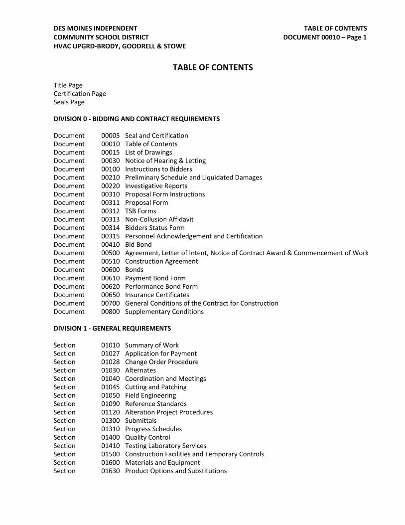
TABLE OF CONTENTS DOCUMENT 00010 – Page 1
DES MOINES INDEPENDENT COMMUNITY SCHOOL DISTRICT HVAC UPGRD-BRODY, GOODRELL & STOWE
TABLE OF CONTENTS
Title Page Certification Page Seals Page
DIVISION 0 - BIDDING AND CONTRACT REQUIREMENTS
Document 00005 Seal and Certification Document 00010 Table of Contents Document 00015 List of Drawings Document 00030 Notice of Hearing & Letting Document 00100 Instructions to Bidders Document 00210 Preliminary Schedule and Liquidated Damages Document 00220 Investigative Reports Document 00310 Proposal Form Instructions Document 00311 Proposal Form Document 00312 TSB Forms Document 00313 Non-Collusion Affidavit Document 00314 Bidders Status Form Document 00315 Personnel Acknowledgement and Certification Document 00410 Bid Bond Document 00500 Agreement, Letter of Intent, Notice of Contract Award & Commencement of Work Document 00510 Construction Agreement Document 00600 Bonds Document 00610 Payment Bond Form Document 00620 Performance Bond Form Document 00650 Insurance Certificates Document 00700 General Conditions of the Contract for Construction Document 00800 Supplementary Conditions
DIVISION 1 - GENERAL REQUIREMENTS
Section 01010 Summary of Work Section 01027 Application for Payment Section 01028 Change Order Procedure Section 01030 Alternates Section 01040 Coordination and Meetings Section 01045 Cutting and Patching Section 01050 Field Engineering Section 01090 Reference Standards Section 01120 Alteration Project Procedures Section 01300 Submittals Section 01310 Progress Schedules Section 01400 Quality Control Section 01410 Testing Laboratory Services Section 01500 Construction Facilities and Temporary Controls Section 01600 Materials and Equipment Section 01630 Product Options and Substitutions

TABLE OF CONTENTS DOCUMENT 00010 – Page 2
DES MOINES INDEPENDENT COMMUNITY SCHOOL DISTRICT HVAC UPGRD-BRODY, GOODRELL & STOWE
Section 01650 Commissioning of Systems Section 01700 Contract Closeout Section 01705 Early Release of Retained Funds Section 01710 Contract Closeout Forms
DIVISION 21 - FIRE SUPPRESSION
21 0050 BASIC FIRE SUPPRESSION REQUIREMENTS21 0529 HANGERS AND SUPPORTS FOR FIRE SUPPRESSION PIPING AND EQUIPMENT21 1200 FIRE SUPPRESSION PIPING21 1300 FIRE SUPPRESSION SPRINKLER SYSTEMS
DIVISION 22 - PLUMBING
22 0050 BASIC PLUMBING REQUIREMENTS22 0529 HANGERS AND SUPPORTS FOR PLUMBING PIPING AND EQUIPMENT22 0719 DOMESTIC PLUMBING INSULATION22 1116 DOMESTIC PLUMBING PIPING22 1119 DOMESTIC PLUMBING SPECIALTIES
DIVISION 23 - HEATING, VENTILATING, AND AIR-CONDITIONING (HVAC) 23 0050 BASIC HVAC REQUIREMENTS23 0090 MINOR HVAC DEMOLITION FOR REMODELING23 0519 METERS AND GAUGES FOR HVAC PIPING23 0529 HANGERS AND SUPPORTS FOR HVAC PIPING AND EQUIPMENT23 0553 IDENTIFICATION FOR HVAC PIPING AND EQUIPMENT23 0593 TESTING, ADJUSTING, AND BALANCING FOR HVAC23 0713 DUCT INSULATION23 0719 HVAC PIPING INSULATION23 0913 DDC INSTRUMENTS AND CONTROL DEVICES FOR HVAC23 0923 DDC CONTROL SYSTEM23 0993 SEQUENCE OF OPERATION FOR HVAC CONTROLS23 2113 HYDRONIC PIPING23 2123 HYDRONIC PUMPS23 2133 HYDRONIC SPECIALTIES23 2500 CLEANING AND TREATMENT OF HYDRONIC SYSTEMS23 2923 VARIABLE FREQUENCY MOTOR CONTROLLER23 3100 HVAC DUCTS AND CASING23 3300 AIR DUCT ACCESSORIES23 3421 ENERGY RECOVERY VENTILATORS23 3600 AIR TERMINAL UNITS23 3700 AIR OUTLETS AND INLETS23 7303 SEMI CUSTOM AIR HANDLING UNITS23 8147 GROUND SOURCE HEAT PUMP
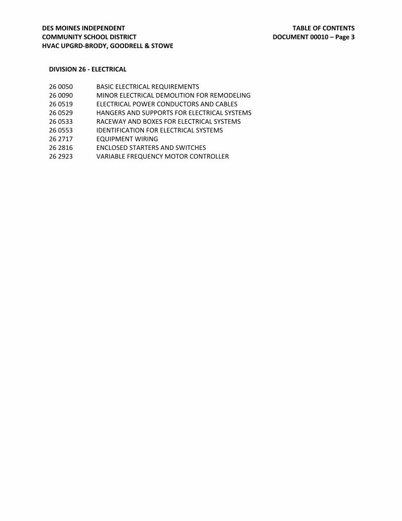
TABLE OF CONTENTS DOCUMENT 00010 – Page 3
DES MOINES INDEPENDENT COMMUNITY SCHOOL DISTRICT HVAC UPGRD-BRODY, GOODRELL & STOWE
DIVISION 26 - ELECTRICAL 26 0050 BASIC ELECTRICAL REQUIREMENTS26 0090 MINOR ELECTRICAL DEMOLITION FOR REMODELING26 0519 ELECTRICAL POWER CONDUCTORS AND CABLES26 0529 HANGERS AND SUPPORTS FOR ELECTRICAL SYSTEMS26 0533 RACEWAY AND BOXES FOR ELECTRICAL SYSTEMS26 0553 IDENTIFICATION FOR ELECTRICAL SYSTEMS26 2717 EQUIPMENT WIRING26 2816 ENCLOSED STARTERS AND SWITCHES26 2923 VARIABLE FREQUENCY MOTOR CONTROLLER

LIST OF DRAWINGS DOCUMENT 00015 – Page 1
DES MOINES INDEPENDENT COMMUNITY SCHOOL DISTRICT HVAC UPGRD-BRODY, GOODRELL & STOWE
LIST OF DRAWINGS
Note: See drawing sheet index on drawing ME-1
C0.0
C0.0 OVERALL COVER SHEET
BRODY MIDDLE SCHOOLC1.0 SYMBOLS SHEETME2.1 ROOF PLANMD1.0N BASEMENT DEMOLITION PLAN - NORTHMD1.1 FIRST FLOOR DEMOLITION PLAN - NORTHMD2.0N BASEMENT PIPING DEMO PLANM1.0N BASEMENT MECHANICAL PLAN - NORTHM1.0W BASEMENT MECHANICAL PLAN - WESTM1.1N FIRST FLOOR MECHANICAL PLAN - NORTHM1.2W SECOND FLOOR MECHANICAL PLANM2.0N BASEMENT MECHANICAL PIPING PLAN - NORTHM4.1 MECHANICAL DETAILSM4.2 MECHANICAL DETAILSM5.1 MECHANICAL SCHEDULESE1.0N BASEMENT ELECTRICAL PLAN - NORTH
GOODRELL MIDDLE SCHOOLC1.0 SYMBOLS SHEETS1.0 STRUCTURAL ROOF PLANME1.0 SITE PLANMD1.1A LEVEL 1 MECHANICAL DEMOLITION PLAN - AREA AME1.1A LEVEL 1 MECHANICAL PLAN - AREA AME1.1B LEVEL 1 MECHANICAL PLAN - AREA BME1.1C LEVEL 1 MECHANICAL PLAN - AREA CME1.2A LEVEL 2 MECHANICAL PLAN - AREA AME1.2B LEVEL 2 MECHANICAL PLAN - AREA BME1.2C LEVEL 2 MECHANICAL PLAN - AREA CME2.0 MECHANICAL ELECTRICAL ROOF PLANME3.1 ENLARGED PLANSME3.2 ENLARGED PLANSME5.1 MECHANICAL DETAILSME6.1 MECHANICAL SCHEDULES
STOWE ELEMENTARYC1.0 SYMBOLS SHEETS2.1 STRUCTURAL ROOF PLANME1.0 SITE PLANME1.1A LEVEL 1 PLAN - AREA AME1.1B LEVEL 1 PLAN - AREA BME1.2A LEVEL 2 PLAN - AREA AME1.2B LEVEL 2 PLAN - AREA BME1.3B LEVEL 3 PLAN - AREA BME2.1 ROOF PLANM2.0B LEVEL 0 MECHANICAL PIPING PLANM2.1A LEVEL 1 MECHANICAL PIPING PLAN - AREA AM2.1B LEVEL 1 MECHANICAL PIPING PLAN - AREA BM2.2A LEVEL 2 MECHANICAL PIPING PLAN - AREA AM2.2B LEVEL 2 MECHANICAL PIPING PLAN - AREA BM2.3B LEVEL 3 MECHANICAL PIPING PLAN - AREA BM5.1 MECHANICAL DETAILS AND SCHEDULES
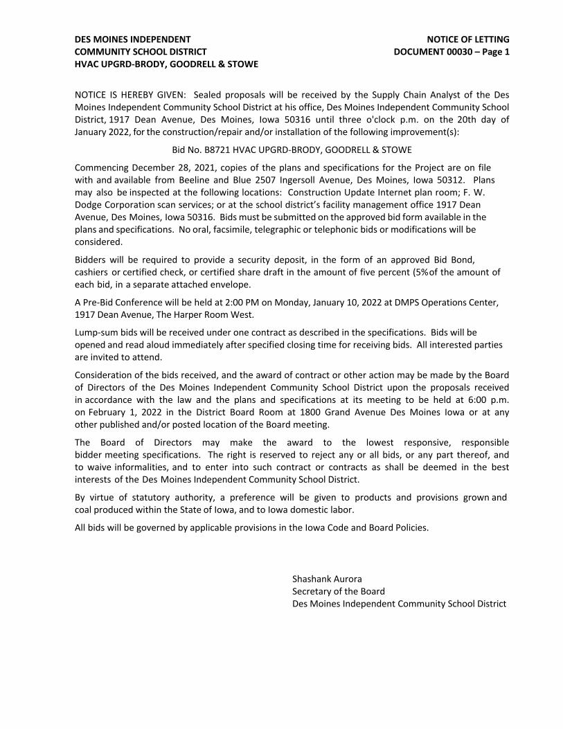
NOTICE OF LETTING DOCUMENT 00030 – Page 1
DES MOINES INDEPENDENT COMMUNITY SCHOOL DISTRICT HVAC UPGRD-BRODY, GOODRELL & STOWE
NOTICE IS HEREBY GIVEN: Sealed proposals will be received by the Supply Chain Analyst of the Des Moines Independent Community School District at his office, Des Moines Independent Community School District, 1917 Dean Avenue, Des Moines, Iowa 50316 until three o'clock p.m. on the 20th day of January 2022, for the construction/repair and/or installation of the following improvement(s):
Bid No. B8721 HVAC UPGRD-BRODY, GOODRELL & STOWE
Commencing December 28, 2021, copies of the plans and specifications for the Project are on file with and available from Beeline and Blue 2507 Ingersoll Avenue, Des Moines, Iowa 50312. Plans may also be inspected at the following locations: Construction Update Internet plan room; F. W. Dodge Corporation scan services; or at the school district’s facility management office 1917 Dean Avenue, Des Moines, Iowa 50316. Bids must be submitted on the approved bid form available in the plans and specifications. No oral, facsimile, telegraphic or telephonic bids or modifications will be considered.
Bidders will be required to provide a security deposit, in the form of an approved Bid Bond, cashiers or certified check, or certified share draft in the amount of five percent (5% of the amount of each bid, in a separate attached envelope.
A Pre-Bid Conference will be held at 2:00 PM on Monday, January 10, 2022 at DMPS Operations Center, 1917 Dean Avenue, The Harper Room West.
Lump-sum bids will be received under one contract as described in the specifications. Bids will be opened and read aloud immediately after specified closing time for receiving bids. All interested parties are invited to attend.
Consideration of the bids received, and the award of contract or other action may be made by the Board of Directors of the Des Moines Independent Community School District upon the proposals received in accordance with the law and the plans and specifications at its meeting to be held at 6:00 p.m. on February 1, 2022 in the District Board Room at 1800 Grand Avenue Des Moines Iowa or at any other published and/or posted location of the Board meeting.
The Board of Directors may make the award to the lowest responsive, responsible bidder meeting specifications. The right is reserved to reject any or all bids, or any part thereof, and to waive informalities, and to enter into such contract or contracts as shall be deemed in the best interests of the Des Moines Independent Community School District.
By virtue of statutory authority, a preference will be given to products and provisions grown and coal produced within the State of Iowa, and to Iowa domestic labor.
All bids will be governed by applicable provisions in the Iowa Code and Board Policies.
Shashank AuroraSecretary of the Board Des Moines Independent Community School District
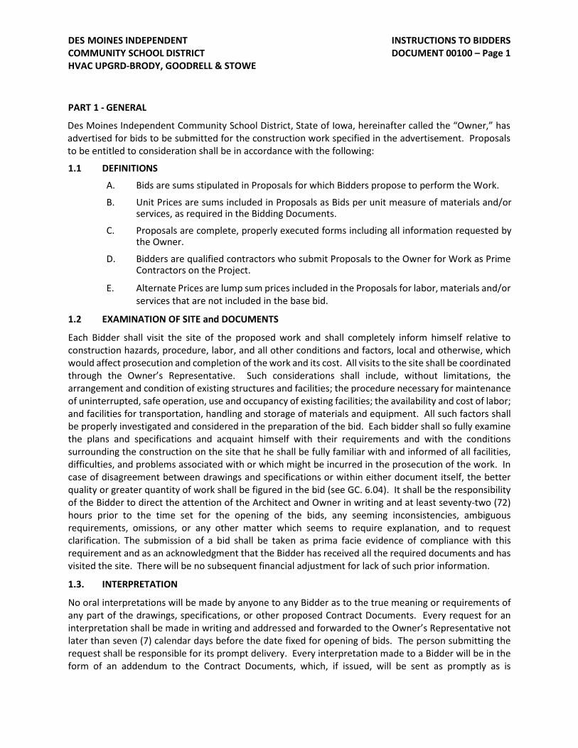
INSTRUCTIONS TO BIDDERS DOCUMENT 00100 – Page 1
DES MOINES INDEPENDENT COMMUNITY SCHOOL DISTRICT HVAC UPGRD-BRODY, GOODRELL & STOWE
PART 1 - GENERAL
Des Moines Independent Community School District, State of Iowa, hereinafter called the “Owner,” has advertised for bids to be submitted for the construction work specified in the advertisement. Proposals to be entitled to consideration shall be in accordance with the following:
1.1 DEFINITIONS
A. Bids are sums stipulated in Proposals for which Bidders propose to perform the Work.
B. Unit Prices are sums included in Proposals as Bids per unit measure of materials and/orservices, as required in the Bidding Documents.
C. Proposals are complete, properly executed forms including all information requested bythe Owner.
D. Bidders are qualified contractors who submit Proposals to the Owner for Work as PrimeContractors on the Project.
E. Alternate Prices are lump sum prices included in the Proposals for labor, materials and/orservices that are not included in the base bid.
1.2 EXAMINATION OF SITE and DOCUMENTS
Each Bidder shall visit the site of the proposed work and shall completely inform himself relative to construction hazards, procedure, labor, and all other conditions and factors, local and otherwise, which would affect prosecution and completion of the work and its cost. All visits to the site shall be coordinated through the Owner’s Representative. Such considerations shall include, without limitations, the arrangement and condition of existing structures and facilities; the procedure necessary for maintenance of uninterrupted, safe operation, use and occupancy of existing facilities; the availability and cost of labor; and facilities for transportation, handling and storage of materials and equipment. All such factors shall be properly investigated and considered in the preparation of the bid. Each bidder shall so fully examine the plans and specifications and acquaint himself with their requirements and with the conditions surrounding the construction on the site that he shall be fully familiar with and informed of all facilities, difficulties, and problems associated with or which might be incurred in the prosecution of the work. In case of disagreement between drawings and specifications or within either document itself, the better quality or greater quantity of work shall be figured in the bid (see GC. 6.04). It shall be the responsibility of the Bidder to direct the attention of the Architect and Owner in writing and at least seventy-two (72) hours prior to the time set for the opening of the bids, any seeming inconsistencies, ambiguous requirements, omissions, or any other matter which seems to require explanation, and to request clarification. The submission of a bid shall be taken as prima facie evidence of compliance with this requirement and as an acknowledgment that the Bidder has received all the required documents and has visited the site. There will be no subsequent financial adjustment for lack of such prior information.
1.3. INTERPRETATION
No oral interpretations will be made by anyone to any Bidder as to the true meaning or requirements of any part of the drawings, specifications, or other proposed Contract Documents. Every request for an interpretation shall be made in writing and addressed and forwarded to the Owner’s Representative not later than seven (7) calendar days before the date fixed for opening of bids. The person submitting the request shall be responsible for its prompt delivery. Every interpretation made to a Bidder will be in the form of an addendum to the Contract Documents, which, if issued, will be sent as promptly as is

INSTRUCTIONS TO BIDDERS DOCUMENT 00100 – Page 2
DES MOINES INDEPENDENT COMMUNITY SCHOOL DISTRICT HVAC UPGRD-BRODY, GOODRELL & STOWE
practicable to all persons to whom the drawings, specifications, and other proposed Contract Documents have been issued. All such addenda shall become part of the Contract Documents and their receipt shall be acknowledged in the Bid Proposal. The Owner will not be responsible for any other explanations or interpretations of the proposed Contract Documents.
1.4 PROPOSAL FORMS
Proposal forms included in the specification may be copied and used for submitting proposals. Proposals shall be made upon the forms provided, therefore. Refer to Document 00311 Proposal Form Instructions, and Document 00311 Proposal Form. Any Proposal NOT submitted on required forms may be rejected.
Attention is directed to the fact that the Contract Documents contain one complete set of bidding and contract forms; these are sample forms included for the information of Bidders. They are not to be detached from the Contract Documents, filled out or executed.
Special attention is directed to the Form of Bid Bond (Document 00410) included in the bidding documents. Additional copies of this form may be secured from the Owner’s Representative, but the use of this particular form is not mandatory. Any similar standard form of a recognized responsible surety which contains the same stipulations and guarantees, the same execution of the contract and indemnification of the Owner in case of default, will be acceptable.
1.5 PREPARATION OF PROPOSAL FORMS
All proposal forms must be prepared in single copy and in conformity with and be based upon and submitted subject to all requirements of the Contract Documents. They must be fully completed with all blanks appropriately filled in. Each bid shall be legibly written or printed in ink on the separate form provided. No alterations in bids, or in the printed forms therefore, by erasures, interpolations, or otherwise will be acceptable unless each such alteration is signed or initialed by the Bidder; if initialed, the Owner may require the Bidder to identify any alteration so initialed. No alteration in any bid, or in the form on which it is submitted, shall be made after the bid has been submitted.
It will be the Bidder’s responsibility to secure any and all addenda from the Architect. The Bidder will be required to acknowledge receipt of all addenda. Owner reserves the right to reject any bid which is received which has not been based upon all addenda issued by the Architect.
No Bidder may submit more than one bid. Multiple bids under different names will not be accepted from one firm or association.
The Bidder is required to bid on all alternates and complete all blanks on the bid form. If alternates are called for on a type or method of construction as to which the Bidder does not desire to bid, the Bidder shall insert the words “NO BID.” In case the Bidder desires to bid on an alternate, it shall set forth in the space provided therefore, the amount to be added or deducted from the base bid or in the event that the Bidder does not desire to make a change from the base bid, it shall so indicate by using the words “NO CHANGE.” In the selection of alternates, the Owner reserves the right to select or reject any or all alternates in the proposal if, in the judgment of the Board of Directors, or its designees, the best interest of the School District will be so served.
1.6 BID PERFORMANCE GUARANTIES
Bid security (single copy) in the form of a certified or cashier's check, certified share draft, money or surety bond in the amount of at least five (5%) percent of the bid price, payable without condition or qualification to Des Moines Independent Community School District, shall accompany each bid in the OUTER envelope,
INSTRUCTIONS TO BIDDERS DOCUMENT 00100 – Page 3
DES MOINES INDEPENDENT COMMUNITY SCHOOL DISTRICT HVAC UPGRD-BRODY, GOODRELL & STOWE
as evidence of good faith and as a guarantee that if awarded the contract, the Bidder will execute the Contract and give bond as required. The Bidder assumes all responsibility for furnishing acceptable bid security.
Bid security in the form of a bond (see Document 00410) will be accepted only if from a regularly established firm licensed to write such surety in the State of Iowa.
The bid security of each unsuccessful Bidder will be returned when the Construction Agreement is fully executed. The bid security will be voided but retained by the Owner, if, after the Notice of Contract Award, the Bidder shall enter into a Contract and file a satisfactory performance bond, labor and material payment bond, and certificates of required insurance, all within ten (10) calendar days after the date such notice is given by the Owner. The bid security of the second and third lowest responsible Bidders may be retained for not to exceed forty-five (45) days after opening, pending the execution of the Construction Agreement and submission of bond by the successful Bidder.
This bid security may be retained by the Owner as liquidated damages, if the bid is accepted and a contract thereon is awarded but the successful Bidder fails to enter into a contract in the form prescribed with legally responsible sureties, within ten (10) calendar days after date of Notice of Contract Award is given by the Owner.
The Owner shall require the Bidder to whom a Contract is awarded to furnish to the Owner both Performance and Labor and Material Payment bonds in the amount of one hundred (100%) percent of the Contract price, covering the faithful performance of the Contract and the payment of all obligations arising thereunder, and the Bidder will further provide warranties as required by the specifications or General Conditions.
The bonds shall be executed on the forms included with the Contract Documents (forms shall not be removed from the Contract Documents; Bidders may use copies of the bond forms included in the specifications). Accompanying each bond form shall be a “Power of Attorney” authorizing the attorney in fact to bind the surety company and certified to include the date of the bond.
1.7 LIST OF SUBCONTRACTORS AND SUPPLIERS OF LABOR AND MATERIAL
The lowest bidder for each contract shall, within twenty-four (24) hours following the bid opening, provide the Owner with the signed List of Subcontractors and Suppliers of Labor and Material on the formprovided in Section 00100 Instructions to Bidders. Subcontractor is any entity performing 1-1/2% or more of the contract value. The List shall detail the quotations used in the preparation of the bid and whose services are proposed to be used in construction of the project. The List must be complete showing all sections in the Construction Documents. Failure to submit the List may preclude the bid from further consideration by the Owner. The Owner reserves the right to either disclose or not disclose the List of the successful Bidder.
Each Bidder shall identify and fully disclose on the List all those subcontractors and suppliers proposed for the work with which the Bidder is connected either directly or indirectly as part owner, participant in profits and losses or in any other manner financially or economically.
1.8 BACKGROUND INFORMATION
The lowest bidder for each contract shall, within twenty-four (24) hours following the bid opening, provide the Owner with the Background Information included in Section 00100 Instructions to Bidders. The Contractor must complete and fully disclose all information requested in the Background Information.

INSTRUCTIONS TO BIDDERS DOCUMENT 00100 – Page 4
DES MOINES INDEPENDENT COMMUNITY SCHOOL DISTRICT HVAC UPGRD-BRODY, GOODRELL & STOWE
Failure to submit the Background Information may preclude the bid from further consideration by the Owner.
The Owner may make such investigations as deemed necessary to determine the ability and qualification of the Bidder. Bidders shall submit within twenty-four (24) hours, if requested by the Owner, such evidence of the Bidder's competency and practical knowledge to do the particular work covered by his proposal and of the Bidder's financial responsibility, resources, experience, organization and equipment to complete the proposed work. Failure to comply with this requirement may result in the rejection of consideration of such bid.
In determining the Bidder’s qualifications, the following factors, among others, will be considered: work previously completed by the Bidder; the qualifications of the proposed subcontractors for their work; Bidder references; and whether the Bidder (a) maintains a permanent place of business; (b) has adequate plant and equipment to do the work properly and expeditiously; (c) has the financial resources to meet all obligations incident to the work; (d) has appropriate technical experience; and (e) has adequate, competent, experienced staff and supervisors who will be committed to the work until completion.
Each Bidder may be required to show that he has handled former work and that no just claims have been prosecuted or are pending against such work. No bid will be accepted from a Bidder who is engaged on any work which would impair his ability to perform or finance this work or other work in progress.
The Owner reserves the right to reject any bid if the Owner determines, in its sole and absolute discretion, that the Bidder is not properly qualified to carry out the obligations of the Contract and/or to complete the work contemplated by the contract. Conditional bids will not be accepted.
1.9 PERMITS AND FEES
The School District shall secure and pay for the general building permit. Trade contractors will be responsible to obtain and pay for their specialty permits. The Owner is exempt from paying certain fees and it will be the contractor’s responsibility to acquaint himself with the laws and regulations governing said fees. Attention is directed to the requirements of the General Conditions regarding obtaining permits. The contractor shall obtain and pay for all fees associated with work in the Department of Transportation right of way.
1.10 TAXES
Sales and use taxes shall be excluded from the bid for all items incorporated into the final project. The Owner will provide sales tax exemption certificates as appropriate. See section 00700 General Conditions paragraph 12.04 for additional requirements.
1.11 SIGNATURE OF BIDDERS
Each Bidder shall sign and notarize the bid form, on the last page of the form and the bid bond If the Bidder is an individual, the Bidder must sign in individual capacity. Bids by partnerships shall be signed with the partnership name followed by the signature and designation of one of the partners or other authorized representative. Bids by corporations shall be signed with the name of the corporation followed by the signature and designation of the president or other person authorized to bind the corporation and attested to by the secretary with corporate seal (if available). Bids by joint ventures shall be signed by each participant in the joint venture or by an authorized agent of each participant. The names of all persons signing should also be typed or printed below the signature. A bid by a person who affixes to his signature the word “president,” “secretary,” “agent,” or other designation without disclosing his principal
INSTRUCTIONS TO BIDDERS DOCUMENT 00100 – Page 5
DES MOINES INDEPENDENT COMMUNITY SCHOOL DISTRICT HVAC UPGRD-BRODY, GOODRELL & STOWE
may be held to be the bid of the individual signing. When requested by the Owner, evidence of the authority of the person signing shall be furnished.
1.12 SUBMISSION OF BIDS
Bid Documents shall be enclosed in two envelopes (OUTER and INNER), each of which shall be sealed and clearly labeled “BID DOCUMENTS” and identified with the description of the work to which the proposal applies; the name of the project; the name and address of the Bidder; and the time of opening bids; all in prominent lettering so as to guard against opening prior to the stipulated time. The INNER envelopeshall include the form of proposal (Document 00311) and Shall be marked “BID ENCLOSED”. The “OUTER envelope” shall include the Bid Bond (Document 00410)), along with the INNER envelope. If the OUTER envelope does NOT include the required document, the INNER “BID ENCLOSED” envelope will NOT be opened. No responsibility shall attach to any employee of the Owner for the premature opening of any bid not prominently identified. The Bidder shall be responsible for placing his firm name and the name and number, if applicable, of the project and the time of the bidding on the outside of such bid envelope.
The Bid Documents shall be submitted at the time and location as noted in the Invitation to Bid. Bids received after the specified time of closing will be returned unopened.
1.13 WITHDRAWAL OF BIDS
Any Bidder may withdraw his bid if written request for withdrawal signed in the same manner and by the same person who signed the Bid Form is received by the individual of the School District requesting the bids prior to the time established for the opening of the bids.
No Bidder may withdraw his bid for forty-five (45) days after the scheduled time set for the opening thereof, or before award of the Contract, unless said award is delayed for a period exceeding forty-five (45) calendar days.
1.14 MODIFICATIONS
No oral, telephonic, or telegraphic modifications will be considered.
1.15 ACCEPTANCE OF BIDS
The Owner reserves the right to accept the bid which in its judgment is the most responsive responsible and best bid or to reject any and all bids and alternatives and to waive or disregard irregularities or informalities in any bid as it may deem to be in the best interest of the School District. The Board of Directors or its designees may consider as irregular any bid on which there is an alteration of, or departure from, the bid form. All proposals received after the specified time of closing shall be returned unopened.
Final determination of compliance with specifications will rest with the Owner.
1.16 APPLICABLE LAWS AND REGULATIONS
Each Bidder shall familiarize himself with all state and local laws, codes, ordinances, and regulations which might in any manner affect the work to be done; the materials to be supplied; the taxes, permits and fees to be paid; or the labor to be employed in and about the work. Any claim of misunderstanding or ignorance on the part of any successful Bidder will not in any way excuse such Bidder from the necessity of full compliance with every such law, code, ordinance, or regulation. All state laws, codes and regulations and local ordinances, which are applicable, shall be complied with including but not limited to those specified in these documents.
INSTRUCTIONS TO BIDDERS DOCUMENT 00100 – Page 6
DES MOINES INDEPENDENT COMMUNITY SCHOOL DISTRICT HVAC UPGRD-BRODY, GOODRELL & STOWE
1.17 INSURANCE
Throughout the life of the contract, the Contractor will be required to carry the types and amounts of insurance named in the General Conditions.
1.18 CONTRACTOR'S LICENSE
Any successful Bidder may be required by the Owner to obtain the necessary and applicable Contractor’s License from all appropriate governmental authorities and if required, shall not allow any subcontractor to commence work on his subcontract until all similar provisions required of the subcontractor have been obtained and approved.
1.19 POST-BID INTERVIEWS
Bidders in contention for contract awards may be asked to attend Post-Bid Interviews, submit Post-Bid Submittals in rough draft for review. (See Document 00500.)
1.20 DAVIS BACON AND RELATED ACTS
This contract is being funded by federal dollars. The successful bidder will be required to conform to the wage requirements prescribed by the federal Davis-Bacon and Related Acts which requires that all laborers and mechanics employed by contractors and sub-contractors performing on contracts funded in whole or in part with federal funds in excess of $2,000 pay their laborers and mechanics not less than the prevailing wage rates and fringe benefits, as determined by the Secretary of Labor, for the corresponding classes of laborers and mechanics employed on similar projects in the area.
INSTRUCTIONS TO BIDDERS DOCUMENT 00100 – Page 7
DES MOINES INDEPENDENT COMMUNITY SCHOOL DISTRICT HVAC UPGRD-BRODY, GOODRELL & STOWE
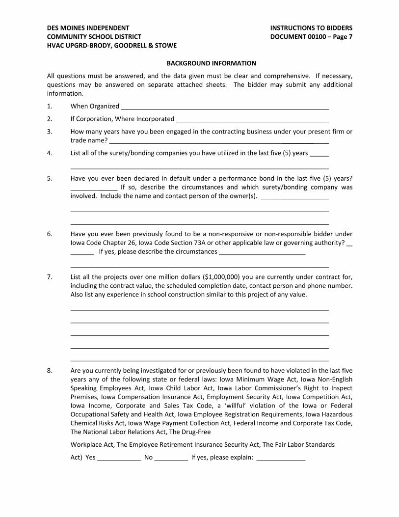
BACKGROUND INFORMATION
All questions must be answered, and the data given must be clear and comprehensive. If necessary, questions may be answered on separate attached sheets. The bidder may submit any additional information.
1. When Organized
2. If Corporation, Where Incorporated
3. How many years have you been engaged in the contracting business under your present firm ortrade name? _________
4. List all of the surety/bonding companies you have utilized in the last five (5) years
5. Have you ever been declared in default under a performance bond in the last five (5) years?________ If so, describe the circumstances and which surety/bonding company wasinvolved. Include the name and contact person of the owner(s). ______
6. Have you ever been previously found to be a non-responsive or non-responsible bidder underIowa Code Chapter 26, Iowa Code Section 73A or other applicable law or governing authority?
If yes, please describe the circumstances
7. List all the projects over one million dollars ($1,000,000) you are currently under contract for,including the contract value, the scheduled completion date, contact person and phone number.Also list any experience in school construction similar to this project of any value.
8. Are you currently being investigated for or previously been found to have violated in the last fiveyears any of the following state or federal laws: Iowa Minimum Wage Act, Iowa Non-EnglishSpeaking Employees Act, Iowa Child Labor Act, Iowa Labor Commissioner’s Right to InspectPremises, Iowa Compensation Insurance Act, Employment Security Act, Iowa Competition Act,Iowa Income, Corporate and Sales Tax Code, a ‘willful’ violation of the Iowa or FederalOccupational Safety and Health Act, Iowa Employee Registration Requirements, Iowa HazardousChemical Risks Act, Iowa Wage Payment Collection Act, Federal Income and Corporate Tax Code,The National Labor Relations Act, The Drug-Free
Workplace Act, The Employee Retirement Insurance Security Act, The Fair Labor Standards
Act) Yes No If yes, please explain:

INSTRUCTIONS TO BIDDERS DOCUMENT 00100 – Page 8
DES MOINES INDEPENDENT COMMUNITY SCHOOL DISTRICT HVAC UPGRD-BRODY, GOODRELL & STOWE
9. Do you currently have any legal action pending which could impact your ability to perform thisProject? If yes, please explain:
No actions will be made on the basis of answers to the above questions without an inquiry and an opportunity to be heard regarding the circumstances of the matters reported.
The undersigned hereby authorizes and requests any person, firm or corporation to furnish any credit history and financial condition or other information required by the District in verification of the recitals comprising this statement of Background Information. The undersigned further authorizes the District to conduct any and all necessary investigations of the undersigned’s federal and state Occupational Safety and Health Act (OSHA) Compliance, including access to State and Federal records.
I hereby certify that the above information is true and correct to the best of my knowledge and that the District may rely on the information provided.
THIS STATEMENT MUST BE NOTARIZED.
NAME OF CONTRACTOR:
BY:
Signature Title
Type/Print Name Date
STATE OF IOWA, COUNTY, ss:
Subscribed and sworn to before me by the said on this day of , 20_.
____________________________________
Notary Public in and for the State of Iowa

INSTRUCTIONS TO BIDDERS DOCUMENT 00100 – Page 9
DES MOINES INDEPENDENT COMMUNITY SCHOOL DISTRICT HVAC UPGRD-BRODY, GOODRELL & STOWE
LIST OF SUBCONTRACTORS AND SUPPLIERS OF LABOR AND MATERIAL
PROJECT: CONTRACTOR NAME:_____________________________
Pursuant to the provisions set forth in the Instructions to Bidders, The General Conditions, and the Proposal Form, the above-named contractor hereby designates below the names and locations of the place of business of each subcontractor. District may request subcontractor license number.
SUBCONTRACTOR BUSINESS ADDRESS WORK TO BE DONE
Comments:_________________________________________________________________
_________________________________________________________________________
_________________________________________________________________________
END OF DOCUMENT

SCHEDULE AND LIQUIDATED DAMAGES DOCUMENT 00210 – Page 1
DES MOINES INDEPENDENT COMMUNITY SCHOOL DISTRICT HVAC UPGRD-BRODY, GOODRELL & STOWE PART 1 - GENERAL
1.1 TIME OF COMPLETION
A. It is to be understood that time is of the essence for this Contract and the Contractor will berequired to perform the Work within the allowable time set forth in the Contract. In thisconnection, attention is directed to the provisions of the General Conditions andSupplementary General Conditions, if any, relative to delays, extensions of time, andliquidated damages. The successful bidder/contractor shall, within ten (10) days after theNotice of Contract Award, prepare and submit for the Owner's approval, a PreliminaryConstruction Schedule. The schedule shall indicate the time of performance and thecompletion dates of the various portions of the Work, and the dates upon which the Ownermay expect to be allowed to occupy all or portions of the Project.
B. The Owner and the Contractor shall agree mutually on any changes in either the schedule orthe rate of performance of the Work which might either favorably or adversely affect suchschedule dates. No additional compensation or fee shall be paid by the Owner, for anycompletion of all or any portions of the Work earlier than scheduled unless otherwisespecifically noted in Bid Documents.
1.2 PRELIMINARY CONSTRUCTION SCHEDULE
A. The Preliminary Construction Schedule indicates planned Substantial Completion dates for significant activities during the construction period. Substantial Completion of an activity is considered to be when the work of subsequent activities can proceed in accordance with the Project Construction Schedule.
1.3 CONSTRUCTION PROGRESS SCHEDULE
A. A detailed Construction Progress Schedule shall be submitted by the Contractor prior to thesubmission of the first request for payment. No partial payment on account of workperformed shall be made until such detailed Construction Progress Schedule has beenapproved by the Owner. Refer to Section 01310 for format requirements. Constructionsequence or timing of schedules received from contractors may be adjusted in the ProjectConstruction Progress Schedule by the Owner’s Representative to facilitate sequencing andcoordination of the overall Project.
B. During the construction period the Contractor is required to regularly provide informationand input on scheduling and coordination of his work. The Construction Progress Schedulewill detail the Contractor's performance between Project milestone dates. ConstructionProgress Schedules will be required with each Contractor’s Application for Payment.
C. The mandatory Project milestones are listed in this section.
PROJECT MILESTONES
A. Bids Due: January 20th 2022
B. Notice of Award: February 1st 2022
C. Construction Start June 1, 2022
D. Substantial Completion: August 12, 2022
E. Final Completion: September 30th 2022
SCHEDULE AND LIQUIDATED DAMAGES DOCUMENT 00210 – Page 2
DES MOINES INDEPENDENT COMMUNITY SCHOOL DISTRICT HVAC UPGRD-BRODY, GOODRELL & STOWE
F. Definitions:
1. Construction Start date: Established date on which the Contractor shall actively begin the Work on site to be completed under this contract. The construction start date may be amended to permit the Contractor to begin work sooner than established herein, upon approval of the Owner.
2. Substantial Completion date: Established date on which the Work, or designated portion(s) thereof, has been sufficiently completed in accordance with the Contract Documents so as to permit the owner to safely and legally occupy or utilize the Work for its intended use, subject only to minor punch list items the absence of completion which does not interfere with the Owner’s intended use of the project.
3. Final Completion date: Established date on which all outstanding items of the Work -including activities established in the Contract Documents, punch lists and established closeout documentation – have been fully executed and submitted to the Owner.

SCHEDULE AND LIQUIDATED DAMAGES DOCUMENT 00210 – Page 3
DES MOINES INDEPENDENT COMMUNITY SCHOOL DISTRICT HVAC UPGRD-BRODY, GOODRELL & STOWE
GENERAL CONTRACTOR AND ALL SUBCONTRACTORS SHALL INCLUDE THE NECESSARY PROJECT MANAGEMENT, LABOR, OVERTIME OR DOUBLE SHIFT REQUIREMENTS TO MEET THE PROJECT’S SUBSTANTIAL COMPLETION DATE . WITHIN LIMITATIONS NOTED BELOW, THE BUILDING IS AVAILABLE 24/7.
General notes:
- These schools will not be in summer session during the duration of the project. Contractor work during school days / school activities shall not restrict full use of the parking lots and building by the school students, staff and visitors.
- Work can be done on all days during the summer session.
- All hauling of equipment and materials in/out and debris removal must insure the safety of the students, staff and visitors. Station personnel at areas of conflict when material or equipment is transferred in and out.
- The contractor may utilize the school parking lot during the summer break.
- Work to be coordinated through the Owner’s representative.
- All existing utility and communication services and distribution systems shall remain active during this work. Should a system be affected due to this work, the contractor shall make any required repairs to the system affected. Systems to maintain include in part: heating and ventilating, plumbing, electrical, temperature controls, fire alarm, security, intercoms, data /communications, and clock systems.
- Temporary security barriers and interior construction barriers shall be installed to separate the school and public from the work areas when rooms with work cannot be secured. All partitions shall be constructed per Section 01500 and shall be from floor to structure above. Maintain and remove the partitions when no longer required. Patch adjacent surfaces as required.
- Emergency exiting as required by the City of Des Moines code officials must be kept available while work continues for the renovation. The contractor shall phase the work around the exits to maintain a level unobstructed path of travel at all times to the public right of way.
- Close Out: Completion of Closeout Documents and punch list. – August 15, 2020 – September 30, 2022. All punch list work shall occur after school hours.
END OF DOCUMENT

INVESTIGATION REPORTS DOCUMENT 00220 – Page 1
March 15, 2001
DES MOINES INDEPENDENT COMMUNITY SCHOOL DISTRICT HVAC UPGRD-BRODY, GOODRELL & STOWE
PART 1 - GENERAL
1.1 INFORMATION AVAILABLE TO BIDDERS
The following reports are available to bidders for information:
A. Abatement report available by request. Abatement will be performed by owner.B. The Contractor is hereby notified that some or all of the buildings covered by this ConstructionAgreement may contain lead-based paint. Some or all of the buildings covered by this ConstructionAgreement may be considered child occupied facilities as that term is used by the United StatesEnvironmental Protection Agency ("EPA") and the Iowa Department of Public Health ("IDPH"). StartingApril 2010, federal and state law will require contractors that disturb lead-based paint in homes, childcare facilities and schools, built before 1978 to be certified and follow specific practices to prevent leadcontamination. Further information regarding these requirements is available on the Iowa Departmentof Public Health website.The Contractor is solely and fully responsible for the compliance with all applicable law and regulationsregarding lead-based paint, including but not limited to those of EPA, IDPH and OSHA.
1.2 USE OF INFORMATION
A. All these documents made available by the Owner are for information only and are not a warranty of existing conditions.B. Bidders may purchase a copy at cost of reproduction.C. The data contained in the above items have been utilized in the preparation of construction documents. The Contractor may rely on the accuracy of the technical
data contained in the report, but not upon non-technical data, interpretations or opinions contained therein, or for the completeness thereof for the Contractor's purposes.D. Except as indicated in the preceding paragraph, Contractor has full responsibility with respect to subsurface conditions at the site.

PROPOSAL FORM INSTRUCTIONS DOCUMENT 00310 – Page 1
DES MOINES INDEPENDENT COMMUNITY SCHOOL DISTRICT HVAC UPGRD-BRODY, GOODRELL & STOWE
PART 1 - GENERAL
1.1 PROPOSAL FORMS
A. Bidders are required to use the Proposal Form provided in Document 00311 or submit bid onthe DMPS electronic portal. Contact the DMPS Senior Supply Chain Analyst at 515-242-7649to become registered to submit a bid electronically. Additional proposal forms may be copiedfrom this manual or obtained from the Owner’s Representative.
PART 2 - PROPOSAL FORMAT
2.1 BID PROPOSALS
A. The Proposal consists of all the following required documents:
1. Proposal Form (Document 00311) Inner Envelope.
2. Bid Security (Document 00410) Outer Envelope.
B. Bid documents shall be enclosed in two envelopes (OUTER and INNER), each of which shall besealed and clearly labeled “BID DOCUMENTS” and identified with the name and Bid Numberof the project; the name and address of the Bidder; and the time or opening bids. The INNERenvelope shall contain the Bid Proposal. The OUTER envelope shall contain the Bid Bond andINNER envelope. If all supporting documents are not included, the inner envelope will not beopened.
All information shall be in prominent lettering so as to guard against opening prior to thestipulated time. No responsibility shall attach to any employee of the Owner for thepremature opening of any bid not prominently identified. The Bidder shall be responsible forplacing his firm name and number, if applicable, of the project and the time of the bidding onthe outside of such bid envelope.
C. All spaces provided on the Proposal Forms shall be filled in. If any space provided is notutilized by the Bidder, that space shall be filled in with the notation "NA" (Not Applicable).
D. The Proposal Forms shall be typewritten or manually printed in ink.
E. Where indicated, all amounts shall be expressed in words and in figures. In case ofdiscrepancy, the words shall govern.
F. Bidders shall not make unsolicited notations or statements on the Proposal Forms. Alterationof the Proposal Forms is not permitted and may result in the proposal being considered non-responsive.
G. The person who signs the Proposal shall initial all changes to and erasures of the Bidder’sentries on the Proposal Forms.
H. Each Proposal shall include the legal name of the Bidder and a statement regarding whetherthe Bidder is a sole proprietor, a partnership, a corporation, or other type of legal entity.Proposals submitted by corporations shall have the state of incorporation noted. Any Bidsubmitted by an agent shall have a current Power of Attorney attached, certifying the agent'spower to bind the Bidder.
PART 3 - COMPLETION OF PROPOSAL FORMS
3.1 PROPOSAL FORM (DOCUMENT 00311)
A. Submit only one Proposal Form. Copies of the Proposal Form may be made.
B. Fill in the numbers and dates of all Addenda received and considered in the Proposal.Proposals must include acknowledgement of all Addenda issued prior to the Bid Date.

PROPOSAL FORM INSTRUCTIONS DOCUMENT 00310 – Page 2
DES MOINES INDEPENDENT COMMUNITY SCHOOL DISTRICT HVAC UPGRD-BRODY, GOODRELL & STOWE
C. Type or print the signer's name and title in the spaces provided below the signature.
D. Date the Form in the spaces provided.
E. Place the Contractor's name at the bottom of each page in the space provided.
F. Have the Bid Proposal Notarized.
G. Completed Proposal form to be included in the INNER envelope.
3.2 TSB (Targeted Small Business Participation) FORM (DOCUMENT 00312) Indicate participation on bid form. Low bidder to provide participation documents along with 24 HR information.
A. Program Description
1. In accordance with the Code of Iowa, Articles 73.15 through 73.21 and as amended bySec. 223 of House File 479, the Board of Education of the Des Moines IndependentCommunity School District seeks to provide opportunities for Iowa Targeted SmallBusinesses in the award of all contracts. The Certified Iowa Targeted Small Businessparticipation target is ten percent (10%) of the base bid.
B. Definitions
1. Targeted Small Business (TSB) means a small business which is fifty-one percent or moreowned, operated, and actively managed by one or more women or minority persons.Certified in the above context means the TSB has been certified by the IowaDepartment of Inspections and Appeals. A complete listing of all certified TSB's maybe secured from the Iowa Department of Economic Development (515) 242-4700.
2. Small business means any enterprise located in this state which is operated for profitunder a single management, and which has an annual gross income of less thanthree million dollars computed as the average of the three preceding fiscal years.
3. Minority person(s) means an individual who is Black, Hispanic, Asian or PacificIslander, American Indian or Alaskan native.
4. Actively managed means exercising the power to make policy decisions affecting thebusiness.
5. Operated means actively involved in the day-to-day management of the business.
C. Performance and Payment Bond Waiver
1. If Contractor is a TSB, the contractor may be eligible to receive a waiver of theperformance and payment bond requirements pursuant to the provisions of theIowa Satisfaction and Performance Bond Program, Section 12.44 of the Code ofIowa.
2. Certification of eligibility to participate in the Iowa Satisfaction and PerformanceBond Program is determined by the Iowa Department of Inspection and Appeals.

PROPOSAL FORM INSTRUCTIONS DOCUMENT 00310 – Page 3
DES MOINES INDEPENDENT COMMUNITY SCHOOL DISTRICT HVAC UPGRD-BRODY, GOODRELL & STOWE
D. Documentation
To document that a good faith effort has been made to meet the TSB participation goal,each prime bidder shall submit with their bid an executed copy of this form, completelyfilled out. Make additional copies of the form as required.
E. Place the Contractor's name at the bottom of each page in the space provided.
F. Date the Form in the spaces provided.
G. Completed TSB form Page 1 must be signed and notarized by the person signing the ProposalForm.
H. Completed TSB forms to be included with the 24 hour information.
3.3 NON-COLLUSION AFFIDAVIT (DOCUMENT 00313)
By signing bid form, bidder acknowledges non-collusion.
A. Submit the Non-Collusion Affidavit on the form provided. Copies may be made.
B. Type or print the signer's name and title in the spaces provided.
C. Place the Contractor's name at the bottom of the page in the space provided.
D. Have the Non-Collusion Affidavit Notarized.
E. Completed Non-Collusion Affidavit to be included by low bidder with the24 HR. information.
3.4 BIDDERS STATUS FORM (DOCUMENT 00314)
Indicate on bid form, bidders residency status.
A. Submit the fully completed Bidders Status From on the form provided. Copies may be made.
B. Place the Contractor's name at the bottom of the page in the space provided.
C. Sign and date the Form in the space provided.
D. Completed Bidders Status Form to be included by low bidder along with the 24 Hr.information.
3.5 PERSONNEL ACKNOWLEDGEMENT AND CERTIFICATION (DOCUMENT 00315)
By signing, bidder acknowledges commitment to compliance with all applicable rules, regulations, and restrictions regarding the employment of personnel as defined therein.
A. Submit an executed copy of the Personnel Certification and Acknowledgement form. Copiesmay be made.
B. Sign and date the Form in the space provided.
C. Completed Bidders Status Form to be included by low bidder along with the 24 Hr.information.
3.6 SUBMISSION OF PROPOSALS
A. Bidders shall bear full responsibility for delivering Proposals to the location for receipt ofProposals by the time and date for receipt of Proposals.
B. Owner will not provide telephones for use by Bidders when preparing their bid.
C. Telephone, faxed or oral bids will not be accepted.
3.7 MODIFICATION OR WITHDRAWAL OF PROPOSALS
PROPOSAL FORM INSTRUCTIONS DOCUMENT 00310 – Page 4
DES MOINES INDEPENDENT COMMUNITY SCHOOL DISTRICT HVAC UPGRD-BRODY, GOODRELL & STOWE
A. Any Bidder may withdraw his bid if written request for withdrawal signed in the same mannerand by the same person who signed the Bid Form is received by the individual of the SchoolDistrict requesting the bids prior to the time established for the opening of the Bids.
B. No Bidder may withdraw his bid for forty-five (45) days after the scheduled time set for theopening thereof, or before award of the Contract, unless said award is delayed for a periodexceeding forty-five (45) calendar days.
C. Proposals that are withdrawn may be resubmitted before the time and date designated forthe receipt of Proposals.
D. No oral, telephonic, telegraphic or FAXED modifications will be considered.
END OF DOCUMENT
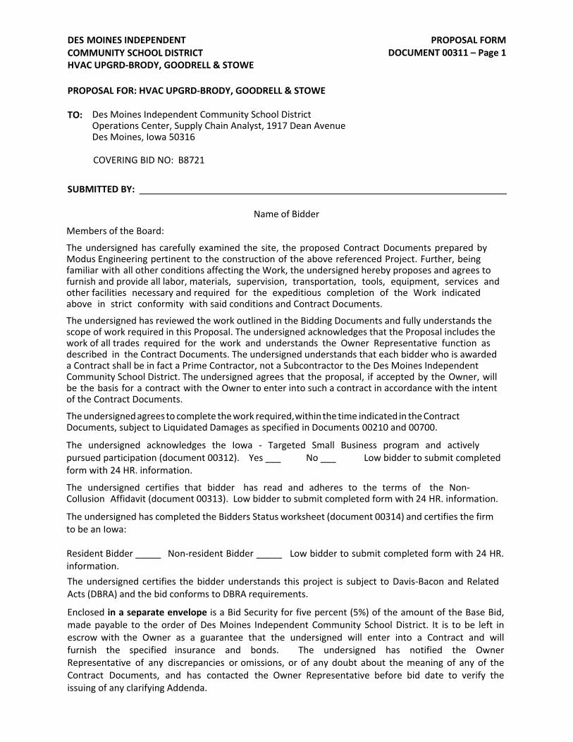
PROPOSAL FORM DOCUMENT 00311 – Page 1
TO:
DES MOINES INDEPENDENT COMMUNITY SCHOOL DISTRICT HVAC UPGRD-BRODY, GOODRELL & STOWE
PROPOSAL FOR: HVAC UPGRD-BRODY, GOODRELL & STOWE
Des Moines Independent Community School District Operations Center, Supply Chain Analyst, 1917 Dean Avenue Des Moines, Iowa 50316
COVERING BID NO: B8721
SUBMITTED BY:
Name of Bidder
Members of the Board:
The undersigned has carefully examined the site, the proposed Contract Documents prepared by Modus Engineering pertinent to the construction of the above referenced Project. Further, being familiar with all other conditions affecting the Work, the undersigned hereby proposes and agrees to furnish and provide all labor, materials, supervision, transportation, tools, equipment, services and other facilities necessary and required for the expeditious completion of the Work indicated above in strict conformity with said conditions and Contract Documents.
The undersigned has reviewed the work outlined in the Bidding Documents and fully understands the scope of work required in this Proposal. The undersigned acknowledges that the Proposal includes the work of all trades required for the work and understands the Owner Representative function as described in the Contract Documents. The undersigned understands that each bidder who is awarded a Contract shall be in fact a Prime Contractor, not a Subcontractor to the Des Moines Independent Community School District. The undersigned agrees that the proposal, if accepted by the Owner, will be the basis for a contract with the Owner to enter into such a contract in accordance with the intent of the Contract Documents.
The undersigned agrees to complete the work required, within the time indicated in the Contract Documents, subject to Liquidated Damages as specified in Documents 00210 and 00700.
The undersigned acknowledges the Iowa - Targeted Small Business program and actively pursued participation (document 00312). Yes ___ No ___ Low bidder to submit completed form with 24 HR. information.
The undersigned certifies that bidder has read and adheres to the terms of the Non-Collusion Affidavit (document 00313). Low bidder to submit completed form with 24 HR. information.
The undersigned has completed the Bidders Status worksheet (document 00314) and certifies the firm to be an Iowa:
Resident Bidder _____ Non-resident Bidder _____ Low bidder to submit completed form with 24 HR. information. The undersigned certifies the bidder understands this project is subject to Davis-Bacon and Related Acts (DBRA) and the bid conforms to DBRA requirements.
Enclosed in a separate envelope is a Bid Security for five percent (5%) of the amount of the Base Bid, made payable to the order of Des Moines Independent Community School District. It is to be left in escrow with the Owner as a guarantee that the undersigned will enter into a Contract and will furnish the specified insurance and bonds. The undersigned has notified the Owner Representative of any discrepancies or omissions, or of any doubt about the meaning of any of the Contract Documents, and has contacted the Owner Representative before bid date to verify the issuing of any clarifying Addenda.

PROPOSAL FORM DOCUMENT 00311 – Page 2
DES MOINES INDEPENDENT COMMUNITY SCHOOL DISTRICT HVAC UPGRD-BRODY, GOODRELL & STOWE
The undersigned further acknowledges receipt of the following Addenda:
NO.
NO.
NO.
BASE BID - BID NO. B8721
DATE
DATE
DATE
HVAC UPGRD-BRODY, GOODRELL & STOWE
The undersigned proposes to provide and construct the Work at the Brody school location as required, and the undersigned proposes to provide and construct the Work at the Goodrell school location as required and, the undersigned proposes to provide and construct the Work at the Stowe school location as required, in accordance with said Contract Documents for the lump sum price of:
_______________________________________________________________________________Dollars
($ _______________________________________), EXCLUDING ALL SALES TAXES. (Amount shall be shown in both words and figures. In case of discrepancy, the amount shown in words shall govern).
The undersigned agrees to submit the AIA pay application in three parts, one for each school site. The submitted schedule of values shall be submitted as stand alone schedules. One schedule for each school site. The owner will issue payment in accordance with the pay application for each school site.
SCHEDULE OF ALTERNATES – NONE
LIST OF SUBCONTRACTORS AND SUPPLIERS OF LABOR AND MATERIAL
The lowest bidder for each contract shall, within twenty-four (24) hours following the bid opening, provide the Owner with the List of Subcontractors and Suppliers of Labor and Material. Subcontractor is any entity performing 1-1/2% or more of the contract value. The List shall detail the quotations used in the preparation of the bid and whose services are proposed to be used in construction of the project. The List must be complete showing all sections in the Construction Documents. Failure to submit the List may preclude the bid from further consideration by the Owner. The Owner reserves the right to either disclose or not disclose the List of the successful Bidder.
Each Bidder shall identify and fully disclose on the List all those subcontractors and suppliers proposed for the work with which the Bidder is connected either directly or indirectly as part owner, participant in profits and losses or in any other manner financially or economically.
The forms for the List of Subcontractors and Suppliers of Labor and Materials are included in the Instruction to Bidders, Section 00100.
PROPOSAL FORM DOCUMENT 00311 – Page 3
DES MOINES INDEPENDENT COMMUNITY SCHOOL DISTRICT HVAC UPGRD-BRODY, GOODRELL & STOWE
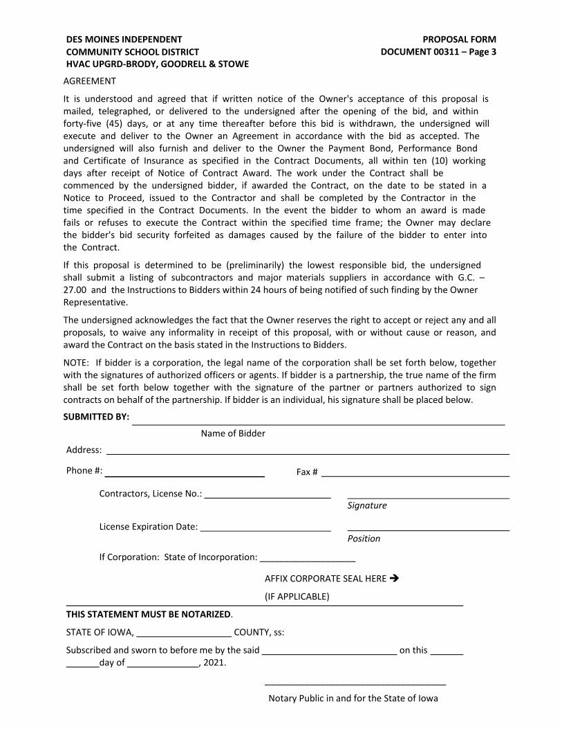
AGREEMENT
It is understood and agreed that if written notice of the Owner's acceptance of this proposal is mailed, telegraphed, or delivered to the undersigned after the opening of the bid, and within forty-five (45) days, or at any time thereafter before this bid is withdrawn, the undersigned will execute and deliver to the Owner an Agreement in accordance with the bid as accepted. The undersigned will also furnish and deliver to the Owner the Payment Bond, Performance Bond and Certificate of Insurance as specified in the Contract Documents, all within ten (10) working days after receipt of Notice of Contract Award. The work under the Contract shall be commenced by the undersigned bidder, if awarded the Contract, on the date to be stated in a Notice to Proceed, issued to the Contractor and shall be completed by the Contractor in the time specified in the Contract Documents. In the event the bidder to whom an award is made fails or refuses to execute the Contract within the specified time frame; the Owner may declare the bidder's bid security forfeited as damages caused by the failure of the bidder to enter into the Contract.
If this proposal is determined to be (preliminarily) the lowest responsible bid, the undersigned shall submit a listing of subcontractors and major materials suppliers in accordance with G.C. – 27.00 and the Instructions to Bidders within 24 hours of being notified of such finding by the Owner Representative.
The undersigned acknowledges the fact that the Owner reserves the right to accept or reject any and all proposals, to waive any informality in receipt of this proposal, with or without cause or reason, and award the Contract on the basis stated in the Instructions to Bidders.
NOTE: If bidder is a corporation, the legal name of the corporation shall be set forth below, together with the signatures of authorized officers or agents. If bidder is a partnership, the true name of the firm shall be set forth below together with the signature of the partner or partners authorized to sign contracts on behalf of the partnership. If bidder is an individual, his signature shall be placed below.
SUBMITTED BY:
Name of Bidder
Address:
Phone #: Fax #
Contractors, License No.: Signature
License Expiration Date: Position
If Corporation: State of Incorporation: ___________________
AFFIX CORPORATE SEAL HERE
(IF APPLICABLE)
THIS STATEMENT MUST BE NOTARIZED.
STATE OF IOWA, COUNTY, ss:
Subscribed and sworn to before me by the said on this day of , 2021.
____________________________________
Notary Public in and for the State of Iowa

TSB FORMS DOCUMENT 00312 – Page 1
DES MOINES INDEPENDENT COMMUNITY SCHOOL DISTRICT HVAC UPGRD-BRODY, GOODRELL & STOWE
Contractor Name
Low bidder to submit form with 24 HR information
If bidder is awarded the contract for this project, the bidder proposes for owner approval the award of a subcontract to the following certified Iowa TSB's:
(if more room is needed, supply same information on second sheet and attach to this form)
1._____________________________________ ___________________________________
TSB Company Name Address
________________________________________________ $___________________
Description of Work Dollar Amount
2._____________________________________ _________________________________
TSB Company Name Address
________________________________________________ $____________________
Description of Work Dollar Amount
3._____________________________________ __________________________________
TSB Company Name Address
________________________________________________ $_____________________
Description of Work Dollar Amount
________________________________________________ ______________________
Bidder's Company Name Telephone No.
________________________________ _____________________ ______ ________
Address City State Zip
Signature (Same person who signs proposal) Title
Type/Print Name Date
THIS STATEMENT MUST BE NOTARIZED.
STATE OF _______________, COUNTY, ss:
Subscribed and sworn to before me by the said on this day of , 202_.
____________________________________
Notary Public in and for the State of _______

TSB FORMS DOCUMENT 00312 – Page 2
DES MOINES INDEPENDENT COMMUNITY SCHOOL DISTRICT HVAC UPGRD-BRODY, GOODRELL & STOWE
Contractor Name
Low bidder to submit form with 24 HR information
Bidders to supply all the following information
Bidder is _____ / is not _____ a certified Iowa Targeted Small Business, (TSB).
If bidder did not contact any certified Targeted Small Businesses, then state why:
The following TSB's were contacted and declined to participate:
(If more room is needed, supply same information on second sheet and attach to this form)
1. _____________________________________ ___________________________________
TSB Company Name Address
_______________________________________ _________________ _________________
Contact Name Date Contacted Telephone No.
_____________________________________________________________________________
Reason given for declining participation
2. _____________________________________ ___________________________________
TSB Company Name Address
_______________________________________ _________________ _________________
Contact Name Date Contacted Telephone No.
_____________________________________________________________________________
Reason given for declining participation
3. _____________________________________ ___________________________________
TSB Company Name Address
_______________________________________ _________________ _________________
Contact Name Date Contacted Telephone No.
_____________________________________________________________________________
Reason given for declining participation
4. _____________________________________ ___________________________________
TSB Company Name Address
_______________________________________ _________________ _________________
Contact Name Date Contacted Telephone No.
_____________________________________________________________________________
Reason given for declining participation
NON-COLLUSION AFFIDAVIT DOCUMENT 00313 – Page 1
DES MOINES INDEPENDENT COMMUNITY SCHOOL DISTRICT HVAC UPGRD-BRODY, GOODRELL & STOWE
LOW BIDDER TO SUBMIT FORM WITH 24 HR INFORMATION ________________________ Contractor Name
NON-COLLUSION AFFIDAVIT
The Contractor and/or the sub-contractors, as applicable, shall provide this affidavit:
NON-COLLUSION AFFIDAVIT TO BE EXECUTED BY BIDDER AND SUBMITTED WITH BID IN OUTER ENVELOPE. State of Iowa )
) ss. County of Polk )
being first duly sworn, deposes and says that he or she
(Name)
is _________________________________________ of (Title) (Contractor)
the party making the foregoing bid that the bid is not made in the interest of, or on the behalf of, any undisclosed person, partnership, company, association, organization, or corporation; that the bid is genuine and not collusive or sham; that the bidder has not directly or indirectly induced or solicited any other bidder to put in a false or sham bid, and has not directly or indirectly colluded, conspired, connived, or agreed with any bidder or anyone else to put in a sham bid, or that anyone shall refrain from bidding; that the bidder has not in any manner, directly or indirectly, sought by agreement, communication, or conference with anyone to fix the bid price of the bidder or any other bidder, or to fix any overhead, profit, or cost element of the bid price, or of that of any other bidder, or to secure any advantage against the public body awarding the contract of anyone interested in the proposed contract; that all statements contained in the bid are true; and, further, that the bidder has not, directly or indirectly, submitted his or her bid price or any breakdown thereof, or the contents thereof, or divulged information or data relative thereto, or paid, and will not pay, any fee to any corporation, partnership, company association, organization, bid depository, or to any member or agent thereto to effectuate a collusive or sham bid."
The undersigned certifies under penalty of perjury that the foregoing is true and correct;
THIS STATEMENT MUST BE NOTARIZED.
NAME OF CONTRACTOR:
BY:
Signature Title
Type/Print Name Date
STATE OF __________________, COUNTY, ss:
Subscribed and sworn to before me by the said on this day of , 202_.
____________________________________________
Notary Public in and for the State of

BIDDER STATUS FORM DOCUMENT 00314 – Page 1
DES MOINES INDEPENDENT COMMUNITY SCHOOL DISTRICT HVAC UPGRD-BRODY, GOODRELL & STOWE

BIDDER STATUS FORM DOCUMENT 00314 – Page 2
DES MOINES INDEPENDENT COMMUNITY SCHOOL DISTRICT HVAC UPGRD-BRODY, GOODRELL & STOWE

PERSONNEL ACKNOWLEDGEMENT AND CERTIFICATION DOCUMENT 00315 – Page 1
DES MOINES INDEPENDENT COMMUNITY SCHOOL DISTRICT HVAC UPGRD-BRODY, GOODRELL & STOWE
Acknowledgment & Certification
______________________________ (“Company”) is providing services to the Des Moines Independent Community School District (“District”) as a Contractor, vendor, supplier, provider or sub-provider and/or is operating or managing the operations of a Contractor, vendor, supplier or provider. The services provided by the Company may involve the presence of the Company’s employees upon the real property of the District.
The Company acknowledges that Iowa law prohibits a sex offender who has been convicted of a sex offense against a minor from being present upon the real property of the District. The Company further acknowledges that, pursuant to Iowa law, a sex offender who has been convicted of a sex offense against a minor shall not operate, manage, be employed by, or act as a Contractor or volunteer at the District.
The Company hereby certifies that no one who is an owner, operator or manager of the Company has been convicted of a sex offense against a minor. The Company further certifies and agrees that it shall not permit any person who is a sex offender convicted of a sex offense against a minor to provide any services to the District in accordance with the prohibitions set forth above.
The Company further certifies that the Company has completed a satisfactory background check on the Company’s employees. The Company hereby agrees to provide the District with the Company’s background screening procedures including specific context and infractions that are reviewed by the Company. The District reserves the right to, but does not have the obligation to, conduct a District background check on Company employees as determined by the District in its sole discretion. The District reserves the right to restrict access of any Company employee upon the real property of the District if such employee does not clear the District’s background check.
The District reserves the right, but does not have the obligation to, to audit the Company’s background screening program at any time, whether announced or unannounced. The Company hereby agrees that the Company shall, upon request, permit an authorized District representative to review background screening records, including those of individual Company employees, in order to conduct a compliance review, audit or investigation, to the fullest extent permitted by law.
The Company shall ensure that the provisions of this Acknowledgement and Certification are extended to any and all subcontractors, consultants, or others the Company may engage if such engagement involves their presence upon the real property of the District.
The Company understands and agrees that violation of any of the provisions of this Acknowledgement and Certification shall constitute sufficient grounds for termination of any contract or subcontract without damages or penalty to the District.
This Acknowledgment and Certification is to be construed under the laws of the State of Iowa. If any portion hereof is held invalid, the balance of the document shall, notwithstanding, continue in full legal force and effect.
In signing this Acknowledgment and Certification, the person signing on behalf of the Company hereby acknowledges that he/she has read this entire document that he/she understands its terms, and that he/she not only has the authority to sign the document on behalf of the Company, but has signed it knowingly and voluntarily.

PERSONNEL ACKNOWLEDGEMENT AND CERTIFICATION DOCUMENT 00315 – Page 2
DES MOINES INDEPENDENT COMMUNITY SCHOOL DISTRICT HVAC UPGRD-BRODY, GOODRELL & STOWE
Signed:
Print Name:
Title:
Date:

DES MOINES INDEPENDENT PERSONNEL ACKNOWLEDGEMENT AND CERTIFICATION COMMUNITY SCHOOL DISTRICT DOCUMENT 00315 – Page 3
HVAC UPGRD-BRODY, GOODRELL & STOWE
Draft Policy Regarding Background Checks of Applicants for Employment
The Des Moines Independent Community School District’s primary function is the education and care of the District’s students. The District considers student safety and well-being to be of paramount importance. Because of the requirements of Iowa law, and in order to further these compelling interests, the District’s hiring process includes requests for information regarding an applicant’s past criminal conviction(s). Background checks will be conducted as required by law and District policy/practice. Backgrounds checks will not be performed until a recommendation to hire has been made by the hiring team, after the interview process has occurred.
The District is also committed to equity in its entire employment process, including its hiring process. In order to achieve an equitable process with respect to the consideration of criminal convictions, while promoting the compelling interests of student safety and well-being, the District will consider an applicant’s criminal record in light of the following:
1. All applications will be considered on a case-by-case basis. While the District will endeavorto consider each applicant’s individual situation, it will also attempt to achieve equitableresults between similarly-situated applicants.
2. Because honesty and candor are essential to the employer-employee relationship, failureof an applicant to disclose past criminal convictions on their application for employmentand/or failure to cooperate with requests from the District to provide additionalinformation necessary to the hiring process will generally result in a denial ofemployment.
3. Where an applicant’s application and/or background check result in a finding that theapplicant has one or more criminal convictions, the District will issue a Pre-Adverse ActionNotice to the employee, requesting that the employee provide the District with additionalinformation relating to the conviction(s) prior to the District making a decision relating tothe applicant’s employment. The applicant’s cooperation and candor are important If theapplicant fails to provide additional information within the time requested, the District willmake a decision based on the information available to it. Applicants should be aware thatfailure to promptly and voluntarily provide additional information will weigh heavilyagainst hiring that applicant.
4. Once the District has received all available information relating to the applicant’s criminalbackground, the District will analyze all available information on a case-by-case basis.Factors examined by the District may include, but are not necessarily limited to allconsiderations that are job-related and consistent with business necessity, includingspecifically:
a. The gravity of the offense/conduct,b. Whether the individual has a record of multiple convictions or a
documented pattern indicating disregard or the law,c. Time since the offense(s),d. Whether there are any pending charges at the time of application,e. Nature of the job sought,f. How the offense(s) relates to the job,g. The population the applicant may interact with,h. Where applicable, evidence of rehabilitation
5. If the District determines not to move forward with employment, the applicant will receivea Final Adverse Action notice.

PERSONNEL ACKNOWLEDGEMENT AND CERTIFICATION DOCUMENT 00315 – Page 4
DES MOINES INDEPENDENT COMMUNITY SCHOOL DISTRICT HVAC UPGRD-BRODY, GOODRELL & STOWE
6. If an application is rejected due to an applicant’s past criminal conviction(s), that employee
may be considered for employment no sooner than seven (7) years from the date of themost recent offense. All decisions will be made based on all information available to theDistrict at the time of the subsequent application.

BID BOND DOCUMENT 00410 – Page 1
DES MOINES INDEPENDENT COMMUNITY SCHOOL DISTRICT HVAC UPGRD-BRODY, GOODRELL & STOWE
PROPOSAL FORM TO BE SUBMITTED IN OUTER ENVELOPE
BID BOND
KNOW ALL PERSONS BY THESE PRESENTS, that we as Principal, and
as Surety, are held and firmly bound to the Des Moines Independent Community School District, hereinafter called the "School District," in the penal sum of
Dollars ($ ), in lawful money of the United States, for the payment of which sum will and truly be made, we bind ourselves, our heirs, executors, administrators, and successors, jointly and severally, firmly, by these presents. The condition of this obligation is such that whereas the Principal has submitted the accompanying Bid, dated for the project:
NOW, THEREFORE, if the Principal shall not withdraw said bid within the period specified therein after the opening of the same, or, if no period be specified, within forty-five (45) days after said opening, and shall, within the period specified therefore, or, if no period be specified, within seven (7) days after the prescribed forms are presented for signature, enter into a written Contract with the School District, in accordance with the bid, as accepted, and give bond with good and sufficient Surety or Sureties, as may be required for the faithful performance and proper fulfillment of such Contract, then the above obligation shall be void and of no effect, otherwise to remain in full force and virtue.
By virtue of statutory authority, the full amount of this Bid Bond shall be forfeited to the School District in liquidation of damages sustained in the event that the afore described bidder, Principal, fails to execute the Contract and provide the bond as provided in the Specifications or by law.
IN WITNESS WHEREOF, the parties have executed this instrument under their several seals this the name and corporate seal of each corporate party being hereto affixed and these presents duly signed by the undersigned representatives pursuant to authority of the governing bodies.
(date) Principal
By:
(date) Surety
By:
(Attach Power of Attorney of agent executing Bond)
END OF DOCUMENT

AGREEMENT, LETTER OF INTENT, NOTICE TO PROCEED AND COMMENCEMENT OF WORK
DOCUMENT 00500 - Page 1
DES MOINES INDEPENDENT COMMUNITY SCHOOL DISTRICT HVAC UPGRD-BRODY, GOODRELL & STOWE PART 1 - GENERAL
1.1 OWNER/CONTRACTOR AGREEMENT
A. The Agreement between the Owner and each Contractor will be written on the Owner'sstandard Owner/Contractor Agreement Form. A sample of this form appears as Document00510.
B. The Owner/Contractor Agreement Form will be completed by the Owner and will be sent tothe selected Contractor. A minimum of three (3) copies will be prepared for signing.
C. The executed Owner/Contractor Agreement, along with the Contract Documents as definedin Document 00700, will be the entire, integrated Contract between the Owner and eachContractor.
D. Upon receipt of an Owner/Contractor Agreement, the successful Bidder shall review it forcompleteness and accuracy, execute it, and return it to the Owner.
E. The Owner will execute each Owner/Contractor Agreement after the Bidder and after allrequired post-bid documents, (see 1.2.C. below), have been submitted.
1.2 NOTICE OF CONTRACT AWARD
A. The Owner shall issue a Notice to Proceed prior to the commencement of work under theOwner/Contractor Agreement.
B. No Contractor shall commence work until all required bonds (Documents 00600, 00610 and00620) and insurance (Document 00650) have been submitted to and accepted by the Owner.
C. Upon receipt of a Notice to Proceed, and receipt of requisite bid documents, each Contractorshall commence work in accordance with the conditions contained in the Notice to Proceed.
END OF DOCUMENT
CONSTRUCTION AGREEMENT DOCUMENT 00510 – Page 1
DES MOINES INDEPENDENT COMMUNITY SCHOOL DISTRICTHVAC UPGRD-BRODY, GOODRELL & STOWE
CONSTRUCTION AGREEMENT
THIS AGREEMENT, made and entered into this ___ day of ______, 2022 by and betweenDES MOINES INDEPENDENT COMMUNITY SCHOOL DISTRICT (hereinafter designated as the “Owner”), and ______________________________ (hereinafter designated as the “Contractor”), in connection with the construction of ____________ complete with all work appurtenant thereto.
In consideration of the compensation to be paid to the Contractor and of the mutual agreements herein contained, the parties agree as follows:
CA - 1.00 SCOPE OF THE WORK
The Contractor will furnish all tools, equipment, machinery, supplies, superintendence, insurance, transportation and other construction accessories, services and facilities specified or required to be incorporated in and form a permanent part of the completed work. In addition, the contractor shall provide and perform all necessary labor in a good, firm, substantial workmanlike manner and in accordance with the conditions and prices stated in the Bid Proposal and the requirements, stipulations, provisions and conditions of the Contract Documents as defined in the attached General Conditions. Said documents form the contract and are as fully a part thereof as if repeated verbatim herein. The Contractor shall perform, execute, construct and complete all things mentioned as to be done by the him in the Contract Documents, the Owner's official award of this contract to the Contractor being based on the acceptance by the Owner of the Contractor's bid, or part thereof.
CA - 2.00 THE CONTRACT DOCUMENTS
The Contract Documents shall consist of this written Agreement, which shall incorporate by this reference all of the instruments set out in Article 1 of the General Conditions as fully as if they were set out in this Agreement in full. All of the said documents and instruments are incorporated into this Agreement by the signature of the parties hereto.
CA - 3.00 TIME OF COMPLETION
The Contractor agrees to commence work under this Agreement by no later than ___________and to substantially complete all work by no later than ____________.
CA-4.00 DAVIS BACON AND RELATED ACTS
The contractor agrees to comply with Davis-Bacon and Related Acts requirements per Attachments B and C
CA - 6.00 CONTRACT SUM

CONSTRUCTION AGREEMENT DOCUMENT 00510 – Page 2
DES MOINES INDEPENDENT COMMUNITY SCHOOL DISTRICT HVAC UPGRD-BRODY, GOODRELL & STOWE
The Owner shall pay to the Contractor for performance of the work encompassed by this Agreement, and the Contractor will accept as full compensation therefor the lump sum of:
See Attachment “A”
subject to adjustment as provided by the Contract Documents, to be paid by progress payments in cash or its equivalent in the manner provided for in the Contract Documents.
CA - 7.00 ACCEPTANCE AND FINAL PAYMENT
A.) Early Release of Retained Funds - Upon Substantial Completion the Contractor may apply for a partial or full release of retained funds The Contractor, the Architect, and the Owner shall inspect the work covered by the portion of funds requested. When the work is found to be acceptable under the Agreement, including the satisfactory completion of all items covered by the request, the Architect shall promptly certify such to the Owner, over his own signature. The certification shall state that that portion of work provided for in this Agreement has been completed in accordance with the Contract Documents and is accepted by the Architect under the terms and conditions therefore. The Owner shall have the right to withhold 1) an amount equal to 200% of the value of labor and materials yet to be provided on the project as determined by the Owner and its authorized representative and 2) an amount equal to 200% of the value of any Chapter 573 claims currently on file at the time the request for release of retained funds is approved. The balance found to be due the Contractor, and noted in said certificate, shall be due and payable. Approval of the retained balance will be made by resolution of the Owner’ Board of Directors within thirty (30) days, unless otherwise agreed to by the parties..
B) Final Payment of Retained Funds - Upon receipt of written notice that the work is readyfor final inspection and acceptance, the Contractor, the Architect, and the Owner shall inspect the work. When the work is found to be acceptable under the Agreement, and the Agreement fully performed, including the satisfactory completion of all punch list items, the Architect shall promptly certify such to the Owner, over his own signature. The certification shall state that the work provided for in this Agreement has been completed in accordance with the Contract Documents and is accepted by the Architect under the terms and conditions therefor. The entire balance found to be due the Contractor, and noted in said final certificate, shall be due and payable. Before issuance of the Owner's Letter of Acceptance, the Contractor shall submit evidence satisfactory to the Owner that all payrolls, material bills, and other indebtedness connected with the work has been or will promptly be paid.
CA - 8.00 REPRESENTATIONS
The Contractor shall not extend the credit or faith of the Owner to any other persons or organizations.
CA - 9.00 ASSIGNMENT
The Contractor shall not assign all of his rights or obligations under this Agreement without the express written consent of the Owner. Upon any assignment even though consented to by the Owner, the Contractor shall remain liable for the performance of the work under this Agreement.
CA - 10.00 PARTIAL INVALIDITY
If any provisions of this Agreement are in violation of any statute or rule of law of the State of Iowa, then such provisions shall be deemed null and void to the extent that they may be in violation of law without invalidating the remaining provisions hereof.
CA - 11.00 WAIVER

CONSTRUCTION AGREEMENT DOCUMENT 00510 – Page 3
DES MOINES INDEPENDENT COMMUNITY SCHOOL DISTRICT HVAC UPGRD-BRODY, GOODRELL & STOWE
No waiver of any breach of any one of the agreements, terms conditions or covenants of this Agreement by the Owner shall be deemed or imply or constitute a waiver of any other agreement, term, condition or covenant of this Agreement. The failure of the Owner to insist on strict performance of any agreement, term, condition or covenant, herein set forth, shall not constitute, or be construed as a waiver of the Owner's rights thereafter to enforce any other default; neither shall such failure to insist upon strict performance be deemed sufficient grounds to enable the Contractor to forego or subvert or otherwise disregard any other agreement, term, condition or covenant of this Agreement.
CA - 12.00 ENTIRE AGREEMENT
The within Agreement, together with the Contract Documents as defined in Article 2.00 herein, constitute the entire agreement of the parties hereto. No modification, change, or alteration of the within Agreement shall be of any legal force or effect unless in writing, signed by all the parties hereto.
CA - 13.00 COUNTERPARTS
This Agreement may be executed in several counterparts and each such counterpart shall be deemed an original.
CA - 14.00 GOVERNING LAW
Venue for any and all legal actions regarding or arising out of the transaction covered herein shall be solely in the District Court in and for Polk County, State of Iowa. This transaction shall be governed by the laws of the state of Iowa.
CA - 15.00 ATTORNEYS' FEES
In the event it becomes necessary for either party to enforce any provisions or breach of this Agreement by commencing litigation, the prevailing party in such action shall be entitled to collect, as part of any judgment entered, its reasonable expert witness and attorneys’ fees and costs.
CA - 16.00 NOTICES
All notices, requests, demands and other communications given or to be given under this Agreement shall be in writing. They shall be deemed to have been duly given when served if served personally, or on the second day after mailing if mailed by first class mail, registered or certified, postage prepaid, and properly addressed to the party to whom notice is to be given as set forth below.
If to Owner: DMPS Executive Director of Operations
If to Contractor, then to the individual at the address set forth in the signature block below.
Either party may change its address for purposes of notice by giving written notice to the other party in accordance with this paragraph.
CA - 17.00 BONDS
The Contractor shall furnish both a performance bond and a payment bond and shall pay the premium thereon. The performance bond shall guarantee the full performance of the contract.
CA – 18.00 DESIGNATED REPRESENTATIVE
The OWNER will designate a District representative who will be its authorized representative with the CONTRACTOR under this AGREEMENT.

CONSTRUCTION AGREEMENT DOCUMENT 00510 – Page 4
DES MOINES INDEPENDENT COMMUNITY SCHOOL DISTRICT HVAC UPGRD-BRODY, GOODRELL & STOWE
IN WITNESS WHEREOF, the parties have executed this Agreement on the day and year first above written, and shall extend to and bind the parties, their successors, assigns and personal representatives.
DES MOINES INDEPENDENT
COMMUNITY SCHOOL DISTRICT
By: ATTEST:
President, Board of Directors Secretary, Board of Directors
Contractor Firm & Address:
Contractor Signature
CONSTRUCTION AGREEMENT DOCUMENT 00510 – Page 5
DES MOINES INDEPENDENT COMMUNITY SCHOOL DISTRICT HVAC UPGRD-BRODY, GOODRELL & STOWE
Attachment “A” to Document 00510
Construction Agreement
Des Moines Independent Community School District
(HVAC UPGRD-BRODY, GOODRELL & STOWE )
RE: Award of Bid No. B8712
As recorded in the meeting minutes of the Board of Directors held on ______________, the following is a description of the base bid and alternates proposed by ____________________ and accepted by the Board of Directors:
Base Bid:
Alternate
(Contractor Name). bid:
Base Bid: $
Total Contract Amount: $
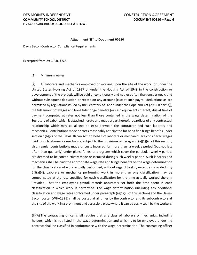
CONSTRUCTION AGREEMENT DOCUMENT 00510 – Page 6
DES MOINES INDEPENDENT COMMUNITY SCHOOL DISTRICT HVAC UPGRD-BRODY, GOODRELL & STOWE
Attachment “B” to Document 00510
Davis Bacon Contractor Compliance Requirements
Excerpted from 29 C.F.R. § 5.5:
(1) Minimum wages.
(i) All laborers and mechanics employed or working upon the site of the work (or under theUnited States Housing Act of 1937 or under the Housing Act of 1949 in the construction or development of the project), will be paid unconditionally and not less often than once a week, and without subsequent deduction or rebate on any account (except such payroll deductions as are permitted by regulations issued by the Secretary of Labor under the Copeland Act (29 CFR part 3)), the full amount of wages and bona fide fringe benefits (or cash equivalents thereof) due at time of payment computed at rates not less than those contained in the wage determination of the Secretary of Labor which is attached hereto and made a part hereof, regardless of any contractual relationship which may be alleged to exist between the contractor and such laborers and mechanics. Contributions made or costs reasonably anticipated for bona fide fringe benefits under section 1(b)(2) of the Davis–Bacon Act on behalf of laborers or mechanics are considered wages paid to such laborers or mechanics, subject to the provisions of paragraph (a)(1)(iv) of this section; also, regular contributions made or costs incurred for more than a weekly period (but not less often than quarterly) under plans, funds, or programs which cover the particular weekly period, are deemed to be constructively made or incurred during such weekly period. Such laborers and mechanics shall be paid the appropriate wage rate and fringe benefits on the wage determination for the classification of work actually performed, without regard to skill, except as provided in § 5.5(a)(4). Laborers or mechanics performing work in more than one classification may be compensated at the rate specified for each classification for the time actually worked therein: Provided, That the employer's payroll records accurately set forth the time spent in each classification in which work is performed. The wage determination (including any additional classification and wage rates conformed under paragraph (a)(1)(ii) of this section) and the Davis–Bacon poster (WH–1321) shall be posted at all times by the contractor and its subcontractors at the site of the work in a prominent and accessible place where it can be easily seen by the workers.
(ii)(A) The contracting officer shall require that any class of laborers or mechanics, including helpers, which is not listed in the wage determination and which is to be employed under the contract shall be classified in conformance with the wage determination. The contracting officer
Attachment “B ” to Document 00510

CONSTRUCTION AGREEMENT DOCUMENT 00510 – Page 7
DES MOINES INDEPENDENT COMMUNITY SCHOOL DISTRICT HVAC UPGRD-BRODY, GOODRELL & STOWE
shall approve an additional classification and wage rate and fringe benefits therefore only when the following criteria have been met:
(1) The work to be performed by the classification requested is not performed by aclassification in the wage determination; and
(2) The classification is utilized in the area by the construction industry; and
(3) The proposed wage rate, including any bona fide fringe benefits, bears areasonable relationship to the wage rates contained in the wage determination.
(B) If the contractor and the laborers and mechanics to be employed in the classification (ifknown), or their representatives, and the contracting officer agree on the classification and wage rate (including the amount designated for fringe benefits where appropriate), a report of the action taken shall be sent by the contracting officer to the Administrator of the Wage and Hour Division, U.S. Department of Labor, Washington, DC 20210. The Administrator, or an authorized representative, will approve, modify, or disapprove every additional classification action within 30 days of receipt and so advise the contracting officer or will notify the contracting officer within the 30–day period that additional time is necessary.
(C) In the event the contractor, the laborers or mechanics to be employed in the classificationor their representatives, and the contracting officer do not agree on the proposed classification and wage rate (including the amount designated for fringe benefits, where appropriate), the contracting officer shall refer the questions, including the views of all interested parties and the recommendation of the contracting officer, to the Administrator for determination. The Administrator, or an authorized representative, will issue a determination within 30 days of receipt and so advise the contracting officer or will notify the contracting officer within the 30–day period that additional time is necessary.
(D) The wage rate (including fringe benefits where appropriate) determined pursuant toparagraphs (a)(1)(ii)(B) or (C) of this section, shall be paid to all workers performing work in the classification under this contract from the first day on which work is performed in the classification.
(iii) Whenever the minimum wage rate prescribed in the contract for a class of laborers ormechanics includes a fringe benefit which is not expressed as an hourly rate, the contractor shall either pay the benefit as stated in the wage determination or shall pay another bona fide fringe

CONSTRUCTION AGREEMENT DOCUMENT 00510 – Page 8
DES MOINES INDEPENDENT COMMUNITY SCHOOL DISTRICT HVAC UPGRD-BRODY, GOODRELL & STOWE
benefit or an hourly cash equivalent thereof.
(iv) If the contractor does not make payments to a trustee or other third person, the contractormay consider as part of the wages of any laborer or mechanic the amount of any costs reasonably anticipated in providing bona fide fringe benefits under a plan or program, Provided, That the Secretary of Labor has found, upon the written request of the contractor, that the applicable standards of the Davis–Bacon Act have been met. The Secretary of Labor may require the contractor to set aside in a separate account assets for the meeting of obligations under the plan or program.
(2) Withholding.
The (write in name of Federal Agency or the loan or grant recipient) shall upon its own action or upon written request of an authorized representative of the Department of Labor withhold or cause to be withheld from the contractor under this contract or any other Federal contract with the same prime contractor, or any other federally-assisted contract subject to Davis–Bacon prevailing wage requirements, which is held by the same prime contractor, so much of the accrued payments or advances as may be considered necessary to pay laborers and mechanics, including apprentices, trainees, and helpers, employed by the contractor or any subcontractor the full amount of wages required by the contract. In the event of failure to pay any laborer or mechanic, including any apprentice, trainee, or helper, employed or working on the site of the work (or under the United States Housing Act of 1937 or under the Housing Act of 1949 in the construction or development of the project), all or part of the wages required by the contract, the (Agency) may, after written notice to the contractor, sponsor, applicant, or owner, take such action as may be necessary to cause the suspension of any further payment, advance, or guarantee of funds until such violations have ceased.
(3) Payrolls and basic records.
(i) Payrolls and basic records relating thereto shall be maintained by the contractor during thecourse of the work and preserved for a period of three years thereafter for all laborers and mechanics working at the site of the work (or under the United States Housing Act of 1937, or under the Housing Act of 1949, in the construction or development of the project). Such records shall contain the name, address, and social security number of each such worker, his or her correct classification, hourly rates of wages paid (including rates of contributions or costs anticipated for bona fide fringe benefits or cash equivalents thereof of the types described in section 1(b)(2)(B) of the Davis–Bacon Act), daily and weekly number of hours worked, deductions made and actual wages paid. Whenever the Secretary of Labor has found under 29 CFR 5.5(a) (1)(iv) that the wages of any laborer or mechanic include the amount of any costs reasonably anticipated in providing

CONSTRUCTION AGREEMENT DOCUMENT 00510 – Page 9
DES MOINES INDEPENDENT COMMUNITY SCHOOL DISTRICT HVAC UPGRD-BRODY, GOODRELL & STOWE
benefits under a plan or program described in section 1(b)(2)(B) of the Davis–Bacon Act, the contractor shall maintain records which show that the commitment to provide such benefits is enforceable, that the plan or program is financially responsible, and that the plan or program has been communicated in writing to the laborers or mechanics affected, and records which show the costs anticipated or the actual cost incurred in providing such benefits. Contractors employing apprentices or trainees under approved programs shall maintain written evidence of the registration of apprenticeship programs and certification of trainee programs, the registration of the apprentices and trainees, and the ratios and wage rates prescribed in the applicable programs.
(ii)(A) The contractor shall submit weekly for each week in which any contract work is performed a copy of all payrolls to the (write in name of appropriate federal agency) if the agency is a party to the contract, but if the agency is not such a party, the contractor will submit the payrolls to the applicant, sponsor, or owner, as the case may be, for transmission to the (write in name of agency). The payrolls submitted shall set out accurately and completely all of the information required to be maintained under 29 CFR 5.5(a)(3)(i), except that full social security numbers and home addresses shall not be included on weekly transmittals. Instead the payrolls shall only need to include an individually identifying number for each employee (e.g., the last four digits of the employee's social security number). The required weekly payroll information may be submitted in any form desired. Optional Form WH–347 is available for this purpose from the Wage and Hour Division Web site at http://www.dol.gov/esa/whd/forms/wh347instr.htm or its successor site. The prime contractor is responsible for the submission of copies of payrolls by all subcontractors. Contractors and subcontractors shall maintain the full social security number and current address of each covered worker, and shall provide them upon request to the (write in name of appropriate federal agency) if the agency is a party to the contract, but if the agency is not such a party, the contractor will submit them to the applicant, sponsor, or owner, as the case may be, for transmission to the (write in name of agency), the contractor, or the Wage and Hour Division of the Department of Labor for purposes of an investigation or audit of compliance with prevailing wage requirements. It is not a violation of this section for a prime contractor to require a subcontractor to provide addresses and social security numbers to the prime contractor for its own records, without weekly submission to the sponsoring government agency (or the applicant, sponsor, or owner).
(B) Each payroll submitted shall be accompanied by a “Statement of Compliance,” signed bythe contractor or subcontractor or his or her agent who pays or supervises the payment of the persons employed under the contract and shall certify the following:
(1) That the payroll for the payroll period contains the information required to beprovided under § 5.5 (a)(3)(ii) of Regulations, 29 CFR part 5, the appropriate information

CONSTRUCTION AGREEMENT DOCUMENT 00510 – Page 10
DES MOINES INDEPENDENT COMMUNITY SCHOOL DISTRICT HVAC UPGRD-BRODY, GOODRELL & STOWE
is being maintained under § 5.5 (a)(3)(i) of Regulations, 29 CFR part 5, and that such information is correct and complete;
(2) That each laborer or mechanic (including each helper, apprentice, and trainee)employed on the contract during the payroll period has been paid the full weekly wages earned, without rebate, either directly or indirectly, and that no deductions have been made either directly or indirectly from the full wages earned, other than permissible deductions as set forth in Regulations, 29 CFR part 3;
(3) That each laborer or mechanic has been paid not less than the applicable wage ratesand fringe benefits or cash equivalents for the classification of work performed, as specified in the applicable wage determination incorporated into the contract.
(C) The weekly submission of a properly executed certification set forth on the reverse side ofOptional Form WH–347 shall satisfy the requirement for submission of the “Statement of Compliance” required by paragraph (a)(3)(ii) (B) of this section.
(D) The falsification of any of the above certifications may subject the contractor orsubcontractor to civil or criminal prosecution under section 1001 of title 18 and section 231 of title 31 of the United States Code.
(iii) The contractor or subcontractor shall make the records required under paragraph (a)(3)(i)of this section available for inspection, copying, or transcription by authorized representatives of the (write the name of the agency) or the Department of Labor, and shall permit such representatives to interview employees during working hours on the job. If the contractor or subcontractor fails to submit the required records or to make them available, the Federal agency may, after written notice to the contractor, sponsor, applicant, or owner, take such action as may be necessary to cause the suspension of any further payment, advance, or guarantee of funds. Furthermore, failure to submit the required records upon request or to make such records available may be grounds for debarment action pursuant to 29 CFR 5.12.
(4) Apprentices and trainees—
(i) Apprentices. Apprentices will be permitted to work at less than the predetermined rate forthe work they performed when they are employed pursuant to and individually registered in a bona fide apprenticeship program registered with the U.S. Department of Labor, Employment and

CONSTRUCTION AGREEMENT DOCUMENT 00510 – Page 11
DES MOINES INDEPENDENT COMMUNITY SCHOOL DISTRICT HVAC UPGRD-BRODY, GOODRELL & STOWE
Training Administration, Office of Apprenticeship Training, Employer and Labor Services, or with a State Apprenticeship Agency recognized by the Office, or if a person is employed in his or her first 90 days of probationary employment as an apprentice in such an apprenticeship program, who is not individually registered in the program, but who has been certified by the Office of Apprenticeship Training, Employer and Labor Services or a State Apprenticeship Agency (where appropriate) to be eligible for probationary employment as an apprentice. The allowable ratio of apprentices to journeymen on the job site in any craft classification shall not be greater than the ratio permitted to the contractor as to the entire work force under the registered program. Any worker listed on a payroll at an apprentice wage rate, who is not registered or otherwise employed as stated above, shall be paid not less than the applicable wage rate on the wage determination for the classification of work actually performed. In addition, any apprentice performing work on the job site in excess of the ratio permitted under the registered program shall be paid not less than the applicable wage rate on the wage determination for the work actually performed. Where a contractor is performing construction on a project in a locality other than that in which its program is registered, the ratios and wage rates (expressed in percentages of the journeyman's hourly rate) specified in the contractor's or subcontractor's registered program shall be observed. Every apprentice must be paid at not less than the rate specified in the registered program for the apprentice's level of progress, expressed as a percentage of the journeymen hourly rate specified in the applicable wage determination. Apprentices shall be paid fringe benefits in accordance with the provisions of the apprenticeship program. If the apprenticeship program does not specify fringe benefits, apprentices must be paid the full amount of fringe benefits listed on the wage determination for the applicable classification. If the Administrator determines that a different practice prevails for the applicable apprentice classification, fringes shall be paid in accordance with that determination. In the event the Office of Apprenticeship Training, Employer and Labor Services, or a State Apprenticeship Agency recognized by the Office, withdraws approval of an apprenticeship program, the contractor will no longer be permitted to utilize apprentices at less than the applicable predetermined rate for the work performed until an acceptable program is approved.
(ii) Trainees. Except as provided in 29 CFR 5.16, trainees will not be permitted to work at lessthan the predetermined rate for the work performed unless they are employed pursuant to and individually registered in a program which has received prior approval, evidenced by formal certification by the U.S. Department of Labor, Employment and Training Administration. The ratio of trainees to journeymen on the job site shall not be greater than permitted under the plan approved by the Employment and Training Administration. Every trainee must be paid at not less than the rate specified in the approved program for the trainee's level of progress, expressed as a percentage of the journeyman hourly rate specified in the applicable wage determination. Trainees shall be paid fringe benefits in accordance with the provisions of the trainee program. If

CONSTRUCTION AGREEMENT DOCUMENT 00510 – Page 12
DES MOINES INDEPENDENT COMMUNITY SCHOOL DISTRICT HVAC UPGRD-BRODY, GOODRELL & STOWE
the trainee program does not mention fringe benefits, trainees shall be paid the full amount of fringe benefits listed on the wage determination unless the Administrator of the Wage and Hour Division determines that there is an apprenticeship program associated with the corresponding journeyman wage rate on the wage determination which provides for less than full fringe benefits for apprentices. Any employee listed on the payroll at a trainee rate who is not registered and participating in a training plan approved by the Employment and Training Administration shall be paid not less than the applicable wage rate on the wage determination for the classification of work actually performed. In addition, any trainee performing work on the job site in excess of the ratio permitted under the registered program shall be paid not less than the applicable wage rate on the wage determination for the work actually performed. In the event the Employment and Training Administration withdraws approval of a training program, the contractor will no longer be permitted to utilize trainees at less than the applicable predetermined rate for the work performed until an acceptable program is approved.
(iii) Equal employment opportunity. The utilization of apprentices, trainees and journeymenunder this part shall be in conformity with the equal employment opportunity requirements of Executive Order 11246, as amended, and 29 CFR part 30.
(5) Compliance with Copeland Act requirements. The contractor shall comply with therequirements of 29 CFR part 3, which are incorporated by reference in this contract.
(6) Subcontracts. The contractor or subcontractor shall insert in any subcontracts the clausescontained in 29 CFR 5.5(a)(1) through (10) and such other clauses as the (write in the name of the Federal agency) may by appropriate instructions require, and also a clause requiring the subcontractors to include these clauses in any lower tier subcontracts. The prime contractor shall be responsible for the compliance by any subcontractor or lower tier subcontractor with all the contract clauses in 29 CFR 5.5.
(7) Contract termination: debarment. A breach of the contract clauses in 29 CFR 5.5 may begrounds for termination of the contract, and for debarment as a contractor and a subcontractor as provided in 29 CFR 5.12.
(8) Compliance with Davis–Bacon and Related Act requirements. All rulings and interpretationsof the Davis–Bacon and Related Acts contained in 29 CFR parts 1, 3, and 5 are herein incorporated by reference in this contract.
(9) Disputes concerning labor standards. Disputes arising out of the labor standards provisions
CONSTRUCTION AGREEMENT DOCUMENT 00510 – Page 13
DES MOINES INDEPENDENT COMMUNITY SCHOOL DISTRICT HVAC UPGRD-BRODY, GOODRELL & STOWE
of this contract shall not be subject to the general disputes clause of this contract. Such disputes shall be resolved in accordance with the procedures of the Department of Labor set forth in 29 CFR parts 5, 6, and 7. Disputes within the meaning of this clause include disputes between the contractor (or any of its subcontractors) and the contracting agency, the U.S. Department of Labor, or the employees or their representatives.
(10) Certification of eligibility.
(i) By entering into this contract, the contractor certifies that neither it (nor he or she) nor anyperson or firm who has an interest in the contractor's firm is a person or firm ineligible to be awarded Government contracts by virtue of section 3(a) of the Davis–Bacon Act or 29 CFR 5.12(a)(1).
(ii) No part of this contract shall be subcontracted to any person or firm ineligible for award ofa Government contract by virtue of section 3(a) of the Davis–Bacon Act or 29 CFR 5.12(a)(1).
(iii) The penalty for making false statements is prescribed in the U.S. Criminal Code, 18 U.S.C.1001.
(b) Contract Work Hours and Safety Standards Act. The Agency Head shall cause or require thecontracting officer to insert the following clauses set forth in paragraphs (b)(1), (2), (3), and (4) of this section in full in any contract in an amount in excess of $100,000 and subject to the overtime provisions of the Contract Work Hours and Safety Standards Act. These clauses shall be inserted in addition to the clauses required by § 5.5(a) or § 4.6 of part 4 of this title. As used in this paragraph, the terms laborers and mechanics include watchmen and guards.
(1) Overtime requirements. No contractor or subcontractor contracting for any part of thecontract work which may require or involve the employment of laborers or mechanics shall require or permit any such laborer or mechanic in any workweek in which he or she is employed on such work to work in excess of forty hours in such workweek unless such laborer or mechanic receives compensation at a rate not less than one and one-half times the basic rate of pay for all hours worked in excess of forty hours in such workweek.
(2) Violation; liability for unpaid wages; liquidated damages. In the event of any violation of theclause set forth in paragraph (b)(1) of this section the contractor and any subcontractor responsible therefor shall be liable for the unpaid wages. In addition, such contractor and subcontractor shall be liable to the United States (in the case of work done under contract for the District of Columbia or a territory, to such District or to such territory), for liquidated damages. Such liquidated damages shall

CONSTRUCTION AGREEMENT DOCUMENT 00510 – Page 14
DES MOINES INDEPENDENT COMMUNITY SCHOOL DISTRICT HVAC UPGRD-BRODY, GOODRELL & STOWE
be computed with respect to each individual laborer or mechanic, including watchmen and guards, employed in violation of the clause set forth in paragraph (b)(1) of this section, in the sum of $27 for each calendar day on which such individual was required or permitted to work in excess of the standard workweek of forty hours without payment of the overtime wages required by the clause set forth in paragraph (b)(1) of this section.
(3) Withholding for unpaid wages and liquidated damages. The (write in the name of the Federalagency or the loan or grant recipient) shall upon its own action or upon written request of an authorized representative of the Department of Labor withhold or cause to be withheld, from any moneys payable on account of work performed by the contractor or subcontractor under any such contract or any other Federal contract with the same prime contractor, or any other federally- assisted contract subject to the Contract Work Hours and Safety Standards Act, which is held by the same prime contractor, such sums as may be determined to be necessary to satisfy any liabilities of such contractor or subcontractor for unpaid wages and liquidated damages as provided in the clause set forth in paragraph (b)(2) of this section.
(4) Subcontracts. The contractor or subcontractor shall insert in any subcontracts the clauses setforth in paragraph (b) (1) through (4) of this section and also a clause requiring the subcontractors to include these clauses in any lower tier subcontracts. The prime contractor shall be responsible for compliance by any subcontractor or lower tier subcontractor with the clauses set forth in paragraphs (b)(1) through (4) of this section.

CONSTRUCTION AGREEMENT DOCUMENT 00510 – Page 15
DES MOINES INDEPENDENT COMMUNITY SCHOOL DISTRICT HVAC UPGRD-BRODY, GOODRELL & STOWE
Attachment “C” to Document 00510
WAGE RATES
This project is defined as a building construction project in Polk County, Iowa. The various applicable wage rates as of date of letting are below. More information on prevailing wage rates, including modifications made after date of letting, can be found here: https://sam.gov/content/wage-determinations
END OF DOCUMENT
Attachment “C ” to Document 00510
WAGE RATES
This project is defined as a building construction project in Polk County, Iowa. The various applicable wage rates as of date of letting are below. More information on prevailing wage rates, including modifications made after date of letting, can be found here: https://sam.gov/content/wage-determinations
END OF DOCUMENT

BONDS DOCUMENT 00600 – Page 1
DES MOINES INDEPENDENT COMMUNITY SCHOOL DISTRICT HVAC UPGRD-BRODY, GOODRELL & STOWE PART 1 - GENERAL
1.1 BONDS
A. The Owner shall require the Bidder to whom a Contract is awarded to furnish bothPerformance and Labor and Material Payment bonds in the amount of one hundred percent,(100%), of the Contract price. Bonds shall cover the faithful performance of the Contract andthe payment of all obligations arising thereunder. The Bidder will further provide warrantiesas required by the specifications or General Conditions.
B. The bonds shall be executed on the forms included with the Contract Documents (forms shallnot be removed from the Contract Documents; Bidders shall obtain original copies of thebond forms from the Owner’s Representative). Accompanying each bond form shall be a“Power of Attorney” authorizing the attorney in fact to bind the surety company and certifiedto include the date of the bond.
C. Performance Bond shall be in the amount of one hundred percent (100%) of the total amountof work covered by this contract. It shall guarantee the faithful performance of the Contractoror manufacturer; and it shall insure the District during the work required by any Contract andfor a period of one (1) year from the date of final acceptance of the work, against faulty orimproper materials and/or workmanship that may be discovered during that time. Ifrequired, warranties extending beyond one years, such as for roofing, shall be as specified inthe individual specification sections.
D. Payment Bond shall be in the amount of one hundred percent (100%) of the total amount ofwork covered by this contract; and shall be in accordance with the law of the State of Iowa tosecure the payment of all claims for labor and materials used or consumed in the performanceof this Contract.
E. Payment Bonds and Performance Bonds shall include:
1. Full name and address of Contractor, Surety and Owner
2. The Contract Date
3. The exact amount of the Contract
4. Signature of Contractor
5. Corporate Seal if applicable
6. Notarization of Contractor and Surety
7. Power of Attorney
8. Local contact for Surety, with name, phone number, and address to which legalnotices may be sent.
1.2 BOND COSTS IN BIDS
A. Include all costs for Payment Bonds or Performance Bonds in the bid amounts.
END OF DOCUMENT

PAYMENT BOND FORMS DOCUMENT 00610 – Page 1
DES MOINES INDEPENDENT COMMUNITY SCHOOL DISTRICT HVAC UPGRD-BRODY, GOODRELL & STOWE
LABOR AND MATERIAL PAYMENT BOND
Bond No. _____________
(This Bond is issued simultaneously with a Performance Bond in favor of the Owner conditioned on the full and timely performance of the Contract.)
KNOW ALL MEN BY THESE PRESENTS that as Principal (the “Principal”),
and a corporation organized and existing under the laws of the State of , and authorized to transact business in the State of Iowa, as Surety (the “Surety”), jointly and severally bind themselves, their heirs, personal representatives, successors, and assigns, to the DES MOINES INDEPENDENT COMMUNITY SCHOOL DISTRICT, 2100 Fleur Drive, Des Moines, Iowa 50321, as Obligee (the “Owner”), for the use and benefit of it and the claimants as defined below, in the principal amount of
($ ) as adjusted by approved change orders (not to exceed 10 percent of the principal amount of this Bond unless expressly approved by the Surety, which approval shall not be unreasonably withheld) and interest as provided by law, for the payment of all amounts which become due under the Contract described below.
The Principal and the Owner have entered into a written Construction Agreement dated ______________________________, 202__, together with related “Contract Documents” as defined therein (all of which are collectively referred to as the “Contract” and incorporated herein by this reference), for the following Project:
______________________________________________________________________________
______________________________________________________________________________
The condition of this obligation is such that, if the Principal shall at all times promptly make payment of all amounts, claims, or demands lawfully due to all persons, firms, associations, or corporations supplying or furnishing to the Principal or its subcontractors labor or materials, supplies, or equipment which are used, provided, or performed in the prosecution of the work provided for in the Contract and any and all duly authorized modifications of the Contract that may hereafter be made, then this obligation shall be null and void; otherwise, the Surety shall pay the full value of all such claims or demands and shall indemnify and hold the Owner harmless from all payments which the Owner may be required to make under the Contract or applicable law in excess of the Contract price not exceeding the amount of this obligation, together with interest as provided by law, as well as attorneys’ fees and costs incurred by the Owner in the resolution of any claim. All such subcontractors, laborers, and materialmen shall have rights under the within Bond as are set forth in the statutes and laws of the State of Iowa.
Further, each and every claimant, who institutes a lawsuit for compensation or payment under the terms payment under the terms hereof, as part of any court award, shall be entitled to reasonable attorneys’ fees and costs.
The undersigned Surety for value received hereby agrees that no extension of time, change in, addition to, or other modification of the terms of the Contract or work to be performed thereunder, or of the specifications, or of the Contract Documents, shall in any way affect its obligation on this Bond and the Surety hereby waives notice of any such extension of time, change, addition, or modification.

DES MOINES INDEPENDENT PAYMENT BOND FORMS COMMUNITY SCHOOL DISTRICT DOCUMENT 00610 – Page 2 HVAC UPGRD-BRODY, GOODRELL & STOWE Any notice which any party desires or is required to provide another shall be in writing and shall be effective upon receipt when delivered or transmitted by personal delivery, certified (return receipt) mail, or express mail service to the addresses set forth herein.
IN WITNESS WHEREOF, said Principal and Surety have executed this Bond, this _______ day of _____________________, 202__.
ATTEST: __________________________________________
Principal
By:_______________________________________
Address:__________________________________
(SEAL) __________________________________________
ATTEST: __________________________________________
(Surety)
By:_______________________________________
Address:__________________________________
(SEAL) __________________________________________
Claims Telephone Number: ___________________
Claims Fax Number:_________________________
The fully executed Bond form must be accompanied by a current Power of Attorney.
END OF DOCUMENT

PERFORMANCE BOND FORMS DOCUMENT 00620 – Page 1
DES MOINES INDEPENDENT COMMUNITY SCHOOL DISTRICT HVAC UPGRD-BRODY, GOODRELL & STOWE
PERFORMANCE BOND
Bond No. _____________
KNOW ALL MEN BY THESE PRESENTS That as Principal (the
“Principal”), and , a corporation organized and existing under the laws of the State of , and authorized to transact business in the State of Iowa, as Surety (the “Surety”), jointly and severally, bind themselves, their heirs, personal representatives, successors, and assigns to the DES MOINES INDEPENDENT COMMUNITY SCHOOL DISTRICT, 2100 Fleur Drive, Des Moines, Iowa 50321, as Obligee (the “Owner”), in the principal amount of ($
) as adjusted by approved change orders (not to exceed 10 percent of the principal amount of this Bond unless expressly approved by the Surety, which approval shall not be unreasonably withheld) and interest as provided by law (collectively referred to herein as the “Penal Sum”), for the performance of the Construction Agreement between the Principal and the Owner, dated ________________________________, 202__, for the following (Project):
______________________________________________________________________________
______________________________________________________________________________
together with the obligations of the Contract Documents, as defined in the Construction Agreement, all of which documents are collectively referred to herein as the "Contract" and are incorporated by this reference.
The condition of this obligation is such that, if the Principal shall at all times duly, promptly, and properly perform all the terms and conditions of the Contract and any authorized modifications thereof during the original term of the Contract, any extensions thereof that may be granted by the Owner, and during the term of any guarantee or warranty required under the Contract, the Principal and Surety shall have no obligation under this Bond, otherwise it shall remain in full force and effect.
The Surety for value received agrees that no extension of time, change in, addition to, or other alteration or modification of the terms of the Contract or work to be performed thereunder, or any other forbearance on the part of either the Owner or the Principal to the other shall in any way release or affect the Surety's liability or obligation on this Bond, and the Surety hereby waives notice of any such extension of time, change, addition, modification, alteration, or forbearance.
Whenever the Owner terminates the Contract in accordance with the terms thereof, the Surety shall, within fifteen (15) calendar days after written notice of such termination, notify the Owner in writing of its election to complete the Contract in accordance with its terms, or notify the Owner that the Surety elects not to complete the Contract. If the Surety fails to give the written notice so required within such fifteen (15) calendar day period, then it will be deemed to have elected not to complete the Contract. Should theSurety elect to complete the Contract, then it shall, within fifteen (15) additional calendar days followingwritten notice of such election, obtain a contractor, subject to approval by the Owner in writing, tocomplete the original Contract in accordance with its terms and conditions and thereafter proceed withthe work with due diligence and make available as the work progresses sufficient funds to pay the cost ofcompletion less the balance of the Contract price. The Surety may not engage the Principal to completethe Contract, without the prior written consent of the Owner, which consent may be withheld in the

DES MOINES INDEPENDENT PERFORMANCE BOND FORMS COMMUNITY SCHOOL DISTRICT DOCUMENT 00620 – Page 2 HVAC UPGRD-BRODY, GOODRELL & STOWE Owner's sole discretion. If the Surety elects to complete the Contract, then it shall be entitled to receive the balance of the Contract price, less (i) any amounts paid by the Owner to the Principal; (ii) costs incurred by the Owner in correcting any defective work; (iii) any additional legal, design professional, and other costs incurred by the Owner resulting from the Principal's default; and (iv) liquidated damages caused by delayed performance or nonperformance of the Principal. Any progress payments, less retainage, due but not paid at the date of termination shall be paid to the Surety so long as the Surety has agreed to indemnify the Owner for the amount thereof and no other claims have been made to such funds by subcontractors or suppliers in accordance with the Contract or applicable law.
In the event the Surety elects not to complete the Contract, the Owner may then have the work completed by such means and in such manner, by contract with or without public bidding, or otherwise, as it may deem advisable. The Surety in such event shall at all times make available, as work progresses under the Contract between the Owner and its new contractor, sufficient funds, not to exceed the Penal Sum, to pay the cost of the completion of the Contract pursuant to its terms, together with the other amounts set forth in (i) through (iv) above, but in no event shall the Surety be responsible for the payment of any sums to the Owner until the Owner has paid in full its total obligation under the terms of the original Contract, plus change orders, less deductions and claims chargeable by law or by the Contract, if any, and less the retainage which will be disbursed as provided by the Contract Documents and applicable law.
The procedures set forth herein shall apply should there be a default and termination or a succession of defaults and terminations in fulfilling the terms and conditions of the work under the original Contract.
In the event there are negotiations between the Principal and/or the Surety and the Owner subsequent to the date of termination, each party shall appoint an authorized representative with authority to represent it during the negotiations. All written communications and official discussions between the parties shall be conducted by these authorized representatives. Any notice which any party desires or is required to provide another shall be in writing and shall be effective upon receipt when delivered or transmitted by personal delivery, certified (return receipt) mail, or express mail service to the addresses set forth herein.
Any proceeding, legal or equitable, under this Bond may be instituted in any court of competent jurisdiction in the location in which the work is located and shall be instituted before
the expiration of three (3) years from the date on which final payment under the contract is made; provided, however, that this period may be extended by one (1) additional year by the Owner's giving written notice to the Surety within the three (3) year period of a potential claim. Any judgment recovered hereunder by the Owner shall include interest at the legal rate, together with reasonable attorneys' fees and costs.

PERFORMANCE BOND FORMS DOCUMENT 00620 – Page 3
DES MOINES INDEPENDENT COMMUNITY SCHOOL DISTRICT HVAC UPGRD-BRODY, GOODRELL & STOWE No right action shall accrue under this Bond to or for the use of any person or entity other than the Owner or its successors and assigns.
IN WITNESS WHEREOF, the Principal and Surety have signed this Performance Bond as of the __________ day of ___________________, 202__.
ATTEST: __________________________________________
Principal
By: ______________________________________
Address: __________________________________
(SEAL) __________________________________________
ATTEST: __________________________________________
(Surety)
By: ______________________________________
Address __________________________________
(SEAL) __________________________________________
Claims Telephone Number: ___________________
Claims Fax Number: ________________________
The fully executed bond form must be accompanied by a current Power of Attorney.
END OF DOCUMENT

INSURANCE CERTIFICATES DOCUMENT 00650 – Page 1
DES MOINES INDEPENDENT COMMUNITY SCHOOL DISTRICT HVAC UPGRD-BRODY, GOODRELL & STOWE PART 1 - GENERAL
1.1 INSURANCE CERTIFICATES
A. Each Contractor shall provide insurance certificates to the Owner indicating that all requiredinsurance coverage is in force prior to beginning work on the project.
B. Use a standard Insurance Certificate Form such as the "Acord" Form available from yourinsurance agent. Also include the Owner, the Architect, and their agents, representatives andemployees to be added to the original certificate as additional named insurers.
1.2 CONTRACTOR'S LIABILITY INSURANCE
A. The Contractor shall purchase and maintain liability insurance to protect the Owner and theArchitect, and their agents, representatives and employees from claims set forth below whichmay arise out of or result from the Contractor's operations under the contract whether suchoperations be by himself or by any subcontractor or by anyone directly or indirectly employedby any of them or by anyone for whose acts any of them may be liable. The insurance requiredshall include contractual liability insurance applicable to the Contractor's obligations.Insurance requirements are set forth in the General Conditions, Paragraph GC-25.00.
B. The insurance required shall be primary and non-contributory to any insurance possessed orprocured by the Owner and limits of liability shall be not less than those set forth.
C. Certificates of insurance acceptable to the Owner shall be filed with the Owner prior tocommencement of the work.
1.3 PROPERTY INSURANCE
A. The Owner will provide property insurance for losses and damages in excess of $100,000.00in accordance with the General Conditions, Paragraph 25.03 of the contract documents. Thecontractor shall be responsible for and pay all losses and damages under $100,000.00.
B. The Owner will provide an endorsement listing the Architect as additional insured under allsuch policies of insurance.
END OF DOCUMENT
DES MOINES INDEPENDENT GENERAL CONDITIONS of THE CONTRACT COMMUNITY SCHOOL DISTRICT DOCUMENT 00700 - page 1 HVAC UPGRD-BRODY, GOODRELL & STOWE _____________________________________________________________________________
GENERAL CONDITIONS OF THE CONTRACT
______________________________________________________________________________
INDEX TO THE ARTICLES
Article
Acceptance and Final Payment GC - 53.00
Access to Work GC - 15.00
Architect’s Status and Inspections GC - 29.00
Assignment GC - 44.00
Benchmarks, Monuments, Stakes, and Measurements GC - 13.00
Blasting GC - 40.00
Cash Allowances GC - 31.00
Changed Conditions GC - 19.00
Changes in the Work GC - 17.00
Claims for Extra Cost or Additional Time GC - 18.00
Cleaning Up GC - 34.00
Contract Documents GC - 1.00
Contract Price, Items Covered by GC - 5.00
Contractors’ Mutual Responsibility GC - 46.00
Contractor’s Superintendence and Supervision GC - 16.00

GENERAL CONDITIONS of THE CONTRACT DOCUMENT 00700 - page 2
DES MOINES INDEPENDENT COMMUNITY SCHOOL DISTRICT HVAC UPGRD-BRODY, GOODRELL & STOWE
Article
Correction of Work GC - 20.00
Cutting, Patching, and Excavating GC - 33.00
Damage to Utilities GC - 38.00
Definitions GC - 2.00
Drawings and Specifications GC - 7.00
Electronic Communications GC - 59.00
Employees GC - 10.00
Execution, Correlation, Intent, and Interpretation of Contract Documents
GC - 6.00
Expediting Materials GC - 57.00
Contractors Project Guarantee after Completion GC - 55.00
Historical Data GC - 41.00
Indemnification GC - 49.00
Insurance GC - 25.00
Liens GC - 47.00
Materials, Labor, Facilities, and Storage GC - 9.00
Miscellaneous Keys, Switches, etc. GC - 58.00
Occupancy GC - 37.00
Oral Statements GC - 3.00
Owner’s Right to Carry Out Work GC - 21.00
Owner’s Right to Terminate Contract GC - 22.00
Payment GC - 23.00
Performance and Payment Bonds GC - 26.00
Owner’s Representative’s Status and Inspections GC -30.00
Project Sign GC - 39.00
Protection of Work and Property GC - 14.00
Reference Standards GC - 4.00
Relations of Contractor and Subcontractor GC - 28.00
Request for Release of Retained Funds GC – 52.00

GENERAL CONDITIONS of THE CONTRACT DOCUMENT 00700 - page 3
DES MOINES INDEPENDENT COMMUNITY SCHOOL DISTRICT HVAC UPGRD-BRODY, GOODRELL & STOWE
Article
Royalties and Patents GC - 11.00
Schedule and Progress Reports, Construction GC - 24.00
Separate Contracts GC - 45.00
Shop Drawings and Samples GC - 8.00
Soil Test Report GC - 56.00
Statutes, Ordinances, and Regulations GC - 35.00
Subcontractors GC - 27.00
Substantial Completion GC - 51.00
Substitutions, Approval of GC - 36.00
Surveys, Permits, Laws, Regulations, and Taxes GC - 12.00
Temporary or Trial Usage GC - 43.00
Testing of Building Systems GC - 42.00
Use of Premises GC - 32.00
Warranties on Portions of the Work GC - 54.00
Work in Existing Building GC - 48.00

GENERAL CONDITIONS of THE CONTRACT DOCUMENT 00700 - page 4
DES MOINES INDEPENDENT COMMUNITY SCHOOL DISTRICT HVAC UPGRD-BRODY, GOODRELL & STOWE GC - 1.00 CONTRACT DOCUMENTS
The Work shall be accomplished in accordance with the Contract Documents which shall be included in this Contract and shall consist of the Invitation to Bid, Instructions to Bidders, Bid Security, Proposal, Notice of Contract Award, Insurance Policies and Certificates, Notice to Proceed, Performance Bond, Labor and Material Payment Bond, Construction Agreement, the General Conditions of the Contract, Supplementary General Conditions, drawings and specifications, tests and engineering data, approved change orders, Contractor’s Requests for Payment, Architect’s Certificates, and all addenda issued by the Owner or Architect prior to the awarding of the Contract.
GC - 2.00 DEFINITIONS
Words, phrases, and other expressions used in these Contract Documents shall have meanings as follows:
2.01 “Contract” or “Contract Documents” shall include the items enumerated above under CONTRACT DOCUMENTS.
2.02 “Owner” shall mean the Des Moines Independent Community School District, named and designated as such in the Contract Documents acting through its duly authorized representatives.
2.03 “Contractor” shall mean the corporation, company, partnership, firm, entity, or individual named and designated as such in the Contract Documents which has entered directly into this Contract with the Owner for the performance of the Work covered thereby, and any persons or entities acting on its behalf.
2.04 “Subcontractor” shall mean and refer to a corporation, partnership, entity, or individual having a direct contract with the Contractor or another subcontractor for performing work and/or furnishing labor or material which is incorporated into the Work at the request of the Contractor or other subcontractor.
2.05 “Architect” shall mean the architects or engineers designated, appointed, or otherwise employed or delegated by the Owner, or its duly authorized representatives, acting within the scope of the particular duties entrusted to them in each case.
2.06 "Owner’s Representative" shall mean the person(s) designated by the District, acting
within the scope of the particular duties entrusted to them, to provide services toward the management and implementation of the Work as the Owner's designated representative.
2.07 “Notice to Proceed” shall be deemed to have been duly served if made in writing and
delivered in person to the individual or to a member of the firm or to an officer of the corporation for whom it is intended, or if sent by registered or certified mail to the last known business address.
2.08 “The Work” shall mean the equipment, supplies, materials, labor, and services to be furnished under the Contract and the carrying out of all obligations imposed or required by the Contract Documents.
2.09 “The Project” is the total construction designed by the Architect of which the work performed under the Contract Documents may be the whole or a part.

GENERAL CONDITIONS of THE CONTRACT DOCUMENT 00700 - page 5
DES MOINES INDEPENDENT COMMUNITY SCHOOL DISTRICT HVAC UPGRD-BRODY, GOODRELL & STOWE 2.10
2.11
2.12
2.13
All time limits stated in the Contract Documents are of the essence of the Contract and must be strictly adhered to.
The Contract shall be governed by the laws of the State of Iowa.
The date of Final Completion of a Project is the date when construction is certified by the Architect to be finally completed in accordance with Contract Documents, as modified by any change orders agreed to by the parties and when the Owner has fully accepted the Project for the use for which it was intended. Such date will be set forth on a Letter of Final Acceptance issued by the Owner.
“Drawings” or “plans” shall mean all (a) graphic and pictorial portions of the Contract furnished by the Owner and/or Architect as a basis for the award of Contract; (b) supplementary drawings furnished by the Owner and/or Architect to clarify and to define in greater detail the intent of the Contract drawings and specifications;(c) drawings furnished by the Owner to the Contractor during the progress of the Work; and (d) engineering data and drawings submitted by the Contractor during the progress of the Work, provided such drawings are acceptable to the Architect.
2.14 “Specifications” are the written technical information concerning materials, components, systems, and equipment as indicated on the drawings or plans and which state the quality, performance, characteristics, and installations to be achieved by application of construction methods.
2.15 “Substantial Completion” is:
2.15.1 Established date on which the Work or designated portions thereof has been sufficiently completed in accordance with the Contract Documents so as permit the Owner to safely and legally occupy or utilize the Work for it’s intended use, subject only to minor punch list items the absence of completion which does not interfere with the Owner’s intended use of the Project.
2.15.2 as defined in Iowa Code Chapter 26 for purposes of early release of retainage only.
GC - 3.00 ORAL STATEMENTS
It is understood and agreed that the written terms and provisions of the Contract Documents shall supersede all oral statements of representatives of the Owner, and oral statements shall not be effective or be construed as being a part of this Contract.
GC - 4.00 REFERENCE STANDARDS
Reference to the standards of any technical society, organization, or association, or to codes of local or state authorities, shall mean the latest standard, code, specification, or tentative standard adopted and published at the date of the Contract Documents unless specifically stated otherwise.
GC - 5.00 ITEMS COVERED BY CONTRACT PRICE
Unless otherwise specifically provided herein, the Contractor shall accept the compensation stated in the Construction Agreement as full payment for furnishing all materials, transportation, apparatus, temporary structures, equipment, services, fuel, energy, light, water, labor, tools and all risks and losses of

DES MOINES INDEPENDENT GENERAL CONDITIONS of THE CONTRACT COMMUNITY SCHOOL DISTRICT DOCUMENT 00700 - page 6 HVAC UPGRD-BRODY, GOODRELL & STOWE every kind and description connected with the prosecution of the Work, and all other things necessary for the complete and proper execution of the Work contemplated by or reasonably implied from the Contract Documents, within the time limits indicated therein.
GC – 6.00 EXECUTION, CORRELATION, INTENT, AND INTERPRETATION OF CONTRACT
DOCUMENTS AND COMPLETION DATE
6.01 Execution. The Contract Documents shall be signed in multiple copies as directed by the Owner. Within ten (10) days of Notice of Contract Award, the Contractor shall submit to the Owner a minimum of five (5) fully executed original sets of the Construction Agreement; Performance Bond and Labor and Material Payment Bond with original Power of Attorney; and certificates of required insurance coverages. The date of the Contract for purposes of these documents shall be the date of the Notice of Contract Award letter. The Owner will execute the Construction Agreement, assemble all copies, and distribute the Contract Documents. The Contractor shall not commence the Work until he receives the Notice to Proceed.
6.02 Correlation. By submitting the bid, the Contractor represents that he has visited the site, familiarized himself with the local conditions under which the Work is to be performed, and correlated his observations with the requirements of the Contract Documents.
6.03 Intent. The intention of the Contract Documents is to include all labor and materials, tools, equipment, construction equipment, water, heat, utilities, transportation, and other facilities and services necessary for the proper execution and completion of the Work. Materials or work described in words which as applied have a well-known technical or trade meaning shall be held to refer to such recognized standards.
The organization of the specifications into divisions, sections, and articles, as the case may be, and the arrangement of drawings shall not control the Contractor in dividing the work among subcontractors or in establishing the extent of work to be performed by any trade.
It is intended that even though Work is not covered under any heading, division, section, article, branch, class, or trade of the specifications, it shall nevertheless be supplied if it is required elsewhere in the Contract Documents or is reasonably inferable there from as being necessary to produce the intended results.
The specifications and drawings are intended to supplement but not necessarily duplicate each other/ Any work exhibited in one and not the other shall be executed as if it had been set forth in both, so that the Work will be constructed according to the complete design.
6.04 Interpretation. Should anything necessary for a clear understanding of the Work be omitted from the specifications and drawings, or should the requirements appear to be in conflict, the Contractor shall secure written interpretations or instructions from the Architect before proceeding with the Work affected thereby. It is understood and agreed that the Work shall be performed according to the true intent of the Contract Documents.

DES MOINES INDEPENDENT GENERAL CONDITIONS of THE CONTRACT COMMUNITY SCHOOL DISTRICT DOCUMENT 00700 - page 7 HVAC UPGRD-BRODY, GOODRELL & STOWE Where a conflict occurs between or within standards, specifications, and drawings, the more stringent or higher quality requirements shall apply. The precedence of the Construction Documents is in the following sequence:
1. Addenda to the drawings and specifications take precedence over the originalConstruction Documents.
2. Specifications take precedence over drawings, except in cases of error.
3. In the drawings, the precedence shall be drawings of larger scale over those of smallerscale and noted materials over graphic indications.
4. Any work mentioned in the specifications and not shown on the drawings or shownon the drawings and not mentioned in the specifications shall be of like effect as ifshown or mentioned in both. The Contractor shall examine the specifications anddrawings and check all dimensions and notify the Architect and the Owner of anydiscrepancies between the specifications and drawings and any deficiencies,omissions, or errors before any work is commenced.
6.05 All work on the Project shall be finally completed within the times indicated in the construction documents.
GC - 7.00 DRAWINGS AND SPECIFICATIONS
7.01 Copies Furnished. Unless otherwise provided in the Contract Documents, the Contractor will be furnished, free of charge, all copies of drawings and specifications and addenda reasonably necessary for the execution of the Work.
7.02 Ownership of Drawings. All drawings, specifications, and copies thereof furnished by the Architect are the property of the Owner, whether the work for which they are made is executed or not and are not to be used on other work except by written agreement with the Owner.
7.03 Drawings and Specifications Available on the Site. The Contractor shall maintain at the site for the Owner and the Architect one copy of all drawings, specifications, addenda, approved shop drawings, change orders, and other modifications, in good order and marked to record all changes made during construction. The Contractor shall also keep on the site all applicable standards, codes, manufacturer's or other specifications referenced in the Contract Documents. The drawings, marked to record all changes made during construction, shall be delivered to the Architect for the Owner upon completion of the Work.
7.04 Figured Dimensions to Govern. Dimensions and elevations shown on the drawings shall be accurately followed. Where dimensions are not indicated, Contractor shall immediately request clarification from the Architect so as not to delay the Work and Contractor shall not proceed with such work until the necessary dimensions have been obtained from the Architect.
7.05 Contractor to Check Drawings and Schedules. The Contractor shall check all dimensions, elevations, and quantities shown on the drawings and furnished by the Architect, and shall

DES MOINES INDEPENDENT GENERAL CONDITIONS of THE CONTRACT COMMUNITY SCHOOL DISTRICT DOCUMENT 00700 - page 8 HVAC UPGRD-BRODY, GOODRELL & STOWE
notify the Architect in a timely manner of any discrepancy between the drawings and the conditions on the ground, or any error or omission in drawings, or in the layout as given by stakes, points, or instructions, which he may discover. Before ordering any material or doing any work, the Contractor shall verify all measurements at the building and shall be responsible for the correctness of same. No extra charge or compensation will be allowed on account of difference between actual dimensions and measurements taken in the field. Any difference which may be found shall be submitted to the Architect in a timely manner for consideration before proceeding with the Work. The Contractor will not be allowed to take advantage of any error or omission in the drawings or Contract Documents. Full instructions will be furnished by the Architect should such error or omission be discovered and the Contractor shall carry out such instructions as if originally specified.
7.06 Detail Drawings and Instructions. Upon the contractor’s written report, the Architect shall furnish, within 10 working days, additional instructions by means of drawings or otherwise, necessary for the proper execution of the Work. All such drawings and instructions shall be consistent with the Contract Documents, true developments thereof, and reasonably inferable therefrom. The Work shall be executed in conformity therewith, and the Contractor shall do no work without proper drawings and instructions.
7.07 Project Record Drawings. The Contractor shall maintain a Contract set of drawings at the site with all changes or deviations from the original drawings neatly marked thereon in a contrasting color. The Contractor shall also maintain a Contract set of specifications at the site, noting therein by appropriate section, the names, models, and other distinguishing characteristics of the products actually incorporated into the Work. This set of drawings and specifications shall be updated daily as the job progresses and shall be made available to the Owner and Architect for inspection at all times. Upon completion of the Work and before final payment, this Project Record set of drawings and specifications shall be delivered to the Architect.
7.08 Contractors’ Review of Drawings, Plans and Specifications. Contractor’s review of drawings, plans and specifications developed by the Architect and/or the Design Team under this Agreement shall be made in Contractor’s capacity as a contractor and not as a licensed design professional.

GENERAL CONDITIONS of THE CONTRACT DOCUMENT 00700 - page 9
DES MOINES INDEPENDENT COMMUNITY SCHOOL DISTRICT HVAC UPGRD-BRODY, GOODRELL & STOWE GC - 8.00 SHOP DRAWINGS AND SAMPLES
8.01 Shop Drawings. Shop drawings are drawings, diagrams, illustrations, schedules, performance charts, brochures, manufacturer's literature, product data, and any other information which are prepared by the Contractor or any subcontractor, manufacturer, supplier, or distributor, and which illustrate some portion of the Work. Said drawings will be submitted in a format agreeable to the Owner and Owner’s Representative.
8.02 Samples. Samples are physical examples furnished by the Contractor to illustrate materials, finishes, equipment, or workmanship, and to establish standards by which the Work will be judged.
8.03 Subcontractor. The Contractor shall require each subcontractor to prepare, stamp with approval, and submit to the Contractor with reasonable promptness and in orderly sequence so as to cause no delay in the Work or in the work of any other subcontractor, all shop drawings and samples on all shop fabricated items and on all matters, required by the Contract Documents or subsequently by the Architect as covered by modifications. Shop drawings and samples will properly identify specified items. At the time of submission, the subcontractor shall inform the Contractor, the Architect and the Owner’s Representative in writing of any deviation in the shop drawings or samples from the requirements of the Contract Documents. Substitutions will be allowed only in accordance with the provisions of Section 36.00 hereinafter.
The Contractor shall also require each subcontractor to prepare and transmit sufficient sets of sepia transparencies, reverse printed, and prints of all shop drawings which are specially drawn for this Project, including detailed fabrication and erection drawings, setting drawings, diagrammatic drawings, material schedules, and samples to the Contractor to meet the Project construction schedule and the subcontractors’ Contract schedule, or shall present, in writing, valid reasons for any delay. Sepias shall not be folded, but shall be rolled and transmitted in a tube suitable for mailing.
All shop drawings for all equipment and/or materials in a given system shall be submitted at one time, each complete set in a separate brochure. Complete maintenance/warranty data are to be submitted to the Contractor for distribution to the Owner’s Representative for review by the Architect and final acceptance by the Owner.
Each sheet of shop drawings shall identify the Project, subcontractor, and fabricator or manufacturer and the date of the drawings. All shop drawings shall be numbered in sequence and each sheet shall indicate the total number of sheets in the set.
The shop drawings shall indicate types, gauges, and finish of all materials. Where a shop coat of paint is required, its brand name, manufacturer’s identification number, and type shall be indicated. Sufficient data in each set of shop drawings shall be included to permit a detailed study of the system submitted and its conformance to the Contract Documents and design intent.
The Contractor will review, approve, stamp, and then submit the sepia transparencies, prints, and samples to the Owner’s Representative and Architect for approval with copies

DES MOINES INDEPENDENT GENERAL CONDITIONS of THE CONTRACT COMMUNITY SCHOOL DISTRICT DOCUMENT 00700 - page 10 HVAC UPGRD-BRODY, GOODRELL & STOWE
to the Owner. After review, the Owner’s Representative will then return the sepia transparencies to the Contractor with the Owner’s Representative’s and Architect’s appropriate comments. Those returned for correction shall be corrected and resubmitted. Upon receiving the approved sepia sets from the Owner’s Representative, the Contractor will make requested sets of prints for distribution to appropriate subcontractors, fabricators, manufacturers, and suppliers who require them for coordination of their work.
8.04 Verification. By approving and submitting shop drawings and samples, the Contractor thereby represents that it has determined and verified all field measurements, field construction criteria, dimensions, elevations, quantities, materials, catalog numbers, and similar data, as shown on the drawings and specifications furnished by the Architect and that he has checked and coordinated each shop drawing and sample with the requirements of the Work and of the Contract Documents.
8.05 Architect Review. The Architect will review and approve shop drawings and samples with reasonable promptness so as to cause no delay, but only for conformance with the design concept of the Project and with the information given in the Contract Documents. The Architect’s approval of a separate item shall not indicate approval of an assembly in which the item functions. On the completion of the Work, the Owner’s Representative shall be furnished three corrected copies of all shop or setting drawings showing the as-built condition of the Work. The Owner’s Representative, after the Architect’s review, will furnish one of these copies to the Owner. Architect will keep one copy.
8.06 Corrections. The Contractor shall make any corrections required by the Architect and shall resubmit the required number of corrected copies of shop drawings or new samples until approved. The Contractor shall direct specific attention in writing or on resubmitted shop drawings to revisions other than the corrections requested by the Architect on previous submissions.
8.07 Contractor’s Responsibility. The Architect’s approval of shop drawings or samples shall not relieve the Contractor of responsibility for any deviation from the requirements of the Contract Documents unless the Contractor has informed the Architect in writing in a separate letter attached to the submittal of such deviation at the time of submittal and the Architect has given written approval to the specific deviation, nor shall the Architect’s approval relieve the Contractor from responsibility for errors or omissions in the shop drawings or samples.
8.08 Architect Approval Required. No portion of the Work requiring the submission of a shop drawing or sample shall be commenced until such submittal has been approved by the Architect. All such portions of the Work shall be in accordance with approved shop drawings and samples. All material finishes and samples will be approved at one time. The Contractor shall submit all items requiring approval of finishes, color, material, etc., with sufficient lead time to allow simultaneous consideration and preparation of complete finish Color Schedule. No approvals of single items will be considered.
GC - 9.00 MATERIALS, LABOR, FACILITIES, AND STORAGE

DES MOINES INDEPENDENT GENERAL CONDITIONS of THE CONTRACT COMMUNITY SCHOOL DISTRICT DOCUMENT 00700 - page 11 HVAC UPGRD-BRODY, GOODRELL & STOWE
9.01 Contractor’s Responsibility. Unless otherwise stipulated, the Contractor shall provide and pay for all materials, labor, tools, equipment, machinery, transportation, and other facilities necessary for the proper execution and completion of the Work. The Contractor shall provide and pay for all the temporary facilities required to supply all the power, light, water, and heat needed by him and the subcontractors for their work and shall install and maintain all such facilities in such manner as to protect the public and workers and conform with any applicable laws and regulations. If temporary heat and/or protection is required for the expeditious prosecution of the Work and before the permanent heating apparatus is available for use, the temporary heating apparatus shall be installed and operated in such a manner that the finish work and/or construction will not be damaged thereby.
Unless otherwise specified, the Contractor shall pay for all the power, light, and water used by him and the subcontractors, without regard to whether such items are metered by temporary or permanent meters. The cutoff date on permanent meters shall be either the agreed date of full occupancy by the Owner or the date of final acceptance of the Project, whichever shall be the earlier date. Upon completion of the Work, the Contractor shall remove all such temporary facilities from the site.
9.02 Materials. Unless otherwise specified, all materials shall be new and both workmanship and materials shall be of the highest quality. The Contractor shall furnish satisfactory evidence as to the kind and quality of materials. Samples shall be furnished, when specified, and the work shall be in accordance with those samples which have been approved.
9.03 Facilities and Storage. The Contractor shall provide and maintain, in a neat and sanitary condition, adequate temporary toilet facilities for the use of any and all employees engaged on the Work, in strict compliance with the requirements of all applicable codes, regulations, laws, and ordinances. In no event may present toilet facilities of any existing building at the site of the Work be used by employees of the Contractor or subcontractors. Upon completion of the Work, he shall remove all such temporary facilities from the site and disinfect the premises.
The Contractor shall provide suitable temporary facilities and quarters for workmen and shall maintain on premises water-tight storage shed or sheds, tool houses for storage of building materials and tools which may be damaged by weather. The Contractor shall allow space for the erection of sheds and provide similar facilities for storage by subcontractors of their materials and tools. Storage of materials shall be confined to the site. These facilities or quarters shall further provide for protection against theft and damage of building materials and tools. Upon completion of the Work, the Contractor shall remove all such temporary facilities from the site.
The Contractor shall provide adequate, weatherproofed, heated, and well-lighted office space at the site of the Work, for the use of the Architect, Owner’s Representative, and the Owner. The Contractor shall also provide telephone service at such office, which shall be available for the use of the Architect, Owner’s Representative, and the Owner, without

DES MOINES INDEPENDENT GENERAL CONDITIONS of THE CONTRACT COMMUNITY SCHOOL DISTRICT DOCUMENT 00700 - page 12 HVAC UPGRD-BRODY, GOODRELL & STOWE
charge, except for toll calls. Requirements of the office space are as listed in Section 01500 paragraph 1.26.
All of the foregoing facilities shall be of a quality and placed in locations acceptable to the Owner and Owner’s Representative.
9.04 Salvage of Materials. Owner reserves the right to salvage any and all materials, equipment, furnishings, and other elements to be removed from the site regardless if such removal is indicated in the plans, specifications, drawings or other Contract Documents.
GC - 10.00 EMPLOYEES
10.00A Qualifications. The Contractor and his subcontractors shall at all times enforce strict discipline and good order among his employees, and shall not employ on the Work any person considered by the Architect, Owner or Owner’s Representative to be unfit or not skilled in the work assigned. The Contractor shall also keep its employees and those of its subcontractor from socializing upon the site of the Work after normal work hours and from fraternizing at any time with staff, students, parents, and other persons who are at the school or the site of the Work.
10.00B No Contractor shall allow any of its employees listed on the Iowa Sex Offender Registry to perform work on District Projects. The District has interpreted an "unfit employee" for purposes of this Contract to be any employee currently listed on the Iowa Sex Offender Registry. The Contractor shall fill out and sign the “Acknowledgement and Certification” form located behind this section prior to executing the Agreement.
10.00C Employee background checks are the responsibility of the Contractor and his subcontractors.
10.01 Drug-Free Zone. The Des Moines Independent Community School District is a drug-free zone. In furtherance of this standard, the Contractor shall establish and maintain a safe and efficient work environment for all employees, free from the effects of alcohol, controlled substances, and illicit drugs. The manufacture, distribution, dispensing, possession, or use of alcohol, controlled substances, and illicit drugs is prohibited on or adjacent to the Project site and all of the Owner's property at all times. Illicit drug use is the use of illegal drugs and the abuse of alcohol and other drugs, including anabolic steroids. Controlled substances are drugs specifically identified and regulated under state or federal law and include, but are not limited to, opiates, narcotics, cocaine, amphetamines and other stimulants, depressants, hallucinogenic substances, and marijuana. The Contractor will strictly enforce this prohibition among his own employees and his subcontractors and their employees at all times. Employees who violate these prohibitions will be subject to disciplinary action by their employers up to and including termination and may be denied access to the site of the Work. Violation of this provision shall also constitute sufficient grounds for termination of the Contract or any subcontract without damages or penalty to the Owner.
10.02 No Smoking . Statewide smoking ban – Iowa Code Section 142D.3

GENERAL CONDITIONS of THE CONTRACT DOCUMENT 00700 - page 13
DES MOINES INDEPENDENT COMMUNITY SCHOOL DISTRICT HVAC UPGRD-BRODY, GOODRELL & STOWE
1. Smoking now is prohibited in all areas of school buildings, including nonpublicschools, as well as all school grounds, parking lots, athletic fields, including inside anyvehicle located on school grounds or school parking lots. No longer can a schooldesignate a smoking area.
2. Smoking is prohibited inside all publicly owned vehicles, even if parked in a privatedrive.
3. Smoking is prohibited inside a private vehicle that is parked in a school parking lot.
The Iowa Department of Public Health (DPH) is in charge of writing administrativerules for the enforcement of this new law. DPH states that it will also provide sample“no smoking” signs that schools may download for free.
4. In addition, The use of tobacco and nicotine products; including, but not limited to,cigarettes, nicotine chew, snus, dissolvables, electronic cigarettes, any electronic orother devices that can be used to deliver nicotine to the person inhaling from thedevice, any other look-alike products in which the original product would includetobacco and/or nicotine and/or other nicotine products that are not approved by theFederal Drug Administration for tobacco cessation; on District property; including inDistrict buildings, on District grounds, in District transportation vehicles, or at anyDistrict activity; is prohibited.
10.03 Equal Opportunity Policy. Because it is the desire of the Des Moines Independent Community School District to encourage equal employment policies, all Contractors, including suppliers supplying goods or services to the School District, are expected to comply with the spirit of equal opportunity employment, as well as with the letter of all applicable statutes and regulations. Compliance shall require Contractor not to discriminate and, in addition, to take reasonable affirmative action to ensure that members of minority groups are effectively accorded equal employment opportunities.
10.04 Responsibility for Employees. The Contractor shall be responsible to the Owner for the acts and omissions of all its employees. The Contractor shall further be responsible for the acts and omissions of all subcontractors, their agents and employees, and all other persons acting on behalf of the Contractor or subcontractors as set forth herein.
GC - 11.00 ROYALTIES AND PATENTS The Contractor shall pay all royalties and license fees. The Contractor shall defend all suits or claims for infringement of any patent rights and shall hold the Owner harmless from loss on account thereof. If the Contractor has information that the process or article specified is an infringement of a patent, it shall be responsible for such loss unless it promptly gives such information to the Architect and Owner’s Representative.
GENERAL CONDITIONS of THE CONTRACT DOCUMENT 00700 - page 14
DES MOINES INDEPENDENT COMMUNITY SCHOOL DISTRICT HVAC UPGRD-BRODY, GOODRELL & STOWE GC - 12.00 SURVEYS, PERMITS, LAWS, REGULATIONS, AND TAXES
12.01 Surveys. The Contractor shall obtain from the Architect a copy of all surveys provided by the Owner describing property lines, elevation benchmarks, physical characteristics, and utility locations.
12.02 Permits and Licenses. General building permit will be secured and paid for by the Owner. Any other permits, governmental fees, and licenses necessary for the proper execution and completion of the Work shall be secured and paid for by the Contractor. Easements for permanent structures or permanent changes in existing facilities shall be secured, maintained and paid for by the Owner, unless otherwise specified. The Owner will negotiate and provide for all electrical, gas, water, and sewer mains for Contractor's connections. The Contractor is to arrange with the utility company for actual connection, make necessary connections, and pay for all inspection fees and permits in connection therewith as required by any governmental agency. In addition, the Contractor will furnish any material or items as required to complete all connections. The Contractor shall call for all required government inspections on a timely basis.
12.03 Laws and Regulations. The Contractor shall give all notices and comply with all laws, ordinances, rules, and regulations bearing on the conduct of the Work as drawn and specified. If the Contractor observes that the drawings and specifications are at variance therewith, it shall promptly notify the Architect and the Owner’s Representative in writing and any necessary changes shall be adjusted as provided in the Contract for changes in the Work. If the Contractor performs any work knowing it to be contrary to such laws, ordinances, rules, and regulations, and without such notice to the Architect and the Owner’s Representative, it shall bear all costs arising therefrom and to correct same.
12.04 Taxes. The Owner is exempt from sales and use taxes (Section 423.3(31) Code of Iowa). The Owner will provide exemption certificates to Contractors for materials to be incorporated into the Project.
The Contractor is subject to payment of Iowa income tax on income from this work in amounts prescribed by law. If the Contractor is a non-Iowa partnership, individual, association, or corporation, it shall furnish evidence prior to the execution of the Contract that bond or securities have been posted with the Iowa State Department of Revenue in the amount required by law.
GC - 13.00 BENCHMARKS, MONUMENTS, STAKES, AND MEASUREMENTS
13.01 Benchmarks. The Contractor shall properly stake out the Work and provide and rigidly set benchmarks and batter boards as necessary for the proper performance of the Work. The Contractor shall remain responsible for their maintenance and their accuracy. A permanent benchmark, approved as to location and type by the Architect, from which all grades are to be taken, shall be established near the site of the Work by the Contractor. From this benchmark the Contractor shall ascertain all grades and levels to the building as needed. The Contract Documents shall include all necessary information to establish the benchmark.

DES MOINES INDEPENDENT GENERAL CONDITIONS of THE CONTRACT COMMUNITY SCHOOL DISTRICT DOCUMENT 00700 - page 15 HVAC UPGRD-BRODY, GOODRELL & STOWE
13.02 Preservation of Monuments and Stakes. The Contractor shall carefully preserve all monuments, benchmarks, property markers, reference points, and stakes. In case of his destruction thereof, the Contractor will be charged with the expense of replacement and shall be responsible for any mistake or loss of time that may be caused. Permanent monuments or benchmarks which must be removed or disturbed shall be protected until properly referenced for relocation. The Contractor shall furnish materials and assistance for the proper replacement of such monuments or benchmarks.
13.03 Measurements. Before ordering any material or performing any work, the Contractor shall verify all measurements at the Project and shall be responsible for the accuracy of same. No extra charge or compensation shall be allowed because of any difference between actual dimensions and the measurements indicated in the drawings or specifications. Any discrepancies shall be submitted to the Architect, Owner and Owner’s Representative for consideration before proceeding with the Work.
GC - 14.00 PROTECTION OF WORK AND PROPERTY
The Contractor shall take all necessary precautions for the safety of, and shall provide all necessary protection to prevent damage, injury, or loss to all employees on the Project and all other persons who may be affected thereby; all the Work and all materials and equipment to be incorporated therein, whether in storage on or off the site, under the care, custody, or control of the Contractor or any of its subcontractors; and other property at the site or adjacent thereto, including trees, shrubs, lawns, walks, pavements, roadways, structures, and utilities not designated for removal, relocation, or replacement in the course of construction.
The Contractor shall comply with all applicable provisions of the Occupational Safety and Health Administration (OSHA) and all laws, ordinances, rules, regulations, and orders of any public authority having jurisdiction for the safety of persons or property or to protect them from damage, injury, or loss. It shall erect and maintain all necessary safeguards for the safety and protection of workmen, Owners, and users of adjacent facilities and the public and shall post danger signs and other warnings against hazards created by such features of construction as protruding nails, hoists, well holes, elevator shafts, hatchways, scaffolding, window openings, stairways, excavations, and falling materials; and shall designate a responsible member of his organization at the site whose duty shall be the prevention of accidents. This person shall be the Contractor’s superintendent unless otherwise designated in writing by the Contractor to the Owner’s Representative.
The Contractor is hereby notified that some or all of the buildings covered by this Construction Agreement may contain lead-based paint. Some or all of the buildings covered by this Construction Agreement may be considered "targeted housing" as that term is used by the United States Environmental Protection Agency ("EPA") and the Iowa Department of Public Health ("IDPH"). The scope of work described herein is not "lead abatement" as that term is used by the EPA and IDPH in that the activities included are not designed to permanently eliminate lead-based paint hazards, but are designed to repair, restore or remodel a structure even though the activities may incidentally result in a reduction or elimination of lead-based hazards.
The Contractor is solely and fully responsible for the compliance with all applicable law and regulations regarding lead-based paint, including but not limited to those of EPA, IDPH and OSHA.

DES MOINES INDEPENDENT GENERAL CONDITIONS of THE CONTRACT COMMUNITY SCHOOL DISTRICT DOCUMENT 00700 - page 16 HVAC UPGRD-BRODY, GOODRELL & STOWE The Contractor shall be liable for and shall promptly repair, remedy, indemnify, and pay for all damage or loss to any person or property caused in whole or in part by the Contractor, any subcontractor, or anyone directly or indirectly employed by any of them, or by anyone for whose acts any of them may be liable, except damage or loss proximately caused by faulty drawings or specifications, or to the acts or omissions of the Owner, Owner’s Representative, or Architect and not attributable to any fault or negligence of the Contractor.
In an emergency affecting the safety of life or of the Work or of adjoining property, the Contractor, without special instruction or authorization from the Owner’s Representative, Owner or Architect, is hereby permitted to act, at his discretion, to prevent such threatened loss or injury; and he shall so act, without appeal, if so authorized or instructed. Any compensation, claimed by the Contractor on account of emergency work, shall be determined by agreement. Notification of and report of such emergencies shall be made immediately to the Owner’s Representative, Owner and Architect. GC - 15.00 ACCESS TO WORK
15.01 Access. The Architect, Owner’s Representative, Owner, and their representatives shall at all times have access to the Work wherever it is in preparation or progress, and the Contractor shall provide proper facilities for such access so that the Architect and Owner’s Representative may perform their functions under the Contract Documents.
15.02 Inspection. If the specifications, the Architect’s instructions, laws, ordinances, or any public authority require any work to be specially tested or approved, the Contractor shall give the Architect and Owner’s Representative timely notice of its readiness for checking by the Architect or inspection by another authority, and if the inspection is by another authority, of the date fixed for such inspection. All required certificates of inspection shall be secured by the Contractor. If any work should be covered up without approval or consent of the Architect, it must, if required by the Architect, be uncovered for examination at the Contractor’s expense.
Re-examination of questioned work may be ordered by the Owner through the Owner’s Representative, and if so ordered, the work must be uncovered by the Contractor. If work is found to be in accordance with the Contract Documents, the Owner shall pay the cost of re-examination and replacement. If such work is found not to be in accordance with the Contract Documents, the Contractor shall pay such cost.
15.03 Testing. Materials incorporated into the Project will be subject to routine tests as required to ensure their compliance with the specifications. Such tests may include, but shall not necessarily be restricted to, the following: Concrete: primary mix design, slump tests, cylinder compressions tests, and air entrainment tests; Steel: tensile tests; Welds: field inspection and x-ray examination; Soils: sub-soil investigation, physical analysis, and compaction tests; Asphalt pavement: physical analysis and compaction tests; and Roofing-Samples cut from in-place built-up roof.
Any other basic materials for which standard laboratory test procedures have been established may also be included if doubt as to their quality should arise.

DES MOINES INDEPENDENT GENERAL CONDITIONS of THE CONTRACT COMMUNITY SCHOOL DISTRICT DOCUMENT 00700 - page 17 HVAC UPGRD-BRODY, GOODRELL & STOWE
Any testing of the above nature will be done at the discretion of the Owner who will bear all costs, unless otherwise provided in the Contract Documents. The Contractor shall be held responsible for providing samples of sufficient size for test purposes and for cooperating with the Owner or his representative in obtaining and preparing samples for tests. All tests will be in accordance with standard test procedures and will be performed by persons or firms selected by the Owner.
GC - 16.00 CONTRACTOR’S SUPERINTENDENCE AND SUPERVISION
During the progress of the Work, the Contractor shall ensure that a competent superintendent and any necessary assistants, all satisfactory to the Architect, Owner and the Owner’s Representative, are on the Project site at all times while work is in progress. The superintendent shall not be changed by the Contractor except with the consent of the Architect, Owner and Owner’s Representative, unless the superintendent proves to be unsatisfactory to the Contractor and ceases to be in its employ. The superintendent shall represent the Contractor in its absence, and all directions given to the superintendent shall be as binding as if given to the Contractor. The Architect, Owner and Owner’s Representative shall not be responsible for the acts or omissions of the superintendent or the superintendent’s assistants.
The Contractor shall provide full-time, qualified, and efficient supervision of the Work, using competent skill and attention. It shall direct, schedule, and coordinate the Work. It is responsible for determining and supervising all temporary and permanent erection and construction sequences, techniques, means, or methods. It shall coordinate the Work to ensure that all parts fit together properly and in accordance with the Contract Documents. It shall carefully study and compare all Contract Documents and other instructions and shall at once report to the Owner’s Representative any error, inconsistency, or omission which he may discover.
The superintendent shall see that the Work is carried out in accordance with the Contract Documents and in a thorough and first-class manner in every respect. The Contractor shall provide engineering, surveying, and coordination to accurately establish all lines, levels, and marks necessary to facilitate the operations of all concerned in the Contractor's work. It shall lay out the Work in a manner satisfactory to the Architect, making permanent records of all lines and levels required for excavation, grading, and foundations, and for all other parts of the work. It shall determine the commencement and certify the proper completion of the various stages of construction.
The Contractor shall arrange for the foreman of each subcontractor (mechanical, electrical, masonry, plastering, painting, etc.) on the job to meet with the Owner’s Representative and the Architect at the job prior to any work being started by this particular subcontractor so that all phases of the subcontractor’s work can be thoroughly discussed and the quality of materials and workmanship expected can be completely understood and agreed upon.

GENERAL CONDITIONS of THE CONTRACT DOCUMENT 00700 - page 18
DES MOINES INDEPENDENT COMMUNITY SCHOOL DISTRICT HVAC UPGRD-BRODY, GOODRELL & STOWE GC - 17.00 CHANGES IN THE WORK
17.01 Field Order Request. The Owner may, at any time, by a written FOR (Field Order Request) directed through the Architect and Owner’s Representative, without notice to the sureties and without invalidating the Contract, make changes in the drawings and/or specifications of this Contract within the general scope thereof; order extra work; or make changes by altering, adding to, or deducting from the Work. If such changes cause an increase or decrease in Contract amount, an equitable adjustment shall be made and the Contract shall be modified in writing accordingly. Any claim of the Contractor for adjustment under this clause must be asserted in writing within ten (10) days from the date of receipt by the Contractor of the notification of change. No FOR or other form of order or directive by the Owner, Owner’s Representative or Architect requiring additional compensable work to be performed, which causes the aggregate amount payable under the Contract Documents to exceed the amount appropriated for the original Construction Agreement shall be issued unless the Contractor is given written assurance by the Owner that lawful appropriations to cover the costs of the additional work have been made.
Any change or aggregate of changes which causes an increase or decrease greater that 15% of the Contract amount, shall be approved by the Board of Directors in writing.
17.02 Approvals. Field orders are to be approved by the Chief Operations Officer, the Architect and the Owner’s Representative. Refer to Section 01028 “Change Procedures” for the requirements associated with documenting Field Order Requests.
17.03 Minor Changes. In giving instructions, the Architects shall have authority to make minor changes in the Work, which do not involve extra cost, and which are not inconsistent with the purposes of the building or the Owner’s intent. Architect shall immediately notify Owner and Owner’s Representative in writing of any authorized minor changes in the Work. Otherwise, except in an emergency endangering life or property, no extra work or change shall be made unless in pursuance of a written order from the Owner and Owner’s Representative signed or countersigned by the Architect, or a written order from the Architect stating that the Owner and Owner’s Representative has authorized the extra work or change. No claim for an addition to the Contract sum shall be valid unless ordered or authorized in the manner set forth in this section.
17.04 Price Differential. The cost or credit resulting from a change in the Work shall be determined in one or more of the following ways:
a. By estimate, with a detailed cost breakdown as set forth in subparagraph c. below,and acceptance in a lump sum, with a mark-up to the Owner, for the Contractorand all affected subcontractors as outlined in Section 01028 “Change Procedures”.
b. By unit prices named in the Contract or subsequently agreed upon.
c. If the parties are unable to agree on one of the above methods, then the amount shall bedetermined by force account under the following formula:

GENERAL CONDITIONS of THE CONTRACT DOCUMENT 00700 - page 19
DES MOINES INDEPENDENT COMMUNITY SCHOOL DISTRICT HVAC UPGRD-BRODY, GOODRELL & STOWE
i. The actual cost of all direct labor performed (including forepersons employedcontinuously on the Work, but not the salary, or any part thereof, of theContractor’s superintendent) and the actual materials furnished for and used insuch work, less all available cash, trade, or other discounts;
ii. Rental for the use of such items of equipment as have an individual value in excessof One Thousand Dollars ($1,000); provided that the amount of such rental chargeand the length of time and probable cost of the use of such equipment shall havebeen authorized in writing by the Owner and the Owner’s Representative;
iii. All proportionate sums paid for royalties, permits, and inspection fees;
iv. All proportionate premiums for Public Liability Insurance, Worker’sCompensation, and other proper and necessary insurance, as well as all applicablepayroll taxes;
v. Either a predetermined lump sum, fixed fee, or a negotiated percentage fee whichfee shall be applied to the total of paragraphs in i., ii., and iii. only, and shallconstitute full compensation to the Contractor for all costs and expenses,including all overhead and profit, which are not otherwise enumerated above.Subcontractors, if employed by the Contractor on this part of the Work, willreceive such portion of the Contractor’s fee as may be agreed and paid to them bythe Contractor.
vi. The Contractor shall keep and present, in such manner as the Owner and Owner’sRepresentative may direct, an accurate accounting of all of the foregoing costs,together with all supporting vouchers and other documentation, all subject toaudit by the Owner.
GC - 18.00 CLAIMS FOR EXTRA COST OR ADDITIONAL TIME
18.01 Claims for Extra Cost or Time. If the Contractor claims that any instructions by drawings or otherwise, after the date of the Contract, involve extra costs under this Contract which were not included in the original bid, or requires an extension of the Contract time, he shall give the Owner, Architect and Owner’s Representative written notice thereof no later than seven (7) calendar days after the receipt of such instructions, and in any event before proceeding to execute the Work, except in an emergency endangering life or property, and the procedure shall then be as provided for changes in the Work. No such claim shall be valid unless so made. Any change in the Contract amount or Contract time must be authorized by change order. Contractor must list all claims on each Pay Application submitted.
18.02 Delays and Extensions of Time. If the Contractor is delayed at any time in the commencement or progress of the critical path of the Work by any act or neglect of the Owner, Owner’s Representative or the Architect, or by any employee of each, or by any separate Contractor employed by the Owner, or by changes ordered in the Work, or by unavoidable casualties beyond the Contractor’s control which Contractor could not have avoided by the exercise of diligence, or by any cause which the Owner determines may

DES MOINES INDEPENDENT GENERAL CONDITIONS of THE CONTRACT COMMUNITY SCHOOL DISTRICT DOCUMENT 00700 - page 20 HVAC UPGRD-BRODY, GOODRELL & STOWE
justify the delay, then the completion date shall be extended in writing by Owner for such reasonable time as the Owner may determine. A time extension shall be Contractor’s sole remedy and compensation for all such delays.
Extension of the Contract completion time will be considered for delays due to weather conditions only when such conditions have had a material, adverse impact upon the critical path of the Construction Progress Schedule, are more unusually severe and extended than could have reasonably been anticipated based upon normal conditions for the relevant period of time, and only if a request for such an extension of time is received within seven (7) days of the first date of each delay. Actual adverse weather delay days must preventwork on critical activities for fifty percent (50%) or more of the Contractor’s scheduledwork day. Determination of extension shall be made only after analyzing the ten-yearaverage of data from NOAA and other sources for time period being claimed. Actual daysover and above this ten-year average will be considered for time extension.
All requests for extension of time shall be subject to the Owner's approval and shall be made in writing to the Owner’s Representative no more than seven (7) days after the occurrence causing the delay; otherwise they shall be waived. Any request for extension of time for a change in the Work or for any occurrence allegedly causing a delay as provided for herein must be substantiated by demonstrating the effect of the change or occurrence on the critical path of the Construction Progress Schedule.
If no schedule or agreement is made stating the dates upon which written interpretations or detail drawings shall be furnished, then no claim for delay shall be allowed on account of failure to furnish such interpretations or drawings until fifteen (15) days after demand is made for them, and not then unless such claim is reasonable.
Should the time for completion of the Contract be extended, the Owner reserves the right to occupy any part of the structure upon written notice to the Contractor from the Owner’s Representative, but only after the Architect and Owner’s Representative have made a thorough inspection accompanied by the Contractor's superintendent to note any defects in workmanship or materials which are the responsibility of the Contractor. Any such partial occupancy shall not be deemed a waiver of any provision for liquidated damages for delay in substantial or final completion, as applicable.
When the whole or a portion of the Work is suspended for any reason, each Contractor shall properly cover over, secure, and protect all work as may be susceptible to damage from any cause.
This Article does not exclude the recovery of damages by the Owner for delay under other provisions of the Contract Documents.
GC - 19.00 CHANGED CONDITIONS
19.01 Changed Conditions. The Contractor shall promptly, and before such conditions are disturbed, notify the Owner, Architect and Owner’s Representative in writing of: (1) sub-surface or latent physical conditions at the site differing materially from thoseindicated in the Contract Documents, or (2) unknown physical conditions at the site, of an
DES MOINES INDEPENDENT GENERAL CONDITIONS of THE CONTRACT COMMUNITY SCHOOL DISTRICT DOCUMENT 00700 - page 21 HVAC UPGRD-BRODY, GOODRELL & STOWE
unusual nature, differing materially from those ordinarily encountered and generally recognized as inherent in work of the character provided for in the Contract Documents. The Owner, Owner’s Representative and the Architect shall promptly investigate the conditions, and if the Owner finds that such conditions do so materially differ and cause an increase or decrease in the cost of, or the time required for, performance of the Work, an equitable adjustment shall be made and the Contract modified in writing accordingly. Any claim of the Contractor for adjustment hereunder shall not be allowed unless it has given notice as above required.
19.02 Asbestos and Hazardous Materials. If the Contractor, Architect or Owner’s Representative encounter or otherwise identify or suspect asbestos, asbestos-containing material, hazardous materials, except for lead-based paint, which is addressed in GC Article 14.00, or other unusual or unexpected conditions, Contractor, Architect or Owner’s Representative shall immediately notify the Owner and shall not continue work on the Project until authorized by Owner in writing.
GC - 20.00 CORRECTION OF WORK
20.01 Correction of Work Before and After Completion. The Architect, Owner and Owner’s Representative have the authority to reject work which is defective or does not conform to the Contract Documents. The Contractor, following written demand from the Owner’s Representative, shall promptly correct all work rejected by the Architect, Owner’s Representative or Owner as defective or as failing to conform to the Contract Documents whether observed before or after final completion and whether or not fabricated, installed, or completed. The Contractor shall bear all costs of correcting such rejected work, including the cost of the Architect’s, Owner’s Representative’s and/or Owner’s consultant's additional services. If the Contractor proceeds to build in or cover the item which has been rejected, it shall be totally responsible for the cost of removal and replacement of said item and removal and replacement of all necessary work surrounding or covering the item in order to produce a first-class job.
20.02 Tests to Determine Conformance. Whenever in the opinion of the Architect, Owner’s Representative or the Owner, tests are essential to assure the professional evaluation of the Work which is subject to being rejected or condemned, the necessary number of tests will be performed by the consultants designated by the Owner. All parties to the Contract will comply with the methods and extent of the corrections submitted in writing to the Owner, Architect and the Owner’s Representative by the designated consultant. The cost of the tests will become the Contractor's responsibility when corrections of any nature are recommended by the consultant to the investigated work; otherwise, the Owner will pay for all tests performed. Should such special testing, inspection, or approval be caused by the Contractor's failure to follow the requirements of the Contract Documents or of required tests under GC-15.03, Testing, indicating conditions not in conformance with the Contract Documents, the costs of such additional testing, inspection, or approval shall be borne by the Contractor, regardless of the results.

DES MOINES INDEPENDENT GENERAL CONDITIONS of THE CONTRACT COMMUNITY SCHOOL DISTRICT DOCUMENT 00700 - page 22 HVAC UPGRD-BRODY, GOODRELL & STOWE
20.03 Removal of Rejected Work. The Contractor shall promptly remove from the premises all work rejected by the Architect or Owner as failing to conform to the Contract Documents whether physically in place or not. Thereafter, the Contractor shall promptly replace and re-execute such work in accordance with the Contract and without expense to the Owner. The Contractor shall further bear the expense of making good all work of other subcontractors found to be defective or destroyed or damaged by such removal or replacement.
If the Contractor does not remove such rejected work within a reasonable time, fixed by written notice from the Owner through the Owner’s Representative, the Owner may remove it and may store the material at the expense of the Contractor. If the Contractor does not pay the expenses of such removal within ten (10) days’ time thereafter, the Owner may, upon ten (10) days’ written notice, sell such materials at auction or at private sale. In such case, the Owner shall account to the Contractor for the net proceeds thereof, after deducting all the costs and expenses that should have been borne by the Contractor, including compensation for additional Architect or consultant services. If the net proceeds of sale do not cover all costs which the Contractor should have borne, the difference shall be charged to the Contractor and an appropriate change order shall be issued. If the payments then or thereafter due the Contractor are not sufficient to cover such amount, the Contractor shall pay the difference to the Owner.
20.04 Correction of Work After Final Payment. Neither the final estimate nor payment nor any provision in the Contract Documents shall relieve the Contractor of responsibility for faulty materials or workmanship and, unless otherwise specified, it shall remedy any defects due thereto and pay for any damage to other work or property resulting therefrom, which shall appear within a period of one (1) year from the date of final completion and acceptance. This warranty shall be in addition to and not in lieu of all other remedies available to the Owner.
20.05 Failure to Correct the Work. If the Contractor fails to correct such defective or nonconforming work, the Owner may correct it and otherwise proceed against the Contractor for the cost thereof in accordance with the provisions of these General Conditions.
20.06 Deductions for Uncorrected Work. If the Owner deems it inexpedient to correct work that has been damaged or is defective or has not been completed in accordance with the Contract Documents, an appropriate deduction from the Contract price shall be made and reflected by a change order, or, if the amount is determined after final payment, it shall be paid by the Contractor.
20.07 Additional Obligations. The obligations of the Contractor to correct the Work shall be in addition to, and not in limitation of, any other obligations imposed upon him by law, special guarantees, warranties, or other rights of the Owner.
GC - 21.00 OWNER’S RIGHT TO CARRY OUT WORK
If the Contractor should neglect to prosecute the Work properly or fail to perform any provision of this Contract, the Owner, after three (3) working days’ written notice to the Contractor, may, without prejudice

GENERAL CONDITIONS of THE CONTRACT DOCUMENT 00700 - page 23
DES MOINES INDEPENDENTCOMMUNITY SCHOOL DISTRICTHVAC UPGRD-BRODY, GOODRELL & STOWE
to any other remedy it may have, make good such deficiencies and may deduct the reasonable cost thereof from the payment then or thereafter due the Contractor. In the event such work is performed by the Owner, the Owner’s employees, or by persons other than the Contractor at the Owner’s request, the Owner shall not be liable to the Contractor for inconvenience expense or subsequent cost of removal of such work. The amount to be deducted as cost of doing the Work shall include the cost of the Architect’s additional services made necessary by such default. If the payments then or thereafter due the Contractor are not sufficient to cover such amount, the Contractor shall pay the difference to the Owner.
GC - 22.00 OWNER’S RIGHT TO TERMINATE CONTRACT
22.01 With Cause. If the Contractor should be adjudged a bankrupt; or if it should make a general assignment for the benefit of his creditors without approval of the Owner; or if a receiver should be appointed on account of his insolvency; or if it should refuse or should fail, except in cases for which extension of time is provided, to supply enough properly skilled workers, competent supervision and superintendence of the Work, proper materials, or competent management of the Project; or if it should fail to make prompt payment to subcontractors or for material or labor; or disregard laws, ordinances, or the instructions of the Architect or Owner; or otherwise be guilty of a material violation of any provision of the Contract; then the Owner, when in its sole opinion sufficient cause exists to justify such action, may, without prejudice to any other right or remedy and after giving the Contractor, and his surety, if any, seven (7) days’ written notice, terminate the employment of the Contractor and take possession of the premises and of all materials, tools, and appliances thereon and finish the Work by whatever method the Owner may deem expedient. In such case the Contractor shall not be entitled to receive any further payment until the Work is finally completed and accepted by the Owner. If the unpaid balance of the Contract sum shall exceed the expense of completing the Work, including compensation for additional architectural, managerial, consultant, and administrative services, such excess shall be paid to the Contractor. If such expense shall exceed such unpaid balance, the Contractor shall pay the difference to the Owner. The expense incurred by the Owner, as herein provided, and the damages incurred through the Contractor's default, shall be determined by the Owner.
22.02 Without Cause. Should conditions arise which in the Owner’s opinion make it necessary or advisable to discontinue work under the Contract Documents, the Owner may terminate the Contract in whole or in part without cause or fault by the Contractor by giving seven (7) calendar days’ written notice to the Contractor. The notice shall specify the date and extent to which the Contract is terminated. Upon any such termination, the Owner shall take possession of the site and all or any part of the materials and equipment delivered or en route to the site. In the event of termination under this paragraph 22.02, the Contractor shall be equitably paid for all work properly completed, based upon the approved Schedules of Values.
GC - 23.00 PAYMENT
23.01 Schedule of Values. Payments will be made on the valuation of the Work done. Before any Request for Payment will be considered, the Contractor shall submit to the Owner’s

DES MOINES INDEPENDENT GENERAL CONDITIONS of THE CONTRACT COMMUNITY SCHOOL DISTRICT DOCUMENT 00700 - page 24 HVAC UPGRD-BRODY, GOODRELL & STOWE
Representative a complete, itemized schedule of the values of the various parts of the Work, aggregating the total sum of the Contract and separating material costs from other costs. Such schedule shall include as costs the material costs of all subcontractors under such Contractor and the costs of all materials to be taken from the Contractor’s or subcontractors’ own stocks of material. The schedule shall be submitted on forms supplied by the Owner’s Representative and supported by such evidence as to its correctness as the Owner’s Representative, Architect or the Owner may direct. A separate line item shall be included in the schedule of values for overhead and profit. This schedule will be used for the estimates and payments provided for in these General Conditions. Along with such schedule the Contractor shall submit a schedule of values of estimated monthly application amounts for the course of the Work to assist the Owner in arranging payment.
23.02 Payments to Contractors. Payment to the Contractor will be made by the Owner from cash on hand from such sources as may be legally available, and from the proceeds of the Statewide Sales Tax for school infrastructure imposed by the State and authorized by the electors of the Des Moines Independent Community School District by it’s most current Revenue Purpose Statement. Payment shall be made to the Contractor based on monthly estimates in amounts equal to ninety-five percent (95%) of the Contract value of the Work completed, including materials and equipment delivered to the job during the preceding calendar month and will be based upon an Application for Payment prepared by the Contractor, subject to the approval of the Architect. One (1) copy of the Application for Payment shall be filed with the Owner’s Representative. The Architect and Owner’s Representative will certify to the Owner for payment the accuracy of each approved Application for Payment on or before eleven days prior to a regularly scheduled board meeting and within 7 working days. Such monthly payments shall in no way be construed as an act of acceptance for any part of the Work partially or totally completed. It is the policy of the Board of Directors of the Owner to schedule Certificates of Payment and accounting times to coincide with the regular meetings of the Board and to pay Contractor no more often than once per month. The Owner reserves the right to withhold payments at any time regardless of the Architect’s or Owner’s Representative’s recommendations.
The Contractor warrants and guarantees that title to all work, materials, and equipment covered by an Application for Payment, whether incorporated in the Project or not, will pass to the Owner upon the receipt of such payment by the Contractor, free and clear of all liens, claims, security interests, or encumbrances; and that no work, materials, or equipment covered by a Request for Payment will have been acquired by the Contractor or by any other person performing the Work at the site or furnishing materials and equipment for the Project, subject to an agreement under which an interest therein or an encumbrance thereon is retained by the seller or otherwise imposed by the Contractor or such other person. This provision shall not be construed as relieving the Contractor from the sole responsibility for all materials and work upon which payments have been made or the restoration of any damaged work or as a waiver of the right of the Owner to require the fulfillment of all the terms of the Contract.

DES MOINES INDEPENDENT GENERAL CONDITIONS of THE CONTRACT COMMUNITY SCHOOL DISTRICT DOCUMENT 00700 - page 25 HVAC UPGRD-BRODY, GOODRELL & STOWE
23.03 Document Submission. Contractor shall be responsible for submitting all required Contract Documents and Applications for Payment in forms acceptable to the Owner, including but not limited to, electronic submission.
23.04 Applications for Payment. No Application for Payment will be submitted to the Owner until and unless the Architect and Owner’s Representative have certified it. No approval of a progress payment, nor any progress payment, nor any partial or entire use or occupancy of the Project by the Owner shall constitute an acceptance of any work not completed in accordance with the Contract Documents.
23.05 Payments Withheld. The Owner may withhold payment or the Architect may decline to approve an Application for Payment in whole or in part, or the Architect may withhold or nullify the whole or any part of any Application previously issued, because of subsequently discovered evidence or subsequent inspections, for such an amount or to such extent as may be necessary in the opinion of either to protect the Owner from loss on account of:
a. Defective work not remedied;
b. A reasonable doubt that the Contract can be completed for thebalance then unpaid;
c. Damage to another Contractor;
d. Failure of the Contractor to prosecute any portion of the Work in atimely manner or in compliance with any approved schedules;
e. Failure of the Contractor to submit on a timely basis anydocumentation required by the Contract Documents, including,without limitation, monthly progress reports, schedule of values,potential claims or request for approval of subcontractors.
GC - 24.00 CONSTRUCTION SCHEDULE AND PROGRESS REPORTS
All time limits stated in the Contract Documents are of the essence of the Contract.
All work on the Project shall be finally completed within the times indicated in the Construction Documents.
The Contractor shall submit, within ten (10) calendar days after the date of the Notice of Contract Award in a format acceptable to the Owner, a Preliminary Construction Schedule for the Project. This schedule shall start with the date of the Notice of Contract Award, and the completion date shall be a date which will enable the Owner to accept the Work on the date specified in the Construction Agreement.
Contractor shall submit a detailed Construction Progress Schedule prior to the first application for payment. The schedule shall portray fully a timetable representing the various elements in the schedule of values and shall provide for the expeditious and practicable execution of the Work. The time shown between the starting and completion dates of the various elements within the schedule shall represent one hundred percent (100%) completion of each element. The detailed Construction Progress Schedule shall indicate the critical path of the Work. This schedule shall be revised monthly during the progress of the Work. Monthly updates of the schedule shall be required as a Condition of Approval for the

GENERAL CONDITIONS of THE CONTRACT DOCUMENT 00700 - page 26
DES MOINES INDEPENDENTCOMMUNITY SCHOOL DISTRICTHVAC UPGRD-BRODY, GOODRELL & STOWE
Contractor’s Application for Payment. Additional detailed schedules of separate elements of the Work may be requested at the Owner’s discretion.
In addition, the Contractor shall submit with the Request for Payment monthly progress reports. Basically, these reports shall reflect the Contractor’s “work in place” progress and will be certified by the Contractor or its superintendent as to the date and contents of such “work in place” progress report. If requested by the Owner, the monthly progress reports shall also include representative photographs of the actual work in place. Such reports shall depict progress and percentage of completion, consistent with the values and amounts contained on the counterpart Request for Payment. The subcontractors shall be supplied copies of the Contractor’s approved schedule. These subcontractors shall develop a similar schedule based on their respective work. Failure to submit an approved progress schedule or monthly progress report shall be deemed cause to reject Requests for Payment.
The Contractor shall schedule all work so as to reduce to a minimum any disruption in the use of the existing facilities and interruptions of utility service of any type. Where electrical or mechanical work performed under this Contract will necessitate interruptions of service to existing facilities, the Contractor shall furnish and install temporary service to such facilities or perform such work at such times when said existing utilities are not in normal use. This Contractor shall bear the cost of all overtime or inconvenience resulting therefrom.
GC - 25.00 INSURANCE The Contractor shall purchase and maintain such insurance as will protect it from claims set forth below which may arise out of or result from the Contractor’s operations under the Contract, whether such operations be by himself or by any subcontractor or by anyone directly or indirectly employed by any of them, or by anyone for whose acts any of them may be liable. All such insurance shall be subject to the approval of the Owner for adequacy of protection, and shall include a provision preventing cancellation without thirty (30) days’ prior notice to the Owner in writing.
25.01 Liability Insurance Requirements. The Contractor shall procure and maintain, at its own expense, until final completion and acceptance by the Owner, liability insurance as hereinafter specified. The liability insurance required is as follows:
a. Commercial General Liability Insurance. Contractor’s General Public Liability andProperty Damage Insurance issued to the Contractor and protecting it from all claimsfor personal injury, including death and all claims for destruction of or damage toproperty arising out of or in connection with any operations under his Contract,whether such operations be by himself or by a subcontractor under him, or anyonedirectly or indirectly employed by the Contractor or by a subcontractor under him, orby anyone for whose acts any of them may be liable.
All such insurance shall be written with a limit of liability of not less than $1,000,000for all damages arising out of one occurrence for bodily injury, including death, andproperty damage. The General Liability policy should have a general aggregate limitof $2,000,000 for all damages and a products completed aggregate of $2,000,000 forall damages. The policy should be endorsed to provide the designated constructionProject general aggregate endorsement showing the address of the Project coveredby this agreement.
GENERAL CONDITIONS of THE CONTRACT COMMUNITY DOCUMENT 00700 - page 27
DES MOINES INDEPENDENT SCHOOL DISTRICT HVAC UPGRD-BRODY, GOODRELL & STOWE
All such insurance shall be written on a comprehensive policy form and shall specifically cover all blasting operations, elevators, products, completed operations, explosions, collapse, subsidence, and underground damage. Certificates evidencing the issuance of such insurance, addressed to the Owner, shall be filed with the Owner and Owner’s Representative within ten (10) days after the date of the Notice of Contract Award.
b. The policy shall include the Owner and Owner’s Representative as an additionalinsured. The insurer shall give the Owner and Owner’s Representative notification ofany cancellation or termination by refusal to renew the policy or of any change incoverage of the policy in the manner provided by law. If no such notification isprovided by law, the insurer shall give the Owner and the Owner’s Representative atleast thirty (30) days’ prior written notification of any cancellation or termination byrefusal to renew the policy or of any change in coverage of the policy.
25.02 Worker’s Compensation Insurance. The Contractor shall maintain at his own expense, until completion of the Work and Final Acceptance thereof by the Owner, Worker's Compensation Insurance, including occupational disease provisions, covering the obligations of the Contractor in accordance with the provisions of the laws of the State of Iowa. The Contractor shall furnish the Owner with a certificate giving evidence that the Contractor is covered by the Worker's Compensation Insurance herein required, each certificate specifically stating that such insurance includes occupational disease provisions. All such certificates shall be furnished within ten (10) days after the date of the Notice of Award. This policy should also include Employer’s Liability Insurance with minimum limits of $500,000 each accident for bodily injury, $500,000 each accident for bodily injury by disease, and $500,000 policy limit for bodily injury by disease.
25.03 Property Insurance. The Owner shall pay for and maintain Property Insurance, covering property of every kind and description to be incorporated into the Work, including materials and supplies, used or to be used, as part of or incidental to the construction operations. The insurance shall exclude the Contractor’s and its subcontractors’ equipment, tools, and machinery, which are not incorporated into the Work. The Property insurance shall be written under a ‘Special Cause of Loss Form’ to include perils of fire, lightning, windstorm, vandalism, and theft, as well as other perils normally covered by the standard Insurance Service Office Special Cause of Loss Form.
A loss insured under the Owner’s Property Insurance shall be adjusted by the Owner and made payable to the Owner on behalf of the Contractor and its subcontractors as their interests may appear. The Contractor shall pay subcontractors their just portions of any insurance proceeds received by the Owner and paid to the Contractor.
Unless the Owner agrees otherwise, in writing, all monies received shall be applied toward rebuilding or repairing the destroyed or damaged work.
The Owner, Contractor, its subcontractors and suppliers waive all rights against each other for damages caused by fire or other perils to the extent covered by the Property Insurance (for damages in excess of $100,000.00) obtained pursuant to this section or other property
DES MOINES INDEPENDENT GENERAL CONDITIONS of THE CONTRACT COMMUNITY SCHOOL DISTRICT DOCUMENT 00700 - page 28 HVAC UPGRD-BRODY, GOODRELL & STOWE
insurance applicable to the Work, except such rights as they may have to the proceeds of such insurance held by the Owner on their behalf. The Contractor shall require similar waivers of his subcontractors, sub-subcontractors, agents, and employees of any of them.
The deductible will be $100,000.00. Contractor is responsible for all losses and damages less than the deductible.
25.04 Installation Floater. The Contractor shall maintain an Installation Floater policy and Builder’s Risk policy covering the Work and Materials not yet installed in the building or not otherwise covered by Builders Risk insurance. The Floater should have a minimum limit of $100,000. The Floater shall cover the following areas:
A. Property in transit; and
B. Property stored off-site at a temporary location.
25.05 Comprehensive Automobile Liability. The Contractor shall pay for and maintain Comprehensive Automobile Liability Insurance, including owned, non-owned, and hired vehicles in the following amounts:
Bodily Injury and Property Damage: $1,000,000 combined single limit
25.06 All liability policies which include the Owner as an additional insured shall include a Governmental Immunities Endorsement (See the Standard Endorsements Figure 1070.5), pursuant to Chapter 670.4 of the Iowa Code, which endorsement shall include the following provisions:
a. Nonwaiver of Government Immunity. The insurance carrier expressly agrees andstates that the purchase of this policy and including the Owner as an AdditionalInsured does not waive any of the defenses of governmental immunity available tothe Owner under Iowa Code Section 670.4 as it now exists and as it may be amendedfrom time to time.
b. Claims Coverage. The insurance carrier further agrees that this policy of insuranceshall cover only those claims not subject to the defenses of governmental immunityunder Iowa Code Section 670.4 as it now exists and as it may be amended from timeto time.
c. Assertion of Government Immunity. The Owner shall be responsible for asserting anydefense of governmental immunity, and may do so at any time and shall do so uponthe timely written request of the insurance carrier.
d. Non-Denial of Coverage. The insurance carrier shall not deny coverage or deny any ofthe rights and benefits accruing to the Owner under this policy for reasons ofgovernmental immunity unless and until a court of competent jurisdiction has ruled infavor of the defense(s) of governmental immunity asserted by the Owner.
This Government Immunities Endorsement shall be included on all Insurance policieswhich include the Owner as Additional Insured.

DES MOINES INDEPENDENT GENERAL CONDITIONS of THE CONTRACT COMMUNITY SCHOOL DISTRICT DOCUMENT 00700 - page 29 HVAC UPGRD-BRODY, GOODRELL & STOWE
25.07 Cancellation and Insurance Companies. All policies of insurance carried by the Contractor shall provide for 30 days advance written notice of cancellation, non-renewal, or material change in insurance coverage directed to the Des Moines Independent Community School District. The Owner will accept the policies written only by sureties legally authorized in the State of Iowa.
25.08 The Contractor and its subcontractors, sub-subcontractors and their supplies are responsible for all damage to their own tools, equipment, and vehicles of every type. The Contractor, its subcontractors, sub-subcontractors and their suppliers shall waive subrogation against the Owner for any damage to such equipment, tools, and vehicles including any insurance in force to cover such equipment.
GC - 26.00 PERFORMANCE AND PAYMENT BONDS
The Contractor shall, within ten (10) days of the Notice of Contract Award, furnish bonds to the Owner in the full amount of the Contract price, covering both the faithful performance of the Contract and the payment of all obligations for labor and materials arising thereunder, on such forms as the Owner may prescribe and with such sureties as the Owner may approve. Such bonds shall be duly executed by a qualified surety, conditioned upon the true and faithful performance of the Contract, and shall provide that if the Contractor or his subcontractors fail to duly pay for any labor, materials, or other supplies used or consumed by such Contractor or his subcontractors in the performance of the Work contracted to be done, the surety will pay the same in an amount not exceeding the sum specified in the bond, as adjusted by approved change orders, and together with interest as provided by law. The Performance Bond shall additionally guarantee that the Contractor shall remedy any omissions, correct any and all defects, and adjust and make operable all component parts of the Work falling under the requirements of his Contract which may be called to his attention within a period of twelve (12) months following the date of the Letter of Acceptance.
The premium for all bonds shall be paid by the Contractor and included in the bid price in the Bid Proposal. The Owner will accept and approve bonds written by sureties legally authorized to write such bonds in the State of Iowa. If, at any time a surety on such a bond becomes irresponsible or loses its right to do business in the State of Iowa, the Owner may require another surety acceptable to the Owner, which the Contractor shall furnish within ten (10) days after receipt of written notice to do so.
GC - 27.00 SUBCONTRACTORS
The Contractor shall, within twenty-four (24) hours following the bid opening, provide to the Owner a completed List of Subcontractors and Suppliers of Labor and Material, which details whose quotations it has used in preparation of his bid. The Contractor shall, before awarding any subcontracts, re-verify to the Owner and Architect in writing the names of subcontractors proposed for the Project. Any deviation from the original subcontractor and supplier list will not be allowed unless justification is submitted in writing to the Owner by the Contractor that the subcontractor or supplier is deemed unfit or unable to perform the specified work, is unwilling to enter into a subcontract, or is not in compliance with the Contract Documents. The Contractor shall not employ any subcontractors that the Owner or Architect may, within a reasonable time, object to as incompetent, unfit, or otherwise undesirable. Substitutions of subcontractors listed in the executed proposal form may not be made without written approval of the

GENERAL CONDITIONS of THE CONTRACT DOCUMENT 00700 - page 30
DES MOINES INDEPENDENT COMMUNITY SCHOOL DISTRICT HVAC UPGRD-BRODY, GOODRELL & STOWE Owner.
The Owner shall, on request, furnish to a subcontractor, wherever practicable, evidence of the amounts certified on his account.
The Contractor agrees that it is as fully responsible to the Owner for the acts and omissions of his subcontractors and of persons either directly or indirectly employed by them, as it is for the acts and omissions of persons directly employed by it.
The Contractor, at the conclusion of the Work and before final payment is made, shall furnish to the Owner a listing, giving names, contact persons, addresses, and telephone numbers of all subcontractors and material suppliers who furnished labor and materials on the Project with identification of the services rendered and materials provided.
Nothing contained in the Contract Documents shall create any direct contractual relation between any subcontractor and the Owner.
GC - 28.00 RELATIONS OF CONTRACTOR AND SUBCONTRACTOR
The Contractor agrees to bind every subcontractor by a written agreement and require in his Contracts that every subcontractor be bound by the terms of the Construction Agreement, the General Conditions of the Contract, the Supplementary General Conditions, the drawings and specifications as far as applicable to his work, including the following provisions of this Article, unless specifically noted to the contrary in a subcontract approved in writing as adequate by the Owner.
The subcontractor agrees with the Contractor:
a. To be bound to the Contractor by the terms of the Construction Agreement, GeneralConditions of the Contract, the Supplementary General Conditions, the drawings andspecifications, and any other Contract Documents, and to assume toward it all theobligations and responsibilities that it, by those documents, assumes toward the Owner;
b. To preserve and protect the rights of the Owner and the Architect under the Contract withrespect to the Work to be performed under the subcontract so that the subcontractingthereof will not prejudice such rights;
c. To perform all Work in accordance with the requirements of the Contract Documents;
d. To submit to the Contractor applications for payment in such reasonable time as to enablethe Contractor to apply for payment as specified in the General Conditions;
e. To make all claims for extras, for extensions of time, and for damages for delays orotherwise, to the Contractor in the manner provided in the General Conditions of theContract and the Supplementary General Conditions for like claims by the Contractor uponthe Owner, except that the time for making claims for extra cost is one week.
The Contractor agrees:
f. To be bound to the subcontractor by all the obligations that the Owner assumes to theContractor under the Agreement, General Conditions of the Contract, the Supplementary

DES MOINES INDEPENDENT GENERAL CONDITIONS of THE CONTRACT COMMUNITY SCHOOL DISTRICT DOCUMENT 00700 - page 31 HVAC UPGRD-BRODY, GOODRELL & STOWE
General Conditions, the drawings and specifications, and by all the provisions thereof affording remedies and redress to the Contractor from the Owner.
g. To pay the subcontractor not later than seven (7) calendar days immediately following thepayment of each certificate issued under the schedule of values described in these GeneralConditions, the amount allowed to the Contractor on account of the subcontractor’s workto the extent of the subcontractor's interest therein.
h. To pay the subcontractor, upon the payment of Certificates, if issued otherwise than as ing. above, so that at all times his total payments shall be as large in proportion to the valueof the Work done by it as the total amount certified to the Contractor is to the value of theWork done by it.
i. To pay the subcontractor to such extent as may be provided by the Contract Documentsor the subcontract, if either of these provides for earlier or larger payments than theabove.
j. To pay the subcontractor a just share of any insurance payment received by theContractor, applicable to work performed by such subcontractor.
If the Owner knows or has reason to know the Contractor is not making timely payments to the subcontractors and/or suppliers, the Owner may require the Contractor to submit verified documentation evidencing that full and timely payments have been made to the subcontractors and suppliers and/or that legal justification exists for withholding payments. In addition, the Owner may contact the subcontractors and suppliers directly to obtain verification that payments have been made as required by law or the Contract Documents.
Nothing in this Article shall create any obligation on the part of the Owner to pay or to see to the payment of any sums to any subcontractor, nor shall it form the basis for any action by the subcontractor against the Owner on any contractual theories.
GC - 29.00 ARCHITECT'S STATUS AND INSPECTIONS
29.01 Authority. The Architect shall act on the Owner’s behalf through the Owner’s Representative during construction and until the expiration of the warranty period. The Architect has the authority to act on behalf of the Owner only to the extent expressly provided in the Contract Documents or otherwise in writing. The Architect, with written approval of the Owner, shall have authority through the Owner’s Representative to stop the Work whenever such stoppage may be necessary in the Architect’s reasonable opinion to ensure the proper execution of the Contract.
29.02 Decisions. The Architect shall be, in the first instance, the interpreter of the conditions of the Contract and the judge of its performance, although the Owner shall retain the final authority in decisions regarding such matters. The Architect shall, within a reasonable time, make recommendations to the Owner’s Representative on all claims of the Contractor and on all other matters relating to the execution and progress of the Work. All such decisions shall be subject to review by the Owner. The Architect’s decisions in

DES MOINES INDEPENDENT GENERAL CONDITIONS of THE CONTRACT COMMUNITY SCHOOL DISTRICT DOCUMENT 00700 - page 32 HVAC UPGRD-BRODY, GOODRELL & STOWE
matters relating to artistic effect, after consultation with the Owner, shall be final, if within the terms of the Contract Documents.
29.03 Inspections. The Contractor shall provide timely notice to the Owner, Owner’s Representative and the Architect when inspections are desirable or required by the terms of the Contract or the Architect’s and Owner’s Representative’s agreement with the Owner. Such notice shall be given in order to allow for the following reviews and inspections, among others:
a. Reviewing and approving shop drawings samples and other submissions forconformance with the design concept of the Project and for compliance with theinformation given in the Contract Documents;
b. Inspection of bearing surfaces of excavations before footings are poured;
c. Inspection of reinforcing steel after installation and before concrete is placed;
d. Inspection of structural and architectural concrete before, during, and after pouring;
e. Evaluation of all laboratory reports;
f. Inspection of structural steel after erection and prior to its being covered or enclosed;
g. Inspection of mechanical work following its installation and prior to its being coveredand enclosed;
h. Inspection of electrical work following its installation and prior to its being coveredor enclosed; and
i. Inspection of exposed surfaces for compliance with the Construction Documents.
GENERAL CONDITIONS of THE CONTRACT DOCUMENT 00700 - page 33
DES MOINES INDEPENDENT COMMUNITY SCHOOL DISTRICT HVAC UPGRD-BRODY, GOODRELL & STOWE GC – 30.00 OWNER’S REPRESENTATIVE’S STATUS AND INSPECTIONS
30.01 Authority. The Owner’s Representative shall be the District’s principal agent and shall act on the Owner’s behalf through the Program during construction and until the expiration of the warranty period. The Owner’s Representative has the authority to act on behalf of the Owner to the extent expressly authorized in the Contract Documents or otherwise expressed in writing. The Owner’s Representative, with written approval of the Owner, shall have authority to stop the Work whenever such stoppage may be necessary in the Owner’s Representative’s reasonable opinion to ensure the proper execution of the Contract.
30.02 Administration. The Owner’s Representative shall establish and implement procedures for reviewing and processing requests and making recommendations to the Owner and Architect with respect to clarifications and interpretations of the Contract Documents; shop drawings; samples and other submittals; contract schedule adjustments; change order and field order proposals; written proposals for substitutions; payment applications; and the maintenance of logs. Although the Owner shall retain the final authority in decisions regarding such matters, as the Owner’s representative, the Owner’s Representative shall be the party to whom all such information shall be submitted. The Owner’s Representative’s recommendation to the Owner shall relate to design considerations, matters of cost, scheduling and time of construction, and clarity, consistency and coordination of documentation.
30.03 Inspections. The Contractor shall provide timely notice to the Owner, Owner’s Representative and the Architect when inspections are desirable or required by the terms of the Contract or the Architect’s and Owner’s Representative’s agreement with the Owner. Such notice shall be given in order to allow for the following reviews and inspections, among others:
a. Reviewing and approving shop drawings samples, product data and othersubmissions for conformance with the design concept of the Project and forcompliance with the information given in the Contract Documents;
b. Inspection of bearing surfaces of excavations before footings are poured;
c. Inspection of reinforcing steel after installation and before concrete is placed;
d. Inspection of structural and architectural concrete before, during, and after pouring;
e. Evaluation of all laboratory reports;
f. Inspection of structural steel after erection and prior to its being covered orenclosed;
g. Inspection of mechanical work following its installation and prior to its being coveredand enclosed;
h. Inspection of electrical work following its installation and prior to its being coveredor enclosed; and

GENERAL CONDITIONS of THE CONTRACT DOCUMENT 00700 - page 34
DES MOINES INDEPENDENT COMMUNITY SCHOOL DISTRICT HVAC UPGRD-BRODY, GOODRELL & STOWE
i. Inspection of exposed surfaces for compliance with the Construction Documents.
j. Reviewing Project schedules and schedule changes.
k. Reviewing requests for change in the Contract including all change Orders and FieldOrders.
l. Reviewing and making recommendations for pay requests.
m. Reviewing certificates and policies of insurance for compliance with the ContractDocuments.
n. Inspecting the site for construction observations and supervision and preparingwritten and photographic documentation.
GC - 31.00 CASH ALLOWANCES
The Contractor shall include in the Contract sum all allowances stated in the Contract Documents. These allowances shall cover the net cost of the materials and equipment delivered and unloaded at the site, and all applicable taxes. The Contractor's handling costs on the site, labor, installation costs, overhead, profit, and other expenses contemplated for the original allowance shall be included in the Contract sum and not in the allowance. The Contractor shall cause the Work covered by these allowances to be performed for such amounts and by such persons as the Owner or Architect may direct through the Owner’s Representative, but it will not be required to employ persons against whom it makes a reasonable objection. If the cost, when determined, is more than or less than the allowance, the Contract sum shall be adjusted accordingly by field order which will include additional handling costs on the site, labor, installation costs, overhead, profit, and other expenses resulting to the Contractor from any increase over the original allowance.
GC - 32.00 USE OF PREMISES
The Contractor shall confine its apparatus, the storage of materials, and the operations of its workers to limits indicated by law, ordinances, permits, and the Contract Documents, and shall not unreasonably encumber the premises with its materials. Contractor shall not place or store any materials, equipment, or other items or goods outside the construction area as designated in the Construction Documents, without prior written approval of the Owner and Owner’s Representative. The Contractor shall not load or permit any part of the structure to be loaded with a weight that will endanger its safety. The Contractor shall enforce all Owner instructions and other regulations regarding signs, advertisements, fires, and smoking and shall not allow the possession or consumption of alcohol or drugs on the premises by his or any subcontractor’s workers. The Contractor shall limit his construction activities, including material storage, to areas approved by the Owner’s Representative.
GC - 33.00 CUTTING, PATCHING, AND EXCAVATING
The Contractor shall do all cutting, fitting, or patching of his work that may be required to make its several parts come together properly and fit it to receive or be received by work of the subcontractors shown upon, or reasonably implied by, the drawings and specifications for the completed structure.

DES MOINES INDEPENDENT GENERAL CONDITIONS of THE CONTRACT COMMUNITY SCHOOL DISTRICT DOCUMENT 00700 - page 35 HVAC UPGRD-BRODY, GOODRELL & STOWE Any cost caused by defective or improperly timed work shall be borne by the party responsible therefore. The Contractor shall not endanger any work by cutting, excavating, or otherwise altering the Work and shall not cut or alter the Work of any subcontractor except with the consent of the Architect.
The Contractor will ensure that each subcontractor leaves all chases, holes, or openings straight, true, and of proper size in its own work, or cut the same in existing work as may be necessary for the proper installation of its own or another subcontractor’s work consulting with the Owner’s Representative and the Contractor regarding proper location and size of same. In case of its failure to leave or cut same in the proper place, it shall cut them afterward at its own expense. No piers or other structural members shall be cut or modified in the field without the written consent of the Architect and Owner’s Representative. Any extensive cutting of non-structural elements shall also require the Owner’s Representative’s and Architect’s approval. After such work has been installed, it shall carefully fit around, close up, repair, patch, and point up same as directed to the entire satisfaction of the Architect. Each section of this specification shall include all cutting, patching, and excavating for that
GCtrade - 34.divisi00 on unlCLEess ANINspeciG UficallP y stated to the contrary.
The Contractor shall at all times keep the premises free from accumulations of waste material or rubbish caused by its employees or work, and shall remove all rubbish as often as is necessary or as directed by the Owner, Architect or Owner’s Representative, or as specified elsewhere in these documents. At the completion of the Work, it shall remove all its rubbish from and about the building, and all its tools, scaffolding, and surplus materials and shall wash all glazing and window frames inside and outside throughout the building, removing all stains, paint, etc., on same. Care shall be taken not to scratch the glazing in this clean up.
All doors and wall coverings shall be left thoroughly clean and finished; all walls and ledges shall be dusted; all plumbing fixtures shall be cleaned; all hardware shall be free of all labels, paint, stains, dust, dirt, and the like; all marks, stains, fingerprints, other oil, and dirt shall be removed from painted, decorated, or natural finish work and the building will be ready for occupancy except for being further equipped by the Owner. In case of dispute, the Owner may perform such cleaning up as may be required and charge the cost to the Contractor.
GC - 35.00 STATUTES, ORDINANCES, AND REGULATIONS
The Contract shall be governed by the laws of the State of Iowa.
The Contractor and all subcontractors shall comply with all applicable federal and state statutes, rules, regulations, and directives of any governmental body having jurisdiction over the Work to be performed. Should any of the provisions of the Contract Documents be in conflict therewith, then that portion which is in conflict shall be considered stricken and the applicable statute, ordinance, regulation, or ruling substituted therefore. All such cases of apparent conflict coming to the attention of any party shall immediately be called to the attention of the Owner. The Contractor shall strictly observe and comply with all federal and state laws pertaining to the employment and payment of labor.
Fix

GENERAL CONDITIONS of THE CONTRACT DOCUMENT 00700 - page 36
DES MOINES INDEPENDENT COMMUNITY SCHOOL DISTRICT HVAC UPGRD-BRODY, GOODRELL & STOWE GC - 36.00 APPROVAL OF SUBSTITUTIONS
The Contractor will be held to have used in his base proposal and to furnish under the Contract those items of equipment and/or materials which are specifically identified in the specifications by a manufacturer’s name, model, or catalog number. Owner, in its sole discretion, may approve substitution of equipment and/or materials of makes other than those specifically named in the Contract Documents so long as the equipment or material proposed for substitution in the opinion of the Owner is just as suitable as equipment and/or materials named in the specifications so far as performance, construction, efficiency, and utility are concerned.
All requests for substitutions must be submitted in writing at least seven (7) working days prior to the bid opening to the Owner for evaluation and final approval. Contractor’s request shall include a complete listing of the substitutions proposed, with drawings and other data required by Owner, supporting Contract price changes pertaining to each proposed substitution. Contractor shall also furnish drawings or other data required to indicate any modifications which would result from use of the proposed changes and shall furnish general arrangement drawings, full descriptive data, and any other information required to demonstrate that the proposed substitutions are equal to the product(s) specified. The Owner will determine if the proposed substitutions are acceptable or unacceptable and will notify all potential bidders of its decisions no later than five (5) calendar days before bid opening. In the absence of the Owner’s written acceptance, no substitution will be allowed for any items specified in the Contract Documents. Acceptance by the Owner of proposed substitutions shall not relieve Contractor of the responsibility for providing workmanship, materials and equipment meeting quality standards established for the Project. No substitution may be made subsequent to the award of the Contract, except upon Owner’s written approval.
Contractor may offer alternate systems to the ones named in the specifications by submitting with the proposal and on the form provided, identifying data on the system proposed, together with a statement of the amount of addition or deduction from the base bid if the bidder’s alternate is accepted. Prior approval by the Owner is not required on items submitted as alternate bids.
GC - 37.00 OCCUPANCY
The Contractor, upon the Owner’s written request, shall allow the Owner to occupy portions of the Work and to place and install, subject to reasonable restrictions, as much equipment and furnishings during the progress of the Work as is possible without interfering with the progress of the Work. Such occupancy and the placing or installing of equipment and furnishings shall not in any way evidence the completion of the Work or signify the Owner’s acceptance of the Work, or any part of it. Equipment includes such things as kitchen equipment, etc. Furnishings include such things as lockers, benches, desks, etc. Prior to occupancy, the Architect and Owner shall make a thorough inspection accompanied by the Contractor’s superintendent to note any defects in workmanship or materials which are the responsibility of the Contractor. The provisions of the Article shall not be in limitation of the Owner’s rights set forth in Article 18.00.
GENERAL CONDITIONS of THE CONTRACT DOCUMENT 00700 - page 37
DES MOINES INDEPENDENT COMMUNITY SCHOOL DISTRICT HVAC UPGRD-BRODY, GOODRELL & STOWE GC- 38.00 DAMAGE TO UTILITIES
The Contractor shall take adequate precautions to protect existing utilities on and off the site and avoid damage thereto. The Contractor shall repair or replace or have repaired or replaced at his own expense any damage to streets, water, sewer, light, power, cable, or telephone lines, damaged by reason of his work.
The location and extent of underground utilities and cables and conduit as indicated on the drawings are not guaranteed. This information is shown only for such use as bidders and Contractors may choose to make of it. All Contractors shall check with all public utilities companies for locations and shall comply with their regulations regarding their utilities in performing the Work.
Active underground utilities shall be adequately protected from damage and if damaged shall be immediately repaired. Removal or relocation of same shall be done only as indicated on the drawings. If they are in use, they shall be maintained in continuous service. If not indicated on the drawings or not known to exist, the Contractor shall report discovery of such lines to the Architect and shall not proceed further until directed to do so.
Inactive or abandoned utilities, whether or not they are indicated on the drawings, shall be recorded as to location and depth and shall be removed for a distance of not less that three (3) feet from outside line of all concrete work unless otherwise required by regulations. Ends shall be capped or plugged. There will be no adjustment of Contract amount for work due to inactive or abandoned utilities indicated on the drawings.
GC - 39.00 PROJECT SIGN
If required by the specifications, the Contractor shall provide a Project sign in such form and size as may be approved by the Owner. No other advertising is permitted on the Project site.
GC - 40.00 BLASTING
No explosives of any nature except for those normally employed in powder actuated tools, .38 caliber or smaller, shall be employed or used on any site except with the express and specific prior written approval of the Architect and the Owner and any appropriate governmental authorities, in each instance. The Contractor shall notify the Architect of need for such approval three (3) days prior to the proposed use of such explosives.
GC - 41.00 HISTORICAL DATA
In addition to warranties, guarantees, operating instructions, etc., elsewhere specified, the Contractor, at the conclusion of the Work and before final payment is made, shall furnish a listing, giving principal’s names, addresses, and telephone numbers of all subcontractors and material suppliers who furnished labor or materials on the job with identification of the services rendered. There shall be provided one (1) copy to the Owner’s Representative, one (1) copy to the Architect and three (3) copies to the Owner. All copies will be delivered to the Owner’s Representative for review and distribution.

GENERAL CONDITIONS of THE CONTRACT DOCUMENT 00700 - page 38
DES MOINES INDEPENDENT COMMUNITY SCHOOL DISTRICT HVAC UPGRD-BRODY, GOODRELL & STOWE GC - 42.00 TESTING OF BUILDING SYSTEMS (COMMISSIONING)
The Contractor shall submit a written plan prior to completion and acceptance, consistent with the Contract Documents and applicable codes, for the testing of all building systems. All testing shall be of the complete system, before covering, or of individually separable larger portions of the system and shall be performed in the presence of the appropriate consultant and representative of the Owner. A written report shall be filed in the office of Facility Management, Des Moines Independent Community School District, recording each test, and signed by such consultant.
GC - 43.00 TEMPORARY OR TRIAL USAGE
Temporary or trial usage by the Owner of any mechanical device, machinery, apparatus, equipment, or any work or material supplied under the Contract before final completion and written acceptance by the Architect shall not be construed as evidence of the Architect's or Owner's acceptance of same or the commencement of any warranty periods.
The Owner has the privilege of such temporary or trial usage, for such reasonable time as the Owner and the Architect deem proper. The Contractor shall make no claim for damage or injury to or breaking of any parts of such work which may be caused by weakness or inaccuracy of structural parts or by defective materials or workmanship.
If the Contractor so elects, it may, without cost to the Owner, make such trial usage. However, trials shall only be conducted with the Architect’s prior approval and under the Architect’s observation.
When heating, air conditioning, ventilating, exhaust, or other items of electrical or other equipment are installed, it shall be the responsibility of the Contractor installing such equipment to operate it for a satisfactory period of time as required by the Architect for proper testing of the equipment and instructing the Owner’s operating personnel. All items of equipment, testing meters, testing instruments, and incidentals required for proper testing and for instructing the Owner’s operating personnel, shall be provided by the Contractor responsible for providing and installing the equipment.
GC - 44.00 ASSIGNMENT
Neither party to the Contract shall assign the Contract or sublet it as a whole without the written consent of the other, nor shall the Contractor assign any moneys due or to become due to him hereunder, without the previous written consent of the Owner.
GC - 45.00 SEPARATE CONTRACTS
The Owner reserves the right to let other contracts in connection with this Work. The Contractor shall afford such other Contractors’ reasonable opportunity for the introduction and storage of their materials and the execution of their work, and shall properly connect and coordinate its work with theirs.
If any part of the Contractor’s work depends for proper execution or results upon the Work of any other Contractor, the Contractor shall inspect and promptly report to the Owner through the Owner’s Representative any defects in such work that render it unsuitable for such proper execution and results. Its failure to inspect and report shall constitute an acceptance of the other Contractor’s work as fit and proper for the reception of his work, except as to defects which may develop in the other Contractor's work after the execution of its work.

DES MOINES INDEPENDENT GENERAL CONDITIONS of THE CONTRACT COMMUNITY SCHOOL DISTRICT DOCUMENT 00700 - page 39 HVAC UPGRD-BRODY, GOODRELL & STOWE To ensure the proper execution of his subsequent work, the Contractor shall measure work already in place and shall at once report to the Owner through the Architect any discrepancy between the executed work and the drawings.
GC - 46.00 CONTRACTORS’ MUTUAL RESPONSIBILITY
The entire Project may be covered by more than one contract and in such case there will of necessity be a certain overlapping of contracts. Each Contractor shall, therefore, take due notice of the Work called for in contracts other than his own. Should the Contractor cause damage to any separate Contractor on the Work, the Contractor agrees, upon due notice, to settle with such other separate Contractor by agreement, if it will so settle. If such other separate Contractor sues the Owner on account of any damage alleged to have been so sustained, the Owner may notify the Contractor, who shall, at the Owner’s option, defend such proceedings at the Contractor’s expense or reimburse the Owner for the expenses incurred in defense, and, if any judgment against the Owner arises therefrom, the Contractor shall pay or satisfy it and pay all costs and expenses thereby incurred by the Owner.
GC - 47.00 LIENS
It is hereby mutually understood by and between the parties hereto that no Contractor, subcontractor, materialman, vendee, laborer, mechanic, or other person, can or will contract for or in any other manner have or acquire any lien upon the building or works covered by this Contract, or the land upon which the same is situated.
GC - 48.00 WORK IN EXISTING BUILDING
In addition to all other requirements of the Contract Documents, if the Work involves an addition to an existing building, the Contractor shall erect and maintain during the progress of the Work, suitable dust-proof partitions to protect such building and the occupants thereof. If necessary in the Owner’s, Owner’s Representative’s or Contractor’s judgment, or pursuant to manufacturer’s directives or recommendations in order to protect occupants from noxious fumes, odors, or hazardous substances, the Contractor may be required to provide additional ventilation and/or work different or extended hours to avoid disruption to other activities within the existing building.
If any portions of an existing building are to be remodeled or repaired, such portions shall be adequately partitioned off with dust-proof partitions and well ventilated. Contractor's personnel shall not access areas still in use by the Owner without prior, written authorization. All remodeling work shall be scheduled and submitted to the Owner and Owner’s Representative for approval. The various Contractors shall schedule their work jointly, in order that each may accomplish his work within such existing building in an orderly fashion during regular school vacation periods, where possible, or in such a manner as to permit full use of the building and without impairment of any existing facilities.
During the course of construction the Contractor shall maintain free and unimpeded all required exits from the building. Barricades shall be so erected that traffic is separated and protected from the construction. Such exits shall not be closed at any time for any reason while the building is occupied nor at any time when the building is unoccupied except after written approval is given by the Owner and proper warning and directional signs are posted.

GENERAL CONDITIONS of THE CONTRACT DOCUMENT 00700 - page 40
DES MOINES INDEPENDENT COMMUNITY SCHOOL DISTRICT HVAC UPGRD-BRODY, GOODRELL & STOWE GC - 49.00 INDEMNIFICATION
The Contractor shall indemnify and hold the Owner and the Architect and their agents and employees harmless from and against all claims, damages, losses, and expenses, including attorneys’ fees arising out of or resulting from the performance of the Work, provided that any such claim, damage, loss, or expense is attributable to bodily injury, sickness, disease, or death, or to injury to or destruction of tangible property, including the Work itself and including the loss of use resulting therefrom but only to the extent caused by any negligent or intentional act or omission or breach of contract of the Contractor, any subcontractor, anyone directly or indirectly employed by any of them, or anyone for whose acts any of them may be liable, regardless of whether or not it is caused in part by a party indemnified hereunder. This specific indemnification by the Contractor is in addition to and not in lieu of other remedies which may be available to the Owner.
Contractor agrees to indemnify and hold harmless the District and their agents and employees from and against all claims, damages, losses and expenses, including attorneys’ fees, arising out of or resulting from a breach of cybersecurity or other cyber fraud incident affecting Contractor that results in the disclosure of the District’s financial or other confidential information to any unauthorized person or misuse of the District’s financial or other confidential information by any unauthorized person. This specific indemnification by Contractor is in addition to and not in lieu of other remedies which may be available to the District.
The obligations of the Contractor under this Article shall not extend to and will be reduced by the liability of the Architect or the Architect’s Consultants to the extent directly attributable to and proximately caused by (A) the negligent preparation or approval of drawings or specifications, or (B) errors or omissions in written directions or instructions given by the Architect or the Architect’s Consultants.
GC – 51.00 SUBSTANTIAL COMPLETION
When the Contractor considers that the Work, or a designated portion thereof which is acceptable to the Owner, is substantially complete, the Contractor shall prepare for the Owner a list of items to be completed or corrected and submit it to the Owner’s Representative. The list shall include written warranties and related documents required by the Contract and assembled by the Contractor. The failure to include any items on such list does not alter the responsibility of the Contractor to complete all Work in accordance with the Contract Documents. When the Architect and the Owner’s Representative, on the basis of an inspection, jointly determine that the Work or designated portion thereof is substantially complete, the Architect and Owner’s Representative will then prepare a Statement of Responsibilities of the Contractor for security, maintenance, heat, utilities, damage to the Work and insurance, and fix the time within which the Contractor shall complete the items listed therein. Warranties required by the Contract Documents shall commence on the date of occupancy of the Work or designated portion thereof by the Owner unless otherwise provided in the Statement of Responsibilities. The Statement of Responsibilities shall be submitted to the Owner and the Contractor for his written acceptance of the responsibilities assigned in such Statement.
GC—52 REQUEST FOR EARLY RELEASE OF RETAINED FUNDS
Upon achieving Substantial Completion, the Contractor may formally request the release of all or part of the retained funds being held on the Project. The Contractor’s request for Release of Retained Funds shall be accompanied by the required sworn statement that ten (10) calendar days prior to filing the Request

DES MOINES INDEPENDENT GENERAL CONDITIONS of THE CONTRACT COMMUNITY SCHOOL DISTRICT DOCUMENT 00700 - page 41 HVAC UPGRD-BRODY, GOODRELL & STOWE for Release of Retained Funds the required sworn statement was given to all known subcontractors, sub-subcontractors and suppliers that the Contractor is requesting the early release of retained funds. If proper documentation is received from the Contractor, the Owner will release the requested funds at the next monthly Board meeting of within thirty (30) days, whichever is less, except it may retain the followia) ng: An amount equal to 200% of the value of labor and materials yet to be provided on the Project,
which will include the value of the itemized costs for closeout phase items of the Project as listedin Section 01705 of the documents and other items as determined by the Owner and its authorized Contract representative.
b) An amount equal to 200% of the value of any Chapter 573 claims currently on file at the time theRequest for Release of Retainage Funds is approved.
If the Owner withholds an amount from the retainage payment to the Contractor, the Owner willprovide a reason the request is being denied the Contractor within thirty (30) calendar days of thereceipt of the request.
Approval of early release of retained funds will be made by Resolution of Owner’s Board ofDirectors. The Request will be presented to the Board of Directors for acceptance when:
1) All Work, under the request has been certified as finally and satisfactorilycompleted;
2) All Work, under the request has been inspected and approved by theOwner’s representative;
3) the Contractor has certified to the Owner that the materials, labor, andservices involved in each Application for Payment have been paid inaccordance with the Contract Documents; and
4) Documents as outlined in Section 01705 “Early Release of Retained Funds” including, butnot limited to, the following documents have been completed and received by the Owner:
Request for Release of Retained Funds - DMDSFM - -----
Notice of Contractor’s Request for Early Release of Retained Funds
Consent of Surety to Early Release of Retained Funds
GC - 53.00 ACCEPTANCE AND FINAL PAYMENT
Within a reasonable time after final completion of the Work and before Final Acceptance thereof, a final inspection shall be made by the Architect to determine whether the Work has been completed in accordance with the Contract Documents. A written Report of Inspection and detailed “punch list,” certified as to contents and date of inspection, shall be completed by the Architect and delivered or mailed to the Contractor.
All prior Requests for Payment shall be subject to correction in the final Request for Payment.
The balance remaining due the Contractor, if any, following Final Acceptance will be paid not earlier than thirty-one (31) days from the date of Final Acceptance of said work by the Owner, subject to the conditions and in accordance with the provision of Chapter 573 of the Code of Iowa.

DES MOINES INDEPENDENT GENERAL CONDITIONS of THE CONTRACT COMMUNITY SCHOOL DISTRICT DOCUMENT 00700 - page 42 HVAC UPGRD-BRODY, GOODRELL & STOWE Final Acceptance of the Work will be made by Resolution of Owner’s Board of Directors. The Work will be presented to the Board of Directors for Final Acceptance when:
1) All Work, including the punch list, has been certified as finally andsatisfactorily completed;
2) All Work, including the punch list, has been inspected and approved bythe Owner’s representative;
3) the Contractor has certified to the Owner that the materials, labor, andservices involved in each Application for Payment have been paid inAccordance with the Contract Documents; and
4) Documents as outlined in Section 01700 “Contract Closeout”, including, but not limited to,the following documents have been received by the Owners:
Application for and Certification of Payment - DMPSFM-600
Itemization Sheet for Final Payment - DMPSFM-610
Certificate of Completion - DMPSFM-620
Contractor’s Affidavit of Payment of Debts & Claims - DMPSFM-630
Contractor’s Affidavit of Release of Liens - DMPSFM-640
Consent of Surety Company to Final Payment - DMPSFM-650
Architect’s Certificate of Specifications - DMPSFM-660
Lien Waivers
Required Guarantees
If any unpaid claim for such labor, materials, supplies, or equipment is filed with the Owner before payment in full of all sums due the Contractor, the Owner shall withhold from the final payment sufficient funds, if available and in accordance with Iowa Code Chapter 573, as amended, to provide for the payment of such claim, until the same shall have been paid or withdrawn. Such payment or withdrawal shall be evidenced by filing with the Owner a receipt in full or an order authorizing withdrawal signed by the claimant or his duly authorized agent or assignee.
If a claim under Iowa Chapter 573 is filed against the Owner, the Contractor agrees to defend, indemnify, hold harmless and/or reimburse the Owner from, against and for any and all damages, settlements, payments or expenses, (including reasonable attorneys fees) incurred by the Owner on account of any and all claims filed against the Project as a direct result of the Contractor.
If any claim for such labor, materials, supplies, or equipment remains unsatisfied after all payments are made by the Owner to the Contractor, the Contractor shall refund to the Owner all sums which the latter may for any reason be compelled to pay to satisfy such claim, including all costs and attorneys' fees incurred by the Owner as a result of the Contractor's default in such respect.

DES MOINES INDEPENDENT GENERAL CONDITIONS of THE CONTRACT COMMUNITY SCHOOL DISTRICT DOCUMENT 00700 - page 43 HVAC UPGRD-BRODY, GOODRELL & STOWE The making and acceptance of the final payment shall not constitute a waiver of any claims by the Owner, including, among other things, those arising from unpaid claims, from faulty work which appears before or after final payment, or from any failure to comply with any requirements of the Contract DGC – 54.ocuments. 00 WARRANTIES ON PORTIONS OF THE WORK
The Contractor shall, in case of work performed or materials or equipment provided for which warranties are required by the Contract Documents, secure the required warranties and deliver copies thereof to the Architect and the Owner upon completion of the Work. All such warranties shall commence from the date set forth in the Certificate of Substantial Completion and will not in any way reduce the Contractor’s responsibilities under his Contract. Whenever guarantees or warranties are required by the specifications for a longer period than one year, such longer period shall govern.
Contractor shall provide Owner with an acceptable maintenance bond at the time of Final Acceptance. Maintenance guarantee shall run for one (1) year from the time of acceptance to protect Owner from faulty workmanship and materials as outlined in the preceding paragraph.
GC - 55.00 CONTRACTOR’S PROJECT GUARANTEE AFTER COMPLETION
The Contractor expressly warrants and guarantees that the Project will be constructed in a good, firm, substantial workmanlike manner; free from structural and workmanship defects and defects in materials; and that the improvements will be fit for occupancy and built in strict compliance with contract documents.
Neither the Architect’s approval of the final Request for Payment nor payment of any Request for Payment or of any sum previously withheld from the Contractor shall relieve the Contractor of responsibility for its warranty and guarantee hereunder or for faulty materials or workmanship, and, unless otherwise agreed, it unconditionally agrees to remedy any defects due thereto, and pay for any damages resulting therefrom, which shall appear within a period of one (1) year from the date set forth in the Letter of Acceptance of his work. The Contractor shall repair or replace any defective workmanship and materials in a manner acceptable to the Owner, without expense to the Owner, within ten (10) days after written notification by the Owner of such defect. If said repairs or replacements or mutually satisfactory arrangements have not been made within ten (10) days, the Owner shall make said repairs or replacements and charge the cost to the Contractor.
The Owner, the Architect, and the Contractor together shall make at least one (1) complete inspection of the Work after the Work has been accepted by the Architect and the Owner. Such inspection shall be made approximately eleven (11) months after the acceptance of the Work. The Architect shall make a written report of the inspection, certified as to contents and date of inspection, and forward the report by mail to the Owner and the Contractor within seven (7) days after completion of the inspections. The Contractor shall immediately initiate such remedial work as may be necessary to correct any deficiencies or defective work shown by this report and shall promptly complete all such remedial work in a satisfactory manner.
If the Contractor fails to promptly correct deficiencies and defects shown by the report within ten (10) days after notice thereof, the Owner may do so. The Owner shall be entitled to collect from the Contractor all costs and expenses incurred in correcting such deficiencies and defects, as well as all damages resulting from such deficiencies and defects. The guarantee and warranties of the Contractor provided for herein are in addition to and not in lieu of any other remedies available to the Owner.
fix

GENERAL CONDITIONS of THE CONTRACT DOCUMENT 00700 - page 44
DES MOINES INDEPENDENT COMMUNITY SCHOOL DISTRICT HVAC UPGRD-BRODY, GOODRELL & STOWE GC - 57.00 EXPEDITING MATERIALS
The Contractor shall exercise due diligence in seeing that all equipment, materials, and supplies are ordered and delivered well in advance of the time they are needed on the job; and it shall properly store and protect same at his expense and in accordance with these General Conditions, either at the site or elsewhere as approved by the Architect. It shall, when requested, submit to the Architect evidence that such orders have been placed and/or received.
GC - 58.00 MISCELLANEOUS KEYS, SWITCHES, ETC.
Except as otherwise specifically required by the Technical Specifications at the completion of the Project, all loose keys for hose bibs, adjustment keys and wrenches for door closers and panic hardware, keys for electric switches, electrical panels, and all other equipment shall be identified and accounted for and turned over to the Architect for transmittal to the Owner.
GC - 59.00 ELECTRONIC COMMUNICATIONS
If required by the Contract Documents, the Contractor shall use the Internet based Project Management system for communications and tracking of the Project. The system shall be used to keep comprehensive account of Project activities, conditions and issues including, but not necessarily limited to, general correspondence, reports, drawings, drawing submittals and drawing schedules, submittals, shop drawings, payment requests, transmittals, change request, and authorization, meeting minutes, confirmation of oral instruction, notice of non-conforming work, press photographs, call-back requests, and other documentation as may be specified by the Owner.. The Contractor shall have access to the program established at their main office as well as the Project site. There is no fee associated with the use of the Internet based Project Management System.

SUPPLEMENTAL CONDITIONS DOCUMENT 00800 – Page 1
DES MOINES INDEPENDENT COMMUNITY SCHOOL DISTRICT HVAC UPGRD-BRODY, GOODRELL & STOWE
The following supplements modify, change, delete from or add to the General Conditions of the Contract for Construction. Where any Article of the General Conditions is modified or any Paragraph, Subparagraph, or Clause thereof is modified or deleted by these Supplementary Conditions, the unaltered provisions of that Article, Paragraph, Subparagraph, or Clause shall remain in effect.
DAVIS BACON COMPLIANCE REQUIREMENTS
Excerpted from 29 C.F.R. § 5.5:
(1) Minimum wages.
(i) All laborers and mechanics employed or working upon the site of the work (or under theUnited States Housing Act of 1937 or under the Housing Act of 1949 in the construction ordevelopment of the project), will be paid unconditionally and not less often than once a week, andwithout subsequent deduction or rebate on any account (except such payroll deductions as arepermitted by regulations issued by the Secretary of Labor under the Copeland Act (29 CFR part 3)),the full amount of wages and bona fide fringe benefits (or cash equivalents thereof) due at time ofpayment computed at rates not less than those contained in the wage determination of theSecretary of Labor which is attached hereto and made a part hereof, regardless of any contractualrelationship which may be alleged to exist between the contractor and such laborers andmechanics. Contributions made or costs reasonably anticipated for bona fide fringe benefits undersection 1(b)(2) of the Davis–Bacon Act on behalf of laborers or mechanics are considered wagespaid to such laborers or mechanics, subject to the provisions of paragraph (a)(1)(iv) of this section;also, regular contributions made or costs incurred for more than a weekly period (but not lessoften than quarterly) under plans, funds, or programs which cover the particular weekly period,are deemed to be constructively made or incurred during such weekly period. Such laborers andmechanics shall be paid the appropriate wage rate and fringe benefits on the wage determinationfor the classification of work actually performed, without regard to skill, except as provided in §5.5(a)(4). Laborers or mechanics performing work in more than one classification may becompensated at the rate specified for each classification for the time actually worked therein:Provided, That the employer's payroll records accurately set forth the time spent in eachclassification in which work is performed. The wage determination (including any additionalclassification and wage rates conformed under paragraph (a)(1)(ii) of this section) and the Davis–Bacon poster (WH–1321) shall be posted at all times by the contractor and its subcontractors atthe site of the work in a prominent and accessible place where it can be easily seen by the workers.
(ii)(A) The contracting officer shall require that any class of laborers or mechanics, including helpers, which is not listed in the wage determination and which is to be employed under the contract shall be classified in conformance with the wage determination. The contracting officer shall approve an additional classification and wage rate and fringe benefits therefore only when
SUPPLEMENTAL CONDITIONS DOCUMENT 00800 – Page 2
DES MOINES INDEPENDENT COMMUNITY SCHOOL DISTRICT HVAC UPGRD-BRODY, GOODRELL & STOWE
the following criteria have been met:
(1) The work to be performed by the classification requested is not performed by aclassification in the wage determination; and
(2) The classification is utilized in the area by the construction industry; and
(3) The proposed wage rate, including any bona fide fringe benefits, bears areasonable relationship to the wage rates contained in the wage determination.
(B) If the contractor and the laborers and mechanics to be employed in the classification (ifknown), or their representatives, and the contracting officer agree on the classification and wagerate (including the amount designated for fringe benefits where appropriate), a report of theaction taken shall be sent by the contracting officer to the Administrator of the Wage and HourDivision, U.S. Department of Labor, Washington, DC 20210. The Administrator, or an authorizedrepresentative, will approve, modify, or disapprove every additional classification action within30 days of receipt and so advise the contracting officer or will notify the contracting officer withinthe 30–day period that additional time is necessary.
(C) In the event the contractor, the laborers or mechanics to be employed in the classificationor their representatives, and the contracting officer do not agree on the proposed classificationand wage rate (including the amount designated for fringe benefits, where appropriate), thecontracting officer shall refer the questions, including the views of all interested parties and therecommendation of the contracting officer, to the Administrator for determination. TheAdministrator, or an authorized representative, will issue a determination within 30 days ofreceipt and so advise the contracting officer or will notify the contracting officer within the 30–day period that additional time is necessary.
(D) The wage rate (including fringe benefits where appropriate) determined pursuant toparagraphs (a)(1)(ii)(B) or (C) of this section, shall be paid to all workers performing work in theclassification under this contract from the first day on which work is performed in theclassification.
(iii) Whenever the minimum wage rate prescribed in the contract for a class of laborers ormechanics includes a fringe benefit which is not expressed as an hourly rate, the contractor shalleither pay the benefit as stated in the wage determination or shall pay another bona fide fringebenefit or an hourly cash equivalent thereof.

SUPPLEMENTAL CONDITIONS DOCUMENT 00800 – Page 3
DES MOINES INDEPENDENT COMMUNITY SCHOOL DISTRICT HVAC UPGRD-BRODY, GOODRELL & STOWE
(iv) If the contractor does not make payments to a trustee or other third person, the contractormay consider as part of the wages of any laborer or mechanic the amount of any costs reasonablyanticipated in providing bona fide fringe benefits under a plan or program, Provided, That theSecretary of Labor has found, upon the written request of the contractor, that the applicablestandards of the Davis–Bacon Act have been met. The Secretary of Labor may require thecontractor to set aside in a separate account assets for the meeting of obligations under the planor program.
(2) Withholding.
The (write in name of Federal Agency or the loan or grant recipient) shall upon its own action or upon written request of an authorized representative of the Department of Labor withhold or cause to be withheld from the contractor under this contract or any other Federal contract with the same prime contractor, or any other federally-assisted contract subject to Davis–Bacon prevailing wage requirements, which is held by the same prime contractor, so much of the accrued payments or advances as may be considered necessary to pay laborers and mechanics, including apprentices, trainees, and helpers, employed by the contractor or any subcontractor the full amount of wages required by the contract. In the event of failure to pay any laborer or mechanic, including any apprentice, trainee, or helper, employed or working on the site of the work (or under the United States Housing Act of 1937 or under the Housing Act of 1949 in the construction or development of the project), all or part of the wages required by the contract, the (Agency) may, after written notice to the contractor, sponsor, applicant, or owner, take such action as may be necessary to cause the suspension of any further payment, advance, or guarantee of funds until such violations have ceased.
(3) Payrolls and basic records.
(i) Payrolls and basic records relating thereto shall be maintained by the contractor during thecourse of the work and preserved for a period of three years thereafter for all laborers andmechanics working at the site of the work (or under the United States Housing Act of 1937, orunder the Housing Act of 1949, in the construction or development of the project). Such recordsshall contain the name, address, and social security number of each such worker, his or her correctclassification, hourly rates of wages paid (including rates of contributions or costs anticipated forbona fide fringe benefits or cash equivalents thereof of the types described in section 1(b)(2)(B) ofthe Davis–Bacon Act), daily and weekly number of hours worked, deductions made and actualwages paid. Whenever the Secretary of Labor has found under 29 CFR 5.5(a) (1)(iv) that the wagesof any laborer or mechanic include the amount of any costs reasonably anticipated in providingbenefits under a plan or program described in section 1(b)(2)(B) of the Davis–Bacon Act, thecontractor shall maintain records which show that the commitment to provide such benefits is
SUPPLEMENTAL CONDITIONS DOCUMENT 00800 – Page 4
DES MOINES INDEPENDENT COMMUNITY SCHOOL DISTRICT HVAC UPGRD-BRODY, GOODRELL & STOWE
enforceable, that the plan or program is financially responsible, and that the plan or program has been communicated in writing to the laborers or mechanics affected, and records which show the costs anticipated or the actual cost incurred in providing such benefits. Contractors employing apprentices or trainees under approved programs shall maintain written evidence of the registration of apprenticeship programs and certification of trainee programs, the registration of the apprentices and trainees, and the ratios and wage rates prescribed in the applicable programs.
(ii)(A) The contractor shall submit weekly for each week in which any contract work is performed a copy of all payrolls to the (write in name of appropriate federal agency) if the agency is a party to the contract, but if the agency is not such a party, the contractor will submit the payrolls to the applicant, sponsor, or owner, as the case may be, for transmission to the (write in name of agency). The payrolls submitted shall set out accurately and completely all of the information required to be maintained under 29 CFR 5.5(a)(3)(i), except that full social security numbers and home addresses shall not be included on weekly transmittals. Instead the payrolls shall only need to include an individually identifying number for each employee (e.g., the last four digits of the employee's social security number). The required weekly payroll information may be submitted in any form desired. Optional Form WH–347 is available for this purpose from the Wage and Hour Division Web site at http://www.dol.gov/esa/whd/forms/wh347instr.htm or its successor site. The prime contractor is responsible for the submission of copies of payrolls by all subcontractors. Contractors and subcontractors shall maintain the full social security number and current address of each covered worker, and shall provide them upon request to the (write in name of appropriate federal agency) if the agency is a party to the contract, but if the agency is not such a party, the contractor will submit them to the applicant, sponsor, or owner, as the case may be, for transmission to the (write in name of agency), the contractor, or the Wage and Hour Division of the Department of Labor for purposes of an investigation or audit of compliance with prevailing wage requirements. It is not a violation of this section for a prime contractor to require a subcontractor to provide addresses and social security numbers to the prime contractor for its own records, without weekly submission to the sponsoring government agency (or the applicant, sponsor, or owner).
(B) Each payroll submitted shall be accompanied by a “Statement of Compliance,” signed bythe contractor or subcontractor or his or her agent who pays or supervises the payment of thepersons employed under the contract and shall certify the following:
(1) That the payroll for the payroll period contains the information required to beprovided under § 5.5 (a)(3)(ii) of Regulations, 29 CFR part 5, the appropriate informationis being maintained under § 5.5 (a)(3)(i) of Regulations, 29 CFR part 5, and that suchinformation is correct and complete;

SUPPLEMENTAL CONDITIONS DOCUMENT 00800 – Page 5
DES MOINES INDEPENDENT COMMUNITY SCHOOL DISTRICT HVAC UPGRD-BRODY, GOODRELL & STOWE
(2) That each laborer or mechanic (including each helper, apprentice, and trainee)employed on the contract during the payroll period has been paid the full weekly wagesearned, without rebate, either directly or indirectly, and that no deductions have beenmade either directly or indirectly from the full wages earned, other than permissibledeductions as set forth in Regulations, 29 CFR part 3;
(3) That each laborer or mechanic has been paid not less than the applicable wage ratesand fringe benefits or cash equivalents for the classification of work performed, asspecified in the applicable wage determination incorporated into the contract.
(C) The weekly submission of a properly executed certification set forth on the reverse side ofOptional Form WH–347 shall satisfy the requirement for submission of the “Statement ofCompliance” required by paragraph (a)(3)(ii) (B) of this section.
(D) The falsification of any of the above certifications may subject the contractor orsubcontractor to civil or criminal prosecution under section 1001 of title 18 and section 231 oftitle 31 of the United States Code.
(iii) The contractor or subcontractor shall make the records required under paragraph (a)(3)(i)of this section available for inspection, copying, or transcription by authorized representatives ofthe (write the name of the agency) or the Department of Labor, and shall permit suchrepresentatives to interview employees during working hours on the job. If the contractor orsubcontractor fails to submit the required records or to make them available, the Federal agencymay, after written notice to the contractor, sponsor, applicant, or owner, take such action as maybe necessary to cause the suspension of any further payment, advance, or guarantee of funds.Furthermore, failure to submit the required records upon request or to make such recordsavailable may be grounds for debarment action pursuant to 29 CFR 5.12.
(4) Apprentices and trainees—
(i) Apprentices. Apprentices will be permitted to work at less than the predetermined rate forthe work they performed when they are employed pursuant to and individually registered in abona fide apprenticeship program registered with the U.S. Department of Labor, Employment andTraining Administration, Office of Apprenticeship Training, Employer and Labor Services, or with aState Apprenticeship Agency recognized by the Office, or if a person is employed in his or her first90 days of probationary employment as an apprentice in such an apprenticeship program, who is

SUPPLEMENTAL CONDITIONS DOCUMENT 00800 – Page 6
DES MOINES INDEPENDENT COMMUNITY SCHOOL DISTRICT HVAC UPGRD-BRODY, GOODRELL & STOWE
not individually registered in the program, but who has been certified by the Office of Apprenticeship Training, Employer and Labor Services or a State Apprenticeship Agency (where appropriate) to be eligible for probationary employment as an apprentice. The allowable ratio of apprentices to journeymen on the job site in any craft classification shall not be greater than the ratio permitted to the contractor as to the entire work force under the registered program. Any worker listed on a payroll at an apprentice wage rate, who is not registered or otherwise employed as stated above, shall be paid not less than the applicable wage rate on the wage determination for the classification of work actually performed. In addition, any apprentice performing work on the job site in excess of the ratio permitted under the registered program shall be paid not less than the applicable wage rate on the wage determination for the work actually performed. Where a contractor is performing construction on a project in a locality other than that in which its program is registered, the ratios and wage rates (expressed in percentages of the journeyman's hourly rate) specified in the contractor's or subcontractor's registered program shall be observed. Every apprentice must be paid at not less than the rate specified in the registered program for the apprentice's level of progress, expressed as a percentage of the journeymen hourly rate specified in the applicable wage determination. Apprentices shall be paid fringe benefits in accordance with the provisions of the apprenticeship program. If the apprenticeship program does not specify fringe benefits, apprentices must be paid the full amount of fringe benefits listed on the wage determination for the applicable classification. If the Administrator determines that a different practice prevails for the applicable apprentice classification, fringes shall be paid in accordance with that determination. In the event the Office of Apprenticeship Training, Employer and Labor Services, or a State Apprenticeship Agency recognized by the Office, withdraws approval of an apprenticeship program, the contractor will no longer be permitted to utilize apprentices at less than the applicable predetermined rate for the work performed until an acceptable program is approved.
(ii) Trainees. Except as provided in 29 CFR 5.16, trainees will not be permitted to work at lessthan the predetermined rate for the work performed unless they are employed pursuant to andindividually registered in a program which has received prior approval, evidenced by formalcertification by the U.S. Department of Labor, Employment and Training Administration. The ratioof trainees to journeymen on the job site shall not be greater than permitted under the planapproved by the Employment and Training Administration. Every trainee must be paid at not lessthan the rate specified in the approved program for the trainee's level of progress, expressed as apercentage of the journeyman hourly rate specified in the applicable wage determination.Trainees shall be paid fringe benefits in accordance with the provisions of the trainee program. Ifthe trainee program does not mention fringe benefits, trainees shall be paid the full amount offringe benefits listed on the wage determination unless the Administrator of the Wage and HourDivision determines that there is an apprenticeship program associated with the correspondingjourneyman wage rate on the wage determination which provides for less than full fringe benefits
SUPPLEMENTAL CONDITIONS DOCUMENT 00800 – Page 7
DES MOINES INDEPENDENT COMMUNITY SCHOOL DISTRICT HVAC UPGRD-BRODY, GOODRELL & STOWE
for apprentices. Any employee listed on the payroll at a trainee rate who is not registered and participating in a training plan approved by the Employment and Training Administration shall be paid not less than the applicable wage rate on the wage determination for the classification of work actually performed. In addition, any trainee performing work on the job site in excess of the ratio permitted under the registered program shall be paid not less than the applicable wage rate on the wage determination for the work actually performed. In the event the Employment and Training Administration withdraws approval of a training program, the contractor will no longer be permitted to utilize trainees at less than the applicable predetermined rate for the work performed until an acceptable program is approved.
(iii) Equal employment opportunity. The utilization of apprentices, trainees and journeymenunder this part shall be in conformity with the equal employment opportunity requirements ofExecutive Order 11246, as amended, and 29 CFR part 30.
(5) Compliance with Copeland Act requirements. The contractor shall comply with therequirements of 29 CFR part 3, which are incorporated by reference in this contract.
(6) Subcontracts. The contractor or subcontractor shall insert in any subcontracts the clausescontained in 29 CFR 5.5(a)(1) through (10) and such other clauses as the (write in the name of theFederal agency) may by appropriate instructions require, and also a clause requiring thesubcontractors to include these clauses in any lower tier subcontracts. The prime contractor shallbe responsible for the compliance by any subcontractor or lower tier subcontractor with all thecontract clauses in 29 CFR 5.5.
(7) Contract termination: debarment. A breach of the contract clauses in 29 CFR 5.5 may begrounds for termination of the contract, and for debarment as a contractor and a subcontractor asprovided in 29 CFR 5.12.
(8) Compliance with Davis–Bacon and Related Act requirements. All rulings and interpretationsof the Davis–Bacon and Related Acts contained in 29 CFR parts 1, 3, and 5 are herein incorporatedby reference in this contract.
(9) Disputes concerning labor standards. Disputes arising out of the labor standards provisionsof this contract shall not be subject to the general disputes clause of this contract. Such disputesshall be resolved in accordance with the procedures of the Department of Labor set forth in 29CFR parts 5, 6, and 7. Disputes within the meaning of this clause include disputes between thecontractor (or any of its subcontractors) and the contracting agency, the U.S. Department of Labor,

SUPPLEMENTAL CONDITIONS DOCUMENT 00800 – Page 8
DES MOINES INDEPENDENT COMMUNITY SCHOOL DISTRICT HVAC UPGRD-BRODY, GOODRELL & STOWE
or the employees or their representatives.
(10) Certification of eligibility.
(i) By entering into this contract, the contractor certifies that neither it (nor he or she) nor anyperson or firm who has an interest in the contractor's firm is a person or firm ineligible to beawarded Government contracts by virtue of section 3(a) of the Davis–Bacon Act or 29 CFR5.12(a)(1).
(ii) No part of this contract shall be subcontracted to any person or firm ineligible for award ofa Government contract by virtue of section 3(a) of the Davis–Bacon Act or 29 CFR 5.12(a)(1).
(iii) The penalty for making false statements is prescribed in the U.S. Criminal Code, 18 U.S.C.1001.
(b) Contract Work Hours and Safety Standards Act. The Agency Head shall cause or require thecontracting officer to insert the following clauses set forth in paragraphs (b)(1), (2), (3), and (4) of thissection in full in any contract in an amount in excess of $100,000 and subject to the overtime provisionsof the Contract Work Hours and Safety Standards Act. These clauses shall be inserted in addition to theclauses required by § 5.5(a) or § 4.6 of part 4 of this title. As used in this paragraph, the terms laborersand mechanics include watchmen and guards.
(1) Overtime requirements. No contractor or subcontractor contracting for any part of thecontract work which may require or involve the employment of laborers or mechanics shall requireor permit any such laborer or mechanic in any workweek in which he or she is employed on suchwork to work in excess of forty hours in such workweek unless such laborer or mechanic receivescompensation at a rate not less than one and one-half times the basic rate of pay for all hours workedin excess of forty hours in such workweek.
(2) Violation; liability for unpaid wages; liquidated damages. In the event of any violation of theclause set forth in paragraph (b)(1) of this section the contractor and any subcontractor responsibletherefor shall be liable for the unpaid wages. In addition, such contractor and subcontractor shall beliable to the United States (in the case of work done under contract for the District of Columbia or aterritory, to such District or to such territory), for liquidated damages. Such liquidated damages shallbe computed with respect to each individual laborer or mechanic, including watchmen and guards,employed in violation of the clause set forth in paragraph (b)(1) of this section, in the sum of $27 foreach calendar day on which such individual was required or permitted to work in excess of thestandard workweek of forty hours without payment of the overtime wages required by the clause

SUPPLEMENTAL CONDITIONS DOCUMENT 00800 – Page 9
DES MOINES INDEPENDENT COMMUNITY SCHOOL DISTRICT HVAC UPGRD-BRODY, GOODRELL & STOWE
set forth in paragraph (b)(1) of this section.
(3) Withholding for unpaid wages and liquidated damages. The (write in the name of the Federalagency or the loan or grant recipient) shall upon its own action or upon written request of anauthorized representative of the Department of Labor withhold or cause to be withheld, from anymoneys payable on account of work performed by the contractor or subcontractor under any suchcontract or any other Federal contract with the same prime contractor, or any other federally- assisted contract subject to the Contract Work Hours and Safety Standards Act, which is held by thesame prime contractor, such sums as may be determined to be necessary to satisfy any liabilities ofsuch contractor or subcontractor for unpaid wages and liquidated damages as provided in the clauseset forth in paragraph (b)(2) of this section.
(4) Subcontracts. The contractor or subcontractor shall insert in any subcontracts the clauses setforth in paragraph (b) (1) through (4) of this section and also a clause requiring the subcontractorsto include these clauses in any lower tier subcontracts. The prime contractor shall be responsible forcompliance by any subcontractor or lower tier subcontractor with the clauses set forth in paragraphs(b)(1) through (4) of this section.
END OF DOCUMENT

SUMMARY OF WORK DOCUMENT 01010 – Page 1
DES MOINES INDEPENDENT COMMUNITY SCHOOL DISTRICT HVAC UPGRD-BRODY, GOODRELL & STOWE PART 1 - GENERAL
1.1 SUMMARY
A. Section Includes:
1. Project description.
2. Work by Owner.
3. District Furnished Products.
4. Contractor’s Use of Site and Premises.
5. Surrounding Site Condition Survey.
6. Work Sequence.
7. District Occupancy.
1.2 PROJECT DESCRIPTION - STOWE SITE
A. Location: The following scope of work is the the STOWE site.
B. The project includes removal and replacement of the existing three rooftop ERV units and associated ductwork revisions and re balancing of the ERV grilles throughout the building as reflected in the construction documents. Including rooftop screen wall for new ERVs.C. The project includes upgrading the building FMS controls. The project also includes replacing all heat pump hose kits. The project also includes flushing and cleaning entire geo piping system.
D. One bid will be submitted to include all trades and sub-contractors.
1 .3 PROJECT DESCRIPTION - BRODY SITE
A. Location: The following scope of work is the the BRODY site.
B. The project includes the removal of 3 AHUs and replacing them with 3 SFs. Also included is the replacement of all thermostats on every dual duct CAV terminal units New building relief fans are to be installed , controlled by local delta pressure controllers for VAV building pressure control.
C. The boiler system is re-piped to change to an uncoupled primary secondary pumping arrangement by installing boiler pumps and a hydronic bridge.
D. One bid will be submitted to include all trades and sub-contractors.
1 .3 PROJECT DESCRIPTION - GOODRELL SITE
A. Location: The following scope of work is the the GOODRELL site.
B. The project includes the removal and replacement of 1 ERV. Re-piping and deducting ofvarious heat pumps including rooftop screen wall for new ERV.
C. The JCI control system will be upgraded as a part of this project.
D. On bid will be submitted to include all trades and sub-contractors.
VAV
The project also includes flushing and cleaning entiregeo piping system

A. Items noted "NIC" (Not in Contract), will be furnished and installed by others separately from
1.4
A. Products furnished by the District and installed by the Contractor. Refer to drawings for these items.
B. District's Responsibilities:
1. Arrange and pay for owner furnished product delivery to site. (Verify for each item)
2. On delivery, inspect products jointly with Contractor.
3. Submit claims for transportation damage and replace damaged, defective, or deficient items.
4. Maintain manufacturer's warranties, inspections and service.
5. Obtain receipt for materials delivered to Contractor.
C. Contractor's Responsibilities:
1. Receive and unload products at site; inspect for completeness or damage, jointlywith District.
2. Handle, store, install and finish products.
3. Repair or replace items damaged after receipt.
1.3 WORK BY OWNER
A. Items noted "NIC" (Not in Contract), will be furnished and installed by others separately from the work included in these Bid Packages.the work included in these Bid Packages.
DISTRICT FURNISHED PRODUCTS
SUMMARY OF WORK DOCUMENT 01010 – Page 2
DES MOINES INDEPENDENT COMMUNITY SCHOOL DISTRICT HVAC UPGRD-BRODY, GOODRELL & STOWE PART 1 - GENERAL

SUMMARY OF WORK DOCUMENT 01010 – Page 3
DES MOINES INDEPENDENT COMMUNITY SCHOOL DISTRICT HVAC UPGRD-BRODY, GOODRELL & STOWE
A. Limit use of site and premises to allow:
1. District use of the existing building during the construction period.
2. Work by other contractors and work by District.
3. Safe use of site and premises by public.
4. Contractor and subcontractor employees’ use of areas outside construction zone isrestricted.
B. Coordinate use of premises under direction of the Owner.
C. Notify Owner in advance of a shutdown of utilities or work outside designated constructionand staging areas. Coordinate such work with Owner. All utility shutdowns shall be approvedby the Owner.
1.6 SURROUNDING SITE CONDITION SURVEY A. Prior to commencement of work, the Contractor, the Owner and the Architect shall jointly
survey the site and existing buildings, paving, plant life, and other items, noting and recordingexisting damage such as cracks, sags, loose blocks or bricks, unhealthy plant life, and otherdamage.
B. This record shall serve as a basis for determination of subsequent damage to these items dueto settlement or movement due to demolition and construction operations.
C. Such damage, as noted, shall be suitably marked on the item, if possible, and the officialrecord of existing damage shall be signed by the parties making the survey.
D. Cracks, sags, or other damage to the site and adjacent buildings, paving, plant life, and otheritems not noted in the original survey, but subsequently observed shall be reported immedi-ately to the Owner in writing.
1.7 WORK SEQUENCE A. Construct work in phases to accommodate District requirements during the construction
period. Coordinate construction schedule and operations with the Owner. Sequencing islisted in Section 00210.
1.8 DISTRICT OCCUPANCY A. The District will occupy the existing building during the construction period.
B. Time is of the essence.
PART 2 - PRODUCTS
Not used
PART 3 - EXECUTION
Not used
END OF SECTION
1.5 CONTRACTOR USE OF SITE AND PREMISES

APPLICATION FOR PAYMENT DOCUMENT 01027 – Page 1
DES MOINES INDEPENDENT COMMUNITY SCHOOL DISTRICT HVAC UPGRD-BRODY, GOODRELL & STOWE
PART 1 - GENERAL
1.1 SUMMARY
A. Section Includes
1. Procedures for preparation and submittal of Applications for Payment.
B. Related Sections:
1. Document 00510 - Agreement: Contract Sum and unit prices.
2. Document 00700 - General Conditions: Progress Payments and Final Payment.
3. Section 01300 - Submittals: Submittal procedures.
4. Section 01700 - Contract Closeout: Final Payment.
5. Document 00800 - Supplementary Conditions
1.2 SCHEDULE OF VALUES
A. Submit to the Owner’s Representative a Schedule of Values allocated to the various portionsof the Work broken down by building and trade, supported by data to substantiate itsaccuracy as the Owner’s Representative, Architect, and the Owner may require. Thisschedule, when approved, shall be used as a basis for the Contractor's application forpayment.
B. Sample of the Schedule of Values format follows this section. All line items shall be separatedinto labor and material components. A separate line item shall be included in the Scheduleof Values for the Contractors Overhead and Profit.
C. Schedule of Values must be submitted, reviewed and approved by the Owner’sRepresentative and Architect prior to the first Application for Payment.
1.3 FORMAT
A. Sample of the Application for Payment form follows this Section and is titled "Application andCertification for Payment". Electronic emailed copies of payment applications will be used.
1.4 PREPARATION OF APPLICATIONS
A. Applications shall be prepared in two copies.
B. Contractor to meet with Owner’s Representative and Architect at regular job progressmeeting to review proposed Application for Payment.
C. Application as tentatively approved by Owner’s Representative and Architect shall besubmitted.
D. Use data from approved Schedule of Values. Provide dollar value in each column for each lineitem for portion of work performed.
E. Submit back-up documentation to support Application for Payment as may be requested bythe Architect or Owner’s Representative.
F. Architect will review Project Record Documents at each billing meeting. Status of ProjectRecord Documents will be considered in evaluating proposed monthly billings.
G. List each authorized Change Order as an extension on the Schedule of Values, listing ChangeOrder number and dollar amount as for an original item of Work.
APPLICATION FOR PAYMENT DOCUMENT 01027 – Page 2
DES MOINES INDEPENDENT COMMUNITY SCHOOL DISTRICT HVAC UPGRD-BRODY, GOODRELL & STOWE
H. Prepare Application for Final Payment as specified in Section 01700.
I. Prepare and submit with each Application for Payment the List of Potential Claims that followsthis section per the requirements of paragraph G.C. – 18.01 of the General Conditions, Section00700.
J. Prepare requests and accompanying sworn statement for early release of retained funds uponSubstantial Completion as specified in Section 01705 “Early Release of Retained Funds”
1.5 SUBMITTAL PROCEDURES
A. All submittals associated with the Application for Payment shall be done in one copy.
B. Submit an updated construction schedule with each Application for Payment.
C. Payment Period: Submit at monthly intervals as coordinated by the Owner’s Representative.
D. Submit substantiating data as may be required.
E. Submit wavers on the form approved by the Owner’s Representative.
F. Submit list of potential claims.
1.6 SUBSTANTIATING DATA
A. When Owner’s Representative requires substantiating information, submit data justifyingdollar amounts in question.
B. Provide one copy of data with cover letter for each copy of submittal. Show Applicationnumber, date, and line item by number and description.
C. When Application for Payment is requesting payment for stored materials the followinginformation shall be submitted:
1. Letter transferring ownership of material stored off site.
2. Insurance certificate covering material stored off site.
3. Invoice from supplier confirming cost of all stored material, whether on or off site.
1.7 PAYMENT PERIOD
A. If the Contractor has made a request for payment as stated above, the District will, withreasonable promptness, issue payments to the Contractor on the next standard monthlypayment schedule, for such amount as the District, Architect, and Owner’s Representativedetermine to be properly due. If there are no problems with that month's progress billing,reimbursement for compensation shall be paid to the Contractor no later than thirty (30) daysfrom the approved progress billing.
PART 2 - PRODUCTS
Not used
PART 3 - EXECUTION
Not used
END OF DOCUMENT
APPLICATION FOR PAYMENT DOCUMENT 01027 – Page 3
DES MOINES INDEPENDENT COMMUNITY SCHOOL DISTRICT HVAC UPGRD-BRODY, GOODRELL & STOWE
LIST OF POTENTIAL CLAIMS
To: Des Moines Public Schools
From:
Invoice Period: HVAC UPGRD-BRODY, GOODRELL & STOWE :
Bid Number: XXXXX From: To:
Check one of the following:
Yes, we have the following listed potential claims for the contract period listed above. (List below or on additional sheets the potential claims for this contract period. Include description of potential claim and a potential estimated cost.)
No, we do not have any potential claims for the contract period listed above.
(Signature) (Date)
(Printed Name)
(Title)


CHANGE PROCEDURE DOCUMENT 01028 – Page 1
DES MOINES INDEPENDENT COMMUNITY SCHOOL DISTRICT HVAC UPGRD-BRODY, GOODRELL & STOWE PART 1 - GENERAL
1.1 SUMMARY
A. Section Includes
1. Submittals.
2. Documentation of change in Contract Sum and Contract Time.
3. Change procedures.
4. Execution of change orders.
5. Correlation of Contractor submittals.
B. Related Sections
1. Document 00700 - General Conditions: Governing requirements for changes in theWork, in Contract Sum, and Contract Time.
2. Section 01300 - Submittals.
3 Section 01700 - Contract Closeout: Project Record Documents.
1.15 DEFINITIONS
The following definitions shall be used in establishing prices for change orders:
A. “Price” is the direct cost of material, labor, equipment, insurance, bond, and subcontractcosts, plus profit and overhead.
B. “Cost” is the direct expense for material, labor, equipment, insurance, bond, and subcontractcosts.
C. “Direct expense” is the Contractor’s actual cost of any item that is required for the completionof his Contract obligation (i.e., tool rental, material, equipment, etc.).
D. “Overhead” is a business expense created by the project, but not necessarily a direct part ofthat portion of the work involved (i.e., small tools, project management, (including job sitesuperintendent, administrative support, etc.).
E. “Profit” is the compensation accruing to the Contractor for the assumption of risk in abusiness enterprise.
1.2 SUBMITTALS
A. Submit name of the individual authorized to receive change documents and be responsiblefor informing others in Contractor's employ or Subcontractors of changes to the Work.
B. Field Order Request Forms: Forms approved by the Owner’s Representative and Owner.
C. Approved Forms are attached to this Section.
D. FIELD ORDER REQUESTS MUST BE SUBMITTED IN WRITING WITHIN TEN (10) DAYS FROM THE DATE THE CONTRACTOR HAS KNOWLEDGE OF THE PROPOSED CHANGE.
1.3 DOCUMENTATION OF CHANGE IN CONTRACT SUM AND CONTRACT TIME
A. Furnish a proposal for a Field Order Request containing a price breakdown, itemized asrequired by the Owner’s Representative. The breakdown shall be in sufficient detail to permitan analysis of all direct costs, such as material, labor, equipment, insurance, bond, and
CHANGE PROCEDURE DOCUMENT 01028 – Page 2
DES MOINES INDEPENDENT COMMUNITY SCHOOL DISTRICT HVAC UPGRD-BRODY, GOODRELL & STOWE
subcontract costs. Any amount claimed for subcontracts shall be supported by a similar price breakdown.
B. Maintain detailed records of work done on a time and material basis. Provide a completedescription of the proposed change together with complete information required forevaluation and to substantiate costs of all changes in the Work.
C. Document each quotation for a change in cost or time with sufficient data to allow evaluationof the quotation.
D. Provide additional data to support computations for each request:
1. Quantity of products, labor and equipment.
2. Taxes, insurance and bonds.
3. Justification for any change in Contract Time.(Applies to critical path items only)
4. Credit for deletions from Contract, similarly documented.
E. Support each claim for additional costs, and for work done on a time and material basis, withadditional information:
1. Origin and date of claim.
2. Dates and times work was performed, and by whom.
3. Time records and wage rates paid.
4. Invoices and receipts for products, equipment, and subcontracts, similarlydocumented.
1.4 PROFIT & OVERHEAD MARK-UP FOR FIELD ORDERS AND CHANGE ORDERS
A. The profit and overhead mark-up on costs for all change orders shall NOT EXCEED thefollowing:
1. Fifteen (15) percent maximum mark-up for overhead and profit for Work directlyperformed by employees of the Contractor, Subcontractor or Sub-Subcontractor.
2. Five (5) percent maximum Contractor’s mark-up for overhead and profit for Workperformed or passed through by a Subcontractor and passed through to the Ownerby the Contractor.
3. Five (5) percent maximum Subcontractor’s mark-up for overhead and profit forWork performed or passed through by a Sub-Subcontractor and passed through tothe Owner by the Subcontractor and Contractor.
4. Regardless of the above, the maximum allowable total mark-up for all tiers ofcontractors shall be twenty (20) percent passed through to the Owner by thePrime Contractor under any circumstances.
1.5 CHANGE PROCEDURES – FIELD ORDERS & CHANGE ORDERS
A. The Architect will advise of minor changes in the Work not involving an adjustment toContract Sum or Contract Time by issuing supplemental instructions.
B. The Owner’s Representative may issue a Field Order Request which includes a detaileddescription of a proposed change with supplementary or revised Drawings andSpecifications, a change in Contract Time for executing the change, and the period of time

CHANGE PROCEDURE DOCUMENT 01028 – Page 3
DES MOINES INDEPENDENT COMMUNITY SCHOOL DISTRICT HVAC UPGRD-BRODY, GOODRELL & STOWE
during which the requested price will be considered valid. Contractor shall prepare and submit an estimate within 10 days.
C. The Contractor may propose a change by submitting a request for change to the Owner’sRepresentative describing the proposed change and its full effect on the Work, with astatement describing the reason for the change, and the effect on the Contract Sum andContract Time with full documentation.
D. For any potential claims, the Contractor must fill out a Potential Claim Form with eachmonthly Pay Application. See paragraph 18.01 of the General Conditions and Section01027 – Application for Payment
1.5 EXECUTION OF FIELD ORDERS
A. Upon the Owner’s approval of a Field Order Request (FOR), it will act as the authorizationfor the Contractor to proceed with the change.
B. Field Order Requests are executed for any change up to 15% of contract amount and areapproved by the District’s Chief Operating Officer.
C. If Total of all FORs exceed 15% of the total contract value, the school board will be notifiedand any changes beyond this point are presented to the school board for approval.
1.6 CORRELATION OF CONTRACTOR SUBMITTALS
A. Contractor will promptly revise Schedule of Values and Application for Payment forms torecord each authorized Field Order Request as a separate line item and adjust the ContractSum.
B. Promptly revise progress schedules to reflect any changes in Contract Time, revise sub-schedules to adjust time for other items of work affected by the change, and resubmit.
C. Promptly enter changes in Project Record Documents.
PART 2 - PRODUCTS
Not used
PART 3 - EXECUTION
Not used
END OF SECTION

ALTERNATES DOCUMENT 01030 - Page 1
DES MOINES INDEPENDENT COMMUNITY SCHOOL DISTRICT HVAC UPGRD-BRODY, GOODRELL & STOWE PART 1 - GENERAL
1.1 SECTION INCLUDES
A. Submission procedures.
B. Documentation of changes to Contract Sum and Contract Time.
1.2 RELATED SECTIONS
A. Document 00310 - Proposal: Schedule of Bid Alternates.
B. Document 00510 - Agreement Form: Incorporating monetary value of accepted Alternates.
C. Document 00100 - Instructions To Bidders: Requirements for Alternates.
D. Section 01310 - Progress Schedules: Work schedule affected by Alternates.
E. Section 01600 - Material and Equipment: Product options and substitutions.
1.3 REQUIREMENTS
A. Submit Alternates with full description of the proposed Alternate and the affect on adjacentor related components.
B. Alternates quoted on Proposal Forms will be reviewed and accepted or rejected at Owner'soption. Accepted Alternates will be identified in the Owner-Contractor Agreement.
C. Coordinate related work and modify surrounding work to integrate the Work of eachAlternate.
1.4 SELECTION AND AWARD OF ALTERNATIVES
A. Indicate variation of Bid Price for Alternates described below and list in Proposal Form or anysupplement to it which requests a 'difference' in Bid Price by adding to or deducting from thebase bid price.
B. Bid may be evaluated on base bid price, Consideration may be given to Alternates and BidPrice adjustments.
1.5 SCHEDULE OF ALTERNATES
A. None
PART 2 – PRODUCTS
Not used
PART 3 – EXECUTION
Not used
END OF SECTION
COORDINATION AND MEETINGS DOCUMENT 01040 - Page 1
DES MOINES INDEPENDENT COMMUNITY SCHOOL DISTRICT HVAC UPGRD-BRODY, GOODRELL & STOWE PART 1 - GENERAL
1.1 SUMMARY
A. Section Includes
1. Coordination
2. Pre-construction Meeting
3. Project Meetings
4. Pre-installation Conferences
5. Electrical and Mechanical Coordination
6. Coordination with Work by District
7. Special Meetings
8. Coordination of Contract Closeout
1.2 COORDINATION
A. Coordinate scheduling, submittals, and Work of the various Sections of specifications toassure efficient and orderly sequence of Work, with provisions for accommodating itemsto be installed later and for accommodating items to be installed by the District and otherContractors.
B. Resolve differences or disputes concerning coordination, interference, or extent of workof the various sections of the specifications. Contractor's decisions if consistent with therequirements of the Contract Documents shall be final.
C. Coordinate completion and clean up of Work of separate Sections in preparation forSubstantial Completion.
D. Coordinate requests for substitutions to assure compatibility of space, of operatingelements, and affect on work of other sections.
E. Coordinate sequence of work to accommodate District occupancy as specified in Section01010.
F. Coordinate work so that work within telecom rooms is the first work done when a newtrade comes on-site.
1.3 PRE-CONSTRUCTION MEETING
A. The Owner’s Representative will schedule a conference after Notice of Contract Awardand prior to the start of Work.
B. Attendance Required: Owner, Architect, Owner’s Representative, Contractor, and othersas appropriate.
C. Agenda:
1. Submission of executed bonds and insurance certificates.
2. Distribution of Contract Documents.
3. Submission of Schedule of Values, and progress schedule.

COORDINATION AND MEETINGS DOCUMENT 01040 - Page 2
DES MOINES INDEPENDENT COMMUNITY SCHOOL DISTRICT HVAC UPGRD-BRODY, GOODRELL & STOWE
4. Designation of personnel representing the parties in Contract, the Owner’sRepresentative, and the Architect.
5. Procedures and processing of field decisions, submittals, substitutions, applicationsfor payments, proposal request, Change Orders and Contract Closeout procedures.
1.4 PROJECT MEETINGS
A. The Owner’s Representative will schedule and administer meetings throughout progress ofthe Work at weekly intervals or as designated.
B. The Owner’s Representative will make arrangements for meetings, prepare agenda withcopies for participants, preside at meetings, receive minutes from the Architect, anddistribute copies within two days to Contractor, Architect, Owner, participants and thoseaffected by decisions made. Architect will record minutes in an approved format within 2days and deliver to Owner’s Representative. In the event Architect does not provide minuteswithin 48 hours, the Owner’s Representative may prepare minutes.
C. Attendance Required: Project Manager, job superintendent, major Subcontractors, suppliersand others as appropriate to agenda topics for each meeting.
D. Agenda:
1. Review minutes of previous meetings.
2. Review of Work progress.
3. Field observations, problems and decisions.
4. Identification of problems that impede planned progress.
5. Review of submittals schedule and status of submittals.
6. Maintenance of progress schedule.
7. Corrective measures to regain projected schedules.
8. Planned progress during each succeeding work period.
9. Coordination of projected progress.
10. Maintenance of quality standards and work standards.
11. Effect of proposed changes on progress schedule and coordination.
12. Other business relating to Work.
1.5 PRE-INSTALLATION CONFERENCES
A. The Contractor will convene pre-installation conferences when required by individual Sectionof the Specifications. Include affected parties including the owner’s representative and theArchitect/Engineer.
1.6 ELECTRICAL AND MECHANICAL COORDINATION
A. Coordinate use of project space and sequence of installation of mechanical and electricalwork that is indicated diagrammatically on Drawings. Follow routings shown for pipes, ducts,and conduits as closely as practicable, with due allowance for available physical space; makeruns parallel with lines of building. Utilize space efficiently to maximize accessibility for otherinstallations, for maintenance, and for repairs.
COORDINATION AND MEETINGS DOCUMENT 01040 - Page 3
DES MOINES INDEPENDENT COMMUNITY SCHOOL DISTRICT HVAC UPGRD-BRODY, GOODRELL & STOWE
B. Use large scale drawings, if their preparation is required as part of work of Division 15 -Mechanical, and Division 16 - Electrical, of these specifications, together with shop drawingsand layout drawings of other affected sections of these specifications to check, coordinateand integrate the work of various sections to prevent interferences.
C. Perform and complete checking and coordination before commencing construction in theaffected areas.
D. In finished areas, except as otherwise shown, conceal pipes, ducts, and wiring in theconstruction. Coordinate locations of fixtures and outlets with finish elements.
1.7 COORDINATION WITH WORK BY DISTRICT
A. Coordinate service connections for District furnished and District installed equipment. Verifythat service connections are correct sizes and in required locations.
B. Coordinate support and anchorage for equipment furnished and installed by the District.Provide blocking and backing as shown or directed to facilitate installation of equipment byothers.
1.8 SPECIAL MEETINGS
A. The Owner’s Representative may call special meetings at any time during the course of theproject. Special project meetings, if deemed necessary, shall include representatives of theContractor and subcontractors as required by the Owner’s Representative.
1.9 COORDINATION OF CONTRACT CLOSEOUT
A. Coordinate completion and cleanup of work of separate sections in preparation forSubstantial Completion.
B. After District occupancy of premises, coordinate access to site by the various constructiontrades for correction of defective work and work not in accordance with Contract Documents,to minimize disruption of District's activities.
C. Assemble and coordinate closeout submittals.
PART 2 - PRODUCTS
Not used
PART 3 - EXECUTION
Not used
END OF SECTION

CUTTING AND PATCHING DOCUMENT 01045 - Page 1
DES MOINES INDEPENDENT COMMUNITY SCHOOL DISTRICT HVAC UPGRD-BRODY, GOODRELL & STOWE PART 1 - GENERAL
1.1 SECTION INCLUDES
A. Requirements and limitations for cutting and patching of work.
1.2 RELATED SECTIONS
A. Section 01010 - Summary of Work: Work by District or by separate contractors.
B. Section 01120 - Alteration Project Procedures: Cutting and patching for alteration work.
C. Section 01300 - Submittals.
D. Section 01630 - Product Options and Substitutions.
E. Individual Product Specification Sections:
1. Cutting and patching incidental to work of the section.
2. Advance notification to other sections of openings required in work of thosesections.
3. Limitations on cutting structural members.
1.3 SUBMITTALS
A. Submit written request in advance of cutting or alteration which affects:
1. Structural integrity of any element of project.
2. Integrity of weather-exposed or moisture-resistant element.
3. Efficiency, maintenance, or safety of any operational element.
4. Visual qualities of sight exposed elements.
5. Work by District or by separate contractor.
B. Include in request:
1. Identification of project.
2. Location and description of affected work.
3. Necessity for cutting or alteration.
4. Description of proposed work, and products to be used.
5. Alternatives to cutting and patching.
6. Effect on work of District or separate contractor.
7. Written permission of affected separate contractor.
8. Date and time work will be executed.
1.4 QUALITY ASSURANCE
A. Patching shall achieve security, strength, weather protection and continuity of fire ratings,as applicable.
B. Patching shall successfully duplicate undisturbed adjacent finishes, colors, textures, andprofiles. Where there is a dispute as to whether duplication is successful or has beenachieved to a reasonable degree, the Architect's judgment shall be final.
CUTTING AND PATCHING DOCUMENT 01045 - Page 2
DES MOINES INDEPENDENT COMMUNITY SCHOOL DISTRICT HVAC UPGRD-BRODY, GOODRELL & STOWE PART 2 - PRODUCTS
Not used.
PART 3 - EXECUTION
3.1 EXAMINATION
A. Inspect existing conditions prior to commencing work, including elements subject to damageor movement during cutting and patching.
B. After uncovering existing work, inspect conditions affecting performance of work.
C. Beginning of cutting or patching means acceptance of existing conditions.
3.2 PREPARATION
A. Provide temporary supports to ensure structural integrity of the work. Provide devices andmethods to protect other portions of project from damage.
B. Provide protection from elements for areas which may be exposed by uncovering work.
C. Maintain excavations free of water.
3.3 CUTTING AND PATCHING
A. Execute cutting, fitting, and patching including excavation and fill to complete work.
B. Fit products together, to integrate with other work.
C. Uncover work to install ill-timed work.
D. Remove and replace defective or non-conforming work.
E. Remove samples of installed work for testing when requested.
F. Provide openings in the work for penetration of mechanical, electrical and other work.
3.4 PERFORMANCE
A. Execute work by methods to avoid damage to other work, and which will provide appropriatesurfaces to receive patching and finishing.
B. Employ original installer to perform cutting and patching for weather exposed and moistureresistant elements and sight-exposed surfaces installed as work of this Contract.
C. Cut rigid materials using masonry saw or core drill. Pneumatic tools not allowed without priorapproval.
D. Restore work with new products in accordance with requirements of Contract Documents.
E. Fit work air tight to pipes, sleeves, ducts, conduit, and other penetrations through surfaces.
F. At penetrations of fire rated walls, partitions, ceiling, or floor construction, completely sealvoids with fire rated material to full thickness of the penetrated element.
G. Refinish surfaces to match adjacent finish. For continuous surfaces, refinish to nearestintersection or natural break. For an assembly, refinish entire unit. Painted surfaces shall notpresent a spotty, touched-up appearance.
END OF SECTION

FIELD ENGINEERING DOCUMENT 01050 - Page 1
March 16, 2001
DES MOINES INDEPENDENT COMMUNITY SCHOOL DISTRICT HVAC UPGRD-BRODY, GOODRELL & STOWE PART 1 - GENERAL
1.1 SECTION INCLUDES
A. Quality control.
B. Surveying services.
C. Project record documents.
1.2 RELATED SECTIONS
A. General Conditions: Benchmarks, Monuments, Statues and Measurements. GC-13
B. Section 01700 - Contract Closeout: Project record documents.
1.3 QUALITY CONTROL
A. Employ a professional Engineer of the discipline required for specific service on project,licensed in the State of Iowa.
B. Submit evidence of Engineer's errors and omissions insurance coverage in the form of anInsurance Certificate.
1.4 SUBMITTALS
A. Submit name, address, and telephone number of Engineer before starting survey work.
B. On request, submit documentation verifying accuracy of survey work.
C. Submit a copy of registered site drawing and certificate signed by the Engineer, that the eleva-tions and locations of the work are in conformance with Contract Documents.
1.5 PROJECT RECORD DOCUMENTS
A. Maintain complete, accurate log of control and survey work as it progresses. Indicatedimensions, locations, angles, and elevations of construction and site work.
B. Submit Record Documents under provisions of Section 01700.
C. Project Record documents are to be updated on a regular basis. The status of the ProjectRecord Documents will be considered when evaluating Applications for Payment. See section1027 paragraph 1.4 E.
1.6 EXAMINATION
A. Verify locations of survey control points prior to starting work.
B. Promptly notify Architect of any discrepancies discovered.
1.7 SURVEY REFERENCE POINTS
A. Contractor to locate and protect survey control and reference points.
B. Control datum for survey is that indicated on Drawings.
C. Protect survey control points prior to starting site work; preserve permanent reference pointsduring construction.
D. Promptly report to Program Manager the loss or destruction of any reference point or relo-cation required because of changes in grades or other reasons.
E. Replace dislocated survey control points based on original survey control. Make no changeswithout prior written notice to Architect.

FIELD ENGINEERING DOCUMENT 01050 - Page 2
March 16, 2001
DES MOINES INDEPENDENT COMMUNITY SCHOOL DISTRICT HVAC UPGRD-BRODY, GOODRELL & STOWE 1.8 SURVEY REQUIREMENTS
A. Provide field engineering services. Utilize recognized engineering survey practices.
B. Establish a minimum of two permanent bench marks on site, referenced to establishedcontrol points. Record locations, with horizontal and vertical data, on Project Record Docu-ments.
C. Establish lines and levels, locate and lay out by instrumentation and similar appropriatemeans:
1. Site improvements including pavements; stakes for grading, fill and topsoil place-ment; utility locations, slopes, and invert elevations.
2. Grid or axis for structures.
3. Building foundation, column locations, and ground floor elevations.
D. Periodically verify layouts by same means.
PART 2 - PRODUCTS
Not used.
PART 3 - EXECUTION
Not used.
END OF SECTION

REFERENCE STANDARDS DOCUMENT 01090 - Page 1
DES MOINES INDEPENDENT COMMUNITY SCHOOL DISTRICT HVAC UPGRD-BRODY, GOODRELL & STOWE PART 1 - GENERAL
1.1 SUMMARY
A. Section Includes
1. Quality Assurance.
2. Statutory and Jurisdictional Regulations.
3. General Standards for Work and Materials.
B. Related Sections
1. Document 00700 - General Conditions of the Contract for Construction
1.2 QUALITY ASSURANCE
A. For products of workmanship specified by association, trade, or Federal Standards, complywith requirements of the standard, except when more rigid requirements are specified or arerequired by applicable codes.
1.3 STATUTORY AND JURISDICTIONAL REGULATIONS
A. All work shall conform to the following requirements:
All building projects for Des Moines Public Schools (DMPS) shall be designed and ContractDocuments prepared in conformity with the following Codes and Regulations:
1. International Building Code (Most current version used by City of Des Moines)
2. International Existing Buildings Code (Most current version used by City of DesMoines)
3. Des Moines Municipal Code
4. Uniform Plumbing Code (Most current version used by City of Des Moines)
5. National Electric Code (Most current version used by City of Des Moines)
6. International Mechanical Code (Most current version used by City of Des Moines)
7. International Fire Code (Most current version used by City of Des Moines)
8. Metropolitan Design Standards for Engineering
9. Iowa State Energy Code ASHRAE/IES 90.1-1989
10. ADA Accessibility Guideline for Buildings and Facilities
11. "State Elevator Code", Chapter 89A, Code of Iowa (current edition)
12. "Fire Safety Regulations for Schools and Colleges", State Fire Marshal, Departmentof Public Safety current edition of the Life Safety Code 101
13. "Accessibility for Persons with Disabilities”, Chapter 104 A, Code of Iowa (currentedition)
14. United States Occupational Safety and Health Administration 29CFR – Safety andHealth Regulations for Construction.
15. United States Occupational Safety and Health Administration 29CFR 1910 –

REFERENCE STANDARDS DOCUMENT 01090 - Page 2
DES MOINES INDEPENDENT COMMUNITY SCHOOL DISTRICT HVAC UPGRD-BRODY, GOODRELL & STOWE
Occupational Safety and Health Standards.
16. United States Environmental Protection Agency 40CFR 63 - National EmissionsStandards for Hazardous Air Pollutants.
1.4 GENERAL STANDARDS FOR WORK AND MATERIALS
A. Trade Standards:
1. Referenced standards shall have full force and effect as though printed herein. Uponrequest, Architect will furnish information as to where copies may be obtained.
2. Material or trade associations, societies, or other bodies regularly publishingstandards most widely used under these documents are listed herein together withreference symbols.
3. Individual standards referenced in technical specifications (Divisions 1 throughDivision 16) shall also apply to the work of this contract.
4 No construction shall commence until building plans have been submitted to and approved by the State Fire marshal’s Office and the State Building Code Bureau and/or other approving agencies as applicable.
1.5 APPLICATION
A. If there is a conflict between any referenced standard and the Contract Documents, notify theProgram Manager, and await instructions before proceeding with affected work.
B. The contractual relationships, duties, and responsibilities of the parties to the Contract shallnot be altered by mention or inference in any reference document.
PART 2 - PRODUCTS
Not used
PART 3 -EXECUTION
Not used
END OF SECTION

ALTERATION PROJECT PROCEDURES DOCUMENT 01120 - Page 1
DES MOINES INDEPENDENT COMMUNITY SCHOOL DISTRICT HVAC UPGRD-BRODY, GOODRELL & STOWE PART 1 - GENERAL
1.1 SECTION INCLUDES
A. Products and installation for patching and extending existing work.
B. Products and installation for installing new components in existing construction.
C. Transition and adjustments.
D. Repair of damaged surfaces, finishes, and cleaning.
1.2 RELATED SECTIONS
A. Section 01040 - Coordination: Work sequence: District occupancy.
B. Section 01045 - Cutting and Patching.
C. Section 01500 - Construction Facilities and Temporary Controls: Temporary enclosures,protection of installed work and existing facilities, and cleaning during construction.
PART 2 - PRODUCTS
2.1 PRODUCTS FOR PATCHING AND EXTENDING WORK
A. New Materials: As specified in product sections or match existing products and work forpatching and extending work.
B. Type and Quality of Existing Products: Determine by inspection and testing products wherenecessary, referring to existing work as a standard.
PART 3 - EXECUTION
3.1 EXAMINATION
A. Verify that demolition is complete, and areas are ready for installation of new work.
B. Beginning of restoration work means acceptance of existing conditions.
3.2 PREPARATION
A. Cut, move, or remove items as necessary for access to alterations and renovation work.Replace and restore at completion.
B. Remove unsuitable material not marked for salvage, such as rotted wood, corrodedmetals, and deteriorated masonry and concrete. Replace materials as specified forfinished work.
C. Remove items to be salvaged and relocate to an area on the main level of the building asdesignated by the Owner’s Representative. Coordinate Owner's storage with Owner’sRepresentative. Weather protect until acceptance by Owner.
D. Remove debris and abandoned items from area and from concealed spaces.
E. Prepare surface and remove surface finishes to provide for proper installation of new workand finishes.
F. Close openings in exterior surfaces to protect existing work and salvage items fromweather and extremes of temperature and humidity. Insulate ductwork and piping toprevent condensation in exposed areas.
G. Protect existing fire alarm sensors and wiring in ceilings and walls from damage.

ALTERATION PROJECT PROCEDURES DOCUMENT 01120 - Page 2
DES MOINES INDEPENDENT COMMUNITY SCHOOL DISTRICT HVAC UPGRD-BRODY, GOODRELL & STOWE
1. Alert Owner’s Representative prior to work in buildings with existing active firealarm sensors to avoid response to false alarm and advise Owner’s Representativeeach day at end of work to reinstate response to alarms.
3.3 INSTALLATION
A. Coordinate work of alterations and renovations to expedite completion sequentially and toaccommodate District occupancy.
B. Remove, cut, and patch work in a manner to minimize damage and to provide a means ofrestoring products and finishes to specified condition.
C. Refinish visible existing surfaces to remain in renovated rooms and spaces, to specifiedcondition for each material, with a neat transition to adjacent finishes.
D. Advise Architect of existing plumbing, heating, ventilation, air conditioning, and electricalsystems which are found to be deficient during course of the work.
E. Install products as specified in individual sections.
3.4 TRANSITIONS
A. Where new work abuts or aligns with existing, perform a smooth and even transition. Patchwork to match existing adjacent work in texture and appearance.
B. When finished surfaces are cut so that a smooth transition with new work is not possible,terminate existing surface along a straight line at a natural line of division.
3.5 ADJUSTMENTS
A. Where removal of partitions or walls results in adjacent spaces becoming one, rework floors,walls, and ceilings to a smooth plane without breaks, steps, or bulkheads.
B. Where a change of plane of 1/4 inch or more occurs, provide for a smooth transition.
C. Trim existing doors as necessary to clear new floor finish. Refinish trim as required.
D. Fit work at penetrations of surfaces as specified in Section 01045.
3.6 FINISHES
A. Finish surfaces as specified in individual product sections.
B. Finish patch work to produce uniform finish and texture over entire area. When finish cannotbe matched, refinish entire surface to nearest intersections.
END OF SECTION
SUBMITTALS DOCUMENT 01300 - Page 1
DES MOINES INDEPENDENT COMMUNITY SCHOOL DISTRICT HVAC UPGRD-BRODY, GOODRELL & STOWE PART 1 - GENERAL
1.1 SUMMARY
A. Section Includes
1. Submittal procedures.
B. Related Sections
1. Section 01310 - Progress Schedules
2. Section 01400 - Quality Control
3. Section 01630 - Product Options and Substitutions
4. Section 01700 - Contract Closeout: Contract closeout submittals.
5. Document 00700 – General Conditions of the Contract
1.2 SUBMITTAL PROCEDURES
A. Submit schedule of submittals within 3 working days of receiving Notice of ContractAward. Submittal schedule to include proposed submittal number, specification section,title and anticipated date of submission.
B. All submittals to be submitted for approval within 30 days of Notice of Contract Award.
C. Transmit submittals to Owner’s Representative using Owner’s Representative approvedformat. Electronic PDF submittals are to be used when possible.
D. Number the submittals using the specification number from the specifications.Resubmittals shall have original number with an alphabetic suffix.
E. Identify Project, Contractor, Subcontractor or supplier; name and telephone number ofindividual to contact for additional information; pertinent Drawing sheet and detailnumber(s), specification section number, as appropriate, and date of submission.
F. Apply Contractor's stamp, signed or initialed, certifying that review, verification ofproducts required, field dimensions, adjacent construction work, and coordination ofinformation, is in accordance with the requirements of the work and Contract Documents.
G. Submit product data sheets which clearly designate which of the items on the sheet isbeing provided. Cross all other items out to clarify the submittal.
H. Submit color charts in proper quantities of original color materials; photocopiedreproductions will not be accepted.
I. Fully coordinate material prior to submittal. Determine and verify field dimensions andconditions, catalog numbers, and similar data. Coordinate with public agencies involvedand secure necessary approvals; signify that approvals have been secured by stamp orother means. Coordinate with the various types of work involved; make submittals ingroups containing all associated items.
J. Submit product submittals required by individual sections of the specifications. Submittalsnot required by the specifications, but made at the option of the Contractor, will bereturned without review unless accompanied by written, valid justification.

SUBMITTALS DOCUMENT 01300 - Page 2
DES MOINES INDEPENDENT COMMUNITY SCHOOL DISTRICT HVAC UPGRD-BRODY, GOODRELL & STOWE
K. Schedule submittals to expedite the Project and deliver to Owner’s Representative.Coordinate submission of related items. Allow a minimum of 15 calendar days forprocessing.
L. Make complete product submittals. Include shop drawings, product data, samples,manufacturer's instructions and manufacturer's certificates as required in individualspecification sections. Partial submittals will be rejected as not complying with ContractDocuments. Manufacturer's certificates based on tests or inspections at time ofmanufacture may be submitted separately.
M. Identify variations from Contract Documents and product or system limitations which maybe detrimental to successful performance of the completed work. State whether submit-ted product is the specified product or an accepted substitution. Shop drawings andproduct data indicating substitutions which have not been previously accepted will bereturned without review.
N. Provide space for Contractor, Owner’s Representative, and Architect/Engineer reviewstamps.
O. Submit in PDF format.
P. The Architect will review the submittals; mark the submittals with required revisions;stamp the submittals and indicate "No Exceptions Taken," "Make Corrections Noted,""Revise and Resubmit," "Rejected" or "Submit Specified Item" and return the submittal.
Q. Review the returned submittals and take appropriate action as indicated. If submittals aremarked "Revise and Resubmit," "Rejected" or "Submit Specified Item," make revisionsnecessary, identify revisions with a 'cloud' and resubmit in same manner and number asfor the original submittal.
R. The Architect will review the resubmittal and take action, as appropriate, in the samemanner as for the original submittal.
S. Review the returned resubmittal and take appropriate action as indicated. Continue torevise and resubmit until Architect returns resubmittal marked "No Exception Taken" or"Make Corrections Noted." Said marks signify final action.
T. Following final action by the Architect, provide copies of submittals for concerned partiesincluding District, Job Superintendent and appropriate subcontractors. Instruct parties topromptly report any inability to comply with provisions.
U. Use only those submittals which bear stamps showing final review of the Contractor, theArchitect and appropriate Architect's consultant, as appropriate.
V. If deviations, discrepancies or conflicts between the shop drawings/submittals andcontract documents are discovered either prior to or after the shop drawings/submittalsare processed by the Architect, the contract documents shall control over the shopdrawings/submittals.
1.3 PRODUCT DATA/MATERIAL LIST
A. Submit the number of copies which the Contractor requires, plus six (6) copies which will beretained of any submittal which cannot be made by PDF..

SUBMITTALS DOCUMENT 01300 - Page 3
DES MOINES INDEPENDENT COMMUNITY SCHOOL DISTRICT HVAC UPGRD-BRODY, GOODRELL & STOWE
B. Submit manufacturer's most recently published catalog sheets, brochures, drawings,schedules, performance charts, illustrations and other standard descriptive data.
1. Modify submittal in a neat and orderly fashion to delete information which is notapplicable to Project.
2. Supplement standard information to provide additional information applicable toProject.
3. Make note of dimension and clearances required.
4. Make note of performance characteristics and capacitates.
1.4 SAMPLES
A. Submit the size of samples specified in individual specification sections. Submit the numberof samples which the contractor requires, plus two (2) of which will be retained. Contractorto retain Owner copy of sample at project site.
B. Submit samples to illustrate functional and aesthetic characteristics of the Product, withintegral parts and attachment devices. Coordinate sample submittal for interfacing work.
C. Submit samples of finishes from the full range of manufacturer's standards of selected customcolors, textures and patterns for Architect's selection.
D. Where samples have natural variation in texture, color and dimension, submit samplesshowing extreme range plus the middle variation.
E. Erect Field Samples and Mock-Ups at the Project site at location acceptable to Owner’sRepresentative and Architect. Construct each sample or mock-up complete, including workof all trades required in finished work.
1.5 SHOP DRAWINGS
A. Submit in the form of one reproducible transparency and five opaque reproductions if submittal cannot be made by PDF or CAD. Opaque reproductions will be retained by the Owner’s Representative and Architect.
B. State or indicate data necessary to describe the product or system. Present in a clear and thorough manner.
C. Identify field dimensions; show relation to adjacent or critical features, work or products.
D. Title each drawing with HVAC UPGRD-BRODY, GOODRELL & STOWE and number.
E. After review, reproduce and distribute in accordance with article on procedures above and for Record Documents described in Section 01700, Contract Closeout.
1.6 MANUFACTURER'S INSTRUCTIONS AND CERTIFICATES
A. When specified in individual specification sections, submit manufacturer's printed instructionfor delivery, storage, assembly, installation, start-up, adjusting, finishing in quantitiesspecified for Product Date.
B. Identify conflicts between manufacturer's instructions and Contract Documents.
C. Submit manufacturer's certifications based on recent or previous test results with othersubmittals specified. Submittal certifications based on tests or inspections at time ofmanufacture with product delivery.
D. When specified in individual specification sections, submit manufacturer's certificate forreview in quantities specified for Product Data.

SUBMITTALS DOCUMENT 01300 - Page 4
DES MOINES INDEPENDENT COMMUNITY SCHOOL DISTRICT HVAC UPGRD-BRODY, GOODRELL & STOWE
E. Indicated material or product conforms to or exceeds specified requirements. Submitsupporting reference data, affidavits, and certifications as appropriate.
F. Certificates may be recent or previous test results on material or Product, but must beacceptable to Architect.
1.7 PATTERNS AND COLORS
A. Unless the exact pattern and color of a product is indicated in the Contract Documentswhenever a choice of pattern or color is available for a product, submit accurate color chartsand pattern charts in the required number of original color or patterns for review andselection.
1.9 SUBMITTAL TIMELINE
A. The following submittals are due within 24 hours of Bid Time:
1. Targeted Small Business Participation Form (Document 00312)
2. Non-Collusion Affidavit (Document 00313)
3. Bidder Status Form (Document 00314)
4. Personnel Acknowledgement and Certification (Document 00315)
5. List of Subcontractors and Suppliers
B. The following submittals are due 10 working days after Notice of Contract Award:
1. Preliminary Construction Schedule
2. Certificate of Insurance
3. Bond
4. Schedule of Submittals
5. Copy of Contractor’s Safety Program
6. Copy of Contractor’s Jobsite Staging Plan
C. The following submittals are due 10 working days prior to first Application for Payment:
1. Schedule of Values
2. Construction Progress Schedule
3. Security Program (section 01500 para. 1.21)
D. The following submittals are due 30 calendar days after Notice of Contract Award:
1. Balance of all required Project submittals
E. The submittal log will be maintained by the Contractor.
PART 2 - PRODUCTS
Not used

SUBMITTALS DOCUMENT 01300 - Page 5
DES MOINES INDEPENDENT COMMUNITY SCHOOL DISTRICT HVAC UPGRD-BRODY, GOODRELL & STOWE PART 3 - EXECUTION
Not used
END OF SECTION

CONSTRUCTION PROGRESS SCHEDULES DOCUMENT 01310 - Page 1
March 16, 2001
DES MOINES INDEPENDENT COMMUNITY SCHOOL DISTRICT HVAC UPGRD-BRODY, GOODRELL & STOWE PART 1 - GENERAL
1.1 SUMMARY
A. Section Includes
1. Format.
2. Content.
3. Revisions to Schedules.
4. Submittals.
B. Related Sections
1. Section 01040 - Coordination and Meetings: Project Meetings.
1.2 FORMAT
A. Prepare Schedules as a horizontal bar chart or CPM with separate bar for each major portionof Work or operation, identifying first workday of each week.
B. Use commercially available software for producing schedule. Provide electronic document toOwner’s Representative if requested.
C. Sequence of listing: The chronological order of the start of each item of work.
D. Scale and Spacing: To provide space for notations and revisions.
1.3 CONTENT
A. Show complete sequence of construction by activity, with dates for beginning and completionof each element of construction.
B. Identify each item by specification Section number.
C. Identify work by separate stages and logically grouped activities.
D. Provide sub-schedules to define critical portions of the entire Schedule.
E. Show accumulated percentage of completion of each item, and total percentage of Workcompleted, as of the first day of each month.
F. Show coordination with District work and other contractors.
G. Show the network schedule logic on the schedule form of a CPM (or table if a bar chart isused).
H. Indicate Critical Path of project activities on the project schedule.
1.4 REVISIONS TO SCHEDULES
A. Indicate progress of each activity to date of submittal, and projected completion date of eachactivity.
B. Identify activities modified since previous submittal, major changes in scope and otheridentifiable changes.
C. Provide narrative report to define problem areas, anticipated delays and impact on Schedule.Report corrective action taken, or proposed, and its effect.
CONSTRUCTION PROGRESS SCHEDULES DOCUMENT 01310 - Page 2
March 16, 2001
DES MOINES INDEPENDENT COMMUNITY SCHOOL DISTRICT HVAC UPGRD-BRODY, GOODRELL & STOWE 1.5 SUBMITTALS
A. Submit Preliminary Construction Schedule within 10 working days after date of Notice ofAward.
B. Construction Progress Schedule to be submitted and accepted prior to first Application forPayment.
C. After the Owner’s Representative has accepted the Construction Progress Schedule, it shallbecome the basis for determining scheduled completion of the project.
D. Submit updated Construction Progress Schedules with each Application for Payment.
E. Submit the schedule by electronic distribution.
1.6 DISTRIBUTION
A. Distribute copies of Project Construction Schedule to project site file, Subcontractors,suppliers, and other concerned parties.
B. Instruct recipients to promptly report, in writing, problems anticipated by projectionsindicated in Schedules.
PART 2 - PRODUCTS
Not used
PART 3 - EXECUTION
Not used
END OF SECTION

QUALITY CONTROL DOCUMENT 01400 - Page 1
March 16, 2001
DES MOINES INDEPENDENT COMMUNITY SCHOOL DISTRICT HVAC UPGRD-BRODY, GOODRELL & STOWE PART 1 - GENERAL
1.1 SECTION INCLUDES
A. Quality assurance and control of installation.
B. References.
C. Field samples.
D. Mock-up.
E. Inspection and testing laboratory services.
F. Manufacturers' field services and reports.
1.2 RELATED SECTIONS
A. Section 01090 - Reference Standards.
B. Section 01300 - Submittals: Submission of Manufacturers' Instructions and Certificates.
C. Section 01410 - Testing Laboratory Services
D Section 01600 - Material and Equipment: Requirements for material and product quality.
1.3 QUALITY ASSURANCE/CONTROL OF INSTALLATION
A. Monitor quality control over suppliers, manufacturers, products, services, site conditions, andworkmanship to produce Work of specified quality.
B. Comply fully with manufacturers' instructions, including each step in sequence.
C. Should manufacturers' instructions conflict with Contract Documents, request clarificationfrom Owner’s Representative before proceeding.
D. Comply with specified standards as a minimum quality for the Work except when morestringent tolerances, codes or specified requirements indicate higher standards or moreprecise workmanship.
E. Perform work by persons qualified to produce workmanship of specified quality.
F. Secure Products in place with positive anchorage devices designed and sized to withstandstresses, vibration, physical distortion or disfigurement.
1.4 REFERENCES
A. Conform to reference standards in effect on date of Contract Documents unless otherwisespecified in product Sections.
B. Obtain copies of standards when required by Contract Documents.
C. The contractual relationship of the parties to the Contract shall not be altered from theContract Documents by mention or inference otherwise in any reference document.
1.5 FIELD SAMPLES
A. Install field samples at the site as required by individual specification sections for review.
B. Acceptable samples represent a quality level for the Work.
C. Where field sample is specified in individual sections to be removed, clear area after fieldsample has been accepted by Architect.

QUALITY CONTROL DOCUMENT 01400 - Page 2
March 16, 2001
DES MOINES INDEPENDENT COMMUNITY SCHOOL DISTRICT HVAC UPGRD-BRODY, GOODRELL & STOWE 1.6 MOCK-UP
A. Mock-ups shall be prepared in a timely manner to allow review and acceptance by theOwner’s Representative, Owner and Architect.
B. Assemble and erect specified items, with specified attachment and anchorage devices,flashings, seals and finishes.
C. Where mock-up is specified in individual Sections to be removed, clear area after mock-uphas been accepted by Architect.
1.7 INSPECTION AND TESTING LABORATORY SERVICES
A. Owner will appoint, employ and pay for services of an independent firm to perform inspectionand testing.
B. The independent firm will perform inspections, tests, and other services specified in individualspecification sections and as required by the Architect.
C. Reports will be submitted by the independent firm to the Architect and Owner’sRepresentative in writing indicating observations and results of tests and indicatingcompliance or non-compliance with Contract Documents.
D. Cooperate with independent firm; furnish samples of materials, design mix, equipment, tools,storage and assistance as requested.
1. Notify Architect, Inspector and Owner’s Representative 48 hours prior to expectedtime for operations requiring services.
2. Make arrangements with independent firm and pay for additional samples and testsrequired for Contractor's use.
1.8 MANUFACTURERS' FIELD SERVICES AND REPORTS
A. Submit qualifications of observer to Owner’s Representative 30 days in advance of requiredobservations. Observer subject to approval of Owner’s Representative and Architect.
B. When specified in individual specification sections, require material or product suppliers ormanufacturers to provide: qualified staff personnel to observe site conditions, conditions ofsurfaces and installation; quality of workmanship; start-up of equipment; test, adjust, andbalance of equipment; and other as applicable, and to initiate instructions when necessary.
C. Individuals to report observations and site decisions or instructions given to applicators orinstallers that are supplemental or contrary to manufacturers' written instructions.
D. Submit report in triplicate within 30 days of observation to Owner’s Representative forreview.
PART 2 - PRODUCTS
Not used
PART 3 - EXECUTION
Not used
END OF SECTION

TESTING LABORATORY SERVICES DOCUMENT 01410 - Page 1
DES MOINES INDEPENDENT COMMUNITY SCHOOL DISTRICT HVAC UPGRD-BRODY, GOODRELL & STOWE PART 1 - GENERAL
1.1 SECTION INCLUDES
A. District provided testing laboratory services.
B. Contractor provided testing and inspection services.
1.2 RELATED SECTIONS
A. Section 01700 - Contract Closeout: Record documents.
B. Individual Specification Sections: Inspections and tests required, and standards for testing.
C. Divisions 15 and 16 - Mechanical and Electrical: Testing, adjusting and balancing of mechanicaland electrical systems.
1.3 SELECTION AND PAYMENT
A. The District will employ and pay for the services of testing to conduct required tests andinspections for the project.
1. Soils: The District will employ and pay for the services of a Soils Engineer to observeexcavating, grading, and filling operations and to provide testing of soil materials asspecified in individual sections of this specification. The Soils Engineer will havemanagement, laboratory and field supervisory personnel with minimum 5 yearsexperience in testing and inspection of soils materials and will have adequatefacilities, equipment, and technical references to permit performance of testing andinspections within applicable regulations and standards.
2. Other Construction: The District will employ and pay for the services of a testinglaboratory to conduct tests, inspections, and special inspections as required and asspecified in individual sections of this specification.
a. For construction requiring testing and inspection other than special inspection.The testing laboratory will have management, laboratory and field supervisorypersonnel with minimum 5 years experience in testing and inspection of workand materials of construction and will have adequate facilities, equipment, andtechnical references to permit performance of testing and inspections withinapplicable regulations and standards.
B. Re-testing: Per paragraph G.C. 20, when initial tests indicate non-compliance with theContract Documents, subsequent re-testing occasioned by the non-compliance shall beperformed by the same testing agency and the costs thereof will be deducted by the Districtfrom the Contract Sum by Change or Field Order.
C. Re-testing Covered Work: Re-examination of previously tested and inspected work may beordered by the Architect and by the Owner. The Contractor shall uncover such work if re-testing is ordered. If work is found in accordance with Contract Documents, the District willpay costs of uncovering, removing, re-testing and replacing. If work is found not inaccordance with Contract Documents, the District will deduct the cost of re-testing from theContract Sum by Change Order and the Contractor will bear the costs of uncovering, removingand replacing work.
D. Testing and inspecting performed for Contractor's convenience, such as testing andinspection to establish equivalence of substitutions, equivalence of repairs to damaged

TESTING LABORATORY SERVICES DOCUMENT 01410 - Page 2
DES MOINES INDEPENDENT COMMUNITY SCHOOL DISTRICT HVAC UPGRD-BRODY, GOODRELL & STOWE
materials, and testing and inspecting to expedite the operations, shall be the Contractor's responsibility.
1. The Contractor shall employ a licensed professional engineer of the disciplinerequired to develop a testing program that will establish equivalency.
2. The Contractor shall submit the testing program to the Architect for review.
3. The Contractor shall arrange testing in accordance with the accepted testing programto be performed by the District's testing laboratory.
4. The costs of testing done by the District's testing laboratory for the Contractor will bededucted from the Contract Sum by Change Order.
5. The Contractor may not arrange for testing upon portions of the work alreadycompleted except with the written consent of the Architect.
E. Employment of testing laboratory shall in no way relieve Contractor of obligation to performwork in accordance with requirements of Contract Documents.
F. The Architect shall have the right to make tests at any time on materials or work done wheth-er those materials are specified or substituted items.
1.4 AGENCY RESPONSIBILITIES
A. Provide qualified personnel at site. Cooperate with Program Manager, Architect, andContractor in performance of services.
B. Perform specified sampling and testing of materials in accordance with specified standards.
C. Ascertain compliance of materials and mixes with requirements of Contract Documents.
D. Promptly notify Program Manager, Architect, and Contractor of observed irregularities andnon-conformance of work and products.
E. Perform additional tests required by Architect.
F. Attend Preconstruction Meeting. Attend Progress Meetings as requested.
G. Provide quantity estimates for all work associated with unforeseen conditions.
1.5 AGENCY REPORTS
A. Test/Inspection Reports:
1. Include every test and inspection made regardless of whether such tests andinspections indicate that the material and procedures are satisfactory orunsatisfactory.
2. Provide documentation describing scope of additional work associated withunforeseen conditions.
3. Include records of special sampling operations as required.
4. Indicate specified design strength of materials such as masonry, concrete and steel.
5. State whether or not materials and procedures comply with requirements of theConstruction Documents.
6. Submit copies of reports to Program Manager, District, Architect, Structural Engineer,Civil Engineer, Soils Engineer and/or Contractor as applicable within 14 days of tests.Submit copies of reports of non-complying materials and procedures immediately.

TESTING LABORATORY SERVICES DOCUMENT 01410 - Page 3
DES MOINES INDEPENDENT COMMUNITY SCHOOL DISTRICT HVAC UPGRD-BRODY, GOODRELL & STOWE 1.6 LIMITS ON AGENCY AUTHORITY
A. Agency or laboratory may not release, revoke, alter or enlarge on requirements of ContractDocuments.
B. Agency or laboratory may not approve or accept any portion of the work.
C. Agency or laboratory may not assume any duties of Contractor.
D. Agency or laboratory has no authority to stop work.
1.7 CONTRACTOR RESPONSIBILITIES
A. Package and deliver to laboratory at designated location adequate samples of materialsproposed to be used which require testing. Samples shall be selected by laboratorypersonnel. Allow proper time for selecting samples, and making tests or considerations.
B. Cooperate with laboratory personnel, and provide access to work and to manufacturer'sfacilities.
C. Provide incidental labor and facilities to provide access to work to be tested, to obtain andhandle samples as selected by laboratory personnel at the site or at source of products to betested, to facilitate tests and inspections, and for storage and curing of test samples.
D. Notify Program Manager and Architect, minimum 24 hours prior to expected time foroperations requiring inspection and testing services. Do not allow work to be covered priorto inspection and testing.
1.8 SCHEDULE OF INSPECTIONS AND TESTS
A. Testing Certificates Provided by Contractor as required:
1. Mill test reports for reinforcing steel.
2. Mill test reports for cement.
3. Weighmasters tickets for each load of transit mixed concrete.
4. Weighmasters affidavit.
5. Certifications of welders.
6. Certifications of materials.
B. Initial Testing Provided by Owner as required:
1. Site Clearing: Test compaction of excavation backfill.
2. Earthwork:
a. Sample and test fill and base materials for compliance with specifiedrequirements.
b. Inspect placement of engineered fill.
c. Inspect bottoms of footings and foundation trenches.
d. Test compaction of each layer of engineered fill.
3. Trenching:
a. Inspect placement of trench backfill.
b. Test compaction of trench backfill.

TESTING LABORATORY SERVICES DOCUMENT 01410 - Page 4
DES MOINES INDEPENDENT COMMUNITY SCHOOL DISTRICT HVAC UPGRD-BRODY, GOODRELL & STOWE
4. Asphalt Concrete Paving:
a. Sample and test quality of paving and base if directed by Program Manager andArchitect.
b. Test compaction of paving and base if directed by Program Manager andArchitect.
5. Portland Cement Concrete Paving:
a. Review mix designs.
b. Sample and test compressive strength of concrete.
c. Sample and test slump of concrete.
6. Concrete Reinforcing:
a. Inspect placement and installation of reinforcing steel.
b. Inspect field welding of reinforcing steel.
7. Cast-In-Place Concrete:
a. Sample and test cement.
b. Sample and test aggregate.
c. Review mix designs and confirm mix design proportions with weighmaster.
d. Perform initial batch plant inspection.
e. Inspect concrete placement.
f. Sample and test slump of concrete.
g. Test air content of concrete.
h. Sample and test concrete for compressive strength.
i. Test concrete for shrinkage.
8. Structural Steel:
a. Inspect shop and field welding.
b. Test full penetration welds.
9. Metal Fabrications:
a. Inspect shop and field welding of load bearing fabrications.
b. Test full penetration welds in load bearing fabrications.
10. Fire caulking:
a. Inspection by city certified inspection agency.
b. Test in accordance with accepted practice.
C. Initial Testing Performed by Owner's Testing Laboratory at Owner's Cost: The cost of thefollowing initial tests, if required, will be deducted by the Owner from the Contract Sum byChange Order.
1. Testing to establish equivalence of material not properly identified.
2. Testing to establish equivalence of substitutions.

TESTING LABORATORY SERVICES DOCUMENT 01410 - Page 5
DES MOINES INDEPENDENT COMMUNITY SCHOOL DISTRICT HVAC UPGRD-BRODY, GOODRELL & STOWE
3. Testing required in order to expedite Contractor's operations.
4. Testing relating to repair of work which fails to meet specifications.
5. Testing and inspection required to correct damage to material in shipping anderection.
PART 2 - PRODUCTS
Not Used
PART 3 - EXECUTION
Not Used
END OF SECTION
CONSTRUCTION FACILITIES AND TEMPORARY CONTROLS
DOCUMENT 01500 - Page 1
DES MOINES INDEPENDENT COMMUNITY SCHOOL DISTRICT HVAC UPGRD-BRODY, GOODRELL & STOWE PART 1 - GENERAL
1.1 SUMMARY
A. Section Includes
1. Temporary Utilities: Electricity, lighting, heat, ventilation, telephone service, waterservice and sanitary facilities.
2. Temporary Controls: Barriers, fencing, water, noise and vibration control, dust andmud control, traffic control, interior and exterior enclosures, protection of installedwork, security and fire protection.
3 Construction Facilities: Access roads, parking, progress cleaning, projectidentification, field offices and storage sheds, and construction aids.
B. Related Sections
1. Section 01700 - Contract Closeout: Final Cleaning.
2. Document 00700 – General Conditions of the Contract.
1.2 REFERENCES
A. ASTM E84 - Surface Burning Characteristics of Building Materials.
B. ASTM E90 - Laboratory Measurement of Airborne-Sound Transmission Loss of BuildingPartitions.
1.3 SUBMITTALS
A. Submit under the provisions of Section 01300.
1.4 TEMPORARY ELECTRICITY
A. Contractor shall provide all additional materials required for temporary power (e.g. spiderboxes, temporary panels and feeder cables) and to provide labor to relocate the panels asrequired for the project. Contractor shall provide the labor to tie in the temporary panels tothe main switchboard and to provide periodic service and maintenance to the temporarypanels
B. Temporary electrical power will be available at the project site from existing outlets andpanels. Contractor will replace damaged receptacles damaged by construction activities atno cost to the District.
C. Owner will pay cost of energy used. Contractor shall exercise measures to conserve energy.
D. Should the existing electrical power not be sufficient, Contractor will arrange with the utilitycompany to provide the additional service required and pay the costs associated with provid-ing the additional service or to provide generators. The Contractor will pay cost of this energyused.
Permanent convenience receptacles may be used during construction. Any devices damaged during construction shall be replaced at no cost to the Owner.
1.5 TEMPORARY LIGHTING (See Section 1.4)
1.6 TEMPORARY HEAT
A. The contractor shall supply any temporary heating systems and fuel required for the additionarea to allow the continuous progression of the exterior and interior work on the building.

CONSTRUCTION FACILITIES AND TEMPORARY CONTROLS
DES MOINES INDEPENDENT COMMUNITY SCHOOL DISTRICT HVAC UPGRD-BRODY, GOODRELL & STOWE DOCUMENT 01500 - Page 2
Contractor to install and maintain construction phase filters to prevent dust from entering the systems.
1.7 TEMPORARY VENTILATION
A. Each Trade Contractor shall be responsible for providing adequate forced ventilation ofenclosed areas for proper installation and curing of materials, to disperse humidity, and toprevent hazardous accumulations of dust, fumes, vapors and gases.
1.8 TEMPORARY TELEPHONE SERVICE
A. The Contractor will be responsible for their phone / communications services.
B. Trade Contractor’s Project Manager and on-site Project Supervisor shall carry mobiletelephones with them during all work hours of the project and be available by phone duringoff hours for emergencies. Mobile phone numbers to be made available to the Owner priorto start of construction.
1.9 TEMPORARY WATER SERVICE
A. The contractor can use the existing water services for ordinary uses. Contractor is responsiblefor getting water from the closest existing water source.
B. Owner will pay cost of water used for ordinary uses. Exercise measures to conserve water.
1.10 SANITARY FACILITIES
A. The contractor shall provide temporary chemical toilets for the use of their workmen.
B. Existing and permanent sanitary facilities shall not be used.
1.11 BARRIERS
A. Contractor’s, as required, shall provide temporary barriers as detailed below:
1. Provide temporary barriers to prevent unauthorized entry to construction / buildingareas and to protect existing facilities and adjacent properties from damage fromconstruction operations.
2. Provide barricades as required by governing authorities for public rights of way andfor public access.
B. Relocate barriers as required by progress of work.
C. Maintain temporary barriers in a structurally sound condition with a neat, orderlyappearance. Observe temporary barriers daily for safety compliance.
D. Protect non-owned vehicular traffic, stored materials, site and structures from damage.
E. Walkways and Barricades: If Contractor's portion of work interferes with pedestrians on thestreets, provide pedestrian walkway protection and wood barricades conforming to Citystandards and requirements.
1.12 TEMPORARY FENCING
A. Temporary fencing is required as necessary to secure contractor work areas, storage areasand to protect the public. Temporary fencing and gates are to be installed and removed bythe contractor. All fencing shall be 6’ high chain link with a top rail and new fabric. It shall beinstalled sound, maintained during its use and removed when work is complete.
1.13 CONTROL OF WATER
A. Each trade Contractor shall be responsible for water control as detailed below.

CONSTRUCTION FACILITIES AND TEMPORARY CONTROLS
DES MOINES INDEPENDENT COMMUNITY SCHOOL DISTRICT HVAC UPGRD-BRODY, GOODRELL & STOWE DOCUMENT 01500 - Page 3
1. Rainwater shall be prevented from entering the facilities while work is underway.Rainwater, surface or subsurface water, or other fluid, shall not be permitted toaccumulate in excavations or under or about the structures. Should such conditionsdevelop or be encountered, the areas affected shall be de-watered with temporarypumps, piping, ditches, dams or other methods at the expense of the TradeContractor.
2. Grade site to drain. Maintain excavations free of water. Provide, operate andmaintain pumping equipment.
3. Protect site from puddling or running water. Provide water barriers as required toprotect site from soil erosion.
1.14 NOISE AND VIBRATION CONTROL
A. Contractor shall insure noise and vibrations generated through the completion of the Workdo not affect educational activities. The contractor and their subcontractors shall modifywork schedules, at no cost to the owner, if necessary to prevent disruptions to educationalactivities.
B. Contractor shall comply with applicable regulatory requirements for the operation ofpowered equipment as detailed below.
C. Equipment and impact tools shall have intake and exhaust mufflers.
D. Cooperate with the Owner if the use of noisy and vibratory equipment becomesobjectionable.
E. Speakers / radios will not be permitted.
1.15 DUST AND MUD CONTROL
A. Contractor shall be responsible for controlling dust and mud during construction.
1. Execute Work by methods to minimize raising dust from construction operations.
2. Conform with applicable Federal, State and Local regulatory requirements andordinances concerning dust control.
3. Contractor shall be responsible for additional cleaning required in in portions of thebuilding outside of the work area that are impacted by dust and debris generatedfrom completing work activities.
B. Provide positive means to prevent airborne dust from dispersing into atmosphere.
C. Remove mud originating from construction site from city streets and sidewalks.
1.16 TRAFFIC CONTROL
A. Contractor: Furnish, erect and maintain sufficient warning and directional signs, barricadesand warning lights and sufficient flag people to give adequate warning of construction tovehicular traffic at all times.
B. Coordinate lane closures with appropriate government agencies.
C. Maintain a minimum number of travel lanes for traffic specified by appropriate governmentagencies.
1.17 EXTERIOR ENCLOSURES
A. Contractor shall be responsible for exterior enclosures as detailed below.

CONSTRUCTION FACILITIES AND TEMPORARY CONTROLS
DES MOINES INDEPENDENT COMMUNITY SCHOOL DISTRICT HVAC UPGRD-BRODY, GOODRELL & STOWE DOCUMENT 01500 - Page 4
1. Provide temporary insulated weather-tight closures of openings in exterior surfacesto provide acceptable working conditions and protection for materials, to allow fortemporary heating and maintenance of ambient temperatures identified in individualspecification sections and to prevent entry of unauthorized persons. Provide doorswith self-closing hardware and locks.
2. Provide temporary roofing as required.
1.18 INTERIOR ENCLOSURES
1. Provide temporary dust and traffic control enclosures to prevent dust and debrisfrom entering unaltered areas and to protect the public.
2. Certain interior enclosures shall be installed at the start of the project.
1.19 PROTECTION OF INSTALLED WORK
A. Contractor shall be responsible for protection of installed work as detailed below.
1. Protect installed work and provide protection from damage.
2. Provide temporary protection for installed products. Control activity in immediatework area to minimize damage.
3. Provide protective coverings at walls, projections, jambs, sills and soffits of openings.
4. Protect finished floors, stairs and other surfaces from traffic, dirt, wear, damage andmovement of heavy objects by protecting with durable sheet materials.
5. Prohibit traffic from landscaped areas.
1.20 PROTECTION OF EXISTING FACILITIES
A. Contractor shall be responsible for protection of existing facilities as detailed below.
1. Provide temporary protection for existing facilities as specified for installed work.
2. Replace or repair pipes, conduits and conductors broken or severed as a result ofconstruction activities by the end of the workday in which they were broken orsevered.
3. Become familiar with existing conditions of all systems to remain. Provide temporaryconnections as required to maintain systems. Protect systems during construction.Provide temporary tie-in pipes, conduits and conductors as required to maintainsystems completely operational during construction.
4. The trade contractor shall be responsible for the protection of tops, trunks, and rootsystems of existing trees and shrubs on the project site. Install planking with 2 x 4’sto 8’ minimum height to protect existing tree trunks on the project site that may besubject to construction damage. Installation of protective structure shall be madebefore any work is started and not removed until directed by the Owner. Alternatemethod is to fence around the drip lines of the trees.
Do not permit heavy equipment or stockpiles within the branch spread. No ropes,wires, cables, or other devices shall at any time be affixed to a tree or shrub so as todamage the bark, break branches, or destroy its natural shape.
The Trade Contractor shall be liable in cases of accidental damage to trees and shrubs

CONSTRUCTION FACILITIES AND TEMPORARY CONTROLS
DES MOINES INDEPENDENT COMMUNITY SCHOOL DISTRICT HVAC UPGRD-BRODY, GOODRELL & STOWE DOCUMENT 01500 - Page 5
that are to remain on the site.
The Trade Contractor shall notify the Owner immediately in cases of accidental damage so that the proper repairs can be made. Cost of such repairs will be assessed to the Trade Contractor. The Trade Contractor shall not attempt to make such repairs himself.
Evaluation of trees or shrubs damaged beyond repair shall be made on the basis of replacement cost, if replaceable, with material of equal size. In cases where it would not be possible to replace a tree with one of equal size, trees shall be evaluated on the basis on the "Shade Tree Evaluation" formula of the International Shade Tree Conference, current edition.
5. Maintain existing plumbing, mechanical, electrical, security, intercom and fire alarmsystems operational at all times.
1.21 SECURITY
A. Contractor shall be responsible for the security of its own equipment and materials on the jobsite.
B. Provide sufficient security program and facilities to protect work, existing facilities and Owneroperations within construction area from unauthorized entry, vandalism and theft.
C. Secure, maintain and protect the work, stored materials, equipment and temporary facilitiesuntil time of acceptance, or such earlier time as Owner may choose to assume suchresponsibility.
D. Contain and secure construction equipment and materials to satisfaction of the Owner.
E. Submit security program to Owner for review and coordination.
1.22 TEMPORARY FIRE PROTECTION
A. Provide and maintain fire extinguishers, fire hoses and other equipment necessary for fireprotection.
B. Designate use and use such equipment for fire protection only.
1.23 LAWN AREAS
1. Contractor's vehicles may not be driven into lawn areas without prior approval of theOwner. In those cases where it is necessary to drive such a vehicle or vehicles, theContractor shall provide planking material upon which to drive. The Contractor shallbe held responsible for any damages incurred.
2. Lawn areas which are disturbed by construction shall be repaired to the satisfactionof the Owner and paid for by the Contractor.
1.24 PARKING
A. Contractor: The contractor may utilize school parking lots during non school hours. All otherparking shall be off site.
1.25 PROGRESS CLEANING
A. Contractor shall provide all measures to secure debris and provide dumpsters for removalfrom the site.
B. Contractor shall maintain all work areas free of waste materials, debris and rubbish.

CONSTRUCTION FACILITIES AND TEMPORARY CONTROLS
DES MOINES INDEPENDENT COMMUNITY SCHOOL DISTRICT HVAC UPGRD-BRODY, GOODRELL & STOWE DOCUMENT 01500 - Page 6
Maintain site in a clean and orderly condition by removing waste materials weekly or more frequently as required. Remove debris and rubbish from pipe chases, plenums, attics, crawl spaces and other closed or remote spaces, prior to enclosing the space. Broom and vacuum clean interior areas prior to start of surface finishing and continue cleaning to eliminate dust.
C. Contractor shall supply labor for a general job site cleanup each Friday. The buildings shallbe brought to a broom clean condition and all debris shall be deposited in the dumpsters.Break cartons and containers down for better use of dumpsters.
1.26 STORAGE
A. Trade contractors shall store all their materials onsite in a manner not to interfere with thework of any other trade contractor. Trade contractors shall move their stored materials asrequired for the work of all to proceed.
1.27 CONSTRUCTION AIDS
A. Furnish, operate and maintain a complete plant for fabricating, handling, conveying,installing, and erecting materials and equipment required under the Contract. Includeelevators, hoists, derricks and conveyances for transportation of workers and transportingand placing materials and equipment necessary for performance of the work.
B. Maintain plant and equipment in safe and efficient operating condition. Repair damage dueto defective plant and equipment and use thereof at no increase in Contract Sum.
C. Furnish, erect, and maintain for duration of work, scaffolds, runways, guardrails, platformsand similar temporary construction necessary for the performance of work. Such facilitiesshall be of type and arrangement required, structurally sound and well secured.
1.28 REMOVAL OF UTILITIES, FACILITIES AND CONTROLS
A. Remove temporary above grade or buried utilities, materials, equipment and facilities priorto inspection at completion.
B. Clean and repair damage caused by installation or use of temporary facilities.
C. Restore existing facilities used during construction to original condition. Restore permanentfacilities used during construction to specified condition.
1.29 TEMPORARY CONTROLS
A. Temporary Construction, Equipment and Protection
1. Protection: Contractor must protect all workers and equipment from power lines andmaintain safe distances and protective devices as required by OSHA.
2. Temporary construction and equipment: Temporary construction and equipmentshall conform to regulations, ordinances, laws and other requirements of authoritieshaving jurisdiction, including insurance companies, with regards to safetyprecautions, operation and fire hazard.
B. Pollution Control
1. Provide methods, means and facilities to prevent contamination of soil, water andatmosphere from discharge of noxious, toxic substances and pollutants produced byconstruction operations.
2. Waste solvents, oils and other materials which may be harmful to people, plant life,

CONSTRUCTION FACILITIES AND TEMPORARY CONTROLS
DES MOINES INDEPENDENT COMMUNITY SCHOOL DISTRICT HVAC UPGRD-BRODY, GOODRELL & STOWE DOCUMENT 01500 - Page 7
or the environment, shall be removed from the site in containers and disposed of in accordance with applicable laws and regulations.
3. Erect, maintain and remove silt fencing and other erosion control measures asrequired.
C. Safety
1. Contractor shall submit Company Safety Plan 10 days after Notice of Award underthe Provisions of Section 01300.
PART 2 - PRODUCTS
Not used
PART 3 - EXECUTION
Not used
END OF SECTION

MATERIALS AND EQUIPMENT DOCUMENT 01600 - Page 1
DES MOINES INDEPENDENT COMMUNITY SCHOOL DISTRICT HVAC UPGRD-BRODY, GOODRELL & STOWE PART 1 - GENERAL
1.1 SUMMARY
A. Section Includes
1. Products.
2. Transportation and handling.
3. Storage and protection.
B. Related Sections
1. Section 01400 - Quality Control: Product quality monitoring.
2. Section 01630 - Substitutions.
1.2 PRODUCTS
A. Products: Means new materials, machinery, components, equipment, fixtures and systemsforming the Work. Does not include machinery and equipment used for preparation,fabrication, conveying and erection of the Work. Products may also include existing materialsor components required for reuse.
B. Do not reuse materials and equipment removed from existing premises, except as specificallypermitted by the Contract Documents.
C. Provide interchangeable components of the same manufacturer, for similar components.
1.3 TRANSPORTATION AND HANDLING
A. Transport and handle products in accordance with manufacturer's instructions.
B. Promptly inspect shipments to assure that products comply with requirements, quantities arecorrect, and products are undamaged.
C. Provide equipment and personnel to handle products by methods to prevent soiling,disfigurement, or damage.
1.4 STORAGE AND PROTECTION
A. Store and protect products in accordance with manufacturer's instructions, with seals andlabels intact and legible. Store sensitive products in weather-tight, climate controlledenclosures.
B. For exterior storage of fabricated products, place on sloped supports, above ground.
C. Provide off-site storage and protection when site does not permit on-site storage orprotection.
D. Cover products subject to deterioration with impervious sheet covering. Provide ventilationto avoid condensation.
E. Store loose granular materials on solid flat surfaces in a well-drained area. Prevent mixingwith foreign matter.
F. Provide equipment and personnel to store products by methods to prevent soiling,disfigurement or damage.
G. Arrange storage of products to permit access for inspection. Periodically inspect to assureproducts are undamaged and are maintained under specified conditions.

MATERIALS AND EQUIPMENT DOCUMENT 01600 - Page 2
DES MOINES INDEPENDENT COMMUNITY SCHOOL DISTRICT HVAC UPGRD-BRODY, GOODRELL & STOWE PART 2 - PRODUCTS
Not Used
PART 3 - EXECUTION
Not Used
END OF SECTION

PRODUCT OPTIONS AND SUBSTITUTIONS DOCUMENT 01630 – Page 1
DES MOINES INDEPENDENT COMMUNITY SCHOOL DISTRICT HVAC UPGRD-BRODY, GOODRELL & STOWE PART 1 GENERAL
1.1 SECTION INCLUDES
A. Contractor's options in selection of products.
B. Requests for substitution of products.
1.2 RELATED SECTIONS
A. Document 00700 - General Conditions: Standards of Materials.
B. Document 00800 - Supplementary Conditions
C. Section 01040 - Coordination: Applicability of specified reference standards; coordination ofconstruction.
D. Section 01300 - Submittals: Proposed products list; product data submittals.
E. Section 01700 - Contract Closeout: Record documents operation and maintenance data.
1.3 OPTIONS (Based on scope of project and products specified for use, review listed options below and coordinate with General Conditions 3.11.4.)
A. Products Specified by Reference Standards or by Description Only: Any product meetingthose standards.
B. Products Specified by Naming One or More Manufacturers with a Provision for Substitutions:Submit a request for substitution for any manufacturer not specifically named.
C. Products Specified by Naming Several Manufacturers: Products of named manufacturersmeeting specifications; no substitutions of products by other manufacturers allowed.
D. Products Specified by Naming Only One Manufacturer: No option due to necessity to matchexisting products or systems; no substitutions allowed.
1.4 LIMITATIONS ON SUBSTITUTIONS
A. Requests for substitutions of products will be considered only during the bid period per G.C.- 35. Subsequent requests will be considered only in case of product unavailability or otherconditions beyond control of Contractor.
B. Substitutions will not be considered when indicated on shop drawings or product datasubmittals without separate formal request, when requested directly by subcontractor orsupplier, or when acceptance will require substantial revision of Contract Documents.
C. Substitute products shall not be ordered or installed without written acceptance.
D. Only one request for substitution for each product will be considered. When substitution isnot accepted, provide specified product.
E. Architect and Owner will determine acceptability of substitutions.
F. Substitutions shall not extend the contract completion date.
1.5 REQUESTS FOR SUBSTITUTIONS
A. Submit separate request for each substitution. Document each request with complete datasubstantiating compliance of proposed substitution with requirements of ContractDocuments.
B. Identify product by Specifications section and Article numbers. Provide manufacturer's nameand address, trade name of product, and model or catalog number. List fabricators and sup-pliers, as appropriate.

PRODUCT OPTIONS AND SUBSTITUTIONS DOCUMENT 01630 – Page 2
DES MOINES INDEPENDENT COMMUNITY SCHOOL DISTRICT HVAC UPGRD-BRODY, GOODRELL & STOWE
C. Attach product data as specified in Section 01300.
D. List similar projects using product, dates of installation and names of Architect/Engineer andOwner.
E. Give itemized comparison of proposed substitution with specified product, listing variationsand reference to Specifications section and Article numbers.
F. Give quality and performance comparison between proposed substitution and the specifiedproduct.
G. Give cost data comparing proposed substitution with specified product and amount of netchange to Contract Sum.
H. List availability of maintenance services and replacement materials.
I. State effect of substitution on construction schedule and changes required in other work orproducts.
J. State if use of proposed substitutions is subject to payment of license fee or royalty.
K. Submit sample of manufacturer's standard form of guarantee or warranty for proposedsubstitution.
1.6 CONTRACTOR REPRESENTATION
A. Request for substitution constitutes a representation that Contractor:
1. Has investigated proposed product and has determined that it is equal to or superiorin all respects to specified product or that the cost reduction offered is amplejustification for accepting the offered substitution.
2. Will provide same warranty for substitution as for specified product.
3. Will coordinate installation of accepted substitute, making such changes as may berequired for work to be complete in all respects.
4. Will pay additional costs generated by an accepted substitution, including the costof the Architect's additional services associated with reviewing and incorporatingthe substitution.
B. Contractor certifies that:
1. Cost data presented is complete and includes all related costs under this Contract.
2. Substitution is in full compliance with the Contract Documents and applicableregulatory requirements.
C. Contractor waives claims for additional costs related to substitution which may later becomeapparent.
1.7 SUBMITTAL PROCEDURES
A. Submit three copies of request for substitution.
B. Requests for substitutions will be reviewed and Contractor notified in writing of Owner’sdecision to accept or reject requested substitution no later than five (5) calendar days beforebid.
C. For accepted products, submit shop drawings, product data and samples under provisions ofSection 01300.
PART 2 PRODUCTS

PRODUCT OPTIONS AND SUBSTITUTIONS DOCUMENT 01630 – Page 3
DES MOINES INDEPENDENT COMMUNITY SCHOOL DISTRICT HVAC UPGRD-BRODY, GOODRELL & STOWE
Not used.
PART 3 EXECUTION
Not used.

PRODUCT OPTIONS AND SUBSTITUTIONS DOCUMENT 01630 - Page 4
January 26, 2004
DES MOINES INDEPENDENT COMMUNITY SCHOOL DISTRICT HVAC UPGRD-BRODY, GOODRELL & STOWE PRE-BID REQUEST SUBSTITUTION FORM
To: Modus Engineering
130 E 3rd Street, Suite 300
Des Moines, IA 50309
PROJECT: HVAC UPGRD-BRODY, GOODRELL & STOWE
Email: [email protected] We hereby submit for your consideration the following product as substitute for specified item for the above project:
Section Page Paragraph/Line Specified Item
Proposed Substitution:
Attach complete product description, drawings, photographs, performance and test data, warranty, information and other information necessary for evaluation. Identify specific model numbers, finishes, options, etc.
A. Will changes be required to building design or drawing dimensions in order to properly installproposed substitution? Yes No . If yes, explain.
B. Will the undersigned pay for changes to the building design, including engineering anddrawings costs, caused by requested substitution? Yes No .
C. Differences between proposed substitution and specified item.
D. What affect does substitution have on other trades?
E. Does manufacturer's warranty of the proposed substitution differ from that specified?
Yes No .
If yes, explain

PRODUCT OPTIONS AND SUBSTITUTIONS DOCUMENT 01630 - Page 5
DES MOINES INDEPENDENT COMMUNITY SCHOOL DISTRICT HVAC UPGRD-BRODY, GOODRELL & STOWE
January 26, 2004
Submitted by:
For Architect's Use Only: Signature
Accepted Accepted as Noted Firm
Not Accepted Received Too Late Address
By:
Date:
Remarks:
Date:
Telephone:
END OF SECTION

COMMISSIONING OF SYSTEMS DOCUMENT 01650 - Page 1
DES MOINES INDEPENDENT COMMUNITY SCHOOL DISTRICT HVAC UPGRD-BRODY, GOODRELL & STOWE PART 1 - GENERAL
1.1 SECTION INCLUDES
A. Starting systems.
B. Demonstration and instructions.
1.2 RELATED SECTIONS
A. Section 01400 - Quality Control: Manufacturers field reports.
B. Section 01700 - Contract Closeout.
1.3 STARTING SYSTEMS
A. Coordinate schedule for start-up of various equipment and systems.
B. Notify Owner’s Representative seven days prior to start-up of each item.
C. Verify that each piece of equipment or system has been checked for proper lubrication, driverotation, belt tension, control sequence or other conditions which may cause damage.
D. Verify that tests, meter readings and specified electrical characteristics agree with thoserequired by the equipment or system manufacturer.
E. Verify wiring and support components for equipment are complete and tested.
F. Execute start-up under supervision of responsible manufacturer's technical representative inaccordance with manufacturers' instructions.
G. When specified in individual specifications sections, require manufacturer to provideauthorized representative to be present at site to inspect, check and approve equipment orsystem installation prior to start-up, and to supervise placing equipment or system inoperation.
H. Submit a written report in accordance with Section 01400 that equipment or system has beenproperly installed and is functioning correctly.
1.4 DEMONSTRATION AND INSTRUCTIONS
A. Demonstrate operation and maintenance of Products to Owner's personnel two weeks priorto date of Substantial Completion.
B. Demonstrate Project equipment and instruct in a classroom environment located at the siteand instructed by a qualified representative who is knowledgeable about the Project.
C. Utilize operation and maintenance manuals as basis for instruction. Review contents ofmanual with Owners' personnel in detail, to explain all aspects of operation and maintenance.
D. Demonstrate start-up, operation, control, adjustment, trouble-shooting, servicing,maintenance and shutdown of each item of equipment at scheduled times, at designatedlocation.
E. All demonstrations and training sessions of equipment/products/systems by qualifiedpersonnel shall be video recorded by the Contractor. Two copies of the video recording shallbe turned over to the Owner’s Representative.
F. Prepare and insert additional data in operations and maintenance manuals when need foradditional data becomes apparent during instruction.
G. The amount of time required for instruction on each item of equipment and system is thatspecified in individual sections.

COMMISSIONING OF SYSTEMS DOCUMENT 01650 - Page 2
DES MOINES INDEPENDENT COMMUNITY SCHOOL DISTRICT HVAC UPGRD-BRODY, GOODRELL & STOWE PART 2 - PRODUCTS
Not used
PART 3 - EXECUTION
Not used
END OF SECTION

CONTRACT CLOSEOUT DOCUMENT 01700 - Page 1
DES MOINES INDEPENDENT COMMUNITY SCHOOL DISTRICT HVAC UPGRD-BRODY, GOODRELL & STOWE
PART 1 - GENERAL
1.1 SECTION INCLUDES
A. Closeout procedures.
B. Final cleaning.
C. Adjusting.
D. Project Record Documents.
E. Operation and maintenance data.
F. Instruction of District personnel.
G. Warranties and bonds.
H. Certification of Asbestos-Free Construction.
I. Spare parts and maintenance materials.
J. Restoration of damaged work.
K. Remedial work.
L. Keys
1.2 RELATED SECTIONS
A. Section 01040 - Project Meetings
B. Section 01500 - Construction Facilities and Temporary Controls: Progress cleaning
C. Section 01650 - Commissioning of Systems
D. Document 00700 – General Conditions
1.3 CLOSEOUT PROCEDURES
A. Submit written certification that Contract Documents have been reviewed, work has beeninspected, and work is complete in accordance with Contract Documents and ready forArchitect's inspection.
B. Provide submittals to Architect required by governing or other authorities.
C. At the conclusion of the work and before final payment is made, furnish to the Owner a listwith the names, contact persons, addresses and telephone numbers, of all the subcontractorsand material suppliers who furnished labor and materials on the project. The list shall includeidentification of the services rendered and of the materials provided by each subcontractor.
D. Submit final Application for Payment identifying total adjusted Contract Sum, previouspayments, and sum remaining due. Deliver Project Record Documents, Warranties andBonds, Certification of Asbestos-Free Construction, Spare Parts and Maintenance Materials,final Operation and Maintenance Data at one time with final Application for Payment, and fullreleases from all subcontractors and suppliers.
1.4 FINAL CLEANING
A. Contractor shall perform the following cleaning:
1. Execute cleaning prior to final inspection.

CONTRACT CLOSEOUT DOCUMENT 01700 - Page 2
DES MOINES INDEPENDENT COMMUNITY SCHOOL DISTRICT HVAC UPGRD-BRODY, GOODRELL & STOWE
2. Comply with applicable regulatory requirements during cleaning and disposaloperations.
3. Use cleaning materials which will not create hazards to health or property or causedamage to products or work.
4. Use cleaning materials and methods recommended by the manufacturers of theproducts to be cleaned.
5. Schedule operations to prevent dust and other contaminants resulting from cleaningoperations from adhering to wet or newly finished surfaces.
6. Remove grease, stains, fingerprints, labels, spilled and spattered materials and otherforeign materials from interior and exterior surfaces exposed to view includingglazing.
7. Remove waste and surplus materials and rubbish from the site.
8. Leave areas which have been entered during the course of the work in a neatcondition, free from debris, weeds and material not called for in the ConstructionDocuments.
9. Wash and clean interior and exterior glass and window frames.
B. Contractor shall perform final cleaning of the equipment installation. This clean up willinclude:
1. Wash and shine and polish glossy surfaces to a clear shine.
2. Vacuum and wipe insides of casework.
3. Vacuum and mop floor
4. Clean equipment and fixtures to a sanitary condition.
5. Clean new and existing surfaces, equipment and fixtures within project area.
1.5 ADJUSTING
A. Adjust operating products and equipment to ensure smooth and unhindered operation.
1.6 PROJECT RECORD DOCUMENTS
A. Maintain on site, one set of the following record documents; record actual revisions to thework:
1. Contract Drawings.
2. Specifications.
3. Addenda.
4. Change Orders and other modifications to the Contract.
5. Reviewed shop drawings, product data and samples.
6. Construction schedule.
B. Store Record Documents separate from documents used for construction. Label eachdocument "Project Record" in neat, large printed letters. Do not use Project RecordDocuments for construction.
CONTRACT CLOSEOUT DOCUMENT 01700 - Page 3
DES MOINES INDEPENDENT COMMUNITY SCHOOL DISTRICT HVAC UPGRD-BRODY, GOODRELL & STOWE
C. Maintain Project Record Documents in a clean dry, legible condition and in good order.
D. Record information concurrent with construction progress. Do not conceal any work untilrequired information is recorded.
E. Record information initially on set of opaque Drawings and in a copy of Project Manualprovided by the District. Transfer information from opaque Drawings to reproducibleDrawings provided by the District.
F. Make Project Record Documents available to Owner’s Representative, and Architect at alltimes.
G. Architect will review Project Record Documents at each billing meeting. Status of ProjectRecord Documents will be considered in evaluating proposed monthly billings.
H. Specifications: Legibly mark and record at each product section description of actual productsinstalled, including the following:
1. Manufacturer's name, the product model and number.
2. Product substitutions or alternates utilized.
3. Changes made by addenda and modifications.
I. Record Drawings and Shop Drawings: Legibly mark each item to record actual constructionincluding:
1. Changes made by addenda and modifications.
2. Measured depths of foundations in relation to finish floor datum.
3. Measured horizontal and vertical locations of underground utilities andappurtenances, referenced to permanent surface improvements such as column linesand walls.
4. Measured locations of internal utilities and appurtenances concealed in construction,referenced to visible and accessible features of the work.
5. Measured locations of items, not necessarily concealed, which have been changedfrom locations shown on Contract Documents.
6. Deviations from sizes, locations, and other features of installations shown in theContract Documents.
7. Details not on original Contract Drawings.
J. Construction Schedule: Submit a Final Construction Progress Schedule based on the latest,updated progress revised to indicate actual dates and durations of the various constructionactivities.
K. Submit documents to Owner’s Representative with final Application for Payment. Provide informat as acceptable to Architect.
1.7 OPERATION AND MAINTENANCE DATA
A. Operations and maintenance manuals shall be submitted in an electronic PDF format on adisc.
B. Prepare covers with printed title "OPERATION AND MAINTENANCE INSTRUCTIONS," title ofproject and subject matter of if multiple discs are required.
C. Internally subdivide the contents with permanent page dividers, logically organized asdescribed below; with tab titling clearly printed under reinforced laminated plastic tabs.

CONTRACT CLOSEOUT DOCUMENT 01700 - Page 4
DES MOINES INDEPENDENT COMMUNITY SCHOOL DISTRICT HVAC UPGRD-BRODY, GOODRELL & STOWE
D. Contents: Prepare a Table of Contents for each product or system description identified.
E. Part 1: Directory, listing names, addresses and telephone numbers of Architect, Engineer,Contractor, Subcontractors and major equipment suppliers.
F. Part 2: Operation and maintenance instructions arranged by specification section. For eachcategory identify names, addresses and telephone numbers of Subcontractors and suppliers.Identify the following:
1. Manufacturer's trade or brand name, catalog or model number and, whereapplicable, serial number,
2. Significant design criteria.
3. List of equipment.
4. Parts list for each component.
5. Operating instructions.
6. Maintenance instructions for equipment and systems.
7. Maintenance instructions for finishes, including recommended cleaning methods andmaterials and special precautions identifying detrimental agents.
G. Part 3: Project documents and certificates, including the following:
1. Approved copies of shop drawings and product data.
2. Air and water balance reports.
3. Certificates.
4. Photocopies of warranties and bonds.
H. Submit one copy of completed volumes in final form 15 days prior to final inspection. Thiscopy will be returned after final inspection, with Architect comments. Revise content ofdocuments as required prior to final submittal.
I. Submit final volumes revised, with final Application for Payment.
J. Provide data where specified in individual sections.
1.8 INSTRUCTION OF DISTRICT'S PERSONNEL
A. Where specified in individual specification sections, furnish qualified personnel for on-the-jobinstruction of the Owner's operation and maintenance personnel in accordance with section01650.
B. Furnish instruction including special start-ups and running time prior to occupancy of subjectareas. Furnish at no additional cost to Owner.
1.9 WARRANTIES AND BONDS
A. Warrant the entire work against defects in materials and workmanship for 12 months fromdate of acceptance. In addition, warrant or bond work as required in the individualspecification sections.
B. Warranties between Contractor and manufacturers and between Contractor and suppliersshall not affect warranties between the Contractor and the District.

CONTRACT CLOSEOUT DOCUMENT 01700 - Page 5
DES MOINES INDEPENDENT COMMUNITY SCHOOL DISTRICT HVAC UPGRD-BRODY, GOODRELL & STOWE
C. Submit warranties typed on the Contractor's letterhead if for the entire work and on the subcontractor's letterhead if for the work of a specification section. Use the form in Section 01710.
D. Provide original and two (2), notarized copies. Execute and assemble documents from subcontractors, suppliers and manufacturers. Verify compliance with Contract Documents. Provide table of contents and assemble in binder with durable plastic cover. Identify on or readable through the front cover with the HVAC UPGRD-BRODY, GOODRELL & STOWE and address, the Contractor's name and address and the title 'WARRANTIES AND BONDS.'
E. Submit all material with final Application for Payment. For equipment put into use with Owner's permission during construction, submit within ten days after first operation. For items of work delayed beyond Date of Substantial Completion, provide updated submittal within ten days after acceptance, listing date of acceptance as start of warranty period.
1.10 CERTIFICATION OF ASBESTOS-FREE CONSTRUCTION
A. Certify that no materials containing asbestos were incorporated into the construction of workof the Contract.
B. Submit certification typed on Contractor's letterhead. Identify the project by name, address,District Job Number. See Section 01710 for form.
1.11 SPARE PARTS AND MAINTENANCE MATERIALS
A. Provide products, spare parts, maintenance and extra materials in quantities specified inindividual specification sections.
B. Deliver to project site prior to final payment and place in location as directed by Owner’sRepresentative/Owner; obtain receipt.
1.12 RESTORATION OF DAMAGED WORK
A. Restore or replace, as specified or directed by the Architect, materials or finishes damagedfrom movement of equipment or other operations at no additional expense to the District.
B. Restore to match original work. Finishes shall match appearance of original adjacent work.
1.13 REMEDIAL WORK
A. Perform remedial work necessary due to faulty workmanship or materials at no additionalexpense to the District.
B. Coordinate remedial work with District. Perform at such time and in such manner to causeminimal interruption and inconvenience to the District's operation.
1. 14 SERVICE AND MAINTENANCE CONTRACTS [for elevators, etc.]
A. Compile, review and submit specified service and maintenance contracts.
B. Provide in PDF format titled 'SERVICE AND MAINTENANCE CONTRACTS.'
C. Submit with warranties and bonds.
PART 2 - PRODUCTS
Not Used
PART 3 - EXECUTION
Not Used
END OF SECTION

EARLY RELEASE OF RETAINED FUNDS DOCUMENT 01705 – Page 1
DES MOINES INDEPENDENT COMMUNITY SCHOOL DISTRICT HVAC UPGRD-BRODY, GOODRELL & STOWE
PART 1 - GENERAL
1.1 SECTION INCLUDES
A. Procedures
B. Values of Closeout Requirements
C. Forms
1.2 RELATED SECTIONS
A. Document 00700 – General Conditions of the Contract
B. Section 01700 - Contract Closeout
C. Section 01710 – Contract Closeout Forms
1.3 PROCEDURES
A. In compliance with Chapter 38 Section 13 of the Iowa Code the Owner allows for theContractor to request the early release of retained funds.
B. Prior to Owner’s release of any retained funds, the Contractor shall submit the followingforms:
1. Request for Release of Retained Funds (Section 01705 – Page 2)
2. Notice of Contractor’s Request for Early Release of Retained Funds (Section 01705 –Page 3) (This form is to be completed by all subcontractors, sub-subcontractors andsuppliers on the Project).
3. Consent of Surety to Early Release of Retained Funds (Section 01705 – Page 4)
1.4 VALUES OF CLOSEOUT REQUIREMENTS
A. The Owner has established monetary values of closeout requirements for this Project. TheOwner will retain funds equal to 200% of the value of any of the following items that are notcomplete at the time of the request for release of retained funds. This is in addition to fundsretained for incomplete construction and punch list items.
1. Project Record Documents (Section 01700 – Section 1.6) Value $ 2,000.00
2. Operation and Maintenance Data (Section 01700 – Section 1.7) Value $ 2,000.00
PART 2 - PRODUCTS
Not Used
PART 3 - EXECUTION
Not Used
END OF SECTION

EARLY RELEASE OF RETAINED FUNDS DOCUMENT 01705 – Page 2
DES MOINES INDEPENDENT COMMUNITY SCHOOL DISTRICT HVAC UPGRD-BRODY, GOODRELL & STOWE
REQUEST FOR RELEASE OF RETAINED FUNDS
OWNER . ARCHITECT TO: Des Moines Independent
Community School District 2100 Fleur Drive Des Moines, IA 50321
PROJECT: _________________________________________________
FROM: (Contractor)
This is to certify that I, am an authorized official of working in the capacity of and have been properly authorized by said firm or corporation to sign the following statements pertaining to the subject Contract:
On , the project described above was designated substantially complete as provided for by Chapter 38 of the Iowa Code. As of , the total amount retained by the Owner on this Contract is $_____________________.
Pursuant to Iowa Code Chapter 38, Contractor is now making this formal request for the release of all / part (circle one) of the retained funds currently being withheld by the Owner on this Contract.
I know of my own personal knowledge, and do hereby certify, that at least ten (10) calendar days prior to filing this Request for Release of Retained Funds with the Owner, the required notice was given by the Contractor to all known subcontractors, sub-sub-contractors and suppliers on the Project that the Contractor was requesting the early release of retained funds. A signed copy of each said notice is attached hereto.
Notwithstanding this Request for Release for the Retained Funds, the Owner will continue to retain, as applicable:
a. an amount equal to 200% of the value of labor or materials yet to be provided on the Project which willinclude the value of the itemized costs for closeout phase items of the Project as listed in Section 01705 ofthe documents, as determined by the Owner through its authorized contract representative.
b. an amount equal to 200% of the value of any Chapter 573 claims currently on file at the time of this Requestor as otherwise authorized by Iowa Code Chapter 573Upon review by the Owner of this Request, any Chapter 573 claims on file, and the status of any work or materials still remaining to be provided on the Project, the Owner shall release all applicable retained funds at its next regularly scheduled board meeting or within thirty (30) days, whichever is less. The Contractor shall release the paid retained funds to the subcontractors and suppliers in the same manner as retained funds are released to the Contractor by the Owner. Each subcontractor shall pass through to each lower tier subcontractor or supplier all retained fund payments from the Contractor in the same manner.
If the Owner does not release all funds requested by the Contractor, Owner shall provide an itemization and/or reason(s) for the non-release to the Contractor within thirty (30) days of the Contractor’s request. ________________________________ ________________________________ ____________ CONTRACTOR BY DATE
STATE OF IOWA, __________________ COUNTY, ss:
Subscribed and sworn to before me by the said on this day of , .
__________________________________________________ Notary Public in and for the State of Iowa

EARLY RELEASE OF RETAINED FUNDS DOCUMENT 01705 – Page 3
DES MOINES INDEPENDENT COMMUNITY SCHOOL DISTRICT HVAC UPGRD-BRODY, GOODRELL & STOWE
NOTICE OF CONTRACTOR’S REQUEST FOR EARLY RELEASE OF RETAINED FUNDS
PART A - NOTICE:
You are hereby notified that __ (Contractor)________ will be requesting an early release of funds on a public improvement designated as ____ (Name of Project)______ for which you have or may have provided labor or materials. The request will be made pursuant to Iowa Code section 38.13. The request may be filed with the Des Moines Independent Community School District after ten calendar days from the date of this notice. The purpose of the request is to have the Des Moines Independent Community School District release and pay funds for all work that has been performed and charged to Des Moines Independent Community School District as of the date of this notice. This notice is provided in accordance with Iowa Code section 38.13.
This Notice was sent by ___(Contractor) on ______________, 202_.
This Notice was received by __________________________ on _______________, 202_.
_____________________________ (Signature of Receiver)
PART B – SWORN STATEMENT:
The total aggregate value of our agreement, purchase order or Work on this Project to date is $__________________, of which we acknowledge receipt of total payments to date of $________________.
The below stated entity, as a Subcontractor, Sub-Subcontractor and/or Supplier attests and certifies the amounts entered above are correct as of the date of this Affidavit, and: 1) that it has received Notice from the Prime Contractor that it intends to apply for partial (or full) Release of Retained Funds and/or Final Payment for the Project, 2) that it is current in payments received to date on this project, 3) that, as of this date, is not aware of any potential claims against the Project or the Owner, and 4) that it will submit all required final closeout substantiation and documents as required by the project documents for it’s area of the work within sixty calendar days.
____________________________ _____________________ (Entity) (Date)

EARLY RELEASE OF RETAINED FUNDS DOCUMENT 01705 – Page 4
DES MOINES INDEPENDENT COMMUNITY SCHOOL DISTRICT HVAC UPGRD-BRODY, GOODRELL & STOWE
CONSENT OF SURETY FOR RELEASE OF RETAINED FUNDS
TO OWNER: PROJECT NO.:
Des Moines Independent Community CONTRACT DATED: School District 2100 Fleur Drive Des Moines, IA 50321
PROJECT: _________________________________________________________________
CONTRACTOR: _____________________________________________________________
In accordance with the provisions of the Contract between the Owner and the Contractor for the above project, the
, SURETY, on bond number dated hereby approves of the release of retained funds of the Contractor as authorized by law, and agrees that the release of retained funds to the Contractor shall not relieve the Surety of any of its obligations to Des Moines Independent Community School District, 2100 Fleur Drive, Des Moines, Iowa, 50321, OWNER, as set forth in said Surety’s bond.
IN WITNESS WHEREOF, the Surety has hereunto set its hand on this date:
________________________________________ Surety
________________________________________ Signature of authorized representative
ATTEST:
________________________________________ (Seal): Printed name and title

CONTRACT CLOSEOUT FORMS DOCUMENT 01710 -- Page 1
DES MOINES INDEPENDENT COMMUNITY SCHOOL DISTRICT HVAC UPGRD-BRODY, GOODRELL & STOWE
CONTRACTOR'S CERTIFICATE OF SUBSTANTIAL COMPLETION
OWNER ARCHITECT
TO: Des Moines Independent Community School District 2100 Fleur Drive Des Moines, IA 50321
PROJECT:
FROM: (Contractor)
This is to certify that I, am an authorized
official of working in the capacity of and have been properly authorized by said firm or corporation to sign the following statements pertaining to the subject contact:
I know of my own personal knowledge, and do hereby certify, that the work of the contract described above has been performed in accordance with, and in conformity to, the contract drawings and specifications. A list of all incomplete work is attached.
The Contractor hereby releases the Owner and its agents from all claims of and liability to the Contractor for anything done or furnished for or relating to the work, as specified in the Project Manual, except demands against the Owner for the remainder of progress payments retained to date, and unresolved written claims prior to this date.
The contract work is now substantially complete, ready for its intended use, and ready for your inspection.
A list of items to be completed or corrected is attached hereto. The failure to include any items on such list does not alter the responsibility of the Contractor to complete all Work in accordance with the Contract Documents.
The Contractor will complete or correct the work on the list of items attached hereto within ________________ days from the above date of Completion.
Contractor By Date
Architect By Date
The Owner accepts the work or designated portion thereof as substantially complete and will assume full possession thereof at (time) on (date), which is also the date of commencement of applicable warranties required by the contract documents, except as stated below:
Des Moines Independent Community School District
By Date
This Document shall not become Valid until signed by the Contractor, Architect, and Owner

CONTRACT CLOSEOUT FORMS DOCUMENT 01710 -- Page 2
DES MOINES INDEPENDENT COMMUNITY SCHOOL DISTRICT HVAC UPGRD-BRODY, GOODRELL & STOWE
CERTIFICATE OF FINAL ACCEPTANCE
PROJECT: PROJECT NO:
CONTRACT DATED:
FROM: OWNER: Des Moines Independent TO CONTRACTOR: Community School District 2100 Fleur Drive Des Moines, IA 50321
The Work performed under this contract has been reviewed and found, to the Owner’s Representative’s and Architect’s best knowledge, information and belief, to be complete, based on the Owner’s Representative’s and Architect’s on-site observations, inspections, and data gathered. The date of completion of the Project or portion thereof designated above is hereby established as
Contractor By Date
Architect By Date
The Owner accepts the work or designated portion thereof as complete and will assume full acceptance thereof at (time) on (date).
DMPS Facility Management
Des Moines Independent Community School District
By Date
This Document shall not become Valid until signed by the Contractor, Architect, and Owner.
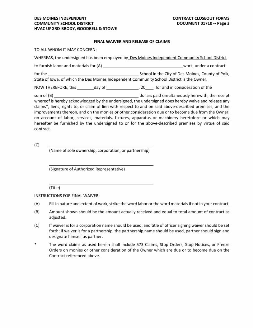
CONTRACT CLOSEOUT FORMS DOCUMENT 01710 -- Page 3
DES MOINES INDEPENDENT COMMUNITY SCHOOL DISTRICT HVAC UPGRD-BRODY, GOODRELL & STOWE
FINAL WAIVER AND RELEASE OF CLAIMS
TO ALL WHOM IT MAY CONCERN:
WHEREAS, the undersigned has been employed by Des Moines Independent Community School District
to furnish labor and materials for (A) work, under a contract
for the School in the City of Des Moines, County of Polk, State of Iowa, of which the Des Moines Independent Community School District is the Owner.
NOW THEREFORE, this day of , 20 , for and in consideration of the
sum of (B) dollars paid simultaneously herewith, the receipt whereof is hereby acknowledged by the undersigned, the undersigned does hereby waive and release any claims*, liens, rights to, or claim of lien with respect to and on said above-described premises, and the improvements thereon, and on the monies or other consideration due or to become due from the Owner, on account of labor, services, materials, fixtures, apparatus or machinery heretofore or which may hereafter be furnished by the undersigned to or for the above-described premises by virtue of said contract.
(C) (Name of sole ownership, corporation, or partnership)
(Signature of Authorized Representative)
(Title)
INSTRUCTIONS FOR FINAL WAIVER:
(A) Fill in nature and extent of work, strike the word labor or the word materials if not in your contract.
(B) Amount shown should be the amount actually received and equal to total amount of contract asadjusted.
(C) If waiver is for a corporation name should be used, and title of officer signing waiver should be setforth; if waiver is for a partnership, the partnership name should be used, partner should sign anddesignate himself as partner.
* The word claims as used herein shall include 573 Claims, Stop Orders, Stop Notices, or FreezeOrders on monies or other consideration of the Owner which are due or to become due on theContract referenced above.

CONTRACT CLOSEOUT FORMS DOCUMENT 01710 -- Page 4
DES MOINES INDEPENDENT COMMUNITY SCHOOL DISTRICT HVAC UPGRD-BRODY, GOODRELL & STOWE
CONSENT OF SURETY TO FINAL PAYMENT
TO OWNER: Des Moines Independent Community PROJECT NO: School District 2100 Fleur Drive CONTRAT DATED: Des Moines, IA 50321
PROJECT:
In accordance with the provisions of the Contract between the Owner and the Contractor as indicated above, the
, SURETY, on bond of
, CONTRACTOR.
hereby approves of the final payment of the Contractor, and agrees that final payment to the Contractor shall not relieve the Surety of any of its obligations to Des Moines Independent Community School District, 2100 Fleur Drive, Des Moines, Iowa, 50321, OWNER, as set forth in said Surety’s bond.
IN WITNESS WHEREOF, the Surety has hereunto set its hand on this date:
________________________________________ Surety
________________________________________ Signature of authorized representative
ATTEST:
________________________________________ (Seal): Printed name and title

CONTRACT CLOSEOUT FORMS DOCUMENT 01710 -- Page 5
DES MOINES INDEPENDENT COMMUNITY SCHOOL DISTRICT HVAC UPGRD-BRODY, GOODRELL & STOWE
CONTRACTOR’S AFFIDAVIT OF PAYMENT OF DEBTS AND CLAIMS AND RELEASE OF CLAIMS
TO OWNER: Des Moines Independent PROJECT NO: Community School District 2100 Fleur Drive Des Moines, IA 50321
PROJECT: CONTRACT DATED:
STATE OF: Iowa
COUNTY OF: Polk
The undersigned hereby certifies, except as listed below, payment has been made in full and all obligations have otherwise been satisfied for all materials and equipment furnished, for all work, labor, and services performed, and for all known indebtedness and claims against the Contractor for damages arising in any manner in connection with the performance of the contract referenced above for which the Owner or Owner’s property might in any way be held responsible or encumbered.
EXCEPTIONS:
The undersigned hereby further certifies that to the best of the undersigned’s knowledge, information and belief, except as listed below, the Release of Claims attached hereto include the Contractor, all subcontractors, all suppliers of materials and equipment, and all performers of Work, labor or services who have or may have 573 claims, or encumbrances or the right to assert claims or encumbrances against any property of the Owner arising in any manner out of the performance of the Contract referenced above.
EXCEPTIONS:

CONTRACT CLOSEOUT FORMS DOCUMENT 01710 -- Page 6
CONTRACTOR:
BY: Signature of authorized representative
Printed Name and Title
DES MOINES INDEPENDENT COMMUNITY SCHOOL DISTRICT HVAC UPGRD-BRODY, GOODRELL & STOWE
SUPPORTING DOCUMENTS ATTACHED
HERETO:
1. Consent of Surety to Final Payment. DMPSFM-640
Indicate attachment: yes no
The following supporting documents are attached:
1. Contractor’s Waiver and Release of Claims
2. Separate Waiver and Releases of Claims fromSubcontractors and material and equipmentsuppliers accompanied by a list thereof.
Subscribed and sworn before me on this date
Notary Public
My Commission Expires

CONTRACT CLOSEOUT FORMS DOCUMENT 01710 -- Page 7
DES MOINES INDEPENDENT COMMUNITY SCHOOL DISTRICT HVAC UPGRD-BRODY, GOODRELL & STOWE
ARCHITECT’S CERTIFICATE OF SPECIFICATIONS TO OWNER: Director, Facility Management PROJECT NO:
Des Moines Independent Community School District CONTRACT FOR: 2100 Fleur Drive Des Moines, IA 50321
The undersigned hereby certifies as follows:
1. The above referenced Project is finally completed; and
2. No asbestos or asbestos-containing material was specified as a building material in any ConstructionDocuments for the Project; and
3. To the best of my knowledge, no asbestos or asbestos-containing material was used as a buildingmaterial in the Project.
Architect
Date
Subscribed and sworn before me on this date
Notary Public
My Commission Expires
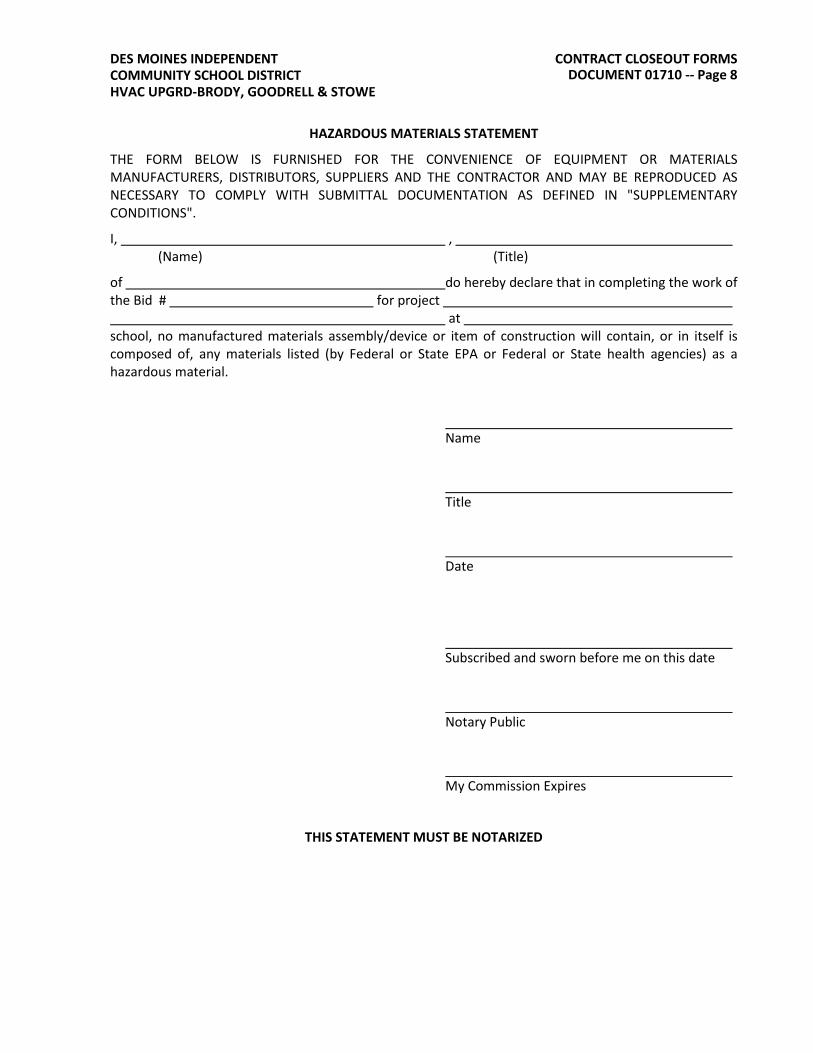
CONTRACT CLOSEOUT FORMS DOCUMENT 01710 -- Page 8
DES MOINES INDEPENDENT COMMUNITY SCHOOL DISTRICT HVAC UPGRD-BRODY, GOODRELL & STOWE
HAZARDOUS MATERIALS STATEMENT
THE FORM BELOW IS FURNISHED FOR THE CONVENIENCE OF EQUIPMENT OR MATERIALS MANUFACTURERS, DISTRIBUTORS, SUPPLIERS AND THE CONTRACTOR AND MAY BE REPRODUCED AS NECESSARY TO COMPLY WITH SUBMITTAL DOCUMENTATION AS DEFINED IN "SUPPLEMENTARY CONDITIONS".
I, , (Name) (Title)
of do hereby declare that in completing the work of the Bid # for project
at school, no manufactured materials assembly/device or item of construction will contain, or in itself is composed of, any materials listed (by Federal or State EPA or Federal or State health agencies) as a hazardous material.
Name
Title
Date
Subscribed and sworn before me on this date
Notary Public
My Commission Expires
THIS STATEMENT MUST BE NOTARIZED

CONTRACT CLOSEOUT FORMS DOCUMENT 01710 -- Page 9
DES MOINES INDEPENDENT COMMUNITY SCHOOL DISTRICT HVAC UPGRD-BRODY, GOODRELL & STOWE
WARRANTY FOR
We hereby warrant that the which we have
provided in the has been completed in accordance with the
requirements of Specification Section(s) and the Contract Documents.
We agree to repair or replace any or all of our work, together with any other adjacent work which may be displaced by so doing, that may prove to be defective in its workmanship or material within a period of from the date of acceptance of the above named project by the Owner; and we also agree to repair any and all damages resulting from such defects, all without additional expense to the Owner, ordinary wear and tear and unusual abuse or neglect excepted.
In the event of our failure to comply with the above mentioned conditions within 30 days after being notified in writing by the Owner, we collectively or separately do hereby authorize the Owner to proceed to have such defective work repaired or replaced and made good at our expense, and we will honor and pay the costs and charges therefore upon demand.
Signed: Date:
Subcontractor's name:
Address:
License Number:
Countersigned: Date
Contractors name:
Address:
License Number:
or
Manufacturer's Name
Address:
OR
Signed: Date:
Contractors name:
Address:
License Number:
THIS STATEMENT MUST BE NOTARIZED.

MODUS / 2021-057 HVAC Upgrades to Brody, Goodrell & Stowe 21 0050 - 1BASIC FIRE SUPPRESSION REQUIREMENTS
SECTION 21 0050BASIC FIRE SUPPRESSION REQUIREMENTS
PART 1 GENERAL1.01 SECTION INCLUDES
A. Basic Fire Suppression Requirements specifically applicable to Mechanical DivisionSpecification Sections.
B. Division 21 Specification requirements also include, by reference, all Division 00 and 01specification sections. This contractor is responsible to review these specification sections. Requirements of these specification sections are included as a part of this contract.
1.02 OWNER OCCUPANCYA. The owner will occupy the premises during the construction period.B. Limit use of site and premises to allow owner occupancy.C. Cooperate with the owner to minimize conflict and to facilitate owner's operations.D. Schedule the work to accommodate this requirement.
1.03 REGULATORY REQUIREMENTSA. This contractor shall give proper authorities all requisite notices relating to work in their charge,
obtain official permits, licenses for temporary construction and pay proper fees for it.B. This contractor is to be solely answerable for and shall promptly make good all damage, injury
or delay to other contractors, to neighboring premises or to persons or property of the public bythe contractor, by the contractor's employees or through any operation under the contractor'scharge, whether in the contract or as extra work.
C. No attempt has been made to reproduce in these specifications any of the rules or regulationscontained in city, state or federal ordinances and codes pertaining to the work covered by thesespecifications that the contractor be thoroughly familiar with all such ordinances and codes.
D. The fact that said various rules, regulations and ordinances are not repeated in this specificationdoes not relieve this contractor of the responsibility of making the entire installation inaccordance with the requirement of those authorities having jurisdiction.
E. All work shall comply with the applicable recommendations of:1. The National Board of Fire Underwriters2. The American Gas Association3. The National Fire Protection Association (NFPA)4. The Occupations Safety and Health Act (OSHA)5. Current IBC Building Code6. Current applicable city building codes7. Fire Protection: Conform to UFC and NFPA
F. Mechanical: Conform to current mechanical code.G. Plumbing: Conform to current plumbing code.H. Obtain permits and request inspections from authority having jurisdiction.
1.04 QUALIFICATIONSA. The fire suppression installer must be a company specializing in applying the work of this
division with a minimum of five years experience.1.05 SYSTEM DESCRIPTION
A. Design and install the system to NFPA 13.B. With the existing system, the contractor shall verify that the sprinkler system meets the currently
enforced version of the NFPA. This contractor shall provide all work and devices required tobring the system in to compliance. [Use on private systems and buildings that have beenunoccupied for a period of time]

MODUS / 2021-057 HVAC Upgrades to Brody, Goodrell & Stowe 21 0050 - 2BASIC FIRE SUPPRESSION REQUIREMENTS
C. Remodel: The existing wet sprinkler system shall be modified as required for the new spaceoccupancy. Modifications shall include, but not be limited to, number and location of sprinklerheads, type of heads, rerouting and resizing of branches, etc.
1.06 PROJECT/SITE CONDITIONSA. Install work in locations shown on the drawings unless prevented by project conditions.B. Prepare drawings showing proposed rearrangement of work to meet project conditions,
including changes to work specified in other sections. Obtain permission of owner andarchitect/engineer prior to proceeding.
C. This contractor, before submitting their bid, shall visit the site of the project to become familiarwith locations and conditions affecting their work.
D. It is the intent of this specification that this contractor furnish all labor and material required tocomplete the installation as outlined in the drawings and specifications. No additions to thecontract price shall be allowed due to the failure of this contractor to properly evaluate the effectof existing conditions on the work to be done under this contract.
E. Whenever renovation or remodeling or relocation of existing equipment is included in thecontract, it is imperative that all locations of existing piping, ductwork, equipment, services andgrades be noted on the job site prior to bid being submitted and that all elevations and gradesbe verified before roughing in new work.
F. This contractor shall provide holes as necessary for the installation of their work and inaccordance with other specification sections in materials other than the structure.
1.07 SEQUENCING AND SCHEDULINGA. This contractor shall arrange their work in order that it progresses along with the general
construction of the building.B. This contractor shall be kept informed as to the work of other trades engaged in the project and
shall execute their work in such a manner so as not to delay or interfere with progress of othercontractors.
C. Where space for mechanical and electrical lines and piping is limited, it is imperative that allsuch trades coordinate their work so as to ensure concealment in space provided. Whereconflict exists, the engineer shall decide priority of space. If work is not properly coordinated,the engineer may require removal and relocation of work without additional compensation.
1.08 GUARANTEEA. This contractor shall guarantee all of the apparatus, materials, equipment furnished, and labor
installed under this contract for a period of one year after date of final acceptance, unless alonger period is specified.
B. Neither final certificate of payment nor any provisions in the contract documents nor partial orcomplete occupancy of premises by owner shall constitute an acceptance for work not done inaccordance with contract documents or relieve the contractor of liability in respect to anyexpress warranties or responsibility for faulty materials or workmanship.
C. Should any defects arise as the result of defective workmanship or material within theguarantee period set forth, this contractor shall make the necessary correction at their ownexpense.
1.09 ENGINEER APPROVED EQUAL PRODUCTSA. When the engineer, at the request of the interested parties, including the contractor, supplier
and manufacturer approved "engineer approved equal" products for this project, such productsare approved on the assumption that they will equal or exceed the performance of the productsspecified.
B. If such products do not do so after being installed on this project, this contractor shall replace ormodify the particular product as necessary to equal the performance of the products specified atno expense to the owner, architect or engineer.

MODUS / 2021-057 HVAC Upgrades to Brody, Goodrell & Stowe 21 0050 - 3BASIC FIRE SUPPRESSION REQUIREMENTS
C. Request for "engineer approved equal" products shall be received by the architect/engineerprior to the last addendum being issued. Requests for substitutions received after this date willnot be considered. Substitution requests shall clearly state which products are beingconsidered for substitution. Substitution requests shall include all pertinent product informationneeded to evaluate the substitution as an "equal".
D. Similar products shall be all of the same manufacturers and style. There is no exception to thisunless prior approval has been granted from engineer.
1.10 OWNER'S RIGHT OF SALVAGEA. Before beginning construction, this contractor shall check and verify with the owner each item of
existing equipment that must be removed.B. The owner will designate which items of material or equipment not reused that they may wish to
keep. This contractor shall then remove these items with care and store in a locationdesignated by the owner for the owner's disposal.
C. All other items of equipment to be removed and not specified for reuse in new construction orreserved by the owner for their own use shall become the property of the contractor and shall beremoved from site.
1.11 PROTECTION AND MAINTENANCEA. The work covered by these drawings and specifications involves all work in the [new] [existing]
building.B. Where necessary to connect to any existing utility service, this contractor shall contact the
owner and shall coordinate any building service connection with the owner so that normaloperation to the building is disrupted as little as possible.
C. Any work to be done in existing structures shall be coordinated with the owner andarrangements made so that traffic flow may be maintained and areas finished where possiblebefore other areas are begun.
D. This contractor shall protect existing equipment in all finished areas from dirt, dust and damageas a result of their work.
E. Coordinate protection requirements with department heads before beginning construction.F. Protect any building openings from unauthorized entry. Coordinate with owner where building
entry must be controlled.1.12 DEMOLITION
A. This contractor shall be responsible for the demolition and removal of all existing mechanicalelements within the project area except as follows:1. Elements shown on the drawings as "existing to remain and/or to be relocated".2. Elements serving adjacent areas.3. Elements required for the support of the newly remodeled areas.4. All elements to be removed are subject to the Owner's Right of Salvage.
B. Preserve services to the existing facility. Extend/reroute/reconnect existing systems as requiredproviding for the continued function of these systems.
1.13 CUTTING AND PATCHINGA. This contractor shall do all cutting and patching necessary for the installation of their work in all
existing and new buildings unless otherwise noted.B. In areas where the integrity of new or existing fire separation assembly/wall is compromised by
the work, contractor shall be responsible to patch and/or seal openings as necessary tomaintain/return fire separation to rating as required by applicable codes.
C. This contractor shall do all cutting and patching required for their work beyond the remodeledareas unless otherwise noted. All finish work shall include patching to match existing adjacentsurfaces. Painting shall be by others.
MODUS / 2021-057 HVAC Upgrades to Brody, Goodrell & Stowe 21 0050 - 4BASIC FIRE SUPPRESSION REQUIREMENTS
D. This contractor shall arrange for openings in the building as required for the installation ofequipment furnished under this contract. Where piping must be extended or changed, patchingwith concrete will be done in the building. Patching shall be at both the top and bottom ofsleeves where above grade.
1.14 CLEANING AND RUBBISHA. This contractor shall upon completion of their work, remove all rubbish and debris resulting from
this contractor's operation and shall remove it from site at their own expense.B. In so far as this contractor's work is concerned, all equipment shall be cleaned and the
premises left in first class condition.C. This contractor shall maintain the work area each day to prevent hazardous accumulation of
waste from their work.1. Refer to architectural specifications for approved sealant manufacturers.
1.15 SEALING AND PENETRATIONA. Clearance around the piping passing through fire or smoke rated construction shall be sealed to
maintain the rated integrity of the construction (1 hr. 2 hrs. etc.). One and two-hour ratedassemblies are to be patched on both sides of the assembly.
B. This contractor shall verify with the architect drawings the rating and location of all suchconstruction and seal all penetrations.
C. Manufacturer offering products to comply with the requirements include the following:1. Dow Corning "Silicone RTV Foam"2. 3-M Corporation "Fire Barrier Caulk and Putty"3. Thomas & Betts "Flame Safe Fire Stop System"
D. Installation of these products to be in strict accordance with manufacturer's recommendationsand architectural specification sections or equivalent fire stopping general specification section.
E. The contractor shall submit shop drawings showing approved sealing assemblies to be utilizedon this project.
1.16 HAZARDOUS MATERIALSA. If the contractor stores any hazardous solvents or other materials on the site, the contractor
shall obtain copies of the safety data sheets for the materials and post them on the site. Thecontractor shall inform the owner and all employed of any potential exposure to this material.
B. At no time shall any product containing asbestos be incorporated into the work.1. If asbestos materials are encountered, report to the owner. The owner will be responsible
for asbestos removal.1.17 AS-BUILT DRAWINGS
A. This contractor shall provide, at the conclusion of the project, one clean, non-torn, neat, andlegible "as-built" set of drawings to the owner. These drawings shall show the routing of pipesand equipment drawn in at scaled locations. All dimensions indicated shall be referenced to acolumn line. A set of construction drawings will be furnished for this work.
B. All sprinkler systems installed shall be shown on the "as-built" drawings.C. Refer to respective general specification section for additional information.D. This contractor shall update these drawings during the project at least every week.
1.18 REVIEW OF MATERIALSA. This contractor shall submit to the engineer for review one (1) electronic copy of a brochure
giving a complete list of materials and equipment they propose to furnish. The brochure shallcontain complete information as to the make of equipment, type, size, capacities, dimensionsand illustration. One of these returned copies shall be kept on the job at all times.
B. Checking of submittal drawings by the engineer does not relieve the contractor of theresponsibility for the accuracy of such drawings and for their conformity to drawings and

MODUS / 2021-057 HVAC Upgrades to Brody, Goodrell & Stowe 21 0050 - 5BASIC FIRE SUPPRESSION REQUIREMENTS
specifications unless the contractor notifies engineer in writing of such deviation at time suchdrawings are furnished.
C. All submittals shall have the date marked on them when the contractor receives them from thesupplier. Submittals shall be submitted through the contractor and shall not come direct fromthe supplier to the architect or engineer.
D. This contractor shall mark the date and sign each set signifying that the contractor has checkedeach of them in their entirety before submitting to the engineer. Submittals that are not datedand signed by the contractor will not be accepted, or checked and will be marked "resubmit" andsent back to the contractor.
1.19 TEST OF SYSTEMSA. This contractor, before concealed, shall test all systems installed under this contract as called
for in these specifications and as required by local codes. Tests shall be made in the presenceof the engineer, local authorities or their duly authorized representative. Any defects discoveredin testing shall be corrected and the tests repeated until all defects are eliminated.
B. This contractor shall be held responsible for all damage resulting from defects in the system.C. At the conclusion of construction (before any covering up, painting or finishing) each element of
the system shall be thoroughly tested against leakage with appropriate pressure tests asoutlined herein and in appropriate sections of the specifications. All testing shall be hydrostaticunless permission is granted otherwise.1. Underground Fire Lines: 200 psi. Maintain in accordance with NFPA 13.
D. Fluid lines other than the above shall be tested in accordance with NFPA 13.E. After completion of installation, the systems shall be given tests under full operating conditions
and pressures and all adjustments shall be made to make the system operative as required. Allsafety devices shall be tested for correct operation.
1.20 SCOPE OF WORKA. All work shall be performed by well-qualified and licensed mechanics with a thorough
knowledge of the various systems involved in this building. It shall be this contractor'sresponsibility to see that their mechanics are familiar with all the various codes and testsapplicable to this work.
B. All equipment shall be new and of the type as specified by the engineer unless otherwise notedin these specifications or on the drawings to remain and or be reused.
C. The intent of the drawings and specifications is for complete installation of the systems outlinedin the drawings and specifications so that at the conclusion of construction the system will beturned over to the owner complete and ready for safe and efficient operation.
D. This contractor shall be required to furnish and install all such items normally included onsystems of this type, which, while not mentioned directly herein or on the drawings are obviouslyessential to the installation and operation of the system and which are normally furnished onquality installation of this type. The drawings and specifications cannot deal individually with themany minute items that may be required by the nature of the systems.
E. If there is a discrepancy between the drawings and the specifications or within either document,the more stringent requirement shall be estimated unless brought to the engineer’s attentionand an addendum is issued for clarification.
F. The Fire Suppression Contractor shall establish system elevations prior to fabrication andinstallation. The Fire Suppression Contractor shall coordinate elevations with other trades. Allelevations shall be coordinated with all trades in the field prior to installation. When a conflictbetween trades arises, the design team shall be notified immediately prior to further installationhowever priority shall be as follows:1. Lighting Fixtures2. Gravity flow piping, including steam and condensate.3. Electrical bus duct.4. Sheet metal.

MODUS / 2021-057 HVAC Upgrades to Brody, Goodrell & Stowe 21 0050 - 6BASIC FIRE SUPPRESSION REQUIREMENTS
5. Cable trays, including access space.6. Other piping.7. Conduits and wireway.
1.21 VERIFICATION OF ELEVATION OF EXISTING LINESA. This contractor, before starting any new work, shall verify the elevations of all existing piping to
which they must connect under this contract. The contractor shall report any discrepanciesbetween drawing elevations and actual elevations to the engineer before proceeding with thework. Failure of the contractor to do so shall make the contractor liable for the cost of extrawork involved.
1.22 DAILY HOUSEKEEPINGA. At the end of each working day, this contractor shall remove all of their debris, rubbish, tools
and surplus materials from the project work area. The work area shall be broom clean and leftin a neat and orderly condition. This contractor, for the removal of debris from the project, shallnot use the owner’s waste disposal facility.
B. At end of construction, all equipment shall be cleaned and the premises left in first classcondition as far as this contractor's work is concerned.
1.23 CLEANING OF MECHANICAL SYSTEMSA. This contractor shall clean all piping systems by flushing with water until free from all sand, grit,
gravel, oil, etc.B. Where connections are made to existing piping systems, this contractor shall provide isolation
valves, threaded tees, etc., as required to facilitate the cleaning and testing of all new piping.C. This contractor shall thoroughly clean all rust, grease, plaster, cement, etc., from all equipment
and piping furnished and installed by them as required to leave surfaces suitable for finishpainting.
D. This contractor shall keep all pipes, plugged, drained or otherwise protected duringconstruction. All items of mechanical equipment shall be suitably protected and uponcompletion of project shall be equal to new condition.
PART 2 PRODUCTSNOT USED
PART 3 EXECUTIONNOT USED
END OF SECTION
MODUS / 2021-057 HVAC Upgrades to Brody, Goodrell & Stowe 21 0529 - 1HANGERS AND SUPPORTS FOR FIRE SUPPRESSION PIPING AND EQUIPMENT
SECTION 21 0529HANGERS AND SUPPORTS FOR FIRE SUPPRESSION PIPING AND EQUIPMENT
PART 1 GENERAL1.01 SECTION INCLUDES
A. Pipe hangers and supportsB. AccessoriesC. Sleeves
1.02 REFERENCESA. ASME B31.1 - Power PipingB. ASME B31.9 - Building Services PipingC. ASTM F708 - Design and Installation of Rigid Pipe HangersD. MSS SP58 - Pipe Hangers and Supports - Materials, Design and ManufacturerE. MSS SP69 - Pipe Hangers and Supports - Selection and ApplicationF. MSS SP89 - Pipe Hangers and Supports - Fabrication and Installation PracticesG. NFPA 13 - Installation of Sprinkler SystemsH. NFPA 14 - Installation of Standpipe and Hose SystemsI. UL 203 - Pipe Hanger Equipment for Fire Protection Service
1.03 SUBMITTALSA. Product Data: Provide manufacturers catalog data including load capacity.B. Design Data: Indicate load carrying capacity of trapeze, multiple pipe, and riser support
hangers.C. Manufacturer's Installation Instructions: Indicate special procedures and assembly of
components.1.04 REGULATORY REQUIREMENTS
A. Conform to applicable code for support of piping.PART 2 PRODUCTS2.01 PIPE HANGERS AND SUPPORTS
A. Manufacturers:1. Grinnell2. Tolco3. Engineer approved equal.
B. Fire Protection Piping:1. Hangers for Pipe Sizes 1/2 Inch to 1-1/2 Inch: Carbon steel, adjustable swivel, split ring.2. Hangers for Pipe Sizes Two Inch (2") and Over: Carbon steel, adjustable, clevis.3. Multiple or Trapeze Hangers: Steel channels with welded spacers and hanger rods.4. Wall Support for Pipe Sizes to Three Inches: Cast iron hook.5. Wall Support for Pipe Sizes Four Inch (4") and Over: Welded steel bracket and wrought
steel clamp.6. Vertical Support: Steel riser clamp.7. Floor Support: Cast iron adjustable pipe saddle, lock nut, nipple, floor flange, and concrete
pier or steel support.8. Provide zinc coated hangers and supports for all non air conditioned areas.
2.02 ACCESSORIESA. Hanger Rods: Mild steel threaded both ends, threaded one end or continuous threaded.B. Install in accordance with manufacturer's instructions.

MODUS / 2021-057 HVAC Upgrades to Brody, Goodrell & Stowe 21 0529 - 2HANGERS AND SUPPORTS FOR FIRE SUPPRESSION PIPING AND EQUIPMENT
2.03 SLEEVESA. Sleeves for pipes through fire rated and fire resistive floors and walls, and fire proofing to be a
fire rated sleeve assembly including seals, UL listed.B. Stuffing and Firestopping Insulation: Fiberglass type, non-combustible per UL tested assembly
type.C. Sealant Manufacturers:
1. Dow Corning Silicone RTV Foam.2. 3-M Fire Barrier Caulk and Putty.3. Thomas & Betts Flame Safe Fire Stop System.4. Engineer approved equal.
PART 3 EXECUTION3.01 INSTALLATION
A. Install in accordance with manufacturer's instructions.3.02 PIPE HANGERS AND SUPPORTS
A. Provide hanger rod size and spacing in accordance to NFPA requirements.B. Support piping in accordance to NFPA requirements.C. Install hangers to provide minimum 1/2 inch space between finished covering and adjacent
work.D. Place hangers within 12 inch of each horizontal elbow.E. Use hangers with 1-1/2 inch minimum vertical adjustment.F. Support vertical piping at every floor.G. Where several pipes can be installed in parallel and at same elevation, provide multiple or
trapeze hangers.H. Support riser piping independently of connected horizontal piping.I. Design hangers for pipe movement without disengagement of supported pipe.J. Prime coat exposed steel hangers and supports. Hangers and supports located in crawl
spaces, pipe shafts, and suspended ceiling spaces are not considered exposed.3.03 SLEEVES
A. Set sleeves in position in formwork. Provide reinforcing around sleeves.B. Size sleeves large enough to allow for movement due to expansion and contraction.C. Extend sleeves through floor one inch (1") above finished floor level. Caulk sleeves.D. Provide sleeves where piping penetrates floor, ceiling or wall fire rated assemblies. Close off
space between pipe or duct and adjacent work with fire stopping insulation and caulk.E. Provide close fitting metal collar or escutcheon covers at both sides of penetration. Install
chrome plated steel escutcheons at finished surfaces and within cabinets.3.04 SCHEDULES
HANGER ROD MAX. HANGER SPACING DIAMETERPipe Size Feet Inches
1/2 to 1-1/4 6.5 3/81-1/2 to 2 10.0 3/82-1/2 to 3 10.0 1/2
4 to 6 10.0 5/88 to 12 14.0 7/8
14 and Over 20.0 1

MODUS / 2021-057 HVAC Upgrades to Brody, Goodrell & Stowe 21 0529 - 3HANGERS AND SUPPORTS FOR FIRE SUPPRESSION PIPING AND EQUIPMENT
END OF SECTION

MODUS / 2021-057 HVAC Upgrades to Brody, Goodrell & Stowe 21 0529 - 4HANGERS AND SUPPORTS FOR FIRE SUPPRESSION PIPING AND EQUIPMENT

MODUS / 2021-057 HVAC Upgrades to Brody, Goodrell & Stowe 21 1200 - 1FIRE SUPPRESSION PIPING
SECTION 21 1200FIRE SUPPRESSION PIPING
PART 1 GENERAL1.01 SECTION INCLUDES
A. Sprinkler and standpipe piping1.02 RELATED SECTIONS
A. Specification Section 21 1300 - Fire Suppression Sprinkler Systems1.03 REFERENCES
A. ANSI/ASME B16.3 - Malleable Iron Threaded Fittings, Class 150 and 300B. ANSI/ASME B16.4 - Cast Iron Threaded Fittings, Class 125 and 250C. ANSI/ASME B16.9 - Factory-Made Wrought Steel Butt Welding FittingsD. ANSI/ASME B16.22 - Wrought Copper and Copper Alloy Solder Joint Pressure FittingsE. ANSI/ASME Sec 9 - Welding and Brazing QualificationsF. ANSI/ASTM A53 - Standard Specification for Pipe, Steel, Black and Hot-Dipped, Zinc-Coated,
Welded and SeamlessG. ANSI/ASTM A135 - Electric Resistance Welded Steel PipeH. ASTM A795 - Black and Hot-Dipped Zinc-Coated (Galvanized) Welded and Seamless Steel
Pipe for Fire Protection UseI. ASTM B88 - Seamless Copper Water TubeJ. ASTM D1784 - Standard Specification for Rigid Poly(Vinyl Chloride) (PVC) Compounds and
Chlorinated Poly(Vinyl Chloride) (CPVC) CompoundsK. ASTM F437 - Standard Specification for Threaded Chlorinated Poly(Vinyl Chloride) (CPVC)
Plastic Pipe Fittings, Schedule 80L. ASTM F438 - Standard Specification for Socket-Type Chlorinated Poly(Vinyl Chloride) (CPVC)
Plastic Pipe Fittings, Schedule 40M. ASTM F439 - Standard Specification for Chlorinated Poly (Vinyl Chloride) (CPVC) Plastic Pipe
Fittings, Schedule 80N. ASTM F442 - Standard Specification for Chlorinated Poly(Vinyl Chloride) (CPVC) Plastic Pipe
(SDR-PR)O. ASTM F493 - Standard Specification for Solvent Cements for Chlorinated Poly(Vinyl Chloride)
(CPVC) Plastic Pipe and FittingsP. AWS A5.8 - Specifications for Filler Metal for Brazing and Braze WeldingQ. NFPA 13 - Installation of Sprinkler SystemsR. NFPA 13R - Installation of Sprinkler Systems in Residential Occupancies up to and Including
Four Stories of HeightS. NFPA 14 - Standpipe and Hose SystemsT. NFPA 24 - Installation of Private Fire Service Mains and their Appurtenances
1.04 SUBMITTALSA. Shop Drawings: Indicate pipe materials used, jointing methods, supports, floor, and wall
penetration seals.B. Product Data: Provide manufacturers catalog information. Indicate valve data and ratings.
1.05 OPERATION AND MAINTENANCEA. Maintenance Instructions: Include installation instructions, spare parts list, procedures and
treatment programs.

MODUS / 2021-057 HVAC Upgrades to Brody, Goodrell & Stowe 21 1200 - 2FIRE SUPPRESSION PIPING
1.06 QUALITY ASSURANCEA. Perform to NFPA 13.B. Welding Materials and Procedures: Perform to ASME Code.C. Valves: Bear UL and FM label or marking. Provide manufacturer's name and pressure rating
marked on valve body.D. Maintain one copy of each document on site.
1.07 DELIVERY, STORAGE AND PROTECTIONA. Deliver, store, protect and handle products to site.B. Deliver and store valves in shipping containers with labeling in place.C. Provide temporary end caps and closures on piping and fittings. Maintain in place until
installation.PART 2 PRODUCTS2.01 SPRINKLER AND STANDPIPE PIPING (ABOVE GROUND)
A. Steel Pipe:1. Two Inch (2") and Smaller: ASTM A135, Schedule 40 black mill coating.2. 2-1/2 Inch and Larger: ASTM A135, Schedule 10 black mill coating.3. Fittings:
a. Steel Pipe 2 Inch and Smaller: ANSI/ASME B16.9 cast iron or ANSI/ASME B16.3malleable iron, threaded.
b. Steel Pipe 2-1/2 Inch and Larger: Mechanical grooved couplings, ductile iron housingclamps, lock "C" shaped composition gasket, steel bolts, nuts, and washers.
B. Copper Pipe: ASTM B88, type L, annealed.1. Fittings: ASTM B16.22 wrought copper or bronze pressure fittings.2. Joints: AWS A5.8 brazed.3. Use copper piping within MRI rooms.
PART 3 EXECUTION3.01 PREPARATION
A. Ream pipe and tube ends, remove burrs, bevel plain end ferrous pipe.B. Remove scale and foreign material, from inside and outside, before assembly.C. Prepare piping connections to equipment with flanges or unions.
3.02 INSTALLATIONA. See plumbing specifications for underground piping requirements.B. Route piping in orderly manner, plumb and parallel to building structure. Maintain gradient.C. Install piping to conserve building space and to not interfere with use of space and other work.D. Group piping whenever practical at common elevations.E. Sleeve pipes passing through partitions, walls, and floors.F. Install piping to allow for expansion and contraction without stressing pipe, joints or connected
equipment.G. Prepare pipe, fittings, supports and accessories for finish painting. Where pipe support
members are welded to structural building frame, scrape, brush clean and apply one coat ofzinc rich primer to welding.
H. Do not penetrate building structural members unless indicated.I. Provide sleeves when penetrating footings, floors and walls. Seal pipe and sleeve penetrations
to achieve fire resistance equivalent to fire separation required.J. Die cut screw joints with full cut standard taper pipe threads with red lead and linseed oil or
other non-toxic joint compound applied to male threads only.

MODUS / 2021-057 HVAC Upgrades to Brody, Goodrell & Stowe 21 1200 - 3FIRE SUPPRESSION PIPING
K. Install valves with stems upright or horizontal, not inverted. Remove protective coatings prior toinstallation.
L. Provide butterfly valves for shut-off or isolating service.M. Provide drain valves at main shut-off valves, low points of piping and apparatus.N. Run drain piping to suitable drainage point, interior to the building. Coordinate all locations with
architect.O. Route piping concealed above ceiling. Where piping has to be exposed, coordinate all pipe
routing with the architect.END OF SECTION

MODUS / 2021-057 HVAC Upgrades to Brody, Goodrell & Stowe 21 1200 - 4FIRE SUPPRESSION PIPING

MODUS / 2021-057 HVAC Upgrades to Brody, Goodrell & Stowe 21 1300 - 1FIRE SUPPRESSION SPRINKLER SYSTEMS
SECTION 21 1300FIRE SUPPRESSION SPRINKLER SYSTEMS
PART 1 GENERAL1.01 SECTION INCLUDES
A. Sprinkler heads1.02 RELATED SECTIONS
A. Specification Section 21 1200 - Fire Suppression Piping1.03 REFERENCES
A. ASTM F2503 - Standard Practice for Marking Medical Devices and Other Items for Safety in theMagnetic Resonance Environment
B. NFPA 13 - Installation of Sprinkler SystemsC. NFPA 15 - Water Spray Fixed Systems for Fire ProtectionD. NFPA 231 - Standard for General StorageE. NFPA 231C - Standard for Rack Storage of MaterialsF. FM - Factory Mutual Approval GuideG. NFPA 70 - National Electrical CodeH. UL - Fire Resistance DirectoryI. UL 199 - Automatic SprinklersJ. Warnock Hersey - Certification Listings
1.04 SYSTEM DESCRIPTIONA. Provide system as specified in Section 21 0050.
1.05 SUBMITTALSA. Product Data: Provide manufacturers catalog data including load capacity.B. Manufacturer's Installation Instructions: Indicate special procedures and assembly of
components.1.06 PROJECT RECORD DOCUMENTS
A. Preliminary Shop Drawings: Prior to detailed submission, submit preliminary layout of finishedceiling areas indicating only head locations coordinated with ceiling installation.
B. Shop Drawings: Indicate hydraulic calculations, detailed pipe lay out, hangers and supports,components and accessories. Indicate system controls.
C. Product Data: Provide data on sprinklers, valves, and specialties including manufacturerscatalog information. Submit performance ratings, rough-in details, weights, supportrequirements, and piping connections.
D. Submit shop drawings, product data and hydraulic calculations to the local fire marshal andowner's insurance underwriter for approval. Submit proof of approval to architect and engineer.
E. Manufacturer's Certificate: Certify that system has been tested and meets or exceeds coderequirements.
1.07 AS BUILT DRAWINGSA. Record actual locations of sprinkler heads and deviations of piping from the drawings. Indicate
drain and test locations.1.08 OPERATION AND MAINTENANCE DATA
A. Maintenance Data: Include components of system, servicing requirements, record drawings,inspection data, replacement part numbers, availability and location of service depot.
MODUS / 2021-057 HVAC Upgrades to Brody, Goodrell & Stowe 21 1300 - 2FIRE SUPPRESSION SPRINKLER SYSTEMS
1.09 QUALITY ASSURANCEA. Perform work in accordance with the System Description in Section 21 0050 where applicable
and pre-approved by State Fire Marshal.B. Equipment and components shall bear UL and FM label or markings.C. Maintain one copy of document on site.
1.10 QUALIFICATIONSA. Installer: Company specializing in performing work of this section with a minimum of three years
experience.1.11 REGULATORY REQUIREMENTS
A. Hydraulic Calculations, Product Data and Shop Drawings:1. Bear stamp of approval of authority having jurisdiction.2. Submit to the State of Iowa and to the owner's insurance underwriter.
1.12 DELIVERY, STORAGE AND PROTECTIONA. Deliver, store, and protect products to site.B. Store products in shipping containers and maintain in place until installation. Provide temporary
inlet and outlet caps. Maintain caps in place until installation.PART 2 PRODUCTS2.01 MANUFACTURERS
A. VikingB. ReliableC. TycoD. Engineer approved equal.
2.02 SPRINKLER HEADSA. Suspended Ceiling Type:
1. Type: Recessed2. Head Finish: Enamel, color white.3. Fusible Link: Glass bulb type temperature rated for specific area hazard.
B. Exposed Area Type:1. Type: Standard upright type with guard.2. Finish: Brass3. Fusible Link: Glass bulb type temperature rated for specific area hazard.
C. Side Wall Type:1. Type: Recessed horizontal sidewall type with matching screw on escutcheon plate.2. Head Finish: brass3. Escutcheon Plate Finish: Enamel,4. Fusible Link: Glass bulb type temperature rated for specific area hazard.
PART 3 EXECUTION3.01 INSTALLATION
A. Install equipment in accordance with manufacturer’s instructions.B. Place pipe runs to minimize obstruction to other work.C. Place piping in concealed spaces above finished ceilings.D. Flush entire piping system of foreign matter.E. Hydrostatically test entire system including piping from the post indicator valve to the building.
All piping associated with the automatic fire sprinkler system shall be tested by the Division 21contractor.
MODUS / 2021-057 HVAC Upgrades to Brody, Goodrell & Stowe 21 1300 - 3FIRE SUPPRESSION SPRINKLER SYSTEMS
F. Require test be witnessed by authority having jurisdiction.G. Install white painted sprinkler heads in all areas except as noted below:
1. Install brass exposed heads in all areas that do not have ceiling systems.2. Install concealed sprinkler heads in all areas where noted on the drawings.
H. Coordinate all head locations with mechanical/electrical systems as well as architecturaldrawings.
3.02 INTERFACE WITH OTHER PRODUCTSA. Ensure required devices are installed and connected as required to fire alarm system.
END OF SECTION

MODUS / 2021-057 HVAC Upgrades to Brody, Goodrell & Stowe 21 1300 - 4FIRE SUPPRESSION SPRINKLER SYSTEMS

MODUS / 2021-057 HVAC Upgrades to Brody, Goodrell & Stowe 22 0050 - 1BASIC PLUMBING REQUIREMENTS
SECTION 22 0050BASIC PLUMBING REQUIREMENTS
PART 1 GENERAL1.01 SECTION INCLUDES
A. Basic Plumbing Requirements specifically applicable to Mechanical Division SpecificationSections.
B. Division 22 Specification requirements also include, by reference, all Division 00 and 01 specification sections. This contractor is responsible to review these specification sections. Requirements of these specification sections are included as a part of this contract.
1.02 OWNER OCCUPANCYA. The owner will occupy the premises during the construction period.B. Limit use of site and premises to allow owner occupancy.C. Cooperate with the owner to minimize conflict and to facilitate owner's operations.D. Schedule the work to accommodate this requirement.
1.03 REGULATORY REQUIREMENTSA. This contractor shall give proper authorities all requisite notices relating to work in their charge,
obtain official permits, licenses for temporary construction and pay proper fees for it.B. This contractor is to be solely answerable for and shall promptly make good all damage, injury
or delay to other contractors, to neighboring premises or to persons or property of the public bythemselves, by their employees or through any operation under their charge, whether in thecontract or extra work.
C. No attempt has been made to reproduce in these specifications any of the rules or regulationscontained in city, state or federal ordinances and codes pertaining to the work covered by thesespecifications that the contractor be thoroughly familiar with all such ordinances and codes.
D. The fact that said various rules, regulations and ordinances are not repeated in this specificationdoes not relieve the contractor of the responsibility of making the entire installation inaccordance with the requirement of those authorities having jurisdiction.
E. All work shall comply with the applicable recommendations of:1. The National Board of Fire Underwriters2. The American Gas Association3. The National Fire Protection Association (NFPA)4. The Occupations Safety and Health Act (OSHA)5. Current IBC Building Code6. Current applicable city building codes
F. Mechanical: Conform to current mechanical code.G. Plumbing: Conform to current plumbing code.H. Obtain permits and request inspections from authority having jurisdiction.I. Safe Drinking Water Act and Senate Bill S.3874: All products must meet the lead-free
requirements of the SDWA and NSF/ANSI 372 certification.1.04 PROJECT/SITE CONDITIONS
A. Install work in locations shown on the drawings unless prevented by project conditions.B. Prepare drawings showing proposed rearrangement of work to meet project conditions,
including changes to work specified in other sections. Obtain permission of owner andarchitect/engineer before proceeding.
C. This contractor, before submitting their bid, shall visit the site of the project to familiarizethemselves with locations and conditions affecting their work.

MODUS / 2021-057 HVAC Upgrades to Brody, Goodrell & Stowe 22 0050 - 2BASIC PLUMBING REQUIREMENTS
D. It is the intent of this specification that the contractor furnishes all labor and material requiredcompleting the installation as outlined in the drawings and specifications. No additions to thecontract price shall be allowed due to the failure of this contractor to properly evaluate the effectof existing conditions on the work to be done under this contract.
E. Whenever renovation or remodeling or relocation of existing equipment is included in thecontract, it is imperative that all locations of existing piping, ductwork, equipment, services andgrades be noted on the job site before bid is submitted and that all elevations and grades beverified before roughing in new work.
F. This contractor shall provide holes as necessary for the installation of their work and inaccordance with other specification sections in materials other than the structure.
1.05 SEQUENCING AND SCHEDULINGA. This contractor shall arrange their work in order that it progresses along with the general
construction of the building.B. This contractor shall be kept informed as to the work of other trades engaged in the project and
shall execute their work in such a manner so as not to delay or interfere with progress of othercontractors.
C. Where space for mechanical and electrical lines and piping is limited, it is imperative that allsuch trades coordinate their work so as to ensure concealment in space provided. Whereconflict exists, the engineer shall decide priority of space. If work is not properly coordinated,the engineer may require removal and relocation of work without additional compensation.
1.06 GUARANTEEA. This contractor shall guarantee all of the apparatus, materials, equipment furnished and labor
installed under this contract for a period of one year after date of final acceptance, unless alonger period is specified.
B. Neither final certificate of payment nor any provisions in the contract documents nor partial orcomplete occupancy of premises by owner shall constitute an acceptance for work not done inaccordance with contract documents or relieve the contractor of liability in respect to anyexpress warranties or responsibility for faulty materials or workmanship.
C. Should any defects arise as the result of defective workmanship or material within theguarantee period set forth, this contractor shall make the necessary correction at their ownexpense.
1.07 ENGINEER APPROVED EQUAL PRODUCTSA. When the engineer, at the request of the interested parties, including the contractor, supplier
and manufacturer approved "engineer approved equal" products for this project, such productsare approved on the assumption that they will equal or exceed the performance of the productsspecified.
B. If such products do not do so after being installed on this project, this contractor shall replace ormodify the particular product as necessary to equal the performance of the products specified atno expense to the owner, architect or engineer.
C. Request for "engineer approved equal" products shall be received by the architect/engineerprior to the last addendum being issued. Requests for substitutions received after this date willnot be considered. Substitution requests shall clearly state which products are beingconsidered for substitution. Substitution requests shall include all pertinent product informationneeded to evaluate the substitution as an "equal".
D. Similar products shall be all of the same manufacturers and style. There is no exception to thisunless prior approval has been granted from engineer.
1.08 OWNER'S RIGHT OF SALVAGEA. Before beginning construction, this contractor shall check and verify with the owner each item of
existing equipment that must be removed.

MODUS / 2021-057 HVAC Upgrades to Brody, Goodrell & Stowe 22 0050 - 3BASIC PLUMBING REQUIREMENTS
B. The owner will designate which items of material or equipment not reused that they may wish tokeep. This contractor shall then remove these items with care and store in a locationdesignated by the owner for the owner's disposal.
C. All other items of equipment to be removed and not specified for reuse in new construction orreserved by the owner for their use shall become the property of the contractor and shall beremoved from site.
1.09 PROTECTION AND MAINTENANCEA. Where necessary to connect to any existing utility service, this contractor shall contact the
owner and shall coordinate any building service connection with the owner so that normaloperation to the building is disrupted as little as possible.
B. Any work to be done in existing structures shall be coordinated with the owner andarrangements made so that traffic flow may be maintained and areas finished where possiblebefore other areas are begun.
C. This contractor shall protect existing equipment in finished areas from dirt, dust and damage asa result of their work.
D. Coordinate protection requirements with department heads before beginning construction.E. Protect any building openings from unauthorized entry. Coordinate with owner where building
entry must be controlled.1.10 DEMOLITION
A. This contractor shall be responsible for the demolition and removal of all existing mechanicalelements within the project area except as follows:1. Elements shown on the drawings as "existing to remain and/or to be relocated".2. Elements serving adjacent areas.3. Elements required for the support of the newly remodeled areas.4. All elements to be removed are subject to the Owner's Right of Salvage.
B. Preserve services to the existing facility. Extend/reroute/reconnect existing systems as requiredproviding for the continued function of these systems.
1.11 CUTTING AND PATCHINGA. This contractor shall do all cutting and patching necessary for the installation of their work in all
existing and new buildings unless otherwise noted.B. This contractor shall arrange for openings in the building as required for the installation of
equipment furnished under this contract.C. Where sewers must be extended or changed, patching with concrete will be done in the
building. Patching shall be at both the top and bottom of sleeves where above grade.D. In areas where the integrity of new or existing fire separation assembly/wall is compromised by
the work, contractor shall be responsible to patch and/or seal openings as necessary tomaintain/return fire separation to rating as required by applicable codes.
E. This contractor shall do all cutting and patching required for their work beyond the remodeledareas unless otherwise noted. All finish work shall include patching to match existing adjacentsurfaces. Painting shall be by others.
1.12 CLEANING AND RUBBISHA. This contractor shall upon completion of his work, remove all rubbish and debris resulting from
their operation and shall remove it from site at their own expense.B. In so far as their work is concerned, all equipment shall be cleaned and the premises left in first
class condition.C. This contractor shall maintain the work area each day to prevent hazardous accumulation of
waste from their work.

MODUS / 2021-057 HVAC Upgrades to Brody, Goodrell & Stowe 22 0050 - 4BASIC PLUMBING REQUIREMENTS
1.13 SEALING AND PENETRATIONA. Clearance around the piping passing through fire or smoke rated construction shall be sealed to
maintain the rated integrity of the construction (1 hr. 2 hrs. etc.). One and two-hour ratedassemblies are to be patched on both sides of the assembly.
B. This contractor shall verify rating and location of all such construction with the architecturaldrawings and seal all penetrations.
C. Manufacturer offering products to comply with the requirements include the following:1. Dow Corning "Silicone RTV Foam"2. 3-M Corporation "Fire Barrier Caulk and Putty"3. Thomas & Betts "Flame Safe Fire Stop System"
D. Installation of these products to be in strict accordance with manufacturer's recommendationsand architectural specification sections or equivalent fire stopping architectural specificationsection.
E. This contractor shall submit shop drawings showing approved sealing assemblies to be utilizedon this project.
1.14 HAZARDOUS MATERIALSA. If the contractor stores any hazardous solvents or other materials on the site, they shall obtain
copies of the safety data sheets for the materials and post them on the site. The contractorshall inform the owner and all employed of any potential exposure to this material.
B. At no time shall any product containing asbestos be incorporated into the work.1. If asbestos materials are encountered, report to the owner. The owner will be responsible
for asbestos removal.1.15 RECORD DRAWINGS
A. This contractor shall provide, at the conclusion of the project, one clean, non-torn, neat, andlegible "as-built" set of drawings to the owner. These drawings shall show the routing of pipes,ductwork and equipment drawn in at scaled locations. All dimensions indicated shall bereferenced to a column line. A set of construction blue prints will be furnished for this work.
B. All mechanical systems installed shall be shown on the "as-built" drawings.C. Refer to respective architectural specification section for additional information.D. This contractor shall update these drawings during the project at least every week.
1.16 REVIEW OF MATERIALSA. This contractor shall submit to the engineer for review one (1) electronic copy of a brochure
giving a complete list of materials and equipment they propose to furnish. The brochure shallcontain complete information as to the make of equipment, type, size, capacities, dimensionsand illustration. One of the returned copies shall be kept on the job at all times.
B. Checking of submittal drawings by the engineer does not relieve the contractor of theresponsibility for the accuracy of such drawings and for their conformity to drawings andspecifications unless the contractor notifies engineer in writing of such deviation at time suchdrawings are furnished.
C. All submittals shall have the date marked on them when the contractor receives them from thesupplier. Submittals shall be submitted through the contractor and shall not come direct fromthe supplier to the architect or engineer.
D. This contractor shall mark the date and sign each set that they have checked each of them intheir entirety before submitting to the engineer. Submittals that are not dated and signed by thecontractor will not be accepted, or checked and will be marked "resubmit" and sent back to thecontractor.
1.17 TEST OF SYSTEMSA. This contractor shall, before concealed, test all systems installed under this contract as called
for in these specifications and as required by local codes. Tests shall be made in the presence

MODUS / 2021-057 HVAC Upgrades to Brody, Goodrell & Stowe 22 0050 - 5BASIC PLUMBING REQUIREMENTS
of the engineer, local authorities or their duly authorized representative. Any defects discoveredin testing shall be corrected and the tests repeated until all defects are eliminated.
B. This contractor shall be held responsible for all damage resulting from defects in the system.C. At the conclusion of construction (before any covering up, painting or finishing) each element of
the system shall be thoroughly tested against leakage with appropriate pressure tests asoutlined herein and in appropriate sections of the specifications. All testing shall be hydrostaticunless permission is granted otherwise.1. Water: 100 psi maintained 8 hours2. Under Floor Pipes: 200 psi maintained 8 hours in accordance with NFPA133. Sanitary Sewer: 10 foot hydrostatic4. Storm Sewer: 10 foot hydrostatic
D. Fluid lines other than the above 1.5 times operating with a minimum pressure of 60 psig.E. No covering or backfilling of sewer lines shall be done until inspected by the architect or local
inspector. Test T’s shall be provided on all waste and vent stacks 4'-6" above each floor asrequired for testing the plumbing system.
F. After completion of installation, the systems shall be given tests under full operating conditionsand pressures and all adjustments shall be made to make the system operative as required. Allsafety devices shall be tested for correct operation.
1.18 SCOPE OF WORKA. All work shall be performed by well-qualified and licensed mechanics with a thorough
knowledge of the various systems involved in this building. It shall be this contractor'sresponsibility to see that their mechanics are familiar with all the various codes and testsapplicable to this work.
B. All equipment shall be new and of the type as specified by the engineer unless otherwise notedin these specifications or on the drawings to remain and or be reused.
C. The intent of the drawings and specifications is for complete installation of the systems outlinedin the drawings and specifications so that at the conclusion of construction the system will beturned over to the owner complete and ready for safe and efficient operation.
D. This contractor shall be required to furnish and install all such items normally included onsystems of this type, which, while not mentioned directly herein or on the drawings are obviouslyessential to the installation and operation of the system and which are normally furnished onquality installation of this type. The drawings and specifications cannot deal individually with themany minute items that may be required by the nature of the systems.
E. If there is a discrepancy between the drawings and the specifications or within either document,the more stringent requirement shall be estimated unless brought to the engineer’s attentionand an addendum is issued for clarification.
F. The Plumbing Contractor shall establish system elevations prior to fabrication and installation.The Plumbing Contractor shall coordinate elevations with other trades. All elevations shall becoordinated with all trades in the field prior to installation. When a conflict between tradesarises, the design team shall be notified immediately prior to further installation however priorityshall be as follows:1. Lighting Fixtures2. Gravity flow piping, including steam and condensate.3. Electrical bus duct.4. Sheet metal.5. Cable trays, including access space.6. Other piping.7. Conduits and wireway.
1.19 VERIFICATION OF ELEVATION OF EXISTING LINESA. This contractor, before starting any new work, shall verify the elevations of all existing piping to
which they must connect under this contract. The contractor shall report any discrepancies

MODUS / 2021-057 HVAC Upgrades to Brody, Goodrell & Stowe 22 0050 - 6BASIC PLUMBING REQUIREMENTS
between drawing elevations and actual elevations to the engineer before proceeding with thework. Failure of the contractor to do so shall make them liable for the cost of extra workinvolved.
1.20 DAILY HOUSEKEEPINGA. At the end of each working day, this contractor shall remove all of their debris, rubbish, tools
and surplus materials from the project work area. The work area shall be broom clean and leftin a neat and orderly condition. The contractor for the removal of debris from the project shallnot use the owner’s waste disposal facility.
B. At end of construction, all equipment shall be cleaned and the premises left in first classcondition as far as this contractor's work is concerned.
1.21 CLEANING OF MECHANICAL SYSTEMSA. The mechanical contractor shall clean and passivate all plumbing systems. Flush systems with
water until free from all sand, grit, gravel, oil, etc. Provide Babcock/Wilcox Millipore andbiological testing on the flush water. The flush will be considered a success when the waterexiting the system contains less than 100 ppb of total suspended solids and less than 100RLUs.
B. Where connections are made to existing piping systems, this contractor shall provide isolationvalves, threaded tees, etc., as required to facilitate the cleaning and testing of all new piping.
C. This contractor shall thoroughly clean all rust, grease, plaster, cement, etc., from all equipmentand piping furnished and installed by them as required to leave surfaces suitable for finishpainting.
D. This contractor shall keep all pipes, traps, waste lines, ducts, etc., plugged, drained or otherwiseprotected during construction. All items of mechanical equipment shall be suitably protectedand upon completion of project shall be equal to new condition.
1.22 TRENCHING AND BACKFILLINGA. Each contractor is responsible for their own individual trenching and backfilling unless otherwise
noted in the drawings or addendum.B. All underground utilities, piping, etc shall be located exactly before digging. This contractor shall
be held responsible for all damages caused by failure to do so.C. Any backfill shall be tamped and compacted to prevent future settling. The backfill shall be
installed to a smooth and level grade and installed in accordance with local codes.D. All excess dirt shall be cleared from the area and disposed of as directed by the owner.E. Refer to architectural specification sections for additional requirements.
PART 2 PRODUCTSNOT USED
PART 3 EXECUTIONNOT USED
END OF SECTION

MODUS / 2021-057 HVAC Upgrades to Brody, Goodrell & Stowe 22 0529 - 1HANGERS AND SUPPORTS FOR PLUMBING PIPING AND EQUIPMENT
SECTION 22 0529HANGERS AND SUPPORTS FOR PLUMBING PIPING AND EQUIPMENT
PART 1 GENERAL1.01 SECTION INCLUDES
A. Pipe hangers and supports1.02 RELATED SECTIONS
A. Specification Section 22 0548 - Vibration and Seismic Controls for Plumbing Piping andEquipment
B. Specification Section 22 1116 - Domestic Water Piping1.03 REFERENCES
A. ASME B31.9 - Building Services PipingB. ASTM F708 - Design and Installation of Rigid Pipe HangersC. MSS SP58 - Pipe Hangers and Supports - Materials, Design and ManufacturerD. MSS SP69 - Pipe Hangers and Supports - Selection and ApplicationE. MSS SP89 - Pipe Hangers and Supports - Fabrication and Installation Practices
1.04 SUBMITTALSA. Product Data: Provide manufacturers catalog data including load capacity.B. Design Data: Indicate load carrying capacity of trapeze, multiple pipe, and riser support
hangers.C. Manufacturer's Installation Instructions: Indicate special procedures and assembly of
components.1.05 REGULATORY REQUIREMENTS
A. Conform to applicable code for support of piping.PART 2 PRODUCTS2.01 PIPE HANGERS AND SUPPORTS
A. Manufacturers:1. Anvil International2. Tolco/Cooper B-Line3. Engineer approved equal.
B. Plumbing Piping - Drain, Waste and Vent:1. Conform to ASME B31.9; ASTM F7082. Hangers for Pipe Sizes 1/2 Inch to 1-1/2 Inch: Carbon steel adjustable swivel, split ring.
Figure 104.3. Hangers for Pipe Sizes 2 Inches and Over: Carbon steel, adjustable, clevis. Anvil
International Figure 260.4. Multiple or Trapeze Hangers: Steel channels with welded spacers and hanger rods.5. Wall Support for Pipe Sizes to 3 Inches: Cast iron bracket. Anvil International Figure 213.6. Wall Support for Pipe Sizes 4 Inches and Over: Welded steel bracket and wrought steel
clamp. Anvil International Figure 195.7. Vertical Support: Steel riser clamp. Anvil International Figure 261.8. Floor Support: Cast iron adjustable pipe saddle, lock nut, nipple, floor flange, and concrete
pier or steel support. Anvil International Figure 264.9. Copper Pipe Support: Carbon steel ring, adjustable, and copper plated. Anvil International
Figure 97.10. Provide zinc coated hangers and supports for all non air conditioned areas.11. Provide stainless steel hangers and supports in locker rooms and other high humidity area.

MODUS / 2021-057 HVAC Upgrades to Brody, Goodrell & Stowe 22 0529 - 2HANGERS AND SUPPORTS FOR PLUMBING PIPING AND EQUIPMENT
12. Provide zinc coated (hot dipped galvanized) hangers and supports for all exteriorapplications.
C. Plumbing Piping - Water:1. Conform to ASME B31.9; ASTM F708.2. Hangers for Pipe Sizes 1/2 Inch to 1-1/2 Inches: Carbon steel adjustable swivel, split ring.
Anvil International Figure 104.3. Hangers for Cold Pipe Sizes 2 Inch and Over: Carbon steel, adjustable, clevis. Anvil
International Figure 260.4. Hangers for Hot Pipe Sizes 2 Inch to 4 Inch: Carbon steel, adjustable, clevis. Anvil
International Figure 260.5. Hangers for Hot Pipe Sizes 6 Inch and Over: Adjustable steel yoke, cast iron roll, single
hanger. Anvil International Figure 181.6. Multiple or Trapeze Hangers: Steel channels with welded spacers and hanger rods.7. Multiple or Trapeze Hangers for Hot Pipe Sizes 6 Inches and Over: Steel channels with
welded spacers and hanger rods, cast iron roll. Anvil International Figure 175.8. Wall Support for Pipe Sizes to 3 Inches: Cast iron bracket. Anvil International Figure 213.9. Wall Support for Pipe Sizes 4 Inches Over: Welded steel bracket and wrought steel clamp.
Anvil International Figure 195.10. Wall Support for Hot Pipe Sizes 6 Inches and Over: Welded steel bracket and wrought
steel clamp with adjustable steel yoke and cast iron roll. Anvil International Figure 195 and181.
11. Vertical Support: Steel riser clamp. Anvil International Figure 261.12. Floor Support for Cold Pipe: Cast iron adjustable pipe saddle, lock nut, nipple, floor flange,
and concrete pier or steel support. Anvil International Figure 264.13. Floor Support for Hot Pipe Sizes to 4 Inches: Cast iron adjustable pipe saddle, lock nut,
nipple, floor flange, and concrete pier or steel support. Anvil International Figure 264.14. Floor Support for Hot Pipe Sizes 6 Inches and Over: Adjustable cast iron roll and stand,
steel screws, and concrete pier or steel support. Anvil International Figure 274.15. Copper Pipe Support: Carbon steel ring, adjustable, copper plated. Anvil International
Figure 97.16. Provide zinc coated hangers and supports for all non air conditioned areas.17. Provide stainless steel hangers and supports in locker rooms and other high humidity area.18. Provide zinc coated (hot dipped galvanized) hangers and supports for all exterior
applications.PART 3 EXECUTION3.01 INSTALLATION
A. Install in accordance with manufacturer's instructions.3.02 PIPE HANGERS AND SUPPORTS
A. Support horizontal piping as scheduled.B. Install hangers to provide minimum 1/2 inch space between finished covering and adjacent
work.C. Place hangers within 12 inch of each horizontal elbow.D. Use hangers with 1-1/2 inch minimum vertical adjustment.E. Support horizontal cast iron pipe adjacent to each hub with 5 foot maximum spacing between
hangers.F. Support vertical piping at every floor. Support vertical cast iron pipe at each floor at hub.G. Where several pipes can be installed in parallel and at same elevation, provide multiple or
trapeze hangers.H. Support riser piping independently of connected horizontal piping.I. Provide copper plated hangers and supports for copper piping.
MODUS / 2021-057 HVAC Upgrades to Brody, Goodrell & Stowe 22 0529 - 3HANGERS AND SUPPORTS FOR PLUMBING PIPING AND EQUIPMENT
J. Design hangers for pipe movement without disengagement of supported pipe.K. Prime coat exposed steel hangers and supports. Hangers and supports located in crawl
spaces, pipe shafts, and suspended ceiling spaces are not considered exposed.3.03 SCHEDULES
HANGER ROD MAX. HANGER SPACING DIAMETERPipe Size Feet Inches
1/2 to 1-1/4 6.5 3/81-1/2 to 2 10.0 3/82-1/2 to 3 10.0 1/2
4 to 6 10.0 5/88 to 12 14.0 7/8
14 and Over 20.0 1PVC (all sizes) 6.0 3/8
C.I. Bell & Spigot (or No-Hub)and at Joints
5.0 5/8
END OF SECTION

MODUS / 2021-057 HVAC Upgrades to Brody, Goodrell & Stowe 22 0529 - 4HANGERS AND SUPPORTS FOR PLUMBING PIPING AND EQUIPMENT

MODUS / 2021-057 HVAC Upgrades to Brody, Goodrell & Stowe 22 0719 - 1DOMESTIC PLUMBING INSULATION
SECTION 22 0719DOMESTIC PLUMBING INSULATION
PART 1 GENERAL1.01 SECTION INCLUDES
A. FiberglassB. Flexible elastomeric foam insulation
1.02 RELATED SECTIONSA. Specification Section 22 0553 - Identification for Plumbing Piping and Equipment
1.03 REFERENCESA. ASTM A167 - Standard Specification for Stainless and Heat-Resisting Chromium-Nickel Steel
Plate, Sheet and StripB. ASTM B209 - Standard Specification for Aluminum and Aluminum-Alloy Sheet and PlateC. ASTM C177 - Standard Test Method for Steady-State Heat Flux Measurements and Thermal
Transmission Properties by Means of the Guarded Hot Plate ApparatusD. ASTM C195 - Standard Specification for Mineral Fiber Thermal Insulating CementE. ASTM C240 - Standard Test Methods of Testing Cellular Glass Insulation BlockF. ASTM C449/C449M - Standard Specification for Mineral Fiber Hydraulic-Setting Thermal
Insulating and Finishing CementG. ASTM C518 - Standard Test Method for Steady-State Heat Flux Measurements and Thermal
Transmission Properties by Means of the Heat Flow Meter ApparatusH. ASTM C533 - Standard Specification for Calcium Silicate Block and Pipe Thermal InsulationI. ASTM C534 - Standard Specification for Preformed Flexible Elastomeric Cellular Thermal
Insulation in Sheet and Tubular FormJ. ASTM C547 - Standard Specification for Mineral Fiber Preformed Pipe InsulationK. ASTM C552 - Standard Specification for Cellular Glass Thermal InsulationL. ASTM C578 - Standard Specification for Preformed, Cellular Polystyrene Thermal InsulationM. ASTM C591 - Standard Specification for Unfaced Preformed Rigid Cellular Polyurethane
Thermal InsulationN. ASTM C610 - Standard Specification for Expanded Perlite Block and Pipe Thermal InsulationO. ASTM C795 - Standard Specification for Thermal Insulation for Use in Contact with Austenitic
Stainless SteelP. ASTM C921 - Standard Practice for Determining the Properties of Jacketing Materials for
Thermal InsulationQ. ASTM D1056 - Standard Specification for Flexible Cellular Materials - Sponge or Expanded
RubberR. ASTM D1667 - Standard Specification for Flexible Cellular Materials - Vinyl Chloride Polymers
and CopolymersS. ASTM D1784 - Standard Specification for Rigid Poly (Vinyl Chloride) (PVC) Compounds and
Chlorinated Poly (Vinyl Chloride) (CPVC) CompoundsT. ASTM D2842 - Standard Test Method for Water Absorption of Rigid Cellular PlasticsU. ASTM E84 - Standard Test Method for Surface Burning Characteristics of Building MaterialsV. ASTM E96 - Standard Test Methods for Water Vapor Transmission of MaterialsW. NAIMA National Insulation StandardsX. NFPA 255 - Standard Method of Test of Surface Burning Characteristics of Building MaterialsY. UL 723 - Standard for Test for Surface Burning Characteristics of Building Materials

MODUS / 2021-057 HVAC Upgrades to Brody, Goodrell & Stowe 22 0719 - 2DOMESTIC PLUMBING INSULATION
1.04 SUBMITTALSA. Product Data: Provide product description, thermal characteristics, list of materials, and
thickness for each service and location.1.05 QUALITY ASSURANCE
A. Manufacturer Qualifications: Company specializing in manufacturing the products specified inthis section with minimum three years experience.
B. Applicator Qualifications: Company specializing in performing the work of this section withminimum three years experience.
1.06 REGULATORY REQUIREMENTSA. Conform to maximum flame spread/smoke developed rating of 25/50 in accordance with ASTM
E84.1.07 DELIVERY, STORAGE, AND PROTECTION
A. Accept materials on site, labeled with manufacturer's identification, product density andthickness.
1.08 ENVIRONMENTAL REQUIREMENTSA. Maintain ambient conditions required by manufacturers of each product.B. Maintain temperature before, during, and after installation for minimum of 24 hours.
PART 2 PRODUCTS2.01 FIBERGLASS
A. Manufacturers:1. Johns Manville Micro-Lok HP2. Owens Corning3. Knauff4. Engineer approved equal.
B. Insulation: ASTM C547 rigid molded, noncombustible.C. "K" Value: ASTM C335, 0.23 at 75 deg F.D. Minimum Service Temperature: 0 deg F.E. Maximum Service Temperature: 800 deg F.F. Maximum Moisture Absorption: <5% by weight.G. Vapor Barrier Jacket: ASTM C1136, white Kraft paper with fiberglass yarn, bonded to
aluminized film.H. Moisture Vapor Transmission: ASTM E96; 0.02 perm inches.I. Secure with self-sealing longitudinal laps and butt strips.J. Surface Burning: ASTM E84; Flame Spread-25, Smoke Developed-50K. VOC Content: ASTM D5116; 0.15 g/l
2.02 FLEXIBLE ELASTOMERIC FOAM INSULATION[Note to specifier: Elastomeric foam is not commonly used on domestic systems. Unlikefiberglass, the vapor barrier is "built into" the insulation and offers a more reliable means toprevent moisture migration. Fiberglass is a more common insulation type for domestic systems.]
A. Manufacturers:1. Armacell: AP Armaflex2. Aerocel3. K-flex4. Engineer approved equal.
B. Insulation: ASTM C534 flexible cellular elastomeric molded sheet.

MODUS / 2021-057 HVAC Upgrades to Brody, Goodrell & Stowe 22 0719 - 3DOMESTIC PLUMBING INSULATION
C. "K" Value: ASTM C177 or C518; 0.27 at 75 deg F.D. Minimum Service Temperature: -40 deg F.E. Maximum Service Temperature: 220 deg F.F. Maximum Moisture Absorption: ASTM D1056, 5.0% by weight gain.G. Maximum Water Vapor Permeability: ASTM E96; 0.05 perm-in.H. Maximum Flame Spread: ASTM E84; 25I. Maximum Smoke Developed: ASTM E84; 50J. Insulated Pipe Hangers: Refer to the requirements for elastomeric insulation contained in the
Inserts and Shields portion of this section.K. Elastomeric Foam Adhesive:
1. Manufacturers:a. Armstrong #BLV 520b. Aeroflexc. Halstead/K-Flexd. Engineer approved equal.
2. Air-dried contact adhesive, compatible with insulation.3. VOC Content: 0 g/L as calculated and reported by SCAQMD 1168.
PART 3 EXECUTION3.01 EXAMINATION
A. Verify that piping has been tested before applying insulation materials.B. Verify that surfaces are clean and dry with foreign material removed.
3.02 INSTALLATIONA. Install materials in accordance with manufacturer's instructions.B. Exposed Piping: Locate insulation and cover seams in least visible locations.C. Insulated Dual Temperature Pipes or Cold Pipes Conveying Fluids Below Ambient
Temperature:1. Provide vapor barrier jackets, factory applied or field applied.2. Insulate fittings, joints and valves with molded insulation of like material and thickness as
adjacent pipe.3. Provide PVC fitting covers.4. Continue insulation through walls (unless in firewall sleeves), pipe hangers and other pipe
penetrations.5. Insulate entire system including fittings, valves, unions, flanges, strainers, flexible
connections, pump bodies, and expansion joints.6. Vapor seal insulation ends every 20 feet.
D. Insulated Pipes Conveying Fluids Above Ambient Temperature:1. Provide standard jackets with vapor barrier, factory applied.2. Insulate fittings, joints and valves with insulation of like material and thickness as adjoining
pipe.3. Provide PVC fitting covers.4. Continue insulation through walls (unless in firewall sleeves) pipe hangers and other pipe
penetrations.E. Inserts and Shields:
1. Manufacturers:a. Jeff Company/Buckaroob. Amacellc. Cooper/Eatond. TPSe. Engineer approved equal.

MODUS / 2021-057 HVAC Upgrades to Brody, Goodrell & Stowe 22 0719 - 4DOMESTIC PLUMBING INSULATION
2. Shields: Galvanized saddle with flared edges between pipe hangers or pipe hanger rollsand inserts.
3. Insert Location: Between support shield and piping and under the vapor barrier and finishjacket.
4. Insert Configuration: Minimum six inch (6") long of same thickness and contour asadjoining insulation; may be factory fabricated.
5. Insert Type:a. Polystyrene and Fiberglass Insulation: 360 degree polyisocyanurate or phenolic foam
cylindrical insert capable of supporting piping system. Pre-fabricated, insulated andjacketed supports are acceptable. Blocks, plugs, or wood material are not acceptable.
b. Flexible Elastomeric Foam Insulation: Pre-fabricated 360 degree insulated pipehanger with polyethylene inserts (Armacell "Armafix" or equal). Match thickness ofpipe insulation. Hanger shall have PVC or aluminum jacket. Provide friction tape oninside of pipe clamp/support to avoid slipping.
F. Insulation shall be continuous at all hangers. Hanger shall not be in direct contact with pipe.G. Insulation on piping served by heat trace shall be sized large enough to enclose the pipe and
the heat wire.3.03 TOLERANCE
A. Substituted insulation materials shall provide thermal resistance within 10% at normalconditions, as materials indicate.
3.04 SCHEDULEFIBERGLASS INSULATION
PIPING SYSTEMS: PIPE SIZE THICKNESSPlumbing Systems:Domestic Hot Water and Re-Circulation Less than 1.5" 1"Domestic Hot Water and Re-Circulation 1.5" and Larger 1.5"Plumbing Vents within 10' of Exterior: All 1"Domestic Cold Water All 1"Condensate Drain from Cooling Coil: All 1"
FLEXIBLE ELASTOMERIC FOAM INSULATION
PIPING SYSTEMS: PIPE SIZE THICKNESSPlumbing Systems:Domestic Hot Water and Re-Circulation: Less than 1.5" 1"Domestic Hot Water and Re-Circulation: 1.5" and Larger 1.5Plumbing Vents Within 10' of Exterior: All 3/4"Domestic Cold Water: All 3/4"
END OF SECTION

MODUS / 2021-057 HVAC Upgrades to Brody, Goodrell & Stowe 22 1116 - 1DOMESTIC PLUMBING PIPING
SECTION 22 1116DOMESTIC PLUMBING PIPING
PART 1 GENERAL1.01 SECTION INCLUDES
A. Sanitary sewer piping (below grade)B. Sanitary sewer piping (above grade)C. Water piping (above grade)
1.02 RELATED SECTIONSA. Specification Section 22 0553 - Identification for Plumbing Piping and Equipment
1.03 REFERENCESA. ASME B31.1 - Power PipingB. ASME B31.9 - Building Service PipingC. ASME Section 9 - Welding and Brazing QualificationsD. ASME B16.1 - Cast Iron Pipe Flanges and Flanged Fittings Class 25, 125, 250 and 800E. ASME B16.3 - Malleable Iron Threaded FittingsF. ASME B16.4 - Cast Iron Threaded Fittings Class 125 and 250G. ASME B16.18 - Cast Bronze Solder - Joint Pressure FittingsH. ASME B16.22 - Wrought Copper and Bronze Solder-Joint Pressure FittingsI. ASME B16.23 - Cast Copper Alloy Solder-Joint Drainage Fittings – DWVJ. ASME B16.26 - Cast Bronze Fittings for Flared Copper TubesK. ASME B16.29 - Wrought Copper and Wrought Copper Alloy Solder-Joint Drainage Fittings -
DWVL. ASME B16.32 - Cast Copper Alloy Solder-Joint Fittings for Solvent Drainage SystemsM. ASTM A53 - Pipe, Steel, Black and Hot-Dipped Zinc Coated, Welded and SeamlessN. ASTM A74 - Cast Iron Soil Pipe and FittingsO. ASTM B32 - Solder MetalP. ASTM B43 - Seamless Red Brass PipeQ. ASTM B88 - Seamless Copper Water TubeR. ASTM B306 - Copper Drainage Tube (DWV)S. ASTM C14 - Concrete Sewer, Storm Drain and Culvert PipeT. ASTM C443 - Joints or Circular Concrete Sewer and Culvert Pipe, Using Rubber GasketsU. ASTM C564 - Rubber Gaskets for Cast Iron Soil Pipe and FittingsV. ASTM D1785 - Poly Vinyl Chloride (PVC) Plastic Pipe, Schedules 40, 80 and 120W. ASTM D2683 - Socket type Polyethylene fillings for outside diameter controlled polyethylene
pipeX. AWS A5.8 - Brazing Filler MetalY. AWWA C105 - Polyethylene Encasement for Ductile Iron Piping for Water and Other LiquidsZ. AWWA C110 - Ductile Iron Gray Iron Fittings three inch (3") through 48 inch for Water and
Other LiquidsAA. AWWA C111 - Rubber Gasket Joints for Ductile Iron and Gray Iron Pressure Pipe and FittingsAB. AWWA C651 - Disinfecting Water MainsAC. CISPI 301 - Cast Iron Soil Pipe and Fittings for Hubless Cast Iron Sanitary Systems

MODUS / 2021-057 HVAC Upgrades to Brody, Goodrell & Stowe 22 1116 - 2DOMESTIC PLUMBING PIPING
AD. CISPI 310 - Joints for Hubless Cast Iron Sanitary SystemsAE. NSF/ANSI 61 - Drinking Water System Components - Health EffectsAF. NSF/ANSI 372 - Drinking Water System Components - Lead Content
1.04 SUBMITTALSA. Product Data: Provide data on pipe materials, pipe fittings, valves and accessories. Provide
manufacturers catalog information. Indicate valve data and ratings.B. Provide schedule of all system types and piping and fitting types provided, clearly indicating
which submitted piping and fittings are associated to each system on the project. Schedule shallbe at the beginning of piping submittal
1.05 PROJECT RECORD DOCUMENTSA. Record actual locations of valves.
1.06 OPERATION AND MAINTENANCE DATAA. Maintenance Data: Include installation instructions, spare parts list and exploded assembly
views.1.07 QUALITY ASSURANCE
A. Perform work in accordance with the State of Iowa.B. Valves: Manufacturer's name and pressure rating marked on valve body.C. Welding Materials and Procedures: Conform to ASME Code and applicable state labor
regulations.D. Welder’s Certification: In accordance with ASME Section IX.E. Identify pipe with marking including size, material classification, specification, potable water
certification and water pressure rating.F. Maintain one copy of each document on site.G. All cast iron soil pipe and fittings shall be marked with the collective trademark of the Cast Iron
Soil Pipe Institute or be prior approved by engineer.H. All cast iron soil pipe and fittings shall be installed according to the latest edition of the Cast Iron
Soil Pipe and Fittings Handbook.1.08 REGULATORY REQUIREMENTS
A. Perform work in accordance with local jurisdiction plumbing code.B. Conform to applicable code for installation of back flow prevention devices.C. Provide certificate of compliance from authority having jurisdiction indicating approval of
installation of back flow prevention devices.D. Wetted surfaces of brass and bronze components shall contain <0.25% weighted average lead
content (lead free) as defined by NSF/ANSI Standards 61 and 372.1.09 DELIVERY, STORAGE AND PROTECTION
A. Deliver, store, protect and handle products to site.B. Accept valves on site in shipping containers with labeling in place. Inspect for damage.C. Provide temporary protective coating on cast iron and steel valves.D. Provide temporary end caps and closures on piping and fittings. Maintain in place until
installation.E. Protect piping systems from entry of foreign materials by temporary covers, completing sections
of the work and isolating parts of completed system.1.10 WARRANTY
A. Provide a 25-year non-prorated warranty on PEX tubing.

MODUS / 2021-057 HVAC Upgrades to Brody, Goodrell & Stowe 22 1116 - 3DOMESTIC PLUMBING PIPING
1.11 ENVIRONMENTAL REQUIREMENTSA. Do not install underground piping when bedding is wet or frozen.
PART 2 PRODUCTS2.01 SANITARY SEWER PIPING (BELOW GRADE)
A. Cast Iron Pipe:1. ASTM A74 service weight.2. Fittings: Cast iron.3. Joints: ASTM C564, neoprene gasket system.4. Minimum Size: Three inches.5. All cast iron soil pipe and fittings shall be marked with the collective trademark of the Cast
Iron Soil Pipe Institute or be prior approved by engineer.B. PVC Pipe:
1. ASTM D2665.2. Fittings: PVC.3. Joints: ASTM F477, elastomeric gaskets.
2.02 SANITARY SEWER PIPING (ABOVE GRADE)A. Cast Iron Pipe:
1. CISPI 301 hubless service weight three inch (3") and larger.2. Fittings: Cast iron.3. Joints: Neoprene gaskets and stainless steel clamp-and-shield assemblies conforming to
CISPI 310.4. All cast iron soil pipe and fittings shall be marked with the collective trademark of the Cast
Iron Soil Pipe Institute or be prior approved by engineer.2.03 WATER PIPING (ABOVE GRADE)
A. Copper Tubing:1. ASTM B88, type #L hard drawn.2. Fittings: ASME B16.22, wrought copper and bronze.3. Joints: ASTM B32, solder, Grade 95TA.
PART 3 EXECUTION3.01 PREPARATION
A. Ream pipe and tube ends. Remove burrs. Bevel plain end ferrous pipe.B. Remove scale and dirt, on inside and outside, before assembly.C. Prepare piping connections to equipment with flanges or unions.
3.02 INSTALLATIONA. Install in accordance with manufacturer's instructions.B. Provide non-conducting dielectric connections wherever jointing dissimilar metals.C. Route piping in orderly manner and maintain gradient. Route parallel and perpendicular to
walls.D. Install piping to conserve building space and not interfere with use of space.E. Group piping whenever practical at common elevations.F. Install piping to allow for expansion and contraction without stressing pipe, joints or connected
equipment.G. Provide clearance in hangers and from structure and other equipment for installation of
insulation and access to valves and fittings.H. Provide access where valves and fittings are not exposed. Coordinate size and location of
access doors.

MODUS / 2021-057 HVAC Upgrades to Brody, Goodrell & Stowe 22 1116 - 4DOMESTIC PLUMBING PIPING
I. Establish elevations of buried sanitary and storm sewer piping outside the building to ensure notless than four feet (4') of cover unless otherwise noted.
J. Where pipe support members are welded to structural building frame, scrape, brush clean andapply one coat of zinc rich primer to welding.
K. Provide support for utility meters in accordance with requirements of utility companies.L. Prepare exposed, unfinished pipe, fittings, supports and accessories not pre-finished, ready for
finish painting.M. Install bell and spigot pipe with bell end upstream.N. Install valves with stems upright or horizontal, not inverted.O. Install water piping to ASME B31.9.P. Sleeve pipes passing through partitions, walls and floors.Q. Clean out all sanitary sewers to remove any debris prior to substantial completion.R. All cast iron soil pipe shall be installed in accordance with cast iron soil pipe institute handbook
(latest edition).S. All cast iron soil pipe shall be marked with the trademark of the soil pipe institute.T. Where static water pressure in the water supply piping exceeds 80 psi, a water pressure
reducing valve preceded by a strainer shall be installed and the static pressure reduced to 80psi or less. Pressure regulator(s) equal to or exceeding 1-1/2 inches shall not require a strainer.
3.03 APPLICATIONA. Install unions downstream of valves and at equipment or apparatus connections.B. Install brass male adapters each side of valves in copper piped system. Solder adapters to
pipe.3.04 ERECTION TOLERANCES
A. Establish invert elevations, slopes for drainage to 1/8 inch per foot 1% minimum. Maintaingradients.
B. Slope water piping minimum 0.25% and arrange to drain at low points.3.05 SCHEDULES
A. See the drawings.END OF SECTION

MODUS / 2021-057 HVAC Upgrades to Brody, Goodrell & Stowe 22 1119 - 1DOMESTIC PLUMBING SPECIALTIES
SECTION 22 1119DOMESTIC PLUMBING SPECIALTIES
PART 1 GENERAL1.01 SECTION INCLUDES
A. Floor drain1.02 RELATED SECTIONS
A. Specification Section 22 1116 - Domestic Plumbing Piping 1.03 REFERENCES
A. ASME A113.6.3; Floor and Trench DrainsB. ASME A113.6.4 - Roof, Deck and Balcony DrainsC. ASSE 1010-01; Water Hammer ArrestorsD. ASSE 1011 - Hose Connection Vacuum BreakersE. ASSE 1012 - Backflow Preventers with Immediate Atmospheric VentF. ASSE 1013 - Backflow Preventers, Reduced Pressure PrincipleG. ASSE 1019 - Wall Hydrants, Frost Proof Automatic Draining Anti-Backflow TypesH. ASTM C478 - Precast Reinforced Concrete Manhole Sections (ASTM C478M - Precast
Reinforced Concrete Manhole SectionsI. AWWA C506 - Backflow Prevention Devices - Reduced Pressure Principle and Double Check
Valve TypesJ. PDI G-101 - Testing and Rating Procedure for Grease Interceptors with Appendix of Sizing and
Installation DataK. PDI WH-201 - Water Hammer ArrestorsL. NSF/ANSI 61 - Drinking Water System Components - Health EffectsM. NSF/ANSI 372 - Drinking Water System Components - Lead Content
1.04 SUBMITTALSA. Product Data: Provide component sizes, rough-in requirements, service sizes and finishes.B. Shop Drawings: Indicate dimensions, weights and placement of openings and holes.C. Certificates: Certify that grease interceptors meet or exceed specified requirements.D. Manufacturer's Instructions: Indicate assembly and support requirements.E. Project Record Documents: Record actual locations of equipment, clean out, backflow
preventers, water hammer arrestors.F. Operation Data: Indicate frequency of treatment required for interceptors.G. Maintenance Data: Include installation instructions, spare parts lists, exploded assembly views.
1.05 QUALITY ASSURANCEA. Manufacturer Qualifications: Company specializing in manufacturing the products specified in
this section with minimum three years experience.1.06 DELIVERY, STORAGE AND PROTECTION
A. Accept specialties on site in original factory packaging. Inspect for damage.1.07 REGULATORY REQUIREMENTS
A. Wetted surfaces of brass and bronze components shall contain <0.25% weighted average leadcontent (lead free) as defined by NSF/ANSI Standards 61 and 372.
MODUS / 2021-057 HVAC Upgrades to Brody, Goodrell & Stowe 22 1119 - 2DOMESTIC PLUMBING SPECIALTIES
PART 2 PRODUCTS2.01 FLOOR DRAIN (FD-1)
A. Manufacturers:1. Watts #FD-1002. Smith3. Zurn4. Josam5. Wade6. Sun Drainage7. Engineer approved equal.
B. Assembly: ASME A112.6.3.C. Epoxy coated cast iron floor drain with anchor flange, reversible clamping collar with primary
and secondary weepholes and adjustable strainer.D. Accessories:
1. Provide with membrane clamp on all floor drains installed above slab ongrade.2. Provide with strainer extension to accommodate thick fills as required.
E. Strainer: Seven inch (7") diameter nickel bronze strainer.F. Contractor shall select outlet type.G. Outlet size: As noted on drawings.H. Options: Provide where indicated:
1. 6 x 6 square nickel bronze strainer.2. Heavy Duty (HD) strainer.3. Sediment bucket.
PART 3 EXECUTION3.01 PREPARATION
A. Coordinate cutting and forming of roof and floor construction to receive drains to require invertelevations.
3.02 INSTALLATIONA. Install in accordance with manufacturer's instructions.B. Install air gap fittings at all equipment drains when equipment is connected to domestic water.C. Coordinate all floor drain locations with associated equipment.
END OF SECTION
MODUS / 2021-057 HVAC Upgrades to Brody, Goodrell & Stowe 23 0050 - 1BASIC HVAC REQUIREMENTS
SECTION 23 0050BASIC HVAC REQUIREMENTS
PART 1 GENERAL1.01 SECTION INCLUDES
A. Basic HVAC Requirements specifically applicable to Mechanical Division Specification Sections.B. Division 23 Specification requirements also include, by reference, all Division 00 and 01
specification sections. This contractor is responsible to review these specification sections. Requirements of these specification sections are included as a part of this contract.
1.02 OWNER OCCUPANCYA. The owner will occupy the premises during the construction period.B. Limit use of site and premises to allow owner occupancy.C. Cooperate with the owner to minimize conflict and to facilitate owner's operations.D. Schedule the work to accommodate this requirement.
1.03 REGULATORY REQUIREMENTSA. This contractor shall give proper authorities all requisite notices relating to work in their charge,
obtain official permits, licenses for temporary construction and pay proper fees for it.B. This contractor is to be solely answerable for and shall promptly make good all damage, injury
or delay to other contractors, to neighboring premises or to persons or property of the public bythemselves, by their employees or through any operation under their charge, whether in thecontract or extra work.
C. No attempt has been made to reproduce in these specifications any of the rules or regulationscontained in city, state or federal ordinances and codes pertaining to the work covered by thesespecifications that the contractor be thoroughly familiar with all such ordinances and codes.
D. The fact that said various rules, regulations and ordinances are not repeated in this specificationdoes not relieve the contractor of the responsibility of making the entire installation inaccordance with the requirement of those authorities having jurisdiction.
E. All work shall comply with the applicable recommendations of:1. The National Board of Fire Underwriters2. American Gas Association3. The National Fire Protection Association (NFPA)4. The Occupations Safety and Health Act (OSHA)5. Current IBC Building Code6. Current applicable city building codes.7. Current International Energy Conservation Code
F. Mechanical: Conform to current mechanical code.G. Plumbing: Conform to current plumbing code.H. Obtain permits and request inspections from authority having jurisdiction.
1.04 PROJECT/SITE CONDITIONSA. Install work in locations shown on the drawings unless prevented by project conditions.B. Prepare drawings showing proposed rearrangement of work to meet project conditions,
including changes to work specified in other sections. Obtain permission of owner andarchitect/engineer before proceeding.
C. This contractor, before submitting bid, shall visit their the site of the project to familiarizethemselves with locations and conditions affecting their work.
D. It is the intent of this specification that the contractor furnishes all labor and material requiredcompleting the installation as outlined in the drawings and specifications. No additions to the
MODUS / 2021-057 HVAC Upgrades to Brody, Goodrell & Stowe 23 0050 - 2BASIC HVAC REQUIREMENTS
contract price shall be allowed due to the failure of this contractor to properly evaluate the effectof existing conditions on the work to be done under this contract.
E. Whenever renovation or remodeling or relocation of existing equipment is included in thecontract, it is imperative that all locations of existing piping, ductwork, equipment, services andgrades be noted on the job site before bid is submitted and that all elevations and grades beverified before roughing in new work.
F. This contractor shall provide holes as necessary for the installation of their work and inaccordance with other specification sections in materials other than the structure.
1.05 SEQUENCING AND SCHEDULINGA. This contractor shall arrange their work in order that it progresses along with the general
construction of the building.B. This contractor shall be kept informed as to the work of other trades engaged in the project and
shall execute their work in such a manner so as not to delay or interfere with progress of othercontractors.
C. Where space for mechanical and electrical lines and piping is limited, it is imperative that allsuch trades coordinate their work so as to ensure concealment in space provided. Whereconflict exists, the engineer shall decide priority of space. If work is not properly coordinated,the engineer may require removal and relocation of work without additional compensation.
1.06 GUARANTEEA. This contractor shall guarantee all of the apparatus, materials, equipment furnished and labor
installed under this contract for a period of one year after date of final acceptance, unless alonger period is specified.
B. Neither final certificate of payment nor any provisions in the contract documents nor partial orcomplete occupancy of premises by owner shall constitute an acceptance for work not done inaccordance with contract documents or relieve the contractor of liability in respect to anyexpress warranties or responsibility for faulty materials or workmanship.
C. Should any defects arise as the result of defective workmanship or material within theguarantee period set forth, this contractor shall make the necessary correction at their ownexpense.
1.07 ENGINEER APPROVED EQUAL PRODUCTSA. When the engineer, at the request of the interested parties, including the contractor, supplier
and manufacturer approved "engineer approved equal" products for this project, such productsare approved on the assumption that they will equal or exceed the performance of the productsspecified.
B. If such products do not do so after being installed on this project, this contractor shall replace ormodify the particular product as necessary to equal the performance of the products specified atno expense to the owner, architect or engineer.
C. Request for "engineer approved equal" products shall be received by the architect/engineerprior to the last addendum being issued. Requests for substitutions received after this date willnot be considered. Substitution requests shall clearly state which products are beingconsidered for substitution. Substitution requests shall include all pertinent product informationneeded to evaluate the substitution as an "equal".
D. Similar products shall be all of the same manufacturers and style. There is no exception to thisunless prior approval has been granted from engineer.
1.08 OWNER'S RIGHT OF SALVAGEA. Before beginning construction, this contractor shall check and verify with the owner each item of
existing equipment that must be removed.B. The owner will designate which items of material or equipment not reused that they may wish to
keep. The contractor shall then remove these items with care and store in a locationdesignated by the owner for the owner's disposal.

MODUS / 2021-057 HVAC Upgrades to Brody, Goodrell & Stowe 23 0050 - 3BASIC HVAC REQUIREMENTS
C. All other items of equipment to be removed and not specified for reuse in new construction orreserved by the owner for their use shall become the property of the contractor and shall beremoved from site.
1.09 PROTECTION AND MAINTENANCEA. Where necessary to connect to any existing utility service, this contractor shall contact the
owner and shall coordinate any building service connection with the owner so that normaloperation to the building is disrupted as little as possible.
B. Any work to be done in existing structures shall be coordinated with the owner andarrangements made so that traffic flow may be maintained and areas finished where possiblebefore other areas are begun.
C. This contractor shall protect existing equipment in finished areas from dirt, dust and damage asa result of their work.
D. Coordinate protection requirements with department heads before beginning construction.E. Protect any building openings from unauthorized entry. Coordinate with owner where building
entry must be controlled.1.10 DEMOLITION
A. This contractor shall be responsible for the demolition and removal of all existing mechanicalelements within the project area except as follows:1. Elements shown on the drawings as "existing to remain and/or to be relocated".2. Elements serving adjacent areas.3. Elements required for the support of the newly remodeled areas.4. All elements to be removed are subject to the Owner's Right of Salvage.
B. Preserve services to the existing facility. Extend/reroute/reconnect existing systems as requiredproviding for the continued function of these systems.
1.11 CUTTING AND PATCHINGA. This contractor shall do all cutting and patching necessary for the installation of their work in all
existing and new buildings unless otherwise noted.B. This contractor shall arrange for openings in the building as required for the installation of
equipment furnished under this contract. Where [ductwork] or [piping] must be extended orchanged, patching with concrete will be done in the building. Patching shall be at both the topand bottom of sleeves where above grade.
C. In areas where the integrity of new or existing fire separation assembly/wall is compromised bythe work, contractor shall be responsible to patch and/or seal openings as necessary tomaintain/return fire separation to rating as required by applicable codes.
D. This contractor shall do all cutting and patching required for their work beyond the remodeledareas unless otherwise noted. All finish work shall include patching to match existing adjacentsurfaces. Painting shall be by others.
1.12 CLEANING AND RUBBISHA. This contractor, upon completion of their work, shall remove all rubbish and debris resulting
from their operation and shall remove it from site at their own expense.B. In so far as their work is concerned, all equipment shall be cleaned and the premises left in first
class condition.C. This contractor shall maintain the work area each day to prevent hazardous accumulation of
waste from their work.1.13 SEALING AND PENETRATION
A. Clearance around the piping passing through fire or smoke rated construction shall be sealed tomaintain the rated integrity of the construction (1 hr. 2 hrs. etc.). One and two-hour ratedassemblies are to be patched on both sides of the assembly.

MODUS / 2021-057 HVAC Upgrades to Brody, Goodrell & Stowe 23 0050 - 4BASIC HVAC REQUIREMENTS
B. This contractor shall verify rating and location of all such construction with the architecturaldrawings and seal all penetrations.
C. Manufacturer offering products to comply with the requirements include the following:1. Dow Corning "Silicone RTV Foam"2. 3-M Corporation "Fire Barrier Caulk and Putty"3. Thomas & Betts "Flame Safe Fire Stop System"
D. Installation of these products to be in strict accordance with manufacturer's recommendationsand architectural specification sections or equivalent fire stopping architectural specificationsection.
E. This contractor shall submit shop drawings showing approved sealing assemblies to be utilizedon this project.
1.14 ELECTRICAL CONNECTIONSA. This contractor shall turn over all magnetic starters, thermal protective switches, and speed
changing switches furnished under this contract for all motor driven equipment to the electricalcontractor who will install such starters and switches and wire them to their respective motorsas a part of the electrical contract.
1.15 HAZARDOUS MATERIALSA. If the contractor stores any hazardous solvents or other materials on the site, they shall obtain
copies of the safety data sheets for the materials and post them on the site. The contractorshall inform the owner and all employed of any potential exposure to this material.
B. At no time shall any product containing asbestos be incorporated into the work.1. If asbestos materials are encountered, report to the owner. The owner will be responsible
for asbestos removal.1.16 RECORD DRAWINGS
A. This contractor shall provide at the conclusion of the project one clean, non-torn, neat, andlegible "as-built" set of drawings to the owner. These drawings shall show the routing of pipes,ductwork and equipment drawn in at scaled locations. All dimensions indicated shall bereferenced to a column line. A set of construction blue prints will be furnished for this work.
B. All mechanical systems installed shall be shown on the "as-built" drawings. This includes alladdendum items and change orders.
C. Refer to respective architectural specification section for additional information.D. This contractor shall update these drawings during the project at least every week.
[Note to Specifier: Use Item 1.19.E below for building which need an ASHRAE LegionellosisRisk Management Program. ASHRAE recommends this program for health care facilities, eldercare facilities, multi housing units with central potable water, building with one or morewhirlpools, spas, fountains, misters, atomizers, air washes, humidifiers, open or closed circuitcooling towers or evaporative condensers, and all buildings over 10 stories high including belowgrade levels.
1.17 REVIEW OF MATERIALSA. This contractor shall submit to the engineer for review one (1) electronic copy giving a complete
list of materials and equipment they propose to furnish. The brochure shall contain completeinformation as to the make of equipment, type, size, capacities, dimensions and illustration. One of these returned copies shall be kept on the job at all times.
B. Checking of submittal drawings by the engineer does not relieve the contractor of theresponsibility for the accuracy of such drawings and for their conformity to drawings andspecifications unless the contractor notifies engineer in writing of such deviation at time suchdrawings are furnished.
MODUS / 2021-057 HVAC Upgrades to Brody, Goodrell & Stowe 23 0050 - 5BASIC HVAC REQUIREMENTS
C. All submittals shall have the date marked on them when the contractor receives them from thesupplier. Submittals shall be submitted through the contractor and shall not come direct fromthe supplier to the architect or engineer.
D. This contractor shall mark the date and sign each set that they have checked each of them intheir entirety before submitting to the engineer. Submittals that are not dated and signed by thecontractor will not be accepted, or checked and will be marked "resubmit" and sent back to thecontractor.
1.18 TEST OF SYSTEMSA. This contractor, before concealed, shall test all systems installed under this contract as called
for in these specifications and as required by local codes. Tests shall be made in the presenceof the engineer, local authorities or their duly authorized representative. Any defects discoveredin testing shall be corrected and the tests repeated until all defects are eliminated.
B. This contractor shall be held responsible for all damage resulting from defects in the system.C. At the conclusion of construction (before any covering up, painting or finishing) each element of
the system shall be thoroughly tested against leakage, with appropriate pressure tests, asoutlined herein and in appropriate sections of the specifications. All testing shall be hydrostaticunless permission is granted otherwise.1. Water: 100 psi maintained 8 hours2. Under Floor Pipes: 200 psi maintained 8 hours
D. Fluid lines other than the above 1.5 times operating with a minimum pressure of 60 psig.E. After completion of installation, the systems shall be given tests under full operating conditions
and pressures and all adjustments shall be made to make the system operative as required. Allsafety devices shall be tested for correct operation.
1.19 SCOPE OF WORKA. All work shall be performed by well-qualified and licensed mechanics with a thorough
knowledge of the various systems involved in this building. It shall be this contractor'sresponsibility to see that their mechanics are familiar with all the various codes and testsapplicable to this work.
B. All equipment shall be new and of the type as specified by the engineer unless otherwise notedin these specifications or on the drawings to remain and or be reused.
C. The intent of the drawings and specifications is for complete installation of the systems outlinedin the drawings and specifications so that at the conclusion of construction the system will beturned over to the owner complete and ready for safe and efficient operation.
D. This contractor shall be required to furnish and install all such items normally included onsystems of this type, which, while not mentioned directly herein or on the drawings are obviouslyessential to the installation and operation of the system and which are normally furnished onquality installation of this type. The drawings and specifications cannot deal individually with themany minute items that may be required by the nature of the systems.
E. If there is a discrepancy between the drawings and the specifications or within either document,the more stringent requirement shall be estimated unless brought to the engineer’s attentionand an addendum is issued for clarification.
F. The HVAC Contractor shall establish system elevations prior to fabrication and installation. TheHVAC Contractor shall coordinate elevations with other trades. All elevations shall becoordinated with all trades in the field prior to installation. When a conflict between tradesarises, the design team shall be notified immediately prior to further installation however priorityshall be as follows:1. Lighting Fixtures2. Gravity flow piping, including steam and condensate3. Electrical bus duct4. Sheet metal5. Cable trays, including access space

MODUS / 2021-057 HVAC Upgrades to Brody, Goodrell & Stowe 23 0050 - 6BASIC HVAC REQUIREMENTS
6. Other piping7. Conduits and wireway
1.20 VERIFICATION OF ELEVATION OF EXISTING LINESA. This contractor shall before starting any new work, verify the elevations of all existing piping to
which they must connect under this contract. The contractor shall report any discrepanciesbetween drawing elevations and actual elevations to the engineer before proceeding with thework. Failure of the contractor to do so shall make them liable for the cost of extra workinvolved.
1.21 DAILY HOUSEKEEPINGA. At the end of each working day, this contractor shall remove all of their debris, rubbish, tools
and surplus materials from the project work area. The work area shall be broom clean and leftin a neat and orderly condition. The contractor for the removal of debris from the project shallnot use the owner’s waste disposal facility.
B. At end of construction, all equipment shall be cleaned and the premises left in first classcondition as far as this contractor's work is concerned.
1.22 CLEANING OF MECHANICAL SYSTEMSA. The mechanical contractor shall clean and passivate all piping systems. Flush hydronic systems
with water until free from all sand, grit, gravel, oil, etc. Provide Babcock/Wilcox Millipore andbiological testing on the flush water. The flush will be considered a success when the waterexiting the system contains less than 100 ppb of total suspended solids and less than 100RLUs.
B. Where connections are made to existing piping systems, this contractor shall provide isolationvalves, threaded tees, etc., as required to facilitate the cleaning and testing of all new piping.
C. This contractor shall thoroughly clean all rust, grease, plaster, cement, etc., from all equipment,ductwork and piping furnished and installed by them as required to leave surfaces suitable forfinish painting.
D. This contractor shall keep all pipes, ducts, etc., plugged, drained or otherwise protected duringconstruction. All items of mechanical equipment shall be suitably protected and uponcompletion of project shall be equal to new condition.
1.23 ALTERNATESA. Refer to General Specification Sections for alternate bid description.
1.24 DIGITAL MEDIA AGREEMENTA. Computer Aided Drafting (CAD) documents may be available to the contractor for some uses.
Contact the engineer prior to bidding to determine what information is available to betransmitted to the contractor in digital form.
B. When documents are determined to be available, and as requested by the contractor, they willbe transmitted upon the completion and execution of the MODUS digital media agreement. Aservice fee for each document transmitted will be assessed to the contractor. Documents will betransmitted upon payment receipt. Current service fee is $100.00 per CAD sheet.
PART 2 PRODUCTSNOT USED
PART 3 EXECUTIONNOT USED
END OF SECTION

MODUS / 2021-057 HVAC Upgrades to Brody, Goodrell & Stowe 23 0090 - 1MINOR HVAC DEMOLITION FOR REMODELING
SECTION 23 0090MINOR HVAC DEMOLITION FOR REMODELING
PART 1 GENERAL1.01 SECTION INCLUDES
A. The requirements of the Contract Forms, the Conditions of the Contract, Division 1 - GeneralRequirements and Specification Section 23 0050 - Basic Mechanical Requirements "GeneralProvisions" apply to this section.
1.02 SCOPEA. This contractor shall be responsible for the demolition and removal of all existing mechanical
elements within the project area except as follows:1. Elements shown on the drawings as "existing to remain and/or to be relocated".2. Elements serving adjacent areas.3. Elements required for the support of the newly remodeled areas.
B. Preserve services to the existing facility. Extend, reroute, and reconnect existing systems asrequired providing for the continued function of these systems.
C. This contractor shall be responsible for the cutting and capping of all existing gas, water, sewer,and any other utility service.
D. Demolition shall be accomplished by the proper tools and equipment for the work to beremoved. Personnel shall be experienced and qualified in the type of work to be performed.
E. This contractor shall remove all abandon equipment, piping, ductwork, supports, equipmentcurbs, and bases associated with the remodeled areas unless noted otherwise.
F. This contractor is responsible to provide temporary HVAC protection during this project.1.03 MATERIALS
A. All elements to be removed are subject to the Owner's Right of Salvage.B. All materials removed shall be the property of the removing contractor and shall be removed
from the site by them, unless otherwise specified.C. The owner may designate and have salvage rights to any material herein demolished by this
contractor. The contractor shall coordinate with the owner prior to start of demolition.1.04 WORK BY OTHERS
A. Unless specifically noted under other contracts, this mechanical contractor shall assume theywill perform all required work. In general, the following will be performed by others:1. The electrical contractor will disconnect all electrical service and remove conduit back to
behind finished surfaces, close and cap ends of conduits.1.05 EXISTING CONDITIONS
A. If any piping serving existing fixtures or equipment (that are to remain) are disturbed byoperations under this contract, this contractor shall provide pipe and insulation required tore-establish continuity of such piping systems.
B. This contractor shall arrange for the general contractor to repair and patch all construction withmaterial necessary to match surrounding due to the removal of equipment, piping, andductwork.
C. This contractor shall furnish all required labor and material, where required, to extend new workto connect to similar work for extension of existing systems.
D. Demolition drawings are based on casual field observation and existing record documents. Report discrepancies to the owner before disturbing existing installation. Beginning ofdemolition means installer accepts existing conditions.

MODUS / 2021-057 HVAC Upgrades to Brody, Goodrell & Stowe 23 0090 - 2MINOR HVAC DEMOLITION FOR REMODELING
PART 2 PRODUCTSNOT USED
PART 3 EXECUTIONNOT USED
END OF SECTION

MODUS / 2021-057 HVAC Upgrades to Brody, Goodrell & Stowe 23 0519 - 1METERS AND GAUGES FOR HVAC PIPING
SECTION 23 0519METERS AND GAUGES FOR HVAC PIPING
PART 1 GENERAL1.01 SECTION INCLUDES
A. Pressure gaugesB. Pressure gauge tappingsC. Stem type thermometersD. Dial thermometersE. Thermometer supportsF. Test plugsG. Static pressure gauges
1.02 RELATED SECTIONSA. Specification Section 23 0913 - Instruments and Control Devices for HVACB. Specification Section 23 0993 - Sequence of Operation for HVAC ControlsC. Specification Section 23 2113 - Hydronic Piping
1.03 REFERENCESA. ASME B40.1 - Gauges - Pressure Indicating Dial Type - Elastic ElementB. ASME MFC-3M - Measurement of Fluid Flow in Pipes Using Orifice, Nozzle and VenturiC. ASTM E1 - Standard Specification for ASTM ThermometersD. ASTM E77 - Standard Test Method for Inspection and Verification of ThermometersE. AWWA C700 - Cold-Water Meters - Displacement Type, Bronze Main CaseF. AWWA C701 - Cold-Water Meters - Turbine Type, for Customer ServiceG. AWWA C702 - Cold-Water Meters - Compound TypeH. AWWA C703 - Cold-Water Meters - Fire-Service TypeI. AWWA C706 - Direct-Reading Remote-Registration Systems for Cold-Water MetersJ. AWWA C710 - Cold-Water Meters - Displacement Type, Plastic Main CaseK. AWWA M6 - Water Meters - Selection, Installation, Testing, and MaintenanceL. UL 393 - Indicating Pressure Gauges for Fire-Protection ServiceM. UL 404 - Gauges, Indicating Pressure, for Compressed Gas Service
1.04 SUBMITTALSA. Product Data: Provide manufacturers data and list, which indicates use, operating range, total
range, accuracy, and location for manufactured components.B. Project Record Documents: Record actual locations of components and instrumentation.C. Operation and Maintenance Data: Include instructions for calibrating instruments.
1.05 ENVIRONMENTAL REQUIREMENTSA. Do not install instruments when areas are under construction, except for required rough in, taps,
support, and test plugs.PART 2 PRODUCTS2.01 PRESSURE GAUGES
A. Manufacturers:1. Ametek/US Gauge Series 19802. Trerice3. Miljaco Corp.

MODUS / 2021-057 HVAC Upgrades to Brody, Goodrell & Stowe 23 0519 - 2METERS AND GAUGES FOR HVAC PIPING
4. Weiss Instruments5. Dwyer6. Winters Instruments7. Engineer approved equal.
B. Gauge: Install where indicated on the drawings, 4.5 inch dial size pressure gauge, phenolic solidfront pressure relieving case, Grade 2A, +/- 0.5% accuracy with range approximately twiceworking pressure.
C. All gauges to be fitted with gauge cocks.2.02 PRESSURE GAUGE TAPPINGS
A. Needle Valve: Brass, 1/4 inch NPT for minimum 300 psi.B. Ball Valve: Brass 1/4 inch NPT for 250 psi.C. Pulsation Damper: Pressure snubber brass with 1/4 inch NPT connections.D. Siphon: Steel, Schedule 40, 1/4 inch NPT angle or straight pattern.
2.03 STEM TYPE THERMOMETERSA. Manufacturers:
1. Weiss #9VU2. Trerice3. Miljaco4. Engineer approved equal.
B. Thermometer: ASTM E1, blue organic-filled glass tube, lens front tube, cast aluminum casewith enamel finish.
C. Size: Six inch (6") scale where less than six foot (6') above floor, nine inch (9") scale wherehigher than six feet (6') above floor.
D. Window: Polyester/glass mixture or acrylic.E. Stem: Aluminum, 3/4 inch NPT, 3-1/2 inch.F. Accuracy: Two percent.G. Calibration: Degree F.
2.04 DIAL THERMOMETERSA. Manufacturers:
1. Weiss #5VBM2. Trerice3. Miljaco4. Winters Instruments.5. Engineer approved equal.
B. Thermometer: ASTM E1, stainless steel case, bimetallic helix actuated with silicone fluiddamping, white with black markings and black pointer hermetically sealed lens, stainless steelstem and variable angle face.
C. Size: Three inch (3") diameter dial.D. Lens: Clear glass.E. Accuracy: One percent.F. Calibration: Degree F.
2.05 THERMOMETER SUPPORTSA. Socket: Brass separable sockets for thermometer stem with or without extensions as required.B. Flange: Outside three inch (3") diameter reversible flange, designed to fasten to sheet metal air
ducts with brass perforated stem.
MODUS / 2021-057 HVAC Upgrades to Brody, Goodrell & Stowe 23 0519 - 3METERS AND GAUGES FOR HVAC PIPING
2.06 TEST PLUGSA. Test Plug: Brass 1/4 inch fitting and cap for receiving 1/8 inch outside diameter pressure or
temperature probe with neoprene core for temperatures up to 200 deg F.2.07 STATIC PRESSURE GAUGES
A. Dial Gauges: Dial 3-1/2 inch diameter in metal case, diaphragm actuated, black figures on whitebackground, front re-calibration adjustment, and 2% of full-scale accuracy.
B. Manufacturers:1. Weiss #9VS3-1/22. Trerice3. Miljaco4. Engineer approved equal.
C. Inclined Manometer: Plastic with red liquid on white background with black figures, frontre-calibration adjustment, 3% of full-scale accuracy.
D. Accessories: Static pressure tips with compression fittings for bulkhead mounting, 1/4 inchdiameter tubing.
PART 3 EXECUTION3.01 INSTALLATION
A. Install one pressure gauge per pump with taps before strainers and on suction and discharge ofpump; pipe to gauge.
B. Install gauge taps in piping.C. Install pressure gauges with pulsation dampeners. Provide ball valve to isolate each gauge.
Install siphon on gauges in steam systems. Extend nipples and siphons to allow clearance frominsulation.
D. Install thermometers in piping systems in sockets in short couplings. Enlarge pipes smallerthan 2-1/2 inches for installation of thermometer sockets. Ensure sockets allow clearance frominsulation.
E. Install thermometers in air duct systems on flanges.F. Install thermometer sockets adjacent to controls systems thermostat, transmitter or sensor
sockets. Where thermometers are provided on local panels, duct or pipe mountedthermometers are not required.
G. Locate duct mounted thermometers minimum ten foot (10') downstream of mixing dampers,coils or other devices causing air turbulence.
H. Coil and conceal excess capillary on remote element instruments.I. Install static pressure gauges to measure across filters and filter banks, (inlet to outlet). On
multiple banks, provide manifold and single gauge.J. Provide instruments with scale ranges selected according to service with largest appropriate
scale.K. Install gauges and thermometers in locations where they are easily read from normal operating
level. Install vertical to 45 degree off vertical.L. Adjust gauges and thermometers to final angle, clean windows and lenses, and calibrate to
zero.M. Locate test plugs adjacent to thermometers and thermometer sockets adjacent to pressure
gauges and pressure gauge taps.N. Refer to schematics and details on drawings for additional locations.
END OF SECTION

MODUS / 2021-057 HVAC Upgrades to Brody, Goodrell & Stowe 23 0519 - 4METERS AND GAUGES FOR HVAC PIPING

MODUS / 2021-057 HVAC Upgrades to Brody, Goodrell & Stowe 23 0529 - 1HANGERS AND SUPPORTS FOR HVAC PIPING AND EQUIPMENT
SECTION 23 0529HANGERS AND SUPPORTS FOR HVAC PIPING AND EQUIPMENT
PART 1 GENERAL1.01 SECTION INCLUDES
A. Pipe hangers and supportsB. Equipment basesC. Sleeves
1.02 RELATED SECTIONSA. Specification Section 23 2113 - Hydronic Piping
1.03 REFERENCESA. ASME B31.1 - Power PipingB. ASME B31.2 - Fuel Gas PipingC. ASME B31.5 - Refrigeration PipingD. ASME B31.9 - Building Services PipingE. ASTM F708 - Design and Installation of Rigid Pipe HangersF. MSS SP58 - Pipe Hangers and Supports - Materials, Design and ManufacturerG. MSS SP69 - Pipe Hangers and Supports - Selection and ApplicationH. MSS SP89 - Pipe Hangers and Supports - Fabrication and Installation Practices
1.04 SUBMITTALSA. Product Data: Provide manufacturers catalog data including load capacity.B. Design Data: Indicate load carrying capacity of trapeze, multiple pipe, and riser support
hangers.C. Manufacturer's Installation Instructions: Indicate special procedures and assembly of
components.1.05 REGULATORY REQUIREMENTS
A. Conform to applicable code for support of piping.PART 2 PRODUCTS2.01 PIPE HANGERS AND SUPPORTS
A. Manufacturers:1. Anvil International International2. Cooper B-Line/Tolco3. Engineer approved equal.
B. Hydronic Piping:1. Conform to ASME B31.9; ASTM F7082. Hangers for Pipe Sizes 1/2" to 1-1/2": Carbon steel, adjustable swivel, split ring. Anvil
International Figure 104.3. Hangers for Cold Pipe Sizes 2" and Over: Carbon steel, adjustable, clevis. Anvil
International Figure 260.4. Hangers for Hot Pipe Sizes 2" to 4": Carbon steel, adjustable, clevis. Anvil International
Figure 260.5. Hangers for Hot Pipe Sizes 6" and Over: Adjustable steel yoke, cast iron roll, single
hanger. Anvil International Figure 181.6. Multiple or Trapeze Hangers: Steel channels with welded spacers and hanger rods.7. Multiple or Trapeze Hangers for Hot Pipe Sizes 6" and Over: Steel channels with welded
spacers and hanger rods, cast iron roll. Anvil International Figure 175.8. Wall Support for Pipe Sizes to 3 Inches: Cast iron bracket. Anvil International Figure 213.

MODUS / 2021-057 HVAC Upgrades to Brody, Goodrell & Stowe 23 0529 - 2HANGERS AND SUPPORTS FOR HVAC PIPING AND EQUIPMENT
9. Wall Support for Pipe Sizes 4" and Over: Welded steel bracket and wrought steel clamp.Anvil International Figure 195.
10. Wall Support for Hot Pipe Sizes 6" and Over: Welded steel bracket and wrought steelclamp with adjustable steel yoke and cast iron roll. Anvil International Figure 195 and 181.
11. Vertical Support: Steel riser clamp. Anvil International Figure 261.12. Floor Support for Cold Pipe: Cast iron adjustable pipe saddle, lock nut, nipple, floor flange,
and concrete pier or steel support. Anvil International Figure 264.13. Floor Support for Hot Pipe Sizes to 4": Cast iron adjustable pipe saddle, lock nut, nipple,
floor flange and concrete pier or steel support. Anvil International Figure 264.14. Floor Support for Hot Pipe Sizes 6" and Over: Adjustable cast iron roll and stand, steel
screws, and concrete pier or steel support. Anvil International Figure 274.15. Copper Pipe Support: Carbon steel ring, adjustable, copper plated. Anvil International
Figure 97.16. Provide zinc coated hangers and supports for all non air conditioned areas.17. [Provide aluminum hangers and supports in pool area.]18. Provide stainless steel hangers and supports in locker rooms and other high humidity area.19. Provide zinc coated (hot dipped galvanized) hangers and supports for all exterior
applications.2.02 EQUIPMENT BASES
A. Provide housekeeping pads of concrete, minimum four inch (4") thick and extending six inch(6") beyond supported equipment.
2.03 SLEEVESA. Sleeves for pipes through wall below grade shall be Schedule 40, two pipe diameters larger
than pipe. Seal with Linkseal.B. Sleeves for pipes through non-fire rated floors shall be 18 gauge galvanized steel.C. Sleeves for pipes through non-fire rated beams, walls, footings, and potentially wet floors shall
be Schedule 40 steel pipe or 18 gauge galvanized steel.D. Sleeves for pipes through fire rated and fire resistive floors and walls, and fire proofing to be a
fire rated sleeve assembly including seals, UL listed.E. Stuffing and Firestopping Insulation: Fiberglass type, non-combustible per UL tested assembly
type.F. Sealant Manufacturers:
1. Dow Corning Silicone RTV Foam.2. 3-M Fire Barrier Caulk and Putty.3. Thomas & Betts Flame Safe Fire Stop System.4. Engineer approved equal.
PART 3 EXECUTION3.01 INSTALLATION
A. Install in accordance with manufacturer's instructions.3.02 PIPE HANGERS AND SUPPORTS
A. Support horizontal piping as scheduled.B. Install hangers to provide minimum 1/2 inch space between finished covering and adjacent
work.C. Place hangers within 12 inches of each horizontal elbow.D. Use hangers with 1-1/2 inch minimum vertical adjustment.E. Where several pipes can be installed in parallel and at same elevation, provide multiple or
trapeze hangers.F. Support riser piping independently of connected horizontal piping.

MODUS / 2021-057 HVAC Upgrades to Brody, Goodrell & Stowe 23 0529 - 3HANGERS AND SUPPORTS FOR HVAC PIPING AND EQUIPMENT
G. Provide copper plated hangers and supports for copper piping.H. Design hangers for pipe movement without disengagement of supported pipe.I. Support vertical piping every ten feet or on every floor.
3.03 EQUIPMENT BASES AND SUPPORTSA. Provide housekeeping pads of concrete, minimum four inch (4") thick and extending six inches
(6") beyond all floor supported equipment.B. Provide templates, anchor bolts and accessories for mounting and anchoring equipment.C. Construct supports of steel members. Brace and fasten with flanges bolted to structure.D. Provide rigid anchors for pipes after vibration isolation components are installed.
3.04 SLEEVESA. Set sleeves in position in formwork. Provide reinforcing around sleeves.B. Size sleeves large enough to allow for movement due to expansion and contraction. Provide for
continuous insulation wrapping.C. Extend sleeves through floor one inch (1") above finished floor level. Caulk sleeves.D. Provide sleeves where piping penetrates floor, ceiling or wall fire rated assemblies. Close off
space between pipe and adjacent work with fire stopping insulation and caulk.E. Provide close fitting metal collar or escutcheon covers at both sides of penetration. Install
chrome plated steel escutcheons at finished surfaces and within cabinets.3.05 SCHEDULES
HANGER ROD MAX. HANGER SPACING DIAMETERPipe Size Feet Inches
1/2 to 1-1/4 6.5 3/81-1/2 to 2 10.0 3/82-1/2 to 3 10.0 1/2
4 to 6 10.0 5/88 to 12 14.0 7/8
14 and Over 20.0 1
END OF SECTION

MODUS / 2021-057 HVAC Upgrades to Brody, Goodrell & Stowe 23 0529 - 4HANGERS AND SUPPORTS FOR HVAC PIPING AND EQUIPMENT

MODUS / 2021-057 HVAC Upgrades to Brody, Goodrell & Stowe 23 0553 - 1IDENTIFICATION FOR HVAC PIPING AND EQUIPMENT
SECTION 23 0553IDENTIFICATION FOR HVAC PIPING AND EQUIPMENT
PART 1 GENERAL1.01 SECTION INCLUDES
A. NameplatesB. Pipe markersC. Labels
PART 2 PRODUCTS2.01 NAMEPLATES
A. Description: Laminated three-layer plastic with engraved black letters on light contrastingbackground color.
2.02 PIPE MARKERSA. Color and Lettering: Conform to ASME A13.1.B. Plastic Tape Pipe Markers: Flexible, vinyl film tape with pressure sensitive adhesive backing
and printed markings indicating flow direction arrow and identification of fluid being conveyed.2.03 LABELS
A. Description: Laminated Mylar, size 1.9" x 0.75" adhesive backed with printed identification.PART 3 EXECUTION3.01 PREPARATION
A. De-grease and clean surfaces to receive adhesive for identification materials.3.02 INSTALLATION
A. Install identifying devices after completion of coverings and painting.B. Install plastic nameplates with corrosive-resistant mechanical fasteners or adhesive.C. Install labels with sufficient adhesive to ensure permanent adhesion and seal with clear lacquer.
Apply paint primer before applying labels for unfinished canvas covering.D. Identify air handling units, pumps, heat transfer equipment, tanks, and water treatment devices
with [plastic nameplates] [stencil painting]. Small devices, such as in-line pumps, may beidentified with tags.
E. Identify control panels and major control components outside panels with plastic nameplates.F. Tag automatic controls, instruments, and relays. Key to control schematic.G. Identify piping, concealed or exposed with plastic tape pipe markers. Use tags on piping 3/4
inch diameter and smaller. Identify service, flow direction, and pressure. Install in clear viewand align with axis of piping. Locate identification not to exceed 20 feet on straight runsincluding risers and drops, adjacent to each valve and tee, at each side of penetration ofstructure or enclosure and at each obstruction. Identify on both sides of any wall.
H. Conform to owner's existing identification scheme. Verify with owner prior to bid.END OF SECTION

MODUS / 2021-057 HVAC Upgrades to Brody, Goodrell & Stowe 23 0553 - 2IDENTIFICATION FOR HVAC PIPING AND EQUIPMENT

MODUS / 2021-057 HVAC Upgrades to Brody, Goodrell & Stowe 23 0593 - 1TESTING, ADJUSTING, AND BALANCING FOR HVAC
SECTION 23 0593TESTING, ADJUSTING, AND BALANCING FOR HVAC
PART 1 GENERAL1.01 RESPONSIBILITIES
A. THIS SPECIFICATION SECTION IS FOR INFORMATIONAL PURPOSES ONLY AND TO AIDTHOSE ENGAGED IN THE CONSTRUCTION OF HEATING, VENTILATING, AIRCONDITIONING, EXHAUST, AND APPERTUNANT SYSTEMS INCLUDED IN THISPROJECT. THE TESTING AND BALANCING AGENCY ENGAGED TO COMPLETE ALLREQUIRED WORK FOR THIS PROJECT WILL BE SECURED BY AND UNDER DIRECTCONTRACT WITH THE OWNER. ALL WORK COMPLETED BY THE SELECTED TESTINGAND BALANCING AGENCY WILL BE COMPLETED IN CONFORMANCE WITH THISSECTION.
B. THE DIVISION 23 MECHANICAL CONTRACTOR SHALL PROVIDE ALL LABOR ANDMATERIALS TO ASSIST THE TAB AGENCY IN THE EXECUTION OF THEIR WORK ANDCORRECT ALL IDENTITIED DEFICIENCIES AS REQUIRED THROUGHOUTCONSTRUCTION AT NO ADDITIONAL COST TO THE OWNER.
1.02 SECTION INCLUDESA. Testing, adjustment, and balancing of air systemsB. Testing, adjustment, and balancing of hydronic systemsC. Measurement of final operating condition of HVAC systemsD. REFERENCES
1. AABC - National Standards for Total System Balance2. ADC - Test Code for Grilles, Registers, and Diffusers3. ASHRAE 111 - Practices for Measurement, Testing, Adjusting, and Balancing of Building
Heating, Ventilation, Air-conditioning, and Refrigeration Systems4. NEBB - Procedural Standards for Testing, Adjusting, and Balancing of Environmental
Systems5. SMACNA - HVAC Systems Testing, Adjusting, and Balancing
E. SUBMITTALS1. Submit name of adjusting and balancing agency for approval within 30 days after award of
Contract.2. Field Reports: Indicate deficiencies in systems that would prevent proper testing, adjusting,
and balancing of systems and equipment to achieve specified performance.3. Prior to commencing work, submit report forms or outlines indicating adjusting, balancing,
and equipment data required.4. Submit draft copies of report for review prior to final acceptance of project. Provide final
copies for Architect/Engineer and for inclusion in operating and maintenance manuals.5. Provide reports in soft cover, letter size, 3-ring binder manuals, complete with index page
and indexing tabs with cover identification at front and side. Include set of reduceddrawings with air outlets and equipment identified to correspond with data sheets, andindicating thermostat locations.
6. Include detailed procedures, agenda, sample report forms and copy of AABC NationalProject Performance Guaranty prior to commencing system balance.
7. Test Reports: Indicate data on AABC National Standards for Total System Balance Forms.F. PROJECT RECORD DOCUMENTS
1. Record actual locations of flow measuring stations, balancing valve, and rough setting.G. QUALITY ASSURANCE
1. Perform total system balance in accordance with AABC National Standards for FieldMeasurement and Instrumentation, Total System Balance.
2. Maintain one copy of each document on site.H. QUALIFICATIONS
MODUS / 2021-057 HVAC Upgrades to Brody, Goodrell & Stowe 23 0593 - 2TESTING, ADJUSTING, AND BALANCING FOR HVAC
1. Independent agency specializing in the testing, adjusting and balancing of systemsspecified in this section with minimum three years experience.
2. Perform work under supervision of AABC Certified Test and Balance Engineer or NEBBCertified Testing, Balancing and Adjusting Supervisor.
I. PRE-BALANCING CONFERENCE1. Convene a conference one week prior to commencing work of this section.
J. SEQUENCING1. Sequence work to commence after completion of systems and schedule completion of
work before substantial completion of project.K. SCHEDULING
1. Schedule and provide assistance in final adjustment and test of life safety system with thefire authority.
PART 2 PRODUCTSNOT USED
PART 3 EXECUTION3.01 EXAMINATION
A. Verify that systems are complete and operable before commencing work. Ensure the followingconditions:1. Systems are started and operating in a safe and normal condition.2. Temperature control systems are installed complete and operable.3. Proper thermal overload protection is in place for electrical equipment.4. Final filters are clean and in place. If required, install temporary media in addition to final
filters.5. Duct systems are clean of debris.6. Fans are rotating correctly.7. Fire, smoke, and volume dampers are in place and open.8. Air coil fins are cleaned and combed.9. Access doors are closed and duct end caps are in place.10. Air outlets are installed and connected.11. Duct system leakage is minimized.12. Hydronic systems are flushed, filled, and vented.13. Pumps are rotating correctly.14. Proper strainer baskets are clean and in place.15. Service and balance valves are open.
B. Submit field reports. Report defects and deficiencies noted during performance of services thatprevents system balance.
C. Beginning of work means acceptance of existing conditions.3.02 PREPARATION
A. Provide instruments required for testing, adjusting, and balancing operations. Make instrumentsavailable to the engineer to facilitate spot checks during testing.
B. Provide additional balancing devices as required.3.03 INSTALLATION TOLERANCES
A. Air Handling Systems: Adjust to within +/- 5% of design for supply systems and +/- 10% ofdesign for return and exhaust systems.
B. Air Outlets and Inlets: Adjust total to within + 10% and - 5% of design to space. Adjust outletsand inlets in space to within +/- 10% of design.
C. Hydronic Systems: Adjust to within +/- 10% of design.3.04 ADJUSTING
A. Ensure recorded data represents actual measured or observed conditions.

MODUS / 2021-057 HVAC Upgrades to Brody, Goodrell & Stowe 23 0593 - 3TESTING, ADJUSTING, AND BALANCING FOR HVAC
B. Permanently mark settings of valves, dampers, and other adjustment devices allowing settingsto be restored. Set and lock memory stops.
C. After adjustment, take measurements to verify balance has not been disrupted or that suchdisruption has been rectified.
D. Leave systems in proper working order, replacing belt guards, closing access doors, closingdoors to electrical switch boxes, and restoring thermostats to specified settings.
E. At final inspection, recheck random selections of data recorded in report. Recheck points orareas as selected and witnessed by the owner.
F. Check and adjust systems approximately six months after final acceptance and submit report.3.05 WATER SYSTEM PROCEDURE
A. Adjust water systems to provide required or design quantities.B. Use calibrated Venturi tubes, orifices, or other metered fittings and pressure gauges to
determine flow rates for system balance. Where flow-metering devices are not installed, baseflow balance on temperature difference across various heat transfer elements in the system.
C. Adjust systems to provide specified pressure drops and flows through heat transfer elementsprior to thermal testing. Perform balancing by measurement of temperature differential inconjunction with air balancing.
D. Effect the system balance with automatic control valves fully open to heat transfer elements.E. Effect adjustment of water distribution systems by means of balancing cocks, valves, and
fittings. Do not use service or shut-off valves for balancing unless indexed for balance point.F. Where available pump capacity is less than total flow requirements or individual system parts,
full flow in one part may be simulated by temporary restriction of flow to other parts.3.06 SCHEDULES
A. Equipment Requiring Testing, Adjusting, and Balancing:1. HVAC Pumps2. Reciprocating Water Chillers3. Induction Units4. Air Handling Units5. Fans6. Air Filters7. Air Terminal Units8. Air Inlets and Outlets
B. Report Forms1. Title Page:
a. Name of Testing, Adjusting, and Balancing Agencyb. Address of Testing, Adjusting, and Balancing Agencyc. Telephone number of Testing, Adjusting, and Balancing Agencyd. Project Namee. Project Locationf. Project Architectg. Project Engineerh. Project Contractori. Project Altitudej. Report Date
2. Summary Comments:a. Design versus final performance.b. Notable characteristics of system.c. Description of systems operation sequence.d. Summary of out door and exhaust flows to indicate amount of building pressurization.e. Nomenclature used throughout report.

MODUS / 2021-057 HVAC Upgrades to Brody, Goodrell & Stowe 23 0593 - 4TESTING, ADJUSTING, AND BALANCING FOR HVAC
f. Test conditions.3. Instrument List:
a. Instrumentb. Manufacturerc. Model numberd. Serial numbere. Rangef. Calibration date
4. Electric Motors:a. Manufacturerb. Model/Framec. HP/BHPd. Phase, voltage, amperage; nameplate, actual, no loade. RPMf. Service factorg. Starter size, rating, heater elementsh. Sheave Make/Size/Bore
5. V-Belt Drive:a. Identification/locationb. Required driven RPMc. Driven sheave, diameter and RPMd. Belt, size and quantitye. Motor sheave diameter and RPMf. Center to center distance, maximum, minimum, and actual
6. Pump Data:a. Identification/numberb. Manufacturerc. Size/Modeld. Impellere. Servicef. Design flow rate, pressure drop, BHPg. Actual flow rate, pressure drop, BHPh. Discharge pressurei. Suction pressurej. Total operating head pressurek. Shut off, discharge and suction pressuresl. Shut off, total head pressure
7. Cooling Coil Data:a. Identification/Numberb. Locationc. Serviced. Manufacturere. Air flow, design and actualf. Entering air DB temperature, design and actualg. Entering air WB temperature, design and actualh. Leaving air DB temperature, design and actuali. Leaving air WB temperature, design and actualj. Water flow, design and actualk. Water pressure drop, design and actuall. Entering water temperature, design and actualm. Leaving water temperature, design and actualn. Saturated suction temperature, design and actualo. Air pressure drop, design and actual
8. Heating Coil Data:

MODUS / 2021-057 HVAC Upgrades to Brody, Goodrell & Stowe 23 0593 - 5TESTING, ADJUSTING, AND BALANCING FOR HVAC
a. Identification/Numberb. Locationc. Serviced. Manufacturere. Air flow, design and actualf. Water flow, design and actualg. Water pressure drop, design and actualh. Entering water temperature, design and actuali. Leaving water temperature, design and actualj. Entering air temperature, design and actualk. Leaving air temperature, design and actuall. Air pressure drop, design and actual
9. Air Moving Equipment:a. Locationb. Manufacturerc. Model numberd. Serial numbere. Arrangement/Class/Dischargef. Air flow, specified and actualg. Return air flow, specified and actualh. Outside air flow, specified and actuali. Total static pressure (total external), specified and actualj. Inlet pressurek. Discharge pressurel. Sheave make/size/borem. Number of belts/make/sizen. Fan RPM
10. Return Air/Outside Air Data:a. Identification/Locationb. Design air flowc. Actual air flowd. Design return air flowe. Actual return air flowf. Design outside air flowg. Actual outside air flowh. Return air temperaturei. Outside air temperaturej. Required mixed air temperaturek. Actual mixed air temperaturel. Design outside/return air ratiom. Actual outside/return air ratio
11. Exhaust Fan Data:a. Locationb. Manufacturerc. Model numberd. Serial numbere. Air flow, specified and actualf. Total static pressure (total external), specified and actualg. Inlet pressureh. Discharge pressurei. Sheave Make/Size/Borej. Number of Belts/Make/Sizek. Fan RPM
12. Duct Traverse:
MODUS / 2021-057 HVAC Upgrades to Brody, Goodrell & Stowe 23 0593 - 6TESTING, ADJUSTING, AND BALANCING FOR HVAC
a. System zone/branchb. Duct sizec. Aread. Design velocitye. Design air flowf. Test velocityg. Test air flowh. Duct static pressurei. Air temperaturej. Air correction factor
13. Flow Measuring Station:a. Identificationb. Locationc. Sized. Manufacturere. Model numberf. Serial numberg. Design flow rateh. Design pressure dropi. Actual/final pressure dropj. Actual/final flow ratek. Station calibrated setting
14. Terminal Unit Data:a. Manufacturerb. Type, constant, variable, single, dual ductc. Identification/numberd. Locatione. Model numberf. Sizeg. Minimum static pressureh. Minimum design air flowi. Maximum design air flowj. Maximum actual air flowk. Inlet static pressurel. Air temperature rise across reheat coil
C. This contractor shall traverse the ductwork entering and leaving the remodeled areas. At theconclusion of all phases, this contractor shall re-measure all airflows in the ducts entering andleaving the remodeled areas. Adjust the AHU fan(s) serving this area as necessary to returnairflows to areas external to the remodeled areas back to pre-construction conditions.or
D. This contractor shall measure the flow of the main system pumps serving the remodeled areas. At the conclusion of all phases, this contractor shall re-measure all flows at the pumps servingthe remodeled areas. Adjust the flow of the pumps serving this area as necessary to returnflows to areas external to the remodeled areas back to pre-construction conditions.
END OF SECTION

MODUS / 2021-057 HVAC Upgrades to Brody, Goodrell & Stowe 23 0713 - 1DUCT INSULATION
SECTION 23 0713DUCT INSULATION
PART 1 GENERAL1.01 SECTION INCLUDES
A. Fiberglass (rigid board)B. Fiberglass (flexible duct wrap)
1.02 RELATED SECTIONSA. Specification Section 23 3100 - HVAC Ducts and CasingsB. Specification Section 23 3300 - Air Duct Accessories
1.03 REFERENCESA. ASTM B209 - Standard Specification for Aluminum and Aluminum-Alloy Sheet and PlateB. ASTM C518 - Standard Test Method for Steady-State Heat Flux Measurements and Thermal
Transmission Properties by Means of the Heat Flow Meter ApparatusC. ASTM C578 - Standard Specification for Rigid, Cellular Polystyrene Thermal InsulationD. ASTM C921 - Standard Practice for Determining the Properties of Jacketing Materials for
Thermal InsulationE. ASTM C1071 - Standard Specification for Thermal and Acoustical Insulation (Fiberglass, Duct
Lining Material)F. ASTM E84 - Standard Test Method for Surface Burning Characteristics of Building MaterialsG. ASTM E96 - Standard Test Methods for Water Vapor Transmission of MaterialsH. ASTM E162 - Standard Test Method for Surface Flammability of Materials Using a Radiant Heat
Energy SourceI. ASTM G21 - Standard Practice for Determining Resistance of Synthetic Polymeric Materials to
FungiJ. ASTM C612: Standard Specification for Mineral Fiber Block and Board Thermal InsulationK. ASTM C1290: Standard Specification for Flexible Fibrous Glass Blanket Insulation Used to
Externally Insulate HVAC DuctsL. ASTM E2336: Standard Test Methods for Fire Resistive Grease Duct Enclosure SystemsM. ASTM C1338: Standard Test Method for Determining Fungi Resistance of Insulation Materials
and FacingsN. NAIMA National Insulation StandardsO. NFPA 255 - Standard Method of Test of Surface Burning Characteristics of Building MaterialsP. SMACNA - HVAC Duct Construction Standards - Metal and FlexibleQ. UL 723 - Standard for Test for Surface Burning Characteristics of Building Materials
1.04 SUBMITTALSA. Product Data: Provide product description, thermal characteristics, and list of materials and
thickness for each service and locations.B. Manufacturer's Installation Instructions: Indicate procedures that ensure acceptable
workmanship and installation standards will be achieved.1.05 QUALITY ASSURANCE
A. Manufacturer Qualifications: Company specializing in manufacturing the products specified inthis section with minimum three years experience.
B. Applicator Qualifications: Company specializing in performing the work of this section approvedby manufacturer.

MODUS / 2021-057 HVAC Upgrades to Brody, Goodrell & Stowe 23 0713 - 2DUCT INSULATION
1.06 REGULATORY REQUIREMENTSA. Materials: Flame spread/smoke developed rating of 25/50 in accordance with ASTM E84.B. Identification: External duct insulation and factory insulated flexible duct shall be legibly printed
or identified at intervals not greater than 36 inch with name of manufacturer, the thermalresistance R-value at the specified thickness; and the flame spread and smoke developedindexes of the composite material.
1.07 DELIVERY, STORAGE AND PROTECTIONA. Deliver, store, protect and handle products to site.B. Accept materials on site in original factory packaging, labeled with manufacturer's identification,
including product density and thickness.C. Protect insulation from weather and construction traffic, dirt, water, chemical, and mechanical
damage, by storing in original wrapping.1.08 ENVIRONMENTAL REQUIREMENTS
A. Maintain ambient temperatures and conditions required by manufacturers of adhesives, masticsand insulation cements.
B. Maintain temperature during and after installation for minimum period of 24 hours.PART 2 PRODUCTS2.01 FIBERGLASS (RIGID BOARD)
A. Manufacturers:1. Johns Manville Spin-Glas2. Owens Corning3. Knauff4. Certainteed5. Engineer approved equal.
B. Insulation: ASTM C612; semi-rigid board semi-rigid fiberglass boards with a thermosetting resinbinder.1. "K" Value: ASTM C518, 0.23 at 75 deg F.2. Maximum Service Temperature: 450 deg F.3. Maximum Moisture Absorption: Less than 5% by weight.4. Density: 3.0 lb/cu. ft.5. Maximum Flame Spread/Smoke Developed Index: ASTM E84; 25/50
C. Adhesive: As recommended by the manufacturer.D. Fasteners: Galvanized steel spot-welded PIN.E. Vapor Barrier Jacket:
1. All Service Jacket (ASJ): White laminated foil reinforced with fiber glass yarn. ASTM E96permeance; 0.02 perm. Pressure sensitive tape shall match the insulation facing.[Note to Specifier: FSK has been the most traditional facing for rigid board insulation(polished foil exterior). ASJ provides more puncture protection (white laminated exterior)and is slightly more expensive. FSK facing is normally enough protection but consider ASJfor exterior applications and in areas prone to damage (mechanical rooms). Both facingtypes in combination with the tape is a sufficient vapor barrier for interior applications.]
F. Exterior Vapor Barrier Jacket (Ducts exposed to outdoor conditions):1. Manufacturers:
a. VentureClad 1579CWb. Polyguard Alumagaurdc. Engineer approved equal.
2. Self adhesive, UV resistant, flexible weather and vapor barrier cladding.3. Material thickness: 15 mil minimum4. Tensile strength: PSTC 131; 50 lb/in

MODUS / 2021-057 HVAC Upgrades to Brody, Goodrell & Stowe 23 0713 - 3DUCT INSULATION
5. Puncture resistance; ASTM D774/D1000: 80 psi6. Water Vapor Permeance; ASTM E96; 0.0 perms7. Tape: Multi-layered pressure sensitive tape provided by the jacket manufacturer to match
jacket properties.8. Warranty: 10 year warranty from leaks caused by defects in material or manufacturing
when installed in accordance to manufacturer recommendation.2.02 FIBERGLASS (FLEXIBLE DUCT WRAP)
[Note to Specifier: Wrap is used on ductwork in concealed locations. It can be used in exposedlocations but the final finish is easily punctured. Architects generally don't want to see it.]
A. Manufacturers:1. Owens Corning2. Knauff3. Johns Manville4. CertainTeed5. Engineer approved equal.
B. Insulation: ASTM C1290; flexible, noncombustible blanket.1. "K" Value: ASTM C518, 0.27 at 75 deg F.2. Installed R-value (compressed to 25%) for 1-1/2": 4.53. Maximum Service Temperature: ASTM C411; 250 deg F.4. Maximum Moisture Absorption: ASTM C1104; 5% by weight5. Density: 1.0 lb./cu. ft. (0.75 lb/cu ft for attic insulation)6. Microbial Growth: ASTM C1338; does not support the growth of mold, fungi and bacteria.7. Maximum Flame Spread/Smoke Developed Index: ASTM E84; 25/50
C. Vapor Barrier Jacket:1. Kraft paper reinforced with fiberglass yarn and bonded to aluminized film.2. Maximum Moisture Vapor Transmission: ASTM E96; 0.02 perm.
D. Vapor Barrier Tape Pressure sensitive tape approved by the manufacturer.PART 3 EXECUTION3.01 EXAMINATION
A. Verify that ductwork has been tested before applying insulation materials.B. Verify that surfaces are clean, foreign material removed and dry.
3.02 INSTALLATIONA. Install in accordance with manufacturer’s instructions.B. Insulated Ductwork Conveying Air Below Ambient Temperature:
1. Provide insulation with vapor barrier jackets.2. Finish with tape and vapor barrier jacket.3. Continue insulation through walls, sleeves, hangers and other duct penetrations.4. Insulate entire system including fittings, joints, flanges, fire dampers, flexible connections,
expansion joints, reheat coils, and any other item exposed to ductwork air temperature.C. Insulated Ductwork Conveying Air Above Ambient Temperature:
1. Provide with standard vapor barrier jacket.2. Insulate fittings and joints. Where service access is required, bevel and seal ends of
insulation.D. Exterior Ductwork Insulation Application:
1. Secure insulation with vapor barrier with adhesive. Seal vapor barrier jacket joints withvapor barrier tape to match jacket.
2. Install without sag on underside of ductwork. Use adhesive or mechanical fastenerswhere necessary to prevent sagging.
3. Lift ductwork off trapeze hangers and insert spacers.4. Seal vapor barrier penetrations with vapor barrier adhesive and tape.

MODUS / 2021-057 HVAC Upgrades to Brody, Goodrell & Stowe 23 0713 - 4DUCT INSULATION
5. Stop and point insulation around access doors and damper operators to allow operationwithout disturbing wrapping.
3.03 SCHEDULESFIBERGLASS RIGID BOARD
DUCTWORK- exposed or in tunnels THICKNESSSupply Ducts (Mechanical Rooms) 1-1/2" Return Ducts (Mechanical Rooms) 1-1/2"
Exhaust Ducts (Mechanical Rooms) 1-1/2"Relief Ducts (Mechanical Rooms) 1-1/2"
Outdoor Intake Ducts (Mechanical Rooms) 2"Outdoor Air Plenums 2"
Plenums 1-1/2"All Ductwork Exterior to building 3"
FIBERGLASS FLEXIBLE DUCT WRAP
DUCTWORK - Concealed THICKNESSSupply Ducts 1-1/2"Return Ducts 1-1/2"
Exhaust 1-1/2"Relief 1-1/2"
END OF SECTION

MODUS / 2021-057 HVAC Upgrades to Brody, Goodrell & Stowe 23 0719 - 1HVAC PIPING INSULATION
SECTION 23 0719HVAC PIPING INSULATION
PART 1 GENERAL1.01 SECTION INCLUDES
A. Fiberglass (Steam, chilled, hot, Geo)1.02 RELATED SECTIONS
A. Specification Section 23 2113 - Hydronic Piping1.03 REFERENCES
A. ASTM A167 - Standard Specification for Stainless and Heat-Resisting Chromium-Nickel SteelPlate, Sheet and Strip
B. ASTM B209 - Standard Specification for Aluminum and Aluminum-Alloy Sheet and PlateC. ASTM C177 - Standard Test Method for Steady-State Heat Flux Measurements and Thermal
Transmission Properties by Means of the Guarded Hot Plate ApparatusD. ASTM C195 - Standard Specification for Mineral Fiber Thermal Insulating CementE. ASTM C240 - Standard Test Methods of Testing Cellular Glass Insulation BlockF. ASTM C449/C449M - Standard Specification for Mineral Fiber Hydraulic-Setting Thermal
Insulating and Finishing CementG. ASTM C518 - Standard Test Method for Steady-State Heat Flux Measurements and Thermal
Transmission Properties by Means of the Heat Flow Meter ApparatusH. ASTM C533 - Standard Specification for Calcium Silicate Block and Pipe Thermal InsulationI. ASTM C534 - Standard Specification for Preformed Flexible Elastomeric Cellular Thermal
Insulation in Sheet and Tubular FormJ. ASTM C547 - Standard Specification for Mineral Fiber Preformed Pipe InsulationK. ASTM C552 - Standard Specification for Cellular Glass Thermal InsulationL. ASTM C578 - Standard Specification for Preformed, Cellular Polystyrene Thermal InsulationM. ASTM C591 - Standard Specification for Unfaced Preformed Rigid Cellular Polyurethane
Thermal InsulationN. ASTM C610 - Standard Specification for Expanded Perlite Block and Pipe Thermal InsulationO. ASTM C795 - Standard Specification for Thermal Insulation for Use in Contact with Austenitic
Stainless SteelP. ASTM C921 - Standard Practice for Determining the Properties of Jacketing Materials for
Thermal InsulationQ. ASTM D1056 - Standard Specification for Flexible Cellular Materials - Sponge or Expanded
RubberR. ASTM D1667 - Standard Specification for Flexible Cellular Materials - Vinyl Chloride Polymers
and CopolymersS. ASTM D1784 - Standard Specification for Rigid Poly (Vinyl Chloride) (PVC) Compounds and
Chlorinated Poly (Vinyl Chloride) (CPVC) CompoundsT. ASTM D2842 - Standard Test Method for Water Absorption of Rigid Cellular PlasticsU. ASTM E84 - Standard Test Method for Surface Burning Characteristics of Building MaterialsV. ASTM E96 - Standard Test Methods for Water Vapor Transmission of MaterialsW. NAIMA National Insulation StandardsX. NFPA 255 - Standard Method of Test of Surface Burning Characteristics of Building MaterialsY. UL 723 - Standard for Test for Surface Burning Characteristics of Building Materials

MODUS / 2021-057 HVAC Upgrades to Brody, Goodrell & Stowe 23 0719 - 2HVAC PIPING INSULATION
1.04 SUBMITTALSA. Product Data: Provide product description, thermal characteristics, list of materials, and
thickness for each service and locations.1.05 QUALITY ASSURANCE
A. Manufacturer Qualifications: Company specializing in manufacturing the products specified inthis section with minimum three years experience.
B. Applicator Qualifications: Company specializing in performing the work of this section withminimum three years experience.
1.06 REGULATORY REQUIREMENTSA. Conform to maximum flame spread/smoke developed rating of 25/50 in accordance with ASTM
E84.1.07 DELIVERY, STORAGE, AND PROTECTION
A. Accept materials on site, labeled with manufacturer's identification, product density andthickness.
1.08 ENVIRONMENTAL REQUIREMENTSA. Maintain ambient conditions required by manufacturers of each product.B. Maintain temperature before, during, and after installation for minimum of 24 hours.
PART 2 PRODUCTS2.01 FIBERGLASS
A. Manufacturers:1. Johns Manville Micro-Lok HP2. Owens Corning3. Knauf4. Engineer approved equal.
B. Insulation: ASTM C547 rigid molded, noncombustibleC. "K" Value: ASTM C335, 0.25 at 75 deg F.D. Minimum Service Temperature: 0 deg F.E. Maximum Service Temperature: 800 deg F.F. Maximum Moisture Absorption: <5% by weightG. Vapor Barrier Jacket: ASTM C1136, white Kraft paper with fiberglass yarn, bonded to
aluminized film.H. Moisture Vapor Transmission: ASTM E96; 0.02 perm inches.I. Secure with self-sealing longitudinal laps and butt strips.J. Surface Burning: ASTM E84; Flame Spread-25, Smoke Developed-50K. VOC Content: ASTM D5116; 0.15 g/l
PART 3 EXECUTION3.01 EXAMINATION
A. Verify that piping has been tested before applying insulation materials.B. Verify that surfaces are clean and dry with foreign material removed.
3.02 INSTALLATIONA. Install materials in accordance with manufacturer's instructions.B. Exposed Piping: Locate insulation and cover seams in least visible locations.C. Insulated Dual Temperature Pipes or Cold Pipes Conveying Fluids Below Ambient
Temperature:

MODUS / 2021-057 HVAC Upgrades to Brody, Goodrell & Stowe 23 0719 - 3HVAC PIPING INSULATION
1. Provide vapor barrier jackets, factory applied or field applied.2. Insulate fittings, joints and valves with molded insulation of like material and a thickness as
adjacent pipe.3. PVC fitting covers may be used.4. Continue insulation through walls (unless in firewall sleeves), pipe hangers and other pipe
penetrations.5. Insulate entire system including fittings, valves, unions, flanges, strainers, flexible
connections, pump bodies, and expansion joints.6. Vapor seal insulation ends every 20 feet.
D. Insulated Pipes Conveying Fluids Above Ambient Temperature:1. Provide standard jackets with vapor barrier, factory applied.2. Insulate fittings, joints and valves with insulation of like material and thickness as adjoining
pipe.3. PVC fitting covers may be used.4. Hot piping conveying fluids 140 deg F or less do not insulate flanges and unions at
equipment, but level and seal ends of insulation.5. Hot piping conveying fluids over 140 deg F, insulate flanges and unions at equipment.
E. Inserts and Shields:1. Manufacturers:
a. Jeff Company/Buckaroob. Armacellc. Cooper/Eatond. TPSe. Engineer approved equal.
2. Shields: Galvanized saddle with flared edges between pipe hangers or pipe hanger rollsand inserts.
3. Insert Location: Between support shield and piping and under the vapor barrier and finishjacket.
4. Insert Configuration: Minimum six inch (6") long of same thickness and contour asadjoining insulation; may be factory fabricated.
5. Insert Type:a. Polystyrene and Fiberglass Insulation: 360 degree polyisocyanurate or phenolic foam
cylindrical insert capable of supporting piping system. Pre-fabricated, insulated andjacketed supports are acceptable. Blocks, plugs, or wood material are not acceptable.
b. Closed Cell (Elastomeric) Insulation: Pre-fabricated 360 degree insulated pipe hangerwith polyethylene inserts (Armacell "Armafix" or equal). Match thickness of pipeinsulation. Hanger shall have PVC or aluminum jacket. Provide friction tape on insideof pipe clamp/support to avoid slipping.
F. Insulation shall be continuous at all hangers. Hanger shall not be in direct contact with pipe.G. Heat traced piping insulate fittings, joints and valves with insulation of like material, thickness
and finish as adjoining pipe. Size large enough to enclose pipe and heat tracer.3.03 TOLERANCE
A. Substituted insulation materials shall provide thermal resistance within 10% at normalconditions, as materials indicate.
3.04 SCHEDULEFIBERGLASS INSULATION
PIPING SYSTEMS PIPE SIZE THICKNESSHeating Water Supply and Return: Less than 1.5" 1.5"Heating Water Supply and Return: 1.5" and larger 2"
Chilled Water Supply/Return Less than 6" 1"Chilled Water Supply/Return 6" and larger 1.5"

MODUS / 2021-057 HVAC Upgrades to Brody, Goodrell & Stowe 23 0719 - 4HVAC PIPING INSULATION
Pump Bodies, Valves, and Devices ALL 1"Cooling Coil Condensate Drains: ALL 1"
END OF SECTION

MODUS / 2021-057 HVAC Upgrades to Brody, Goodrell & Stowe 23 0913 - 1DDC INSTRUMENTS AND CONTROL DEVICES FOR HVAC
SECTION 23 0913DDC INSTRUMENTS AND CONTROL DEVICES FOR HVAC
PART 1 GENERAL1.01 SECTION INCLUDES
A. Control valvesB. Rectangular control dampersC. Input/output sensors for DDC controlsD. Thermostats and thermostat/sensor accessoriesE. Variable frequency drives (VFD)
1.02 RELATED SECTIONSA. Specification Section 23 0923 - DDC SystemB. Specification Section 23 0933 - Direct Digital Control System for Laboratory Air Flow ControlC. Specification Section 23 0993 - Sequence of Operation for HVAC Controls
1.03 REFERENCESA. AMCA 500D - Laboratory Methods of Testing Dampers for RatingsB. NFPA 70 - National Electrical CodeC. NFPA 90A - Installation of Air Conditioning and Ventilation Systems
1.04 SUBMITTALSA. Shop Drawings:
1. Trunk cable schematic showing Tier #1, Tier #2 and Tier #3 conductors. Theseschematics must show all Tier #1, Tier #2 and Tier #3 equipment and controllers added byor affected by this project, the location of each device and the location of power circuits foreach device.
2. Drawings of connected input and output points. These drawings must show the input oroutput device, terminal points on the input or output device, the controller that the deviceconnects to, terminal points on the controller and intermediate connections such asterminal blocks.
3. Drawings of location of control components, including sensors not close to theirmechanical system (i.e., room temperature sensors, duct mounted sensors) and controlenclosures. The locations may be shown on copies of the project's mechanical systemdrawings.
B. Descriptive data of operating, user and application software located at Tier #1, Tier #2 and Tier#3. If existing software affects the controls installed for this project, include descriptive data ofthat software.
C. Control System Components:1. Front and side views of enclosures with overall dimensions and conduit entrance locations.2. Voltage, amp draw, MOCP and MCA of the controllers and attached devices.3. Ambient conditions to include temperature and relative humidity allowed for storage and
operation of the controllers and attached devices.4. Listed Marks from an OSHA nationally recognized testing laboratory that comply with the
listing requirements in Specification Section 23 0923 and Specification Section 23 0993.D. Sequence of operation that outlines the programming running in the Tier #2 Tier #3 controllers,
both programmable and application specific, and shows compliance with the sequence ofcontrol published in Specification Section 23 0993 and on the construction drawings. Thesequence may be presented in a narrative or flow chart format.
E. Schedule of valves indicating size, flow and pressure drop for each valve. Demonstrate thevalves' materials of construction, static pressure rating, pressure drop rating and close offpressure rating using the submitted actuator.
MODUS / 2021-057 HVAC Upgrades to Brody, Goodrell & Stowe 23 0913 - 2DDC INSTRUMENTS AND CONTROL DEVICES FOR HVAC
F. Schedule of dampers indicating size, blade arrangement and pressure drop at the design CFM.Demonstrate the dampers' materials of construction, FPM at design CFM and shaft torque atdesign CFM.
G. Closeout:1. Record actual location of control components, including sensors not close to their
mechanical system (i.e., room temperature sensors, duct mounted sensors) and controlenclosures. Show these locations on marked up project mechanical system drawings and /or the shop drawings.
2. Revise shop drawings to reflect the as installed system and the final sequences ofoperation.
3. Routine preventative maintenance schedule that follows NEMA ICS 1.3 - PreventativeMaintenance of Industrial Control and Systems Equipment. Include instructions foroperating controllers and describe the operating limits that must be maintained to preventhazardous or unsafe conditions.
4. Provide manufacturers' warranties in writing. All equipment provided or furnished by theFMS contractor must be warranted as required in the project specification. Make out thewarranties in owner's name and register with the equipment's manufacturer.
1.05 QUALITY ASSURANCEA. The installer must be a company specializing in applying the work of this section with a
minimum of five years experience. The installer may be a subcontractor with the minimum fiveyears experience with their work overseen and directed by the Facility Management System(FMS) contractor.
B. Any electrician installing electrical circuits must be licensed in Iowa as a Class A or Class BMaster Electrician or must be licensed in Iowa as a Class A or B Journeyman Electrician and beemployed either by an Iowa recognized electrical contractor or an Iowa licensed Class A orClass B Master Electrician. This licensing requirement does not apply to the installation of classtwo or class three remote control circuits, signaling circuits, power limited circuits, optical fibercables, other cabling or communications circuits, including raceways, as defined by NFPA 70 forvoice, video, audio and data circuits. Refer to Iowa Code Section 103.
1.06 REGULATORY REQUIREMENTSA. Electrical installation to conform to requirements of NFPA 70.B. Products must be listed and classified by Underwriters Laboratories, Inc. (UL) or ETL as
suitable for the purpose specified and indicated.C. All electrical work must be inspected in accordance with Iowa law. The inspection must be
conducted by a state licensed inspector or the inspector of a political subdivision that Iowa Statelaw recognizes as allowed to conduct inspections inside that subdivision. This inspectionrequirement does not apply to the installation of class two or class three remote control circuits,signaling circuits, power limited circuits, optical fiber cables, other cabling or communicationscircuits, including raceways, as defined by NFPA 70 for voice, video, audio and data circuits. Refer to Iowa Code Section 103.
1.07 WARRANTYA. Warranty must be one-year parts and labor unless noted otherwise for specific components.
Warranty starts when the FMS Tier #1 software is operating; all required graphics are installed,fully active and displaying the input and output points, access to the internet is established theTier #2 hardware is operating, the Tier #3 hardware is operating, the Tier #2 and Tier #3databases are stored on the Tier #1 mass storage device and the owner has taken beneficialoccupancy of the building.
B. All warranty service must be conducted by a technician employed by the FMS contractor exceptthat problems specific to installation by a subcontractor may be resolved by that subcontractor.
1.08 MAINTENANCE SERVICEA. No regular maintenance of the control system is required after the warranty starts.

MODUS / 2021-057 HVAC Upgrades to Brody, Goodrell & Stowe 23 0913 - 3DDC INSTRUMENTS AND CONTROL DEVICES FOR HVAC
B. Submit a written report to the owner after any warranty call. The report must state the reasonfor the warranty call, the FMS contractor's technicians diagnosis and any hardware or softwarerepair or replacement required.
PART 2 PRODUCTS2.01 MANUFACTURERS
A. Instruments and control devices specified below may be made by the FMS manufacturer or maybe third party OEM equipment cataloged by the FMS manufacturer that meets the specificationrequirements. All third party OEM devices must be warranted the same as devicesmanufactured by the approved FMS manufacturers and those warranties; both labor andmaterial, must be executed by the FMS contractor.1. Johnson Controls, Inc.2. Siemens Industries3. Trane Company4. Schneider Electric5. Honeywell6. Distech7. Automated Logic8. Minco9. BAPI10. Dwyer11. Veris12. ACI13. Belimo Air Control14. Apollo15. Bray16. Fisher17. Tyco/Keystone18. Griswold19. Danfoss20. Flow Control Industries21. Ruskin22. Tamco23. Honeywell Analytics24. MSA25. Setra26. Rosemont27. Endress + Hauser28. Gerand Engineering29. Onicon30. Badger31. Ebtron32. Air Monitor33. Engineer approved equal.
B. This is a list of allowed manufacturers of end devices, both input (i.e. sensors) and output (i.e.actuators, valves, dampers). Inclusion of this list does not allow that manufacturer to bid theFMS System as the FMS contractor. The qualifications of the FMS contractor are established inSpecification Section 23 0923 - Direct Digital Control Systems for HVAC.
2.02 CONTROL VALVESA. Ball Pattern:
1. Up to 2 Inches: Brass or bronze body, NPT female connections. The value trim mustinclude a stainless steel ball and stem.
MODUS / 2021-057 HVAC Upgrades to Brody, Goodrell & Stowe 23 0913 - 4DDC INSTRUMENTS AND CONTROL DEVICES FOR HVAC
2. Modulated Valves: The valve manufacturer recommended maximum pressure drop formodulation service must be greater than the pump shut off head. Ball valves must not beused for steam service.
3. Over 2 Inches: Brass, bronze or iron body, ANSI Class 125# flanges. The valve trim mustinclude a stainless steel ball and stem. The valve manufacturer recommended maximumpressure drop for modulation service must be greater than the pump shut off head formodulated valves. Ball valves must not be used for steam service.
4. Hydronic Systems:a. Valve assembly, including packing, must be capable of continuous service at
pressure of 125 psig and medium temperature of 250 deg F.b. Size for between 4 and 6 PSIG maximum pressure drop at design flow for modulating
service. Size equal to line size and use full port design for two-position service.c. Two-way valves must have equal percentage characteristic, three-way valves linear
characteristic. Two-way valve and actuator must be rated to close off against thepump shut off head. Three-way valve and actuator installed upstream of a pump mustbe rated to close off either inlet port against the shut off head of the more upstreampump supplying that pump, the 3-way valve is a mixing valve for a coil, it must berated to close off a 10 psig pressure difference across a closed port.
B. Globe Pattern:1. Up to 2 Inches: Bronze body, NPT female connections. Sweat or flare connections are
allowed for copper piping. The valve must have stainless steel trim. The valvemanufacturer recommended maximum pressure drop for modulation service must begreater than the pump shut off head for modulated valves in water or glycol solutionservice. The valve must have a renewable composition disc or metal to metal seatingmeeting ANSI Class IV leakage requirements.
2. Over 2 inches: Brass, bronze, cast iron, ductile iron or steel body. ANSI Class 125/150flanges for fluid temperatures, including steam superheat, up to 300 deg F. ANSI Class250/300 flanges for fluid temperatures over 300 deg F. The valve must have stainlesssteel trim. The valve manufacturer recommended maximum pressure drop for modulationservice must be greater than the pump shut off head for modulated valves in water orglycol solution service. The valve must have a renewable composition disc or metal tometal seating meeting ANSI Class IV leakage requirements.
3. Hydronic Systems:a. Valve assembly, including packing and disc material, must be capable of continuous
service at pressure of 125 psig and medium temperature of at least 250 deg F forwater and glycol systems.
b. Size for between 4 and 6 PSIG maximum pressure drop at design flow for modulatingservice. Size equal to line size for two-position service.
c. Two-way valves must have equal percentage characteristic, three-way valves linearcharacteristics. Two-way valve and actuator must be rated to close off against thepump shut off head. Three-way valve and actuator installed upstream of a pump mustbe rated to close off either inlet port against the shut off head of the more upstreampump supplying that pump. If the 3-way valve is a mixing valve for a coil, it must berated to close off a 10 psig pressure difference across a closed port.
C. Operators:1. All modulating valve actuators must be electronic, using a 0-10 Vdc or 4-20 mA positioning
input.2. All two-position valve actuators must be electric.3. Valve actuators on standard or pressure independent valves serving outside air preheating
coils; heating coils at air handlers, fan coils or unit ventilators with outside air dampers;cooling coils at air handlers, fan coils or unit ventilators with outside air dampers and noheating coil upstream of the cooling coil; unit heaters in vestibules to outside; unit heaterswithin five feet (5') of an outside door or steam to hot water convertor supplied with up to15 PSIG steam at the valve actuators on valves serving steam to hot water converter

MODUS / 2021-057 HVAC Upgrades to Brody, Goodrell & Stowe 23 0913 - 5DDC INSTRUMENTS AND CONTROL DEVICES FOR HVAC
supplied with higher than 15 PSIG steam at the valve inlet and heat pump isolation valvesmust spring return to closed on loss of power.
4. All fail in place valve actuators on standard and pressure independent valves must have amanual means for an operator to position the valve.
5. All valve actuators must be capable of continuous service at the medium temperatureexpected for the valve. The actuator may be placed in a factory approved position that isnot below the horizontal plane of the valve body and/or equipped with factory approvedinsulation and heat shields in order to meet this requirement.
2.03 RECTANGULAR CONTROL DAMPERSA. Test in accordance with AMCA 500. Damper must be a Class 1A low leakage damper.B. Frames must be aluminum or galvanized steel welded or riveted with corner reinforcement,
minimum 16 gauge.C. Blades must be aluminum or galvanized steel airfoil shape with maximum blade size of 6" W x
48" L minimum 22 gauge, attached to minimum 1/2 inch shafts with setscrews.D. The maximum section size must not be larger than 48” W x 48” H. A larger damper must be
constructed of multiple sections joined together by a jack shaft.E. All single section dampers must have an extended shaft.F. Blade seals must be synthetic elastomeric mechanically attached, field replaceable.G. Shaft bearings must be plastic or stainless steel.H. Jamb seals must be compressible and flexible metal.I. The leakage must be 4 CFM/SF or less at one inch (1") wg static pressure difference.J. The fully closed damper assembly must be capable of withstanding the shutoff pressure (total
pressure of fan produced at no flow) of the air moving system's fan without damage.K. The damper must have an operating temperature range of -40 to 200 deg F.L. Operators:
1. Provide smooth proportional control with sufficient power for air velocities 20% greaterthan maximum design velocity and provide tight seal against maximum system pressures. Provide spring return for two-position dampers and for modulating dampers requiringfail-safe operation.
2. All modulating damper actuators must be electronic, using a 0-10 Vdc or 4-20 mApositioning input.
3. Modulating outside, relief and exhaust air dampers, modulating return air dampersassociated with an outside air damper and modulating face and bypass dampersassociated with a heating coil must fail safe. The outside, relief and exhaust dampersmust fail closed. The return dampers must fail open. The face and bypass dampers mustfail to an open face and a closed bypass.
4. All two-position damper actuators must be electric.5. Provide a sufficient number of damper actuators, each of sufficient torque, to achieve
smooth movement throughout the damper assembly range. As a minimum, provide onedamper operator for every 16 sq. ft. of damper area.
2.04 INPUT/OUTPUT SENSORS FOR DDC CONTROLA. Temperature Sensors and Transmitters:
1. Temperature sensors used for measuring room temperature and mounted on a wall orceiling or installed in a return duct must have a +/- 0.5 F accuracy over a range of 55F to95F. The sensor accuracy requirement applies to sensors that are connected to a Tier 2or Tier 3 controller or sensors that are part of a thermostat. Room temperature sensorsmay be thermistor or RTD.
2. Temperature sensors used to measure the discharge air temperature from an air valve,unit heater, fan coil unit, unit ventilator or duct mounted reheat coil must have a +/- 0.75Faccuracy over a range of 20F to 120F. These temperature sensors may be thermistor orRTD. A duct mounted temperature sensor assembly must include a gasket to prevent air

MODUS / 2021-057 HVAC Upgrades to Brody, Goodrell & Stowe 23 0913 - 6DDC INSTRUMENTS AND CONTROL DEVICES FOR HVAC
leakage. The temperature sensor may connect directly to a Tier 2 or Tier 3 controller ormay connect to a temperature transmitter that in turn connects to a Tier 2 or Tier 3controller.
3. FMS contractor furnished or provided temperature sensors used for duct, air processingmachine, immersion or outside air measurement other than to measure an air valve, unitheater, fan coil unit, unit ventilator or duct mounted reheat coil discharge temperature, mayuse a thermistor or RTD. Single point sensors must have an accuracy of +/- 0.36F orbetter in the range of 20F to 120F. Averaging sensors must have an accuracy of +/- 0.5For better in the range of 20F to 120F.a. An air processing machine is a packaged air handler, modular air handler, field built
air handler, energy recovery ventilator, standalone preheat coil assembly or standalone fan.
b. Duct or air processing machine temperature sensors include single point or averagingelement sensors listed on the point list in the sequence of operation or on the controlsystem drawings that are used to sense discharge air temperature from an airprocessing machine, discharge temperature from any coil inside an air processingmachine, entering air temperature into any coil inside an air processing machine,mixed air temperature associated with an air processing machine or air temperatureentering an air processing machine.
c. Use single point temperature sensors in ducts or air processing machine locationsthat are 10 square feet or smaller and not used to measure mixed air temperature.
d. Use averaging elements for locations required in a point list or that are larger than 10square feet or used to measure mixed air temperature, regardless of duct area. Useaveraging elements that are at least 24 inches long at locations with up to 5 squarefeet of cross sectional area. Use averaging elements that are at least 48 inches longat locations with between 5 and 10 square feet of cross sectional area. Useaveraging elements with a length of at least 96 inches long at locations with between10 and 15 square feet of cross sectional area. Use averaging elements with a lengthof at least 96 inches long plus additional 12 inch increments for each square footincrement of cross sectional area above 15 square feet (i.e., a cross sectional area of16 square feet requires a 108 inch long element. A cross sectional area of 20 squarefeet requires a 154 inch long element.). Multiple averaging bulb sensors may be usedat a particular location to meet the bulb length requirement. Averaging sensors thatare up to 48-inches long may be rigid or bendable. Averaging sensors longer than48-inches long must be bendable.
e. Single point and averaging temperature sensor assemblies must include a junctionbox with a gasket to prevent leakage and reduce vibration noise.
f. Temperature sensors used for outside air temperature measurement be in a NEMA 4watertight fitting or enclosure and shielded from the direct rays of the sun at all times.
g. Temperature sensors used for fluid temperature measurement must be inserted intoa separable immersion well. The well must be constructed of brass or stainless steel.
4.a. The sensor must be inserted into a separable immersion well. The well must be
constructed of brass or stainless steel.b. The EN60751, Class A compliant temperature sensors must use 2-wire 4-20 mA
transmitters to send the temperature information to the Tier 2 or Tier 3 controllers. The transmitter must have a measurement accuracy of equal to or less than +/-0.2F. The transmitter must have a long term stability of less than or equal to 0.05% of fullscale per year.1) The transmitter must be placed in close proximity to the sensor so the sensor
lead length is not longer than 36 inches. The transmitter may be placed in anenclosure that is attached to the RTD sensor unless the transmitter'smanufacturer recommends or requires remote mounting due to the processtemperature. Special attention must be given to heated water temperatureassemblies to insure that the transmitters remain within the manufacturer's

MODUS / 2021-057 HVAC Upgrades to Brody, Goodrell & Stowe 23 0913 - 7DDC INSTRUMENTS AND CONTROL DEVICES FOR HVAC
ambient temperature requirements. The control design must assume thatheated water will present at the upper end of the span (220F).
2) Immersion temperature assemblies for chilled water must span 32F to 68F.3) Immersion temperature assemblies for condenser water must span 50F to 110F.4) Immersion temperature assemblies for heat pump loop systems must span 20F
to 120F.5) Immersion temperature assemblies for heated water must span 70F to 220F.
c. Relative Humidity Sensors:1) The room and duct mounted relative humidity sensors must have a detection
range of 0 - 100% relative humidity (RH) with linear output and be accuratewithin 3% full range, unless another accuracy is indicated on the points list.
2) The outside air relative humidity sensors must have a detection range of 0 -100% relative humidity (RH) with linear output and be accurate within 2% fullrange.
3) Place outside air sensors in a watertight inlet fitting, shielded from direct rays ofsun.
d. Gas Sensors:1) CO2 Sensors:
(a) The room and duct mount CO2 sensors must have a detection range of 0 -2,000 ppm with linear output and be accurate within 100 ppm across thespan.
(b) The sensing technology must be infrared and the sensor must have anexpected lifetime of at least ten years.
(c) Place duct sensors in an appropriate enclosure as required by themanufacturer.
e. Air Static and Differential Pressure Sensors:1) The pressure sensors must be electronic. Static pressure sensors to measure
duct pressure close to the supply fan must range 0-10 in W.C. Static pressuresensors for to measure duct pressure distant from the supply fan must range 0-5in WC. Differential pressure sensors to measure mixed air plenums' staticpressure must range 0-1 in W.C. Differential pressure sensors to measurereturn, relief or exhaust fan suction pressure must range 0-2.5 in W.C.Differential pressure sensors for room or building pressure measurement mustrange -0.25-0.25 in WC. Differential pressure sensors for exhaust damperpressure drop measurement must range 0-1 in WC. Differential pressuresensors for up to MERV 14 filters' pressure drop measurement must range 0-1in W.C. Differential pressure sensors for MERV 15 and higher and HEPA filters'pressure drop measurement must range 2.5 in W.C. Differential pressuresensors for velocity pressure measurement at air flow stations (terminal box airvalves, duct flow measuring stations, fan inlet flow measuring stations) must notrange more than 150% of the velocity pressure associated with the maximumexpected CFM at the measuring station, except that the next higher standardspan may be selected.
2) Pressure sensors must be thermally compensated with a zero span shift of nomore than 0.04% of full scale per degree F of change.
3) Multiple range pressure sensors must meet the full scale accuracy requirementfor the range selected, not only for the highest range available. The sensorsmust have a non-repeatability error of no more than 0.05% full scale andhysteresis error of no more than 0.1% of full scale. Pressure sensors used forvelocity pressure measurement must have an accuracy of 0.4% of full scale. Allother pressure sensors must have an accuracy of 1.0% of full scale.
f. Water and Glycol Solution Static and Differential Pressure Sensors:1) The pressure sensors must be electronic. Static pressure sensors for pipe
pressure must span no more than 150% of the expected maximum pressure,except that the next higher standard span may be selected. Differential pressuresensors for pipe to pipe pressure differential measurement must range 0-25 psid

MODUS / 2021-057 HVAC Upgrades to Brody, Goodrell & Stowe 23 0913 - 8DDC INSTRUMENTS AND CONTROL DEVICES FOR HVAC
when installed at a hydraulically distant point from the pumps and 0-50 psidwhen installed in close proximity to the pumps. Differential pressure sensors forventuri pressure differential measurement must have a differential pressurerange selected so the maximum expected flow through the venturi produces areading that is approximately 50% of full scale.
2) Differential pressure sensors must have three-valve manifolds.3) Differential pressure sensors must have a proof pressure of at least 50 psig on
either port.4) Static pressure sensors must have a proof pressure of at least 100 psig.5) Pressure sensors must be thermally compensated with a zero/span shift of no
more than 0.02% of full scale per degree F of change.6) Multiple range pressure sensors must meet the full scale accuracy requirement
for the range selected, not only for the highest range available. The pressuresensors must have a non-repeatability error of no more than 0.05% full scale andhysteresis error of no more than 0.1% of full scale. The pressure sensors musthave an accuracy of 0.25% of full scale.
g. Equipment Operation Sensors:1) Sense fan on/off status with adjustable threshold current sensors sized for the
fan motors full load current draw on one horse power and larger motors. Useon/off current sensors for smaller motors.
2) Sense pump on/off status with on/off current sensors.3) Sense the run status of any other electric motor with adjustable threshold current
sensors sized for the motors full load current draw on one horse power andlarger motors. Use on / off current sensors for smaller motors.
2.05 THERMOSTATS AND THERMOSTAT/SENSOR ACCESSORIESA. Room Thermostat and Sensor Accessories:
1. Any thermostat or sensor located on an exterior wall or an interior wall adjacent to aninterior space that is not maintained at a similar temperature during the winter (i.e., asometimes heated garage) must have an insulating base.
2. Any temperature sensor indicated to be flush mount must be a stainless steel plate withthe sensor attached and thermally bridged to the back of the plate.
B. Electric Low Limit Duct Thermostat:1. Snap acting, single-pole, single throw, manual or automatic reset switch which trips if
temperature sensed across any 12 inch of bulb length is equal to or below setpoint. Provide manual or automatic reset per the sequence of control.
2. The bulb length must be no less than 12 inch of length for every square foot of duct area atthe location of installation. Provide multiple low limit thermostats if required to cover theduct area.
3. Except as otherwise specified in the sequence or on the drawings, place the bulb(s) on theentering side of the first coil in the air handler unless the air handler has more than a 25%minimum outside setting and the first coil is a heating coil. In that case, place the bulb onthe leaving side of the coil, no more than one inch (1") downstream of that coil.
4. Except as otherwise specified in the sequence or on the drawings, serpentine the bulbevenly across the duct area and place one run of the bulb within six inch (6") of theexpected cold air stratification. (For example, if the outside air duct connects to the top ofthe return duct, one run of the bulb must be within six inch (6") of the top of the duct). Orient the lay of the bulb so it is parallel with the expected stratification. For example, ifthe outside air duct connects to the side of the return duct, run the bulb vertically. If theoutside air duct connects to the top or bottom of the return duct, run the bulb horizontally.
2.06 VARIABLE FREQUENCY DRIVESA. The FMS contractor must furnish all field installed variable frequency drives for the pumps and
fans.B. The variable frequency drives installed on or inside packaged air handlers and a on pump skids
must be provided by the equipments manufacturer unless the FMS contractor is directed to
MODUS / 2021-057 HVAC Upgrades to Brody, Goodrell & Stowe 23 0913 - 9DDC INSTRUMENTS AND CONTROL DEVICES FOR HVAC
furnish the VFD in Specification Section 23 0993 - SEQUENCE OF OPERATION or by notes onthe drawings.
C. All FMS contractor furnished VFDs must meet the requirements of Specification Section 232923 - VARIABLE FREQUENCY CONTROLLERS.
D. All FMS contractor furnished VFDs must be installed by the electrical contractor.PART 3 EXECUTION3.01 PREPARATION
A. Verify that systems are ready to receive work.B. Beginning of installation means installer accepts existing conditions.C. Sequence work to ensure installation of components is complementary to installation of similar
components in other systems.D. Coordinate installation of system components with installation of mechanical systems
equipment such as air handling units and air terminal units.E. Ensure installation components are complementary to installation of similar components.F. Coordinate installation of system components with installation of mechanical systems
equipment such as air handling units and air terminal units.G. Do not install control instruments, including controllers, until building environment can be
maintained within the operating conditions required by the manufacturer.H. Verify that field measurements are as indicated on shop drawings and instructed by
manufacturer.3.02 INSTALLATION
A. Install all devices in accordance with manufacturer's instructions.B. Check and verify location of thermostats and other exposed control sensors with plans and
room details before installation. Align with lighting switches.C. Mount long bulb duct thermostats and temperature sensors using flanges and element holders.D. Provide separable wells for liquids and flanges for air bulb elements.E. Mount all outside sensor's transmitters indoors and place the outside located elements under a
sun shield.F. Any thermostat or sensor mounted in a gym, fitness center, corridor, locker room, shower room,
public restroom or cafeteria must have a metal guard mounted on a separate base. Any guardin a locker or shower room must have a rust resistant finish such as stainless steel constructionor an epoxy or powder coat finish.
G. Automatic dampers must have parallel blades. When two dampers mix air, such as an outsideand a return damper combination, install dampers so the air streams butt each other as thedampers open.
H. Install all water and glycol solution differential pressure transmitters with three valve manifolds. The manifold must allow connecting the high and low pressure ports together as well asisolating the high and low pressure ports from the process. The manifold may be field or factoryfabricated.
I. Install venturi and vortex shedding water and glycol solution flow meters in a location wherethere are ten pipe diameters of unobstructed straight pipe upstream and five pipe diameters ofunobstructed straight pipe downstream of the flow meter. Install vortex shedding steam andgas flow meters in a location where there are ten pipe diameters of unobstructed pipe upstreamand five pipe diameters of unobstructed straight pipe downstream of the flow meter. If there aretwo 90 degree elbows in the same plane upstream of the meter, the upstream straight pipelength must be 15 pipe diameters. If there are two 90 degree elbows out of plane or any valveupstream of the meter, the upstream straight pipe length must be 30 pipe diameters. If the flowmeter is smaller than the pipe diameter, locate the size transitions so that the required straightpipe lengths are the same size as the flow meter. The required upstream pipe diameters may

MODUS / 2021-057 HVAC Upgrades to Brody, Goodrell & Stowe 23 0913 - 10DDC INSTRUMENTS AND CONTROL DEVICES FOR HVAC
be reduced by using a manufacturer furnished or approved flow straightener. Any flow meter inan open system (i.e., open cell cooling tower) must only be installed in a horizontal pipe that isexpected to always be completely full of water. Any flow meter in a closed liquid system mustonly be installed in a horizontal pipe or a vertical pipe where fluid flow is up. A vortex sheddingmeter in a gas or steam system where two phase flow is present must be installed at a welldrained location where very little liquid is expected to flow or accumulate.
J. Install electromagnetic water and glycol solution flow meters in a location where there are threepipe diameters of unobstructed straight pipe upstream and two pipe diameters of unobstructedstraight pipe downstream of the flow meter or with the distances required by the manufactureinstallation manual if longer. The diameter of the meter tube may be up to two standard pipediameters smaller than the pipe (i.e., down to six inch (6") on a ten inch (10") pipe). If the flowmeter is smaller than the pipe diameter, the size transition may be made at the meter withoutconsideration for any straight pipe lengths at the meters size. The required upstream pipediameters may be reduced by using a manufacturer furnished or approved flow straightener. Any flow meter in an open system (i.e., open cell cooling tower) must only be installed in ahorizontal pipe that is expected to always be completely full of water. Any flow meter in a closedliquid system must only be installed in a horizontal pipe or a vertical pipe where fluid flow is up.
K. Install electronic heat removal principal duct air flow stations and velocity pressure duct air flowprobes in a location where there are five equivalent round duct diameters of unobstructedstraight duct upstream and two equivalent round duct diameters of unobstructed straight ductdownstream of the station or probe array. Install velocity pressure duct air flow stations in alocation where there are three equivalent round duct diameters of unobstructed straight ductupstream and one-half equivalent round duct diameters of unobstructed straight ductdownstream of the station. If the air flow station is smaller than the nominal duct, locate thetransitions so the required straight duct lengths are the same dimension as the air flow station.
L. Install damper motors on the outside of the duct in a warm location for outside air dampers. Extend damper shaft, including jack shafts, to the outside of the duct. The actuators for returndampers may be installed inside the duct. The actuators for exhaust and relief dampers may bemounted inside the duct if placed on the air entering side of the damper. Any actuator placedinside the duct must be accessible for replacement through a hinged access door. If anydamper actuator must be installed outside in the weather, it must be in a NEMA 2, 3R or 4 (orIEC equivalent) enclosure and must have a heating element in the enclosure. The actuatormust be able to provide full torque as the outside air temperature varies from -20F to 110F. Ifany damper actuator must be installed inside roof mounted HVAC equipment, that actuatormust be cooled and / or heated as needed so that the motor provides full torque as the outsideair temperature varies from -20F to 110F. Damper actuators may be stacked as long as doneso in accordance with the manufacturer's instructions for stacking actuators.
M. Mount control panels adjacent to associated equipment on vibration free walls or free standingangle iron supports. One cabinet may accommodate more than one system in same equipmentroom.
N. Provide engraved plastic nameplates, attached with rivets or screws, for instruments andcontrols inside cabinet and on the cabinet face. Each controller must have a label that matchesthe designation used on the shop drawings. Each cabinet must have a label that matches thedesignation on the shop drawings. Each controller must have a label that describes thedistribution panel board and circuit breaker that supplies its power. Each group of transformersmust have a label that describes the distribution panel board and circuit breaker that suppliesthe group's power. If all components inside a cabinet are powered from the same circuitbreaker, place the power source label on the front of the cabinet.
O. Provide raceway, electrical wiring and wiring devices.P. Provide a dedicated 120 Vac, 20 amp circuit for the Tier #1 PC workstation and server (if
required) and each Tier #2 controller. Tier #3 controllers that require 120 vac must be poweredfrom the same circuit as the associated Tier #2 controller or a dedicated 20 amp circuit for Tier#3 controllers. The transformers for Tier #3 controllers that require 24 vac must be poweredfrom the same circuit as the associated Tier #2 controller or a dedicated 20 amp circuit for Tier

MODUS / 2021-057 HVAC Upgrades to Brody, Goodrell & Stowe 23 0913 - 11DDC INSTRUMENTS AND CONTROL DEVICES FOR HVAC
#3 controllers. The associated sensors and actuators of each Tier #2 and Tier #3 controllermust be powered from the same circuit as the controller. If sensors and actuators must beelectrically isolated from each other or their controllers, use 1:1 isolation transformers so thatthe same power circuit requirement is met. The FMS components, including sensors andactuators, must not share power circuits with anything else.
Q. Low voltage wiring must be run in raceway in exposed locations and non-accessible ceiling andwall areas. In concealed but accessible locations, control wiring must be in cable tray whereavailable. Where cable tray is not available, low voltage control wiring must be neatly routedparallel and perpendicular to the building lines above accessible ceilings and grouped usingD-rings. Use type CL2P (plenum) cable for all wiring and cables not in enclosed raceway. Noraceway may be installed in view of occupants except in mechanical and electrical utility rooms.
R. When installing a current sensor on any motor that is controlled by a VFD, place the currentsensor on the power entering side of the VFD. Provide a separate junction box up-stream of theVFD to house the CT.
S. Provide conduit and electrical wiring. Refer to electrical specification for conduit requirements. All conduits for control system wiring and cabling must match the color required in the electricalSpecification Section 26 0553 Identification for Electrical Systems.
END OF SECTION

MODUS / 2021-057 HVAC Upgrades to Brody, Goodrell & Stowe 23 0913 - 12DDC INSTRUMENTS AND CONTROL DEVICES FOR HVAC

MODUS / 2021-057 HVAC Upgrades to Brody, Goodrell & Stowe 23 0923 - 1DDC CONTROL SYSTEM
SECTION 23 0923DDC CONTROL SYSTEM
PART 1 GENERAL1.01 SCOPE OF WORK
A. The work will extend the existing building direct digital control system to both the new andrenovation construction. The DDC systems will be improved/updated at the three schoolsites,Brody,Goodrell & Stowe. The control vendor allowed to bid is:1. Johnson Controls, Inc. represented by company branch with business offices at 11318
Aurora Ave., Urbandale, IA 50322 and 1351 60th St. NE, Cedar Rapids, IA 52402.2. The Brody site scope shall includes: 1. new boiler /pump sequencing 2.New central dual
duct AHU controls. 3. New terminal box thermostats , with existing box controls3. The Goodrell site scope includes: 1. New ERV control 2. Misc control replacement per
commissioning report. 3. Misc common space heat pump and control replacement.4. Newthermostats and valves for all heat pumps.Heat Pumps exist to remain.
4. The Stowe site scope includes: 1. New ERV control 2. New boiler control 3.New heatpump thermostats and valves.
1.02 FMS CONTRACTOR RESPONSIBILITIESA. The FMS (facility management system) contractor will provide and connect together all building
automation equipment for HVAC equipment control.B. The building automation equipment includes, but is not limited to, DDC panels, controllers,
auxiliary panels, sensors, thermostats, operator interface hardware, relays, switches,transformers valves, actuators and variable frequency drives.
C. The FMS contractor must see equipment in compliance with UL 946 PAZX and UL 864 UDTZand other subsystem listings as applicable.
D. All electronic equipment must conform to the requirements of FCC Regulations, Part 15,Subpart B governing radio frequency electromagnetic interference by an unintentional radiatorand must be so labeled.
E. The FMS contractor must submit the necessary shop drawings required for the installation ofthe control system.
F. The FMS contractor must provide all low voltage control wiring and its enclosing raceways,except for the specific mounting box and conduit installation assigned to the electricalcontractor. The FMS contractor must terminate this wiring in the DDC panels and all fielddevices.
G. The FMS contractor must document the installed system.1.03 MECHANICAL CONTRACTOR RESPONSIBILITIES
A. The mechanical contractor must include the following:1. Install the temperature sensor wells furnished by the FMS contractor.2. Install the automatic control valves furnished by the FMS contractor.
1.04 ELECTRICAL CONTRACTOR RESPONSIBILITIESA. The electrical contractor must include the following:
1. Provide power wiring to and through the disconnect to electrical motors, starters andcontrol transformers.
2. Install the variable frequency drives furnished by the FMS contractor.1.05 MAINTENANCE SERVICE
A. No regular maintenance of the control system is required after the warranty starts.B. Submit a written report to the owner after any warranty call. The report must state the reason for
the warranty call, the FMS contractor's technicians diagnosis and any hardware or softwarerepair or replacement required.

MODUS / 2021-057 HVAC Upgrades to Brody, Goodrell & Stowe 23 0923 - 2DDC CONTROL SYSTEM
PART 2 PRODUCTS2.01 MANUFACTURERS AND PRODUCT LINES
A. JOHNSON CONTROLS, INC. (METASYS EXTENDED ARCHITECTURE) REPRESENTED BYCOMPANY BRANCH WITH BUSINESS OFFICES AT 11318 AURORA AVE., URBANDALE, IA50322.
2.02 GENERAL PRODUCT DESCRIPTIONA. The existing FMS system installed in the building shall be extended to serve these replacement
ERVs, AHUs, and heat pumps..Remove existing and provide new as described.PART 3 EXECUTIONPREPARATION3.01 SEE SPECIFICATION SECTION 23 0913 DDC INSTRUMENTS AND CONTROL DEVICES FOR
HVAC PART 3.01 FOR REQUIRED PREPARATION WORK.3.02 INSTALLATION
A. See Specification Section 23 0913 DDC Instruments and Control Devices for HVAC Part 3.02for required installation work.
3.03 FMS MANUFACTURER'S FIELD SERVICESA. Prepare and start systems in such a manner as to preserve the manufacturer's warrantyB. Start-up and Commission Systems: Allow sufficient time for start-up and commissioning prior to
placing control systems in permanent operation.END OF SECTION

MODUS / 2021-057 HVAC Upgrades to Brody, Goodrell & Stowe 23 0993 - 1SEQUENCE OF OPERATION FOR HVAC CONTROLS
SECTION 23 0993SEQUENCE OF OPERATION FOR HVAC CONTROLS
PART 1 GENERAL1.01 SCOPE
A. SUPPLY FANS #SF-1, SF-2, SF-3 AND BUILDING EXHAUST FAN CONTROL (BRODY)B. BOILER AND PUMP CONTROL (BRODY)C. ERV #1, #2, #3 at (STOWE) and ERV #1 (GOODRELL)D. WATER TO AIR GEOTHERMAL HEAT PUMPS (STOWE and GOODRELL)E. DUAL PUMP CONTROL (STOWE)F. BACKUP BOILER CONTROL (STOWE)G. GEOTHERMAL WELL FIELD (STOWE)
1.02 RELATED SECTIONSA. Specification Section 23 0913 - DDC Instruments and Control Devices for HVAC.B. Specification Section 23 0923 - DDC System for Large or Medium HVAC System.
1.03 GENERAL PROVISIONSA. The Facility Management System (FMS) contractor, general contractor, mechanical contractor,
electrical contractor, low voltage systems contractor and all equipment suppliers must examinethis sequence of operation and provide hardware, software, design services, technicianservices, programming services, computers, controllers, sensors, transmitters, switches,actuated devices, relays, contactors, automation dampers, electrical power, cabling, wiring,enclosures, raceways, installations and anything else required to implement the intent of theindividual sequences of control embodied in this sequence of operation and result in fullyfunctioning FMS systems. The FMS system includes all required interfaces and connections toequipment not furnished by the FMS contractor. Anything required to meet the intent of thissequence of operation, even if not specifically listed, must be furnished, installed or provided asrequired.
B. The requirements stated in this sequence of operation take precedence over any controlfeatures or requirements stated in the specification document or in the drawing notes for anyequipment that is touched by this sequence of operation.
C. The equipment suppliers must examine all of this sequence of operation. They are commendedto pay particular attention to the following parts of the sequence of operation because of theneed to integrate the FMS with the factory provided controls on the equipment.
D. All points in the point lists must be provided. Additionally, any additional physical or virtualpoints that are required to execute the sequence of operation must also be provided as part ofthe base bid contract.
E. All setpoints, alarm thresholds, timers, dead bands, time constants, sampling intervals, etc.stated in the sequence of operation are preliminary and must be modified by the FMS contractorduring start up, formal commissioning and as required during the warranty period to insure astable and comfortable building environment commensurate with proper operation of theequipment that preserves their manufacturers' warranties.
PART 2 SEQUENCE OF OPERATIONPART 3 EXECUTION3.01 SUPPLY FANS #SF-1, SF-2, SF-3 AND BUILDING EXHAUST FAN CONTROL (BRODY)
A. The SFs are dual duct VAV style serving a system of existing dual duct VAV boxes Remoteexhaust fans do building pressure control. There are 4 existing exhaust fans on the gym , onenew relief fan on the roof and one new non-powered relief damper/hood on 2nd floor.

MODUS / 2021-057 HVAC Upgrades to Brody, Goodrell & Stowe 23 0993 - 2SEQUENCE OF OPERATION FOR HVAC CONTROLS
1. Each Sf is a variable speed supply fan array, SF-2 is the only system that gets a newchilled water cooling coil. All 3 SFs share a common mixing air side economizer withoutdoor dry bulb control.
2. The SFs must have a complete field installed control system that executes this section ofthe sequence of control.
3. Building VAV box controls are existing and do not need replaced at this time. These are tobe viewed via a link on the associated AHU graphic page.
4. 4. Replace all the VAV box thermostats as a part of this project scope. Owner provided,this contractor to install.
B. The SF’s controls must perform the important control functions that include the following:1. Supply air temperature control using the heating coil, economizer and cooling coil.2. Hot and cold duct supply duct pressure control using the supply fan.3. Building pressure control using the outside air damper, relief air damper and fan control via
local DP of the remote exhaust fans with two position control dampers. The exhaust fansshall operate to limit building positive pressure referenced to outdoor. Upon sensingpositive pressure in the tunnel , the new relief fan shall run and modulate to maintainneutral pressure by new VFD. The relief damper shall be open when the fan runs.
4. The gym has 4 rooftop exhaust fans. Interlock these to a local DP sensor to run whenbuilding pressure setpoints are exceeded. No VFD on these fans.
5. The new relief damper and roof hood on 2nd floor shall modulate the damper to maintainneutral corridor pressure as controlled by a local DP control.
C. Point notes.1. If a point is labeled (GRAPHIC), that point must be placed on the AHU master graphic.2. If a point is labeled (adj.), that point must be readily adjustable by an authorized user.3. If a point is labeled (locally adj.), that electro-mechanical must be readily adjustable by
hand or with a screw driver.D. The FMS contractor must include the following:
1. Furnish a variable frequency drive for the supply fan array. The electrical contractorinstalls the VFD.
2. Each fan in the fan array must have its own current sensing run status sensor.3. Furnish a variable frequency drive for the new tunnel relief fan. The electrical contractor
installs the VFD.E. AHU Protection Functions.
1. Safetiesa. Safeties must be hard wired and not depend on the operation of the FMS to work.b. If the building fire alarm activates, shut down the fans.c. If the air temperature over any 12-inch section of the low limit temperature
thermostat(s) (LT-1) serpentine across the entering side of the cooling coil falls below40F (locally adj.):1) The supply fans stop.2) The outside damper closes.3) The heating valve opens.4) The cooling valve opens.5) If an operator presses the thermostat’s manual reset, the air handler resumes
operation.d. If the static pressure in the supply duct (PS-1) is above 4.0 in W.C. (locally adj.) or if
the static pressure in the return duct (PS-2) is below -2.0 in W.C. (locally adj.):1) Shut down the supply fans.2) If an operator presses the pressure safety’s manual reset, the air handler
resumes operation.2. Alarms. Alarms must appear and buffer at the alarm reporting locations until
acknowledged.a. If the low limit temperature thermostat (LT-1) trips, annunciate a critical alarm.b. If the high or low (PS-1, 2) pressure safety trips, annunciate an alarm.

MODUS / 2021-057 HVAC Upgrades to Brody, Goodrell & Stowe 23 0993 - 3SEQUENCE OF OPERATION FOR HVAC CONTROLS
c. If the supply fan array’s VFD or the exhaust fan VFDs generates an alarm, annunciatean alarm.
d. If the mixed air temperature (TE-3) is below 40F (adj.) for more than 1 minute (adj.),annunciate an alarm.
e. If a fan does not indicate on (CS-1) if commanded on or indicates on if commandedoff, annunciate an alarm.
f. If the air handler’s supply air filter’s (DP-1) pressure drop is above the adjusted supplyfilter alarm set point for more than 15 minutes, annunciate an alarm.1) Adjust the supply filter alarm set point for fan speed.2) Use the equation supply filter alarm set point at maximum speed * (fan speed
percent / 100)^2 to determine the set point at any fan speed.3) Disable the alarm if the fan speed is less than 40% (adj.).
g. If a room CO2 (CO2-1) level is above 2,000 PPM (adj.), annunciate an alarm. Provideremote CO2 sensors in the Gym, the cafeteria, the Media center and 2nd floorcorridor.
F. Set Points1. The supply filter alarm set point at maximum fan speed is 1.0 in W.C. (adj.).2. Economizer cooling supply temperature set point.
a. Determine the set point every 15 minutes.b. If the outside air temperature is at or above 65F (adj.), the supply temperature set
point is 55F (adj.).c. If the outside air temperature is at or below 60F (adj.), the supply temperature set
point is 60F (adj.).d. As the outside air temperature varies from 60F to 65F, the supply temperature set
point varies linearly from 60F to 55F.3. Chilled water cooling supply temperature set point.
a. If the economizer is off, the cooling supply temperature set point equals the supplytemperature set point.
b. If the economizer is on, the cooling supply temperature set point is 2F (adj.) above thesupply temperature set point.
4. The heating supply temperature set point is 2F (adj.) below the supply air temperature setpoint.
5. The mixed air low temperature set point is 40F (adj.).6. The return air low temperature set point is 68F (adj.).7. The economizer on set point is 67F (adj.).8. The supply static pressure set point is 1.0 in. W.C. (GRAPHIC).9. The tunnel relief fan static pressure setpoint is 0.1 in W.C. ( GRAPHIC)10. The minimum outside air damper shall open fully when a supply fan starts. The 2nd main
outside air damper shall modulate by mixed air temp control in parallel with the return airdamper.a. Smooth the building inside to outside differential pressure (DP-2) value.
1) If using the second order digital low pass filter to smooth the building inside tooutside differential pressure value:(a) Set the sample time at 4 seconds (adj.).(b) Set the time constant at 10 seconds (adj.).
b. The low building differential pressure set point is 0.0 in W.C. (GRAPHIC).c. The high building differential pressure set point is 0.15 in W.C. (adj.) higher than the
low building differential pressure set point.d. The room low CO2 set point is 1,000 PPM (GRAPHIC.).e. The high CO2 set point is 100 PPM (adj.) higher than the low CO2 set point.f. The outside air damper low minimum set point is 5% (adj.) open.g. The outside air damper high minimum set point is 20% (adj.) open.h. The FMS changes the outside air damper’s minimum position set point to meet
ventilation demand and to adjust the building’s pressure profile.

MODUS / 2021-057 HVAC Upgrades to Brody, Goodrell & Stowe 23 0993 - 4SEQUENCE OF OPERATION FOR HVAC CONTROLS
1) The outdoor air damper’s minimum position set point changes in response toroom CO2 concentration and building indoor to outdoor differential pressure.
2) Evaluate the rooms’ CO2 concentrations (CO2) and the smoothed buildingindoor to outdoor differential pressure every 15 minutes (adj.) and update theoutside air damper minimum position.(a) Linearly change the outside air damper minimum position set point between
the outside air damper low minimum set point and the outside air damperhigh minimum set point as the room CO2 varies between the low CO2 setpoint and the high CO2 set point.
(b) Linearly change the outside air damper minimum position set point betweenthe outside air damper low minimum set point and the outside air damperhigh minimum set point as the smoothed building indoor to outdoordifferential pressure varies between the high building differential pressureset point and the low building differential pressure set point. As thedifferential pressure falls lower, increase the outside air damper opening.
i. The outside air damper minimum position set point is the more open positiondetermined by room CO2 or building indoor to outdoor differential pressure.
G. On / Off Functions.1. Economizer
a. Evaluate the economizer every 15 minutes (adj.).b. If the outside air temperature is above the economizer on set point, turn ECON to ON.c. If the outside air temperature is below the economizer on set point, turn ECON to
OFF.H. AHU On / Off Functions.
1. The FMS time clock indexes the AHU between occupied and unoccupied in response to atime of day schedule or an afterhours override.a. The FMS time clock indexes the AHU and its associated VAV air valves between
occupied and unoccupied in response to a time of day schedule.1) The time clock transition from unoccupied to occupied must be through an
optimized start routine.(a) Index the AHU from unoccupied to occupied no sooner than 15 minutes and
no further than two hours before scheduled occupancy.(b) The optimizer goal is to have the XXXX room temperature within 1F of its
occupied heating set point during cool or cold weather and within 1F of itsoccupied cooling set point during warm or hot weather.
b. If a user presses a thermostat’s override button, the FMS indexes the AHU tooccupied. All AHU associated thermostats index to occupied.
c. If the temperature at any room’s thermostat is below its setback temperature set pointor is above its setup temperature set point, the FMS indexes the AHU to occupied. The thermostats remain indexed to unoccupied.
d. If the time of day schedule indicates unoccupied, no thermostat is overridden, allroom temperatures are above their setback temperature set point and all roomtemperatures are below their setup temperature set points, the FMS indexes the AHUto unoccupied.
2. If the FMS commands the AHU unoccupied:a. The supply fans shut down.b. The heating valve (V-2) closes. Modulate the heating valve to maintain the mixed air
temperature (TTE-3) at the mixed air low temperature set point.c. The cooling valve (V-1) closes.d. The outside air dampers and the relief air dampers close. The gym exhaust fans
dampers closee. The return air damper (AE-2) opens.
3. If the FMS commands the AHU occupied, or the AHU returns from a power failure:a. The supply fans run.b. The supply fans may modulate.

MODUS / 2021-057 HVAC Upgrades to Brody, Goodrell & Stowe 23 0993 - 5SEQUENCE OF OPERATION FOR HVAC CONTROLS
c. The heating valve may modulate.d. The cooling valve may modulate.e. The min outside air damper opensf. The outside air damper may modulate.
1) The outside air damper remains closed for the first 5 minutes (adj.) of supplyfans’ operation.
2) The outside air damper may gradually open over the next 10 minutes (adj.).(a) Allow the maximum opening of the outside air damper to linearly increase
from 0% open to 100% open over the time interval.3) If the maximum opening ramp reaches 100%:
(a) The outside air damper may open to any position commanded by the FMS.g. The return air damper may modulate.
I. AHU Supply Air Temperature Control.1. Modulate the heating section, economizer and cooling valve in sequence to maintain the
supply air temperature set point in each of the dual duct zones.2. Modulate the heating valve (V-2) to maintain the supply air temperature (TTE-1) at the
heating supply temperature set point.3. Dampers Control
a. If ECON is OFF:1) Outside air damper control.
(a) Position the outside air damper (AE-1) to the minimum outside air damperposition set point.
2) Position the return air damper (AE-2) in opposition to the outside air damper.b. If ECON is ON:
1) Outside air damper control.(a) If the return air temperature (TE-4) is less than the return air low
temperature set point, close the outside air damper.(b) Modulate the outside air damper (AE-1) between outside air damper
minimum position set point and 100% open to maintain the supply airtemperature (TE-1) at the economizer cooling supply air temperature setpoint.
(c) Override the outside air damper positioning signal to maintain the mixed airtemperature (TE-3) at the mixed air low temperature set point.
2) Modulate the return air damper (AE-2) in opposition to the outside air damper.4. Cooling Valve Control
a. Modulate the 3 way cooling coil valve (V-1) to maintain supply air temperature (TE-1)at the chilled water cooling supply temperature set point.
J. Supply and Exhaust Fans Control1. Modulate the supply fans to maintain the supply static pressure (SP-1) at the supply static
pressure set point.2. Modulate the exhaust fans to maintain the building static pressure (SP-2) at the static
pressure set point.K. Special Algorithms
1. The FMS must smooth these analog values.a. Building inside to outside differential pressure.
1) Use sample time (t) of 15 seconds. This is a good starting value. Adjust duringstartup.
2) Use time constant (T) of 120 seconds. This is a good starting valve. Adjustduring startup. Time constant is usually adjusted first, and sample time onlyadjusted if filter response needs finer tuning.
2. If the FMS has a smoothing algorithm that removes medium to high frequencycomponents from the analog signal, that algorithm may be used.

MODUS / 2021-057 HVAC Upgrades to Brody, Goodrell & Stowe 23 0993 - 6SEQUENCE OF OPERATION FOR HVAC CONTROLS
3. An algorithm that averages by only accumulating discrete values sampled at a fixed timeinterval and divides the sum by the number of samples is not enough for smoothing and isnot acceptable.
4. If the FMS does not have an acceptable smoothing algorithm, use the second order digitallow pass filter.
5. Second Order Digital Low Pass Filter. This algorithm must be implemented in a FMS tier 2controller.a. Definitions
1) Y2 = SECOND ORDER FILTER OUTPUT(a) This is the smoothed analog value to use in the control algorithms.
2) Y1 = FIRST ORDER FILTER OUTPUT AND SECOND ORDER FILTER INPUT3) Y0 = LATEST SENSED VARIABLE INTO FIRST ORDER FILTER
(a) The sensed variable is the physical analog value that the filter smooths.(b) For example, this could be the output from the building inside to outside
differential pressure sensor.(c) The sensed variables for building inside to outside differential pressure, duct
static pressure and CFM often bounce too quickly and may need smoothedto be useable.
(d) Other sensed variables such as GPM, steam pressure, discharge airtemperature benefit from the filter if the sensed variable is bouncing toomuch.
4) e = EPSILON (2.71828)5) t = SAMPLE TIME IN SECONDS
(a) Sample time is how often the equation looks at and records the sensedvariable.
(b) For example, this would be about every 15 seconds for building inside tooutside differential pressure.
(c) A rapidly changing value such as CFM may sample every 2 seconds.6) T = TIME CONSTANT IN SECONDS
(a) Time constant is the response of the system to a step change of the input.(b) One time constant is about the time needed for the system response to
reach about 63% of its final valve.(c) For example, start the building inside to outside differential pressure time
constant at 120 seconds.(d) The time constant must be adjusted during startup to tune the algorithm.(e) A short time constant will make Y2 bounce too much.(f) A long time constant will make Y2 take a long time to reach a new stable
value after a step change in Y0.b. Run the calculation every scan of controller.
1) Look at YO every sample time (t).2) For building inside to outside differential pressure example, run the calculation
every program scan but update Y0 every 15 seconds.c. M = e^(-t/T) (e^ is the natural antilog function) [first equation]d. M = MIN (M, 0.999) (never allow M >= 1.0) [second equation]e. Y1 = (Y1 – Y0) * M + Y0 [third equation]f. Y2 = (Y2 – Y1) * M + Y1 [fourth equation]
L. Points List.1. All points listed below must appear on the AHU dedicated graphic.2. All points labeled as (GRAPHIC) must appear on the AHU dedicated graphic.3. Analog Input (AI)
a. Supply air temperature (TE-1) (averaging sensor)( three required. One in each dualduct zone)
b. Heating coil leaving air temperature (TE-2) (averaging sensor)c. Cooling coil leaving air temperature (TE-2) (averaging sensor)

MODUS / 2021-057 HVAC Upgrades to Brody, Goodrell & Stowe 23 0993 - 7SEQUENCE OF OPERATION FOR HVAC CONTROLS
d. Mixed air temperature (TE-3) (averaging sensor)e. Return air temperature (TE-4) (averaging sensor)f. Outside air dry bulb temperature (global)g. Supply duct static pressure (SP-1)h. Supply air filter differential pressure (DP-1)i. Smoothed building inside to outside differential pressure (calculated from DP-2)j. Room CO2 (??)
4. Analog Output (AO)a. Chilled water valve (V-1)b. Heated water valve (V-2)c. Outside air damper (AE-1)d. Return air damper (AE-2)e. Supply fans’ VFD speed
5. Digital Input (DI)a. Low limit detection thermostat (LT-1) tripb. Pressure safety (PS-1, 2) tripc. Supply fans’ VFD alarmd. Exhaust fans’ VFD alarme. Exhaust fan status (CS-1) (current sensor)f. Supply fan status (CS-1) (current sensor) (one sensor for each fan motor in array)
6. Digital Output (DO)a. Supply fans’ VFD On / Off
7. Linkagea. Direct link from the dedicated graphic to the sequence of operation section AHU-1.b. Direct link from the dedicated graphic to the time of day schedule.
3.02 BOILER AND PUMP CONTROL (BRODY)A. The heated water system has two condensing boilers in a variable flow secondary configuration
and constant speed heated water primary pumps..B. The boiler control is existing. The FMS contractor shall modify this control to adapt to a
primary/secondary pumping arrangement. The FMS contractor shall move the boiler controlwater temperature sensor.
C. The existing duplex secondary pump controls are to remain . Update system graphic to shownew flow diagram
D. The FMS will furnish two new VFDs for the new primary pumps.E. The FMS contractor must include the following:
1. Furnish the immersion temperature sensors. The mechanical contractor installs thesensors.
2. Provide an enclosed DPST relay for each boiler.a. The FMS contractor must wire from the boiler’s pump control contact to the relay coil.
If the boiler commands pump operation, the relay energizes.b. The electrician must wire the boiler’s primary pump’s power through one contact or
use that contact to control the pump’s motor starter.c. The FMS contractor must wire from the other relay contact to a DI. If the relay
contact closes, the boiler has commanded the pump to run.3. Provide a current sensor (CS-3,4,5) for each boiler’s primary pump.
F. Protection1. Alarms
a. Alarms must appear and buffer at the alarm reporting locations until acknowledged.b. If the boiler system indicates an alarm, annunciate an alarm.c. If a boiler commands its primary pump to run and the pump does not indicate
operation (CS) or a boiler commands its primary pump to stop and the pump indicatesoperation, annunciate an alarm.

MODUS / 2021-057 HVAC Upgrades to Brody, Goodrell & Stowe 23 0993 - 8SEQUENCE OF OPERATION FOR HVAC CONTROLS
d. If one of the secondary pumps failG. Boiler System Operation
1. If a secondary pump indicates on (CS-1, 2) index BOILERS RUN to ON.2. If no secondary pump indicates on, index BOILERS RUN to OFF.
H. Enable / Disable1. If BOILERS RUN is ON, enable the boilers.2. If BOILERS RUN is OFF, disable the boilers.
I. Heated Water Temperature Control1. The boiler master and subordinate controllers do all control functions.2. The boilers operate as a group.3. The boilers exchange lead and lag positions as determined by the boiler controller.4. The boilers stage and modulate to maintain the secondary heated water supply
temperature at the SECONDARY HEATED SUPPLY WATER TEMPERATURE SETPOINT.
5. The boilers sequence for condensing operation.6. The boiler controller starts and stops the primary pumps.
J. Points List.1. All points listed below must appear on the heated water graphic.2. Analog Input (AI)
a. Primary heated water return water temperature (TE-1)b. Boiler leaving water temperature (TE-2,3,4)c. Primary heated water supply water temperature (TE-5)
3. Analog Output (AO)a. SECONDARY HEATED SUPPLY WATER TEMPERATURE SET POINT (hard wired)
4. Digital Input (DI)a. Boiler controller general alarm (hard wired)b. Boiler B-1 primary pump command statusc. Boiler B-2 primary pump command statusd. Boiler B-1 primary pump run status (CS-3) (current sensor)e. Boiler B-2 primary pump run status (CS-4) (current sensor)f. System secondary pump #1 run status (CS-5) (current sensor)g. System secondary pump #2 run status (CS-6) (current sensor)
5. Digital Output (DO)a. Boiler system Enable / Disable (hard wired)
6. Linkagea. Direct link from the graphic to the sequence of operation section HEATED WATER
PRIMARY.3.03 ERV #1, #2, #3 AT STOWE AND ERV #1 AT GOODRELL
A. This contractor shall furnish and install all necessary control interfaces and devices to connectand operate these ERVs per the description of operation in specification section 23-3421Energy Recovery Ventilator
B. Provide a new graphic page for each ERV and indicate unit control pointsC. Provide full BACnet integration to the ERV controls.D. The energy recovery ventilator is a total heat recovery unit with an constant speed (ECM for
balancing) supply fan, constant speed (ECM for balancing) exhaust fan and variable1. effectiveness wheel total heat exchanger. It is associated with a DX coil for cooling and
dehumidification and a modulating electric heat coil in the reheat position.E. Point Notes.
1. If a point is labeled (GRAPHIC), that point must be placed on the system master graphicso authorized users may adjust (AO) or toggle (DO) or index (MSOV).
F. The FMS contractor must include the following:

MODUS / 2021-057 HVAC Upgrades to Brody, Goodrell & Stowe 23 0993 - 9SEQUENCE OF OPERATION FOR HVAC CONTROLS
1. Provide a room temperature sensor for each separately conditioned area.2. Provide a +/- 3% accuracy room relative humidity transmitter for each separately
conditioned area.3. Provide supply air temperature sensors.
a. Place a sensor immediately after the heat exchanger.b. Place a sensor immediately after each DX coil.c. Place a sensor immediately after each heating coil.
4. Provide exhaust air temperature sensors.a. Place a sensor immediately before the heat exchanger.b. Place a sensor immediately after the heat exchanger.
5. Provide adjustable threshold current switches.a. ERV supply fan status.b. ERV exhaust fan status.
6. Provide 0 – 1 in. W.C. differential pressure transmitters.a. ERV supply filter pressure drop.b. ERV return filter pressure drop.
7. Furnish AMCA Class 1 parallel blade damper actuators. Factory provided and installed.a. Outside air isolation.b. Exhaust air to outside air bypass.c. Exhaust air isolation.
8. Provide damper position indication. This function may be done with actuator end switches.a. Outside air isolation damper full open.b. Exhaust air to outside air bypass damper full open.c. Exhaust air isolation damper full open.
9. Factory installed modulating, spring return to normal damper actuators.a. Normally closed for outside air isolation.b. Normally open for exhaust air to bypass air.c. Normally closed for exhaust air isolation.
G. Alarms. Alarms must appear and buffer at the alarm reporting locations until acknowledged.1. If a room temperature is above 90F (adj.) or below 55F (adj.), annunciate an alarm.2. If a room temperature is below 40F (adj.), annunciate a critical alarm.3. If a room relative humidity is above 70% RH (adj.), annunciate an alarm.4. If a fan does not indicate operation when commanded on or indicates operation after
commanded off, annunciate an alarm.5. If a damper does not indicate open when commanded open or indicates open after
commanded closed, annunciate an alarm.6. If a filter pressure drop is above 0.5 in W.C. (adj.) for more than 10 minutes, annunciate an
alarm.H. Set Points
1. The DA cooling temperature set point is 70F (GRAPHIC adj.).2. The DA heating temperature set point is 5F (adj.) below the room cooling temperature set
point.3. The room dehumidification set point is 65% RH (GRAPHIC adj.).4. The room cooling setup temperature set point is 84F (adj.).5. The room heating setback temperature set point is 62F (adj.).6. The heating coil heating temperature set point is 90F (GRAPHIC adj.).7. The heating coil dehumidification temperature set point = the room cooling temperature set
point – 2F.8. The cooling / dehumidification enable set point is 50F (GRAPHIC adj.).9. The damper switch high limit temperature set point is 90F (adj.).10. The damper switch low limit temperature set point is -5F (adj.).
I. Enable / Disable Functions.1. Cooling and Dehumidification

MODUS / 2021-057 HVAC Upgrades to Brody, Goodrell & Stowe 23 0993 - 10SEQUENCE OF OPERATION FOR HVAC CONTROLS
a. Allow the cooling / dehumidification condensing unit to cycle on command if theoutside air temperature is above the cooling / dehumidification enable set point andthe ERV supply fan indicates on.
b. Stop the cooling / dehumidification condensing unit if the outside air temperature ismore than 2F below the cooling / dehumidification enable set point or the ERV supplyindicates off.
2. Heatinga. Allow the heating coil to modulate on command if the ERV supply fan indicate on.b. Stop the heating coil if the ERV supply fan indicates off.
J. System On / Off functions1. The FMS indexes the system to off, on in night or on in occupied.2. The FMS time clock indexes the system between on in occupied and off in response to a
time of day schedule.3. If the FMS commands the system off:
a. The ERV supply and exhaust fans stop.b. The heating coils stop.c. The DX compressor stops.d. Close the outside air and exhaust air isolation dampers.e. Open the exhaust air to outside air bypass damper.
4. Operation if system is commanded to off.a. If the temperature at either room’s temperature sensor falls below the room heating
setback temperature set point. OR.b. If the temperature at either room’s temperature sensor rises above the room cooling
setup temperature set point. OR.c. The relative humidity at either room’s relative humidity transmitter rises above the
room dehumidification set point. THEN.d. Command the system to on in night.
1) The heating coils may modulate on command.2) The DX compressor may cycle on command.3) The outside air and exhaust air isolation dampers remain closed.4) The exhaust air to outside air bypass damper remains open.
5. Operation if system is commanded to on in night.a. If the temperature at both room’s temperature sensor is more than 2F above the room
heating setback temperature set point. AND.b. If the temperature at both room’s temperature sensor is more than 2F below the room
cooling setup temperature set point. AND.c. If the relative humidity at both room’s relative humidity transmitter is more than 5% RH
below the room dehumidification set point. THEN.d. Command the system to off.
6. If the FMS commands the system on in occupied:a. The ERV supply and exhaust fans run.b. The heating coils may modulate on command.c. The DX compressor may cycle on command.d. The outside air and exhaust air isolation dampers may open or close on command.e. The exhaust air to outside air bypass damper may close or open on command.
K. Cooling / Dehumidification1. If a room temperature is above the room cooling temperature set point and the DX status
is off or dehumidifying.a. Start the DX compressor.b. Command the condensing unit to cool.c. Command the DX status to cooling.
2. If a room relative humidity is above the room dehumidification set point and the DX statusis off.a. Start the DX compressor.

MODUS / 2021-057 HVAC Upgrades to Brody, Goodrell & Stowe 23 0993 - 11SEQUENCE OF OPERATION FOR HVAC CONTROLS
b. Command the condensing unit to cool.c. Command the DX status to dehumidifying.
3. If a room temperature is more than 2F (adj.) below the room cooling temperature set pointand the room relative humidity is more than 5% RH (adj.) below the room dehumidificationset point.a. Stop the DX compressor.b. Command the DX status to off.
L. Heating1. If a room temperature is below the room heating temperature set point.
a. Modulate the heating coil to maintain the heating coil discharge air temperature at theheating coil heating temperature set point.
2. If the DX status is dehumidifying.a. Modulate the heating coil to maintain the heating coil discharge air temperature at the
heating coil dehumidification temperature set point.3. If the room temperature is more than 2F (adj.) above the room heating temperature set
point and the DX status is not dehumidifying.a. Stop the heating coil.
M. Dampers1. If the outside air temperature is above the damper switch high limit temperature set point.
a. Close the outside air and exhaust air isolation dampers.b. Open the exhaust air to outside air bypass damper.
2. If the outside air temperature is below the damper switch low limit temperature set point.a. Close the outside air and exhaust air isolation dampers.b. Open the exhaust air to outside air bypass damper.
3. If the outside air temperature is more than 2F below the damper switch high limittemperature set point and more than 2F above the damper switch low limit temperature setpoint.a. Open the outside air and exhaust air isolation dampers.b. Close the exhaust air to outside air bypass damper.
N. Points List.1. All points listed below must appear on the system dedicated graphic.2. Analog Input (AI)
a. Room temperature (2)b. Heat exchanger supply side discharge air temperaturec. Cooling coil discharge temperature (2)d. Heating coil discharge air temperature (2)e. Outside air temperature (global)f. Heat exchanger exhaust side entering air temperatureg. Heat exchanger exhaust side leaving air temperatureh. Room relative humidity (2)i. Supply side filter pressure dropj. Exhaust side filter pressure drop
3. Analog Output (AO)a. Electric heat SCR control
4. Digital Input (DI)a. Supply fan status (current sensor)b. Exhaust fan status (current sensor)c. Outside air isolation damper open indicationd. Exhaust air isolation damper open indicatione. Exhaust air to outside air bypass damper open indication
5. Digital Output (DO)a. ERV fans On / Offb. Outside air and exhaust air isolation dampers Open / Close

MODUS / 2021-057 HVAC Upgrades to Brody, Goodrell & Stowe 23 0993 - 12SEQUENCE OF OPERATION FOR HVAC CONTROLS
c. Exhaust air to outside air bypass damper Open / Closed. DX cooling On / Off (2)e. DX cooling reversing valve Heat / Cool (2)f. Duct electric heat Enable / Disable (2)
6. Multistate Input Variable (MSIV) [displays status of a multistate point]a. DX status (cooling, dehumidifying, off)
7. Linkagea. Direct link to the time of day schedule.b. Direct link from the dedicated graphic to the sequence of operation section ENERGY
RECOVERY VENTILATOR SYSTEM.3.04 WATER TO AIR GEOTHERMAL HEAT PUMPS (STOWE AND GOODRELL)
A. STOWE and GOODRELL:1. The existing heat pumps are to remain . Provide new thermostats. reuse wiring. Provide
new 2 position control valves for the mechanical contractor to install on new hose kits forall heat pumps.
B. GOODRELL:1. See drawings for some heat pump units that are to be replaced. For these units provide
new controls in addition to part A above.C. Provide new field installed controls for new heat pumps.D. All heat pumps are to be shown on a graphical interface based upon building floor plans.
Display real time room temperature, room temperature set point, room humidity, heat or coolmode, occ or unocc mode.
E. The heat pumps are duct connected water to air ground coupled heat pumps .F. The FMS contractor must include the following:
1. Provide a dedicated Tier 3 controller (T3C) for each group of heat pumps. This is existingto be reused in most cases.
2. Provide a supply air temperature sensor (TE-1) that is placed downstream of the horizontalor vertical heat pumps.
3. Provide a wall mounted thermostat (TH-1) that includes the following:a. Local set point adjustment.b. Unoccupied override button.c. Software limit the set point adjustment range to 70F to 75F (adj.).d. Override button initiates occupied operation for a time duration adjustable up to at
least four hours.4. Provide a current activated supply fan status switch (CS-1).5. Furnish a 24 Vac spring return 2-position NC water side isolation valve (V-1) to be installed
by the mechanical contractor, except as noted on the construction drawings.6. Wire the water side isolation valve (V-1) to the heat pump.
G. Set Points.1. The room temperature set point is set using the thermostat’s local set point adjustment.2. The room occupied cooling temperature set point is 2F (adj.) above the room temperature
set point.3. The room occupied heating temperature set point is 2F (adj.) below the room temperature
set point.4. The setback temperature set point is 62F (GRAPHIC). Limit adjustment range to between
60F (adj.) and 66F (adj.).5. The setup temperature set point is 84F (GRAPHIC). Limit adjustment range to between
80F (adj.) and 86F (adj.).6. The override period is 2 hours (adj.).
H. Protection1. Safeties
a. If the supply fan does not indicate (CS-1) on, stop the compressor.

MODUS / 2021-057 HVAC Upgrades to Brody, Goodrell & Stowe 23 0993 - 13SEQUENCE OF OPERATION FOR HVAC CONTROLS
2. Alarms. Alarms must appear and buffer at the alarm reporting locations untilacknowledged.a. If the room temperature (TH-1) is more than 4F above the night setup temperature set
point or more than 4F below the night setback temperature set point, annunciate analarm.
b. If the room temperature (TH-1) is below 45F (adj.), annunciate a critical alarm.c. If the supply fan (CS-1) does not indicate on if commanded on or indicates on if
commanded off, annunciate an alarm.I. The FMS indexes the associated ERV between on and off based on its time of day schedule.J. The FMS indexes the room thermostat between occupied and unoccupied.
1. The time of day schedule indexes the room thermostat. Usually this schedule is the sameschedule as the associated central unit.
2. Using the override button indexes the room thermostat to occupied. If the override timeexpires and the time of day of schedule is unoccupied, the room thermostat indexes tounoccupied.
3. If the thermostat is indexed to occupied, the heating and cooling set points correspond tothe settings on the local thermostat.
4. If the thermostat is indexed to unoccupied, the heating set point is the setback temperatureset point and the cooling set point is the setup temperature set point.
K. If the thermostat is indexed to unoccupied.1. If the room temperature is above the setup temperature set point:
a. Run the fan.b. Switch reversing valve to cool.c. Run compressor.d. Open the water side isolation valve.
2. If the room temperature is below the setback temperature set point:a. Run the fan.b. Switch reversing valve to heat.c. Run compressor.d. Open the water side isolation valve.
3. If the room temperature is between the setback temperature set point and the setuptemperature set point.a. Stop the fan.b. Stop the compressor.c. Close the water side isolation valve.
L. If the thermostat is indexed to occupied.1. Run the fan.2. If the room temperature is above the room’s occupied cooling temperature set point:
a. Switch the reversing valve to cool.b. Run the compressor at low speed.c. Open the water side isolation valve.
3. If the room temperature is more than 2F above the room’s occupied cooling temperatureset point:a. Run the compressor.
4. If the room temperature is between the room’s occupied cooling temperature and occupiedheating temperature set points:a. Stop the compressor.b. Close the water side isolation valve.
5. If the room temperature is below the room’s occupied heating temperature set point:a. Switch the reversing valve to heat.b. Run the compressor.c. Open the water side isolation valve.
MODUS / 2021-057 HVAC Upgrades to Brody, Goodrell & Stowe 23 0993 - 14SEQUENCE OF OPERATION FOR HVAC CONTROLS
6. If the room temperature is more than 2F below the room’s occupied heating temperatureset point:a. Run the compressor.
M. Points List.1. All points shown here, and all points labeled as (GRAPHIC) must appear on each heat
pump’s dedicated graphic.2. Analog Input (AI) (to T3C)
a. Room temperature (TH-1)b. Supply air temperature (TE-1)c. Room temperature setpoint (TH-1)
3. Digital Input (DI) (to T3C)a. Unoccupied override (TH-1)b. Fan status (current switch) (CS-1)
4. Digital Output (DO) (from T3C)a. Supply fan On / Offb. Reversing Valve Heat / Coolc. First stage compressor On / Off
5. Linkagea. Direct link from the graphic to the sequence of operation section HORIZONTAL AND
VERTICAL TWO STAGE HEAT PUMP UNITS, or to console unit .N. Direct link from the graphic to the time of day scheduler
3.05 DUAL PUMP CONTROL (STOWE)A. Update the geo pump duplexer controls. Show operation on a system graphic
3.06 BACKUP BOILER CONTROL (STOWE)A. Update the boiler control on a system graphic. Show status and inlet and outlet temps
3.07 GEOTHERMAL WELL FIELD (STOWE)A. Show a piping schematic graphic. Show water temps out and from the geo field . Show water
temp to and from the building, after the boiler connection.END OF SECTION

MODUS / 2021-057 HVAC Upgrades to Brody, Goodrell & Stowe 23 2113 - 1HYDRONIC PIPING
SECTION 23 2113HYDRONIC PIPING
PART 1 GENERAL1.01 SECTION INCLUDES
A. Heating water and glycol pipingB. Chilled water pipingC. Equipment drains and overflowsD. Unions, flanges, and couplingsE. Ball valvesF. Butterfly valvesG. Spring loaded wafer check valvesH. Inline check valveI. Swing check valve
1.02 RELATED SECTIONSA. Specification Section 23 0548 - Vibration and Seismic Controls for HVAC Piping and EquipmentB. Specification Section 23 0719 - HVAC Piping InsulationC. Specification Section 23 2500 - HVAC Water Treatment
1.03 REFERENCESA. ASME - Boiler and Pressure Vessel Codes, SEC 9 - Qualification Standard for Welding and
Brazing Procedures, Welders, Brazers, and Welding and Braising OperatorsB. ASME B16.3 - Malleable Iron Threaded Fittings Class 50 and 300C. ASME B16.18 - Cast Copper Alloy Solder Joint Pressure FittingsD. ASME B16.22 - Wrought Copper and Copper Alloy Solder Joint Pressure FittingsE. ASME B31.5 - Refrigeration PipingF. ASME B31.9 - Building Services PipingG. ASTM A53 - Pipe, Steel, Black and Hot-Dipped, Zinc Coated Welded and SeamlessH. ASTM A234 - Piping Fittings of Wrought Carbon Steel and Alloy Steel for Moderate and
Elevated TemperaturesI. ASTM B32 - Solder MetalJ. ASTM B88 - Seamless Copper Water TubeK. ASTM F708 - Design and Installation of Rigid Pipe HangersL. ASTM D1785 - Poly (Vinyl Chloride) (PVC) Plastic Pipe, Schedules 40, 80, and 120M. ASTM D2235 - Solvent Cement for Acrylonitrile-Butadiene-Styrene (ABS) Plastic Pipe and
FittingsN. ASTM D2241 - Poly (Vinyl Chloride) (PVC) Pressure-Rated Pipe (SDR-Series)O. ASTM D2310 - Machine-Made Reinforced Thermosetting Resin PipeP. ASTM D2466 - Poly (Vinyl Chloride) (PVC) Plastic Pipe Fittings, Schedule 40Q. ASTM D2467 - Socket-Type Poly (Vinyl Chloride) (PVC) Plastic Pipe Fittings, Schedule 80R. ASTM D2680 - Acrylonitrile-Butadiene-Styrene (ABS) and Poly (Vinyl Chloride) (PVC)
Composite-Sewer PipingS. ASTM D2683 - Socket-Type Polyethylene Fittings for Outside Diameter-Controlled Polyethylene
Pipe and TubingT. ASTM D2751 - Acrylonitrile-Butadiene-Styrene (ABS) Sewer Pipe and Fittings

MODUS / 2021-057 HVAC Upgrades to Brody, Goodrell & Stowe 23 2113 - 2HYDRONIC PIPING
U. ASTM D2855 - Making Solvent-Cemented Joints with Poly (Vinyl Chloride) (PVC) Pipe andFittings
V. ASTM D3309 - Polybutylene (PB) Plastic Hot-and Cold-Water Distribution SystemsW. ASTM F477 - Elastomeric Seals (Gaskets) for Joining Plastic PipeX. ASTM F845 - Plastic Insert Fittings for Polybutylene (PB) TubingY. ASTM F876 - Crosslinked Polyethylene (PEX) TubingZ. AWS A5.8 - Brazing Filler MetalAA. AWS D1.1 - Structural Welding CodeAB. AWWA C105 - Polyethylene Encasement for Ductile Iron Piping for Water and Other LiquidsAC. AWWA C110 - Ductile - Iron and Gray -Iron Fittings three inch (3") through 48 inches for Water
and Other LiquidsAD. AWWA C111 - Rubber-Gasket Joints for Ductile Iron and Gray-Iron Pressure Pipe and FittingsAE. AWWA C151 - Ductile-Iron Pipe, Centrifugally Cast in Metal Molds or Sand-Lined Molds for
Water or Other Liquids1.04 SUBMITTALS
A. Product Data: Include data on pipe materials, pipe fittings, valves, and accessories. Providemanufacturers catalog information. Indicate valve data and ratings.
B. Provide schedule of all system types and piping and fitting types provided, clearly indicatingwhich submitted piping and fittings are associated to each system on the project. Schedule shallbe at the beginning of piping submittal
C. Welder’s Certificate: Include Welder’s Certification of Compliance with ASME Section IX.D. Manufacturer's Installation Instructions: Indicate hanging and support methods, joining
procedures.1.05 PROJECT RECORD DOCUMENTS
A. Record actual locations of valves.1.06 OPERATION AND MAINTENANCE DATA
A. Maintenance Data: Include installation instructions, spare parts lists, exploded assembly views.1.07 QUALIFICATIONS
A. Manufacturer: Company specializing in manufacturing the products specified in this section withminimum three years experience.
B. Installer: Company specializing in performing the work of this section with minimum three yearsexperience.
C. Welders: Certify in accordance with ASME Section IX.1.08 REGULATORY REQUIREMENTS
A. Conform to ASME B31.9 code for installation of piping system.B. Welding Materials and Procedures: Conform to ASME SEC 9 and applicable state labor
regulations.C. Provide certificate of compliance from authority having jurisdiction indicating approval of
welders.1.09 DELIVERY, STORAGE AND HANDLING
A. Deliver, store, protect and handle products to site.B. Accept valves on site in shipping containers with labeling in place. Inspect for damage.C. Provide temporary protective coating on cast iron and steel valves.D. Provide temporary end caps and closures on piping and fittings. Maintain in place until
installation.

MODUS / 2021-057 HVAC Upgrades to Brody, Goodrell & Stowe 23 2113 - 3HYDRONIC PIPING
E. Protect piping systems from entry of foreign materials by temporary covers, completing sectionsof the work and isolating parts of completed system.
F. Protect plastic piping materials from degradation due to ultraviolet (UV) light exposure. Whereplastic piping materials are stored in a location that receives direct sunlight, provide protectivecoverings to shield materials UV light exposure.
PART 2 PRODUCTS2.01 HEATING WATER AND GLYCOL PIPING (ABOVE GROUND)
A. Steel Pipe: ASTM A53, SCH 40/STD WT. Grade B, Black.1. Fittings:
a. Threaded: ASTM A196, 150 PSI Malleable Ironb. Weld: ASTM B16.3 Malleable Iron or ASTM A234 Forged Steel Welding Typec. Grooved: ASTM A536, Grade 65-45-12 Ductile Irond. Flanges: Class 125 and 250, Cast Iron or Forged Steel Fittings
2. Joints:a. Two Inch (2”) and Under: Threadedb. Two Inch (2”) and Over: Weldedc. Two Inch (2”) and Over: Flanged, Raised Face, Class 125 or 250d. Two Inch (2”) and Over: Grooved Mechanical Couplings
B. Copper Tubing: ASTM B88, type #L, hard drawn.1. Fittings: ASME B16.18 cast brass or ASME B16.22 solder wrought copper.2. Tee Connections: Mechanically extracted collars with notched and dimpled branch tube.3. Joints: Solder, lead free, 95-5 tin antimony or tin and silver with melting range 430 deg F to
535 deg F.2.02 CHILLED WATER PIPING (ABOVE GRADE)
A. Steel Pipe: ASTM A53, SCH 40/STD WT. Grade B, Black.1. Fittings:
a. Threaded: ASTM A196, 150 PSI Malleable Ironb. Weld: ASTM B16.3 Malleable Iron or ASTM A234 Forged Steel Welding Typec. Grooved: ASTM A536, Grade 65-45-12 Ductile Irond. Flanges: Class 125 and 250, Cast Iron or Forged Steel Fittings
2. Joints:a. Two Inch (2”) and Under: Threadedb. Two Inch (2”) and Over: Weldedc. Two Inch (2”) and Over: Flanged, Raised Face, Class 125 or 250d. Two Inch (2”) and Over: Grooved Mechanical Couplings
B. Copper Tubing: ASTM B88, type #L, hard drawn.1. Fittings: ASME B16.18, cast brass or ASME B16.22, solder wrought copper.2. Tee Connections: Mechanically extracted collars with notched and dimpled branch tube.3. Joints: Solder, lead free, ASTM B32, 95-5 tin-antimony or tin and silver with melting range
430 deg F to 535 deg F.2.03 EQUIPMENT DRAINS AND OVERFLOWS
A. Copper Tubing: ASTM B88, type #M, hard drawn.1. Fittings: ASME B16.18 cast brass.2. Joints: Solder, lead free, ASTM B32, 95-5 tin-antimony or tin and silver with melting range
430 deg F to 535 deg F.B. Steel Pipe: ASTM A53, Schedule 40, black. Minimum 0.375 inch wall for 12 inch and over.
1. Fittings: ASTM B16.3, malleable iron.2. Joints: Threaded for pipe two inch (2") and under; AWS D1.1 welded for pipe over 2
inches.C. PVC Pipe: Schedule 40

MODUS / 2021-057 HVAC Upgrades to Brody, Goodrell & Stowe 23 2113 - 4HYDRONIC PIPING
1. ASTM D2665.2. Fittings: PVC.3. Joints: ASTM D2855 solvent weld with ASTM D2564 solvent cement.
2.04 UNIONS, FLANGES AND COUPLINGSA. Unions for Pipe Two Inch (2") and Under:
1. Ferrous Piping: 150 psig malleable iron, threaded.2. Copper Pipe: Bronze, soldered joints.
B. Flanges for Pipe Over Two Inches:1. Ferrous Piping: 150 psig forged steel, slip-on.2. Copper Piping: Bronze.3. Gaskets: 1/16 inch thick preformed neoprene.
C. Grooved Mechanical Couplings for Sizes Two (2”) and Larger1. Manufacturers:
a. Victaulic2. Coupling Housing: Cast Ductile Iron Conforming to ASTM A536, rigid-type unless
otherwise indicated. Housing design shall feature pad-to-pad contact for visual verificationof a properly installed product.
3. Sealing Gasket: Pressure-Responsive C-Shaped EPDM Elastomer with a temperaturerating of -30F to 250F. Gaskets shall be formulated and rated for heating waterapplications. Gaskets recommending/requiring the use of specialized lubricants/coatings toachieve an improved heating water rating are not approved for use.
4. Applications:a. Rigid-Type Couplings: Required for use in all applications unless otherwise indicated.
Couplings shall comply with the pipe hanging requirements as outlined in ASMEB31.9
b. Flexible-Type Couplings: Allowed for use in locations where vibration attenuation,thermal expansion compensation, and pipe stress relief is required.1) Vibration Attenuation: Three “flexible-type” Victaulic couplings may be used in
lieu of a flexible connector. The three couplings shall be installed in closeproximity to the vibration source on both the supply and return sides of theequipment.
2) Thermal Expansion/Contraction: Flexible-type couplings may be used toaccommodate for thermal expansion/contraction of the piping system. Installthese couplings - as well as pipe anchors, hangers, and guides asrecommended by the coupling manufacturer.
D. Dielectric Nipples:1. Required for all dissimilar metal pipe joints.2. Joints: Threaded, Flanged, or Grooved3. Fittings: Dielectric Nipple – Copper Silicone Casting conforming to UNS C87850. The
fitting must have a minimum end to end length of:a. 3 inches (1/2 to ¾ inch IPS/CTS Pipe)b. 4 inches (1 to 2 inch IPS/CT)c. 6 inches (2-1/2 to 4 inch IPS/CTS Pipe)
2.05 BALL VALVES (2" AND SMALLER)A. Manufacturers:
1. Apollo #77-1402. Watts #LFB6080G2-SS3. Nibco #T-585-70-664. Milwaukee #BA-400S35. Engineer approved equal.
B. Bronze two piece full port body, stainless steel ball and stem, RPTFE seats and thrust washer,lever handle, threaded ends.

MODUS / 2021-057 HVAC Upgrades to Brody, Goodrell & Stowe 23 2113 - 5HYDRONIC PIPING
C. Pressed Copper System Ball Valves Up to and Including 2 inches:1. Manufacturers:
a. Apollo #77Wb. Nibco #PF-585-70c. Milwaukee #BA-400 P2d. Engineer approved equal.
2. Bronze two piece full port body, stainless steel ball and stem, RPTFE seats and stuffingbox ring, lever handle, press ends.
2.06 BALL VALVES (2-1/2" AND LARGER)A. Manufacturers:
1. Apollo2. Watts3. NIbco #F-510-S6-R-66-FS4. Milwaukee5. Engineer approved equal.
B. Cast steel body, [chrome plated steel ball] [stainless steel ball], RPTFE seat and thrust washer,lever handle, flanged.
2.07 BUTTERFLY VALVES (OVER 2")A. Manufacturers:
1. Nibco #LD-20002. Apollo #LD1413. DeZurik #BOS-US4. Victaulic #7615. Engineer approved equal.
B. Body: Ductile iron ASTM A 536, lugged, extended neck capable of providing bi-directional"Dead End Service" without the need for a downstream blind flange.
C. Seat: Up to 12", Molded-in resilient EPDM seat, bonded to valve body. Over 12": Cartridge Seat.D. Disc: Aluminum Bronze or Bronze B-584 C84400 or stainless steel.E. Stem: Stainless steel 316 or 416.F. Valve size Up to 12": Pins fastening the disc to stem are expressly prohibited. Valve sizes over
12": Bolts fastening disc to stem are acceptable.G. Operator: Lever handle (10 position) with memory stop. All butterfly valves six inch (6") and
larger shall have gear operated handles.2.08 SPRING LIFT CHECK VALVES (UP TO 2 INCHES)
A. Manufacturers:1. Crane #27TF2. Lukenheimer #2333. Engineer approved equal.
B. Lift check style, bronze body, bronze or stainless steel trim, stainless steel spring, renewableseat and disc, Class 150, threaded ends.
2.09 SPRING LOADED WAFER CHECK VALVES (OVER 2 INCHES)A. Manufacturers:
1. Nibco #9102. Metraflex #9003. Victaulic #716/779/W7154. Engineer approved equal.
B. Globe style, silent check, cast iron body, bronze or stainless steel trim, stainless steel spring,renewable seat and disc, Class 125, flanged or grooved ends.

MODUS / 2021-057 HVAC Upgrades to Brody, Goodrell & Stowe 23 2113 - 6HYDRONIC PIPING
2.10 IN-LINE CHECK VALVE (UP TO 2 INCHES)A. Manufacturers
1. Nibco #T-4802. Engineer approved equal.
B. In-line check style, bronze body, stainless steel trim, stainless steel spring, PTFE disc, Class125, threaded ends.
2.11 SWING CHECK VALVE (UP TO 2 INCHES)A. Manufacturers
1. Apollo #164T2. Nibco #T-4333. Milwaukee #515Y4. Engineer approved equal.
B. Horizontal swing style, Y-pattern, bronze body, bronze trim, renewable bronze disc, Class 150,threaded ends.
2.12 SWING CHECK VALVE (OVER 2 INCHES)A. Manufacturers
1. Apollo #2. Nibco #9183. Milwaukee #F-2974M4. Victaulic #716/779/W7155. Engineer approved equal.
B. Horizontal swing style, bolted cover, cast iron body, iron disc with bronze face rings, Class 125,flanged ends.
2.13 SPRING ASSISTED, SWING CHECK VALVE (OVER 2 INCHES)A. Manufacturers
1. 1.Victaulic 716/779/W7152. 2. Milwaukee3. 5.Engineer approved equal.
B. Body: Ductile Iron, ASTM A-536 Grad 65-45-12. Tapped with Venturi Ports/Outlets for FlowMeasurement.
C. Disc: Elastomer encapsulated ductile iron disc, stainless steel spring and shaft, nickel platedgasket seating surface. 14”+: 304 stainless steel dual flap disc.
PART 3 EXECUTION3.01 PREPARATION
A. Ream pipe and tube ends. Remove burrs. Bevel plain end ferrous pipe.B. Remove scale and dirt on inside and outside before assembly.C. Prepare piping connections to equipment with flanges or unions.D. Keep open ends of pipe free from scale and dirt. Protect open ends with temporary plugs or
caps.E. After completion fill, clean, and treat systems.
3.02 INSTALLATIONA. Install in accordance with manufacturer's instructions.B. Install heating water, glycol, chilled water piping to ASME B31.9.C. Route piping in orderly manner, parallel to building structure and maintain gradient.D. Install piping to conserve building space and not interfere with use of space.E. Group piping, whenever practical, at common elevations.

MODUS / 2021-057 HVAC Upgrades to Brody, Goodrell & Stowe 23 2113 - 7HYDRONIC PIPING
F. Sleeve pipe passing through partitions, walls, and floors.G. Slope piping and arrange to drain at low points in open system.H. Install piping to allow for expansion and contraction without stressing pipe, joints or connected
equipment.I. Provide clearance in hangers and from structure and other equipment for installation of
insulation and access to valves and fittings.J. Provide access where valves and fittings are not accessible. Coordinate size and location of
access doors.K. Slope piping and arrange systems to drain at low points. Use eccentric reducers to maintain top
of pipe level.L. Where pipe support members are welded to structural building framing; scrape, brush clean,
and apply one coat of zinc rich primer to welds.M. Prepare unfinished pipe, fittings, supports, and accessories for finish painting.N. Install valves with stems upright or horizontal. Not inverted.O. Wire welding is not permitted.P. Caulking or salting of joints is not permitted.Q. Condensate drain lines shall have four inch (4”) high vent T’s every 20 feet minimum or in each
horizontal line when less than 20 feet. Provide cleanouts as required to service line.R. Where more than one piping system material is specified, ensure system components are
compatible and joined to ensure the integrity of the system is not jeopardized. Providenecessary joining fittings. Ensure that flanges, union, and couplings for servicing areconsistently provided.
S. Use unions, flanges, and couplings downstream of valves and at equipment or apparatusconnections. Do not use direct welded or threaded connections to valves, equipment or otherapparatus.
T. Use non-conducting dielectric connections whenever jointing dissimilar metals in open systems.U. Provide pipe hangers and supports in accordance with ASTM B31.9 unless indicated otherwise.V. Use ball or butterfly valves for shut-off and to isolate equipment, part of systems or vertical
risers.W. Use 3/4 inch ball valves with cap for drains at main shut-off valves, low points of piping, bases
of vertical risers, and at equipment. Pipe to nearest floor drain.3.03 PIPE JOINT CONSTRUCTION
A. Ream/remove burrs from plain ends of pipe. Prepare pipe with a beveled end prior to welding.B. Remove Scale, slag and debris from inside and outside of pipe and fittings prior to assembly.C. Soldered Joints: Construct joints according to ASTM B828. Apply ASTM B813 water-flushable
flux, unless otherwise indicated. Install using lead-free solder complying with ASTM B32D. Threaded Joints: Thread Pipe with tapered pipe threads according to ASME B1.20.1. Ream
Pipe ends to remove burrs and restore full ID. Apply appropriate tape or thread compound toexternal pipe threads
E. Welded Joints: Construct joints according to AWS D10.12/D10.12MF. Flanged JointsG. Grooved Mechanical Joints:
1. Pipe ends shall be grooved in accordance with coupling manufacturer’s current listedstandards conforming to ANSI/AWWA C-606
2. All grooved product shall be of one manufacturer

MODUS / 2021-057 HVAC Upgrades to Brody, Goodrell & Stowe 23 2113 - 8HYDRONIC PIPING
3. All installers and fabricators of grooved mechanical joints shall have completed atraining-course provided by a factory-trained-representative.
END OF SECTION

MODUS / 2021-057 HVAC Upgrades to Brody, Goodrell & Stowe 23 2123 - 1HYDRONIC PUMPS
SECTION 23 2123HYDRONIC PUMPS
PART 1 GENERAL1.01 SECTION INCLUDES
A. In-line circulatorsB. Base mounted pumps
1.02 RELATED SECTIONSA. Specification Section 23 0719 - HVAC Piping InsulationB. Specification Section 23 2113 - Hydronic Piping
1.03 REFERENCESA. UL 778 - Motor Operated Water PumpsB. NFPA 70 - National Electrical Code
1.04 PERFORMANCE REQUIREMENTSA. Ensure pumps operate at specified system fluid temperatures without vapor binding and
cavitation, are non-overloading in parallel or individual operation, and operate within 25% ofmidpoint of published maximum efficiency curve.
1.05 SUBMITTALSA. Product Data: Provide certified pump curves showing performance characteristics with pump
and system operating point plotted. Include NPSH curve when applicable. Include electricalcharacteristics and connection requirements.
B. Manufacturer's Installation Instructions: Indicate hanging and support requirements andrecommendations.
C. Millwright's Certificate: Certify that base mounted pumps have been aligned.1.06 OPERATION AND MAINTENANCE DATA
A. Operation and Maintenance Data: Include installation instructions, assembly views, lubricationinstructions, and replacement parts list.
1.07 QUALIFICATIONSA. Manufacturer: Company specializing in manufacture, assembly and field performance of pumps
with minimum three years experience.B. Alignment: Base mounted pumps shall be aligned by qualified millwright.
1.08 REGULATORY REQUIREMENTSA. Products Requiring Electrical Connection: Listed and classified by UL as suitable for the
purpose specified and indicated.PART 2 PRODUCTS2.01 IN-LINE CIRCULATORS
A. Manufacturers:1. B & G2. Taco3. Paco4. Armstrong Pumps, Inc.5. Patterson Pump6. Engineer approved equal.
B. Type: Horizontal shaft, single stage, direct connected with resiliently mounted motor for in-linemounting, oil lubricated for 125 psig maximum working pressure.
C. Casing: Cast iron with flanged pump connections.

MODUS / 2021-057 HVAC Upgrades to Brody, Goodrell & Stowe 23 2123 - 2HYDRONIC PUMPS
D. Impeller: Cast bronze, keyed to shaft.E. Bearings: Two oil lubricated bronze sleeves.F. Shaft: Stainless steel with bronze sleeve, integral thrust collar.G. Seal: Carbon rotating against a stationary ceramic seat, 212 deg F maximum continuous
operating temperature.H. Drive: Flexible coupling.I. Wiring Terminations: Provide terminal lugs to match branch circuit conductor quantities, sizes,
and materials indicated. Enclose terminal lugs in terminal box sized to NFPA 70.J. Motor: Epact Premium efficient style.
2.02 BASE MOUNTED PUMPSA. Manufacturers:
1. B & G2. Taco3. Paco4. Armstrong Pumps, Inc.5. Patterson Pump6. Engineer approved equal.
B. Type: Horizontal shaft, single stage, direct connected, radially or horizontally split casing for 125psig maximum working pressure.
C. Casing: Cast iron with suction and discharge gauge ports, renewable bronze casing wearingrings, seal flush connection, drain plug, flanged suction, and discharge.
D. Impeller: Bronze, fully enclosed, keyed to shaft.E. Bearings: Grease lubricated roller or ball bearings.F. Shaft: Alloy steel with bronze shaft sleeve.G. Seal: Carbon rotating against a stationary ceramic seat, 212 deg F maximum continuous
operating temperature.H. Drive: Flexible coupling with coupling guard.I. Baseplate: Cast iron or fabricated steel with integral drain rim.J. Wiring Terminations: Provide terminal lugs to match branch circuit conductor quantities, sizes
and materials indicated. Enclose terminal lugs in terminal box sized to NFPA 70.PART 3 EXECUTION3.01 PREPARATION
A. Verify that electric power is available and of the correct characteristics.3.02 INSTALLATION
A. Install in accordance with manufacturer's instructions.B. Provide access space around pumps for service. Provide no less than minimum as
recommended by manufacturer.C. Decrease from line size with long radius reducing elbows or reducers. Support piping adjacent
to pump such that no weight is carried on pump casings. Provide supports under elbows onpump suction and discharge line sizes four inches and over for close coupled or base mountedpumps.
D. Provide line sized shut-off valve and strainer on pump suction, and line sized combination pumpdischarge valve (flow control, check valve, and shut off) on pump discharge.
E. Provide air cock and drain connection on horizontal pump casings.F. Provide drains for bases and seals, piped to and discharging into floor drains.G. Check, align, and certify alignment of base mounted pumps prior to start-up.

MODUS / 2021-057 HVAC Upgrades to Brody, Goodrell & Stowe 23 2123 - 3HYDRONIC PUMPS
H. Install close coupled and base mounted pumps on concrete housekeeping base with anchorbolts, set and level and grout in place. Provide two inch cork pad for vibration isolation.
I. Lubricate pumps before start-up.J. Provide double sphere flexible Metraflex Metrasphere pipe connection at base mounted pumps.K. Base mounted pumps shall have suction diffuser and strainer at pump intake.L. Provide a single pressure gauge piped between pump supply and suction with a set of isolation
valves for reading of pump differential pressure.3.03 SCHEDULES
A. See the drawings.END OF SECTION

MODUS / 2021-057 HVAC Upgrades to Brody, Goodrell & Stowe 23 2123 - 4HYDRONIC PUMPS

MODUS / 2021-057 HVAC Upgrades to Brody, Goodrell & Stowe 23 2133 - 1HYDRONIC SPECIALTIES
SECTION 23 2133HYDRONIC SPECIALTIES
PART 1 GENERAL1.01 SECTION INCLUDES
A. Air ventsB. StrainersC. Combination pump discharge valves (triple duty valve)D. Automatic flow control valvesE. Heat pump hose kits
1.02 RELATED SECTIONSA. Specification Section 23 2113 - Hydronic PipingB. Specification Section 23 2123 - Hydronic PumpsC. Specification Section 23 2500 - HVAC Water Treatment
1.03 REFERENCESA. ASME - Boilers and Pressure Vessel Codes, SEC 8-D-Rules for Construction of Pressure
Vessels.1.04 SUBMITTALS
A. Product Data: Provide product data for manufactured products and assemblies required for thisproject. Include component sizes, rough-in requirements, service sizes, and finishes. Includeproduct description, model and dimensions.
B. Submit inspection certificates for pressure vessels from authority having jurisdiction.C. Manufacturer's Installation Instructions: Indicate hanging and support methods, joining
procedures.1.05 PROJECT RECORD DOCUMENTS
A. Record actual locations of flow controls.1.06 OPERATION AND MAINTENANCE DATA
A. Maintenance Data: Include installation instructions, assembly views, lubrication instructions andreplacement parts list.
1.07 QUALIFICATIONSA. Manufacturer: Company specializing in manufacturing the products specified in this section with
minimum three years experience.1.08 DELIVERY, STORAGE AND HANDLING
A. Deliver, store, protect and handle products to the site.B. Accept valves on site in shipping containers with labeling in place. Inspect for damage.C. Provide temporary protective coating on cast iron and steel valves.D. Provide temporary end caps and closures on piping and fittings. Maintain in place until
installation.E. Protect piping systems from entry of foreign materials by temporary covers, completing sections
of the work, and isolating parts of completed system.PART 2 PRODUCTS2.01 AUTOMATIC AIR VENTS
A. Float Type Manufacturers:1. Bell & Gossett #1072. Taco

MODUS / 2021-057 HVAC Upgrades to Brody, Goodrell & Stowe 23 2133 - 2HYDRONIC SPECIALTIES
3. Dole4. Metraflex5. Patterson Pump6. Taco7. Engineer approved equal.
B. Brass or semi-steel body, copper, polypropylene or solid non-metallic float, stainless steel valveand valve seat; suitable for system operating temperature and pressure with isolating valve.
C. Washer Type: Brass with hygroscopic fiber discs, vent ports, adjustable cap for manual shut-offand integral spring loaded ball check valve.
2.02 Y STRAINERSA. Size 2" and Under:
1. Manufacturers:a. MetraFlex #TSb. Mueller Steam Specialtyc. Wattsd. Yarwaye. Engineer approved equal.
2. Screwed brass or iron body for 175 psig working pressure, "Y" pattern with 1/32 inchstainless steel perforated screen.
B. Size 2-1/2 Inch to 4 Inches:1. Manufacturers:
a. Victaulic 732b. MetraFlex #TFc. Yarwayd. Wattse. Engineer approved equal.
2. Flanged or grooved iron body for 175 psig W.O.G. working pressure, basket pattern with1/8 inch stainless steel perforated screen.
C. Provide drain valve with hose connection and cap on all strainers.2.03 COMBINATION PUMP DISCHARGE VALVES (TRIPLE DUTY VALVE)
A. Manufacturers:1. Armstrong Pumps, Inc.2. B & G3. Taco4. Patterson5. Victaulic6. Engineer approved equal.
B. Valves: Straight or angle pattern, flanged cast-iron valve body with bolt-on bonnet for 175 psigoperating pressure, non-slam check valve with spring-loaded bronze disc and seat, stainlesssteel stem, and calibrated adjustment permitting flow regulation.
C. In lieu of individual specified components, a pre-manufactured packaged assembly may besubmitted. The assembly shall contain all the components assembled in the order as shown onthe drawings and details.
2.04 AUTOMATIC FLOW CONTROL VALVES (AUTO FLOW)A. Manufacturers:
1. Bell & Gossett2. Danfoss3. FDI4. General Treatment Products5. Griswold6. HCI

MODUS / 2021-057 HVAC Upgrades to Brody, Goodrell & Stowe 23 2133 - 3HYDRONIC SPECIALTIES
7. Pro Hydronic Specialties8. Engineer approved equal.
B. Valves shall be factory set and shall automatically limit the rate of flow to required capacitywithin +/- 5% accuracy over an operating pressure differential of at least fourteen times theminimum required for control. Operating differential is not to exceed 3 psig.
C. The control mechanism of the valve shall consist of a self-contained, open chamber cartridgeassembly with unobstructed flow passages that eliminate accumulation of particles and debris. The cartridge shall be removable in one piece and all internal working parts shall be type #300passivated stainless steel. The unit shall utilize the available differential pressure across thevalve to actuate the control mechanism and shall be capable of self-cleaning the variable inletports over the full control range.
D. Cast iron valve bodies shall be provided with inlet and outlet tappings and shall be marked toshow direction of flow. Valve bodies shall be rated for use at not less than 150% of systemdesigned operating pressures. Each valve shall be furnished with a kit consisting of 1/4" x 2"minimum size nipples, quick disconnect valves (located outside of insulation) and fittingssuitable for use with measuring instruments specified.
E. Provide submittal indicating certified performance data for the flow control valve, based onindependent lab tests, supervised, and witnessed by a registered professional engineer. Providedocuments showing actual pressure drop of units at scheduled gpm, including pressure dropthrough cartridge. Size for 3 psig maximum pressure drop at design flow rate.
F. Provide a metal identification tag with chain for each installed valve. The tag to be marked withzone identification, valve model number, and rated flow in GPM.
G. Flow control valves shall be warranted for a period of five years from date of substantialcompletion. The contractor shall furnish and install replacement cartridges with proper pressurerange as required be test and balance agency to reach design flow.
H. Integral shut off valve is allowed. Provide in accordance to Specification Section 23 2113Hydronic Piping.
I. Flow Measuring Instructions:1. Flow measuring instructions to verify flow rates shall be furnished.2. Correct flow shall be verified by establishing that the operating pressure differential across
the valve tappings is within the range indicated on the submittal data sheet for that modelnumber.
2.05 HEAT PUMP HOSE KITSA. Manufacturers:
1. Bell & Gossett2. Danfoss3. FDI4. General Treatment Products5. Griswold6. Pro Hydronic Specialties7. Tour & Anderson8. HCI9. Engineer approved equal.
B. Provide heat pump hose kits for pipe sizes up to 2" per the details and notes on the drawings.Hose kits shall contain the following components:1. Isolation ball valves. Valves shall be provided with integral unions.2. Unions at the heat pump piping connections.3. Wye strainer.4. Automatic flow control valve.5. The components listed above shall meet the requirements of the corresponding equipment
specifications in sections 23 2113 and 21 2133. Isolation valves shall be separate fromstrainers or automatic flow control valves. Integral valves shall not be allowed.

MODUS / 2021-057 HVAC Upgrades to Brody, Goodrell & Stowe 23 2133 - 4HYDRONIC SPECIALTIES
6. Braided stainless steel flexible hoses, 125 psig rated minimum, 12 inch minimum length.7. Control valves shall be provided by the FMS contractor per specification section 23 0913.
PART 3 EXECUTION3.01 INSTALLATION
A. Install specialties in accordance with manufacturer's instructions.B. Where large air quantities can accumulate, provide enlarged air collection standpipes.C. Provide manual air vents at system high points and as indicated.D. Provide vent tubing to nearest drain for automatic air vents in ceiling spaces or other concealed
locations.END OF SECTION

MODUS / 2021-057 HVAC Upgrades to Brody, Goodrell & Stowe 23 2500 - 1CLEANING AND TREATMENT OF HYDRONIC SYSTEMS
SECTION 23 2500CLEANING AND TREATMENT OF HYDRONIC SYSTEMS
PART 1 GENERAL1.01 SECTION INCLUDES
A. Cleaning of closed systemsB. Treatment of closed systems
1.02 RELATED SECTIONSA. Specification Section 23 2113 - Hydronic PipingB. Specification Section 23 2133 - Hydronic Specialties
1.03 REFERENCESA. ASHRAE 188 - Legionellosis: Risk Management for Building Water SystemsB. ASME B31.9 - Building Services PipingC. ASME - CRTD-34 - Consensus on Operation Practices for the Control of Feedwater and Boiler
Water Chemistry in Modern Industrial BoilersD. ASME - Boilers and Pressure Vessel Codes, SEC 8-D-Rules for Construction of Pressure
VesselsE. NFPA 70 - National Electrical Code
1.04 SUBMITTALSA. Shop Drawings: Indicate system schematic, equipment locations, controls schematics, electrical
characteristics, and connection requirements.B. Product Data: Provide information on treatment materials, chemicals, and equipment including
electrical characteristics and connection requirements.C. Manufacturer's Installation Instructions: Indicate placement of equipment in systems, piping
configuration, connection requirements, and start-up procedures.D. Manufacturer's Field Reports: Indicate start-up of treatment systems when completed and
operating properly. Provide analysis of system water after final system cleaning, and after initialtreatment regimen has been implemented.
E. Field Report: Provide a service report, generated on-site by the water treatment representative,certifying that the cooling towers, chillers, fluid coolers, and other hydronic equipment have beencleaned, passivated, and started up in accordance with specifications and the proceduresrecommended by the equipment manufacturer.
F. Field Report: Provide a service report, generated on-site by the water treatment representative,certifying that the boilers have been cleaned in accordance with specifications and theprocedures recommended by the boiler manufacturer.
G. Operation and Maintenance Data: Include data on treatment controllers, chemical feed pumps,and other equipment including spare parts lists, procedures, and treatment programs. Includestep by step instructions on test procedures including target concentrations.
H. Provide SDS Sheets for all chemical products.1.05 PROJECT RECORD DOCUMENTS
A. Record actual locations of equipment and piping, including sampling points, systemblow-downs, and location of chemical injectors.
B. Record volume of each hydronic system, as measured by water fill meter.1.06 QUALIFICATIONS
A. Manufacturer: Company specializing in manufacturing the products specified in this section withminimum ten-years’ experience. Company shall have local representatives with water analysislaboratories and full time service personnel.

MODUS / 2021-057 HVAC Upgrades to Brody, Goodrell & Stowe 23 2500 - 2CLEANING AND TREATMENT OF HYDRONIC SYSTEMS
B. Installer: Company specializing in performing the work of this section and approved bymanufacturer. The company must be a member of the Association of Water Technologies(AWT), or technical equivalent. The water treatment chemistry program shall be designed by anAWT “Certified Water Technologist” to meet the performance requirements defined by thisspecification and AWT guidelines.
1.07 REGULATORY REQUIREMENTSA. Conform to applicable code for addition of non-potable chemicals to building mechanical
systems.B. Products Requiring Electrical Connection: Listed and classified by UL as suitable for the
purpose specified and indicated.C. Biocide products shall be registered with the EPA, with the registration number clearly shown on
drum labels.PART 2 PRODUCTS2.01 SCOPE
A. STOWE and GOODRELL SITES1. The well fields will be flushed/cleaned/tested and filled by A1 Geothermal Co. from the geo
vault outward.Include cost in Mechanical bid.2. The building hydronic piping will be drained/cleaned/tested and filled by the mechanical
contractor, using IWMC from the geo vault inward.3. Flushing taps are in the geo vault. Pump vault dry.
B. BRODY SITE:1. The mechanical contractor using IWMC will drain and fill the chilled water system as
necessary to install the new coil.2.02 VENDORS
A. Iowa Water Management CompanyB. No Engineer approved equal.
2.03 CLEANING OF CLOSED SYSTEMSA. Provide all required materials and services to clean system of all oils, dirt, flux, pipe mill varnish,
iron oxide corrosion by-products, and microbial agents. The process must be capable ofremoving grease and petroleum products, and must passivate all wetted surfaces in systemincluding ferrous and non- ferrous piping, associated ferrous and non- ferrous pipe fittings, andmechanical equipment. It is the responsibility of the mechanical contractor to coordinate the proper cleaning andpassivation of the hydronic systems. The mechanical contractor shall provide for the watertreatment contractor the materials of construction, fill volumes, and other information requiredfor cleaning and passivation of the hydronic systems.
B. Materials:1. Cleaning: Alkaline compound with emulsifying agents and detergent of sufficient strength
to completely clean system of all foreign substances.2. Passivation: Provide passivation chemicals appropriate for construction of piping system.
Provide protection for all ferrous and non- ferrous components. Coordinate with themechanical contractor to provide protection for all materials of construction used in thesystem, including aluminum, brass, and other non-ferrous material.
3. Biocide: Provide required agents to bring biological growth within testing parameters.C. Procedure:
1. Initial System Flush:a. The system shall be filled with water and thoroughly flushed to remove any dirt and
debris from the materials of construction. The system must be filled and drained frompoints which maximize flow throughout the entire loop. A system pressure of at least

MODUS / 2021-057 HVAC Upgrades to Brody, Goodrell & Stowe 23 2500 - 3CLEANING AND TREATMENT OF HYDRONIC SYSTEMS
10 psig must be maintained during the flush. Soft water shall be used to fill and flushheating water systems.
b. All valves and zones in the loop must be in the open position during the flushingprocess. Fully flush all dead-end branch piping.
c. The initial flush must last for at least four continuous hours.d. Use temporary water meter to record volume in each system, for use by the water
treatment contractor.2. Secondary Flush and System Cleaning:
a. The system shall be filled with the passivating and cleaning agents.b. The system must be circulated continuously for at least 48 hours. Provide additional
cleaner or circulation time as required to properly clean old or fouled piping. If thesystem has a boiler, raise the loop temperature to 160°F to improve cleaning.
c. Once the cleaner has recirculated for at least 48 hours, the system must flushedagain.
d. The secondary flush must last for at least eight continuous hours. After the systemhas been flushed, samples must be taken at 3 different points in the system to verifythe system is clean. The flush will be considered a success when a conductivity test,of the water exiting the loop, reads within 20% of the makeup water composition.Alternately, a Babcock/ Wilcox Millipore testing of the water exiting the loop containsless than 100 ppb of total suspended solids. Biological testing must show less than100 RLUs/CFUs. The specified biocide must be applied at legal dosage rates ifmicrobiological growth exceeds 100 RLUs/CFUs. The water treatment vendor, andcommissioning authority, must verify that the flush has achieved the listed testparameters before this step is considered complete.
e. It is the responsibility of the mechanical contractor to coordinate the proper cleaningand treatment of closed loop systems with non-ferrous (aluminum, copper, etc.)components. Coordinate with the water treatment contractor to provide appropriatecleaners and treatments, that clean and protect the components, and comply withlocal and state laws.
f. It is the responsibility of the mechanical contractor to coordinate the proper cleaningand treatment of Geo-thermal systems. Provide appropriate cleaners and treatmentsthat comply with local and state laws. Temporary cleaners, in a geothermal system,must be fully flushed from the system within one week of introduction.
g. All fill water must be metered, by mechanical contractor, and the volume recorded foruse by the water treatment contractor.
3. Connection to existing system: Before a new connection is made to an existing glycolsystem, the water chemistry of the existing and new segments shall be analyzed to verifythe compatibility of the union. Refer to Testing section for required values and ranges. Ifthe existing and new segments are required to be joined, before final testing, for anyreason, the contractor is responsible to provide all cleaning and treatment, of all segmentsof the system required to achieve a complete system that meets the final testingrequirements.
D. Testing: Verify system cleanliness and system chemistries to ensure the specifications statedabove are achieved. Collect samples from three different points in the system. Once complete,send results to project Engineer and commissioning authority for review.1. Chemical Additions: Once inhibitor and or glycol has been added to the system, the
system must be tested for glycol degradation, glycol concentration, system inhibitors,corrosion products, and system contaminants.
2. Existing Glycol Systems: Existing glycol systems, to be attached to new pipinginstallations, shall be tested and documentation provided to show they meet the followingtolerances
ITEM ALLOWABLE RANGE [NOTE TO SPECIFIER: DELETECOLUMN AFTER READING]
System Properties

MODUS / 2021-057 HVAC Upgrades to Brody, Goodrell & Stowe 23 2500 - 4CLEANING AND TREATMENT OF HYDRONIC SYSTEMS
System pH 9.0-10.5Glycol % XX %Copper Within 30% of new system MEASURES CORROSIONFerrous Iron Within 50% of new system MEASURES CORROSIONConductivity Within 20% of new system MEASURES FOREIGN MATTERRFU/CFU >100 per mill MEASURES BIOLOGICAL
GROWTH
Heating System Inhibitors VERIFY INHIBITORSTolyltriazole 2-7 ppmNitrite (NO2) 800-1200 ppm
Cooling System Inhibitors VERIFY INHIBITORSMolybdate (MoO4) 100-150 ppm effective inhibitor but banned in
some jurisdictionsSilica (SiO2) 50-100 ppmNitrite (NO2) 800-1,500 ppmPolyacrylate 20-60 FAU
If any of the above tests do not fall within required limits, the existing glycol system mustbe treated and retested, or flushed and refilled, to bring test results within range beforenew glycol can be added.
3. Final Testing: After final system fill, provide documentation system meets followingconditions.
ITEM ALLOWABLE RANGE [NOTE TO SPECIFIER - DELETECOLUMN AFTER READING]
System Properties System pH 9.0-10.5Copper Within 30% of feed water MEASURES CORROSIONFerrous Iron Within 50% of feed water MEASURES CORROSIONConductivity Within 20% of feed water MEASURES FOREIGN MATTERRFU/CFU >100 per mill MEASURES BIOLOGICAL GROWTH
Heating System Inhibitors VERIFY INHIBITORSTolyltriazole 2-7 ppmNitrite (NO2) 800-1200 ppm
Cooling System Inhibitors VERIFY INHIBITORSNitrite (NO2) 800-1200 ppmPolyacrylate 20-60 FAUMolybdate (Mo04) 100-150 ppm effective inhibitor but banned in some
jurisdictions Silica (Si02) 50-100 ppm
PART 3 EXECUTION3.01 PREPARATION
A. Completely fill system, to operational conditions, for cleaning and passivation. The system mustbe filled, started, and vented prior to cleaning.
B. Use temporary water meter to record capacity in each system. Verify meter is functional,calibrated, and installed per manufactures instructions.
C. Place terminal control valves in open position during cleaning. All system zones must be openduring flush and passivation.
D. Verify that electric power is available and of the correct characteristics.

MODUS / 2021-057 HVAC Upgrades to Brody, Goodrell & Stowe 23 2500 - 5CLEANING AND TREATMENT OF HYDRONIC SYSTEMS
E. Refer to plans, details, and flow diagrams for locations and installation requirements.3.02 INSTALLATION
A. Install in accordance with manufacturer's instructions. Provide water treatment report frommanufacturer's representative.
END OF SECTION

MODUS / 2021-057 HVAC Upgrades to Brody, Goodrell & Stowe 23 2500 - 6CLEANING AND TREATMENT OF HYDRONIC SYSTEMS

MODUS / 2021-057 HVAC Upgrades to Brody, Goodrell & Stowe 23 2923 - 1VARIABLE FREQUENCY MOTOR CONTROLLER
SECTION 23 2923VARIABLE FREQUENCY MOTOR CONTROLLER
PART 1 GENERAL1.01 SCOPE
A. All variable frequency motor controllers that are not integral to factory furnished equipment suchas air handlers, chillers, pump skids, etc., must be furnished by the facilities managementsystem (FMS) contractor and installed by the electrical contractor.
B. The FMS contractor is responsible to provide all low voltage control wiring and cabling requiredto interface the FMS with the variable frequency motor controllers.
1.02 SECTION INCLUDESA. Variable frequency motor controller to include a variable frequency drive (VFD) and a VFD
bypass.1.03 RELATED SECTIONS
A. Specification Section 23 0993 - Sequence of Operation1.04 REFERENCES
A. NEMA ICS 7 - Industrial Control and Systems: Adjustable Speed DrivesB. NEMA ICS 7.1 - Safety Standards for Construction and Guide for Selection, Installation and
Operation of Adjustable-Speed Drive SystemsC. NEMA 250 - Enclosures for Electrical Equipment (1000 Volts Maximum)D. NETA ATS - Acceptance Testing Specifications for Electrical Power Distribution Equipment and
Systems (International Electrical Testing Association)E. NFPA 70 - National Electrical CodeF. UL 508C - Standard for Power Conversion EquipmentG. UL 61800-5-1 - Standard for Adjustable Speed Electrical Power Drive Systems - Part 5-1:
Safety Requirements - Electrical, Thermal and Energy1.05 SUBMITTALS
A. Product Data: Provide catalog sheets showing voltage, controller size, ratings and size ofswitching and over current protective devices, short circuit ratings, dimensions, and enclosuredetails.
B. Shop Drawings: Indicate front and side views of enclosures with overall dimensions and weightsshown; conduit entrance locations and requirements; and nameplate legends.
C. Test Reports: Indicate field test and inspection procedures and test results.D. Manufacturer's Instructions: Indicate application conditions and limitations of use stipulated by
testing agency specified under Regulatory Requirements. Include instructions for storage,handling, protection, examination, preparation, and installation of product.
E. Manufacturer's Field Reports: Indicate start-up inspection findings.F. Operation Data: NEMA ICS 7.1. Include instructions for starting and operating controllers, and
describe operating limits that may result in hazardous or unsafe conditions.G. Maintenance Data: NEMA ICS 7.1. Include routine preventive maintenance schedule.
1.06 REGULATORY REQUIREMENTSA. Conform to requirements of NFPA 70.B. Products: UL or ETL Listed Mark to demonstrate product as suitable for the purpose specified
and indicated.1.07 DELIVERY, STORAGE, AND HANDLING
A. Accept controllers on site in original packing. Inspect for damage.

MODUS / 2021-057 HVAC Upgrades to Brody, Goodrell & Stowe 23 2923 - 2VARIABLE FREQUENCY MOTOR CONTROLLER
B. Store in a clean, dry space. Maintain factory wrapping or provide an additional heavy canvas orheavy plastic cover to protect units from dirt, water, construction debris, and traffic.
C. Handle in accordance with manufacturer's written instructions. Lift only with lugs provided for thepurpose. Handle carefully to avoid damage to components, enclosure, and finish.
1.08 WARRANTYA. Provide parts and labor warranty of variable frequency motor controller for one year from date of
substantial completion of project or 18 months after date of shipment from manufacturer,whichever is sooner.
PART 2 PRODUCTS2.01 MANUFACTURERS
A. ABBB. DanfossC. SiemensD. Square DE. ToshibaF. YaskawaG. TraneH. Johnson ControlsI. No engineer approved equal.
2.02 DESCRIPTIONA. Enclosed variable frequency controllers suitable for operating the indicated loads, in
conformance with requirements of NEMA ICS 7.B. Select unspecified features and options in accordance with NEMA ICS 7.1.
2.03 RATINGSA. Rated Input Voltage: See schedule.B. Motor Nameplate Voltage: See schedule.C. Displacement Power Factor: Between 1.0 and 0.95, lagging, over entire range of operating
speed and load.D. Operating Ambient: 0 deg C to 40 deg C.E. Provide equipment which complies with UL508C or UL 61800-5-1.
2.04 DESIGN FEATURESA. VFD must use microprocessor-based inverter logic isolated from power circuits.B. VFD must use variable torque pulse-width-modulated inverter system.C. VFD must have ability to operate at full load and have motor disconnected from output without
damage to the system.D. VFD must attempt five automatic restarts following fault condition before locking out and
requiring manual restart.E. VFD must catch and run forward a reverse rotating load.F. VFD and VFD bypass (variable frequency motor controller) to have short circuit withstand rating
of at least 65K RMS symmetrical Amps.G. VFD must be field programmable to skip two adjustable width frequency bands.H. VFD must have a field programmable carrier frequency adjustable up to at least 15 KHz.I. VFD must have a P+I controller that can modulate the VFD speed to maintain a set point and
use a field provided 4-20 mA or 0-10 Vdc transmitter.

MODUS / 2021-057 HVAC Upgrades to Brody, Goodrell & Stowe 23 2923 - 3VARIABLE FREQUENCY MOTOR CONTROLLER
2.05 PRODUCT OPTIONS AND FEATURESA. Display: Provide integral digital display to indicate output voltage, output frequency, and output
current.B. Status Indicators: Separate indicators for over current, over voltage, ground fault, over
temperature, and input power ON.C. Volts Per Hertz Adjustment: +/- 10%D. Current Limit Adjustment: 60% - 110% of rated.E. Acceleration Rate Adjustment: 0.5 - 30 seconds.F. Deceleration Rate Adjustment: 1 - 30 seconds.G. Input Speed Signal: 4 - 20 mA and 0-10 Vdc.H. Under voltage release.I. Control Power Source: Integral control transformer.J. Door Interlocks: Provide mechanical means to prevent opening of equipment with power
connected, or to disconnect power if door is opened; include means for defeating interlock byqualified persons.
K. Safety Interlocks: Provide terminals for remote contact to inhibit starting under both manual andautomatic mode.
L. Control Interlocks: Provide terminals for remote contact to allow starting in automatic mode.M. VFD Bypass: Provide HOA switch, contactor, motor running overload protection, and short
circuit protection for full voltage, non-reversing operation of the motor. Provide isolation switchto allow maintenance of VFD during bypass operation. Provide terminals for field providedsafety interlock that can shut down the VFD and VFD bypass.
N. Disconnecting Means: Include integral disconnect switch on the line side of each controller.O. Output Filter: Provide 5% load reactor when output lead length is over 150 feet.P. Input Filter: Provide 3% input AC line reactor.Q. Condensation Control: If the enclosure is NEMA 3R or NEMA 4, provide an enclosure heater
and thermostat.2.06 FMS INTERFACE
A. Provide the VFD with a communication interface to the FMS.B. The VFD must have enough internal logic and memory to respond to control and monitoring by
the FMS.C. The interface must use BACnet MS/TP or MODBUS RTU communication protocol.D. The interface may alternately use Johnson N2 or Siemens Apogee FLN communication protocol
at the request of the FMS contractor.2.07 FABRICATION
A. Wiring Terminations: Match conductor materials and sizes indicated.B. Enclosure: NEMA 250, suitable for equipment application in places restricted to persons
employed on the premises.1. Indoor dry locations: Type 1.2. Indoor wet or outdoor locations: Type 3R.
[NOTE TO SPECIFIER: Other enclosure options include NEMA 4 for washdown, NEMA4X for rust resistant washdown and NEMA 12 for oiltight. Verify if one of these is needed.]
C. Finish: Manufacturer's standard enamel.2.08 SOURCE QUALITY CONTROL
A. Shop inspect and perform standard productions tests for each controller.

MODUS / 2021-057 HVAC Upgrades to Brody, Goodrell & Stowe 23 2923 - 4VARIABLE FREQUENCY MOTOR CONTROLLER
PART 3 EXECUTION3.01 EXAMINATION
A. Verify that surface is suitable for controller installation.B. Do not install controller until building environment can be maintained within the service
conditions required by the manufacturer.C. Verify that field measurements are as indicated on shop drawings.
3.02 INSTALLATIONA. The electrical contractor is responsible for the installation items.B. Install in accordance with NEMA ICS 7.1.C. Make sure that the motor(s) rotate in correct direction when VFD and VFD bypass are used.D. Tighten accessible connections and mechanical fasteners after placing controller.E. Select and install overload heater elements in motor controllers to match installed motor
characteristics.F. Neatly type label inside each motor controller door identifying motor served, nameplate
horsepower, full load amperes, code letter, service factor, and voltage/phase rating. Place inclear plastic holder.
3.03 FIELD QUALITY CONTROLA. Inspect in accordance with NETA ATS.B. Perform inspections listed in NETA ATS.
3.04 MANUFACTURER’S FIELD SERVICESA. Provide as many start up sessions as are required for phasing.
3.05 ADJUSTINGA. Make final adjustments to installed controller to assure proper operation of loads. Obtain
performance requirements from installer of loads.3.06 DEMONSTRATION
A. Demonstrate operation of VFD in automatic and manual modes.B. Demonstrate operation of VFD bypass.
END OF SECTION

MODUS / 2021-057 HVAC Upgrades to Brody, Goodrell & Stowe 23 3100 - 1HVAC DUCTS AND CASING
SECTION 23 3100HVAC DUCTS AND CASING
PART 1 GENERAL1.01 SECTION INCLUDES
A. MaterialsB. Ductwork fabricationC. Manufactured ductwork and fittingsD. CasingE. Pre-insulated weatherproof exterior ductwork
1.02 RELATED SECTIONSA. Specification Section 23 0593 - Testing, Adjusting, and Balancing for HVACB. Specification Section 23 0713 - Duct Insulation.C. Specification Section 23 3300 - Air Duct Accessories.D. Specification Section 23 3600 - Air Terminal Units.E. Specification Section 23 3700 - Air Outlets and Inlets.
1.03 REFERENCESA. ASTM A 36 - Structural SteelB. ASTM A 90 - Weight of Coating on Zinc-Coated (Galvanized) Iron or Steel ArticlesC. ASTM A 167 - Stainless and Heat-Resisting Chromium-Nickel Steel Plate, Sheet, and StripD. ASTM A 366 - Steel, Sheet, Carbon, Cold Rolled, Commercial QualityE. ASTM A 480 - General Requirements for Flat-Rolled Stainless and Heat-Resisting Steel Plate,
Sheet, and StripF. ASTM A 525 - General Requirements for Steel Sheet, Zinc-Coated (Galvanized) by the Hot-Dip
ProcessG. ASTM A 527 - Steel Sheet, Zinc-Coated (Galvanized) by Hot-Dip Process, Lock Forming
QualityH. ASTM A 568 - Steel, Sheet, Carbon, and High-Strength, Low-Alloy, Hot-Rolled and Cold-RolledI. ASTM A 569 - Steel, Carbon (0.15 Maximum, Percent), Hot-Rolled Sheet and Strip,
Commercial QualityJ. ASTM B209 - Aluminum and Aluminum-Alloy Sheet and PlateK. ASTM C14 - Concrete Sewer, Storm Drain, and Culvert PipeL. ASTM C443 - Joints for Circular Concrete Sewer and Culvert Pipe, using Rubber GasketsM. AWS D9.1 - Welding of Sheet MetalN. NBS PS 15 - Voluntary Product Standard for Custom Contact-Molded Reinforced-Polyester
Chemical Resistant Process EquipmentO. NFPA 90A - Installation of Air Conditioning and Ventilating SystemsP. NFPA 90B - Installation of Warm Air Heating and Air Conditioning SystemsQ. NFPA 91 - Installation of Blower and Exhaust Systems for Dust, Stock and Vapor Removal or
ConveyingR. NFPA 96 - Installation of Equipment for the Removal of Smoke and Grease-Laden Vapors from
Commercial Cooking EquipmentS. SMACNA - HVAC Air Duct Leakage Test ManualT. SMACNA - HVAC Duct Construction Standards - Metal and Flexible
MODUS / 2021-057 HVAC Upgrades to Brody, Goodrell & Stowe 23 3100 - 2HVAC DUCTS AND CASING
U. UL 181 - Factory-Made Air Ducts and Connectors1.04 PERFORMANCE REQUIREMENTS
A. No variation of duct configuration or sizes permitted except by written permission. Size roundducts installed in place of rectangular ducts in accordance with ASHRAE table of equivalentrectangular and round ducts.
1.05 SUBMITTALSA. Shop Drawings: Indicate duct fittings, particulars such as gauges, sizes, welds, and
configuration prior to start of work for four inch (4") pressure class and higher and kitchen hoodexhaust systems.
B. Product Data: Provide data for duct materials, duct liner, and duct connectors.1.06 PROJECT RECORD DOCUMENTS
A. Record actual locations of ducts and duct fittings. Record changes in fitting location and type. Show additional fittings used.
1.07 QUALITY ASSURANCEA. Perform work in accordance with SMACNA - HVAC Duct Construction Standards - Metal and
Flexible.B. Maintain one copy of document on site.
1.08 QUALIFICATIONSA. Manufacturer: Company specializing in manufacturing the products specified in this section with
minimum three-years experience.B. Installer: Company specializing in performing the work of this section with minimum three-years
experience.1.09 REGULATORY REQUIREMENTS
A. Construct ductwork to NFPA 90A Standards.1.10 ENVIRONMENTAL REQUIREMENTS
A. Do not install duct sealants when temperatures are less than those recommended by sealantmanufacturers.
B. Maintain temperatures during and after installation of duct sealants.1.11 WARRANTY
A. Pre-insulated weatherproof exterior ductwork shall have a 10 year warranty.PART 2 PRODUCTS2.01 MATERIALS
A. Galvanized Steel Ducts: ASTM A924 and ASTM A653 galvanized steel sheet, lock-formingquality, having G60 zinc coating of in conformance with ASTM A90.
B. Fasteners: Rivets, bolts or sheet metal screws.C. Duct Sealant
1. Manufacturers:a. Design Polymerics (DP1010)b. Ductmatec. Durodyned. Engineer approved equal.
2. Description: Water based, non hardening, high velocity/high pressure duct sealantintended for indoor and outdoor HVAC ducts.
3. Pressure Rating: 10" water column minimum.4. Service Temperature: -20 to 200F5. Listings

MODUS / 2021-057 HVAC Upgrades to Brody, Goodrell & Stowe 23 3100 - 3HVAC DUCTS AND CASING
a. ASTM E-84/UL723 Flame/Smoke Spread: 25/50 or less.b. UL-181B listed for use on Flex Duct connections.c. Conforms to NFPA 90A & 90B requirements.d. Approved for use on interior of ducts.
6. VOC Contenta. 0 g/Lb. CDPH Standard Method v1.1 (14 days): Less than 5.0 mg/m3.
D. Hanger Rod: ASTM A36; steel, galvanized; threaded both ends, threaded one end.2.02 DUCTWORK FABRICATION
A. Fabricate and support in accordance with SMACNA HVAC Duct Construction Standards - Metaland Flexible, and as indicated. Provide duct material, gauges, reinforcing and sealing foroperating pressures indicated.
B. Increase duct sizes gradually, not exceeding 15 degree divergence wherever possible;maximum 30 degree divergence upstream of equipment and 45 degree convergencedownstream.
C. Construct T's, bends, and elbows with radius of not less than 1-1/2 times width of duct oncenterline. Where not possible and where rectangular elbows are used, provide airfoil turningvanes. Where acoustical lining is indicated, provide turning vanes of perforated metal withfiberglass insulation.
D. Fabricate continuously welded round and oval duct fittings two gauges heavier than duct gaugesindicated in SMACNA Standard. Joints shall be minimum four inch (4") cemented slip joint,brazed or electric welded. Prime coat welded joints.
E. Provide standard 45 degree lateral wye takeoffs or 90 degree conical tee takeoffs.F. Fabricate all exposed ductwork using paint grip galvanized sheet metal.G. All outside air intake or relief ductwork above finished areas shall be caulked to be watertight.
An auxiliary continuous drain pan shall be provided beneath these ducts to prevent damage incase of a waterproofing failure. Line this drain pan with 1/2 inch duct liner and turn up all edges.
2.03 MANUFACTURED DUCTWORK AND FITTINGSA. Manufacture in accordance with SMACNA HVAC Duct Construction Standards - Metal and
Flexible and as indicated. Provide duct material, gauges, reinforcing, and sealing for operatingpressures indicated.
B. Round Ducts: Machine made from round spiral lock seam duct with light reinforcingcorrugations, fittings manufactured at least two gauges heavier metal than duct.
2.04 CASINGSA. Fabricate casings in accordance with SMACNA HVAC Duct Construction Standards - Metal and
Flexible and construct for operating pressures indicated.B. Mount floor mounted casings on four inch (4") high concrete curbs. At floor, rivet panels on
eight inch (8") centers to angles. Provide liner of 18 gauge galvanized expanded metal meshsupported at 12 inch centers, turned up 12 inches at sides with sheet metal shields where floorsare acoustically insulated.
C. Reinforce door frames with steel angles tied to horizontal and vertical plenum supportingangles. Install hinged access doors where [indicated] [required] for access to equipment forcleaning and inspection. Provide clear wire glass observation ports, minimum 6" x 6" size.
D. Fabricate acoustic casings with reinforcing turned inward. Provide 16 gauge back facing and 22gauge perforated front facing with 3/32 inch diameter holes on 5/32 inch centers. Constructpanels three inch (3") thick packed with 4.5 lb./cu. ft. minimum fiberglass media on invertedchannels of 16 gauge.
2.05 PRE-INSULATED WEATHERPROOF EXTERIOR DUCTWORKA. Manufacturers:

MODUS / 2021-057 HVAC Upgrades to Brody, Goodrell & Stowe 23 3100 - 4HVAC DUCTS AND CASING
1. Thermaduct OD2. AQC3. Engineer approved equal.
B. Fiber-free closed cell foam insulation, factory bonded to a high impact strength UV stable 1000micron exterior vinyl shell. Ductwork shall have closed cell, zero fiber insulation and asses theUL 181 mold growth test. Duct shall have a minimum R value of R-8.1 with 1-3/16” thick panel.Color white, 10 year warranty, shell tensile strength of 6,350 psi.
C. Product data:1. "K" Value: 0.146 BTU/in/ft/hr./ deg F.2. Minimum R-value: R-8.1 both of package and installed.3. Maximum Exterior Service Temperature: 185 deg. F.4. Maximum Interior Service Temperature: 165 deg. F.5. Closed Cell Content: >90%6. Vapor Barrier: Bonded aluminum foil with zero permeability, 1000 micron UV stable vinyl7. Maximum Flame Spread/Smoke Developed Index: ASTM E84; 25/508. Maximum Air Velocity: 5000 fpm9. Maximum Pressure: +/- 6 in. w.g.
PART 3 EXECUTION3.01 INSTALLATION
A. Install in accordance with manufacturer's instructions.B. Install and seal ducts in accordance with SMACNA HVAC Duct Construction Standards - Metal
and Flexible.C. All ductwork shall be sealed to provide a SMACNA Seal Class A installation for all longitudinal
seams, all transverse seams and all duct penetrations. Flame spread rating shall not exceed25 and smoke developed shall not exceed 50 when tested in compliance with ASTM-E-84-87.
D. Sealant shall be non-hardening and water resistant. Sealant shall be capable of being appliedwith a brush and shall be applied in accordance with manufacturer's instructions. Each seam orpenetration shall be dressed after application of sealant for neat appearance.
E. Ductwork shall be installed following essentially lines indicated on the drawings. Install offsets,and angles. Transitions may be required to avoid interference with other work and existingconditions. Maintain full capacity of ductwork.
F. Flex Duct Installation:1. Maximum length of flex duct: 5ft2. Provide 90 deg elbow splines to prevent flex duct kinking, especially when connecting to
ceiling diffusers3. Connections to rigid ducts and fittings: Peal back insulation and place flexible inner core
over fitting and seal with two layers of duct tape (minimum 2" overlap on fitting and flexduct core). Install clamps over the top of the duct tape. Stretch insulation back over fittingand wrap with two layers of duct tape. Duct Sealant/Mastic may be substituted for the tapethat seals the inner core to the fitting. Refer to manufacturer's instructions. Duct tape,mastic/sealant and clamps shall be UL181 listed.
G. Duct sizes are net outside dimensions. Maintain outside sizes for lined ducts. Do not increaseduct dimensions.
H. Locate ducts with sufficient space around equipment to allow normal operating andmaintenance activities.
I. Provide openings in ductwork where required to accommodate thermometers and controllers. Provide pilot tube openings where required for testing of systems, complete with metal can withspring device or screw to ensure against air leakage. Where openings are provided in insulatedductwork, install insulation material inside a metal ring.
J. Use crimp joints with or without bead for joining round duct sizes eight inch (8") and smaller withcrimp in direction of airflow.

MODUS / 2021-057 HVAC Upgrades to Brody, Goodrell & Stowe 23 3100 - 5HVAC DUCTS AND CASING
K. Use double nuts and lock washers on threaded rod supports.L. Connect terminal units to supply ducts directly with rigid duct. Do not use flexible duct.M. Connect diffusers to low pressure ducts directly or with five foot (5') maximum length of flexible
duct held in place with strap or clamp.N. Connect flexible ducts to metal ducts with draw bands.O. Set plenum doors six inch (6") to 12 inches above floor. Arrange door swing so that fan static
pressure holds door in closed position.P. During construction, provide temporary closures of metal or taped polyethylene on open
ductwork to prevent construction dust from entering ductwork system.Q. All joints in rectangular rigid round or oval ductwork that exceeds 100 inches in perimeter length
shall be made with the "Ductmate Industries" flanged and caulked joint system.R. Pre-insulated weatherproof exterior ductwork: Install per manufacturer's instructions.
3.02 SCHEDULESDUCTWORK MATERIAL
AIR SYSTEM MATERIALLow Pressure Supply Galvanized Steel
Medium & High Pressure Supply Galvanized SteelReturn and Relief Galvanized SteelGeneral Exhaust Galvanized Steel
Outside Air Intake Galvanized Steel
DUCTWORK PRESSURE CLASS
AIR SYSTEM PRESSURE CLASSSupply 4"
Return and Relief 1"Intake and Exhaust 1"Outside Air Intake 2"
A. Note:1. Supply ductwork upstream of dual duct, terminal unit shall be at a pressure class of four
inches.END OF SECTION

MODUS / 2021-057 HVAC Upgrades to Brody, Goodrell & Stowe 23 3100 - 6HVAC DUCTS AND CASING

MODUS / 2021-057 HVAC Upgrades to Brody, Goodrell & Stowe 23 3300 - 1AIR DUCT ACCESSORIES
SECTION 23 3300AIR DUCT ACCESSORIES
PART 1 GENERAL1.01 SECTION INCLUDES
A. Air turning devices/extractorsB. Backdraft dampersC. Duct access doorsD. Duct test holesE. Flexible duct connectionsF. Volume control dampersG. Rectangular control dampersH. Round control dampers
1.02 RELATED SECTIONSA. Specification Section 23 3100 - HVAC Ducts and Casings.B. Specification Section 23 3600 - Air Terminal Units.
1.03 REFERENCESA. NFPA 90A - Installation of Air Conditioning and Ventilating SystemsB. NFPA 92A - Smoke Control SystemsC. NFPA 70 - National Electrical CodeD. SMACNA - HVAC Duct Construction Standards - Metal and FlexibleE. UL 33 - Heat Responsive Links for Fire-Protection ServiceF. UL 555 - Fire Dampers and Ceiling DampersG. UL 555S - Leakage Rated Dampers for use in Smoke Control Systems
1.04 SUBMITTALSA. Shop Drawings: Indicate for shop fabricated assemblies including volume control dampers and
all accessories.B. Product Data: Provide for shop fabricated assemblies including volume control dampers, duct
access doors, and fire and smoke dampers. Include electrical characteristics and connectionrequirements.
C. Manufacturer's Installation Instructions: Indicate for combination fire and smoke dampers.1.05 PROJECT RECORD DOCUMENTS
A. Record actual locations of access doors or test holes.1.06 QUALIFICATIONS
A. Manufacturer: Company specializing in manufacturing the products specified in this section withminimum three years experience.
1.07 REGULATORY REQUIREMENTSA. Products Requiring Electrical Connection: Listed and classified by Underwriters' Laboratories
Inc., as suitable for the purpose specified and indicated.1.08 DELIVERY, STORAGE AND HANDLING
A. Deliver, store, protect and handle products to site under provisions of Architectural SpecificationSections.
B. Protect dampers from damage to operating linkages and blades.

MODUS / 2021-057 HVAC Upgrades to Brody, Goodrell & Stowe 23 3300 - 2AIR DUCT ACCESSORIES
PART 2 PRODUCTS2.01 AIR TURNING DEVICES/EXTRACTORS
A. Multi-blade device with radius blades attached to pivoting frame and bracket, steel constructionwith push-pull operator strap.
2.02 BACKDRAFT DAMPERSA. Manufacturers:
1. Ruskin2. United Air3. Greenheck4. NCA5. United Enertech6. Air Balance7. Engineer approved equal.
B. Multi-Blade, Parallel Action Gravity Balanced Backdraft Dampers: Extruded aluminum withblades of maximum six inch (6") width with flexible vinyl sealed edges, linked together inrattle-free manner with 90 degree stop, bearings and plated steel pivot pin; adjustment device topermit setting for varying differential static pressure.
2.03 DUCT ACCESS DOORSA. Manufacturers:
1. Ruskin2. Nailor3. Engineer approved equal.
B. Fabricate in accordance with SMACNA HVAC Duct Construction Standards - Metal andFlexible, and as indicated.
C. Fabrication: Rigid and close fitting of galvanized steel with sealing gaskets and quick fasteninglocking devices. Install minimum one inch (1") thick insulation with sheet metal cover forinsulated ductwork.1. Less Than 12 Inch Square: Secure with sash locks.2. Up to 18 inch Square: Provide two hinges and two sash locks.3. Up to 24 inch x 48 Inches: Three hinges and two compression latches with outside and
inside handles.4. Larger Sizes: Provide an additional hinge.
D. Access doors with sheet metal screw fasteners are not acceptable.2.04 DUCT TEST HOLES
A. Temporary Test Holes: Cut or drill in ducts as required. Cap with neat patches or neopreneplugs.
B. Permanent Test Holes: Factory fabricated, airtight flanged fittings with screw cap. Provideextended neck fittings to clear insulation.
2.05 FLEXIBLE DUCT CONNECTIONSA. Fabricate in accordance with SMACNA HVAC Duct Construction Standards - Metal and
Flexible, and as indicated.B. Connector: Fabric crimped into metal edging strip.C. Fabric: UL listed fire-retardant neoprene coated woven fiberglass fabric to NFPA 90A, minimum
density 30 oz. per sq. yd.D. Net Fabric Width: Approximately two inches (2") wide.E. Metal: Galvanized 24 gauge steel, three inches (3") wide.F. Leaded Vinyl Sheet: Minimum 0.55 inches thick, 0.87 lbs. per sq. ft., 10 dB attenuation in 10 to
10,000 Hz range.

MODUS / 2021-057 HVAC Upgrades to Brody, Goodrell & Stowe 23 3300 - 3AIR DUCT ACCESSORIES
2.06 VOLUME CONTROL DAMPERSA. Fabricate in accordance with SMACNA HVAC Duct Construction Standards - Metal and
Flexible, and as indicated.B. Splitter Dampers:
1. Material: Same gauge as duct to 24 inch size in either direction and two gauges heavier forsizes over 24 inches.
2. Blade: Fabricate of double thickness sheet metal to streamline shape, secured withcontinuous hinge or rod.
3. Operator: Minimum 1/4 inch diameter rod in self-aligning, universal joint action flangedbushing with set screw.
C. Single Blade Dampers: Fabricate for duct sizes up to 6" x 30 inches.D. Multi-Blade Damper: Fabricate of opposed blade pattern with maximum blade sizes 8 inches x
72 inches. Assemble center and edge crimped blades in prime coated or galvanized channelframe with suitable hardware.
E. End Bearings: Except in round ductwork 12 inch and smaller, provide end bearings. Onmultiple blade dampers, provide oil-impregnated nylon or sintered bronze bearings.
F. Quadrants:1. Provide locking, indicating quadrant regulators on single and multi-blade dampers.2. On insulated ducts mount quadrant regulators on standoff mounting brackets, bases or
adapters.3. Where rod lengths exceed 30 inches, provide regulator at both ends.
2.07 RECTANGULAR CONTROL DAMPERSA. Test in accordance with AMCA 500. Damper must be a Class 1 or 1A low leakage damper.B. Frames must be aluminum or galvanized steel welded or riveted with corner reinforcement,
minimum 16 gauge.C. Blades must be aluminum or galvanized steel airfoil shape with maximum blade size of 6" W x
48" L minimum 22 gauge, attached to minimum 1/2 inch shafts with setscrews.D. The maximum section size must not be larger than 48” W x 48” H. A larger damper must be
constructed of multiple sections joined together by a jack shaft.E. All single section dampers must have an extended shaft.F. Blade seals must be synthetic elastomeric mechanically attached, field replaceable.G. Shaft bearings must be plastic or stainless steel.H. Jamb seals must be compressible and flexible metal.I. The leakage must be 4 CFM/SF or less at one inch (1") wg static pressure difference.J. The fully closed damper assembly must be capable of withstanding the shutoff pressure (total
pressure of fan produced at no flow) of the air moving system's fan without damage.K. The damper must have an operating temperature range of -40 to 200 deg F.L. Operators:
1. Provide smooth proportional control with sufficient power for air velocities 20% greaterthan maximum design velocity and provide tight seal against maximum system pressures. Provide spring return for two-position dampers and for modulating dampers requiringfail-safe operation.
2. All modulating damper actuators must be electronic, using a 120V positioning input.3. Modulating outside, relief and exhaust air dampers, modulating return air dampers
associated with an outside air damper and modulating face and bypass dampersassociated with a heating coil must fail safe. The outside, relief and exhaust dampersmust fail closed. The return dampers must fail open. The face and bypass dampers mustfail to an open face and a closed bypass.
4. All two-position damper actuators must be electronic, using a 120v positioning input.

MODUS / 2021-057 HVAC Upgrades to Brody, Goodrell & Stowe 23 3300 - 4AIR DUCT ACCESSORIES
5. Provide a sufficient number of damper actuators, each of sufficient torque, to achievesmooth movement throughout the damper assembly range. As a minimum, provide onedamper operator for every 16 sq. ft. of damper area.
2.08 ROUND CONTROL DAMPERSA. Test in accordance with AMCA 500.B. Damper must be butterfly type with circular blade attached to a shaft.C. Frames must be aluminum or galvanized steel, minimum 20 gauge.D. Blades must be aluminum or galvanized steel, minimum 22 gauge, attached to 1/2 inch shaft.E. The damper must have an extended shaft.F. Blade seals must be synthetic elastomeric mechanically attached.G. Shaft bearings must be plastic or stainless steel.H. The leakage must be 0.1 CFM/perimeter inch or less at one inch (1") wg static pressure
difference.I. The fully closed damper assembly must be capable of withstanding the shutoff pressure (total
pressure of fan produced at no flow) of the air moving system's fan without damage.J. The damper must have an operating temperature range of -40 to 200 deg F.K. Operators:
1. Provide smooth proportional control with sufficient power for air velocities 20% greaterthan maximum design velocity and provide tight seal against maximum system pressures. Provide spring return for two-position dampers and for modulating dampers requiringfail-safe operation.
2. All modulating damper actuators must be electronic, using a 0-10 Vdc or 4-20 mApositioning input.
3. Modulating outside, relief and exhaust air dampers, modulating return air dampersassociated with an outside air damper and modulating face and bypass dampersassociated with a heating coil must fail safe. The outside, relief and exhaust dampersmust fail closed. The return dampers must fail open. The face and bypass dampers mustfail to an open face and a closed bypass.
4. All two-position damper actuators must be electronic, using a 120v positioning input.5. Provide a sufficient number of damper actuators, each of sufficient torque, to achieve
smooth movement throughout the damper assembly range.PART 3 EXECUTION3.01 PREPARATION
A. Verify that electric power is available and of the correct characteristics.3.02 INSTALLATION
A. Install accessories in accordance with manufacturer's instructions, NFPA 90A, and followSMACNA HVAC Duct Construction Standards - Metal and Flexible.
B. Provide backdraft dampers on exhaust ducts nearest to outside and where indicated.C. Provide duct access doors for inspection and cleaning before and after filters, coils, fans,
automatic dampers at fire dampers, combination fire and smoke dampers and elsewhere asindicated. Review locations prior to fabrication.
D. Provide duct test holes where indicated and required for testing and balancing purposes.E. Provide fire dampers, combination fire and smoke dampers at locations indicated, where ducts
and outlets pass through fire rated components and where required by authorities havingjurisdiction. Install with required perimeter mounting angles, sleeves, and breakaway ductconnections, corrosion resistant springs, bearings, bushings and hinges.
F. Install smoke dampers and combination smoke and fire dampers in accordance with NFPA92A.

MODUS / 2021-057 HVAC Upgrades to Brody, Goodrell & Stowe 23 3300 - 5AIR DUCT ACCESSORIES
G. Provide flexible connections immediately adjacent to equipment in ducts associated with fansand motorized equipment and supported by vibration isolators. Use braided stainless steelflexible connections to equipment located within a one hour rated area.
H. Provide volume balancing dampers at points on supply, return, and exhaust systems wherebranches are taken from larger ducts as required for air balancing. Install minimum two ductwidths from duct take-off. Drawings may not indicate all volume damper locations.
I. Use splitter dampers only where indicated.J. Provide volume balancing dampers on duct take-off to diffusers, grilles and registers, regardless
of whether dampers are specified as part of the diffuser, grille or register assembly. Locate asclose as possible yet accessible to the main trunk duct. Drawings may not indicate all volumedamper locations.
K. The electrical contractor shall wire smoke damper operators.L. Provide turning vanes in all supply, return and exhaust ductwork unless noted otherwise.
Turning vanes shall not be installed in kitchen hood exhaust, dishwasher hood exhaust and kilnhood exhaust.
END OF SECTION

MODUS / 2021-057 HVAC Upgrades to Brody, Goodrell & Stowe 23 3300 - 6AIR DUCT ACCESSORIES
MODUS / 2021-057 HVAC Upgrades to Brody, Goodrell & Stowe 23 3421 - 1ENERGY RECOVERY VENTILATORS
SECTION 23 3421ENERGY RECOVERY VENTILATORS
PART 1 GENERAL1.01 SECTION INCLUDES
A. Energy recovery ventilator (Rooftop, D/X cooling, electric heat, large single wheel)1.02 RELATED SECTIONS
A. Specification Section 23 3100 - HVAC Ducts and Casings.B. Specification Section 23 3300 - Air Duct Accessories.
1.03 SYSTEM DESCRIPTIONA. Unit is capable of transferring sensible and latent energy as listed in the equipment schedule.B. Unit is designed to be used as a stand-alone energy recovery ventilator or an energy recovery
component in a dedicated HVAC system or as a complete ventilation/HVAC unit with theaddition of optional heat/cool accessory modules.
C. Energy recovery wheel to be factory installed in unit.D. Unit shall be configured for field installed controls.
1.04 QUALITY ASSURANCEA. Unit shall be constructed in accordance with CSA C22.2 and UL 1995 and shall carry the ETLus
and ETLc label of approval.B. Insulation shall comply with NFPA 90A requirements for flame spread and smoke generation.C. Airflow data shall comply with AMCA 210 method of testing.D. All units shall be run tested prior to shipment.
1.05 DELIVERY, STORAGE HANDLINGA. Unit shall be stored and handled per unit manufacturer's recommendations.
1.06 REFERENCESA. AMCA 99 - Standards HandbookB. AMCA 210 - Laboratory Methods of Testing Fans for Rating PurposesC. AMCA 261 - Directory of Products Licensed to Bear the AMCA Certified Ratings SealD. AMCA 300 - Test Code for Sound Rating Air Moving DevicesE. AMCA 301 - Method of Publishing Sound Ratings for Air Moving DevicesF. NEMA MG1 - Motors and GeneratorsG. NFPA 96 - Installation of Equipment for the Removal of Smoke and Grease Vapors from
Commercial Cooking EquipmentH. UL 705 - Power Ventilators
1.07 SUBMITTALSA. Product Data: Provide data on fans and accessories including fan curves with specified
operating point clearly plotted, power, RPM, sound power levels at rated capacity, and electricalcharacteristics and connection requirements.
B. Manufacturer's Instructions: Indicate installation instructions.1.08 QUALITY ASSURANCE
A. Manufacturer Qualifications: Company specializing in manufacturing the products specified inthis section with minimum three years experience.
1.09 REGULATORY REQUIREMENTSA. Products Requiring Electrical Connection: Listed and classified by Underwriters Laboratories
Inc., as suitable for the purpose specified and indicated.

MODUS / 2021-057 HVAC Upgrades to Brody, Goodrell & Stowe 23 3421 - 2ENERGY RECOVERY VENTILATORS
PART 2 PRODUCTS2.01 ENERGY RECOVERY VENTILATOR (ROOFTOP, D/X COOLING, ELECTRIC HEAT) (LARGE
SINGLE WHEEL)A. Equipment: Packaged outdoor energy recovery ventilator consisting of an enthalpy wheel, wheel
drive system, ventilation air fan, exhaust air fan, heating and/or cooling coils, necessarydampers, temperature sensors and controls. All regularly maintained parts must be serviceablein just minutes. Provide units with return air bypass damper feature.
B. Unit Cabinet:1. Cabinet shall be constructed of heavy gauge G90 galvanized steel with galvanized frame.2. Unit shall include gray, baked on polyester pre-painted galvanized steel package.3. Unit shall have lifting and forklift holes in the unit base for rigging or lifting to mounting
location.4. Cabinet shall be insulated throughout with a minimum one inch foil faced fire retardant
material.5. Main access panels shall be removed with screw fasteners to provide access to all
components.6. Enthalpy wheel shall be easily removed from the unit.
C. Operating Characteristics: Unit shall be capable of providing a constant volume of air at aspecified external static pressure at all fan operating speeds.
D. Blowers:1. Fan ratings are based on tests made in accordance with AMCA Standard 210.2. Fans must be selected to operate on a stable, efficient part of the fan curve when
delivering air quantities scheduled against static of the system.3. Fan blades shall be statically and dynamically balanced and tested prior to shipment.4. Fans shall be provided with internal vibration isolation mounts.5. Fans shall have pillow block bearings.6. Fan discharge shall be connected to outside wall of unit with flexible duct collar.
E. Motors:1. Motors shall be continuous duty and matched to the fan loads.2. Motors include motor starters.3. Motors shall meet EPAC regulations for high efficiency.4. Motor selection must include a 15% service factor.5. Energy wheel drive motor shall have internal overload protection.
F. Electrical Requirements:1. Unit shall have a single point power connection only.2. All unit safety controls shall be factory mounted and wired, requiring only field installation of
remote sensing devices and wiring to unit mounted terminals.3. Unit shall be provided with 120 V service receptible powered from a unit supplied 480
V/120 V transformer.G. Wheel:
1. Enthalpy wheel substrate should be of pure aluminum foil as to allow quick and efficientuptake of thermal energy, provide sufficient mass for optimum heat transfer, and givemaximum sensible heat recovery at low rotational speeds.
2. Energy recovery performance for the wheel shall be rated in accordance to ARI Standard1060 and CERTIFIED to ARI. Wheels tested in independent labs in accordance to ARIStandard 1060 without ARI Certification are not acceptable. Plastic wheels are notacceptable.
3. Non-ARI certified wheels must be tested at a third party independent laboratory. Previouslytested wheel data is not acceptable. Wheel manufacturer to include all expensesassociated with the wheel testing in this proposal. Notify the engineer and owner fourweeks in advance of wheel testing to all for witnessing and travel arrangements. All travelexpenses for owner and engineer shall be included in the wheel manufacturer's price.

MODUS / 2021-057 HVAC Upgrades to Brody, Goodrell & Stowe 23 3421 - 3ENERGY RECOVERY VENTILATORS
4. Enthalpy wheel shall conform to the requirements of NFPA-90A and have documentedproof of smoke development of no more than 50 and flame spread of no more than 25.Plastic wheels are not acceptable.
5. Enthalpy drive system shall not have any take-up pulley and shall require no fieldadjustments by employing minimal stretch, non-adjustable drive belts.
6. Enthalpy wheel cassette shall be complete with face seal and perimeter seal to minimizeEATR (Exhaust Air Transfer Ratio) when tested in accordance to ARI Standard 1060.EATR values must be certified to ARI.
7. Enthalpy wheel shall be self cleaned by two counter flow air streams and come equippedin a slide out cassette for easy maintenance removal.
8. Enthalpy wheel shall be cleanable with low pressure air or vacuum without degrading thelatent performance and shall allow dry particles up to 800 microns to pass freely to preventclogging of the media.
9. Enthalpy wheel comes equipped with permanently sealed ball bearings with 200,000 hour.a. L-10 life.
10. Enthalpy Wheel Defrost Strategies:a. Variable speed defrost (DDC controller) complete with an A/C inverter duty wheel
motor. This strategy allows the recovery of energy while the unit is in defrost.b. A post energy wheel electric coil control through an SCR shall be included to insure
the temperatures of the air entering the heat pump coil as satisfactory for heat pumpoperation at design winter conditions. See schedule for electrical loads.
11. Filtration: Unit shall come equipped with two inches, 30% efficient supply and exhaustfilters.
H. Controls:1. All service connectors shall be quick disconnect type.2. Unit circuitry shall allow the following operational characteristics:
a. Dry contacts for occupancy control. Day night schedule provided by buildingautomation control contractor.
b. Unoccupied re-circulation dampers to be provided with unit. When unit is required tocycle to maintain reduced unoccupied temperatures, the outside air and exhaust airdamper will remain closed and the return air damper will go to a full open position.When unit is indexed to occupied control the unit will go to 100% outside air and100% exhaust air with return air damper going closed.
c. Units will be provided with provisions for complete field installed controls.3. Temperature Controls:
a. Units shall be furnished with provisions for complete field installed controls Thetemperature control contractor shall field mount, wire, and terminate unit furnishedsensors for ERV # 1, # 2 and ERV # 3 at STOWE and ERV#1 at Goodrell.
4. The control contractor shall provide a start/stop signal to the energy recovery unit throughthe building automatic system. The energy recovery unit supply fan and exhaust fan shallstart, and the outdoor air damper and exhaust air dampers shall be indeed to a full openposition. The energy recovery wheel will begin rotation and run at maximum rpm. Internaldefrost controls will vary wheel speed as required during heating season to preventfrosting. When the unit is off, wheel shall stop.
5. When the unit is indexed to the unoccupied temperatures in winter and unoccupiedsetpoints for humidity and temperature in the summer. On unoccupied cycle, the outdoorair and exhaust air damper shall remain closed and the recirculation damper shall go to afull open position.
I. Options:1. Unit shall come equipped with sensing and control devices for modulating heat control.2. Electric Heater/Post Wheel Heat:
a. Approved heaters shall be supplied where indicated in these specifications(CSA/NRL).

MODUS / 2021-057 HVAC Upgrades to Brody, Goodrell & Stowe 23 3421 - 4ENERGY RECOVERY VENTILATORS
b. Coils shall be of a high grade nickel-chrome alloy and shall be insulated by means ofnon-rotating ceramic galvanized steel frame. Coil terminal pins shall be stainlesssteel insulated by means of non-rotating ceramic bushings.
c. All heaters shall be equipped with a fail safe, automatic re-set and a disc-typethermal cut out, as required by CSA and NRTL.
d. Cutouts shall be shielded from accidental impact and shall de-energize the heater inthe case of insufficient airflow.
e. The heater shall be equipped with protective screens on both sides of the coils formaintenance and safety purposes.
f. Load fuses shall be supplied as required by the NEC (National Electrical Code).g. All duct heaters shall be complete with the following built in controls:
1) High limit cut outs.2) Magnetic contactors as required.3) Control transformer.4) Airflow sensor as standard components.5) Optional Staging:
(a) 100% SCR proportional controller.J. Internal Protection: Unit cabinet shall be lined with a galvanized liner to provide a readily
cleanable surface and to act as a vapor barrier and protect insulation from degradation.1. Sensor Contacts:
a. Control device and contacts shall be included to provide a 24 VAC signal when filtersrequire replacing.
b. Unit shall come equipped with a wheel rotation sensor. A 24 VAC signal will beprovided if the enthalpy wheel fails.
2. External Finish:a. Unit shall include gray, pre-painted galvanized steel package. Cabinet shall withstand
10 years without cracking, chipping, peeling, brazing, or spotting.b. Unit shall be constructed of heavy gauge G60 galvanized steel (indoor units only).
3. Outside Air Damper Unit Shall Include:a. A non-insulated spring return outside air damper.b. Unit shall have non-insulated dampers with a leakage rate not to exceed 5 cfm per
square foot at one inch (1") water column static pressure. Dampers shall be providedwith extruded EPDM gasketing on the leading edges of the damper blades.
4. Exhaust Air Damper Unit Shall Include:a. A non-insulated spring return exhaust air damper.b. Unit shall have non-insulated dampers with a leakage rate not to exceed 5 cfm per
square foot at one inch (1") water column static pressure. Dampers shall be providedwith extruded EPDM gasketing on the leading edges of the damper blades.
5. Door Fasteners: Unit shall include handles for unit access.6. Outside Air Intake: Unit shall include outside air intake (c/w hood).7. Exhaust Discharge: Unit shall include side exhaust discharge (c/w hood).8. Supply Discharge: Unit shall include down supply discharge.9. Return Air: Unit shall include bottom return air.10. Supply Filtration: Unit shall include two inch Medium Efficiency Filters (MEF).11. Exhaust Filtration: Unit shall include two inch Medium Efficiency Filters (MEF).12. Free Cooling: Unit shall come equipped with a factory installed thermostat (dry bulb) to
control free cooling.13. Blower Isolation: Unit shall come equipped with spring blower isolation.14. Cassette Access: Unit shall come equipped with reverse cassette access to allow the
wheel to be removed from the back of the unit (return side).15. Integrated DX Cooling:
a. Unit shall come equipped with reverse cassette access to allow the wheel to beremoved from the back of the unit (return side).
MODUS / 2021-057 HVAC Upgrades to Brody, Goodrell & Stowe 23 3421 - 5ENERGY RECOVERY VENTILATORS
b. Evaporator Coil: Unit shall come equipped with integrated direct expansion cooling,having coils with copper tubes that are mechanically expanded into aluminum finswith a 16 gauge galvanized frame. Coils are tested in accordance with ARI 410,capacities to be as per the schedule.
c. Drain Pan: Unit shall come equipped with stainless steel dual slope condensate drainpan with 3/4 inch NPT drain connection.
d. Condenser Section: Condenser coil shall have coils with copper tubes that aremechanically expanded into aluminum fins with a 16 gauge galvanized frame. Coilsare tested in accordance with ARI 410. Condenser fans are vertical discharge, directdrive with steel blades, statically and dynamically balanced and permanentlylubricated with built-in thermal overload protection. Fan blades to be protected byheavy gauge steel wire shield.
e. Unit shall come charged with R407c refrigerant, factory run and leak tested.16. Compressors:
a. Refrigeration system shall incorporate a single circuit with one compressor.b. Unit shall include hot gas bypass for modulation.c. Unit shall include high and low pressure gauge connections.d. Unit shall include suction and discharge valves.e. Coils shall be factory run and leak tested with all necessary controls for operation.
17. Control Panel: Unit shall come equipped with an integral door interlocking disconnect andfactory installed, programmed and run tested DDC controls, and necessary sensors toprovide control of post conditioning coil functions and unit operation.
K. Accessories:1. (Outdoor Units Only). Unit shall include a insulated roof curb.2. External Non-Fused Disconnect: 600 VAC rated, NEMA/EEMAC 3 weatherproof painted
steel enclosure with front accessible terminals, foolproof mechanism, stainless steelhardware and provision for padlocking in the 'ON' or 'OFF' position.
L. Remote Mounted Control Panel:1. A remote mounted control panel shall be provided to control and monitor the operation of
the unit which includes:a. Hand/Off/Auto switch.b. Low/High switch (if equipped with two speed motors).c. Supply fan on indicator light (if equipped with single speed motors).
2. Exhaust fan on indicator light (if equipped with single speed motors).3. Defrost on indicator light (if equipped with defrost option).4. Wheel failure indicator light (if equipped with wheel rotation sensor option).5. Dirty exhaust/supply filter indicator lights (if equipped with dirty filter sensor option).6. Free cooling on indicator light (if equipped with free cooling option).
M. Manufacturers:1. Trane.2. Aaon.3. Engineer approved equals.4. Valent5. Extex
PART 3 EXECUTION3.01 INSTALLATION
A. Install in accordance with manufacturer's instructions.B. Secure roof or wall exhausters with cadmium plated steel lag screws to roof curb or structure.C. Extend ducts to roof or wall exhausters into roof curb or structure. Counterflash duct to roof or
wall opening.D. Provide sheaves required for final air balance.E. Install backdraft dampers on inlet to roof and wall exhausters.

MODUS / 2021-057 HVAC Upgrades to Brody, Goodrell & Stowe 23 3421 - 6ENERGY RECOVERY VENTILATORS
F. Do not operate fans until ductwork is clean, filters are in place, and bearings are lubricated.G. If equipment is to be operated prior to building turn over to the owner, the mechanical contractor
must install filter media on all return and exhaust grilles.H. Install motorized control dampers on the intake and exhaust ducts serving the energy recovery
ventilator.3.02 SCHEDULES
A. See drawings.END OF SECTION

MODUS / 2021-057 HVAC Upgrades to Brody, Goodrell & Stowe 23 3600 - 1AIR TERMINAL UNITS
SECTION 23 3600AIR TERMINAL UNITS
PART 1 GENERAL1.01 SECTION INCLUDES
A. Dual duct variable volume air terminal units1.02 RELATED SECTIONS
A. Specification Section 23 0923 - Direct Digital Control Systems for HVACB. Specification Section 23 0993 - Sequence of OperationC. Specification Section 23 2113 - Hydronic Piping.D. Specification Section 23 3100 - HVAC Ducts and Casings.E. Specification Section 23 3300 - Air Duct Accessories.F. Specification Section 23 3700 - Air Outlets and Inlets
1.03 REFERENCESA. AHRI 880 - Performance Rating of Air TerminalsB. ASTM E 84 - Standard Test Method for Surface Burning Characteristics of Building MaterialsC. NFPA 70 - National Electrical CodeD. NFPA 90A - Installation of Air Conditioning and Ventilation SystemsE. UL 181 - Factory-Made Air Ducts and Connectors
1.04 PERFORMANCE TOLERANCESA. Base performance on tests conducted in accordance with AHRI 880.
1.05 SUBMITTALSA. Shop Drawings: Indicate configuration, general assembly, and materials used in fabrication, and
electrical characteristics and connection requirements.B. Product Data: Provide data indicating configuration, general assembly, and materials used in
fabrication. Include catalog performance ratings that indicate airflow, static pressure, and NCdesignation. Include electrical characteristics and connection requirements.
C. Include schedules listing discharge and radiated sound power level for each of second throughsixth octave bands at inlet static pressures of 0.5 to 2.0 in W.C.
D. Manufacturer's Installation Instructions: Indicate support and hanging details, and serviceclearances required.
1.06 PROJECT RECORD DOCUMENTSA. Record actual locations of units and controls components.
1.07 OPERATION AND MAINTENANCE DATAA. Operation and Maintenance Data: Include manufacturer's descriptive literature, operating
instructions, maintenance and repair data, and parts lists. Include directions for resettingconstant volume regulators.
1.08 QUALIFICATIONSA. Manufacturer: Company specializing in manufacturing the products specified in this section with
minimum three years experience.1.09 REGULATORY REQUIREMENTS
A. Products Requiring Electrical Connection: Listed and classified by UL or ETL as suitable for thepurpose specified and indicated.

MODUS / 2021-057 HVAC Upgrades to Brody, Goodrell & Stowe 23 3600 - 2AIR TERMINAL UNITS
1.10 WARRANTYA. Provide parts and labor warranty for one year after system acceptance or 18 months after
shipment from factory, whichever is sooner.PART 2 PRODUCTS2.01 MANUFACTURERS
A. The Trane Co.B. TitusC. Price IndustriesD. CarnesE. Nailor IndustriesF. KruegerG. Tuttle & BaileyH. Engineer approved equal.
2.02 MANUFACTURED UNITSA. Constant and variable air volume air terminal units for connection to single or dual duct, central
air systems.B. Identify each terminal unit with clearly marked identification label and airflow indicator. Include
unit nominal airflow, maximum factory set airflow, minimum factory set airflow, and coils type.2.03 DUAL DUCT VARIABLE VOLUME UNITS
A. Basic Assembly:1. Casings: Minimum 22 gauge steel.2. Lining: Minimum one inch (1") thick elastomeric or vinyl coated fibrous glass insulation, 1.5
lb./cu ft. or heavier density, meeting NFPA 90A requirements and UL 181 erosionrequirements and bacteriological standard ASTM C665 and ASTM E 84 25/50. Fibersmust be isolated from the air stream using a fiber free lining or a vinyl or metal facing overthe lining.
3. Plenum Air Inlets: Round stub connections for duct attachment.4. Plenum Air Outlets: "S" slip and drive connections.
B. Basic Unit:1. Configuration: Two air volume dampers inside unit casing.2. Volume Dampers: Construct of galvanized steel with peripheral gasket and self-lubricating
bearings; maximum damper leakage: 2% of design airflow at [one inch] [three inch] ratedinlet static pressure.
C. Sound:1. The air terminal unit NC must not be higher than 35 at the scheduled maximum CFM at
1.0 in W.C. inlet pressure.2. Select an air terminal unit larger than scheduled as needed to meet the maximum NC
requirement.D. Air Flow Sensing:
1. Provide a multiple point averaging velocity pressure measuring sensor in each of the airvalve inlets. The sensors must be a velocity pressure amplifying design.
2. Provide taps on the total and static pressure lines for TAB to measure the pressures.E. Factory Installed Controls:
1. The air terminal manufacturer must install the air terminal unit controller, the velocitypressure sensors (if separate from the controller), the air terminal unit controller enclosureand the air terminal unit damper actuators.
2. The air terminal manufacturer must connect the air terminal air flow sensors to the velocitypressure sensors using plenum rated tubing.

MODUS / 2021-057 HVAC Upgrades to Brody, Goodrell & Stowe 23 3600 - 3AIR TERMINAL UNITS
3. The air terminal manufacturer must install the control devices, wiring and tubing at theirown cost.
4. The FMS contractor must ship the air terminal unit controller, velocity pressure sensors (ifa separate component), controller enclosure and damper actuators to the air terminalmanufacturer’s factory at the cost of the FMS contractor.
5. The FMS contractor must provide all wiring and tubing diagrams.F. Provided and Installed by the Building Automation Contractor. See the Sequence of Operation
(23 0993), Control Devices (23 0913) and the Control Drawings.PART 3 EXECUTION3.01 INSTALLATION
A. Install in accordance with manufacturer's instructions.B. Provide ceiling access doors or locate units above easily removable ceiling components.C. Support units individually from structure. Do not support from adjacent ductwork.D. Connect to ductwork.E. Provide minimum of five feet (5') of one inch (1") thick lined ductwork downstream of units. A
discharge attenuator meets these requirements.3.02 SCHEDULES
A. See drawings.END OF SECTION

MODUS / 2021-057 HVAC Upgrades to Brody, Goodrell & Stowe 23 3600 - 4AIR TERMINAL UNITS

MODUS / 2021-057 HVAC Upgrades to Brody, Goodrell & Stowe 23 3700 - 1AIR OUTLETS AND INLETS
SECTION 23 3700AIR OUTLETS AND INLETS
PART 1 GENERAL1.01 SECTION INCLUDES
A. Diffusers/registers/grillesB. Roof hoods
1.02 REFERENCESA. ADC 1062 - Certification, Rating and Test ManualB. AMCA 500 - Test Method for Louvers, Dampers and ShuttersC. ARI 650 - Air Outlets and InletsD. ASHRAE 70 - Method of Testing for Rating the Air Flow Performance of Outlets and InletsE. SMACNA - HVAC Duct Construction Standard - Metal and FlexibleF. NFPA 70 - National Electrical CodeG. NFPA 90A - Installation of Air Conditioning and Ventilating Systems
1.03 SUBMITTALSA. Product Data: Provide data for equipment required for this project. Review outlets and inlets as
to size, finish, and type of mounting prior to submission. Review ceiling type and style beforesubmitting. Submit schedule of outlets and inlets showing type, size, location, application, andnoise level.
1.04 PROJECT RECORD DOCUMENTSA. Record actual locations of air outlets and inlets.
1.05 QUALITY ASSURANCEA. Test and rate air outlet and inlet performance in accordance with ADC Equipment Test Code
1062 and ASHRAE 70.B. Test and rate louver performance in accordance with AMCA 500.
1.06 QUALIFICATIONSA. Manufacturer: Company specializing in manufacturing the products specified in this section with
minimum three years experience.PART 2 PRODUCTS2.01 DIFFUSERS/REGISTERS/GRILLES
A. Manufacturers:1. Titus2. Carnes3. Tuttle & Bailey4. Price Ind.5. Krueger6. Nailor7. Engineer approved equal.
B. Refer to schedule on drawings for style, size, and finish.2.02 ROOF HOODS
A. Fabricate air inlet or exhaust hoods in accordance with SMACNA HVAC Duct ConstructionStandards - Metal and Flexible.
B. Fabricate of aluminum, minimum 16 gauge base and 18 gauge hood; suitably reinforced withremovable hood and birdscreen with 1/2 inch aluminum square mesh for exhaust and 3/4 inchfor intake, and factory clear finish.

MODUS / 2021-057 HVAC Upgrades to Brody, Goodrell & Stowe 23 3700 - 2AIR OUTLETS AND INLETS
C. Fabricate louver penthouse with mitered corners and reinforce with structural angles.D. Mount unit on minimum 12 inch high curb base with insulation between duct and curb.E. Make hood outlet area minimum of twice throat area.F. Provide backdraft damper or FMS control damper.
PART 3 EXECUTION3.01 INSTALLATION
A. Install in accordance with manufacturer's instructions.B. Check location of outlets and inlets and make necessary adjustments in position and type to
conform to architectural features, symmetry, and lighting arrangement.C. Install diffusers to ductwork with airtight connection.D. Provide balancing dampers on duct take-off to diffusers, grilles and registers, despite whether
dampers are specified as part of the diffuser or grille and register assembly.3.02 SCHEDULES
A. See drawings.END OF SECTION

MODUS / 2021-057 HVAC Upgrades to Brody, Goodrell & Stowe 23 7303 - 1SEMI CUSTOM AIR HANDLING UNITS
SECTION 23 7303SEMI CUSTOM AIR HANDLING UNITS
PART 1 GENERAL1.01 SECTION INCLUDES
A. ManufacturersB. GeneralC. CasingD. FansE. Motors and drivesF. CoilsG. Heating coilsH. Operating controls
1.02 SCOPE SF-1, SF-2, AND SF-3 (BRODY SITE)A. The AHU has a variable air volume supply fan with chilled water cooling, hot water heating, total
This is a dual duct style unit1. Major features of the AHU are:
a. Unhoused plenum supply fan(s) with a field provided adjustable speed drive (ASD).Arranged as a fan wall array. Fan speed varies to maintain the supply duct pressureat set point.
b. Chilled water cooling. SF-2 only2. Furnish:
a. Factory manufactured custom AHU.1) In general, the AHU must arrive on the job site as an assembled package, only
requiring installation and connection to the duct work, piping, electric power andfield installation of the FMS controls to produce conditioned air.
2) If the AHU is too large for field installation of an assembled package, the AHUmay arrive broken down into its major segments, i.e. fan, access, coil, mixed air,etc. The contractor must assemble the segments into a finished packagefollowing the manufacturer’s installation, operation and maintenance (IOM)manual and directives.
b. Touch up paint to match factory applied finish.B. The AHU is SF-1, SF-2, and SF-3.C. The furnished AHU must meet or exceed the scheduled capacities and performance indicated
on the construction drawings.D. Provide AHU manufacturer backed warranty.E. Work by others includes:
1. Placing the AHU at its operating location and securing it in accordance with applicablecodes, construction specifications, construction drawing’s details, construction drawing’snotes and the AHU manufacturer’s installation and operation manual (IOM). This workmust be done by the mechanical contractor.
2. Connecting electrical power to the AHU. This work must be done by the electricalcontractor.
3. Connecting water pipes to the AHU. This work must be done by the mechanicalcontractor.
4. Connecting the duct work to the AHU. This work must be done by the mechanicalcontractor.
5. Providing the FMS controls. This work must be done by the FMS contractor.6. Installing FMS valves and sensors in the piping systems. This work must be done by the
mechanical contractor.

MODUS / 2021-057 HVAC Upgrades to Brody, Goodrell & Stowe 23 7303 - 2SEMI CUSTOM AIR HANDLING UNITS
1.03 RELATED SPECIFICATION SECTIONSA. The AHU manufacturer must examine the specification to determine requirements that touch on
the AHU. Some specification sections that focus on the AHU include the following.B. Specification Section 23 0713 - Duct InsulationC. Specification Section 23 0913 - DDC Instruments and Control Devices for HVACD. Specification Section 23 0923 - DDC SystemE. Specification Section 23 0993 - Sequence of Operation for HVAC ControlsF. Specification Section 23 2123 - Hydronic PipingG. Specification Section 23 2923 - Variable Frequency Motor ControllerH. Specification Section 23 3100 - HVAC Ducts and CasingsI. Specification Section 23 3300 - Air Duct Accessories
1.04 SUBMITTALSA. Manufacturer’s technical data for each model and size submitted:
1. Dimensions and Weightsa. Lengthb. Widthc. Heightd. Wall thickness for top, bottom, sides and doorse. Inner and outer wall skins’ gage thicknessesf. Arrangement drawing with dimensions for each segment as well as assembled unitg. Arrangement drawing with door dimensions, door locations and door swingsh. Corner weights for assembled unit with empty coilsi. Corner weights for assembled unit with full coilsj. Corner weights for segments shipped separately with empty coilsk. Inspection access clearancesl. Service clearancesm. Coil removal clearancesn. Fan removal clearances
2. Construction Featuresa. Insulation values for top, bottom, sides and doors.b. Cut sheets detailing top panels’ construction. Include sections.c. Cut sheets detailing side panels’ construction. Include sections.d. Cut sheets detailing floor’s construction. Include section.e. Cut sheets detailing doors’ construction. Include sections.f. Deflection calculations for the top and side panels.
3. AHU Performancea. Internal total pressure drop at design CFMb. Design supply, return and outside air external static pressure drop. These should
match the values on the schedule.4. Filters
a. See schedule on the plans.b. Filter assembly is furnished and installed by the mechanical contractor.
5. Coilsa. Manufacturerb. Modelc. Air side sensible capacity for individual heating coilsd. Assembly air side sensible capacity for assembled multiple heating coilse. Air side sensible and latent capacity for individual cooling coilsf. Assembly air side sensible and latent capacity for assembled multiple cooling coilsg. Face and case dimensions for individual coils

MODUS / 2021-057 HVAC Upgrades to Brody, Goodrell & Stowe 23 7303 - 3SEMI CUSTOM AIR HANDLING UNITS
h. Assembly face and case dimensions for assembled multiple coilsi. Connections dimensionsj. Circuitingk. Rowsl. CFMm. Face velocityn. Air entering DB temperatureo. Air entering WB temperature for cooling coilsp. Air leaving DB temperatureq. Air leaving WB temperature for cooling coilsr. Dry coil air pressure drops. Wet coil air pressure drop for cooling coilst. GPM for hydronic coilsu. Fluid entering temperature for hydronic coilsv. Fluid leaving temperature for hydronic coilsw. Fluid pressure drop for hydronic coilsx. Fluid velocity for hydronic coilsy. Tube materialz. Tube diameteraa. Tube wall thicknessab. Casing materialac. Casing thicknessad. Fin materialae. Fin thicknessaf. Fin spacing
6. Fan assembliesa. Manufacturerb. Modelc. Wheel sized. Full load motor efficiencye. Curve at design CFM and pressure risef. BHP at design with wet coils and clean filtersg. BHP with wet coils and dirty filtersh. Inlet sound power in dB for AMCA octave bands one through eighti. Outlet sound power in DB for AMCA octave bands one through eightj. Motor manufacturerk. Motor modell. Motor HPm. Assembly frame vibration isolation
7. Furnished specialties that require field installation8. Installation and operating manual (IOM)
B. Shop drawings:1. Field installation2. Location and size of mechanical field connections, including pipes and ducts3. Electrical field connections, including required conductor size, MCA and MOCP.
C. Commissioning:1. Field startup checklist and results.
D. Maintenance:1. Maintenance manuals for each model and size furnished.2. The maintenance manuals must include instructions for lubrication, filter replacement,
motor and driveline replacement, spare parts list and diagram of factory wiring.E. Warranty:
1. Comprehensive

MODUS / 2021-057 HVAC Upgrades to Brody, Goodrell & Stowe 23 7303 - 4SEMI CUSTOM AIR HANDLING UNITS
1.05 QUALITY ASSURANCEA. The AHU must be designed, tested, rated and certified in accordance with and installed in
compliance with applicable sections of the following codes, standards and publications. Theapplicable version of each code, standard or publication is the most recent adopted by theorganization issuing the code, standard or publication.1. AMCA Standard 204 - Balance Quality and Vibration Level for Fans2. AMCA Publication 211 - Certified Ratings Program - Product Rating Manual for Fan Air
Performance3. AMCA Standard 300 - Reverberant Room Method for Sound Testing of Fans4. AMCA Standard 301 - Methods for Calculating Fan Sound Ratings from Laboratory Test
Data5. AMCA Publication 311 - Certified Ratings Program - Product Rating Manual for Fan Sound
Performance6. AMCA Standard 500-D - Laboratory Methods of Testing Dampers for Rating7. AMCA Standard 511 - Certified Rating Program - Product Rating Manual for Air Control
Devices8. ANSI / ABMA 9 - Load Ratings and Fatigue Life for Ball Bearings9. ANSI / ABMA 11 - Load Ratings and Fatigue Life for Roller Bearings10. ANSI / AHRI 260 - Sound Rating of Ducted Air Moving and Conditioning Equipment11. ANSI / AHRI 410 - Forced-Circulation Air-Cooling and Air-Heating Coils12. ANSI / AHRI 430 - Performance Rating of Central Station Air-Handling Unit Supply Fans13. ANSI / AHRI 1060 - Performance Rating of Air-to-Air Exchangers for Energy Recovery
Ventilation Equipment14. ANSI / AHRI 1350 - Mechanical Performance Rating of Central Station Air-Handling Unit
Casings15. ANSI / ASHRAE 68 - Laboratory Method for Testing to Determine the Sound Power in a
Duct16. ANSI / ASHRAE 84 - Method of Testing Air-to-Air Heat / Energy Exchangers17. ANSI / ASHRAE 111 - Testing, Adjusting and Balancing of Building HVAC Systems18. ANSI / NFPA 70 - National Electric Code (NEC)19. ANSI / NFPA 90A - Standard for the Installation of Air-Conditioning and Ventilating
Systems20. ANSI / UL 508C - Standard for Power Conversion Equipment21. ANSI / UL 61800-5-1 - Standard for Adjustable Speed Electrical Power Drive Systems22. ANSI / UL 900 - Standard for Air Filter Units23. ASTM A653 - Standard Specification for Steel Sheet, Zinc-Coated (Galvanized) or
Zinc-Iron Alloy-Coated (Galvanealed) by the Hot-Dip Process24. ASTM B117 - Standard Practice for Operating Salt Spray (Fog) Apparatus25. ASTM C423 - Standard Test Method for Sound Absorption and Sound Absorption
Coefficients by the Reverberation Room Method26. ASTM E477 - Standard Test Method for Laboratory Measurement of Acoustical and
Airflow Performance of Duct Liner Materials and Prefabricated Silencers27. ASTM E795 - Standard Practices for Mounting Test Specimens During Sound Absorption
Tests28. ASTM E84 - Standard Test Method for Surface Burning Characteristics of Building
Materials29. ASTM E90 - Standard Test Method for Laboratory Measurement of Airborne Sound
Transmission Loss of Building Partitions and Elements30. ASTM E413 - Classification for Rating Sound Insulation31. OSHA - Occupational Safety and Health Act32. SMACNA - HVAC Duct Construction Standards - Metal and Flexible33. SMACNA - Standard Practice in Sheet Metal Work
B. The AHU air volume, static pressure, fan speed and motor brake horsepower must be certifiedin accordance with AHRI 430.

MODUS / 2021-057 HVAC Upgrades to Brody, Goodrell & Stowe 23 7303 - 5SEMI CUSTOM AIR HANDLING UNITS
C. The AHU coil capacities and pressure drops must be certified in accordance with AHRI 410.D. All factory provided adjustable speed drives must meet the requirements of UL 508C or UL
61800-5-1.E. The AHU performance must meet or exceed the requirements shown on the schedule that is on
the construction drawings.F. Any AHU component required to do so must have a mark from an OSHA Nationally Recognized
Testing Laboratory (NRTL). Examples include factory provided electric heat. These marksinclude the ETL Listed Mark or UL Listed Mark.
G. The AHU manufacturer must have a manufacturer trained and manufacturer authorized serviceorganization within 150 miles of the job site.
H. Comprehensive Warranty1. The manufacturer must comprehensively warrant all equipment and material of its
manufacturer and all equipment and material of all subassemblies manufactured by othersbut factory installed onto the AHU (i.e. adjustable speed drive, control components, coils,dampers) against defects in workmanship and material for eighteen (18) months from dateof shipment or twelve (12) months from date of start-up, whichever occurs first.a. The comprehensive equipment and material warranty must repair or replace defective
components, including labor to do so, at no cost to the customer.b. Any removal of refrigerant, evacuation of the refrigerant circuit(s), reinstallation of
refrigerant and lubricating oil and replacement of lost refrigerant and oil required dueto the warranted defect or the consequent warranted repair must be provided as partof the warranted repair and at no cost to the customer.
1.06 DELIVERY AND HANDLINGA. The AHU must be delivered to the job site fully assembled and ready for installation if the size is
practical for shipping, rigging and installation. The assembly must have lifting lugs or shippingskid to allow for field rigging and installation of the assembly.
B. If the AHU ships in sections and requires field assembly, each section must have tags and airflow arrows on each section to indicate its location in the assembly and its orientation indirection of air flow. The sections must have lifting lugs or shipping skids to allow for fieldrigging and installation of the sections.
C. The AHU assembly or sections must arrive on site with fan motors, sheaves, belts, motor / fanisolation devices completely assembled and mounted.
D. Ship the AHU assembly or sections with a protective covering.E. Store, handle and lift the AHU assembly or sections per the manufacturer’s instructions.
1.07 STARTUP REQUIREMENTSA. Do not operate an AHU until ductwork is connected, ductwork is clean, filters are in place,
bearings are lubricated and fan(s) have been test run to determine correct rotation and dynamicbalance at submitted maximum speed.
B. If a fan is started before filters are in place, the mechanical contractor must power wash thecoils, even if dirt is not noticeable in the coil passages.
C. The startup must be conducted in complete conformity with the manufacturer’s requirements topreserve the comprehensive warranty.
1.08 EXTRA MATERIALSA. Furnish extra materials described here. Package with protective covering for storage. Identify
with labels that describe contents.B. Place filters for startup and balancing in the unit before starting the fan(s).C. Install a new set of filters when startup and balancing is finished.

MODUS / 2021-057 HVAC Upgrades to Brody, Goodrell & Stowe 23 7303 - 6SEMI CUSTOM AIR HANDLING UNITS
PART 2 PRODUCTS2.01 MANUFACTURERS
A. Approved AHU Manufacturers. Subject to the requirements of this specification and the notesand schedules on the construction drawings, provide products of one of these manufacturers. Approval does not relieve the manufacturer from meeting all requirements.1. Haakon Industries2. Nortek Air Solutions3. Marcraft4. Innovent5. Air Flow Equipment
B. The mechanical contractor must compensate the general contractor, other lower tier contractorsand the engineering consultant to modify the construction plans, construction specifications andthe building features to accommodate equipment other than the scheduled AHU. Thesebuilding features include:1. AHU structural support due to weight and / or size2. Electrical wire and conduit size3. Electrical overcurrent protection size4. Hydronic pipe size5. AHU size6. AHU required clearances for operation, maintenance and component replacement
2.02 GENERALA. The manufacturer must furnish a factory assembled air handling unit (AHU) as detailed in this
specification, shown on the construction drawings and scheduled on the construction drawings. The AHU must include:1. Supply fan(s)2. Cooling coil SF-2 only3. Adjustable speed drives
B. The AHU will be installed indoors.C. Any components, permanent or removable, in the air path must have an ASTM E84 smoke
developed rating of 50 or less and a flame spread rating of 25 or less.D. The AHU must be painted or otherwise finished to meet a ASTM B117 500 hour salt spray test.
There must be no visible corrosion at the end of the test.E. The AHU must operate continuously at design load with its casing between:
1. 40F to 95F.F. The AHU must operate continuously at design load with its air path components exposed to
temperatures ranging from -20F to 110F. Any air path components after a heating coil mustoperate continuously at the heating coil’s scheduled leaving air temperature.
G. Provide at least four IOMs to the mechanical contractor.2.03 CASING
A. The casing encompasses all sections of the AHU. Since this is a semi-custom AHU, the termsection refers to functional areas in the AHU, not different segments as used to construct amodular AHU. These sections include fan, coil, filter, mixed air, exhaust air, energy exchanger,humidifier, electric heat, silencer, air blender, moisture eliminator and access.
B. Each AHU must be constructed to allow access to the entire interior for inspection and cleaning. Access to the interior must meet one of these requirements.1. Removable side panels on the section. Removal of side panels must not affect the
structural integrity of the unit. Use removable side panels only for coil, silencer, air blenderor moisture eliminator sections.
2. Access sections on both sides of the section. Access sections must have a door on themaintenance access side.

MODUS / 2021-057 HVAC Upgrades to Brody, Goodrell & Stowe 23 7303 - 7SEMI CUSTOM AIR HANDLING UNITS
C. The casing and doors must be capable of withstanding 150 percent the design static pressurebut at least plus and a 2-inch thick, 6-inch W.C. casing with L / 240 deflection and class 6leakage.
D. The casing and doors must have a maximum deflection of panel / door length (L) divided by 300at plus and minus ten (10) inches W.C.
E. The casing, structural frame and doors must be protected from corrosion in one or both wayslisted here.1. Constructed from steel that is chemically cleaned, primed with rust inhibiting primer and
finished with rust inhibiting enamel paint.F. If the casing, structural frame and / or doors have exterior welds or interior welds that burn
through to the exterior wall; smooth the weld or burn through, chemically clean, prime with rustinhibiting primer and finish with rust inhibiting enamel paint.
G. The casing must have double wall sides, double wall top and double wall bottom.1. Except in fan sections, the exterior and interior walls must be solid metal.2. Fan sections must have solid metal exterior walls but may have perforated metal interior
walls.3. The side, doors, floors and roofs thicknesses must be at least three (3) inch.4. The sides, doors, floors and roofs must have at least a R13 insulation value.5. Any insulation must be placed between the walls so that no insulation touches the air path,
except in fan sections.6. The side, door and roof wall skins must be at least 20 gauge if the insulation is batt or
board.7. The side, door and roof wall skins must be at least 22 gauge if the insulation is a foam that
bonds the inside and outside wall skins.8. Floor construction.
a. The floor upper skin must be at least 10 gauge tread plate.b. The floor lower skin must be at least 18 gauge.c. The floor must be water tight and designed for wash down with a minimum water
depth of 2 inches on the floor.d. Weld all floor seams and other seams within 2 inches of the floor top.
9. The inside and outside wall skins must not have any through metal, except screws,between them.
H. Casing openings for air flow.1. Casing openings for duct attachment must be sized so design CFM velocity is not higher
than 1,500 FPM and no lower than 1,300 FPM.2. Casing openings must use bellmouth fittings.
I. The coils’ and moisture eliminators’ drain pans must be:1. Double sloped.2. Made from stainless steel.3. Placed under all coils and moisture eliminators. This allows capture of water from coil
cleaning as well as condensate from cooling / dehumidification coils and moistureeliminators.
4. Placed so that moisture carry over from the cooling / dehumidification coils and moistureeliminators is captured in the pan.
5. Underside must be factory insulated.J. The AHU(s) must have a perimeter base rail to support all sections of the unit and raise the unit
to allow trapping the cooling coil(s) without needing to penetrate the finished floor. The base railmust meet the casing’s corrosion protection requirements. The base rail may be under thecasing or an integrated box beam around the perimeter of the casing.
K. The AHU must have decals and tags to indicate lifting points, service areas and caution areas.2.04 FANS
A. Fan Placement

MODUS / 2021-057 HVAC Upgrades to Brody, Goodrell & Stowe 23 7303 - 8SEMI CUSTOM AIR HANDLING UNITS
1. Place fans far enough away from the upstream coil or filter so that an angle between thefan’s axis and the top or bottom of the upstream coil or filter is not more acute than 45degrees.
2. Do not place the fans closer to the downstream coil or filter than the fan wheel diameter.3. Do not place the fan wheels closer to the casing than ½ of the fan diameter.4. Do not place parallel multiple fans’ wheels closer than the fan wheel diameter to each
other.B. Provide parallel multiple fan group consisting of single width single inlet (SWSI) [backward
inclined] [air foil] unhoused centrifugal fan assemblies.1. The multiple fan group’s air velocity must be uniform and not exceed the scheduled
cooling coil and filter bank velocity when measured 12-inches upstream of the multiple fangroup intake and 48-inches downstream of the multiple fan group discharge.
2. Each AC induction motor in the multiple fan group will be field wired to the field providedmotor controller(s).
3. Each fan’s AC induction motor in the multiple fan group must be individually wired throughfactory provided individual overload assemblies to a single electrical connection for fieldwiring to a single field provided ASD sized for the total connected amp draw of all the fanmotors in the multiple fan group. Alternately, each ECM fan in the multiple fan group mustbe wired through factory provided motor controllers to a single point power connection.
4. Prevent reverse air flow through any non-powered fan in the multiple fan group.a. Provide each fan in the multiple fan group with a back-draft damper placed on the
fan’s discharge. The damper must be equal to a Ruskin BD6 with an AMCA 500-Dleakage not more than 15 CFM / SF at 8-inches W.C. differential pressure.
5. Enclose unhoused plenum fans with removable wire guards.C. The fan assemblies must:
1. Consist of fan, fan drive line and motor placed on an assembly base.2. Not pass through the first critical speed as it accelerates to the design RPM.3. Be dynamically balanced in the horizontal, vertical and axial directions at the design RPM.4. Placed on vibration isolators that use spring isolation.5. Be tested in accordance with AMCA 204 with the fan assembly rigidly mounted in the test
stand. The vibration signatures of each bearing, measured in the horizontal, vertical andaxial directions, must not exceed 0.15 in / second peak velocity with the fan turning atdesign RPM.
6. Be capable of operating without dynamic imbalance, vibration greater than design RPMpeak velocity or surge in the speed range between 20 percent of design RPM and 110percent of design RPM.
D. Provide ASD or ECM to control variable speed fans.E. Any fan with factory or field provided ASD must not require an output frequency higher than 90
Hz to drive the fan at design CFM at design total pressure.2.05 MOTORS AND DRIVES
A. Motors controlled by ASD must be Epact premium efficiency inverter duty ready.B. Motors controlled by ASD must have shaft grounding rings.C. Motors must be able to run continuously at 12 Hz.D. The bearings must have a L10 80,000 or L50 200,000 hour life per ABMA 9 or ABMA 11.E. Provide a fan assembly nameplate, permanently mounted near the fan assembly.
1. Drive shaft bearings’ part numbers.2. Design RPM.3. Motor HP.
2.06 COILSA. Install coils so that headers and return bends are enclosed inside the unit’s casing.B. Coil tubes must be constructed from seamless copper tubes.

MODUS / 2021-057 HVAC Upgrades to Brody, Goodrell & Stowe 23 7303 - 9SEMI CUSTOM AIR HANDLING UNITS
C. Coil fins must be aluminum or copper.D. Coil fins must be mechanically bonded to the coil tubes.E. Construct coil casings of galvanized steel.F. Coils must be no higher than 51 inches. Use multiple stacked coils if the coil assembly must be
taller.G. If two or more cooling coils are stacked, install drain channels between the coils to drain
condensate to the main drain pans without allowing the condensate to drain over the faces oflower coils or blowing in the air stream.
H. Water Coils:1. Coils must not be more than six rows deep. If more depth is required, place the coils’ air
sides in series with at least 18 inches of accessible inter coil space to allow field cleaning. Multiple coils must be selected so that when their water sides are piped in counter flowseries configuration, the air leaving conditions from the coil group match the schedule andtheir GPM and water temperature rise match the schedule.
2. Install coils so the water flow is from bottom to top and counter to the air flow direction.3. Label the supply and return connections on the outside of the unit so the installing
contractor can correctly attach the supply and return pipes.4. Tube thickness must be at least 0.025 inches.5. Construct headers of seamless round copper tubing.6. Use a maximum density of 10 fins per inch for cooling coils.7. Use a maximum density of 12 fins per inch for heating coils.8. Proof test to 300 PSIG.9. Leak test under water to 200 PSIG. Nitrogen / trace gas pressurization with trace gas leak
detection or mass spectrometer trace gas detection in a vacuum chamber are acceptableleak tests.
10. Factory charge the coil with 15 PSIG dry nitrogen for shipping.2.07 OPERATING CONTROLS
A. The FMS contractor will field install all controls that meets the requirements of SpecificationSection 23 0993 - Sequence of Operation for HVAC Controls.
PART 3 EXECUTION3.01 INSTALLATION
A. Rig and install the AHU following the manufacturer’s instructions, construction drawings andconstruction specifications.
B. Use manufacturer furnished touch up paint that matches the AHU’s finish to paint damaged andabraded factory finish.
C. Do not operate the AHU for any purpose, temporary or permanent, until:1. Ductwork cleaned.2. Filters in place.3. Field installed control input devices, output devices and safety controls in place, wired and
operational.4. Bearings lubricated.5. The manufacturer’s installation and startup checklists finished.6. The manufacturer’s required start up process is completed by a factory trained and
authorized technician.D. The manufacturer or a manufacturer trained and manufacturer authorized service organization
must train the owner’s maintenance technicians to adjust, operate and maintain the AHU.END OF SECTION

MODUS / 2021-057 HVAC Upgrades to Brody, Goodrell & Stowe 23 7303 - 10SEMI CUSTOM AIR HANDLING UNITS
MODUS / 2021-057 HVAC Upgrades to Brody, Goodrell & Stowe 23 8147 - 1GROUND SOURCE HEAT PUMP
SECTION 23 8147GROUND SOURCE HEAT PUMP
PART 1 GENERAL1.01 SECTION INCLUDES
A. Ground source heat pumpB. Field installed accessories
1.02 REFERENCESA. ANSI/ASHRAE 15 - Safety Code for Mechanical RefrigerationB. ANSI/ASHRAE 90A - Energy Conservation in New Building DesignC. ANSI/UL 207 - Refrigerant Containing Components and Accessories, Non-ElectricalD. ARI 330 - Ground Source Closed Loop Heat Pump EquipmentE. ARI 520 - Positive Displacement Refrigerant Compressors, Compressor Units and Condensing
UnitsF. ARI 270 - Sound Rating of Outdoor Unitary EquipmentG. ASHRAE 14 - Methods of Testing for Rating Positive Displacement Condensing Units
1.03 SUBMITTALSA. Submit shop drawings indicating components, assembly, dimensions, weights and loads
required clearances, location and size of field connections. Include schematic layouts showingheat pump units, cooling coils, piping and accessories required for complete system.
B. Submit product data indicating rated capacities, weight specialties and accessories, electricalnameplate data and wiring diagrams.
C. Submit design data indicating pipe and equipment sizing.1.04 OPERATION AND MAINTENANCE DATA
A. Include start up instructions, maintenance instructions, parts list, controls and accessories.1.05 DELIVERY, STORAGE, AND PROTECTION
A. Deliver products to site.B. Store and protect products.C. Comply with manufacturer's installation instructions for rigging, unloading, and transporting
units.D. Protect units on site from physical damage.E. Protect coils.
1.06 WARRANTYA. Provide one-year warranty on all parts and five-year warranty on compressor parts.B. Warranty: Include coverage for refrigerant compressors.
1.07 QUALITY ASSURANCEA. Contractor shall be approved for installation of this system by the engineer. Obtain approval
prior to bid.PART 2 PRODUCTS2.01 GROUND SOURCE HEAT PUMP
A. Manufacturers:1. The Trane Co.2. Bosch & Carrier3. Climate Master4. Water Furnace

MODUS / 2021-057 HVAC Upgrades to Brody, Goodrell & Stowe 23 8147 - 2GROUND SOURCE HEAT PUMP
5. Engineer approved equal.B. Furnish and install heat pumps with capacities and unit characteristics as listed in the schedule.
Heat pumps shall be installed as horizontal or vertical where shown on the drawings.C. Cabinet shall have heavy gauge structurally formed steel construction.D. Unit cabinet shall be field reversible for either left hand or right hand piping or electrical
connections without factory modifications. Heat pump chassis shall interface with either lefthand or right hand configurations with no modifications.
E. Provide manufacturer's standard acoustic treatment package on each heat pump to includeextra heavy insulation on compressor and rubber grommet for each compressor.
F. All heat pump chassis contain a sealed refrigerant circuit consisting of a hermetic compressorincluding internal and external vibration isolator mountings.
G. Compressor shall use "PSC" type motors with overloads. Each hermetic circuit shall include thehermetic motor/compressor assembly, reversing valve of hermetic construction with easilyreplaced external electric solenoid coil, water-to-refrigerant heat exchanger, air-to-refrigerantheat exchanger, capillary expansion device or thermostatic expansion valve to meter refrigerantflow between the air and water coils and all interconnecting refrigerant tubing.
H. Water to refrigerant heat exchanger shall be co-axial tube-in-tube type with water flowingthrough inner serpentine copper coils suitable for 300 psig working pressure and so arrangedthat air is not trapped in the coil.
I. All heat pump units shall be supplied with integral safety controls to include a high-pressurerefrigerant cutout switch and Freezestat for low water temperature protection. The low watertemperature protection device shall be of the direct sensing type, immersed in the leavingwaterside of the water to refrigerant heat exchanger for accurate temperature sensing with orwithout water flow. Suction pressure type controls are not acceptable.
J. The refrigerant-to-air heat exchanger shall be constructed of 3/8 inch seamless staggeredcopper tubes with .006 inch thick corrugated aluminum fins 12 or 14 per inch and circuit foroptimum performance.
K. All heat pump blowers in heat pumps, five tons or less shall be of the multi-speed design and"PSC" type with internal overload protection and high power factory for maximum efficiency. Allblower motors shall be direct connected to DWDI fan wheels selected for efficient quietoperation.
L. Controls:1. Heat pump controls shall be funished and installed by the FMS contractor.2. Heap pump shall be furnished with factory wiring and terminal strips suutable for field
install controls.3. Coordinate requirements with JCI Controls of Des. Moines, Iowa4. Furnish each heat pump with a factory installed 75 KVA 120 V transformer for field
provided FMS controller.M. All vertical base mounted heat pump units shall be provided with two inch (2") thick filter rack
that allows filter removal from either side of the unit. Provide throwaway pleated filters.N. Remove all heat pump filter racks where return grille filters are provided for respective heat
pump.O. All heat pump equipment shall be UL listed. Disconnect field mounted by electrical contractor.P. Provide the internal or external electric heating coil with internal fan control. See schedule on
drawings. Provide stops per schedule. Disconnect field mounted by the electrical contractor.Q. Provide optional sound insulation package on all horizontal heat pumps.
2.02 FIELD INSTALLED ACCESSORIESA. In multiple compressor units, this will be the first stage refrigeration circuit. The assembly shall
modulate the water flow to the equipment in order to maintain a fixed discharge pressure in

MODUS / 2021-057 HVAC Upgrades to Brody, Goodrell & Stowe 23 8147 - 3GROUND SOURCE HEAT PUMP
cooling or a fixed suction pressure in heating. The assembly shall prevent water flow to the unitwhenever the unit is neither cooling nor heating.
B. Provide flexible hose/valve kits as per this specification and the detail on the drawings. Hoseand valves shall be line size and not unit connection size. Refer to associated hydronic pipingand specialties specification sections for additional requirements.
PART 3 EXECUTION3.01 INSTALLATION
A. Install in accordance with manufacturer's instructions.B. Provide for connection to electrical service.C. Install all vertical units on four inch (4") concrete housekeeping pads unless otherwise noted.D. Provide connection to heat pump system.E. Install all thermostats and wiring.
3.02 MANUFACTURER'S FIELD SERVICESA. Provide initial and cooling season start-up and winter season shut down during first year of
operation, including routine servicing and check out.B. Supply initial charge of refrigerant and oil for each refrigerant circuit. Replace losses of
refrigerant and oil.3.03 INSTALLATION AND START UP
A. This contractor shall strictly follow the heat pump manufacturer's instructions for installation andstart up.
B. The heat pump manufacturer shall include with his bid a complete set of installation and startupinstructions for the review of the contractor.
C. The data shall include mounting details, proper clearances for service and removal, systemflushing before start up, chemical treatment to assure proper pH of water in system and properpitching of piping, etc.
D. A representative of the heat pump manufacturer shall visit the site before installation starts toinstruct the contractor and shall be present at system start up.
3.04 SCHEDULEA. See the drawings.
END OF SECTION

MODUS / 2021-057 HVAC Upgrades to Brody, Goodrell & Stowe 23 8147 - 4GROUND SOURCE HEAT PUMP

MODUS / 2021-057 HVAC Upgrades to Brody, Goodrell & Stowe 26 0050 - 1BASIC ELECTRICAL REQUIREMENTS
SECTION 26 0050BASIC ELECTRICAL REQUIREMENTS
PART 1 GENERAL1.01 SECTION INCLUDES
A. Basic Electrical Requirements specifically applicable to Electrical Division SpecificationSections.
B. Division 26 Specification requirements also include, by reference, all Division 00 and 01specification sections. This contractor is responsible to review these specification sections. Requirements of these specification sections are included as a part of this contract.
1.02 OWNER OCCUPANCYA. The owner will occupy the premises during the construction period.B. Limit use of site and premises to allow owner occupancy.C. Cooperate with the owner to minimize conflict and to facilitate owner's operations.D. Schedule the work to accommodate this requirement.
1.03 REGULATORY REQUIREMENTSA. This contractor shall give proper authorities all requisite notices relating to work in their charge,
obtain official permits, licenses for temporary construction and pay proper fees for it.B. This contractor is to be solely answerable for and shall promptly make good all damage, injury
or delay to other contractors, to neighboring premises or to persons or property of the public bythemselves, by their employees or through any operation under their charge, whether in thecontract or extra work.
C. No attempt has been made to reproduce in these specifications any of the rules or regulationscontained in city, state or federal ordinances and codes pertaining to the work covered by thesespecifications that the contractor be thoroughly familiar with all such ordinances and codes.
D. The fact that said various rules, regulations and ordinances are not repeated in this specificationdoes not relieve the contractor of the responsibility of making the entire installation inaccordance with the requirement of those authorities having jurisdiction.
E. All work shall comply with the applicable recommendations of:1. The National Board of Fire Underwriters2. The ANSI-NFPA 70 National Electrical Code3. The National Fire Protection Association (NFPA)4. The Occupations Safety and Health Act (OSHA)5. IBC Building Code (current) and any current applicable city building and or electrical codes.6. Fire Protection: Conform to International Fire Code (IFC) and NFPA.7. International Energy Conservation Code (IECC)
F. Obtain permits and request inspections from authority having jurisdiction.G. Conform to latest approved versions of codes.
1.04 PROJECT/SITE CONDITIONSA. Install work in locations shown on drawings unless prevented by project conditions.B. Prepare drawings showing proposed rearrangement of work to meet project conditions,
including changes to work specified in other sections. Obtain permission of owner andarchitect/engineer before proceeding.
C. This contractor, before submitting their bid, shall visit the site of the project to familiarizethemselves with locations and conditions affecting their work.
D. It is the intent of this specification that the contractor furnish all labor and material required tocomplete the installation as outlined in the drawings and specifications. No additions to thecontract price will be allowed due to the failure of this contractor to properly evaluate the effectof existing conditions on the work to be done under this contract.

MODUS / 2021-057 HVAC Upgrades to Brody, Goodrell & Stowe 26 0050 - 2BASIC ELECTRICAL REQUIREMENTS
E. Whenever renovation or remodeling or relocation of existing equipment is included in thecontract, it is imperative that all locations of existing wiring conduits, electrical panels,equipment, services and grades be noted on the job site before bid is submitted and that allelevations and grades be verified before roughing in new work.
F. This contractor shall provide, as necessary, for the installation of their work and in accordancewith materials other than the structure.
1.05 SEQUENCING AND SCHEDULINGA. This contractor shall arrange their work in order that it progresses along with the general
construction of the building.B. This contractor shall be kept informed as to the work of other trades engaged in the project and
shall execute their work in such a manner so as not to delay or interfere with progress of othercontractors.
C. Where space for mechanical and electrical lines and piping is limited, it is imperative that allsuch trades coordinate their work so as to ensure concealment in space provided. Whereconflict exists, the engineer shall decide priority of space. If work is not properly coordinated,the engineer may require removal and relocation of work without additional compensation.
1.06 GUARANTEEA. This contractor shall guarantee all of the apparatus, materials, equipment furnished, and labor
installed under this contract for a period of one year after date of final acceptance, unless alonger period is specified.
B. Neither final certificate of payment nor any provisions in the contract documents nor partial orcomplete occupancy of premises by owner shall constitute an acceptance for work not done inaccordance with contract documents or relieve the contractor of liability in respect to anyexpress warranties or responsibility for faulty materials or workmanship.
C. Should any defects arise as the result of defective workmanship or material within theguarantee period set forth, this contractor shall make the necessary correction at their ownexpense.
1.07 ENGINEER APPROVED EQUAL PRODUCTSA. When the engineer, at the request of the interested parties, including the contractor, supplier
and manufacturer approved "engineer approved equal" products for this project, such productsare approved on the assumption that they will equal or exceed the performance of the productsspecified.
B. If such products do not do so after being installed on this project, this contractor shall replace ormodify the particular product as necessary to equal the performance of the products specified atno expense to the owner, architect or engineer.
C. Request for "engineer approved equal" products shall be received by the architect/engineerprior to the last addendum being issued. Requests for substitutions received after this date willnot be considered. Substitution requests shall clearly state which products are beingconsidered for substitution. Substitution requests shall include all pertinent product informationneeded to evaluate the substitution as an "equal".
D. Similar products shall be all of the same manufacturers and style. There is no exception to thisunless prior approval has been granted from engineer.
1.08 OWNER'S RIGHT OF SALVAGEA. Before beginning construction, the contractor shall check and verify with the owner each item of
existing equipment that must be removed.B. The owner will designate which items of material or equipment not reused that they may wish to
keep. The contractor shall then remove these items with care and store in a locationdesignated by the owner for the owner's disposal.

MODUS / 2021-057 HVAC Upgrades to Brody, Goodrell & Stowe 26 0050 - 3BASIC ELECTRICAL REQUIREMENTS
C. All other items of equipment to be removed and not specified for reuse in new construction orreserved by the owner for their use shall become the property of the contractor and shall beremoved from the site.
1.09 PROTECTION AND MAINTENANCEA. The work covered by these drawings and specifications may involve work in both new and
remodeled areas of the building.B. Where necessary to connect to any existing utility service, this electrical contractor shall contact
the owner and shall coordinate any building service connection with the owner so that normaloperation to the building is disrupted as little as possible.
C. Any work to be done in existing structures shall be coordinated with the owner andarrangements made so that traffic flow may be maintained and areas finished where possiblebefore other areas are begun.
D. This contractor shall protect existing equipment in finished areas from dirt, dust and damage asa result of their work.
E. Coordinate protection requirements with department heads before beginning construction.F. Protect any building openings from unauthorized entry. Coordinate with owner where building
entry must be controlled.1.10 DEMOLITION
A. This contractor shall be responsible for the demolition and removal of all existing electricalelements within the project area except as follows:1. Elements shown on the drawings as "existing to remain and/or to be reused".2. Elements serving adjacent areas.3. Elements required for the support of the newly remodeled areas.4. All elements to be removed are subject to the Owner's Right of Salvage.
B. Preserve services to the existing facility. Extend/reroute/reconnect the existing systems asrequired providing for the continued function of these systems.
1.11 CUTTING AND PATCHINGA. This contractor shall do all cutting and patching necessary for the installation of his work in all
existing and new buildings unless otherwise noted.B. In areas where the integrity of new or existing fire separation assembly/wall is compromised by
the work, this contractor shall be responsible to patch and/or seal openings as necessary tomaintain and/or return fire separation to rating as required by applicable codes.
C. This contractor shall do all cutting and patching required for his work beyond the remodeledareas unless otherwise noted. All finish work shall include patching to match existing adjacentsurfaces. Painting shall be by others.
1.12 CLEANING AND RUBBISHA. This contractor, upon completion of their work, shall remove all rubbish and debris resulting
from their operation and shall remove it from site at their own expense.B. As far as their work is concerned, all equipment shall be cleaned and the premises left in first
class condition.C. This contractor shall maintain the work area each day to prevent hazardous accumulation of
waste from their work.1.13 SEALING AND PENETRATION
A. Clearance around the piping passing through fire or smoke rated construction shall be sealed tomaintain the rated integrity of the construction (1 hr. 2 hrs. etc.). One and two-hour ratedassemblies are to be patched on both sides of the assembly.
B. This contractor shall verify rating and location of all such construction with the architecturaldrawings and seal all penetrations.

MODUS / 2021-057 HVAC Upgrades to Brody, Goodrell & Stowe 26 0050 - 4BASIC ELECTRICAL REQUIREMENTS
C. Manufacturer offering products to comply with the requirements include the following:1. Dow Corning "Silicone RTV Foam"2. 3-M Corporation "Fire Barrier Caulk and Putty"3. Thomas & Betts "Flame Safe Fire Stop System"
D. Installation of these products are to be in strict accordance with the manufacturer'srecommendations.
E. This contractor shall submit shop drawings showing approved sealing assemblies to be utilizedon this project.
1.14 ELECTRICAL CONNECTIONSA. This contractor shall mount and wire all magnetic starters, thermal protective switches, and
speed changing switches furnished under the mechanical contract and install such starters andswitches and wire them to their respective motors as a part of the electrical contract.
B. All other magnetic starter switches, safety switches and speed control devices indicated on theelectrical drawings or specifications are the responsibility of the electrical contractor to furnishand install.
C. Unless specifically stated elsewhere, the wiring of the temperature control system shall be theresponsibility of the mechanical contractor.
D. The contractor shall provide line voltage power and rough-in for Fire Alarm system. Coordinaterequired line voltage and installation locations prior to bid.
1.15 HAZARDOUS MATERIALSA. If the contractor stores any hazardous solvents or other materials on the site, they shall obtain
copies of the safety data sheets for the materials and post them at the site. The contractor shallinform the owner and all employed of any potential exposure to this material.
B. At no time shall any product containing asbestos be incorporated into the work.1. If asbestos materials are encountered, report to the owner. The owner will be responsible
for asbestos removal.1.16 AS-BUILT DRAWINGS
A. This electrical contractor shall provide (at the conclusion of the project) one clean, non-torn,neat and legible "as-built" set of drawings to the owner. These drawings shall show the routingof conduit, wiring and equipment drawn in at scaled locations. All circuits shall be labeled andshall conform to labeled panel breakers. All dimensions indicated shall be referenced to acolumn line. A set of construction drawings will be furnished for this work.
B. All electrical panels and electrical installed equipment shall be shown on the "as-built" drawings.C. Refer to General Specification Sections for additional requirements.D. This contractor shall update these drawings during the project at least once a week.
1.17 ALTERNATESA. Refer to description of alternate bids under General Specification Sections.
1.18 REVIEW OF MATERIALSA. This contractor shall submit to the engineer for review one (1) electronic copy giving a complete
list of materials, fixtures, devices and panels they propose to furnish. The brochure shallcontain complete information as to the make of equipment, type, size, capacities, dimensions,and illustration. One of the returned copies shall be kept on the job at all times.
B. Checking of submittal drawings by the engineer does not relieve the contractor of theresponsibility for the accuracy of such drawings and for their conformity to drawings andspecifications unless the contractor notifies engineer, in writing, of such deviation at time suchdrawings are furnished.

MODUS / 2021-057 HVAC Upgrades to Brody, Goodrell & Stowe 26 0050 - 5BASIC ELECTRICAL REQUIREMENTS
C. All submittals shall have the date marked on them when the contractor receives them from thesupplier. Submittals shall be submitted through the contractor and shall not come direct fromthe supplier to the architect or engineer.
D. This contractor shall mark the date and sign each set. This indicates that each of them havebeen checked in their entirety before submitting to the engineer. Submittals that are not datedand signed by the contractor will not be accepted or checked and will be marked "resubmit" andsent back to the contractor.
1.19 TEST OF SYSTEMSA. This contractor shall, before concealed, test all systems installed under this contract as called
for in these specifications and as required by local codes. Tests shall be made in the presenceof the engineer, local authorities or their duly authorized representative. Any defects discoveredin testing shall be corrected and the tests repeated until all defects are eliminated.
B. This contractor shall be held responsible for all damage resulting from defects in the system.C. Each individual feeder circuit shall be tested at the panel and in testing for insulation resistance
to ground; the power equipment shall be connected for proper operation. In no case shall theinsulation resistance to ground be less than that required by the National Electrical Code (NEC).
D. For 480V systems that are 1,000 amps or greater, this contractor shall provide primary injectiontesting to satisfy the requirements of the National Electrical Code (NEC) to ensure theground-fault protection system has been performance tested when first installed on-site andprovide a written record of this test to the Owner once completed.
1.20 SCOPE OF WORKA. This contractor shall furnish all the labor and material necessary to install a complete electrical
system for the building. The system shall include all items of work as outlined in thesespecifications and on the drawings.
B. All work shall be performed by a well-qualified, licensed electrician with a thorough knowledgeof the various systems involved in this building. It shall be this contractor's responsibility to seethat their employees are familiar with all the various codes and tests applicable to this work.
C. All equipment shall be new and of the type specified by the engineer unless otherwise noted inthese specifications or on the drawings to remain and or be reused.
D. The intent of the specifications and drawings is for complete installation of the systems outlinedin the specifications and drawings so that at the conclusion of construction the system will beturned over to the owner complete and ready for safe and efficient operation. The specificationsand drawings cannot deal individually with the many minute items that may be eventuallyrequired by the nature of the systems.
E. This contractor is required to furnish and install all such items normally included on systems ofthis type, which, while not mentioned directly herein or on the drawings are obviously essentialto the installation and operation of the system and which are normally furnished on qualityinstallation of this type.
F. This contractor, before proceeding with any work, shall review the architectural drawings. Anyconflict between the electrical and architectural drawings shall be reported to the engineer forclarification.
G. If there is a discrepancy between the drawings and the specifications or within either document,the more stringent requirement shall be estimated unless brought to the engineer’s attentionand an addendum is issued for clarification.
H. The Electrical Contractor shall establish electrical utility elevations prior to fabrication andinstallation. The Electrical Contractor shall coordinate utility elevations with other trades. Allelevations shall be coordinated with all trades in the field prior to installation. When a conflictbetween trades arises, the design team shall be notified immediately prior to further installationhowever priority shall be as follows:1. Lighting Fixtures2. Gravity flow piping, including steam and condensate.

MODUS / 2021-057 HVAC Upgrades to Brody, Goodrell & Stowe 26 0050 - 6BASIC ELECTRICAL REQUIREMENTS
3. Electrical bus duct.4. Sheet metal.5. Cable trays, including access space.6. Other piping.7. Conduits and wireway.
1.21 DAILY HOUSEKEEPING AND CLEANINGA. At the end of each workday, the contractor shall remove all of their debris, rubbish, tools, and
surplus materials from the project work area. The work area shall be broom cleaned and left ina neat and orderly condition. The contractor shall not use the owner’s waste disposal facility forthe removal of debris from the project.
B. At end of construction, all equipment shall be cleaned and the premises left in first classcondition as far as this contractor's work is concerned.
1.22 WALL CONTINUITY (1 HR.)A. All items mounted in 1 hr. rated walls requiring an opening larger than a four inch (4") square
(16 sq. inches) require the 1 hr. rating not be degraded.B. Any branch panel in a 1 hr. wall will require the exterior of the recessed panel be covered with
5/8 inch fire rated gypsum board. This is true for any device requiring more than a 16 sq. inchopening.
1.23 VARIABLE FREQUENCY CONTROLLERSA. Refer to Specification Section 23 0913 DDC Instruments and Control Devices for HVAC and 23
2923 Variable Frequency Motor Controllers for additional information.B. This contractor is responsible for the installation of the VFD and all components, to include the
reactors and any other separate items provided as part of the VFD package. Coordinateinstallation requirements with the FMS contractor.
PART 2 PRODUCTSNOT USED
PART 3 EXECUTIONNOT USED
END OF SECTION

MODUS / 2021-057 HVAC Upgrades to Brody, Goodrell & Stowe 26 0090 - 1MINOR ELECTRICAL DEMOLITION FOR REMODELING
SECTION 26 0090MINOR ELECTRICAL DEMOLITION FOR REMODELING
PART 1 GENERAL1.01 SECTION INCLUDES
A. The requirements of the Contract Forms, the Conditions of the Contract, Division 1 - GeneralRequirements "General Provisions" apply to this section.
1.02 SCOPEA. This contractor shall be responsible for the demolition and removal of all existing electrical
elements within the project area except as follows:1. Elements shown on the drawings as "existing to remain and/or to be relocated".2. Elements serving adjacent areas.3. Elements required for the support of the newly remodeled areas.
B. Preserve services to the existing facility. Extend, reroute, and reconnect existing systems asrequired providing for the continued function of these systems.
C. Demolition shall be accomplished by the proper tools and equipment for the work to beremoved. Personnel shall be experienced and qualified in the type of work to be performed.
D. This electrical contractor shall remove all abandoned equipment, conduit, supports, equipmentcurbs and bases associated with the remodeled area unless noted otherwise.
E. This contractor is responsible to provide temporary electrical protection during this project.1.03 MATERIALS
A. All elements to be removed are subject to the Owner's Right of Salvage.B. All materials removed shall be the property of the removing contractor and shall be removed
from the site by them, unless otherwise specified.C. The owner may designate and have salvage rights to any material herein demolished by this
contractor. It will be the owner's responsibility to designate such salvageable items and removethem prior to the contractor working in that area.
1.04 WORK BY OTHERSA. Unless specifically noted under other contracts, the electrical contractor shall assume they will
perform all required work. In general, the following will be performed by others:1. The mechanical contractor shall be responsible for the cutting and capping of all existing
gas, water, sewer, and any other utility service.1.05 EXISTING CONDITIONS
A. If any existing fixtures or devices that are to remain are disturbed by operations under thiscontract, the contractor is required to re-establish continuity of such systems.
B. The electrical contractor shall arrange for the general contractor to repair and patch allconstruction with material necessary to match surrounding due to removal of equipment andconduit.
C. The electrical contractor shall furnish all required labor and material, where required, to extendnew work to connect to similar work for extension of existing systems.
D. Demolition plans are based on casual field observations and existing record documents. Reportdiscrepancies to the owner before disturbing existing installation. Beginning of demolitionmeans installer accepts existing conditions.
E. [This Contractor is responsible for all costs incurred in repair, relocations, or replacement of anycables, conduits, or other services if damaged without proper investigation.]

MODUS / 2021-057 HVAC Upgrades to Brody, Goodrell & Stowe 26 0090 - 2MINOR ELECTRICAL DEMOLITION FOR REMODELING
PART 2 PRODUCTSNOT USED
PART 3 EXECUTION3.01 EXAMINATION
A. Verify field-circuiting arrangements and reconnect as necessary.B. Verify that abandoned wiring and equipment serve only abandoned facilities. Reconnect
circuits, as required, to prevent de-energizing of remaining receptacles and lights.C. Demolition drawings are based on casual field observation and existing record documents.
Report discrepancies to the owner before disturbing existing installation.D. Beginning of demolition means installer accepts existing conditions.E. Review existing panels to remain in the area of construction. Notify the design team of any
damaged circuit breakers or missing closure plates.F. Review existing lighting to remain in the area of construction. Notify the design team of any
non-functional lamps, ballasts, or electrical parts.3.02 PREPARATION
A. Disconnect electrical systems in walls, floors, and ceilings scheduled for removal. Disconnectcircuits at the source.
B. Coordinate utility service outage with local utility company.C. Provide temporary wiring and connections to maintain existing systems in service during
construction. When work must be performed on energized equipment or circuits use personnelexperienced in such operations. This shall include 600 volt or less systems and low voltagesignal circuits.
3.03 DEMOLITION AND EXTENSION OF EXISTING ELECTRICAL WORKA. Demolish and extend existing electrical work under provisions of this section.B. Remove, relocate, and extend existing installations to accommodate new construction.C. Remove abandoned wiring to source of supply.D. Remove exposed abandoned conduit, including abandoned conduit above accessible ceiling
finishes. Cut conduit flush with walls and floors and patch surfaces.E. Disconnect abandoned outlets and remove devices. Remove abandoned outlets if conduit
servicing them is abandoned and removed. Provide a blank cover for abandoned outlets thathave not been removed.
F. Disconnect and remove abandoned panelboards and distribution equipment.G. Disconnect and remove electrical devices and equipment serving utilization removed
equipment.H. Disconnect and remove abandoned luminaires, brackets, stems, hangers, and other
accessories. This contractor shall include in their bid, associated fees for disposal of ballastsand lamps.
I. Repair adjacent construction and finishes damaged during demolition and extension work.J. Maintain access to existing electrical installations that remain active. Modify installation or
provide access panel as appropriate.K. Extend existing installation using materials and methods compatible with existing electrical
installations or as specified.L. The electrical contractor is responsible for removal of lamps and ballast from existing fixtures to
be demolished. The electrical contractor is to properly dispose of these items in accordancewith codes for hazardous materials.

MODUS / 2021-057 HVAC Upgrades to Brody, Goodrell & Stowe 26 0090 - 3MINOR ELECTRICAL DEMOLITION FOR REMODELING
3.04 CLEANING AND REPAIRA. Clean and repair existing materials that remain or are to be reused.B. Panelboards: Clean exposed surfaces and check tightness of electrical connections. Provide
typed circuit directory showing revised circuiting arrangement.C. Luminaires: Remove existing luminaires for cleaning. Use mild detergent to clean all exterior
and interior surfaces; rinse with clean water and wipe dry.3.05 INSTALLATION
A. Install relocated materials and equipment.END OF SECTION

MODUS / 2021-057 HVAC Upgrades to Brody, Goodrell & Stowe 26 0090 - 4MINOR ELECTRICAL DEMOLITION FOR REMODELING

MODUS / 2021-057 HVAC Upgrades to Brody, Goodrell & Stowe 26 0519 - 1ELECTRICAL POWER CONDUCTORS AND CABLES
SECTION 26 0519ELECTRICAL POWER CONDUCTORS AND CABLES
PART 1 GENERAL1.01 SECTION INCLUDES
A. Building wireB. Wiring connectors
1.02 RELATED SECTIONSA. Specification Section 26 0553 - Identification for Electrical SystemsB. Specification Section 28 3100 - Fire Detection and Alarm
1.03 REFERENCESA. NECA Standard of Installation (National Electrical Contractors Association)B. NETA ATS - Acceptance Testing Specifications for Electrical Power Distribution Equipment and
Systems (International Electrical Testing Association)C. NFPA 70 - National Electrical CodeD. Product Data: Provide for each cable assembly type.E. Test Reports: Indicate procedures and values obtained.F. Manufacturer's Installation Instructions: Indicate application conditions and limitations of use
stipulated by product testing agency specified under Regulatory Requirements.G. NFPA 92B - Smoke Management for Malls, Atria, and Large SpacesH. IBC Section 909 - Smoke Control Systems
1.04 SUBMITTALSA. Project Record Documents: Record actual locations of components and circuits.B. Project Record Documents: Provide documentation of the manufacturer’s recommended lug
torque value for aluminum conductors, the date the lugs were torqued, and installed torquereadings.
1.05 QUALIFICATIONSA. Manufacturer: Company specializing in manufacturing products specified in this section with
minimum three years experience.1.06 REGULATORY REQUIREMENTS
A. Conform to NFPA 70.B. Furnish products listed and classified by Underwriters Laboratories Inc., as suitable for the
purpose specified and indicated.1.07 PROJECT CONDITIONS
A. Verify that field measurements are as indicated.B. Wire and cable routing indicated is approximate unless dimensioned. Include wire and cable
lengths within 10 foot of length shown.1.08 COORDINATION
A. Where wire and cable destination is indicated and routing is not shown, determine exact routingand lengths required.
PART 2 PRODUCTS2.01 BUILDING WIRE
A. Manufacturers:1. Okanite2. Bell/Hubbell #BICC

MODUS / 2021-057 HVAC Upgrades to Brody, Goodrell & Stowe 26 0519 - 2ELECTRICAL POWER CONDUCTORS AND CABLES
3. American Insulated Wire4. General Cable5. Southwire6. United Copper Industries7. Encore Wire Corporation8. Engineer approved equal.
B. Description: Insulated conductor wire.1. All wire shall be stranded. Refer to Section 26 0553 Identification for Electrical Systems for
conductor color requirements.C. Conductor:
1. Copper2. Insulation Voltage Rating: 600 volts.3. Insulation: NFPA 70, type #THHN/THWN-2. All cable installation procedures or sizing
shall be based on 75 deg C temperature rating.2.02 WIRING CONNECTORS
A. Split Bolt Connectors:1. Burndy2. Engineer approved equal.
B. Spring Wire Connectors:1. Thomas & Betts2. Engineer approved equal.
C. Compression Connectors:1. Burndy2. Thomas & Betts3. Engineer approved equal.
PART 3 EXECUTION3.01 EXAMINATION
A. Verify that interior of building has been protected from weather.B. Verify that mechanical work likely to damage wire and cable has been completed.C. Verify that raceway installation is complete and supported.
3.02 PREPARATIONA. Completely and thoroughly swab raceway over two inch (2") in size or buried below grade
before installing wire.3.03 WIRING METHODS
A. Concealed Dry Interior Locations: Use only building wire, type #THHN/THWN-2 insulation inraceway.
B. Exposed Dry Interior Locations: Use only building wire, type #THHN/THWN-2 insulation inraceway.
C. Above Accessible Ceilings: Use only building wire, type #THHN/THWN-2 insulation in raceway.D. Wet or Damp Interior Locations: Use only building wire, type #THHN/THWN-2 insulation in
raceway.E. Exterior Locations: Use only building wire, type #THHN/THWN-2 insulation, in raceway. Use
liquid-tight wiring methods. Use liquid-tight connections.F. Underground Installations: Use only building wire, type #THHN/THWN-2 insulation, in raceway.
Use liquid-tight wiring methods.G. Interior Installations: Use only building wire, type #THHN/THWN-2 insulation, in raceway.H. Use wiring methods indicated.

MODUS / 2021-057 HVAC Upgrades to Brody, Goodrell & Stowe 26 0519 - 3ELECTRICAL POWER CONDUCTORS AND CABLES
3.04 INSTALLATIONA. Route wire and cable as required meeting project conditions.B. Install cable in accordance with the NECA "Standard of Installation."C. Use stranded conductors for feeders and branch circuits larger than 12 AWG.D. Use conductors not smaller than 12 AWG for power and lighting circuits. Only
pre-manufactured fixture whips are allowed to be 14 AWG.E. Use #10 AWG conductors for 20 ampere, 120 volt branch circuits longer than 75 feet.F. Use #10 AWG conductors for 20 ampere, 208/240 volt branch circuits longer than 200 feet.G. Use #10 AWG conductors for 20 ampere, 277 volt branch circuits longer than 300 feet.H. Provide minimum #8 AWG wiring for exterior lighting and power circuits leaving building.I. It shall be the responsibility of the electrical contractor to verify all voltage drop and size all wire
accordingly.J. Pull all conductors into raceway at same time.K. Use suitable wire pulling lubricant for building wire #4 AWG and larger.L. Protect exposed cable from damage.M. Use suitable cable fittings and connectors.N. Neatly train and lace wiring inside boxes, equipment and panel boards.O. Clean conductor surfaces before installing lugs and connectors.P. Make splices, taps, and terminations to carry full ampacity of conductors with no perceptible
temperature rise.Q. Use suitable reducing connectors or mechanical connector adaptors for connecting aluminum
conductors to copper conductors.R. Use split bolt connectors for copper conductor splices and taps, #6 AWG and larger. Tape
non-insulated conductors and connector with electrical tape to 150% of insulation rating ofconductor.
S. Use solderless pressure connectors with insulating covers for copper conductor splices andtaps, #8 AWG and smaller.
T. Use insulated spring wire connectors with plastic caps for copper conductor splices and taps,#10 AWG and smaller. All connections in exterior hand holes shall have liquidtight connections.
U. Trench and backfill for direct burial cable installation. Install warning tape along entire length ofdirect burial cable within three inch (3") of grade.
V. Identify and color code wire and cable under provisions of Specification Section 26 0553 -Identification for Electrical Systems. Identify each conductor with its circuit number or otherdesignation indicated.
W. Terminate aluminum conductors with tin-plated aluminum-bodied compression connectors only. Fill with anti-oxidant compound before installing conductor.
X. Do not install multi-wire branch circuits. No sharing of neutral shall be permitted.Y. Install all conductors and make final connections in accordance with all manufacturer’s
recommendations.Z. Circuits indicated as 3-pole and having ECM motor loads shall include a neutral conductor.
3.05 FIELD QUALITY CONTROLA. Perform field inspection and testing.B. Inspect wire and cable for physical damage and proper connection.C. Measure tightness of bolted connections and compare torque measurements with
manufacturer's recommended values.

MODUS / 2021-057 HVAC Upgrades to Brody, Goodrell & Stowe 26 0519 - 4ELECTRICAL POWER CONDUCTORS AND CABLES
D. Verify continuity of each branch circuit conductor.END OF SECTION

MODUS / 2021-057 HVAC Upgrades to Brody, Goodrell & Stowe 26 0529 - 1HANGERS AND SUPPORTS FOR ELECTRICAL SYSTEMS
SECTION 26 0529HANGERS AND SUPPORTS FOR ELECTRICAL SYSTEMS
PART 1 GENERAL1.01 SECTION INCLUDES
A. Product requirementsB. Formed steel channelC. Sleeves
1.02 REFERENCESA. NECA Standard of Installation (National Electrical Contractors Association)B. NFPA 70 - National Electrical Code
1.03 SUBMITTALSA. Product Data: Provide manufacturers catalog data for fastening systems.B. Manufacturer's Instructions: Indicate application conditions and limitations of use stipulated by
product testing agency specified under Regulatory Requirements. Include instructions forstorage, handling, protection, examination, preparation, and installation of products.
1.04 REGULATORY REQUIREMENTSA. Conform to requirements of NFPA 70.B. Products: Listed and classified by Underwriters Laboratories, Inc. as suitable for the purpose
specified and indicated.PART 2 PRODUCTS2.01 PRODUCT REQUIREMENTS
A. Materials and Finishes:1. Corrosion resistant.2. Select materials, sizes, and types of anchors, fasteners and supports to carry the loads of
equipment and conduit, including weight of wire in conduit.B. Anchors and Fasteners:
1. Concrete Structural Elements: Use expansion anchors and preset inserts.2. Steel Structural Elements: Use beam clamps and welded fasteners.3. Concrete Surfaces: Use self-drilling anchors and expansion anchors.4. Hollow Masonry, Plaster, and Gypsum Board Partitions: Use toggle bolts and hollow wall
fasteners.5. Solid Masonry Walls: Use expansion anchors and preset inserts.6. Sheet Metal: Use sheet metal screws.7. Wood Elements: Use wood screws.
C. Staples:1. Wood Elements: UV resistant polyethylene saddles. For use with non-metallic sheathed
cable only.2.02 FORMED STEEL CHANNEL
A. Manufacturers:1. Globe Strut2. Uni-Strut3. Kindorf4. Power-Strut5. Erico6. Engineer approved equal.
B. Description: Galvanized steel.C. Provide aluminum supports and hangers in pool area and pool equipment room.

MODUS / 2021-057 HVAC Upgrades to Brody, Goodrell & Stowe 26 0529 - 2HANGERS AND SUPPORTS FOR ELECTRICAL SYSTEMS
2.03 SLEEVESA. For conduits passing through wall, below grade, underground wall sleeves for conduits 4" or
larger shall be continuous rigid steel. Seal with Linkseal, or engineer approved equal, at twodiameters larger than conduit.
PART 3 EXECUTION3.01 INSTALLATION
A. Install products in accordance with manufacturer's instructions and utility company regulationswhere applicable.
B. Provide anchors, fasteners and supports in accordance with NECA "Standard of Installation".1. Do not fasten supports to pipes, ducts, mechanical equipment, or conduit.2. Do not use spring steel clips and clamps.3. Do not use powder-actuated anchors.4. Do not drill or cut structural members.
C. Fabricate supports from structural steel or formed steel members or steel channel. Rigidly weldmembers or use hexagon-head bolts to present neat appearance with adequate strength andrigidity. Use spring lock washers under all nuts.
D. Install surface-mounted cabinets and panelboards with minimum of four anchors.E. Use steel channel supports to stand cabinets and panelboards one inch (1") off wall in all wet
and damp locations.F. Use sheet metal channel to bridge studs above and below cabinets and panelboards recessed
in hollow partitions.G. All pathways and hangers shall be independently hung.
END OF SECTION

MODUS / 2021-057 HVAC Upgrades to Brody, Goodrell & Stowe 26 0533 - 1RACEWAY AND BOXES FOR ELECTRICAL SYSTEMS
SECTION 26 0533RACEWAY AND BOXES FOR ELECTRICAL SYSTEMS
PART 1 GENERAL1.01 SECTION INCLUDES
A. Conduit requirementsB. Conduit typesC. Box types
1.02 REFERENCESA. ANSI C80.1 - Rigid Steel Conduit, Zinc CoatedB. ANSI C80.3 - Electrical Metallic Tubing, Zinc CoatedC. ANSI C80.5 - Rigid Aluminum ConduitD. ANSI/NEMA FB 1 - Fittings, Cast Metal Boxes, and Conduit Bodies for Conduit and Cable
AssembliesE. ANSI/NFPA 70 - National Electrical CodeF. NEMA 250 - Enclosures for Electric EquipmentG. NEMA WD 6 - Wiring Device ConfigurationsH. NEMA RN 1 - Polyvinyl Chloride (PVC) Externally Coated Galvanized Rigid Steel Conduit and
Intermediate Metal ConduitI. NECA (National Electrical Contractor's Association) Standard of InstallationJ. NEMA WD 6 - Wiring Device ConfigurationsK. TIA-569-B - Commercial Building Standard for Telecommunications Pathways and SpacesL. NEMA OS 2 – Nonmetallic Outlet Boxes, Device Boxes, Covers, and Box Supports; National
Electrical Manufacturers Association; 2013 (ANSI/NEMA OS2)M. UL 514C- Nonmetallic Outlet Boxes, Flush-Device Boxes, and Covers; Current Edition,
Including All Revisions1.03 RELATED SECTIONS
A. Specification Section 26 0543 - Underfloor Ducts and Raceways for Electrical SystemsB. Specification Section 27 0526 - Grounding and Bonding for Communications Systems
1.04 PROJECT RECORD DOCUMENTSA. Accurately record actual routing of conduits larger than two inches.B. Record actual locations and mounting heights of outlet, pull, and junction boxes on project
record documents.1.05 REGULATORY REQUIREMENTS
A. Conform to requirements of ANSI/NFPA 70.B. Furnish products listed and classified by Underwriters Laboratories, Inc. as suitable for purpose
specified and shown.1.06 SUBMITTALS
A. Product Data: Provide dimensions, knockout sizes and locations, materials, fabrication details,finishes, and accessories.
B. Manufacturer's Instructions: Indicate application conditions and limitations of use stipulated byproduct testing agency specified under Regulatory Requirements. Include instructions forstorage, handling, protection, examination, preparation, and installation of product.

MODUS / 2021-057 HVAC Upgrades to Brody, Goodrell & Stowe 26 0533 - 2RACEWAY AND BOXES FOR ELECTRICAL SYSTEMS
1.07 QUALIFICATIONSA. Manufacturer: Company specializing in manufacturing products specified in this section with
minimum three years experience.1.08 DELIVERY, STORAGE, AND HANDLING
A. Deliver, store, protect, and handle products to the site.B. Accept products on site. Inspect for damage.C. Protect products from corrosion and entrance of debris by storing above grade. Provide
appropriate covering.1.09 PROJECT CONDITIONS
A. Verify that field measurements are as shown on the drawings.B. Verify routing and termination locations of conduit prior to rough in.C. Conduit routing is shown on the drawings in approximate locations unless dimensioned. Route
as required completing the wiring system.PART 2 PRODUCTS2.01 CONDUIT REQUIREMENTS
A. Minimum Size: 1/2 inch for power wiring and 1 inch for low voltage wiring unless notedotherwise.
B. Size conduit per ANSI/NFPA 70.C. Wet and Damp Locations:
1. Use rigid steel conduit and intermediate metal conduit.2. Use aluminum conduit and fitting in pool and pool equipment room.
D. Dry Locations:1. Concealed: Use rigid steel conduit, intermediate metal conduit or electrical metallic tubing.2. Exposed: Use rigid steel conduit, intermediate metal conduit or electrical metallic tubing.
2.02 CONDUIT TYPESA. Metal Conduit:
1. Rigid Steel Conduit: ANSI C80.12. Rigid Aluminum Conduit: ANSI C80.53. Intermediate Metal Conduit (IMC): Rigid steel4. Fittings and Conduit Bodies: ANSI/NEMA FB 1; material to match conduit.
B. Flexible Metal Conduit:1. Description: Interlocked steel construction.2. Fittings: ANSI/NEMA FB 1.
C. Liquidtight Flexible Metal Conduit:1. Description: Interlocked steel construction with PVC jacket.2. Fittings: ANSI/NEMA FB 1.
D. Electrical Metallic Tubing (EMT):1. Description: ANSI C80.3; galvanized tubing.2. Fittings and Conduit Bodies: ANSI/NEMA FB 1; [steel compression type with steel lock
nut, and ring or] steel setscrew fittings. Install compression type fittings in all wet anddamp areas.
3. Fittings and Conduit Bodies: ANSI/NEMA FB 1; steel compression type with steel lock nut,and ring. Steel setscrew fittings are NOT permitted. [UIHC ONLY]
E. Fittings and Conduit Bodies:1. NEMA TC 32. Install offsets at surface boxes.3. Install single hole strap connectors on all exposed conduit one inch (1") and smaller.

MODUS / 2021-057 HVAC Upgrades to Brody, Goodrell & Stowe 26 0533 - 3RACEWAY AND BOXES FOR ELECTRICAL SYSTEMS
2.03 BOX TYPESA. General Requirements:
1. Do not use boxes and associated accessories for applications other than as permitted byNFPA 70 and product listing.
2. Provide all boxes, fittings, supports, and accessories required for a complete racewaysystem and to accommodate devices and equipment to be installed.
3. Provide a low voltage partition divider plate for applications where low voltage and linevoltage circuits share the same outlet box.
B. Outlet Boxes:1. Sheet Metal Outlet Boxes: ANSI/NEMA OS 1, galvanized steel. [Minimum of 4 x 4 square
with depth of 2-1/8 inch = FOR MERCY PROJECTS ONLY] [Minimum of 4 x 4 squarewith depth of 1-1/2 inch = FOR UIHC PROJECTS ONLY]a. Luminaire and Equipment Supporting Boxes: Rated for weight of equipment
supported. Include 1/2 inch male fixture studs where required.b. Concrete Ceiling Boxes: Concrete Type.
2. Sheet Metal Communications Boxes: ANSI/NEMA OS 1, galvanized steel. Minimum of4-11/16 inch square with a depth of 2-1/8 inch.a. Refer to the drawings for plaster ring size/opening.
3. PVC Molded Construction box: 2 hour fire rating. Captive nails and bracket support. Foruse with non-metallic sheathed cable. May be used in wood construction on multi-familyresidential new construction projects only. UL listed.a. Use nonmetallic boxes when exposed rigid PVC conduit is used.b. Nonmetallic Boxes: Comply with NEMA OS 2; and list and label as complying with UL
514C.C. Pull and Junction Boxes:
1. Sheet Metal Boxes: NEMA OS 1 galvanized steel.2. Surface Mounted Cast Metal Box: NEMA 250, type #4 and #6, flat-flanged, surface
mounted junction box:a. Material: Galvanized cast iron.
3. Cover: Furnish with ground flange, neoprene gasket and stainless steel cover screws.4. Fiberglass Hand Holes:
a. Die molded fiberglass hand holes.b. Cable Entrance: Precut 6" x 6" cable entrance at center bottom of each side.c. Cover: Fiberglass weatherproof cover with nonskid finish and light traffic rating.
PART 3 EXECUTION3.01 CONDUIT INSTALLATION
A. Install conduit in accordance with NECA "Standard of Installation."B. Arrange supports to prevent misalignment during wiring installation.C. Support conduit using coated steel, malleable iron straps, lay-in adjustable hangers, clevis
hangers, and split hangers.D. Group related conduit support using conduit rack. Construct rack using steel channel and
provide space on each for 25% additional conduits.E. Fasten conduit supports to building structure and surfaces.F. Do not support conduit with perforated pipe straps. Remove wire used for temporary supports.G. Do not use spring steel clips and clamps for support.H. Do not attach conduit to ceiling support wires.I. Arrange conduit to maintain headroom and present neat appearance.J. Route exposed conduit parallel and perpendicular to walls.K. Route conduit installed above accessible ceilings, parallel and perpendicular to walls.

MODUS / 2021-057 HVAC Upgrades to Brody, Goodrell & Stowe 26 0533 - 4RACEWAY AND BOXES FOR ELECTRICAL SYSTEMS
L. Route the conduit in and under slab from point-to-point.M. Do not cross conduits in slab.N. Maintain adequate clearance between conduit and piping.O. Maintain 12 inch clearance between conduit and surfaces with temperatures exceeding 104
degree F.P. Cut conduit square using saw or pipe cutter; de-burr cut ends.Q. Bring conduit to shoulder of fittings; fasten securely.R. Use conduit hubs to fasten conduit to cast boxes.S. A run of conduit shall not contain more than the equivalent of four (4) quarter bends (360
degrees), including those bends located immediately at the outlet or body. Use conduit bodies tomake sharp changes in direction (as around beams). Use hydraulic one-shot bender tofabricate bends in metal conduit larger than two inch (2") size. All conduit shall be held right tostructure.
T. Avoid moisture traps; provide junction box with drain fitting at low points in conduit system.U. Provide suitable fittings to accommodate expansion and deflection where conduit crosses
control and expansion joints.V. Provide suitable pull string in each empty conduit except sleeves and nipples.W. Use suitable caps to protect installed conduit against entrance of dirt and moisture.X. Ground and bond all conduits.Y. Identify conduit.Z. Use flexible and liquidtight conduits where required by NEC.AA. Flexible conduit up to six feet (6') in length can be used to connect mechanical equipment with
motors, compressors, light fixtures or unless directed by engineer.AB. Install insulated bushings on all conduits and sleeves serving low voltage wiring prior to pulling
wire unless otherwise noted.AC. Install grounded insulated bushings on all conduits and sleeves serving data wiring prior to
pulling wire unless otherwise noted.AD. All low voltage conduits shall be sized to have less than 40% fill. Each penetration through a
surface of any kind shall have a conduit sleeve with insulated bushings.AE. Junction boxes shall not be installed over four foot (4') above accessible ceiling without prior
written approval by owner.AF. Conduits which enter communications entrance facilities shall extend 4 inches above the
finished floor or 3 inches through the wall.AG. Minimum bend radius for communications conduits:
1. For conduits 2" or less, maintain a minimum bend radius of (6) times the actual insidediameter of the conduit.
2. For conduits greater than 2", maintain a minimum bend radius of (10) times the actualinside diameter of the conduit.
AH. Communications conduits shall have no more than two (2) 90 degree bends between pull pointsand contain no continuous sections longer than 100 feet. Insert pull points or pull boxes forconduits exceeding 100 feet in length.1. A third bend is acceptable if:
a. The total run is not longer than (33) feet.b. The conduit size is increased to the next trade size.
AI. No continuous section of conduit may exceed 100 feet. Utilize pull boxes as necessary. Refer tothe pull box execution section for more information.

MODUS / 2021-057 HVAC Upgrades to Brody, Goodrell & Stowe 26 0533 - 5RACEWAY AND BOXES FOR ELECTRICAL SYSTEMS
AJ. All wiring in the same conduit shall be from the same source and have the same voltage exceptwhere approved by the owner.
AK. Exterior rooftop pathways shall be supported above roofing membrane utilizing rubber typesupport bases with 12 ga. galvanized channel supports (Copper B-Line Dura-Block orequivalent). Adjust height as necessary for compliance with NEC.
AL. For conduit installed in precast concrete walls or floors, it shall be acceptable to utilize Schedule40 PVC conduit in lieu of EMT.
AM. [All exposed conduit routing in common and public areas shall be coordinated prior to rough-inat an on-site construction meeting between the design team and contractor.]
3.02 BOX INSTALLATIONA. Install boxes in accordance with NECA "Standard of Installation."B. Install electrical boxes in locations as shown on the drawings and as required for splices, taps,
wire pulling, equipment connections and compliance with regulatory requirements.C. Set wall mounted boxes at elevations to accommodate mounting heights as indicated.D. Electrical boxes are shown on the drawings in approximate locations unless dimensioned.
Adjust box location up to ten foot (10') if required to accommodate intended purpose. Verifywith architectural drawings and elevations for additional information.
E. Orient boxes to accommodate wiring device orientation.F. Maintain headroom and present neat mechanical appearance.G. Install pull boxes and junction boxes above accessible ceilings and in unfinished areas only.
Junction boxes shall not be installed over four foot (4’) above accessible ceilings.H. Inaccessible Ceiling Areas: Install outlet and junction boxes no more than six inches (6") from
ceiling access panel or from removable recessed luminaire.I. Fire-stop boxes to preserve fire resistance rating of partitions and other elements. Boxes may
be installed within a minimum of 24 inch separation with written approval prior to installation.J. Coordinate mounting heights and locations of outlets mounted above counters, benches, and
back splashes.K. Locate outlet boxes to allow luminaires positioned as shown on the drawings. If light fixture
locations conflict with ceiling plans, the electrical contractor shall document discrepancies andsend to the engineer for clarification.
L. Align adjacent wall mounted outlet boxes for switches, thermostats, and similar devices.M. Use flush mounting outlet box in finished areas.N. Locate flush mounting box in masonry wall to require cutting of masonry unit corner only.
Coordinate masonry cutting to achieve neat opening.O. Do not install flush mounting box back-to-back in wall, provide minimum six inch (6") separation.P. Provide minimum 24 inch separation for receptacles in acoustic rated walls. Provide sound
blocking putty where lighting control devices are located in the same stud cavity.Q. Secure flush mounting box to interior wall and partition studs. Accurately position to allow for
surface finish thickness.R. Install flush mounting box without damaging wall insulation or reducing its effectiveness.S. Use adjustable steel channel fasteners for hung ceiling outlet box.T. Do not fasten boxes to ceiling support wires.U. Support boxes independently of conduit.V. Use gang box where more than one device is mounted together. Do not use sectional box.W. Use gang box with plaster ring for single device outlets.X. Use cast outlet box in exterior locations exposed to the weather and wet locations.

MODUS / 2021-057 HVAC Upgrades to Brody, Goodrell & Stowe 26 0533 - 6RACEWAY AND BOXES FOR ELECTRICAL SYSTEMS
Y. Use cast iron floor boxes for installation in slab on-grade, formed steel boxes are acceptable forother installations unless otherwise noted.
Z. Set floor boxes level.AA. Large Pull Boxes: Use set screw enclosure in interior dry locations, surface-mounted cast metal
box in other locations.AB. Use stamped steel bridges to fasten flush mounting outlet box between studs.AC. Group devices associated with each other eight inches (8") on center (i.e. receptacle, data,
voice outlet).AD. All floor mounted device locations shall have a dimensioned drawing from the Architect prior to
installation.3.03 PULLBOXES
A. Size communications cabling pull boxes according to the following:
Conduit Trade Size
Width Length Depth Width Increase for Additional
Conduit1" 4" 16" 3" 2"
1-1/4" 6" 20" 3" 3"1-1/2" 8" 28" 4" 4"
2" 8" 36" 4" 5"2-1/2" 10" 42" 5" 6"
3" 12" 48" 5" 6"4" 16" 60" 8" 6"
B. Directional changes within a pullbox shall not be allowed. Conduit entering the box shall haveconduit leaving the box from the opposite side. Do not use a pull box to make 90 degree turns.
C. Install pullboxes in conveniently accessible locations.D. Where identified on drawings as lockable, key all pullboxes the same.E. Label all pull boxes. Handwritten labels shall not be accepted.
3.04 INTERFACE WITH OTHER PRODUCTSA. Install conduit using materials and method to preserve fire resistance rating of partitions and
other elements.B. Piping and Ductwork: Route conduits through roof openings or through suitable roof jack with
pitch pocket. Coordinate location with roofing installation specified.C. Coordinate installation of outlet and junction boxes for equipment connection.
3.05 ADJUSTINGA. Adjust flush-mounting outlets to make front flush with finished wall material.B. Install knockout closures in unused box openings.C. Adjust floor box flush with finish flooring material.
3.06 CLEANINGA. Clean interior of boxes to remove dust, debris, and other material.B. Clean exposed surfaces and restore finish.
END OF SECTION

MODUS / 2021-057 HVAC Upgrades to Brody, Goodrell & Stowe 26 0553 - 1IDENTIFICATION FOR ELECTRICAL SYSTEMS
SECTION 26 0553IDENTIFICATION FOR ELECTRICAL SYSTEMS
PART 1 GENERAL1.01 SECTION INCLUDES
A. Nameplates and labelsB. Wire markersC. Identification
1.02 REFERENCESA. NFPA 70 - National Electrical CodeB. NFPA 70E - Standard for Electrical Safety in the Workplace
1.03 REGULATORY REQUIREMENTSA. Conform to requirements of NFPA 70.B. Products: Listed and classified by Underwriters Laboratories, Inc. as suitable for the purpose
specified and indicated.PART 2 PRODUCTS2.01 NAMEPLATES AND LABELS
A. Labels: Embossed adhesive tape with 3/16 inch white letters on black background. Use onlyfor identification of individual wall switches and receptacles, control device stations, andcommunication outlets.
2.02 WIRE MARKERSA. Description: Tape feeders to indicate phases.B. Locations: Each conductor at panelboard gutters, pull boxes, outlet and junction boxes, and
each load connection.C. Legend:
1. Power and Lighting Circuits: Branch circuit or feeder number indicated.2. Control Circuits: Control wire number indicated on schematic and interconnection
diagrams.2.03 IDENTIFICATION
A. Identify All Junction Boxes With Appropriate Marker As Follows:1. 480 Volt System: Orange (circuit name and number)2. 208 Volt System: Black (circuit name and number)3. Fire Alarm System: Red
B. Series rating identification:1. Upstream devices of series rated components not enclosed in a single NEMA type
enclosure shall be identified with a nameplate using 1/8-inch lettering height reading"CAUTION - SERIES RATED SYSTEM - IDENTICAL COMPONENT REPLACEMENTREQUIRED".
2. Downstream devices of series rated components not enclosed in a single NEMA typeenclosure shall be identified with a nameplate using 1/8-inch lettering height reading"CAUTION - SERIES RATED SYSTEM - ADDITIONAL SERIES COMBINATION RATING:XX,XXX RMS SYMMETRICAL AMPERES" where XX,XXX shall be the series combinationrating.
C. Write the circuit number of each device inside the device box (not ON the device cover). Allreceptacles and light switches (new and existing) shall have the final circuit number installed oneach device cover with a nylon label. Coordinate exact requirements with the owner prior toinstallation.
D. Temporary label all outlets and switches with circuit numbers.

MODUS / 2021-057 HVAC Upgrades to Brody, Goodrell & Stowe 26 0553 - 2IDENTIFICATION FOR ELECTRICAL SYSTEMS
E. Label all outlets and switches with an adhesive label identifying panel and circuit the device isenergized by.
PART 3 EXECUTION3.01 PREPARATION
A. Degrease and clean surfaces to receive nameplates and labels.3.02 INSTALLATION
A. Install nameplate and label parallel to equipment lines.B. Secure nameplate to equipment front using screws.C. Secure nameplate to inside surface of door on panelboard that is recessed in finished locations.
END OF SECTION

MODUS / 2021-057 HVAC Upgrades to Brody, Goodrell & Stowe 26 2717 - 1EQUIPMENT WIRING
SECTION 26 2717EQUIPMENT WIRING
PART 1 GENERAL1.01 SECTION INCLUDES
A. Cord and caps1.02 RELATED SECTIONS
A. Specification Section 26 0519 - Electrical Power Conductors and CablesB. Specification Section 26 0533 - Raceway and Boxes for Electrical Systems
1.03 REFERENCESA. NEMA WD 1 - General Purpose Wiring DevicesB. NEMA WD 6 - Wiring Devices - Dimensional RequirementsC. NFPA 70 - National Electrical CodeD. Product Data: Provide wiring device manufacturers catalog information showing dimensions,
configurations, and construction.E. Manufacturer's Instructions: Indicate application conditions and limitations of use stipulated by
product testing agency specified under Regulatory Requirements. Include instructions forstorage, handling, protection, examination, preparation, and installation of product.
1.04 SUBMITTALSA. Product Data: Provide catalog data for nameplates, labels and markers.B. Manufacturer's Instructions: Indicate application conditions and limitations of use stipulated by
product testing agency specified under Regulatory Requirements. Include instructions forstorage, handling, protection, examination, preparation, and installation of product.
1.05 REGULATORY REQUIREMENTSA. Conform to requirements of NFPA 70.B. Products: Listed and classified by Underwriters Laboratories, Inc. as suitable for the purpose
specified and indicated.1.06 COORDINATION
A. Obtain and review shop drawings, product data, manufacturer's wiring diagrams andmanufacturer’s instructions for equipment furnished under other sections.
B. Determine connection locations and requirements.C. Sequence rough in of electrical connections to coordinate with installation of equipment.D. Sequence electrical connections to coordinate with start-up of equipment.
PART 2 PRODUCTS2.01 CORDS AND CAPS
A. Provide and install, as required, for the installation of equipment for this project. Verify thatequipment scheduled for others to provide or install requires installation of cord and caps priorto bidding.
B. Attachment Plug Construction: Conform to NEMA WD 1.C. Configuration: NEMA WD 6, match receptacle configuration at outlet provided for equipment.D. Cord Construction: ANSI/NFPA 70, type #SO multi-conductor flexible cord with identified
equipment-grounding conductor, suitable for use in damp locations.E. Size: Suitable for connected load of equipment, length of cord and rating of branch circuit over
current protection.

MODUS / 2021-057 HVAC Upgrades to Brody, Goodrell & Stowe 26 2717 - 2EQUIPMENT WIRING
PART 3 EXECUTION3.01 EXAMINATION
A. Verify that equipment is ready for electrical connection, wiring, and energization.3.02 ELECTRICAL CONNECTIONS
A. Make electrical connections in accordance with equipment manufacturer's instructions.B. Make conduit connections to equipment using flexible conduit. Use liquid tight flexible conduit
with watertight connectors in damp, wet, or sterile locations.C. Make wiring connections using wire and cable with insulation suitable for temperature
encountered in heat producing equipment.D. Provide receptacle outlet where connection with attachment plug is indicated. Provide cord and
cap where field supplied an attachment plug is indicated.E. Provide suitable strain-relief clamps and fittings for cord connections at outlet boxes and
equipment connection boxes.F. Install disconnect switches, controllers, control stations, and control devices as indicated or
required by code.G. Provide interconnecting conduit and wiring between devices and equipment where indicated.
END OF SECTION
MODUS / 2021-057 HVAC Upgrades to Brody, Goodrell & Stowe 26 2816 - 1ENCLOSED STARTERS AND SWITCHES
SECTION 26 2816ENCLOSED STARTERS AND SWITCHES
PART 1 GENERAL1.01 SECTION INCLUDES
A. Safety switchesB. Motor-Rated starters and switches
1.02 RELATED REQUIREMENTSA. Specification Section 26 0529 - Hangers and Supports for Electrical SystemsB. Specification Section 26 0553 - Identification for Electrical SystemsC. Specification Section 26 2813 - Fuses
1.03 REFERENCE STANDARDSA. NEMA FU 1 - Low Voltage Cartridge Fuses; National Electrical Manufacturers AssociationB. NEMA KS 1 - Enclosed and Miscellaneous Distribution Equipment Switches (600 Volts
Maximum); National Electrical Manufacturers AssociationC. NETA STD ATS - Acceptance Testing Specifications for Electrical Power Distribution
Equipment and Systems; International Electrical Testing AssociationD. NFPA 70 - National Electrical Code; National Fire Protection AssociationE. NECA - Standard of Installation (published by the National Electrical Contractors Association)
1.04 SUBMITTALSA. See Section 01 3000 - Administrative Requirements, for submittal procedures.B. Product Data: Provide switch ratings and enclosure dimensions.C. Project Record Documents: Record actual locations of enclosed switches.
1.05 QUALITY ASSURANCEA. Conform to requirements of NFPA 70.B. Manufacturer Qualifications: Company specializing in manufacturing the products specified in
this section with minimum three years documented experience and with service facilities within100 miles of Project.
C. Products: Listed and classified by Underwriters Laboratories Inc. as suitable for the purposespecified and indicated.
PART 2 PRODUCTS2.01 SAFETY SWITCHES
A. Manufacturers1. Square D2. General Electric3. Eaton4. Siemens5. Engineer approved equal.6. No engineer approved equal.
B. Manufacturers: [MMC-DBQ ONLY]1. Square D2. No engineer approved equal.
C. Heavy duty safety switches shall be used for all motor loads over 1 HP and all non-motor loads20 amps and greater.1. Fusible Switch Assemblies: NEMA KS 1, Type HD enclosed load interrupter knife switch.
a. Externally operable handle interlocked to prevent opening front cover with switch inON position.

MODUS / 2021-057 HVAC Upgrades to Brody, Goodrell & Stowe 26 2816 - 2ENCLOSED STARTERS AND SWITCHES
b. Handle lockable in OFF position.c. Fuse clips: Designed to accommodate NEMA FU1, Class R fuses, with rejection clips
designed to permit installation of Class R fuses only.d. Indicated as a disconnect switch with a "F" on the drawings.
2. Nonfusible Switch Assemblies: NEMA KS 1, Type HD enclosed load interrupter knifeswitch.a. Externally operable handle interlocked to prevent opening front cover with switch in
ON position.b. Handle lockable in OFF position.
3. Enclosures: NEMA KS 1.a. Interior Dry Locations: Type 1 .b. Exterior Locations: Type 3R.c. Enclosures shall be provided with a method of opening the cover without opening the
switch.4. Enclosure shall include a grounding bar.
2.02 MOTOR-RATED STARTERS AND SWITCHESA. Manufacturers
1. Square D2. General Electric3. Cutler-Hammer4. Siemens5. Cooper-Bussmann6. Engineer approved equal.
B. Motor-rated starters and switches may be used for all motor loads 1 HP and less and allnon-motor loads under 20 amps.1. Motor-Rated Switch with Fuseholder
a. Basis of Design: Cooper-Bussmann "STY".b. Description: Motor-rated toggle switch disconnecting means with plug fuseholder.c. Fuseholder: Designed to accommodate plug fuses. Provide fuse sized per NEC 430.d. For use with single-pole motors only.
2. Nonfusible Motor-Rated Startera. Basis of Design: Square D "Type F".b. Description: Fractional horsepower manual starter with melting alloy type thermal
overload relay.c. Handle lockable in OFF position.d. Current rating: 16Ae. For use with single-phase motors only.f. Provide and install thermal units sized per NEC 430.
3. Nonfusible Motor-Rated Switcha. Basis of Design: Square D "Type K".b. Description: Fractional horsepower manual switch with melting alloy type thermal
overload relay.c. Handle lockable in OFF position.d. Current rating: 30Ae. For use with single or three phase motors.
C. Motor-rated starters may be used for all motor loads 1 HP and greater.1. Nonfusible Motor-Rated Starter
a. Basis of Design: Square D "M Type"b. Description: Integral horsepower manual starter switch with melting alloy type thermal
overload with auxiliary contact.c. ON-OFF positiond. For use with single-phase or three phase motors or pumps only.e. Provide and install thermal units sized per NEC 430.

MODUS / 2021-057 HVAC Upgrades to Brody, Goodrell & Stowe 26 2816 - 3ENCLOSED STARTERS AND SWITCHES
PART 3 EXECUTION3.01 INSTALLATION
A. Install in accordance with NECA "Standard of Installation."B. Install in accordance with manufacturer's instructions.C. Install plumb and provide in accordance with Specification Section 26 0529 - Hangers and
Supports for Electrical Systems.D. Height to be five foot (5') to operating handle.E. Install fuses in fusible disconnect switches. Fuses shall not be installed until equipment is ready
to be energized.F. Provide one set of spare fuses of each size and type.G. Provide adhesive label with white letters on black background for associated equipment.H. Apply adhesive tag on inside door of each fused switch indicating NEMA fuse class and size
installed.3.02 FIELD QUALITY CONTROL
A. Perform field inspection in accordance with Section 01 4000.B. Inspect and test in accordance with NETA STD ATS, except Section 4.C. Perform inspections and tests listed in NETA STD ATS, Section 7.5.1.2.
END OF SECTION

MODUS / 2021-057 HVAC Upgrades to Brody, Goodrell & Stowe 26 2816 - 4ENCLOSED STARTERS AND SWITCHES

MODUS / 2021-057 HVAC Upgrades to Brody, Goodrell & Stowe 26 2923 - 1VARIABLE FREQUENCY MOTOR CONTROLLER
SECTION 26 2923VARIABLE FREQUENCY MOTOR CONTROLLER
PART 1 GENERAL1.01 SCOPE
A. All variable frequency motor controllers that are not integral to factory furnished equipment suchas air handlers, chillers, pump skids, etc., must be provided by the FMS contractor.
B. The facilities management system (FMS) contractor must provide all low voltage control wiringand cabling required to interface the FMS with the variable frequency motor controllers.
1.02 SECTION INCLUDESA. Variable frequency motor controller to include a variable frequency drive (VFD) and a VFD
bypass.1.03 RELATED SECTIONS
A. Specification Section 23 0993 - Sequence of Operation1.04 REFERENCES
A. NEMA ICS 7 - Industrial Control and Systems: Adjustable Speed DrivesB. NEMA ICS 7.1 - Safety Standards for Construction and Guide for Selection, Installation and
Operation of Adjustable-Speed Drive SystemsC. NEMA 250 - Enclosures for Electrical Equipment (1000 Volts Maximum)D. NETA ATS - Acceptance Testing Specifications for Electrical Power Distribution Equipment and
Systems (International Electrical Testing Association)E. NFPA 70 - National Electrical CodeF. UL 508C - Standard for Power Conversion EquipmentG. UL 61800-5-1 - Standard for Adjustable Speed Electrical Power Drive Systems - Part 5-1:
Safety Requirements - Electrical, Thermal and Energy1.05 SUBMITTALS
A. Product Data: Provide catalog sheets showing voltage, controller size, ratings and size ofswitching and over current protective devices, short circuit ratings, dimensions, and enclosuredetails.
B. Shop Drawings: Indicate front and side views of enclosures with overall dimensions and weightsshown; conduit entrance locations and requirements; and nameplate legends.
C. Test Reports: Indicate field test and inspection procedures and test results.D. Manufacturer's Instructions: Indicate application conditions and limitations of use stipulated by
testing agency specified under Regulatory Requirements. Include instructions for storage,handling, protection, examination, preparation, and installation of product.
E. Manufacturer's Field Reports: Indicate start-up inspection findings.F. Operation Data: NEMA ICS 7.1. Include instructions for starting and operating controllers, and
describe operating limits that may result in hazardous or unsafe conditions.G. Maintenance Data: NEMA ICS 7.1. Include routine preventive maintenance schedule.
1.06 REGULATORY REQUIREMENTSA. Conform to requirements of NFPA 70.B. Products: UL or ETL Listed Mark to demonstrate product as suitable for the purpose specified
and indicated.1.07 DELIVERY, STORAGE, AND HANDLING
A. Accept controllers on site in original packing. Inspect for damage.
MODUS / 2021-057 HVAC Upgrades to Brody, Goodrell & Stowe 26 2923 - 2VARIABLE FREQUENCY MOTOR CONTROLLER
B. Store in a clean, dry space. Maintain factory wrapping or provide an additional heavy canvas orheavy plastic cover to protect units from dirt, water, construction debris, and traffic.
C. Handle in accordance with manufacturer's written instructions. Lift only with lugs provided for thepurpose. Handle carefully to avoid damage to components, enclosure, and finish.
1.08 WARRANTYA. Provide parts and labor warranty of variable frequency motor controller for one year from date of
substantial completion of project or 18 months after date of shipment from manufacturer,whichever is sooner.
PART 2 PRODUCTS2.01 MANUFACTURERS
A. ABBB. DanfossC. SiemensD. Square DE. ToshibaF. YaskawaG. TraneH. Johnson ControlsI. No engineer approved equal.
2.02 DESCRIPTIONA. Enclosed variable frequency controllers suitable for operating the indicated loads, in
conformance with requirements of NEMA ICS 7.B. Select unspecified features and options in accordance with NEMA ICS 7.1.
2.03 RATINGSA. Rated Input Voltage: See schedule.B. Motor Nameplate Voltage: See schedule.C. Displacement Power Factor: Between 1.0 and 0.95, lagging, over entire range of operating
speed and load.D. Operating Ambient: 0 deg C to 40 deg C.E. Provide equipment which complies with UL508C or UL 61800-5-1.
2.04 DESIGN FEATURESA. VFD must use microprocessor-based inverter logic isolated from power circuits.B. VFD must use variable torque pulse-width-modulated inverter system.C. VFD must have ability to operate at full load and have motor disconnected from output without
damage to the system.D. VFD must attempt five automatic restarts following fault condition before locking out and
requiring manual restart.E. VFD must catch and run forward a reverse rotating load.F. VFD and VFD bypass (variable frequency motor controller) to have short circuit withstand rating
of at least 65K RMS symmetrical Amps.G. VFD must be field programmable to skip two adjustable width frequency bands.H. VFD must have a field programmable carrier frequency adjustable up to at least 15 KHz.I. VFD must have a P+I controller that can modulate the VFD speed to maintain a set point and
use a field provided 4-20 mA or 0-10 Vdc transmitter.

MODUS / 2021-057 HVAC Upgrades to Brody, Goodrell & Stowe 26 2923 - 3VARIABLE FREQUENCY MOTOR CONTROLLER
2.05 PRODUCT OPTIONS AND FEATURESA. Display: Provide integral digital display to indicate output voltage, output frequency, and output
current.B. Status Indicators: Separate indicators for over current, over voltage, ground fault, over
temperature, and input power ON.C. Volts Per Hertz Adjustment: +/- 10%D. Current Limit Adjustment: 60% - 110% of rated.E. Acceleration Rate Adjustment: 0.5 - 30 seconds.F. Deceleration Rate Adjustment: 1 - 30 seconds.G. Input Speed Signal: 4 - 20 mA and 0-10 Vdc.H. Under voltage release.I. Control Power Source: Integral control transformer.J. Door Interlocks: Provide mechanical means to prevent opening of equipment with power
connected, or to disconnect power if door is opened; include means for defeating interlock byqualified persons.
K. Safety Interlocks: Provide terminals for remote contact to inhibit starting under both manual andautomatic mode.
L. Control Interlocks: Provide terminals for remote contact to allow starting in automatic mode.M. VFD Bypass: Provide HOA switch, contactor, motor running overload protection, and short
circuit protection for full voltage, non-reversing operation of the motor. Provide isolation switchto allow maintenance of VFD during bypass operation. Provide terminals for field providedsafety interlock that can shut down the VFD and VFD bypass.
N. Disconnecting Means: Include integral disconnect switch on the line side of each controller.O. Output Filter: Provide 5% load reactor when output lead length is over 150 feet.P. Input Filter: Provide 3% input AC line reactor.Q. Condensation Control: If the enclosure is NEMA 3R or NEMA 4, provide an enclosure heater
and thermostat.2.06 FMS INTERFACE
A. Provide the VFD with a communication interface to the FMS.B. The VFD must have enough internal logic and memory to respond to control and monitoring by
the FMS.C. The interface must use BACnet MS/TP or MODBUS RTU communication protocol.D. The interface may alternately use Johnson N2 or Siemens Apogee FLN communication protocol
at the request of the FMS contractor.2.07 FABRICATION
A. Wiring Terminations: Match conductor materials and sizes indicated.B. Enclosure: NEMA 250, suitable for equipment application in places restricted to persons
employed on the premises.1. Indoor dry locations: Type 1.2. Indoor wet or outdoor locations: Type 3R.
[NOTE TO SPECIFIER: Other enclosure options include NEMA 4 for washdown, NEMA4X for rust resistant washdown and NEMA 12 for oiltight. Verify if one of these is needed.]
C. Finish: Manufacturer's standard enamel.2.08 SOURCE QUALITY CONTROL
A. Shop inspect and perform standard productions tests for each controller.

MODUS / 2021-057 HVAC Upgrades to Brody, Goodrell & Stowe 26 2923 - 4VARIABLE FREQUENCY MOTOR CONTROLLER
PART 3 EXECUTION3.01 EXAMINATION
A. Verify that surface is suitable for controller installation.B. Do not install controller until building environment can be maintained within the service
conditions required by the manufacturer.C. Verify that field measurements are as indicated on shop drawings.
3.02 INSTALLATIONA. The electrical contractor is responsible for the installation items.B. Install in accordance with NEMA ICS 7.1.C. Make sure that the motor(s) rotate in correct direction when VFD and VFD bypass are used.D. Tighten accessible connections and mechanical fasteners after placing controller.E. Select and install overload heater elements in motor controllers to match installed motor
characteristics.F. Neatly type label inside each motor controller door identifying motor served, nameplate
horsepower, full load amperes, code letter, service factor, and voltage/phase rating. Place inclear plastic holder.
3.03 FIELD QUALITY CONTROLA. Inspect in accordance with NETA ATS.B. Perform inspections listed in NETA ATS.
3.04 MANUFACTURER’S FIELD SERVICESA. Provide as many start up sessions as are required for phasing.
3.05 ADJUSTINGA. Make final adjustments to installed controller to assure proper operation of loads. Obtain
performance requirements from installer of loads.3.06 DEMONSTRATION
A. Demonstrate operation of VFD in automatic and manual modes.B. Demonstrate operation of VFD bypass.
END OF SECTION

BASEMENT ELECTRICAL PLAN - NORTH

MECHANICAL ENGINEERHOLLY STEVENS
515-412-5308
ELECTRICAL ENGINEERHARRY DOYLE
515-251-7280
J
J
RX
DOOR CONTACT
PROXIMITY CARD READER
MULLION MOUNT CARD READER
KEYPAD
PUSHBUTTON (REQUEST TO EXIT)
PANIC/DURESS BUTTON
STAFF CONSOLE
DOME LIGHT - WALL MOUNT
DOME LIGHT - CEILING MOUNT
SUB-STATION STATION
PATIENT CALL STATION
STAFF STATION
NURSE PRESENCE LOCATOR
ELECTRICAL SYMBOLS LISTWIRING DEVICES
NOTE: NOT ALL SYMBOLS SHOWN MAY BE REQUIRED FOR THIS PROJECT
LUMINAIRES
EXIT & EMERGENCY
COMMUNICATIONS SYSTEMS
MISCELLANEOUS
SWITCH-LEG IN CONDUIT
EMPTY CONDUIT
ABOVE FINISHED FLOORAFF
POINT OF NEW CONNECTION
WEATHERPROOFWP
UNDER GROUND CONDUITUC
EC
CONDUIT
EQUIPMENT WIRING
WEATHERPROOF DISCONNECTING MEANS
MS
FUSED DISCONNECTING MEANS
MOTOR STARTER SWITCH WITH RED RUN PILOT LIGHT
DISCONNECTING MEANS
WP
DISTRIBUTION
DEVICE ON WIREMOLDWMF
WG WIRE GUARD
NURSE CALL
ACCESS CONTROL
VARIABLE FREQUENCY DRIVE W/INTEGRAL DISCONNECT
GFI
WPGFI
ABOVE FINISH GRADEAFG
FIRE STOP[FS]
EZ PASS-THROUGH
H
F
T
EXISTING - TO BE REMOVED
EXISTING - TO BE RELOCATED
EXISTING - TO REMAIN
DUPLEX WALL RECEPTACLE
DUPLEX WALL RECEPTACLE ABOVE COUNTER BACKSPLASH OR AS INDICATED
DUPLEX GROUND FAULT CIRCUIT INTERRUPTER RECEPTACLE
DUPLEX WEATHERPROOF GROUND FAULT CIRCUIT INTERRUPTER RECEPTACLE WITH COVER
QUADRUPLEX RECEPTACLE
QUADRUPLEX RECEPTACLE ABOVE COUNTER BACKSPLASH OR AS INDICATED
DUPLEX CEILING RECEPTACLE
JUNCTION BOX
WIREMOLD/PLUGMOLD W/ENTRANCE FITTING AS SPECIFIED AND
RECEPTACLES & DEVICES AS INDICATED
2'x4' RECESSED TROFFER FIXTURE W/TYPE NUMBER
1'x4' RECESSED TROFFER FIXTURE W/TYPE NUMBER
INGROUND FIXTURE W/TYPE NUMBER
SURFACE MOUNT FIXTURE W/TYPE NUMBER
GROUND MOUNT FLOOD LIGHT FIXTURE W/TYPE NUMBER
SINGLE FACE CEILING MOUNTED EXIT SIGN
W/ILLUMINATED FACE AND DIRECTION
DOUBLE FACE CEILING MOUNTED EXIT SIGN
W/ILLUMINATED FACE(S) AND DIRECTION INDICATED
WALL MOUNTED EXIT SIGN W/DIRECTION INDICATED
EDGE MOUNTED EXIT SIGN W/ILLUMINATED FACE(S)
AND DIRECTION INDICATED
TELEPHONE OUTLET IN WALL
TELEPHONE OUTLET ABOVE COUNTER BACKSPLASH
TELEPHONE OUTLET FOR WALL MOUNTED TELEPHONE
DATA OUTLET IN CEILING
DATA OUTLET ABOVE COUNTER BACKSPLASH
COMBINATION PHONE/DATA OUTLET IN WALL
COMBINATION PHONE/DATA OUTLET ABOVE COUNTER
TELEVISION OUTLET IN WALL
TELEVISION OUTLET IN CEILING
WALL HORN INDICATOR
CEILING SPEAKER
INTERCOM PUSH BUTTON
AUDIO VISUAL OUTLET IN WALL
AUDIO VISUAL OUTLET IN FLOOR
CLOCK LOCATION
CLOCK LOCATION - DOUBLE FACEADA PUSH BUTTON (BY OTHERS)
ROUND CEILING MOUNT EMERGENCY LIGHT FIXTURE
W/ TYPE AND CIRCUIT INDICATED ON PLANS
(FULL SHADE)
RECTANGULAR CEILING MOUNT EMERGENCY LIGHT
FIXTURE W/ TYPE AND CIRCUIT INDICATED ON PLANS
(FULL SHADE)
SURFACE-MOUNT PANEL
FLUSH-MOUNT PANEL
C/T CABINET
METER
WIRELESS ACCESS POINT
DUPLEX WALL RECEPTACLE FOR 208V, VERIFY POWER NEEDS
HAND DRYER (BY OTHERS)
AUTOMATIC FAUCET/VALVE
REQUEST TO EXIT (WALL OR CEILING MOUNTED)
EMERGENCY BATTERY PACK
TREE UPLIGHT FIXTURE W/TYPE NUMBER
DUPLEX TAMPER-RESISTANT RECEPTACLE
VFD
C
CDF
W
DC
CR
CM
KP
PB
S
S
IC
AV
AV
WAP
DB
ER
EXR
EX
DATA OUTLET IN WALL W/ # OF JACKS#
2'x2' RECESSED TROFFER FIXTURE W/TYPE NUMBER
2'x4' SURFACE MOUNT TROFFER FIXTURE W/TYPE NUMBER
RECESSED LINEAR FIXTURE W/TYPE NUMBER
SURFACE MOUNT LINEAR FIXTURE W/TYPE NUMBER
WALL MOUNT LINEAR FIXTURE W/TYPE NUMBER
SURFACE/CEILING MOUNT STRIP FIXTURE W/TYPE NUMBER
SUSPENDED MOUNT STRIP FIXTURE W/TYPE NUMBER
COVE LIGHT FIXTURE W/TYPE NUMBER
RECESSED DOWNLIGHT FIXTURE W/TYPE NUMBER
PENDANT MOUNT FIXTURE W/TYPE NUMBER
WALL MOUNT FIXTURE W/TYPE NUMBER
TRACK MOUNT FIXTURE W/TYPE NUMBER
POLE MOUNT FIXTURE W/TYPE NUMBER
SECURITY CAMERA
U DUPLEX RECEPTACLE WITH USB CHARGER PORT
TRANSFORMER
FIRE ALARM & DETECTION
DUCT SMOKE DETECTOR
SMOKE DETECTOR - CEILING MOUNTED
F
HEAT DETECTOR - RATE OF RISE
HEAT DETECTOR - FIXED TEMPERATURE
FIRE ALARM PULL STATION
FIRE ALARM HORN/STROBE - WALL MOUNTED
R
F
FIRE ALARM STROBE LIGHT - WALL MOUNTED
R
DH
FIRE ALARM RELAY
FIRE ALARM HOLD OPEN CONNECTION
FIRE/SMOKE DAMPER CONNECTIONFSD
FIRE ALARM STROBE LIGHT - CEILING MOUNTED
FIRE ALARM SPEAKER/STROBE - CEILING MOUNTEDC
FACP
FAAP
FIRE ALARM CONTROL PANEL
FIRE ALARM ANNUNCIATOR PANEL
FIRE ALARM HORN/STROBE - CEILING MOUNTEDC
FIRE ALARM SPEAKER/STROBE - WALL MOUNTED
FIRE ALARM SPEAKER - WALL MOUNTEDs
s FIRE ALARM SPEAKER - CEILING MOUNTEDC
2'x2' SURFACE MOUNT TROFFER FIXTURE W/TYPE NUMBER
H DUPLEX RECEPTACLE INSTALLED HORIZONTALLY
ECB EMERGENCY CONTROL BOX
M
SMOKE DETECTOR WITH SOUNDER BASE
COMBINATION SMOKE/CO DETECTORCO
S
E DUPLEX RECEPTACLE ON BACKUP POWER
#
VEM VOICE EVACUATION AND MESSAGING
#
#
EMERGENCY PUSH BUTTON (GENERATORS/BOILERS)EPO
FLEXIBLE DUCT CONNECTOR
A
CONED TAKEOFF WITH DAMPER
AUTOMATIC MOTORIZED CONTROL DAMPER
SQUARE CEILING DIFFUSER WITH ROUND NECK
SQUARE CEILING RETURN AIR GRILLE
SQUARE CEILING EXHAUST OR RELIEF AIR GRILLE
LINEAR SLOT DIFFUSER
FLOOR REGISTER OR GRILLE
SIDEWALL REGISTER OR GRILLE
FLEX DUCT WITH SIZE
DUCT SIZE: HORIZONTAL WIDTH x VERTICAL HEIGHT
(NET OUTSIDE SHEET METAL DIMENSION)
RECTANGULAR ELBOW WITH TURNING VANES
DIRECTIONAL FLOW ARROW
???
HORIZONTAL DAMPER
FSD = FIRE/SMOKE DAMPER, FD = FIRE DAMPER, SD = SMOKE DAMPER
CD = CONTROL DAMPER
SUPPLY AIR DUCT SECTION UP OR TOWARDS
RETURN AIR DUCT SECTION UP OR TOWARDS
EXHAUST AIR DUCT SECTION UP OR TOWARDS
OUTSIDE AIR DUCT SECTION UP OR TOWARDS
SUPPLY AIR DUCT SECTION DOWN OR AWAY
RETURN AIR DUCT SECTION DOWN OR AWAY
EXHAUST AIR DUCT SECTION DOWN OR AWAY
OUTSIDE AIR DUCT SECTION DOWN OR AWAY
GRILLE/DIFFUSER TAG WITH TYPE NUMBER AND CFM QUANTITY
S = SUPPLY, R = RETURN, E = EXHAUST
VARIABLE AIR VOLUME (VAV) BOX WITH TYPE NUMBER
VAV ?
EXISTING DUCTWORK TO BE REMOVED
EXISTING DUCTWORK TO REMAIN
THERMOSTAT
HUMIDISTAT
ECCENTRIC DUCT REDUCER
CONCENTRIC DUCT REDUCER
VOLUME CONTROL DAMPER
MECHANICAL SYMBOLS LISTNOTE: NOT ALL SYMBOLS SHOWN MAY BE REQUIRED FOR THIS PROJECT
SHEET METAL
EX
FS
THERMOMETER
TEMPERATURE WELL
HOSE BIBB
BALANCING VALVE
TRIPLE DUTY VALVE
SPR
3WAY CONTROL VALVE
CALIBRATED BALANCE VALVE
2WAY CONTROL VALVE
SWING CHECK VALVE
BALL VALVE
BUTTERFLY VALVE
AIR VENT
STRAINER W/DRAIN VALVE
PRESSURE GAUGE
V
FLEXIBLE PIPE CONNECTOR
STRAINER
PIPE CAP
BACKFLOW PREVENTERBFP
PIPE RISER
PIPE DROP
UNION
HB
DSPR
SPRINKLER LINE
DRY TYPE SPRINKLER LINE
DRY SPRINKLER HEAD
WET SPRINKLER HEAD
FIRE HYDRANT
SIDE MOUNT SPRINKLER HEAD
FIRE DEPARTMENT CONNECTION
FLOW SWITCH
TS SPRINKLER LINE TAMPER SWITCH
EXISTING LINE TO REMAIN
EXISTING LINE TO BE REMOVED
POINT OF NEW CONNECTION
ER
EXR
EXISTING TO REMAIN
EXISTING TO BE REMOVED
EXISTING TO BE RELOCATED
PLUMBING
PIPING SPECIALTIES
FIRE EXTINGUISHING SYSTEM
MISCELLANEOUS
GRILLE/DIFFUSER TAG WITH TYPE NUMBER AND CFM QUANTITY
S = SUPPLY, R = RETURN, E = EXHAUST
T
H
-
-
-
-
-
P/T PORT
CDR
CWS
CDS
CWR
HWR
PC
HWS
LPS
MPR
LPR
MPS
HPR
HPS
DOMESTIC COLD WATER LINE - CW
DOMESTIC HOT WATER LINE - HW
PD
LP
V
ST
AW
SW
SW
TW
DOMESTIC HOT WATER CIRCULATING LINE - HWC
TEMPERED WATER LINE
SOFT COLD WATER LINE
SOFT HOT WATER LINE
SANITARY SEWER LINE
ACID WASTE LINE BELOW FLOOR SLAB
STORM SEWER LINE
OFD STORM SEWER OVERFLOW LINE
PLUMBING VENT LINE
AV ACID PLUMBING VENT LINE
CD CONDENSATE DRAIN LINE
G NATURAL GAS LINE
LIQUEFIED PETROLEUM GAS LINE
RL
RS
REFRIGERANT LIQUID LINE
REFRIGERANT SUCTION LINE
HG REFRIGERANT HOT GAS BYPASS LINE
PUMPED DISCHARGE LINE
CLEANOUT IN FLOORC.O.
C.O. CLEANOUT AT OR ABOVE CEILING
CLEANOUT IN WALLC.O.
SHOWERHEAD
FLOOR DRAIN
ROOF DRAIN
HYDRONIC PIPINGHIGH PRESSURE STEAM SUPPLY LINE (51-125 PSIG)
HIGH PRESSURE CONDENSATE RETURN LINE
MEDIUM PRESSURE STEAM SUPPLY LINE (16-50 PSIG)
MEDIUM PRESSURE CONDENSATE RETURN LINE
LOW PRESSURE STEAM SUPPLY LINE (0-15 PSIG)
LOW PRESSURE CONDENSATE RETURN LINE
PUMPED CONDENSATE RETURN LINE
HEATING HOT WATER SUPPLY LINE
HEATING HOT WATER RETURN LINE
CHILLED WATER SUPPLY LINE
CHILLED WATER RETURN LINE
CONDENSER WATER SUPPLY LINE
CONDENSER WATER RETURN LINE
CTB COOLING TOWER BLOWDOWN LINE
SS
LUBRICATED PLUG VALVE
WALL HYDRANTWH
GATE VALVE
FD
8∅
18x12
GREASE SANITARY SEWER LINE GSS
NOTE:
VERIFY BUILDING DIMENSIONS FOR ROUGH-IN
WORK WITH ARCHITECT'S DRAWINGS.
SHEET NAME:
SHEET:
DATE
VERSIO
N
12.2
8.2
021
100%
CO
NSTRU
CTIO
N D
RAW
ING
SB
RO
DY
MID
DL
E S
CH
OO
L H
VA
C I
MP
RO
VE
ME
NT
S
250
1 P
AR
K A
VE
NU
E,
DE
S M
OIN
ES
, IA
SYMBOLS SHEET
C1.0
21-057 BRODY MIDDLE SCHOOL HVAC IMPROVEMENTS
SHEET INDEX
C1.0 SYMBOLS SHEET
ME2.1 ROOF PLAN
MD1.0N BASEMENT DEMOLITION PLAN - NORTH
MD1.1 FIRST FLOOR DEMOLITION PLAN - NORTH
MD2.0N BASEMENT PIPING DEMO PLAN
M1.0N BASEMENT MECHANICAL PLAN - NORTH
M1.0W BASEMENT MECHANICAL PLAN - WEST
M1.1N FIRST FLOOR MECHANICAL PLAN - NORTH
M1.2W SECOND FLOOR MECHANICAL PLAN
M2.0N BASEMENT MECHANICAL PIPING PLAN - NORTH
M4.1 MECHANICAL DETAILS
M4.2 MECHANICAL DETAILS
M5.1 MECHANICAL SCHEDULES
E1.0N BASEMENT ELECTRICAL PLAN - NORTH
BRODY MIDDLE SCHOOL HVAC IMPROVEMENTS2501 PARK AVENUE - DES MOINES, IA

GENERAL NOTES:
A. LAYOUT AND ROUTING SHOWN IS DIAGRAMMATIC AND SCHEMATIC IN
NATURE. NOT ALL OFFSETS MAY BE SHOWN. CONTRACTOR SHALL VERIFY
EXACT ROUTING REQUIRED AND NUMBER OF OFFSETS AND TRANSITIONS.
B. MAINTAIN SERVICE CLEARANCE IN FRONT OF AND ABOVE ELECTRICAL
EQUIPMENT AND ACCESS. DO NOT INSTALL EQUIPMENT OR ROUTE DUCTS IN
CLEARANCE SPACE. REFER TO EQUIPMENT INSTALLATION AND
INSTRUCTIONS.
C. COORDINATE THERMOSTAT LOCATIONS WITH CASEWORK, WALL TYPES, AND
FURNISHINGS PRIOR TO ROUGH-IN.
D. COORDINATE DUCT ROUTING WITH STRUCTURAL AND ALL TRADES.
E. COORDINATE ALL EXPOSED DUCTWORK ROUTING WITH DESIGN TEAM PRIOR
TO ROUGH-IN.
F. COORDINATE DUCT ROUTING IN LOCATIONS WITH EXISTING CONDITIONS.
FIELD VERIFY EXISTING CONDITIONS PRIOR TO ROUGH-IN.
EX EF
EX EF
EX EF
EX EF
EX RELIEF HOOD AND ASSOCIATED
DAMPER SHALL BE REMOVED. INSTALL
NEW RF-1B IN ITS PLACE. PROVIDE
AND INSTALL NEW CURB OR CURB
ADAPTER AS REQUIRED FOR
INSTALLATION OF NEW FAN AND
CONTROL DAMPER.
EX EF
EX EF
EX COOLING TOWER
PROVIDE NEW CIRCUIT AND
BREAKER IN MDP FOR NEW
RELIEF FAN. MDP IS
LOCATED IN BASEMENT
EQUIPMENT ROOM .
NEW 50"x50" EA
CONTROL DAMPER
IN SHAFT NEAR
ROOF AT INLET OF
NEW EXHAUST FANWP
RH-1
(ON ROOF)
1
REFERENCED NOTES:
1. PROVIDE NEW 48"x96" RELIEF HOOD AND CURB WITH RELIEF CONTROL
DAMPER IN SAME LOCATION AS PREVIOUSLY REMOVED RELIEF HOOD.
LOCATION MAY REQUIRE INVESTIGATION ABOVE SECOND FLOOR CEILING.
PROVIDE DIFFERENTIAL PRESSURE DAMPER CONTROL USING DP FROM
SECOND FLOOR TO OUTSIDE AND OPEN DAMPER TO MAINTAIN NEUTRAL
INTERIOR PRESSURE.
#
NOTE:
VERIFY BUILDING DIMENSIONS FOR ROUGH-IN
WORK WITH ARCHITECT'S DRAWINGS.
SHEET NAME:
SHEET:
DATE
VERSIO
N
12.2
8.2
021
100%
CO
NSTRU
CTIO
N D
RAW
ING
SB
RO
DY
MID
DL
E S
CH
OO
L H
VA
C I
MP
RO
VE
ME
NT
S
250
1 P
AR
K A
VE
NU
E,
DE
S M
OIN
ES
, IA
ROOF PLAN
ME2.1
21-057 BRODY MIDDLE SCHOOL HVAC IMPROVEMENTS
1/16" = 1'-0"1
MECHANICAL ELECTRICAL ROOF PLAN
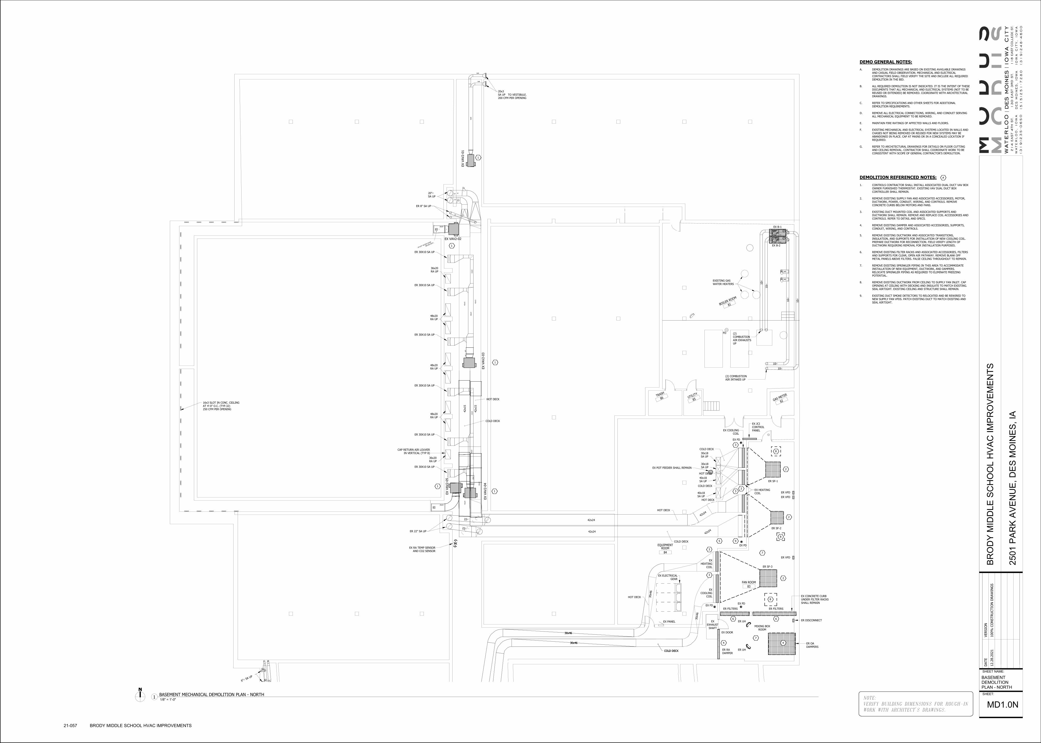
EX V
AV2-0
1
EX VAV2-02
EX V
AV2-0
3
EX V
AV2-0
5
EX V
AV2-0
4
T
S
40x18
SA UP
40x18
SA UP
30x18
SA UP
30x18
SA UP
COLD DECK
HOT DECK
COLD DECK
HOT DECK
HOT DECK
COLD DECK
COLD DECK
HOT DECK
42x2
4
42x2
4
30x46
30x46
(2)
COMBUSTION
AIR EXHAUSTS
UP
(2) COMBUSTION
AIR INTAKES UP
10∅
10∅
10∅
10∅
10∅
10∅
10∅
10∅
EXISTING GAS
WATER HEATERS
FD
30x4
6
30x4
6
6" SA UP∅
16x3 SLOT IN CONC. CEILING
AT 4'-0" O.C. (TYP.32)
42x24
42x24
30x46
30x46
6∅
6∅
250 CFM PER OPENING
AD
AD
24"x24" ACCESS DOOR
BELOW DUCT.
28x8
24"
16"
28x20
28x20
36x20
RA UP
36x20
RA UP
48x20
RA UP
48x20
RA UP
48x20
RA UP
20"∅SA UP
20x3
SA UP
COLD DECK
HOT DECK
8x8
8x8
16x8
6∅
8∅8∅
22∅
22∅
42x15
42x15
42x15
42x15
20x22
12x22
20x22
12x22
42x24
42x24
22∅
22∅
200 CFM PER OPENINGTO VESTIBULE.
COLD DECK
84
EQUIPMENTROOM
83
FAN ROOM
86TRASH
85UTILIT
Y
82GAS METER
81BOILER ROOM
CAP RETURN AIR LOUVER
IN VERTICAL (TYP 8)
ER 8" SA UP
ER 30X10 SA UP
ER 30X10 SA UP
ER 30X10 SA UP
ER 30X10 SA UP
ER 30X10 SA UP
ER 30X10 SA UP
ER 22" SA UPER SF-2
ER SF-1
ER SF-3
ER UH
ER UH
1
1
1
1
1
2
2
2
5
3
3
EX B-1
EX B-2
EX RA TEMP SENSOR
AND CO2 SENSOR
4 4
ER FILTERS ER FILTERS
ER RA
DAMPER
ER OA
DAMPERS
66
7
EX
EXHAUST
SHAFT
EX CONCRETE CURB
UNDER FILTER RACKS
SHALL REMAIN
9
EX POT FEEDER SHALL REMAIN
ER VFD
ER VFD
ER VFD
EX FD
EX FD
EX FDEX FD
3
3
3
7
EX
COOLING
COIL
EX
HEATING
COIL
EX HEATING
COIL
EX COOLING
COIL
EX PANEL
EX ELECTRICAL
GEAR
ER DISCONNECT
EX DOOR
8
8
8
EX JCI
CONTROL
PANEL
MIXING BOX
ROOM
DEMO GENERAL NOTES:
A. DEMOLITION DRAWINGS ARE BASED ON EXISTING AVAILABLE DRAWINGS
AND CASUAL FIELD OBSERVATION. MECHANICAL AND ELECTRICAL
CONTRACTORS SHALL FIELD VERIFY THE SITE AND INCLUDE ALL REQUIRED
DEMOLITION IN THE BID.
B. ALL REQUIRED DEMOLITION IS NOT INDICATED. IT IS THE INTENT OF THESE
DOCUMENTS THAT ALL MECHANICAL AND ELECTRICAL SYSTEMS (NOT TO BE
REUSED OR EXTENDED) BE REMOVED. COORDINATE WITH ARCHITECTURAL
DRAWINGS.
C. REFER TO SPECIFICATIONS AND OTHER SHEETS FOR ADDITIONAL
DEMOLITION REQUIREMENTS.
D. REMOVE ALL ELECTRICAL CONNECTIONS, WIRING, AND CONDUIT SERVING
ALL MECHANICAL EQUIPMENT TO BE REMOVED.
E. MAINTAIN FIRE RATINGS OF AFFECTED WALLS AND FLOORS.
F. EXISTING MECHANICAL AND ELECTRICAL SYSTEMS LOCATED IN WALLS AND
CHASES NOT BEING REMOVED OR REUSED FOR NEW SYSTEMS MAY BE
ABANDONED IN PLACE. CAP AT MAINS OR IN A CONCEALED LOCATION IF
REQUIRED.
G. REFER TO ARCHITECTURAL DRAWINGS FOR DETAILS ON FLOOR CUTTING
AND CEILING REMOVAL. CONTRACTOR SHALL COORDINATE WORK TO BE
CONSISTENT WITH SCOPE OF GENERAL CONTRACTOR'S DEMOLITION.
DEMOLITION REFERENCED NOTES:
1. CONTROLS CONTRACTOR SHALL INSTALL ASSOCIATED DUAL DUCT VAV BOX
OWNER FURNISHED THERMOSTAT. EXISTING VAV DUAL DUCT BOX
CONTROLLER SHALL REMAIN.
2. REMOVE EXISTING SUPPLY FAN AND ASSOCIATED ACCESSORIES, MOTOR,
DUCTWORK, POWER, CONDUIT, WIRING, AND CONTROLS. REMOVE
CONCRETE CURBS BELOW MOTORS AND FANS.
3. EXISTING DUCT MOUNTED COIL AND ASSOCIATED SUPPORTS AND
DUCTWORK SHALL REMAIN. REMOVE AND REPLACE COIL ACCESSORIES AND
CONTROLS. REFER TO DETAIL AND SPECS.
4. REMOVE EXISTING DAMPER AND ASSOCIATED ACCESSORIES, SUPPORTS,
CONDUIT, WIRING, AND CONTROLS.
5. REMOVE EXISTING DUCTWORK AND ASSOCIATED TRANSITIONS,
INSULATION, AND SUPPORTS FOR INSTALLATION OF NEW COOLING COIL.
PREPARE DUCTWORK FOR RECONNECTION. FIELD VERIFY LENGTH OF
DUCTWORK REQUIRING REMOVAL FOR INSTALLATION PURPOSES.
6. REMOVE EXISTING FILTER RACKS AND ASSOCIATED ACCESSORIES, FILTERS
AND SUPPORTS FOR CLEAR, OPEN AIR PATHWAY. REMOVE BLANK OFF
METAL PANELS ABOVE FILTERS. FALSE CEILING THROUGHOUT TO REMAIN.
7. REMOVE EXISTING SPRINKLER PIPING IN THIS AREA TO ACCOMMODATE
INSTALLATION OF NEW EQUIPMENT, DUCTWORK, AND DAMPERS.
RELOCATE SPRINKLER PIPING AS REQUIRED TO ELIMINATE FREEZING
POTENTIAL.
8. REMOVE EXISTING DUCTWORK FROM CEILING TO SUPPLY FAN INLET. CAP
OPENING AT CEILING WITH DECKING AND INSULATE TO MATCH EXISTING.
SEAL AIRTIGHT. EXISTING CEILING AND STRUCTURE SHALL REMAIN.
9. EXISTING DUCT SMOKE DETECTORS TO RELOCATED AND BE REWIRED TO
NEW SUPPLY FAN VFDS. PATCH EXISTING DUCT TO MATCH EXISTING AND
SEAL AIRTIGHT.
#
NOTE:
VERIFY BUILDING DIMENSIONS FOR ROUGH-IN
WORK WITH ARCHITECT'S DRAWINGS.
SHEET NAME:
SHEET:
DATE
VERSIO
N
12.2
8.2
021
100%
CO
NSTRU
CTIO
N D
RAW
ING
SB
RO
DY
MID
DL
E S
CH
OO
L H
VA
C I
MP
RO
VE
ME
NT
S
250
1 P
AR
K A
VE
NU
E,
DE
S M
OIN
ES
, IA
BASEMENT
DEMOLITION
PLAN - NORTH
MD1.0N
21-057 BRODY MIDDLE SCHOOL HVAC IMPROVEMENTS
1/8" = 1'-0"1
BASEMENT MECHANICAL DEMOLITION PLAN - NORTH

DN
WALK-IN
COOLER
TEACHERS
46
MEN'SRESTROOM
48
WAITING
GIRLS
ADVISOR
51
VESTIBULE50
CORRIDOR
61
STORAGE58
OFFICE
58
OFFICE
56
OFFICE
55
SHOWERS
53
BOYSLOCKER ROOM
63
WOMEN'SRESTROOM
64
MEN'SRESTROOM
65
JANITOR
66
CORRIDOR
115
TEACHERSDINING
113
STORAGE
117
TOILET
116
MANAGER
107
STORAGE
112
KITCHEN114CAFETERIA
103
TOILET101
RECEIVING
100
CUSTODIAN
99
EQUIPMENT
97
PRACTICE
96
PRACTICE
94
INSTRUMENTSTORAGE
95PRACTICE
89
TOILET
91
LIVINGROOM
93
MUSICROOM
98
BOILERROOM
87
GRAPHICARTS
92
CHORALROOM
106
CORRIDOR
83
FINISHINGROOM
84
LUMBERSTORAGE
85
PROJECTSTORAGE
86B
SHOP
86A
SHOP
82
HOMEMAKING
81
VESTIBULE80
EQUIPMENTSTORAGE
79
TOWELS
78
TOILET
77
SHOWERS
74
HALL
78
ROOM
75
GIRLSLOCKER ROOM
73
STORAGE71
OFFICE
69
STAGE &CHAIRS
67
GYMNASIUM
EX VAV1-22
1 1
1
1
1
1
1
1
1
1
1
1
1
11
1
1
1
1
1
1
11
1
1
1
1
1
1
1
1
1
1
1 1
1
1
1
1
1 1
11
1 1
11
1
1
1
1
1
EX VAV1-04 EX VAV1-01
EX VAV1-02EX VAV1-05
EX VAV1-03EX VAV1-06
T
T
T
TT
T
T
T
T
EX V
AV2-0
6
EX VAV2-08
EX VAV2-07
T
TT
EX VAV1-14
EX VAV1-10
EX V
AV1-1
3
EX V
AV1-1
2
EX V
AV1-1
1EX V
AV1-0
7
EX V
AV1-0
9
EX V
AV1-0
8
T
TT
T
T
T
T
EX VAV1-23EX VAV1-21
EX VAV1-20
EX VAV1-17
EX VAV1-19
EX VAV1-16
EX VAV1-18
T
T
T
EX VAV1-15
EX VAV1-27
EX V
AV1-2
6
EX V
AV1-2
4
EX VAV1-25
T
T
EX V
AV2-1
0
EX VAV2-09
2EX OA INTAKE
LOUVER
DEMO GENERAL NOTES:
A. DEMOLITION DRAWINGS ARE BASED ON EXISTING AVAILABLE DRAWINGS
AND CASUAL FIELD OBSERVATION. MECHANICAL AND ELECTRICAL
CONTRACTORS SHALL FIELD VERIFY THE SITE AND INCLUDE ALL REQUIRED
DEMOLITION IN THE BID.
B. ALL REQUIRED DEMOLITION IS NOT INDICATED. IT IS THE INTENT OF THESE
DOCUMENTS THAT ALL MECHANICAL AND ELECTRICAL SYSTEMS (NOT TO BE
REUSED OR EXTENDED) BE REMOVED. COORDINATE WITH ARCHITECTURAL
DRAWINGS.
C. REFER TO SPECIFICATIONS AND OTHER SHEETS FOR ADDITIONAL
DEMOLITION REQUIREMENTS.
D. REMOVE ALL ELECTRICAL CONNECTIONS, WIRING, AND CONDUIT SERVING
ALL MECHANICAL EQUIPMENT TO BE REMOVED.
E. MAINTAIN FIRE RATINGS OF AFFECTED WALLS AND FLOORS.
F. EXISTING MECHANICAL AND ELECTRICAL SYSTEMS LOCATED IN WALLS AND
CHASES NOT BEING REMOVED OR REUSED FOR NEW SYSTEMS MAY BE
ABANDONED IN PLACE. CAP AT MAINS OR IN A CONCEALED LOCATION IF
REQUIRED.
G. REFER TO ARCHITECTURAL DRAWINGS FOR DETAILS ON FLOOR CUTTING
AND CEILING REMOVAL. CONTRACTOR SHALL COORDINATE WORK TO BE
CONSISTENT WITH SCOPE OF GENERAL CONTRACTOR'S DEMOLITION.
DEMOLITION REFERENCED NOTES:
1. CONTROLS CONTRACTOR SHALL INSTALL ASSOCIATED DUAL DUCT VAV BOX
OWNER FURNISHED THERMOSTAT. EXISTING VAV DUAL DUCT BOX
CONTROLLER SHALL REMAIN.
2. REMOVE, CLEAN, REINSTALL LOUVER AND REPLACE FILTERS.
#
NOTE:
VERIFY BUILDING DIMENSIONS FOR ROUGH-IN
WORK WITH ARCHITECT'S DRAWINGS.
SHEET NAME:
SHEET:
DATE
VERSIO
N
12.2
8.2
021
100%
CO
NSTRU
CTIO
N D
RAW
ING
SB
RO
DY
MID
DL
E S
CH
OO
L H
VA
C I
MP
RO
VE
ME
NT
S
250
1 P
AR
K A
VE
NU
E,
DE
S M
OIN
ES
, IA
FIRST FLOOR
DEMOLITION
PLAN - NORTH
MD1.1
21-057 BRODY MIDDLE SCHOOL HVAC IMPROVEMENTS
1/8" = 1'-0"1
FIRST FLOOR MECHANICAL DEMOLITION PLAN

84
EQUIPMENTROOM
83
FAN ROOM
86TRASH
85UTILIT
Y
82GAS METER
81BOILER ROOM
EX 2" HWS
EX 2" HWR
EX 2" HWR
EX 2
" H
WS
EX 6" HWS
EX 1" HWSEX 1" HWR
EX 6
" H
WS
EX 6
" H
WR
EX 6" HWREX 6" HWS
EX 6
" H
WR
EX 6
" H
WS
EX 4" HWS
EX 4" HWR
ER 4" HWR
EX 4
" H
WR
ER
2"
ER
2"
ER 2"
ER 2"
EX 6
" H
WR
EX GF
EXR AS
EX SHWP-2
EX SHWP-1
EX 2
" H
WR
EX 2
" H
WS
ER UH
ER UH
EX UH
2
1
2
2
1
ER
3
EX COOLING
COIL
EX HEATING
COIL
EX HEATING
COIL
EX HEATING
COIL
EX COOLING
COIL
ER B-1
ER B-2
EX VAV2-01
EX VAV2-02
EX VAV2-03
EX VAV2-04
EX VAV2-05
5
EX 6
" CW
SEX 6
" CW
R
EX POT FEEDER SHALL REMAIN
EX 4" HWS
EX 4
" H
WS
4
4
3
EX PANEL
EX ELECTRICAL
GEAR
6
7
EX JCI
CONTROL
PANEL
EX CH-1
EX PUMP
EX PUMP
EX PUMP
EX PUMP
EX ETEX
AS
DEMO GENERAL NOTES:
A. DEMOLITION DRAWINGS ARE BASED ON EXISTING AVAILABLE DRAWINGS
AND CASUAL FIELD OBSERVATION. MECHANICAL AND ELECTRICAL
CONTRACTORS SHALL FIELD VERIFY THE SITE AND INCLUDE ALL REQUIRED
DEMOLITION IN THE BID.
B. ALL REQUIRED DEMOLITION IS NOT INDICATED. IT IS THE INTENT OF THESE
DOCUMENTS THAT ALL MECHANICAL AND ELECTRICAL SYSTEMS (NOT TO BE
REUSED OR EXTENDED) BE REMOVED. COORDINATE WITH ARCHITECTURAL
DRAWINGS.
C. REFER TO SPECIFICATIONS AND OTHER SHEETS FOR ADDITIONAL
DEMOLITION REQUIREMENTS.
D. REMOVE ALL ELECTRICAL CONNECTIONS, WIRING, AND CONDUIT SERVING
ALL MECHANICAL EQUIPMENT TO BE REMOVED.
E. MAINTAIN FIRE RATINGS OF AFFECTED WALLS AND FLOORS.
F. EXISTING MECHANICAL AND ELECTRICAL SYSTEMS LOCATED IN WALLS AND
CHASES NOT BEING REMOVED OR REUSED FOR NEW SYSTEMS MAY BE
ABANDONED IN PLACE. CAP AT MAINS OR IN A CONCEALED LOCATION IF
REQUIRED.
G. REFER TO ARCHITECTURAL DRAWINGS FOR DETAILS ON FLOOR CUTTING
AND CEILING REMOVAL. CONTRACTOR SHALL COORDINATE WORK TO BE
CONSISTENT WITH SCOPE OF GENERAL CONTRACTOR'S DEMOLITION.
DEMOLITION REFERENCED NOTES:
1. EXISTING DUCT MOUNTED CHILLED WATER COOLING COIL AND
ASSOCIATED SUPPORTS AND DUCTWORK SHALL REMAIN. PROVIDE NEW
COIL ACCESSORIES AND CONTROLS. REFER TO DETAIL AND SPECS.
2. EXISTING DUCT MOUNTED HEATING WATER COIL AND ASSOCIATED
SUPPORTS AND DUCTWORK SHALL REMAIN. PROVIDE NEW COIL
ACCESSORIES AND CONTROLS. REFER TO DETAIL AND SPECS.
3. REMOVE EXISTING HWS/HWR, INSULATION, HANGERS , SUPPORTS, AND
ACCESSORIES FROM THIS POINT TO EXISTING UNIT HEATERS BEING
REMOVED. CAP PIPING.
4. REMOVE EXISTING UNIT HEATERS AND ASSOCIATED PIPING, INSULATION,
HANGERS, SUPPORTS, VALVES, AND ACCESSORIES BACK TO MAIN RIGHT
AFTER LAST HEATING COIL. SEAL ALL WALL PENETRATIONS AIRTIGHT.
5. REFER TO HEATING SYSTEM SCHEMATICS FOR HEATING HOT WATER
PIPING REMOVAL REQUIRED FOR INSTALLATION OF NEW PRIMARY BOILER
PUMPS, BYPASS PIPING, ACCESSORIES AND CONTROLS.
6. REMOVE 4" CWS/CWR PIPE CAPS FOR EXTENSION AND CONNECTION TO
NEW COOLING COIL.
7. RELOCATE EXISTING AIR SEPARATOR AND ASSOCIATED BUTTERFLY VALVE,
ANGLE SUPPORTS FROM STRUCTURE, AND HANGERS FOR INSTALLATION OF
NEW BYPASS PIPE. EXISTING THERMOMETER, PRESSURE RELIEF, AND
BUTTERFLY VALVE SHALL REMAIN.
#
NOTE:
VERIFY BUILDING DIMENSIONS FOR ROUGH-IN
WORK WITH ARCHITECT'S DRAWINGS.
SHEET NAME:
SHEET:
DATE
VERSIO
N
12.2
8.2
021
100%
CO
NSTRU
CTIO
N D
RAW
ING
SB
RO
DY
MID
DL
E S
CH
OO
L H
VA
C I
MP
RO
VE
ME
NT
S
250
1 P
AR
K A
VE
NU
E,
DE
S M
OIN
ES
, IA
BASEMENT
PIPING DEMO
PLAN
MD2.0N
21-057 BRODY MIDDLE SCHOOL HVAC IMPROVEMENTS
1/8" = 1'-0"1
BASEMENT MECHANICAL PIPING DEMOLITION PLAN

EX V
AV2-0
1
EX VAV2-02
EX V
AV2-0
3
EX V
AV2-0
5
EX V
AV2-0
4
6" SA UP∅
16x3 SLOT IN CONC. CEILING
AT 4'-0" O.C. (TYP.32)
40x18
SA UP
40x18
SA UP
30x18
SA UP
30x18
SA UP
HOT DECK
COLD DECK
COLD DECK
HOT DECK
42x24
42x24
30x46
30x46
6∅
6∅
(2)
COMBUSTION
AIR EXHAUSTS
UP
(2) COMBUSTION
AIR INTAKES UP
BOILERS
10∅
10∅
10∅
10∅
10∅
10∅
10∅
10∅
EXISTING GAS
WATER HEATERS
250 CFM PER OPENING
FD
AD
AD
24"x24" ACCESS DOOR
BELOW DUCT.
28x8
24"
16"
28x20
28x20
36x20
RA UP
36x20
RA UP
48x20
RA UP
48x20
RA UP
48x20
RA UP
20"∅SA UP
20x3
SA UP
COLD DECK
HOT DECK
8x8
8x8
16x8
6∅
8∅8∅
22∅
22∅
42x15
42x15
42x15
42x15
20x22
12x22
20x22
12x22
42x24
42x24
22∅
22∅
200 CFM PER OPENINGTO VESTIBULE.
COLD DECK
HOT DECK
42x2
4
30x4
6
30x4
6
84
EQUIPMENTROOM
86TRASH
85UTILIT
Y
82GAS METER
81BOILER ROOM
84
EQUIPMENTROOM
86TRASH
85UTILIT
Y
82GAS METER
81BOILER ROOM
EX B-1
EX B-2
EX UH
1
1
1
1
1
EX POT FEEDER SHALL REMAIN
SF-3
43,355 CFM
SUPPLY FANS
26,160 CFM
SUPPLY FANS
SF-2
COOLING COIL
CC-1
39,800 CFM
SUPPLY FANS
SF-1
NEW FILTER
RACK FR-1
140.75"W x 99"H
27" DEEP
84"x96"
ECON O.A. CONTROL DAMPER
(N.C.) (LOW LEAKAGE)
55,000 CFM IN DUCT JUST BELOW
FALSE CEILING AT O.A. SHAFT
CUT, PATCH, AND SEAL
EXISTING WALL AIRTIGHT
(TYP)
2
3
EX FD
EX FD
EX FD EX FD
EX PANEL
EX ELECTRICAL
GEAR
4
96"W x 96"H R.A.
CONTROL DAMPER IN
SIDE OF 120"x96"
MIXING BOX DUCT.
INFILL OPENING AND SEAL
AIR PATHWAY AIRTIGHT
REPLACE TEMPERATURE SENSOR
AND CO2 SENSOR
CO2
T
EXISTING 4'-7" x 9'-0" RELIEF SHAFT
EX JCI
CONTROL
PANEL
36"x96"
MIN O.A. CONTROL DAMPER
(N.O.) (LOW LEAKAGE)
25,000 CFM IN DUCT JUST
BELOW CEILING AT O.A. SHAFT
EX STRUCTURAL
POST (TYP)
OPEN WALL FROM DAMPER REMOVAL
FILTER ACCESS DOOR. PROVIDE
MIN 27" CLEAR IN FRONT OF DOOR.
EX COLUMN
120"x96" O.A.
DUCT DOWN
TO FLOOR
FROM SHAFT
24x24 DUCT ACCESS DOOR
5
CAULK AROUND
COLUMN AIR TIGHT
CC-1
TRANSITION
RESTS ON
FLOOR.
6
6
6
7
EX GF
8
EX SHWP-2
EX SHWP-1
9
9
9
GENERAL NOTES:
A. LAYOUT AND ROUTING SHOWN IS DIAGRAMMATIC AND SCHEMATIC IN
NATURE. NOT ALL OFFSETS MAY BE SHOWN. CONTRACTOR SHALL VERIFY
EXACT ROUTING REQUIRED AND NUMBER OF OFFSETS AND TRANSITIONS.
B. MAINTAIN SERVICE CLEARANCE IN FRONT OF AND ABOVE ELECTRICAL
EQUIPMENT AND ACCESS. DO NOT INSTALL EQUIPMENT OR ROUTE DUCTS IN
CLEARANCE SPACE. REFER TO EQUIPMENT INSTALLATION AND
INSTRUCTIONS.
C. COORDINATE THERMOSTAT LOCATIONS WITH CASEWORK, WALL TYPES, AND
FURNISHINGS PRIOR TO ROUGH-IN.
D. COORDINATE DUCT ROUTING WITH STRUCTURAL AND ALL TRADES.
E. COORDINATE ALL EXPOSED DUCTWORK ROUTING WITH DESIGN TEAM PRIOR
TO ROUGH-IN.
F. COORDINATE DUCT ROUTING IN LOCATIONS WITH EXISTING CONDITIONS.
FIELD VERIFY EXISTING CONDITIONS PRIOR TO ROUGH-IN.
REFERENCED NOTES:
1. CONTROLS CONTRACTOR SHALL INSTALL ASSOCIATED DUAL DUCT VAV BOX
OWNER FURNISHED THERMOSTAT. EXISTING VAV DUAL DUCT BOX
CONTROLLER SHALL REMAIN.
2. PROVIDE NEW EXHAUST FAN ON ROOF WITH NEW RELIEF CONTROL
DAMPER ON FAN INLET. PROVIDE INSULATED ADAPTER CURB ON EXISTING
RELIEF HOOD CURB AND SEAL AIRTIGHT. PROVIDE ACCESS AT CURB FOR
DAMPER ACTUATOR.
3. PROVIDE NEW MIXING BOX DUCT 120"x96" FOR 80,000 CFM OUTSIDE AIR
AND 55,000 CFM RETURN AIR. TRANSITION OUTLET DUCT DIRECTLY TO
NEW FILTER BANK. FIELD VERIFY EXISTING CONDITIONS AND ALLOWABLE
DIMENSIONS OF MIXING SECTION AND DAMPERS. DAMPER ACTUATORS
WILL BE LOCATED IN DUCT AIRSTREAM.
4. PROVIDE GALVANIZED FRAME INFILL OF RETURN AIR OPENING WITH
GALVANIZED SHEET METAL COVER IN APPROXIMATELY TWO AREAS TO BE
FIELD VERIFIED. SEAL FILTER HOUSING TO THE WALLS, AIR TIGHT.
5. POUR NEW CONCRETE CURB EXTENSION TO SUPPORT NEW 27" DEEP
FILTER BANK. MATCH 8" HEIGHT OF OLD FILTER BANK CURB. PRESERVE
ANY EXISTING DRAINS IN THE AREA AND FORM AROUND THEM.
6. POUR NEW CONCRETE CURB UNDER NEW FAN WALL. FORM AROUND
EXISTING CURBS TO REMAIN.
7. POUR NEW 6" CURB UNDER NEW CC-1.
8. CONTROLS CONTRACTOR SHALL REPLACE ALL EXISTING TEMPERATURE
SENSOR AND CO2 SENSORS IN BUILDING.
9. CAP OPENING AT CEILING WITH DECKING AND INSULATE TO MATCH
EXISTING. SEAL PLENUM AIRTIGHT. EXISTING CEILING AND STRUCTURE
SHALL REMAIN.
#
NOTE:
VERIFY BUILDING DIMENSIONS FOR ROUGH-IN
WORK WITH ARCHITECT'S DRAWINGS.
SHEET NAME:
SHEET:
DATE
VERSIO
N
12.2
8.2
021
100%
CO
NSTRU
CTIO
N D
RAW
ING
SB
RO
DY
MID
DL
E S
CH
OO
L H
VA
C I
MP
RO
VE
ME
NT
S
250
1 P
AR
K A
VE
NU
E,
DE
S M
OIN
ES
, IA
BASEMENT
MECHANICAL
PLAN - NORTH
M1.0N
21-057 BRODY MIDDLE SCHOOL HVAC IMPROVEMENTS
1/8" = 1'-0"1
BASEMENT MECHANICAL PLAN - NORTH

EX V
AV3-4
4
EX VAV3-42EX VAV3-41
EX VAV3-40
EX VAV3-39
EX VAV3-38EX VAV3-36
EX VAV3-37
EX VAV3-35
EX VAV3-34
EX V
AV3-3
2
EX V
AV3-3
1
EX VAV3-33
EX VAV3-29EX VAV3-28
EX V
AV3-
30
EX VAV3-27
EX VAV3-25
EX VAV3-26EX VAV3-24EX VAV3-23
EX VAV3-20
EX VAV3-19
EX VAV3-22
EX VAV3-21EX VAV3-17
EX VAV3-18
EX VAV3-16
EX VAV3-15
EX VAV3-13
EX VAV3-14
EX VAV3-11EX VAV3-12EX VAV3-10
EX VAV3-09EX VAV3-07
EX VAV3-06
EX V
AV3-
06
EX VAV3-5
EX VAV3-03
EX VAV3-04
EX VAV3-02
EX VAV3-01
EX VAV3-4
EX EF-1
VD
AD
BD
12x6
200 C.F.M.
12x6
200 C.F.M.
12x6
14x14
14x14
16x16
20x1616x24 14x24
12x16
14x2614x22
14x26
12x18
20x8
SA UP
24x8
SA UP
24x8
SA UP
24x8
SA UP
10x6
SA UP
20x4
SA UP20x4
SA UP
5" SA UP∅ 5" SA UP∅
20x8
SA UP
20x8
SA UP
12x8
SA UP
20x8
SA UP
20x8
SA UP
10x6
SA UP
20x8
SA UP
20x8
SA UP
20x8
SA UP
24x8
SA UP
16x8
SA UP24x8
SA UP
24x8
SA UP
20x8
SA UP
20x8
SA UP
24x8
SA UP 16x6
SA UP
11x5
SA UP24x8
SA UP
20x8
SA UP
8x8
SA UP
18x8
SA UP
20x8
SA UP20x8
SA UP10x6
SA UP32x8
SA UP
20x8
SA UP
HOT DECK
HOT DECK
COLD DECK
HOT DECK
16∅
9∅
16∅
14∅
14∅
5∅
12∅
5∅
5∅
16∅
12∅5∅
9∅9∅
9∅
16∅
9∅
9∅
16∅
16∅
16∅
16∅
16∅
16∅
16∅
16∅
16∅
16∅ 16∅
16∅
16∅
30x42
30x42
30x42
30x4230x34
30x34
30x34
30x3430x34
30x3430x28
30x28
COLD DECK
T
89
TELECOM
89
TELECOM
89
TELECOM
1
1
1
1
1
1 1 1 1 11
11
1
1
1 1
1
1
1
1 1
11
1 1
1 1
1
1 11
1
1 1
11
1
1 1
1
1
EX 60"x48"
FIRE DAMPER
2
TCO2
REPLACE TEMPERATURE SENSOR
AND CO2 SENSOR
3
REFERENCED NOTES:
1. CONTROLS CONTRACTOR SHALL INSTALL ASSOCIATED DUAL DUCT VAV BOX
OWNER FURNISHED THERMOSTAT. EXISTING VAV DUAL DUCT BOX
CONTROLLER SHALL REMAIN.
2. MECHANICAL CONTRACTOR SHALL FIELD VERIFY EXISTING FIRE DAMPERS
ON FIRST LEVEL AND IN TUNNEL ARE 100% OPEN AND FUNCTIONING
PROPERLY. REPORT BACK TO DESIGN TEAM WITH FINDINGS.
3. CONTROLS CONTRACTOR SHALL REPLACE ALL EXISTING TEMPERATURE
SENSOR AND CO2 SENSORS IN BUILDING.
#
GENERAL NOTES:
A. LAYOUT AND ROUTING SHOWN IS DIAGRAMMATIC AND SCHEMATIC IN
NATURE. NOT ALL OFFSETS MAY BE SHOWN. CONTRACTOR SHALL VERIFY
EXACT ROUTING REQUIRED AND NUMBER OF OFFSETS AND TRANSITIONS.
B. MAINTAIN SERVICE CLEARANCE IN FRONT OF AND ABOVE ELECTRICAL
EQUIPMENT AND ACCESS. DO NOT INSTALL EQUIPMENT OR ROUTE DUCTS IN
CLEARANCE SPACE. REFER TO EQUIPMENT INSTALLATION AND
INSTRUCTIONS.
C. COORDINATE THERMOSTAT LOCATIONS WITH CASEWORK, WALL TYPES, AND
FURNISHINGS PRIOR TO ROUGH-IN.
D. COORDINATE DUCT ROUTING WITH STRUCTURAL AND ALL TRADES.
E. COORDINATE ALL EXPOSED DUCTWORK ROUTING WITH DESIGN TEAM PRIOR
TO ROUGH-IN.
F. COORDINATE DUCT ROUTING IN LOCATIONS WITH EXISTING CONDITIONS.
FIELD VERIFY EXISTING CONDITIONS PRIOR TO ROUGH-IN.
NOTE:
VERIFY BUILDING DIMENSIONS FOR ROUGH-IN
WORK WITH ARCHITECT'S DRAWINGS.
SHEET NAME:
SHEET:
DATE
VERSIO
N
12.2
8.2
021
100%
CO
NSTRU
CTIO
N D
RAW
ING
SB
RO
DY
MID
DL
E S
CH
OO
L H
VA
C I
MP
RO
VE
ME
NT
S
250
1 P
AR
K A
VE
NU
E,
DE
S M
OIN
ES
, IA
BASEMENT
MECHANICAL
PLAN - WEST
M1.0W
21-057 BRODY MIDDLE SCHOOL HVAC IMPROVEMENTS
1/8" = 1'-0"1
BASEMENT MECHANICAL PLAN - WEST
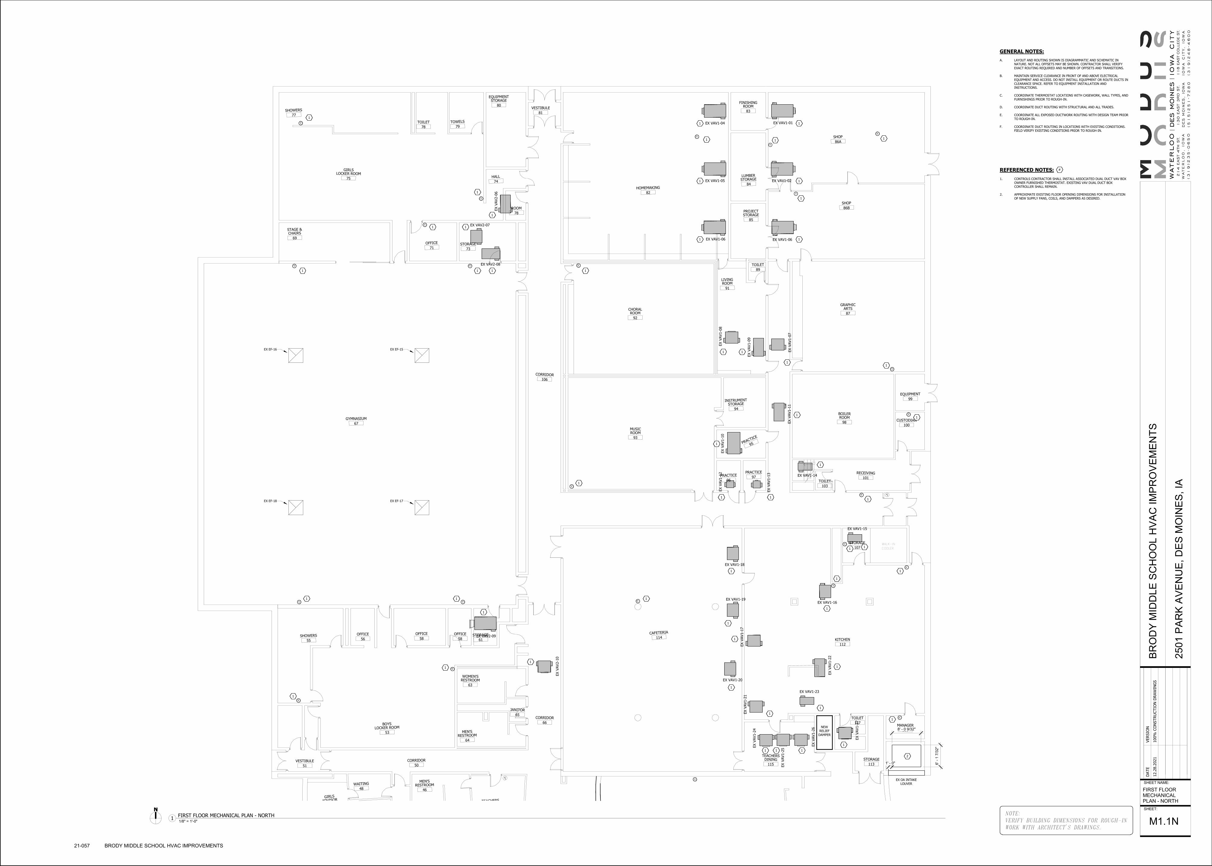
T
T
T
T
T
TT
T T
T
T
T
TT
T
T
T T
T
T
T
T
TT
EX V
AV2-0
6
EX VAV2-08
EX VAV2-07
EX V
AV2-1
0
EX VAV2-09
EX V
AV1-0
7
EX VAV1-02
EX VAV1-01EX VAV1-04
EX VAV1-05
EX VAV1-06 EX VAV1-06
EX V
AV1-0
8
EX V
AV1-0
9
EX V
AV1-1
1
EX V
AV1-1
0EX V
AV1-1
2
EX V
AV1-1
3
EX VAV1-14
EX VAV1-15
EX VAV1-18
EX VAV1-16EX VAV1-19
EX V
AV1-1
7
EX VAV1-20
EX V
AV1-2
2
EX V
AV1-2
7
EX V
AV1-2
1
EX VAV1-23
EX V
AV1-2
6
EX V
AV1-2
5
EX V
AV1-2
4
DN
WALK-IN
COOLER
TEACHERS
46
MEN'SRESTROOM
48
WAITING
GIRLS
ADVISOR
51
VESTIBULE50
CORRIDOR
61
STORAGE58
OFFICE
58
OFFICE
56
OFFICE
55
SHOWERS
53
BOYSLOCKER ROOM
63
WOMEN'SRESTROOM
64
MEN'SRESTROOM
65
JANITOR
66
CORRIDOR
115
TEACHERSDINING
113
STORAGE
117
TOILET
116
MANAGER
107
STORAGE
112
KITCHEN114CAFETERIA
103
TOILET101
RECEIVING
100
CUSTODIAN
99
EQUIPMENT
97
PRACTICE
96
PRACTICE
94
INSTRUMENTSTORAGE
95PRACTICE
89
TOILET
91
LIVINGROOM
93
MUSICROOM
98
BOILERROOM
87
GRAPHICARTS
92
CHORALROOM
106
CORRIDOR
83
FINISHINGROOM
84
LUMBERSTORAGE
85
PROJECTSTORAGE
86B
SHOP
86A
SHOP
82
HOMEMAKING
81
VESTIBULE80
EQUIPMENTSTORAGE
79
TOWELS
78
TOILET
77
SHOWERS
74
HALL
78
ROOM
75
GIRLSLOCKER ROOM
73
STORAGE71
OFFICE
69
STAGE &CHAIRS
67
GYMNASIUM
EX EF-15EX EF-16
EX EF-17EX EF-18
1' - 0"
8' - 0 9/32"
6' -
1 7
/32
"
111
1
1
1
1
1
1
1
1
1
1
1 1
1
1
1
1
1 1
11
1 1
11
1
1
1
1
1
1 1
1
1
1
1
1
1
1
1
1
1
1
11
1
1
1
1
1
1
T
T
T T
T T
T
T
T
T
T
T
T
T
1
T
T
T
T
T
T
T
T
T
T
1
NEW
RELIEF
DAMPER
2
EX OA INTAKE
LOUVER
GENERAL NOTES:
A. LAYOUT AND ROUTING SHOWN IS DIAGRAMMATIC AND SCHEMATIC IN
NATURE. NOT ALL OFFSETS MAY BE SHOWN. CONTRACTOR SHALL VERIFY
EXACT ROUTING REQUIRED AND NUMBER OF OFFSETS AND TRANSITIONS.
B. MAINTAIN SERVICE CLEARANCE IN FRONT OF AND ABOVE ELECTRICAL
EQUIPMENT AND ACCESS. DO NOT INSTALL EQUIPMENT OR ROUTE DUCTS IN
CLEARANCE SPACE. REFER TO EQUIPMENT INSTALLATION AND
INSTRUCTIONS.
C. COORDINATE THERMOSTAT LOCATIONS WITH CASEWORK, WALL TYPES, AND
FURNISHINGS PRIOR TO ROUGH-IN.
D. COORDINATE DUCT ROUTING WITH STRUCTURAL AND ALL TRADES.
E. COORDINATE ALL EXPOSED DUCTWORK ROUTING WITH DESIGN TEAM PRIOR
TO ROUGH-IN.
F. COORDINATE DUCT ROUTING IN LOCATIONS WITH EXISTING CONDITIONS.
FIELD VERIFY EXISTING CONDITIONS PRIOR TO ROUGH-IN.
REFERENCED NOTES:
1. CONTROLS CONTRACTOR SHALL INSTALL ASSOCIATED DUAL DUCT VAV BOX
OWNER FURNISHED THERMOSTAT. EXISTING VAV DUAL DUCT BOX
CONTROLLER SHALL REMAIN.
2. APPROXIMATE EXISTING FLOOR OPENING DIMENSIONS FOR INSTALLATION
OF NEW SUPPLY FANS, COILS, AND DAMPERS AS DESIRED.
#
NOTE:
VERIFY BUILDING DIMENSIONS FOR ROUGH-IN
WORK WITH ARCHITECT'S DRAWINGS.
SHEET NAME:
SHEET:
DATE
VERSIO
N
12.2
8.2
021
100%
CO
NSTRU
CTIO
N D
RAW
ING
SB
RO
DY
MID
DL
E S
CH
OO
L H
VA
C I
MP
RO
VE
ME
NT
S
250
1 P
AR
K A
VE
NU
E,
DE
S M
OIN
ES
, IA
FIRST FLOOR
MECHANICAL
PLAN - NORTH
M1.1N
21-057 BRODY MIDDLE SCHOOL HVAC IMPROVEMENTS
1/8" = 1'-0"1
FIRST FLOOR MECHANICAL PLAN - NORTH

TTTTTT
T T T T T
T
T
T
T T T T
T T T
16x10
12x8
12x8
12x8
12x8
12x8
8x10
10x6
6x16 6x8 6x166x8
6x8 6x16 6x16 6x8 6x8 6x16 6x16 6x86x8 6x16 6x16 6x86x8 6x16 6x16 6x8
6x8 6x8 6x16 6x16 6x86x8 6x16 6x16 6x86x8 6x16 6x16 6x8 6x8 6x8 6x16 6x16 6x8 6x8 6x16 6x16 6x8
6x8 6x16 6x16 6x86x8 6x16 6x16 6x86x8 6x16 6x16 6x86x6 6x8 6x8
6x8 6x16
6x8 6x16 6x16 6x8 6x86x16
EX 24x8
SA DN
EX 24x8
SA DN
EX 14x2 1/4 SA REG
(TYP. 6) 1000 TOTAL CFM
EX 14x2 1/4 SA REG
(TYP. 6) 1000 TOTAL CFMEX 14x2 1/4 SA REG
(TYP. 6) 1000 TOTAL CFM
EX 14x2 1/4 SA REG
(TYP. 6) 1000 TOTAL CFM
EX 14x2 1/4 SA REG (TYP. 6)
1440 TOTAL CFM
EX 14x2 1/4 SA REG (TYP. 6)
1440 TOTAL CFM
EX 14x2 1/4 SA REG (TYP. 7)
1600 TOTAL CFM
EX 14x2 1/4 SA REG (TYP. 6)
1440 TOTAL CFM
EX 14x2 1/4 SA REG (TYP. 6)
1200 TOTAL CFM
EX 14x2 1/4 SA REG (TYP. 6)
1600 TOTAL CFM
EX 14x2 1/4 SA REG
(TYP. 6) 1000 TOTAL CFM
EX 14x2 1/4 SA REG
(TYP. 6) 1000 TOTAL CFM
EX 14x2 1/4 SA REG
(TYP. 6) 1100 TOTAL CFM
EX 14x2 1/4 SA REG
(TYP. 4) 1000 TOTAL CFM
EX 14x2 1/4 SA REG (TYP. 4)
1000 TOTAL CFM
EX 14x2 1/4 SA REG (TYP. 3)
500 TOTAL CFM
EX 14x2 1/4 SA REG (TYP. 4)
1200 TOTAL CFM
EX 14x2 1/4 SA REG (TYP. 4)
1200 TOTAL CFM
EX 20x8
SA DN
EX 20x8
SA DN
EX 24x8
SA DN
EX 16x6
SA DN
EX 24x8
SA DN
EX 20x8
SA DN
EX 16x6
SA DN
EX 20x8
SA DN
EX 20x8
SA DN
EX 20x8
SA DN
EX 20x8
SA DN
EX 20x8
SA DN
EX 20x4
SA DN
EX 20x4
SA DN
EX 10x6
SA DN
EX 20x8
SA DN
EX 20x8
SA DN
EX 20x8
SA DN
EX 20x8
SA DN
10x6
SA DN
EX 20x24 EA
UP TO FAN
EX 14x2 1/4 SA
REG (TYP. 2)
400 TOTAL CFM
440 CFM
440 CFM
440 CFM
440 CFM100 CFM
100 CFM
100 CFM
10x6
100 CFM
6"∅200 CFM
201
STAIR
223A
CLASSROOM
224
CORRIDOR
215
CLASSROOM
213
CLASSROOM
217
CLASSROOM
208
WORK ROOM
219
CLASSROOM
211A
CLASSROOM
215
STAIR
212
CLASSROOM
221
BOY'SRESTROOM
222
GIRL'SRESTROOM
226
CLASSROOM
224
CLASSROOM
220
CLASSROOM
218
CLASSROOM
216
CLASSROOM
214
CLASSROOM
222A
CLASSROOM
214
CORRIDOR
207
TOILET
221
CLASSROOM
225
STORAGE209
DARK ROOM
211B
CLASSROOM
223
CLASSROOM
222B
CLASSROOM
1 1
1 1
1 1 1
11 1
1
1
1 1 1
1 1
1
1
1
T T T T T T T T T T
TTTTTTTTT
T
EX 2'x8' FIRE DAMPER
ABOVE CEILING
EX RETURN AIR PATH
TO BASEMENT
EX 24x24 RA
GRILLE W/ FIRE
DAMPER
RETURN AIR LEAVES ROOMS THRU EXISTING
TRANSOM GRILLES ABOVE CORRIDOR CEILING
TO EXISTING RETURN AIR SHAFT IN
CLASSROOM 211B
23
RH-1
(ON ROOF)
GENERAL NOTES:
A. LAYOUT AND ROUTING SHOWN IS DIAGRAMMATIC AND SCHEMATIC IN
NATURE. NOT ALL OFFSETS MAY BE SHOWN. CONTRACTOR SHALL VERIFY
EXACT ROUTING REQUIRED AND NUMBER OF OFFSETS AND TRANSITIONS.
B. MAINTAIN SERVICE CLEARANCE IN FRONT OF AND ABOVE ELECTRICAL
EQUIPMENT AND ACCESS. DO NOT INSTALL EQUIPMENT OR ROUTE DUCTS IN
CLEARANCE SPACE. REFER TO EQUIPMENT INSTALLATION AND
INSTRUCTIONS.
C. COORDINATE THERMOSTAT LOCATIONS WITH CASEWORK, WALL TYPES, AND
FURNISHINGS PRIOR TO ROUGH-IN.
D. COORDINATE DUCT ROUTING WITH STRUCTURAL AND ALL TRADES.
E. COORDINATE ALL EXPOSED DUCTWORK ROUTING WITH DESIGN TEAM PRIOR
TO ROUGH-IN.
F. COORDINATE DUCT ROUTING IN LOCATIONS WITH EXISTING CONDITIONS.
FIELD VERIFY EXISTING CONDITIONS PRIOR TO ROUGH-IN.
REFERENCED NOTES:
1. CONTROLS CONTRACTOR SHALL INSTALL ASSOCIATED DUAL DUCT VAV BOX
OWNER FURNISHED THERMOSTAT. EXISTING VAV DUAL DUCT BOX
CONTROLLER SHALL REMAIN.
2. MECHANICAL CONTRACTOR SHALL FIELD VERIFY EXISTING FIRE DAMPER IS
100% OPEN AND FUNCTIONING PROPERLY. REPORT BACK TO DESIGN TEAM
WITH FINDINGS.
3. PROVIDE NEW 48"x96" RELIEF HOOD WITH RELIEF CONTROL DAMPER IN
SAME LOCATION OF EXISTING CAPPED RELIEF HOOD. FIELD VERIFY
EXISTING STRUCTURAL SUPPORT FOR PREVIOUS OPENING FOR NEW
DAMPER SIZE DIMENSIONAL LIMITATIONS. DAMPER SHALL BE CONTROLLED
BY DIFFERENTIAL PRESSURE SENSOR. REFER TO SPECIFICATIONS.
#
NOTE:
VERIFY BUILDING DIMENSIONS FOR ROUGH-IN
WORK WITH ARCHITECT'S DRAWINGS.
SHEET NAME:
SHEET:
DATE
VERSIO
N
12.2
8.2
021
100%
CO
NSTRU
CTIO
N D
RAW
ING
SB
RO
DY
MID
DL
E S
CH
OO
L H
VA
C I
MP
RO
VE
ME
NT
S
250
1 P
AR
K A
VE
NU
E,
DE
S M
OIN
ES
, IA
SECOND FLOOR
MECHANICAL
PLAN
M1.2W
21-057 BRODY MIDDLE SCHOOL HVAC IMPROVEMENTS
1/8" = 1'-0"1
SECOND FLOOR MECHANICAL PLAN - WEST

84
EQUIPMENTROOM
86TRASH
85UTILIT
Y
82GAS METER
81BOILER ROOM
84
EQUIPMENTROOM
86TRASH
85UTILIT
Y
82GAS METER
81BOILER ROOM
EX 2" HWS
EX 2" HWR
EX 2" HWR
EX 6" HWS
EX 1" HWSEX 1" HWR
EX 6
" H
WS
EX 6
" H
WR
EX 6" HWREX 6" HWS
EX 6
" H
WR
EX 6
" H
WS
EX 4" HWS
EX 4" HWR
ER 4" HWR
EX 5
" H
WR
EX 4
" H
WR
BP-1
6" BYPASS
EX GF
EXR ASEX SHWP-2
EX SHWP-1
EX 2
" H
WR
EX 2
" H
WS
BP-2
EX UH
EX B-1
EX B-2
EX 8" CHWS/CHWR UP
TO TOWER
8" CWS8"
CW
R
8" CDS
EX PCWP-1
FUTURE CHILLER
EX CDWP-2
EXISTING CW MAKEUP WATER
BFP AND PIPING SHALL REMAIN
CWR
8" CDR
CD
R CD
R
REBALANCE CHILLED WATER COILS AS FOLLOWS:AHU-1 COIL BALANCE TO 160 gpm (304 gpm total)
AHU-2 COIL BALANCE TO 98 gpm (197 gpm total)AHU-3 COIL BALANCE TO 190 gpm (374 gpm total)
EX CONTROL PANEL
SHALL REMAIN
EX CH-1
EX CDWP-1
EX PCWP-2
EX POT FEEDER
SHALL REMAIN
SF-3
45,000 CFM
SUPPLY FANS
SF-2
SUPPLY FANS
26,160 CFM
EX COOLING
COIL
EX HEATING
COIL
EX HEATING
COIL
EX HEATING
COIL
EX COOLING
COIL
EX 4
" H
WS
EX 4" HWS
EX 6
" CW
REX 6
" CW
S
EX PANEL
EX ELECTRICAL
GEAR
4" CWR
4" CWS
1
1
2
2
2
3
4
FILTER RACK
MIXING
BOX
CC-1
EX FD
EX FD
EX FD
EX FD
5
SF-1
SUPPLY FANS
50,000 CFM
1-1
/4"
CD
6
EX JCI
CONTROL
PANEL
12" STAINLESS STEEL
DRAIN PANS ON
BOTH SIDES OF CC-1
GENERAL NOTES:
A. LAYOUT AND ROUTING SHOWN IS DIAGRAMMATIC AND SCHEMATIC IN
NATURE. NOT ALL OFFSETS MAY BE SHOWN. CONTRACTOR SHALL VERIFY
EXACT ROUTING REQUIRED AND NUMBER OF OFFSETS AND TRANSITIONS.
B. MAINTAIN SERVICE CLEARANCE IN FRONT OF AND ABOVE ELECTRICAL
EQUIPMENT AND ACCESS ZONES. REFER TO ELECTRICAL EQUIPMENT
INSTALLATION AND INSTRUCTIONS. DO NOT INSTALL PIPING IN CLEARANCE
SPACE OF ELECTRICAL OR MECHANICAL EQUIPMENT.
C. COORDINATE ALL PIPING ROUTING WITH BUILDING STRUCTURE AND OTHER
TRADES PRIOR TO INSTALLATION TO ALLOW FOR PROPER CLEARANCES AND
FLOW REQUIREMENTS.
D. PROVIDE ISOLATION BALL VALVES ON BRANCH PIPING TAPS FROM MAIN ON
ALL SUPPLY AND RETURN PIPES. ENSURE VALVES ARE INSTALLED IN
ACCESSIBLE LOCATIONS.
E. VERIFY ALL SITE CONDITIONS PRIOR TO START OF WORK. FIELD VERIFY ALL
NEW AND EXISTING PIPE ROUTING WITH EXISTING CONDITIONS PRIOR TO
ROUGH-IN. MAKE NECESSARY OFFSETS AS REQUIRED.
F. COORDINATE ALL EXPOSED PIPE ROUTING WITH DESIGN TEAM PRIOR TO
ROUGH-IN, SPECIFIC RACKING REQUIREMENTS MAY BE REQUIRED.
G. ALL CONDENSATE DRAIN PIPING SHALL BE 3/4" WITH INSULATION UNLESS
NOTED OTHERWISE.
DEMOLITION REFERENCED NOTES:
1. EXISTING DUCT MOUNTED CHILLED WATER COOLING COIL AND
ASSOCIATED SUPPORTS SHALL REMAIN. PROVIDE NEW COIL ACCESSORIES
AND CONTROLS. REFER TO DETAIL AND SPECS.
2. EXISTING DUCT MOUNTED HEATING WATER COIL AND ASSOCIATED
SUPPORTS SHALL REMAIN. PROVIDE NEW COIL ACCESSORIES AND
CONTROLS. REFER TO DETAIL AND SPECS.
3. REFER TO NEW HEATING SYSTEM SCHEMATIC FOR HEATING HOT WATER
PIPING REMOVAL REQUIRED FOR INSTALLATION OF NEW PRIMARY BOILER
PUMPS, BYPASS PIPING, ACCESSORIES AND CONTROLS.
4. EXTENSION 4" CWS/CWR AND CONNECT TO NEW COOLING COIL. ROUTE
CONDENSATE PIPING TO EXISTING FLOOR DRAIN. REFER TO COOLING COIL
DETAIL FOR PIPING CONFIGURATION AND ACCESSORIES. COIL
ACCESSORIES SHALL BE MOUNTED IN MECHANICAL ROOM, NOT FAN ROOM
WHERE POSSIBLE TO REDUCE MAINTENANCE ACCESSIBILITY
REQUIREMENTS IN PRESSURIZED FAN ROOM. SEAL ALL PIPE PENETRATIONS
THROUGH FAN ROOM WALL AIR TIGHT. PIPE INSULATION SHALL BE
CONTINUOUS THROUGH WALL WITH PIPE JACKET FOR PROPER SEAL.
5. ROUTE COIL CONDENSATE PIPING TO EXISTING FLOOR DRAIN IN FAN
ROOM.
6. RELOCATE EXISTING AIR SEPARATOR AND ASSOCIATED BUTTERFLY VALVE,
ANGLE SUPPORTS FROM STRUCTURE, AND HANGERS FOR INSTALLATION OF
NEW BYPASS PIPE. EXISTING THERMOMETER, PRESSURE RELIEF, AND
BUTTERFLY VALVE SHALL REMAIN.
#
NOTE:
VERIFY BUILDING DIMENSIONS FOR ROUGH-IN
WORK WITH ARCHITECT'S DRAWINGS.
SHEET NAME:
SHEET:
DATE
VERSIO
N
12.2
8.2
021
100%
CO
NSTRU
CTIO
N D
RAW
ING
SB
RO
DY
MID
DL
E S
CH
OO
L H
VA
C I
MP
RO
VE
ME
NT
S
250
1 P
AR
K A
VE
NU
E,
DE
S M
OIN
ES
, IA
BASEMENT
MECHANICAL
PIPING PLAN -
NORTH
M2.0N
21-057 BRODY MIDDLE SCHOOL HVAC IMPROVEMENTS
1/8" = 1'-0"1
BASEMENT MECHANICAL PIPING PLAN

EX B-1 EX B-2
EXISTING SHWP-1 EXISTING SHWP-2
VFD VFD
EXISTING
EXPANSION
TANK
6" HWS
6" HWR
6" HWS
6" HWR6" HWR
6" HWS
T
NEW JCI CONTROL
THERMOSTAT
NEW 6" BYPASST
EXISTING
GLYCOL
FEEDER
THERMOMETER (TYP.)
STRAINER (TYP.)
NEW BUTTERFLY
VALVE
BP-1 BP-2
2" HWS 2" HWR
4"
HW
S
4"
HW
S
4"
HW
R
NEW BUTTERFLY
VALVE
4"
HW
R
RELOCATE
EXISTING AIR
SEPARATOR
REFER TO INLINE PUMP
DETAIL FOR CONFIGURATION
SHEETMETAL CONNECTORS, INC.,
SPIN-IN BELLMOUTH CONNECTOR,
PREFABRICATED TAKE-OFF
DUCT MAIN
QUADRANT
LOCKING
DAMPER
SHEET METAL
CONNECTORS, INC
H.E.T.
PREFABRICATED
TAKEOFF
CLOSE
OPENING AT
CORNERS
QUADRANT
LOCKING
DAMPER
L=1/4 W, 4" MIN.
45°W
L
DUCT MAIN
DUCT MAIN
SPECIFIED
INSULATION
PIPE SADDLE WITH FLARED
EDGES NOTCHED TO FIT PIPE
HANGER, TO SPAN 180°
PIPE HANGER
(SEE SPECS)
ALL INSULATION
SHALL PASS UNBROKEN
THROUGH HANGER
SPECIFIED
INSULATIONLENGTH = 12"
360 DEGREE
INSERT (SEE SPEC)
FLARED
EDGES
CORNERS
ARE CLIPPED
NOTE:
REFER TO SPECIFICATIONS FOR 360
DEGREE INSERT INFORMATION.
BRANCH LINE DRAIN (TYP)
AIR FLOW
3/4" HOSE CONNECTION
AIR VENT
AIR FLOW
V
UNION (TYP)
AIR VENT V
BRANCH LINE DRAIN
STRAINER
THREE-WAY MIXING VALVE
THERMOMETER (TYP)
BALL VALVE (TYP)
CWS
CWR
PETES PLUG (TYP)
CIRCUIT SETTER (TYP)
COIL DRAIN
DRAIN PAN
CONDENSATE DRAIN
LINE RUN TO NEAREST
FLOOR DRAIN
3/4" HOSE
CONNECTION
3/4" HOSE
CONNECTION
DRAIN PANCONDENSATE DRAIN
LINE RUN TO NEAREST
FLOOR DRAIN
COIL DRAINDUCT
DUCT
SEAL DRAIN PANS
TIGHT TO COIL
ROOF LEVEL
MECH ROOM/TUNNEL
84"W x 96"L ECON OA
DAMPER (N.C.)
(LOW LEAKAGE)
36"W x 96"L
MIN OA DAMPER (N.O.)
(LOW LEAKAGE)
96"W x 96"H
RA DAMPER (N.O.)
(LOW LEAKAGE)
50" x 50"
EA DAMPER (N.C.)
(LOW LEAKAGE)
VFDSF-3
FAN WALL
SF-2
FAN WALLVFD
VFD
SF-1
FAN WALL
T
EAT
NEW FILTER RACK
EX COOLING COIL
EX COOLING COIL
NEW CW COOLING COIL
(SEAL TO WALL)
EX HOT WATER COIL
NEW EXHAUST FAN
RB-1B
T
T
T
T
T
T
T
T
M
CLASSROOMS, OFFICE AREAS
GYMNASIUM, LOCKER ROOMS
SHOP CLASSROOMS
AUDITORIUM, KITCHEN, CAFETERIA
MM
MRA
TUNNEL
EX OA LOUVER
EX HOT WATER COIL
EX HOT WATER COIL
RELIEF AIR FROM
TUNNEL TO RELIEF
SHAFT
T
EAT
T
EAT
CC-1
FAN ROOM
EX B-1 EX B-2
EXISTING SHWP-1 EXISTING SHWP-2
VFD VFD
RELOCATE EXISITNG
AIR SEPARATOR FOR
INSTALLATION OF
NEW BYPASS
EXISTING
EXPANSION
TANK
6" HWS
6" HWR
6" HWS
6" HWR6" HWR
6" HWS
T
EXISTING
GLYCOL
FEEDER
THERMOMETER (TYP.)
2" HWS 2" HWR
4"
HW
S
4"
HW
R
4"
HW
S
4"
HW
R
REMOVE EXISTING HWR
PIPING FOR INSTALLATION
OF THE NEW PRIMARY PUMP
AND ACCESSORIES
EX CHECK VALVE REMOVE PIPING FOR
INSTALLATION OF NEW BYPASS
1/4" (TYP.)
BALL VALVE (TYP)
PRESSURE GAGE
(0-100 PSIG)
PUMP
T & P PORT (TYP)
FLEXIBLE PIPE
CONNECTORS ON PUMPS
WITHOUT SOFT START
CONTROL (TYP) SPRING CHECK VALVE.
NO TRIPLE DUTY VALVE
ALLOWED.
STRAINER WITH
BLOWDOWN VALVE
VFD
NOTES:
1. SUPPORT PUMP PER MANUFACTURER'S INSTALLATION REQUIREMENTS. IF THOSE REQUIREMENTS
ARE NOT STATED, SUPPORT PUMP BODY WITH FLOOR SUPPORTS OR HANGERS THAT CONTACT THE
BODY ON THE WATER ENTERING AND WATER LEAVING SIDES.
BUTTERFLY OR BALL
VALVE (TYP)
NOTE:
VERIFY BUILDING DIMENSIONS FOR ROUGH-IN
WORK WITH ARCHITECT'S DRAWINGS.
SHEET NAME:
SHEET:
DATE
VERSIO
N
12.2
8.2
021
100%
CO
NSTRU
CTIO
N D
RAW
ING
SB
RO
DY
MID
DL
E S
CH
OO
L H
VA
C I
MP
RO
VE
ME
NT
S
250
1 P
AR
K A
VE
NU
E,
DE
S M
OIN
ES
, IA
MECHANICAL
DETAILS
M4.1
21-057 BRODY MIDDLE SCHOOL HVAC IMPROVEMENTS
No Scale1
NEW HEATING SYSTEM SCHEMATIC
No Scale6
45 BRANCH CONNECTION DETAIL
No Scale3
INSULATED PIPE HANGER DETAIL
No Scale4
DOUBLE COOLING COIL PIPING DETAILNo Scale
7FAN ROOM SCHEMATIC
No Scale2
DEMO HEATING SYSTEM SCHEMATIC
No Scale5
IN-LINE PUMP DETAIL
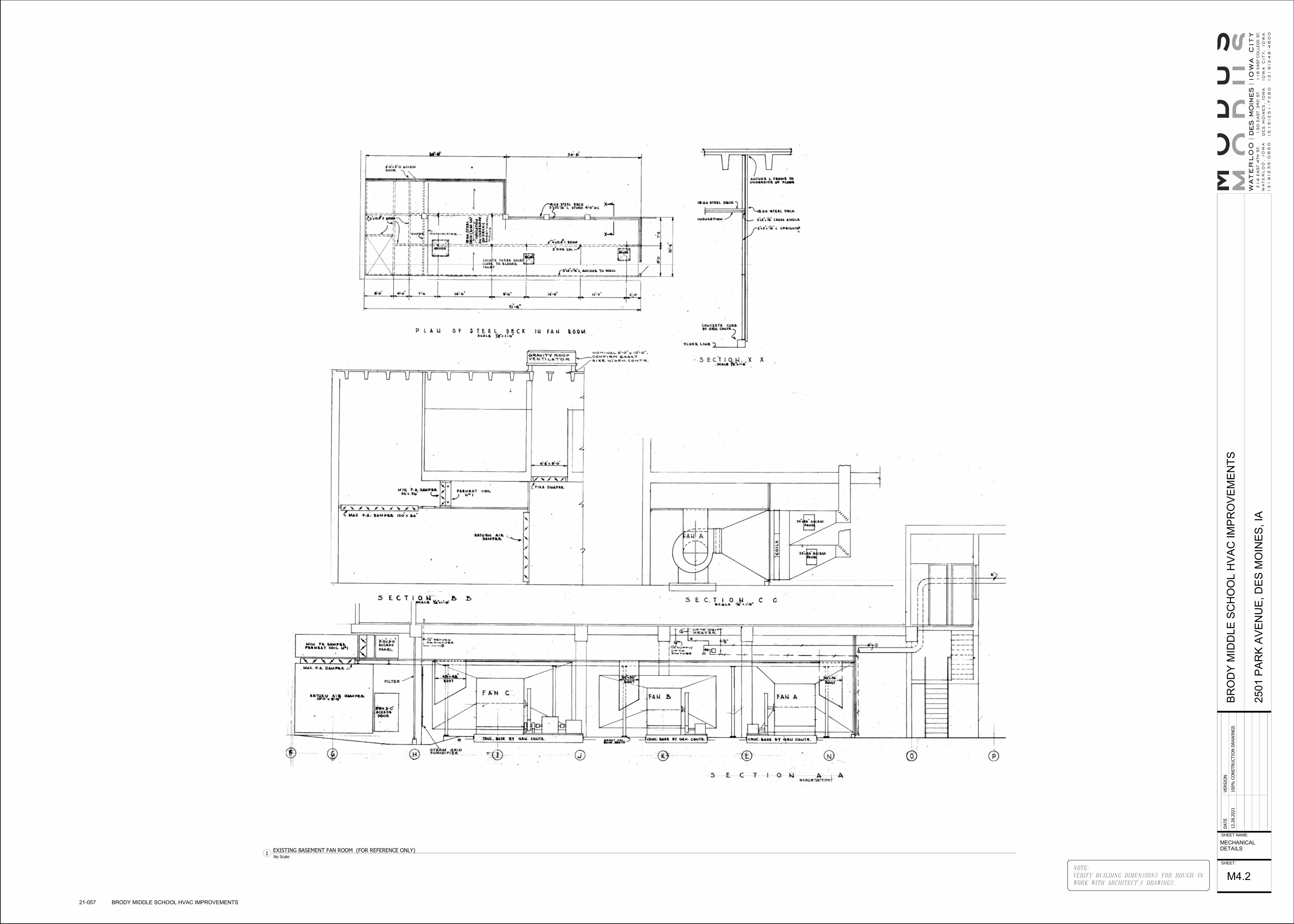
NOTE:
VERIFY BUILDING DIMENSIONS FOR ROUGH-IN
WORK WITH ARCHITECT'S DRAWINGS.
SHEET NAME:
SHEET:
DATE
VERSIO
N
12.2
8.2
021
100%
CO
NSTRU
CTIO
N D
RAW
ING
SB
RO
DY
MID
DL
E S
CH
OO
L H
VA
C I
MP
RO
VE
ME
NT
S
250
1 P
AR
K A
VE
NU
E,
DE
S M
OIN
ES
, IA
MECHANICAL
DETAILS
M4.2
21-057 BRODY MIDDLE SCHOOL HVAC IMPROVEMENTS
No Scale1
EXISTING BASEMENT FAN ROOM (FOR REFERENCE ONLY)

NOTE:
VERIFY BUILDING DIMENSIONS FOR ROUGH-IN
WORK WITH ARCHITECT'S DRAWINGS.
SHEET NAME:
SHEET:
DATE
VERSIO
N
12.2
8.2
021
100%
CO
NSTRU
CTIO
N D
RAW
ING
SB
RO
DY
MID
DL
E S
CH
OO
L H
VA
C I
MP
RO
VE
ME
NT
S
250
1 P
AR
K A
VE
NU
E,
DE
S M
OIN
ES
, IA
MECHANICAL
SCHEDULES
M5.1
21-057 BRODY MIDDLE SCHOOL HVAC IMPROVEMENTS
DUAL DUCT VARIABLE AIR VOLUME BOX SCHEDULE
UNIT TAG COLD HOT COLD MAX. HOT MAX. BOX MIN.
STATICPRESSURE
MINIMUM(DAMPER WIDE
OPEN) RADIANT DISCHARGE MANUFACTURER
EX VAV1-01 14 10 1350 1350 0 0.13 25 18 TITUS
EX VAV1-02 14 12 1600 1600 0 0.18 27 20 TITUS
EX VAV1-03 14 12 1600 1600 0 0.18 27 20 TITUS
EX VAV1-04 14 10 1350 1350 0 0.13 25 18 TITUS
EX VAV1-05 14 10 1350 1350 0 0.13 25 18 TITUS
EX VAV1-06 14 10 1350 1350 0 0.13 25 18 TITUS
EX VAV1-07 16 14 2000 2000 0 0.2 31 23 TITUS
EX VAV1-08 16 14 2400 2400 0 0.28 32 25 TITUS
EX VAV1-09 09 08 600 600 0 0.11 24 14 TITUS
EX VAV1-10 14 12 1800 1800 0 0.23 28 22 TITUS
EX VAV1-11 09 08 600 600 0 0.11 24 14 TITUS
EX VAV1-12 04 04 100 100 0 0.18 15 - TITUS
EX VAV1-13 04 04 100 1000 0 0.18 15 - TITUS
EX VAV1-14 07 07 400 400 0 0.25 21 16 TITUS
EX VAV1-15 07 07 300 300 0 0.14 18 11 TITUS
EX VAV1-16 16 16 3600 3600 0 0.64 36 31 TITUS
EX VAV1-17 16 14 2400 2400 0 0.28 32 25 TITUS
EX VAV1-18 16 14 2000 2000 0 0.2 31 23 TITUS
EX VAV1-19 16 14 2000 2000 0 0.2 31 23 TITUS
EX VAV1-20 16 14 2000 2000 0 0.2 31 23 TITUS
EX VAV1-21 16 14 2000 2000 0 0.2 31 23 TITUS
EX VAV1-22 09 08 600 600 0 0.11 24 14 TITUS
EX VAV1-23 07 07 300 300 0 0.14 18 11 TITUS
EX VAV1-24 16 14 2000 2000 0 0.2 31 23 TITUS
EX VAV1-25 16 14 2000 2000 0 0.2 31 23 TITUS
EX VAV1-26 16 14 2000 2000 0 0.2 31 23 TITUS
EX VAV1-27 16 14 2000 2000 0 0.2 31 23 TITUS
EX VAV2-01 07 07 400 400 0 0.25 21 16 TITUS
EX VAV2-02 16 16 4000 4000 0 0.79 40 34 TITUS
EX VAV2-03 16 16 4000 4000 0 0.79 40 34 TITUS
EX VAV2-04 16 16 4000 4000 0 0.79 40 34 TITUS
EX VAV2-05 16 16 4000 4000 0 0.79 40 34 TITUS
EX VAV2-06 10 10 1000 1000 0 0.26 24 18 TITUS
EX VAV2-07 16 16 3360 3360 0 0.56 34 29 TITUS
EX VAV2-08 09 09 675 675 0 0.14 25 15 TITUS
EX VAV2-09 14 10 1325 1325 0 0..12 24 18 TITUS
EX VAV2-10 16 16 3400 3400 0 0.57 36 29 TITUS
EX VAV3-01 10 10 1000 1000 0 0.26 24 18 TITUS
EX VAV3-02 10 10 1000 1000 0 0.26 24 18 TITUS
EX VAV3-03 14 12 1700 1700 0 0.2 27 22 TITUS
EX VAV3-04 10 10 1000 1000 0 0.26 24 18 TITUS
EX VAV3-05 10 10 1000 1000 0 0.26 24 18 TITUS
EX VAV3-06 14 10 1200 1200 0 0.1 24 17 TITUS
EX VAV3-07 10 10 1000 1000 0 0.26 24 18 TITUS
EX VAV3-08 14 12 1440 1440 0 0.15 25 19 TITUS
EX VAV3-09 14 12 1200 1200 0 0.2 27 22 TITUS
EX VAV3-10 14 10 1200 1200 0 0.1 24 17 TITUS
EX VAV3-11 10 10 1000 1000 0 0.26 24 18 TITUS
EX VAV3-12 14 12 1440 1440 0 0.15 25 19 TITUS
EX VAV3-13 14 10 1200 1200 0 0.1 24 17 TITUS
EX VAV3-14 14 10 1200 1200 0 0.1 24 17 TITUS
EX VAV3-15 10 10 1000 1000 0 0.26 24 18 TITUS
EX VAV3-16 14 12 1600 1600 0 0.18 27 20 TITUS
EX VAV3-17 14 10 1200 1200 0 0.1 24 17 TITUS
EX VAV3-18 08 08 500 500 0 0.25 21 16 TITUS
EX VAV3-19 08 08 400 400 0 0.16 18 14 TITUS
EX VAV3-20 14 10 1250 1250 0 0.11 24 17 TITUS
EX VAV3-21 06 06 230 230 0 0.25 16 11 TITUS
EX VAV3-22 08 08 500 500 0 0.25 21 16 TITUS
EX VAV3-23 14 10 1200 1200 0 0.1 24 17 TITUS
EX VAV3-24 14 12 1600 1600 0 0.18 27 20 TITUS
EX VAV3-25 14 10 1200 1200 0 0.1 24 17 TITUS
EX VAV3-26 10 10 1000 1000 0 0.26 24 18 TITUS
EX VAV3-27 10 10 1000 1000 0 0.26 24 18 TITUS
EX VAV3-28 08 08 ABANDONED ABANDONED 0 0.16 18 14 TITUS
EX VAV3-29 14 12 1440 1440 0 0.15 25 19 TITUS
EX VAV3-30 10 10 1000 1000 0 0.26 24 18 TITUS
EX VAV3-31 08 08 ABANDONED ABANDONED 0 0.16 18 14 TITUS
EX VAV3-32 08 08 430 430 0 0.19 20 14 TITUS
EX VAV3-33 10 08 600 600 0 0.11 24 14 TITUS
EX VAV3-34 10 10 1000 1000 0 0.26 24 18 TITUS
EX VAV3-35 10 10 1000 1000 0 0.26 24 18 TITUS
EX VAV3-36 10 10 1000 1000 0 0.26 24 18 TITUS
EX VAV3-37 14 10 1250 1250 0 0.11 24 17 TITUS
EX VAV3-38 14 12 1575 1575 0 0.18 27 20 TITUS
EX VAV3-39 10 10 ABANDONED ABANDONED 0 0.26 24 18 TITUS
EX VAV3-40 12 10 1100 1100 0 0.24 27 19 TITUS
EX VAV3-41 06 06 ABANDONED ABANDONED 0 0.19 16 10 TITUS
EX VAV3-42 10 10 1000 1000 0 0.26 24 18 TITUS
EX VAV3-43 10 10 1000 1000 0 0.26 24 18 TITUS
EX VAV3-44 14 12 1700 1700 0 0.2 27 22 TITUS
PUMP SCHEDULE
UNIT TAG MANUFACTURER MODEL SYSTEMFLOW RATE
(GPM)TOTAL HEAD
(FT)EFFICIENCY
(%)
MOTOR DATA
HP RPM ELECTRICAL
BP-1 BELL & GOSSETT SERIES E-90-STOCK 2AB B-1 50 25 57.4 3/4 1800 460/3
BP-2 BELL & GOSSETT SERIES E-90-STOCK 2AB B-2 50 25 57.4 3/4 1800 460/3
APPROVED PUMP MANUFACTURERS:
1. TACO
2. OWNER APPROVED EQUAL.
SUPPLY FAN ARRAY SCHEDULE
UNIT TAG MANUFACTURER MODEL SERVESDIMENSIONS
(WxHxD)AIRFLOW
(CFM)ESP
(IN. WG)QUANTITY OF
FANSMOTOR
BHPMOTOR
HPFAN SPEED
(RPM) MOTOR TYPE ARRAY MCA
ELECTRICAL
MOCP VOLTAGE/PHASE
SF-1 INTELLICUBE ECP-500 VAV1 SYSTEM 117x58x25 40,000 4 6 7.04 7.5 2349 ECM 55 60 460/3
SF-2 INTELLICUBE ECP-560 VAV2 SYSTEM 88x88x25 26,160 4 4 5.58 7.5 1740 ECM 35 40 460/3
SF-3 INTELLICUBE ECP-500 VAV3 SYSTEM 117x58x25 45,000 4 6 7.04 7.5 2349 ECM 55 60 460/3
COOLING COIL SCHEDULE
UNIT TAG MANUFACTURER SERVES TYPE
COIL
AIRFLOW
(CFM)
COIL
QUANTITY UNIT LxH (IN) FLUID GPM ROWS
FINS PER
FOOT
COIL FACE
AREA (SF)
TOTAL
CAPACITY
(MBH)
SENSIBLE
CAPACITY
(MBH)
E.D.B./E.W.B.
(ºF/ºF)
L.D.B/L.W.B
. (ºF/ºF)
AIR P.D.
(IN)
E.W.T./L.W.T.
(ºF/ºF)
WATER
P.D. (FT)CC-1 TRANE SF-2 CASED 13,080 2 70x55 30% PG 98.6 6 140 26.98 495 360.4 80/67 55/54.8 0.626 45/55 1.81
NOTES:
1. QUANTITY OF 2 COILS, STACKED, FOR A TOTAL OF 26,160 CFM, 197 GPM.
FILTER RACK SCHEDULE
UNIT TAG MANUFACTURER MODEL RACK TYPE HOUSING TYPE AIRFLOW (CFM)WIDTH x HEIGHT
(INxIN)DEPTH
(IN)FACE VELOCITY
(FPM) FILTER TYPEEFFICIENCY
(MERV)FILTER
THICKNESS (IN)
CLEAN STATICPRESSURE
DROP (IN WC)
DIRTY STATICPRESSURE
DROP (IN WC)
FR-1 AAF SURE-FLO V-BANK SIDE ACCESS 96,000 140.75"x99" 27 500 MEGAPLEAT - M9 9 2 0.22 1.0
NOTES:
1. PROVIDE CLEAN FILTERS AT SUBSTAINTIAL COMPLETION.
2. PROVIDE GALVANIZED FRAME INFILL OF RETURN AIR OPENING WITH GALVANIZED SHEET METAL COVER IN APPROXIMATELY TWO AREAS TO BE FIELD VERIFIED.
3. SEAL FILTER HOUSING TO THE WALLS, AIR TIGHT.
4. ALLOW 27" MINIMUM FRONT CLEARANCE.
5. DESIGN FOR FILTER RACK FOR ONE SIDE ACCESS.
6. MECHANICAL CONTRACTOR SHALL FIELD VERIFY EXISTING DIMENSIONS OF FILTER WALL WITH NEW FILTER RACK SIZE AND LOCATION AND NEW MIXING BOX.
RELIEF FAN SCHEDULE
UNIT TAG MANUFACTURER MODEL SERVES
AIRFLOW(CFM)
ESP(IN. WG)
MOTORBHP
MOTORHP
FAN SPEED(RPM) DRIVE TYPE
SOUND LEVEL(SONES)
ELECTRICAL
MOCP VOLTAGE/PHASE
RF-1B COOK 42HEE422D11 TUNNEL AIR SHAFT 25,000 0.5 7.15 7.5 1140 DIRECT 58 15 480/3
NOTES:
1. NEMA 1 PAINTED GALVANIZED ENCLOSURE.
2. MAIN DISCONNECT.
3. REMOTE ELECTRONICS FOR EACH EC FAN.
4. SPEED CONTROLLER, 10K POTENTIOMETER, 24V ON/OFF.
NOTES:
1. PROVIDE NEW CURB OR ADAPTER CURB AS REQUIRED FOR INSTALLATION OF NEW DAMPER AND FAN.
MECHANICAL CONTRACTOR SHALL FIELD VERIFY EXSITING CONDITIONS.
RELIEF HOOD SCHEDULE
UNIT TAG MANUFACTURER MODEL SERVESTHROAT WIDTH xLENGTH (IN x IN)
THROAT AREA(SF)
WEIGHT(LBS)
RH-1 GREENHECK FGR SECOND FLOOR RELIEF 48x96 32 350
NOTES:
1. MECHANICAL CONTRACTOR SHALL FIELD VERIFY EXISTING STRUCTURAL OPENING DIMENSIONS PRIOR TO ORDERING.
2. MECHANICAL CONTRACTOR SHALL COORDINATE CONTROL DAMPER REQUIREMENTS WITH JCI.

84
EQUIPMENTROOM
86TRASH
85UTILIT
Y
82GAS METER
81BOILER ROOM
84
EQUIPMENTROOM
86TRASH
85UTILIT
Y
82GAS METER
81BOILER ROOM
VF
DV
FD
VF
D
BP-1
BP-2
NEW FAN WALL
SF-3
NEW FAN WALL
SF-2
NEW FAN WALL
SF-1
EX PANEL
EX MDP
ELECTRICAL
GEAR
VFD
7.5 HP
480/3P
UP TO NEW
RF-1B ON ROOF
TWO NEW PORCELAIN SOCKETS WITH LED BULBS.
WIRE TO EXISTING SWITCH AT TUNNEL DOOR.
REMOVE (3) 150A-3P BREAKERS SERVING
EXISTING SUPPLY FANS (SF-1, SF-2, SF-3).
INSTALL NEW BREAKERS FOR NEW SUPPLY
FANS. REUSE WIRE AND CONDUITS. REMOVE
EXISTING VFD'S AND INSTALL NEW VFD'S IN
SAME LOCATION. WIRE TO NEW FAN WALL
ASSEMBLY. FURNISH AND INSTALL A NEW
15A-3P BREAKER FOR NEW RELIEF FAN.
R
R
R
EXISTING PANEL HB. SQ "D"
NF 125A MB 480V TWO
FURNISH & INSTALL NEW
15A-3P BREAKERS FOR NEW
PUMPS HWP-1 & HWP-2
VFDVFD
TO PANEL HB 15A-3P 3/4 HP 480V
TO PANEL HB 15A-3P 3/4 HP 480V
EX
EX
EX
EX
M
NEW FIRE ALARM
FAN SHUTDOWN
TYPICAL OF 3
MDP
45HP 480V
60A-3P
EXISTING DUCT SMOKE
DETECTORS TO BE REUSED.
WIRE TO NEW VFD'S FOR
SHUTDOWN. (TYP)
EX
EXM
MDP
30HP 480V
40A-3P
EX
EX
M
MDP
45HP 480V
60A-3P
EX GF
EX AS
EX SHWP-1
EX SHWP-2
EX PUMP
EX PUMP
CC-1
NEW FILTER RACK
1
1
EX B-1
EX B-2
EX UH
GENERAL NOTES:
A. ALL DISCONNECTS ON MECHANICAL EQUIPMENT SHALL BE
MOUNTED ON STRUCTURE TO ALLOW REMOVAL OF THE
EQUIPMENT FOR MAINTENANCE WITH A MINIMUM OF WIRING
WORK. VERIFY NEC CLEARANCE REQUIREMENTS ARE MET PRIOR TO
ROUGH-IN.
B. MAINTAIN SERVICE CLEARANCE AROUND ALL MECHANICAL &
ELECTRICAL EQUIPMENT. DO NOT ROUTE PIPING OR CONDUIT IN
CLEARANCE SPACE.
REFERENCED NOTES:
1. REMOVE ALL EXISTING DEVICES, POWER, WIRING, AND CONDUITS NOT
BEING REUSED IN THIS ROOM. PATCH WALL AND CEILING OPENINGS.
#
NOTE:
VERIFY BUILDING DIMENSIONS FOR ROUGH-IN
WORK WITH ARCHITECT'S DRAWINGS.
SHEET NAME:
SHEET:
DATE
VERSIO
N
12.2
8.2
021
100%
CO
NSTRU
CTIO
N D
RAW
ING
SB
RO
DY
MID
DL
E S
CH
OO
L H
VA
C I
MP
RO
VE
ME
NT
S
250
1 P
AR
K A
VE
NU
E,
DE
S M
OIN
ES
, IA
BASEMENT
ELECTRICAL PLAN
- NORTH
E1.0N
21-057 BRODY MIDDLE SCHOOL HVAC IMPROVEMENTS
1/8" = 1'-0"1
BASEMENT ELECTRICAL PLAN - NORTH
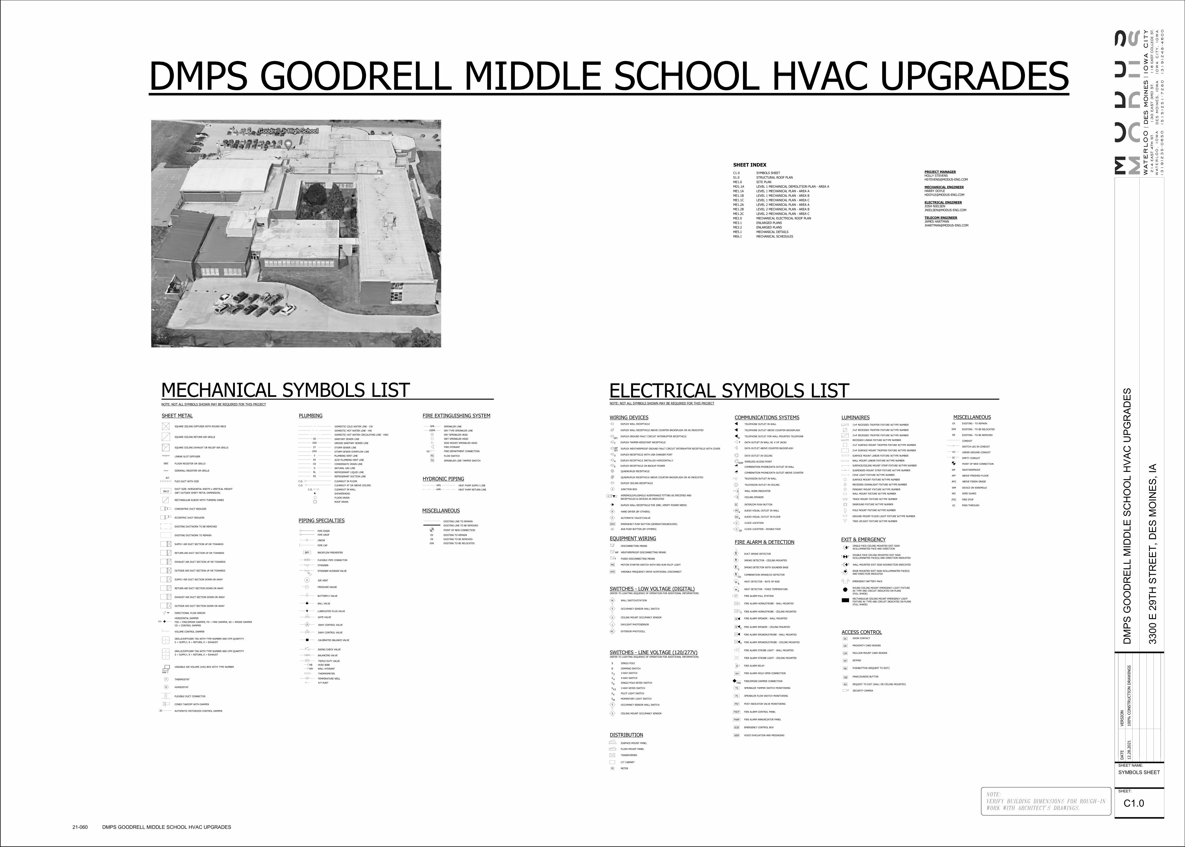
PROJECT MANAGER
HOLLY STEVENS
MECHANICAL ENGINEER
HARRY DOYLE
ELECTRICAL ENGINEER
JOSH NIELSEN
TELECOM ENGINEER
JAMES HARTMAN
J
J
RX
DOOR CONTACT
PROXIMITY CARD READER
MULLION MOUNT CARD READER
KEYPAD
PUSHBUTTON (REQUEST TO EXIT)
PANIC/DURESS BUTTON
ELECTRICAL SYMBOLS LISTWIRING DEVICES
NOTE: NOT ALL SYMBOLS SHOWN MAY BE REQUIRED FOR THIS PROJECT
SWITCHES - LOW VOLTAGE (DIGITAL)
LUMINAIRES
EXIT & EMERGENCY
COMMUNICATIONS SYSTEMS MISCELLANEOUS
SWITCH-LEG IN CONDUIT
EMPTY CONDUIT
ABOVE FINISHED FLOORAFF
POINT OF NEW CONNECTION
WEATHERPROOFWP
UNDER GROUND CONDUITUC
EC
CONDUIT
EQUIPMENT WIRING
WEATHERPROOF DISCONNECTING MEANS
MS
FUSED DISCONNECTING MEANS
MOTOR STARTER SWITCH WITH RED RUN PILOT LIGHT
DISCONNECTING MEANS
WP
DISTRIBUTION
PC
DEVICE ON WIREMOLDWM
F
WG WIRE GUARD
ACCESS CONTROL
VARIABLE FREQUENCY DRIVE W/INTEGRAL DISCONNECT
GFI
WPGFI
ABOVE FINISH GRADEAFG
FIRE STOP[FS]
EZ PASS-THROUGH
H
F
T
EXISTING - TO BE REMOVED
EXISTING - TO BE RELOCATED
EXISTING - TO REMAINDUPLEX WALL RECEPTACLE
DUPLEX WALL RECEPTACLE ABOVE COUNTER BACKSPLASH OR AS INDICATED
DUPLEX GROUND FAULT CIRCUIT INTERRUPTER RECEPTACLE
DUPLEX WEATHERPROOF GROUND FAULT CIRCUIT INTERRUPTER RECEPTACLE WITH COVER
QUADRUPLEX RECEPTACLE
QUADRUPLEX RECEPTACLE ABOVE COUNTER BACKSPLASH OR AS INDICATED
DUPLEX CEILING RECEPTACLE
JUNCTION BOX
WIREMOLD/PLUGMOLD W/ENTRANCE FITTING AS SPECIFIED AND
RECEPTACLES & DEVICES AS INDICATED
2'x4' RECESSED TROFFER FIXTURE W/TYPE NUMBER
1'x4' RECESSED TROFFER FIXTURE W/TYPE NUMBER
INGROUND FIXTURE W/TYPE NUMBER
SURFACE MOUNT FIXTURE W/TYPE NUMBER
GROUND MOUNT FLOOD LIGHT FIXTURE W/TYPE NUMBER
SINGLE FACE CEILING MOUNTED EXIT SIGN
W/ILLUMINATED FACE AND DIRECTION
DOUBLE FACE CEILING MOUNTED EXIT SIGN
W/ILLUMINATED FACE(S) AND DIRECTION INDICATED
WALL MOUNTED EXIT SIGN W/DIRECTION INDICATED
EDGE MOUNTED EXIT SIGN W/ILLUMINATED FACE(S)
AND DIRECTION INDICATED
TELEPHONE OUTLET IN WALL
TELEPHONE OUTLET ABOVE COUNTER BACKSPLASH
TELEPHONE OUTLET FOR WALL MOUNTED TELEPHONE
DATA OUTLET IN CEILING
DATA OUTLET ABOVE COUNTER BACKSPLASH
COMBINATION PHONE/DATA OUTLET IN WALL
COMBINATION PHONE/DATA OUTLET ABOVE COUNTER
TELEVISION OUTLET IN WALL
TELEVISION OUTLET IN CEILING
WALL HORN INDICATOR
CEILING SPEAKER
INTERCOM PUSH BUTTON
AUDIO VISUAL OUTLET IN WALL
AUDIO VISUAL OUTLET IN FLOOR
CLOCK LOCATION
CLOCK LOCATION - DOUBLE FACEADA PUSH BUTTON (BY OTHERS)
ROUND CEILING MOUNT EMERGENCY LIGHT FIXTURE
W/ TYPE AND CIRCUIT INDICATED ON PLANS
(FULL SHADE)
RECTANGULAR CEILING MOUNT EMERGENCY LIGHT
FIXTURE W/ TYPE AND CIRCUIT INDICATED ON PLANS
(FULL SHADE)
SURFACE-MOUNT PANEL
FLUSH-MOUNT PANEL
C/T CABINET
METER
EXTERIOR PHOTOCELL
CEILING MOUNT OCCUPANCY SENSOR
WIRELESS ACCESS POINT
DUPLEX WALL RECEPTACLE FOR 208V, VERIFY POWER NEEDS
OCCUPANCY SENSOR WALL SWITCH
HAND DRYER (BY OTHERS)
AUTOMATIC FAUCET/VALVE
REQUEST TO EXIT (WALL OR CEILING MOUNTED)
EMERGENCY BATTERY PACK
TREE UPLIGHT FIXTURE W/TYPE NUMBER
DUPLEX TAMPER-RESISTANT RECEPTACLE
VFD
C
CDF
W
DC
CR
CM
KP
PB
S
S
IC
AV
AV
WAP
DB
ER
EXR
EX
DATA OUTLET IN WALL W/ # OF JACKS#
2'x2' RECESSED TROFFER FIXTURE W/TYPE NUMBER
2'x4' SURFACE MOUNT TROFFER FIXTURE W/TYPE NUMBER
RECESSED LINEAR FIXTURE W/TYPE NUMBER
SURFACE MOUNT LINEAR FIXTURE W/TYPE NUMBER
WALL MOUNT LINEAR FIXTURE W/TYPE NUMBER
SURFACE/CEILING MOUNT STRIP FIXTURE W/TYPE NUMBER
SUSPENDED MOUNT STRIP FIXTURE W/TYPE NUMBER
COVE LIGHT FIXTURE W/TYPE NUMBER
RECESSED DOWNLIGHT FIXTURE W/TYPE NUMBER
PENDANT MOUNT FIXTURE W/TYPE NUMBER
WALL MOUNT FIXTURE W/TYPE NUMBER
TRACK MOUNT FIXTURE W/TYPE NUMBER
POLE MOUNT FIXTURE W/TYPE NUMBER
SECURITY CAMERA
U DUPLEX RECEPTACLE WITH USB CHARGER PORT
S
S
TRANSFORMER
FIRE ALARM & DETECTION
DUCT SMOKE DETECTOR
SMOKE DETECTOR - CEILING MOUNTED
F
HEAT DETECTOR - RATE OF RISE
HEAT DETECTOR - FIXED TEMPERATURE
FIRE ALARM PULL STATION
FIRE ALARM HORN/STROBE - WALL MOUNTED
R
F
FIRE ALARM STROBE LIGHT - WALL MOUNTED
R
DH
FIRE ALARM RELAY
FIRE ALARM HOLD OPEN CONNECTION
FIRE/SMOKE DAMPER CONNECTIONFSD
FIRE ALARM STROBE LIGHT - CEILING MOUNTED
FIRE ALARM SPEAKER/STROBE - CEILING MOUNTEDC
TS
FS
PIV
FACP
FAAP
SPRINKLER TAMPER SWITCH MONITORING
SPRINKLER FLOW SWITCH MONITORING
POST INDICATOR VALVE MONITORING
FIRE ALARM CONTROL PANEL
FIRE ALARM ANNUNCIATOR PANEL
FIRE ALARM HORN/STROBE - CEILING MOUNTEDC
FIRE ALARM SPEAKER/STROBE - WALL MOUNTED
FIRE ALARM SPEAKER - WALL MOUNTEDs
s FIRE ALARM SPEAKER - CEILING MOUNTEDC
DAYLIGHT PHOTOSENSORL
2'x2' SURFACE MOUNT TROFFER FIXTURE W/TYPE NUMBER
H DUPLEX RECEPTACLE INSTALLED HORIZONTALLY
WALL SWITCH/STATIONW
ECB EMERGENCY CONTROL BOX
M
SMOKE DETECTOR WITH SOUNDER BASE
COMBINATION SMOKE/CO DETECTORCO
S
E DUPLEX RECEPTACLE ON BACKUP POWER
VEM VOICE EVACUATION AND MESSAGING
#
#
(REFER TO LIGHTING SEQUENCE OF OPERATION FOR ADDITIONAL INFORMATION)
SWITCHES - LINE VOLTAGE (120/277V)
S
KSINGLE POLE KEYED SWITCHS
K33-WAY KEYED SWITCHS
SINGLE POLE
S 3-WAY SWITCH3
S 4-WAY SWITCH4
(REFER TO LIGHTING SEQUENCE OF OPERATION FOR ADDITIONAL INFORMATION)
PPILOT LIGHT SWITCHS
MMOMENTARY LIGHT SWITCHS
D DIMMING SWITCH
CEILING MOUNT OCCUPANCY SENSOR
OCCUPANCY SENSOR WALL SWITCH
S
S
EMERGENCY PUSH BUTTON (GENERATORS/BOILERS)EPO
FLEXIBLE DUCT CONNECTOR
A
CONED TAKEOFF WITH DAMPER
AUTOMATIC MOTORIZED CONTROL DAMPER
SQUARE CEILING DIFFUSER WITH ROUND NECK
SQUARE CEILING RETURN AIR GRILLE
SQUARE CEILING EXHAUST OR RELIEF AIR GRILLE
LINEAR SLOT DIFFUSER
FLOOR REGISTER OR GRILLE
SIDEWALL REGISTER OR GRILLE
FLEX DUCT WITH SIZE
DUCT SIZE: HORIZONTAL WIDTH x VERTICAL HEIGHT
(NET OUTSIDE SHEET METAL DIMENSION)
RECTANGULAR ELBOW WITH TURNING VANES
DIRECTIONAL FLOW ARROW
???
HORIZONTAL DAMPER
FSD = FIRE/SMOKE DAMPER, FD = FIRE DAMPER, SD = SMOKE DAMPER
CD = CONTROL DAMPER
SUPPLY AIR DUCT SECTION UP OR TOWARDS
RETURN AIR DUCT SECTION UP OR TOWARDS
EXHAUST AIR DUCT SECTION UP OR TOWARDS
OUTSIDE AIR DUCT SECTION UP OR TOWARDS
SUPPLY AIR DUCT SECTION DOWN OR AWAY
RETURN AIR DUCT SECTION DOWN OR AWAY
EXHAUST AIR DUCT SECTION DOWN OR AWAY
OUTSIDE AIR DUCT SECTION DOWN OR AWAY
GRILLE/DIFFUSER TAG WITH TYPE NUMBER AND CFM QUANTITY
S = SUPPLY, R = RETURN, E = EXHAUST
VARIABLE AIR VOLUME (VAV) BOX WITH TYPE NUMBER
VAV ?
EXISTING DUCTWORK TO BE REMOVED
EXISTING DUCTWORK TO REMAIN
THERMOSTAT
HUMIDISTAT
ECCENTRIC DUCT REDUCER
CONCENTRIC DUCT REDUCER
VOLUME CONTROL DAMPER
MECHANICAL SYMBOLS LISTNOTE: NOT ALL SYMBOLS SHOWN MAY BE REQUIRED FOR THIS PROJECT
SHEET METAL
EX
FS
THERMOMETER
TEMPERATURE WELL
HOSE BIBB
BALANCING VALVE
TRIPLE DUTY VALVE
SPR
3WAY CONTROL VALVE
CALIBRATED BALANCE VALVE
2WAY CONTROL VALVE
SWING CHECK VALVE
BALL VALVE
BUTTERFLY VALVE
AIR VENT
STRAINER W/DRAIN VALVE
PRESSURE GAUGE
V
FLEXIBLE PIPE CONNECTOR
STRAINER
PIPE CAP
BACKFLOW PREVENTERBFP
PIPE RISER
PIPE DROP
UNION
HB
DSPR
SPRINKLER LINE
DRY TYPE SPRINKLER LINE
DRY SPRINKLER HEAD
WET SPRINKLER HEAD
FIRE HYDRANT
SIDE MOUNT SPRINKLER HEAD
FIRE DEPARTMENT CONNECTION
FLOW SWITCH
TS SPRINKLER LINE TAMPER SWITCH
EXISTING LINE TO REMAIN
EXISTING LINE TO BE REMOVED
POINT OF NEW CONNECTION
ER
EXR
EXISTING TO REMAIN
EXISTING TO BE REMOVED
EXISTING TO BE RELOCATED
PLUMBING
PIPING SPECIALTIES
FIRE EXTINGUISHING SYSTEM
MISCELLANEOUS
GRILLE/DIFFUSER TAG WITH TYPE NUMBER AND CFM QUANTITY
S = SUPPLY, R = RETURN, E = EXHAUST
T
H
-
-
-
-
-
P/T PORT
HPR
HPS
DOMESTIC COLD WATER LINE - CW
DOMESTIC HOT WATER LINE - HW
V
ST
DOMESTIC HOT WATER CIRCULATING LINE - HWC
SANITARY SEWER LINE
STORM SEWER LINE
OFD STORM SEWER OVERFLOW LINE
PLUMBING VENT LINE
AV ACID PLUMBING VENT LINE
CD CONDENSATE DRAIN LINE
G NATURAL GAS LINE
RL
RS
REFRIGERANT LIQUID LINE
REFRIGERANT SUCTION LINE
CLEANOUT IN FLOORC.O.
C.O. CLEANOUT AT OR ABOVE CEILING
CLEANOUT IN WALLC.O.
SHOWERHEAD
FLOOR DRAIN
ROOF DRAIN
HYDRONIC PIPINGHEAT PUMP SUPPLY LINE
HEAT PUMP RETURN LINE
SS
LUBRICATED PLUG VALVE
WALL HYDRANTWH
GATE VALVE
FD
8∅
18x12
GREASE SANITARY SEWER LINE GSS
NOTE:
VERIFY BUILDING DIMENSIONS FOR ROUGH-IN
WORK WITH ARCHITECT'S DRAWINGS.
SHEET NAME:
SHEET:
DATE
VERSIO
N
12.2
8.2
021
100%
CO
NSTRU
CTIO
N D
RAW
ING
SD
MP
S G
OO
DR
EL
L M
IDD
LE
SC
HO
OL
HV
AC
UP
GR
AD
ES
330
0 E
29T
H S
TR
EE
T,
DE
S M
OIN
ES
, IA
SYMBOLS SHEET
C1.0
21-060 DMPS GOODRELL MIDDLE SCHOOL HVAC UPGRADES
SHEET INDEX
C1.0 SYMBOLS SHEET
S1.0 STRUCTURAL ROOF PLAN
ME1.0 SITE PLAN
MD1.1A LEVEL 1 MECHANICAL DEMOLITION PLAN - AREA A
ME1.1A LEVEL 1 MECHANICAL PLAN - AREA A
ME1.1B LEVEL 1 MECHANICAL PLAN - AREA B
ME1.1C LEVEL 1 MECHANICAL PLAN - AREA C
ME1.2A LEVEL 2 MECHANICAL PLAN - AREA A
ME1.2B LEVEL 2 MECHANICAL PLAN - AREA B
ME1.2C LEVEL 2 MECHANICAL PLAN - AREA C
ME2.0 MECHANICAL ELECTRICAL ROOF PLAN
ME3.1 ENLARGED PLANS
ME3.2 ENLARGED PLANS
ME5.1 MECHANICAL DETAILS
ME6.1 MECHANICAL SCHEDULES
DMPS GOODRELL MIDDLE SCHOOL HVAC UPGRADES

NOTE:
VERIFY BUILDING DIMENSIONS FOR ROUGH-IN
WORK WITH ARCHITECT'S DRAWINGS.
SHEET NAME:
SHEET:
DATE
VERSIO
N
12.2
8.2
021
100%
CO
NSTRU
CTIO
N D
RAW
ING
SD
MP
S G
OO
DR
EL
L M
IDD
LE
SC
HO
OL
HV
AC
UP
GR
AD
ES
330
0 E
29T
H S
TR
EE
T,
DE
S M
OIN
ES
, IA
STRUCTURAL
ROOF PLAN
S1.0
21-060 DMPS GOODRELL MIDDLE SCHOOL HVAC UPGRADES
METAL WALL PANEL

HP-15
HP-14
FOT = = FOT = FOT
=
=
=
FOT
FO
T=
=
FO
T=
=FOTFOT
=
==
FO
TF
OT
FO
T=
FOT=
TO
D10'-3"
BO
D9'-3"
(80)
AT-1
S
S
HP-4S
HP-7S
HP-5S
HP-9S
HP-16S
HP-6S
HP-6S
HP-14S
HP-15S
HP-8
S
HP-3S
HP-6S
HP-8
S
HP-4S
HP-5S
HP-8SHP-8
S
BC-1S
HP-9S
HP-6S
HP-6S
HP-6S
HP-8S
H
500
H
500
N
J
170
H
360
G
250
I
100
J175
G
330
G
330
G
330
N
G330
G
330
G
330
N
G330
G
330
G
330
N
J
175
J
175
S A
130 (typ. 9)
B200
B200
I100
(typ. 4)
K260
(typ. 4)
N
G
325 G
325
G
325
G
325
K270
G300
N
H
400
H
400
H
400
H
400 K
270
200
100 100100 100 100100 100
200
100
S
A 90
A 80
S
C235
C235
S
BF
B160
DN
E 75
E 75
DN
S
S
A 50 A
70
S
C260
A 60
B
140
S
S
S
S
B
210
B210
B155
B155
B155
TO HP-8 IN FAN ROOM001 BELOW
(7 Typ.)
B150
B150
C250
C250
S
S
S
I150
E100
E100
I
150
B200
C
265
C
265
C
265
C
265
C
265
C265
S
S
S
B
200
B
200
B
200
B
200
B
200
Offset Down
EXHAUST AIR DUCT DOWN
S
B
200
A
120
A
120
A
120
A
120
H400
H400
H400
N1200
V330
W280
H400
H400
H400
N1200
V330
W280
S
S C200
C300
C300
C300
A100
A100
B
200
S
S
S
S
S
C270
(typ. 6)
B200
(typ. 2)
B200
(typ. 2) S
C
300
(typ
. 4)
S
C
315
(typ
. 2)
I 75
I 75
HP-3 LOCATEDABOVE IN FANROOM 2017
CAP E
XIS
TIN
G 6
4" X 1
8" D
UCT
C240
T 50
COURTYARD
1022
8TH GRADE READING
1024
SPEC. ED.
1025
SPEC. ED.
1026
SPEC. ED.
1027
BOYS
1095
JANITOR
1094
STAIR
1023
SPEC. ED.
1096
TELE
1097
CORR
1028
GIRLS
1021
8TH GRADE MATH
1019
WORK RM
1132
CORR
1092
VESTIBULE
1067
SUCCESS
1068
MEN
1130
VEST
1131
VEST
1069
WOMEN
1108
CORRIDOR
1046
SPEC. ED.
1031
WORK RM
1102
CORRIDOR
1033
8 GR. READING/LANG
1100
H.P. CL
1029
8 GR. READING /LANG.
1099
H.P. CL
1098
CORR
1103
TUNNEL ACCESS
1020
8TH GRADE SCIENCE
1047
TOILET
1101
VEST
1048
COMPUTER LAB.1032
LIBRARY COMPUTERS
1030
LIBRARY
1018
8TH GRADE SCIENCE
1010
TOILET
1011
COT
1008
TREATMENT
1007
NURSE WAITING 1004
SECRETARY
1006
VICE PRINCIPAL
1005
DEAN
1000
SECRETARY
1003
FIRE STOR.
1071
WORK ROOM
1002
PRINCIPAL
1014
COUNSELING
1017
COUN. OFF.
1016
COUN. CONF.
1015
COUN. OFF.
1012
COT
1001
WAITING
1013
LAUND.
1134
1093
CORRIDOR
1009
NURSE OFFICE
1167
HP CL.
1155
HP CL.
1153
HP CL.
1133
HP CL.
1162
HP CL.
1161
HP CL.
1160
HP CL.1159
HP CL.
1154
HP CL.1158
HP CL.
1157
HP CL.
1165
HP CL.1166
HP CL.1163
H.P. CL
1164
H.P. CL
1156
HP CL.
EX HP-6 EX HP-6 EX HP-6
EX HP-8 EX HP-8
EX HP-8 EX HP-9
EX HP-5
EX HP-4
EX HP-6
EX
HP-15
EX
HP-5
EX HP-8
EX
HP-14
EX HP-4
EX HP-16
EX HP-6
EX HP-9
EX HP-5
3
3
NEW HP-7
1
2
2
2
2 2
2 2
2
2
2
2
2
2
2
2
2
2
2
3
1
1
3
3 3
3
3
3
3
3
3
3
3
3
3
3
AREA C
AREA A
AR
EA
A
AR
EA
B
EX HP-63
2
2
2
EX HP-3
3
4
4
420 CFM
415 CFM
12"x10"
12"x
10"
3
3
4
5
5
5
DEMOLITION GENERAL NOTES:
A. DEMOLITION DRAWINGS ARE BASED ON EXISTING AVAILABLE DRAWINGS
AND CASUAL FIELD OBSERVATION. MECHANICAL AND ELECTRICAL
CONTRACTORS SHALL FIELD VERIFY THE SITE AND INCLUDE ALL REQUIRED
DEMOLITION IN THE BID.
B. ALL REQUIRED DEMOLITION IS NOT INDICATED. IT IS THE INTENT OF THESE
DOCUMENTS THAT ALL MECHANICAL AND ELECTRICAL SYSTEMS (NOT TO BE
REUSED OR EXTENDED) BE REMOVED. COORDINATE WITH ARCHITECTURAL
DRAWINGS.
C. REFER TO SPECIFICATIONS AND OTHER SHEETS FOR ADDITIONAL
DEMOLITION REQUIREMENTS.
D. REMOVE ALL ELECTRICAL CONNECTIONS, WIRING, AND CONDUIT SERVING
ALL MECHANICAL EQUIPMENT TO BE REMOVED.
E. MAINTAIN FIRE RATINGS OF AFFECTED WALLS AND FLOORS.
REFERENCED NOTES:
1. EXISTING HEAT PUMP SHALL REMAIN. REMOVE AND REPLACE EXISTING
HEAT PUMP HOSE KIT PER DETAIL.
2. REPLACE EXISTING THERMOSTAT AND HEAT PUMP CONTROL VALVE.
DISCONNECT, RECONNECT, AND EXTEND WIRING TO EXISTING BACNET
CONTROLLER. CONTROLS CONTRACTOR SHALL INSTALL OWNER FURNISHED
THERMOSTAT.
3. REMOVE EXISTING OUTSIDE AIR DUCTWORK AND ASSOCIATED
ACCESSORIES, HANGERS, AND SUPPORTS FROM ERV-5 IN SHAFT TO HEAT
PUMPS.
4. PATCH WALL WITH SHEET METAL ABOVE CEILING ON BOTH SIDES OF WALL
WHERE EXISTING DUCTWORK WAS REMOVED FROM SHAFT AND SEAL WITH
FIRE CAULKING.
5. REMOVE AND REINSTALL EXISTING CEILING GRID, CEILING TILES, LIGHTS,
SMOKE DETECTORS, SPRINKLER HEADS AS REQUIRED FOR REMOVAL OF
EXISTING DUCTWORK.
#
NOTE:
VERIFY BUILDING DIMENSIONS FOR ROUGH-IN
WORK WITH ARCHITECT'S DRAWINGS.
SHEET NAME:
SHEET:
DATE
VERSIO
N
12.2
8.2
021
100%
CO
NSTRU
CTIO
N D
RAW
ING
SD
MP
S G
OO
DR
EL
L M
IDD
LE
SC
HO
OL
HV
AC
UP
GR
AD
ES
330
0 E
29T
H S
TR
EE
T,
DE
S M
OIN
ES
, IA
LEVEL 1
MECHANICAL
DEMOLITION
PLAN - AREA A
MD1.1A
21-060 DMPS GOODRELL MIDDLE SCHOOL HVAC UPGRADES
1/8" = 1'-0"1
LEVEL 1 HVAC DEMOLITION PLAN - AREA A

S
S
S
WV
WV
WV
WV
T
T
GV
GV
x x x x x x x x
xxxxxx
x x x x x x x x x x x x x x x
xxxxx
x x x x x x x x x x x x x x x x x
DYH
FO
FO
FO
12"W
12"W
12"W
12"W
12"W
W
24"W
24"W 24"W
24"W
24"W
6"W6"W6"W
4"W
4"W
ST ST
21" RCP
10" RC
P
10" RCP
6" W
6" SS6" SS
4" ST
10" CMP
12"
CM
P
FO
FO
FO
FO
FO
FO
FO
SIGN
3300
GOODRELL MIDDLE SCHOOL
625.44'
S 00°32'57" W
GRASS
GRASS
GRAVEL
PCC
PCC
E 29th ST
100
101122
115
SIDEWALK
SIDEWALK
SIDEWALK
6' CHAIN LINK FENCE
6' CHAIN LINK FENCE
6' CHAIN LINK FENCE
GATE
GATE
T T T
TT
TT
T
T T
T
T
TT
TT
TT
T
OHE
OHE
OHE
OHE
OHE OHE OHE
OHE
OHE
UGE
UGE
UGE
UGE
UGE
4"G
4"G
GG
GG
GG
G
4"G4"G
4"G
G
G
24"TILE
24"ST
4"ST
15"ST
12"ST
12"ST
10"TILE
10"TILE
4"TILE
18"TILE
10"TILE
4"TILE
4"TILE RD
RD
INTAKETC=104.9INV=80.1
24"ST
24"ST
24"ST
10"SS
10"SS
10"SS
6"SS SRVC
6"SS
ABANDONED
10"SS
10"SS
10"SS
10"SS
8"SS
EX GEOTHERMAL
WELL FIELD VAULT1
REFERENCED NOTES:
1. INSPECT GEOTHERMAL VAULT INCLUDING SEAL, LIGHTS, VALVES, AND
SUMP PUMP. PROVIDE REPORT OF FINDINGS. PRESSURE TEST GOEHTERMAL
SYSTEM INCLUDING BUILDING LOOP AND GEOTHERMAL FIELD. FILL,
PACIFY, TEST, AND CHEMICALLY TREAT GEOTHERMAL SYSTEM AFTER
PRESSURE TEST. REFER TO SPECIFICATION SECTION 23 2500.
#
NOTE:
VERIFY BUILDING DIMENSIONS FOR ROUGH-IN
WORK WITH ARCHITECT'S DRAWINGS.
SHEET NAME:
SHEET:
DATE
VERSIO
N
12.2
8.2
021
100%
CO
NSTRU
CTIO
N D
RAW
ING
SD
MP
S G
OO
DR
EL
L M
IDD
LE
SC
HO
OL
HV
AC
UP
GR
AD
ES
330
0 E
29T
H S
TR
EE
T,
DE
S M
OIN
ES
, IA
SITE PLAN
ME1.0
21-060 DMPS GOODRELL MIDDLE SCHOOL HVAC UPGRADES
1" = 30'-0"1
SITE PLAN

HP-15
HP-14
FOT = = FOT = FOT
=
=
=
FOT
FO
T=
=
FO
T=
=FOTFOT
=
==
FO
TF
OT
FO
T=
FOT=
TO
D10'-3"
BO
D9'-3"
(80)
AT-1
S
S
HP-4S
HP-7S
HP-5S
HP-9S
HP-16S
HP-6S
HP-6S
HP-14S
HP-15S
HP-8
S
HP-3S
HP-6S
HP-8
S
HP-4S
HP-5S
HP-8SHP-8
S
BC-1S
HP-9S
HP-6S
HP-6S
HP-6S
HP-8S
H
500
H
500
N
J
170
H
360
G
250
I
100
J175
G
330
G
330
G
330
N
G330
G
330
G
330
N
G330
G
330
G
330
N
J
175
J
175
S A
130 (typ. 9)
B200
B200
I100
(typ. 4)
K260
(typ. 4)
N
G
325 G
325
G
325
G
325
K270
G300
N
H
400
H
400
H
400
H
400 K
270
200
100 100100 100 100100 100
200
100
S
A 90
A 80
S
C235
C235
S
BF
B160
DN
E 75
E 75
DN
S
S
A 50 A
70
S
C260
A 60
B
140
S
S
S
S
B
210
B210
B155
B155
B155
TO HP-8 IN FAN ROOM001 BELOW
(7 Typ.)
B150
B150
C250
C250
S
S
S
I150
E100
E100
I
150
B200
C
265
C
265
C
265
C
265
C
265
C265
S
S
S
B
200
B
200
B
200
B
200
B
200
Offset Down
EXHAUST AIR DUCT DOWN
S
B
200
A
120
A
120
A
120
A
120
H400
H400
H400
N1200
V330
W280
H400
H400
H400
N1200
V330
W280
S
S C200
C300
C300
C300
A100
A100
B
200
S
S
S
S
S
C270
(typ. 6)
B200
(typ. 2)
B200
(typ. 2) S
C
300
(typ
. 4)
S
C
315
(typ
. 2)
I 75
I 75
HP-3 LOCATEDABOVE IN FANROOM 2017
CAP E
XIS
TIN
G 6
4" X 1
8" D
UCT
C240
T 50
COURTYARD
1022
8TH GRADE READING
1024
SPEC. ED.
1025
SPEC. ED.
1026
SPEC. ED.
1027
BOYS
1095
JANITOR
1094
STAIR
1023
SPEC. ED.
1096
TELE
1097
CORR
1028
GIRLS
1021
8TH GRADE MATH
1019
WORK RM
1132
CORR
1092
VESTIBULE
1067
SUCCESS
1068
MEN
1130
VEST
1131
VEST
1069
WOMEN
1108
CORRIDOR
1046
SPEC. ED.
1031
WORK RM
1102
CORRIDOR
1033
8 GR. READING/LANG
1100
H.P. CL
1029
8 GR. READING /LANG.
1099
H.P. CL
1098
CORR
1103
TUNNEL ACCESS
1020
8TH GRADE SCIENCE
1047
TOILET
1101
VEST
1048
COMPUTER LAB.1032
LIBRARY COMPUTERS
1030
LIBRARY
1018
8TH GRADE SCIENCE
1010
TOILET
1011
COT
1008
TREATMENT
1007
NURSE WAITING 1004
SECRETARY
1006
VICE PRINCIPAL
1005
DEAN
1000
SECRETARY
1003
FIRE STOR.
1071
WORK ROOM
1002
PRINCIPAL
1014
COUNSELING
1017
COUN. OFF.
1016
COUN. CONF.
1015
COUN. OFF.
1012
COT
1001
WAITING
1013
LAUND.
1134
1093
CORRIDOR
1009
NURSE OFFICE
1167
HP CL.
1155
HP CL.
1153
HP CL.
1133
HP CL.
1162
HP CL.
1161
HP CL.
1160
HP CL.1159
HP CL.
1154
HP CL.1158
HP CL.
1157
HP CL.
1165
HP CL.1166
HP CL.1163
H.P. CL
1164
H.P. CL
1156
HP CL.
GENERAL NOTES:
A. LAYOUT AND ROUTING SHOWN IS DIAGRAMMATIC AND SCHEMATIC IN
NATURE. NOT ALL OFFSETS MAY BE SHOWN. CONTRACTOR SHALL VERIFY
EXACT ROUTING REQUIRED AND NUMBER OF OFFSETS AND TRANSITIONS.
B. MAINTAIN SERVICE CLEARANCE IN FRONT OF AND ABOVE ELECTRICAL
EQUIPMENT AND ACCESS ZONES. REFER TO ELECTRICAL EQUIPMENT
INSTALLATION AND INSTRUCTIONS. DO NOT INSTALL PIPING IN CLEARANCE
SPACE OF ELECTRICAL OR MECHANICAL EQUIPMENT. DO NOT INSTALL
EQUIPMENT OR ROUTE DUCTS IN CLEARANCE SPACE.
C. COORDINATE ALL PIPING ROUTING WITH BUILDING STRUCTURE AND OTHER
TRADES PRIOR TO INSTALLATION TO ALLOW FOR PROPER CLEARANCES AND
FLOW REQUIREMENTS.
D. PROVIDE ISOLATION BALL VALVES ON BRANCH PIPING TAPS FROM MAIN ON
ALL SUPPLY AND RETURN PIPES. ENSURE VALVES ARE INSTALLED IN
ACCESSIBLE LOCATIONS.
E. VERIFY ALL SITE CONDITIONS PRIOR TO START OF WORK. FIELD VERIFY ALL
NEW AND EXISTING PIPE ROUTING WITH EXISTING CONDITIONS PRIOR TO
ROUGH-IN. MAKE NECESSARY OFFSETS AS REQUIRED.
F. COORDINATE ALL EXPOSED PIPE ROUTING WITH DESIGN TEAM PRIOR TO
ROUGH-IN, SPECIFIC RACKING REQUIREMENTS MAY BE REQUIRED. PROVIDE
JACKETING ON EXPOSED PIPING UNLESS OTHERWISE NOTED.
G. ALL CONDENSATE DRAIN PIPING SHALL BE 3/4" WITH INSULATION UNLESS
NOTED OTHERWISE.
A. COORDINATE THERMOSTAT LOCATIONS WITH CASEWORK, WALL TYPES, AND
FURNISHINGS PRIOR TO ROUGH-IN.
B. PROVIDE VOLUME CONTROL BALANCING DAMPERS ON ALL SUPPLY, RETURN,
EXHAUST AIR TAPS IN ACCESSIBLE LOCATIONS FOR AIR BALANCING. INSTALL
CABLE OPERATED DAMPER OR ACCESS PANEL IF DAMPER IS LOCATED ABOVE
GYP CEILINGS.
C. COORDINATE DUCT ROUTING WITH STRUCTURAL AND ALL TRADES.
D. COORDINATE ALL EXPOSED DUCTWORK ROUTING WITH DESIGN TEAM PRIOR
TO ROUGH-IN.
E. COORDINATE SUPPLY, RETURN, AND EXHAUST GRILLE/DIFFUSER LOCATIONS
WITH EXISTING CEILING PLANS.
F. COORDINATE DUCT ROUTING IN LOCATIONS WITH EXISTING CONDITIONS.
FIELD VERIFY EXISTING CONDITIONS PRIOR TO ROUGH-IN.
EX HP-6 EX HP-6 EX HP-6
EX HP-8 EX HP-8
EX HP-8 EX HP-9
EX HP-5
EX HP-4
EX HP-6
EX
HP-15
EX
HP-5
EX HP-8
EX
HP-14
EX HP-4
EX HP-16
EX HP-6
EX HP-9
EX HP-5
1
1
EX HP-7
1
2
2
2
2 2
2 2
2
2
2
2
2
2
2
2
2
2
2
1
1
1
1
1 1
1
1
1
1
1
1
1
1
1
1
1
AREA C
AREA A
AR
EA
A
AR
EA
B
EX HP-61
2
2
2
EX HP-3
1
DOAS-1
4
TOP OF NEW CONCRETE PAD
SHALL BE 7" LOWER THAN
EXISTING DOOR STOOP AND SLOPE
SOUTH AT 10% GRADE.
SLOPE
REFER TO SCREEN WALL DETAILS
MOUNT NEW UNIT ON 14" CURB ON
CONCRETE PAD. REFER TO EQUIPMENT
AND SCREEN WALL DETAILS.
2
420 CFM
415 CFM
ROUTE DUCTWORK VERTICAL ALONG WALL.
SUPPORT ELBOW FROM CONCRETE PAD.
SUPPORT VERTICAL DUCTWORK FROM WALL.
INSULATE AND WRAP DUCTWORK PER SPECS.
FS=200 CFM
FS=745 CFM14"x
12"
SA
5
EXISTING
DOOR STOOP
7
945 CFM
8
8
8
8
TYP
TYP
TYP
TYP
6
415 CFM
6
420 CFM
3
9
9
10
11
S
S
S
S S
S
S S
S
S2
S2
S
S
S
S
S
S
S
S
S
S
S
CP
WP
DOAS-1
480V-3P/70A
PNL HF
REFERENCED NOTES:
1. EXISTING HEAT PUMP SHALL REMAIN. REMOVE AND REPLACE EXISTING
HEAT PUMP HOSE KIT PER DETAIL.
2. REPLACE EXISTING THERMOSTAT AND HEAT PUMP CONTROL VALVE.
DISCONNECT, RECONNECT, AND EXTEND WIRING TO EXISTING BACNET
CONTROLLER. CONTROLS CONTRACTOR SHALL INSTALL OWNER FURNISHED
THERMOSTAT.
3. PATCH WALL WITH SHEET METAL ABOVE CEILING ON BOTH SIDES OF WALL
WHERE EXISTING DUCTWORK WAS REMOVED FROM SHAFT AND SEAL WITH
FIRE CAULKING.
4. EXTEND 10x10 FRESH AIR DUCTWORK THROUGH ROOF FROM NEW DOAS
DUCTWORK SUPPLY AIR MAIN. TRANSITION TO 10" ROUND. PROVIDE
BALANCE DAMPER AND FLOW SENSOR IN HEAT PUMP CLOSET FOR PROPER
BALANCING IN ACCESSIBLE LOCATION. INSULATE NEW DUCTWORK WITH
FIBERGLASS WRAP PER SPEC.
5. EXTEND 14x12 FRESH AIR DUCTWORK THROUGH ROOF FROM NEW DOAS
DUCTWORK SUPPLY AIR MAIN. TRANSITION AS REQUIRED TO FIT WITHIN
EXISTING CONDITIONS. PROVIDE BALANCE DAMPER AND FLOW SENSOR TO
EACH HEAT PUMP CLOSET FOR PROPER BALANCING IN ACCESSIBLE
LOCATION. INSULATE NEW DUCTWORK WITH FIBERGLASS WRAP PER SPEC.
6. 10x10 RETURN AIR DUCT THROUGH ROOF TO DOAS UNIT. TRANSITION AS
REQUIRED TO FIT WITHIN JOIST SPACE. BALANCE TO AIRFLOW NOTED.
7. 14x12 RETURN AIR DUCT THROUGH ROOF TO DOAS UNIT. TRANSITION AS
REQUIRED TO FIT WITHIN JOIST SPACE. BALANCE TO AIRFLOW NOTED.
8. CAP ALL EXISTING OA AND RA DUCTS WITH SHEET METAL BEHIND LOW
GRILLES. EXISTING LOW GRILLES SHALL REMAIN.
9. REMOVE AND REINSTALL EXISTING CEILING GRID, CEILING TILES, LIGHTS,
SMOKE DETECTORS, SPRINKLER HEADS AS REQUIRED FOR INSTALLATION
OF NEW DUCTWORK.
10. NEW VERTICAL RIBBED 36” WIDE, 1 1/2” T. GALV. X 22 GAGE STEEL SIDING
PANEL (FIRESTONE – VR-CLASSIC OMEGA PANEL). ATTACH TO GALV. STEEL
TUBE FRAME WITH NEOPRENE GASKETED SELF-TAPPING SHEET METAL
SCREWS WITH COLOR MATCH SCREW CAP AT 9” O.C. CAP CORNERS WITH
PRE-FINISHED OUTSIDE CORNER FLASHING. COLOR SHALL BE BURGUNDY
OR EQUAL.
11. NEW H.M. FRAME AND (2) 3’-0”W x 7’-6”H. A PAIR OF H.M. DOORS SHALL
INCLUDE FLUSH BOLTS AT TOP AND BOTTOM OF DOOR WITH LOCKING
HANDLE.
#
NOTE:
VERIFY BUILDING DIMENSIONS FOR ROUGH-IN
WORK WITH ARCHITECT'S DRAWINGS.
SHEET NAME:
SHEET:
DATE
VERSIO
N
12.2
8.2
021
100%
CO
NSTRU
CTIO
N D
RAW
ING
SD
MP
S G
OO
DR
EL
L M
IDD
LE
SC
HO
OL
HV
AC
UP
GR
AD
ES
330
0 E
29T
H S
TR
EE
T,
DE
S M
OIN
ES
, IA
LEVEL 1
MECHANICAL
PLAN - AREA A
ME1.1A
21-060 DMPS GOODRELL MIDDLE SCHOOL HVAC UPGRADES
1
3
3
3
1/8" = 1'-0"1
LEVEL 1 HVAC PLAN - AREA A

11
HP-15
HP-14
EF-4
HP-13
FO
T=
=
FO
T=
=
38/14
EXTG.
285
(7 TYP.)
34/12 24/12 18/8
(500)
(500)
AT-1
HP-3S
HP-6S
HP-4S
HP-6S
S
S
HP-9S
HP-7S
HP-7S
HP-9S
HP-6S
HP-8S
HP-14S
HP-15S
HP-8
S
100 100100 100
200
100
TO HP-8 IN FAN ROOM001 BELOW
(7 Typ.)
S
B
200
B
200
B
200
B
200
36" X 12" EXHAUST AIR DUCTDOWN TO FAN ROOM 001
36" X 15" RETURN AIR DUCT
36" X 18"
S
B
200
A
120
A
120
B200
A
120
2' 6" X 1' 6"EHAUST LOUVER
KILN HOOD
G
260
G
260
G
260
G
260
G
260
B200
A100
L
500
R500
C250(typ. 4)
S
I
N1400
N
S
S
G
320
G
320
G
320
G
320
G
320
F160
N1600
S
N1200
G
350
G
350
G
350
B
160
F 60
F100
F 60
F
180
I 60
I 100
I 60
J
180
I 60
F
200
K
230
I
100 I
100
S
S
UP
G
330
F 250
F 250
F 250
F 250
N1000
S
B200
B200
E 60
E 60
A110
A 100(4 typ.)
J 200(4 typ.)
FLOOR MOUNTEDHEAT PUMP (5 typ.)
U
530
UP
U
530
U
530
S
S
S
C 240(typ. 5)
D
425
(typ
. 3) A
90
B 210(typ. 3)
J 150(typ. 3)
S
S
O
1995
DOWN
DOWN
B 200(TYP.4)
R
450
R300
J 150(typ. 3)
C
315
(typ
. 2)
C 250(typ. 4)
HP-6 LOCATED ABOVEIN FAN ROOM 2017
S
1000
HP-3 LOCATEDABOVE IN FANROOM 2017
B 200(typ. 2)
R
A 120(typ. 3)
S S
C
240
CAP E
XIS
TIN
G 6
4" X 1
8" D
UCT
A 100(typ. 4)
B
200
B200
1132
CORR
1092
VESTIBULE
1172
STAIR
1135
STAIR
1072
AUDITORIUM
1138
STORAGE
1073
STAGE
1137
STORAGE
1136
CORRIDOR
1070
INTERVENTION
1061
GROWTH / FLEX
1130
VEST
1131
VEST
1142
STOR 1087
VOCAL
1143
STOR1148
CORR
1085
PRACTICE
1079
GIRLS
1078
BOYS
1144
STOR
1145
JANITOR
1086
BAND/OCHESTRA
1147
VESTIBULE
1082
WORK ROOM
1083
GRAPHIC ARTS
1080
GENERAL SHOP
1081
WORK ROOM
1084
PRACTICE
1128
VEST.
1123
CORRIDOR
1146
H.P. CL
1059
GROWTH / FLEX
1134
1141
OFFICE
1140
HALL
1150
STOR
1090
ART
1139
VEST
1149
VEST
1089
DRAMA
1091
KILN
1066
SPED
1075
FCS KITCHENS
1074
FCS SEW
1076
LAUNDRY
1129
STOR.
1077
MECH.
1088
MUSIC PRAC
1152
CL
1168
HP CL.
1169
HP CL.
1170
STOR.
1171
STOR.
1174
HP CL.
1151
CL
EX
HP-15
EX
HP-14
EX HP-3
EX HP-6
EX HP-8
EX HP-9
EX HP-7
EX HP-13
EX HP-6
EX HP-9
EX
HP-10
EX HP-7
EX
HP-10
EX HP-4
EX HP-6
EX EF-4
EX CUH-1
EX CUH-1
EX CUH-1
EX CUH-1
1
1
2
2
2
2
2
2
2
2
2
2
2
2
22
2
1
1
1
11
1
1
1
1
11
1
1
AREA C
AREA B
AR
EA
A
AR
EA
B
1
2
S
S
S
S S
S
S
S
S
2S
2S
S
S
S
S
S
GENERAL NOTES:
A. LAYOUT AND ROUTING SHOWN IS DIAGRAMMATIC AND SCHEMATIC IN
NATURE. NOT ALL OFFSETS MAY BE SHOWN. CONTRACTOR SHALL VERIFY
EXACT ROUTING REQUIRED AND NUMBER OF OFFSETS AND TRANSITIONS.
B. MAINTAIN SERVICE CLEARANCE IN FRONT OF AND ABOVE ELECTRICAL
EQUIPMENT AND ACCESS ZONES. REFER TO ELECTRICAL EQUIPMENT
INSTALLATION AND INSTRUCTIONS. DO NOT INSTALL PIPING IN CLEARANCE
SPACE OF ELECTRICAL OR MECHANICAL EQUIPMENT. DO NOT INSTALL
EQUIPMENT OR ROUTE DUCTS IN CLEARANCE SPACE.
C. COORDINATE ALL PIPING ROUTING WITH BUILDING STRUCTURE AND OTHER
TRADES PRIOR TO INSTALLATION TO ALLOW FOR PROPER CLEARANCES AND
FLOW REQUIREMENTS.
D. PROVIDE ISOLATION BALL VALVES ON BRANCH PIPING TAPS FROM MAIN ON
ALL SUPPLY AND RETURN PIPES. ENSURE VALVES ARE INSTALLED IN
ACCESSIBLE LOCATIONS.
E. VERIFY ALL SITE CONDITIONS PRIOR TO START OF WORK. FIELD VERIFY ALL
NEW AND EXISTING PIPE ROUTING WITH EXISTING CONDITIONS PRIOR TO
ROUGH-IN. MAKE NECESSARY OFFSETS AS REQUIRED.
F. COORDINATE ALL EXPOSED PIPE ROUTING WITH DESIGN TEAM PRIOR TO
ROUGH-IN, SPECIFIC RACKING REQUIREMENTS MAY BE REQUIRED. PROVIDE
JACKETING ON EXPOSED PIPING UNLESS OTHERWISE NOTED.
G. ALL CONDENSATE DRAIN PIPING SHALL BE 3/4" WITH INSULATION UNLESS
NOTED OTHERWISE.
A. COORDINATE THERMOSTAT LOCATIONS WITH CASEWORK, WALL TYPES, AND
FURNISHINGS PRIOR TO ROUGH-IN.
B. PROVIDE VOLUME CONTROL BALANCING DAMPERS ON ALL SUPPLY, RETURN,
EXHAUST AIR TAPS IN ACCESSIBLE LOCATIONS FOR AIR BALANCING. INSTALL
CABLE OPERATED DAMPER OR ACCESS PANEL IF DAMPER IS LOCATED ABOVE
GYP CEILINGS.
C. COORDINATE DUCT ROUTING WITH STRUCTURAL AND ALL TRADES.
D. COORDINATE ALL EXPOSED DUCTWORK ROUTING WITH DESIGN TEAM PRIOR
TO ROUGH-IN.
E. COORDINATE SUPPLY, RETURN, AND EXHAUST GRILLE/DIFFUSER LOCATIONS
WITH EXISTING CEILING PLANS.
F. COORDINATE DUCT ROUTING IN LOCATIONS WITH EXISTING CONDITIONS.
FIELD VERIFY EXISTING CONDITIONS PRIOR TO ROUGH-IN.
REFERENCED NOTES:
1. EXISTING HEAT PUMP SHALL REMAIN. REMOVE AND REPLACE EXISTING
HEAT PUMP HOSE KIT PER DETAIL
2. REPLACE EXISTING THERMOSTAT AND HEAT PUMP CONTROL VALVE.
DISCONNECT, RECONNECT, AND EXTEND WIRING TO EXISTING BACNET
CONTROLLER. CONTROLS CONTRACTOR SHALL INSTALL OWNER FURNISHED
THERMOSTAT.
#
NOTE:
VERIFY BUILDING DIMENSIONS FOR ROUGH-IN
WORK WITH ARCHITECT'S DRAWINGS.
SHEET NAME:
SHEET:
DATE
VERSIO
N
12.2
8.2
021
100%
CO
NSTRU
CTIO
N D
RAW
ING
SD
MP
S G
OO
DR
EL
L M
IDD
LE
SC
HO
OL
HV
AC
UP
GR
AD
ES
330
0 E
29T
H S
TR
EE
T,
DE
S M
OIN
ES
, IA
LEVEL 1
MECHANICAL
PLAN - AREA B
ME1.1B
21-060 DMPS GOODRELL MIDDLE SCHOOL HVAC UPGRADES
1/8" = 1'-0"1
LEVEL 1 HVAC PLAN - AREA B
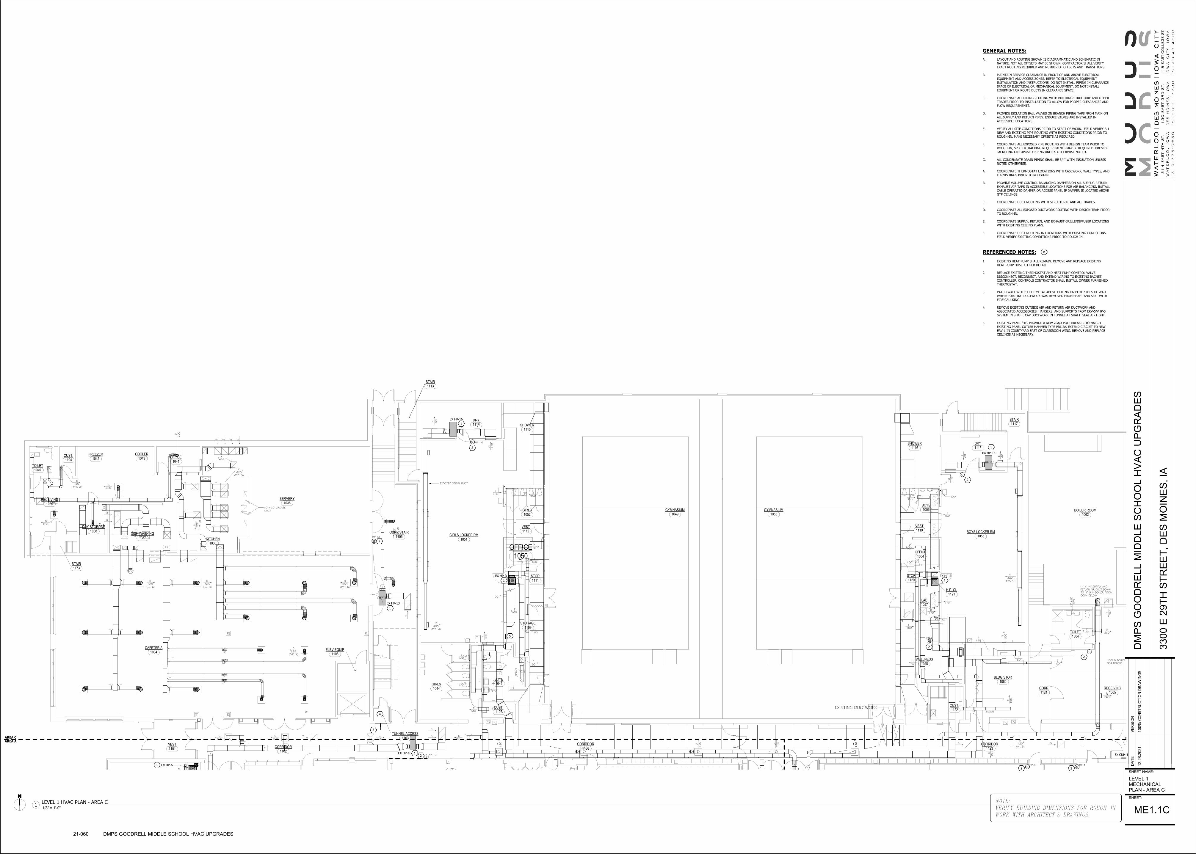
HP-13
HP-13
=
=FOTFOT
=
=
26/8
26/10
26/12
22/8
M
HP-13
S
HP-16S
HP-5
S
HP-4S
HP-6S
HP-7S
HP-16S
HP-8
EXISTING DUCTWORK
A
120
A
120
A
120
A
120
A
120
N
S
S C200
C300
C300
S
I 75
A
120
G 260
G 260
A 120(typ. 3)
S S
C
240
E 60
I150
I150
N
300
F
155
DOWNUP
I 100
B 170
I 100
H375
I 80
I100
E100
I100
J 200
O
1120
E
80
I
80
Y 330(typ. 4)
HP-9 IN BOILER ROOM004 BELOW
14" X 14" SUPPLY ANDRETURN AIR DUCT DOWNTO HP-9 IN BOILER ROOM0004 BELOW
N
960
CAP
E 80
12" X 8
"
1
20
J200
Z
300
I100
I100 J
200
I100
E100
F180
I100
E100
F180
I100
I100
Y 400(TYP. 4)
O
1120
E
80
I
80
EXPOSED SPRIAL DUCT
B
200
(TYP.
2)
S
UP
UP
UP
UP
UP
D 380(typ. 6)
D 465(typ. 3)
D 380(TYP. 6)
B 225(TYP. 4)
10" x 20" GREASEDUCT
X
495
(TYP.
3)
X 620(TYP. 5)
X495
S
S
S
S
B
200
A100
S
S
X 530(TYP. 3)
B200
B200
E 50(typ. 2)
C240
DO
WN
1111
STOR
1108
CORRIDOR
1102
CORRIDOR
1128
VEST.
1123
CORRIDOR
1122
CUST.
1060
BLDG STOR
1124
CORR
1065
RECEIVING
1064
TOILET
1057
LAB
1058
WELLNESS
1121
H.P. CL
1120
STOR
1054
OFFICE
1055
BOYS LOCKER RM
1056
BOYS
1116
SHOWER
1117
STAIR
1118
DRY
1053
GYMNASIUM
1049
GYMNASIUM
1113
STAIR
1114
DRY
1115
SHOWER
1112
VEST
1052
GIRLS
1051
GIRLS LOCKER RM
1050
OFFICE
1110
H.P. CL
1109
STORAGE
1035
SERVERY
1034
CAFETERIA
1036
KITCHEN
1104
CUST.
1044
GIRLS
1106
CORR/STAIR
1103
TUNNEL ACCESS
1041
OFFICE
1040
TOILET
1039
RECEIVING
1037
DISH WASHING1119
VEST
1105
ELEV EQUIP
1101
VEST
1045
BOYS
1107
CUST.
1038
DRY STORAGE
1062
BOILER ROOM
1042
FREEZER1043
COOLER
1173
STAIR
GENERAL NOTES:
A. LAYOUT AND ROUTING SHOWN IS DIAGRAMMATIC AND SCHEMATIC IN
NATURE. NOT ALL OFFSETS MAY BE SHOWN. CONTRACTOR SHALL VERIFY
EXACT ROUTING REQUIRED AND NUMBER OF OFFSETS AND TRANSITIONS.
B. MAINTAIN SERVICE CLEARANCE IN FRONT OF AND ABOVE ELECTRICAL
EQUIPMENT AND ACCESS ZONES. REFER TO ELECTRICAL EQUIPMENT
INSTALLATION AND INSTRUCTIONS. DO NOT INSTALL PIPING IN CLEARANCE
SPACE OF ELECTRICAL OR MECHANICAL EQUIPMENT. DO NOT INSTALL
EQUIPMENT OR ROUTE DUCTS IN CLEARANCE SPACE.
C. COORDINATE ALL PIPING ROUTING WITH BUILDING STRUCTURE AND OTHER
TRADES PRIOR TO INSTALLATION TO ALLOW FOR PROPER CLEARANCES AND
FLOW REQUIREMENTS.
D. PROVIDE ISOLATION BALL VALVES ON BRANCH PIPING TAPS FROM MAIN ON
ALL SUPPLY AND RETURN PIPES. ENSURE VALVES ARE INSTALLED IN
ACCESSIBLE LOCATIONS.
E. VERIFY ALL SITE CONDITIONS PRIOR TO START OF WORK. FIELD VERIFY ALL
NEW AND EXISTING PIPE ROUTING WITH EXISTING CONDITIONS PRIOR TO
ROUGH-IN. MAKE NECESSARY OFFSETS AS REQUIRED.
F. COORDINATE ALL EXPOSED PIPE ROUTING WITH DESIGN TEAM PRIOR TO
ROUGH-IN, SPECIFIC RACKING REQUIREMENTS MAY BE REQUIRED. PROVIDE
JACKETING ON EXPOSED PIPING UNLESS OTHERWISE NOTED.
G. ALL CONDENSATE DRAIN PIPING SHALL BE 3/4" WITH INSULATION UNLESS
NOTED OTHERWISE.
A. COORDINATE THERMOSTAT LOCATIONS WITH CASEWORK, WALL TYPES, AND
FURNISHINGS PRIOR TO ROUGH-IN.
B. PROVIDE VOLUME CONTROL BALANCING DAMPERS ON ALL SUPPLY, RETURN,
EXHAUST AIR TAPS IN ACCESSIBLE LOCATIONS FOR AIR BALANCING. INSTALL
CABLE OPERATED DAMPER OR ACCESS PANEL IF DAMPER IS LOCATED ABOVE
GYP CEILINGS.
C. COORDINATE DUCT ROUTING WITH STRUCTURAL AND ALL TRADES.
D. COORDINATE ALL EXPOSED DUCTWORK ROUTING WITH DESIGN TEAM PRIOR
TO ROUGH-IN.
E. COORDINATE SUPPLY, RETURN, AND EXHAUST GRILLE/DIFFUSER LOCATIONS
WITH EXISTING CEILING PLANS.
F. COORDINATE DUCT ROUTING IN LOCATIONS WITH EXISTING CONDITIONS.
FIELD VERIFY EXISTING CONDITIONS PRIOR TO ROUGH-IN.
EX HP-16EX CUH-1
EX HP-3
EX HP-16
EX HP-16
EX HP-5
EX HP-13
1
1
2
22
2
1
2
1
1
1
2
AREA C
AREA A
EX HP-61
3
4
2
S
2
S
S S
S
S
S
5
REFERENCED NOTES:
1. EXISTING HEAT PUMP SHALL REMAIN. REMOVE AND REPLACE EXISTING
HEAT PUMP HOSE KIT PER DETAIL
2. REPLACE EXISTING THERMOSTAT AND HEAT PUMP CONTROL VALVE.
DISCONNECT, RECONNECT, AND EXTEND WIRING TO EXISTING BACNET
CONTROLLER. CONTROLS CONTRACTOR SHALL INSTALL OWNER FURNISHED
THERMOSTAT.
3. PATCH WALL WITH SHEET METAL ABOVE CEILING ON BOTH SIDES OF WALL
WHERE EXISTING DUCTWORK WAS REMOVED FROM SHAFT AND SEAL WITH
FIRE CAULKING.
4. REMOVE EXISTING OUTSIDE AIR AND RETURN AIR DUCTWORK AND
ASSOCIATED ACCESSORIES, HANGERS, AND SUPPORTS FROM ERV-5/VHP-5
SYSTEM IN SHAFT. CAP DUCTWORK IN TUNNEL AT SHAFT. SEAL AIRTIGHT.
5. EXISTING PANEL 'HF'. PROVIDE A NEW 70A/3 POLE BREAKER TO MATCH
EXISTING PANEL CUTLER HAMMER TYPE PRL 2A. EXTEND CIRCUIT TO NEW
ERV-1 IN COURTYARD EAST OF CLASSROOM WING. REMOVE AND REPLACE
CEILINGS AS NECESSARY.
#
NOTE:
VERIFY BUILDING DIMENSIONS FOR ROUGH-IN
WORK WITH ARCHITECT'S DRAWINGS.
SHEET NAME:
SHEET:
DATE
VERSIO
N
12.2
8.2
021
100%
CO
NSTRU
CTIO
N D
RAW
ING
SD
MP
S G
OO
DR
EL
L M
IDD
LE
SC
HO
OL
HV
AC
UP
GR
AD
ES
330
0 E
29T
H S
TR
EE
T,
DE
S M
OIN
ES
, IA
LEVEL 1
MECHANICAL
PLAN - AREA C
ME1.1C
21-060 DMPS GOODRELL MIDDLE SCHOOL HVAC UPGRADES
1/8" = 1'-0"1
LEVEL 1 HVAC PLAN - AREA C

=
HP-13
M
FSD
HP-6S HP-6S HP-6S
HP-16
S
HP-6 S
HP-6 S
HP-6S
HP-7
S
HP-7
SHP-6
S
HP-7S
HP-4S
HP-9
S
HP-6
SHP-8SHP-6S
HP-7 SHP-8S
HP-13
S
20" X 14" Ø
H
400
N
1400
H
400
H
400
CAP
J J
F200
K
230
B
200
(typ
. 2)
S
20" X 14" Ø
H
400
H
400
H
400
N
1200 K
230
N
990
G
330
G
330
G
330
K
230
N
1600 H
400
G
325
H
400
H
400
CAP
K230
N
990
F210
F210
F210
K
230
H
400
H
400
H
400
H
400
N1600
B 200(typ. 2)
S
S
S S
K??230
EXISTING 15" X 15" EXHAUST DUCTUP THROUGH ROOF TO NEW FAN
S
S
A 100(typ. 9)
N
600
G
300
G
300
F
140
N
600
H
350
H
350
H
350
H
350
20" X 14" Ø
K
230
J
160
B
200 J
200(typ. 4)
I
80
80
80
8" X 12"
B
200
R L
20" X 14" Ø
H
400
H
400
H
400
K
230 N
1600
H
400
H
400
H
400
H
400
K
230
20" X 14" Ø
N
1200
H
400
H
400
H
400
20" X 14" Ø
K
230 N
1200 20" X 14" Ø
G
300
G
300
G
300
G
300
K
230
N
1200
G330
G330
G330
N990
I105
G330
G330
G330
N990
I105
A
100
(typ
. 4)
S
S
E 40
100
S
48" X 36" EXHAUSTAIR LOUVER
100(typ. 6)
UP 2"
I 75
I 75
40
105
330
990
175175
330 330
990
330 330
330
105
990
330 330
330
105
2015
SPEC.ED.
2014
6TH GRADE
2012
BOYS
2011
GIRLS
2010
6TH GR.
2008
6TH GRADE
2006
6TH GRADE MATHEMATICS
2004
6th GRADE READING
2002
7TH GRADE2041
STAIR
2042
CUST.
2059
H.P. CL
2058
STAIR2057
H.P. CL
2013
6TH GRADE SCIENCE
2050
H.P. CL
2009
WORK
2007
6TH GRADE SCIENCE
2056
H.P. CL
2055
CUST.
2054
STOR
2060
CORRIDOR
2049
H.P. CL
2005
6TH GRADE GEOGRAPHY
2003
7TH GRADE SCIENCE
2001
WORK 2000
7TH GRADE SCIENCE
2043
STAIR
2016
7TH GRADE GEOGRAPHY
2040
CORR2018
7TH GRADE GEOG./CIVICS
2019
WOMEN
2020
MEN2022
7TH GRADE READING
2021
OFFICE2036
CORRIDOR
2023
7TH GRADE MATHEMATICS
2025
7th GRADE READING
2048
H.P. CL
2047
H.P. CL
2046
H.P. CL
2045
H.P. CL
2033
H.P. CL
2034
H.P. CL
2035
H.P. CL
2038
H.P. CL
2039
H.P. CL
2044
HP CL.2062
H.P. CL
GENERAL NOTES:
A. LAYOUT AND ROUTING SHOWN IS DIAGRAMMATIC AND SCHEMATIC IN
NATURE. NOT ALL OFFSETS MAY BE SHOWN. CONTRACTOR SHALL VERIFY
EXACT ROUTING REQUIRED AND NUMBER OF OFFSETS AND TRANSITIONS.
B. MAINTAIN SERVICE CLEARANCE IN FRONT OF AND ABOVE ELECTRICAL
EQUIPMENT AND ACCESS ZONES. REFER TO ELECTRICAL EQUIPMENT
INSTALLATION AND INSTRUCTIONS. DO NOT INSTALL PIPING IN CLEARANCE
SPACE OF ELECTRICAL OR MECHANICAL EQUIPMENT. DO NOT INSTALL
EQUIPMENT OR ROUTE DUCTS IN CLEARANCE SPACE.
C. COORDINATE ALL PIPING ROUTING WITH BUILDING STRUCTURE AND OTHER
TRADES PRIOR TO INSTALLATION TO ALLOW FOR PROPER CLEARANCES AND
FLOW REQUIREMENTS.
D. PROVIDE ISOLATION BALL VALVES ON BRANCH PIPING TAPS FROM MAIN ON
ALL SUPPLY AND RETURN PIPES. ENSURE VALVES ARE INSTALLED IN
ACCESSIBLE LOCATIONS.
E. VERIFY ALL SITE CONDITIONS PRIOR TO START OF WORK. FIELD VERIFY ALL
NEW AND EXISTING PIPE ROUTING WITH EXISTING CONDITIONS PRIOR TO
ROUGH-IN. MAKE NECESSARY OFFSETS AS REQUIRED.
F. COORDINATE ALL EXPOSED PIPE ROUTING WITH DESIGN TEAM PRIOR TO
ROUGH-IN, SPECIFIC RACKING REQUIREMENTS MAY BE REQUIRED. PROVIDE
JACKETING ON EXPOSED PIPING UNLESS OTHERWISE NOTED.
G. ALL CONDENSATE DRAIN PIPING SHALL BE 3/4" WITH INSULATION UNLESS
NOTED OTHERWISE.
A. COORDINATE THERMOSTAT LOCATIONS WITH CASEWORK, WALL TYPES, AND
FURNISHINGS PRIOR TO ROUGH-IN.
B. PROVIDE VOLUME CONTROL BALANCING DAMPERS ON ALL SUPPLY, RETURN,
EXHAUST AIR TAPS IN ACCESSIBLE LOCATIONS FOR AIR BALANCING. INSTALL
CABLE OPERATED DAMPER OR ACCESS PANEL IF DAMPER IS LOCATED ABOVE
GYP CEILINGS.
C. COORDINATE DUCT ROUTING WITH STRUCTURAL AND ALL TRADES.
D. COORDINATE ALL EXPOSED DUCTWORK ROUTING WITH DESIGN TEAM PRIOR
TO ROUGH-IN.
E. COORDINATE SUPPLY, RETURN, AND EXHAUST GRILLE/DIFFUSER LOCATIONS
WITH EXISTING CEILING PLANS.
F. COORDINATE DUCT ROUTING IN LOCATIONS WITH EXISTING CONDITIONS.
FIELD VERIFY EXISTING CONDITIONS PRIOR TO ROUGH-IN.
EX HP-4
EX HP-13
EX HP-8
EX
HP-7
EX HP-6
EX HP-6 EX HP-6
EX HP-6
EX HP-6
EX
HP-9
EX HP-7EX HP-6
EX HP-7 EX HP-7
EX
HP-8
EX HP-7
EX HP-4EX HP-8
EX HP-13
1
1
2
2
2
2 2
2 2
2
1
1
11
1
1
1
1
1
11
1
11
1
1
1
2
2
2 2 2 2
2
2
22
2
1
AREA C
AREA A
AR
EA
A
AR
EA
B
24"x
12"
SA 24"x12" RA
24"x
12"
SA
20"x
12"
SA
10x10 OA DN. REFER TO DUCT
ROOF PENETRATION DETAIL.
14x12 OA DN. REFER TO DUCT
ROOF PENETRATION DETAIL.
10"x
10"
SA
20"x12" SA
24x12 SA DN
24x12 RA DN
TO DOAS-1
18"x
12"
RA
10"x
10"
RA
14"x12" RA
10x10 RA DN. REFER TO DUCT
ROOF PENETRATION DETAIL.
14x12 RA DN. REFER TO DUCT
ROOF PENETRATION DETAIL.
10x10 RA DN. REFER TO DUCT
ROOF PENETRATION DETAIL.
10x10 OA DN. REFER TO DUCT
ROOF PENETRATION DETAIL.
3
3
3
3
S
S
S
S
S S
S
S
S
S
S S
S
S
S 2
2
S
S
S
SSS
REFERENCED NOTES:
1. EXISTING HEAT PUMP SHALL REMAIN. REMOVE AND REPLACE EXISTING
HEAT PUMP HOSE KIT PER DETAIL.
2. REPLACE EXISTING THERMOSTAT AND HEAT PUMP CONTROL VALVE.
DISCONNECT, RECONNECT, AND EXTEND WIRING TO EXISTING BACNET
CONTROLLER. CONTROLS CONTRACTOR SHALL INSTALL OWNER FURNISHED
THERMOSTAT.
3. SUPPORT DUCTWORK FROM EXISTING ROOF STRUCTURE PER SMACNA AND
MANUFACTURER'S INSTALLATION RECOMMENDATIONS. REFER TO DUCT
ROOF SUPPORT DETAIL AND EXISTING INSTALLATION EXAMPLE PHOTOS.
DUCTS MUST BE SUPPORTED FROM TOP AND BOTTOM.
#
NOTE:
VERIFY BUILDING DIMENSIONS FOR ROUGH-IN
WORK WITH ARCHITECT'S DRAWINGS.
SHEET NAME:
SHEET:
DATE
VERSIO
N
12.2
8.2
021
100%
CO
NSTRU
CTIO
N D
RAW
ING
SD
MP
S G
OO
DR
EL
L M
IDD
LE
SC
HO
OL
HV
AC
UP
GR
AD
ES
330
0 E
29T
H S
TR
EE
T,
DE
S M
OIN
ES
, IA
LEVEL 2
MECHANICAL
PLAN - AREA A
ME1.2A
21-060 DMPS GOODRELL MIDDLE SCHOOL HVAC UPGRADES
1/8" = 1'-0"1
LEVEL 2 HVAC PLAN - AREA A

HP-13
HP-16
M
M
42/50
72/30
30/18
30/9
30/18
30/9
30/18
30/9
40/18
40/18
STEEL GRILLFOR SPEAKER(2 TYP.)
60/24
HP-16
S
HP-6 S
HP-6 S
HP-6
S
H
400
B 200(typ. 2)
S
S
K??230
G
300
48" X 3
6" EXHAUST
AIR
LO
UVER
G330
G330
G330
N990
I105
G330
G330
G330
N990
I105
A
100
(typ
. 4)
S
S
E 40
100
S
EXISTING AUDITORIUM DUCTAND DIFFUSERS REMAIN
48" X 36" EXHAUSTAIR LOUVER
UP 2"
I 75
I 75
40
FOR WORK IN THIS AREASEE SHEET M3.2
330
105
2041
STAIR
2042
CUST.
7TH GRADE SCIENCE
2043
STAIR
2016
7TH GRADE GEOGRAPHY
2040
CORR
2017
FAN ROOM
7TH GRADE GEOG./CIVICS
WOMEN
2021
OFFICE
2037
2038
H.P. CL
2039
H.P. CL
UPPER VOLUME OF AUDITORIUM
EX HP-6
EX HP-6
EX HP-13
EX HP-16
2
2
1
1
1
2
2
AREA C
AREA B
AR
EA
A
AR
EA
B
3
S
S
S
S
EX RTU-5
EX RTU-2
EX RTU-6 3
HP-12
HP-11 HP-11
GENERAL NOTES:
A. LAYOUT AND ROUTING SHOWN IS DIAGRAMMATIC AND SCHEMATIC IN
NATURE. NOT ALL OFFSETS MAY BE SHOWN. CONTRACTOR SHALL VERIFY
EXACT ROUTING REQUIRED AND NUMBER OF OFFSETS AND TRANSITIONS.
B. MAINTAIN SERVICE CLEARANCE IN FRONT OF AND ABOVE ELECTRICAL
EQUIPMENT AND ACCESS ZONES. REFER TO ELECTRICAL EQUIPMENT
INSTALLATION AND INSTRUCTIONS. DO NOT INSTALL PIPING IN CLEARANCE
SPACE OF ELECTRICAL OR MECHANICAL EQUIPMENT. DO NOT INSTALL
EQUIPMENT OR ROUTE DUCTS IN CLEARANCE SPACE.
C. COORDINATE ALL PIPING ROUTING WITH BUILDING STRUCTURE AND OTHER
TRADES PRIOR TO INSTALLATION TO ALLOW FOR PROPER CLEARANCES AND
FLOW REQUIREMENTS.
D. PROVIDE ISOLATION BALL VALVES ON BRANCH PIPING TAPS FROM MAIN ON
ALL SUPPLY AND RETURN PIPES. ENSURE VALVES ARE INSTALLED IN
ACCESSIBLE LOCATIONS.
E. VERIFY ALL SITE CONDITIONS PRIOR TO START OF WORK. FIELD VERIFY ALL
NEW AND EXISTING PIPE ROUTING WITH EXISTING CONDITIONS PRIOR TO
ROUGH-IN. MAKE NECESSARY OFFSETS AS REQUIRED.
F. COORDINATE ALL EXPOSED PIPE ROUTING WITH DESIGN TEAM PRIOR TO
ROUGH-IN, SPECIFIC RACKING REQUIREMENTS MAY BE REQUIRED. PROVIDE
JACKETING ON EXPOSED PIPING UNLESS OTHERWISE NOTED.
G. ALL CONDENSATE DRAIN PIPING SHALL BE 3/4" WITH INSULATION UNLESS
NOTED OTHERWISE.
A. COORDINATE THERMOSTAT LOCATIONS WITH CASEWORK, WALL TYPES, AND
FURNISHINGS PRIOR TO ROUGH-IN.
B. PROVIDE VOLUME CONTROL BALANCING DAMPERS ON ALL SUPPLY, RETURN,
EXHAUST AIR TAPS IN ACCESSIBLE LOCATIONS FOR AIR BALANCING. INSTALL
CABLE OPERATED DAMPER OR ACCESS PANEL IF DAMPER IS LOCATED ABOVE
GYP CEILINGS.
C. COORDINATE DUCT ROUTING WITH STRUCTURAL AND ALL TRADES.
D. COORDINATE ALL EXPOSED DUCTWORK ROUTING WITH DESIGN TEAM PRIOR
TO ROUGH-IN.
E. COORDINATE SUPPLY, RETURN, AND EXHAUST GRILLE/DIFFUSER LOCATIONS
WITH EXISTING CEILING PLANS.
F. COORDINATE DUCT ROUTING IN LOCATIONS WITH EXISTING CONDITIONS.
FIELD VERIFY EXISTING CONDITIONS PRIOR TO ROUGH-IN.
REFERENCED NOTES:
1. EXISTING HEAT PUMP SHALL REMAIN. REMOVE AND REPLACE EXISTING
HEAT PUMP HOSE KIT PER DETAIL.
2. REPLACE EXISTING THERMOSTAT AND HEAT PUMP CONTROL VALVE.
DISCONNECT, RECONNECT, AND EXTEND WIRING TO EXISTING BACNET
CONTROLLER. CONTROLS CONTRACTOR SHALL INSTALL OWNER FURNISHED
THERMOSTAT.
3. CONTROLS CONTRACTOR SHALL REPLACE RA-CO2 SENSORS FOR EXISTING
RTU.
#
NOTE:
VERIFY BUILDING DIMENSIONS FOR ROUGH-IN
WORK WITH ARCHITECT'S DRAWINGS.
SHEET NAME:
SHEET:
DATE
VERSIO
N
12.2
8.2
021
100%
CO
NSTRU
CTIO
N D
RAW
ING
SD
MP
S G
OO
DR
EL
L M
IDD
LE
SC
HO
OL
HV
AC
UP
GR
AD
ES
330
0 E
29T
H S
TR
EE
T,
DE
S M
OIN
ES
, IA
LEVEL 2
MECHANICAL
PLAN - AREA B
ME1.2B
21-060 DMPS GOODRELL MIDDLE SCHOOL HVAC UPGRADES
1/8" = 1'-0"1
LEVEL 2 HVAC PLAN - AREA B

48/32
48/32
40/30
40/20
24/17
48/32
24/17
40/30
40/20
16/8
S
AA 500(typ. 16)
100(typ. 6)
105
300
800
225
225
175175
G
300
(typ
. 2)
75
200
280
1400
105
EX 495(typ 4)
EX 48" X 30" OUTSIDEAIR LOUVER
EX 4
8" X 3
0" EXHAUST
AIR
LO
UVER
EX 4
8" X 3
0" O
UTS
IDE
AIR
LO
UVER
280
280 280 280
300
105
105
200
2021
OFFICE2036
CORRIDOR
2027
7th GRADE LANGUAGE ARTS
2037
STAIRS
2034
H.P. CL
2035
H.P. CL
2029
STAIR
2030
MECH.
2028
H.P. CL
2032
CUST.2031
ELEC.
2026
BOYS
2024
GIRLS
2061
MEZZININE
UPPER VOLUME OF GYMNASIUM
ME3.1
1
EX HP-15
EX HP-4
EX HP-9
EX HP-7
EX HP-7
EX HP-5
1
11
1
1
1
1 1
1
2
AREA C
AREA A
1
1
S
EX HP-17 EX HP-17 EX HP-17
EX HP-10
EX HP-10
S
2
HP-11 HP-11
GENERAL NOTES:
A. LAYOUT AND ROUTING SHOWN IS DIAGRAMMATIC AND SCHEMATIC IN
NATURE. NOT ALL OFFSETS MAY BE SHOWN. CONTRACTOR SHALL VERIFY
EXACT ROUTING REQUIRED AND NUMBER OF OFFSETS AND TRANSITIONS.
B. MAINTAIN SERVICE CLEARANCE IN FRONT OF AND ABOVE ELECTRICAL
EQUIPMENT AND ACCESS ZONES. REFER TO ELECTRICAL EQUIPMENT
INSTALLATION AND INSTRUCTIONS. DO NOT INSTALL PIPING IN CLEARANCE
SPACE OF ELECTRICAL OR MECHANICAL EQUIPMENT. DO NOT INSTALL
EQUIPMENT OR ROUTE DUCTS IN CLEARANCE SPACE.
C. COORDINATE ALL PIPING ROUTING WITH BUILDING STRUCTURE AND OTHER
TRADES PRIOR TO INSTALLATION TO ALLOW FOR PROPER CLEARANCES AND
FLOW REQUIREMENTS.
D. PROVIDE ISOLATION BALL VALVES ON BRANCH PIPING TAPS FROM MAIN ON
ALL SUPPLY AND RETURN PIPES. ENSURE VALVES ARE INSTALLED IN
ACCESSIBLE LOCATIONS.
E. VERIFY ALL SITE CONDITIONS PRIOR TO START OF WORK. FIELD VERIFY ALL
NEW AND EXISTING PIPE ROUTING WITH EXISTING CONDITIONS PRIOR TO
ROUGH-IN. MAKE NECESSARY OFFSETS AS REQUIRED.
F. COORDINATE ALL EXPOSED PIPE ROUTING WITH DESIGN TEAM PRIOR TO
ROUGH-IN, SPECIFIC RACKING REQUIREMENTS MAY BE REQUIRED. PROVIDE
JACKETING ON EXPOSED PIPING UNLESS OTHERWISE NOTED.
G. ALL CONDENSATE DRAIN PIPING SHALL BE 3/4" WITH INSULATION UNLESS
NOTED OTHERWISE.
A. COORDINATE THERMOSTAT LOCATIONS WITH CASEWORK, WALL TYPES, AND
FURNISHINGS PRIOR TO ROUGH-IN.
B. PROVIDE VOLUME CONTROL BALANCING DAMPERS ON ALL SUPPLY, RETURN,
EXHAUST AIR TAPS IN ACCESSIBLE LOCATIONS FOR AIR BALANCING. INSTALL
CABLE OPERATED DAMPER OR ACCESS PANEL IF DAMPER IS LOCATED ABOVE
GYP CEILINGS.
C. COORDINATE DUCT ROUTING WITH STRUCTURAL AND ALL TRADES.
D. COORDINATE ALL EXPOSED DUCTWORK ROUTING WITH DESIGN TEAM PRIOR
TO ROUGH-IN.
E. COORDINATE SUPPLY, RETURN, AND EXHAUST GRILLE/DIFFUSER LOCATIONS
WITH EXISTING CEILING PLANS.
F. COORDINATE DUCT ROUTING IN LOCATIONS WITH EXISTING CONDITIONS.
FIELD VERIFY EXISTING CONDITIONS PRIOR TO ROUGH-IN.
REFERENCED NOTES:
1. EXISTING HEAT PUMP SHALL REMAIN. REMOVE AND REPLACE EXISTING
HEAT PUMP HOSE KIT PER DETAIL.
2. REPLACE EXISTING THERMOSTAT AND HEAT PUMP CONTROL VALVE.
DISCONNECT, RECONNECT, AND EXTEND WIRING TO EXISTING BACNET
CONTROLLER. CONTROLS CONTRACTOR SHALL INSTALL OWNER FURNISHED
THERMOSTAT.
#
NOTE:
VERIFY BUILDING DIMENSIONS FOR ROUGH-IN
WORK WITH ARCHITECT'S DRAWINGS.
SHEET NAME:
SHEET:
DATE
VERSIO
N
12.2
8.2
021
100%
CO
NSTRU
CTIO
N D
RAW
ING
SD
MP
S G
OO
DR
EL
L M
IDD
LE
SC
HO
OL
HV
AC
UP
GR
AD
ES
330
0 E
29T
H S
TR
EE
T,
DE
S M
OIN
ES
, IA
LEVEL 2
MECHANICAL
PLAN - AREA C
ME1.2C
21-060 DMPS GOODRELL MIDDLE SCHOOL HVAC UPGRADES
1/8" = 1'-0"1
LEVEL 2 HVAC PLAN - AREA C

FACP
EX RTU-5
EX RTU-2
EX RTU-6
1
EX RTU-3
EX RTU-1
EX RTU-4
ER HOOD
ER HOOD
3
3
2
REFERENCED NOTES:
1. REPLACE EXISTING RETURN AIR CO2 SENSORS SERVING ERV.
2. REPLACE EXISTING OUTSIDE AIR TEMPERATURE SENSOR SERVING ERV.
3. REMOVE EXISTING ROOF HOOD AND ASSOCIATED DUCTWORK, DAMPER,
CONDUITS, WIRING, AND CONTROLS. CAP ROOF CURB WITH 2" INSULATED
SHEET METAL. SEAL WATERTIGHT.
#
GENERAL NOTES:
A. LAYOUT AND ROUTING SHOWN IS DIAGRAMMATIC AND SCHEMATIC IN
NATURE. NOT ALL OFFSETS MAY BE SHOWN. CONTRACTOR SHALL VERIFY
EXACT ROUTING REQUIRED AND NUMBER OF OFFSETS AND TRANSITIONS.
B. MAINTAIN SERVICE CLEARANCE IN FRONT OF AND ABOVE ELECTRICAL
EQUIPMENT AND ACCESS. DO NOT INSTALL EQUIPMENT OR ROUTE DUCTS IN
CLEARANCE SPACE. REFER TO EQUIPMENT INSTALLATION AND
INSTRUCTIONS.
C. COORDINATE THERMOSTAT LOCATIONS WITH CASEWORK, WALL TYPES, AND
FURNISHINGS PRIOR TO ROUGH-IN.
D. PROVIDE VOLUME CONTROL BALANCING DAMPERS ON ALL SUPPLY, RETURN,
EXHAUST AIR TAPS IN ACCESSIBLE LOCATIONS FOR AIR BALANCING. INSTALL
CABLE OPERATED DAMPER OR ACCESS PANEL IF DAMPER IS LOCATED ABOVE
GYP CEILINGS.
E. COORDINATE DUCT ROUTING WITH STRUCTURAL AND ALL TRADES.
F. COORDINATE ALL EXPOSED DUCTWORK ROUTING WITH DESIGN TEAM PRIOR
TO ROUGH-IN.
G. COORDINATE SUPPLY, RETURN, AND EXHAUST GRILLE/DIFFUSER LOCATIONS
WITH ARCHITECTURAL REFLECTED CEILING PLAN AND ALL TRADES.
H. COORDINATE DUCT ROUTING IN LOCATIONS WITH EXISTING CONDITIONS.
FIELD VERIFY EXISTING CONDITIONS PRIOR TO ROUGH-IN.
NOTE:
VERIFY BUILDING DIMENSIONS FOR ROUGH-IN
WORK WITH ARCHITECT'S DRAWINGS.
SHEET NAME:
SHEET:
DATE
VERSIO
N
12.2
8.2
021
100%
CO
NSTRU
CTIO
N D
RAW
ING
SD
MP
S G
OO
DR
EL
L M
IDD
LE
SC
HO
OL
HV
AC
UP
GR
AD
ES
330
0 E
29T
H S
TR
EE
T,
DE
S M
OIN
ES
, IA
MECHANICAL
ELECTRICAL
ROOF PLAN
ME2.0
21-060 DMPS GOODRELL MIDDLE SCHOOL HVAC UPGRADES
1/16" = 1'-0"1
MECHANICAL ELECTRICAL ROOF PLAN

EX 495(typ 4)
EX 48" X 30" OUTSIDEAIR LOUVER
EX 4
8" X 3
0" EXHAUST
AIR
LO
UVER
EX 4
8" X 3
0" O
UTSID
EAIR
LO
UVER
2061
MEZZININE
16/12
0001
FAN ROOM
0003
ELECTRICAL
0002
STAIR
0004
SWITCH GEAR
EX ERV-7
EX HP-15
MEZZANINE
EX HP-9
DISHWASHING
EX MAU-1
KITCHEN HOOD
EX HP-10
KITCHEN
EX HP-10
SERVERY
EX
EF-1
EX EWH
EX EWH
2
3
3
2
3
3
EX HP-4
RECEIVING
2 23 3
2
5
HP-17
CAFETERIA1
2
3HP-17
CAFETERIA1
2
3HP-17
CAFETERIA1
6
5
EX HP-8
EX HP-13
EX VHP-3
EX ERV-3
EX VHP-4
EX ERV-4
2
2
2
2
4
3
3
3
3
5
5 EX BOILER
EX VFD
EX VFD
EX P-1
EX P-1A
EX HP-6
EX ET
EX HP-6
32
2 3
GENERAL NOTES:
A. LAYOUT AND ROUTING SHOWN IS DIAGRAMMATIC AND SCHEMATIC IN
NATURE. NOT ALL OFFSETS MAY BE SHOWN. CONTRACTOR SHALL VERIFY
EXACT ROUTING REQUIRED AND NUMBER OF OFFSETS AND TRANSITIONS.
B. MAINTAIN SERVICE CLEARANCE IN FRONT OF AND ABOVE ELECTRICAL
EQUIPMENT AND ACCESS. DO NOT INSTALL EQUIPMENT OR ROUTE DUCTS IN
CLEARANCE SPACE. REFER TO EQUIPMENT INSTALLATION AND
INSTRUCTIONS.
C. COORDINATE THERMOSTAT LOCATIONS WITH CASEWORK, WALL TYPES, AND
FURNISHINGS PRIOR TO ROUGH-IN.
D. PROVIDE VOLUME CONTROL BALANCING DAMPERS ON ALL SUPPLY, RETURN,
EXHAUST AIR TAPS IN ACCESSIBLE LOCATIONS FOR AIR BALANCING. INSTALL
CABLE OPERATED DAMPER OR ACCESS PANEL IF DAMPER IS LOCATED ABOVE
GYP CEILINGS.
E. COORDINATE DUCT ROUTING WITH STRUCTURAL AND ALL TRADES.
F. COORDINATE ALL EXPOSED DUCTWORK ROUTING WITH DESIGN TEAM PRIOR
TO ROUGH-IN.
G. COORDINATE SUPPLY, RETURN, AND EXHAUST GRILLE/DIFFUSER LOCATIONS
WITH ARCHITECTURAL REFLECTED CEILING PLAN AND ALL TRADES.
H. COORDINATE DUCT ROUTING IN LOCATIONS WITH EXISTING CONDITIONS.
FIELD VERIFY EXISTING CONDITIONS PRIOR TO ROUGH-IN.
ER VHP-5
ER ERV-5
7
8ER 20x14 OA/RA
DUCTS DN
9
9REFERENCED NOTES:
1. REMOVE AND REPLACE EXISTING HEAT PUMP AND ASSOCIATED HOSE KIT.
DISCONNECT ASSOCIATED DUCTWORK, PIPING, POWER, WIRING, AND
CONTROLS FOR REMOVAL AND REINSTALLATION. FIELD VERIFY NEW HEAT
PUMP CONFIGURATION, CLEARANCES, ADJUST AND OFFSET PIPING AND
DUCTWORK FOR ANY RELOCATION OR RECONFIGURATION AS REQUIRED
TO MEET CURRENT CODES AND CITY OF DES MOINES CLEARANCE
REQUIREMENTS.
2. EXISTING HEAT PUMP IS PIPED BACKWARDS. DISCONNECT HPS AND HPR
PIPING, REPIPE TO RECONNECT TO CORRECT HEAT PUMP PORTS. REPLACE
EXISTING HEAT PUMP HOSE KIT. REFER TO DETAIL. FLUSH, REFILL, CLEAN,
AND CHEMICALLY TREAT ENTIRE GEOTHERMAL SYSTEM (BUILDING AND
WELL FIELD) PER SPECIFICATIONS.
3. REPLACE EXISTING THERMOSTAT WITH OWNER FURNISHED THERMOSTAT.
CONTROLS CONTRACTOR SHALL REWIRE NEW THERMOSTAT TO EXISTING
HEAT PUMP CONTROLLER.
4. REPLACE EXISTING RETURN AIR CO2 SENSORS SERVING ERV.
5. CONTROLS CONTRACTOR SHALL VERIFY MINIMUM AND MAXIMUM OUTSIDE
AIR DAMPER CONTROLS ARE OPERATING PROPERLY AND ADJUST AS
REQUIRED.
6. EXISTING ERV IS PIPED BACKWARDS. DISCONNECT HPS AND HPR PIPING,
REPIPE TO RECONNECT TO CORRECT PIPING PORTS. REPLACE EXISTING
HOSE KIT. REFER TO HEAT PUMP DETAIL. FLUSH, REFILL, CLEAN, AND
CHEMICALLY TREAT ENTIRE GEOTHERMAL SYSTEM (BUILDING AND WELL
FIELD) PER SPECIFICATIONS
7. REMOVE EXISTING ENERGY RECOVERY UNIT AND ASSOCIATED HANGERS,
SUPPORTS DUCTWORK, PIPING, POWER, CONDUIT, WIRING, AND
CONTROLS.
8. REMOVE EXISTING HEAT PUMP AND ASSOCIATED DUCTWORK, PIPING,
HANGERS, SUPPORTS, ACCESSORIES, CONDUITS, POWER, WIRING, AND
CONTROLS. REMOVE EXISTING DUCTWORK, INSULATION, HANGERS, AND
SUPPORTS FROM UNIT INCLUDING RISERS IN CHASE. CAP AND ABANDON
DUCTWORK AT TUNNEL.
9. REMOVE EXISTING ROOF HOOD AND ASSOCIATED DUCTWORK, DAMPER,
CONDUITS, WIRING, AND CONTROLS. CAP ROOF CURB WITH 2" INSULATED
SHEET METAL. SEAL WATERTIGHT.
#
NOTE:
VERIFY BUILDING DIMENSIONS FOR ROUGH-IN
WORK WITH ARCHITECT'S DRAWINGS.
SHEET NAME:
SHEET:
DATE
VERSIO
N
12.2
8.2
021
100%
CO
NSTRU
CTIO
N D
RAW
ING
SD
MP
S G
OO
DR
EL
L M
IDD
LE
SC
HO
OL
HV
AC
UP
GR
AD
ES
330
0 E
29T
H S
TR
EE
T,
DE
S M
OIN
ES
, IA
ENLARGED
PLANS
ME3.1
21-060 DMPS GOODRELL MIDDLE SCHOOL HVAC UPGRADES
1/4" = 1'-0"1
LEVEL 2 HVAC PLAN - MEZZININE
1/4" = 1'-0"3
BASEMENT HVAC PLAN - FAN ROOM1/8" = 1'-0"
4BASEMENT BOILER ROOM 1062
1/4" = 1'-0"2
LEVEL 2 HVAC PLAN - STAIRS

HP-12
EX HP-6
EX HP-3
EX HP-16
HP-11
1
1
1
2
3
EX ERV-6
EX ERV-2
EX ERV-1
EX VHP-1
HP-11
4
5
EX VHP-2
66
6
3
3
3
3
3
7
8
9
9
9
9
9
9
6
6
HP-12
EX HP-6
EX HP-3
EX HP-16
HP-11
EX ERV-6
EX ERV-2
EX ERV-1
EX VHP-1
HP-11
EX VHP-2
2
1 1
1
REFERENCED NOTES:
1. REMOVE AND REPLACE EXISTING HEAT PUMP AND ASSOCIATED HOSE KIT.
DISCONNECT ASSOCIATED DUCTWORK, PIPING, POWER, WIRING, AND
CONTROLS FOR REMOVAL AND REINSTALLATION. FIELD VERIFY NEW HEAT
PUMP CLEARANCES, ADJUST AND OFFSET PIPING AND DUCTWORK FOR ANY
RELOCATION OR CONFIGURATION AS REQUIRED TO MEET CURRENT IMC
AND CITY OF DES MOINES CLEARANCE REQUIREMENTS.
2. EXISTING HEAT PUMP IS PIPED BACKWARDS. DISCONNECT HPS AND HPR
PIPING, REPIPE TO RECONNECT TO CORRECT HEAT PUMP PORTS. REPLACE
EXISTING HEAT PUMP HOSE KIT. REFER TO DETAIL. FLUSH, REFILL, CLEAN,
AND CHEMICALLY TREAT ENTIRE GEOTHERMAL SYSTEM (BUILDING AND
WELL FIELD) PER SPECIFICATIONS.
3. REPLACE EXISTING THERMOSTAT WITH OWNER FURNISHED THERMOSTAT.
CONTROLS CONTRACTOR SHALL REWIRE NEW THERMOSTAT TO EXISTING
HEAT PUMP CONTROLLER.
4. REPLACE EXISTING RETURN AIR CO2 SENSORS SERVING ERV.
5. REPLACE EXISTING OUTSIDE AIR TEMPERATURE SENSOR SERVING ERV.
6. EXISTING VHP-2 DUCTED INCORRECTLY INTO EX HP-3 AND EX HP-6.
REDUCT VHP-2 SUPPLY INTO RETURN OF EX HP-3 AND EX HP-6 BETWEEN
ERV EXHAUST CONNECTION AND ASSOCIATED HEAT PUMP AS SHOWN ON
THIS DRAWING. PATCH DUCTWORK AND INSULATE TO MATCH EXISTING.
7. EXISTING VHP-1 DISCONNECT IS LABELED IMPROPERLY AND SHALL BE
RELABED.
8. EXISTING ERV-1 DISCONNECT MISLABELED AS ERV-5. RELABEL
DISCONNECT PROPERLY.
9. CONTROLS CONTRACTOR SHALL VERIFY OUTSIDE AIR DAMPER AND
EXHAUST FAN CONTROLS ARE OPERATING PROPERLY FOR ERV-1, ERV-2,
ERV-6. ADJUST AS REQUIRED.
#
GENERAL NOTES:
A. LAYOUT AND ROUTING SHOWN IS DIAGRAMMATIC AND SCHEMATIC IN
NATURE. NOT ALL OFFSETS MAY BE SHOWN. CONTRACTOR SHALL VERIFY
EXACT ROUTING REQUIRED AND NUMBER OF OFFSETS AND TRANSITIONS.
B. MAINTAIN SERVICE CLEARANCE IN FRONT OF AND ABOVE ELECTRICAL
EQUIPMENT AND ACCESS. DO NOT INSTALL EQUIPMENT OR ROUTE DUCTS IN
CLEARANCE SPACE. REFER TO EQUIPMENT INSTALLATION AND
INSTRUCTIONS.
C. COORDINATE THERMOSTAT LOCATIONS WITH CASEWORK, WALL TYPES, AND
FURNISHINGS PRIOR TO ROUGH-IN.
D. PROVIDE VOLUME CONTROL BALANCING DAMPERS ON ALL SUPPLY, RETURN,
EXHAUST AIR TAPS IN ACCESSIBLE LOCATIONS FOR AIR BALANCING. INSTALL
CABLE OPERATED DAMPER OR ACCESS PANEL IF DAMPER IS LOCATED ABOVE
GYP CEILINGS.
E. COORDINATE DUCT ROUTING WITH STRUCTURAL AND ALL TRADES.
F. COORDINATE ALL EXPOSED DUCTWORK ROUTING WITH DESIGN TEAM PRIOR
TO ROUGH-IN.
G. COORDINATE SUPPLY, RETURN, AND EXHAUST GRILLE/DIFFUSER LOCATIONS
WITH ARCHITECTURAL REFLECTED CEILING PLAN AND ALL TRADES.
H. COORDINATE DUCT ROUTING IN LOCATIONS WITH EXISTING CONDITIONS.
FIELD VERIFY EXISTING CONDITIONS PRIOR TO ROUGH-IN.
NOTE:
VERIFY BUILDING DIMENSIONS FOR ROUGH-IN
WORK WITH ARCHITECT'S DRAWINGS.
SHEET NAME:
SHEET:
DATE
VERSIO
N
12.2
8.2
021
100%
CO
NSTRU
CTIO
N D
RAW
ING
SD
MP
S G
OO
DR
EL
L M
IDD
LE
SC
HO
OL
HV
AC
UP
GR
AD
ES
330
0 E
29T
H S
TR
EE
T,
DE
S M
OIN
ES
, IA
ENLARGED
PLANS
ME3.2
21-060 DMPS GOODRELL MIDDLE SCHOOL HVAC UPGRADES
1/4" = 1'-0"1
LEVEL 2 HVAC PLAN - FAN ROOM 20171/4" = 1'-0"
2LEVEL 2 MECHANICAL PIPING PLAN - FAN ROOM 2017
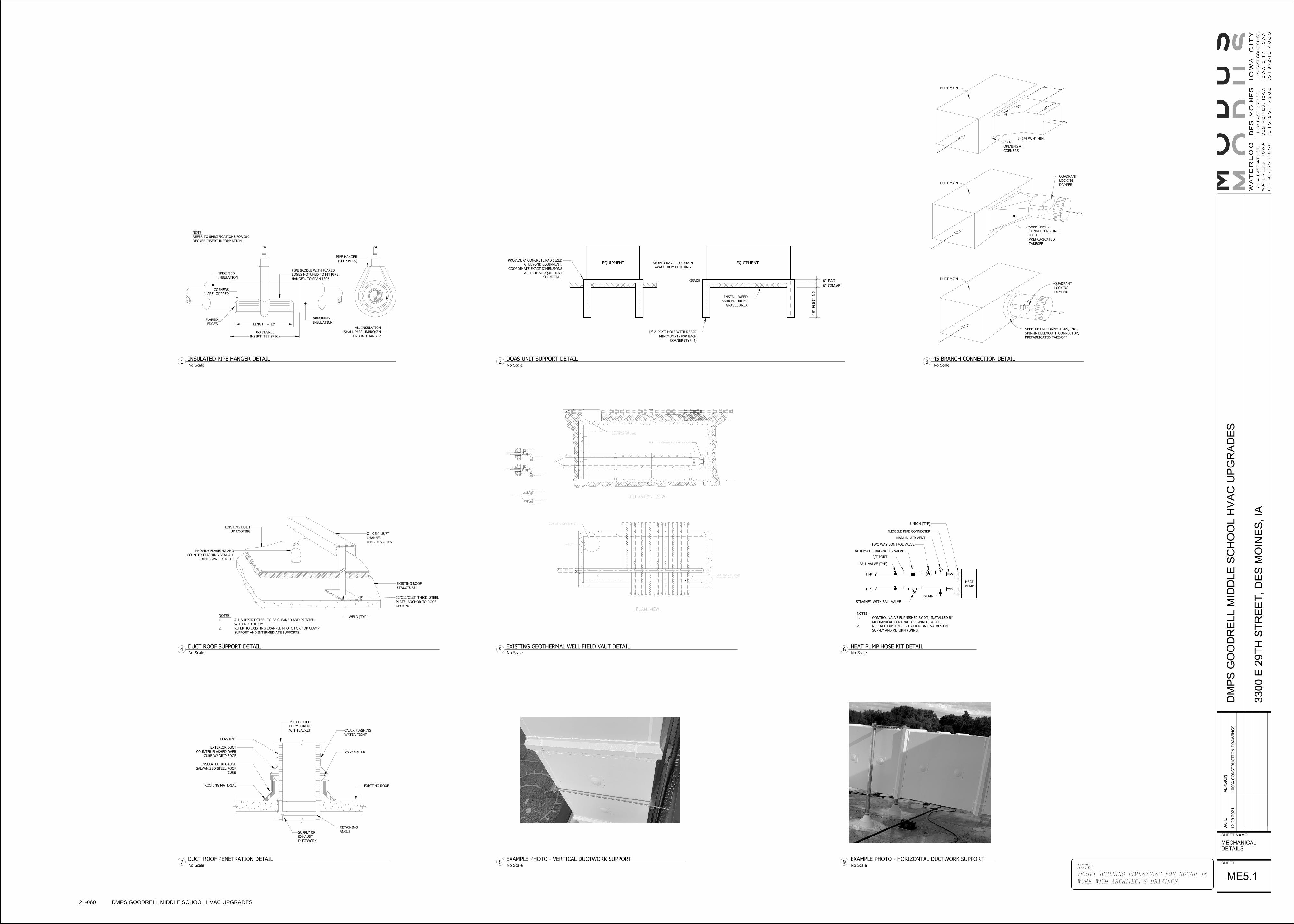
HPS
HPR
18"
LADDER
PENETRATION (TYP.)
ADJUST AS REQUIREDMANHOLE RINGS
PLAN VIEW
ELEVATION VIEW
6"
CAPPED FOR FUTURE USE2" HPS & HPR PIPES
VALVE OR EQUAL"TACO" ACCU-FLO BALANCING
FROM FUTURE WELL FIELD6" HPS HEADER PIPE TO BUILDING
2" RUNOUT
ISOLATION BALL VALVE
BUILDING TO FUTURE WELL FIELD6" HPR HEADER PIPE FROM
2" RUNOUT
HPSHPR
NORMALLY CLOSED BUTTERFLY VALVE
LADDER
HPR
HPS
WATER STOP
WATER PROOF SLEEVE
LINK SEAL
PIT WALL
WATER STOP
WATER PROOF SLEEVE
LINK SEAL
PIT WALL
MANHOLE COVER (24" ∅)
LINK-SEAL AT EACH
CL
LC
VALVE OR APPROVED EQUAL
CIRCUITSFROM VERTICAL
BALL VALVE WITH PLUGPURGING AND TEST
2" RUNOUT
6" HEADER PIPE
"TACO" ACCU-FLO BALANCING
ISOLATION BALL VALVE
2" RUNOUT
BALL VALVE WITH PLUGPURGING AND TEST
CIRCUITSTO VERTICAL
2"
2"
6" HEADER PIPE
P/TPORT
P/TPORT
SHEETMETAL CONNECTORS, INC.,
SPIN-IN BELLMOUTH CONNECTOR,
PREFABRICATED TAKE-OFF
DUCT MAIN
QUADRANT
LOCKING
DAMPER
SHEET METAL
CONNECTORS, INC
H.E.T.
PREFABRICATED
TAKEOFF
CLOSE
OPENING AT
CORNERS
QUADRANT
LOCKING
DAMPER
L=1/4 W, 4" MIN.
45°W
L
DUCT MAIN
DUCT MAIN
V
HPR
HPS
BALL VALVE (TYP)
P/T PORT
STRAINER WITH BALL VALVE
TWO WAY CONTROL VALVE
MANUAL AIR VENT
FLEXIBLE PIPE CONNECTER
UNION (TYP)
DRAIN
HEAT
PUMP
AUTOMATIC BALANCING VALVE
NOTES:
1. CONTROL VALVE FURNISHED BY JCI, INSTALLED BY
MECHANICAL CONTRACTOR, WIRED BY JCI.
2. REPLACE EXISTING ISOLATION BALL VALVES ON
SUPPLY AND RETURN PIPING.
SPECIFIED
INSULATION
PIPE SADDLE WITH FLARED
EDGES NOTCHED TO FIT PIPE
HANGER, TO SPAN 180°
PIPE HANGER
(SEE SPECS)
ALL INSULATION
SHALL PASS UNBROKEN
THROUGH HANGER
SPECIFIED
INSULATIONLENGTH = 12"
360 DEGREE
INSERT (SEE SPEC)
FLARED
EDGES
CORNERS
ARE CLIPPED
NOTE:
REFER TO SPECIFICATIONS FOR 360
DEGREE INSERT INFORMATION.
EQUIPMENT
6" PAD
EQUIPMENT
INSTALL WEED
BARRIER UNDER
GRAVEL AREA
PROVIDE 6" CONCRETE PAD SIZED
6" BEYOND EQUIPMENT.
COORDINATE EXACT DIMENSIONS
WITH FINAL EQUIPMENT
SUBMITTAL.
SLOPE GRAVEL TO DRAIN
AWAY FROM BUILDING
12"∅ POST HOLE WITH REBAR
MINIMUM (1) FOR EACH
CORNER (TYP. 4)
6" GRAVEL
48"
FO
OTIN
G
GRADE
C4 X 5.4 LB/FT
CHANNEL
LENGTH VARIES
EXISTING ROOF
STRUCTURE
12"X12"X1/2" THICK STEEL
PLATE. ANCHOR TO ROOF
DECKING
WELD (TYP.)
PROVIDE FLASHING AND
COUNTER FLASHING SEAL ALL
JOINTS WATERTIGHT.
EXISTING BUILT
UP ROOFING
NOTES:
1. ALL SUPPORT STEEL TO BE CLEANED AND PAINTED
WITH RUSTOLEUM.
2. REFER TO EXISTING EXAMPLE PHOTO FOR TOP CLAMP
SUPPORT AND INTERMEDIATE SUPPORTS.
2" EXTRUDED
POLYSTYRENE
WITH JACKET CAULK FLASHING
WATER TIGHT
2"X2" NAILER
EXISTING ROOF
RETAINING
ANGLESUPPLY OR
EXHAUST
DUCTWORK
ROOFING MATERIAL
INSULATED 18 GAUGE
GALVANIZED STEEL ROOF
CURB
EXTERIOR DUCT
COUNTER FLASHED OVER
CURB W/ DRIP EDGE
FLASHING
NOTE:
VERIFY BUILDING DIMENSIONS FOR ROUGH-IN
WORK WITH ARCHITECT'S DRAWINGS.
SHEET NAME:
SHEET:
DATE
VERSIO
N
12.2
8.2
021
100%
CO
NSTRU
CTIO
N D
RAW
ING
SD
MP
S G
OO
DR
EL
L M
IDD
LE
SC
HO
OL
HV
AC
UP
GR
AD
ES
330
0 E
29T
H S
TR
EE
T,
DE
S M
OIN
ES
, IA
MECHANICAL
DETAILS
ME5.1
21-060 DMPS GOODRELL MIDDLE SCHOOL HVAC UPGRADES
No Scale3
45 BRANCH CONNECTION DETAIL
No Scale6
HEAT PUMP HOSE KIT DETAIL
No Scale1
INSULATED PIPE HANGER DETAIL
No Scale5
EXISTING GEOTHERMAL WELL FIELD VAUT DETAIL
No Scale2
DOAS UNIT SUPPORT DETAIL
No Scale4
DUCT ROOF SUPPORT DETAIL
No Scale7
DUCT ROOF PENETRATION DETAILNo Scale
8EXAMPLE PHOTO - VERTICAL DUCTWORK SUPPORT
No Scale9
EXAMPLE PHOTO - HORIZONTAL DUCTWORK SUPPORT

NOTE:
VERIFY BUILDING DIMENSIONS FOR ROUGH-IN
WORK WITH ARCHITECT'S DRAWINGS.
SHEET NAME:
SHEET:
DATE
VERSIO
N
12.2
8.2
021
100%
CO
NSTRU
CTIO
N D
RAW
ING
SD
MP
S G
OO
DR
EL
L M
IDD
LE
SC
HO
OL
HV
AC
UP
GR
AD
ES
330
0 E
29T
H S
TR
EE
T,
DE
S M
OIN
ES
, IA
MECHANICAL
SCHEDULES
ME6.1
21-060 DMPS GOODRELL MIDDLE SCHOOL HVAC UPGRADES
GEOTHERMAL HEAT PUMP SCHEDULE
UNIT TAG MANUFACTURER MODEL TYPE AIRFLOW (CFM)
EXTERNALSTATIC
PRESSURE (INWC)
FLOW RATE(GPM)
FLUIDPRESSURE
DROP (FT H2O)
COOLING HEATING
EER COP FILTER
ELECTRICAL
EWT/LWT (F/F) EAT/LAT (F/F)NET CAPACITY
(MBH)SENSIBLE
CAPACITY (MBH) EWT/LWT (F/F) EAT/LAT (F/F)
TOTALCAPACITY
(MBH) MCA MOCPVOLTAGE/PHAS
E
HP-11 TRANE GEVE1204 VERTICAL 4,000 1.3 35 20.3 77/85 80.6/60 121.6 91 45/40.5 68/93 101.2 14.54 4.5 MERV 8 21.65 25 460/3
HP-12 TRANE GEVE3004 VERTICAL 10,000 1.4 56.5 8.9 77/91 80.6/60 303.1 227.6 45/37 68/95 266.7 13.9 4.3 MERV 8 54.35 70 460/3
HP-17 TRANE GEH0724 HORIZONTAL 2,300 0.5 9 4.1 77/99 80.6/57.5 75.9 58.2 45/35 68/92 60.1 13.4 4.8 MERV 8 14.85 20 460/3
DEDICATED OUTSIDE AIR SYSTEM SCHEDULE
UNIT TAG MANUFACTURER MODEL
SUPPLY FAN EXHAUST FAN DX COOLING COIL ELECTRIC PREHEAT COIL ELECTRIC HEATING COIL FILTERS ENERGY RECOVERY WHEEL
VO
LT
AG
E/P
HA
SE
MCA MOCP
MAXIMUM UNITWEIGHT WITH
CURB (LBS)AIR
FLO
W (
CF
M)
E
.S.P
. (I
N.
H2
0)
T
.S.P
.(I
N.
H2
0)
TO
TA
L M
OT
OR
HP
TO
TA
L M
OT
OR
B.H
.P.
FA
N R
PM
AIR
FLO
W (
CF
M)
E
.S.P
. (I
N.
H2
0)
T
.S.P
.(I
N.
H2
0)
TO
TA
L M
OT
OR
HP
TO
TA
L M
OT
OR
B.H
.P.
FA
N R
PM
FIN
S/IN
CH
CO
IL R
OW
S
N
ET
TO
TA
L C
AP
AC
IT
Y(M
BH
)
N
ET
SE
NS
IB
LE
CA
PA
CIT
Y(M
BH
)
E
.D.B
./E
.W.B
.(°F
/°F
)
L.D
.B./
L.W
.B.(
°F
/°F
)
L.D
.B./
L.W
.B.
(RE
HE
AT
)(°F
/°F
)
MR
C (
LB
/H
)
A
IR
P.D
.(I
N H
2O
)
CAPACITY(KW)
E.D.B./E.W.B.(°F/°F)
L.D.B.(°F)
AIR P.D.(IN H2O) C
AP
AC
IT
Y (
KW
)
E.D
.B.
(°F
)
L.D
.B.
(°F
)
AIR
P.D
. (I
N H
2O
)
FIL
TE
R M
ED
IA
TH
ICK
NE
SS
(IN
)
EFF
ICIE
NC
Y
SUMMER WINTER
O
A D
B/W
B(°
F/°F
)
R
A D
B/W
B(°
F/°F
)
EA
AIR
FLO
W (
CF
M)
S
A D
B/W
B(°
F/°F
)
S
NE
SIB
LE
EF
FE
CT
IV
EN
ES
S(%
)
O
A D
B/W
B(°
F)
R
A D
B/W
B(°
F)
EA
AIR
FLO
W (
CF
M)
S
A D
B/W
B(°
F)
S
EN
SIB
LE
EF
FE
CT
IV
EN
ES
S(%
)
DOAS-1 TRANE OABD108D4 1800 2.0 3.27 6 1.6 2401 1800 1.25 2.26 6 1.4 2298 12 4 90.9 54.3 80.6/68.4 51.2/51.1 77/61.31 56.05 0.16 5 -10/-10 -1.22 0.03 24 47 89.1 0.03 3 MERV 8 95/76 75/63 2221 80.6/68.4 0.72 -1.2/-2.3 68/52 19.5/19.4 47/37.3 0.73 460/3 64.5 70 2110
NOTES:
1. UNIT SHALL HAVE SINGLE POINT POWER.
2. PROVIDE UNIT WITH HORIZONTAL SUPPLY AND RETURN CONNECTIONS.
3. PROVIDE NECESSARY INTERNAL DAMPERS TO OPERATE UNIT IN RECIRCULATION MODE DURING UNOCCUPIED PERIODS TO CONTROL SPACE HUMIDITY. CONTROLS AND CONTROL SEQUENCE BY JCI PER SPECIFICATIONS.
4. SUPPLY AND EXHAUST FAN VFD'S SHALL BE FURNISHED BY FMS CONTRACTOR AND INSTALLED BY ELECTRICAL CONTRACTOR. VFD'S SHALL BE MOUNTED REMOTELY INSIDE A NEARBY MECHANICAL ROOM WHERE POSSIBLE.
5. PROVIDE DIGITAL SCROLL COMPRESSORS ON ALL CIRCUITS.
6. PROVIDE NON-FUSED DISCONNECT SWITCH WITH 115V OUTLET, WIRED BY ELECTRICAL CONTRACTOR FROM NEAREST PANEL.
7. PROVIDE CONDENSER HAILGUARD.
8. PROVIDE AIRFLOW MONITORING PIEZO RING.
9. PROVIDE 2" DOUBLE WALL CONSTRUCTION AND STAINLESS STEEL DRAIN PAN.
10. PROVIDE CURB.
NOTES:
1. MECHANICAL CONTRACTOR SHALL FIELD VERIFY EXISTING PIPING AND DUCTWORK CONFIGURATION OF HEAT PUMPS PRIOR TO SUBMITTING EQUIPMENT. ALL HEAT PUMPS SHALL MAINTAIN CITY OF DM CLEARANCE REQUIREMENTS.
2. EXISTING HEAT PUMPS ARE CURRENTLY PIPED BACKWARDS AND MUST BE REPIPED FOR PROPER OPERATION.
3. PROVIDE NEW HOSE KITS FOR ALL NEW AND EXISTING HEAT PUMPS.
4. PROVIDE (2) HP-11 UNITS SERVING GYMNASIUM.
5. PROVIDE (1) HP-12 UNIT SERVING AUDITORIUM.
6. PROVIDE (3) HP-17 UNITS SERVING CAFETERIA.
7. PROVIDE LOW TEMPERATURE HEAT PUMPS.
EXISTING HEAT PUMP SCHEDULE
UNIT TAG TYPE
AIRFLOW(CFM)
FLOW RATE(GPM) FLA VOLTAGE/PHASE
HP-3 VERTICAL 400 3.1 5.8 277/1
HP-4 VERTICAL 630 5.2 10.1 277/1
HP-5 VERTICAL 800 6.0 5.2 460/3
HP-6 VERTICAL 1000 7.2 6.2 460/3
HP-7 VERTICAL 1200 8.8 6.7 460/3
HP-8 VERTICAL 1400 10.7 8.6 460/3
HP-9 VERTICAL 1600 11.6 9.1 460/3
HP-10 VERTICAL 2000 14.8 11.0 460/3
HP-11 VERTICAL 4000 33 24.2 460/3
HP-12 VERTICAL 9670 56.5 47.3 460/3
HP-13 HORIZONTAL 400 3.1 5.8 277/1
HP-14 HORIZONTAL 800 6 5.2 460/3
HP-15 HORIZONTAL 1000 7.2 6.2 460/3
HP-16 HORIZONTAL 1600 11.6 9.1 460/3
HP-17 HORIZONTAL 2300 17.4 13.0 460/3
VHP-1 HORIZONTAL 1200 8.0 6.7 460/3
VHP-2 HORIZONTAL 400 3.5 5.8 277/1
VHP-3 HORIZONTAL 400 3.5 5.8 277/1
VHP-4 HORIZONTAL 2000 14.8 11.5 460/3
VHP-5 HORIZONTAL 1200 8.0 6.7 460/3

MECHANICAL ENGINEER
HOLLY [email protected]
515-412-5308
ELECTRICAL ENGINEER
HARRY DOYLE
J
J
RX
DOOR CONTACT
PROXIMITY CARD READER
MULLION MOUNT CARD READER
KEYPAD
PUSHBUTTON (REQUEST TO EXIT)
PANIC/DURESS BUTTON
STAFF CONSOLE
DOME LIGHT - WALL MOUNT
DOME LIGHT - CEILING MOUNT
SUB-STATION STATION
PATIENT CALL STATION
STAFF STATION
NURSE PRESENCE LOCATOR
ELECTRICAL SYMBOLS LISTWIRING DEVICES
NOTE: NOT ALL SYMBOLS SHOWN MAY BE REQUIRED FOR THIS PROJECT
LUMINAIRES
EXIT & EMERGENCY
COMMUNICATIONS SYSTEMS
MISCELLANEOUS
SWITCH-LEG IN CONDUIT
EMPTY CONDUIT
ABOVE FINISHED FLOORAFF
POINT OF NEW CONNECTION
WEATHERPROOFWP
UNDER GROUND CONDUITUC
EC
CONDUIT
EQUIPMENT WIRING
WEATHERPROOF DISCONNECTING MEANS
MS
FUSED DISCONNECTING MEANS
MOTOR STARTER SWITCH WITH RED RUN PILOT LIGHT
DISCONNECTING MEANS
WP
DISTRIBUTION
DEVICE ON WIREMOLDWMF
WG WIRE GUARD
NURSE CALL
ACCESS CONTROL
VARIABLE FREQUENCY DRIVE W/INTEGRAL DISCONNECT
GFI
WPGFI
ABOVE FINISH GRADEAFG
FIRE STOP[FS]
EZ PASS-THROUGH
H
F
T
EXISTING - TO BE REMOVED
EXISTING - TO BE RELOCATED
EXISTING - TO REMAIN
DUPLEX WALL RECEPTACLE
DUPLEX WALL RECEPTACLE ABOVE COUNTER BACKSPLASH OR AS INDICATED
DUPLEX GROUND FAULT CIRCUIT INTERRUPTER RECEPTACLE
DUPLEX WEATHERPROOF GROUND FAULT CIRCUIT INTERRUPTER RECEPTACLE WITH COVER
QUADRUPLEX RECEPTACLE
QUADRUPLEX RECEPTACLE ABOVE COUNTER BACKSPLASH OR AS INDICATED
DUPLEX CEILING RECEPTACLE
JUNCTION BOX
WIREMOLD/PLUGMOLD W/ENTRANCE FITTING AS SPECIFIED AND
RECEPTACLES & DEVICES AS INDICATED
2'x4' RECESSED TROFFER FIXTURE W/TYPE NUMBER
1'x4' RECESSED TROFFER FIXTURE W/TYPE NUMBER
INGROUND FIXTURE W/TYPE NUMBER
SURFACE MOUNT FIXTURE W/TYPE NUMBER
GROUND MOUNT FLOOD LIGHT FIXTURE W/TYPE NUMBER
SINGLE FACE CEILING MOUNTED EXIT SIGN
W/ILLUMINATED FACE AND DIRECTION
DOUBLE FACE CEILING MOUNTED EXIT SIGN
W/ILLUMINATED FACE(S) AND DIRECTION INDICATED
WALL MOUNTED EXIT SIGN W/DIRECTION INDICATED
EDGE MOUNTED EXIT SIGN W/ILLUMINATED FACE(S)
AND DIRECTION INDICATED
TELEPHONE OUTLET IN WALL
TELEPHONE OUTLET ABOVE COUNTER BACKSPLASH
TELEPHONE OUTLET FOR WALL MOUNTED TELEPHONE
DATA OUTLET IN CEILING
DATA OUTLET ABOVE COUNTER BACKSPLASH
COMBINATION PHONE/DATA OUTLET IN WALL
COMBINATION PHONE/DATA OUTLET ABOVE COUNTER
TELEVISION OUTLET IN WALL
TELEVISION OUTLET IN CEILING
WALL HORN INDICATOR
CEILING SPEAKER
INTERCOM PUSH BUTTON
AUDIO VISUAL OUTLET IN WALL
AUDIO VISUAL OUTLET IN FLOOR
CLOCK LOCATION
CLOCK LOCATION - DOUBLE FACEADA PUSH BUTTON (BY OTHERS)
ROUND CEILING MOUNT EMERGENCY LIGHT FIXTURE
W/ TYPE AND CIRCUIT INDICATED ON PLANS
(FULL SHADE)
RECTANGULAR CEILING MOUNT EMERGENCY LIGHT
FIXTURE W/ TYPE AND CIRCUIT INDICATED ON PLANS
(FULL SHADE)
SURFACE-MOUNT PANEL
FLUSH-MOUNT PANEL
C/T CABINET
METER
WIRELESS ACCESS POINT
DUPLEX WALL RECEPTACLE FOR 208V, VERIFY POWER NEEDS
HAND DRYER (BY OTHERS)
AUTOMATIC FAUCET/VALVE
REQUEST TO EXIT (WALL OR CEILING MOUNTED)
EMERGENCY BATTERY PACK
TREE UPLIGHT FIXTURE W/TYPE NUMBER
DUPLEX TAMPER-RESISTANT RECEPTACLE
VFD
C
CDF
W
DC
CR
CM
KP
PB
S
S
IC
AV
AV
WAP
DB
ER
EXR
EX
DATA OUTLET IN WALL W/ # OF JACKS#
2'x2' RECESSED TROFFER FIXTURE W/TYPE NUMBER
2'x4' SURFACE MOUNT TROFFER FIXTURE W/TYPE NUMBER
RECESSED LINEAR FIXTURE W/TYPE NUMBER
SURFACE MOUNT LINEAR FIXTURE W/TYPE NUMBER
WALL MOUNT LINEAR FIXTURE W/TYPE NUMBER
SURFACE/CEILING MOUNT STRIP FIXTURE W/TYPE NUMBER
SUSPENDED MOUNT STRIP FIXTURE W/TYPE NUMBER
COVE LIGHT FIXTURE W/TYPE NUMBER
RECESSED DOWNLIGHT FIXTURE W/TYPE NUMBER
PENDANT MOUNT FIXTURE W/TYPE NUMBER
WALL MOUNT FIXTURE W/TYPE NUMBER
TRACK MOUNT FIXTURE W/TYPE NUMBER
POLE MOUNT FIXTURE W/TYPE NUMBER
SECURITY CAMERA
U DUPLEX RECEPTACLE WITH USB CHARGER PORT
TRANSFORMER
FIRE ALARM & DETECTION
DUCT SMOKE DETECTOR
SMOKE DETECTOR - CEILING MOUNTED
F
HEAT DETECTOR - RATE OF RISE
HEAT DETECTOR - FIXED TEMPERATURE
FIRE ALARM PULL STATION
FIRE ALARM HORN/STROBE - WALL MOUNTED
R
F
FIRE ALARM STROBE LIGHT - WALL MOUNTED
R
DH
FIRE ALARM RELAY
FIRE ALARM HOLD OPEN CONNECTION
FIRE/SMOKE DAMPER CONNECTIONFSD
FIRE ALARM STROBE LIGHT - CEILING MOUNTED
FIRE ALARM SPEAKER/STROBE - CEILING MOUNTEDC
FACP
FAAP
FIRE ALARM CONTROL PANEL
FIRE ALARM ANNUNCIATOR PANEL
FIRE ALARM HORN/STROBE - CEILING MOUNTEDC
FIRE ALARM SPEAKER/STROBE - WALL MOUNTED
FIRE ALARM SPEAKER - WALL MOUNTEDs
s FIRE ALARM SPEAKER - CEILING MOUNTEDC
2'x2' SURFACE MOUNT TROFFER FIXTURE W/TYPE NUMBER
H DUPLEX RECEPTACLE INSTALLED HORIZONTALLY
ECB EMERGENCY CONTROL BOX
M
SMOKE DETECTOR WITH SOUNDER BASE
COMBINATION SMOKE/CO DETECTORCO
S
E DUPLEX RECEPTACLE ON BACKUP POWER
#
VEM VOICE EVACUATION AND MESSAGING
#
#
EMERGENCY PUSH BUTTON (GENERATORS/BOILERS)EPO
FLEXIBLE DUCT CONNECTOR
A
CONED TAKEOFF WITH DAMPER
AUTOMATIC MOTORIZED CONTROL DAMPER
SQUARE CEILING DIFFUSER WITH ROUND NECK
SQUARE CEILING RETURN AIR GRILLE
SQUARE CEILING EXHAUST OR RELIEF AIR GRILLE
LINEAR SLOT DIFFUSER
FLOOR REGISTER OR GRILLE
SIDEWALL REGISTER OR GRILLE
FLEX DUCT WITH SIZE
DUCT SIZE: HORIZONTAL WIDTH x VERTICAL HEIGHT
(NET OUTSIDE SHEET METAL DIMENSION)
RECTANGULAR ELBOW WITH TURNING VANES
DIRECTIONAL FLOW ARROW
???
HORIZONTAL DAMPER
FSD = FIRE/SMOKE DAMPER, FD = FIRE DAMPER, SD = SMOKE DAMPER
CD = CONTROL DAMPER
SUPPLY AIR DUCT SECTION UP OR TOWARDS
RETURN AIR DUCT SECTION UP OR TOWARDS
EXHAUST AIR DUCT SECTION UP OR TOWARDS
OUTSIDE AIR DUCT SECTION UP OR TOWARDS
SUPPLY AIR DUCT SECTION DOWN OR AWAY
RETURN AIR DUCT SECTION DOWN OR AWAY
EXHAUST AIR DUCT SECTION DOWN OR AWAY
OUTSIDE AIR DUCT SECTION DOWN OR AWAY
GRILLE/DIFFUSER TAG WITH TYPE NUMBER AND CFM QUANTITY
S = SUPPLY, R = RETURN, E = EXHAUST
VARIABLE AIR VOLUME (VAV) BOX WITH TYPE NUMBER
VAV ?
EXISTING DUCTWORK TO BE REMOVED
EXISTING DUCTWORK TO REMAIN
THERMOSTAT
HUMIDISTAT
ECCENTRIC DUCT REDUCER
CONCENTRIC DUCT REDUCER
VOLUME CONTROL DAMPER
MECHANICAL SYMBOLS LISTNOTE: NOT ALL SYMBOLS SHOWN MAY BE REQUIRED FOR THIS PROJECT
SHEET METAL
EX
FS
THERMOMETER
TEMPERATURE WELL
HOSE BIBB
BALANCING VALVE
TRIPLE DUTY VALVE
SPR
3WAY CONTROL VALVE
CALIBRATED BALANCE VALVE
2WAY CONTROL VALVE
SWING CHECK VALVE
BALL VALVE
BUTTERFLY VALVE
AIR VENT
STRAINER W/DRAIN VALVE
PRESSURE GAUGE
V
FLEXIBLE PIPE CONNECTOR
STRAINER
PIPE CAP
BACKFLOW PREVENTERBFP
PIPE RISER
PIPE DROP
UNION
HB
DSPR
SPRINKLER LINE
DRY TYPE SPRINKLER LINE
DRY SPRINKLER HEAD
WET SPRINKLER HEAD
FIRE HYDRANT
SIDE MOUNT SPRINKLER HEAD
FIRE DEPARTMENT CONNECTION
FLOW SWITCH
TS SPRINKLER LINE TAMPER SWITCH
EXISTING LINE TO REMAIN
EXISTING LINE TO BE REMOVED
POINT OF NEW CONNECTION
ER
EXR
EXISTING TO REMAIN
EXISTING TO BE REMOVED
EXISTING TO BE RELOCATED
PLUMBING
PIPING SPECIALTIES
FIRE EXTINGUISHING SYSTEM
MISCELLANEOUS
GRILLE/DIFFUSER TAG WITH TYPE NUMBER AND CFM QUANTITY
S = SUPPLY, R = RETURN, E = EXHAUST
T
H
-
-
-
-
-
P/T PORT
CDR
CWS
CDS
CWR
HWR
PC
HWS
LPS
MPR
LPR
MPS
HPR
HPS
DOMESTIC COLD WATER LINE - CW
DOMESTIC HOT WATER LINE - HW
PD
LP
V
ST
AW
SW
SW
TW
DOMESTIC HOT WATER CIRCULATING LINE - HWC
TEMPERED WATER LINE
SOFT COLD WATER LINE
SOFT HOT WATER LINE
SANITARY SEWER LINE
ACID WASTE LINE BELOW FLOOR SLAB
STORM SEWER LINE
OFD STORM SEWER OVERFLOW LINE
PLUMBING VENT LINE
AV ACID PLUMBING VENT LINE
CD CONDENSATE DRAIN LINE
G NATURAL GAS LINE
LIQUEFIED PETROLEUM GAS LINE
RL
RS
REFRIGERANT LIQUID LINE
REFRIGERANT SUCTION LINE
HG REFRIGERANT HOT GAS BYPASS LINE
PUMPED DISCHARGE LINE
CLEANOUT IN FLOORC.O.
C.O. CLEANOUT AT OR ABOVE CEILING
CLEANOUT IN WALLC.O.
SHOWERHEAD
FLOOR DRAIN
ROOF DRAIN
HYDRONIC PIPINGHIGH PRESSURE STEAM SUPPLY LINE (51-125 PSIG)
HIGH PRESSURE CONDENSATE RETURN LINE
MEDIUM PRESSURE STEAM SUPPLY LINE (16-50 PSIG)
MEDIUM PRESSURE CONDENSATE RETURN LINE
LOW PRESSURE STEAM SUPPLY LINE (0-15 PSIG)
LOW PRESSURE CONDENSATE RETURN LINE
PUMPED CONDENSATE RETURN LINE
HEATING HOT WATER SUPPLY LINE
HEATING HOT WATER RETURN LINE
CHILLED WATER SUPPLY LINE
CHILLED WATER RETURN LINE
CONDENSER WATER SUPPLY LINE
CONDENSER WATER RETURN LINE
CTB COOLING TOWER BLOWDOWN LINE
SS
LUBRICATED PLUG VALVE
WALL HYDRANTWH
GATE VALVE
FD
8∅
18x12
GREASE SANITARY SEWER LINE GSS
NOTE:
VERIFY BUILDING DIMENSIONS FOR ROUGH-IN
WORK WITH ARCHITECT'S DRAWINGS.
SHEET NAME:
SHEET:
DATE
VERSIO
N
12.2
8.2
021
100%
CO
NSTRU
CTIO
N D
RAW
ING
SD
MP
S S
TO
WE
ELE
ME
NT
AR
Y H
VA
C I
MP
RO
VE
ME
NT
S
141
1 E
33R
D S
TR
EE
T,
DE
S M
OIN
ES
, IA
SYMBOLS SHEET
C1.0
20-061 DMPS STOWE ELEMENTARY HVAC IMPROVEMENTS
SHEET INDEX
C1.0 SYMBOLS SHEET
S2.1 STRUCTURAL ROOF PLAN
ME1.0 SITE PLAN
ME1.1A LEVEL 1 PLAN - AREA A
ME1.1B LEVEL 1 PLAN - AREA B
ME1.2A LEVEL 2 PLAN - AREA A
ME1.2B LEVEL 2 PLAN - AREA B
ME1.3B LEVEL 3 PLAN - AREA B
ME2.1 ROOF PLAN
M2.0B LEVEL 0 MECHANICAL PIPING PLAN
M2.1A LEVEL 1 MECHANICAL PIPING PLAN - AREA A
M2.1B LEVEL 1 MECHANICAL PIPING PLAN - AREA B
M2.2A LEVEL 2 MECHANICAL PIPING PLAN - AREA A
M2.2B LEVEL 2 MECHANICAL PIPING PLAN - AREA B
M2.3B LEVEL 3 MECHANICAL PIPING PLAN - AREA B
M5.1 MECHANICAL DETAILS AND SCHEDULES
1411 E 33RD ST - DES MOINES, IA
STOWE ELEMENTARY HVAC IMPROVEMENTS
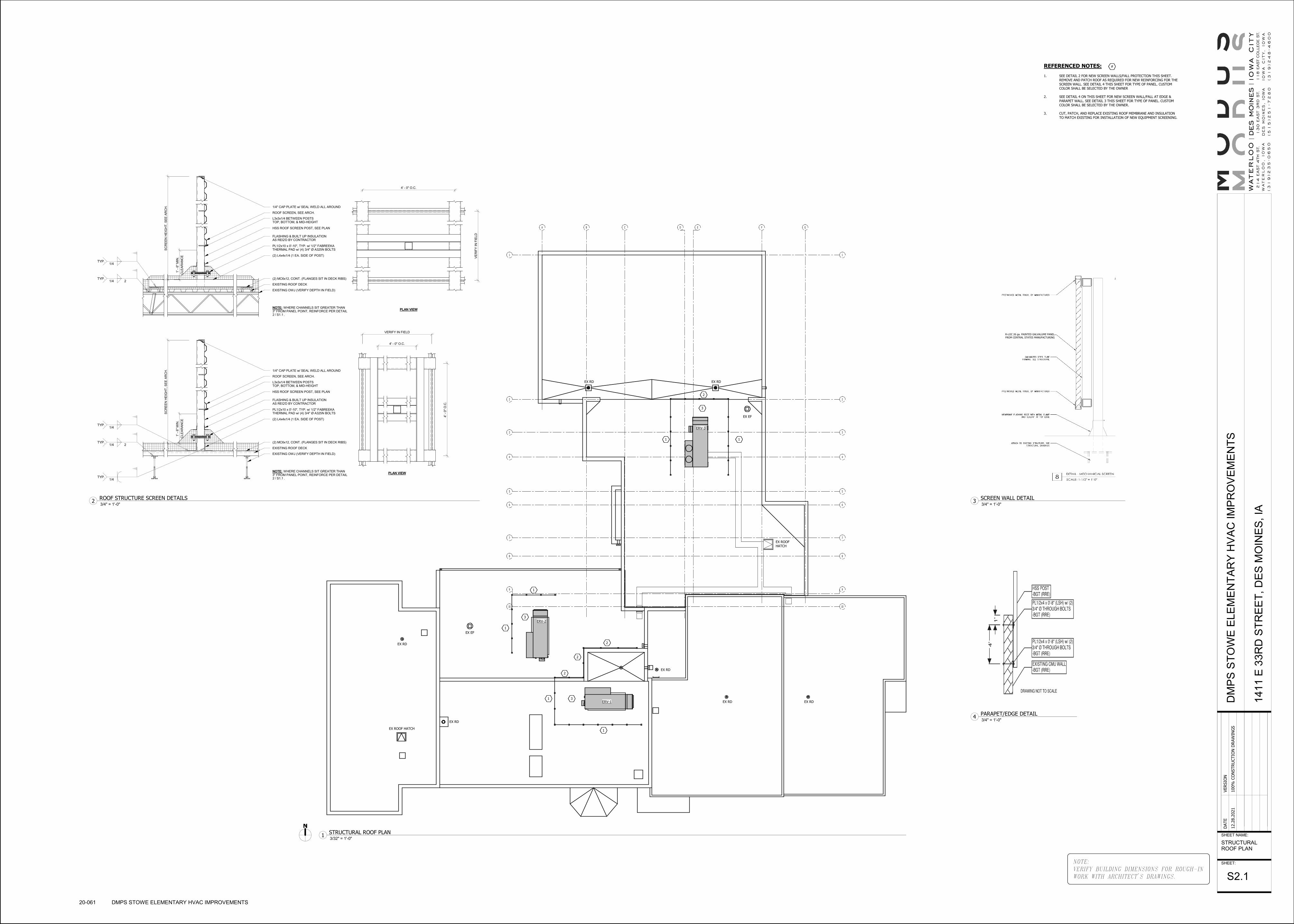
A B E F G
1
2
3
4
5
6
7
C D
8
9
10
1
2
3
4
5
6
7
9
10
8
RD RD
/
EXISTING ROOF DECK
(2) MC6x12, CONT. (FLANGES SIT IN DECK RIBS)
PL1/2x10 x 0'-10", TYP. w/ 1/2" FABREEKATHERMAL PAD w/ (4) 3/4" Ø A325N BOLTS
FLASHING & BUILT UP INSULATIONAS REQ'D BY CONTRACTOR
HSS ROOF SCREEN POST, SEE PLAN
1/4" CAP PLATE w/ SEAL WELD ALL AROUND
ROOF SCREEN, SEE ARCH.
L3x3x1/4 BETWEEN POSTSTOP, BOTTOM, & MID-HEIGHT
EXISTING OWJ (VERIFY DEPTH IN FIELD)
(2) L4x4x1/4 (1 EA. SIDE OF POST)
PLAN VIEWNOTE: WHERE CHANNELS SIT GREATER THAN3" FROM PANEL POINT, REINFORCE PER DETAIL .2 S1.11/4
TYP.
1/4 2TYP.
1/4TYP.
SC
RE
EN
HE
IGH
T, S
EE
AR
CH
.
CLE
AR
AN
CE
1' -
6"
MIN
.
4' - 0" O.C.
4' -
0"
O.C
.
VERIFY IN FIELD
/
EXISTING ROOF DECK
(2) MC6x12, CONT. (FLANGES SIT IN DECK RIBS)
PL1/2x10 x 0'-10", TYP. w/ 1/2" FABREEKATHERMAL PAD w/ (4) 3/4" Ø A325N BOLTS
FLASHING & BUILT UP INSULATIONAS REQ'D BY CONTRACTOR
HSS ROOF SCREEN POST, SEE PLAN
1/4" CAP PLATE w/ SEAL WELD ALL AROUND
ROOF SCREEN, SEE ARCH.
L3x3x1/4 BETWEEN POSTSTOP, BOTTOM, & MID-HEIGHT
EXISTING OWJ (VERIFY DEPTH IN FIELD)
(2) L4x4x1/4 (1 EA. SIDE OF POST)
PLAN VIEWNOTE: WHERE CHANNELS SIT GREATER THAN3" FROM PANEL POINT, REINFORCE PER DETAIL .2 S1.1
1/4 2TYP.
1/4TYP.
SC
RE
EN
HE
IGH
T, S
EE
AR
CH
.
CLE
AR
AN
CE
1' -
6"
MIN
.
4' - 0" O.C.
VE
RIF
Y IN
FIE
LD
ERV-1
ERV-2
ERV-3
EX ROOF HATCH
EX ROOF
HATCH
EX RDEX RD
EX EF
EX RD
EX RD EX RD
EX RD
EX RD
EX EF
1
1
2
2
2
1
2
1
1
1 3
3
3
REFERENCED NOTES:
1. SEE DETAIL 2 FOR NEW SCREEN WALLS/FALL PROTECTION THIS SHEET. REMOVE AND PATCH ROOF AS REQUIRED FOR NEW REINFORCING FOR THE
SCREEN WALL. SEE DETAIL 4 THIS SHEET FOR TYPE OF PANEL. CUSTOM COLOR SHALL BE SELECTED BY THE OWNER
2. SEE DETAIL 4 ON THIS SHEET FOR NEW SCREEN WALL/FALL AT EDGE &
PARAPET WALL. SEE DETAIL 3 THIS SHEET FOR TYPE OF PANEL. CUSTOM COLOR SHALL BE SELECTED BY THE OWNER.
3. CUT, PATCH, AND REPLACE EXISTING ROOF MEMBRANE AND INSULATION
TO MATCH EXISTING FOR INSTALLATION OF NEW EQUIPMENT SCREENING.
#
R-LOC 26 ga. PAINTED GALVALUME PANEL
FROM CENTRAL STATES MANUFACTURING
NOTE:
VERIFY BUILDING DIMENSIONS FOR ROUGH-IN
WORK WITH ARCHITECT'S DRAWINGS.
SHEET NAME:
SHEET:
DATE
VERSIO
N
12.2
8.2
021
100%
CO
NSTRU
CTIO
N D
RAW
ING
SD
MP
S S
TO
WE
ELE
ME
NT
AR
Y H
VA
C I
MP
RO
VE
ME
NT
S
141
1 E
33R
D S
TR
EE
T,
DE
S M
OIN
ES
, IA
STRUCTURALROOF PLAN
S2.1
20-061 DMPS STOWE ELEMENTARY HVAC IMPROVEMENTS
3/32" = 1'-0"1
STRUCTURAL ROOF PLAN
3/4" = 1'-0"2
ROOF STRUCTURE SCREEN DETAILS
3/4" = 1'-0"4
PARAPET/EDGE DETAIL
3/4" = 1'-0"3
SCREEN WALL DETAIL

TRASH
DUMPSTER
UGE
STOWE(EXISTING 3-STORY BLDG)
ELEMENTARY
T&O/E
U/E
NEW 6' WALK
NEW
6' W
ALK
NEW 6' WALK
C
4"EX.W
4"EX. co
S4"
S 4"
S
S
EM
WV
WV
DYH
D
D
D
co
CO
S
S
S
A
BB
A
G,WP
T &
O/E
U/TU/T
U/E
T
TO MAINSWITCHBOARD
UGE
FUTURESIGN
4'-0
"
6'-0"
UGE
SEE E121A FORCONTINUATION
LA-13
H2B-5
15
9
6
13
1
T
VERTICAL BORE FIELD
4" HPS/R
REMOVE EXISTINGUNDERGROUND
STORM SEWER ANDCAP AT MAIN
15'-0
"
15'-0"
1
1
REFERENCED NOTES:
1. INSPECT GEOTHERMAL VAULT INCLUDING SEAL, LIGHTS, VALVES, AND
SUMP PUMP. PROVIDE REPORT OF FINDINGS. PRESSURE TEST GOEHTERMAL
SYSTEM INCLUDING BUILDING LOOP AND GEOTHERMAL FIELD. FILL,
PACIFY, TEST, AND CHEMICALLY TREAT GEOTHERMAL SYSTEM AFTER
PRESSURE TEST. REFER TO SPECIFICATION SECTION 23 2500.
#
NOTE:
VERIFY BUILDING DIMENSIONS FOR ROUGH-IN
WORK WITH ARCHITECT'S DRAWINGS.
SHEET NAME:
SHEET:
DATE
VERSIO
N
12.2
8.2
021
100%
CO
NSTRU
CTIO
N D
RAW
ING
SD
MP
S S
TO
WE
ELE
ME
NT
AR
Y H
VA
C I
MP
RO
VE
ME
NT
S
141
1 E
33R
D S
TR
EE
T,
DE
S M
OIN
ES
, IA
SITE PLAN
ME1.0
20-061 DMPS STOWE ELEMENTARY HVAC IMPROVEMENTS

W-D
88
D
10
9
7
6
5
4
3
2
1
B GFECA
10
9
7
6
5
4
3
2
1
TOILETVESTIBULE
106
GIRL'S TOILET
107
BOY'S TOILET
108
GYMNASIUM
110
OUTDOORSTORAGE
150
STORAGE
113
JANITOR
109
P.E. OFFICE
111STORAGE
112
WORK ROOM
105
TOILET
104
NURSE
103 CONFERENCE
102
OFFICE
101
RECEPTION
100
VESTIBULE
149
LOBBY
141
S
S
S
S
S
S
S
EX S.D.
S.D.
S.D.
S.D.
S.D.
S.D.
M
M
M
M
M
M
600
510
180
180
90
180
60
60
60
60
180
EX 14/8 UP
6/6
6/6
10/6
10/6
6/6
6/6
6/6
10/6
10/6
6/6
12/6
12/8
14/8
14/8
6/6
12/6
14/8
14/8
315315315
265
230230
200
200
215
215
230
200
125
125
280330
14/1020/1224/12
14/8
18/10
14/10
10/6
14/10
10/8
14/8
16/10
18/12
20/12
12/6
18/10
18/10
24/16
60
1900
1070
400
460
200
430
12/8
230 10/8
10/8280
HP-7
EX 4" DRYER VENT UP∅EX 4" DRYER VENT DN∅
265
265
265
S
S
S
S
S
S
4
EX PANEL H1B
EX HP-2
EX HP-2
EX HP-3
EX HP-4
EX CUH
EX CUH
EX CUH
1
GENERAL NOTES:
A. LAYOUT AND ROUTING SHOWN IS DIAGRAMMATIC AND SCHEMATIC IN NATURE. NOT ALL OFFSETS MAY BE SHOWN. CONTRACTOR SHALL VERIFY
EXACT ROUTING REQUIRED AND NUMBER OF OFFSETS AND TRANSITIONS.
B. MAINTAIN SERVICE CLEARANCE IN FRONT OF AND ABOVE ELECTRICAL EQUIPMENT AND ACCESS. DO NOT INSTALL EQUIPMENT OR ROUTE DUCTS IN
CLEARANCE SPACE. REFER TO EQUIPMENT INSTALLATION AND INSTRUCTIONS.
C. COORDINATE THERMOSTAT LOCATIONS WITH CASEWORK, WALL TYPES, AND
FURNISHINGS PRIOR TO ROUGH-IN.
D. PROVIDE VOLUME CONTROL BALANCING DAMPERS ON ALL SUPPLY, RETURN, EXHAUST AIR TAPS IN ACCESSIBLE LOCATIONS FOR AIR BALANCING. INSTALL
CABLE OPERATED DAMPER OR ACCESS PANEL IF DAMPER IS LOCATED ABOVE GYP CEILINGS.
E. COORDINATE DUCT ROUTING WITH STRUCTURAL AND ALL TRADES.
F. COORDINATE ALL EXPOSED DUCTWORK ROUTING WITH DESIGN TEAM PRIOR TO ROUGH-IN.
G. COORDINATE SUPPLY, RETURN, AND EXHAUST GRILLE/DIFFUSER LOCATIONS WITH ARCHITECTURAL REFLECTED CEILING PLAN AND ALL TRADES.
H. COORDINATE DUCT ROUTING IN LOCATIONS WITH EXISTING CONDITIONS.
FIELD VERIFY EXISTING CONDITIONS PRIOR TO ROUGH-IN.
REFERENCED NOTES:
1. REBALANCE NEW ERV SUPPLY AND RETURN AIRFLOW TO MATCH NEW
AIRFLOWS NOTED.
#
NOTE:
VERIFY BUILDING DIMENSIONS FOR ROUGH-IN
WORK WITH ARCHITECT'S DRAWINGS.
SHEET NAME:
SHEET:
DATE
VERSIO
N
12.2
8.2
021
100%
CO
NSTRU
CTIO
N D
RAW
ING
SD
MP
S S
TO
WE
ELE
ME
NT
AR
Y H
VA
C I
MP
RO
VE
ME
NT
S
141
1 E
33R
D S
TR
EE
T,
DE
S M
OIN
ES
, IA
LEVEL 1 PLAN -AREA A
ME1.1A
20-061 DMPS STOWE ELEMENTARY HVAC IMPROVEMENTS
1/8" = 1'-0"1
LEVEL 1 PLAN - AREA A

4E
3E
2E
1E
EEDECEBEAE
PAPER TOWEL DISPENSER
LIQUID SOAP DISPENSER
WALL-HUNG SINK
10
9
10
9
T
TT
T
T
T
T
T
U P
U P
CLOSET
134
TOILET
120
STORAGE
148
TOILET
118
TOILET
122
WORK ROOM
127
TOILET
129
BOYSTOILET
130
GIRLSTOILET
135
HALL
140
STAFF
136
STORAGE
138
STAIR
139
S.L.P.
133
HALL
131
GUIDANCE
132
MENTALDISABILITIES
128
LIBRARY
126
VESTIBULE
144
PRE-KINDERGARTEN
123 KINDERGARTEN
121
VESTIBULE
143
KINDERGARTEN
119KINDERGARTEN
117
STAIR
146
STAIR
145
HALL
142
ELEVATOR
147OFFICE
116
151
TOILET
137
TOILET
124
TOILET
125
NURSE
103 CONFERENCE
102
KITCHEN
115
CAFETERIA
114
S
S
S S
S
S
S
S
S
S
S
S
S
S
SEX S.D.
EX S.D.
M
M
2240
14501305
675
300235
300
235
300235300235
125
125
300
375225
460
300 235
680
90
14/10
60
125
180
180
8001500
500
16/1016/1020/1020/10
14/814/1020/10 14/814/8
20/10 20/10
10/6
12/6
6/6
6/6
6/6
6/6
12/8
6/6
12/8
12/6
12/6
16/8
10/6
14/812/6
10/6
6/6
12/6
12/6
10/6
6/6
6/6
10/612/6
8/6
14/6
14/8 250250
26/1026/10
36/1
0
36/1
036
/14
12/8
180
100
250
250
250
315
315
315315315
315
230230
200
14/8
16/10
18/10
14/1020/1224/12
14/10
18/12
20/12
18/10 12/6
20/10
24/16
16/12
EX 16x16 UP TO
EX EF-1 ON
ROOF
20/10
22/10
90
90
75
60
20/10
10/6
EX 6/6 DN
860
1900
860
1070460
6/612/6
6/6
UPUP
90
90
EX KEH-1
90
36/1
4
445
10x10
E1
EX PANEL H1A
EX HP-4
EX HP-1 EX HP-1 EX HP-1 EX HP-1
EX HP-1
EX HP-1
EX HP-1 EX HP-1 EX HP-1 EX HP-1
EX HP-1
EX HP-8
EX HP-3
EX HP-3
EX HP-1
EX HP-1
EX CUH
EX CUH
EX
EX CUHEX
EX HP-1 EX HP-1 EX HP-1
1
UP TO ERV-2
ON ROOF
ERV-2 CONTROL
PANEL
2
GENERAL NOTES:
A. LAYOUT AND ROUTING SHOWN IS DIAGRAMMATIC AND SCHEMATIC IN NATURE. NOT ALL OFFSETS MAY BE SHOWN. CONTRACTOR SHALL VERIFY
EXACT ROUTING REQUIRED AND NUMBER OF OFFSETS AND TRANSITIONS.
B. MAINTAIN SERVICE CLEARANCE IN FRONT OF AND ABOVE ELECTRICAL EQUIPMENT AND ACCESS. DO NOT INSTALL EQUIPMENT OR ROUTE DUCTS IN
CLEARANCE SPACE. REFER TO EQUIPMENT INSTALLATION AND INSTRUCTIONS.
C. COORDINATE THERMOSTAT LOCATIONS WITH CASEWORK, WALL TYPES, AND
FURNISHINGS PRIOR TO ROUGH-IN.
D. PROVIDE VOLUME CONTROL BALANCING DAMPERS ON ALL SUPPLY, RETURN, EXHAUST AIR TAPS IN ACCESSIBLE LOCATIONS FOR AIR BALANCING. INSTALL
CABLE OPERATED DAMPER OR ACCESS PANEL IF DAMPER IS LOCATED ABOVE GYP CEILINGS.
E. COORDINATE DUCT ROUTING WITH STRUCTURAL AND ALL TRADES.
F. COORDINATE ALL EXPOSED DUCTWORK ROUTING WITH DESIGN TEAM PRIOR TO ROUGH-IN.
G. COORDINATE SUPPLY, RETURN, AND EXHAUST GRILLE/DIFFUSER LOCATIONS WITH ARCHITECTURAL REFLECTED CEILING PLAN AND ALL TRADES.
H. COORDINATE DUCT ROUTING IN LOCATIONS WITH EXISTING CONDITIONS.
FIELD VERIFY EXISTING CONDITIONS PRIOR TO ROUGH-IN.
REFERENCED NOTES:
1. REMOVE AND REPLACE EXISTING ENERGY RECOVERY UNIT ON ROOF. DISCONNECT EXISTING DUCTWORK, PIPING, POWER, CONDUITS, WIRING,
AND CONTROLS. INSTALL NEW ERV IN SAME PLACE. PROVIDE NEW INSULATED ADAPTER CURB. TRANSITION AND OFFSET NEW DUCTWORK WITHIN THE CURB TO NEW ERV UNIT CONNECTIONS. ALL DUCTS SHALL BE DIRECTLY CONNECTED, SEALED AIRTIGHT, AND INSULATED; PLENUM CURB
IS NOT ALLOWED. PROVIDE NEW POWER WIRING FROM EXISTING DISCONNECT AND NEW CONTROLS TO NEW ERV WHERE REQUIRED.
2. REBALANCE NEW ERV SUPPLY AND RETURN AIRFLOW TO MATCH NEW
AIRFLOWS NOTED.
#
NOTE:
VERIFY BUILDING DIMENSIONS FOR ROUGH-IN
WORK WITH ARCHITECT'S DRAWINGS.
SHEET NAME:
SHEET:
DATE
VERSIO
N
12.2
8.2
021
100%
CO
NSTRU
CTIO
N D
RAW
ING
SD
MP
S S
TO
WE
ELE
ME
NT
AR
Y H
VA
C I
MP
RO
VE
ME
NT
S
141
1 E
33R
D S
TR
EE
T,
DE
S M
OIN
ES
, IA
LEVEL 1 PLAN -AREA B
ME1.1B
20-061 DMPS STOWE ELEMENTARY HVAC IMPROVEMENTS
1/8" = 1'-0"1
LEVEL 1 PLAN - AREA B

T T
88
D
10
9
7
6
5
4
3
2
1
10
9
7
6
5
4
3
2
1
GFECBA
MUSICSTORAGE
225
ELECTRICAL
223
GYMNASIUM
110
KILN
219
VESTIBULE
228
ARTSTORAGE
218
MUSIC
224
PRACTICE
222
PRACTICE
221
STORAGE
227
ART
217
JANITOR
226CO-TEACH
216
UPPERLOBBY
220
S
S
S
S
S
M
M
60
60
360 360
360 300
EX 20/14 UP
14/8 DN
560
560
12/8
12/6
14/1012/6
16/12
12/8
12/6
12/6
60
6/6
6/6
6/6
6/6
10/6
14/10
6/6
6/6
12/6
530
(TYP-6)
250
50
50
250
220
860
250
250
250
250
60
100
270
270
270
270
18/12
14/8
18/10
8/6 12/8 16/8
10/6
16/10
18/12
850
20/10
220 10/6
1080
20/12
20/12
1000
60
EX 14x12 DN TO EX KILN
HOOD AND EX 14x12 UP
TO EX EF-2 ON ROOF
6/6
200
860
18/12
10/6
16/10
100
EX 14/10
MOTORIZED
DAMPER
12/10600
20/12
18"∅
18/10
EX 4" DRYER∅VENT
1600
18"∅
18"∅
18"∅
18"∅
EX HP-2
EX HP-4
EX HP-5
EX HP-6
EX HP-1 EX HP-1 EX HP-1
EX PANEL H2B
EX CUH
TO ERV-3
(ON ROOF)
EX HP-7 EX HP-7
1
2
3
EX #MSHEX ERV'S WIRE TO
THIS BOARD
EX DAMPERS SHALL OPERATE IN OPPOSITE.WHEN KILN TURNS ON, KILN ROOM DAMPERDAMPER OPENS TO SUPPLY 600 CFM.
WHEN OTHER DAMPER CLOSES 480 CFM OFF. NO KILN BALANCE ERV TO 2060 CFM.
4
GENERAL NOTES:
A. LAYOUT AND ROUTING SHOWN IS DIAGRAMMATIC AND SCHEMATIC IN NATURE. NOT ALL OFFSETS MAY BE SHOWN. CONTRACTOR SHALL VERIFY
EXACT ROUTING REQUIRED AND NUMBER OF OFFSETS AND TRANSITIONS.
B. MAINTAIN SERVICE CLEARANCE IN FRONT OF AND ABOVE ELECTRICAL EQUIPMENT AND ACCESS. DO NOT INSTALL EQUIPMENT OR ROUTE DUCTS IN
CLEARANCE SPACE. REFER TO EQUIPMENT INSTALLATION AND INSTRUCTIONS.
C. COORDINATE THERMOSTAT LOCATIONS WITH CASEWORK, WALL TYPES, AND
FURNISHINGS PRIOR TO ROUGH-IN.
D. PROVIDE VOLUME CONTROL BALANCING DAMPERS ON ALL SUPPLY, RETURN, EXHAUST AIR TAPS IN ACCESSIBLE LOCATIONS FOR AIR BALANCING. INSTALL
CABLE OPERATED DAMPER OR ACCESS PANEL IF DAMPER IS LOCATED ABOVE GYP CEILINGS.
E. COORDINATE DUCT ROUTING WITH STRUCTURAL AND ALL TRADES.
F. COORDINATE ALL EXPOSED DUCTWORK ROUTING WITH DESIGN TEAM PRIOR TO ROUGH-IN.
G. COORDINATE SUPPLY, RETURN, AND EXHAUST GRILLE/DIFFUSER LOCATIONS WITH ARCHITECTURAL REFLECTED CEILING PLAN AND ALL TRADES.
H. COORDINATE DUCT ROUTING IN LOCATIONS WITH EXISTING CONDITIONS.
FIELD VERIFY EXISTING CONDITIONS PRIOR TO ROUGH-IN.
REFERENCED NOTES:
1. REMOVE AND REPLACE EXISTING ENERGY RECOVERY UNIT ON ROOF. DISCONNECT EXISTING DUCTWORK, PIPING, POWER, CONDUITS, WIRING, AND CONTROLS. INSTALL NEW ERV IN SAME PLACE. PROVIDE NEW
INSULATED ADAPTER CURB. TRANSITION AND OFFSET NEW DUCTWORK WITHIN THE CURB TO NEW ERV UNIT CONNECTIONS. ALL DUCTS SHALL BE DIRECTLY CONNECTED AND INSULATED; PLENUM CURB NOT ALLOWED. PROVIDE NEW POWER WIRING FROM EXISTING DISCONNECT AND NEW
CONTROLS TO NEW ERV AS REQUIRED.
2. EXTEND EXISTING SUPPLY AND RETURN DUCTWORK WITHIN EXISTING CURB OR NEW ADAPTER CURB TO NEW ERV CONNECTIONS. IF THIS IS NOT
POSSIBLE, REROUTE DUCTWORK IN CEILING PLENUM TO ADJUST TO LOCATION OF NEW ERV. FIELD VERIFY EXISTING CONDITIONS.
3. PROVIDE REMOTE CONTROL PANEL FOR ERV-3.
4. REBALANCE NEW ERV SUPPLY AND RETURN AIRFLOW TO MATCH NEW AIRFLOWS NOTED.
#
NOTE:
VERIFY BUILDING DIMENSIONS FOR ROUGH-IN
WORK WITH ARCHITECT'S DRAWINGS.
SHEET NAME:
SHEET:
DATE
VERSIO
N
12.2
8.2
021
100%
CO
NSTRU
CTIO
N D
RAW
ING
SD
MP
S S
TO
WE
ELE
ME
NT
AR
Y H
VA
C I
MP
RO
VE
ME
NT
S
141
1 E
33R
D S
TR
EE
T,
DE
S M
OIN
ES
, IA
LEVEL 2 PLAN -AREA A
ME1.2A
20-061 DMPS STOWE ELEMENTARY HVAC IMPROVEMENTS
1/8" = 1'-0"1
LEVEL 2 PLAN - AREA A

AE BE CE DE EE
4E
3E
2E
1E
T
TT
TT T
T
T
10
9
10
9
D N
U P
U P
D N
D N
ELEVATOR
147
ELEVATOREQUIPMENT
215
TOILET
206
TOILET
202
STORAGE
204
STAIR
231
PRACTICE
222
PRACTICE
221
UPPERLOBBY
220
HALL
229
CLASSROOM
201CLASSROOM
200
CO-TEACH
203
CO-TEACH
208
CLASSROOM
205
CLASSROOM
207
CLASSROOM
209
CLASSROOM
210
GIRLSTOILET
214
BOYSTOILET
211
BEHAVIORALDISABILITIES
212
HALL
230
HALL
232
STAIR
233
READING RECOVERY/MATH IN CLASS
213
S
S
S
S
S
S
SS
S
S
S
EX S.D.S.D.
MM
EX 26/14 UP
300230
60
300230
300 230
60
300230300230300
230
300
230
375
280
300 230
470
14/8
14/8
18/10 18/12 20/12
14/8 14/10 18/12
10/8
12/6
6/6
180
180
250250
10/8
14/818/12
26/1
4
10/6
12/6
14/820/1020/10 14/8
18/12
10/610/6
10/6
10/6
10/6
12/6
12/6
12/6 12/6 12/6
12/6
12/6
12/6
10/6
10/6
6/6
6/6
12/8
14/8
6/6
60
60
6/6
6/6
250
250
50
50
250
18/12
14/88/6 12/8 16/8
860
20/1018/10
850
20/10
90
90
60
860
EX FR.D.
EX EF-1
500
ERV-2
1
EX HP-1 EX HP-1 EX HP-1
5
EX HP-1 EX HP-1 EX HP-1 EX HP-1
EX HP-1 EX HP-1 EX HP-1 EX HP-1 EX HP-1
EX HP-1
EX HP-1
EX HP-1
EX HP-1
EX HP-1
EX HP-1
EX PANEL H2B
EX PANEL H2A
EX CUH
1
TO ERV-1
ON ROOF1
2
ERV-1 REMOTE
CONTROL PANEL
3
4
5
GENERAL NOTES:
A. LAYOUT AND ROUTING SHOWN IS DIAGRAMMATIC AND SCHEMATIC IN NATURE. NOT ALL OFFSETS MAY BE SHOWN. CONTRACTOR SHALL VERIFY
EXACT ROUTING REQUIRED AND NUMBER OF OFFSETS AND TRANSITIONS.
B. MAINTAIN SERVICE CLEARANCE IN FRONT OF AND ABOVE ELECTRICAL EQUIPMENT AND ACCESS. DO NOT INSTALL EQUIPMENT OR ROUTE DUCTS IN
CLEARANCE SPACE. REFER TO EQUIPMENT INSTALLATION AND INSTRUCTIONS.
C. COORDINATE THERMOSTAT LOCATIONS WITH CASEWORK, WALL TYPES, AND
FURNISHINGS PRIOR TO ROUGH-IN.
D. PROVIDE VOLUME CONTROL BALANCING DAMPERS ON ALL SUPPLY, RETURN, EXHAUST AIR TAPS IN ACCESSIBLE LOCATIONS FOR AIR BALANCING. INSTALL
CABLE OPERATED DAMPER OR ACCESS PANEL IF DAMPER IS LOCATED ABOVE GYP CEILINGS.
E. COORDINATE DUCT ROUTING WITH STRUCTURAL AND ALL TRADES.
F. COORDINATE ALL EXPOSED DUCTWORK ROUTING WITH DESIGN TEAM PRIOR TO ROUGH-IN.
G. COORDINATE SUPPLY, RETURN, AND EXHAUST GRILLE/DIFFUSER LOCATIONS WITH ARCHITECTURAL REFLECTED CEILING PLAN AND ALL TRADES.
H. COORDINATE DUCT ROUTING IN LOCATIONS WITH EXISTING CONDITIONS.
FIELD VERIFY EXISTING CONDITIONS PRIOR TO ROUGH-IN.
REFERENCED NOTES:
1. REMOVE AND REPLACE EXISTING ENERGY RECOVERY UNIT ON ROOF. DISCONNECT EXISTING DUCTWORK, PIPING, POWER, CONDUITS, WIRING,
AND CONTROLS. INSTALL NEW ERV IN SAME PLACE. PROVIDE NEW INSULATED ADAPTER CURB. TRANSITION AND OFFSET NEW DUCTWORK WITHIN THE CURB TO NEW ERV UNIT CONNECTIONS. ALL DUCTS SHALL BE DIRECTLY CONNECTED AND INSULATED; PLENUM CURB NOT ALLOWED.
PROVIDE NEW POWER WIRING FROM EXISTING DISCONNECT AND NEW CONTROLS TO NEW ERV AS REQUIRED.
2. PROVIDE REMOTE CONTROL PANEL FOR ERV-1.
3. CAP EXISTING DUCT. SEAL AIRTIGHT AND INSULATE TO MATCH EXISTING.
4. REMOVE EX 12x6 SUPPLY TAP AND INSTALL NEW 12x6 TAP AND BALANCING
DAMPER OFF EXISTING RETURN MAIN. REBALANCE TO NEW AIRFLOW NOTED. REMOVE AND REPLACE DIFFUSER WITH NEW 24"x24" EGGCRATE (22"x22" NECK) RETURN GRILLE WITH PLENUM FOR EXISTING DUCT CONNECTION. MECHANICAL CONTRACTOR SHALL FIELD VERIFY EXISTING
SMOKE DAMPER IS OPERATIONAL. REPORT FINDINGS BACK TO OWNER AND DESIGN TEAM.
5. REBALANCE NEW ERV SUPPLY AND RETURN AIRFLOW TO MATCH NEW AIRFLOWS NOTED.
#
NOTE:
VERIFY BUILDING DIMENSIONS FOR ROUGH-IN
WORK WITH ARCHITECT'S DRAWINGS.
SHEET NAME:
SHEET:
DATE
VERSIO
N
12.2
8.2
021
100%
CO
NSTRU
CTIO
N D
RAW
ING
SD
MP
S S
TO
WE
ELE
ME
NT
AR
Y H
VA
C I
MP
RO
VE
ME
NT
S
141
1 E
33R
D S
TR
EE
T,
DE
S M
OIN
ES
, IA
LEVEL 2 PLAN -AREA B
ME1.2B
20-061 DMPS STOWE ELEMENTARY HVAC IMPROVEMENTS
1/8" = 1'-0"1
LEVEL 2 PLAN - AREA B

4E
3E
2E
1E
EEDECEBEAE
10
9
10
9
T
T
TT
T
T
D N
D N
D N
D N
ELEVATOR
147
HALL
314
STAIR
315
CLOSET
308
BOYSTOILET
306
GIRLSTOILET
310
JANITOR
311STAIR
312
HALL
313
CLASSROOM
300
CO-TEACH
301
CLASSROOM
302CO-TEACH
303
CLASSROOM
304
CLASSROOM
305
SWINGCLASSROOM
307
LITERACY LEADER/BOOK ROOM
309
S
S
S
S
SS
S
S
S
S
EX S.D.M
300210
50
300
300300
300
210210
210
465
210375
60
300170
18/10 18/12 20/12
14/8 14/10 16/10
235
235
300300
14/8
16/8
12/8
10/6 12/6 12/612/6
6/6
10/6
10/6
12/6
6/6
6/614/8
10/6
12/6
12/6
10/6
12/8
12/8
10/6
12/6
90
1070
20/10
50
36/14 36/14
28/14 28/14
EX 36/16 UP TO
EX 26/14 DN
4E
3E
2E
1E
EEDECEBEAE
10
9
10
9
T
T
TT
T
T
D N
D N
D N
D N
ELEVATOR
147
HALL
314
STAIR
315
CLOSET
308
BOYSTOILET
306
GIRLSTOILET
310
JANITOR
311STAIR
312
HALL
313
CLASSROOM
300
CO-TEACH
301
CLASSROOM
302CO-TEACH
303
CLASSROOM
304
CLASSROOM
305
SWINGCLASSROOM
307
LITERACY LEADER/BOOK ROOM
309
S
S
S S
S
S
S
S
S
3 EX PANEL H3A
1
ERV-1 ON ROOF
EX HP-1
EX HP-1
EX HP-1
EX HP-4
EX CUH
EX HP-1
EX HP-1
EX HP-1EX HP-1
EX HP-1
EX HP-1 EX HP-1 EX HP-1
EX HP-1EX HP-1 EX HP-1
GENERAL NOTES:
A. LAYOUT AND ROUTING SHOWN IS DIAGRAMMATIC AND SCHEMATIC IN NATURE. NOT ALL OFFSETS MAY BE SHOWN. CONTRACTOR SHALL VERIFY
EXACT ROUTING REQUIRED AND NUMBER OF OFFSETS AND TRANSITIONS.
B. MAINTAIN SERVICE CLEARANCE IN FRONT OF AND ABOVE ELECTRICAL EQUIPMENT AND ACCESS. DO NOT INSTALL EQUIPMENT OR ROUTE DUCTS IN
CLEARANCE SPACE. REFER TO EQUIPMENT INSTALLATION AND INSTRUCTIONS.
C. COORDINATE THERMOSTAT LOCATIONS WITH CASEWORK, WALL TYPES, AND
FURNISHINGS PRIOR TO ROUGH-IN.
D. PROVIDE VOLUME CONTROL BALANCING DAMPERS ON ALL SUPPLY, RETURN, EXHAUST AIR TAPS IN ACCESSIBLE LOCATIONS FOR AIR BALANCING. INSTALL
CABLE OPERATED DAMPER OR ACCESS PANEL IF DAMPER IS LOCATED ABOVE GYP CEILINGS.
E. COORDINATE DUCT ROUTING WITH STRUCTURAL AND ALL TRADES.
F. COORDINATE ALL EXPOSED DUCTWORK ROUTING WITH DESIGN TEAM PRIOR TO ROUGH-IN.
G. COORDINATE SUPPLY, RETURN, AND EXHAUST GRILLE/DIFFUSER LOCATIONS WITH ARCHITECTURAL REFLECTED CEILING PLAN AND ALL TRADES.
H. COORDINATE DUCT ROUTING IN LOCATIONS WITH EXISTING CONDITIONS.
FIELD VERIFY EXISTING CONDITIONS PRIOR TO ROUGH-IN.
REFERENCED NOTES:
1. REBALANCE NEW ERV SUPPLY AND RETURN AIRFLOW TO MATCH NEW
AIRFLOWS NOTED.
#
NOTE:
VERIFY BUILDING DIMENSIONS FOR ROUGH-IN
WORK WITH ARCHITECT'S DRAWINGS.
SHEET NAME:
SHEET:
DATE
VERSIO
N
12.2
8.2
021
100%
CO
NSTRU
CTIO
N D
RAW
ING
SD
MP
S S
TO
WE
ELE
ME
NT
AR
Y H
VA
C I
MP
RO
VE
ME
NT
S
141
1 E
33R
D S
TR
EE
T,
DE
S M
OIN
ES
, IA
LEVEL 3 PLAN -AREA B
ME1.3B
20-061 DMPS STOWE ELEMENTARY HVAC IMPROVEMENTS
1/8" = 1'-0"1
LEVEL 3 PLAN - AREA B

A B E F G
1
2
3
4
5
6
7
C D
8
9
10
1
2
3
4
5
6
7
9
10
8
RD RD
ERV-1
ERV-2
ERV-3
EX ROOF HATCH
EX ROOF
HATCH
EX RDEX RD
EX EF
EX RD
EX RD EX RD
EX RD
EX RD
EX EF
1
1
1
2
3
3 4
3
5
6
GENERAL NOTES:
A. LAYOUT AND ROUTING SHOWN IS DIAGRAMMATIC AND SCHEMATIC IN NATURE. NOT ALL OFFSETS MAY BE SHOWN. CONTRACTOR SHALL VERIFY
EXACT ROUTING REQUIRED AND NUMBER OF OFFSETS AND TRANSITIONS.
B. MAINTAIN SERVICE CLEARANCE IN FRONT OF AND ABOVE ELECTRICAL EQUIPMENT AND ACCESS. DO NOT INSTALL EQUIPMENT OR ROUTE DUCTS IN
CLEARANCE SPACE. REFER TO EQUIPMENT INSTALLATION AND INSTRUCTIONS.
C. COORDINATE THERMOSTAT LOCATIONS WITH CASEWORK, WALL TYPES, AND
FURNISHINGS PRIOR TO ROUGH-IN.
D. PROVIDE VOLUME CONTROL BALANCING DAMPERS ON ALL SUPPLY, RETURN, EXHAUST AIR TAPS IN ACCESSIBLE LOCATIONS FOR AIR BALANCING. INSTALL
CABLE OPERATED DAMPER OR ACCESS PANEL IF DAMPER IS LOCATED ABOVE GYP CEILINGS.
E. COORDINATE DUCT ROUTING WITH STRUCTURAL AND ALL TRADES.
F. COORDINATE ALL EXPOSED DUCTWORK ROUTING WITH DESIGN TEAM PRIOR TO ROUGH-IN.
G. COORDINATE SUPPLY, RETURN, AND EXHAUST GRILLE/DIFFUSER LOCATIONS WITH ARCHITECTURAL REFLECTED CEILING PLAN AND ALL TRADES.
H. COORDINATE DUCT ROUTING IN LOCATIONS WITH EXISTING CONDITIONS.
FIELD VERIFY EXISTING CONDITIONS PRIOR TO ROUGH-IN.
REFERENCED NOTES:
1. REMOVE AND REPLACE EXISTING ENERGY RECOVERY UNIT ON ROOF. DISCONNECT EXISTING DUCTWORK, PIPING, POWER, CONDUITS, WIRING,
AND CONTROLS. INSTALL NEW ERV IN SAME PLACE. PROVIDE NEW INSULATED CURB. TRANSITION AND OFFSET NEW DUCTWORK WITHIN THE CURB TO NEW ERV UNIT CONNECTIONS. (SEE OLD CURB VS NEW CURB DETAIL THIS SHEET) ALL DUCTS SHALL BE DIRECTLY CONNECTED AND INSULATED; PLENUM CURB NOT ALLOWED. PROVIDE NEW POWER WIRING
FROM EXISTING DISCONNECT AND NEW CONTROLS TO NEW ERV AS REQUIRED.
2. DISCONNECT 480V-3P, 70A WIRING TO EXISTING ERU-3 TO ALLOW FOR
REMOVAL. RECONNECT WIRING AND EXTEND CONDUIT TO NEW ERV-3. UNIT HAS A FACTORY DISCONNECT SWITCH. REMOVE 70A-3P BREAKER IN MAIN SWITCHBOARD #MSH AND REPLACE WITH 40A-3P MATCHING BREAKER. CONNECT TO EXISTING WIRING.
3. DISCONNECT AND REMOVE THE FIRE ALARM CONNECTION TO EXISTING ERU SHUTDOWN CIRCUIT. EXTEND THIS FIRE ALARM INTERCONNECTION TO NEW ERV. THE EXISTING DUCT SMOKE DETECTORS SHALL REMAIN.
WIRE THESE TO THE NEW ERV SHUTDOWN CIRCUIT.
4. DISCONNECT 480V, 125A-3P WIRING TO EXISTING ERU-1 TO ALLOW FOR REMOVAL. RECONNECT WIRING AND EXTEND CONDUIT TO NEW ERV-1. UNIT HAS A FACTORY DISCONNECT SWITCH. REMOVE 125A-3P BREAKER IN
MAIN SWITCHBOARD #MSH AND REPLACE WITH 80A-3P MATCHING BREAKER. CONNECT TO EXISTING WIRING.
5. DISCONNECT 480V, 110A-3P WIRING TO EXISTING ERU-2 TO ALLOW FOR
REMOVAL. RECONNECT WIRING AND EXTEND CONDUIT TO NEW ERV-2. UNIT HAS A FACTORY DISCONNECT SWITCH. REMOVE 110A-3P BREAKER IN MAIN SWITCHBOARD #MSH AND REPLACE WITH 70A-3P MATCHING BREAKER. CONNECT TO EXISTING WIRING.
6. REMOVE EXISTING FALL PROTECTION RAILING.
#
OLD
ERV-3
NEW
ERV-2
NEW
ERV-1NEW
ERV-3
OLD
ERV-2
OLD
ERV-1
NOTE:
VERIFY BUILDING DIMENSIONS FOR ROUGH-IN
WORK WITH ARCHITECT'S DRAWINGS.
SHEET NAME:
SHEET:
DATE
VERSIO
N
12.2
8.2
021
100%
CO
NSTRU
CTIO
N D
RAW
ING
SD
MP
S S
TO
WE
ELE
ME
NT
AR
Y H
VA
C I
MP
RO
VE
ME
NT
S
141
1 E
33R
D S
TR
EE
T,
DE
S M
OIN
ES
, IA
ROOF PLAN
ME2.1
20-061 DMPS STOWE ELEMENTARY HVAC IMPROVEMENTS
3/32" = 1'-0"1
MECHANICAL ELECTRICAL ROOF PLAN
1/8" = 1'-0"2
OLD CURB VS NEW CURB DUCT DETAILS

U P
CEBEAE
MECHANICAL TUNNEL
UNEXCAVATED
UNEXCAVATEDUNEXCAVATED
UNEXCAVATED
MECHANICAL TUNNEL
UNEXCAVATED
UNEXCAVATED
UNEXCAVATED
UNEXCAVATED
UNEXCAVATED
UNEXCAVATED
TOILET
002
TELECOMROOM
004
ELECTRICAL
003CUSTODIANOFFICE
001
RECEIVINGAREA
005
STORAGE
006
MECHANICAL
007
STAIR
008
HPR
EX WATER METER
HPS
HPR
EX 3/4" CW UP
EX 2" SAN UP AND DN
HPSHPR
3/4" 140°HW
CDCD
1 1/4"
1 1/2"
EX SPRINKLER MAIN UP
EX 4" HPS/R UP
1 1/4"
1 1/2"
3/4"
3"
SM
4"
1"
EX MIXING VALVE2"
1 1/4"
CD
3/4"
1 1/4"
EX HPS/R LOOP MAKEUP WATER BACKFLOW PREVENTER
EX 2"CW, 3/4" 140°HW, AND 3/4"HW UP
1"
1"
3/4"
CO
1 1/2"
EXISTING 1 1/2"CW
EXISTING 1 1/4"CW
EX 1 1/4" HW
1 1/4"
EX EWH-1
EX P-3
EX HB
EX B-1EX VFD
EX VFD
EX P-4
EX P-1 EX P-2
HPS
HPR
3/4" HPS/HPR UP TO HP-13/4"
ON FIRST FLOOR (TYP-3)
TO/FROM
WELL FIELD
EX HP-2
EX HP-2
31
1
1
EX HP-2
S S
S
2
2
2
GENERAL NOTES:
A. LAYOUT AND ROUTING SHOWN IS DIAGRAMMATIC AND SCHEMATIC IN NATURE. NOT ALL OFFSETS MAY BE SHOWN. CONTRACTOR SHALL VERIFY
EXACT ROUTING REQUIRED AND NUMBER OF OFFSETS AND TRANSITIONS.
B. MAINTAIN SERVICE CLEARANCE IN FRONT OF AND ABOVE ELECTRICAL EQUIPMENT AND ACCESS ZONES. REFER TO ELECTRICAL EQUIPMENT INSTALLATION AND INSTRUCTIONS. DO NOT INSTALL PIPING IN CLEARANCE
SPACE OF ELECTRICAL OR MECHANICAL EQUIPMENT.
C. COORDINATE ALL PIPING ROUTING WITH BUILDING STRUCTURE AND OTHER TRADES PRIOR TO INSTALLATION TO ALLOW FOR PROPER CLEARANCES AND
FLOW REQUIREMENTS.
D. PROVIDE ISOLATION BALL VALVES ON BRANCH PIPING TAPS FROM MAIN ON ALL SUPPLY AND RETURN PIPES. ENSURE VALVES ARE INSTALLED IN
ACCESSIBLE LOCATIONS.
E. VERIFY ALL SITE CONDITIONS PRIOR TO START OF WORK. FIELD VERIFY ALL NEW AND EXISTING PIPE ROUTING WITH EXISTING CONDITIONS PRIOR TO
ROUGH-IN. MAKE NECESSARY OFFSETS AS REQUIRED.
F. COORDINATE ALL EXPOSED PIPE ROUTING WITH DESIGN TEAM PRIOR TO ROUGH-IN, SPECIFIC RACKING REQUIREMENTS MAY BE REQUIRED. PROVIDE
JACKETING ON EXPOSED PIPING UNLESS OTHERWISE NOTED.
G. ALL CONDENSATE DRAIN PIPING SHALL BE 3/4" WITH INSULATION UNLESS NOTED OTHERWISE.
REFERENCED NOTES:
1. REMOVE AND REPLACE EXISTING HEAT PUMP HOSE KIT PER DETAIL.
2. REPLACE EXISTING THERMOSTAT AND UPGRADE ASSOCIATED HEAT PUMP CONTROL VALVE. DISCONNECT, RECONNECT, AND EXTEND WIRING TO EXISTING BACNET CONTROLLER.
3. PRESSURE TEST GOEHTERMAL SYSTEM INCLUDING BUILDING LOOP AND GEOTHERMAL FIELD. HIRE A-ONE GEOTHERMAL FOR PRESSURE TEST OF THE WELL FIELD AND PROVIDE TEST REPORT. DO NOT USE SYSTEM PUMPS. FILL, PACIFY, TEST, AND CHEMICALLY TREAT GEOTHERMAL SYSTEM AFTER
PRESSURE TEST.
#
NOTE:
VERIFY BUILDING DIMENSIONS FOR ROUGH-IN
WORK WITH ARCHITECT'S DRAWINGS.
SHEET NAME:
SHEET:
DATE
VERSIO
N
12.2
8.2
021
100%
CO
NSTRU
CTIO
N D
RAW
ING
SD
MP
S S
TO
WE
ELE
ME
NT
AR
Y H
VA
C I
MP
RO
VE
ME
NT
S
141
1 E
33R
D S
TR
EE
T,
DE
S M
OIN
ES
, IA
LEVEL 0MECHANICALPIPING PLAN
M2.0B
20-061 DMPS STOWE ELEMENTARY HVAC IMPROVEMENTS
1/8" = 1'-0"1
LEVEL 0 MECHANICAL PIPING PLAN - AREA B
S
S
S
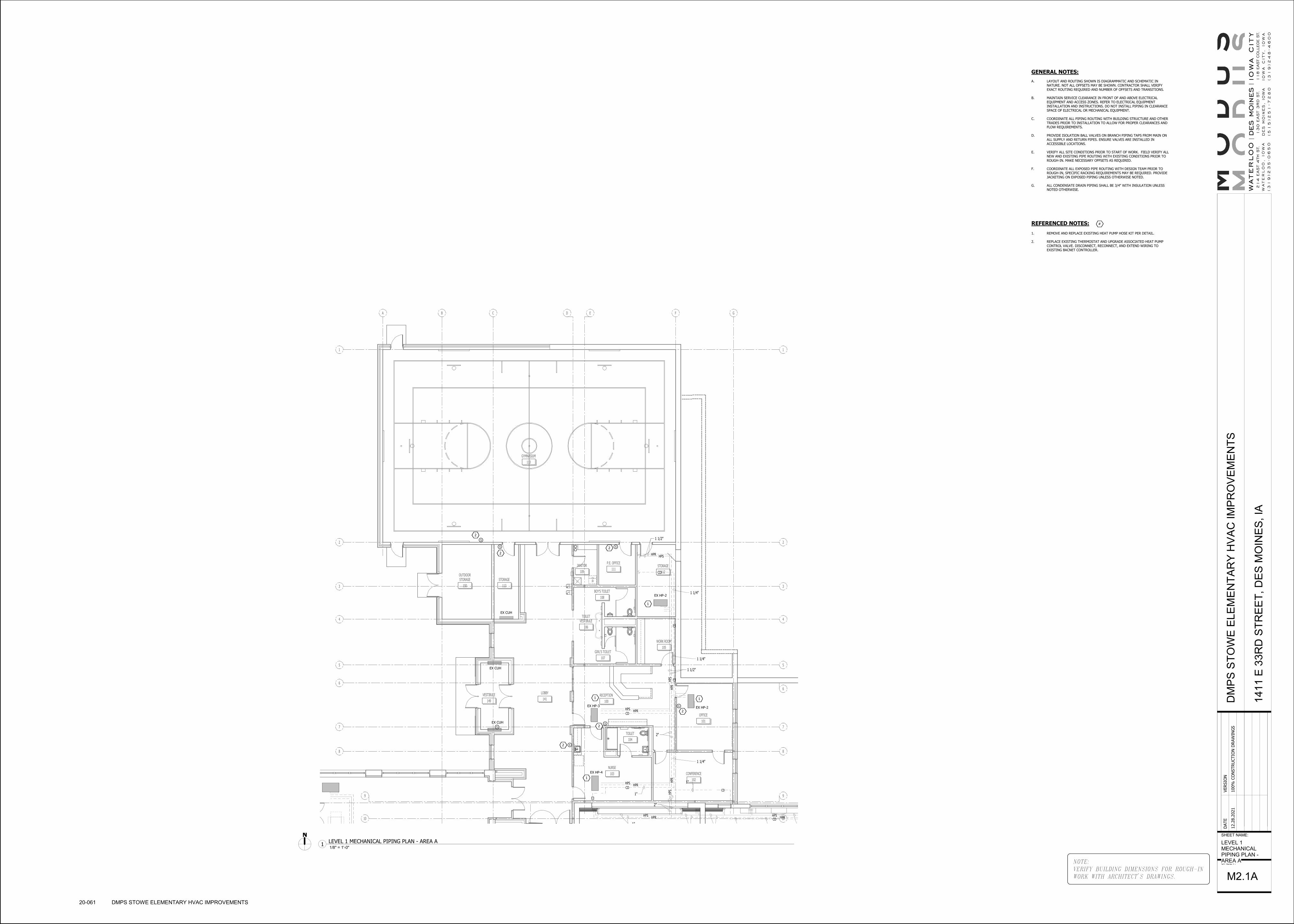
W-D
88
D
10
9
7
6
5
4
3
2
1
B GFECA
10
9
7
6
5
4
3
2
1
TOILETVESTIBULE
106
GIRL'S TOILET
107
BOY'S TOILET
108
GYMNASIUM
110
OUTDOORSTORAGE
150
STORAGE
113
JANITOR
109
P.E. OFFICE
111STORAGE
112
WORK ROOM
105
TOILET
104
NURSE
103 CONFERENCE
102
OFFICE
101
RECEPTION
100
VESTIBULE
149
LOBBY
141
1"
CD
HPSHPR
HPSHPR
CD
CD
CD
CD
CD
CD
1"
HPS
HPR
2"
HPS
HPR
HPSHPR
HPSHPR
HPSHPR
CD
1 1/2"
1 1/2"
2"
1 1/4"
1 1/4"
1 1/4"
1"
11
1
1
EX HP-2
EX HP-2EX HP-3
EX HP-4
EX CUH
EX CUH
EX CUH
S
S
S
S
S
S
S
2
2
2
2
2
2
GENERAL NOTES:
A. LAYOUT AND ROUTING SHOWN IS DIAGRAMMATIC AND SCHEMATIC IN NATURE. NOT ALL OFFSETS MAY BE SHOWN. CONTRACTOR SHALL VERIFY
EXACT ROUTING REQUIRED AND NUMBER OF OFFSETS AND TRANSITIONS.
B. MAINTAIN SERVICE CLEARANCE IN FRONT OF AND ABOVE ELECTRICAL EQUIPMENT AND ACCESS ZONES. REFER TO ELECTRICAL EQUIPMENT INSTALLATION AND INSTRUCTIONS. DO NOT INSTALL PIPING IN CLEARANCE
SPACE OF ELECTRICAL OR MECHANICAL EQUIPMENT.
C. COORDINATE ALL PIPING ROUTING WITH BUILDING STRUCTURE AND OTHER TRADES PRIOR TO INSTALLATION TO ALLOW FOR PROPER CLEARANCES AND
FLOW REQUIREMENTS.
D. PROVIDE ISOLATION BALL VALVES ON BRANCH PIPING TAPS FROM MAIN ON ALL SUPPLY AND RETURN PIPES. ENSURE VALVES ARE INSTALLED IN
ACCESSIBLE LOCATIONS.
E. VERIFY ALL SITE CONDITIONS PRIOR TO START OF WORK. FIELD VERIFY ALL NEW AND EXISTING PIPE ROUTING WITH EXISTING CONDITIONS PRIOR TO
ROUGH-IN. MAKE NECESSARY OFFSETS AS REQUIRED.
F. COORDINATE ALL EXPOSED PIPE ROUTING WITH DESIGN TEAM PRIOR TO ROUGH-IN, SPECIFIC RACKING REQUIREMENTS MAY BE REQUIRED. PROVIDE
JACKETING ON EXPOSED PIPING UNLESS OTHERWISE NOTED.
G. ALL CONDENSATE DRAIN PIPING SHALL BE 3/4" WITH INSULATION UNLESS NOTED OTHERWISE.
REFERENCED NOTES:
1. REMOVE AND REPLACE EXISTING HEAT PUMP HOSE KIT PER DETAIL.
2. REPLACE EXISTING THERMOSTAT AND UPGRADE ASSOCIATED HEAT PUMP
CONTROL VALVE. DISCONNECT, RECONNECT, AND EXTEND WIRING TO
EXISTING BACNET CONTROLLER.
#
NOTE:
VERIFY BUILDING DIMENSIONS FOR ROUGH-IN
WORK WITH ARCHITECT'S DRAWINGS.
SHEET NAME:
SHEET:
DATE
VERSIO
N
12.2
8.2
021
100%
CO
NSTRU
CTIO
N D
RAW
ING
SD
MP
S S
TO
WE
ELE
ME
NT
AR
Y H
VA
C I
MP
RO
VE
ME
NT
S
141
1 E
33R
D S
TR
EE
T,
DE
S M
OIN
ES
, IA
LEVEL 1MECHANICALPIPING PLAN -AREA A
M2.1A
20-061 DMPS STOWE ELEMENTARY HVAC IMPROVEMENTS
1/8" = 1'-0"1
LEVEL 1 MECHANICAL PIPING PLAN - AREA A

4E
3E
2E
1E
4E
3E
2E
1E
EEDECEBEAE
PAPER TOWEL DISPENSER
LIQUID SOAP DISPENSER
WALL-HUNG SINK
10
9
10
9
T
TT
T
T
T
T
T
U P
U P
CLOSET
134
TOILET
120
STORAGE
148
TOILET
118
TOILET
122
WORK ROOM
127
TOILET
129
BOYSTOILET
130
GIRLSTOILET
135
HALL
140
STAFF
136
STORAGE
138
STAIR
139
S.L.P.
133
HALL
131
GUIDANCE
132
MENTALDISABILITIES
128
LIBRARY
126
VESTIBULE
144
PRE-KINDERGARTEN
123 KINDERGARTEN
121
VESTIBULE
143
KINDERGARTEN
119KINDERGARTEN
117
STAIR
146
STAIR
145
HALL
142
ELEVATOR
147OFFICE
116
TRASH
151
TOILET
137
TOILET
124
TOILET
125
NURSE
103 CONFERENCE
102
KITCHEN
115
CAFETERIA
1141"
1"
CD
EX 3/4" CW UP
HPS
HPR
HPSHPR
HPSHPR
HPSHPR
HPSHPR
HPSHPR
HPSHPR
HPS
HPR
HPS
HPR
HPS
HPR
HPS
HPR
HPS
HPR
HPSHPR
HPSHPR
HPSHPR
CD
CD
CDCD
CD
CD
CD
CDCDCDCD
CD
CD
EX 3/4"HPS/HPR DN
EX 1 1/4"CD UP
CD
CD
CD
HPS
HPR
HPS
HPR CD
1 1/4"
3/4"
1"
1 1/4"
1 1/4"
1 1/2"
1 1/4"
1"
1 1/2"
1 1/2"
1"
2 1/2"2 1/2"2"
3" 2 1/2"
2 1/2"
HPS
HPR
2"
HPSHPR
1"
1"
3"
1 1/4"
3"
EX 3" HPS/R UP
EX 4" HPS/R DN
3"
EX 3/4" HPS/R AND CD
UP (TYP-18)
1 1/4"
1"
EX 1 1/2" CD UP
1"
1"
3/4"1"
3/4"1"
1 1/4"
1 1/4"
3/4"1 1/4"
1 1/4"
1"
EX 2" VENT UP
1 1/4"
2"
1
EX HP-4
EX HP-1
1
1
1
1 1
1
1
EX HP-1EX HP-1
EX HP-1
EX HP-8
EX HP-3
EX HP-3
EX HP-1
EX CUH
EX CUH
1
EX HP-1 1 1 1 EX HP-1 1
EX HP-1 1 EX HP-1 1 EX HP-1 1 EX HP-11
1
EX HP-1
1
EX HP-1
1
EX HP-1
S
S
SSS
S
S
S
S
S
S
S
S
2
2
2
222
2
2
2
2
2
2
EX HP-1 EX HP-1
GENERAL NOTES:
A. LAYOUT AND ROUTING SHOWN IS DIAGRAMMATIC AND SCHEMATIC IN
NATURE. NOT ALL OFFSETS MAY BE SHOWN. CONTRACTOR SHALL VERIFY
EXACT ROUTING REQUIRED AND NUMBER OF OFFSETS AND TRANSITIONS.
B. MAINTAIN SERVICE CLEARANCE IN FRONT OF AND ABOVE ELECTRICAL
EQUIPMENT AND ACCESS ZONES. REFER TO ELECTRICAL EQUIPMENT
INSTALLATION AND INSTRUCTIONS. DO NOT INSTALL PIPING IN CLEARANCE
SPACE OF ELECTRICAL OR MECHANICAL EQUIPMENT.
C. COORDINATE ALL PIPING ROUTING WITH BUILDING STRUCTURE AND OTHER
TRADES PRIOR TO INSTALLATION TO ALLOW FOR PROPER CLEARANCES AND
FLOW REQUIREMENTS.
D. PROVIDE ISOLATION BALL VALVES ON BRANCH PIPING TAPS FROM MAIN ON
ALL SUPPLY AND RETURN PIPES. ENSURE VALVES ARE INSTALLED IN
ACCESSIBLE LOCATIONS.
E. VERIFY ALL SITE CONDITIONS PRIOR TO START OF WORK. FIELD VERIFY ALL
NEW AND EXISTING PIPE ROUTING WITH EXISTING CONDITIONS PRIOR TO
ROUGH-IN. MAKE NECESSARY OFFSETS AS REQUIRED.
F. COORDINATE ALL EXPOSED PIPE ROUTING WITH DESIGN TEAM PRIOR TO
ROUGH-IN, SPECIFIC RACKING REQUIREMENTS MAY BE REQUIRED. PROVIDE
JACKETING ON EXPOSED PIPING UNLESS OTHERWISE NOTED.
G. ALL CONDENSATE DRAIN PIPING SHALL BE 3/4" WITH INSULATION UNLESS
NOTED OTHERWISE.
REFERENCED NOTES:
1. REMOVE AND REPLACE EXISTING HEAT PUMP HOSE KIT PER DETAIL.
2. REPLACE EXISTING THERMOSTAT AND UPGRADE ASSOCIATED HEAT PUMP
CONTROL VALVE. DISCONNECT, RECONNECT, AND EXTEND WIRING TO
EXISTING BACNET CONTROLLER.
#
NOTE:
VERIFY BUILDING DIMENSIONS FOR ROUGH-IN
WORK WITH ARCHITECT'S DRAWINGS.
SHEET NAME:
SHEET:
DATE
VERSIO
N
12.2
8.2
021
100%
CO
NSTRU
CTIO
N D
RAW
ING
SD
MP
S S
TO
WE
ELE
ME
NT
AR
Y H
VA
C I
MP
RO
VE
ME
NT
S
141
1 E
33R
D S
TR
EE
T,
DE
S M
OIN
ES
, IA
LEVEL 1MECHANICALPIPING PLAN -AREA B
M2.1B
20-061 DMPS STOWE ELEMENTARY HVAC IMPROVEMENTS
No Scale1
LEVEL 1 MECHANICAL PIPING PLAN - AREA B

T T
88
D
10
9
7
6
5
4
3
2
1
10
9
7
6
5
4
3
2
1
GFECBA
MUSICSTORAGE
225
ELECTRICAL
223
GYMNASIUM
110
KILN
219
VESTIBULE
228
ARTSTORAGE
218
MUSIC
224
PRACTICE
222
PRACTICE
221
STORAGE
227
ART
217
JANITOR
226CO-TEACH
216
UPPERLOBBY
220
3/4"
HPSHPR
CD CD
1 1/4"CD DN
CD
CD
3/4"
3/4"
1 1/2"V
1 1/2"HPS/R DN
1"
1 1/4"
3/4" 3/4"
3/4"
1"
2"
3/4"
EX 1 1/4" CD
1 1/4"HPS
HPR
2"
1 1/4"P
EX PRESSURE TRANSDUCER
1"
1 1
1 1
1
1
EX HP-2 EX HP-4
EX HP-5EX HP-6
1
1
EX HP-1
1
EX HP-7 EX HP-7
EX HP-1 EX HP-1
SS
S
S
S
2
2
2 2
2
EX CUH
NEW PRESSURE TRANDUCER
GENERAL NOTES:
A. LAYOUT AND ROUTING SHOWN IS DIAGRAMMATIC AND SCHEMATIC IN
NATURE. NOT ALL OFFSETS MAY BE SHOWN. CONTRACTOR SHALL VERIFY
EXACT ROUTING REQUIRED AND NUMBER OF OFFSETS AND TRANSITIONS.
B. MAINTAIN SERVICE CLEARANCE IN FRONT OF AND ABOVE ELECTRICAL
EQUIPMENT AND ACCESS ZONES. REFER TO ELECTRICAL EQUIPMENT
INSTALLATION AND INSTRUCTIONS. DO NOT INSTALL PIPING IN CLEARANCE
SPACE OF ELECTRICAL OR MECHANICAL EQUIPMENT.
C. COORDINATE ALL PIPING ROUTING WITH BUILDING STRUCTURE AND OTHER
TRADES PRIOR TO INSTALLATION TO ALLOW FOR PROPER CLEARANCES AND
FLOW REQUIREMENTS.
D. PROVIDE ISOLATION BALL VALVES ON BRANCH PIPING TAPS FROM MAIN ON
ALL SUPPLY AND RETURN PIPES. ENSURE VALVES ARE INSTALLED IN
ACCESSIBLE LOCATIONS.
E. VERIFY ALL SITE CONDITIONS PRIOR TO START OF WORK. FIELD VERIFY ALL
NEW AND EXISTING PIPE ROUTING WITH EXISTING CONDITIONS PRIOR TO
ROUGH-IN. MAKE NECESSARY OFFSETS AS REQUIRED.
F. COORDINATE ALL EXPOSED PIPE ROUTING WITH DESIGN TEAM PRIOR TO
ROUGH-IN, SPECIFIC RACKING REQUIREMENTS MAY BE REQUIRED. PROVIDE
JACKETING ON EXPOSED PIPING UNLESS OTHERWISE NOTED.
G. ALL CONDENSATE DRAIN PIPING SHALL BE 3/4" WITH INSULATION UNLESS
NOTED OTHERWISE.
REFERENCED NOTES:
1. REMOVE AND REPLACE EXISTING HEAT PUMP HOSE KIT PER DETAIL.
2. REPLACE EXISTING THERMOSTAT AND UPGRADE ASSOCIATED HEAT PUMP
CONTROL VALVE. DISCONNECT, RECONNECT, AND EXTEND WIRING TO
EXISTING BACNET CONTROLLER.
#
NOTE:
VERIFY BUILDING DIMENSIONS FOR ROUGH-IN
WORK WITH ARCHITECT'S DRAWINGS.
SHEET NAME:
SHEET:
DATE
VERSIO
N
12.2
8.2
021
100%
CO
NSTRU
CTIO
N D
RAW
ING
SD
MP
S S
TO
WE
ELE
ME
NT
AR
Y H
VA
C I
MP
RO
VE
ME
NT
S
141
1 E
33R
D S
TR
EE
T,
DE
S M
OIN
ES
, IA
LEVEL 2MECHANICALPIPING PLAN -AREA A
M2.2A
20-061 DMPS STOWE ELEMENTARY HVAC IMPROVEMENTS
1/8" = 1'-0"1
LEVEL 2 MECHANICAL PIPING PLAN - AREA A

AE BE CE DE EE
4E
3E
2E
1E
4E
3E
2E
1E
T
TT
TT T
T
T
10
9
10
9
D N
U P
U P
D N
D N
ELEVATOR
147
ELEVATOREQUIPMENT
215
TOILET
206
TOILET
202
STORAGE
204
STAIR
231
PRACTICE
222
PRACTICE
221
UPPERLOBBY
220
HALL
229
CLASSROOM
201CLASSROOM
200
CO-TEACH
203
CO-TEACH
208
CLASSROOM
205
CLASSROOM
207
CLASSROOM
209
CLASSROOM
210
GIRLSTOILET
214
BOYSTOILET
211
BEHAVIORALDISABILITIES
212
HALL
230
HALL
232
STAIR
233
READING RECOVERY/MATH IN CLASS
213
1"
1"
3/4"
HPSHPR
CD
CD
HPS
HPR
HPSHPR
HPSHPR
HPSHPR
HPSHPR
HPSHPR
HPSHPR
HPS
HPR
HPS
HPR
HPS
HPR
HPS
HPR
HPS
HPR
HPSHPR
EX 3/4" HPS/HPR AND CD UP TO HP-1 ON
THIRD FLOOR (TYP-14)
CD
CD
CDCD
CD
CD
CDCD
1"
1 1/4"
1"
2"2"2 1/2"2 1/2"2 1/2"
2 1/2"
EX 3" HPS/R DN
EX 1" HPS/R UP
3/4" 3/4"
3/4"
2"
3/4"
1"
2"
1 1/4"HPS
HPR
CD
3/4"1" 1"1"
CD
1"
EX 1" CD DN
3/4"
CD
EX 1 1/4" CD DN
3/4" (TYP)
EX 3/4" CD UP AND
1" CD DN
3/4"
EX 1" HPS/R UP AND 3" HPS/R DN
3/4"
2"
1 1/4"P
EX PRESSURE TRANSDUCER
1
1
1
1
1
1
EX HP-1
1
HP-1
EX HP-1
EX CUH
EX HP-3
1
1
1
EX HP-1
1
EX HP-1
EX HP-1
ERV-2
EX EF-1
EX HP-1 EX HP-1
S
S
S
S
S
S S S
S
S
S
2
2
2
222
2
2
2
2
2
EX HP-1
EX HP-1
EX HP-1
1HP-1EX HP-1 1HP-1EX HP-1 1HP-1EX HP-1
1HP-1EX HP-1 1HP-1EX HP-1 1HP-1EX HP-1 1HP-1EX HP-1 1HP-1EX HP-1
NEW PRESSURE TRANDUCER
GENERAL NOTES:
A. LAYOUT AND ROUTING SHOWN IS DIAGRAMMATIC AND SCHEMATIC IN
NATURE. NOT ALL OFFSETS MAY BE SHOWN. CONTRACTOR SHALL VERIFY
EXACT ROUTING REQUIRED AND NUMBER OF OFFSETS AND TRANSITIONS.
B. MAINTAIN SERVICE CLEARANCE IN FRONT OF AND ABOVE ELECTRICAL
EQUIPMENT AND ACCESS ZONES. REFER TO ELECTRICAL EQUIPMENT
INSTALLATION AND INSTRUCTIONS. DO NOT INSTALL PIPING IN CLEARANCE
SPACE OF ELECTRICAL OR MECHANICAL EQUIPMENT.
C. COORDINATE ALL PIPING ROUTING WITH BUILDING STRUCTURE AND OTHER
TRADES PRIOR TO INSTALLATION TO ALLOW FOR PROPER CLEARANCES AND
FLOW REQUIREMENTS.
D. PROVIDE ISOLATION BALL VALVES ON BRANCH PIPING TAPS FROM MAIN ON
ALL SUPPLY AND RETURN PIPES. ENSURE VALVES ARE INSTALLED IN
ACCESSIBLE LOCATIONS.
E. VERIFY ALL SITE CONDITIONS PRIOR TO START OF WORK. FIELD VERIFY ALL
NEW AND EXISTING PIPE ROUTING WITH EXISTING CONDITIONS PRIOR TO
ROUGH-IN. MAKE NECESSARY OFFSETS AS REQUIRED.
F. COORDINATE ALL EXPOSED PIPE ROUTING WITH DESIGN TEAM PRIOR TO
ROUGH-IN, SPECIFIC RACKING REQUIREMENTS MAY BE REQUIRED. PROVIDE
JACKETING ON EXPOSED PIPING UNLESS OTHERWISE NOTED.
G. ALL CONDENSATE DRAIN PIPING SHALL BE 3/4" WITH INSULATION UNLESS
NOTED OTHERWISE.
REFERENCED NOTES:
1. REMOVE AND REPLACE EXISTING HEAT PUMP HOSE KIT PER DETAIL.
2. REPLACE EXISTING THERMOSTAT AND UPGRADE ASSOCIATED HEAT PUMP
CONTROL VALVE. DISCONNECT, RECONNECT, AND EXTEND WIRING TO
EXISTING BACNET CONTROLLER.
#
NOTE:
VERIFY BUILDING DIMENSIONS FOR ROUGH-IN
WORK WITH ARCHITECT'S DRAWINGS.
SHEET NAME:
SHEET:
DATE
VERSIO
N
12.2
8.2
021
100%
CO
NSTRU
CTIO
N D
RAW
ING
SD
MP
S S
TO
WE
ELE
ME
NT
AR
Y H
VA
C I
MP
RO
VE
ME
NT
S
141
1 E
33R
D S
TR
EE
T,
DE
S M
OIN
ES
, IA
LEVEL 2MECHANICALPIPING PLAN -AREA B
M2.2B
20-061 DMPS STOWE ELEMENTARY HVAC IMPROVEMENTS
1/8" = 1'-0"1
LEVEL 2 MECHANICAL PIPING PLAN - AREA B

4E
3E
2E
1E
EEDECEBEAE
4E
3E
2E
1E
10
9
10
9
T
T
TT
T
T
D N
D N
D N
D N
ELEVATOR
147
HALL
314
STAIR
315
CLOSET
308
BOYSTOILET
306
GIRLSTOILET
310
JANITOR
311STAIR
312
HALL
313
CLASSROOM
300
CO-TEACH
301
CLASSROOM
302CO-TEACH
303
CLASSROOM
304
CLASSROOM
305
SWINGCLASSROOM
307
LITERACY LEADER/BOOK ROOM
309
4E
3E
2E
1E
EEDECEBEAE
4E
3E
2E
1E
10
9
10
9
T
T
TT
T
T
D N
D N
D N
D N
ELEVATOR
147
HALL
314
STAIR
315
CLOSET
308
BOYSTOILET
306
GIRLSTOILET
310
JANITOR
311STAIR
312
HALL
313
CLASSROOM
300
CO-TEACH
301
CLASSROOM
302CO-TEACH
303
CLASSROOM
304
CLASSROOM
305
SWINGCLASSROOM
307
LITERACY LEADER/BOOK ROOM
309
1"
CD
HPS
HPR
3/4"
EX 3/4" HPS/R AND CD DN
EX 3/4" HPS/R AND CD DN
EX 3/4" HPS/R AND CD DN
EX 3/4" HPS/R AND CD DNEX 3/4" HPS/R AND CD DN
EX 3/4" HPS/R AND CD DN
EX 3/4" HPS/R AND CD DN
EX 1" HPS/R DN
EX 3/4" CD DN
1
1
1
1
S
EX HP-1
EX HP-1
EX HP-1
EX HP-4
EX CUH
1
EX HP-1
1
EX HP-1
1
1
EX HP-1
1EX HP-1
1
EX HP-1
EX HP-1 EX HP-1 EX HP-111
1EX HP-1
1
EX HP-1
1
EX HP-1
S
S
S S
S
S
S
S
S2
2
22
2
2
2
2
GENERAL NOTES:
A. LAYOUT AND ROUTING SHOWN IS DIAGRAMMATIC AND SCHEMATIC IN
NATURE. NOT ALL OFFSETS MAY BE SHOWN. CONTRACTOR SHALL VERIFY
EXACT ROUTING REQUIRED AND NUMBER OF OFFSETS AND TRANSITIONS.
B. MAINTAIN SERVICE CLEARANCE IN FRONT OF AND ABOVE ELECTRICAL
EQUIPMENT AND ACCESS ZONES. REFER TO ELECTRICAL EQUIPMENT
INSTALLATION AND INSTRUCTIONS. DO NOT INSTALL PIPING IN CLEARANCE
SPACE OF ELECTRICAL OR MECHANICAL EQUIPMENT.
C. COORDINATE ALL PIPING ROUTING WITH BUILDING STRUCTURE AND OTHER
TRADES PRIOR TO INSTALLATION TO ALLOW FOR PROPER CLEARANCES AND
FLOW REQUIREMENTS.
D. PROVIDE ISOLATION BALL VALVES ON BRANCH PIPING TAPS FROM MAIN ON
ALL SUPPLY AND RETURN PIPES. ENSURE VALVES ARE INSTALLED IN
ACCESSIBLE LOCATIONS.
E. VERIFY ALL SITE CONDITIONS PRIOR TO START OF WORK. FIELD VERIFY ALL
NEW AND EXISTING PIPE ROUTING WITH EXISTING CONDITIONS PRIOR TO
ROUGH-IN. MAKE NECESSARY OFFSETS AS REQUIRED.
F. COORDINATE ALL EXPOSED PIPE ROUTING WITH DESIGN TEAM PRIOR TO
ROUGH-IN, SPECIFIC RACKING REQUIREMENTS MAY BE REQUIRED. PROVIDE
JACKETING ON EXPOSED PIPING UNLESS OTHERWISE NOTED.
G. ALL CONDENSATE DRAIN PIPING SHALL BE 3/4" WITH INSULATION UNLESS
NOTED OTHERWISE.
REFERENCED NOTES:
1. REMOVE AND REPLACE EXISTING HEAT PUMP HOSE KIT PER DETAIL.
2. REPLACE EXISTING THERMOSTAT AND UPGRADE ASSOCIATED HEAT PUMP
CONTROL VALVE. DISCONNECT, RECONNECT, AND EXTEND WIRING TO
EXISTING BACNET CONTROLLER.
#
NOTE:
VERIFY BUILDING DIMENSIONS FOR ROUGH-IN
WORK WITH ARCHITECT'S DRAWINGS.
SHEET NAME:
SHEET:
DATE
VERSIO
N
12.2
8.2
021
100%
CO
NSTRU
CTIO
N D
RAW
ING
SD
MP
S S
TO
WE
ELE
ME
NT
AR
Y H
VA
C I
MP
RO
VE
ME
NT
S
141
1 E
33R
D S
TR
EE
T,
DE
S M
OIN
ES
, IA
LEVEL 3MECHANICALPIPING PLAN -AREA B
M2.3B
20-061 DMPS STOWE ELEMENTARY HVAC IMPROVEMENTS
1/8" = 1'-0"1
LEVEL 3 MECHANICAL PIPING PLAN - AREA B

FRONT VIEW RIGHT END VIEW
EXISTING EXTERIOR WALL
FIRST FLOOR
EX 3/4" COPPER CONDENSATE
EX 3/4" HPS/R
NEW BALANCE VALVE
NEW FLOW CONTROL VALVE
WITH TEST PORTS
NEW FLEXIBLE HOSE (TYP)NEW PRESSURE
TEMPERATURE TEST
PORTLOOP HOSES TOGETHER FOR
SYSTEM FLUSHING
NEW STRAINER
EX RETURN AIR OPENING
NEW TWO WAY CONTROL VALVE
EX HP-1 EX HP-1
SA
NEW SHUT OFF VALVE
NEW ISOLATION VALVE
3" HPS/R (TYP)
EX VALVE VAULT
EX 4" HPS/R MAINS
GRADE
MANHOLE COVER
BY-PASS VALVE
STEPS
T
T
T
METER
4"
4"
EXPANSION
TANK
4"
4"
WATER FILL ONLY
INITIAL SYSTEM
LOOP PUMP
HP WATER
LOOP PUMP
HP WATER
AIR SEPARATOR
4" HPS/R LOOP TO BUILDING
4"
TO EX BOILER
3/4"
3/4"
AIR ELIMINATOR
1 1/2"
4"
AUTO RELIEF VALVE
WATER METER
4"
FEEDER
SLUG
THERMOMETER (TYP)
CAP
1 1/2"
4" HPS/R TO
VALVE PIT
4"4"
4"
4"4"
AUTOMATIC
CONTROL BYPASS
VALVE (280 GPM)
GRADEHPS
HPR
4"
PIPE AUTO VENT OVER TO AND
SPILL INTO FLOOR DRAIN
HPR
TEMPERATURE CONTROL TEMP.
SENSOR (TYP)
DRAIN VALVE WITH HOSE
CONNECTION
12" MAX.
MAX. 4'-0"
REDUCED PRESSURE
BACKFLOW PREVENTER
PRESSURE GAUGE
UNION (TYP)PRESSURE REDUCING
VALVE
1" BY-PASS
LOOP HOSE FOR
SYSTEM FLUSHING
NEW PRESSURE/TEMPERATURE
TEST VALVE
NEW FLOW CONTROL
VALVE WITH TEST VALVES
RETURN AIRFILTER
CD
NEW STRAINER/SHUTOFF
AIR FLOW
EX HEAT PUMP
NEW FLEXIBLE HOSE (TYP)
NEW BALANCE VALVE
EX UNION
NEW TWO WAY CONTROL VALVE
HPR
HPS
6"
3" ZONE CIRCUIT (TYP)
THERMOMETER
PRESSURE GAUGE
3" BALL VALVE (TYP)
PORT (TYP)
PRESSURE/TEMP
4"
4"
DRAIN VALVE (TYP)
BLIND FLANGE
CONNECTION (TYP)
4" FILL AND FLUSH
BYPASS VALVE EX 4" HEADER MANIFOLD (TYP)
VAULT WALL
6 CIRCUITS
AUTO FLOW VALVE (TYP)
NOTES:1. REMOVE AND REPLACE EXISTING HOSE KIT INCLUDING ISOLATION
SHUT OFF VALVES AND ASSOCIATED ACCESSORIES AS NOTED.
REFERENCED NOTES:1. CONTRACTOR SHALL VERIFY AND REBALANCE EX P-1 AND EX P-2 TO SUM OF EXISTING HEAT
PUMP FLOWRATES AFTER WELL FIELD AND BUILDING FLUSING, CLEANING, AND REFILLING.2. REFER TO SPECIFICATION SECTION 23 2500 FOR GEOTHERMAL SYSTEM REQUIREMENTS.
EX P-1 EX P-2
1 1
2
2
NOTES:1. REMOVE AND REPLACE EXISTING HOSE KIT INCLUDING ISOLATION
SHUT OFF VALVES AND ASSOCIATED ACCESSORIES AS NOTED.
NOTES:1. MECHANICAL CONTRACTOR SHALL HIRE A-ONE GEOTHERMAL TO
INSPECT, PRESSURE TEST, AND FLUSH GEOTHERMAL WELL FIELD AND BUILDING HEAT PUMP LOOP SYSTEM. REFER TO SPECIFICATION SECTION 23 2500 FOR MORE DETAILS.
2. PROVIDE INSPECTION TEST AND PRESSURE TEST TO OWNER AND
DESIGN TEAM FOR REVIEW PRIOR TO REFILLING SYSTEM.
NOTE:
VERIFY BUILDING DIMENSIONS FOR ROUGH-IN
WORK WITH ARCHITECT'S DRAWINGS.
SHEET NAME:
SHEET:
DATE
VERSIO
N
12.2
8.2
021
100%
CO
NSTRU
CTIO
N D
RAW
ING
SD
MP
S S
TO
WE
ELE
ME
NT
AR
Y H
VA
C I
MP
RO
VE
ME
NT
S
141
1 E
33R
D S
TR
EE
T,
DE
S M
OIN
ES
, IA
MECHANICALDETAILS ANDSCHEDULES
M5.1
20-061 DMPS STOWE ELEMENTARY HVAC IMPROVEMENTS
No Scale3
EXISTING CONSOLE HEAT PUMP DETAILNo Scale
2EXISTING GEOTHERMAL VAULT SECTION
No Scale4
EXISTING HEAT PUMP SYSTEM PIPING SCHEMATIC
No Scale5
EXISTING HORIZONTAL HEAT PUMP DETAIL
No Scale1
EXISTING VAULT HEADER MANIFOLD DETAIL
ENERGY RECOVERY VENTILATOR SCHEDULE
UNIT TAG MANUFACTURER MODEL
SUPPLY FAN SECTION EXHAUST FAN SECTION DX COOLING COIL SECTION ELECTRIC HEATING COIL SECTION FILTER SECTIONS ENERGY RECOVERY WHEEL
VO
LT
AG
E/P
HA
SE
MCA MOCP
MAXIMUM UNITWEIGHT WITH
CURB (LBS)AIR
FLO
W (
CF
M)
E
.S.P
. (I
N.
H2
0)
T
.S.P
.(I
N.
H2
0)
TO
TA
L M
OT
OR
HP
TO
TA
L M
OT
OR
B.H
.P.
FA
N R
PM
AIR
FLO
W (
CF
M)
E
.S.P
. (I
N.
H2
0)
T
.S.P
.(I
N.
H2
0)
TO
TA
L M
OT
OR
HP
TO
TA
L M
OT
OR
B.H
.P.
FA
N R
PM
FIN
S/IN
CH
CO
IL R
OW
S
N
ET
TO
TA
L C
AP
AC
IT
Y(M
BH
)
N
ET
SE
NS
IB
LE
CA
PA
CIT
Y(M
BH
)
E
.D.B
./E
.W.B
.(°F
/°F
)
L.D
.B./
L.W
.B.(
°F
/°F
)
L.D
.B./
L.W
.B.
(RE
HE
AT
)(°F
/°F
)
MR
C (
LB
/H
)
A
IR
P.D
.(I
N H
2O
)
CA
PA
CIT
Y (
KW
)
E.D
.B./
E.W
.B.
(°F
/°F
)
L.D
.B.
(°F
)
AIR
P.D
. (I
N H
2O
)
FIL
TE
R M
ED
IA
TH
ICK
NE
SS
(IN
)
EFF
ICIE
NC
Y
SUMMER WINTER
O
A D
B/W
B(°
F/°F
)
R
A D
B/W
B(°
F/°F
)
EA
AIR
FLO
W (
CF
M)
S
A D
B/W
B(°
F/°F
)
S
NE
SIB
LE
EF
FE
CT
IV
EN
ES
S(%
)
O
A D
B/W
B(°
F)
R
A D
B/W
B(°
F)
EA
AIR
FLO
W (
CF
M)
S
A D
B/W
B(°
F)
S
EN
SIB
LE
EF
FE
CT
IV
EN
ES
S(%
)
ERV-1 TRANE HORIZON OAKD300A4 5625 2.00 3.71 7.5 4.65 1850 2.00 3.27 5 4.09 1769 6 311.2 160.7 82.5/71.9 54.8/54.4 75/62.1 202.63 0.25 32 42.4/60.4 50.4 0.02 2 MERV 8 94.0/78.0 89.4/72.6 5563 82.5/71.9 0.73 -10.0/-10.0 70.0/52.0 5563 42.4/32.9 0.74 460/3 72.3 80 5700
ERV-2 TRANE HORIZON OAKD264A4 4500 2.00 3.53 5 3.49 1707 2.00 3.05 5 3.06 1621 6 271.5 144.5 82.4/71.7 51.7/51.4 74.0/60.29 180.72 0.41 32 43.8/66.3 66.3 0.01 2 MERV 8 94.0/78.0 77.0/65.0 4553 82.4/71.1 0.74 -10.0/-10.0 70.0/53.0 4533 43.8/35.2 0.75 460/3 67.6 70 5600
ERV-3 TRANE HORIZON OADG012G3 2180 2.00 2.92 2 1.4 2180 2.00 2.72 1.5 1.25 2102 6 142.5 76.9 83.2/71.0 49.0/48.7 85.5/63.18 92.71 0.23 20 39.5/69.2 69.2 0 2 MERV 8 94.0/78.0 77.0/65.0 2038 77.0/65.0 0.78 -10.0/-10.0 70.0/53.0 2038 39.5/33.1 0.80 460/3 39.6 40 4500
EXISTING HEAT PUMP SCHEDULE
UNIT TAG MANUFACTURER MODEL TYPESUPPLY
AIRFLOW (CFM) ESP (IN WC)CONDENSER
WATER (GPM)MAX. WPD
(FT HD)
COOLING HEATING
MCA MOCP VOLTAGE/PHASE
TOTALCAPACITY
(MBH)
SENSIBLECAPACITY
(MBH) EWT/LWT (F/F)CAPACITY
(MBH) EWT/LWT (F/F)
EX HP-1 TRANE GECE0187 CONSOLE 460 0.5 2.7 1.2 15.8 12 90/105 15.2 45/36.8 10.5 15 277/1
EX HP-2 TRANE EXHF0187 HORIZONTAL 570 0.5 2.7 1.9 18.2 14.5 90/106.8 17.6 45/35.1 11.8 15 277/1
EX HP-3 TRANE EXHF0247 HORIZONTAL 836 0.5 3.6 2.8 22 18 90/105.6 22.7 45/35.5 12.3 20 277/1
EX HP-4 TRANE EXHF0307 HORIZONTAL 1045 0.5 4.5 4.2 28.7 24.9 90/105.8 27.9 45/35.3 16.4 25 277/1
EX HP-5 TRANE EXHF0364 HORIZONTAL 1140 0.5 5.4 2.5 32.6 26.7 90/105.1 34.5 45/35.2 10.5 15 460/3
EX HP-6 TRANE EXHF0424 HORIZONTAL 1197 0.5 6.3 3.6 38.8 30 90/105.3 40 45/35.2 11.3 15 460/3
EX HP-7 TRANE EXHF0484 HORIZONTAL 1520 0.5 7.2 3.8 44 35.8 90/105.4 45.6 45/35.2 12 15 460/3
EX HP-8 TRANE EXHF0704 HORIZONTAL 1881 0.5 13.3 5.1 61.4 46.5 90/101.5 65.6 45/37.6 18.1 25 460/3
NOTES:1. UNITS SHALL HAVE SINGLE POINT POWER.2. PROVIDE NECESSARY INTERNAL DAMPERS TO OPERATE UNIT IN RECIRCULATION MODE DURING UNOCCUPIED PERIODS TO CONTROL SPACE HUMIDITY. CONTROLS AND CONTROL SEQUENCE BY JCI PER SPECIFICATIONS.
3. SUPPLY AND EXHAUST FAN VFD'S SHALL BE FURNISHED BY FMS CONTRACTOR AND INSTALLED BY ELECTRICAL CONTRACTOR. VFD'S SHALL BE MOUNTED REMOTELY INSIDE A NEARBY MECHANICAL ROOM WHERE POSSIBLE.4. PROVIDE DIGITAL SCROLL COMPRESSORS ON ALL CIRCUITS.5. PROVIDE NON-FUSED DISCONNECT SWITCH WITH 115V OUTLET.6. PROVIDE CONDENSER HAILGUARD.
7. PROVIDE AIRFLOW MONITORING PIEZO RING.8. PROVIDE UNITS WITH VIBRATION ISOLATION CURBS.
NOTES:1. EXISTING HEAT PUMPS SHALL REMAIN.
2. PROVIDE NEW HEAT PUMP HOSE KITS TO MATCH EXISTING HEAT PUMPS.