Seismic Response of the San Salvatore Hospital of Coppito (L’Aquila) during the 6th April 2009...
14
159 Effects on structures and infrastructures 2.8.1 Introduction The recent earthquake of 6 th April 2009 signifi- cantly hit the city of L’Aquila and its surround- ings both for the serious number of casualties and for the damage suffered by residential and important structures. Among the latter, one of the most important is surely the San Salvatore Hos- pital of Coppito, the crucial point of the hospital system in the area of L’Aquila, which was com- pletely evacuated during the emergency due the damage at various floors of the buildings. A thorough analysis of the hospital facilities has shown besides the essentially non-structural damage also some aspects of the construction of the hospital complex, which might be crucial for the seismic response to future shocks and there- fore open more critical damage scenarios. Other smaller hospitals located in neighbouring urban areas showed minor damage, allowing partial absorption of emergencies, thus reducing the enormous overload on the field hospital set up close to the San Salvatore Hospital. Recent valuations, in fact, have shown that more than 1500 injured received assistance during the days after the emergency, which confirms the tremendous impact on the hospital system. The hospital structure has been designed in 1966 and took about 30 years to build entirely. Such an information is particularly important if related to developments in domestic seismic reg- ulation. In fact, the first Italian seismic law, con- sidered a forerunner of the most modern ones, was n. 64 of 2/2/1974 (Gazzetta Ufficiale, 1974), issued after the 1974 Ancona earth- quake. Previously, references to seismic law came from Royal Decrees (e.g. Regio Decreto Legge n. 2105 of 22/11/1937), while during the Republic era there was Act n. 1684 of 1962 (Gazzetta Ufficiale, 1962) that followed the Campania earthquake of 21/08/1962, and was later completed by Act. n.1224 of 5/11/1964 (Gazzetta Ufficiale, 1964), and by the Act n. 6090, 1969 (Ministero dei Lavori Pubblici, 1969) issued after the Belice earth- quake. However, such references were oriented towards defining heights, thicknesses, executive methods and quality of materials rather than calculation methods and design criteria. After the 6 th April earthquake, only 3 buildings out of 15 in the San Salvatore complex suffered considerable structural damage. This was limited to small areas and primarily was due to evident issues that will be described in detail later in this work. There was slight and relatively limited non- structural damage and significant non-structural damage in only a few buildings. In these latter inner partitions significantly helped the lateral resistance by dissipating the earthquake’s energy and suffering critical damages (Fig. 1). The basement and semi-basement part of the complex, mostly made up of reinforced concrete walls, showed a stiff box response without sig- nificant damage. Finally, no evident damage was observed in the foundation structures. From the point of view of the human safety, the most widespread and relevant non-structural damage was that of exterior façade bricks, cov- ering the entire surface of all the buildings. Such a coating, not linked to the interior walls, in many cases was partially or totally detached. No sig- nificant damage was observed on the equipment and internal mechanical devices inside. The present paper aims to briefly describe the activities carried out by Eucentre in San Salva- tore Hospital during the days after the main shock. Data on the geometric and instrumental surveys carried out in the emergency and post- emergency phases are presented together with the assessment of the damage and usability of the buildings. Finally an example is presented of the vulnerability assessment of one of the hospi- tal buildings, using a simplified procedure. 2.8 Seismic Response of the San Salvatore Hospital of Coppito (L’Aquila) during the 6 th April 2009 earthquake C. Casarotti 1 , A. Pavese 1-2 , S. Peloso 1 ■ 1 Fondazione Eucentre - Centro Europeo di Formazione e Ricerca in Ingegneria Sismica, Pavia. www.eucentre.it 2 Dipartimento di Meccanica Strutturale, Università degli Studi di Pavia. www.unipv.it 2.8.2 The Eucentre intervention unit Usability assessment surveys and the subsequent detailed tests were carried out using a system developed by Eucentre, designed and built under the STEP Project, Strategies and Tools for Early Post-Earthquake Assessment (Casarotti et
Transcript of Seismic Response of the San Salvatore Hospital of Coppito (L’Aquila) during the 6th April 2009...
159
Effects on structures and infrastructures
2.8.1 IntroductionThe recent earthquake of 6th April 2009 signifi-cantly hit the city of L’Aquila and its surround-ings both for the serious number of casualtiesand for the damage suffered by residential andimportant structures. Among the latter, one of themost important is surely the San Salvatore Hos-pital of Coppito, the crucial point of the hospitalsystem in the area of L’Aquila, which was com-pletely evacuated during the emergency due thedamage at various floors of the buildings.A thorough analysis of the hospital facilities hasshown besides the essentially non-structuraldamage also some aspects of the construction ofthe hospital complex, which might be crucial forthe seismic response to future shocks and there-fore open more critical damage scenarios.Other smaller hospitals located in neighbouringurban areas showed minor damage, allowingpartial absorption of emergencies, thus reducingthe enormous overload on the field hospital setup close to the San Salvatore Hospital. Recentvaluations, in fact, have shown that more than1500 injured received assistance during thedays after the emergency, which confirms thetremendous impact on the hospital system.The hospital structure has been designed in1966 and took about 30 years to build entirely.Such an information is particularly important ifrelated to developments in domestic seismic reg-ulation. In fact, the first Italian seismic law, con-sidered a forerunner of the most modern ones,was n. 64 of 2/2/1974 (Gazzetta Ufficiale,1974), issued after the 1974 Ancona earth-quake. Previously, references to seismic lawcame from Royal Decrees (e.g. Regio DecretoLegge n. 2105 of 22/11/1937), while duringthe Republic era there was Act n. 1684 of 1962(Gazzetta Ufficiale, 1962) that followed theCampania earthquake of 21/08/1962, andwas later completed by Act. n.1224 of
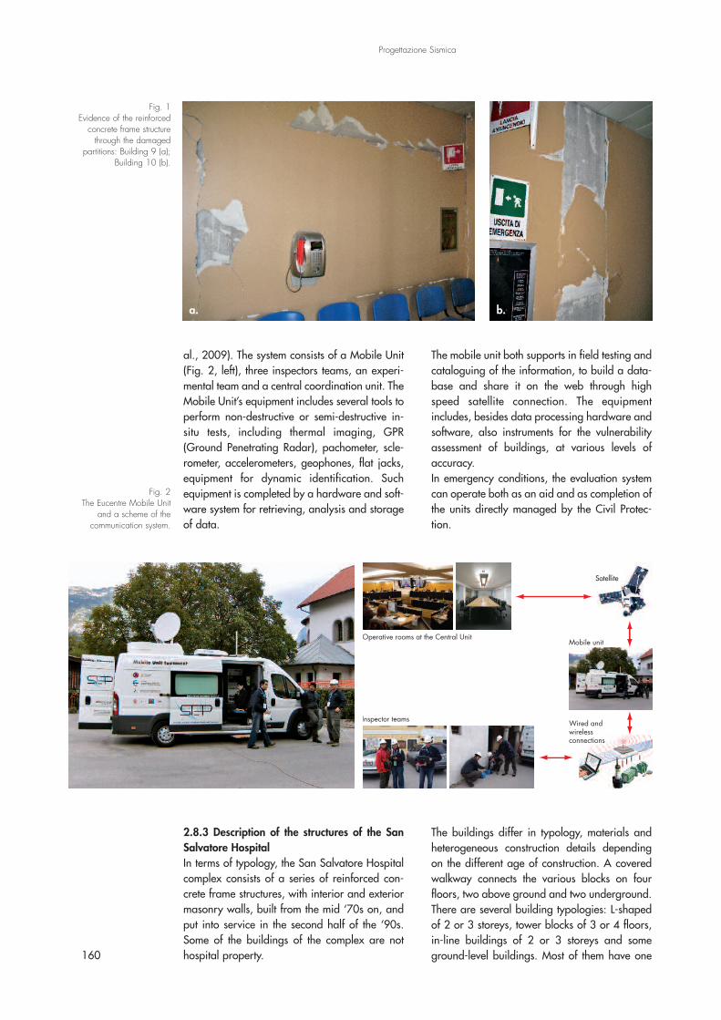
5/11/1964 (Gazzetta Ufficiale, 1964), and bythe Act n. 6090, 1969 (Ministero dei LavoriPubblici, 1969) issued after the Belice earth-quake. However, such references were orientedtowards defining heights, thicknesses, executivemethods and quality of materials rather thancalculation methods and design criteria.After the 6th April earthquake, only 3 buildingsout of 15 in the San Salvatore complex sufferedconsiderable structural damage. This was limitedto small areas and primarily was due to evidentissues that will be described in detail later in thiswork. There was slight and relatively limited non-structural damage and significant non-structuraldamage in only a few buildings. In these latterinner partitions significantly helped the lateralresistance by dissipating the earthquake’s energyand suffering critical damages (Fig. 1).The basement and semi-basement part of thecomplex, mostly made up of reinforced concretewalls, showed a stiff box response without sig-nificant damage. Finally, no evident damagewas observed in the foundation structures.From the point of view of the human safety, themost widespread and relevant non-structuraldamage was that of exterior façade bricks, cov-ering the entire surface of all the buildings. Sucha coating, not linked to the interior walls, in manycases was partially or totally detached. No sig-nificant damage was observed on the equipmentand internal mechanical devices inside.The present paper aims to briefly describe theactivities carried out by Eucentre in San Salva-tore Hospital during the days after the mainshock. Data on the geometric and instrumentalsurveys carried out in the emergency and post-emergency phases are presented together withthe assessment of the damage and usability ofthe buildings. Finally an example is presented ofthe vulnerability assessment of one of the hospi-tal buildings, using a simplified procedure.
2.8 Seismic Response of the San Salvatore Hospital of Coppito (L’Aquila)during the 6th April 2009 earthquake
C. Casarotti1, A. Pavese1-2, S. Peloso1 �
1 Fondazione Eucentre - Centro Europeo di Formazione e Ricerca in Ingegneria Sismica, Pavia. www.eucentre.it2 Dipartimento di Meccanica Strutturale, Università degli Studi di Pavia. www.unipv.it
2.8.2 The Eucentre intervention unitUsability assessment surveys and the subsequentdetailed tests were carried out using a system
developed by Eucentre, designed and builtunder the STEP Project, Strategies and Tools forEarly Post-Earthquake Assessment (Casarotti et
al., 2009). The system consists of a Mobile Unit(Fig. 2, left), three inspectors teams, an experi-mental team and a central coordination unit. TheMobile Unit’s equipment includes several tools toperform non-destructive or semi-destructive in-situ tests, including thermal imaging, GPR(Ground Penetrating Radar), pachometer, scle-rometer, accelerometers, geophones, flat jacks,equipment for dynamic identification. Suchequipment is completed by a hardware and soft-ware system for retrieving, analysis and storageof data.
The mobile unit both supports in field testing andcataloguing of the information, to build a data-base and share it on the web through highspeed satellite connection. The equipmentincludes, besides data processing hardware andsoftware, also instruments for the vulnerabilityassessment of buildings, at various levels ofaccuracy.In emergency conditions, the evaluation systemcan operate both as an aid and as completion ofthe units directly managed by the Civil Protec-tion.
160
Progettazione Sismica
Fig. 1Evidence of the reinforced
concrete frame structurethrough the damaged
partitions: Building 9 (a);Building 10 (b).
Fig. 2The Eucentre Mobile Unit
and a scheme of thecommunication system.
2.8.3 Description of the structures of the SanSalvatore HospitalIn terms of typology, the San Salvatore Hospitalcomplex consists of a series of reinforced con-crete frame structures, with interior and exteriormasonry walls, built from the mid ‘70s on, andput into service in the second half of the ‘90s.Some of the buildings of the complex are nothospital property.
The buildings differ in typology, materials andheterogeneous construction details dependingon the different age of construction. A coveredwalkway connects the various blocks on fourfloors, two above ground and two underground.There are several building typologies: L-shapedof 2 or 3 storeys, tower blocks of 3 or 4 floors,in-line buildings of 2 or 3 storeys and someground-level buildings. Most of them have one
a. b.
Building 11 (Other property)
Group 1
Group 2
Group 3
Group 4
Group 5
Building 1Building 10
Build
ingDelt
a 8Building L3 Building L4
Building L5
Building L1 Building L2
Building 9
Church
Build
ingDelt
a 7
Build
ingDelt
a 6
Building 3A
Building 2A
Building 3B
Building 2B
Building 6 (Other property)
Building 12 (Other property)
or two basement floors.The approximate date of construction and themain function of the various blocks, identified on
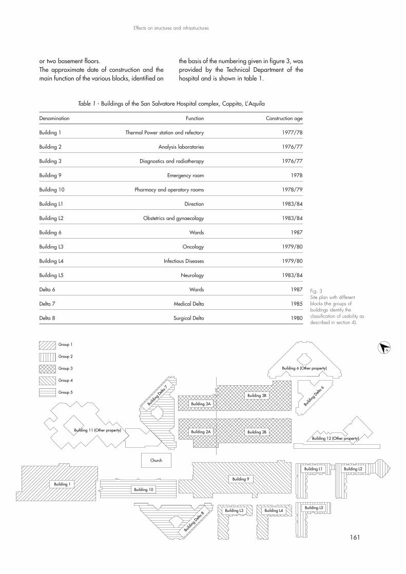
the basis of the numbering given in figure 3, wasprovided by the Technical Department of thehospital and is shown in table 1.
161
Effects on structures and infrastructures
Fig. 3Site plan with differentblocks (the groups ofbuildings identify theclassification of usability asdescribed in section 4).
Table 1 - Buildings of the San Salvatore Hospital complex, Coppito, L’Aquila
Denomination Function Construction age
Building 1 Thermal Power station and refectory 1977/78
Building 2 Analysis laboratories 1976/77
Building 3 Diagnostics and radiotherapy 1976/77
Building 9 Emergency room 1978
Building 10 Pharmacy and operatory rooms 1978/79
Building L1 Direction 1983/84
Building L2 Obstetrics and gynaecology 1983/84
Building 6 Wards 1987
Building L3 Oncology 1979/80
Building L4 Infectious Diseases 1979/80
Building L5 Neurology 1983/84
Delta 6 Wards 1987
Delta 7 Medical Delta 1985
Delta 8 Surgical Delta 1980
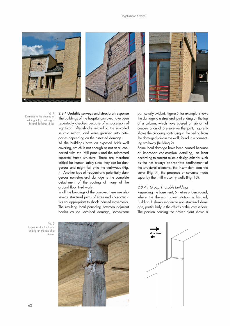
2.8.4 Usability surveys and structural responseThe buildings of the hospital complex have beenrepeatedly checked because of a succession ofsignificant after-shocks related to the so-calledseismic swarm, and were grouped into cate-gories depending on the assessed damage.All the buildings have an exposed brick wallcovering, which is not enough or not at all con-nected with the infill panels and the reinforcedconcrete frame structure. These are thereforecritical for human safety since they can be dan-gerous and might fall onto the walkways (Fig.4). Another type of frequent and potentially dan-gerous non-structural damage is the completedetachment of the coating of many of theground floor tiled walls.In all the buildings of the complex there are alsoseveral structural joints of sizes and characteris-tics not appropriate to shock induced movements.The resulting local pounding between adjacentbodies caused localised damage, somewhere
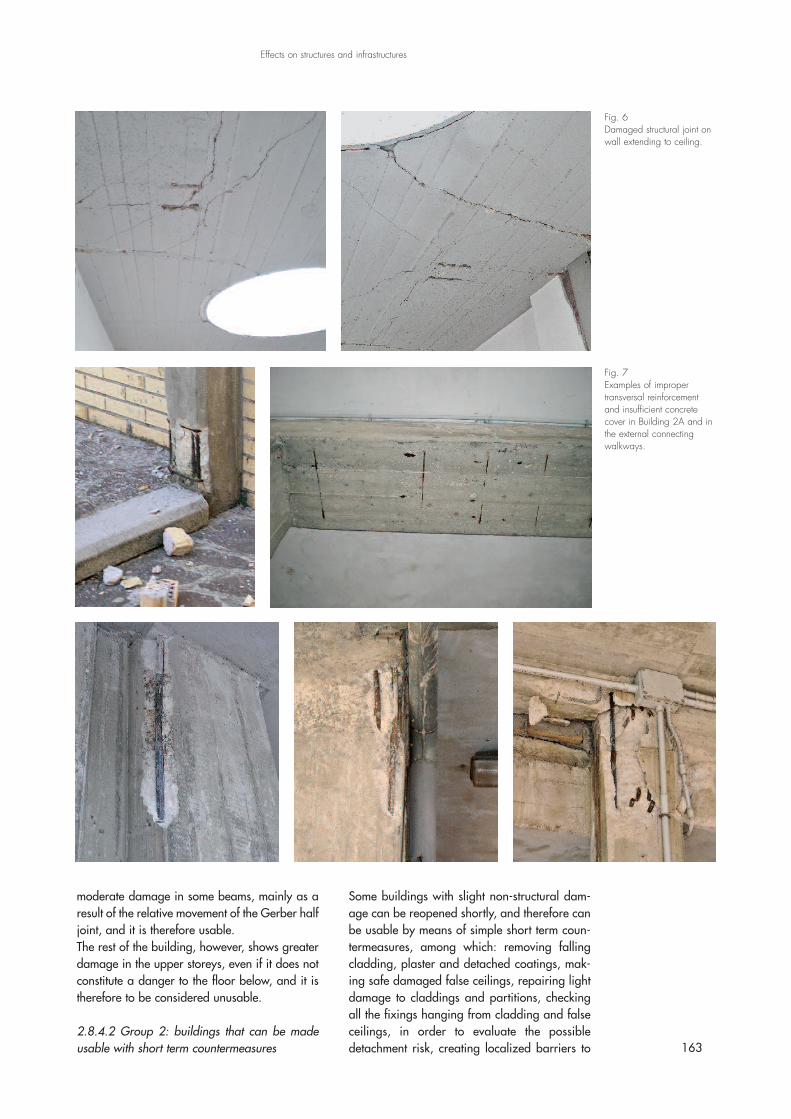
particularly evident. Figure 5, for example, showsthe damage to a structural joint ending on the topof a column, which have caused an abnormalconcentration of pressure on the joint. Figure 6shows the cracking continuing in the ceiling fromthe damaged joint in the wall, found in a connect-ing walkway (Building 2).Some local damage have been caused becauseof improper construction detailing, at leastaccording to current seismic design criteria, suchas the not always appropriate confinement ofthe structural elements, the insufficient concretecover (Fig. 7), the presence of columns madesquat by the infill masonry walls (Fig. 13).
2.8.4.1 Group 1: usable buildingsRegarding the basement, 6 metres underground,where the thermal power station is located,Building 1 shows moderate non-structural dam-age, particularly in the offices at the lowest floor.The portion housing the power plant shows a
162
Progettazione Sismica
Fig. 4Damage to the coating ofBuilding 2 (a), Building 9
(b) and Building L3 (c).
Fig. 5Improper structural jointending on the top of a
column. structural joint
a. b. c.
moderate damage in some beams, mainly as aresult of the relative movement of the Gerber halfjoint, and it is therefore usable.The rest of the building, however, shows greaterdamage in the upper storeys, even if it does notconstitute a danger to the floor below, and it istherefore to be considered unusable.
2.8.4.2 Group 2: buildings that can be madeusable with short term countermeasures
Some buildings with slight non-structural dam-age can be reopened shortly, and therefore canbe usable by means of simple short term coun-termeasures, among which: removing fallingcladding, plaster and detached coatings, mak-ing safe damaged false ceilings, repairing lightdamage to claddings and partitions, checkingall the fixings hanging from cladding and falseceilings, in order to evaluate the possibledetachment risk, creating localized barriers to 163
Effects on structures and infrastructures
Fig. 7Examples of impropertransversal reinforcementand insufficient concretecover in Building 2A and inthe external connectingwalkways.
Fig. 6Damaged structural joint onwall extending to ceiling.
protect walkways, and removing unsafe por-tions of the outer coating. Buildings L1, L2 andL5 belong to this category, which show wide-spread light non-structural damage, particularlyat the ground level. These three buildings will bethe first to be reopened at the end of May2009, less than two months after the mainshock.
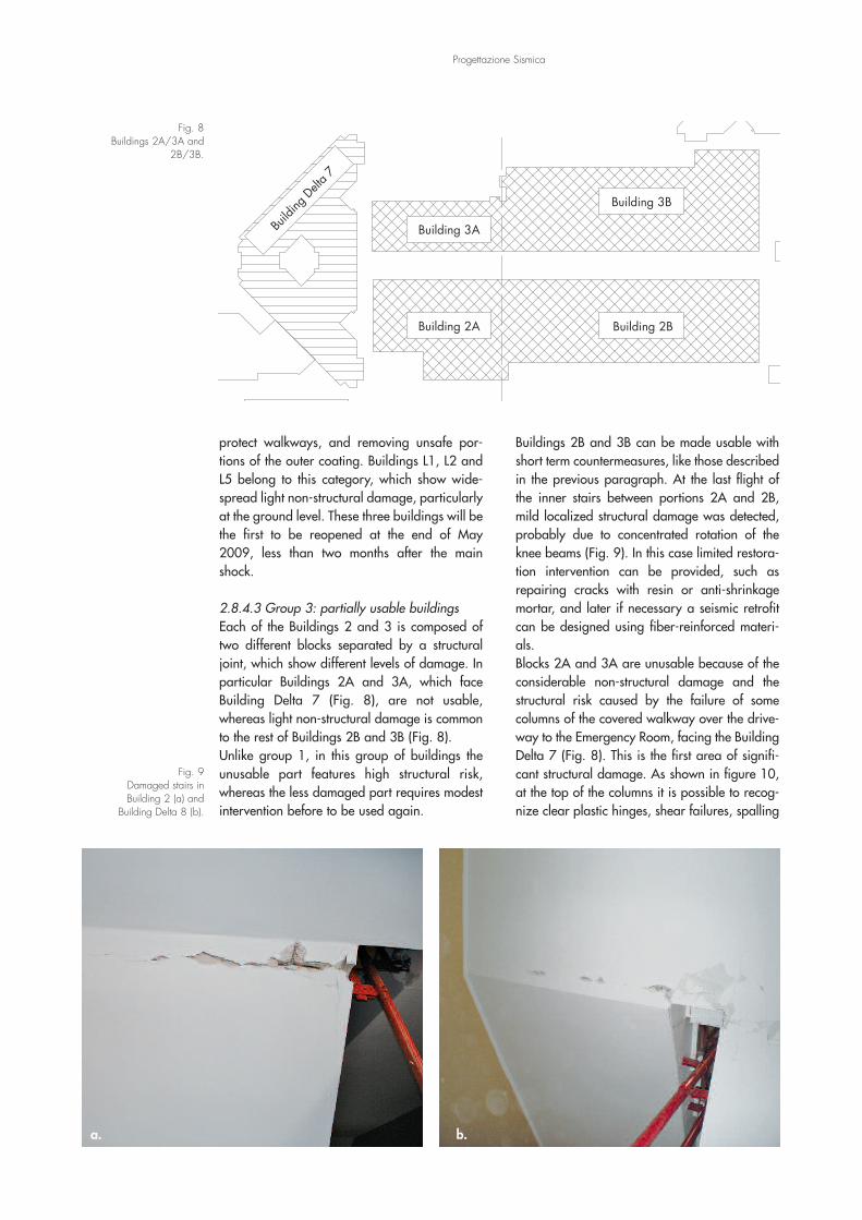
2.8.4.3 Group 3: partially usable buildingsEach of the Buildings 2 and 3 is composed oftwo different blocks separated by a structuraljoint, which show different levels of damage. Inparticular Buildings 2A and 3A, which faceBuilding Delta 7 (Fig. 8), are not usable,whereas light non-structural damage is commonto the rest of Buildings 2B and 3B (Fig. 8).Unlike group 1, in this group of buildings theunusable part features high structural risk,whereas the less damaged part requires modestintervention before to be used again.
Buildings 2B and 3B can be made usable withshort term countermeasures, like those describedin the previous paragraph. At the last flight ofthe inner stairs between portions 2A and 2B,mild localized structural damage was detected,probably due to concentrated rotation of theknee beams (Fig. 9). In this case limited restora-tion intervention can be provided, such asrepairing cracks with resin or anti-shrinkagemortar, and later if necessary a seismic retrofitcan be designed using fiber-reinforced materi-als.Blocks 2A and 3A are unusable because of theconsiderable non-structural damage and thestructural risk caused by the failure of somecolumns of the covered walkway over the drive-way to the Emergency Room, facing the BuildingDelta 7 (Fig. 8). This is the first area of signifi-cant structural damage. As shown in figure 10,at the top of the columns it is possible to recog-nize clear plastic hinges, shear failures, spalling
Progettazione Sismica
Fig. 8Buildings 2A/3A and
2B/3B.
Building 2A
Building 3A
Building 2B
Building 3B
Build
ingDelt
a 7
Fig. 9Damaged stairs inBuilding 2 (a) and
Building Delta 8 (b).
a. b.
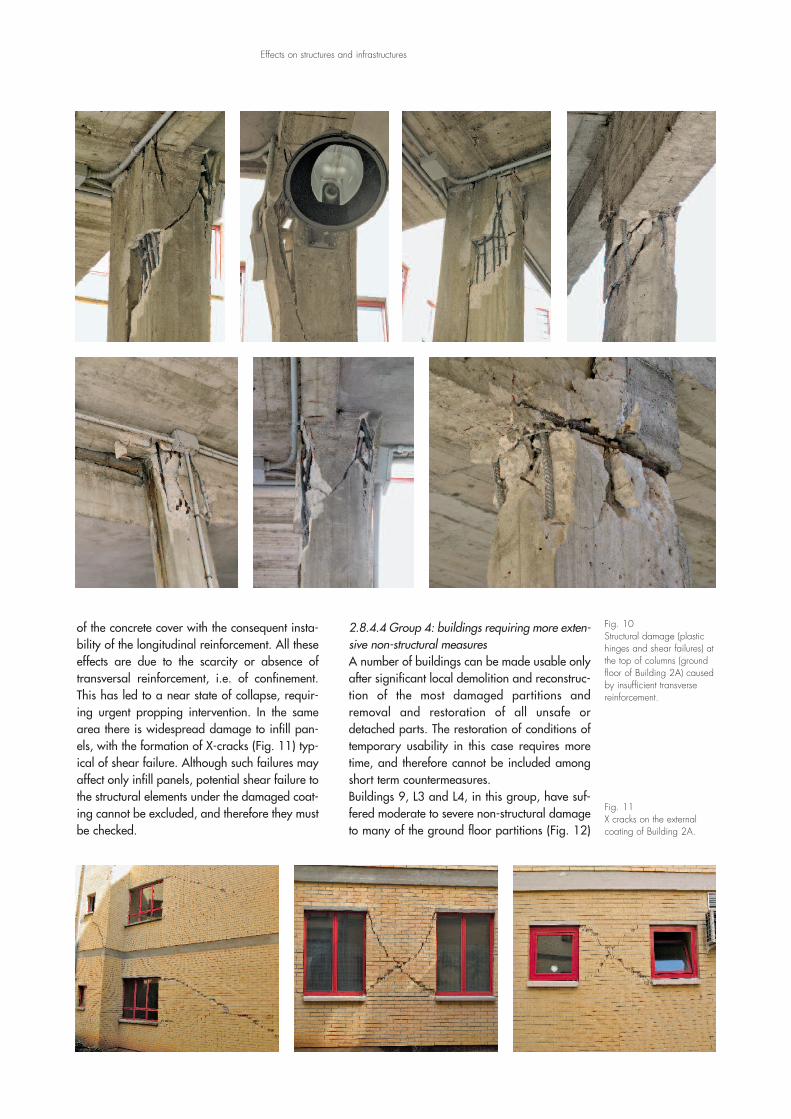
of the concrete cover with the consequent insta-bility of the longitudinal reinforcement. All theseeffects are due to the scarcity or absence oftransversal reinforcement, i.e. of confinement.This has led to a near state of collapse, requir-ing urgent propping intervention. In the samearea there is widespread damage to infill pan-els, with the formation of X-cracks (Fig. 11) typ-ical of shear failure. Although such failures mayaffect only infill panels, potential shear failure tothe structural elements under the damaged coat-ing cannot be excluded, and therefore they mustbe checked.
2.8.4.4 Group 4: buildings requiring more exten-sive non-structural measuresA number of buildings can be made usable onlyafter significant local demolition and reconstruc-tion of the most damaged partitions andremoval and restoration of all unsafe ordetached parts. The restoration of conditions oftemporary usability in this case requires moretime, and therefore cannot be included amongshort term countermeasures.Buildings 9, L3 and L4, in this group, have suf-fered moderate to severe non-structural damageto many of the ground floor partitions (Fig. 12)
Effects on structures and infrastructures
Fig. 10Structural damage (plastichinges and shear failures) atthe top of columns (groundfloor of Building 2A) causedby insufficient transversereinforcement.
Fig. 11X cracks on the externalcoating of Building 2A.
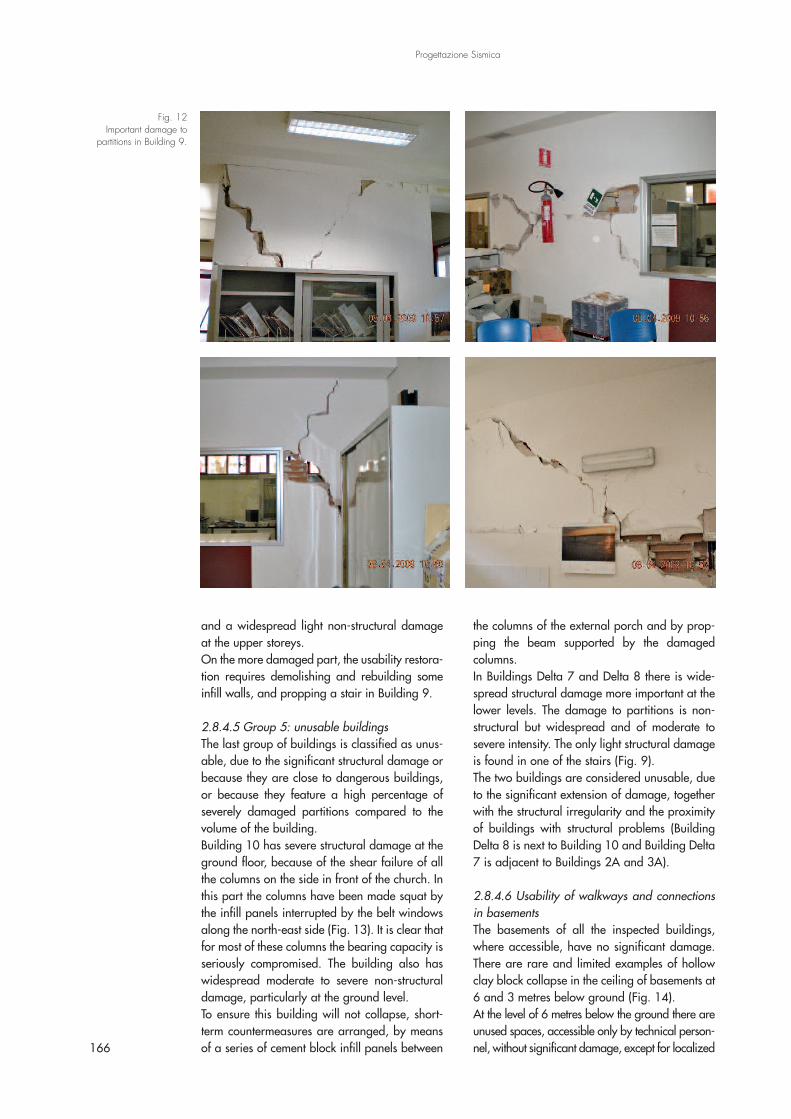
and a widespread light non-structural damageat the upper storeys.On the more damaged part, the usability restora-tion requires demolishing and rebuilding someinfill walls, and propping a stair in Building 9.
2.8.4.5 Group 5: unusable buildingsThe last group of buildings is classified as unus-able, due to the significant structural damage orbecause they are close to dangerous buildings,or because they feature a high percentage ofseverely damaged partitions compared to thevolume of the building.Building 10 has severe structural damage at theground floor, because of the shear failure of allthe columns on the side in front of the church. Inthis part the columns have been made squat bythe infill panels interrupted by the belt windowsalong the north-east side (Fig. 13). It is clear thatfor most of these columns the bearing capacity isseriously compromised. The building also haswidespread moderate to severe non-structuraldamage, particularly at the ground level.To ensure this building will not collapse, short-term countermeasures are arranged, by meansof a series of cement block infill panels between
the columns of the external porch and by prop-ping the beam supported by the damagedcolumns.In Buildings Delta 7 and Delta 8 there is wide-spread structural damage more important at thelower levels. The damage to partitions is non-structural but widespread and of moderate tosevere intensity. The only light structural damageis found in one of the stairs (Fig. 9).The two buildings are considered unusable, dueto the significant extension of damage, togetherwith the structural irregularity and the proximityof buildings with structural problems (BuildingDelta 8 is next to Building 10 and Building Delta7 is adjacent to Buildings 2A and 3A).
2.8.4.6 Usability of walkways and connectionsin basementsThe basements of all the inspected buildings,where accessible, have no significant damage.There are rare and limited examples of hollowclay block collapse in the ceiling of basements at6 and 3 metres below ground (Fig. 14).At the level of 6 metres below the ground there areunused spaces, accessible only by technical person-nel, without significant damage, except for localized166
Progettazione Sismica
Fig. 12Important damage to
partitions in Building 9.
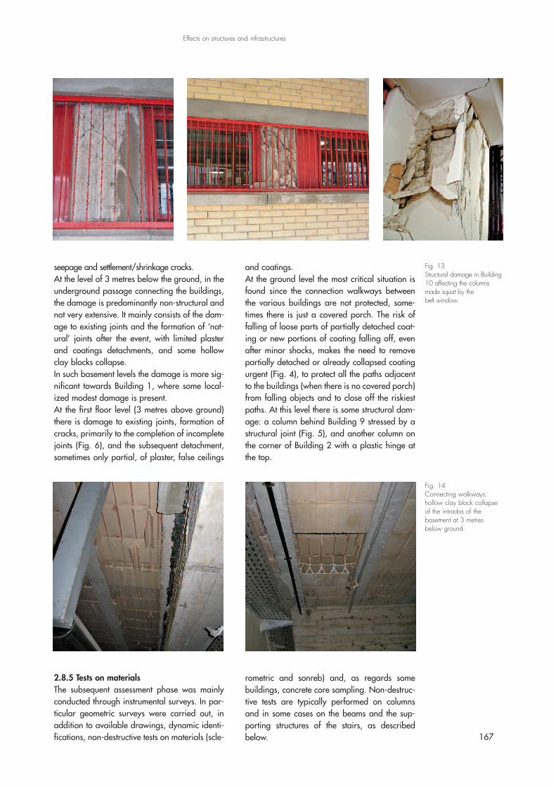
seepage and settlement/shrinkage cracks.At the level of 3 metres below the ground, in theunderground passage connecting the buildings,the damage is predominantly non-structural andnot very extensive. It mainly consists of the dam-age to existing joints and the formation of ‘nat-ural’ joints after the event, with limited plasterand coatings detachments, and some hollowclay blocks collapse.In such basement levels the damage is more sig-nificant towards Building 1, where some local-ized modest damage is present.At the first floor level (3 metres above ground)there is damage to existing joints, formation ofcracks, primarily to the completion of incompletejoints (Fig. 6), and the subsequent detachment,sometimes only partial, of plaster, false ceilings
and coatings.At the ground level the most critical situation isfound since the connection walkways betweenthe various buildings are not protected, some-times there is just a covered porch. The risk offalling of loose parts of partially detached coat-ing or new portions of coating falling off, evenafter minor shocks, makes the need to removepartially detached or already collapsed coatingurgent (Fig. 4), to protect all the paths adjacentto the buildings (when there is no covered porch)from falling objects and to close off the riskiestpaths. At this level there is some structural dam-age: a column behind Building 9 stressed by astructural joint (Fig. 5), and another column onthe corner of Building 2 with a plastic hinge atthe top.
167
Effects on structures and infrastructures
Fig. 13Structural damage in Building10 affecting the columnsmade squat by thebelt window.
Fig. 14Connecting walkways:hollow clay block collapseof the intrados of thebasement at 3 metresbelow ground.
2.8.5 Tests on materialsThe subsequent assessment phase was mainlyconducted through instrumental surveys. In par-ticular geometric surveys were carried out, inaddition to available drawings, dynamic identi-fications, non-destructive tests on materials (scle-
rometric and sonreb) and, as regards somebuildings, concrete core sampling. Non-destruc-tive tests are typically performed on columnsand in some cases on the beams and the sup-porting structures of the stairs, as describedbelow.
168
Progettazione Sismica
2.8.5.1 Non-destructive TestsPacometric scanning is used in some cases todetect the layout and number of longitudinalreinforcement in the accessible structural ele-ments and the layout of the transverse reinforce-ment, in others to properly localize the areas fornon-destructive testing and concrete samplingwithout compromising the bars.Before testing all the surfaces should be pre-pared. After removing plaster, mortar residualson the concrete surface are removed with a steelbrush and a silicon carbide abrasive stone ofmoderate granular texture, in order to discovera smooth part of the structure, at least 25 cmwide without signs of degradation.The sclerometric index is determined accordingto the UNI EN 12504-2 standard (UNI, 2001).On both sides of the elements under investiga-tion non-overlapping sclerometric measures aretaken, not less than 25 mm between each meas-urement or from the edge of any surface faultsand steel bar, previously located. The instrumentmeasures the rebound of a mass thrown onto apiston on the concrete surface. The test result isa scale that measures how far the massrebounds, values from which the averagerebound index is obtained together with its stan-dard deviation.At the same points ultrasonic tests have been car-ried out using the direct transmission technique,as specified by the UNI EN 12504-4 standard(UNI, 2005). With the direct transmissionmethod two points are chosen on opposite sidesof the structural element for sending and receiv-ing the acoustic signal, so that the sound beam isperpendicular to the surface. The technique isbased on the transparency of the concrete struc-tural element to the passage of sound waves, i.e.on the measure of the transmission time of thewave from one side of the element to the other.The ultrasonic analysis is performed with trans-ducers at a frequency of 55 kHz and 50 mmdiameter, using plasticine as a coupling material.The transmission velocity V is given by:
(1)
Where tp is the transmission time of the wave andD is the size of the object. From the transmissionvelocity V [m/s] and the density ρ [kg/m3], themodulus of elasticity E is obtained as:
(2)
The parameters obtained with the two methodsare related to the material elastic properties anddensity. To estimate the cubic compressionstrength, the combined sclerometer-ultrasoundmethod is used according to the formula:
Rs = 1,2 x 10⁻⁹ x Ir1,058 x V2,446 [MPa] (3)
where V and Ir represent the ultrasonic wavevelocity and the average rebound indexobtained from sclerometric tests, respectively.
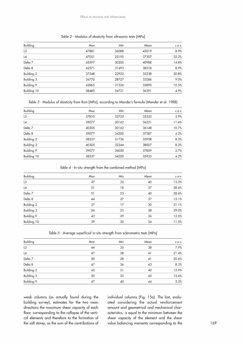
2.8.5.2 Non-destructive test resultsNon-destructive tests have been performed ondifferent parts of the buildings, in 4 to 13 differ-ent positions per building. The average values ofthe modulus of elasticity obtained from each testfor each building, with their ranges of variation,are shown in table 2 and table 3, in terms ofultrasonic test results and of the sclerometrictests, respectively. Tables 4 and 5 show the val-ues obtained for the concrete compressivestrength, as results of the combined method andof the sclerometric tests, respectively.The results of non-destructive tests on the con-crete of buildings show medium to good qualityboth in terms of strength and modulus of elastic-ity. The coefficients of variation are, with fewexceptions, moderate and show good stability ofvalues. The steel used has in some cases asmooth surface, in others improved adherence,confirming that construction took place over avery long period of time.Concluding, it can be assumed that the materialcharacteristics are sufficient to ensure a properbehaviour of the buildings, but in several casesdesign details are in contrast with the mostrecent seismic codes, especially regarding thedetails of reinforcement at the element ends andin the beam-column joints.
2.8.6 Simplified vulnerability assessmentAs already mentioned above, Building 10 showsone of the most critical conditions in the hospitalcomplex. For this reason it was decided to applyto this structure the simplified evaluationmethodology developed within the SAVE project(Updated tools for the seismic vulnerability of
building stock and of urban systems Task 2) ofINGV-GNDT (Dolce and Moroni, 2005) in orderto estimate the collapse ground acceleration forthe building and to understand some criticalissues of its seismic response.The simplified procedure, assuming a collapsemechanism characterized by strong beams and
weak columns (as actually found during thebuilding survey), estimates for the two maindirections the maximum shear capacity of eachfloor, corresponding to the collapse of the verti-cal elements and therefore to the formation ofthe soft storey, as the sum of the contributions of
individual columns (Fig. 15a). The last, evalu-ated considering the actual reinforcementamount and geometrical and mechanical char-acteristics, is equal to the minimum between theshear capacity of the element and the shearvalue balancing moments corresponding to the 169
Effects on structures and infrastructures
Table 2 - Modulus of elasticity from ultrasonic tests [MPa]
Building Max Min Mean c.o.v.
L3 47881 36088 42019 8.9%
L4 47051 25195 37307 25.2%
Delta 7 45597 30205 40988 14.8%
Delta 8 42571 31493 38318 8.9%
Building 2 37548 22922 32238 20.8%
Building 3 36770 28727 33286 9.0%
Building 9 42865 31326 35890 10.5%
Building 10 38485 34721 36391 4.9%
Table 3 - Modulus of elasticity from Rcm [MPa], according to Mander’s formula (Mander et al. 1988)
Building Max Min Mean c.o.v.
L3 37810 33722 35325 3.9%
L4 39077 30162 36321 11.4%
Delta 7 40305 30162 36148 10.7%
Delta 8 39077 34200 37387 4.2%
Building 2 38237 31736 35958 8.3%
Building 3 40305 32244 38007 8.2%
Building 9 39077 36050 37859 2.7%
Building 10 38237 34200 35935 4.2%
Table 4 - In-situ strength from the combined method [MPa]
Building Max Min Mean c.o.v.
L3 47 32 40 13.3%
L4 51 18 37 38.6%
Delta 7 51 23 40 28.6%
Delta 8 44 27 37 15.1%
Building 2 37 17 30 31.1%
Building 3 56 23 38 29.0%
Building 9 43 29 36 12.5%
Building 10 39 30 34 11.5%
Table 5 - Average superficial in-situ strength from sclerometric tests [MPa]
Building Max Min Mean c.o.v.
L3 44 35 38 7.9%
L4 47 28 41 21.4%
Delta 7 50 28 41 20.6%
Delta 8 47 36 43 8.3%
Building 2 45 31 40 15.9%
Building 3 50 32 45 15.6%
Building 9 47 40 44 5.3%

formation of plastic hinges at the ends of the col-umn. This also provides information about theexpected collapse type. Finally, assuming aninverted triangular distribution of horizontalforces (Fig. 15b), that is proportional to the massand level of each storey, the procedure evaluatesthe collapse multiplier for each floor, identifyingthe soft storey as corresponding to the lowercoefficient.To evaluate the natural period of the structure, theprocedure determines the overall stiffness of eachfloor by adding the stiffness of all columns foreach of the two considered directions (Fig. 15c).Once the stiffness of all floors is known, the nat-ural period in the direction under considerationis evaluated by the Rayleigh formula (Cloughand Penzien, 1975), using the deformed shapeproduced by the static forces previously defined.From the fundamental period of vibration of thebuilding and the spectral shape for the site soilcategory, the collapse peak ground accelerationis estimated (Fig. 15d) together with the corre-sponding return period. For further detail refer toDolce and Moroni (2005).In what follows, results are shown of the evalua-tion procedure applied to Building 10. In theabsence of the structural design details, sectionshave been re-designed by using a procedureessentially based on the evaluation of axialloads, on the live loading conditions providedby the standards of the ‘70s and on the use ofthe allowable stress method. Due to the presenceof joints that cut the building, a single portion
was considered with dimensions Lx = 50 m andLy = 23.5 m (Fig. 16).In the re-design of the structure, a concretecharacteristic compressive strength Rck of 30MPa has been adopted, derived from the ultra-sonic and sclerometric test results, which corre-sponds to a design allowable stress of 9.75MPa. It was not possible, however, to run anytest to determine the steel strength, but since inthe damaged columns ribbed bars are visibleand considering the building constructionperiod, it is conservative to assume a FeB38Ktype of steel with a corresponding allowablestress equal to 215 MPa.The standard column, obtained from the allow-able stress design for gravity loads only, has 8φ16 as longitudinal reinforcement and 2-leg φ8stirrups at 20 cm as transverse reinforcement.The reinforcement detected in the columns duringthe surveys is actually different, probably becauseof different assumptions regarding the entity ofpermanent and live loads. For this reason it wasdecided to perform a parametric analysis to eval-uate the variation in collapse acceleration as afunction of the bar diameters. The collapse accel-eration calculation has also been carried out bothconsidering and ignoring the presence of beltwindows that limit the deformation capacity andincrease the shear vulnerability (squat elements)of the ground floor columns.In table 6 the results obtained from the simplifiedprocedure described above are shown syntheti-cally. For the case studies considering the pres-
170
Progettazione Sismica
Fig. 15Scheme of the simplified
assessment procedure.
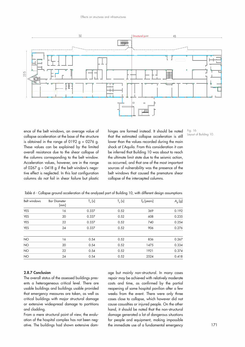
ence of the belt windows, an average value ofcollapse acceleration at the base of the structureis obtained in the range of 0192 g ÷ 0276 g.These values can be explained by the limitedoverall resistance due to the shear collapse ofthe columns corresponding to the belt window.Acceleration values, however, are in the rangeof 0267 g ÷ 0418 g if the belt window’s nega-tive effect is neglected. In this last configurationcolumns do not fail in shear failure but plastic
hinges are formed instead. It should be notedthat the estimated collapse acceleration is stilllower than the values recorded during the mainshock at L’Aquila. From this consideration it canbe inferred that Building 10 was about to reachthe ultimate limit state due to the seismic action,as occurred, and that one of the most importantsources of vulnerability was the presence of thebelt windows that caused the premature shearcollapse of the intercepted columns.
171
Fig. 16Layout of Building 10.
Table 6 - Collapse ground acceleration of the analyzed part of Building 10, with different design assumptions
Belt windows Bar Diameter Tx [s] Ty [s] TR [years] Ag [g][mm]
YES 16 0.337 0.52 369 0.192
YES 20 0.337 0.52 608 0.235
YES 22 0.337 0.52 740 0.254
YES 24 0.337 0.52 906 0.276
NO 16 0.54 0.52 836 0.267
NO 20 0.54 0.52 1475 0.334
NO 22 0.54 0.52 1921 0.374
NO 24 0.54 0.52 2524 0.418
2.8.7 ConclusionThe overall status of the assessed buildings pres-ents a heterogeneous critical level. There areusable buildings and buildings usable providedthat emergency measures are taken, as well ascritical buildings with major structural damageor extensive widespread damage to partitionsand cladding.From a mere structural point of view, the evalu-ation of the hospital complex has not been neg-ative. The buildings had shown extensive dam-
age but mainly non-structural. In many casesrepair may be achieved with relatively moderatecosts and time, as confirmed by the partialreopening of some hospital pavilion after a fewweeks from the event. There were only threecases close to collapse, which however did notcause casualties or injured people. On the otherhand, it should be noted that the non-structuraldamage generated a lot of dangerous situationsfor people and equipment, making impossiblethe immediate use of a fundamental emergency
Effects on structures and infrastructures
structure. In these terms the San Salvatore Hos-pital’s performance can be considered less suit-able than expected.In terms of prevention, it should be noted that theissue of usability surveys of strategic structures inemergency conditions deserves serious thought.
In the perspective of the recent experience, it isconsidered essential to prepare a plan for post-earthquake inspection of hospital structures tobe developed in collaboration with teams ofexperts in all those functional and operationalneeds of strategic structures during emergencies.
172
Progettazione Sismica
AcknowledgmentsThe authors thank the European Community’s Environ-ment DG, financial supporter of the STEP project,which allowed the implementation and use of theMobile Unit, the Department of Civil Protection for the
support on the field during the phases of inspectionand data retrieving, L’Aquila’s Fire Department, andEng. M.A. Tursini and all the staff of the Hospital’sTechnical Office for the availability and precious sup-port offered to the survey teams.
ReferencesCasarotti C., Dacarro F., Pavese A., Peloso S. (2009)
- “Mobile Unit for fast experimental post-earth-quake vulnerability assessment”, Atti del XIII Con-vegno ANIDIS, Bologna.
Clough R.W., Penzien J. (1975) - Dynamics of Struc-tures, McGraw-Hill.
Dolce M., Moroni C. (2005) - “La valutazione dellavulnerabilità e del rischio sismico degli edificipubblici mediante le procedure VC (vulnerabilitàc.a.) e VM (vulnerabilità muratura)”, Atti delDiSGG, Potenza.
Gazzetta Ufficiale (1962) - “Legge 25 novembre1962, n. 1684. Provvedimenti per l’edilizia,conparticolari prescrizioni per le zone sismiche”, GUn. 326 del 22/12/1962.
Gazzetta Ufficiale (1964) - Legge 5 novembre 1964 n°1224. Integrazioni della legge 25 novembre 1962,n. 1684, concernente provvedimenti per l’ediliziacon particolari prescrizioni per le zone sismiche.
Gazzetta Ufficiale (1974) - Legge 2 febbraio 1974, n.64. Provvedimenti per le costruzioni con partico-
lari prescrizioni per le zone sismiche, GU n. 076del 21/03/1974.
Mander J.B., Priestley M.J.N., Park, R. (1988) - Theo-retical Stress-Strain Model for Confined Con-crete,” Journal of Structural Engineering, ASCE,Vol. 114, No. 8, pp. 1804-1826.
Ministero dei Lavori Pubblici (1969) - “Circolare11.8.1969 N. 6090. Norme per la proget-tazione, il calcolo, la esecuzione ed il collaudo dicostruzioni con strutture prefabbricate in zoneasismiche e sismiche”.
Regio Decreto Legge (1937) - Regio Decreto Legge 22novembre 1937 n° 2105, Norme tecniche diedilizia con speciali prescrizioni per le localitàcolpite dai terremoti.
UNI (2001) - UNI EN 12504-2:2001 - Prove sul cal-cestruzzo nelle strutture - Prove non distruttive -Determinazione dell’indice sclerometrico.
UNI (2005) - UNI EN 12504-4:2005 - Prove sul cal-cestruzzo nelle strutture - Parte 4: Determinazionedella velocità di propagazione degli impulsi ultra-sonici.