A Cross-Sectional Survey of Salty Snack Consumption among ...
Upload
khangminh22Category
view
0download
0
MANUAL 1189468 REV 1 (8/19) $21.00
Owner’s Manual
IMPORTANT FOR FUTURE REFERENCE Please complete this information and retain this manual for the life of the equipment:
Model #: Serial
#: Date
Purchased:
Sectional Fryers
Model P16-PF45 & P20-PF65
WARNING
Improper installation, adjustment, alteration, service, or maintenance can cause property damage, injury, or death.
Read installation, operation, and maintenance instructions thoroughly before installing or servicing this equipment.
1100 Old Honeycutt Road Fuquay-Varina, North Carolina 27526 USA • www.southbendnc.com

OWNER’S MANUAL 1189468 REV 1 (8/19) PAGE 2 of 50
SECTIONAL FRYERS SAFETY PRECAUTIONS
SAFETY PRECAUTIONS
Before installing and operating this equipment, be sure everyone involved in its operation is fully trained and aware of
precautions. Accidents and problems can be caused by failure to follow fundamental rules and precautions.
The following symbols, found throughout this manual, alert you to potentially dangerous conditions to the operator,
service personnel, or to the equipment.
DANGER
WARNING
CAUTION
NOTICE
This symbol warns of immediate hazards that will result in severe injury or death.
This symbol refers to a potential hazard or unsafe practice that could result in injury or death.
This symbol refers to a potential hazard or unsafe practice that could result in injury, product
damage, or property damage.
This symbol refers to information that needs special attention or must be fully
understood, even though not dangerous
WARNING FIRE HAZARD FOR YOUR SAFETY
DO NOT store or use gasoline or other flammable vapors and liquids in the vicinity of cooking
appliances. Keep area around cooking appliances free and clear of combustibles.
Purchaser of equipment must post in a prominent location detailed instructions to be followed in the event the
operator smells gas. Obtain the instructions from the local gas supplier.
WARNING BURN HAZARD
Contact with hot surfaces will cause severe burns. Always use caution when operating cooking appliances.
WARNING EXPLOSION AND ASPHYXIATION HAZARD
In the event a gas odor is detected, shut down equipment at the main gas shut-off valve and immediately call the
emergency phone number of your gas supplier.
Improper ventilation can result in headaches, drowsiness, nausea, and could result in death. Do not obstruct the
flow of combustion and ventilation air to and from cooking appliances.
WARNING ELECTRIC SHOCK HAZARD
For appliances that use electric power, disconnect the power to the appliance before cleaning. Do not remove
panels that require tools to remove.
NOTICE
Southbend appliances are intended for commercial use only. Not for household use.
Warranty will be void if service work is performed by other than a qualified technician, or if other than genuine
Southbend replacement parts are installed.
Give this Owner’s Manual and important papers to the proper authority to retain for future reference.
Copyright © 2019 by Southbend. All rights reserved. Published in the United States of America.

OWNER’S MANUAL 1189468 REV 1 (8/19) PAGE 3 of 50
SECTIONAL FRYERS INSTALLATION
INSTALLATION CHECKING YOUR NEW FRYER Your new fryer has been carefully packed into one crate. Every effort has been made to ensure that your fryer is delivered to you in perfect condition. As you unpack your new fryer, inspect each of the pieces for damage. If something is damaged, DO NOT sign the bill of lading. Contact the shipper immediately, the shipper is only responsible for 15 days after delivery. Check the packing list enclosed with your fryer to ensure that you have received all of the parts to the fryer. If you are missing any parts, contact the dealer from whom the fryer was purchased.
CAUTION
To prevent equipment damage, don’t tilt the fryer onto any two of its casters or pull the unit by the flue vents. LEG/CASTER INSTALLATION AND ADJUSTMENT Installing the legs and leveling the fryer is done with a 7/16" wrench, socket, and a large pair of water pump pliers. The
legs/ casters must be installed to provide the necessary height to meet sanitation requirements and assure adequate air
supply to the burner. Attach the legs by performing the following procedure.
a. Lay the fryer on its side being careful not to damage the flue by pulling on it. Protect the outside of the fryer
with cardboard or a drop cloth when laying it down.
b. Attach each leg/caster with the hex head cap screws supplied with the fryer. Each leg/caster requires four 1/4-20 x 5/8" cap screws.
c. Mount the screws from the inside of the fryer with the nut on the outside. The nuts have lock washers
attached to them, therefore it is not necessary to use lock washers.
d. When all four legs/casters are mounted, stand the unit up being careful not to put too much weight on any one
leg/ caster. Adjust the height and level the fryer by adjusting the leveling devices on the leg/caster with the
water pump pliers.
e. On units with casters, move the fryer to the desired location and lock the wheels using the locking devices
on the front of the casters.
WARNING The fryer must be properly restrained to prevent movement or tipping. This restraint must prevent the fryer
from movements that would splash hot liquids on personnel, which could cause severe burns or injuries.
Always wear oil proof gloves when moving or handling equipment or hot liquids.
INSTALLATION CLEARANCES
The fryer needs clearance around it for proper operation. Adequate clearances allow for servicing and proper burner
operation. The clearances shown below are for cooker installation in combustible and noncombustible construction.
Combustible Non-Combustible
Construction Construction
Back 6" 0"
Sides 6" 0"
Floor - Combustible 9" 9" (Needed for Combustion)

OWNER’S MANUAL 1189468 REV 1 (8/19) PAGE 4 of 50
SECTIONAL FRYERS SPECIFICATIONS
SPECIFICATIONS
GAS CONNECTION Your fryer will give you peak performance when the gas supply line is of sufficient size to provide the correct gas flow.
The gas line must be installed to meet the local building codes or National Fuel Gas Code ANSI Z223.1 Latest Edition.
In Canada, install the fryer in accordance with CAN/CGA-B149.1 or .2 and local codes. Gas line sizing requirements
can be determined by your local gas company by referring to National Fuel Gas Code, Appendix C, Table C-4
(natural gas) and Table C-16 (propane). The gas line needs to be large enough to supply the necessary amount of
fuel to all appliances without losing pressure to any appliance.
WARNING NEVER supply the fryer with a gas that is not indicated on the data plate. Using the incorrect gas type will
cause improper operation. If you need to convert the fryer to another type of fuel, contact your dealer.
FUEL TYPES
Each fryer is equipped to work with one type of fuel. The type of fuel with which the appliance is intended to operate
is stamped on the data plate attached to the inside of the door.
NOTICE
NEVER use an adaptor to make a smaller gas supply line fit the cooker connection. This
may not allow proper gas flow for optimum burner operation, resulting in poor cooker
performance.
QUICK DISCONNECT GAS CONNECTION Gas fryers equipped with casters must be installed with connectors that comply with the Standard for Connectors for
Movable Gas Appliances, ANSI Z223.1 Latest Edition, and Addenda Z21.69A Latest Edition. This connection should
include a quick disconnect device that complies with the Standard for Quick Disconnect Devices for Use With Gas Fuel ,
ANSI Z223.1 Latest Edition. When installing a quick disconnect you must also install a means for limiting the movement
of the fryer. This device will prevent the gas line or the quick disconnect from being strained. The restraining device
should be attached to the cooker on the back panel.
FUEL SUPPLY LINE LEAK AND PRESSURE TESTING The fuel supply system must be tested before the fryer is used. If the fuel line is going to be tested at a pressure
greater than (>)1/2 PSIG (3.45 kPa), make sure that the fryer is disconnected from the fuel line. If the fuel line is to be
tested at a pressure equal to or less than (<) 1/2 PSIG (3.45 kPa), the fryer can be connected but the unit’s gas valve
must be shut. Test all gas line connections for leaks with a solution of soap and water when pressure is applied.
ELECTRICAL CONNECTION The electrical service used by the fryer must comply with local codes. If there are no local codes that apply, refer to the
National Electrical Code (NEC), ANSI/NFPA 70 to install the service. In Canada refer to CSA Standard C22.1 and local
codes. Wiring diagrams are provided inside the fryer control box.
VENTILATION AND FIRE SAFETY SYSTEMS Your new fryer must have proper ventilation to function safely and properly. Exhaust gas temperatures can reach as high as 1000°F. Therefore, it is very important to install a fire safety system. Your ventilation system should be designed to allow for easy cleaning. Frequent cleaning of the ventilation system and the fryer will reduce the chances of fire. Table 1-2 provides a list of reference documents that provide guidance on ventilation and fire safety systems. This table is not necessarily complete. Additional information can be obtained from the CSA-International, 8501 East Pleasant Valley Road, Cleveland, OH 44131.

OWNER’S MANUAL 1189468 REV 1 (8/19) PAGE 5 of 50
SECTIONAL FRYERS SPECIFICATIONS
Excessive ventilation causes drafts, which will interfere with the proper operation of the pilot and the burner. Leave at
least 18 inches of open space between the fryer’s flue vent opening and the intake of the exhaust hood.
CAUTION
Ensure that your ventilation system does not cause a down draft at the fryer’s flue opening.
Down drafts will not allow the fryer to exhaust properly and will cause overheating which
may cause permanent damage. Damage caused by down drafts will not be covered under
equipment warranty. NEVER allow anything to obstruct the flow of combustibles or
ventilation exiting from the fryer flue. DO NOT put anything on top of the flue area.
NOTICE NEVER connect the blower directly to the flue openings. The direct flow of air will cause
poor temperature recovery, poor ignition, inefficient operation of the fryer, and could
extinguish the pilot.
GAS LINE REQUIREMENTS A properly installed gas supply system will deliver 7.0 ± 2.0" w.c. natural gas (12.0 ± 2.0" w.c. LP) to all appliances
connected to the line, operating at full demand.
NOTICE
Do NOT exceed 13.5" W.C. pressure as damage may occur to the gas valve.
TOPIC UNDERWRITERS LABORATORY
DOCUMENT
NATIONAL FUEL GAS CODE
DOCUMENT
EXHAUST HOODS
ANSI/UL 710
ANSI/NFPA 96
POWER VENTILATORS
ANSI/UL 705
ANSI/NFPA 96
FILTER UNIT
ANSI/UL 586
ANSI/UL 900
ANSI/NFPA 96
TYPES OF FIRE EXTINGUISHERS AND DETECTION EQUIPMENT
CO2 ANSI/UL 154 ANSI/NFPA 12
DRY CHEMICAL
ANSI/UL 299
ANSI/NFPA 17
WATER
ANSI/UL 626
ANSI/NFPA 13
FOAM
ANSI/UL 8
ANSI/NFPA 11
SPRINKLERS
ANSI/UL 199
ANSI/NFPA 13
SMOKE DETECTORS
ANSI/UL 268
ANSI/NFPA 72
FIRE DETECTION THERMOSTATS
ANSI/UL 521
ANSI/NFPA 72
IF MAINTENANCE IS REQUIRED, CONTACT YOUR LOCAL FACTORY SERVICER, LOCAL
FACTORY REPRESENTATIVE, OR THE FACTORY TO OBTAIN SERVICE.

OWNER’S MANUAL 1189468 REV 1 (8/19) PAGE 6 of 50
SECTIONAL FRYERS OPERATION
OPERATION
LIGHTING INSTRUCTIONS 1. Fill kettle before lighting.
2. Turn combination gas valve knob to “PILOT” position.
3. Depress valve knob and light pilot. With pilot burning, hold knob depressed for 60 seconds. d. Release knob,
pilot should remain lit.
4. DO NOT TURN COMBINATION GAS VALVE KNOB TO THE “ON” POSITION UNTIL VESSEL IS FULL OF
WATER OR SHORTENING. TURNING THE KNOB TO “ON” WITH VESSEL EMPTY WILL DAMAGE THE
VESSEL OR COMPONENTS AND VOID WARRANTY.
5. Relighting - wait 5 minutes before attempting to relight the pilot to allow for any gas in the fryer to dissipate.
WARNING
Gas units installed with casters must have a restraining device. This device must be connected at all
times that the fryer is connected to the gas supply. If it is disconnected for any reason, it must be
reconnected.
INITIAL CLEANING
When the fryer is shipped, many of its parts are covered with a thin coat of oil for protection. Before the fryer is ready
for cooking it must be cleaned. This will remove oil coating and any foreign matter that may have accumulated during
storage and shipment. Perform the cleaning as described below.
1. Fill the vessel with water.
2. Turn the fryer gas valve knob to the “ON” position. Allow the fryer to bring the water to a low boil and add one
3. Packet of fryer cleaner or a mild, low sudsing detergent and allow water to continue to boil for a minute,
making sure the water does not boil over.
4. Turn the gas valve knob to the “PILOT” position and allow fryer to soak with the hot water for 15 minutes.
NOTICE Do not leave the fryer unattended during cleaning. Never let the water level go below the “Min Level” mark
on the back of the tank.
5. Using the fryer cleaning brush, scrub the inside of the fryer to remove protective coating.
6. When cleaning is complete, turn the gas valve knob to the “OFF” position and drain the water into a container
suitable for hot water and dispose of it.
7. When the tank has cooled, rinse it thoroughly with cool water. Continue to rinse the tank until the cleaner has
been rinsed thoroughly from the tank.
8. Using a clean dry cloth, wipe out all of the water. Be very thorough removing the water, because any residual
water will cause hot oil to splatter out of the fryer. Close the drain valve and remove container.
9. Now that the tank is clean, you are ready to fill and operate the fryer. Refer to instructions on adding shortening
to the fryer.

OWNER’S MANUAL 1189468 REV 1 (8/19) PAGE 7 of 50
SECTIONAL FRYERS OPERATION
THERMOSTAT CALIBRATION CHECK
NOTICE
Thermostat calibration requires that the temperature of the fryer be raised above boiling. Therefore,
you will need to drain the water from the fryer and fill it with oil. Before removing the water, perform
the Initial Cleaning of the fryer. Cleaning the fryer now will prevent you from having to drain the oil
and refill with water later.
To perform the calibration check detailed below, you will need a digital thermometer.
1. Place the tip of the thermometer in the shortening approximately 1" above the temperature sensors.
2. Set the thermostat at 325°F and wait for the temperature reading on the thermometer to rise. As the
temperature rises toward 325°F watch the thermometer closely.
3. If the shortening temperature reaches 350°F and the burners DO NOT turn off, turn the thermostat down. Keep
lowering the thermostat setting until the burners go out.
CAUTION
If the burners do not turn off at the lowest thermostat setting, the thermostat could be defective.
Contact your representative immediately.
4. Let the fryer cycle 4 to 6 times before checking the temperature. Compare the thermometer temperature
against the thermostat setting. If the values are more than 5°F apart, calibrate the thermostat using the
appropriate calibration procedure in this manual.
THERMOSTAT CALIBRATION Millivolt thermostats
1. Set the thermostat dial to 325°F.
2. Remove the thermostat dial by pulling the knob straight out. DO NOT rotate the dial.
3. Hold the outside of the shaft so it does not move. Use the tip of a small, flat tip screw driver to scrape away the
sealing compound from the adjustment screw.
4. Turn the adjustment screw clockwise to lower the temperature setting and counterclockwise to raise the
temperature. One quarter turn changes the temperature approximately 25°F.
5. Turn the adjustment until the burners turn on at 325°F. Replace the knob and allow the fryer to cycle 4 to 6
times. Check the temperature of the thermometer against the thermostat dial. If it is greater than 5° F
difference, repeat the calibration procedure.
6. When the calibration is correct, remove the thermometer and replace the tube screen.
FRYER OPERATION
Filling the Fryer with Liquid Shortening
1. Make sure the drain valve is completely closed.
2. Fill the fryer with oil to the “Oil Level” line marked on the back of the tank.

OWNER’S MANUAL 1189468 REV 1 (8/19) PAGE 8 of 50
SECTIONAL FRYERS OPERATION
Filling the Fryer with Solid Shortening
1. Make sure the drain valve is completely closed.
2. Remove the screen covering the tubes.
3. Cut the shortening into cubes no larger than 1". ALWAYS pack the shortening below, between, and on top of the
burner tubes. DO NOT leave any large air gaps. Use care when packing the solid shortening in the tank. DO NOT
bend or break the temperature sensor probes. If these are damaged the fryer will not function properly.
4. Once the fryer is packed with shortening, the shortening must be melted.
5. To melt shortening, manually pulse the burners ON and OFF using the thermostat until the shortening is liquidized
enough to cover the heat tubes. This will protect the tank and components from damage and extend the life of the oil.
Fryer Shut-Down
There are two shutdown modes of fryer operation, STANDBY and COMPLETE. The Standby mode removes the ability
for the fryer’s main burners to cycle. Complete shutdown turns off the gas supply to the fryer. Shut down the fryer by:
STANDBY
Turn the thermostat to OFF. Turn the gas valve clockwise to the PILOT position. The cooker is now in Standby mode
and can remain this way for only brief periods of time. NEVER leave the cooker in Standby overnight.
COMPLETE
To completely shut down the cooker, push and turn the gas valve counterclockwise to the OFF position. The fryer is
now completely shut down and can be cleaned and filtered.
FILTER PROCEDURES
NOTICE When working with hot oil ALWAYS wear oil-proof, insulated gloves.
WARNING NEVER • Run the filter system without a filter bag/paper.
NEVER • Empty the oil from the fryer before turning OFF the fryer burners.
NEVER • Store the UFM Filter Unit anywhere other than in the fryer filter cavity.
1. Slide the filter pan out. Carefully remove filtered residue off the filter media. Examine the filter media for clogged
or torn areas. Refer to filter media replacement instructions following this section. Reinstall the pan.
2. Turn the fryer that is to be filtered OFF (See Standby Shutdown). Remove the baskets from the fryer tank(s).
3. Use the clean out brush to lift out the tube screens. If there are excess crumbs in the fryer tank, remove them
with the crumb scoop.
4. If you have replaced the filter media or remove crumbs and debris, sprinkle Pre-Coat Filter Aid on the filter paper.
5. Check the drain spout to ensure that it is in the drain tower and over the filter pan opening.
6. Slowly open the green handled drain valve for the tank being filtered. If necessary use the clean-brush to clear
the crumbs from the drain. Use the brush to clean the sides of the tank as the oil drains.

OWNER’S MANUAL 1189468 REV 1 (8/19) PAGE 9 of 50
SECTIONAL FRYERS OPERATION
WARNING
This filter pan is only large enough to hold the contents of ONE (1) tank at a time,
during the filter process.
7. When the tank is empty, close the green handled drain valve. Open the red handled return valve to the tank you
are filtering. This will start the pump and return the oil to the bottom of the fry tank.
8. When bubbles are seen coming out of the oil return spout, close the red handled valve to turn the pump off. If
necessary add more oil to the tank to return the oil level to the fill mark. The fryer is now ready for use.
DRAINING A TANK
Note -The filter system is also used to drain the fryers. You will need a container capable of holding 400°F oil and
protective gloves.
1. Rotate the drain down spout so that it extends in the container that you want to drain the shortening into.
2. Open the green handled drain valve for the tank to be drained. The oil will drain into the container you have
chosen. When the container is full or the fry tank is empty, close the green handled drain valve. If the container
was full repeat this step until fryer tank is empty.
3. Once tank is completely empty add new shortening and follow fryer start up procedures.
WARNING
The power supply must be disconnected before servicing or cleaning the appliance.
FILTER MEDIA REPLACEMENT
The filter module stores neatly under the fryer when not in use. The unit is very easy to use and allows for quick
installation and filtration, even under the busiest conditions. Follow the procedures below to change the filter media.
WARNING
At operating temperature, the shortening in the fryer may be hotter than 375°F (190°C). This hot, melted shortening will cause severe burns. DO NOT let the hot shortening touch your skin or clothing. Always wear
insulated oil proof gloves when working on the filter system. It will be easier and safer if the filter assembly has cooled to room temperature before handling any filter parts.
1. With the filter pan empty of oil, remove the filter media by grasping the filter pan handle and gently pull the
assembly toward the front of the fryer.
2. Separate the filter pickup tube from the filter pickup screen assembly by pulling up on the pickup tube just above
where it connects to the pickup screen assembly. Lift pickup tube and swing it to the left, until it rests on the left
hand side of the filter pan.
3. Grab filter screen pickup assembly lift handles and carry it to a trash barrel and shake off heavy discard any debris
that may be built upon the top of the assembly.
4. Unscrew the filter paper clip bracket from the filter paper support screen and slide the filter paper support screen
out of the filter paper clip bracket.

OWNER’S MANUAL 1189468 REV 1 (8/19) PAGE 10 of 50
SECTIONAL FRYERS OPERATION
5. Remove filter paper support screen from the filter envelope.
6. All of the filter pick up assembly parts can be washed in a dish washer or a pot sink. Flush out the suction tube
assembly with hot water. After cleaning, it is very important to thoroughly dry the parts before reassembling. Water
and oil do not mix. Water in hot oil will cause the oil to splatter.
7. Start reassembling the filter pick up assembly by sliding the new filter paper on to the filter paper support rack.
Ensure that the hole in the filter paper goes over the pickup tube assembly threaded connector.
8. Fold the open end of the bag in two folds. The first fold should be approximately 1 inch from the end and the
second should be over the edge of the rack assembly.
9. Slide the clip screen over the folded end of the filter paper. Ensure the opening of the clip screen goes over the
pickup tube connection. Screw the suction tube connection onto the threaded connection.
10. Place the filter pickup assembly into the filter pan and slide the filter pan assembly back into the fryer cabinet.
11. Filter unit is now ready for use.

OWNER’S MANUAL 1189468 REV 1 (8/19) PAGE 11 of 50
SECTIONAL FRYERS CLEANING AND MAINTENANCE
CLEANING AND MAINTENANCE
WARNING
Disconnect the power supply to the appliance before cleaning. Do not remove panels that require tools to remove.
WARNING Adjustments and service work should be performed only by a qualified technician who is experienced in, and
knowledgeable with the operation of commercial gas cooking equipment. To assure confidence, contact your
authorized service agency for reliable service, advice and other assistance with your appliance. Insist upon genuine
factory parts to be used for any repair or service of your appliance.
Southbend appliances are sturdily constructed of the best materials and are designed to provide durable service when
treated with ordinary care. To expect the best performance, your equipment must be maintained in good condition and
cleaned daily. Naturally, the periods for this care and cleaning depend on the amount and degree of usage.
Following the daily and periodic maintenance procedures will enhance long life for your equipment. Climatic
conditions (such as salt air), may require more thorough and frequent cleaning or the life of the equipment could be
adversely affected.
Keep exposed, cleanable areas clean at all times.
INITIAL CLEANING - See Page 6
DAILY CLEANING AND MAINTENANCE
Cleaning should be performed daily to maintain peak operation and appearance.
1. Wipe up any shortening that spills onto the exterior of the fryer. This should be done with a clean soft cloth while the
oil is still warm.
2. Use warm water with a mild detergent to clean surfaces. Be careful not to get water in the shortening and to remove
any detergent from the fry tank.
3. Use a nonabrasive scouring powder or pad to clean stains if necessary.
4. Perform the weekly boil out cleaning of your fryer described below.
WEEKLY FRYER CLEANING AND MAINTENANCE
This cleaning should include a complete draining of the fryer and a boil out.
1. You will need a container large enough to hold 1 1/2 times the oil in one tank. This container should also be able to
withstand 400° F oil temperatures.
2. Shut fryer gas system OFF completely before performing procedures to ensure unit does not come on during any
part
of the cleaning operation.
3. Drain the oil from the fryer and discard or save for reuse. Remove tube rack/mesh tube screens and remove any
large debris from the bottom of the fry tank. Once clean, return tube rack/mesh screens to the fry tank. Close the
drain valve and fill the fry tank with water and non-caustic detergent.

OWNER’S MANUAL 1189468 REV 1 (8/19) PAGE 12 of 50
SECTIONAL FRYERS CLEANING AND MAINTENANCE
4. Relight gas system pilot, following the lighting instructions.
5. Turn the fryer gas valve knob to the “ON” position. Allow the fryer to bring the water to a low boil and add one packet
of fryer cleaner or a mild, low sudsing detergent and allow water to continue to boil for a minute, making sure water
does not boil over.
6. Turn the gas valve knob to the “PILOT” position and allow fryer to soak with the hot water for 15 minutes.
7. Using the fryer cleaning brush, scrub the inside of the fryer to remove protective coating.
8. When cleaning is complete, turn the gas valve knob to the “OFF” position and drain the water into a container
suitable for hot water and dispose of it.
9. When the tank has cooled, rinse it thoroughly with cool water. Continue to rinse the tank until the cleaner has been
rinsed, thoroughly from the tank.
10. Using a clean dry cloth, wipe out all of the water. Be very thorough removing the water, because any residual water
will cause hot oil to splatter out of the fryer. Close the drain valve and remove container.
11. Now that the tank is clean, you are ready to fill and operate the fryer. Refer to instructions on adding shortening to
the fryer.

OWNER’S MANUAL 1189468 REV 1 (8/19) PAGE 13 of 50
SECTIONAL FRYERS
This Page Left Blank for Notes:

OWNER’S MANUAL 1189468 REV 1 (8/19) PAGE 14 of 50
SECTIONAL FRYERS PARTS LISTS AND DRAWINGS
PARTS LISTS P16-PF45 ONLY
TANK & FLUE Tank & Flue Drawing A - Parts List
ITEM # PART # PART DESCRIPTION
1 B3322601-C TANK WELDMENT MODULAR SST SG14R
2
1405556 36” DEEP FLUE ASSEMBLY
1405559 42” DEEP FLUE ASSEMBLY
60131002 BALL VALVE 1-1/4 FULL PORT REVERSIBLE LUG RIGHT HAND
4 A8030407 DRAIN LINE PIPING ADAPTER SG, SGM (NON-FILTER)
5 B6700604-C WIRING PROBE SERVICE KIT SG
B6700608-C WIRING PROBE SERVICE KIT (BACK UP THERMOSTAT)
10 A3525901 FLUE GASKET SG14T
11 P7036726 STEEL TANK PLUG 1/4NPT
12 60130101 TANK REAR ADAPTER 37.5 FLARE SWIVEL X 1/2NPT
P7036729 STEEL TANK PLUG 1/2NPT
13 A1406702 CLAMP HIGH LIMIT THERMOSTAT SG MILLIVOLT
16 PP11366 SCREW 10-24 X 5/8 PAN HEAD SST THREAD FORMING
18 P0076100 SCREW 10-24 X 3/4 SELF TAPPING
19 P0092300 NUT HEX 10-24 KEP ZN

OWNER’S MANUAL 1189468 REV 1 (8/19) PAGE 15 of 50
SECTIONAL FRYERS PARTS LISTS AND DRAWINGS
P16-PF45 ONLY
Tank & Flue Drawing A

OWNER’S MANUAL 1189468 REV 1 (8/19) PAGE 16 of 50
SECTIONAL FRYERS PARTS LISTS AND DRAWINGS
P16-PF45 ONLY
BURNER ASSEMBLY Burner Assembly Drawing B - Parts List
ITEM # PART # PART DESCRIPTION
1 B8039101 BURNER MANIFOLD WELDMENT CENTER-TAP SG14, SG14R (REPLACES B8029701)
2 B8042001 SELF-CLEANING BURNER RUNNER TUBE SG14, SG14R
3 60147801 THERMAL-LIMIT SWITCH WITH MANUAL RESET
4
A8028401 GASKET BURNER BRACKET SG14R,SGM1824
3M SUPER 77 MULTIPURPOSE HIGH TACK SPRAY ADHESIVE
(REQUIRED WHEN INSTALLING NEW ITEM #4)
DO NOT SPRAY ADHESIVE ACROSS BURNER FACES
5 A8027701 BURNER FLAME JUMPER SG14,SG14R,SG18,SG18F,SGC
8
B8037301-C BURNER SLOTTED-FACE NATURAL
B8037302-C BURNER SLOTTED-FACE LP
B8041901 BURNER INCONEL 601 WIRE-FACE SCREEN NATURAL SCB & LP
(REPLACES B8030001)
9 60127501 FITTING ADAPTER FLARED 15/16-16 UN-2A X 1/2 FNPT BRASS
10 60129701 FITTING 1/4 MNPT X .344-32 UNS ORIFICE TIP BRASS
11A 60132801 FITTING TEST PRESSURE PLUG 1/8-27 (CE)
11B N/A PLUG 1/8 NPT 3/16 HEX SOCKET STEEL
12
A7513701 ORIFICE TIP 1.45mm DIA
P6071309 ORIFICE TIP 1/16 DIA
P6071336 ORIFICE TIP #36 DIA
P6071337 ORIFICE TIP #37 DIA
P6071338 ORIFICE TIP #38 DIA
P6071339 ORIFICE TIP #39 DIA
P6071340 ORIFICE TIP #40 DIA
P6071341 ORIFICE TIP #41 DIA
P6071342 ORIFICE TIP #42 DIA
P6071343 ORIFICE TIP #43 DIA
P6071344 ORIFICE TIP #44 DIA
P6071353 ORIFICE TIP #53 DIA
P6071354 ORIFICE TIP #54 DIA
P6071355 ORIFICE TIP #55 DIA
PP10859 ORFICE TIP 1.51 mm DIA
13 PP10023 SCREW 10-24 X 3/8 SELF TAPPING
14 PP10687 SCREW 6-32 X 5/16 TRUSS HEAD PHILLIPS ZN
15 A8028001 BURNER BRACKET SG14R
16 A2036904-C SELF-CLEANING BURNER HIGH-LIMIT BRACKET SG14, SG14R, SG18
17 P0075300 SCREW 10-16 X 5/8 HEX HEAD SELF-DRILLING
19 B8031702 BURNER ASSEMBLY SLOT FACE NATURAL SG14R
B8031705 BURNER ASSEMBLY INCONEL 601 WIRE-FACE SG14R NOT SHOWN

OWNER’S MANUAL 1189468 REV 1 (8/19) PAGE 17 of 50
SECTIONAL FRYERS PARTS LISTS AND DRAWINGS
P16-PF45 ONLY
Burner Assembly Drawing B
OWNER’S MANUAL 1189468 REV 1 (8/19) PAGE 18 of 50
SECTIONAL FRYERS PARTS LISTS AND DRAWINGS
P16-PF45 ONLY
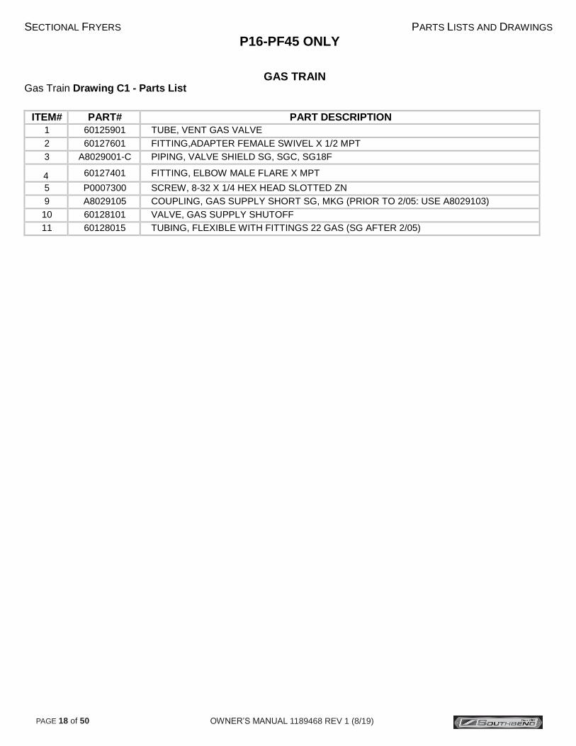
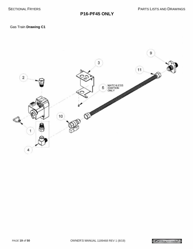
GAS TRAIN Gas Train Drawing C1 - Parts List
ITEM# PART# PART DESCRIPTION
1 60125901 TUBE, VENT GAS VALVE
2 60127601 FITTING,ADAPTER FEMALE SWIVEL X 1/2 MPT
3 A8029001-C PIPING, VALVE SHIELD SG, SGC, SG18F
4 60127401 FITTING, ELBOW MALE FLARE X MPT
5 P0007300 SCREW, 8-32 X 1/4 HEX HEAD SLOTTED ZN
9 A8029105 COUPLING, GAS SUPPLY SHORT SG, MKG (PRIOR TO 2/05: USE A8029103)
10 60128101 VALVE, GAS SUPPLY SHUTOFF
11 60128015 TUBING, FLEXIBLE WITH FITTINGS 22 GAS (SG AFTER 2/05)
OWNER’S MANUAL 1189468 REV 1 (8/19) PAGE 19 of 50
SECTIONAL FRYERS PARTS LISTS AND DRAWINGS
P16-PF45 ONLY
Gas Train Drawing C1

OWNER’S MANUAL 1189468 REV 1 (8/19) PAGE 20 of 50
SECTIONAL FRYERS PARTS LISTS AND DRAWINGS
P16-PF45 ONLY
GAS TRAIN
Gas Train Drawing C2 - Parts List
ITEM# PART# PART DESCRIPTION
2 60125201-C VALVE, GAS VS820 NAT SG, SGC, SG18F
60125202-C VALVE, GAS VS820 LP SG, SGC, SG18F
5 A8035302 PIPING, PILOT BRACKET SG14 SG14R SG18
10 60128801 PILOT, REVERSE STANDING NAT SG
60128802 PILOT, REVERSE STANDING LP SG
11 60119001 TUBE, FLEXIBLE WITHOUT FITTINGS 18 X 1/4 OD SG, SG18F, SGC
12 60088001 SCREW, 10-32 X 1/4 HEX HEAD SST
14 60125501 THERMOPILE, MILLIVOLT
23
2908-0940501 ORIFICE, PILOT RUNNER TUBE #52 NAT SG14, SG14R, SG14T
2908-0940502 ORIFICE, PILOT RUNNER TUBE #68 LP SG
28A B6783401 WIRING, IGNITION CABLE WITH GROUND WRAP 20" SG*

OWNER’S MANUAL 1189468 REV 1 (8/19) PAGE 21 of 50
SECTIONAL FRYERS PARTS LISTS AND DRAWINGS
P16-PF45 ONLY
Gas Train Drawing C2

OWNER’S MANUAL 1189468 REV 1 (8/19) PAGE 22 of 50
SECTIONAL FRYERS PARTS LISTS AND DRAWINGS
P16-PF45 & P20-PF65
GAS CONVERSION KITS Gas Conversion Kits Quick Reference
COVERING ALL COUNTRIES EXCEPT:
Turkey, Switzerland, Slovenia, Slavakia, Spain, Romania, Bulgaria, Czech Republic, England, Scotland, Wales, Hungary, Ireland,
Luxembourg, Poland, Portugal, France, Germany, South Korea, Australia, Belgium, Cyprus, Malta, Austria, Denmark, Estonia, Finland,
Greece, Italy, Latvia, Lithuania, Norway, Sweden
For these countries see parts lists D5, D6, D7, or D8
BURNER TYPE WIRE FACED BURNERS SLOT FACED BURNERS NAT TO LP PARTS LIST LP TO NAT PARTS LIST NAT TO LP PARTS LIST LP TO NAT PARTS LIST
SG14R B7510085-C D2 B7510082-C D2 B8043206-C D1 B8043210-C D1
SG18 B7510084-C D2 B7510081-C D2 B8043208-C D1 B8043212-C D1
MILLIVOLT SYSTEM, HONEYWELL VS820 GAS VALVE

OWNER’S MANUAL 1189468 REV 1 (8/19) PAGE 23 of 50
SECTIONAL FRYERS PARTS LISTS AND DRAWINGS
P16-PF45 & P20-PF65
Gas Conversion Kits Drawing D

OWNER’S MANUAL 1189468 REV 1 (8/19) PAGE 24 of 50
SECTIONAL FRYERS PARTS LISTS AND DRAWINGS
P16-PF45 & P20-PF65
Gas Conversion Kits Slot Face Burners Parts List D1
SLOT FACED BURNERS NATURAL TO LP ITEM # MODELS VALVE PART # PART DESCRIPTION QTY
1
SG14,SG18F VS820 B8043205-C GAS CONV KIT SLOT FACED NAT TO LP VS820 SG14
SG14R, SG14RDI VS820 B8043206-C GAS CONV KIT SLOT FACED NAT TO LP VS820 SG14R
SG18 VS820 B8043208-C GAS CONV KIT SLOT FACED NAT TO LP VS820 SG18
SG14 VR8204 B8043213-C GAS CONV KIT SLOT FACED NAT TO LP VR8204 SG14
SG14R VR8204 B8043214-C GAS CONV KIT SLOT FACED NAT TO LP VR8204 SG14R
SG18 VR8204 B8043216-C GAS CONV KIT SLOT FACED NAT TO LP VR8204 SG18
1A
SG14, SG18F VS820/VR8204 P6071353 ORIFICE TIP #53 DIA 4
SG14R, SG14RDI VS820/VR8204 P6071309 ORIFICE TIP 1/16 DIA 4
SG18 VS820/VR8204 P6071353 ORIFICE TIP #53 DIA 5
1B
SG14, SG18F, SG18, VS820 60126502 GAS VALVE CONV KIT VS820 NAT TO LP 1
SG14R, SG14RDI
SG14, SG18, SG14R VR8204 PP11141 GAS VALVE CONV KIT VR8204 NAT TO LP 1
1C
SG14, SG18F, SG18, VS820/VR8204 P6071665 ORFICE PILOT SPUD LP .016 DIA 1
SG14R, SG14RDI
1D SG14, SG18F, SG14T
VS820/VR8204 PP10426 GAS CONV NOTICE LABEL NAT TO LP 1 SG14R, SG14RDI, SG18
1E
SG14, SG18F, SG14T, VS820/VR8204 B8037302-C BURNER SLOTTED-FACE 304-SST LP 4
SG14R, SG14RDI
SG18 VS820/VR8204 B8037302-C BURNER SLOTTED-FACE 304-SST LP 5
SLOT FACED BURNERS LP TO NATURAL ITEM # MODELS VALVE PART # PART DESCRIPTION QTY
1 SG14R, SG14RDI VS820 B8043210-C GAS CONV KIT SLOT FACED LP TO NAT VS820 SG14R
1A
SG14, SG18F VS820/VR8204 P6071341 ORIFICE TIP #41 DIA 4
SG14R, SG14RDI VS820/VR8204 P6071338 ORIFICE TIP #38 DIA 4
SG18 VS820/VR8204 P6071341 ORIFICE TIP #41 DIA 5
1B
SG14, SG18F, SG18, VS820 60126501 GAS VALVE CONV KIT VS820 LP TO NAT 1
SG14R, SG14RDI
SG14, SG18, SG14R VR8204 PP11319 GAS VALVE CONV KIT VR8204 LP TO NAT 1
1C
SG14, SG18F, SG18, VS820/VR8204 P6071666 ORFICE PILOT SPUD NAT .022 DIA 1
SG14R, SG14RDI
1D SG14, SG18F, SG14T
VS820/VR8204 PP10427 GAS CONV NOTICE LABEL LP TO NAT 1 SG14R, SG14RDI, SG18
1E
VS820/VR8204 B8037301-C BURNER SLOTTED-FACE 304-SST NAT 4
SG14R, SG14RDI
SG18 VS820/VR8204 B8037301-C BURNER SLOTTED-FACE 304-SST NAT 5

OWNER’S MANUAL 1189468 REV 1 (8/19) PAGE 25 of 50
SECTIONAL FRYERS PARTS LISTS AND DRAWINGS
P16-PF45 & P20-PF65
Gas Conversion Kits Wire Face Burners Parts List D2
WIRE FACED OR SCB BURNERS NATURAL TO LP ITEM # MODELS VALVE PART # PART DESCRIPTION QTY
1
SG14, SG14DI, SG18, SG18DI VS820 B7510084-C GAS CONV KIT NAT TO LP VS820 SG14,SG18
SG14R, SG14RDI VS820 B7510085-C GAS CONV KIT NAT TO LP VS820 SG14R
SG14, SG18 VR8204 B7510090-C GAS CONV KIT NAT TO LP VR8204 SG14,SG18
1A
SG14, SG14DI, SG18, SG18DI VS820/VR8204 P6071353 ORIFICE TIP #53 DIA 5
SG14R, SG14RDI VS820/VR8204 P6071309 ORIFICE TIP 1/16 DIA 4
1B
SG14, SG14DI, SG14R, VS820 60126502 GAS VALVE CONV KIT VS820 NAT TO LP 1
SG14RDI, SG18, SG18DI
SG14, SG18, SG14R VR8204 PP11141 GAS VALVE CONV KIT VR8204 NAT TO LP 1
1C
SG14, SG14DI, SG14R, VS820/VR8204 P6071665 ORFICE PILOT SPUD LP .016 DIA 1
SG14RDI, SG18, SG18DI
1D SG14, SG14DI, SG14R, SG14T
VS820/VR8204 PP10426 GAS CONV NOTICE LABEL NAT TO LP 1 SG14TDI, SG14RDI, SG18, SG18DI
WIRE FACED OR SCB BURNERS LP TO NATURAL
ITEM # MODELS VALVE PART # PART DESCRIPTION QTY
1
SG14, SG14DI, SG18, SG18DI VS820 B7510081-C GAS CONV KIT LP TO NAT VS820 SG14,SG18
SG14R, SG14RDI VS820 B7510082-C GAS CONV KIT LP TO NAT VS820 SG14R
SG14, SG18 VR8204 B7510087-C GAS CONV KIT LP TO NAT VR8204 SG14,SG18
1A
SG14, SG14DI, SG18, SG18DI VS820/VR8204 P6071341 ORIFICE TIP #41 DIA 5
SG14R, SG14RDI VS820/VR8204 P6071338 ORIFICE TIP #38 DIA 4
1B
SG14, SG14DI, SG14R, VS820 60126501 GAS VALVE CONV KIT VS820 LP TO NAT 1
SG14RDI, SG18, SG18DI
SG14, SG18, SG14R VR8204 PP11319 GAS VALVE CONV KIT VR8204 LP TO NAT 1
1C
SG14, SG14DI, SG14R, VS820/VR8204 P6071666 ORFICE PILOT SPUD NAT .022 DIA 1
SG14RDI, SG18, SG18DI
1D SG14, SG14DI, SG14R, SG14T
VS820/VR8204 PP10427 GAS CONV NOTICE LABEL LP TO NAT 1 SG14TDI, SG14RDI, SG18, SG18DI

OWNER’S MANUAL 1189468 REV 1 (8/19) PAGE 26 of 50
SECTIONAL FRYERS PARTS LISTS AND DRAWINGS
P16-PF45 ONLY
PUMP ASSEMBLY
Pump Assembly Drawing E - Parts List
ITEM# PART# PART DESCRIPTION
1 60132201 FLUROPOLYMER HOSE 3/4 NPT FEMALE SWIVEL X 3/4 MPT
2 B6677001 FILTER INLET COUPLING
3 60131306 NIPPLE 3/4NPT X 11 BLACK IRON
4 A7029701-C FILTER PUMP MOUNTING PLATE SFS*
5A
60143501 PUMP ASSEMBLY 8GPM .3HP 115/230V (50/60HZ)
60143503 PUMP ASSEMBLY 8GPM .3HP 208/240V (50/60HZ)
60143505 PUMP MOTOR ONLY 8GPM .3HP 115/230V (50/60HZ)
60143506 PUMP MOTOR ONLY 8GPM .3HP 208/240V (50/60HZ)
60143507 PUMP HEAD ONLY 8GPM (NO MOTOR)
6 P0080750 WASHER 5/16 FLAT
7 PP10828 NUT HEX 5/16 - 18 (KEP)
8 PP11261 BOLT 5/16 X 3/4
9 PP11338 POWER CORD MALE IEC-320 16-3 AWG
10 P9037679 ELBOW BLACK IRON 90° 3/4NPT
11 P7037355 NIPPLE 3/4NPT X 2 BLACK IRON
12 P7037751 STREET ELBOW BLACK IRON 90° 3/4NPT
13
60133503 HEATER TAPE 50W 120V 1/2 X 72 (AFTER 3/06)
60133504 HEATER TAPE 50W 240/220V 1/2 X 72 (AFTER 3/06)
60133508 HEATER TAPE 50W 208V 1/2 X 72 (AFTER 3/06)
14 A7092201-C FILTER PIPING CLAMP
15 PP10023 SCREW 10 - 24 X 3/8 SELF TAPPING
17 A8033801 ELBOW FEMALE X MALE 15/16 FLARE
18
NOT
SHOWN
(INCLUDES
ALL ITEMS)
B6678501-C FILTER PUMP ASSEMBLY 115V W/O HEAT TAPE (SG)
B6678502-C FILTER PUMP ASSEMBLY 208V W/O HEAT TAPE (SG)
B6678503-C FILTER PUMP ASSEMBLY 230V W/O HEAT TAPE (SG)
B6678504-C FILTER PUMP ASSEMBLY 240V W/O HEAT TAPE (SG)
B6678505-C FILTER PUMP ASSEMBLY 115V WITH HEAT TAPE (SG)
B6678506-C FILTER PUMP ASSEMBLY 208V WITH HEAT TAPE (SG)
B6678507-C FILTER PUMP ASSEMBLY 230V WITH HEAT TAPE (SG)
B6678508-C FILTER PUMP ASSEMBLY 240V WITH HEAT TAPE (SG)

OWNER’S MANUAL 1189468 REV 1 (8/19) PAGE 27 of 50
SECTIONAL FRYERS PARTS LISTS AND DRAWINGS
P16-PF45 ONLY
Pump Assembly Post Drawing E

OWNER’S MANUAL 1189468 REV 1 (8/19) PAGE 28 of 50
SECTIONAL FRYERS PARTS LISTS AND DRAWINGS
P16-PF45 ONLY
PUMP BOX Pump Box Drawing F - Parts List
ITEM# PART# PART DESCRIPTION
1 A7028701-C FILTER PUMP BOX HOUSING
2 B6748701 FILTER PUMP BOX WIRING
3 60148401 POWER INLET/OUTLET IEC320
(REPLACES 60130701, NEW A7028701-C REQUIRED PRIOR TO 6/05)
4 P0092300 NUT 10 - 24 (KEP)
5 PP11058 RELAY SPST 30A 24VAC (115V)
60104701 RELAY DPST 30A 24VAC (208/220/240V)
6 PP10693 SCREW 10 - 24 X 3/8
7
60130301 TRANSFORMER 5VA 120V
60130302 TRANSFORMER 5A 240VAC
60130303 TRANSFORMER 5VA 208V
8 60077901 CIRCUIT BREAKER, SPST 250V 10A (115V)
60078502 CIRCUIT BREAKER, DPST 250V 5A (208/220/240V)
9 60132701 FUSE, CERAMIC 0.2A TD .25 X 1.25 (208/220/240V)
10 60128403 M-F JUMPER CORD IEC-320 16-3 AWG X 34" SFSG*
60128501 CORD NEMA 5-15P / IEC320 16-3 AWG X 96"
11 PP11228 BUTT SPLICE BLUE (115V)
PP10765 FUSE HOLDER (208/220/240V)
13 A1844001-C CABLE RETAINER
14 60130501 LAY IN STRAIN RELIEF
16
NOT
SHOWN
(INCLUDE
S ALL
ITEMS)
B6673006-C FILTER PUMP CONTROL BOX ASSEMBLY 115V SGM*
B6673007-C FILTER PUMP CONTROL BOX ASSEMBLY 220/240V SGM*
B6675001-C FILTER PUMP CONTROL BOX ASSEMBLY 115V
B6675002-C FILTER PUMP CONTROL BOX ASSEMBLY 208V
B6675003-C FILTER PUMP CONTROL BOX ASSEMBLY 220/240V
B6675004-C FILTER PUMP CONTROL BOX ASSEMBLY 115V SFSG*
B6675005-C FILTER PUMP CONTROL BOX ASSEMBLY 208V SFSG*
B6675006-C FILTER PUMP CONTROL BOX ASSEMBLY 220/240V SFSG*

OWNER’S MANUAL 1189468 REV 1 (8/19) PAGE 29 of 50
SECTIONAL FRYERS PARTS LISTS AND DRAWINGS
P16-PF45 ONLY
Pump Box Drawing F

OWNER’S MANUAL 1189468 REV 1 (8/19) PAGE 30 of 50
SECTIONAL FRYERS PARTS LISTS AND DRAWINGS
P16-PF45 ONLY
SMALL ASSEMBLIES Small Assemblies Drawing G - Parts List
ITEM# PART# PART DESCRIPTION
1 PP10084 SWITCH, HI-LIMIT LCM05030
2 A8028601-C PIPING, BRACKET HI-LIMIT-THERMOSTAT SG MILLIVOLT
3 60125402 THERMOSTAT, RX MILLIVOLT 200-374F
60125401 THERMOSTAT, RX MILLIVOLT 200-400F
4 P0190700 CLIP, CANOE FASTEX
5 PP10539 KNOB, THERMOSTAT WITH OFF, 200-400F & 100-200C
6 PP10687 SCREW, 6-32 X 313 THRUSS HEAD PHILLIPS ZN
7 P0007300 SCREW, 8-32 X 250 HEX HEAD ZN
10 B6744401 WIRING, MILLIVOLT HI-LIMIT & THERMOSTAT SG

OWNER’S MANUAL 1189468 REV 1 (8/19) PAGE 31 of 50
SECTIONAL FRYERS PARTS LISTS AND DRAWINGS
P16-PF45 ONLY
Small Assemblies Drawing G

OWNER’S MANUAL 1189468 REV 1 (8/19) PAGE 32 of 50
SECTIONAL FRYERS PARTS LISTS AND DRAWINGS
P16-PF45 & P20-PF65
FILTER PAN Filter Pan Drawing H - Parts List
ITEM# PART# PART DESCRIPTION
1 B6671201 FILTER, STRAINER CAP SFD
2 B6673901 FILTER, PICKUP TUBE P16-PF45
B6671001 FILTER, PICKUP TUBE P20-PF65
3 60068301 O-RING, VITON 1" ID X 1.375" OD
4 B6671102 FILTER, SUPPORT CLIP P16-PF45 PAPER
B6671103 FILTER, SUPPORT CLIP P20-PF65 PAPER
5 B6664303 FILTER, SUPPORT P16-PF45 PAPER
B6664304 FILTER, SUPPORT P20-PF65 PAPER
6 B6670802 FILTER, PAN P16-PF45
B6670801 FILTER, PAN P20-PF65
7 60131401 RIGID 2.5" CASTER
8 PP11208 LOCK WASHER #10 SST (SPLIT)
9 P0011300 SCREW, 10-24 X 3/8
10 60136301 EXTERNAL RETAINING RING 1-7/16"

OWNER’S MANUAL 1189468 REV 1 (8/19) PAGE 33 of 50
SECTIONAL FRYERS PARTS LISTS AND DRAWINGS
P16-PF45 & P20-PF65
Filter Pan Drawing H

OWNER’S MANUAL 1189468 REV 1 (8/19) PAGE 34 of 50
SECTIONAL FRYERS PARTS LISTS AND DRAWINGS
P16-PF45 & P20-PF65
DRAIN LINE Drain Line Drawing J - Parts List
ITEM# PART# PART DESCRIPTION
1 A7022201 FILTER DRAIN FLANGE
2 A7022101 FILTER DRAIN SEAL FERRULE
3 B6665101 FILTER DRAIN ELBOW
4 60088002 3/8-16 X 1-1/4 SCREW
5A 60068303 FLUROPOLYMER O-RING, 3" X 3.25 OD (WHITE)
5B 60068302 VITON O-RING (BLACK)
6 B6664701 FILTER DRAIN LINE DOWN SPOUT SG14-14, SG14-18, SG14-14R
B6664702 FILTER DRAIN LINE DOWN SPOUT SG18-18, SG18-14*
7 60137501 STEEL PLUG, 1/2NPT INTERNAL HEX
8 B6665201 FILTER DRAIN TEE
9 60059302 DRAINLINE GASKET
10 60127702 QUICK RELEASE BAND CLAMP
11
A7022401 DRAIN LINE TUBE SG18-18, SGM1824-1824
A7022403 DRAIN LINE TUBE SG18-14
A7022405 DRAIN LINE TUBE SG14-18
A7022407 DRAIN LINE TUBE SG14-14
A7022409 DRAIN LINE TUBE SG14T-14, SG14-14T
A7022411 DRAIN LINE TUBE SG14T-14T
A7022413 DRAIN LINE TUBE SG14T-18
A7022415 DRAIN LINE TUBE SG18-14T
12 A7021701 FILTER, NIPPLE ADAPTER
30 P0082700 WASHER, 3/8 SPLIT LOCK
31 PP10177 VINYL SCREW PROTECTION CAP

OWNER’S MANUAL 1189468 REV 1 (8/19) PAGE 35 of 50
SECTIONAL FRYERS PARTS LISTS AND DRAWINGS
P16-PF45 & P20-PF65
Drain Line Drawing J

OWNER’S MANUAL 1189468 REV 1 (8/19) PAGE 36 of 50
SECTIONAL FRYERS PARTS LISTS AND DRAWINGS
P16-PF45 & P20-PF65
RETURN LINE Return Line Drawing K - Parts List
ITEM# PART# PART DESCRIPTION
1 PP10263 PROXIMITY ACTUATOR SWITCH
2 A7020501-C FILTER RETURN HANDLE BRACKET CLAMP
3 A7020301-C FILTER RETURN HANDLE BRACKET P20-PF65
A7020401-C FILTER RETURN HANDLE BRACKET P16-PF45
4 PP10266 SCREW 4 - 40 X .250
5 B4003701 RETURN HANDLE P16-PF45
B4003702 RETURN HANDLE P20-PF65
6 PP10023 SCREW 10 - 24 X 1/2 SELF TAPPING
7 B5305001 DRAIN VALVE INTERLOCK ASSEMBLY
8 60129802 RETURN VALVE HANDLE SG14T LH
9 P0190200 COTTER PIN 1/16 X 3/4
10 60131801 FILTER RETURN BALL VALVE 3 WAY (W/ SG14, SG18, SG14T RH HANDLE)
11 60130001 RETURN VALVE END CAP
14
60135901 HOSE REINFORCED FLUROPOLYMER SWIVEL X SWIVEL 14.5 (14-14)
60135902 HOSE REINFORCED FLUROPOLYMER SWIVEL X SWIVEL 19.5 (18-18)
60135903 HOSE REINFORCED FLUROPOLYMER SWIVEL X SWIVEL 17.5 (18-14)
60135904 HOSE REINFORCED FLUROPOLYMER SWIVEL X SWIVEL 15.0 (14-18)
60128008 FLEXIBLE TUBING WITH FITTINGS 15.50 (14-14, 18-14T, 14-18)
60128009 FLEXIBLE TUBING WITH FITTINGS 19.00 (18-18, 18-14, 14-18, 1824-1824)
15 A8033001 RETURN TEE FLARE X FLARE X FLARE SGBNB
16 P0080750 WASHER FLAT 5/16
18 60133801 VENT TUBE PLUG
19 60128010 FLEXIBLE TUBING WITH FITTINGS 22.00 LH UNIT VENT TUBE
20 60131901 SPRING WASHER 5/8 5/16 HOLE
21 60130101 SWIVEL FITTING NPT TO MPT ADAPTER
26 B6746301 RETURN HOSE WIRE JUMPER
27 A1844401-C WIRE CLAMP

OWNER’S MANUAL 1189468 REV 1 (8/19) PAGE 37 of 50
SECTIONAL FRYERS PARTS LISTS AND DRAWINGS
P16-PF45 & P20-PF65
Return Line Drawing K

OWNER’S MANUAL 1189468 REV 1 (8/19) PAGE 38 of 50
SECTIONAL FRYERS PARTS LISTS AND DRAWINGS
P20-PF65 ONLY
TANK ASSEMBLY & THERMOSTAT
Tank Assembly and Thermostat Drawing L - Parts List
ITEM# PART# PART DESCRIPTION
1 A1406702 CLAMP HIGH LIMIT/THERMOSTAT
2 N/A SCREW 10-24 X 5/8 PAN HEAD SST THREAD FORMING
3
1188585 P20-PF65 36" DEEP FLUE FRONT
1188583 P20-PF65 36" DEEP FLUE REAR
1188586 P20-PF65 42" DEEP FLUE FRONT
1188584 P20-PF65 42" DEEP FLUE REAR
4 60131002 BALL VALVE, 1-1/4" FULL PORT REVERSIBLE LUG, RIGHT HAND
5 A8030407 DRAIN LINE PIPING ADAPTER (NON-FILTER)
6 N/A STEEL TANK PLUG 1/4" NPT
7 B3322801-C TANK WELDMENT MODULAR P20-PF65
8 N/A NUT HEX 10-24 KEP ZINC
9 60130101 TANK REAR ADAPTOR 37.5 FLARE SWIVEL X 1/2" NPT (FILTER)
N/A STEEL TANK PLUG 1/2" NPT (NON-FILTER)
10 N/A SCREW 10-24 X 3/4" SELF TAPPING
11 PP10539 KNOB, THERMOSTAT WITH OFF, 200-400F (100-200C)
12 60125401 THERMOSTAT , RX MILLIVOLT 200-400F
13 PP10084 SWITCH, HI-LIMIT
14 B6744401 WIRING, MILLIVOLT HI-LIMIT & THERMOSTAT

OWNER’S MANUAL 1189468 REV 1 (8/19) PAGE 39 of 50
SECTIONAL FRYERS PARTS LISTS AND DRAWINGS
P20-PF65 ONLY
Tank Assembly and Thermostat Drawing L
1
2
3
4
7
8
9
10
6
5
11
12
13
14

OWNER’S MANUAL 1189468 REV 1 (8/19) PAGE 40 of 50
SECTIONAL FRYERS PARTS LISTS AND DRAWINGS
P20-PF65 ONLY
BURNER ASSEMBLY Burner Assembly Drawing M - Parts List
ITEM# PART# PART DESCRIPTION
1 B8029801 BURNER MANIFOLD WELDMENT P20-PF65
2 60127501 FITTING ADAPTOR FLARED 15/16-16 UN-2A X 1/2" FNPT BRASS
3 N/A PLUG 1/8" NPT 3/16" HEX SOCKET STEEL
4
P6071353 ORIFICE TIP, #53 - LP
P6071341 ORIFICE TIP, #41 - NAT
5
B8037302-C BURNER, SLOTTED FACE LP GAS
B8037301-C BURNER, SLOTTED FACE NAT GAS
6 N/A SCREW 10-24 X 3/8" SELF TAPPING
7 A7020301 FILTER RETURN HANDLE BRACKET
8 A7020501 FILTER RETURN HANDLE COVER
9
60128801 NATURAL GAS STANDING PILOT
60128802 PROPANE GAS STANDING PILOT
10 A8035302 PILOT BRACKET
11 N/A SCREW 10-24 X 1/4" HEX HEAD SST

OWNER’S MANUAL 1189468 REV 1 (8/19) PAGE 41 of 50
SECTIONAL FRYERS PARTS LISTS AND DRAWINGS
P20-PF65 ONLY Burner Assembly Drawing M
1
5
4
3
2
10
11
6
7
8 9

OWNER’S MANUAL 1189468 REV 1 (8/19) PAGE 42 of 50
SECTIONAL FRYERS PARTS LISTS AND DRAWINGS
P20-PF65 ONLY
GAS VALVE ASSEMBLY Gas Valve Assembly Drawing N - Parts List
ITEM# PART# PART DESCRIPTION
1 60128015 TUBING, FLEXIBLE WITH FITTINGS, 22 GAS
2 60128101 VALVE, GAS SUPPLY, SHUT-OFF
3 60127401 FITTING, ELBOW MALE FLARE X MPT
4 60127601 FITTING, ADAPTER FEMALE SWIVEL X 1/2 MPT
5
60126502 CONVERSION KIT, NAT TO LP VR820
60126501 CONVERSION KIT LP TO NAT VR820
6
60125201-C MILLIVOLT GAS VALVE, VS820 NAT
60125202-C MILLIVOLT GAS VALVE, VS820 LP
7 60119001 TUBING, FLEXIBLE WITHOUT FITTINGS 18 X 1/4 OD
8 60125501 THERMOPILE, MILLIVOLT
9
60128801 PILOT ASSEMBLY, NAT
60128802 PILOT ASSEMBLY, LP

OWNER’S MANUAL 1189468 REV 1 (8/19) PAGE 43 of 50
SECTIONAL FRYERS PARTS LISTS AND DRAWINGS
P20-PF65 ONLY Gas Valve Assembly Drawing N

OWNER’S MANUAL 1189468 REV 1 (8/19) PAGE 44 of 50
SECTIONAL FRYERS PARTS LISTS AND DRAWINGS
P20-PF65 ONLY
FILTER PUMP ASSEMBLY
Filter Pump Assembly Drawing P - Parts List
ITEM# PART# PART DESCRIPTION
1 60132201 TEFLON HOSE 3/4" NPT FEMALE SWIVEL X 3/4 MPT
2 B6677001 FILTER INLET COUPLING
3 60131307 NIPPLE 3/4 NPT X 12 BLACK IRON
4 A7029201-C FILTER PUMP MOUNTING PLATE
5A
60143501 PUMP ASSEMBLY 8GPM .3HP 115/230V (50/60HZ)
60143503 PUMP ASSEMBLY 8GPM .3HP 208/240V (50/60HZ)
60143505 PUMP MOTOR ONLY 8GPM .3HP 115/230V (50/60HZ)
60143506 PUMP MOTOR ONLY 8GPM .3HP 115/230V (50/60HZ)
60143507 PUMP HEAD ONLY 8GPM (NO MOTOR)
6 N/A WASHER 5/16 FLAT
7 N/A NUT HEX 5/16 - 18 (KEP)
8 N/A BOLT 5/16 X 3/4
9 PP11338 POWERT CORD MALE IEC-320 16-3 AWG
10 N/A ELBOW BLACK IRON 90° 3/4NPT
11 N/A NIPPLE 3/4NPT X 2 BLACK IRON
12 N/A STREET ELBOW BLACK IRON 90° 3/4NPT
13
60133503 HEATER TAPE 50W 120V 1/2 X 72
60133504 HEATER TAPE 50W 240/220V 1/2 X 72
60133508 HEATER TAPE 50W 208V 1/2 X 72
14 A7092201-C FILTER PIPING CLAMP
15 N/A SCREW 10-24 X 3/8" SELF TAPPING
16 A8033801 ELBOW FEMALE X MALE 15/16 FLARE

OWNER’S MANUAL 1189468 REV 1 (8/19) PAGE 45 of 50
SECTIONAL FRYERS PARTS LISTS AND DRAWINGS
P20-PF65 ONLY Filter Pump Assembly Drawing P

OWNER’S MANUAL 1189468 REV 1 (8/19) PAGE 46 of 50
SECTIONAL FRYERS PARTS LISTS AND DRAWINGS
P20-PF65 ONLY
FILTER PUMP CONTROL BOX
Filter Pump Control Box Drawing R - Parts List
ITEM# PART# PART DESCRIPTION
1 A7028701-C FILTER PUMP BOX HOUSING
2 B6748701 FILTER PUMP BOX WIRING
3 60148401 POWER INLET/OUTLER IEC-320
4 N/A NUT 10-24 (KEP)
5
PP11058 RELAY SPST 30A 24VAC (115V)
60104701 RELAY DPST 30A 24VAC (208/220/240V)
6 N/A SCREW 10-24 X 3/8
7
60130301 TRANSFORMER 5VA 120V
60130302 TRANSFORMER 5VA 240V
30130303 TRANSFORMER 5VA 208V
8
60077901 CIRCUIT BREAKER, SPST 250V 10A (115V)
60078502 CIRCUIT BREAKER, DPST 250V 5A (208/220/240V)
9
60128403 M-F JUMPER CORD IEC-320 16-3 AWG X 34"
60128501 CORD NEMA 5-15P IEC-320 16-3 AWG X 96"
10 A1844001-C CABLE RETAINER
11 60130501 LAY IN STRAIN RELIEF

OWNER’S MANUAL 1189468 REV 1 (8/19) PAGE 47 of 50
SECTIONAL FRYERS PARTS LISTS AND DRAWINGS
P20-PF65 ONLY
Filter Pump Control Box Drawing R

OWNER’S MANUAL 1189468 REV 1 (8/19) PAGE 48 of 50
SECTIONAL FRYERS PARTS LISTS AND DRAWINGS
P16-PF45 & P20-PF65
ACCESSORIES Accessories Drawing S - Parts List
ITEM# PART# PART DESCRIPTION
1
1186990 TANK COVER - P16-PF45
1186991 TANK COVER - P20-PF65
2
1405600 BASKET HANGER - P16-PF45 - 36" DEEP FLUE
1188591 BASKET HANGER - P20-PF65 - 36" DEEP FLUE
1405607 BASKET HANGER - P16-PF45 - 42" DEEP FLUE
1189465 BASKET HANGER - P20-PF65 - 42" DEEP FLUE
3
A6667104 FILTER PAPER - P16-PF45 -18.5" X 20.5"
PP10613 FILTER PAPER - P20-PF65 -20.5" X 9.92"
4 B5008101 FRYER CRUMB SCOOP
5 PP10056 CLEANING BRUSH NYLON
6 B6681201 FILTER CRUMB SCOOP
7 A3301001 CLEAN-OUT ROD
8
P6072184 TWIN BASKET P20-PF65
P6072188 TWIN BASKET FINE MESH P20-PF65
P6072145 TWIN BASKET P16-PF45
P6072146 TWIN BASKET FINE MESH P16-PF45
P6072147 TRIPLE BASKET P16-PF45
P6072185 TRIPLE BASKET P20-PF65
P6072143 SQUARE BULK BASKET FRONT HANDLE P16-PF45
P6072144 SQAURE BULK BASKET FINE MESH, FRONT HANDLE P16-PF45
P6072181 SQUARE BULK BASKET FRONT HANDLE P20-PF65
P6072180 SQUARE BULK BASKET SIDE HANDLES P20-PF65
9
P6073148 TUBE RACK P16-PF45
A4500201 TUBE SCREEN P16-PF45
B4511901 TUBE RACK P20-PF65
P6072186 TUBE SCREEN P20-PF65

OWNER’S MANUAL 1189468 REV 1 (8/19) PAGE 49 of 50
SECTIONAL FRYERS PARTS LISTS AND DRAWINGS
P16-PF45 & P20-PF65
Accessories Drawing S

OWNER’S MANUAL 1189468 REV 1 (8/19) PAGE 50 of 50
Sectional Fryers Model P16-PF45 & P20-PF65
A product with the Southbend name incorporates the best in durability and low maintenance. We all recognize, however,
that replacement parts and occasional professional service may be necessary to extend the useful life of this appliance.
When service is needed, contact a Southbend Authorized Service Agency, or your dealer. To avoid confusion, always
refer to the model number, serial number, and type of your appliance.
Southbend
1100 Old Honeycutt Road Fuquay-Varina, North Carolina 27526 USA
www.southbendnc.com
Copyright © 2022 FDOKUMEN