
Section 5 - ASAQS Model Preambles for Trades November 2008
224
Section 5 - ASAQS Model Preambles for Trades November 2008 Ramgoolam www.ramgoolamgroup.com Bespoke Global Efficacy.
-
Upload
khangminh22 -
Category
Documents
-
view
2 -
download
0
Transcript of Section 5 - ASAQS Model Preambles for Trades November 2008

Section 5 - ASAQS Model Preambles for Trades November 2008
Ramgoolam www.ramgoolamgroup.com Bespoke Global Efficacy.

The Association of South African Quantity Surveyors Die Vereniging van Suid-Afrikaanse Bourekenaars
MODEL PREAMBLES FOR TRADES 2008 forming part of the bills of quantities
Project:
Contract Reference Number:
Effective date November 2008 ISBN 978-0-620-1663-4

(i)
EXPLANATORY NOTES AND INSTRUCTIONS ON THE USE OF THESE MODEL PREAMBLES 1. The document 1.1 This document is published by and is available from the Association of South African Quantity Surveyors, P.O. Box
3527, Halfway House, 1685. Telephone (011) 315 4140. E-mail: [email protected] 1.2 The contents of this document are intended to cover workmanship and materials encountered in a significant
majority of projects. If a material is not encountered in a significant majority of projects, its preamble will in all like-lihood not be included in this document
1.3 By its very nature, this document is a “Model” document and one that is designed to act as a basis upon which to
build. It is anticipated that it will be supplemented by a “Supplementary Preambles” document included in the text of the bills of quantities that will include, inter alia, the following: 1.3.1 supplementary clauses of a general nature that practitioners may deem necessary to cover their own
individual requirements,
1.3.2 additional clauses pertaining to specific materials incorporated in a project and not covered by the Model Preambles,
1.3.3 amendments to anything contained in the Model Preambles. A clause has been incorporated in the
“General” section of the document stipulating that anything contained in the “Supplementary Preambles” which is at variance to that which is contained in the Model Preambles, will take precedence over the Model Preambles and apply to the works in hand
1.4 It is intended that this document will be used by reference only in the text of the bills of quantities and will NOT be
bound or reproduced therein 2. The basic philosophy 2.1 Wherever possible, reference has been made throughout the preambles to South African National Standards
(SANS) to describe materials and methods respectively. It is therefore incumbent on the users of these preambles to have ready access to the relevant Specifications and Codes. Where such Specifications or Codes do not exist, suitable preambles have been compiled
2.2 These preambles have been designed to assist in abbreviating descriptions in the text of the bills of quantities and
practitioners are encouraged to make use of this facility. e.g. The description of a stormwater catchpit would read:
“Brick stormwater catchpit size internally 600 x 400 x 1 200mm deep to invert fitted with and including a 450 x 300mm x 59kg cast iron grating and frame”
2.3 Wherever alternatives exist in respect of materials or workmanship, specific choices have been made in these
preambles. Should users require different choices to specific items, these should be referred to in the Supplementary Preambles as outlined in clause 1.3
3. Additional notes in the use of these Model Preambles 3.1 Concrete, Formwork and Reinforcement
The Project Specification embodied in these preambles was compiled in collaboration with the Authors of SANS 1200G, which forms the basis for the Concrete, Formwork and Reinforcement model preambles Users of these preambles are advised to submit a copy of the Model Preambles to the Engineers involved in a project for their scrutiny. Any amplifications, amendments, etc required by individual Engineers would then be incorporated in the Supplementary Preambles referred to in item 1.3
3.2 Roof Coverings
The roof coverings included in these Model Preambles are limited in their content and therefore any roofing mate-rial not included in these Preambles will need to have its full preamble included in the Supplementary Preambles
3.3 Structural Steelwork
The comments made under item 3.1 apply equally to Structural Steelwork
Note that the protective treatment of the structural steel covers only the treatment up to and including the primer (and patching after erection). The finishing coats of paint must be fully described and included either in the “Structural Steelwork” or in the “Paintwork” trade, as the practitioner wishes

MODEL PREAMBLES FOR TRADES CONTENTS REFERENCE TRADE PAGE
1
A General 2
B Alterations 3 C Earthworks 4 D Concrete, Formwork and Reinforcement 6 E Precast Concrete 10 F Masonry 11 G Waterproofing 14 H Roof Coverings etc 15 I Carpentry and Joinery 17 J Ceilings, Partitions and Access Flooring 20 K Floor Coverings, Wall Linings, etc 22 L Ironmongery 23 M Structural Steelwork 24 N Metalwork 25 O Plastering 29 P Tiling 31 Q Plumbing and Drainage 32 R Glazing 41 S Paintwork 42 T Paperhanging 44 U External Works 45

A. GENERAL A.1 APPLICATION OF CLAUSES
These Model Preambles for Trades, and any Supplementary Preambles, shall be read in conjunction with and shall form part of the descriptions of items in the bills of quantities
Where descriptions or Supplementary Preambles in the bills of quantities differ from these Model Preambles for Trades, the descriptions or Supplementary Preambles in the bills of quantities shall take precedence. Where supplementary preambles differ from descriptions in the bills of quantities, the descriptions in the bills of quantities shall take precedence Except where otherwise stated, all preambles contained in any individual Trade Preamble shall apply equally to any work of a similar nature in all other trades
A.2 ABBREVIATIONS
The following abbreviations shall apply: AASHTO – American Association of State Highway and Transportation Officials AISI – American Institute of Steel Industries BS – British Standard CKS – Coordinating Specifications issued by the Central Coordinating Committee under the
auspices of the South African Bureau of Standards CSIR – Council for Scientific and Industrial Research SANS – South African National Standards and the number following shall refer to the
relevant specification or code of practice as the case may be A.3 MATERIALS AND WORKMANSHIP
Materials and workmanship shall be the best of their respective kinds. Only new and undamaged materials shall be used in the Works. Materials to be permanently installed into the works shall not be used for any temporary purposes on site. Work shall be to the approval of the Principal Agent and shall be executed in accordance with the relevant manufacturer’s written recommendations and instructions where applicable
A.4 PROPRIETARY PRODUCTS
For the purposes of submission of tenders, rates for items described in the bills of quantities by trade names, catalogue references, etc shall be for the particular type and manufacture specified The approval of the Principal Agent shall be obtained prior to any substitution and where products or materials etc other than those specified are used, adjustments in the rates will be made if necessary
A.5 ASSEMBLING
Rates for manufactured items shall include assembling complete and handing over in proper working order A.6 REFERENCES IN DESCRIPTIONS
Any references given in brackets at the end of certain descriptions shall refer to the relevant references on the drawings or schedules
A.7 WATER
Water shall be clean and free from injurious amounts of acids, alkalis, organic matter and other substances and shall be suitable for its intended use
A.8 APPLICATION OF THE NATIONAL BUILDING REGULATIONS
All work shall be executed in accordance with the requirements of SANS 10400 A.9 ACCURACY IN BUILDINGS
The dimensional and positional accuracy of the buildings and their component parts shall comply with Grade II requirements of SANS 10155 unless otherwise stated
A.10 REFERENCES TO OTHER DOCUMENTS
References in these “Model Preambles for Trades” to other documents, including SANS, CKS and BS, shall pertain to the latest edition thereof including all amendments thereto at the date for submission of the tender
2

B. ALTERATIONS B.1 ALTERATIONS
In taking down and removing existing work the utmost care shall be observed to prevent any structural or other damage to remaining portions of the building. The Contractor shall ensure the stability of all structures during alteration work Special care shall be exercised during the progress of the work to ensure that any electrical installations, water supply pipes, telephone and other services which may be encountered are not interfered with and notice shall be given to the Principal Agent if any disconnection or alterations become necessary
The Contractor shall take all precautions necessary to prevent any nuisance from dust whilst carrying out the work
B.2 MATERIALS FROM THE ALTERATIONS, CREDIT, ETC
Materials recovered from the alterations (except where described as to be re-used or to be handed over to the Employer) will become the property of the Contractor, who may allow credit in respect thereof where provided for in the bills of quantities. Such materials shall not be re-used in new work without written permission from the Principal Agent
Materials described as “removed” shall be removed from the site immediately.
Materials described as “handed over to the Employer” shall be carefully dismantled where necessary, neatly stored under cover on the site where directed and protected from damage, until required Materials described as “set aside for re-use” shall be carefully dismantled where necessary, cleaned, neatly stored under cover and protected from damage until required for re-use. Any damage caused to such materials during removal, storage or refixing shall be made good at the Contractor’s expense
B.3 DISPOSAL OF DEBRIS ETC
The Contractor shall be responsible for the removal from the site of all materials, debris and rubbish resulting from the alterations
B.4 MAKING GOOD DAMAGED WORK
The Contractor shall make good in all trades to existing work where damaged or disturbed through the alterations with all necessary new materials to match the existing
B.5 FORMING NEW OPENINGS OR ALTERING OPENINGS IN EXISTING WALLS
Where new openings are formed or openings altered in existing walls, the wall above the opening shall be broken out and a new brick, in situ concrete or prestressed concrete lintel inserted, complete with all necessary reinforcement, formwork, turning piece, etc, the jambs and portions of openings as described shall be built up with new brickwork or blockwork properly toothed and bonded to existing, cavities of hollow walls shall be closed where necessary and finishes shall be made good all round and into reveals
B.6 BUILDING UP OPENINGS
Where existing openings are given in number as built up, the existing surfaces all round shall be prepared as necessary, brickwork or blockwork properly toothed and bonded to existing, wedged up to underside of existing lintel and finishes shall be made good on both sides
3

C. EARTHWORKS C.1 DEMOLITIONS
C.1.1 Nature and extent
Descriptions of demolitions give a rough guide only as to the scope of the work. Tenderers are therefore advised to visit the site before submitting a tender and to acquaint themselves with the nature and extent of the work to be done and the value of recoverable materials which are not to be re-used or handed over to the Employer. Unless otherwise stated, loose furniture, kitchen and other equipment, apparatus, machinery, etc shall remain the property of the Employer and the removal thereof does not fall within the scope of this Contract The Contractor shall completely demolish the buildings etc in a careful, skilful, practical and safe manner down to 150mm below ground level
Demolitions shall include breaking up and removing:
all floors and surface beds; all external screen walls, steps, ramps, aprons, surface water channels, rainwater sumps, gulleys, etc attached to the building to be demolished; all services, manholes, etc in ground to a point not less than 1m beyond the perimeter of the building including plugging off ends of all remaining pipes, drains, etc, filling in holes where necessary and ramming and levelling to ground level
Where only a portion of a building is to be demolished, it shall be done without damage to the remaining portion of the building. Any such damage shall be made good by the Contractor at his own expense
C.1.2 Notices etc
The Contractor shall, before commencing work, obtain all necessary authorisation for carrying out the work, by whatever means including the use of pneumatic equipment or blasting, give all necessary notices and pay all charges and fees in connection therewith. He shall also comply with all regulations pertaining to rodent extermination and he shall obtain the requisite Rodent Extermination Clearance Certificate and pay all necessary fees. All receipts and certificates shall be left in the safekeeping of the Principal Agent. All the abovementioned charges and fees shall be paid by the Contractor and included in his prices The Contractor shall give ample notice to the Principal Agent and Local Authorities regarding any disconnections necessary prior to the removal or interruption of electrical or telephone cables, water and sanitary services etc
C.1.3 Loss
After the handing over of the site to the Contractor, the full risk of any loss or damage to buildings to be demolished shall be the responsibility of the Contractor and he shall take such precautions as he deems necessary against such loss or damage
C.1.4 Materials from the demolitions, credit, etc
Materials recovered from the demolitions will become the property of the Contractor, who may allow credit in respect thereof where provided for in the bills of quantities. Such materials shall not be re-used in any new work without written permission from the Principal Agent
C.1.5 Disposal of debris etc
The Contractor shall be responsible for the removal from the site of all materials, rubble, debris and rubbish resulting from the demolitions
C.2 SOIL INSECTICIDES
The application of soil insecticides shall be carried out in accordance with “The application of soil insecticides for the protection of buildings” - SANS 10124
4

C.3 FILLING ETC
C.3.1 Filling generally Filling over site shall be spread, levelled, watered and consolidated in layers not exceeding 300mm Filling under floors and backfilling to excavations shall be suitable inert material, free from clay, vegetable matter, large stones, etc, having a maximum plasticity index of 10, spread, levelled and compacted to a density of at least 90% Mod. AASHTO
C.3.2 Hardcore
Hardcore shall be broken stone or other approved hard material graded from 25mm to 75mm with the finer material on top and shall be spread, levelled and consolidated
C.4 EXCAVATIONS
C.4.1 Classification of excavated material
“Hard rock” shall mean granite, quartzitic sandstone or other rock of similar hardness, the removal of which requires drilling, wedging and splitting or the use of explosives “Soft rock” shall mean hard material the removal of which warrants the use of pneumatic tools and includes hard shale, ferricite, compact ouklip and material of similar hardness “Earth” shall mean all ground other than that classified as “hard rock” or “soft rock” and shall include made-up ground and any loose stones or pieces of concrete not exceeding 0,03m
3 in volume
5
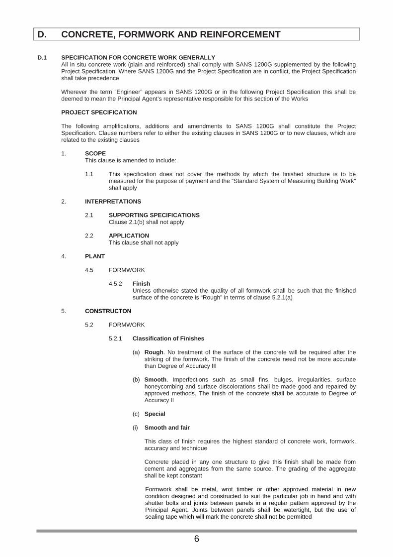
D. CONCRETE, FORMWORK AND REINFORCEMENT D.1 SPECIFICATION FOR CONCRETE WORK GENERALLY
All in situ concrete work (plain and reinforced) shall comply with SANS 1200G supplemented by the following Project Specification. Where SANS 1200G and the Project Specification are in conflict, the Project Specification shall take precedence
Wherever the term “Engineer” appears in SANS 1200G or in the following Project Specification this shall be deemed to mean the Principal Agent’s representative responsible for this section of the Works
PROJECT SPECIFICATION
The following amplifications, additions and amendments to SANS 1200G shall constitute the Project Specification. Clause numbers refer to either the existing clauses in SANS 1200G or to new clauses, which are related to the existing clauses
1. SCOPE
This clause is amended to include:
1.1 This specification does not cover the methods by which the finished structure is to be measured for the purpose of payment and the “Standard System of Measuring Building Work” shall apply
2. INTERPRETATIONS
2.1 SUPPORTING SPECIFICATIONS
Clause 2.1(b) shall not apply
2.2 APPLICATION This clause shall not apply
4. PLANT
4.5 FORMWORK
4.5.2 Finish
Unless otherwise stated the quality of all formwork shall be such that the finished surface of the concrete is “Rough” in terms of clause 5.2.1(a)
5. CONSTRUCTON
5.2 FORMWORK
5.2.1 Classification of Finishes
(a) Rough. No treatment of the surface of the concrete will be required after the striking of the formwork. The finish of the concrete need not be more accurate than Degree of Accuracy III
(b) Smooth. Imperfections such as small fins, bulges, irregularities, surface
honeycombing and surface discolorations shall be made good and repaired by approved methods. The finish of the concrete shall be accurate to Degree of Accuracy II
(c) Special
(i) Smooth and fair
This class of finish requires the highest standard of concrete work, formwork, accuracy and technique
Concrete placed in any one structure to give this finish shall be made from cement and aggregates from the same source. The grading of the aggregate shall be kept constant
Formwork shall be metal, wrot timber or other approved material in new condition designed and constructed to suit the particular job in hand and with shutter bolts and joints between panels in a regular pattern approved by the Principal Agent. Joints between panels shall be watertight, but the use of sealing tape which will mark the concrete shall not be permitted
6

Designated joints shall be in the position and of the details shown upon the working drawings. Should the Contractor wish to incorporate further construction joints or amend the position of those shown to suit his own requirements or technique, this may be allowed provided that all design considerations are met, that the prior approval of the Engineer is obtained and that any extra costs are borne by the Contractor In the case of horizontal construction joints, the top edge of the concrete on the smooth and fair finished side shall be struck true and level with a trowel Special care shall be taken to ensure that forms are clean and free of all pieces of tying wire, nails and other debris at the time of concreting The standard of finish shall be such that upon removal of the formwork, no further treatment, other than treatment of bolt holes if required, shall be found necessary to provide a straight, smooth and uniform finish of good quality and consistent colour and texture, free of all honeycombing etc. Any defect shall be made good by either removing and replacing the defective concrete or, in certain instances only, by patching
5.5 CONCRETE
5.5.1.6 Prescribed mix concrete
Where prescribed mix concrete is specified the proportions of constituents, the maximum size of coarse aggregate and the estimated minimum compressive strength shall be as specified in the following table:
Proportions of Constituents
Class of Concrete
Estimated minimum compressive strength in MPa at 28 days
Maximum nominal size of coarse aggregate in mm
Cement (Parts)
Fine aggregate (Parts)
Coarse aggregate (Parts)
A 7 37,5 1 4 8
B 15 19 1 3 5
C 20 19 1 2,5 3,5
Cement shall comply with SANS 50917-1 of strength 32,5N or higher Should cement and aggregates be mixed by volume, the contents of a 50kg sack of cement shall be taken to be 0,033m
3
Notwithstanding the requirements contained in SANS 1200G, the Principal Agent may permit certain items of non-structural concrete to be mixed by hand If the concrete is mixed by hand, it shall first be mixed in a dry state on a clean non-absorbent surface until it is of uniform colour and consistency. Just enough water shall then be added to permit mixing and working, at which stage the concrete shall continue to be mixed until it is of uniform colour and consistency
5.5.1.7 Strength concrete Where strength concrete is specified it shall be designated by its specified strength followed by the size of stone used in its manufacture, eg 30 MPa/19mm The water/cement ratio shall be as Table 5 of clause 5.5.1.5 for moderate exposure conditions
5.5.1.8 “No-Fines” concrete
“No-fines” concrete shall consist of one part cement to eight parts aggregate graded from minimum 6mm to maximum 13mm size
7

The quantity of water used shall be just sufficient to form a smooth grout which shall completely coat every particle of aggregate and also to ensure that the grout is just wet enough to form a small fillet at each point of contact between the stones. “No-fines” concrete mixed with excessive water, which results in a thin grout, which drops off the aggregate, will be rejected
“No-fines” concrete shall be placed in its final position within 20 minutes of mixing and shall be placed in continuous horizontal layers. Concrete shall be spade worked sufficiently to ensure that it fills the forms but vibrating, tamping or ramming will not be permitted
5.5.3.2 Ready-mixed concrete
The use of ready-mixed concrete and the acceptability of test results from a central concrete production facility shall be subject to the written approval of the Engineer
6. TOLERANCES
Degree of Accuracy II shall apply for all work unless otherwise stated 7. TESTS
7.1 FACILITIES AND FREQUENCY OF SAMPLING
7.1.2 Frequency of sampling
7.1.2.5 The frequency of sampling shall be as directed by the Engineer, but not
less than one set of cubes from every 50m³ cast
8. MEASUREMENT AND PAYMENT This clause shall not apply
D.2 AGGREGATES OF LOW DENSITY
Aggregates of low density shall comply with SANS 794 D.3 HOLLOW BLOCKS, PREFABRICATED BLOCK BEAMS AND PLANKS, ETC
Blocks, block beams, planks, etc shall be fixed and supported in such a manner that no movement can take place before or during the casting of concrete. No broken components shall be used
D.4 SUPERVISION
A competent and experienced foreman shall superintend personally the whole of the concrete construction and pay special attention to: (a) The quality, testing and mixing of materials, (b) The placing and compaction of concrete, (c) The construction and removal of formwork and (d) The sizes and position of reinforcement
The Contractor shall obtain the permission of the Principal Agent before commencing concreting of foundations or reinforced structure
No inspection, approval, authorisation to proceed, comment or instructions following from such an inspection, or failure of the Principal Agent to comment on any particular aspect of the work, shall be deemed to relieve the Contractor in any way from his obligation to ensure through his own supervision that the work is constructed in every way in accordance with the Drawings, Specification and Conditions of Contract, nor relieve him from his obligations to make good any fault or defect, nor shall it be deemed that there is any obligation on the Principal Agent to inspect all or any part of the Works or that such inspection is necessarily complete in every respect
D.5 GENERAL
Concrete
Rates for concrete work shall include all “construction joints” other than “designated joints” as defined in SANS 1200G clause 2.4.3 which are measured separately, and for the design of strength concrete mixes and all testing of concrete and materials other than compressive strength testing of concrete samples taken from concrete being placed in the Works. The Contractor shall only be entitled to payment for those samples and compressive strength tests called for by the Engineer and which pass the test requirements
8

Surface beds cast in panels shall be cast in panels approximately 9m
2
Formwork
Formwork to slabs and beams shall be cambered where required Rates for formwork to soffits shall include propping not exceeding 3,5m high unless otherwise described. Formwork to walls and columns is not exceeding 3,5m high above bearing level unless otherwise described Reinforcement Standard welded steel fabric reinforcement shall be as included in Table 1 of SANS 1024 and shall have 300mm wide laps. The mass of binding wire is not included in the mass of the reinforcement and the cost thereof shall be included in the rates for the reinforcement
9

E. PRECAST CONCRETE E.1 MATERIALS AND WORKMANSHIP
Materials and workmanship shall comply with the following standards: Precast concrete paving slabs SANS 541 Cement, water, aggregates and reinforcement shall be as described under D. CONCRETE, FORMWORK AND REINFORCEMENT
E.2 CONCRETE
Concrete shall be as described under D. CONCRETE, FORMWORK AND REINFORCEMENT and unless otherwise stated shall be prescribed mix concrete Class C but with coarse aggregate of an appropriate size
E.3 MOULDS
Before each casting, moulds shall be coated with a suitable release agent which will not in any way discolour the surface of the finished product or impair its strength. Where items are described as “finished smooth from the mould” or as “precast terrazzo”, moulds shall be made to a high degree of accuracy and shall be such as to leave even and smooth surfaces
E.4 FINISHES TO BLOCKS
Where described as “precast terrazzo”, such surfaces shall have a facing of terrazzo described under O. PLASTERING. The facing shall be poured into the moulds in a wet state (not dry pressed) and thoroughly worked up against finished faces to ensure that it finishes smooth from the mould Projections shall be rubbed off and faces shall be of even colour and free from blemishes, cracks and other imperfections. Salient angles shall be arris rounded
E.5 CASTING ETC
Items shall be suitably cured, shall not be handled whilst still green and shall not be built in within 21 days of casting
E.6 REINFORCEMENT
Unspecified reinforcement required for manufacturing, handling and erection purposes and for reinforcing projecting and other unwieldy portions of blocks shall be provided by the Contractor at his discretion
E.7 BEDDING, JOINTING AND POINTING
Blocks shall be bedded and jointed solidly in Class I mortar as described under F. MASONRY and shall be pointed with slightly keyed joints
Blocks finished with “precast terrazzo” shall have joints raked out and pointed with slightly keyed joints in tinted waterproofed mortar composed of one part cement and three parts sand to match terrazzo facing
E.8 GENERAL
Precast concrete work shall include reinforcement required for manufacturing, handling and erection purposes, steel rod or wire hooks and/or mortices for lewis bolts required for handling and transporting, any necessary temporary propping and strutting and bedding, jointing and pointing
10

F. MASONRY F.1 MATERIALS AND WORKMANSHIP
Materials and workmanship shall comply with the following standards: Burnt clay masonry units SANS 227 Limes for use in building SANS 523 {Slaked (hydrated) limes} Aggregates from natural sources – fine aggregates for plaster and mortar SANS 1090
Concrete masonry units SANS 1215 Prestressed concrete lintels SANS 1504 Burnt clay paving units SANS 1575 Metal ties for cavity walls SANS 28
Common cement SANS 50197-1 (Class 32,5N) Masonry cement SANS 50413-1 (Class 22,5X)
Concrete masonry construction SANS 10145 The structural use of masonry SANS 10164-1 Masonry walling SANS 10249
Concrete floors SANS 10109-1&2
F.2 SAND
Sand shall be washed where necessary and screened through a 2,4mm mesh sieve
F.3 BURNT CLAY BRICKS
Burnt clay bricks shall be of nominal size 222 x 106 x 73mm unless otherwise stated Common bricks shall be General Purpose bricks Extra hard burnt bricks shall be General Purpose (Special) bricks Facing bricks shall exhibit a liability to efflorescence not in excess of “Slight” and water absorption when tested in conformity with the requirements of SANS 227 shall not exceed 14% Particular care shall be taken to preserve arrisses and faces of facing and paving bricks during transit and handling
F.4 CONCRETE BRICKS
Concrete bricks shall have a nominal compressive strength of 8 MPa F.5 QUARRY TILES ETC
Quarry, cement and similar tiles shall be of approved manufacture, even in shape and size, free from cracks, twists or blemishes and uniform in colour
F.6 WIRE TIES
Wire ties shall be of galvanized steel of the single wire type for solid walls and either the “Butterfly” or Modified PWD type for hollow walls. Ties shall be of sufficient length to allow not less than 75mm of each end to be built into brickwork or embedded in concrete
F.7 BRICKWORK REINFORCEMENT
Brickwork reinforcement shall be manufactured from hard drawn steel wire conforming to BS 785 and shall consist of two 2,8mm diameter main wires with 2,5mm diameter cross wires at 300mm centres welded at intersections
11

Brickwork reinforcement shall be lapped not less than 300mm at end joints and for a length equal to the width of the widest reinforcement at intersections
F.8 MORTAR
Mortar shall comply with the following table:
1
2
3
4
Mortar Class
Minimum compresive strength MPa
Cement:sand (common cement)
Cement:sand (masonry cement)
I
10
1:4 or 50kg to 130 litres
1:3 or 50kg to 100 litres
II
5
1:6 or 50kg to 200 litres
1:5 or 50kg to 170 litres
III
1,5
1:9 or 50kg to 300 litres
1:6 or 50kg to 200 litres
Mortar shall be Class II unless otherwise specified Mortar plasticizers may only be used with the approval of the Principal Agent The materials shall be mixed dry until of uniform colour, water added and the mixture turned over until the ingredients are thoroughly incorporated Mortar shall be produced in such quantities as can be used before commencement of set and no mortar that has set shall be used
F.9 COMPO MORTAR
Compo mortar shall be Class III mortar in accordance with clause F.8 but with a lime content of 80 litres
The lime and sand shall be mixed dry until of uniform colour, water added and the mixture turned over until the ingredients are thoroughly incorporated. Immediately before use, the cement shall be mixed in and the requisite amount of water added. Compo mortar shall be produced in such quantities as can be used before commencement of set and no compo mortar that has set shall be used
F.10 BRICKWORK
Wherever practicable, brickwork shall be built in stretcher bond. Unless legitimately required to form bond, no false headers shall be used. English bond shall only be used where specifically so indicated or where stretcher bond is not practicable Brickwork, unless otherwise described, shall be built in Class II mortar Bricks shall be laid on a solid bed of mortar and all joints shall be grouted up solid The brickwork shall be carried up in a uniform manner, no part being raised more than 1,2m above adjoining work Where necessary, bricks shall be wetted before being laid and the course of bricks last laid shall be well wetted before laying a fresh course upon it
Walls in thicknesses of more than one skin shall have at least five wire ties per square metre. Linings to concrete, unless otherwise specified, shall be tied to the concrete with at least five wire ties per square metre
Hollow walls, unless otherwise specified, shall be built of two half brick skins with cavity between, tied together with at least five wire ties per square metre. The cavities shall be kept free of all rubbish, mortar droppings and projecting mortar. Mortar joints to brickwork shall be not less than 8mm or more than 12mm thick
12

F.11 BLOCKWORK
Unless otherwise described, all blockwork shall be built in stretcher bond. Whole blocks shall be used except where bats or closers are required to form bond. Blockwork, unless otherwise described, shall be built in Class II mortar
Solid blocks shall be laid on a solid bed of mortar and all joints shall be grouted up solid Hollow blocks shall be laid in shell bedding, ie only the inner and outer shells of the blocks shall be covered with mortar. Vertical joints shall be similarly formed
The blockwork shall be carried up in a uniform manner, no part being raised more than 1,2m above adjoining work Clay blocks shall be wetted before being laid and the course of blocks last laid shall be well wetted before laying a fresh course upon it
F.12 CENTRES AND TURNING PIECES
Centres and turning pieces to soffits of arches and lintels shall be left in position for not less than 14 days
F.13 FACE BRICKWORK
Face brickwork shall be built in stretcher bond, unless otherwise specified, to a true and fair face. Perpends shall be vertically aligned
Facing bricks shall be mixed to ensure that the proper blending of bricks within the colour range of each facing brick being used is obtained
F.14 PAVINGS, SILLS, COPINGS, ETC
Clay bricks and tiles shall be wetted before fixing and shall be solidly bedded and jointed in Class I mortar and pointed with slightly keyed joints
13

G. WATERPROOFING G.1 MATERIALS AND WORKMANSHIP
Materials and workmanship shall comply with the following standards:
Bituminous damp-proof courses SANS 248 (Type FV) Polyolefin film for damp- and waterproofing in buildings (walls, sills, etc) SANS 952 (Type B) Polyolefin film for damp- and waterproofing in buildings (floors and basements) SANS 952 (Type C) Mastic asphalt for roofing SANS 297 Mastic asphalt for damp-proof courses and tanking SANS 298 Bituminous roofing felt SANS 92 (Type 60) Polyolefin film for damp- and waterproofing in buildings (flat roofs) SANS 952 (Type A) Chloroprene rubber sheet (for waterproofing) SANS 580 Sealing compounds for the building industry, two-component, polysulphide base SANS 110 (Type 2 - Gun Grade) Sealing compounds for the building and construction industry, two- component, polyurethane base SANS 1077
The waterproofing of buildings (including damp- proofing and vapour barrier installation) SANS 10021
G.2 WATERPROOFING TO ROOFS, BASEMENTS, ETC
Waterproofing to roofs, basements, etc shall be carried out by workmen who are experienced in this type of work
G.3 DAMP-PROOF COURSE TO WALLS
All joints in damp-proof course to walls shall be lapped a minimum of 150mm except at junctions and corners where the lap shall equal the full thickness of the wall
14

H. ROOF COVERINGS ETC H.1 MATERIALS AND WORKMANSHIP
Materials and workmanship shall comply with the following standards: Concrete roofing tiles SANS 542 Clay roofing tiles SANS 632 Sawn softwood timber battens SANS 1783-4 Fibre-cement sheets (flat and profiled) SANS 685 Aluminium alloy corrugated and troughed sheets SANS 903 Continuous hot-dip zinc-coated carbon steel sheet of commercial, lock-forming and drawing qualities SANS 3575 Continuous hot-dip zinc-coated carbon steel sheet of structural quality SANS 4998 Polyolefin film for damp- and waterproofing in buildings SANS 952 Metal roofing tiles SANS 1022 Glass-reinforced polyester (GRP) laminated sheets (profiled or flat) SANS 1150 Fasteners for roof and wall coverings in the form of sheeting SANS 1273 Materials for thermal insulation of buildings SANS 1381-1&4 Expanded polystyrene thermal insulation boards SANS 1508
Fixing of concrete interlocking roofing tiles SANS 10062 Roof and side cladding SANS 10237
Sheet zinc BS 849 Sheet lead BS 1178 Sheet aluminium BS 1470 Sheet copper BS 2870
H.2 GALVANIZED STEEL PROFILED SHEETS ETC
Galvanized steel profiled sheets, ridge and hip coverings, etc shall be coated with a minimum of 275 g zinc per m2 and shall be free of white rust
H.3 GALVANIZED SHEET IRON
Galvanized sheet iron shall be rolled steel sheet coated on both sides with a minimum of 275 g of zinc per m2
and shall be free from white rust H.4 NAILING AND SCREWING
Where nailing and screwing is required: • galvanized iron nails and screws shall be used for galvanized sheet iron and sheet zinc
• copper or copper alloy nails and screws for sheet copper and sheet lead
• aluminium alloy or stainless steel nails and screws for sheet aluminium
15

H.5 LAPS
Sheet metal flashings shall have minimum 100mm laps and linings to valleys, secret gutters, etc minimum 225mm laps
H.6 GENERAL
Rates for profiled sheet roofing and rolled edges, ridge and hip coverings, flashing pieces, etc of metal, fibre-cement, plastic, etc shall include fixing accessories
16

I. CARPENTRY AND JOINERY I.1 MATERIALS AND WORKMANSHIP
Materials and workmanship shall comply with the following standards:
Sawn softwood timber : General requirements SANS 1783-1 Sawn softwood timber : Stress-graded structural timber and timber for frame wall construction SANS 1783-2 Sawn softwood timber : Brandering and battens SANS 1783-4 Softwood flooring boards SANS 629 Hardwood furniture timber SANS 1099 Hardwood block and strip flooring SANS 281 Wooden ceiling and panelling boards SANS 1039 Laminated timber (glulam) SANS 1460 Gypsum plasterboard SANS 266 Fibreboard products SANS 540 Wood-wool panels (cement bonded) SANS 637 Fibre-cement sheets (flat and profiled) SANS 685 Fibre-cement boards SANS 803 Plywood and composite board SANS 929 Wooden ceiling and panelling boards SANS 1039 Particle boards SANS 50312-1to7 Decorative laminates SANS 4586 Wooden doors SANS 545 Fire doors SANS 1253
Materials for thermal insulation of buildings SANS 1381-1,2,4&6 Expanded polystyrene thermal insulation boards SANS 1508 Mild steel nails SANS 820 Metal screws for wood SANS 1171 Wood-preserving creosote SANS 539
Softwood shall bear the relevant SABS mark and shall be ordered in the sizes in which it will be used as no scantlings of marked timber will be allowed. Should SABS marked timber be unavailable, the Principal Agent’s prior permission shall be obtained before using unmarked timber
I.2 HARDWOODS
All hardwoods shall be specially selected, well seasoned, free from sapwood and well kiln dried. Meranti shall be Red or Medium Brown Meranti, even in grain and colour, selected from “Standard and Better” quality from Malaysia
17

I.3 INFECTION AND PRE-TREATMENT OF TIMBER
All timber used on the site, whether for permanent or temporary work, shall be free of borer or other beetle and termite infection. If the work under this contract falls within an area designated under Government Notice R2577 of 197812-29, permanent softwood fixed in the building shall be treated against borer etc in accordance with Government Notice R451 of 1969-03-28 using Class B or C preservative When treated timbers are cut, the cut surfaces shall be effectively brushed with at least two coats of preservative solution
I.4 CONSTRUCTION IN GENERAL
Where applicable, construction methods shall comply with SANS 10082. Wood and laminate flooring shall be installed in accordance with SANS 10043. Roof trusses shall be manufactured, erected and braced in accordance with SANS 10243
I.5 STRUCTURAL TIMBER
Timbers generally shall be in single lengths and jointing of timbers will only be permitted when the required length is unobtainable. Only the absolute minimum of joints to obtain a particular length will be permitted and such joints are to be evenly spaced along the length of the timber Finger-jointing of structural timber will be permitted, in which case it shall be manufactured in accordance with SANS 10096
I.6 PLATE NAILED TIMBER ROOF TRUSSES
Plate nailed timber roof trusses shall be of approved design and manufacture and constructed with softwood structural timber by a truss Fabricator holding a current Certificate of Competence awarded by the Institute of Timber Construction Each roof truss shall have all its members accurately cut and closely butted together and rigidly fixed by CSIR approved patented galvanized metal spiked connectors, precision pressed on both sides of each intersection by an approved method, all in accordance with the manufacturer’s instructions The design, manufacture and transportation of the roof trusses, bracing, etc shall be under the control of a registered Structural Engineer in accordance with SANS 1900, SANS 10160 and SANS 10163, who shall, after erection, provide a certificate confirming that the design, manufacture, transportation, erection and bracing has been carried out in accordance with this specification The design shall include for all live loads, wind loads and for dead loads imposed by roof covering, purlins, ceilings, etc Fully detailed shop drawings of all trusses etc, indicating sizes, bracing, loading, etc, shall be submitted to the Principal Agent for approval prior to fabrication Unless specific erection instructions are given, erection shall be carried out in accordance with the procedures and recommendations of the manual “The Erection and Bracing of Timber Roof Trusses” published by the Institute for Timber Construction and the Council for Scientific and Industrial Research or as detailed by the designer Roof trusses and bracing shall include design and preparation of shop drawings
I.7 TONGUED AND GROOVED BOARDING
Tongued and grooved boards for floors, panelling, etc shall be in long varying lengths with joints tightly cramped up and secret nailed. Flooring boarding shall be flush jointed with staggered heading joints and machine sanded after fixing
I.8 JOINERY
Skirtings, cornices, rails, etc shall be in single lengths wherever practicable and shall have splayed heading joints where necessary. Skirtings shall be trenched at back All horns of door frames shall be checked and splayed back where frames are fixed projecting or flush with surface and built in Heads of screws in exposed faces of hardwood joinery shall be sunk and match pelleted Joinery shall have arris rounded angles and shall be blocked and planted on
18

I.9 VENEERS
All face veneers shall be of kiln dried timber, free from knots, cracks, patchwork, sapwood and other defects, selected and glued, dried and machine-sanded to a smooth finish. All veneers shall be applied under hydraulic pressure
I.10 DOORS
Flush doors shall have solid timber edge strips with concealed edges. Where doors are to be finished with a transparent finish, the veneer and the edge strips shall be timber of the same species and as far as possible of matching colour. Unless otherwise described all flush doors shall be of interior quality, but where exterior quality doors are specified the glue used shall be of the WBP type Framed and ledged batten doors described as filled in with V-jointed boarding shall be filled in flush on one side with tongued and grooved vertical boarding, V-jointed on one or both sides and of the thickness stated. The boarding shall be in narrow widths, closely cramped up, rebated or tongued on outer edges and housed to grooves in stiles and rails and twice countersunk brass screwed at each intersection with ledges and braces and the inner edges of the abutting stiles and rails shall be chamfered to form a V-joint at junction with the board Unless otherwise described double doors shall have rebated meeting stiles
I.11 FIXING
All nails and screws shall be of the size, length and type appropriate to their respective uses. All screws for hardwood joinery work shall be brass Items described as “plugged” shall be screwed to fibre, plastic or metal plugs at not exceeding 600mm centres. Where items are described as “bolted”, the bolts have been given separately
I.12 ADHESIVES
Adhesives shall comply with BS 1204 and 4071 where applicable. Adhesives used in the manufacture of external joinery exposed to excessive moisture (eg kitchen and laboratory worktops) shall be of the WBP type
19

J. CEILINGS, PARTITIONS AND ACCESS FLOORING J.1 MATERIALS AND WORKMANSHIP
Materials and workmanship shall comply with the following standards:
Gypsum plasterboard SANS 266 Fibreboard products SANS 540 Gypsum cove cornice SANS 622 Wood-wool panels (cement-bonded) SANS 637 Sawn softwood timber : Brandering and battens SANS 1783-4 Sawn softwood timber : Timber for frame wall Construction SANS 1783-2 Fibre-cement boards SANS 803 Plywood and composite board SANS 929 Wooden ceiling and panelling boards SANS 1039 Materials for thermal insulation of buildings SANS 1381-1&4 Expanded polystyrene thermal insulation boards SANS 1508 Raised access flooring SANS 1549
J.2 TONGUED AND GROOVED BOARDING
Tongued and grooved boarding for ceilings shall be in long varying lengths, V-jointed one side and with joints tightly cramped up and secret nailed
J.3 CEILINGS ETC
J.3.1 Brandering
Brandering for ceilings and eaves soffit coverings shall be symmetrically arranged with necessary smaller panels. Main branders shall be at right angles to roof timbers, with cross branders cut in between and branders shall be fixed with galvanized wire nails driven in on skew alternately in opposite directions
J.3.2 Ceiling boards
Ceiling boards shall be in long lengths symmetrically arranged with necessary smaller panels, closely butted and secured at 150mm centres to brandering with galvanized or cadmium-plated clout-headed nails
J.4 GYPSUM SKIM PLASTER
Gypsum skim plaster shall be pure gypsum plaster finished with a steel trowel J.5 EXPOSED TEE-SYSTEM SUSPENDED CEILINGS
The ceiling panels shall be as described in the items and the panels shall be stiffened at back as recommended by the manufacturer to prevent bowing or sagging The exposed surfaces of all ceiling panels and supporting members shall be uniform in colour and free from surface blemishes
The suspension grid system shall be an approved patent suspension system comprising 38mm galvanized steel main and cross tee bearers spaced in both directions at centres to suit sizes of ceiling panels used, with the cross bearers fitted between and notched to form flush fit with main bearers. The exposed flange of the tees shall be 25mm wide, covered with a rolled aluminium cap painted a low sheen satin white. Cornices etc shall be as described in the items and shall be finished to match the exposed tees
20

The main tee bearers shall have holes for cross tees at 300mm centres and holes for hangers at 50mm centres. In addition, main and cross tee bearers shall be holed as necessary for and provided with timber wedges or steel clips where recommended by the manufacturer to prevent ceiling panels from lifting The web of the exposed cross tee bearers shall extend to form a positive interlock with the main tee bearers and the lower flange shall be cut back to provide a joint free appearance All hangers shall be galvanized and shall be at centres to meet the requirements of the specification with one end fixed to the suspension grid main bearers and the other end fitted with suitable galvanized fixing cleat securely fixed to the structure. Fixing points shall be agreed to by the Principal Agent before any power shot fixings are made. Hangers shall not be suspended from air-conditioning ducts. Where recommended by the manufacturer, hangers shall be of the rigid type Component parts and fixings shall be non-corrosive and able to withstand atmospheric pollution. Surfaces of aluminium which are in contact with other materials when fixed, particularly metals, shall be suitably insulated to prevent electrolytic corrosion Ceilings shall comprise hangers, suspension grid system and ceiling panels, shall be constructed in a manner suitable for carrying air-conditioning diffusers and light fittings in the positions required, shall be set out to layouts approved by the Principal Agent and shall have the standard suspension systems modified as necessary to work around any pipes or light fittings
J.6 FLUSH PLASTERED SUSPENDED CEILINGS
Gypsum plasterboard panels of the specified thickness generally in 1200mm widths and in long lengths shall be fixed grey side down with self-tapping screws to the suspension system with the joints between boards loosely butt jointed and covered with 50mm wide strips of self-adhesive fibre tape The plasterboard panels shall be finished with gypsum skim plaster trowelled to a smooth polished surface to the thickness etc recommended by the manufacturer The suspension system shall be an approved patent concealed suspension system consisting of galvanized mild steel bearers suspended on approved non-rusting metal hangers spaced generally at 1200mm centres or to suit layout of air-conditioning ducts and other services etc above ceiling with one end bolted to the bearer and the other end fitted with a galvanized fixing cleat securely fixed to the structure as required Fixing points shall be agreed to by the Principal Agent before any power shot fixings are made. Hangers shall not be suspended from air-conditioning ducting Ceilings shall comprise hangers, suspension system, ceiling panels and plaster finish, shall be constructed in a manner suitable for carrying air-conditioning diffusers and light fittings in the positions required, shall be set out to layouts approved by the Principal Agent and shall have the standard suspension system modified as necessary to work around any pipes or light fittings
21

K. FLOOR COVERINGS, WALL LININGS, ETC K.1 MATERIALS AND WORKMANSHIP
Materials and workmanship shall comply with the following standards:
Semi-flexible vinyl floor tiles SANS 581 Resin modified vinyl floor tiles SANS 586 Flexible vinyl flooring SANS 786 Hardwood block and strip flooring SANS 281 Wood mosaic flooring SANS 978 Textile floor coverings (pile construction) SANS 1375 Textile floor coverings (needle-punched construction) SANS 141 Carpet underlays SANS 1419
The installation of wood and laminate flooring SANS 10043
The installation of resilient thermoplastic and similar flexible floor covering materials SANS 10070
The installation of textile floor coverings SANS 10186
Sheet linoleum (calendered types), cork, carpet and linoleum tiles BS 810 Solid rubber flooring BS 1711 Felt backed linoleum BS 1863
K.2 LAYING OF MATERIAL
Floor tiles shall be laid with continuous joints in both directions Patterned floor coverings shall be matched at joints
K.3 GENERAL
Floor coverings, wall linings, skirtings, nosings, etc shall include all preparatory work to screeded or plastered surfaces etc, priming coats and adhesives Floor coverings and wall linings shall be dressed around and into corners. Wood block and wood mosaic flooring shall be sanded with a sanding machine and sealed with a coat of approved penetrating sealer Plastic handrails shall have welded and polished butt joints
22

L. IRONMONGERY L.1 MATERIALS AND WORKMANSHIP
Materials and workmanship shall comply with the following standards:
Locks, latches and associated furniture for doors. (Domestic type) SANS 4
Kitchen cupboards: Built-in and free-standing SANS 1385
Single action closers SANS 1510
Padlocks SANS 1533
Fasteners SANS 1700 Chalk writing boards for schools CKS 36
L.2 KEYS
Locks shall have the minimum possible number of interchangeable keys. Cylinder locks and locks described as “en suite” shall be clearly marked with consecutive numbers and each key shall be punched with the corresponding number of the relative lock
L.3 FIXING
Unless otherwise described, ironmongery is to be fixed to wood Items described as “plugged” shall be screwed to fibre, plastic or metal plugs Screws, bolts, etc for fixing of ironmongery shall be of matching metal and finish, except for aluminium ironmongery or ironmongery fixed to aluminium in which cases stainless steel screws may be used All necessary preparation of pressed steel door frames for the fixing of ironmongery to the frames has been included with the pressed steel door frames
L.4 KITCHEN CUPBOARDS
Steel cupboards shall be finished with baked enamel. Tops of floor cupboards shall have laminated plastic covering Cupboards shall be fitted with all necessary hinges, handles, catches, etc. Cupboards shall be securely fixed with all necessary screws and fibre, plastic or metal plugs Where cupboards are described as a “series”, tops shall be continuous and cupboards shall be bolted or screwed together, including bolts, screws, holes, etc
23

M. STRUCTURAL STEELWORK M.1 SPECIFICATION
All structural steelwork shall comply with SANS 1200H or 1200HA as applicable. Structural fasteners shall comply with SANS 1700
Whenever the term “Engineer” appears in SANS 1200H or 1200HA or in the following Project Specification this shall be deemed to mean the Principal Agent’s representative responsible for this section of the Works
M.2 PROJECT SPECIFICATION INCORPORATING AMPLIFICATIONS, ADDITIONS AND AMENDMENTS TO
SANS 1200H AND 1200HA
The following amplifications, additions and amendments to SANS 1200H and SANS 1200HA shall apply and clause numbers refer to either the existing clauses in the relevant SANS or to new clauses which are related to the clauses therein
SANS 1200H
3.1.1 Weldable structural steel
Weldable structural steel shall comply with SANS 1431
5.1.2 Contractor provides shop details
The Contractor shall be responsible for the preparation of all shop detail drawings
5.1.3 Engineer provides shop details
This clause shall not apply
5.3.9 Protective treatment
Structural steelwork shall be cleaned and prepared by wire brushing in accordance with SANS 10064 and all surfaces shall be primed as specified to a minimum dry film thickness of 30 micrometres before leaving the workshop. Upon delivery to the site and again after erection all bared surfaces shall be made good with similar primer
8. Measurement and payment
This clause shall not apply
SANS 1200HA
5.2.10 Protective treatment
Structural steelwork shall be cleaned and prepared by wire brushing in accordance with SANS 10064 and all surfaces shall be primed as specified to a minimum dry film thickness of 30 micrometres before leaving the workshop. Upon delivery to the site and again after erection all bared surfaces shall be made good with similar primer
5.3.7 Repairs to paint and site painting
This clause shall not apply
8. Measurement and payment This clause shall not apply
24

N. METALWORK N.1 MATERIALS AND WORKMANSHIP
Materials and workmanship shall comply with the following standards:
Fasteners SANS 1700 Expanded metal SANS 190-1&2 Windows and doors made of rolled mild steel sections SANS 727 Hot-dip galvanized zinc coatings on fabricated iron and steel articles SANS 121 Strongroom and vault doors SANS 949 Anodized coatings on aluminium (for architectural applications) SANS 999 Steel door frames SANS 1129 Mushroom- and countersunk-head bolts and nuts SANS 1143 Welding of metalwork SANS 1044 Adjustable glass-louvred windows CKS 413 Aluminium sheet and strips BS 1470 Aluminium extruded tube and hollow sections BS 1474 Aluminium bars and sections BS 1476
N.2 STEEL
Steel shall be mild steel of approved commercial quality. Steelwork shall be cleaned and prepared by wire brushing in accordance with SANS 10064 and given one coat of primer as specified before leaving the workshop N.2.1 Galvanizing of steel
Steelwork described as “galvanized” shall be galvanized by means of the hot-dip process after fabrication. Where welding on site is unavoidable, such welded joints shall be cleaned down and cold galvanized to approval
N.3 STAINLESS STEEL
Stainless steel shall be AISI Type 304 stainless steel and shall be buffed to an even satin finish. Stainless steel screws shall be used for fixing stainless steel
N.4 ALUMINIUM
Aluminium extrusions shall be of 6063-T6 alloy and temper. Aluminium sheet and strips shall be of 1200-H4 alloy and temper. Joints in all aluminium members shall be formed in an approved manner so that the joints are practically invisible. Screw heads, pins, rivets, etc shall be concealed as far as possible. 300 Series stainless steel screws and bolts shall be used for jointing and fixing aluminium work The surfaces of all aluminium which are in contact with other materials when fixed shall be suitably insulated with a non-absorbent insulating material to prevent corrosion. All aluminium work shall be suitably protected against damage, deterioration or discolouration caused by mortar droppings, paint, etc by taping with removable tape, covering with temporary casings or by covering with motor oil
N.4.1 Anodizing of aluminium
Aluminium described as “anodized” shall be treated with Grade 25 coating thickness for exterior use or Grade 15 for interior use as specified, to the required finish. All alloys to be anodized shall be suited to anodizing
25

N.5 BOLTS AND NUTS Nuts shall be of at least the strength grade appropriate to the grade of bolt or other threaded element with which they are used
N.6 SCREWING OF METALWORK TO STEEL, WOOD, CONCRETE, ETC
Metalwork described as “screwed” to steel, wood, etc or “plugged” to brickwork, concrete, etc shall be fixed at not exceeding 500mm centres, with necessary holes, countersinking, threading, screws, set screws, self-tapping screws and fibre, plastic or metal plugs
N.7 BOLTING OF METALWORK
Where metalwork is described as “bolted” to steel, wood, brickwork, concrete, etc the bolts are measured elsewhere
N.8 WELDING OF METALWORK
All welds shall be cleaned and filed or ground off smooth to approval. All welded joints shall be continuous N.9 METALWORK GENERALLY
Metalwork shall have all sharp edges ground smooth. Tubular and pipe work shall include running joints. Rails etc described as “continuous” shall be in long lengths with welded joints
N.10 PRESSED STEEL DOORS, FRAMES, ETC
N.10.1 Door frames
Frames shall project not less than 20mm into floor finish. Except where described as galvanized, frames shall be primed as specified before leaving the factory. Frames are to jambs and heads of openings. Frames for single doors shall be provided with two 100mm steel butt hinges and an adjustable striking plate for a mortice lock and frames for double doors shall be provided with four 100mm steel butt hinges. Butt hinges shall be steel butts with loose pins, welded to frames. Where necessary mortar caps shall be welded to frames and back plates shall be welded on behind tappings for screws
N.10.2 Cupboard door frames
Cupboard door frames shall be as described in N.10.1, but with thresholds of unequal channel section, two 100mm steel butt hinges to hanging stiles, two 75mm steel butt hinges to hanging stiles above transoms, necessary striking plates for mortice locks and keeps for barrel bolts
N.10.3 Combination doors and frames
Combination doors and frames shall be manufactured of 1,6mm thick steel plate. Frames shall be as described in N.10.1. Doors shall be standard design and required profile, with a 44mm wide edge all round, vertical reinforcing ribs pressed in and with two reinforcing rails welded on. The door shall be provided with two lever mortice lock with lock box welded to inside. Doors shall be welded to steel butts
N.10.4 Transformer room doors and frames
Transformer room doors and frames shall be manufactured of 1,6mm thick steel plate. Frames shall be as described in N.10.1. Doors shall be of standard design with a 44mm wide edge all round, vertical reinforcing ribs pressed in and with three reinforcing rails welded on. Single doors shall be fitted with a padlock cleat and two 100mm brass pintle hinges and double doors shall be fitted with a padlock cleat, two 150mm bolts and four 100mm brass pintle hinges. Each leaf shall be fitted with a louvered ventilation panel of standard design backed with 6mm mesh galvanized wire vermin proof screen
N.10.5 Sizes
The frame widths given refer to unfinished wall thicknesses
N.10.6 Glazing beads
Where specified, glazing beads shall be 12 x 12mm standard metal glazing beads mitred at angles and countersunk screwed on at not exceeding 300mm centres with self-tapping screws
26

N.11 STEEL WINDOWS, DOORS, ETC
N.11.1 Windows, doors, etc
All fittings to windows, doors, etc shall be chromium plated. Fixed lights and opening sashes shall be in single squares. Windows etc of single unit construction shall have weather bars at transoms above opening sashes
Composite windows not of single piece construction shall be coupled with standard coupling mullions and transoms that correspond with the window section used Kicking plates and panels shall be 1,6mm metal plate fixed with standard metal glazing beads mitred at angles and countersunk screwed on at not exceeding 300mm centres with self-tapping screws Except where described as galvanized, windows, doors, burglar bars, etc shall be primed as specified before leaving the factory
N.11.2 Burglar bars and flyscreens
Where windows are described as fitted with burglar bars or flyscreens, these shall be standard type fitted over opening sashes
N.12 ADJUSTABLE LOUVRE UNITS
Adjustable louvre units shall be suitable for hand or longarm operation
Louvre units shall include glass louvres with polished edges and installation, including holes, screws, rivets, preparation of openings, etc
N.13 ALUMINIUM WINDOWS AND DOORS
The foregoing preambles “N.4 – ALUMINIUM” shall apply to aluminium windows, doors, etc in all respects in so far as they are applicable. Aluminium windows and doors shall be manufactured from extruded aluminium members of 6063T6, 6261-T6 or 6082-T6 alloy and temper Ancillary members such as sills, flashings, infill panels and the like formed from flat sheet material shall be of an appropriate alloy selected from 1200, 3004 or 5251 complying with BS 1470 of a temper suitable for the method of forming and a composition suitable for anodizing or painting as required
Windows, doors, etc shall be of an approved standard system, manufactured by an approved firm experienced in this type of work, and shall meet with the minimum recommended performance requirements as set out by the Association of Architectural Aluminium Manufacturers of South Africa (AAAMSA) in the latest edition of the Selection Guide
The fittings for all opening sashes shall be substantial and, unless otherwise described, shall be of high quality aluminium alloy finished to match the windows, doors, etc on which they occur. Samples of all fittings shall be supplied to the Principal Agent for approval
Top, side and bottom hung opening sashes shall be hung on two aluminium hinges with 300 Series stainless steel pins, nylon bushes and stainless steel washers. Side hung sashes shall have fasteners and sliding stays, top hung sashes shall have peg stays and bottom hung sashes shall have spring catches and concealed arms
Projected out sashes shall have aluminium fasteners and concealed arms of a non-corrosive material compatible with aluminium
The frames which are to be built into openings in brickwork shall be fitted with the manufacturer’s standard type fixing lugs, not less than 20 x 3 x 150mm long, screwed to frame and placed one near each corner and intermediately not more than 450mm apart to sides, top and bottom and where fixed to concrete reveals, wood sub-frames or to preformed openings in brickwork shall have countersunk holes for screws, one near each corner and intermediately not more than 450mm apart to sides, top and bottom N.13.1 Glazing beads
Where so described, openings and sashes of windows and doors shall be fitted with approved channel section aluminium glazing beads sufficient in size and profile to suit the method of glazing employed, finished to match the windows, doors, etc and neatly mitred. Screws where necessary shall be of aluminium or 300 Series stainless steel and have pan or raised heads finished to match the beads
27

N.13.2 Finishes
Windows, doors, etc described as “anodized” shall be treated with Grade 25 coating thickness. Windows, doors, etc described as “factory painted” shall have an electrostatically applied oven baked polyester paint coating not less than 25 micrometres thick
N.13.3 General
Aluminium windows, doors, etc shall include glass as described, fixing in position, sealing and protection against damage, deterioration or discolouration by taping with removable tape or covering with temporary casings or motor oil and removing same on completion
N.14 STRONGROOM AND RECORD ROOM DOORS
Strongroom and record room doors shall not be built in as the work proceeds, but shall be fixed later in the openings provided. The Contractor shall ensure that the lock or other important parts of the door are not tampered with. Should any such tampering occur, the Contractor will be held responsible and at the Principal Agent’s discretion shall provide a new door or lock and keys at his own expense. The keys shall not be delivered together with the doors to the building site. The Contractor shall arrange for the manufacturer to send the keys direct to the Principal Agent per registered post. If these instructions are not complied with, a new lock and keys shall be provided by the Contractor at his own expense
N.15 STEEL ROLLER SHUTTERS
Roller shutters shall be of approved manufacture comprising curtain, vertical channel guides and top mechanism. The curtain shall be constructed of 1mm thick machine-rolled galvanized interlocking slats with mild steel end locks spot welded to alternate strips. The bottom shall be provided with a galvanized rail riveted on and vertical edges shall slide in galvanized channel guides formed of steel not less than 2,5mm thick bolted to sides of openings
The mechanism shall be covered in a galvanized sheet iron box. The ungalvanized sections shall be primed as specified before leaving the factory
28

O. PLASTERING O.1 MATERIALS AND WORKMANSHIP
Materials and workmanship shall comply with the following standards:
Common cement SANS 50197-1(Class 32,5N) Masonry cement SANS 50413-1(Class 225X) Limes for use in building SANS 523 {Slaked (hydrated) limes}
Aggregates from natural sources – Fine aggregates for plaster and mortar SANS 1090
O.2 PREPARATORY WORK
Surfaces shall be clean and free of oil and thoroughly wetted directly before any plastering or other in situ finishes are commenced. Concrete surfaces shall be slushed with a mixture of one part cement and one part coarse sand or otherwise treated to form a proper key. Preparatory coats shall be thoroughly scored and roughened to form a proper key
O.3 FINISH
All coats of paving and plastering shall be executed in one operation without any blemishes O.4 SCREEDS
Screeds shall be composed of one part cement and four parts sand O.5 CEMENT RENDER
Cement render shall be composed of one part cement and three parts sand finished with a steel trowel to a smooth polished surface and cured for at least seven days after laying Cement render finish shall be divided into panels not exceeding 6m2 with V-joints and deep trowel cuts
O.6 GRANOLITHIC
Granolithic shall be composed of one part cement, one part fine sand, two parts coarse sand and one part granite or other approved stone aggregate that will pass through a 5mm sieve, finished with a steel trowel to a smooth polished surface and cured for at least seven days after laying
Coloured granolithic shall be carried out in two coats in one operation and shall be tinted to the required colour with approved colouring pigment mixed into the finishing coat. Under no circumstances is the pigment to be sprinkled on and trowelled in after the granolithic is laid
Granolithic shall be divided into panels not exceeding 6m2 with V-joints and deep trowel cuts
O.7 TERRAZZO
Terrazzo shall be applied in two coats. The undercoat shall be composed of one part cement and three parts sand and shall be finished with a wooden float. The finishing coat shall be composed of one part cement and two parts marble or stone aggregate of a colour and size to obtain the required colour and texture and shall be at least 12mm thick, and applied before the undercoat has dried out. The finishing coat shall be compacted by tamping or rolling until superfluous water has been expelled, finished with a steel trowel and cured for at least seven days after laying. The finished surface shall show at least 80% of the aggregate
Surfaces described as “polished” shall be polished by machine using various grades of abrasive and grouting with tinted cement as necessary between polishings
Surfaces described as “polished” shall be polished by machine using various grades of abrasive and grouting with tinted cement as necessary between polishings
Surfaces described as “brushed” shall be brushed with a steel wire brush on the day the terrazzo has been laid to expose the aggregate as required
Where required, brass or other dividing strips shall be embedded in the undercoat to finish flush with the finished surface
29

Three sample blocks, each size 300 x 300mm, as separately measured shall be prepared for approval by the Principal Agent and kept in an accessible place on the site until the completion of the contract
O.8 SKIRTINGS
Skirtings shall not exceed 25mm thick and shall have a fair edge with arris or rounded external angle at top edge or V-joint to finish flush with plaster and coved or square junction with floor finish
O.9 THICKNESS OF PLASTER
All plaster, other than skim plaster, shall be not less than 10mm and not more than 20mm thick O.10 CEMENT PLASTER
Cement plaster shall comply with the following table:
1
2
3
Plaster Class
Cement:sand (common cement)
Cement:sand (masonry cement)
I
1:4 or 50kg to 130 litres
1:3 or 50kg to 100 litres
II
1:6 or 50kg to 200 litres
1:5 or 50kg to 170 litres
III
1:9 or 50kg to 300 litres
1:6 or 50kg to 200 litres
O.11 COMPO PLASTER
Compo plaster shall be composed of one part cement, two parts lime and nine parts sand O.12 GYPSUM SKIM PLASTER
Gypsum skim plaster shall be pure gypsum plaster finished with a steel trowel O.13 TWO COAT PLASTER WITH GYPSUM FINISH
Two coat plaster with gypsum finish shall comprise an undercoat of Class II cement plaster finished with a wooden float and a finishing coat of gypsum skim plaster
O.14 ROUGH-CAST PLASTER
Rough-cast plaster shall be applied in two coats. The undercoat shall be composed of one part cement and five parts sand finished with a wooden float. The finishing coat shall be composed of one part cement and three parts stone aggregate that will pass through a 4mm sieve. The finishing coat shall be flicked on with a machine before the undercoat has set to obtain an even texture
O.15 FINE ROUGH-CAST PLASTER
Fine rough-cast plaster shall be as for rough-cast plaster but the finishing coat shall be composed of one part cement and three parts coarse sand
0.16 GENERAL
Rates for plastering described as being on vertical surfaces of brickwork or blockwork shall include concrete columns, beams and lintels flush with the face of the wall
30

P. TILING P.1 MATERIALS AND WORKMANSHIP
Materials and workmanship shall comply with the following standards:
Glazed ceramic wall tiles and fittings SANS 22
Ceramic wall and floor tiles SANS 1449 Common cement SANS 50197-1(Class 32,5N) Masonry cement SANS 50413-1(Class 22,5X) Aggregates from natural sources – Fine aggregates for plaster and mortar SANS 1090
The design and installation of ceramic tiling SANS 10107
P.2 TILES, MOSAICS, ETC
Tiles, mosaics, etc shall be even in shape and size, free from cracks, twists or blemishes and uniform in colour
P.3 PREPARATORY WORK
Surfaces shall be clean and free of oil and thoroughly wetted directly before any tiling is commenced. Concrete surfaces shall be slushed with a mixture of one part cement and one part coarse sand or otherwise treated to form a proper key
P.4 CERAMIC WALL AND FLOOR TILING
Where tiles are fixed to plaster or screeds with an adhesive, the adhesive shall be as recommended by the manufacturer of the tiles. Joints shall be straight, continuous and flush pointed with an approved grouting compound
P.5 GENERAL
Tiling described as “on walls” is on brick walls or block walls unless otherwise stated and shall include concrete columns, beams and lintels flush with the face of the wall
31

Q. PLUMBING AND DRAINAGE Q.1 MATERIALS AND WORKMANSHIP
Materials and workmanship shall comply with the following standards:
Sheet metal
Sheet zinc BS 849 Sheet aluminium BS 1470 Sheet copper BS 2870
Rainwater systems
Unplasticized poly(vinyl chloride) (PVC-U) components for external rainwater systems SANS 11 Pipes and fittings Steel pipes : Pipes suitable for threading and of nominal size not exceeding 150mm SANS 62
Plain-ended solid drawn copper tubes for Potable water SANS 460
Malleable cast iron fittings threaded to ISO 7-1 SANS 4 Polyethylene (PE) pipes for water supply – Specifications SANS 4427
Cast iron fittings for asbestos cement pressure pipes SANS 546 Vitrified clay sewer pipes and fittings SANS 559 Reinforced concrete pressure pipes SANS 676 Concrete non-pressure pipes SANS 677 Cast iron pipes and pipe fittings for use above ground in drainage installations SANS 746 Unplasticized poly(vinyl chloride) (PVC-U) sewer and drain pipes and pipe fittings SANS 791
Fibre-cement pipes, couplings and fittings for sewerage, drainage and low-pressure irrigation SANS 819
Pitch-impregnated fibre pipes and fittings and jointing SANS 921
Unplasticized poly (vinyl chloride) (PVC-U) pressure pipe systems SANS 966-1 Unplasticized poly(vinyl chloride) (PVC-U) soil, waste and vent pipes and pipe fittings SANS 967
Rubber joint rings (non-cellular) SANS 974-1
Copper-based fittings for copper tubes SANS 1067-1&2
Fibre-cement pressure pipes and couplings SANS 1223 Polypropylene pressure pipes SANS 1315 Non-metallic waste traps SANS 1321-1&2 Vent valves for drainage installations SANS 1532 Heavy duty cast iron pipe fittings for drainage and gas and water supplies BS 78
32

Lead pipes BS 602
Cast iron pressure pipes for use in drainage and gas and water supplies BS 1211
Stainless steel pipes for use with compression fittings BS 4127 Sanitary fittings etc
Stainless steel sinks with draining boards (for domestic use) SANS 242 Stainless steel wash-hand basins and wash troughs SANS 906 Stainless steel sinks for institutional use SANS 907 Stainless steel stall urinals SANS 924
Acrylic sanitary ware : Baths SANS 1402-1
Glazed ceramic sanitary ware SANS 497 WC flushing cisterns SANS 821 Flush valves for WC flushing cisterns SANS 1509 Taps, valves etc Water taps (metallic bodies) SANS 226
Water taps (plastic bodies) SANS 1021 Single control mixer taps SANS 1480 Float valves SANS 752 Plastic floats for ball valves SANS 1006 Functional control valves and safety valves for Domestic hot and cold water supply systems SANS 198 Cast iron gate valves for waterworks SANS 664 Automatic shut-off flush valves for water closets and urinals SANS 1240 Check valves (flanged and wafer types) SANS 1551-1&2 Fire extinguishers
Portable refillable fire extinguishers SANS 1910 Portable rechargeble fire extinguishers : Halogenated hydrocarbon type extinguishers SANS 1151
Water heaters and fire hose reels
Fixed electric storage water heaters SANS 151 Fire hose reels (with semi-rigid hose) SANS 543 Drainage covers, gratings, etc
Cast iron surface boxes and manhole and inspection covers and frames SANS 558 Cast iron gratings for gullies and stormwater drains SANS 1115 The installation of polyethylene and poly (vinyl chloride) (PVC-U and PVC-M) pipes SANS 10112
Water supply and drainage for buildings SANS 10252-1&2
33

Cast iron step irons BS 1247
Q.2 GENERAL
Q.2.1 Excavations
Excavations shall be deemed to be in “earth”. Backfilling to excavations shall be executed in 300mm thick layers, watered and compacted. Surplus excavated material shall be spread and levelled over site as directed
Q.2.2 Concrete
Unreinforced concrete shall be Class B prescribed mix concrete and reinforced and precast concrete shall be Class C prescribed mix concrete
Q.2.3 Brickwork
Brickwork shall be of extra hard burnt bricks built in Class I mortar Q.2.4 Plaster
Plaster shall be 1:3 cement plaster finished smooth with a steel trowel. All angles shall be rounded Q.2.5 Diameters of pipes etc
Diameters stated for pipes, traps, valves, etc are internal diameters except PVC, polyethylene, stainless steel and copper pipes and traps for which external diameters are stated
Q.3 SHEET METAL WORK
Q.3.1 Galvanized sheet iron
Galvanized sheet iron shall be rolled steel sheet coated on both sides with Class Z275, unless otherwise specified, zinc coating complying with SANS 3575/4998. Sheets shall be free from white rust
Q.4 EAVES GUTTERS
Q.4.1 Galvanized sheet iron gutters
Galvanized sheet iron gutters shall have beaded edges and all joints shall be riveted and soldered. Angles shall be strengthened with 50 x 0,6mm galvanized sheet iron strips soldered on over the internal faces of mitres
Gutters shall be fixed with falls to outlets on 30 x 3mm galvanized mild steel brackets, bent to the shape of gutters, with front ends taken up to the underside of beaded edge of gutter and each screwed to roof timbers or bolted to fibre-cement fascias with 6mm galvanized gutter bolts. Gutters shall be bolted to brackets at front with 6mm galvanized gutter bolts, one to each bracket Brackets shall be positioned at joints of gutters and intermediately at not exceeding 1,25m centres
Q.4.2 Fibre-cement gutters
Fibre-cement gutters shall have spigot and socket joints. Gutters shall be fixed with falls to outlets on standard aluminium alloy brackets, screwed or bolted to roof timbers or fascias
Q.4.3 Unplasticized polyvinyl chloride (UPVC) gutters
Gutters shall be fixed with falls to outlets on brackets as supplied by the manufacturer, screwed or bolted to roof timbers or fascias
Q.4.4 Aluminium gutters
Aluminium gutters shall be roll formed on site to required lengths and profiles from 3003H14-3SH4 alloy strip not less than 0,7mm thick factory coated on both sides with baked enamel and two coats of silicone modified polyester to a total minimum thickness of 20 micrometres. Angles, stopped ends, etc shall be prefabricated units pop riveted to gutters with joints sealed with mastic. The guttering shall be in continuous lengths between angles, stopped ends, etc
34

Q.5 RAINWATER PIPES
Q.5.1 Galvanized sheet iron pipes
Galvanized sheet iron pipes shall have seams at the back and shall be jointed with soldered slip joints. Pipes shall be fixed to walls etc with galvanized mild steel holderbats spaced at not exceeding 2m centres with tails driven in or cut and pinned in 1:3 cement mortar
Q.5.2 Fibre-cement pipes
Fibre-cement pipes shall have spigot and socket joints. Pipes shall be fixed to walls etc with standard aluminium alloy holderbats with tails driven in or cut and pinned in 1:3 cement mortar
Q.5.3 Unplasticized polyvinyl chloride (UPVC) pipes
Pipes shall be fixed to walls etc with patented UPVC or aluminium clips and holderbats as supplied by the manufacturer of the pipe
Q.5.4 Aluminium pipes
Aluminium pipes and fixing straps shall be formed from 3003H14-3SH4 alloy strip not less than 0,7mm thick factory coated on both sides as described for aluminium gutters. Pipes shall be in continuous lengths with formed angles, offsets, shoes, etc. Pipes shall be fixed to walls etc with 20 x 0,6mm straps at not exceeding 1,5m centres screwed to 25 x 75 x 100mm hardwood chamfered and oiled blocks plugged to walls
Q.6 STORMWATER CHANNELS
In-situ concrete stormwater channels shall be constructed of unreinforced concrete with segmental channel formed in top. Channels shall be laid to falls on a well rammed earth bottom and finished smooth on exposed surfaces Precast concrete channels shall be of 25 MPa concrete, generally in 1m lengths, finished smooth from the mould on exposed surfaces, laid to falls on a well rammed earth bottom, jointed in 1:3 cement mortar and pointed with keyed joints
35

Q.7 JOINTS
Joints of pipes not covered by SANS shall be as follows:
Pipes
Joints
Fibre-cement, concrete, pitch-impregnated fibre and vitrified clay pipes for use under ground in non-pressure pipe lines
Flexible joints in accordance with the manufacturer’s instructions
Cast iron for use above ground Spigot and socket joints with tarred rope yarn and caulking compound
or Plain ended joints with stainless steel couplings
with neoprene rubber sleeves
Cast iron for use below ground Spigot and socket joints with tarred rope yarn and caulking compound
Galvanized mild steel Joints of screwed galvanized steel sockets or bolted galvanized iron flanges
Screwed joints with plastic jointing tape or hemp
Flanged joints which shall be bolted and provided with rubber gaskets and with flanges screwed to pipes
Joints between pipes of different materials shall be as follows:
Between cast iron and mild steel Spigot and socket joints with tarred rope yarn and caulking compound
Between cast iron and clay Spigot and socket joint with semi-dry cement caulking and 1:2 cement mortar fillet
Between mild steel or copper and clay Spigot and socket joint with either bitumen or semi-dry cement caulking and 1:2 cement mortar fillet
Q.8 FIXING OF PIPES
Pipes shall be fixed as follows:
Q.8.1 Galvanized mild steel (except those stated in Q.8.3)
To walls with galvanized mild steel brackets for pipes not exceeding 80mm diameter and with galvanized cast iron hinged holderbats with brass pins or bolts for pipes exceeding 80mm diameter; both types with tails cut and pinned in 1:3 cement mortar
To woodwork with screw-on type galvanized mild steel holderbats
Q.8.2 Copper and stainless steel To walls with brass holderbats or screw-on type two- piece spacing clips for pipes not exceeding 75mm diameter and with purpose made holderbats for pipes exceeding 75mm diameter; both types with tails cut and pinned in 1:3 cement mortar
To woodwork with screw-on type brass holderbats
Q.8.3 Cast iron and galvanized mild steel for soil, waste and vent pipes
To walls with hinged cast iron holderbats with brass bolts and with tails cut and pinned in 1:3 cement mortar
To woodwork with screw-on type galvanized mild steel holderbats
Q.8.4 Polyethylene, polypropylene and patented UPVC or unplasticized polyvinyl chloride
To walls, woodwork, etc with aluminium clips and holderbats as supplied by the manufacturer of the pipes
Q.8.5 Fibre-cement To walls with aluminium alloy holderbats with tails cut and pinned in 1:3 cement mortar
36

Q.8.6 Pipes fixed to ceilings Fixed with holderbats and standard or purpose made hangers, with extended hangers for pipes to falls
Q.9 PIPES LAID IN GROUND
Q.9.1 Water pipes etc
Water pipes, gas pipes, etc laid in ground shall be at least 400mm deep from the crown of the pipe to the finished surface
Q92 Drain pipes
Excavations taken out too deep shall be filled in with selected soil and compacted. Backfilling to sides and up to 300mm above plastic pipes shall be free from stone or hard substances which will not pass a 10mm mesh
Q.10 CLEANING EYE LIDS
Cleaning eye lids for drain pipe fittings shall be fixed and sealed as follows:
Pipe fittings
Method of sealing and fixing
Fibre-cement
Sealed with synthetic rubber or bituminous mastic packing and fixed with screws
Vitrified clay Polypropylene lid sealed with synthetic rubber packing and pressed into position
Polypropylene and unplasticized polyvinyl chloride
Sealed with synthetic rubber packing and screwed on or pressed into position
Cast iron Sealed with tallow or putty and fixed with non-ferrous metal screws
Galvanized malleable cast iron and cast brass Sealed with synthetic rubber packing and screwed in
Q.11 CLEANING EYES
Cleaning eyes shall consist of cast iron frames and lids with letters “CE” (or “SO”) cast in lids. The lids shall be secured with non-ferrous metal screws. Frames shall be jointed to vertical drain pipes. Cleaning eyes shall be encased in unreinforced concrete taken up to ground level and plastered on exposed surfaces
Q.12 INSPECTION EYE MARKER SLABS
Inspection eye marker slabs shall be 350 x 350 x 50mm thick precast concrete finished smooth from the mould, with letters “IE” (or “IO”) formed in top and placed flush in ground or paving
Q.13 GULLEYS
Gulleys shall be built up of traps, vertical piping and gulley heads with loose gratings, all encased in unreinforced concrete to finish flush with gulley head top and taken up to at least 50mm above surrounding finished surfaces. The outer top edge of the concrete encasing shall be splayed and the exposed surfaces plastered
37

Q.14 DISHED GULLEYS
Dished gulleys shall be built up of traps, vertical piping and gulley heads with loose gratings, all encased in unreinforced concrete and with dished unreinforced concrete hopper size 450 x 450mm overall around gulley head with rounded kerb 50mm wide to front and sides and 25mm wide at back, 100mm high above top of dishing and the hopper plastered on exposed surfaces. Top of hopper shall be taken up to at least 50mm above surrounding finished surfaces
Q.15 SUMPS, CATCHPITS, INSPECTION CHAMBERS, ETC
Q.15.1 Rainwater sumps
Rainwater sumps shall be built with half-brick sides on 100mm thick unreinforced concrete bottom, plastered internally on walls and with 80mm high unreinforced concrete kerb at top rebated for grating or cover and plastered on exposed surfaces
Q.15.2 Stormwater catchpits and inspection chambers
Brick catchpits and inspection chambers shall be built with one-brick sides on 150mm thick unreinforced concrete bottom projecting 100mm beyond walls all round, plastered internally on walls and with 100mm thick reinforced concrete cover slab with opening rebated for frame of grating or cover and plastered on exposed surfaces
Precast concrete catchpits and inspection chambers shall be constructed in accordance with the applicable details shown on Drawing LE-1 of SANS 1200LE. Precast concrete manhole sections and slabs shall comply with SANS 1294 and pipes shall be SC type and in accordance with SANS 677
Q.15.3 Sewer inspection chambers
Brick inspection chambers shall be built as for brick stormwater inspection chambers and with the bottom of the chamber well benched around half round channels, bends, junctions, etc up to sides of chamber in unreinforced concrete finished smooth Precast concrete inspection chambers shall be constructed in accordance with the applicable details shown on Drawing LD-5 of SANS 1200LD. Precast concrete manhole sections and slabs shall comply with SANS 1294 and the pipes shall be SC type in accordance with SANS 677
Q.15.4 Stormwater drain junction boxes
Junction boxes shall be formed of 150mm thick unreinforced concrete bottom and sides to suit the various sizes of the drain pipes and built after the pipes have been laid, with the sides taken up slightly higher than the highest pipe and finished level on top for and covered with a 75mm thick loose precast concrete slab
Q.15.5 Step irons
Where inspection chambers exceed 1,2m deep, cast iron step irons shall be provided, built into the wall at 300mm centres and staggered regularly in vertical rows spaced at 200mm centres horizontally
Q.16 STOPCOCK AND METER BOXES
Stopcock and meter boxes shall be built with half-brick sides with a cast iron box and lid complying with SANS 558 set in 75mm wide unreinforced concrete kerb for the full depth of the cast iron box and plastered on exposed surfaces
Q.17 VALVE CHAMBERS
Valve chambers shall be built with half-brick sides with 100mm thick unreinforced concrete kerb to top with rebate for cover and frame to finish flush with adjacent paving or finished ground level and plastered on exposed surfaces
Q.18 CAST IRON COVERS, GRATINGS, ETC
All cast iron covers, gratings, frames and surface boxes shall be coated with preservative solution. Frames shall be cast into concrete. Covers, except covers to stormwater drainage or electrical cable inspection chambers, shall be set in grease
Q.19 CONCRETE ENCASING
Concrete encasing for pipes, bends, traps, gulleys, grease traps, etc shall be unreinforced concrete not less than 100mm thick all round
38

Q.20 SANITARY FITTINGS
Q.20.1 General
Glazed ceramic, acrylic and porcelain enamelled sanitary fittings and component parts shall be white. Accessories for sanitary fittings shall be chromium plated brass Waste outlets for baths, basins, etc shall comprise chromium plated brass waste union with grating, rubber washers and locknut, fitted with rubber or vulcanite plug on a chromium plated brass chain and stay
Q.20.2 Stainless steel sanitary fittings
Stainless steel sinks and draining boards, basins, wash troughs and urinals shall be AISI Type 304 satin finished stainless steel. All stainless steel fittings shall be treated on the back with a vermin proof sound deadening coating. Sinks, basins and wash troughs shall be provided with 40mm diameter screwed waste outlets
Q.20.3 Precast concrete wash troughs
Reinforced precast concrete wash troughs shall have a sloping front with ribbed rubbing surface and shall be finished smooth on exposed faces with top edges and inner angles rounded. Each compartment shall be fitted with a 40mm diameter waste outlet. Wash troughs shall each be supported on two reinforced precast concrete pedestals finished smooth on exposed faces
Q.20.4 Steel baths
Steel baths shall be porcelain enamelled internally and painted externally and fitted with waste outlet and overflow grating with coupling
Q.20.5 Acrylic resinous baths
Acrylic resinous baths shall be fitted with waste outlet and overflow grating with coupling Q.20.6 Acrylic resinous wash hand basins
Acrylic resinous wash hand basins and vanity units shall have a smooth high gloss finish, with outlet openings, soap recesses, tap-holes and integral overflow and shall be fitted with waste outlet and overflow grating with coupling
Q.20.7 Glazed ceramic sanitary fittings
Sinks shall be provided with integral weir overflows Washdown closet pans shall have washdown action and be provided with smooth finished injection moulded polypropylene heavy duty double flap seats fixed with non-ferrous bolts. Urinal channels shall be provided with outlet gratings fitted in bitumen
Q.20.8 Flush and sparge pipes
Flush pipes for high level cisterns shall be of plastic or drawn galvanized steel Flushpipes for low level cisterns shall be of plastic Flush and sparge pipes for urinals with high level cisterns shall be of chromium plated copper piping and of the sizes recommended by the manufacturer of the urinal
Q.21 INSTALLATION OF SANITARY FITTINGS
Sanitary fittings shall be installed as follows:
Q.21.1 Precast concrete wash troughs
Precast concrete wash troughs shall be bedded on top of pedestals which shall be bedded on floors in 1:3 cement mortar
Q.21.2 Stainless steel wash troughs and wash hand basins
Stainless steel wash troughs and wash hand basins shall be fixed to walls on a pair of galvanized mild steel gallows brackets bolted to wall with 6mm diameter expanding bolts
39

Q.21.3 Acrylic resinous wash hand basins Acrylic resinous wash hand basins shall be fixed to walls on a pair of standard painted cast iron brackets screwed to underside of basin and bolted to wall with 6mm diameter expanding bolts
Q.21.4 Ceramic wash hand basins
Ceramic wash hand basins shall be fixed to walls on a pair of standard painted steel or cast iron brackets bolted to wall with 6mm diameter expanding bolts
Q.21.5 Acrylic resinous baths
Acrylic resinous baths shall be bedded in 1:5 cement mortar on three cross rows of bricks or bedded solid on a layer of dry river sand and fixed to wall with galvanized steel brackets under edges (in the middle of the sides against walls) bolted to wall with 6mm diameter expanding bolts and sealed along top against wall finishes with patent mildew resistant silicone rubber
Q.21.6 Washdown closet pans and cisterns
Washdown closet pans shall be bedded on floors in 1:3 cement mortar. Cisterns shall be fixed to walls with 6mm diameter expanding bolts
Q.21.7 Ceramic urinals
Ceramic stall and slab urinals shall be bedded on floors and against walls in 1:3 cement mortar. Slabs, channels, treads, etc shall be jointed in 1:3 cement mortar and pointed in white cement
Ceramic bowl urinals shall be fixed to walls on standard steel brackets bolted to wall with 6mm diameter expanding bolts. Cisterns shall be fixed to walls on standard brackets bolted to wall with 6mm diameter expanding bolts
Q.21.8 Stainless steel urinals
Stainless steel stall and slab urinals shall be bedded on floors in 1:3 cement mortar and with backs and sides against walls filled in with fine unreinforced concrete. Cisterns shall be fixed as cisterns for ceramic urinals
Q.22 FIRE HOSE REELS
Fire hose reels shall each be fitted with a 30m long hose of internal diameter not less than 19mm with a 4,8mm internal diameter chromium plated brass nozzle
Q.23 FIRE EXTINGUISHERS
All fire extinguishers shall be fully charged
Q.24 TESTS
Sewerage pipe lines, sanitary plumbing including fittings and hot and cold water supply and fire service shall be tested to the approval of the Principal Agent and Local Authority
The Contractor shall provide all testing apparatus, material and labour required for the tests and inspections
40

R. GLAZING R.1 MATERIALS AND WORKMANSHIP
Materials and workmanship shall comply with the following standards:
Glass in building SANS 50572-1 to 5 Glazing putty for wooden and metal window frames SANS 680 Silvered glass mirrors for general use SANS 1236 Safety and security glazing materials for buildings SANS 1263-1 to 3 Sealing compounds for the building industry, one Component, silicone-rubber based SANS 1305 The installation of glazing materials in buildings SANS 10137
Work on glass for glazing SANS 1817 R.2 PUTTY ETC
Glazing putty shall be Type I for wooden sashes and Type II for steel sashes. Putty for glazing to unpainted hardwood shall be tinted to match the colour of the wood Back putty shall not exceed 3mm thick. Putty shall not be painted until it has formed a surface crust, and if the putty does not form a surface crust it shall be replaced Butyl putty shall be used where glass is to be fixed in aluminium sashes with glazing beads Non-setting compounds shall be used where laminated glass is fixed in sashes with glazing beads
41

S. PAINTWORK S.1 MATERIALS AND WORKMANSHIP
Materials and workmanship shall comply with the following standards:
Decorative paint for interior use SANS 515
Decorative high gloss enamel paints SANS 630
Primers for wood (for external work) SANS 678
Primers for wood (for internal work) SANS 678
Zinc phosphate primer for steel SANS 1319
Undercoats for paints (except emulsion paint) SANS 681
Aluminium paint SANS 682
Varnish for interior use SANS 887
Emulsion paints SANS 1586
Materials for paintwork shall be delivered to the site in unopened containers and applied in accordance with the manufacturer’s instructions. Materials shall be suitable for application to the surfaces concerned. Undercoats shall be as recommended by the manufacturer of the finishing coats
S.2 PREPARATORY WORK
S.2.1 Plastered surfaces etc
Plastered surfaces shall be thoroughly inspected and, if necessary, washed down and brushed in order to remove any traces of efflorescence and allowed to dry completely before any paint finish is applied. Before any paint is applied, holes, cracks and irregularities in plaster and other surfaces shall be filled with a suitable filler and finished smooth. Unfinished concrete surfaces shall have all projections rubbed off and shall be thoroughly cleaned with a spirits-of-salts solution (1 part concentrated spirits-of-salts to 4 parts water)
S.2.2 Metal surfaces
Metal surfaces shall be sanded, where necessary, washed with a suitable cleaning agent and left smooth Protective coatings applied by manufacturers to galvanized metal surfaces shall be removed with a suitable agent and the surfaces washed down Rust, grease and defective factory primers on metal surfaces, as well as pitch on cast iron pipes, shall be removed
S.2.3 Wood surfaces
Knots in woodwork shall be treated with knotting. Minor blemishes shall be filled with a suitable filler. Wood surfaces shall be sanded smooth
S.3 APPLICATION OF PAINT
Primers to wood surfaces shall be applied by brush. Primers to other surfaces may be applied by roller with the approval of the Principal Agent. Undercoats and finishing coats may be applied by brush or roller
Paint shall not be sprayed on except in the case of cellulose and other special paints where spray painting is the accepted method of application
Before subsequent coats of paint are applied the previous coat shall be properly dry and shall be sanded down where necessary
42

S.4 COLOUR SCHEME
A colour scheme comprising colours and the blending of colours approved by the Principal Agent shall be used for the paintwork. The tints of the undercoats shall closely match the finishing coat but nevertheless differ sufficiently to indicate the number of undercoats. Colour samples of the finishing coats shall be provided in all cases
S.5 GENERAL
Paintwork shall include the preparation of surfaces, filling, stopping, sanding and priming of nail heads and screws. Where windows, sashes, etc are to be painted, the rebates of the openings to be glazed shall be primed
43

T. PAPERHANGING T.1 PREPARATORY WORK
Plaster surfaces to be papered shall be dry, thoroughly cleaned down, filled with a suitable filler as necessary to obtain a smooth surface and painted thereafter with a single coat of emulsion paint
Wood surfaces to be papered shall be knotted, stopped and sanded
T.2 PAPERHANGING
Wallpaper shall be hung in vertical long lengths. Vertical joints shall be close-fitted and plumb and the paper shall be tightly fitted to skirtings, ceilings, door frames, windows, etc. Horizontal joints will not be allowed
44

U. EXTERNAL WORKS U.1 GENERAL
U.1.1 Excavations Excavations shall be deemed to be in “earth”
U.2 LANDSCAPING
U.2.1 Topsoil
Topsoil shall vary between sandy loamy soil and sandy clayey soil with an ideal composition of 15% to 25% clay, 10% silt/sludge and 65% to 75% sand, with a minimum ratio of organic material of 2%. All material shall be free of harmful deposits as well as unwanted seeds
U.2.2 Compost
Compost shall be composed of properly decayed organic material, free from harmful deposits, salts, seeds and other waste material and shall have a pH of more than 4 and less than 7
U.2.3 Mulch
Mulch shall be approved organic material free from small particles of bark residue, fungus, disease, etc
U.2.4 Lime
Lime shall be agricultural lime of an approved manufacture
U.2.5 Fertilizer
Fertilizer shall be of the type specified, mixed thoroughly into the soil as prescribed. No fertilizer shall be added more than two weeks prior to planting
U.2.6 Backfilling
Backfilling in plant and tree holes shall be composed of two parts topsoil to one part compost mixed thoroughly together and compacted by foot in 100mm layers. Fertilizer shall only be added if pre-scribed
U.2.7 Pebbles
Pebbles shall be smooth with a uniform colour and form and ranging in size from 50mm to 75mm diameter. Removal of pebbles from river beds shall be done selectively to avoid any major disruption to the ecology of the river and environment
U.2.8 Plant material
U.2.8.1 General
All plant material (plants, shrubs, trees, etc) shall be obtained from a registered nursery and shall be free from damaged parts, parasites, fungus, other plant diseases or insects. No container-bound plants will be acceptable
U.2.8.2 Trees
The height of trees described in the bills of quantities shall be measured from the top of the root ball to the top of the tree. Where trees are pruned, such prune wounds shall not be more than 25mm in diameter and be sealed with an approved sealing compound
U.2.8.3 Shrubs and small plants
Shrubs and small plants shall meet the requirements for height and spread as specified. Thin or sparsely branched plants shall not be accepted. Branches shall be well spread with ample young branches and the plant as a whole shall be growing well
U.2.8.4 Groundcover
Groundcover shall be dense and healthy and shall comply with the minimum requirements for leaf density as specified
45

Formal grass shall be planted as runners in 50mm deep drills at 150mm centres unless otherwise described
U.2.9 Cultivation and preparation of planting areas etc
All surface rocks and stones larger than 50mm shall be removed before commencing cultivation and preparation. The entire area shall be ripped and rotavated using approved machinery by breaking up the earth to a depth of 300mm at 600mm centres in both directions, unless otherwise described, and then levelled. Where fertilizer or compost is specified, it shall be worked into the topsoil after ripping and rotavation to a depth of 300mm and finished to final levels
All fertilizer to areas to be grassed shall be strewn on the final layer before final finishing is commenced and worked mechanically into the top 150mm soil
U.2.10 Planting procedure
Holes for shrubs and groundcover shall be as follows:
Shrubs – 500 x 500 x 500mm deep
Groundcover – 300 x 300 x 300mm deep (if not planted in drills)
Holes for trees shall be square, of adequate size to accommodate the root system and suitable for the height of the tree
All plant material shall be watered thoroughly before careful removal from the container and planted in the prescribed planting medium with the top of the soil in the container finishing level with the surrounding area. Water dams size 800mm diameter x 150mm deep and 500mm diameter x 150mm deep shall be formed around trees and shrubs respectively and all planting material shall be watered immediately after planting. Trees, shrubs, etc shall be properly staked or stayed, depending on their size, on the prevailing windy side with patent tree ties
U.2.11 Maintenance
All planted areas shall be maintained for a period of three months after practical completion as defined in the contract with the exception of hydroseeded areas which shall be maintained for 12 months after an acceptable cover has been obtained
This maintenance shall consist of keeping clear of weeds and litter, loosening soil where necessary every two weeks, replacing damaged, diseased or dead plants, pruning, cutting and mowing as neces-sary and watering so as to keep the plant material in a healthy growing condition
U.3 ROADWORK
U.3.1 Filling
Filling under roads etc shall be of inert material having a maximum plasticity index of 10, free from large stones etc spread, levelled, watered and compacted in layers not exceeding 200mm thick to a density of 98% Mod AASHTO
U.3.2 Preparation of sub-grade
The sub-grade shall be prepared by scarifying for a depth of 150mm and compacting to a density of 98% Mod. AASHTO, including trimming to the correct levels and grades
U.3.3 Base course
The base course shall consist of crusher run stone compacted to a density of 98% Mod. AASHTO and finished to the correct levels and grades
U.3.4 Weed killer
The completed sub-grade shall be treated with an approved total weed killer
U.3.5 Bituminous premix road surfacing
Before spreading the premix material, the base course shall be swept clean and free from all dust, dirt and loose particles, lightly wetted and sprayed with a prime coat of cutback bitumen complying with SANS 308 at the rate of 1 litre/m2
The material shall consist of semi-gap graded crushed stone aggregate having the following grading:
46

Sieve size (mm) % By mass passing sieve
13,2 100 4,75 45-60 2,36 42-55 1,18 40-52 0,3 25-45 0,075 5-12
The aggregate shall be mixed with bituminous road tar binder complying with SANS 748 at the rate of 1m3 of stone to 120 litre of emulsion at atmospheric temperature The binder shall be added to the stone and mixed until the stone is uniformly coated. Thereafter 5% of clean, dry quartzitic sand shall be added and mixed until evenly distributed through the mixture The premix shall be applied only after the primer has dried out completely and shall be spread imme-diately after mixing and rolled on the same day Spreading shall be done evenly over the prepared base course to a loose depth sufficient to ensure the consolidated thickness specified Rolling shall commence as soon as the binder has set sufficiently, followed after three days by a final rolling
U.3.6 Precast concrete block road surfacing
Paving blocks shall be precast concrete blocks complying with SANS 1058 Blocks shall be laid to true levels and grades on and including a 25mm thick layer of river sand with joints exceeding 2mm and not exceeding 6mm wide
After laying, the paving shall be compacted by means of a vibrating plate compactor, with joints be-tween the blocks filled in, after compaction, by sweeping in fine sand
Infill areas at edges of paving constituting less than 25% of a full block unit and of 25mm minimum dimension shall be filled with Class C prescribed mix unreinforced concrete with top surface trowelled smooth to match blocks. Smaller areas shall be filled with 1:4 cement mortar
U.3.7 Precast concrete kerbs and channels
Precast concrete kerbs and channels shall comply with SANS 927, generally in 1m lengths and finished smooth from the mould on exposed surfaces. Kerbs and channels shall be bedded on and jointed in 1:3 cement mortar and pointed with keyed joints. Bases to kerbs shall be Class B prescribed mix unreinforced concrete
U.3.8 Process control tests
The Contractor shall be responsible for carrying out all necessary process control tests on the density and moisture content of the compacted sub-grade, base course, etc to ensure that the required com-paction is being attained
U.4 FENCING ETC
U.4.1 Materials Materials and workmanship shall comply with the following specifications and requirements :
Wooden poles, droppers, guardrail posts and spacer blocks SANS 457-2&3
Zinc-coated fencing wire SANS 675
Prefabricated concrete components for fencing SANS 1372 Chain-link fencing and its wire accessories SANS 1373
47

Fasteners SANS 1700 Anti-intruder fences CKS 451
Metal droppers and standards CKS 451
U.4.2 Galvanized wire
All galvanized wire shall be zinc coated wire with Class B zinc coating. Straining wire shall be 4mm diameter galvanized mild steel wire. Tie wire shall be 1,6mm diameter galvanized mild steel wire
U.4.3 Plastic coated wire
Plastic coated straining wire shall be 3,15mm diameter Class C galvanized mild steel wire plastic coat-ed to an overall diameter of 3,95mm
Plastic coated tie wire shall be 1,8mm diameter Class C galvanized mild steel wire plastic coated to an overall diameter of 2,5mm
U.4.4 Galvanized barbed wire
Galvanized barbed wire shall be 2,5mm diameter mild steel double strand reverse twist zinc coated barbed wire with Class A zinc coating
U.4.5 Galvanized wire mesh
Galvanized wire mesh shall be 50mm mesh chain link netting of 2,5mm diameter Class C galvanized mild steel wire
U.4.6 Plastic coated wire mesh
Plastic coated wire mesh shall be 50mm mesh chain link netting of 2,5mm diameter Class C galva-nized mild steel wire plastic coated to an overall diameter of 3,25mm
U.4.7 Galvanized welded wire mesh
Galvanized welded wire mesh shall be fabricated from pre-galvanized wires to rectangular pattern welded together at each intersection using a welding method which forms a zinc oxide protective coat-ing at each intersection
U.4.8 Razor wire
Razor wire shall be fabricated from 2,5mm diameter galvanized high tensile steel wire fitted with razor barbs formed of 0,5mm galvanized steel strip clipped on at 37,5mm centres
U.4.9 Metal droppers and standards
Droppers shall be of ridged T-section mild steel with a mass of not less than 0,55kg/m. Standards shall be of I- section mild steel with a mass of not less than 3kg/m or of ridged edge Y-section mild steel with a mass of not less than 2,5kg/m, and shall be driven 600mm deep into the ground
Droppers and standards shall have either galvanized, sprayed metal or painted finish as described in the items and in accordance with CKS 451. In addition, those surfaces of standards embedded in the ground shall be coated with bitumen
U.4.10 Metal posts and stays
Posts and stays shall comply with CKS 451 and shall be of black galvanized mild steel tubing as speci-fied
Straining posts shall be of 108mm outside diameter x 3mm wall thickness tubing, each with a 300 x 300 x 5mm thick mild steel sole plate and a steel cap welded on
Intermediate posts shall be of 50mm outside diameter x 2,5mm wall thickness tubing, each with a 230 x 230 x 5mm thick mild steel sole plate and a steel cap welded on Stays for straining posts shall be of 50mm outside diameter x 2,5mm wall thickness tubing, each with a 230 x 230 x 5mm thick mild steel sole plate welded on and fixed raking with top end flattened, bent, holed and bolted to straining post with and including a 5mm diameter galvanized mild steel bolt with nut and washer
Posts and stays shall have either galvanized or painted finish as described in the items and in accor-dance with CKS 451. In addition, sole plates and portions of posts and stays embedded in ground shall be coated with bitumen
48

U.4.11 Timber posts, stays and droppers
Timber posts shall be 125mm diameter, timber stays shall be 100mm diameter and timber droppers shall be 30mm diameter
U.4.12 Prestressed concrete posts and stays
Prestressed concrete posts and stays shall be finished smooth from the mould and uniformly stressed by means of high tensile longitudinal prestressing wires with concrete cover to wires of not less than 20mm
Corner and straining posts shall be 100 x 100mm and intermediate posts and stays shall be 75 x 75mm. Stays shall be fixed raking with top end splayed and glued to posts with a suitable epoxy compound
U.4.13 Bolts, nuts and washers
Straining eye bolts, hinge bolts, bolts, nuts and washers shall be galvanized
U.4.14 Precast concrete fencing
Precast concrete fencing over sloping terrain shall be stepped to suit terrain, including the use of in-creased lengths of posts as necessary, excavation, etc
U.4.15 Concrete bases
Bases in ground for posts, stays, etc shall be of Class B prescribed mix concrete with tops 100mm below surface of ground Sizes of concrete bases for posts, stays, etc shall be as follows: Straining and gate posts – 450 x 450 x 700mm deep Intermediate posts – 300 x 300 x 600mm deep Stays – 600 x 300 x 500mm deep
U.4.16 Security overhangs
Where fencing is described as having a security overhang, the posts and standards shall have angular (single arm) extension arms
Extension arms shall be attached to the posts and standards by welding in the case of steel and by spiking in the case of timber
Concrete extension arms shall be cast integrally with the post or standard
Barbed wire to security overhangs shall be tightly strained and wired at each intersection with exten-sion arms and shall have barbed wire braces at 450mm centres between standards, posts, etc wired onto the barbed wire and the top straining wire
U.4.17 Gates
Gates shall be formed of 40mm outside diameter x 2,5mm wall thickness mild steel tubular framework with welded joints, strongly braced as necessary and filled in with wire mesh as described above, prop-erly strained and securely bound to framework with tie wire
49

Section 6 - Annexures
Ramgoolam www.ramgoolamgroup.com Bespoke Global Efficacy.

6.1 Annexure A - Architectural Drawings
Ramgoolam www.ramgoolamgroup.com Bespoke Global Efficacy.

164 m
2
22 m
2
7 m
2
2 m
2
7 m
2
36
32
3726
1400
18
00
11
4
17
19
60
02 432
60
0
920 2 680 3 969 3 159
83
57
19 647
32
00
25
00
14
56
3107400010004500
39
00
11
00
21
56
12
00
20
00
25
00
PPE/ EQUIP
STORE
PA
SS
AG
E
Ex. Sewer
Manhole
PROPOSED HIP
MACHINE ROOM
GRANITE
LAB SAMPLE STORE
PROPOSED MET. LAB
SLIDING DOOR WITH
VACUUM SEAL
VACUUM LOBBY
prep
WALL MOUNTED
SANITIZER
WALL
MOUNTED
SANITIZER
STEEL SHELVING
STEEL SHELVING TO
SPECIALIST
115mm BRICK WALL
PLASTERED AND
PAINTED
150 X 150MM M/S
GALV. STEEL POST
TO ENG SPEC.
WALKWAY ABOVE
NEW RAMP
DEMOLISH
EXIST. STAIR
REMOVE EXIST
SINK CABINET
UNDER COUNTER
GEYSER
COLD WATER LINE TO BE
PULLED FROM EXISTING
POINT AT SINK UNIT TO BE
REMOVED
FLUSH PLASTERED
CEILING WITH 4 X 600MM Ø
ROUND DUMMY
DIFFUSERS FOR ACCESS
FLUSH PLASTERED
CEILING WITH 4 X 600MM Ø
ROUND DUMMY
DIFFUSERS FOR ACCESS
FLUSH PLASTERED
CEILING WITH 1 X 600MM Ø
ROUND DUMMY
DIFFUSERS FOR ACCESS
FLUSH PLASTERED
CEILING WITH 1 X 600MM Ø
ROUND DUMMY
DIFFUSERS FOR ACCESS
STRIP PAINT FROM EXIST.
DOORS, SAND AND SEAL
WITH A CLEAR VARNISH
STRIP PAINT FROM EXIST.
DOORS, SAND AND SEAL
WITH A CLEAR VARNISH
REMOVE HANGING LIGHTS AND
MAKE GOOD EXISTING CEILING
AND PAINT.
ALL EXIST STEEL WINDOWS TO BE
CAULKED AND MADE
WEATHERPROOF AND
PERMANENTLY SEALED BY MEANS
OF TOUCH WELDING
SLIDING DOOR TO BE
MADE WEATHERPROOF.
SLIDING DOOR TO BE
MADE WEATHERPROOF.
EX
IS
T. S
LID
IN
G D
OO
R
EX
IS
T. S
LID
IN
G D
OO
R
STRIP PAINT FROM EXIST.
DOORS, SAND AND SEAL
WITH A CLEAR VARNISH
EX
IS
T. O
VE
RH
EA
D G
AN
TR
Y
EX
IS
T. O
VE
RH
EA
D G
AN
TR
Y
HOT ISOSTATIC PRESS
WC-01
FC-01
STRIP EXISTING FLOOR COVERING, APPLY
SELF LEVELLING SCREED AND FINISH WITH
ANTI-STATIC VINYL SHEETS WITH COVED
SKIRTINGS FORMED FROM A 45DEG MORTAR
FILLETS. VINYL TO WRAP UP WALL BY 200MM.
FC-02
STRIP EXISTING FLOOR COVERING, APPLY A
STRUCTURAL SCREED, SIKA OR SIMILAR
APPROVED AND FINISH WITH HEAVY DUTY
EPOXY.
WC-02
REPAIR ALL CRACKS AND PREPARE TO 150 X
150MM JOHNSON WHITE ALL TILES UP TO
2100MM AND THEREAFTER PAINT, 1 X PRIMER
AND 2 X TOPCOATS WASHABLE EGGSHELL
ENAMEL.
WC-01
WC
-0
1W
C-0
1
WC
-0
1W
C-0
1
WC-01
WC-01
FC-02
WC-01
WC-01
WC
-0
1
WC
-0
1W
C-0
1
FC-01
FC-01
FC-01
FC-01
WC
-0
1
WC-01
WC-01
FC-03
STRIP EXISTING FLOOR COVERING, APPLY 600
X 600MM THROUGH COLOUR PORCELAIN TILE
FC-04
STRIP EXISTING FLOOR COVERING, APPLY 300
X 300MM THROUGH COLOUR PORCELAIN TILE
WC-01
REPAIR ALL CRACKS AND PREPARE TO
RECEIVE PAINT. 1 X PRIMER AND 2 X
TOPCOATS WASHABLE EGGSHELL ENAMEL.
FC-03
i.e
gulley
i.e
32 m
2
GRANITE
3500
7040
10
00
AC Unit
AC
U
nit
PR
OP
OS
ED
H
IP
ME
CH
AN
IC
AL
P
LIN
TH
13
10
14596800
11
00
0
PL
EA
SE
R
EF
ER
T
O S
TR
UC
TU
RA
L
EN
GR
S D
RA
WIN
G.
GENERATOR
CONCRETE
PLINTH
PLEASE REFER TO STRUCTURAL
ENGRS DRAWING.
5500
34
00
FINAL LAOUT AS PER ENGRS
DRAWING.
3391
CC01
DP01
CC01
DP01
SD01
CC02 CC01
12
00
MSTEEL WIREMESH
DOORS TO CAGE
CAGE STORE 2
CAGE
STORE 1
MSTEEL WIREMESH
DOORS TO CAGE
D04
D04
STEEL CAGE
3000MM HIGH X 2.5MM THICK GALVANISED
DIAMOND WIRE MESH (50MM APERTURE) OR
SIMILAR APPROVED, WITH HORIZONTAL
BRACING WIRES AND 50 X 50MM M/S HOLLOW
TUBE POSTS @ 1200MM C/C FIXED WITH
FLOOR CHEMICAL ANCHORS AND BASE
PLATES. STEEL GATES TO BE 50 X 50MM
GALVANISED M/S HOLLOW TUBES FRAME,
WITH SLIDING BOLT AND LUGS FOR A
PADLOCK, AND GALVANISED DIAMOND WIRE
MESH INFILL PANELS TO MATCH FENCE AND
EACH LEAF TO BE FIXED TO SUBFRAME WITH 3
X HEAVY DUTY HINGES. ALL TO ENGINEERS
SPECIFICATIONS.
(CONTRACTOR TO PROVIDE SHOP DRAWINGS
FOR APPROVAL PRIOR TO PROCUREMENT)
30 m
2
20 m
2
10 m
2
3 m
2
6 m
2
3 632
1 217
1 200
1 216
8 304 110 1 838
1 722
11
01 800
5 760
10280
1 200
NEW X-RAY LAB
NEW STEEL STAIRCASE
LOAD MATERIALS
MA
IN
TE
NA
NC
E
MA
IN
TE
NA
NC
E
1.2 TONNES?
MOBILE X-RAY
MACHINE
G-LAB TOP
NEW OFFICE
NEW 1800 X 1200MM
ALUMINIUM FIXED GLAZING
WINDOW
DOUBLE VOLUME
M.I.P
MID-LEVEL
TRUNKING FOR
POWER AND
DATA
PA
SS
AG
E
MIN. 1000MM HIGH STEEL BALUSTRADE TO STAIR
TO COMPLY WITH SANS 10400-PARTS M & S.
ALLOWANCE TO BE MADE
FOR HOISTING OF X-RAY
MACHINE INTO POSITION
EXIST. OVERHEAD
GANTRY
wc
wc wc
whb whb
wh
b
prep
UNDER
COUNTER
GEYSER
DEMOLISH
DEMOLISH
WC-01
FC-03
WC-01
WC
-0
1
WC
-0
1
FC-04 WC
-0
2
WC
-0
2
WC
-0
2
FC-04
FC-03
WC
-0
1
WC-01
WC-01
WC
-0
1
FC-01
i.e
CC01
CC01
D01
D02
D03 D03
D01
CC02
CC
01
CC01
CC01
CC01
NEW STEEL CATWALK
EXTRACTOR FAN TO
DETAIL
EXISTING
FOUNDATIONS
EXISTING
FOUNDATIONS
ngl
ngl
Ex. STEEL WINDOWS TO BE
PERMANENTLY SHUT 230mm
THICK WALL. PLASTER &
PAINTED
NEW BUILT-IN CUPBOARDS TO
SPECIALIST DETAILS
SUSPENDED CEILING
EXISTING
FOUNDATIONS
PROPOSED
MET. LAB
PROPOSED HIP
MACHINE ROOM
NEW X-RAY
LAB
26
00
27
00
GF
FF
Ex. STEEL WINDOWS TO BE
PERMANENTLY SHUT 230mm
THICK WALL. PLASTER &
PAINTED
Ex. RAINWATER GOODS
ngl
GF GFGF
ngl
GF
FFFF
GF
Ex. FACEBRICK
Ex. ROOF
Ex. EXISTING
STEEL WINDOWS
Ex. EXISTING
STEEL WINDOWS
TO BE REMOVED,
CLOSED WITH
230mm BRICK AND
MAKE GOOD ON
ALL TRADES
FACEBRICK Ex. TIMBER SLIDING DOORS
Ex. ROOF
Ex. FACEBRICK
Ex. TIMBER DOORS
Ex. STAIRS TO BE REMOVED
AND REPLACED WITH A RAMP
Ex. FACEBRICK
Steel Handrail to detail
10
00
12
00
Ex. EXISTING
STEEL WINDOWS
Ex. EXISTING
STEEL WINDOWS
TO BE REMOVED,
CLOSED WITH
230mm BRICK AND
MAKE GOOD ON
ALL TRADES
164 m
2
22 m
2
7 m
2
2 m
2
7 m
2
3632
3726
1400
1800
114
1719
600
2 432
600
920 2 680 3 969 3 159
8357
19 647
3200
2500
1456
3107400010004500
3900
1100
2156
1200
2000
2500
B16|G|79C1J08400084ZZMECHANICALPLANT RM714.01Wind Tunnel79 - Wind Tunnel
B16|G|87C1J08400084ZZLABORATORYSTANDARD8.82--
B16|G|80E008400084ZZLABORATORYSTANDARD7.16--
B16|G|78C1J08400084ZZLABORATORYSTANDARD24.38--
B16|G|75C1J08400084ZZLABORATORYDRY80.70Laboratory75 - Laboratory
B16|G|77C1J08400084ZZMECHANICALPLANT RM63.85Wind Tunnel77 - Wind Tunnel
B16|G|76I0--CIRC SUPPORTUNIMPEDED11.51Circulation Space76 - Circulation Space
B16|G|ST01I0--VERTICALSTAIRESC11.35--
B16|G|72H0--BUILDSERVICETOILET9.65Ablution72 - Ablution
B16|G|51A2VACANTVACANTMEETING RMMEETING RM44.26Meeting Room51 - Meeting Room
B16|G|50D00270001380STORAGE_TEMPGENERAL75.88Store Room50 - Store Room
B16|G|52A108400084ZZOFFICESENCLOSED18.97Office52 - Office
B16|G|53A208400084ZZOFFICESENCLOSED18.99Office53 - OfficeB16|G|55A108400084ZZOFFICESENCLOSED22.99Office55 - Office
B16|G|60H00270001385MECHANICALPLANT RM23.25--B16|G|62F008400084ZZBUILDSERVICETEAKITCH12.64Kitchen62 - KitchenB16|G|64A108400084ZZOFFICESENCLOSED25.22Office64 - OfficeB16|G|68A108400084ZZSTORAGE_TEMPGENERAL12.60Store Room68 - Store RoomB16|G|70A108400084ZZOFFICESENCLOSED12.38Office70 - Office
B16|G|59A108400084ZZSTORAGE_TEMPGENERAL12.95Store Room59 - Store RoomB16|G|61A108400084ZZOFFICESENCLOSED12.58Office61 - OfficeB16|G|65A108400084ZZOFFICESENCLOSED19.00Office65 - OfficeB16|G|67A208400084ZZSTORAGE_TEMPGENERAL12.62Store Room67 - Store RoomB16|G|69A20220002201MECHANICALPLANT RM25.31Plant Room69 - Plant Room
B16|G|ST02I0--VERTICALSTAIRESC5.48--
B16|G|71I0--CIRC SUPPORTUNIMPEDED26.93Circulation Space71UK - Circulation Space
B16|G|66I0--CIRC SUPPORTUNIMPEDED30.79Circulation Space68UK - Circulation Space
B16|G|48I0--CIRC SUPPORTUNIMPEDED42.02Circulation Space52UK - Circulation Space
PPE/ EQUIP
STORE
PA
SS
AG
E
EXISTING
RAMP
Ex. Sewer
Manhole
PROPOSED HIP
MACHINE ROOM
GRANITE
LAB SAMPLE STORE
PROPOSED MET. LAB
SLIDING DOOR WITH
VACUUM SEAL
VACUUM LOBBY
prep
WALL MOUNTED
SANITIZER
WALL
MOUNTED
SANITIZER
STEEL SHELVING
STEEL SHELVING TO
SPECIALIST
115mm BRICK WALL
PLASTERED AND
PAINTED
150 X 150MM M/S
GALV. STEEL POST
TO ENG SPEC.
WALKWAY ABOVE
NEW RAMP
DEMOLISH
EXIST. STAIR
REMOVE EXIST
SINK CABINET
UNDER COUNTER
GEYSER
COLD WATER LINE TO BE
PULLED FROM EXISTING
POINT AT SINK UNIT TO BE
REMOVED
FLUSH PLASTERED
CEILING WITH 4 X 600MM Ø
ROUND DUMMY
DIFFUSERS FOR ACCESS
FLUSH PLASTERED
CEILING WITH 4 X 600MM Ø
ROUND DUMMY
DIFFUSERS FOR ACCESS
FLUSH PLASTERED
CEILING WITH 1 X 600MM Ø
ROUND DUMMY
DIFFUSERS FOR ACCESS
FLUSH PLASTERED
CEILING WITH 1 X 600MM Ø
ROUND DUMMY
DIFFUSERS FOR ACCESS
STRIP PAINT FROM EXIST.
DOORS, SAND AND SEAL
WITH A CLEAR VARNISH
STRIP PAINT FROM EXIST.
DOORS, SAND AND SEAL
WITH A CLEAR VARNISH
REMOVE HANGING LIGHTS AND
MAKE GOOD EXISTING CEILING
AND PAINT.
ALL EXIST STEEL WINDOWS TO BE
CAULKED AND MADE
WEATHERPROOF AND
PERMANENTLY SEALED BY MEANS
OF TOUCH WELDING
SLIDING DOOR TO BE
MADE WEATHERPROOF.
SLIDING DOOR TO BE
MADE WEATHERPROOF.
EX
IS
T. S
LID
IN
G D
OO
R
EX
IS
T. S
LID
IN
G D
OO
R
STRIP PAINT FROM EXIST.
DOORS, SAND AND SEAL
WITH A CLEAR VARNISH
EX
IS
T. O
VE
RH
EA
D G
AN
TR
Y
EX
IS
T. O
VE
RH
EA
D G
AN
TR
Y
HOT ISOSTATIC PRESS
WC-01
WC-01
WC
-0
1W
C-0
1
WC
-0
1W
C-0
1
WC-01
WC-01
FC-02
WC-01
WC-01
WC
-0
1
WC
-0
1W
C-0
1
FC-01
FC-01
FC-01
FC-01
WC
-0
1
WC-01
WC-01
FC-03
i.e
gulley
i.e
32 m
2
GRANITE
3500
7040
1000
AC Unit
AC
U
nit
PR
OP
OS
ED
H
IP
ME
CH
AN
IC
AL
P
LIN
TH
1310
14596800
11000
PLE
AS
E R
EF
ER
T
O S
TR
UC
TU
RA
L
EN
GR
S D
RA
WIN
G.
GENERATOR
CONCRETE
PLINTH
PLEASE REFER TO STRUCTURAL
ENGRS DRAWING.
5500
3400
FINAL LAOUT AS PER ENGRS
DRAWING.
3391
CC01
DP01
CC01
DP01
SD01
CC02 CC01
1200
MSTEEL WIREMESH
DOORS TO CAGE
CAGE STORE 2CAGE
STORE 1
MSTEEL WIREMESH
DOORS TO CAGE
D04
D04
WIRE CAGE STORE 2
WIRE CAGE
STORE 1D04
EXISTING
FOUNDATIONS
FF FL
WC-01D03D03 WC-01
GF FL
PLASTER AND PAINT
STEEL BALUSTRADE TO
ENGR'S DETAILS
443 2062 2062 2062 20621782
MSTEEL WIREMESH TO ENGR'S DETAILS
21
00
32
00
30
00
STEEL CAGE
3000MM HIGH X 2.5MM THICK GALVANISED
DIAMOND WIRE MESH (50MM APERTURE) OR
SIMILAR APPROVED, WITH HORIZONTAL
BRACING WIRES AND 50 X 50MM M/S HOLLOW
TUBE POSTS @ 1200MM C/C FIXED WITH
FLOOR CHEMICAL ANCHORS AND BASE
PLATES. STEEL GATES TO BE 50 X 50MM
GALVANISED M/S HOLLOW TUBES FRAME,
WITH SLIDING BOLT AND LUGS FOR A
PADLOCK, AND GALVANISED DIAMOND WIRE
MESH INFILL PANELS TO MATCH FENCE AND
EACH LEAF TO BE FIXED TO SUBFRAME WITH 3
X HEAVY DUTY HINGES. ALL TO ENGINEERS
SPECIFICATIONS.
(CONTRACTOR TO PROVIDE SHOP DRAWINGS
FOR APPROVAL PRIOR TO PROCUREMENT)
CONTRACTORS TO VERIFY ALL LEVELS, HEIGHTS AND DIMENSIONS ON SITE AND TO CHECK
SAME AGAINST THE DRAWINGS BEFORE PUTTING ANY WORK IN HAND.
ANY ERRORS, DISCREPANCIES OR OMISSIONS TO BE REPORTED TO THE ARCHITECT
IMMEDIATELY.
ALL STRUCTURAL WORK, BE IT CONCRETE OR STEEL, IS TO BE EXECUTED IN ACCORDANCE
WITH CONSULTING STRUCTURAL ENGINEER'S DRAWINGS, SPECIFICATIONS AND
INSTRUCTIONS.
QUALITY OF ALL MATERIALS AND WORKMANSHIP TO COMPLY WITH THE RELEVANT LATEST
SPECIFICATION AND SHALL CONFORM TO THE MINIMUM STANDARDS SPECIFIED IN THE
STANDARD PREAMBLES IN THE BILL OF QUANTITIES OR, IN THE ABSENCE OF A BILL OF
QUANTITIES, THESE STANDARDS SHALL BE AVAILABLE FOR PERSUAL AT THE OFFICES OF
THE ARCHITECTS.
CONTRACTOR IS RESPONSIBLE FOR CORRECT SETTING OUT OF THE BUILDINGS, ALL
EXTERNAL AND ALL INTERNAL WALLS WITH PARTICULAR REFERENCE TO BOUNDARIES
BUILDING LINES, ETC.
ALL CONTRACTORS TO CHECK THE DETAILS SHOWN ON THIS DRAWING FOR COMPLIANCE
WITH STANDARDS OF GOOD BUILDING PRACTICE WITH PARTICULAR REFERENCE TO
SPECIAL REQUIREMENTS NECESSITATED BY LOCAL AND/OR ON SITE CONDITIONS AND TO
REPORT ANY COMMENT TO THE ARCHITECTS.
CONTRACTORS ARE TO ENSURE THAT ALL DETAILS SHOWN ON THIS DRAWING ARE IN
COMPLIANCE WITH ALL LAWS, STATUTUES AND REGULATIONS, INCLUDING BUT NOT LIMITED
TO THE NATIONAL BUILDING REGULATIONS, THE APPLICABLE LOCAL AUTHORITY BY-LAWS
AND REGULATIONS, THE APPLICABLE ELECTRICAL, MECHANICAL, CIVIL AND STRUCTURAL
NATIONAL STANDARDS. THE ONUS IS UPON THE CONTRACTOR FAMILIARISE THEMSELVES
WITH THE RELEVANT LAWS, STATUTUES, REGULATIONS, BY-LAWS, NATIONAL STANDARDS,
ETC.
CONTRACTORS ARE TO LOCATE AND IDENTIFY EXISTING SERVICES ON SITE AND TO
PROTECT THESE FROM DAMAGE THROUGHOUT THE DURATION OF THE WORKS.
CONTRACTOR IS TO BUILD IN APPROVED D.P.C.'S, WHETHER OR NOT THESE ARE SHOWN
ON DRAWINGS, TO ALL EXTERNAL WALLS AT EACH FLOOR, BEAM OR PARAPET LEVEL AND
TO ALL WINDOWS, DOORS, GRILLES OR OTHER OPENINGS IN EXTERNAL WALLS. CAVITY
WALLS TO HAVE STEPPED D.P.C.'S.
ANY QUERIES ARISING FROM ALL THE ABOVE MUST BE REPORTED TO THE ARCHITECTS
FOR CLARIFICATION BEFORE ANY WORK IS PUT IN HAND.
THIS DRAWING IS NOT TO BE SCALED. FIGURED DIMENSIONS TO BE USED AT ALL TIMES.
THIS DRAWING IS PROTECTED UNDER THE SOUTH AFRICAN COPYRIGHT ACT OF 1956, AND
CANNOT BE USED OR REPRODUCED IN PART OR IN WHOLE WITHOUT AUTHORS CONSENT.
WHERE THIS DRAWING IS UTILISED IN THE FOREIGN TERRITORIES, THEN IT SHALL BE
ADDITIONALLY PROTECTED UNDER THE COPYRIGHT LAW THAT IS CURRENTLY IN USE IN
THAT PARTICULAR TERRITORY.
GENERAL NOTES & INSTRUCTIONS TO ALL CONTRACTORS
REVISIONS
REV. DATE ORIG.DESCRIPTION
TH
E D
ES
IG
N, T
EX
T, S
TA
TIS
TIC
S, G
RA
PH
IC
S A
ND
LA
YO
UT
O
F T
HIS
D
OC
UM
EN
T IS
T
HE
P
RO
PE
RT
Y O
F JA
VA
NG
WE
A
DV
IS
OR
Y A
ND
IN
TE
RM
ED
IA
RY
S
ER
VIC
ES
(P
TY
) LT
D. A
NY
R
EP
RO
DU
CT
IO
N, D
IS
TR
IB
UT
IO
N, M
OD
IF
IC
AT
IO
N A
ND
/O
R A
LT
ER
AT
IO
NS
W
IT
HO
UT
T
HE
E
XP
RE
SS
P
ER
MIS
SIO
N O
F JA
VA
NG
WE
A
DV
IS
OR
Y A
ND
IN
TE
RM
ED
IA
RY
S
ER
VIC
ES
(P
TY
) LT
D IS
B
RE
AC
H O
F C
OP
YR
IG
HT
.
P.O. BOX 584 I Jukskei Park, 2153
Johannesburg I Republic of South Africa
DRAWING ISSUE INFORMATION
PROJECT NAME
COORDINATION
CONCEPT DESIGN
DETAIL DESIGN
SIGNATURE
SACAP REGISTRATION
QUANTITIES
CLIENT APPROVAL
TENDER
CONSTRUCTION
MUNICIPAL APPROVAL
AS-BUILT INFORMATION
ISSUED FOR:
DWG SCALEPAPER SIZE
DWG NUMBER
DRAWING TITLE/DESCRIPTION
mobile :+27 71 497 2715
email : [email protected]
CLIENT :
CSIR FACILITIES
MEIRING NAUDE ROAD
BRUMMERIA
PRETORIA
JOB NUMBER
APPROVED FOR ISSUE BY :
DRAWN
START DATE
REV. NUMBER
CHECKED
ERF NUMBER
STREET ADDRESS
CSIR HIP FACILITY
627 MEIRING NAUDE ROAD, PRETORIA
627 MEIRING NAUDE ROAD,
BRUMMERIA PRETORIA
CP-100
21-A-PTA-002
HA1
WJTV
GROUND, FIRST FLOOR
PLAN AND SITE PLAN
01-JULY-2021
1:100
A 09-JUL-2021 ISSUED FOR CLIENT COMMENTS TV
GROUND FLOOR PLAN 1:100
FIRST FLOOR PLAN 1:100
B 23-JUL-2021 UPDATED FOR PROCSA STAGE 2 SUBMISSION WJ
C 25-JUL-2021 HOT ISOSTATIC MACHINE FOOTPRINT ADDED WJ
D 30-JUL-2021 HOT ISOSTATIC MACHINE FOOTPRINT CHANGED WJ
PPE AREA & VACCUM AREA CHANGED AND WINDOWS
CLOSED WITH BRICKSTV
SOUTH ELEVATION 1:100
E 24-AUG-2021 ADDED SECTION A-A TV
SECTION A-A PLAN 1:100
NORTH ELEVATION 1:100
WEST ELEVATION 1:100
ADDED NORTH; SOUTH & WEST ELEVATION
SITE PLAN 1:500
F 31-JAN-2022 INDICATION OF CEILING TYPES
INDICATION OF DOOR TYPES
TV
G 11-FEB-2022 CHANGED DOOR TYPES TO LAB SAMPLE STORE TV
CHANGED DOOR TYPES TO PASSAGE
ADDED WIRE CAGE STORES 1 AND 2 WITH STEEL GATES
ADDED EXTRACTOR TO X-RAY LAB AND RELOCATED
SINK AND WATER POINTS
SECTIONAL ELEVATION
1:100

2 0
32
915
1 1
50
1 1
00
800
1 9
00
200
800
2 0
32
750
813
750
800
915
1 1
50
2 0
32
813
FR
OS
TE
DV
INY
L
750
35 915 915 3535 1 830 35
1 900
65
750
750
560
65
2 0
60
2 1
25
2 0
32
750
700 700
1 511
ELEVATION
DRAWN FROM INSIDE OF THEROOM/SPACE INTO WHICHTHE DOOR SWINGS OPEN
FRAME
IRONMONGERY
QUANTITY
LEAF/OPENING SECTION
CONTRACTORS TO VERIFY ALL LEVELS, HEIGHTS AND DIMENSIONS ON SITE AND TO CHECK
SAME AGAINST THE DRAWINGS BEFORE PUTTING ANY WORK IN HAND.
ANY ERRORS, DISCREPANCIES OR OMISSIONS TO BE REPORTED TO THE ARCHITECT
IMMEDIATELY.
ALL STRUCTURAL WORK, BE IT CONCRETE OR STEEL, IS TO BE EXECUTED IN ACCORDANCE
WITH CONSULTING STRUCTURAL ENGINEER'S DRAWINGS, SPECIFICATIONS AND
INSTRUCTIONS.
QUALITY OF ALL MATERIALS AND WORKMANSHIP TO COMPLY WITH THE RELEVANT LATEST
SPECIFICATION AND SHALL CONFORM TO THE MINIMUM STANDARDS SPECIFIED IN THE
STANDARD PREAMBLES IN THE BILL OF QUANTITIES OR, IN THE ABSENCE OF A BILL OF
QUANTITIES, THESE STANDARDS SHALL BE AVAILABLE FOR PERSUAL AT THE OFFICES OF THE
ARCHITECTS.
CONTRACTOR IS RESPONSIBLE FOR CORRECT SETTING OUT OF THE BUILDINGS, ALL
EXTERNAL AND ALL INTERNAL WALLS WITH PARTICULAR REFERENCE TO BOUNDARIES
BUILDING LINES, ETC.
ALL CONTRACTORS TO CHECK THE DETAILS SHOWN ON THIS DRAWING FOR COMPLIANCE
WITH STANDARDS OF GOOD BUILDING PRACTICE WITH PARTICULAR REFERENCE TO SPECIAL
REQUIREMENTS NECESSITATED BY LOCAL AND/OR ON SITE CONDITIONS AND TO REPORT ANY
COMMENT TO THE ARCHITECTS.
CONTRACTORS ARE TO ENSURE THAT ALL DETAILS SHOWN ON THIS DRAWING ARE IN
COMPLIANCE WITH ALL LAWS, STATUTUES AND REGULATIONS, INCLUDING BUT NOT LIMITED
TO THE NATIONAL BUILDING REGULATIONS, THE APPLICABLE LOCAL AUTHORITY BY-LAWS
AND REGULATIONS, THE APPLICABLE ELECTRICAL, MECHANICAL, CIVIL AND STRUCTURAL
NATIONAL STANDARDS. THE ONUS IS UPON THE CONTRACTOR FAMILIARISE THEMSELVES
WITH THE RELEVANT LAWS, STATUTUES, REGULATIONS, BY-LAWS, NATIONAL STANDARDS,
ETC.
CONTRACTORS ARE TO LOCATE AND IDENTIFY EXISTING SERVICES ON SITE AND TO PROTECT
THESE FROM DAMAGE THROUGHOUT THE DURATION OF THE WORKS.
CONTRACTOR IS TO BUILD IN APPROVED D.P.C.'S, WHETHER OR NOT THESE ARE SHOWN ON
DRAWINGS, TO ALL EXTERNAL WALLS AT EACH FLOOR, BEAM OR PARAPET LEVEL AND TO ALL
WINDOWS, DOORS, GRILLES OR OTHER OPENINGS IN EXTERNAL WALLS. CAVITY WALLS TO
HAVE STEPPED D.P.C.'S.
ANY QUERIES ARISING FROM ALL THE ABOVE MUST BE REPORTED TO THE ARCHITECTS FOR
CLARIFICATION BEFORE ANY WORK IS PUT IN HAND.
THIS DRAWING IS NOT TO BE SCALED. FIGURED DIMENSIONS TO BE USED AT ALL TIMES.
THIS DRAWING IS PROTECTED UNDER THE SOUTH AFRICAN COPYRIGHT ACT OF 1956, AND
CANNOT BE USED OR REPRODUCED IN PART OR IN WHOLE WITHOUT AUTHORS CONSENT.
WHERE THIS DRAWING IS UTILISED IN THE FOREIGN TERRITORIES, THEN IT SHALL BE
ADDITIONALLY PROTECTED UNDER THE COPYRIGHT LAW THAT IS CURRENTLY IN USE IN THAT
PARTICULAR TERRITORY.
GENERAL NOTES & INSTRUCTIONS TO ALL CONTRACTORS
REVISIONS
REV. DATE ORIG.DESCRIPTION
THE
DE
SIG
N, T
EX
T, S
TATI
ST
ICS
, GR
AP
HIC
S A
ND
LAY
OU
T O
F TH
IS D
OC
UM
EN
T IS
TH
E P
RO
PE
RTY
OF
JAVA
NG
WE
AD
VIS
OR
Y A
ND
INTE
RM
ED
IAR
Y S
ER
VIC
ES
(PTY
) LTD
. AN
Y R
EP
RO
DU
CTI
ON
, DIS
TRIB
UTI
ON
, MO
DIF
ICAT
ION
AN
D/O
R A
LTE
RAT
ION
S W
ITH
OU
T TH
E E
XP
RE
SS
PE
RM
ISS
ION
OF
JAVA
NG
WE
AD
VIS
OR
Y A
ND
INTE
RM
ED
IAR
Y S
ER
VIC
ES
(PTY
) LTD
IS B
RE
AC
H O
F C
OP
YR
IGH
T.
00 02-FEB-2022 FIRST ISSUE WJDP01
D04 -
SD01
ELEMENT
ELEMENT
ELEMENT
T.O.C
ENVIRONMENT = INTERNAL MIN. PRESSURE = - - - - Pa
UNDERSIDE OFBEAM/LINTEL/CEILING
T.O.C
T.O.C
- D01 - D02
- - - -
- - - - -
D03 -ENVIRONMENT = INTERNAL MIN. PRESSURE = - - - - Pa ENVIRONMENT = INTERNAL MIN. PRESSURE = - - - - Pa ENVIRONMENT = INTERNAL MIN. PRESSURE = - - - - Pa
TOTAL = 1 (1 X RH)
ENVIRONMENT = INTERNAL MIN. PRESSURE = - - - - Pa ENVIRONMENT = INTERNAL MIN. PRESSURE = - - - - Pa ENVIRONMENT = INTERNAL MIN. PRESSURE = - - - - Pa ENVIRONMENT = INTERNAL MIN. PRESSURE = - - - - Pa
ENVIRONMENT = INTERNAL MIN. PRESSURE = - - - - PaENVIRONMENT = INTERNAL MIN. PRESSURE = - - - - PaENVIRONMENT = INTERNAL MIN. PRESSURE = - - - - PaENVIRONMENT = INTERNAL MIN. PRESSURE = - - - - Pa - -
QUANTITY
ALUMINIUM DOOR FRAME FOR 114MM DRY WALL PARTITION, WITH MITRED CORNER JOINTS, TO SUIT 915 X
2032MM DOOR LEAF.
915 X 2032 X 40MM THICK SOLID TIMBER DOUBLE DOOR, H/W EDGED, TO ARCHITECTS APPROVAL.
NATURAL ANODISED
1 X COAT WOOD PRIMER. UNDERCOAT AND TOP COATS EGGSHELL ENAMEL AS PER MANUFACTURERS
SPECIFICATIONS. PAINT TO LATER SPEC.
TOTAL = 2 (1 X LH, 1 X RH)
1.2MM THICK S/S 800 X 200MM KICKPLATE, CENTRED ON DOOR
& FIXED TO BOTH SIDES OF DOOR WITH MIN. 3 GALV. SCREWS
ALONG EACH SIDE AND PAINTABALE SILICON
400 x 400MM NATURAL ANODISED ALUMINIUM GRILL
COMPLETE WITH TELEPSCOPIC BACK FRAME TO
ARCHITECTS APPROVAL, CENTRED ON KICKPLATE.
VIEWING 200 X 800MM VIEWEING PANEL
1 X PAIR ROUND 500MM S/S PULL HANDLE WITH 15MM Ø X 30MM POSTS, BACK TO BACK FIXING SET AND
ROSETTE. 1 X CYLINDER LOCK WITH CYLINDER, S/S ROLLER CATCH AND S/S STRIKER PLATE AND 1 X PAIR S/S
CYLINDER ESCUTCHEON. HINGES AS SUPPLIED WITH FRAME. 1 X REGULAR ARM DELAYED ACTION DOOR
CLOSER. 1 X DOOR STOP. FINAL DETAILS TO LATER SPEC. BY ARCHITECT
UNDERSIDE OFBEAM/LINTEL/CEILING
1.6MM THICK, STANDARD PRESSED STEEL DOOR FRAME FOR 110MM WALL, SINGLE REBATED AND FACTORY
PRIMED WITH RED OXIDE TO SUIT 813 X 2032MM DOOR LEAF.
1 X PAIR ROUND 500MM S/S PULL HANDLE WITH 15MM Ø X 30MM POSTS, BACK TO BACK FIXING SET AND
ROSETTE. 1 X CYLINDER LOCK WITH CYLINDER, S/S ROLLER CATCH AND S/S STRIKER PLATE AND 1 X PAIR S/S
CYLINDER ESCUTCHEON. HINGES AS SUPPLIED WITH FRAME. 1 X REGULAR ARM DELAYED ACTION DOOR
CLOSER. 1 X DOOR STOP. FINAL DETAILS TO LATER SPEC. BY ARCHITECT
813 X 2032 X 40MM THICK SOLID TIMBER DOOR, H/W EDGED, TO ARCHITECTS APPROVAL.
2 X COATS EGGSHELL ENAMEL PAINT TO LATER SPEC.
1 X COAT WOOD PRIMER. UNDERCOAT AND TOP COATS EGGSHELL ENAMEL AS PER MANUFACTURERS
SPECIFICATIONS. PAINT TO LATER SPEC.
TOTAL = 1 (1 X RH)
1.2MM THICK S/S 750 X 800MM KICKPLATE, CENTRED ON DOOR
& FIXED TO BOTH SIDES OF DOOR WITH MIN. 3 GALV. SCREWS
ALONG EACH SIDE AND PAINTABALE SILICON
UNDERSIDE OFBEAM/LINTEL/CEILING
1.6MM THICK, STANDARD PRESSED STEEL DOOR FRAME FOR 110MM WALL, SINGLE REBATED AND FACTORY
PRIMED WITH RED OXIDE TO SUIT 915 X 2032MM DOOR LEAF.
1 X PAIR WC INDICATOR SET AND 1 X WC DEADLOCK WITH 8MM FOLLOWER. 1 X REGUALR ARM DELAYED
ACTION DOOR CLOSER. HINGES AS SUPPLIED WITH FRAME. 1 X DOOR MOUNTED DOOR STOP. FINAL DETAILS
TO LATER SPEC. BY ARCHITECT
915 X 2032 X 40MM THICK SOLID TIMBER DOOR, H/W EDGED, TO ARCHITECTS APPROVAL.
2 X COATS EGGSHELL ENAMEL PAINT TO LATER SPEC.
1 X COAT WOOD PRIMER. UNDERCOAT AND TOP COATS EGGSHELL ENAMEL AS PER MANUFACTURERS
SPECIFICATIONS. PAINT TO LATER SPEC.
1.2MM THICK S/S 800 X 750MM KICKPLATE, CENTRED ON DOOR
& FIXED TO BOTH SIDES OF DOOR WITH MIN. 3 GALV. SCREWS
ALONG EACH SIDE AND PAINTABALE SILICON
400 x 400MM NATURAL ANODISED ALUMINIUM GRILL
COMPLETE WITH TELEPSCOPIC BACK FRAME TO
ARCHITECTS APPROVAL, CENTRED ON KICKPLATE.
178 X 152MM S/S PUSH PLATE TO ACCEPT WC DOOR
INDICATOR FIXED TO DOOR WITH GALV. SCREWS AND
PAINTABLE SILICON.
300MM ROUND PULL HANDLE INSTALLED
HORIZONTALLY OUTSIDE CUBICLE AND VERTICALLY
INSIDE CUBICLE.
UNDERSIDE OFBEAM/LINTEL/CEILING
1.6MM THICK, STANDARD PRESSED STEEL DOOR FRAME FOR 230MM WALL, SINGLE REBATED AND FACTORY
PRIMED WITH RED OXIDE TO SUIT 813 X 2032MM DOOR LEAF.
1 X PAIR ROUND 500MM S/S PULL HANDLE WITH 15MM Ø X 30MM POSTS, BACK TO BACK FIXING SET AND
ROSETTE. 1 X CYLINDER LOCK WITH CYLINDER, S/S ROLLER CATCH AND S/S STRIKER PLATE AND 1 X PAIR S/S
CYLINDER ESCUTCHEON. HINGES AS SUPPLIED WITH FRAME. 1 X REGULAR ARM DELAYED ACTION DOOR
CLOSER. 1 X DOOR STOP. FINAL DETAILS TO LATER SPEC. BY ARCHITECT
813 X 2032 X 40MM THICK SOLID TIMBER DOOR, H/W EDGED, TO ARCHITECTS APPROVAL.
2 X COATS EGGSHELL ENAMEL PAINT TO LATER SPEC.
1 X COAT WOOD PRIMER. UNDERCOAT AND TOP COATS EGGSHELL ENAMEL AS PER MANUFACTURERS
SPECIFICATIONS. PAINT TO LATER SPEC.
TOTAL = 2 (2 X RH)
1.2MM THICK S/S 800 X 200MM KICKPLATE, CENTRED ON DOOR
& FIXED TO BOTH SIDES OF DOOR WITH MIN. 3 GALV. SCREWS
ALONG EACH SIDE AND PAINTABALE SILICON
FRAME
IRONMONGERY
GLAZING
CILL
LEAF/OPENING SECTION
INTERNAL -
EXTERNAL -
SG1 - SAFETY GLASS (CLEAR)
SG2 - PG GLASS "SOLAR SHIELD S10 E-RANGE" (AQUAMARINE)
UNDERSIDE OFBEAM/LINTEL/CEILING
SG1
WINDOW
NIL
DOOR
DORMAKABA "ES 200" SLIDING DOOR SYSTEM OR SIMILAR APPROVED TO SUIT ALUMINIUM THICKNESS.
ACCESS CONTROL BY OTHERS.
FINAL DETAILS TO LATER SPEC. BY ARCHITECT
SG1 SG1
WINDOW - NIL
DOOR - POWDER COATED ALUMNINIUM TO MATCH DOOR FRAME.
SHOPFRONT - POWDER COATED ALUMINIUM, COLOUR = RAL 9016 "TRAFFIC WHITE" OR SIMILAR APPROVED.
DOOR - POWDER COATED ALUMINIUM TO MATCH SHOPFRONT.
- -
TOTAL = 1
P.O. BOX 584 I Jukskei Park, 2153
Johannesburg I Republic of South Africa
DRAWING ISSUE INFORMATION
PROJECT NAME
COORDINATION
CONCEPT DESIGN
DETAIL DESIGN
SIGNATURE
SACAP REGISTRATION
QUANTITIES
CLIENT APPROVAL
TENDER
CONSTRUCTION
MUNICIPAL APPROVAL
AS-BUILT INFORMATION
ISSUED FOR:
DWG SCALEPAPER SIZE
DWG NUMBER
DRAWING TITLE/DESCRIPTION
mobile :+27 71 497 2715
email : [email protected]
CLIENT :
CSIR FACILITIES
MEIRING NAUDE ROAD
BRUMMERIA
PRETORIA
JOB NUMBER
APPROVED FOR ISSUE BY :
DRAWN
START DATE
REV. NUMBER
CHECKED
ERF NUMBER
STREET ADDRESS
CSIR HIP FACILITY
627 MEIRING NAUDE ROAD, PRETORIA
627 MEIRING NAUDE ROAD,BRUMMERIA PRETORIA
1:100
LA-400
21-A-PTA-002
A1
WJWJ
DOOR SCHEDULE
01-JULY-2021
001
ELEVATION
DRAWN FROM INSIDE OF THEROOM/SPACE INTO WHICHTHE DOOR SWINGS OPEN
ELEVATION
DRAWN FROM INSIDE OF THEROOM/SPACE INTO WHICHTHE DOOR SWINGS OPEN
FRAME
IRONMONGERY
QUANTITY
LEAF/OPENING SECTION
TOTAL = 2 (2 X LH)
UNDERSIDE OFBEAM/LINTEL/CEILING
2 X COATS EGGSHELL ENAMEL PAINT TO LATER SPEC.
1 X COAT WOOD PRIMER. UNDERCOAT AND TOP COATS EGGSHELL ENAMEL AS PER MANUFACTURERS
SPECIFICATIONS. PAINT TO LATER SPEC.
1.2MM THICK S/S 700 X 750MM KICKPLATE, CENTRED ON
DOOR & FIXED TO BOTH SIDES OF DOOR WITH MIN. 3
GALV. SCREWS ALONG EACH SIDE AND PAINTABALE
SILICON
1.6MM THICK, STANDARD PRESSED STEEL DOOR FRAME FOR 230MM WALL, SINGLE REBATED AND FACTORY
PRIMED WITH RED OXIDE TO SUIT 1511 X 2032MM DOOR LEAF.
1511 X 2032 X 40MM THICK SOLID MERANTI TIMBER DOUBLE DOOR, H/W EDGED, TO ARCHITECTS APPROVAL.
1 X PAIR ROUND 500MM S/S PULL HANDLE WITH 15MM Ø X 30MM POSTS, BACK TO BACK FIXING SET AND
ROSETTE. 1 X CYLINDER LOCK WITH CYLINDER, S/S ROLLER CATCH AND S/S STRIKER PLATE AND 1 X PAIR S/S
CYLINDER ESCUTCHEON. 1 X 300MM FLUSH LEVEL BOLT, 1 X DUST EXCLUDING SOCKET AND 1 X 150MM
FLUSH LEVER BOLT. HINGES AS SUPPLIED WITH FRAME. 1 X DOOR STOP. FINAL DETAILS TO LATER SPEC. BY
ARCHITECT. ACCESS CONTROL BY OTHERS.
ACTIVELEAF
001 10-FEB-2022 D04 ADDED WJ

6.2 Annexure B - Civil/ Structural Drawings
Ramgoolam www.ramgoolamgroup.com Bespoke Global Efficacy.

AutoCAD SHX Text
DATE
AutoCAD SHX Text
REV
AutoCAD SHX Text
1:1
AutoCAD SHX Text
A1
AutoCAD SHX Text
DRAWN
AutoCAD SHX Text
std-plot.ctb
AutoCAD SHX Text
AFR1145-STR-DET-001-PRE-00.dwg
AutoCAD SHX Text
NO.
AutoCAD SHX Text
PLOT SCALE:
AutoCAD SHX Text
FILE NAME:
AutoCAD SHX Text
PLOT STYLE:
AutoCAD SHX Text
PAPER SIZE:
AutoCAD SHX Text
DATE
AutoCAD SHX Text
DATE
AutoCAD SHX Text
PROJECT:
AutoCAD SHX Text
CLIENT:
AutoCAD SHX Text
PROJECT MANAGER:
AutoCAD SHX Text
PROJECT DIRECTOR:
AutoCAD SHX Text
O:\PROJECTS AFR\AFR1100 General\AFR1145 Hot Isostatic Press Facility\10 Drawings_Maps\10.3 Design Drawings\AFR1145-STR-DET-001-PRE-00.dwg
AutoCAD SHX Text
DESCRIPTION
AutoCAD SHX Text
01
AutoCAD SHX Text
JM
AutoCAD SHX Text
PRELIMINARY
AutoCAD SHX Text
00
AutoCAD SHX Text
27/07/2021
AutoCAD SHX Text
02
AutoCAD SHX Text
03
AutoCAD SHX Text
05
AutoCAD SHX Text
06
AutoCAD SHX Text
07
AutoCAD SHX Text
08
AutoCAD SHX Text
09
AutoCAD SHX Text
DRAWN
AutoCAD SHX Text
DESIGNED
AutoCAD SHX Text
CHECKED
AutoCAD SHX Text
TITLE:
AutoCAD SHX Text
STRUCTURAL STEEL DETAILS: STEEL STAIR AND 1st FLOOR SLAB
AutoCAD SHX Text
HOT ISOSTATIC PRESS FACILITY
AutoCAD SHX Text
SCALE:
AutoCAD SHX Text
AS SHOWN
AutoCAD SHX Text
04
AutoCAD SHX Text
DRAWING NUMBER :
AutoCAD SHX Text
-
AutoCAD SHX Text
STATUS
AutoCAD SHX Text
PRE
AutoCAD SHX Text
REVISION
AutoCAD SHX Text
00
AutoCAD SHX Text
Cnr. Rose/Havelock Street Central, Port Elizabeth, 6001 PO Box 5104 Walmer,6065 Tel: +27 (41) 505-8000 Fax: +27 (41) 585-3437 [email protected]
AutoCAD SHX Text
THIS DOCUMENT EMBODIES DESIGNS AND INFORMATION PROPRIETARY TO AFRICOAST CONSULTING ENGINEERS. IT IS TO BE USED ONLY FOR THE PURPOSE AND BY THE ENTITY FOR WHICH IT WAS ORIGINALLY SUPPLIED. THE DOCUMENT MAY NOT BE DUPLICATED, DISCLOSED TO ANY OTHER PERSON OR ENTITY, OR USED FOR MANUFACTURE OF THE ITEM IN PART OR IN WHOLE WITHOUT WRITTEN CONSENT OF AFRICOAST CONSULTING ENGINEERS.
AutoCAD SHX Text
DRG STD CHECKED
AutoCAD SHX Text
-
AutoCAD SHX Text
-
AutoCAD SHX Text
-
AutoCAD SHX Text
PROJECT No.
AutoCAD SHX Text
AFR1145
AutoCAD SHX Text
DISCIPLINE
AutoCAD SHX Text
STR
AutoCAD SHX Text
SUB No.
AutoCAD SHX Text
DET
AutoCAD SHX Text
DWG No.
AutoCAD SHX Text
001
AutoCAD SHX Text
27/07/2021
AutoCAD SHX Text
W.VOSLOO
AutoCAD SHX Text
26/07/2021
AutoCAD SHX Text
W.VOSLOO
AutoCAD SHX Text
27/07/2021
AutoCAD SHX Text
J.MÜLLER
AutoCAD SHX Text
LAYOUT SCALE 1:50
AutoCAD SHX Text
MOBILE X-RAY MACHINE
AutoCAD SHX Text
EXISTING OVERHEAD GANTRY
AutoCAD SHX Text
203x133x25kg/m UB SUPORT BEAMS BELOW SLAB
AutoCAD SHX Text
75x75x4.5 SHS COLUMN
AutoCAD SHX Text
75x75x4.5 SHS COLUMN
AutoCAD SHX Text
60x60x6 RSA ANCHORED TO WALL
AutoCAD SHX Text
60x60x6 RSA BRACING
AutoCAD SHX Text
180x70 PFC ANCHORED TO WALL USING M16 CHEM. ANCHORS @ 500 CC
AutoCAD SHX Text
200x75 PFC
AutoCAD SHX Text
200x75 PFC
AutoCAD SHX Text
200x75 PFC
AutoCAD SHX Text
200x75 PFC STRINGER
AutoCAD SHX Text
200x75 PFC STRINGER
AutoCAD SHX Text
180x70 PFC
AutoCAD SHX Text
180x70 PFC
AutoCAD SHX Text
180x70 PFC
AutoCAD SHX Text
180x70 PFC
AutoCAD SHX Text
180x70 PFC
AutoCAD SHX Text
180x70 PFC
AutoCAD SHX Text
180x70 PFC
AutoCAD SHX Text
180x70 PFC
AutoCAD SHX Text
180x70 PFC
AutoCAD SHX Text
180x70 PFC
AutoCAD SHX Text
180x70 PFC
AutoCAD SHX Text
180x70 PFC
AutoCAD SHX Text
A
AutoCAD SHX Text
A
AutoCAD SHX Text
SECTION A-A SCALE 1:25
AutoCAD SHX Text
75x75x4.5 SHS COLUMN
AutoCAD SHX Text
75x75x4.5 SHS COLUMN
AutoCAD SHX Text
75x75x4.5 SHS COLUMN
AutoCAD SHX Text
75x75x4.5 SHS COLUMN
AutoCAD SHX Text
180x70 PFC ANCHORED TO WALL USING M16 CHEM. ANCHORS @ 500 CC
AutoCAD SHX Text
180x70 PFC ANCHORED TO WALL USING M16 CHEM. ANCHORS @ 500 CC
AutoCAD SHX Text
60x60x6 RSA ANCHORED TO WALL USING M16 USING M16 CHEM. ANCHORS
AutoCAD SHX Text
60x60x6 RSA BRACING
AutoCAD SHX Text
180x70 PFC
AutoCAD SHX Text
200x75 PFC
AutoCAD SHX Text
SOLE PLATE SCALE 1:5
AutoCAD SHX Text
150x12x150 LONG FL. SOLE PLATE WELDED 6mm CFW TO 75x75x4.5 SHS COLUMNS. 4x 18 HOLESFORM M16 CHEM. ANCHORS
AutoCAD SHX Text
B
AutoCAD SHX Text
C
AutoCAD SHX Text
B
AutoCAD SHX Text
C
AutoCAD SHX Text
C
AutoCAD SHX Text
SECTION B-B SCALE 1:10
AutoCAD SHX Text
STAIR TREAD
AutoCAD SHX Text
MENTIS BALL TYPE HANDRAIL SYSTEM
AutoCAD SHX Text
200x75 PFC STRINGER
AutoCAD SHX Text
60x60x6 RSA ANCHORED 2x M16 MECHANICAL ANCHORS TO WALL.
AutoCAD SHX Text
4.5mm VASTRAP PLATE AS STAIR TREADS
AutoCAD SHX Text
SECTION C-C SCALE 1:10
AutoCAD SHX Text
SECTION D-D SCALE 1:5
AutoCAD SHX Text
203x133x25 kg/m UB SUPPORT BEAM
AutoCAD SHX Text
7x 14 STAGGERED HOLES IN TOP FLANGE OFSUPPORT BEAMS @ 500 FOR HILTI M12 CHEM. CC FOR HILTI M12 CHEM. ANCHORS (HIT-HY170 OR EQUAL APPROVED)
AutoCAD SHX Text
SUPPORT BEAM BOLTED INTO SLAB SOFFIT USING M12 CHEM. ANCHORS @ 500 CC
AutoCAD SHX Text
D
AutoCAD SHX Text
D
AutoCAD SHX Text
10 THK GUSSET
AutoCAD SHX Text
10 THK GUSSET
AutoCAD SHX Text
180x10x300 LONG FL. END PLATE. 4x 22 HOLES FOR M20 CHEM.ANCHORS TO WALL.
AutoCAD SHX Text
1. STRUCTURAL STEEL (SANS 10162) STRUCTURAL STEEL (SANS 10162) 1.1. ALL STRUCTURAL STEEL TO BE GRADE S355 UNLESS OTHERWISE ALL STRUCTURAL STEEL TO BE GRADE S355 UNLESS OTHERWISE SHOWN. 1.2. ALL WELDS TO BE 6mm CONTINUOUS FILLET WELDS UNLESS ALL WELDS TO BE 6mm CONTINUOUS FILLET WELDS UNLESS SHOWN OTHERWISE AND TO CONFORM TO APPROVED STANDARDS (SABS 044 AND SANS 0167). 1.3. ELECTRODES FOR ELECTRIC WELDING SHALL BE E7018. FOR ELECTRODES FOR ELECTRIC WELDING SHALL BE E7018. FOR OTHER WELDING TYPES, ELECTRODES TO BE APPROVED BY THE ENGINEER. 1.4. BUTT WELDS AND SPLICES SHALL DEVELOP THE FULL STRENGTH BUTT WELDS AND SPLICES SHALL DEVELOP THE FULL STRENGTH OF THE JOINED ELEMENTS. 1.5. WELDING SHALL BE PERFORMED BY CODED WELDERS. WELDING SHALL BE PERFORMED BY CODED WELDERS. SUPPORTING DOCUMENTATION TO BE SUBMITTED TO THE ENGINEER. 1.6. QUALITY CONTROL ON WELDS SHALL BE AS FOLLOWS: QUALITY CONTROL ON WELDS SHALL BE AS FOLLOWS: 1.6.1. ALL WELDS TO BE INSPECTED USING VISUAL AIDS ALL WELDS TO BE INSPECTED USING VISUAL AIDS 1.6.2. BUTT WELDS: 100% ULTRASONIC NDT BUTT WELDS: 100% ULTRASONIC NDT 1.6.3. FILLET WELDS: 20% MPI FILLET WELDS: 20% MPI 1.6.4. CRANE / CRAWL BEAMS: 100% ULTRASONIC NDT CRANE / CRAWL BEAMS: 100% ULTRASONIC NDT 1.7. ALL BOLTS TO BE GRADE 8.8 UNLESS OTHERWISE SHOWN. ALL BOLTS TO BE GRADE 8.8 UNLESS OTHERWISE SHOWN. 1.8. WORKSHOP DRAWINGS OF STRUCTURAL STEEL WORK TO BE WORKSHOP DRAWINGS OF STRUCTURAL STEEL WORK TO BE SUBMITTED TO THE ENGINEER FOR APPROVAL PRIOR TO FABRICATION. DRAWINGS SHALL BE CHECKED FOR DESIGN COMPLIANCE. NO DIMENSIONAL CHECKS WILL BE DONE. ALLOW 7 WORKING DAYS FOR APPROVAL. 1.9. ALL DIMENSIONS AND LEVELS TO BE CHECKED ON SITE PRIOR ALL DIMENSIONS AND LEVELS TO BE CHECKED ON SITE PRIOR TO FABRICATION OF STEEL. 1.10. ERECTION METHOD STATEMENT TO BE SUBMITTED TO THE ERECTION METHOD STATEMENT TO BE SUBMITTED TO THE ENGINEER FOR APPROVAL. 1.11. CERTIFICATE FROM THE STEEL MANUFACTURER VERIFYING STEEL CERTIFICATE FROM THE STEEL MANUFACTURER VERIFYING STEEL GRADE TO BE SUBMITTED TO THE ENGINEER. 1.12. THE CONTRACTOR IS RESPONSIBLE FOR DESIGN, ERECTION, THE CONTRACTOR IS RESPONSIBLE FOR DESIGN, ERECTION, MAINTENANCE AND REMOVAL OF ALL TEMPORARY BRACING OR PROPPING. 1.13. WHERE HSFG BOLTS ARE SPECIFIED, THE FOLLOWING SHALL WHERE HSFG BOLTS ARE SPECIFIED, THE FOLLOWING SHALL APPLY: 1.14. CONTACT SURFACES SHALL BE FREE FROM, GREASE, RUST, PAINT CONTACT SURFACES SHALL BE FREE FROM, GREASE, RUST, PAINT ETC. DURING FASTENING. 1.15. TIGHTENING TO BE DONE IN ACCORDANCE WITH SANS 094 TIGHTENING TO BE DONE IN ACCORDANCE WITH SANS 094 CLAUSE 5.3.1 FOR FRICTION GRIP AND CORONET LOAD INDICATING WASHERS FOR HSFG BOLTS. 1.16. EDGES OF FLAME CUT PLATES TO BE GROUND SMOOTH. EDGES OF FLAME CUT PLATES TO BE GROUND SMOOTH. 1.17. GALVANISED STEEL MEMBERS AND BOLTS TO BE HOT DIPPED GALVANISED STEEL MEMBERS AND BOLTS TO BE HOT DIPPED GALVANIZED TO A MEAN COATING THICKNESS OF 85 MICRON. 1.18. ALL CIRCULAR HOLLOW SECTIONS TO BE PROVIDED WITH VENT ALL CIRCULAR HOLLOW SECTIONS TO BE PROVIDED WITH VENT AND DRAINAGE HOLES. 1.19. ALL HOT DIPPED GALVANIZING TO BE CARRIED OUT IN STRICT ALL HOT DIPPED GALVANIZING TO BE CARRIED OUT IN STRICT ACCORDANCE WITH SANS 121:2000 / ISO 1461:1999 BY AN SABS ACCREDITED GALVANISER. 1.20. STRUCTURAL STEEL TO COMPLY WITH SANS 1200H UNLESS STRUCTURAL STEEL TO COMPLY WITH SANS 1200H UNLESS OTHERWISE STATED.
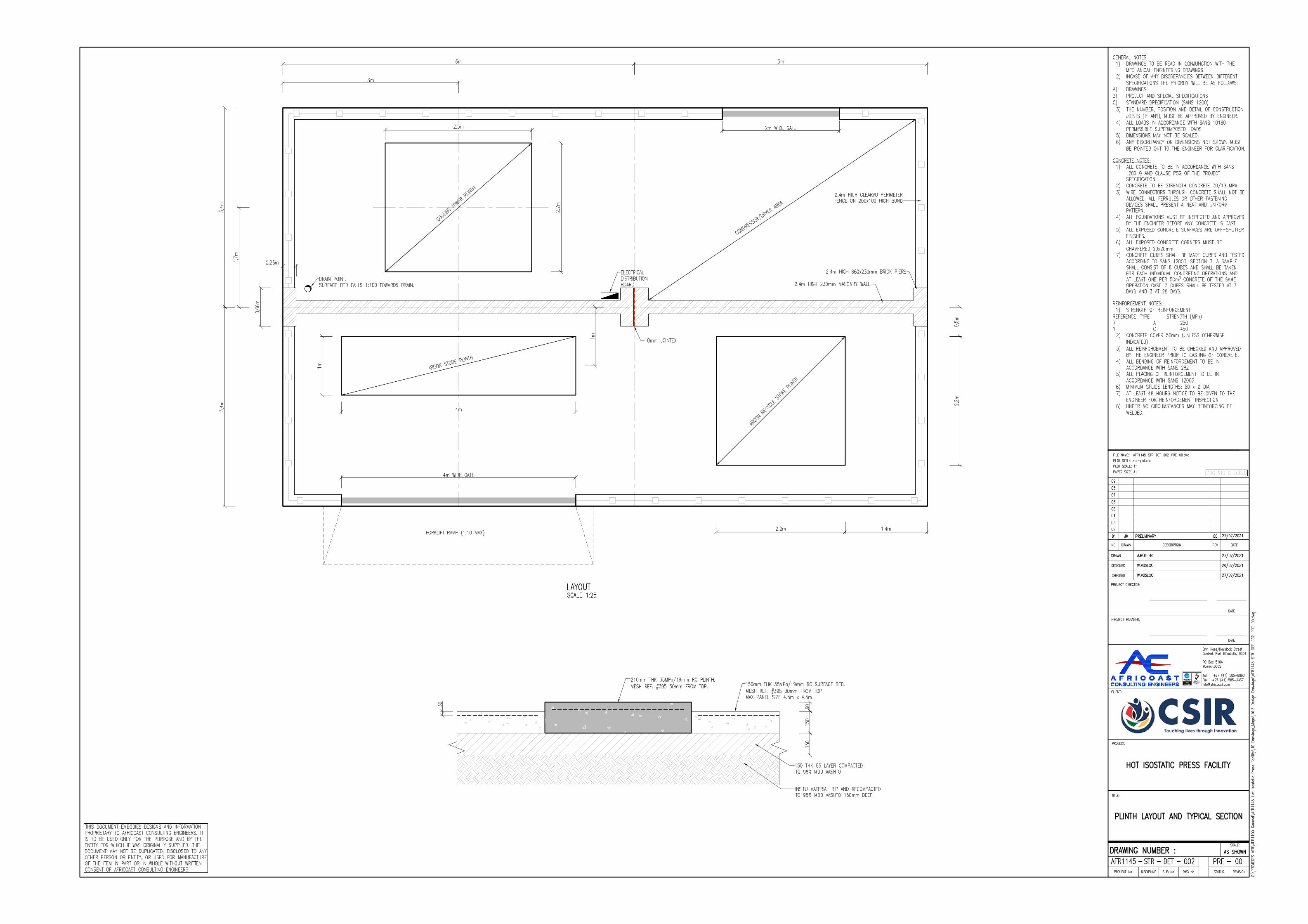
AutoCAD SHX Text
DATE
AutoCAD SHX Text
REV
AutoCAD SHX Text
1:1
AutoCAD SHX Text
A1
AutoCAD SHX Text
DRAWN
AutoCAD SHX Text
std-plot.ctb
AutoCAD SHX Text
AFR1145-STR-DET-002-PRE-00.dwg
AutoCAD SHX Text
NO.
AutoCAD SHX Text
PLOT SCALE:
AutoCAD SHX Text
FILE NAME:
AutoCAD SHX Text
PLOT STYLE:
AutoCAD SHX Text
PAPER SIZE:
AutoCAD SHX Text
DATE
AutoCAD SHX Text
DATE
AutoCAD SHX Text
PROJECT:
AutoCAD SHX Text
CLIENT:
AutoCAD SHX Text
PROJECT MANAGER:
AutoCAD SHX Text
PROJECT DIRECTOR:
AutoCAD SHX Text
O:\PROJECTS AFR\AFR1100 General\AFR1145 Hot Isostatic Press Facility\10 Drawings_Maps\10.3 Design Drawings\AFR1145-STR-DET-002-PRE-00.dwg
AutoCAD SHX Text
DESCRIPTION
AutoCAD SHX Text
01
AutoCAD SHX Text
JM
AutoCAD SHX Text
PRELIMINARY
AutoCAD SHX Text
00
AutoCAD SHX Text
27/07/2021
AutoCAD SHX Text
02
AutoCAD SHX Text
03
AutoCAD SHX Text
05
AutoCAD SHX Text
06
AutoCAD SHX Text
07
AutoCAD SHX Text
08
AutoCAD SHX Text
09
AutoCAD SHX Text
DRAWN
AutoCAD SHX Text
DESIGNED
AutoCAD SHX Text
CHECKED
AutoCAD SHX Text
TITLE:
AutoCAD SHX Text
PLINTH LAYOUT AND TYPICAL SECTION
AutoCAD SHX Text
HOT ISOSTATIC PRESS FACILITY
AutoCAD SHX Text
SCALE:
AutoCAD SHX Text
AS SHOWN
AutoCAD SHX Text
04
AutoCAD SHX Text
DRAWING NUMBER :
AutoCAD SHX Text
-
AutoCAD SHX Text
STATUS
AutoCAD SHX Text
PRE
AutoCAD SHX Text
REVISION
AutoCAD SHX Text
00
AutoCAD SHX Text
Cnr. Rose/Havelock Street Central, Port Elizabeth, 6001 PO Box 5104 Walmer,6065 Tel: +27 (41) 505-8000 Fax: +27 (41) 585-3437 [email protected]
AutoCAD SHX Text
THIS DOCUMENT EMBODIES DESIGNS AND INFORMATION PROPRIETARY TO AFRICOAST CONSULTING ENGINEERS. IT IS TO BE USED ONLY FOR THE PURPOSE AND BY THE ENTITY FOR WHICH IT WAS ORIGINALLY SUPPLIED. THE DOCUMENT MAY NOT BE DUPLICATED, DISCLOSED TO ANY OTHER PERSON OR ENTITY, OR USED FOR MANUFACTURE OF THE ITEM IN PART OR IN WHOLE WITHOUT WRITTEN CONSENT OF AFRICOAST CONSULTING ENGINEERS.
AutoCAD SHX Text
DRG STD CHECKED
AutoCAD SHX Text
-
AutoCAD SHX Text
-
AutoCAD SHX Text
-
AutoCAD SHX Text
PROJECT No.
AutoCAD SHX Text
AFR1145
AutoCAD SHX Text
DISCIPLINE
AutoCAD SHX Text
STR
AutoCAD SHX Text
SUB No.
AutoCAD SHX Text
DET
AutoCAD SHX Text
DWG No.
AutoCAD SHX Text
002
AutoCAD SHX Text
J.MÜLLER
AutoCAD SHX Text
27/07/2021
AutoCAD SHX Text
W.VOSLOO
AutoCAD SHX Text
26/07/2021
AutoCAD SHX Text
W.VOSLOO
AutoCAD SHX Text
27/07/2021
AutoCAD SHX Text
DRAIN POINT. SURFACE BED FALLS 1:100 TOWARDS DRAIN.
AutoCAD SHX Text
ELECTRICAL DISTRIBUTION BOARD
AutoCAD SHX Text
10mm JOINTEX
AutoCAD SHX Text
2.4m HIGH 230mm MASONRY WALL
AutoCAD SHX Text
2.4m HIGH 660x230mm BRICK PIERS
AutoCAD SHX Text
2.4m HIGH CLEARVU PERIMETER FENCE ON 200x100 HIGH BUND
AutoCAD SHX Text
COOLING TOWER PLINTH
AutoCAD SHX Text
ARGON STORE PLINTH
AutoCAD SHX Text
ARGON RECYCLE STORE PLINTH
AutoCAD SHX Text
COMPRESSOR/DRYER AREA
AutoCAD SHX Text
FORKLIFT RAMP (1:10 MAX)
AutoCAD SHX Text
210mm THK 35MPa/19mm RC PLINTH. MESH REF. #395 50mm FROM TOP.
AutoCAD SHX Text
150mm THK 35MPa/19mm RC SURFACE BED. MESH REF. #395 30mm FROM TOP. MAX PANEL SIZE 4.5m x 4.5m
AutoCAD SHX Text
150 THK G5 LAYER COMPACTED TO 98% MOD AASHTO
AutoCAD SHX Text
INSITU MATERIAL RIP AND RECOMPACTED TO 95% MOD AASHTO 150mm DEEP.
AutoCAD SHX Text
LAYOUT SCALE 1:25
AutoCAD SHX Text
GENERAL NOTES 1) DRAWINGS TO BE READ IN CONJUNCTION WITH THE DRAWINGS TO BE READ IN CONJUNCTION WITH THE MECHANICAL ENGINEERING DRAWINGS. 2) INCASE OF ANY DISCREPANCIES BETWEEN DIFFERENT INCASE OF ANY DISCREPANCIES BETWEEN DIFFERENT SPECIFICATIONS THE PRIORITY WILL BE AS FOLLOWS: A) DRAWINGS DRAWINGS B) PROJECT AND SPECIAL SPECIFICATIONS PROJECT AND SPECIAL SPECIFICATIONS C) STANDARD SPECIFICATION (SANS 1200) STANDARD SPECIFICATION (SANS 1200) 3) THE NUMBER, POSITION AND DETAIL OF CONSTRUCTION THE NUMBER, POSITION AND DETAIL OF CONSTRUCTION JOINTS (IF ANY), MUST BE APPROVED BY ENGINEER. 4) ALL LOADS IN ACCORDANCE WITH SANS 10160 ALL LOADS IN ACCORDANCE WITH SANS 10160 PERMISSIBLE SUPERIMPOSED LOADS 5) DIMENSIONS MAY NOT BE SCALED. DIMENSIONS MAY NOT BE SCALED. 6) ANY DISCREPANCY OR DIMENSIONS NOT SHOWN MUST ANY DISCREPANCY OR DIMENSIONS NOT SHOWN MUST BE POINTED OUT TO THE ENGINEER FOR CLARIFICATION. CONCRETE NOTES: 1) ALL CONCRETE TO BE IN ACCORDANCE WITH SANS ALL CONCRETE TO BE IN ACCORDANCE WITH SANS 1200 G AND CLAUSE PSG OF THE PROJECT SPECIFICATION. 2) CONCRETE TO BE STRENGTH CONCRETE 30/19 MPA. CONCRETE TO BE STRENGTH CONCRETE 30/19 MPA. 3) WIRE CONNECTORS THROUGH CONCRETE SHALL NOT BE WIRE CONNECTORS THROUGH CONCRETE SHALL NOT BE ALLOWED. ALL FERRULES OR OTHER FASTENING DEVICES SHALL PRESENT A NEAT AND UNIFORM PATTERN. 4) ALL FOUNDATIONS MUST BE INSPECTED AND APPROVED ALL FOUNDATIONS MUST BE INSPECTED AND APPROVED BY THE ENGINEER BEFORE ANY CONCRETE IS CAST. 5) ALL EXPOSED CONCRETE SURFACES ARE OFF-SHUTTER ALL EXPOSED CONCRETE SURFACES ARE OFF-SHUTTER FINISHES. 6) ALL EXPOSED CONCRETE CORNERS MUST BE ALL EXPOSED CONCRETE CORNERS MUST BE CHAMFERED 20x20mm. 7) CONCRETE CUBES SHALL BE MADE CURED AND TESTED CONCRETE CUBES SHALL BE MADE CURED AND TESTED ACCORDING TO SANS 1200G, SECTION 7. A SAMPLE SHALL CONSIST OF 6 CUBES AND SHALL BE TAKEN FOR EACH INDIVIDUAL CONCRETING OPERATIONS AND AT LEAST ONE PER 50m CONCRETE OF THE SAME 3 CONCRETE OF THE SAME OPERATION CAST. 3 CUBES SHALL BE TESTED AT 7 DAYS AND 3 AT 28 DAYS. REINFORCEMENT NOTES: 1) STRENGTH OF REINFORCEMENT: STRENGTH OF REINFORCEMENT: REFERENCE TYPE STRENGTH (MPa) TYPE STRENGTH (MPa) STRENGTH (MPa) R A 250 A 250 250 Y C 450 C 450 450 2) CONCRETE COVER 50mm (UNLESS OTHERWISE CONCRETE COVER 50mm (UNLESS OTHERWISE INDICATED) 3) ALL REINFORCEMENT TO BE CHECKED AND APPROVED ALL REINFORCEMENT TO BE CHECKED AND APPROVED BY THE ENGINEER PRIOR TO CASTING OF CONCRETE. 4) ALL BENDING OF REINFORCEMENT TO BE IN ALL BENDING OF REINFORCEMENT TO BE IN ACCORDANCE WITH SANS 282 5) ALL PLACING OF REINFORCEMENT TO BE IN ALL PLACING OF REINFORCEMENT TO BE IN ACCORDANCE WITH SANS 1200G 6) MINIMUM SPLICE LENGTHS: 50 x Ø DIA MINIMUM SPLICE LENGTHS: 50 x Ø DIA 7) AT LEAST 48 HOURS NOTICE TO BE GIVEN TO THE AT LEAST 48 HOURS NOTICE TO BE GIVEN TO THE ENGINEER FOR REINFORCEMENT INSPECTION 8) UNDER NO CIRCUMSTANCES MAY REINFORCING BE UNDER NO CIRCUMSTANCES MAY REINFORCING BE WELDED.

AutoCAD SHX Text
CONTACT DETAIL SCALE 1:10
AutoCAD SHX Text
REVISION
AutoCAD SHX Text
NO.
AutoCAD SHX Text
DRAWN
AutoCAD SHX Text
DATE
AutoCAD SHX Text
DRAWN
AutoCAD SHX Text
DESIGNED
AutoCAD SHX Text
CHECKED
AutoCAD SHX Text
PROJECT MANAGER
AutoCAD SHX Text
PROJECT DIRECTOR
AutoCAD SHX Text
W.VOSLOO
AutoCAD SHX Text
W.VOSLOO
AutoCAD SHX Text
S.NOWALA
AutoCAD SHX Text
O:\PROJECTS AFR\AFR1100 General\AFR1145 Hot Isostatic Press Facility\10 Drawings_Maps\10.3 Design Drawings\AFR1145-STR-DET-003-PRE-00.dwg
AutoCAD SHX Text
SCALE:
AutoCAD SHX Text
AS SHOWN
AutoCAD SHX Text
DRAWING NUMBER :
AutoCAD SHX Text
-
AutoCAD SHX Text
-
AutoCAD SHX Text
-
AutoCAD SHX Text
-
AutoCAD SHX Text
PROJECT No.
AutoCAD SHX Text
AFR1145
AutoCAD SHX Text
DISCIPLINE
AutoCAD SHX Text
STR
AutoCAD SHX Text
SUB No.
AutoCAD SHX Text
DET
AutoCAD SHX Text
DWG No.
AutoCAD SHX Text
003
AutoCAD SHX Text
STATUS
AutoCAD SHX Text
PRE
AutoCAD SHX Text
REVISION
AutoCAD SHX Text
00
AutoCAD SHX Text
REV
AutoCAD SHX Text
CONTACT/BASE PLATE SIZE
AutoCAD SHX Text
01
AutoCAD SHX Text
SN
AutoCAD SHX Text
PRELIMINARY
AutoCAD SHX Text
00
AutoCAD SHX Text
07/09/2021
AutoCAD SHX Text
02
AutoCAD SHX Text
03
AutoCAD SHX Text
04
AutoCAD SHX Text
05
AutoCAD SHX Text
DRAWING NUMBER CODES
AutoCAD SHX Text
DISCIPLINE WAT = WATER = WATER WATER SEW = SEWER = SEWER SEWER RDS = ROADS = ROADS ROADS SW = STORM WATER = STORM WATER STORM WATER ELE = ELECTRICAL = ELECTRICAL ELECTRICAL STR = STRUCTURAL = STRUCTURAL STRUCTURAL MEC = MECHANICAL = MECHANICAL MECHANICAL EW = EARTHWORKS = EARTHWORKS EARTHWORKS TRA = TRANSPORTATION= TRANSPORTATIONTRANSPORTATION
AutoCAD SHX Text
SUBDIVISION No. LS = LONGSECTION = LONGSECTION LONGSECTION XS = CROSS SECTION = CROSS SECTION CROSS SECTION DET = DETAILS = DETAILS DETAILS GA = GENERAL = GENERAL GENERAL ARRANGEMENT SP = SITE & KEY = SITE & KEY SITE & KEY PLANS
AutoCAD SHX Text
STATUS TEN = TENDER = TENDER TENDER PRE = PRELIMINARY = PRELIMINARY PRELIMINARY CON = CONSTRUCTION = CONSTRUCTION CONSTRUCTION ASB = AS BUILT= AS BUILTAS BUILT
AutoCAD SHX Text
Cnr. Rose/Havelock Street Central, Port Elizabeth, 6001 PO Box 5104 Walmer,6065 Tel: +27 (41) 505-8000 Fax: +27 (41) 585-3437 [email protected]
AutoCAD SHX Text
THIS DOCUMENT EMBODIES DESIGNS AND INFORMATION PROPRIETARY TO AFRICOAST CONSULTING ENGINEERS. IT IS TO BE USED ONLY FOR THE PURPOSE AND BY THE ENTITY FOR WHICH IT WAS ORIGINALLY SUPPLIED. THE DOCUMENT MAY NOT BE DUPLICATED, DISCLOSED TO ANY OTHER PERSON OR ENTITY, OR USED FOR MANUFACTURE OF THE ITEM IN PART OR IN WHOLE WITHOUT WRITTEN CONSENT OF AFRICOAST CONSULTING ENGINEERS.
AutoCAD SHX Text
DRG STD CHECKED
AutoCAD SHX Text
EXISTING SLAB
AutoCAD SHX Text
360x360mm, 20mm THK GALVANISED MILD STEEL BASEPLATE.
AutoCAD SHX Text
PLINTH.
AutoCAD SHX Text
150KPa BEARING PRESSURE.
AutoCAD SHX Text
1. STRUCTURAL STEEL (SANS 10162) STRUCTURAL STEEL (SANS 10162) 1.1. ALL STRUCTURAL STEEL TO BE GRADE S355 ALL STRUCTURAL STEEL TO BE GRADE S355 UNLESS OTHERWISE SHOWN. 1.2. ALL WELDS TO BE 6mm CONTINUOUS FILLET ALL WELDS TO BE 6mm CONTINUOUS FILLET WELDS UNLESS SHOWN OTHERWISE AND TO CONFORM TO APPROVED STANDARDS (SABS 044 AND SANS 0167). 1.3. ELECTRODES FOR ELECTRIC WELDING SHALL ELECTRODES FOR ELECTRIC WELDING SHALL BE E7018. FOR OTHER WELDING TYPES, ELECTRODES TO BE APPROVED BY THE ENGINEER. 1.4. BUTT WELDS AND SPLICES SHALL DEVELOP BUTT WELDS AND SPLICES SHALL DEVELOP THE FULL STRENGTH OF THE JOINED ELEMENTS. 1.5. WELDING SHALL BE PERFORMED BY CODED WELDING SHALL BE PERFORMED BY CODED WELDERS. SUPPORTING DOCUMENTATION TO BE SUBMITTED TO THE ENGINEER. 1.6. QUALITY CONTROL ON WELDS SHALL BE AS QUALITY CONTROL ON WELDS SHALL BE AS FOLLOWS: 1.6.1. ALL WELDS TO BE INSPECTED USING ALL WELDS TO BE INSPECTED USING VISUAL AIDS 1.6.2. BUTT WELDS: 100% ULTRASONIC NDT BUTT WELDS: 100% ULTRASONIC NDT 1.6.3. FILLET WELDS: 20% MPI FILLET WELDS: 20% MPI 1.6.4. CRANE / CRAWL BEAMS: 100% CRANE / CRAWL BEAMS: 100% ULTRASONIC NDT 1.7. ALL BOLTS TO BE GRADE 8.8 UNLESS ALL BOLTS TO BE GRADE 8.8 UNLESS OTHERWISE SHOWN. 1.8. WORKSHOP DRAWINGS OF STRUCTURAL STEEL WORKSHOP DRAWINGS OF STRUCTURAL STEEL WORK TO BE SUBMITTED TO THE ENGINEER FOR APPROVAL PRIOR TO FABRICATION. DRAWINGS SHALL BE CHECKED FOR DESIGN COMPLIANCE. NO DIMENSIONAL CHECKS WILL BE DONE. ALLOW 7 WORKING DAYS FOR APPROVAL. 1.9. ALL DIMENSIONS AND LEVELS TO BE ALL DIMENSIONS AND LEVELS TO BE CHECKED ON SITE PRIOR TO FABRICATION OF STEEL. 1.10. ERECTION METHOD STATEMENT TO BE ERECTION METHOD STATEMENT TO BE SUBMITTED TO THE ENGINEER FOR APPROVAL. 1.11. CERTIFICATE FROM THE STEEL MANUFACTURER CERTIFICATE FROM THE STEEL MANUFACTURER VERIFYING STEEL GRADE TO BE SUBMITTED TO THE ENGINEER. 1.12. THE CONTRACTOR IS RESPONSIBLE FOR THE CONTRACTOR IS RESPONSIBLE FOR DESIGN, ERECTION, MAINTENANCE AND REMOVAL OF ALL TEMPORARY BRACING OR PROPPING. 1.13. WHERE HSFG BOLTS ARE SPECIFIED, THE WHERE HSFG BOLTS ARE SPECIFIED, THE FOLLOWING SHALL APPLY: 1.14. CONTACT SURFACES SHALL BE FREE FROM, CONTACT SURFACES SHALL BE FREE FROM, GREASE, RUST, PAINT ETC. DURING FASTENING. 1.15. TIGHTENING TO BE DONE IN ACCORDANCE TIGHTENING TO BE DONE IN ACCORDANCE WITH SANS 094 CLAUSE 5.3.1 FOR FRICTION GRIP AND CORONET LOAD INDICATING WASHERS FOR HSFG BOLTS. 1.16. EDGES OF FLAME CUT PLATES TO BE EDGES OF FLAME CUT PLATES TO BE GROUND SMOOTH. 1.17. GALVANISED STEEL MEMBERS AND BOLTS TO GALVANISED STEEL MEMBERS AND BOLTS TO BE HOT DIPPED GALVANIZED TO A MEAN COATING THICKNESS OF 85 MICRON. 1.18. ALL CIRCULAR HOLLOW SECTIONS TO BE ALL CIRCULAR HOLLOW SECTIONS TO BE PROVIDED WITH VENT AND DRAINAGE HOLES. 1.19. ALL HOT DIPPED GALVANIZING TO BE ALL HOT DIPPED GALVANIZING TO BE CARRIED OUT IN STRICT ACCORDANCE WITH SANS 121:2000 / ISO 1461:1999 BY AN SABS ACCREDITED GALVANISER. 1.20. STRUCTURAL STEEL TO COMPLY WITH SANS STRUCTURAL STEEL TO COMPLY WITH SANS 1200H UNLESS OTHERWISE STATED. 1.21. IF PLINTH IS SLOPED, GAP BETWEEN IF PLINTH IS SLOPED, GAP BETWEEN BASEPLATE AND PLINTH TO BE GROUTED. 1.22. M12 HD BOLTS TO BE USED ON BASEPLATE. M12 HD BOLTS TO BE USED ON BASEPLATE. 1.23. MINIMUM EDGE DISTANCE OF 30mm FOR THE MINIMUM EDGE DISTANCE OF 30mm FOR THE BASE PLATE MUST BE MAINTAINED.
AutoCAD SHX Text
4 M12 HILTI HIT-HY 200 MORTAR WITH HIT-Z ROD.
AutoCAD SHX Text
CONTACT DETAIL SCALE 1:10
AutoCAD SHX Text
4 M12 HILTI HIT-HY 200 MORTAR WITH HIT-Z ROD.
AutoCAD SHX Text
360x360mm, 20mm THK GALVANISED MILD STEEL BASEPLATE.

6.3 Annexure C - Electrical Drawings
Ramgoolam www.ramgoolamgroup.com Bespoke Global Efficacy.

℄
164 m2
22 m2
32 m2
7 m2
2 m2
7 m2
B16|G|52A108400084ZZOFFICESENCLOSED18.97Office52 - Office
PPE/EQUIPSTORE PA
SSA
GE
EXISTINGRAMP
Ex. SewerManhole
PROPOSED HIP MACHINE ROOM
GRANITE
GRANITE
LAB SAMPLE STORE
PROPOSED MET. LAB
VACUUM LOBBY
prep
STEEL SHELVING
GR
ANIT
E
GYPROC HABITOWALLING SYSTEM
150 X 150MM M/S GALV. STEEL POST TO ENG SPEC.
WALKWAY ABOVE
UNDERCOUNTERGEYSER
COLD WATER LINE TO BEPULLED FROM EXISTINGPOINT AT SINK UNIT TO BEREMOVED FLUSH PLASTERED CEILING
WITH 4 X 600MM Ø ROUNDDUMMY DIFFUSERS FORACCESS
FLUSH PLASTERED CEILINGWITH 1 X 600MM Ø ROUNDDUMMY DIFFUSERS FORACCESS
STRIP PAINT FROM EXIST.DOORS, SAND AND SEALWITH A CLEAR VARNISH
EXIS
T. S
LID
ING
DO
OR
EXIS
T. O
VER
HEA
D G
ANTR
Y
FC-02
FC-01
FC-01
i.e
i.e
(DOUBLE VOLUME HEIGHT 6800mm)
NEW DB-HIP
EXISITNG BUILDING 16MAIN LV BOARD TO BEREPLACED
CONTRACTOR TO PROVIDE BUNDWALL350mm HIGH, WITH FUEL/WATERSEPARATOR. STORM WATER TODISCHARGE TO STORM WATER SYSTEM.
3P 110Ø SLEEVE
5000
2300
LEGEND:
DISTRIBUTION BOARD
SYMBOL DESCRIPTION
400mm WIDE HEAVY DUTY CABLE LADDERIN CEILING (GROUND FLOOR LEVEL)
XP NUMBER OF SLEEVES OF Y DIAMETER
2 x 185mm2 4-Core Cu PVC/SWA/ECC/PVC
2 x 185mm2 4-Core Cu PVC/SWA/ECC/PVC
XP Y
2 x 185mm2 4-Core Cu PVC/SWA/ECC/PVC
SUB
DB-
CT
DB TO BE COORDINATEDWITH MECHANICAL LAYOUTS 3P
110
Ø S
LEEV
E
CABLE TRAY TO BE MOUNTEDAT 6500mm AFFL
400mm WIDE HEAVY DUTY CABLE LADDERIN CEILING AT 6500mm AFFL
CABLE TRAY VERTICAL RISER
CABLE TRAY VERTICAL RISER
NEW GENERATOR ON NEW PLINTH
DRAWING NO.:
PURPOSE :
CHECKED BY :
DATE :
DRAWN BY :
SCALE :
DESIGNED BY :
PAPER SIZE :
REVISION NO.:
APPROVED BY :
SUPPLY AUTHORITY :
CLIENT :
PROJECT NO.:
CAD FILE NAME :
DISCIPLINE :
PROJECT NAME :
DRAWING TITLE :
CONSULTANT :
INITIALSDISCRIPTIONDATENO.
NOTES :
A
B
C
D
E
F
G
H
I
J
K
L
M
N
O
P
A1
1 2 3 4 5 6 7 8 9 10 11 12 13 14 15 16 17 18 19 20REVISION HISTORY
1 2 3 4 5 6 7 8 9 10 11 12 13 14 15 16 17 18 19 20 21 22 23
21 22 23
A
B
C
D
E
F
G
H
I
J
K
L
M
N
O
PSHEET NO.:
P SENOSI M LEKOBOTJA
J ALBERTS (Pr.Eng) J ALBERTS (Pr.Eng)
JULY 2021 TENDER
A1
1:75
12964-EE-100
C01
BUILDING 16SITE PLAN LAYOUT
BULK POWER SUPPLY ARRANGEMENT
12964
CSIR HOT ISOSTATICPRESS FACILITY
ELECTRICAL
CITY OF TSHWANE
12964-EE-100
A 20/07/2021 PRELIM DESIGN JAA
B 29/07/2021 DETAIL DESIGN JAA
C 25/08/2021 FOR TENDER JAA

164 m2
22 m2
32 m2
7 m2
2 m2
7 m2
PPE/EQUIPSTORE PA
SSA
GE
PROPOSED HIP MACHINE ROOM
GRANITE
GRANITE
LAB SAMPLE STORE
PROPOSED MET. LAB
prep
STEEL SHELVING
GR
ANIT
E
GYPROC HABITOWALLING SYSTEM
150 X 150MM M/S GALV. STEEL POST TO ENG SPEC.
WALKWAY ABOVE
UNDERCOUNTERGEYSER
WITH 4 X 600MM Ø ROUNDDUMMY DIFFUSERS FORACCESS
FLUSH PLASTERED CEILINGWITH 1 X 600MM Ø ROUNDDUMMY DIFFUSERS FORACCESS
STRIP PAINT FROM EXIST.DOORS, SAND AND SEALWITH A CLEAR VARNISH
EXIS
T. S
LID
ING
DO
OR
EXIS
T. O
VER
HEA
D G
ANTR
Y
FC-02
FC-01
FC-01
i.e
i.e
(DOUBLE VOLUME HEIGHT 6800mm)
NEW DB-HIPO2
O2
O2AO2CONT
30 m2
20 m2
10 m2
3 m2
6 m2
NEW X-RAY LAB
NEW STEEL STAIRCASE
LOAD MATERIALS
MAI
NTE
NAN
CE
MAIN
TENAN
CE
1.2 TONNES?
MOBILE X-RAYMACHINE
GRANITE
NEW OFFICE
NEW 1800 X 1200MMALUMINIUM FIXED GLAZINGWINDOW
DOUBLE VOLUME
M.I.P
MID-LEVEL TRUNKINGFOR POWER ANDDATA
PASS
AG
E
MIN. 1000MM HIGH STEEL BALUSTRADE TO STAIRTO COMPLY WITH SANS 10400-PARTS M & S.
ALLOWANCE TO BE MADEFOR HOISTING OF X-RAYMACHINE INTO POSITION
EXIST. OVERHEADGANTRY
wc wc wc
whb whb
whb
prep
UNDERCOUNTERGEYSER
DEMOLISH
DEMOLISH
FC-03
WC-01
FC-01
i.e
(DOUBLE VOLUME HEIGHT 6800mm)
LEGEND:
DISTRIBUTION BOARD
SYMBOL DESCRIPTION
OXYGEN SENSOR AT 1500MM AFFL
OXYGEN SENSOR REMOTE ALARM MOUNTED ABOVEDOOR
INSTRUMENTATION CABLE
O2A O2A
O2
O2AO2
CONTOXYGEN SENSOR CONTROLLER AT 1500MM AFFL
FROM OXYGEN SENSORCONTROLLER ON
THE GROUND FLOOR
CONTROLLER AUDIBLE ALARM 2AUDIBLE ALARM 1
AUDIBLE ALARM 3
24VPOWERSUPPLY
DC POWERAC POWER INPUT
O2
SENSOR 1
O2
SENSOR 2(SCREEN NOTEARTHED)
SCREENEARTHED
OXYGEN SENSOR CONNECTION PHILOSOPHY
SCREENEARTHED
DRAWING NO.:
PURPOSE :
CHECKED BY :
DATE :
DRAWN BY :
SCALE :
DESIGNED BY :
PAPER SIZE :
REVISION NO.:
APPROVED BY :
SUPPLY AUTHORITY :
CLIENT :
PROJECT NO.:
CAD FILE NAME :
DISCIPLINE :
PROJECT NAME :
DRAWING TITLE :
CONSULTANT :
INITIALSDISCRIPTIONDATENO.
NOTES :
A
B
C
D
E
F
G
H
I
J
K
L
M
N
O
P
A1
1 2 3 4 5 6 7 8 9 10 11 12 13 14 15 16 17 18 19 20REVISION HISTORY
1 2 3 4 5 6 7 8 9 10 11 12 13 14 15 16 17 18 19 20 21 22 23
21 22 23
A
B
C
D
E
F
G
H
I
J
K
L
M
N
O
PSHEET NO.:
P SENOSI M LEKOBOTJA
J ALBERTS (Pr.Eng) J ALBERTS (Pr.Eng)
JULY 2021 TENDER
A1
1:75
12964-EE-101
C01
BUILDING 16GROUND & FIRST FLOOR PLAN
OXYGEN SENSOR LAYOUT
12964
CSIR HOT ISOSTATICPRESS FACILITY
ELECTRICAL
CITY OF TSHWANE
12964-EE-101
A 20/07/2021 PRELIM DESIGN JAA
B 29/07/2021 DETAIL DESIGN JAA
C 25/08/2021 FOR TENDER JAA

2300
SLEEVE
220
220
220 5000 220
350
300
GENERATOR BUNDED PLINTH AREASCALE 1:50
A
A
SECTION A-ASCALE 1:50
300
300
300 300
220
300
2300
300
220
MENTISGRATING
CONCRETE CAST WALL
CONCRETECAST WALLGENERATOR PLINTH
MENTISGRATING
DRAWING NO.:
PURPOSE :
CHECKED BY :
DATE :
DRAWN BY :
SCALE :
DESIGNED BY :
PAPER SIZE :
REVISION NO.:
APPROVED BY :
SUPPLY AUTHORITY :
CLIENT :
PROJECT NO.:
CAD FILE NAME :
DISCIPLINE :
PROJECT NAME :
DRAWING TITLE :
CONSULTANT :
INITIALSDISCRIPTIONDATENO.
NOTES :
A
B
C
D
E
F
G
H
I
J
K
L
M
N
O
P
A3
1 2 3 4 5 6 7 8 9 10 11 12 13 14 15 16 17 18 19 20REVISION HISTORY
1 2 3 4 5 6 7 8 9 10 11 12 13 14 15 16 17 18 19 20 21 22 23
21 22 23
A
B
C
D
E
F
G
H
I
J
K
L
M
N
O
PSHEET NO.:
P SENOSI M LEKOBOTJA
J ALBERTS (Pr.Eng) J ALBERTS (Pr.Eng)
JULY 2021 TENDER
A3
1:50
12964-EE-102
C01
BUILDING 16GENERATOR BUNDED PLINTH AREA
12964
CSIR HOT ISOSTATICPRESS FACILITY
ELECTRICAL
CITY OF TSHWANE
12964-EE-102
A 30/07/2021 DETAIL DESIGN JAA
B 25/08/2021 FOR TENDER JAA
C 03/09/2021 MENTIS GRATING ADDED JAA

164 m2
22 m2
32 m2
7 m2
2 m2
7 m2
PPE/EQUIPSTORE PA
SSA
GE
Ex. SewerManhole
PROPOSED HIP MACHINE ROOM
GRANITE
GRANITE
LAB SAMPLE STORE
PROPOSED MET. LAB
VACUUM LOBBY
prep
STEEL SHELVING
GR
ANIT
E
GYPROC HABITOWALLING SYSTEM
150 X 150MM M/S GALV. STEEL POST TO ENG SPEC.
WALKWAY ABOVE
UNDERCOUNTERGEYSER
COLD WATER LINE TO BEPULLED FROM EXISTINGPOINT AT SINK UNIT TO BEREMOVED FLUSH PLASTERED CEILING
WITH 4 X 600MM Ø ROUNDDUMMY DIFFUSERS FORACCESS
FLUSH PLASTERED CEILINGWITH 1 X 600MM Ø ROUNDDUMMY DIFFUSERS FOR
STRIP PAINT FROM EXIST.DOORS, SAND AND SEALWITH A CLEAR VARNISH
EXIS
T. S
LID
ING
DO
OR
EXIS
T. O
VER
HEA
D G
ANTR
Y
FC-02
FC-01
FC-01
i.e
i.e
(DOUBLE VOLUME HEIGHT 6800mm)
16A DEDICATED SINGLE SWITCHED SOCKETOUTLET (300mm AFFL OR ON POWER SKIRTING)
DATA OUTLET (ON POWER SKIRTING)
2 COMPARTMENT LIGHT GREY PVL POWERSKIRTING FLOOR MOUNTED TO BEINSTALLED COMPLETE WITH LIDS, ENDCAPS. ELBOWS, T-PIECES AND ENDS ETC
DESCRIPTIONSYMBOL
DISTRIBUTION BOARD
16A NORMAL SINGLE SWITCHED SOCKETOUTLET (300mm AFFL OR ON POWER SKIRTING)
LEGEND
CR
CRBGU
CR
BGU
ACCESS CONTROL CARD READER
BREAK GLASS UNIT
DATA CABINET FOR IT
X NUMBER OF SLEEVES OF Y DIAMETERFOR DATA CABLING
BACK TO BACK POWER SKIRTINGMOUNTED ON TOP OF
GRANITE COUNTER TOP
CR
CR
20A ISOLATOR 1-POLE ISOLATOR FORGEYSER OR AIRCON UNIT OR FAN32A ISOLATOR 3-POLE ISOLATOR FORAIRCON63A ISOLATOR 3-POLE ISOLATOR FORAIRCON
NEW DB-HIP
16A DEDICATED SINGLE SWITCHED SOCKETOUTLET FOR OXYGEN SENSOR CONTROLLERAT 1500mm AFFL
DRAWING NO.:
PURPOSE :
CHECKED BY :
DATE :
DRAWN BY :
SCALE :
DESIGNED BY :
PAPER SIZE :
REVISION NO.:
APPROVED BY :
SUPPLY AUTHORITY :
CLIENT :
PROJECT NO.:
CAD FILE NAME :
DISCIPLINE :
PROJECT NAME :
DRAWING TITLE :
CONSULTANT :
INITIALSDISCRIPTIONDATENO.
NOTES :
A
B
C
D
E
F
G
H
I
J
K
L
M
N
O
P
A1
1 2 3 4 5 6 7 8 9 10 11 12 13 14 15 16 17 18 19 20REVISION HISTORY
1 2 3 4 5 6 7 8 9 10 11 12 13 14 15 16 17 18 19 20 21 22 23
21 22 23
A
B
C
D
E
F
G
H
I
J
K
L
M
N
O
PSHEET NO.:
P SENOSI M LEKOBOTJA
J ALBERTS (Pr.Eng) J ALBERTS (Pr.Eng)
JULY 2021 TENDER
A1
1:50
12964-EE-200
C01
BUILDING 16FIRST FLOOR PLAN
SMALL POWER LAYOUT
12964
CSIR HOT ISOSTATICPRESS FACILITY
ELECTRICAL
CITY OF TSHWANE
12964-EE-200
A 20/07/2021 PRELIM DESIGN JAA
B 29/07/2021 DETAIL DESIGN JAA
C 25/08/2021 FOR TENDER JAA

30 m2
20 m2
10 m2
3 m2
6 m2
NEW X-RAY LAB
NEW STEEL STAIRCASE
LOAD MATERIALS
MAI
NTE
NAN
CE
MAIN
TENAN
CE
1.2 TONNES?
MOBILE X-RAYMACHINE
GRANITE
NEW OFFICE
NEW 1800 X 1200MMALUMINIUM FIXED GLAZINGWINDOW
DOUBLE VOLUME
M.I.P
MID-LEVEL TRUNKINGFOR POWER ANDDATA
PASS
AG
E
MIN. 1000MM HIGH STEEL BALUSTRADE TO STAIRTO COMPLY WITH SANS 10400-PARTS M & S.
ALLOWANCE TO BE MADEFOR HOISTING OF X-RAYMACHINE INTO POSITION
EXIST. OVERHEADGANTRY
wc wc wc
whb whb
whb
prep
UNDERCOUNTERGEYSER
DEMOLISH
DEMOLISH
FC-03
WC-01
FC-01
i.e
(DOUBLE VOLUME HEIGHT 6800mm)
16A DEDICATED SINGLE SWITCHED SOCKETOUTLET (300mm AFFL OR ON POWER SKIRTING)
DATA OUTLET (ON POWER SKIRTING)
2 COMPARTMENT LIGHT GREY PVL POWERSKIRTING FLOOR MOUNTED TO BEINSTALLED COMPLETE WITH LIDS, ENDCAPS. ELBOWS, T-PIECES AND ENDS ETC
DESCRIPTIONSYMBOL
DISTRIBUTION BOARD
16A NORMAL SINGLE SWITCHED SOCKETOUTLET (300mm AFFL OR ON POWER SKIRTING)
LEGEND
SUB
DB-
FF
CR ACCESS CONTROL CARD READER
CR
CR
CR
CR
CR
CR
BGU BREAK GLASS UNIT
BGU
30A ISOLATOR 1-POLE ISOLATOR FORGEYSER OR AIRCON
DRAWING NO.:
PURPOSE :
CHECKED BY :
DATE :
DRAWN BY :
SCALE :
DESIGNED BY :
PAPER SIZE :
REVISION NO.:
APPROVED BY :
SUPPLY AUTHORITY :
CLIENT :
PROJECT NO.:
CAD FILE NAME :
DISCIPLINE :
PROJECT NAME :
DRAWING TITLE :
CONSULTANT :
INITIALSDISCRIPTIONDATENO.
NOTES :
A
B
C
D
E
F
G
H
I
J
K
L
M
N
O
P
A1
1 2 3 4 5 6 7 8 9 10 11 12 13 14 15 16 17 18 19 20REVISION HISTORY
1 2 3 4 5 6 7 8 9 10 11 12 13 14 15 16 17 18 19 20 21 22 23
21 22 23
A
B
C
D
E
F
G
H
I
J
K
L
M
N
O
PSHEET NO.:
P SENOSI M LEKOBOTJA
J ALBERTS (Pr.Eng) J ALBERTS (Pr.Eng)
JULY 2021 TENDER
A1
1:50
12964-EE-201
C01
BUILDING 16FIRST FLOOR PLAN
SMALL POWER LAYOUT
12964
CSIR HOT ISOSTATICPRESS FACILITY
ELECTRICAL
CITY OF TSHWANE
12964-EE-201
A 20/07/2021 PRELIM DESIGN JAA
B 29/07/2021 DETAIL DESIGN JAA
C 25/08/2021 FOR TENDER JAA

164 m2
22 m2
32 m2
7 m2
2 m2
7 m2
PPE/EQUIPSTORE PA
SSA
GE
Ex. SewerManhole
PROPOSED HIP MACHINE ROOM
GRANITE
GRANITE
LAB SAMPLE STORE
PROPOSED MET. LAB
VACUUM LOBBY
prep
STEEL SHELVING
GR
ANIT
E
GYPROC HABITOWALLING SYSTEM
150 X 150MM M/S GALV. STEEL POST TO ENG SPEC.
WALKWAY ABOVE
UNDERCOUNTERGEYSER
COLD WATER LINE TO BEPULLED FROM EXISTINGPOINT AT SINK UNIT TO BEREMOVED FLUSH PLASTERED CEILING
WITH 4 X 600MM Ø ROUNDDUMMY DIFFUSERS FORACCESS
FLUSH PLASTERED CEILINGWITH 1 X 600MM Ø ROUNDDUMMY DIFFUSERS FOR
STRIP PAINT FROM EXIST.DOORS, SAND AND SEALWITH A CLEAR VARNISH
EXIS
T. S
LID
ING
DO
OR
EXIS
T. O
VER
HEA
D G
ANTR
Y
FC-02
FC-01
FC-01
i.e
i.e
(DOUBLE VOLUME HEIGHT 6800mm)
EXIT
EXIT
EXIT
A
A1
A A
A
A1
A1A
A A1
A1A
PC
NEW DB-HIPTO FLOOD LIGHTS INFIRST FLOOR
A1
A1 A1 A1 A1 A1
A1 A1 A1 A1 A1
A1 A1 A1
TYPE F: LED FLOOD 215W 700MA, 25661LUMENS, 600MM X 350MM X 100MM PANEL,SURFACE MOUNTED LUMINAIRE, MOUNTED AT5.0M HEIGHT OR EQUAL, BETTER OR SIMILARAPPROVED
LEGEND:
DISTRIBUTION BOARD
SYMBOL DESCRIPTION
A
A1
TYPE A: 1 X 33W LED, 3956 LUMENS, 600MM X 600MMX 30MM PANEL, 99.9% EFFICIENCY RECESSED /SURFACE MOUNTED LUMINAIRE, OR EQUAL, BETTEROR SIMILAR APPROVED
TYPE D: LED 18W DOWNLIGHT LUMINAIRE - WITHBATTERY BACK-UP OR EQUAL, BETTER OR SIMILARAPPROVED
TYPE E: 8W SINGLE SIDED SURFACE MOUNTEDEMERGENCY ESCAPE SIGNAGE LUMINAIREWITH 1-HR BATTERY BACK-UP UNIT OR EQUAL,BETTER OR SIMILAR APPROVED
EXIT
TYPE J: 55W 1050MA WIDE BEAM BULKHEADSURFACE MOUNTED OR EQUAL, BETTER ORSIMILAR APPROVED
PD3, 360 DEGREES ROUND SURFACE MOUNTMOTION SENSORS WITH DETECTION 6M(ADJUSTABLE) & LIGHT SENSITIVITY (ADJUSTABLE)BY CONTROLS IN FRONT LENS. SIZE 50MMDIAMETER X 25MM DEEP - WHITE COLOUR
TYPE B: 20W LED SERIES 21 WITH PRISMATICDIFFUSER WALL SURFACE MOUNTED LUMINAIRE OREQUAL, BETTER OR SIMILAR APPROVED
16A 1-LEVER 3-WAY LIGHT SWITCH
PC PHOTOCELL
TYPE A1: 1 X 33W LED, 3956 LUMENS, 600MM X600MM X 30MM PANEL, 99.9% EFFICIENCYRECESSED / SURFACE MOUNTED LUMINAIRE, WITH1-HR BATTERY BACK-UP UNIT OR EQUAL, BETTEROR SIMILAR APPROVED
DRAWING NO.:
PURPOSE :
CHECKED BY :
DATE :
DRAWN BY :
SCALE :
DESIGNED BY :
PAPER SIZE :
REVISION NO.:
APPROVED BY :
SUPPLY AUTHORITY :
CLIENT :
PROJECT NO.:
CAD FILE NAME :
DISCIPLINE :
PROJECT NAME :
DRAWING TITLE :
CONSULTANT :
INITIALSDISCRIPTIONDATENO.
NOTES :
A
B
C
D
E
F
G
H
I
J
K
L
M
N
O
P
A1
1 2 3 4 5 6 7 8 9 10 11 12 13 14 15 16 17 18 19 20REVISION HISTORY
1 2 3 4 5 6 7 8 9 10 11 12 13 14 15 16 17 18 19 20 21 22 23
21 22 23
A
B
C
D
E
F
G
H
I
J
K
L
M
N
O
PSHEET NO.:
P SENOSI M LEKOBOTJA
J ALBERTS (Pr.Eng) J ALBERTS (Pr.Eng)
JULY 2021 TENDER
A1
1:50
12964-EE-300
C01
BUILDING 16GROUND FLOOR PLAN
LIGHTING LAYOUT
12964
CSIR HOT ISOSTATICPRESS FACILITY
ELECTRICAL
CITY OF TSHWANE
12964-EE-300
A 20/07/2021 PRELIM DESIGN JAA
B 29/07/2021 DETAIL DESIGN JAA
C 25/08/2021 FOR TENDER JAA

30 m2
20 m2
10 m2
3 m2
6 m2
NEW X-RAY LAB
NEW STEEL STAIRCASE
LOAD MATERIALS
MAI
NTE
NAN
CE
MAIN
TENAN
CE
1.2 TONNES?
MOBILE X-RAYMACHINE
GRANITE
NEW OFFICE
NEW 1800 X 1200MMALUMINIUM FIXED GLAZINGWINDOW
DOUBLE VOLUME
M.I.P
MID-LEVEL TRUNKINGFOR POWER ANDDATA
PASS
AG
E
MIN. 1000MM HIGH STEEL BALUSTRADE TO STAIRTO COMPLY WITH SANS 10400-PARTS M & S.
ALLOWANCE TO BE MADEFOR HOISTING OF X-RAYMACHINE INTO POSITION
EXIST. OVERHEADGANTRY
wc wc wc
whb whb
whb
prep
UNDERCOUNTERGEYSER
DEMOLISH
DEMOLISH
FC-03
WC-01
FC-01
i.e
(DOUBLE VOLUME HEIGHT 6800mm)
EXIT
EXIT
A1
A
A1
A
A A1
A
A1
AA1
A
SUB
DB-
FF
A
TYPE F: LED FLOOD 215W 700MA, 25661LUMENS, 600MM X 350MM X 100MM PANEL,SURFACE MOUNTED LUMINAIRE, MOUNTED AT5.0M HEIGHT OR EQUAL, BETTER OR SIMILARAPPROVED
LEGEND:
DISTRIBUTION BOARD
SYMBOL DESCRIPTION
A
A1
TYPE A: 1 X 33W LED, 3956 LUMENS, 600MM X 600MMX 30MM PANEL, 99.9% EFFICIENCY RECESSED /SURFACE MOUNTED LUMINAIRE, OR EQUAL, BETTEROR SIMILAR APPROVED
TYPE D: LED 18W DOWNLIGHT LUMINAIRE - WITHBATTERY BACK-UP OR EQUAL, BETTER OR SIMILARAPPROVED
TYPE E: 8W SINGLE SIDED SURFACE MOUNTEDEMERGENCY ESCAPE SIGNAGE LUMINAIREWITH 1-HR BATTERY BACK-UP UNIT OR EQUAL,BETTER OR SIMILAR APPROVED
EXIT
TYPE J: 55W 1050MA WIDE BEAM BULKHEADSURFACE MOUNTED OR EQUAL, BETTER ORSIMILAR APPROVED
PD3, 360 DEGREES ROUND SURFACE MOUNTMOTION SENSORS WITH DETECTION 6M(ADJUSTABLE) & LIGHT SENSITIVITY (ADJUSTABLE)BY CONTROLS IN FRONT LENS. SIZE 50MMDIAMETER X 25MM DEEP - WHITE COLOUR
TYPE B: 20W LED SERIES 21 WITH PRISMATICDIFFUSER WALL SURFACE MOUNTED LUMINAIRE OREQUAL, BETTER OR SIMILAR APPROVED
16A 1-LEVER 3-WAY LIGHT SWITCH
PC PHOTOCELL
TYPE A1: 1 X 33W LED, 3956 LUMENS, 600MM X600MM X 30MM PANEL, 99.9% EFFICIENCYRECESSED / SURFACE MOUNTED LUMINAIRE, WITH1-HR BATTERY BACK-UP UNIT OR EQUAL, BETTEROR SIMILAR APPROVED
DRAWING NO.:
PURPOSE :
CHECKED BY :
DATE :
DRAWN BY :
SCALE :
DESIGNED BY :
PAPER SIZE :
REVISION NO.:
APPROVED BY :
SUPPLY AUTHORITY :
CLIENT :
PROJECT NO.:
CAD FILE NAME :
DISCIPLINE :
PROJECT NAME :
DRAWING TITLE :
CONSULTANT :
INITIALSDISCRIPTIONDATENO.
NOTES :
A
B
C
D
E
F
G
H
I
J
K
L
M
N
O
P
A1
1 2 3 4 5 6 7 8 9 10 11 12 13 14 15 16 17 18 19 20REVISION HISTORY
1 2 3 4 5 6 7 8 9 10 11 12 13 14 15 16 17 18 19 20 21 22 23
21 22 23
A
B
C
D
E
F
G
H
I
J
K
L
M
N
O
PSHEET NO.:
P SENOSI M LEKOBOTJA
J ALBERTS (Pr.Eng) J ALBERTS (Pr.Eng)
JULY 2021 TENDER
A1
1:50
12964-EE-301
C01
BUILDING 16FIRST FLOOR PLAN LIGHTING LAYOUT
12964
CSIR HOT ISOSTATICPRESS FACILITY
ELECTRICAL
CITY OF TSHWANE
12964-EE-301
A 20/07/2021 PRELIM DESIGN JAA
B 29/07/2021 DETAIL DESIGN JAA
C 25/01/2021 FOR TENDER JAA

164 m2
22 m2
32 m2
7 m2
2 m2
7 m2
PPE/EQUIPSTORE PA
SSA
GE
PROPOSED HIP MACHINE ROOM
GRANITE
GRANITE
LAB SAMPLE STORE
PROPOSED MET. LAB
prep
STEEL SHELVING
GR
ANIT
E
WALKWAY ABOVE
UNDERCOUNTERGEYSER
EXIS
T. S
LID
ING
DO
OR
EXIS
T. O
VER
HEA
D G
ANTR
Y
FC-02
FC-01
FC-01
i.e
i.e
(DOUBLE VOLUME HEIGHT 6800mm)S
FIR
E
B
B
30 m2
20 m2
10 m2
3 m2
6 m2
NEW X-RAY LAB
NEW STEEL STAIRCASE
LOAD MATERIALS
MAI
NTE
NAN
CE
MAIN
TENAN
CE
1.2 TONNES?
MOBILE X-RAYMACHINE
GRANITE
NEW OFFICE
NEW 1800 X 1200MMALUMINIUM FIXED GLAZINGWINDOW
DOUBLE VOLUME
M.I.P
MID-LEVEL TRUNKINGFOR POWER ANDDATA
PASS
AG
E
MIN. 1000MM HIGH STEEL BALUSTRADE TO STAIRTO COMPLY WITH SANS 10400-PARTS M & S.
ALLOWANCE TO BE MADEFOR HOISTING OF X-RAYMACHINE INTO POSITION
EXIST. OVERHEADGANTRY
wc wc wc
whb whb
whb
prep
UNDERCOUNTERGEYSER
DEMOLISH
DEMOLISH
FC-03
WC-01
FC-01
i.e
(DOUBLE VOLUME HEIGHT 6800mm)
SMOKE DETECTOR IN CEILING VOID WITHREMOTE LED INDICATION
HEAT DETECTOR
FIRE BREAK GLASS UNIT
FIRE PANEL
CONDUIT LINK IN CEILING VOID
OPTICAL SMOKE DETECTOR BELOW CEILING
COMBINED SIREN / STROBE (RED)
DESCRIPTION
PA SYSTEM
B
S
FIRE
PA SPEAKER
LEGENDSYMBOL
S
B
FROM GROUND FLOORFIRE DETECTION
DRAWING NO.:
PURPOSE :
CHECKED BY :
DATE :
DRAWN BY :
SCALE :
DESIGNED BY :
PAPER SIZE :
REVISION NO.:
APPROVED BY :
SUPPLY AUTHORITY :
CLIENT :
PROJECT NO.:
CAD FILE NAME :
DISCIPLINE :
PROJECT NAME :
DRAWING TITLE :
CONSULTANT :
INITIALSDISCRIPTIONDATENO.
NOTES :
A
B
C
D
E
F
G
H
I
J
K
L
M
N
O
P
A1
1 2 3 4 5 6 7 8 9 10 11 12 13 14 15 16 17 18 19 20REVISION HISTORY
1 2 3 4 5 6 7 8 9 10 11 12 13 14 15 16 17 18 19 20 21 22 23
21 22 23
A
B
C
D
E
F
G
H
I
J
K
L
M
N
O
PSHEET NO.:
P SENOSI M LEKOBOTJA
J ALBERTS (Pr.Eng) J ALBERTS (Pr.Eng)
JULY 2021 TENDER
A1
1:75
12964-EE-500
A01
BUILDING 16GROUND & FIRST FLOOR PLAN
FIRE DETECTION LAYOUT
12964
CSIR HOT ISOSTATICPRESS FACILITY
ELECTRICAL
CITY OF TSHWANE
12964-EE-500
A 26/08/2021 FOR TENDER JAA

400V, 25kA, 50Hz, 3ph + NEUTRAL + EARTH BUSBAR
800A
STANDBY COMPARTMENT
63A
E/L
20A
P1
20A
P2
20A
EL1
NEW DB-HIPPD
1
PD2
6A 10A
PC
C1
BYPASSSWITCH
N
10A
L2
10A
L1
M
G
FUSE LINK
POWER TRANSFORMER
THREE PHASE CIRCUIT BREAKER
BULK METER
GENERATOR
CABLE TERMINATION
SINGLE PHASE CIRCUIT BREAKER
DESCRIPTIONSYMBOL
LEGEND
BARE COPPER EARTH WIREBCEW
ISOLATOR
E/LEARTH LEACKAGE
63A
E/L
20A 20A 20A20A
P3
20A
PD3
PD4
400V, 10kA, 50Hz, 3ph + NEUTRAL + EARTH BUSBAR
60A
STANDBY COMPARTMENT
63A
E/L
20A
P1
20A
P2
20A
SUB DB-FF
20APD
5
P4
10A
L2
10A
L1
10A
L3
10A
L4
10A
L5SPAR
E
PD1
PD2
63A
E/L
20A 20A 20A
SPAR
E
60A
SUB
DB-
FF
10A
F2 -
FAN
30A
G1
-G
EYSE
R
10A30A
LIG
HTS
(TO
ILET
PAS
SAG
EM
AIN
DO
OR
)
10A 15A
L5
400V, 25kA, 50Hz, 3ph + NEUTRAL + EARTH BUSBAR
E/L
R.5
3
E/L
R.5
1
E/L
R.5
0
LIG
HTS
(PAS
SAG
E)
SEC
UR
ITY
LIG
HTS
35A
TIM
ER S
UPP
LY
10A
LIG
HTS
(R'S
53,
55)
10A
LIG
HTS
(PAS
SAG
E)
BUIL
DIN
G 1
2
6A 25A
C1
BYPASSSWITCH
N
BUIL
DIN
G 1
9
30A 30A 60A
DB5
(R.4
1)
100A
DB8
(WIN
D-T
, S-W
ALL)
150A
DB4
(EAS
T EN
D O
F BU
ILD
ING
)
60A 60A
DB1
(R.5
9)
DB1
0(R
.162
)
DB3
(R.2
0)
DB3
0(R
.51-
S)
150A 150A 150A 150A 175A
DB-
H
30A
X-R
AYM
ACH
INE
40A
CO
OLI
NG
TO
WER
22kW
40A
CO
MPR
ESSO
R22
kW
2 x 185mm² 4Core Cu PVC/SWA/ECC/PVC
FED FROM NEW MAIN BOARD VIA 2 x 185mm² 4CoreCu PVC/SWA/ECC/PVC
800A
GEN
ERAT
OR
CH
ANG
E-O
VER
PAN
EL
NORMAL COMPARTMENT
30A30A
SPAR
E
SPAR
E
SPAR
E
SPAR
E
SPAR
E
35A
10A30A
LIG
HTS
(TO
ILET
PAS
SAG
EM
AIN
DO
OR
)
10A 15A
L5
400V, 25kA, 50Hz, 3ph + NEUTRAL + EARTH BUSBAR
EXISTING MDB16(1)
E/L
R.5
3
E/L
R.5
1
E/L
R.5
0
LIG
HTS
(PAS
SAG
E)
SEC
UR
ITY
LIG
HTS
35A
TIM
ER S
UPP
LY
10A
LIG
HTS
(R'S
53,
55)
10A
LIG
HTS
(PAS
SAG
E)
BUIL
DIN
G 1
2
2A 25A
C1
TIMERSWITCH
N
BUIL
DIN
G 1
9
30A 30A 60A
DB5
(R.4
1)
100A
DB8
(WIN
D-T
, S-W
ALL)
150A
DB4
(EAS
T EN
D O
F BU
ILD
ING
)
60A 60A
DB1
(R.5
9)
DB1
0(R
.162
)
DB3
(R.2
0)
DB3
0(R
.51-
S)
150A 150A 150A 150A 175A
DB-
H
NORMAL COMPARTMENT
30A30A
SPAR
E
SPAR
E
SPAR
E
SPAR
E
SPAR
E
SPAR
E
35A
20A
PD6
63A
E/L
350A
HIP
& G
RAP
HIT
EFU
RN
ACE
220k
VA
10m
m2 4
cor
e C
u4m
m2 B
CEW
10m
m2 4
cor
e C
u4m
m2 B
CEW
2 X
70m
m2 4
cor
e C
u2
X 35
mm
2 BC
EW
10A
F1 -
FAN
30A
G1
- GEY
SER
20A
AC2
-AI
RC
ON
20AAC
1 -
AIR
CO
N
AC2
-AI
RC
ON
63A
AC1
-AI
RC
ON
SURGE ARRESTOR
FED FROM BUILDING 12(OPEN AT BUILDING 12) FED FROM BUILDING 19
NEW MDB16(1)
NEW GENSET500kVA 3ph
GENERATORC/O BOARD
OUTDOORINSTALLATION
800AATS
800A3Ø25kA
OXY
GEN
SEN
SOR
NO
.1 T
O N
O.6
6X10A
20A
SPAR
E
20A
SPAR
E
10A
SPAR
E
10A
SPAR
E
400V, 10kA, 50Hz, 3ph +NEUTRAL + EARTH BUSBAR
60A
STANDBY COMPARTMENT
COOLING TOWERSUB DB-CT
10A
LIG
HTS
PLU
GS
60A
SUB
DB-
CT
FED FROM BUILDING 12(OPEN AT BUILDING 12) FED FROM BUILDING 19
4mm
2 4 c
ore
Cu
2.5m
m2 B
CEW
2.5m
m2 4
cor
e C
u2.
5mm
2 BC
EW
2.5m
m2 4
cor
e C
u2.
5mm
2 BC
EW
2.5m
m2 4
cor
e C
u2.
5mm
2 BC
EW
4mm
2 4 c
ore
Cu
2.5m
m2 B
CEW
2.5m
m2 4
cor
e C
u2.
5mm
2 BC
EW
4mm
2 4 c
ore
Cu
2.5m
m2 B
CEW
4mm
2 4 c
ore
Cu
2.5m
m2 B
CEW
4mm
2 4 c
ore
Cu
2.5m
m2 B
CEW
2.5m
m2 4
cor
e C
u2.
5mm
2 BC
EW
2.5m
m2 4
cor
e C
u2.
5mm
2 BC
EW
2.5m
m2 4
cor
e C
u2.
5mm
2 BC
EW
2.5m
m2 4
cor
e C
u2.
5mm
2 BC
EW
2.5m
m2 4
cor
e C
u2.
5mm
2 BC
EW
2.5m
m2 4
cor
e C
u2.
5mm
2 BC
EW
4mm
2 4 c
ore
Cu
2.5m
m2 B
CEW
4mm
2 4 c
ore
Cu
2.5m
m2 B
CEW 6m
m2 4
cor
e C
u4m
m2 B
CEW
2.5m
m2 4
cor
e C
u2.
5mm
2 BC
EW
35m
m2 4
cor
e C
uPV
C/S
WA/
ECC
/PVC
16m
m2 4
cor
e C
uPV
C/S
WA/
ECC
/PVC
4mm
2 4 c
ore
Cu
2.5m
m2 B
CEW
4mm
2 4 c
ore
Cu
2.5m
m2 B
CEW
4mm
2 4 c
ore
Cu
2.5m
m2 B
CEW
4mm
2 4 c
ore
Cu
2.5m
m2 B
CEW
4mm
2 4 c
ore
Cu
2.5m
m2 B
CEW
4mm
2 4 c
ore
Cu
2.5m
m2 B
CEW
4mm
2 4 c
ore
Cu
2.5m
m2 B
CEW
4mm
2 4 c
ore
Cu
2.5m
m2 B
CEW
4mm
2 4 c
ore
Cu
2.5m
m2 B
CEW
4mm
2 4 c
ore
Cu
2.5m
m2 B
CEW
4mm
2 4 c
ore
Cu
2.5m
m2 B
CEW
4mm
2 4 c
ore
Cu
2.5m
m2 B
CEW
4mm
2 4 c
ore
Cu
2.5m
m2 B
CEW
4mm
2 4 c
ore
Cu
2.5m
m2 B
CEW
4mm
2 4 c
ore
Cu
2.5m
m2 B
CEW
4mm
2 4 c
ore
Cu
2.5m
m2 B
CEW
2.5m
m2 4
cor
e C
u2.
5mm
2 BC
EW
10A
L32.
5mm
2 4 c
ore
Cu
2.5m
m2 B
CEW
5X20A
AUTO
DR
AIN
NO
.1 T
O N
O.5
4mm
2 4 c
ore
Cu
2.5m
m2 B
CEW
20A
4mm
2 4 c
ore
Cu
2.5m
m2 B
CEW
DEW
PO
INT
2X20A
4mm
2 4 c
ore
Cu
2.5m
m2 B
CEW
MAN
IFO
LDN
O.1
TO
NO
.2
20A
SPAR
E
30A
AC5
TOAC
9 -
AIR
CO
N
4mm
2 4 c
ore
Cu
2.5m
m2 B
CEW
5X30A 20A
SPAR
E
20A
SPAR
E
TIMERSWITCH
EXISTING CABLE EXISTING CABLE
EXISTING CABLE EXISTING CABLE
63A
E/L
20A
16mm² 4Core Cu PVC/SWA/ECC/PVC35mm² 4Core CuPVC/SWA/ECC/PVC
30A
UPS
10m
m2 4
cor
e C
uPV
C/S
WA/
ECC
/PVC
SPAR
E
R FIRE
6A
C1N
R FIRE
6A
C1N
D
D
R FIRE
6A
C1N
AC3
TOAC
4 -
AIR
CO
N
4mm
2 4 c
ore
Cu
2.5m
m2 B
CEW
2X30A
DRAWING NO.:
PURPOSE :
CHECKED BY :
DATE :
DRAWN BY :
SCALE :
DESIGNED BY :
PAPER SIZE :
REVISION NO.:
APPROVED BY :
SUPPLY AUTHORITY :
CLIENT :
PROJECT NO.:
CAD FILE NAME :
DISCIPLINE :
PROJECT NAME :
DRAWING TITLE :
CONSULTANT :
INITIALSDISCRIPTIONDATENO.
NOTES :
A
B
C
D
E
F
G
H
I
J
K
L
M
N
O
P
A1
1 2 3 4 5 6 7 8 9 10 11 12 13 14 15 16 17 18 19 20REVISION HISTORY
1 2 3 4 5 6 7 8 9 10 11 12 13 14 15 16 17 18 19 20 21 22 23
21 22 23
A
B
C
D
E
F
G
H
I
J
K
L
M
N
O
PSHEET NO.:
CONSULTING ENGINEERS
P SENOSI M LEKOBOTJA
J ALBERTS (Pr.Eng) J ALBERTS (Pr.Eng)
JULY 2021 TENDER
A1
NTS
12964-EE-700
D01
SINGLE LINE DIAGRAM
12964
CSIR HOT ISOSTATICPRESS FACILITY
ELECTRICAL
CITY OF TSHWANE
12964-EE-700
A 20/07/2021 PRELIM DESIGN JAA
B 29/07/2021 DETAIL DESIGN JAA
C 25/08/2021 FOR TENDER JAA
D 27/08/2021 FIRE CONTACTOR ADDED JAA

POWER TRANSFORMER
CIRCUIT BREAKER
DESCRIPTIONSYMBOL
LEGEND:
GENERATOR
OFF LOAD ISOLATOR
BUSBAR
CHANGE-OVER
SURGE ARRESTOR
PC PHOTOCELL
N
C1 CONTACTOR
63A
ELU
EARTH LEACKAGE
10A
LIGHTS(PASSAGE)
800A
L1,L2,L3
GENERATORCHANGE-OVER
PANEL
NORMAL COMPARTMENT400V 25kA
35A
E/L R.53
30A
30A
30A
E/L R.51 E/L R.50LIGHTS
(TOILET,PASSAGE
MAIN DOOR)
10A
SPARE
15A
SPARE
35A
TIMERSUPPLY
10A
LIGHTS(R'S 53, 55)
10A
LIGHTS(PASSAGE)
BUILDING12
10A
LIGHTS
40A
+ 4mm
² BCE
W
L1
COOLINGTOWER
STANDBY POWER 400V 60A 10kA
PLUGS
+ 2.5m
m² BC
EW
4mm²
Cu
16mm
² Cu
+ 2.5m
m² BC
EW
2.5mm
² Cu
3 x Class II SPD's(SURGE
ARRESTORS)
40A
COMPRESSOR
+ 4mm
² BCE
W
6mm²
Cu
COOLING TOWERSUB DB-CT
63A
E/L
20A
63A
BUILDING19
30A
DB-H
30A
SPARE
60A
DB-5((R.41)
100A
DB-8(WIND-T,S-WALL)
150A
DB-4(EAST END OF
BUILDING)
2 X 60
A
SPARE
AUTO DRAINNO1 TO NO.5
+ 2.5m
m² BC
EW
2.5mm
² Cu
DEW POINT
+ 2.5m
m² BC
EW
2.5mm
² Cu
MANFOLDNO.1 TO NO.5
+ 2.5m
m² BC
EW
2.5mm
² Cu
SPARE
5X20
A
20A
20A
20A
ENL1,L2,L3
STANDBY COMPARTMENT400V 60A 10kA
SUB DB-FF
3 x Class II SPD's(SURGE
ARRESTORS)
P1, P2SPARE
63A
E/L
3 x 20
A63
A
PD1, PD2SPARE
63A
E/L
3 x 20
A63
A
+ 2.5m
m² BC
EW
4mm²
Cu
+ 2.5m
m² BC
EW
4mm²
Cu
2 X 20
A
AC1 TOAC2
(AIRCON)
30A
X-RAYMACHINE
+ 4mm
² BCE
W 6m
m² C
u
5 X 10
A
L1TO L5
2.5mm
² Cu
+ 2.5m
m² BC
EW
30A
G1(GEYSER)
4mm²
Cu
+ 2.5m
m² BC
EW
2 x 10
A
F1 TO F2(FAN)
+ 2.5m
m² BC
EW
2.5mm
² Cu
+ 2.5m
m² BC
EW
4mm²
Cu
ENL1,L2,L3
NORMAL POWER COMPARTMENT400V 800A 25kA
NEW DB-HIP
3 x Class II SPD's(SURGE
ARRESTORS)
6APS
10A
20A
C
EL1PD1TO
PD3
63A
E/L
3 x 20
A63
A
+2.5m
m² BC
EW2.5
mm² C
u
PD4TO
PD6
63A
E/L
3 x 20
A63
A
+ 2.5m
m² BC
EW
4mm²
Cu
+ 2.5m
m² BC
EW
4mm²
Cu
5 X 30
A
AC5 TOAC9
(AIRCON)
60A
SUB DB-FF
PVC/S
WA/EC
C/PVC
16mm
² Cu
3X10
A
L1TO L3
4mm²
Cu
+ 2.5m
m² BC
EW(CR
ISIS R
OOM)
30A
G1(GEYSER)
4mm²
Cu
+ 2.5m
m² BC
EW
30A
AC1(AIRCON)
+ 2.5m
m² BC
EW
4mm²
Cu
350A
HIP &GRAPHITE
+ 2 X
35mm²
BCEW
2 X
70mm
² Cu
P1TOP4
63A
E/L
4 x 20
A63
A
+ 2.5m
m² BC
EW
4mm²
Cu
6 X 10
A
OXYGENSENSOR
NO.1-NO.6
+ 2.5m
m² BC
EW
2.5mm
² Cu
60A
SUB DB-CT
PVC/S
WA/EC
C/PVC
35mm
² Cu
20A
SPARE
20A
SPARE
30A
AC2(AIRCON)
+ 2.5m
m² BC
EW
4mm²
Cu
+ 2.5m
m² BC
EW
4mm²
Cu
NEW MDB16(1)
6APS
25A
20A
C
L5SECURITY
LIGHTS
CABL
EEX
ISTIN
G
2 X 20
A
SPARE
2 X 10
A
SPARE
150A
DB1(R.59)
150A
DB10(R.162)
150A
DB3(R.20)
150A
DB30(R.51-S)
175A
SPARE
EN
FROMBUILDING
19
FROMBUILDING
12
NEWDB-HIP
FROMBUILDING
12
800A
PVC/S
WA/EC
C/PVC
185m
m² C
u
PVC/S
WA/EC
C/PVC
16mm
² Cu
EN
63A
PVC/S
WA/EC
C/PVC
NEWDB-HIP
35mm
² Cu
3. EQUIPMENT:
3.1 SQUARE KEY TURN LOCKS REQUIRED (2 OFF) ON EACH FACE PLATE3.2 ALL CIRCUIT BREAKERS TO BE OF APPROVED BY ENGINEER3.3 BUSBARS TO BE COLOUR CODED WITH HEAT SHRINK INSULATION FOR FULL LENGTH3.4 MINIMUM EARTH WIRE CONNECTION BETWEEN SURGE PROTECTION DEVICES AND EARTH BAR : 16mm² GREEN INSULATED EARTH WIRE3.5 COPPER BUSBAR SIZING : 1.5A/mm²3.6 SWITCHING CONTACTORS TO BE OF MERLIN GERIN MANUFACTURE3.7 CIRCUIT BREAKERS FOR ALL AIR CONDITIONING CIRCUITS TO BE "CURVE D" TYPE
4. LABELLING:
4.1 ALL LABELS SHALL BE ENGRAVED SANDWICH BOARD FIXED WITH METAL THREADED SCREWS AND NUTS4.2 ALL INTERNAL EQUIPMENT TO BE LABELLED e.g. FUSES, CONTACTORS etc.4.3 EACH EQUIPMENT TO BE LABELLED WITH 20mm LETTERING4.4 DB LABELLING TO BE 30mm HIGH 4.5 MCB'S SHALL NOT BE NUMBERED; ENGRAVED LABELS REQUIRED4.6 PROVIDE STEEL POCKET INSIDE EACH DOOR FOR A4 SIZE DRAWING
NOTES1. CONSTRUCTION :
1.1 DB SHALL COMPLY WITH REQUIREMENTS OF IEC439-1(LV SWITCHGEAR AND CONTROL GEAR ASSEMBLIES) 1.2 NEW MDB16(1) : SINGLE COMPARTMENT, FLOOR MOUNTED DB WITH SQUARE KEY - LOCKABLE FACE PLATES
1.3 CONDUIT AND CABLE ENTRY : TOP AND BOTTOM1.4 FACE PLATES TO HAVE CHROME HANDLES (2 OFF) ON EACH PLATE FOR REMOVAL AND BE SECURED WITH CATCHES1.5 GLAND PLATE : 2mm THICKNESS1.6 ALLOW 30% SPARE SPACE
2. COLOUR :
2.1 FRAME INSIDE AND OUTSIDE : ELECTRIC ORANGE B262.2 FACE PLATES : NORMAL POWER COMPARTMENT - ELECTRIC ORANGE B26
2.3 DOOR : ELECTRIC ORANGE B26
STANDBY POWER COMPARTMENT - SIGNAL RED A11UPS POWER COMPARTMENT - VIOLET
SUB DB-FF: SINGLE COMPARTMENT, RECESSED OR FLUSHED WALL MOUNTED - KEY PADLOCK ON DOORS
DB-AC - ELECTRIC ORANGE
NEW DB-HIP: SINGLE COMPARTMENT, RECESSED OR FLUSHED WALL MOUNTED - KEY PADLOCK ON DOORSSUB DB-CT: SINGLE COMPARTMENT, RECESSED OR FLUSHED WALL MOUNTED - KEY PADLOCK ON DOORS
CABL
EEX
ISTIN
G
CABL
EEX
ISTIN
G
CABL
EEX
ISTIN
G
CABL
EEX
ISTIN
G
CABL
EEX
ISTIN
G
CABL
EEX
ISTIN
G
CABL
EEX
ISTIN
G
CABL
EEX
ISTIN
G
CABL
EEX
ISTIN
G
CABL
EEX
ISTIN
G
CABL
EEX
ISTIN
G
CABL
EEX
ISTIN
G
CABL
EEX
ISTIN
G
CABL
EEX
ISTIN
G
CABL
EEX
ISTIN
G
CABL
EEX
ISTIN
G
CABL
EEX
ISTIN
G
CABL
EEX
ISTIN
G
CABL
EEX
ISTIN
G
CABL
EEX
ISTIN
G
CABL
EEX
ISTIN
G
CABL
EEX
ISTIN
G
CABL
EEX
ISTIN
G
CABL
EEX
ISTIN
G
CABL
EEX
ISTIN
G
2 X 18
5mm²
Cu
PVC/S
WA/EC
C/PVC
60A
30A
UPS
PVC/S
WA/EC
C/PVC
10mm
² Cu
6A
FIRE
C
R
6A
FIRE
C
R
6A
FIRE
C
R
DD
2 X 30
A
AC3 TOAC4
(AIRCON)
+ 2.5m
m² BC
EW
4mm²
Cu
DRAWING NO.:
PURPOSE :
CHECKED BY :
DATE :
DRAWN BY :
SCALE :
DESIGNED BY :
PAPER SIZE :
REVISION NO.:
APPROVED BY :
SUPPLY AUTHORITY :
CLIENT :
PROJECT NO.:
CAD FILE NAME :
DISCIPLINE :
PROJECT NAME :
DRAWING TITLE :
CONSULTANT :
INITIALSDISCRIPTIONDATENO.
NOTES :
A
B
C
D
E
F
G
H
I
J
K
L
M
N
O
P
A1
1 2 3 4 5 6 7 8 9 10 11 12 13 14 15 16 17 18 19 20REVISION HISTORY
1 2 3 4 5 6 7 8 9 10 11 12 13 14 15 16 17 18 19 20 21 22 23
21 22 23
A
B
C
D
E
F
G
H
I
J
K
L
M
N
O
PSHEET NO.:
CONSULTING ENGINEERS
P SENOSI M LEKOBOTJA
J ALBERTS (Pr.Eng) J ALBERTS (Pr.Eng)
JULY 2021 TENDER
A1
NTS
12964-EE-701
D01
DISTRIBUTION BOARDS
12964
CSIR HOT ISOSTATICPRESS FACILITY
ELECTRICAL
CITY OF TSHWANE
12964-EE-701
A 20/07/2021 PRELIM DESIGN JAA
B 29/07/2021 DETAIL DESIGN JAA
C 25/08/2021 FOR TENDER JAA
D 27/08/2021 FIRE CONTACTOR ADDED JAA

6.4 Annexure D - Mechanical/ Fire Drawings
Ramgoolam www.ramgoolamgroup.com Bespoke Global Efficacy.

NOTES:
1. This drawing may only be used for HVAC services.2. Routes and zones have been allocated to this service, location
dimensions are indicative of these.3. To prepare his construction/shop drawings, the HVAC sub-
contractor must inspect all the architects drawings including structural and other services design drawings pertaining to the works and shall acquaint himself with the general arrangement of all other services and ensure that in fixing his work it will not obstruct the fixing or future maintenance of services.
4. Any in-clarities must be brought to the attention of the mechanical engineer.
5. The HVAC sub-contractor is responsible for correct field dimensions, clearances and heights,quantities, fabrication processes and techniques of construction & co-ordination of his work with that of all other trades providing all devices necessary for safe and satisfactory operation.
6. Final site measurements must be made by the HVAC sub-contractor before manufacturing or ordering of any equipment.
7. Supply, Exhaust and fresh air ducting to be un- insulated ducting. All Fans to be interlocked with light switches in respective areas, unless where indicated.
8. Indicated ducting sizes are sheetmetal sizes.9. All ducting to be manufactured, installed and commissioned in
compliance with ASHRAE standards.10. All air diffusion equipment to be powder coated to an architect
approved colour.11. All specified equipment must be installed according to the
manufacturer's specification.12. All HVAC equipment to be protected against vibrations by
means of anti-vibration mountings.13. All duct connections to have flexible connections not exceeding
1m.14. The main contractor shall be responsible for all openings in
walls, ceilings and doors for HVAC items of equipment.15. Refrigerant piping, control and electrical wiring in ceiling void to
run on cable trays-Exposed piping and wiring to run in trunking.16. Drawing must be read in conjunction with the relevant HVAC
specification and bills of quantities.17. All AC units to be derated and suited for site location. Units to
also be industrial type units.18. All Supply Wall/Window Fans to be complete with air.19. All Equipment and HVAC accesories to be selected to ensure a
maximum noise rating of 35 dBA is not exceeded.
Supply Piping
Return Piping
PIPING LEGEND
Extraction air
Supply air
Fresh air
DUCT LEGEND
WF
02
WF
02
WF 02 WF 02 WF 02
WF
03
WF
01
WF 01
100 L/s
28
00
L/s
560 L/s
56
0 L
/s56
0 L
/s
1A
/3Ø
1A
/3Ø
1A/3Ø
560 L/s
1A/3Ø
560 L/s
1A/3Ø
2A
/3Ø
1A
/3Ø
10
0 L
/s
1A/3Ø
DG 01Door Relief Grille
DG 01Door Relief Grille
SD 01200 L/s
SD 01200 L/s
SD 01200 L/s
SD 01200 L/s
400 mmx300 mm
CW
-UB
ODU-CW-UBA
B
C
D
E
F
G
H
I
J
K
L
M
N
O
P
A1
1 2 3 4 5 6 7 8 9 10 11 12 13 14 15 16 17 18 19 20
1 2 3 4 5 6 7 8 9 10 11 12 13 14 15 16 17 18 19 20 21 22 23 24
21 22 23 24
A
B
C
D
E
F
G
H
I
J
K
L
M
N
O
PDRAWING NUMBER :
PURPOSE :
CHECKED BY :
DATE :
DRAWN BY :
SCALE :
DESIGNED BY :
PAPER SIZE :
REVISION NUMBER :
APPROVED BY :
SUPPLY AUTHORITY :
CLIENT :
PROJECT NUMBER :
CAD FILE NAME :
DISCIPLINE :
PROJECT NAME :
DRAWING TITLE :
CONSULTANT :
INITIALSDESCRIPTIONDATENO.
REVISION HISTORY
SHEET NUMBER :
MECHANICAL
12964 - CSIR/DRAWING/WIP
HOT ISOSTATIC PRESS FACILITY
12964
M.S
T.S.M
2021-07-26
A1
0 2021-07-26 FOR INFORMATION M.S
FOR INFORMATION
T.S.M
MOTLA CONSULTING ENGINEERS
BLOCK F, LYTTELTOWN OFFICE PARKSHELANTI AVE, CENTURIONP O BOX 10914CENTURION0046TEL : 012 663 1328FAX : 012 663 4039EMAIL: [email protected]
T.S.M
GROUND FLOOR HVAC LAYOUT
12964 - ME001
SCHEDULE 01 - CHILLED WATER UP BLOWER UNIT
TYPE MARK SIZE ( H x W x D) [mm] WEIGHT [kg] Air Flow (L/s) Sound Pressure Level (dB(A))@3m) SE_POWER 1 Quantity
CW-UB 1000x500x1980 47 4500 L/s 45 0 kW 1
SCHEDULE 02 - OUTDOOR UNIT
TYPE MARK SIZE ( H x W x D) [mm] WEIGHT [kg] COOLING CAPACITY(kW) POWER (kW) PHASE/VOLTAGE/Hz Quantity
ODU-CW-UB 1970X902X668 102 7 kW 0 kW 3/380/50 1
SCHEDULE 03 - SWIRL DIFFUSER
Type Mark Size Flow Max Pressure Drop [ Pa] Quantity
SD 01 200 mmø 200.0 L/s 4
SCHEDULE 04- WALL FAN
TYPE MARK Air Flow (L/s) Quantity
WF 01 100 L/s 2
WF 02 560 L/s 5
WF 03 2800 L/s 1
SCHEDULE 05 - DOOR GRILLE
Type Mark Size Quantity
DG 01 400 mm X 400 mm 2
GROUND FLOOR PLAN 1:100

NOTES:
1. This drawing may only be used for HVAC services.2. Routes and zones have been allocated to this service, location
dimensions are indicative of these.3. To prepare his construction/shop drawings, the HVAC sub-
contractor must inspect all the architects drawings including structural and other services design drawings pertaining to the works and shall acquaint himself with the general arrangement of all other services and ensure that in fixing his work it will not obstruct the fixing or future maintenance of services.
4. Any in-clarities must be brought to the attention of the mechanical engineer.
5. The HVAC sub-contractor is responsible for correct field dimensions, clearances and heights,quantities, fabrication processes and techniques of construction & co-ordination of his work with that of all other trades providing all devices necessary for safe and satisfactory operation.
6. Final site measurements must be made by the HVAC sub-contractor before manufacturing or ordering of any equipment.
7. Supply, Exhaust and fresh air ducting to be un- insulated ducting. All Fans to be interlocked with light switches in respective areas, unless where indicated.
8. Indicated ducting sizes are sheetmetal sizes.9. All ducting to be manufactured, installed and commissioned in
compliance with ASHRAE standards.10. All air diffusion equipment to be powder coated to an architect
approved colour.11. All specified equipment must be installed according to the
manufacturer's specification.12. All HVAC equipment to be protected against vibrations by
means of anti-vibration mountings.13. All duct connections to have flexible connections not exceeding
1m.14. The main contractor shall be responsible for all openings in
walls, ceilings and doors for HVAC items of equipment.15. Refrigerant piping, control and electrical wiring in ceiling void to
run on cable trays-Exposed piping and wiring to run in trunking.16. Drawing must be read in conjunction with the relevant HVAC
specification and bills of quantities.17. All AC units to be derated and suited for site location. Units to
also be industrial type units.18. All Supply Wall/Window Fans to be complete with air.19. All Equipment and HVAC accesories to be selected to ensure a
maximum noise rating of 35 dBA is not exceeded.
Supply Piping
Return Piping
PIPING LEGEND
Extraction air
Supply air
Fresh air
DUCT LEGEND
DV 0330 L/s
DV 0330 L/s
DV 0330 L/s
DV 0330 L/s
DV 0330 L/s
10
0 m
mø
10
0 m
mø
100 mmø
CAS-01
ODU-CAS 01
WL 0130 L/s
ODU-DU 01
DU
01
WL 03310 L/s
RAG 01
20
0 m
mø
20
0 m
mø
20
0 m
mø
20
0 m
mø
300 mmø250 mmø
55 L/s55 L/s
55 L/s
55 L/s
WL 02120 L/s
WL 02120 L/s
A
B
C
D
E
F
G
H
I
J
K
L
M
N
O
P
A1
1 2 3 4 5 6 7 8 9 10 11 12 13 14 15 16 17 18 19 20
1 2 3 4 5 6 7 8 9 10 11 12 13 14 15 16 17 18 19 20 21 22 23 24
21 22 23 24
A
B
C
D
E
F
G
H
I
J
K
L
M
N
O
PDRAWING NUMBER :
PURPOSE :
CHECKED BY :
DATE :
DRAWN BY :
SCALE :
DESIGNED BY :
PAPER SIZE :
REVISION NUMBER :
APPROVED BY :
SUPPLY AUTHORITY :
CLIENT :
PROJECT NUMBER :
CAD FILE NAME :
DISCIPLINE :
PROJECT NAME :
DRAWING TITLE :
CONSULTANT :
INITIALSDESCRIPTIONDATENO.
REVISION HISTORY
SHEET NUMBER :
MECHANICAL
12964 - CSIR/DRAWING/WIP
HOT ISOSTATIC PRESS FACILITY
12964
M.S
T.S.M
2021-07-26
A1
0 2021-07-26 FOR INFORMATION M.S
FOR INFORMATION
T.S.M
MOTLA CONSULTING ENGINEERS
BLOCK F, LYTTELTOWN OFFICE PARKSHELANTI AVE, CENTURIONP O BOX 10914CENTURION0046TEL : 012 663 1328FAX : 012 663 4039EMAIL: [email protected]
T.S.M
FIRST FLOOR HVAC LAYOUT
12801 - ME002
SCHEDULE 06 - CASSETTES
TYPE MARK SIZE ( H x W x D) [mm] WEIGHT [kg] HEATING CAPACITY[kW] Power [kW] PHASE/VOLTAGE/Hz CURRENT [A] Quantity
CAS-01 575X260X620 16.5 3.6 kW 0.32 kW 1/240/50 0.14 A 1
SCHEDULE 07 - CASSETE OUTDOOR UNIT
TYPE MARK SIZE ( H x W x D) [mm] WEIGHT [kg] COOLING CAPACITY(kW) POWER (kW) PHASE/VOLTAGE/Hz Quantity
ODU-CAS 01 215X1110X710 29 4 kW 1 kW 1/240/50 1
SCHEDULE 08 - DUCTED OUTDOOR UNIT
TYPE MARK SIZE ( H x W x D) [mm] WEIGHT [kg] COOLING CAPACITY(kW) POWER (kW) PHASE/VOLTAGE/Hz Quantity
ODU-DU 01 215X1110X710 102 7 kW 4 kW 3/380/50 1
SCHEDULE 09 - DUCTED UNIT
TYPE MARK SIZE ( H x W x D) [mm] WEIGHT [kg] COOLING CAPACITY(kW) POWER (kW) PHASE/VOLTAGE/Hz Quantity
DU 01 1970X902X668 47 7 kW 0 kW 3/380/50 1
SCHEDULE 10 - WEATHER LOUVER
Type Mark Size Quantity
WL 01 300 mmx300 mm 1
WL 02 300 mmx300 mm 2
WL 03 300 mmx300 mm 1
SCHEDULE 11 - RETURN AIR GRILLE
Type Mark Flow [l/s] Size [mm] Max Pressure Drop [ Pa] Max Noise Level dBA Quantity
RAG 01 0.0 L/s 1
SCHEDULE 12 - EXTRACTION FAN
Extraction Fan Model( AMS) Diameter (mm) Flow rate Power (W) Ph\V\Hz Current [A] Quantity
EFA 01 TD 1300/250 SILENT 244 150.0 L/s 153.0 W 1/240/50 0.61 A 2
SCHEDULE 13 - SUPPLY FAN
Fresh Air Fan Diameter [mm] Flow rate Power (W) Ph\V\Hz Current [A] Quantity
SFA 01 244 150.0 L/s 153.0 W 1/240/50 0.61 A 2
FIRST FLOOR PLAN 1:100
SCHEDULE - DIFFUSERS
Type Mark Flow Quantity
SD 01 200.0 L/s 4

6.5 Annexure E - Architectural Project Specification
Ramgoolam www.ramgoolamgroup.com Bespoke Global Efficacy.

CSIR HOT ISOSTATIC PRESS FACILITY
GENERAL SPECIFICATIONS, FINISHING AND SANITARY
SCHEDULE
Compiled for:
Compiled by:
Centre For Scientific and Industrial Research
Meiring Naude Rd
Brummeria
Pretoria, 0184
Contact : xxx
mobile : xxx
fixed : xxx
email : [email protected]
Javangwe Advisory and Intermediary Services
P.O. Box 584
Juksei Park, 2188
Johannesburg
Contact : Wilson M I Javangwe
Telephone : +27 71 497 2715
Facsimile : +27 86 600 7290
email : [email protected]
web : www.javangwe.com
Document Control:
Reference Description
21-A-PTA-002 CSIR HIP General Specifications, Finishing and Sanitary Schedule
Rev # Description Author Approved Date Signature
000 First issue WJ WJ 18-Oct-2021
001 First issue WJ WJ 06-Dec-2021
The design, text, statistics, graphics and layout of this document is the property of Javangwe Advisory and Intermediary Services (Pty) Ltd.
Any reproduction, distribution, modification and/or alterations without the express permission or acknowledgment of Javangwe Advisory
and Intermediary Services (Pty) Ltd is a breach of the Copyright Act 98 of 1978, as amended.
© Copyright 2021 Javangwe Advisory and Intermediary Services.

Page 1 of 45
Table of Contents
CHAPTER 1 – INTERNAL FINISHES ...................................................................................... 5
1 FLOORS ..................................................................................................................... 5
1.1 GENERAL ...................................................................................................................... 5
1.1.1 Codes of Practice ................................................................................................... 5
1.1.2 Construction ......................................................................................................... 5
1.1.3 Screeds ................................................................................................................. 8
1.1.4 Joints .................................................................................................................... 8
1.2 FLOOR COVERINGS ....................................................................................................... 9
2 WALLS .................................................................................................................... 11
2.1 GENERAL .................................................................................................................... 11
2.1.1 Codes of Practice ................................................................................................. 11
2.1.2 Construction ....................................................................................................... 11
2.1.3 Plaster To Masonry Walls .................................................................................... 13
2.1.4 Rhinolite To Drywall Partitions ............................................................................ 14
2.1.5 Joints .................................................................................................................. 14
2.2 WALL COVERINGS ....................................................................................................... 14
3 CONCRETE SOFFITS ................................................................................................. 16
3.1 GENERAL .................................................................................................................... 16
3.1.1 Codes of Practice ................................................................................................. 16
3.1.2 Construction ....................................................................................................... 16
3.1.3 Joints .................................................................................................................. 17
3.2 CONCRETE SOFFIT COVERINGS .................................................................................... 18
4 BULKHEADS AND CEILINGS ...................................................................................... 19
4.1 GENERAL .................................................................................................................... 19
4.1.1 Codes of Practice ................................................................................................. 19
4.1.2 Construction ....................................................................................................... 19
4.1.3 Drywall Bulkheads .............................................................................................. 20
4.1.4 Drywall Flush Plastered/Nail Up Ceilings .............................................................. 20

Page 2 of 45
4.1.5 Suspended Lay-in Ceilings .................................................................................... 20
4.1.5 Joints .................................................................................................................. 21
4.2 CEILING COVERINGS ................................................................................................... 21
5 JOINERY .................................................................................................................. 23
5.1 GENERAL .................................................................................................................... 23
5.1.1 Codes of Practice ................................................................................................. 23
5.1.2 Construction ....................................................................................................... 23
5.1.3 Paint To Supawood Elements .............................................................................. 23
CHAPTER 2 – EXTERNAL FINISHES.................................................................................... 24
1 FLOORS & PAVING .................................................................................................. 24
1.1 GENERAL .................................................................................................................... 24
1.1.1 Codes of Practice ................................................................................................. 24
1.1.2 Construction ....................................................................................................... 24
1.1.3 Screeds ............................................................................................................... 27
1.1.4 Joints .................................................................................................................. 28
1.1.5 Riversand Bedding .............................................................................................. 28
1.2 EXTERNAL PATIOS, STAIRS AND RAMPS ...................................................................... 29
1.3 PAVED APRON ............................................................................................................ 29
2 WALLS .................................................................................................................... 30
2.1 GENERAL .................................................................................................................... 30
2.1.1 Codes of Practice ................................................................................................. 30
2.1.2 Construction ....................................................................................................... 30
2.1.3 Plaster To Masonry Walls .................................................................................... 30
2.1.4 Joints .................................................................................................................. 31
2.2 PLASTERED WALLS ...................................................................................................... 32
2.3 UNPLASTERED WALLS ................................................................................................. 32
3 CONCRETE SOFFITS ................................................................................................. 33
3.1 GENERAL .................................................................................................................... 33

Page 3 of 45
3.1.1 Codes of Practice ................................................................................................. 33
3.1.2 Construction ....................................................................................................... 33
3.1.3 Joints .................................................................................................................. 34
3.2 PLASTERED AND UN-PLASTERED SOFFITS .................................................................... 34
4 CEILINGS TO PATIOS & ROOF EAVES ........................................................................ 36
4.1 GENERAL .................................................................................................................... 36
4.1.1 Codes of Practice ................................................................................................. 36
4.1.2 Construction ....................................................................................................... 36
4.1.3 Drywall Nail Up Ceilings ...................................................................................... 36
5 WINDOWS AND DOORS .......................................................................................... 37
5.1 GENERAL .................................................................................................................... 37
5.1.1 Codes of Practice ................................................................................................. 37
5.1.2 Construction ....................................................................................................... 37
5.1.3 Plaster to Door and Window Reveals and Window Cills ........................................ 37
5.1.4 Precast Concrete Window Cills ............................................................................ 38
5.1.5 Tile Window Cills ................................................................................................. 38
5.1.6 Door Frames and leaf’s ........................................................................................ 39
5.2 WINDOW CILLS ........................................................................................................... 39
5.3 TIMBER DOOR LEAFS .................................................................................................. 39
6 ROOF COVERINGS & RAINWATER GOODS ................................................................ 40
6.1 GENERAL .................................................................................................................... 40
6.1.1 Codes of Practice ................................................................................................. 40
6.1.2 Construction ....................................................................................................... 40
6.1.3 Metal Roof Coverings .......................................................................................... 40
6.1.4 Rainwater Goods ................................................................................................ 40
6.2 METAL ROOF COVERINGS ........................................................................................... 40
6.3 RAINWATER GOODS ................................................................................................... 41
CHAPTER 3 – SANITARY SCHEDULE .................................................................................. 42

Page 4 of 45

Page 5 of 45
CHAPTER 1 – INTERNAL FINISHES
1 FLOORS
1.1 GENERAL
1.1.1 Codes of Practice
SANS 10155: 1980 Accuracy in buildings
SANS 10107: 2011 Code of Practice for the Design & Installation for Ceramic Tiling
SANS 10043: 2009 The installation of wood and laminate flooring
SANS 10109-2: 2004 Concrete floors. Part 2: Finishes to concrete floors
SANS 10070: 2012 The installation of resilient thermoplastic and similar flexible floor covering
materials
SANS 2001:CC1:2007 Construction works Part CC1: Concrete works (structural)
1.1.2 Construction
Permissible deviations appropriate to the degree of accuracy specified in the scope of work shall be
applied to linear dimensions, position, verticality, levelness, squareness and bow. If no degree of
accuracy is specified, degree of accuracy II shall apply.
Any deviation from flatness of a plane surface or any abrupt change in a continuous surface shall be
measured as the maximum deviation of the surface from any straight line of length 3 m joining two

Page 6 of 45
points on the surface, determined by means of a straight edge, the ends of which are supported on
identical blocks of suitable thickness placed over each of the points.
Where a wood-floated or steel-floated or power-floated finish or a screed topping or granolithic finish
is required in terms of the scope of work, the concrete shall, unless otherwise specified in the
specification data, be finished to a degree of accuracy II.
All new surface beds and suspended concrete floors to comply with the structural engineers’ details,
specifications, and shall, unless specified otherwise, comply with the Class 2 floor classification.
Class Description Max Deviation (mm)
1 For floors requiring minimum irregularity, such as large format
specialised warehouses and stores with an epoxy or vinyl floor
finish. May necessitate the use of special methods and will require
close supervision
3
2 Reasonable degree of accuracy required and suitable for the major
proportion of construction work
5
3 Suitable for floors where both a reasonable degree of accuracy and
regularity is not important
10
Table 1 Classification of floors

Page 7 of 45
Table 2 Accuracy in concrete work (source: SANS 2001-CC1:2007 p55)

Page 8 of 45
1.1.3 Screeds
Existing Concrete Surface Beds and Suspended Slabs
All existing concrete surface beds and suspended slabs to receive a self-levelling structural screed and
shall, unless specified otherwise, result in a floor that comply’s with the Class 2 floor classification.
Bonded Screeds To New Concrete Surface Beds and Suspended Slabs
All new concrete surface beds, shall, unless specified otherwise and only once they are in a hardened
state, receive a wood floated screed finish, minimum 25mm and maximum 50mm thick.
Where the screed is anticipated to exceed or exceeds 50mm in thickness, reinforcing mesh as per the
structural engineer’s specification shall be required.
All screeds shall be applied in one single operation, unless practically impossible to do so at which
point the manufacturers written guidance, if applicable, as well as the structural engineers written
specifications and permission shall be obtained prior to applying the screed in more than one
operation.
Permissible Deviations from datum level
All screeds shall ensure that the specified floor classification as per Table 1 is achieved.
1.1.4 Joints
All screeds and floor coverings shall be installed without any interference whatsoever with any of the
structural joints in the concrete surface bed and suspended floors.

Page 9 of 45
The installation of all floor coverings shall allow for movement joints, other than structural joints, in
strict compliance with the manufacturer’s specifications.
All structural and movement joints that are expressed in the floor coverings shall, except in the case
of an epoxy finish or if specified otherwise, receive a flat transition strip as per the architect’s details
and specification.
1.2 FLOOR COVERINGS
REF TYPE SIZE (mm) SUPPLIER SUPPLIER CODE
FC-01 Anti-static vinyl 2 Polyflor SD 5110
Static dissipative vinyl floor sheets laid in the long direction with welded joints.
Polyfor approved adhesive.
REF TYPE SIZE (mm) SUPPLIER SUPPLIER CODE
FC-02 Epoxy 600 x 600 t.b.c t.b.c
Hardwearing chemical, abrasion, impact, wear, graffiti and stain resistant self-smoothing epoxy
resin floor topping with a 70oC thermal resistance and a slip resistance (TRPL pendulum slip test) of
80 (dry) and 30 (wet) 5 to 10mm thick with a compressive strength of greater than 70N/mm2 and a
gloss colour finish selected from the manufacturers standard colour range and installed in strict
accordance with the manufacturer’s instructions by a manufacturer approved installer. Sample and
colour and colour to be approved by architect prior to ordering.
REF TYPE SIZE (mm) SUPPLIER SUPPLIER CODE
FC-03 Porcelain 600 x 600 t.b.c t.b.c
Full-bodied porcelain floor tile, non-slip finish. Colour: to later spec.
TAL “Goldstar 6” tile adhesive or similar approved.
TAL “High Traffic Grout”, dove grey.
REF TYPE SIZE (mm) SUPPLIER SUPPLIER CODE
FC-04 Porcelain 300 x 300 t.b.c t.b.c
Full-bodied porcelain floor tile, non-slip finish. Colour: to later spec.
TAL “Goldstar 6” tile adhesive or similar approved.
TAL “High Traffic Grout”. Colour: dove grey.

Page 10 of 45
REF TYPE SIZE (mm) SUPPLIER SUPPLIER CODE
FT-TR01 Aluminium 12 Kirk Marketing ASE120
M•Trim straight edge trim to suit 10-12mm thick tile.
REF TYPE SIZE (mm) SUPPLIER SUPPLIER CODE
FT-TR02 Aluminium 12 Kirk Marketing AMJ120
M•Trim movement joint to suit 10-12mm thick tile.
REF TYPE SIZE (mm) SUPPLIER SUPPLIER CODE
FT-TR03 Aluminium 12 Kirk Marketing AFTIR120
M•Trim tile-in ramp to suit 10-12mm thick tile.
REF TYPE SIZE (mm) SUPPLIER SUPPLIER CODE
FT-TR04 Porcelain 12 Kirk Marketing ATIN120
M•Trim tile-in stair nosing to suit 10-12mm thick tile.

Page 11 of 45
2 WALLS
2.1 GENERAL
2.1.1 Codes of Practice
SANS 10155: 1980 Accuracy in buildings
SANS 1090: 2009 Aggregates from natural sources — Fine aggregates for plaster and mortar
SANS 2001-EM1:2007 Construction works - Part EM1: Cement plaster
SANS 50197-1:2013 Cement Part 1: Composition, specifications, and conformity criteria for
common cements
SANS 10400-K:2011 The application of the National Building Regulations Part K: Walls
2.1.2 Construction
All new masonry walls to comply with the SANS 10155: 1980 - Accuracy in buildings permissible
deviations in walls.
All new drywall partitions to be constructed using the Gyproc Sound Resistant Wall System with 15mm
thick Gyproc SoundBloc, and to comply with Table 4.

Page 12 of 45
Table 3 Permissible deviations in masonry work (SANS 10155: 1980 Accuracy in Buildings p29)
Table 4 Permissible deviations in drywall partitions and lightweight internal walls (General specification for drywall partitions and lightweight internal walls South African Building Interior Systems Association 2nd Ed, June 2004)

Page 13 of 45
2.1.3 Plaster To Masonry Walls
Existing and New Masonry and Concrete Walls
All plaster to existing and new masonry and concrete walls, shall, unless specified otherwise, be a min
10mm and max 20mm thick, with a steel trowelled finish.
Where the plaster is anticipated to exceed or exceeds 20mm in thickness, reinforcing mesh as per the
structural engineer’s specification shall be required.
Each plaster coast shall be applied in one single operation, unless practically impossible to do so at
which point the manufacturers written guidance, if applicable, as well as the structural engineers
written specifications and permission shall be obtained prior to applying any single coat of plaster in
more than one operation.
The chasing of plaster is expressly prohibited, however where the chasing of plaster is unavoidable,
the minimum cover thickness of the plaster over chased services and reinforcing mesh as per the
structural engineer’s specification shall be required.
The moisture content of all walls as measured with a Doser Hygrometer (or equivalent) shall not, at
the time of applying the primer, exceed BD 2 scale - 8% or less.
Permissible Deviations from datum level
All plaster shall ensure that Grade II accuracy as per SANS 10155: 1980 - Accuracy in buildings as per
Table 3 is achieved.

Page 14 of 45
2.1.4 Rhinolite To Drywall Partitions
All drywall partitions to be skimmed with 1 x coat 2.5mm thick Rhinolite or similar approved.
2.1.5 Joints
All plaster, skim coat and wall coverings shall be installed without any interference whatsoever with
any of the structural joints in the walls.
The installation of all plaster, skim coat and wall coverings shall allow for movement joints, other than
structural joints, in strict compliance with the manufacturer’s specifications.
All structural and movement joints that are expressed in the plaster and wall coverings shall, except
in the case of an epoxy or resin finish or if specified otherwise, receive a flexible “Polymer Paintable
Joint Sealant” as per the structural engineers’ details and specification.
2.2 WALL COVERINGS
REF TYPE SIZE (mm) SUPPLIER SUPPLIER CODE
WC-01 Paint n/a Dulux To later spec
All plastered walls and drywall partitions to receive 1 x coat “Dulux 1 Step prep Water Based Primer,
Sealer and Undercoat”, or similar approved, minimum 16hrs overcoating time, to be followed by 2
x coats Dulux Easy Care Washable and Tough PVA”, or similar approved. Minimum 48hrs drying
time between successive coats.
REF TYPE SIZE (mm) SUPPLIER SUPPLIER CODE
WC-02 Ceramic 200 x 200 t.b.c t.b.c
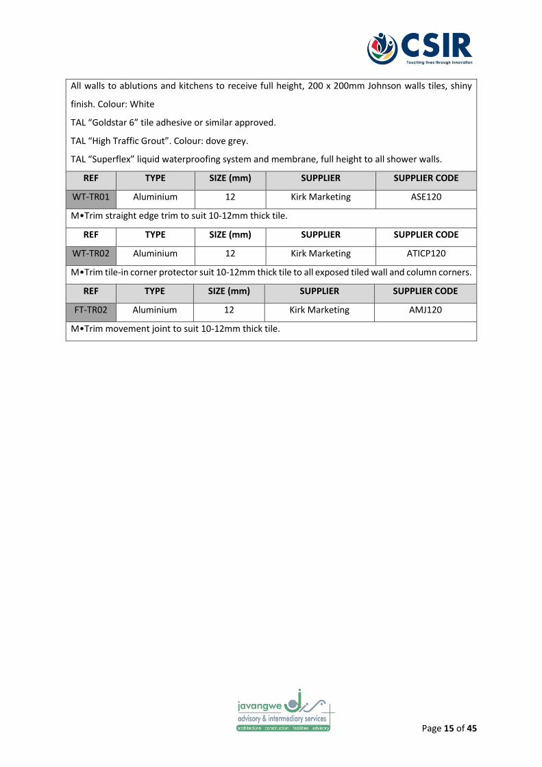
Page 15 of 45
All walls to ablutions and kitchens to receive full height, 200 x 200mm Johnson walls tiles, shiny
finish. Colour: White
TAL “Goldstar 6” tile adhesive or similar approved.
TAL “High Traffic Grout”. Colour: dove grey.
TAL “Superflex” liquid waterproofing system and membrane, full height to all shower walls.
REF TYPE SIZE (mm) SUPPLIER SUPPLIER CODE
WT-TR01 Aluminium 12 Kirk Marketing ASE120
M•Trim straight edge trim to suit 10-12mm thick tile.
REF TYPE SIZE (mm) SUPPLIER SUPPLIER CODE
WT-TR02 Aluminium 12 Kirk Marketing ATICP120
M•Trim tile-in corner protector suit 10-12mm thick tile to all exposed tiled wall and column corners.
REF TYPE SIZE (mm) SUPPLIER SUPPLIER CODE
FT-TR02 Aluminium 12 Kirk Marketing AMJ120
M•Trim movement joint to suit 10-12mm thick tile.

Page 16 of 45
3 CONCRETE SOFFITS
3.1 GENERAL
3.1.1 Codes of Practice
SANS 10155: 1980 Accuracy in buildings
SANS 1090: 2009 Aggregates from natural sources — Fine aggregates for plaster and mortar
SANS 2001-EM1:2007 Construction works - Part EM1: Cement plaster
SANS 50197-1:2013 Cement Part 1: Composition, specifications, and conformity criteria for
common cements
3.1.2 Construction
Soffits to Existing and New Concrete Suspended Slabs
All loose plaster to existing concrete soffits, shall be removed.
All damaged plaster in exposed areas shall be made good and unless specified otherwise, the thickness
and finish shall match the existing plaster finish.
All exposed plaster to existing and new concrete suspended slabs, shall, unless specified otherwise,
be a min 10mm and max 20mm thick, with a steel trowelled finish.
Where the plaster is anticipated to exceed or exceeds 20mm in thickness, reinforcing mesh as per the
structural engineer’s specification shall be required.

Page 17 of 45
Each plaster coast shall be applied in one single operation, unless practically impossible to do so at
which point the manufacturers written guidance, if applicable, as well as the structural engineers
written specifications and permission shall be obtained prior to applying any single coat of plaster in
more than one operation.
The chasing of plaster is expressly prohibited, however where the chasing of plaster is unavoidable,
the minimum cover thickness of the plaster over chased services and reinforcing mesh as per the
structural engineer’s specification shall be required.
The moisture content of all walls as measured with a Doser Hygrometer (or equivalent) shall not, at
the time of applying the primer, exceed BD 2 scale - 8% or less.
Permissible Deviations from datum level
All plaster shall ensure that Grade II accuracy as per SANS 10155: 1980 - Accuracy in buildings as per
Table 3 is achieved.
3.1.3 Joints
All plaster shall be installed without any interference whatsoever with any of the structural joints in
the concrete suspended floors.
All visible structural and movement joints that are expressed in the plastered or painted soffit, shall,
except in the case of a painted finish, or if specified otherwise, receive a flexible “Polymer Paintable
Joint Sealant” as per the structural engineers’ details and specification.

Page 18 of 45
3.2 CONCRETE SOFFIT COVERINGS
REF TYPE SUPPLIER COLOUR SUPPLIER CODE
CS-01 Paint Dulux Dulux To later spec
All exposed plastered and un-plastered soffits shall receive 1 x coat “Dulux 1 Step prep Water Based
Primer, Sealer and Undercoat”, or similar approved, minimum 16hrs overcoating time, to be
followed by 2 x coats Dulux Easy Care Washable and Tough PVA”, or similar approved. Minimum
48hrs between successive coats.

Page 19 of 45
4 BULKHEADS AND CEILINGS
4.1 GENERAL
4.1.1 Codes of Practice
SANS 10155: 1980 Accuracy in buildings
General specification for drywall partitions and lightweight internal walls South African Building
Interior Systems Association 2nd Ed, June 2004
4.1.2 Construction
All new bulkheads and ceilings shall comply with to comply with the SANS 10155: 1980 - Accuracy in
buildings permissible deviations in floors and ceilings.
Table 5 Permissible deviations in floors and ceilings (SANS 10155: 1980 Accuracy in Buildings p33)

Page 20 of 45
4.1.3 Drywall Bulkheads
All drywall bulkheads shall be constructed with 6.4mm thick “Gyproc Rhinoboard” or similar approved,
on “Gyproc Donn Steel Brandering” and with aluminium shadow line plaster trims all around.
All drywall bulkheads to be skimmed with 1 x coat 2.5mm thick Rhinolite or similar approved.
Permissible Deviations from datum level
All bulkheads and flush plastered/nail up ceilings shall comply with Grade II accuracy as per SANS
10155: 1980 - Accuracy in buildings as per Table 5.
4.1.4 Drywall Flush Plastered/Nail Up Ceilings
All drywall flush plastered/nail up ceilings shall be constructed with 6.4mm thick “Gyproc Rhinoboard”
or similar approved on 38 x 38mm SA pine brandering at max 760mm centres, with “Gyproc Rhinolite
Quickcornice” No 10 or similar approved.
All drywall flush plastered/nail up ceilings to be skimmed with 1 x coat 2.5mm thick Rhinolite or similar
approved.
Permissible Deviations from datum level
All drywall flush plastered/nail up ceilings shall comply with Grade II accuracy as per SANS 10155: 1980
- Accuracy in buildings as per Table 5.
4.1.5 Suspended Lay-in Ceilings

Page 21 of 45
All lay-in ceilings shall be constructed with “Gyproc Donn T38V/T37V ceiling grid”or similar approved,
suspended from the building structural members, with aluminium shadow line plaster trims and
transition strips all around.
Permissible Deviations from datum level
All suspended lay-in ceilings shall comply with Grade II accuracy as per SANS 10155: 1980 - Accuracy
in buildings as per Table 3.
4.1.5 Joints
All suspended bulkheads and lay-in ceilings shall be installed without any interference whatsoever
with any of the structural joints in the floors and walls.
The installation of all suspended bulkheads and lay-in ceilings shall allow for movement joints, other
than structural joints, in strict compliance with the manufacturer’s specifications.
All structural and movement joints that are expressed in the suspended bulkheads shall, unless
specified otherwise, receive a flexible “Polymer Paintable Joint Sealant” as per the structural
engineers’ details and specification.
4.2 CEILING COVERINGS
REF TYPE SUPPLIER COLOUR SUPPLIER CODE
CC-01 Paint Dulux To later spec To later spec
All suspended bulkheads to receive 1 x coat “Dulux 1 Step prep Water Based Primer, Sealer and
Undercoat”, or similar approved, minimum 16hrs overcoating time, to be followed by 2 x coats
Dulux Easy Care Washable and Tough PVA” with minimum 48hrs between successive coats.

Page 22 of 45
The moisture content of all suspended drywall bulkheads as measured with a Doser Hygrometer (or
equivalent) shall not, at the time of applying the primer, exceed BD 2 scale - 8% or less.
REF TYPE SUPPLIER COLOUR SUPPLIER CODE
CC-02 Paint Gyproc To later spec To later spec
All suspended lay-in ceiling grids to receive “Gyproc Gyptone Acoustic Tile”.

Page 23 of 45
5 JOINERY
5.1 GENERAL
5.1.1 Codes of Practice
SANS 10155: 1980 Accuracy in buildings
5.1.2 Construction
All timber carcasses to be constructed from 16mm thick white melamine boards and 3mm Masonite
backing boards, with 16mm thick supawood doors and drawer fronts as per approved shop drawings.
5.1.3 Paint To Supawood Elements
All timber supawood doors and drawer fronts to receive 1 x coat Dulux Duco Spray.

Page 24 of 45
CHAPTER 2 – EXTERNAL FINISHES
1 FLOORS & PAVING
1.1 GENERAL
1.1.1 Codes of Practice
SANS 10155: 1980 Accuracy in buildings
SANS 10107: 2011 Code of Practice for the Design & Installation for Ceramic Tiling
SANS 10043: 2009 The installation of wood and laminate flooring
SANS 10109-2: 2004 Concrete floors. Part 2: Finishes to concrete floors
SANS 10070: 2012 The installation of resilient thermoplastic and similar flexible floor covering
materials
SANS 1058:2012 Concrete paving blocks
SANS 1200-MJ:1984 Standard Specification For Civil Engineering Construction : Segmented Paving
SANS 2001:CC1:2007 Construction works Part CC1: Concrete works (structural)
1.1.2 Construction
Permissible deviations appropriate to the degree of accuracy specified in the scope of work shall be
applied to linear dimensions, position, verticality, levelness, squareness and bow. If no degree of
accuracy is specified, degree of accuracy II shall apply.

Page 25 of 45
Any deviation from flatness of a plane surface or any abrupt change in a continuous surface shall be
measured as the maximum deviation of the surface from any straight line of length 3 m joining two
points on the surface, determined by means of a straight edge, the ends of which are supported on
identical blocks of suitable thickness placed over each of the points.
Where a wood-floated or steel-floated or power-floated finish or a screed topping or granolithic finish
is required in terms of the scope of work, the concrete shall, unless otherwise specified in the
specification data, be finished to a degree of accuracy II.
All new surface beds and suspended concrete floors to comply with the structural engineers’ details,
specifications, and shall, unless specified otherwise, comply with the Class 2 floor classification.
Class Description Max Deviation (mm)
1 For floors requiring minimum irregularity, such as large format
specialised warehouses and stores with an epoxy or vinyl floor
finish. May necessitate the use of special methods and will require
close supervision
3
2 Reasonable degree of accuracy required and suitable for the major
proportion of construction work
5
3 Suitable for floors where both a reasonable degree of accuracy and
regularity is not important
10
Table 6 Classification of floors

Page 26 of 45
Table 7 Accuracy in concrete work (source: SANS 2001-CC1:2007 p55)

Page 27 of 45
All new layer works for paving to comply with civil engineers’ details and specifications.
1.1.3 Screeds
Existing Concrete Surface Beds
All existing concrete surface beds to receive a self-levelling structural screed and shall, unless specified
otherwise, result in a floor that complys with the Class 2 floor classification.
Bonded Screeds To New Concrete Surface Beds
All new concrete surface beds, shall, unless specified otherwise and only once they are in a hardened
state, receive a wood floated screed finish, minimum 25mm and maximum 50mm thick.
Where the screed is anticipated to exceed or exceeds 50mm in thickness, reinforcing mesh as per the
structural engineer’s specification shall be required.
All screeds shall be applied in one single operation, unless practically impossible to do so at which
point the manufacturers written guidance, if applicable, as well as the structural engineers written
specifications and permission shall be obtained prior to applying the screed in more than one
operation.
Bonded Screeds To New Concrete Plinth Surface Beds
All new concrete plinth surface beds, shall be constructed with a class I (one) degree of accuracy and
shall, unless specified otherwise and only once they are in a hardened state, receive a steel floated
structural screed finish to falls as per structural engineers specifications and details.

Page 28 of 45
All screeds shall be applied in one single operation, unless practically impossible to do so at which
point the manufacturers written guidance, if applicable, as well as the structural engineers written
specifications and permission shall be obtained prior to applying the screed in more than one
operation.
Permissible Deviations from datum level
All screeds shall ensure that the specified floor classification as per Table 6 is achieved.
1.1.4 Joints
All screeds and floor coverings shall be installed without any interference whatsoever with any of the
structural joints in the concrete surface bed and suspended floors.
The installation of all floor coverings shall allow for movement joints, other than structural joints, in
strict compliance with the manufacturer’s specifications.
All structural and movement joints that are expressed in the floor coverings shall, except in the case
of an epoxy finish or if specified otherwise, receive a flat transition strip as per the architect’s details
and specification.
1.1.5 Riversand Bedding
All precast concrete paving blocks to be bedded in an uncompacted riversand bedding as per SANS
1200-MJ Standard Specification For Civil Engineering Construction : Segmented Paving.

Page 29 of 45
1.2 EXTERNAL PATIOS, STAIRS AND RAMPS
All external floors and ramps to receive a 600 x 600mm matt, full body, slip-resistant external porcelain
floor tile to be fixed onto substrate with tile adhesive, grout joints and grouting in strict accordance
with the manufacturer’s specification.
All exposed tile edges to floors to receive an aluminium straight edge trim, by Kirk Marketing, or similar
approved.
All stair nosing’s and ramp landings to receive an aluminium edging with luminescent non-slip insert,
all by Kirk Marketing, or similar approved.
1.3 PAVED APRON
All paved aprons to receive a medium interlocking precast concrete paver as per civil engineers
specifications.

Page 30 of 45
2 WALLS
2.1 GENERAL
2.1.1 Codes of Practice
SANS 10155: 1980 Accuracy in buildings
SANS 1090: 2009 Aggregates from natural sources — Fine aggregates for plaster and mortar
SANS 2001-EM1:2007 Construction works - Part EM1: Cement plaster
SANS 50197-1:2013 Cement Part 1: Composition, specifications, and conformity criteria for
common cements
SANS 10400-K:2011 The application of the National Building Regulations Part K: Walls
2.1.2 Construction
All new masonry walls to comply with the SANS 10155: 1980 - Accuracy in buildings permissible
deviations in walls (Table 3).
2.1.3 Plaster To Masonry Walls
Existing and New Masonry and Concrete Walls
All loose and damaged plaster to existing masonry shall be stripped off and made good, with new
plaster to match thickness of existing plaster

Page 31 of 45
All plaster to new masonry and concrete walls, shall, unless specified otherwise, be a min 10mm and
max 20mm thick, with a steel trowelled finish.
Where the plaster is anticipated to exceed or exceeds 20mm in thickness, reinforcing mesh as per the
structural engineer’s specification shall be required.
Each plaster coast shall be applied in one single operation, unless practically impossible to do so at
which point the manufacturers written guidance, if applicable, as well as the structural engineers
written specifications and permission shall be obtained prior to applying any single coat of plaster in
more than one operation.
The chasing of plaster is expressly prohibited, however where the chasing of plaster is unavoidable,
the minimum cover thickness of the plaster over chased services and reinforcing mesh as per the
structural engineer’s specification shall be required.
Permissible Deviations from datum level
All plaster shall ensure that Grade II accuracy as per SANS 10155: 1980 - Accuracy in buildings as per
Table 3 is achieved.
2.1.4 Joints
All plaster and wall coverings shall be installed without any interference whatsoever with any of the
structural joints in the walls.
The installation of all plaster and wall coverings shall allow for movement joints, other than structural
joints, in strict compliance with the manufacturer’s specifications.

Page 32 of 45
All structural and movement joints that are expressed in the plaster and wall coverings shall, unless
specified otherwise, receive a flexible “Polymer Paintable Joint Sealant” as per the structural
engineers’ details and specification.
2.2 PLASTERED WALLS
All plastered walls to receive 1 x coat “Dulux Super Grip All Surface Primer coat”, or similar approved,
minimum 16hrs overcoating time, to be followed by 2 x coats “Dulux Weathergaurd”, or similar
approved. Minimum 48hrs drying time between successive coats.
The moisture content of all walls as measured with a Doser Hygrometer (or equivalent) shall not, at
the time of applying the primer, exceed BD 2 scale - 8% or less.
2.3 UNPLASTERED WALLS
All unplastered walls to receive 2 x coat “Dulux Brick Dressing, Sealer and Undercoat”, or similar
approved, minimum 18hrs overcoating time.
The moisture content of all walls as measured with a Doser Hygrometer (or equivalent) shall not, at
the time of applying the primer, exceed BD 2 scale - 8% or less.

Page 33 of 45
3 CONCRETE SOFFITS
3.1 GENERAL
3.1.1 Codes of Practice
SANS 10155: 1980 Accuracy in buildings
SANS 1090: 2009 Aggregates from natural sources — Fine aggregates for plaster and mortar
SANS 2001-EM1:2007 Construction works - Part EM1: Cement plaster
SANS 50197-1:2013 Cement Part 1: Composition, specifications, and conformity criteria for
common cements
3.1.2 Construction
Soffits to Existing and New Concrete Suspended Slabs
All loose plaster to existing concrete soffits, shall be removed.
All damaged plaster in exposed areas shall be made good and unless specified otherwise, the thickness
and finish shall match the existing plaster finish.
All exposed plaster to existing and new concrete suspended slabs, shall, unless specified otherwise,
be a min 10mm and max 20mm thick, with a steel trowelled finish.
Where the plaster is anticipated to exceed or exceeds 20mm in thickness, reinforcing mesh as per the
structural engineer’s specification shall be required.

Page 34 of 45
Each plaster coast shall be applied in one single operation, unless practically impossible to do so at
which point the manufacturers written guidance, if applicable, as well as the structural engineers
written specifications and permission shall be obtained prior to applying any single coat of plaster in
more than one operation.
The chasing of plaster is expressly prohibited, however where the chasing of plaster is unavoidable,
the minimum cover thickness of the plaster over chased services and reinforcing mesh as per the
structural engineer’s specification shall be required.
Permissible Deviations from datum level
All plaster shall ensure that Grade II accuracy as per SANS 10155: 1980 - Accuracy in buildings as per
Table 3 is achieved.
3.1.3 Joints
All plaster shall be installed without any interference whatsoever with any of the structural joints in
the concrete suspended floors.
All visible structural and movement joints that are expressed in the plastered or painted soffit, shall,
except in the case of a painted finish, or if specified otherwise, receive a flexible “Polymer Paintable
Joint Sealant” as per the structural engineers’ details and specification.
3.2 PLASTERED AND UN-PLASTERED SOFFITS
All exposed plastered and un-plastered soffits shall receive 1 x coat “Dulux 1 Step prep Water Based
Primer, Sealer and Undercoat”, or similar approved, minimum 16hrs overcoating time, to be followed
by 2 x coats “Dulux Weathergaurd”, or similar approved. Minimum 48hrs between successive coats.

Page 35 of 45
The moisture content of all exposed plastered and un-plastered soffits as measured with a Doser
Hygrometer (or equivalent) shall not, at the time of applying the primer, exceed BD 2 scale - 8% or
less.

Page 36 of 45
4 CEILINGS TO PATIOS & ROOF EAVES
4.1 GENERAL
4.1.1 Codes of Practice
SANS 10155: 1980 Accuracy in buildings
General specification for drywall partitions and lightweight internal walls South African Building
Interior Systems Association 2nd Ed, June 2004
4.1.2 Construction
All new ceilings to external patios and roof eaves shall comply with to comply with the SANS 10155:
1980 - Accuracy in buildings permissible deviations in floors and ceilings (Table 5).
4.1.3 Drywall Nail Up Ceilings
All drywall nail up ceilings shall be constructed with “Gyproc Moisture Resistant” board, or similar
approved on 38 x 38mm SA pine brandering at max 760mm centres.
Permissible Deviations from datum level
All drywall flush plastered/nail up ceilings shall comply with Grade II accuracy as per SANS 10155: 1980
- Accuracy in buildings as per Table 5.

Page 37 of 45
5 WINDOWS AND DOORS
5.1 GENERAL
5.1.1 Codes of Practice
SANS 10155: 1980 Accuracy in buildings
SANS 1090: 2009 Aggregates from natural sources — Fine aggregates for plaster and mortar
SANS 2001-EM1:2007 Construction works - Part EM1: Cement plaster
SANS 50197-1:2013 Cement Part 1: Composition, specifications, and conformity criteria for
common cements
SANS 10400-K:2011 The application of the National Building Regulations Part K: Walls
5.1.2 Construction
All door and window openings in new masonry walls to comply with the SANS 10155: 1980 - Accuracy
in buildings permissible deviations in walls (Table 3).
5.1.3 Plaster to Door and Window Reveals and Window Cills
Existing and New Masonry and Concrete Walls
All loose and damaged plaster to existing masonry shall be stripped off and made good, with new
plaster to match thickness of existing plaster

Page 38 of 45
All plaster to existing and new door and window reveals shall, unless specified otherwise, be min
10mm and max 20mm thick, with a steel trowelled finish.
Where the plaster is anticipated to exceed or exceeds 20mm in thickness, reinforcing mesh as per the
structural engineer’s specification shall be required.
Each plaster coast shall be applied in one single operation, unless practically impossible to do so at
which point the manufacturers written guidance, if applicable, as well as the structural engineers
written specifications and permission shall be obtained prior to applying any single coat of plaster in
more than one operation.
The chasing of plaster is expressly prohibited, however where the chasing of plaster is unavoidable,
the minimum cover thickness of the plaster over chased services and reinforcing mesh as per the
structural engineer’s specification shall be required.
Permissible Deviations from datum level
All plaster shall ensure that Grade II accuracy as per SANS 10155: 1980 - Accuracy in buildings as per
Table 3 is achieved.
5.1.4 Precast Concrete Window Cills
All precast concrete window cills to later specification.
5.1.5 Tile Window Cills
All tiled window cills to later specification.

Page 39 of 45
5.1.6 Door Frames and leaf’s
Timber or pressed metal door frames with solid core 5-panel timber or pressed metal door leafs to
suit daylight opening.
Fire door frames to suit daylight opening with 2hr fire rated fire doors to be factory finished with a
clear varnish.
5.2 WINDOW CILLS
All precast concrete and tile window cills to receive 1 x coat “Dulux Super Grip All Surface Primer”, or
similar approved, minimum 16hrs overcoating time, to be followed by 2 x coats “Dulux
Weathergaurd”, or similar approved. Minimum 48hrs drying time between successive coats.
The moisture content of all walls as measured with a Doser Hygrometer (or equivalent) shall not, at
the time of applying the primer, exceed BD 2 scale - 8% or less.
5.3 TIMBER DOOR LEAFS
All timber doors to sanded and sealed with 1 x coat Dulux Wood Primer and 2 x coats “Dulux Woodgard
Exterior Double Life Timbavarnish Eggshell” varnish, or similar approved.

Page 40 of 45
6 ROOF COVERINGS & RAINWATER GOODS
6.1 GENERAL
6.1.1 Codes of Practice
SANS 10400-L:2011 The application of the National Building Regulations Part L: Roofs
6.1.2 Construction
All roof coverings to comply with SANS 10400-L:2011 The application of the National Building
Regulations Part L: Roofs
6.1.3 Metal Roof Coverings
All roof coverings to be Safintra 0,50mm thick SAFLOK 410 Colorplus® AZ150 interlocking roof
sheeting.
6.1.4 Rainwater Goods
All rainwater gutters and downpipes to be made from 0.5mm thick galvanised iron.
6.2 METAL ROOF COVERINGS

Page 41 of 45
All roof coverings to be” 0,50mm thick SAFLOK 410 Colorplus® AZ150 interlocking roof sheeting with
a “Sunset Red” finish.
6.3 RAINWATER GOODS
All rainwater goods to receive 1 x coat Dulux Galvanised Iron Primer and 2 x coats “Dulux Pearlgo”
water-based paint, or similar approved.

Page 42 of 45
CHAPTER 3 – SANITARY SCHEDULE
X-RAY LAB
KEY: QTY: DESCRIPTION:
1 DOUBLE SINK (X-RAY LAB)
FRANKE ‘PROJECTLINE’ INSET SINK, RECESSED DARINAGE LEDGE AND 38mm DIAMETER WASTE FITTINGS SIZE: 1160mm X 460mm
FINISH: STAINLESS STEEL
BATHROOMS
KEY: QTY: DESCRIPTION:
2 WATER CLOSET
VAAL SANITARYWARE VITREOUS CHINA "PARKTOWN" 90° OUTLET TOP INLET (CODE 431500) OR BACK INLET (CODE 431600) CLOSED RIM BACK-TO-WALL PAN. TOP INLET CAN BE USED WITH AN EXPOSED FLUSHVALVE.
COLOUR: WHITE
2 FLUSHVALVE
EXPOSED TYPE, BACK ENTRY TOILET FLUCHVALVE WIH CONTROL STOP AND WALL FLANGE. WITH BENT FLUCH PIPE AND PAN CONNECTOR. SANS 1240 HORIZONTAL TELESCOPIC ADJUSTMENT (CONTROL STOP VALVE BODY) FOR EASY INSTALLATION.
CODE: FM1-100
2 BASIN
VAAL SANITARYWARE WALL HUNG 455 X 290MM “BANTAM” BASIN WITH TWO TAPHOLES, INTEGRATED OVERFLOW AND CHAINSTAY HOLE.

Page 43 of 45
4 BASIN TAP
MEDICAL ELBOW-ACTION PILLAR TAP, CHROME. INCLUDES: 1/4" TURN CERAMIC DISC HEAD PART, BLUE INDICE, 1/2" BSP MALE INLET, AND FLANGED BACKNUT. IDEAL FOR MEDICAL, KITCHEN AND INDUSTRIAL INSTALLATIONS. SANS 226 TYPE 2.
3 BASIN WASTE
UN-SLOTTED BATH AQUAWASTE (CLICK-CLACK WASTE) 70mm DIAMETER FLANGE, 40mm LONG SHANK, 1½” BSP MALE OUTLET CONNECTION.
CODE: 318-40 FINISH: CHROME PLATE
2 DOUBLE TOILET ROLL HOLDER WITH SPINDLE SYSTEM DOUBLE TOILET ROLL HOLDER WITH SPINDLE SYSTEM FRO WALL MOUNTING, STAINLESS STEEL SURFACE SATIN FINISHED, FOLDED FRONT COVER, CYLINDER LOCK WITH FRANKE STANDARD KEY. FOR 2 ROLLS WITH MAX. 120MM Ø, SECOND ROLL WILL BE RELEASED AFTER CONSUMPTION OF FIRST ROLL, WITH SPINDLES, RESERVE ROLL NOT VISIBLE. INCLUDES STAINLESS STEEL SCREWS AND DOWELS. CODE: RODX672 144 X 138 X 301 359987
2 SOAP DISPENSER LIQUID SOAP DISPENSER FOR WALL MOUNTING, MANUFACTURED FROM 18/10 STAINLESS STEEL, SATIN FINISH. WITH A DEEP DRAWN LID, WELDED BODY AND CYLINDER LOCK WITH STANDARD FRANKE KEY. THE DISPENSER INCORPORATES A 1 LITRE POLYETHYLENE CONTAINER WHICH IS SUITABLE FOR LIQUID AND ANTISEPTIC SOAPS AND LOTIONS. SCREWS AND DOWELS INCLUDED. CODE: BS618 200 X 130 X 85 359800

Page 44 of 45
MOBILITY IMPAIRED PERSONS (PARAPLEGIC TOILET)
KEY: QTY: DESCRIPTION:
1 BASIN
VAAL SANITARYWARE CERAMIC FIRECLAY 550 X 400MM RECTANGULAR “SPRINGBOK” BASIN WITH TWO TAPHOLES, INTEGRATED OVERFLOW AND CHAINSTAY HOLE.
1 WATER CLOSET
VAAL SANITARYWARE VITREOUS CHINA "PEARL PARAPLEGIC” SEMI-CLOSE COUPLED 90° OUTLET OPEN RIM WASHDOWN PAN AND MATCHING 9 LITRE CISTERN COMPLETE WITH LID, FITMENTS, AND PURPOSE MADE C.P. SIDE-FLUSH LEVER (LEFT OR RIGHT). SUPPLIED WITH PURPOSE MADE THERMOSET SEAT AND COVER PLATE.
2 PARAPLEGIC TOILET TAP
MEDICAL ELBOW-ACTION PILLAR TAP, CHROME. INCLUDES: 1/4" TURN CERAMIC DISC HEAD PART, BLUE INDICE, 1/2" BSP MALE INLET, AND FLANGED BACKNUT. IDEAL FOR MEDICAL, KITCHEN AND INDUSTRIAL INSTALLATIONS. SANS 226 TYPE 2.
1 CISTERN AND FLUSH VALVE BACKRAIL FRANKE 750 X 260MM X 32MM Ø GRABRAIL MANUFACTURED FROM 18/10 STAINLESS STEEL, SATIN FINISH TO PREVENT SLIPPING. INCLUDES SCREWS AND DOWELS. CODE: CNTXBR 750 X 260MM 35992

Page 45 of 45
1 ANGLE BAR FRANKE 618 X 95 X 256MM X 31.8MM Ø GRABRAIL MANUFACTURED FROM 18/10 STAINLESS STEEL, SATIN FINISH TO PREVENT SLIPPING. INCLUDES SCREWS AND DOWELS. CODE: CNTX700A 618 X 95 X 256MM 35877
1 DOUBLE TOILET ROLL HOLDER WITH SPINDLE SYSTEM DOUBLE TOILET ROLL HOLDER WITH SPINDLE SYSTEM FRO WALL MOUNTING, STAINLESS STEEL SURFACE SATIN FINISHED, FOLDED FRONT COVER, CYLINDER LOCK WITH FRANKE STANDARD KEY. FOR 2 ROLLS WITH MAX. 120MM Ø, SECOND ROLL WILL BE RELEASED AFTER CONSUMPTION OF FIRST ROLL, WITH SPINDLES, RESERVE ROLL NOT VISIBLE. INCLUDES STAINLESS STEEL SCREWS AND DOWELS. CODE: RODX672 144 X 138 X 301 359987
1 SOAP DISPENSER LIQUID SOAP DISPENSER FOR WALL MOUNTING, MANUFACTURED FROM 18/10 STAINLESS STEEL, SATIN FINISH. WITH A DEEP DRAWN LID, WELDED BODY AND CYLINDER LOCK WITH STANDARD FRANKE KEY. THE DISPENSER INCORPORATES A 1 LITRE POLYETHYLENE CONTAINER WHICH IS SUITABLE FOR LIQUID AND ANTISEPTIC SOAPS AND LOTIONS. SCREWS AND DOWELS INCLUDED. CODE: BS618 200 X 130 X 85 359800

6.6 Annexure F - Civil/ Structural Project Specification
Ramgoolam www.ramgoolamgroup.com Bespoke Global Efficacy.

CSIR
Relocation/Protection of Existing Services
C3.1 : DESCRIPTION OF THE WORKS
C3.1.1 TEMPORARY WORKS
Normal temporary work such as supports for formwork, shoring of trenches etc. will be
required to facilitate construction.
Trenches and excavations need to be barricaded sufficiently in order to prevent, as far as is
reasonably practicable, any person from falling into and/or being buried or trapped by a fall
or dislodgement of material. The Contractor must ensure that the necessary steps are taken
to ensure the stability of any adjoining building, structure or road that is likely to be affected.
C3.1.2 Other Services (i.e. Telkom, Electricity, etc.)
The Contractor shall ensure that the position of all existing services affected by the Works
have been verified before construction works commences and should it be necessary to
lower or relocate any service, the Contractor will be required to make the necessary
arrangements with the relevant service provider and to advise the Employers Agent
accordingly.
C3.1.3 Protection of Existing Works
The Contractor shall take all necessary steps to ascertain the location of existing services
before commencing any section of the works and shall exercise the greatest care when
working in the vicinity of such services. No more than three weeks and not less than one
week before commencing his operations in any particular area, the Contractor shall request
in writing from the Employers Agent the latest available drawings showing the location of
services already installed. The Contractor will also be responsible for contacting the various
service providers, arranging a meeting and verifying all known as well as possible unknown
services on site.
The Contractor shall take all necessary steps to protect any existing works whatsoever
against damage which may arise as a result of his operations on Site. The Contractor shall
bear the cost of the repair of damage to any service, the possible existence of which could
reasonably have been ascertained by him in good time.
Where the Contractor is responsible for damage for which repairs have to be carried out by
the Employer or an outside Authority, the costs of these repairs will be recovered by means
of a deduction from the Contractor’s monthly Payment Certificate. The Employer will attend
to the payment of monies due to outside authorities, should the Contractor not make direct
payment, to the outside authorities, timeously.

C3.2 : ENGINEERING
C3.2.1 DESIGN SERVICES AND ACTIVITY MATRIX
C3.2.2 SERVICES KNOWN TO BE IN THE VICINITY OF THE WORKS SITE
Many known services cross the site of the works. These are shown on the drawings as far as
possible. Before any work commences the exact positions of all services must be located
and the services identified, marked and recorded on plan for inclusion in the as-built drawing.
Items have been allowed in the Bill of Quantities for dealing with and protecting existing
services where they are known.
The Contractor, shall however, ensure that prior to construction all the necessary Record
Drawings and Way-leaves for all services have been obtained and verified on site by the
relevant service providers in his presence. The Contractor must request in writing the
relevant official to indicate the said services within 48 hours prior to the commencement of
the work, after which the responsibility rests with the service department if the services are
not indicated to the Contractor as requested.
The Contractor shall take whatever extra precautions are required to protect all existing
services from damage during the period of the Contract. Any damage to existing services
indicated by the relevant service providers or other damage as a result thereof, shall be for
the Contractors account.
C3.3 : CONSTRUCTION
PSA GENERAL
PSA PAYMENT CLAUSES
PSA 8.5.3 Relocation of municipal services ........................................................ Unit: Provisional Sum
The provincial sum is to cover the costs payable by the contractor to service providers, on
the engineer’s instruction only, for the relocation of existing services which impede
construction activities.

6.7 Annexure G - Electrical Project Specification
Ramgoolam www.ramgoolamgroup.com Bespoke Global Efficacy.

CSIR HIP Building 16 Electrical and Electronic Technical Specification
1
CSIR HIP (HOT ISOSTATIC PRESS)
ELECTRICAL & ELECTRONIC ENGINEERING SERVICES
TECHNICAL SPECIFICATION
1. GENERAL
2. SCOPE OF WORKS
3. SITE LOCATION AND DETAILS
4. STANDARDS AND CODES OF PRACTICE
5 QUALITY OF MATERIALS
6. COMPETENCE OF PERSONNEL, WORKMANSHIP AND STAFF
7. CO-ORDINATION OF SERVICES
8. FINISHING AND TIDYING
9. SUPERVISION
10. PROTECTION OF OTHER SERVICES AND STRUCTURES
11. POWER SUPPLY TO SITE
12. LOW VOLTAGE CABLE INSTALLATION
13. DISTRIBUTION BOARDS
14. CONDUITS, POWERSKIRTING, CABLE TRAYS, CABLE LADDERD, AND CABLE DUCTS
15. LIGHTING INSTALLATION
16. POWER INSTALLATION
17. WIRING
18. TELEPHONE AND DATA INSTALLATION
19. UPS INSTALLATION
20 GENERATOR
21 ACCESS CONTROL
22 EARTHING AND BONDING
23 OXYGEN SENSORS
24 BALANCING OF LOADS
25 SITE TESTS AND COMMISSIONING
26 MAINTENANCE PERIOD
27 TECHNICAL DATA SCHEDULE

CSIR HIP Building 16 Electrical and Electronic Technical Specification
2
CSIR HIP (HOT ISOSTATIC PRESS) ELECTRICAL & ELECTRONIC ENGINEERING SERVICES: TECHNICAL SPECIFICATION
1. GENERAL
1.1 This specification comprises all aspects regarding the building electrical installation of the CSIR HOT ISOSTATIC PRESS (hereinafter referred to as “CSIR HIP”) Building situated in the East of Tshwane (Pretoria), Gauteng.
1.2 The Technical Specification shall be read in conjunction with the Standard Specifications listed in section 4 below, schedule of quantities, drawings and Special Conditions of Contract included in this document. Where contradictions occur between the documents, the most stringent requirement shall rule, unless otherwise stated by the Engineer.
1.3 All work shall be scheduled in liaison with the Main Contractor to suit his contract programme.
2. SCOPE OF WORKS
2.1 The scope of the installation shall comprise of the following: the supply, delivery, off-loading, installation, commissioning, testing and guarantee of the following material and equipment associated with the above-mentioned works:
2.1.1 Replacement of existing Building 16 main distribution board
2.1.2 Stripping out of all existing services in the HIP project area.
2.1.3 The installation of low voltage cable between the main distribution board & generator change-over panel, DB HIP (Standby Power), Sub DB-FF, Cooling Tower Sub DB and the UPS.
2.1.4 New Generator installation
2.1.5 New UPS installation
2.1.6 New lighting installation.
2.1.7 New small power installation.
2.1.8 Wireways and conduits to lights, socket outlets and power outlets.
2.1.9 Cable tray and ducting installation.
2.1.10 Wiring of lighting and power points with PVC insulated conductors and bare copper earth wire.
2.1.11 Excavation, backfilling and compaction of cable trenches.
2.1.12 Access control system
2.1.13 Fire detection system
2.1.14 Oxygen sensor installation
2.1.15 Earthing and bonding including lightning protection Provide earthing to all metal structures and sanitary ware.
2.1.16 Site supervision and quality management.
2.1.17 Training: The Contractor shall provide basic training to the technical personnel (End-User) for the UPS, Generator and Oxygen sensor and Oxygen sensor controller configuration, operation & maintenance.
2.1.18 Commissioning, testing and handing over of complete electrical installation detailed above and to provide "as-built" drawings.
2.1.19 Maintenance during the maintenance period.

CSIR HIP Building 16 Electrical and Electronic Technical Specification
3
2.1.20 Attending to defects during the defects liability period from the completion of the whole project, in line with the defects liability period stipulated in the contract in respect of building services and/or engineering services.
2.2 These aspects should be seen only as a brief summary of the scope of work and not as a complete record. Quantities and volume of work shall be read or obtained from the drawings and the text of the specification.
2.3 All components, mounting brackets, draw boxes, junction boxes, cabling, wiring and all other electrical, mechanical and civil works required to complete the works in accordance with the specification, prior to first delivery, shall be deemed to be included in the tendered rates and prices, even though some items may not be mentioned separately. No claims whatsoever, in this regard, will be considered after the contract has been awarded.
2.4 In addition, the work shall be neat, of high standard and to the satisfaction of the Engineer, the Client and all other members of the professional team and Contractors on site.
3. SITE LOCATION AND DETAILS 3.1 The site of the works is located in the East of Tshwane (Pretoria), Gauteng.. 3.2 The site is subject to the following prevailing conditions:
Maximum Temperature : 30 0C
Minimum Temperature : 5 0C
Relative Humidity : Average annual is 60% Altitude : ±1370m above sea level
Figure 1: Weather Conditions for Pretoria, Gauteng 4. STANDARDS AND CODES OF PRACTICE 4.1 The electrical work shall be carried out strictly in accordance with:

CSIR HIP Building 16 Electrical and Electronic Technical Specification
4
SANS 10142 – 1 “The wiring of premises. Part 1: LV Installation” Upgrading of the lighting installation to achieve minimum average light levels as
stipulated in the code of practice for interior lighting, “SANS 10114-1.
The OHS Act, 1993 (Act 85 of 1993) as amended SANS Code of Practice - 10313-1999: “The Protection of Structures Against Lightning” The National Department of Public Works’ Standard Specification for Electrical and Mechanical Installations The National Building Regulations and Building Standards Act 1977 (Act 103 of 1977) as amended The Municipal By-Laws and any Local Authority Regulations which may be in force The Local Fire Office Regulations The Local Government Ordinary 1939 (Ordinary 17 of 1939) as amended. The Electricity Act 1984 Act 41 of 1984 The Green Building Act 2012-1 of 2013 as amended Manufacturer’s specifications and installation instructions
Additional SANS and NRS standards not explicitly stated shall still apply.
5 QUALITY OF MATERIALS 5.1 All materials supplied or utilised under the electrical contract works shall be new and unused.
Only materials of first-class quality shall be utilised. Samples of all materials e.g. luminaires, outlets, cable support systems, etc, may be subject to approval by the Engineer before the procurement process commences.
5.2 All materials shall comply with the relevant specifications as listed in Section 4 above. 5.3 All materials shall be unconditionally guaranteed for a period of 12 months from the date of
practical completion of the Whole of the Contract Works. Where Supplier's guarantees are of a shorter duration than 12 months, the Contractor shall unreservedly agree to the extension and cession of all warranties and guarantees.
5.4 The Contractor shall replace any materials that are found to be defective during the defects
liability period. 5.5 The Contractor shall arrange factory inspections and tests to be witnessed by the Engineer
for all the distribution boards and generator unit manufactured and supplied as part of this project.
6. COMPETENCE OF PERSONNEL, WORKMANSHIP AND STAFF 6.1 All Electrical work shall be executed and supervised by suitably qualified staff. Only suitably
qualified Artisans shall be permitted to carry out and supervise work on electrical installations. The Contractor shall provide proof of current Artisan qualifications and experience on request.
6.2 The Contractor shall at all times have an adequate number of employees, plant and
equipment available during the construction period to ensure that the electrical work does not delay the construction programme.
7. CO-ORDINATION OF SERVICES
The Contractor shall be responsible for the on site co-ordination of the electrical services with the Contractor and other Contractors. Due allowance shall be made for this continuous liaison and on-site co-ordination in the tender price.

CSIR HIP Building 16 Electrical and Electronic Technical Specification
5
8. FINISHING AND TIDYING 8.1 In view of the concentration of construction and other activities likely to be experienced
during the Contract period, progressive and systematic finishing and tidying will form an essential part of this Contract. On no account will soil, rubble, materials, equipment or unfinished operations be allowed to accumulate in such a manner as to unnecessarily impede the activities of others.
8.2 Finishing and tidying shall therefore not be left to the end of the Contract, but shall be a
continuous operation. 9. SUPERVISION
Work shall at all time be subject to full time supervision by a qualified and experienced Master Electrician. This representative must be authorised and competent to receive instructions on behalf of the Contractor.
10. PROTECTION OF OTHER SERVICES AND STRUCTURES 10.1 The Contractor shall take all the necessary precautions to protect existing services, finishes
and structures during the execution of the Contract, and shall be fully responsible for all repairs and damages thereto. The costs for any repairs of damages shall be recovered from the Contractor.
10.2 The Contractor shall also exercise extreme care when excavations are made, to avoid
damage to existing or newly installed services. Any damages to other services shall be rectified forthwith and the costs for the rectification will therefore be recovered from the Contractor.
11 BALANCING OF LOADS
The electrical contractor shall be responsible for the measurement, testing and balancing of load between all the phases of busbars to the satisfaction of the Engineer. Distribution board equipment shall be connected in such an order that the load is balanced across all three phases.
12 SITE TESTS AND COMMISSIONING 12.1 It is the responsibility of the Electrical Contractor to provide all labour, accessories and
properly calibrated and certified measuring instruments necessary for all the tests required under this contract.
12.2 Prior to beginning any aspect of commissioning, the contractor shall present for the
Engineer’s review/approval, two copies of a complete commissioning procedures manual including checklists. The relevant checklists shall be utilised and formally signed off as part of the commissioning phase.
12.3 Preparation of commissioning report shall include, but not necessarily limited to: 12.3.1 Manufacturer’s operating, servicing and maintenance manuals for each and every individual
item of plant installed.
12.3.2 Inventory for the items of mechanical/electrical plant(s) and or equipment that shall be for installation in the project.
12.4 The following minimum site tests shall be carried out by the electrical contractor and the
results presented to the Engineer: Insulation resistance between all conductors and earth

CSIR HIP Building 16 Electrical and Electronic Technical Specification
6
Insulation resistance between all conductors and neutral
Insulation resistance between all 3 phase conductors
Resistance of earth path between the main earth bar, all exposed conductive parts of
the installation and distribution boards
Polarity of light switches and socket outlets
Earth leakage protection
Phase rotation of three phase circuits
12.5 After submission of the test results, the Electrical Contractor shall notify the Engineer that the
installation is complete, tested and in working order. The Client and/or the Engineer will witness the re-testing of the installation.
12.6 Final Testing and Certification as per the Client Specification
• The Clients Standard Specification for Electrical and Mechanical Installations of the CTC Building
• The application of the National Building Regulation – South African National Standard (SANS) 10400 (Part A – XA)
• Electrical Installations of Buildings - Fundamental Principles, Assessment of General Characteristics, Definitions - IEC 60364-1
• Electrical Installations of Buildings - Protection for Safety - IEC 60364-4
• Electrical Installations of Buildings - Selection and Erection of Electrical Equipment IEC 60364-5
• Electrical Installations of Buildings - Verification - IEC 60364-6
• Electrical Installations of Buildings - Requirements for Special Installations or Locations - IEC60364-7
• Rotating Electrical Machines - BS EN 60034
• Degrees of Protection Provided by Enclosures Ip Code - IEC 60529
• The By-Laws and any Local Authority Regulations which may be in force.
• Manufacturer’s specifications and installation instructions
13 MAINTENANCE PERIOD 13.1 The equipment and installation supplied under this contract shall be guaranteed for a period
of twelve months from date of completion of the whole project of the Contract Works. The tender price shall include for the above.
13.2 The maintenance period will be for a period of twelve months, calculated from the date the
installation has been taken over by the Client. Payment of the full amount of the retention money will be effected after the lapse of the maintenance period, provided the installation has been in satisfactory working order during this period. The Electrical Sub-Contractor shall be responsible for the replacement of all faulty electrical equipment supplied and installed as part of this contract, including blown or faulty lamps during the maintenance period.
14 POWER SUPPLY TO SITE
Building 16 has existing LV cable supplies from Buildings 12 and 19 to the Building 16 main LV distribution board. This board shall be replaced.

CSIR HIP Building 16 Electrical and Electronic Technical Specification
7
15 LOW VOLTAGE CABLE INSTALLATION 15.1 The tender price shall include the supply, delivery, installation, testing and commissioning of
all the cables indicated on the drawings, including the making off and connections at both ends.
15.2 All cables shall have stranded copper conductors and shall be of the PVC/SWA/PVC type,
600/1000V grade and shall comply with Wiring Regulations, SANS 10142 and the National Building Regulation – South African National Standard (SANS) 10400 (Part A – XA).
15.3 All terminations shall be done with lugs, glands and shrouds as specified. Shrouds shall
cover the gland completely. 15.4 All cables shall be labelled at both ends. The cables shall be labelled by means of
“Grafoplast” or approved type cable markers. The cable labelling shall indicate the full name of both distribution boards. Thus, if DB MAIN feeds DB HIP, the label at each cable end shall read “DB MAIN/DB HIP”.
15.5 Copper earth continuity conductors will not be installed with low voltage cables. All cables
shall have tinned copper earth conductors as part of the armouring (i.e. ECC conductors shall be included as part of the armouring).
15.6 Cables in which the phase conductors are colour coded by means of a coloured stripe along
the insulation will not be accepted. The entire conductor PVC insulation shall be fully colour coded in red, white, blue or black. The conductors of cables used for single phase loads or connections shall be red and black. Cables with red, white and blue conductors will not be accepted for use on single phase loads or connections.
15.7 All cables shall be tested after installation in accordance with Electrical Installations of
Buildings - Verification - IEC 60364-6. In addition, all cables shall be phased out to ensure correct phase rotation.
15.8 All test results shall be submitted to the Engineer in writing, before the final commissioning of the equipment and cables take place.
15.9 It shall be the responsibility of the electrical Contractor to determine the correct lengths of
cable required on site, before placing an order. The Contractor shall not be reimbursed for any surplus or shortfall of cable.
15.10 Cable reticulation outside the buildings shall be by means of underground cables installed in
uPVC sleeves. Where sleeves are not specified, cables shall be laid directly in the ground. Minimum laying depths shall be 600 mm below final ground level unless otherwise specified, and routes shall be as indicated on the drawings. Detail Trench Lay-out is reflected on the Site Plan Layout for CSIR (Refer to the Site Layout Drawing).
15.11 All trenching, including excavations, bedding layers, shoring and prevention of waterlogging,
drainage of excavations, backfilling and compaction of trenches form part of this contract. Trenches shall be compacted to a minimum of 93% of modified AASHTO density during backfilling.
15.12 Contractor shall take cognisance of the fact that other services might be installed along the
same routes as the cables. The contractor shall, before commencing with any excavations, peg out the proposed cable route and confirm it with the engineer.
15.13 Positions of cable markers shall be pegged on site in collaboration with the engineer. The
wording of the labels shall be provided by the engineer. 15.14 Joints will not be permitted in any of the low voltage cables. 15.15 Cables Installed on Cable trays

CSIR HIP Building 16 Electrical and Electronic Technical Specification
8
15.15.1 Cables shall be fixed to the cable trays by means of stainless-steel strapping at 600mm
spacing. 15.15.2 The Contractor shall plan cable runs prior to installation of cables as crossing of cables will
not be accepted unless it is impossible to avoid. 15.16 Cable Schedule:
Table 1: Cable Schedule Item Type and size Distance
per circuit (m)
Circuit qty
Total distance
(m)
From To
1 POWER CABLE SCHEDULE
1.1 185mm² 4-core Cu PVC/SWA/ECC/PVC 600/1000V cable
15 2 30 New Main DB Generator Change-Over Panel
1.2 185mm² 4-core Cu PVC/SWA/ECC/PVC 600/1000V cable
25 2 50 Generator Change-Over Panel
New DB HIP (Standby Power )
1.3 16mm² 4-core Cu PVC/SWA/ECC/PVC 600/1000V welding cable
15 1 15 Main DB (Standby Power )
Sub DB-FF
1.4 35mm² 4-core Cu PVC/SWA/ECC/PVC 600/1000V cable
33 1 33 Main DB (Standby Power )
Cooling Tower Sub DB
1.5 10mm² 4-core Cu PVC/SWA/ECC/PVC 600/1000V cable
15 1 15 Main DB (Standby Power )
UPS
16 DISTRIBUTION BOARDS 16.1 Construction of Distribution Boards and Specification: 16.1.1 A new single compartment distribution board for the CSIR HIP building shall be supplied and
installed as part of this contract. The distribution board shall be powder coated and colour shall be as specified.
16.1.2 The new Building 16 main distribution boards shall be of the floor mounted type with square
key turn-locks on each face plate and shall be installed in the position as indicated on the drawings. All equipment shall be mounted behind removable panels with handles.
16.1.3 The new sub-distribution board, DB-HIP, located at the ground floor / machine room building 16, shall be of the floor mounted type with square key turn-locks on each face plate and shall be installed in the position as indicated on the drawings. All equipment shall be mounted behind removable panels with handles.
16.1.4 The new sub-distribution board located at the first floor (Sub DB - FF) shall be wall recessed mounted type with key-lockable doors and shall be installed in the position as indicated on the drawings.
16.1.5 The Cooling Towers Sub-DB (located at the cooling towers and argon gas storage) shall be
wall surface mounted type with key-lockable doors and shall be installed in the position as indicated on the drawings. The Sub-DB shall be an outdoor weather-proof type panel.

CSIR HIP Building 16 Electrical and Electronic Technical Specification
9
16.1.6 A steel pocket shall be provided on the inside of the DB door to accommodate an A4 size drawing and/or circuit list.
16.1.7 All equipment shall be mounted behind removable panels with handles. 16.1.8 Door hinges shall be of the “Procast” or similar type 16.1.9 All phase, neutral and earth bars shall be adequately sized to accommodate existing circuits
as well as allow for 30% future. 16.1.10 Circuit breakers shall be used in the cascade arrangement and only cascade arrangements
proven by SABS tests or Electrical Installations of Buildings - Protection for Safety – IEC 60364-4 shall be utilised throughout.
16.1.11 Lightning arrestors with indication shall be fitted in each distribution and sub-distribution
board. Minimum size of the earth conductor between the lightning arrestors and the earth bar shall be 16mm
2.
16.1.12 Electrical contractors are advised to order their distribution boards from a reputable
manufacturer as inferior boards will not be accepted. 16.1.13 The electrical Contractor to note that manufacturer of the distribution board shall only
commence after approval of the factory drawings by the Engineer. 16.2 Additional requirements 16.2.1 Conduit and cable entry: Top and bottom. 16.2.2 Face plates to have chrome handles (2 off) on each plate for removal and be secured with
catches. 16.2.3 Gland plate: 2mm thickness. 16.2.4 Allow 30% spare space for maintenance purpose or future additions. 16.3 Colour: 16.3.1 Frame inside and outside: electric orange B26. 16.3.2 Face plates: Normal power compartment - Electric Orange B26.
Standby power compartment - Signal Red A11 UPS power compartment – Violet
16.3.3 Door: Electric Orange B26.
16.4 Equipment: 16.4.1 Square key turn locks required (2 off) on each face plate. 16.4.2 All circuit breakers to be of approved by engineer. 16.4.3 Busbars to be colour coded with heat shrink insulation for full length. 16.4.4 Minimum earth wire connection between surge protection devices and earth bar: 16mm²
green insulated earth wire. 16.4.5 Copper busbar sizing: 1.5A/mm². 16.4.6 Switching contactors to be of reputable manufacture. 16.4.7 Circuit breakers for all air conditioning circuits to be "Curve D", motor curve or equivalent
type.
16.5 Labelling: 16.5.1 All labels shall be engraved sandwich board fixed with metal threaded screws and nuts. 16.5.2 All internal equipment to be labelled e.g. fuses, contactors etc. 16.5.3 All equipment to be labelled with 20mm lettering. 16.5.4 DB board name labelling to be 30mm high. 16.5.5 MCB's shall not be numbered; engraved labels required. 16.5.6 Provide steel pocket inside each door for A4 size drawing and/or circuit descriptions.

CSIR HIP Building 16 Electrical and Electronic Technical Specification
10
Table 2: Distribution Boards Schedule
DB Name Specification
New Main-DB Refer to notes on Single Line Diagram (SLD) drawing for detail Construction, Colour, Equipment and Labelling requirements.
New DB-HIP Refer to notes on Single Line Diagram (SLD) drawing for detail Construction, Colour, Equipment and Labelling requirements.
Sub DB-FF Refer to notes on Single Line Diagram (SLD) drawing for detail Construction, Colour, Equipment and Labelling requirements.
Sub DB-Cooling Tower
Refer to notes on Single Line Diagram (SLD) drawing for detail Construction, Colour, Equipment and Labelling requirements.
17 CONDUITS, POWERSKIRTING, CABLE TRAYS, CABLE LADDERD, AND CABLE DUCTS 17.1 Conduits
17.1.1 All conduits and accessories shall bear the SABS mark or similar approved equal. 17.1.2 SABS approved (or similar approved equal) PVC conduit and accessories may be used
inside the building. 17.1.3 All external conduits exposed to sunlight or rain shall be galvanised steel. External draw box
covers shall be sealed with white silicone after the installation is completed. 17.1.4 Conduit installation on masonry wall surfaces shall not be permitted inside the building. All
conduit to be chased into walls. Chasing by means of hammer and/or chisel will not be accepted. All chasing work shall be carried out by means of power-driven machinery using abrasive cutting discs.
17.1.5 Conduit work under open roof structures and inside accessible ceilings shall be done in a
rectangular grid pattern. Steel saddles shall be used inside ceilings. Caddy clamps shall be used on roof purlins, maximum spacing of saddles and clamps shall be 750 mm.
17.1.6 All steel conduits shall be securely bonded to earth. 17.1.7 Bushes fitted to steel conduits shall be brass only. Other materials are unacceptable. 17.1.8 Raised conduit saddles shall be installed at 1500mm intervals. 17.1.9 All conduit offsets shall be neat and at equal angles. 17.1.10 All conduits installed for services provided by others shall be fitted with 2,5 mm ø galvanised
draw wire if the wiring is not installed as part of this contract. 17.2 Powerskirting
17.2.1 Powerskirting shall be the 165 mm high x 55 mm deep, 2-lid 2-compartment type manufactured from 0.8mm steel and powder coated. The electrical Contractor shall confirm colour with the Architect and the Engineer before placing an order.
17.2.2 Powerskirting shall be supplied complete with purpose-made faceplate equipment and all the necessary accessories including covers, bends, clip-on partitions, etc.

CSIR HIP Building 16 Electrical and Electronic Technical Specification
11
17.2.3 Powerskirting shall be used for power, data and telephone wiring and outlets shall be compatible with the powerskirting.
17.2.4 The powerskirting shall be linked to the distribution board by conduit installed to a pre-
manufactured conduit entry unit behind the powerskirting. The powerskirting shall be clearly marked on the front cover “conduit entry”. The conduit shall be run in floor screed, walls and/or in the ceiling void.
17.2.5 The same arrangement shall apply at positions where powerskirting are interlinked. A
minimum of five 25 mm diameter PVC conduit shall be installed in each case; i.e power 3x, data 1x and telephone 1x. Tenderers shall allow in their price for drilling through walls and chasing in the walls or floor for the interlinks as may be necessary or as indicated on drawings.
17.3 Cable trays
17.3.1 Cable trays, where required, shall be of the heavy-duty 2.5 mm thickness hot dipped
galvanised steel type or approved equivalent trays. The cable tray width shall be as specified on the relevant drawings.
17.3.2 Only purpose-made splices, risers, offsets and bends shall be used. 17.3.3 Trays shall be fastened onto 500 mm lengths of P2000 or similar approved unistrut. Each
unistrut section shall be fixed to the roof or wall steel sheeting with galvanized 10 mm x 50mm Ø Fisher or similar approval anchors. Unistrut spacing shall be 600 mm maximum. Only purpose-made accessories shall be used.
17.4 Cable ladders 17.4.1 Cable ladders, where required, shall be hot dipped galvanized and all members shall be 2
mm thick, with 76 mm side rails and cross rungs at 375 centres. Cable ladders shall be supported at maximum 800 mm intervals with approved galvanized suspension brackets or P2000 or similar approved Unistrut or 10 mm galvanized threaded rod hangers.
17.4.2 The width shall be as specified and only purpose-made accessories shall be used. 17.5 Trunking 17.5.1 Steel trunking, where required, shall be the hot dip galvanised type with 0,8 thickness
complete with elbows, tees and covers. The width shall be as specified. 17.5.2 The distribution board shall be linked to openings in ceilings by means of 127 mm wide, hot dip
galvanised steel trunking supplied complete with distribution outlets and covers. The trunking shall be powder coated and the colour shall match the DB exterior colour.
18 LIGHTING INSTALLATION 18.1 General 18.1.1 The electrical Contractor shall allow for the supply and installation of the complete new
lighting layout for the CSIR HIP building as indicated on the relevant drawings. 18.1.2 Samples of luminaires shall be submitted to the engineer for approval before ordering
commences. 18.1.3 All new light fittings shall be delivered to site in boxes as packed by the manufacturer. When
the Work is handed over, all light fittings shall be in a working condition, new and unused.

CSIR HIP Building 16 Electrical and Electronic Technical Specification
12
18.1.4 The permanent light fittings intended for installation shall not be used for temporary lighting during construction. The certificate of completion for the installation will not be finalised, unless all light fittings and lamps are in working order.
18.1.5 Tenderers to note the 16A current rating of switches and motion sensors as indicated on the
drawing shall be installed. The new lighting installation shall be controlled individually from 16A light switches in different office spaces. All light switches shall be of the same manufacturer.
18.1.6 The internal lighting installation of various areas of the CSIR HIP building shall be provided by means of LED type luminaires. Colour temperatures of LED luminaires shall be equivalent to the fluorescent and PL type lamp colour temperatures stated below.
18.1.7 All linear fluorescent type luminaires, if required, shall be equipped with 26 mm diameter
tubes generally 1 200 mm long and with a colour temperature of 4300 K (cool white) and minimum colour rendering index (Ra) of 64 unless otherwise stated. The engineer will reject unmarked lamps. All costs to replace these lamps with marked lamps will be for the contactor’s account.
18.1.8 All PL type lamps, if required, shall be colour 41, with a temperature of 2700 K. Lamps not marked thus will not be accepted, as stipulated above.
18.1.9 Conduits: Special care shall be taken to ensure that conduit connections do not violate the
IP rating of luminaires. This applies specifically to the exterior luminaires. Mounting holes and conduit entries shall be sealed with black silicone after connection.
18.1.10 No luminaires shall be fitted to masonry wall with fasteners smaller than 3,5 mm diameter
and a wall plug smaller than 8 mm diameter. Galvanised 30 mm ø fender washers shall be used with each fastener.
18.1.11 In suspended ceilings, the circuit wiring shall consist of 20 mm conduits and standard 100 x
50 mm draw boxes above the ceiling. In close vicinity of the luminaire positions, a 5 A unswitched socket outlet shall be provided, fixed to the conduits for support, for power supply to luminaires, where wiring channels are used, the unswitched socket outlets may be mounted on the outside of the wiring channel in suitable outlet box, and conduit connections shall be properly established between socket outlet boxes and wiring channels and correct glands used. Under no circumstances may wiring pass through a hole in metal channels or outlet boxes without proper protection against damage on the edges of the metal holes.
18.1.12 All indoor luminaires to be supplied with 3 m electrical cord fitted with a 5 Amp socket. 18.1.13 For light switches, 100 x 50 x 50 mm drawboxes shall be provided. 18.1.14 Photocell shall be accommodated inside IP 65 bulkhead luminaires. No direct switching of
lighting circuits via photocell contacts can be accepted. 18.2 Schedule of Luminaires
All luminaires shall bear the SABS mark or similar equal approved. Luminaires shall be provided complete with lamps and control gear. The following luminaire types are to be installed in the positions indicated on the drawing: Table 3: Luminaire Schedule and light switches
Type Luminaire Description Luminaire Watts
Type A 1 x 33W LED, 3956 Lumens, 600mm x 600mm x 30mm Panel, 99.9% efficiency recessed / surface mounted Luminaire, or equal, better or similar
33W

CSIR HIP Building 16 Electrical and Electronic Technical Specification
13
Type Luminaire Description Luminaire Watts
approved
Type A1 1 x 33W LED, 3956 Lumens, 600mm x 600mm x 30mm Panel, 99.9% efficiency recessed / surface mounted Luminaire, with 1-hr battery back-up unit or equal, better or similar approved
33W
Type D LED 18W Downlight Luminaire - with battery back-up or equal, better or similar approved
18W
Type B 20W LED Series 21 with Prismatic Diffuser Wall Surface Mounted Luminaire or equal, better or similar approved
20W
Type E 8W Single Sided Surface mounted emergency escape signage luminaire with 1-hr battery back-up unit or equal, better or similar approved
8W
Type J 55W 1050mA WIDE BEAM Bulkhead Surface Mounted or equal, better or similar approved
55W
Type F LED FLOOD 215W 700mA, 25661 Lumens, 600mm x 350mm x 100mm Panel, surface mounted Luminaire, Mounted at 5.0m Height or equal, better or similar approved
215W
Light Switches Description:
16A, 1-WAY, 1-LEVER LIGHT SWITCH
16A, 2-WAY, 1-LEVER LIGHT SWITCH
16A, 3-WAY, 1-LEVER LIGHT SWITCH
16A, INTERMEDIATE LIGHT SWITCH
360O MOTION SENSORS
19 SMALL POWER INSTALLATION
19.1 General
Contractor to note that new single-phase small power installation is required for the CSIR Building 16 HIP facility, which will comprise of new single-phase socket outlets, new wireways and new wiring.
19.2 Power skirting
19.2.1 All power skirting outlets shall be compatible with the power skirting installed as part of this contract.
19.2.2 Normal outlets shall be the standard 16 Amp, 3-pin switched type. Dedicated outlets shall be
red 16 A, 3 pin of the switched type with a half round earth pin. One red plug top shall be supplied with each dedicated socket outlet installed (and shall be included in the price of the dedicated socket outlet).
19.2.3 Telephone and data outlets shall consist of purpose-made outlet covers. Telephone outlets
shall be RJ11 sockets. Data outlets shall consist of RJ45 sockets. 19.3 Single phase socket outlets in wall
Normal socket outlets shall be the 16 Amp, flush mounted single or double 3-pin switched socket with cover plates to match the outlets and colour to be approved by architect.

CSIR HIP Building 16 Electrical and Electronic Technical Specification
14
19.4 Isolators Local isolator for air conditioning units shall if required, consist of 20A or 30A surface mounted double pole complete with outlet box and cover plate; position shall be as indicated on the drawing.
20 WIRING 20.1 All internal wiring shall, unless stated otherwise, comprise of PVC insulated, stranded copper
conductors and bare stranded copper earth continuity conductors. 20.2 Wiring shall not be drawn into conduit until the conduit installation has been completed, fitted
with bushes and all moisture and debris has been removed. 20.3 No joints of any kind shall be permitted in wiring. No more than 1 single or 1 three phase
circuit may be drawn into any conduit. 20.4 No “surfix” / ”twin & earth” wiring will be accepted. 20.5 The following minimum conductor sizes shall be used:
Table 4: Conductor Sizes
Circuit Minimum conductor (size)
Phase (mm²) Earth (mm²)
Lighting 2.5 2.5
Socket outlet 4 2.5
Air conditioners 4
Unless otherwise required by the
equipment rating
2.5
Unless otherwise required by the
equipment rating
20.6 Wiring for telephone and data shall be supplied, installed and terminated by others. The electrical Contractor shall only be responsible for provision of all wireways and termination panels required for the data and telephone installation.
21 TELEPHONE AND DATA INSTALLATION 21.1 Supply, delivery and installation of the telephone distribution board, conduit, draw boxes,
outlets and cover plates form part of this contract. 21.2 Telephone points (if required) not installed in power-skirting shall be flush mounted 100 x 50
x 50 mm draw boxes complete with cover plate. 21.3 2,5mm diameter galvanised draw wire shall be installed in all telephone conduits. All
telephone points shall be interlinked by means of 20mm diameter conduit which shall terminate in the telephone distribution board supplied and installed as part of this contract.
21.4 Telephone outlets shall be RJ11 sockets and data outlets shall be the RJ45. 21.5 Telephone distribution board (if required) shall be 300mm x 200 mm flush mounted cabinet
with door and fitted with a wooden backboard. The board shall be labelled “Telephone DB”. Engraved labels shall be used.

CSIR HIP Building 16 Electrical and Electronic Technical Specification
15
22 UPS INSTALLATION 22.1 General
This part of the specification covers all aspects regarding the dedicated UPS installation for the CSIR HIP building situated in the East of Tshwane (Pretoria). The minimum equipment requirements are outlined, but do not cover all the details of design and construction. Such details are recognised as being the exclusive responsibility of the contractor.
22.2 Scope of work
The scope of the installation shall comprise of the following: the transport, manufacture, supply, testing, delivery, off-loading, connection, installation, commissioning, site testing and guarantee of one (1) x 6kVA UPS system, 230V/230V 50Hz 1ø input / 1ø output, manual and static by-pass and battery temperature sensor. The new UPS be installed as follows:
The dedicated UPS power for the CSIR for all critical load at the CSIR Building which would provide loads to the PLC and critical computerized equipment in the HIP Building in the building.
The UPS is powered by normal power when there are no power failures, and by the standby generator in the event of power failures.
A 30-minute battery back-up for 6kVA at 0.8pf (power factor). Batteries to be protected by DC fuses.
22.3 Accommodation
The plant rooms / space will be provided by the Client and the contractor shall ensure that the space allowed is sufficient for the installation of the UPS and that the ventilation of the plant room is adequate. If any changes to the design have to be made the contractor must inform the consulting engineer in writing. It is anticipated that the UPS will be installed in the Metrology laboratory.
22.4 Nature of UPS load
Single-phase input (1Ø in), single phase output (1Ø out), 230V/230V 50Hz, 6kVA UPS system.
The UPS will mainly supply:
PLC and critical computerized equipment in the HIP Building in the building
Computer workstations (Plugs Dedicated)
22.5 Technical Requirements 22.5.1 Quality, Standards and Regulations
All material and equipment supplied for this contract shall be new and the best of their respective kind. All new materials and equipment supplied, shall comply fully with the requirements laid down in the specification. The whole of the works shall be executed in accordance with best practice and to approval of the engineer. The equipment shall comply with the latest issues of the following standard specifications:
(A) South African Bureau of Standards
SABS 150 Insulated wire. SANS 1091 Colour standards for paint.

CSIR HIP Building 16 Electrical and Electronic Technical Specification
16
SANS 0142 Wiring code of practice. SANS 1474 UPS units.
(B) Regulations and Rights of Engineer
Apart from any other authority, which the engineer may have in terms of the contract, he shall have the right to set the standard and to accept or reject part of the specified equipment depending on the quality of material and workmanship offered. The contractor shall be notified if the quality of such materials and/or workmanship is not acceptable. In such an event, the contractor shall replace the specific part or repair it to the satisfaction of the engineer, all at the cost of the contractor. Such an instruction shall not exempt the contractor from any of his obligations in terms of the contract. The installation shall be erected and carried out in accordance with:
a) The Basic Conditions of Employment Act and the Machinery and Occupational Safety
Act of 1983, as amended. b) The local Municipality by-laws and Regulations as well as the regulations of the local
Supply Authority. c) The local Fire regulations. d) The Regulations of the Department of Posts and Telecommunications. e) The Standard Regulations of any Government Department or public service company
where applicable.
In addition, the contractor shall at his cost issue all notices in respect of the installation to the local authorities, and shall exempt the client from all losses, costs or expenditures which may arise as a result of the contractor's failure to comply with the requirements of the regulations enumerated above. It shall be assumed that the contractor is conversant with the above-mentioned requirements. Should any requirements, by-law or regulation, which contradicts the requirements of this document, apply or become applicable during erection of the installation, the contractor shall immediately inform the engineer of such a contradiction. Under no circumstances shall the contractor carry out variations to the installation in terms of such contradictions without obtaining the written permission to do so from the engineer.
22.5.2 Uninterrupted Power Supply (UPS)
Definitions
(a) UPS shall denote the complete UPS unit with associated controls, remote alarm panel and batteries and any accessories required by the system for its successful operation.
(b) Power Converter Module shall denote a rectifier, battery charger, inverter,
electromechanical by-pass switch and manually operated by-pass switch. (c) Rectifier shall denote that portion of the converter module containing the equipment and
controls to convert the incoming AC power to regulated DC power required by the inverter.
(d) Inverter shall denote that part that converts the DC supplied by the rectifier to AC
satisfying the load requirements. (e) Electro-mechanical by-pass static switch shall denote a by-pass system provided break
free switching from inverter to mains operation and vice versa.

CSIR HIP Building 16 Electrical and Electronic Technical Specification
17
(f) Battery charger shall denote that portion of the power converter module containing the
equipment and controls to convert the incoming AC power to precisely regulated DC power required for battery charging.
(g) Critical load denotes the load as presented to the UPS by the computer or other load
requiring constant supply and associated circuits and apparatus. (h) Mean-Time-Between-Failure (MTBF) shall denote an overall MTBF of the UPS as a
complete system. (i) A system failure shall denote any interruption to, or degradation of the critical load bus
voltage or frequency beyond the limits set forth herein. (j) Efficiency shall denote the ratio of real output power (kW) to real input power (kW) with
the UPS operating at a defined load power at the defined power factor, the battery fully charged and with nominal input voltage.
22.5.3 System Requirements (The Required Input and Output Voltages) (A) Input to the UPS
(a) Input voltage : 230V ± 10% (b) Frequency : 50Hz ± 4% (c) System : 1 phase, 2 wire with operative earth conductor,
supplied from utility network or standby generator set. Refer to detail specification. (d) Power factor : Not less than 0,8 lagging. (e) Max starting current : 10 times full load current for not more than ½ a
cycle with rectifier soft starting facility.
(B) Output to Load (a) Rating : 6 kVA (b) Output voltage : 230V ± 1 % single phase (c) Frequency : 50 Hz ± 0,5 Hz. (d) System : 1 phase 2 wire with operative earth conductor (e) Voltage regulator : ± 10% maximum deviation of steady state voltage
recovering to within 5% in less than 50 ms and to within 1% less in that 100 ms. (f) Frequency stability : Normally automatically synchronised to mains
frequency if the latter is within 50 Hz ± 2% (adjustable window) Runs free at 50 Hz ± 0,5 Hz at any load when mains is out of limits.
(g) Harmonic content : Less than 4% total distortion. (h) Amplitude modulation : Less than 2%
(C) Overall Performance
Efficiency (overall) : 80 - 85% (D) Ambient Operating Conditions

CSIR HIP Building 16 Electrical and Electronic Technical Specification
18
Refer to Section 1, General – Clause 5 (E) System Description
The system shall consist of a static 6kVA UPS complete with the following components : (a) Rectifier/charger. (b) Inverter. (c) Battery. (d) Automatic electronic no-break bypass circuit and switch. (e) Separate manual bypass switch. (f) Protective devices and measuring equipment. (g) The required controls and necessary equipment. (a) A self-monitoring system with digital readout by means of which all critical functions can
be checked.
The system shall be capable of providing an uninterrupted supply to the load with the output characteristics as specified for a minimum period of 30 minutes during a total mains failure (i.e. normal mains and standby generator supply failure). The batteries shall be rated at an AC load power factor of 0,8 lagging. The complete system, including all controls shall be designed in such a way that the failure of any one vital central component will NOT cause a complete system failure. If necessary, such a failure must be avoided by connecting the load directly to the mains by means of the bypass switch.
The UPS shall operate satisfactorily synchronous with the mains supply even under severe conditions of up to 100% unbalanced load. The UPS shall be amply rated to carry the stated full load current. The UPS shall furthermore be capable of withstanding the following overloads.
Static Overloads: 100% of full load continuously.
125% of full load for 5 minutes. 150% of full load for 2 minutes. 165% of full load for 1 second with inductive decay after initial equipment switch on surge current.
Dynamic Overload : 300% for less than 5 msec.
1000% for less than 1 msec. All component parts, cables and other connections shall be amply rated to withstand the overloads stated and maintain the input voltage at the load within the tolerances stated. The equipment shall be designed for the maximum operating efficiency. The efficiency shall be determined when the system is delivering full load at 0,8 power factor with the batteries fully charged. The load required by the auxiliary equipment (controls, alarms, etc). electronic switches and cabinet fan shall be included in he determination of overall efficiency. A typical test report clearly showing how the efficiencies are calculated, shall be submitted with the tender.

CSIR HIP Building 16 Electrical and Electronic Technical Specification
19
It shall be the responsibility of the successful tenderer to ensure satisfactory operation of the complete system for the load to be supplied. It is, therefore, essential that the tenderer acquaint himself fully with typical load conditions before the tender closing date. All cabinets containing thyristors shall be adequately screened and earthed to prevent direct radio frequency radiation.
(F) Inverter Oscillator
The inverter shall contain an oscillator capable of operating and maintaining the inverter output frequency as specified. The inverter oscillator shall be capable of frequency synchronisation and phase locking to the mains (or standby generator) power source frequency. When operating as a slave to the mains or standby power and a failure occurs in the slaving signal, the invertor oscillator shall automatically revert to a free running state and maintain the specified limits. All changes in output frequency to free run or synchronise shall be gradual to suit the load requirements.
(G) Rectifier
The UPS shall have its own rectifier and rectifier transformer which shall operate satisfactorily from the mains or standby supply. The rectifier shall be of the solid state type providing full wave rectification of the input voltage suitably regulated to suit the input requirements of the inverter. Where necessary, a high grade DC filter shall be utilised to limit the output ripple to within acceptable levels for the inverter input. Current limiting features shall be provided to protect the rectifier. The current limiting settings shall be variable for final adjustment on site.
Voltage free contacts shall be provided for the malfunction alarms of the rectifier. An input monitoring circuit shall be provided for the rectifier. This circuit shall switch off the rectifier when the r.m.s. value or frequency of the input voltage falls below present values. The necessary protection circuitry shall be provided to switch off the rectifier if any one of the rectifier phases should fail, thus presenting an unbalanced load to the incoming supply. The output of the rectifier shall be connected in parallel to the battery and inverter. The rectifier shall have over temperature protection. Temperature sensing probes shall be placed on the thyristor housing, thyristor mounting, or on the heat sink close to the thyristor. The sensing of the off coming air temperature alone is not acceptable.
Tenderers shall take into account the possible effects of harmonics that may be present on the input supply due to non-sinusoidal waveforms at the rectifier input, phase commutation, the effect of reactance during phase commutation etc. The input voltage monitoring circuits of the rectifiers shall be adequately filtered and buffered to ensure reliable load control and to prevent continuous on-off switching of the rectifiers. For three phase units each of the three rectifier transformers shall have a different primary to secondary phase displacement in order to minimise the harmonics generated by the rectifiers.
22.6 Maintenance and Operating Manuals 22.6.1 The Contractor shall provide and prepare comprehensive technical data catalogues, operating
instructions, maintenance procedures and fault-finding instructions for the UPS unit supplied. 22.6.2 One complete set of the UPS maintenance and operating manuals must be prepared and
submitted to the Engineer for approval 3 weeks before commissioning.

CSIR HIP Building 16 Electrical and Electronic Technical Specification
20
22.6.3 Upon receipt of the Engineers comments, the Contractor shall edit his submission and provide the Engineer with two complete sets of the O&M manuals to enable the User Department to maintain and adjust the system.
22.6.4 The installation shall be deemed incomplete until the final corrected sets of documentation
has been delivered to the Engineer. 22.7 Training of an operator
After the installation has been commissioned, the Contractor shall train an appointed person to operate and control the UPS unit. The cost of training shall be included in the tender price. The training procedures shall be submitted to the Engineer in writing. After completion of the training period, the trainee will be evaluated by the Engineer.
22.8 Guarantee period
The installation shall be guaranteed for 12 months. Inspections, services, repairs and adjustments during this period will be provided free of charge and within 6 hours following any call-out.
22.9 Maintenance and Operating Manuals
The UPS and battery unit will be inspected by the Engineer at the Manufacturer's premises before delivery takes place. The Manufacturer shall carry out the following tests, in order that the Engineer may witness compliance of the unit to specified requirements. The manufacturer shall submit a proposed detail test procedure to the Engineer at least two weeks before testing:
(a) Performance tests
i) input
ii) output
iii) output overload
iv) regulation
v) efficiency
vi) transfer time
vii) battery load test
viii) 1 step full load acceptance
ix) full load discharge for 30 minutes
x) harmonic transfer characteristics
(b) Simulation test
i) each alarm condition to be simulated
ii) each visual alarm to be tested
iii) each audible alarm to be tested
All necessary equipment and test gear shall be available during these tests.

CSIR HIP Building 16 Electrical and Electronic Technical Specification
21
23 GENERATOR (A) GENERAL AND EQUIPMENT REQUIREMENT: 23.1 Intent of Document
The specification is intended to cover the complete installation of the generator plant at the CSIR under the “CSIR HIP Building 16” project. The minimum equipment requirements are outlined, but do not cover all the details of design and construction. Such details are recognised as being the exclusive responsibility of the contractor. In all cases where a device or part of the equipment is referred to in the singular, it is intended that such reference shall apply to as many devices as are required to complete the installation.
23.2 Standards and Codes All work and equipment shall be in accordance with the requirements of BS5514 and shall comply with the Occupational Health and Safety Act, No 85 of 1993 and current regulations of all other codes applicable to this work.
23.3 Regulations The installation shall be erected and tested in accordance with the following Acts and regulations: a) The latest issue of SABS 0142: “Code of Practice for the Wiring of Premises”, b) The Occupational Health and Safety Act, 1993 (Act 85 of 1993) as amended, c) The Local Government Ordinance 1939 (Ordinance 17 of 1939) as amended and
the municipal by-laws and any special requirements of the local supply authority, d) The Fire Brigade services Act 1993 Act 99 of 1987 as amended, e) The National Building Regulations and Building Standards Act 1977 (Act 103 of
1977) as emended, f) The Post Office Act 1958 (Act 44 of 1958) as amended, g) The Electricity Act 1984 (Act 41 of 1984) as amended and h) The Regulations of the local Gas Board where applicable.
23.4 Scope of Work Supply, delivery and installation of the complete new 500kVA, 3-phase, 400V standby generating set (complete with sound attenuated weatherproof canopy) dedicated for the entire CSIR HIP Building 16 is required for all essential load at the CSIR. The generator shall be mounted in an outdoor weatherproof sound attenuated canopy. 8-12 hours of diesel storage is required, which is stored in a tank fitted into the base of the generator. 500kVA, 3 phase, 400V prime rated diesel engine and alternator set with 10% over-load (8 to 12-hour standby time). Generator container set (soundproof enclosure) (entire genset, sound attenuation and control panel to be installed within container). Air / Water Cooling – System. Generator bulk fuel tank system (to allow for 8-12 hour standby time) including fuel pump and minimum 8m fuel pipes / extension hose pipe. The generator shall be mounted on a concrete plinth in a bund wall area, with suitable fuel/storm water separator. It is recognized that generator physical dimensions may differ and it will be the responsibility of the contractor to provide the detail design of the concrete plinth and bund-wall area, designed and sign-off by a professional structural engineer sourced by the Contractor. The client’s civil/structural engineer shall only confirm that the
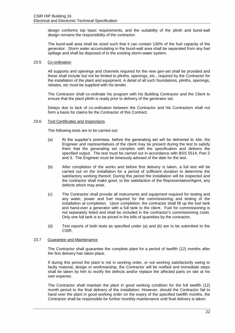
CSIR HIP Building 16 Electrical and Electronic Technical Specification
22
design conforms top basic requirements, and the suitability of the plinth and bund-wall design remains the responsibility of the contractor. The bund-wall area shall be sized such that it can contain 130% of the fuel capacity of the generator. Storm water accumulating in the bund-wall area shall be separated from any fuel spillage and shall be disposed of to the existing storm-water system.
23.5 Co-ordination All supports and openings and channels required for the new gen-set shall be provided and these shall include but not be limited to plinths, openings, etc., required by the Contractor for the installation of the plant and equipment. A detail of all such foundations, plinths, openings, rebates, etc must be supplied with his tender. The Contractor shall co-ordinate his program with his Building Contractor and the Client to ensure that the plant plinth is ready prior to delivery of the generator set. Delays due to lack of co-ordination between the Contractor and his Contractors shall not form a basis for claims be the Contractor of this Contract.
23.6 Test Certificates and Inspections The following tests are to be carried out: (a) At the supplier’s premises, before the generating set will be delivered to site, the
Engineer and representatives of the client may be present during the test to satisfy them that the generating set complies with the specification and delivers the specified output. The test must be carried out in accordance with BSS 5514, Part 2 and 3. The Engineer must be timeously advised of the date for the test.
(b) After completion of the works and before first delivery is taken, a full test will be
carried out on the installation for a period of sufficient duration to determine the satisfactory working thereof. During this period the installation will be inspected and the contractor shall make good, to the satisfaction of the Representative/Agent, any defects which may arise.
(c) The Contractor shall provide all instruments and equipment required for testing and
any water, power and fuel required for the commissioning and testing of the installation at completion. Upon completion, the contractor shall fill up the fuel tank and hand-over a generator with a full tank to the client. Fuel for commissioning is not separately listed and shall be included in the contractor’s commissioning costs. Only one full tank is to be priced in the bills of quantities by the contractor.
(d) Test reports of both tests as specified under (a) and (b) are to be submitted to the
CSIR.
23.7 Guarantee and Maintenance The Contractor shall guarantee the complete plant for a period of twelfth (12) months after the first delivery has taken place. If during this period the plant is not in working order, or not working satisfactorily owing to faulty material, design or workmanship, the Contractor will be notified and immediate steps shall be taken by him to rectify the defects and/or replace the affected parts on site at his own expense. The Contractor shall maintain the plant in good working condition for the full twelfth (12) month period to the final delivery of the installation. However, should the Contractor fail to hand over the plant in good working order on the expiry of the specified twelfth months, the Contractor shall be responsible for further monthly maintenance until final delivery is taken.

CSIR HIP Building 16 Electrical and Electronic Technical Specification
23
During this period the contractor will undertake to arrange that the plant be inspected at least once per month by a qualified member of his staff who shall: - (a) Report to the Officer-in-charge, keeping the maintenance records, and enter into a
log book the date of the visit, the tests carried out, the adjustments made, and any further details that may be required.
(b) Grease and oil moving parts, where necessary. (c) Check the air filter and, when necessary, clean the filter and replace filter oil. (d) Check the lubricating oil and top-up when necessary. (e) After the plant has run one oil change for the number of hours stipulated by the
manufacturers, drain the sump and refill with fresh lubricating oil. The reading of the hour meter on the switchboard will be taken to establish the number of hours run by the plant.
Under this heading only the cost of the actual oil used, shall be charged as an extra on the monthly account.
(f) Clean the lubricating oil filter and/or replace the filter element at intervals
recommended by the engine manufacturer, the cost of a new filter element to be charged as an extra on the monthly account.
(g) Check and when necessary adjust the valve settings and the fuel injection
equipment. (h) Check the battery and top-up the electrolyte when necessary. (i) Test-run the plant for 0,5 hour and check the automatic starting with simulated faults
on the mains, the proper working of all parts, including the electrical gear the protective devices with fault indicators, the changeover equipment and the battery charger. Make the necessary adjustments.
(j) Report to the Department and to the Contractor on any parts that become
unserviceable through fair wear and tear, or damaged by causes beyond the control of the Contractor.
The Contractor on receiving the report, shall immediately submit a detailed quotation for the repair or replacement of such parts to the CSIR.
(k) Advise the Client when it has become necessary to de-carbonise the engine and
submit a quotation for this service. (l) Top up the water of the radiator, if applicable. (m) Clean the plant and its components.
23.8 Materials and Workmanship (a) The work throughout shall be executed to the highest standards and to the entire
satisfaction of the Representative/Agent who shall interpret the meaning of the Contract Document and shall have the authority to reject any work and materials, which, in his judgement, are not in full accordance therewith. All condemned material and workmanship shall be replaced or rectified as directed and approved by the Engineer.
(b) All work shall be executed in a first-class manner by qualified tradesman.

CSIR HIP Building 16 Electrical and Electronic Technical Specification
24
(c) The Contractor shall warrant that the materials and workmanship shall be of the
highest grade, that the equipment shall be installed in a practical and first-class manner in accordance with the best practices and ready and complete for full operation. It is specifically intended that all material or labour which is usually provided as part of such equipment as is called for and which is necessary for its proper completion and operation shall be provided without additional cost whether or not shown or described in the Contract Document.
(d) The Contractor shall thoroughly acquaint himself with the work involved and shall
verify on site all measurements necessary for proper installation work. The Contractor shall also be prepared to promptly furnish any information relating to his own work as may be necessary for the proper installation work and shall co-operate with and co-ordinate the work of others as may be applicable.
(e) All components and their respective adjustment, which do not form part of the
equipment installation work, but influence the optimum and safe operation of the equipment shall be considered to form part of, and shall be included in the Contractor’s scope of works.
(f) All control equipment and serviceable items shall be installed and positioned such
that they will be accessible and maintainable. (g) The Contractor shall make sure that all safety regulations and measures are applied
and enforced during the installation and guarantee periods to ensure the safety of the public and the User Client.
23.9 Brochures Detailed brochures of all equipment offered shall be presented together with the tender documents.
23.10 Submittals The following information must accompany the tender documents (a) Full particulars, performance curves and illustrations of the equipment offered, must
be submitted with the Tender. (b) The design of the control system to comply with the requirements for automatic
starting, stopping, interlocking and isolation as specified. (c) The successful Tenderer must, as soon as possible after receipt of the order, submit
detailed drawings and wiring diagrams of the plant and the switchgear. One diagram shall be contained in a metal pouch on the side of the switchboard
(B) TECHNICAL SPECIFICATION 23.11 General Supply, deliver, install, commission, test and maintain an emergency generating set at the CSIR HIP Building 16, in Pretoria, Gauteng Province. The set must be installed outdoor on the generator plinth. 23.12 Site Information And Conditions 23.12.1 Location The site is at situated in Pretoria, Gauteng Province.

CSIR HIP Building 16 Electrical and Electronic Technical Specification
25
23.12.2 Site Conditions The following site conditions will be applicable and equipment shall be suitably rated to develop their assigned rating and duty at these conditions. a) Height above sea level : ±1370m above sea level b) Maximum ambient temperature : 30 °C c) Maximum ambient humidity at lowest temperature : 60% 23.13 Output And Voltage After the de-rating factors for the engine and generator due to site conditions have been taken into account, the set must have a site output and voltage as follows: - No load voltage : 400/230 Volt Rating : 500 kVA Power at 0,8 power factor : 400 kW Frequency : 50Hz Fault Level : 25kA 23.14 Change-over Control Panel Unit All switch- and control gear shall be rated for a fault current level of 25kA. 23.15 Cables The contractor will be responsible for all electrical cable connections associated with the complete generating set installation. 23.16 Engine A sump drainpipe must be fitted with a shut-off valve placed in a convenient position outside the base frame to facilitate drainage. Recommended oil types must be indicated on the engine, or base frames, by means of suitable labels. All engine instruments shall have clear markings on the faceplates, indicating the normal operating zone(s), maximum and minimum allowable values/limits and danger zone(s). The flywheel shall be covered by approved hoods. 23.17 Alternator The Alternator shall be of the low harmonic type. 23.18 Load Acceptance The generator set shall be capable of accepting 75% of the specified site electrical output 10 seconds after the starter motor is energised and the remaining 25%, 5 seconds thereafter, i.e. 100% load acceptance shall not exceed 15 seconds. 23.19 Fuel Drip Tray A drip tray approximately 100mm deep shall be mounted below the fuel tank and must be large enough to collect any fuel that drips from the tank accessories. The drip tray shall be manufactured from black mild steel. The thickness of the drip tray sheet steel shall not be less than 2mm.

CSIR HIP Building 16 Electrical and Electronic Technical Specification
26
23.20 Completion Time The Generator Set is required to be commissioned in conjunction with the building contract. 23.21 Inform The successful tenderer shall inform the Engineer when the set is ready for installation. 23.22 Fuel Supply Tank The new 500kVA (400V, 3phase) genset shall be supplied complete with automatic change-over panel, fuel storage tank, fuel pump. The tank shall have sufficient capacity for the generating set to run the engine on full load for a period of 8-12 hours. A drip tray approximately 100mm deep shall be mounted below the fuel tank and must be large enough to collect any fuel that drips from the tank accessories. The drip shall be manufactured from black mild steel with a thickness of not less than 2mm.
24 ACCESS CONTROL
24.1 Scope of Work
The Scope of Works includes, but is not limited to the following:
Supply, installation, testing and commissioning high quality access control system along with power supply, power distribution and required accessories in the locations of all ground and first floor doors to the HIP Plant room.
The price quoted by the bidders should include all the expenses incurred in commissioning of all access control units.
Training & handing over of all materials, equipment and appliances. Any other items/accessories required for installation, testing and commissioning of
access control system. No extra cost shall be paid for miscellaneous items if required to complete the work.
The access control system, shall interface to the existing access control system of the CSIR.
24.2 ACCESS CONTROL SYSTEM – TECHNICAL SPECIFICATIONS
Access control system planned for CSIR building 16 is an integrated solution that consists of hardware and software designed to control entry into selected areas and manage movement of people. The system is designed to increase security by defining access permissions based on area and time for each user and maintaining a log of all events. The access control systems for:
Employee and Visitors Access Control The system shall allow interfacing with the oxygen sensors and in case of a leakage, shall unlock doors such that emergency services personnel may obtain access to the facility.
24.2.1 Software
The number of cards/users shall be limited only by memory available in hardware. At least 3 active cards per user shall be supported. At least 8 access levels per user shall be supported. Access levels should be assigned to a user, not to a card, in order to help issue a new
card in a fast and easy manner, without reassigning access levels. The software shall support at least 4000 holiday dates and have automatic holiday
rescheduling feature.

CSIR HIP Building 16 Electrical and Electronic Technical Specification
27
The software shall have the ability to produce the following report types: system and alarm event reports, user reports, hardware configuration settings, access level reports, employee time & attendance reports.
The reports shall be available in Adobe PDF and MS Excel formats. Report filters must be convenient and user friendly: content of access levels, hardware
settings and time zone configuration. The software shall support an unlimited number of building
viewing interface shall have conveniesoftware shall allow operator to conveniently edit floor plans by “dragging and dropping” hardware devices to selected plan areas.
The downloading shall be done in background and not affect the normal use of the software in any way.
The software shall use an industry standard database engine released not earlier than 2005 and currently supported by the manufacturer.
The software shall be available in the official language(s) of the country where it is being installed. If such language is not included in the standard installation, the software shall support user friendly translation method: simply replacing program text directly in the software (“on the fly”), without the need of sending any files to the manufacturer for compiling.
The software shall have a modern interface, attractively designed and convenient to use.
The software shall be adapted for operators who have not received any special training related to management of integrated security systems.
Introducing the system to a new operator shall not take more than 1 hour. In order to reduce the amount of work done by an operator, the software shall
incorporate an option to copy objects: users, doors, floor plans, time schedules, access levels and holidays.
The software shall facilitate integration with other systems of the building. The software shall have the ability to transfer entry and exit events to HR systems with
the purpose of work time calculation. The software shall store information and provide reports about visitors and
appointments. 24.2.2 Hardware
The hardware shall support open architecture. Communication protocols shall be available to system integrators and software
development companies in order to protect end-users from being constrained to a single brand of hardware or software.
The hardware shall support all industry standard readers that output information in Wiegand or Clock/Data formats (up to 128 bits).
There shall be at least 2 types of controllers: (a) for one door with an entry reader and an exit button and (b) for one door with two readers (entry and exit) or for two separate doors with entry readers and exit button.
There shall be an IP-reader available. The IP-reader shall integrate a contactless card reader and controller in a single body, designed for surface mounting on a wall or a door frame eliminating the need for enclosures.
Each controller and IP-reader shall have a standard RJ-45 network port for communication with software and other controllers.
Controller and IP-reader shall support standard Ethernet 10/100BaseT network and TCP/IP communication protocol.
Systems using Ethernet converters, adapters, or terminal servers that enable network connectivity for legacy controllers by tunneling RS-232/485 serial data over Ethernet shall not be acceptable.
Single-door controller and IP-reader shall have at least 32Mb SDRAM operating memory and 8 MB Flash memory for database and events. Two-door controller shall have an option for expanding Flash memory to 32MB.
All controllers and IP-readers shall use a 32Bit 100Mhz RISC processor (or better) in order to enable fast execution of advanced functions.

CSIR HIP Building 16 Electrical and Electronic Technical Specification
28
Controllers and IP-readers shall use Linux operating system and accept firmware upgrades via network.
All system parameters including card numbers, PINs, access levels, time schedules, holidays and operations modes shall be stored in controller and IP-reader memory and not affected in case of a power loss.
Single-door controller and IP-reader shall have enough memory to store at least 40,000 users. Two-door controller shall have enough memory to store at least 250,000 users.
In case communication with the host PC is interrupted, the controller and IP-reader must have enough memory to store at least 5000 latest events (FIFO buffer).
Operation of controller and IP-reader shall be completely independent of the PC or “Master controller”. Should the PC or the communication link fail, the users should not be affected in any way and all functions should continue working.
a) Maintenance Work: A technician should be assigned to this agreement, and back up technicians should be available as required to give the CSIR prompt service as required at all times. A service provider (SP) account representative will be assigned to the CSIR, and will be the primary contact personnel for communications regarding this agreement. The SP should also have extensive technical support and parts inventory available to the CSIR in the event as needed and local warehouses and national service distribution centre availability for express delivery in emergencies. The service provider (SP) should periodically examine, lubricate, adjust, and as the need arises repair or replace the components associated with maintenance. At an additional cost to CSIR, the SP shall be requested to install any additional components or accessories to the equipment which is recommended or required due to parts being unserviceable. Should any form of labour and/or material be required on any of these excluded components, these costs will be brought to the attention of CSIR via a detailed written quotation who will then provide a separate order to cover these costs. Only good quality parts that are correctly designed, manufactured and suitable in all respects, shall be used.
24.2.3 Access Control Equipment
The following access control equipment shall be installed:
Table 5: Access Control Equipment to be installed:
Equipment Description Location / Position of equipment
Access Control Card Reader Refer to the design / tender drawing
(12964-EE-200 and 12964-EE-201)
Break Glass Unit Refer to the design / tender drawing
(12964-EE-200 and 12964-EE-201)
25 EARTHING AND BONDING
The Contractor is to ensure that the installations covered in this document are effectively earthed and bonded in accordance with the requirements of the Code Of Practice for Earthing - BS7430 or SABS 0142 or similar approved equal.
26 OXYGEN SENSORS 26.1 Clients Requirement:
It is required to monitor the oxygen levels in the HIP machine room to prevent asphyxiation as a result of argon leakage.

CSIR HIP Building 16 Electrical and Electronic Technical Specification
29
The CSIR has standardized on oxygen sensors to ensure stock levels across the CSIR can be managed. The Contractor will not be allowed to purchase any oxygen sensors or controllers unless the type, manufacturer, model and functionality has been assessed and it is compatible with the type and sensors kept by the CSIR.
26.2 Oxygen Sensor
The oxygen sensor shall measure oxygen levels and generate alarms when the oxygen levels fall below 19.5% or rise above 23.5%. Two sensors minimum shall be provided (one on either side of the machine) and to be installed at 1.5m above floor level against the wall. The sensor shall be a 3-wire 4-20mA and RS485 Modbus output fixed point detector with built-in alarm and fault relays for the protection of personnel and plant from flammable, toxic and Oxygen hazards. Each sensor shall incorporate a transmitter with local display and fully configurable via non-intrusive magnetic switch interface. Each oxygen sensor shall have a mounting plate with 4 mounting holes suitable for M8 bolts. The sensor cartridge shall be connected to a transmitter with a sensor retaining ring and covered with a weatherproof protection assembly. The oxygen transmitter shall have a display module. The sensor and transmitter shall form an integral unit. Each sensor shall have an IP66 rating and able to operate in temperatures -20°C to +55°C. Accuracy shall be less than 0.5%Vol. It shall be equipped with two alarms at 19.5%Vol and 23.5%Vol with a default calibration point of 20.9%Vol. Cable access shall be via 20mm threaded galvanized conduits. Unused cable entry points shall be equipped with suitable seals supplied with the transmitter. The transmitter shall be of the auto recognizing type when the oxygen sensor is plugged into it. The display shall have a tri-colour backlit area with the three colour modes as follows: green for normal, yellow for fault or warning, and red for alarm. All sensors shall be connected to a controller suitable for the sensors, which will provide additional functionality and relay alarms to strobe lights.
26.3 Instrument cabling The sensors shall be connected through 1.0mm
2 3-wire overall screened instrumentation
wiring to the controller, with the screen only connected to earth at the controller.
26.4 Oxygen Sensor Controller
The controller will be mounted either in the office upstairs, or in the passage on the ground floor and each sensor\s transmitter and all alarm strobe lights shall be connected to the controller. The sensor shall be suitable for up to 8 channels with provision for an expansion unit in the future, if required. The controller shall be suitable for 3-wire transmitter connections. The controller shall have a polycarbonate housing and be suitable for wall mounting. It shall have a 7 inch colour LCD touchscreen for the graphic user interface. It shall have 3 LED’s for master indicators (green for normal, red for alarm, and yellow for fault or warning. It shall have an audible alarm ≥70dB at 1m, with a common reset / mute operation. The unit language for the display shall be English. The unit shall be equipped with a 24V DC power supply, or alternatively be able to accept a 220V 50Hz AC input. The unit shall be able to operate in temperatures -10°C up to 55°C at a relative humidity of 95%. It shall be rated IP65.

CSIR HIP Building 16 Electrical and Electronic Technical Specification
30
It shall be suitable to accept eight 3-wire 4-20mA inputs as well as RS485 Modbus connections. It shall have 12 minimum 1.7A@30V DC or 250V AC outputs, as well as four powered alarm and three common alarm outputs. It shall have a 22.2V 2600mAh Li-Ion back-up battery to provide a backup of at least 30 minutes. Configuration, events and data shall be logged in the unit/ Remote monitoring shall be possible through Modbus TCP, Modbus RTU and/or Ethernet.
26.5 Oxygen Sensor Remote Alarm
Remote strobe alarms will be positioned at the three doors leading from the passage (ground and first floors) as well as the office. Integration with the access control doors can be provided if necessary, through the controller whereby access controlled doors can be unlocked in case emergency services requires access to rooms. Audible flashing or strobe alarms shall be connected to the oxygen sensing controller system, and all strobes and audible alarms shall sound when the oxygen level sensed by any sensor in the HIP room drops below 19.5% or rise above 23.5%. This shall indicate that the HIP room should not be accessed without proper PPE. The doors shall under no circumstances be prevented from being opened to allow access by emergency personnel. The remote alarm unit shall be either 24V DC or 250V AC rated and be suitable for connection to the oxygen sensing controller. The alarm output shall be 100dB(A) at 1m. the flash rate shall be 1Hz. The unit shall be able to operate in temperatures of -10°C up to 55°C. The strobe light lens colour shall be red and shall have automatic sounder synchronization. The tone shall be set such that it is not confused with any evacuation, fire or other tones already in use at the CSIR Building 16.
26.6 Training
The Contractor shall provide training to the client on the configuration, operation and maintenance of the oxygen sensors, controller and alarm interface.
26.7 Oxygen sensing Equipment The following sensors / instrument equipment shall be installed:
Table 6: Instruments to be installed:
Equipment Description Location / Position of equipment
Oxygen Sensor Refer to the design / tender drawing:
(12964-EE-101: Oxygen Sensor Layout)
Oxygen Sensor Controller Refer to the design / tender drawing:
(12964-EE-101: Oxygen Sensor Layout)
Oxygen Sensor Audible Alarm Refer to the design / tender drawing:
(12964-EE-101: Oxygen Sensor Layout)

CSIR HIP Building 16 Electrical and Electronic Technical Specification
31
27 TECHNICAL DATA SCHEDULE
The trade name and/or catalogue numbers of all equipment forming part of the tender offer must be submitted. This information schedule must be fully completed by the Contractor.
27.1 Cables
(a) Manufacturer : .........................................................
(b) Type : .........................................................
(c) Complies with Spec? : .......................................... (Yes/No)
27.2 Labelling system for cables
(a) Manufacturer : .........................................................
(b) Type : .........................................................
27.3 Cable trays
(a) Manufacturer : .........................................................
(b) Type : .........................................................
27.4 Cable trunking
(a) Manufacturer : .........................................................
(b) Type : .........................................................
27.5 Wall-mounted isolators 27.5.1 Flush-mounted double pole
(a) Manufacturer : .........................................................
(b) Type (No of pins) : .........................................................
(c) IP rating : .........................................................
27.5.2 Flush-mounted triple pole
(a) Manufacturer : .........................................................
(b) Type (No of pins) : .........................................................
(c) IP rating : .........................................................

CSIR HIP Building 16 Electrical and Electronic Technical Specification
32
27.5.3 Surface mounted double pole
(a) Manufacturer : .........................................................
(b) Type (No of pins) : .........................................................
(c) IP rating : .........................................................
27.5.4 Surface mounted triple pole
(a) Manufacturer : .........................................................
(b) Type (No of pins) : .........................................................
(c) IP rating : .........................................................
27.6 Light switches
(a) Manufacturer : .........................................................
(b) Current rating : .........................................................
(c) Weather proof type: manufacturer : .........................................................
(d) Weather proof type IP rating : .........................................................
27.7 Switched socket outlets
(a) Manufacturer : .........................................................
(b) Current rating : .........................................................
27.8 Telephone outlets
(a) Manufacturer : .........................................................
(b) To spec : ............................................ (yes/no)
27.9 Luminaires
27.9.1 Type A : 1 x 33W LED, 3956 Lumens, 600mm x 600mm x 30mm Panel, 99.9% Efficiency recessed / surface mounted Luminaire, or equal, better or similar approved
(a) Manufacturer : .........................................................
(b) Type : .........................................................
(c) Complies with Spec? : .......................................... (Yes/No)

CSIR HIP Building 16 Electrical and Electronic Technical Specification
33
27.9.2 Type A1: 1 x 33W LED, 3956 Lumens, 600mm x 600mm x 30mm Panel, 99.9% efficiency recessed / surface mounted Luminaire, with 1hour battery back-up unit or equal,
better or similar approved
(a) Manufacturer : .........................................................
(b) Type : .........................................................
(c) Complies with Spec? : .......................................... (Yes/No)
27.9.3 Type D : LED 18W Downlight Luminaire - with battery back-up or equal, better or
similar approved
(a) Manufacturer : .........................................................
(b) Type : .........................................................
(c) Complies with Spec? : .......................................... (Yes/No)
27.9.4 Type B: 20W LED Series 21 with Prismatic Diffuser Wall Surface Mounted
Luminaire or equal, better or similar approved
(a) Manufacturer : .........................................................
(b) Type : .........................................................
(c) Complies with Spec? : .......................................... (Yes/No)
27.9.5 Type E: 8W Single Sided Surface mounted emergency escape signage luminaire
with 1-hr battery back-up unit or equal, better or similar approved
(a) Manufacturer : .........................................................
(b) Type : .........................................................
(c) Complies with Spec? : .......................................... (Yes/No)
27.9.6 Type J: 55W 1050mA WIDE BEAM Bulkhead Surface Mounted or equal, better or similar
approved
(a) Manufacturer : .........................................................
(b) Type : .........................................................
(c) Complies with Spec? : .......................................... (Yes/No)
27.9.7 Type F: LED FLOOD 215W 700mA, 25661 Lumens, 600mm x 350mm x 100mm Panel,
surface mounted Luminaire, Mounted at 5.0m Height or equal, better or similar approved
(a) Manufacturer : .........................................................
(b) Type : .........................................................
(c) Complies with Spec? : .......................................... (Yes/No)

CSIR HIP Building 16 Electrical and Electronic Technical Specification
34
27.10 Photocells
(a) Manufacturer : .........................................................
(b) Installation method : .........................................................
(c) Type and IP rating of enclosure : .........................................................
27.11 Wiring
(a) Manufacturer : .........................................................
(b) Type : .........................................................
(c) Complies with Spec : .......................................... (Yes/No)
27.12 Labeling system for wiring
(a) Manufacturer : .........................................................
(b) Type : .........................................................
27.13 Distribution boards
Distribution Board
(a) Manufacturer : .........................................................
(c) Complies with Spec : .......................................... (Yes/No)
27.14 Circuit breakers
(a) Manufacturer : .........................................................
(b) Trade name : .........................................................
(c) Port of delivery : .........................................................
(d) Minimum fault level : ..................................................... kA
27.15 Isolators
(a) Manufacturer : .........................................................
(b) Trade name : .........................................................
(c) Minimum fault level : ..................................................... kA
27.16 Earth leakage units
(a) Manufacturer : .........................................................
(b) Sensitivity rating : .........................................................
(c) Minimum fault level : ..................................................... kA

CSIR HIP Building 16 Electrical and Electronic Technical Specification
35
27.17 Contactors
(a) Manufacturer : .........................................................
(b) Type : .........................................................
(c) Current rating reference : ........................................ (e.g. AC3)
(d) Control voltage : .........................................................
27.18 Power skirting
(a) Manufacturer : .........................................................
(b) Material : .........................................................
(c) Dimensions : ............................................ (h) x (d)
(d) Number of compartments : .........................................................
27.19 UPS:
The delivery, manufacture, supply, testing, delivery, off-loading, connection, installation, commissioning, site testing and guarantee of one (1) x 6kVA UPS system, 230V/230V 50Hz 1ø input / 1ø output, manual and static by-pass and battery temperature sensor.
(a) Manufacturer : .........................................................
(b) Size ................................................... kVA
(c) Dimension : .........................................................
(d) Complies with Spec : ......................................... (Yes/No) :
(e) Deviation from above specification:
.…………………………………………………………………………………..
……………………………………………………………………………………
.…………………………………………………………………………………..
……………………………………………………………………………………
.…………………………………………………………………………………..
27.20 Generator: 500kVA, 3-phase, 50Hz, 400V prime rated diesel engine and alternator set with
10% overload (8-12hour standby time) standby generator set complete with automatic change-over panel according to specification). Generator bulk fuel tank system (to allow for 8-12-hour standby time) (including fuel pump & minimum 8m fuel pipes / extension hose pipe).
(a) Manufacturer : .........................................................
(b) Size : .................................................. kVA
(c) Fuel Tank System (8-12 hour standby time) : ................................................ hours

CSIR HIP Building 16 Electrical and Electronic Technical Specification
36
(d) Dimension : .........................................................
(e) Complies with Spec : .......................................... (Yes/No) :
(f) Deviation from above specification:
.…………………………………………………………………………………..
……………………………………………………………………………………
.…………………………………………………………………………………..
27.21 Access Control
(a) Manufacturer : .........................................................
(b) Type : .........................................................
(c) Complies with Spec : .......................................... (Yes/No)
27.1 Oxygen Sensors (Instrument)
(a) Manufacturer : .........................................................
(b) Sensor Type: : .......................................... (Yes/No)
(c) Controller: : .......................................... (Yes/No)
(c) Remote / Audible Alarm : .......................................... (Yes/No) :
(d) Complies with Spec : .......................................... (Yes/No) :
(e) Deviation from above specification:
.…………………………………………………………………………………..
……………………………………………………………………………………
SIGNED ON BEHALF OF TENDERER : ....................................................................
NAME IN FULL : ....................................................................
COMPANY : ....................................................................
DATE :………………………………………………….

6.8 Annexure H - Mechanical Project Specification
Ramgoolam www.ramgoolamgroup.com Bespoke Global Efficacy.

CSIR Hot Isostatic Press (12964) Annexure H: Mechanical project specification
1.0 PARTICULAR SPECIFICATION PAGE 01
1.1 Preface
3. TECHNICAL SPECIFICATIONS PAGE 19
3.1 Cassette unit
3.2 Under ceiling unit
3.3 Ventilation systems
3.4 Compressor systems
3.5 Overblow unit
3.6 Data sheets
1.2 General work description
1.3 Site design conditions
1.4 Project drawings
1.3 Scope of work
1.5 Argon installation
1.6 Compressed air installation
1.7 Process water (cooling tower) piping installation
1.8 Air-conditioning installations
1.9 Ventilation installations
1.10 Other work
1.11 Work program
2.0 GENERAL SPECIFICATION PAGE 08
2.1 Preface
2.2 Regulatory framework
2.3 Contract management and control
2.4 Documentation
2.5 Hand-over documentation
2.6 Testing and commissioning
2.7 Work allocation
2.8 Handling of material
2.9 Setting out of work
2.10 Shop drawing submittal
2.11 Working drawings
2.12 Equipment Submittal
2.13 Operation and maintenance manual submittal
2.14 Training
2.15 Defects liability period
2.16 Warranty
2.17 Maintenance
2.18 Temporary use of equipment
2.19 Division of work
2.20 Hours of work and site conditions
2.21 Access to the site
2.22 Storage of materials
2.23 Accessibility and maintainability
2.24 Spares
2.25 Material selection

CSIR Hot Isostatic Press (12964) Annexure H: Mechanical project specification
1
1.0 PARTICULAR SPECIFICATION
1.1 Preface
This annexure is supplementary to the tender document: Request for proposals for the
construction of a hot isostatic press facility at CSIR (Pretoria site); and pertains to
mechanical equipment and utilities to support the new press and building systems.
This particular specification contains the elements pertaining to site conditions, scope of
works, and explanation of proposed new equipment or installations required for the
mechanical part of the contract.
Consequently, all works shall be designed, supplied, delivered, installed, commissioned,
and maintained completely as specified herein and in harmony with the original
equipment manufacturers (OEM) requirements and the OHS Act, and as shown on
drawings.
1.2 General work description
This specification entails the design, supply, installation, testing, commissioning, and
maintenance of all new installations together with associated ancillary equipment for the
full operation of installations completely as specified and as shown on the drawings.
The particular specification, general specification, technical specifications, and drawings
shall be read in conjunction to the rest of the tender or contract document specification.
Any inconsistencies ought to be raised for clarification by the engineer or principal agent.
1.3 Site design conditions
Project location (nearest town) : CSIR Pretoria (6km from Pretoria CBD) GPS co-Ordinates : -25.74501, 28.28163
Altitude, m asl : 1322
Average summer DB, °C : 31.7°C
Average minimum DB, °C : 3.9°C
Maximum noise rating, dBA : 35 - 54dBA
1.4 Project drawings
All installations on the drawings shall be completely as specified and as indicated in the
bills of quantities; and provided drawings form part of the mechanical scope of work.
Drawings shall be issued upon request; listed as follows:
a) 12964 - ME001: Ground floor HVAC layout b) 12964 - ME002: First floor HVAC layout c) 12964 - ME003: Mechanical utilities layout

CSIR Hot Isostatic Press (12964) Annexure H: Mechanical project specification
2
1.3 Scope of work
1.3.1 Design work
The tenderer shall familiarize himself with the design and where they are of the opinion
that the selected routing or mounting is not feasible; shall raise such concerns with the
engineer.
Moreover, the contractor shall evaluate the positioning of equipment in accordance with
aesthetic requirements and attainment of the sought craftsmanship standards.
The contractor shall be responsible for the correct sizing of all equipment and ancillaries
supplied such as flanges, valves, supporting brackets, and filters / separators.
Additionally, such sizing shall also be as per manufacturer's recommendations.
The contractor shall be responsible the design and strengthening arrangements to effect
mounting and / or plinths for all supplied installations, ramps leading into plantrooms,
fasteners for supports, security fencing, and other ancillaries.
1.3.2 New installations
The press shall be supplied by others and located inside the newly renovated workshop.
The proposed new mechanical plinth / plantroom shall be located next to the workshop.
The installations forming part of the mechanical scope of work include the following:
a) Supply and installation of argon gas piping, from virgin argon gas storage and reclaimed argon storage, to the new press. Hiring of the virgin argon storage forms part of the mechanical scope. Reclaimed argon storage tank to be free issue.
b) Supply and installation of a new compressor system complete with a new compressor, compressed air piping from the compressor to the new press, dryer, water separator, filters, regulators, coil hoses, and blow guns.
c) Supply and installation of water piping from the proposed new evaporative cooling tower to the press. The water piping installation shall also include general plumbing to extend municipal water to the proposed new cooling tower and press. The proposed new cooling tower shall be free issue.
d) Supply and installation of new air-conditioning installations. Air-conditioning installations shall be new direct expansion (dx) units in the form of concealed ducted unit, cassette units, and CRAC air handling unit to provide precision cooling to the new metrology laboratory.
e) Supply and installation of new ventilation installations. Ventilation shall be provided either by extraction fans or filtered fresh air fans.
1.5 Argon installation
The proposed new press consumes a minor portion of argon during an operating cycle
while most of the argon is recycled after an operating cycle. Hence, two argon sources
are necessary for the press to operate viz. virgin and reclaimed argon storage.

CSIR Hot Isostatic Press (12964) Annexure H: Mechanical project specification
3
1.5.1 Virgin argon storage
The tenderer shall supply and install the virgin argon storage system. This virgin argon
storage shall be typical to the Afrox high purity multi cylinder pack (MCP) containing 15
off argon cylinders with a total argon storage mass of 261 kg at 200 Bar.
1.5.2 Reclaimed argon storage
The reclaimed argon storage shall be free issue by the client to the contractor. The
tenderer shall rig into place the reclaimed argon MCP storage. Rigging shall be
assumed to be from within CSIR premises, over the new “clear view” fence, and onto the
proposed new mechanical plinth or plantroom.
The contractor shall prepare and propose the rigging method statement depending on
the works program. The engineer and safety specialist shall review and approve the
method statement.
The reclaimed argon MCP storage is approximately 1.5m wide, 1.2m high, and 2.2m
deep and weighs 2250 kg (empty). The MCP has four lifting eye bolts on top and also
has forklift provision at the bottom for handling purposes.
1.5.3 Argon gas piping
The tenderer shall supply and install stainless piping to handle argon in line with ASME
B31.3: Process piping against which the tenderer’s welder shall be coded as a minimum.
Alternatively, a coded welder as per ASME BPVC.IX-2021: Welding, Brazing, and fusing
qualifications shall also be accepted. OSH Act, Pressure regulations shall be adhered to.
The piping shall also be in line with BS EN 10088-2: Technical delivery conditions for
sheet/plate and strip of corrosion resisting steels for general purposes. Furthermore, the
quality management process for the manufacture of the new piping system shall be in
line with SANS 347: Categorization and conformity assessment criteria for all pressure
equipment.
There shall be one pipe running from the two storages at the mechanical plinth leading
into the press inside the building. Both the virgin and reclaimed argon gas storages shall
feed this common pipe. However, the virgin argon storage shall feed via a non-return
valve so that virgin argon storage cannot be charged with reclaimed argon during
backflow recycling.
The virgin argon storage and reclaimed argon storage shall each contain a lockable shut
off valve for isolation. Furthermore, each gas storage shall be provided with a safety
valve for storage protection and a gauge for reading the storage pressure. The main
argon supply line from the gas store shall have a bleed valve for maintenance purposes.
The very last connection piece to the multi cylinder packs, in the plant area, would be
through a high-pressure stainless steel braided hose to allow for flexible positioning of
replacement charged cylinder packs.
The argon piping shall operate at 200 Bar pressure and 50oC (during reclaim cycle).
The pipe nominal diameter shall be 25mm and schedule 40.

CSIR Hot Isostatic Press (12964) Annexure H: Mechanical project specification
4
Moreover, there shall be 7 Nm3 of argon vented or exhausted over 20 seconds directly
from the press and out into atmosphere per operating cycle. The tenderer shall supply
and install an exhaust pipe that shall be 2½ inches in diameter, protruding to at least 2m
above the roof, and complete with a silencer exterior of the building. The silencer shall,
beside reducing noise, blend the argon with air.
1.6 Compressed air installation
The proposed new press does not use compressed air. However, compressed air is
required for purposes of cleaning workpieces. Regardless, the highest compressed air
quality is required and shall be Class 02 in terms of ISO 8573-1:2010 Compressed air -
Part 1: Contaminants and purity classes.
1.6.1 New compressor
The contractor shall supply, install, and commission to full operation a new screw type
compressor. The compressor shall be rated to provide 1500 litres per minute at 10 Bar,
complete with a 360-litre air receiver and 12-month maintenance.
The compressor shall be installed outdoors and shall be selected to withstand elements.
Moreover, the compressor shall have motor protection against low/high voltage, high
current, high temperature, open phase, reverse phase, and overload situations.
1.6.2 Dryer
The contractor supply, install, and commission to full operation a medium flow heatless
adsorption dryer that does not require certification as a pressure vessel to match the
new compressor. The dryer shall provide a constant outlet air dewpoint and with oil
vapour reduction as per ISO8573-1: Class 01 with full feature electronic control display
with energy saving capability and with 12-month maintenance.
1.6.3 Ancillaries
The contractor shall supply and install all necessary ancillaries to ensure compressed air
purity and workshop usage. The ancillaries shall include a water separator, 5 off high
efficiency filters, 5 off regulators, 5 off coil hoses, and 5 off aluminium blow guns.
1.7 Process water (cooling tower) piping installation
The contractor shall supply and install new 2-inch stainless steel water piping between
the press and the cooling tower (within 25m). The cooling tower shall be free issue by
the client and the contractor shall rig the tower into place and complete the piping
installation. The contractor’s program shall need to be co-ordinated with others.
Fabrication of process water supply manifold would need to take place or to be
completed once the cooling tower is on site. The contractor shall further allow for a
normal tap water supply leading the cooling tower for evaporative cooling effect.

CSIR Hot Isostatic Press (12964) Annexure H: Mechanical project specification
5
1.8 Air-conditioning installations
1.8.1 Precision cooling
The contractor shall supply, install, and commission a precision cooling direct expansion
(dx) air handling unit in the Metrology laboratory. The air handling unit shall control the
laboratory to within the following temperature and humidity range:
Temperature : 20 ± 1oC
Stability and uniformity : ± 0.3oC per hour
Relative humidity : 20 – 45%
The air handling unit shall be a computer room air conditioning (CRAC) unit complete
with a filtered fresh air fan to introduce outdoor air into the laboratory in line with SANS
10400: Part O - Lighting and ventilation.
Supplied air shall be introduced into the laboratory via four (4) swirl air diffusers
connected to a common air conditioning duct leading to the top of the CRAC unit. The
return air stream shall be via a suitably sized wall mounted grille without undue noise.
The air-conditioning contractor shall be registered with the South African Refrigeration &
Air-Conditioning Contractor's association as an Authorised Refrigeration Practitioner
1.8.2 General air-condition
The contractor shall supply, install, and commission to full operation general air-conditioning units configured as follows: a) New x-ray laboratory: general air-conditioning with ventilation provided via a
concealed ducted unit complete with an inline duct fan (with primary filtering) as indicated on the drawings.
b) New Office: general air-conditioning and ventilation (filtered fresh air supply) shall be provided via a ceiling mounted cassette unit and inline duct fan as indicated on the drawings.
The air-conditioning contractor shall be registered with the South African Refrigeration &
Air-Conditioning Contractor's association as an Authorised Refrigeration Practitioner
1.9 Ventilation installations
1.9.1 Proposed press / machine room: similarly; Table 2 of SANS 10400 Part O (Lighting and ventilation) shall be used in approximating the machine room to parking garages. The underlying assumption being to guard against accumulation of hazardous gases (CO2 and Argon). The table suggests 10 air changes per hour of ventilation for garages. However, in order to guard against accumulation of dust in the machine room – outdoor supply fans shall be provided to replace the air expelled from the press room. The fresh air supply fans shall be complete with primary filters to prevent dust ingress.

CSIR Hot Isostatic Press (12964) Annexure H: Mechanical project specification
6
Five supply fans shall be strategically placed along the machine room perimeter in order to ensure that the ventilation air sweeps the general area where the press shall be located as indicated on the drawings. Only one extraction fan shall be provided which shall expel all the air fed into the machine room and this fan shall be complete with a variable speed drive in order to balance the expelled air amount to supplied air amount while guarding against undesired infiltration. The assumption is that potential Argon leak would occur close to the press. Hence, since argon is heavier than air – all the fans shall be located at approximately 1 500 mm above finished floor level (about the standing height of a person). The fans shall be interlocked with the press so that the funs run when the press is operational.
1.9.2 Vacuum lobby: The lobby is positioned to guard against an appreciable volume air from entering the metrology laboratory. The lobby leads into the laboratory through two doorways where only one door can be opened at a time thereby preventing a draft of air from outdoor infiltrating into the laboratory. The suggestion is to not provide any mechanical air control apart from an operational control in the sense that; personnel shall be made aware of the strict metrology laboratory operating conditions and need to only open one door at a time. Moreover, the laboratory shall be complete with access control.
1.9.3 Laboratory sample store: Table 2 of SANS 10400 Part O (Lighting and ventilation) recommends 2 air changes per hour of ventilation for Wholesale stores and has been used to approximate the laboratory store. Consequently, only one wall mounted ventilation fan shall be allowed as shown on the drawings.
1.9.4 Ablutions: all ablutions shall be provided with stale air extraction fans as per Table 2 of SANS 10400 Part O (Lighting and ventilation).
1.10 Other work
1.10.1 Electrical
All outdoor isolators, for air-conditioning units, shall be provided by the Electrical
Contractor from which the Mechanical Contractor shall feed the outdoor and indoor
air-conditioning units.
The Mechanical Contractor shall be responsible for all wiring from outdoor isolators to
air-conditioning units. Moreover, the Mechanical Contractor shall allow for a further
isolator at proximity to each indoor unit for maintenance purposes.
1.10.2 Carpentry Work
All works to be co-ordinated with the Main Contractor. Moreover, cutting and drilling
for installation of louvers, return air grilles, and supply air diffusers, fans, and
mechanical equipment in general shall form part of this Mechanical Scope of Work.

CSIR Hot Isostatic Press (12964) Annexure H: Mechanical project specification
7
1.10.3 Builder's Work
Builder's Work form part of the Mechanical Scope of Work and the Contractor shall be
responsible and allow for the provision of all wall openings, appropriately designed &
sized plinths, supporting brackets, and all building work as required by the
Mechanical Installations.
1.10.4 Painting Work
Painting Work form part of the Mechanical Scope of Work and all painting shall be in
accordance with SANS10064- 2011, SABS 097 - 1972, SANS 630 – 2009, And shall
consist of:
Preparation : In accordance with SANS 10064
Ground Coat : 25 Micron red lead according to SANS 50312 type 11
Undercoat : 25 Micron
Finish : 25-micron alkyd enamel according to SABS 30
Colour : In accordance with SANS 1091-1975
Necessary colour coding shall be as per SANS 10140: Identification colour markings
(Contents of pipelines) would typically be Compressed Air (Artic blue or Pink for
instrument air), Argon (Peacock Blue), Closed circuit cooling tower water (white),
Drinkable spray water for cooling tower (Brilliant green).
1.11 Work program
The Main building construction period shall be in line within the principal contract
period which period shall be co-ordinated with other disciplines. The mechanical
contractor shall fit within the overall program and which may be adjusted from time to
time. Moreover, the contractor shall take into account the lead times provided by the
client of the free issue materials for integration into his program.

CSIR Hot Isostatic Press (12964) Annexure H: Mechanical project specification
8
2.0 GENERAL SPECIFICATION
2.1 Preface
This general specification contains the standard parts of the mechanical tender and / or
mechanical contract. The specification details the minimum offer which shall include
design, supply, delivery, installation, commissioning, operation, and maintenance of
materials and systems part of mechanical engineering installations. The installations
shall be completely as specified, as reflected on the bill of quantities, and as shown on
drawings.
2.2 Regulatory framework
The tenderer shall ensure that the installations, including all associated works and
methodologies, comply with all the latest amendments of statutory requirements and
regulations. The tenderer shall ensure conformance to the following:
a) Occupational Health & Safety Act, Act No. 85 of 1993 b) Construction Regulations c) Pressure equipment regulations (PER 2009) as amended. Special note shall be
made of the requirements for all persons working with and handling pressurized refrigerant gasses to be suitably registered as "competent" persons.
d) Government, Provincial and Local Authorities, Ordinances, Regulations, by-laws, Rules, and other legal instructions.
e) All works shall be executed to satisfy the National Building Regulations as applied through SANS 10400: The Application of the National Building Regulations, as amended, together with associated parts.
f) Commissioning shall be executed in accordance with the Chartered Institution of Building Services Engineers (CIBSE) Commissioning Guides M or American Society of Heating Refrigeration and Air-conditioning Engineers (ASHRAE) Guideline 1-1996.
g) Standard Specifications and codes of Practice issued by the South African National Standards and British Standards Institute.
h) SANS 10140-3 – 2017: Identification colour marking Part 3: Contents of pipelines i) SANS 10142-1 – 2017: The wiring of premises Part 1: Low-voltage installations j) SANS 10147 – 2014: Refrigerating systems including plants associated with air-
conditioning systems k) SANS 347 – 2012: Categorization and conformity assessment criteria for all
pressure equipment l) SANS 10173 – 2003: The installation, testing, and balancing of air-conditioning duct
work m) SANS 10191 -2007 Acoustics: Determination of sound power levels of noise
sources - Guidelines for the use of basic standards for the reparation of noise test codes
n) SANS 10250-2 – 2010: The minimization of environmental pollution during the servicing and repair of automotive air-conditioning equipment Part 2: Servicing and repairs using refrigerant recycle equipment
o) SANS 193 – 2013: Fire dampers p) SANS 1238 – 2005: Air-conditioning ductwork q) SANS 1383 – 2008: Rigid urethane and isocyanurate foams for use in thermal
insulation r) SANS 1424 – 2013: Filters for use in air-conditioning and general ventilation

CSIR Hot Isostatic Press (12964) Annexure H: Mechanical project specification
9
s) SANS 1445-3 – 2018: Thermal insulation materials for industrial applications Part 3: Bonded preformed mineral fibre pipe sections
t) SANS 1470-3 – 2008: Sound power labelling Part 3: Rotating electrical machinery u) SANS 1498 – 2007: Algaecides for use in industrial cooling water v) SANS 1508 – 2007: Expanded polystyrene thermal insulation boards w) SANS 60335-2-24, IEC 60335-2-24; 2014: Household and similar electrical
appliances – Safety Part 2-24: Particular requirements for refrigerating appliances, ice-cream appliances and icemakers
x) SANS 60335-2-30, IEC 60335-2-30; 2015: Household and similar electrical appliances – Safety Part 2-30: Particular requirements for room heaters
y) SANS 60335-2-40, IEC 60335-2-40; 2015: Household and similar electrical appliances – Safety Part 2-40: Particular requirements for electrical heat pumps, air-conditioners, and dehumidifiers
z) SANS 60335-2-41, IEC 60335-2-41; 2015: Household and similar electrical appliances– Safety Part 2-41: Particular requirements for pumps
aa) SANS 60335-2-51, IEC 60335-2-51; 2014 Household and similar electrical appliances– Safety Part 2-51: Particular requirements for stationary circulation pumps for heating and service water installations
bb) SANS 60335-2-88, IEC 60335-2-88; 2003: Household and similar electrical appliances– Safety Part 2-88 Particular requirements for humidifiers intended for use with heating, ventilation, or air conditioning systems
cc) SANS 60335-2-98, IEC 60335-2-98; 2010: Household and similar electrical appliances– Safety Part 2-98: Particular requirements for humidifiers
dd) SANS 60335-2-104, IEC 60335-2-104; 2003: Household and similar electrical appliances– Safety Part 2-104 Particular requirements for appliances to recover and/or recycle refrigerant from air conditioning and refrigeration equipment
ee) SANS 60598-2-19, IEC 60598-2-19; 1981: Luminaries Part 2: Particular requirements Section 19: Air-handling luminaries (safety requirements)
ff) SANS 60730-2-9, IEC 60730-2-9; 2013: Automatic electrical controls for household and similar use Part 2-9: Particular requirements for temperature sensing controls
gg) SANS 60730-2-11, IEC 60730-2-11; 2007: Automatic electrical controls for household and similar use Part 2-11: Particular requirements for energy regulators
hh) SANS 14644-1, ISO 14644-1, 2 and 3; 1999: Clean rooms and associated controlled environments Part 1: Classification of air cleanliness
Works shall be executed in accordance with good engineering practice and
workmanship at all times. SANS specification shall take precedence in case of
conflicting statements in the above specifications. All references to standards and
regulations shall be deemed to apply to the latest, current, and / or as amended
standard.
2.3 Contract management and control
Resources
The tenderer shall make available suitably competent, experienced, and capable
resources for the timely execution of the works in accordance with the project
specification. Project meetings shall be attended as requested by the Engineer,
Principal Contractor and Employer. Upper-level management attendance shall be
provided at regular site, contract, commercial and engineering meetings.

CSIR Hot Isostatic Press (12964) Annexure H: Mechanical project specification
10
The tenderer shall submit an organogram of supervisory staff with names that will be
involved in the project, showing the time in a month that each individual will be
committing to the project against the project program (i.e., a resourced program).
The tenderer shall submit curriculum vitae of his key staff indicating relevant experience.
All resources on site shall be certified via appropriate organizations demonstrating
competence in their ability to perform the tasks required.
Program and completion
The tenderer shall provide a resourced program of the works, in accordance with the
directives herein and in compliance with the form of contract. This program shall be
provided within one week of appointment and shall clearly indicate all interdependencies
related to works by others.
The tenderer shall ensure their program of works is co-ordinated with other disciplines in
the project and satisfies the requirements of the main contractor and the principle
building contract. The program of works shall be updated bi-monthly to indicate
progress on site and to attend to any potential delays.
The contractor shall submit a detailed works program and anticipated cash flow estimate
of his/her offer.
Suitable time shall be allocated to perform commissioning, validation, and hand-over
upon approval of the engineer. Attention is drawn to the required completion dates and
penalties as described within the contract conditions.
Lead time guarantee
The contractor shall submit with the tender offer a guarantee that all equipment and
corresponding supply lead times, delivery, installation, and commissioning of all
equipment can be achieved within the project time frame.
Quality management
The tenderer shall maintain an ISO9000 series compliant quality management system
for the duration of the contract. The quality file shall be kept on site and shall be made
available for inspection by the Engineer, Employer, or his agents.
Signed off quality control checklists, commissioning schedules and test certificates shall
be provided prior with all invitations for inspection by the contractor. The Engineer
reserves the right to charge the contractor at the prevailing Engineering Council rates for
abortive inspections.
Only the highest possible standards of workmanship will be accepted. No inferior quality
of workmanship will be accepted.
Scrutiny of drawings
All drawings, circuit or schematic diagrams prepared by or on behalf of the contractor for
submission to the engineer in terms of the requirements of this specification shall have

CSIR Hot Isostatic Press (12964) Annexure H: Mechanical project specification
11
been thoroughly checked, corrected where necessary and signed as approved by the
contractor before submission to the engineer.
The scrutiny of any drawings by the engineer will include the review of the arrangement,
type, and operational suitability of the equipment in general only. Approval by the
engineer will not release the contractor from his responsibility for the proper operation of
the installation or for its full compliance with the specification, drawings, local authority
and statutory requirements, or for ensuring that the equipment can be physically
accommodated within the space and via the access provided.
2.4 Documentation
Documentation shall be provided to demonstrate compliance with all applicable quality,
regulatory and specified requirements. The following list of documentation will be
required, as a minimum, in order to complete the commissioning phase of the project.
All will be subject to approval by the engineer before implementation on site.
a) Contract particulars including contact details and company details of all parties to the contract
b) Emergency contact details for use in case of emergency and service call-out c) General arrangement drawings, approved workshop drawings and as-built drawings d) Critical spares list e) Full parts list including component manufacturer’s part numbers and contact details f) Component manufacturers data sheets g) Equipment configuration details including air flow balancing data h) Inventory list with serial and part numbers and drawing references i) Electrical and control panel layout drawings and wiring diagrams j) Safety certification for the complete system k) Operating and maintenance manuals l) Factory acceptance test reports m) Commissioning report and training documentation n) Completed and signed training register for user personnel on the new installations o) Product, equipment, and material Warranties p) Escalation steps and basic troubleshooting guide
2.5 Hand-over documentation
The contractor shall provide a list of items and documentation for verification prior to
handover. This list shall be circulated a minimum of 14 days prior to the request for
handover of the project such that the list may be reviewed and amended as may be
required.
Project handover is conditional upon receipt and verification of close-out documents.
The typical handover documentation shall be issued as three (3) copies of each of the
following - operating and maintenance manuals, as-built drawings, certificate of
compliance, drawings of the entire wiring installation from distribution boards to
equipment including terminations thereof, commissioning report including actual test
results of all systems after commissioning, proof or certificate of training of end-user
personnel, and a certificate of commitment for the maintenance and guarantee period as
applicable via the contract.

CSIR Hot Isostatic Press (12964) Annexure H: Mechanical project specification
12
2.6 Testing and commissioning
All safety devices shall be checked for effective operation by simulating the abnormal or
overload conditions. All tests and results shall be recorded, and a test report shall be
compiled for insertion in the operating and maintenance manual.
For all green buildings, technical buildings, pharmaceutical facilities, healthcare facilities
and otherwise as requested the commissioning procedure shall conform to the
requirements of ASHRAE Guideline 1.1 -2007: HVAC&R Technical Requirements for
The Commissioning Process and to CIBSE Commissioning Code M: Commissioning
Management.
2.7 Work allocation
The work allocation will consist of the following:
a) The end user will provide the necessary permanent electric power supply to a point required by the mechanical contractor. The Client will not supply any distribution boards and equipment, or lighting, or power, or ventilation installations.
b) Alterations, which may be required by the contactor, shall be approved by the engineer and form part of the contractor’s scope of work e.g., drilling of access holes.
c) The contractor shall provide a site instruction book on site permanently. d) The contractor shall provide their own tools, labour, temporary storage and
accommodation, material, plant, transport, and equipment and execute the contract with a minimal disturbance to the end user. Pre-fabrication off site shall be adopted where possible.
e) The Contractor shall provide their own sheds and site offices. f) The Contractor shall prepare all construction drawings and eventual as-built
drawings, constituting the entire installation. Two sets of hard paper prints of construction drawings are required for scrutiny before construction is commenced.
2.8 Handling of material
The contractor shall be responsible for providing all the required equipment for the off-
loading and proper handling or rigging of the material on site. They shall also be
responsible for the installation into the correct position.
2.9 Setting out of work
The Contractor shall be responsible for the correct setting out of any holes, sleeves,
penetrations, plinths, plant hangers and openings that may be required.
2.10 Shop drawing submittal
The contractor shall submit detailed "shop" drawings indicating the works to be
completed. Shop drawings shall be provided to the Engineer within 14 days following
confirmation of the intent to appoint or sooner as directed by the Employer, Engineer or
agent.
Shop drawing submission shall be made in triplicate, at full scale, and shall include a
cover sheet, date stamp, and approval stamp. Shop drawings shall clearly indicate
works to be completed by others, i.e., power supplies, drains, water supplies, builder's
openings, sleeves, and penetrations.

CSIR Hot Isostatic Press (12964) Annexure H: Mechanical project specification
13
Shop drawings shall be compliance with ISO standards. Shop drawings shall indicate
the particulars of the parties responsible for the design drafting, review, and approval of
the drawings.
The scale, drawing size, revision number date and drawing particulars shall be clearly
indicated on the drawings. Drawings shall include all sections, 3D views, assembly
views, plan views and layouts as required to fully understand the works to be executed.
Works shall be executed strictly in accordance with shop drawings approved by the
Engineer. Three copies of the approved shop drawings shall be maintained on site for
the inspection of the Engineer at all times.
2.11 Working drawings
One copy of the approved shop drawings shall be maintained up to date to reflect the as
built conditions on site. This drawing shall be marked up with all deviations from the
approved drawings and shall be highlighted to show installation progress. This marked
up drawing shall be copied and issued to the Engineer every time it may be requested.
2.12 Equipment Submittal
The contractor shall compile and submit three (3) booklets of the equipment selection
and submittal to the Consulting Engineer within two weeks after appointment for
approval. Performance and construction specifications shall be provided for each type of
equipment. The equipment submittal booklet shall consist of:
a) Cover page stating the project name, the Client, the consulting engineer and the contractor with contact persons and details
b) The index page stating the contents and sections of the submittal with page numbers
c) General page containing a brief description of the project and the equipment offered d) Introduction: brief history of the contractor, experience, personnel proposed for the
project with brief CV and project photos where the equipment proposed was used. e) Table of the equipment capacity of all equipment contained in the submittal showing
the following: f) Design conditions g) Equipment name and designation h) Area served i) Operating capacity j) Dimensions (length, width, height, and weight) k) Starting current, running current and voltage l) Noise level m) Compliance with specification n) Details of the equipment offered (one page per item installed). o) General name of equipment offered previous project where equipment was used
with reference from the Client p) The Equipment: all technical specifications, photos where applicable, service
interval and estimated operating life in years of the equipment. The technical specifications as a minimum shall state:
q) Capacities r) Material of manufacture and type of finishes s) Make

CSIR Hot Isostatic Press (12964) Annexure H: Mechanical project specification
14
t) Model number u) Manufacturer details v) Estimated delivery date w) Noise levels x) Operating conditions and performance curves where applicable y) Compliance with specifications z) Electrical requirements and loading aa) Energy efficiency measures of the equipment offered bb) Any special sustainable design and details included in the equipment cc) The completed schedule of information in the tender document dd) Manufacturer's catalogues ee) Control system and electrical schematics for the equipment ff) Any other relevant information gg) Motivation for the proposed equipment
hh) Conclusion
• Approval page for signature and date containing the following:
• The contractor’s name and responsible person signature
• The consulting engineer’s name and responsible person signature
• The Client's signature and responsible person
• Approval stamp by consulting engineer.
2.13 Operation and maintenance manual submittal
The contractor shall compile and submit one (1) booklet of the operation and
maintenance manual to the engineer; two months prior to practical completion for
approval. On approval by the consulting Engineer, the contractor shall prepare and
submit three (3) copies of the approved operation and maintenance manual on practical
completion sign off in both hard copy and soft copy. The operation and maintenance
manual shall consist of the items as listed herein this specification or as detailed
elsewhere in the particular specifications for installations involved.
a) Cover page stating the project name, the Client, the consulting engineer and the contractor with contact persons and details
b) The index page with contents, sections of the submittal with page numbers c) General information on the project: d) Name of project e) Address of project f) Start and completion date g) The professional team and contacts h) The contracting team and contacts i) Emergency contact details of the contractor j) Maintenance start and completion date k) Major equipment suppliers and contact details
l) Description of the System
• Design conditions and technical specification
• Salient points of the installation
• Detailed description of the systems
• Health and safety considerations associated with the systems
• Detailed technical specification and description of all installed equipment

CSIR Hot Isostatic Press (12964) Annexure H: Mechanical project specification
15
m) Table of the equipment capacity of all equipment and systems installed on the project showing the following:
• Equipment name and designation
• Area served
• Operating capacity
• Dimensions (length, width, height, and weight)
• Starting current, running current and voltage
• Noise level
• Compliance with specification
n) Supplier details and catalogues or technical manuals for each major equipment installed on the project.
o) Operating and Maintenance procedures
• Start and stop procedures
• Emergency procedures
• Procedures for the service, replacement and maintenance of all plant, equipment, and systems.
p) Operating and maintenance schedules and checklists:
• Weekly maintenance
• Monthly
• 3 monthlies
• Quarterly
• Yearly
• Minor service
• Major service
• Every 5 years
• Every 10 years
q) Commissioning results and details of each equipment and system r) Training of end user details and attendance register sign off s) Recommended spares t) As built drawings and documentation u) Equipment submittal approved page v) Conclusion
w) Approval page for signature and date:
• The contractor’s name and responsible person signature
• The engineer’s name and responsible person signature
• The Client’s signature and responsible person
• Approval stamp by the engineer.
2.14 Training
On completion of the entire sub-contract work, the contractor shall conduct a detailed
training session on the installation works for the end user/client representatives. This
training shall address the operations, maintenance, and all other requirements to
maintain a fully functional service to the Client.

CSIR Hot Isostatic Press (12964) Annexure H: Mechanical project specification
16
For the training to commence, the contractor shall compile and submit two (2) copies of
the detailed training manual to the consulting engineer within three months prior to
practical completion for approval by the engineer and the end user client. The
submission will include the agenda for the training, the requirements and qualifications
for the training and the duration.
From the consulting engineer, the contractor shall allow a minimum period of two weeks
to train the end user in the proper functionality of the system. The training shall consist of
both formal classroom training and hands on training on the completed project.
2.15 Defects liability period
The defects liability period shall be in accordance with the form of contract but shall not
be less than 12 months. During the defects’ liability period all patent and latent defects
shall be attended to by the contractor without cost to the Client.
Any item which is repaired or replaced during the guarantee period shall be guaranteed
for a further 12 months. The guarantee shall include parts, labour, shipping,
transportation, consumables. No cost associated with equipment or workmanship failure
or defect shall be attributed to the Client during the defects’ liability period.
2.16 Warranty
The contract works shall remain under warranty for 12 months following practical
completion of the works. Sectionalized practical completion shall necessitate
sectionalized warranty. A warranty schedule shall be provided for the installation and
contained within the O&M manual.
2.17 Maintenance
After first delivery of the installation (practical completion), there will follow a 12-month
free maintenance and guarantee period. No costs of maintenance shall be incurred by
the Client during the free maintenance period. All equipment shall be maintained as per
manufacturer's recommendations. Moreover, as a minimum, the Contractor shall allow
for maintenance as per Minor & Major Maintenance Schedules forming part of this
specification.
2.18 Temporary use of equipment
No equipment forming part of the permanent installation shall be operated or used,
during the construction period without the written permission by the engineer.
Equipment shall be handed over to the employer in a new condition for the beneficial
use of the Client.
2.19 Division of work
The division of work between the main contractor and the mechanical contractor
together with other specialist contractors shall be as stated within the principle for of
agreement and as specified.

CSIR Hot Isostatic Press (12964) Annexure H: Mechanical project specification
17
2.20 Hours of work and site conditions
The site will remain in full operation during all mechanical works. Mechanical works shall
be scheduled to minimize interruption to site activities. Works shall be scheduled for
completion during normal working hours.
In the event of a need to work outside normal hours overtime rates may be affected in
order to avoid client disturbance. In the event of a need to work outside normal working
hours in order to achieve program commitments such time shall not be recoverable as a
variation to the contract.
2.21 Access to the site
The site shall be secured. All personnel shall be required to adhere to the prevailing site
terms and conditions of entry and security protocol. The terms and conditions include
but are not limited to the following:
a) Registration of all personnel entering the with the security office b) Criminal background checks must be submitted c) All personnel entering the site shall be free of criminal record d) All personnel may be searched at site access and during the course of their duties.
2.22 Storage of materials
Materials shall be stored in places allocated by the main contractor, employer or his
agent. Stored equipment and materials shall be protected against damage, dust and dirt,
corrosion, theft, and vandalism. Stored materials shall be safely stacked and shall not
overload the construction beyond design limits.
2.23 Accessibility and maintainability
All equipment shall be so installed as to be readily accessible for operation, maintenance
and repair. A minimum of 1.5 m service access shall be provided around all floor
mounted central plant.
All electrical isolators shall be within 1 m of rotating plant and machinery and within clear
sight of the equipment access provision.
Filters, belts, bearings, and other routinely maintained items shall be readily accessible
from a comfortable and safe location. All items of the installation shall be readily
accessible for quick and easy replacement. Adequate space shall be left around all
items for the removal and replacement of parts.
2.24 Spares
A full set of spares for types of consumable items such as filters, strainers, belts, and
lubricating fluids shall be kept on site and a full set shall be handed over on the
anniversary of the first hand over date.
2.25 Material selection
All materials shall be selected to ensure compatibility with local conditions, the
environment of application and suitability with the fluid or service carried. Where multiple

CSIR Hot Isostatic Press (12964) Annexure H: Mechanical project specification
18
materials are utilized in an assembly or construction the compatibility of the materials
shall be ensured.
Galvanic corrosion risk shall be mitigated by the use of non-conductive spacers, cathodic
protection, or active protection. Materials shall exhibit fire and smoke characteristics in
accordance with the rational fire design and National Regulations.
All insulation and cladding shall be applied by experts in the field. Joints shall be as far
as possible below the piping and out of immediate view.

CSIR Hot Isostatic Press (12964) Annexure H: Mechanical project specification
19
3. TECHNICAL SPECIFICATIONSSpecification Description Pages 1. Cassette unit 20-23 2. Under ceiling unit 24-29 3. Ventilation systems 30-39 4. Compressor systems 40-48 5. Overblow unit 49-54 6. Data sheets 55 - 61

CSIR Hot Isostatic Press (12964) Annexure H: Mechanical project specification
20
1. SCOPE: CEILING MOUNTED CASSETTE UNITS
The Ceiling Mounted Cassette Unit Installations shall be as specified under this section of the project specifications
1.1 APPLICABLE STANDARDS
The air-conditioning units and installation in general shall be in accordance with:
• SANS 1125: Room air conditioners and heat pumps
• SABS 0147: Refrigerating systems including plants associated with air-conditioning systems
• SANS 60335-2-40: Household and similar electrical appliances – Safety. Part 2 – 40: Particular requirements for electrical heat pumps, air conditioners and dehumidifiers
• SANS 10142-1-2003: The wiring of premises Part 1: Low-voltage installations
• SABS 1453: Copper tubes for medical gas and vacuum services
2. CASSETTE SPLIT TYPE UNITS
2.2 GENERAL
The units shall be of the heat pump type. The air-conditioning units shall be standard factory assembled, piped and wired. The units shall be thoroughly tested for all operating conditions. Spares shall be freely available in South Africa. On request, the Contractor shall provide the Engineer with performance test certificates.
The air-conditioning units and installation in general shall be in accordance with the cassette unit’s supplier’s recommendations. Any discrepancies between this specification and the supplier’s recommendations that may influence the unit’s performance or guarantee shall be clarified with the Engineer during tender stage.
The electrical power requirements to the condensing units shall be:
• Single phase when the cooling capacity of the unit is less than 10 kW.
• Three phase when the cooling capacity of the unit is more or equal to 10 kW.
The indoor unit and condensing unit shall be interconnected with refrigerant piping, electrical wiring and interlocking control cabling. The pipe and cable connections shall be made in accordance with the unit supplier’s recommendations. The refrigerant shall conform to the Montreal Protocol and not be subject to the phasing out programme.
The indoor unit shall be of the 4-way blow type.
Indoor units shall have factory fitted, electrically operated condensate pumps with a drainpipe connection. Integral safety switches shall be provided to prevent the pump from running dry, and to prevent the cassette unit from operating when the condensate pump has failed. The indoor unit shall be fitted with fresh air connection knockout panel.
Each condensing unit with connected evaporator unit shall be clearly labelled to identify different split units
The outdoor unit coil shall be treated for corrosion with blygold, techni-coat, corium or any other method as approved by the Engineer.

CSIR Hot Isostatic Press (12964) Annexure H: Mechanical project specification
21
All units shall be of Daikin manufacture or other approved. “Other approved” means approved by the Engineer during the tender stage.
2.3 PERFORMANCE SPECIFICATIONS
Cooling and heating capacities are room conditions, and all equipment shall be de-rated to meet these requirements.
De-rating shall be done to compensate for the following:
• Altitude above sea level.
• Refrigerant pipe lengths.
• Design conditions specified.
All units shall be capable of meeting total and sensible cooling requirements. Tenderers shall provide proof of de-rated capacities with their tender. All capacities specified are to be achievable at medium evaporator fan speed.
2.4 PROTECTION AND SAFETY DEVICES
Reverse phase, three phase overload, overload during startup, phase imbalance, phase loss and low voltage protection shall be provided for all three phase motors.
Protection fuses shall be provided for all control circuits.
The compressor shall have high and low refrigerant pressure protection.
The indoor and outdoor units shall comply with the safety requirements as set out in:
• SANS 60335-2-40: Household and similar electrical appliances – Safety. Part 2-40: Particular requirements for electrical heat pumps, air-conditioners and dehumidifiers.
2.5 ELECTRICAL
Generally, the power to cassette units shall be provided by the electrical contractor in a weatherproof isolator mounted within 1 m from the condensing unit. The mechanical contractor shall do the entire electrical installation from the isolator to the condensing unit and the indoor unit.
Where the electrical contractor provides a cable only to a distribution board that serves a group of air-conditioning units, the mechanical contractor shall provide the distribution board, connect the incoming power cable and shall do all the electrical wiring from the distribution board to the condensing units and the indoor units.
In all instances the mechanical contractor shall provide isolators as required. All electrical and control cables shall be neatly strapped with the refrigeration piping in a galvanised cable tray.
The entire electrical installation shall comply with:
• SANS 10142-1-2003: The wiring of premises Part 1: Low-voltage installations
On completion, the Contractor shall issue a compliance certificate for the entire electrical installation.
Electrical and control cables mounted between indoor and outdoor units shall be installed without joints in the cable and shall be of the UV protected type.

CSIR Hot Isostatic Press (12964) Annexure H: Mechanical project specification
22
2.6 CONTROLS
Controls shall be of the hard wired, wall mounted electronic type. Controls shall be of the same manufacture as the air-conditioner. Controls shall be mounted over a flush mounted 100 mm x 50 mm electrical box. Control wiring shall be installed in a 20 mm electrical conduit from the controller to the air conditioning unit. The conduit and outlet box shall be chased into the wall by the Electrical Contractor. The electrical contractor shall install the conduit from the outlet box to 100 mm above ceiling level directly above the controller.
2.7 REFRIGERANT CIRCUITS
Refrigerant piping shall be in accordance with the following standards:
• SABS 1453: Copper tubes for medical gas and vacuum services
• SABS 0147: Refrigerating systems including plants associated with air-conditioning systems
Fittings shall be copper based capillary solder fittings in accordance with SABS 1067. All soldered joints on proprietary manufactured units shall be carefully checked and remade if found damaged in transit.
Pipe size selections shall be such as to produce moderately low velocities whilst:
• Ensuring proper oil return to the compressor and minimizing lubricating oil being trapped in the system.
• Ensuring practical lines without excessive pressure drops and with proper feed to evaporators.
• Preventing liquid refrigerant from entering the compressor during operation and at shutdown.
Refrigerant piping shall be sized and fitted with the necessary oil traps strictly in accordance with the unit manufacturer’s requirements.
All refrigerant pipelines shall be insulated with the “Armaflex” type, lightweight, elastomeric nitrile rubber tube insulation. Insulation thickness shall be 13 mm.
Suction and liquid pipelines shall be insulated separately and joints on insulation shall be glued with the insulation manufacturer’s recommended adhesive to create a vapour barrier.
The installation of trunking and trays shall form part of this mechanical contract.
5. INSTALLATION REQUIREMENTS
5.1 INSTALLATION OF INDOOR AND OUTDOOR UNITS
During installation, care shall be taken to ensure that no vibrations are carried over to structures to which the indoor and outdoor units are fixed.
Outdoor condensing units shall be installed on wall mounted brackets and / or a concrete slab as indicated on the project drawings.
Where installed on wall mounted brackets, the condensing unit shall be properly bolted to the mounting bracket with adequately sized fasteners. Bracket design to be checked by structural engineer.
Where installed on a concrete slab, the condensing unit shall be fitted on top of neoprene vibration isolating pads and 450 mm square concrete paving slabs.

CSIR Hot Isostatic Press (12964) Annexure H: Mechanical project specification
23
5.2 INSTALLATION OF CONDENSATE DRAIN PIPES
If an outdoor unit (heat pump type) is mounted against a wall more than 1 m above ground / floor level, the unit shall be fitted with an uPVC drain pipe neatly saddled to the wall. Drain pipe sizes for outdoor units shall be to the supplier’s recommendation.
Condensate drain pipes shall always run together with refrigerant pipes and shall always be installed in the same trunking and on the same cable trays for as far as the installation permits. Surface mounted drain piping shall only be allowed where condensate drain pipes run in a different direction to either a service duct, waste water pipe or any other location as indicated on the project drawings. Surface mounted drain piping shall be secured to the wall by means
Drain pipes shall run together with the refrigerant pipes to the outside unit where the condensate shall be drained.
All condensate pipes running from indoor units to waste water pipes, outlet gullies or open wastewater points shall be fitted with a U-trap at a location as indicated on the project drawings.
uPVC pipes shall be used for drain piping from indoor units. Drain pipe sizes for indoor units
shall be 25 mm for all unit sizes.
The first 5m of drain piping shall be insulated with “Armaflex” type, lightweight, elastomeric nitrile rubber tube insulation. Insulation thickness shall be 13 mm. In ceiling voids, drain pipes shall be installed in galvanized cable trays. Where drain piping does not run with refrigeration piping in the same cable trays, 76 mm galvanised “Cabstrut” light duty cable tray shall be used. Drain piping shall be fixed to the cable tray with suitably sized cable ties installed at 500 mm intervals.
Horizontal mounted drain pipes shall be installed at a slope of 20 mm per 1 000 mm, ensuring positive drainage.
Where drainage piping or control cabling is required to be installed flush-mounted, positioning and chasing shall be done in good time to meet construction programs.
5.3 INSTALLATION OF REFRIGERANT PIPING
Refrigerant piping shall be arranged so that normal inspection and servicing of the compressor and other equipment is not hindered. Locations where copper tubing will be exposed to mechanical damage shall be avoided. Hangers and supports where piping go through walls shall be installed to prevent transmission of vibration to the building.
Refrigerant piping in ceiling voids and mounted internally against walls shall be installed in 101 mm wide galvanised steel Cabstrut light duty cable trays (per unit). Pipes shall be strapped over insulation to cable trays at 500 mm intervals with suitably sized cable ties. Cable trays shall be 152 mm wide where drainpipes run together with refrigerant piping (per unit).
Externally mounted refrigeration pipes and drainpipes shall be mounted in Cabstrut P9000 cable trunking (127 mm x 76.2 mm). Cable trunking shall be complete with clip on covers. Pipes and cables shall be strapped together every 500 mm with suitably sized cable ties and loosely fitted in the trunking. The trunking shall be manufactured from galvanised steel and epoxy powder-coated to a colour as specified by the Engineer.
Any insulation material not covered by the trunking and exposed to the elements shall be neatly strapped with cable ties to minimise the possibility of dirt and water entering between the insulation and refrigeration pipes.

CSIR Hot Isostatic Press (12964) Annexure H: Mechanical project specification
24
1. SCOPE: CEILING SUSPENDED SPLIT TYPE UNITS
The Under-Ceiling Unit installations or Ceiling suspended split units shall be specified under this section of the project specification
2. APPLICABLE STANDARDS
The air-conditioning units and installation in general shall be in accordance with:
• SANS 1125: Room air conditioners and heat pumps
• SABS 0147: Refrigerating systems including plants associated with air-conditioning systems
• SANS 60335-2-40: Household and similar electrical appliances – Safety. Part 2 – 40: Particular requirements for electrical heat pumps, air conditioners and dehumidifiers
• SANS 10142-1-2003: The wiring of premises Part 1: Low-voltage installations
• SABS 1453: Copper tubes for medical gas and vacuum services

CSIR Hot Isostatic Press (12964) Annexure H: Mechanical project specification
25
CEILING SUSPENDED SPLIT TYPE UNITS
2.1 GENERAL
The units shall be of the heat pump type.
The air-conditioning units shall be standard factory assembled, piped and wired. The units shall be thoroughly tested for all operating conditions. Spares shall be freely available in South Africa. On request, the Contractor shall provide the engineer with performance test certificates.
The air-conditioning units and installation in general shall be in accordance with the ceiling suspended unit’s supplier’s recommendations. Any discrepancies between this specification and the supplier’s recommendations that may influence the unit’s performance or guarantee shall be clarified with the engineer during tender stage.
The electrical power requirements to the condensing units shall be:
• Single phase when the cooling capacity of the unit is less than 10 kW.
• Three phase when the cooling capacity of the unit is more or equal to 10 kW.
The indoor unit and condensing unit shall be interconnected with refrigerant piping, electrical wiring and interlocking control cabling. The pipe and cable connections shall be made in accordance with the unit supplier’s recommendations. The refrigerant shall be of the R22 type.
Each condensing unit with connected evaporator unit shall be clearly labelled to identify different split units.
The outdoor unit coil shall be treated for corrosion with blygold, techni-coat, corium or any other method as approved by the Engineer.
All units shall be of Daikin manufacture or other approved make. “Other approved” means approved by the Engineer during the tender stage.

CSIR Hot Isostatic Press (12964) Annexure H: Mechanical project specification
26
2.2 PERFORMANCE SPECIFICATIONS
Cooling and heating capacities are room conditions and all equipment shall be de-rated to meet site design conditions requirements.
De-rating shall be done to compensate for the following:
• Altitude above sea level.
• Refrigerant pipe lengths.
• Design conditions specified.
All units shall be capable of meeting total and sensible cooling requirements. Tenderers shall provide proof of de-rated capacities with their tender. All capacities specified are to be achievable at medium evaporator fan speed.
2.3 PROTECTION AND SAFETY DEVICES
Reverse phase, three phase overload, overload during startup, phase imbalance, phase loss and low voltage protection shall be provided for all three phase motors.
Protection fuses shall be provided for all control circuits.
The compressor shall have high and low refrigerant pressure protection.
The indoor and outdoor units shall comply with the safety requirements as set out in:
• SANS 60335-2-40: Household and similar electrical appliances – Safety. Part 2-40: Particular requirements for electrical heat pumps, air-conditioners and dehumidifiers.
2.4 ELECTRICAL
Generally the power to ceiling suspended units shall be provided by the electrical contractor in a weather proof isolator mounted within 1m from the condensing unit. The mechanical contractor shall do the entire electrical installation from the isolator to the condensing unit and the indoor unit.
Where the electrical contractor provides a cable only to a distribution board that serves a group of air-conditioning units, the mechanical contractor shall provide the distribution board, connect the incoming power cable and shall do all the electrical wiring from the distribution board to the condensing units and the indoor units.
In all instances the mechanical contractor shall provide isolators as required. All electrical and control cables shall be neatly strapped with the refrigeration piping in a galvanised cable tray.
Where applicable, section 1.3 (electrical) of this project specification shall also apply to this section of the specification.
The entire electrical installation shall comply with:
• SANS 10142-1-2003: The wiring of premises Part 1: Low-voltage installations
On completion, the Contractor shall issue a compliance certificate for the entire electrical installation.
Electrical and control cables mounted between indoor and outdoor units shall be installed without joints in the cable and shall be of the UV protected type.
2.5 CONTROLS

CSIR Hot Isostatic Press (12964) Annexure H: Mechanical project specification
27
Controls shall be of the hard wired, wall-mounted electronic type. Controls shall be of the same manufacture as the air-conditioner. Controls shall be mounted over a flush-mounted 100 mm x 50 mm electrical box. Control wiring shall be installed in a 20 mm electrical conduit from the controller to the air conditioning unit. The conduit and outlet box shall be chased into the wall by the electrical contractor. The electrical contractor shall install the conduit from the outlet box to 100 mm above ceiling level directly above the controller.
2.6 REFRIGERANT CIRCUITS
Refrigerant piping shall be in accordance with the following standards:
• SABS 1453: Copper tubes for medical gas and vacuum services
• SABS 0147: Refrigerating systems including plants associated with air-conditioning systems
Fittings shall be copper based capillary solder fittings in accordance with SABS 1067. All soldered joints on proprietary manufactured units shall be carefully checked and remade if found damaged in transit.
Pipe size selections shall be such as to produce moderately low velocities whilst:
• Ensuring proper oil return to the compressor and minimising lubricating oil being trapped in the system.
• Ensuring practical lines without excessive pressure drops and with proper feed to evaporators.
• Preventing liquid refrigerant from entering the compressor during operation and at shutdown.
Refrigerant piping shall be sized and fitted with the necessary oil traps strictly in accordance with the unit manufacturer’s requirements.
All refrigerant pipelines shall be insulated with the “Armaflex” type, lightweight, elastomeric nitrile rubber tube insulation. Insulation thickness shall be 13 mm.
Suction and liquid pipelines shall be insulated separately and joints on insulation shall be glued with the insulation manufacturer’s recommended adhesive to create a vapour barrier.
The installation of trunking and trays shall form part of this mechanical contract.
3. INSTALLATION REQUIREMENTS
The following standard drawings shall apply and shall be read in conjunction with this specification:
DRAWING DESCRIPTION DRAWING NUMBER
Typical condenser mounting detail with isolator position (wall-mounted with U-trap)
TBC
Typical condenser mounting detail with isolator position (wall-mounted without U-trap)
TBC

CSIR Hot Isostatic Press (12964) Annexure H: Mechanical project specification
28
3.1 INSTALLATION OF INDOOR AND OUTDOOR UNITS
During installation, care shall be taken to ensure that no vibrations are carried over to structures to which the indoor and outdoor units are fixed.
Indoor units shall be suspended from the ceiling and installed as indicated on the project standard drawings.
Outdoor condensing units shall be installed on wall-mounted brackets and / or a concrete slab as indicated on the project drawings.
Where units are installed on wall-mounted brackets, the condensing unit shall be properly bolted to the mounting bracket with adequately sized fasteners.
Where outdoor units are installed on a concrete slab, the condensing unit shall be fitted on top of neoprene vibration isolating pads and 450 mm square concrete paving slabs.
3.2 INSTALLATION OF CONDENSATE DRAINPIPES
The ceiling suspended unit is installed on the inside of an exterior wall with wall-mounted brackets where the condensate and refrigerant pipes penetrate directly behind the unit thought the wall. No integral condensate pump needed.
3.3 INSTALLATION OF CONDENSATE DRAINPIPES
If an outdoor unit (heat pump type) is mounted against a wall more than 1 m above ground / floor level, the unit shall be fitted with an uPVC drainpipe neatly saddled to the wall. Drainpipe sizes for outdoor condensing units shall be to the supplier’s specification.
Condensate drainpipes shall always run together with refrigerant pipes and shall always be installed in the same trunking and on the same cable trays for as far as the installation permits. Surface mounted drain piping shall only be allowed where condensate drainpipes run in a different direction to either a service duct, wastewater pipe or any other location as indicated on the project drawings. Surface mounted drain piping shall be secured to the wall by means of galvanised steel saddles at no more than 1 m intervals.
Where ceiling suspended units are mounted on the inside of exterior walls on wall-mounted brackets, the mechanical contractor shall drill sufficiently sized holes through which refrigerant pipes, drainpipes and cable wires shall penetrate directly behind the indoor unit. Drainpipes running from the indoor unit through the wall shall be adequately sloped to ensure positive drainage.
All condensate pipes running from indoor units to wastewater pipes, outlet gullies or open wastewater points shall be fitted with a U-trap at a location as indicated on the project drawings.
uPVC pipes shall be used for drain piping from indoor units. Drainpipe sizes for indoor units
shall be 32 mm for all unit sizes.
The first 5m of drain piping shall be insulated with “Armaflex” type, lightweight, elastomeric nitrile rubber tube insulation. Insulation thickness shall be 13 mm.
Where drainage piping or control cabling is required to be installed flush mounted, positioning and chasing shall be done in good time to meet construction programs.
3.4 INSTALLATION OF REFRIGERANT PIPING
Refrigerant piping shall be arranged so that normal inspection and servicing of the compressor and other equipment is not hindered. Locations where copper tubing will be exposed to mechanical damage shall be avoided. Hangers and supports where piping go through walls shall be installed to prevent transmission of vibration to the building.

CSIR Hot Isostatic Press (12964) Annexure H: Mechanical project specification
29
Refrigerant piping in ceiling voids and mounted internally against walls shall be installed in 101 mm wide galvanised steel Cabstrut light duty cable trays (per unit). Pipes shall be strapped over insulation to cable trays at 500 mm intervals with suitably sized cable ties. Cable trays shall be 152 mm wide where drainpipes run together with refrigerant piping (per unit).
Externally mounted refrigeration pipes and drainpipes shall be mounted in Cabstrut P9000 cable trunking (127 mm x 76.2 mm). Cable trunking shall be complete with clip on covers. Pipes and cables shall be strapped together every 500 mm with suitably sized cable ties and loosely fitted in the trunking. The trunking shall be manufactured from galvanised steel and epoxy powder coated to a colour as specified by the engineer.
Any insulation material not covered by the trunking and exposed to the elements shall be neatly strapped with cable ties to minimise the possibility of dirt and water entering between the insulation and refrigeration pipes.

CSIR Hot Isostatic Press (12964) Annexure H: Mechanical project specification
30
1. SCOPE: VENTILATION SYSTEMS
The following installations shall be specified under this section of the project specification:
• All fresh air and extraction systems
2. DESIGN CRITERIA
• Shall be as shown in the Particular Specification and as per Engineer’s Instruction
3. APPLICABLE STANDARDS
The air-conditioning units and installation in general shall be in accordance with:
• SANS 1424-1987: Filters for use in air-conditioning and general ventilation
• SANS 1238:2005: Air-conditioning ductwork
• SANS 10173:2003: The installation, testing and balancing of air-conditioning ductwork
• SANS 60335-2-80: Household and similar electrical appliances – Safety Part 2-80: Particular requirements for fans
• SANS 10108: The classification of hazardous locations and the selection of apparatus for use in such locations

CSIR Hot Isostatic Press (12964) Annexure H: Mechanical project specification
31
4. VENTILATION FANS
4.1 GENERAL
The combination of fan and attenuators shall be such that the specified noise levels are achieved.
Where no pressure requirements are indicated, the Contractor shall estimate the fan static pressure requirements for the system lay-out and tender accordingly. Where filters are included in the system, the static pressure losses through filters shall be estimated at 150 Pa through each stage of filtration.
Ventilation and extraction fan duties as specified on the tender drawings shall be checked against the respective system’s design resistance once all information on the selected system is available. Where fan duties are found inadequate, the contractor shall notify the Engineer before ordering the equipment.
Fans shall be selected to operate at or as close to maximum efficiency as possible.
Attenuators shall be mounted directly onto the fan casing with flexible connections between the ducts and attenuators.
Fans shall be fitted with the manufacturer's nameplates permanently fixed to the casing in a prominent position, clearly indicating manufacturer, model number, size, speed, maximum operating speed, maximum power absorbed and serial number.
Fan air in/outlets not connected to ducting or equipment shall be protected with easy removable safety wire mesh screens.
Indicating arrows for both directions of rotation and direction of airflow shall be provided on fan casings.
All fans shall be installed in accordance with the manufacturer's requirements and recommendations.
All fans shall be mounted on anti-vibration mountings or supported from anti-vibration hangers.
Bearings shall be of the ball or roller type and shall be quiet in operation. They shall be sized to give a long life (not less than 100 000 hours) at the loads imposed by the application.
Belt guards shall be arranged to permit lubrication and use of speed counters with the guards in position. Belt guards shall have adequate ventilation for belt cooling.
The construction and design of electrical apparatus for ventilation equipment in hazardous environments shall comply with the relevant SANS specification, e.g. SANS 10108. The electrical installation shall comply with SANS 60335-2-80: Household and similar electrical appliances – Safety Part 2-80 Particular requirements for fans.
4.2 IN-LINE MIXED FLOW FANS
In line mixed flow fans shall be suitable for duct installation as indicated on the project drawings for the relevant ventilation and/or extraction system(s). Mixed flow fans shall be manufactured from a self-extinguishing material, be IP54 protected and be equipped with fan motor overload protection. Fans shall have compact overall dimensions with the overall diameter only slightly larger than the ventilation duct.
In-line mixed flow fans shall have two speed settings and shall be sized and selected so as to meet the required fan duty at the lower speed setting. In line mixed flow fans with their adjoining attenuators shall not exceed the NC level as set out in Section 1.2, Sound Control.

CSIR Hot Isostatic Press (12964) Annexure H: Mechanical project specification
32
To minimise the transmission of vibration of fan noise, fans shall be resiliently mounted on rubber cushions or anti-vibration hanger rods.
4.3 IN-LINE AXIAL FLOW FANS
Axial flow fans shall be of the non-overloading, aerofoil type with peak power requirements occurring at normal operating pressure range. The fan motor shall have a rating exceeding this requirement. Axial flow fans shall operate at the highest possible efficiency at the lowest possible blade tip speed.
Impeller blades shall be manufactured from a die-cast aluminium alloy clamped in a split steel or aluminium cast hub. Hubs on larger fans shall be manufactured from hot dip galvanised steel. The blade pitch shall be adjustable at the hub. Cast steel hubs shall be electro-coated.
Axial flow fan casings shall be manufactured from hot dipped galvanised mild steel with predrilled flanges on both ends of the fan. An access panel of ample size shall be provided in the casing. All fasteners shall be zinc plated.
Fan motors shall be totally enclosed and shall be of the squirrel-cage induction type with protection to IP 55 standard. An external weather proof terminal box forming part of the casing shall be included in the design for motor connections. Where belt driven fans are used, belts shall be of the V-belt type with grooved pulleys. Belts shall be oil resistant, non-sparking and non-static. Belt drives shall comply with OHSA requirements.
Axial flow fans shall be statically and dynamically balanced in accordance with ISO 1940 – 1973 within grade G6.3.
Axial flow fans shall always be resiliently mounted on anti-vibration mountings to prevent carry over of vibration to the structure to which the unit is fixed.
Roof Mounted fans shall be of precision manufacture from glass fibre reinforced polyester resin giving a strong yet light-weight construction. The cowls shall be aerodynamically designed to produce the minimum possible resistance to airflow whilst offering full protection against the weather. Associated motors shall be asynchronous induction type motors with squirrel type external rotors. Moreover, shall be complete with a steel finger proof guard as standard; mounted to the inlet side of the fan.
Fans shall be installed with sound attenuators as specified in Section 1.2 of this specification. . In line centrifugal fans with their adjoining attenuators shall not exceed the NC level as set out in Section 1.2, Sound Control.
In-line axial flow fans shall be of the Donkin type Majax 2 or equally approved.
4.4 CEILING FANS
The Ceiling Fans shall be steel construction with three (3) aluminium blades epoxy painted, brilliant white. 1400mm diameter
Fan shall be mounted with a V-shaped ceiling hook with rubber bush fixed to the roof structure supporting the fan via a steel shackle with nut and bolt.
Both upper and lower fixings on the down red to have plastic canopies to conceal fixing.
Down rod to be adjusted to ensure a minimum height of the fan blades to be no less than 2.3 meters AF.F.L
The fans shall have individual surface mounted flush type speed regulator with four(4) speeds. The conduit to the fans and wall box to be provided by the electrician.
Fan motors to be no bigger than 220v motors with permanent capacitor 290 RPM max. Ceiling fans to be Luft LCF56 or other approved.

CSIR Hot Isostatic Press (12964) Annexure H: Mechanical project specification
33
5. DUCTING
5.1 APPLICABLE DRAWINGS
The following standard drawings shall apply to the installation of ducting and shall be read in conjunction with this specification.
DRAWING DESCRIPTION DRAWING NUMBER
Bends and turning vanes for various size rectangular ducts STD-D15
Longitudinal seams for rectangular low pressure ductwork STD-D16
Transverse Joints for rectangular low pressure ductwork STD-D17
Hangers and supports for ducting without insulation and vapour barrier
STD-D18
Longitudinal seams and transverse joints for rectangular medium and high pressure ductwork
STD-D20
Fastening of flexible material to metal ductwork STD-D21
Longitudinal seams and transverse joints for circular ductwork STD-D22
Typical change in size and shape of duct cross-sectional areas STD-D23
Bends and turning vanes for various size circular ducts STD-D24
5.2 GENERAL
Sheet metal ductwork shall be manufactured in accordance with SANS 1238 and installed balanced and tested as set out in SANS 10173. The installation and manufacture of ductwork shall strictly be in accordance with SANS standard specifications with specific attention given to the following:
• Changes in size and shape of ducting: refer to SANS 1238, section 6.3. Particular requirements are given on the following standard drawing: TYPICAL CHANGE IN SIZE AND SHAPE OF DUCT CROSS-SECTIONAL AREAS, STD-D23.
• Access openings, doors and covers refer to SANS 1238, Section 5.3.
• Sealant requirements: refer to SANS 1238, Section 5.6.
• External ducting insulation: refer to SANS 10173, Section 5.4.
• Material thickness and duct stiffening for low pressure ductwork: refer to SANS 1238, Section 6 for rectangular ductwork and SANS 1238, Section 7 for circular ductwork.
• Radius and square bends as well as turning vanes: refer to SANS 1238, section 6.4. Typical bend layouts as set out in SANS 1238 are given on the following standard drawings: BENDS AND TURNING VANES FOR VARIOUS SIZE RECTANGULAR DUCTS, STD-D15 and BENDS AND TURNING VANES FOR VARIOUS SIZE CIRCULAR DUCTS, STD-D24.
• Unless the sheet-metal ductwork is inherently corrosion protected, all sheet-metal shall be protected against corrosion as outlined in SANS 1238, Section 8.
It shall be the responsibility of the installing contractor to ensure proper assembly and sealing of sheet-metal ductwork and insulation strictly in accordance with SANS specifications.

CSIR Hot Isostatic Press (12964) Annexure H: Mechanical project specification
34
The air duct system shall be of the low-pressure type and the ductwork shall be manufactured of galvanised mild steel with general material requirements as set in section 5.1 and 5.2 of SANS 1238. The ductwork shall either be circular or rectangular in cross-section as indicated on the project drawings.
The first dimension given on the drawings for rectangular ductwork shall be read as the width on plan and the depth on section, and the second dimension shall be read as the depth on plan and the width on section.
The duct dimensions shown on the drawings are sheet metal dimensions. All final dimensions shall be checked on site or verified by means of architect’s working drawings and structural drawings before the fabrication of the ducting.
Sealing membranes and adhesives for affixing insulation shall meet the indexes for surface spread of flame, heat contribution and smoke production as set out in section 4 of SANS 1238.
The inner surfaces of ducting shall be smooth, and no internal insulation shall be used. Dampers, sound attenuators, duct splitters and turning vanes shall be installed where indicated on the drawings.
Flexible connections shall be provided between all fans, sound attenuators and ducting. Flexible connections exposed to weather shall be provided with protecting galvanised sheet steel cover strips. The material used for flexible joints shall comply with the requirements as set out in SANS 1238, section 5.5. Flexible connections shall be provided on both sides of the equipment with a method as indicated on the following standard drawing: FASTENING OF FLEXIBLE MATERIAL TO METAL DUCTWORK, STD-21.
Ducting shall always be installed in such a way, that, especially in plant rooms, maximum height between the floor and the underside of ducting is achieved.
The installation and testing of hangers shall comply with the requirements as set out in SANS 10173. All hangers shall be treated against corrosion and shall be painted.
Reinforcement, duct stiffening and fastening accessories shall be galvanised and installed where required. Only duct accessories manufactured from compatible materials, which comply with SANS 10173, shall be installed with the ductwork. Tie rods shall be manufactured from galvanised steel. Rivets, screws, bolts and other fastening equipment shall be corrosion proof.
5.3 LONGITUDINAL SEAMS AND TRANSVERSE JOINTS
Pieces of ductwork shall be joined with the necessary sealants, as applicable, as set out in SANS 10173, Section 5.
5.3.1 Rectangular Ductwork
Longitudinal seams and transverse joints for rectangular ductwork shall be in accordance with SANS 1238, Section 6. Refer to the following standard drawings for typical details on longitudinal seams and transverse joints:
• LONGITUDINAL SEAMS FOR RECTANGULAR LOW-PRESSURE DUCTWORK, STD - 16
• TRANSVERSE JOINTS FOR RECTANGULAR LOW-PRESSURE DUCTWORK, STD – 17
• LONGITUDINAL SEAMS & TRANSVERSE JOINTS FOR MEDIUM AND HIGH-PRESSURE DUCTWORK, STD - 20
As an alternative to transverse joints specified in SANS 1238, other flanged joints such as MEZ-flanges will also be considered provided that they meet the SANS requirements.

CSIR Hot Isostatic Press (12964) Annexure H: Mechanical project specification
35
MEZ-flanges or equivalent products shall be manufactured from cold rolled steel and hot-dip galvanised after manufacture.
5.3.2 Circular Ductwork
Longitudinal seams and transverse joints for circular ductwork shall be according to SANS 1238, Section 7. Refer to the following standard drawings for typical details on longitudinal seams and transverse joints:
• LONGITUDINAL SEAMS & TRANSVERSE JOINTS FOR CIRCULAR DUCTWORK
5.4 THE HANGING AND SUPPORTING OF DUCTWORK
Hangers and supports for rectangular and circular ductwork with no insulation shall comply with SANS 10173, section 5.3 “Ductwork with no vapour barrier”. The hanger and support types used for ducting with insulation may be used. In addition to these types, the types depicted in the following standard drawing may also be used: HANGERS AND SUPPORTS FOR DUCTING WITH NO INSULATION, STD-D18.
5.5 FLEXIBLE DUCTING
Flexible ducting shall comply with the requirements as set out in SANS 10173, section 5.7. Flexible ducting shall be proprietary manufactured with a fire rating to SABS 0177 Part 3 Class 1. The flexible ducting shall have an adequate working pressure and temperature range to suit the application of the installation.
Flexible ducting shall at all times be kept to a length not exceeding 1.5m. Flexible ducting shall not have more than the equivalent of one 90o bend and bends shall be of maximum possible radius. Flexible ducting shall be supported with sufficient and correct brackets that will ensure maintenance of shape.
Flexible ducting shall be provided between air terminals, diffusers and all locations as indicated on the project drawings.
The inner core shall be of aluminium laminate with a heavy-duty steel helix core.
5.6 TESTING OF DUCTWORK
All ducting shall be leak tested in accordance with SANS 10173, section 4.3. No ducting shall have leakage rates in excess of 5 % of the required air flow rate in any section of ductwork or in excess of the SANS permissible leakage rates, whichever is the smallest.
6. AIR TERMINALS AND DAMPERS
6.1 GENERAL
Where selected by the contractor, air diffusion equipment shall be selected in accordance with the manufacturer’s recommendations, capable of passing the specified air quantity at the appropriate throw without creating excessive resistance, noise or local draughts. All air diffusing equipment shall be capable of meeting the NC level requirements, as specified in section 1.2 – sound control, for the space environment where the equipment is installed.
In all instances where spigot boxes (plenums) are used for the connection of air diffusion equipment, the inside surfaces shall be painted black to prevent visibility of the internal surface from ground level.
During commissioning of the system, each grille, diffuser, valve etc. shall be set to deliver the specified air quantity. It is the Contractor’s responsibility to check regenerated noise levels of grilles offered against the overall acoustic performance of the system required. Noisy grilles that exceed the NC level requirements of the given space shall be replaced at the Contractor’s expense with more suitable types.

CSIR Hot Isostatic Press (12964) Annexure H: Mechanical project specification
36
7. DOOR AND TRANSFER GRILLES
Transfer air grilles shall be complete with fixed curved blades and outer frame on both sides of the wall or partition. Transfer air grilles shall be of aluminium extruded type, naturally anodised or epoxy powder coated to a colour as specified by the Engineer. Openings in walls where transfer grilles are to be installed shall be provided by the Building Contractor.
Door air grilles shall be installed in wooden doors only. In cases where steel and glass doors are used, transfer grilles or transfer ducting as an alternative shall be installed. Door air grilles shall be of the chevron-blade type. Door air grilles shall be manufactured from extruded type 5OS anodised aluminium, naturally anodised or epoxy powder coated to a colour as specified by the engineer.
Transfer ducting shall comprise of galvanised sheet metal ducting and aluminium curved blade intake and outlet transfer grilles. Flexible ducting shall not be used as transfer ducting.
8. WEATHER LOUVRES
Weather louvres shall be manufactured of extruded aluminium sections and finished in a colour as approved by the Engineer. Louvres shall be of the Europair type WL or other approved.
Weather louvres shall be constructed with drip edges to blades and rigid frames to enable building in.
Weather louvres shall be watertight and shall prevent the entrainment of raindrops at a face velocity of up to 3 m/s.
Galvanized expanded metal or wire mesh screens with 12 mm opening sizes shall be fitted behind the blades of each weather louvre.
Top and bottom blades shall be fitted flush with the frame and be smooth without grooves, channels or recess where dirt or water can collect.
The free area through the louvre available for airflow shall be a minimum of 65 % of the nominal area of the louvre.
9. FIXING OF WALL-MOUNTED GRILLES AND LOUVRES
All wall-mounted grilles and louvers shall be fixed to a hard wood frame. The timber frames shall be supplied with the grilles as part of this installation.
The timber frames shall be manufactured in such a way that the grilles fit into them and such that the flanges of the grilles extend past the outer edge of the frames by approximately 5 mm. The timber frames shall be provided with the necessary cleats with which to mount them in brick or concrete walls. The depth of the timber frames shall be similar to the walls in which they are fitted.
The frames shall be supplied to the builder in good time so that they can be built into the walls. Should the mechanical contractor fail to do this, the frames shall be let into the walls afterwards and all builder's work, making good and painting shall be for the account of the mechanical contractor.
10. EXHAUST DISC VALVES
Disc valves shall be supplied and installed in the ceilings of the ablution areas and connected to the extract ducts by means of sheet metal spigots and flexible ducting.
The disc valves shall consist of a ring and central disc, which when rotated shall adjust the volume through the outlet. During commissioning of the system, each disc valve shall be set to exhaust the specified air quantity.

CSIR Hot Isostatic Press (12964) Annexure H: Mechanical project specification
37
Disc valves in ceilings shall be of the polypropylene type, in a finish to match the ceiling colour. The valves shall be of the Europair DVS type or other approved.
11. VOLUME CONTROL DAMPERS
Volume control dampers shall be installed in branch ducting to ensure a balanced air flow to all duct sections.
Damper blades, links and damper frames shall be of rigid construction and manufactured from galvanised steel. Dampers shall comply with SANS 1238.
Dampers for positive volume control purposes shall be manual or electric actuator driven as specified. Dampers shall be of the link or gear type.
A manually adjustable damper shall be fitted with an external adjusting lever in an accessible position. The lever shall be mounted on a square shaft and fitted with a locking mechanism that clearly indicates the current position of the blade. "OPEN", "CLOSED" and "OPERATING POSITION" shall also be clearly marked on each damper.
The inside cross-sectional area of the damper shall be equal to that of the connecting ductwork and shall conform to the same standards of air-tightness as the rest of the ductwork system. The damper shall be fitted to the ducting in which it is installed by means of a flanged connection.
Dampers creating unacceptable vibrations and noise levels will be rejected and will need to be replaced at the Contractor's expense.
Multi-vane control dampers shall be of the opposed blade type.
12. FIRE DAMPERS
Fire dampers shall be installed where indicated on the drawings.
Fire/smoke control dampers shall comply with SABS 193 as amended, and shall be SABS marked with proven low leakage in the closed position.
Fire dampers shall be flanged both sides, and an access panel shall be provided in ducting at each fire damper, preferably on the upstream side of the damper.
Fire damper markings shall be as follows:
a) Manufacturer's name or trade name or trade mark.
b) Fire resistance rating, in hours.
c) Vital instructions regarding installation, direction of airflow, mounting position.
The open or closed status of the damper shall be clearly indicated outside the casing for inspection purposes.
Fire dampers shall have at least a 2 hour resistance rating when tested in accordance with SABS 193.
Fire dampers shall be fusible link operated.
Labels shall be installed on the ceiling grid below all fire dampers indicated their positions, and reading: "Fire damper above".
Dampers shall be sized so that the nominal free air area when in the open position is not less that the connected duct free air area.

CSIR Hot Isostatic Press (12964) Annexure H: Mechanical project specification
38
Fire dampers shall be installed according to the manufacturer's and SABS requirements and recommendations.
Fire dampers shall be installed as to form part of a continuous barrier to passage of fire when in a closed position. Where a fire damper cannot be fitted immediately adjacent to the fire wall, the section of ducting between the damper and the wall shall be of at least the same metal thickness and fire rating as the damper casing.
Dampers shall be self-supporting in case of duct destruction due to heat. Care shall be exercised that the supporting frame be installed so that the closing device is accessible.
Sheet metal sleeves shall be provided for housing the fire dampers where fire dampers are mounted in walls. These sleeves shall be built into the walls by the building contractor. Retaining angles shall be installed on the four sides of the fire damper sleeve on both sides of the wall. The angles shall be fastened to the sleeves only, and not to the wall. The retaining angles shall lap the masonry by a minimum of 25 mm around the entire opening. Recommended minimum angle sizes are:
Largest dimension of fire damper Angles
Up to 1 200 mm 38 x 38 x 3,2 mm
1 200 mm to 1 800 mm 44 x 44 x 2 mm
Over 1 800 mm 51 x 51 x 4,8 mm
Clearance shall be provided between the sleeve and the masonry opening on the top and at the sides of the fire damper to allow for expansion. Allow a gap of 1 mm for each 100 mm of sleeve width or depth, but the gap shall no exceed 15 mm.
All fixing and installation materials, i.e. bolts and nuts, rawl-bolts and mortar works shall be as per fire damper manufacturer's specification and shall not affect the fire rating of the fire damper installation. Combustible materials such as plastic or similar rawl-bolts and plugs are not permitted.
13. AIR FILTERS
13.1 GENERAL
Air filters of the make, type and size as specified on the drawings shall be installed.
Filters installed close to exposed air inlets, shall be protected by means of weather louvres and wire mesh screens.
Filter holding frames shall be of approved manufacturer with standardized dimensions to enable replacement with equivalent filters of all recognized manufacturers.
Construction and manufacture of all components shall be such that under no circumstances any un-filtered air can by-pass filters or filter banks.
Sufficient space shall be allowed in front or behind filters, to enable inspection and servicing.
13.2 FILTER MEDIA
Washable filter media shall be fitted behind hinged return air grilles where indicated on the
project drawings. The filter media shall be of the Peter McLeod PM 100 type, 100 grams / m² density and 5 mm thick. The filter media shall be of the synthetic type and shall be capable of arresting lint of the return air. The filter media shall fit and extend past the outer perimeter of the wire mesh in the return air grille such that the bypass of unfiltered air is avoided. The filter media shall be fire proof. Glass fibre filter media type shall not be acceptable
14. PRIMARY PLEATED FILTER

CSIR Hot Isostatic Press (12964) Annexure H: Mechanical project specification
39
Primary filters shall be of the 50 mm pleated washable panel type and of the Peter McLeod Manufacture. The media shall be synthetic and shall be of the self-supporting type. The media shall fit into and extend to seal all round in the panel frame to ensure that no air bypasses the media. The filter outer panel frame shall be of galvanised steel.
All filter accessories including the channel filter holding frames and clips shall be standard products of the filter manufacturer. Filter holding frames shall be manufactured from galvanised steel. Filter holding frames shall be bolted or riveted together, where necessary, and shall be suitably reinforced in larger arrangements to withstand all possible operating conditions. An airtight seal shall be provided where filter holding frames are joined together. All metal parts shall be sufficiently protected against corrosion.
Primary filter panels shall fit into channel holding frames with sealing gaskets located between filter panel and channel holding frame. Where the channel holding frames are located on the downstream side of the filter, at least two spring loaded clips shall be used to ensure a positive seal against the edge gaskets and to keep filter panel in place. Where the channel holding frames are located at the upstream side of the filter, at least four spring loaded clips shall be used. All clips shall be from stainless steel.
The primary filter shall be of filtration class G4 have an average ASHRAE arrestance of 90 %, SABS tested. The dust holding capacity shall not be less than 150 g per square meter. The initial (clean) and final (dirty) resistance of the filter shall be 65 Pa and 250 Pa respectively. The above-mentioned features shall be based on a rated face velocity of 2.5 m/s.
15. SOUND ATTENUATORS
All fans shall be fitted with attenuators such that room noise levels comply with Section 1.2: Sound Control of this tender specification.
Where attenuators are selected by the contractor, the attenuator shall be selected such that the pressure drop on both suction and discharge attenuators are minimized whilst meeting the noise level attenuation performance levels as required.
16. Where in-line axial flow Donkin Majax-2 fans are used, Donkin Silax or Silax-P cylindrical attenuators shall be used or equally approved. These attenuators shall have casings constructed from pre-galvanised steel sheet, glass fibre absorbing material and a 1.6 mm thick pre-galvanised wire mesh to retain the acoustic material. Where Silax-P attenuators are used, actuators shall have an acoustic pod constructed from pre-galvanised wire mesh and filled with fibre glass acoustic material. The acoustic material shall meet BS 476:Part 7, Class 1 spread of flame requirements.
17. ELECTRICAL
The electrical contractor shall provide an isolator within 1m from the ventilation fans. The mechanical contractor shall do the entire electrical installation from the isolator to the fans.
18. CONTROL
Generally, ventilation fans shall be supplied with a 24 hour, 7 day timer or shall be switched on/off with the light switch, whichever the case; the mechanical contractor shall be responsible for the supply and wiring of the necessary equipment.
Where fans are required to be interlocked with air conditioning units, the mechanical contractor shall provide the control DB with the necessary relays and control equipment. The ventilation fan shall switch on and off with the corresponding air conditioning unit. The control panel shall be labelled as indicated on the project drawing.

CSIR Hot Isostatic Press (12964)
Annexure H: Mechanical project specification
40
1. AIR COMPRESSORS
Compressors in the larger capacity ranges shall be equipped with positive pressure
lubrication systems.
Compressors shall be operated within the selection and speed ranges recommended by the
manufacturer.
Larger units shall be factory fitted with crankcase heaters as standard.
Compressors having nominal cooling capacities of 35 kW and larger shall be equipped with
built-in capacity controlled steps (Depending on number of cylinders) of unloading cylinders.
Compressors with nominal cooling capacity exceeding 7 kW must start unloaded.
Open type compressors shall be directly coupled to the drive motor by means of flexible
couplings.
Compressor and motor shall be mounted on a single robust bedplate of fabricated steel
construction.
The following controls and instruments shall be provided as a minimum.
a. Suction and discharge pressure gauges with isolating valves,
b. Oil pressure gauge and low oil pressure safety switch on compressors with positive
pressure oil feed,
c. Sight glass indicating oil level in crankcase.
Units of 7 kW and larger shall be fitted with a suction strainer and an oil filter with
replaceable element and safety by-pass.
Initial charge of oil shall be provided.
Motor over-temperature & over-current protection shall be provided.
Serviceable compressors shall be equipped with shut-off valves on the suction and
discharge sides.
Compressor and components of 40kg or heavier shall be fitted with lifting lugs.
Tenders for compressors of a manufacture not adequately backed by South African
suppliers carrying sufficient stock of the complete line of spare parts which are subject to
replacement will not be considered.

CSIR Hot Isostatic Press (12964)
Annexure H: Mechanical project specification
41
2. WATER CIRCUITS AND ACCESSORIES
2.1 PIPING
Piping layouts and circuits shall be laid out as shown on the drawings, including schematic
drawings issued with the service.
Unless otherwise specified open circuit condenser cooling water piping shall be heavy class
steel piping to SABS 62: 1971, amended and galvanised to SABS 763 : 1988 for type B
articles, heavy duty.
Unless otherwise specified closed circuit condenser water piping, primary and secondary
chilled water piping and closed-circuit hot water piping for heating circuits shall be medium
class black piping to SABS 62 : 1971, painted or coated as specified prior to insulation
where applicable.
Where specified in the detail specification chilled water piping and condenser water piping
up to size 50mm diameter may be copper piping.
Where specified condenser water piping may be uPVC not less than class 6, or as specified.
Pipe connections from main circuits to unitary equipment such as fan coils, humidifiers etc.
shall be annealed copper class 2 to SABS 460: 1985, as amended, of sufficient length to
provide flexibility.
Fittings and accessories larger than 50mm nominal bore size shall be flanged with standard
flanges to SABS 1123.
Compressed mineral fibre joint rings shall be used for flanged joint packings.
Fittings and accessories smaller than 50mm nominal bore may use screwed connections.
Screwed fittings shall be of malleable cast iron to SABS 509: 1975, amended. Ordinary light
type or black iron fittings shall not be used.
Screw thread shall be to BS21 of ISO R7.
PTFE sealing tape or other approved sealing compound shall be used on screwed
connections.
Welding to galvanised piping or fittings will not be permitted.
Where welding for whatever purpose is unavoidable the complete section shall be hot dip
galvanised after manufacture.
Cold galvanising will not be accepted.
Full radius bends and sweep fittings must be used wherever possible. Elbows may only be
used under exceptional conditions and only with written permission of the Engineer.
Where it is necessary to reduce pipes in size, reducing sockets only shall be used and not
bushes.

CSIR Hot Isostatic Press (12964)
Annexure H: Mechanical project specification
42
In horizontal runs of piping, where there is only a slight fall eccentric fittings are to be used.
Pressure relief valves shall be of Spirax or approved manufacture and shall be installed in
the positions indicated on the drawings.
Pressure relief valve drains shall be taken to a suitable safe discharge point.
Where pipes pass through walls etc., sleeve pipes must be provided by the Contractor.
Sleeve pipes should be made in such a manner that they will not foul against any piping due
to the natural expansions and contraction of the piping.
All pipelines must be provided with 15mm drain cocks at all low points in the system so that
the pipework can be drained of liquid without dismantling. Sufficient drain points must be
provided to drain the system completely.
Provision shall be made by tenderers in their tender price to have one in every twenty
welded joints cut-out for inspection and testing and for making good afterwards.
Should any of the test welds prove unsatisfactory the Contractor will be called upon to have
all welds on the installation X-rayed and examined, at his own expense, by an approved
Inspection Authority.
The Contractor will then be required to submit written test and inspection reports by the
Inspection Authority before the installation will be considered for acceptance.
Horizontal pipes shall be installed with a slope of a least 1 in 500 to allow venting of air to the
expansion tank wherever possible. Air pockets shall be avoided. High points shall be
provided with automatic air vent valves or air bottles. Air vents or bottles shall be designed
for at least 1,5 times the working pressure of the system.
Piping in plant rooms shall be so arranged that normal inspection and servicing of equipment
is not obstructed.
All pipes must be neatly fitted and shall be run in such a manner as to prevent the formation
of air locks.
On all circuits, screwed unions or flanged joints are to be provided to allow for the easy
dismantling of pipes. Unions or flanges must be provide at all Tee-offs and adjacent to all
valves. Pipes up to 50mm nominal size may use unions but pipes larger than 50mm must be
flanged. On straight or continuous runs of pipe, unions or flanges shall be provided at
intervals not exceeding 20 metres.
Pipes which are not dimensioned on drawings shall be sized as follows:-
The velocity shall not exceed 3m/s.
The friction rate shall not exceed 140 kPa per 100m length.
The pressure drop through all circuits shall be approximately the same. If this cannot be
achieved by pipe sizing alone due to excessive resultant velocities, throttling or balancing
type valves shall be provided where required.

CSIR Hot Isostatic Press (12964)
Annexure H: Mechanical project specification
43
Pipe supports and the positions of anchors shall be such as to allow for movement due to
pipe expansion and contraction or expansion joints in the building structure as applicable.
Expansion joints, where required, shall be of the bellows type manufactured from stainless
steel or may be of the Viking Johnson pipe coupling or equal where moderate expansion
movements are to be accommodated.
Expansion joints shall be rated at not less than 1,5 times the maximum working pressure in
the system. Expansion joints in hot water piping shall be suitable for water temperatures up
to 120ºC.
Pipe hangers shall be of the spring, roller, chain or rod type. The maximum spacing of
hangers and the minimum diameter of hanger rods shall be as follows:-
Nominal Pipe Size
(mm)
Maximum Span (m) Minimum Rod Diameter
(mm)
25 2,2 10
40 2,8 10
50 3,1 10
80 3,7 14
90 4,0 14
100 4,3 16
125 4,9 16
150 5,2 20
200 5,8 22
250 6,7 22
300 7,0 22
High compression type thermal insulation such as hard wood timber of the same diameter as
the required insulation shall be provided between hangers and chilled and hot water pipes.
2.2 STRAINERS
Water strainers shall be of the pot or angle type. Strainers shall be designed for not less than
1 000 kPa or 1,5 times the maximum system working pressure whichever is the greatest.
Strainer screens shall be of bronze, monel metal or stainless steel and shall have the
following maximum perforation sizes:-
Strainer Size (mm) Perforation Size (mm)
2 – 50 0,8
65 – 150 1,6
200 – 300 3,2
over 300 6,4
The effective free area of the screen shall in all cases be not less than 3 times the cross-
sectional area of the inlet opening.

CSIR Hot Isostatic Press (12964)
Annexure H: Mechanical project specification
44
Strainers shall be installed in accessible positions where the strainers can be easily removed
and cleaned.
2.3 PRESSURE GAUGES AND THERMOMETERS
Pressure gauges shall be of the "Bourdon" type to BS 1780 with at least a 100mm dial and
calibrated in kPa with the maximum range not exceeding 1,5 times the system working
pressure. Forged brass or gunmetal gauge cocks must be fitted with each pressure gauge.
Thermometers shall be of the replaceable glass type with bronze casings, fitted into pockets
for removal without draining the system. The thermometers shall be calibrated in ºC
(degrees Celsius) and the scale length shall be at least 170mm. Pockets shall be of brass,
filled with oil and shall be installed vertically.
On pipes smaller than 50mm diameter, pipe sizes must be increased locally to install the
sockets.
2.4 AIR RELEASE VALVES
Automatic air release valves shall be provided where shown on the drawings, but shall in
addition also be fitted to piping at all high points and other places where air may accumulate.
As these points depend on the installation of the system, full responsibility for fitting these
valves rests with the Contractor.
Valves shall be of the inverted float type similar or equal to Honeywell, Braukmann or Spirax.
They shall have either integral shut-off valves or be preceded by a lock shield valve.
Connections to the service pipe shall be made at the highest point to ensure complete
venting. Valves shall be mounted with the inlet connection exactly vertical.
2.5 DRAIN COCKS
Drain cocks shall be of copper alloy and be of the screw down pattern type to BS2879 :
1957, Type A. They shall be fitted to all low points in the installation to ensure full draining of
the system.
2.6 VALVES AND NON-RETURN VALVES
Isolating valves, unless otherwise specified in the detail specification shall be Saunders Type
A or Type KB diaphragm valves or equal fitted with suitable diaphragms and rated for at
least 1 000 kPa working pressure and the system temperature.
Diaphragm valves shall be provided with hand wheels. Valves of 80mm and larger which are
installed higher than 2 500mm above floor level, shall be provided with chainwheels and
chains.
Where isolating valves of the gate type are specified it shall be of the type with solid or
flexible wedges in accordance with SABS 664 and SABS 776. Valves of 80mm nominal bore
and smaller shall be of bronze or gunmetal.
In lieu of gate valves, other types of valves may also be offered provided that bodies,
temperature and pressure ratings are generally as specified for gate valves and that the fluid
pressure drop for wide open valves does not exceed that of 40 diameters of pipe of the
same size.

CSIR Hot Isostatic Press (12964)
Annexure H: Mechanical project specification
45
Diaphragm type valves and gate valves shall not be used for balancing or throttling
purposes.
Unless otherwise specified in the detail specification balancing valves shall be similar or
equal to the STA-T shut-off/balancing valves. Valves shall be provided with drain cocks with
hose connections and two pressure cocks across each valve to enable measuring the flow
rate. A differential pressure gauge to measure the pressure drop across all the valves in the
system and a flow chart for each valve size used shall be provided by the Contractor at first
handover.
Throttling valves shall be either plug, globe, angle or "Y" valves. Provision shall be made to
prevent opening and closing of throttling valves by unauthorised persons once they are set.
Check valves shall be of the swing or lift type with seats of neoprene, gunmetal or stainless
steel, discs of bronze, gunmetal or stainless steel and bronze or cast iron bodies, suitably
rated for system pressure and temperatures.
2.6 GENERAL
Flexible connections shall be provided at all chiller and pump connections and where
indicated on the drawings. These shall be of nylon reinforced moulded neoprene rubber with
metal flanges at both ends. Metal reinforcing will not be accepted.
The flexible connections shall be of spherical or double spherical construction as required.
The flexible connections shall be installed strictly in accordance with the manufacturer's
recommendations and shall be suitable for the system working pressures and temperatures.
Pressure gauges, thermometers and shut-off valves shall be provided in the following
positions in each water pipe circuit:
A pressure gauge, thermometer and shut-off valve before and after each condenser, dry
cooler, air handling unit and self-contained air conditioning unit.
A shut-off valve at the in- and outlet of each cooling tower and fan coil unit.
A strainer shall be provided at the suction side of each pump.
A pressure gauge before and after each strainer and at each pump discharge for pump
units.
A shut-off valve before each strainer and at each pump discharge for pump units.
Pressure gauges, thermometers, unions and shut-off valves shall be provided at the inlet
and outlet of chilled water and central heating coils.
Strainers shall be provided upstream of coils and control valves.
2.7 TESTING OF PIPING INSTALLATIONS
Testing of the installation is to be carried out by the Contractor at his own expense in the
presence of the Engineer. The following actions shall be carried out:

CSIR Hot Isostatic Press (12964)
Annexure H: Mechanical project specification
46
After the flushing and cleaning of the pipelines, all lines shall be completely filled with cold
water and bled of all air.
The pipe system shall then be subjected to a test pressure of 1,5 times the working pressure
by means of a test pump. This pressure shall be maintained for a minimum of 60 minutes.
Any leaks apparent during the test shall be made good and the test repeated until no further
leaks exist. Items not capable of withstanding this test pressure shall be isolated from the
pipe system.

CSIR Hot Isostatic Press (12964)
Annexure H: Mechanical project specification
47
3. INSTALLATION OF PIPEWORK
Pipework shall be installed in accordance with the service drawings issued with the detail
specification.
The tender drawings are schematic and do not purport to show exact positions of pipes or
specific details of construction of the latter. All final dimensions must be checked on site
before preparation of manufacturing drawings and the fabrication of piping.
Where beams, stanchions or other obstructions interfere with the straight running of pipes;
suitable offsets shall be provided or alternatively changes in the section of the particular pipe
made, all in accordance with good engineering practice.
Sufficient off-sets or alternatively expansion bellows shall be allowed in piping installations to
allow for expansion and contraction.
It is required that tenderers make themselves conversant with all the drawings of the
particular building in order to determine the number of such offsets or changes in section
and the positions in which they will be required.
Due allowance shall be made in the tender price for such offsets and changes required.

CSIR Hot Isostatic Press (12964)
Annexure H: Mechanical project specification
48
4. PRESSURE GAUGES
4.1 STANDARD PRESSURE GAUGES
Standard Gauges are to be of a high-quality dry gauge designed to provide reliable service
on applications not corrosive to brass. These gauges housings should wither be of a ABS
case or drawn steel type casing.
The standard lenses are to be of plexiglass and of the clear front design. The stem and
connection are to be machined in one piece from brass.
The bourdon tubes are to be of high quality and made in the "C" configuration on pressure
ranges of 40 Bar and lower and are the "coiled" or "spiral" safety tube on ranges above 40
Bar.
This spiral tube allows the higher pressure to be spread out over a greater area thereby
reducing bourdon tube stress. The dial should provide precision movements for accurate
readings to a standard 12.570 of full scale tolerance. The dials should be UV resistant with
readings provided in kPa (kilopascals). Duel scale with PSI and kPA will also be accepted.
Pressure Gauges should be suitable for applications in hydraulics, process, petrochemical,
medical, food, pharmaceutical and most industrial and commercial applications.
Should options and variations be proposed in this tender, it shall be required that samples be
provided.
Should the gauge be subjected to direct physical shock, Rubber Case Protectors (RCP)
shall be installed.
Recalibrating adjustment screw shall be provided and shall be accessible through the dial to
facilitate re-setting of the gauge to the zero point without disassembling the gauge.
Should special connections be required such as female threads, straight threads (flare or
swivel type) and or special O-ring connections. It shall be deemed to be included in the price
of the gauge.
Certificate of Calibration shall be provided with each gauge. Certificates of Calibration shall
provide the user with a serial numbered gauge along with a calibration sheet against a
primary pressure standard and shall traceable to the National Institute of Standard and
technology (formerly National Bureau of Standards)
Working Pressure Limitations :
a. Dynamic Pressure: The working pressure should be limited to 60% of the dial
range.
b. Static Pressure: The working pressure, where no sharp fluctuations occur,
should be limited to 90% of the dial range.
Ambient Temperature: -18 °C to 60°C

CSIR Hot Isostatic Press (12964) Annexure H: Mechanical project specification
49
1. SCOPE: OVERBLOW PRECISION COOLING UNIT – COMPUTER ROOM AIR CONDITIONING (CRAC)
The Overblow precision cooling air handling units (direct expansion units) shall be as specified under this section of the project specification
2. APPLICABLE STANDARDS
The air-conditioning units and installation in general shall be in accordance with:
• SANS 1125: Room air conditioners and heat pumps
• SABS 0147: Refrigerating systems including plants associated with air-conditioning systems
• SANS 60335-2-40: Household and similar electrical appliances – Safety. Part 2 – 40: Particular requirements for electrical heat pumps, air conditioners and dehumidifiers
• SANS 10142-1-2003: The wiring of premises Part 1: Low-voltage installations
• SABS 1453: Copper tubes for medical gas and vacuum services
• OHS Act, Pressure Equipment regulations

CSIR Hot Isostatic Press (12964) Annexure H: Mechanical project specification
50
OVERBLOW PRECISION COOLING UNIT – COMPUTER ROOM AIR CONDITIONING (CRAC)
2.1 GENERAL
The units shall be of the heat pump type or with cooling plus electric heating.
The air-conditioning units shall be standard factory assembled, piped and wired. The units shall be thoroughly tested for all operating conditions. Spares shall be freely available in South Africa. On request, the Contractor shall provide the engineer with performance test certificates.
The air-conditioning units and installation in general shall be in accordance with the computer room air conditioning (CRAC) as per supplier’s recommendations. Any discrepancies between this specification and the supplier’s recommendations that may influence the unit’s performance or guarantee shall be clarified with the engineer during tender stage.
The electrical power requirements to the condensing units shall be:
• Single phase when the cooling capacity of the unit is less than 10 kW.
• Three phase when the cooling capacity of the unit is more or equal to 10 kW.
The indoor unit and condensing unit shall be interconnected with refrigerant piping, electrical wiring, and interlocking control cabling. The pipe and cable connections shall be made in accordance with the unit supplier’s recommendations. The refrigerant shall be of non prohibited type such as R410.
Each condensing unit with connected evaporator unit shall be clearly labelled to identify different split units.
The outdoor unit coil shall be treated for corrosion with blygold, techni-coat, corium or any other method as approved by the Engineer.
2.2 PERFORMANCE SPECIFICATIONS
Cooling and heating capacities are room conditions, and all equipment shall be de-rated to meet site design conditions on site.
De-rating shall be done to compensate for the following:
• Altitude above sea level.
• Refrigerant pipe lengths.
• Design conditions specified.
All units shall be capable of meeting total and sensible cooling requirements. Tenderers shall provide proof of de-rated capacities with their tender. All capacities specified are to be achievable at medium evaporator fan speed.
2.3 PROTECTION AND SAFETY DEVICES
Reverse phase, three phase overload, overload during startup, phase imbalance, phase loss and low voltage protection shall be provided for all three phase motors.
Protection fuses shall be provided for all control circuits.
The compressor shall have high and low refrigerant pressure protection.
The indoor and outdoor units shall comply with the safety requirements as set out in:
• SANS 60335-2-40: Household and similar electrical appliances – Safety. Part 2-40: Particular requirements for electrical heat pumps, air-conditioners and dehumidifiers.

CSIR Hot Isostatic Press (12964) Annexure H: Mechanical project specification
51
2.4 ELECTRICAL
Generally, the power to the unit shall be provided by the electrical contractor in a weatherproof isolator mounted within 1m from the condensing unit. The mechanical contractor shall do the entire electrical installation from the isolator to the condensing unit and the indoor unit.
Where the electrical contractor provides a cable only to a distribution board that serves a group of air-conditioning units, the mechanical contractor shall provide the distribution board, connect the incoming power cable, and shall do all the electrical wiring from the distribution board to the condensing units and the indoor units.
In all instances the mechanical contractor shall provide isolators as required. All electrical and control cables shall be neatly strapped with the refrigeration piping in a galvanised cable tray.
The entire electrical installation shall comply with:
• SANS 10142-1-2003: The wiring of premises Part 1: Low-voltage installations
On completion, the Contractor shall issue a compliance certificate for the entire electrical installation.
Electrical and control cables mounted between indoor and outdoor units shall be installed without joints in the cable and shall be of the UV protected type.
In accordance with EN60204-1 norms, suitable for indoor installation, complete with:
• Main switch with door lock safety on frontal panel.
• Magneto thermic switches for each compressor and for supply fans
• Contactors for each load.
• Inverter compressors and supply fans equipped with EC electric motor don’t require contactors.
• Transformer for auxiliary circuit and microprocessor supply.
2.5 CONTROL SYSTSEM
Microprocessor control system with graphic display for control and monitor of operating and alarms status. The system shall include:
• Built-in clock for alarms date and time displaying and storing.
• Built-in memory for the storing of the intervened events (up to 200 events recorded).
• Predisposition for connectivity board housing (MBUS RS485/JBUS, MBUS RS232/JBUS for GSM modem, LON, BACnet for Ethernet (SNMP- TCP/IP), BACnet for MS/TP). The electronic cards shall be optional accessories that shall be finalised prior to equipment procurement.
• Main components hour-meter.
• Non-volatile “Flash” memory for data storage in case of power supply faulty.
• Menu with protection password.
• Demand Limit function (for machines with double refrigerant circuit only).
• LAN connection.
2.6 REFRIGERANT CIRCUITS
Refrigerant piping shall be in accordance with the following standards:
• SABS 1453: Copper tubes for medical gas and vacuum services
• SABS 0147: Refrigerating systems including plants associated with air-conditioning systems

CSIR Hot Isostatic Press (12964) Annexure H: Mechanical project specification
52
Fittings shall be copper based capillary solder fittings in accordance with SABS 1067. All soldered joints on proprietary manufactured units shall be carefully checked and remade if found damaged in transit.
Pipe size selections shall be such as to produce moderately low velocities whilst:
• Ensuring proper oil return to the compressor and minimising lubricating oil being trapped in the system.
• Ensuring practical lines without excessive pressure drops and with proper feed to evaporators.
• Preventing liquid refrigerant from entering the compressor during operation and at shutdown.
Refrigerant piping shall be sized and fitted with the necessary oil traps strictly in accordance with the unit manufacturer’s requirements.
All refrigerant pipelines shall be insulated with the “Armaflex” type, lightweight, elastomeric nitrile rubber tube insulation. Insulation thickness shall be 13 mm.
Suction and liquid pipelines shall be insulated separately and joints on insulation shall be glued with the insulation manufacturer’s recommended adhesive to create a vapour barrier.
The installation of trunking and trays shall form part of this mechanical contract.
The air conditioner shall be supplied with a minimum R410A refrigerant charge.
Components for each refrigerant circuit shall include the following:
• Electronic expansion valve which allows high performance and system efficiency to ensure timely and accurate response to changes in temperature and pressure
• Sight glass.
• Filter dryer on liquid line.
• Pressure transducers with indication, control and protection functions, on low and high refrigerant pressure.
• High pressure safety switch with manual reset.
• Liquid receiver with accessories.
• Refrigerant circuit with copper tubing with anticondensate insulation of the suction line.
• Lubricant oil charge.
• Valves on gas delivery and liquid return for coupling to remote air-cooled condenser.
• 0÷10V proportional signal to manage the condensing control system of the remote air-cooled condenser.
• Oil separator on gas discharge.
• Condensing control by continuous variation of remote condenser fan rotation speed for operations with ambient temperature down to -15°C.

CSIR Hot Isostatic Press (12964) Annexure H: Mechanical project specification
53
3. INSTALLATION REQUIREMENTS
The air handling side shall be floor standing with cold air supply outlet on top of the machine or “over blow”. The return air stream shall be on the front of the machine as indicated below.
3.1 INSTALLATION OF INDOOR AND OUTDOOR UNITS
During installation, care shall be taken to ensure that no vibrations are carried over to structures to which the indoor and outdoor units are fixed.
Indoor units shall be placed directly on the floor slab, however, with appropriate rubber mounting to guard against undue vibration.
Outdoor condensing units shall be installed on wall-mounted brackets and / or a concrete slab as indicated on the project drawings.
Where units are installed on wall-mounted brackets, the condensing unit shall be properly bolted to the mounting bracket with adequately sized fasteners.
Where outdoor units are installed on a concrete slab, the condensing unit shall be fitted on top of neoprene vibration isolating pads and 450 mm square concrete paving slabs.
3.2 INSTALLATION OF CONDENSATE DRAINPIPES
If an outdoor unit (heat pump type) is mounted against a wall more than 1 m above ground / floor level, the unit shall be fitted with an uPVC drainpipe neatly saddled to the wall. Drainpipe sizes for outdoor condensing units shall be to the supplier’s specification.
Condensate drainpipes shall always run together with refrigerant pipes and shall always be installed in the same trunking and on the same cable trays for as far as the installation permits. Surface mounted drain piping shall only be allowed where condensate drainpipes run in a different direction to either a service duct, wastewater pipe or any other location as indicated on the project drawings. Surface mounted drain piping shall be secured to the wall by means of galvanised steel saddles at no more than 1 m intervals.
Where ceiling suspended units are mounted on the inside of exterior walls on wall-mounted brackets, the mechanical contractor shall drill sufficiently sized holes through which refrigerant pipes, drainpipes and cable wires shall penetrate directly behind the indoor unit. Drainpipes running from the indoor unit through the wall shall be adequately sloped to ensure positive drainage.
All condensate pipes running from indoor units to wastewater pipes, outlet gullies or open wastewater points shall be fitted with a U-trap at a location as indicated on the project drawings.

CSIR Hot Isostatic Press (12964) Annexure H: Mechanical project specification
54
uPVC pipes shall be used for drain piping from indoor units. Drainpipe sizes for indoor units
shall be 32 mm for all unit sizes.
The first 5m of drain piping shall be insulated with “Armaflex” type, lightweight, elastomeric nitrile rubber tube insulation. Insulation thickness shall be 13 mm.
Where drainage piping or control cabling is required to be installed flush mounted, positioning and chasing shall be done in good time to meet construction programs.
3.3 INSTALLATION OF REFRIGERANT PIPING
Refrigerant piping shall be arranged so that normal inspection and servicing of the compressor and other equipment is not hindered. Locations where copper tubing will be exposed to mechanical damage shall be avoided. Hangers and supports where piping go through walls shall be installed to prevent transmission of vibration to the building.
Refrigerant piping in ceiling voids and mounted internally against walls shall be installed in 101 mm wide galvanised steel Cabstrut light duty cable trays (per unit). Pipes shall be strapped over insulation to cable trays at 500 mm intervals with suitably sized cable ties. Cable trays shall be 152 mm wide where drainpipes run together with refrigerant piping (per unit).
Externally mounted refrigeration pipes and drainpipes shall be mounted in Cabstrut P9000 cable trunking (127 mm x 76.2 mm). Cable trunking shall be complete with clip on covers. Pipes and cables shall be strapped together every 500 mm with suitably sized cable ties and loosely fitted in the trunking. The trunking shall be manufactured from galvanised steel and epoxy powder coated to a colour as specified by the engineer.
Any insulation material not covered by the trunking and exposed to the elements shall be neatly strapped with cable ties to minimise the possibility of dirt and water entering between the insulation and refrigeration pipes.

CSIR Hot Isostatic Press (12964) Annexure H: Mechanical project specification
55
PRECISION COOLING: INDOOR UNIT – PROPOSED PERFORMENCE
MAIN CIRCUIT
DESIGN CONDITIONS oC 26.0
Dry bulb temperature % 30
Relative humidity m 1700
Altitude m3/h 4100
Air flow Pa 20
ESP External Static Pressure oC 35.0
Outdoor air temperature
Coil working temperature
PERFORMANCE AT DESIGN CONDITIONS
Total cooling capacity gross kW 17.2
Sensible cooling capacity gross kW 17.2
Net cooling capacity kW 16.8
Net sensible cooling capacity kW 16.8
SHR 1
EER (Indoor unit) kW/kW 2.43
Total power input (Comp + fans) kW 7.09
Leaving air temperature oC 10.6
Leaving relative humidity % 79
Effective heat exchange area
PERFORMENCE AT MINIMUM SPEED COMPRESSOR
Total cooling capacity gross kW 5.92
Sensible cooling capacity gross kW 5.92
Net cooling capacity kW 5.86
Net sensible cooling capacity kW 5.86
SHR 1.00
EER (Indoor unit) kW/kW 4.77
Total power input (Comp + fans) kW 1.24
Leaving air temperature oC 11.5
Leaving air relative humidity % 74
Air flow m3/h 1500
PARTIAL LOADS WITH COMPRESSOR MODULATION
Load % 100 80 60 40 20
Outdoor air temperature oC 35.0 35.0 35.0 35.0 35.0
Air flow m3/h 4100 3307 2514 1721 1500
Total cooling capacity gross kW 17.2 13.8 10.3 6.88 3.44
Sensible cooling capacity gross kW 17.2 13.8 10.3 6.88 3.44
Net cooling capacity kW 16.8 13.5 10.1 6.8 3.37
Net sensible cooling capacity kW 16.8 13.5 10.1 6.8 3.37
Compressors power absorption kW 6.66 4.18 2.51 1.46 0.73
Fans power input kW 0.43 0.27 0.16 0.08 0.07
Total power input (Comp + fans) kW 7.09 4.45 2.67 1.54 0.8
Condensing temperature oC 49.9 46.3 43.1 40.3 39.5
EER (Indoor unit) kW/kW 2.43 3.1 3.86 4.47 4.3

CSIR Hot Isostatic Press (12964) Annexure H: Mechanical project specification
56
COMPRESSORS
Compressor type SCROLL
Compressor nr No 1
Compressors power absorption kW 6.66
FANS
Fans type EC BASIC
Quantity No 1
Air flow m3/h 4100
Fans power input kW 0.43
SPF (Specific power factor) W / l/s 0.38
Filters
Noise data dB (A) 47
Distance m 1
WEIGHT & DIMENSIONS
A mm 785
B mm 675
H mm 1925
Weight kg 240
ELECTRICAL DATA
Power supply V/ph/Hz 400/3+n/50
Max Electrical power absorbed kW 9.48
Max absorbed current A 18.7
Max inrush current A 5.7
Power input kW 7.09

CSIR Hot Isostatic Press (12964) Annexure H: Mechanical project specification
57
PRECISION COOLING: OUTDOOR UNIT – PROPOSED PERFORMENCE
MAIN CIRCUIT
REMOTE CONDENSER
Quantity No 1
Circuits No 1
Outdoor air temperature oC 35.0
Condensing temperature oC 49.9
Air flow m3/h 6370
Rejection capacity kW 23.5
FANS
Fans power input kW .37
Quantity No 1
Project pressure Pa 100
WEIGHT & DIMENSIONS
A mm 1400
B mm 665
H mm 1027
Weight kg 120
ELECTRICAL DATA
Power supply V/ph/Hz 230/1/50
Power input kW 0.37
Total power input A 0.60
Max absorbed current A 2.62
AIR SUPPLY REMOTE CONDENSER
Supply air direction
NOISE DATA
Total sound pressure dB (A) 58
Distance m 1

CSIR Hot Isostatic Press (12964) Annexure H: Mechanical project specification
58
PRECISION COOLING: INDOOR UNIT – PERFORMANCE ON OFFER
MAIN CIRCUIT
DESIGN CONDITIONS oC
Dry bulb temperature %
Relative humidity m
Altitude m3/h
Air flow Pa
ESP External Static Pressure oC
Outdoor air temperature
Coil working temperature
PERFORMANCE AT DESIGN CONDITIONS
Total cooling capacity gross kW
Sensible cooling capacity gross kW
Net cooling capacity kW
Net sensible cooling capacity kW
SHR
EER (Indoor unit) kW/kW
Total power input (Comp + fans) kW
Leaving air temperature oC
Leaving relative humidity %
Effective heat exchange area
PERFORMENCE AT MINIMUM SPEED COMPRESSOR
Total cooling capacity gross kW
Sensible cooling capacity gross kW
Net cooling capacity kW
Net sensible cooling capacity kW
SHR
EER (Indoor unit) kW/kW
Total power input (Comp + fans) kW
Leaving air temperature oC
Leaving air relative humidity %
Air flow m3/h
PARTIAL LOADS WITH COMPRESSOR MODULATION
Load %
Outdoor air temperature oC
Air flow m3/h
Total cooling capacity gross kW
Sensible cooling capacity gross kW
Net cooling capacity kW
Net sensible cooling capacity kW
Compressors power absorption kW
Fans power input kW
Total power input (Comp + fans) kW
Condensing temperature oC
EER (Indoor unit) kW/kW

CSIR Hot Isostatic Press (12964) Annexure H: Mechanical project specification
59
COMPRESSORS
Compressor type
Compressor nr No
Compressors power absorption kW
FANS
Fans type
Quantity No
Air flow m3/h
Fans power input kW
SPF (Specific power factor) W / l/s
Filters
Noise data dB (A)
Distance m
WEIGHT & DIMENSIONS
A mm
B mm
H mm
Weight kg
ELECTRICAL DATA
Power supply V/ph/Hz
Max Electrical power absorbed kW
Max absorbed current A
Max inrush current A
Power input kW

CSIR Hot Isostatic Press (12964) Annexure H: Mechanical project specification
60
PRECISION COOLING: OUTDOOR UNIT – PERFORMANCE ON OFFER
MAIN CIRCUIT
REMOTE CONDENSER
Quantity No
Circuits No
Outdoor air temperature oC
Condensing temperature oC
Air flow m3/h
Rejection capacity kW
FANS
Fans power input kW
Quantity No
Project pressure Pa
WEIGHT & DIMENSIONS
A mm
B mm
H mm
Weight kg
ELECTRICAL DATA
Power supply V/ph/Hz
Power input kW
Total power input A
Max absorbed current A
AIR SUPPLY REMOTE CONDENSER
Supply air direction
NOISE DATA
Total sound pressure dB (A)
Distance m

CSIR Hot Isostatic Press (12964) Annexure H: Mechanical project specification
61
COMPRESSOR – PROPOSED PERFORMANCE
COMPRESSOR
Motor power kW 11
Discharge pressure Bar 10
Discharge flow rate L/min 1380
Drive type Direct drive
Start system Star-delta
Oil type #46 Shell Carona S3 semi synthetic
Oil volume L 7.6
Motor energy rating % 90.3
Motor power factor 1.1
Power supply V / ph / Hz 400 / 3 / 50
Full load current A 29.7
Cooling method Air cooled
Fan motor power kW 0.19
Air flow of cooling fan (per fan) m3/hr 3900
Minimum cable cross section per core mm2 10
Dimensions (L x D x H) mm 1740 x 750 x 1450
Weight Kg 330
Noise dB (A) 66
Receiver volume L 360
Outlet pipe diameter G ¾”
COMPRESSOR – PERFORMANCE OFFER
COMPRESSOR
Motor power kW
Discharge pressure Bar
Discharge flow rate L/min
Drive type
Start system
Oil type
Oil volume L
Motor energy rating %
Motor power factor
Power supply V / ph / Hz
Full load current A
Cooling method
Fan motor power kW
Air flow of cooling fan (per fan) m3/hr
Minimum cable cross section per core mm2
Dimensions (L x D x H) mm
Weight Kg
Noise dB (A)
Receiver volume L
Outlet pipe diameter