SECTION 4 CONTROLS - Thomas Equipment
109
4-1 4 SECTION 4 CONTROLS Steering 4.1 Steering Control System Illustrations . . . . . . . . . . . . . . . . . . . . . . . . . . . . . . . . . pg. 4-2, 4-3 Neutral Detent Adjustment . . . . . . . . . . . . . . . . . . . . . . . . . . . . . . . . . . . . . . . . . pg. 4-4, 4-5 Neutral Adjustment . . . . . . . . . . . . . . . . . . . . . . . . . . . . . . . . . . . . . . . . . . . . . . . . . . pg. 4-6 Tracking Adjustment (Speed) . . . . . . . . . . . . . . . . . . . . . . . . . . . . . . . . . . . . . . . . . . pg. 4-7 Control Lever Replacement . . . . . . . . . . . . . . . . . . . . . . . . . . . . . . . . . . . . . . . . . . . . pg. 4-8 Foot Pedals 4.2 Foot Pedal System Illustration . . . . . . . . . . . . . . . . . . . . . . . . . . . . . . . . . . . . . . . . . . pg. 4-9 Cable Replacement . . . . . . . . . . . . . . . . . . . . . . . . . . . . . . . . . . . . . . . . . . . . . . . . . pg. 4-10 Angle Adjustment . . . . . . . . . . . . . . . . . . . . . . . . . . . . . . . . . . . . . . . . . . . . . . . . . . . pg. 4-11 Pedal Replacement . . . . . . . . . . . . . . . . . . . . . . . . . . . . . . . . . . . . . . . . . . . . . . . . . . pg. 4-12 Hand Controls 4.3 Hand Control System Illustration . . . . . . . . . . . . . . . . . . . . . . . . . . . . . . . . . . . . . . pg. 4-13 Cable Replacement . . . . . . . . . . . . . . . . . . . . . . . . . . . . . . . . . . . . . . . . . . . . . . . . . pg. 4-14 Angle Adjustment . . . . . . . . . . . . . . . . . . . . . . . . . . . . . . . . . . . . . . . . . . . . . . . . . . pg. 4-15 Control Lever Replacement . . . . . . . . . . . . . . . . . . . . . . . . . . . . . . . . . . . . . . . . . . . pg. 4-16 Throttle 4.4 Throttle System Illustration . . . . . . . . . . . . . . . . . . . . . . . . . . . . . . . . . . . . . . . . . . . pg. 4-17 Adjustment . . . . . . . . . . . . . . . . . . . . . . . . . . . . . . . . . . . . . . . . . . . . . . . . . . . . . . . . pg. 4-18 Throttle Cable Replacement . . . . . . . . . . . . . . . . . . . . . . . . . . . . . . . . . . . . . . . . . . pg. 4-20 Restraint Bar 4.5 Restraint Bar System Illustration . . . . . . . . . . . . . . . . . . . . . . . . . . . . . . . . . . . . . . . pg. 4-21 Gas Spring Replacement . . . . . . . . . . . . . . . . . . . . . . . . . . . . . . . . . . . . . . . . . . . . . pg. 4-22 Restraint Bar Replacement . . . . . . . . . . . . . . . . . . . . . . . . . . . . . . . . . . . . . . . . . . . pg. 4-23 Parking Brake 4.6 General Information . . . . . . . . . . . . . . . . . . . . . . . . . . . . . . . . . . . . . . . . . . . . . . . . . pg. 4-24 Trouble Shooting 4.7 Steering Controls . . . . . . . . . . . . . . . . . . . . . . . . . . . . . . . . . . . . . . . . . . . . . . . . . . . pg. 4-25 Foot Pedals . . . . . . . . . . . . . . . . . . . . . . . . . . . . . . . . . . . . . . . . . . . . . . . . . . . . . . . . pg. 4-25 Hand Controls . . . . . . . . . . . . . . . . . . . . . . . . . . . . . . . . . . . . . . . . . . . . . . . . . . . . . pg. 4-25 Restraint Bar . . . . . . . . . . . . . . . . . . . . . . . . . . . . . . . . . . . . . . . . . . . . . . . . . . . . . . pg. 4-25
-
Upload
khangminh22 -
Category
Documents
-
view
0 -
download
0
Transcript of SECTION 4 CONTROLS - Thomas Equipment

4-1
4
SECTION 4 CONTROLS
Steering 4.1Steering Control System Illustrations . . . . . . . . . . . . . . . . . . . . . . . . . . . . . . . . . pg. 4-2, 4-3Neutral Detent Adjustment . . . . . . . . . . . . . . . . . . . . . . . . . . . . . . . . . . . . . . . . . pg. 4-4, 4-5Neutral Adjustment . . . . . . . . . . . . . . . . . . . . . . . . . . . . . . . . . . . . . . . . . . . . . . . . . . pg. 4-6Tracking Adjustment (Speed) . . . . . . . . . . . . . . . . . . . . . . . . . . . . . . . . . . . . . . . . . . pg. 4-7Control Lever Replacement . . . . . . . . . . . . . . . . . . . . . . . . . . . . . . . . . . . . . . . . . . . . pg. 4-8
Foot Pedals 4.2Foot Pedal System Illustration . . . . . . . . . . . . . . . . . . . . . . . . . . . . . . . . . . . . . . . . . . pg. 4-9Cable Replacement . . . . . . . . . . . . . . . . . . . . . . . . . . . . . . . . . . . . . . . . . . . . . . . . . pg. 4-10Angle Adjustment . . . . . . . . . . . . . . . . . . . . . . . . . . . . . . . . . . . . . . . . . . . . . . . . . . . pg. 4-11Pedal Replacement . . . . . . . . . . . . . . . . . . . . . . . . . . . . . . . . . . . . . . . . . . . . . . . . . . pg. 4-12
Hand Controls 4.3Hand Control System Illustration . . . . . . . . . . . . . . . . . . . . . . . . . . . . . . . . . . . . . . pg. 4-13Cable Replacement . . . . . . . . . . . . . . . . . . . . . . . . . . . . . . . . . . . . . . . . . . . . . . . . . pg. 4-14Angle Adjustment . . . . . . . . . . . . . . . . . . . . . . . . . . . . . . . . . . . . . . . . . . . . . . . . . . pg. 4-15Control Lever Replacement . . . . . . . . . . . . . . . . . . . . . . . . . . . . . . . . . . . . . . . . . . . pg. 4-16
Throttle 4.4Throttle System Illustration . . . . . . . . . . . . . . . . . . . . . . . . . . . . . . . . . . . . . . . . . . . pg. 4-17Adjustment . . . . . . . . . . . . . . . . . . . . . . . . . . . . . . . . . . . . . . . . . . . . . . . . . . . . . . . . pg. 4-18Throttle Cable Replacement . . . . . . . . . . . . . . . . . . . . . . . . . . . . . . . . . . . . . . . . . . pg. 4-20
Restraint Bar 4.5Restraint Bar System Illustration . . . . . . . . . . . . . . . . . . . . . . . . . . . . . . . . . . . . . . . pg. 4-21Gas Spring Replacement . . . . . . . . . . . . . . . . . . . . . . . . . . . . . . . . . . . . . . . . . . . . . pg. 4-22Restraint Bar Replacement . . . . . . . . . . . . . . . . . . . . . . . . . . . . . . . . . . . . . . . . . . . pg. 4-23
Parking Brake 4.6General Information . . . . . . . . . . . . . . . . . . . . . . . . . . . . . . . . . . . . . . . . . . . . . . . . . pg. 4-24
Trouble Shooting 4.7Steering Controls . . . . . . . . . . . . . . . . . . . . . . . . . . . . . . . . . . . . . . . . . . . . . . . . . . . pg. 4-25Foot Pedals . . . . . . . . . . . . . . . . . . . . . . . . . . . . . . . . . . . . . . . . . . . . . . . . . . . . . . . . pg. 4-25Hand Controls . . . . . . . . . . . . . . . . . . . . . . . . . . . . . . . . . . . . . . . . . . . . . . . . . . . . . pg. 4-25Restraint Bar . . . . . . . . . . . . . . . . . . . . . . . . . . . . . . . . . . . . . . . . . . . . . . . . . . . . . . pg. 4-25

STEERING 4.1
4-2
4
R.H. Control lever (Std)
1 Control lever2 Control handle3 Screw4 Bellows Cover5 Bellows6 Bolt7 Flat washer8 Lock washer9 Bolt10 Female Rod End11 Lock Nut12 Nut13 Hydroback (*)
14 Bolt15 Spacer Washer16 Male Rod end17 Nut18 Female Rod End19 Bolt20 Pintle Lever21 Lock Nut22 Bolt23 Lock Nut24 Control Linkage(*) Includes items 10, 12, 13, & 16
1
2
3
24
4
5
6
7
8
89
1011
11
12
12
13
1415
16
17
17
18
18
19
19
20
21
2223
23
C2944

4-3
4
STEERING 4.1
L.H. Control lever (Std)
1 Control handle2 Control lever3 Bellows4 Bellows Cover5 Screw6 Washer7 Bolt8 Lock Nut9 Flat Washer10 Lock Washer11 Bolt12 Spacer Washer
13 Lock Nut14 Nut15 Hydro back (*)16 Male Rod End17 Female Rod End18 Bolt19 Lock Nut20 Pintle Lever21 Bolt22 Control Rod23 Nut(*) Includes items 10, 22, 25 & 26
1
2
3
4
5
678
8
910
11
12
13
13
14
1516
17
17
18
18
19
20
21
2223
23
C2943

4-4
4
STEERING 4.1
Neutral Detent Adjustment
The steering levers are equipped with a spring centeringdevice called a hydroback. The hydroback returns thesteering lever to neutral position when the steering leversare not being operated.This feature automatically keeps the loader in neutralwhen ever the engine is started, or when the controllevers are released.If the loader creeps, is not in neutral, when the engine isstarted or the steering lever is released from forward orreverse position, the hydroback device may need to beadjusted, repaired or replaced.
1 Raise the boom arms, engage the boom support pinsand shut off the engine. Raise and block the loadersecurely off the ground.
2 Remove the seat (fig. C806) and hydrostatic shield(fig. C2358). Note the location of the hydroback. (fig.C2364)
3 Cycle the control lever while watching the hydrobackaction. The hydroback should have a positive “detent”feel to it as the lever is in the neutral position.
4 Check the rod ends on each end of the hydroback.They must be free of any play. Replace the rod ends ifany play or slack is noticed. (fig. C1638)
5 If the control lever is able to move slightly withoutspring tension returning it to neutral, the hydroback needsadjusted.
Hydroback location
C2364
Detent adjustment
2 Detent jam nuts
C1638
Hydroback assembly
Rod ends
Jam nut
C806
C2358
Remove seat assembly
Hydrostatic shield
IMPORTANT
If you are unfamiliar with the control operations ofthe loader, read the Owner’s / Operator’s Manualbeforehand.
WARNING
Never work under the boom arms without theboom supports engaged.
IMPORTANT
Repairs or adjustment to the control lever systemmay change the loader neutral position. Make surethe loader is raised securely off the ground beforerestarting the engine.

4-5
4
STEERING 4.1
Detent Adjustment (con’t.)6 Loosen the 2 jam nuts next to the main body. (fig.C1638, C2364)7 Turn the 2 nuts away from the main body of thehydroback.8 Cycle the control lever several times.9 Push the control lever rearward until you feel resis -tance. Stop.10 Turn the 2 jam nuts back toward the main body ofthe hydroback until the nut just touches the flat washer.11 Cycle the control lever again checking for a positive“detent” feel. If you now have a positive neural, tightenthe 2 jam nuts together. If the hydroback still does notcenter, the hydroback has internal damage or wear.Replace the hydroback assembly with a new one.
Angle finder
Angle finder
C2048 Note the base angle
C2442
Hydro Back ReplacementReplacing the hydro back changes the steering controllever angle. To correctly set the angle after the hydro -back has been installed:1 Replace the hydro back by removing the 2 boltslocated at either end of the hydro back assembly.2 Install the hydro back in the reverse order. Check thesteering control rod ends and replace them now if theyare worn.3 Use an angle finder to check the base measurementangle the loader is sitting at. (fig. C2048) Note the anglethe loader is sitting at. This measurement will have to beadded or subtracted to the next measurement to give themost accurate adjustment.4 Attach an angle finder to the most vertical part of thecontrol lever. (fig. C2442)5 Turn the hydro back threaded rod (fig. C2364) in orout of the female rod end to move the control lever to areading of 9º leaning forward. Be sure to allow for anglethe loader is sitting at. (Base angle) Jam the nut againstthe rod end when completed.
Make sure there is a minimum of 3/8’’ (6mm) ofthread holding the female rod end to the threaded rod.
2 Detent jam nuts
C1638
Hydroback assembly
Rod ends
Jam nut
C2364
2 Detent jam nuts
Angle adjustment
Lean forward 9º
IMPORTANT
Repairs or adjustment to the control lever systemmay change the loader neutral position. Make surethe loader is raised securely off the ground beforerestarting the engine, or accelerated loader move-ment may result.

4-6
4
STEERING 4.1
1 Raise the boom arms, engage the boom support pinsand shut off the engine. Raise and block the loadersecurely off the ground.
2 Remove the seat and hydrostatic shield. Note thelocation of the steering control linkage. (fig. C2443,2438a)3 Check the control rod end bushings for wear. If anyplay is present between the bushings and the bolts replacethe rod ends.4 Check the pintle lever for tightness on the swashplate shaft. Tighten the clamping bolt or replace the pintlelever if required. (fig. C2359)5 If and when all rod bushings and pivot points havebeen check for wear or binding, proceed with the neutraladjustment.6 Loosen the jam nuts on the control rod linkage. (fig.C2438b)7 Start the engine and release the parking brake. Notethe direction the drive wheels are rotating.8 Remove the bolt in one of the control rod ends andmake adjustments be turning the rod ends and linkage tolengthen or shorten the linkage as required. Replace thebolt and tighten the jam nuts against the rod ends andrecheck the neutral adjustment. Repeat if necessary.Maintain 3/8’’ (9mm) thread in rod end.9 Very fine adjustment can be made at the hydro backthreaded rod. Adjustment here affects the control leverangle. Only make minor adjustments using thismethod. Maintain 3/8’’ (9mm) thread in rod end.
Neutral AdjustmentBefore performing the neutral adjustment make surethe neutral detent or hydro back is functioning andadjusted properly. Refer to page 4-4.
Control rod linkage (R.H.)
Control rod linkage (L.H.)
C2443
C2438a
Control rod ends
Control rod ends
C2359
Pintle levers Mounting bolts
C2438b
Loosen jam nuts
Turn rod end
IMPORTANT
If you are unfamiliar with the control operations ofthe loader, read the Owner’s / Operator’s Manualbeforehand.
WARNING
Never work under the boom arms without the boomsupports engaged.
WARNINGRepairs or adjustment to the control lever systemmay change the loader neutral position. Make surethe loader is raised securely off the ground beforerestarting the engine, or accelerated loader move-ment may result.

4-7
4
STEERING 4.1
Tracking Adjustment (Speed)Tracking adjustment, or wheel speed, is set individuallyfor L.H. and R.H. sides, forward and reverse. If the oper-ator complains the loader does not go in a straight linewhen the levers are pushed clear forward the limiter stopsmay need adjustment.1 Raise the boom arms, engage the boom support pinsand shut off the engine. Raise and block the loadersecurely off the ground.
2 Remove the seat and hydrostatic shield. Note thelocation of the steering control limiter bolts located frontand rear of each steering control lever, just below thepivot point. (fig. C2364).3 Make sure the detent and neutral adjustments areadjusted correctly. Refer to pages 4-4 ~ 4-6.4 If and when all rod bushings and pivot points havebeen check for wear or binding, proceed with the wheelspeed adjustment.5 Start the engine and release the parking brake. Adjustthe engine RPM to the full high idle position. (3000RPM) Refer to Section 7 to verify engine RPM.
6 Using an RPM surface speed measuring tool (fig.C1837 Thomas P/N 43981), check wheel speed in the for-ward and reverse direction. Repeat for opposite side. (fig.C2445)7 Correct wheel speed is set evenly at 82 RPM forwardand reverse for both sides.8 If adjustment is necessary, loosen the jam nut (fig.C2025) and turn the limiter bolt in to increase wheelspeed or out to slow it down.9 Tighten the jam nut and retest the speed adjustment.Repeat if necessary.10 Replace the seat and hydrostatic shield.
Note: If the wheel speed does not meet the above specifi-cation, check the engine RPM. Refer to Section 7.If the engine RPM check out good you may need tocheck for hydrostatic problems such as drive motor sealleakage etc. Refer to Section 2 for testing procedures.
C2364
C2359
Speed control limiter bolts
Jam nuts
Check rod end bushings for wear
Check pintle lever tightness
C1837
Combination wheelspeed and photo -sensor tachometer.Thomas P/N 43981
C2445
WARNING
Never work under the boom arms without the boomsupports engaged.
WARNING
Raise the loader securely off the ground beforestarting the engine or accelerated loader movementmay result.
Place speed measuring device in center of axle

4-8
4
STEERING 4.1
Control Lever Replacement1 Raise the boom arms, engage the boom supports andshut off the engine. Raise the loader securely off theground to prevent accidental engagement of the drivefunctions upon restarting the engine.
2 Remove the seat and hydrostatic shield.
3 Remove the control handle by turning counter clockwise. (fig. C2948)
4 Remove the screws holding the bellows cover down.(fig. C2446) Slide the bellows over the top of the lever.
5 Remove the bolt going through the control rod andhydro back linkage. (fig. C2438a)
6 Remove the bolt and washers mounting the controllever to it’s pivot point. (fig.C2438b) The control lever isnow free to be removed.
7 Replace the control lever in the reverse order. Lightlylubricate the pivot shaft with white grease when assem-bling the control lever to the pivot shaft.
8 If necessary, make adjustments to the neutral center-ing and wheel speed as required. Refer to pages 4 - 4 ~ 4 - 7.
Note: If the loader is equipped with optional electricalaccessories operated by control handle mounted switches,the control handle switch wiring will need to be discon-nected and transferred to the new steering lever.
C2438b
C2438a
Disconnect controllinkage
Remove the mounting bolt
C2446
Control lever cover
Remove bolts
WARNING
Never work under the boom arms without theboom supports engaged.
WARNING
Repairs or adjustment to the control lever systemmay change the loader neutral position. Make surethe loader is raised securely off the ground beforerestarting the engine.
C2948
Remove control lever handle

4-9
4
FOOT PEDALS 4.2
1
2
3
4
4
5
6
6
6
7
7
7
8
8
8
9
10
10
1011
12
13
14
14
1516
15 16
19
1.T
ilt p
edal
9.Pi
vot s
haft
2.A
uxili
ary
peda
l10
.C
ontr
ol c
able
3.L
ift p
edal
11.
Cab
le b
oot
4.A
xle
cove
r 12
.B
ulkh
ead
mou
nt5.
Nyl
on w
ashe
r13
.B
olt
6.C
otte
r pi
n14
.Fl
at w
ashe
r7.
Cle
vis
pin
15.
Loc
k w
ashe
r8.
Cle
vis
16.
Nut
C10
62
Dia
gram
C10
62 L
egen
d

4-10
4
FOOT PEDALS 4.2
Check cable ends, eyelets or rod ends, and mounting pinsfor wear before removing the cable. Replace worn partswhen replacing new cables. Cable ends should be inspect-ed every 150 hours of operation.
1 Raise the boom arms, engage the boom supports andshut off the engine.
2 Remove the seat and hydrostatic shield.
3 Loosen the jam nuts on the cable clevis ends. (fig.C2440, C2367)
4 Loosen the cable nuts. (fig. C2439, C2367)
5 Remove the bolts retaining the bulk head mount tothe frame plate. (fig. C2439)
6 Remove the cotter pins from both ends of the cablesand remove the clevis pins. (fig. C2440, C2367)
7 Remove the cable.
8 Remove the clevis and eyelet ends of the cable andreuse them if still serviceable.
9 Install the new cable in the reverse order above.There must be a minimum of 3/8’’ (6mm) of threadengagement into the cable clevis and eyelet ends.
Note: After installation of a new cable, the foot pedalangle will need to be verified and adjusted if necessary.Refer to page 4-11.
Cable Replacement
C2439
C2367
Bulk head mounting bolts
C2440 Cotter pins
Bulk head mount
Cotter pins
Cable nuts
Clevis pin
Cable nut
Jam nut
Jam nut
WARNING
Never work under the boom arms without the boomsupports engaged.

4-11
4
FOOT PEDALS 4.2
Angle AdjustmentAfter changing the control cable the foot pedal angle willneed to be verified and / or adjusted to provide operatorcomfort and proper pedal travel clearance.
Note: If the operator feels discomfort due to current pedalangles, they may be adjusted to their preference. Be sureto check for pedal travel clearance afterward. Alwaysmaintain a minimum of 3/8’’ (6mm) of thread into thecable clevis and eyelet cable ends. (fig. C617)
1 Make sure the cable ends are screwed onto the cablethreads a minimum of 3/8’’ (6mm). (fig. C617)
2 Place an angle finder on the inner fender of theloader to find the base measurement. Note the reading.(fig. C2048)
C617
Cable clevis
C2048
Checking the base angle
Angle finder
Jam nut
Checking the pedal angle
C2050
Maintain 3/8’’ (6mm) thread contact
C2013
Cable nuts
Adjusting the pedal angle
4 Adjust the pedal angles by turning the cable nuts oneither side of the bulk heads, front and / or rear. Adjustthe lift and tilt pedal angle to 15º. The auxiliary pedalangle is factory set at 20 º. Be sure to allow for the baseangle measurement taken previously. Example: If the baseangle measured 3º, add or subtract that angle from theangle measured on the pedal.
5 Tighten the cable nuts against the bulk heads, frontand rear. tighten the jam nuts on the cable ends if notalready done. Check the control cable operation bycycling the pedals. Operation should be smooth and thepedal should have unrestricted travel when heeled andtoed. If binding is occurring the control valve spools orelectric lock system may need servicing.
3 Place the angle finder on the heel of the pedal to bechecked or adjusted. (fig. C2050) A spacer may need tobe placed on the pedal to allow the angle finder to layflat. Note the reading.

4-12
4
FOOT PEDALS 4.2
Foot Pedal ReplacementIf the foot pedals or shaft need replacement due to dam-age or wear:
1 Raise the boom arms, engage the boom supports andshut off the engine.
2 Remove the seat and hydrostatic shield.
3 Remove the cable clevis cotter pins. (fig. C2010)
4 Remove the set screws and collar retaining the footpedal shaft to the side mount. (fig. C2430)
5 Slide the shaft clear over to right hand side andremove and save any nylon spacer washer if present.
6 Tip the loose end of the shaft up and remove thecomplete pedal and shaft assembly together. Keep countof the spacer washer used if present. They are used toalign the pedals with the cables.
7 Replace worn parts as required. The foot pedals areequipped with bronze oillite bushings that are pressedinto place and machined to size afterward. They are notserviceable separately. The complete pedal must bereplaced.
8 Reinstall pedals in the reverse order. Be sure to addspacer washers as required to either end of the foot pedalshaft to align the pedals with the cables. (fig. C2281).Failure to align the pedal and cables properly will causestiffness, binding and / or premature cable wear. Totalpedal movement side to side, end play, should not exceed1 / 8” (3mm).
Remove cotter pins
C2010
Remove shaft bolt
C2430
Pedal removal
C2281
Spacer washers
WARNING
Never work under the boom arms without the boomsupports engaged.

4-13
4
HAND CONTROLS 4.3
1 Control handle2. Control lever3. Pivot pin4. Split pin5. Bolt6. Rod end7. Washer8. Lock nut9. Cable10. Bolt11. Lock washer12. Flat washer13. Bolt14. Rod end15. Nut
Hand Operated Control Lever (L.H. Shown)
C2942
16. Lock washer17. Nut 18. Nut19. Bolt (speed limiter)20. Swivel assembly21. Bolt22. Rod end23. Nut24. Hydroback25. Control linkage26. Bolt27. Lock nut28. Lock nut29. Bolt30. Bolt31. Eyelet32. Clevis pin33. Cotter pin34. Pintle lever
1
21
22
23
24
2526
27
28
29
30
31
3233
20
19
18
17
17
16
16
16
34
15
15
14
14
13 1211
11
11
2
34
56
7
89
10

4-14
4
HAND CONTROLS 4.3
Check cable ends, eyelets or rod ends, and mounting pinsfor wear before removing the cable. Replace worn partswhen replacing new cables. Cable ends should be inspect-ed every 150 hours of operation.
1 Raise the boom arms, engage the boom supports andshut off the engine.
2 Remove the seat and hydrostatic shield.
3 Loosen the jam nuts on the cable rod end and eyeletend. (fig. C2020, C2034)
4 Loosen the cable nuts. (fig. C2448, C2367)
5 Remove the cotter pins from control valve end of thecable and remove the clevis pins. (fig. C2022)
6 Remove the cable.
7 Remove the clevis and eyelet ends of the cable andreuse them if still serviceable.
8 Install the new cable in the reverse order above.There must be a minimum of 3/8’’ (6mm) of threadengagement into the cable rod end and eyelet ends.
Note: After installation of a new cable, the controllever angle will need to be verified and adjusted if nec-essary. Refer to page 4-15.
Cable Replacement
C2022
Cable eyelet, control valve end
Control cables
C2446
C2448
Jam nut
Rod end
Cable nuts
Bulk head mount
C2367
Cable nuts
Valve end of cable view
Bulk head mount
WARNING
Never work under the boom arms without the boomsupports engaged.

4-15
4
HAND CONTROLS 4.3
Angle AdjustmentAfter changing the control cable the control lever anglewill need to be verified and / or adjusted to provide oper-ator comfort and proper pedal travel clearance.
1 Make sure the cable ends are screwed onto the cablethreads a minimum of 3/8’’ (6mm).
2 Place an angle finder on the fender of the loader tofind the base measurement. Note the reading. (fig. C2049)
3 Place the angle finder on the control lever as shownin fig. C2449. Note the reading. The correct angle is 18º+ / - 1º.
4 Adjust the angle by moving the cable nuts up ordown on their mount. Adjustment may be made at thefront and / or the rear of the cable. (fig. C2448, C2367)Be sure to allow for the base angle, the angle the loadermay be leaning at while measuring. Add or subtract thismeasurement as necessary.
5 Tighten all cable nuts and jam nuts on the cable ends.(fig. C2448, C2367)
6 Cycle the control levers to check for travel clearance.Be sure controls return freely to the center position andthe control locks engage positively.
7 Replace the seat and hydrostatic shields.
C2049
C2449
C2448
Checking the base angle
Angle finder
Adjust cable nuts
Adjust cable nuts
Tighten jam nuts
Tighten jam nuts
C2367
Valve end of cable view

4-16
4
HAND CONTROLS 4.3
Control Lever Replacement1 Raise the boom arms, engage the boom supports andshut off the engine.
2 Remove the seat and hydrostatic shield.3 Remove the control handle from the steering lever byturning it counter clockwise. (fig. C2948) The handlemay be reused on the new or repaired control lever.4 Remove the bellows cover screws (fig.C2450) andremove the bellows.5 Remove the bolt from the control cable to the swivelassembly. ( fig. C2447)6 Remove the bolt from the control rod and hydro backlinkage. (fig. C2447)7 Remove the bolt from the swivel assembly andremove the control lever assembly. (fig. C2047)
Note: If the loader is equipped with optional electricalaccessories operated by control handle mounted switches,the control handle switch wiring will need to be discon-nected and transferred to the new steering lever.If the control lever functions are sloppy due to excessivewear of the swivel bushing, the swivel assembly may bereplaced.
See fig. C1201 page 4-13 for exploded view of controllever assembly.
1 Remove the roll pin in the swivel shaft. 2 Remove the swivel shaft. Use a brass drift punch andhammer if necessary.3 Save any spacer washers that may have been used.4 Replace the swivel assembly.Replace all parts in the reverse order. Use the spacerwashers to remove the fore and aft movement of thesteering lever on the swivel assembly. Use a new roll pinwhen installing the swivel shaft.Install the control lever assembly to the loader in thereverse order of removal.Cycle the control lever after installation to check forbinding and travel clearance.Check the control lever angles. Pages 4-5 and 4-15.Check the wheel speed, or tracking, to assure optimumperformance. Page 4-7.
C2450
Bellows cover
C2447
Remove bolts
C2948
Remove control handle
C2047
Remove mounting bolt
WARNING
Never work under the boom arms without the boomsupports engaged.

4-17
4
THROTTLE 4.4
1. Throttle knob2. Throttle handle3. Bellows4. Lock nut5. Flat washer6. Spring7. Friction pad8. Bolt9. Cable mount10. Throttle cable11. Bolt12. Bolt13. Limiter Bolt14. Nut
12
1413
11
10
8
9
5
7
6
5
4
3
2
1
C1121
Throttle Control System

4-18
4
THROTTLE 4.4
AdjustmentsThe throttle system can be adjusted for tension and totaltravel. (stroke)If the throttle system can not maintain a constant, steady,engine speed then the throttle handle tension spring mayneed to be adjusted.
1 Raise the boom arms, engage the boom supports andshut off the engine.
2 Remove the seat and hydrostatic shield.
3 Locate the throttle handle pivot and tension springunder the left hand cover plate. (fig. C2359, C2363)
4 Tighten the nut on the tension spring clock wise toincrease the spring tension to gain clamping force againstthe friction pad.
If this fails to repair the problem then the friction padmay need to be replaced.
To check the throttle travel:
1 Open the rear door and locate the engine lever andthrottle control cable.
2 Stroke the throttle lever in the full forward position.(C2451) The engine lever must touch the limiter boltstops to acquire full engine speed. (fig. C2625)
3 Stroke the throttle lever rearward until it stops. Theengine lever should touch the limiter bolt to acquire theengines proper low idle speed.
4 Adjust the set collars an either side of the enginelever and throttle linkage to get the full range of requiredtravel for the engine lever to touch the limiter bolts.
C2363
Tension spring
Lock nut
Cable nuts
Friction pad
C2625Low Idleposition
Low Idleposition
Hi Idleposition
Hi Idleposition
Throttle control
C2451
Engine lever
Limiter bolts
C2359
Tension spring location
WARNING
Never work under the boom arms without the boomsupports engaged.

4-19
4
NOTES
THOMAS

4-20
4
THROTTLE 4.4
Throttle Cable Replacement1 Raise the boom arms, engage the boom supports andshut off the engine.
2 Remove the seat and hydrostatic shield. (fig. C806).
3 Loosen the set screw connecting the throttle cable tothe throttle handle. (fig. C2363). Loosen the mountingnuts.
4 Open the rear door and loosen the set screw connect-ing the throttle cable to the engine lever. (fig. C2626).Loosen the mounting nuts.
5 Remove the throttle cable.
6 Replace the throttle cable in the reverse order above.
7 Adjust the cable as outlined in section 4.4 so theengine lever bumps the limiter bolts (fig. C2625) whenthe throttle lever is stroked full ahead (high idle) and fullrearward (low idle).
C2626
C806
Seat assembly
Safety switchwiring connector
C2363
Under side view of throttle lever handle
Throttle lever Throttle cable
C2625
WARNING
Never work under the boom arms without the boomsupports engaged.
Set screw
Set screw
Mounting nuts
Limiters
Engine lever
Cable nuts

4-21
4
RESTRAINT BAR 4.5
C1014
Restraint Bar System
1. Restraint bar assembly2. Gas spring3. Ball stud4. Lock nut5. Stove bolt6. Switch7. Lock nut8. Bolt9. Spacer
1
2
3
4
5
6
7
8
9

4-22
4
RESTRAINT BAR 4.5
Gas Spring ReplacementThe restraint bar is held up, over head, by means of a gasassist type strut. (gas spring)If the seal in the strut has deteriorated and failed, or thestrut rod has been damaged, the restraint bar will not stayin the upright position due to gas pressure loss.
To replace the gas spring assembly:
1 Lower the liftarms and park the loader on a level sur-face. Shut off the engine.
2 Insert a small flat bladed screwdriver behind thespring clips (fig. C2042) on either end of the gas spring.Twist the screw driver while pulling out on the gasspring. Repeat for the opposite end.
C2027
Gas spring
Mounting nut
C2042
Insert screwdriver
Spring clip
C2043
C2044
Ball type pivot mount
Ball socket
4 The new gas spring is fully charged and is extendedto full length when installed. (fig. C2044)
5 Push one end of the gas spring onto the ball pivotmount.
6 Raise the restraint bar and attach the opposite end.
7 Cycle the restraint bar to verify the new gas springwill hold the restraint bar in the upright position.
3 Check the ball pivot mounts for wear or damage.(fig. C2043) Replace them if necessary.

4-23
4
RESTRAINT BAR 4.5
Restraint Bar Replacement1 Lower the liftarms and park the loader on a level sur-face. Shut off the engine.
2 Remove the nut from the upper gas spring pivot ball.(fig. C2936, C2027) Remove the mount and gas springtogether allowing the restraint bar to lower.
3 Remove the 2 restraint bar mounting nuts. (fig.C2027) There is one on either side of the restraint bar.
4 Squeeze the restraint bar ends inward and removeeach side from it’s pivot / mounting bolt. Use caution, donot damage the safety switch located to the right rear ofthe restraint bar.
5 Replace the restraint bar in the reverse order. Usenew lock nuts on the restraint bar mounts. Tighten toremove slack between the restraint bar and spacer bush-ings. Do not over tighten. The restraint bar should cyclefreely up and down without binding.
6 Re- attach the upper ball pivot mount to the restraintbar. Cycle the restraint bar to check proper operation.
7 Check to make sure the safety switch is contactingthe restraint bar, and functioning properly. This safetyswitch activates the parking brake when the engine isoperating, the operator is seated with the seat belt fas-tened, and the restraint bar is in the raised position.Lower the restraint bar to release the parking brake.
C2027
C2043
Gas strut mount
Gas strut mount
Restraint bar mount
C2935
C2936
Remove upper gas spring mount
Socket
Ball
Gas strut mounting
4-24
4
PARKING BRAKE 4.6
General Information
C1106
Optional parking brake switch
C807
Seat pressure switch
C1816
Seat belt safety switch
C2362
Solenoid brake valveRestraint bar safety switch
C2027
Each drive motor contains a set of clutch pack type fric-tion discs that are spring loaded in the engaged position.The parking brake will only release when the clutch packreceives hydraulic pressure to separate the discs.
The parking brake system requires 200 psi (13.78 bar)hydraulic pressure to release or separate the clutch packsin the drive motors. The hydraulic pressure is provided bythe charge pressure relief valve in the hydrostatic tandempump.
The parking brake is inter locked with various safetyswitches. (fig. C807, C1816, C2362, C2027) The parkingbrake will only release when the engine is operating, theoperator is seated with the seat belt fastened and therestraint bar is in the lowered position.
The parking brake may also be equipped with an optionalpush button switch located on the front left down tube ofthe ROPS. (fig. C1106)
When the engine is operating and all safety switches arefunctioning and in the closed position, the hydraulic /electric solenoid brake valve (fig. C2362) will allowcharge pressure to release the parking brake in the drivemotors.

4-25
4
TROUBLE SHOOTING 4.7
Symptom Cause Corrective Action SectionLoader creeps, Neutral adjustment Adjust linkage 4.1won’t center Worn, loose linkage Replace, tighten parts 4.1
Binding, dragging parts Repair, replace 4.1Steering jerky Worn, loose linkage Replace 4.1
Binding linkage Repair, replace 4.1Linkage adjustment Adjust 4.1Low charge pressure Repair, replace 2
Loader doesn’t track straight Limiter stops Adjust 4.1Binding linkage Repair, replace 4.1Hydrostatic failure Repair, replace 2
Boom controls inoperative Damaged cables, linkage Replace 4.2, 4.3Safety switch ( s ) Adjust, replace 5Bad electrical ground Repair 5Blown fuse Replace 5Valve lock malfunction Replace parts 1, 5Low hydraulic oil Replenish 1No oil pressure Test and repair 1
Boom operation slow Cable linkage Replace, adjust 4.2, 4.3Aux. hydraulics engaged DisengageEngine RPM low Adjust 7Control valve relief Adjust, replace 1Cylinder seal, damage Repair, replace 1
Boom controls stiff Cable wear Replace 4.2, 4.3Pivot wear Replace parts 4.2, 4.3Control valve wear Repair, replace 1
Auxiliary hyd. inoperative Blown fuse Replace 5(solenoid control type) Switch ( s ) failure Replace 5
Aux. valve malfunction Repair, replace 1Electrical short Repair 5Bad electrical ground Repair 5
Brake won’t hold Service plunger on brake Inspect and service 2valve openBrake disc wear or damage Repair, replace 2
Brake won’t release Blown fuse Replace 5Safety switch malfunction Adjust, replace 5Lack of hydrostatic charge Test, repair 2pressureBrake valve failure Repair, replace 2

NOTES
THOMAS

5-1
5
SECTION 5 ELECTRICAL
General Information .............................. 5.1Specifications ............................................................................... pg. 5-2Introduction .................................................................................. pg. 5-3
Wiring Schematic .................................. 5.2ROPS Harness ............................................................................. pg. 5-4Engine Harness ............................................................................ pg. 5-4Schematic ........................................................................pg. 5-5, 5-6, 5-7
Instrumentation ..................................... 5.3Dash Panel ................................................................................... pg. 5-8Switch and Bulb Replacement ..................................................... pg. 5-8Fuel Gauge ................................................................................... pg. 5-9Fuel Sender ................................................................................ pg. 5-10Hour Meter ................................................................................. pg. 5-10
Ignition Switch ...................................... 5.4Ignition Switch Test .................................................................... pg 5-11
Engine Glow Plugs ............................... 5.5Glow Plug Test ........................................................................... pg. 5-12Indicator Test ............................................................................. pg. 5-12
Battery ................................................... 5.6Removal & Inspection ...................................................... pg. 5-13, 5-14Boosting ..................................................................................... pg. 5-14
Electrical Panel ..................................... 5.7Circuit Breaker, Fuse & Relay .................................................. pg. 5-15
Starter Circuit ........................................ 5.8Schematic ................................................................................... pg. 5-16
Charging Circuit ................................... 5.9Schematic ................................................................................... pg. 5-17
Safety Circuit ...................................... 5.10Schematic ................................................................................... pg. 5-18General Information ...................................................................p g. 5-19
Cooling Fan Circuit ............................ 5.11Schematic ................................................................................... pg. 5-20General Information ................................................................... pg. 5-21
Auxiliary Circuit ................................. 5.12Schematic ................................................................................... pg. 5-22Auxiliary Control Handle .......................................................... pg. 5-23
Accessory Circuit ................................ 5.13Schematic ................................................................................... pg. 5-24
Trouble Shooting ................................ 5.14Guide ................................................................................ pg. 5-25, 5-26
5-2
5
GENERAL INFORMATION 5.1
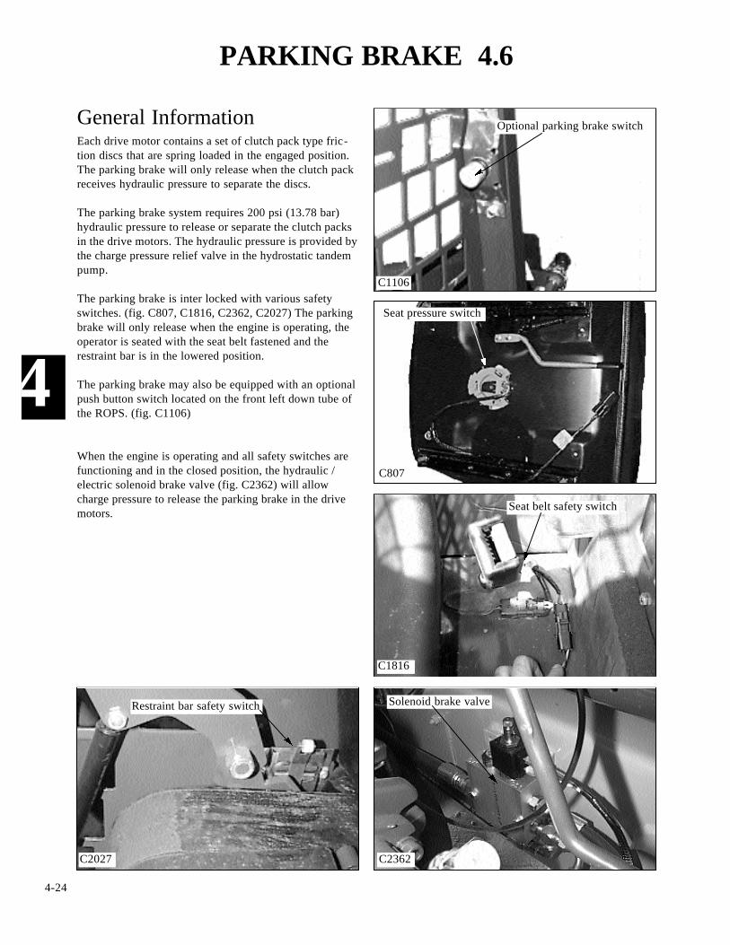
Ignition .......................................................... 12 VoltsGrounding .................................................... NegativeAlternator Brand ................................... NippondensoAlternator Rating ........................................... 60 AmpAlternator Type ............................. Internal RegulatorBattery ............................................................ One (1)Battery Rating ............................................ 730 CCA, .................................................. 125 Reserve Minutes
Battery Type ............................................ SERV 3478Starter Brand ......................................... NippondensoPre - Heater ........................................ (4) Glow PlugsGlow Plug Location ............................ Cylinder HeadCircuit Breaker ....................................... (1) 40 Amp,............................................. Starter / Ignition Switch
Protection .......... Fuse Block in Engine CompartmentFuse Rating:Engine Shut Off Solenoid ............................. 15 AmpAlternator ....................................................... 10 AmpSafety Circuit ................................................. 10 AmpHorn ............................................................... 10 AmpAux. Hydraulics ............................................. 10 AmpCab Heater ..................................................... 10 AmpBack up Alarm ............................................... 10 AmpDome Light .................................................... 10 AmpStarter ................................................. 40 Amp Relay*Glow Plugs ........................................ 40 Amp Relay*Cooling Fans ............................... (2) 40 Amp Relay** ............................. Linked to 10 Amp Fuse in Panel

5-3
GENERAL INFORMATION 5.1
5Control valve
C2348
IntroductionThe photographs below and at right show the safetyswitches and their location. These photographs will assistyou when referencing the electrical circuit drawings. Theparking brake will not release and the lift and tilthydraulic functions will not operate when any one ofthese circuits have failed or malfunctioned.
Be sure to disconnect the seat pressure switch connec-tor before removing the seat from the loader and becareful not to pinch the wires upon installation.
Solenoidspool locks
Main harness plug connection
C2458 C2451
C807
C1106
C2362C2027
Restraint bar switch Hydraulic brake valve
Parking brake switch (optional)
Seat pressure switch
Seat belt switch
Connector
5-4
5
PIN WIRE COLOR FUNCTION
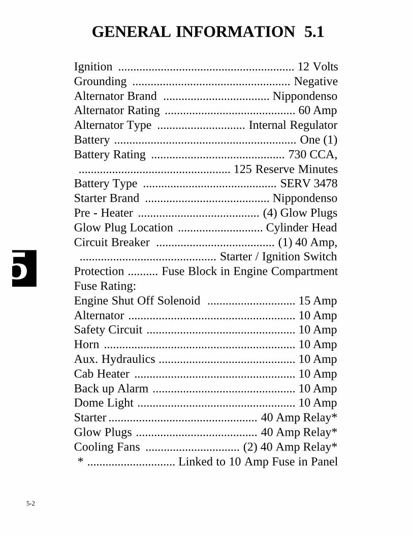
1 Tan Starter relay2 Blk / Wht Fuse block3 Red / Wht Glow plug relay4 White Circuit breaker5 Purple Engine oil pressure6 Pink Air filter7 Pple / Wht Coolant temperature8 Wht / Brn Horn button9 Brn / Wht Brake light switch10 Red / Org Rear light11 Org / Blue Fuel level (+)12 Blue / Wht Hydraulic temperature13 Grey / Wht Alternator (L)14 Grey Seat Belt
Engine Harness ConnectorDiagram C2459a Legend. Shown is the wire color andfunction of each pin terminal in the connector plug.
1
2
3
6 5
4
7
8
9
10
11
12 13C2459a
1
2
3
6 5
4
7
8
9
10
11
12 13
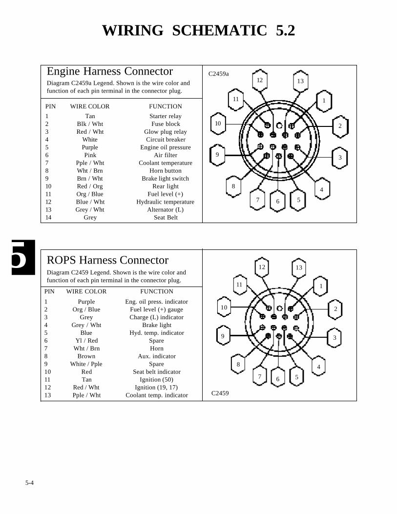
PIN WIRE COLOR FUNCTION
1 Purple Eng. oil press. indicator2 Org / Blue Fuel level (+) gauge3 Grey Charge (L) indicator4 Grey / Wht Brake light5 Blue Hyd. temp. indicator6 Yl / Red Spare7 Wht / Brn Horn8 Brown Aux. indicator9 White / Pple Spare10 Red Seat belt indicator11 Tan Ignition (50)12 Red / Wht Ignition (19, 17)13 Pple / Wht Coolant temp. indicator
ROPS Harness ConnectorDiagram C2459 Legend. Shown is the wire color andfunction of each pin terminal in the connector plug.
C2459
WIRING SCHEMATIC 5.2

5-5
5
WIRING SCHEMATIC 5.2
C2960
Light Kit Wire Harness
To Fuse Block
Light Kit Wire Harness
Continued on next page…

C2961
5
5-6
WIRING SCHEMATIC 5.2
Engine Wire Harness
Light Kit Wire Harness
To switch atLeft Hand
Control Lever
Light KitWire Harness
To Rear Work Light

C2962
5
5-7
WIRING SCHEMATIC 5.2
ROPS Wire Harness
Light Kit Wire Harness
5-8
5
INSTRUMENTATION 5.3
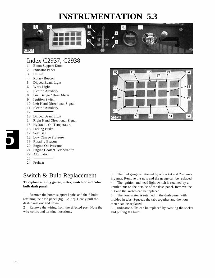
Index C2937, C29381 Boom Support Knob2 Indicator Panel3 Hazard4 Rotary Beacon5 Dipped Beam Light6 Work Light7 Electric Auxiliary8 Fuel Gauge / Hour Meter9 Ignition Switch10 Left Hand Directional Signal11 Electric Auxiliary1213 Dipped Beam Light14 Right Hand Directional Signal15 Hydraulic Oil Temperature16 Parking Brake17 Seat Belt18 Low Charge Pressure19 Rotating Beacon20 Engine Oil Pressure21 Engine Coolant Temperature22 Alternator2324 Preheat
23 24
15
1413121110
3 The fuel gauge is retained by a bracket and 2 mount-ing nuts. Remove the nuts and the gauge can be replaced.4 The ignition and head light switch is retained by aknurled nut on the outside of the dash panel. Remove thenut and the switch can be replaced.5 The hour meter is retained in the dash panel withmolded in tabs. Squeeze the tabs together and the hourmeter can be replaced.6 Indicator bulbs can be replaced by twisting the socketand pulling the bulb.
Switch & Bulb ReplacementTo replace a faulty gauge, meter, switch or indicatorbulb dash panel:
1 Remove the boom support knobs and the 6 boltsretaining the dash panel (fig. C2937). Gently pull thedash panel out and down.2 Remove the wiring from the effected part. Note thewire colors and terminal locations.
9821
C2937
C2938
16
17
18
19
20
21 22
4
3
5
7
6
5-9
5
INSTRUMENTATION 5.3
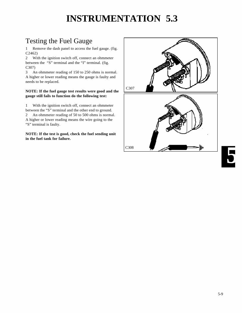
Testing the Fuel Gauge1 Remove the dash panel to access the fuel gauge. (fig.C2462)2 With the ignition switch off, connect an ohmmeterbetween the “S” terminal and the “I” terminal. (fig.C307)3 An ohmmeter reading of 150 to 250 ohms is normal.A higher or lower reading means the gauge is faulty andneeds to be replaced.
NOTE: If the fuel gauge test results were good and thegauge still fails to function do the following test:
1 With the ignition switch off, connect an ohmmeterbetween the “S” terminal and the other end to ground.2 An ohmmeter reading of 50 to 500 ohms is normal.A higher or lower reading means the wire going to the“S” terminal is faulty.
NOTE: If the test is good, check the fuel sending unitin the fuel tank for failure.
C307
C308
5-10
5
INSTRUMENTATION 5.3
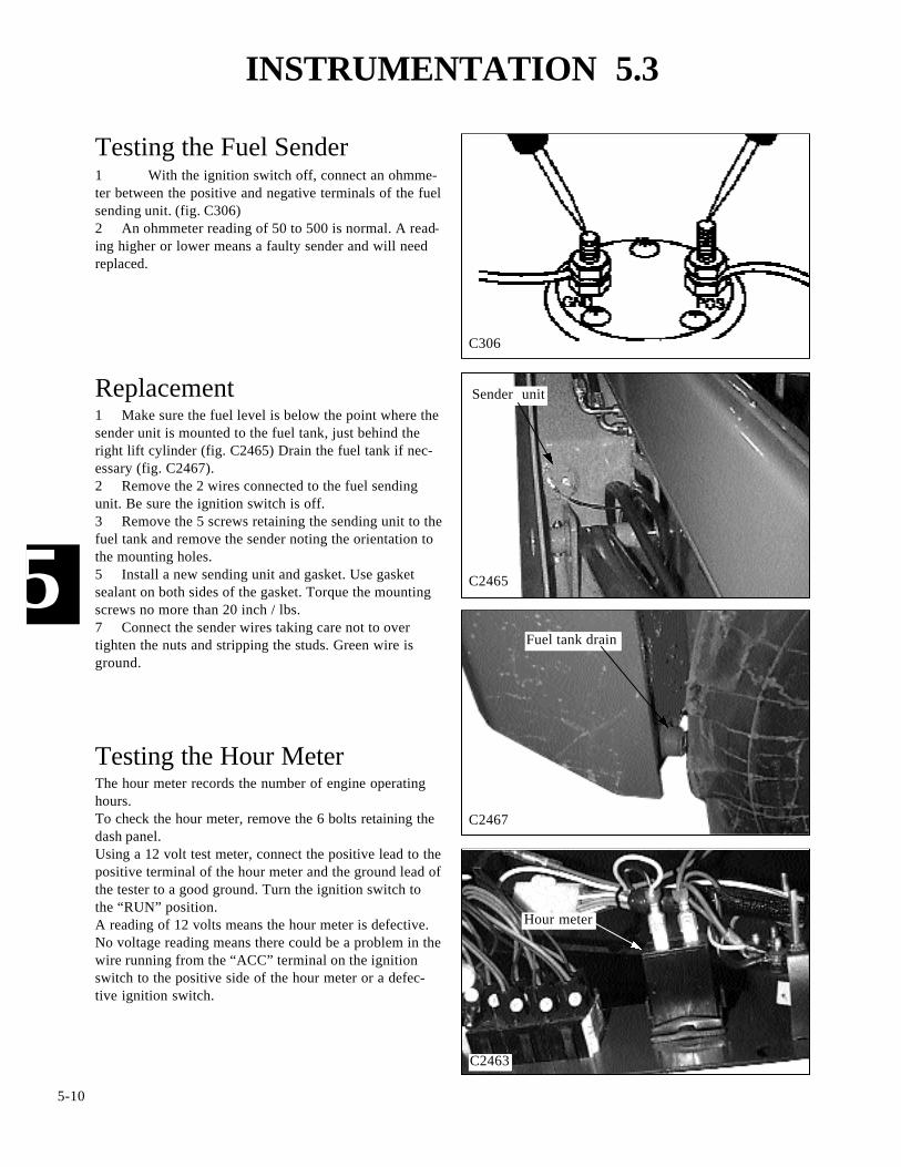
Testing the Fuel Sender1 With the ignition switch off, connect an ohmme-ter between the positive and negative terminals of the fuelsending unit. (fig. C306)2 An ohmmeter reading of 50 to 500 is normal. A read-ing higher or lower means a faulty sender and will needreplaced.
C306
C2467
C2463
C2465
Replacement1 Make sure the fuel level is below the point where thesender unit is mounted to the fuel tank, just behind theright lift cylinder (fig. C2465) Drain the fuel tank if nec-essary (fig. C2467).2 Remove the 2 wires connected to the fuel sendingunit. Be sure the ignition switch is off.3 Remove the 5 screws retaining the sending unit to thefuel tank and remove the sender noting the orientation tothe mounting holes.5 Install a new sending unit and gasket. Use gasketsealant on both sides of the gasket. Torque the mountingscrews no more than 20 inch / lbs.7 Connect the sender wires taking care not to overtighten the nuts and stripping the studs. Green wire isground.
Testing the Hour MeterThe hour meter records the number of engine operatinghours.To check the hour meter, remove the 6 bolts retaining thedash panel.Using a 12 volt test meter, connect the positive lead to thepositive terminal of the hour meter and the ground lead ofthe tester to a good ground. Turn the ignition switch tothe “RUN” position.A reading of 12 volts means the hour meter is defective.No voltage reading means there could be a problem in thewire running from the “ACC” terminal on the ignitionswitch to the positive side of the hour meter or a defec-tive ignition switch.
Fuel tank drain
Sender unit
Hour meter

5-11
5
IGNITION SWITCH 5.4
C297
C299
C300
Testing the Ignition SwitchThe ignition switch is a 4 position switch. OFF, PRE-HEAT, RUN and START. Turning the key counterclock-wise will engage the PREHEAT. To activate the starter,turn the key clockwise. When the key is released it willreturn to the RUN position.Before performing any test to the ignition switch, discon-nect the negative or ground wire from the battery termi-nal. Remove the 3 screws retaining the right hand dashpanel to the dash pod to access the ignition switch.TEST 1: “RUN” POSITION.Connect an ohmmeter across the terminals marked 30 andACC. (fig. C297) Turn the ignition switch to the run posi-tion.A low resistance reading is normal. High resistance read-ing means you will have to replace the ignition switch.TEST 2: “START” POSITION.(a) Connect an ohmmeter between the terminals marked30 and 50 on the ignition switch. (fig. C298) Turn theignition switch to the “START” position and observe theohm readings.
C298
(b) Connect the ohmmeter leads across terminals marked30 and 17 on the ignition switch. (fig. C299) Turn theignition switch to the “START” position and observe theohmmeter reading.Low resistance reading is normal.High resistance reading means the ignition switch needsreplacement.
TEST 3: “HEAT” POSITION.Connect the ohmmeter leads between the terminalsmarked 30 and 19 on the ignition switch. (fig. C300) Turnthe ignition switch to the “HEAT” position and observethe ohmmeter readings.Low resistance reading normal.High resistance reading, replace the ignition switch.
5-12
5
ENGINE GLOW PLUGS 5.5
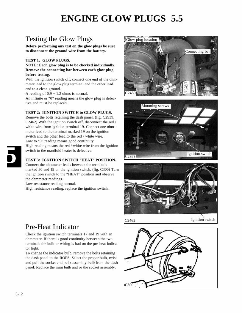
Testing the Glow PlugsBefore performing any test on the glow plugs be sureto disconnect the ground wire from the battery.
TEST 1: GLOW PLUGS.NOTE: Each glow plug is to be checked individually.Remove the connecting bar between each glow plugbefore testing.With the ignition switch off, connect one end of the ohm-meter lead to the glow plug terminal and the other leadend to a clean ground.A reading of 0.9 ~ 1.2 ohms is normal.An infinite or “0” reading means the glow plug is defec-tive and must be replaced.
TEST 2: IGNITION SWITCH to GLOW PLUGS.Remove the bolts retaining the dash panel. (fig. C2939,C2462) With the ignition switch off, disconnect the red /white wire from ignition terminal 19. Connect one ohm-meter lead to the terminal marked 19 on the ignitionswitch and the other lead to the red / white wire.Low to “0” reading means good continuity.High reading means the red / white wire from the ignitionswitch to the manifold heater is defective.
TEST 3: IGNITION SWITCH “HEAT” POSITION.Connect the ohmmeter leads between the terminalsmarked 30 and 19 on the ignition switch. (fig. C300) Turnthe ignition switch to the “HEAT” position and observethe ohmmeter readings.Low resistance reading normal.High resistance reading, replace the ignition switch.
C2480
Glow plug location
C2939Ignition switch
Mounting screws
Ignition switch
C300
C2462
Pre-Heat IndicatorCheck the ignition switch terminals 17 and 19 with anohmmeter. If there is good continuity between the twoterminals the bulb or wiring is bad on the pre-heat indica-tor light.To change the indicator bulb, remove the bolts retainingthe dash panel to the ROPS. Select the proper bulb, twistand pull the socket and bulb assembly bulb from the dashpanel. Replace the mini bulb and or the socket assembly.
Connecting bar

5-13
5
BATTERY 5.6
The battery is located in the ROPS behind the operatorsseat. To remove the battery:1 Remove the seat mount retaining bolt and disconnectthe seat belt wiring harness connection. (fig. C806)2 Pull up and toward the front of the loader andremove the seat. Be careful to not catch any electricalwiring while removing.
Removal and Inspection
C806
Mounting bolt
Seat switch harness
C2483
C1328
Battery hold down
C2458
Access bolt
Battery compartment
5 Remove the bolt securing the battery hold downbracket. (fig. C1328)6 Carefully remove the battery from the compartment.7 Inspect the battery cables for corrosion and damage.Remove any corrosion using a wire brush and a sodasolution. Replace the cables having damaged or deformedends.8 Clean the outside of the battery case if the battery isto be reused. Flush the terminal areas with a soda solutiontaking care not to allow the solution into the battery cells.Remove corrosion from the battery terminals with a wirebrush..
4 Disconnect both battery ground terminals first. Thendisconnect the positive cables from the battery.
3 Remove the access bolt from the battery compart-ment cover (fig. C2483) to gain access to the battery (fig.C2458).
WARNING
Batteries contain sulfuric acid which can harm the eyesand skin on contact. Always wear goggles and protec-tive clothing while servicing the battery. Flush skin oreyes with water upon contact. Consult a physician.
Battery
Battery access panel

5-14
5
BATTERY 5.6
C1328
C2347
C914
C2484
Removal and Inspection9 Inspect the battery case for cracks that may allowelectrolyte to leak into the environment.Inspect the batteries on a regular basis for damage such ascracks or a broken case.Inspect the battery cables for tightness and corrosion.Remove any corrosion and coat the terminals with adielectric grease.Check the battery hold downs to be sure they are properlyretaining the battery in the compartment. (fig. C1328)
Check and clean
BoostingIn the event the loader has failed to start and requiresboosting, a boosting lug or post is located in the enginecompartment. (fig. C2347)1 Open the rear door and raise the engine compartmentcover.2 Remove the red rubber protective cover from theboosting lug. (fig. C914)3 The ignition must be in the off position.4 Connect the positive cable from the 12 volt boostingsupply to the boosting lug on the loader.5 Connect the negative ground cable to the boostingsupply first, and then to a clean ground on the loaderengine. Keep the cables away from any moving parts.6 Start the engine.7 Remove the negative ground cable from the enginefirst and then the boosting supply. Remove the positivecable from the boosting lug.
Circuit BreakerThe circuit breaker is in the fuse panel, located in theengine compartment. (fig. C2484). See section 5.7.
Boosting lug location
Boosting lug
Circuit breaker location
5-15
5
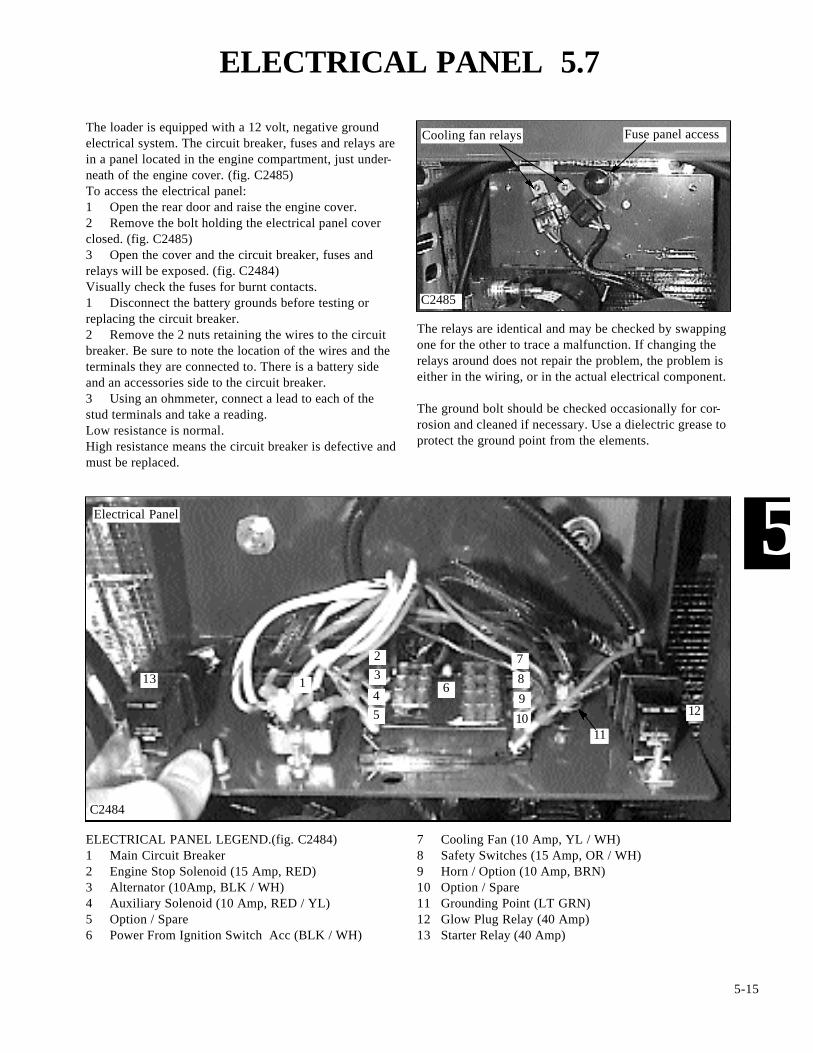
ELECTRICAL PANEL 5.7
C2485
Fuse panel access
C2484
7 Cooling Fan (10 Amp, YL / WH)8 Safety Switches (15 Amp, OR / WH)9 Horn / Option (10 Amp, BRN)10 Option / Spare11 Grounding Point (LT GRN)12 Glow Plug Relay (40 Amp)13 Starter Relay (40 Amp)
11
1
23
45
6
7
8
9
1012
13
Electrical Panel
ELECTRICAL PANEL LEGEND.(fig. C2484)1 Main Circuit Breaker2 Engine Stop Solenoid (15 Amp, RED)3 Alternator (10Amp, BLK / WH)4 Auxiliary Solenoid (10 Amp, RED / YL)5 Option / Spare6 Power From Ignition Switch Acc (BLK / WH)
Cooling fan relays
The relays are identical and may be checked by swappingone for the other to trace a malfunction. If changing therelays around does not repair the problem, the problem iseither in the wiring, or in the actual electrical component.
The ground bolt should be checked occasionally for cor-rosion and cleaned if necessary. Use a dielectric grease toprotect the ground point from the elements.
The loader is equipped with a 12 volt, negative groundelectrical system. The circuit breaker, fuses and relays arein a panel located in the engine compartment, just under-neath of the engine cover. (fig. C2485)To access the electrical panel: 1 Open the rear door and raise the engine cover.2 Remove the bolt holding the electrical panel coverclosed. (fig. C2485)3 Open the cover and the circuit breaker, fuses andrelays will be exposed. (fig. C2484)Visually check the fuses for burnt contacts.1 Disconnect the battery grounds before testing orreplacing the circuit breaker.2 Remove the 2 nuts retaining the wires to the circuitbreaker. Be sure to note the location of the wires and theterminals they are connected to. There is a battery sideand an accessories side to the circuit breaker.3 Using an ohmmeter, connect a lead to each of thestud terminals and take a reading.Low resistance is normal.High resistance means the circuit breaker is defective andmust be replaced.

5-16
5
STARTING CIRCUIT 5.8
C2487

5-17
5
CHARGING CIRCUIT 5.9
C2488

5-18
5
SAFETY CIRCUIT 5.10
C2492

5-19
5
SAFETY CIRCUIT 5.10
C807
C1816
C2027
C1514 C2362
Seat switch
Seat belt latch & switch
Harness plugs
Restraint bar switch
Parking brake solenoid coilControl valve lock solenoid coil
General InformationThe loader is equipped with 3 inter - connected safetyswitches. These 3 switches operate 2 electric solenoidcontrolled lock devices. One (1) solenoid coil on thehydraulic brake valve (fig. C2364), one (1) pair of sole-noid coils on the hydraulic control valve (fig. C1514)Failure of any one (1) of these switches will prevent theoperation of the solenoid coils and loader functions. All 3must be hooked up, functioning and, if applicable, adjust-ed correctly.
The bottom of the operators seat is equipped with a pres-sure sensitive switch. The operator must be in the seat toclose the switch and release the parking brake and unlockthe control valve functions. (fig. C807) No adjustmentsrequired. When removing and replacing the seat, be sureto disconnect the wire connector and not to pinch thewires under the seat plate.
The seat belt assembly is equipped with a safety switch.The operator must have the seat belt fastened aroundthem in order to close the switch and allow the parkingbrake to release and the control valve to function. (fig.C1816) No adjustments required.
The restraint bar is equipped with a dual function safetyswitch. (fig. C2027) With the restraint bar in the raisedposition, the parking brake is activated, the control valvefunctions are locked and the activation indicator lights areilluminated on the dash panel.Lowering the restraint bar releases the parking brake byenergizing the solenoid coil to release the hydraulic brakevalve lock (fig. C2362), turns off the indicator lights inthe dash panel and releases the locks in the main controlvalve by energizing the solenoid coils. (fig. C1514).The restraint bar must be in the lowered position for thecontrol functions to operate.The switch must contact the restraint bar when in thelowered position.
Mounting screws
Lock mechanism
Connector
5-20
5
COOLING FAN CIRCUIT 5.11
C2490

5-21
5
COOLING FAN CIRCUIT 5.11
C2498
C2497
C2500
C2603
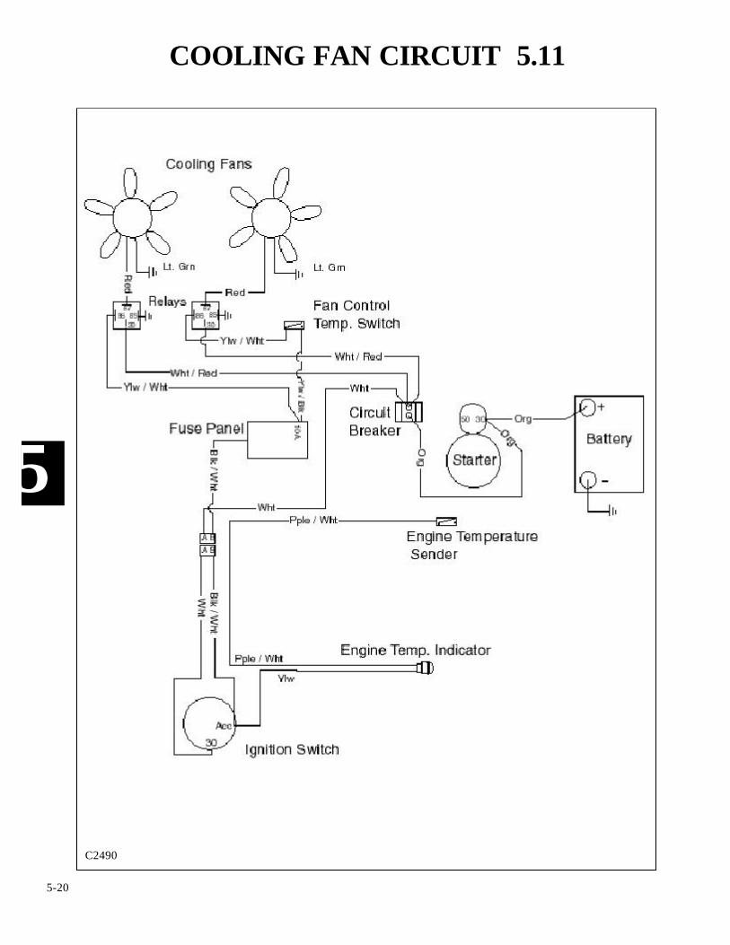
General InformationThe loader is equipped with dual cooling fans. The fansand motors are contained in a single housing and cannotbe replaced individually. (fig. C2601).
The cooling fans may be accessed by opening the reardoor and removing the bolt retaining the engine radiatorto the mounting bracket. (fig. C2498). The radiator maythen be swung open.
Check the electrical wiring to make sure it will notinterfere with the radiator when swung open. (fig.C2497). Also check the gas strut (optional) to radiatorclearance before swinging the radiator open. It may benecessary to disconnect the gas strut if so equipped.(fig. C2603).
Access bolt
Electrical connections
Gas strut
Radiator fitting
C2601
Cooling fan assembly

5-22
5
ELECTRIC AUXILIARY CIRCUIT 5.12
C2493
5-23
5
AUXILIARY CONTROL HANDLE 5.12
C2945
C2946
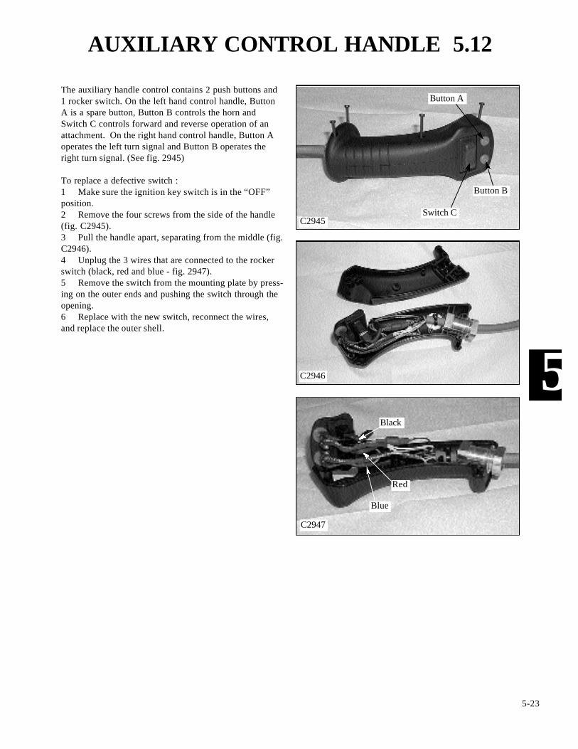
The auxiliary handle control contains 2 push buttons and1 rocker switch. On the left hand control handle, ButtonA is a spare button, Button B controls the horn andSwitch C controls forward and reverse operation of anattachment. On the right hand control handle, Button Aoperates the left turn signal and Button B operates theright turn signal. (See fig. 2945)
To replace a defective switch :1 Make sure the ignition key switch is in the “OFF”position.2 Remove the four screws from the side of the handle(fig. C2945).3 Pull the handle apart, separating from the middle (fig.C2946).4 Unplug the 3 wires that are connected to the rockerswitch (black, red and blue - fig. 2947).5 Remove the switch from the mounting plate by press-ing on the outer ends and pushing the switch through theopening.6 Replace with the new switch, reconnect the wires,and replace the outer shell.
C2947
Button A
Button B
Switch C
Black
Red
Blue

5-24
5
ACCESSORIES CIRCUIT 5.13
C2489

5-25
5
Problem Cause Corrective Action Section5.6Starter will not
engage.Battery discharged. Check the battery and charge or replace.
Loose or disconnectedwiring.
Verify continuity of starting circuit. Check and repair.
5.4Defective ignitionswitch.
Check the switch and replace if necessary.
Defective starter sole-noid.
Check and replace if necessary. Kubota repair manualP / N 40916.
Defective starter. Check and replace if necessary.
Starter motor turnsbut does not engage.
Defective overrunningclutch or low batterycharge.
Replace starter or parts. Check the battery and charg-ing system. Kubota repair manual P / N 40916.
Defective starter.Pinion engages butengine does not turnover.
Check and replace. Kubota repair manual P / N 40916.
Low battery charge. Check and repair. 5.6
Engine seizure. Check and replace. 7
Hydrostatic pump fail-ure.
Check and replace. 2
Starter motor rotatesa full speed beforepinion engages.
Defective pinionspring.
Check and replace. Kubota repair manual P / N 40916.
Starter remainsengaged after theengine has started.
Faulty ignition switch. Check and replace.
Defective solenoid. Check and replace. Kubota repair manual P / N 40916.
5.4
Defective relay. Check and replace. 5.7
Problem Cause Corrective Action SectionControl locks willnot release.
Blown fuse. Check fuse and replace with 15 Amp. 5.7Safety switch out ofadjustment or defective.
Remove the seat, check and adjust or replace. 5.10
2 / 5.10Check and replace.Defective lock solenoid.
Defective lock mecha-nism.
Check and replace. 1.4 / 5.10
Short in wiring harness. Check for proper grounding, repair or replace harness.
STARTING SYSTEM
SAFETY LOCKING MECHANISM
TROUBLE SHOOTING 5.14
Kubota repairmanual
Kubota repairmanual
Kubota repairmanual
Kubota repairmanual
Kubota repairmanual
Kubota repairmanual

5-26
5
TROUBLE SHOOTING 5.14
Problem Cause Corrective Action Section
CHARGING SYSTEM
Battery low incharge.
Faulty wiring or con-nections.
Check and repair or replace.
Defective alternator orregulator.
Defective alternator orregulator.
Defective alternator orregulator.
Check charging output. Repair or replace if necessary.(see Kubota manual Thomas p / n 40916)
Check charging output. Replace if necessary.(see Kubota repair manual Thomas p / n 40916)
Check charging output. Replace if necessary.(see Kubota repair manual Thomas p / n 40916)
Check charging output. Replace if necessary.(see Kubota repair manual Thomas p / n 40916)
7
Defective battery.
Defective battery.
Alternator overcharg-ing and battery over-heats.
Test battery and replace if necessary.
Test battery and replace if necessary.
Defective regulator
Drive belt slipping.Low or no outputvoltage from alterna-tor.
Check and adjust.
Check and adjust.
Check and adjust.
7
7
Faulty wiring or con-nections.
Check and repair or replace.
Check and repair or replace.
Check and repair or replace.
Check and repair or replace.(see Kubota repair manual Thomas p / n 40916)
Charge indicatorlight flickers or runsdim.
Faulty wiring or con-nections.
Dirty alternator sliprings or brushes.
Charge indicatorgoes out but becomesbrighter as the engineRPM increases.
Faulty wiring or con-nections.
Charge indicatorlight is on while theengine is operating.
Drive belt slipping.
Drive belt slipping.
5.6Kubota repairmanual
Kubota repairmanual
Kubota repairmanual
Kubota repairmanual
Kubota repairmanual

Quick - Tach .......................................... 6.1Illustration ..................................................................................... pg. 6-2Preventative Maintenance ............................................................. pg. 6-4Removal ........................................................................................ pg. 6-5Installation...................................................................................... pg. 6-5Disassembly .................................................................................. pg. 6-6Assembly ....................................................................................... pg. 6-6
Boom Arms ............................................ 6.2Removal ........................................................................................ pg. 6-7Installation ..................................................................................... pg. 6-7
Boom Support ........................................ 6.3Boom Arm Supports ...................................................................... pg. 6-8
ROPS (Cab) ........................................... 6.4Removal ........................................................................................ pg. 6-9Installation ..................................................................................... pg. 6-9
Rear Door .............................................. 6.5Removal ...................................................................................... pg. 6-10Installation ................................................................................... pg. 6-10
6-1
6
SECTION 6 MAIN FRAME

QUICK - TACH 6.1
6-2
6
C1098
Uni
vers
al Q
uick
- T
ach
Ass
embl
y
1617
18
19
15
1614
13
12
11
10987
6
53
2
1
5
3
1Q
uick
- T
ack
Ass
embl
y2
Qui
ck -
Tac
h Fr
ame
3B
olt
4Pi
vot P
in5
Loc
k N
ut6
Loc
k N
ut7
Lin
kage
Blo
ck8
Nut
9B
ushi
ng10
Spri
ng
4
11L
ock
Pin
Ass
embl
y (L
& R
)12
Bol
t13
Pivo
t Bus
hing
14L
ock
Han
dle
(L &
R)
15B
elle
ville
Spr
ing
16Fl
at W
ashe
r17
Bol
t18
Bol
t19
Loc
k W
ashe
r

NOTES
6-3
6
THOMAS

QUICK TACH 6.1
Preventative MaintenanceTo keep the quick - tach locking pins and mechanismworking freely, and to prevent pin and bushing wear, thequick tack must be lubricated every 8 hours of operations.More often in dirty applications.
Lubricate the quick - tach as follows:
1 Remove any attachment from the loader, raise theboom arms, engage the boom supports, engage the park-ing brake and shut off the engine. (fig. C2665, C2666).
2 Clean any dirt build up around the linkages.
3 Lubricate the grease fittings on each of the pivot pinbushings with a good quality multi purpose lithium basedgrease until excess shows. (fig. C2667).
6-4
6
C2665
C2668
C2667
C2666
Grease lock pin assembly (L & R)
Grease pivot pins (L & R)
4 Lubricate the attachment locking pins. (fig. C2668).
Engage boom supports
Service position

QUICK - TACH 6.1
Removal1 Remove any attachment and lower the boom arms.
2 Start the engine and extend the tilt cylinders approxi-mately 3 to 4 inches. (8 to 10 cm) (fig. C1831).
3 Shut off the engine and engage the parking brake.
4 Remove the bolts retaining the pivot pins to the quick- tach frame. (fig. C2669).
5 Place a block of wood under the quick - tach andremove the tilt cylinder pivot pins first. (fig. C2670)Allow the quick - attach to roll forward onto the block ofwood.
Note: If this repair is being performed in a proper workshop, a hand cart works excellent for this next step. Placethe hand cart under the quick - tach instead of the blockof wood. (fig. C1835).
6 The block of wood or hand cart is used to relievesome of the weight on the 2 (two) lower pivot pins.Wedge the block of wood tightly against the quick - tachframe as best you can.
7 Remove the two lower pivot pins and remove thequick - tach assembly.
6-5
6
C1831
C2670
C1835
C2669
Remove bolts
Extend tilt cylinders
InstallationUpon installing the quick - tach to the loader boom arms:
1 Make sure all pivot pins and bushings are good con-dition. Do not reuse worn parts. Replace pins and hard-ened bushings as required. Check and / or replace thehardened bushings in the lower boom arm pivots.
2 Use the hand cart or a floor jack to assist installingthe quick - tach to the loader boom arms. (Or lay it downon your piece of wood. (fig. C1835).
3 Raise the bottom of the quick - tach up to align theboom arm pivot holes and the lower quick - tach pivotbushings. Install the 2 lower pivot pins, retaining boltsand or lock nuts.
4 Swing the quick - tach up and align the 2 tilt cylinderpivot bushings with the quick - tach bushings and installthe pins and retaining bolts and lock nuts.
5 Lubricate all pivots until excess grease can be seenflowing out around the bushings and pins.
Remove pins
Model not exactly as shown

QUICK - TACH 6.1
DisassemblyFollow the exploded schematic on the 2nd page of thissection to assist in taking apart the locking mechanism,and to assemble the system back together. Please note thatthe quick - tach does not have to be removed to service orreplace locking mechanism parts.1 Remove the bolt retaining the lock handle to the locklinkage. (fig. C1829).2 Remove the bolt retaining the lock handle to thequick - tach frame. (fig. C1829).3 Pull the locking pin and linkage out of the guidebushing. (fig. C1836).4 Loosen the jam nut on the linkage block. Remove thebolt holding locking pin to the lock linkage block.5 Separate the parts and inspect the spring for brokenor sacking (compressed) coils. (fig. C1830) Replace partsas required.6 Inspect the locking pin for wear. Make sure thebeveled end of the pin is not worn or broken. Check thefit of the pin in the quick - tach guide bushing. If the pinor bushing is excessively worn replace the pin or com-plete quick - tach assembly.7 Inspect the lock handle mounting holes for fit againstthe handle pivot bushings. Replace the handle or pivotbushings as required if the fit is sloppy. (fig. C1830)8 Check the fit of the lower pivot pins in the quick -tach. Discard worn pins and replace the hardened bush-ings in the quick - tach if so equipped.9 Check and replace any grease fittings that are dam-aged or defective.
6-6
6
C1829
C1818
C1830
C1836
AssemblyUpon assembling the locking mechanism to the quick -tach, use 242 Loctite (blue) on all the mounting nuts andbolts.1 When assembling the locking pin to the spring, bush-ing and linkage block, adjust the length of the bolt to 41/16 inches. (103mm). This is measured from under thehead of the bolt up to, and against the linkage block. (fig.C1818). This is very crucial for lock pin engagement tothe attachment.2 Replace the rest of the lock mechanism in the reverseorder above.3 Lubricate all pins and bushings.4 Check the lock mechanism by cycling the lock leversto ensure correct engagement through the attachment andsufficient pressure to hold the lock system down in theover - center position. (Engages and stay in the lockedposition).
Linkage bolt measurement
Pivot bushing Stabilizer bushing
Bolt
SpringJam nut
Linkage block
Q / T handle bolts
Handle
Lock pin
Lock pinguide bushing
BOOM ARMS 6.2
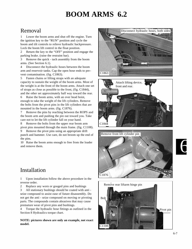
Removal1 Lower the boom arms and shut off the engine. Turnthe ignition key to the “RUN” position and cycle theboom and tilt controls to relieve hydraulic backpressure.Lock the boom lift control in the float position. 2 Return the key to the “OFF” position and engage theparking brake. (raise the restraint bar).3 Remove the quick - tach assembly from the boomarms. (See Section 6.1).4 Disconnect the hydraulic hoses between the boomarm and reservoir tanks. Cap the open hose ends to pre-vent contamination. (fig. C1863).5 Fasten chains or lifting straps with an adequatecapacity to sustain the weight of the boom arms. Most ofthe weight is at the front of the boom arms. Attach one setof straps as close as possible to the front, (fig. C1844),and the other set approximately half way toward the rear.6 Raise the boom arms, with an over head hoist,enough to take the weight of the lift cylinders. Removethe bolts from the pivot pins in the lift cylinders that aremounted in the boom arms. (fig. C1876).7 Remove the pins by reaching between the ROPS andthe boom arm and pushing the pin out toward you. Takecare not to let the lift cylinder fall on your hand.8 Remove the bolts from the upper rear boom armpivot pins mounted through the main frame. (fig. C1108).9 Remove the pivot pins using an appropriate driftpunch and hammer. Use care, do not broom up the end ofthe pins.10 Raise the boom arms enough to free from the loaderand remove them.
6-7
6
C1863
C1108
C1876
C1844
Bolt
Pivot pin
Installation1 Upon installation follow the above procedure in thereverse order.2 Replace any worn or gouged pins and bushings3 All stationary bushings should be coated with anti -seize compound to assist ease of future disassembly. Donot get the anti - seize compound on moving or pivotingparts. The compounds contain abrasives that may causepremature wear of pivot pins and bushings.4 Torque the hydraulic hose fittings as outlined in theSection 8 Hydraulics torque chart.
NOTE: pictures shown are only an example, not exactmodel.
Disconnect hydraulic hoses, both sides
Remove front lift cylinder pin
Remove rear liftarm hinge pin
Attach lifting device,front and rear.
BOOM SUPPORTS 6.3
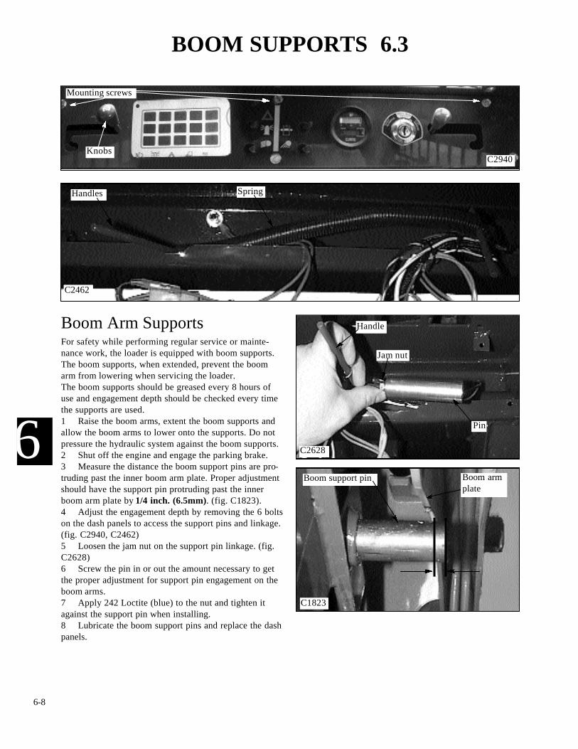
Boom Arm SupportsFor safety while performing regular service or mainte-nance work, the loader is equipped with boom supports.The boom supports, when extended, prevent the boomarm from lowering when servicing the loader.The boom supports should be greased every 8 hours ofuse and engagement depth should be checked every timethe supports are used.1 Raise the boom arms, extent the boom supports andallow the boom arms to lower onto the supports. Do notpressure the hydraulic system against the boom supports.2 Shut off the engine and engage the parking brake.3 Measure the distance the boom support pins are pro-truding past the inner boom arm plate. Proper adjustmentshould have the support pin protruding past the innerboom arm plate by 1/4 inch. (6.5mm). (fig. C1823).4 Adjust the engagement depth by removing the 6 boltson the dash panels to access the support pins and linkage.(fig. C2940, C2462)5 Loosen the jam nut on the support pin linkage. (fig.C2628)6 Screw the pin in or out the amount necessary to getthe proper adjustment for support pin engagement on theboom arms.7 Apply 242 Loctite (blue) to the nut and tighten itagainst the support pin when installing.8 Lubricate the boom support pins and replace the dashpanels.
6-8
6
C1823
C2940
Boom support pin Boom armplate
Mounting screws
C2462
Knobs
Handles Spring
C2628
Handle
Jam nut
Pin

ROPS 6.4
Removal1 Lower the boom arms, shut off the engine andengage the parking brake.2 Remove the seat assembly and the hydrostatic shieldand disconnect the battery terminals.3 Disconnect the ground cable from the mainframe andROPS.4 Disconnect the main wiring harness connector.(fig.C2458).5 Remove any cable ties that may be used to tie wiringand hoses to the ROPS. Check the engine compartmentand the hydrostatic pump area for wiring connections andties that will need to be disconnected from accessory cir-cuits.6 Disconnect the restraint bar safety switch wiring.7 Remove the nuts and washers on the ROPS isolatormounts. There are 2 in the front (fig. C2630) and 2 in therear. (fig. C2629).8 Attach chains or straps with a sufficient load rating tosafely raise the ROPS from the frame. (fig. C2231).9 Raise the ROPS using an over head hoist. Check forwiring that may still be connected and remove asrequired.
6-9
6
C2458
C2231
C2630
C2629
Installation1 Upon assembling the ROPS to the loader mainframe,ensure the mounting isolators are in serviceable condi-tion. Replace any worn, damaged or weathered isolators.2 Reverse the removal procedure taking care not topinch any wiring and connections.3 Torque the ROPS mounting isolator nuts at 60 lbs /ft. (81.5 Nm)
Rear ROPS mount (LH shown)
Front ROPS mount (RH shown)IMPORTANT
Check the ROPS mounting isolators every 150 hoursfor deterioration to prevent unwanted vibration andmovement.
Battery
Main harness connection
IMPORTANT
Assure the safety features are properly functioningafter replacement of the ROPS assembly.

REAR DOOR 6.5
Removal1 Open the rear door and disconnect the wire connectorgoing to the cooling fans.2 Remove the bolts retaining the radiator to the door.(fig. C2498).3 Remove the radiator and gently lower to the ground.4 Attach chains or straps to the rear door.4 Using a hoist, raise the chains to take the weight ofthe door and remove the mounting bolts and door.5 Remove the radiator baffle and cooling fans.
6-10
6
C2601
C2498
C1041
Remove mounting bolts
Cooling fansInstallation1 Replace the door to the frame in the reverse orderabove.2 Adjust the door guide plate so the rear door lookslevel with the engine compartment cover, and the doorslides freely into the closed position.3 Adjust the door latch linkage so the door does notrattle when in the closed position. This is accomplishedby turning the turnbuckle on the latch linkage. (fig.C1041).
1 Rear door2 Lock nut3 Bolt4 Lock nut5 Flat washer6 Gas strut (option)7 Bolt8 Rod clip9 Rod10 Turnbuckle11 Nut12 Rod13 Rotary latch14 Latch reinforcement15 Bearing mount16 Lock Washer17 Lock nut18 Latch19 Rad baffle20 Rivet21 Door guide22 Bolt23 Lock nut24 Flat washer25 Ball stud
18
25
25
19
20
21
22
23
24
1716
1514
13
12
1110
9
8
76 54
3
2
1
Baffle
Fan wire connector
Fan wire connector

7-1
7
SECTION 7 ENGINE
Maintenance .......................................... 7.1Lubrication System............................................................................ pg. 7-2 Fuel System ....................................................................................... pg. 7-4 Air Filter ............................................................................................ pg. 7-6 Cooling System ................................................................................. pg. 7-8 Drive Belt ........................................................................................ pg. 7-10Universal Joint................................................................................. pg. 7-11
Cylinder Head ........................................ 7.2Valve Adjustment............................................................................. pg. 7-12Compression Test............................................................................. pg. 7-14Cylinder Head Torque ..................................................................... pg. 7-15
Engine Replacement ...............................7.3
Engine Removal ............................................................................. pg. 7-16Engine Installation .......................................................................... pg. 7-17
Specifications ........................................ 7.4Dimensions, Capacities, Service Limits & Clearances ................... pg. 7-18
Trouble Shooting ................................... 7.5Guide ............................................................................................... pg. 7-20

Lubrication SystemEngine Oil and Filter:Engine oil and filter changes should be made with theengine warm. Change the engine oil every 75 hours andthe oil filter every 150 hours of operation.Park the loader on a level surface, lower the boom arms,engage the parking brake and shut off the engine.
1 Access the engine compartment by opening the reardoor and lifting the engine cover. (fig. C2941)
7-2
7
C2941
C2202
C2631
C842
ENGINE MAINTENANCE 7.1
Engine oil drain line
Engine oil filter location
Access the engine compartment
Lubricate oil filter O-ring7 Lubricate the new oil filter O-ring seal with engineoil and install to the engine hand tightened. (fig. C2202)
8 Replace the oil line drain cap and place the line backin the engine compartment.
5 Remove the oil filter using an appropriate filterwrench. If the oil filter area is excessively dirty, cleanaround the filter area before removing the oil filter to pre-vent contaminant’s reaching the engine lubricating sys-tem. (fig. C2631).
6 Check the oil filter mounting adapter area afterremoving the oil filter and check for dirt on the sealingsurface and to make sure the oil filter O-ring seal has notstuck to the oil filter adapter.
2 Locate the engine oil drain line and loosen the cap.(fig. C842)
3 Place the line through the hole in the chassis androute to a container that will contain at least 8 liters(1.5gal) of fluid.
4 Remove the cap from the line and allow the oil todrain thoroughly.

ENGINE MAINTENANCE 7.1
Lubrication System (cont’d)9 Remove the oil fill cap located in the engine rockerarm cover. (fig. C2480) Add 6.5 liters (7qts) of 10W30API classification SE / CD engine oil. Replace the fill capin the rocker arm cover.
NOTE: Oil capacity includes the oil filter. Reduce oiladded by 0.5 liters (0.5qts) if the oil filter is notreplaced.
7-3
7
C2480
C2633
C2632
C2631
Engine oil fill cap
Engine oil leveldip stick location
Engine oil level dip stick markings
Check for leaks
11 Check the level of the engine oil. (fig. C2632). Addoil as required to bring the oil to the top mark of theengine oil dip stick if required. (fig. C2633). Do not overfill.
Change the engine oil every 75 hours and the engine oilfilter every 150 hours.
10 Start the engine and check for leaks around the oilfilter and oil drain line. (fig. C2631). Allow the engine tooperate for approximately 3 ~ 5 minutes and then shut itoff.
Low level (add)
Full level

ENGINE MAINTENANCE 7.1
Fuel SystemFuel Filter:The fuel filter is a spin on type and is located in theengine compartment on the engine mounting bracket.Change the fuel filter every 400 operating hours.To change the fuel filter: Park the loader on a level sur-face, lower the boom arms, engage the parking brake,shut off the engine and remove the key.
1 Access the engine compartment by opening the reardoor and lifting the engine cover. (fig. C2347)
2 Close the fuel line shut off petcock located on thelower right hand side of the fuel tank. (fig. C2634) Thiswill prevent fuel loss due to siphoning.
3 Remove the fuel filter using a filter wrench. (fig.C2631) Check to make sure the fuel filter O-ring seal hasnot stuck to the filter adapter mount.
4 Lubricate the new fuel filter O-ring seal with lightoil. Tighten the filter to the adapter mount hand tight.
5 Open the fuel line shut off petcock.
7-4
7
C2347
C2635
C2631
C2634
Fuel shut off petcock
Engine air bleed petcock
Fuel filter6 Open the fuel filter bleed bolt on the filter adapterhousing and allow the fuel to dribble out. (fig. C2631)Tighten the bleed bolt.
7 Open the engine fuel line / air bleed bolt located justto the left of the fuel injection pump. (fig. C2635) Startthe engine and set to idle. Close the fuel line / air bleedpetcock when fuel starts to spit out. This can be accom-plished easier with help from an assistant.
If the engine fails to continue operating, it may be neces-sary to bleed the fuel system of air after changing the fuelfilter or running out of fuel. See Bleeding the FuelSystem, next page.
Primer pump
Filter bleed bolt

ENGINE MAINTENANCE 7.1
Fuel System (cont’d)Bleeding the Fuel System:If the loader has been run dry of fuel, or the fuel filter hasbeen changed, it may be necessary to bleed the air fromthe fuel lines.
1 Replenish the fuel reservoir (tank) with a minimumof 10 gallons (45 L) of fuel. This will allow the fuel tosiphon through readily.
2 Make sure the fuel line shut off petcock is fully open.(fig. C2634)
3 Loosen the fuel filter bleeder bolt and allow the fuelto siphon through the fuel line and filter. (fig. C2631)Tighten the fuel filter bleeder bolt.
4 Loosen the air bleed bolt located to the left of thefuel injection pump. (fig. C2635).
5 Crank the hand primer pump (fig. C2635) until fueltrickles out the engine air bleed bolt. Tighten the bolt.
6 Pre- heat and the start engine. Allow to operate atidle speed for few minutes. Shut off the engine.
If the engine fails to continue operating it may be nec-essary to repeat the procedure, or try the following.
1 Open the engine air bleed bolt.Turn the engine overwith the starter until the engine starts to smoke. Close theair bleed bolt. Do not engage the starter for more than 15second intervals. Allow the starter to cool between start-ing attempts for 1 (one) minute.
2 Pre- heat and the start engine. Allow to operate atidle speed for few minutes. Shut off the engine.
If the engine operates but idles roughly, or knocks(has an air lock in an injector line), it may be neces-sary to bleed the individual injection lines while theengine is operating.
Loosen the injection lines, one at a time, starting atthe injector pump. Tighten the line when fuel spits outthen move onto the next injection line if required. Do allthe lines on the injector pump first, then move to theinjector connection next.
TIP: A quick way to bleed the fuel system if air pres-sure is readily available is to pressurize the fuel tankvia the fuel return line and open the engine air bleedbolt. Do not over pressurize, 5 ~ 10 psi is adequate.
7-5
7
C2634
C2635
C2631
Engine air bleed
Fuel line shut off petcock
Fuel filter bleeder bolt
Primer pump
WARNING
Use extreme caution when bleeding air from theinjection lines. Fuel is pressurized over 2000 psiand can penetrate the skin causing serious injury.

ENGINE MAINTENANCE 7.1
Air FilterThe loader is equipped with a dry cartridge, radial sealtype filter element.The loader is equipped with an air restriction indicator,located inline between the air cleaner and the engine airinlet. When the air filter element requires servicing theindicator will turn red in color.Over servicing the air filters can damage the seals andpleated filter material if proper care is not taken.Never beat, shake or bend a filter element to clean.Cleaning with pressurized air can damage the pleatedmaterial. .Recommended service intervals are as the restrictionindicator dictates, then replacement is required.Filters improperly serviced and leading to engine fail-ure are not warrantable by Thomas or the enginemanufacturer.To service the air filter: park the loader on a level surface,lower the boom arms, engage the parking brake shut offthe engine and remove the key.
Daily Checks1 The air inlet restriction indicator should be visuallychecked daily, and for proper function by pushing in onthe reset button. (fig. C2636). If the indicator is showinga red color, then the filter system will need to be serviced.
NOTE: If the indicator fails to reset after servicing,replace the indicator.
2 Air cleaner hoses and clamps should be inspecteddaily for proper tightness and verify air inlet hose integri-ty. Replace any worn or cracked inlet hoses immediately.Check the air cleaner mounting hardware for tightness.
Servicing the Air Filter Elements:1 Release the latches holding the air cleaner cover tothe canister body. (fig. C2637)
2 Pull straight out on the primary element to removefrom the air cleaner housing. (fig. C2638) Do not twist orforce the filter. This may damage the sealing area aroundthe end of the air filter element.
7-6
7
C2636
C2638
C2637
C902
Air cleaner cover mounting latches
Air restriction indicator
Primary air filter element
Filter element
Outlet
Inlet Cover Vacuatorvalve
IMPORTANT
Air filter service intervals recommended only whenthe service indicator dictates.
Reset button

ENGINE MAINTENANCE 7.1
Air Filter (cont’d)3 After removing the air filter elements, carefully wipeout any excess dirt from the air cleaner housing. (fig.C2640).
4 Check the air filter element seal before installing tothe air cleaner housing. (fig. C2201). Be sure the seal isnot damaged, torn or gouged. Do not use a filter with adamaged seal.
5 When installing the air filter elements to the aircleaner housing, support the back of housing with onehand and push the air filter element into position as gen-tly as possible. (fig. C2641). Make sure it has fully seatedto the air cleaner housing.
6 Install the air cleaner cover onto the housing. Be sureto align the latch hooks with the notches in the air cleanerhousing.
Do not use the covers latches to push the air filter ele-ments into position.
7-7
7
C2639
C2640
C2201
C2641
Air filter element
Clean out dirt
Filter sealing area
Air filter element radial seal
Install filter element

ENGINE MAINTENANCE 7.1
Cooling SystemDaily Checks:The loader is equipped with a liquid cooled diesel engine.The radiator is located in the rear door and requires dailycoolant level checks and radiator service if necessary.The cooling system should always be checked when theengine is cool.Park the loader on a level surface, lower the boom arms,engage the parking brake and shut off the engine.1 Access the radiator by opening the rear door.2 Visually inspect the radiator cooling fins for dirt ordebris build up that may be blocking air flow through theradiator. (fig. C2498). Blow any dirt or debris out withcompressed air and / or water. Do not exceed 40 psi (2.7Kg / cm2) Any bent cooling fins should be carefullystraightened to prevent air flow obstruction.4 Remove the radiator cap to verify the coolant level inthe radiator. If the coolant level is below the upper part ofthe radiator tank, and the coolant bottle is still full, theneither the radiator cap is defective or there is a coolantleak in the cooling system. Perform a pressure test of the
cooling system.
Testing the Cooling System:1 Ensure the radiator is full of coolant.2 Start the engine operate until warm, NOT HOT!3 Shut off the engine and carefully remove the radiatorcap. Use extreme caution.
7-8
7
C2498
C2500
C2499
Radiator cap
Radiator fins
WARNING
To prevent eye injury, wear safety goggles whencleaning with compressed air
CAUTION
To prevent radiator fin damage, do not use airpressure higher than 40 psi (2.7 kg / cm2)
WARNING
Never remove the radiator cap when the engine ishot.
CAUTION
Always use pre - mixed or diluted engine coolantto prevent engine over heating, freezing and properwater pump lubrication
Service bolt
Electricalconnector
Electricalconnector
C2602
Gas strut

ENGINE MAINTENANCE 7.1
Cooling System (cont’d)4 Attach a radiator tester and increase the pressure to0.9 kg / cm2 (12.8 psi).(fig. C172) Inspect the radiator,hoses and engine block for external leaks. Repair asrequired.5 Attach a radiator tester to the radiator cap. (fig.C173) Apply 0.9 kg / cm 2 (12.8 psi ) pressure to the radia-tor cap. The pressure should not drop more than 0.3kg /cm 2 (4.3 psi) in 10 seconds. Replace the radiator cap ifrequired.If no external leaks are found, and the radiator cap testsgood, there may be an internal problem with the enginesuch as a gasket, cylinder head or block defect. Consult aKubota Repair Manual P / N 40916 (Kubota P / N 97897-0109-5) to assist in engine disassembly and inspection.
Coolant Replacement:The engine coolant should be changed every 1000 hoursof operation. To change the coolant:Park the loader on a level surface, lower the boom arms,engage the parking brake and shut off the engine.1 Make sure the engine is not hot to touch. Remove theradiator cap.2 Remove the radiator drain plug located lower leftcorner of radiator. (fig. C2203) Be prepared to contain 7liters (1.8 gal) of fluid.3 Open the engine drain petcock located next to theengine fuel pump, just below the engine solenoid shut off.(fig. C1060) Close the drain petcock after the engine iscompletely drained.Note: Attaching a piece of 5 / 16” (8mm) hose to thedrain petcock and routing to a container, lessens wastefluid clean up. Please dispose of waste fluid in an envi-ronmentally friendly manner.4 Replace the radiator drain plug using teflon tape orequivalent on the threads. Be sure to tighten the drainplug so it does not protrude past the radiators lowermount. This will prevent interference with the hydraulicoil cooler.5 Pre - mix the engine coolant, ethylene glycol, toequal parts of water. (50 / 50 ratio) Add the mixed coolantto the engine radiator.The cooling system will holdapproximately 7 liters (1.8 gal) of coolant. Never usecoolant undiluted. Pure coolant does not absorb and passheat efficiently. It will also gel in cold weather.
7-9
7
C172
C2642
C2497
C173
Engine block drain petcock
Radiator drain plug
Radiator cap test
Pressurizing thecooling system
WARNING
Never remove the radiator cap when the engine ishot.

MAINTENANCE 7.1
Drive Belt AdjustmentThe fan (alternator) drive belt should be checked daily fortension and wear. The drive belt should be replacedpromptly when fraying of the belt cords or cracks in therubber are observed. Failure to replace the drive beltcould lead to slippage or complete failure, causing theengine to over heat and lead to extensive repairs.To Adjust the Drive Belt:
1 Park the loader on a level surface, lower the boomarms, engage the parking brake and shut off the engine.2 Access the engine compartment by opening the reardoor and lifting the engine cover. (fig. C2347)3 Remove the drive belt / pulley guard to access thedrive belt (fig. C2347).4 Check the drive belt tension midway between thealternator and crankshaft drive pulley. (fig. C174) Correcttension is 10 ~ 12mm deflection @ 98 newtons force. (3 /8 ~ 1 / 2’’ deflection @ 22 lbs force).
Drive Belt Replacement:
1 Remove the bolts retaining the guard to the radiatorshroud. (fig.C2347)2 Loosen the 2 bolts on the alternator and allow thebelt tension to loosen off.3 Pull the drive belt off the alternator pulley, crankshaftpulley and remove.4 Replace in reverse order and adjust belt tension asdescribed above.
7-10
7
C2347
C174
Fan pulley Alternator pulley
Measure belttension here
Crankshaftpulley
Belt guard

ENGINE MAINTENANCE 7.1
7-11
THOMAS

CYLINDER HEAD 7.2
Valve AdjustmentThe engine used in this application uses a solid lifter (tap-pet) design that requires periodic maintenance of therocker arm to valve clearance. (Valve lash)Valve clearance should be checked every 500 hours ofoperation. Always check the valve clearance while theengine is cold. Correct valve clearance is 0.18 ~0.22mm (0.0071 ~ 0.0087in).
Procedure to Check / Adjust the Valve Clearance:1 Park the loader on a level surface, lower the boomarms, engage the parking brake and shut off the engine.Remove the ignition key for safety.2 Allow the engine to cool to room temperature.
3 Access the engine compartment by opening the reardoor and lifting the engine compartment cover.4 Remove the 4 nuts and washers retaining the valvecover to the engine cylinder head and remove the cover.(fig. C2100)NOTE: The crankshaft pairs pistons # 1 and # 4, and pis -tons # 2 and # 3 to rise and fall at the same time. Thecamshaft valve timing though, has the cylinder pairs ondifferent cycles of operation.Example: If both pistons on # 1 and # 4 were at top deadcenter (TDC), one of the cylinders would be on the com-pression stroke (both valves closed) the other cylinderwould be starting the intake stroke. (Intake valve startingto open).5 Turn the engine over until the intake valve is juststarting to opening on number 1 (one) cylinder. (Cylinderclosest to radiator) This valve action means that cylindernumber 4 (next to flywheel) is on the compression stroke,with both valves closed. This is the proper point to checkand / or adjust the intake and exhaust valves on cylindernumber 4.6 Insert a feeler gauge between the rocker arm and theintake or exhaust valve on cylinder number 4. (fig. C551)If necessary, loosen the jam nut on top of the rocker armand turn the adjustment screw to acquire correct valveclearance. Correct valve clearance is 0.18 ~ 0.22mm(0.0071 ~ 0.0087in).
7-12
7 C2100
C551
Valve / rocker arm cover
IMPORTANT
Do not adjust the valveclearance while the engineis hot. Clearances providedare for cold engine adjust-ment only.
7 Rotate the engine after checking / setting cylindernumber 4 valves, until cylinder number 4 intake valvestart to open. This position means that cylinder number 1(one) is on the compression stroke and can have theintake and exhaust valves checked and / or adjusted.Correct valve clearance is 0.18 ~ 0.22mm (0.0071 ~0.0087in).8 Repeat the procedure for cylinder pairs 2 and 3. Asone of the cylinders intake valves are just starting to openthe opposite cylinder is on the compression stroke andcan have it’s valves adjusted.Correct valve clearance is 0.18 ~ 0.22mm (0.0071 ~0.0087in).9 Rotate the engine 2 ~ 3 complete revolutions andrecheck the valve clearances by repeating the procedureabove.10 Replace the valve cover. Tighten the mounting nutsto 6.9 ~ 8.8 Nm (5.1 ~ 6.6 ft / lbs).

CYLINDER HEAD 7.2
7-13
7
(notes)
THOMAS

CYLINDER HEAD 7.2
Compression TestingTesting the engine for compression is not a normal part ofa scheduled maintenance procedure, but is importantwhen trying to diagnose engine power or unusual perfor-mance related problems with the engine.Before performing a compression test, be sure the bat-tery is fully charged and valve clearances are correctlyadjusted. See page 7-12. Be sure the air cleaner andexhaust systems are free of obstructions, to prevent afalse or low reading
The engine should warmed up for approximately 5 min-utes prior to compression testing.
To Perform Compression Test:1 Move the loader to a level surface, lower the boomarms. engage the parking brake and shut off the engine.Remove the ignition key for safety.2 Access the engine by opening the rear door and rais-ing the engine compartment cover.3 Disconnect the wiring plug connection on the enginestop solenoid. (fig. C) This will prevent fuel flowing tothe engine when the engine is turning over.4 Clean dirt from the top of the engine area to preventcontaminant’s entering the engine.5 Remove the fuel injection pipes from the fuel injec-tors. (fig. C2211) If the injector pipes are corroded or thepipes twist with the nut when loosening, replace the injec-tion pipe before putting the loader back into service. Capthe open lines and injectors to prevent contaminationentering the fuel injection system.6 Remove the fuel transfer lines from the injectors.7 Remove the fuel injectors from each cylinder. Usecaution. Do not damage the injector while removing fromthe cylinder head.8 Connect a compression tester (see Special Tools inSection 8) to the cylinder to be tested. (fig. C179) Be sureto use the correct thread on the adapter screwed into theinjector hole.9 Rotate the engine with the starter (200 ~ 300 RPM)2 ~ 3 complete revolutions. Note the compression readingon the gauge. Repeat the process again to verify the firsttest reading.10 Continue the compression test and the remainingcylinders keeping written notes of all the registered testreadings.11 Compare the compression test readings with thespecifications given in Section 7.4, EngineSpecifications.
continued...
7-14
7
C2211
C179
Injector hole
Compression tester
Injector pipe
Injector
Transfer line

CYLINDER HEAD 7.2
Cylinder Head After replacement of the engine cylinder head, the properbolt torquing sequence must be followed. (fig. C578)Torque the bolts in 3 separate steps, increasing tightnessto the specified 63.7 ~ 68.6 Nm (47 ~ 50.6 ft / lbs).Apply oil to the threads of the bolt and to the heads of thebolt where they contact the cylinder head casting.Always install a new head gasket and oil gallery O- ringwhen replacing the cylinder head.After installation, operate the engine for half an hour tobring to full operating temperature. Allow the engine tofully cool and retorque the cylinder head bolts.
7-15
7
C179
C578
Compression Testing (cont’d)If the compression test reading are low, add a smallamount of oil, through the injector hole, to the affectedcylinder (s). Recheck the compression test readings. If thereadings improve from the first test then the piston ringsor cylinder bores are likely worn.If the compression reading does not improve the problemis likely a cylinder head related problem such as valvetrain, cylinder head gasket, or a bad piston. The cylinderhead should be removed for further inspection. See theKubota Service / Repair Manual P / N 97897-109-5 orThomas P / N 40916.
Cylinder head bolt torque sequence
Gear case end Flywheel end

C914
ENGINE REPLACEMENT 7.3
Engine Removal1 Move the loader to a level surface. Raise the boomarms , engage the boom supports, apply the parkingbrake, shut off the engine and remove the ignition key.
2 Remove the seat and hydrostatic shield.
3 Access the battery compartment and disconnect thebattery cables, ground first, and remove the ground fromengine to frame (fig. C2458).
4 Shut off the fuel line petcock located at the bottomright hand tank, inside the engine compartment.
5 Loosen the fuel line clamp and disconnect the fuelline.
6 Drain the engine oil and coolant. A drain petcock islocated behind the boosting lug mount (fig. C914).Remove the coolant hoses from the engine (fig. C914,C2778). Note the overflow hose located next to the ther-mostat housing (fig. C2778).
7 Disconnect the fuel return line at the rear of theengine.
8 Disconnect the throttle linkage from the engine.
9 Remove the muffler assembly.
10 Disconnect the main electrical harness connector,(fig. C2458) hydraulic temperature sender, optional acces-sory wire connections and the two (2) connectors going tothe cooling fans mounted in the rear door (fig. C2497).
7-16
7
C2458
C2497
C2778
Remove coolant hoses
Remove coolant hose
Disconnect battery cables and main harness connection
Coolant drain
Disconnect fan wiring

ENGINE REPLACEMENT 7.3
Engine Removal (continued)11 Open the fuse panel and remove the bolts retaining tothe frame (fig. C2484). The fuse panel and harness maystay with the engine during removal.
12 Remove the bolts retaining the tandem pump to thebellhousing. (fig. C2608) Support the pump from drop-ping before proceeding. See note below.
Note: If desired, the hydrostatic tandem pump may beremoved with the engine assembly as a single unit.Bypass step 12 if preferred. Drain the hydraulic reser-voir, remove and cap all hydraulic hoses as required.See section 1 and 2 for details.
13 The engine rests on three (3) isolator mounts. One(1) on each side of the engine block and one (1) locatedfurther forward under the hydrostatic pump (fig. 2779).Remove the mounting bolts retaining the engine to theframe isolator mounts.
14 Attach lifting device to engine to prevent damage toinjector lines etc., remove the engine.
Engine Replacement
Transfer the engine mounts, bellhousing, flywheel adaptercoupling, air cleaner assembly, electrical harness, senderand switches as required.
Note: The painted surface of the engine block andmounts, where the mounting bolts are used, must havethe paint removed to assure adequate grounding forelectrical components.
Use loctite 242 (blue) on all engine mount to engineblock bolts and torque as outlined.
Use teflon sealant on electrical sender and switches.
Check the engine mounting isolators for deterioration andreplace as required (fig. C2780).
Torque Specifications:
Engine mounts to engine block ........ 37 ft / lbs (50.3nm)Engine mounts to frame isolators ..... 60 ft / lbs (81.6nm)Flywheel adapter coupler.................. 20 ft / lbs (27.2nm)Bellhousing to engine ....................... 20 ft / lbs (27.2nm)Tandem pump to bellhousing ........... 55 ft / lbs (74.8nm)
7-17
7
C2484
C2780
C2779
C2608
Remove panel bolts
Remove bolts from mount. See note.
Engine mounting locations
Check the engine mounting isolators

7-18
7
ENGINE SPECIFICATIONS 7.4
Make and model ......................................................................................................................................... Kubota V1305EType ............................................................................................................................................. Vertical , In Line, 4 CycleNumber of cylinders ................................................................................................................................................. 4 (four)Displacement ....................................................................................................................................... 1335cc (81.5 cu. in.)Cylinder bore ....................................................................................................................................... 76 mm (2.99 inches)
....................................................... Allowable limit: 76.0 ~ 76.019mm + 0.15mm. (2.9921 ~ 2.9929 + 0.0059 inches)........................................................................................................... Oversize Cylinder Bore +0.5mm (0.0197 inches)
Ring Gap ............................................................................................... Allowable Service Limit 1.25mm (0.0492 inches)Top Compression Ring .................................................................................. 0.25 ~ 0.40mm (0.0098 ~ 0.0157 inches)Second Compression Ring ............................................................................. 0.25 ~ 0.40mm (0.0098 ~ 0.0157 inches)Oil Ring .......................................................................................................... 0.25 ~ 0.40mm (0.0098 ~ 0.0157 inches)
Stroke ...................................................................................................................................................73.6 mm (2.9 inches)Bearing clearance ............ Main journals: 0.04 ~ 0.118mm (0.0006 ~ 0.0015 in) < 0.2 mm (0.0079 in) allowable limit >
.................................... Rod journals: 0.025 ~ 0.087 mm (0.0009 ~ 0.0034 in)< 0.2 mm (0.0079 in) allowable limit >......................... Thrust bearing end play: 0.15 ~ 0.31 mm (0.0059 ~ 0.0122 in) < 0.5 mm (0.0197 in) allowable limit
Maximum engine speed (no load) ...................................................................................................................... 3000 RPMLow idle setting ................................................................................................................................................... 1300 RPMCooling system ........................................................................................................................................................... LiquidCold starting aid ............................................................................................................ Glow plug in combustion chamberPower (ISO 9249 Net Power) .............................................................................................. 22.5Kw (30 hp) @ 3000 RPMTorque (ISO 9249 Net Power) ................................................................................. 6 kg /m. (43.4 lbs / ft.) @ 2400 RPMCompression ratio ...................................................................................................................................................... 22.0: 1Engine compression ............................................................................................................ 29 - 33kgf / cm
2(412 - 469psi)
............................................................................... Service limit: 23kgf / cm3
(327psi) 10 % variance among cylindersFiring order (viewed from gear case end) ......................................................................................................... 1 - 3 - 4 - 2Fuel injection pump ................................................................................................................. Bosch MD type mini pumpFuel injection timing .................................................................................................... 21º ~ 23° BTDC (0.37 ~ 0.40 Rad)Injector working pressure ........................................................................................ 140 - 150 kgf / cm
3(1990 - 2133 psi)
Direction of rotation (viewed from flywheel end) .............................................................................. Counter - clockwiseLocation of timing marks ............................................................................................................................................ N / AValve clearance, (cold) ........................................................................................ . 0.145 - 0.185 mm (0.0057 - 0.0072 in)Valve seat angle ............................................................................................................................... Intake 1.047 Rad (60º)
.................................................................................................................................................. Exhaust 0.785 Rad (45º)Valve seat width ........................................................................................................................ Intake 2.12mm (0.0835 in)
........................................................................................................................................... Exhaust 2.12mm (0.0835 in)Valve face angle ............................................................................................................................... Intake 1.047 Rad (60º)
.................................................................................................................................................. Exhaust 0.785 Rad (45º)Valve recessing ...................................................................................................... - 0.05mm ~ 0.4mm (0.0020 ~ 0.016in)

ENGINE SPECIFICATIONS 7.4
Fuel type ........................................................................................................................................................... Diesel No. 2Fuel filter ............................................................................................................................................... Single spin on typeAir cleaner ...................................................................................... Single dry cartridge element with restriction indicatorOil filter ................................................................................................................................................. Single spin on typeEngine oil pressure ............................................................................................... @ Idle speed 98 Kpa (14 psi) minimum
..................................................................................................................... @ Rated speed 245 Kpa (36 psi) minimumOil pressure switch ....................................................................................................................... Closes @ 49 Kpa (7 psi)Engine oil capacity with filter ......................................................................................................................... 8 l. (8. 5 qts)Oil type .................................................................................................................................................. 10W30API SE,CDCooling system capacity ............................................................................................................................. 14.5 l (3.2 gal.)Radiator cap pressure setting .................................................................................................................. 88 KPa (12. 8 psi)Thermostat rating ......................................................................................................................... Fully open 85°C (185°F)
TIGHTENING TORQUES FOR SPECIAL BOLTS AND NUTS
Valve Cover Cap Nuts ......................................................................................................... 6.9 ~ 8.8 nm (5.1 ~ 6.5lbs / ft)Head Bolts ....................................................................................................................... 63.7 ~ 68.6nm (47 ~ 50.6lbs / ft)Bearing Case Bolts (8mm) ........................................................................................... 29.4 ~ 34.3nm (21.7 ~ 25.3lbs / ft)Bearing Case Bolts (9mm) .............................................................................................. 49 ~ 53.9nm (36.2 ~ 39.8lbs / ft)Flywheel Bolts (10mm) ................................................................................................ 53.9 ~ 58.8nm (39.8 ~ 43.4lbs / ft)Connecting Rod Bolts (8mm) ......................................................................................... 41.2 ~ 46.1nm (30.4 ~ 34lbs / ft)Rocker Arm Bracket Nuts (7mm) ................................................................................ 21.6 ~ 26.5nm (15.9 ~ 19.5lbs / ft)Idle Gear Shaft Bolts (6mm) .............................................................................................. 9.8 ~ 11.3nm (7.2 ~ 8.3lbs / ft)Glow Plugs (S / N ~ 488290 [10mm] ) ........................................................................ 19.6 ~ 24.5nm (14.5 ~ 18.1lbs / ft)
(S / N 488291 ~ [8mm] ) ............................................................................. 7.8 ~ 14.7nm (5.8 ~ 10.8lbs / ft)Nozzle Holder Assembly (Injector, 20mm) .................................................................... 49 ~ 68.6nm (36.2 ~ 50.6lbs / ft)Injector Pipe Nuts (12mm) ............................................................................................24.5 ~ 34.3nm (18.1 ~ 25.3lbs / ft)
Engine mounts to engine block ............................................................................................................. 50.3nm (37 ft / lbs)Engine mounts to frame isolators........................................................................................................... 81.6nm (60 ft / lbs)Flywheel adapter coupler ....................................................................................................................... 27.2nm (20 ft / lbs)Bellhousing to engine............................................................................................................................. 27.2nm (20 ft / lbs)Tandem pump to bellhousing ................................................................................................................ 74.8nm (55 ft / lbs)
7-19
7

7-20
7
ENGINE TROUBLE SHOOTING 7.5
PROBABLE CAUSEPiston rings gap facing the same directionOil ring worn or stuckPiston ring groove wornValve stem and guide wornCrankshaft bearing and crank pin bearing worn
Injection pump’s plunger wornInjection pump broken
Head gasket defectiveCylinder block or cylinder head flawed
Engine oil insufficientOil strainer cloggedRelief valve stuck with dirtRelief valve spring weakened or brokenExcessive oil clearance of crankshaft bearingExcessive oil clearance of crank pin bearingExcessive oil clearance of rocker arm bearingOil passage cloggedOil pump defectiveDifferent type of oil
Relief valve defectiveEngine oil insufficient
Fan belt broken or elongatedCooling water insufficientRadiator net and radiator fin clogged with dustInside of radiator corrodedCooling water flow route corrodedRadiator cap defectiveOverload runningHead gasket defectiveIncorrect injection timing
Unsuitable fuel usedIncorrect injection timingEngine’s moving parts seem to be seizingUneven fuel injectionDeficient nozzle injectionCompression leak
Battery electrolyte insufficientFan belt slipsWiring disconnectedRectifier defectiveAlternator defectiveBattery defective
SYMPTOMExcessive lubricant oil consumption
Fuel mixed into lubricant oil
Water mixed into lubricant oil
Low oil pressure
High oil pressure
Engine overheated
Deficient output
Battery quickly discharges
SOLUTIONShift gap directionReplaceReplaceReplaceReplace
Replace pump element or pumpReplace
ReplaceReplace
ReplenishCleanCleanReplaceReplaceReplaceReplaceCleanReplaceUse the specified oil type
ReplaceReplenish
Change or adjustReplenishCleanClean or replaceClean or replaceReplaceLoosen the loadReplaceAdjust
Use the specified fuel AdjustRepair or replaceRepair or replace injection pumpRepair or replace nozzleReplace head gasket, tightencylinder head bolt, glow plug and nozzle holder
Replenish distilled water Adjust belt tension or changeConnectReplace ReplaceChange

ENGINE TROUBLE SHOOTING 7.5
7-21
7
SymptomEngine does not start
Starter does not run
Engine revolution is not smooth
Either white or blue exhaust gas isobserved
Either black or dark gray exhaust gasis observed
RemedyReplenish fuelVent airChange fuel and repair or replacefuel systemCleanClean or changeUse the specified fuel or engine oil
Use the specified fuelTighten nutAdjustReplaceCleanRepair or replaceRepair or replace
Replace head gasket, tighten cylin-der head bolt, glow plug and nozzleholderCorrect or replace timing gearReplaceAdjust
ChargeRepair or replaceRepair or replaceConnect
Clean or changeClean or changeTighten nutRepair or replaceAdjustRepair or replaceCleanRepair
Reduce to the specified levelRepair or replaceAdjustAdjust top clearance
Lessen the loadUse the specified fuelClean or changeClean or change
CauseNo fuelAir in the fuelWater in the fuel
Fuel pipe cloggedFuel filter cloggedExcessively high viscosity of fuel or engine oil at lowtemperatureFuel with low octane numberFuel leak due to loose injection pipe retaining nutIncorrect injection timingFuel cam shaft wornInjection nozzle cloggedInjection pump malfunctioningSeizure of crankshaft, camshaft, piston, cylinder lineror bearingCompression leak from cylinder
Improper valve timing Piston ring and liner wornExcessive valve clearance
Battery dischargedStarter malfunctioningKey switch malfunctioningWiring disconnected
Fuel filter clogged or dirtyAir cleaner cloggedFuel leak due to loose injection pipe retaining nutInjection pump malfunctioningIncorrect nozzle opening pressureInjection nozzle stuck or cloggedFuel overflow pipe cloggedGovernor malfunctioning
Excessive engine oilLow grade fuel usedFuel filter cloggedAir cleaner clogged
OverloadLow grade fuel usedfuel filter cloggedAir cleaner clogged

NOTES
7-22
7 THOMAS

8
8-1
SECTION 8MAINTENANCE & SPECIFICATIONS
Maintenance............................................ 8.1Preventative Maintenance Schedule.................................................. pg. 8-2Service Access ................................................................................... pg. 8-3Daily Service ..................................................................................... pg. 8-750 Hour Service ................................................................................. pg. 8-8
Trouble Shooting .................................... 8.2Hydrostatic Drive ............................................................................ pg. 8-10Final Drive....................................................................................... pg. 8-10Parking Brake .................................................................................. pg. 8-10Hydraulic System............................................................................. pg. 8-11Control Levers................................................................................. pg. 8-12Electrical .......................................................................................... pg. 8-12Diesel Engine................................................................................... pg. 8-13
Special Tools........................................... 8.3Descriptions & P / N’s..................................................................... pg. 8-15
Specifications.......................................... 8.4Loader Specifications ...................................................................... pg. 8-20Sound Power Level Specifications.................................................. pg. 8-22Torque Chart / Specifications.......................................................... pg. 8-23
Conversion Charts .................................. 8.5Metric to U.S. Formula.................................................................... pg. 8-24U.S. to Metric Formula.................................................................... pg. 8-25

8
8-2
MAINTENANCE 8.1
8.1 Preventative Maintenance Service Schedule
8 H
OU
RS
50 H
OU
RS
150
HO
UR
S
400
HO
UR
S
1000
HO
UR
S
ITEM SERVICE REQUIRED
Engine Oil
Radiator(Water cooled only)
Hydraulic Oil
Oil Cooler
Air Cleaner
Tires and Wheels
Safety Equipment
Decals
Lubrication
50 Hour Service
PreventativeMaintenance
Engine Fuel Filter
Hydraulic Reservoir
Final Drive
Engine Cooling System
Check level. If necessary add 10W30 API Classification SE / CD oil.
Check level. If necessary fill with 50 / 50 mixture of ethylene glycol and water.Check for leaks, dirt build up and bent cooling fins. If necessary, straighten cool-ing fins and clean radiator with compressed air (40psi [ 27Kpa] max) or flushwith water.
Check level. If necessary add 10W30 API Classification SE / CD oil.
Check cooling fins for obstruction. Clean with compressed air or water.
Check air restriction indicator. Replace filter element(s) as required when the airrestriction indicator dictates.
Check tires for pressure and damage. Inflate standard tires to 50 psi (345 Kpa),flotation tires to 40 ~ 45 psi (276 ~ 310 Kpa). Torque wheel nuts to 100 ~ 110 lbs/ ft (136 ~ 149 Nm).
Check the following safety equipment for proper operation and condition: Seatbelt. restraint bar, hydraulic control locks, parking brake, boom supports, quick-tach locks, side screens, glass, shields and safety treads. Repair or replace asneeded.
Check for damaged or missing safety and instruction decals. See the Owner’s /Operator’s manual. Replace decals as required.
Grease all hinge pin fittings until excess shows.
Perform complete 50 hour service. See Section 8.1.4.
It is recommended as a preventative maintenance that the 50 hour service berepeated every 150 hours after the initial 50 hour service. See 8.1.4.
Replace the engine fuel filter. See Section 7.1.
Change the hydraulic oil and replace the suction element. Replenish reservoirwith 10W30 API Classification SE / CD oil. See Section 1.
Change the final drive lubricating oil. See Section 3
Drain, flush and replenish the engine coolant. See Section 7.
Note: For complete engine service details refer to Section 7 of this manual. If further information is required refer tothe engine manufacturers service manual.
WARNING
To avoid personal injury, service repairs must beperformed by an authorized Thomas dealer.

8
8-3
8.1.2 SERVICE ACCESS1. 2A Boom Support
For safety while performing regular service or mainte-nance work, the loader is equipped with boom supportpins. The boom support pins when extended prevent theboom arms from dropping if hydraulic pressure is relievedor the hydraulic controls are accidentally cycled.
To operate the boom support, first remove any bucket orattachment from the quick - tach; raise the boom arms tofull height. Raise the boom support handle (fig. C729) upand push out toward boom arms to extend the boom sup-port pins (fig. C694) Slowly lower the boom arms downon to the pins.
1. 2B Seat RemovalThe seat and seat plate can be removed to provide accessto the controls, hydraulic and hydrostatic components. Toremove the seat assembly, remove the fasteners located atthe front of the seat.BE SURE TO DISCONNECT THEELECTRICAL PLUG! Lift the seat assembly out of themachine. When installing the seat, be sure the seat plate islocked in place at the rear (fig. C806).
1. 2C Hydrostatic Shield
The hydrostatic shield can be by removing the two (2)fasteners (fig.C2358).
C806
C1131
Hydrostatic Shield
C729
C694
Electrical Plug
MAINTENANCE 8.1
Fasteners
WARNING
To avoid personal injury: Do not leave boom armsup unless the boom supports are engaged.
IMPORTANT
Fully retract boom support pins before raising orlowering boom arms.

8
8-4
MAINTENANCE 8.1
Final drive fill location
Final drive fluid level / drain plugs
C597
C2360
C2483
Battery access panel
C1048
Door latch handle
Door handle
8.1.2 Service Access
1. 2D Battery Compartment
The battery may be accessed by first removing the seatfrom the loader, removing the retaining screws and open-ing the access panel. (fig. C2483).
1. 2E Final Drive Fluid
The final drive housing has an upper level and lowerlevel, check and drain plug, located at the bottom front ofthe loader, next to each front tire. (fig. C597).
1. 2F Final Drive Fill
The final drive fill location is accessed by removing theseat and hydrostatic shield. The fill plugs may then beremoved to replenish fluid. (fig. C2360).
1. 2G Engine Compartment
The engine compartment is completely enclosed for com-ponent protection and lockable to discourage vandalism.For servicing, the rear door swings open and the enginecover hinges up. To open; raise the door handle latch,grasp the door handle and pull outward.
IMPORTANT
Keep the rear door closed except for servicing.Make sure the door is closed and latched beforeoperating the loader.

8
8-5
MAINTENANCE 8.1
Oil fill
Oil check
Filters
Hydraulic reservoir sight gauge
C2354
C2672
C2498
Radiator / fan service access
Fuse, relay and circuit breakeraccess knob
C2485
8.1.2 Service Access
1. 2H Radiator / Cooling Fan
Access to the back side of the radiator and the enginecooling fans is gained by opening the rear door, removingthe retaining bolt and swinging the radiator open, awayfrom the door. (fig. C2498). Be sure to check for possibleelectrical and cooling hose clearance while swinging theradiator from the door.
1. 2J Oil Reservoir
The oil reservoir is located at the rear, left side of theloader. It is part of the mainframe structure. The reservoirlevel is accessed by opening the rear door and visuallychecking the sight gauge. (fig. C2354). The reservoir fillis located at the top of the reservoir. The hydraulic filteris also located here.
1. 2K Engine
The engine is accessed by opening the rear door and rais-ing the engine compartment cover. (fig. C2672). The oillevel dipstick is located next to the alternator assembly.Oil fill is located on top of the engine rocker arm cover.The engine is equipped with a remote line for drainingthe engine oil. The oil filter and fuel filter are located tothe lower left of the engine assembly.
1. 2L Fuse panel
The fuse panel is located in the engine compartment.Open the rear door and raise the engine compartmentcover. Open the panel by removing the retaining bolt orknob. A decal is located inside the panel showing properfuse size and use.
Hydraulic oil filter
Oil drain line

8
8-6
MAINTENANCE 8.1
THOMAS
8
8-7
8.1.3 DAILY SERVICE CHECK
1.3A Radiator Service
With the engine cool remove the radiator cap and check thecoolant level. If adding coolant is required fill with a 50%mixture of ethylene glycol and water for cold weather pro-tection.
The radiator cooling fins must be kept free of debris other-wise overheating of the engine will occur. Inspect the radi-ator cooling fins for damage or buildup of debris. Repairany damage and if necessary flush the radiator with com-pressed air to remove debris.
1.3B Hydraulic Oil Level
Check the oil level with the machine on a level surface withthe lift arms down and the bucket flat on the ground. Openthe rear door and check the oil level sight glass (SeeSection 1). If oil is apparent the oil level is satisfactory.
If necessary to add oil, remove the reservoir cap located atthe top of the oil reservoir and add oil until oil appears inthe oil level sight glass.
Use a good quality 10W30 oil which meets the API classi-fication SE/CD only.
1.3C Air Cleaner
The loader is equipped with an air restriction service indi-cator.
Should the indicator window color change from green tored, the air cleaner system is restricted or clogged. Servicethe air cleaner system immediately.
Check that all hose clamps are tight and the hose is undam-aged. Check the vacuator valve for damage.
1.3D Tires and Wheel Nuts
Inspect tires for wear or damage. Check and inflate tires tocorrect pressure:
8.50 X 15 . . . . 30 -35 P.SI. (207 - 241 KPa)10.50 x 15 . . . 30 -35 P.SI. (207 - 241 KPa)
To prevent shearing of the wheel studs and rim damagecheck wheel nuts for proper torque 100 -110 lbs. ft. (136 -149 N.M.) daily. After changing a rim, check wheel nutshourly, until the reading stabilizes.
1.3E Safety Equipment
Check all safety equipment for proper operation and con-dition; seat belt, boom support, seat bar, foot pedal lock,parking brake, quick tach lock, shields and safety treads.Lubricate all linkages, springs and pivot points with a sili-cone based lubricant. Repair or replace if necessary.
1.3F Decals
Check the condition of all safety and instruction decals.Replace any damaged or missing decals. Refer to the partsbook or owners manual for decal locations, description andpart numbers.
1.3G Lubrication
There are sixteen grease fittings located in the loader thatrequire lubrication every eight hours. (See Section 6)Lubricate with a good quality multi-purpose lithium basedgrease. apply grease until excess shows.
Refer to the service schedule for complete service details.the sixteen lubrication points are:
Rear Boom Pivots (2)Boom Cylinder Bushings (4)Bucket Cylinder Bushings (4)Boom Supports (2)Quick - Tach Pivot and Lock Pins (4)
1.3H Engine Oil Level
To check the oil level, stop the engine with the loader onlevel ground, open the rear door and remove the dipstick.
Keep the oil level between the full and low mark on the dip-stick (See Section 7). Do not fill above the full mark.
MAINTENANCE 8.1

8
8-8
8.1.4 50 HOUR SERVICE CHECKThe following service check is to be performed by yourdealer after the first 50 hours of operation.
1 Engine
1.1 Oil Filter:Change the engine oil filter. Use only original replace-ment parts. Refer to section 7 for installation details.Change the oil filter every 150 hours thereafter.
1.2 Engine Oil:Change the engine oil. Use only 10W30 API classifica-tion SE/CD oil. Refer to section 7 for procedure.Change engine oil every 150 hours thereafter.
1.3 Coolant Level:Check that the coolant is to the proper level. The cool-ing system is filled with a 50% mixture of ethylene gly-col and water.
1.4 Radiator for Leakage and Dirt:If necessary flush the radiator with compressed air and/ or water. (40 psi [27 Kpa] max) Dirt buildup on theradiator cooling fins can cause both engine andhydraulic system overheating. Check rubber gasket onradiator to door baffle.
1.5 Fan Belt Tension and Condition:Check fan belt for cuts or wear, if necessary replace.Check tension and adjust as shown in section 7.
1.6 Fuel System for Leaks:Make a visual inspection of fuel system for leaks andpotential hazards such as fuel line(s) touching exhaustmanifold, flywheel, etc. Replace fuel filter every 400hours.
1.7 Air Intake and Cleaner System:
Follow the manufacturers inspection procedures.Check that the filter indicator is not indicating that fil-ter service is required. Check all hose clamps and checkthe air inlet outlet hoses for cracks or chaffing.
1.8 Exhaust System:Visually inspect the exhaust system and ensure allclamps are secure and the manifold bolts/nuts are tight.Check muffler for carbon and soot build up and plug-ging. If necessary clean or replace.
1.9 Engine Speed:
Check and if necessary adjust engine R.P.M. Maximumno load high idle: 3000 RPM.
2 Hydraulic/Hydrostatic
2.1 Hydraulic Oil Filter:Change the hydraulic oil filter. Change the hydraulicfilter every 150 hours after the initial change.Lubricate the filter cartridge seal with system fluid.
2.2 Hydraulic Oil Level:If oil is visible in the oil level sight glass the level issatisfactory.If additional oil is required use only 10W30 APIclassification SE/CD oil. Fill to the line marked nextto the sight gauge.
2.3 Hoses and Pipes:Make a visual inspection of all hydraulic lines and fit-tings for leaks, chaffing and tightness. Check thatsteel lines do not touch one another and clamps aretight.
2.4 Cylinders:Inspect cylinders for leaks. Extend cylinders andcheck for rod damage. Check pivot pins and bushingsfor wear.
2.5 Hydraulic Functions:Check that the following operate properly: controlvalve float position, auxiliary hydraulic detent,hydraulic cylinders.
2.6 Pumps & Motors:Inspect pumps and motors for leaks.
MAINTENANCE 8.1
WARNING
To avoid personal injury: never work under raisedboom arms without the boom supports properlyengaged. Shut off the engine and remove the key toprevent accidental engagement of the engine. Neverrepair or tighten hydraulic hoses or fittings with theengine running or the system under pressure.

8
8-9
3 Final Drive
3.1 Oil Level:Check lubricating oil level. If necessary add 10W30API classification SE/CD oil.
3.2 Drive Chain Condition:Check drive chains for any sign of wear or damage.Check lubrication oil in housing for signs of contam-ination.
3.3 Hydrostatic Motor Mounting Bolts:Check torque 80 ft. lbs. (108.2 N.M.)
3.4 Axle Bearing End Play:Axle bearings are pre - loaded and must have no endplay. Inspect and adjust if necessary.
4 Controls and Safety Equipment
4.1 Control Levers, Operation and Linkage:Check that the steering levers operate freely withoutbinding, they return to neutral when released and themachine travels in a straight line with both levers in for-ward position. Replace worn rod end as required.
4.2 Hydraulic Controls, Operation and Linkage:
Check that the hydraulic controls operate freely withoutbinding. Before leaving the operator‘s seat, ensure thecontrols are locked, raise the safety bar and unbucklethe seat belt. Lubricate or replace linkage as required.
4.3 Engine Throttle Control:
Check that the throttle control operates freely withoutbinding or slackening off due to vibration. Check throt-tle travel to ensure full engagement of high and lowengine idle settings.
4.4 Parking Brake:Check that the parking brake engages and completelydisengages. The park brake automatically engages withseat bar up.
4.5 Boom Supports:Check that the boom supports operate without binding.
4.6 Quick - Tach, Operation & Linkage:
Ensure the quick - tach linkage operates smoothly with-out binding and the safety locks engage the attachmentscompletely. Check the springs for broken coils.
4.7 Seat Belt:Check seat belt condition. If necessary replace.For your safety, the loader is equipped with electricallyactivated safety devices through the seat and seat belt.See Section 5.
5 Electrical
5.1 Battery:Maintenance Free.
5.2 Battery Terminals:Check battery terminals for corrosion. If necessary,clean.
5.3 Operation of Starter:
Engage and disengage the starter several times to ensureit’s working properly. To prevent starter damage do notengage for more than 15 seconds. Allow 1 minutebetween starting attempts for cooling the starter.
5.4 Operation of Electrical Equipment:
Make a complete check of all electrical equipment,gauges, warning devices, pre-heat indicator, worklights, seat switch and belt and all optional equipmentto ensure they are operating correctly.
6 Grease / Lubrication
Lubricate the following points with a good qualitygrease. Numbers marked ( ) indicate the number of fit-tings at each location.Rear Boom Pivots (2)Boom Cylinder Bushings (4)Bucket Cylinder Bushings (4)Boom Supports (2)Quick - Tach Pivot and Lock Pin (4)
7 General7.1 Tire Pressure:
Check the tire pressure and if necessary inflate to thefollowing pressures: 8.50 x 15 @ 30 - 35 PSI (207 - 241KPa), 10.50 x 15 @ 30 - 35 PSI (207 - 241 KPa).
7.2 Wheel Nut Torque:Check and torque wheel nuts to 100 - 110 ft. lbs. (136 -149 N.M.).
7.3 Condition of ROPS (Cab):Inspect the condition of the ROPS mounting isolators.Replace isolators if deteriorated. Inspect both the seatand seat belt. Ensure all safety and instruction decalsare in place. Inspect sound insulation, side windowsand door operation for machines equipped with cabenclosure kits.
7.4 Condition of Shields and Safety Equipment:Inspect and ensure all shields are in place and secure-ly fastened. Inspect and ensure all safety equipment isworking properly. Ensure owners and operators man-ual, safety manual and all safety and instruction decalsare in place. If necessary, replace. If the safety con-trols are malfunctioning or require adjustment consultyour Thomas Equipment Dealer for service.
7.5 General Condition:Make a general inspection of the machine looking forloose or missing parts, oil leaks, etc.
MAINTENANCE 8.1

8
8-10
Final drive trans-mission noisy
No lubricating oil
Parking brakedamaged or out ofadjustment
Axles have toomuch end play
Chain loose
Check and bring oil tothe proper level. Use10W30 SE/CD engineoil
Inspect and adjust orreplace damaged parts
Pre-load axle bearingsremoving all end play
Replace the chain
8.2B Final Drive Transmission
Brake will nothold machine
Brake will notrelease machine
Brake valve willnot release pres-sure
Brake parts dam-aged or worn
Brakes are disen-gaged
No power to brakevalve solenoid
No pressure insupply line tobrake valve
Brakes areengaged
Verify position of over-ride
Consult your Dealer orThomas Service Dept.
Engage parking brake
Check fuse, If fine, con-sult Dealer or ThomasService Dept.
Consult your Dealer orThomas service Dept.
Release brake
8.2C Park Brake
Symptom Cause Remedy
Symptom Cause Remedy
TROUBLESHOOTING 8.2
8. 2A Hydrostatic Drive 8.2A Hydrostatic DriveSymptom Cause Remedy
No power on Reservoir low Replenish with one side (both on oil 10W30 APIdirections) SE/CD oil.
Check for hose or fitting leak.
Disconnected Reconnect and adjustcontrol linkage linkage.
Groove pin Replace. Checksheared on pintle lever for loose pump pintle bolt orlever excessive play.
High pressure Replace line. Ensureline failure new line fits without
being forced. Ifnecessary stressrelieve.
Drive chain Replace chain or failure connection link. Adjust tightener tension.
Motor shaft Inspect and repairor key failure defective parts. Check motor mounting bolts.
Excessive Inspect and repairinternal defective unit. Flush leakage in al lines and tank. and/or motor Replace filter.pump Check on type
of fluid used andengine RPM.
No power on Defective relief Replace defectiveone side (one valve valve.direction only)
Damaged ball Disassemble and check repair.
No power on Reservoir low Replenish with both sides on oil 10W30 API SE/CD(also loss of Check for hose or
hydraulic fitting leakspower)
Universal Joint Inspect and repairfailure between damaged parts Flushengine and pump all lines and tank,
change filter. Check on type of fluid usedand engine RPM
Damaged Disassemble andball check repair
Gradual loss Excessive Consult dealer or of power as internal Thomas Service machine leakage in Dept.warms up pump and/or
motor
Symptom Cause Remedy
System erratic Air in system due Replenish withand/or noisy to low oil level in 10W30 API SE/CD
reservoir oil.
Air in system due Check fittings to leak at and tighten.suction fitting
Internal pump or Consult your dealermotor wear or Thomas Servicecaused by Dept.overspeeding
Excessive play in Adjust linkage andlinkage or pintle tighten or replacelever pintle lever.
Machine will Control levers Check that shieldsnot travel in a binding are not stopping straight line in lever from full travel.high range
Check for linkage binding at springmount. Adjust tracking.

8
8-11
Hydraulicaction jerky
Boom raisesslowly at fullengine rpm
Lift or tiltcylinders willnot support aload
Hydraulic oiloverheating
Reservoir low onoil
Air in hydraulicsystem
Anti-cavitationcheck valve notfunctioning
Reservoir low onoil
Foot pedal linkagebinding
Auxiliary footpedal engaged
Engine RPM tooslow
Anti-cavitationcheck valve springbroken
Pressure reliefvalve in controlvalve faulty
Internal leakage inpump due to wear
Oil bypassing oneor both lift cylin-der piston seals
External leakbetween or at con-trol valve andcylinders
Control valvespool not center-ing
Oil leaking by oneor both cylinderpiston seals
Reservoir low onfluid
Oil cooler pluggedor dirty (alsocheck engine radi-ator)
Replenish with 10W30 API or 20W50 SE/CD oil.
Check for leakbetween reservoirand pump. Bleed Systemby extending and retract-ing lift cylinders severaltimes.
Inspect and repair orreplace
Replenish with 10W30 or20W50 API SE/CD oil
Inspect and adjust
Disengage
Check RPM and reset
Replace
Check pressure if neces-sary - adjust
Check pump flow andrepair or replace as neces-sary
Install new piston seal kits
Check for leaks and cor-rect
Check for sticking footpedal linkage
Check for broken or stuckreturn spring on valvespool
Install new piston seal kits
Replenish with 10W30 or20W50 API SE/CD oil
Clean cooling fins
TROUBLESHOOTING 8.2
Symptom Cause Remedy
8.2D Hydraulic System
Symptom Cause Remedy
Loss ofhydraulicpower (noflow fromgear pump)
Loss ofhydraulicpower (flowfrom gearpump)
Reservoir low onfluid hose or fittingleak.
Universal Jointbetween engine andpump failure
Spline coupling fail-ure between frontand rear hydrostaticpump
Hydraulic gear pumpnot functioning
Reservoir low onfluid
Foot pedal linkagedisconnected or bind-ing
Auxiliary foot pedal engaged
Relief valve failurein control valve
Replenish with 10W30or 20W50 API SE/CDoil. Check for leaks.
Inspect and replacedamaged parts. Checkfor misalignmentbetween engine andpumps.
Inspect coupling forsheared splines. Alsocheck pump shaftbearings.
Inspect and repair.
Replenish with 10W30or 20W50 API SE/CDoil
Inspect and adjust.
Disengage
Check pressure andadjust.
8.2D Hydraulic System
Hydraulic oiloverheating
Foot pedalsdo not oper-ate smoothly
Auxiliary foot pedalengaged
Engine RPM tooslow
Incorrect temperaturesensor
Foot pedal linkageout of adjustment
Foot pedal linkagesneed lubrication
Cable Binding
Disengage
Check RPM andadjust
Replace
Adjust foot pedal link-ages
Lubricate with a sili-cone based lubricant
Check routing forkinks etc.
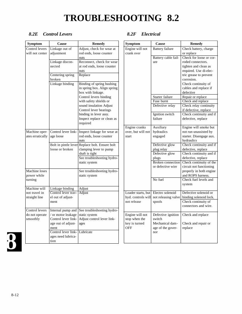
8
8-12
Adjust, check for wear atrod ends, loose counternutsReconnect, check for wearat rod ends, loose counternutsReplace
Binding of spring bushingin spring box. Align springbox with linkage.Control levers bindingwith safety shields orsound insulation AdjustControl lever bearingsbinding in lever assy.Inspect replace or clean asrequired
Inspect linkage for wear atrod ends, loose counternutsReplace bolt. Ensure boltclamping lever to pumpshaft is tightSee troubleshooting hydro-static system
See troubleshooting hydro-static system
AdjustAdjust
See troubleshooting hydro-static systemAdjust control lever link-ages
Lubricate
Engine will notcrank over
Engine cranksover, but will notstart
Loader starts, buthyd. controls willnot release
Engine will notstop when thekey is turnedOFF
Control leverswill not center
Machine oper-ates erratically
Machine losespower whileturning
Machine willnot travel instraight line
Control leversdo not operatesmoothly
Linkage out ofadjustment
Linkage discon-nected
Centering springbrokenLinkage binding
Control lever link-age loose
Bolt in pintle leverloose or broken
Linkage bindingControl lever trav-el out of adjust-ment
Internal pump and/ or motor leakageControl lever link-age out of adjust-mentControl lever link-ages need lubrica-tion
8.2E Control Levers
Battery failure
Battery cable fail-ure
Starter failureFuse burntDefective relay
Ignition switchfailure
Auxiliaryhydraulicsengaged
Defective glowplug relayDefective glowplugsBroken connectionor defective wire
No fuel
Electro solenoidnot releasing valvespools
Defective ignitionswitchMechanical dam-age of the gover-nor
Check battery, chargeor replaceCheck for loose or cor-roded connectors.tighten and clean asrequired. Use di-elec-tric grease to preventcorrosion.Check continuity ofcables and replace ifdefectiveRepair or replaceCheck and replaceCheck relay continuityif defective, replaceCheck continuity and ifdefective, replace
Engine will smoke butnot run unassisted bystarter. Disengage aux.hydraulicsCheck continuity and ifdefective, replaceCheck continuity and ifdefective, replaceCheck continuity of thecircuit not functioningproperly in both engineand ROPS harness.Check fuel levels andsystem
Defective solenoid orbinding solenoid lock.Check continuity ofconnectors and wire.
Check and replace
Check and repair orreplace
8.2F Electrical
Symptom Cause Remedy Symptom Cause Remedy
TROUBLESHOOTING 8.2

8
8-13
SymptomEngine does not start
Starter does not run
Engine revolution is not smooth
Either white or blue exhaust gas isobserved
Either black or dark gray exhaust gasis observed
RemedyReplenish fuelVent airChange fuel and repair or replacefuel systemCleanClean or changeUse the specified fuel or engine oil
Use the specified fuelTighten nutAdjustReplaceCleanRepair or replaceRepair or replace
Replace head gasket, tighten cylin-der head bolt, glow plug and nozzleholderCorrect or replace timing gearReplaceAdjust
ChargeRepair or replaceRepair or replaceConnect
Clean or changeClean or changeTighten nutRepair or replaceAdjustRepair or replaceCleanRepair
Reduce to the specified levelRepair or replaceAdjustAdjust top clearance
Lessen the loadUse the specified fuelClean or changeClean or change
CauseNo fuelAir in the fuelWater in the fuel
Fuel pipe cloggedFuel filter cloggedExcessively high viscosity of fuel or engine oil at lowtemperatureFuel with low octane numberFuel leak due to loose injection pipe retaining nutIncorrect injection timingFuel cam shaft wornInjection nozzle cloggedInjection pump malfunctioningSeizure of crankshaft, camshaft, piston, cylinder lineror bearingCompression leak from cylinder
Improper valve timing Piston ring and liner wornExcessive valve clearance
Battery dischargedStarter malfunctioningKey switch malfunctioningWiring disconnected
Fuel filter clogged or dirtyAir cleaner cloggedFuel leak due to loose injection pipe retaining nutInjection pump malfunctioningIncorrect nozzle opening pressureInjection nozzle stuck or cloggedFuel overflow pipe cloggedGovernor malfunctioning
Excessive engine oilLow grade fuel usedFuel filter cloggedAir cleaner clogged
OverloadLow grade fuel usedfuel filter cloggedAir cleaner clogged
8.2G Diesel Engine
TROUBLESHOOTING 8.2

8
8-14
CausePiston rings gap facing the same directionOil ring worn or stuckPiston ring groove wornValve stem and guide wornCrankshaft bearing and crank pin bearing worn
Injection pump plunger wornInjection pump broken
Head gasket defectiveCylinder block or cylinder head flawed
Engine oil insufficientOil strainer cloggedRelief valve stuck with dirtRelief valve spring weakened or brokenExcessive oil clearance of crankshaft bearingExcessive oil clearance of crank pin bearingExcessive oil clearance of rocker arm bearingOil passage cloggedOil pump defectiveDifferent type of oil
Relief valve defectiveEngine oil insufficient
Fan belt broken or elongatedCooling water insufficientRadiator net and radiator fin clogged with dustInside of radiator corrodedCooling water flow route corrodedRadiator cap defectiveOverload runningHead gasket defectiveIncorrect injection timing
Unsuitable fuel usedIncorrect injection timingEngine’s moving parts seem to be seizingUneven fuel injectionDeficient nozzle injectionCompression leak
Battery electrolyte insufficientFan belt slipsWiring disconnectedRectifier defectiveAlternator defectiveBattery defective
8.2G Diesel Engine
SymptomExcessive lubricant oil consumption
Fuel mixed into lubricant oil
Water mixed into lubricant oil
Low oil pressure
High oil pressure
Engine overheated
Deficient output
Battery quickly discharges
RemedyShift gap directionReplaceReplaceReplaceReplace
Replace pump element or pumpReplace
ReplaceReplace
ReplenishCleanCleanReplaceReplaceReplaceReplaceCleanReplaceUse the specified oil type
ReplaceReplenish
Change or adjustReplenishCleanClean or replaceClean or replaceReplaceLoosen the loadReplaceAdjust
Use the specified fuel AdjustRepair or replaceRepair or replace injection pumpRepair or replace nozzleReplace head gasket, tightencylinder head bolt, glow plug and nozzle holder
Replenish distilled water Adjust belt tension or changeConnectReplace ReplaceChange
TROUBLESHOOTING 8.2

8
8-15
SPECIAL TOOLS 8.3
T103T135
T133’S’
*T103S*T103T135
T133’S’
*T103**T135*T173HL
T173HLS’T173HL’S’II
T203HDT233HDT243HDS
*T83 / 95S*T173T233
T173HLT173HLS’
T173HL’S’IIT203HDT233HD
T243HD’S
T103T135
T133’S’
ALLMODELS
P / N Illustration Description Model
955280 AXLE INSTALLATION TOOL - To install axlein final drive housing.
962201*955281 SEAL INSTALLATION TOOL - To install axle
seal in final drive housing.
Quantity - 3 required
955283*957372
AXLE EXTRACTOR TOOLS - To remove axlefrom final drive housing.
960986*955287
SEAL INSTALLATION TOOL - To install axleseal in final drive housing.
Quantity - 1
958674 SEAL INSTALLATION TOOL - To install axleseal in final drive housing.
Quantity - 2 required.
960997CHAIN TENSION TOOL - To test chain ten-sion.
U-1288 Universal Tool Kit 1 each. Combination wrench 7/16”, 1/2”,9/16”,11/16” 3/4”, 1 1/16”,1 1/4”. Sockets, 1”,1/2” drive, 7/8”, 1/2” drive, tool pouch, allenwrench 5/32” and 1/8”

8
8-16
916-30042-0125197
07909-30202-0125198
07916-30820-0125199
07916-30840-0125200
70090-01125-0125201
960456
DRY LINER PULLER - Used for removing andinstalling the dry liner of the engine.Consists of:304742 (64mm); 304743 (68mm); 30744 (75mm)304745 (76mm); 304746 (82mm); 304747(105mm); Removing Plates; 304748 InstallingPlate
DIESEL ENGINE COMPRESSION TESTER -Used to measure diesel engine compression anddiagnosis of need for major overhaul.
CRANKSHAFT NUT SOCKET - Used to take offand fix the crankshaft nut. (46 mm).
NOZZLE REMOVER SOCKET - Used to unfas-ten the screw type nozzle holders.
NOZZLE DISASSEMBLY SOCKET - Used inplace of a vice for disassembly and repair of noz-zles.
HYDRAULIC FLOW AND PRESSURE GAUGEASSEMBLY.
Kubota
Kubota
Kubota
Kubota
Kubota
All Loaders
P / N Illustration Description Model
SPECIAL TOOLS 8.3
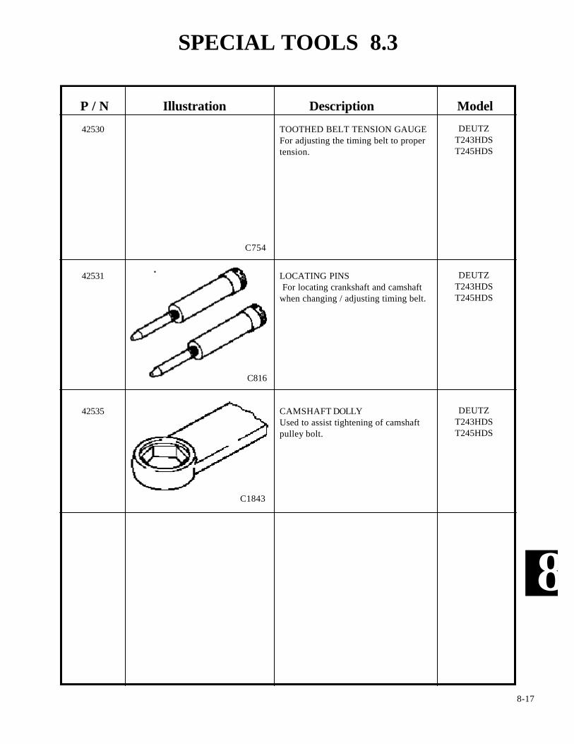
8
8-17
TOOTHED BELT TENSION GAUGEFor adjusting the timing belt to propertension.
LOCATING PINSFor locating crankshaft and camshaft
when changing / adjusting timing belt.
CAMSHAFT DOLLYUsed to assist tightening of camshaftpulley bolt.
DEUTZT243HDST245HDS
DEUTZT243HDST245HDS
DEUTZT243HDST245HDS
P / N Illustration Description Model
42530
42531
42535
C1843
C754
C816
SPECIAL TOOLS 8.3

8
8-18
P/N Illustration Description Model
ALLMODELS
ALLMODELS
SPECIAL TOOLS 8.3
C1840
C1841
CHAIN PULLER
SPANNER WRENCH 2’’ - 4 3/4’’To repair hydraulic cylinders
PHOTO SENSOR / WHEEL SPEEDTACHOMETER (Dual Function)
ALLMODELS
ALLMODELS
ALLMODELS
FORCE GAUGE, PUSH PULLFor measuring restraint bar brake cableadjustment. Special order only
T173HLST173HLS IIT243HDST245HDS
C1839
C1837
43979
43980
43981
C2342
C2343
MULTI METERFor measuring continuity, voltage, etc.
ANGLE FINDERFor measuring control angles, U-joint andchassis angles etc.

8
8-19
NOTES
THOMAS
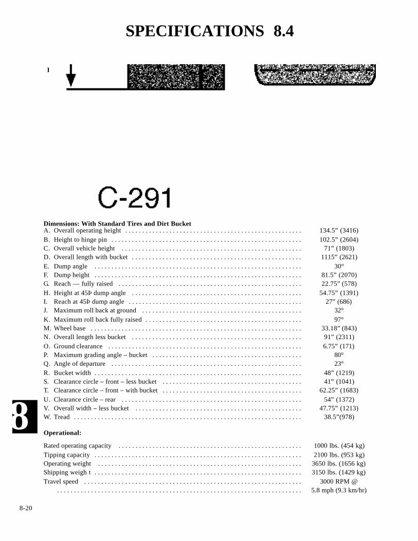
8
8-20
Dimensions: With Standard Tires and Dirt BucketA. Overall operating height . . . . . . . . . . . . . . . . . . . . . . . . . . . . . . . . . . . . . . . . . . . . . . . . . . . . 134.5” (3416)B. Height to hinge pin . . . . . . . . . . . . . . . . . . . . . . . . . . . . . . . . . . . . . . . . . . . . . . . . . . . . . . . . 102.5” (2604)C. Overall vehicle height . . . . . . . . . . . . . . . . . . . . . . . . . . . . . . . . . . . . . . . . . . . . . . . . . . . . . 71” (1803)D. Overall length with bucket . . . . . . . . . . . . . . . . . . . . . . . . . . . . . . . . . . . . . . . . . . . . . . . . . . 1115” (2621)E. Dump angle . . . . . . . . . . . . . . . . . . . . . . . . . . . . . . . . . . . . . . . . . . . . . . . . . . . . . . . . . . . . . 30°F. Dump height . . . . . . . . . . . . . . . . . . . . . . . . . . . . . . . . . . . . . . . . . . . . . . . . . . . . . . . . . . . . . 81.5” (2070)G. Reach — fully raised . . . . . . . . . . . . . . . . . . . . . . . . . . . . . . . . . . . . . . . . . . . . . . . . . . . . . . 22.75” (578)H. Height at 45Þ dump angle . . . . . . . . . . . . . . . . . . . . . . . . . . . . . . . . . . . . . . . . . . . . . . . . . . 54.75” (1391)I. Reach at 45Þ dump angle . . . . . . . . . . . . . . . . . . . . . . . . . . . . . . . . . . . . . . . . . . . . . . . . . . . 27” (686)J. Maximum roll back at ground . . . . . . . . . . . . . . . . . . . . . . . . . . . . . . . . . . . . . . . . . . . . . . . 32° K. Maximum roll back fully raised . . . . . . . . . . . . . . . . . . . . . . . . . . . . . . . . . . . . . . . . . . . . . . 97° M. Wheel base . . . . . . . . . . . . . . . . . . . . . . . . . . . . . . . . . . . . . . . . . . . . . . . . . . . . . . . . . . . . . . 33.18” (843)N. Overall length less bucket . . . . . . . . . . . . . . . . . . . . . . . . . . . . . . . . . . . . . . . . . . . . . . . . . . 91” (2311)O. Ground clearance . . . . . . . . . . . . . . . . . . . . . . . . . . . . . . . . . . . . . . . . . . . . . . . . . . . . . . . . . 6.75” (171)P. Maximum grading angle – bucket . . . . . . . . . . . . . . . . . . . . . . . . . . . . . . . . . . . . . . . . . . . . 80° Q. Angle of departure . . . . . . . . . . . . . . . . . . . . . . . . . . . . . . . . . . . . . . . . . . . . . . . . . . . . . . . . 23° R. Bucket width . . . . . . . . . . . . . . . . . . . . . . . . . . . . . . . . . . . . . . . . . . . . . . . . . . . . . . . . . . . . . 48” (1219)S. Clearance circle – front – less bucket . . . . . . . . . . . . . . . . . . . . . . . . . . . . . . . . . . . . . . . . . 41” (1041)T. Clearance circle – front – with bucket . . . . . . . . . . . . . . . . . . . . . . . . . . . . . . . . . . . . . . . . . 62.25” (1683)U. Clearance circle – rear . . . . . . . . . . . . . . . . . . . . . . . . . . . . . . . . . . . . . . . . . . . . . . . . . . . . . 54” (1372)V. Overall width – less bucket . . . . . . . . . . . . . . . . . . . . . . . . . . . . . . . . . . . . . . . . . . . . . . . . . 47.75” (1213)W. Tread . . . . . . . . . . . . . . . . . . . . . . . . . . . . . . . . . . . . . . . . . . . . . . . . . . . . . . . . . . . . . . . . . . . 38.5”(978)
Operational:
Rated operating capacity . . . . . . . . . . . . . . . . . . . . . . . . . . . . . . . . . . . . . . . . . . . . . . . . . . . . . . 1000 lbs. (454 kg)Tipping capacity . . . . . . . . . . . . . . . . . . . . . . . . . . . . . . . . . . . . . . . . . . . . . . . . . . . . . . . . . . . . . 2100 lbs. (953 kg)Operating weight . . . . . . . . . . . . . . . . . . . . . . . . . . . . . . . . . . . . . . . . . . . . . . . . . . . . . . . . . . . . 3650 lbs. (1656 kg)Shipping weigh t . . . . . . . . . . . . . . . . . . . . . . . . . . . . . . . . . . . . . . . . . . . . . . . . . . . . . . . . . . . . . 3150 lbs. (1429 kg)Travel speed . . . . . . . . . . . . . . . . . . . . . . . . . . . . . . . . . . . . . . . . . . . . . . . . . . . . . . . . . . . . . . . . 3000 RPM @
. . . . . . . . . . . . . . . . . . . . . . . . . . . . . . . . . . . . . . . . . . . . . . . . . . . . . . . . . . . . . . . . . . . . . . . . 5.8 mph (9.3 km/hr)
LOADER SPECIFICATIONS
SPECIFICATIONS 8.4

8
8-21
Engine
Make and model ......................................................................................................................................... Kubota V1305EType.............................................................................................................................................. Vertical , In Line, 4 CycleNumber of cylinders............................................................................................................................................................ 4Cylinder bore ........................................................................................................................................ 76 mm (2.99 inches)Stroke................................................................................................................................................. 73.6 mm (2.90 inches)Displacement ........................................................................................................................................ 1332cc .(81.5cu. in)Maximum engine speed (no load) ...................................................................................................................... 3000 RPMLow idle setting.................................................................................................................................................... 1300 RPMCooling system ........................................................................................................................................................... LiquidPower (ISO 9249 Net Power)............................................................................................ 22.4Kw (30.0 hp) @ 3000 RPMTorque (ISO 9249 Net Power) ................................................................................ 60.0 N.m. (43.4 lbs / ft.) @ 2000 RPMCompression ratio....................................................................................................................................................... 22.0: 1Firing order (viewed from gear case end).......................................................................................................... 1 - 3 - 4 - 2Fuel injection timing................................................................................................................................. 18° - 20º BTDC.Injector working pressure ....................................................................................... 1990 - 2133 PSI (140 - 150 Kgf / cm
3)
Direction of rotation (viewed from flywheel end) ............................................................................... Counter - clockwiseValve clearance, (cold)............................................................................................... . 0071 - .0087 in (0 - .18 - 0.22 mm)Fuel type ............................................................................................................................................................ Diesel No. 2Air cleaner ........................................................................................... Replaceable dry cartridge with restriction indicatorEngine oil capacity with filter .......................................................................................................................... 8. 5 qts. (8 l)Oil type ................................................................................................................................................... 10W30API SE,CDCooling system capacity.................................................................................................................................. 3.2 gal. (12 l)Radiator cap pressure setting.................................................................................................................. 12. 8 PSI (88 KPa)Thermostat rating.......................................................................................................................... Fully open 185°F (85°C)
Hydraulic System
Pump type ...................................................................................................................................... Gear, 0.61 cu. in. (11cc)Capacity (theoretical) ............................................................................................................................. 8.7 GPM (33 L/m)Rated RPM ................................................................................................................................................................... 3000Rated pressure ................................................................................................................... 2150 (Zero Flow) PSI (148 bar)Filtration ............................................................................................................................................................... 10 MicronHydraulic fluid ........................................................................................................................... 10W30 API Class, SE/CDControl valve (to S / N LC001080) ................................................. Parallel type with float on lift and detent on auxiliaryControl valve (S / N LC001081 onward)........................................... Series type with float on lift and detent on auxiliaryCylinders. ..........................................................................................................................................Lift Tilt......Type........................................................................................................................................Double acting Double actingQty per loader ..................................................................................................................................... 2 2.......Bore diameter ................................................................................................................................... 2.0 in. 2.0 in.Rod diameter ................................................................................................................................ 1.125 in. 1.125 in.Stroke ............................................................................................................................................ 26.00 in. 14.875 in.
SPECIFICATIONS 8.4

8
8-22
LPA Sound level at operators ear. . . . . . . . . . . . . . . . 83 DbALWA Adjusted sound level at 10m (32.8ft). . . . . . . . .96 DbA
SOUND POWER LEVEL
Hydrostatic Transmission & Final Drive
Pump type .......................................................................................................................... Two in line, axial piston pumpsPump displacement ................................................................................................................................ 1.5 cu. in. (25 cm
3)
Motor type ................................................................................................................................................................ GerolerMotor displacement ........................................................................................................................ 19.9 cu. in. (326.3 cm
3)
System relief setting .............................................................................................................................. 3625 PSI (250 bar)Final drive ...................................................................................................... Roller chain running in oil bath to each axleDrive chain size ................................................................................................................................................. ASA 60 HT
Electrical
Alternator ....................................................................................................................................................................60 ampBattery ..................................................................................................................................................................730 C.C.AStarter...........................................................................................................................................................................12 voltCircuit breaker rating .................................................................................................................................................40 amp
Tires
Standard ..............................................................................................................8.50 x 15 @ 30 - 35 PSI (207 - 241 Kpa)Flotation ...........................................................................................................10.50 x 15 @ 30 - 35 PSI (207 - 241 KPa)
Fluid Capacities
Fuel tank ..........................................................................................................43 L (11.3 gal) Diesel No. 2 Engine lubrication ..............................................................................................8 L (8.5 qts.) 10W30 API SE, CDFinal drive transmissions (each) ........................................................................7 L (1.8 gal.) 10W30 API SE, CDHydraulic reservoir .............................................................................................34 L (9 gal.) 10W30 API SE, CDEngine cooling system ......................................................................................12 L (3.2 gal) 50 / 50 water & ethylene
SPECIFICATIONS 8.4

8
8-23
Torque SpecificationsLoader
Wheel nuts (24) . . . . . . . . . . . . . . . . . . . . . . . . . . . . . . . . . . . . . . . . . . . . . . . . . . . . . . . . 100 - 110 ft lbs. (136 - 139 Nm)Motor mount isolators (3) . . . . . . . . . . . . . . . . . . . . . . . . . . . . . . . . . . . . . . . . . . . . . . . . . . . . . . . . . . .60 ft / lbs (81.6 Nm)
FOR NON-CRITICAL AND NOT OTHERWISE MENTIONED APPLICATIONS. THE FOLLOWING GENERALASSEMBLY TORQUES WILL APPLY:
Bolts & Nuts Torque ft. lbs (Nm.)1/4 - 20 5 - 7 (6. 7 - 9. 5)5/16 - 18 12 - 15 (16 - 20)5/16 - 24 12 - 15 (16 - 20)3/8 - 16 17 - 22 (23 - 30)3/8 - 24 22 - 27 (30 - 37)7/16 - 14 30 - 35 (41 - 47)
SPECIFICATIONS 8.4
HOSE SIZE 37º JIC FITTINGS HOSE SIZE ORB FITTINGS1/4 9 to 10 1/4 14 to 165/16 15 to 16 5/16 18 to 203/8 20 to 22 3/8 24 to 261/2 30 to 33 1/2 50 to 605/8 40 to 44 5/8 72 to 803/4 70 to 77 3/4 125 to 1357/8 82 to 90 7/8 160 to 1801 55 to 60 1 200 to 2201 1/4 120 to 132 1 1/4 210 to 2801 1/2 131 to 144 1 1/2 270 to 3602 300 to 330
The following torque specifications are for steel ORB fittings into aluminum.
HOSE SIZE ORB FITTINGS HOSE SIZE ORB FITTINGS1/4 5 to 7 3/4 40 to 455/16 8 to 10 7/8 50 to 553/8 10 to 12 1 90 to 991/2 21 to 24 1 1/4 80to 905/8 27 to 30
Torque MotorDescription Qty. SpecificationValve Housing 4 130Bearing Housing 8 46.5Front Cover 8 10.7Bearing Nut 1 45Mounting 4 80
Tandem PumpDescription Qty. SpecificationFront Support 1 50 (+/- 2)Rear Mounting 2 55 (+/- 2)Trunion Seal Carrier 4 20 (+/- 2)Trunion Seal Cover 4 20 (+/- 2)Relief Valve 4 40 (+/- 10)Charge Relief Cap 1 40 ~ 100Tandem Section 4 40 (+/- 5)Gear Pump 2 25 (+/- 2)
7/16 - 20 40 - 45 (54 - 61)1/2 - 13 45 - 50 (61 - 68)1/2 - 20 50 - 60 (68 - 81)9/16 - 12 60 - 70 (81 - 95)9/16 - 18 65 - 75 (88 - 102)5/8 - 11 75 - 85 (102 - 115)5/8 - 18 100 - 110 (136 - 150)
Hydraulic Fittings: Specifications listed in ft / lbs. Multiply by 1.36 for Nm.
Note: Torque specification are in ft /lbs. Multiply by1.36 for newton meters.

8
8-24
CONVERSION CHART 8.5
Metric to U.S. Formula

8
8-25
CONVERSION CHART 8.5
U.S. to Metric Formula