SECTION 303-01A: Engine - I6 - Barra Swap LLC
84
SECTION 303-01A: Engine - I6 VEHICLE APPLICATION: 2008.0 Falcon CONTENTS SPECIFICATIONS Lubricants and Sealants ..................................................................................................................... 303-01A-01 General Specifications ........................................................................................................................ 303-01A-01 Torque Specifications ........................................................................................................................ 303-01A-03 DESCRIPTION AND OPERATION Engine - I6............................................................................................................................................ 303-01A-05 DIAGNOSIS AND TESTING Inspection and Verification ................................................................................................................. 303-01A-10 Symptom Chart .................................................................................................................................... 303-01A-11 Component Tests ............................................................................................................................... 303-01A-13 GENERAL PROCEDURES Cylinder Head Inspection ................................................................................................................... 303-01A-16 Valve Inspection................................................................................................................................... 303-01A-16 Valve Measurement ........................................................................................................................... 303-01A-17 Valve Guide Inspection ...................................................................................................................... 303-01A-17 Valve Guide Replacement ................................................................................................................ 303-01A-18 Valve Seat Inspection/Repair ............................................................................................................ 303-01A-18 Valve Spring Inspection ...................................................................................................................... 303-01A-19 Camshaft End Play Inspection .......................................................................................................... 303-01A-19 Camshaft Inspection.......................................................................................................................... 303-01A-20 Camshaft Journal Clearance - Plastigauge Method .................................................................... 303-01A-20 Roller Follower Inspection .................................................................................................................. 303-01A-21 Lash Adjuster Bore Inspection .......................................................................................................... 303-01A-21 Cylinder Block Inspection/Repair..................................................................................................... 303-01A-22 Cylinder Bore - Taper......................................................................................................................... 303-01A-22 Cylinder Bore - Out-of-Round.......................................................................................................... 303-01A-22 Piston Inspection ................................................................................................................................ 303-01A-23 Piston Clearance Inspection/ Repair............................................................................................... 303-01A-23 Piston Ring Clearance Inspection.................................................................................................... 303-01A-23 Piston Ring Clearance Inspection.................................................................................................... 303-01A-24 Crankshaft Inspection........................................................................................................................ 303-01A-25 Crankshaft Main Bearing Clearance ............................................................................................... 303-01A-25 Crankshaft End Play Inspection/Repair .......................................................................................... 303-01A-26 Connecting Rod Inspection.............................................................................................................. 303-01A-26 Connecting Rod Big End Bearing Clearance .................................................................................303-01A-27 Connecting Rod Side Clearance Inspection...................................................................................303-01A-27 Piston and Connecting Rod Inspection...........................................................................................303-01A-27 Version: 2008.0 Falcon Workshop Manual 303-01A Engine - I6 303-01A
-
Upload
khangminh22 -
Category
Documents
-
view
0 -
download
0
Transcript of SECTION 303-01A: Engine - I6 - Barra Swap LLC

SECTION 303-01A: Engine - I6VEHICLE APPLICATION: 2008.0 Falcon
CONTENTSSPECIFICATIONS
Lubricants and Sealants ..................................................................................................................... 303-01A-01
GeneralSpecifications ........................................................................................................................ 303-01A-01
TorqueSpecifications ........................................................................................................................ 303-01A-03
DESCRIPTION AND OPERATION
Engine - I6 ............................................................................................................................................ 303-01A-05
DIAGNOSIS AND TESTING
InspectionandVerification ................................................................................................................. 303-01A-10
SymptomChart ....................................................................................................................................303-01A-11
ComponentTests ............................................................................................................................... 303-01A-13
GENERAL PROCEDURES
CylinderHeadInspection ................................................................................................................... 303-01A-16
ValveInspection ................................................................................................................................... 303-01A-16
ValveMeasurement ........................................................................................................................... 303-01A-17
ValveGuideInspection ...................................................................................................................... 303-01A-17
ValveGuideReplacement ................................................................................................................ 303-01A-18
ValveSeatInspection/Repair ............................................................................................................ 303-01A-18
ValveSpringInspection ...................................................................................................................... 303-01A-19
CamshaftEndPlayInspection .......................................................................................................... 303-01A-19
CamshaftInspection .......................................................................................................................... 303-01A-20
CamshaftJournalClearance-PlastigaugeMethod .................................................................... 303-01A-20
RollerFollowerInspection .................................................................................................................. 303-01A-21
LashAdjusterBoreInspection .......................................................................................................... 303-01A-21
CylinderBlockInspection/Repair ..................................................................................................... 303-01A-22
CylinderBore-Taper ......................................................................................................................... 303-01A-22
CylinderBore-Out-of-Round .......................................................................................................... 303-01A-22
PistonInspection ................................................................................................................................ 303-01A-23
PistonClearanceInspection/Repair ............................................................................................... 303-01A-23
PistonRingClearanceInspection .................................................................................................... 303-01A-23
PistonRingClearanceInspection .................................................................................................... 303-01A-24
CrankshaftInspection ........................................................................................................................ 303-01A-25
CrankshaftMainBearingClearance ............................................................................................... 303-01A-25
CrankshaftEndPlayInspection/Repair .......................................................................................... 303-01A-26
ConnectingRodInspection .............................................................................................................. 303-01A-26
ConnectingRodBigEndBearingClearance .................................................................................303-01A-27
ConnectingRodSideClearanceInspection...................................................................................303-01A-27
PistonandConnectingRodInspection ...........................................................................................303-01A-27
Version:2008.0FalconWorkshopManual
303-01A Engine - I6 303-01A

GENERAL PROCEDURES
TimingChainElongation .....................................................................................................................303-01A-27
IN-VEHICLE REPAIR
OilFilter ................................................................................................................................................. 303-01A-28
OilLevelIndicator&Tube .................................................................................................................. 303-01A-28
CylinderHeadTemperatureSensor .............................................................................................. 303-01A-29
CamPositionSensor ......................................................................................................................... 303-01A-29
CrankshaftPositionSensor .............................................................................................................. 303-01A-30
OilPressure&OilTemperatureSensor .......................................................................................... 303-01A-30
CombustionKnockSensor ............................................................................................................... 303-01A-31
ExhaustGasOxygenSensor ............................................................................................................ 303-01A-31
Temperature-ManifoldAirPressureSensor ................................................................................ 303-01A-32
CrankshaftVibrationDamper ........................................................................................................... 303-01A-32
CrankshaftFrontOilSeal ................................................................................................................... 303-01A-33
CrankshaftRearOilSeal .................................................................................................................... 303-01A-34
Flexplate/DrivePlate ......................................................................................................................... 303-01A-34
WaterPump ........................................................................................................................................ 303-01A-34
ElectronicThrottleBodyandIntakeManifold ................................................................................ 303-01A-35
IntakeManifoldTuningValve(IMTV) ................................................................................................ 303-01A-38
ExhaustManifoldAssembly ............................................................................................................. 303-01A-39
OilControlValveSeal ......................................................................................................................... 303-01A-40
ValveCover ......................................................................................................................................... 303-01A-40
IgnitionCoils/WiringLoom ................................................................................................................ 303-01A-43
Camshafts,VCTPhaser,OilControlValves,&OCVFilters ......................................................... 303-01A-44
CamshaftRemoval ............................................................................................................................ 303-01A-45
CamshaftandVCTPhasers ............................................................................................................. 303-01A-45
CamshaftInstallation ...........................................................................................................................303-01A-47
TimingChainTensioner ..................................................................................................................... 303-01A-49
VCTPhaser ........................................................................................................................................ 303-01A-49
RockerArm,LashAdjuster,ValveSpringandValveStemSeal .................................................. 303-01A-50
RockerArmandLashAdjuster ......................................................................................................... 303-01A-51
ValvespringandValveStemSeal ..................................................................................................... 303-01A-51
FrontCover ......................................................................................................................................... 303-01A-52
CamshaftDrive ................................................................................................................................... 303-01A-62
TimingChainTensionerRelease ...................................................................................................... 303-01A-63
CylinderHead ..................................................................................................................................... 303-01A-64
Engine .................................................................................................................................................. 303-01A-68
EngineMounting .................................................................................................................................303-01A-72
EngineOilPan ......................................................................................................................................303-01A-72
OilPumpPickupTube.........................................................................................................................303-01A-74
OilPump ................................................................................................................................................303-01A-75
Version:2008.0FalconWorkshopManual
303-01A Engine - I6 303-01A
CONTENTS (Continued)

IN-VEHICLE REPAIR
PistonandRodAssembly ..................................................................................................................303-01A-76
Mainbearings/Crankshaft .................................................................................................................303-01A-77
RearMainBearingCapAssembly ....................................................................................................303-01A-78
PistonRing ............................................................................................................................................303-01A-78
DISASSEMBLY AND ASSEMBLY
KeyRetainer-ValveSpring ...............................................................................................................303-01A-79
ValveStemSeal ...................................................................................................................................303-01A-79
PistonandConnectingRodAssembly ........................................................................................... 303-01A-80
PistonandConnectingRodDisassemblyandAssembly ........................................................... 303-01A-80
ConnectingRodBolt ......................................................................................................................... 303-01A-81
Version:2008.0FalconWorkshopManual
303-01A Engine - I6 303-01A
CONTENTS (Continued)

303-01A Engine - I6 303-01A-1
Version:2008 Falcon Workshop Manual
SPECIFICATIONS
Lubricants and Sealants
Description Specification
EngineOil5W-30ILSAC-GF4/GF5
WSS-M2C929-A/WSS-M2C946-A(I6DOHCVCT)
SiliconeSealant(Loctite5900)
WSSM4G323A7
AntiSeizecompound(Loctite767orsimilar)
ESEFM99C100A
RubberGrease ESZM1C223A
General Specifications
Description Specification
Displacement 3983cc
Numberofcylinders In line 6
CompressionRatio
DOHCVCT 10.3:1
Poweratspecifiedrpm(DIN)on95RON
DOHCVCT 198kW@5000
Torqueatspecifiedrpm(DIN)on95RON
DOHCVCT 409Nm@3250
Bore/Stroke 92.25mm/99.31mm
FiringOrder 1-5-3-6-2-4
OilPressure-2000rpm@80°C(normaloperatingtemperature)OilPressure-700rpm(idle)@80°C(normaloperatingtemperature)
300kPaminimum
120kPaminimum
SparkPlug-I6
DOHCVCT AGSP22Z13
CompressionPressureatMaximumcrankingspeed
DOHCVCT 1010kPa
Idle Speed
AutotransinNeutral
DOHCVCT 700 ± 50 rpm
AutotransinDrive
DOHCVCT 530 ± 50 rpm
IntakeManifoldVacuum@Idlerpm
DOHCVCT 60kPa@Drive
Cylinder Head/Valve Train CombustionChamberVolume
63.25 - 65.75cc
Jointfaceflatness 0.08mmin150mmor0.18mmoverall
Cylinderheadjointfacesurfacefinish
2.5Rz(Din)@2.5cut-off,Wt<10.0,Mr68%[email protected] um
MinimumCylinderheaddeckheight
Std - 0.3 mm
Valveseatwidth-Intake 1.0mm - 1.4mm
Valveseatwidth-Exhaust 1.25mm - 1.75mm
Valveseatangle 44.75°
Valveseatrunout 0.04mm
Valvestemtoguideclearance
0.020mm - 0.069mm
Valveguideparentborediameter
9.975mm - 10.025mm
Valveguideoutsidediameter
10.028mm - 10.039mm
Valveguideinsidediameter
6.015mm - 6.044mm
Valveheaddiameter-intake
35mm
Valveheaddiameter-exhaust
32mm
Gauge Diameters Valvefacerunout 0.05mm
Valvefaceangle 45.5°
Valvestemdiameter(In&Ex)
5.975mm - 5.995mm
Valveseatinsertrecessdiameter(In)
35.07mm - 35.12mm
Valveseatinsertrecessdiameter(Ex)
32.37mm - 32.42mm
Valveseatinsertouterdiameter(In)
35.192mm - 35.208mm
Valveseatinsertouterdiameter(Ex)
32.492mm - 32.508 mm
Valvespringfreelength 50.0 mm
Valvespringinstalledload/length
280N/37.8mm
Valvespringcompressedload/length
550N/26.8mm
Valvespringallowableloadloss
Valvespring-outofsquare
2°
Rockerarmratio 2.04
HydraulicLashAdjusterdiameter
13.972mm - 13.984mm
Lashadjusterboreincylinderhead
13.990mm - 14.007mm
CollapsedLashadjusterclearance at cam
0.5mm - 1.1mm (desired)

303-01A Engine - I6 303-01A-2
Version:2008 Falcon Workshop Manual
Description Specification
Camshaft
Lobelift(In&Ex) 5.39mm
Valvelift(In&Ex) 11.00mm
Camshaftendplay 0.1mm - 0.3mm
Camshaftjournaldiameter
34.928mm - 34.968mm -Front
29.928mm - 29.968mm -Remainder
CamshaftJournalmaxoutofround
0.015mm
Cylinderheadbearingdiameter
34.987mm - 35.012mm -Front
29.987mm - 30.012mm -Remainder
Journaltobearingclearance
0.019mm - 0.084mm
ServiceLimit 0.120mm
ValveTiming EngineStopped,VCTPhasersFullyAdvanced&VCTLockingPinsEngaged
IntakeOpens 27.5°BTDC
IntakeCloses 48.5°ABDC
ExhaustOpens 78.5°BBDC
ExhaustCloses 2.5°BTDC
IntakeCamCentre-line(MaximumLift)
99.5°ATDC
ExhaustCamCentre-line(MaximumLift)
131.5°BTDC
TimingChainMaximumElongation
0.35%
Cylinder Block
Headgasketthickness 0.25mmatbody,0.37mmatcylinderbore
Mainbearingborediameter
71.517mm - 71.541mm
Cylinderborediameter 92.24mm - 92.26mm Std
92.79mm - 92.31mm (0.05mmO/S)
93.74mm - 92.76mm (0.5mmO/S)
93.24mm - 93.26mm (1.0mmO/S)
Outofroundlimit 0.015mm
Outofroundservicelimit 0.125mm
Taperservicelimit 0.25mm
Crankshaft
Mainbearingjournaldiameter
67.481mm - 67.505mm
Connectingrodjournaldiameter
53.93mm - 53.95mm
Crankshaftfreeendplay 0.10mm - 0.20mm
ServiceLimit 0.30mm
Connectingrodbearings-clearancetocrankshaft-desired
0.025mm - 0.04mm
Connectingrodbearings-clearancetocrankshaft-servicelimit
0.06mm
Mainbearings-clearancetocrankshaft-desired
0.02mm - 0.04mm
Mainbearings-clearancetocrankshaft-servicelimit
0.06mm
Connecting Rod
SmallendborediameterFixedPin(WithoutBushing)
23.104mm - 23.144mm
Bigendborediameter 56.871mm - 56.889mm
Length(centretocentre) 153.78mm - 153.92mm
Alignment(boretobore-maxdifference)Twist
0.20mmServiceLimit
Bend 0.10mmServiceLimit
Side clearance (assembledtocrank)Standard
0.09mm - 0.27mm
SideclearanceServicelimit
0.36mm
SPECIFICATIONS (Continued)

303-01A Engine - I6 303-01A-3
Version:2008 Falcon Workshop Manual
Description Specification
BoreDiameter 92.24 92.25 92.26
Installedpistonringgap-TopCompression-New
TBATopRingInstalled Gap
0.267mm ~ 0.417mm
0.299mm ~ 0.449mm
0.330mm ~ 0.480mm
Installedpistonringgap-2ndRing-New
TBA2ndRingInstalled Gap
0.287mm ~ 0.447mm
0.319mm ~ 0.479mm
0.350mm ~ 0.510mm
OilRing(Rail)Gap-New0.15mm - 0.75mm OilRing
Installed Gap0.087mm ~ 0.687mm
0.119mm ~ 0.719mm
0.150mm ~ 0.750mmOilRing(Rail)Gap-
ServiceLimit1.0mm
Description Specification
Piston
Pistondiameter(STD)
(Measuredat12.5upfromPistonSkirt)
92.201mm-92.215mm (WithoutSkirtCoating)92.211mm-92.235mm (WithSkirtCoating)
Pistontoboreclearance(new)
0.025mm-0.059mm 0.005mm-0.049mm
PistonPinborediameter(FixedPin)
Notethe“PintoPistonClearance”requiredbelow
23.169mm - 23.174mm
Ringgroovewidth-TopCompression
1.23mm - 1.25mm
Ringgroovewidth-LowerCompression
1.52mm - 1.54mm
Ringgroovewidth-OilRing
2.99mm - 3.01mm
Pistonpinlength 65.10mm - 65.30mm
Pistonpindiameter(FixedPin)
Notethe“PintoPistonClearance”requiredbelow.
23.157mm - 23.162mm
Pintopistonclearance 0.010mm-0.015mm
Ringgrooveclearance-TopCompressionNew
0.04mm - 0.080mm
Ringgrooveclearance-TopCompressionServicelimit
0.15mm
Ringgrooveclearance-2ndRingNew
0.03mm - 0.075mm
Ringgrooveclearance-2ndRingServicelimit
0.15mm
Oilringgrooveclearance-new
0.028mm - 0.17mm
Oilringgrooveclearance-servicelimit
0.20mm
SPECIFICATIONS (Continued)
Lubrication system
Oilcapacity-InitialFill(Dryengine)
7.0L
OilChangewithoutFilter 5.8L
OilChangewithFilter 6.8L
Torque Specifications
Oilthreadswithengineoil.Donotoilthreadsthatrequirethreadsealantorthreadlocker.
Description Nm
MainBearingCapbolts 85
CylinderHeadBolts(exceptfrontandrear)
Step1:40NmStep2:Rotate120°
clockwise
FrontandRearCylinderHeadBolts(X4Bolts)
Step1:30NmStep2:Rotate90°
clockwise
OilPantoCylinderblock/frontcover
10
OilPantomainbearingcrossbolts
58(Applythreadsealant)
OilPanRearFace Flushor0.25mmforwardofrearfaceof
block
OilPanDrainPlug 26
IntakeManifold-CylinderHead
17-24
IntakeManifoldBracket(Upper)
16
ToManifold 8-12
ToCylinderHead 8-12
IntakeManifoldPencilStrut(Lower)
20
ToManifold 17-24
ToCylinderHead 17-24
ToEngineMt.Support 44-55
FuelRailtoIntakeManifold
8-12
IntakeManifoldETB 8-12

303-01A Engine - I6 303-01A-4
Version:2008 Falcon Workshop Manual
Description Nm
IntakeManifoldMTV 4.5-5.5
IntakeManifoldPressure/TemperatureSensor
2
IntakeManifoldDipStickTube
10
ExhaustManifoldtoCylinderHead
27
ExhaustManifoldHeatShield-Lower
20
ExhaustManifoldSlipJoint
Stud 16
Nut 23
FlywheeltoCrankshaft(Manual)
90
FlywheeltoCrankshaft(Auto)
70
ManualFlywheelHousingtoBlock
50
OilPumptoCylinderBlock
10
OilPumpPickupTubetoOilPump
10
OilPumpPickupTubetoMainBearingBolt
20
OilFilterAdaptortoCylinderBlock
17
OilFiltertoCylinderblock Withoiledgasket,handtightenuntilgasketcontactsblockface,tightenafurther¾turn
OilPressureSensor 20(Applythreadsealant)
OilTemperatureSensor 20(Applythreadsealant)
KnockSensortoCylinderBlock
20-25(Applythreadsealant)
TimingCovertoCylinderBlock
28(Applythreadsealant)
CrankshaftPositionSensortoTimingCover
10-12
ThermostatHousingtoCylinderHead
20(Applythreadlocker)
WaterOutlettoThermostatHousing
20
HeaterTubetoThermostatHousing
20
HeaterTubetoBlock(Exhaustside)
27
WaterPumptoCylinderBlock
20
SPECIFICATIONS (Continued)
Description NmEngineMountBrackettoCylinderBlock
50(Applythreadlocker)
EngineMounttoEngineMountBracket
102
AlternatorBracket(rear)toCylinderBlock
25
SparkPlugs 17
VariableCamTimingUnittoCamshaft
Step1:20NmStep2:Rotate40°
clockwise
SparkPlugCovertoRockerCover
7
IgnitionCoiltoRockerCover
24
CamCovertoCylinderHead-Fronttwolongbolts
13
CamCovertoCylinderHead-Sixshortbolts
10(Applythreadlocker)
OilControlValveSealstoCamCover
7
CamCapstoCylinderHead
10
Camshaftpositionsensortocylinderhead
9
CylinderHeadTemperaturesensortoCylinderHead
15
TimingChainFixedChainGuidetoCylinderBlockandCylinderHead
20
TimingChainTensionertoCylinderHead
9
TimingChainGuidePivotBolttoOilPump
47
TimingChainGuidePivotNut
9
CrankshaftVibrationDamper/FrontPulleytoCrankshaft
145
ConnectingRodCaptoConnectingrod
Step1:25NmStep2:90°clockwise.

303-01A Engine - I6 303-01A-5
Version:2008 Falcon Workshop Manual
Engine - I6
The4.0LI6isafourvalvepercylinder,DualOverheadCamshaftEnginewithindividualintakeandexhaustvariablecamtimingunits.Adistributorlessignitionsystemwithindividualcoilsmountedabovethesparkplugsisused.Thecylinderblockiscastiron,andisattachedtoanaluminiumoilpanwithcross-boltedmainbearingcapstoincreaserigidity.Theoilpumpismountedonthenoseofthecrankshaft,andasinglestagerollerchaindrivesthehollowcamshafts.Hydrauliclashadjustersandrollerfingerfollowersactivatethevalves.Anelectronicthrottlebodyisemployedtogetherwithavariablelengthintakemanifold.Petrolversiononlyisavailable.
WARNING
EngineswithplasticinletmanifoldsarenotsuitableforconversiontoLPG.Theplasticinlet
manifoldisonlydesignedtoworkwithpetrolengines-itisdangeroustotrytousethistypeofmanifoldwithvapourbasedLPGfuelsystems.
DESCRIPTION AND OPERATION

303-01A Engine - I6 303-01A-6
Version:2008 Falcon Workshop Manual
Upper Engine Components
AUS00356A
21
20
19
18
17
16
15
23
9
33
30
28
34
14
8
13
31
2726
25
5
1
2
12
22
7
3
11
29
4
10
32
24
6
DESCRIPTION AND OPERATION (Continued)

303-01A Engine - I6 303-01A-7
Version:2008 Falcon Workshop Manual
Upper Engine Components
Item Description
1 CoilandBootAssembly
2 SparkPlug
3 Cap-Camshaftintakebridge-Rear
4 Camshaft-Intake
5 Cylinderheadtemperaturesensor
6 Engineliftingeye,LH,FRT
7 SensorAssemblycamshafttiming
8 Headgasket
9 SensorAssemblycamshafttiming
10 Cylinderhead
11 Lashadjusterassembly
12 Clip
13 Engineliftingeye,RH,RR
14 Valve-Inlet
15 Valve-Exhaust
16 Insert-CylinderHead
17 Bushing-Valveguide
18 Seal-Valvestem
19 Spring-Valve
20 Retainer-Valvespring
21 Key-Valvespringretainer
22 Rockerarm
23 Camtimingassembly-Enginevariable
24 Toptimingchainguide
25 Cap-Camshaftexhaustbridge,FRT
26 HousingandValveassemblycamshaftvariabletiming
27 Gasket-Valverockerarmcover
28 Seal-Gasketvalverockerarmcover
29 Gasket-Rockerarmcover
30 Gasket-Sparkplug
31 Cover-Valverockerarm
32 Sparkplugcoverassembly
33 Oilfillercapgasket
34 Oilfillercap
DESCRIPTION AND OPERATION (Continued)

303-01A Engine - I6 303-01A-8
Version:2008 Falcon Workshop Manual
Lower Engine Components
AUS04701A
22
23a
26
27
24
16
3
4
12
33
831
32
36
37
38
15
19
10
7
6
5
21
25
17
1128
20
18
13
14
9
734
29
30
23b
23c
35
2
1
DESCRIPTION AND OPERATION (Continued)

303-01A Engine - I6 303-01A-9
Version:2008 Falcon Workshop Manual
Lower Engine Components
Item Description
1 TimingChainTensioner
2 Leverarmassembly-Timingchaintensioner
3 Timingchain
4 Guideassembly-Timingchain
5 Oilpump
6 Oilpumppick-up/Screen
7 SensorAssemblyEngineSparkintensity(knocksensors)
8 Driveplate/Flexplate
9 Cover-Flywheelhousing
10 Filterassembly-Oil
11 Pistoncompressionring,Upper
12 Pistoncompressionring,Lower
13 PistonOilcontrol,Ring
14 Piston
15 Connectingrod
16 Bearingupper-Connectingrod(BigEnd)
17 Bearinglower-Connectingrod(BigEnd)
18 Cap-ConnectingRod
19 Pin-Piston
20 Cover-Flywheel
21 Plug-OilPandrain
22 Pan-Oilpan
23a FrontHalfMoonSeal-OilPan
23b FrontHalfMoonSeal-OilPan
23c FIPGasket(SiliconRTV)-OilPan
24 Crankwindageoilbaffle
25 Brace-Mainbearingcapsupport
26 Crankshaftmainbearingcaps
27 Crankshaftmainbearing-Lower
28 Crankshaft
29 Crankshaftmainbearings-Upper
30 Cylinderblock
31 Tube-Oilleverindicator
32 Oilleverindicator
33 Damperassembly-Crankshaft
34 Cranksensor
35 Crankshaftsprocket/Tonewheel
36 Switchassembly-Oilpressure
37 Seal-Oil,Cylinderfrontcover
38 Cover-Cylinderfront
DESCRIPTION AND OPERATION (Continued)

303-01A Engine - I6 303-01A-10
Version:2008 Falcon Workshop Manual
Engine
Inspection and Verification
Sincediagnosisandtestingactuallybeginswhenrepairsaretakenon,thefollowingprocedureisrecommended.
1. Verifythecustomerconcernbyoperatingthesystem.
2. Visuallyinspectforobvioussignsofmechanicaldamageorelectricaldamage.Iftheconcerncannotbereproduced,carryoutaroadtestand/orvisualcheckwiththeaidofthefollowingtable.
Visual Inspection Chart
Mechanical
• Coolantleaks
• Oilleaks
• Leaksinthefuelsystem
• Visiblydamagedorwornparts
• Looseormissingnutsorbolts
3. Ifanobviouscauseforanobservedorreportedconcernisfound,correctthecause(ifpossible)beforeproceedingtothenextstep.
4. Iftheconcernisnotvisuallyevident,verifythesymptomandrefertotheSymptomChart.
DIAGNOSIS AND TESTING

303-01A Engine - I6 303-01A-11
Version:2008 Falcon Workshop Manual
Symptom Chart
Condition Possible Sources Action
Enginewillnotcrank
• FaultyStarterSystem.• RefertoSection303-06Starting
System.
• TransmissionlevernotinPorN.
• PlaceinP.
• Seized engine. • Replaceengine.
• Coolantincylinders. • Replaceengine.
Enginecranksbutwillnotstart• Ignitionsysteminoperative.
• RefertoSection303-06StartingSystem.
• Fuelsysteminoperative. • RefertoSection303-04.
Engineslow/difficulttostart
• VariableCamTiming(VCT)unitlockpinnotengagedatstart.
• VCTunitOilControlValvejammed.
• CleanOilControlValve.RefertoValveCoverSection.
Enginemisfires
• FailSafeCoolinginoperation. • Repaircoolantsystem.
• Ignitionsystemfaulty. • RefertoSection303-06.
• Fuelsystemfaulty. • RefertoSection303-04.
• Restrictedexhaustsystem. • InspectExhaustsystem.
• Intakevacuumleak.• CarryoutIntakeManifoldVacuum
testinthissection.
• Burnedvalve/poorseating. • Performacompressioncheck.
• Brokenvalvespring. • Inspectvalvesprings.
• Headgasketleakage. • Inspectheadgasket.
• Pistondamage.• Performcylindercompression
check.
Rough-RollingIdle
• FaultyintakeOilControlValve(OCV)
• ReplaceintakeOCVonly
• Lowidleoilpressure• Measureminimumidleoil
pressureandrepair.Referrelevantsection.
• Incorrectsparkpluggap• Re-gapsparkplugto
specification.ReferSection303-06
InsufficientPower
• DualPlenumIntakeManifoldnotoperative.
• Checkswitchingoccursat3700rpm-refertoSection303-14.
• VCTunit(s)notoperative. • RefertoSection303-14.
• ElectronicThrottleControlUnitfaulty.
• RefertoSection303-14.
ExcessiveFuelConsumption
• Green(lowmileage)engine/vehicle.City/stop-startdriving.
• Establishaccuratefuelconsumptionusingfull-to-fullmethod.
• FaultyFuelSystem. • RefertoSection303-04.
• Green engine. • Recheckat15,000km.
• Valvestemsealdamagedormissing.
• Inspecttheseals.
• Oilleakage. • Repairoilleakage.
• IncorrectOilviscosity. • Drainandfillwithcorrectoil.
• Piston/rings/cylinderwornordamaged.
• Repair.RefertoSection303-00.
DIAGNOSIS AND TESTING (Continued)

303-01A Engine - I6 303-01A-12
Version:2008 Falcon Workshop Manual
Condition Possible Sources Action
ExcessiveOilConsumption
• Dilutedoil• Determinethecause.Correct.
Drainandrefilloil.
• Crankcaseoverfilled. • Adjustoillevel.
• FaultyPCVValve. • Checkandreplace.
Engineleaksoil
• Jointfastenersloose. • Tightentospecification.
• Outofpositionordamagedseal/RTVsealantomitted/inadequate.
• Pressurisecrankcaseto35kPa.Applysoapywater,checkforleak.Inspect and replace.
• Worn/outofpositioncrankrotaryseal.
• Inspect and replace.
• Porouscasting.
• Cleansuspectarea,Performpressurizedcrankcasecheck.Runengine,checkforleak.Replacecasting.
• SealantinCrankDamperkeywayomittedorinadequate.
• Replacesealant.
• SealantbetweenRearMainCapandblockomittedorinadequate.
• Performpressurizedcrankcaseleakcheck.Repair.
EngineNoise
• ExcessiveCrankshaftMainbearingorbigendclearance.
• ExcessiveCrankshaftendplay.
• Excessivecamshaftendplay.
• Excessivepistontocylinderboreclearance/damagedpiston/bentconnectingrod.
• Excessivepistonpintopistonpinboreclearance.
• Excessivehydraulicvalveadjusterclearance.
• Worncamlobeorrollerfingerfollower.
• Excessivevalveguideclearance.
• Brokenvalvespring.
• Loosetimingchain.
• Loosecrankdamper.
• Worn/noisyFrontEndAccessoryDriveBelt.
• Worn/noisytensioner/idlerpulley.
• Exhaustgasleakage.
• Inspectandrepair.ReferrelevantSection.
• Softorspongylashadjusters.• Checkforexcessivelyloworhigh
oillevel.Airleakinsuctionsideofoilpump.
• Carbonincombustionchamber/toplandofpiston.
• Removecarbonusingproprietarycarbonremovaltreatment.
DIAGNOSIS AND TESTING (Continued)
303-01A Engine - I6 303-01A-13
Version:2008 Falcon Workshop Manual
Component Tests
Engine Oil Leaks
Note:Beforeinstallingnewgasketsoroilseals,makesurethatthefaultisclearlyestablished.Iftheoilleakcannotbeidentifiedclearlybyavisualinspection,carryoutapressurizedcrankcaseleakcheck.
Pressurised leak check
1. Cleantheenginewithasuitablecleaningfluidtoremovealltracesofoil.
2. BlockoffthelinetothePCVvalve.
3. Applyaregulatedairsupplylinetothefreshairmakeuppointontherockercover.
4. Pressurisethecrankcaseto35kPa.
5. Checkforairleaksbywashingthesuspectareawithasolutionofsoapywaterandwatchingforbubbles.
6. Repairallleaksasnecessary.
General Remarks
Note:Removingfusesanddisconnectingelectricalcomponentscausesthepowertraincontrolmodule(PCM)tologanerrormessage.AfterthemeasurementshavebeencarriedoutthiserrormessageshouldbeclearedfrommemorybyconnectingtoIDS.
Thecompressionpressureshouldbecheckedwiththeengineatoperatingtemperature.
Check The Compression Pressure
WARNING
Onautomatictransmissionvehicles,select‘’P’’.Failuretofollowtheseinstructionsmay
resultinpersonalinjury.
1. Removethefuelpumprelay.
2. Starttheengineandrunforafewseconds,thenstall.
3. Removethesparkplugs.
4. Installanadaptorandcompressiontester.
5. Installanauxiliarystarterswitchinthestartingcircuit.WiththeignitionswitchOFF,usetheauxiliarystarterswitchtocranktheengineaminimumoffivecompressionstrokes,andrecordthehighestreading.Notetheapproximatenumberofcompressionstrokesrequiredtoobtainthehighestreading.
6. Repeatthetestoneachcylinder,crankingtheengineapproximatelythesamenumberofcompressionstrokes.
7. Installthecomponentsinreverseorder,observingthespecifiedtighteningtorques.
8. ResetthePCMfaultmemory.
DIAGNOSIS AND TESTING (Continued)
Interpretation of the Results
Theindicatedcompressionpressureisconsideredtobewithinspecificationifthelowestreadingcylinderiswithin75%ofthehighestreading.
CAUTION
Ifengineoilissprayedintothecombustionchamber,runtheengineat2000rpmforabout
15minutes(inordertoburntheoilandpreventdamagetothecatalyticconverter)aftercarryingoutthemeasurement.
Ifthemeasurementononeormorecylindersissignificantlylowerthanthespecifiedvalue,spraysomeengineoilintothecombustionchamberandrepeatthecompressionmeasurement.
Ifthereadinggreatlyimproves,thepistonringsaredamaged.
Ifthereadingstaysthesame,thecauseiseitherdamagedvalvesorvalveseats.
Ifthemeasurementsfortwoadjacentcylindersarebothtoolow,thenitisverylikelythatthecylinderheadgasketbetweenthecylinderisburntthrough.Thiscanalsoberecognizedbytracesofengineoilinthecoolantand/orcoolantintheengineoil.
Excessive Engine Oil Consumption
Theamountofoilanengineuseswillvarywiththewaythevehicleisdriveninadditiontonormalengine-to-enginevariation.Thisisespeciallytrueduringthefirst15,000kmwhenanewengineisbeingbrokeninoruntilcertaininternalcomponentsbecomeconditioned.Vehiclesusedinheavy-dutyoperationmayusemoreoil.Thefollowingareexamplesofheavy-dutyoperation:
• Trailertowingapplications
• Severeloadingapplications
• Sustainedhighspeedoperation
Enginesneedoiltolubricatethefollowinginternalcomponents:
• Cylinderblockcylinderwalls
• Pistonsandpistonrings
• Intakeandexhaustvalvestems
• Intakeandexhaustvalveguides
• Allinternalenginecomponents
Whenthepistonsmovedownward,athinfilmofoilisleftonthecylinderwalls.Asthevehicleisoperated,someoilisalsodrawnintothecombustionchamberspasttheintakeandexhaustvalvestemsealsandburned.

303-01A Engine - I6 303-01A-14
Version:2008 Falcon Workshop Manual
Thefollowingisapartiallistofconditionsthatcanaffectoilconsumptionrates:
• Engine size
• Operatordrivinghabits
• Ambient temperatures
• Qualityandviscosityofoil
Operationundervaryingconditionscanfrequentlybemisleading.Avehiclethathasbeenrunforseveralthousandkilometresonshorttripsorincoldambienttemperaturesmayhaveconsumeda‘’normal’’amountofoil.However,whencheckingtheengineoillevel,itmaymeasureuptothefullmarkontheoillevelindicatorduetodilution(condensationandfuel)intheenginecrankcase.Ifthevehicleisthendrivenathighspeedsonahighwaywherethecondensationandfuelboiloff,thenexttimetheengineoilischeckeditmayappearthatalitreofoilwasusedinarelativelyshortdistance.
MakesuretheselectedengineoilmeetstheFordspecificationandtherecommendedAPIperformancecategory‘’SJ/CF’’andSAEviscositygradeasshowninthevehicle’sOwner’sManual.Itisalsoimportantthattheengineoilischangedattheintervalsspecifiedforthetypicaloperatingconditions.
Oil Consumption Test
Thefollowingdiagnosticprocedureisusedtodeterminethesourceofexcessiveoilconsumption.
Note:Oiluseisnormallygreaterduringthefirst15,000kmofservice.Asmileageincreases,oilusedecreases.Highspeeddriving,towing,highambienttemperatureandotherfactorsmayresultingreateroiluse.
1. Defineexcessiveconsumptionsuchasthenumberofkilometresdrivenperlitreofoilused.Alsodeterminecustomer’sdrivinghabits,suchassustainedhighspeedoperation,towing,extendedidleandotherconsiderations.
2. VerifythattheenginehasnoexternaloilleaksasdescribedintheEngineOilLeakssection.
3. Verifythattheenginehasthecorrectoillevel.
4. Verifythattheengineisnotbeingruninanoverfilledcondition.Checktheoillevelatleastfiveminutesafterahotshutdownwiththevehicleparkedonalevelsurface.
5. CarryoutanOilConsumptionTest:
1. Fora4.0LI6engine,draintheengineoilandrefilltheengine.Runfor10minutes,andallowtheenginetostandfor5minutestoallowtheoiltodraintothecrankcase.
2. Topuptheoillevelexactlytothefullmark.Allowtostandfor5minutesandre-check.
Note:Forenginesotherthanthe4.0LI6,refilltheenginewithonelitrelessoilthanspecified.
DIAGNOSIS AND TESTING (Continued)
Runtheenginefor10minutesandallowtostandfor5minutes.Cleanthedipstickandscribealineonthebackfaceofthedipstickbladecorrespondingwiththislevel,thenreinsert.Addexactly1litreofoiltotheengine.Runfor5minutesandallowtostandfor5minutes.Markthenewlevelonthebackofthedipstick.ThisshouldcorrespondcloselytotheFULLmark.
3. Recordthevehicle’sodometerreading.
4. Instructthecustomertodrivethevehicleasusualand:
• Checktheoillevelregularlyatintervalsof250km.
• ReturntotheservicepointwhentheoilleveldropsbelowtheADDmarkontheoildipstick.
• Addonlyfulllitresofthesameoilinanemergency.Notethemileageatwhichtheoilisadded.
5. Checktheoillevelunderthesameconditionsandatthesamelocationasinsteps1-3.
6. Measurethedistancefromthefullmarktothecurrentoillevelontheoildipstickandcalculatetheoilusagebasedonavolumeof1.0litresusedfor10mmdistancebelowtheFULLmarkforthe4.0LI6engines.Forenginesemployingthealternatemethodofmarkingthedipstickwithlevelscorrespondingtoavolumedifferenceof1litre,notethedistancethenewoillevelisbelowtheTopscribedmarkanddividethisbythedistancebetweentheoriginaltwoscribedmarks.Thisgivesthevolumeofoilinlitresusedduringthetest.
7. Dividethedistancetravelled(kilometres)duringthetestbytheamountofoilused(litres)toproducetheoilconsumptioninkilometresperlitre.
8. IftheoilconsumptionisunacceptablegotoStep 9.
6. Checkthepositivecrankcaseventilation(PCV)system.Makesurethesystemisnotplugged.
7. Checkforpluggedoildrain-backholesinthecylinderheadandcylinderblock.
8. IftheconditionstillexistsaftercarryingouttheabovetestsgotoStep9.
9. CarryoutacylindercompressiontestasoutlinedintheCompressionTestsection.Thiscanhelpdeterminethesourceofoilconsumptionsuchasvalves,pistonringsorotherareas.
10. Checkvalveguidesforexcessiveguideclearance.Installnewvalvestemsealsifrequired.

303-01A Engine - I6 303-01A-15
Version:2008 Falcon Workshop Manual
11. Wornordamagedinternalenginecomponentscancauseexcessiveoilconsumption.Smalldepositsofoilonthetipsofthesparkplugscanbeacluetointernaloilconsumption.
Intake Manifold Vacuum Test
Bringtheenginetonormaloperatingtemperature.Connectavacuumgaugeorequivalenttotheintakemanifold.Runtheengineatthespecifiedidlespeed.
Thevacuumgaugeshouldreadbetween51-74kPadependingupontheengineconditionandthealtitudeatwhichthetestiscarriedout.Subtract4.0kPafromthespecifiedreadingforevery300mofelevationabovesealevel.
Thereadingshouldbesteady.Adjustthegaugedampercontrol(whereused)iftheneedleisflutteringrapidly.Adjustdamperuntilneedlemoveseasilywithoutexcessiveflutter.
DIAGNOSIS AND TESTING (Continued)

303-01A Engine - I6 303-01A-16
Version:2008 Falcon Workshop Manual
Cylinder Head Inspection
WARNING
ContinuousexposurewithUSEDengineoilhascausedskincancerinlaboratorymice.
Protectyourskinbywashingwithsoapandwaterimmediatelyafterthiswork.
1. Conductadyepenetrant(orsimilar)cracktest.Replacethecylinderheadifnecessary.
2. Inspectforthefollowingandrepairifnecessary.
• Sunkenvalveseats
• Excessivecamshaftbearingclearanceandend play
• Excessivelashadjusterboresize
3. Measurethecylinderheadfordistortion.Thiscanbeachievedbyusingastraightedgeandfeelergaugealongthehorizontalandverticallyalignedboltholesontheshadedsurface.
4. Repeattheprocedurealongthediagonalfromthetopleftboltholetothebottomrightboltholeandalongthediagonalfromthetoprightboltholetothebottomleftbolthole.
AUS00296
Maximum distortion
0.18mmlengthwaysor0.075mmin150mmtransversely
5. Ifthecylinderheaddistortionexceedsthemaximum,repairbygrindingthejointfaceorreplacethecylinderhead.
Maximum joint face machining 0.3mm
Minimum surface combustion chamber volume
64.0cc
GENERAL PROCEDURES
6. Measurethemanifoldcontactsurfacedistortionasshown.
AUS00297
Maximum distortion 0.15mm
7. Ifthedistortionexceedsthespecification,grindthesurface.
Maximum grinding 0.20mm
Valve Inspection
Inspectthefollowingvalveareas:
1. Thevalvetip,forpittingandwear.
2. Thekeepergrooves,forburnsandwear.
3. Thestem,forwear,scuffingandbending.
4. Thevalvehead,forburning,cracksandpittingoftheseat.
5. Thevalveheadthickness.
AUS00298
4
2 3
1
Item Description
1 Valvetip
2 Keepergrooves
3 Stem
4 Valvehead
5 Valveheadthickness

303-01A Engine - I6 303-01A-17
Version:2008 Falcon Workshop Manual
Valve Measurement
1. Measurethevalveheadmarginthicknessofeachvalve.Replacethevalveifnecessary.
AUS00299
Margin thickness (min) IN:1.1mm
EX:1.1mm
2. MeasurethestemdiameterofeachvalveinXandYdirectionsatthethreepoints(A,B,andC)shown.Replacethevalveifnecessary.
AUS00300
CBAY
X
Standard Diameter (IN and EX)
5.975 - 5.995mm
Minimum Diameter 5.950mm
GENERAL PROCEDURES (Continued)
Valve Guide Inspection
MeasuretheinnerdiameterofeachvalveguideinXandYdirectionsatthethreepoints(A,B,andC)shown.
AUS00301
CBAY
X
Standard Inner Diameter
6.015 - 6.044 mm
Maximum diameter 6.070mm

303-01A Engine - I6 303-01A-18
Version:2008 Falcon Workshop Manual
Valve Guide Replacement
Removal
1. Removethevalveguidefromthecombustionchambersidebyusingadrift.
AUS00303
Installation
1. Installtheguideusingadriftsotheprotrusion(A)isasspecified.
AUS00302
A
Protrusion A 13.5 - 14.1 mm
2. Reamtheguidetosize.
Diameter 6.015 - 6.044 mm
GENERAL PROCEDURES (Continued)
Valve Seat Inspection/Repair
1. Measuretheseatcontactwidth.Ifnecessary,resurfacethevalveseatusinga45°valveseatcutterand/orresurfacethevalveface.
AUS00304
Intake 1.0 - 1.4 mm
Exhaust 1.25 - 1.75 mm
Note:Afterresurfacingvalvesorseats,checkcollapsedlashadjusterclearance.
2. Verifythattheseatingpositionisatthecentreofthevalveface.
• Iftheseatingpositionistoohigh,correctthevalveseatusinga65°(IN)or75°(EX)cutter,anda45°cutter.
• Iftheseatingpositionistoolow,correctthevalveseatusinga35°cutter,anda45°cutter.
INLET
AUS0030535O
45O
65O
EXHAUST
35O
45O
75O

303-01A Engine - I6 303-01A-19
Version:2008 Falcon Workshop Manual
3. Measuretheprotrudinglength(L)ofthevalvestem.Replacethevalveorvalveseatifnecessary.
L
AUS00306
Standard dimension L IN:50.00 EX:47.92
Maximum dimension L IN:51.0 EX:48.9
Valve Spring Inspection1. Checkthevalvespringloadatsetlength
L
AUS00307
Minimum Load 250N at 37.8 mm
GENERAL PROCEDURES (Continued)
2. Measuretheout-of-squareofthevalvespring.Replacethevalvespringifnecessary.
X
AUS00308
Maximum valve spring out-of-square
1.75mm
Camshaft End Play Inspection
1. Removetherollerfollowers.Foradditionalinformation,refersection303-00ofthe2008.0FalconWorkshopManual.
2. UseaDialIndicatorwithbasketrytomeasurecamshaftendplay.
3. Positionthecamshafttotherearofthecylinderhead.
4. Zerotheindicator.
5. Movethecamshafttothefrontofthecylinderhead.Noteandrecordthecamshaftendplay.
• Ifcamshaftendplayexceedsspecifications,installnewcamshaftandrecheckendplay.
• Ifcamshaftendplayexceedsspecificationaftercamshaftinstallation,installanewcylinderhead.
Standard end play 0.1 - 0.3 mm
Maximum end play 0.4 mm

303-01A Engine - I6 303-01A-20
Version:2008 Falcon Workshop Manual
Camshaft Inspection
1. SettheNo.1andNo.7journalsonV-blocks.Measurethecamshaftrunout.Replacethecamshaftifnecessary.
AUS00310
Maximum runout 0.1mm
2. Checkthecamlobeforcracksandpitting.Minorindentationsareacceptable.Replaceifnecessary.
AUS00311
GENERAL PROCEDURES (Continued)
3. Measurethejournaldiameterin2directions.Replacethecamshaftifnecessary.
AUS00312
2
1 1
2
Standard diameter
Journal 1 34.928 - 34.968 mm
Journal 2 - 7 29.928 - 29.968 mm
Minimum diameter
Journal 1 34.900 mm
Journal 2 - 7 29.900 mm
Camshaft Journal Clearance - Plastigauge Method
1. Removethecamshaftbearingcapandlaytheplastigaugeacrossthesurface.
2. Reinstallthecamshaftbearingcap-DONOTrotatethecamshaft.
3. Removethecamshaftbearingcapandmeasurethewidthoftheplastigaugewiththescaleprovidedtodeterminetheclearance.Replacethecomponentsasrequiredifnecessary.
AUS01528
Standard clearance 0.019 - 0.084 mm
Maximum clearance 0.100 mm

303-01A Engine - I6 303-01A-21
Version:2008 Falcon Workshop Manual
Roller Follower Inspection
1. Inspecttherollerforflatspotsorscoring.
2. Checktheballsocketandvalvepadforscuffingandwear.
AUS00313
Lash Adjuster Bore Inspection
1. Measurethediameterofeachlashadjusterbore
AUS00314
Y
X
Standard diameter 13.990 - 14.007 mm
2. Measurethediameterofeachlashadjuster.
Standard diameter 13.972 - 13.984 mm
GENERAL PROCEDURES (Continued)
3. Calculatetheclearancebetweenthelashadjusterandtherelatedlashadjusterbore.Replacethelashadjusterorcylinderheadifnecessary.
AUS00315
Standard clearance 0.006 - 0.035 mm
Maximum clearance 0.050 mm

303-01A Engine - I6 303-01A-22
Version:2008 Falcon Workshop Manual
Cylinder Block Inspection/Repair
Measurethedistortionofthecylinderblocktopsurfaceinthetwodirectionsasshown.Repairbygrindingorreplaceifnecessary.
AUS00316
B
A
Maximum cylinder block distortion
Direction A 0.15 mm
Direction B 0.05 mm
Maximum grinding 0.20 mm
Minimum Piston-Deck 0.50 mm
Maximum Surface finish Rz 13.5
Cylinder Bore - Taper
Measurethecylinderboreatthetopandbottom.Verifythecylinderboreiswithinthewearlimit.Thedifferenceindicatesthecylinderboretaper.Borethecylindertothenextoversize.
AUS00317
Service limit 0.25 mm
GENERAL PROCEDURES (Continued)
Cylinder Bore - Out-of-Round
Measurethecylinderboreintwodirections.Thedifferenceistheout-of-round.Verifytheout-of-roundiswithinthewearlimitandborethecylindertothenextoversizelimit.
AUS00318
Y
X
Service limit 0.125 mm
Cylinder bore - Reboring sizes
Size Diameter (mm)
Standard 92.24 - 92.26
0.5 oversize 92.74 - 92.76
1.0 oversize 93.24 - 93.26

303-01A Engine - I6 303-01A-23
Version:2008 Falcon Workshop Manual
Piston Inspection
Measuretheouterdiameterofeachpistonatarightangle(90°)tothepistonpin,44.5mmbelowthecrown.
AUS00319
Piston Clearance Inspection/ Repair
1. Calculatethepiston-to-cylinderclearance.Replacethepistonorreborethecylinderstofitoversizepistonifnecessary.
Standard Clearance 0.030mminterferenceto0.025mmclearance
Service limit 0.09 mm clearance
2. Ifthepistonisreplaced,thepistonringsmustalsobereplaced.
Piston Ring Clearance Inspection1. Measurethepistonring-to-ringlandclearance
aroundtheentirecircumference.Replacethepistonringifnecessary.
Standard Limit Top 0.04 - 0.08 mm
Second 0.03 - 0.075 mm
Oil 0.028 - 0.170 mm
AUS00320
GENERAL PROCEDURES (Continued)
Service LimitTop 0.15 mm
Second 0.15 mm
Oil 0.20 mm
2. Insertthepistonringintothecylinderbyhandandusethepistontopushittothebottomoftheringtravel.
3. Measureeachpistonringendgapusingafeelergauge.Replacethepistonringifnecessary.
AUS00321
X
Standard End Gap Top TBA
Second TBA
Oil 0.15 - 0.75 mm
Maximum End GapTop 0.45 mm
Second 0.60 mm
Oil 1.0 mm

303-01A Engine - I6 303-01A-24
Version:2008 Falcon Workshop Manual
Piston Ring Clearance Inspection
1. MeasureeachpistonpinholediameterinXandYdirectionsatthefourpoints(A,B,CandD)asshown.
AUS00322
A
B
C
D
Y
X
Standard Diameter
DOHC VCT 23.169 - 23.174 mm
2. MeasureeachconnectingrodsmallendinnerdiameterinXandYdirectionsasshown.
AUS00323
Y
X
Standard Diameter
DOHC VCT 23.132 - 23.144 mm
GENERAL PROCEDURES (Continued)
3. MeasureeachpistonpindiameterinXandYdirectionsatthefourpoints(A,B,CandD)asshown.
AUS00324
DCBAY
X
Standard Diameter
DOHC VCT 23.157 - 23.162 mm
4. Calculatethepistonpintopiston-pinboreclearance.Replacethepistonand/orpistonpinifnecessary.
Standard Clearance
DOHC VCT TBA
5. Connectingrodbushasrequired.
Standard Interference
DOHC VCT 0.013 - 0.030 mm

303-01A Engine - I6 303-01A-25
Version:2008 Falcon Workshop Manual
Crankshaft Inspection
1. Measurethecrankshaftrunout.Replacethecrankshaftifnecessary.
AUS00325
Standard End Gap
Maximum runout - between adjacent journals
0.05 mm
Maximum runout - between any journals
0.08 mm
2. MeasurethejournaldiameterinXandYdirectionatthetwopoints(AandB)asshown.Replacethecrankshaftorgrindthejournalandinstalltheundersizebearingifnecessary.
AUS00326
BA
YX
Main Journal
Bearing Diameter 67.481 - 67.505 mm
Out-of-round 0.006 mm
Taper 0.008 mm
Crank Pin
Bearing Diameter 53.93 - 53.95 mm
Out-of-round 0.006 mm
Taper 0.008mm(max)
GENERAL PROCEDURES (Continued)
Crankshaft Main Bearing Clearance
1. Positionaplastigaugeontopofthejournalsintheaxialdirection.
2. Installthemainbearingcap.DONOTrotatethecrankshaft.
3. Removethemainbearingcap.
4. Measurethemainjournalclearance.Iftheclearanceexceedsthemaximum,replacethemainbearingorgrindthemainjournalandinstalltheundersizebearingssothatthespecifiedclearanceisobtained.
AUS00327
Standard Clearance 0.025 - 0.04 mm
Maximum Clearance 0.06mm
Bearing size Bearing thickness
Standard 1.996 - 2.000 mm
0.250 mm undersize 2.118 - 2.128 mm
0.508 mm undersize 2.245 - 2.255 mm
1.016 mm undersize 2.499 - 2.509 mm

303-01A Engine - I6 303-01A-26
Version:2008 Falcon Workshop Manual
Crankshaft End Play Inspection/Repair
1. Installthethrustmainbearingandcap.
2. Measurethecrankshaftendplay.Useadialindicatorwithbracketrytomeasurecrankshaftend play.
3. Positionthecrankshafttotherearofthecylinderblock.
4. Zerotheindicator.
5. Movethecrankshafttothefrontofthecylinderblock.Noteandrecordthecrankshaftendplay.
• Ifthecrankshaftendplayexceedsspecifications,installanewcrankshaftthrustwasherorcrankshaftthrustmainbearing.
AUS00287
Standard end play 0.10 - 0.20 mm
Maximum end play 0.30 mm
GENERAL PROCEDURES (Continued)
Connecting Rod Inspection
1. Measureeachconnectingrodforbendingandtwist.Replacetheconnectingrodifnecessary.
AUS01333
Bending 0.10 mm
AUS01334
Twist 0.20 mm
AUS00329
Centre-to-centre distance
153.82 - 153.89 mm

303-01A Engine - I6 303-01A-27
Version:2008 Falcon Workshop Manual
Connecting Rod Big End Bearing Clearance1. Positionaplastigaugeontopofthejournalsinthe
axialdirection.
2. Installtheconnectingrodcap.
3. Removetheconnectingrodcap.
4. Measurethecrankpinclearance.Iftheclearanceexceedsthemaximum,replacetheconnectingrodbearingorgrindthecrankpinanduseundersizebearingsothatthespecifiedclearanceisobtained.
AUS01226
Standard Clearance 0.025 - 0.04 mm
Maximum Clearance 0.06mm
Bearing size Bearing thickness Standard 1.445 - 1.458 mm
0.051 mm undersize 1.470 - 1.483 mm
0.254 mm undersize 1.572 - 1.585 mm
0.508 mm undersize 1.699 - 1.712 mm
Connecting Rod Side Clearance Inspection
1. Installtheconnectingrodcap.
2. Measuretheconnectingrodbigendsideclearance.
AUS01227
Standard Clearance 0.09 - 0.27 mm
Maximum Clearance 0.36mm
GENERAL PROCEDURES (Continued)
Piston and Connecting Rod Inspection
Checktheoscillationtorqueasshown.Ifthelargeenddoesnotdropbyitsownweight,replacethepistonorthepistonpin.
AUS00328
Timing Chain Elongation
ToestablishthepercentageelongationoftheTimingchain:
1. Hangthechainverticallyoverasuitablepin&hookaweighttothefreeend.
2. Measurethelength(frompinO.D.topinO.D)overthemaximumnumberofchainpinspossibleusingverniercallipers.Notethenumberofpinsmeasured.
3. Repeatthemeasurementacrossthreeseparatelengthsofthechainandaveragetheresults.
4. MeasuretheO.Dofonechainpinwithverniers.
5. Calculatethetheoreticalchainlength=(measurednumberofpins-1)x8.0mmpitch+measuredpinO.D.
6. Comparetheactuallengthmeasuredwiththetheoreticallength:maximumelongationpermissible=0.35%.
Alternativelymeasuretheactuallengthofanewchain(asabove)andcomparewiththeoriginalchainandcompareasapercentageofthenewchainlength.

303-01A Engine - I6 303-01A-28
Version:2008 Falcon Workshop Manual
Oil Filter
Removal
1. Unscrewfilterusingafilterwrench.
AUS07866
Installation
1. Install as indicated.
2. Lubricatethesealwithengineoilpriortoinstallation.
Oil Level Indicator & Tube
Removal
1. RemovetheOilLevelindicatorfromtheOilLevelTube.
2. Detachthewiringretainerandpositionasidethewiringharness.
AUS07868
3. Unscrewretainingbolt.
IN-VEHICLE REPAIR
4. RemoveOilLevelTube.
AUS07867
Installation
1. InspecttheO-ringatthebaseofthetubefordamageandrenewifnecessary.Lubricatewithengineoilpriortoreinstallationofthetube.
2. InserttheOilLevelTubeandsecurewithretainingscrew.
3. Withthetubereinstalledintheblock,ensuretheO-ringisfullyseatedintheblockcounterbore.
AUS01275
4. InserttheOilLevelIndicatorandattachthewiringharnessretaineronthebracket.
AUS07868

303-01A Engine - I6 303-01A-29
Version:2008 Falcon Workshop Manual
Cylinder Head Temperature Sensor
Removal
1. Thecylinderheadtappedholeisblind.
2. DisconnecttheelectricalconnectorfromCylinderHeadTemperatureSensor.
AUS08041
3. UnscrewandremovethesensorfromCylinderHead.
AUS01413
15 Nm
Installation
1. Installationisreversaloftheremovalprocedure.
2. Donotusethreadsealant/locker.
IN-VEHICLE REPAIR (Continued)
Cam Position Sensor
Removal and Installation
1. Raiseandsupportthevehicle.Foradditionalinformation,refertosection100-02ofthe2008FalconWorkshopManual
2. Removethe“NVHEngineUndertray”.
AUS07386
x15
x4
3. DisconnectCamPositionSensorelectricalconnectors.
AUS08039
AUS08040
4. Unscrewretainingbolt&removeCamPositionSensor.
5. ChecktheconditionoftheO-ringpriortoinstallation.

303-01A Engine - I6 303-01A-30
Version:2008 Falcon Workshop Manual
6. LubricatetheO-ringwithengineoilpriortoinstallation.
9 Nm
AUS01366
Crankshaft Position Sensor
Removal and Installation
1. Raiseandsupportthevehicle.Foradditionalinformation,refertosection100-02ofthe2008FalconWorkshopManual
2. Removethelowerairdeflector.
x18x18
AUS07165
3. RemoveAccessoryDriveBelt.Foradditionalinformation,refertosection303-05Aofthe2008FalconWorkshopManual
4. Disconnecttheelectricalconnectortothecrankshaftpositionsensor.
AUS07947
IN-VEHICLE REPAIR (Continued)
5. Unscrewretainingbolt&removeCrankshaftPositionSensor.
6. ChecktheconditionoftheO-ringpriortoinstallation.
7. LubricatetheO-ringwithengineoilpriortoinstallation.
AUS01326
9 Nm
Oil Pressure & Oil Temperature Sensor
Removal and Installation
1. Raiseandsupportthevehicle.Foradditionalinformation,refertosection100-02ofthe2008FalconWorkshopManual
2. Whenre-installingtheoriginalsensor,coatthethreadswithLoctite567(orsimilar)threadsealant.Newreplacementsensorsarepre-coated.Tightentheoiltemperaturesensor(notshowninthisillustration)to18-25Nm.Tightentheoilpressuresensor(directlyleftofthepressuresensor,showninthisillustrationto24Nm.
AUS07084

303-01A Engine - I6 303-01A-31
Version:2008 Falcon Workshop Manual
IN-VEHICLE REPAIR (Continued)
Combustion Knock Sensors
Removal and Installation
1. Raiseandsupportthevehicle.Foradditionalinformation,refertosection100-02ofthe2008FalconWorkshopManual
2. Removethe“NVHEngineUndertray”.
AUS07386
x15
x4
3. Unscrewretainingbolt&removethe2CombustionKnockSensor
AUS07083
4. Whenre-installingtheKnocksensor,coatthethreadswithLoctite242(orsimilar)threadlocker.
Exhaust Gas Oxygen Sensor (Pre Catalytic Convertor)
Removal and Installation
1. Raiseandsupportthevehicle.Foradditionalinformation,refertosection100-02ofthe2008FalconWorkshopManual
2. Disconnecttheelectricalconnector.
3. UnscrewandremovetheExhaustGasOxygenSensorfromthevehicle.
4. CoatthethreadswithaNickelAnti-Seizecompound(Loctite767orsimilar)perESE-FM99C100-A.
AUS01418
45 7Nm
Exhaust Gas Oxygen Sensor (Post Catalytic Convertor)
Removal and Installation
1. Raiseandsupportthevehicle.Foradditionalinformation,refertosection100-02ofthe2008FalconWorkshopManual
2. Disconnecttheelectricalconnector.
3. UnscrewandremovetheExhaustGasOxygenSensorfromthevehicle.
4. CoatthethreadswithaNickelAnti-Seizecompound(Loctite767orsimilar)perESE-FM99C100-A.

303-01A Engine - I6 303-01A-32
Version:2008 Falcon Workshop Manual
Temperature - Manifold Air Pressure Sensor
1. Disconnecttheelectricalconnector.
AUS08042
2. UnscrewtheretainingscrewandremovetheManifoldAirPressureSensor.
AUS08043
2 Nm
3. InspecttheconditionoftheO-ringpriortoinstallation.
4. Whenreplacingthefasteningscrewinthenormallyaspiratedinletmanifold,becarefulnottoexceed2Nmoftorque.Excessivetorquewillstripthethreadintheplasticmaterial.
IN-VEHICLE REPAIR (Continued)
Crankshaft Vibration Damper
Removal
1. Raiseandsupportthevehicle.Foradditionalinformation,refertosection100-02ofthe2008FalconWorkshopManual
2. Removethelowerairdeflector.
x18x18
AUS07165
3. RemovetheAccessoryDrivebelt.Foradditionalinformation,refertosection303-05Aofthe2008FalconWorkshopManual
4. RemovetheRetainingBolt.
5. UseSST303-642toremovethedamper.
6. Removekey.
145 Nm
AUS07914
Installation
1. Applysealerinthekeywayasshown.
2. Lubricatethesealrubbingareawithengineoil.
3. UseSST303-642toinstallthedamper.

303-01A Engine - I6 303-01A-33
Version:2008 Falcon Workshop Manual
IN-VEHICLE REPAIR (Continued)
4. Inspectkeyfordamage.Replaceifnecessary.
145 Nm
AUS07914
5. InstalltheRetainingbolt.
6. InstalltheAccessoryDrivebelt.Foradditionalinformation,refertosection303-05Aofthe2008FalconWorkshopManual
7. Installthelowerairdeflector.
x18x18
AUS07165
8. Lowerthevehicle.Foradditionalinformation,refertosection100-02ofthe2008FalconWorkshopManual
Crankshaft Front Oil Seal
Removal
1. Disconnectthebatterygroundcable.Foradditionalinformation,refertosection414-01ofthe2008FalconWorkshopManual
2. Raiseandsupportthevehicle.Foradditionalinformation,refertosection100-02ofthe2008FalconWorkshopManual
3. Removethelowerairdeflector.
x18x18
AUS07165
4. Removetheradiatorcoolingfanassembly.Foradditionalinformation,refertosection303-03Aofthe2008FalconWorkshopManual
5. Removetheradiator.Foradditionalinformation,refertosection303-03Aofthe2008FalconWorkshopManual
6. Removethefrontendaccessorydrivebelt.Foradditionalinformation,refertosection303-05Aofthe2008FalconWorkshopManual
7. RemovetheCrankshaftVibrationDamper.Foradditionalinformation,referCrankshaftVibrationDamperprocedureinthissection.
8. Protectthecrankshaftwithapieceofsoftmetalorplastic,anduseascrewdrivertoleverouttheoilseal.
1
3
2
AUS01284
Item Description
1 Screwdriver(flathead)
2 CrankshaftFrontOilSeal
3 SoftMetalorPlastic(shim)

303-01A Engine - I6 303-01A-34
Version:2008 Falcon Workshop Manual
IN-VEHICLE REPAIR (Continued)
Installation
1. Cleanthefrontcoverrecessandtapinthesealuntilitisfullyseated.
2. Lubricatethelipofthesealwithengineoil.
AUS01285
3. InstalltheCrankshaftVibrationDamper.
Crankshaft Rear Oil Seal
Removal
1. Removethetransmission.Foradditionalinformation,refertosection307-01Aofthe2008FalconWorkshopManual.
2. Removetheflexplate/driveplate.Foradditionalinformation,refertosection307-01Aofthe2008FalconWorkshopManual
Note:Otherpotentialsourcesofoilleakshouldbeeliminatedpriortoreplacingtheseal.
3. Insertasuitablebrassstripbetweenthesealandthecrankshafttoprotectthecrankshaftsealsurface.
4. Insertascrewdriverbetweenthesealandtheprotectionstripandleverouttheseal.
AUS01286
Installation
1. Cleanthesealrecessintheblock.
2. Oilthelipofthesealandtheshaft.
3. InstallthesealevenlyusingtheSSTE9312.
AUS01287
Flexplate/ Drive Plate
Removal and Installation
1. Removethetransmission.Foradditionalinformation,refertosection307-01Aofthe2008FalconWorkshopManual.
2. Removetheflexplate/driveplate.Foradditionalinformation,refertosection307-01Aofthe2008FalconWorkshopManual
Water Pump
Removal
1. Removetheradiatorcoolingfanassembly.Foradditionalinformation,refertosection303-03Aofthe2008FalconWorkshopManual
2. Removethefrontendaccessorydrivebelt.Foradditionalinformation,refertosection303-05Aofthe2008FalconWorkshopManual
3. Removethewaterpumppulley.Foradditionalinformation,refertosection303-03Aofthe2008FalconWorkshopManual
4. Removethealternatorandbrace.Foradditionalinformation,refertosection414-02ofthe2008FalconWorkshopManual

303-01A Engine - I6 303-01A-35
Version:2008 Falcon Workshop Manual
IN-VEHICLE REPAIR (Continued)
5. Removetheradiatorlowerhose(andcoolant).Foradditionalinformation,refertosection303-03Aofthe2008FalconWorkshopManual
AUS01291
12
3
21 Nm
Item Description
1 WaterPump
2 Bolt(x4)
3 AlternatorBrace
6. UnscrewheaterpipeY-clamponrearofwaterpumphousing.
AUS04407
Note:Weepingandstainingofcoolantfromthewaterpumpdrainreservoircanhappenunderextremecircumstances.Whenthewaterpumpissuspectedofleaking,thisshouldbeconfirmedwithacoolingsystempressuretest.
Note:Thepumpisasealedunit,andshouldbereplacedcompleteiffaulty.
Installation
Toinstall,reversetheremovalprocedurewithspecialconsiderationgiventothefollowing.
1. Checktheconditionoftheheaterpiperecessintherearofthewaterpump.
2. ChecktheconditionoftheO-ringontheendoftheheaterpipeandrenewifdamaged.
3. LubricatetheO-ringtoassistassembly.
AUS01292
Electronic Throttle Body and Intake Manifold
WARNING
EngineswithplasticinletmanifoldsarenotsuitableforconversiontoLPG.Theplasticinlet
maniifoldisonlydesignedtoworkwithpetrolengines-itisdangeroustotrytousethistypeofmanifoldwithLPGfuel.
Removal
1. Backofftheaircleanerlidwormdriveclampuntillooseonitscollar.
AUS07174
2. DetachthePositiveCrankcaseVentilation(PCV)hosefromtheduct&backoffthethrottlebody

303-01A Engine - I6 303-01A-36
Version:2008 Falcon Workshop Manual
wormdriveclampuntillooseonitscollar
AUS07180
3. DisconnecttheelectricalconnectorandremovetheETB.
AUS07283
x4
AUS07871
3
21
8-12 Nm
Item Description
1 Gasket-Throttlebody
2 Throttlebody
3 M6screw(x4)
4. Removedipstickandtube.
AUS07872
8-12 Nm
5. Disconnectthebrakeboostervacuumhose,disconnectthehosetovacuumreservoirfromintakemanifold,fuelpressureregulatorhose,PCVhose,andtheMTVvacuumhosefromthemanifold,manifoldabsolutepressureandtemperaturesensor.
AUS01278A
6. Detachcanistervacuumhoseandhosetovacuumreservoirfromintakemanifold.
AUS07874
7. Removethe2uppercylinderheadtomanifoldbracketsfromthefrontendoftheintake
IN-VEHICLE REPAIR (Continued)

303-01A Engine - I6 303-01A-37
Version:2008 Falcon Workshop Manual
manifold.
AUS08088
x2
8. Removethe2uppercylinderheadtomanifoldbracketsfromtherearendoftheintakemanifold.
AUS08089
x2
9. Removethe4fuelrailmountingbolts.
AUS08090
x4
8-12 Nm
10. Removethe2lowercylinderblocktomanifoldpencil struts.
AUS08086
x4
11. Depressuriseanddrainthefuelsystemandfuelrail.Foradditionalinformation,refertosection310-00ofthe2008FalconWorkshopManualDisconnectthereturnandsupplylinesonthefuelrailfromthevehiclelines.Removethefuelrailandinjectorsasanassembly.
AUS05571
12. Removetheintakemanifold.
AUS08087
x12
21 Nm 2
1
3
4
Item Description
1 Fuelrail
2 Supportbracket
3 Knocksensor
4 M8Bolts
Note:TheElectronicThrottleBodyisanonadjustableitem.Thesetscrewispermanentlyset
IN-VEHICLE REPAIR (Continued)

303-01A Engine - I6 303-01A-38
Version:2008 Falcon Workshop Manual
IN-VEHICLE REPAIR (Continued)
Intake Manifold Tuning Valve (IMTV)
Removal
1. Removetheairductassembly.Foradditionalinformation,refertosection303-12Aofthe2008.0FalconWorkshopManual.
AUS01276A
1
2. DetachthehosefromtheIMTV.
3. Unscrewtheretainingscrews.
AUS05558
4. RemovetheIMTV.
Installation
1. InserttheIMTVcartridgeintothemanifoldwhiletakingcarenottopinchtheO-ring.Orientitintothecorrectposition.
2. Takingcarenottocrossthreadorstripthethreadsinthemanifoldfortheselfformingscrews.TorquetheM6screwsto4.5-5.5Nm.
AUS05559
intothehousing.Foradditionalinformation,refertosection303-14ofthe2008FalconWorkshopManual
Installation
1. Whenreinstallingtheintakemanifoldboltstothecylinderheadensurethattheaxi-radsforthecylinderheadboltsarepresent.Iftheaxi-radsappeartobewornordamaged,theyshouldbereplaced.
2. TorquetheM8boltsto17-24Nm.
3. Replacethesealsbetweenthecylinderheadandthemountingflangeoftheintakemanifold.
4. WhenreinstallingtheETBtotheintakemanifold,useanewgasketandnewboltsorapplyLoctite242(orsimilar)threadlockertothethreads.
5. TorquetheETBM6boltsto8-12Nm.
6. Whenreinstallingthefuelrailtotheintakemanifold,replacetheO-Ringsealsoneachinjector.
7. TorquethefuelrailM6boltsto8-12Nm.
8. WhenreinstallingthedipsticktubeandanewboltorapplyLoctite242(orsimilar)threadlockertothethread.TorquetheM6boltto8-12Nm.
9. Theintakemanifoldtuningvalve(IMTV)positionissetinthefactoryandshouldnotbetouched,unlesstheIMTVistobeserviced.

303-01A Engine - I6 303-01A-39
Version:2008 Falcon Workshop Manual
IN-VEHICLE REPAIR (Continued)
Exhaust Manifold AssemblyRemoval1. Removetheheatshieldbyunscrewingthe
retainingbolts.
AUS01296A
27 Nm
2. Disassembletheitemsinthefollowingorder.
AUS07873
32
1
5
4
27 Nm
Item Description1 CatalyticConverterInletPipe
2 LiftingEye
3 RetainingBolt
4HeatedExhaustGasOxygen(HEGO)Sensor
5 ExhaustManifoldAssembly
Installation
1. Fit2M10x1.5boltswithheadsremovedasguide pins.
2. Fitanewgasketandlooselyassembledmanifoldontoguidepins.
WARNINGDonotfitausedgasket,throwawayanyoldgaskets.Alwaysfitanewgasket.
Donotinstallusedstudsandnuts,throwawayalloldstudsandnuts.Alwaysusenewfasteners.
3. Installlowermanifoldtoheadstuds,andnipupthenuts.
4. Removeguidepins,installremainderofstudsandnutsexcludingtheboltsthoseusedtoattachtheheatshield.
5. Tightenthenutsprogressivelytospecification.
6. Tightenthefronttorearmanifoldjointnutstospecification.
7. Installthecatalyticconvertorinletpipewiththeexhaustmanifold.Torquethestudsandnutstospecifications.
WARNINGDonotfitausedgasket,throwawayanyoldgaskets.Alwaysfitanewgasket.
Donotinstallusedstudsandnuts,throwawayalloldstudsandnuts.Alwaysusenewfasteners.
8. LubricatetheHEGOsensorthreadwithLoctite767(orsimilar)anti-seizecompoundperESE-FM99C100-A.
9. Installtheliftingeyeandtheretainingbolt.

303-01A Engine - I6 303-01A-40
Version:2008 Falcon Workshop Manual
Oil Control Valve Seal
Removal
1. RemovetheSparkPlugcover.Foradditionalinformation,refertheValveCoverprocedureinthissection.
AUS07917
2
5
3
41
Item Description1 Bolt(X8)2 Oilfillercap3 PCVhoseconnector(front)4 PCVhoseconnector(rear)5 Sparkplugcover
2. Disconnecttheelectricalconnectorsforthecamshaftvariabletimingsensor.
AUS07941
IN-VEHICLE REPAIR (Continued)
3. Checkmetalgarterbandisstillinplaceontheseal.
1
AUS013002
7 Nm
Item Description
1 Plate-Gasketvalverockerarmcover
2 Bolt
Installation
1. AftertighteningtheValveCoverretainingbolts,inserttheOilControlValvesealsintotheValveCoverwithoutdisplacingthemetalgarterband,andtightenthesealretainingbolts.
Valve Cover
Removal
1. Removetheairductassembly.Foradditionalinformation,refertosection303-12Aofthe2008.0FalconWorkshopManual.
AUS01276A
1
Item Description
1 Air duct

303-01A Engine - I6 303-01A-41
Version:2008 Falcon Workshop Manual
2. DisconnecttheelectricalconnectorandremovetheETB.
AUS07283
x4
AUS07871
3
21
8-12 Nm
Item Description
1 Gasket-Throttlebody
2 Throttlebody
3 M6screw(x4)
3. RemovetheSparkPlugCover.
AUS07917
2
5
3
41
Item Description1 Bolt(X8)2 Oilfillercap3 PCVhoseconnector(front)4 PCVhoseconnector(rear)5 Sparkplugcover
4. Removethe6IgnitionCoilretainingbolts.
0.12 pt
AUS01304A
24 Nm
5. DisconnecttheIgnitionCoilelectricalconnectors.
AUS01304
6. Removetheigntioncoils.
7. Disconnecttheelectricalconnectorsforthecamshaftvariabletimingsensor.
AUS07941
IN-VEHICLE REPAIR (Continued)

303-01A Engine - I6 303-01A-42
Version:2008 Falcon Workshop Manual
IN-VEHICLE REPAIR (Continued)
8. RemovetheOilcontrolvalvesealsretainingbolts.Checkmetalgarterbandisstillinplaceontheseal.
1
AUS013002
7 Nm
Item Description1 Plate-Gasketvalverockerarmcover2 Bolt
9. Removevalvecoverretainingbolts(8).
10. Removethevalvecover.
AUS01301
3
1
14 Nm
13 Nm2
Item Description
1 Boltandwasher
2 Boltandwasher
3 Valvecover
Installation
1. CleanthecoverincludingPCVandfreshairchambers,andsealgrooves.Fitnewseals.
AUS01302
2. ApplysealerWSS-M4G323A7in2placesontheValveCovertocylinderhead/frontcoverjointsasshown,refitthecover,checktheperipheralsealisnotdisplacedoutofthegrooveusingamirrorfortherearoftheengine.
3. Whenre-installingthe8shortboltswhichretaintheValveCovertothecylinderheadassembly,coatthethreadswithLoctite242(orsimilar)threadlocker.
AUS01303
4. Connectthecamshaftvariabletimingsensorelectricalconnectors.
5. ChecktheOilControlValveSeals,replaceifnecessaryandrefitaftertheValveCoveristighteneddown.
6. Connecttheignitioncoilelectricalconnectors.
7. InstalltheIgnitionCoilsanditsretainingbolts.
8. Installthesparkplugcover.
9. ReinstalltheElectronicThrottleBody(ETB).Foradditionalinformation,refertheElectronicThrottleBodyprocedureinthissection.
10. Refittheairductassembly.Foradditionalinformation,refertosection303-12Aofthe2008.0FalconWorkshopManual.

303-01A Engine - I6 303-01A-43
Version:2008 Falcon Workshop Manual
Ignition Coils/Wiring Loom
Removal
1. Removetheairductassembly.Foradditionalinformation,refertosection303-12Aofthe2008.0FalconWorkshopManual.
AUS01276A
1
Item Description
1 Airintaketubeassembly
2 Bolt
2. RemovetheElectronicThrottleBody(ETB).Foradditionalinformation,refertheElectronicThrottleBodyprocedureinthissection.
3. Removetheoilfillercap,PCVvalveandPCVhoses.
4. RemovetheSparkPlugCover.
AUS07917
2
5
3
41
Item Description1 Bolt(X8)2 Oilfillercap3 PCVhoseconnector(front)4 PCVhoseconnector(rear)5 Sparkplugcover
5. RemovetheIgnitionCoilretainingbolts.
IN-VEHICLE REPAIR (Continued)
6. DisconnecttheIgnitionCoilelectricalconnectors.
AUS01304
7. RemovetheIgntionCoils.
Installation
1. EverytimetheIgnitionCoilsareremoved,apply2gramsofsyntheticgreaseESF-M1C229-A(DupontKrytox)usingasuitableapplicator(cottonbud)totheinsideofthetaperedsectionofthecoilboot,smearingitevenlyoverthesurface.
AUS01677A
2. Refittheignitioncoilsandreconnectthewiringloomtothecoils&oilcontrolvalves.Installcoilsecuringboltsandtorquetospecification(24Nm).
Note:Theshortleadisattachedtotheintakeoilcontrolvalveandthelongleadisconnectedtotheexhaustoilcontrolvalve.
3. EnsureallofthewiringisclearoftheSparkPlugCoversealsurfaces,andthatthewiringdoesnotobstructanyhardwaremountingpoints.
4. EnsurethatthewiringislocatedcorrectlyinthegroovesintheValveCoverwhereitexitstheSparkPlugCoverwhenrefittingtheSparkPlugCover.

303-01A Engine - I6 303-01A-44
Version:2008 Falcon Workshop Manual
Camshafts, VCT Phaser, Oil Control Valves, & OCV Filters
AUS01305
1
4
5 6
3
2
4
Item Description
1 VCTOilControlValve
2 CamshaftBearingcaps
3 Camshaft-Intake
4 ChainGuide
5 VariableCamTiming(VCT)unit
6 Camshaft-exhaust
IN-VEHICLE REPAIR (Continued)

303-01A Engine - I6 303-01A-45
Version:2008 Falcon Workshop Manual
Camshaft Removal
Removal
• Removevalvecover.Foradditionalinformation,refertoValveCoverprocedureinthissection.
Camshaft and VCT Phasers
Special Tool(s)
SST303-777
Timingchaintensionerspecialservicetool
303-777
SST303-778
Camshaftholdingtool
303-778
1. RotatethecrankshaftsotheVCTtimingmarks(onthesprocket)areverticallyupwardsandthecrankshaftatTopDeadCentre.
2. Markthetwotimingchainlinksabovethetimingmarkswithamarkerpen.
AUS01306
1
2
Note:Theyellowandorangecolouredlinksusedfororiginalassembly,andassemblywiththefrontcoverremoved,areonlysynchronizedwiththetimingmarksonceevery38crankshaftrevolutions,andshouldbeignoredwhenworkingwiththefrontcoverinplace(unlesssynchronized).
IN-VEHICLE REPAIR (Continued)
3. ReleasethetimingchaintensionbycompressingthetensionerusingSST303-777.Foradditionalinformation,refertoTimingChainTensionerprocedureinthissection.
AUS01308
4. FittheSST303-778tothecamshaftsinthecentralpositionbetweenthecapsandtightentopreventrotation.
AUS01309
5. LoosentheboltattachingtheVCTunitstothecamshafts.
6. Donotusethechaintopreventrotationwhenlooseningthecentralboltasthisloadwillbetransmittedthroughthelockedphasermechanismandcouldcausedamage.
AUS01310
20 Nm then 40
20 Nm then 40

303-01A Engine - I6 303-01A-46
Version:2008 Falcon Workshop Manual
7. WhilstholdingtheVCTphaserandtimingchain,slidetheVCTphaserforwardoffthecamshaftsandrestontopofthetimingcover.
Note:DonotremovethetimingchainfromtheVCTphasers.
8. Removethetool.
9. Loosenthecamshaftcapbolts2turnsatatimeintheordershownbelow.
AUS01311
19 20 22 18 24 28 2621 17 23 27 2516 15
5 6 8 4 10 14 127 3 9 13 112 1
10. Removecamshaftcaps.
11. Removeinlet&exhaustcamshaft.
IN-VEHICLE REPAIR (Continued)

303-01A Engine - I6 303-01A-47
Version:2008 Falcon Workshop Manual
Camshaft Installation
Installation
1. Checkthecamshaftjournalclearance.
2. Lubricatethehead-cambearingsurfaceswithengineoil.
AUS01598
Note:UsethefollowingillustrationtoidentifytheExhaustandInletcamshafts.
AUS01793
1
2
Item Description
1 Exhaust
2 Inlet
IN-VEHICLE REPAIR (Continued)
3. FittherespectiveIntakeandExhaustcamshaftswiththetimingpinpositionedverticallyupwards.Takecarenottodamagethethrustsurfacesonjournal#2.
AUS01312
4. Checkforburrsanddamageonthecap-to-headjointsandthecam-to-VCTphaserjoint.Tightenbolts2turnsatatimeinthesameordershownintheremovalsection.
Note:Thecam-capoilpassagemustbeabsolutelyclean.
5. RotatethecrankshaftsotheVCTtimingmarks(onthesprocket)areverticallyupwardsandthecrankshaftatTopDeadCentre.
6. AlignthemarkedthetwotimingchainlinkswiththeVCTtimingmarkssprocket.
AUS01306
1
2
Note:Theyellowandorangecolouredlinksusedfororiginalassembly,andassemblywiththefrontcoverremoved,areonlysynchronizedwiththetimingmarksonceevery38crankshaftrevolutions,andshouldbeignoredwhenworkingwiththefrontcoverinplace(unlesssynchronized).
Note:Ifacamshafttimingerrorissuspected,anditisnecessarytocheckthebasiccamtimingusingthevalveliftlossmethod,thenthecamsmustbefullyadvancedandbothVCTPhaserlockingpinsengaged.

303-01A Engine - I6 303-01A-48
Version:2008 Falcon Workshop Manual
7. Checkthatthecamsarefullyadvancedandthelockingpinsengagedbygrippingeachcamshaftbetweenthejournalsnumbers4&5withasuitablewrenchusingsoftprotectivepads,andattempttorotatethecamshaftbackwardsandforwardsrelativetotheVCTPhaser.
8. EstablishthepointofmaximumliftonaNo.1cylinderintakecamlobebydeterminingthepositionswheretheliftisreducedby0.25mmeithersideofmaximumlift.Notethecrankshaftangleswhilerotatingthecrankshaftinaclockwisedirectiononly.
9. Averagethetwocrankshaftanglestogivethepointofmaximumlift.
10. RepeatthisprocedurefortheNo.1cylinderexhaustcamlobe.
11. CheckthepistonTDCinasimilarwaybyfittinganadaptorinthesparkplugholeincylinder No.1withanadjustablelengthpinprotrudingintothecylindersothatitjustpreventsthepistonfromreachingTDC.Locktheadjustmentusingasuitablelocknut.
12. Rotatetheengineclockwiseuntilthepistontouchesthepinandnotingthecrankshaftangle,andthenrotatingitanti-clockwise,andagainnotetheangle.
13. AveragethetwocrankshaftanglestogiveTDC,andcompareittothetimingmarkontheCrankshaftVibrationDampertoensurethattheDamperoutsideelementhasnotrotated.Ifthereisasignificantdiscrepancy,replacetheDamper.RefertoCrankshaftVibrationDamperinthissection.
StandardIntakeCamTiming
[email protected]°ATDC
StandardExhaustCamTiming
[email protected]°BTDC
IN-VEHICLE REPAIR (Continued)

303-01A Engine - I6 303-01A-49
Version:2008 Falcon Workshop Manual
Timing Chain Tensioner
Special Tool(s)
SST303-777
Timingchaintensionerspecialservicetool
303-777
1. Releasethetimingchaintensionbycompressingthetensioner.Referthissection.
AUS01308
VCT Phaser
Special Tool(s)
SST303-778
Camshaftholdingtool
303-778
IN-VEHICLE REPAIR (Continued)
Removal
1. Removevalvecover.Foradditionalinformation,refertoValveCoverprocedureinthissection.
2. FittheSST303-778tothecamshaftsinthecentralpositionbetweencapsandtightentopreventrotation.
AUS01309
3. LoosentheboltattachingtheVCTunitstothecamshafts.
4. Donotusethechaintopreventrotationwhenlooseningthecentralboltasthisloadwillbetransmittedthroughthelockedphasermechanismandcouldcausedamage.
AUS01310
20 Nm then 40
20 Nm then 40
5. WhilstholdingtheVCTphaserandtimingchain,slidetheVCTphaserforwardoffthecamshaftsandrestontopofthetimingcover.
Note:DonotremovethetimingchainfromtheVCTphasers.
6. Removethetool.

303-01A Engine - I6 303-01A-50
Version:2008 Falcon Workshop Manual
Installation
1. Toinstall,reversetheremovalprocedure.
2. Theoilcontrolvalves&camcapboresmustbeabsolutelyclean.
AUS01599
3. The camcapoilpassagesmustbeabsolutelyclean.
Rocker Arm, Lash Adjuster, Valve Spring and Valve Stem Seal
1. Disassembleintheorderindicatedinthetable.
3
1
42
7
5
6
AUS01601
IN-VEHICLE REPAIR (Continued)
Item Description
1 Camfollower
2 Lashadjusterretainingclip
3 Lashadjuster
4 Valvespringretainers
5 Valvespringretainerkeys
6 Valvespring
7 Valvestemseal

303-01A Engine - I6 303-01A-51
Version:2008 Falcon Workshop Manual
Rocker Arm and Lash Adjuster
Therockerarmandlashadjusterareclippedtogethertopreventrockerdisplacementunderextraordinarystartupconditions.
Careshouldbetakenwhenremovingtheassembly,soasnottostraintheclip.
Donotremovetheclipunlesseithertherockerarmorlashadjusteraretobereplacedandfitanewclip.
Iftheclipislooseontherockerarmitshouldbereplacedwhentherockerandlashadjusterassemblyisremovedfromthecylinderhead.
Removal
1. Removethecamshaft.Foradditionalinformation,refertotheCamshaftprocedureinthissection.
2. Disengagetherockerarmfromthevalvetip.
3. Therockerarm&lashadjusterassemblycanberaisedandthelashadjusterremovedfromthecylinderhead.
Installation
1. Toinstall,reversetheremovalprocedure.
IN-VEHICLE REPAIR (Continued)
Valve spring and Valve Stem Seal
Removal
1. Removetheappropriatesparkplug,andpressurisethecylinderviaanairlineandadaptor.DONOTexceed800kPa.
2. Removethekeys,retainersandvalvespringusingasuitablevalvespringcompressor.
AUS01602
3. Removethevalvestemseal/springseatassemblywithpliersormulti-grips,beingcarefulnottomarkthevalvestem.
Installation
1. Pressurisethecylinderviaanairlineandadaptor.Donotexceed800kPa.
2. Usean18mminsidediametertubetogentlyseatthevalvestemseal.
3. Reassembleinthereverseordertotheprocedureabove.
AUS01603
Note:Thevalvespringmustbefittedwiththesmallerdiameterendupwards.

303-01A Engine - I6 303-01A-52
Version:2008 Falcon Workshop Manual
Front Cover
6
2
1
7
4
5
3
AUS01604
Item Description
1 Idle pulley
2 Frontcover
3 Crankshaftsensor
4 Drivebelttensionerassembly
5 Crankshaftvibrationdamper
6 Dowelfrontcoverlocation
7 Bolt-Frontcover
IN-VEHICLE REPAIR (Continued)

303-01A Engine - I6 303-01A-53
Version:2008 Falcon Workshop Manual
Front cover
Removal
Specialtool
Harmonicbalancerstrapwrenchholdingtool,SST303-D055oranequivalantsuitableholdingtool.
SST303-642
specialservicetoolSST 303-642
1. Raiseandsupportthevehicle.Foradditionalinformation,refertosection100-02ofthe2008.0FalconWorkshopManual.
2. Disconnectthebatterygroundcable.Foradditionalinformation,refertosection414-01ofthe2008.0FalconWorkshopManual.
3. Removethecoolingfanmotorandshroudassembly. Foradditionalinformation,refertosection303-03Aofthe2008.0FalconWorkshopManual.
4. Removetheaccessorydrivebelt.Foradditionalinformation,refertosection303-05Aofthe2008.0FalconWorkshopManual.
5. Removethetwoidlerpulleysretainingboltsandremovetheidlerpulleys.
AUS09759
6. Removetheaccessorydrivebelttensionerpulleyretainingboltandthetensionerpulley.
AUS09760
7. Removethecrankshaftpulleyretainingboltandwasher.
• Installthespecialservicetool303-D055orequivalenttoholdthecrankshaftpulley.
AUS09741
8. InstallthespecialservicetoolSST303-642toremovethecrankshaftpulley.
9. Cleanthesealant(silastic)fromthecrankshaftkeywayandcrankshaftpulley.
IN-VEHICLE REPAIR (Continued)

303-01A Engine - I6 303-01A-54
Version:2008 Falcon Workshop Manual
IN-VEHICLE REPAIR (Continued)
10. Repositionthealternator.
• Removethealternatorretainingboltsx3.
• Loosenthewaterpumptoalternatorbracketretainingboltandpostionthebracketaside
• Removetherearalternatormountingboltx1andpositionasidethealternator.
AUS09742
x3x1
11. Disconnectthecrankshaftsensorelectricalconnectorandremovethecrankshaftsensor.
AUS09743
12. Disconnectthevacuumhosefromthebrakebooster.
AUS09756
13. DisconnectthePCVandenginebreatherhosesx2.
AUS09744
14. Removetheengineoilfillercap.
15. Removetheignitioncoilcoverretainingtorquescrewsx8.
AUS09745
x8
16. Removethebrakeboostervacuumhosebracketretainingscrewsx2andre-positionthebracketandhose.
AUS09746
x2

303-01A Engine - I6 303-01A-55
Version:2008 Falcon Workshop Manual
IN-VEHICLE REPAIR (Continued)
17. RemovetheignitioncoilandVCTsolenoidwiringharness.
• Removethewiringharnessretainingscrewx1.
• DisconnecttheVCTsolenoidelectricalconnectorsx2.
• Disconnecttheignitioncoilelectricalconnectorsx6.
AUS09747
18. RemovetheignitioncoilandVCTsolenoids.
• Removetheignitioncoilretainingboltsx6andremovetheignitioncoils.
• RemovetheVCTsolenoidretainingboltsx4andremovetheVCTsolenoidswithretainers.
AUS09748
x6
x4x4
19. Removethevalvecoverfastenersandremovethevalvecover.
AUS09749
x8
x2
20. Cleanthevalvecoverandthecylinderheadsurface.
21. Removethefrontcoverretainingboltsx9
AUS09750
x9
22. Raisethevehicle.
23. Removetheairdeflectorretainingsrcewsx18andremovetheairdeflector.
x18x18
AUS07165

303-01A Engine - I6 303-01A-56
Version:2008 Falcon Workshop Manual
24. Removethefrontsumpretainingboltsx4.
AUS09751
x4
25. Lowerthevehicle.
26. Carefullyseparatetheenginefrontcoverfromtheblock.
AUS09752
CAUTION
Placesuitablecoveringtoexposedinternalenginecomponents.(Toavoidforeigndebris
enteringintotheenginewhilecleaningthefrontcovertotheengineblockarea).
27. Removethefrontcoverdowelsx2fromthefrontcover.
AUS09757
Inspection
• Removeanysealantfromthefrontcovertotheblocksurfaceandthefrontcovertotheoilpansurface.
• Checktheconditionoftheoilpan,frontcovertoblockandcrankshaftrotarysealsandreplaceifrequired.
• Ensurethejointsurfacesarecleanandfreeofoil.
IN-VEHICLE REPAIR (Continued)

303-01A Engine - I6 303-01A-57
Version:2008 Falcon Workshop Manual
Installation
1. ApplyasmallbeadofLoctite5900totheoilpantoblockthefrontcoverjointin2placesasshown.
AUS01809
2. ApplyasmallbeadofLoctite5900tothefrontfacejointbetweenthecylinderheadandcylinderblockin2placesasshown.
AUS01810
3. ApplyasmallbeadofLoctite5900tothefrontfacejointbetweenthecylinderheadandcylinderblockin2placesasshown.
AUS01811
4. ApplyacontinuousbeadofLoctite5900aroundthefrontcoverattopofridge,notbottom.
AUS09755
CAUTION
Placethefrontcoveragainstthecylinderblock,usingtwocrossheadtypescrewdrivers
orsimilarthroughtwoboltholesinthefrontcoverandintothecylinderheadtopositionthefrontcover.
5. Fitthetwolowerdowelsintothefrontcoverandintothecylinderblock.
AUS09757
6. Inserttheretainingboltsandapplythreadsealantintothefrontcovertoholditinposition,tightenthefrontcoverretainingboltsx9to28Nm.
AUS09750
x9
IN-VEHICLE REPAIR (Continued)

303-01A Engine - I6 303-01A-58
Version:2008 Falcon Workshop Manual
7. Raisethevehicle
8. Installthefrontsumpretainingboltsx4.
AUS09751
x4
9. Lowerthevehicle
10. Replacethevalvecovergasketandsparkplugseals.
11. ApplyLoctite5900tothefrontcovertotheblockarea.
AUS09758
12. Installthevalvecover.
• Looselystartallthevalvecoverfasteners.
• Inspectthevalvecovergasketforcorrectfitment.
• Tightenthevalvecoverfasteners.
AUS09749
x8
x2
13. InstalltheignitioncoilandtheVCTsolenoids.
• Installtheignitioncoilandtightentheretainingboltsx6.
• InstalltheVCTsolenoidandtightentheretainingboltsx4.
AUS09748
x6
x4x4
14. InstalltheignitioncoilandtheVCTsolenoidwiringharness.
• Connecttheignitioncoilelectricalconnectorsx6.
• ConnecttheVCTsolenoidelectricalconnectorsx2.
• Installtheharnessretainingscrewx1andtighten.
AUS09747
IN-VEHICLE REPAIR (Continued)

303-01A Engine - I6 303-01A-59
Version:2008 Falcon Workshop Manual
15. Positionthebracketandthevacuumsupplyhosebacktotheorigionalplaceandinstallthebrakeboostervacuumhosebracketretainingscrewsx2andtighten.
AUS09746
x2
16. Installthecoilcoverandtightentheretainingtorquescrewsx8
AUS09745
x8
17. ConnectthePCVandtheenginebreatherhosesx2
AUS09744
18. Connectthevacuumsupplyhosetothebrakebooster.
AUS09756
19. Installthecrankshaftsensor.
• Installthecrankshaftsensorretaingboltx1andtighten.
• Connectthecrankshaftelectricalconnector.
AUS09743
IN-VEHICLE REPAIR (Continued)

303-01A Engine - I6 303-01A-60
Version:2008 Falcon Workshop Manual
20. Positionthealternatorbacktoorigionalplace.
• Positionthealternatortoorigionalplaceandlooselyinstallthealternatorretainingx3.
• Looselyinstalltherearalternatormountingboltx1.
• Positionthewaterpumptoalternatorbrackettoorigionalposition.
• Tightenalltheretainingbolts.
AUS09754
x3x1
21. Positiontheharmonicbalancerontothecrankshaftandinstallthespecialservicetool303-D055orequivalenttoholdthecrankshaftpulley.
• Applysealanttotheharmonicbalancerandtothecrankshaftkeyway.
• Installtheharmonicbalancerretainingboltx1.
• Torquethebolttothespecification.
145 Nm
AUS07914
22. Installthedrivebelttenionerandtightentheretainingbolttothespecifications.
AUS09760
23. Installthetwoidlerpulleysandtightentheretainingboltstothespecifications.
AUS09759
24. Installtheaccessorydrivebelt.Foradditionalinformation,refertosection303-05Aofthe2008.0FalconWorkshopManual.
25. Installtheenginecoolingfanmotorandshroudassembly. Foradditionalinformation,refertosection303-03Aofthe2008.0FalconWorkshopManual.
26. Checkengineoillevel,topupasrequired.
27. Connectthebattery.Foradditionalinformation,refertosection414-01ofthe2008.0FalconWorkshopManual.
CAUTION
Allow 2 hours for sealant to cure
28. Starttheengine.
29. Raisethevehicle.
IN-VEHICLE REPAIR (Continued)

303-01A Engine - I6 303-01A-61
Version:2008 Falcon Workshop Manual
30. Inspecttheengineforoilleaks.
31. Installtheairdeflectorshieldx18screws.
x18x18
AUS07165
32. Lowerthevehicle.
IN-VEHICLE REPAIR (Continued)

303-01A Engine - I6 303-01A-62
Version:2008 Falcon Workshop Manual
Camshaft Drive
AUS01630
32
1
9
4
5
7
6
8
Item Description
1 Frontcover
2 Gasket-Frontcover
3 Tensionerassemblytimingchain
4 Timingchainguidetension
5 Timingchainguidefixed
6 Timingchain
7 Crankshafttonewheel
8 Crankshaftsensor
9 Frontseal
10 Crankshaftvibrationdamper
Removal
1. Removethefrontcover.Foradditionalinformation,refertheFrontCoverprocedureinthissection.
2. Removethetensioner.Foradditionalinformation,refertheTensionerprocedureinthissection.
3. Removethetimingchain.
4. Removethecranksprocket/timingwheel.
5. Removethemovingchainguide.
6. Removethefixedchainguide.
7. Removethechainguide(toprun).
IN-VEHICLE REPAIR (Continued)

303-01A Engine - I6 303-01A-63
Version:2008 Falcon Workshop Manual
Timing Chain Tensioner Release
Special Tool(s)
SST303-777
Timingchaintensionerspecialservicetool
303-777
Removal
1. RotateLeverAanticlockwisebyengagingpinofSST303-777intoholeinlever.
2. Pushinplungeruntil3-4mmisvisible.
3. ReleaseloadfromLeverAsoratchetteethengagewith1stteethonplunger.
4. PushinplungerslightlysoholeinAalignswithholeCandislockedwithSST.
AUS01631
303-777
A
C
IN-VEHICLE REPAIR (Continued)
Installation
1. SetthecrankshaftpositiontoTopDeadCentre:Cylinder#1Firing(bothVCTphasertimingmarksverticallyupwards).
AUS01306
1
2
Item Description
1 Yellowlinks
2 TimingdotonVCT
2. Alignyellowlinkat6o’clockwithitspositionindicator.Alignorangelinkat1o’clockwiththetimingindicatorontonewheel.Theorangelinkshouldbehalfvisiblewithinthetonewheelcutawayhole.
AUS01632
2
4
3
1
Item Description
1 Yellowlink
2 Yellowlinkpositionindicator
3 Timingindentontonewheel
4 Orangelink
3. RemovetheSST303-777toreleasethetensioner.
4. Rotatecrankshaftbackandforwardstocheckthattheslackisremovedfromchain.
5. Reverseremovalprocedureforcamshaftdrivecomponents.

303-01A Engine - I6 303-01A-64
Version:2008 Falcon Workshop Manual
Cylinder Head
Removal
1. Removetheradiatorcoolingfanassembly.Foradditionalinformation,refertosection303-03Aofthe2008.0FalconWorkshopManual.
2. Removetheradiator.Foradditionalinformation,refertosection303-03Aofthe2008.0FalconWorkshopManual.
3. Removethevalvecover.Foradditionalinformation,refertoValveCoverprocedureinthissection.
4. Removetimingchain.
5. Removecamshafts.Foradditionalinformation,refertocamshaftsprocedureinthissection.
6. Removeintakemanifold.Foradditionalinformation,refertoIntakeManifoldprocedureinthissection.
7. Removeexhaustmanifold.Foradditionalinformation,refertoexhaustmanifoldprocedureinthissection.
8. DisconnecttheCylinderHeadTemperatureSensor,andtwocamshaftpositionsensorsfromrearofcylinderhead.
AUS01413
15 Nm
9. Loosenthecylinderheadboltsinthesequenceshown.
4 8 12 14 10 6 2
37 11 13 9 5 1
AUS01633
IN-VEHICLE REPAIR (Continued)
Installation
1. Ensurealljointsurfacesarecleanandfreeofoiland grease.
Note:Anewcylinderheadgasketmustbeused.
2. Lightlylubricatetheboltthreadsandwashersurfaceswithengineoil.
3. Rundownallboltsto30Nminthetighteningsequenceshown.
11 7 3 1 5 9 13
128 4 2 6 10 14
AUS01633A
4. Tightenallboltsto90Nminthetighteningsequenceshown.
5. Backoffallboltsuntilloose,usingtheboltlooseningsequence.Foradditionalinformation,referCylinderHead-Removalprocedureinthissection.
6. Tighteninnerbolts(#1to#10)to40Nmusingthetighteningsequenceshown.
7. Tightenouterbolts(#11to#14)to30Nmusingthetighteningsequenceshown.
8. Rotatebolts(#1to#10)anadditional120°±5°usingthetighteningsequenceshown.
9. Rotatebolts(#11to#14)anadditional90°±5°usingthetighteningsequenceshown.

303-01A Engine - I6 303-01A-65
Version:2008 Falcon Workshop Manual
10. Lubricatethehead-cambearingsurfaceswithengineoil.
Note: UsethefollowingillustrationtoidentifytheExhaustandInletcamshafts.
AUS01793
1
2
Item Description
1 Exhaust
2 Inlet
IN-VEHICLE REPAIR (Continued)
1. Installthecamshafts.
AUS09787

303-01A Engine - I6 303-01A-66
Version:2008 Falcon Workshop Manual
Note: Installthecamshaftcapsaspertheillustrationshownbelow,failuretofollowinstructionsmayresultindamagetotheengine.
AUS09775
2. Tightenthecamshaftcapretainingboltstwoturnsatatimeintheordershownbelow.
AUS01311
19 20 22 18 24 28 2621 17 23 27 2516 15
5 6 8 4 10 14 127 3 9 13 112 1
3. UsingasuitabletoolrotatethecamshaftstoalignthetimingdotontheVCTphasers(bothcamshaftsatthe12o’clockposition).
IN-VEHICLE REPAIR (Continued)

303-01A Engine - I6 303-01A-67
Version:2008 Falcon Workshop Manual
AUS09785
4. Installthetimingchain.
AUS01306
1
2
Item Description
1 Yellowlinks
2 TimingdotonVCT
5. Alignyellowlinkat6o’clockwithitspositionindicator.Alignorangelinkat1o’clockwiththetimingindicatorontonewheel.Theorangelinkshouldbehalfvisiblewithinthetonewheelcutawayhole.
AUS01632
2
4
3
1
6. RemovetheSST303-777toreleasethetensioner.
7. Rotatethecrankshafttocheckthattheslackisremovedfromthechain.
8. Recheckallthetimingmarks.
9. Installthefrontenginecover.Foradditionalinformation,refertotheFrontEngineCoverremovalandinstallationprocedureinthissection.
10. Installthevalvecover.Foradditionalinformation,refertotheValveCoverremovalandinstallationprocedureinthissection.
11. Installtheexhaustmanifold.Foradditionalinformation,refertotheexhaustmanifoldremovalandinstallationprocedureinthissection.
12. Installtheinletmanifold.
13. Installtheelectronicthrottlebody.Foradditionalinformation,refertotheElectronicThrottleBodyremovalandinstallationprocedureinthissection.
14. Installtheaircleanerbody.Foradditionalinformation,refertosection:303-12IntakeAirDistributionandFilteringofthe2008.0FGFalconWorkshopManual.
Note: Installanewthermostathousinggasket.
15. Installthethermostathousingtothecylinderheadx2retainingbolts.
AUS09786
x2
16. Installtheairdeflectorretainingscrewsx18.
17. Installtheradiatorcoolingfanassembly.Foradditionalinformation,refertosection303-03Aofthe2008.0FalconWorkshopManual.
18. Connectthebattery.Foradditionalinformation,refertosection414-01ofthe2008.0FalconWorkshopManual.
19. Checktheengineoillevel,topupengineoillevelasrequired.
20. FillandbleedthecoolingsystemForadditionalinformation,refertosection:303-03AEngineCoolingofthe2008.0FGFalconWorkshopManual.
IN-VEHICLE REPAIR (Continued)

303-01A Engine - I6 303-01A-68
Version:2008 Falcon Workshop Manual
EngineRemoval1. DisconnectHoodstrutsandsecurelytieback
EngineHood,orremovebonnet.
2. RecovertheA/Cgas.Foradditionalinformation,refertoSection412-03ofthe2008.0FalconWorkshopManual.
3. Disconnectbatteryleadsandremovebattery.Foradditionalinformation,refertosection414-01ofthe2008.0FalconWorkshopManual.
4. RemoveAirCleanerassemblyandinductiontubes.Foradditionalinformation,refertosection303-12Aofthe2008.0FalconWorkshopManual.
5. Raisethevehicle.Foradditionalinformation,refertosection100-02ofthe2008.0FalconWorkshopManual.
6. Drainenginecoolantfromradiatortap.Foradditionalinformation,refertosection303-03Aofthe2008.0FalconWorkshopManual.
7. Removetheradiatorandcoolingfanassembly.Foradditionalinformation,refertosection303-03Aofthe2008.0FalconWorkshopManual.
8. RemovetheA/Ccondensor.Foradditionalinformation,refertosection412-03Aofthe2008.0FalconWorkshopManual.
9. Removetheintakemanifoldtuningvalve(IMTV)vacuumhose.
10. Detachthevacuumreservoirsupplyhose.
11. Detachtheactivatedcharcoalcanisterpipeconnectorsinthevicinityofthethrottlebody.
12. Disconnectthealternatorpositivesupply,thealternatorharnessconnectorandharnessretainer.
13. Detach2connectorsontheLHSenginemounting.
14. Removethe2theairconditioningcompressorhosesanddisconnecttheelectronicconnector.Donotremovethecompressor.
AUS07299
15. Disconnectvacuumhosefromvacuumcheck
IN-VEHICLE REPAIR (Continued)
valve.
AUS01566
16. Detachthecoolantpipesattheheatercoreinletandoutletpipesatthefirewall.
AUS08000
x2
17. RemovePCMmodule.Foradditionalinformation,refertosection303-14Aofthe2008.0FalconWorkshopManual.
18. DisconnecttheHegosensorelectricalconnector.
AUS01418
45 7Nm
19. Disconnecttheengineloomwiringplugsfrom

303-01A Engine - I6 303-01A-69
Version:2008 Falcon Workshop Manual
theundersideofPCM.
1
2
AUS02186
Item Description
1 PCMModule
2 Engineelectricalconnectors
20. Detachtransmissionmultiplugandtransmissionwiringharnessretainersfromthetransmission.
AUS07885
21. Disconnectvacuumhosesfromintakemanifold.
AUS02187
22. DisconnectFuellinesatthequickrelease
connectorsbelowlefthandsideoffirewall.
AUS01441
4
15 2
3
Item Description1 FuelTubeSupply
2 FuelVapourHose
3 FuelTanktoVapourHose
4 RearBrakeLines
5 FuelTubeReturn
23. Removethecatalyticconvertor.Foradditionalinformation,refertosection309-00Aofthe2008.0FalconWorkshopManual.
24. Removethestartermotor.Foradditionalinformation,refertosection303-06Aofthe2008.0FalconWorkshopManual.
25. Removethe4boltsfromconvertortoflexplatethroughthestarterholeinthebellhousing.Foradditionalinformation,refertosection307-01Aofthe2008.0FalconWorkshopManual.
26. Removethetransmissiontoenginebolts.Foradditionalinformation,refertosection307-01Aofthe2008.0FalconWorkshopManual.
27. Disconnectthetransmissioncoolerpipesfromthetransmissioncooler,locatedontheLHSoftheengineoilsump.
AUS07556
28. Removetheenginemountingtochassisnuts.
29. RemovetheearthwiringcablefromtheRHSof
IN-VEHICLE REPAIR (Continued)

303-01A Engine - I6 303-01A-70
Version:2008 Falcon Workshop Manual
IN-VEHICLE REPAIR (Continued)
thecylinderblock.
AUS08011
26 Nm
30. Installthespecialtool‘liftingeye’.
31. Installanappropriateliftingcranetotheengine.
32. Connectsuitableengineliftertotheliftbracketssuppliedandcarefullyremoveengineassembly.Onbasemodelsonly,installfrontliftingeyeandboltto40±6Nm.
AUS02189
Installation
1. Installengineliftingcrane.
2. Installtheengine.
3. Installtransmissiontoenginebolts.Foradditionalinformation,refertosection307-01Aofthe2008.0FalconWorkshopManual.
4. Installenginemountingtochassisnuts.
5. Installthe(4)torqueconvertertodriveplateboltsthroughthestartermotoropeninginthebellhousing.Foradditionalinformation,refertosection307-01Aofthe2008.0FalconWorkshopManual.
6. Installthestartermotor.Foradditionalinformation,refertosection303-06Aofthe2008.0FalconWorkshopManual.
7. Installthecatalyticconverter.Foradditionalinformation,refertosection309-00Aofthe2008.0FalconWorkshopManual.
8. Installthetransmissionmultiplugandtransmissionwiringharnessretainerstothetransmission.
9. InstalltheearthwiringcabletotheRHSofthecylinderblock.
10. ConnectthefuellinesatthequickreleaseconnectorsbelowtheLHSfirewall.
11. Connectthetransmissioncoolerpipestothetransmissioncooler.TransmissioncoolerislocatedontheLHSoftheengineoilsump.Foradditionalinformation,refertosection412-03ofthe2008.0FalconWorkshopManual.
AUS07556
12. ConnecttheHegosensorelectricalconnector.(Hegosensorislocatedontheexhaustmanifold).
13. Installthevacuumhoseatthetandembooster.
14. Removethespecialtool‘liftingeye’.
15. Installthecoolantpipesattheheatercoreinletandoutletpipesatthefirewall.

303-01A Engine - I6 303-01A-71
Version:2008 Falcon Workshop Manual
AUS08000
x2
16. InstallthePCMmodule.Foradditionalinformation,refertosection303-14Aofthe2008.0FalconWorkshopManual.
17. InstallthedischargeandsuctionpipesattheA/Ccompressor.Foradditionalinformation,refertosection412-03ofthe2008.0FalconWorkshopManual.
18. InstallthetwoharnessretainersontheLHSenginemounting.
19. Connectthealternatorpositivesupply,thealternatorharnessconnectorandharnessretainer.
20. Attachtheintakemanifoldtuningvalve(IMTV)vacuumhose.
21. Attachtheactivatedcharcoalcanisterpipeconnectorinthevicinityofthethrottlebody.
22. Attachthevacuumreservoirsupplyhose.
23. InstalltheA/Ccondensor.Foradditionalinformation,refertosection412-03ofthe2008.0FalconWorkshopManual.
24. Installtheradiatorandcoolingfanassembly.Foradditionalinformation,refertosection303-03Aofthe2008.0FalconWorkshopManual.
25. Filltheenginecoolantsystem.Foradditionalinformation,refertoSection303-03Aofthe2008.0FalconWorkshopManual.
26. Installtheairinductionpipeswiththeaircleanerassembly.Foradditionalinformation,refertosection303-12Aofthe2008.0FalconWorkshopManual.
27. Installthebattery.Foradditionalinformation,refertosection414-01ofthe2008.0FalconWorkshopManual.
28. FilltheA/Csystem.Foradditionalinformation,refertosection412-03ofthe2008.0FalconWorkshopManual.
29. Installtheenginehoodandattachthehoodstruts.
IN-VEHICLE REPAIR (Continued)

303-01A Engine - I6 303-01A-72
Version:2008 Falcon Workshop Manual
Engine Mounting
1. Mounttheengineonanenginerolloverstand.
WARNING
Self-lockingbrakesystemoftheenginestandmaynotbeeffectivewhentheengineisheld
inanunbalancedposition.Thiscouldleadtosudden,rapidmovementoftheengineandmountingstandhandleandcauseseriousinjury.Neverkeeptheengineinanunbalancedposition,andalwaysholdtherotatinghandlefirmlywhenturningtheengine.
Engine Oil Pan
Removal
1. Raisethevehicle.Foradditionalinformation,refertosection100-02ofthe2008.0FalconWorkshopManual.
2. Removethemainbearingcrossbolts.
58 Nm
AUS00289
Note:Thereare5mainbearingcrossboltsontherighthandsideand4onthelefthandsideoftheoilpan.
3. Removetheoilpanflangebolts.
Note:The23oilpanflangeboltsareslightlylongerthanthebearingcrossbolts.Storethemseparatelywhenremoved.
Note:Only12righthandsidepanflangeboltsareshown.Thereareafurther11onlefthandside.
4. Removetheoilpanseal.Todosouseasuitabletooltoleverouteachcorneroftheoilpantobreaktheseal.
Note:Takecarenottodamagethesealingsurfaceoftheoilpan.
IN-VEHICLE REPAIR (Continued)
5. Removetheoilpan.
AUS07946
x23
9 Nm
Installation
1. Cleanblockandsumpcontactsurfaces.Todosowipeoffexcessoil.(Particularnoteshouldbegiventotheareacircledinredtotheleft).
AUS05027
2. Useascrapertoremovethebulkofthesiliconmaterial,ensurenoneofthismaterialenterstheengine.
AUS05028

303-01A Engine - I6 303-01A-73
Version:2008 Falcon Workshop Manual
3. UseaScotchbriteorasimilarpadtoremovetherestofthesiliconmaterial.
AUS05029
4. Usecontactcleanertoensurenooilisleftonthesurfaces.
C
ON
TAC
T
CLE
AN
ER
AUS05030
5. Checktheoilpanbaffleplatesforcracksandlooserivets.
6. Fitanewhalfmoonseal,ensuringthatitfitsintothegrove.
AUS05032
7. Fitanewrearhalfmoonseal,ensuringthatitfitsintothegrove.
IN-VEHICLE REPAIR (Continued)
8. Insertdowelsinblockasshowntoguidethesumpintothecorrectposition.
AUS05025
9. ApplyacontinuousbeadofLoctite5900aroundthesump.Thebeadshouldbepositionedonthetopridge,notonthebottomarea.
10. Atthe4locationsshown,applyadditionalLoctite5900(orsimilar).
11. ApplyabeadofsealantLoctite5900(orsimilar)atthefrontcovertoblockjoint(2places),andtherearmainbearingcaptoblockjoint(2places).
AUS00292

303-01A Engine - I6 303-01A-74
Version:2008 Falcon Workshop Manual
AUS00294
12. Placesumponblockandinsertflangebolts.
13. Replacedowelswithflangebolts.
14. CoatthemainbearingcrossboltthreadswithLoctite567(orsimilar)threadsealant.
58 Nm
AUS00289
15. Installoilpanflangeboltstospecifiedtorque.
Oil Pump Pickup Tube
Removal
1. Removetheoilpan.Foradditionalinformation,refertheoilpanprocedureinthissection.
AUS07946
x23
9 Nm
2. Removethepickuptubeattachmentboltstooilpump.
AUS07944
x2
x2
10 Nm
21 Nm
1
2
3
Item Description
1 Nut
2 Pickuptube
3 Bolt
3. Removetheoilpumppickuptube.
Installation
1. Inspecttheintakeflangesontheoilpumpandpickuptubeforsignsofdamage.
2. FitanewO-ringtothisjoint
3. Tightenthepickuptubetooilpumpboltsandcheckthatthemountingbracketissittinglightlyontheheadofthemainbearingbolt,orjustclearbyupto1mm,beforefittingthenut.
Note:Heavybearing,oralargegapcouldcauseanairleakandshouldbecorrectedbyadjustingthebracket.
IN-VEHICLE REPAIR (Continued)

303-01A Engine - I6 303-01A-75
Version:2008 Falcon Workshop Manual
Oil pump
Removal
1. Removetheoilpan.Foradditionalinformation,refertheoilpanprocedureinthissection.
AUS07946
x23
9 Nm
2. RemovetheFrontCover.Foradditionalinformation,referthefrontcoverprocedureinthissection.
3. Removethepickuptubemountingbracketnut(attachedtomainbearingboltstud).
AUS07944
x2
x2
10 Nm
21 Nm
1
2
3
Item Description
1 Nut
2 Pickuptube
3 Bolt
4. Removetheoilpickuptube.Foradditionalinformation,refertheoilpickuptubeprocedureinthissection.
IN-VEHICLE REPAIR (Continued)
5. Removetheoilpumptoblockmountingbolts.
AUS07945
x5
10 Nm
2
1
Item Description
1 Bolt
2 Oilpump
6. Removetheoilpump.
Note:Theoilpumpisanon-repairableitemandshouldbereplacedifdamaged.
Installation
1. Engagethedriveflatsintheoilpumprotorborewiththetwoflatsonthecrankshaft.
2. Gentlypushtheoilpumpintopositionagainstthecylinderblock.
Note:Rotatingtheoilpumpbodyandgentlyrockingitforeandaftwillassistassembly.
3. DONOTuseforce.

303-01A Engine - I6 303-01A-76
Version:2008 Falcon Workshop Manual
Piston and Rod Assembly
Removal
Placetheengineonarolloverstandandinvertbeforeperformingthisprocedure.
1. Removethemainbearingbolts.
2. Removethewindagebaffle.
3. Removethemainbearingcapsandlowermainbearings.
4. RotatethecrankshafttoBottomDeadCentreontherespectivecylinderstoimproveaccesstotheconnectingrodbolts.
5. FitConnectingrodboltprotectorspriortodisengagingtheconnectingrodfromthecrankshaft.
AUS01635
48 Nm
IN-VEHICLE REPAIR (Continued)
Installation
1. Useboltprotectorswheninstallingtheassembly.
AUS01639
Note:Ensurenewconnectingrodboltshavebeenfitted,asthe‘TorquetoYield’boltsarenotreusable.
2. Ensurethecapandtheconnectingrodcarrythesamecylindernumbermarkingonthesamesideoftherod.
3. Tighteneachpairofboltsto25Nm,thenafurther90 degrees.
AUS01635
48 Nm
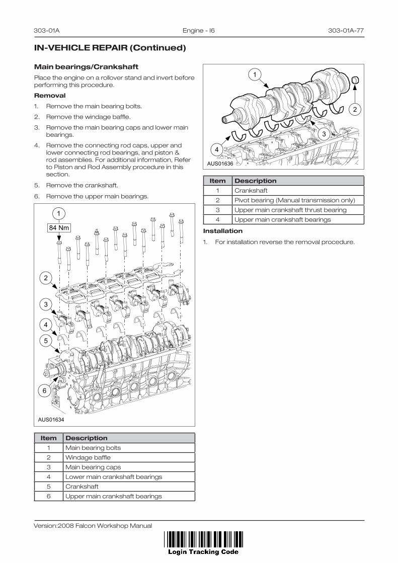
303-01A Engine - I6 303-01A-77
Version:2008 Falcon Workshop Manual
Main bearings/CrankshaftPlacetheengineonarolloverstandandinvertbeforeperformingthisprocedure.
Removal
1. Removethemainbearingbolts.
2. Removethewindagebaffle.
3. Removethemainbearingcapsandlowermainbearings.
4. Removetheconnectingrodcaps,upperandlowerconnectingrodbearings,andpiston&rodassemblies.Foradditionalinformation,RefertoPistonandRodAssemblyprocedureinthissection.
5. Removethecrankshaft.
6. Removetheuppermainbearings.
AUS01634
1
84 Nm
2
3
4
5
6
Item Description
1 Mainbearingbolts
2 Windagebaffle
3 Mainbearingcaps
4 Lowermaincrankshaftbearings
5 Crankshaft
6 Uppermaincrankshaftbearings
IN-VEHICLE REPAIR (Continued)
AUS01636
2
1
3
4
Item Description
1 Crankshaft
2 Pivotbearing(Manualtransmissiononly)
3 Uppermaincrankshaftthrustbearing
4 Uppermaincrankshaftbearings
Installation
1. Forinstallationreversetheremovalprocedure.

303-01A Engine - I6 303-01A-78
Version:2008 Falcon Workshop Manual
Rear Main Bearing Cap Assembly
1. ApplysiliconesealantLoctite5900(orasealantwhichmeetstheFordspecificationWSS-M4G323-A7)totherearmainbearingcaptoblockjointasshown.
2. Fittherearmainbearingcapandtightenwithin5minutesofapplicationofthesealant.
3. Reversetheremovalprocedure.
AUS01641
IN-VEHICLE REPAIR (Continued)
Piston Ring
Installation
1. Verifythesecondpistonringisinstalledwiththedotupwards.
2. Positiontheendgapsofthepistonringsasshown.
COMPRESSIONRING
COMPRESSIONRING
OIL RING SPACER
25.0 25.0
150 DEG 150 DEG
A
BB
C C
OIL RINGSEGMENT
OIL RINGSEGMENT
AUS01637
mm
3. Ensurethenotchonthepistonisfacingthefrontoftheengine,thevalvecut-outsareontheexhaustside,andtheconnectingrodoilsquirtholeisontheexhaustsideoftheengine.
AUS01638

303-01A Engine - I6 303-01A-79
Version:2008 Falcon Workshop Manual
Key Retainer - Valve Spring
Disassembly
1. Removethekeysusingavalvespringcompressor.
2. Removethevalvespringretainer.
3. Removethevalvespring.
4. Removethevalvestemseal.
AUS01643
1
2
3
4
Item Description
1 Key-Valvespringretainer
2 Valvespringretainer
3 Valvespring
4 Valvestemseal
Assembly
ToassembleReversethedisassembleprocedure.
AUS01646
DISASSEMBLY AND ASSEMBLY
Valve Stem Seal
Disassembly
1. Removethesealusingapairofpliers.
Assembly
1. Ensurethecylinderheadisclean.
2. Ensurethecylinderheadjointfaceisfreefromscratchesandnicksinthesealingareasaroundthecylinderboreandoilandwaterways.
3. Lubricatethevalveguideswithengineoil.
AUS01644
4. Fitnewsealsusingan18mminsidediameterdrift.
AUS01645

303-01A Engine - I6 303-01A-80
Version:2008 Falcon Workshop Manual
Piston and Connecting Rod Assembly
Assembly
7
6
5
4
9
8
1
2 3
AUS08091
Item Description
1 Compressionringupper
2 Compressionringlower
3 Oilrings
4 Piston
5 Connectingrod
6 Connectingrodbolt
7 Connectingrodcap
8 Connectingrodnut
9 GudgeonPin
DISASSEMBLY AND ASSEMBLY (Continued)
Piston and Connecting Rod Disassembly and Assembly
Assembly
1. UseSST303-D034toremoveandinstallthepistonfromtheconnectingrodassembly.
AUS01648
Note:Donotseparatethepistonandrodunlesstherod,pinorpistonistobereplaced.

303-01A Engine - I6 303-01A-81
Version:2008 Falcon Workshop Manual
Connecting Rod Bolt
Theconnectingrodboltsarepermanentlystretchedeachtimetheyaretightenedandshouldonlybeusedonce.
Replacetheconnectingrodboltspriortorebuildingtheengine.Theoldboltscanbeusedtoestablishbearingclearances.ThecorrectlevelboltsaremarkedWR/AB.
AUS01649
1
2
3
4
Item Description
1 WR/AAmarking
2 Straightknurl
3 Diamondknurl
4 Pilotpoint
DISASSEMBLY AND ASSEMBLY (Continued)