SECTION 1 - ShipServ
14
SECTION 1 Wire Rope All the COORDINATED WIRE ROPE companies supply the highest quality crane ropes made in the USA, Canada and Europe. We specialize in servicing the container cranes in the ports of Long Beach and Los Angeles. Our other emphasis is with Diepa Rope which is one of the oldest and most respected in Europe. We offer Crane ropes for all applications. In order for a wire rope to be used safely in any application it must be inspected regularly in a proper manner. ASME standards such as B30.5 (mobile cranes) and B30.2 (overhead cranes) are two safety standards that provide detailed inspection procedures and retirement criteria. Both Standards specify that all running ropes should be visually inspected daily. The inspection should be more than just a quick look. A quick look may not reveal all the evidence of damage or broken wires sufficient to require removal from service. The inspection must be done carefully and in enough light so that broken wires and damage can be observed. Special care should be taken when inspecting portions of the rope subjected to repetitive wear such as the following: Step up and cross over points on the drum Repetitive pick up points Areas of the rope operating through a reverse bend in the reeving system Equalizer sheaves The inspection should be concerned with determining rope wear or damage which require the rope to be retired or replaced immediately. The inspection should be looking for the following: Distortions such as kinking, crushing, unlaying, birdcaging, strand distortion or core protrusion Corrosion Broken or cut strands Number, type and distribution of broken wires Lubrication condition “Making Quality and Safety Our Priority” 1 2
-
Upload
khangminh22 -
Category
Documents
-
view
0 -
download
0
Transcript of SECTION 1 - ShipServ

SECTION 1
Wire Rope
All the Coordinated Wire rope companies supply the highest quality crane ropes made in the USA, Canada and Europe. We specialize in servicing the container cranes in the ports of Long Beach and Los Angeles. Our other emphasis is with Diepa Rope which is one of the oldest and most respected in Europe. We offer Crane ropes for all applications.
In order for a wire rope to be used safely in any application it must be inspected regularly in a proper manner. ASME standards such as B30.5 (mobile cranes) and B30.2 (overhead cranes) are two safety standards that provide detailed inspection procedures and retirement criteria. Both Standards specify that all running ropes should be visually inspected daily. The inspection should be more than just a quick look.
A quick look may not reveal all the evidence of damage or broken wires sufficient to require removal from service. The inspection must be done carefully and in enough light so that broken wires and damage can be observed. Special care should be taken when inspecting portions of the rope subjected to repetitive wear such as the following:
Step up and cross over points on the drum
Repetitive pick up points
Areas of the rope operating through a reverse bend in the reeving system
Equalizer sheaves
The inspection should be concerned with determining rope wear or damage which require the rope to be retired or replaced immediately. The inspection should be looking for the following:
Distortions such as kinking, crushing, unlaying, birdcaging, strand distortion or core protrusion
Corrosion
Broken or cut strands
Number, type and distribution of broken wires
Lubrication condition
“Making Quality and Safety Our Priority”
1
2

WIRE ROPE
General Guidance on Rope Selection
When selecting a steel wire rope to suit a particularapplication the following characteristics should be takeninto consideration.
StrengthRotation ResistanceFatigue ResistanceResistance to wear and abrasionResistance to crushingResistance to corrosionRope extension
StrengthThe responsibility for determining the minimum strengthof a rope for use in a given system rests with themanufacturer of the machine, appliance, or liftingequipment. As part of this process the manufacturer of themachine, appliance or lifting equipment will need to beaware of any local regulations, standards or codes ofpractice which might govern the design factor of the ropeand other factors which might influence the design ofsheaves and drums, the shape of the groove profiles andcorresponding radius, the drum pitch and the fleet angle,all of which have an effect on rope performance.
Once the strength (referred to as minimum breaking forceor minimum breaking load) of the rope has beendetermined it is then necessary to consider which type ofrope will be suitable for the intended duty. It is importanttherefore for the designer to be fully aware of theproperties, characteristics and limitations on use of themany different kinds of steel wire ropes which are available.
Important note for operatorsBridon recommends that once the machine, appliance orlifting equipment has been taken into service, anyreplacement rope should possess the requiredcharacteristics for the duty in question and should, as aminimum, at least comply with the minimum guaranteedbreaking force stated by the original equipmentmanufacturer.
Resistance to RotationIt is important to determine whether there is arequirement to use a Rotation Resistant rope.
Six or eight strand rope constructions are usually selectedunless load rotation on a single part system or “cabling” ona multi - part reeving system are likely to cause operationalproblems.
When loaded, steel wire ropes will generate:
- “Torque” if both ends are fixed.- “Turn” if one end is unrestrained.
TorqueWhen both ends of a rope are fixed, the applied forcegenerates “torque” at the fixing points.
Anchor atStructure
Anchorat Drum
ForceGenerates
Torque
Anchored
Free toRotate
ForceCreates
Turn
The torque or turn generated will increase as the loadapplied increases. The degree to which a wire ropegenerates torque or turn will be influenced by theconstruction of the rope. Having recognized what canhappen when a rope is loaded it is necessary to select thecorrect type of rope. It should be noted that all ropes willrotate to some degree when loaded .
The diagram below serves to illustrate the differences in rotationalproperties between the three basic types of stranded rope.
Specific information including the torque factor and theturn value expressed in degrees per lay length forindividual rope constructions can be found on page 79.
Torq
ue
or
Turn
Load
Endurance 6x19Endurance 6x36Dyform 6Dyform 8
Endurance 8RREndurance 19Dyform 18/18Pi
Dyform 34LR/34Pi/34MAXEndurance 35LS
TurnWhen one end of a rope is free to rotate, the applied loadcauses the rope to turn.
1
3

WIRE ROPE
Standard 6X19 & 6X36 Classification
Diameter Approx massIWRC
EIP min breakingforceIWRC
EEIP min breaking force
IWRCInch mm Lb/ft kg/ft Tons kN Tons kN1/4 0.12 0.05 3.40 30.3
7 0.14 0.06 3.80 34.2 4.2 37.75/16 0.18 0.08 5.27 46.9
8 0.18 0.08 5.00 44.7 5.5 49.29 0.23 0.11 6.40 56.5 7.0 62.3
3/8 0.26 0.11 7.55 67.210 0.29 0.13 7.80 69.8 8.3 76.911 0.35 0.16 9.50 84.4 10.5 93.0
7/16 0.35 0.15 10.20 90.7 11.2 99.612 0.41 0.19 11.40 101.0 12.4 110.7
1/2 0.46 0.20 13.30 118.4 14.6 129.913 0.48 0.22 13.30 118.0 14.6 130.014 0.56 0.25 15.40 137.0 17.0 151.0
9/16 0.58 0.26 16.80 149.5 18.5 164.75/8 0.72 0.32 20.60 183.3 22.7 202.0
16 0.73 0.33 20.10 179.0 22.1 197.018 0.93 0.42 25.40 226.0 28.0 249.019 1.03 0.47 28.30 252.0 31.2 278.0
3/4 1.04 0.46 29.40 261.7 32.4 288.420 1.15 0.52 31.40 279.0 34.6 308.022 1.39 0.63 38.00 338.0 41.8 372.0
7/8 1.41 0.62 39.80 354.2 43.8 389.824 1.65 0.75 45.20 402.0 49.8 443.0
1 1.85 0.82 51.70 460.1 56.9 506.426 1.94 0.88 53.10 472.0 58.4 520.028 2.24 1.02 61.05 547.0 67.8 603.0
1-1/8 2.34 1.03 65.00 578.5 71.5 636.41-1/4 2.89 1.28 79.90 711.1 87.9 782.3
32 2.93 1.33 80.40 715.0 88.5 787.01-3/8 3.49 1.54 96.00 854.4 106.0 943.4
36 3.71 1.68 101.60 904.0 112.1 997.01-1/2 4.16 1.84 114.0 1014.6 125.0 1112.5
40 4.58 2.08 125.90 1120.0 138.3 1230.01-5/8 4.88 2.15 132.0 1174.8 146.0 1299.4
44 5.54 2.51 151.7 1350.0 167.4 1489.01-3/4 5.66 2.50 153.0 1361.7 169.0 1504.11-7/8 6.49 2.86 174.0 1548.6 192.0 1708.8
48 6.60 2.99 181.0 1610.0 199.2 1772.02 7.39 3.26 198.0 1762.2 217.0 1931.3
1
4

WIRE ROPE
Endurance DYFORM® 18/18PI
• High strength Rotation Resistant ropeincorporating Dyform strands - confirmed byBridon’s “Powercheck” testing of a samplefrom each production length.
• Good resistance to rotation - confirmed byBridon’s unique “Twistcheck” type testingprogram.
• Superior bending fatigue life when comparedwith conventional multistrand ropes -confirmed by laboratory testing and extensivefield experience.
• Excellent resistance to crushing and abrasionresulting from the overall compactness androbustness of the rope and the Dyformstrands - recommended when multi-layerspooling is involved.
• Reduced elongation results from increasedsteel content and the Dyform process.
• Optional plastic coating of IWRC to furtherextend fatigue life, improve structuralstability and resistance to corrosion.
Table of sizes, mass and minimum breaking force -Endurance Dyform® 18/18PI
Rope gradeMin breaking force
Diameter Approx massWSC
in mm Ib/ft kg/ft tons kNDyform
3/8 0.31 0.14 8.3 73.910 0.34 0.15 9.5 84.311 0.41 0.19 11.8 105.0
7/16 0.42 0.19 11.2 99.712 0.49 0.22 13.6 121.0
1/2 0.55 0.24 14.6 129.913 0.58 0.26 16.5 147.014 0.67 0.30 18.8 167.0
9/16 0.70 0.31 19.2 170.95/8 0.86 0.38 22.7 202.0
16 0.88 0.40 24.6 219.018 1.11 0.50 31.2 278.019 1.23 0.56 34.2 304.0
3/4 1.24 0.55 32.4 288.420 1.37 0.62 37.7 335.022 1.66 0.75 45.5 405.0
7/8 1.69 0.75 43.8 389.824 1.97 0.89 54.2 482.0
1 2.21 0.98 57.5 511.626 2.31 1.05 64.3 572.028 2.68 1.22 74.4 662.0
11/8 2.79 1.23 71.5 636.411/4 3.45 1.52 87.9 782.3
32 3.50 1.59 96.6 859.013/8 4.17 1.84 106.0 943.911/2 4.97 2.19 125.0 1112.5
NOTE: all sizes Powerchecked
Visit our website:www.coordinatedcompanies.com
1
5

WIRE ROPE
Endurance DYFORM® 6/6PI
• Strongest of all ropes in the six strandproduct range - confirmed by Bridon’s“Powercheck” testing of a sample from eachproduction length.
• Superior bending fatigue life when comparedwith conventional six strand ropes -confirmed by laboratory testing and extensivefield experience.
• Excellent resistance to crushing and abrasionresulting from the overall compactness androbustness of the rope and the Dyformstrands - recommended when multi-layerspooling is involved.
• Reduced elongation results from increasedsteel content and the Dyform process.
• Optional plastic coating of IWRC to furtherextend fatigue life, improve structuralstability and resistance to corrosion.
Table of sizes, mass and minimum breaking force -Endurance Dyform® 6/6PI
Rope gradeMin breaking force
Diameter Approx massWSC
in mm Ib/ft kg/ft tons kNDyform
3/8 0.28 0.12 8.8 78.310 0.32 0.14 9.6 85.311 0.39 0.18 11.0 98.1
7/16 0.38 0.17 11.9 105.912 0.44 0.20 12.8 114.0
1/2 0.50 0.22 15.3 136.213 0.54 0.24 16.5 147.014 0.63 0.29 19.0 169.0
9/16 0.63 0.28 19.3 171.85/8 0.78 0.35 22.7 202.0
16 0.79 0.36 24.4 217.018 1.03 0.47 30.9 275.019 1.12 0.51 33.9 302.0
3/4 1.13 0.50 32.4 288.420 1.22 0.55 37.4 333.022 1.46 0.66 44.7 398.0
7/8 1.53 0.68 43.8 389.824 1.79 0.81 54.7 487.0
1 2.00 0.88 57.5 511.826 2.10 0.95 64.7 576.028 2.41 1.09 74.7 665.0
11/8 2.54 1.12 71.5 636.411/4 3.13 1.38 87.9 782.3
32 3.15 1.43 94.9 844.013/8 3.79 1.67 106.0 943.4
36 3.98 1.80 119.1 1060.011/2 4.51 1.99 125.0 1112.5
NOTE: All sizes Powerchecked
1
6
WIRE ROPE
Endurance DYFORM® 8/8PI
WIRE ROPE
• High breaking force - confirmed by Bridon’s“Powercheck” testing of a sample from eachproduction length.
• Superior bending fatigue life when comparedwith other conventional eight strand ropes -confirmed by laboratory testing and extensivefield experience.
• Excellent resistance to crushing and abrasionresulting from the overall compactness androbustness of the rope and the Dyformstrands - recommended when multi-layerspooling is involved.
• Reduced elongation results from increasedsteel content and the Dyform process.
• Optional plastic coating of IWRC to furtherextend fatigue life, improve structuralstability and resistance to corrosion.
Table of sizes, mass and minimum breaking force -Endurance Dyform® 8/8PI
Rope gradeMin breaking force
Diameter Approx massWSC
in mm Ib/ft kg/ft tons kNDyform
3/8 0.32 0.14 9.7 86.3
10 0.30 0.14 9.8 87.311 0.38 0.17 11.8 105.0
7/16 0.40 0.18 12.4 110.412 0.44 0.20 14.2 126.0
1/2 0.51 0.23 16.2 143.7
13 0.52 0.23 16.5 147.0
14 0.60 0.27 19.2 171.0
9/16 0.65 0.29 20.3 180.7
5/8 0.80 0.35 25.0 222.5
16 0.78 0.35 25.2 224.0
18 1.01 0.46 31.8 283.0
19 1.12 0.51 35.5 316.0
3/4 1.16 0.51 36.0 320.4
20 1.24 0.56 39.3 350.0
22 1.49 0.68 47.7 424.0
7/8 1.58 0.70 48.3 429.424 1.78 0.81 56.8 505.0
1 2.05 0.91 62.8 558.5
26 2.12 0.96 66.5 592.0
28 2.47 1.12 77.2 687.0
11/8 2.60 1.15 79.0 703.1
11/4 3.22 1.42 98.0 872.2
32 3.26 1.48 100.8 897.0
13/8 3.90 1.72 117.0 1041.3
36 4.07 1.85 127.9 1138.0
11/2 4.62 2.04 138.0 1228.2
NOTE: All sizes Powerchecked
1
7

WIRE ROPE
Constructex®
• Nine Strand rope made up of three differentstrand constructions. Each outside strandmanufactured with a soft plastic center.
• High strength - confirmed by Bridon’s“Powercheck” testing of a sample.
• Excellent resistance to crushing and wearresulting from the overall compactness androbustness of the rope.
• Flexible construction with good fatigue life inmost applications.
Table of sizes, mass and minimumbreaking force - Constructex®
Minimumbreaking
forceDiameter Approx mass
in Ib/ft kg/ft tons kN
5/8 0.9 0.39 25.5 226.93/4 1.1 0.50 36.5 324.77/8 1.5 0.68 48.5 431.51 2.0 0.91 62.5 556.0
11/8 2.6 1.18 79.5 707.311/4 3.2 1.45 97.6 868.313/8 3.8 1.72 119 1058.711/2 4.6 2.09 139 1236.715/8 5.3 2.41 162 1441.313/4 6.2 2.81 185 1645.9
NOTE: All sizes Powerchecked
Visit our website:www.coordinatedcompanies.com
1
8

WIRE ROPE
Spezialdrahtseile/Special Wire Ropes
The Special Characteristics of DIEPA Special Wire Ropes
• Only high quality wires are used. The tolerances of these wires are more restricted than those allowed under the standards for wires. Additionally, our suppliers are required to supply wires with higher values in torsion and bending.
• For ropes with plastic inserts, only that plastic material, which offers the best mechanical and performance capabilities, the polyamide, is selected. And from within the polyamide family only the best performing is used, namely the Polyamide 12.
• Together with a well known petrochemical company, a special lubricant was developed. This is especially effective against corrosion over a long period of time. The inner parts of the ropes, “the ropes critical area”, are thoroughly bathed with this special lubricant during their individual stranding.
• Self designed and constructed stranding machines, closing machines, and aggregates provide for highest stranding precision. A very extensive number of modern machinery is available. Therefore, every rope in each of the offered diameters is manufactured with the highest quality, in the most appropriate machine.
• The different constructions of Diepa Special Wire Ropes are specially designed for specific applications. Our many decades of experience allow us to recommend the most appropriate rope.
• Because of their special construction and solid structure, Diepa Special Wire Ropes are less affected by higher rope strain from the ropes reeving system, the inappropriate handling of rope, the installing of the rope, or during applications under critical conditions.
→ Long rope life + High rope’s safety throughout service life = Profitability
1
9

WIRE ROPE
Diepa Special Crane Ropes in Stock
MINIMUM PRODUCT BREAKING CODE LAY GRADE STRENGTH
D12007mm L/RHOL 1960N/mm 9306 pounds9mm RHOL 1960N/mm 15,399 pounds10mm RHOL 1960N/mm 19,018 pounds1/2" RHOL 1960N/mm 30,572 pounds14mm RHOL 1960N/mm 37,317 pounds9/16" RHOL 1960N/mm 38,890 pounds5/8" RHOL 1960N/mm 47,882 pounds3/4" RHOL 1960N/mm 69,013 pounds7/8" RHO 1960N/mm 93,966 pounds1" RHOL 1960N/mm 122,741 pounds
D1315CZ6mm RHOL 1960N/mm 7441 pounds8mm RHLL 1960N/mm 13,218 pounds8mm RHLL (Gal) 2160N/mm 14,207 pounds9mm RHLL 1960N/mm 16,725 pounds9mm RHLL 2160N/mm 17,984 pounds10mm RHLL 1770N/mm 18,524 pounds10mm RHLL 2160N/mm 22,168 pounds11mm RHLL 1960N/mm 25,178 pounds11mm RHLL 2160N/mm 26,976 pounds12mm RHLL 2160N/mm 31,922 pounds13mm L/RHLL 2160N/mm 37,766 pounds14mm RHLL 2160N/mm 43,611 pounds14mm RHLL(Gal) 2160N/mm 43,611 pounds16mm RHLL 2160N/mm 57,549 pounds17mm RHLL 1960N/mm 60,022 pounds18mm RHLL 2160N/mm 72,610 pounds19mm L/RHLL(Gal) 2160N/mm 80,478 pounds20mm RHLL 1960N/mm 83,401 pounds21mm LHLL 1960N/mm 92,617 pounds21mm RHLL 2160N/mm 99,362 pounds22mm RHLL 2160N/mm 109,028 pounds23mm RHLL 2160N/mm 118,694 pounds24mm RHLL 2160N/mm 128,810 pounds25mm RHLL 2160N/mm 137,353 pounds28mm RHLL 2160N/mm 174,894 pounds34mm RHLL 2160N/mm 255,373 pounds
B6526mm RHLL 2160N/mm 154,887 pounds
MINIMUM PRODUCT BREAKING CODE LAY GRADE STRENGTH
S3216mm L/RHOL 1960N/mm 6,564 pounds7mm L/RHOL 1960N/mm 8,925 pounds8mm L/RHOL 1960N/mm 9,824 pounds9mm L/RHOL 1960N/mm 14,229 pounds11mm L/RHOL 1960N/mm 21,603 pounds
PZ3711/4" RHOL 1960N/mm 7,149 pounds5/16" RHOL 1960N/mm 12,500 pounds3/8" RHOL 1960N/mm 17,900 pounds10mm RHOL 1770N/mm 17,939 pounds11mm RHOL 1960N/mm 24,054 pounds12mm RHOL 1960N/mm 28,744 pounds1/2" RHOL 1960N/mm 32,000 pounds9/16" RHOL 1960N/mm 40,500 pounds5/8" RHOL 1960N/mm 50,000 pounds3/4" RHOL 1960N/mm 72,000 pounds7/8" RHOL 1960N/mm 98,100 pounds1" RHOL 1960N/mm 128,100 pounds
SKZ86.5mm RHOL(Gal-Plas) 2160N/mm 10,026 pounds9mm RHOL(Gal-Plas) 1960N/mm 17,422 pounds10mm RHOL / Plas 2160N/mm 23,829 pounds11mm RHOL 2160N/mm 28,744 pounds12mm RHOL 1960N/mm 30,573 pounds13mm RHOL 1960N/mm 35,743 pounds14mm RHOL 1960N/mm 42,038 pounds16mm RHOL 2160N/mm 60,696 pounds18mm RHOL 1960N/mm 69,913 pounds19mm RHOL 2160N/mm 84,750 pounds20mm RHOL 2160N/mm 94,641 pounds22mm RHOL 1960N/mm 105,431 pounds24mm RHOL 2160N/mm 136,229 pounds25mm RHOL 2160N/mm 146,794 pounds28mm RHOL 2160N/mm 184,786 pounds
SUPER 243/4" RHOL 2160N/mm 81,827 pounds7/8" RHOL 2160N/mm 111,286 pounds
Contact your Coordinated Companies representative and ask for the recommended Diepa crane rope for your particular needs. We have the right rope for virtually any application and would be happy to assist you in choosing a crane rope that will give you the most service for your money.
1
10

WIRE ROPE
Typical Examples of Wire Rope Deterioration
Mechanical damagedue to rope movementover sharp edgeprojection while underload.
1 Typical wire fracturesas a result of bendfatigue.
9
Localized wear due toabrasion on supportingstructure.
2 Wire fractures at thestrand, or coreinterface, as distinctfrom ‘crown’ fractures.
10
Narrow path of wearresulting in fatiguefractures, caused byworking in a grosslyoversize groove, orover small supportrollers.
3 Break up of IWRCresulting from highstress application.
11
Two parallel paths ofbroken wires indicativeof bending through anundersize groove in thesheave.
4 Looped wires as aresult of torsionalimbalance and/or shockloading.
12
Severe wear,associated with hightread pressure.
5 Typical example oflocalized wear anddeformation.
13
Severe wear in LangsLay, caused byabrasion.
6 Multi strand rope ‘birdcaged’ due to torsionalimbalance.
14
Severe corrosion.7 Protrusion of ropecenter resulting frombuild up of turn.
15
Internal corrosion whileexternal surface showslittle evidence ofdeterioration.
8 Substantial wear andsevere internalcorrosion.
16
1
11

WIRE ROPE
Troubleshooting Guide
Mechanical damage caused by the rope contacting thestructure of the crane on which it is operating or anexternal structure - usually of a localized nature.
Generally results from operational conditions.Check sheave guards and support/guide sheaves toensure that the rope has not “jumped out” of theintended reeving system.Review operating conditions.
Problem Cause/Action
Opening of strands in Rotation Resistant ropes - in extremecircumstances the rope may develop a “birdcage distortion”or protrusion of inner strands.
Note - Rotation Resistant ropes are designed with a specificstrand gap which may be apparent on delivery in an offtension condition. These gaps will close under load and willhave no effect on the operational performance of the rope.
Check sheave and drum groove radii using sheave gaugeto ensure that they are no smaller than nominal roperadius +2.5% - Bridon recommends that the sheave anddrum groove radii are checked prior to any ropeinstallation.Repair or replace drum/sheaves if necessary.Check fleet angles in the reeving system - a fleet angle inexcess of 1.5 degrees may cause distortion (see page 95).Check installation method - turn induced duringinstallation can cause excessive rope rotation resulting indistortion (See pages 86 to 90).Check if the rope has been cut “on site “ prior toinstallation or cut to remove a damaged portion from theend of the rope. If so, was the correct cutting procedureused? Incorrect cutting of Rotation Resistant, low rotationand parallel closed ropes can cause distortion inoperation (See page 88 to 89).Rope may have experienced a shock load.
Broken wires or crushed or flattened rope on lower layersat crossover points in multi - layer coiling situations.
Wire breaks usually resulting from crushing or abrasion.
Check tension on underlying layers. Bridon recommendsan installation tension of between 2% and 10% of theminimum breaking force of the wire rope. Care should betaken to ensure that tension is retained in service.Insufficient tension will result in these lower layers beingmore prone to crushing damage.Review wire rope construction. Dyform wire ropes aremore resistant to crushing on underlying layers thanconventional rope constructions.Do not use more rope than necessary.Check drum diameter. Insufficient bending ratioincreases tread pressure.
Wires looping from strands. Insufficient service dressing.Consider alternative rope construction.If wires are looping out of the rope underneath acrossover point, there may be insufficient tension on thelower wraps on the drum.Check for areas of rope crushing or distortion.Possible fleet angle problems causing rope rotation.
“Pigtail” or severe spiralling in rope. Check that the sheave and drum diameter is largeenough - Bridon recommends a minimum ratio of thedrum/sheave to nominal rope diameter of 18:1.Indicates that the rope has run over a small radius orsharp edge.Check to see if the rope has “jumped off” a sheave andhas run over a shaft.
The following is a simplified guide to common wire rope problems. In the event of no other standard being applicable, it is recommended that ropes are inspected/examined in accordance with ASME B30.5.
1
12
WIRE ROPE
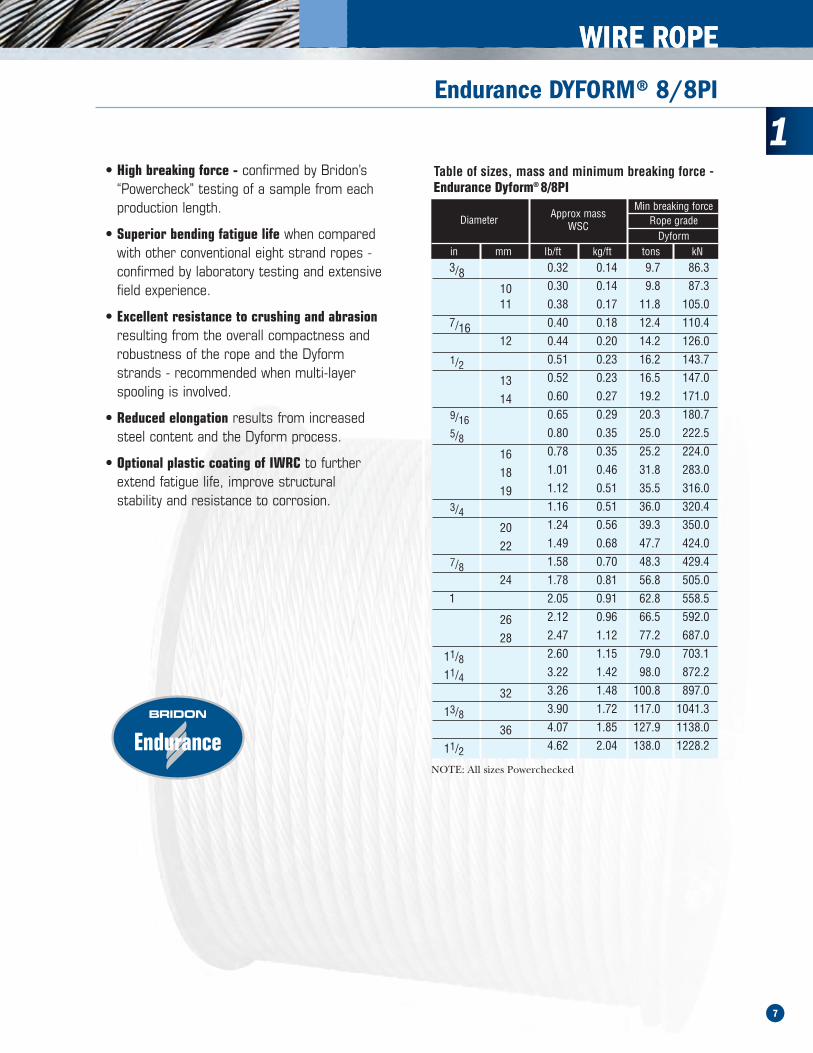
Troubleshooting Guide (cont.)
One line of broken wires running along the length of therope indicating insufficient support for the rope, generallycaused by oversize sheave or drum grooving.
Check to see if the groove diameter is no greater than15% greater than the nominal rope diameter.Repair or replace drum/sheaves if necessary.Check for contact damage.
Short rope life resulting from evenly/randomly distributedbend fatigue wire breaks caused by bending through thereeving system.
Fatique induced wire breaks are characterized by flat endson the broken wires.
Bending fatigue is accelerated as the load increases and asthe bending radius decreases (see page 74). Considerwhether either factor can be improved.Check wire rope construction - Dyform ropes are capableof doubling the bending fatigue life of a conventionalsteel wire rope.
Short rope life resulting from localized bend fatigue wirebreaks.
Fatique induced wire breaks are characterized by flat endson the broken wires.
Bending fatigue is accelerated as the load increases and asthe bending radius decreases (see page 74). Considerwhether either factor can be improved.Check wire rope construction - Dyform ropes are capableof doubling the bending fatigue life of a conventionalsteel wire rope.Localized fatigue breaks indicate continuous repetitivebends over a short length. Consider whether it iseconomic to periodically shorten the rope in order tomove the rope through the system and progressivelyexpose fresh rope to the severe bending zone. In orderto facilitate this procedure it may be necessary to beginoperating with a slightly longer length of rope.
Broken rope - ropes are likely to break when subjected tosubstantial overload or misuse particularly when a rope hasalready been subjected to mechanical damage.
Corrosion of the rope both internally and/or externallycan also result in a significant loss in metallic area. Therope strength is reduced to a level where it is unable tosustain the normal working load.
Review operating conditions.
Rotation of the load in a single fall system. Review rope selection.Consider use of Rotation Resistant rope.
Rotation of the load in a multi - fall system resulting in“cabling” of the rope falls.
Possibly due to induced turn during installation oroperation.
Review rope selection (see page 76 to 78 cabling calc.)Consider use of Rotation Resistant rope.Review installation procedure (see page 87 to 90) oroperating procedures.
Problem Cause Action
Wave or corkscrew deformations normally associated withmultistrand ropes.
Check sheave and drum groove radii using sheave gaugeto ensure that they are no smaller than nominal roperadius +2.5% - Bridon recommends that the sheave/drumgroove radii are checked prior to any rope installation.Repair or replace drum/sheaves if necessary.Check fleet angles in the reeving system - a fleet angle inexcess of 1.5 degrees may cause distortion (see page 76)Check that rope end has been secured in accordance withmanufacturers instructions (see page 88 & 89).Check operating conditions for induced turn.
Two single axial lines of broken wires running along thelength of the rope approximately 120 degrees apartindicating that the rope is being “nipped” in a tight sheave.
Check sheave and drum groove radii using sheave gaugeto ensure that they are no smaller than nominal roperadius + 2.5% - Bridon would recommend that thesheave/drum groove radii are checked prior to any ropeinstallation.Repair or replace drum/sheaves if necessary.
1
13

WIRE ROPE
Troubleshooting Guide (cont.)
Problem Cause Action
Sunken wraps of rope on the drum normally associatedwith insufficient support from lower layers of rope orgrooving.
Check correct rope diameter.If grooved drum check groove pitch.Check tension on underlying layers - Bridon recommendan installation tension of between 2% and 10% of theminimum breaking force of the wire rope - Care shouldbe taken to ensure that tension is retained in service.Insufficient tension will result in these lower layers beingmore prone to crushing damage.Make sure that the correct rope length is being used. Toomuch rope (which may not be necessary) may aggravatethe problem.
Short rope life induced by excessive wear and abrasion. Check fleet angle to drum.Check general alignment of sheaves in the reeving system.Check that all sheaves are free to rotate.Review rope selection. The smooth surface of Dyformwire ropes gives better contact with drum and sheaves andoffers improved resistance to “interference” betweeenadjacent laps of rope.
External corrosion. Consider selection of galvanized rope.Review level and type of service dressing.
Internal corrosion. Consider selection of galvanized rope.Review frequency amount and type of service dressing.Consider selection of plastic impregnated (PI) wire rope.
Rope accumulating or “stacking” at drum flange - due toinsufficient fleet angle.
Review drum design with original equipmentmanufacturer - consider adding rope kicker, fleetingsheave etc.
Core protrusion or broken core in single layer six or eightstrand rope.
Caused by repetitive shock loading - review operatingconditions.
Visit our website:www.coordinatedcompanies.com
1
14

WIRE ROPE
Decimal & Metric Conversion Table
FractionalEquivalent
(In)
DecimalEquivalent
(In)
MetricEquivalent
(mm)
FractionalEquivalent
(In)
DecimalEquivalent
(In)
MetricEquivalent
(mm)
1/64 .0156 .397 33/64 .5156 13.097
1/32 .0312 .794 17/32 .5312 13.494
3/64 .0469 1.191 35/64 .5469 13.891
1/16 .0625 1.588 9/16 .5625 14.288
5/64 .0781 1.984 37/64 .5781 14.684
3/32 .0938 2.381 19/32 .5938 15.081
7/64 .1094 2.778 39/64 .6094 15.478
1/8 .1250 3.175 5/8 .6250 15.875
9/64 .1406 3.572 41/64 .6406 16.272
5/32 .1562 3.969 21/32 .6562 16.669
11/64 .1719 4.366 43/64 .6719 17.065
3/16 .1875 4.762 11/16 .6875 17.462
13/64 .2031 5.159 45/64 .7031 17.859
7/32 .2188 5.556 23/32 .7188 18.256
15/64 .2344 5.953 47/64 .7344 18.653
1/4 .2500 6.350 3/4 .7500 19.050
17/64 .2656 6.747 49/64 .7656 19.447
9/32 .2812 7.144 25/32 .7812 19.844
19/64 .2969 7.541 51/64 .7969 20.241
21/64 .3281 8.334 13/16 .8125 20.638
11/32 .3438 8.731 53/64 .8281 21.034
23/64 .3594 9.128 27/32 .8438 21.431
3/8 .3750 9.525 55/64 .8594 21.828
25/64 .3906 9.922 7/8 .8750 22.225
13/32 .4062 10.319 57/64 .8906 22.622
27/64 .4219 10.716 29/32 .9062 23.019
7/16 .4375 11.112 59/64 .9219 23.416
29/64 .4531 11.509 15/16 .9375 23.812
15/32 .4688 11.906 61/64 .9531 24.209
31/64 .4844 12.303 31/32 .9688 24.606
1/2 .5000 12.700 1 1.000 25.400
1
15