SECTION 07 13 52, MODIFIED BITUMINOUS SHEET ...
373
09-11 VA 656-341 07 13 52 - 1 SECTION 07 13 52 MODIFIED BITUMINOUS SHEET WATERPROOFING PART 1 - GENERAL 1.1 DESCRIPTION: This section specifies modified bituminous sheet material used for exterior below grade waterproofing. A. Provide at new foundations at building additions, and the perimeter of the new elevator pit. B. Provide also at repair/tie-ins to existing pipe tunnel waterproofing. 1.2 MANUFACTURER’S QUALIFICATIONS: A. Approval by Contracting Officer Representative is required of products and services of proposed manufacturers, and installers, and will be based upon submission by Contractor that: 1. Manufacturer regularly and presently manufactures bituminous sheet waterproofing as one of its principal products. 2. Installer has technical qualifications, experience, trained personnel and facilities to install specified items. 3. Manufacturer's product submitted has been in satisfactory and efficient operation on three similar installations for at least three years. 4. Submit list of installations, include name and location of project and name of owner. 1.3 SUBMITTALS: A. Submit in accordance with Section 01 33 23, SUBMITTAL PROCEDURES. B. Manufacturer's Literature and Data: 1. Bituminous sheet. 2. Primer. 3. Mastic. 4. Protection material, temporary and permanent. 5. Printed installation instructions for conditions specified. C. Certificates: 1. Indicating bituminous sheet manufacturer's approval of primer, and roof cement. 2. Indicating bituminous sheet waterproofing manufacturer's qualifications as specified. 3. Approval of installer by bituminous sheet manufacturers. 4. Water test report. D. Include all required LEED Forms as listed/referenced in Division 1.
-
Upload
khangminh22 -
Category
Documents
-
view
0 -
download
0
Transcript of SECTION 07 13 52, MODIFIED BITUMINOUS SHEET ...

09-11
VA 656-341 07 13 52 - 1
SECTION 07 13 52
MODIFIED BITUMINOUS SHEET WATERPROOFING
PART 1 - GENERAL
1.1 DESCRIPTION:
This section specifies modified bituminous sheet material used for
exterior below grade waterproofing.
A. Provide at new foundations at building additions, and the perimeter
of the new elevator pit.
B. Provide also at repair/tie-ins to existing pipe tunnel waterproofing.
1.2 MANUFACTURER’S QUALIFICATIONS:
A. Approval by Contracting Officer Representative is required of products
and services of proposed manufacturers, and installers, and will be
based upon submission by Contractor that:
1. Manufacturer regularly and presently manufactures bituminous sheet
waterproofing as one of its principal products.
2. Installer has technical qualifications, experience, trained
personnel and facilities to install specified items.
3. Manufacturer's product submitted has been in satisfactory and
efficient operation on three similar installations for at least
three years.
4. Submit list of installations, include name and location of project
and name of owner.
1.3 SUBMITTALS:
A. Submit in accordance with Section 01 33 23, SUBMITTAL PROCEDURES.
B. Manufacturer's Literature and Data:
1. Bituminous sheet.
2. Primer.
3. Mastic.
4. Protection material, temporary and permanent.
5. Printed installation instructions for conditions specified.
C. Certificates:
1. Indicating bituminous sheet manufacturer's approval of primer, and
roof cement.
2. Indicating bituminous sheet waterproofing manufacturer's
qualifications as specified.
3. Approval of installer by bituminous sheet manufacturers.
4. Water test report.
D. Include all required LEED Forms as listed/referenced in Division 1.

09-11
VA 656-341 07 13 52 - 2
1.4 PRODUCT DELIVERY, STORAGE AND HANDLING:
A. Deliver materials to job in manufacturer's original unopened container.
B. Do not store material in areas where temperature is lower than 10
degrees C (50 degrees F,) or where prolonged temperature is above 32
degrees C (90 degrees F).
1.5 ENVIRONMENTAL REQUIREMENTS:
A. Ambient Surface and Material Temperature: Not less than 4 degrees C (40
degrees F), during application of waterproofing.
1.6 WARRANTY:
A. Warrant bituminous sheet waterproofing installation against moisture
leaks and subject to terms of "Warranty of Construction", FAR clause
52.246-21, except that warranty period is two years.
1.7 APPLICABLE PUBLICATIONS:
A. Publications listed below form a part of this specification to the
extent referenced. Publications are referenced by basic designation
only.
B. Federal Specifications (Fed. Spec.):
UU-B-790A...............Building Paper, Vegetable Fiber: (Kraft, Water-
INT AMD 1 Proof, Water Repellent and Fire Resistant)
C. American Society for Testing and Materials (ASTM):
C578-10.................Rigid Cellular Polystyrene Thermal Insulation
D41-11..................Asphalt Primer Used in Roofing, Dampproofing
and Waterproofing
D2822-05................Asphalt Roof Cement
D6380-03(R2009).........Asphalt Roll Roofing (Organic Felt)
D. American Hardboard Association (AHA):
A135.4-1995.............Basic Hardboard
PART 2 - PRODUCTS
2.1 BITUMINOUS SHEET:
A. Cold applied waterproofing membrane composed primarily of modified
bituminous material prefabricated in sheet form designed for below
grade exterior. Sheet reinforced with fibers at manufacturer's option.
B. Thickness of Bituminous Sheet: 1.5 mm (60 mils), plus or minus 0.13 mm
(5 mils), and bonded to a 0.1 mm (4 mil) thick plastic sheet.
C. Provide with a release sheet to prevent bonding of bituminous sheet to
itself.
D. Bituthene 3000 or the low temperature version by W. R. Grace & Co. is

09-11
VA 656-341 07 13 52 - 3
specified, with Polyguard 650 series, and Mel-Roll LM by WR Meadows
also approved.
2.2 PRIMER AND ROOF CEMENT:
A. Furnished by manufacturer of bituminous sheet as required for particular
application in accordance with sheet manufacturer's instructions.
B. Primer: ASTM D41.
C. Roof Cement: ASTM D4586.
2.3 PROTECTION MATERIAL:
A. Polystyrene: ASTM C578, Type I or VIII, 13 mm (1/2-inch) minimum
thickness.
B. Hardboard: PS-58, Service Type, 6 mm (1/4-inch) thick.
2.4 PATCHING COMPOUND:
A. A factory prepared, non-shrinking, fast setting, cementitious adhesive
compound containing no ferrous metal or oxide.
2.5 TERMINATION TRIM & SEALANT:
A. Surface conditioner, mastic, liquid membrane, tape, and accessories
specified or acceptable to the manufacturer of the sheet membrane.
B. Termination Bar: Genflex F-0.55, 16 Ga., G-90 field anchor bar; or
Trufast’s TB 125, 1/8” thick x 1” aluminum termination bar with holes
spaced 6” centers.
C. Exposed flashing/Reglets: See Section 07 6000 SHEETMETAL.
D. Term. Bar Sealant: Mastic manufactured specifically, such as Bituthane
Mastic.
PART 3 - EXECUTION
3.1 PREPARATION:
A. Surface Condition:
1. Before applying waterproofing materials, ensure concrete and masonry
surfaces are fully cured, smooth, clean, dry, and free from high
spots, depressions, loose and foreign particles and other deterrents
to adhesion.
2. Fill voids, joints, and cracks with patching compound.
B. Concrete surfaces cured a minimum of seven days, free from release
agents, concrete curing agents, and other contaminates.
3.2 APPLICATION:
A. Priming:
1. Prime concrete and masonry surfaces.

09-11
VA 656-341 07 13 52 - 4
2. Application method, amount of primer and condition or primer before
installation of bituminous sheet as recommended by primer
manufacturer.
3. Reprime when required in accordance with manufacturer's
instructions.
B. Bituminous Sheet Installation:
1. Remove release sheet prior to application.
2. Lay bituminous sheet from low point to high point so that laps shed
water.
3. Treat expansion, construction and control joints and evident working
cracks as expansion joints. Apply bituminous sheet in double
thickness over joint by first applying a strip of bituminous sheet
not less than 200 mm (8 inches) wide, centered over joint.
4. Lap seams not less than 50 mm (2 inches).
5. Lay succeeding sheet with laps, and roll or press into place.
6. Repair misaligned or inadequately lapped seams in accordance with
manufacturer’s instructions.
7. Seal seams and terminations in accordance with sheet manufacturer’s
instructions.
C. Corner Treatment:
1. At inside and outside corners apply double cover using an initial
strip not less than 280 mm (11 inches) wide, centered along axis of
corner.
2. Cover each strip completely by the regular application of bituminous
sheet.
3. Provide a fillet or cant on inside corners.
4. Form cants using patching compound
5. Do not use wood, fiber, and insulating materials for cants.
D. Projection Treatment:
1. Apply a double layer of bituminous sheet around pipes and similar
projections at least 150 mm (6 inches) wide.
2. At drains, apply a bead of roof cement over a double layer of
bituminous sheet under clamping rings.
E. All vertical edge terminations and Horizontal top terminations, shall
edged with termination bar, fastened at 6” oc, with ¼” diameter
tapcons, or zamac expansion anchors, with stainless steel nail.
3.3 PROTECTION:
A. Protect bituminous sheet before backfill or wearing courses are placed.
09-11
VA 656-341 07 13 52 - 5
B. Install protection material and hold in place in accordance with
instructions of manufacturer of waterproofing materials.
C. Permanent Protection:
1. Vertical Surfaces:
a. Install hardboard protection material or rigid insulation.
b. Extend protection full height from footing to top of backfill.
c. If graded backfill is used, use hardboard.
D. Horizontal Surfaces:
1. Install bituminuous roll to form impervious waterproofing layer.
2. Use protection board specified for vertical surfaces.
E. Temporary Protection: When waterproofing materials are subjected to
damage by sunlight and cannot be immediately protected as specified,
protect waterproofing materials by waterproof building paper or
suitable coating approved by manufacturer of waterproofing system used.
3.4 PATCHING:
A. Repair tears, punctures, air blisters, and inadequately lapped seams,
in accordance with manufacturer’s instructions before protection course
is applied.
3.5 TESTING:
A. Before any protection or wearing course is applied, test all horizontal
applications of waterproofing with a minimum of 25 mm (1-inch) head of
water above highest point and leave for 24 hours.
B. Mark leaks and repair when waterproofing is dry.
C. Certify, to COR- Contracting Officer Representative , that water tests
have been made and that areas tested were found watertight.
3.6 INSPECTION:
A. Do not cover waterproofed surfaces by other materials or backfill until
work is approved by Resident Engineer.
- - - E N D - - -

06-01-12
VA 656-341 07 21 13 - 1
SECTION 07 21 13
THERMAL INSULATION
PART 1 - GENERAL
1.1 DESCRIPTION:
A. This section specifies thermal insulation for buildings.
1.2 RELATED WORK:
A. Hollow core precast: Section 03 41 33, PRECAST STRUCTURAL PRETENSIONED
CONCRETE.
B. Insulation for TPO Roofing Systems: Section 07 54 23, TPO ROOF SYSTEMS.
C. Intumescent Sealant and Safing insulation: Section 07 84 00,
FIRESTOPPING.
D. Cavity Wall Insulation: Section 04 20 00 UNIT MASONRY.
E. Rigid Roof Insulation at Base Bid Sloped Roof: See Section 07 2200.
1.3 SUBMITTALS:
A. Submit in accordance with Section 01 33 23, SUBMITTAL PROCEDURES.
B. Manufacturer's Literature and Data:
1. Insulation, each type used
2. Adhesive, each type used
3. Tape
C. Certificates: Stating the type, thickness and "R" value (thermal
resistance) of the insulation to be installed.
D. Include all required LEED Forms as listed/referenced in Division 1.
1.4 STORAGE AND HANDLING:
A. Store insulation materials in weathertight enclosure.
B. Protect insulation from damage from handling, weather and construction
operations before, during, and after installation.
1.5 APPLICABLE PUBLICATIONS:
A. The publications listed below form a part of this specification to the
extent referenced. The publications are referenced in the text by basic
designation only.
B. American Society for Testing and Materials (ASTM):
C553-08.................Mineral Fiber Blanket Thermal Insulation for
Commercial and Industrial Applications
C578-10.................Rigid, Cellular Polystyrene Thermal Insulation
C612-10.................Mineral Fiber Block and Board Thermal
Insulation

06-01-12
VA 656-341 07 21 13 - 2
C665-06.................Mineral Fiber Blanket Thermal Insulation for
Light Frame Construction and Manufactured
Housing
C954-10.................Steel Drill Screws for the Application of
Gypsum Panel Products or Metal Plaster Base to
Steel Studs From 0.033 (0.84 mm) inch to 0.112
inch (2.84 mm) in thickness
E84-10..................Surface Burning Characteristics of Building
Materials
F1667-11................Driven Fasteners: Nails, Spikes and Staples
PART 2 - PRODUCTS
2.1 INSULATION – GENERAL:
A. Where thermal resistance ("R" value) is specified or shown for
insulation, the thickness shown on the drawings is nominal. Use only
insulation with actual thickness that is not less than that required to
provide the thermal resistance specified.
B. Where "R" value is not specified for insulation, use the thickness
shown on the drawings.
C. Insulation Products shall comply with following minimum content
standards for recovered materials:
Material Type Percent by Weight
Rigid foam(Division 4 cavity
wall) and perimeter foundation
insulation
9 percent recovered material
Rock wool material 60 percent recovered material
The minimum-content standards are based on the weight (not the volume)
of the material in the insulating core only.
2.2 MASONRY CAVITY WALL INSULATION:
A. See Section 04 20 00 UNIT MASONRY.
2.3 PERIMETER INSULATION IN CONTACT WITH SOIL:
A. Extruded Polystyrene Board: ASTM C578, Type IV, where covered by soil
or concrete.
2.4 EXTERIOR FRAMING OR FURRING INSULATION:
A. Batt Insulation, oversized to the stud or framing cavity

06-01-12
VA 656-341 07 21 13 - 3
B. Mineral Wool Fiber: ASTM C665, Type II, Class C, Category I where
framing is faced with gypsum board.
C. Fill stud cavity completely and full height
D. The following mineral wool insulation is acceptable:
1. Roxul’s ComfortBatt insulation,
2. J-M’s TempControl Batt,
3. Thermafiber’s Ultrabatt Insulation.
E. Provide mineral wool batt in full depth of cavity and full width of
stud spacing.
2.5 ACOUSTICAL INSULATION:
A. See Section 09 29 00 GYPSUM BOARD.
2.6 LOOSE INSULATION:
A. Mineral Wool Batt, cut to fit, equivalent to mineral batt previously
specified.
B. Fill all voids with loose fit mineral wool insulation. Fill voids
completely around window and exterior opening blocking, etc.
2.7 FIRESTOP SEALANT:
A. FireBlock Sealant: 24- to 32-kg.cu. m (1.5- to 2.0-lb/cu. ft) density,
with flame-spread index of 25 or less per ASTM E 162.
1. Hilti CF AS CJP 2005479 Fireblock is only acceptable product.
2.8 FASTENERS:
A. Staples or Nails: ASTM F1667, zinc-coated, size and type best suited
for purpose.
B. Screws: ASTM C954 or C1002, size and length best suited for purpose
with washer not less than 50 mm (two inches) in diameter.
C. Impaling Pins: Steel pins with head not less than 50 mm (two inches) in
diameter with adhesive for anchorage to substrate. Provide impaling
pins of length to extend beyond insulation and retain cap washer when
washer is placed on the pin.
2.9 ADHESIVE:
A. As recommended by the manufacturer of the insulation.
B. Foundation Insulation Adhesive: Locktite’s PL premium Polyurethane
construction adhesive, compatible with insulation and waterproofing
membrane.
2.10 TAPE:
A. Pressure sensitive adhesive on one face.
B. Perm rating of not more than 0.50.

06-01-12
VA 656-341 07 21 13 - 4
2.11 ROOF FRAMING BATT INSULATION: (ALTERNATIVE ROOF FRAMING)
A. Mineral Fiber, Batt Insulation: ASTM C665, Type 1, 2 lb. density
Friction fit.
B. Roof framing insulation shall be installed in multiple layers, in depth
to leave a minimum of 1 1/4" above insulation for venting, resulting in
one layer(Comfortbatt R10) at 2.5” thickness and one layer (Comfortbatt
R24) at 6” thickness, for a total thickness of 8.5”.
C. Install in conjunction with FSK insulation attached to the underside of
roof framing. .
D. The following insulation is acceptable:
1. Roxul’s Comfort Batt insulation,
2. J-M’s TempControl Batt,
3. Thermafiber’s Ultrabatt Insulation.
E. Provide mineral wool batt full width of Roof framing spacing; example:
24” metal joist spacing, provide minimum of 24.25” width insulation.
F. R-Value of installed batt insulation: Minimum R-33
2.12 RIGID FSK MINERAL WOOL:
(USED AT ALTERNATE ROOF FRAMING--AT UNDERSIDE OF METAL ROOF FRAMING)
A. High density mineral wool insulation with FSK foil faced vapor retarder
having a perm rating of not more than 0.02. Insulation thickness: 1.5".
1. ROXUL’s “CurtainRock 80” with FSK reinforced foil facer is
acceptable.
B. Mineral Wool shall meet ASTM C612, Type IVB, minimum 6.00 lb. density
Class A, FSK Faced. Provide 4'x 8'or custom size sheets as determined
by the insulating contractor to minimize joints. Note: provide 24" wide
units at locations receiving gypsum board finish (accommodating the
furring).
C. Fasteners: #10 or 12 self drilling fastener with 1 1/4" min. diameter
plastic washer. Products by ITW Buildex are approved. Length minimum
3/4" longer than insulation thickness.
D. Tape: FSK foil tape specifically made for taping seams in Foil Faced
mineral wool/ High density insulation. Use for taping seams and
terminations, thus providing continuous vapor barrier. Provide minimum
4” width tape.
2.13: BAFFLE VENTS: (alternative roof framing)

06-01-12
VA 656-341 07 21 13 - 5
A. ADO’s Provent, PVxxx48D series, 29” x 48” manufactured from tear
resistant, high impact plastic, sized to work with 24” joist spacing.
Install at each rafter space.
PART 3 - EXECUTION
3.1 INSTALLATION – GENERAL:
A. Install insulation with the vapor barrier facing the heated side,
unless specified otherwise.
B. Install rigid insulating units with joints close and flush, in regular
courses and with cross joints broken.
C. Install batt or blanket insulation with tight joints and filling
framing void completely. Seal cuts, tears, and unlapped joints with
tape.
D. Fit insulation tight against adjoining construction and penetrations,
unless specified otherwise.
3.2 PERIMETER INSULATION:
A. Vertical insulation:
1. Fill joints of insulation with same material used for bonding.
2. Bond Extruded polystyrene board to surfaces with construction
adhesive, specifically made for extruded insulation. Apply in
accordance with recommendations of insulation manufacturer.
B. Horizontal insulation under concrete floor slab:
1. Lay insulation boards and blocks horizontally on level, compacted
and drained fill.
2. Extend insulation from foundation walls towards center of building
not less than 600 mm (24 inches) or as shown.
3.3 EXTERIOR FRAMING OR FURRING BLANKET INSULATION:
A. Pack insulation around door frames and windows and in building
expansion joints, door soffits and other voids. Pack behind outlets
around pipes, ducts, and services encased in walls. Open voids are not
permitted. Hold insulation in place with pressure sensitive tape.
B. Lap vapor retarder flanges together over face of framing for continuous
surface. Seal all penetrations through the insulation.
C. Overstuff batt insulation between metal studs or framing and exterior
wall furring.
3.4 FSK RIGID MINERAL WOOL:
A. Cover the underside of the roof framing with a continuous layer of the
rigid insulation with integral vapor retarder. Fasten to steel joists

06-01-12
VA 656-341 07 21 13 - 6
at 6-8" oc along each rafter, as recommended by the manufacturer. Lap
seams and tape with seam tape material. Tape also all screws/washers
with a minimum of 4" square of foil tape. Install according to
manufacturer's installation recommendations. Coordinate the
installation of mineral wool batts between the roof framing with this
installation. Tape all seams and terminations with manufacturer's
recommended FSK foil tape, as well as fastener/washer locations.
Coordinate the installation of 1 1/2" zee furring with Section 09 22
16, NON-STRUCTURAL METAL FRAMING, where gypsum is applied to the
underside of the roof framing. At those locations provide 24" wide
rigid FSK insulation.
- - - E N D - - -

10-10
VA 656-341 07 22 00 - 1
SECTION 07 22 00
ROOF AND DECK INSULATION (BASE BID)
PART 1 - GENERAL
1.1 DESCRIPTION:
A. Roof and deck insulation, gypsum protection board, vapor retarder, on
new sloped roof framing construction ready to receive wood furring
nailers and roof sheathing at shingled roof areas.
1.2 RELATED WORK:
A. General sustainable design documentation requirements: Section 01 81 13
SUSTAINABLE DESIGN REQUIREMENTS.
B. Roof insulation used in TPO (flat) Roofs: Section 07 54 23 TPO ROOFING.
C. Wood furring, blocking, edge blocking and roof sheathing: Section 06
10 00, ROUGH CARPENTRY.
D. Perimeter, rigid, and batt or blanket insulation: Section 07 21 13,
THERMAL INSULATION.
E. Sheet metal components and wind uplift requirements for roof-edge
design: Section 07 60 00, FLASHING AND SHEET METAL.
F. Cavity Wall Insulation: Section 04 20 00 UNIT MASONRY.
1.3 APPLICABLE PUBLICATIONS:
A. Publications listed below form a part of this specification to the
extent referenced. Publications are referenced in the text by the basic
designation only. Editions of applicable publications current on date
of issue of bidding documents apply unless otherwise indicated.
B. American Society of Heating, Refrigeration and Air Conditioning
(ASHRAE):
90.1-07.................Energy Standard for Buildings except Low-Rise
Residential Buildings
C. ASTM International (ASTM):
C726-05.................Mineral Fiber Roof Insulation Board
C553....................Standard Specification for Mineral Fiber
Blanket Thermal Insulation for Commercial and
Industrial Applications.
C612....................Standard Specification for Mineral Fiber Block
and Board Thermal Insulation.
C726....................Standard Specification for Mineral Fiber Roof
Insulation Board.

10-10
VA 656-341 07 22 00 - 2
C1104/C1104M............Standard Test Method for Determining the Water
Vapor Sorption of Unfaced Mineral Fiber Insulation.
C1338...................Standard Test Method for Determining Fungi
Resistance of Insulation Materials and Facings.
E84.....................Standard Test Method for Surface Burning
Characteristics of Building Materials
D. FM Approvals: RoofNav Approved Roofing Assemblies and Products.
4450-89.................Approved Standard for Class 1 Insulated Steel
Deck Roofs
4470-10.................Approved Standard for Class 1 Roof Coverings
1-28-09.................Loss Prevention Data Sheet: Design Wind Loads.
1-29-09.................Loss Prevention Data Sheet: Above-Deck Roof
Components
1-49-09.................Loss Prevention Data Sheet: Perimeter Flashing
E. National Roofing Contractors Association: Roofing and Waterproofing
Manual
F. U.S. Department of Agriculture (USDA): USDA BioPreferred Catalog,
www.biopreferred.gov
G. Underwriters Laboratories, Inc. (UL): Fire Resistance Directory (2009)
1.4 PERFORMANCE REQUIREMENTS:
A. Thermal Performance: Provide roof insulation meeting minimum overall
average R-value of 33.
B. FM Approvals: Provide roof insulation complying with requirements in
FM Approvals 4450 and 4470 as part of specified roofing system, listed
in FM Approvals "RoofNav" as part of roofing system meeting
Fire/Windstorm Classification in Division 07 roofing section.
1.5 QUALITY CONTROL:
A. Requirements of Division 07 roofing section for qualifications of
roofing system insulation Installer; Work of this Section shall be
performed by same Installer.
B. Requirements of Division 07 roofing section for inspection of Work of
this Section and qualifications of Inspector.
C. Unless specified otherwise, comply with the recommendations of the NRCA
"Roofing and Waterproofing Manual" applicable to insulation for
storage, handling, and application.
D. Requirements of roofing system uplift pressure design for specified
roofing system.

10-10
VA 656-341 07 22 00 - 3
E. Requirements of applicable FM Approval for specified roofing system
insulation attachment.
F. Requirements of applicable Miami-Dade County approval for high-wind
zone design.
1.6 SUBMITTALS:
A. Submit in accordance with Section 01 33 23, SUBMITTAL PROCEDURES.
1. Include all required LEED Forms as listed/referenced in Division 1.
B. Product Data:
1. Roof insulation, each type.
2. Fastening requirements.
3. Insulation span data for flutes of metal decks.
C. LEED and Federal Sustainable Design Submittals:
1. Product Data for Credit IEQ 4.1: For adhesives and sealants used
inside the weatherproofing system, documentation including printed
statement of VOC content.
2. Product Data for Credits MRc4 Recycled Content and MRc5 Regional
Content: For products having recycled content and or regional
content, documentation indicating percentages by weight of
postconsumer and preconsumer recycled content. Include statement
indicating cost for each product having recycled content.
3. Product Data for Federally-Mandated Bio-Based Materials: For roof
materials, indicating USDA designation and compliance with
definitions for bio-based products, Rapidly Renewable Materials, and
certified sustainable wood content.
D. Shop Drawings: Include plans, sections, details, and attachments.
1. Layout of insulation showing slopes, tapers, penetration, and edge
conditions.
E. Samples:
1. Roof insulation, each type.
2. Fasteners, each type.
3. Vapor/Air Retarder.
F. Certificates:
1. Indicating type, thermal conductance, and minimum and average
thickness of insulation.
2. Indicating materials and method of application of insulation system
meet the requirements of FM Approvals for specified roofing system.
G. Laboratory Test Reports: Thermal values of insulation products.
H. Layout of tapered roof system showing units required.

10-10
VA 656-341 07 22 00 - 4
I. Documentation of supervisors' and inspectors' qualifications.
1.7 DELIVERY, STORAGE AND MARKING:
A. Comply with the recommendations of the NRCA "Roofing and Waterproofing
Manual" applicable to storage, handling and installation requirements.
1.8 QUALITY ASSURANCE:
A. Roof insulation on combustible or steel decks shall have a flame spread
rating not greater than 75 and a smoke developed rating not greater
than 150, exclusive of covering, when tested in accordance with ASTM
E84, or shall have successfully passed FM Approvals 4450.
1. Insulation bearing the UL label and listed in the UL Building
Materials Directory as meeting the flame spread and smoke developed
ratings will be accepted in-lieu-of copies of test reports.
2. Compliance with flame spread and smoke developed ratings will not be
required when insulation has been tested as part of a roof
construction assembly of the particular type used for this project
and the construction is listed as fire-classified in the UL Building
Materials Directory or listed as Class I roof deck construction in
the FM Approvals "RoofNav."
3. Insulation tested as part of a roof construction assembly shall bear
UL or FM labels attesting to the ratings specified herein.
PART 2 - PRODUCTS
2.1 ROOF AND DECK INSULATION
A. Roof and Deck Insulation, General: Preformed roof insulation boards
approved by roofing manufacturer and listed as component of FM
Approvals-approved roofing system.
B. Mineral Wood Rigid Roof Insulation - General:
1. Fire performance:
a. Rated roof insulation: To FM Approval 4450/4470,
b. Non-combustibility: To ASTM E136.
c. External spread of flame on roof surface: To UL 790
d. Thermal degradation and charring: To UL 263.
e. Surface Burning Characteristics: To ASTM E84.
1) Flame spread: 0.
2) Smoke developed: 0
2. Water Vapour Transmission: To ASTM E96, 41.3 Perms
3. Moisture Resistance: To ASTM C1104, moisture sorption of 0.3%.
4. Water absorption less than 1.2%: To ASTM C209.

10-10
VA 656-341 07 22 00 - 5
5. Thermal resistance: To ASTM C518,
a. R Value: 4.0 hr.ft2.F/Btu at 75ºF.
b. System Total R value: 7.5” x R4.0 = R-30 roof insulation
6. Impact resistance: To FM 4473, Class 4 and UL 2218, Class 4.
7. Corrosive resistance: To ASTM C665, Corrosive to steel - Pass.
8. Stainless steel stress corrosion: To ASTM C871 and ASTM C692.
9. Compressive resistance: To ASTM C165, 10% deformation 12 psi.
10. Density: To ASTM C612, 11 lbs/ft3.
C. Mineral Wool Board ROOF Insulation: ASTM C726.
1. Base Layer:
a. Mineral/Stone wool fibre insulation board.
1) Size: 48 x 48 inches.
2) Thickness: 4 inches.
3) Acceptable Material: ROXUL INC., MonoBoard is acceptable.
4) Contact: Saverio Marzella, Roxul Insulation-USA
Oak Point Drive South
Bayville, New York 11709
Office: (516) 922-3020
Cell: (516) 282-6434
2. Top Layer: Rigid, monolithic, dual-density mineral wool insulation
board impregnated with bitumen top layer to ASTM C726, complete with
high density top layer, no cover board required.
a. Low-Slope Roofing Insulation: Stone wool fibre insulation board.
1) Size: 48 x 48 inches.
2) Thickness: 3.5 inches.
3) Acceptable Material: Roxul Inc. TopRock DD.
D. Owens Corning’s Thermafiber products are also acceptable.
Phone: 888-834-2371, Telephone Extension - 265
Email: [email protected]
2.3 GYPSUM PROTECTION BOARD:
A. Fire resistive Type 'C' gypsum board by USG, Gold Bond, Georgia
Pacific; 1/2" thickness.
2.4 ROOF DECK VAPOR RETARDER:
A. Air/Vapor Retarder (direct to deck)
1. Soprema Products, 800-356-3521; Wadsworth, Ohio are acceptable.
a. Firestone’s V-Force Vapor Barrier, as well as Carlisle’s Vap’Air
Seal MD also acceptable.
10-10
VA 656-341 07 22 00 - 6
2. Type: Self-adhesive SopraVap’r vapor barrier; 45” roll width,
composed of reinforced SBS bitumen, and polyethylene woven composite
facer, direct to deck applications, complete with release sheet for
adhesive back.
a. Physical Properties:
1) Thickness: 31 mils (0.8mm)
2) ASTM D 5147, Tensile strength: 54 lbf/in(9.5kN/m)
3) ASTM E96, Procedure B, Water Vapor Permeance: 0.06 perm
4) ASTM D1970, Tear Resistance: 95 lbf (423N)
3. Provide accessories for terminations such as 6” x 42”, 24 ga.
backer plate for end of roll supports, allowing 6”overlap of end
seams onto a flat surface.
4. Provide recommended mastic for sealing penetrations.
2.5 FASTENERS:
A. Fasteners: Factory-coated steel fasteners and metal or plastic, 2”
diameter or greater, plates complying with FM Approvals 4470, designed
for fastening insulation boards to roof deck.
PART 3 - EXECUTION
3.1 EXAMINATION:
A. Comply with requirements of Division 07 roofing section.
3.2 PREPARATION:
A. Comply with requirements of Division 07 roofing section.
3.3 AIR/VAPOR RETARDER INSTALLATION:
A. General:
1. Install self-adhesive vapor retarder on metal roof decks where
indicated, in a continuous fashion. Apply primer to galvanized roof
deck if recommended by vapor barrier manufacturer.
a. As a minimum, wipe/clean deck surface, removing any rolling oil
used during the deck’s fabrication.
2. At vertical surfaces, turn up vapor retarder to top of insulation or
base flashing, fasten as indicated below.
3. At all pipes, walls, and similar penetrations through vapor
retarder, seal openings with manufacture’s recommended mastic to
prevent moisture entry from below.
4. Seal penetrations with mastic.
B. Steel Deck:

10-10
VA 656-341 07 22 00 - 7
1. Material and method of application of roofing systems used on metal
decks shall meet the requirements of FM Approvals for Class I-A
Insulated Steel Roof Deck.
2. Roll out install vapor barrier in direction of deck flutes.
3. Install to clean and dry metal roof deck.
4. Terminate where running vertically up plywood sheathing with
plastic washered fasteners, spaced at 8” oc.
5. Install metal backer plates at roll terminations, providing a solid
surface for end of roll overlaps. Fasten to deck with pancake head
screws.
3.4 GYPSUM PROTECTION BOARD:
A. Place protection board on vapor barrier covered metal deck; install
so that no edge is left unsupported along fluting.
B. Leave no voids in coverage; abut edges firmly.
3.5 RIGID INSULATION INSTALLATION:
A. Insulation Installation, General:
1. Install roof insulation in accordance with roofing system
manufacturer's written instructions.
2. Install roof insulation in accordance with requirements of FM
Approval's Listing for specified roofing system.
B. Insulation Thickness:
1. Thickness of roof insulation shown on drawings is nominal. Actual
thickness shall provide the average thermal resistance "R" value of
not less than that specified in Performance Requirements Article.
2. Insulation on Metal Decks: Provide minimum thickness of insulation
for metal decks recommended by the insulation manufacturer to span
rib opening flute size) of metal deck used. Support edges of
insulation on metal deck ribs.
3. When thickness of insulation to be used is more or less than that
shown on the drawings, make adjustments in the alignment and
location of roof drains, flashing, gravel stops, fascia and similar
items at no additional cost to the Government.
4. Not less than two layers of insulation shall be provided more in
thickness unless specified otherwise. Stagger joints minimum 300mm
(12 inches).
C. Lay insulating units with close joints, in regular courses and with
cross joints broken. When laid in more than one layer, break joints of
succeeding layers of roof insulation with those in preceding layer.

10-10
VA 656-341 07 22 00 - 8
D. Lay units with long dimension perpendicular to the rolled
(longitudinal) direction of the roofing felt.
E. Seal all cut edges at penetrations and at edges against blocking with
bitumen or roof cement.
F. Cut to fit tight against blocking or penetrations.
G. Cover all insulation installed on the same day; comply with temporary
protection after installation, or complete the wood furring, deck and
underlayment requirements of Division 6 Carpentry, and Division 07
roofing section.
H. Installation Method:
1. Mechanically Fastened Insulation:
a. Fasten both layers with fasteners minimum of 1 faster per 4 sf: 4
per 4x4 board, and 8 per 4x8 sized boards. (2 per cut board)
b. Stagger insulation layers, offsetting a minimum of 12”.
c. Subsequent wood furring and sheathing layers will be installed
over the roof insulation system, by Section 06 10 00 ROUGH
CARPENTRY.
- - - E N D - - -

08-01-12
VA 656-341 07 27 26 - 1
SECTION 07 27 26
FLUID-APPLIED MEMBRANE AIR BARRIERS
PART 1 - GENERAL
1.1 DESCRIPTION:
A. This section specifies fluid-applied( Roller application only) membrane
air barrier material and accessories used for exterior above grade wall
assembly air barriers and their extension and connection to adjacent
air barrier components in roof and opening construction to provide a
durable, continuous vapor permeable, moisture barrier system.
1.2 RELATED WORK
A. General quality assurance and quality control requirements: Section
01 45 29 TESTING LABORATORY SERVICES.
B. Masonry units serving as substrate for membrane air barriers, including
preparation of surface: Section 04 20 00 UNIT MASONRY.
C. Flashing components of factory finished roofing and wall systems to
which membrane air barriers will transition: Division 07 roofing and
wall system sections.
D. Other flashing components to which membrane air barriers will
transition: Section 07 60 00 FLASHING AND SHEET METAL.
E. Joint Sealants: Section 07 92 00, JOINT SEALANTS.
F. Division 08 exterior openings sections for opening transitions
providing airtight seal between membrane air barrier and aluminum
windows & louvers and vents.
G. Wall sheathings serving as substrate for membrane air barriers:
Section 06 10 00 ROUGH CARPENTRY.
1.3 APPLICABLE PUBLICATIONS
A. Publications listed below form a part of this specification to the
extent referenced. Publications are referenced in the text by the basic
designation only. Editions of applicable publications current on date
of issue of bidding documents apply unless otherwise indicated.
1. American Society of Testing and Materials (ASTM):
C920-10.................Standard Specification for Elastomeric Joint
Sealants
C1193-09................Standard Guide for Use of Joint Sealants
D412-06.................Standard Test Methods for Vulcanized Rubber and
Thermoplastic Elastomers—Tension

08-01-12
VA 656-341 07 27 26 - 2
D2369-10................Standard Test Method for Volatile Content of
Coatings
E96/E96M-05.............Standard Test Methods for Water Vapor
Transmission of Materials
E162-09.................Standard Test Method for Surface Flammability
of Materials Using a Radiant Heat Energy Source
E783-02.................Standard Test Method for Field Measurement of
Air Leakage Through Installed Exterior Windows
and Doors
E1186-03(2009)..........Standard Practices for Air Leakage Site
Detection in Building Envelopes and Air Barrier
Systems
E2178-03................Standard Test Method for Air Permeance of
Building Materials
E2357-05................Standard Test Method for Determining Air
Leakage of Air Barrier Assemblies
2. U.S. Environmental Protection Agency (EPA)
40 CFR 59, Subpart D....National Volatile Organic Compound Emission
Standards for Consumer and Commercial Products
3. SOUTH COAST AIR QUALITY MANAGEMENT DISTRICT (SCAQMD):
1168-89(2003)...........Adhesive and Sealant Applications
1.4 PERFORMANCE REQUIREMENTS
A. General: Membrane air barrier shall be capable of performing as a
continuous vapor-permeable air barrier and as a moisture drainage plane
transitioned to adjacent flashings and discharging water to the
building exterior. Membrane air barriers shall accommodate substrate
movement and seal expansion and control joints, construction material
transitions, opening transitions, penetrations, and perimeter
conditions without moisture deterioration and air leakage exceeding
performance requirements.
B. Air-Barrier Assembly Air Leakage: Maximum 0.2 L/s x sq. m of surface
area at 75 Pa (0.04 cfm/sq. ft. of surface area at 1.57 lbf/sq. ft.)per
ASTM E 2357.
C Material Compatibility: Provide membrane air barrier materials that
are compatible with one another and with adjacent materials under
conditions of service and application required, as demonstrated by
membrane air barrier manufacturer based on testing and field
experience.

08-01-12
VA 656-341 07 27 26 - 3
1.5 QUALIFICATIONS:
A. Approvals: Approval by Contracting Officer is required of products and
services of proposed manufacturers, and installers, and will be based
upon submission by Contractor that:
B. Manufacturer Qualifications: Manufacturer regularly and presently
manufactures fluid-applied membrane air barrier material meeting
section requirements as one of its principal products.
1. Manufacturer's product submitted has been in satisfactory and
efficient operation on five similar installations for at least five
years.
a. Submit list of installations, include name and location of
project and name of owner.
2. Accreditation: Manufacturer is accredited by the Air Barrier
Association of America.
C. Installer Qualifications: Installer has technical qualifications,
experience, certifications, trained personnel, membrane air barrier
manufacturer's approval, and facilities to install specified items.
1. Installer's applicators shall be trained and certified by
manufacturer of air barrier system.
2. Installer's full time on-site field supervisor shall have completed
three projects of similar scope within last year, be able to
communicate verbally with Contractor, Architect, testing agency, and
employees.
Accreditation: Installer's supervisor shall be a Level 3
D. Testing Agency Qualifications: Testing laboratory accredited by
International Accreditation Service, Inc. or American Association for
Laboratory Accreditation.
1. Testing agencies personnel shall be experienced in the installation
of specified air barrier system and qualified to perform observation
and inspection specified in Field Quality Control Article to
determine Installer’s compliance with the requirements of this
Project.
1.6 SUBMITTALS:
A. Submit in accordance with Section 01 33 23, SHOP DRAWINGS, PRODUCT
DATA, AND SAMPLES.
B. Manufacturer's Literature and Data:
1. Fluid-applied membrane air barrier.
2. Primer.
08-01-12
VA 656-341 07 27 26 - 4
3. Mastic.
4. Detail Membrane.
5. Modified bituminous strip.
6. Fireblock sealant.
7. Joint sealant.
8. Printed installation instructions for conditions specified.
C. Certificates:
1. Indicating membrane air barrier manufacturer's qualifications as
specified.
2. Indicating approval of installer by membrane air barrier
manufacturer.
3. Indicating qualifications of installer and installer's personnel.
4. Indicating air barrier manufacturer's determination that proposed
materials are chemically and adhesively compatible with adjacent
materials.
5. Indicating products meet project limitations on VOC content.
D. Inspection Reports: Daily reports of testing agency and reports of
testing and inspection agency. Include weather conditions, description
of work performed, tests performed, defective work observed, and
corrective actions taken to correct defective work.
E. Include all required LEED Forms as listed/referenced in Division 1.
1.7 COORDINATION:
A. Coordinate installation of work of this Section with adjacent and
related work to ensure provision of continuous, unbroken, durable air
barrier system.
1.8 PRODUCT DELIVERY, STORAGE AND HANDLING:
A. Deliver materials to job in manufacturer's original unopened
containers.
B. Do not store material in areas where temperature is lower than 10
degrees C (50 degrees F,) or where prolonged temperature is above 32
degrees C (90 degrees F).
1.9 ENVIRONMENTAL REQUIREMENTS:
Ambient Surface and Material Conditions: Not less than 4 degrees C (40
degrees F), during application of waterproofing, visibly dry, and
complying with manufacturer's written instructions.

08-01-12
VA 656-341 07 27 26 - 5
1.10 WARRANTY:
Warrant membrane air barrier installation against air and moisture
leaks subject to terms of "Warranty of Construction", FAR clause
52.246-21, except that warranty period is two years.
PART 2 - PRODUCTS
2.1 MATERIALS
A. Source Limitations: Obtain membrane air barrier materials and
accessories from single manufacturer.
B. VOC Content: Maximum 250 g/L per 40 CFR 59, Subpart D (EPA Method 24).
2.2 MEMBRANE AIR BARRIER:
A. Fluid-Applied, Vapor-Permeable Membrane Air Barrier: Elastomeric,
modified bituminous or synthetic polymer membrane, meeting the
following:
1. Air Permeance, ASTM E 2178: 0.02 L/s x sq. m of surface area at 75-
Pa (0.004 cfm/sq. ft of surface area at 1.57-lbf/sq. ft.) pressure
difference.
2. Vapor Permeance, ASTM E 96/E96M: Minimum 580 ng/Pa x s x sq. m (10
perms).
3. Elongation, Ultimate, ASTM D 412, Die C: 200 percent, minimum.
4. Combustion Characteristics: Flame spread, not greater than 25;
smoke developed, not greater than 450, ASTM E 84.
5. Thickness of Membrane Air Barrier: Not less than 1.0 mm (40 mils),
applied in single continuous coat.
6. Perm-A-Barrier VP Liquid from Grace Construction Products,
distributed by Construction Midwest Inc. New Hope, Minnesota,
763-253-9028 are acceptable, with Carlisle’s CCW Barritech VP
System & Henry’s Air Bloc 31 System, also acceptable.
2.3 ACCESSORY MATERIALS:
A. Primer: Liquid waterborne primer meeting VOC requirements, recommended
for substrate by membrane air barrier manufacturer.
B. Detail Membrane Sheet: Modified bituminous, 1.0-mm- (40-mil- thick
self-adhering composite sheet consisting of 0.9 mm (36 mils) of
rubberized asphalt laminated to polyethylene film.
C. Substrate Patching Material: Manufacturer's standard trowel-grade
filler material.
08-01-12
VA 656-341 07 27 26 - 6
D. FireBlock Sealant: Foamed-in-place, 24- to 32-kg.cu. m (1.5- to 2.0-
lb/cu. ft) density, with flame-spread index of 25 or less per ASTM E
162.
1. Hilti CF AS CJP 2005479 Fireblock foam is only acceptable product.
E. Joint Sealant: ASTM C 920, single-component, neutral-curing silicone;
Class 100/50 (low modulus), Grade NS, Use NT related to exposure,
approved by membrane air barrier manufacturer for adhesion and
compatibility with membrane air barrier and accessories.
PART 3 - EXECUTION
3.1 EXAMINATION:
A. Surface Condition: Before applying membrane air barrier materials,
ensure substrates are fully cured, smooth, clean, dry, and free from
high spots, depressions, loose and foreign particles and other
deterrents to adhesion.
B. Verify concrete surfaces have cured for time period recommended by
membrane air barrier manufacturer, free from release agents, concrete
curing agents, and other contaminates.
C. Verify masonry joints are flush and filled with mortar.
3.2 INTERFACE WITH OTHER WORK
A. Commencement of Work: Commence work once membrane air barrier
substrates are adequately protected from weather and will remain
protected during remainder of construction.
B. Sequencing of Work: Coordinate sequencing of work with work of other
sections that form portions of building envelope air barrier to ensure
that flashings and transition materials can be properly installed.
C. Subsequent Work: Coordinate work with work of other sections installed
subsequent to membrane air barrier to ensure complete inspection of
installed membrane air barrier and sealing of membrane air barrier
penetrations necessitated by subsequent work.
3.3 AIR BARRIER INSTALLATION
A. General: Prepare substrates and install and apply air barrier
components in accordance with air barrier manufacturer's written
instructions consistent with manufacturer's qualifying tested
assemblies.
3.4 PREPARATION
A. Prepare and treat substrate in accordance with membrane air barrier
manufacturer's written instructions.

08-01-12
VA 656-341 07 27 26 - 7
B. Mask adjacent finished surfaces.
C. Remove contaminants and film-forming coatings from concrete.
D. Remove projections and excess materials and fill voids with substrate
patching material.
E. Prepare and treat joints and cracks in substrate per ASTM C 1193 and
membrane air barrier manufacturer's written instructions.
F. Apply primer to substrates.
3.5 APPLICATION OF TRANSITION STRIPS/DETAIL MEMBRANE
A. Install transition strips and accessory materials according to membrane
air barrier manufacturer's written instructions.
B. Connect and seal membrane air barrier material to adjacent components
of building air barrier system, including, but not limited to, roofing
system air barrier, exterior glazing and window systems, curtain wall
systems, door framing, and other openings.
C. Flexible Opening Transition: Prime concealed perimeter frame surfaces
of windows, & louvers. Apply flexible opening transition so that a
minimum of 75 mm (3 inches) over coverage is achieved over each
substrate.
1. Fill gaps at perimeter of openings with Fireblock sealant.
D. Penetrations: Fill gaps at perimeter of penetrations with foam
Fireblock sealant. Seal transition strips around penetrating objects
with termination mastic.
E. Flashings: Seal top of through-wall flashings to membrane air barrier
with continuous transitions strip of type recommended by membrane air
barrier manufacturer for type of flashing.
3.6 FLUID AIR-BARRIER MEMBRANE INSTALLATION
A. Apply fluid membrane air barrier material in full contact with
substrate to produce a continuous seal with transition strips according
to membrane air barrier manufacturers written instructions.
1. Apply fluid membrane in thickness recommended by manufacturer, but
not less than thickness specified in this section.
2. Roller application only. Do not spray apply unless
B. Leave membrane air barrier exposed until tested and inspected by
Owner's testing agency and approved by COR.
C. Correct deficient applications not passing tests and inspections, make
necessary repairs, and retest as required to demonstrate compliance
with requirements.

08-01-12
VA 656-341 07 27 26 - 8
3.7 TESTING:
A. Testing Agency: Owner will engage a qualified testing agency to
perform inspections, including documenting of membrane air barrier
prior to concealment.
1. Inspections: Air-barrier materials, accessories, and installation
are subject to inspection for compliance with requirements,
including the following:
2. Continuity of air-barrier system has been achieved throughout the
building envelope with no gaps or holes.
3. Continuous structural support of air-barrier system has been
provided.
4. Masonry and concrete surfaces are smooth, clean, and free of
cavities, protrusions, and mortar droppings.
5. Site conditions for application temperature and dryness of
substrates have been maintained.
6. Maximum exposure time of materials to UV deterioration has not been
exceeded.
7. Surfaces have been primed, if applicable.
8. Laps in strips and transition strips have complied with minimum
requirements and have been shingled in the correct direction (or
mastic has been applied on exposed edges), with no fishmouths.
9. Termination mastic has been applied on cut edges.
10. Strips and transition strips have been firmly adhered to substrate.
11. Compatible materials have been used.
12. Transitions at changes in direction and structural support at gaps
have been provided.
13. Connections between assemblies (air-barrier and sealants) have
complied with requirements for cleanliness, surface preparation and
priming, structural support, integrity, and continuity of seal.
14. All penetrations have been sealed.
15. Inspections shall be carried out at the following rate: 0 to 35,000
square feet (0 – 3,250 square meters) – two inspections.
16. Forward written inspection reports to the COR within 5 working days
of the inspection being performed.
17. If the inspections reveal any defects, promptly remove and replace
defective work at no additional cost to the Owner.
B. Inspections shall include:
08-01-12
VA 656-341 07 27 26 - 9
1. Compatibility of materials within membrane air barrier system and
with adjacent materials.
2. Suitability of substrate and support for membrane air barrier
materials.
3. Suitability of conditions under which membrane air barrier will be
applied.
4. Adequacy of substrate priming.
5. Proper application and joint and edge treatment of transition
strips, flexible opening transitions, and accessory materials.
6. Continuity and gap-free installation of membrane air barrier,
transition strips, and accessory materials.
3.8 CLEANING AND PROTECTION
A. Clean spills, stains, and overspray resulting application utilizing
cleaning agents recommended by manufacturers of affected construction.
Remove masking materials.
B. Protect membrane air barrier from damage from subsequent work. Protect
membrane materials from exposure to UV light in excess of that
acceptable to membrane air barrier manufacturer; replace overexposed
materials and retest.
- - - E N D - - -

05-01-12
VA 656-341 07 31 13 - 1
SECTION 07 31 13
ASPHALT SHINGLES
PART 1 - GENERAL
1.1 DESCRIPTION
A. This section specifies roof underlayment and fiberglass asphalt
shingles, ice and water protection membrane, fasteners, ridge/hip
vents, and misc. accessories.
1.2 RELATED WORK
A. Roof edge trim, facia, flashing, valley tin, Counterflashing and
flashing of roof projections: Section 07 60 00, FLASHING AND SHEET
METAL.
B. Roof Sheathing, cutting of vents at Ridges and hips: Section 06 1000,
ROUGH CARPENTRY.
1.3 SUMITTALS
A. Submit in accordance with Section 01 33 23, SUBMITTAL PROCEDURES.
1. Include all required LEED Forms as listed/referenced in Division 1.
B. Samples: Shingles, each type, color and texture.
C. Manufacturer's Literature and Data, including installation
instructions:
1. Shingles, each type (standard and ridge)
2. Ridge/Hip Vents
3. Plumbing vent Flashings
4. Sealant
5. Ice and water membrane
6. Underlayment
D. Copy of Warranties.
1.4 DELIVERY AND STORAGE
A. Deliver materials in manufacturer's unopened bundles or containers with
the manufacturer's brand and name clearly marked thereon.
B. Shingle bundle wrapping shall bear the label of Underwriters
Laboratories, Inc.
C. Store shingles in accordance with manufacturer's printed instructions.
Store roll goods on end in an upright position.
D. Keep materials dry, covered completely and protected from the weather.

05-01-12
VA 656-341 07 31 13 - 2
1.5 APPLICABLE PUBLICATIONS
A. Publications listed below form a part of this specification to the
extent referenced. Publications are referenced in the text by the basic
designation only.
B. American Society for Testing and Materials (ASTM):
D226-09.................Asphalt-Saturated Organic Felt Used in Roofing
and Waterproofing
D1970-11................Self-Adhering Polymer Modified Bituminous Sheet
Materials Used as Steep Roofing Underlayment
for Ice Dam Protection
D2178-04................Asphalt Glass Felt used in Roofing and
Waterproofing
D3018-11................Class A Asphalt Shingles Surfaced with Mineral
Granules
D3462-10................Asphalt, Shingles Made from Glass Felt and
Surfaced with Mineral Granules
F1667-11................Driven Fasteners: Nails, Spikes, and Staples
C. Underwriter’s Laboratories Inc. (UL):
UL790-08................Fire Tests of Roof Covering
PART 2 - PRODUCTS
2.1 SHINGLES
A. 3 Tab, Class A: (Fire resistive), per UL790. ASTM D3018, Type I and
ASTM 3462, square butt for a maximum exposure of 125 mm (5 inches),
headlap minimum 50 mm (2 inches), wind resistant, self sealing. Minimum
weight: 10.3 Kg/sqm (210 lbs/100sft).
B. Color and Type: Match existing GAF Shingles on the VA Campus,
believed to by GAF Weathermax, in “Charcoal Black Blend”. Provide
matching ridge/hip shingles recommended by GAF for use in their roof
system, such as Ridglass 12" Ridge Cap Shingles by GAF.
C. Warranty: 30 year limited “commercial” warranty on the shingle materials.
Provide 80 mph limited wind warranty.
D. Shingles shall also meet UL 997 wind test, ASTM D3161 type 1, and ASTM
D362 requirements; Dade Country approved.
E. Starter Strip: ProStart Starter Strip by GAF is acceptable.
2.2 ROOFING NAILS
A. ASTM F1667; Type I, Style 20, galvanized steel, deformed shanks, with
heads 9.5 mm to 11 mm (3/8-inch to 7/16-inch) diameter.

05-01-12
VA 656-341 07 31 13 - 3
B. Use nails 32 mm (1-1/4 inches) long(verify)for shingles and 19 mm (3/4-
inch long) for felt.
2.3 ICE and WATER BARRIER
A. Self adhering, self sealing, bituminous leak barrier, surfaced with
smooth poly film, approved by UL, Dade County, ICC, State of Florida
and Texas Dept. of Insurance. StormGuard Leak Barrier” by GAF is
acceptable. Ice and Water Membrane from WR Grace is also acceptable.
Prime roof deck if required, or installed during colder temperatures.
2.4 SHINGLE UNDERLAYMENT:
A. Water repellent, breather type cellulose/glass fiber composite roofing
underlayment. Meets or exceed ASTM D226 and D4869 and approved by UL
and the Florida Building Code. Each roll contains approximately 4
squares (432 sq. ft.) of material and is 36” x 144” “Shingle-Mate” Roof
Deck Protection, by GAF is acceptable.
2.5 PLUMBING VENT STACK FLASHINGS:
A. 2-piece, factory manufactured stack flashings equal to type by FJ Moore
is acceptable, manufactured from galvanized metal, flashing type base
and lead collar with adjustable draw clamp.
2.6 ROOF VENTILATION:
A. HIP or Ridge Vents:
1. “Hip and Ridge Master Plus” ridge vents as manufactured by Mid-
America Building Products (800-521-8486) with internal baffle system
preventing bugs, blowing snow or rain from entering, 11.2” wide with
net free venting of 12 square inches per linear foot. Vent is a
"shingle over style" and is manufactured from co-polymer with 40
year limited warranty.
a. Air Vent Inc. “Hip/Ridge Vent HIPVBL Series”, with an integrated
rain diverter to channel water away from vent, an internal weather
filter to protect from weather infiltration and an external wind
baffle is also acceptable.
2. Provide termination ends for ridge vents, and transition pieces for
where they terminate.
a. Provide “Ridge Master Plus” at ridges, and “Hip Master plus”
series at hips.
3. Follow manufacturer’s recommendations for installation especially on
hips, and on cutting the slots for the Hip and ridge venting.
Install vent full length of hips even though the vent openings are
intermittent, and start half way up the hip run.

05-01-12
VA 656-341 07 31 13 - 4
2.7 STEP FLASHING, GUTTER APRONS & DRIP EDGE & Copper Valley flashing:
A. Heavy gauge (24 ga.)prefinished drip edge and gutter aprons, as well as
roof to wall, step flashings, and copper valley flashing are provided
by Section 07 60 00, SHEETMETAL, and installed by this roofing section
during the course of the roof installation. Seal lapped joints.
B. Color to match existing, and as picked by COR.
2.8 PLASTIC ROOF CEMENT:
A. ASTM Specification D-4586, Type I.
B. Henry 204 Plastic Roof Cement, GAF’s Matrix 203 series, Allied’s Tri-
Built-professional grade, are examples of acceptable products.
2.9 SEALANT:
A. Sealant: High-performance, single-component, non-sag, silyl-terminated
polyether elastomeric sealant. ASTM C 920 compliance:
1. Type Grade: NS (nonsag).
2. Class: 100/50 for vertical joints.
3. Use Related to Exposure: NT (nontraffic).
4. Sonolastic 150 by BASF Building Systems, Bondaflex STP 25, DuraLink by
ChemLink, are acceptable.
5. Color: blends with surrounding surfaces.
PART 3 EXECUTION
3.1 PREPARATION
A. Roof surfaces shall be sound, reasonably smooth and free from defects
which would interfere with roofing installation.
B. Roof accessories, vent pipes and other projections through the roof
must be in place and roof flashing installed or ready for installation
before laying shingles.
3.2 WORKMANSHIP:
A. Install in strict accordance with Roof Manufacturer's printed
instructions and per Installation Procedures of ARMA.
B. Install asphalt shingle roofing over surfaces which are dry, free of
ridges, warps and voids.
C. Coordinate installation of roof-mounted components, or items projecting
through. Ensure roof openings are properly sized and located prior to
roofing installation.
D. Complete roof installation to provide weathertight service.

05-01-12
VA 656-341 07 31 13 - 5
1. Note: Install ice dam and underlayment as soon as plywood roof
sheathing is installed. Coordinate with Section 06 1000 Rough
Carpentry.
3.3 LAYING
A. Lay (double lap) felt under shingles over entire roof.
B. Install asphalt felt underlayment, without wrinkles, lapping a minimum
of 100 mm (four inches) at ends, 450 mm (18 inches) at head. Extend
felt 13 mm (1/2-inch) beyond edges of roof. Nail felt 125 mm (five
inches) on centers along laps.
C. At eaves, install 2 rows of ice and water membrane roll roofing not
less than 460 mm (36 inches) wide, overlapping all joints 6”, thus
extending a minimum of 5’-6” up from the roof edge.
1. Valleys: Ice and water membrane shall extend up all valleys,
centering the double width row in the valley. Center the 36” wide
row in the valley, and add additional ½ rolls each side of centered
row. Lap 6” as recommended.
2. Hand nailing of shingles at valleys and eaves with ice and water
membrane material is to be provided.
D. Starter course installed per manufacturer’s recommendations, and shall
overhang edge of roof 13 mm (1/2-inch). Install on eaves and rakes as
indicated on installation instructions. Use adhesive at the rake
installation per instructions.
1. Add sealant at tabs of shingles at the rake, minimum 24” in from the
rake, add sealant daubs (quarter sized x 1/8” thick) to the underside
of all shingle tabs.
E. Lay shingles with maximum exposure of 125 mm (5 inches). Nail shingles
in accordance with manufacturer's published directions, “Enhanced
Nailing Application, minimum of 6 nails per shingle.
F. Follow manufacturer’s recommendations, if installing during cold
weather months, include hand sealing of the shingles.
G. Provide open valleys as detailed. Section 07 6000 to provide copper
valley flashing for installation by this Section.
H. Install ridge shingles, in combination of ridge venting.
I. Provide leak barrier and step flashing at roof to wall intersections,
at dormers, etc.
J. Apply shingles, shingle tabs, and metal flashing in full bed of roof
cement where terminating at vertical wall with metal flashings.

05-01-12
VA 656-341 07 31 13 - 6
3.4 METAL DRIP EDGE & GUTTER APRON
A. At rakes & eaves, install metal drip edges/gutter apron made of 26
gauge prefinished specified under Section 07 60 00, FLASHING AND SHEET
METAL. Apply the metal drip edge directly over the underlayment along
the rakes, with the gutter apron installed directly to deck prior to
the ice and water membrane installation.
B. Secure metal drip edges with compatible nails spaced not more than 250
mm (10 inches) on center along the inner edges.
3.5 FLASHINGS
A. Provide metal flashings specified under Section 07 60 00, FLASHING AND
SHEET METAL at the intersections of roofs, adjoining walls, or
projections through the deck such as chimneys and vent stacks. Give
careful attention to the installation of all flashings. Install per
ARMA and SMACNA recommendations.
3.6 RIDGE/HIP & VENTING:
A. Bend each shingle lengthwise down center to provide equal exposure on
each side of ridge. Beginning at one end of ridge, apply shingles with
maximum 125 mm (5 inches) exposure.
B. Secure each shingle with one nail on each side, 210 mm (8-1/2 inches)
back from exposed end and one inch up from edge.
C. Install hip and ridge vents in strict accordance with manufacturer’s
recommended installation instructions. Set in beads of sealant, and
nail as indicated. Review venting slots and openings with Division 06
1000, Rough Carpentry, as the Hip vents have very particular methods of
cutting the slots.
3.7 VALLEY FLASHING
A. Install metal valley flashing shown and as specified under Section 07
60 00, FLASHING AND SHEET METAL. Secure valley flashing in accordance
with shingle manufacturer's printed instructions.
B. Expose flashing in open portion of valley a minimum of 125 mm (5 inches)
and lap the shingles over the flashing a minimum of 125 mm (5 inches).
C. Clip the top leading edge of shingles, (nearest valley) the as
indicated in Manufacturer’s installation literature, and ARMA
installation guidelines. Install plastic roof cement as indicated.
Seal laps in valley flashing. Use copper or stainless steel nails
where installing copper products.
- - - E N D - - -

10-11
VA 656-341 07 40 00 - 1
SECTION 07 40 00
METAL WALL PANELS
PART 1 - GENERAL
1.1 DESCRIPTION
A. This section specifies metal wall panels, trim and accessories, as
shown, and required by jobsite conditions.
1.2 RELATED WORK
A. Roof coping: Section 07 6000: FLASHING & SHEETMETAL.
B. TPO ROOFING: Section 07 54 23.
C. Roof Shingles: Section 07 31 13.
D. Wood Blocking/sheathing: Section 06 1000.
1.3 MANUFACTURER'S QUALIFICATIONS
A. Metal wall panels shall be products of a manufacturer regularly engaged
in the fabrication and erection of metal panels of the type and design
shown and specified.
1.4 SUBMITTALS
A. Submit in accordance with Section 01 33 23, SUBMITTAL PROCEDURES.
1. Include all required LEED Forms as listed/referenced in Division 1.
B. Samples: Metal panel, 150 mm (six inch) square, showing finish, each
color and texture.
C. Shop Drawings: Wall and roof panels, showing details of construction
and installation, thickness and kind of material, closures, flashing,
fastenings and related components and accessories.
D. Manufacturer's Literature and Data: Wall panels
1.5 APPLICABLE PUBLICATIONS
A. The publications listed below form a part of this specification to the
extent referenced. The publications are referenced in the text by the
basic designation only.
B. American Society for Testing and Materials (ASTM):
A653/A653M-10 .......... Steel Sheet, Zinc-Coated (Galvanized), or Zinc-
Iron Alloy-Coated (Galvannealed) by the Hot-Dip
Process
A463-10 ................ Steel Sheet, Cold-Rolled, Aluminum-Coated, by
the Hot-Dip Process
A924/A924M-10 .......... Steel Sheet, Metallic Coated by the Hot-Dip
Process
A1008/A1008M-10 ........ Steel, Sheet, Cold-Rolled, Carbon, Structural,
High Strength Low Alloy

10-11
VA 656-341 07 40 00 - 2
E119-10 ................ Fire Test of Building Construction and Materials
PART 2 - PRODUCTS
2.1 WALL PANELS:
A. Centria's 22 ga. CFP III-1 panel, 1 1/2" deep profile, 12" width panel,
with 1 stiffening bead, hidden fastener system is acceptable.
Prefinish with Kynar based paint system. Custom bend and manufacture
misc. trim required for complete installation, including base, j-trim
termination trim, inside and outside corner trim, etc. Panels shall be
provided with sheet length the full height of the door.
B. Panel products by Robertson IW-11A, ASC-Pacific's PS-(R1) -12 system, and
Metal Sales, MBCI and UNACLAD/Firestone’s equivalents also acceptable.
2.2 FINISH:
A. AA-R1X finish Fluoropolymer (Kynar) enamel finish, consisting of a
chemical pre-treatment of the base aluminum; then applying a primer
coat of 0.1 to 0.4 mil dry film thickness; a polyvinylidene fluoride
resin finish coat of 0.8 mil minimum dry film thickness on one side,
and a wash coat of 0.3 to 0.4 mil minimum dry film thickness applied to
B. Panel and Trim Colors: picked from complete Kynar based painting
system. Provide manufacturer's 20-year paint warranty system covering
chalk, fade, blister, painting and fading.
2.3 FABRICATION
A. Metal panels shall be single sheets, of approximate overall depth and
configuration shown on drawings. Connection between panels shall be by
interlocking joints. Furnish wall panels in one continuous length for
full height with no horizontal joints, except at openings. Construct
panels as follows:
1. Wall panels: 24 gauge prefinished galvanized metals.
2. Metal trim, Accessories and flashing shall be the same thickness and
color as prefinished panels. Installation of accessories and
flashing shall be as detailed, or as recommended by the panel
manufacturer, and approved during shop drawing submittals.
2.4 ACCESSORIES:
A. General: As recommended by manufacturer for use in their system.
B. Flexible Closure Strips: Closed cell expanded cellular rubber, self
extinguishing, cut or premoulded to match corrugation configuration of
panel. Provide where indicated and where required to ensure
weathertight construction.

10-11
VA 656-341 07 40 00 - 3
C. Blind Sealant: Single component polyurethane base, multi-component,
chemical curing; Type 2 - nonsagging; conforming to FS TT-S-0027E;
nonstaining and nonbleeding or butyl rubber sealant; as recommended by
panel manufacturer. Color to match panels.
D. Tape Sealant: 100% solids, pressure sensitive grey polyisobutylene
compound tape, with release paper backing not less than 1/2" wide and
1/8" thick.
E. Exposed Sealants:
1. Nonabsorbent closed cell nongassing polyolefin foam such as "Sof-
Rod" by A.E.T. (Applied Extrusion Technology) or equivalent by
Sonneborne. Backer rod shall be material as recommended by sealant
manufacturer for back-up of and compatibility with sealant. Provide
1 size larger than joint width or sized to provide 25% compression
of installed rod.
2. Joint Primer: Of same manufacturer as compound used. Prime all
joints as required by the manufacturer.
3. Sealant: Polyurethane base, multicomponent, chemical curing; Type 2
- nonsagging, conforming to FS TT-S-00227E; Class A; or nonstaining
and nonbleeding.
F. Building Paper: Exceeding FS UU-B-790A, Type 1, Grade D:
1. Products such as: C500 Building Wrap by GreenGard/Pactiv, spun
bound polypropylene; with Dupont's Tyvek Commercial Wrap D
(drainable) spunbound olefin, non-woven, non-perforated, are
acceptable.
2. Tape seams with manufacturer's Contractor's Tape and flashing system.
PART 3 - EXECUTION
3.1 INSTALLATION
A. General: Install panels in accordance with the manufacturer's approved
erection instructions and diagrams, except as specified otherwise. Panels
shall be in full and firm contact with supports and with each other at
side and end laps. Where panels are cut in the field, or where any of the
factory applied coverings or coatings are abraded or damaged in handling
or installation, they shall, after the necessary repairs have been made
with material of the same type and color as the weather coating, be
approved before being installed. All cut ends and edges, including those
at openings through the sheets shall be sealed completely. Correct
defects or errors in the materials in an approved manner. Replace

10-11
VA 656-341 07 40 00 - 4
materials which cannot be corrected in an approved manner with
nondefective material. Provide molded closure strips where indicated and
whenever sheets terminate with open ends after installation.
B. Wall Panels:
1. Cover plywood sheathing substrate completely with building paper,
weather lapping at 6” edges and ends. Apply with manufacture’s
recommended fasteners.
2. Apply panels with the configuration in a vertical position. Provide
panels in the longest obtainable lengths from base to eave with no
horizontal joints except at the junctions overflow scuppers. Seal
side and end laps with joint sealing material. Flash and seal walls
at the base, at the top, around windows, door frames, framed
louvers, and other similar openings. Install closure strips,
flashings, and sealing material in an approved manner that will
assure complete weather tightness.
C. Flashing: All metal flashing and related closures and accessories in
connection with the preformed metal panels shall be provided as
indicated and as necessary to provide a watertight installation.
Details of installation, which are not indicated, shall be in
accordance with the panel manufacturer's printed instruction and
details, or the approved shop drawings. Installation shall allow for
expansion and contraction of flashing.
D. Fasteners: Fastener spacings shall be in accordance with the
manufacturer's recommendations, and as necessary to withstand the
design loads indicated. Install fasteners in valleys or crowns as
recommended by the manufacturer of the sheet being used. Install
fasteners in straight lines within a tolerance of 13 mm (1/2-inch) in
the length of a bay. Drive exposed penetrating type fasteners normal to
the surface, and to a uniform depth to seat gasketed washers properly,
and drive so as not to damage factory applied coating. Exercise
extreme care in drilling pilot holes for fastenings to keep drills
perpendicular and centered in valleys, or crowns, as applicable. After
drilling, remove metal filings and burrs from holes prior to installing
fasteners and washers. Torque used in applying fasteners shall not
exceed that recommended by the manufacturer. Remove panels deformed or
otherwise damaged by over-torqued fastenings, and provide new panels.
Remove metal shavings and filings from roofs on completion to prevent
rusting and discoloration of the panels.

10-11
VA 656-341 07 40 00 - 5
3.2 PROTECTION AND CLEANING
A. Protect panels and other components from damage during and after
erection, and until project is accepted by the Government.
B. After completion of work, all exposed finished surfaces of panels shall
be cleaned of soil, discoloration and disfiguration. Touch-up abraded
surfaces of panels.
- - - E N D - - -
01-13
VA 656-341 07 54 23 - 1
SECTION 07 54 23
THERMOPLASTIC POLYOLEFIN (TPO) ROOFING
PART 1 GENERAL
1.1 DESCRIPTION
A. Thermoplastic Polyolefin (TPO) sheet roofing sheet roofing system,
meeting UL Class “A” requirements, complete with roof insulation,
gypsum protection board, and vapor retarder.
B. Temporary EPDM Roofs for existing building protection as indicated and
required to keep existing building watertight during the construction
of the new 2nd and 3rd levels. Modification of existing EPDM ballasted
roof,( which becomes temporary roof) and once construction allows the
installation of the new TPO roof and shingled roofs, removal of
existing ballasted roofs and existing temporary EPDM roof systems.
C. Repair of existing EPDM Roof system, where required, including
additional pavers as indicated.
1.2 RELATED WORK
A. Wood blocking, and nailers: Section 06 10 00, ROUGH CARPENTRY.
B. Protection of existing roof system, is to be provided by General
Contractor.
C. Metal cap flashings, copings, fascia, and expansion joints:
Section 07 60 00, FLASHING AND SHEET METAL.
D. Roof hatches, Section 07 72 00, ROOF ACCESSORIES.
E. Mechanical equipment supports: Section 23 34 00, HVAC FANS and Section
23 31 00, HVAC DUCTS AND CASINGS, Section 23 37 00, AIR OUTLETS AND
INLETS.
F. Acoustic insulation inserts at Acoustic Deck areas, Furnished by SECTION
05 3100, METAL ROOF DECK, and installed by this Section 07 5423.
1.3 QUALITY ASSURANCE
A. Approved applicator by the membrane roofing system manufacturer, and
certified by the manufacturer as having the necessary expertise to
install the specific system.
B. Pre-Roofing Meeting:
1. Upon completion of roof deck installation and prior to any roofing
application, hold a pre-roofing meeting arranged by the Contractor
and attended by the Roofing Inspector, Material Manufacturers
Technical Representative, Roofing Applicator, Contractor, and COR.
2. Discuss specific expectations and responsibilities, construction
procedures, specification requirements, application, environmental

01-13
VA 656-341 07 54 23 - 2
conditions, job and surface readiness, material storage, and
protection.
3. Inspect roof deck at this time to:
a. Verify that work of other trades which penetrates roof deck is
completed.
b. Determine adequacy of deck anchorage, presence of foreign
material, moisture and unlevel surfaces, or other conditions that
would prevent application of roofing system from commencing or
cause a roof failure.
c. Examine samples and installation instructions of manufacturer.
d. Perform pull out test of fasteners (See paragraph 3.2).
1.4 SUBMITTALS
A. Submit in accordance with Section 01 33 23, SUBMITTAL PROCEDURES.
1. Include all required LEED Forms as listed/referenced in Division 1.
B. Applicators approval certification by manufacturer.
C. Shop Drawings:
1. Sheet membrane layout.
2. Fastener pattern, layout, and spacing requirements.
3. Termination details.
4. Tapered insulation layout.
D. Manufacturers installation instructions revised for project.
E. Samples:
1. Sheet membrane: One 150 mm (6 inch) square piece.
2. Sheet flashing: One 150 mm (6 inch) square piece.
3. Fasteners: Two, each type.
1.5 DELIVERY, STORAGE AND HANDLING
A. Deliver, store, and handle materials as specified by manufacturer.
B. Store volatile materials separate from other materials with separation
to prevent fire from damaging the work, or other materials.
1.6 WARRANTY
A. Roofing work subject to the terms of the Article “Warranty of
Construction”, FAR clause 52.246-21, except extend the warranty period
to 5 (five) years.
B. Manufacturer of Roof Systems shall provide a labor and material
warranty covering Roof membrane system, and its accessories, for a
period of 15 years.
01-13
VA 656-341 07 54 23 - 3
C. Adhered Roofs: Fastener placement, enhancement of corner and perimeter
fasteners, top cover board requirements as required to achieve the 72
mph wind warranty.
1. Enhance fastening system of insulation/substrate at perimeter and
field to achieve the warranty.
1.7 APPLICABLE PUBLICATIONS
A. Publications listed below form a part of this specification to the
extent referenced. Publications are referenced in the text by the basic
designation only.
B. American Society for Testing and Materials (ASTM):
A167-99(R2009)..........Stainless and Heat-Resisting Chromium-Nickel
Steel Plate, Sheet and Strip
B209-07.................Aluminum and Aluminum-Alloy Sheet and Plate
D751-06.................Coated Fabrics
C1371-04................Standard Test Method for Determination of
Emittance of Materials Near Room Temperature
Using Portable Emissometers
C1549-04................Standard Test Method for Determination of Solar
Reflectance Near Ambient Temperature Using a
Portable Solar Reflectometer
D2103-10................Polyethylene Film and Sheeting
D2240-05(R2010).........Rubber Property - Durometer Hardness
D3884-09................Abrasive Resistance of Textile Fabrics (Rotary
Platform, Double-Head Method)
D4586-07................Asphalt Roof Cement, Asbestos Free
D6878-08................Standard Specification for Thermoplastic
Polyolefin Based Sheet Roofing
E96-10..................Water Vapor Transmission of Materials
E108-10.................Fire Tests of Roof Coverings
G21-09..................Resistance of Synthetic Polymeric Materials to
Fungi
C. National Roofing Contractors Association (NRCA):
Fifth Edition - 05......The NRCA Roofing and Waterproofing Manual.
D. Federal Specifications (Fed. Spec.)
FF-S-107C(2)............Screws, Tapping and Drive
FF-S-111D(1)............Screw, Wood
E. Factory Mutual Engineering and Research Corporation (FM):
Annual Issue............Approval Guide Building Materials

01-13
VA 656-341 07 54 23 - 4
F. Underwriters Laboratories, Inc (UL):
Annual Issue............Building Materials Directory
Annual Issue............Fire Resistance Directory
G. Warnock Hersey (WH):
Annual Issue............Certification Listings
H. Cool Roof Rating Council:
CRRC-1..................Product Rating Program, www.coolroofs.org
1.8 LEED SUBMITTALS
A. Product data. Unless otherwise indicated, submit the following for each
type of product provided under work of this Section:
1. Recycled Content:
a. Indicate recycled content; indicate percentage of pre-consumer and
post-consumer recycled content per unit of product.
2. Local/Regional Materials: (within 500 mile radius from site)
a. Indicate location of manufacturing facility; indicate distance
between manufacturing facility and the project site.
b. Indicate location of extraction, harvesting, and recovery; indicate
distance between extraction, harvesting, and recovery and the
project site.
3. Albedo data: Provide information identifying the reflectance of the
following products provided under work of this Section:
a. Roofing - Initial solar reflectance greater than or equal to .65,
with reflectance maintained to be at or above .50 after 3 years in
normal conditions.
4. Energy Efficiency:
a. Submit documentation for Energy Star qualifications for products
provided under work of this Section.
B. Submit environmental data in accordance with Table 1 of ASTM E2129 for
products provided under work of this Section.
1.9 PERFORMANCE REQUIREMENTS
A. Material Compatibility: Provide roofing materials that are compatible
with one another under conditions of service and application required,
as demonstrated by membrane roofing manufacturer based on testing and
field experience.
B. Roofing System Energy Performance Requirements: Provide a roofing
system identical to components that that have been successfully tested
by a qualified independent testing and inspecting agency to meet the
following requirements:

01-13
VA 656-341 07 54 23 - 5
1. Energy Performance, Energy Star: Provide roofing system that is
listed on DOE's ENERGY STAR "Roof Products Qualified Product List"
for low-slope roof products.
2. Solar Reflectance Index: Not less than 78 when calculated according
to ASTM E1980 based on testing identical products by a qualified
testing agency.
PART 2 - PRODUCTS
2.1 EPDM SHEET ROOFING
A. Manufacturers and Names: Carlisle SynTec Inc. Sure-weld Adhered TPO
Roof System, with TPO Ultra-ply System by Firestone Building Products
Company and Versi-weld System by the Versico/Goodyear, also acceptable.
B. TPO Sheet: ASTM D6878, internally fabric or scrim reinforced, 1.5 mm
(60 mils) thick, with fabric backing.
1. Color: White.
C. Membrane Properties and Characteristics
1. Breaking Strength, ASTM D 751 grab method: 360 lbf
2. Tearing Strength, ASTM D 751, Proc. B, 8”sq.: 130 lbf typical
3. Puncture Resistance, FTM 101C, Method 2031: 350 lbf typical.
4. Field Seam Strength, ASTM D1876 Tested in peel: 60 lbf/in, typical.
5. Properties after Heat Aging, ASTM D573, 5376 hours at 240degrees F.
a. Breaking strength: 225 min.
b. Elongation reinf.: 13.5 min
c. Tearing strength: 33 lbf. Min.
d. Weight change, %: 1.0 max.
2.2 MISCELLANEOUS ROOFING MEMBRANE MATERIALS
A. Sheet Flashing: Manufacturer's standard sheet flashing of same
material, type, reinforcement, thickness, and color as TPO sheet
membrane.
B. Bonding Adhesive: Manufacturer's standard, water based.
C. Metal Termination Bars: Manufacturer's standard, predrilled stainless-
steel or aluminum bars, approximately 25 by 3 mm (1 by 1/8 inch) thick;
with anchors.
D. Metal Battens: Manufacturer's standard, aluminum-zinc-alloy-coated or
zinc-coated steel sheet, approximately 25 mm wide by 1.3 mm (1 inch
wide by 0.05 inch) thick, prepunched.

01-13
VA 656-341 07 54 23 - 6
E. Fasteners: Factory-coated steel fasteners and metal or plastic plates
complying with FM Approvals 4470, designed for fastening membrane to
substrate.
F. Flexible Walkways: Factory-formed, nonporous, heavy-duty, slip-
resisting, surface-textured walkway pads or rolls, approximately 5 mm
(3/16 inch) thick, and acceptable to TPO membrane roofing system
manufacturer. Textured surface and similar to Firestone’s Ultraply
Walkway pads.
G. Miscellaneous Accessories: Provide sealers, preformed flashings,
preformed inside and outside corner sheet flashings, T-joint covers,
lap sealants, termination reglets, and other accessories acceptable to
manufacturer.
2.3 ADHESIVE AND SEALANT MATERIALS:
A. General: Adhesive and sealant materials recommended by roofing system
manufacturer for intended use, identical to materials utilized in
approved listed roofing system, and compatible with roofing membrane.
1. Liquid-type auxiliary materials shall comply with VOC limits of
authorities having jurisdiction.
2.4 FASTENERS
A. Fasteners and washers required for securing roof perimeter strip.
1. Steel stress plate washers as required by sheet roofing manufacturer:
a. Coated against corrosion.
b. Separate or attached to fastener.
c. Approximately 50 mm (2 inch) diameter or 40 mm x 65 mm (1-1/2 by
2-1/2 inches) rectangular plate with rounded corners, minimum
thickness 0.6 mm (0.023-inch).
2. Fastening strip or batten strip for securing roof membrane:
a. Stainless steel strip: ASTM A167 type 302 or 304, minimum 0.5 mm
(0.018-inch) thick.
b. Aluminum strip: ASTM B209, minimum 2.4 mm (0.094-inch) thick.
c. Rounded corners on strips.
d. Form strips 38 mm (1-1/2 inches) wide, 3000 mm (10 feet) maximum
length with 6 mm x 10 mm (1/4 by 3/8 inch) punched slotted holes
at 100 mm (4 inch) centers; centered on width of strip. Punch
holes 2 mm (1/16 inch) larger than fastener shank when shank is
larger than 5 mm (3/16 inch).
3. Steel decks: Screws; Fed Spec FF-S-107, hardened nylon screw or
steel screw coated to resist corrosion, self-drilling, anti-backout

01-13
VA 656-341 07 54 23 - 7
thread design. Minimum pullout resistance of 135 Kg (300 pounds),
minimum thread penetration of 13 mm (1/2 inch).
4. Wood:
a. Screws; Fed. Spec. FF-S-111, Type I, Style 2.5, coated to resist
corrosion, length to provide 19 mm (3/4 inch) minimum penetration.
b. Nails: Barbed shank, galvanized.
5. Washers: Neoprene backed metal washer 28 mm (1-1/8 inch) minimum
diameter.
6. To Sheet Metal: Self tapping screw; Fed. Spec. FF-S-107, 2 mm (No.
14), sheet metal screw, minimum thread penetration of 6 mm (1/4
inch); stainless steel.
B. Pipe Compression Clamp or Drawband:
1. Stainless steel or cadmium plated steel drawband.
2. Worm drive clamp device.
C. Surface mounted base flashing clamp strip:
1. Stainless steel strip, ASTM A167, type 302 or 304, dead soft temper,
minimum 0.5 mm (0.018-inch) thick.
2. Aluminum strip: ASTM B209 24 mm (.094-inch) thick.
3. For exposed location, form strips with 6 mm (1/4 inch) wide top edge
bent out 45 degrees (for sealant) from 40 mm (1-1/2 inch) wide
material; 2400 mm (8 feet) maximum length with slotted 6 mm x 10 mm
(1/4 by 3/8-inch) holes punched at 200 mm (8 inch) centers, centered
between bend and bottom edges.
4. For locations covered by cap flashings, form strips 30 mm (1-1/4
inch) wide, 2400 mm (8 feet) maximum length with slotted holes 6 mm
x 10 mm (1/4 by 3/8 inch) punched at 200 mm (8 inch) centers,
centered on strip width.
2.5 VAPOR RETARDER
A. 10 mil Polyethylene film.
B. Tape seams with manufacturer’s recommended seam tape, similar to 3M’s
Contractor’s sheathing tape.
2.6 GYPSUM PROTECTION BOARD( GYPSUM SHEATHING)
A. ASTM C1177; 5/8” glass matted gypsum sheathing, with polymer coated or
silicone treated core. Dens-Glass Gold gypsum sheathing by Georgia-
Pacific, with Certainteed’s GlasRoc, USG’s Fiberock, with Aquatough,
National Gypsum’s GoldBond E²xP and Temple-Inlands Greenglass are
acceptable.
01-13
VA 656-341 07 54 23 - 8
1. Mold resistance: Rating of 10 per ASTM D3273
2.7 INSULATION:
A. Tapered and flat isocyanurate board stock, Meeting ASTM C1289 and FS HH-
I-1972; Face both sides with glass facer sheets compatible with solid
mopping, maximum 4' x 4' boards; 2lb. nom. per cubic foot density
minimum, with minimum compressive strength of than 18.5 lbs (20 psi
nominal) square inch. Dimensional Stability: 2% maximum linear change
when conditioned at 158F (70 C) and 97% relative humidity for 7 days.
Curing time: 24 hours minimum, plus an additional 24 hours minimum per
inch of thickness at a minimum of 60 F before shipment from the
manufacturer. Insulation shall meet the Long Term Thermal Resistance
values per CAN/ULC-S770 “Standard test Method for Determination of Long
Term Thermal Resistance of Closed Cell Thermal Insulating Foams” with an
aged R- Value of a minimum of 5.7 per inch. Insulation shall also be FM
approved for Class 1 and 'UL' approved Class A for insulated steel roof
deck construction.
B. The following are Acceptable: Thermal System with 1279 Facer, NRG's
Energy I, Atlas A.C. Foam II, Firestone ISO 95+ G.L. Facers, Celotex's
Apache Pyrox, Celo-Foam with Ultra or Pyrox Facers, Manville Ultra
Guard Gold and equivalent products by Hunter are all acceptable.
Direction changes in tapered system must use mitered boards.
C. Insulation Board maximum thickness: 3" maximum insulation thickness;
when thicker total thicknesses are necessary, provide boards in
multiple layers to achieve the desired total thicknesses. Where
multiple layers used, stagger joints vertically and offset from the
underlying layers, minimum of 12" stagger.
2.8 INSULATION FASTENERS:
A. Carlisle's Sure-seal fasteners or fastener approved by other membrane
manufacturers. Fastener shall be an approved FM threaded fastener and
shall have a head design which inhibits damage to the roof membrane and
an insulation plate which provides a countersink for the fastener head
while not allowing the accumulation of adhesive around the fastener head.
2.9 TOP COVER INSULATION:
A. FM approved; 1/2" rigid fiberboard meeting ASTM C208, type II, grade 2;
1. 4' x 4' size maximum as manufactured by Heubert, Knight-Celotex’s
Structodek, Temple-Inland’s HD Fiberboard; International Bildrite’s
HD RoofRite, Carlisle’s HP Recovery Board are acceptable.
2.10 TAPERED EDGE STRIPS AND CRICKETS:

01-13
VA 656-341 07 54 23 - 9
A. Manufacturer's standard precut type compatible with specified roofing
system; rigid fiberboard or perlite insulation. Provide minimum slope
of 1/4" per foot unless indicated otherwise on Drawings.
2.11 PAVER BLOCKS: (Additional at existing EPDM roof)
A. Match existing 12" x 16" x 1-1/2" interlocking ballast pavers as
manufactured by Westile Pavers.
B. Lay in bond to match existing layout, and as recommended by
manufacturer or as indicated on Drawings. Paver blocks shall weigh 16
lbs. with minimum density of 145 PCF and compressive strength of 5000
PSI at 28 day cure.
C. Provide ballast paver limited material warranty for 20 years.
D. Install on 60 mil EPDM membrane protective matt.
PART 3 - EXECUTION
3.1 GENERAL
A. Do not apply if deck will be used for subsequent work platform, storage
of materials, or staging or scaffolding will be erected thereon unless
protection provided to distribute loads less than one-half compression
resistance of roofing system materials.
1. Curbs, blocking, edge strips, and other components to which roofing
and base flashing is attached in place ready to receive insulation
and, roofing.
2. Coordinate roof operation with sheet metal work and roof insulation
work so that insulation and flashing are installed concurrently to
permit continuous roofing operations.
3. Complete installation of flashing, insulation, and roofing in the
same day except for the area where temporary protection is required
when work is stopped.
B. Phased construction is not permitted. The complete installation of
roofing system is required in the same day except for area where
temporary protection is required when work is stopped. Complete
installation includes pavers and ballast for ballasted systems.
C. Dry out surfaces, including the flutes of metal deck, that become wet
from any cause during progress of the work before roofing work is
resumed.
D. Apply materials only to dry substrates.
E. Except for temporary protection specified, do not apply materials
during damp or rainy weather, during excessive wind conditions, nor

01-13
VA 656-341 07 54 23 - 10
while moisture (dew, snow, fog, ice, or frost) is present in any amount
in or on the materials.
1. Do not apply materials to substrate having temperature of 4°C (40
degrees F) or less, or when materials applied with the roof require
higher application temperature.
2. Do not apply materials when the temperature is below 4°C (40 degrees F).
F. Temporary Protection:
1. Install temporary protection consisting of a temporary seal and
water cut-offs at the end of each day's work and when work is halted
for an indefinite period or work is stopped when precipitation is
imminent.
2. Temporarily seal exposed surfaces of insulation within the roofing
membrane.
3. Do not leave insulation surfaces or edges exposed.
4. Use polyethylene film or building paper to separate roof sheet from
bituminous materials.
5. Apply the temporary seal and water cut off by extending the roof
membrane beyond the insulation and securely embedding the edge of
the roof membrane in 6 mm (1/4 inch) thick by 50 mm (2 inches) wide
strip of temporary closure sealant (night sealant) and weight edge
with sandbags, to prevent displacement; space sandbags not over 2400
mm (8 foot) centers. Check daily to insure temporary seal remains
watertight. Reseal open areas and weight down.
6. Before the work resumes, cut off and discard portions of the roof
membrane in contact with roof cement or bituminous materials.
a. Cut not less than 150 mm (6 inches) back from bituminous coated
edges or surfaces.
b. Remove temporary polyethylene film or building paper.
7. Remove and discard sandbags contaminated with bituminous products.
8. For roof areas that are to remain intact and that are subject to
foot traffic and damage, provide temporary wood walkways with
notches in sleepers to permit free drainage.
9. Provide 2 mm (6 mil) polyethylene sheeting or building paper cover
over roofing membrane under temporary wood walkways and adjacent
areas. Round all edges and corners of wood bearing on roof surface.
3.2 PREPARATION
A. Test pull out resistance of fasteners in deck in the presence of the
COR before starting roofing work. Tests are not required for wood.

01-13
VA 656-341 07 54 23 - 11
1. Test applicable fastener type in applicable deck.
2. Install fasteners through a sample of the insulation, if any is to
be used, into the structural deck.
3. Test the pull out resistance with a pull out tester.
4. Test one fastener in each deck level and one for every 230 m² (2500
square feet) of deck type and level.
5. Test at locations designated by COR.
6. Do not proceed with the roofing work if the pull out resistance of
the fasteners is less than specified.
7. Test results:
a. Repeat tests using other type fasteners or use additional
fasteners to stay within the pullout load resistance criteria.
B. Remove dirt, debris, and surface moisture. Cover or fill voids greater
than 6 mm (1/4 inch) wide to provide solid support for roof membrane.
C. Install separation sheet over bituminous material on deck surface
lapping edges and ends 150 mm (6 inches) or as recommended by roof
membrane manufacturer.
1. Do not install of separation sheet beyond what can be covered by
roofing membrane each day.
2. Use polyethylene, or building paper, that will be compatible with
seaming method.
3. Insure separation sheet completely isolates bituminous materials
from EPDM roofing membrane.
4. Turn up at penetrations, or other surfaces where bituminous
materials occur, to cover bituminous product.
5. Turn down over edges of blocking at perimeters to cover blocking.
3.3 ACOUSTIC INSULATION INSERTS:
A. Install in the deck flutes of acoustic deck areas, just prior to roofing.
3.4 PROTECTION BOARD:
A. Place protection board on metal deck; install so that no edge is left
unsupported along fluting.
B. Leave no voids in coverage; abut edges firmly.
3.5 VAPOR BARRIER/AIR RETARDER:
A. Lay vapor barrier on protection board, with minimum overlap of seams and
edges 4". All seams and edges, etc., shall be taped using per
manufacturer's seam seal. At roof edges, parapets, curbs, etc., extend
vapor barrier up blocking minimum of 4". Adhere to vertical surfaces with

01-13
VA 656-341 07 54 23 - 12
tape, and nail with Simplex nails at 6" o.c. staggered 1" from top of edge
and 2" up from juncture of vertical and horizontal surfaces.
3.6 INSULATION:
A. General:
1. Lay with joints staggered. Neatly cut to fit insulation around roof
opening, projections, etc. Lay no more insulation than can be
covered by roofing membrane the same day. Provide in a minimum of 2
layers.
2. Maximum moisture content of insulation at time of application to be
4% of dry weight.
3. Stagger all joints of upper layer with joints of bottom layer and
stagger short joints in each layer. Stagger joints a minimum of 25%
of the board dimension.
4. Lay with edges in moderate contact, but do not force into place.
5. Insulation joint wider than 1/4" shall be filled with insulation cut
to fit.
6. Tapered insulation shall be installed loose laid as shown on
drawings, above layer of base insulation.
7. Install tapered edge strips and crickets at locations as shown on
the drawings.
8. Top surface of insulation shall be smooth, continuous and clean.
9. Extra care will be required to properly cut and fit insulation
boards to conform to changes in deck slope and other irregularities.
3.7 TOP COVER:
A. Install the Top cover insulation staggering the joints with that of the
rigid roof insulation a minimum of 12". Lay per previous requirements,
with moderately tight joints.
3.8 FASTENING INSULATION LAYERS:
A. Mechanically fasten to deck with fasteners in quantity and pattern
approved by roofing manufacturer, minimum 1 per 2 S.F. and 2 fasteners
at cut insulation boards.
B. Increase/enhance fastener layout at roof edge perimeter, to meet
manufacturer’s wind speed warranty as previously indicated.
C. Adhered Roofs: Fastener placement, enhancement of corner and perimeter
fasteners, top cover board requirements shall be made per as required
to meet manufacturer’s 72 mph wind warranty.

01-13
VA 656-341 07 54 23 - 13
3.9 INSTALLATION OF TPO ROOFING
A. Do not allow the membrane to come in contact with surfaces contaminated
with asphalt, coal tar, oil, grease, or other substances which are not
compatible with TPO.
B. Install the membrane so the sheets run perpendicular to the long
dimension of the insulation boards.
C. Commence installation at the low point of the roof and work towards the
high point. Lap the sheets so the flow of water is not against the
edges of the sheet.
D. Position the membrane so it is free of buckles and wrinkles.
E. Roll sheet out on deck; inspect for defects as being rolled out and
remove defective areas. Allow for relaxing before proceeding.
1. Lap edges and ends of sheets 50 mm (two inches) or more as
recommended by the manufacturer.
2. Heat weld laps. Apply pressure as required. Seam strength of laps as
required by ASTM D4434.
3. Check seams to ensure continuous adhesion and correct defects.
4. Finish edges of laps with a continuous beveled bead of sealant to
sheet edges to provide smooth transition.
5. Finish seams as the membrane is being installed (same day).
6. Anchor perimeter to deck or wall as specified.
F. Repair areas of welded seams where samples have been taken or marginal
welds, bond voids, or skips occurs.
G. Repair fishmouths and wrinkles by cutting to lay flat and installing
patch over cut area extending 100 mm (four-inches) beyond cut.
H. Membrane Perimeter Anchorage:
1. Install metal fastening strip at the perimeter of each roof level,
curb flashing, expansion joints and similar penetrations as
indicated and in accordance with membrane manufacturer's
instructions on top of roof membrane to deck or wall.
2. Mechanically Fastened Metal Fastening Strip:
a. Set top of mechanical fastener set flush with top surface of the
metal fastening strip. Space mechanical fasteners a maximum 300
mm (12 inches) on center starting 25 mm (one inch) from the end
of the nailing strip.
b. When strips are cut round corners and eliminate sharp corners.
01-13
VA 656-341 07 54 23 - 14
c. After mechanically fastening strip cover and seal strip with a
six-inch wide roof membrane strip; heat weld to roof membrane and
seal edges.
d. At roof edge metal, turn the membrane down over the front edge of
the blocking or the nailer to below blocking. Secure the
membrane to the vertical portion of the nailer; or, if required
by the membrane manufacturer with fasteners spaced not over 300
mm (12 inches) on centers.
e. At parapet walls, intersecting building walls and curbs, secure
the membrane to the structural deck with fasteners 300 mm (12
inches) on centers or as shown on NRCA manual.
I. Adhered System:
1. Apply adhesive in quantities required by roof membrane manufacturer.
2. Fold sheet back on itself after rolling out and coat the bottom side
of the membrane and the top of the deck with adhesive. Do not coat
the lap joint area.
3. After adhesive has set according to adhesive manufacturer’s
application instruction, roll the membrane into the adhesive in a
manner that minimizes voids and wrinkles.
4. Repeat for other half of sheet. Cut voids and wrinkles to lay flat
and clean for repair patch over cut area.
3.10 INSTALLATION OF FLASHING
A. Install flashings as the membrane is being installed. If the flashing
cannot be completely installed in one day, complete the installation
until the flashing is in a watertight condition and provide temporary
covers or seals.
B. Flashing Roof Drains:
1. Install roof drain flashing as recommended by the membrane
manufacturer, generally as follows:
a. Coordinate to set the metal drain flashing in asphalt roof
cement, holding cement back from the edge of the metal flange.
b. Do not allow the roof cement to come in contact with the TPO roof
membrane.
c. Adhere the TPO roof membrane to the metal flashing with the
membrane manufacturer's recommended adhesive.
2. Turn down the metal drain flashing and TPO roof membrane into the
drain body and install clamping ring and strainer.
01-13
VA 656-341 07 54 23 - 15
C. Installing TPO Base Flashing and Pipe Flashing:
1. Install TPO flashing membranes to pipes, wall or curbs to a height
not less than eight-inches above roof surfaces and 100 mm (four
inches) on roof membrane.
a. Adhere flashing to pipe, wall or curb with adhesive.
b. Form inside and outside corners of TPO flashing membrane in
accordance with NRCA manual. Form pipe flashing in accordance
with NRCA manual use pipe boot.
c. Lap ends not less than 100 mm (four inches).
d. Heat weld flashing membranes together and flashing membranes to
roof membranes. Finish exposed edges with sealant as specified.
e. Install flashing membranes in accordance with NRCA manual.
2. Anchor top of flashing to walls or curbs with fasteners spaced not
over 200 mm (eight inches) on centers. Use fastening strip on ducts.
Use pipe clamps on pipes or other round penetrations.
3. Apply sealant to top edge of flashing.
D. Installing Building Expansion Joints:
1. Install base flashing on curbs as specified.
2. Coordinate installation with metal expansion joint cover or roof
expansion joint system.
2. Install flexible tubing 1-1/2 times width of joint over joint. Cover
tubing with TPO flashing strip adhered to base flashing and lapping
base flashing 100 mm (four inches). Finish edges of laps with
sealants as specified.
E. Repairs to membrane and flashings:
1. Remove sections of TPO sheet roofing or flashing that is creased.
F. Do not allow the membrane to come in contact with surfaces contaminated
with asphalt, coal tar, oil, grease, or other substances which are not
compatible with EPDM roofing membrane.
G. If possible, install the membrane so the sheets run perpendicular to
the long dimension of the insulation boards.
H. If possible, start at the low point of the roof and work towards the
high point. Lap the sheets so the flow of water is not against the
edges of the sheet. Coordinate with roof insulation installation.
I. Position the membrane so it is free of buckles and wrinkles.
J. Roll sheet out on deck; inspect for defects as sheet is being rolled
out and remove defective areas:
1. Allow 30 minutes for relaxing before proceeding.

01-13
VA 656-341 07 54 23 - 16
2. Lap edges and ends of sheets 75 mm (3 inches) or more as recommended
by the manufacturer. Clean lap surfaces as specified by
manufacturer.
3. Adhesively splice laps. Apply pressure as required. Seam strength of
laps as required by ASTM D4637.
4. Check seams to ensure continuous adhesion and correct defects.
5. Finish edges of laps with a continuous beveled bead of lap sealant
to sheet edges to provide smooth transition as specified by
manufacturer.
6. Finish seams as the membrane is being installed (same day).
7. Anchor perimeter to deck or wall as specified.
K. Membrane Perimeter Anchorage:
1. Install batten strip or steel stress plate with fasteners at the
perimeter of each roof level, curb flashing, expansion joints and
similar penetrations as indicated in accordance with membrane
manufacturer's instructions on top of roof membrane to wall or deck.
2. Mechanically fastened as follows:
a. Top of mechanical fastener set flush with top surface of the
nailing strip or stress plate.
b. Space mechanical fasteners a maximum 300 mm (12 inches) on center.
c. Start 25 mm (1 inch) from the end of the nailing strip when used.
d. When strip is cut round edge and corners before installing.
e. Set fasteners in lap sealant and cover fastener head with
fastener sealer including batten strip or stress plate.
f. Stop fastening strip where the use of the nailing strip
interferes with the flow of the surface water, separate by a 150
mm (6 inch) space, then start again.
i. At parapet walls intersecting building walls and curbs, secure
the membrane to the structural deck with fasteners 150 mm (6
inches) on center or as shown in NRCA manual (Fifth Edition)
L. Adhered System:
1. Apply bonding adhesive in quantities required by roof membrane
manufacturer.
2. Fold sheet back on itself, clean and coat the bottom side of the
membrane and the top of the deck with adhesive. Do not coat the lap
joint area.

01-13
VA 656-341 07 54 23 - 17
3. After adhesive has set according to adhesive manufacturer's
application instruction, roll the membrane into the adhesive in
manner that minimizes voids and wrinkles.
4. Repeat for other half of sheet. Cut voids and wrinkles to lay flat
and clean for repair patch over cut area.
M. Install flashings as the membrane is being installed (same day). If the
flashing cannot be completely installed in one day, complete the
installation until the flashing is in a watertight condition and
provide temporary covers or seals.
N. Flashing Roof Drains:
1. Install roof drain flashing as recommended by the membrane
manufacturer, generally as follows:
a. Coordinate to set the metal drain flashing in asphalt roof
cement, holding cement back from the edge of the metal flange.
b. Do not allow the roof cement to come in contact with the EPDM
roof membrane.
c. Adhere the EPDM roof membrane to the metal flashing with the
membrane manufacturer's recommended bonding adhesive.
2. Turn down the metal drain flashing and EPDM roof membrane into the
drain body and install clamping ring and strainer.
3.11 PRECAST PAVERS (EXISTING BALLASTED ROOF AREA)
A. Install as soon as roof membrane is repaired.
B. Protective underpayment installation under ballast:
1. Loose lay protection mat or separation sheet over roof membrane
smooth and free of tension and stress without wrinkles. Do not
stretch sheet.
2. Use full sheet width at perimeters with end laps held back not less
than 3 m (10 feet) from roof edge at corners.
3. Lap ends not less than 300 mm (one foot).
4. Extend 50 to 75 mm (2 to 3 inches) above ballast at perimeter and
penetrations.
C. Installation of pavers:
1. Saw cut or core drill pavers for cut units.
2. Install pavers with butt joints in running bond with not less than
one half length units at ends.
a. Stagger end joints; generally locate joints near midpoint of
adjacent rows, except where end joints occur in valleys. Miter
end joints to fit in valleys.

01-13
VA 656-341 07 54 23 - 18
b. Cut to fit within 13 mm (1/2 inch) of penetrations.
3.12 WALKWAY PADS (ADHERED ROOF AREAS)
A. Clean membrane where pads are applied.
B. Adhere pads to membrane with splicing cement.
C. Allow not less than 1 inch break between pads and 2 inch maximum break.
3.13 FIELD QUALITY CONTROL
A. Examine and probe seams in the membrane and flashing in the presence of
the COR and Membrane Manufacturer's Inspector.
B. Probe the edges of welded seams with a blunt tipped instrument. Use
sufficient hand pressure to detect marginal bonds, voids, skips, and
fishmouths.
C. Cut 100 mm (4 inch) wide by 300 mm (12 inch) long samples through the
seams where directed by the COR.
1. Cut one sample for every 450 m (1500 linear feet) of seams.
2. Cut the samples perpendicular to the longitudinal direction of the
seams.
3. Failure of the samples to maintain the standard of quality within a
reasonable tolerance of the approved samples will be cause for
rejection of the work.
D. Repair areas of welded seams where samples have been taken or marginal
bond voids or skips occur.
E. Repair fishmouths and wrinkles by cutting to lay flat and installing
patch over cut area extending 100 mm (4 inches) beyond cut.
F. Final Roof Inspection: Arrange for roofing system manufacturer's
technical personnel to inspect roofing installation on completion.
1. Notify Owner/Representative 48 hours in advance of date and time of
inspection
3.14 TEMPORARY ROOF PROTECTION
A. Install temporary roof protection, over existing roof system, where
existing roof will be subject to phasing of roof work, construction
traffic, scaffolds, and work over roof area.
B. Remove and store ballast and pavers a minimum of 8 ft from the newly
extended vertical adjacent walls.
C. Install not less than 18 mm (3/4 inch) extruded polystyrene, such as
Dow Styrofoam SM, and cover with 18 mm (¾”) thick plywood roof
protection.
D. Once overhead adjacent work is completed, remove temporary protection,
and test existing roof system. Any damaged areas shall be repaired.

01-13
VA 656-341 07 54 23 - 19
Repair cuts, tears, and punctures with patches to keep existing roof
system watertight.
E. Use repair systems recommended by existing roof manufacturer, as the
roof system is still under warranty from the manufacture. Existing
manufacturer is believed to be Firestone.
F. Reposition ballast as indicated, and relay existing pavers, with new
pavers added per the new paver layout indicated.
3.15 EPDM REPAIR - EXISTING ADJACENT ROOF:
A. Manufacturer of existing roof system is believed to be Carlisle.
System is a 60-mil EPDM ballasted system.
B. Use materials compatible with existing roof system materials and
acceptable to Carlisle so as not to void existing warranty.
C. Installer shall be a certified Carlisle installer. Verification of
modification work must be submitted to Carlisle to prevent voiding of
warranty.
D. Tear back existing roofing membrane as required 3'-0"+. Replace any
insulation damaged during this installation. Use compatible and
acceptable insulation as acceptable to membrane manufacturer.
E. Once work is complete record modifications and send to membrane
manufacturer.
F. Keep traffic to minimum on existing roof system. Review precautions
with General Contractor.
3.16 EXISTING EPDM ROOF REMOVAL:
A. Coordinate the time for removal of existing EPDM roof systems.
Remove all ballast off of the roof and campus. Ballast becomes
property of contractor. Remove roof membrane and insulation as required
to expose precast decking, wooden nailers and curbs. Remove dust and
debris from roof area and premises.
B. Remove EPDM roof system only after the permanent overhead roofs are
installed.
C. Remove dust and debris from roof deck, adjacent areas and from
premises.
3.17 TEMPORARY EPDM ROOF SYSTEM:
A. Install temporary 60 mil EPDM Roof system on minimum R-12 Temporary
sloped insulation. Insulation shall be sloped to allow proper drainage
of the temporary roof system.

01-13
VA 656-341 07 54 23 - 20
B. Old, salvaged insulations are allowed in this temporary roof system.
However, provide new membrane for the temporary roof system. Provide
temporary ballast, tires, etc. to keep temporary roof in place.
C. The temporary roof system is installed over the existing concrete
precast deck, protecting the areas over the main building level, prior
to, and during the erection the next level of precast and masonry
bearing walls. Flashing will be necessary are multiple stages of the
erection of the new addition. Coordinate temporary roof protection with
the General Contractor and Owner.
3.18 CLEAN-UP:
A. Clean-up includes removal of all roofing materials from surfaces not
specified to receive these materials; such as walls, walkways, metal
flashings, etc.
B. Existing grass areas, plantings, or other site improvements that are
damaged or altered during performance of the reroofing work shall be
repaired to the Owner's satisfaction prior to final payment.
C. All scraps, equipment, debris and foreign materials shall be removed
from the roof and grounds at the completion of the job.
- - - E N D - - -

12-01-13
VA 656-341 07 60 00 - 1
SECTION 07 60 00
FLASHING AND SHEET METAL
PART 1 - GENERAL
1.1 DESCRIPTION
A. Formed sheet metal work for wall and roof flashing, copings, roof edge
metal, coping covers, fascia, Drip trim, gutter apron, drainage
specialties, and premanufactured products are specified in this section.
1.2 RELATED WORK
A. Thru-wall flashing is provided by Section 04 2000 UNIT MASONRY. This
Section, 07 60 00 shall provide wall reglets, which are laid with the
masonry.
B. TPO Roof System: Section 07 54 23, TPO ROOFING SYSTEMS.
C. Joint Sealants: Section 07 92 00, JOINT SEALANTS.
D. Installation of drip trim, gutter apron, valley flashing, roof to wall
step flashing is by Section 07 3113 SHINGLES. Fabrication of this sheet
metal is by this Section 07 6000 SHEET METAL.
1.3 APPLICABLE PUBLICATIONS
A. Publications listed below form a part of this specification to the
extent referenced. Publications are referenced in the text by the basic
designation only. Editions of applicable publications current on date
of issue of bidding documents apply unless otherwise indicated.
B. American National Standards Institute/Single-Ply Roofing Institute
(ANSI/SPRI):
ANSI/SPRI ES-1-03.......Wind Design Standard for Edge Systems Used with
Low Slope Roofing Systems
C. American Architectural Manufacturers Association (AAMA):
AAMA 620................Voluntary Specification for High Performance
Organic Coatings on Coil Coated Architectural
Aluminum
AAMA 621................Voluntary Specification for High Performance
Organic Coatings on Coil Coated Architectural
Hot Dipped Galvanized (HDG) and Zinc-Aluminum
Coated Steel Substrates
D. ASTM International (ASTM):
A167-99(R2009)..........Stainless and Heat-Resisting Chromium-Nickel
Steel Plate, Sheet, and Strip
12-01-13
VA 656-341 07 60 00 - 2
A653/A653M-11...........Steel Sheet Zinc-Coated (Galvanized) or Zinc
Alloy Coated (Galvanized) by the Hot- Dip
Process
B32-08..................Solder Metal
B370-12.................Copper Sheet and Strip for Building
Construction
D4586-07................Asphalt Roof Cement, Asbestos Free
E. Sheet Metal and Air Conditioning Contractors National Association
(SMACNA): Architectural Sheet Metal Manual.
F. National Association of Architectural Metal Manufacturers (NAAMM):
AMP 500-06..............Metal Finishes Manual
G. Federal Specification (Fed. Spec):
A-A-1925A...............Shield, Expansion; (Nail Anchors)
UU-B-790A...............Building Paper, Vegetable Fiber
H. International Code Commission (ICC): International Building Code,
Current Edition
1.4 PERFORMANCE REQUIREMENTS
A. Wind Design Standard: Fabricate and install roof edge metal, such as
facia and copings to meet ANSI/SPRI ES-1 requirements.
1. Outward Pressure: 28psf; Exposure “B”, 90mph (18 psf) and 1.15
importance factor.
2. Upward Pressure: 38psf; Exposure “B”, 90mph (18 psf) and 1.15
importance factor.
1.5 SUBMITTALS
A. Submit in accordance with Section 01 33 23, SUBMITTAL PROCEDURES.
1. Include all required LEED Forms as listed/referenced in Division 1.
B. Shop Drawings: For all specified items, including:
1. Flashings
2. Parapet Coping Covers.
3. Gravel Stop-Fascia
4. Overflow Scuppers
5. Fascia & soffits.
6. Roof edge trim, gutter apron, step flashing & valley flashing at
Shingled roof.
7. Gutter, downspout and gutter accessories.
C. Manufacturer's Literature and Data: For all specified items, including
soffit vents, and filter fabric.

12-01-13
VA 656-341 07 60 00 - 3
D. Certificates: Indicating compliance with specified finishing
requirements, from applicator and contractor.
PART 2 - PRODUCTS
2.1 FLASHING AND SHEET METAL MATERIALS
A. Copper ASTM B370, cold-rolled temper.
B. Prefinished Galvanized Metals:
1. AISI G90 commercial quality extra smooth, 24 ga. steel, primed and
factory coated on one side with premium PVFD flouropon (70% kynar
based) coating to a total dry mil thickness of 1 mill, with reverse
side receiving .3 to .4 mil dry coating. Strippable film is applied
for protection.
2. Color to match existing (believed to be PacClad’s Dark Bronze-
verify prior during shop drawing submittal).
3. Manufacturers: Peterson Aluminum, UnaClad/Firestone, Berridge
Metals, Vincent Metals all acceptable.
C. Aluminum Sheet: ASTM B209, alloy 3003-H14 (used at counterflashing at
aluminum hoods, relief air vents, exhaust fans)
D. Galvanized Sheet: ASTM, A653.
2.2 FLASHING ACCESSORIES
A. Solder: ASTM B32; flux type and alloy composition as required for use
with metals to be soldered.
B. Rosin Paper: Fed-Spec. UU-B-790, Type I, Grade D, Style 1b, Rosin-sized
sheathing paper, weighing approximately 3 Kg/10 m²(6 lbs/100 sf).
C. Bituminous Paint: ASTM D1187, Type I.
D. Fasteners:
1. Use copper, copper alloy, bronze, brass, or stainless steel for
copper and stainless steel for stainless steel and aluminum alloy.
Use galvanized steel or stainless steel for galvanized steel.
2. Nails:
a. Minimum diameter for copper nails: 3 mm (0.109 inch).
b. Minimum diameter for aluminum nails: 3 mm (0.105 inch).
c. Minimum diameter for stainless steel nails: 2 mm (0.095 inch) and
annular threaded.
d. Length to provide not less than 22 mm (7/8 inch) penetration into
anchorage.
3. Rivets: Not less than 3 mm (1/8 inch) diameter.
4. Expansion Shields: Fed Spec A-A-1925A.

12-01-13
VA 656-341 07 60 00 - 4
E. Sealant: As specified in Section 07 92 00, JOINT SEALANTS for exterior
locations.
F. Roof Cement: ASTM D4586.
G. Soffit Vents: Leighs 648 BR under Eave prefinished aluminum soffit vent
is acceptable. Vent is proved with 101 sq. inch free area. Install in
continuous fashion at soffit vents.
H. Filter Fabric: Modified polyester matting as manufactured by Cobra
Ventilation, is acceptable. Cut into 4” strips for installation into
soffit/facia venting system. (Used at Parapet venting system)
2.3 SHEET METAL THICKNESS
A. Except as otherwise shown or specified use thickness or weight of sheet
metal as follows:
B. Concealed Locations (Built into Construction):
1. Copper: 30g (10 oz) minimum 0.33 mm (0.013 inch thick).
2. Stainless steel: 0.25 mm (0.010 inch) thick.
4. Galvanized steel: 0.5 mm (0.021 inch) thick.
C. Exposed Locations:
1. Copper: 0.4 Kg (16 oz & 20oz where indicated.
2. Stainless steel: 0.4 mm (0.015 inch).
D. Thickness of aluminum or galvanized steel is specified with each item.
2.4 FABRICATION, GENERAL
A. Jointing:
1. In general, copper, stainless steel and copper clad stainless steel
joints, except expansion and contraction joints, shall be locked and
soldered.
2. Jointing of copper 0.5 Kg (20 oz) weight or greater, or stainless
steel over 0.45 mm (0.018 inch) thick shall be done by lapping,
riveting and soldering.
3. Joints shall conform to following requirements:
a. Flat-lock joints shall finish not less than 19 mm (3/4 inch)
wide.
b. Lap joints subject to stress shall finish not less than 25 mm
(one inch) wide and shall be soldered and riveted.
c. Unsoldered lap joints shall finish not less than 100 mm (4
inches) wide.
4. Flat and lap joints shall be made in direction of flow.
5. Soldering:

12-01-13
VA 656-341 07 60 00 - 5
a. Pre tin both mating surfaces with solder for a width not less
than 38 mm (1 1/2 inches) of uncoated copper, stainless steel,
and copper clad stainless steel.
b. Wire brush to produce a bright surface before soldering lead
coated copper.
c. Treat in accordance with metal producers recommendations other
sheet metal required to be soldered.
d. Completely remove acid and flux after soldering is completed.
B. Expansion and Contraction Joints:
1. Fabricate in accordance with the Architectural Sheet Metal Manual
recommendations for expansion and contraction of sheet metal work in
continuous runs.
2. Space joints as shown or as specified.
3. Space expansion and contraction joints for copper, stainless steel,
and copper clad stainless steel at intervals not exceeding 7200 mm
(24 feet).
4. Space expansion and contraction joints for aluminum at intervals not
exceeding 5400 mm (18 feet), except do not exceed 3000 mm (10 feet)
for gravel stops and fascia-cant systems.
5. Fabricate slip-type or loose locked joints and fill with sealant
unless otherwise specified.
6. Fabricate joint covers of same thickness material as sheet metal
served.
C. Cleats:
1. Fabricate cleats to secure flashings and sheet metal work over 300
mm (12 inches) wide and where specified.
2. Provide cleats for maximum spacing of 300 mm (12 inch) centers
unless specified otherwise.
3. Form cleats of same metal and weights or thickness as the sheet
metal being installed unless specified otherwise.
4. Fabricate cleats from 50 mm (2 inch) wide strip. Form end with not
less than 19 mm (3/4 inch) wide loose lock to item for anchorage.
Form other end of length to receive nails free of item to be
anchored and end edge to be folded over and cover nail heads.
D. Continuous Cleats:
1. Fabricate continuous edge strips where shown and specified to secure
loose edges of the sheet metal work.

12-01-13
VA 656-341 07 60 00 - 6
2. Except as otherwise specified, fabricate Continuous Keeper strips
from a minimum 20 gauge galvanized metals.
3. Use material compatible with sheet metal to be secured by the edge
strip.
4. Fabricate in 3000 mm (10 feet) maximum lengths with not less than 19
mm (3/4 inch) loose lock into metal secured by edge strip.
5. Fabricate Strips for coping and fascia anchorage to extend below the
supporting wood construction to form a drip and to allow the
flashing to be hooked over the lower edge at least 19 mm (3/4-inch).
6. Fabricate anchor edge maximum width of 75 mm (3 inches) or of
sufficient width to provide adequate bearing area to insure a rigid
installation
E. Drips:
1. Form drips at lower edge of sheet metal counter-flashings (cap
flashings), fascias, gravel stops, wall copings, by folding edge
back 13 mm (1/2 inch) and bending out 45 degrees from vertical to
carry water away from the wall.
2. Form drip to provide hook to engage cleat or edge strip for
fastening for not less than 19 mm (3/4 inch) loose lock where shown.
F. Edges:
1. Edges of flashings concealed in masonry joints opposite drain side
shall be turned up 6 mm (1/4 inch) to form dam, unless otherwise
specified or shown otherwise.
2. Finish exposed edges of flashing with a 6 mm (1/4 inch) hem formed
by folding edge of flashing back on itself when not hooked to edge
strip or cleat. Use 6 mm (1/4 inch) minimum penetration beyond wall
face with drip for through-wall flashing exposed edge.
3. All metal roof edges shall meet requirements of IBC, current
edition.
2.5 THROUGH-WALL FLASHINGS
A. By Section 04 20 00 UNIT MASONRY
2.6 COUNTERFLASHING (CAP FLASHING OR HOODS)
A. Aluminum or prefinished galvanized metals, unless specified otherwise.
B. Fabricate to lap base flashing a minimum of 100 mm (4 inches) with drip:
1. Form lock seams for outside corners. Allow for lap joints at ends
and inside corners.
2. In general, form flashing in lengths not less than 2400 mm (8 feet)
and not more than 3000 mm (10 feet).

12-01-13
VA 656-341 07 60 00 - 7
3. Two-piece, lock in type flashing may be used in-lieu-of one piece
counter-flashing.
4. Manufactured assemblies may be used.
5. Where counterflashing is installed at new work use an integral
flange at the top designed to be extended into the masonry joint or
reglet in concrete.
6. Where counterflashing is installed at existing work use surface
applied type, formed to provide a space for the application of
sealant at the top edge.
C. One-piece Counterflashing:
1. Back edge turned up and fabricate to lock into reglet in concrete.
2. Upper edge formed to extend full depth of masonry unit in mortar
joint with back edge turned up 6 mm (1/4 inch).
D. Two-Piece Counterflashing:
1. Receiver to extend into masonry wall depth of masonry unit with back
edge turned up 6 mm (1/4 inch) and exposed edge designed to receive
and lock counterflashing upper edge when inserted.
2. Counterflashing upper edge designed to snap lock into receiver.
E. Surface Mounted Counterflashing; one or two piece:
1. Use at existing or new surfaces where flashing can not be inserted
in vertical surface.
2. One piece fabricate upper edge folded double for 65 mm (2 1/2
inches) with top 19 mm (3/4 inch) bent out to form "V" joint sealant
pocket with vertical surface. Perforate flat double area against
vertical surface with horizontally slotted fastener holes at 400 mm
(16 inch) centers between end holes. Option: One piece surface
mounted counter-flashing (cap flashing) may be used. Fabricate as
detailed on Plate 51 of SMACNA Architectural Sheet Metal Manual.
3. Two pieces: Fabricate upper edge to lock into surface mounted
receiver. Fabricate receiver joint sealant pocket on upper edge and
lower edge to receive counterflashing, with slotted fastener holes
at 400 mm (16 inch) centers between upper and lower edge.
F. Pipe Counterflashing:
1. Form flashing for water-tight umbrella with upper portion against
pipe to receive a draw band and upper edge to form a "V" joint
sealant receiver approximately 19 mm (3/4 inch) deep.
2. Fabricate 100 mm (4 inch) over lap at end.

12-01-13
VA 656-341 07 60 00 - 8
3. Fabricate draw band of same metal as counter flashing. Use 0.6 Kg
(24 oz) copper or 0.33 mm (0.013 inch) thick stainless steel or
copper coated stainless steel.
4. Use stainless steel bolt on draw band tightening assembly.
5. Vent pipe counter flashing may be fabricated to omit draw band and
turn down 25 mm (one inch) inside vent pipe.
G. Where vented edge decks intersect vertical surfaces, form in one piece,
shape to slope down to a point level with and in front of edge-set
notched plank; then, down vertically, overlapping base flashing.
2.7 FASCIA, COPING COVERS
A. General:
1. Fabricate in lengths not less than 2400 mm (8 feet) long and maximum
of 3000 mm (10 feet).
2. Fabricate internal and external corners as one-piece with legs not
less than 600 mm (2 feet) or more than 1200 mm (4 feet) long.
3. Fabricate roof flange not less than 100 mm (4 inches) wide.
4. Fabricate top edge to extend above roof not less than 25 mm (one
inch) for embedded gravel aggregate and not less than 100 mm (4
inches) for loose laid ballast.
5. Fabricate lower edge outward at an angle of 45 degrees to form drip
and as fascia or as counter flashing as shown:
a. Fabricate of one-piece material of suitable width for fascia
height of 250 mm (10 inch) maximum or counterflashing lap of not
less than 100 mm (4 inch) over base flashing.
b. Fabricate bottom edge of formed fascia to receive edge strip.
c. When fascia bottom edge forms counter flashing over roofing lap
roofing not less than 150 mm (6 inches).
B. Formed Coping Covers, and Fascia:
1. Fabricate as shown of 24 gauge minimum prefinished galvanized metals.
2. When fascia exceeds 150 mm (6 inches) in depth, form one or more
horizontal stops not less than 13 mm (1/2 inch) high in the fascia.
3. Fabricate as two-piece fascia when fascia depth exceeds 250 mm (10
inches).
4. At joint between ends of sheets, provide a concealed clip soldered
or welded near one end of each sheet to hold the adjoining sheet in
lapped position. The clip shall be approximately 100 mm (4 inches)
wide and shall be the full depth of the fascia less 25 mm (one inch)

12-01-13
VA 656-341 07 60 00 - 9
at top and bottom. Clip shall be of the same thickness as the
fascia.
5. Provide Continuous keeper/edge strip as specified with lower hooked
edge bent outward at an angle of 45 degrees.
6. Fabricate Coping/Fascia system, complete with fastenings to meet
ANSI/SPRI ES-1 requirements.
7. Provide concealed flashing splice plate at joints not less than 150
mm (6 inches) long and continuous edge strip at lower edge of fascia
made from same metal. Provide double S Slip joint at coping covers
as required.
8. Fabricate as two-piece fascia when coping/fascia face height,
exceeds 175 mm (7 inches).
2.8 GUTTERS (HALF ROUND)- BASE BID AND ALTERNATE
A. Base Bid: Fabricate gutters of not less than the following:
1. 20 oz. copper @ Base Bid.
2. 24 ga. Prefinished GI @ Alternate No. 14.
B. Fabricate half round hanging gutters in sections not less than (20
feet) long, except at ends of runs where shorter lengths are required.
Provide expansion joints as recommended, but runs over 60ft length
shall be provided with expansion joint. Standard Seams shall be pop
riveted and soldered.
1. Prefab Gutters and accessories, such as end caps, corners, expansion
joints, adjustable hangers, etc. shall be provided by same
manufacturer.
2. Acceptable gutter system manufacturers are:
a. Concord Sheetmetal, Pittsburg, CA
b. Berger Brothers Sheetmetal, Feasterville, PA.
c. Classic Gutters LLC, Charlotte, NC
d. Copper Gutter Shop, Orleans, MA
e. Thunderbird Products, El Cajon, CA
f. Chris Industries, Joliet, Illinois.
g. Coppercraft, Grapevine, TX.
C. Building side of gutter shall be not less than 38 mm (1 1/2 inches)
higher than exterior side.
D. Gutter Beads: Stiffen outer edge of gutter by folding edge over
approximately 19 mm (3/4 inch) toward roof and down approximately19 mm
(3/4 inch) unless shown otherwise.
E. Outlet Tubes:

12-01-13
VA 656-341 07 60 00 - 10
1. Form outlet tubes to connect gutters to conductors of copper and
thickness as gutters extend into the conductor 75 mm (3 inch).
Flange upper end of outlet tube 13 mm (1/2 inch).
2. Lock and solder longitudinal seam @ Base Bid. Provide sealed seams
at Prefinished gutter alternate, Alternate No. 14, such as OSI
Gutter Seal, a butyl type sealant used for gutter seams.
3. Seal tube to gutter and rivet to gutter.
4. Fabricate basket strainers of same material as gutters.
F. Gutter Brackets:
1. Fabricate of same metal as gutter and to gutter profile. Use the
following:
2. Adjustable stainless steel, or brass gutter hangers/brackets
(rod/nut style) shall be provided. Spaced at 24” oc maximum. Provide
Zinc or stainless steel hangers at Alternate No. 14, gutter
alternate.
3. Coordinate installation of brackets with Shingling.
2.9 CONDUCTORS (DOWNSPOUTS)
A. Fabricate conductors of same metal and thickness as gutters in sections
approximately 3000 mm (10 feet) long [with 19 mm (3/4 inch) wide flat
locked seams.
1. Fabricate open face channel shape with hemmed longitudinal edges.
B. Fabricate elbows by mitering, riveting, and soldering except seal
aluminum. Lap upper section to the inside of the lower piece.
C. Fabricate open faced 5”x3” open faced copper downspouts, from 20 oz.
copper sheet @ Base Bid. Fabricate from 24 ga. prefinished sheetmetal
at Alternate No. 14.
2.10 SPLASHBLOCKS
A. 12” x 36” precast concrete splash block, installed on 60 mil EPDM
Protective membrane. See Section 03 3053.
2.11 REGLETS
A. Fabricate reglets of one of the following materials:
1. Prefinished Galvanized metals, 24 gauge minimum thickness. Color to
match counterflashing.
B. Fabricate reglets for building into horizontal masonry mortar joints
not less than 19 mm (4 inch) deep, with a 2.5” face leg, with formed
drip.
C. Fabricate mitered corners, fittings, and special shapes as may be
required by details.
12-01-13
VA 656-341 07 60 00 - 11
D. Overlaps shall be sealed with butyl or silicone adhesive sealants.
2.12 FLUE OR STACK FLASHING
A. Flashing at penetrations through roofing shall consist of a metal
collar, sheet metal flashing sleeve and hood.
B. Fabricate collar with roof flange of 1.2 mm (0.047 inch) minimum thick
black iron or galvanized steel sheet.
1. Fabricate inside diameter of collar 100 mm (4 inches) larger than
the outside diameter of the item penetration the roofing.
2. Extend collar height from structural roof deck to not less than
300mm (12 inches) above roof surface.
3. Fabricate collar roof flange not less than 100 mm (4 inches) wide.
C. Fabricate sleeve base flashing with roof flange of either 24 ga.
galvanized metal soldered metal.
1. Fabricate sleeve roof flange not less than 100 mm (4 inches) wide.
2. Extend sleeve around collar up to top of collar.
3. Flange bottom of sleeve out not less than 13 mm (1/24 inch) and
soldered to 100 mm (4 inch) wide flange to make watertight.
4. Fabricate interior diameter 50 mm (2 inch) greater than collar.
D. Fabricate hood counter flashing from same material and thickness as
sleeve.
1. Fabricate the same as pipe counter flashing except allow not less
than 100 mm (4 inch) lap below top of sleeve and to form vent space
minimum of 100 mm (4 inch) wide.
2. Hem bottom edge of hood 13 mm (1/2 inch).
3. Provide a 50 mm (2 inch) deep drawband.
2.13 OVERFLOW SCUPPERS
A. Fabricate scuppers with minimum of 100 mm (4 inch) wide flange.
B. Provide flange at top on through wall scupper to extend to top of base
flashing.
C. Fabricate exterior wall side to project not less than 13 mm (1/2 inch)
beyond face of wall with drip at bottom outlet edge.
D. Fabricate not less than 100 mm (4 inch) wide flange to lap behind
gravel stop fascia.
E. Fabricate exterior wall flange for through wall scupper not less than
25 mm (one inch) wide on top and sides with edges hemmed.
F. Fabricate gravel stop bar of 25 mm x 25 mm (one by one inch) angle
strip soldered to bottom of scupper.

12-01-13
VA 656-341 07 60 00 - 12
G. Fabricate scupper not less than 200 mm (8 inch) wide and not less than
125 mm (5 inch) high for through wall scupper.
H. Seal joints watertight.
2.14 VENTED ‘J’ TRIM:
A. Fabricate from 24 ga. prefinished metal, that has been lanced or
perforated.
B. Use ‘Filter Fabric’ (See Section 06 1000, Rough Carpentry) in
conjunction with this metal.
PART 3 - EXECUTION
3.1 INSTALLATION
A. General:
1. Install flashing and sheet metal items as shown in Sheet Metal and
Air Conditioning Contractors National Association, Inc.,
publication, ARCHITECTURAL SHEET METAL MANUAL, except as otherwise
shown or specified.
2. Apply Sealant as specified in Section 07 92 00, JOINT SEALANTS.
3. Apply sheet metal and other flashing material to surfaces which are
smooth, sound, clean, dry and free from defects that might affect
the application.
4. Remove projections which would puncture the materials and fill holes
and depressions with material compatible with the substrate. Cover
holes or cracks in wood wider than 6 mm (1/4 inch) with sheet metal
compatible with the roofing and flashing material used.
5. Coordinate with masonry work for the application of a skim coat of
mortar to surfaces of unit masonry to receive flashing material
before the application of flashing.
6. Confine direct nailing of sheet metal to strips 300 mm (12 inch) or
less wide. Nail flashing along one edge only. Space nail not over
100 mm (4 inches) on center unless specified otherwise.
7. Install bolts, rivets, and screws where indicated, specified, or
required in accordance with the SMACNA Sheet Metal Manual. Space
rivets at 75 mm (3 inch) on centers in two rows in a staggered
position. Use neoprene washers under fastener heads when fastener
head is exposed.
8. Coordinate with roofing work for the installation of metal base
flashings and other metal items having roof flanges for anchorage
and watertight installation.

12-01-13
VA 656-341 07 60 00 - 13
9. Nail continuous cleats/ keepers on 75 mm (3 inch) on centers in two
rows in a staggered position.
10. Nail individual cleats with two nails and bend end tab over nail
heads. Lock other end of cleat into hemmed edge.
11. Install flashings in conjunction with other trades so that flashings
are inserted in other materials and joined together to provide a
water tight installation.
12. Where required to prevent galvanic action between dissimilar metal
isolate the contact areas of dissimilar metal with, waterproof
building paper, or a coat of bituminous paint.
13. Isolate aluminum in contact with dissimilar metals others than
stainless steel, white bronze or other metal compatible with
aluminum by:
a. Paint dissimilar metal with a prime coat of zinc-chromate or
other suitable primer, followed by two coats of aluminum paint.
b. Paint dissimilar metal with a coat of bituminous paint.
c. Apply an approved caulking material between aluminum and
dissimilar metal.
14. Paint aluminum in contact with or built into mortar, concrete,
plaster, or other masonry materials with a coat of bituminous paint.
15. Paint aluminum in contact with absorptive materials that may become
repeatedly wet with two coats of bituminous paint or two coats of
aluminum paint.
3.2 COUNTERFLASHING (CAP FLASHING OR HOODS)
A. General:
1. Install counterflashing over and in conjunction with installation of
base flashings, except as otherwise specified or shown.
2. Install counterflashing to lap base flashings not less than 100 mm
(4 inch).
3. Install upper edge or top of counterflashing not less than 225 mm (9
inch) above top of the roofing.
4. Lap joints not less than 100 mm (4 inch). Stagger joints with
relation to metal base flashing joints.
5. Use surface applied counterflashing on existing surfaces and new
work where not possible to integrate into item.
6. When fastening to concrete or masonry, use screws driven in
expansion shields set in concrete or masonry. Use screws to wood and
sheet metal. Set fasteners in mortar joints of masonry work.

12-01-13
VA 656-341 07 60 00 - 14
B. One Piece Counterflashing:
1. Where flashing is installed at new masonry, coordinate to insure
proper height, embed in mortar, and end lap.
2. Where flashing is installed in reglet in concrete insert upper edge
into reglet. Hold flashing in place with lead wedges spaced not more
than 200 mm (8 inch) apart. Fill joint with sealant.
3. Where flashing is surface mounted on flat surfaces.
a. When top edge is double folded anchor flat portion below sealant
"V" joint with fasteners spaced not over 400 mm (16 inch) on
center:
1) Locate fasteners in masonry mortar joints.
2) Use screws to sheet metal or wood.
b. Fill joint at top with sealant.
4. Where flashing or hood is mounted on pipe.
a. Secure with draw band tight against pipe.
b. Set hood and secure to pipe with a one by 25 mm x 3 mm (1 x 1/8
inch) bolt on stainless steel draw band type clamp, or a
stainless worm gear type clamp.
c. Completely fill joint at top with sealant.
C. Two-Piece Counterflashing:
1. Where receiver is installed at new masonry coordinate to insure
proper height, embed in mortar, and lap.
2. Surface applied type receiver:
a. Secure to face construction in accordance, with manufacturer's
instructions.
b. Completely fill space at the top edge of receiver with sealant.
3. Insert counter flashing in receiver in accordance with fabricator or
manufacturer's instructions and to fit tight against base flashing.
D. Where vented edge occur install so lower edge of counterflashing is
against base flashing.
E. When counter flashing is a component of other flashing install as
shown.
3.3 REGLETS
A. Install reglets in a manner to provide a watertight installation.
B. Locate reglets not less than 225 mm (9 inch) nor more than 400 mm (16
inch) above roofing, and not less than 125 mm (5 inch) nor more than
325 mm (13 inch) above cant strip.
12-01-13
VA 656-341 07 60 00 - 15
C. Overlap joints minimum of 4” and seal using sealant as specified for
each section of reglet and securely hold in position until concrete or
mortar are hardened:
1. Coordinate reglets for masonry to locate horizontally into mortar
joints.
3.4 FASCIA & COPINGS:
A. General:
1. Install Coping covers, and fascia with allowance for expansion at
each joint; minimum of 6 mm (1/4 inch).
2. Extend roof flange of gravel stop and splice plates not less than
four inches out over roofing and nail or screw to wood nailers.
Space fasteners on 75 mm (3 inch) centers in staggered pattern.
3. Install continuous cleat for fascia drip edge. Secure with fasteners
as close to lower edge as possible on 75 mm (3 inch) centers.
4. Where ends of gravel stops and fascia abut a vertical wall, provide
a watertight, flashed and sealant filled joint.
5. Set flange in roof cement when installed over built-up roofing.
6. Edge securement for low-slope roofs: Low-slope membrane roof systems
metal edge securement, except gutters, shall be designed in
accordance with ANSI/SPRI ES-1, except the basic wind speed shall be
determined from Figure 1609, of IBC 2003.
B. Sheet metal fascia:
1. Install with end joints of splice plates sheets lapped three inches,
or overlap a minimum of 3”.
2. Hook the lower edge of fascia into a continuous edge strip.
3. Lock top section to bottom section for two piece fascia.
3.5 COPINGS
A. General:
1. On walls topped with a wood blocking, install a continuous edge
strip on the front. Lock the coping to the edge strip with a 19 mm
(3/4 inch) loose lock seam.
2. Where shown turn down roof side of coping and extend down over base
flashing as specified for counter-flashing. Coping back edges shall
overlap counterflashing a minimum of 2.5”
3. Install ends adjoining existing construction so as to form space for
installation of sealants. Sealant is specified in Section 07 92 00,
JOINT SEALANTS.
B. Prefinished metal Coping:

12-01-13
VA 656-341 07 60 00 - 16
1. Install with 6 mm (1/4 inch) joint between ends of coping sections.
2. Install joint covers, centered at each joint, and securely lock in
place.
3.6 ENGINE EXHAUST PIPE OR STACK FLASHING
A. Set collar where shown and secure roof tabs or flange of collar to
structural deck with 13 mm (1/2 inch) diameter bolts.
B. Set flange of sleeve base flashing not less than 100 mm (4 inch) beyond
collar on all sides as specified for base flashing.
C. Install hood to above the top of the sleeve 50 mm (2 inch) and to
extend from sleeve same distance as space between collar and sleeve
beyond edge not sleeve:
1. Install insect screen to fit between bottom edge of hood and side of
sleeve.
2. Set collar of hood in high temperature sealant and secure with one by
3 mm (1/8 inch) bolt on stainless steel draw band type, or stainless
steel worm gear type clamp. Install sealant at top of head.
3.7 HANGING GUTTERS
A. Hang gutters with high points equidistant from downspouts. Slope at
not less than 1:200 (1/16 inch per foot). Use a stainless steel or
brass hanging rod system, specifically designed for half round copper
gutters.
B. Lap joints, except for expansion joints, at least 25 mm (one inch) in
the direction of flow. Rivet and seal or solder lapped joints.
C. Support gutters in brackets spaced not more than 600 mm (24 inch) on
centers, brackets attached to facial or wood nailer by at least two
screws or nails.
D. Secure brackets to gutters in such a manner as to allow free movement
of gutter due to expansion and contraction.
E. Gutter Expansion Joint:
1. Locate expansion joints midway between outlet tubes.
2. Provide at least a 25 mm (one inch) expansion joint space between
end baffles of gutters.
3. Install a cover plate over the space at expansion joint.
4. Fasten cover plates to gutter section on one side of expansion joint
only.
5. Secure loose end of cover plate to gutter section on other side of
expansion joint by a loose-locked slip joint.
F. Outlet Tubes: Set bracket strainers loosely into gutter outlet tubes.

12-01-13
VA 656-341 07 60 00 - 17
3.8 DOWNSPOUTS:
A. Provide open faced downspouts with closed sections the top 24” or so.
Each downspout provided with horizontal extensions (that can be raised
and lowered) at the base of the downspout, minimum 48” long or longer
where indicated.
B. Fasten to walls at 60” oc with heavy duty copper sheetmetal straps.
3.9 CONDUCTOR HEADS (OVERFLOW)
A. Where scuppers discharge into downspouts install conductor head to
receive discharge with back edge up behind drip edge of scupper. Fasten
and seal joint. Sleeve conductors to gutter outlet tubes and fasten
joint and joints between sections.
B. Set conductors plumb and clear of wall, and anchor to wall with two
anchor straps, located near top and bottom of each section of
conductor. Strap at top shall be fixed to downspout, intermediate
straps and strap at bottom shall be slotted to allow not less than 13
mm (1/2 inch) movement for each 3000 mm (10 feet) of downspout.
C. Install elbows, offsets and shoes where shown and required. Slope not
less than 45 degrees.
3.10 EXHAUST FANS, FRESH AIR INTAKES:
A. Install on structural curb not less than 200 mm (8 inch) high above
roof surface. Coordinate with Division 22/23 Mechanical and Section 06
1000 ROUGH CARPENTRY.
B. Securely anchor ventilator curb to structural curb with fasteners
spaced not over 300 mm (12 inch) on center.
C. Counterflash with prefinished 24 gauge galvanized metal or .040”
aluminum counterflashing.
3.11 SOFFIT VENTS:
A. Install in continuous fashion at the soffit, per requirements of the
manufacturer.
- - - E N D - - -

10-11
VA 656-341 07 71 00 - 1
SECTION 07 71 00
ROOF SPECIALTIES
PART 1 - GENERAL
1.1 DESCRIPTION
A. This section specifies roof Specialties.
1.2 RELATED WORK
A. Sealant material and installation: Section 07 92 00, JOINT SEALANTS.
B. Section 07 54 23, TPO ROOFING SYSTEMS.
1.3 QUALITY CONTROL
A. All roof accessories shall be the products of manufacturers regularly
engaged in producing the kinds of products specified.
B. Each accessory type shall be the same and be made by the same
manufacturer.
C. Each accessory shall be completely assembled to the greatest extent
possible before delivery to the site.
1.4 SUBMITTALS
A. Submit in accordance with Section 01 33 23, SUBMITTAL PROCEDURES.
B. Samples: Representative sample panel of color anodized aluminum not
less than 100 mm X 100 mm (four by four inches), except extrusions
shall be a width not less than section to be used. Sample shall show
coating with integral color and texture and shall include
manufacturer's identifying label.
C. Shop Drawings: Each item specified showing design, details of
construction, installation and fastenings.
D. Manufacturer's Literature and Data: Each item specified.
E. Certificates: Stating that aluminum has been given specified thickness
of anodizing.
F. Include all required LEED Forms as listed/referenced in Division 1.
1.5 APPLICABLE PUBLICATIONS
A. The publications listed below form a part of this specification to the
extend referenced. The publications are referenced in the text by the
basic designation only.
B. Federal Specifications (Fed. Spec.):
RR-G-1602D..............Grating, Metal, Other Than Bar Type (Floor,
Except for Naval Vessels)
C. American Society for Testing and Material (ASTM):

10-11
VA 656-341 07 71 00 - 2
A653/A653M-10...........Steel Sheet, Zinc-Coated (Galvanized) or Zinc-
Iron Alloy-Coated (Galvannealed) By the Hot-Dip
Process
B209/209M-07............Aluminum and Aluminum Alloy-Sheet and Plate
B221/221M-08............Aluminum-Alloy Extruded Bars, Rods, Wire,
Shapes, and Tubes
C612-10.................Mineral Fiber Block and Board Thermal
Insulation
D1187-97(R2002).........Asphalt-Base Emulsions for Use as Protective
Coatings for Metal
D. National Association of Architectural Metal Manufacturers (NAAMM):
AMP 500 Series..........Metal Finishes Manual
E. American Architectural Manufacturers Association (AAMA):
2605-11.................High Performance Organic Coatings on
Architectural Extrusions and Panels.
PART 2 - PRODUCTS
2.1 MATERIALS
A. Aluminum Sheet: ASTM B209/B209M.
B. Galvanized Sheet Steel: ASTM A526/A526M; G-90 coating.
2.2 ROOF HATCH (SCUTTLE)
A. Manufacturers: Bilco and JL Industries are acceptable manufacturers.
B. Fabricate from aluminum with mill finish.
C. Curb and Cover:
1. Exterior facing: Minimum 2.3 mm (0.09 inch) thick sheet aluminum.
2. Interior facing: Minimum 1 mm (0.04 inch) thick sheet aluminum.
3. Minimum of 25 mm (one inch) thick mineral fiber insulation between
facings of cover and over exterior face of curb.
4. Form exterior curb facing with an integral three inch wide roof
flange and cap flashing minimum 2.3 mm (0.09 inch) thick sheet
aluminum.
5. Make curb 12” height.
6. Form cover to lap curb and cap flashing.
7. Size opening as shown.
D. Hardware:
1. Provide spring snap latch with inside and outside operating handles
and padlock hasp on inside. Provide two snap latches when hinge side
is over 2100 mm (7 feet) long.

10-11
VA 656-341 07 71 00 - 3
2. Provide pintle hinges.
3. Provide automatic hold open and operating arm with enclosed torsion
or compression spring lifting mechanism.
4. Covers shall automatically lock in the open position at not less
than 70 degrees.
5. Provide weatherstripping at cover closure.
6. Galvanize all hardware items.
E. Assembly:
1. Completely shop assemble roof scuttle.
2. Fully weld all joints exposed to the weather and built into the
roofing.
3. Finish weld smooth where exposed.
4. Operation with minimum force to open and close.
2.3 FINISH
A. In accordance with NAAMM Amp 500 Series.
B. Aluminum, Mill Finish: AA-MIX, as fabricated.
2.4 OSHA RAIL SYSTEM:
A. Tested and proven to exceed OSHA fall protection standards,
(29 CFR 1910.23) Rail systems shall be provided by Scuttle manufacturer.
1. Products such as JL Industries Saf-T-Hatch Rooftop Safety Rail &
Bilco’s Bil-Guard are acceptable, and shall be complete with
railings, non-penetrating attachment, custom sized to fit scuttle.
Note: provide complete with self-closing gate.
2.5 ARREST TIE OFF POINTS - Fall Protection:
1. Parapet Mount Anchor:
Guardian’s Ridg1, D-ring roof anchor, stainless steel construction,
with 18” mounting strip. Anchor with stainless‘ steel screws to
backside of parapets at 15 ft. spacing.
2. Flat Roof mounted anchor: Guardian CB-12, system, galvanized finish,
complete with anchor plate, Roof mounted, and flashed by Division 7.
3. See Drawings for locations.
PART 3 - EXECUTION
3.1 INSTALLATION
A. Install roof specialties where shown.
B. Secure with fasteners in accordance with manufacture's printed
installation instructions and approved shop drawings unless shown
otherwise.

10-11
VA 656-341 07 71 00 - 4
C. Coordinate to install insulation where shown; see Section 07 54 23, TPP
ROOF SYSTEMS.
D. Comply with section 07 92 00, JOINT SEALANTS to install sealants where
manufactures installation instructions require sealant.
E. Coordinate with roofing work for installation of items in sequence to
prevent water infiltration.
1. After completion of base flashing bend down cap flashing flange and
secure to blocking with screws.
2. Install expansion joint cover with 6 mm (1/4 inch) wide space at end
joints and tension bars at 600 mm (24 inches) on center.
3. Install cover plates with formed aluminum flashing concealed and
centered on joint. Flashing to lap cover not less than 100 mm (4
inches).
3.2 PROTECTION OF ALUMINUM
A. Provide protection for aluminum against galvanic action wherever
dissimilar materials are in contact, by painting the contact surfaces
of the dissimilar material with two coats of asphalt coating (complete
coverage), or by separating the contact surfaces with a preformed
neoprene tape having pressure sensitive adhesive coating on side.
B. Paint aluminum in contact with wood, concrete and masonry, or other
absorptive materials, that may become repeatedly wet, with two coats of
asphalt coating.
3.3 ADJUSTING
A. Adjust roof hatch hardware to operate freely and so that cover will
operate without binding, close tightly at perimeter and latch securely.
3.4 PROTECTION
A. Protect roof accessories from damage during installation and after
completion of the work from subsequent construction.
- - - E N D - - -

10-11
VA 656-341 07 84 00 - 1
SECTION 07 84 00
FIRESTOPPING
PART 1 GENERAL
1.1 DESCRIPTION
A. Closures of openings in walls, floors, and roof decks against
penetration of flame, heat, and smoke or gases in fire resistant rated
construction.
B. Closure of openings in walls against penetration of gases or smoke in
smoke partitions.
C. Fill penetrations within confines of new construction area, and
existing openings, found at existing 1st floor areas, which become
exposed (due to new ceilings) during the course of this project’s work.
1.2 RELATED WORK
A. Sealants and application: Section 07 92 00, JOINT SEALANTS.
B. Fire and smoke damper assemblies in ductwork: Section 23 31 00, HVAC
DUCTS AND CASINGS and Section 23 37 00, AIR OUTLETS AND INLETS.
C. Electrical Wall penetrations: Divisions 26-28, ELECTRICAL.
1.3 SUBMITTALS
A. Submit in accordance with Section 01 33 23, SUBMITTAL PROCEDURES.
B. Manufacturers literature, data, and installation instructions for types
of firestopping and smoke stopping used.
C. List of FM, UL, or WH classification number of systems installed.
D. Certified laboratory test reports for ASTM E814 tests for systems not
listed by FM, UL, or WH proposed for use.
E. Include all required LEED Forms as listed/referenced in Division 1.
1.4 DELIVERY AND STORAGE
A. Deliver materials in their original unopened containers with
manufacturer’s name and product identification.
B. Store in a location providing protection from damage and exposure to
the elements.
1.5 WARRANTY
A. Firestopping work subject to the terms of the Article “Warranty of
Construction”, FAR clause 52.246-21, except extend the warranty period
to five years.
1.6 QUALITY ASSURANCE:
A. Installer shall have installed manufacturers product for a minimum of 5
years, and be trained in the application of those products.

10-11
VA 656-341 07 84 00 - 2
B. Single Source Responsibility: Obtain firestop systems for each kind of
penetration and construction condition indicated from a single primary
firestop systems manufacturer.
Do not mix products in a firestop system from different manufacturers.
C. Firestop System installation must meet the requirements of ASTM E-814
or UL 1479 tested assemblies that provide a fire rating equal to that
of construction being penetrated.
D. Firestop Design listing shall be by a qualified testing and inspection
agency. Qualified testing agencies are: UL, FM Research, Intertek
Testing Services, and Omega Point Laboratories.
1. Proposed firestop materials and methods shall conform to applicable
governing codes having local jurisdiction.
E. For those firestop applications that exist for which no “tested system”
is available thru the manufacturer, a manufacturer's engineering
judgment derived from similar systems or other tests will be submitted
to local authorities having jurisdiction for their review, and approval
prior to installation.
F. Firestopping materials shall be asbestos – free.
1.7 APPLICABLE PUBLICATIONS
A. Publications listed below form a part of this specification to the
extent referenced. Publications are referenced in the text by the basic
designation only.
B. American Society for Testing and Materials (ASTM):
E84-10..................Surface Burning Characteristics of Building
Materials
E814-11.................Fire Tests of Through-Penetration Fire Stops
C. Factory Mutual Engineering and Research Corporation (FM):
Annual Issue Approval Guide Building Materials
D. Underwriters Laboratories, Inc. (UL):
Annual Issue Building Materials Directory
Annual Issue Fire Resistance Directory
1479-10.................Fire Tests of Through-Penetration Firestops
E. Warnock Hersey (WH):
Annual Issue Certification Listings
F. LEED NC 2009 .......... LEED IEQ Credit 4.1: Low emitting materials
(adhesive and sealants)
1.8 REGULATORY REQUIREMENTS:
A. Conform to applicable local Building Codes for fire resistance ratings.

10-11
VA 656-341 07 84 00 - 3
B. Provide materials, accessories and application procedures which have
been listed by UL, WH, FM or tested by a nationally recognized
independent testing agency in accordance with ASTM E 814 UL 1479 or UL
2079, to achieve the required fire protection rating(s).
1.9 PERFORMANCE REQUIREMENTS:
A. Provide firestopping systems that are produced to resist the spread of
fire, the passage of smoke, and other gases according to requirements
indicated, including but not limited to:
1. Firestop all penetrations of fire-resistance rated wall,
floor/ceiling, and roof/ceiling assemblies, and other locations as
indicated on the Drawings.
2. Provide complete penetration firestopping systems that have been
tested and approved by a 3rd party testing agency.
3. F-Rated through penetration firestop systems: Provide firestop
systems with F ratings indicated, as determined by ASTM E814, but
not less than one hour or the fire resistance rating of the
construction being penetrated.
4. T-Rated through penetration firestop systems: Provide firestop
systems with T ratings, in addition to the F ratings indicated, as
determined by ASTM E814, where required by code.
5. L - Rated through penetration firestop systems: Provide firestop
systems with L ratings, in addition to the F & T ratings indicated,
as determined by UL: 1479, where required by code.
6. Fire Resistive Joints: Provide joint systems with fire-resistance
ratings indicated, as determined in accordance with UL 2079, but not
less than the fire-resistance rating of the construction in which
the joint occurs.
7. For Firestopping exposed to view, traffic, moisture, and physical
damage, provide appropriate firestop systems for those conditions.
PART 2 – PRODUCTS
2.1 Manufacturers:
A. Subject to compliance with thru-penetration firestop systems (XHEZ)
listed in the Volume II of UL fire Resistance Directory.
Products of the following manufacturer's as listed below are
acceptable:
1. Hilti Construction Chemicals, Tulsa, OK, (918) 252-6901
2. 3M Fire Protection Products, St. Paul MN, (612) 736-0203

10-11
VA 656-341 07 84 00 - 4
3. Nelson Firestop Products, 800-331-7325
2.2 FIRESTOP SYSTEMS
A. Use either factory built (Firestop Devices) or field erected (through-
Penetration Firestop Systems) to form a specific building system
maintaining required integrity of the fire barrier and stop the passage
of gases or smoke.
B. Through-penetration firestop systems and firestop devices tested in
accordance with ASTM E814 or UL 1479 using the "F" or "T" rating to
maintain the same rating and integrity as the fire barrier being
sealed. "T" ratings are not required for penetrations smaller than or
equal to 100 mm (4 in) nominal pipe or 0.01 m2 (16 sq. in.) in overall
cross sectional area.
C. Products requiring heat activation to seal an opening by its
intumescence shall exhibit a demonstrated ability to function as
designed to maintain the fire barrier.
D. Firestop sealants used for firestopping or smoke sealing shall have
following properties:
1. Contain no flammable or toxic solvents.
2. Have no dangerous or flammable out gassing during the drying or
curing of products.
3. Water-resistant after drying or curing and unaffected by high
humidity, condensation or transient water exposure.
4. When used in exposed areas, shall be capable of being sanded and
finished with similar surface treatments as used on the surrounding
wall or floor surface.
E. Firestopping system or devices used for penetrations by glass pipe,
plastic pipe or conduits, unenclosed cables, or other non-metallic
materials shall have following properties:
1. Classified for use with the particular type of penetrating material
used.
2. Penetrations containing loose electrical cables, computer data cables,
and communications cables protected using firestopping systems that
allow unrestricted cable changes without damage to the seal.
3. Intumescent products which would expand to seal the opening and act
as fire, smoke, toxic fumes, and, water sealant.
F. Maximum flame spread of 25 and smoke development of 50 when tested in
accordance with ASTM E84.

10-11
VA 656-341 07 84 00 - 5
G. FM, UL, or WH rated or tested by an approved laboratory in accordance
with ASTM E814.
H. Materials to be asbestos free.
2.3 SMOKE STOPPING IN SMOKE PARTITIONS
A. Use silicone sealant in smoke partitions as specified in Section 07 92
00, JOINT SEALANTS.
B. Use mineral fiber filler and bond breaker behind sealant.
C. Sealants shall have a maximum flame spread of 25 and smoke developed of
50 when tested in accordance with E84.
D. When used in exposed areas capable of being sanded and finished with
similar surface treatments as used on the surrounding wall or floor
surface.
PART 3 - EXECUTION
3.1 EXAMINATION
A. Submit product data and installation instructions, as required by
article, submittals, after an on-site examination of areas to receive
firestopping.
3.2 PREPARATION
A. Remove dirt, grease, oil, loose materials, or other substances that
prevent adherence and bonding or application of the firestopping or
smoke stopping materials.
B. Remove insulation on insulated pipe for a distance of 150 mm (six
inches) on either side of the fire rated assembly prior to applying the
firestopping materials unless the firestopping materials are tested and
approved for use on insulated pipes.
3.3 INSTALLATION
A. Do not begin work until the specified material data and installation
instructions of the proposed firestopping systems have been submitted
and approved.
B. Install firestopping systems with smoke stopping in accordance with FM,
UL, WH, or other approved system details and installation instructions.
C. Install smoke stopping seals in smoke partitions.
3.4 CLEAN-UP AND ACCEPTANCE OF WORK
A. As work on each floor is completed, remove materials, litter, and
debris.

10-11
VA 656-341 07 84 00 - 6
B. Do not move materials and equipment to the next-scheduled work area
until completed work is inspected and accepted by the Resident
Engineer.
C. Clean up spills of liquid type materials.
- - - E N D - - -

12-11
VA 656-341 07 92 00 - 1
SECTION 07 92 00
JOINT SEALANTS
PART 1 - GENERAL
1.1 DESCRIPTION:
A. Section covers all sealant and caulking materials and their
application, wherever required for complete installation of building
materials or systems.
1.2 RELATED WORK:
A. Sealing of site work concrete paving: Section 32 05 23, CEMENT AND
CONCRETE FOR EXTERIOR IMPROVEMENTS.
B. Sealants used in conjunction with Metal Wall Panels: Section 07 4000,
METAL WALL PANELS.
C. Firestopping penetrations: Section 07 84 00, FIRESTOPPING.
D. Glazing: Section 08 80 00, GLAZING.
E. Blind Sealants used in installation of aluminum windows: Section 08
5113 ALUMINUM WINDOWS.
F. Sound rated gypsum partitions/sound sealants: Section 09 29 00, GYPSUM
BOARD.
G. Mechanical Work: Section 22 05 11, COMMON WORK RESULTS FOR PLUMBING
H. Sealants used in the installation of Casework and countertops:
SECTION 06 40 00 FINISH CARPENTRY & CASEWORK.
1.3 QUALITY CONTROL:
A. Installer Qualifications: An experienced installer who has specialized
in installing joint sealants similar in material, design, and extent to
those indicated for this Project and whose work has resulted in joint-
sealant installations with a record of successful in-service
performance.
B. Source Limitations: Obtain each type of joint sealant through one
source from a single manufacturer.
C. Product Testing: Obtain test results from a qualified testing agency
based on testing current sealant formulations within a 24-month period,
as listed below:
1. Test elastomeric joint sealants for compliance with requirements
specified by reference to ASTM C920, and where applicable, to other
standard test methods.
1.4 SUBMITTALS:
A. Submit in accordance with Section 01 33 23, SUBMITTAL PROCEDURES.
B. Manufacturer's installation instructions for each product used.

12-11
VA 656-341 07 92 00 - 2
C. Cured samples of exposed sealants for each color where required to
match adjacent material.
D. Manufacturer's Literature and Data:
1. Caulking compound
2. Primers
3. Sealing compound, each type, including compatibility when different
sealants are in contact with each other.
E. Include all required LEED Forms as listed/referenced in Division 1.
1. Note: VOC content on sealants, primers, shall meet LEED IEQc4.1.
1.5 PROJECT CONDITIONS:
A. Environmental Limitations:
1. Do not proceed with installation of joint sealants under following
conditions:
a. When ambient and substrate temperature conditions are outside
limits permitted by joint sealant manufacturer or are below 4.4 C
(40 F).
b. When joint substrates are wet.
B. Joint-Width Conditions:
1. Do not proceed with installation of joint sealants where joint
widths are less than those allowed by joint sealant manufacturer for
applications indicated.
C. Joint-Substrate Conditions:
1. Do not proceed with installation of joint sealants until
contaminants capable of interfering with adhesion are removed from
joint substrates.
1.6 DELIVERY, HANDLING, AND STORAGE:
A. Deliver materials in manufacturers' original unopened containers, with
brand names, date of manufacture, shelf life, and material designation
clearly marked thereon.
B. Carefully handle and store to prevent inclusion of foreign materials.
C. Do not subject to sustained temperatures exceeding 32 C (90 F) or less
than 5 C (40 F).
1.7 DEFINITIONS:
A. Definitions of terms in accordance with ASTM C717 and as specified.
B. Back-up Rod: A type of sealant backing.
C. Bond Breakers: A type of sealant backing.
D. Filler: A sealant backing used behind a back-up rod.

12-11
VA 656-341 07 92 00 - 3
1.8 WARRANTY:
A. Warranty exterior sealing against leaks, adhesion, and cohesive
failure, and subject to terms of "Warranty of Construction", FAR clause
52.246-21, except that warranty period shall be extended to FIVE years.
B. General Warranty: Special warranty specified in this Article shall not
deprive Government of other rights Government may have under other
provisions of Contract Documents and shall be in addition to, and run
concurrent with, other warranties made by Contractor under requirements
of Contract Documents.
1.9 APPLICABLE PUBLICATIONS:
A. Publications listed below form a part of this specification to extent
referenced. Publications are referenced in text by basic designation
only.
B. American Society for Testing and Materials (ASTM):
C509-06.................Elastomeric Cellular Preformed Gasket and
Sealing Material.
C612-10.................Mineral Fiber Block and Board Thermal
Insulation.
C717-10.................Standard Terminology of Building Seals and
Sealants.
C919-08.................Use of Sealants in Acoustical Applications.
C920-10.................Elastomeric Joint Sealants.
C1021-08................Laboratories Engaged in Testing of Building
Sealants.
C1193-09................Standard Guide for Use of Joint Sealants.
C1330-02 (R2007)........Cylindrical Sealant Backing for Use with Cold
Liquid Applied Sealants.
D1056-07................Specification for Flexible Cellular Materials—
Sponge or Expanded Rubber.
E84-09..................Surface Burning Characteristics of Building
Materials.
C. Sealant, Waterproofing and Restoration Institute (SWRI).
The Professionals’ Guide
D. LEED NC 2009 .......... LEED IEQ Credit 4.1: Low emitting materials
(adhesive and sealants)
1.10 SEALANT PRECONSTRUCTION CONFERENCE:
A. Present: Contractor, Sealant work Superintendent for the project
Office Project Manager, Resident Engineer and Owner's Representative.

12-11
VA 656-341 07 92 00 - 4
B. Discuss: Expectations for joint preparation, Sealant joint widths,
depths, Rod stock types, and review typical locations of sealant
installation. Review ordering of specified materials. Sequencing of
construction, etc.
PART 2 - PRODUCTS
2.1 SEALANTS:
A. S-1:
1. ASTM C920, polyurethane.
2. Type M.
3. Class 25.
4. Grade NS.
5. Shore A hardness of 20-40
B. S-2:
1. ASTM C920, polyurethane.
2. Type M.
3. Class 25.
4. Grade P.
5. Shore A hardness of 25-40.
C. S-3:
1. ASTM C920, polyurethane.
2. Type S.
3. Class 25, joint movement range of plus or minus 50 percent.
4. Grade NS.
5. Shore A hardness of 15-25.
6. Minimum elongation of 700 percent.
D. S-4:
1. ASTM C920 polyurethane.
2. Type S.
3. Class 25.
4. Grade NS.
5. Shore A hardness of 25-40.
E. S-5: High-performance, multi-component tintable, non-sag, silyl-
terminated polyether elastomeric sealant. ASTM C 920 compliance:
1. Type and Grade: M (multi-component) and NS (nonsag).
2. Class: 100/50 for vertical joints.
3. Use Related to Exposure: NT (nontraffic).

12-11
VA 656-341 07 92 00 - 5
4. Acceptable Products: Sonolastic 150 Tint Base by BASF Building
Systems.
F. S-6: Field tintable, Silicone sealant meeting FS TT-S-001543 and ASTM
C920; shore 'A' hardness of 15-20 and Tremco’s Spectrem 4 TS tintable
silicone series, SikaSill 295 FPS and Pecora’s 890 FTS are acceptable.
2.2 CAULKING COMPOUND: (INTERIOR JOINTS)
A. C-1: Polyurethane base, single component, solvent curing; conforming
to FS TT-00230, Type II, Class A; nonstaining, nonbleeding and
nonsagging. Color to match as close as possible to adjacent material,
as approved by Architect. Sonneborne’s NP-1, Sika Flex 1a are examples
of acceptable sealants.
B. C-2: Sealant joints at (exposed precast Plank to Plank joints may be
Urethane based as specified above or Pecora’s AC-20 acrylic latex,
meeting ASTM C834.
C. C-3: Sealant: Silicone sealant meeting FS TT-S-001543 and ASTM C920;
shore 'A' hardness of 15-20 and Tremco’s Spectrem 4 TS tintable
silicone series, SikaSill 295 FPS and Pecora’s 890 FTS (field tintable
sealants) are also acceptable
D. C-4: Urethane (multi-component field tintable) Sealant: Polyurethane
base, multicomponent, chemical curing; Type 2 - nonsagging, conforming
to FS TT-S-00227E; Class A; or nonstaining and nonbleeding.
Sonneborne's NP-2 and Tremco's Dymeric 240 series, Sikaflex 2c are
acceptable examples of this sealant.
2.3 COLOR:
A. Sealants used with exposed masonry shall match color of mortar joints.
B. Sealants used with unpainted concrete shall match color of adjacent
concrete.
C. Color of sealants for other locations shall be light gray or aluminum,
unless specified otherwise.
D. Final Color choices, picked by Contracting Officer Representative
(COR), prior to work commencement, at the Sealant Preconstruction
meeting.
2.4 JOINT SEALANT BACKING:
A. General: Provide sealant backings of material and type that are
nonstaining; are compatible with joint substrates, sealants, primers,
and other joint fillers; and are approved for applications indicated by
sealant manufacturer based on field experience and laboratory testing.

12-11
VA 656-341 07 92 00 - 6
B. Cylindrical Sealant Backings: ASTM C1330, of type indicated below and
of size and density to control sealant depth and otherwise contribute
to producing optimum sealant performance:
1. Nonabsorbent closed cell nongassing polyolefin foam such as "Sof-
Rod" by Construction Foam Products, with Sonneborne’s Sonolastic
Soft Rod Backer, and Industrial Thermo Polymer’s ITP Soft Type
Backer Rod 104 all acceptable.
2. Backer rod shall be material as recommended by sealant manufacturer
for back-up of and compatibility with sealant. Provide 1 size
larger than joint width or sized to provide 25% compression of
installed rod.
C. Bond-Breaker Tape: Polyethylene tape or other plastic tape recommended
by sealant manufacturer for preventing sealant from adhering to rigid,
inflexible joint-filler materials or joint surfaces at back of joint
where such adhesion would result in sealant failure. Provide self-
adhesive tape where applicable.
2.5 PRIMER:
A. As recommended by manufacturer of caulking or sealant material.
B. Stain free type.
2.6 CLEANERS-NON POUROUS SURFACES:
A. Chemical cleaners acceptable to manufacturer of sealants and sealant
backing material, free of oily residues and other substances capable of
staining or harming joint substrates and adjacent non-porous surfaces
and formulated to promote adhesion of sealant and substrates.
PART 3 - EXECUTION
3.1 INSPECTION:
A. Inspect substrate surface for bond breaker contamination and unsound
materials at adherent faces of sealant.
B. Coordinate for repair and resolution of unsound substrate materials.
C. Inspect for uniform joint widths and that dimensions are within
tolerance established by sealant manufacturer.
3.2 PREPARATIONS:
A. Prepare joints in accordance with manufacturer's instructions and SWRI.
B. Clean surfaces of joint to receive caulking or sealants leaving joint
dry to the touch, free from frost, moisture, grease, oil, wax, lacquer
paint, or other foreign matter that would tend to destroy or impair
adhesion.

12-11
VA 656-341 07 92 00 - 7
1. Clean porous joint substrate surfaces by brushing, grinding, blast
cleaning, mechanical abrading, or a combination of these methods to
produce a clean, sound substrate capable of developing optimum bond
with joint sealants.
2. Remove loose particles remaining from above cleaning operations by
vacuuming or blowing out joints with oil-free compressed air. Porous
joint surfaces include the following:
a. Concrete.
b. Masonry.
c. Unglazed surfaces of ceramic tile.
3. Remove laitance and form-release agents from concrete.
4. Clean nonporous surfaces with chemical cleaners or other means that
do not stain, harm substrates, or leave residues capable of
interfering with adhesion of joint sealants.
a. Metal.
b. Glass.
c. Porcelain enamel.
d. Glazed surfaces of ceramic tile.
C. Do not cut or damage joint edges.
D. Apply masking tape to face of surfaces adjacent to joints before
applying primers, caulking, or sealing compounds.
1. Do not leave gaps between ends of sealant backings.
2. Do not stretch, twist, puncture, or tear sealant backings.
3. Remove absorbent sealant backings that have become wet before
sealant application and replace them with dry materials.
E. Apply primer to sides of joints wherever required by compound
manufacturer's printed instructions.
1. Apply primer prior to installation of back-up rod or bond breaker
tape.
2. Use brush or other approved means that will reach all parts of
joints.
F. Take all necessary steps to prevent three sided adhesion of sealants.
3.3 BACKING INSTALLATION:
A. Install back-up material, to form joints enclosed on three sides as
required for specified depth of sealant.
B. Where deep joints occur, install filler to fill space behind the back-
up rod and position the rod at proper depth.
12-11
VA 656-341 07 92 00 - 8
C. Cut fillers installed by others to proper depth for installation of
back-up rod and sealants.
D. Install back-up rod, without puncturing the material, to a uniform
depth, within plus or minus 3 mm (1/8 inch) for sealant depths
specified.
E. Where space for back-up rod does not exist, install bond breaker tape
strip at bottom (or back) of joint so sealant bonds only to two
opposing surfaces.
F. Take all necessary steps to prevent three sided adhesion of sealants.
3.4 SEALANT DEPTHS AND GEOMETRY:
A. At widths up to 6 mm (1/4 inch), sealant depth equal to width.
B. At widths over 6 mm (1/4 inch), sealant depth 1/2 of width up to 13 mm
(1/2 inch) maximum depth at center of joint with sealant thickness at
center of joint approximately 1/2 of depth at adhesion surface.
3.5 INSTALLATION:
A. General:
1. Apply sealants and caulking only when ambient temperature is between
5 C and 38 C (40 and 100 F).
2. Do not use polysulfide base sealants where sealant may be exposed to
fumes from bituminous materials, or where water vapor in continuous
contact with cementitious materials may be present.
3. Do not use sealant type listed by manufacture as not suitable for
use in locations specified.
4. Apply caulking and sealing compound in accordance with
manufacturer's printed instructions.
5. Avoid dropping or smearing compound on adjacent surfaces.
6. Fill joints solidly with compound and finish compound smooth.
7. Tool joints to concave surface unless shown or specified otherwise.
8. Finish paving or floor joints flush unless joint is otherwise
detailed.
9. Apply compounds with nozzle size to fit joint width.
10. Test sealants for compatibility with each other and substrate. Use
only compatible sealant.
B. For application of sealants, follow requirements of ASTM C1193 unless
specified otherwise.

12-11
VA 656-341 07 92 00 - 9
3.6 CLEANING:
A. Fresh compound accidentally smeared on adjoining surfaces: Scrape off
immediately and rub clean with a solvent as recommended by the caulking
or sealant manufacturer.
B. After filling and finishing joints, remove masking tape.
C. Leave adjacent surfaces in a clean and unstained condition.
3.7 LOCATIONS:
A. Exterior Building Joints, Horizontal and Vertical:
1. Metal to Metal: Type S-1, S-2
2. Metal to Masonry or Cast Stone: Type S-5
3. Masonry to Masonry or Cast Stone: Type S-5
4. Cast Stone to Cast Stone: Type S-5
5. Threshold Setting Bed: Type S-1, S-3, S-4
6. Masonry Expansion and Control Joints: Type S-5
7. Wood to Masonry: Type S-1
B. Metal Reglets and Flashings:
1. Flashings to Wall: Type S-6
2. Metal to Metal: Type S-6
C. Aluminum to Aluminum: Type S-6
D. Perimeter of Aluminum Windows, Doors, Frames: Type S-5 or Type S-6
E. Interior Caulking:
1. Typical Narrow Joint 6 mm, (1/4 inch) or less at Walls and Adjacent
Components: Types C-1 and C-3.
2. Perimeter of Doors, Windows, Access Panels which Adjoin Concrete or
Masonry Surfaces: Types C-3 and C-4 (custom color)
3. Joints at Masonry Walls and Columns, Piers, Concrete Walls or
Exterior Walls: Types C-1 and C-3.
4. Exposed Isolation Joints at Top of Full Height Walls: Types C
5. Acoustical Joint at Sound Rated Partitions: By Section 09 2900.
F. Sanitary Joints:
1. Walls to Plumbing Fixtures: Type C-3
2. Counter Tops to Walls: Type C-3
3. Pipe Penetrations: By Divisions 22/23 Plumbing.
- - - E N D - - -

SECTION 07 9210
JOINT SEALANTS COMPLIANCE TABLE
VA 656-341 07 9210-1 of 1
INSTRUCTIONS:
Submit form for each sealant and sealant primer used by Section 07
9000 inside the building. Attach all submissions to original of
this form.
Any non-compliant items must be explained in an accompanying attachment.
Form must be certified by responsible representative of Contractor or Sub-
Contractor.
Project Information
Name:
Address:
Contractor/Subcontractor Information Product Information
Name: Manufacturer:
Address: Product Name:
Product Type:
Telephone:
Item Actual VOC
Content
g/L less water)
Maximum VOC
limits
in g/L less water General Sealant 250
Sealant - Other
_
420
Sealant Primer – Porous 775 _
Sealant Primer – Non-porous 250
Sealant Primer – Other 750_
750
I certify information presented on, and attached to, this compliance table is
true, complete and accurate.
Signed: _______________________
Title:
Date:
01-01-13
VA 656-341 08 11 13 - 1
SECTION 08 11 13
HOLLOW METAL DOORS AND FRAMES
PART 1 - GENERAL
1.1 DESCRIPTION
A. This section specifies steel doors, steel frames and related
components.
B. Terms relating to steel doors and frames as defined in ANSI A123.1 and
as specified.
1.2 RELATED WORK
A. Frames fabricated of structural steel: Section 05 50 00, METAL
FABRICATIONS.
B. Door Hardware: Section 08 71 00, DOOR HARDWARE.
C. Glazing: Section 08 80 00, GLAZING.
D. Card readers and biometric devices: Section 28 13 00, ACCESS CONTROL.
E. Door Frame Fill: In masonry walls: Grout fill by Division 4. In
Drywall partitions: Grout fill by Division 9.
1.3 SUBMITTALS
A. Submit in accordance with Section 01 33 23, SHOP DRAWINGS, PRODUCT
DATA, AND SAMPLES.
1. Include all required LEED Forms as listed/referenced in Division 1.
B. Manufacturers Literature and Data:
1. Fire rated doors and frames, showing conformance with NFPA 80 and
Underwriters Laboratory, Inc., or Intertek Testing Services or
Factory Mutual fire rating requirements and temperature rise rating
for stairwell doors. Submit proof of temperature rating.
2. Sound rated doors, including test report from Testing Laboratory.
1.4 SHIPMENT
A. Prior to shipment label each door and frame to show location, size,
door swing and other pertinent information.
B. Fasten temporary steel spreaders across the bottom of each door frame.
1.5 STORAGE AND HANDLING
A. Store doors and frames at the site under cover.
B. Protect from rust and damage during storage and erection until
completion.
1.6 APPLICABLE PUBLICATIONS
A. Publications listed below form a part of this specification to the
extent referenced. Publications are referenced in the text by the basic
designation only.

01-01-13
VA 656-341 08 11 13 - 2
B. Federal Specifications (Fed. Spec.):
L-S-125B................Screening, Insect, Nonmetallic
C. Door and Hardware Institute (DHI):
A115 Series.............Steel Door and Frame Preparation for Hardware,
Series A115.1 through A115.17 (Dates Vary)
D. Steel Door Institute (SDI):
113-01 (R2006)..........Thermal Transmittance of Steel Door and Frame
Assemblies
105 . . . . . . . . . Recommended Erection Instructions for Steel Frames;
Steel Door Institute.
117 . . . . . . . . . . Manufacturing Tolerances for Standard Steel Doors
and Frames; Steel Door Institute.
124. . . . . . . . . . . Maintenance of Hollow Metal Doors and Frames;
Steel Door Institute.
128 . . . . . . . . . . .Acoustical Performance for Steel Door and
Frame Assemblies
E. American National Standard Institute:
A250.8-2003 (R2008).....Specifications for Standard Steel Doors and
Frames
F. American Society for Testing and Materials (ASTM):
A568/568-M-11...........Steel, Sheet, Carbon, and High-Strength, Low-
alloy, Hot-Rolled and Cold-Rolled
A1008-10................Steel, sheet, Cold-Rolled, Carbon, Structural,
High Strength Low Alloy and High Strength Low
Alloy with Improved Formability
E90-09..................Laboratory Measurement of Airborne Sound
Transmission Loss of Building Partitions
G. The National Association Architectural Metal Manufactures (NAAMM):
Metal Finishes Manual (AMP 500-06)
H. National Fire Protection Association (NFPA):
80-13...................Fire Doors and Fire Windows
I. Underwriters Laboratories, Inc. (UL):
Fire Resistance Directory
J. Intertek Testing Services (ITS):
Certifications Listings…Latest Edition
K. Factory Mutual System (FM):
Approval Guide

01-01-13
VA 656-341 08 11 13 - 3
L. LEED NC, v2009 ........ LEED IEQc4.2: Low emitting materials
(Paints and coatings), MRc4 and MRc5.
PART 2 - PRODUCTS
2.1 MATERIALS
A. Sheet Steel: ASTM A1008, cold-rolled for panels (face sheets) of doors.
1. LEED MRc4: Recycled content in Cold rolled Steel: Minimum 6 percent
post-consumer recycled content, or minimum 30 percent pre-consumer
recycled content at contractor’s option.
B. Anchors, Fastenings and Accessories: Fastenings anchors, clips
connecting members and sleeves from zinc coated steel.
C. Prime Paint: Paint that meets or exceeds the requirements of A250.8.
2.2 FABRICATION GENERAL
A. GENERAL-DOORS:
1. Follow ANSI A250.8 ( SDI-100) for fabrication of standard steel
doors, except as specified otherwise. Doors to receive hardware
specified in Section 08 71 00, DOOR HARDWARE. Tolerances as per ANSI
A250.8. Thickness, 44 mm (1-3/4 inches), unless otherwise shown.
2. Close top edge of exterior doors flush and seal to prevent water
intrusion.
3. When vertical steel stiffeners are used for core construction, fill
spaces between stiffeners with mineral fiber insulation.
B. Extra Heavy Duty Doors: ANSI A250.8, Level 3, Physical Performance
level B, Model 1- Full flush, seamless edge design of size and design
shown. Core construction types d or f for interior doors, and, types b,
or c, for exterior doors. Steel thickness: 0.053” thickness( 16 ga.)
minimum.
Core Construction Type Door Core Description
a Kraft honeycomb
b Polyurethane
c Polystyrene
d Unitized steel grid
e Mineral fiberboard
f Vertical steel stiffeners
C. Hinge Reinforcement:

01-01-13
VA 656-341 08 11 13 - 4
1. Hinge Reinforcement at all doors:
a. 12 or 14 ga. continuous reinforcement channel with screw
preps minimum 10 ga. equivalent; or if a plate type hinge
reinforcement is used, an optional 1 1/4"x 3/16" plate
welded to the hinge reinforcement installed full length of
the door similar to Ceco's optional hinge reinforcement
shall be provided.
D. Smoke Doors:
1. Close top and vertical edges flush.
2. Provide seamless vertical edges.
3. Apply Steel astragal to the meeting style at the active leaf of pair
of doors or double egress doors.
4. Provide clearance at head, jamb and sill as specified in NFPA 80.
E. Fire Rated Doors (Labeled):
1. Conform to NFPA 80 when tested by Underwriters Laboratories, Inc.,
Inchcape Testing Services, or Factory Mutual for the class of door
or door opening shown.
2. Fire rated labels of metal, with raised or incised markings of
approving laboratory shall be permanently attached to doors.
a. All Fire rated doors shall have permanently attached labels of
approving laboratory as evidence of conformance with these
requirements.
3. Close top and vertical edges of doors flush. Vertical edges shall be
seamless. Apply steel astragal to the meeting stile of the active
leaf of pairs of fire rated doors, except where vertical rod exit
devices are specified for both leaves swinging in the same
direction.
4. Construct fire rated doors in stairwell enclosures for maximum
transmitted temperature rise of 230 C (450 F) above ambient
temperature at end of 30 minutes of fire exposure when tested in
accordance with ASTM E152.
2.3 DOOR AND FRAME MANUFACTURERS:
A. Steelcraft is acceptable, or equivalent, capable of matching the
hinge and latch spacings/locations used on Campus.
B. Hinge spacing and lockset locations: Match existing hollow metal
doors on VA Campus, believed to meet ANSI A250.8/SDI-100
standards (Verify).
2.4 METAL FRAMES
A. General:

01-01-13
VA 656-341 08 11 13 - 5
1. ANSI A250.8, 1.5 mm (0.060 inch) thick sheet steel,(16 gauge)
a. Minimum Total LEED Recycled Content(CRS used in manufacture):
60%.
2. Frames for exterior doors: Fabricate from 1.9 mm (0.075 inch) thick
galvanealed sheet steel (14 gauge) conforming to ASTM A653, A60
coating.
3. Frames for labeled fire rated doors and windows.
a. Comply with NFPA 80. Test by Underwriters Laboratories, Inc.,
Inchcape Testing Services, or Factory Mutual.
b. Fire rated labels of approving laboratory permanently attached to
frames as evidence of conformance with these requirements.
Provide labels of metal or engraved stamp, with raised or incised
markings.
4. Knocked-down frames are not acceptable. Provide fully welded frames.
5. Provide hospital stops at all door frames.
B. Reinforcement and Covers:
1. ANSI A250.8 for, minimum thickness of steel reinforcement welded to
back of frames.
2. Provide mortar guards securely fastened to back of hardware
reinforcements.
C. Glazed Openings and Panel Opening:
a. Integral stop on exterior, corridor, or secure side of door.
b. Design rabbet width and depth to receive glazing material or panel
shown or specified.
D. Frame Anchors:
1. Floor anchors:
a. Where floor fills occur, provide extension type floor anchors to
compensate for depth of fill.
b. At bottom of jamb use 1.3 mm (0.053 inch) thick steel clip angles
welded to jamb and drilled to receive two 6 mm (1/4 inch) floor
bolts. Use 50 mm x 50 mm (2 inch by 2 inch) 9 mm by (3/8 inch)
clip angle for lead lined frames, drilled for 9 mm (3/8 inch)
floor bolts.
c. Where mullions occur, provide 2.3 mm (0.093 inch) thick steel
channel anchors, drilled for two 6 mm (1/4 inch) floor bolts and
frame anchor screws.
d. Where sill sections occur, provide continuous 1 mm (0.042 inch)
thick steel rough bucks drilled for 6 mm (1/4 inch) floor bolts

01-01-13
VA 656-341 08 11 13 - 6
and frame anchor screws. Space floor bolts at 50 mm (24 inches)
on center.
2. Jamb anchors:
a. Locate anchors on jambs near top and bottom of each frame, and at
intermediate points not over 600 mm (24 inches) apart, except for
fire rated frames space anchors as required by labeling authority.
b. Form jamb anchors of not less than 1 mm (0.042 inch) thick steel
unless otherwise specified.
c. Anchors set in masonry: Use adjustable anchors designed for
friction fit against the frame and for extension into the masonry
not less than 250 mm (10 inches). Use one of following type:
1) Wire loop type of 5 mm (3/16 inch) diameter wire.
2) T-shape or strap and stirrup type of corrugated or perforated
sheet steel.
a. Masonry anchors shall be designed to allow for full
grouting of the jambs after the frames are set.
d. Anchors for stud partitions: Either weld to frame or use lock-in
snap-in type. Provide tabs for securing anchor to the sides of
the studs. Stud partition anchors shall be designed to allow for
full grouting of the jambs after the frames are set.
e. Anchors for frames set in prepared openings:
1) Steel pipe spacers with 6 mm (1/4 inch) inside diameter welded
to plate reinforcing at jamb stops or hat shaped formed strap
spacers, 50 mm (2 inches) wide, welded to jamb near stop.
2) Drill jamb stop and strap spacers for 6 mm (1/4 inch) flat
head bolts to pass thru frame and spacers.
3) Two piece frames: Subframe or rough buck drilled for 6 mm (1/4
inch) bolts.
f. Anchors for observation windows and other continuous frames set
in stud partitions.
1) In addition to jamb anchors, weld clip anchors to sills and
heads of continuous frames over 1200 mm (4 feet) long.
2) Anchors spaced 600 mm (24 inches) on centers maximum.
g. Modify frame anchors to fit special frame and wall construction
and provide special anchors where shown or required.
2.5 FRAME FABRICATION:
A. FRAMES: Manufacturer's standard fabrication for 1-3/4-inch doors.
1. Frames:

01-01-13
VA 656-341 08 11 13 - 7
a. Accurately form and cut mitered corners of welded frames.
Continuous arc-weld on backside of joint including stops.
Grind welded joints to smooth uniform finish.
b. Reinforce and prepare frames to receive hardware by
Section 08 7100.
c. Drill frames to receive silencers (3 per single door) by
Section 08 7100.
d. Fill surface depressions of frames with metallic paste
filler and grind smooth.
e. Chemically treat surfaces and apply one coat of primer.
2.6 SHOP PAINTING
A. Shop Primer:
1. Doors and Frames: Will be cleaned and phosphatized with one coat of
force-cured grey primer applied in accordance with ANSI A224.1-1990
or ASTM specification B117 for finishes.(Passing 120 hour salt spray
test and 240 hour humidity test in compliance w/ ASTM D1735)
PART 3 - EXECUTION
3.1 INSTALLATION
A. Plumb, align and brace frames securely until permanent anchors are set.
1. Use triangular bracing near each corner on both sides of frames with
temporary wood spreaders at midpoint.
2. Use wood spreaders at bottom of frame if the shipping spreader is
removed.
3. Protect frame from accidental abuse.
4. Where construction will permit concealment, leave the shipping
spreaders in place after installation, otherwise remove the
spreaders after the frames are set and anchored.
5. Remove wood spreaders and braces only after the walls are built and
jamb anchors are secured.
B. Floor Anchors:
1. Anchor the bottom of door frames to floor with two 6 mm (1/4 inch)
diameter expansion bolts. Use 9 mm (3/8 inch) bolts on lead lined
frames.
2. Power actuated drive pins may be used to secure frame anchors to
concrete floors.
C. Jamb Anchors:

01-01-13
VA 656-341 08 11 13 - 8
1. Anchors in masonry walls: Embed anchors in mortar. Fill space
between frame and masonry wall with grout or mortar as walls are
built.( Grout fill By Section 04 20 00 MASONRY)
A. Drywall/Steel Stud walls, fill frames solid with grout. ( By
Section 09 29 00 GYPSUM BOARD.
2. Coat all frame backs with a bituminous coating prior to lining of
grout filling in masonry walls, and in drywall/steel stud
partitions.
3. Secure anchors to sides of studs with two fasteners through anchor
tabs. Use steel drill screws to steel studs.
4. Frames set in prepared openings of masonry or concrete: Expansion
bolt to wall with 6 mm (1/4 inch) expansion bolts through spacers.
Where subframes or rough bucks are used, 6 mm (1/4 inch) expansion
bolts on 600 mm (24 inch) centers or power activated drive pins 600
mm (24 inches) on centers. Secure two piece frames to subframe or
rough buck with machine screws on both faces.
D. Install anchors for labeled fire rated doors to provide rating as
required.
3.2 INSTALLATION OF DOORS AND APPLICATION OF HARDWARE
A. Install doors in accordance with SDI-105, except as amended in this
Section, and reviewed Shop Drawings and Product Data.
B. Install hollow metal doors plumb and square, and with maximum diagonal
distortion of 1/16 inch. Install hardware in accordance with
requirements of Section 08 7100, DOOR HARDWARE.
C. Coordinate installation of glass and glazing in doors.
3.3 ADJUSTMENT AND CLEANING:
A. Remove dirt and excess sealants or glazing compound from exposed
surfaces.
B. Touch up marred or abraded surfaces to match original finish.
C. After installation, touch up field welds and scratched and damaged
prime-painted surfaces. Use a primer consistent with shop coat. At
galvanized metal, touch-up with ZRC's Galvalite.
D. Adjust moving parts for smooth operation.
E. Remove debris from Project site.
- - - E N D - - -

10-01-12
VA 656-341 08 14 00-1
SECTION 08 14 00
INTERIOR WOOD DOORS
PART 1 - GENERAL
1.1 DESCRIPTION
A. This section specifies interior flush doors with factory finish.
B. Section includes standard flush doors, fire and smoke rated as
indicated.
1.2 RELATED WORK
A. Metal door frames: Section 08 11 13, HOLLOW METAL DOORS AND FRAMES.
B. Door hardware including hardware location (height): Section 08 71 00,
DOOR HARDWARE.
C. Glazing: Section 08 80 00, GLAZING.
1.3 SUBMITTALS
A. Submit in accordance with Section 01 33 23, SUBMITTAL PROCEDURES.
B. Samples:
1. Corner section of flush veneered door 300 mm (12 inches) square,
showing details of construction, labeled to show grade and type
number and conformance to specified standard.
2. Veneer sample 200 mm (8 inch) by 275 mm (11 inch) by 6 mm (1/4 inch)
showing specified wood species sanded to receive a transparent
finish.
3. Factory finish veneer sample where the prefinished option is
accepted.
C. Shop Drawings:
1. Show every door in project and schedule location in building.
2. Indicate type, grade, finish and size; include detail of glazing and
pertinent details.
3. Provide information concerning specific requirements not included in
the manufacturer's literature and data submittal.
D. Manufacturer's Literature and Data:
1. Labeled fire rated doors showing conformance with NFPA 80.
E. Laboratory Test Reports:
1. Screw holding capacity test report in accordance with WDMA T.M.10.
2. Split resistance test report in accordance with WDMA T.M.5.
3. Cycle/Slam test report in accordance with WDMA T.M.7.
4. Hinge-Loading test report in accordance with WDMA T.M.8.
F. Include all required LEED Forms as listed/referenced in Division 1.
10-01-12
VA 656-341 08 14 00-2
1.4 WARRANTY
A. Doors are subject to terms of Article titled “Warranty of
Construction”, FAR clause 52.246-21, except that warranty shall be as
follows:
1. For interior doors, manufacturer’s warranty for lifetime of original
installation.
B. Environmental Documentation: Submit manufacturer’s environmental
documentation.
1. Forest Stewardship Council (FSC) Stave Lumber and Particleboard Core
Construction: Chain of custody certificate.
2. Manufacturer’s Information: Describe available LEED points.
1.5 DELIVERY AND STORAGE
A. Factory seal doors and accessories in minimum of 6 mill polyethylene
bags or cardboard packages which shall remain unbroken during delivery
and storage.
B. Store in accordance with WDMA I.S.1-A, Job Site Information.
C. Label package for door opening where used.
1.6 APPLICABLE PUBLICATIONS
Publications listed below form a part of this specification to extent
referenced. Publications are referenced in text by basic designation
only.
B. Window and Door Manufacturers Association (WDMA):
I.S.1A-11...............Architectural Wood Flush Doors
I.S.4-09................Water-Repellent Preservative Non-Pressure
Treatment for Millwork
I.S.6A-11...............Architectural Wood Stile and Rail Doors
T.M.6-08................Adhesive (Glue Bond) Durability Test Method
T.M.7-08................Cycle-Slam Test Method
T.M.8-08................Hinge Loading Test Method
T.M.10-08...............Screwholding Test Method
C. National Fire Protection Association (NFPA):
80-10...................Protection of Buildings from Exterior Fire
252-08..................Fire Tests of Door Assemblies
D. ASTM International (ASTM):
E90-09..................Laboratory Measurements of Airborne Sound
E. FSC - Forest Stewardship Council guidelines for environmentally
certified wood doors.
1.7 LEED SUBMITTALS:

10-01-12
VA 656-341 08 14 00-3
A. Product data. Unless otherwise indicated, submit the following for
each type of product provided under work of this Section:
1. Core: Solid FSC certified particleboard core conforming to ANSI
208.A LD-2 consisting of recycled fiber with no added urea-
formaldehyde bonding resins. LEED Credits, MRc7, IEQc 4.4 and MRc4,
MRc5 Recycled and Regional Content.
2. Stiles: Exposed surface same species as or compatible to face
veneer. Glued to core. No added urea-formaldehyde in wood components
and adhesives. LEED Credit IEQ 4.4
3. Top and Bottom Rails: Mill option hardwood or SCL glued to core. No
added urea-formaldehyde in wood components and adhesives. LEED
Credit IEQ 4.4
4. Crossbanding: high-density fiberboard consisting of recycled fibers
with no added urea-formaldehyde. LEED Credit MR 4, and EQ 4.4.
5. Adhesives: Glue lines for assembly between the plies of face,
crossbanding and core are to be Type 1 polyvinyl acetate (PVA). LEED
Credit IEQ 4.4
B. Letter of Certification(s) for Sustainable Forestry:
1. Forest Stewardship Council (FSC): Provide letter of certification
signed by lumber supplier. Indicate compliance with FSC "Principles
for Natural Forest Management" and identify certifying organization.
a. Submit FSC certification numbers; identify each certified product
on a line-item basis.
b. Submit copies of invoices bearing the FSC certification numbers.
C. LEED v2009, MRc7 .......Certified Wood.
IEQc4.4 ....Low Emitting Materials, Composite Woods
and Agrifiber
MRc4, MRc5: Recycled and Regional Content.
PART 2 - PRODUCTS
2.1 FLUSH DOORS
A. General:
1. Meet requirements of WDMA I.S.1-A, Extra Heavy Duty. Doors shall be
FSC Certified.
2. Doors shall be 5-ply and comply with AWI / WDMA PC5 construction.
Doors shall be manufactured by the hot-press method, bonding faces,
crossbands and core together in a single operation with Type I glue.

10-01-12
VA 656-341 08 14 00-4
Doors manufactured by cold-pressing 2 or 3-ply pre-manufactured door
skins to multiple cores in the same press will not be accepted.
3. Thickness: 45 mm (1-3/4 inches) unless otherwise shown or specified.
4. Particle board or LSL Core shall be FSC Certified.
Door shall be Green Guard Certified.
B. Face Veneer:
1. In accordance with WDMA I.S.1-A. and certified to FSC STD-04-004.
2. One species throughout the project unless scheduled or otherwise
shown.
3. For transparent finishes: Premium Grade. plain sliced cut, Uniform
lite, Birch Doors.
a. “A” grade face veneer standard.
b. Match face veneers for doors for uniform effect of color and
grain at joints.
c. Door edges shall be same species as door face veneer except maple
may be used for stile face veneer on birch doors.
d. In existing buildings, match existing wood species and grade of
face veneers and stained finish to match existing doors.
C. Wood for stops, louvers, muntins and moldings of flush doors required
to have transparent finish:
1. Solid Wood of same species as face veneer.
2. Glazing:
a. On non-labeled doors use applied wood stops nailed tight on room
side and attached on opposite side with flathead, countersunk
wood screws, spaced approximately 125 mm (5 inches) on centers.
b. Use stainless steel or dull chrome plated brass screws for
exterior doors.
D. Fire rated wood doors:
1. Fire Performance Rating:
a. “B” label, 1-1/2 hours.
b. “C” label, 3/4 hour.
2. Labels:
a. Doors shall conform to the requirements of ASTM E2074, or NFPA
252, and, carry an identifying label from a qualified testing and
inspection agency for class of door or opening shown designating
fire performance rating.
b. Metal labels with raised or incised markings.

10-01-12
VA 656-341 08 14 00-5
3. Performance Criteria for Stiles of doors utilizing standard mortise
leaf hinges:
a. Hinge Loading: WDMA T.M.8. Average of 10 test samples for Extra
Heavy Duty doors.
b. Direct screw withdrawal: WDMA T.M.10 for Extra Heavy Duty doors.
Average of 10 test samples using a steel, fully threaded #12 wood
screw.
c. Cycle Slam: 1,000,000 cycles with no loose hinge screws or other
visible signs of failure when tested in accordance with WDMA T.M.7.
4. Additional Hardware Reinforcement:
a. Provide fire rated doors with hardware reinforcement blocking.
b. Size of lock blocks as required to secure hardware specified.
c. Top, bottom and intermediate rail blocks shall measure not less
than 125 mm (five inches) minimum by full core width.
d. Reinforcement blocking in compliance with manufacturer's labeling
requirements.
e. Mineral material similar to core is not acceptable.
5. Other Core Components: Manufacturer's standard as allowed by the
labeling requirements.
6. Provide steel frame approved for use in labeled doors for vision
panels.
E. Smoke Barrier Doors:
1. For glazed openings use steel frames approved for use in labeled
doors.
2. Provide a steel astragal on one leaf of pairs of doors, including
double egress doors.
2.3 PREFINISH, PREFIT OPTION
A. Flush doors may be factory machined to receive hardware, bevels,
undercuts, cutouts, accessories and fitting for frame.
B. Factory fitting to conform to specification for shop and field fitting,
including factory application of sealer to edge and routings.
C. Flush doors to receive transparent finish (in addition to being prefit)
shall be factory finished as follows:
1. WDMA I.S.1-A Section F-3 specification for System TR-4, Conversion
Varnish or System TR-5, Catalyzed Vinyl, or approved finish system,
reviewed during shop drawing stage of project.
2. Use stain to match the finish specified in Section 09 06 00 SHEDULE
FOR FINISHES.
10-01-12
VA 656-341 08 14 00-6
2.4 IDENTIFICATION MARK:
A. On top edge of door.
B. Either a stamp, brand or other indelible mark, giving manufacturer’s
name, door’s trade name, construction of door, code date of manufacture
and quality.
C. Fire labels attached to hinge side of doors.
D. Accompanied by either of the following additional requirements:
1. An identification mark or a separate certification including name of
inspection organization.
2. Identification of standards for door, including glue type.
3. Identification of veneer and quality certification.
4. Identification of preservative treatment for stile and rail doors.
2.5 SEALING:
A. Give top and bottom edge of doors two coats of catalyzed polyurethane
or water resistant sealer before sealing in shipping containers.
PART 3 - EXECUTION
3.1 DOOR PREPARATION
A. Field, shop or factory preparation: Do not violate the qualified
testing and inspection agency label requirements for fire rated doors.
B. Clearances between Doors and Frames and Floors:
1. Maximum 3 mm (1/8 inch) clearance at the jambs, heads, and meeting
stiles, and a 19 mm (3/4 inch) clearance at bottom, except as
otherwise specified.
C. Provide cutouts for special details required and specified.
D. Rout doors for hardware using templates and location heights specified
in Section, 08 71 00 DOOR HARDWARE.
E. Fit doors to frame, bevel lock edge of doors 3 mm (1/8 inch) for each
50 mm (two inches) of door thickness undercut where shown.
F. Immediately after fitting and cutting of doors for hardware, seal cut
edges of doors with two coats of water resistant sealer.
G. Finish surfaces, including both faces, top and bottom and edges of the
doors smooth to touch.
H. Apply a steel astragal on the opposite side of active door on pairs of
fire rated or smoke doors.
3.2 INSTALLATION OF DOORS APPLICATION OF HARDWARE
A. Install wood doors plumb and square, and with maximum diagonal
distortion of 1/16 inch.

10-01-12
VA 656-341 08 14 00-7
B. Install hardware in accordance with requirements of Section 08 7100.
C. Coordinate installation of glass and glazing.
D. Replace or rehang doors which are hinge bound and do not swing or
operate freely.
E. Replace prefinished doors damaged during installation.
3.3 DOOR PROTECTION
A. As door installation is completed, place polyethylene bag or cardboard
shipping container over door and tape in place.
B. Provide protective covering over knobs and handles in addition to
covering door.
C. Maintain covering in good condition until removal is approved by
Resident Engineer.
- - - E N D - - -

10-11
VA 656-341 08 31 13 - 1
SECTION 08 31 13
ACCESS DOORS AND FRAMES
PART 1 - GENERAL
1.1 DESCRIPTION:
A. Section specifies access doors or panels. Provide Fire rated variety at
all locations.
1.2 RELATED WORK:
A. Lock Cylinders: Section 08 71 00, DOOR HARDWARE.
B. Locations of access doors for duct work cleanouts: Section 23 31 00,
HVAC DUCTS AND CASINGS, Section 23 37 00, AIR OUTLETS AND INLETS.
1.3 SUBMITTALS:
A. Submit in accordance with Section 01 33 23, SUBMITTAL PROCEDURES.
B. Shop Drawings: Access doors, each type, showing construction, location
and installation details.
C. Manufacturer's Literature and Data: Access doors, each type.
D. Include all required LEED Forms as listed/referenced in Division 1.
1.4 APPLICABLE PUBLICATIONS
A. Publications listed below form a part of this specification to extent
referenced. Publications are referenced in the text by basic
designation only.
B. American Society for Testing and Materials (ASTM):
A167-99(R-2009).........Stainless and Heat-Resisting Chromium-Nickel
Steel Plate, Sheet and Strip
A1008-10................Steel Sheet, Cold-Rolled, Carbon, Structural,
High Strength Low-Alloy
C. American Welding Society (AWS):
D1.3-08.................Structural Welding Code Sheet Steel
D. National Fire Protection Association (NFPA):
80-10...................Fire Doors and Windows
E. The National Association of Architectural Metal Manufacturers (NAAMM):
AMP 500 Series..........Metal Finishes Manual
F. Underwriters Laboratories, Inc. (UL):
Fire Resistance Directory
10-11
VA 656-341 08 31 13 - 2
PART 2 - PRODUCTS
2.1 FABRICATION, GENERAL
A. Fabricate components to be straight, square, flat and in same plane
where required.
1. Slightly round exposed edges and without burrs, snags and sharp
edges.
2. Exposed welds continuous and ground smooth.
3. Weld in accordance with AWS D1.3.
B. Number of locks and non-continuous hinges as required to maintain
alignment of panel with frame. For fire rated doors, use hinges and
locks as required by fire test.
C. Provide anchors or make provisions in frame for anchoring to adjacent
construction. Provide size, number and location of anchors on four
sides to secure access door in opening. Provide anchors as required by
fire test.
2.2 ACCESS DOORS, FIRE RATED:
A. Shall meet requirements for "B" label 1-1/2 hours with maximum
temperature rise of 120 degree C (250 degrees F).
B. Comply with NFPA 80 and have Underwriters Laboratories Inc., or other
nationally recognized laboratory label for Class B opening.
C. Door Panel: Form of 0.9 mm (0.0359 inch) thick steel sheet, insulated
sandwich type construction.
D. Frame: Form of 1.5 mm (0.0598 inch) thick steel sheet of depth and
configuration to suit material and type of construction where
installed. Provide frame flange at perimeter where installed in
concrete masonry or gypsum board openings.
1. Weld exposed joints in flange and grind smooth.
2. Provide frame flange at perimeter where installed in concrete
masonry or gypsum board.
E. Automatic Closing Device: Provide automatic closing device for door.
F. Hinge: Continuous steel hinge with stainless steel pin.
G. Lock:
1. Self-latching, with provision for fitting flush a standard screw-in
type lock cylinder. Lock cylinder specified in Section 08 71 00,
DOOR HARDWARE.

10-11
VA 656-341 08 31 13 - 3
2. Provide latch release device operable from inside of door. Mortise
case in door.
2.3 FINISH:
A. Provide in accordance with NAAMM AMP 500 series on exposed surfaces.
B. Steel Surfaces: Baked-on prime coat over a protective phosphate
coating.
2.4 LOCATION AND SIZE:
A. See drawings for locations, and size of doors.
PART 3 - EXECUTION
3.1 LOCATION:
A. Provide access panels or doors wherever any valves, traps, dampers,
cleanouts, and other control items of mechanical, electrical and
conveyor work are concealed in wall or partition, or are above ceiling
of gypsum board or plaster.
3.2 INSTALLATION, GENERAL:
A. Install access doors in openings to have sides vertical in wall
installations, and parallel to ceiling suspension grid or side walls
when installed in ceiling.
B. Set frames so that edge of frames without flanges will finish flush
with surrounding finish surfaces.
C. Set frames with flanges to overlap opening and so that face will be
uniformly spaced from the finish surface.
D. Set recessed panel access doors recessed so that face of surrounding
materials will finish on the same plane, when finish in door is
installed.
3.3 ANCHORAGE:
A. Secure frames to adjacent construction using anchors attached to frames
or by use of bolts or screws through the frame members.
B. Type, size and number of anchoring device suitable for the material
surrounding the opening, maintain alignment, and resist displacement
during normal use of access door.
C. Anchors for fire rated access doors shall meet requirements of
applicable fire test.
3.4 ADJUSTMENT:
A. Adjust hardware so that door panel will open freely.
B. Adjust door when closed so door panel is centered in the frame.
- - - E N D - - -

SECTION 08 34 00
SMOKE CONTAINMENT CURTAIN
VA 656-341 08 3400-1
PART 1 - GENERAL:
1.01 SCOPE OF WORK:
A. Section includes a smoke detector activated elevator door
smoke containment curtain and control system designated to
provide a tight fitting, smoke and draft control assembly.
B. Provide to Division 26, an end of line diode (3.9v, 2W),
installed at smoke detector to monitor circuit.
1.02 RELATED WORK:
A. Hoistway Hollow metal entrance frame is by Division 14.
B. 120V and control circuit power including conduit, boxes,
conductors, wiring devices and Fire Alarm System are all by
Division 26.
C. Field painting is by Section 09 91 00 PAINTING.
1.03 SHOP DRAWINGS AND PRODUCT DATA:
A. Submit in accordance with Section 01 3323.
1. Clearly indicate pertinent dimensioning, general
construction, component connections and details, anchorage
methods, hardware locations and installation details.
B. Furnish manufacturer's descriptive literature, color samples,
installation and cleaning instructions.
1.04 QUALITY ASSURANCE:
A. Overall Standards: Manufacturer shall maintain a quality
control program in accordance with ICBO-ES Acceptance
criteria AC77.
B. Qualifications: Minimum of 7 years experience in producing
smoke containment systems of type specified.
1. Installer: Factory trained by manufacturer.
C. Certifications:
1. Manufacturer’s ICC-ES Legacy Reports 4968 or 637,
Evaluation reports.
2. Testing Laboratory Label.
3. UL Listing.
1.05 PREINSTALLATION MEETING:
A. Review Substrate conditions, requirements of related work,
installation instructions, storage and handling procedures,
and protection measures.
B. Keep minutes of meeting including responsibilities of various
parties and deviations from specifications and installation
instructions.

SECTION 08 34 00
SMOKE CONTAINMENT CURTAIN
VA 656-341 08 3400-2
C. Schedule and convene a preinstallation meeting prior to
commencement of field operations with the following in
attendance: Contracting Officer Representative(COR), General
Contractor, Smoke Containment System Subcontractor, Painting,
Electrical Contractor.
1.06 OWNERS INSTRUCTIONS:
A. Maintenance and Testing: Perform a minimum semi-annual
maintenance and testing on each smoke containment system as
required by the manufacturer’s warranty, code agency
evaluation reports and as required by local officials having
jurisdiction.
B. Future Painting: Paint auxiliary rails in accordance with O
& M manuals.
PART 2 - PRODUCTS:
2.01 MANUFACTURER:
A. Smoke Guard Corporation, 11420 Executive Drive, Boise Idaho.
Distributed by WL Hall, Eden Prairie, MN (952-937-8400)
B. Model 200 Smoke Guard Series is specified.
2.02 PERFORMANCE REEQUIREMENTS:
A. Air Leakage: Not to exceed 3 CFM per sf of door opening at
0.1 water pressure differential at ambient temperature, and
400 degree F tested per IBC code Requirements.
2.03 COMPONENTS:
A. Curtain: Film: Minimum 1 mil thick transparent polyimide
film, reinforced with minimum 100 denier Nomex yarn at .25”
spacings each way.
B. Magnetic Strips: Flexible multi-pole strips attached to
longitudinal edges of film with low modulus silicone
adhesive.
C. Housing: 20 ga. powder coated, cold rolled steel container
with dust cover, and door with concealed hinges. Housings
are to be provided in full width of elevator hoistway door,
plus 1-½” for mounting to J-box on left side.
D. Auxiliary Rails: 16 ga. type 430 ferretic stainless steel. Size:
2” wide x 1” deep x height as required, complete with as shown on
the shop drawings.
E. Rewind Motor: NFPA 70 90v DC
1. Release Mechanism: Comply with UL Standard No. 864.
2. Screen Rewind Switch: Include switch to rewind curtain
into housing.

SECTION 08 34 00
SMOKE CONTAINMENT CURTAIN
VA 656-341 08 3400-3
F. Label each smoke containment system with the following
information:
1. Manufacturer’s name
2. Maximum leakage rating at specified pressure and
temperature conditions
3. Label of quality control agency.
PART 3 - EXECUTION:
3.01 INSPECTION:
A. Determine that construction of openings, and elevator door
frames are installed and acceptable.
1. Assure that surfaces to receive doors are free of
debris.
B. Do not proceed with installation until conditions are
satisfactory.
3.02 INSTALLATION OF DOORS:
A. Comply with manufacturer's instructions and reviewed Shop
Drawings.
B. Set units plumb, level, and true to line without warp or
rack.
C. Anchor securely to surrounding construction.
D. Adjust for proper operation and performance.
3.03 CLEANING:
A. Clean surfaces in accordance with manufacturer's
instructions.
B. Remove debris from Work site.
3.04 FIELD QUALITY CONTROL:
A. Field Tests: Follow manufacturer’s cycle test procedures.
1. Notify Owner’s representative, local Fire Marshal, Alarm
Subcontractor, and elevator contractor a minimum of 7
days notice in advance of scheduled testing.
B. Complete maintenance service record.
3.05 DEMONSTRATION:
A. Demonstrate required testing and maintenance procedures to
Owner.
END OF SECTION

10-11
VA 656-341 08 41 13 - 1
SECTION 08 41 13
ALUMINUM-FRAMED ENTRANCES AND STOREFRONTS
PART 1 - GENERAL
1.1 DESCRIPTION:
A. This section specifies aluminum entrance work including thermally
improved aluminum framing and doors, as well as other components to
make a complete assembly.
1.2 RELATED WORK:
A. Glass and Insulated panels: Section 08 80 00, GLAZING.
B. Hardware: Section 08 71 00, FINISH HARDWARE.
C. Perimeter Sealants: Section 07 92 00 SEALANTS.
1.3 SUBMITTALS:
A. Submit in accordance with Section 01 33 23, SUBMITTAL PROCEDURES.
1. Include all required LEED Forms as listed/referenced in Division 1.
B. Shop Drawings: (1/2 full scale) showing construction, anchorage,
reinforcement, and installation details.
C. Manufacturer’s Literature and Data:
1. Doors, each type.
2. Entrance and Storefront construction.
D. Samples:
1. Door corner section, 450 mm x 450 mm (18 x 18 inches), of each door
type specified, showing vertical and top hinge edges, door closer
reinforcement, internal reinforcement
2. Two samples of anodized aluminum of each color showing finish and
maximum shade range.
E. Manufacturer's Certificates:
1. Stating that aluminum has been given specified thickness of
anodizing.
2. Indicating manufacturer's qualifications specified.
1.4 QUALITY ASSURANCE:
A. Approval by Contracting Officer Representative (COR) is required of
products of proposed manufacturer, or supplier, and will be based upon
submission by Contractor certification.
B. Certify manufacturer regularly and presently manufactures aluminum
entrances and storefronts as one of their principal products.

10-11
VA 656-341 08 41 13 - 2
1.5 DELIVERY, STORAGE AND HANDLING:
A. Deliver aluminum entrance and storefront material to the site in
packages or containers; labeled for identification with the
manufacturer's name, brand and contents.
B. Store aluminum entrance and storefront material in weather-tight and
dry storage facility.
C. Protect from damage from handling, weather and construction operations
before, during and after installation.
1.6 APPLICABLE PUBLICATIONS:
A. The publications listed below form a part of this specification to the
extent referenced. The publications are referenced in the text by the
basic designation only.
B. American Society for Testing and Materials (ASTM):
B209-07.................Aluminum and Aluminum-Alloy Sheet and Plate
B221-08.................Aluminum and Aluminum-Alloy Extruded Bars,
Rods, Wire, Shapes, and Tubes
E283-04.................Rate of Air Leakage Through Exterior Windows,
Curtain Walls, and Doors Under Specified
Pressure Differences Across the Specimen
E331-00(R2009)..........Water Penetration of Exterior Windows, Curtain
Walls, and Doors by Uniform Static Air Pressure
Difference
F468-10.................Nonferrous Bolts, Hex Cap Screws, and Studs for
General Use
F593-02(R2008)..........Stainless Steel Bolts, Hex Cap Screws and Studs
C. National Association of Architectural Metal Manufacturers (NAAMM):
AMP 500 Series..........Metal Finishes Manual
D. American Architectural Manufacturer's Association (AAMA):
2604-10.................High Performance Organic Coatings on
Architectural Aluminum Extrusions and Panels
E. American Welding Society (AWS):
D1.2-08.................Structural Welding Code Aluminum
1.7 PERFORMANCE REQUIREMENTS:
A. Shapes and thickness of framing members shall be sufficient to
withstand a design wind load of not less than 25 lbs pounds per square
foot) of supported area with a deflection of not more than 1/175 times
the length of the member and a safety factor of not less than 1.65
(applied to overall load failure of the unit). Provide glazing beads,

10-11
VA 656-341 08 41 13 - 3
moldings, and trim of not less than 1.25 mm (0.050 inch) nominal
thickness.
B. Air Infiltration: When tested in accordance with ASTM E 283, air
infiltration shall not exceed 2.63 x 10-50 cm per square meter (0.06
cubic feet per minute per square foot) of fixed area at a test pressure
of 0.30 kPa (6.24 pounds per square foot) 80 kilometers (50 mile) per
hour wind.
C. Water Penetration: When tested in accordance with ASTM E 331, there
shall be no water penetration at a pressure of 0.38 kPa (8 pounds per
square foot) of fixed area.
PART 2 - PRODUCTS
2.1 MATERIALS:
A. Aluminum, ASTM B209 and B221:
1. Alloy 6063 temper T5 for doors, door frames.
2. For color anodized finish, use aluminum alloy as required to produce
specified color.
3. LEED MRc4 - Aluminum Recycled Content: The weighted scrap content
of extrusions shall be 40%, which includes 10 percent post-consumer
scrap, and 30 percent post-industrial scrap.
B. Fasteners:
1. Aluminum: ASTM F468, Alloy 2024.
2. Stainless Steel: ASTM F593, Alloy Groups 1, 2 and 3.
2.2 MANUFACTURERS AND TYPE:
A. Doors & Framing: Kawneer Company’s InsulLOK Entry system, Manko’s 150i,
EFCO’s Thermalstile, and YKK AP’s 50XT thermally improved entry systems are
acceptable.
B. Framing: VG TriFab451T framing system. (2” x 4 ½” size framing system)
is acceptable, with CMI, Manko, EFCO, and YKK AP’s thermally improved
framing systems also acceptable. Provide thermally improved perimeter
frame (reinforced as indicated below) at doors.
C. Door Type(thermally Improved): equivalent to Kawneer’s AA425 Thermally
broken Isolock door system, Wide stile doors with custom 6” horizontal
rail, and 10" bottom rail meeting ADA requirements.
2.3 MISCELLANEOUS PRODUCTS:
A. Misc. Aluminum Flat Stock and Accessories: Provide aluminum misc. flat
stock and accessories as required for a complete installation. Formed
flat stock shall be formed then anodized especially products .080” and
10-11
VA 656-341 08 41 13 - 4
thicker. Provide concealed clips for attachment of flat stock to
framing members, where indicated or required. Anodize to match
framing.
B. Brackets and reinforcement: Manufacturer’s high strength non- magnetic
stainless steel or hot dip galvanized steel, complying with ASTM A388.
1. Door and Frame Reinforcement: Hinge jamb at frame, reinforce each
jamb with primed 1-1/2" x 1-1/2" x 3/16" steel angle running the
full height of door. Butt hinges shall be directly mounted to
reinforcement. Door hinge stile shall be reinforced with continuous
1-1/2" x 3/16" primed flat stock.
C. Frame Anchors: Heavy duty Sleeve type, vibration resistant, and
removable, used to secure framing to perimeter construction. Use
stainless steel fasteners, type, size, and spacings, determined by the
project’s structural requirements.
D. Shims: PVC horseshoe shims in non-load bearing conditions, Korolath
multipolymer bearing shims per structural requirements, and approved
final shops drawings.
E. Frame/shim void filler: Loose fill fiberglass.
2.4 FABRICATION:
A. Fabricate doors of extruded aluminum sections not less than 3 mm (0.125
inch) thick. Fabricate glazing beads of aluminum not less than 1.0 mm
(0.050 inch) thick. Thermally isolate interior door skin from main
door stile and rail, with composite material.
B. Accurately form metal parts and accurately fit and rigidly assemble
joints, except those joints designed to accommodate movement. Seal
joints to prevent leakage of both air and water.
C. Make welds in aluminum in accordance with the recommended practice AWA
D1.2. Use electrodes and methods recommended by the manufacturers of
the metals and alloys being welded. Make welds behind finished surfaces
so as to cause no distortion or discoloration of the exposed side.
Clean welded joints of welding flux and dress exposed and contact
surfaces.
D. Make provisions in doors and frames to receive the specified hardware
and accessories. Coordinate schedule and template for hardware
specified under Section 08 71 00, DOOR HARDWARE. Where concealed
closers or other mechanisms are required, provide the necessary space,
cutouts, and reinforcement for secure fastening.
10-11
VA 656-341 08 41 13 - 5
E. Fit and assemble the work at the manufacturer's plant. Mark work that
cannot be permanently plant-assembled to assure proper assembly in the
field.
2.5 PROTECTION OF ALUMINUM:
A. Isolate aluminum from contact with dissimilar metals other than
stainless steel, white bronze, or zinc by any of the following:
1. Coat the dissimilar metal with two coats of heavy-bodied alkali
resistant bituminous paint.
2. Place caulking compound, or non-absorptive tape, or gasket between
the aluminum and the dissimilar metal.
3. Paint aluminum in contact with mortar, concrete and plaster, with a
coat of aluminum paint primer.
2.6 FRAMES:
A. Fabricate doors, & frames, and similar members from extruded aluminum
not less than 3 mm (0.125 inch) thick.
B. Provide integral stops and glass rebates and applied snap-on type trim.
C. Use concealed screws, bolts and other fasteners. Secure cover boxes to
frames in back of all lock strike cutouts.
D. Fabricate framework with thermal breaks in frames where insulating
glass is scheduled and specified under Section 08 80 00, GLAZING.
2.7 STILE AND RAIL DOORS:
A. Nominal 1-3/4 inch + ½” isolated interior skin equals overall 2 ¼”
thick, with stile and head rail 4.5” nominal width, and bottom rail 250
mm (10 inches) wide.
B. Bevel single-acting doors 3 mm (1/8 inch) at lock, hinge and meeting
stile edges. Provide clearances of 2 mm (1/16 inch) at hinge stiles, 3
mm (1/8 inch) at lock stiles and top rails, and 5 mm (3/16 inch) at
floors and thresholds. Form glass rebates integrally with stiles and
rails. Glazing beads may be formed integrally with stiles and rails or
applied type secured with fasteners at 150 mm (six inches) on centers.
C. Construct doors with a system of welded joints or interlocking dovetail
joints between stiles and rails. Clamp door together through top and
bottom rails with 9 mm (3/8 inch) primed steel rod extending into the
stiles, and having a self-locking nut and washer at each end. Reinforce
stiles and rails to prevent door distortion when tie rods are
tightened. Provide a compensating spring-type washer under each nut to
take up any stresses that may develop. Construct joints between rails
and stiles to remain rigid and tight when door is operated.

10-11
VA 656-341 08 41 13 - 6
D. Weather-stripping: Provide removable, woven pile type (silicone-
treated) weather-stripping attached to aluminum or vinyl holder. Make
slots for applying weather-stripping integral with doors and door frame
stops. Apply continuous weather-stripping to heads, jambs, bottom, and
meeting stiles of doors and frames. Install weather-stripping so doors
can swing freely and close positively.
2.8 REINFORCEMENT FOR BUILDERS HARDWARE:
A. Hinge reinforcing: See previous specifications.
B. Reinforcing for lock face, surface mounted closers: 2.66 mm (0.1046
inch) thick.
C. Reinforcing for all other surface mounted hardware: 1.5 mm (0.0598
inch) thick.
2.9 FINISH
A. In accordance with NAAMM AMP 500 series.
B. Anodized Aluminum:
1. Color Finish: Chemically etched medium matte, with integrally
colored anodic coating, Class I Architectural, 7 mils thick.
Note: More than 50 percent variation of the maximum shade range approved
will not be accepted in a single component or in adjacent
components, stiles, and rails on a continuous series.
PART 3 - EXECUTION
3.1 INSTALLATION:
A. Allowable Installation Tolerances: Install work plumb and true, in
alignment and in relation to lines and grades shown. Variation of 3 mm
(1/8 inch) in 2400 mm (eight feet), non-accumulative, is maximum
permissible for plumb, level, warp, bow and alignment.
B. Anchor aluminum frames to adjoining construction at heads, jambs and
bottom and to steel supports, and bracing. Anchor frames with stainless
steel or aluminum countersunk flathead, expansion bolts or machine
screws, as applicable. Use aluminum clips for internal connections of
adjoining frame sections.
C. Where work is installed within masonry or concrete openings, place no
parts other than built-in anchors and provision for operating devices
located in the floor, until after the masonry or concrete work is
completed.
D. Fill frame voids with loose fill or EPS rigid insulation prior to
installation, or, foam after installation with Fireblock foam sealant.

10-11
VA 656-341 08 41 13 - 7
See Section 07 2113 for specifications on foam and loose fill
insulation.
E. Install hardware specified under Section 08 71 00, DOOR HARDWARE.
3.2 ADJUSTING:
A. After installation of entrance and storefront work is completed, adjust
and lubricate operating mechanisms to insure proper performance.
B. Doors/ closers shall be adjusted so that the opening force meets ADA &
VA Barrier Free Accessibility Requirements. All doors shall be tested
with force meter, and report completed by General Contractor( and sent
to the COR) to indicate the opening force on all doors. If they
exceed maximum opening force requirements (5 lbs.)they shall be
adjusted, until they meet those requirements.
3.3 PROTECTION, CLEANING AND REPAIRING:
A. Remove all mastic smears and other unsightly marks, and repair any
damaged or disfiguration of the work. Protect the installed work
against damage or abuse.
- - - E N D - - -

1-01-12
VA 656-341 08 51 13 - 1
SECTION 08 5113
ALUMINUM WINDOWS
PART 1 - GENERAL
1.1 DESCRIPTION
A. Two(2) track, Double hung, thermally broken, aluminum windows of type
and size shown, complete with hardware, related components and
accessories. Windows shall be factory glazed.
1.2 DEFINITIONS
A. Accessories: Mullions, staff beads, casings, closures, trim, moldings,
panning systems, sub-sills, clips anchors, fasteners, weather-
stripping, insect screens and other necessary components required for
fabrication and installation of window units.
B. Uncontrolled Water: Water not drained to the exterior, or water
appearing on the room side of the window.
1.3 RELATED WORK
A. Masonry Openings: Section 04 20 00, UNIT MASONRY.
B. Wood blocking: Section 06 10 00, ROUGH CARPENTRY.
C. Glazing: Section 08 80 00, GLAZING.
1.4 DELIVERY, STORAGE AND HANDLING
A. Protect windows from damage during handling and construction operations
before, during and after installation.
B. Store windows under cover, setting upright.
C. Do not stack windows flat.
D. Do not lay building materials or equipment on windows.
1.5 QUALITY ASSURANCE
A. Approval by contracting officer is required of products or service of
proposed manufacturers and installers.
B. Approval will be based on submission of certification by Contractor that:
1. Manufacturer regularly and presently manufactures the specified
windows as one of its principal products.
2. Installer has technical qualifications, experience, trained
personnel and facilities to install specified items.
C. Provide each type of window produced from one source of manufacture.
D. Quality Certified Labels or certificate:
1. Architectural Aluminum Manufacturers Association, "AAMA label"
affixed to each window indicating compliance with specification.
2. Certificates in lieu of label with copy of recent test report (not
more than 4 years old) from an independent testing laboratory and

1-01-12
VA 656-341 08 51 13 - 2
certificate signed by window manufacturer stating that windows
provided comply with specified requirements and AAMA 101/I.S.2/A440
for type of window specified.
1.6 SUBMITTAL
A. Submit in accordance with Section 01 33 23, SUBMITTAL PROCEDURES.
B. Shop Drawings:
1. Minimum of 1/2 full scale types of windows on project.
2. Identifying parts of window units by name and kind of metal or
material, show construction, locking systems, mechanical operators,
trim, installation and anchorages.
3. Include glazing details and standards for factory glazed units.
C. Manufacturer's Literature and Data:
Window.
Sash locks, keepers and key.
D. Certificates:
1. Certificates as specified in paragraph QUALITY ASSURANCE.
2. Indicating manufacturers and installers qualifications.
3. Manufacturer's Certification that windows delivered to project are
identical to windows tested.
E. Test Reports:
Copies of test reports as specified in paragraph QUALITY ASSURANCE.
F. Samples: Provide 150 mm (six-inch) length samples showing finishes,
specified.
G. Include all required LEED Forms as listed/referenced in Division 1.
1.6A. LEED SUBMITTALS:
A. Product data. Unless otherwise indicated, submit the following for
each type of product provided under work of this Section:
1. Recycled Content:
a. Indicate recycled content; indicate percentage of pre-consumer
and post-consumer recycled content per unit of product.
b. Recycled certification Form: Submit a fully executed form, for
all products with specified recycled content.
1.7 WARRANTY
A. Warrant windows against malfunctions due to defects in thermal breaks,
hardware, materials and workmanship, subject to the terms of Article
“WARRANTY OF CONSTRUCTION”, FAR clause 52.246-21, except provide 10
year warranty period.
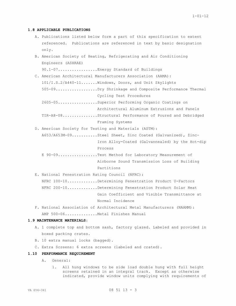
1-01-12
VA 656-341 08 51 13 - 3
1.8 APPLICABLE PUBLICATIONS
A. Publications listed below form a part of this specification to extent
referenced. Publications are referenced in text by basic designation
only.
B. American Society of Heating, Refrigerating and Air Conditioning
Engineers (ASHRAE)
90.1-07.................Energy Standard of Buildings
C. American Architectural Manufacturers Association (AAMA):
101/I.S.2/A440-11.......Windows, Doors, and Unit Skylights
505-09..................Dry Shrinkage and Composite Performance Thermal
Cycling Test Procedures
2605-05.................Superior Performing Organic Coatings on
Architectural Aluminum Extrusions and Panels
TIR-A8-08...............Structural Performance of Poured and Debridged
Framing Systems
D. American Society for Testing and Materials (ASTM):
A653/A653M-09...........Steel Sheet, Zinc Coated (Galvanized), Zinc-
Iron Alloy-Coated (Galvannealed) by the Hot-dip
Process
E 90-09.................Test Method for Laboratory Measurement of
Airborne Sound Transmission Loss of Building
Partitions
E. National Fenestration Rating Council (NFRC):
NFRC 100-10.............Determining Fenestration Product U-Factors
NFRC 200-10.............Determining Fenestration Product Solar Heat
Gain Coefficient and Visible Transmittance at
Normal Incidence
F. National Association of Architectural Metal Manufacturers (NAAMM):
AMP 500-06..............Metal Finishes Manual
1.9 MAINTENANCE MATERIALS:
A. 1 complete top and bottom sash, factory glazed. Labeled and provided in
boxed packing crates.
B. 10 extra manual locks (bagged).
C. Extra Screens: 6 extra screens (labeled and crated).
1.10 PERFORMANCE REQUIREMENT
A. General:
1. All hung windows to be side load double hung with full height
screens retained in an integral track. Except as otherwise
indicated, provide window units complying with requirements of

1-01-12
VA 656-341 08 51 13 - 4
AAMA Classification "AW" grade windows. Windows for this
project will be rated a minimum of AW60 for full size test
units per AAMA/WDMA/CSA 101/I.S.2/A440-05 to withstand a
design pressure of 60 psf minimum.
2. Uniform Load Structural Test
B. With the sash in a closed position test in accordance with ASTM-E-
330. At a static air pressure difference of 60 pounds per square
foot with pressure applied both positively and negatively.
C. Static air pressure difference shall be 1.5 times the design
pressure of 60 psf or 90 psf.
D. At conclusion of test, there shall be no glass breakage; permanent
damage to fasteners, hardware parts, support arms, or actuating
mechanisms, nor any other damage which would cause the window to be
inoperable. Permanent deformation of any frame, sash, or
ventilator member shall not exceed 0.04% of its span.
E. Air Infiltration: With the sash in a closed and locked position,
window shall be tested in accordance with ASTM-E283 and shall meet
the following performance requirements.
1. Air infiltration on windows with less than 18 feet of operable
sash crack perimeter shall not exceed 2.8 cfm per square foot
of window area when tested in a static pressure drop of 1.57
psf (equivalent to 25 mph wind velocity) or 6.3 cfm total when
tested at 6.24 psf (equivalent to 50-mph wind velocity).
2. Air infiltration on windows with 18 or more feet of operable
sash crack perimeter shall not exceed .05 cfm per square foot
of window area at a static pressure drop of 1.57 psf or .15
cfm at 6.24psf.
F. Water Resistance: With the sash in the closed and locked position,
the window shall be subjected to a pressure drop of 10.00 psf. All
tests shall be performed with the screen removed. Tests shall be
conducted in accordance with ASTM-547.
1. Thermal Performance: When tested in accordance with AAMA-1503
or according to NFRC-100 the thermal transmittance due to
conduction (Uc) shall not exceed 0.40 on the entire specimen.
2. When tested in accordance with AAMA-1503 or according to NFRC-
100 the Condensation Resistance Factor (CRF) shall not be less
than 50 on the entire specimen.
G. Provide copies of an independent testing agency verifying the
compliance of the window, indicating they meet or exceed the
performance requirements indicated above.
PART 2 - PRODUCTS
2.1 MATERIALS
A. Aluminum Extrusions; Sheet and Plate: AAMA 101/I.S.2/A440.

1-01-12
VA 656-341 08 51 13 - 5
1. LEED MRc4 - Aluminum Recycled Content: The weighted scrap content
of extrusions shall be 40%, which includes 10 percent post consumer
scrap, and 30 percent post industrial scrap.
B. Sheet Steel, Galvanized: ASTM A653; G90 galvanized coating.
C. Weather-strips: AAMA 101/I.S.2/A440; except leaf type weather-stripping
is not permitted.
D. Insect Screening: Half Screens shall be provided.
1. Regular mesh, 18 by 18, AAMA 101/I.S.2/A440.
2. Aluminum with dark bronze anodized finish unless specified otherwise.
E. Fasteners: AAMA 101/I.S.2/A440. Screws, bolts, nuts, rivets and other
fastening devices to be non-magnetic stainless steel.
1. Fasteners to be concealed when window is closed. Where wall
thickness is less than 3 mm (0.125 inch) thick, provide backup
plates or similar reinforcements for fasteners.
2. Stainless steel self-tapping screws may be used to secure Venetian
blind hanger clips, vent guide blocks, friction adjuster, and limit
opening device.
3. Attach locking and hold-open devices to windows with concealed
fasteners. Provide reinforcing plates where wall thickness is less
than 3 mm (0.125 inch) thick.
F. Weather-strips: AAMA 101/I.S.2/A440.
G. Hardware:
1. Die cast sweep locks (2 per sash) in satin white bronze, 25d
finish Provide Sash lifts: High pressure zinc die-cast.
Sashes shall also be controlled with the use of a sash lock.
2. Provide Sash lifts: High pressure zinc die-cast. Color: Satin
Taupe or Bronze
3. Balances:
a. Balances shall be of appropriate size and capacity to hold
sash in position in accordance with AAMA 101, Section
2.2.1.3.2 and AAMA 902, Section 8.1.
b. Balances shall be high performance sash balances that are
tested in accordance with AAMA 902 “Voluntary Specification
for Sash Balances”.
c. Balances shall meet all minimum AAMA 902 Class 5
requirements with a minimum .30 Manually Applied Force
ratio (MAF).
d. Balances shall be attached to a locking carrier system
that slides on extruded rails in the jamb channels. Sash
shall be field removable for installation and maintenance.
Mounting brackets that are screw attached to the sash will
not be allowed.

1-01-12
VA 656-341 08 51 13 - 6
4. Provide adjustable sash limits on all windows. Install at
heights approved by Contracting Officer’s Representative.
5. Provide exterior aluminum sash stop/ jamb filler, keeping the
top sash from opening no more than 4”.
2.2 THERMAL AND CONDENSATION PERFORMANCE
A. Condensation Resistance Factor (CRF- FRAME): Minimum CRF of C50.
B. Thermal Transmittance:
1. Maximum U value class for insulating glass windows: 50 (U=0.50),
with (Center of glass U-Value: .28 winter/.26 summer)
C. Solar Heat Gain Coefficient (SHGC): SHGC shall comply with State or
local energy code requirement: See Division 08 8000 GLASS.
2.3 DOUBLE HUNG WINDOWS:
A. AAMA 101/I.S.2/A440. Double hung type H-AW60 minimum.
B. AAMA certified product to the AAMA 101/I.S.2/A440.-11 standard.
1. Provide units with "Tilt-in" feature permitting both sides of both
sashes to be cleaned from interior.
2. Do not tilt-in sash without use of a maintenance only release
mechanism and removable locking handle. Finger operated tilt
latches not acceptable.
C. Window units and Manufacturers:
1. St. Cloud’s SCW 5000 series, DH side load units, EFCO's Series 675
Double Hung, and Custom Window’s 9250 series, a double hung units,
side load removal and Kawneer/TRACO 9400 side load DH windows,
Wausau’s 3150 DH series, are examples of acceptable window units.
D. Panning, Frame Extensions: Provide panning or frame extensions
( head Extensions) where indicated. Frame extensions shall be
extruded aluminum, minimum .0625” thickness, finished to match main
frame.
E. Backside Frame Closure: Provide snap-in pvc closure to close the
backside of the aluminum head and jamb frame and to provide backer
for exposed and blind interior sealants.
2.4 FINISH
A. In accordance with NAAMM AMP 500 series.
B. Finish exposed aluminum surfaces as follows:
1. Anodized Aluminum:
a. Finish in accordance with AMP 501 letters and numbers.

1-01-12
VA 656-341 08 51 13 - 7
b. Colored anodized Finish: AA-C22A42 (anodized) or AA-C22A44
(electrolytically deposited metallic compound) medium matte,
integrally colored coating, Class 1 Architectural, 0.7 mils thick.
1) Dyes not accepted.
2) Coated Aluminum:
3) Variation of more than 50 percent of maximum shade range
approved will not be accepted in a single window or in
adjacent windows and mullions on a continuous series.
c. Anodized Color: Dark Bronze to match existing units.
C. Hardware: Finish hardware exposed when window is in the closed
position: Match window color.
2.5 FABRICATION
A. Fabrication to exceed or meet requirements of Physical Load Tests, Air
Infiltration Test, and Water Resistance Test of AAMA 101/I.S.2/A440.
B. Factory Glazing:
1. Window units shall be factory glazed per manufacturer's standard
wet/wet glazing system employing a silicone sealant cap seal at both
exterior and interior conditions and glazing tape/gasket below the
exterior and interior cap seals for a dual glazed condition.
Provide a continuous sealant heel bead bridging between the
perimeter of the interior lite of the insulating glass unit and the
window frame, forming an air and water tight seal. Glazing and
sealants shall be suitable for application specified and as tested
and approved by the window and glass manufacturers.
a. Type of glass required: 1” nom. insulating glass (see Section 08
8000). Provide muntin bars within the IG unit.
b. Install Insulated tempered safety glass at hazardous locations
where required by Life Safety or IBC Building Code.
c. Provide anodized aluminum simulated divided lites, on both sides
of the sash.
2. Comply with combined recommendations of manufacturers of glass,
sealants, gaskets, and other glazing materials, and with
recommendations in referenced glazing publications. Window framing
shall fully capture each glass lite on all sides. Provide necessary
bite on glass, minimum edge and face clearances, and adequate sealant
thicknesses, with reasonable tolerances. Do not exceed edge pressures
stipulated by glass manufacturers for installing glass lights.

1-01-12
VA 656-341 08 51 13 - 8
3. Inspect glass for damage before installing. Do not use glass which
has chipped edges or other damage that may impair performance or
appearance. Install glass with flares or bevels at top of opening,
unless otherwise indicated by manufacturer's label.
4. Install elastomeric setting blocks in sill rabbets. Size and
locate blocks to comply with referenced glazing standard, unless
otherwise required by glass manufacturer. Set blocks in thin course
of heel bead sealant.
5. Provide spacers for glass sizes larger than 50 united inches (length
plus height) to maintain required face clearances, unless gaskets or
glazing tapes will perform this function. Locate spacers directly
opposite each other on inside and outside face of glass.
a. Spacer Thickness: Furnish spacer in thickness slightly less
than final compressed thickness of glazing tape.
b. Bite on glass: 1/8-inch minimum.
6. Provide edge blocking to comply with requirements of referenced
glazing publications, unless otherwise required by glass
manufacturer.
7. Apply toe or heel bead of elastomeric sealant where recommended by
window manufacturer to meet performance requirements.
8. Back Bedding Glazing Tapes: Install tapes continuously but not in
one continuous length. Do not stretch tapes to make them fit
opening. Butt tape at corner joints; do not lap; seal joint with
compatible sealant.
9. Drive-In Wedge Gaskets: Center glass lights in openings on setting
blocks and press firmly against tape by inserting dense compression
gaskets formed and installed to lock in place against faces of
removable stops. Start gasket applications at corners and work
toward centers of openings.
a. Provide adequate anchorage so gasket cannot walk out when
installation is subjected to movement. Square cut wedge-shaped
gaskets at corner, butt joint, and seal with sealant recommended
by gasket manufacturer.
b. Install gaskets so they protrude past face of glazing stops.
10. Apply cap bead of elastomeric sealant over exposed edge of tape,
where required by window manufacturer to meet performance
requirements. Tool exposed surface of sealant to provide a
substantial wash away from glass.
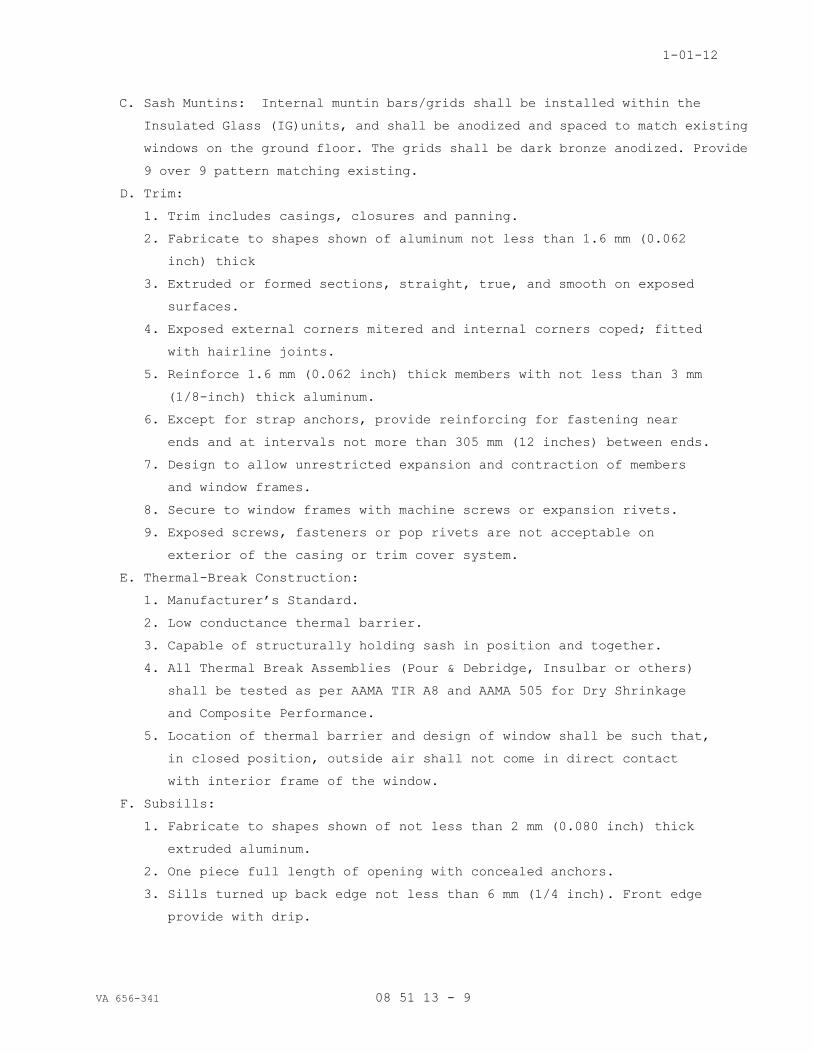
1-01-12
VA 656-341 08 51 13 - 9
C. Sash Muntins: Internal muntin bars/grids shall be installed within the
Insulated Glass (IG)units, and shall be anodized and spaced to match existing
windows on the ground floor. The grids shall be dark bronze anodized. Provide
9 over 9 pattern matching existing.
D. Trim:
1. Trim includes casings, closures and panning.
2. Fabricate to shapes shown of aluminum not less than 1.6 mm (0.062
inch) thick
3. Extruded or formed sections, straight, true, and smooth on exposed
surfaces.
4. Exposed external corners mitered and internal corners coped; fitted
with hairline joints.
5. Reinforce 1.6 mm (0.062 inch) thick members with not less than 3 mm
(1/8-inch) thick aluminum.
6. Except for strap anchors, provide reinforcing for fastening near
ends and at intervals not more than 305 mm (12 inches) between ends.
7. Design to allow unrestricted expansion and contraction of members
and window frames.
8. Secure to window frames with machine screws or expansion rivets.
9. Exposed screws, fasteners or pop rivets are not acceptable on
exterior of the casing or trim cover system.
E. Thermal-Break Construction:
1. Manufacturer’s Standard.
2. Low conductance thermal barrier.
3. Capable of structurally holding sash in position and together.
4. All Thermal Break Assemblies (Pour & Debridge, Insulbar or others)
shall be tested as per AAMA TIR A8 and AAMA 505 for Dry Shrinkage
and Composite Performance.
5. Location of thermal barrier and design of window shall be such that,
in closed position, outside air shall not come in direct contact
with interior frame of the window.
F. Subsills:
1. Fabricate to shapes shown of not less than 2 mm (0.080 inch) thick
extruded aluminum.
2. One piece full length of opening with concealed anchors.
3. Sills turned up back edge not less than 6 mm (1/4 inch). Front edge
provide with drip.

1-01-12
VA 656-341 08 51 13 - 10
4. Sill back edge behind face of window frame. Do not extend to
interior surface or bridge thermal breaks.
5. Do not perforate for anchorage, clip screws, or other requirements.
G. Insect Screens:
1. AAMA 101/I.S.2/A440.
2. Aluminum screen cloth.
PART 3 - EXECUTION
3.1 PROTECTION (DISSIMILAR MATERIALS): AAMA 101/I.S.2/A440.
3.2 INSTALLATION, GENERAL
A. Install window units in accordance with manufacturer's specifications
and recommendations for installation of window units, hardware,
operators and other components of work.
B. Where type, size or spacing of fastenings for securing window
accessories or equipment to building construction is not shown or
specified, use expansion or toggle bolts or screws, as best suited to
construction material.
1. Provide bolts or screws minimum 6 mm (1/4-inch) in diameter.
2. Sized and spaced to resist the tensile and shear loads imposed.
3. Do not use exposed fasteners on exterior, except when unavoidable
for application of hardware.
4. Provide non-magnetic stainless steel Phillips flat-head machine
screws for exposed fasteners, where required, or special tamper-
proof fasteners.
5. Locate fasteners to not disturb the thermal break construction of
windows.
C. Set windows plumb, level, true, and in alignment; without warp or rack
of frames or sash.
D. Anchor windows on jambs/sides with anchor clips or fin trim.
1. Do not allow anchor clips to bridge thermal breaks.
2. Use separate clips for each side of thermal breaks.
3. Make connections to allow for thermal and other movements.
4. Do not allow building load to bear on windows.
5. Use manufacturer's standard clips at corners and not over 600 mm (24
inches) on center.
E. Install in accordance with reviewed Shop Drawings and Product Data.
VERIFY existing openings and conditions prior to ordering window
units.
F. Install panning and exterior sill systems, where indicated.

1-01-12
VA 656-341 08 51 13 - 11
G. Ensure assemblies are plumb, level and free of warp or twist. Maintain
dimensional tolerances and alignment with adjacent Work.
H. Use sufficient anchorage devices to securely and rigidly fasten frame
assemblies to building.
I. Install window systems in accordance with manufacturer’s
recommendations. Install PVC sealant backer and rigid insulation in
frame voids prior to installation.
J. Adjust window hardware in accordance with manufacturer's
recommendations. Carefully adjust for proper operation and
performance.
K. Install loose fill insulation in shim spaces around perimeter of window frame
assemblies, to maintain continuity of thermal barrier.
L. Install blind sealant at inside perimeter of windows, prior to finish sills
or drywall finishes.
3.3 MULLIONS CLOSURES, TRIM, AND PANNING
A. Cut mullion full height of opening and anchor directly to window frame
on each side.
B. Closures, Trim, and Panning: External corners mitered and internal
corners coped, fitted with hairline, tightly closed joints.
C. Secure to concrete or solid masonry with expansion bolts, expansion
rivets, split shank drive bolts, or powder actuated drive pins.
D. Toggle bolt to hollow masonry units. Screwed to wood or metal.
E. Fasten except for strap anchors, near ends and corners and at intervals
not more than 300 mm (12 inches) between.
F. Seal units following installation to provide weathertight system.
3.4 ADJUST AND CLEAN
A. Adjust ventilating sash and hardware to provide tight fit at contact
points, and at weather-stripping for smooth operation and weathertight
closure.
B. Clean aluminum surfaces promptly after installation of windows,
exercising care to avoid damage to protective coatings and finishes.
C. Remove excess glazing and sealant compounds, dirt, and other
substances.
D. Lubricate hardware and moving parts.
E. Clean glass promptly after installation of windows. Remove glazing and
sealant compound, dirt and other substances.
F. Except when a window is being adjusted or tested, keep locked in the
closed position during the progress of work on the project.

1-01-12
VA 656-341 08 51 13 - 12
3.5 OPERATION DEVICES
A. Provide wrenches, keys, or removable locking operating handles, as
specified to operate windows.
B. Provide one emergency ventilating operating handle for every four
windows.
3.6 FIELD QUALITY CONTROL: See Section 01 4529 TESTING LABORATORY SERVICES,
for testing requirements.
A. After Contractor has installed approximately 5-10 windows, the Testing
agency shall conduct tests as indicated below.
1. On-Site Tests (Installed Windows):
a. On-site tests shall be conducted for both air and water
infiltration per AAMA 502, method B as selected by the Architect.
A representative of the window manufacturer shall be present.
Air infiltration shall not exceed .30 CFM per sq. foot of unit
when tested at 6.24 psf.
b. Water resistance shall be tested at 10 psf pressure, and water
flow of 5 gph per square foot of sample area. No water shall
penetrate into the wall structure thru the window units, panels,
mullions, etc. or their associated perimeter joints which are
caulked into the surrounding wall construction, with all sash
closed and locked, and screen in place.
c. A total of 2 units will initially be tested. The Resident
Engineer shall pick the window units to be tested. Tests for
Extraneous Air shall be conducted if initial results exceed
specified amounts.
d. Contractor shall provide scaffolding to allow the testing agency
to test 2nd floor window units.
e. Tests shall be performed prior to interior finishing work,
including the interior sealant joint, to allow visual inspection
and access to areas being tested to check for water leakage.
f. Costs for all tests shall be paid by Owner.
g. When initial tests find noncompliance with the requirements of
Project Manual, retesting of additional windows will be provided,
minimum of two per non-compliant window. All tests and retests
shall be performed by the same Testing agency. All testing shall
be paid for by Contractor.
h. Once noncompliant window is repaired or replaced, the unit shall
be retested.

1-01-12
VA 656-341 08 51 13 - 13
i. Openings of units which fail to comply to the performance
requirements will be rejected and all costs for the corrections
to comply to the requirements as well as future testing for
verification shall be borne by the contractor. Notification by
the Architect or Owner, to the contractor that this work is
substandard and does not meet specifications shall be deemed
sufficient notice to the contractor that he is proceeding with
any further installation AT HIS OWN RISK until he has corrected
any problem which may have caused the failure.
j. Owner’s acceptance of the installation as a result of field
testing shall have no bearing whatever on the terms and
conditions of the warranty and shall not be used by either party
in future dispute which may arise.
- - - E N D - - -

SECTION 08 71 00
FINISH HARDWARE
VA 656-341 08 71 00 - 1
PART 1 - GENERAL
1.1 CONDITIONS
A. Conditions of the contract (General and Supplementary Conditions) and Division One General Requirements, govern the work of this section.
B. This section includes all material, and related service necessary to furnish all finish hardware indicated on the drawings, or specified
herein.
C. Furnish UL listed hardware for all labeled and 20 min. openings in conformance with the requirements for the class of opening scheduled.
Underwriters' requirements shall have precedence over specification
where conflicts exist.
D. All work shall be in accordance with all applicable state and local building codes. Code requirements shall have precedence over this
specification where conflicts exist.
1.2 WORK INCLUDED
A. This section includes the following:
1. Furnish door hardware (for hollow metal, wood and aluminum doors) specified herein, listed in the hardware schedule, and/or required
by the drawings.
2. Cylinders and hardware for Aluminum Doors 3. Thresholds and Weather-stripping (Aluminum frame seals to be
provided by aluminum door supplier)
4. Electro-Mechanical Devices 5. Access Control components and or systems specified within this
section.
B. Where items of hardware are not definitely or correctly specified and is required for the intended service, such omission, error or other
discrepancy should be directed to the Architect prior to the bid date
for clarification by addendum. Otherwise furnish such items in the type
and quantity established by this specification for the appropriate
service intended.
1.3 RELATED WORK IN OTHER SECTIONS
A. This section includes coordination with related work in the following sections:
1. Division 6 Section "Finish Carpentry & Casework". 2. Division 8 Section "Hollow Metal Doors and Frames". 3. Division 8 Section "Wood Doors" 4. Division 8 Section "Aluminum Entrances and Storefronts" 5. Division 28 Sections "Electrical".
1.4 REFERENCES
A. Publications of agencies and organizations listed below form a part of this specification section to the extent referenced.
1. DHI - Recommended Locations for Builders' Hardware. 2. NFPA 80 - Standards for Fire Doors and Windows. 3. NFPA 101 - Code for Safety to Life from Fire in Buildings and
Structures.
4. UL - Building Material Directory. 5. DHI - Door and Hardware Institute 6. WHI - Warnock Hersey

08 71 00 - 2
7. BHMA - Builders Hardware Manufacturers Association 8. IBC 2006 - International Building Code 2006 Edition (as amended by
local building code)
1.5 SUBMITTALS
A. Within ten days after award of contract, submit detailed hardware schedule in quantities as required by Division 1 - General Conditions.
B. Schedule format shall be consistent with recommendations for a vertical format as set forth in the Door & Hardware Institute's (DHI)
publication "Sequence and Format for the Hardware Schedule". Hardware
sets shall be consolidated to group multiple door openings which share
similar hardware requirements. Schedule shall include the following
information:
1. Door number, location, size, handing, and rating. 2. Door and frame material, handing. 3. Degree of swing. 4. Manufacturer 5. Product name and catalog number 6. Function, type and style 7. Size and finish of each item 8. Mounting heights 9. Explanation of abbreviations, symbols, etc. 10.Numerical door index, indicating the hardware set/ group number for
each door.
C. When universal type door closers are to be provided, the schedule shall indicate the application method to be used for installation at each
door: (regular arm, parallel arm, or top jamb).
D. The schedule will be prepared under the direct supervision of a certified Architectural Hardware Consultant (AHC) employed by the
hardware distributor. The hardware schedule shall be signed and
embossed with the DHI certification seal of the supervising AHC. The
supervising AHC shall attend any meetings related to the project when
requested by the architect.
E. Check the specified hardware for suitability and adaptability to the details and surrounding conditions.
F. Review drawings from related trades as required to verify compatibility with specified hardware. Indicate unsuitable or in compatible items,
and proposed substitutions in the hardware schedule.
G. Provide documentation for all hardware to be furnished on labeled fire doors indicating compliance with positive pressure fire testing UL 10C.
H. Furnish manufacturers' catalog data for each item of hardware in quantities as required by Division 1 - General Conditions.
I. Submit a sample of each type of hardware requested by the architect. Samples shall be of the same finish, style, and function as specified
herein. Tag each sample with its permanent location so that it may be
used in the final work.
J. Furnish with first submittal, a list of required lead times for all hardware items.
K. After final approved schedule is returned, transmit corrected copies for distribution and field use in quantities as required by Division 1
- General Conditions.

08 71 00 - 3
L. Furnish approved hardware schedules, template lists, and pertinent templates as requested by related trades.
M. Furnish necessary diagrams, schematics, voltage and amperage requirements for all electro-mechanical devices or systems as required
by related trades. Wiring diagrams shall be opening specific and
include both a riser diagram and point to point diagram showing all
wiring terminations.
N. After receipt of approved hardware schedule, Hardware supplier shall initiate a meeting including the owner's representative to determine
keying requirements. Upon completion of the initial key meeting,
hardware supplier shall prepare a proposed key schedule with symbols
and abbreviations as set forth in the door and hardware institute's
publication "Keying Procedures, Systems, and Nomenclature". Submit
copies of owner approved key schedule for review and field use in
quantities as required by Division 1 - General Conditions. Wiring
diagrams shall be included in final submittals transmitted for
distribution and field use.
1.6 QUALITY ASSURANCE
A. Manufacturers and model numbers listed are to establish a standard of function and quality. Similar items by approved manufacturers that are
equal in design, function, and quality, may be considered for prior
approval of the architect, provided the required data and physical
samples are submitted for approval as set forth in Division One General
Requirements.
B. Obtain each type of hardware (hinges, latch & locksets, exit devices, closers, etc.) from a single manufacturer, although several may be
indicated as offering products complying with requirements.
C. All hardware items shall be manufactured no earlier than 6 months prior to delivery to site.
D. Hardware supplier shall be factory trained and certified by the manufacture to provide and support all computer managed locks and
system components.
E. Installation of hardware shall be installed or directly supervised and inspected by a skilled installer certified by the manufacturer of
locksets, door closers, and exit devices used on the project, or with
not less than 3 years’ experience in successful completion of projects
similar in size and scope.
F. Provide hardware for all labeled fire doors, which complies with positive pressure fire testing UL 10C.
G. Comply with all applicable provisions of the standards referenced within section 1.4 of this specification.
H. Hardware supplier shall participate when reasonably requested to meet with the contractor and or architect to inspect any claim for incorrect
or non-functioning materials; following such inspection, the hardware
supplier shall provide a written statement documenting the cause and
proposed remedy of any unresolved items.
1.7 DELIVERY, STORAGE AND HANDLING
A. Hardware supplier shall deliver hardware to the job site unless otherwise specified.

08 71 00 - 4
B. All hardware shall be delivered in manufacturers' original cartons and shall be clearly marked with set and door number.
C. Coordinate with contractor prior to hardware delivery and recommend secure storage and protection against loss and damage at job site.
D. Contractor shall receive all hardware and provide secure and proper protection of all hardware items to avoid delays caused by lost or
damaged hardware. Contractor shall report shortages to the Architect
and hardware supplier immediately after receipt of material at the job
site.
E. Coordinate with related trades under the direction of the contractor for delivery of hardware items necessary for factory installation.
1.8 PRE-INSTALLATION MEETING
A. Schedule a hardware pre-installation meeting on site to review and discuss the installation of continuous hinges, locksets, door closers,
exit devices, overhead stops, and electromechanical door hardware.
B. Meeting attendees shall be notified 7 days in advance and shall include: Architect, Contractor, Door Hardware Installers (including low
voltage hardware), Manufacturers representatives for above hardware
items, and any other effected subcontractors or suppliers.
C. All attendees shall be prepared to distribute installation manuals, hardware schedules, templates, and physical hardware samples.
1.9 WARRANTY
A. All hardware items shall be warranted against defects in material and workmanship as set forth in Division One General Requirements.
B. Repair, replace, or otherwise correct deficient materials and workmanship without additional cost to owner.
PART 2 - PRODUCTS
2.1 FASTENERS
A. All exposed fasteners shall be Phillips head or as otherwise specified, and shall match the finish of the adjacent hardware. All fasteners ex-
posed to the weather shall be non-ferrous or stainless steel. Furnish
correct fasteners to accommodate surrounding conditions.
B. Where torx tamper resistant fasteners have been specified for a specific hardware group, provide torx head fasteners with center pin on
ALL exposed fasteners.
C. Coordinate required reinforcements for doors and frames. Seek approval of the architect prior to furnishing through-bolts. Furnish through-
bolts as required for materials not readily reinforced.
2.2 BUTT HINGES
A. Acceptable manufacturers and respective catalog numbers:
Ives Stanley Hager McKinney 1. Standard Weight, Plain Bearing 5PB1 F179 1279 T2714
2. Standard Weight, Ball Bearing 5BB1 BB179 BB1279 TB2714
3. Standard Weight, Ball Bearing, Non-Ferrous
5BB1 FBB191 BB1191 TB2314
4. Heavy Weight, Ball Bearing 5BB1HW FBB168 BB1168 T4B3786
5. Heavy Weight, Ball Bearing, Non- 5BB1HW FBB199 BB1199 T4B3386

08 71 00 - 5
Ferrous
B. Unless otherwise specified, furnish the following hinge quantities for each door leaf.
1. 3 hinges for doors up to 90 inches. 2. 1 additional hinge for every 30 inch on doors over 90 inches. 3. 4 hinges for Dutch door applications.
C. Unless otherwise specified, top and bottom hinges shall be located as specified in division 8 Section "Hollow Metal Doors and Frames".
Intermediate hinges shall be located equidistant from others.
D. Unless otherwise specified, furnish hinge weight and type as follows:
1. Standard weight: plain bearing hinge 5PB1 for interior openings through 36 inches wide without a door closer.
2. Standard weight: ball bearing hinge 5BB1 for interior opening over 36 through 40 inches wide without a door closer, and for interior
openings through 40 inches wide with a door closer.
3. Heavyweight: 4 ball bearing hinge 5BB1HW for interior openings over 40 inches wide, and for all vestibule doors.
4. Heavyweight: 4 ball bearing hinge 5BB1HWss for exterior openings unless otherwise listed in groups.
E. Unless otherwise specified, furnish hinges for exterior doors, fabricated from brass, bronze, or stainless steel. Unless otherwise
specified, hinges for interior doors may be fabricated from steel.
F. Unless otherwise specified, furnish hinges in the following sizes:
1. 5" x 5" 2-1/4" thick
doors
2. 4-1/2" x 4-1/2" 1-3/4" thick
doors
G. Furnish hinges with sufficient width to accommodate trim and allow for 180-degree swing.
H. Unless otherwise specified, furnish hinges with flat button tips with non-rising pins at interior doors, non-removable loose pins (NRP) at
exterior and out-swinging interior doors.
I. Unless otherwise specified, furnish all hinges to template standards.
2.3 POWER TRANSFERS
A. Acceptable manufacturers and respective catalog numbers:
Von Duprin ASSA 1. Concealed Two Wire EPT-2 CEPT-10
2. Concealed Ten Wire EPT-10 CEPT-10
B. Door cords shall be armored cable with screw on caps.
C. Concealed power transfers shall be concealed in the door and frame when the door is closed.
D. Concealed power transfers shall have a steel tube to protect wires from being cut.
E. Concealed power transfers with spring tubes shall be rejected.
F. Concealed power transfers shall be supplied with a mud box to house all terminations.
2.4 FLUSH BOLTS AND DUST PROOF STRIKES

08 71 00 - 6
A. Acceptable manufacturers and respective catalog numbers:
Ives Door Controls Hager 1. Dust Proof Strike DP2 80 280X
2. Auto Flush Bolt (Metal Door)
FB31P 842 292D
3. Auto Flush Bolt (Wood Door)
FB41P 942 291D
4. Manual Flush Bolt FB458 780 282D
B. Unless otherwise specified, provide 12" rods for manual flush bolts for door 7'6" or less, 24" top rods for doors over 7'6" to 8'6".
C. Unless otherwise specified, provide doors over 8'6" with automatic top bolts.
D. Provide automatic flush bolts where required to maintain fire door listing and or egress requirements on pairs of doors.
E. All flush-bolt applications shall be UL listed to be installed with top flush-bolt only. Provide auxiliary fire bolt as required for fire rated
openings where less bottom bolt has been specified.
F. Provide all bottom flush bolts with non-locking dust proof strikes.
2.5 EXIT DEVICES
A. Acceptable manufacturers and respective catalog numbers:
Von Duprin Yale Corbin 1. Wide
Stile,
Push Pad
98 / 99 Series 7100-ECK1 Series ED5000-M110 Series
2. Wide Stile,
Electric
Latch
Retraction
QEL 98 / 99
Series
7100-P-ECK1
Series
ED5000-M94-M110
Series
3. Lever Trim 996 Series 600 Series 900 Series
4. Pull Trim 990 Series 500 Series 1300 Series
B. Obtain exit devices from a single manufacturer, although several may be indicated as offering products complying with requirements.
C. All exit devices shall be equipped with a sound-dampening feature to reduce touch pad return noise.
D. On full glass doors there shall be no exposed fasteners on the back of the mechanism visible through the glass.
E. All exit devices shall be provided with flush end caps to reduce potential damage from impact.
F. All exit devices shall be provided with dead-locking latch bolts to insure security.
G. All exit devices shall be U.L. listed for accident hazard. Exit device for use on fire doors shall also be U.L. listed for fire exit hardware.
H. Provide optional strikes, special length rods, and adapter plates to accommodate door and frame conditions. Provide narrow style series
devices in lieu of wide stile series devices where optional strikes
will not accommodate door and frame conditions.

08 71 00 - 7
I. Coordinate with related trades to insure adequate clearance and reinforcement is provided in doors and frames. Provide thru bolts as
required.
J. Refer to hardware groups for exit device applications utilizing the option of: "less bottom rod and floor strike" (LBR)
K. All exit devices shall be provided with optional trim designs to match other lever and pull designs used on the project.
L. Unless specific exit device dogging options are noted within hardware sets, provide dogging options as follows:
1. Fire Rated devices: Dogging not permitted.
2. Non-Rated Exit Only functions not equipped with outside trim or pull: Less Dogging.
3. Non-Rated Classroom functions: Less Dogging.
4. Non-Rated devices utilizing electric latch retraction or electrified outside trim: Less Dogging.
5. All Other Non-Rated devices: Cylinder Dogging utilizing interchangeable core cylinders. Cylinder keyway shall match locksets
furnished on this project.
M. Provide glass bead kits as required to accommodate door conditions. Screws shall not be visible through full glass doors.
N. Where specified, provide compatible keyed mullions with cylinder for pairs of doors.
O. Provide reinforced crossbars for all traditional style exit devices applied to doors over 36" wide.
2.6 LOCKS AND LATCHES
A. Acceptable manufacturers and respective catalog numbers:
Schlage Best Corbin 1. Grade 1 Mortise L Series
03A
45H Series
3H
ML2000 LWA
B. Minimize transmission of heat to lock trim. Provide temperature control modules (TCM) on all electrified locks when cataloged by the
lock manufacturer.
C. Unless otherwise specified, all locks and latches to have:
1. 2-3/4" Backset 2. 1/2" minimum throw latchbolt 3. 1" throw deadbolt 4. 7 pin cylinders 5. ANSI A115.2 strikes
D. Provide guarded latch bolts for all locksets, and latch bolts with sufficient throw to maintain fire rating of both single and paired door
assemblies.
E. Length of strike lip shall be sufficient to clear surrounding trim.
F. Provide wrought boxes for strikes at inactive doors, wood frames, and metal frames without integral mortar covers.
2.7 PULLS, PUSH BARS, PUSH/PULL PLATES
A. Acceptable manufacturers and respective catalog numbers:

08 71 00 - 8
Burns Hager Ives 1. Straight Pull (1" dia., 10" ctc) 26C 4J 8103-0
2. Straight Pull (3/4” dia., 8” ctc) 25B 3G 8102-8
3. Offset Door Pull (1" dia., 10" ctc)
39C 12J 8190-0
4. Pull / Push-Bar (1" dia., 10" ctc Pull)
422 x
26C
153 9103-0
5. Offset Pull / Push-Bar (1" dia., 10" ctc Pull)
422 x
39C
157 9190-0
6. Push Plate (.050 4"X 16") 54 30S 4 x
16
8200 4 x 16
7. Push Plate (.050 6"X 16") 56 30S 6 x
16
8200 6" X 16"
8. Pull Plate (1" dia., 10" ctc - .050" X 4" X 16")
5426C 34J 4 x
16
8303-0 4" X
16"
A. Adjust dimensions of push plates to accommodate stile and rail dimensions, lite and louver cutouts, and adjacent hardware. Where
required by adjacent hardware, push plates shall be factory drilled for
cylinders or other mortised hardware. All push plates shall be beveled
4 sides and counter sunk.
B. Where possible, provide back-to-back, and concealed mounting for pulls and push bars. Push bar length shall be 3" less door width, or center
of stile to center of stile for stile & rail or full glass doors.
2.8 COORDINATORS
A. Acceptable manufacturers and respective catalog numbers:
Ives Door Controls Hager 1. Bar
Coordinator
COR x FL 600 x
Filler
297D x
297F
2. Mounting Bracket
MB
Series
AB, C
Series
297 Series
B. Provide coordinators at all pairs of doors having automatic flush bolts and closers on the inactive leaf, and for pairs of doors having
vertical rod/mortise exit device combinations with overlapping
astragals.
C. Provide appropriate filler bars, closer mounting brackets, carry bars, and special top latch preparations as required by adjacent hardware.
2.9 CLOSERS
A. Acceptable manufacturers and respective catalog numbers:
LCN Yale Norton 1. 4040XP / 4040XP
EDA
R4400 /
PR4400
R7500 /
PR7500
2. 1461 3501 8501
B. Obtain door closers from a single manufacturer, although several may be indicated as offering products complying with requirements.
C. Provide extra heavy duty arm (EDA / HD) when closer is to be installed using parallel arm mounting.
D. Closers shall utilize a stable fluid withstanding temperature range of +120deg F to -30deg F without seasonal adjustment of closer speed to
properly close the door. Closers for fire-rated doors shall be
provided with temperature stabilizing fluid that complies with
standards UL10C.

08 71 00 - 9
E. Unless otherwise specified, all door closers shall have full covers and separate adjusting valves for sweeps, latch, and backcheck.
F. Provide closers for all labeled doors. Provide closer series and type consistent with other closers for similar doors specified elsewhere on
the project.
G. Provide closers with adjustable spring power. Size closers to insure exterior and fire rated doors will consistently close and latch doors
under existing conditions. Size all other door closers to allow for
reduced opening force not to exceed 5 lbs.
H. Install closers on the room side of corridor doors, stair side of stairways and interior side of exterior doors.
I. Closers shall be furnished complete with all mounting brackets and cover plates as required by door and frame conditions, and by adjacent
hardware.
J. Door closers shall be provided with a powder coat finish to provide superior protection against the effects of weathering. Powder coat
finish shall successfully pass a 100 hour salt spray test.
K. Pressure Relief Valve, PRV, shall not be acceptable.
2.10 KICK PLATES AND MOP PLATES
A. Furnish protective plates as specified in hardware groups.
B. Where specified, provide 10" kick plates, 34" armor plates, and 4" mop plates. Unless otherwise specified, metal protective plates shall be
.050" thick; plastic plates shall be 1/8" thick.
C. Protective plates shall be 2" less door width, or 1" less door width at pairs. All protective plates shall be beveled 4 sides and counter
sunk. Protection plates over 16" shall not be provided for labeled
doors unless specifically approved by door manufacturers listing.
D. Where specified, provide surface mounted door edges. Edges shall butt to protective plates. Provide edges with cutouts as required adjacent
hardware.
E. Adjust dimensions of protection plates to accommodate stile and rail dimensions, lite and louver cutouts, and adjacent hardware. Where
required by adjacent hardware, protection plates shall be factory
drilled for cylinders or other mortised hardware.
2.11 OVERHEAD STOPS
A. Acceptable manufacturers and respective catalog numbers:
Glynn-Johnson Rixson Sargent 1. Heavy Duty Surface Mount GJ900 Series 9
Series
590
2. Heavy Duty Concealed Mount
GJ100 Series 1
Series
690
B. Unless otherwise specified, furnish GJ900 series overhead stop for hollow metal or 1-3/4” solid core doors equipped with regular arm
surface type closers that swing more than 140 degrees before striking a
wall, for hollow metal or 1-3/4” solid core doors that open against
equipment, casework, sidelights, or other objects that would make wall
bumpers inappropriate, and as specified in hardware groups.

08 71 00 - 10
C. Furnish sex bolt attachments for wood and mineral core doors unless doors are supplied with proper reinforcing blocks.
D. Provide special stop only (“SE” suffix) overhead stops when used in conjunction with electronic hold open closers.
E. Do not provide holder function for labeled doors.
2.12 WALL STOPS AND HOLDERS
A. Acceptable manufacturers and respective catalog numbers:
Ives Hager Burns 1. Wrought Convex Wall
Bumper
WS406CVX 232W 570
2. Wrought Concave Wall Bumper
WS406CCV 236W 575
B. Furnish a stop or holder for all doors. Furnish floor stops or hinge pin stops only where specifically specified.
C. Where wall stops are not applicable, furnish overhead stops.
D. Do not provide holder function for labeled doors.
2.13 WEATHERSTRIP, GASKETING
A. Acceptable manufacturers and respective catalog numbers:
Zero Pemko NGP Reese 1. Weatherstrip 429 2891_PK 700NA 755
2. Adhesive Gasket 188 S88 5050 797
3. Mullion Seal/Silencer 8780 5110 5100N
4. Meeting Edge Seals 8193 18041 9605 959
5. Sweeps 8192 18061_NB B606 964
6. Sweep w/ drip 8198 345_N C627 354
7. Drip Cap 142 346 16 R201
B. Where specified in the hardware groups, furnish the above products unless otherwise detailed in groups.
C. Provide weatherstripping all exterior doors and where specified.
D. Provide intumescent and other required edge sealing systems as required by individual fire door listings to comply with positive pressure
standards UL 10C.
E. Provide Zero 188 smoke gaskets at all fire rated doors and smoke and draft control assemblies.
F. Provide gasketing for all meeting edges on pairs of fire doors. Gasketing shall be compatible with astragal design provided by door
supplier as required for specific fire door listings.
2.14 THRESHOLDS
A. Acceptable manufacturers and respective catalog numbers:
Zero Pemko NGP Reese 1. Saddle Thresholds 8655 171 425 S205
B. Hardware supplier shall verify all finish floor conditions and coordinate proper threshold as required to insure a smooth transition
between threshold and interior floor finish.
C. Threshold Types:

08 71 00 - 11
1. Unless otherwise specified, provide saddle threshold similar to Zero 8655 for all exterior openings with an interior floor finish less
than or equal to 1/4" in height.
2. Unless otherwise specified, provide half saddle threshold similar to Zero 1674 for all exterior openings with an interior floor finish
greater than 1/4" in height. Threshold height shall match thickness
of interior floor finish.
2.15 POWER SUPPLIES
A. Provide quantities and types as specified in hardware sets. Shared power supplies will not be accepted without prior approval from the
owner.
B. All power supplies shall have the following features:
1. 12/24 VDC Output, field selectable. 2. Class 2 Rated power limited output. 3. Universal 120-240 VAC input. 4. Low voltage DC, regulated and filtered. 5. Polarized connector for distribution boards. 6. Fused primary input. 7. AC input and DC output monitoring circuit w/LED indicators. 8. Cover mounted AC Input indication. 9. Tested and certified to meet UL294. 10. NEMA 1 enclosure. 11. Hinged cover w/lock down screws. 12. High voltage protective cover.
C. All power supplies shall incorporate fused distribution boards.
D. All electro-mechanical systems requiring fail safe circuits shall be capable of interfacing with the fire alarm system to cut power to
appropriate system components. Unless already provided in another
system component, all power supplies utilized in fail safe circuits
shall include an integral relay which when connected to the N/C fire
alarm contact will cut power to all openings connected to the
individual power supply. Power supply, unless otherwise specified, will
automatically reset itself when fire alarm relay returns to normal
state following a fire alarm.
2.16 DOOR POSITION SWITCHES
A. Acceptable manufacturers and respective catalog numbers:
Schlage Electronics Sentrol Sargent 1. Concealed (wood & hollow metal
doors)
679 Series 1076W 3287
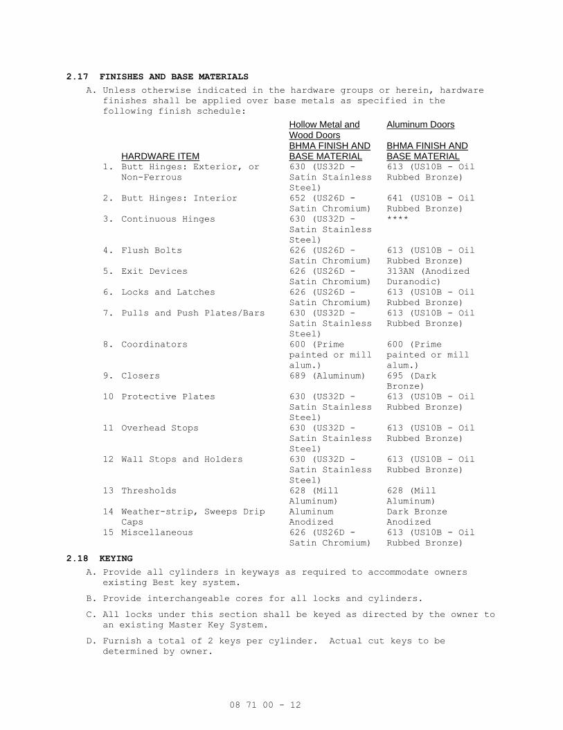
08 71 00 - 12
2.17 FINISHES AND BASE MATERIALS
A. Unless otherwise indicated in the hardware groups or herein, hardware finishes shall be applied over base metals as specified in the
following finish schedule:
Hollow Metal and Wood Doors
Aluminum Doors
HARDWARE ITEM BHMA FINISH AND BASE MATERIAL
BHMA FINISH AND BASE MATERIAL
1. Butt Hinges: Exterior, or Non-Ferrous
630 (US32D -
Satin Stainless
Steel)
613 (US10B - Oil
Rubbed Bronze)
2. Butt Hinges: Interior 652 (US26D -
Satin Chromium)
641 (US10B - Oil
Rubbed Bronze)
3. Continuous Hinges 630 (US32D -
Satin Stainless
Steel)
****
4. Flush Bolts 626 (US26D -
Satin Chromium)
613 (US10B - Oil
Rubbed Bronze)
5. Exit Devices 626 (US26D -
Satin Chromium)
313AN (Anodized
Duranodic)
6. Locks and Latches 626 (US26D -
Satin Chromium)
613 (US10B - Oil
Rubbed Bronze)
7. Pulls and Push Plates/Bars
630 (US32D -
Satin Stainless
Steel)
613 (US10B - Oil
Rubbed Bronze)
8. Coordinators 600 (Prime
painted or mill
alum.)
600 (Prime
painted or mill
alum.)
9. Closers 689 (Aluminum) 695 (Dark
Bronze)
10. Protective Plates 630 (US32D -
Satin Stainless
Steel)
613 (US10B - Oil
Rubbed Bronze)
11. Overhead Stops 630 (US32D -
Satin Stainless
Steel)
613 (US10B - Oil
Rubbed Bronze)
12. Wall Stops and Holders 630 (US32D -
Satin Stainless
Steel)
613 (US10B - Oil
Rubbed Bronze)
13. Thresholds 628 (Mill
Aluminum)
628 (Mill
Aluminum)
14. Weather-strip, Sweeps Drip Caps
Aluminum
Anodized
Dark Bronze
Anodized
15. Miscellaneous 626 (US26D -
Satin Chromium)
613 (US10B - Oil
Rubbed Bronze)
2.18 KEYING
A. Provide all cylinders in keyways as required to accommodate owners existing Best key system.
B. Provide interchangeable cores for all locks and cylinders.
C. All locks under this section shall be keyed as directed by the owner to an existing Master Key System.
D. Furnish a total of 2 keys per cylinder. Actual cut keys to be determined by owner.

08 71 00 - 13
E. Master keys, control keys, and change keys shall be delivered by registered mail to the owner. Construction keys shall be delivered to
the contractor.
PART 3 - EXECUTION
3.1 EXAMINATION
A. Prior to installation of hardware, installer shall examine door frame installation to insure frames have been set square and plumb.
Installer shall examine doors, door frames, and adjacent wall, floor,
and ceiling for conditions, which would adversely affect proper
operation and function of door assemblies. Do not proceed with
hardware installation until such deficiencies have been corrected.
3.2 INSTALLATION
A. Before hardware installation, general contractor/construction manager shall coordinate a hardware installation seminar with a 1 week notice
to all parties involved. The seminar is to be conducted on the
installation of hardware, specifically of locksets, closers, exit
devices, continuous hinges and overhead stops. Manufacturer's
representative of the above products to present seminar. Seminar to be
held at the job site and attended by installers of hardware (including
low voltage hardware) for aluminum, hollow metal and wood doors.
Training to include use of installation manuals, hardware schedule,
templates and physical products samples.
B. Install all hardware in accordance with the approved hardware schedule and manufacturers instructions for installation and adjustment.
C. Set units level, plumb and true to the line and location. Adjust and reinforce the attachment substrate as necessary for proper installation
and operation.
D. Drill and countersink units which are not factory-prepared for anchorage fasteners. Space fasteners and anchors in accord with
industry standards.
E. Drill appropriate size pilot holes for all hardware attached to wood doors and frames.
F. Shim doors as required to maintain proper operating clearance between door and frame.
G. Unless otherwise specified, locate all hardware in accordance with the recommended locations for builders hardware for standard doors and
frames as published by the Door and Hardware Institute.
H. Use only fasteners supplied by or approved by the manufacturer for each respective item of hardware.
I. Mortise and cut to close tolerance and conceal evidence of cutting in the finished work.
J. Conceal push and pull bar fasteners where possible. Do not install through bolts through push plates.
K. Install hardware on UL labeled openings in accordance with manufacturer's requirements to maintain the label.
L. Apply self-adhesive gasketing on frame stop at head & latch side and on rabbet of frame at hinge side.

08 71 00 - 14
M. Install hardware in accordance with supplemental "S" label instructions on all fire rated openings.
N. Install wall stops to contact lever handles or pulls. Do not mount wall stops on casework, or equipment.
O. Where necessary, adjust doors and hardware as required to eliminate binding between strike and latchbolt. Doors should not rattle.
P. Overhead stops used in conjunction with electrified hold open closers shall be templated and installed to coincide with engagement of closer
hold open position.
Q. Install door closers on corridor side of lobby doors, room side of corridor doors, and stair side of stairways.
R. Adjust spring power of door closers to the minimum force required to insure exterior and fire rated doors will consistently close and latch
doors under existing conditions. Adjust all other door closers to
insure opening force does not to exceed 5 lbs.
S. Adjust "sweep", "latch", & "back check" valves on all door closers to properly control door throughout the opening and closing cycle. Adjust
total closing speed as required to comply with all applicable state and
local building codes.
T. Install "hardware compatible" (bar stock) type weatherstripping continuously for an uninterrupted seal. Adjust templating for parallel
arm door closers, exit devices, etc., as required to accommodate
weatherstripping.
U. Unless otherwise specified or detailed, install thresholds with the bevel in vertical alignment with the outside door face. Notch and
closely fit thresholds to frame profile. Set thresholds in full bed of
sealant.
V. Compress sweep during installation as recommended by sweep manufacturer to facilitate a water resistant seal.
W. Deliver to the owner 1 complete set of installation and adjustment instructions, and tools as furnished with the hardware.
3.3 FIELD QUALITY CONTROL
A. After installation has been completed, the hardware supplier and manufacturers representative for locksets, door closers, exit devices,
and overhead stops shall check the project and verify compliance with
installation instructions, adjustment of all hardware items, and proper
application according to the approved hardware schedule. Hardware
supplier shall submit a list of all hardware that has not been
installed correctly.
B. After installation has been completed, the hardware supplier and manufacturers representative shall meet with the owner to explain the
functions, uses, adjustment, and maintenance of each item of hardware.
Hardware supplier shall provide the owner with a copy of all wiring
diagrams. Wiring diagrams shall be opening specific and include both a
riser diagram and point to point diagram showing all wiring
terminations.
3.4 ADJUSTMENT AND CLEANING
A. At final completion, and when H.V.A.C. equipment is in operation, installer shall make final adjustments to and verify proper operation

08 71 00 - 15
of all door closers and other items of hardware. . Lubricate moving
parts with type lubrication recommended by the manufacturer.
B. All hardware shall be left clean and in good operation. Hardware found to be disfigured, defective, or inoperative shall be repaired or
replaced.
3.5 HARDWARE SCHEDULE
A. The following schedule of hardware groups are intended to describe opening function. The hardware supplier is cautioned to refer to the
preamble of this specification for a complete description of all
materials and services to be furnished under this section.
HW SET #: 01
QTY DESCRIPTION CATALOG NUMBER MFR
1 EA CYLINDER AS REQUIRED SCH
EA BALANCE OF HARDWARE BY OTHERS B/O
HW SET #: 02
QTY DESCRIPTION CATALOG NUMBER MFR
EA HINGE AS REQUIRED IVE
1 EA OFFICE/ENTRY LOCK L9050 SCH
1 EA WALL STOP WS406 IVE
FUNCTION: L9050 (F04) OFFICE AND INNER ENTRY LOCK
LATCHBOLT RETRACTED BY LEVER FROM EITHER SIDE UNLESS OUTSIDE IS MADE
INOPERATIVE BY KEY OUTSIDE OR BY TURNING INSIDE THUMBTURN. WHEN OUTSIDE IS
LOCKED, LATCHBOLT IS RETRACTED BY KEY OUTSIDE OR BY LEVER INSIDE. OUTSIDE
LEVER REMAINS LOCKED UNTIL THUMBTURN IS RETURNED TO VERTICAL OR UNLOCKED BY
KEY. AUXILIARY LATCH DEADLOCKS LATCHBOLT WHEN DOOR IS CLOSED.
HW SET #: 03
QTY DESCRIPTION CATALOG NUMBER MFR
EA HINGE AS REQUIRED IVE
1 EA OFFICE/ENTRY LOCK L9050 SCH
1 EA OH STOP 90S GLY
FUNCTION: L9050 (F04) OFFICE AND INNER ENTRY LOCK
LATCHBOLT RETRACTED BY LEVER FROM EITHER SIDE UNLESS OUTSIDE IS MADE
INOPERATIVE BY KEY OUTSIDE OR BY TURNING INSIDE THUMBTURN. WHEN OUTSIDE IS
LOCKED, LATCHBOLT IS RETRACTED BY KEY OUTSIDE OR BY LEVER INSIDE. OUTSIDE
LEVER REMAINS LOCKED UNTIL THUMBTURN IS RETURNED TO VERTICAL OR UNLOCKED BY
KEY. AUXILIARY LATCH DEADLOCKS LATCHBOLT WHEN DOOR IS CLOSED.
HW SET #: 04
QTY DESCRIPTION CATALOG NUMBER MFR
EA HINGE AS REQUIRED IVE
1 EA CLASSROOM LOCK L9070 SCH
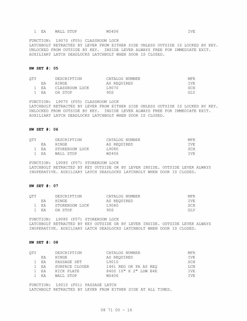
08 71 00 - 16
1 EA WALL STOP WS406 IVE
FUNCTION: L9070 (F05) CLASSROOM LOCK
LATCHBOLT RETRACTED BY LEVER FROM EITHER SIDE UNLESS OUTSIDE IS LOCKED BY KEY.
UNLOCKED FROM OUTSIDE BY KEY. INSIDE LEVER ALWAYS FREE FOR IMMEDIATE EXIT.
AUXILIARY LATCH DEADLOCKS LATCHBOLT WHEN DOOR IS CLOSED.
HW SET #: 05
QTY DESCRIPTION CATALOG NUMBER MFR
EA HINGE AS REQUIRED IVE
1 EA CLASSROOM LOCK L9070 SCH
1 EA OH STOP 90S GLY
FUNCTION: L9070 (F05) CLASSROOM LOCK
LATCHBOLT RETRACTED BY LEVER FROM EITHER SIDE UNLESS OUTSIDE IS LOCKED BY KEY.
UNLOCKED FROM OUTSIDE BY KEY. INSIDE LEVER ALWAYS FREE FOR IMMEDIATE EXIT.
AUXILIARY LATCH DEADLOCKS LATCHBOLT WHEN DOOR IS CLOSED.
HW SET #: 06
QTY DESCRIPTION CATALOG NUMBER MFR
EA HINGE AS REQUIRED IVE
1 EA STOREROOM LOCK L9080 SCH
1 EA WALL STOP WS406 IVE
FUNCTION: L9080 (F07) STOREROOM LOCK
LATCHBOLT RETRACTED BY KEY OUTSIDE OR BY LEVER INSIDE. OUTSIDE LEVER ALWAYS
INOPERATIVE. AUXILIARY LATCH DEADLOCKS LATCHBOLT WHEN DOOR IS CLOSED.
HW SET #: 07
QTY DESCRIPTION CATALOG NUMBER MFR
EA HINGE AS REQUIRED IVE
1 EA STOREROOM LOCK L9080 SCH
1 EA OH STOP 90S GLY
FUNCTION: L9080 (F07) STOREROOM LOCK
LATCHBOLT RETRACTED BY KEY OUTSIDE OR BY LEVER INSIDE. OUTSIDE LEVER ALWAYS
INOPERATIVE. AUXILIARY LATCH DEADLOCKS LATCHBOLT WHEN DOOR IS CLOSED.
HW SET #: 08
QTY DESCRIPTION CATALOG NUMBER MFR
EA HINGE AS REQUIRED IVE
1 EA PASSAGE SET L9010 SCH
1 EA SURFACE CLOSER 1461 REG OR PA AS REQ LCN
1 EA KICK PLATE 8400 10" X 2" LDW B4E IVE
1 EA WALL STOP WS406 IVE
FUNCTION: L9010 (F01) PASSAGE LATCH
LATCHBOLT RETRACTED BY LEVER FROM EITHER SIDE AT ALL TIMES.

08 71 00 - 17
HW SET #: 09 – NOT USED
QTY DESCRIPTION CATALOG NUMBER MFR
EA HINGE AS REQUIRED IVE
1 EA PASSAGE SET L9010 SCH
1 EA SURFACE CLOSER 1461 REG OR PA AS REQ LCN
1 EA KICK PLATE 8400 10" X 2" LDW B4E IVE
1 EA WALL STOP WS406 IVE
1 SET SEALS 188S ZER
FUNCTION: L9010 (F01) PASSAGE LATCH
LATCHBOLT RETRACTED BY LEVER FROM EITHER SIDE AT ALL TIMES.
HW SET #: 10
QTY DESCRIPTION CATALOG NUMBER MFR
EA HINGE AS REQUIRED IVE
1 EA PRIVACY W/DB & IND L9496 OCCUPIED/VACANT SCH
1 EA SURFACE CLOSER 1461 REG OR PA AS REQ LCN
1 EA KICK PLATE 8400 10" X 2" LDW B4E IVE
1 EA WALL STOP WS406 IVE
FUNCTION: L9496 PRIVACY WITH “OCCUPIED” INDICATOR
LEVER RETRACTS LATCHBOLT FROM EITHER SIDE. DEADBOLT THROWN OR RETRACTED BY KEY
OUTSIDE (RETRACTION BY KEY REQUIRED IN THE EVENT OF AN EMERGENCY) OR INSIDE
THUMBTURN. THROWING DEADBOLT LOCKS OUTSIDE LEVER AND DISPLAYS “OCCUPIED”
PLATE. ROTATING INSIDE LEVER SIMULTANEOUSLY RETRACTS BOTH DEADBOLT AND
LATCHBOLT AND UNLOCKS OUTSIDE LEVER.
HW SET #: 11
QTY DESCRIPTION CATALOG NUMBER MFR
EA HINGE AS REQUIRED IVE
1 EA PRIVACY W/DB & IND L9496 OCCUPIED/VACANT SCH
1 EA SURFACE CLOSER 1461 REG OR PA AS REQ LCN
1 EA KICK PLATE 8400 10" X 2" LDW B4E IVE
1 EA WALL STOP WS406 IVE
1 SET SEALS 188S ZER
FUNCTION: L9496 PRIVACY WITH “OCCUPIED” INDICATOR
LEVER RETRACTS LATCHBOLT FROM EITHER SIDE. DEADBOLT THROWN OR RETRACTED BY KEY
OUTSIDE (RETRACTION BY KEY REQUIRED IN THE EVENT OF AN EMERGENCY) OR INSIDE
THUMBTURN. THROWING DEADBOLT LOCKS OUTSIDE LEVER AND DISPLAYS “OCCUPIED”
PLATE. ROTATING INSIDE LEVER SIMULTANEOUSLY RETRACTS BOTH DEADBOLT AND
LATCHBOLT AND UNLOCKS OUTSIDE LEVER.
HW SET #: 12
QTY DESCRIPTION CATALOG NUMBER MFR
EA HINGE AS REQUIRED IVE
1 EA OFFICE/ENTRY LOCK L9050 SCH
1 EA SURFACE CLOSER 1461 REG OR PA AS REQ LCN
1 EA KICK PLATE 8400 10" X 2" LDW B4E IVE
1 EA WALL STOP WS406 IVE

08 71 00 - 18
FUNCTION: L9050 (F04) OFFICE AND INNER ENTRY LOCK
LATCHBOLT RETRACTED BY LEVER FROM EITHER SIDE UNLESS OUTSIDE IS MADE
INOPERATIVE BY KEY OUTSIDE OR BY TURNING INSIDE THUMBTURN. WHEN OUTSIDE IS
LOCKED, LATCHBOLT IS RETRACTED BY KEY OUTSIDE OR BY LEVER INSIDE. OUTSIDE
LEVER REMAINS LOCKED UNTIL THUMBTURN IS RETURNED TO VERTICAL OR UNLOCKED BY
KEY. AUXILIARY LATCH DEADLOCKS LATCHBOLT WHEN DOOR IS CLOSED.
HW SET #: 13
QTY DESCRIPTION CATALOG NUMBER MFR
EA HINGE AS REQUIRED IVE
1 EA OFFICE/ENTRY LOCK L9050 SCH
1 EA SURFACE CLOSER 1461 REG OR PA AS REQ LCN
1 EA KICK PLATE 8400 10" X 2" LDW B4E IVE
1 EA WALL STOP WS406 IVE
1 SET SEALS 188S ZER
FUNCTION: L9050 (F04) OFFICE AND INNER ENTRY LOCK
LATCHBOLT RETRACTED BY LEVER FROM EITHER SIDE UNLESS OUTSIDE IS MADE
INOPERATIVE BY KEY OUTSIDE OR BY TURNING INSIDE THUMBTURN. WHEN OUTSIDE IS
LOCKED, LATCHBOLT IS RETRACTED BY KEY OUTSIDE OR BY LEVER INSIDE. OUTSIDE
LEVER REMAINS LOCKED UNTIL THUMBTURN IS RETURNED TO VERTICAL OR UNLOCKED BY
KEY. AUXILIARY LATCH DEADLOCKS LATCHBOLT WHEN DOOR IS CLOSED.
HW SET #: 14
QTY DESCRIPTION CATALOG NUMBER MFR
EA HINGE AS REQUIRED IVE
1 EA STOREROOM LOCK L9080 SCH
1 EA SURFACE CLOSER 1461 REG OR PA AS REQ LCN
1 EA KICK PLATE 8400 10" X 2" LDW B4E IVE
1 EA WALL STOP WS406 IVE
FUNCTION: L9080 (F07) STOREROOM LOCK
LATCHBOLT RETRACTED BY KEY OUTSIDE OR BY LEVER INSIDE. OUTSIDE LEVER ALWAYS
INOPERATIVE. AUXILIARY LATCH DEADLOCKS LATCHBOLT WHEN DOOR IS CLOSED.
HW SET #: 15
QTY DESCRIPTION CATALOG NUMBER MFR
EA HINGE AS REQUIRED IVE
1 EA STOREROOM LOCK L9080 SCH
1 EA SURFACE CLOSER 1461 REG OR PA AS REQ LCN
1 EA KICK PLATE 8400 10" X 2" LDW B4E IVE
1 EA WALL STOP WS406 IVE
1 SET SEALS 188S ZER
FUNCTION: L9080 (F07) STOREROOM LOCK
LATCHBOLT RETRACTED BY KEY OUTSIDE OR BY LEVER INSIDE. OUTSIDE LEVER ALWAYS
INOPERATIVE. AUXILIARY LATCH DEADLOCKS LATCHBOLT WHEN DOOR IS CLOSED.
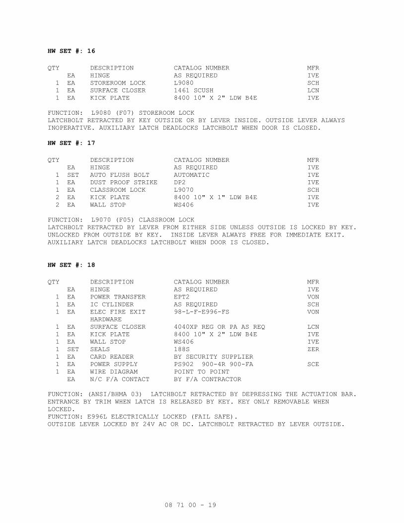
08 71 00 - 19
HW SET #: 16
QTY DESCRIPTION CATALOG NUMBER MFR
EA HINGE AS REQUIRED IVE
1 EA STOREROOM LOCK L9080 SCH
1 EA SURFACE CLOSER 1461 SCUSH LCN
1 EA KICK PLATE 8400 10" X 2" LDW B4E IVE
FUNCTION: L9080 (F07) STOREROOM LOCK
LATCHBOLT RETRACTED BY KEY OUTSIDE OR BY LEVER INSIDE. OUTSIDE LEVER ALWAYS
INOPERATIVE. AUXILIARY LATCH DEADLOCKS LATCHBOLT WHEN DOOR IS CLOSED.
HW SET #: 17
QTY DESCRIPTION CATALOG NUMBER MFR
EA HINGE AS REQUIRED IVE
1 SET AUTO FLUSH BOLT AUTOMATIC IVE
1 EA DUST PROOF STRIKE DP2 IVE
1 EA CLASSROOM LOCK L9070 SCH
2 EA KICK PLATE 8400 10" X 1" LDW B4E IVE
2 EA WALL STOP WS406 IVE
FUNCTION: L9070 (F05) CLASSROOM LOCK
LATCHBOLT RETRACTED BY LEVER FROM EITHER SIDE UNLESS OUTSIDE IS LOCKED BY KEY.
UNLOCKED FROM OUTSIDE BY KEY. INSIDE LEVER ALWAYS FREE FOR IMMEDIATE EXIT.
AUXILIARY LATCH DEADLOCKS LATCHBOLT WHEN DOOR IS CLOSED.
HW SET #: 18
QTY DESCRIPTION CATALOG NUMBER MFR
EA HINGE AS REQUIRED IVE
1 EA POWER TRANSFER EPT2 VON
1 EA IC CYLINDER AS REQUIRED SCH
1 EA ELEC FIRE EXIT
HARDWARE
98-L-F-E996-FS VON
1 EA SURFACE CLOSER 4040XP REG OR PA AS REQ LCN
1 EA KICK PLATE 8400 10" X 2" LDW B4E IVE
1 EA WALL STOP WS406 IVE
1 SET SEALS 188S ZER
1 EA CARD READER BY SECURITY SUPPLIER
1 EA POWER SUPPLY PS902 900-4R 900-FA SCE
1 EA WIRE DIAGRAM POINT TO POINT
EA N/C F/A CONTACT BY F/A CONTRACTOR
FUNCTION: (ANSI/BHMA 03) LATCHBOLT RETRACTED BY DEPRESSING THE ACTUATION BAR.
ENTRANCE BY TRIM WHEN LATCH IS RELEASED BY KEY. KEY ONLY REMOVABLE WHEN
LOCKED.
FUNCTION: E996L ELECTRICALLY LOCKED (FAIL SAFE).
OUTSIDE LEVER LOCKED BY 24V AC OR DC. LATCHBOLT RETRACTED BY LEVER OUTSIDE.

08 71 00 - 20
HW SET #: 19
QTY DESCRIPTION CATALOG NUMBER MFR
EA HINGE AS REQUIRED IVE
1 EA PANIC HARDWARE 98-NL VON
1 EA IC CYLINDER AS REQUIRED BES
1 EA SURFACE CLOSER 1461 REG OR PA AS REQ LCN
1 EA KICK PLATE 8400 10" X 2" LDW B4E IVE
1 EA WALL STOP WS406 IVE
FUNCTION: (ANSI/BHMA 03) LATCHBOLT RETRACTED BY DEPRESSING THE ACTUATION BAR.
ENTRANCE BY TRIM WHEN LATCH IS RELEASED BY KEY. KEY ONLY REMOVABLE WHEN
LOCKED.
HW SET #: 20
QTY DESCRIPTION CATALOG NUMBER MFR
EA HINGE AS REQUIRED IVE
1 EA FIRE EXIT HARDWARE 98-L-F VON
1 EA IC CYLINDER AS REQUIRED BES
1 EA SURFACE CLOSER 1461 REG OR PA AS REQ LCN
1 EA KICK PLATE 8400 10" X 2" LDW B4E IVE
1 EA WALL STOP WS406 IVE
1 SET SEALS 188S ZER
FUNCTION: (ANSI/BHMA 08) LATCHBOLT RETRACTED BY DEPRESSING THE ACTUATION BAR.
ENTRANCE BY LEVER. KEY LOCKS OR UNLOCKS LEVER.
HW SET #: 21
QTY DESCRIPTION CATALOG NUMBER MFR
EA HINGE AS REQUIRED IVE
1 EA PANIC HARDWARE 98-L VON
1 EA IC CYLINDER AS REQUIRED BES
1 EA SURFACE CLOSER 1461 REG OR PA AS REQ LCN
1 EA KICK PLATE 8400 10" X 2" LDW B4E IVE
1 EA WALL STOP WS406 IVE
FUNCTION: (ANSI/BHMA 08) LATCHBOLT RETRACTED BY DEPRESSING THE ACTUATION BAR.
ENTRANCE BY LEVER. KEY LOCKS OR UNLOCKS LEVER.
HW SET #: 22
QTY DESCRIPTION CATALOG NUMBER MFR
EA HINGE AS REQUIRED IVE
1 EA POWER TRANSFER EPT2 VON
1 EA ELEC PANIC HARDWARE QEL+-98-NL-OP VON
1 EA IC CYLINDER AS REQUIRED BES
1 EA DOOR PULL, 1" ROUND 8103 10" IVE
1 EA OH STOP 100S GLY
1 EA SURFACE CLOSER 4040XP TOP JAMB LCN
1 EA RAIN DRIP 142A ZER
1 EA WEATHERSTRIP BY DR/FR SUPPLIER ZER

08 71 00 - 21
1 EA DOOR SWEEP W/DRIP 8198 ZER
1 EA THRESHOLD 8655 ZER
1 EA CARD READER BY SECURITY SUPPLIER
1 EA POWER SUPPLY PS902 900-2RS VON
1 EA ELEVATION DRAWING
1 EA WIRE DIAGRAM POINT TO POINT
FUNCTION: LATCH-BOLT RETRACTED INSIDE BY DEVICE PUSH PAD AND OUTSIDE BY KEY IN
CYLINDER. DOOR LOCKS WHEN KEY IS REMOVED. VALID CREDENTIAL WILL MOMENTARILY
UNLOCK THE DOOR. DOOR RE-LOCKS WHEN CARD READER TIMES OUT.
NOTE: DARK BRONZE FINISH
HW SET #: 23
QTY DESCRIPTION CATALOG NUMBER MFR
EA HINGE AS REQUIRED IVE
1 EA POWER TRANSFER EPT10 VON
1 EA ELEC DELAYED FIRE
EXIT HARDWARE
CX-9975-L-F-BE VON
1 EA IC CYLINDER AS REQUIRED BES
1 EA SURFACE CLOSER 4040XP REG OR PA AS REQ LCN
1 EA KICK PLATE 8400 10" X 2" LDW B4E IVE
1 EA WALL STOP WS406 IVE
1 SET SEALS 188S ZER
1 EA CARD READER BY SECURITY SUPPLIER
1 EA DOOR CONTACT 679-05 SCE
1 EA POWER SUPPLY PS914 VON
1 EA ELEVATION DRAWING
1 EA WIRE DIAGRAM POINT TO POINT
1 EA N/C F/A CONTACT BY F/A CONTRACTOR
DELAYED EGRESS: PUSH AND HOLD FOR ONE SECOND - DOOR WILL OPEN IN 15 SECOND
DEVICE MUST BE FAIL SAFE IN STAIRS.
LEVER TRIM IS INDEPENDENT OF THE DELAYED EGRESS DEVICE
LEVER TRIM IS ALWAYS UNLOCKED AND ALLOW ACCESS TO THE BUILDING FROM THE
STAIRWELL.
PRESENTATION OF VALID CREDENTIAL SHUNTS DELAYED EGRESS DEVICE FROM PUSH SIDE
ALLOWING FREE EGRESS.
HW SET #: 24
QTY DESCRIPTION CATALOG NUMBER MFR
1 EA SURFACE CLOSER 1461 REG OR PA AS REQ LCN
1 EA FIRE/LIFE WALL MAG BY DIVISION 26
EXISTING DOOR, FRAME AND HARDWARE TO BE REUSED.
END OF SECTION

VA656-341 08 80 00-1
SECTION 08 80 00
GLAZING
PART 1 - GENERAL
1.1 DESCRIPTION
A. This section specifies glass, plastic, related glazing materials and
accessories and insulated panels. Glazing products specified apply to
factory or field glazed items.
1.2 RELATED WORK
A. Factory glazed by manufacturer in following units:
1. Mirrors: Section 10 28 00, TOILET and BATH ACCESSORIES.
2. Section 08 51 13, ALUMINUM WINDOWS Double Hung.
B. Glass required in the following:
1. Aluminum doors and framing: Section 08 4113.
2. Hollow Metal doors and frames: Section 08 1113.
3. Wood doors: Section 08 1400.
1.3 LABELS
A. Temporary labels:
1. Provide temporary label on each light of glass identifying
manufacturer or brand and glass type, quality and nominal thickness.
2. Label in accordance with NFRC (National Fenestration Rating Council)
label requirements.
3. Temporary labels shall remain intact until glass is approved by
Resident Engineer.
B. Permanent labels:
1. Locate in corner for each pane.
2. Label in accordance with ANSI Z97.1 and SGCC (Safety Glass
Certification Council) label requirements.
a. Tempered glass.
b. Laminated glass or have certificate for panes without permanent
label.
c. Organic coated glass.
1.4 PERFORMANCE REQUIREMENTS
A. Building Enclosure Vapor Retarder and Air Barrier:
1. Utilize the inner pane of multiple pane sealed units for the
continuity of the air barrier and vapor retarder seal.
2. Maintain a continuous air barrier and vapor retarder throughout the
glazed assembly from glass pane to heel bead of glazing sealant.
10-01-12
VA656-341 08 80 00-2
B. Glass Thickness:
1. Select thickness of exterior glass to withstand dead loads and wind
loads acting normal to plane of glass at design pressures calculated
in accordance with ASCE 7 code.
2. Test in accordance with ASTM E 1300.
3. Thicknesses listed are minimum. Coordinate thicknesses with framing
system manufacturers.
1.5 SUBMITTALS
A. In accordance with Section 01 33 23, SUBMITTAL PROCEDURES.
B. Manufacturer's Certificates:
1. Certificates stating that wire glass, meets requirements for safety
glazing material as specified in ANSI Z97.1.
2. Certificate on shading coefficient.
3. Certificate on "R" value when value is specified.
4. Certificate test reports confirming compliance’s with specified
bullet resistive rating.
C. Warranty: Submit written guaranty, conforming to General Condition
requirements, and to “Warranty of Construction” Article in this
Section.
D. Manufacturer's Literature and Data:
1. Glass, each kind required.
2. Insulating glass units.
3. Glazing cushion.
4. Sealing compound.
E. Samples:
1. Size: 150 mm by 150 mm (6 inches by 6 inches).
2. Tinted glass.
3. Insulated panels
F. Include all required LEED Forms as listed/referenced in Division 1.
1.6 DELIVERY, STORAGE AND HANDLING
A. Delivery: Schedule delivery to coincide with glazing schedules so
minimum handling of crates is required. Do not open crates except as
required for inspection for shipping damage.
B. Storage: Store cases according to printed instructions on case, in
areas least subject to traffic or falling objects. Keep storage area
clean and dry.

10-01-12
VA656-341 08 80 00-3
C. Handling: Unpack cases following printed instructions on case. Stack
individual windows on edge leaned slightly against upright supports
with separators between each.
1.7 PROJECT CONDITIONS
A. Field Measurements: Field measure openings before ordering tempered glass
products. Be responsible for proper fit of field measured products.
1.8 WARRANTY
A. Warranty: Conform to terms of "Warranty of Construction", FAR clause
52.246-21, except extend warranty period for the following:
1. Insulating glass units to remain sealed for 10 years.
2. Laminated glass units to remain laminated for 5 years.
1.9 APPLICABLE PUBLICATIONS
A. Publications listed below form a part of this specification to extent
referenced. Publications are referenced in text by basic designation
only.
B. American National Standards Institute (ANSI):
Z97.1-09................Safety Glazing Material Used in
Building - Safety Performance Specifications
and Methods of Test.
C. American Society for Testing and Materials (ASTM):
C542-05.................Lock-Strip Gaskets
C716-06.................Installing Lock-Strip Gaskets and Infill
Glazing Materials.
C794-10.................Adhesion-in-Peel of Elastomeric Joint Sealants
C864-05.................Dense Elastomeric Compression Seal Gaskets,
Setting Blocks, and Spacers
C920-11.................Elastomeric Joint Sealants
C964-07.................Standard Guide for Lock-Strip Gasket Glazing
C1036-06................Flat Glass
C1048-12................Heat-Treated Flat Glass-Kind HS, Kind FT Coated
and Uncoated Glass.
C1376-10................Pyrolytic and Vacuum Deposition Coatings on
Flat Glass
E84-10..................Surface Burning Characteristics of Building
Materials
E119-10.................Standard Test Methods for Fire Test of Building
Construction and Material
E2190-10................Insulating Glass Unit

10-01-12
VA656-341 08 80 00-4
D. Code of Federal Regulations (CFR):
16 CFR 1201 - Safety Standard for Architectural Glazing Materials; 2010
E. National Fire Protection Association (NFPA):
80-13...................Fire Doors and Windows.
252-12..................Standard Method of Fire Test of Door Assemblies
257-12..................Standard on Fire Test for Window and Glass
Block Assemblies
F. National Fenestration Rating Council (NFRC)
G. Safety Glazing Certification Council (SGCC) 2012:
Certified Products Directory (Issued Semi-Annually).
H. Underwriters Laboratories, Inc. (UL):
752-11..................Bullet-Resisting Equipment.
I. Glass Association of North America (GANA):
Glazing Manual (Latest Edition)
Sealant Manual (2009)
J. American Society of Civil Engineers (ASCE):
ASCE 7-10...............Wind Load Provisions
PART 2 - PRODUCT
2.1 GLASS
A. Use thickness stated unless specified otherwise in assemblies.
B. Clear Glass:
1. ASTM C1036, Type I, Class 1, Quality q3
2. Thickness, 6 mm (1/4 inch).
C. Safety Wired Flat Glass:
1. ASTM C-1036, type II, Class 1, Form 1, Quality q8 and U.L. approved
and labeled, ¼” thick; Safeti’s Superlite I-w safety wire glass;
TGP’s Wirelite NT are acceptable.
2. Ratings: Up to 45 minute only in sidelites. 60-90 minute in doors.
2.2 HEAT TREATED GLASS
A. Clear Tempered Glass:
1. ASTM C1048, Kind FT, Condition A, Type I, Class 1, Quality q3.
2. Thickness, 6 mm (1/4 inch).
B. Tinted Tempered Glass.
1. ASTM C1048, Kind FT, Condition A, Type I, Class 2, Quality q3.
2. Color: light grey tint to match existing.
3. Thickness, 6 mm (1/4 inch).
10-01-12
VA656-341 08 80 00-5
C. Frosted Tempered Glass: ¼” thickness, tempered frosted glass for door
and sidelights, Door 158. In lieu of tempered, the following could be
provided:
1. Frosted Safety Glass: Consisting of two layers of clear Heat
strengthened glass, with PVB interlayer, equal to Oldcastle’s
216500 Snow interlayer.
2.3 COATED GLASS
A. Low-E Tempered Glass:
1. ASTM C1048, Kind FT, Condition C, Type I, Class 1, Quality q3 with
low emissivity pyrolytic coating having an E of 0.15.
2. Apply coating to second or third surface of insulating glass units.
3. Thickness, as indicated.
2.4 INSULATING GLASS UNITS
A. Provide factory fabricated, hermetically sealed glass unit consisting
of two panes of glass separated by a dehydrated air space and comply
with ASTM E2190.
B. Assemble units using glass types specified:
C. Sealed Edge Units (SEU): Cardinal's Low E³/366 units, with PPG’s
SolarBan 70XL units are acceptable, with equivalent by Oldcastle and
Viracon units also acceptable.
1. Insulating Glass Unit Makeup
a. Outboard Lite
1. Glass type: tempered/heat strengthened glass
2. Glass Tint: (Clear)
3. Nominal Thickness: ¼” nominal
4. Glass Strength: (Tempered)
NOTE: Exterior surface of outboard lite shall be treated with a
layer of titanium dioxide layer, and shall be Self cleaning
glass, similar to Cardinal’s NEAT Glass and PPG’s SunClean.
b. Spacer
1. Nominal Thickness:
2. Gas Fill: (90% Argon)
c. Muntin bars: (Aluminum windows only)
Provide dark bronze muntin grids within the air space matching
approved layout and existing windows. See drawings
for approximate layout.
d. Inboard Lite
1. Glass Type: Clear tempered glass
10-01-12
VA656-341 08 80 00-6
2. Glass Tint: none
3. Nominal Thickness: ¼”
4. Glass Strength: (Tempered)
5. Coating Orientation: (Surface #3)
2. Performance Characteristics (Center of Glass)
a. Visible Transmittance: 38%
b. Shading Coefficient (SC): .29
c. Solar heat Gain Coefficient (SHGC): .25
d. U values: Summer - .21 & Winter - .24
3. Glass shall be annealed, heat strengthened or tempered as required
by codes, or as required to meet thermal stress and wind loads.
4. Glass heat-treated by horizontal (roller hearth) process with
inherent roller wave distortion parallel to the bottom edge of the
glass as installed when specified.
2.5 FIRE RESISTANT GLASS WITHOUT WIRE MESH
A. Type 1 (Transparent float glass), Class 1 (Clear).
B. Fire-protective glass products used to protect against smoke and flames
only shall be rated for as indicated or required by local building code
and shall be tested in accordance with NFPA 252 (Standard Methods of
Fire Tests of Door Assemblies) and NFPA 257 (Standard on Fire Test for
Window and Glass Block Assemblies)
C. Fire-resistive products used to protect against smoke, flame, and the
transmission of radiant heat shall be rated (see drawings for minute
designation) and shall be tested in accordance with NFPA 252, NFPA 257,
and ASTM E119 (Standard Test Methods for Fire Tests of Building
Construction and Materials).
D. Fire-rated glass or glass assembly shall be classified by Underwriters
Laboratory (UL), Intertek Testing Services-Warnock Hersey (ITS-WHI) or
any other OSHA certified testing laboratory. All glass shall bear a
permanent mark of classification in accordance with local building code.
E. Maximum size is per the manufacturer’s test agency listing for doors,
transoms, side lights, borrowed lights, and windows.
F. Where safety glazing is required by local building code, fire-rated
glass shall be tested in accordance with CPSC 16 CFR 1201 Category I or
II and bear a permanent mark of classification.
1. Category I products are limited to 0.84 m2 – 9 ft2 and tested to no
less than 203 Nm-150 ft-lbs impact loading.
10-01-12
VA656-341 08 80 00-7
2. Category II products are greater than 0.84 m2 – 9 ft2 and tested to no
less than 542 Nm-400 ft-lbs impact loading. Category II products can
be used in lieu of Category I products.
2.6 GLAZING ACCESSORIES
A. As required to supplement the accessories provided with the items to be
glazed and to provide a complete installation. Ferrous metal accessories
exposed in the finished work shall have a finish that will not corrode
or stain while in service.
B. Setting Blocks: ASTM C864:
1. Channel shape; having 6 mm (1/4 inch) internal depth.
2. Shore a hardness of 80 to 90 Durometer.
3. Block lengths: 50 mm (two inches) except 100 to 150 mm (four to six
inches) for insulating glass.
4. Block width: Approximately 1.6 mm (1/16 inch) less than the full
width of the rabbet.
5. Block thickness: Minimum 4.8 mm (3/16 inch). Thickness sized for
rabbet depth as required.
C. Spacers: ASTM C864:
1. Channel shape having a 6 mm (1/4 inch) internal depth.
2. Flanges not less 2.4 mm (3/32 inch) thick and web 3 mm (1/8 inch)
thick.
3. Lengths: One to 25 to 76 mm (one to three inches).
4. Shore a hardness of 40 to 50 Durometer.
D. Sealing Tapes:
1. Semi-solid polymeric based material exhibiting pressure-sensitive
adhesion and withstanding exposure to sunlight, moisture, heat,
cold, and aging.
2. Shape, size and degree of softness and strength suitable for use in
glazing application to prevent water infiltration.
E. Glazing Gaskets: ASTM C864:
1. Firm dense wedge shape for locking in sash.
2. Soft, closed cell with locking key for sash key.
3. Flanges may terminate above the glazing-beads or terminate flush
with top of beads.
F. Lock-Strip Glazing Gaskets: ASTM C542, shape, size, and mounting as
indicated.
G. Glazing Sealants: ASTM C920, silicone neutral cure:
1. Type S.

10-01-12
VA656-341 08 80 00-8
2. Class 25
3. Grade NS.
4. Shore A hardness of 25 to 30 Durometer.
5. Tremco's Pro-Glaze is acceptable, color selected by Resident
Engineer.
H. Neoprene, EPDM, or Vinyl Glazing Gasket: ASTM C864.
1. Channel shape; flanges may terminate above the glazing channel or
flush with the top of the channel.
2. Designed for dry glazing.
I. Color:
1. Color of glazing compounds, gaskets, and sealants used for aluminum
color frames shall match color of the finished aluminum and be
nonstaining.
2. Color of other glazing compounds, gaskets, and sealants which will
be exposed in the finished work and unpainted shall be black, gray,
or neutral color.
2.7 INSULATED PANELS:
A. Manufacturers: Mapes panels, Lurie Panels Alliance-wall, Mirawal,
Laminators Inc. and Greensteel also acceptable.
B. Type: Laminated sandwich of polystyrene core, 1/8" tempered hardboard
substrates and smooth anodized .032” aluminum skins. 1-inch nominal
thickness. "U" factor of .193.
C. Anodized color Finish: Class II anodized finish on both sides of
panels; Match anodized color of Aluminum Doors. (Section 08 4113)
PART 3 - EXECUTION
3.1 EXAMINATION
A. Verification of Conditions:
1. Examine openings for glass and glazing units; determine they are
proper size; plumb; square; and level before installation is
started.
2. Verify that glazing openings conform with details, dimensions and
tolerances indicated on manufacturer’s approved shop drawings.
B. Advise Contractor of conditions which may adversely affect glass and
glazing unit installation, prior to commencement of installation: Do
not proceed with installation until unsatisfactory conditions have been
corrected.

10-01-12
VA656-341 08 80 00-9
C. Verify that wash down of adjacent masonry is completed prior to
erection of glass and glazing units to prevent damage to glass and
glazing units by cleaning materials.
3.2 PREPARATION
A. For sealant glazing, prepare glazing surfaces in accordance with GANA-
02 Sealant Manual.
B. Determine glazing unit size and edge clearances by measuring the actual
unit to receive the glazing.
C. Shop fabricate and cut glass with smooth, straight edges of full size
required by openings to provide GANA recommended edge clearances.
D. Verify that components used are compatible.
E. Clean and dry glazing surfaces.
F. Prime surfaces scheduled to receive sealants, as determined by
preconstruction sealant-substrate testing.
3.3 INSTALLATION - GENERAL
A. Install in accordance with GANA-01 Glazing Manual and GANA-02 Sealant
Manual unless specified otherwise.
B. Glaze in accordance with recommendations of glazing and framing
manufacturers, and as required to meet the Performance Test
Requirements specified in other applicable sections of specifications.
C. Set glazing without bending, twisting, or forcing of units.
D. Do not allow glass to rest on or contact any framing member.
E. Glaze doors and operable sash, in a securely fixed or closed and locked
position, until sealant, glazing compound, or putty has thoroughly set.
F. Tempered Glass: Install with roller distortions in horizontal position
unless otherwise directed.
G. Laminated Glass:
1. Tape edges to seal interlayer and protect from glazing sealants.
2. Do not use putty or glazing compounds.
H. Insulating Glass Units:
1. Glaze in compliance with glass manufacturer's written instructions.
2. When glazing gaskets are used, they shall be of sufficient size and
depth to cover glass seal or metal channel frame completely.
3. Do not use putty or glazing compounds.
4. Do not grind, nip, cut, or otherwise alter edges and corners of
fused glass units after shipping from factory.
5. Install with tape or gunnable sealant in wood sash.
I. Fire Resistant Glass:

10-01-12
VA656-341 08 80 00-10
1. Wire glass: Glaze in accordance with NFPA 80.
2. Other fire resistant glass: Glaze in accordance with UL design
requirements.
3.4 INSTALLATION - DRY METHOD (TAPE AND GASKET SPLINE GLAZING)
A. Cut glazing tape to length; install on glazing pane. Seal corners by
butting and sealing junctions with butyl sealant.
B. Place setting blocks at 1/4 or 1/3 points with edge block no more
than 150 mm (6 inches) from corners.
C. Rest glazing on setting blocks and push against fixed stop with
sufficient pressure to attain full contact.
D. Install removable stops without displacing glazing spline. Exert
pressure for full continuous contact.
E. Do not exceed edge pressures stipulated by glass manufacturers for
installing glass lites.
F. Trim protruding tape edge.
3.5 INSTALLATION - WET/DRY METHOD (PREFORMED TAPE AND SEALANT)
A. Cut glazing tape to length and set against permanent stops, 5 mm (3/16
inch) below sight line. Seal corners by butting tape and dabbing with
butyl sealant.
B. Apply heel bead of butyl sealant along intersection of permanent stop
with frame ensuring full perimeter seal between glass and frame to
complete the continuity of the air and vapor seal.
C. Place setting blocks at 1/4 or 1/3 points with edge block no more than
150 mm (6 inches) from corners.
D. Rest glazing on setting blocks and push against tape and heel bead of
sealant with sufficient pressure to achieve full contact at perimeter
of pane or glass unit.
E. Install removable stops, with spacer strips inserted between glazing
and applied stops, 6 mm (1/4 inch) below sight line. Place glazing tape
on glazing pane or unit with tape flush with sight line.
F. Fill gap between glazing and stop with silicone sealant to depth equal
to bite of frame on glazing, but not more than 9 mm (3/8 inch) below
sight line.
G. Apply cap bead of silicone type sealant along void between the stop and
the glazing, to uniform line, flush with sight line. Tool or wipe
sealant surface smooth.
3.6 INSTALLATION - WET METHOD (SEALANT AND SEALANT)
A. Place setting blocks at 1/4 points and install glazing pane or unit.
10-01-12
VA656-341 08 80 00-11
B. Install removable stops with glazing centered in space by inserting
spacer shims both sides at 600 mm (24 inch) intervals, 6 mm (1/4 inch)
below sight line.
C. Fill gaps between glazing and stops with silicone type sealant to depth
of bite on glazing, but not more than 9 mm (3/8 inch) below sight line
to ensure full contact with glazing and continue the air and vapor seal.
D. Apply sealant to uniform line, flush with sight line. Tool or wipe
3.7 INSTALLATION - INTERIOR WET/DRY METHOD (TAPE AND SEALANT)
A. Cut glazing tape to length and install against permanent stops,
projecting 1.6 mm (1/16 inch) above sight line.
B. Place setting blocks at 1/4 points with edge block no more than 150 mm
(6 inches) from corners.
C. Rest glazing on setting blocks and push against tape to ensure full
contact at perimeter of pane or unit.
D. Install removable stops, spacer shims inserted between glazing and
applied stops at 600 mm (24 inch) intervals, 6 mm (1/4 inch) below
sight line.
E. Fill gaps between pane and applied stop with silicone sealant to depth
equal to bite on glazing, to uniform and level line.
F. Trim protruding tape edge.
3.8 REPLACEMENT AND CLEANING
A. Clean new glass surfaces removing temporary labels, paint spots, and
defacement after approval by Resident Engineer.
B. Replace cracked, broken, and imperfect glass, or glass which has been
installed improperly.
C. Leave glass, putty, and other setting material in clean, whole, and
acceptable condition.
3.9 PROTECTION
A. Protect finished surfaces from damage during erection, and after
completion of work. Strippable plastic coatings on colored anodized
finish are not acceptable.
3.10 GLAZING SCHEDULE
A. Fire Resistant Glass:
1. Install clear wire glass in interior fire rated or labeled doors and
windows.
B. Tempered Glass (Safety):
1. Install in full and half glazed doors unless indicated otherwise.
2. Install in storefront, windows, and door sidelights adjacent to doors.
10-01-12
VA656-341 08 80 00-12
3. Use clear tempered glass on interior side lights and doors, and on
exterior doors and sidelights unless otherwise indicated or specified.
C. Insulating Glass:
1. Install SEU tinted tempered, in aluminum exterior windows (factory
installed) and in aluminum storefront and entrance framing, and
where indicated in exterior doors or framing.
- - - E N D - - -

10-11
VA656-341 08 90 00 - 1
SECTION 08 90 00
LOUVERS AND VENTS
PART 1 - GENERAL
1.1 DESCRIPTION
A. This section specifies fixed wall louvers.
1.2 RELATED WORK
A. Masonry Openings: Section 04 20 00 UNIT MASONRY.
B. Perimeter Sealants: Section 07 9200.
1.3 SUBMITTALS
A. Submit in accordance with Section 01 33 23, SUBMITTAL PROCEDURES.
B. Shop Drawings:
Each type, showing material, finish, size of members, method of
assembly, and installation and anchorage details.
C. Manufacturer's Literature and Data:
Each type of louver and vent.
D. Include all required LEED Forms as listed/referenced in Division 1.
1.4 APPLICABLE PUBLICATIONS
A. The publications listed below form a part of this specification to the
extent referenced. The publications are referenced in the text by the
basic designation only.
B. The Master Painters Institute (MPI):
Approved Product List – September 2011
C. American Society for Testing and Materials (ASTM):
A167-99(R2009)..........Stainless and Heat-Resisting Chromium - Nickel
Steel Plate, Sheet, and Strip
A1008/A1008M-10.........Steel, Sheet, Carbon, Cold Rolled, Structural,
and High Strength Low-Alloy with Improved
Formability
B209/B209M-03(R2007)....Aluminum and Aluminum Alloy, Sheet and Plate
B221-08.................Aluminum and Aluminum Alloy Extruded Bars,
Rods, Wire, Shapes, and Tubes
B221M-07................Aluminum and Aluminum Alloy Extruded Bars,
Rods, Wire Shapes, and Tubes
D. National Association of Architectural Metal Manufacturers (NAAMM):
AMP 500-06..............Metal Finishes Manual
E. National Fire Protection Association (NFPA):

10-11
VA656-341 08 90 00 - 2
90A-09..................Installation of Air Conditioning and
Ventilating Systems
F. American Architectural Manufacturers Association (AAMA):
2605-11.................High Performance Organic Coatings on
Architectural Extrusions and Panels
G. Air Movement and Control Association, Inc. (AMCA):
500-L-07................Testing Louvers
PART 2 - PRODUCTS
2.1 MATERIALS
A. Aluminum, Extruded: ASTM B221/B221M.
1. LEED MRc4 - Aluminum Recycled Content: The weighted scrap content
of extrusions shall be 40%, which includes 10 percent post-consumer
scrap, and 30 percent post-industrial scrap.
B. Carbon Steel: ASTM A1008/A1008M.
C. Aluminum, Plate and Sheet: ASTM B209/B209M.
D. Fasteners: Fasteners for securing louvers and wall vents to adjoining
construction, except as otherwise specified or shown, shall be toggle
or expansion bolts, of size and type as required for each specific type
of installation and service condition.
1. Where type, size, or spacing of fasteners is not shown or specified,
submit shop drawings showing proposed fasteners, and method of
installation.
2. Fasteners for louvers, louver frames, and wire guards shall be of
stainless steel or aluminum.
2.2 EXTERIOR WALL LOUVERS
A. General:
1. Provide fixed type louvers of size and design shown.
2. Heads, sills and jamb sections shall have formed caulking slots or
be designed to retain caulking. Head sections shall have exterior
drip lip, and sill sections an integral water stop.
3. Furnish louvers with sill extension or separate sill as shown.
4. Frame shall be mechanically fastened or welded construction with
welds dressed smooth and flush.
B. Type: 6” thick, drainable blade louver, .081” extruded aluminum frame
and blade, 54% free area, stepped blade, with framed 1/2" square mesh,
16-gauge galvanized steel bird screen mounted on inside and holes in
jambs for bolt anchorage. No water penetration reported at 1250 FPM

10-11
VA656-341 08 90 00 - 3
(381m/min.) free air velocity maximum velocity tested under AMCA
standard 500, 48% free area.
1. Manufacturer and Make: Airolite K6776, with C/S Louver’s model
A6097 louver; Greenheck’s EDD-601 louver; Industrial Louver 653-XP.
Arrow United Louver, Model EA 615D. EFD-637 by All-Lite Louvers all
acceptable.
2. General: Frames, blades, sills and mullions; 2 mm (0.081-inch) thick
extruded aluminum. Blades shall be drainable type and have
reinforcing bosses.
3. Louvers, fixed: Make frame sizes 13 mm (1/2-inch) smaller than
openings. Single louvers frames shall not exceed 1700 mm (66 inches)
wide. When openings exceed 1700 mm (66 inches), provide twin louvers
separated by mullion members.
2.3 CLOSURE ANGLES AND CLOSURE PLATES
A. Fabricate from 2 mm (0.074-inch) thick aluminum.
B. Provide continuous closure angles and closure plates on inside head,
jambs and sill of exterior wall louvers.
C. Secure angles and plates to louver frames with screws, and to masonry
or concrete with fasteners as specified.
2.4 WIRE GUARDS
A. Provide wire guards on outside of all exterior louvers, except on
exhaust air louvers.
B. Fabricate frames from 2 mm (0.081-inch) thick extruded or sheet
aluminum designed to retain wire mesh.
C. Wire mesh shall be woven from not less than 1.6 mm (0.063-inch)
diameter aluminum wire in 13 mm (1/2-inch) square mesh.
D. Miter corners and join by concealed corner clips or locks extending
about 57 mm (2-1/4 inches) into rails and stiles. Equip wire guards
over four feet in height with a mid-rail constructed as specified for
frame components.
E. Fasten frames to outside of louvers with aluminum or stainless steel
devices designed to allow removal and replacement without damage to the
wire guard or the louver.
2.5 FINISH
A. In accordance with NAAMM Metal Finishes Manual: AMP 500-505
B. Aluminum Louvers
10-11
VA656-341 08 90 00 - 4
1. Organic Finish: AAMA 2605 (Kynar 500 or Hylar 5000 Fluorocarbon
coating). The finish must meet LEED IEQc4.2: Low emitting
materials (Paints and coatings)
2.6 PROTECTION
A. Provide protection for aluminum against galvanic action wherever
dissimilar materials are in contact, by painting the contact surfaces
of the dissimilar material with a heavy coat of bituminous paint
(complete coverage), or by separating the contact surfaces with a
performed synthetic rubber tape having pressure sensitive adhesive
coating on one side.
B. Isolate the aluminum from plaster, concrete and masonry by coating
aluminum with zinc-chromate primer.
C. Protect finished surfaces from damage during fabrication, erection, and
after completion of the work.
PART 3 - EXECUTION
3.1 INSTALLATION
A. Set work accurately, in alignment and where shown. Items shall be
plumb, level, free of rack and twist, and set parallel or perpendicular
as required to line and plane of surface.
B. Furnish setting drawings and instructions for installation of anchors
and for the positioning of items having anchors to be built into
masonry construction. Provide temporary bracing for such items until
masonry is set.
C. Provide anchoring devices and fasteners as shown and as necessary for
securing louvers to building construction as specified. Power actuated
drive pins may be used, except for removal items and where members
would be deformed or substrate damaged by their use.
D. Generally, set wall louvers and vents in masonry walls during progress
of the work. If wall louvers and vents are not delivered to job in time
for installation in prepared openings, make provision for later
installation.
E. Perimeter Sealants are by Section 07 9200.
F. Fill frame voids with loose fill or EPS rigid insulation prior to
installation, or foam after installation with Fireblock foam sealant.
See Section 07 2113 for specifications on foam and loose fill
insulation.

10-11
VA656-341 08 90 00 - 5
3.2 CLEANING AND ADJUSTING
A. After installation, all exposed prefinished and plated items and all
items fabricated from stainless steel and aluminum shall be cleaned as
recommended by the manufacturer and protected from damage until
completion of the project.
B. All movable parts, including hardware, shall be cleaned and adjusted to
operate as designed without binding or deformation of the members, so
as to be centered in the opening of frame, and where applicable, to
have all contact surfaces fit tight and even without forcing or warping
the components.
- - - E N D - - -

ST. CLOUD VAMC OUTPATIENT MENTAL HEALTH CLINIC – BLDG 111 ADDITION VA MEDICAL CENTERS ST. CLOUD, MINNESOTA VA #656-341 / FOSS #1327 SECTION 09 0600 December 29, 2014 COLOR SCHEDULE
VA 656-341 - CS.doc 09 0600-1
SECTION 06 4000 - FINISH CARPENTRY/WOODWORK: PLASTIC LAMINATE:
Countertops: PL-1 Nevamar Color: Paris White Potterware #PO7001T Base & Upper Cabinets: PL-2 Nevamar Color: Basic #S2110T CAST PLASTIC: Reception Desk Transaction: CP-1 Corian Color: Sandstone Window Sills: CP-2 Wilsonart Color: Antique White #1572SL
SECTION 09 3013 – TILE: FLOOR TILE:
Floor Field: FT-1 Daltile Keystones Color: Mottled Medium Brown #D050 Size: 2” x 2” Rep: Abbi Luger 651-246-6530 CERAMIC WALL TILE:
Wall Field: CWT-1 Daltile Semi-Gloss Color: Almond #0135 Size: 4 ¼” x 4 ¼” Rep: Abbi Luger 651-246-6530

ST. CLOUD VAMC OUTPATIENT MENTAL HEALTH CLINIC – BLDG 111 ADDITION VA MEDICAL CENTERS ST. CLOUD, MINNESOTA VA #656-341 / FOSS #1327 SECTION 09 0600 December 29, 2014 COLOR SCHEDULE
VA 656-341 - CS.doc 09 0600-2
SECTION 09 3013 – TILE (cont): CERAMIC WALL TILE cont:
Wall Accent: CWT-2 Daltile Semi-Gloss Color: Oak Moss #0195 Size: 4 ¼” x 4 ¼” Rep: Abbi Luger 651-246-6530
Wall Accent: CWT-3 Daltile Semi-Gloss – liner bar Color: Garden Spot #0141 Size: ½” x 6” Rep: Abbi Luger 651-246-6530 GROUT:
Grout at FT-1: Laticrete Color: Desert Khaki
#56 Sanded & sealed – Owner request
Grout at CWT-1, 2, 3: Laticrete Color: Mushroom #39 Sanded & sealed – Owner request TRIM: To be used at FT to carpet: TR-1 Schluter Reno-TK Color: Satin Anodized Aluminum #AE To be used at all outside wall corners, edges & TR-2 top of wainscot: Schluter Schiene Color: Satin Anodized Aluminum #AE
SECTION 09 6500 - RESILIENT FLOORING: VINYL COMPOSITION TILE: VCT-1 Armstrong Imperial Texture/Standard Excelon Color: Fortress White #51839

ST. CLOUD VAMC OUTPATIENT MENTAL HEALTH CLINIC – BLDG 111 ADDITION VA MEDICAL CENTERS ST. CLOUD, MINNESOTA VA #656-341 / FOSS #1327 SECTION 09 0600 December 29, 2014 COLOR SCHEDULE
VA 656-341 - CS.doc 09 0600-3
SECTION 09 6500 - RESILIENT FLOORING (cont): RUBBER BASE:
Wall: RB-1 Johnsonite Color: Fawn #80 Reception Desk: RB-2 VPI Color: Taupe #14 Stairwells: RB-3 Johnsonite Safe-T-First Rubber Base with ¾” wide Photoluminescent material Style: PDC-XX Base Color: Fawn
#80 TRANSITION STRIP: To be used @ Carpet to resilient flooring: TR-4 Johnsonite Adaptor Style: CTA-XX-A Color: Brown #47
To be used @ Carpet to resilient concrete: TR-4
Johnsonite Edge Guards Style: EG-XX-H Color: Brown #47
STAIR TREAD, RISER & LANDING TILE: Landing Tile @ Stair: RF-1
Johnsonite Rubber Tile Style: Microtone Color: Log Cabin #LE4 Size: 24” x 24” Rep: Rick Gale 952-884-0434
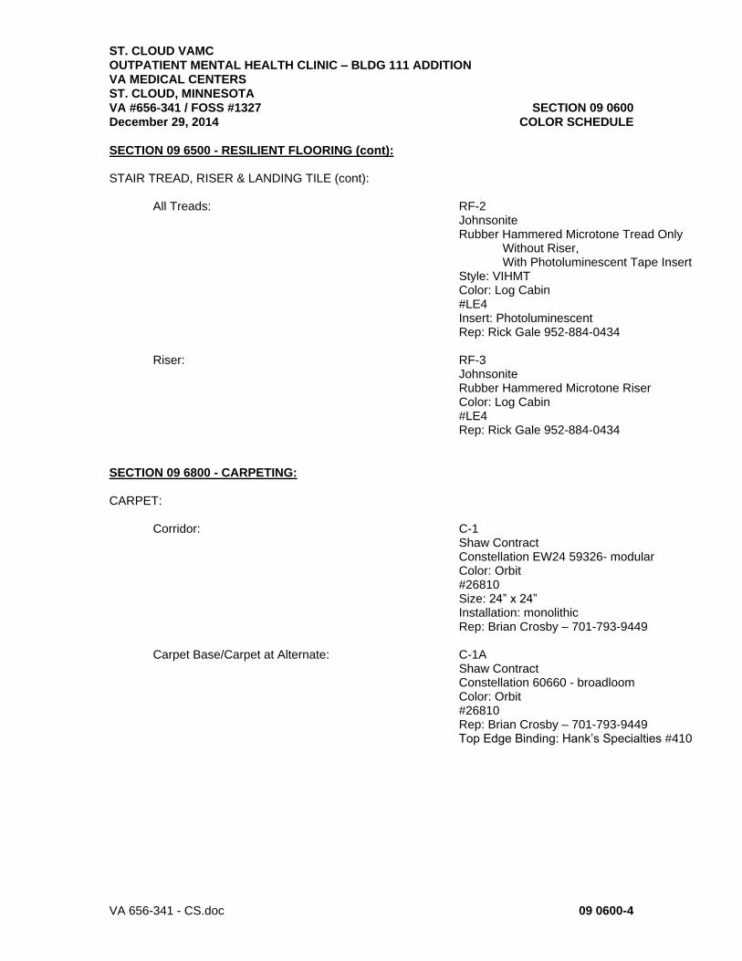
ST. CLOUD VAMC OUTPATIENT MENTAL HEALTH CLINIC – BLDG 111 ADDITION VA MEDICAL CENTERS ST. CLOUD, MINNESOTA VA #656-341 / FOSS #1327 SECTION 09 0600 December 29, 2014 COLOR SCHEDULE
VA 656-341 - CS.doc 09 0600-4
SECTION 09 6500 - RESILIENT FLOORING (cont): STAIR TREAD, RISER & LANDING TILE (cont): All Treads: RF-2
Johnsonite Rubber Hammered Microtone Tread Only Without Riser, With Photoluminescent Tape Insert Style: VIHMT Color: Log Cabin #LE4 Insert: Photoluminescent Rep: Rick Gale 952-884-0434
Riser: RF-3 Johnsonite
Rubber Hammered Microtone Riser Color: Log Cabin #LE4 Rep: Rick Gale 952-884-0434
SECTION 09 6800 - CARPETING: CARPET: Corridor: C-1 Shaw Contract Constellation EW24 59326- modular Color: Orbit #26810 Size: 24” x 24” Installation: monolithic Rep: Brian Crosby – 701-793-9449
Carpet Base/Carpet at Alternate: C-1A Shaw Contract Constellation 60660 - broadloom Color: Orbit #26810 Rep: Brian Crosby – 701-793-9449 Top Edge Binding: Hank’s Specialties #410

ST. CLOUD VAMC OUTPATIENT MENTAL HEALTH CLINIC – BLDG 111 ADDITION VA MEDICAL CENTERS ST. CLOUD, MINNESOTA VA #656-341 / FOSS #1327 SECTION 09 0600 December 29, 2014 COLOR SCHEDULE
VA 656-341 - CS.doc 09 0600-5
SECTION 09 9100 - PAINTS & COATINGS: PAINT: Typical & HM Frames: P-1 Benjamin Moore Color: Gray Mist #962 Accent: P-2 Benjamin Moore Color: Smoky Mountain (green) #AC-18 Accent: P-3 Benjamin Moore Color: Evening Dove (blue) #2128-30 Accent: P-4 Benjamin Moore Color: Cabernet (purple) #2116-30 Accent: P-5 Benjamin Moore Color: Shaker Beige #HC-45

ST. CLOUD VAMC OUTPATIENT MENTAL HEALTH CLINIC – BLDG 111 ADDITION VA MEDICAL CENTERS ST. CLOUD, MINNESOTA VA #656-341 / FOSS #1327 SECTION 09 0600 December 29, 2014 COLOR SCHEDULE
VA 656-341 - CS.doc 09 0600-6
SECTION 10 1443 – PHOTOLUMINESCENT EGRESS PATH MARKINGS: Floor Identification Sign (located at landings): EverGlow Custom Braille/Tactile Signs Aluminum HI 150 Sign Installation via adhesive Color: #Custom Size: 18” h x 12” w
Shown for graphic – not actual text Door Identification Sign (located at doors): EverGlow
Custom Braille/Tactile Signs Aluminum HI 150 Sign Installation via adhesive Color: #Custom Size: 18” h x 12” w
Shown for graphic – not actual text Exit Sign (located on exit door): EverGlow Aluminum HI 150 Sign Installation via adhesive Color: Aluminum with green background and Photoluminscent graphics -35 hour #15.US3163 Size: 30 cm x 15 cm (12” x 6” approx.)

ST. CLOUD VAMC OUTPATIENT MENTAL HEALTH CLINIC – BLDG 111 ADDITION VA MEDICAL CENTERS ST. CLOUD, MINNESOTA VA #656-341 / FOSS #1327 SECTION 09 0600 December 29, 2014 COLOR SCHEDULE
VA 656-341 - CS.doc 09 0600-7
SECTION 10 1443 – PHOTOLUMINESCENT EGRESS PATH MARKINGS (cont): Non-Exit Sign (located on non-exit, EverGlow Intermediate doors) Aluminum HI 150 Sign Installation via adhesive Color: Aluminum with Photoluminscent graphics -35 hour #15.US2400 Size: 20 cm x 20 cm (8” x 8” approx.)
Directional Marker (located at landings EverGlow Close to floor) Aluminum HI 150 Sign Installation via adhesive Color: Aluminum with green background and Photoluminscent graphics #Custom with person/arrow/stairs – both Left and right facing (modify15.US3023) Size: 30 cm x 15 cm (12” x 6” approx.)
Door Push Bar, Stringer, Handrails EverGlow Demarcation Line, Aluminum Strips with Durable Ceramic Exit Door Frames, Coating Stairwell door frames at elevator lobby/ Self-adhesive Corridor/waiting side Color: Photoluminescent (S-01A, S-02A, S-01C, S-02C, 101): #15.US7655 Size: 1” wide
SECTION 10 2600 – WALL PROTECTION: CORNER GUARDS: CG-1 Acrovyn Color: Eggshell #100

ST. CLOUD VAMC OUTPATIENT MENTAL HEALTH CLINIC – BLDG 111 ADDITION VA MEDICAL CENTERS ST. CLOUD, MINNESOTA VA #656-341 / FOSS #1327 SECTION 09 0600 December 29, 2014 COLOR SCHEDULE
VA 656-341 - CS.doc 09 0600-8
SECTION 12 2100 – BLINDS: BLINDS: Vertical Blinds: B-1 Graber/Bali Style: Foundations Color: Foam #03-9303 3 ½” solid vinyl vertical vane
SECTION 10 2123 – CUBICLE/SHOWER CURTAINS: CUBICLE CURTAINS: CC-1 Designer Textiles Int’l Banjo Color: Seafoam #13 Mesh: Ivory Quantity: 2 per room – Owner request
SECTION 12 4813 – ENTRANCE FLOOR MATS AND FRAMES: ENTRANCE MAT SYSTEM: Mat
C/S Group Pedimat M1 system Frame: Bronze Carpet Insert: Mono Tuft HD, color: Espresso #9305
END OF SECTION.

07-01-13
VA656-341 09 22 16 - 1
SECTION 09 22 16
NON-STRUCTURAL METAL FRAMING
PART 1 - GENERAL
1.1 DESCRIPTION
A. This section specifies steel studs wall systems, shaft wall systems,
ceiling or soffit suspended or furred framing, wall furring, fasteners,
and accessories for the screw attachment of gypsum board, plaster bases
or other building boards.
1.2 RELATED WORK
A. Load bearing wall framing and roof framing: Section 05 40 00, COLD-
FORMED METAL FRAMING.
B. Wood blocking and backing support for wall mounted items: Section 06 10 00,
ROUGH CARPENTRY.
C. Ceiling suspension systems for acoustical tile or panels and lay in
gypsum board panels: Section 09 51 00, ACOUSTICAL CEILINGS// Section 09
29 00, GYPSUM BOARD.
1.3 TERMINOLOGY
A. Description of terms shall be in accordance with ASTM C754, ASTM C11,
ASTM C841 and as specified.
B. Underside of Structure Overhead: In spaces where steel trusses or bar
joists are shown, the underside of structure overhead shall be the
underside of the floor or roof construction supported by beams,
trusses, or bar joists. In interstitial spaces with walk-on floors the
underside of the walk-on floor is the underside of structure overhead.
C. Thickness of steel specified is the minimum bare (uncoated) steel
thickness.
1.4 SUBMITTALS
A. Submit in accordance with Section 01 33 23, SUBMITTAL PROCEDURES.
B. Manufacturer's Literature and Data:
1. Studs, runners and accessories.
2. Hanger inserts.
3. Channels (Rolled steel).
4. Furring channels.
5. Screws, clips and other fasteners.
C. Shop Drawings:
1. Typical ceiling suspension system.

07-01-13
VA656-341 09 22 16 - 2
2. Typical metal stud and furring construction system including details
around openings and corner details.
3. Typical shaft wall assembly
4. Typical fire rated assembly and column fireproofing showing details
of construction same as that used in fire rating test.
D. Test Results: Fire rating test designation, each fire rating required
for each assembly.
E. Include all required LEED Forms as listed/referenced in Division 1.
1.5 DELIVERY, IDENTIFICATION, HANDLING AND STORAGE
A. In accordance with the requirements of ASTM C754.
1.6 APPLICABLE PUBLICATIONS
A. The publications listed below form a part of this specification to the
extent referenced. The publications are referenced in the text by the
basic designation only.
B. American Society for Testing and Materials (ASTM)
A641-09.................Zinc-Coated (Galvanized) Carbon Steel Wire
C11-10..................Terminology Relating to Gypsum and Related
Building Materials and Systems
C635-07.................Manufacture, Performance, and Testing of Metal
Suspension System for Acoustical Tile and
Lay-in Panel Ceilings
C636-08.................Installation of Metal Ceiling Suspension
Systems for Acoustical Tile and Lay-in Panels
C645-09.................Non-Structural Steel Framing Members
C754-11.................Installation of Steel Framing Members to
Receive Screw-Attached Gypsum Panel Products
C841-03(R2008)..........Installation of Interior Lathing and Furring
C954-10.................Steel Drill Screws for the Application of
Gypsum Panel Products or Metal Plaster Bases to
Steel Studs from 0.033 in. (0.84 mm) to 0.112
in. (2.84 mm) in Thickness
E580-11.................Application of Ceiling Suspension Systems for
Acoustical Tile and Lay-in Panels in Areas
Requiring Moderate Seismic Restraint.

07-01-13
VA656-341 09 22 16 - 3
PART 2 - PRODUCTS
2.1 PROTECTIVE COATING
A. Galvanize steel studs, runners (track), rigid (hat section) furring
channels, "Z" shaped furring channels, and resilient furring channels,
with coating designation of G-40 minimum, per ASTM 123.
2.2 STEEL STUDS AND RUNNERS (TRACK)
A. ASTM C645, modified for thickness specified and sizes as shown.
1. Use ASTM A525 steel, 0.8 mm (0.0329-inch) thick bare metal (33 mil).
2. Runners same thickness as studs.
B. Provide not less than two cutouts in web of each stud, approximately
300 mm (12 inches) from each end, and intermediate cutouts on
approximately 600 mm (24-inch) centers.
C. Doubled studs for openings and studs for supporting concrete
backer-board.
D. Studs 3600 mm (12 feet) or less in length shall be in one piece.
E. Shaft Wall Framing:
1. Conform to rated wall construction.
2. C-H Studs.
3. E Studs.
4. J Runners.
5. Steel Jamb-Strut.
F. Recycled content in Cold rolled Steel used in studs: Minimum 6 percent
post-consumer recycled content, or minimum 30 percent pre-consumer
recycled content at contractor’s option.
2.3 FURRING CHANNELS
A. Rigid furring channels (hat shape): ASTM C645: 20 ga. only, G-40 finish.
B. Cold Rolled Steel Channels: ASTM C754, cold rolled; or, ASTM C841, cold
rolled.
2.4 FASTENERS, CLIPS, AND OTHER METAL ACCESSORIES
A. ASTM C754, except as otherwise specified.
B. For fire rated construction: Type and size same as used in fire rating
test.
C. Fasteners for steel studs thicker than 0.84 mm (0.033-inch) thick. Use
ASTM C954 steel drill screws of size and type recommended by the
manufacturer of the material being fastened.
D. Clips: ASTM C841 (paragraph 6.11), manufacturer’s standard items.
Clips used in lieu of tie wire shall have holding power equivalent to
that provided by the tie wire for the specific application.

07-01-13
VA656-341 09 22 16 - 4
E. Concrete ceiling hanger inserts (anchorage for hanger wire and hanger
straps): Steel, zinc-coated (galvanized), manufacturers standard items,
designed to support twice the hanger loads imposed and the type of
hanger used.
F. Tie Wire and Hanger Wire:
1. ASTM A641, soft temper, Class 1 coating.
2. Gage (diameter) as specified in ASTM C754 or ASTM C841.
G. Attachments for Wall Furring:
1. Manufacturers standard items fabricated from zinc-coated
(galvanized) steel sheet.
2. For concrete or masonry walls: Metal slots with adjustable inserts
or adjustable wall furring brackets. Spacers may be fabricated from
1 mm (0.0396-inch) thick galvanized steel with corrugated edges.
H. Power Actuated Fasteners: Type and size as recommended by the
manufacturer of the material being fastened.
2.5 SUSPENDED CEILING SYSTEM FOR GYPSUM BOARD (OPTION)
A. Conform to ASTM C635, heavy duty, with not less than 35 mm (1-3/8 inch)
wide knurled capped flange face designed for screw attachment of gypsum
board.
B. Wall track channel with 35 mm (1-3/8 inch) wide flange.
PART 3 - EXECUTION
3.1 INSTALLATION CRITERIA
A. Where fire rated construction is required for walls, partitions, columns,
beams and floor-ceiling assemblies, the construction shall be same as
that used in fire rating test.
B. Construction requirements for fire rated assemblies and materials shall
be as shown and specified, the provisions of the Scope paragraph (1.2)
of ASTM C754 and ASTM C841 regarding details of construction shall not
apply.
3.2 INSTALLING STUDS
A. Install studs in accordance with ASTM C754, except as otherwise shown
or specified.
B. Space studs not more than 400 mm(16 inches) on center.
C. Cut studs 6 mm to 9 mm (1/4 to 3/8-inch) less than floor to underside
of structure overhead when extended to underside of structure overhead.
D. Where studs are shown to terminate above suspended ceilings, provide
bracing as shown or extend studs to underside of structure overhead.

07-01-13
VA656-341 09 22 16 - 5
E. Extend studs to underside of structure overhead for fire, rated
partitions, smoke partitions, shafts, and sound rated partitions
F. Openings:
1. Frame jambs of openings in stud partitions and furring with two
studs placed back to back or as shown.
2. Fasten back to back studs together with 9 mm (3/8-inch) long Type S
pan head screws at not less than 600 mm (two feet) on center,
staggered along webs.
3. Studs fastened flange to flange shall have splice plates on both
sides approximately 50 X 75 mm (2 by 3 inches) screwed to each stud
with two screws in each stud. Locate splice plates at 600 mm (24
inches) on center between runner tracks.
G. Fastening Studs:
1. Fasten studs located adjacent to partition intersections, corners
and studs at jambs of openings to flange of runner tracks with two
screws through each end of each stud and flange of runner.
2. Do not fasten studs to top runner track when studs extend to
underside of structure overhead.
H. Chase Wall Partitions:
1. Locate cross braces for chase wall partitions to permit the
installation of pipes, conduits, carriers and similar items.
2. Use studs or runners as cross bracing not less than 63 mm (2-1/2
inches wide).
I. Form building seismic or expansion joints with double studs back to
back spaced 75 mm (three inches) apart plus the width of the seismic or
expansion joint.
J. Form control joint, with double studs spaced 13 mm (1/2-inch) apart.
3.3 INSTALLING WALL FURRING FOR FINISH APPLIED TO ONE SIDE ONLY
A. In accordance with ASTM C754, or ASTM C841 except as otherwise
specified or shown.
B. Wall furring-Stud System:
1. Framed with 63 mm (2-1/2 inch) or narrower studs, 600 mm (24 inches)
on center.
2. Brace as specified in ASTM C754 for Wall Furring-Stud System or
brace with sections or runners or studs placed horizontally at not
less than three foot vertical intervals on side without finish.
3. Securely fasten braces to each stud with two Type S pan head screws
at each bearing.

07-01-13
VA656-341 09 22 16 - 6
3.4 INSTALLING SUPPORTS REQUIRED BY OTHER TRADES
A. Provide for attachment and support of electrical outlets, plumbing,
laboratory or heating fixtures, recessed type plumbing fixture
accessories, access panel frames, wall bumpers, wood seats, toilet
stall partitions, dressing booth partitions, urinal screens,
chalkboards, tackboards, wall-hung casework, handrail brackets,
recessed fire extinguisher cabinets and other items like auto door
buttons and auto door operators supported by stud construction.
B. Provide additional studs where required. Install metal backing plates,
or special metal shapes as required, securely fastened to metal studs.
3.5 INSTALLING SHAFT WALL SYSTEM
A. Conform to UL Design No. U438 for two-hour fire rating.
B. Position J runners at floor and ceiling with the short leg toward
finish side of wall. Securely attach runners to structural supports
with power driven fasteners at both ends and 600 mm (24 inches) on
center.
C. After liner panels have been erected, cut C-H studs and E studs, from 9
mm (3/8-inch) to not more than 13 mm (1/2-inch) less than
floor-to-ceiling height. Install C-H studs between liner panels with
liner panels inserted in the groove.
D. Install full-length steel E studs over shaft wall line at
intersections, corners, hinged door jambs, columns, and both sides of
closure panels.
E. Suitably frame all openings to maintain structural support for wall:
1. Provide necessary liner fillers and shims to conform to label frame
requirements.
2. Frame openings cut within a liner panel with E studs around
perimeter.
3. Frame openings with vertical E studs at jambs, horizontal J runner
at head and sill.
3.6 INSTALLING FURRED AND SUSPENDED CEILINGS OR SOFFITS
A. Install furred and suspended ceilings or soffits in accordance with
ASTM C754 or ASTM C841 except as otherwise specified or shown for screw
attached gypsum board ceilings and for plaster ceilings or soffits.
1. Space framing at 400 mm (16-inch) centers for gypsum board
anchorage.
B. New exposed concrete slabs:

07-01-13
VA656-341 09 22 16 - 7
1. Use metal inserts required for attachment and support of hangers or
hanger wires with tied wire loops for embedding in concrete.
2. Furnish for installation under Division 3, CONCRETE.
3. Suspended ceilings under concrete rib construction shall have runner
channels at right angles to ribs and be supported from ribs with
hangers at ends and at 1200 mm (48-inch) maximum intervals along
channels. Stagger hangers at alternate channels.
C. Steel decking without concrete topping:
1. Do not fasten to steel decking 0.76 mm (0.0299-inch) or thinner.
2. Toggle bolt to decking 0.9 mm (0.0359-inch) or thicker only where
anchorage to steel framing is not possible.
D. Installing suspended ceiling system for gypsum board (ASTM C635 Option):
1. Install only for ceilings to receive screw attached gypsum board.
2. Install in accordance with ASTM C636.
a. Install main runners spaced 1200 mm (48 inches) on center.
b. Install 1200 mm (four foot) tees not over 600 mm (24 inches) on
center; locate for edge support of gypsum board.
c. Install wall track channel at perimeter.
E. Installing Ceiling Bracing System:
1. Construct bracing of 38 mm (1-1/2 inch) channels for lengths up to
2400 mm (8 feet) and 50 mm (2 inch) channels for lengths over 2400
mm (8 feet) with ends bent to form surfaces for anchorage to
carrying channels and over head construction. Lap channels not less
than 600 mm (2 feet) at midpoint back to back. Screw or bolt lap
together with two fasteners.
2. Install bracing at an approximate 45 degree angle to carrying
channels and structure overhead; secure as specified to structure
overhead with two fasteners and to carrying channels with two
fasteners or wire ties.
F. Contact Ceilings Framing(attached to underside of framing/joists)
1. (Joists) Wire 7/8” hat shaped furring channels (20 ga. minimum) to bottom
chord of steel joists at 16" o.c. Provide steel studs /furring
continuous at perimeter of ceilings and reinforce openings in ceiling.
Coordinate openings with Divisions 22/23 and 26.
2. (Metal Cee Framing): Fasten 7/8” hat channels,(20 ga.) spaced a
maximum of 16” centers. Use appropriate type fasteners for
fastening channels to the Cee Framing. Fasten each leg of furring
to the bottom flange of cee framing (2 fasteners).

07-01-13
VA656-341 09 22 16 - 8
a. Provide steel studs/furring continuous at perimeter of ceilings
and reinforce openings in ceiling. Coordinate openings with
Divisions 22/23 and 26.
3.7 TOLERANCES
A. Fastening surface for application of subsequent materials shall not
vary more than 3 mm (1/8-inch) from the layout line.
B. Plumb and align vertical members within 3 mm (1/8-inch).
C. Level or align ceilings within 3 mm (1/8-inch).
- - - E N D - - -

02-01-13
VA656-341 09 29 00 - 1
SECTION 09 29 00
GYPSUM BOARD
PART 1 - GENERAL
1.1 DESCRIPTION
A. This section specifies installation and finishing of gypsum board.
1.2 RELATED WORK
A. Installation of steel framing members for walls, partitions, furring,
soffits, and ceilings: Section 05 40 00, COLD-FORMED METAL FRAMING, and
Section 09 22 16, NON-STRUCTURAL METAL FRAMING.
B. Acoustical Sealants: Section 07 92 00, JOINT SEALANTS.
1.3 TERMINOLOGY
A. Definitions and description of terms shall be in accordance with ASTM
C11, C840, and as specified.
B. Underside of Structure Overhead: In spaces where steel trusses or bar
joists are shown, the underside of structure overhead shall be the
underside of the floor or roof construction supported by the trusses or
bar joists.
C. "Yoked": Gypsum board cut out for opening with no joint at the opening
(along door jamb or above the door).
1.4 SUBMITTALS
A. Submit in accordance with Section 01 33 23, SUBMITTAL PROCEDURES.
1. Include all required LEED Forms as listed/referenced in Division 1.
B. Manufacturer's Literature and Data:
1. Cornerbead and edge trim.
2. Finishing materials.
3. Laminating adhesive.
4. Gypsum board, each type.
C. Shop Drawings:
1. Typical gypsum board installation, showing corner details, edge trim
details and the like.
2. Typical sound rated assembly, showing treatment at perimeter of
partitions and penetrations at gypsum board.
3. Typical shaft wall assembly.
4. Typical fire rated assembly and column fireproofing, indicating
details of construction same as that used in fire rating test.
D. Samples:
1. Cornerbead.

02-01-13
VA656-341 09 29 00 - 2
2. Edge trim.
3. Control joints.
E. Test Results:
1. Fire rating test, each fire rating required for each assembly.
2. Sound rating test.
1.5 DELIVERY, IDENTIFICATION, HANDLING AND STORAGE
A. In accordance with the requirements of ASTM C840.
1.6 ENVIRONMENTAL CONDITIONS
A. In accordance with the requirements of ASTM C840.
1.7 APPLICABLE PUBLICATIONS
A. The publications listed below form a part of this specification to the
extent referenced. The publications are referenced in the text by the
basic designation only.
B. American Society for Testing and Materials (ASTM):
C11-08..................Terminology Relating to Gypsum and Related
Building Materials and Systems
C475-02.................Joint Compound and Joint Tape for Finishing
Gypsum Board
C840-08.................Application and Finishing of Gypsum Board
C919-08.................Sealants in Acoustical Applications
C954-07.................Steel Drill Screws for the Application of
Gypsum Board or Metal Plaster Bases to Steel
Stud from 0.033 in. (0.84mm) to 0.112 in.
(2.84mm) in thickness
C1002-07................Steel Self-Piercing Tapping Screws for the
Application of Gypsum Panel Products or Metal
Plaster Bases to Wood Studs or Steel Studs
C1047-05................Accessories for Gypsum Wallboard C1658-06 Glass
Mat Gypsum Panels
C1396-06................Gypsum Board
E84-08..................Surface Burning Characteristics of Building
Materials
C. Underwriters Laboratories Inc. (UL):
Latest Edition..........Fire Resistance Directory
D. Inchcape Testing Services (ITS):
Latest Editions.........Certification Listings
1.8 LEED SUBMITTALS

02-01-13
VA656-341 09 29 00 - 3
A. Product data. Unless otherwise indicated, submit the following for
each type of product provided under work of this Section:
1. Recycled Content: Indicate recycled content; indicate percentage of
pre-consumer and post-consumer recycled content per unit of product.
2. Local/Regional Materials:
a. Indicate location of manufacturing facility; indicate distance
between manufacturing facility and the project site.
b. Indicate location of extraction, harvesting, and recovery;
indicate distance between extraction, harvesting, and recovery
and the project site.
3. VOC data: Submit manufacturer’s product data for joint compounds.
Indicate VOC limits of the product. Submit MSDS highlighting VOC
limits.
4. Submit environmental data in accordance with Table 1 of ASTM E2129
for products provided under work of this Section.
B. ACCESSORIES:
1. Reinforcing Tape:
a. Toxicity/IEQ: Sheetrock Joint Tape. Paper; fiberglass joint tape
not permitted.
2. Joint Treatment Materials:
a. Toxicity/IEQ: Lime compound. All purpose joint and texturing
compound containing inert fillers and natural binders. Pre-mixed
compounds shall be free of antifreeze, vinyl adhesives,
preservatives, biocides and other slow releasing compounds
C. LEED QUALITY ASSURANCE:
1. All gypsum products shall be Greenguard Certified for Indoor Air
Quality or they shall conform to the following emission criteria:
a. Individual VOC's ≤ 0.1 TLV
b. Formaldehyde: ≤ 0.05 ppm
c. Styrene: ≤ 0.07 mg/m3
d. Total VOCs: ≤ 0.5 mg/m3
e. Total Adelhydes: ≤ 0.1 ppm
2. All sealants, sealant primers and adhesives used inside of the
weatherproofing system shall conform to VOC limits in accordance with
SCAQMD Rule #1168 Adhesive and Sealant Applications, or they shall be
Greenguard Certified, or they shall conform to the performance
requirements specified herein.

02-01-13
VA656-341 09 29 00 - 4
PART 2 - PRODUCTS
2.1 GYPSUM BOARD
A. Gypsum Board: ASTM C1396, Type X, 16 mm (5/8 inch) thick unless shown
otherwise. Provide 13mm (1/2”) type ‘C’ at contact fireproofing at
underside of CEE joists. See drawings for details.
1. Gypsum Board:
a. Recycled Content: Minimum 5 percent post-consumer recycled
content, or minimum 20 percent pre-consumer recycled content at
contractor’s option.
B. Coreboard or Shaft Wall Liner Panels.
1. ASTM C1396, Type X.
2. Coreboard for shaft walls 300, 400, 600 mm (12, 16, or 24 inches)
wide by required lengths 25 mm (one inch) thick with paper faces
treated to resist moisture.
C. Gypsum cores shall contain maximum percentage of post industrial
recycled gypsum content available in the area (a minimum of 95 percent
post industrial recycled gypsum content). Paper facings shall contain
100 percent post-consumer recycled paper content.
D. Tile Backer Gypsum board: Fiberglass-Mat Faced Gypsum Backing Board:
ASTM C1178, Type X: (ceramic tile backer board)
1. Thickness: 5/8 inch.
2. Width: 4 feet.
3. Length: 8 feet.
4. Weight: 2.5 lb/sq. ft.
5. Edges: Square.
6. Surfacing: Coated fiberglass mat on face, back, and long edges.
7. Mold Resistance (ASTM D3273): Not less than 10, in a test as
manufactured.
8. Microbial Resistance (ASTM D6329, EPA 12-week protocol): Will not
support microbial growth.
9. Permeance (ASTM E96): Not more than 1.0 perms when tiled.
10. Robinson Floor Test Rating (ASTM C627): Light commercial.
11. Acceptable Products:
a. 5/8 inch DensShield Fireguard Tile Backer, Georgia-Pacific
Gypsum.
b. Certainteed’s Diamond Back, Glasroc Tile Backer.
c. USG’s Sheetrock Brand Glass-Mat Panels Mold Tough

02-01-13
VA656-341 09 29 00 - 5
2.2 ACCESSORIES
A. ASTM C1047, except form of 0.39 mm (0.015 inch) thick zinc coated steel
sheet.
B. Flanges not less than 22 mm (7/8 inch) wide with punchouts or
deformations as required to provide compound bond.
C. Corner Beads: Expanded mesh flange, No. 800 mini-bead corner by USG is
acceptable.
D. Termination Trim: Expanded mesh flange, 701/801 Series by USG, or
Clark/Dietrich is acceptable. Provide L or J termination as indicated
or required.
E. Control Joint: No. 093 by USG or Clark/Dietrich is acceptable.
2.3 FASTENERS
A. ASTM C1002 and ASTM C840, except as otherwise specified.
B. ASTM C954, for steel studs thicker than 0.04 mm (0.33 inch).
C. Select screws of size and type recommended by the manufacturer of the
material being fastened.
D. For fire rated construction, type and size same as used in fire rating
test.
E. Clips: Zinc-coated (galvanized) steel; gypsum board manufacturer's
standard items.
2.4 FINISHING MATERIALS AND LAMINATING ADHESIVE
A. ASTM C475 and ASTM C840. Free of antifreeze, vinyl adhesives,
preservatives, biocides and other VOC. Adhesive shall contain a maximum
VOC content of 50 g/l.
2.5 ACOUSTIC/SOUND INSULATION:
A. ASTM C655, type 1, Sound control batt insulation.
B. The following are acceptable: Roxul’s Comfort batt insulation, J-M’s
Sound & Fire Batt, Thermafiber’s Ultrabatt.
c. Provide mineral wool batt in full depth of cavity and full width of
stud spacing.
2.6 ACOUSTICAL SEALANT:
A. Acoustical Sealant for Exposed and Concealed Joints: Manufacturer's
standard non-sag, paintable, nonstaining latex sealant complying with
ASTM C 834 and the following requirements.
1. Product is effective in reducing airborne sound transmission through
perimeter joints and openings in building construction as
demonstrated by testing representative assemblies per ASTM E 90.
B. Products: Subject to compliance with requirements, provide products by

02-01-13
VA656-341 09 29 00 - 6
the following:
1. Acoustical Sealant for Exposed and Concealed Joints:
a. AC-20 FTR Acoustical and Insulation Sealant; Pecora Corp.
b. Tremco Acoustical Sealant; Tremco, Inc.
c. Sheetrock Acoustical Sealant; United States Gypsum Corp.
2.7 DOOR FRAME GROUT:
A. Redtop Gypsum Plaster - sand mix (100:2 ratio) and adding water to be
workable, or Structo-Lite Gypsum Plaster by U.S.G. or equal.
PART 3 - EXECUTION
3.1 GYPSUM BOARD HEIGHTS
A. Extend all layers of gypsum board from floor to underside of structure
overhead on both sides of the partitions,( FULL HEIGHT) unless
otherwise noted on the drawings.
3.2 SOUND/ACOUSTIC INSULATION:
A. Install in all interior walls, unless detailed/noted otherwise, to give
continuous barrier. Extend insulation full height unless noted
otherwise. Fit carefully behind junction boxes, switch or outlet boxes
and other work penetrating sound rated partitions or ceilings.
3.3 INSTALLING GYPSUM BOARD
A. Coordinate installation of gypsum board with other trades and related
work.
B. Install gypsum board in accordance with ASTM C840, except as otherwise
specified.
C. Moisture and Mold–Resistant Assemblies: Provide and install moisture
and mold-resistant glass mat gypsum wallboard products with moisture-
resistant surfaces complying with ASTM C1658 where shown and in
locations which might be subject to moisture exposure during
construction.
D. Use gypsum boards in maximum practical lengths to minimize number of
end joints.
E. Bring gypsum board into contact, but do not force into place.
F. Ceilings:
1. For single-ply construction, use perpendicular application.
G. Walls (Except Shaft Walls):
1. When gypsum board is installed parallel to framing members, space
fasteners 300 mm (12 inches) on center in field of the board, and
200 mm (8 inches) on center along edges.

02-01-13
VA656-341 09 29 00 - 7
2. When gypsum board is installed perpendicular to framing members, space
fasteners 300 mm (12 inches) on center in field and along edges.
3. Stagger screws on abutting edges or ends.
4. For single-ply construction, apply gypsum board with long dimension
either parallel or perpendicular to framing members as required to
minimize number of joints except gypsum board shall be applied
vertically over "Z" furring channels.
5. For two-ply gypsum board assemblies, apply base ply of gypsum board
to assure minimum number of joints in face layer. Apply face ply of
wallboard to base ply so that joints of face ply do not occur at
joints of base ply with joints over framing members.
6. No offset in exposed face of walls and partitions will be permitted
because of single-ply and two-ply or three-ply application
requirements.
7. Control Joints ASTM C840 and as follows:
a. Locate at both side jambs of openings if gypsum board is not
"yoked". Use one system throughout.
b. Not required for wall lengths less than 9000 mm (30 feet).
c. Extend control joints the full height of the wall or length of
soffit/ceiling membrane.
H. Fire and Smoke Partitions:
1. Cut gypsum board for a space approximately 3 mm to 6 mm (1/8 to 1/4
inch) wide around partition perimeter.
2. Coordinate for application of caulking or sealants to space prior to
taping and finishing.
3. For sound rated partitions, use sealing compound (ASTM C919) to fill
the annular spaces between all receptacle boxes and the partition
finish material through which the boxes protrude to seal all holes
and/or openings on the back and sides of the boxes. STC minimum
values as shown.
I. Electrical and Telecommunications Boxes:
1. Seal annular spaces between electrical and telecommunications
receptacle boxes and gypsum board partitions.
J. Accessories:
1. Set accessories plumb, level and true to line, neatly mitered at
corners and intersections, and securely attach to supporting
surfaces as specified.

02-01-13
VA656-341 09 29 00 - 8
2. Install in one piece, without the limits of the longest commercially
available lengths.
3. Corner Beads:
a. Install at all vertical and horizontal external corners and where
shown.
b. Use screws only. Do not use crimping tool.
4. Edge Trim (casings Beads):
a. At both sides of expansion and control joints unless shown
otherwise.
b. Where gypsum board terminates against dissimilar materials and at
perimeter of openings, except where covered by flanges, casings
or permanently built-in equipment.
c. Where gypsum board surfaces of non-load bearing assemblies abut
load bearing members.
d. Where shown.
K. Sound Sealant:
1. Where gypsum board partitions are of sound rated, fire rated, or
smoke barrier construction, follow requirements of ASTM C919 only to
seal all cut-outs and intersections with the adjoining construction
unless specified otherwise.
a. Apply a 6 mm (1/4 inch) minimum bead of sealant each side of
runners (tracks), including those used at partition intersections
with dissimilar wall construction.
b. Coordinate with application of gypsum board to install sealant
immediately prior to application of gypsum board.
c. Partition intersections: Seal edges of face layer of gypsum board
abutting intersecting partitions, before taping and finishing.
d. Openings: Apply a 6 mm (1/4 inch) bead of sealant around all cut-
outs to seal openings of electrical boxes, ducts, pipes and
similar penetrations. To seal electrical boxes, seal sides and
backs.
e. Control Joints: Before control joints are installed, apply
sealant in back of control joint to reduce flanking path for
sound through control joint.
L. Door Frame Grout: Grout door frame jambs, solid with grout.
Provide hold outs as required to accommodate placement/installation
of drywall.

02-01-13
VA656-341 09 29 00 - 9
3.4 FINISHING OF GYPSUM BOARD
A. Finish joints, edges, corners, and fastener heads in accordance with
ASTM C840. Use Level 4 finish for all finished areas open to public
view.
1. Finish to Level 2 finish, at wall and contact fire protection
ceilings areas above finished ceilings.
2. Finish to a Level 3 finish behind ceramic wall tile.
B. Before proceeding with installation of finishing materials, assure the
following:
1. Gypsum board is fastened and held close to framing or furring.
2. Fastening heads in gypsum board are slightly below surface in dimple
formed by driving tool.
C. Finish joints, fasteners, and all openings, including openings around
penetrations, on that part of the gypsum board extending above suspended
ceilings to seal surface of non-decorated smoke barrier, fire rated
gypsum board construction. After the installation of hanger rods,
hanger wires, supports, equipment, conduits, piping and similar work,
seal remaining openings and maintain the integrity of the smoke barrier,
fire rated construction. Sanding is not required of non-decorated
surfaces.
3.5 REPAIRS
A. After taping and finishing has been completed, and before decoration,
repair all damaged and defective work, including non-decorated surfaces.
B. Patch holes or openings 13 mm (1/2 inch) or less in diameter, or
equivalent size, with a setting type finishing compound or patching
plaster.
C. Repair holes or openings over 13 mm (1/2 inch) diameter, or equivalent
size, with 16 mm (5/8 inch) thick gypsum board secured in such a manner
as to provide solid substrate equivalent to undamaged surface.
D. Tape and refinish scratched, abraded or damaged finish surfaces
including cracks and joints in non-decorated surface to provide smoke
tight construction fire protection equivalent to the fire rated
construction
3.6 SITE ENVIRONMENTAL PROCEDURES
A. Indoor Air Quality:
1. Temporary ventilation: Provide temporary ventilation for work of
this Section.

02-01-13
VA656-341 09 29 00 - 10
2. Multi-layer gypsum board: Screw attach. Adhesive attachment will
not be permitted.
B. Waste Management: As specified in Section 01 74 19 – Construction
Waste Management and as follows:
1. Select panel sizes and layout panels to minimize waste; reuse
cutoffs to the greatest extent possible.
3.7 WALL IDENTIFICATION/LABELING/STENCILING: (By Section 09 9100 – PAINTING)
A. At all corridor partitions, smoke-stop partitions, horizontal exit
enclosures, shafts and fire walls, permanently mark both sides of wall
construction above ceilings to identify wall construction.
- - - E N D - - -

05-01-12
VA656-341 09 30 13 - 1
SECTION 09 30 13
CERAMIC/PORCELAIN TILING
PART 1 - GENERAL
1.1 DESCRIPTION
A. This section specifies ceramic floor tile, ceramic wall tile, and
accessories.
1.2 RELATED WORK
A. Sealing of joints where specified: Section 07 92 00, JOINT SEALANTS.
B. Color, texture and pattern of field tile and trim shapes, size of field
tile, and color of grout specified: Section 09 06 00, SCHEDULE FOR
FINISHES.
C. Gypsum wall substrates: Section 09 29 00, GYPSUM BOARD ASSEMBLIES.
1.3 SUBMITTALS
A. Submit in accordance with Section 01 33 23, SUBMITTAL PROCEDURES.
1. Include all required LEED Forms as listed/referenced in Division 1.
B. Samples:
1. Base tile, each type, each color, each size.
2. Mosaic floor tile panels, 225 mm by 225 mm (9 inches by 9 inches),
each type, color, size and pattern.
3. Wall (or wainscot) tile, each color, size and pattern.
4. Trim shapes, bullnose cap and cove including bullnose cap and base
pieces at internal and external corners of vertical surfaces, each
type, color, and size.
C. Product Data:
1. Ceramic and porcelain tile, marked to show each type, size, and
shape required.
2. Dry-set Portland cement mortar and grout.
3. Divider strip.
4. Leveling compound.
5. Latex-Portland cement mortar and grout.
6. Commercial Portland cement grout.
7. Organic adhesive.
D. Certification:
1. Master grade, ANSI A137.1.
2. Manufacturer's certificates indicating that the following materials
comply with specification requirements:
a. Commercial Portland cement grout.
b. Dry-set Portland cement mortar and grout.

05-01-12
VA656-341 09 30 13 - 2
c. Latex-Portland cement mortar and grout.
d. Leveling compound.
e. Organic adhesive.
E. Recycled content - Ceramic & Porcelain Tile:
1. Recycled Content: Minimum 5 percent post-consumer recycled content,
or minimum 20 percent pre-consumer recycled content at contractor’s
option.
2. Submit certification of recycled content of tile materials.
1.4 DELIVERY AND STORAGE
A. Deliver materials in containers with labels legible and intact and
grade-seals unbroken.
B. Store material to prevent damage or contamination.
1.5 APPLICABLE PUBLICATIONS
A. Publications listed below form a part of this specification to the
extent referenced. Publications are referenced in text by basic
designation only.
B. American National Standards Institute (ANSI):
A108.1A-11..............Installation of Ceramic Tile in the Wet-Set
Method with Portland Cement Mortar
A108.1B-11..............Installation of Ceramic Tile on a Cured
Portland Cement Mortar Setting Bed with dry-Set
or latex-Portland Cement Mortar
A108.1C-11..............Contractors Option; Installation of Ceramic
Tile in the Wet-Set method with Portland Cement
Mortar or Installation of Ceramic Tile on a
Cured Portland Cement Mortar Setting Bed with
Dry-Set or Latex-Portland Cement Mortar
A137.1-08...............Ceramic Tile
C. American Society For Testing And Materials (ASTM):
C109/C109M-11...........Standard Test Method for Compressive Strength
of Hydraulic Cement Mortars (Using 2 inch. or
[50-mm] Cube Specimens)
C241-09.................Abrasion Resistance of Stone Subjected to Foot
Traffic
C348-08.................Standard Test Method for Flexural Strength of
Hydraulic-Cement Mortars
C627-10.................Evaluating Ceramic Floor Tile Installation
Systems Using the Robinson-Type Floor Tester

05-01-12
VA656-341 09 30 13 - 3
C979-10.................Pigments for Integrally Colored Concrete
C1028-07................Determining the Static Coefficient of Friction
of Ceramic Tile and Other Like Surfaces by the
Horizontal Dynamometer Pull Meter Method
D. Marble Institute of America (MIA): Design Manual III-2007
E. Tile Council of America, Inc. (TCA):
2007....................Handbook for Ceramic Tile Installation
F. LEED v2009, MRc4, MRc5 .......Recycled Content & Regional Materials
IEQc4.1 & 4.3......Low Emitting Adhesives& Sealants, Low
Emitting Floor systems.
PART 2 - PRODUCTS
2.1 TILE
A. Comply with ANSI A137.1, Standard Grade, except as modified:
1. Inspection procedures listed under the Appendix of ANSI A137.1.
2. Slip Resistant Tile for Floors:
a. Coefficient of friction, when tested in accordance with ASTM
C1028, required for level of performance:
1) Not less than 0.7 (wet condition) for bathing areas.
2) Not less than 0.8 on ramps for wet and dry conditions.
3) Not less than 0.6, except 0.8 on ramps as stated above, for
wet and dry conditions for other areas.
3. Unglazed Ceramic Mosaic Floor Tile: DalTile’s Keystone series,
2x2 with matching trim is acceptable.
4. Mosaic floor tile may be mounted or joined together by a resinous
bonding material along tile edges. Unglazed Ceramic Mosaic Tile:
Nominal 6 mm (1/4 inch) thick with cushion edges.
B. Glazed Ceramic Wall Tile: (CT series)
1. Glazed 4 ¼” x 4 ¼ cushioned edge tile.
2. DalTile’s Semi-gloss Series is acceptable.
C. Trim Shapes:
1. Conform to applicable requirements of adjoining floor and wall tile.
2. Use trim shapes sizes conforming to size of adjoining field wall
tile unless detailed or specified otherwise in Section 09 06 00,
SCHEDULE FOR FINISHES.
3. Internal and External Corners:
a. Square internal and external corner joints are not acceptable.
b. External corners including edges: Use bullnose shapes.

05-01-12
VA656-341 09 30 13 - 4
c. Internal corners: Use cove shapes.
d. Base to floor internal corners: Use special shapes providing
integral cove vertical and horizontal joint.
e. Base to floor external corners: Use special shapes providing
bullnose vertical edge with integral cove horizontal joint. Use
stop at bottom of openings having bullnose return to wall.
f. Wall top edge internal corners: Use special shapes providing
integral cove vertical joint with bullnose top edge.
g. Wall top edge external corners: Use special shapes providing
bullnose vertical and horizontal joint edge.
h. For unglazed ceramic mosaic and glazed wall tile installed in
dry-set Portland cement mortar, latex-Portland cement mortar, and
organic adhesive (thin set methods), use topset base, cove and
surface bullnose shapes as applicable.
2.2 SETTING MATERIALS OR BOND COATS
A. Conform to TCA Handbook for Ceramic Tile Installation.
B. Portland Cement Mortar: ANSI A108.1.
C. Latex-Portland Cement Mortar: ANSI A108.1.
1. For wall applications, provide non-sagging, latex-Portland cement
mortar complying with ANSI A108.1.
2. Prepackaged Dry-Mortar Mix: Factory-prepared mixture of Portland
cement; dry, redispersible, ethylene vinyl acetate additive; and
other ingredients to which only water needs to be added at Project
site.
D. Dry-Set Portland Cement Mortar: ANSI A108.1. For wall applications,
provide non-sagging, latex-Portland cement mortar complying with ANSI
A108.4.
E. Organic Adhesives: ANSI A108.1, Type 1.
2.3 GROUTING MATERIALS
A. Coloring Pigments:
1. Pure mineral pigments, limeproof and nonfading, complying with ASTM
C979.
2. Add coloring pigments to grout by the manufacturer.
3. Job colored grout is not acceptable.
4. Sanded grouts are to be provided.
B. Polymer Modified Floor Grout/Commercial Portland Cement Grout: ANSI
A108.7 color as specified.
1. TEC’s PowerGrout, Mapei’s Ker200 or Bostik’s Hydroment Plus,

05-01-12
VA656-341 09 30 13 - 5
Latrcrete’s SpectralokPro are acceptable
C. Wall Grout/Dry-Set Grout: Laticrete’s Spectralok Pro premium grout is
acceptable, modified stain resistant wall grout.
2.4 PATCHING AND LEVELING COMPOUND
A. Portland cement base, polymer-modified, self-leveling compound,
manufactured specifically for resurfacing and leveling concrete floors.
Products containing gypsum are not acceptable.
B. Shall have minimum following physical properties:
1. Compressive strength - 25 MPa (3500 psig) per ASTM C109/C109M.
2. Flexural strength - 7 MPa (1000 psig) per ASTM C348 (28 day value).
3. Tensile strength - 600 psi per ANSI 118.7.
4. Density – 1.9.
C. Capable of being applied in layers up to 38 mm (1-1/2 inches) thick
without fillers and up to 100 mm (four inches) thick with fillers, being
brought to a feather edge, and being trowelled to a smooth finish.
D. Primers, fillers, and reinforcement as required by manufacturer for
application and substrate condition.
E. Ready for use in 48 hours after application.
2.6 WATERPROOF MEMBRANE – (Rms.106, 107,110, 132,134 and 153 -
upper level toilet room floors)
A. Membrane shall meet al ANSI A118.10 specifications for ceramic waterproofing
membranes. TEC's Hydraflex; Hydroment Ultraset; Tile Tite by A.O. and Applied
Polymers; Uniflex 916 by C-Cure. Latricrete’s Hydroban, or equal by Mapei.
B. Provide with detail mesh for corners, terminations, and where tying into
floor drains, etc. as required by manufacturer and as requested by Shop
drawing submittals.
2.7 METAL DIVIDER STRIPS
A. Schluter aluminum divider strips are acceptable.
B. Heavy top type strip with 5 mm (3/16 inch) wide top and 38 mm (1-1/2
inch) long leg.
C. Embedded leg perforated and deformed for keying to mortar.
D. Aluminum as specified in Section 09 06 00, SCHEDULE FOR FINISHES.
2.8 WATER
A. Clean, potable and free from salts and other injurious elements to
mortar and grout materials.
2.9 CLEANING COMPOUNDS
A. Specifically designed for cleaning masonry and concrete and which will
not prevent bond of subsequent tile setting materials including

05-01-12
VA656-341 09 30 13 - 6
patching and leveling compounds and elastomeric waterproofing membrane
and coat.
B. Materials containing acid or caustic material not acceptable.
2.10 GROUT SEALERS:
A. Custom Building Products or Bostik's "Grout Sealer" are acceptable.
B. Note: Not required if stainproof grouts are used as specified above.
PART 3 - EXECUTION
3.1 ENVIRONMENTAL REQUIREMENTS
A. Maintain ambient temperature of work areas at not less than 16 degree C
(60 degrees F), without interruption, for not less than 24 hours before
installation and not less than three days after installation.
B. Maintain higher temperatures for a longer period of time where required
by manufacturer's recommendation and ANSI Specifications for
installation.
C. Do not install tile when the temperature is above 38 degrees C (100
degrees F).
D. Do not install materials when the temperature of the substrate is below
16 degrees C (60 degrees F).
E. Do not allow temperature to fall below 10 degrees C (50 degrees F)
after fourth day of completion of tile work.
3.2 ALLOWABLE TOLERANCE
A. Variation in plane of sub-floor, including concrete fills leveling
compounds and mortar beds:
1. Not more than 1 in 500 (1/4 inch in 10 feet) from required elevation
where Portland cement mortar setting bed is used.
2. Not more than 1 in 1000 (1/8 inch in 10 feet) where dry-set Portland
cement, and latex-Portland cement mortar setting beds and chemical-
resistant bond coats are used.
B. Variation in Plane of Wall Surfaces:
1. Not more than 1 in 400 (1/4 inch in eight feet) from required plane
where Portland cement mortar setting bed is used.
2. Not more than 1 in 800 (1/8 inch in eight feet) where dry-set or
latex-Portland cement mortar or organic adhesive setting materials
is used.

05-01-12
VA656-341 09 30 13 - 7
3.3 SURFACE PREPARATION
A. Cleaning New Concrete or Masonry:
1. Chip out loose material, clean off all oil, grease dirt, adhesives,
curing compounds, and other deterrents to bonding by mechanical
method, or by using products specifically designed for cleaning
concrete and masonry.
2. Use self-contained power blast cleaning systems to remove curing
compounds and steel trowel finish from concrete slabs where ceramic
tile will be installed directly on concrete surface with thin-set
materials.
3. Steam cleaning or the use of acids and solvents for cleaning will
not be permitted.
B. Patching and Leveling:
1. Mix and apply patching and leveling compound in accordance with
manufacturer's instructions.
2. Fill holes and cracks and align concrete floors that are out of
required plane with patching and leveling compound.
a. Thickness of compound as required to bring finish tile system to
elevation shown.
b. At substrate expansion, isolation, and other moving joints, allow
joint of same width to continue through underlayment.
3. Apply patching and leveling compound to concrete and masonry wall
surfaces that are out of required plane.
4. Apply leveling coats of material compatible with wall surface and
tile setting material to wall surfaces, other than concrete and
masonry that are out of required plane.
C. Mortar Bed for Slopes to Drains:
1. Slope compound to drain where drains are shown.
2. Install mortar bed in depressed slab sloped to drains not less than
1 in 200 (1/16 inch per foot).
3. Allow not less than 50 mm (2 inch) depression at edge of depressed
slab.
4. Screed for slope to drain and float finish.
5. Cure mortar bed for not less than seven days. Do not use curing
compounds or coatings.
D. WALLS:

05-01-12
VA656-341 09 30 13 - 8
1. Apply leveling coats of material compatible with wall surface and
tile setting material to wall surfaces, other than concrete and
masonry that are out of required plane.
3.4 METAL DIVIDER STRIPS
A. Install metal divider strips in floor joints between ceramic and quarry
tile floors and between tile floors and adjacent flooring of other
materials where the finish floors are flush unless shown otherwise.
B. Set divider strip in mortar bed to line and level centered under doors
or in openings.
3.5 WATERPROOFING:
A. Submit manufacturer’s complete installation instructions.
Surface preparation: Provide all work required for preparing surfaces
to receive waterproofing membrane.
B. Toilet Room Floors: Install continuous waterproof membrane per
manufacturer’s recommendations. Provide a minimum of 2 coats of
waterproofing, unless manufacturer requires more.
C. Terminate at walls & doors and door openings per manufacturer’s
recommendations. Extend a minimum of 3” up the walls. Double coat and
seal all joints in backer board and all corners thus filling joints
completely. Allow to dry and cure prior to installation of tile.
D. Pretreat cracks, joints, coves, floor to wall transitions, drains and
penetrations per manufacturer’s recommendations.
E. Install fabric and liquid layers where clamping into floor drains.
F. Sealant at penetrations: Seal void with sealant (Laticrete’s Latasil
or equal) to seal space between drain or penetrations. Do not use grout
or filler mortar.
3.6 CERAMIC TILE - GENERAL
A. Comply with ANSI A108 series of tile installation standards in
"Specifications for Installation of Ceramic Tile" applicable to methods
of installation.
B. Comply with TCA Installation Guidelines:
C. Installation
1. Set floor tile in Portland cement modified mortar, Grout with sanded
mortar meeting ANSI A108.5 requirements.
2. Set wall tile installed over gypsum board and gypsum plaster in
organic adhesive, ANSI A108.1, or latex Portland adhesive, and grout
with unsanded wall grout, meeting ANSI A108.4 requirements.

05-01-12
VA656-341 09 30 13 - 9
3. Set trim shapes in same material specified for setting adjoining
tile.
D. Workmanship:
1. Lay out tile work so that no tile less than one-half full size is
used. Make all cuts on the outer edge of the field.
2. Set tile firmly in place with finish surfaces in true planes. Align
tile flush with adjacent tile unless shown otherwise.
3. Form intersections and returns accurately.
4. Cut and drill tile neatly without marring surface.
5. Cut edges of tile abutting penetrations, finish, or built-in items:
a. Fit tile closely around electrical outlets, piping, fixtures and
fittings, so that plates, escutcheons, collars and flanges will
overlap cut edge of tile.
b. Seal tile joints water tight as specified in Section 07 92 00,
JOINT SEALANTS, around electrical outlets, piping fixtures and
fittings before cover plates and escutcheons are set in place.
6. Completed work shall be free from hollow sounding areas and loose,
cracked or defective tile.
7. Remove and reset tiles that are out of plane or misaligned.
8. Floors:
a. Extend floor tile beneath casework and equipment, except those
units mounted in wall recesses.
b. Align finish surface of new tile work flush with other and
existing adjoining floor finish where shown.
c. In areas where floor drains occur, slope to drains where shown.
d. Shove and vibrate tiles over 200 mm (8 inches) square to achieve
full support of bond coat.
9. Walls:
a. Cover walls and partitions, including pilasters, furred areas,
and freestanding columns from floor to ceiling, or from floor to
nominal wainscot heights shown with tile.
b. Finish reveals of openings with tile, except where other finish
materials are shown or specified.
c. At window openings, provide tile stools and reveals, except where
other finish materials are shown or specified.
d. Finish wall surfaces behind and at sides of casework and
equipment, except those units mounted in wall recesses, with same
tile as scheduled for room proper.
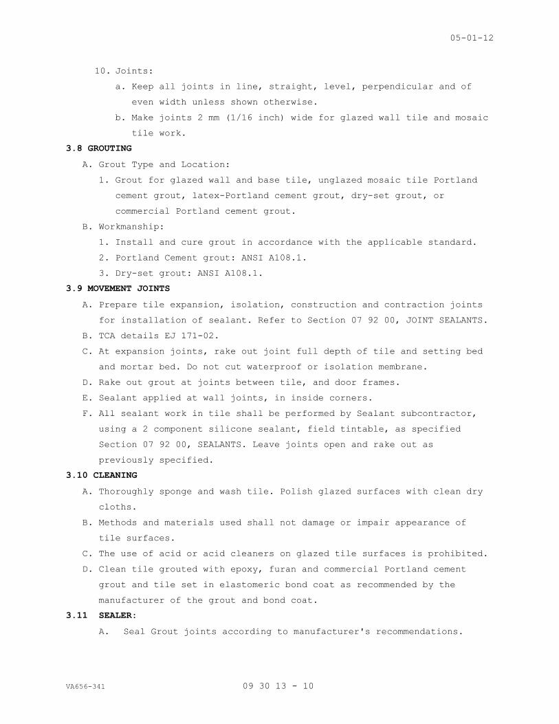
05-01-12
VA656-341 09 30 13 - 10
10. Joints:
a. Keep all joints in line, straight, level, perpendicular and of
even width unless shown otherwise.
b. Make joints 2 mm (1/16 inch) wide for glazed wall tile and mosaic
tile work.
3.8 GROUTING
A. Grout Type and Location:
1. Grout for glazed wall and base tile, unglazed mosaic tile Portland
cement grout, latex-Portland cement grout, dry-set grout, or
commercial Portland cement grout.
B. Workmanship:
1. Install and cure grout in accordance with the applicable standard.
2. Portland Cement grout: ANSI A108.1.
3. Dry-set grout: ANSI A108.1.
3.9 MOVEMENT JOINTS
A. Prepare tile expansion, isolation, construction and contraction joints
for installation of sealant. Refer to Section 07 92 00, JOINT SEALANTS.
B. TCA details EJ 171-02.
C. At expansion joints, rake out joint full depth of tile and setting bed
and mortar bed. Do not cut waterproof or isolation membrane.
D. Rake out grout at joints between tile, and door frames.
E. Sealant applied at wall joints, in inside corners.
F. All sealant work in tile shall be performed by Sealant subcontractor,
using a 2 component silicone sealant, field tintable, as specified
Section 07 92 00, SEALANTS. Leave joints open and rake out as
previously specified.
3.10 CLEANING
A. Thoroughly sponge and wash tile. Polish glazed surfaces with clean dry
cloths.
B. Methods and materials used shall not damage or impair appearance of
tile surfaces.
C. The use of acid or acid cleaners on glazed tile surfaces is prohibited.
D. Clean tile grouted with epoxy, furan and commercial Portland cement
grout and tile set in elastomeric bond coat as recommended by the
manufacturer of the grout and bond coat.
3.11 SEALER:
A. Seal Grout joints according to manufacturer's recommendations.

05-01-12
VA656-341 09 30 13 - 11
3.12 PROTECTION
A. Keep traffic off tile floor, until grout and setting material is firmly
set and cured.
B. Where traffic occurs over tile floor, cover tile floor with not less
than 9 mm (3/8 inch) thick plywood, wood particle board, or hardboard
securely taped in place. Do not remove protective cover until time for
final inspection. Clean tile of any tape, adhesive and stains.
- - - E N D - - -
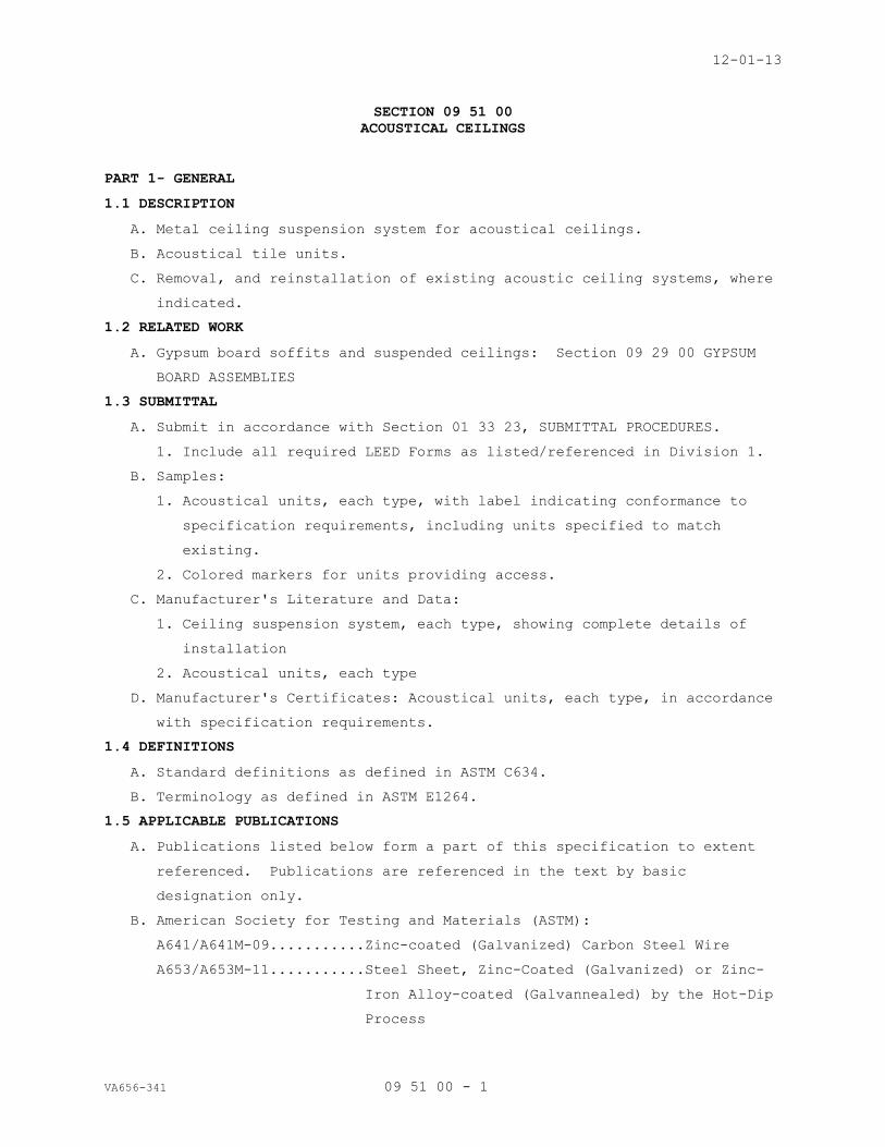
12-01-13
VA656-341 09 51 00 - 1
SECTION 09 51 00
ACOUSTICAL CEILINGS
PART 1- GENERAL
1.1 DESCRIPTION
A. Metal ceiling suspension system for acoustical ceilings.
B. Acoustical tile units.
C. Removal, and reinstallation of existing acoustic ceiling systems, where
indicated.
1.2 RELATED WORK
A. Gypsum board soffits and suspended ceilings: Section 09 29 00 GYPSUM
BOARD ASSEMBLIES
1.3 SUBMITTAL
A. Submit in accordance with Section 01 33 23, SUBMITTAL PROCEDURES.
1. Include all required LEED Forms as listed/referenced in Division 1.
B. Samples:
1. Acoustical units, each type, with label indicating conformance to
specification requirements, including units specified to match
existing.
2. Colored markers for units providing access.
C. Manufacturer's Literature and Data:
1. Ceiling suspension system, each type, showing complete details of
installation
2. Acoustical units, each type
D. Manufacturer's Certificates: Acoustical units, each type, in accordance
with specification requirements.
1.4 DEFINITIONS
A. Standard definitions as defined in ASTM C634.
B. Terminology as defined in ASTM E1264.
1.5 APPLICABLE PUBLICATIONS
A. Publications listed below form a part of this specification to extent
referenced. Publications are referenced in the text by basic
designation only.
B. American Society for Testing and Materials (ASTM):
A641/A641M-09...........Zinc-coated (Galvanized) Carbon Steel Wire
A653/A653M-11...........Steel Sheet, Zinc-Coated (Galvanized) or Zinc-
Iron Alloy-coated (Galvannealed) by the Hot-Dip
Process

12-01-13
VA656-341 09 51 00 - 2
C423-09.................Sound Absorption and Sound Absorption
Coefficients by the Reverberation Room Method
C634-11.................Standard Terminology Relating to Environmental
Acoustics
C635-13.................Metal Suspension Systems for Acoustical Tile
and Lay-in Panel Ceilings
C636-13.................Installation of Metal Ceiling Suspension
Systems for Acoustical Tile and Lay-in Panels
E84-13..................Surface Burning Characteristics of Building
Materials
E119-12.................Fire Tests of Building Construction and
Materials
E413-10.................Classification for Rating Sound Insulation.
E580-11.................Application of Ceiling Suspension Systems for
Acoustical Tile and Lay-in Panels in Areas
Requiring Seismic Restraint
E1264-08e1..............Classification for Acoustical Ceiling Products
C. International Organization for Standardization (ISO)
ISO 14644-1.............Classification of Air Cleanliness
1.6 LEED SUBMITTALS:
A. Product data. Unless otherwise indicated, submit the following for
each type of product provided under work of this Section:
1. Recycled Content:
a. Indicate recycled content; indicate percentage of pre-consumer
and post-consumer recycled content per unit of product.
b. Section 01 3310, Recycled certification Form: Submit a fully
executed form, for all products with specified recycled content.
PART 2 - PRODUCTS
2.1 METAL SUSPENSION SYSTEM
A. ASTM C635, heavy-duty system, except as otherwise specified.
1. Ceiling suspension system members may be fabricated from either of
the following unless specified otherwise.
a. Galvanized cold-rolled steel, bonderized.
1) Recycled Content: Minimum 10 percent post-consumer recycled
content, or minimum 40 percent pre-consumer recycled content
at contractor’s option.

12-01-13
VA656-341 09 51 00 - 3
2. Use same construction for cross runners as main runners. Use of
lighter-duty sections for cross runners is not acceptable.
B. Exposed grid suspension system for support of lay-in panels:
1. Exposed grid width not less than 22 mm (7/8 inch) with not less than
8 mm (5/16 inch) panel bearing surface.
2. Fabricate wall molding and other special molding from the same
material with same exposed width and finish as the exposed grid
members.
3. Match existing, believed to be Chicago Metallic’s 200 series.
2.2 WIRE
A. ASTM A641.
B. For wire hangers: Minimum diameter 2.68 mm (0.1055 inch).
C. For bracing wires: Minimum diameter 3.43 mm (0.1350 inch).
2.3 ANCHORS AND INSERTS
A. Use anchors or inserts to support twice the loads imposed by hangers
attached thereto.
B. Hanger Inserts:
1. Fabricate inserts from steel, zinc-coated (galvanized after
fabrication).
2. Wire tie to steel joists. Use hangers, fastened with concrete
anchors at precast decks.
2.4 CARRYING CHANNELS FOR SECONDARY FRAMING
A. Fabricate from cold-rolled or hot-rolled steel, black asphaltic paint
finish, free of rust.
B. Weighing not less than the following, per 300 m (per thousand linear
feet):
Size mm Size
Inches
Cold-rolled
Kg Pound
Hot-rolled
Kg Pound
38 1 1/2 215.4 475 508 1120
50 2 267.6 590 571.5 1260
2.5 ACOUSTICAL UNITS
A. General:
1. Ceiling Tile shall meet minimum 37% bio-based content in accordance
with USDA Bio-Preferred Product requirements.
2. ASTM E1264, weighing 3.6 kg/m2 (3/4 psf) minimum for mineral fiber
panels or tile.

12-01-13
VA656-341 09 51 00 - 4
3. Class A Flame Spread: ASTM 84
4. Minimum NRC (Noise Reduction Coefficient): 0.55 unless specified
otherwise: ASTM C423.
5. Minimum CAC (Ceiling Attenuation Class): 40-44 range unless
specified otherwise: ASTM E413.
6. Manufacturers standard finish, minimum Light Reflectance (LR)
coefficient of 0.75 on the exposed surfaces.
7. Lay-in panel manufacturer/TYPE:
A. The following matches existing tile and shall be provided: USG
Radar 2210 Series with square edges at ACT-2; USG Radar 2220
series, with Tegular Edges at ACT-1.
B. ACT Series: Type III Units - Mineral base with water-based painted
finish less than 10 g/l VOC, Form 2 - Water felted, minimum 16 mm (5/8
inch) thick. Mineral base to contain minimum 65 percent recycled
content. Non- directional tile are specified.
1. Match Existing ACT tile: USG's Radar, (22XX Series-see above) 2x2
size as previously specified.
2. Standard white color to be provided.
3. Provide tegular edges, and square edge tile as previously specified.
2.6 ACCESS IDENTIFICATION
A. Markers:
1. Use colored markers with pressure sensitive adhesive on one side.
2. Make colored markers of paper of plastic, 6 to 9 mm (1/4 to 3/8
inch) in diameter.
B. Use markers of the same diameter throughout building.
C. Color Code: Use following color markers for service identification:
Color...................Service
Red.....................Sprinkler System: Valves and Controls
Green...................Domestic Water: Valves and Controls
Yellow..................Chilled Water and Heating Water
Orange..................Ductwork: Fire Dampers
Blue....................Ductwork: Dampers and Controls
Black...................Gas: Laboratory, Medical, Air and Vacuum
PART 3 EXECUTION
3.1 CEILING TREATMENT
A. Treatment of ceilings shall include sides and soffits of ceiling beams,
furred work 600 mm (24 inches) wide and over, and vertical surfaces at

12-01-13
VA656-341 09 51 00 - 5
changes in ceiling heights unless otherwise shown. Install acoustic
tiles after wet finishes have been installed and solvents have cured.
B. Lay out acoustical units symmetrically about center lines of each room
or space unless shown otherwise on reflected ceiling plan.
C. Moldings:
1. Install metal wall molding at perimeter of room, column, or edge at
vertical surfaces.
2. Install special shaped molding at changes in ceiling heights and at
other breaks in ceiling construction to support acoustical units and
to conceal their edges.
D. Existing ceiling:
1. Where extension of existing ceilings occur, match existing.
2. Where acoustical units are salvaged and reinstalled or joined, use
salvaged units within a space. Do not mix new and salvaged units
within a space which results in contrast between old and new
acoustic units.
3. Comply with specifications for new acoustical units for new units
required to match appearance of existing units.
3.2 CEILING SUSPENSION SYSTEM INSTALLATION
A. General:
1. Install metal suspension system for acoustical tile and lay-in
panels in accordance with ASTM C636, except as specified otherwise.
2. Use direct or indirect hung suspension system or combination thereof
as defined in ASTM C635.
3. Support a maximum area of 1.48 m2 (16 sf) of ceiling per hanger.
4. Prevent deflection in excess of 1/360 of span of cross runner and
main runner.
5. Provide extra hangers, minimum of one hanger at each corner of each
item of mechanical, electrical and miscellaneous equipment supported
by ceiling suspension system not having separate support or hangers.
6. Provide not less than 100 mm (4 inch) clearance from the exposed
face of the acoustical units to the underside of ducts, pipe,
conduit, secondary suspension channels, concrete beams or joists;
and steel beam or bar joist unless furred system is shown,
7. Use main runners not less than 1200 mm (48 inches) in length.
8. Install hanger wires vertically. Angled wires are not acceptable
except for seismic restraint bracing wires.
B. Anchorage to Structure:

12-01-13
VA656-341 09 51 00 - 6
1. Concrete:
a. Predrill and install ¼” diameter expansion anchor with eye,
similar to Gripple’s Concrete ceiling anchor.
2. Steel:
a. When steel framing does not permit installation of hanger wires
at spacing required, install carrying channels for attachment of
hanger wires.
(1) Size and space carrying channels to insure that the maximum
deflection specified will not be exceeded.
(2) Attach hangers to steel carrying channels, spaced four feet on
center, unless area supported or deflection exceeds the amount
specified.
b. Attach carrying channels to the bottom flange of steel beams
spaced not 1200 mm (4 feet) on center before fire proofing is
installed. Weld or use steel clips to attach to beam to develop
full strength of carrying channel.
c. Attach hangers to bottom chord of bar joists or to carrying
channels installed between the bar joists when hanger spacing
prevents anchorage to joist. Rest carrying channels on top of the
bottom chord of the bar joists, and securely wire tie or clip to
joist.
C. Direct Hung Suspension System:
1. As illustrated in ASTM C635.
2. Support main runners by hanger wires attached directly to the
structure overhead.
3. Maximum spacing of hangers, 1200 mm (4 feet) on centers unless
interference occurs by mechanical systems. Use indirect hung
suspension system where not possible to maintain hanger spacing.
D. Indirect Hung Suspension System:
1. As illustrated in ASTM C635.
2. Space carrying channels for indirect hung suspension system not more
than 1200 mm (4 feet) on center. Space hangers for carrying
channels not more than 2400 mm (8 feet) on center or for carrying
channels less than 1200 mm (4 feet) or center so as to insure that
specified requirements are not exceeded.
3. Support main runners by specially designed clips attached to
carrying channels.
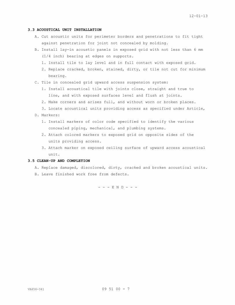
12-01-13
VA656-341 09 51 00 - 7
3.3 ACOUSTICAL UNIT INSTALLATION
A. Cut acoustic units for perimeter borders and penetrations to fit tight
against penetration for joint not concealed by molding.
B. Install lay-in acoustic panels in exposed grid with not less than 6 mm
(1/4 inch) bearing at edges on supports.
1. Install tile to lay level and in full contact with exposed grid.
2. Replace cracked, broken, stained, dirty, or tile not cut for minimum
bearing.
C. Tile in concealed grid upward access suspension system:
1. Install acoustical tile with joints close, straight and true to
line, and with exposed surfaces level and flush at joints.
2. Make corners and arises full, and without worn or broken places.
3. Locate acoustical units providing access as specified under Article,
D. Markers:
1. Install markers of color code specified to identify the various
concealed piping, mechanical, and plumbing systems.
2. Attach colored markers to exposed grid on opposite sides of the
units providing access.
3. Attach marker on exposed ceiling surface of upward access acoustical
unit.
3.5 CLEAN-UP AND COMPLETION
A. Replace damaged, discolored, dirty, cracked and broken acoustical units.
B. Leave finished work free from defects.
- - - E N D - - -

10-11
VA656-341 09 65 00 - 1
SECTION 09 65 00
RESILIENT FLOORING, BASE AND ACCESSORIES
PART 1 - GENERAL
1.1 DESCRIPTION
A. This section specifies the installation of Vinyl Composition Tile,
rubber base and resilient stair treads with rubber tile flooring on
landings and in elevator cab.
B. Provide Photoluminescent products as specified.
1.2 RELATED WORK
A. Color, texture: Section 09 06 00, SCHEDULE FOR FINISHES.
B. Wall substrates: Section 09 29 00 GYPSUM BOARD ASSEMBLIES.
1.3 SUBMITTALS
A. Submit in accordance with Section 01 33 23, SUBMITTAL PROCEDURES.
1. Include all required LEED Forms as listed/referenced in Division 1.
B. Manufacturer's Literature and Data:
1. Description of each product.
2. Base and stair material manufacturer's recommendations for adhesives.
3. Application and installation instructions.
C. Samples:
1. Base: 150 mm (6 inches) long, each type and color.
2. Resilient Stair Treads: 150 mm (6 inches) long.
3. Sheet Rubber Flooring: 300 mm (12 inches) square.
4. Adhesive: Literature indicating each type.
1.4 DELIVERY
A. Deliver materials to the site in original sealed packages or
containers, clearly marked with the manufacturer's name or brand, type
and color, production run number and date of manufacture.
B. Materials from containers which have been distorted, damaged or opened
prior to installation will be rejected.
1.5 STORAGE
A. Store materials in weather tight and dry storage facility.
B. Protect material from damage by handling and construction operations
before, during, and after installation.

10-11
VA656-341 09 65 00 - 2
1.6 APPLICABLE PUBLICATIONS
A. The publication listed below form a part of this specification to the
extent referenced. The publications are referenced in the text by the
basic designation only.
B. American Society for Testing and Materials (ASTM):
E1155-96 (R2008)........Determining Floor Flatness and Floor Levelness
Numbers
F510-93 (R 2008)........Resistance to Abrasion of Resilient Floor
Coverings Using an Abrader with a Grit Feed
Method
F1344-10................Rubber Floor Tile
F1859-10................Rubber Sheet Floor Covering without Backing
F1860-10................Rubber Sheet Floor Covering with Backing
F1861-08................Resilient Wall Base
F710-08.................Preparing Concrete Floors to Receive Resilient
Flooring
F1066-04 (R2010)........Vinyl Composition Floor Tile
F1344-10................Rubber Floor Tile
C. Resilient Floor Covering Institute (RFCI):
IP #2...................Installation Practice for Vinyl Composition
Tile (VCT)
D. Federal Specifications (Fed. Spec.):
SS-T-312................Tile Floor: Asphalt, Rubber, Vinyl and Vinyl
Composition
RR-T-650E...............Treads, Metallic and Non-Metallic, Nonskid
1.7 LEED SUBMITTALS:
A. RECYCLED CONTENT:
1. Rubber:
a. Recycled Content: Minimum 75 percent post-consumer recycled
material.
2. Vinyl:
a. Recycled Content: Minimum 6 percent post-consumer recycled
content, or minimum 30 percent pre-consumer recycled content at
contractor’s option.
B. VOC Data: Submit manufacturer’s product data for adhesives. Indicate
VOC limits of the product. Submit MSDS highlighting VOC limits.
C. Submit Green Seal Certification to GS-36 and description of the basis for
certification.

10-11
VA656-341 09 65 00 - 3
PART 2 - PRODUCTS
2.1 GENERAL
A. Use only products by the same manufacturer and from the same production
run.
2.2 RESILIENT BASE (RB SERIES)
A. ASTM F1861, 3 mm (1/8 inch) thick, 100 mm (4 inches) high, Group 1,
Thermoset vulcanized Rubber. Style B-cove.
B. Where carpet occurs, use Style A-straight, or B coved as determined by
Resident Engineer.
C. Base at Exit Corridors (RB-3): Same as above, but co-extruded with 3/4”
photoluminescent strip. Safe-T-First products by Johnsonite are
acceptable.
2.3 RESILIENT TREADS
A. ASTM F1344, Class 1, homogenous rubber tile, B, through mottle Products
by Johnsonite Rubber are acceptable, Hammer Microtone tread, Style VIHMT.
B. Nosing shape to conform to sub-tread nosing shape.
C. Provide Photo-luminescent visually impaired insert at all treads.
2.4 VINYL COMPOSITION TILE
A. ASTM F1066, Composition 1, Class 2 (through pattern), 300 mm (12 inches)
square, 3 mm (1/8 inch) thick. See Section 09 0600 Color Schedule.
B. Color and pattern uniformly distributed throughout thickness.
2.5 RUBBER TILE
A. ASTM F1344, Class 1, homogenous rubber tile, B, through mottled, 300 mm
(12 inches) square, 3 mm (1/8 inch) thick.
B. Color and pattern uniformly distributed throughout tile.
C. Molded pattern wearing surface base thickness 3 mm (1/8 inch) thick.
D. Rubber tile minimum of 90% post-consumer rubber.
E. Johnsonite products are acceptable, Microtone Series, 24 x 24” tile.
2.6 PRIMER (FOR CONCRETE SUBFLOORS)
A. As recommended by the adhesive and tile manufacturer.
2.7 LEVELING COMPOUND (FOR CONCRETE FLOORS)
A. Provide cementitious products with latex or polyvinyl acetate resins in
the mix.
B. Determine the type of underlayment selected for use by the condition to
be corrected.
2.8 POLISH AND CLEANERS
A. Cleaners RFCI CL-1.
B. Polish: ASTM D4078.
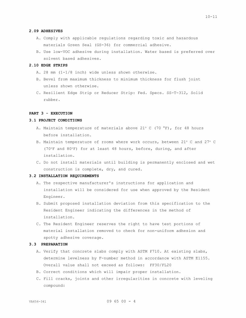
10-11
VA656-341 09 65 00 - 4
2.09 ADHESIVES
A. Comply with applicable regulations regarding toxic and hazardous
materials Green Seal (GS-36) for commercial adhesive.
B. Use low-VOC adhesive during installation. Water based is preferred over
solvent based adhesives.
2.10 EDGE STRIPS
A. 28 mm (1-1/8 inch) wide unless shown otherwise.
B. Bevel from maximum thickness to minimum thickness for flush joint
unless shown otherwise.
C. Resilient Edge Strip or Reducer Strip: Fed. Specs. SS-T-312, Solid
rubber.
PART 3 - EXECUTION
3.1 PROJECT CONDITIONS
A. Maintain temperature of materials above 21o C (70 F), for 48 hours
before installation.
B. Maintain temperature of rooms where work occurs, between 21o C and 27o C
(70oF and 80oF) for at least 48 hours, before, during, and after
installation.
C. Do not install materials until building is permanently enclosed and wet
construction is complete, dry, and cured.
3.2 INSTALLATION REQUIREMENTS
A. The respective manufacturer's instructions for application and
installation will be considered for use when approved by the Resident
Engineer.
B. Submit proposed installation deviation from this specification to the
Resident Engineer indicating the differences in the method of
installation.
C. The Resident Engineer reserves the right to have test portions of
material installation removed to check for non-uniform adhesion and
spotty adhesive coverage.
3.3 PREPARATION
A. Verify that concrete slabs comply with ASTM F710. At existing slabs,
determine levelness by F-number method in accordance with ASTM E1155.
Overall value shall not exceed as follows: FF30/FL20
B. Correct conditions which will impair proper installation.
C. Fill cracks, joints and other irregularities in concrete with leveling
compound:

10-11
VA656-341 09 65 00 - 5
1. Do not use adhesive for filling or leveling purposes.
2. Do not use leveling compound to correct imperfections which can be
corrected by spot grinding.
3. Trowel to smooth surface free of trowel marks, pits, dents,
protrusions, cracks or joints.
D. Clean floor of oil, paint, dust, and deleterious substances: Leave
floor dry and cured free of residue from existing curing or cleaning
agents.
E. Concrete Subfloor Testing:
Determine Adhesion and dryness of the floor by bond and moisture tests
as recommended by RFCI manual MRP.
F. Perform additional subfloor preparation to obtain satisfactory adherence
of flooring if subfloor test patches allows easy removal of tile.
G. Prime the concrete subfloor if the primer will seal slab conditions
that would inhibit bonding, or if priming is recommended by the tile or
adhesive manufacturers.
H. Preparation of existing installation shall include the removal of
existing resilient floor and existing adhesive. Do not use solvents to
remove adhesives.
3.4 BASE INSTALLATION
A. Location:
1. Unless otherwise specified or shown, where base is scheduled,
install base over toe space of base of casework, lockers,
laboratory, pharmacy furniture island cabinets and where other
equipment occurs.
2. Extend base scheduled for room into adjacent closet, alcoves, and
around columns.
B. Application:
1. Apply adhesive uniformly with no bare spots.
2. Set base with joints aligned and butted to touch for entire height.
3. Before starting installation, layout base material to provide the
minimum number of joints with no strip less than 600 mm (24 inches)
length.
a. Short pieces to save material will not be permitted.
b. Locate joints as remote from corners as the material lengths or
the wall configuration will permit.
C. Form corners and end stops as follows:
1. Score back of outside corner.

10-11
VA656-341 09 65 00 - 6
2. Score face of inside corner and notch cove.
D. Roll base for complete adhesion.
3.5 STAIR TREAD INSTALLATION
A. Prepare surfaces to receive the treads in accordance with applicable
portions of paragraph, preparation.
B. Layout of Treads.
1. No joints will be accepted in treads.
2. Set full treads on intermediate and floor landings.
C. Application:
1. Apply adhesive uniformly with no bare spots.
2. Roll and pound treads to assure adhesion.
D. Fill tread nosing completely, using epoxy stair tread caulk.
E. Install in accordance with manufacturer's instructions for application
and installation unless specified otherwise.
3.6 TILE INSTALLATION
A. Install in accordance with manufacturer's instructions for application
and installation unless specified otherwise.
B. Mix tile from at least two containers. An apparent line either of
shades or pattern variance will not be accepted.
C. Tile Layout:
1. If layout is not shown on drawings, lay tile symmetrically about
center of room or space with joints aligned.
2. No tile shall be less than 150 mm (6 inches) and of equal width at
walls.
3. Place tile pattern in the same direction; do not alternate tiles.
D. Trim tiles to touch for the length of intersections at pipes and
vertical projections, seal joints at pipes with waterproof cement.
E. Application:
1. Apply adhesive uniformly with no bare spots.
a. Conform to RFC1-TM-6 for joint tightness and for corner
intersection unless layout pattern shows random corner
intersection.
b. More than 5 percent of the joints not touching will not be
accepted.
2. Roll tile floor with a minimum 45 kg (100 pound) roller. No
exceptions.

10-11
VA656-341 09 65 00 - 7
3. The Resident Engineer may have test tiles removed to check for non-
uniform adhesion, spotty adhesive coverage, and ease of removal.
Install new tile for broken removed tile.
F. Installation of Edge Strips:
1. Locate edge strips under center line of doors unless otherwise shown.
2. Set resilient edge strips in adhesive. Anchor metal edge strips with
anchors and screws specified.
3. Where tile edge is exposed, butt edge strip to touch along tile edge.
4. Where thin set ceramic tile abuts resilient tile, set edge strip
against floor file and against the ceramic tile edge.
3.7 CLEANING AND PROTECTION
A. Clean adhesive marks on exposed surfaces during the application of
resilient materials before the adhesive sets. Exposed adhesive is not
acceptable.
B. Keep traffic off resilient material for a minimum 72 hours after
installation.
C. Clean and polish materials in the following order:
1. For the first two weeks sweep and damp mopped only.
2. After two weeks, scrub resilient materials with a minimum amount of
water and a mild detergent. Leave surface clean and free of
detergent residue.
3. Apply polish to the floors in accordance with the polish
manufacturer's instructions.
D. When construction traffic occurs over tile, cover resilient materials
with reinforced kraft paper properly secured and maintained until
removal is directed by Resident Engineer. At entrances and where
wheeled vehicles or carts are used, cover tile with plywood, hardboard,
or particle board over paper, secured and maintained until removal is
directed by Resident Engineer.
E. When protective materials are removed and immediately prior to
acceptance, replace any damage tile, re-clean resilient materials,
lightly re-apply polish and buff floors.
3.8 LOCATION
A. Unless otherwise specified or shown, install tile flooring, on floor
under areas where casework, laboratory and pharmacy furniture and other
equipment occurs, except where mounted in wall recesses.
B. Extend tile flooring for room into adjacent closets and alcoves.
- - - E N D - - -

SECTION 09 6713
SEAMLESS MECHANICAL ROOM FLOORING
VA 656-341 09 6713-1
PART 1 - GENERAL
1.1 RELATED WORK:
A. Sloped concrete topped floors, curbs, equipment platforms are by
Section 03 3000.
B. Perimeter interior gypsum board partitions: Sections 09 2900 and
09 2216.
C. Pipe sleeves are by Divisions 22/23 and 26.
1.2 SCOPE OF WORK:
A. This Section includes the application of cold fluid applied
seamless mechanical room flooring/waterproofing and self-coved
base in Mechanical Platform Room 204.
1.3 QUALITY ASSURANCE:
A. All coatings provided under this Section shall be compliant US
Green Building Council’s LEED v2009 IEQc4.2: Low-Emitting
Materials—Paints and Coatings
1. Floor Coatings: 100 g/L or less
2. Include all required LEED Forms as listed/referenced in
Division 1.
B. Contractor performing Work under this Section shall have at least
five (5) years proven satisfactory experience on projects of
similar scope.
1. Contractor Experience: The contractor shall furnish a list
of projects using either specified material or equivalent
that they have installed during the last 5 years.
Information shall include: project name, square footage,
owner contact name with owner’s address and phone number.
Also, the contractor shall furnish resumes detailing the
experience of key project personnel including supervisors
and mechanics.
C. Applicator to be an approved applicator by the manufacturer.
1.4 PRODUCT DATA:
A. Submit in accordance with Section 01 33 23 SUBMITTALS.
1. Furnish manufacturer's instructions for evaluating, preparing,
prepping/treating flooring substrates, technical data, tested
physical and performance properties, and printed instructions
for installation of waterproofing/flooring, including
procedures and materials for flashing, self-coving, splicing
and bonding.

SECTION 09 6713
SEAMLESS MECHANICAL ROOM FLOORING
VA 656-341 09 6713-2
2. Submit a copy of the manufacturer’s approval of the
applicator.
B. Shop Drawings: Indicate details such as termination and non-
typical details. Show changes from horizontal to vertical
surface, inside and outside corner applications, self-coving and
termination details, and details where terminating at floor
drains.
C. Furnish descriptions and drawings of materials and methods to
protect waterproofing/flooring systems from damage by subsequent
construction activities.
D. Provide 12” square samples on precast block pavers, the finished
color and texture samples.
E. Manufacturer’s Review of waterproofing/flooring Systems:
1. A written statement, signed by waterproofing applicator and
manufacturer’s representative stating that the Drawings and
specifications have been review, and that they are in
agreement that the selected, specified materials are proper
and adequate for the application shown. Submit copy to the
Owner.
2. A written approval of the condition of the substrate, signed
by manufacturer’s representative, and applicator.
3. Manufacturer's approval of Moisture Content/Test Results:
Manufacturer shall test the moisture content of each floor
location scheduled to receive this waterproofing/flooring
system. Tests shall be made no sooner than 28 days after the
installation of new concrete topping, and no sooner than 6
days after installation of any repair mortar.
4. Tests shall comply with ASTM D4263, “rubber mat moisture
test”.
5. Submit MSDS information for all Materials.
1.5 MAINTENANCE DATA:
A. Provide maintenance manuals which identify substrates, and type
of system used, including recommendations for periodic
inspections, cleaning, care, maintenance and repair of the
flooring system.
1.6 ENVIRONMENTAL CONDITIONS:
A. Minimum temperature 40 degrees F. 24 hours before, during and 24
hours after application or until cured; adequate controlled

SECTION 09 6713
SEAMLESS MECHANICAL ROOM FLOORING
VA 656-341 09 6713-3
ventilation; bright, uniform lighting; broom clean; reasonably
dust free; and kept clear of other tradesmen.
B. Do no Work unless adequate ventilation is provided.
1.7 MOCKUP SAMPLE:
A. Provide samples on 36" square sample board (consisting of 2”
concrete slab on plywood, reinforced with 2” square mesh, and
complete with curb/base indicating slab to wall joint/curb
transition and termination, as well as color and texture.
1. Sample shall be poured and cured 28 days, prior to
installing flooring system to sample prior to installation
of sample. Provide brush blasting and floor prep to sample
identical to what installer would be providing in the field.
Bring completed sample to Preconstruction Conference.
1.8 PRE-INSTALLATION CONFERENCE:
A. After completion of the shop drawing review and upon completion
of the sample listed above, and after the curing, moisture
testing, and mechanical preparation (Shotblasting) of the
concrete topping surface, the applicator/contractor shall meet
with the Owners Representative, Architect, Manufacturer of
product, at the project site for a pre-installation meeting.
1. Review the entire specification and manufacturer’s
installation instructions word for word.
2. Review and finalize special details, and protection
requirements with all present.
3. Review required testing and inspections.
1.9 DELIVERY, STORAGE AND MAINTENANCE:
A. Deliver all materials in original, unopened containers of
packaging clearly labeled with manufacturer's name, brand, type,
shelf life, date of manufacture.
B. Store all materials for work in accordance with manufacturer’s
recommendations, as approved, and in accordance with the
requirements herein specified.
C. Remove all solvent soaked rags from the site of place them in
proper containers to be removed from site at the end of the day.
1.10 ENVIRONMENTAL REQUIREMENTS:
A. Do not apply materials if ambient, materials, or substrate
temperatures are outside the range recommended by the
manufacturer. All temperatures must be rising and above the

SECTION 09 6713
SEAMLESS MECHANICAL ROOM FLOORING
VA 656-341 09 6713-4
minimum for a period of a minimum of 48 hours after completion.
Do not apply if temperatures are below 50 Degrees F. Do not
apply when temperatures are less than 5 degrees F. above dew
point or when weather can directly interfere with the application
or curing period.
1. Do not install until the substrates have a moisture content
approved by the Manufacturer immediately prior to
installation. Written approvals must be sent to Architect.
PART 2 - PRODUCTS
2.1 SEAMLESS FLOORING/WATERPROOFING:
A. System Manufacturers: Sherwin William’s/General Polymers Corp.
with products by Vulkem’s 350/351 System also acceptable
B. Type: Epoflex MER.
C. Color: Picked from manufacturer's standard.
D. Texture: Approved by manufacturer, providing a mild slip
resistant aggregate finish. Aggregate shall be uniformly graded,
with at least 6.5 MOH scale of hardness, 80% in the 25-40 mesh
size no more than 2% passing the 700 mesh sieve. Aggregate to
contain no more than 0.4% iron oxide.
E. Material Compatibility: Provide primers sealants, detail coat
material, vertical application material, base coat material, and
top coat material, and misc. materials that are compatible with
one another, and from a single manufacturer.
F. Joint Sealant: 2 component urethane sealant and primer,
recommended by manufacturer for substrate and joint conditions,
complying with ASTM C920. Provide backer rod, such as Sof-Rod
and as approved by manufacturer.
G. Reinforcing strip: Manufacturer’s recommended mesh reinforcement
embedded in the base coat application.
PART 3 - EXECUTION
3.1 CONDITION OF SURFACES:
A. Ensure environmental and site conditions are suitable for application
and curing, and that surfaces are acceptable in accordance with
manufacturer's recommendations.
B. Moisture Cure new concrete for 28 days minimum prior to application.

SECTION 09 6713
SEAMLESS MECHANICAL ROOM FLOORING
VA 656-341 09 6713-5
C. An independent testing laboratory to determine the suitability of
the concrete subfloor to receive floor covering, with regard to
moisture content, curing compounds, and to ensure concrete floor
is within floor manufacturer’s recommended limits prior to
installation.
1. ASTM F1869 Qualitive Anhydrous Calcium Chloride Test: Do not
install on flooring substrates, with moisture vapor permeance,
in excess of 3 pounds per 1000 sq ft per 24 hours, or the
maximum permeance allowed by the flooring coating manufacturer.
Do not proceed with application until condition is corrected.
2. Perform pH and adhesion tests to concrete substrates in
accordance with floor manufacturer’s recommendations. Testing
for internal relative humidity of concrete slabs must be
conducted in accordance with the latest edition of ASTM F-
2170, not to exceed 75% relative humidity. (ASTM F2170 -
Standard Test Method for Determining Relative Humidity in
Concrete Floor Slabs Using In Situ Probes).
3.2 PROTECTION:
A. Protect adjacent surfaces from damage resulting from Work of this
trade. If necessary, mask and/or cover adjacent surfaces,
fixtures, cabinet work, equipment, etc. by suitable means.
B. Place temporary barricades and post "No Smoking" signs, while
Work is in progress and curing.
C. Advise other trades of fixtures not to be installed until
flooring is applied and cured. (Examples: plumbing fixtures,
painting, resilient flooring, floor-supported equipment or
cabinet work, and caulking.)
3.3 FLOORING APPLICATION:
A. Prepare by providing a ShotBlast (mechanical) preparation system.
Burn off any fiberglass fibers embedded in the concrete substrate
using a weed burner.
B. Surface shall be free of spalling voids, loose material and
projections, with no coarse aggregate exposed. Remove all oil,
grease, dirt, dust, debris, and other contaminants.
C. Provide proper masking of surfaces (not scheduled to receive
flooring system).
D. Prepare vertical and horizontal surfaces at terminations, and
penetrations through waterproofing and at expansion joints,

SECTION 09 6713
SEAMLESS MECHANICAL ROOM FLOORING
VA 656-341 09 6713-6
drains, and sleeves, according to ASTM C898, and manufacturer’s
written instructions. Wire brush all metal surfaces to a clean
shiny surface. Vacuum areas and wipe surfaces clean.
E. Penetration Curbs: Where piping, conduit or ductwork passes thru
the flooring/waterproofing system: Install pipe or duct curbs
(L shaped) manufactured from soldered 24 ga. GI metal, anchored
to floor, joints sealed, with floor finish coving up the
vertical. Minimum size of metal curb: 3” vertical and 2”
horizontal. Set in bed of sealant and anchor with tapcons. Hem
the vertical edge of angle.
1. Concrete curbs may also be provided. Coordinate locations
with Division 3.
F. Apply floor finish in accordance with manufacturer's instructions
employing technically trained and approved mechanics, using
equipment specifically designed for this purpose.
G. Base: Self cove flooring up the walls a minimum of 4”. Provide
coving, termination trim, reinforcement and accessories for a
complete installation.
3.4 JOINT AND CRACK PREPARATION:
A. Prepare route and fill joints and cracks in substrate according
to ASTM C898 and manufacturer’s written instructions. Remove
dust and debris from joints and cracks prior to coating.
1. Cracks less than 1/16” wide: Prime and apply detail coat a
minimum of 6” wide, centered over crack, and extend coat for
the full height of any vertical application. Embed
reinforcing strip in the wet detail coat as recommended by
manufacturer. Allow all detail coats to dry a minimum of 24
hours prior to floor application. Feather edges of detail
coat to avoid edges showing thru the finished coating.
2. Cracks 1/16” to 1/8” wide: Prime, fill with sealant, and
tool flush with putty knife. Allow sealant to cure a
minimum of 16 hours prior to proceeding. Then Prime and
apply detail coat a minimum of 6” wide, centered over crack,
and extend coat for the full height of any vertical
application. Embed reinforcing strip in the wet detail coat
as recommended by manufacturer. Allow all detail coats to
dry a minimum of 24 hours prior to floor application.
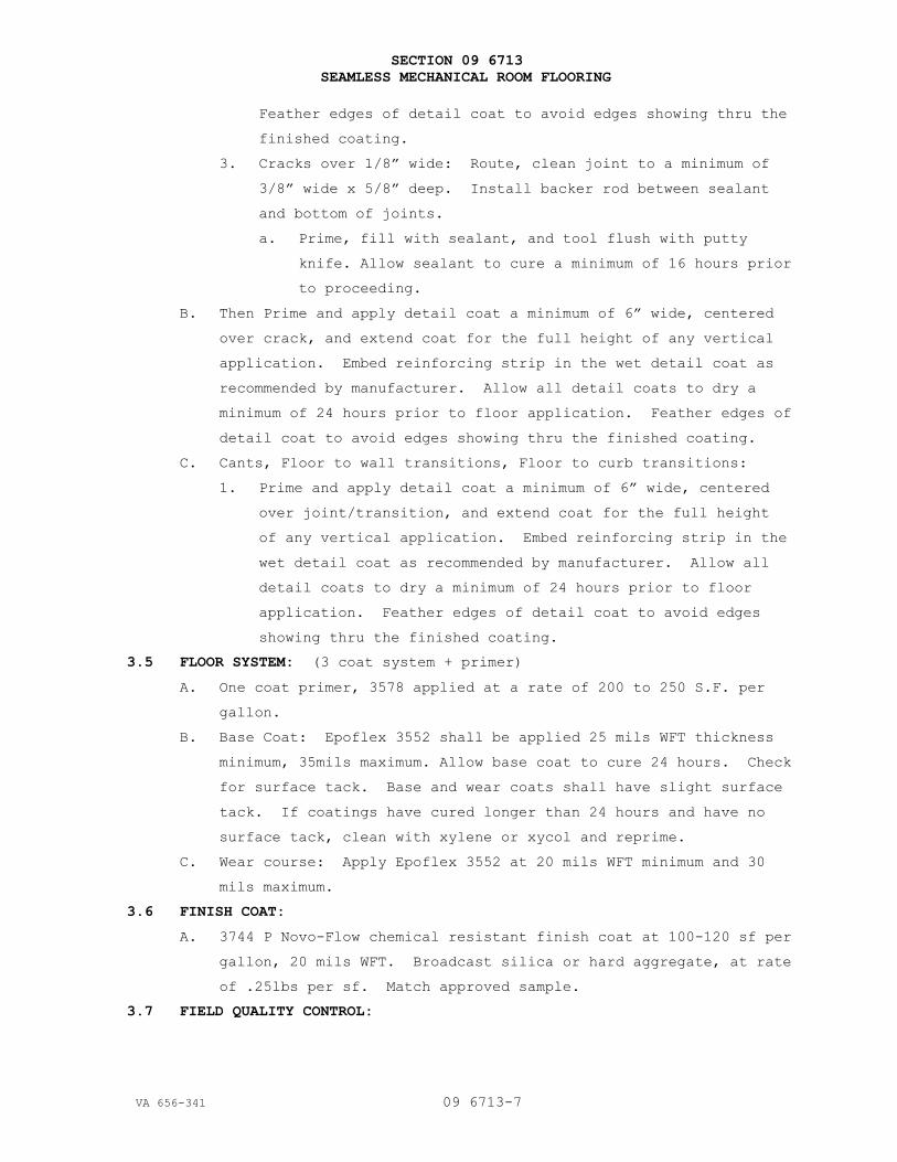
SECTION 09 6713
SEAMLESS MECHANICAL ROOM FLOORING
VA 656-341 09 6713-7
Feather edges of detail coat to avoid edges showing thru the
finished coating.
3. Cracks over 1/8” wide: Route, clean joint to a minimum of
3/8” wide x 5/8” deep. Install backer rod between sealant
and bottom of joints.
a. Prime, fill with sealant, and tool flush with putty
knife. Allow sealant to cure a minimum of 16 hours prior
to proceeding.
B. Then Prime and apply detail coat a minimum of 6” wide, centered
over crack, and extend coat for the full height of any vertical
application. Embed reinforcing strip in the wet detail coat as
recommended by manufacturer. Allow all detail coats to dry a
minimum of 24 hours prior to floor application. Feather edges of
detail coat to avoid edges showing thru the finished coating.
C. Cants, Floor to wall transitions, Floor to curb transitions:
1. Prime and apply detail coat a minimum of 6” wide, centered
over joint/transition, and extend coat for the full height
of any vertical application. Embed reinforcing strip in the
wet detail coat as recommended by manufacturer. Allow all
detail coats to dry a minimum of 24 hours prior to floor
application. Feather edges of detail coat to avoid edges
showing thru the finished coating.
3.5 FLOOR SYSTEM: (3 coat system + primer)
A. One coat primer, 3578 applied at a rate of 200 to 250 S.F. per
gallon.
B. Base Coat: Epoflex 3552 shall be applied 25 mils WFT thickness
minimum, 35mils maximum. Allow base coat to cure 24 hours. Check
for surface tack. Base and wear coats shall have slight surface
tack. If coatings have cured longer than 24 hours and have no
surface tack, clean with xylene or xycol and reprime.
C. Wear course: Apply Epoflex 3552 at 20 mils WFT minimum and 30
mils maximum.
3.6 FINISH COAT:
A. 3744 P Novo-Flow chemical resistant finish coat at 100-120 sf per
gallon, 20 mils WFT. Broadcast silica or hard aggregate, at rate
of .25lbs per sf. Match approved sample.
3.7 FIELD QUALITY CONTROL:

SECTION 09 6713
SEAMLESS MECHANICAL ROOM FLOORING
VA 656-341 09 6713-8
A. Periodically check base and wear course layers for any indication
of bubbling, trapped air or excess moisture. Correct per
manufacturer’s recommendations.
B. Flood Testing: Performed at discretion of Owner, and to the
requirements and recommendations of manufacturer, and ASTM D 5957.
3.8 CURING, PROTECTION AND CLEANING:
A. Cure waterproofing/flooring systems according to manufacturer’s
written recommendations, taking care to prevent contamination and
damage during application stages and curing.
B. Review protection requirements with General Contractor to allow
him to enforce protection requirements by other contractors
during the completion of work.
C. Clean spillage and soiling from adjacent construction using
cleaning agents and procedures recommended by manufacturer.
END OF SECTION

10-11
VA 656-341 09 68 00 - 1
SECTION 09 68 00
CARPETING
PART 1 - GENERAL
1.1 DESCRIPTION
A. Section specifies carpet, fabric bound carpet base, edge strips,
adhesives, and other items required for complete installation.
1.2 RELATED WORK
A. Color and texture of carpet and edge strip: Section 09 06 00, SCHEDULE
FOR FINISHES.
B. Resilient wall base: Section 09 65 00, RESILIENT FLOORING, BASE AND
ACCESSORIES.
1.3 QUALITY ASSURANCE
A. Carpet installed by mechanics certified by the Floor Covering
Installation Board.
B. Certify and label the carpet that it has been tested and meets criteria
of CRI IAQ Carpet Testing Program for indoor air quality.
1.4 SUBMITTALS
A. Submit in accordance with Section 01 33 23, SUBMITTAL PROCEDURES.
1. Include all required LEED Forms as listed/referenced in Division 1.
B. Product Data:
1. Manufacturer’s catalog data and printed documentation stating
physical characteristics, durability, resistance to fading and flame
resistance characteristics for each type of carpet material and
installation accessory.
2. Manufacturer’s printed installation instructions for the carpet,
including preparation of installation substrate, seaming techniques
and recommended adhesives and tapes.
3. Manufacturer’s certificate verifying carpet containing recycled
materials include percentage of recycled materials as specified.
C. Samples:
1. Carpet: "Production Quality" samples 300 x 300 mm (12 x 12 inches) of
carpets, showing quality, pattern and color specified in Section 09
06 00, SCHEDULE FOR FINISHES.
2. Floor Edge Strip (Molding): 150 mm (6 inches) long of each color and
type specified.
3. Base Edge Strip (Molding): 150 mm (6 inches) long of each color
specified.

10-11
VA 656-341 09 68 00 - 2
D. Shop Drawings: Installers layout plan showing seams and cuts for sheet
carpet and carpet module.
E. Maintenance Data: Carpet manufacturer’s maintenance instructions
describing recommended type of cleaning equipment and material, spotting
and cleaning methods and cleaning cycles.
1.5 DELIVERY AND STORAGE
A. Deliver carpet in manufacturer’s original wrappings and packages clearly
labeled with manufacturer’s name, brand, name, size, dye lot number and
related information.
B. Deliver adhesives in containers clearly labeled with manufacturer’s
name, brand name, number, installation instructions, safety instructions
and flash points.
C. Store in a clean, dry, well ventilated area, protected from damage and
soiling. Maintain storage space at a temperature above 16 degrees C (60
degrees F) for 2 days prior to installation.
1.6 ENVIRONMENTAL REQUIREMENTS
A. Areas in which carpeting is to be installed shall be maintained at a
temperature above 16 degrees C (60 degrees F) for 2 days before
installation, during installation and for 2 days after installation. A
minimum temperature of 13 degrees C (55 degrees F) shall be maintained
thereafter for the duration of the contract. Traffic or movement of
furniture or equipment in carpeted area shall not be permitted for 24
hours after installation. Other work which would damage the carpet shall
be completed prior to installation of carpet.
1.7 WARRANTY
A. Carpet and installation subject to terms of "Warranty of Construction"
FAR clause 52.246-21, except that warranty period is extended to two
years.
1.8 APPLICABLE PUBLICATIONS
A. Publication listed below form a part of this specification to extent
referenced. Publications are referenced in text by basic designation
only.
B. American National Standards Institute (ANSI):
ANSI/NSF 140-10.........Sustainable Carpet Assessment Standard
C. American Association of Textile Chemists and Colorists (AATCC):
AATCC 16-04.............Colorfastness to Light
AATCC 129-10............Colorfastness to Ozone in the Atmosphere under
High Humidities

10-11
VA 656-341 09 68 00 - 3
AATCC 134-11............Electric Static Propensity of Carpets
AATCC 165-08............Colorfastness to Crocking: Textile Floor
Conerings-AATCC Crockmeter Method
D. American Society for Testing and Materials (ASTM):
ASTM D1335-05...........Tuft Bind of Pile Yarn Floor Coverings
ASTM D3278-96 (R2004)...Flash Point of Liquids by Small Scale Closed-Cup
Apparatus
ASTM D5116-10...........Determinations of Organic Emissions from Indoor
Materials/Products
ASTM D5252-05...........Operation of the Hexapod Tumble Drum Tester
ASTM D5417-05...........Operation of the Vettermann Drum Tester
ASTM E648-10............Critical Radiant Flux of Floor-Covering Systems
Using a Radiant Heat Energy Source
E. The Carpet and Rug Institute (CRI):
CRI 104-11..............Installation of Commercial Carpet
F. LEED v2009, MRc4, MRc5 .......Recycled Content & Regional Materials
IEQc4.1, 4.3.....Low Emitting Adhesives& Sealants, Low
Emitting Floor systems.
1.9 LEED SUBMITTALS:
A. VOC data:
1. Adhesives:
a. Submit manufacturer’s product data for adhesives. Indicate VOC
limits of the product. Submit MSDS highlighting VOC limits.
Plus Florscore and CRI Green+ ratings
2. Carpet: Submit manufacturer’s certification of compliance with:
a. Carpet and Rug Institute’s Green Label PLUS Indoor Air Quality
Program.
b. FloorScore IAQ Certification means to comply with the volatile
organic compound emissions criteria of the California Section
01350 Program.
B. Nylon Carpet Face Fiber:
1. Recycled Content: Minimum 5 percent post-consumer recycled content,
or minimum 20 percent pre-consumer recycled content at contractor’s
option.
PART 2 - PRODUCTS
2.1 CARPET
A. Physical Characteristics:

10-11
VA 656-341 09 68 00 - 4
1. Carpet free of visual blemishes, streaks, poorly dyed areas, fuzzing
of pile yarn, spots or stains and other physical and manufacturing
defects.
2. Manufacturers standard construction commercial carpet:
a. Modular Tile: 660 mm (24 inches) square tile.
3. Provide static control to permanently control static build up to less
than 2.0 kV when tested at 20 percent relative humidity and 21
degrees C (70 degrees F) in accordance with AATCC 134.
4. Pile Height: Maximum 3.25 mm (0.10 inch).
5. Pile Fiber: Nylon with recycled content 25 percent minimum branded
(federally registered trademark).
6. Pile Type: Level Loop.
7. Backing materials: Manufacturer’s unitary backing designed for glue-
down installation using recovered materials.
8. Appearance Retention Rating (ARR): Carpet shall be tested and have
the minimum 3.5-4.0 Severe ARR when tested in accordance with either
the ASTM D 5252 (Hexapod) or ASTM D 5417 (Vettermann) test methods
using the number of cycles for short and long term tests as
specified.
9. Tuft Bind: Minimum force of 40 N (10 lb) required to pull a tuft or
loop free from carpet backing. Test per ASTM D1335.
10. Colorfastness to Crocking: Dry and wet crocking and water bleed,
comply with AATCC 165 Color Transference Chart for colors, minimum
class 4 rating.
11. Colorfastness to Ozone: Comply with AATCC 129, minimum rating of 4 on
the AATCC color transfer chart.
12. Delamination Strength: Minimum of 440 N/m (2.5 lb/inch) between
secondary backing.
13. Flammability and Critical Radiant Flux Requirements:
a. Test Carpet in accordance with ASTM E 648.
b. Class I: Not less than 0.45 watts per square centimeter.
c. Class II: Not less than 0.22 watts per square centimeter.
d. Carpet in corridors, exits and Medical Facilities: Class I.
14. Density: Average Pile Yarn Density (APYD):
a. Corridors, lobbies, entrances, common areas or multipurpose rooms,
open offices, waiting areas and dining areas: Minimum APYD 6000.
b. Other areas: Minimum APYD 4000.

10-11
VA 656-341 09 68 00 - 5
15. VOC Limits: Use carpet and carpet adhesive that comply with the
following limits for VOC content when tested according to ASTM D
5116:
a. Carpet, Total VOCs: 0.5 mg/sq.m x hr.
b. Carpet, 4-PC (4-Phenylcyclohexene): 0.05 mg/sq.m x hr.
c. Carpet, Formaldehyde: 0.05 mg/sq.m x hr.
d. Carpet, Styrene: 0.4 mg/sq.m x hr.
e. Adhesive, Total VOCs: 10.00 mg/sq.m x hr.
f. Adhesive, Formaldehyde: 0.05 mg/sq.m x hr.
g. Adhesive, 2-Ethyl-1-Hexanol: 3.00 mg/sq.m x hr.
B. Shall meet platinum level of ANSI/NSF 140.
2.2 CARPET C-1 and C-1a:
A. C-1 Manufacturer: Shaw Contract
1. Name: Constellation, EW 24 Modular
2. Face Yarn: Eco Solution Q nylon
3. Construction: Pattern Loop
4. Gauge: 1/10”
5. Yarn Weight: 24 oz/sy
6. Backing Materials: Synthetic/Ecoworx tile
7. Density: 8727
8. Radiant Panel Test: ASTM E-648, Class I; Radiant flux in excess of .45
watts/cm2.
9. Color and Pattern: See Section 09 06 00, SCHEDULE FOR FINISHES.
B. C-1a Carpet Base/ Carpet at Alternate.
1. Manufacturer: Shaw Contract’s broadloom, cut to 4” heights
2. Name: Constellation, broadloom, with Hank’s Specialties #410 fabric
Top Edge Binding.
2.3 ADHESIVE AND CONCRETE PRIMER
A. As manufactured by or for Carpet Tile manufacturer. Waterproof,
resistant to cleaning solutions, steam and water, nonflammable, complies
with air-quality standards as specified. Adhesives flashpoint minimum 60
degrees C (140 degrees F), complies with ASTM D 3278.
2.4 FLOOR EDGE STRIPS (MOLDING)
A Rubber Edge Strip:
1. Beveled floor flange minimum 50 mm (2 inches) wide.
2. Beveled surface to finish flush with carpet for tight joint and other
side to floor finish.

10-11
VA 656-341 09 68 00 - 6
2.5 LEVELING COMPOUND (FOR CONCRETE FLOORS)
A. Provide Portland cement bases polymer modifier with latex or polyvinyl
acetate resin manufactured specifically for resurfacing and leveling
concrete floors. Products containing gypsum are not acceptable.
B. Determine the type of underlayment selected for use by condition to be
corrected.
PART 3 - EXECUTION
3.1 SURFACE PREPARATION
A. Examine surfaces on which carpeting is to be installed.
B. Clean floor of oil, waxy films, paint, dust and deleterious substances
that prevent adhesion, leave floor dry and cured, free of residue from
curing or cleaning agents and existing materials.
C. Correct conditions which will impair proper installation, including
trowel marks, pits, dents, protrusions, cracks or joints.
D. Fill cracks, joints depressions, and other irregularities in concrete
with leveling compound.
1. Do not use adhesive for filling or leveling purposes.
2. Do not use leveling compound to correct imperfections which can be
corrected by spot grinding.
3. Trowel to smooth surface free of trowel marks, pits, dents,
protrusions, cracks or joint lines.
E. Test new concrete subfloor prior to adhesive application for moisture
and surface alkalinity per CRI 104 Section 6.3.1 or per ASTM E1907.
3.2 CARPET INSTALLATION
A. Do not install carpet until work of other trades including painting is
complete and dry.
B. Install in accordance with CRI 104 direct glue down installation.
1. Relax carpet in accordance with Section 6.4.
2. Comply with indoor air quality recommendations noted in Section 6.5.
3. Maintain temperature in accordance with Section 15.3.
C. Secure carpet to subfloor of spaces with adhesive applied as recommended
by carpet manufacturer.
D. Follow carpet manufacturer's recommendations for matching pattern and
texture directions.
E. Cut openings in carpet where required for installing equipment, pipes,
outlets, and penetrations.
1. Bind or seal cut edge of sheet carpet and replace flanges or plates.
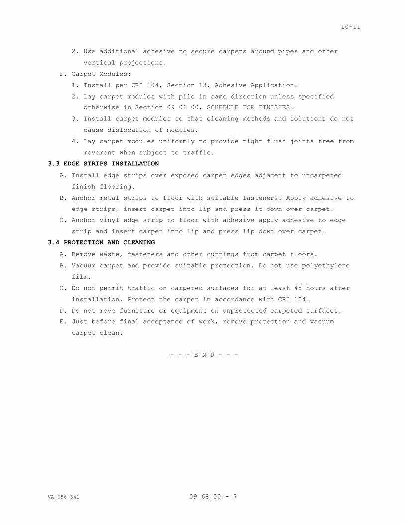
10-11
VA 656-341 09 68 00 - 7
2. Use additional adhesive to secure carpets around pipes and other
vertical projections.
F. Carpet Modules:
1. Install per CRI 104, Section 13, Adhesive Application.
2. Lay carpet modules with pile in same direction unless specified
otherwise in Section 09 06 00, SCHEDULE FOR FINISHES.
3. Install carpet modules so that cleaning methods and solutions do not
cause dislocation of modules.
4. Lay carpet modules uniformly to provide tight flush joints free from
movement when subject to traffic.
3.3 EDGE STRIPS INSTALLATION
A. Install edge strips over exposed carpet edges adjacent to uncarpeted
finish flooring.
B. Anchor metal strips to floor with suitable fasteners. Apply adhesive to
edge strips, insert carpet into lip and press it down over carpet.
C. Anchor vinyl edge strip to floor with adhesive apply adhesive to edge
strip and insert carpet into lip and press lip down over carpet.
3.4 PROTECTION AND CLEANING
A. Remove waste, fasteners and other cuttings from carpet floors.
B. Vacuum carpet and provide suitable protection. Do not use polyethylene
film.
C. Do not permit traffic on carpeted surfaces for at least 48 hours after
installation. Protect the carpet in accordance with CRI 104.
D. Do not move furniture or equipment on unprotected carpeted surfaces.
E. Just before final acceptance of work, remove protection and vacuum
carpet clean.
- - - E N D - - -
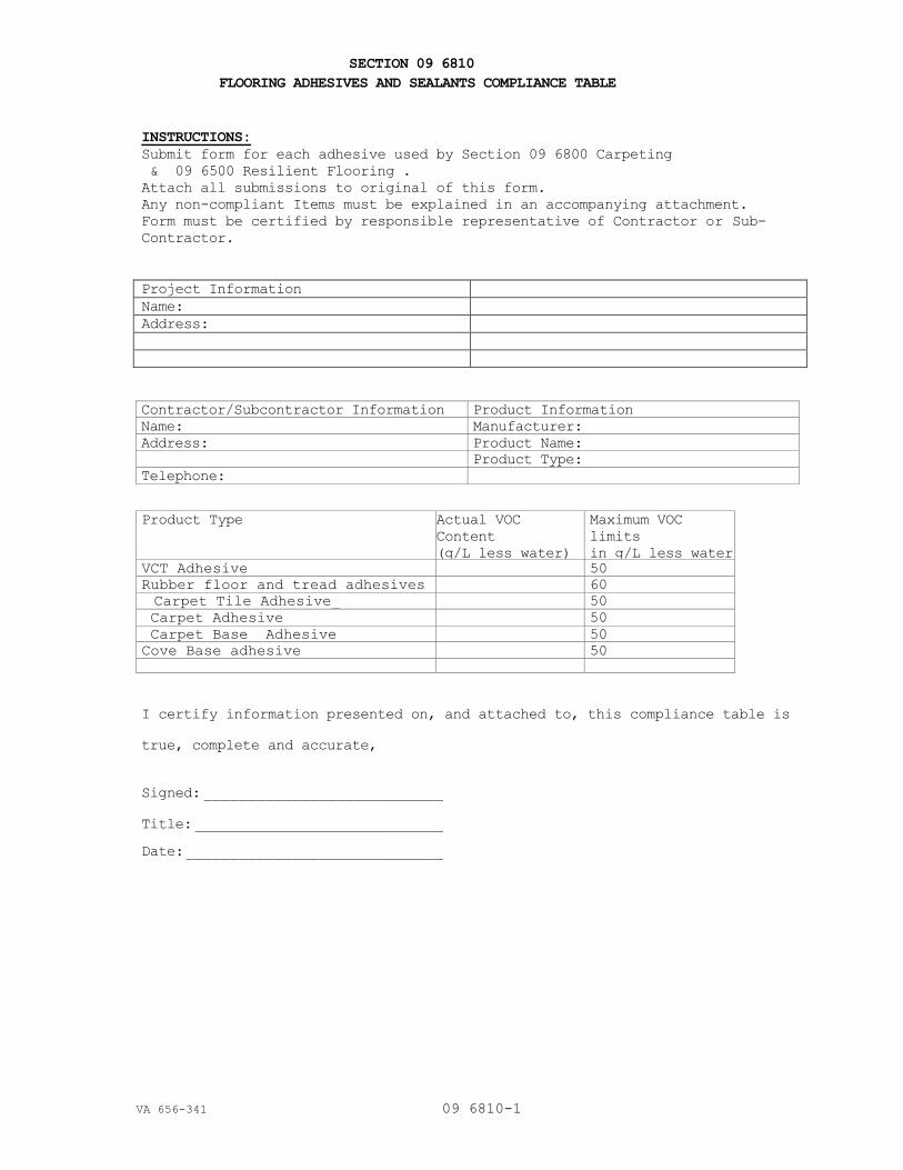
SECTION 09 6810
FLOORING ADHESIVES AND SEALANTS COMPLIANCE TABLE
VA 656-341 09 6810-1
INSTRUCTIONS:
Submit form for each adhesive used by Section 09 6800 Carpeting
& 09 6500 Resilient Flooring .
Attach all submissions to original of this form.
Any non-compliant Items must be explained in an accompanying attachment.
Form must be certified by responsible representative of Contractor or Sub-
Contractor.
Project Information
Name:
Address:
Contractor/Subcontractor Information Product Information
Name: Manufacturer:
Address: Product Name:
Product Type:
Telephone:
Product Type Actual VOC
Content
(g/L less water)
Maximum VOC
limits
in g/L less water
VCT Adhesive 50
Rubber floor and tread adhesives 60
Carpet Tile Adhesive_
Cave Base Adhesive
50
Carpet Adhesive 50
Carpet Base Adhesive 50
Cove Base adhesive 50
I certify information presented on, and attached to, this compliance table is
true, complete and accurate,
Signed: ___________________________
Title: ____________________________
Date: _____________________________

07-01-13
VA 656-341 09 91 00 - 1
SECTION 09 91 00
PAINTING
PART 1-GENERAL
1.1 DESCRIPTION
A. Section specifies field painting.
B. Section specifies prime coats which may be applied in shop under other
sections.
C. Painting includes shellacs, stains, varnishes, coatings specified, and
striping or markers and identity markings.
1.2 RELATED WORK
A. Shop prime painting of steel and ferrous metals: Division 05 - METALS,
Division 08 - OPENINGS, Division 10 - SPECIALTIES, Division 11 -
EQUIPMENT, Division 12 - FURNISHINGS, Division 13 – SPECIAL CONSTRUCTION,
Division 14 – CONVEYING EQUIPMENT.
B. Prefinished flush doors with transparent finishes: Section 08 14 00, WOOD
DOORS.
C. Type of Finish, Color, and Gloss Level of Finish Coat: Section 09 06 00,
SCHEDULE FOR FINISHES.
D. Plastic Laminate casework and millwork: Section 06 4000, FINISH CARPENTRY
& CASEWORK.
E. Seamless Mechanical Room Flooring: SECTION 09 67 13.
1.3 SUBMITTALS
A. Submit in accordance with Section 01 33 23, SUBMITTAL PROCEDURES.
1. Include all required LEED Forms as listed/referenced in Division 1.
B. Manufacturer's Literature and Data:
Before work is started, or sample panels are prepared, submit
manufacturer's literature, the current Master Painters Institute (MPI)
"Approved Product List" indicating brand label, product name and product
code as of the date of contract award, will be used to determine
compliance with the submittal requirements of this specification. The
Contractor may choose to use subsequent MPI "Approved Product List",
however, only one list may be used for the entire contract and each
coating system is to be from a single manufacturer. All coats on a
particular substrate must be from a single manufacturer. No variation from
the MPI "Approved Product List" where applicable is acceptable.

07-01-13
VA 656-341 09 91 00 - 2
C. Sample Panels:
1. After painters' materials have been approved and before work is started
submit sample panels showing each type of finish and color specified.
2. Panels to show color: Composition board, 100 by 250 by 3 mm (4 inch by
10 inch by 1/8 inch).
3. Panel to show transparent finishes: Wood of same species and grain
pattern as wood approved for use, 100 by 250 by 3 mm (4 inch by 10 inch
face by 1/4 inch) thick minimum, and where both flat and edge grain
will be exposed, 250 mm (10 inches) long by sufficient size, 50 by 50
mm (2 by 2 inch) minimum or actual wood member to show complete finish.
4. Attach labels to panel stating the following:
a. Federal Specification Number or manufacturers name and product
number of paints used.
b. Specification code number specified in Section 09 06 00, SCHEDULE
FOR FINISHES.
c. Product type and color.
d. Name of project.
5. Strips showing not less than 50 mm (2 inch) wide strips of undercoats
and 100 mm (4 inch) wide strip of finish coat.
D. Sample of identity markers if used.
E. Manufacturers' Certificates indicating compliance with specified
requirements:
1. Manufacturer's paint substituted for Federal Specification paints meets
or exceeds performance of paint specified.
2. High temperature aluminum paint.
3. Epoxy coating.
4. Intumescent clear coating or fire retardant paint.
5. Plastic floor coating.
1.4 DELIVERY AND STORAGE
A. Deliver materials to site in manufacturer's sealed container marked to
show following:
1. Name of manufacturer.
2. Product type.
3. Batch number.
4. Instructions for use.
5. Safety precautions.
B. In addition to manufacturer's label, provide a label legibly printed as
following:

07-01-13
VA 656-341 09 91 00 - 3
1. Federal Specification Number, where applicable, and name of material.
2. Surface upon which material is to be applied.
3. If paint or other coating, state coat types; prime, body or finish.
C. Maintain space for storage, and handling of painting materials and
equipment in a neat and orderly condition to prevent spontaneous
combustion from occurring or igniting adjacent items.
D. Store materials at site at least 24 hours before using, at a temperature
between 18 and 30 degrees C (65 and 85 degrees F).
1.5 APPLICABLE PUBLICATIONS
A. Publications listed below form a part of this specification to the extent
referenced. Publications are referenced in the text by basic designation
only.
B. American Conference of Governmental Industrial Hygienists (ACGIH):
ACGIH TLV-BKLT-2012.....Threshold Limit Values (TLV) for Chemical
Substances and Physical Agents and Biological
Exposure Indices (BEIs)
ACGIH TLV-DOC-2012......Documentation of Threshold Limit Values and
Biological Exposure Indices, (Seventh Edition)
C. American National Standards Institute (ANSI):
A13.1-07................Scheme for the Identification of Piping Systems
D. American Society for Testing and Materials (ASTM):
D260-86..........Boiled Linseed Oil
E. Commercial Item Description (CID):
A-A-1555................Water Paint, Powder (Cementitious, White and
Colors) (WPC) (cancelled)
A-A-3120................Paint, For Swimming Pools (RF) (cancelled)
F. Federal Specifications (Fed Spec):
TT-P-1411A..............Paint, Copolymer-Resin, Cementitious (For
Waterproofing Concrete and Masonry Walls) (CEP)
G. Master Painters Institute (MPI):
No. 4-12................Interior/ Exterior Latex Block Filler
No. 5-12................Exterior Alkyd Wood Primer
No. 9-12................Exterior Alkyd Enamel MPI Gloss Level 6 (EO)
No. 27-12...............Interior Alkyd Floor Enamel, Gloss (FE)
No. 31-12...............Polyurethane, Moisture Cured, Clear Gloss (PV)
No. 43-12...............Interior Satin Latex, MPI Gloss Level 4
No. 44-12...............Interior Low Sheen Latex, MPI Gloss Level 2
No. 45-12...............Interior Primer Sealer

07-01-13
VA 656-341 09 91 00 - 4
No. 46-12...............Interior Enamel Undercoat
No. 48-12...............Interior Alkyd, Gloss, MPI Gloss Level 6 (AK)
No. 50-12...............Interior Latex Primer Sealer
No. 51-12...............Interior Alkyd, Eggshell, MPI Gloss Level 3
No. 52-12...............Interior Latex, MPI Gloss Level 3 (LE)
No. 53-12...............Interior Latex, Flat, MPI Gloss Level 1 (LE)
No. 54-12...............Interior Latex, Semi-Gloss, MPI Gloss Level 5 (LE)
No. 71-12...............Polyurethane, Moisture Cured, Clear, Flat (PV)
No. 90-12...............Interior Wood Stain, Semi-Transparent (WS)
No. 91-12...............Wood Filler Paste
No. 94-12...............Exterior Alkyd, Semi-Gloss (EO)
No. 95-12...............Fast Drying Metal Primer
No. 98-12...............High Build Epoxy Coating
No. 101-12..............Epoxy Anti-Corrosive Metal Primer
No. 135-12..............Non-Cementitious Galvanized Primer
No. 138-12..............Interior High Performance Latex, MPI Gloss Level 2
(LF)
No. 139-12..............Interior High Performance Latex, MPI Gloss Level 3
(LL)
No. 140-12..............Interior High Performance Latex, MPI Gloss Level 4
No. 141-12..............Interior High Performance Latex (SG) MPI Gloss
Level 5
H. Steel Structures Painting Council (SSPC):
SSPC SP 1-04 (R2004)....Solvent Cleaning
SSPC SP 2-04 (R2004)....Hand Tool Cleaning
SSPC SP 3-04 (R2004)....Power Tool Cleaning
I. EPA AIM Rule: National VOC Emission Standards for Architectural Coatings.
1. Greenguard Environmental institute - Indoor Air Quality emission criteria.
2. Green Seal GS-11 Environmental Standard for Paints and Coatings.
3. Green Seal GC-3 Environmental Criteria for Anti-Corrosive Paints.
4. South Coast Air Quality Management District (SCAQMD) Rule 1713,
Architectural Coatings.
1.6 QUALITY ASSURANCE:
A. All coatings provided under this Section shall comply with the following:
1. Architectural paints, coatings and primers applied to walls and
ceilings: Green Seal Standard GS11, Paints, First Edition, May 20, 1993.
2. Flats: 50g/L
3. Non-Flats: 150 g/L
07-01-13
VA 656-341 09 91 00 - 5
B. Anti-corrosive and anti-rust paints applied to interior ferrous metal
surfaces: Green Seal Standard GC-03, Anti-Corrosive Paints, Second
Edition, January 7, 1997.
C. Clear wood finishes, floor coatings, stains, sealers, and shellacs applied
to interior elements: SCAQMD Rule 1113, Architectural Coatings, rules in
effect on January 1, 2004.
1. Clear wood finishes: Varnish - 350 g/L
2. Lacquer: 550 g/L
3. Floor coatings: 100 g/L
4. Waterproofing Sealers: 250 g/L
5. Sanding Sealers: 275 g/L
6. All other Sealers: 200 g/L
7. Clear Shellac: 730 g/L
8. Pigmented Shellac: 550 g/L
9. Stains: 250 g/L
D. Any pollutant regulated as a primary or secondary outdoor air pollutant must
meet a concentration that will not generate and air concentration greater
than that promulgated by the National Ambient Air Quality Standard (U.S.
EPA, code of Federal Regulations, Title 40, Part 50).
E. Contractor performing Work under this Section shall have at least five (5)
years proven satisfactory experience on projects of similar scope.
F. Conform to the standards contained in the Master Painters Institute
Architectural Painting Specification Manual, latest edition, for all Work
under this Section.
PART 2 - PRODUCTS
2.1 MATERIALS
NOTE: Products by Benjamin Moore are the only acceptable paint products.
Provide LOW VOC products as specified.
A. Fast Drying Metal Primer: MPI 95.
B. Exterior Alkyd, Semi-Gloss (EO): MPI 94.
C. Interior Satin Latex: MPI 43.
D. Interior Low Sheen Latex: MPI 44.
E. Interior Primer Sealer: MPI 45.
F. Interior Enamel Undercoat: MPI 47.
G. Interior Alkyd, Semi-Gloss (AK): MPI 47.
H. Interior Latex Primer Sealer: MPI 50.
I. Interior Latex, Flat, MPI Gloss Level 1 (LE): MPI 53.

07-01-13
VA 656-341 09 91 00 - 6
J. Interior Latex, Semi-Gloss, MPI Gloss Level 5 (LE): MPI 54.
K. Interior Wood Stain, Semi-Transparent (WS): MPI 90.
L. Wood Filler Paste: MPI 91.
M. High Build Epoxy Coating: MPI 98.
N. Waterborne Galvanized Primer: MPI 134.
O. Non-Cementitious Galvanized Primer: MPI 135.
P. Interior High Performance Latex, MPI Gloss Level 2(LF): MPI 138.
Q. Interior High Performance Latex, MPI Gloss Level 3 (LL): MPI 139.
R. Interior High Performance Latex, MPI Gloss Level 4: MPI 140.
S. Interior High Performance Latex (SG), MPI Gloss Level 5: MPI 141.
2.2 PAINT PROPERTIES
A. Use ready-mixed (including colors), except two component epoxies,
polyurethanes, polyesters, paints having metallic powders packaged
separately and paints requiring specified additives.
B. Where no requirements are given in the referenced specifications for
primers, use primers with pigment and vehicle, compatible with substrate
and finish coats specified.
2.3 REGULATORY REQUIREMENTS/QUALITY ASSURANCE
A. Paint materials shall conform to the restrictions of the local
Environmental and Toxic Control jurisdiction, as well as LEED 2009
Requirements.
1. Volatile Organic Compounds (VOC): VOC content of paint materials shall
not exceed 10g/l for interior latex paints/primers and 50g/l for
exterior latex paints and primers.
2. Lead-Base Paint:
a. Materials shall not contain Lead.
3. Asbestos: Materials shall not contain asbestos.
4. Chromate, Cadmium, Mercury, and Silica: Materials shall not contain
zinc-chromate, strontium-chromate, Cadmium, mercury or mercury
compounds or free crystalline silica.
5. Human Carcinogens: Materials shall not contain any of the ACGIH-BKLT
and ACGHI-DOC confirmed or suspected human carcinogens.
6. VOC content for solvent-based paints shall not exceed 250g/l and shall
not be formulated with more than one percent aromatic hydro carbons by
weight.

07-01-13
VA 656-341 09 91 00 - 7
PART 3 - EXECUTION
3.1 JOB CONDITIONS
A. Safety: Observe required safety regulations and manufacturer's warning and
instructions for storage, handling and application of painting materials.
1. Take necessary precautions to protect personnel and property from
hazards due to falls, injuries, toxic fumes, fire, explosion, or other
harm.
2. Deposit soiled cleaning rags and waste materials in metal containers
approved for that purpose. Dispose of such items off the site at end of
each day's work.
B. Atmospheric and Surface Conditions:
1. Do not apply coating when air or substrate conditions are:
a. Less than 3 degrees C (5 degrees F) above dew point.
b. Below 10 degrees C (50 degrees F) or over 35 degrees C (95 degrees
F), unless specifically pre-approved by the Contracting Officer and
the product manufacturer. Under no circumstances shall application
conditions exceed manufacturer recommendations.
2. Maintain interior temperatures until paint dries hard.
3. Do no exterior painting when it is windy and dusty.
4. Do not paint in direct sunlight or on surfaces that the sun will soon
warm.
5. Apply only on clean, dry and frost free surfaces except as follows:
a. Apply water thinned acrylic and cementitious paints to damp (not
wet) surfaces where allowed by manufacturer's printed instructions.
b. Dampened with a fine mist of water on hot dry days concrete and
masonry surfaces to which water thinned acrylic and cementitious
paints are applied to prevent excessive suction and to cool surface.
6. Varnishing:
a. Apply in clean areas and in still air.
b. Before varnishing vacuum and dust area.
c. Immediately before varnishing wipe down surfaces with a tack rag.
3.2 SURFACE PREPARATION
A. Method of surface preparation is optional, provided results of finish
painting produce solid even color and texture specified with no overlays.

07-01-13
VA 656-341 09 91 00 - 8
B. General:
1. Remove prefinished items not to be painted such as lighting fixtures,
escutcheon plates, hardware, trim, and similar items for reinstallation
after paint is dried.
2. Remove items for reinstallation and complete painting of such items and
adjacent areas when item or adjacent surface is not accessible or
finish is different.
3. See other sections of specifications for specified surface conditions
and prime coat.
4. Clean surfaces for painting with materials and methods compatible with
substrate and specified finish. Remove any residue remaining from
cleaning agents used. Do not use solvents, acid, or steam on concrete
and masonry.
C. Wood:
1. Sand to a smooth even surface and then dust off.
2. Sand surfaces showing raised grain smooth between each coat.
3. Wipe surface with a tack rag prior to applying finish.
4. Surface painted with an opaque finish:
a. Coat knots, sap and pitch streaks with MPI 36 (Knot Sealer) before
applying paint.
b. Apply two coats of MPI 36 (Knot Sealer) over large knots.
5. After application of prime or first coat of stain, fill cracks, nail
and screw holes, depressions and similar defects with wood filler
paste. Sand the surface to make smooth and finish flush with adjacent
surface.
6. Before applying finish coat, reapply wood filler paste if required, and
sand surface to remove surface blemishes. Finish flush with adjacent
surfaces.
7. Fill open grained wood such as oak, walnut, ash and mahogany with MPI
91 (Wood Filler Paste), colored to match wood color.
a. Thin filler in accordance with manufacturer's instructions for
application.
b. Remove excess filler, wipe as clean as possible, dry, and sand as
specified.
D. Ferrous Metals:
1. Remove oil, grease, soil, drawing and cutting compounds, flux and other
detrimental foreign matter in accordance with SSPC-SP 1 (Solvent
Cleaning).

07-01-13
VA 656-341 09 91 00 - 9
2. Remove loose mill scale, rust, and paint, by hand or power tool
cleaning, as defined in SSPC-SP 2 (Hand Tool Cleaning) and SSPC-SP 3
(Power Tool Cleaning). Exception: where high temperature aluminum paint
is used, prepare surface in accordance with paint manufacturer's
instructions.
3. Fill dents, holes and similar voids and depressions in flat exposed
surfaces of hollow steel doors and frames, access panels, roll-up steel
doors and similar items specified to have semi-gloss or gloss finish
with TT-F-322D (Filler, Two-Component Type, For Dents, Small Holes and
Blow-Holes). Finish flush with adjacent surfaces.
a. This includes flat head countersunk screws used for permanent
anchors.
b. Do not fill screws of item intended for removal such as glazing
beads.
4. Spot prime abraded and damaged areas in shop prime coat which expose
bare metal with same type of paint used for prime coat. Feather edge of
spot prime to produce smooth finish coat.
5. Spot prime abraded and damaged areas which expose bare metal of factory
finished items with paint as recommended by manufacturer of item.
E. Zinc-Coated (Galvanized) Metal, Surfaces Specified Painted:
1. Clean surfaces to remove grease, oil and other deterrents to paint
adhesion in accordance with SSPC-SP 1 (Solvent Cleaning).
2. Spot coat abraded and damaged areas of zinc-coating which expose base
metal on hot-dip zinc-coated items with MPI 18 (Organic Zinc Rich
Coating). Prime or spot prime with MPI 134 (Waterborne Galvanized
Primer) or MPI 135 (Non- Cementitious Galvanized Primer) depending on
finish coat compatibility.
F. Masonry, Concrete:
1. Clean and remove dust, dirt, oil, grease efflorescence, form release
agents, laitance, and other deterrents to paint adhesion.
2. Use emulsion type cleaning agents to remove oil, grease, paint and
similar products. Use of solvents, acid, or steam is not permitted.
4. Neutralize Concrete floors to be painted by washing with a solution of
1.4 Kg (3 pounds) of zinc sulfate crystals to 3.8 L (1 gallon) of
water, allow to dry three days and brush thoroughly free of crystals.
5. Repair broken and spalled concrete edges with concrete patching
compound to match adjacent surfaces as specified in CONCRETE Sections.

07-01-13
VA 656-341 09 91 00 - 10
Remove projections to level of adjacent surface by grinding or similar
methods.
G. Gypsum Board:
1. Remove efflorescence, loose and chalking plaster or finishing
materials.
2. Remove dust, dirt, and other deterrents to paint adhesion.
3. Fill holes, cracks, and other depressions with CID-A-A-1272A [Plaster,
Gypsum (Spackling Compound) finished flush with adjacent surface, with
texture to match texture of adjacent surface. Patch holes over 25 mm
(1-inch) in diameter as specified in Section for plaster or gypsum
board.
3.3 PAINT PREPARATION
A. Thoroughly mix painting materials to ensure uniformity of color, complete
dispersion of pigment and uniform composition.
B. Do not thin unless necessary for application and when finish paint is used
for body and prime coats. Use materials and quantities for thinning as
specified in manufacturer's printed instructions.
C. Remove paint skins, then strain paint through commercial paint strainer to
remove lumps and other particles.
D. Mix two component and two part paint and those requiring additives in such
a manner as to uniformly blend as specified in manufacturer's printed
instructions unless specified otherwise.
E. For tinting required to produce exact shades specified, use color pigment
recommended by the paint manufacturer.
3.4 APPLICATION
A. Start of surface preparation or painting will be construed as acceptance
of the surface as satisfactory for the application of materials.
B. Unless otherwise specified, apply paint in three coats; prime, body, and
finish. When two coats applied to prime coat are the same, first coat
applied over primer is body coat and second coat is finish coat.
C. Apply each coat evenly and cover substrate completely.
D. Allow not less than 48 hours between application of succeeding coats,
except as allowed by manufacturer's printed instructions, and approved by
Resident Engineer.
E. Finish surfaces to show solid even color, free from runs, lumps, brush
marks, laps, holidays, or other defects.
F. Apply by brush, or roller, except as otherwise specified. Spray
application is not allowed alone. Spray application, followed by roller

07-01-13
VA 656-341 09 91 00 - 11
spreading is acceptable, as long as the dry mil thicknesses of the
finished coats are met.
G. Do not spray paint in existing occupied spaces unless approved by Resident
Engineer, except in spaces sealed from existing occupied spaces.
1. Apply painting materials specifically required by manufacturer to be
applied by spraying.
2. In areas, where paint is applied by spray (and then rolled), mask or
enclose with polyethylene, or similar air tight material with edges and
seams continuously sealed including items specified in WORK NOT
PAINTED, motors, controls, telephone, and electrical equipment, fronts
of sterilizes and other recessed equipment and similar prefinished items.
H. Do not paint in closed position operable items such as access doors and
panels, window sashes, overhead doors, and similar items except overhead
roll-up doors and shutters.
3.5 PRIME PAINTING
Note: Areas shall be checked by COR after surfaces have been primed, but
prior to finish paint application:
A. After surface preparation prime surfaces before application of body and
finish coats, except as otherwise specified.
B. Spot prime and apply body coat to damaged and abraded painted surfaces
before applying succeeding coats.
C. Additional field applied prime coats over shop or factory applied prime
coats are not required except for exterior exposed steel apply an
additional prime coat.
D. Prime rebates for stop and face glazing of wood, and for face glazing of
steel.
E. Metals except boilers, incinerator stacks, and engine exhaust pipes:
1. Steel and iron: MPI 95 (Fast Drying Metal Primer)
2. Zinc-coated steel and iron: MPI 134 (Waterborne Galvanized Primer)
3. Aluminum scheduled to be painted: MPI 95 (Fast Drying Metal Primer).
4. Machinery not factory finished: MPI 9 (Exterior Alkyd Enamel (EO)).
5. Asphalt coated metal: MPI 1 (Aluminum Paint (AP)).
6. Metal over 94 degrees C. (200 degrees F), Boilers, Incinerator Stacks,
and Engine Exhaust Pipes: MPI 22 (High Heat Resistant Coating (HR)).
F. Primer-Gypsum Board, walls, new/existing, ceilings, soffits, etc.:
1. MPI 50, Primer sealer.
G. Primer-Concrete Masonry Units except glazed or integrally colored and
decorative units:

07-01-13
VA 656-341 09 91 00 - 12
1. MPI 4 (Block Filler) on interior surfaces, followed by the same paint
specified for Gypsum Board.
H. Interior Surfaces of Ceilings and Walls - epoxy painted:
1. Use MPI 98 (High Build Epoxy Coating)
3.6 EXTERIOR FINISHES
A. Apply following finish coats where specified in Section 09 06 00, SCHEDULE
FOR FINISHES.
B. Steel and Ferrous Metal:
1. Two coats of MPI 94 (Exterior Alkyd, Semi-Gloss (EO)) on exposed
surfaces, except on surfaces over 94 degrees C (200 degrees F).
3.7 INTERIOR FINISHES
A. Apply following finish coats over prime coats in spaces or on surfaces
specified in Section 09 06 00, SCHEDULE FOR FINISHES.
B. Metal Work:
1. Apply to exposed surfaces.
2. Omit body and finish coats on surfaces concealed after installation
except electrical conduit containing conductors over 600 volts.
3. Ferrous Metal, Galvanized Metal, and Other Metals Scheduled:
a. Apply two coats of MPI 47 (Interior Alkyd, Semi-Gloss (AK)) unless
specified otherwise.
b. Machinery: One coat MPI 9 (Exterior Alkyd Enamel (EO)).
C. Gypsum Board:
1. One coat of MPI 45 (Interior Primer Sealer) plus 2 coats of MPI 139
(Interior High Performance Latex, MPI Gloss level 3 (LL)).
2. One coat of MPI 45 (Interior Primer Sealer) plus 2 coats of MPI 54
(Interior Latex, Semi-Gloss, MPI Gloss Level 5 (LE)) or MPI 114
(Interior Latex, Gloss (LE) and (LG)).
D. Masonry and Concrete Walls:
1. Over MPI 4 (Interior/Exterior Latex Block Filler) on CMU surfaces.
2. Two coats of MPI 139 (Interior High Performance Latex, MPI Gloss level
3 (LL)) or MPI 140 (Interior High Performance Latex MPI Gloss level 4)
E. Concrete Floors: One coat of MPI 68 (Interior/Exterior Latex Porch and
Floor Paint, Gloss (FE)). (Elevator Equipment Room only)
3.8 REFINISHING EXISTING PAINTED SURFACES
A. Clean, patch and repair existing surfaces as specified under surface
preparation.
B. Remove and reinstall items as specified under surface preparation.
07-01-13
VA 656-341 09 91 00 - 13
C. Remove existing finishes or apply separation coats to prevent non
compatible coatings from having contact.
D. Patched or Replaced Areas in Surfaces and Components: Apply spot prime and
body coats as specified for new work to repaired areas or replaced
components.
E. Except where scheduled for complete painting apply finish coat over plane
surface to nearest break in plane, such as corner, reveal, or frame.
F. In existing rooms and areas where alterations occur, Refinish areas as
specified for new work to match adjoining work unless specified or
scheduled otherwise.
3.9 PAINT COLOR
A. Color and gloss of finish coats is specified in Section 09 06 00, SCHEDULE
FOR FINISHES.
B. For additional requirements regarding color see Articles, REFINISHING
EXISTING PAINTED SURFACE and MECHANICAL AND ELECTRICAL FIELD PAINTING
SCHEDULE.
C. Coat Colors:
1. Color of priming coat: Lighter than body coat.
2. Color of body coat: Lighter than finish coat.
3. Color prime and body coats to not show through the finish coat and to
mask surface imperfections or contrasts.
D. Painting, Caulking, Closures, and Fillers Adjacent to Casework:
1. Paint to match color of casework where casework has a paint finish.
2. Paint to match color of wall where casework is stainless steel, plastic
3.10 BUILDING AND STRUCTURAL WORK FIELD PAINTING
A. Painting and finishing of interior and exterior work except as specified
under paragraph 3.11 B.
1. Painting and finishing of new work including colors and gloss of finish
selected is specified in Finish Schedule, Section 09 06 00, SCHEDULE
FOR FINISHES.
2. Painting of disturbed, damaged and repaired or patched surfaces when
entire space is not scheduled for complete repainting or refinishing.
3. Painting of ferrous metal and galvanized metal.
4. Painting of wood with fire retardant paint exposed in attics, when used
as mechanical equipment space // except shingles.
5. Identity painting and safety painting.
B. Building and Structural Work not Painted:
1. Prefinished items:

07-01-13
VA 656-341 09 91 00 - 14
a. Casework, doors, elevator entrances and cabs, metal panels, wall
covering, and similar items specified factory finished under other
sections.
b. Factory finished equipment and pre-engineered metal building
components such as metal roof and wall panels.
2. Finished surfaces:
a. Hardware except ferrous metal.
b. Anodized aluminum, stainless steel, chromium plating, copper, and
brass, except as otherwise specified.
c. Signs, fixtures, and other similar items integrally finished.
3. Concealed surfaces:
a. Inside dumbwaiter, elevator and duct shafts, interstitial spaces,
pipe basements, crawl spaces, pipe tunnels, above ceilings, attics,
except as otherwise specified.
b. Inside walls or other spaces behind access doors or panels.
c. Surfaces concealed behind permanently installed casework and
equipment.
4. Moving and operating parts:
a. Shafts, chains, gears, mechanical and electrical operators,
linkages, and sprinkler heads, and sensing devices.
b. Tracks for overhead or coiling doors, shutters, and grilles.
5. Labels:
a. Code required label, such as Underwriters Laboratories Inc.,
Inchcape Testing Services, Inc., or Factory Mutual Research
Corporation.
b. Identification plates, instruction plates, performance rating, and
nomenclature.
6. Galvanized metal:
a. Exterior chain link fence and gates, corrugated metal areaways, and
b. Except where specifically specified to be painted.
7. Metal safety treads and nosings.
8. Gaskets.
9. Concrete curbs, gutters, pavements, retaining walls, exterior exposed
foundations walls and interior walls in pipe basements.
10. Face brick.
11. Structural steel encased in concrete, masonry, or other enclosure.
12. Structural steel to receive sprayed-on fire proofing.
13. Ceilings, walls, columns in interstitial spaces.

07-01-13
VA 656-341 09 91 00 - 15
14. Ceilings, walls, and columns in pipe basements.
3.11 IDENTITY PAINTING SCHEDULE
A. Identify designated service in accordance with ANSI A13.1, unless
specified otherwise, on exposed piping, piping above removable ceilings,
piping in accessible pipe spaces, interstitial spaces, and piping behind
access panels.
1. Legend may be identified using 2.1 G options or by stencil
applications.
2. Apply legends adjacent to changes in direction, on branches, where
pipes pass through walls or floors, adjacent to operating accessories
such as valves, regulators, strainers and cleanouts a minimum of 12 000
mm (40 feet) apart on straight runs of piping. Identification next to
plumbing fixtures is not required.
3. Locate Legends clearly visible from operating position.
4. Use arrow to indicate direction of flow.
5. Identify pipe contents with sufficient additional details such as
temperature, pressure, and contents to identify possible hazard. Insert
working pressure shown on drawings where asterisk appears for High,
Medium, and Low Pressure designations as follows:
a. High Pressure - 414 kPa (60 psig) and above.
b. Medium Pressure - 104 to 413 kPa (15 to 59 psig).
c. Low Pressure - 103 kPa (14 psig) and below.
d. Add Fuel oil grade numbers.
6. Legend name in full or in abbreviated form as follows:
COLOR OF COLOR OF COLOR OF LEGEND
PIPING EXPOSED PIPING BACKGROUND LETTERS ABBREVIATIONS
Blow-off Yellow Black Blow-off
Boiler Feedwater Yellow Black Blr Feed
A/C Condenser Water Supply Green White A/C Cond Wtr Sup
A/C Condenser Water Return Green White A/C Cond Wtr Ret
Chilled Water Supply Green White Ch. Wtr Sup
Chilled Water Return Green White Ch. Wtr Ret
Shop Compressed Air Yellow Black Shop Air
Air-Instrument Controls Green White Air-Inst Cont
Drain Line Green White Drain
Emergency Shower Green White Emg Shower
High Pressure Steam Yellow Black H.P. ______*
High Pressure Condensate Return Yellow Black H.P. Ret ____*
Medium Pressure Steam Yellow Black M. P. Stm ____*
Medium Pressure Condensate Return Yellow Black M.P. Ret _____*

07-01-13
VA 656-341 09 91 00 - 16
Low Pressure Steam Yellow Black L.P. Stm _____*
Low Pressure Condensate Return Yellow Black L.P. Ret _____*
High Temperature Water Supply Yellow Black H. Temp Wtr Sup
High Temperature Water Return Yellow Black H. Temp Wtr Ret
Hot Water Heating Supply Yellow Black H. W. Htg Sup
Hot Water Heating Return Yellow Black H. W. Htg Ret
Gravity Condensate Return Yellow Black Gravity Cond Ret
Pumped Condensate Return Yellow Black Pumped Cond Ret
Vacuum Condensate Return Yellow Black Vac Cond Ret
Fuel Oil - Grade Brown White Fuel Oil-Grade __*
(Diesel Fuel included under Fuel Oil)
Boiler Water Sampling Yellow Black Sample
Chemical Feed Yellow Black Chem Feed
Continuous Blow-Down Yellow Black Cont. B D
Pumped Condensate Black Pump Cond
Pump Recirculating Yellow Black Pump-Recirc.
Vent Line Yellow Black Vent
Alkali Yellow Black Alk
Bleach Yellow Black Bleach
Detergent Yellow Black Det
Liquid Supply Yellow Black Liq Sup
Reuse Water Yellow Black Reuse Wtr
Cold Water (Domestic) White Green White C.W. Dom
Hot Water (Domestic)
Supply White Yellow Black H.W. Dom
Return White Yellow Black H.W. Dom Ret
Tempered Water White Yellow Black Temp. Wtr
Ice Water
Supply White Green White Ice Wtr
Return White Green White Ice Wtr Ret
Reagent Grade Water Green White RG
Reverse Osmosis Green White RO
Sanitary Waste Green White San Waste
Sanitary Vent Green White San Vent
Storm Drainage Green White St Drain
Pump Drainage Green White Pump Disch
Chemical Resistant Pipe
Waste Yellow Black Acid Waste
Vent Yellow Black Acid Vent
Atmospheric Vent Green White ATV
Silver Recovery Green White Silver Rec
Oral Evacuation Green White Oral Evac
Fuel Gas Yellow Black Gas
Fire Protection Water
Sprinkler Red White Auto Spr

07-01-13
VA 656-341 09 91 00 - 17
Standpipe Red White Stand
Sprinkler Red White Drain
B. Fire and Smoke Partitions:
1. At all corridor partitions, smoke-stop partitions, horizontal exit
enclosures, shafts and fire walls, permanently mark both sides of wall
construction above ceilings to identify wall construction.
a. Label each wall with the words "(number) HOUR (FIRE) (SMOKE) Barrier
- Do Not Penetrate".
b. Apply labeling to partition between 12 inches and 24 inches above
ceiling line, located on surfaces that will not be concealed from
view by subsequent construction.
c. Where a non-rated partition is constructed in front of a rated wall
and extends more than 12 inches above ceiling line, additional
labeling shall be provided on the non-rated portion to identify the
rated wall. [ EXAMPLE: “2-Hour Fire Rated Barrier Behind This
Partition - Do Not Penetrate.” ].
d. Use stencils and paint letters at least 2.5 inches high in permanent
red ink or sign paint.
e. For walls in excess of 20 feet long, label shall be repeated every
15 feet unless otherwise required by applicable code. For walls
less than 15 feet in length, label each wall.
f. Use vertical bold black lines with arrows designating areas of
individual walls that have different ratings.
C. Identify columns in pipe basements and interstitial space:
1. Apply stenciled number and letters to correspond with grid numbering
and lettering shown.
2. Paint numbers and letters 100 mm (4 inches) high, locate 450 mm (18
inches) below overhead structural slab.
3. Apply on four sides of interior columns and on inside face only of
exterior wall columns.
4. Color:
a. Use black on concrete columns.
b. Use white or contrasting color on steel columns.
3.12 PROTECTION CLEAN UP, AND TOUCH-UP
A. Protect work from paint droppings and spattering by use of masking, drop
cloths, removal of items or by other approved methods.
B. Upon completion, clean paint from hardware, glass and other surfaces and
items not required to be painted of paint drops or smears.

07-01-13
VA 656-341 09 91 00 - 18
C. Before final inspection, touch-up or refinished in a manner to produce
solid even color and finish texture, free from defects in work which was
damaged or discolored.
- - - E N D - - -

10-11
VA 656-341 10 11 13 - 1
SECTION 10 11 13
MARKERBOARD & TACKBOARDS
PART 1 - GENERAL
1.1 DESCRIPTION
A. This section specifies markerboards, tackboards and related items.
B. Boards may be either factory or field assembled.
1.2 RELATED WORK
A. Color of markerboard writing surface and tackboard: Section 09 06 00,
SCHEDULE FOR FINISHES
1.3 QUALITY ASSURANCE
A. Boards shall be the products of one manufacturer.
1.4 SUBMITTALS
A. Submit in accordance with Section 01 33 23, SUBMITTAL PROCEDURES.
1. Include all required LEED Forms as listed/referenced in Division 1.
B. Shop Drawings: Identifying all parts by name and material and showing
design, construction, installation, anchorage and relation to adjacent
construction.
C. Manufacturer's Literature and Data:
1. Tackboard
2. Markerboard
D. Samples:
1. Tackboard/Markerboard writing surface, 300 by 300 mm (six by six
inches), each color, mounted on backing.
2. Integrally colored anodized aluminum, 300 mm (six inch) length.
3. Each accessory (after approval, may be used in the work).
4. Cork filled map rail, 6” in length.
1.5 APPLICABLE PUBLICATIONS
A. The publications listed below form a part of this specification to the
extent referenced. The publications are referenced in the text by the
basic designation only.
B. American National Standards (ANSI):
Z97.1-09................Safety Glazing Materials Used in Buildings -
Safety Performance Specifications and Methods
of Test
C. American Society for Testing and Materials (ASTM):
10-11
VA 656-341 10 11 13 - 2
B221/B221M-08...........Aluminum and Aluminum Alloy Extruded Bars,
Rods, Wire, Shapes and Tubes
C1036-06................Flat Glass
C1048-04................Heat-Treated Flat Glass-Kind HS, Kind FT Coated
and Uncoated Glass
F104-03(R2009)..........Nonmetallic Gasket Materials
D. Composite Panel Association (CPA):
A208.1-09...............Particleboard
A135.4-04...............Basic Hardboard
E. Porcelain Enamel Institute (PEI)
1001-11.................Architectural Porcelain Enamel
PART 2 - PRODUCTS
2.1 CHALKBOARD AND MARKERBOARD
A. Markerboards shall consist of a writing surface, snap on aluminum
frame, marker trough, mullions, display rail and accessories, grounds
and other items specified and shown.
2.2 FABRICATION
A. Materials:
1. Aluminum, extruded: ASTM B221.
2. Backing: Hardboard, AHBA A135.4 or particleboard, CPA A208.1.
B. Components:
1. Writing Surface: Factory assembly consisting of face sheet of 24
gauge sheet steel with porcelain enamel board texture finish
conforming to PEI 1001, laminated to a hardboard or particleboard
backing, 9 mm to 13 mm (3/8 to 1/2-inch) thick, and a 0.13 mm
(0.005-inch) thick aluminum foil back sheet laminated to back-face.
2. Frames (Trim): Extruded aluminum, 1.5 mm (0.060-inch) thick, snap-on
type, approximate face width 44 mm (1-3/4 inch), depth and
configuration as required to return to wall and engage clips.
3. Trough: Extruded aluminum, 2.34 mm (0.092-inch) thick, not less than
75 mm (3-inch) projection from writing surface with grooved top
surface, closed ends and return to wall surface at underside.
Design to be snap-on type with concealed fasteners.

10-11
VA 656-341 10 11 13 - 3
4. Accessories: Fabricate from aluminum with holders from spring
steel. Design to suit display rail. Furnish accessories as follows:
Lineal mm (feet) of rail
Accessory Type per accessory
Combination map hook and 1 per lf.
paper holder.
5. Mullions: Snap-on type, same material and face width as frames,
designed to finish flush with frame.
6. Grounds: Continuous zinc-coated (galvanized) steel or extruded
aluminum members designed to support the board writing surface and
clips for snap-on frames, map rail and chalk tray.
7. Clips: Manufacturer's standard as required to support frame,
mullions, display rail, and trough.
C. Boards 3660 mm (12 feet) or less in length shall be in one piece.
Larger units shall have one joint at center. Joints shall have metal
spline, with faces in same plane and edges shall touch along entire
length.
D. Finish exposed aluminum surfaces as follows:
1. AA 45 chemically etched medium matte, with clear anodic coating
Class II Architectural, 0.4 mils thick (AA-M12C22A32).
E. Bulletin Board: Tackboard shall be cork face, 1/4" thick, factory
laminated to hardboard or particle board backing so that thickness of
board equals that of markerboard. Set in framing system similar to that
used for the markerboard system.
PART 3 - EXECUTION
3.1 INSTALLATION, GENERAL
A. Install units in accordance with the manufacturer's installation
instructions, use concealed fasteners.
B. Inspect surfaces and related construction to receive units. Partitions
shall have reinforcing to receive fasteners. Verify type and placement
of reinforcement.
C. Do not proceed with the installation until reinforcement is in place
and surfaces are flat.
D. Assemble units as specified by the manufacturer.
3.2 INSTALLATION OF TACKBOARD AND MARKERBOARD
A. Mount board with adhesive and blocking pads spaced 16 inches on center
each way.

10-11
VA 656-341 10 11 13 - 4
B. Grounds designed to receive clips for snap-on trim shall be continuous
and be secured 300 mm (12 inches) on center. Space clips 300 mm (12
inches) on center.
C. Miter trim at corners, conceal fasteners. Modify trim as required to
conform to surrounding construction details.
- - - E N D - - -

11-11
VA 656-341 10 14 00 - 1
SECTION 10 14 00
SIGNAGE
PART 1 - GENERAL
1.1 DESCRIPTION
A. This section specifies interior signage for room numbers, directional
signs, code required signs, telephone identification signs and temporary
interior signs. Provide photoluminscent signage as specified herein.
1.2 RELATED WORK
A. Electrical: Related Electrical Specification Sections.
B. Lighted EXIT signs for egress purposes are specified under Division 26,
ELECTRICAL.
C. Section 10 14 43 Photoluminescent Egress Path Markings.
D. Color Finish: Section 09 06 00, SCHEDULE FOR FINISHES.
1.3 MANUFACTURER'S QUALIFICATIONS
A. Sign manufacturer shall provide evidence that they regularly and
presently manufactures signs similar to those specified in this section
as one of their principal products.
1.4 SUBMITTALS
A. Submit in accordance with Section 01 33 00, SUBMITTAL PROCEDURES.
1. Include all required LEED Forms as listed/referenced in Division 1.
B. Samples: Sign panels and frames, with letters and symbols, each type.
Submit 2 sets. One set of samples will be retained by Resident Engineer,
other returned to Contractor.
1. Sign Panel, 200 mm x 250 mm (8 inches x 10 inches), with letters.
2. Color samples of each color, 150 mm x 150 mm (6 inches x 6 inches.
Show anticipated range of color and texture.
3. Sample of typeface, arrow and symbols in a typical full size layout.
C. Manufacturer's Literature:
1. Showing the methods and procedures proposed for the concealed
anchorage of the signage system to each surface type.
2. Manufacturer’s printed specifications, anchorage details,
installation and maintenance instructions.
D. Samples: Sign location plan, showing location, type and total number of
signs required.
E. Shop Drawings: Scaled for manufacture and fabrication of sign types.
Identify materials, show joints, welds, anchorage, accessory items,
mounting and finishes.
F. Full size layout patterns for dimensional letters.

11-11
VA 656-341 10 14 00 - 2
1.5 DELIVERY AND STORAGE
A. Deliver materials to job in manufacturer's original sealed containers
with brand name marked thereon. Protect materials from damage.
B. Package to prevent damage or deterioration during shipment, handling,
storage and installation. Maintain protective covering in place and in
good repair until removal is necessary.
C. Deliver signs only when the site and mounting services are ready for
installation work to proceed.
D. Store products in dry condition inside enclosed facilities.
1.6 APPLICABLE PUBLICATIONS
A. The publications listed below form a part of this specification to the
extent referenced. The publications are referenced in the text by the
basic designation only.
B. American Society for Testing and Materials (ASTM):
B209-07.................Aluminum and Aluminum-Alloy Sheet and Plate
B221-08.................Aluminum and Aluminum-Alloy Extruded Bars, Rods,
Wire, Shapes, and tubes.
C. Federal Specifications (Fed Spec):
MIL-PRF-8184F...........Plastic Sheet, Acrylic, Modified.
MIL-P-46144C............Plastic Sheet, Polycarbonate
1.7 MINIMUM SIGN REQUIREMENTS
A. Permanent Rooms and Spaces:
1. Tactile and Braille Characters, raised minimum 0.793 mm (1/32 in).
Characters shall be accompanied by Grade 2 Braille.
2. Type Styles: Characters shall be uppercase, Helvetica Medium,
Helvetica Medium Condensed and Helvetica Regular.
3. Character Height: Minimum 16 mm (5/8 in) high, Maximum 50 mm (2 in).
4. Symbols (Pictograms): Equivalent written description shall be placed
directly below symbol, outside of symbol's background field. Border
dimensions of symbol background shall be minimum 150 mm (6 in) high.
5. Finish and Contrast: Characters and background shall be eggshell,
matte or other non-glare finish with adequate contrast with
background.
6. Mounting Location and Height: As shown. Mounted on wall adjacent to
the latch side of the door and to avoid door swing and protruding
objects.
B. Overhead Signs:
1. Type Styles: As shown. Characters shall have a width-to-height ratio
between 3:5 and 1:1. Characters shall have a stroke width-to-height
ratio of between 1:5 and 1:10.

11-11
VA 656-341 10 14 00 - 3
2. Character Height: minimum 75 mm (3 in) high for overhead signs. As
shown, for directional signs.
3. Finish and Contrast: Same as for signs of permanent rooms and spaces.
4. Mounting Location and Height: As shown.
1.8 COLORS, SCHEDULE, AND FINISHES:
A. Section 09 06 00, SCHEDULE FOR FINSIHES.
PART 2 - PRODUCTS
2.1 GENERAL
A. Signs of type, size and design shown on the drawings and as specified.
B. Signs complete with lettering, framing and related components for a
complete installation.
C. Provide graphics items as completed units produced by a single
manufacturer, including necessary mounting accessories, fittings and
fastenings.
D. Do not scale drawings for dimensions. Contractor to verify and be
responsible for all dimensions and conditions shown by these drawings.
COR (Contracting Officer) to be notified of any discrepancy in drawing,
in field directions or conditions, and/or of any changes required for
all such construction details.
E. The Sign Contractor, by commencing work of this section, assumes overall
responsibility, as part of his warranty of work, to assure that
assemblies, components and parts shown or required within the work of
the section, comply with the Contract Documents. The Contractor shall
further warrant: That all components, specified or required to
satisfactorily complete the installation are compatible with each other
and with conditions of installations.
2.2 PRODUCTS
A. Aluminum:
1. Sheet and Plate: ASTM B209.
2. Extrusions and Tubing: ASTM B221.
B. Cast Acrylic Sheet: MIL-PRF-8184F; Type II, class 1, Water white non-
glare optically clear. Matt finish water white clear acrylic shall not
be acceptable.
C. Vinyl: 0.1 mm thick machine cut, having a pressure sensitive adhesive
and integral colors.

11-11
VA 656-341 10 14 00 - 4
2.3 SIGN STANDARDS
A. Topography:
1. Type Style: Helvetica Medium and Helvetica Medium Condensed. Initial
caps or all caps as indicated in Sign Message Schedule.
2. Arrow: See graphic standards in drawings.
3. Letter spacing: See graphic standards on drawings.
4. Letter spacing: See graphic standards on drawings.
5. All text, arrows, and symbols to be provided in size, colors,
typefaces and letter spacing shown. Text shall be a true, clean,
accurate reproduction of typeface(s) shown. Text shown in drawings
are for layout purposes only; final text for signs is listed in Sign
Message Schedule.
B. Project Colors and Finishes: See Section 09 06 00, SCHEDULE FOR FINISHES.
2.4 SIGN TYPES
A. General:
1. The interior sign system is comprised of sign types families that are
identified by a letter and number which identify a particular group
of signs. An additional number identifies a specific type of sign
within that family.
B. Sign Type:
1. Tactile sign is to be made from a material that provides for letters,
numbers and Braille to be integral with sign plaque material.
2. Numbers, letters and Braille to be raised 0.793 mm (.0312 inches)
from the background surface. The draft of the letters, numbers and
Braille to be tapered, vertical and clean.
3. Braille dots are to conform with standard dimensions for literary
Braille; (a) Dot base diameter: 1.5 mm (.059 inches) (b) Inter-dot
spacing: 2.3 mm (.090 inches) (c) Horizontal separation between
cells: 6.0 mm (.241 inches) (d) Vertical separation between cells:
10.0 mm (.395 inches)
2.5 FABRICATION
A. Design components to allow for expansion and contraction for a minimum
material temperature range of 56 °C (100 °F), without causing buckling,
excessive opening of joints or over stressing of adhesives, welds and
fasteners.
B. Form work to required shapes and sizes, with true curve lines and
angles. Provide necessary rebates, lugs and brackets for assembly of
units. Use concealed fasteners whenever and wherever possible.
C. Shop fabricate so far as practicable. Joints fastened flush to conceal
reinforcement, or welded where thickness or section permits.

11-11
VA 656-341 10 14 00 - 5
D. Contact surfaces of connected members be true. Assembled so joints will
be tight and practically unnoticeable, without use of filling compound.
E. Signs shall have fine, even texture and be flat and sound. Lines and
miters sharp, arises unbroken, profiles accurate and ornament true to
pattern. Plane surfaces be smooth flat and without oil-canning, free of
rack and twist. Maximum variation from plane of surface plus or minus
0.3 mm (0.015 inches). Restore texture to filed or cut areas.
F. Level or straighten wrought work. Members shall have sharp lines and
angles and smooth su1rfaces.
G. Extruded members to be free from extrusion marks. Square turns and
corners sharp, curves true.
H. Drill holes for bolts and screws. Conceal fastenings where possible.
Exposed ends and edges mill smooth, with corners slightly rounded. Form
joints exposed to weather to exclude water.
I. Finish hollow signs with matching material on all faces, tops, bottoms
and ends. Edge joints tightly mitered to give appearance of solid
material.
J. All painted surfaces properly primed. Finish coating of paint to have
complete coverage with no light or thin applications allowing substrate
or primer to show. Finished surface smooth, free of scratches, gouges,
drips, bubbles, thickness variations, foreign matter and other
imperfections.
K. Movable parts, including hardware, are be cleaned and adjusted to
operate as designed without binding of deformation of members. Doors and
covers centered in opening or frame. All contact surfaces fit tight and
even without forcing or warping components.
L. Pre-assemble items in shop to greatest extent possible to minimize field
splicing and assembly. Disassemble units only as necessary for shipping
and handling limitations. Clearly mark units for re-assembly and
coordinated installation.
M. No signs are to be manufactured until final sign message schedule and
location review has been completed by the COR & forwarded to contractor.
PART 3 - EXECUTION
3.1 INSTALLATION
A. Protect products against damage during field handling and installation.
Protect adjacent existing and newly placed construction, landscaping and
finishes as necessary to prevent damage during installation. Paint and
touch up any exposed fasteners and connecting hardware to match color
and finish of surrounding surface.

11-11
VA 656-341 10 14 00 - 6
B. Mount signs in proper alignment, level and plumb according to the sign
location plan and the dimensions given on elevation and sign location
drawings. Where otherwise not dimensioned, signs shall be installed
where best suited to provide a consistent appearance throughout the
project. When exact position, angle, height or location is in doubt,
contact COR for clarification.
C. Contractor shall be responsible for all signs that are damaged, lost or
stolen while materials are on the job site and up until the completion
and final acceptance of the job.
D. Remove or correct signs or installation work COR determines as unsafe
or as an unsafe condition.
E. At completion of sign installation, clean exposed sign surfaces. Clean
and repair any adjoining surfaces and landscaping that became soiled or
damaged as a result of installation of signs.
F. Locate signs as shown on the Sign Location Plans.
G. Certain signs may be installed on glass. A blank glass back up is
required to be placed on opposite side of glass exactly behind sign
being installed. This blank glass back up is to be the same size as sign
being installed.
H. Contractor will be responsible for verifying that behind each sign
location there are no utility lines that will be affected by
installation of signs. Any damage during installation of signs to
utilities will be the sole responsibility of the Contractor to correct
and repair.
I. Furnish inserts and anchoring devices which must be set in concrete or
other material for installation of signs. Provide setting drawings,
templates, instructions and directions for installation of anchorage
devices which may involve other trades.
- - - END - - -
11-11
VA 656-341 10 14 43 - 1
SECTION 10 14 43
PHOTOLUMINESCENT EGRESS PATH MARKINGS
PART 1 - GENERAL
1.1 DESCRIPTION
A. This section specifies furnishing and installation of Photoluminescent
Egress Path Markings, including:
1. Floor Identification Signs
2. Door Identification signs.
3. Exit Signs.
4. Non-Exit Signs
5. Directional Markers
5. Door push bar, stringer, and Demarcation line tape.
6. Final Exit door frame tape.
7. Handrail Tape
1.2 RELATED WORK
A. Section 10 14 00, SIGNAGE. (standard signage)
B. Color Finish: Section 09 06 00, See this as Schedule for all products
listed above is scheduled.
1.3 MANUFACTURER'S QUALIFICATIONS
A. Manufacturer shall provide evidence that they regularly and presently
manufactures similar products to those specified in this section as one
of their principal products.
1.4 SUBMITTALS
A. Submit in accordance with Section 01 33 00, SUBMITTAL PROCEDURES.
B. Samples: Sign panels and frames, with letters and symbols, each type.
Submit 2 sets. One set of samples will be retained by COR, other
returned to Contractor.
1. Sign Panel, 200 mm x 250 mm (8 inches x 10 inches), with letters.
C. Manufacturer's Literature:
1. Showing the methods and procedures proposed for the concealed
anchorage of the Photoluminescent product to each surface type.
2. Manufacturer’s printed specifications, anchorage details,
installation and maintenance instructions.
D. Shop Drawings: Scaled for manufacture and fabrication of sign types.
Identify materials, show joints, welds, anchorage, accessory items,
mounting and finishes.
E. Sustainable Design Submittals:
1. Regional Materials: Certify manufacturing location.

11-11
VA 656-341 10 14 43 - 2
2. Recycled Content: Certify percent recycled content and designate
whether pre-consumer or post-consumer.
3. Paints and Coatings: Certify high solids content, low VOC emissions
1.5 DELIVERY AND STORAGE
A. Deliver materials to job in manufacturer's original sealed containers
with brand name marked thereon. Protect materials from damage.
B. Package to prevent damage or deterioration during shipment, handling,
storage and installation. Maintain protective covering in place and in
good repair until removal is necessary.
C. Deliver signs only when the site and mounting services are ready for
installation work to proceed.
D. Store products in dry condition inside enclosed facilities.
1.6 APPLICABLE PUBLICATIONS
A. National Fire Protection Association (NFPA) (www.nfpa.org) 101 - Life
Safety Code.
B. Underwriters Laboratories, Inc. (UL) (www.ul.com) 1994 - Standard for
Luminous Egress Path marking Systems, 410 – Standard for Slip Resistance
for Floor Surface Materials.
C. American Society for Testing & Materials (ASTM) (www.astm.org) E2072 –
Standard Specification for Photoluminescent (Phosphorescent) Safety
Systems and E2073 – Standard Test Method for Photopic Luminance of
Photoluminescent (Phosphorescent) Markings.
1.7 WARRANTIES:
A. Provide manufacturer’s limited warranty
1. Signs and markings installed in interior locations: 25 years.
PART 2 - PRODUCTS
2.1 GENERAL
A. Signs of type, size and design shown on the drawings and as specified.
B. Signs complete with lettering, framing and related components for a
complete installation.
C. Provide graphics items as completed units produced by a single
manufacturer, including necessary mounting accessories, fittings and
fastenings.
D. Do not scale drawings for dimensions. Contractor to verify and be
responsible for all dimensions and conditions shown by these drawings.
COR to be notified of any discrepancy in drawing, in field directions or
conditions, and/or of any changes required for all such construction
details.

11-11
VA 656-341 10 14 43 - 3
E. The Sign Contractor, by commencing work of this section, assumes overall
responsibility, as part of his warranty of work, to assure that
assemblies, components and parts shown or required within the work of
the section, comply with the Contract Documents. The Contractor shall
further warrant: That all components, specified or required to
satisfactorily complete the installation are compatible with each other
and with conditions of installations.
2.2 MANUFACTURERS
A. Contract Documents are based on products by EverGlow NA, Inc.
(www.everglow.us)
B. Substitutions: Under provisions of Division 01.
2.3 MATERIALS
A. Aluminum:
1. Sheet and Plate: ASTM B209.
2. Extrusions and Tubing: ASTM B221.
B. Cast Acrylic Sheet: MIL-PRF-8184F; Type II, class 1, Water white non-
glare optically clear. Matt finish water white clear acrylic shall not
be acceptable.
C. Vinyl: 0.1 mm thick machine cut, having a pressure sensitive adhesive
and integral colors.
D. Photoluminescent (Luminous) Egress Path Markings:
1. Photoluminescent material absorbs and storing energy from ambient
light – interior lighting and sunlight, does not require any external
power supply.
2. Non-toxic, non-radioactive.
3. Free from vinyl and polyvinyl chloride compounds.
4. Manufactured using low-VOC inks and coatings. High solid epoxy
coatings.
5. High-visibility illumination.
6. Tested and listed to UL 1994.
7. UL approved for use in interior locations with fluorescent lighting.
8. Tested to meet ASTM E2072 or E2073 luminance requirements.
E. EverGlow Tamper Resistant Tape, a conformable acrylic film for marking
stairs and handrails, obstacles, and hazards, perimeter (demarcation
lines) of landings and corridors, door frames and push bars.
F. EverGlow HI150 (standard luminance) for permanent lighting throughout
period of use. Application areas include corridors, staircases, and
escape routes. Standard luminance signs and markings meet UL1994
requirements.

11-11
VA 656-341 10 14 43 - 4
2.4 FABRICATION:
A. Design components to allow for expansion and contraction for a minimum
material temperature range of 56 °C (100 °F), without causing buckling,
excessive opening of joints or over stressing of adhesives, welds and
fasteners.
B. Form work to required shapes and sizes, with true curve lines and
angles. Provide necessary rebates, lugs and brackets for assembly of
units. Use concealed fasteners whenever and wherever possible.
C. Shop fabricate so far as practicable. Joints fastened flush to conceal
reinforcement, or welded where thickness or section permits.
2.5 SCHEDULE OF PRODUCTS REQUIRED:
A. Type and General Locations for products are listed in COLOR SCHEDULE,
Section 09 06 00. Supplier and contractor to estimate quantities
required.
PART 3 - EXECUTION
3.1 INSTALLATION
A. Protect products against damage during field handling and installation.
Protect adjacent existing and newly placed construction, landscaping and
finishes as necessary to prevent damage during installation. Paint and
touch up any exposed fasteners and connecting hardware to match color
and finish of surrounding surface.
B. Mount signs in proper alignment, level and plumb according to the sign
location plan and the dimensions given on elevation and sign location
drawings. Where otherwise not dimensioned, signs shall be installed
where best suited to provide a consistent appearance throughout the
project. When exact position, angle, height or location is in doubt,
contact COR for clarification.
C. Furnish inserts and anchoring devices which must be set in concrete or
other material for installation of Photoluminescent Products. Provide
setting drawings, templates, instructions, adhesive, and directions for
installation of anchorage devices which may involve other trades.
- - - END - - -

11-11
VA 656-341 10 21 23 - 1
SECTION 10 21 23
CUBICLE CURTAIN & TRACKS
PART 1 - GENERAL
1.1 DESCRIPTION
A. This section specifies cubicle curtain track (C.C.T.) and Curtains.
1.2 RELATED WORK
A. Backing for suspending track assembly: Section 06 10 00, ROUGH
CARPENTRY and Section 09 51 00, ACOUSTICAL CEILINGS.
1.3 SUBMITTALS
A. Submit in accordance with Section 01 33 23, SUBMITTAL PROCEDURES.
1. Include all required LEED Forms as listed/referenced in Division 1.
B. Samples:
One 300 mm (12 inch) long piece of cubicle curtain track with carrier
access and end stop.
One clip anchor for fastening track to grid system of acoustical
ceilings.
One curtain carrier.
C. Shop Drawings: Showing layout of tracks and method of anchorage.
D. Manufacturer's Literature and Data: Cubicle curtain track.
1.4 DELIVERY, STORAGE AND HANDLING
A. Deliver material in original package marked to identify the contents,
brand name, and the name of the manufacturer or supplier.
B. Store in dry and protected location. Store so as to not bend or warp
the tracks.
C. Do not open packages until contents are needed for installation, unless
verification inspection is required.
1.5 APPLICABLE PUBLICATIONS
A. The publications listed below form a part of this specification to the
extent referenced. The publications are referenced in the text by the
basic designation only.
B. American Society for Testing and Materials (ASTM):
B221-08.................Aluminum and Aluminum-Alloy Extruded Bars,
Rods, Wire, Shapes, and Tubes.
B456-03(R2009)..........Electrodeposited Coatings for Copper Plus
Nickel Plus Chromium and Nickel Plus Chromium
C. The National Association of Architectural Metal Manufacturers (NAAMM):
AMP 500 Series..........Metal Finishes Manual

11-11
VA 656-341 10 21 23 - 2
PART 2 - PRODUCTS
2.1 CUBICLE CURTAIN TRACKS
A. Surface mounted:
1. Channel Tracks (Surface Mounted Type): Extruded aluminum, ASTM B221,
alloy 6063, temper T5 or T6, channel shaped, with smooth inside
raceway for curtain carriers.
B. Curtain Carriers: Nylon or delrin carriers, with either nylon or delrin
wheels on metal, delrin, or nylon axles. Equip each carrier with either
stainless steel, chromium plated brass or steel hooks with swivel, or
nickel chromium plated brass or stainless steel bead chain and hook
assembly, or delrin carriers may have moulded on delrin hooks. Hook for
bead chain may be the same material and finish as the bead chain or may
be chromium plated steel. Provide 2.2 carriers for every 300 mm (one
foot) of each section of each track length, plus one additional
carrier.
C. End Stop Connectors, Ceiling Flanges and Other Accessories: Fabricate
from the same material with the same finish as the tracks or from
nylon.
D. Hangers and Fittings: Fabricate from the same material with the same
finish as the tracks. Hangers may be round or square for channel tracks
and round for tubular tracks. Design fittings to be compatible with
design of tracks and to safely transmit the track load to the hangers.
E. At end of each section of track, make provision for insertion and
removal of carriers. Design to prevent accidental removal of carrier.
Any operating mechanism shall be removable with common tools.
2.2 FASTENERS
A. Exposed Fasteners, Screws and Bolts: Stainless steel or chromium/nickel
plated brass.
B. Concealed Fasteners, Screws and Bolts: Hot-dip galvanized (except in
high moisture areas use stainless steel).
C. Metal Clips: Anchor curtain tracks to exposed grid of lay-in acoustical
tile ceilings, with concealed metal (butterfly) type or two piece snap
locking type ceiling clip of high strength spring steel. When it is not
possible to install the metal ceiling clip, the cubicle curtain track
may be screwed to the ceiling grid.

11-11
VA 656-341 10 21 23 - 3
2.3 FINISHES
A. Aluminum: Finish numbers for aluminum specified are in accordance with
The Aluminum Association's Designation System. AA-C22A31 finish
Chemically etched medium matte, with clear anodic coating, Class II
Architectural, 0.4 mils thick.
B. Chrome/Nickel Plating: Satin or polished finish as specified, ASTM
B546, minimum thickness of chromium plate as follows:
1. 0.2 mil on copper alloys.
2. 0.4 mil on steel.
C. Stainless Steel: No. 4 in accordance with NAAMM Metal Finishes Manual.
2.4 CUBICLE CURTAINS:
A. Cubicle Curtain: Equal to Interspec’s Hula Hoop Fabric cubicle curtain
with 20 inch Ivory nylon mesh top. Fabric shall be permanently flame
resistant, launderable to 160 Degrees.
Curtains shall hang approx. 12” above floor. Provide with a minimum of
40% fullness, but no less than 16” per curtain length.
B. See Section 09 0600 COLOR SCHEDULE, for color and quantities.
2.5 FABRICATION
A. Weld and grind smooth joints of fabricated components.
B. Form tracks and bends of lengths that will produce the minimum number
of joints. Make track sections up to 4800 mm (16 feet) without joints.
Form corner bend on a 300 mm (12 inch) radius.
C. Provide steel anchor plates, supports, and anchors for securing
components to building construction.
D. Form flat surface without distortion.
E. Shop assemble components and package complete with anchors and fittings.
PART 3 - EXECUTION
3.1 INSTALLATION
A. Install tracks after finish painting and ceiling finishing operations
are complete.
B. Install track level and hangers plumb and securely anchor to the
ceiling to form a rigid installation.
C. Anchor surface mounted curtain tracks directly to exposed grid of
lay-in acoustical tile ceilings with suitable fasteners, spaced
approximately 600 mm (24 inches) on center.

11-11
VA 656-341 10 21 23 - 4
D. Anchor surface mounted curtain tracks to concrete, plaster and gypsum
board ceilings with a minimum of 3 mm (1/8-inch) diameter fastenings or
concealed clips spaced not more than 900 mm (three feet) on center.
E. Install suspended track seven feet, three inches above the finished
floor, with hangers spaced no more than four feet on center. At ceiling
line, provide flange fittings secured to hangers with set screws.
Secure track to walls with flanged fittings and to hangers with special
fittings.
F. Securely fasten end stop caps to prevent their being forced out by the
striking weight of carriers.
G. Remove damaged or defective components and replace with new components
or repair to the original condition.
3.2 ACCEPTANCE
A. Track shall be installed neat, rigid, plumb, level and true, and
securely anchored to the overhead construction.
B. Carrier units shall operate smoothly and easily over the full range of
travel.
- - - E N D - - -

01-11
VA 656-341 10 26 00 - 1
SECTION 10 26 00
WALL GUARDS, CORNER GUARDS, HANDRAILS
PART 1 - GENERAL
1.1 DESCRIPTION
A. This section specifies wall guards (crash rails or bumper guards),
handrail/wall guard combinations, corner guards.
1.2 RELATED WORK
A. Structural steel corner guards: Section 05 50 00, METAL FABRICATIONS.
B. Armor plates and kick plates not specified in this section: Section 08
71 00, DOOR HARDWARE.
C. Color and texture of aluminum and resilient material: Section 09 06 00,
SCHEDULE FOR FINISHES.
1.3 SUBMITTALS
A. Submit in accordance with Section 01 33 23, SUBMITTAL PROCEDURES.
1.Include all required LEED Forms as listed/referenced in Division 1.
B. Shop Drawings: Show design and installation details.
C. Manufacturer's Literature and Data:
1. Handrail/Wall Guard Combinations.
2. Wall Guards.
3. Corner Guards.
D. Test Report: Showing that resilient material complies with specified
fire and safety code requirements.
1.4 DELIVERY AND STORAGE
A. Deliver materials to the site in original sealed packages or containers
marked with the name and brand, or trademark of the manufacturer.
B. Protect from damage from handling and construction operations before,
during and after installation.
C. Store in a dry environment of approximately 21° C (70 degrees F) for at
least 48 hours prior to installation.
1.5 APPLICABLE PUBLICATIONS
A. Publications listed below form a part of this specification to extent
referenced. Publications are referenced in text by basic designation
only.
B. American Society for Testing and Materials (ASTM):
A167-99(R2009)..........Stainless and Heat-Resisting Chromium-Nickel
Steel Plate, Sheet, and Strip
B221-08.................Aluminum and Aluminum-Alloy Extruded Bars,
Rods, Wire, Shapes, and Tubes

01-11
VA 656-341 10 26 00 - 2
D256-06.................Impact Resistance of Plastics
D635-06.................Rate of Burning and/or Extent and Time of
Burning of Self-Supporting Plastics in a
Horizontal Position
E84-09..................Surface Burning Characteristics of Building
Materials
C. The National Association of Architectural Metal Manufacturers (NAAMM):
AMP 500-06..............Metal Finishes Manual
D. National Fire Protection Association (NFPA):
80-10...................Standard for Fire Doors and Windows
E. Society of American Automotive Engineers (SAE):
J 1545-05...............Instrumental Color Difference Measurement for
Exterior Finishes.
F. Underwriters Laboratories Inc. (UL):
Annual Issue............Building Materials Directory
PART 2 - PRODUCTS
2.1 MANUFACTURERS:
A. Construction Specialties (C/S) Acrovyn Products are acceptable.
2.2 MATERIALS
A. Aluminum Extruded: ASTM B221, Alloy 6063, Temper T5 or T6.
B. Resilient Material:
1. Extruded and injection molded acrylic vinyl or extruded polyvinyl
chloride meeting following requirements:
a. Minimum impact resistance of 1197 ps (25 ft lbs per sq.ft) when
tested in accordance with ASTM D256 (Izod impact, ft.lbs. per
inch notch).
b. Class 1 fire rating when tested in accordance with ASTM E84,
having a maximum flame spread of 25 and a smoke developed rating
of 450 or less.
c. Rated self-extinguishing when tested in accordance with ASTM
D635.
d. Material shall be labeled and tested by Underwriters Laboratories
or other approved independent testing laboratory.
e. Integral color with all colored components matched in accordance
with SAE J 1545 to within plus or minus 1.0 on the CIE-LCH scales.
f. Same finish on exposed surfaces.

01-11
VA 656-341 10 26 00 - 3
2.3 CORNER GUARDS
A. Resilient, Shock-Absorbing Corner Guards: Surface mounted 6 mm 1/4-inch
corner) formed to profile shown.
1. Snap-on corner guard formed from resilient material, minimum 2 mm
(0.078-inch) thick, free floating on a continuous 1.6 mm
(0.063-inch) thick extruded aluminum retainer. Design retainer used
for flush mounted type to act as a stop for adjacent wall finish
material. Provide appropriate mounting hardware, cushions and base
plates as required.
2. Provide factory fabricated end closure caps at top and bottom of
surface mounted corner guards.
3. Flush mounted corner guards installed on any fire rated wall shall
maintain the fire rating of the wall. Provide fire test of proposed
corner guard system to verify compliance.
a. Where insulating materials are an integral part of the corner
guard system, the insulating materials shall be provided by the
manufacturer of the corner guard system.
b. All exposed metal in fire rated assemblies shall have a paintable
finish.
4. SSM-20 Series is acceptable by C/S Group.
5. Height: As indicated on drawings.
2.4 WALL GUARDS AND HANDRAILS
A. Resilient Wall Guards and Handrails:
1. Handrail/Wall Guard Combination: Snap-on covers of resilient
material, minimum 2 mm (0.078-inch) thick, shall be free-floated on a
continuous, extruded aluminum retainer, minimum 1.8 mm (0.072-inch)
thick, anchored to wall at maximum 760 mm (30 inches) on center.
a. HRB-4C series by C/S Group is acceptable.
2. Wall Guards (Crash Rails): Snap-on covers of resilient material,
minimum 2.8 mm (0.110-inch) thick, shall be free-floated over 50 mm
(two-inch) wide aluminum retainer clips, minimum 2.3 mm (0.090-inch)
thick, anchored to wall at maximum 600 mm (24 inches) on center,
supporting a continuous aluminum retainer, minimum 1.6 mm (0.062-
inch) thick; or, shall be free-floated over a continuous extruded
aluminum retainer, minimum 2.3 (0.090-inch) thick anchored to wall
at maximum 600 mm (24 inches) on center.
a. SCR-64 Series by C/S Group is acceptable.

01-11
VA 656-341 10 26 00 - 4
3. Provide handrails and wall guards (crash rails) with prefabricated
and closure caps, inside and outside corners, concealed splices,
cushions, mounting hardware and other accessories as required. End
caps and corners shall be field adjustable to assure close alignment
with handrails and wall guards (crash rails). Screw or bolt closure
caps to aluminum retainer.
2.5 FASTENERS AND ANCHORS
A. Provide fasteners and anchors as required for each specific type of
installation.
B. Where type, size, spacing or method of fastening is not shown or
specified, submit shop drawings showing proposed installation details.
2.6 FINISH
A. In accordance with NAAMM AMP 500 series.
B. Aluminum:
1. Concealed aluminum: Mill finish as fabricated, uniform in color and
free from surface blemishes.
C. Vinyl on Handrails, corner guards, crash rails, etc.: See Color
Schedule Section 09 0600 for colors.
PART 3 - INSTALLATION
3.1 RESILIENT CORNER GUARDS
A. Install corner guards on walls in accordance with manufacturer's
instructions.
3.2 RESILIENT HANDRAIL AND RESILIENT WALL GUARDS (CRASH RAIL)
A. Secure guards to walls with mounting cushions, brackets and fasteners
in accordance with manufacturer's details and instructions.
- - - E N D - - -

11-11
VA 656-341 10 28 00 - 1
SECTION 10 28 00
TOILET ACCESSORIES
PART 1 - GENERAL
1.1 DESCRIPTION
A. This section specifies manufactured items usually used in dressing
rooms, toilets, baths, locker rooms and at sinks in related spaces.
B. Items Specified:
1. Paper towel dispenser.(VC) VA Supplied, Contractor installed
2. Toilet tissue dispenser.(VC) VA Supplied, Contractor installed.
3. Grab Bars.
4. Clothes hooks, robe or coat.
5. Metal framed mirrors
6. Soap dishes(VC) VA supplied, Contractor installed.
7. Paper cup dispenser (VC) VA supplied, Contractor installed.
8. Mop racks.
1.2 RELATED WORK
A. Wall backing/blocking: Section 06 10 00 ROUGH CARPENTRY
1.3 SUBMITTALS
A. Submit in accordance with Section 01 33 23, SUBMITTAL PROCEDURES.
1. Include all required LEED Forms as listed/referenced in Division 1.
B. Shop Drawings:
1. Each product specified.
2. Paper towel dispenser and combination dispenser and disposal units.
3. Metal framed mirrors, showing shelf where required, fillers, and
design and installation of units when installed on ceramic tile
wainscots and offset surfaces.
4. Grab bars, showing design and each different type of anchorage.
5. Show material and finish, size of members, and details of
construction, installation and anchorage of mop racks.
C. Samples:
1. One of each type of accessory specified.
2. After approval, samples may be used in the work.
D. Manufacturer's Literature and Data:
1. All accessories specified.
2. Show type of material, gages or metal thickness in inches, finishes,
and when required, capacity of accessories.
3. Show working operations of spindle for toilet tissue dispensers.

11-11
VA 656-341 10 28 00 - 2
4. Mop racks.
E. Manufacturer's Certificates:
1. Attesting that soap dispensers are fabricated of material that will
not be affected by liquid soap or aseptic detergents, Phisohex and
solutions containing hexachlorophene.
2. Anodized finish as specified.
1.4 QUALITY ASSURANCE
A. Each product shall meet, as a minimum, the requirements specified, and
shall be a standard commercial product of a manufacturer regularly
presently manufacturing items of type specified.
B. Each accessory type shall be the same and be made by the same
manufacturer.
C. Each accessory shall be assembled to the greatest extent possible
before delivery to the site.
D. Include additional features, which are not specifically prohibited by
this specification, but which are a part of the manufacturer's standard
commercial product.
1.5 PACKAGING AND DELIVERY
A. Pack accessories individually to protect finish.
B. Deliver accessories to the project only when installation work in rooms
is ready to receive them.
C. Deliver inserts and rough-in frames to site at appropriate time for
building-in.
D. Deliver products to site in sealed packages of containers; labeled for
identification with manufacturer's name, brand, and contents.
1.6 STORAGE
A. Store products in weathertight and dry storage facility.
B. Protect from damage from handling, weather and construction operations
before, during and after installation in accordance with manufacturer's
instructions.
1.7 APPLICABLE PUBLICATIONS
A. Publications listed below form a part of this specification to the
extent referenced. Publications are referenced in the text by the basic
designation only.
B. American Society for Testing and Materials (ASTM):
A167-99(R2009)..........Stainless and Heat-Resisting Chromium-Nickel
Steel Plate, Sheet and Strip

11-11
VA 656-341 10 28 00 - 3
A176-99(R2009)..........Stainless and Heat-Resisting Chromium Steel
Plate, Sheet, and Strip
A269-10.................Seamless and Welded Austenitic Stainless Steel
Tubing for General Service
A312/A312M-09...........Seamless and Welded Austenitic Stainless Steel
Pipes
A653/A653M-10...........Steel Sheet, Zinc-Coated (Galvanized) or Zinc-
Iron Alloy-Coated (Galvannealed) by the Hot-Dip
Process
B221-08.................Aluminum and Aluminum-Alloy Extruded Bars,
Rods, Wire, Shapes, and Tubes
B456-03(R2009)..........Electrodeposited Coatings of Copper Plus Nickel
Plus Chromium and Nickel Plus Chromium
C1036-06................Flat Glass
C1048-04................Heat-Treated Flat Glass-Kind HS, Kind FT Coated
and Uncoated Glass
D635-10.................Rate of Burning and/or Extent and Time of
Burning of Self Supporting Plastics in a
Horizontal Position
F446-85(R2009)..........Consumer Safety Specification for Grab Bars and
Accessories Installed in the Bathing Area.
C. The National Association of Architectural Metal Manufacturers (NAAMM):
AMP 500 Series..........Metal Finishes Manual
D. American Welding Society (AWS):
D10.4-86 (R2000)........Welding Austenitic Chromium-Nickel Stainless
Steel Piping and Tubing
E. Federal Specifications (Fed. Specs.):
A-A-3002................Mirrors, Glass
FF-S-107C (2)...........Screw, Tapping and Drive
FF-S-107C...............Screw, Tapping and Drive.
WW-P-541E(1)............Plumbing Fixtures (Accessories, Land Use)
Detail Specification
PART 2 - PRODUCTS
2.1 MATERIALS
A. Aluminum: ASTM B221, alloy 6063-T5 and alloy 6463-T5.
B. Stainless Steel:

11-11
VA 656-341 10 28 00 - 4
1. Plate or sheet: ASTM A167, Type 302, 304, or 304L, except ASTM A176
where Type 430 is specified, 0.0299-inch thick unless otherwise
specified.
2. Tube: ASTM A269, Alloy Type 302, 304, or 304L.
C. Stainless Steel Tubing: ASTM A269, Grade 304 or 304L, seamless or welded.
D. Stainless Steel Pipe: ASTM A312; Grade TP 304 or TP 304L.
E. Steel Sheet: ASTM A653, zinc-coated (galvanized) coating designation G90.
F. Glass:
1. ASTM C1036, Type 1, Class 1, Quality q2, for mirrors, and for mirror
doors in medicine cabinets.
2. ASTM C1036, Type 1 Class 1 Quality q3, for shelves in medicine cabinets.
3. ASTM C1048, Kind FT, Condition A, Type 1, Class 1 (use in Mental
Health and Behavior Nursing Unit Psychiatric Patient Areas and
Security Examination Rooms where mirrors and glass are specified).
G. Foam Rubber: ASTM D3453, Grade BD, Type 2.
2.2 FASTENERS
A. Exposed Fasteners: Stainless steel or chromium plated brass, finish to
match adjacent surface.
B. Concealed Fasteners: Steel, hot-dip galvanized (except in high moisture
areas such as showers or bath tubs use stainless steel).
C. Toggle Bolts: For use in hollow masonry or frame construction.
D. Hex bolts: For through bolting on thin panels.
E. Expansion Shields: Lead or plastic as recommended by accessory
manufacturer for component and substrate for use in solid masonry or
concrete.
F. Screws:
1. ASME B18.6.4.
2. Fed Spec. FF-S-107, Stainless steel Type A.
G. Adhesive: As recommended by manufacturer for products to be joined.
2.3 FINISH
A. In accordance with NAAMM AMP 500 series.
B. AA-M32 Mechanical finish, medium satin.
1. Chromium Plating: ASTM B456, satin or bright as specified, Service
Condition No. SC2.
2. Stainless Steel: NAAMM AMP 503, finish number 4.
2.4 FABRICATION - GENERAL
A. Welding, AWS D10.4.

11-11
VA 656-341 10 28 00 - 5
B. Grind dress, and finish welded joints to match finish of adjacent
surface.
C. Form exposed surfaces from one sheet of stock, free of joints.
D. Provide steel anchors and components required for secure installation.
E. Form flat surfaces without distortion. Keep exposed surfaces free from
scratches and dents. Reinforce doors to prevent warp or twist.
F. Isolate aluminum from dissimilar metals and from contact with building
materials as required to prevent electrolysis and corrosion.
G. Hot-dip galvanized steel, except stainless steel, anchors and fastening
devices.
H. Shop assemble accessories and package with all components, anchors,
fittings, fasteners and keys.
I. Key items alike.
J. Provide templates and rough-in measurements as required.
K. Round and deburr edges of sheets to remove sharp edges.
2.5 PAPER TOWEL DISPENSERS (VA SUPPLIED, CONTRACTOR INSTALLED)
A. Surface mounted type with sloping top.
B. Dispensing capacity for 300 sheets of any type of paper toweling.
C. Fabricate of stainless steel.
D. Provide door with continuous hinge at bottom, and either spring tension
cam lock or tumbler lock, keyed alike, at top and a refill sight slot
in front.
2.6 TOILET TISSUE DISPENSERS (VA SUPPLIED, CONTRACTOR INSTALLED)
A. Double roll surface mounted type.
B. Mount on continuous backplate.
C. Removable spindle ABS plastic or chrome plated plastic.
D. Wood rollers are not acceptable.
2.7 GRAB BARS
A. Fed. Spec WW-P-541/8B, Type IV, bars, surface mounted, Class 2, grab
bars and ASTM F446.
B. Fabricate of either stainless steel or nylon coated steel, except use
only one type throughout the project:
1. Stainless steel: Grab bars, flanges, mounting plates, supports,
screws, bolts, and exposed nuts and washers.
2. Nylon Coated Steel: Grab bars and flanges complete with mounting
plates and fasteners.
C. Bars:
1. Fabricate from 38 mm (1-1/2 inch) outside diameter tubing.

11-11
VA 656-341 10 28 00 - 6
a. Stainless steel, minimum 1.2 mm (0.0478 inch) thick.
b. Nylon coated bars, minimum 1.5 mm (0.0598 inch) thick.
2. Fabricate in one continuous piece with ends turned toward walls,
except swing up and where grab bars are shown continuous around
three sides of showers, bars may be fabricated in two sections, with
concealed slip joint between.
3. Continuous weld intermediate support to the grab bar.
4. Swing up bars manually operated. Designed to prevent bar from
falling when in raised position.
D. Flange for Concealed Mounting:
1. Minimum of 2.65 mm (0.1046 inch) thick, approximately 75 mm (3 inch)
diameter by 13 mm (1/2 inch) deep, with provisions for not less than
three set screws for securing flange to back plate.
2. Insert grab bar through center of the flange and continuously weld
perimeter of grab bar flush to back side of flange.
2.8 CLOTHES HOOKS-ROBE OR COAT
A. Fabricate hook units either of chromium plated brass with a satin
finish, or stainless steel, using 6 mm (1/4 inch) minimum thick stock,
with edges and corners rounded smooth to the thickness of the metal, or
3 mm (1/8 inch) minimum radius.
B. Fabricate each unit as a double hook on a single shaft, integral with
or permanently fastened to the wall flange, provided with concealed
fastenings.
2.9 METAL FRAMED MIRRORS
A. Fed. Spec. A-A-3002 metal frame; stainless steel, type 302 or 304.
B. Mirror Glass:
1. Minimum 6 mm (1/4 inch) thick.
2. Set mirror in a protective vinyl glazing tape.
3. Use tempered glass for mirrors
C. Frames:
1. Channel or angle shaped section with face of frame not less than 9
mm (3/8 inch) wide. Fabricate with square corners.
2. Use either 0.9 mm (0.0359 inch) thick stainless steel, chrome
finished steel, or extruded aluminum, with clear anodized finish 0.4
mils thick.
3. Filler:

11-11
VA 656-341 10 28 00 - 7
a. Where mirrors are mounted on walls having ceramic tile wainscots
not flush with wall above, provide fillers at void between back
of mirror and wall surface.
b. Fabricate fillers from same material and finish as the mirror frame,
contoured to conceal the void behind the mirror at sides and top.
4. Attached Shelf for Mirrors:
a. Fabricate shelf of the same material and finish as the mirror
frame.
b. Make shelf approximately 125 mm (five inches) in depth, and
extend full width of the mirror.
c. Close the ends and the front edge of the shelf to the same
thickness as the mirror frame width.
d. Form shelf for aluminum framed mirror as an integral part of the
bottom frame member. Form stainless steel shelf with concealed
brackets to attach to mirror frame.
D. Back Plate:
1. Fabricate backplate for concealed wall hanging of either zinc-
coated, or cadmium plated 0.9 mm (0.036 inch) thick sheet steel, die
cut to fit face of mirror frame, and furnish with theft resistant
concealed wall fastenings.
2. Use set screw type theft resistant concealed fastening system for
mounting mirrors.
E. Mounting Bracket:
1. Designed to support mirror tight to wall.
2. Designed to retain mirror with concealed set screw fastenings.
2.10 SOAP DISPENSER (VA SUPPLIED, CONTRACTOR INSTALLED)
A. Wall Mounted, liquid soap dispenser, designed with adjustable needle
valves.
2.11 PAPER CUP DISPENSER
A. Fabricate of stainless steel.
B. Provide door with either concealed stainless steel pivoting rod or
piano hinge, and either spring tension cam lock, or tumbler lock, keyed
alike when more than one accessory unit is provided and with a cup
level refill sight slot in the door front.
C. Fabricate for flat bottom cups.
D. 90 milliliters ounce dispenser unit:
1. Surface mounted single stack dispenser unit having a capacity of
approximately one hundred cups.

11-11
VA 656-341 10 28 00 - 8
2. Form door from one piece to cover front and sides warp free.
E. 120 milliliters (4 ounce) dispenser unit:
1. Recessed type single stack dispenser unit having a capacity of
approximately one hundred cups.
2. Form face frame in one piece.
3. Fabricate door double-pan warp free.
F. Combination (3 to 6 ounce) 90 to 180 milliliters ounce dispenser and
disposal unit:
1. Recessed type, having a capacity of approximately one hundred and
seventy cups.
2. Fabricate as twin stack dispenser unit with an adjustable dispensing
mechanism to dispense any size cup.
3. Fabricate face frames in one piece and doors double pan warp free.
4. Fabricate recessed disposal unit with a removable waste receptacle
having a capacity of not less than 11 liters (3.1 gallons).
2.12 MOP RACKS
A. Minimum 1.0M (40 inches) long with five holders.
B. Clamps:
1. Minimum of 1.3 mm (0.050-inch) thick stainless steel bracket
retaining channel with a hard rubber serrated cam; pivot mounted to
channel.
2. Clamps to hold handles from 13 mm (1/2-inch) minimum to 32 mm (1-1/4
inch) maximum diameter.
C. Support:
1. Minimum of 1 mm (0.0375 inch) thick stainless steel hat shape
channel to hold clamps away from wall as shown.
2. Drill wall flange for 3 mm (1/8 inch) fasteners above and below
clamp locations.
D. Secure clamps to support with oval head machine screws or rivets into
continuous reinforcing back of clamps.
E. Finish on stainless Steel: AMP 503-No. 4.
2.13 STAINLESS STEEL SHELVES (TYPE 44)
A. Shelves:
1. Fabricate shelves of 1.2 mm (0.0478-inch) thick sheet to size and
design shown.
2. Fabricate shelves of hollow metal type construction, forming a
depression as shown, with closed fronts, backs, ends and bottoms.
Reinforce shelves with 1.2 mm (0.0478-inch) thick sheet steel hat
11-11
VA 656-341 10 28 00 - 9
channel stiffeners, full depth, welded to underside of top at
bracket locations.
3. Miter cuts, where made at corners of shelves, continuously welding.
B. Form brackets of 3 mm (1/8-inch) thick steel as shown. Drill brackets
for 6 mm (1/4-inch) anchor bolts.
C. Weld or Screw brackets to shelves.
2.14 BABY CHANGING STATION: Future by Owner.
PART 3 - EXECUTION
3.1 PREPARATION
A. Before starting work notify Resident Engineer in writing of any
conflicts detrimental to installation or operation of units.
B. Verify with the Resident Engineer the exact location of accessories.
3.2 INSTALLATION
A. Set work accurately, in alignment and where shown. Items shall be
plumb, level, free of rack and twist, and set parallel or perpendicular
as required to line and plane of surface.
B. Toggle bolt to steel anchorage plates in metal stud partitions
C. Install accessories in accordance with the manufacturer's printed
instructions and ASTM F446.
D. Install accessories plumb and level and securely anchor to substrate.
E. Install accessories in a manner that will permit the accessory to
function as designed and allow for servicing as required without
hampering or hindering the performance of other devices.
F. Position and install dispensers, and other devices in countertops,
clear of drawers, permitting ample clearance below countertop between
devices, and ready access for maintenance as needed.
G. Align mirrors, dispensers and other accessories even and level, when
installed in battery.
H. Install accessories to prevent striking by other moving, items or
interference with accessibility.
I. Install wall mirrors with tamper resistant screws that are flush
mounted so that they will not support a rope or material for hanging.
3.3 CLEANING
After installation, clean as recommended by the manufacturer and
protect from damage until completion of the project.
- - - E N D - - -

11-11
VA 656-341 10 44 13 - 1
SECTION 10 44 13
FIRE EXTINGUISHER CABINET
PART 1 - GENERAL
1.1 DESCRIPTION
A. This section covers recessed fire extinguisher cabinets.
B. Fire Extinguishers are provided by the VA.
1.2 RELATED WORK
A. Wall Recesses: Section 09 2900, GYPSUM BOARD ASSEMBLIES.
1.3 SUBMITTALS
A. Submit in accordance with Section 01 33 23, SUBMITTAL PROCEDURES.
1. Include all required LEED Forms as listed/referenced in Division 1.
B. Manufacturer's Literature and Data: Fire extinguisher cabinet including
installation instruction and rough opening required.
1.4 APPLICATION PUBLICATIONS
A. The publications listed below form a part of this specification to the
extent referenced. The publications are referenced in the text by the
basic designation only.
B. American Society of Testing and Materials (ASTM):
D4802-10................Poly (Methyl Methacrylate) Acrylic Plastic Sheet
PART 2 - PRODUCTS
2.1 FIRE EXTINGUISHER CABINET
A. Recessed type with flat trim of size and design shown.
2.2 FABRICATION
A. Form body of cabinet from 0.9 mm (0.0359 inch) thick sheet steel.
B. Fabricate door and trim from 1.2 mm (0.0478 inch) thick sheet steel
with all face joints fully welded and ground smooth.
1. LEED MRc4: Recycled content in Cold rolled Steel: Minimum 6 percent
post-consumer recycled content, or minimum 30 percent pre-consumer
recycled content at contractor’s option.
2. Include all required LEED Forms as listed/referenced in Division 1.
C. Glaze doors with 6 mm (1/4 inch) thick ASTM D4802, clear acrylic sheet,
Category B-1, Finish 1.
D. Design doors to open 180 degrees.
E. Provide continuous hinge, pull handle, and adjustable roller catch.
2.3 FINISH
A. Finish interior of cabinet body with baked-on semigloss white enamel.

11-11
VA 656-341 10 44 13 - 2
B. Finish door, frame with manufacturer's standard baked-on prime coat
suitable for field painting.
PART 3 - EXECUTION
A. Install fire extinguisher cabinets in prepared openings and secure in
accordance with manufacturer's instructions.
B. Install cabinet so that bottom of cabinet is 975 mm (39 inches) above
finished floor.
- - - E N D - - -

SECTION 10 51 00
LOCKERS
VA 656-341 10 51 00-1
PART 1 - GENERAL:
1.1 SCOPE OF WORK:
A. Provide Double tier Heavy Duty lockers (Rm. 128).
1. Provide 4 tier units where indicated (Rm.108)
B. Provide fasteners and anchorage devices to install lockers.
C. Provide metal filler panels to fill between banks of lockers and
adjacent work.
D. Provide metal locker bases and sloped tops as indicated.
1.2 RELATED WORK:
A. Padlocks are by Owner.
1.3 SHOP DRAWINGS AND PRODUCT DATA:
A. Product Data: Include construction details, material
descriptions, dimensions of individual components and
profiles, and finishes for each type of locker and bench.
B. Shop Drawings: Show lockers in detail, method of
installation, fillers, trim, base and accessories. Include
locker numbering sequence information.
C. Samples for verification: Submit two samples of each color.
Samples: 6” square of proposed locker colors, consisting of
Powder coated sample on 6” sheet metal.
D. Maintenance Data: For adjusting, repairing, and replacing
locker doors and latching mechanisms to include in
maintenance manuals specified in Division 1.
1.4 QUALITY ASSURANCE:
A. Uniformity and Single Manufacturer Requirements: Provide
each type of metal locker as produced by a single
manufacturer, including necessary mounting accessories,
fittings, and fastenings.
B. Include all required LEED Forms as listed/referenced in
Division 1.
1.5 DELIVERY, STORAGE REQUIREMENTS:
A. Packing and Shipping: Do not deliver metal lockers until
building is enclosed and ready for locker installation.
B. Storage and Protection: Protect materials from damage during
delivery, handling, storage, and installation.
1.6 WARRANTY:
A. Locker manufacturer shall warrant the locker for 2 years from
date of shipment. Warranty shall include all defects in material

SECTION 10 51 00
LOCKERS
VA 656-341 10 51 00-2
and workmanship, excluding finish, vandalism and improper
installation
1.7 LEED REQUIREMENTS:
A. LEED NC, v2009.... meet requirements of Mrc4 and MRc5.
PART 2 - PRODUCTS:
2.1 GENERAL:
A. Provide lockers complete with standard hardware, accessories
and necessary anchors, wood blocking, fillers, trim, and
corners for complete installation.
B. Cold Rolled Steel used in the fabrication of lockers:
1. LEED MRc4 -Recycled Content: Provide products with an
average recycled content of steel products, so
postconsumer recycled content plus one-half of
preconsumer recycled content is not less than 60
percent.
2.2 COLORS:
A. Picked from Manufacturer's standard.
B. Match Color Specified in Section 09 06 00 COLOR SCHEDULE.
2.3 LOCKERS:
A. Provide "Heavy Duty" (knock down) lockers complete with
standard hardware, accessories and necessary anchors, wood
blocking, fillers, trim and corners for complete
installation.
B. Manufacturers: Lyon is specified with List Industries’
Marquis Series; Penco’s Guardian Plus Products, Republic’s HD
Corridor also acceptable.
C. Type: Double Tier Lockers, Heavy Duty Series; 72” height.
D. Construction:
1. Body: 16 ga. Steel, flanges to give double thickness of
metal at vertical corners, 18 ga. backs.
2. Door Frame: 16 ga. formed steel channels, vertical members
to have an additional flange to form continuous door
strike.
3. Doors: one piece, 14 ga. steel with both vertical edges
formed into channel-shaped reinforcement; top and bottom
standard 90 degree flanged.

SECTION 10 51 00
LOCKERS
VA 656-341 10 51 00-3
a. Doors provided with 2 point latching at double tier.
Latch shall be “rattle free” design, no metal
touching metal.
b. Doors shall be louvered and numbered; hinges shall
be minimum of double loop design, pair hinges on all
other designs(2 and 4 tier).
4. Sizes: See drawings for quantities and sizes.
5. Locks: Padlock lock latch,
6. Tops: Continuous sloping type where indicated.
7. Trim: Provide recessed trim steel, prefinished.
8. End Panels:
a. 16 ga. End finishing panels (with no bolt heads showing).
9. Locker Base: 12 ga. galvanealed steel, Continuous
closed type, 4" high equal to Penco's Z base, complete
with rear legs, and end closures/splices, as required
for a complete installation.
PART 3 - EXECUTION:
3.1 INSPECTION:
A. Verify bases are properly sized and located.
B. Assure that surfaces to receive lockers are free of debris.
C. Do not proceed with installation until conditions are
satisfactory
3.2 PROTECTION:
A. Protect locker finishes and adjacent surfaces and materials
from damage or marring during installation.
3.3 INSTALLATION:
A. Comply with reviewed Shop Drawings and Product Data.
B. Install units secure, plumb, square and in line.
C. Anchor units with appropriate anchor devices to suit
materials encountered.
D. Install finished end panels where lockers have exposed ends;
and filler panels and perimeter trim to completely close off
openings where recessed.
E. Adjust doors and latching mechanism to afford quiet and
smooth closing action.
F. Install base and sloped tops per manufacturer's requirements.
END OF SECTION

11-11
VA 656-341 12 24 00 - 1
SECTION 12 24 00
VERTICAL WINDOW BLINDS
PART 1 - GENERAL
1.1 DESCRIPTION
Vertical blinds are specified in this section. Window shades shall be
furnished complete, including brackets, fittings and hardware.
1.2 RELATED WORK
A. Color of vertical blinds: Section 09 06 00, SCHEDULE FOR FINISHES.
1.3 QUALITY CONTROL
A. Manufacturer's Qualification: Blind manufacturer shall provide
evidence that the manufacture of blinds are a major product, and that
the blinds have performed satisfactorily on similar installations.
1.4 SUBMITTALS
A. Submit in accordance with Section 01 33 23, SUBMITTAL PROCEDURES.
1. Include all required LEED Forms as listed/referenced in Division 1.
B. Samples:
1. Vertical blind slats, 300 mm (12 inches) long, including chain and
supporting channels, showing color and finish.
C. Manufacturer's literature and data; showing details of construction and
hardware for:
1. Vertical blinds
2. Auto rotating head rail.
1.5 APPLICABLE PUBLICATIONS
A. The publications listed below form a part of this specification to the
extent referenced. The publications are referenced to in the text by
the basic designation only.
B. Federal Specifications (Fed. Spec.):
AA-V-00200B.............Blinds, Shade, Roller, Window, Roller, Slat,
Cord, and Accessories
C. American Society for Testing and Materials (ASTM):
A167-99(R2009)..........Stainless and heat-Resisting Chromium-Nickel
Steel Plate, Sheet and Strip
B221/B221M-08...........Aluminum-Alloy Extruded Bars, Rods, Wire,
Shapes, and Tubes
D635-10.................Rate of Burning and/or Extent and Time of
Burning of Self-Supporting Plastics in a
Horizontal Position
11-11
VA 656-341 12 24 00 - 2
D648-07.................Deflection Temperature of Plastics Under
Flexural Load in the Edgewise Position
D1784-08................Rigid Poly (Vinyl Chloride) (PVC) Compounds and
Chlorinated Poly (Vinyl Chloride) (CPVC) Compounds
PART 2 - PRODUCTS
2.1 MATERIALS
A. Shade: Opaque vertical plastic louver blades.
B. Stainless Steel: ASTM A167
C. Cords for Blinds: No. 4 braided nylon or No. 4-1/2 braided cotton
having not less than 175 pounds breaking strength.
D. Extruded Aluminum: ASTM B221/B221M.
2.2 VERTICAL BLIND LOUVER BLADES
A. Rigid polyvinyl chloride, light stable, ASTM D1784, Type I, Grade 2, not
less than 0.6 mm (0.025 inch) thick, 90 mm (3-1/2 inches) wide, and with
beaded edges on each side of not less than 1.2 mm (0.050 inch). Louvers
shall withstand 80C (180 degrees F) head chamber for thirty minutes
without distortion; shrinkage or stretching for no more than one half of
one percent as tested by ASTM D648. Louvers shall be opaque and of plain
finish, and permanently flame retardant as tested by ASTM D635.
B. Manufacturer and Type: Graber G-71 Super Vue, and Vertical Blinds by
Springs Window Fashions with EZ open/autorotation feature and Levolor’s
Zirlon vertical blinds with Auto-rotate are all acceptable.
2.3 FABRICATION
A. Fabricate vertical blinds to fit measurements of finished openings
obtained at site.
B. Vertical Blinds: Traversing type with auto-rotating feature, louvers
positioned between window head and sill rails, and including hardware,
brackets, anchors, fastenings and accessories.
1. Head and sill rails shall be one piece, extruded aluminum, full
length with capped ends. Concealed surfaces shall be of
manufacturer's standard finish. Exposed surfaces shall match finish
on windows.
2. Provide carrier trucks for head and sill rails for each louver
blade, with two, aluminum or steel, ball bearing wheels, mounted on
acetal resin axles. Louvers shall be held fixed until reset by
control. Stainless steel, full hard, flexible spacer links shall
space and stabilize each truck by passing smoothly between

11-11
VA 656-341 12 24 00 - 3
stabilizer guides on each truck. No glides or sliders shall be
allowed. Louvers shall traverse at any angle without binding.
3. Louvers shall be kept taut between head and sill rails with a minimum
of one to a maximum of 1 Kg (2-1/2 pounds) of spring tension.
4. Traversing shall be split draw at larger windows, and shall be
accomplished by an anodized aluminum, spiral lead screw extending
the full length of the channel, actuating a lead nut, and controlled
by a nickel plated brass or stainless steel bead chain. Blinds shall
pack when traversed to not more than 11 mm (7/16-inch) per louver
plus space for end caps and end spacer tubes.
5. All vertical louver blades shall overlap not less than 9 mm (3/8-
inch). Blinds shall operate manually in opposite direction from
normal traverse, and end louver shall be firmly fixed by a friction
spacer or anti-creep pin.
2.4 FASTENINGS
Zinc-coated or cadmium plated metal, aluminum or stainless steel
fastenings of proper length and type. Except as otherwise specified,
fastenings for use with various structural materials shall be as
follows:
Type of Fastening Structural Material
Wood screw Wood
Tap screw Metal
Case-hardened, self-
tapping screw
Sheet Metal
Screw or bolt in
expansion shields
Solid masonry
Toggle bolts Hollow blocks,
wallboard and plaster
PART 3 - EXECUTION
3.1 INSTALLATION
A. Vertical Blinds:
1. Support blinds in level position that will permit easy removal and
replacement of units without damage to blind or adjacent surfaces.
Provide at least one fastener for each 500 mm (20 inches) of width,
with end screws maximum of 75 mm (three inches) from end.

11-11
VA 656-341 12 24 00 - 4
2. Protect vertical blinds against defacements, warpage of slats, or
bending of rails. Warped or damaged slats, or bent rails shall be
removed from the site immediately and replaced. Scratching or other
defacements shall be repaired at the Contractor's expense and as
approved by the Contracting Officer ( COR ) .
- - - E N D - - -

SECTION 12 4813 ENTRANCE FLOOR MATS/GRILLES
VA 656-341 12 48 13-1
PART 1 - GENERAL:
1.1 RELATED WORK:
A. Adjacent floor finishes are by Division 9. See Room Finish Schedule.
1.2 SHOP DRAWINGS AND PRODUCT DATA:
A. Submit in accordance with Section 01 3323.
B. Clearly illustrate mats at large scale, showing sizes and installation
details.
C. Furnish manufacturer's descriptive literature, color options and
installation and cleaning instructions.
D. LEED v2009 – lEQc 5 – Entry Way Systems (grilles and matts)
PART 2 - PRODUCTS:
2.1 MANUFACTURERS:
A. Construction Specialties, Inc. is acceptable.
B. Balco, Inc., Reese Enterprises, Inc. and J & L Industries products
are also acceptable.
1. Grid/Series: C/S Pedimat M1 series.
2. Finishes:
a. Carpet: C/S Mono Tuft HD carpet, See Color Schedule, Section
09 0600.
b. Matt Aluminum: Bronze anodized Pedimat frame/connectors,
set on vinyl support/connectors.
3. Provide mill aluminum Pipestem perimeter frame, (which is
covered by adjacent floor finish) an anchor to concrete, with
Tapcon style anchors.
PART 3 - EXECUTION:
3.1 INSPECTION:
A. Determine that construction of openings for floor mats has been
completed.
B. Assure that recessed to receive floor mats are free of debris.
C. Do not proceed with installation until conditions are satisfactory.
3.2 INSTALLATION:
A. Comply with reviewed Shop Drawings and Product Data.
B. Set units level, and true to line without warp or rack.
END OF SECTION

VA 656-341 12 59 00-1
SECTION 12 59 00
MODULAR OR PREMANUFACTURED FURNITURE
PART 1 - GENERAL
1.1 DESCRIPTION
A. This section specifies pre-manufactured/office systems furniture as
indicated on the drawings and as scheduled herein, including related
components and accessories required to form integral units.
B. Where shown, provide items as follows:
1. Mobile metal pedestal filing cabinets
2. Metal overhead shelves with fabric covered flipper doors.
3. Plastic laminate covered countertops for work surfaces.
4. Metal hanging files with fabric covered doors.
5. Misc. items including pencil drawers, tackboards, lights, "bread
boards, etc.
6. All material listed below and shown on drawings.
1.2 RELATED WORK
A. Metal back-up/Blocking in walls is provided by Section 06 1000, ROUGH
CARPENTRY
1.3 MANUFACTURER'S QUALIFICATIONS
A. The fabrication of casework shall be by a manufacturer who produces
furniture specified and shown.
1.4 SUBMITTALS
A. Submit in accordance with Section, SAMPLES AND SHOP DRAWINGS.
B. Manufacturer's Literature and Data:
Storage units
Task Lights
Locks for doors and drawers
C. Samples:
Counter top, plastic laminate, six inch square
Paint colors on metal cabinets.
Vinyl Trim Colors
Fabric samples, six inch square.
Wood stain, finish samples,
D. FURNITURE LAYOUT Drawings (1/2 full size):
1. All Furniture, showing details of construction, including materials,
hardware and accessories.
2. Fastenings and method of installation.

VA 656-341 12 59 00-2
1.5 APPLICABLE PUBLICATIONS
A. The publications listed below form a part of this specification to the
extent referenced. The publications are referenced in the text by basic
designation only.
B. American Society for Testing and Materials (ASTM):
A167-96.................Stainless and Heat-Resisting chromium-Nickel
Steel Plate, Sheet and Strip
A366-96.................Steel Sheet, and Strip, Carbon, Cold Rolled,
Commercial Quality
A156.9-94...............Cabinet Hardware (BHMA 201)
E84-94 ................. Surface Burning Characteristics of Building
.................... Materials
C. National Particleboard Association (ANSI/NPA):
A208.1-93...............Wood Particleboard
D. U.S. Department of Commerce Product Standards (Prod. Std):
PS1-95..................Construction And Industrial Plywood
E. National Electrical Manufacturers Association (NEMA):
LD3-95..................High Pressure Decorative Laminates
LD3.1-95................Performance, Application Fabrication and
Installations of High-Pressure Decorative
Laminates
F. Fabric must meet fire resistive requirements of CAL 133, and NFPA life
Safety Code #101.
PART 2 - PRODUCTS
2.1 MANUFACTURER/TYPE:
A. Herman Miller products are acceptable. All products listed are Herman
Miller's Action Office Series 2.
B. Unicor OMG products are also acceptable.
2.2 FURNITURE ITEM DESCRIPTION:
A. Worksurface: Square edge, rectangular laminate with vinyl edge.
B. Flipper Door unit: B style with lock, and E style with lock. Metal
casework with LT finish.
1. Flipper door unit shall be fabric covered with Price group 2 fabric
chosen at a later date.
2. Flipper door units shall be of design so that they do not close
unless fully extended, and the door shall be such that it is operable

VA 656-341 12 59 00-3
by one hand only, thus containing hardware to prevent racking of the
door, during the opening and closing procedure.
C. Task light: Standard.
1. Unit to be mounted below Flipper door unit
2. Size and finish of light to match flipper door unit
3. T-8 bulbs, 500 degree kelvin color temperature
4. Batwing lens.
5. UL and CSA listed and certified.
D. Tack board: 16" high X width to match width of flipper door unit.
1. Cover tack board with price group 2 fabric, chosen at later date.
E. Wall Strips: As needed to mount each unit and provided in LT finish.
1. Wall strips to be used to attach work surfaces, overhead flipper door
shelving units and wall mounted filing cabinets.
F. Pedestal B-Front Mobile File:
1. 24" deep box/box/file, finished in LT finish with LT pull finish.
G. Bread Board: 15" wide x 23" deep, Square edge in LT finish.
H. Suspended Lateral File, E-Style with lock: Fabric covered front with
Price group 2 fabric, to be chosen at a later date. Metal case with LT
finish.
1. Provide file converters to maximize file space in each unit.
I. Locks and Keys: Provide "Best" 5E series, 7pin tumbler cabinet locks
which shall be masterkeyed to owner requirements are acceptable and
shall be included on all file cabinets and flipper door units.
2.3 FABRICATION
A. Metal furniture shall be of the design and premium grade construction
and of component thickness in conformance manufacturer's quality
standards.
B. Fabricate metal cases of factory finished sheet steel.
PART 3 - EXECUTION
3.1 INSTALLATION
A. Set furniture in place; level, plumb and accurately scribe and secure to
walls, and/or floors.
B. The installation shall be complete including all trim and hardware.
Leave the furniture clean and free from defects.
3.2 FASTENINGS
A. Fastenings for securing to adjoining construction shall be as detailed
on the drawings or approved shop drawings.
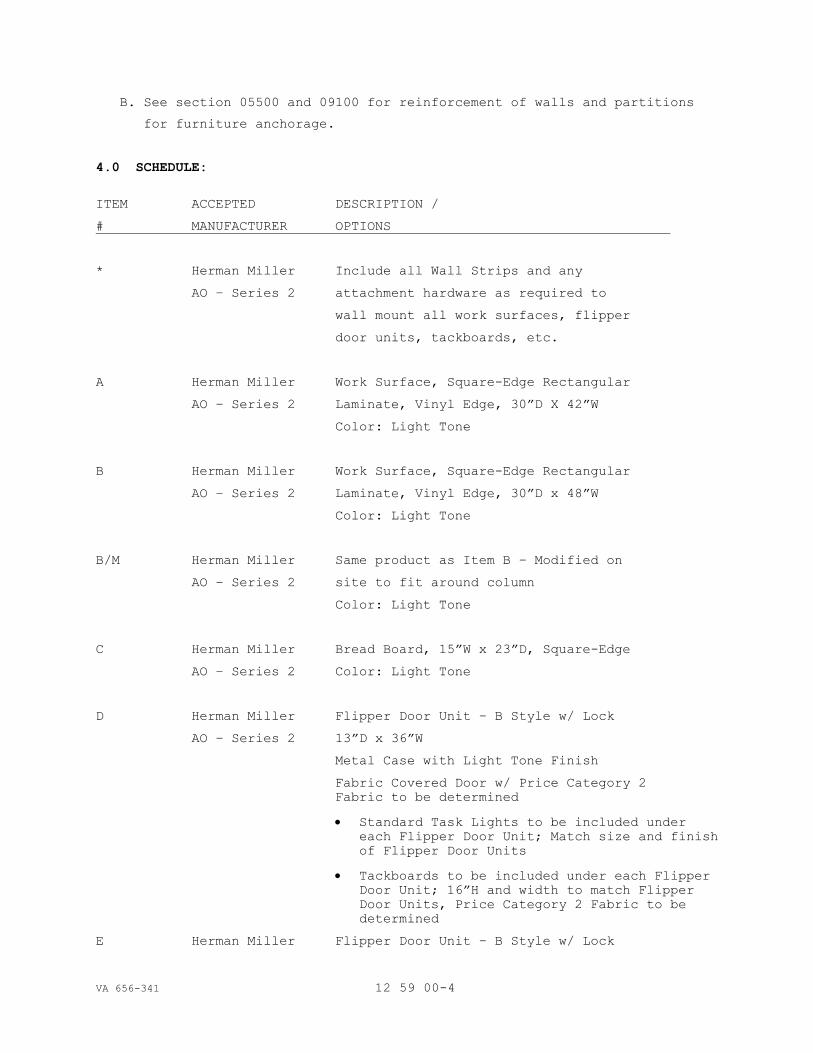
VA 656-341 12 59 00-4
B. See section 05500 and 09100 for reinforcement of walls and partitions
for furniture anchorage.
4.0 SCHEDULE:
ITEM ACCEPTED DESCRIPTION /
# MANUFACTURER OPTIONS
* Herman Miller Include all Wall Strips and any
AO – Series 2 attachment hardware as required to
wall mount all work surfaces, flipper
door units, tackboards, etc.
A Herman Miller Work Surface, Square-Edge Rectangular
AO – Series 2 Laminate, Vinyl Edge, 30”D X 42”W
Color: Light Tone
B Herman Miller Work Surface, Square-Edge Rectangular
AO – Series 2 Laminate, Vinyl Edge, 30”D x 48”W
Color: Light Tone
B/M Herman Miller Same product as Item B – Modified on
AO – Series 2 site to fit around column
Color: Light Tone
C Herman Miller Bread Board, 15”W x 23”D, Square-Edge
AO – Series 2 Color: Light Tone
D Herman Miller Flipper Door Unit – B Style w/ Lock
AO – Series 2 13”D x 36”W
Metal Case with Light Tone Finish
Fabric Covered Door w/ Price Category 2
Fabric to be determined
Standard Task Lights to be included under
each Flipper Door Unit; Match size and finish
of Flipper Door Units
Tackboards to be included under each Flipper
Door Unit; 16”H and width to match Flipper
Door Units, Price Category 2 Fabric to be
determined
E Herman Miller Flipper Door Unit – B Style w/ Lock

VA 656-341 12 59 00-5
AO – Series 2 13”D x 42”W
Metal Case with Light Tone Finish
Fabric Covered Door w/ Price Category 2
Fabric to be determined
ITEM ACCEPTED DESCRIPTION /
# MANUFACTURER OPTIONS
Standard Task Lights to be included under
each Flipper Door Unit; Match size and finish
of Flipper Door Units
Tackboards to be included under each Flipper
Door Unit; 16”H and width to match Flipper
Door Units, Price Category 2 Fabric to be
determined
F Herman Miller Flipper Door Unit – B Style w/ Lock
AO – Series 2 13”D x 48”W
Metal Case with Light Tone Finish
Fabric Covered Door w/ Price Category 2
Fabric to be determined
Standard Task Lights to be included under
each Flipper Door Unit; Match size and finish
of Flipper Door Units
Tackboards to be included under each Flipper
Door Unit; 16”H and width to match Flipper
Door Units, Price Category 2 Fabric to be
determined
G Herman Miller Suspended Lateral File – E-Style w/locks
AO – Series 2 13 ½”H x 15 7/8”D x 42”W
(Include File converters to maximize the
filing space in each lateral file unit.)
Metal Case with Light Tone Finish
Fabric Covered Door w/ Price Category 2
Fabric to be determined
H Herman Miller Pedestal B-Front, Mobile File
AO – Series 2 24”D Box/Box/File
Color: Light Tone surface finish and pull
J Herman Miller Flipper Door Unit – E Style w/ Lock
AO – Series 2 15 ½”H x 14”D x 42”W
Metal Case with Light Tone Finish
Fabric Covered Door w/ Price Category 2
Fabric to be determined

VA 656-341 12 59 00-6
K Herman Miller Flipper Door Unit – E Style w/ Lock
AO – Series 2 15 ½”H x 14”D x 48”W
Metal Case with Light Tone Finish
Fabric Covered Door w/ Price Category 2
Fabric to be determined
ITEM ACCEPTED DESCRIPTION /
# MANUFACTURER OPTIONS
L Herman Miller Flipper Door Unit – (Sim. to Item K)
AO – Series 2 Metal Case with Light Tone Finish
Fabric Covered Door w/ Price Category 2
Fabric to be determined
Standard Task Lights to be included under
each Flipper Door Unit; Match size and finish
of Flipper Door Units
Tackboards to be included under each Flipper
Door Unit; 12”H and width to match Flipper
Door Units, Price Category 2 Fabric to be
determined
M Herman Miller Work Surface, Square-Edge Rectangular
AO – Series 2 Laminate, Vinyl Edge, 24”D x 48”W
Color: Light Tone
N Herman Miller Work Surface, Square-Edge Rectangular
AO – Series 2 Laminate, Vinyl Edge, 24”D x 60”W
Color: Light Tone
O Herman Miller Flipper Door Unit – E Style w/ Lock
AO – Series 2 15 ½”H x 14”D x 60”W
Metal Case with Light Tone Finish
Fabric Covered Door w/ Price Category 2
Fabric to be determined
P Herman Miller Flipper Door Unit – (Sim. to Item O)
AO – Series 2 Metal Case with Light Tone Finish
Fabric Covered Door w/ Price Category 2
Fabric to be determined
Standard Task Lights to be included under
each Flipper Door Unit; Match size and finish
of Flipper Door Units 60" width.
Tackboards to be included under each Flipper
Door Unit; 12”H and width to match Flipper
Door Units, Price Category 2 Fabric to be
determined
Q. Herman Miller Flipper Door Unit – E Style w/ Lock

VA 656-341 12 59 00-7
AO – Series 2 15 ½”H x 14”D x 36”W
Metal Case with Light Tone Finish
Wood Door.
ITEM ACCEPTED DESCRIPTION /
# MANUFACTURER OPTIONS
R. Herman Miller Work Surface, Square Edge Rectangular
AO – Series 2 Laminate, Vinyl edge, 30”d. x 54”
Color: Light Tone
S. Herman Miller Flipper Door Unit – B Style w/ Lock
AO – Series 2 13”D x 54”W
Metal Case with Light Tone Finish
Fabric Covered Door w/ Price Category 2
Fabric to be determined
Standard Task Lights to be included under
each Flipper Door Unit; Match size and finish
of Flipper Door Units
Tackboards to be included under each Flipper
Door Unit; 16”H and width to match Flipper
Door Units, Price Category 2 Fabric to be
determined
T. Herman Miller Modular Panel- Acoustical, fabric covered
AO – Series 2 42”w x 62”tall
Metal Panel trim in light tone finish
Fabric covered panel w/Price Category 2
Fabric to be determined.
U. Herman Miller Sink Base cabinet with single bowl sink
For HealthCare 34 ¾” h. x 24” d. x 48” wide.
Series Casegoods Constructed with integral backsplash and
kickbase and worksurface.
Storage configuration:
Left side: (sink side) door
Right Side: 3 drawers, 8”,12”,12”
Laminate case, doors, drawer fronts and
Worksurface, Color: Light tone.
V. Herman Miller Overhead cabinet with Hinged double doors
For HealthCare (used above “U”)- 34”hx13”dx 48” wide.
Series Casegoods Constructed with integral backsplash and
kickbase and worksurface.

VA 656-341 12 59 00-8
Laminate case, doors, Color: Light tone.
W. Herman Miller Modular Reception Desk
Ethospace Series Size & configuration: See Plan.
Fabric: Price Category 2 – To be determined
Panel Trim Color: To be determined
ITEM ACCEPTED DESCRIPTION /
# MANUFACTURER OPTIONS
Wood Finish: to be determined
Laminate color: To be determined
Rail Tile color: to be determined.
Front Panels:
Base Type: Plain base, receptacles at staff
side only, 2 per workstation.
One voice/data and one power’
Duplex
Frame Tiles: Bottom position 32” h. – Fabric
@ both sides. Top Position: 8” h. – wood at
customer side, rail tile at staff side.
All tiles tackable/acoustic.
Intermediate/Divider panels:
Base Type: Plain base, no receptacles One
Frame Tiles: Bottom position 32” h. – Fabric
@ both sides. Mid Position: 8” h. – fabric at
both sides. Top Position: 8” h. – fabric at
both sides.
All tiles tackable/acoustic.
Transaction Surface: Square edged with under
surface light at staff side. Laminate with
vinyl edge.
Work Surface:
Edge Style: Square
Size: 30” deep except at worksurface height
Transaction surface. This surface to extend
past panels to allow for ADA compliance
Laminate with vinyl edge.
Connectors/End of run: monolithic, non-
segmented - Fabric
END OF SECTION

SECTION 12 9300 BICYCLE RACKS - SITE FURNISHINGS
VA 656-341 12 93 00-1
PART 1 - GENERAL
1.1 DESCRIPTION
A. Section includes information, materials and options for site
furnishings:
1. Bicycle Racks - Hot dip galvanized finish.
2. Concrete pad for bike rack: Section 03 3053
1.2 SUBMITTALS
A. Specification Drawing: Detail drawing of product including overall
dimensions and options.
B. Samples: Various component samples available upon request.
C. Qualifications: Installer must submit evidence of a successful
installation history with comparable materials and designs specified.
1.3 DELIVERY, STORAGE, HANDLING
A. Delivery: Deliver products to site in manufacturer’s original, unopened
containers and packaging. Upon delivery, examine packages immediately
to ensure all products are complete and undamaged.
B. Storage: Store products in a protected, dry area in original undamaged
packaging and containers until ready for installation.
C. Handling: Handle products with sufficient care to prevent any
scratches or damage to the finish.
1.4 WARRANTY
A. Hot Dip Galvanized Finish: Warranted against defects in material or
workmanship for a period of five years.
PART 2 - PRODUCTS
2.1 MANUFACTURER
A. Belson Outdoors, North Aurora, Illinois.
Phone: 800) 323-5664, [email protected]
B. Model:
1. BR-16G, Hot-dip galvanized finish, 9 bike capacity, single sided.
C. Traditional Bike Racks by Parkitbikeracks.com, galvanized finish.
2.2 MATERIALS
A. Tubing: 1 5/8” O.D. diameter main tubes, ¾” O.D. diameter secondary tubing.
B. Portable, for removal in winter.
PART 3 - EXECUTION
3.1 ASSEMBLY
A. Bike racks are shipped fully assembled.
3.2 INSTALLATION

SECTION 12 9300 BICYCLE RACKS - SITE FURNISHINGS
VA 656-341 12 93 00-2
A. Place in area indicated on drawings. Do not
3.3 MAINTENANCE
A. To keep the finish on your products clean we suggest washing them once or
twice monthly with any multi-purpose cleaner. For products with excess
dirt or grime we suggest washing the product with a 2/1 water/bleach
mixture.
3.4 PROTECTION
A. Protect products prior to installation by having them remain in the
manufacturer’s packaging and container.
END OF SECTION
VA 656-341 13 3441 - 1
SECTION 13 3441
WOOD PORTABLE BUILDINGS
PART 1 GENERAL
1.01 SECTION INCLUDES
A. Provide a factory made, wood framed, temporary office building(s).
B. Building Construction Type: IBC Type V-B Wood Frame suitable for Class
B (Business Occupancy) as well as storage and other occupancies as
determined by Code Authorities.
C. The building shall come complete with foundation system and screw
anchors.
D. Portable Buildings shall be installed on site within 90 days of
approved shop drawings, and shall remain on site until Substantial
Completion of the main building project.
1. These buildings will serve as office space for displaced workers
in the area of construction of the main building.
E. The units shall be removed from the site, and the site brought back to
original condition.
1. All foundation systems (ABS Pads and Minuteman screw anchors)
shall be removed.
2. GC shall cover the costs of having the Utilities removed, See
Civil Drwings, and coordinating specification sections.
3. GC shall also cover the costs of having all temporary sidewalks,
etc., removed and bring the site back to original conditions.
1.02 RELATED REQUIREMENTS
A. Wood Portable Building Manufacturer shall assist the General
Contractor by providing the information needed to assist Code
Jurisdictions on obtaining permits necessary for construction and
assure the Owner and Jurisdictions that the project will meet all
requirements for the proposed occupancy.
1.03 PRICE AND PAYMENT PROCEDURES
A. Bid as a subbid to the General Contractor.
1. Provide a stipulated sum cost for providing these units for the
time period previously described, See Specification Section 01 00
00 General Requirements.
2. Note: Unit price for reduction or extension of the use of these
temporary buildings, shall be bid as described in Section 01 00 00
General Requirements, Unit Price No. 1.
1.04 REFERENCE STANDARDS
A. Standard Manufacturer's Wood Frame Building are engineered to meet
State of Minnesota’s Building Code 1361 Commercial Modular Buildings.
Manufacturer shall have a current license issued by HCD for Commercial
Modular Manufacturers.
B. Other Codes that shall be met by manufacturer.
1. CODES: Minnesota’s requirement for Commercial Modular buildings,
which includes, as amended: including Disabled Access, Electrical
Code 2013 edition, Mechanical Code 2013 edition, Plumbing Code

VA 656-341 13 3441 - 2
2013 edition, Energy Code 2013 edition & 28 CFR Part 36, (Federal
American Disability Act, 2010 Standards.
C. ASTM E108 - Standard Test Methods for Fire Tests of Roof Coverings;
2011.
1.05 ADMINISTRATIVE REQUIREMENTS
A. Manufacturer shall furnish a Project Manager to follow the project
from order to delivery.
B. Sequencing: General Contractor shall ensure that utility connections
are achieved in an orderly and correct manner for immediate connection
of factory made for portable wood framed building upon delivery.
1.06 SUBMITTALS
A. Product Data: Wood Portable Building Manufacturer shall provide the
following.
1. Manufacturer: provide electronic submittals (pdf format)
submittals.
2. Color Chips for exterior and interior finishes, describing which
items get which colors. Submittals shall include the finishes
manufacturer's description of the different types of finishes
used.
3. Roofing Manufacturer, profile, gauge, color and fastener system
and perimeter trim. Include gutter, downspouts and splashblocks.
4. Siding Manufacturer, profile, material, thickness, color and
fastener system.
5. Trim: Interior and exterior: material, Profile size and thickness,
fasteners and finish.
6. Underlayment: For Roof, walls and floorings (as may be
applicable).
7. Light Fixtures: Submit manufacturer's catalog information,
including appearance and electrical characteristics.
8. Windows, Doors and Hardware: Provide catalog cuts showing
materials, function and appearance. Owner shall tell manufacturer
which exterior doors are and are not required for ADA access.
9. Interior Ceilings and Walls: substrate (material and thickness)
and finish colors.
10. Structural Systems: State which codes will be met and materials to
be used.
11. Skirting: Insulated skirting shall be provided to withstand
temperature extremes, and site conditions. Skirting shall include
2x treated framing, sheathing, insulation, and metal cladding.
B. Shop Drawings: Standard Floor Plans, Elevations, Details, Foundation
Plan and Standard Anchor Details Drawing furnished by Manufacturer but
all site installation and utility connections are by the General
Contractor or subcontractors. Manufacturer shall work with the GC for
the location of all utility connections and anchor bolt locations as
needed for a successful project. The connections will be installed by
the General Contractor/Subcontractors as required.
C. Shop Drawings: Custom Floor Plans using custom or standard elevations
and details drawings both standard and custom) showing custom features
negotiated with the Wood Portable Buildings manufacturer.
1. Entry Door
a. Installed with hinges, key lock, weather stripping and
threshold as recommended by door manufacturer. Entry doors:
ADA Accessible.

VA 656-341 13 3441 - 3
2. Exterior Door Hardware and Keying: Match Owner’s keying
requirements, such as Stanley/Best Keying System. Provide
removable core cylinders keyed to Owner requirements.
3. Interior Doors: interior doors are to be ADA complaint, keyed to
Owner’s Keying system.
D. Manufacturer's Qualification Statement.
E. Specimen Warranty: (unsigned) Manufacturer's Warranty submit with Shop
Drawings.
F. Certification: Wood Portable Building System shall bear the approval
of the State of Minnesota, and shall provide all life safety
components.
1.07 QUALITY ASSURANCE
A. Manufacturer Qualifications: Company specializing in manufacturing
products specified in this section, with not less than three years of
documented experience and have a state license from state of Minnesota
Department of Labor and Industry, for Commercial Modular Construction.
B. Certification: Wood Portable Building shall bear the approval insignia
of an independent Licensed Structural Engineer, licensed in the state
of Minnesota, certifying the design loads and the temporary foundation
system.
C. Modular office buildings shall be designed by manufacturer and
certified to be in compliance with the following:
1. IBC 2009, unless 2012 IBC is adopted by State.
2. NEC (2009) or Latest year approved by State of MN.
D. Installer Qualifications: Company specializing in the installation of
modular buildings and approved by the modular classroom building
manufacturer.
E. Professional Seal and Signature: Shop drawings and assembly drawings
shall be prepared, stamped and signed by an architect or engineer
licensed in the State of Minnesota.
1.08 TRANSPORTATION, HANDLING, DELIVERY AND STORAGE
A. Coordinate schedule of product delivery to designated prepared areas
in order to minimize site storage time and potential damage to stored
materials.
B. Transport and handle products in accordance with the manufacturer's
instructions.
C. Store materials in accordance with manufacturer's instructions and do
not allow materials to become wet, stained or dirty.
D. Arrange for disposal or return , or recycling of packing materials
such as wood shipping walls, etc.
1.09 PROJECT CONDITIONS
A. Weather Limitations: Proceed with installation only when weather
conditions permit safe installation to be performed according to
manufacturer's written instructions and warranty requirements.
B. Field Measurements: Verify building systems foundations by field
measurements prior to the assembly and installation of the modular
classroom buildings.

VA 656-341 13 3441 - 4
1.10 WARRANTY
A. Manufacturer's Warranty (and the industry standard) is for the length
of use of the units.
B. Manufacturer shall correct defective Work during the entire occupancy
period, starting from the date of arrival on site. This is a material
and workmanship warranty for normal use. Abuse will not be included in
the Warranty.
PART 2 PRODUCTS
2.01 MANUFACTURERS
A. Satellite Shelters, Plymouth MN.
(763) 551-7285
B. ModSpace Modular Buildings, 847-622-7805
C. Markline Industries, Bristol, IN
574-825-5851
D. Whitely Mfg., South Whitley, IN
260-723-5131
E. C & B Custom Modular, Bristol, IN
800-305-1598
2.02 INSTALLATION
A. Site Paving/ sidewalks, etc. (by General Contractor):
1. Concrete: 3,000 psi (20.7 MPa) 28 day concrete, 4 inches (100 mm)
thick portland cement, finish as directed by the Owner.
2. Parking Area Pavement: 4,000 psi (27.6 MPa) 28 day concrete, 5
inches (125 mm) thick, 6/6 - 6 x 6 inch mesh reinforcement, wood
float finish.
2.03 PRE-FAB SYSTEM
A. Basis of Design Manufacturer: Satellite Shelter’s Modular buildings.
Building Corporation. Model: Deluxe Multi Unit Office Building.
1. Modular complex may be new product or a refurbished trailer
sequence.
2. If reused and refurbished, then the units shall be not older than
2009, and are subject to inspection by the VA.
3. Plans of the spaces may deviate from what is indicated on plan,
but must be approved by A/E and VA during the Bidding period.
4. Performance of the buildings shall be adequate to accommodate
Minnesota climatic conditions.
B. BID SUBMISSION: Specifics for the Modular units shall be submitted
with the bidding documents by the General Contractors, so the Modular
supplier shall provide all necessary building specifications, photos,
etc. for evaluation at the time of the bid.
C. Description: Multi Unit - Wood Framed Buildings System. Note the
components listed below are typically used for this system.
1. Color: To be selected by Design Professional from standard color
range of wood portable building manufacturer. Unique colors must
be discussed with manufacturer prior to price agreement.
VA 656-341 13 3441 - 5
D. Design Criteria: (Site Dependent)
1. Comply with the Code requirements stated in PART 1 of this
specification.
2. Floor: 50 PSF Live Load; 100 PSF in Corridors, deck and steps
Wind: Meet or exceed the loading requirements for Minnesota or 90
mph.
3. Roof: Snow load 35 PSF.
Dead Load: weight of building materials components plus
collateral load of 5 psf.
4. Anchoring: must withstand 90 mph wind load or as required by
state of Minnesota Code to meet or exceed NCSBC/ANSI A225.1
requirements.
E. Wood Construction Requirements:
1. Wood Construction Materials: Comply with the following standards.
a. PS1 - Construction & Industry Plywood.
b. PS 20 - American Softwood Lumber Standards.
c. FSC – Forrest Stewartship Council.
2. Wood Treatment where called for by in the IBC and other applicable
Codes:
a. Treated Lumber & Plywood: Comply with Requirements of AMPA U-1
- Use Category System for Wood Treatment determined by use
categories, expected service conditions, and specific
applications.
1) Fire-Retardant Treated Wood, where required: Mark each
piece of wood with producer's stamp indicating compliance
with specified requirements.
F. Floor Construction:
1. 2 each 4x6 skids, #2 Douglas Fir or SYP pressure treated for
ground contact. 2x6 #2 Douglas Fir floor joists, 16” OC. ¾” Sturd-
I-Floor plywood decking, T&G, 5 ply. Floor shall be insulated full
depth, R-19 or greater insulation
G. Wall Construction:
1. 2x4 standard & better, SPF or Doug Fir studs, 16” OC with 2x4
single bottom plate and double top plate. Approved “house wrap”
water resistive barrier.
H. Exterior Finish:
1. 5/8” premium Pine T-111 (303-6) siding with 100% acrylic latex low
VOC paint, semi gloss.
OR
2. 3/8” OSB rated sheathing with 26 gauge ribbed steel siding, HR-36
or Reverse Box Rib, by AEP Span, with cool DuraTech nt finish
paint coating system. Two coat, 1 mil thick paint system, composed
of a low bake universal primer and a silicone-polyester based
topcoat, applied over Zincalume zinc-aluminum coaste steel.
Fasteners as recommended by AEP, self tapping, with bonded
neoprene, sealing washer.
3. Building and window trim furnished and installed by Manufacturer.
However, exterior bottom trim will not be installed and the Owner
will need to do this after that anchor bolts are installed and
accepted by local code officials as may be required. Owner to
install the exterior trim when allowed by the local building
official. Trim pieces shipped loose for site installation by
Owner.
I. Roof Construction:

VA 656-341 13 3441 - 6
1. 2x6, #2 Douglas Fir rafters or Select Structural SPF framing, 24”
OC. Provide 1/2" :12 minimum slope achieved with 2x tapered
sleeper rafter. Deck: 1/2” 3ply CD-X plywood decking (APA Rated
“sheathing). ¼” gypsum drywall non-combustible deck. 15# ASTM
rated roofing felt 0.024” single piece rolled aluminum roofing,
painted white. Rolled roofing shall be fastened 4” OC at edges and
16” OC in two field rows with #14 x 1inch HWH tapping screws with
bonded sealing washers. All field screws shall be further sealed
with one part urethane caulking.
a. Roofing Membrane Flammability: Class A per ASTM E-108.
b. Aluminum roofing shall be 0.024 inches thick and painted white
and rated for 130 miles per hour hold down ability.
c. NOTE: In lieu of Aluminum roofing, provide “adhered” TPO or
adhered EPDM Roofing membrane.
2. Listed framing is from one of the manufacture’s listed.
Other framing systems, standard to the other manufacturer’s are
approved, but subject to meeting loading requirements previously
listed.
J. Exterior Doors:
1. Manufacturer and Style: Active Supply RLC7, 3’x6’8” 22Ga HM door
with welded aluminum frame. 4”x4” NRP ball bearing hinges,
handicap threshold, mechanically attached full weather stripping.
18”x18” clear tempered glass door lite. Door skin shall be vinyl
faced interior and exterior. Hardware shall be Stanley/Best’s 9KC3
series, (entry function), 26D finish.
a. Hardware: Meet Owner’s Stanley/Best removable core Keying
System.
b. Optional sizes: 2’6”x6’8” to 6’x6’8” double doors
c. Provide panic hardware and closers for all exterior doors, in
the main egress corridors.
1. Panic Hardware: Stanley/Precisions Apex 2000 series.
2. Closers: Stanley D-3500 series Closers
d. Provide ball bearing hinges.
2. Optional Door Construction:
a. Galvanized steel frame and door. 16 Gauge welded frame with 18G
foam insulated door, painted to match siding. 4.5”x4.5” NRP
hinges. Sizes2’6”x7’0” to 6’0”x7’0”.
K. Interior Doors:
1. Frame: Timely frame, Browntone.
2. Door: Masonite’s Legacy “Oak”, 3' x 6'-8" x 1'-3/8", solid core
with two 3-1/2" hinges.
3. Prep: Single prep 2-3/4" BS.
4. Hardware: Stanley/Best lever 7KC3 series, grade 2 locksets, and
keyed to Owners keying system, Provide in 626 finish.
a. Office doors, storage and IT rooms shall be lockable.
5. If closers are required due to fire rating: Provide Stanley’s D-
1610 series closers, or equivalent.
L. Windows:
1. Vinyl Framed windows, complying with the following:
a. Type horizontal sliding or vertically single hung with insect
screens. Locking: Single latch.
Glazing: double insulated, low “E”. Tempered where required
by IBC.

VA 656-341 13 3441 - 7
b. Casing: 2 ¼” prefinished ranch casing.
2. Equal to Vector Windows, Fergus Falls, Minnesota.
a. Advantage(Builder) Series vinyl windows.
M. Insulation:
1. Unfaced fiberglass batt insulation. R-19 floor, R-13 walls, R-21
ceiling. Or as required by Energy Code for site’s climate zone.
a. Option: continuous rigid foam insulation for lower U-values
(greater energy efficiency).
N. Interior Finish: Low VOC paint as required by law.
1. Default Walls: Prefinished Vinyl wrapped gypsum wall board with
edges wrapped with vinyl. OR
a. Wood paneling: 1/4" Minnesota Birch with a rated Flame
Spread Rating of 200 or less.
2. Gypsum Wall and ceiling board 5/8 inch at walls and 1/2 inch at
ceilings.
3. Interior Wood Trim: Window trim, extension jambs, and wall base
trim: Prefinished trim to match the Legacy “Oak”.
4. Flooring: Armstrong 12 x 12 x1/8 Excelon Series, color "sand drift
white".
2.04 ELECTRICAL
A. Route all electrical conduit to appropriate panelboard to facilitate
single point connection to the panelboard by othersB. Provide
typical convenience outlets (minimum 4 duplex per room) in all rooms.
Provide additional convenience outlets in medium conference rooms,
break rooms, and other large spaces.
1. Outlets and receptacles: NEMA WD 1 general use.
C. Provide typical low voltage rough-ins in all rooms (minimum of 1 per
room). Provide additional data locations in conference rooms, break
rooms, and other spaces.
D. Provide raceways and junction boxes next for low voltage data
connection. The data locations should be adjacent a convenience
outlet. Low voltage data wiring and terminations by others.
1. All electrical wiring shall be in type MC metallic sheathed
cable. Copper conductors, sized per circuit loads and NEC. #14
AWG minimum.
2. Load Centers: Flush mounted, lockable 120/208 VAC, 60 Hz, single
phase with circuit breakers sized as required by code. The load
centers shall be by the same manufacturer as the manufacturer of
the distribution panel to serve the load centers. The circuit
breakers in the load centers must series rate (fault current
interrupting rating) with upstream circuit breakers in the
distribution panel. The distribution panel will be provided by
others. Verify with the project COR.
E. Office cubicles shall be power via powered raceways. Connection
points should be at the exterior walls and columns
F. In addition to the outlets specified above, provide the following:
1. Bidders shall include an allowance of (30) typical 20A outlets to
be placed by Contractor upon finalization of trailer design. The
intent of these outlets is to power miscellaneous equipment.
2. Bidders shall include an allowance of (10) 20A dedicated outlets
to be placed by Contractor upon finalization of trailer layout.

VA 656-341 13 3441 - 8
The intent of these outlets is to power items such as coffee
makers, microwaves, etc.
3. Bidders shall include an allowance of (20) low voltage raceways
to be placed by Contractor upon finalization of trailer layout.
The intent of these raceways is to provide a path for data
locations and specialty equipment such as TV displays.
G. Provide dedicated circuits for heat trace protection as required to
prevent the plumbing systems from freezing.
H. Provide 2x4 recessed light fixtures with lenses.
1. Lithonia Light Fixtures. LB232, 4’- 2 bulb fixture with T8 bulbs
and electronic multi-voltage ballasts. Surface mounted with
prismatic diffusers. Quantities per Energy Code, at .9 watts/SF
for office use. Higher lighting densities as permitted by Energy
Code under task lighting conditions.
I. Provide exit lighting as required by code.
J. Fire Alarm: Furnish, install and test, and comply with code.
1. Include all devices and wiring.
K. Exterior Lighting: Provide weather proof LED fixtures, near each
exterior door, minimum 1000 lumens, with switch and photocell.
2.05 MECHANICAL AND PLUMBING
A. Cooling and heating units: Systems shall be designed to maintain 70
degrees F. in the winter and 75 degrees F. in summer.
Provide through the wall packaged terminal air conditioner/heat pump
units for each pod as per CEC approved appliance list. Units shall be
American Made. Unit shall be sized for design conditions of 94/75
degrees F DB/WB during summer and -30 degree F during winter.
Ventilation rate for units shall be based on ASHRAE Standard 62.1.
Bolt chassis to wall sleeve to prevent displacement of chassis in
transit and for security.
1. Units shall be controlled by a standalone wall thermostat.
2. Ductwork and diffusers: Provide and install ductwork from unit to
each room as required except IT Rooms, do not provide supply air
to an IT Room. Do not install ductwork over an IT Room. Each
room shall have a supply and return air register located in the
ceiling, air flow rates shall be 1 cfm/SF in office/exam rooms
and 0.8 cfm/SF in corridors. Ductwork and fittings shall be
constructed and supported in accordance with SMACNA HVAC Duct
Construction Standards – Metal and Flexible, 1995 Edition with
1997 Addendum. All supply air ductwork shall be insulated with
2” fiberglass insulation. All ductwork shall be built to 2”
pressure class.
3. Provide fire and smoke dampers as required by Code. Smoke damper
leakage shall be Class II or better.
4. Provide a standalone wall mounted thermostat for each unit.
B. Provide an exhaust fan for each restroom. Exhaust fans shall be sized
for 70 cfm/fixture. Exhaust fans shall be ducted to the exterior
of the building, a minimum of 10 feet away from any fresh air
intake or opening to the building. Exhaust fan shall be
controlled by a wall switch.
C. IT Rooms shall have an exhaust fan provided and installed by the
mechanical contractor. Exhaust fan shall be controlled by a wall

VA 656-341 13 3441 - 9
thermostat. A transfer air duct shall be provided in the wall as
shown on floor plans.
D. Fire Protection: Fire Protection Contractor shall be required to
design, install and test a complete fire protection system in
accordance with NFPA 13. Sprinkler system shall be installed by
the fire protection contractor once modular building is set on-
site. FP contractor shall coordinate pipe routing with Modular
Building Company prior to installation.
D. Plumbing: Restrooms shall meet ADA requirements.
1. Provide and install all plumbing fixtures including toilets,
sinks, urinals, water coolers, floor drains, mop sinks, etc. as
shown on the attached drawings.
2. Provide all plumbing equipment required for a complete and
working system including hot water heater, valves, piping,
backflow preventer, insulation, etc. Hot water recirculation
line and pump shall be required if hot water line exceeds 30 feet
from hot water source. Provide one full size vent through roof as
per plumbing code.
3. Supply piping: Type “L” copper. Pex piping may be allowed if
part of an existing building and is approved by the owner.
4. Sanitary and waste piping: Schedule 40 PVC below grade and cast
iron above grade. Schedule 40 PVC may be allowed above grade if
part of an existing building and is approved by owner and not
installed in a return air plenum.
5. Restrooms shall have proper exhaust fans, meet requirements
stated above.
6. Toilet Fixtures: American Standard Floor mounted, Tank type,
vitreous china, Siphon jet, fully glazed trapway, elongated bowl,
china bolt caps, with white solid plastic, check hinge, self-
sustaining, open front seat less cover.
a. Furnish stainless steel grab bars for accessible fixtures.
7. Water Heaters: Electric, quantity and size as required. Hot
water shall be 130 degree F up to each fixture. Mixing valve
shall be provided at each fixture to control discharge water
temperature.
8. Sinks in restrooms: Wall mounted or drop in vitreous china sinks
with manual single lever American Standard faucet.
9. Sinks in breakroom: Stainless steel drop-in single bowl sink
with American Standard gooseneck faucet and wrist blade handles.
10. Mop sink: 24”x24” fiberglass basin with wall mounted mop sink
faucets.
11. Water Coolers: Elkay dual height water cooler.
12. Floor drain: Provide a floor drain in the mechanical room, shall
be round with brushed aluminum finish.
2.06 FOUNDATION DESIGN
A. Manufacturer shall provide a suggested foundation plan to include wind
uplift calculations, pad footing locations/sizes and all associated
loads.

VA 656-341 13 3441 - 10
1. Final engineered drawings shall be designed/stamped by a Minnesota
licensed engineer.
2. The foundation is meant for temporary structures only, and shall
be designed in accordance with ANSI A225.1.
3. Foundation design shall be based upon 1000PSF soils.
B. Pad Footings: Equal to Oliver Technologies ABS pads, of varying sizes
as required to distribute building loads. Onto the pads, dry stack
CMU concrete block piers. Block shall be normal weight meeting ASTM C-
90. Blocking shall be dry stacked, double 8x8x 16” interlocked with
layers below.
C. Tie Down Straps/Soil Anchors: Minute Man EZ-Anchor Stabilizing
devices, (800-438-7277)complete with locking frame clamp MMA-33,
Minute man strap and stabilizing clips, sized and spacings to meet
loading requirements.
1. Tie down straps shall be 1 ¼” x .035”, type 1, finish B, grade 1
zinc coated steel strapping. Straps must be certified to conform
to ASTM D3952. All tie down straps and connecting hardware to
have a minimum working capacity of 3150 lbs.
2.07 DECKS, STEPS, RAMPS
A. Decks and Steps: Furnish and install aluminum deck, steps, ramps and
railings.
1. All decks, steps, ramps and adjoining doorways must meet NFPA –
Life Safety and ADA.
2. All landings, stair treads, stringers and risers shall be
designed for a minimum uniform live load of 100 PSF and a
concentrated vertical load of 300 PSF or as required by code.
3. Handrails and guardrails shall be designed to resist a
concentrated load of 200 PSF applied at any point and in any
direction or as required by code.
4. Guardrails shall be designed to resist a load of 50 pounds per LF
applied horizontally and a simultaneous load of 100 pounds per LF
applied vertically downward at the top of the guardrail or as
required by code.
5. Inside handrails shall be continuous.
6. All guardrails shall form a protective barrier of a minimum 42"
height and must include balusters that prevent the passage of a
4-inch-diameter sphere, where any portion of the sphere in within
4 inches off the floor or ground surface.
7. The upper handrail shall be 1-1/2" pipe placed 34" to 38" above
the walking surface with a smooth and continuous gripping
surface. The clear space between the handrail and the wall or
guardrail shall be 2-1/4".
8. Ends of handrails shall be either rounded or returned smoothly to
floor, wall or post.
9. Handrails shall not rotate within their fittings.
10. Construct with anti-slip surfaces.
11. Provide 12" diameter concrete footings to a depth of 72".
12. Provide concrete pad over 2" gravel base at the bottom of the
step assembly; Size: Width of step x 6'-0"long.

VA 656-341 13 3441 - 11
PART 3 EXECUTION
3.01 INSTALLERS
A. General Contractor shall furnish a crane or fork-lift intended for the
weight of the Portable Building. Manufacturer will assist the GC by
providing correct minimum lifting capacity and by locating lift points
and recommended lifting capacities.
B. GC will be responsible for having all utility connections in their
correct place before portable building is shipped by the manufacturer.
3.02 EXAMINATION
A. Verification of Conditions: Verify that portable building is complete
and ready for occupancy. Code officials may want to see the anchor
bolts before the bottom trim is installed.
3.03 PREPARATION
A. Protection of In-Place Conditions: Owner's full responsibility.
B. Surface Preparation: Manufacture shall prepare modular building at
factory for over the highway transportation.
C. Bottom Trim: Will be finished and furnished by manufacturer (and
depending on the anchoring system) cut to size and installed by Owner
after anchor bolts are secured.
3.04 DELIVERY AND INSTALLATION
A. Delivery: The Contractor shall deliver the modular Office buildings
to the job site. Contractor is responsible for providing a suitable
storage and staging area, without obstructions, adjacent to the job
site for the Contractor to deliver and temporarily store all modular
buildings and other construction materials prior to their
installation.
1. Space is limited and delivery should be coordinated with the
General Contractor to correspond with installation.
B. All Costs associated with this temporary building shall be the
responsibility of the General Contractor.
C. Set-up: Installer to block, level, seal, skirt and anchor each
modular unit in accordance with the manufacturer's installation
instructions.
1. Contractor will install all anchor ABS foundation system with tie
downs to meet the local wind and seismic code requirements.
2. Install each item in accordance with component manufacturer's
instructions.
D. Skirting: Contractor to install the modular building at the finished
floor height elevation as indicated.
1. Provide 2" x 4", pressure-treated framing with vertical studs at
a minimum of 24" on center.
2. Install a minimum of (12) thermally activated vents around the
building perimeter or as required by code.
3. Provide skirting trim and accessories for complete installation.
3.05 ELECTRICAL
A. THE MODULAR BUILDING SUPPLIER MUST PREWIRE AND MAKE ALL POWER
CONNECTIONS INSIDE THE UNITS BACK TO THE LOAD CENTERS. THE ELECTRICAL
CONTRACTOR WILL MAKE THE CONNECTIONS TO THE INDIVIDUAL LOAD CENTERS.

VA 656-341 13 3441 - 12
B. By Others – Primary Electrical Contractor:
1.Site Electrical: Contractor shall provide all labor and materials
and perform all necessary utility trenching, backfilling and patching
to complete exterior electrical connections from the load side of the
electrical service transformer to the modular building.
2.Fire Alarm System: Contractor to extend existing fire alarm system.
Furnish, install, test and comply with code. Include all system
devices and wiring.
3. Low Voltage: Contractor shall provide low voltage voice and data
system wiring as indicated on the attached drawings. Telephone,
computers and other equipment to be provided by the Owner under
separate contract.
3.06 PLUMBING AND MECHANICAL ( By Others - primary Mechanical contractor)
A. Site Plumbing: Mechanical Contractor to furnish all labor and
materials and perform all necessary utility trenching, backfilling and
patching to complete all exterior PVC sanitary waste (DWV) piping,
manifolding and connections as shown on the attached drawings. Modular
building Contractor shall provide and install all waste piping within
the building. Mechanical Contractor to furnish all labor and
materials to install a new 2” domestic water service and water meter
to the modular building. Modular Building Contractor shall provide
and install all domestic water piping thereafter. Mechanical
Contractor to flush all exterior copper water supply connections at
locations shown on the attached drawing. Mechanical Contractor to
furnish and install a new 4” fire protection service into new building
from 5’ outside of building. Fire Protection Contractor shall provide
and install fire riser and a complete fire protection system. After
temporary building is no longer required, Mechanical Contractor shall
disconnect and remove all piping, hangers, insulation and associated
plumbing materials located in the crawl space and below grade. All
piping and materials located within the modular building shall remain.
B. Mechanical Contractor shall start up, test and adjust all plumbing
fixtures. Provide heat tracing and piping insulation for the copper
supply connections below the modular building.
C. Modular building contractor to install and flash all roof mounted
equipment, exhaust fan outlets and waste vents.
D. Modular building contractor to provide start-up and final ductwork
connections required for heating and cooling equipment.
E. While modular building is being occupied by the VA, Mechanical
Contractor shall be responsible for the maintenance of all Mechanical
Equipment. Duration of occupancy may vary, see above for guidelines.
3.07 GENERAL CONDITIONS
A. Site Supervision: The Contractor shall provide continuous supervision
at the Project by a competent, experienced Superintendent when any
Work is being performed.
1. The Superintendent employed shall be subject to the Owner's
approval. Contractor shall submit for review a written summary

VA 656-341 13 3441 - 13
of the Superintendent's experience and qualifications upon
request.
2. The Superintendent will be responsible for all scheduling and
coordination of trades with the Owner as may be required.
3. The Superintendent will assure the timely completion of the
complete project punchlist.
B. Weekly status reports will be provided during the construction phase
of the project.
C. Cutting and Patching: All cutting and patching shall be completed by
the subcontractor who did the cutting except as otherwise directed by
the Contractor using mechanics accomplished in the kind of work being
patched. Repairing and refinishing of all disturbed surfaces shall
use materials and workmanship conforming to that of the original work.
D. Site Restoration: Installer shall restore to the satisfaction of the
authority having jurisdiction, all damage to any streets, roadways,
pavements outside the perimeter of the modular buildings and curbs as
a result of all Work.
E. Grading: Contractor to complete final grading to restore the site
after the completion of all Work.
F. Cleaning: Installer to meet all applicable general condition
requirements as defined in the Contract Documents.
1. Provide construction dumpsters and portable toilets.
2. Clean the site of all waste and rubbish attributable to the Work.
3. Broom clean to the reasonable satisfaction of the Architect and
Owner.
3.08 CLOSEOUT ACTIVITIES
A. Owner's Representative shall inspect the "like new" condition of the
structure and components. Clean, fix, and re-finish as necessary for
the Owner's occupancy.
1. If problems arise, inform manufacturer by phone and follow up as
required.
B. Exterior (roof, walls and windows) shall be washed, as necessary (in
the field) and cleaned free of dirt.
1. If problems arise, inform manufacturer by phone and follow up as
required.
3.09 PROTECTION
A. Protect installed wood portable building from subsequent construction
operations.
END OF SECTION

VA 656-341 14 24 00-1
SECTION 14 24 00
HYDRAULIC ELEVATORS
PART 1 – GENERAL
1.1 DESCRIPTION
A. This section specifies the engineering, furnishing, and installation of
the complete ready for operation, electro-hydraulic elevator system as
described herein and as indicated on the contract drawings.
B. Passenger Elevators, shall be a “holed” oil hydraulic type with
microprocessor based control, single car selective collective automatic
operation, with car leveling device, signal system, power operated
two-speed side opening car and hoistway doors. Elevator shall have
Class “A” loading.
1.2 RELATED WORK
A. Section 01 33 23 SUBMITTAL PROCEDURES; (FAR 52.236-21) and, SPECIAL
NOTES (VAAR 852.236-91), in GENERAL CONDITIONS.
B. Section 07 84 00, FIRESTOPPING: Sealing around penetrations to maintain
the integrity of fire-rated construction.
C. SECTION 09 06 00, SCHEDULE FOR FINISHES: As a master format for
construction projects, to identify interior and exterior material
finishes for type, texture, patterns, color and placement.
D. Electrical service through fused safety switch, as well as
hoistway, machine room, pit outlets and lighting are by Division 26.
E. Hoist beam and Pit Ladder: Section 05 50 00 MISC. METALS.
F. Rubber Flooring in Elevator Cab: SECTION 09 6500, RESILIENT FLOORING &
BASE.
G. Pit Drain, piping and accessories: Division 22/23 Mechanical.
1.3 QUALITY CONTROL:
A. Qualifications:
1. Approval by the Contracting Officer Representative is required of
products or services of proposed manufacturer, suppliers, and
installers and will be contingent upon submission by Contractor of a
certificate stating the following:
a. Manufacturer is currently and regularly engaged in manufacturing
of elevator equipment as one of his principal products.
b. Installer has technical qualifications of at least three years of
successful experience, trained supervisory and installation

VA 656-341 14 24 00-2
personnel, and facilities to install elevator equipment specified
herein.
c. Contractor shall submit a list of two or more prior hospital
installations where all the elevator equipment the contractor
proposes to furnish on this project has performed satisfactorily
together under conditions of normal use. The list shall include
projects that have been in operation for a period of not less
than two years preceding the date of these specifications;
include the name and addresses of the Medical Center and the
Medical Center Administrators.
2. All hydraulic elevators shall be the product of the same
manufacturer.
3. Approval of manufacturer's equipment will be contingent upon his
having a permanent and satisfactory maintenance service branch which
shall render services within two hours of receipt of notification.
Manufacturer shall submit the names and address of his authorized
branch or service department which will render service to this
installation, together with certification that the quantity and
quality of replacement parts stock on hand is sufficient to warranty
continued operation of the elevator installation.
4. Approval will not be given to any Elevator Contractor and/or
manufacturer who have established on prior projects, either
Government, municipal, or commercial, a record for unsatisfactory
elevator installations, or have repeatedly failed to complete
contracts awarded to him within the contract time, or has not the
requisite record of satisfactorily performing elevator installations
of similar type and magnitude.
1.4 APPLICABLE PUBLICATIONS
A. The publications listed below form a part of this specification.
Elevator installation shall meet the requirements of the latest
editions published and adopted by the United States Department of
Veterans Affairs on the date contract is signed.
B. International Building Code (IBC)
C. Federal Specifications (Fed. Spec.):
J-C-30B(l)..............Cable and Wire, Electrical (Power, Fixed
Installation)
J-C-580B(l).............Cord, Electrical and Wire, Electrical (O to
600-Volt Service)

VA 656-341 14 24 00-3
W-C-596/12F.............Connector, Receptacle, Electrical, General
Purpose, Duplex, Hospital Grade Grounding, 2
Pole, 3 Wire, 15 Amperes, 125 Volts, 50/60
Hertz
W-F-406D................Fittings for Cable, Power, Electrical and
Conduit, Metal Flexible
W-F-408E................Fittings for Conduit, Metal, Rigid (Thick-Wall
and Thin-Wall (EMT) Type)
W-S-610E................Splice Connectors
FF-S-325................Shield, Expansion; Nail Expansion; and Nail,
Drive
QQ-S-766D...............Steel, Stainless and Heat Resisting, Alloys,
Plate, Sheet and Strip
L-P-508H................Plastic Sheet, Laminated, Decorative and Non-
Decorative (Style "D" Type I Class 25 Plastic
Laminate)
TT-E-489................Enamel, Alkyd, Gloss, Low Voc Content
WW-C-566C...............Conduit, Metal, Flexible
D. American Society for Testing and Materials (ASTM):
A1008/A1008M-02.........Steel, Sheet, Cold Rolled, Carbon, Structural,
High-Strength Low-Alloy and High Strength Low-
Alloy with Improved Formation
C612-00a................Mineral Fiber Block and Board Thermal
Insulation
E1042-92(1997)e1........Acoustically Absorptive Materials Applied by
Trowel or Spray
E. Manufacturer's Standardization Society of the Valve and Fittings
Industry (MSS):
SP-58-1993..............Pipe Hangers and Supports
F. American Society of Mechanical Engineers (ASME):
A17.1-2004..............Safety Code for Elevators and Escalators
A17.2-2004..............Inspectors Manual for Elevators and Escalators
F. National Fire Protection Association (NFPA):
70 - Current code. National Electric Code
252-2003................Fire Test of Door Assemblies
G. Society of Automotive Engineers, Inc. (SAE)
J517-91..................Hydraulic Hose, Standard; April 1991
H. Gages:

VA 656-341 14 24 00-4
For Sheet and Plate: U.S. Standard (USS)
For Wires: American Wire Gauge (AWG)
I. American Welding Society (AWS):
D1.1-2002...............Structured Welding Code - Steel
J. National Electrical Manufacturers' Association (NEMA):
LD3-2000................High-Pressure Decorative Laminates
K. Underwriter's Laboratories (UL):
486A-97 Ninth Edition...Wire Connectors and Soldering Lugs for Use with
Copper Conductors
797-83..................High Safety Electrical Metallic Tubing
D. American Society of Mechanical Engineers (ASME):
A17.1...................Safety Code for Elevators and Escalators
A17.2...................Inspectors Manual for Electric Elevators and
Escalators
E. National Fire Protection Association:
NFPA 13..........Standard for the Installation of Sprinkler Systems
NFPA 70..........National Electrical Code (NEC)
NFPA 72..........National Fire Alarm and Signaling Code
NFPA 101.........Life Safety Code
NFPA 252.........Fire Test of Door Assemblies
F. American Society for Testing and Materials (ASTM):
A1008/A1008M-09.........Steel, Sheet, Cold Rolled, Carbon, Structural,
High-Strength Low-Alloy and High Strength Low-
Alloy with Improved Farability
E1042-02................Acoustically Absorptive Materials Applied by
Trowel or Spray
G. Manufacturer's Standardization Society of the Valve and Fittings
Industry (MSS):
SP-58...................Pipe Hangers and Supports
H. Society of Automotive Engineers, Inc. (SAE)
J517-91..................Hydraulic Hose, Standard
I. Gages:
For Sheet and Plate: U.S. Standard (USS)
For Wires: American Wire Gauge (AWG)
J. American Welding Society (AWS):
D1.1....................Structured Welding Code – Steel
K. National Electrical Manufacturers Association (NEMA):
LD-3....................High-Pressure Decorative Laminates
VA 656-341 14 24 00-5
L. Underwriter's Laboratories (UL):
486A....................Safety Wire Connectors for Copper Conductors
797.....................Safety Electrical Metallic Tubing
M. Institute of Electrical and Electronic Engineers (IEEE)
N. Regulatory Standards:
Uniform Federal Accessibility Standards
Americans with Disabilities Act
1.5 SUBMITTALS
A. Submit in accordance with Specification Section 01 33 23, SUBMITTAL
PROCEDURES.
B. Before execution of work, furnish information to evidence full
compliance with contract requirements for proposed items. Such
information shall include, as required: Manufacturer's Name, Trade
Names, Model or Catalog Number, Nameplate Data (size, capacity, and
rating) and corresponding specification reference (Federal or project
specification number and paragraph). All submitted drawings and related
elevator material shall be forwarded to the Contracting Officer
Representative .
C. Shop Drawings:
1. Complete scaled and dimensioned layout in plan and section view
showing the arrangement of equipment and all details of each and
every elevator unit specified including:
a. Complete layout showing location of storage tank/pump assembly,
controller, piping layout, outside diameter of cylinder/plunger
assemblies, size of car platform, car frame members, and support
assembly.
b. Car, guide rails, brackets, buffers, and other components located
in hoistway.
c. Rail bracket spacing and maximum vertical forces on guide rails
in accordance with ASME A17.1 Section 2.23
d. Reactions at points of supports and buffer impact loads.
e. Weights of principal parts.
f. Top and bottom clearances and over travel of the car.
g. Location of shunt trip circuit breaker, switchboard panel, light
switch, and feeder extension points in the machine room.
2. Drawings of hoistway entrances and doors showing details of
construction and method of fastening to the structural members of
the building.

VA 656-341 14 24 00-6
a. Sill details including sill support.
D. Samples:
1. One each of stainless steel plate, 75 mm x 125 mm (3 in. x 5 in.).
2. One each of baked enamel plate, 75 mm x 125 mm (3 in. x 5 in.).
3. One each car and hoistway Braille plate sample.
4 One each Protection pad, 3” x 5”.
5. No other samples of materials specified shall be submitted unless
specifically requested after submission of manufacturer's name. If
additional samples are furnished pursuant to request, adjustment in
contract price and time will be made as provided in Section 00 72
00, GENERAL CONDITIONS.
E. Materials Data: Submit the name of manufacturer and type or style
designation of the following for approval:
1. Controllers.
2. Size of hydraulic power unit.
3. H.P. and R.P.M. of hydraulic power unit motor.
4. Electric control valves, including capacity range.
5. Electric power and power door operator.
6. Hoistway door interlocks and electric contacts.
7. Stroke, certified maximum and minimum loads and maximum striking
speed of car buffers.
8. HP and CFM rating on cab ventilation unit.
F. Complete construction drawings of elevator car enclosure, showing
dimensioned details of construction, fastenings to platform, car
lighting, ventilation, ceiling framing, top exits, and location of car
equipment.
G. Complete dimensioned detail of vibration isolating foundations for
storage tank/pump assembly.
H. Dimensioned drawings showing details of:
1. All signal and operating fixtures.
2. Car slide guides. Show dimension drawing of guide shoes.
3. Hoistway door tracks, hangers, and sills.
4. Door operator, infrared curtain units.
I. Cuts or drawings showing details of controllers and supervisory panels.
J. Furnish certificates as required under: Paragraph "QUALIFICATIONS".
1.6 WIRING DIAGRAMS
A. Provide three complete sets of field wiring and straight line wiring
diagrams showing all electrical circuits in the hoistway, machine room
VA 656-341 14 24 00-7
and fixtures. Install one set coated with an approved plastic sealer
and mounted in the elevator machine room as directed by the Contracting
Officer Representative Representative(COR).
B. In the event field modifications are necessary during installation,
diagrams shall be revised to include all corrections made prior to and
during the final inspection. Corrected diagrams shall be delivered to
the Contractor Officer Representative (COR) within 30 days of final
acceptance.
C. Provide the following information relating to the specific type of
microprocessor controls installed:
1. Owner's information manual, containing job specific data on major
components, maintenance, and adjustment.
2. System logic description.
3. Complete wiring diagrams needed for field troubleshooting,
adjustment, repair and replacement of components. Diagrams shall be
base diagrams, containing all changes and additions made to the
equipment during the design and construction period.
4. Changes made during the warranty period shall be noted on the
drawings in adequate time to have the finalized drawings reproduced
for mounting in the machine room no later than six months prior to
the expiration of the warranty period.
1.7 ADDITIONAL EQUIPMENT
A. Additional equipment required to operate the specified equipment
manufactured and supplied for this installation shall be furnished and
installed by the contractor. The cost of the equipment shall be
included in the base bid.
B. Special equipment not required by specification, which would improve
the operation, may be installed in conjunction with the specified
equipment by the contractor at his option at no additional cost to the
Government, provided prior approval is obtained from the Contracting
Officer’s Technical Representative.
1.8 TOOL CABINET
A. Provide a metal parts/tool cabinet, having two shelves and hinged
doors. Cabinet size shall be 1220 mm (48 in.) high, 762 mm (30 in.)
wide, and 457 mm (18 in.) deep.
1.9 PERFORMANCE STANDARDS
A. The elevators shall be capable of meeting the highest standards of the
industry and specifically the following:

VA 656-341 14 24 00-8
1. Contract speed is high speed in the UP direction of travel with
rated capacity load in the elevator. Speed variation under all load
conditions, regardless of direction of travel, shall not vary more
than 10 (ten) percent.
2. Starting, stopping, and leveling shall be smooth and comfortable
without appreciable steps of acceleration and deceleration.
B. The door opening time:
1. Door opening speed shall be 1.5 feet per second.
2. Door closing speed shall be 2.5 feet per second.
C. Cycle time shall be measured from the time the doors starts to close
until the car has reached the next floor level, with the car stopped
within the level allowance of plus or minus 3 mm (1/8 inch). Cycle
time shall be not more than 10 seconds. The measured floor-to-floor
time interval shall be accomplished without re-leveling, and with
advance door opening action.
D. Pressure: Fluid system components shall be designed and factory tested
for 500 psi operating pressure.
E. Floor level stopping accuracy shall be within 3 mm (1/8 in.) above or
below the floor, regardless of load condition.
1.10 WARRANTY
A. Submit all labor and materials furnished in connection with elevator
system and installation to terms of "Warranty of Construction" articles
of FAR clause 52.246-21. The one year Warranty shall commence after
final inspection, completion of performance test, and upon full
acceptance of the installation and shall concur with the guarantee
period of service.
B. During warranty period if a device is not functioning properly or in
accordance with specification requirements, or if in the opinion of the
Contracting Officer’s Technical Representative, excessive maintenance
and attention must be employed to keep device operational, device shall
be removed and a new device meeting all requirements shall be installed
as part of work until satisfactory operation of installation is
obtained. Period of warranty shall start anew for such parts from date
of completion of each new installation performed, in accordance with
foregoing requirements.

VA 656-341 14 24 00-9
PART 2 - PRODUCTS
2.1 MATERIALS
A. Where stainless steel is specified, it shall be corrosion resisting
steel complying with Fed. Spec. QQ-S-766, Class 302 or 304, Condition A
with Number 4 finish on exposed surfaces. Stainless steel shall have
the grain of belting in the direction of the longest dimension and
surfaces shall be smooth and without waves. During installation all
stainless steel surfaces shall be protected with a suitable material.
B. Where cold rolled steel is specified, it shall be low-carbon steel
rolled to stretcher leveled standard flatness, complying with ASTM A109.
2.2 MANUFACTURED PRODUCTS
A. Materials, devices and equipment furnished shall be of current
production by manufacturers regularly engaged in the manufacture of
such items. Items not meeting this requirement, but meet technical
specifications which can be established through reliable test reports
or physical examination of representative samples, will be considered.
B. When two or more devices of the same class of materials or equipment
are required, these units shall be products of one manufacturer.
C. Manufacturers of equipment assemblies which include components made by
others shall assume complete responsibility for the final assembled unit.
1. All components of an assembled unit shall be products of same
manufacturer.
2. Parts which are alike shall be the product of a single manufacturer.
3. Components shall be compatible with each other and with the total
assembly for the intended service.
D. Motor nameplates shall state manufacturers’ name, rated horsepower,
speed, volts, amperes and other characteristics required by NEMA
Standards and shall be securely attached to the item of equipment in a
conspicuous location.
E. The elevator equipment, including controllers, door operators, and
supervisory system shall be non-proprietary, the product of
manufacturers of established reputation, provided such items are
capably engineered and produced under coordinated specifications to
ensure compatibility with the total operating system. Mixing of
manufactures related to a single system or group of components shall be
identified in the submittals.

VA 656-341 14 24 00-10
F. Where key operated switches are furnished in conjunction with any
component of this elevator installation, furnish four (4) keys for each
individual switch or lock. Provide different key tumblers for different
switch and lock functions. Each and every key shall have a tag bearing
a stamped or etched legend identifying its purpose. Barrel key
switches are not acceptable, except where required by code.
G. If the elevator equipment to be installed is not known to the
Contractor Officer (COR), the Contractor shall submit drawings in
triplicate for approval to the Contractor Officer Representative
(COR), Contracting Officer Representative , and VA CFM Elevator
Engineer showing all details and demonstrate that the equipment to be
installed is in strict accordance with the specifications.
2.3 CAPACITY, SIZE, SPEED, AND TRAVEL
A. Each direct-plunger elevator shall have the capacity to lift the live
load, including the weight of entire car and plunger, at the speed
specified in the following schedule:
ELEVATOR SCHEDULE
Elevator Number P-1 (passenger type)
Clear inside Car dimensions 5’-8” w x 8’-5” d
Rated Load - kg(lb) 4500lbs
Contract Speed - m/s(fpm) 125 fpm
Total Travel - m/s(fpm) 125 fpm
Number of Stops 3
Number of Openings 3
Entrance Type & Size 4’-0” x 7’-0”
Plunger Size- holed unit HD jack
2.4 POWER SUPPLY
A. For power supply in each machine room see Division 26-ELECTRICAL, and
Electrical drawings.
l. A feeder from the power source indicated on the drawings to
hydraulic controller.
2. Shunt Trip Circuit Breaker for controller located at the strike side
of the machine room door shall be lockable only in the “Off”
position.
3. Auxiliary circuits for hydraulic signal and control systems as
indicated on the drawings, from the indicated source to hydraulic

VA 656-341 14 24 00-11
controller. The hydraulic controller, the elevator contractor shall
supply and install motor and power and signal wiring from the
controller to the machine.
2.5 CONDUIT AND WIREWAY
A. Unless otherwise specified or approved, install electrical conductors,
except traveling cable connections to the car, in rigid zinc-coated
steel or aluminum conduit, electrical metallic tubing or metal
wireways. Rigid conduit smaller than 3/4 inch or electrical metallic
tubing smaller than 1/2 inch electrical trade size shall not be used.
All raceways completely embedded in concrete slabs, walls, or floor
fill shall be rigid steel conduit. Wireway (duct) shall be used in the
hoistway and to the controller and between similar apparatus in the
elevator machine room. Fully protect self-supporting connections, where
approved, from abrasion or other mechanical injury. Flexible metal
conduit not less than 3/8 inch electrical trade size may be used, not
exceeding 18 inches in length unsupported, for short connections
between risers and limit switches, interlocks, and for other
applications permitted by NEC.
B. All conduit terminating in steel cabinets, junction boxes, wireways,
switch boxes, outlet boxes and similar locations shall have approved
insulation bushings. Install a steel lock nut under the bushings if
they are constructed completely of insulating materials. Protect the
conductors at ends of conduits not terminating in steel cabinets or
boxes by terminal fittings having an insulated opening for the
conductors.
C. Rigid conduit and EMT fittings using set screws or indentations as a
means of attachment shall not be used. All fittings shall be steel or
malleable iron.
D. Connect motors or other items subject to movement, vibration or removal
to the conduit or EMT systems with flexible, steel conduits.
2.6 CONDUCTORS
A. Unless otherwise specified, conductors, excluding the traveling cables,
shall be stranded or solid coated annealed copper in accordance with
Federal Specification J-C-30B for Type RHW or THW. Where 16 and 18 AWG
are permitted by NEC, single conductors or multiple conductor cables in
accordance with Federal Specification J-C-580 for Type TF may be used
provided the insulation of single conductor cable and outer jacket of
multiple conductor cable is flame retardant and moisture resistant.

VA 656-341 14 24 00-12
Multiple conductor cable shall have color or number coding for each
conductor. Conductors for control boards shall be in accordance with
NEC. Joints or splices are not permitted in wiring except at outlets.
Tap connectors may be used in wireways provided they meet all UL
requirements.
B. Provide all necessary conduit and wiring between machine room and
hoistway.
C. All wiring must test free from short circuits or ground faults.
Insulation resistance between individual external conductors and
between conductors and ground shall be a minimum of one megohm.
D. Where size of conductors is not given, voltage and amperes shall not
exceed limits prescribed by NEC.
E. Provide equipment grounding. Ground the conduits, supports, controller
enclosure, motor, platform and car frame, and all other non-current
conducting metal enclosures for electrical equipment in accordance with
NEC. The ground wires shall be copper, green insulated and sized as
required by NEC. Bond the grounding wires to all junction boxes,
cabinets, and wire raceways.
F. Terminal connections for all conductors used for external wiring
between various items of elevator equipment shall be solderless
pressure wire connectors in accordance with Federal Specification W-S-
610. The Elevator Contractor may, at his option, make these terminal
connections on 10 gauge or smaller conductors with approved terminal
eyelets set on the conductor with a special setting tool, or with an
approved pressure type terminal block. Terminal blocks using pierce-
through serrated washers are not acceptable.
2.7 TRAVELING CABLES
A. All conductors to the car shall consist of flexible traveling cables
conforming to the requirements of NEC. Traveling cables shall run from
the junction box on the car directly to the controller. Junction boxes
on the car shall be equipped with terminal blocks. Terminal blocks
having pressure wire connectors of the clamp type that meet UL 486A
requirements for stranded wire may be used in lieu of terminal eyelet
connections. Terminal blocks shall have permanent indelible identifying
numbers for each connection. Cables shall be securely anchored to avoid
strain on individual terminal connections. Flame and moisture resistant
outer covering must remain intact between junction boxes. Abrupt
bending, twisting and distortion of the cables shall not be permitted.

VA 656-341 14 24 00-13
B. Provide spare conductors equal to 10 percent of the total number of
conductors furnished, but not less than 5 spare conductors in each
traveling cable.
C. Provide shielded wires for the auto dial telephone system within the
traveling cable. Add 5 pair shielded wires for card reader, 2 RG-6/U
coaxial CCTV cables, and 2 pair 14 gauge wires for CCTV power as
needed.
D. If traveling cables come into contact with the hoistway or elevator due
to sway or change in position, provide shields or pads to the elevator
and hoistway to prevent damage to the traveling cables.
E. Hardware cloth wide may be installed from the hoistway suspension point
downward to the elevator pit to prevent traveling cables from rubbing
or chafing. Hardware cloth shall be securely fastened and tensioned to
prevent buckling. Hardware cloth is not required when traveling cable
is hung against a flat wall.
2.8 CONTROLLERS
A. Compartment: Securely mount all assemblies, power supplies, chassis
switches, relays, etc., on a substantial, self-supporting steel frame.
Completely enclose equipment with covers. Provide means to prevent
overheating.
B. Wiring: Controller wiring shall be neatly arranged, readily accessible,
easily traced and securely fastened in place. Identify all spare
conductors to controller.
C. Identify each device and fuse (ampere rating) on panels by name,
letter, or standard symbol, in an approved indelible and legible manner
on device or panel. Coordinate identification markings with identical
markings or wiring diagrams.
D. Provide solid state components and printed circuit boards to control
the hydraulic machine or signal functions. If this option is exercised,
complete details of the components and printed circuit boards, together
with a complete operational description, shall be submitted for
approval prior to manufacture. Incorporate the following features into
the design:
1. The electrical connections between the printed circuit boards
(modules) and the circuit connectors incorporated in the mounting
racks shall be made through individual tabs which shall be an
integral part of each module. The tabs shall be nickel-gold plated
or other approved metal of equal electrical characteristics. Notch

VA 656-341 14 24 00-14
modules to prevent insertion of the modules in the inverted
position.
2. Light emitting diode (LEDS) may be used for visual monitoring of
individual modules.
3. Components shall have interlocking circuits to assure fail-safe
operation and to prevent unwarranted elevator movement in case any
component fails to function properly.
4. Submit method of wire wrappings for point to point wire connections
on the mounting racks for approval.
5. Modules shall be of the type that plug into pre-wired mounting
racks. No field wiring or alteration shall be necessary in order to
replace defective modules.
6. Any field wiring changes required during construction shall be made
only to the mounting rack connection points and not to the
individual module circuitry or components. Any changes to individual
modules shall be performed at the factory.
7. Fabricate module boards from non-conductive, non-corrosive material
which is of sufficient strength so as to support all components
mounted thereon without warping. Space mounting racks sufficiently
apart to prevent accidental contact between individual modules.
8. All logic symbols and circuitry designations shall be in accordance
with ASME Standards.
9. Design solid state components to operate at a maximum of 40 degrees
C (104 degrees F).
10.Bring wiring connections for operating circuits and for external
control circuits to terminal blocks mounted in an accessible
location within the controller cabinet. Terminal blocks using
pierce-through serrated washers shall not be acceptable.
2.9 MICROPROCESSOR CONTROL SYSTEM
A. Provide a microprocessor based system with absolute position/speed
feedback encoded tape and electronic motor starter to control the pump
motor and signal functions in accordance with these specifications.
Across the line and wye-delta starters are not acceptable. Complete
details of the components and printed circuit boards, together with a
complete operational description, shall be submitted for approval.
1. All controllers shall be non-proprietary.
2. Proprietary tools shall not be necessary for adjusting, maintenance,
repair, and testing of equipment.
VA 656-341 14 24 00-15
3. Controller manufacturer shall provide factory training, engineering
and technical support, including all manuals and wiring diagrams to
the VA Medical Center’s designated Elevator Maintenance Service
Provider.
4. Replacement parts shall be shipped overnight within 48 hours of an
order being received.
B. All controller assemblies shall provide smooth, step-less acceleration
and deceleration of the elevator, automatically and irrespective of the
load in the car. All control equipment shall be enclosed in a metal
cabinet with lockable, hinged door(s) and shall be provided with a
means of ventilation. All non-conducting metal parts in the machine
room shall be grounded in accordance with NEC. Cabinet shall be
securely attached to the building structure.
C. Circuit boards for the control of each and every elevator system;
dispatching, signals, door operation and special operation shall be
installed in a NEMA Type 1 General Purpose Enclosure. Circuit boards
shall be moisture resistant, non-corrosive, non-conductive, fabricated
of non-combustible material and adequate thickness to support the
components mounted thereon. Mounting racks shall be spaced to prevent
accidental contact between individual circuit boards and modules.
D. Modules shall be of the type that plug into pre-wired mounting racks.
Field wiring or alteration shall not be necessary in order to replace
defective modules.
E. Each device, module and fuse (with volt and ampere rating) shall be
identified by name, letter or standard symbol in an approved indelible
and legible manner on the device or panel. Coordinate identification
markings with identical markings on wiring diagrams.
F. The electrical connections between the printed circuit boards (modules)
and the circuit connectors incorporated in the mounting racks shall be
made through individual tabs which shall be an integral part of each
module. The tabs shall be nickel-gold plated or other approved metal
of equal electrical characteristics. Modules shall be keyed or notched
to prevent insertion of the modules in the inverted position.
G. Light emitting diodes (LED) shall be for visual monitoring of
individual modules.
H. Components shall have interlocking circuits to assure fail-safe
operation and to prevent elevator movement should a component
malfunction.

VA 656-341 14 24 00-16
I. Method of wire wrapping from point to point with connections on the
mounting racks shall be submitted for approval.
J. Field wiring changes required during construction shall be made only to
the mounting rack connection points and not to the individual module
circuitry or components. If it is necessary to alter individual
modules they shall be returned to the factory where design changes
shall be made and module design records changed so correct replacement
units will be available.
K. All logic symbols and circuitry designations shall be in accordance
with ASME and NEC Standards.
L. Solid state components shall be designed to operate within a
temperature range of 32 to 104 degrees Fahrenheit, humidity non-
condensing up to 85 percent.
M. Wiring connections for operating circuits and for external control
circuits shall be brought to terminal blocks mounted in an accessible
location within the controller cabinet. Terminal blocks using pierce
through serrated washers shall not be used.
2.10 EMERGENCY RESCUE OPERATION
A. Provide a power source to send the elevator to the lowest landing by
activating the down valves. After the elevator has leveled at the
lowest landing, provide power to open the car and hoistway doors
automatically. After a predetermined time the car and hoistway doors
shall close. Power shall stay applied to the door open button so the
doors can be opened from the inside of the elevator. The elevator shall
remain shut down at the bottom landing until normal power is restored.
Install a sign on the controller indicating that the power is applied
to the down valve and door operator during loss of normal power.
2.11 SINGLE CAR SELECTIVE COLLECTIVE AUTOMATIC OPERATION
A. Provide single car selective collective automatic operation for
passenger elevators.
B. Operate car without attendant from push buttons inside the car and
located at each floor adjacent to the elevator entrance. When car is
available, automatically start car and dispatch it to the floor
corresponding to registered car or hall call. Once car starts, it shall
respond to registered calls in direction of travel in the order floors
are reached. Do not reverse car directions until all car calls have
been answered or until all hall calls ahead of car and corresponding to
direction of car travel have been answered. Slow car and stop

VA 656-341 14 24 00-17
automatically at floors corresponding to registered calls, in the order
in which they are approached in either direction of travel. As
slowdown is initiated, automatically cancel the hall call and car call.
Hold car at arrival floor an adjustable time interval to allow
passenger transfer. Illuminate appropriate push button to indicate call
registration. Extinguish light when call is answered.
C. When all calls in the system have been satisfied, the elevator shall
shut down at the last landing served with the car and hoistway doors
closed. Registration of a call at the landing where the car is parked
shall automatically open the car and hoistway doors. Provide a
predetermined time delay to permit passengers entering the parked car
to register the call of their choice and establish direction of travel
before the system can respond to landing calls registered to the same
time above or below the parked car.
D. Auxiliary Landing Call Operation: In the event of corridor call button
circuit failure, elevators are to service each floor in both directions
in a predetermined pattern without registration of a call within the
elevator. Provide an illuminated signal in the controller to indicate
that emergency dispatch operation is in effect. Restoration of the
landing call button system shall cause normal operation to resume.
E. Car lights and fan in the elevator shall not shut off when elevator is
idle. Arrange circuits so that power to lights and outlets on top and
bottom of car shall not be interrupted.
2.12 FIREFIGHTERS’ SERVICE
A. Provide Firefighters’ Service as per ASME A17.1 Section 2.27.
B. Smoke Detectors:
1. Smoke detection devices that are designated for actuation of
Elevator Phase I "FIRE SERVICE" response in each elevator lobby, top
of hoistway, and machine room shall be provided by others.
a. Elevator lobby smoke detectors shall activate only the elevators
sharing the corresponding or common lobby.
b. Top of hoistway smoke detectors shall activate fire recall and
the top of hoistway motorized vent.
c. Elevator or group of elevators serving separate isolated areas of
the same floor shall have an independent smoke detection system.
d. Machine room smoke detectors shall activate fire recall for each
and every elevator with equipment located in that machine room.

VA 656-341 14 24 00-18
e. Hoistway ventilation, provided by others, located at the top of
hoistway for elevators that penetrate more than three floors and
meets the requirements of ASME A17.1 Section 2.1.4 and IBC
Section 3004. The vent shall stay closed under power. When the
top of hoistway smoke detector is activated, the power is removed
from the vent and the vent shall open. When the smoke detector is
reset, the vent shall close by power.
2.13 PUMP UNIT ASSEMBLY
A. Completely integrate the pump unit for the control of the elevator and
self-contain in a unit fabricated of structural steel. The unit shall
consist of a hydraulic fluid pump driven by an induction motor together
with oil control valves, piping, etc.
B. Control valves shall be electronically controlled. Hydraulic fluid flow
shall be controlled to insure speed variation of not more than five (5)
percent under all load conditions.
C. Hydraulic system working pressure shall not exceed 500 psi under any
load condition.
D. Pump shall be positive displacement, rotary screw type, specifically
designed for hydraulic elevator service, having a steady discharge
without pulsation to give smooth and quiet operation. Pump output shall
be capable of lifting elevator car with rated capacity, with a speed
variation of no more than five (5) percent between no load and full
load. Pump shall operate under flooded suction in an accurately
machined case with the clearance required to assure maximum efficiency.
Hydraulic fluid by-pass shall discharge directly into storage tank.
E. Motor shall be submersible drip proof, ball bearing, and induction
type, with a synchronous speed not in excess of 1800 RPM. Design motor
specifically for elevator service, not to exceed nameplate full load
current by more than 10% and be continuously rated 80 starts per hour
without exceeding a rise of 40 degrees C. Include closed transition SCR
soft start.
F. Not Used.
G. Hydraulic equipment may be installed within the oil storage tank if
applicable for elevator size, speed, and duty rating.
H. Design motor, pump, tank, and piping to accommodate future travel, if
specified.

VA 656-341 14 24 00-19
2.14 HYDRAULIC SYSTEM
A. Construct the storage tank of sheet steel, welded construction, and a
steel cover with suitable means for filling, a minimum one-inch
protected vent opening, an overflow connection, and a valve drain
connection. Tank shall act as a storage tank only, and sized to pass
through machine room door as shown on drawings. Provide marked gauge to
monitor hydraulic fluid level. Tank shall be of capacity to hold volume
of hydraulic fluid required to lift elevator to top terminal landing,
plus a reserve of not less than ten gallons. Provide a baffle in the
bottom of the tank to prevent entry of any sediment or foreign
particles into hydraulic system. Baffle shall also minimize aeration of
hydraulic fluid. Permissible minimum hydraulic fluid level shall be
clearly indicated. Hydraulic fluid shall be of good grade to assure
free flow when cool, and have minimum flash point of 400 degrees F.
Provide initial supply of hydraulic fluid for operation of elevator.
1. Thermostatically control the viscosity of the hydraulic fluid with
temperature thermostat to maintain the fluid temperature in the
reservoir, pump and valves at a constant operating viscosity.
2. Provide a data plate on the tank framing indicating the
characteristics of the hydraulic fluid used.
3. Hydraulic Fluid: Bio Based Soybean hydraulic fluid, specifically
made for Elevators, and minimum of 90% bio-based. Bio based fluids
shall be acceptable by Elevator manufacturer.
Below is List of Acceptable Products:
a. Next’s NXT BIO HYD ELV fluid
b. SoyClean’s Envirolift Elevator Hydraulic Oil
c. Enviromax by Thyssen Krups.
d. Ultralube’s Elevator Hydraulic fluid,ISO46
e. Bunge Oils, AgriTech Soy Based Elevator Fluid ATSO232
B. Furnish and install connections between the storage tank, pump,
muffler, operating valves, and cylinder complete with necessary valves,
pipe supports, and fittings. All connections between the discharge side
of the pump, check valve, muffler, cylinder, lowering valves shall be
of schedule 40 steel with threaded, flanged, or welded mechanical
couplings. Size of pipe and couplings between cylinder and pumping unit
shall be such that fluid pressure loss is limited to 10 percent. NO
GROOVED FITTINGS ALLOWED.

VA 656-341 14 24 00-20
C. Do not subject valves, piping, and fittings to working pressure greater
than those recommended by the manufacturer.
D. Support all horizontal piping. Place hangers or supports within 305 mm
(12 in.) on each side of every change of direction of pipe line and
space supports not over 3.0 meters (10 ft) apart. Secure vertical runs
properly with iron clamps at sufficiently close intervals to carry
weight of pipe and contents. Provide supports under pipe to floor.
1. Provide all piping from remote machine room to hoistway, including
necessary supports or hangers. If remote piping is underground or in
damp inaccessible areas, install hydraulic piping thru PVC sleeve
pipe.
E. Install pipe sleeves where pipes pass through walls or floors. Set
sleeves during construction. After installation of piping, equip the
sleeves with snug fitting inner liner of either glass or mineral wool
insulation.
F. Install blowout-proof, non-hammering, oil-hydraulic muffler in the
hydraulic fluid supply pressure line near power unit in machine room.
Design muffler to reduce to a minimum any pulsation or noises that may
be transmitted through the hydraulic fluid into the hoistway.
G. Arrange control valves to operate so hydraulic fluid flow will be
controlled in positive and gradual manner to insure smooth starting and
stopping of elevator.
H. Provide safety check valve between cylinder and flexible pump
connection which will hold elevator with specified load at any point
when pump stops or pressure drops below minimum operating levels.
I. Provide an automatic shut-off valve in the oil supply line at the
cylinder inlet. Weld pipe protruding from cylinder at inlet and thread
to receive shut-off valve. Activate the automatic shut-off valve when
there is more than a ten percent increase in high speed in the down
direction. When activated, this device shall immediately stop the
descent of the elevator, and hold the elevator until it is lowered by
use of the manual lowering feature of the valve. Arrange the manual
lowering feature of the automatic shut-off valve to limit the maximum
descending speed of the elevator to 15 fpm. The exposed adjustments of
the automatic shut-off valve shall have their means of adjustment
sealed after being set to their correct position.
J. Provide external tank shut-off valve to isolate hydraulic fluid during
maintenance operations.
VA 656-341 14 24 00-21
K. Provide all pump relief and other auxiliary valves to comply with the
requirements of the ASME A17.1 Section 3.19 and to insure smooth, safe,
and satisfactory operation of elevator.
L. Furnish and adjust by-pass and relief valve in accordance with ASME
A17.1 Rule 3.19.4.2.
M. Install check valve to hold the elevator car with rated load at any
point when the pump stops.
N. Provide shut-off valves in the pit near the cylinder and in the machine
room capable of withstanding 150 percent of design operating pressure.
Each manual valve shall have an attached handle.
0. Conveniently locate the manual lowering valve, easily accessible, and
properly identified with a red arrow and not concealed within the
storage tank. Mark the operating handle in red.
P. Provide a low oil control feature which shall shut off the motor and
pump and return the elevator to the lowest landing. Upon reaching the
lowest landing, doors will open automatically allowing passengers to
leave the car. Then doors shall close. All control buttons, except the
door open button, shall be made ineffective.
Q. Provide oil-tight drip pan for assembled pumping unit, including
storage tank. Pan shall be not less than 16 gauge sheet steel, with
one-inch sides.
R. The entire hydraulic system, including muffler, shall be tested to
withstand a pressure equal to twice the calculated working pressure.
Submit certification that test has been performed.
2.15 HYDRAULIC JACK UNIT
A. Design cylinder and plungers in accordance with ASME A17.1. It shall be
of sufficient size to lift gross load the height specified. Factory
test at a pressure equal to twice the calculated working pressure, for
strength and to insure freedom from leakage. Provide bottom of cylinder
head with internal guide bearing and top of cylinder head with
removable packing gland. Packing gland shall permit ready replacement
of packing. Victaulic type packing gland head will not be permitted.
1. Provide a bleeder valve located below the cylinder flange to release
air or other gases from the system.
2. Equip cylinder with drip ring below the packing gland to collect
leakage of hydraulic fluid.
3. Bolt the cylinder mounting brackets to continuous footing channels
that also support the rails and buffers.

VA 656-341 14 24 00-22
B. Install a flexible tubing scavenger line with an electrically operated
pump between the piston drip ring and oil storage tank. Scavenger line,
pump and strainers shall operate independently of hydraulic fluid
pressure. Equip scavenger pump with a water float designed to prevent
operation of the pump should the pit flood and designed to be manually
reset. Strap the pump and reservoir to the pit channels.
C. Plunger shall be heavy seamless steel tubing, turned smooth and true to
within plus or minus .38 mm (0.015 in.) tolerance and no diameter
change greater than .07 mm (0.003in.) per-inch of length. Grind the
plunger surface to a fine polish finish, 12 micro-inches or finer.
Where plunger is multi-piece construction, machine the joints to assure
perfectly matching surfaces. No tool marks shall be visible.
1. Secure plungers to underside of platform supporting beams with
fastenings capable of supporting four times the weight of the
plunger. The platen plate shall incorporate piston car vibration
isolator as herein specified.
2. Provide a stop ring welded or screwed to the bottom of plunger that
shall prevent the plunger from leaving its cylinder.
3. Isolate plunger head from the platen plate to prevent corrosion or
electrolysis.
4. Carefully protect plunger and replace if gouged, nicked or scored.
5. If conditions beneath the pit floor are not adequate to support the
total loading of the elevator, install reinforcing members in the
pit floor.
D. Before installation, clean entire cylinder wall of all traces of oil,
grease, moisture, dirt and scale.
2.16 HYDRAULIC JACK UNIT CASING
A. The casing shall be iron or steel not less than 0.375-inch thick, at
least 15.2 mm (six-inches) larger in diameter than the cylinder. The
Elevator Contractor shall demonstrate to the Contractor Officer
Representative (COR) that the casing has been accurately set,
positioned, and plumbed to accept jack unit. Close the bottom with a
minimum of 15.2 mm (6-inches) of concrete. Fill space between casing
and cylinder and tamp with washed, dry sand after cylinder has been
accurately located. After setting, the top of the casing shall be
sealed.
B. Provide PVC casing liner to fit inside steel casing. Fabricate from
schedule 80 PVC pipe with watertight bottom and a top flange gasketed

VA 656-341 14 24 00-23
to seal to plunger flange and to form a complete, watertight,
electrically non-conductive encasement of the entire unit. Provide two
one-inch diameter PVC filler elbows and caps at the top of the casing
liner. Fill space between jack unit and casing liner with a petroleum-
based corrosion preventive by pouring into one filler (both caps
removed) until oil is visible in both fillers. Cap both tubes.
C. Provide suitable well hole to accommodate casing. Coordinate the
drilling of jack hole and setting cylinder with construction of
concrete pit. Provide watertight joint between the casing and the pit
floor at bottom of pit.
1. Besides the items listed above regarding casing the jackhole, etc.,
elevator contractor shall abide by State of Minnesota regulations
regarding the drilling and casing, etc., of the jackhole.
D. Base bid on drilling hole in dirt, sand, rock, gravel, loam, boulders,
hardpan, water, or other obstacles. Include the removal of all dirt and
debris, off site to an approved dumping ground.
E. Fill the hold out in pit floor with hydraulic concrete to seal the
jack/casing system to the pit floor.
2.17 CAR BUFFERS
A. Provide a minimum of two spring buffers for each elevator that meet the
requirements of ASME A17.1 Section 3.22. Securely fasten buffers and
supports to the pit channels and in the alignment with striker plates
on elevator. Ever installed buffer shall have a permanently attached
metal plate indicating its stroke and load rating. Buffer anchorage
shall not puncture pit waterproofing.
B. Design and install buffers to provide minimum car runby required by
ASME A17.1 Rule 3.4.2.
C. Furnish pipe stanchions and struts as required to properly support the
buffer.
2.18 CAR GUIDES
A. Install on car frame four adjustable roller guides each assembled on a
substantial metal base, to permit individual self-alignment to the
guide rails.
B. Roller Guides
1. Each guide shall be of an approved type consisting of not less than
three (3) wheels, each with a durable, resilient oil-resistant
material tire rotating on ball bearings having sealed-in
lubrication. Assemble rollers on a substantial metal base and mount

VA 656-341 14 24 00-24
to provide continuous spring pressure contact of all wheels with the
corresponding rail surfaces under all conditions of loading and
operation. The wheels shall be of ample diameter and shall run on
three-machine finished dry rail surfaces. Secure the roller guides
at top and bottom on each side of car frame and counterweight frame.
All mounting bolts shall be fitted with nuts, flat washers, split
lock washers and if required, beveled washers.
2. Provide sheet metal guards to protect wheels on top of car.
3. Minimum diameter of car rollers shall not be less than 152 mm (6
inches). The entire elevator car shall be properly balanced to
equalize pressure on all guide rollers. Cars shall be balanced in
post-wise and front-to-back directions. Test for this balanced
condition shall be witnessed at time of final inspection.
2.19 GUIDE RAILS, SUPPORTS, AND FASTENINGS
A. Guide rails shall conform to ASME A17.1 Section 2.23.
B. Guide rails for car shall be planed steel T-sections and weigh minimum
22.5 kg/m (15 lb/ft), or shall be manufacturer’s standard, such as
Omega Rail by Thyssen Krups, or equal by Schindler.
C. Securely fasten guide rails to the brackets or other supports by heavy
duty steel rail clips.
D. Provide necessary car rail brackets of sufficient size and design to
secure substantial rigidity to prevent spreading or distortion of rails
under any condition.
1. Slotted or oversized holes shall be fitted with flat washers and
shall conform to ASME A17.1 Rule 2.23.10.3.
2. Where fastenings are over 4.2 m (14 ft) apart, rails shall be
reinforced with 228 mm (9 in.) channel or approved equal backing to
secure the rigidity required.
E. Rail joints and fishplates shall be in accordance with ASME A17.1 Rule
2.23.7. Rail joints shall not interfere with clamps and brackets.
Design rail alignment shims to remain in place if fastenings become
loose.
F. Guide rails shall extend from channels on pit floor to within 76 mm (3
in.) of the underside of the concrete slab or grating at top of
hoistway with a maximum deviation of 3.2 mm (1/8 in.) from plumb in all
directions. Provide a minimum of 19 mm (3/4 in.) clearance between
bottom of rails and top of pit channels.

VA 656-341 14 24 00-25
G. Guide rail anchorages in pit shall be made in a manner that will not
reduce effectiveness of the pit waterproofing.
H. In the event inserts or bond blocks are required for the attachment of
guide rails, the Contractor shall furnish such inserts or bond blocks
and shall install them in the forms before the concrete is poured. Use
inserts or bond blocks only in concrete or block work where steel
framing is not available for support of guide rails. Expansion-type
bolting for guide rail brackets will not be permitted.
I. Guide rails shall be clean and free of any signs of rust, grease, or
abrasion before final inspection. Paint the shank and base of the T-
section with two field coats of manufacturer’s standard enamel.
2.20 NORMAL AND FINAL TERMINAL STOPPING DEVICES
A. Mount normal stopping switch on car or in hoistway to slow speed of car
and bring it to an automatic stop level with the terminal landings.
1. Switch shall function with any load up to and including 125 percent
of rated elevator capacity at any speed obtained in normal
operation.
2. Switch, when opened, shall permit operation of car in reverse
direction.
3. No normal stopping device, other than one mounted on car and
activated by cams in hoistway, or mounted in hoistway and activated
by cams on car, shall be permitted.
B. Mount final terminal stopping switches in the hoistway.
1. Switches shall be positively opened by car, should the car travel
beyond the normal stopping switches.
2. Switches shall be independent of other stopping devices.
3. Switches, when opened, shall remove power from hoist motor, apply
hoist machine brake, and prevent operation of car in either
direction.
C. After final stopping switches have been adjusted, through bolt switches
to guide rail.
2.21 CROSSHEAD DATA PLATE AND CODE DATA PLATE
A. Permanently attach a non-corrosive metal Data Plate to car crosshead.
Data plate shall bear information required by ASME A17.1 Section 2.16.3
and 2.20.2.1.
B. Permanently attach a Code Data Plate, in plain view, to the controller,
ASME A17.1 Section 8.9.
VA 656-341 14 24 00-26
2.22 TOP-OF-CAR OPERATING DEVICE
A. The device shall conform to ASME A17.1 and the following:
1. Activate the device by a toggle switch mounted in the device. The
switch shall have the "ON" and "OFF" positions permanently marked on
the faceplate with 1/4-inch letters.
2. Accomplish movement of the elevator by the continuous pressure on a
direction button and a safety button.
3. Provide an emergency stop toggle type switch as per ASME.
4. Provide permanent identifications for the operation of all
components in the device.
5. Permanently attach the device to the elevator crosshead, on the side
of the elevator which is nearest to the hoistway door opening.
Locate approximately 2’-8” above top of car, as clearance allows.
2.22A WORKMAN’S LIGHTS AND OUTLETS
A. Provide duplex GFCI protected type receptacles and lamp, with wire
guards on top of elevator car and beneath platform.
B. The receptacles shall be in accordance with Fed. Spec. W-C-596/12D for
Type D7, 2-pole, 3-wire grounded type rated for 15 amperes and 125
volts.
2.23 CAR LEVELING DEVICE
A. Car shall be equipped with a two-way leveling device to automatically
bring the car to within 3 mm (1/8 in.) of exact level with the landing
for which a stop is initiated regardless of load in car or direction.
B. If the car stops short or travels beyond the floor, the leveling
device, within its zone shall automatically correct this condition and
maintain the car within 3 mm (1/8 in.) of level with the floor landing
regardless of the load carried.
C. Provide encoded steel tape, steel tape with magnets or steel vanes with
magnetic switches. Submit design for approval.
2.24 EMERGENCY STOP SWITCHES
A. Provide an emergency stop switch for each top-of-car device, pit,
machine spaces, service panel and firefighters’ control panel inside
the elevator. Mount stop switches in the pit adjacent to pit access
door, at top of the pit ladder 1220 mm (48 in.) above the bottom
landing sill and 1220 mm (48 in.) above the pit floor adjacent to the
pit ladder.
B. Each stop switch shall be red in color and shall have "STOP" and "RUN"
positions legibly and indelibly identified.

VA 656-341 14 24 00-27
2.25 ELEVATOR CAR OPERATING PANELS
A. Locate main car operating panel in car enclosure so that the highest
passenger use device shall be no more than 1200 mm (4 feet) above the
finished floor. Locate the alarm bell button at the bottom of the panel
with the centerline no less than 875 mm (35 inches) above the finished
floor.
1. All terminology on main car operating panel and auxiliary panel
shall be engraved. Use 6 mm (1/4 inch) or larger letters for all
passengers use devices in main and auxiliary car operating panels.
Use 3 mm (1/8 inch) letters to identify all other devices in lower
section of the main car operating panel.
a. Phase II firefighters’ operating instructions
b. Building number and car number
c. “No Smoking”
d. Car capacity in pounds
e. Medical emergency operation
B. Main car operating panel:
1. The control panel shall contain:
a. A complete set of raised or flush illuminated (light emitting
diodes) pushbuttons with a minimum diameter of 25.4 mm (1 inch).
Buttons shall have the floor designation indelibly marked on
their face using 13 mm (1/2 inch) characters. Floor designation
to be verified by COTR. The button illumination shall extinguish
when the car reverses its travel. As the car stops for a floor,
that corresponding button shall be extinguished. All buttons to
be marked in Braille.
b. Emergency stop key switch (red in color) with markings to show
“RUN” and “STOP”. Emergency stop switch shall be key operated.
Key removable in off position.
1) Connect emergency signal alarm bell button to a 150 mm (6
inch) vibrating bell located on top of car. Furnish and
install bell including the necessary wiring and auxiliary
devices.
c. Emergency signal alarm bell button (red in color). Illuminate
button when actuated.
d. Two position key operated independent service transfer switch
marked "INDEPENDENT SERVICE" with two positions marked "ON" and
"OFF". Key shall be removable only in the off position.

VA 656-341 14 24 00-28
e. A three position key operated fire service switch marked "FIRE
OPERATION" with three positions marked "OFF, HOLD and ON". Key
removable in all positions.
f. A red translucent light jewel with a visual graphic per ASME
A17.1 which shall illuminate when required on fire service
operation. It shall be marked "FIRE SERVICE".
g. An audible signal system for fire service operation.
h. A button marked “CALL CANCEL” for fire service operation.
i. Door "OPEN" and door "CLOSE" buttons located below the car
buttons. locate the door "OPEN" button adjacent to the car door
entrance column. For rear openings provide rear door "OPEN" and
"CLOSE" buttons for full selective door operation.
j. Emergency “Push to Call” button for two way communication with
auto dial system. “Push to Call” button or adjacent light jewel
shall illuminate and flash when call is acknowledged. Button
shall match floor pushbutton design. Provide “Push to Call”
button, tactile symbol and Braille adjacent to button mounted
integral with car front return panel Engrave “Push To Talk” in 6
mm(1/4 inch) letters over button.
k. Provide keyed switch to lock elevator button at each floor level.
l. Car operating panel shall be hinged, to allow access to switches
and wiring upon removal of two fasteners.
m. All car operating panel keyed switches shall be Best 7 pin
removable core. VA to key.
2.26 AUXILIARY CAR OPERATING PANEL
A. Provide an auxiliary car operating panel in the side wall of the
elevator below the top handrail immediately adjacent to the front
entrance column strike jamb. The auxiliary car operating panel shall
contain only those controls essential to passenger operation.
1. Mount red emergency signal alarm bell button, door "OPEN" and door
"CLOSE" buttons in an easily identifiable group with stop switch and
the alarm bell button mounted at a point no closer than 875 mm (35
inches) to the finished floor and nearest the door jamb.
2. Complete set of illuminated pushbuttons with a minimum diameter of
25.4 mm (1 inch). Buttons shall have the floor designation indelibly
marked on their face using 13 mm (1/2 inch) characters,
corresponding to the numbers of the main car operating buttons.
VA 656-341 14 24 00-29
Provide the buttons in a compact vertical grouping for center
opening doors and a horizontal group for two-speed doors.
3. Cross-Connect all buttons in the auxiliary car operating panels to
their respective buttons in the main car operating panel.
Registration of a car call in either panel shall cause the
corresponding button to illuminate in both the main and auxiliary
car operating panels.
4. The auxiliary car operating panel faceplate shall match the main car
operating panel faceplate in material and general design. Secure the
faceplate with non-corrosive white metal spanner head or bristol
head tamperproof screws.
5. Submit design of auxiliary car operating panel for approval.
6. Install auto dial phone in auxiliary car operating panel.
7. Emergency push to talk button for two way communication with auto
dial system.
8. Provide Best 7-Pin removable core keyed switch to lock elevator
button at each floor level. VA to key.
9. Auxiliary car operating panel shall be hinged, to allow access to
switches and wiring upon removal of two fasteners.
2.27 SINGLE CAR SELECTIVE COLLECTIVE AUTOMATIC OPERATION
A. Provide selective collective automatic operation for passenger elevator.
B. Design system so that upon registration of one or more landing calls,
car shall start automatically, provided hoistway door interlock
circuits and car door circuits are established, and shall stop at the
first floor reached for which a car or landing call has been registered
which corresponds to the direction in which the car is traveling. Car
shall stop at floors for which car and/or landing calls have been
registered, in natural order in which floors are reached by car,
without regard to sequence in which the calls have been registered,
provided a call for a given floor has been registered sufficiently in
advance of arrival at that floor to permit stop to be made. Arrange
operation so that if no car calls have been registered and the car
starts up in response to several "DOWN" landing calls, car shall travel
to highest "DOWN" call first and then reverse to collect other "DOWN"
calls. Collect "UP" landing calls in the same manner, when the car
starts down in response to "UP" calls by first stopping for lowest "UP"
landing call. If while car is traveling in the up direction, "DOWN"
landing calls are registered, the car shall make no response to the

VA 656-341 14 24 00-30
"DOWN" landing calls. However, "DOWN" calls shall remain registered and
after highest "UP" call has been satisfied, car shall automatically
proceed to the highest "DOWN" call and shall then collect "DOWN" calls
as, hereinbefore, specified. Likewise, when the car is traveling down,
no response shall be made to "UP" landing calls, but such "UP" calls
shall remain registered and shall be answered by the car on its next up
trip. Provide an adjustable time limit relay to hold car at landing
for predetermined time after the car stops.
C. When all calls in the system have been satisfied, the elevator shall
shut down at the last landing served with the car and hoistway doors
closed. Registration of a call at the landing where the car is parked
shall automatically open the car and hoistway doors.
2.28 INDEPENDENT SERVICE
A. Provide a two position key operated "INDEPENDENT SERVICE SWITCH" in the
main car operating panel which shall have its positions marked "OFF"
and "ON". When the switch is in the "ON" position, the car shall
respond only to calls registered on landing push buttons. Car and
hoistway door shall not close until a car button or the "DOOR CLOSE"
button is pressed and held until the interlock circuits are
established. Resume normal service when the switch is returned to the
"OFF" position.
2.29 FIRE SERVICE
A. To be compatible with IRC-3 Edwards System.
B. Provide Fire Service as per ASME A17.1.
C. Smoke Detectors:
1. Smoke detection devices in each elevator lobby, top of hoistway and
machine room, provided by General Contractor. Furnish and install
the smoke detection devices, together with all necessary conduit,
wiring, relay, etc. required between the Fire Alarm System and the
junction box of the elevator lobby control panel, under "FIRE ALARM
SYSTEMS". All necessary connections from the elevator lobby control
panel to the elevator control system in the machine room shall be
furnished and installed under this section of the specification.
2. Smoke detection devices in each lobby, top of hoistway and machine
room smoke detection device, transmit a signal to the building fire
alarm control console. Transmit an "Alarm" signal from the console
to the elevators, which shall activate the "Fire Service" Phase I
operation. The "Alarm" signal received from any elevator lobby, top

VA 656-341 14 24 00-31
of hoistway or machine room smoke detection device, except that
device located in the main lobby shall activate the same sequence of
operation activated by the "Fire Service" key operated switch in the
main lobby control panel. Together the "Alarm" signal received from
the smoke detection device, located in the main landing lobby, shall
activate the same sequence of operation activated by sending the
elevator to the designated alternate floor.
3. When an "Alarm" signal initiates Phase I operation, momentary
movement of the "Fire Service" key in the lobby control panel to the
"ON" position shall be required to return elevators to automatic
operation if "Alarm" signal is cleared.
2.30 AUXILIARY BATTERY POWER OPERATION
A. Provide a battery power source to send the elevator to the lowest
landing by activating the down valve. After the elevator has leveled
at the lowest landing, provide power to open the car doors
automatically. After a predetermined time the car doors shall close.
Power shall stay applied to the door open button so the doors can be
opened from inside the elevator only. The elevator shall remain shut
down at the bottom landing until normal power is restored. Install a
sign on each controller indicating that power is applied to the down
valve and door operator during loss of normal power.
2.31 CAR POSITION INDICATOR
A. Provide an alpha-numeric LED digital position indicator in each main
car operating panel, consisting of numerals and arrows not less than 50
mm (2 inch) high, to indicate position of car and direction of car
travel. Indicator faceplate shall be stainless steel. Provide L.E.D. or
L.C.D. illumination. Locate position indicator in the main car
operating panel. When no direction has been established, neither arrow
shall be illuminated.
B. Provide an audible signal to momentarily sound as the car is stopping
at, or passing a floor. It shall be no less than 20dB with a frequency
no higher than 1500 Hz.
2.32 COMBINATION CORRIDOR LANTERN AND CORRIDOR POSITION INDICATOR
A. Provide alpha-numeric digital L.E.D. position indicators directly over
hoistway landing entranceways at each floor. Indicator cover plates
shall consist of faceplates of stainless steel. Numerals shall be not
less than 50 mm (2 inches) high. Cover plates shall be readily
removable for relamping. In addition to the numerals, each indicator

VA 656-341 14 24 00-32
shall have a "WHITE" up arrow and a "RED" down arrow. When car is
standing at a landing with no direction established arrows shall not be
illuminated. Each corridor position indicator shall be equipped with a
clearly audible electronic tone which shall sound once for "UPWARD"
bound car and twice for "DOWNWARD" bound car. Audible signal shall not
sound when a car passes the floor without stopping.
2.33 AUDIO VOICE SYSTEM
A. Provide voice audio activated by stopping at a floor. Audio voice to
announce floor designations. The voice announcer shall be a digitized
floor announcer that will announce the floor numbers and direction of
travel and special announcements. The voice announcer will be a natural
human voice that receives messages and shall comply with ADA
requirements for audible car position indicators. The voice announcer
shall have two separate volume controls, one for the floor announcement
and another for the floor direction. The voice announcer shall be 250
mm W x 250 mm H x 150 mm D (10 inch W x 10 inch L x 6 inch D) voice box
450 mm (18 inch) full range loud speaker to be located on top of the
cab. The voice box shall be concealed above the elevator dome. The
speaker shall be mounted center of the elevator dome or as directed by
the COTR. The voice announcer unit shall contain 21 ports which can
accommodate 21 standard floors and direction messages. Install voice
announcer per manufacturer’s recommendations and instructions. The
voice announcer shall be the product of one manufacturer of established
reputation. Provide manufacturer literature and list of voice messages.
Provide special messages for Fire Service, Medical Emergency, “Do not
block doors” or others as directed by COTR. Audio Voice System shall
have the ability to be turned on or off at Owner’s discretion.
2.34 HOISTWAY ACCESS SWITCHES
A. Provide hoistway access switch for elevator at top terminal landing to
permit access to top of car, and at bottom terminal landing to permit
access to pit. When side slide doors are specified, mount the access
key switch 1800 mm (six feet) above the corridor floor in the recessed
portion of the strike jamb where it will be protected by the leading
edge of the closed hoistway door or on the wall adjacent to strike jamb
side six feet above the floor. The exposed portion of each access
switch or its faceplate shall have legible, indelible legends to
indicate identity and "UP", "DOWN", and "OFF" positions. Design and
location of access switches shall be submitted for approval. Each

VA 656-341 14 24 00-33
access switch shall have key removable only when switch is in "OFF"
position. Provide lunar key barrel lock. Lock shall not be operable by
any other key which will operate any other lock or device used for any
other purpose in the hospital. Arrange the hoistway switch to initiate
and maintain movement of the car. When the car is moved down from the
top terminal landing, limit the zone of travel to a distance not
greater than the height of the car crosshead.
B. Provide emergency keyway for all hoistway entrances.
2.35 HOISTWAY ENTRANCES FOR PASSENGERS AND SERVICE ELEVATORS
A. Provide entrances and door frames of stainless steel. Complete
entrances with sills, hanger supports, hangers, tracks, angle struts,
unit frames, door panels, fascia plates, toe guards, hardware, bumpers,
sight guards, and wall anchors.
B. Provide one piece extruded aluminum sills with non-slip wearing
surface, grooved for door guides and recessed for fascia plates. Sills
shall have an overall height of not less than 19 mm (3/4 inch),
thickness of not less than 3 mm (1/8 inch), and set true, straight and
level, with hoistway edges plumb over each other, and top surfaces
flush with finished floor. Grout sills full length after installation.
C. Construct hanger supports of not less than 4.5 mm (3/16 inch) thick
steel plate, and bolted to strut angles.
D. Structural steel angles 127 mm by 127 mm by 12 mm (5” by 5” by 1/2")
shall extend from top of sill to bottom of floor beam above, and shall
be securely fastened at maximum 457 mm (18 inch) O.C. and at each end
with two bolts.
E. Provide jambs and head soffits, of not less than 14 gauge stainless
steel, for entrances. Jambs and head soffits shall be combination buck
and jamb welded construction, and provided with three tile anchors each
side. Side jambs shall be curved type. Radius of curvature shall be
about 90 mm (3 1/2-inches). Head jamb shall be square type, and shall
overhang corridor face of side jambs by 6 mm (1/4 inch). Rigidly fasten
jambs and head soffits to building structure. Provide jambs and head
soffits with oiled paper covering suitably taped at factory, or other
suitable type of protective covering. After installation, protect jambs
and head soffits with wood framing to prevent damage to finish.
Solidly grout jambs.
F. If drywall is used for hoistway construction, submit method of
anchoring jambs to front hoistway walls for approval.

VA 656-341 14 24 00-34
G. Provide hoistway entrance with flush two speed side slide hoistway
doors Elevators #P1. Door panels shall be not less than 16 gauge
stainless sheet steel, flush type construction, and not less than 35 mm
(1 1/2-inches) thick. Top and bottom of door panels shall have
continuous stiffener channels welded in place. Reinforcement of the
door panels shall be approximately 0.04-inch in thickness and of the
hat section type. At bottom of each panel, provide two accurately
fitted removable laminated phenolic or other approved material, guides
with fire stops. Reinforce each door panel for hangers, interlock
mechanism, power door operator and closer. One door panel of each
entrance shall bear a BOCA label, Underwriters' label, or, in lieu of
this, other labels may be furnished provided they are based on fire
test reports and factory inspection procedures acceptable to
Contracting Officer Representative . Fasten sight guard of 16 gauge
metal, extending full height of panel, to leading edge of fast speed
panel of two-speed doors. Door finish shall be stainless steel with No.
4 finish.
H. Provide rubber bumpers at top and bottom of strike jambs and/or struts
for stopping door panels at limits of travel in opening and closing
directions.
I. Provide 14 gauge sheet steel fascia plates in hoistway to extend
vertically from head of hanger support housing to sill above. Plates
shall be the same width as the door opening of elevator and adequately
reinforced to prevent waves and buckles. Below bottom terminal landing
and over upper terminal landing provide suitable toe guard and dust
cover beveled back to wall and adequately fastened. Provide cover plate
the width of the door opening on hanger pockets.
J. Provide hangers for hoistway door panels and have means to transmit
motion from one door panel to the other. Fasten the hangers to the door
sections. Provide with reinforcements at the point of attachment. The
hanger shall have provisions for vertical and lateral adjustment. The
hanger shall be of the two-point suspension type, consisting of nylon
or other non-metallic tired sheaves fitted with dustproof, grease
packed ball or roller bearings mounted on a malleable iron or steel
bracket. The hanger sheaves shall operate at a relatively low
rotational speed, and shall roll on a high-carbon, cold-rolled or drawn
steel track shaped so as to permit free movement of sheaves without
regard to vertical adjustment of sheave, bracket or housing. Beneath

VA 656-341 14 24 00-35
the track and each hanger sheave, provide a hardened steel up-thrust
roller capable of withstanding a vertical thrust equal to the carrying
capacity of adjacent upper sheave. The up-thrust shall have fine
vertical adjustments, and the face of the roller shaped so as to permit
free movement of the hanger sheave. The up-thrust roller shall have
ball or roller bearings. Provide the hanger sheaves with steel fire
stops to prevent disengagement from tracks. Fit each hanger sheave with
a felt, or similar material, wiper to provide a light lubricating film
between the sheave and hanger track.
K. Do not use hangers that are constructed integrally with the door
panels.
L. Provide raised numerals for all openings, with a centerline of 50 mm (2
inches) high, located on each side of entrance frame, at a height of
1500 mm (5-feet) above the landing sill. The numerals shall also
contain Braille.
M. Provide unique car number on every elevator entrance at designated
level, minimum 75 mm (3 inches) in height. Car number to be verified
by COTR.
2.36 ELECTRIC POWER DOOR OPERATORS: PASSENGER ELEVATORS
A. Provide a high-speed, heavy duty, alternating-current (AC), VVVF
master-type, door operator to automatically open the car and hoistway
doors simultaneously when the car is leveling, and automatically close
the doors simultaneously at the expiration of the door-open timing.
Motor shall be of the high-internal resistance type, capable of
withstanding high currents resulting from stall without damage to the
motor. The door operator shall be capable of opening a car door and
hoistway door simultaneously, at a maximum speed of not less than two
feet per second. The closing speed of the doors shall be one foot per
second. A reversal of direction of the doors from the closing to
opening operation initiated by the infrared curtain unit reopening
device, or the door "OPEN" button, shall be accomplished within no more
than 38 mm (1 1/2-inches) maximum of door movement. Particular emphasis
is to be placed on obtaining quiet interlock and door operation, and
smooth, fast, dynamic braking for door reversals and stopping of the
doors reversals, and stopping of the door extremes of travel. Construct
all levers, operating the doors, of heavy steel members, and all pivot
points shall have ball or roller bearings. Use electric power to open
and close the doors. Auxiliary automatic door closers required under

VA 656-341 14 24 00-36
Rule 2.11.3 of ASME A17.1 shall be torsion spring type or spring loaded
sill mounted type.
B. Design the door operator so that in case of interruption or failure of
the electric power from any cause, it shall permit emergency manual
operation of both the car door and the hoistway door from within the
car, at door zone only, outside of door zone, doors are restricted to
100 mm (4 inch) opening.
1. It shall not be possible for the doors to open by power unless the
elevator is within the leveling zone.
2. Provide infrared curtain unit. The device shall cause the car and
hoistway doors to reverse automatically to the fully-open position
should the unit be actuated while the doors are closing. Unit shall
function at all times when the doors are not closed, irrespective of
all other operating features. The leading edge of the unit shall
have an approved black finish.
C. Should the doors be prevented from closing for more than predetermined
adjustable interval of 20 to 45 seconds by the interruption or failure
of the infrared curtain unit door control shall be rendered inoperative
and the doors shall close at reduced speed while a nudging buzzer
located on the car shall sound.
1. If an obstruction in the sill should not activate the infrared
curtain unit door control device and prevent the doors from closing
for more than a predetermined adjustable interval of 45 to 90
seconds, the doors shall reverse to the fully open position and
reestablish the closing cycle.
D. Provide door "OPEN" and "CLOSE" buttons. When the door "OPEN" button is
pressed and held, the doors, if in the open position, shall remain open
and, if the doors are closing, they shall stop, reverse and reopen.
Momentary pressure of the door "CLOSE" button shall initiate the
closing of the doors prior to the expiration of the normal door open
time.
E. Provide special tool to allow manual opening of hoistway doors at all
landings.
2.37 ELECTRIC INTERLOCKS
A. Equip each hoistway door with true interlock, functioning as hoistway
unit system, to prevent operation of car until all hoistway doors are
locked in closed position as defined by ASME A17.1. Interlock shall
prevent opening of hoistway door from corridor side, unless car is at
VA 656-341 14 24 00-37
rest at landing, is operating in leveling zone at landing, or hoistway
access switch is used.
B. Hoistway door interlock shall not be accepted, unless it has
successfully met requirements of Rule 2.12.6 of ASME A17.1. Securely
fasten approved devices to the car, and arrange to operate the
interlocks without objectionable noise, shock or jar.
C. Equip car doors with electric contact which prevents operation of car
until doors are closed as defined in ASME A17.1 unless car is operating
in leveling zone or hoistway access switch is used. Locate door contact
to prevent its being tampered with from inside of car. Car door contact
shall not be accepted, unless it has successfully met requirements of
Rule 2.13 of ASME A17.1.
D. Wiring installed from the hoistway riser to each door interlock shall
be NEC type (SF-2), or equivalent.
1. Type SF-2 cable terminations in the interlock housing shall be
sleeved with glass braid fillers, or asbestos braid jackets.
E. Provide devices, either mechanical or electrical, which shall prevent
operation of the elevator in event an accident to or defective door
operator equipment has permitted an independent car or hoistway door
panel to remain in the "unclosed" or "unlocked" position.
2.38 CAR FRAME
A. Car frame shall conform to requirements of ASME A17.1, and constructed
of steel plates and structural shapes securely riveted, bolted, or
welded together. No iron casting will be permitted. The entire assembly
shall be rugged construction, and amply braced to withstand unequal
loading of platform. Car frame members shall be such as to relieve the
car enclosure of all strains. Balance car front to back and side to
side. Provide balancing weights and frames, properly located, to
achieve the required true balance.
2.39 CAR PLATFORM FOR PASSENGER ELEVATORS
A. Construct the car platform so as to comply with all the requirements of
ASME A17.1. Provide car entrances with extruded aluminum sill or better
with machined or extruded guide grooves. Cover underside and all
exposed edges of wood filled platform with black sheet iron of not less
than 27 gauge, with all exposed joints and edges folded under. Fire
resistant paint is not acceptable. Platform shall have flexible vinyl
composition tile flooring not less than 3 mm (1/8 inch) thick. Color:
Armstrong Excelon Imperial Texture 51899 Cool White. Adhesive material

VA 656-341 14 24 00-38
shall be type recommended by manufacturer of tile. Lay tile flush with
threshold plate and coved base. Equip platform with 533 mm (21 inch
deep sheet-steel toe-guard apron of not less than 12 gauge at hoistway
entrance side. Extend at least three-inches beyond each side of
entrance jamb. Securely brace toe-guard apron to car construction, and
bevel bottom edge at not less than 60 degree angle nor more than 75
degree angle from horizontal. Install platform in the hoistway, so that
the clearance between front edge and landing threshold shall not exceed
32 mm (1 1/4-inches).
B. Provide sound and vibration isolator of neoprene or other resilient
material in compression, which will resist oil and aging, in
conjunction with platform steel platen. Provide buffer strike plates
securely fastened to car frame plank or bolster.
C. Provide grounding connection between piston and underside of platform
or car frame.
2.40 CAR ENCLOSURE FOR PASSENGER ELEVATORS
A. Car enclosure for passenger elevators shall have a minimum dome height
inside the cab of 2440 mm (8 feet).
B. Securely fasten car enclosure to platform by through bolts located at
intervals of not more than 457 mm (18 inches), running through an angle
at the base of panels to underside of platform. Provide 6 mm (1/4 inch)
bolts with nuts and lock washers.
C. Front return wall panel, entrance columns, rear corner columns,
entrance head, jamb and transom shall be 14 gauge stainless steel. Side
and rear wall panels 1220 mm (48 inches) from finished floor to top of
panel shall be 14 gauge stainless steel. Side and rear panels from 1220
mm (48 inches) above finished floor up to and including the canopy
shall be 14 gauge cold rolled steel covered with high pressure plastic
laminate. Apply the plastic laminate to a minimum thickness of 15 mm
(5/8 inch) particle board that meets ASME and Federal requirements.
Submit a method of fastening particle board to steel. This particle
board shall be one piece on back and sides. It shall be flush with the
face of the bottom section of the stainless steel. Plastic laminate
shall comply with Federal Spec. L-P-508, Style Type 1, Class 1. Formica
Color: Pumice No. 858-58. Interior shall be flush panel construction
with angles welded on exterior to insure adequate rigidity. Coat
exterior of panels with mastic sound insulation material approximately
2.5 mm (3/32-inch) thick followed by a prime coat. Mastic material
VA 656-341 14 24 00-39
shall conform to ASTM E1042. Stainless steel wainscot and wall panels
above shall be radius “vee” joint with ends of panels turned to
exterior and bolted together.
1. Face side and rear wall panels above the stainless steel wainscot
with high pressure plastic laminate. Smooth and flush all joints
with no ragged or broken edges. Plastic laminate shall comply with
NEMA LD3, textured finish, general purpose type, grade designation
GP 50, 0.050-inch thickness, except with a minimum wear resistance
of 1200 cycles, and backer sheet, grade designation BK 20, .51 mm
(0.020-inch) thickness.
D. Provide a hinged top emergency exit to conform to ASME A17.1. Exit
shall be unobstructed when open, and shall have a mechanical and
electrical stop. Provide contacts to prevent operation of the elevator
when the emergency exit is open. Provide Best 7 Pin cylinder lock
keyed from both sides to Owner’s requirements.
E. Locate car position indicator in main car operating panel.
F. Provide duplex, GFCI protected type receptacle in car. Locate flush-
mounted receptacle on the centerline of the main car operating panel,
6-inches above the car floor. The receptacle shall be in accordance
with Fed. Spec. W-C-596, 2-pole, 3-wire grounded type rated for 15
amperes and 125 volts. Receptacle face plate shall be stainless steel
and if removable fasten with white metal tamperproof spanner head or
Bristol head screws. Receptacle shall permit current to flow only while
a standard plug is in the proper position in the receptacle.
G. Construct canopy of not less than 12 gauge steel.
H. Provide car lighting with indirect LED Type lighting, consisting of
two, double lamp fixtures, equipped with two T-8 style LED, 48” long
lamps ( Warm White) per fixture. Lamps mounted on cab top, above a
suspended brushed stainless steel or aluminum angle suspension system
with approved opaque lumicite sheeting. Install the lumicite sheets so
that they are removable for cleaning and relamping.
1. Maintain light level at a minimum 50 foot candles.
I. Provide a blower unit arranged to exhaust through an opening in the
canopy. Provide a stainless or chrome plated fan grill around the
opening. Provide 2-speed type unit, capable of rated free delivery air
displacement of approximately 380 and 700 cfm at respective speed.
Mount unit on top of car with rubber isolation to prevent transmission
of vibration to car structure. Provide screening over exhaust end of

VA 656-341 14 24 00-40
blower. Provide a 3-position switch to control the unit in main car
operating panel.
J. Car enclosure base shall be of 14-gauge stainless steel, 150 mm (6
inches) high. Provide straight type base at front return sides, and
rear of car. Vertical face of base at sides and rear shall be flush
with, or recessed behind, the wainscot directly above the base. Base
shall be not less than 14 gauge. There shall be no exposed fastenings
in base. Provide a series of baffled openings around the base of the
enclosure which shall provide a minimum area of 450 square mm (18
square inches) and a maximum area of 610 square mm (24 square inches).
K. Provide car enclosure with double handrails of solid stainless steel,
not less than 75 mm (3 inches) wide by 9 mm (3/8 inch) thick. Locate
handrails approximately 38 mm (1 1/2-inches) from cab wall. Install
handrails on two sides and rear. Curve ends of handrails to
wainscoting. Conceal all handrail fastenings, and handrails shall be
removable from inside the car enclosure. The centerlines of the
handrails shall be 75 mm and 1050 mm (30 and 42 inches) above the car
floor.
L. Provide car entrance with two-speed side opening horizontal sliding car
doors. Construct door panels to be flush hollow metal construction, not
less than 25 mm (1 inch) thick, consisting of not less than one piece
continuous 16 gauge stainless steel on car side face and leading and
trailing edges. Separate the two plates by a sound-deadening material,
and reinforce by steel shapes welded to the plates at frequent
intervals. Reinforce panels as required for installation of hangers,
power-operating and door-opening devices. Hang doors on two-point
suspension hangers having ball-bearing sheaves not less than 75 mm (3
inches) in diameter, with rubber or non-metallic sound-reducing tires.
Equip hangers with adjustable ball-bearing rollers to take upward
thrust of panels. Upthrust roller shall be capable of being locked in
position after adjustment to a maximum of 0.015-inch clearance. Provide
two non-metallic gibs on each door panel. Gibs shall be replaceable
without removal of door panel.
M. Provide a permanently attached stainless steel capacity plate on
elevator. Capacity plate shall be conspicuously located on the front
return panel containing the main car-operating panel. Plate shall show
the rated load of the elevator in pounds, with engraved or cast letters
not less than 6 mm (1/4 inch) high. Fill engraved letters with black

VA 656-341 14 24 00-41
paint. The capacity may be engraved in the main car-operating panel
faceplate, in lieu of a separate capacity plate.
N. Provide each passenger elevator with one set of protection pads of
sufficient length to completely cover two sides and rear walls of cab
interior. Pads shall consist of a minimum of 6 mm (1/4 inch) thick
glass fiber insulation securely sewn between flame resistant vinyl
coated coverings. Color covering shall be approved by the COTR. Provide
stainless steel pad buttons or hooks, spaced at intervals of not more
than 150 mm (18 inches) to adequately support pads.
O. Provide an emergency car lighting system on car, consisting of a
rechargeable battery, charger, controls, and light fixture. The system
shall automatically provide emergency light in the car upon failure or
abnormal interruption of the normal car lighting service, and function
irrespective of the position of the light control switch in the car.
The system shall be capable of maintaining a minimum illumination of
1.0 foot-candle when measured four feet above the car floor, and
approximately one foot in front of the car operating panel, for a
period of not less than four hours. The emergency light shall be
located in the main car operating panel.
P. A constant pressure switch that automatically returns to the "OFF"
position when released, and a pilot light, for the periodic testing of
battery and lamps, shall be provided.
Q. FLOORING: By Section 09 6500, Rubber Flooring.
2.41 AUTO DIAL PHONE SYSTEM
A. Furnish and install a complete intercommunication system, as part of
this work.
B. The auto dial system shall be located in the auxiliary car operating
panel. The speaker and unit shall be mounted on the backside of the
perforated stainless steel plate cover.
C. An auto dial system shall be provided for each elevator. The auto dial,
when activated by the “PUSH TO TALK” button, shall automatically dial
to the 24 hour area. Provide Braille direction for button also.
D. Each elevator shall have an individual phone number.
PART 3 - EXECUTION
3.1 PREPARATION
A. Examine work of other trades on which the work of this Section depends.
Report defects to COTR in writing which may affect the work of this

VA 656-341 14 24 00-42
trade or equipment operation, dimensions from site for preparation of
shop drawings.
B. Ensure that shaft and openings for moving equipment are plumb, level
and in line, and that pit is to proper depth, waterproofed and drained
with necessary access doors, ladder, guard.
C. Ensure that machine room is properly illuminated, air conditioned, and
equipment, foundations, beams correctly located complete with floor and
access door.
D. Before fabrication, take necessary job site measurements, and verify
where work is governed by other trades. Check measurement of space for
equipment, and means of access for installation and operation. Obtain
dimensions from site for preparation of shop drawings.
E. Ensure the following preparatory work, provided under other Sections,
has been properly completed to receive the elevator work:
1. Supply of electric feeder wires to the terminals of the elevator
control panel, including shunt trip circuit breaker to be calibrated
by Contractor. Provision of hoistway outlets for car light and for
light in the pit and outlets in machine room for light. Furnishing
of electric power for testing and adjusting elevator equipment.
2. Furnish GFI Protected circuit breaker panel in machine room for car
and hoistway lights and receptacles.
3. Supply of power for emergency cab lighting and ventilation from a
power panel specified in Division 26, ELECTRICAL and fed by building
emergency circuits.
4. Machine room enclosed and protected from moisture, with self-closing,
self-locking door.
5. Provide fire extinguisher in machine room.
6. Elevator Hoistway Lighting specified in Division 26, Electrical.
Continuous 28 watt T-8 with wire guards, mounted vertically next to
hoistway doors and switched at each landing.
F. Supply in ample time for installation by other trades, inserts,
anchors, bearing plates, brackets, supports and bracing including all
setting templates and diagrams for placement.
3.2 INSTALLATION
A. Perform work with competent mechanics skilled in this work and under
the direct control and supervision of the elevator manufacturer's
experienced foreman.

VA 656-341 14 24 00-43
B. Set hoistway entrances in alignment with car openings, and true with
plumb sill lines.
C. Install machinery, guides, controls, car and all equipment and
accessories in accordance with manufacturer's instructions, applicable
codes, and standards, to provide a quiet, smooth operating
installation, free from side sway, oscillation or vibration.
D. Isolate and dampen machine vibration with properly sized sound-reducing
anti-vibration pads.
E. Erect hoistway sills, headers and frames prior to erection of rough
walls and doors. Erect fascias and toe guards after rough walls are
finished.
F. Grout sills and hoistway entrance frames.
3.3 CLEANING
A. Prior to final acceptance, remove protection from finished or
ornamental surfaces, and clean and polish surfaces with due regard to
type of material.
3.4 SPACE CONDITIONS
A. Attention is called to overhead clearance, pit clearances, overall
space in machine room, and construction conditions at building site in
connection with elevator work. Addition or revision of space
requirements, or construction changes that may be required for the
complete installation of the elevators, must be arranged for and
obtained by the Contractor, subject to approval of COTR. Include cost
of such changes in bid, and form a part of the contract. Provide
proper, satisfactory code legal installation of equipment as a whole,
including all construction, accessories and devices in connection with
elevator, mechanical and electrical work specified herein.
B. Where concrete beams, floor slabs or other building construction
protrude more than 50 mm (2 inches) into hoistway, bevel all top
surfaces of said projections 20 gauge steel to an angle of at least
seventy-five degrees with the horizontal.
3.5 ARRANGEMENT OF EQUIPMENT
A. Clearance around elevator, mechanical and electrical equipment shall
comply with applicable provisions of NEC.
B. Arrange equipment in machine room so that major equipment components
can be removed for repair or replacement, without dismantling or
removing other equipment in same machine room.
VA 656-341 14 24 00-44
C. Where applicable, locate controller near and visible to its respective
pump unit.
3.6 WORKMANSHIP AND PROTECTION
A. All installations shall be made in a first class, neat and skillful
manner by mechanics experienced in the trade involved. Mechanically and
electrically correct all details of the installation. All materials and
equipment shall be new, and without imperfections.
B. Include recesses, cutouts, slots, holes, patching, grouting,
refinishing and the like, to accommodate installation of equipment in
the elevator contractor's work. Core drill all new holes in concrete.
C. No structural members shall be cut or altered. Restore work in place,
which has been damaged or defaced, equal to original condition.
D. Finish work shall be straight, level and plumb, with true, sharp
surfaces and lines. Protect all machinery and equipment against dirt,
water or mechanical injury. Thoroughly clean all work at final
completion, and deliver in perfect unblemished condition.
E. Grease gun fittings shall be pressure relief type.
F. Completely enclose selector cables or tapes, which are exposed to
accidental contact in the machine room with 16 gauge sheet metal or
expanded metal guards.
G. Guard exposed gears, sprockets, selector drums, etc. from accidental
contact, in accordance with Rule 2.10.1 of ASME A17.1.
3.7 PAINTING AND FINISHING
A. Elevator equipment shall be factory painted with manufacturer's
standard finish and color.
1. Elevator pump unit, controllers, and crossheads of cars shall be
identified by 100 mm (4 inch) high numerals and letters located as
directed. Color of numbers shall contrast with color surfaces to
which they are applied.
2. Surface (except contact surfaces of working parts) of elevator
items, such as, controllers, car frame, underside of platforms,
guide rails, rail brackets, all uncoated ferrous metal items and
hydraulic piping shall be given approved prime coat.
3. Upon completion of installation and prior to final inspection, all
equipment shall be thoroughly cleaned of grease oil, cement,
plaster, and other debris. All equipment, except that which is
otherwise specified to have factory finish, shall then be given two
coats of paint of approved color.

VA 656-341 14 24 00-45
4. Paint hoistway walls White.
5. Paint floor designation numbers not less than 100 mm (4 inches)
high, on hoistway doors, fascias or walls as required by Rule 100.7
of ASME A17.1. The color of the paint used shall contrast with the
color of the surfaces to which it is applied.
B. Hoistway entrances of passenger elevators:
1. Door panels shall be stainless steel with No. 4 finish.
2. Fascia plates, toe guards, dust covers, hanger covers and other
metal work, including built-in or hidden work and structural metal,
(except stainless steel entrance frames and surfaces to receive
baked enamel finish) shall be given approved prime coat in the shop,
and one field coat of paint of approved color.
C. Elevator cabs for passenger elevators:
1. Interior and exterior steel surfaces shall be parkerized or given
equivalent rust resistant treatment before finish is applied except
where stainless steel is called for at doors, entrance and wainscot.
2. Factory finish interior steel surfaces with one coat of baked on
enamel or proxylin lacquer.
3. Exterior faces of car doors shall be Stainless Steel with No. 4
finish.
3.8 PRE-TESTS AND TEST
A. Pre-test as per specifications, the elevator and related equipment, in
the presence of the COTR. Test for proper operation before requesting
final inspection. Conduct final inspection at other than normal working
hours, if required by the COTR’s Representative. Test elevator as
specified in the presence of, and under the direction of, the COTR’s
Representative. Procedure outlined in the "Inspectors’ Manual for
Hydraulic Elevators ASME A17.2 shall apply.
B. Upon completion of elevator installation, conduct operating and car
testing for approval of Contracting Officer Representative . Furnish
test instruments and materials, including properly marked test weights,
voltmeters, amp probe, sound level meter, centigrade thermometers,
light meter, stop watch, MEGGER, pressure gauges, direct reading
tachometer for making tests and a means of two-way communication.
Conduct tests in the presence of, and witnessed by, a QEI Certified
Elevator Inspector.

VA 656-341 14 24 00-46
C. Speed Load Runs: Speed test with no load, 50 percent load, and contract
load shall be made in both directions, before the full load run test
and after the full load test.
D. Full Load Run Test: Subject the elevator to a test for a period of one
hour continuous run, with specified full load in the car. During test
run, stop the car at all floors in both directions of travel, for a
standing period of not less than eight nor more than twelve seconds per
floor. Elevator starting, stopping, acceleration and deceleration shall
remain consistent during the test.
E. Temperature Rise Test: Test motors during Full Load Run Test to
demonstrate that the temperature rise under operating conditions in the
building will not exceed 40 degrees C, above ambient, when measured
with a thermometer or other approved means. Do not make full load run
tests until constant temperatures are reached on all such pieces of
equipment.
F. Microprocessor controls:
1. A diagnostic testing device, maintenance terminal or approved means
of diagnostic and maintenance suitable for all trouble shooting
procedures related to the specific type microprocessor controls
installed on this project, shall be provided. This diagnostic
testing device or maintenance terminal shall conform to the
following:
a. The diagnostic testing device or maintenance terminal shall
become the property of the Veteran’s Administration.
b. The diagnostic testing device or maintenance terminal shall be
demonstrated and tested during the final testing of the elevator
installation.
c. A series of not less than ten simulated malfunctions shall be
diagnosed properly by the device.
d. A period of at least four hours shall be dedicated to the
instruction of its use to a representative of the Department of
Veterans Affairs designated by the COTR.
e. The diagnostic testing device shall be programmed specifically
for this job and this job only.
f. The device shall not require recalibration or reconfiguration and
shall be functional for the life of the equipment specified
herein.

VA 656-341 14 24 00-47
G. Car Leveling Test: Tested by Elevator Contractor. Witnessed and
reported to COTR. Test elevator car leveling device for accuracy of
leveling at all floors with no load, 50 percent load, and full load in
car, in both directions of travel before and after temperature test.
Accuracy of floor leveling, as specified, shall be within plus or minus
3 mm (1/8 inch) of level with any landing floor for which the stop has
been initiated (with a definite range of distance in advance of the
landing), regardless of load in car or direction of travel. The car
leveling device shall automatically correct over travel as well as
under travel, and shall maintain the car floor within plus or minus 3
mm (1/8 inch) of level with the landing floor regardless of change in
load.
H. Setting of the Car-Door Contacts: Measure the position of the car door
at which the car may be started. The distance from full closure shall
not exceed that required by ASME A17.1. This test shall be made with
the hoistway doors closed, or the hoistway door contact inoperative.
I. Setting of Interlocks: Measure the position of the hoistway door at
which the car may be started and shall not exceed ASME A17.1
requirements.
J. Overload Devices: Test all overload current protection devices in the
system at final inspection.
K. Operating and Signal Systems: Operate the car by the operating devices
provided. The operation, signals, and automatic floor leveling shall
function in accordance with the requirements specified. Starting,
stopping and leveling shall be smooth and comfortable, without bumps or
jars.
L. Working Pressure: Verify working pressure of the hydraulic system by
pressure gauges placed in the system line. Take readings in the
machine room with no load, 50 percent load, balanced load and full load
in car.
M. Test automatic shutoff valve for proper operation.
N. Insulation Resistance: Elevator's complete wiring system shall be free
from short circuits and grounds; and the insulation resistance for the
system shall be determined by use of MEGGER.
O. Evidence of malfunction in any tested system or parts of equipment or
component part thereof that occurs during, or as a result of, the
tests, shall be corrected, repaired, or replaced at no additional cost
to the Government, and the test repeated.

VA 656-341 14 24 00-48
P. If any equipment fails test requirements and a reinspection is
required, the Contractor shall be responsible for the cost of
reinspection including salaries, transportation expenses and other
expenses incurred by the representatives of the Contracting Officer
Representative .
3.9 INSTRUCTION OF PERSONNEL
A. Provide competent instructors to train Veteran’s Administration
personnel in care and operation of all parts of equipment. Instruction
on hydraulic elevator installation shall be given during regular
working hours. Instruction shall commence upon completion of all work
required and upon initial operation before final acceptance of work.
Instructors shall be qualified representatives, possessing complete
knowledge of equipment.
B. Instructors shall be available for one 8-hour working day minimum, with
instruction period directed by the COTR.
C. In addition to oral instruction, written instructions in triplicate
relative to care and operation of all parts of equipment shall be
furnished and delivered to the COTR in independently bound folders.
Video cassette recording will also be acceptable. Written instructions
shall include complete, correct and legible wiring diagrams,
nomenclature sheets of all electrical apparatus, including location of
each device, complete and comprehensive sequence of operations,
complete parts lists with descriptive literature and identification,
diagrammatic cuts of equipment and parts, etc. Information shall also
include MSDS sheets, electrical operating characteristics of all
circuits, fields, relays, timers and electronic devices, as well as RPM
values and related characteristics for all rotating equipment. Provide
any supplementary instructions for adjustment and care of new equipment
as may become necessary due to changes, modifications and/or
replacement of equipment or its operation, under requirements of
paragraph entitled, "Warranty of Construction".
3.10 INSPECTIONS AND MAINTENANCE
A. Furnish complete maintenance and inspection service on entire elevator
installation for a period of (1) one year after completion and
acceptance of the elevator installation by the COTR. This maintenance
service shall begin concurrently with the warranty. Maintenance work
shall be performed by skilled elevator personnel directly employed and

VA 656-341 14 24 00-49
supervised by the same company that furnished and installed the
elevator equipment specified herein.
B. The maintenance service shall include the following:
1. Logged Monthly systematic examination of equipment.
2. Cleaning, lubricating, adjusting, repairing and replacing of all
parts as necessary to keep the equipment in first class condition
and proper working order.
3. Furnishing all lubricant, cleaning materials and parts required.
4. The performance standards set forth in this specification, including
flight time, cycle time, and door times shall be maintained at all
times.
5. The operational system shall be maintained to the standards
specified hereinafter including any changes or adjustments required
to meet varying conditions of hospital occupancy.
6. Maintain smooth starting and stopping and accurate leveling at all
times.
C. Maintenance service shall not include the performance of any work
required as a result of improper use, accidents, or negligence for
which the contractor is not directly responsible.
D. Provide 24 hour emergency (Defined as Elevator being out of Service)
call-back service which shall consist of promptly responding to calls
within two hours for emergency service should a shutdown or emergency
trouble develop between regular examinations. Overtime emergency call-
back service shall be limited to minor adjustments and repairs required
to protect the immediate safety of the equipment and persons in and
about the elevator.
E. Respond to non-emergency call within one business day.
F. Service and emergency personnel shall report to the COTR or his
authorized representative upon arrival at the hospital and again upon
completion of the required work. A copy of the work ticket containing a
complete description of the work performed shall be given to the COTR.
G. The contractor shall maintain a log in the Engineering Office. The log
shall list the date and time of all monthly examinations and all
trouble calls. Each trouble call shall be fully described including the
nature of the call, necessary correction performed or parts replaced.
- - - E N D - - -