Seabrook Station - License Renewal Application, Volume III.
631
Seabrook Station License Renewal Applicabion I NEX,,,Tera" ENERGY0 SEABROOK VOLUME III
-
Upload
khangminh22 -
Category
Documents
-
view
0 -
download
0
Transcript of Seabrook Station - License Renewal Application, Volume III.
Seabrook StationLicense Renewal Applicabion
I
NEX,,,Tera"ENERGY0
SEABROOK
VOLUME III
Chapter 3 - Aging Management Review Results
3.5
V.
AGING MANAGEMENT OF SYSTEMS, STRUCTURES, ANDCOMPONENT SUPPORTS
5.1 INTRODUCTION
This section provides the results of the aging management review for thosecomponents identified in Section 2.4, Structures and Component Supports, asbeing subject to aging management review. The Structures and ComponentSupports or portions of Structures, Component Supports and commodities,which are addressed in this section, are described in the indicated sections.
* Buildings, Structures Within License Renewal (2.4.1)
* Containment Structures (2.4.2)
* Fuel Handling and Overhead Cranes (2.4.3)
* Miscellaneous Yard Structures (2.4.4)
* Primary Structures (2.4.5)
* Supports (2.4.6)
* Turbine Building (2.4.7)
• Water Control Structures (2.4.8)
Table 3.5.1, Summary of Aging Management Evaluations for Structures andComponent Supports, provides a summary comparison of the SeabrookStation aging management activities with the aging management activitiesevaluated in NUREG-1801 for Structures and Component Supports. Textaddressing summary items requiring further evaluation is provided in Section3.5.2.2.
3.2 RESULTS
The following tables summarize the results of the aging management reviewfor Structures and Component Supports:
3.5
Table 3.5.2-1
Table 3.5.2-2
Table 3.5.2-3
Table 3.5.2-4
Table 3.5.2-5
Summary of Aging Management Evaluation - Buildings,Structures Within License Renewal
Summary of Aging Management Evaluation - Containment
Structures
Summary of Aging Management Evaluation - Fuel Handlingand Overhead Cranes
Summary of Aging Management Evaluation - MiscellaneousYard Structures
Summary of Aging Management Evaluation - PrimaryStructures
Table 3.5.2-6 Summary of Aging Management Evaluation - Supports
Seabrook Station Unit 1License Renewal Application
Page 3.5-1

Chapter 3 - Aging Management Review Results
Table 3.5.2-7 Summary of Aging Management Evaluation TurbineBuilding
Table 3.5.2-8 Summary of Aging Management Evaluation - Water ControlStructures
The materials of construction, service environments, aging effects requiringmanagement, and credited aging management programs are provided foreach of the system, structures and component supports system in thefollowing Sections:,
* Buildings, Structures Within License Renewal (3.5.2.1.1)
* Containment Structures (3.5.2.1.2)
* Fuel Handling and Overhead Cranes (3.5.2.1.3)
a Miscellaneous Yard Structures (3.5.2.1.4)
* Primary Structures (3.5.2.1.5)
* Supports (3.5.2.1.6)
* Turbine Building (3.5.2.1.7)
* Water Control Structures (3.5.2.1.8)
3.5.2.1 Materials, Environments, Aging Effects Requiring Managementand Aging Management Programs
3.5.2.1.1 Buildings, Structures Within License Renewal
Materials
The materials of construction for the Buildings, Structures Within LicenseRenewal components are:
" Concrete
" Concrete Block
" Fluorogold
• Rock
0 Roofing
* Stainless Steel
* Steel
Environments
The Buildings, Structures Within License Renewal components are exposedto the following environments:
, Air - Indoor Uncontrolled (External)
Seabrook Station Unit 1License Renewal Application
Page 3.5-2
Chapter 3 - Aging Management Review Results
• Air- Outdoor (External)
• Ground Water / Soil (External)
• Raw Water (External)
Aging Effects Requiring Management
The following aging effects associated with the Buildings, Structures WithinLicense Renewal components require management:
* Cracking
o Cracking, Loss of Bond, Loss of Material (spalling, scaling)
• Expansion and Cracking
• Fretting or Lockup
• Increase in Porosity and Permeability, Cracking, Loss of Material(spalling, scaling)
• Increase in Porosity and Permeability, Loss of Strength
* Loss of Material
* Loss of Material, Loss of Form
* Separation, Environmental Degradation, Water in Leakage
The following aging management programs manage the aging effects for theBuildings, Structures Within License Renewal components:
" Fire Protection Program (B.2.1.15)
" Structures Monitoring Program (B.2.1.31)
Table 3.5.2-1, Summary of Aging Management Evaluation - Buildings,Structures Within License Renewal, summarizes the results of the agingmanagement review for the Buildings, Structures within License Renewal.
3.5.2.1.2 Containment Structures
Materials
The materials of construction for the Containment Structures components are:
" Aluminum
" Concrete
" Elastomer
* Glass
o Roofing
" Stainless Steel
Seabrook Station Unit 1 Page 3.5-3License Renewal Application

Chapter 3 - Aging Management Review Results
* Steel
Environments,
The Containment Structures components are exposed to the followingenvironments:
* Air - Indoor Uncontrolled (External)
* Air - Outdoor (External)
* Air - With Borated Water Leakage (External)
a Groundwater/Soil (External)
0 Raw Water (External)
Aging Effects Requiring Management
The following aging effects associated with the Containment Structurescomponents require management:
" Cracking
* Cracking, Loss of Bond, and Loss of Material (Spalling, Scaling)
* Expansion and Cracking
* Increase in Porosity and Permeability, Cracking, Loss of Material(spalling, scaling)
* Increase in Porosity and Permeability, Loss of Strength
* Increased Hardness, Shrinkage and Loss of Strength
* Loss of Material and Cracking
* Loss of material
* Loss of Sealing, Leakage Through Containment
* Separation, Environmental Degradation, Water in Leakage
Aging Management Programs
The following aging management programs manage the aging effects for theContainment Structures components:
* ASME Section XI, Subsection IWE Program (B.2.1.27)
* ASME Section XI, Subsection IWL Program (B.2.1.28)
* Boric Acid Corrosion Program (B.2.1.4)
* Fire Protection Program (B.2.1.15)
* Structures Monitoring Program (B.2.1.31) -
Seabrook Station Unit 1 Page 3.5-4License Renewal Application

Chapter 3 - Aging Management Review Results
Table 3.5.2-2, Summary of Aging Management Evaluation - ContainmentStructures, summarizes the results of-the aging management review for theContainment Structures
3.5.2.1.3 Fuel Handling and Overhead Cranes
Materials
The materials of construction for the Fuel Handling and Overhead Cranescomponents are:
* Steel
Environments
The Fuel Handling and Overhead Cranes components are exposed to thefollowing environments:
* Air - Indoor Uncontrolled (External)
* Air - With Borated Water Leakage (External)
Aging Effects Requiring Management
The following aging effects associated with the Fuel Handling and OverheadCranes components require management:
* Loss of material
Aging Management Programs
The following aging management programs manage the aging effects for the-Fuel Handling and Overhead Cranes components:
* BoricAcid Corrosion Program (B.2.1.4)
o Inspection of Heavy Load and Light, Load (Related to Refueling)Handling Systems Program (B.2.1.13)
a Structures Monitoring Program (B.2.1.31)
Table 3.5.2-3, Summary of Aging Management Evaluation - Fuel Handlingand Overhead Cranes, summarizes the results of the aging managementreview for the Fuel Handling and Overhead Cranes.
3.5.2.1.4 Miscellaneous Yard Structures
Materials
The materials of construction for the Miscellaneous Yard Structurescomponents are:
o Aluminum
" Concrete
* Concrete Block
Seabrook Station Unit 1 Page 3.5-5License Renewal Application

Chapter 3 - Aging Management Review Results
" Elastomer
" Roofing
, Stainless Steel
" Steel
Environments
The Miscellaneous Yard Structures components are exposed to the followingenvironments:
* Air - Indoor Uncontrolled (External)
* Air - Outdoor (External)
* Ground Water / Soil (External)
, Raw Water (External)
Aging Effects Requiring Management
The following aging effects associated with the Miscellaneous Yard Structurescomponents require management:
" Crack Initiation and Growth
, Cracking, Loss of Bond, and Loss of Material (Spalling, Scaling)
" Cracking
, Expansion and Cracking
, Increase in Porosity and Permeability, Cracking, Loss of Material(Spalling, Scaling)
" Increased hardness, shrinkage and loss of strength
" Loss of Material Cracking
, Loss of Material
" Separation, Environmental Degradation, Water In Leakage
Aging Management Programs
The following aging management programs manage the aging effects for theMiscellaneous Yard Structures components:
, Fire Protection Program (B.2.1.15)
* Structures Monitoring Program (B.2.1.31)
Table 3.5.2-4, Summary of Aging Management Evaluation - MiscellaneousYard Structures, summarizes the results of the aging management review forthe Miscellaneous Yard Structures.
Seabrook Station Unit 1 Page 3.5-6License Renewal Application
Chapter 3 - Aging Management Review Results,
3.5.2.1.5 Primary Structures
Materials
The materials of construction for the Primary Structures components are:
* Aluminum
* Concrete
* Elastomer
* Lubrite
* Non-Metallic Fire Proofing
o Roofing
* Stainless Steel
* Steel
Environments-
The Primary Structures components are exposed to the following environments:
* Air - Indoor Uncontrolled (External)
* Air - Outdoor (External)
" Air - With Borated Water Leakage (External)
* Ground Water / Soil (External)
* Raw Water (External)
* Treated Borated Water (External)
Aging Effects Requiring Management
The following aging .effects associated with the Primary Structurescomponents require management:
* Cracking
* Cracking, Loss of Bond, and Loss of Material (Spalling, Scaling)
* Expansion and Cracking
* Increase in Porosity and Permeability, Cracking, Loss of Material(spalling, scaling)
" Increase in Porosity and Permeability, Loss of Strength
* Increased Hardness, Shrinkage and Loss of Strength
" Loss of Material, Cracking
o Loss of material
Seabrook Station Unit 1 Page 3.5-7License Renewal Application
Chapter 3 - Aging Management Review Results
a Loss of Mechanical Function
* Separation, Environmental Degradation, Water in Leakage
Aging Management Programs
The following aging management programs manage the aging effects for thePrimary Structures components:
• Boric Acid Corrosion Program (B.2.1.4)
* Fire Protection Program (B.2.1.15)
* Structures Monitoring Program (B.2.1.31)
* Water Chemistry Program (B.2.1.2)
Table 3.5.2-5, Summary of Aging Management Evaluation - PrimaryStructures, summarizes the results of the aging management review for thePrimary Structures.
3.5.2.1.6 Supports
Materials
The materials of construction for the Support components are:
" Aluminum
* Boral
* Concrete
" Elastomer
" Lubrite
* Stainless Steel
* Steel
Environments
The Support components are exposed to the following environments:
* Air - Indoor Uncontrolled (External)
* Air - Outdoor (External)
* Air - With Borated Water Leakage (External)
* Raw Water (External)
* Treated Borated Water (External)
Aging Effects Requiring Management
The following aging effects associated with the Support components requiremanagement:
Seabrook Station Unit 1 Page 3.5-8License Renewal Application
Chapter 3 - Aging Management Review Results
* Cracking
" Loss of material
* Loss of Mechanical Function/ Corrosion, Distortion, Dirt, etc.
.* Reduction in Concrete Anchor Capacity
" -Reduction of Neutron Absorbing Capability and Loss of Material
* Reduction or Loss of Isolation Function
Aging Management Programs
The following aging management programs manage the aging effects for theSupport components:
* ASME Section XI, Subsection IWF Program (B.2.1.29)
" Boral Monitoring Program (B.2.2.2)
* Boric Acid Corrosion Program (B.2.1.4)
* Structures Monitoring Program (B.2.1.31)
" Water Chemistry Program (B.2.1.2)
Table 3.5.2-6, Summary of Aging Management Evaluation - Supports,summarizes the results of the aging management review for-the Supports.
3.5.2.1.7 Turbine Building
Materials
The materials of construction for the Turbine Building components are:
* Aluminum
* Concrete
* Concrete Block
* Elastomer
• Roofing
* Steel
Environments
The Turbine Building components are exposed to the following environments:
* Air - Indoor Uncontrolled (External)
* Air - Outdoor (External)
* Raw Water (External)
Seabrook Station Unit 1 Page 3.5-9License Renewal Application
Chapter 3 - Aging Management Review Results
Aging Effects Requiring Management
The following aging effects associated with the Turbine Building componentsrequire management:
* Cracking, Loss of Bond, and Loss of Material (Spalling, Scaling)/Corrosionof Etnbedded Steel
* Cracking
Expansion and Cracking
* Increased hardness, shrinkage and loss of strength
* Increase in Porosity and Permeability, Cracking, Loss of Material(spalling, scaling)
* Loss of Material
* Loss of Material, Cracking
* Separation, Environmental Degradation, Water In leakage
Aging Management Programs
The following aging management programs manage the aging effects for theTurbine Building components:
" Fire Protection Program (B.2.1.15)
* Structures Monitoring Program (B.2.1.31)
Table 3.5.2-7, Summary of Aging Management Evaluation - Turbine Building,summarizes the results of the aging management review for the TurbineBuilding.
3.5.2.1.8 Water Control Structures
Materials
The materials of construction for the Water Control Structures componentsare:
* Concrete
* Elastomer
a Roofing
* Steel
Environments
The Water Control Structures components are exposed to the followingenvironments:
o Air - Indoor Uncontrolled (External)
Seabrook Station Unit 1 Page 3.5-10License Renewal Application
Chapter 3 - Aging Management Review Results
* Air,- Outdoor (External)
* Ground Water / Soil (External)
" Raw Water (External)
Aging Effects Requiring Management
The following aging effects associated with the Water Control Structurescomponents require management:
* Cracking, Loss of Bond, and Loss of Material (Spalling, Scaling)/Corrosionof Embedded Steel
* Expansion and Cracking
• Increased hardness, shrinkage and loss of strength
* Increase in Porosity and Permeability, Cracking, Loss of Material(spalling, scaling)
* Concrete Cracking and Spalling
* Increase in Porosity and Permeability, Loss of Strength
* Loss of Material
* Loss of Material, Cracking
* Separation, Environmental Degradation, Water In leakage
Aging Management Programs
The following aging management programs manage the aging effects for theWater Control Structures components:
" Fire Protection Program (B.2.1.15)
" Structures Monitoring Program (B.2.1.31)
Table 3.5.2-8, Summary of Aging Management Evaluation - Water ControlStructures- summarizes the results of the aging management review for theWater Control Structures.,
Seabrook Station Unit 1 Page 3.5-11License Renewal Application
Chapter 3 - Aging Management Review Results
3.5.2.2 Further Evaluation of Aging Management as Recommended byNUREG-1 801 for Structures and Component Supports
NUREG-1801 indicates that further evaluation is necessary for certain aging-effects and other issues. Section 3.5.2.2 of NUREG-1800 discusses theseaging effects and other issues that require further evaluation. The followingsections, numbered corresponding to the discussions in NUREG-1800,explain the Seabrook Station approach to these areas requiring furtherevaluation.
3.5.2.2.1 PWR and BWR Containments
3.5.2.2.1.1 Aging of Inaccessible Concrete Areas
NUREG-1800 item 3.5.2.2.1.1 relates to potential aging of inaccessibleconcrete areas in concrete and steel containments due to aggressivechemical attack and corrosion of embedded steel. NUREG-1801 indicatesthat further evaluation is necessary if the environment is aggressive.
The Seabrook Station containment inaccessible and accessible concreteareas are designed in accordance with American Concrete Institute (ACI)Specification 318-71. The resulting reinforced concrete is dense, with lowpermeability.
Degradation due to aggressive chemical attack is applicable to SeabrookStation. Aggressive chemical attack only becomes significant whenenvironmental conditions exceed threshold values (Chlorides > 500 ppm,Sulfates >1500 ppm, or pH < 5.5). Seabrook Station is not located in areasexposed to sulfate attack, nor is it located near industrial plants whoseemissions could alter environmental parameters, but is exposed to chlorideattack. Groundwater analyses confirm that. the Seabrook Station sitegroundwater is aggressive. Testing performed from November 2008 toSeptember 2009 found pH values between 5.8 and 7.5, chloride valuesbetween 19 ppm and 3900 ppm, and sulfate values between 10 ppm and 100ppm. Resistance to mild acid attack is enhanced through the use of denseconcrete that has low permeability and a low wate& to cement ratio. SeabrookStation Structures Monitoring Program, B.2.1.31 will perform'concrete testingand rebar inspection to determine the effects f the aggressive groundwater onthe concrete. The concrete testing and the rebar inspection will represent allconcrete below grade.
Corrosion of embedded steel becomes significant if environmental conditionsare found to be aggressive. As noted above, Seabrook Station groundwateranalyses confirm that the Seabrook Station site groundwater is aggressive.Additionally, corrosion is not significant if the concrete has a low water tocement ratio, low permeability, and designed in accordance with ACIStandards (ACI 318 or ACI 349). The design and construction of theSeabrook Station concrete structures generally prevents corrosion ofembedded steel from occurring. As a result, corrosion of embedded steel in
Seabrook Station Unit 1 Page 3.5-12License Renewal Application

Chapter 3 - Aging Management Review Results
the Seabrook Station containment building is managed by. the SeabrookStation ASME Section XI, Subsection IWL Program, B.2.1.28.
Seabrook Station ASME Section XI, Subsection IWL Program, B.2.1.28inspections are conducted per Seabrook Station procedures which providesinstructions 'to perform visual examination of the concrete surfaces of theprimary containment in accordance with requirements of IWL-2500.Examinations performed under visual examination (VT-3C) examine concretesurfaces for evidence of damage or degradation shown below:
" Chemical attack, abrasion or erosion sufficient to expose coarseaggregate.
" Water flowing from, or on, the surface of the concrete (exceptbasement Annulus).
" Scaling and/or disintegration sufficient to expose coarse aggregate.
" Cracks, spalls, voids or popouts.
" Efflorescence, exudation and/or encrustation.
* Discoloration indicative of corrosion of embedded steel.
" Exposure of reinforcing steel.
" Cracking, blistering and/or peeling of coatings.
3.5.2.2.1.2 Cracks and Distortion due to Increased Stress Levels fromSettlement; Reduction of Foundation Strength, Cracking andDifferential Settlement due to Erosion of Porous ConcreteSubfoundations, if Not Covered by Structural Monitoring Program
NUREG-1800 item 3.5.2.2.1.2 indicates that cracks due to increased stresslevels from settlement could occur in Pressurized Water Reactor (PWR)containments. Additionally, reduction of foundation strength, cracking, anddifferential settlement due to erosion of porous concrete subfoundations couldoccur in PWR containments. For plants that rely on a dewatering system,NUREG-1801 recommends verification of the continued functionality of thedewatering system during the period of extended operation. For all plants,NUREG-1801 recommends no further evaluation if these issues are managedby the applicant's Structural Monitoring Program.
Seabrook Station does not rely on a dewatering system for control ofsettlement.
Seabrook Station structures are founded on sound bedrock, fill concrete, orconsolidated backfill and do not have any potential areas of settlement ordisplacement. Similarly, gradation requirements, compaction criteria andcompaction test for engineered fill ensure a foundation material that willsupport the design loads with negligible settlement. The concrete foundationsat Seabrook Station are not constructed of porous concrete and are notsubject to flowing water.
Seabrook Station Unit 1 Page 3.5-13License Renewal Application

Chapter 3 - Aging Management Review Results
Therefore, both cracks and distortion due to increased stress levels fromsettlement, and reduction of foundation strength, cracking, and differentialsettlement due to erosion of porous concrete subfoundations for thecontainment, are not aging effects requiring management for the period ofextended operation.
3.5.2.2.1.3 Reduction of Strength and Modulus of Concrete Structuresdue to Elevated Temperature
NUREG-1800 item 3.5.2.2.1.3 relates to reduction of strength and modulus ofconcrete due to elevated temperatures. NUREG-1801 recommends furtherevaluation of a plant-specific aging management program for any portion ofthe concrete. containment components that exceed specified temperaturelimits, i.e., general area temperature greater than 150 OF and local areatemperature greater than 200 OF.
Reduction of strength and modulus of concrete due to elevated temperaturesis not applicable to Seabrook Station. Containment concrete degradation dueto elevated temperatures is not applicable because no containment- concretestructural components exceed the specified temperature limits. Thecontainment structure cooling subsystem is designed to maintain the normalambient air temperature in the containment structure at or below 1200 F. Thecontainment structure cooling subsystem also functions to prevent theconcrete temperature in the area of the reactor supports from exceeding1500 F, and the neutron detector cavity from exceeding 1350 F, during normaloperation. If the pipe carries hot fluid, the space between the pipe and thesleeve is insulated to maintain the concrete temperature adjoining theembedded sleeve at or below 2000 F during normal plant operation.
3.5.2.2.1.4 Loss of Material due to General, Pitting and Crevice Corrosion
NUREG-1800 item 3.5.2.2.1.4 relates to loss of material due to general,pitting and crevice corrosion for steel elements of accessible and inaccessibleareas of containments. The American Society of Mechanical Engineers(ASME) Section XI, Subsection IWE and Title 10 Code of FederalRegulations (CFR) Part 50 Appendix J Programs are recommended tomanage these aging effects. NUREG-1801 recommends further evaluation ofplant-specific programs to manage these aging effects for inaccessible areasif corrosion is significant.
Corrosion for inaccessible areas (e.g., embedded containment liner) is notexpected for Seabrook Station because containment concrete in contact withthe embedded containment liner at Seabrook Station was designed,constructed, and inspected in accordance with applicable ACI and AmericanSociety for Testing and Materials (ASTM) standards, which provide for a goodquality, dense, well cured, and low permeability concrete. Design practicesand procedural controls ensured that the concrete was consistent with therecommendations and guidance provided by ACI 201.2R.
Seabrook Station Unit 1 Page 3.5-14License Renewal Application
Chapter 3 - Aging Management Review Results
The seismic isolation material between the fill mat and the containment lineris sealed at the mat surface level with caulk. This caulked joint is examinedfor signs of degradation during Seabrook Station ASME Section XI,Subsection IWL Program, B.2.1.28 inspections.
Nonetheless, the absence of concrete aging effects is confirmed byinspections performed per the Seabrook Station ASME Section XI,Subsection IWL Program, B.2.1.28.
3.5.2.2.1.5 Loss of Pre-stress due to Relaxation, Shrinkage, Creep, andElevated Temperature
NUREG-1800 item 3.5.2.2.1.5 relates to loss of pre-stress forces due torelaxation, shrinkage, creep, and elevated temperature for pre-stressedconcrete containments. If loss of pre-stress is identified to be a Time-LimitedAging Analysis (TLAA), then it is required to be evaluated consistent with the10 CFR 54.21(c).
The Seabrook Station Containment Building is not a pre-stressed concretecontainment. Loss of pre-stress forces due to relaxation, shrinkage, creep,and elevated temperature for-the containment is not applicable at SeabrookStation.
3.5.2.2.1.6 Cumulative Fatigue Damage
NUREG-1800 item 3.5.2.2.1.6 relates to fatigue analyses of containmentcomponents including suppression pool steel shells (including welded joints)and penetrations (including penetration sleeves, dissimilar metal welds, andpenetration bellows. If such fatigue analyses are determined to be Time-Limited Aging Analyses (TLAAs), then they are required to be evaluatedconsistent with the 10 CFR 54.21 (c).
.The evaluation of Seabrook Station containment penetrations that experiencesignificant cyclic loading is addressed separately in Section 4.7, "PenetrationLoad Cycles".
Fatigue analyses for the Seabrook Station containment liner plates are notpart of the current licensing basis and therefore do not meet the definition of aTLAA as based on 10 CFR 54.3.
3.5.2.2.1.7 Cracking due to Stress Corrosion Cracking (SCC)
NUREG-1800 item 3.5.2.2.1.7 relates to cracking due to stress corrosioncracking of stainless steel penetration sleeves, penetration bellows, anddissimilar metal welds. Further evaluation is recommended to ensure thatthis aging effect is adequately managed.
The Seabrook Station Aging Management Review (AMR) results concludethat cracking due to Stress Corrosion Cracking (SCC) is-not an aging effectrequiring management for Seabrook Station stainless steel containmentpenetration sleeves, bellows, and dissimilar metal welds. Both high
Seabrook Station Unit 1 Page 3.5-15License Renewal Application

Chapter 3 - Aging Management Review Results
temperature (> 140 OF) and exposure to an aggressive environment arerequired for SCC to be applicable. At Seabrook Station, these two conditionsare not'simultaneously present for any stainless steel penetration sleeves,bellows, or dissimilar metal welds. Further, reviews of Seabrook Stationplant-specific operating experience did not identify any Stress CorrosionCracking (SCC) of these components.
3.5.2.2.1.8 Cracking due to Cyclic LoadingNUREG-1800 item 3.5.2.2.1.8 relates to cracking due to cyclic loading inshells and penetrations. Existing- programs include the ASME Section Xl,Subsection IWE and 10 CFR 50 Appendix J. However, NUREG-1801recommends further evaluation, noting that visual examinations implementedby these programs may not have the ability to detect fine cracks that mayresult from cracking due to cyclic loading.
The Seabrook Station Aging Management Review (AMR) results concludethat cracking due to cyclic loading for containment components withoutCurrent Licensing Basis (CLB) fatigue analyses is not an aging effectrequiring management. These components are designed to withstandoperating stress levels and as such, cracking due to cyclic loading is unlikelyto occur. Further, reviews of Seabrook Station operating experience did notidentify any events related to cyclic loading induced cracking of containmentcomponents.
This subsection also lists components associated with Boiling Water Reactor(BWR) primary containment - that require aging management for crackinitiation and growth due to Stress Corrosion Cracking (SCC). Thesecomponents are not applicable to Seabrook Station, a Pressurized WaterReactor (PWR).
3.5.2.2.1.9 Loss of Material (Scaling, Cracking and Spalling) due toFreeze-Thaw
NUREG-1800 item 3.5.2.2.1.9 relates to loss of material (scaling, cracking,and spalling) due to freeze-thaw in concrete containments. ASME Section XI,Subsection IWL program is recommended to manage this aging effect.However, NUREG-1801 recommends further evaluation of this aging effectfor plants located in moderate to severe weathering conditions.
Loss of material due to freeze-thaw effects is not an aging effect requiringmanagement for the Seabrook Station concrete containment. The! SeabrookStation concrete containment is enclosed by a containment enclosure buildingand therefore is not exposed to severe weathering conditions. Loss ofmaterial (scaling, cracking, and spalling) due to freeze-thaw is only applicableto concrete containments exposed to severe weathering conditions.
Seabrook Station Unit 1 Page 3.5-16License Renewal Application
Chapter 3 - Aging Management Review Results
3.5.2.2.1.10 Cracking due to Expansion and Reaction with Aggregate, andIncrease in Porosity and Permeability due to Leaching ofCalcium Hydroxide
NUREG-1800 item 3.5.2.2.1.10 relates to cracking due-to expansion andreaction with aggregate, and to increase in porosity and permeability due toleaching of calcium hydroxide in concrete elements of containments. ASMESection X1, Subsection IWL is recommended to manage this aging effect.NUREG-1801 recommends further evaluation if the concrete was notconstructed in accordance with the recommendations in ACI 201.2R.
At Seabrook Station, concrete was constructed equivalent torecommendations in ACI 201.2R.
Concrete aggregates used in Seabrook Station concrete structures wereselected per ASTM C33, which uses ASTM C295 "Petrographic Examinationof Aggregates for Concrete". Aggregates identified as potentially reactivewere not used at Seabrook Station.
However, Seabrook Station conservatively manages cracking due toexpansion and reaction with aggregates through the Seabrook Station ASMESection X1, Subsection IWL Program, B.2.1.28 and the Seabrook StationStructures Monitoring Program, B.2.1.31.
Loss of material due to leaching of calcium hydroxide is conservativelyconsidered to be an aging effect requiring management for Seabrook Station.There have been indications of leaching in below grade concrete in SeabrookStation structures other than the Containment Building. Leaching of calciumhydroxide from reinforced concrete becomes significant only if the concrete isexposed to flowing water. Resistance to leaching is enhanced by using adense, well-cured .concrete with low permeability. These structures aredesigned in accordance with ACI 318 and constructed in accordance with ACI301 and ASTM standards. However, due to the observed indications ofleaching, Seabrook Station manages loss of material due to leaching ofcalcium hydroxide with the Seabrook Station ASME Section Xl, SubsectionIWL Frrogram, B.2.1.28.
3.5.2.2.2 Safety-Related and Other Structures and Component Supports
3.5.2.2.2.1 Aging of Structures Not Covered by Structures MonitoringProgram
1. Cracking, Loss of Bond, and Loss of Material (Spalling, Scaling) Due toCorrosion of Embedded Steel for Groups 1-5, 7, 9 Structures.
Concrete in inaccessible areas is evaluated for cracking, loss of bond, andloss of material due to corrosion of embedded steel. The NUREG-1801description of an aggressive environment is pH < 5.5, chlorides > 500ppm, or sulfates > 1500 ppm. Recent analysis of groundwater samples
Seabrook Station Unit 1. Page 3.5-17License Renewal Application

Chapter 3 - Aging Management Review Results
has shown an increase in chloride levels to above the threshold. SeabrookStation groundwater is currently classified as aggressive.
Therefore, cracking, loss of bond, and loss of material due to corrosion ofembedded steel are aging effects requiring aging management for theperiod of extended operation.
When applicable, the condition of accessible areas may be used toevaluate the condition of inaccessible areas. Additionally, the SeabrookStation Structures Monitoring Program, B.2.1.31 will include examinationsof concrete in soil below grade every 5 years or when excavated for anyreason. To monitor the below grade environment, ground water chemistrywill be sampled every 5 years for the above parameters as. part of theSeabrook Station Structures Monitoring Program, B.2.1.31.
2. Increase in Porosity and Permeability, Cracking, Loss of Material(Spalling, Scaling) Due to Aggressive Chemical Attack for Groups 1-5, 7, 9Structures.
Concrete in inaccessible areas is evaluated for increase in porosity andpermeability, cracking, and loss of material due to aggressive chemicalattack. The NUREG-1801 description of an aggressive environment is pH< 5.5, chlorides > 500 ppm, or sulfates > 1500 ppm. Recent analysis ofgroundwater samples has shown an increase in chloride levels to abovethe threshold. Seabrook Station groundwater is currently classified asaggressive.
Therefore, increase in porosity and permeability, cracking, and loss ofmaterial due to aggressive chemical attack are aging effects requiringaging management for the period of extended operation.
When applicable, the condition of accessible areas may be used toevaluate the condition of inaccessible areas. Additionally, the SeabrookStation Structures Monitoring Program, B.2.1.31 will include examinationsof concrete in below grade soil every 5 years or when excavated for anyreason. To monitor the below grade environment, ground water chemistrywill be sampled every 5 years for the above parameters as part of.theSeabrook Station Structures Monitoring Program, B.2.1.31.
3. Loss of Material Due to Corrosion for Groups 1-5, 7, 8 Structures
Loss of material due to corrosion is an aging effect requiring managementfor the period of extended operation. The Seabrook Station StructuresMonitoring Program, B.2.1.31 will be used to manage this aging effect forGroups 1-5, 7, 8 Structures.
4. Loss of Material (Spalling, Scaling) and Cracking Due to Freeze-Thaw forGroups1-3, 5, 7-9 Structures
Seabrook Station Unit 1 Page 3.5-18License Renewal Application
Chapter 3 - Aging Management Review Results
Concrete in inaccessible areas is evaluated for loss of material andcracking due to freeze-thaw. Seabrook Station is located in a severeweathering region according toFigure 1 of ASTM C33-07.
Due to the aggregate size used in Seabrook Station, the air content of theconcrete is higher then 6% recommended by NUREG-1801 for freezethaw resistance, but within the acceptable guidelines of ACI 201 and 318.The concrete is a dense, durable mixture of sound, coarse aggregate,cement and water. Because of the slight variation in the concrete,Seabrook Station will manage the aging effect of loss of material andcracking of concrete due to freeze-thaw for the period of extendedoperation.
5. Cracking Due to Expansion and Reaction With Aggregates for Group 1-5,7-9 Structures.
Concrete in inaccessible areas is evaluated for expansion and crackingdue to reaction with aggregate. Tests and petrographic examinationsperformed according to ASTM C227-50 or ASTM C295-54 verified thataggregates used are not reactive. However, Seabrook Stationconservatively manages cracking due to expansion and reaction withaggregates through the Seabrook Station Structures Monitoring Program,B.2.1.31.
6. Cracks and Distortion Due to Increased Stress Levels from Settlement forGroups 1-3, 5-9 Structures.
Seabrook Station structures are founded on sound bedrock, fill concrete,or engineered backfill and do not have any potential areas of settlement ordisplacement which need be monitored. Similarly, gradation requirements,compaction criteria and compaction test for engineered fill ensure afoundation material which will support the design loads with negligiblesettlement. A dewatering system is not used at Seabrook Station.Therefore, cracks and distortion of concrete due to increased stress levelsfrom settlement, are not aging effects requiring management for the periodof extended operation.
7. Reduction in Foundation Strength, Cracking, Differential Settlement Dueto Erosion of Porous Concrete Subfoundation for Groups 1-3, 5-9Structures.
Differential settlement and erosion of porous concrete sub-foundations isnot applicable to Seabrook Station. The concrete foundations at SeabrookStation are not constructed of porous concrete.
Therefore, reduction of foundation strength, cracking, and differentialsettlement due to erosion of porous concrete subfoundations, are notaging effects requiring management for the period of extended operation.
Seabrook Station Unit 1 Page 3.5-19License Renewal Application
Chapter 3 - Aging Management Review Results
8. Lock Up Due to Wear for Lubrite Radial Beam Seats in Drywell and OtherSliding Support Bearings and Sliding Support Surfaces.
NUREG-1801 requires aging management for fretting or lockup due tomechanical wear of Lubrite® or similar material. However, Electric PowerResearch Institute (EPRI) Aging Effects for Structures and StructuralComponents (Structural .Tools), evaluates the aging effect (loss ofmaterial) and says that wear is not significant since there is insufficientrelative motion and frequency due to thermal cycling during plant heat-up,cool-down, and normal operation.
Lubrite® materials for nuclear applications are designed to resistdeformation, have a low coefficient of friction, resist softening at elevatedtemperatures, resist corrosion, withstand high intensities of radiation, andwill not score or mar. Therefore, lock-up due to wear for Lubrite® plates isnot an aging effect requiring management at Seabrook Station.Nonetheless, Lubrite® plate inspections are performed in accordance withthe Seabrook Station Structures Monitoring Program, B.2.1.31 andSeabrook Station ASME Section Xl, Subsection IWF Program, B.2.1.29 toconfirm the absence of wear.
3.5.2.2.2.2 Aging Management of Inaccessible Areas
1. Loss of material due to freeze-thaw
NUREG-1800 item 3.5.2.2.2.2 (1) relates to loss of material and crackingdue to freeze-thaw in below-grade inaccessible concrete areas of Groups1-3, 5, and 7-9 structures. Further evaluation of this aging effect isrecommended for inaccessible areas of these Groups of structures forplants located in moderate to severe weathering conditions.
Concrete in inaccessible areas is evaluated for loss of material andcracking due to freeze-thaw. Seabrook Station is located in a severeweathering region according to Figure 1 of ASTM C33-07.
Due to the aggregate size used in Seabrook Station concrete, the aircontent of the concrete is higher then 6% as recommended by NUREG-1801 for freeze thaw resistance, but within the acceptable guidelines ofACI 201 and 318. The concrete is a dense, durable mixture of sound,coarse aggregate, cement and water. Because of the slight variation in theconcrete, Seabrook Station will manage the aging effect of loss of materialand cracking of concrete due to freeze-thaw for the period of extendedoperation.
When applicable, the condition of accessible areas may be used toevaluate the condition of inaccessible areas. Additionally, the SeabrookStation Structures Monitoring Program, B.2.1.31 will include examinationsof concrete below grade in soil every 5 years or when excavated for anyreason. To monitor the below grade environment, ground water chemistry
Seabrook Station Unit 1 Page 3.5-20License Renewal Application

Chapter 3 - Aging Management Review Results
will be sampled every 5 years for the above parameters as part of theSeabrook Station Structures Monitoring Program, B.2.1.31.
2. Cracking due to expansion and reaction with aggregates
NUREG-1800 item 3.5.2.2.2.2 (2) relates to cracking due to expansionand reaction with aggregates in below-grade inaccessible concrete areasof Groups 1-5, and 7-9 structures. Further evaluation is recommended ifthe concrete was not constructed in accordance with therecommendations in ACI 201.2R.
Concrete was constructed equivalent to recommendations in ACI 201.2R.
Concrete aggregates used in Seabrook Station concrete structures wereselected per ASTM C33, which uses ASTM C295 "PetrographicExamination of Aggregates for Concrete". Aggregates identified aspotentially reactive were not used at Seabrook Station. Nevertheless,Seabrook Station uses the' Seabrook Station Structures MonitoringProgram, B.2.1.31 to conservatively manage the aging effect of crackingof concrete due to expansion and reaction with aggregate.
3. Cracks and distortion due to increased stress levels fromsettlement and reduction of foundation strength, cracking, and differentialsettlement due to erosion of porous concrete subfoundations.
NUREG-1800 item 3.5.2.2.2.2 (3) relates to cracks and distortion due toincreased stress levels from settlement and reduction of foundationstrength, cracking, and differential settlement due to erosion of porousconcrete subfoundations in below-grade inaccessible concrete areas ofGroups 1-3, 5 and 7-9 structures. If the plant's CLB credits a de-wateringsystem, NUREG-1801 recommends verification of the continuedfunctionality of the de-watering system during the period of extendedoperation. Otherwise, no further evaluation is required if this activity isincluded in the scope of the Structures Monitoring Program.
Seabrook Station does not rely on a dewatering system for control ofsettlement.
Differential settlement and erosion of porous concrete sub-foundations isnot applicable to Seabrook Station. Seabrook Station structures arefounded on sound bedrock, fill concrete, or engineered backfill that isý notsubject to significant settlement. The concrete foundations at SeabrookStation are not constructed of. porous concrete and are not subject toflowing water.
Therefore, cracks and distortion due to increased stress levels fromsettlement, and reduction of foundation strength, cracking, and differentialsettlement due to erosion of porous concrete subfoundations, are notaging effects requiring management for the period of extended operation.
4. Aggressive chemical attack and corrosion of embedded steel
Seabrook Station Unit 1 Page 3.5-21License Renewal Application
Chapter 3 - Aging Management Review Results
Further evaluation is recommended by NUREG-1801 for agingmanagement of inaccessible concrete areas exposed to an aggressiveenvironment. Possible aging effects are increases in' porosity andpermeability, cracking, and loss of material (spalling, scaling) due' toaggressive chemical attack and cracking, loss of bond, and loss ofmaterial (spalling, scaling) due to corrosion of embedded steel. Periodicmonitoring of below-grade water chemistry is recommended as anacceptable approach to demonstrate that the below-grade environment isnot aggressive.
Degradation due to aggressive chemical attack is applicable to SeabrookStation. Aggressive chemical attack only becomes significant whenenvironmental conditions exceed threshold values (Chlorides > 500 ppm,Sulfates >1500 ppm, or pH < 5.5). Seabrook Station is not located inareas exposed to sulfate attack, nor is it located near industrial plantswhose emissions could alter environmental parameters, but is exposed tochloride attack. Groundwater analyses confirm that the Seabrook Stationsite groundwater is aggressive. Testing performed from November 2008 toSeptember 2009 found pH values between 5.8 and 7.5, chloride valuesbetween 19 ppm and 3900 ppm, and sulfate values between 10 ppm and100 ppm. Resistance to mild acid attack is enhanced through the use ofdense concrete that has low permeability and a low water to cement ratio.
Corrosion of embedded steel becomes significant if environmentalconditions are found to be aggressive. As noted above, Seabrook Stationgroundwater analyses confirm that the Seabrook Station site groundwateris aggressive. Seabrook Station concrete is designed with low water tocement ratio, low permeability, and designed in accordance with ACIStandards (ACI 318 or ACI 349). Seabrook Station Structures MonitoringProgram, B.2.1.31 will perform concrete testing and rebar inspection todetermine the effects of the aggressive groundwater on the concrete. Theconcrete testing and the rebar inspection will represent all concrete belowgrade.
Conservatively, cracking, loss of bond, and loss of material due tocorrosion of embedded steel are aging effects requiring agingmanagement for the period of extended operation. Seabrook Station willuse inspections conducted in accordance with the Seabrook StationStructures Monitoring Program, B.2.1.31 to meet this requirement.
5. Leaching of Calcium Hydroxide
NUREG-1800 indicates that further evaluation is recommended to addressincreases in porosity and permeability due to leaching of calciumhydroxide in below-grade inaccessible concrete areas in Groups 1-3, 5,and 7-9 structures. An aging management program is recommended onlyif the concrete was not constructed in accordance with the
Seabrook Station Unit 1 Page 3.5-22License Renewal Application

Chapter 3 - Aging Management Review Results
recommendations in ACI 201.2R. Otherwise, an aging managementprogram is recommended.
Although concrete was constructed equivalent to recommendations in ACI201.2R, loss of material due to leaching of calcium hydroxide isconsidered to be an aging effect requiring management for SeabrookStation. There have been indications of leaching in below grade concretein Seabrook Station structures. Leaching of calcium hydroxide fromreinforced concrete becomes significant only if the concrete is exposed toflowing water. Resistance to leaching is enhanced by using a dense, well-cured concrete with low permeability. These structures are designed inaccordance with ACI 318 and constructed in accordance with ACI 301 andASTM standards. Nevertheless, Seabrook Station manages loss ofmaterial due to leaching of calcium hydroxide with the Seabrook StationStructures Monitoring Program, B.2.1.31.
3.5.2.2.2.3 Reduction of Strength and Modulus of Concrete Structuresdue to Elevated Temperature
NUREG-1800 item 3.5.2.2.2.3 relates to reduction of strength and modulus ofconcrete due to elevated temperatures in Group 1-5 concrete structures. Forany concrete elements that exceed 150 OF for general areas and 200°F forlocal areas, further evaluation and implementation of a plant-specific programis recommended.
No in-scope Group 1-5 concrete structures at Seabrook Station exceed, orhave areas that exceed, these thresholds.
3.5.2.2.2.4 Aging Management of Inaccessible Areas for Group 6Structures
1. Increase in Porosity and Permeability, and Loss of Material (Spalling,Scaling), Chemical Attack; Cracking, Loss of Bond, and Loss of Material(Spalling, Scaling), Corrosion of Embedded Steel.
Evaluation of concrete in inaccessible areas for Increase in Porosity andPermeability, and Loss of Material (Spalling, Scaling), Chemical Attack;Cracking, Loss of Bond, and Loss of Material (Spalling, Scaling),Corrosion of Embedded Steel is applicable to Seabrook Station.Aggressive chemical attack only becomes significant when environmentalconditions exceed threshold values (Chlorides > 500 ppm, Sulfates >1500ppm, or pH < 5.5). Seabrook Station is not located in areas exposed tosulfate attack, nor is it located near industrial plants whose emissionscould alter environmental parameters, but is exposed to chloride attack.Groundwater analyses confirm that the Seabrook Station site groundwateris aggressive. Testing performed from November 2008 to September 2009found pH values between 5.8 and 7.5, chloride values between 19 ppmand 3900 ppm, and sulfate values between 10 ppm and 100 ppm.Seabrook Station Structures Monitoring Program, B.2.1.31 will perform
Seabrook Station Unit 1 Page 3.5-23License Renewal Application

Chapter 3 - Aging Management Review Results
concrete testing and rebar inspection to determine the effects of theaggressive groundwater on the concrete. The concrete testing and therebar inspection will represent all concrete below grade.
Therefore Increase in Porosity and Permeability, and Loss, of Material(Spalling, Scaling), Chemical Attack; Cracking, Loss of Bond, and Loss ofMaterial (Spalling, Scaling), Corrosion of Embedded Steel are agingeffects requiring aging management for the period of extended operation.
When applicable, the condition of accessible areas may be used toevaluate the condition of inaccessible areas. Additionally, the SeabrookStation Structures Monitoring Program, B.2.1.31 will include examinationsof below grade in soil concrete every 5 years or when excavated for anyreason. To monitor the below grade environment, ground water chemistrywill be sampled every 5 years for the above parameters as part of theSeabrook Station Structures Monitoring Program, B.2.1.31.
2. Loss of Material (Spalling, Scaling) and Cracking Due to Freeze-Thaw.
Concrete in inaccessible areas is evaluated for loss of material andcracking due to freeze-thaw. Seabrook Station is located in a severeweathering region according to Figure 1 of ASTM C33-07 and due to theaggregate size the air content is higher then 6%, as recommended by theGeneric Aging Lessons Learned (GALL) but, within the acceptableguidelines of ACI 201 and 318. The concrete is a dense, durable mixtureof sound, coarse aggregate, cement and water. Therefore loss of materialand cracking of concrete due to freeze-thaw is an aging effect requiringaging management for the period of extended operation.
3. Cracking Due to Expansion and Reaction With Aggregates and Increasein
Porosity and Permeability, and Loss of Strength Due to Leaching ofCalcium Hydroxide
Concrete in inaccessible areas is evaluated for expansion and crackingdue to reaction with aggregate. Tests and petrographic examinationsperformed according to ASTM C227-50 or ASTM C295-54 verified thataggregates used are not reactive. Nevertheless, Seabrook Stationmanages both cracking due to expansion and reaction with aggregatesand Increase in porosity and permeability, and loss-of material due toleaching of calcium hydroxide with the Seabrook Station StructuresMonitoring Program, B.2.1.31.
3.5.2.2.2.5 Cracking due to Stress Corrosion Cracking and Loss ofMaterial due to Pitting and Crevice Corrosion
Based on the EPRI Aging Effects for Structures and Structural Components(Structural Tools), aging management is not required for crack initiation andgrowth (cracking) due to stress corrosion cracking of stainless steel in the
Seabrook Station Unit 1 Page 3.5-24License Renewal Application
Chapter 3 - Aging Management Review Results
air/gas environment. The Seabrook Station environment does not containaggressive contaminates, and the material temperature is less than 1400 F.Both temperature and aggressive contaminate levels must breach industrylimits for stress corrosion cracking to occur. Therefore, cracking of stainlesssteel due to stress corrosion cracking is not an aging effect requiringmanagement at Seabrook Station. Loss of material due to pitting and crevicecorrosion, however, is an aging effect that is managed at Seabrook Station.
3.5.2.2.2.6 Aging of Supports Not Covered by Structures MonitoringProgram
NUREG-1800 item 3.5.2.2.2.6 relates to further evaluation of certaincomponent support/aging effect combinations if they are not covered by theStructures Monitoring Program. This includes (1) loss of material due togeneral and pitting corrosion associated with Groups B2-B5 supports; (2)reduction in concrete anchor capacity due to degradation of the surroundingconcrete associated with Groups B1-B5 supports; and (3) reduction/loss ofisolation function due to degradation of vibration isolation elementsassociated with Group B4 supports.
For items (1) through (3), the Seabrook Station responses are shown below:
(1) Loss of material due to general and pitting corrosion associatedwith Groups B2-B5 supports.
Consistent with NUREG-1800, Seabrook Station manages loss ofmaterial due to corrosion in Groups B2-B5 supports with theSeabrook Station Structures Monitoring Program, B.2.1.31.
(2) Reduction in concrete anchor capacity due to degradation of thesurrounding concrete associated with Groups B1-B5 supports.
Consistent with NUREG-1800,. Seabrook Station managesreduction in concrete anchor capacity due to degradation of thesurrounding concrete with the Seabrook Station StructuresMonitoring Program, B.2.1.31.
(3) Reduction/loss of isolation function due to degradation of vibrationisolation elements associated with Group B4 supports
This item is not applicable to Seabrook Station. Seabrook Stationdoes not have any supports with vibration isolation elements whichrequire AMR. The vibration isolation elements identified by theSeabrook Station integrated plant assessment were determined tobe integral parts of active equipment.
3.5.2.2.2.7 Cumulative Fatigue Damage due to Cyclic Loading
Due to cyclic loading, cumulative fatigue damage is possible for Groups B1.1,B1.2, and B1.3 component supports. If a TLAA, as defined in 10 CFR 54.3,exists, then the TLAA must be evaluated in accordance with 10 CFR 54.21 (c).
Seabrook Station Unit 1 Page 3.5-25License Renewal Application
Chapter 3 - Aging Management Review Results
The results of Seabrook Station reviews conducted to identify TLAAs in thecurrent licensing basis did not identify any fatigue analyses for componentsupport members, including anchor bolts or welds. Therefore, no evaluation inaccordance with 10 CFR 54.21 (c) is required.
3.5.2.2.3 Quality Assurance for Aging Management of Nonsafety-Related Components
Quality Assurance Program and Administrative Controls are discussed inSection B.1.3.
3.5.2.3 Time-Limited Aging Analyses (TLAAs)
The TLAAs identified below are associated with the Containment systemscomponents and referenced in LRA Section 4.7.
. Crane
3.5.3 CONCLUSION
The Structures and Component Supports subject to aging managementreview have been identified in accordance with the scoping criteria of 10 CFR54.4. Aging effects have been identified based on plant and industryoperating experience as well as industry literature. Programs to managethese aging effects have been identified in this section, and detailed programdescriptions are provided in Appendix B. These activities demonstrate thatthe aging effects associated with the Structures and Component Supports willbe adequately managed such that there is reasonable assurance that theintended functions will be maintained consistent with the current licensingbasis for the period of extended operation.
Seabrook Station Unit 1License Renewal Application
Page 3.5-26

Chapter 3 - Aging Management Review Results
Table 3.5.1
Summary Of Aging Management Evaluations for Structures and Structural Components
ilhte~hC -o~net IAging .. IAging-,Manageet rtert Ealuation Dsuso.NLimnb~r -_.__ Effect I Mechanismi__ P rPogam Recomnmended - _
PWR Concrete (Reinforced and Prestressed) and Steel Containments
3.5.1-1 Concrete elements: Aging of accessible and ISI (IWL) and for inaccessible concrete, Yes, plant-specific, if Seabrook manageswalls, dome, inaccessible concrete an examination of representative samples environment is accessible andbasemat, ring girder, areas due to aggressive of below-grade concrete and periodic aggressive inaccessible concretebuttresses, chemical attack, and monitoring of groundwater if environment components due tocontainment (as corrosion of embedded is non-aggressive. A plant-specific corrosion of embeddedapplicable steel program is to be evaluated if environment corrosion of eme
is aggressive. steel with the ASMESection X1, SubsectionIWL Program, B.2.1.28.
Aggressive chemicalattack is an applicableaging effect requiring.management forSeabrook.
Further evaluation isprovided in LRASubsection 3.5.2.2.1.1.
The StructuresMonitoring Program,B.2.1.31, will perform
concrete testing andrebar inspection todetermine the effects ofthe aggressivegroundwater on theconcrete. The concretetesting and the rebarinspection will representall concrete below grade.
Seabrook Station Unit 1License Renewal Application
Page 3.5- 27
Chapter 3 -Aging Management Review Results
Table 3.5.1
Summary Of Aging Management Evaluations for Structures and Structural Components
Item Co _Aging - Aging. Mana6gement -Further.Evaluation -Diuson _
Number Copnn~~ EffectI Mechanism Programn - eommended -- __
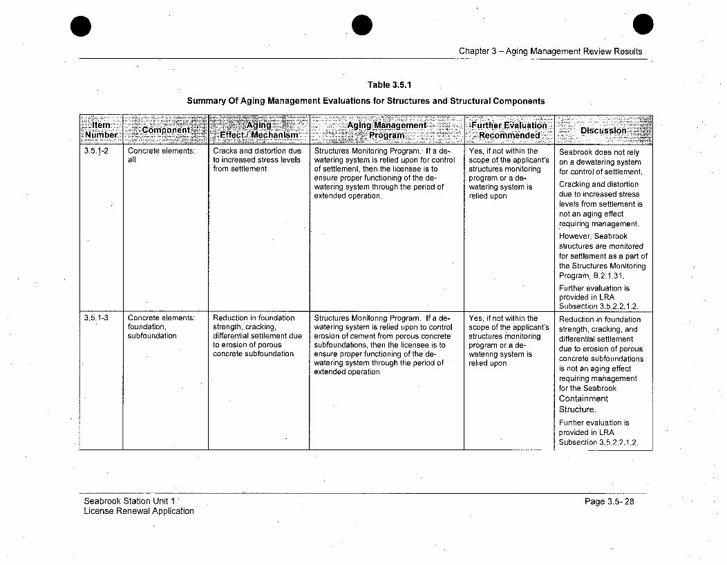
3.5.1-2 Concrete elements: Cracks and distortion due Structures Monitoring Program. If a de- Yes, if not within the Seabrook does not relyall to increased stress levels watering system is relied upon for control scope of the applicant's on a dewatering system
from settlement of settlement, then the licensee is to structures monitoring for control of settlement.ensure proper functioning of the de- program or a de-watering system through the period of watering system is Cracking and distortionextended operation. relied upon due to increased stress
levels from settlement isnot an aging effectrequiring management.However, Seabrookstructures are monitoredfor settlement as a part ofthe Structures MonitoringProgram, B.2.1.31.Further evaluation isprovided in LRASubsection 3.5.2.2.1.2.
3.5.1-3 Concrete elements: Reduction in foundation Structures Monitoring Program. If a de- Yes, if not within the Reduction in foundationfoundation, strength, cracking, watering system is relied upon to control scope of the applicant's strength, cracking, and
subfoundation differential settlement due erosion of cement from porous concrete structures monitoring differential settlementto erosion of porous subfoundations, then the licensee is to program or a de- due to erosion of porousconcrete subfoundation ensure proper functioning of the de- watering system is concrete subfoundations
watering system through the period of - relied uponextended operation is not an aging effect
requiring managementfor the SeabrookContainmentStructure.Further evaluation isprovided in LRASubsection 3.5.2.2.1.2.
Seabrook Station Unit 1 'License Renewal Application
Page 3.5- 28

Chapter 3 -Aging Management Review Results
Table 3.5.1
Summary Of Aging Management Evaluations for Structures and Structural Components
Item7~Aig Aging-Manage rnent. Further Evalufation - Dsusoý.,Number Copnn fet~caim ~ rogramr7n •Recommeded'3.5.1-4 Concrete elements: Reduction of strength and Plant-specific -Yes, plant-specific if This item is not
dome, wall, basemat, modulus due to elevated temperature limits are applicable to Seabrook.ring girder, temperature exceededbuttresses,No containmentcontainment, components exceed the
concrete fill-in specified temperatureannulus (as thresholds.applicable) Further evaluation is
provided in LRASubsection 3.5.2.2.1.3.
3.5.1-5 BWR only.
3.5.1-6 Steel elements: steel Loss of material due to ISI (IWE) and 10 C.FR Part 50, Appendix J Yes, if corrosion is Consistent with NUREG-liner, liner anchors, general, pitting, and significant for 1801.integral attachments crevice corrosion inaccessible areas
Seabrook manages lossof material with theASME Section XI,Subsection IWEProgram, B.2.1.27.Loss of material due to
corrosion is not expectedto be significant for.inaccessible areas.Further evaluation isprovided in LRASubsection 3.5.2.2.1.4.
Seabrook Station Unit 1License Renewal Application
Page 3.5- 29
Chapter 3 -Aging Management Review Results
Table 3.5.1
Summary Of Aging Management Evaluations for Structures and Structural Components
eComponent Aging i9±' Aging Mag nt.......Further Eva t.nDiscussion -"'Numbier -~Effect/I Mechanism ~ .Program - Reco- mmeiinde6d
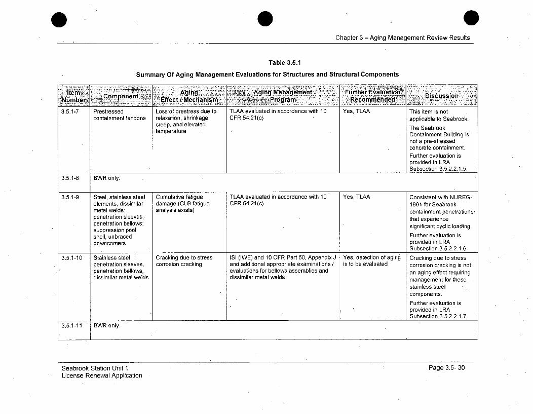
3.5.1-7 Prestressed Loss of prestress due to TLAA evaluated in accordance with 10 Yes, TLAA This item is notcontainment tendons relaxation, shrinkage, CFR 54.21(c) applicable to Seabrook.
creep, and elevated The Seabrooktemperature Containment Building is
not a pre-stressed
concrete containment.Further evaluation isprovided in LRASubsection 3.5.2.2.1.5.
3.5.1-8 BWR only.
3.5.1-9 Steel, stainless steel Cumulative fatigue TLAA evaluated in accordance with 10 Yes, TLAA Consistent with NUREG-elements, dissimilar damage (CLB fatigue CFR 54.21(c) 1801 for Seabrookmetal welds: analysis exists) containment penetrations,penetration sleeves,. that experiencepenetration bellows; significant cyclic loading.suppression pool
shell, unbraced Further evaluation isdowncomers provided in LRA
Subsection 3.5.2.2.1.6.
3.5.1-10 Stainless steel Cracking due to stress ISI (IWE) and 10 CFR Part 50, Appendix J Yes, detection of aging Cracking due to stresspenetration sleeves, corrosion cracking and additional appropriate examinations / is to be evaluated corrosion cracking is notpenetration bellows, evaluations for bellows assemblies and an aging effect requiringdissimilar metal welds dissimilar metal welds management for these
stainless steelcomponents.
Further evaluation isprovided in LRASubsection 3.5.2.2.1.7.
3.5.1-11 BWR only.
Seabrook Station Unit 1 Page 3.5- 30License Renewal Application
Chapter 3 - Aging Management Review Results
Table 3.5.1
Summary Of Aging Management Evaluations for Structures and Structural Components
ItmAging :Ij~Aging.Management Further EvaluationItemoen 'PormKcm eNaea ,K Discussion:
________ - Effect/ Mechanismr6granReom dd
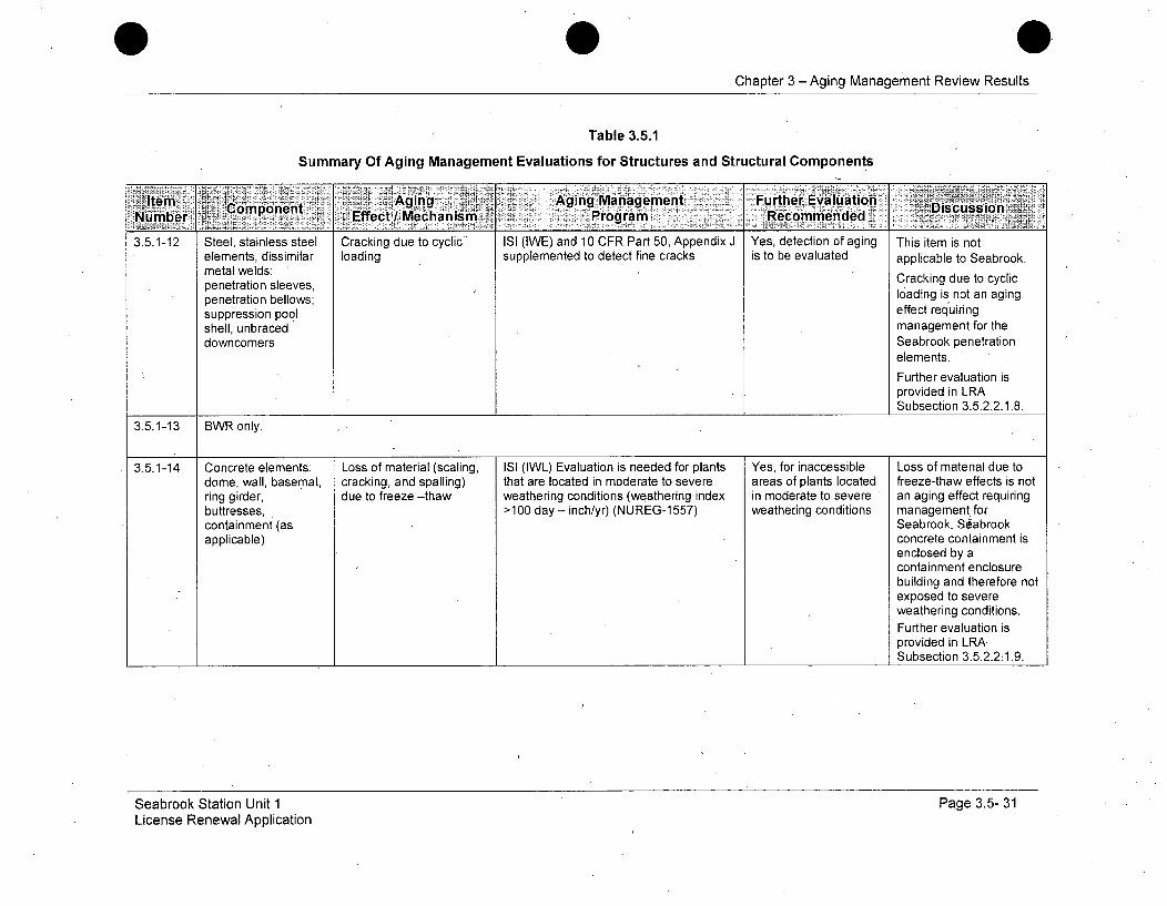
3.5.1-12 Steel, stainless steel Cracking due to cyclic- ISI (IWE) and 10 CFR Part 50, Appendix J Yes, detection of aging This item is notelements, dissimilar loading supplemented to detect fine cracks is to be evaluated applicable to Seabrook.metal welds:eta sleeves, Cracking due to cyclicpenetration bellows; loading is not an aging
suppression pool effect requiringshell, unbraced management for thedowncomers Seabrook penetration
elements.
Further evaluation isprovided in LRASubsection 3.5.2.2.1.8.
3.5.1-13 BWR only.
3.5.1-14 Concrete elements: Loss of material (scaling, ISI (IWL) Evaluation is needed for plants Yes, for inaccessible Loss of material due todome, wall, basemat, cracking, and spalling) that are located in moderate to severe areas of plants located freeze-thaw effects is notring girder, due to freeze -thaw weathering conditions (weathering index in moderate to severe an aging effect requiringbuttresses, >100 day - inch/yr) (NUREG-1 557) weathering conditions management. forcontainment (as Seabrook. Seabrookapplicable) concrete containment is
enclosed by acontainment enclosurebuilding and therefore notexposed to severeweathering conditions.Further evaluation isprovided in LRASubsection 3.5.2.2:1.9.
Seabrook Station Unit 1License Renewal Application
Page 3.5- 31
Chapter 3 -Aging Management Review Results
Table 3.5.1
Summary Of Aging Management Evaluations for Structures and Structural Components
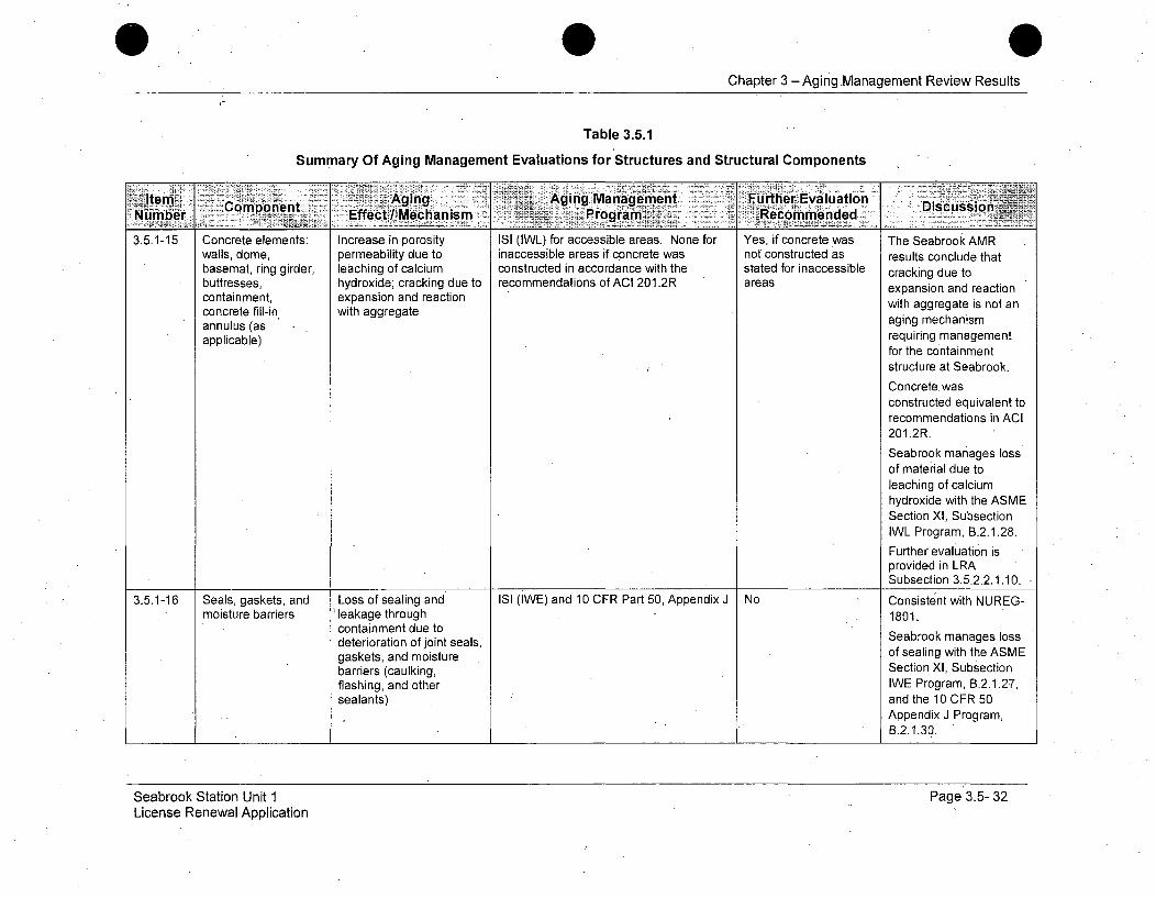
Item, Aging .. Aging Management urhrEvaluation Dsuso~Number Cmoet Effect / Mechanism Program :Recommended3.5.1-15 Concrete elements: Increase in porosity ISI (IWL) for accessible areas. None for Yes, if concrete was The Seabrook AMR
walls, dome, permeability due to inaccessible areas if concrete was not constructed as results conclude thatbasemat, ring girder, leaching of calcium constructed in accordance with the stated for inaccessible cracking due tobuttresses, hydroxide; cracking due to recommendations of ACI 201.2R areas expansion and reactioncontainment, expansion and reaction with aggregate is not anconcrete fill-in with aggregate aging mechanismannulus (as requiring management
for the containment
structure at Seabrook.
Concrete. wasconstructed equivalent torecommendations in ACI201.2R.
Seabrook manages lossof material due toleaching of calciumhydroxide with the ASMESection XI, SubsectionIWL Program, B.2.1.28.Further evaluation isprovided in LRASubsection 3.5.2.2.1.10.
3.5.1-16 Seals, gaskets, and Loss of sealing and ISI (IWE) and 10 CFR Part 50, Appendix J No Consistent with NUREG-moisture barriers 'leakage through 1801.
containment due todeterioration of joint seals, Seabrook manages lossgaskets, and moisture of sealing with the ASMEbarriers (caulking, Section XI, Subsectionflashing, and other IWE Program, B.2.1.27,sealants) and the 10 CFR 50
Appendix J Program,B.2.1.30.
Seabrook Station Unit 1License Renewal Application
Page 3.5- 32

Chapter 3 - Aging Management Review Results
Table 3.5.1
Summary Of Aging Management Evaluations for Structures and Structural Components
,~ Cmponnt Agingý Aging Mvanagement Furtner Evalu~ation.NUmbef Effect / Mechanism Programn Recommended -
3.5.1-17 Personnel airlock, Loss of leak tightness in 10 CFR Part 50, Appendix J and plant No Consistent with NUREG-equipment hatch and closed position due to Technical Specifications 1801.CRD hatch locks, mechanical wear of locks, The 10 CFR 50 Appendixhinges, and closure hinges, and closure J 1r CFR 15 0 ismechanisms mechanisms J Program, B.2.1.30, is
used to manage loss ofleak tightness.
3.5.1-18 Steel penetration Loss of material due to ISI (IWE) and 10 CFR Part 50 Appendix J No Consistent with NUREG-sleeves and dissimilar general, pitting, and 1801.metal welds; crevice corrosionpersonnel airlock, The ASME Section Xl,equipment hatch, and Subsection IWE, B.2.1.27CRD hatch manages loss of material
due to corrosion, 10 CFR50 Appendix J Program,B.2.1.30, manages lossof leak tightness.
3.5.1-19 BWR only.
3.5.1-20 BWR only.
3.5.1-21 BWR only.
3.5.1-22 Prestressed Loss of material due to ISI (IWL) No Not Applicable. Seabrookcontainment: tendons corrosion Station does not haveand anchorage prestressed tendons.components
Safety Related and Other Structures; and Component Supports
Seabrook Station Unit 1License Renewal Application
Page 3.5- 33
Chapter 3 -Aging Management Review Results
Table 3.5.1
Summary Of Aging Management Evaluations for Structures and Structural Components
Item Co'mpont A-ging __ Aging Management. Furtther.Evaluatioh D iscusio.NrbrEffect I Mchanism Program Retý6mmenided-
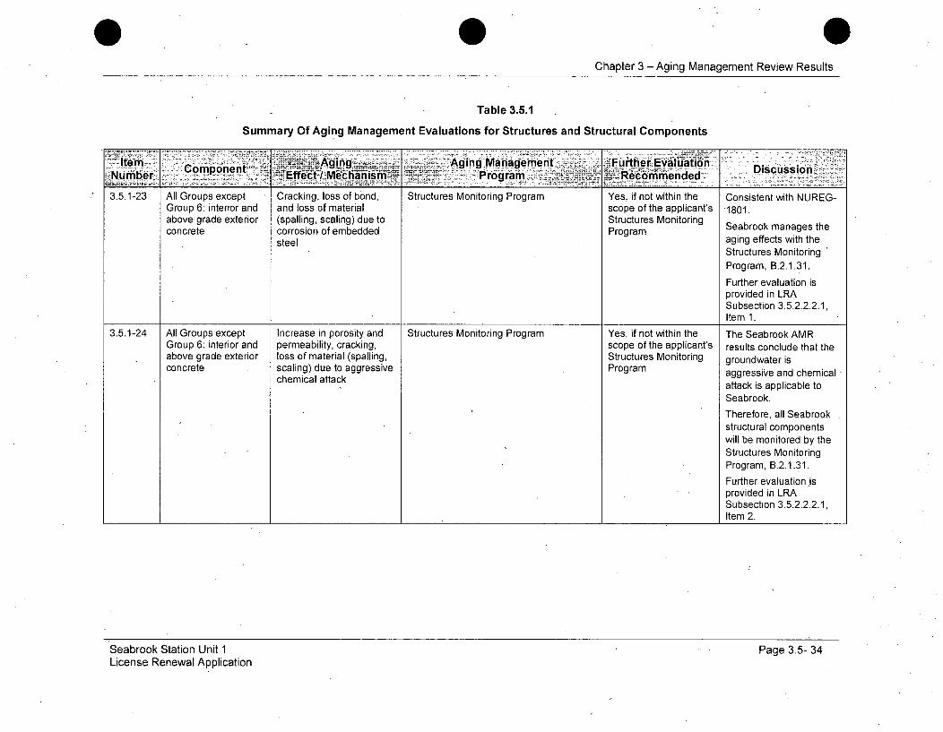
3.5.1-23 All Groups except Cracking, loss of bond, Structures Monitoring Program Yes, if not within the Consistent with NUREG-Group 6: interior and and loss of material scope of the applicant's "1801.above grade exterior (spalling, scaling) due to Structures Monitoringconcrete corrosion of embedded Program Seabrook manages thesteel aging effects with the
Structures MonitoringProgram, B.2.1.31.Further evaluation isprovided in LRASubsection 3.5.2.2.2.1,Item 1.
3.5.1-24 All Groups except Increase in porosity and Structures Monitoring Program Yes, if not within the The Seabrook AMRGroup 6: interior and permeability, cracking, scope of the applicant's results conclude that theabove grade exterior loss of material (spalling, Structures Monitoring groundwater isconcrete scaling) due to aggressive Program aggressive and chemical
chemical attack attack is applicable to
Seabrook.Therefore, all Seabrook
structural componentswill be monitored by theStructures MonitoringProgram, B.2.1.31.Further evaluation isprovided in LRASubsection 3.5.2.2.2.1,Item 2.
Seabrook Station Unit 1License Renewal Application
Page 3.5- 34

Chapter 3 -Aging Management Review Results
Table 3.5.1
Summary Of Aging Management Evaluations for Structures and Structural Components
~~ltein ~~Aging &-- w Aging Management ~ .Further Evaluation DsusoNumber -,p~pn x Effect IMechanismf Program Recommended
3.5.1-25 All Groups except Loss of material due to Structures Monitoring Program If Yes, if not within the Consistent with NUREG-Group 6: steel corrosion protective coatings are relied upon to scope of the applicant's 1801.components: all manage the effects of aging, the Structures Monitoringstructural steel structures monitoring program is to Program Seabrookmanages
include provisions to address protective corrosion of steelcoating monitoring and maintenance components with the
Structures MonitoringProgram, B.2.1.31.Further evaluation isprovided in LRASubsection 3.5.2.2.2.1,Item 3.
3.5.1-26 All Groups except Loss of material (spalling, Structures Monitoring Program Yes, if not within the Consistent with NUREG-Group 6: accessible scaling) and cracking due Evaluation is needed for plants that are scope of the applicant's 1801.and inaccessible to freeze-thaw located in moderate to severe weathering Structures Monitoringconcrete: foundation conditions (weathering index >100 day- Program or for Seabrook manages Loss
inclh/yr) (NUREG-1557) inaccessible areasof of material (spalling,plants located in scaling) and cracking duemoderate to severe to freeze-thaw with theweathering conditions Structures Monitoring
Program, B.2.1.31.
Further evaluation isprovided in LRASubsection 3.5.2.2.2.1,Item 4.
Seabrook Station Unit 1License Renewal Application
Page 3.5- 35

Chapter 3 - Aging Management Review Results
Table 3.5.1
Summary Of Aging Management Evaluations for Structures and Structural Components
I temni" A" Aing ~'Aging-Management Fulrther Evalua"tionNUmber C poet Effect / Mechanism Program Recommen~rded Dsuso
3.5.1-27 All Groupsexcept Cracking due to Structures Monitoring Program None for Yes, if not within the This item is notGroup 6: accessible expansion due to reaction inaccessible areas if concrete was scope of the applicant's applicable to Seabrook.and inaccessible with aggregates constructed in accordance with the Structures Monitoring The Seabrook AMRinterior / exterior recommendations in ACI 201.2R-77 Program or concreteconcrete was not constructed as results conclude that
stated for inaccessible reaction with aggregatesareas is not significant and the
concrete was constructedconsistent with therecommendations of ACI201.2R.Nonetheless, allSeabrook structuralcomponents applicable tothis item will bemonitored by theStructures MonitoringProgram, B.2.1.31:Further evaluation isprovided in LRASubsection 3.5.2.2.2.1,Item 5.
Seabrook Station Unit 1License Renewal Application
Page 3.5- 36

Chapter 3 -Aging Management Review Results
Table 3.5.1
Summary Of Aging Management Evaluations for Structures and Structural Components
Item ~ ~ om~nentAging _Aging,,Management " _ Further EvaluationDsc siWComect/Mnchanism-- ___Nubr fec McaPs rogram n Recommended3.5.1-28 Groups 1-3, 5-9: All Cracks and distortion due Structures Monitoring Program If a de- Yes, if not within the This item is not
to increased stress levels watering system is relied upon for control scope of the applicant's applicable to Seabrook.from settlement of settlement, then the licensee is to Structures Monitoring The Seabrook AMR
ensure proper functioning of the de- Program or a de-watering system through the period of watering system is results conclude thatextended operation relied upon settlement is not
significant.
Further, a dewateringsystem is not relied uponfor control of settlementat Seabrook.Further evaluation isprovided in LRASubsection 3.5.2.2.2.1,Item 6.
3.5.1-29 Groups 1-3, 5-9: Reduction in foundation Structures Monitoring Program If a de- Yes, if not within the This item is notfoundation strength, cracking, watering system is relied upon for control scope of the applicant's applicable to Seabrook.
differential settlement due of settlement, then the licensee is to Structures Monitoring The Seabrook AMRto erosion of porous ensure proper functioning of the de- Program or a de-concrete subfoundation watering system through the period of watering system is results conclude that
extended operation relied upon settlement is notsignificant.Further, a dewateringsystem is not relied uponfor control of settlementat Seabrook.Further evaluation is
provided in LRASubsection 3.5.2.2.2.1,Item 7.
Seabrook Station Unit 1License Renewal Application
Page 35- 37
Chapter 3 -Aging Management Review Results
Table 3.5.1
Summary Of Aging Management Evaluations for Structures and Structural Components
Item. 'Aging. -Aging Management Further EautonI tComponent DiscussionNumber~ _ Effect MeclianismI .~~-- Proga Recommended -
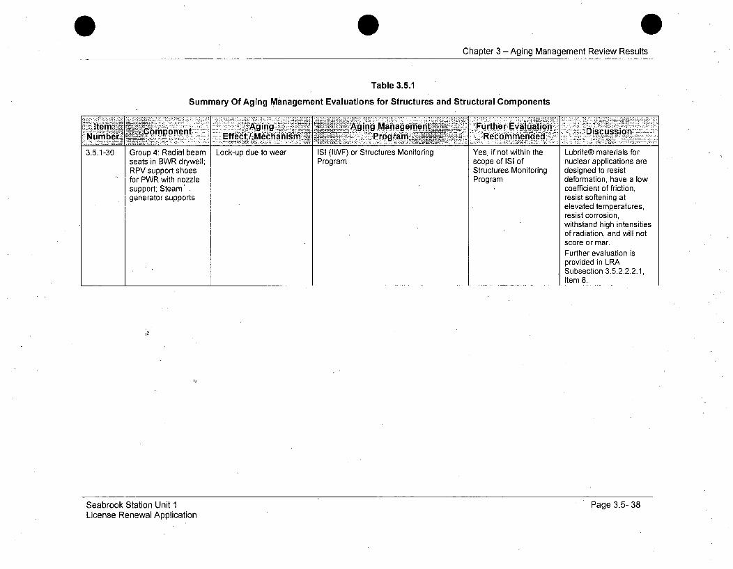
3.5.1-30 Group 4: Radial beam Lock-up due to wear ISI (IWF) or Structures Monitoring Yes, if not within the Lubrite® materials forseats in BWR drywell; Program scope of ISI of nuclear applications areRPV support shoes Structures Monitoring designed to resistfor PWR with nozzle Program deformation, have a lowsupport; Steam" coefficient of friction,generator supports resist softening at
elevated temperatures,resist corrosion,withstand high intensitiesof radiation, and will notscore or mar.Further evaluation isprovided in LRASubsection 3.5.2.2.2.1,Item 8.
Seabrook Station Unit 1License Renewal Application
Page 3.5- 38

Chapter 3 -Aging Management Review Results
Table 3.5.1
Summary Of Aging Management Evaluations for Structures and Structural Components
IteNmbe o~et ~ " gn Aging Management FiitheEvaluation,Nme,.Effect/ /Mechanism Y~ , Program~ Futhe icsin~ commended,-
3.5.1-31 Groups 1-3, 5, 7-9: Increase in porosity and Structures Monitoring Program Yes, plant-specific if The Seabrook AMRbelow grade concrete permeability, cracking, Examination of representative samples of environment is results conclude that thecomponents, such as loss of material (spalling, below grade concrete, and periodic aggressive groundwater isexterior walls below scaling) / aggressive monitoring of groundwater, if the aggressive.grade and foundation chemical attack; cracking, environment is non-aggressive. A plant-
loss of bond, and loss of specific program is to be evaluated if the The Structuresmaterial (spalling, environment is aggressive Monitoring Program,scaling)/ corrosion of B.2.1.31, will manageembedded steel degradation of accessible
and inaccessibleconcrete componentsdue to corrosion ofembedded steel.
Further evaluation isprovided in LRASubsection 3.5.2.2.2.2.
The StructuresMonitoring Program,B.2.1.31, will performconcrete testing andrebar inspection todetermine the effects ofthe aggressivegroundwater on theconcrete. The concretetesting and the rebarinspection will representall concrete below grade.
Seabrook Station Unit 1License Renewal Application
Page 3.5- 39
Chapter 3 - Aging Management ReView Results
Table 3.5.1
Summary Of Aging Management Evaluations for Structures and Structural Components
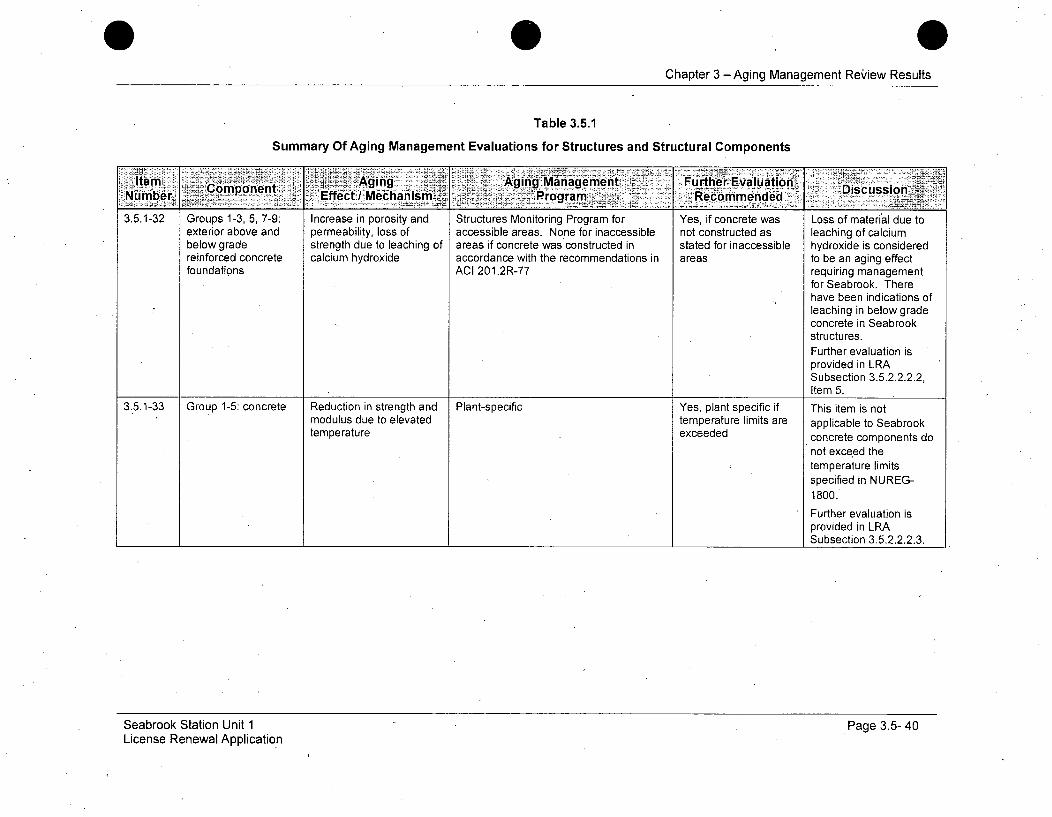
I1temn j.Aging IAging ianagemeni Furthier-Evaluation-icsso~INu mber om net Effect/ Mechanism-. Program_ý Recommended3.5.1-32 Groups 1-3, 5, 7-9: Increase in porosity and Structures Monitoring Program for Yes, if concrete was Loss of material due to
exterior above and permeability, loss of accessible areas. None for inaccessible not constructed as leaching of calciumbelow grade strength due to leaching of areas if concrete was constructed in stated for inaccessible hydroxide is consideredreinforced concrete calcium hydroxide accordance with the recommendations in areas to be an aging effectfoundations ACI 201.2R-77 requiring management
for Seabrook. Therehave been indications ofleaching in below gradeconcrete in Seabrookstructures.Further evaluation isprovided in LRASubsection 3.5.2.2.2.2,Item 5.
3.5.1-33 Group 1-5: concrete Reduction in strength and Plant-specific Yes, plant specific if This item is notmodulus due to elevated temperature limits are applicable to Seabrooktemperature exceeded concrete components do
not exceed thetemperature limitsspecified in NUREG-1800.Further evaluation isprovided in LRASubsection 3.5.2.2.2.3.
Seabrook Station Unit 1License Renewal Application
Page 3.5- 40
Chapter 3 -Aging Management Review Results
Table 3.5.1
Summary Of Aging Management Evaluations for Structures and Structural Components
-item ConoetAging§ . .r Aging-Management Further Evaluation Dsuso~Nmbr~-Effect /IMecha~nism ~ Programn Recommended
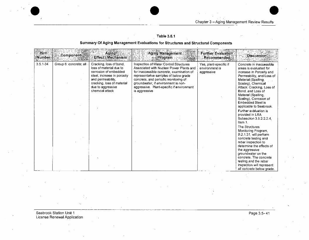
3.5.1-34 Group 6:.concrete; all Cracking, loss of bond, Inspection of Water Control Structures Yes, plant-specific if Concrete in inaccessibleloss of material due to Associated with Nuclear Power Plants and environment.is areas is evaluated forcorrosion of embedded for inaccessible concrete, examination of aggressive increase in Porosity andsteel, increase in porosity representative samples of below grade Permeability, and Loss ofand permeability, concrete, and periodic monitoring of Material (Spalling,cracking, loss of material groundwater, if environment is non- Scaling), Chemicaldue to aggressive aggressive. Plant-specific if environment Attack; Cracking, Loss ofchemical attack is aggressive Bond, and Loss of
Material (Spalling,Scaling), Corrosion ofEmbedded Steel isapplicable .to Seabrook.Further evaluation isprovided in LRASubsection 3.5.2.2.2.4,Item 1.The StructuresMonitoring Program,B.2.1.31, will performconcrete testing andrebar inspection todetermine the effects ofthe aggressivegroundwater on theconcrete. The concretetesting and the rebarinspection will representall concrete below grade.
Seabrook Station Unit 1LicenseRenewal Application
Page 3.5- 41
0Chapter 3 -Aging Management Review Results
Table 3.5.1
ýSummary Of Aging Management Evaluations for Structures and Structural Components
Ite mr- Aging, Aging Management Furtlher. EvaluationD sdioNumber Cmont Effect /IMechanism- Program § Recommendedisuso
3.5.1-35 Group 6: exterior Loss of material (spalling, Inspection of Water Control Structures Yes, for inaccessible Consistent with NUREG-above and below scaling) and cracking due Associated with Nuclear Power Plants is areas of plants located 1801.grade concrete to freeze-thaw needed for plants that are located in in moderate to severefoundation moderate to severe weathering conditions weathering conditions Seabrook manages Loss
(weathering index >100 day-inch/yr) of material (spalling,(NUEG 1557) scaling) and cracking due
to freeze-thaw with theStructures MonitoringProgram, B.2.1.31.Further evaluation isprovided in LRASubsection 3.5.2.2.2.4,Item 2.
3.5.1-36 Group 6: all Cracking due to Accessible areas: Inspection of Water Yes, if concrete was Consistent with NUREG-accessible expansion / reaction with Control Structures Associated with not constructed as 1801.inaccessible aggregates Nuclear Power Plants. None for stated for inaccessiblereinforced concrete inaccessible areas if concrete was areas-
constructed in accordance with the Monitoring Program,recommendations in ACI 201.2R77 B.2.1.31, will manage
degradation of accessibleand inaccessibleconcrete components forcracking due toexpansion / reaction withaggregates.Further evaluation isprovided in LRASubsection 3.5.2.2.2.4,Item 3.
Seabrook Station Unit 1License Renewal Application
Page 3.5- 42

Chapter 3 -Aging Management Review Results
Table 3.5.1
Summary Of Aging Management Evaluations for Structures and Structural Components
Item ~Aging Aging' Managementz< Further Evaluation DsusoNumber Component Effect/I Mechanism ... Program: Recommended Dsuso
3.5.1-37 Group 6: exterior Increase in porosity and For accessible areas, Inspection of Water Yes, if concrete was Consistent with NUREG-above and below permeability, loss of Control Structures Associated with not constructed as 1801.grade reinforced strength due to leaching of Nuclear Power Plants. None for stated for inaccessibleconcrete foundation calcium hydroxide inaccessible areas if concrete was areas The Structuresinterior slab constructed in accordance with the Monitoring Program,recommendations in ACI 201.2R77 B.2.1.31, will manage
degradation of accessible
and inaccessibleconcrete componentsdue to Increase inporosity and permeability,loss of strength due toleaching of calciumhydroxideFurther evaluation isprovided in LRASubsection 3.5.2.2.2.4,Item 3.
3.5.1-38 Group 7, 8: Tank Cracking due to stress Plant-specific Yes, plant-specific There are noliners corrosion cracking; loss of components at Seabrook
material due to pitting and that are subject to thiscrevice corrosion aging effect.
Further evaluation isprovided in LRASubsection 3.5.2.2.2.5.
Seabrook Station Unit 1License Renewal Application
Page 3.5- 43

Chapter 3 -Aging Management Review Results
Table 3.5.1
Summary Of Aging Management Evaluations for Structures and Structural Components
Further Eva Nlation~iRecommended Discussion
Support members;welds; boltedconnections; supportanchorage to buildingstructure
Loss of material due togeneral and pittingcorrosion
Yes, if not within thescope of the applicant'sStructures MonitoringProgram
Consistent with NUREG-1801.
The StructuresMonitoring Program,B.2.1.31, will managedegradation forcomponents for loss ofmaterial due to generaland pitting corrosion
Further evaluation isprovided in LRASubsection 3.5.2.2.2.6,Item1.
3.5.1-40 Building concrete at Reduction in concrete Structures Monitoring Program Yes, if not within the Consistent with NUREG-locations of anchor capacity due to scope of the applicant's 1801.expansion and local concrete degradation Structures Monitoringgrouted anchors; / service-induced cracking Program The Structures
grout pads for support or other concrete aging Monitoring Program,
base plates mechanisms B.2.1.31, will managedegradation for the agingeffects.Further evaluation isprovided in LRASubsection 3.5.2.2.2.6,Item 2.
Seabrook Station Unit 1License Renewal Application
Page 3.5- 44
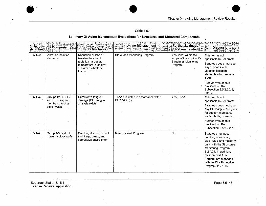
Chapter 3 -Aging Management Review Results
Table 3.5.1
Summary Of Aging Management Evaluations for Structures and Structural Components
:-.i: ...... . f r.~ii'l •~ i;' i;ItmAgngn Annaae nt cFurther Evaluaition1. DscsNumber, aComponent Effect /Mechanism :Proga - 5 Recommended Dicsion
3.5.1-41 Vibration isolation Reduction or loss of Structures Monitoring Program Yes, if not within the This item is notelements isolation function / scope of the qpplicant's applicable to Seabrook.
radiation hardening, Structures Monitoring Stemperature, humidity, Program Seabrook does not havesustained vibratory any supports withloading vibration isolation
elements which requireAMR.Further evaluation isprovided in LRASubsection 3.5.2.2.2.6,Item 3.
3.5.1-42 Groups B1.1, B1.2, Cumulative fatigue TLAA evaluated in accordance with 10 Yes, TLIAA This item is notand B1.3: support damage (CLB fatigue CFR 54.21(c) applicable to Seabrook.members: anchor analysis exists) Seabrook does not havebolts, welds
any CLB fatigue anaiysesfor support members,anchor bolts, or welds.Further evaluation isprovided in LRASubsection 3.5.2.2.2.7.
3.5.1-43 Group 1-3, 5, 6: all Cracking due to restraint Masonry Wall Program No Seabrook managesmasonry block walls shrinkage, creep, and cracking of masonry
aggressive environment block walls and masonryunits with the StructuresMonitoring Program,B.2.1.31. In addition,masonry wall FireBarriers, are managedwith the Fire ProtectionProgram, B.2.1.15.
Seabrook Station Unit 1License Renewal Application
Page 3.5- 45
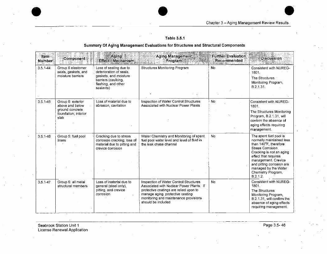
Chapter 3 -Aging Management Review Results
Table 3.5.1
Summary Of Aging Management Evaluations for Structures and Structural Components
Item Copnn Aglng Aging ManagementFrteEaltonDsuin:Number> Effect Mechanism. Program Recomnmended
3.5.1-44 Group 6 elastomer Loss of sealing due to *Structures Monitoring Program No Consistent with NUREG-seals, gaskets, and deterioration of seals, 1801.moisture barriers gaskets, and moisture The Structures
barriers (caulking,flashing, and other Monitoring Program,sealants) B.2.1.31.
3.5.1-45 Group 6: exterior Loss of material due to Inspection of Water Control Structures No Consistent with NUREG-above and below abrasion, cavitation Associated with Nuclear Power Plants 1801.ground concrete The Structures Monitoringfoundation; interiorslab Program, B.2.1.31, will
confirm the absence ofaging effects requiringmanagement.
3.5.1-46 Group 5: fuel pool Cracking due to stress Water Chemistry and Monitoring of spent No The spent fuel pool isliners corrosion cracking; loss of fuel pool water level and level of fluid in normally maintained less
material due to pitting and the leak chase channel than 1400F, thereforecrevice corrosion Stress Corrosion
Cracking is not an agingeffect that requiresmanagement. Creviceand pitting corrosion aremanaged by the WaterChemistry Program,B.2.1.2.
3.5.1-47 Group 6: all metal Loss of material due to Inspection of Water Control Structures No Consistent with NUREG-structural members general (steel only), Associated with Nuclear Power Plants. If 1801.
pitting, and crevice protective coatings are relied upon to The Structurescorrosion manage aging, protective coating Monitoring Program,
monitoring and maintenance provisions B.2.1.31, will confirm theshould be included absence of aging effects
requiring management.
Seabrook Station Unit 1License Renewal Application
Page 3.5- 46
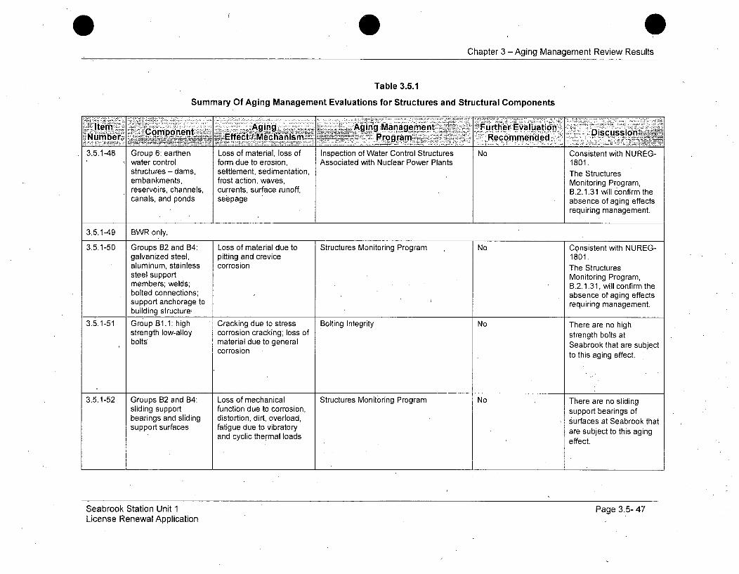
0 0Chapter 3 -Aging Management Review Results
Table 3.5.1
Summary Of Aging Management Evaluations for Structures and Structural Components
.. Aipg. .. _ __Aging Managemnent , Furth~er Evaluation DsusinItem.....C ompoent EfciMt~isiNurompr Discussion.....c...e..e
3.5.1-48 Group 6: earthen Loss of material, loss of Inspection of Water Control Structures No Consistent with NUREG-water control form due to erosion, Associated with Nuclear Power Plants 1801.structures- dams, settlement, sedimentation, The Structuresembankments, frost action, waves, Monitoring Program,reservoirs, channels, currents, surface runoff, B.2.1.31 will confirm thecanals, and ponds seepage absence of aging effects
requiring management.
3.5.1-49 BWR only.
3.5.1-50 Groups B2 and B4: Loss of material due to Structures Monitoring Program No Consistent with NUREG-galvanized steel, pitting and crevice 1801.aluminum, stainless corrosion The Structures
steel support Monitoring Program,members; welds; B.2.1.31, will confirm thebolted connections; absence of aging effectssupport anchorage to requiring management.building structure:
3.5.1-51 Group B1.1: high Cracking due to stress Bolting Integrity No There are no highstrength low-alloy corrosion cracking; loss of strength bolts atbolts material due to general Seabrook that are subject
corrosion to this aging effect.
3.5.1-52 Groups B2 and 84: Loss of mechanical Structures Monitoring Program No There are no slidingsliding support function due to corrosion, support bearings ofbearings and sliding distortion, dirt, overload, surfaces at Seabrook thatsupport surfaces fatigue due to vibratory are subject to this aging
and cyclic thermal loads effect.
Seabrook Station Unit 1License Renewal Application
Page 3.5- 47
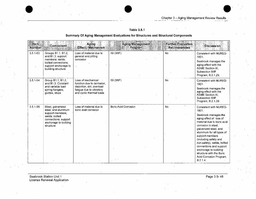
Chapter 3 -Aging.Management Review Results
Table 3.5.1
Summary Of Aging Management Evaluations for Structures and Structural Components
Ale.1 iAging _Aging Managemen Further-Evaluati'Nubr _Component -fet~caim--Prgai inDiscussion-
Effec / Mehais Progra Recommended
3.5.1-53 Groups Bi1., B1.2, Loss of material due to ISI (IWF) No Consistent with NUREG-and B1.3: support general and pitting 1801.members: welds; corrosionbolted connections; Seabrook manages thesupport anchorage to aging effect with thebuilding structure. ASME Section Xl,
Subsection IWFProgram, B.2.1.29.
3.5.1-54 Group B1.1, B1.2, Loss of mechanical ISI (IWF) No Consistent with NUREG-and B1.3: Constant *function due to corrosion, 1801.and variable load distortion, dirt, overload Seabrook manages thespring hangers; fatigue due to vibratory aging manages theguides; stops and cyclic thermal loads aging effect with theASME Section Xl,
Subsection WFProgram, B.2.1.29.
3.5.1-55 ýSteel, galvanized Loss of material due to Boric Acid Corrosion No Consistent with NUREG-steel, and aluminum boric acid corrosion 1801.support members;welds; bolted Seabrook manages theconnections; support aging effect of loss ofanchorage to building material due to boric acidstructure corrosion in steel,
galvanized steel, andalumihum for all types ofsupport members(including safety andnon-safety), welds, bolted
connections and supportanchorage to buildingstructure with the BoricAcid Corrosion Program,B.2.1.4.
Seabrook Station Unit 1License Renewal Application
Page 3.5- 48
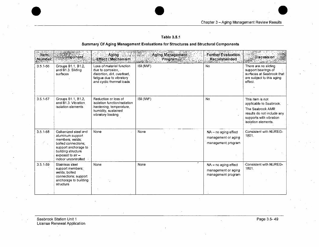
Chapter 3 -Aging Management Review Results
Table 3.5.1
Summary Of Aging Management Evaluations for Structures and Structural Components
Item. - Agin .4 ,Agng Managerntbt-- Further Evialuation .Discussio
ýýNurnber, - copnt, 'Effect / Mechanism -- . Porn~: Repommeded
3.5.1-56 Groups B1.1, 11.2, Loss of material function ISI (IWF) No There are no slidingand B1.3: Sliding due to corrosion, support bearings ofsurfaces distortion, dirt, overload, surfaces at Seabrook that
fatigue due to vibratory are subject to this agingand cyclic thermal loads effect.
3.5.1-57 Groups B1.1, B1.2; Reduction or loss of ISI (IWF) No This item is notand B1.3: Vibration isolation function/radiation applicable to Seabrook.isolation elements hardening, temperature, The Seabrook AMR
humidity, sustainedvibratory loading results do not include any
supports with vibrationisolation elements.
3.5.1-58 Galvanized steel and None None NA - no aging effect Consistent with NUREG-aluminum support management or 1801.members; welds; agingbolted connections; management programsupport anchorage tobuilding structureexposed to air -indoor uncontrolled
3.5.1-59 Stainless steel None None NA - no aging effect -Consistent with NUREG-support members; management or aging 1801.welds; bolted agconnections; support management programanchorage to buildingstructure
Seabrook Station Unit 1License Renewal Application
Page 3.5- 49
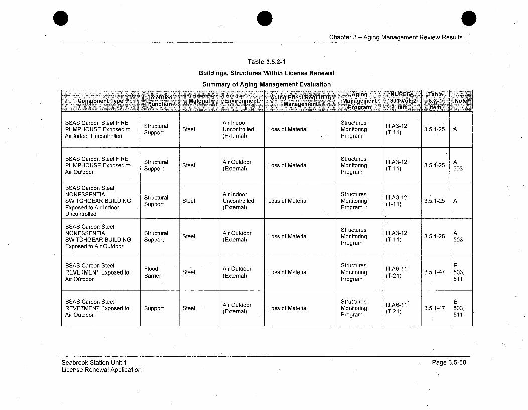
0Chapter 3 -Aging Management Review Results
Table 3.5.2-1
Buildings, Structures Within License Renewal
Summary of Aging Management Evaluation
Copnen"Tp Intended Maera EvroInmn Aging Effect Requirin g Maighet 81Vl 3.XG Table Nt~rogram; tem'A .lterný.
BSAS Carbon Steel FIRE Structural Air Indoor Structures II.A3-12PUMPHOUSE Exposed to Uncontrolled Loss of Material Monitoring (T-12Air Indoor Uncontrolled (External) Program
BSAS Carbon Steel FIRE StructuresPUMPHOUSE Exposed to Structural Steel Loss of Material Monitoring (T-1 3.5.1-25 A,Air Outdoor Support (External) Program (T-1 1) 503
BSAS Carbon SteelNONESSENTIAL Structural Air Indoor Structures III.A3.12SWITCHGEAR BUILDING Steel Uncontrolled Loss of Material Monitoring -1 3.5.1-25 AExposed to Air Indoor Support (External) Program (T-11)
Uncontrolled
BSAS Carbon Steel StructuresNONESSENTIAL Structural rSteel Loss of Material Monitoring OT.A3-12 3.5.1-25 A,SWITCHGEAR BUILDING Support (External) Program (T-11) 503Exposed to Air Outdoor
BSAS Carbon Steel Flood Air Outdoor Structures IIl.A6-!1 E,REVETMENT Exposed to Barrier Steel (External) Loss of Material Monitoring (T-21) 3.5.1-47 503,Air Outdoor Program (T-21) 511
BSAS Carbon Steel Air Outdoor Structures II1.A6-!1 E,REVETMENT Exposed to Support Steel (External) Loss of Material Monitoring (T-21) 3.5.1-47 503,Air Outdoor (Program 511
Seabrook Station Unit 1License Renewal Application
Page 3.5-50

Chapter 3 - Aging Management Review Results
Table 3.5.2-1
Buildings, Structures Within License Renewal
Summary of Aging Management Evaluation
- A~"Ain 7 NUREG-.; Tablei
BSAS Carbon SteelE t Structures I.A6-1 1REVETMENT Exposed to Flood Steel RwWtern Loss of Material Monitoring (T-21) 3.5.1-47 511
Raw Water BinProgram5
BSAS Carbon Steel Raw Water Structures III.A6-11 E,REVETMENT Exposed to Support Steel (External) Loss of Material Monitoring (T-21) 3.5.1-47 509,Raw Water Program 511
BSAS Carbon Steel Raw Water Structures IIl A6-1 1 E,REVETMENT Exposed to Flppoor Steel (External) Loss of Material Monitoring (T-21) 3.5.1-47 509,Raw Water Program 511
BSAS Carbon Steel Raw Water Structures E11,A6-11 E,REVETMENT Exposed to Support Steel (External) Loss of Material Monitoring (T-21) 3.5.1-47 509,Raw Water Program 511
BSAS Carbon Steel Raw Water Structures IlI.A6-11 H,REVETMENT Exposed to Barrier Steel (External) Loss of Material Monitoring (T-21) 3.5.1-47 514Raw Water Program 511BSAS Carbon Steel FodRaw Water Structures III.A6-11 H,
BSAS Carbon Steel StructuresREVETMENT Exposed to Support Steel Raw Water Loss of Material Monitoring (LTA6-11 3.5.1-47 H,
Raw Water (External) Program (T-21) 514
Seabrook Station Unit 1License Renewal Application
' Page 3.5-51

Chapter 3 - Aging Management Review Results
Table 3.5.2-1
Buildings, Structures Within License Renewal
Summary of Aging Management Evaluation
Intended Maeil-_-Aging Effect Re'qudiring ~ ~ UE-- alComponent ,Type Function Environment Maanmetagement, 1801 Vol.2I. K3X: 1 N ote- .7 .Prog~ramr.< item Itrr
BSAS Carbon Steel Flood Raw Water Structures II1.A6-11 E,REVETMENT Exposed to Barrier Steel (External) Loss of Material Monitoring (T-21)" 3.5.1-47 509,Raw Water Program 511
BSAS Carbon Steel Structures E,REVETMENT Exposed to Support Steel RwWter Loss of Material Monitoring 3.5.1-47 509,(External) Moioig 21)3.1-7 59Raw Water Program 511
BSAS Carbon Steel STEAMGENERATOR Air Indoor StructuresBLOWDOWN RECOVERY Structural Steel Uncontrolled Loss of Material Monitoring (TI.A3-12 3.5.1-25 ABUILDING Exposed to Air Support (External) Program
Indoor Uncontrolled
BSAS Carbon Steel STEAMGENERATOR Structural Air Outdoor Structures II1.A3-12 A,BLOWDOWN RECOVERY Support Steel (External) Loss of Material PMonitoring (T-1r1) 3.5.1-25 aBUILDING Exposed to Air Program 503Outdoor
BSAS ConcreteNONESSENTIAL Structural Air Outdoor Cracking, Loss of Bond, Structures II1.A3-9 3.5.1-23 ASWITCHGEAR BUILDING Support Concrete (External) Loss of Material (Spalling, Monitoring (T-04)Exposed to Air Outdoor Scaling) Program
BSAS Concrete StructuresNONESSENTIAL Structural Concrete Air Outdoor Expansion and Cracking Monitoring III.A3-2 3.5.1-27 ASWITCHGEAR BUILDING Support (External) Proram (T-03)Exposed to Air Outdoor Program
Seabrook Station Unit 1License Renewal Application
Page 3.5-52
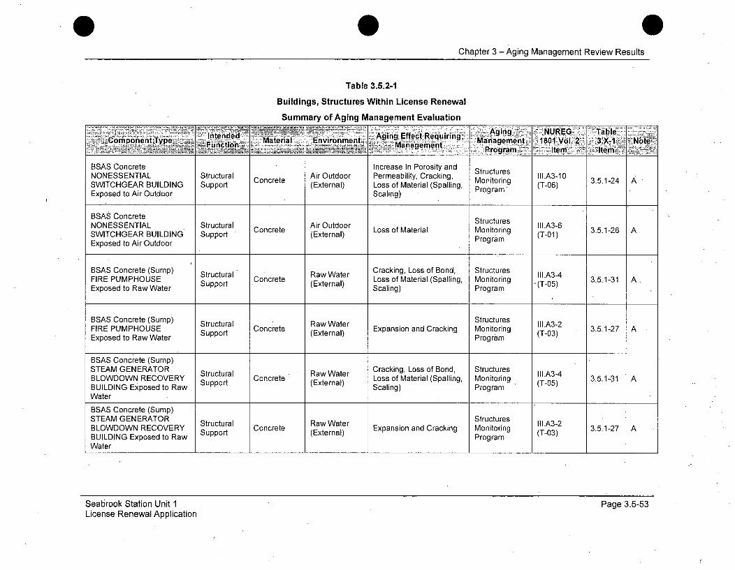
Chapter 3 -Aging Management Review Results
Table 3.5.2-1
Buildings, Structures Within License Renewal
Summary of Aging Management Evaluation
Intended>, Material Environment Aging Effect un Requirin • .'. Agin. NUREG TableCopoet yp~ Fundtion~z Kanagqmqnt gren :11
_ rogram :Item It. m
BSAS Concrete Increase In Porosity andNONESSENTIAL Structural Concrete Air Outdoor Permeability, Cracking S s II1.A3-10SWITCHGEAR BUILDING Support (External) Loss of Material (Spalling, Monitoring (T-06)Exposed to Air Outdoor Scaling) Program
BSAS ConcreteNONESSENTIAL Structural Air Outdoor Structures lII1.A3-6NONESW ENABL Strucrt ' Concrete (Exter Loss of Material Monitoring (T-1 3.5.1-26 ASWITCHGEAR BUILDING Support (External) Porm(T-01)Exposed to Air Outdoor Program
BSAS Concrete (Sump) Structural Raw Water Cracking, Loss of Bond, Structures II1.A3-4FIRE PUMPHOUSE Concrete Loss of Material (Spalling, Monitoring 3.5.1-31 A .Exposed to Raw Water Support (External) Scaling) Program "(T-05)
BSAS Concrete (Sump) Structural Structures II.A3-2
FIRE PUMPHOUSE StrtRaw Water Expansion and Cracking Monitoring 3.5.1-27 AExposed to Raw Water Support (External) Program (T-03)
BSAS Concrete (Sump)STEAM GENERATOR Structural C Raw Water Cracking, Loss of Bond, Structures III.A3-4BLOWDOWN RECOVERY Support Concrete (External) Loss of Material (Spalling, Monitoring (T-05) 3.5.1-31 ABUILDING Exposed to Raw Scaling) ProgramWater
BSAS Concrete (Sump)STEAM GENERATOR StructuresSEMGNRTR Structural Raw Water Stutrs II1.A3-2BLOWDOWN RECOVERY Sura Concrete RwWter Expansion and Cracking Monitoring (T-0 3.5.1-27 ABUILDING Exposed to Raw Program(T-03)
Water
Seabrook Station Unit 1License Renewal Application
Page 3.5-53
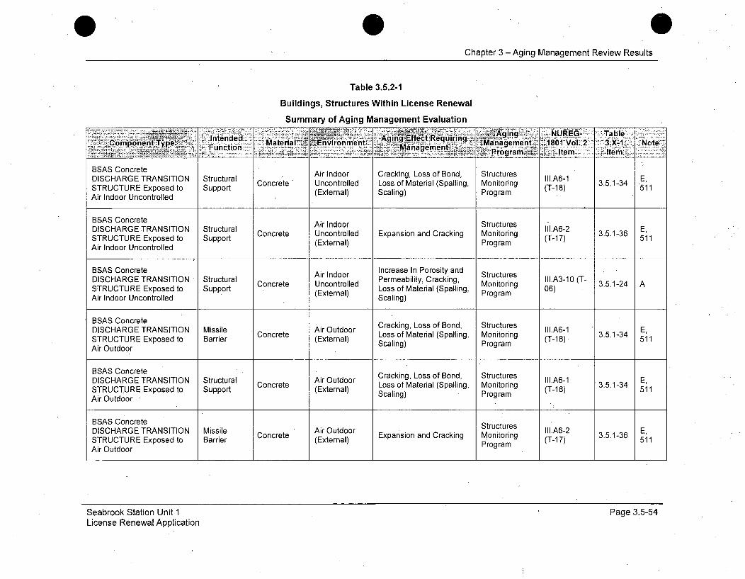
Chapter 3 - Aging Management Review Results
Table 3.5.2-1
Buildings, Structures Within License Renewal
Summary of Aging Management Evaluation
Comonet Tpe Intende Aging-ift cARequiring N.~§ging A U_-' Tal:'Function MaeraI 7 iEivibme ,. gmetn',BV-l.2 .- 1 Nt
STRUTURExpsedto. upprt(xtenal Saig Program em Item
BSAS Concrete Air Indoor StructuresDISCHARGE TRANSITION Structural Air Undoor Can Los or Bond, Storutr III.A6-1 E,
STUTR xoe o Spot Concrete Uncontrolled Losasiof Mate rialckping, Monitoring (T-178) 3.5.1-34 511STRUCTURE Exposed to. Support (External) Scln)Program(T1.851
Air Indoor Uncontrolled
BSAS Concrete Air Indoor StructuresDISCHARGE TRANSITION Structural Concrete Uncontrolled Monitoring III.A6-2 3.5.1- ,STRUCTURE Exposed to Support (External) Exson a (T-1M7) 3.5.1-30511Air Indoor Uncontrolled (Extrnal Program
BSAS Concrete Increase In Porosity and StructuresDISCHARGE TRANSITION Structural Aie Indoor Permeability, Cracking, IoIA3-10 (T- 3.5.1-24es
Concrete Uncontrolled (SallngMonito)ring II.61 3.5.1-24 A,
STRUCTURE Exposed to Support (External) Loss of Material (Spalling, Program (-06)Air Indoor Uncontrolled Scaling)
BSAS ConcreteDISCHARGE TRANSITION Missile Air Outdoor Cracking, Loss of Bond, Structures III.A6-1 E,STRUCTURE Exposed to Barrier Concrete (External) Loss of Material (Spalling, Monitoring (T-18) 3.5.1-34 511Air Outdoor Scaling) Program
BSAS Concrete Cracking, Loss of Bond, StructuresDISCHARGE TRANSITION Structural Concrete Air Outdoor Exp Material (Spalling Monitoring III.A6-1 3.5.1-3 E,STRUCTURE Exposed to Support (External) lProgram (T-1 8) 511Air Outdoor
BSAS Concrete SrcueDISCHARGE TRANSITION Missile Air Outdoor Stutrs III.A6-2 E,STRUCTURE Exposed to Barrier Concrete (External) Expansion and Cracking Monitoring (T-1 7) 3.5.1-36 51Air Outdoor Program51
Seabrook Station Unit 1License Renewal Application
Page 3.5-54
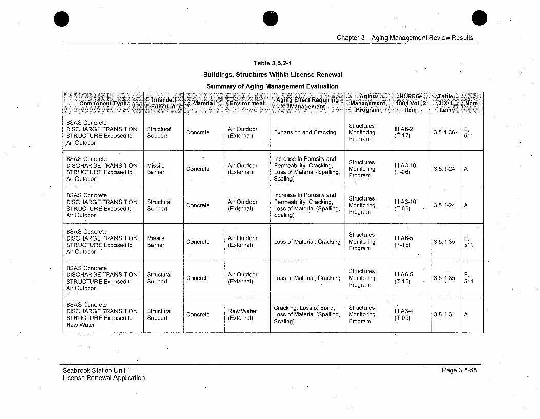
Chapter 3 - Aging Management Review Results
Table 3.5.2-1
Buildings, Structures Within License Renewal
Summary of Aging Management Evaluation'~ ].P ging NUJREG-ý jTable',
Intede AingEffect Requ iringCompnentIntene -gmn 180aVoag2ement.Not
BSAS Concrete StructuresDISCHARGE TRANSITION Structural Concrete AirExpansion and Cracking Monitoring E,(A-1 3.5.1-36STRUCTURE Exposed to Support (External) Program (T-17) 511Air Outdoor
BSAS Concrete Increase In Porosity and StructuresDISCHARGE TRANSITION Missile Concrete Air Outdoor Permeability, Cracking, Monitoring (T0 3.5.1-24 ASTRUCTURE Exposed to Barrier (External) Loss of Material (Spalling, (T-06)Air Outdoor Scaling) Program
BSAS Concrete Increase In Porosity andAir Outdoor Perebilty Craki Stuctre II1.A3-10DISCHARGE TRANSITION Structural Concrete racing, Monitoring 3.5.1-24 ASTRUCTURE Exposed to Support (External) Loss of Material (Spalling, Program (T-06)Air Outdoor Scaling)
BSAS Concrete StructuresDISCHARGE TRANSITION Missile Concrete Air Outdoor Loss of Material, Cracking Monitoring (-5 3.5.1-35 E,STRUCTURE Exposed to Barrier (External) Program (T-15) 3511Air Outdoor
BSAS Concrete StructuresDISCHARGE TRANSITION Structural Air Outdoor iII.A6-5 E,STRUCTURE Exposed to Support Concrete Loss of Material, Cracking Monitoringram (T-15) 3.5.1-35 11Air Outdoor
BSAS Concrete Cracking, Loss of Bond, StructuresDISCHARGE TRANSITION Structural Concrete Raw Water Loss of Material (Spalling, Monitoring (T0.A34 3.5.1-31 ASTRUCTURE Exposed to Support (External) Scaling) Program(T-05)Raw Water
Seabrook Station Unit 1License Renewal Application
Page 3.5-55
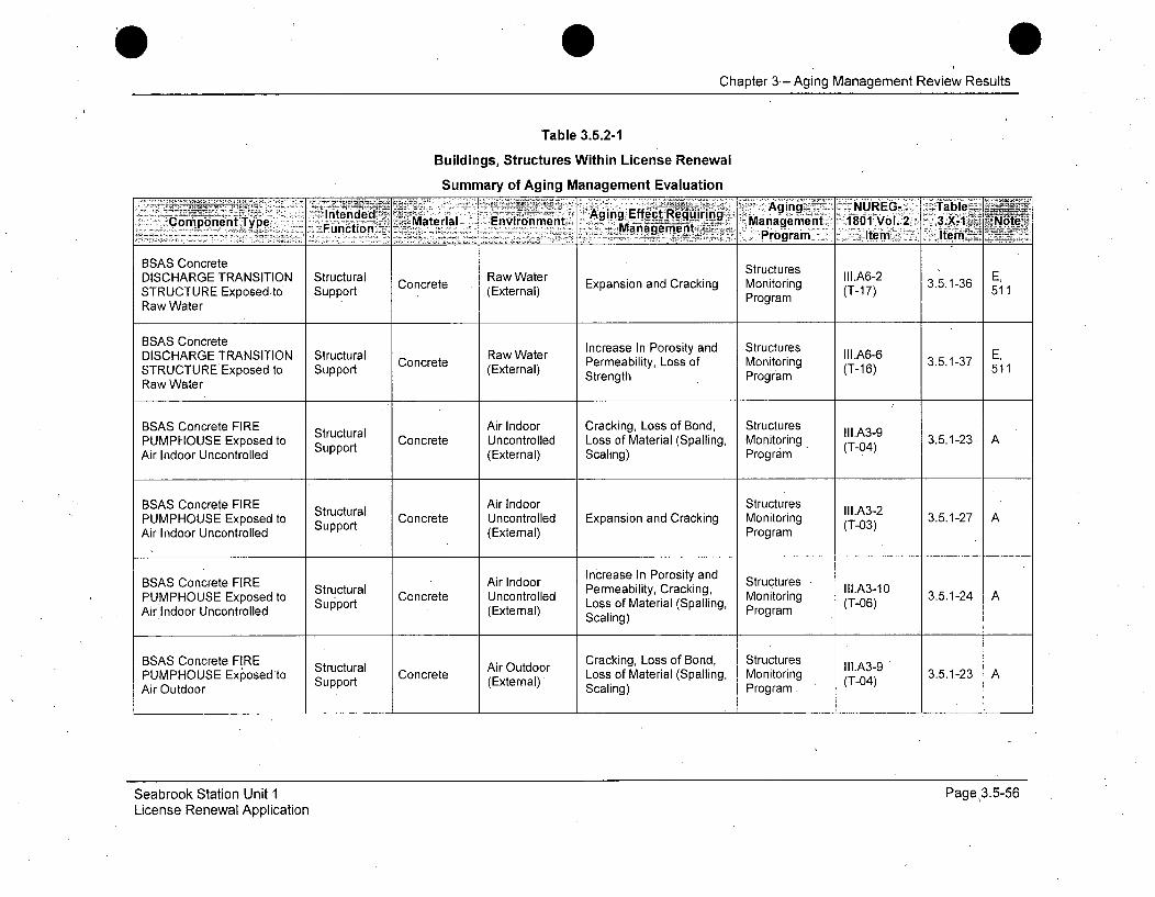
0Chapter 3 - Aging Management Review Results
Table 3.5.2-1
Buildings, Structures Within License Renewal
Summary of Aging Management Evaluation
- -•i.i: -! - Aging> -NUREG- Table __
BSAS Concrete StructuresDISCHARGE TRANSITION Structural Concrete Raw Water II1.A6-2 E,
STRUCTURE Exposed.to Support (External) Expansion and Cracking Monitoring (T-17) 3.5.1-36 511Raw Water Program
BSAS Concrete Increase In Porosity and Structures
DISCHARGE TRANSITION Structural C t Raw Water pabiio s of Monitoring III.A6-6 E,STRUCTUREExposed to Support oncree (External) Strength Program (T-16) 3.5.1-37 511
Raw WaterBSAS Concrete FIREe nProiyan tucue
BSAS Concrete FIRE Structural Air Indoor Cracking, Loss of Bond, Structures III.A3-9PUMPHOUSE Exposed to Support Concrete Uncontrolled Loss of Material (Spalling, Monitoring (T-04) 3.5.1-23 AAir Indoor Uncontrolled (External) Scaling) Program
BSAS Concrete FIRE Structural Air Indoor Structures III.A3-2PUMPHOUSE Exposed to Support Concrete Uncontrolled Expansion and Cracking Monitoring (T-03) 3.5.1-27 AAir Indoor Uncontrolled (External) Program
BSAS Concrete FIRE Structural Air Indoor Increase In Porosity and StructuresPUMPHOUSE Exposed to Surupora Concrete Uncontrolled Permeability, Cracking, Monitoring (T-06) 3.5.1-24 AAir Indoor Uncontrolled Support (External) Loss of Material (Spalli Program
Scaling)
BSAS Concrete FIRE Structural Air Outdoor Cracking, Loss of Bond, Structures III.A3-9PUMPHOUSE Exposed to Strutu Air Outern Loss of Material (Spalling, Monitoring (T-04) 3.5.1-23 AAir Outdoor Support (External) Scaling) Program
Seabrook Station Unit 1License Renewal Application
Page 3.5-56
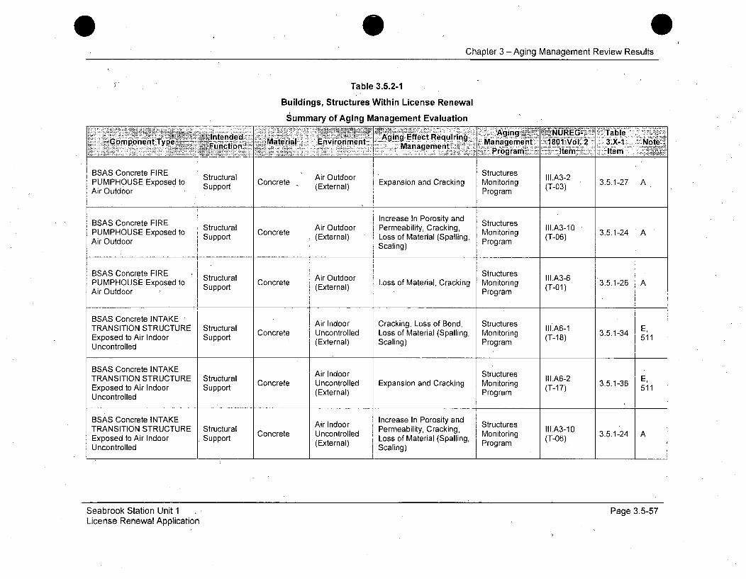
Chapter 3 - Aging Management Review Results
Table 3.5.2-1
Buildings, Structures Within License Renewal
Summary of Aging Management Evaluation
Intended .. Aginc Effect Requiring Aig ~ ~ URG alCiompot•mt Type+ intenuletio• 'Material Environment - .g q ., :. Management 1801bVol. 2 3.X-1 NoteBSASCoeanageeent., . ProcgtraesI
Structural Air Outdoor S III.A3-2PUMPHOUSE Exposed to Concrete Expansion and Cracking Monitoring 3.5.1-27 AAir Outdoor Support (External) Program (T03)
BSAS Concrete FIRE Increase In Porosity and StructuresPUMPHOUSE Exposed to Structural Concrete Air Outdoor Permeability, Cracking, Monitoring I.A3-10 3.5.1-24 A
AirpOotdtoroSupport (External) Loss of Material (Spalling, Program (T-06)Air Outdoor Scaling) (rogrng
BSAS Concrete FIRE Structural Air Outdoor Structures II1.A3-6PUMPHOUSE Exposed to Strt Concrete ArOtdr Loss of Material, Cracking Monitoring 3.5.1-26 AAir Outdoor Support (External) Program (T-O1)
BSAS Concrete INTAKE Air Indoor Cracking, Loss of Bond, StructuresTRANSITION STRUCTURE Structural Ill.A6-1 E,Exposed to Air Indoor Support Concrete Uncontrolled Loss of Material (Spalling, Monitoring (T-18) 511Uncontrolled (External) Scaling) Program
BSAS Concrete INTAKE-TRANSITION STRUCTURE Structural II1.A6-2 E.Exposed to Air Indoor Support Concrete Uncontrolled Expansion and Cracking Monitoring (T-17) 3.5.1-36 511Uncontrolled (External) Program
BSAS Concrete INTAKE Increase In Porosity andAir Indoor CkStructures lA31TRANSITION STRUCTURE Structural Concrete Uncontrolled Permeability, Cracking, rog Il.A3-10 3Exposed to Air Indoor Support (External) Loss of Material (Spalling, coarig (T-06))Uncontrolled Scaling)
Seabrook Station Unit 1License Renewal Application
Page 3.5-57
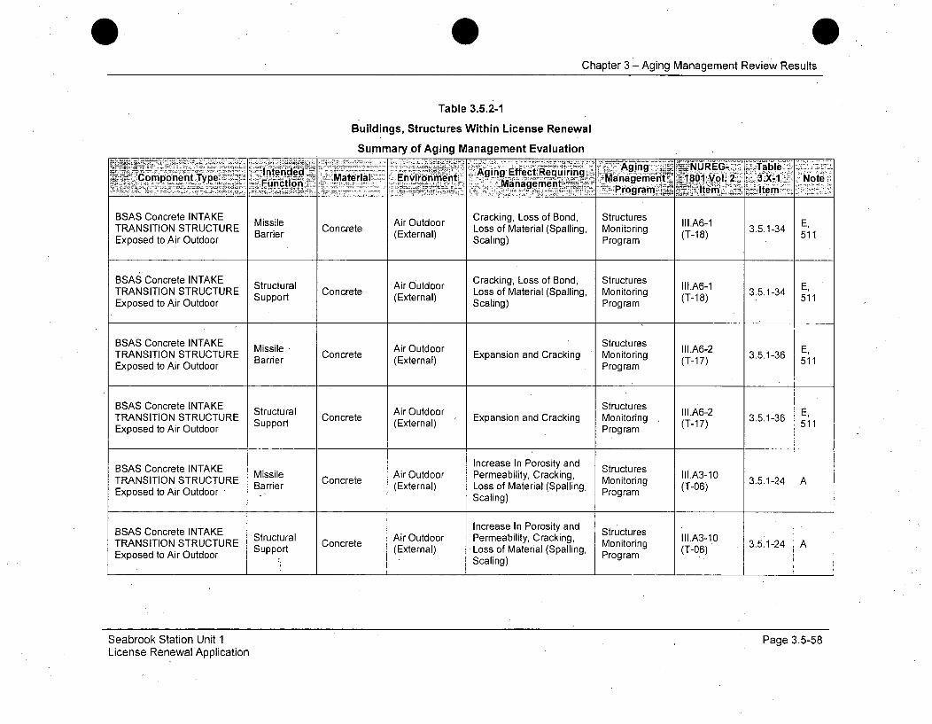
Chapter 3 - Aging Management Review Results
Table 3.5.2-1
Buildings, Structures Within License Renewal
Summary of Aging Management Evaluation
IntendedI~ ~ AgigEfc eurnging J_ :NUREG. Table:Cmomponent Type Funco Material t.. Environment 'gn Efect q-i--.- Managementoz180:-oI.2.3.X-1 :, Note-
F ntin ~%,: Management roamjki 4:emIe
BSAS Concrete INTAKE Missile Air Outdoor Cracking, Loss of Bond, Structures III.A6-1 E,TRANSITION STRUCTURE Concrete Loss of Material (Spalling, MonitoringExposed to Air Outdoor (External) Scaling) Program (T-18) 511
BSAS Concrete INTAKE Structural Air Outdoor Cracking, Loss of Bond, Structures III.A6-1 E,TRANSITION STRUCTURE C Loss of Material (Spalling, Monitoring 3.5.1-34Exposed to Air Outdoor Support (External) Scaling) Program (T-18) 511
BSAS Concrete INTAKE Structures 3.5.1-36TRANSITION STRUCTURE Missie Concrete ArOtdr Expansion and Cracking Monitoring -1 3.5.1-36
ExosdtoAr udor Barrier (External) Crcig(T-1 7) 511Exposed to Air Outdoor Program
BSAS Concrete INTAKE StructuresTRANSITION STRUCTURE Air Outdoor IIIA6-2 E
Exposed to Air Outdoor Support (External) Program (T-17) 511
BSAS Concrete INTAKE Increase In Porosity and StructuresTRANSITION STRUCTURE Missile Air Outdoor Permeability, Cracking, Monitoring II.A3-10 3.5.1-24 AExposed to Air Outdoor Barrier Concrete (External) Loss of Material (Spalling, Program (T-06)
Scaling)
Increase In Porosity andBSAS Concrete INTAKE Structural Concrete Air Outdoor Permeability, Cracking, Monitoring II1.A3-10ExpO N To Support (External) Loss of Material (Spalling, (T-06)Exposed to Air Outdoor Program
Seabrook Station Unit 1License Renewal Application
Page 3.5-58

Chapter 3 -Aging Management Review Results
Table 3.5.2-1
Buildings, Structures Within License Renewal
Summary of Aging Management Evaluation
- ,~ . , Agng NUREG- TableComponent Type, Itne ,Material Envronm ent Aging Effect Requiring 'Man a..gement , 1801 Vol.2 3.X-1, Note:Function M aManagementProga I', tem>'Thtem ¾"
BSAS Concrete INTAKE Missile Air Outdoor Structures II.A6-5 (T-TRANSITION STRUCTURE Missie Concrete (Exter Loss of Material, Cracking Monitoring 15) 3.5.1-35 A,Exposed to Air Outdoor . • Program
BSAS Concrete INTAKE S StructuresTRANSITION STRUCTURE Structural Concrete Air Outdoor Loss of Material, Cracking Monitoring A65 3.5.1-35 AExposed to Air Outdoor Support (External) Program 15)
BSAS Concrete INTAKE Structural Raw Water Cracking, Loss of Bond, Structures III.A3-4 A,
TRANSITION STRUCTURE SuIpport Concrete (External) Loss of Material (Spalling, Monitoring (T-05) 3.5.1-31Exposed to Raw Water Scaling) Program 509
BSAS Concrete INTAKE Structures E,TRANSITION STRUCTURE Support Concrete (External) Expansion and Cracking Monitoring (T-17)2 3.5.1-36 511
Exposed to Raw Water Program
BSAS Concrete INTAKE Increase In Porosity and StructresTRANSITION STRUCTURE Structural Concrete Raw Water Inreasinity and Structores IIl.A6-6 3.5.1-37 E,Exposed to Raw Water Support (External) Strength Program (T-16) 511
BSAS Concrete Masonry Air IndoorUnits FIRE PUMPHOUSE Fire Barrier Concrete Uncontrolled Cracking Fire Protection III.A3-11 3.5.1-43 E,Exposed to Air Indoor Block Program (T-12) 513Uncontrolled (External)
Seabrook Station Unit 1License Renewal Application
Page 3.5-59
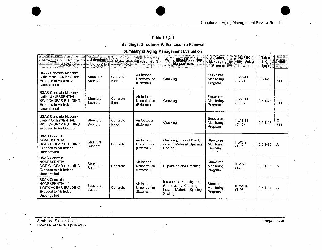
Chapter 3 - Aging Management Review Results
Table 3.5.2-1
Buildings, Structures Within License Renewal
Summary of Aging Management Evaluation
Component Type I: tend <Mate rial Environment AManaement. Aging lNUREG-2 TaxbleFunction~l ae:I~Aig ~ Rurn Management~÷81Vl2 .- ~N~__ - ---- - _ - - rogram~E- Item: ItemTyfý
BSAS Concrete Masonry Air Indoor 'StructuresUnits FIRE PUMPHOUSE Structural Concrete Uncontrolled Cracking Monitoring II1.A3-11 3.5.1-43 E,Exposed to Air Indoor Support Block • (T-12) 511Uncontrolled (External) Program
BSAS Concrete MasonryUnits NONESSENTIAL Air Indoor StructuresSWITCHGEAR BUILDING Structural Concrete Uncontrolled Cracking Monitoring II1.A3-11 3.5.1-43 E,
Exposed to Air Indoor (External) Program(T-12)Uncontrolled
BSAS Concrete Masonry StructuresUnits NONESSENTIAL Structural Concrete Air Outdoor Cracking Monitoring II1.A3-11 3.5.1-43 E,SWITCHGEAR BUILDING Support Block (External) Proram (T-12) 511Exposed to Air Outdoor Program
BSAS ConcreteNONESSENTIAL Structural Air Indoor Cracking, Loss of Bond, Structures II1.A3-9SWITCHGEAR BUILDING Support Concrete Uncontrolled Loss of Material (Spalling, Monitoring (T-04)3.5.1-23 AExposed to Air Indoor (External) Scaling) Program
Uncontrolled
BSAS ConcreteNONESSENTIAL Structural Air Indoor Structures III.A3-2SWITCHGEAR BUILDING Support Concrete Uncontrolled Expansion and Cracking Monitoring 3.5.1-27 AExposed to Air Indoor (External) Program (T03)
Uncontrolled
BSAS ConcreteNONESSENTIAL Air Indoor Perea bintPorosity and Structures
SWITCHGEAR BUILDING Structural Concrete Uncontrolled Permeability, Cracking, Monitoring (T-06) 3.5.1-24 AExposed to Air Indoor GrSupport Cocrnal) Loss of Material (Spalling, ProgramUncontrolled Scaling)
Seabrook Station Unit 1License Renewal Application
Page 3.5-60
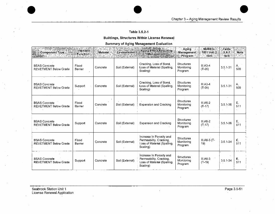
0Chapter 3 -Aging Management Review Results
Table 3.5.2-1
Buildings, Structures Within License Renewal
Summary of Aging Management Evaluation
Intended- E~7uiAging - UE - TableComponent-Typ 'uto Maera En"iro~nment ýgn EfcR-Management 1801 Vol. 2 3.-1 Note
- --. ~ 1-.Program Item I- tem
BSAS Concrete Flood Cracking, Loss of Bond, Structures III.A3-4 A,Concrete Soil (External) Loss of Material (Spalling, Monitoring (T-05) 3.5.1-31REVETMENT Below Grade Barrier (Taling 509ra
Scaling) Program50
BSAS Concrete Cracking, Loss of Bond, Structures III.A3-4 A,REVETMENT Below Grade Support Concrete Soil (External) Loss of Material (Spalling, Monitoring (T-05) 3.5.1-31 A,
Scaling) Program 509
BSAS Concrete Flood Structures II1.A6-2 E,REVETMENT Below Grade Barrier Concrete Soil (External) Expansion and Cracking Monitoring (T-17) 3.5.1-36 511Program 511
Structures II1.A6-2 E,REVETMENT Below Grade Support Concrete Soil (External) Expansion and Cracking Monitoring (T-17) 3.5.1-36 511BSASVConrENTelo GraProgram
Increase In Porosity and StructuresBSAS Concrete Flood Concrete Soil (External) Permeability, Cracking, II1.A6-3 (T- E,REVETMENT Below Grade Barrier Loss of Material (Spalling,Monitoring 19) 511
Scaling) Program
Increase In Porosity and StructuresBSAS Concrete Support Concrete Soil (External) Permeability, Cracking, III.A6-3 E,REVETMENT Below Grade Loss of Material (Spalling, Program (T-19) 511
Scaling)
Seabrook Station Unit 1License Renewal Application
Page 3.5-61

0 0Chapter 3 - Aging Management Review Results
Table 3.5.2-1
Buildings, Structures Within License Renewal
Summary of Aging Management Evaluation
....t- .... gg Effecteqird•i. Agin g NUREG- Table . .ComponentTyPe- en.-Environment - Material 10 V. X1Environment -1ol•2- 3X-1 Note
Function -Magmenagement-: Ite
BSAS Concrete Flood Increase In Porosity and Structures III.A6-6 E,
REVETMENT Below Grade Barrier Concrete Soil (External) Permeability, Loss of -Monitoring (T-16) 3.5.1-37 509,Strength Program 511
BSAS Concrete Increase In Porosity and Structures II1.A6-6 E,
REVETMENT Below Grade Support Concrete Soil (External) Permeability, Loss of Monitoring (T-16) 3.5.1-37 509,Strength Program 511
BSAS Concrete Flood Air Outdoor Cracking, Loss of Bond, Structures IlI.A61 E,REVETMENTExposed to Barrier Concrete (External) Loss of Material (Spalling, Monitoring (T-18) 3.5.1-34 511Air Outdoor Scaling) Program
BSAS Concrete Air Outdoor Cracking, Loss of Bond, Structures II.A6-1 E,REVETMENT Exposed to Support Concrete ArOtdr Loss of Material (Spalling, Monitoring (T-18) 3.5.1-34 1Air Outdoor (External) Scaling) Program (T-18) 51
BSAS Concrete Flood Air Outdoor Structures l11.A6-2 E,REVETMENT Exposed to Barrier Concrete (External) Expansion and Cracking Monitoring (T17) 3.5.1-36
Air Outdoor Program 511
BSAS Concrete Air Outdoor Structures III.A6-2 E,REVETMENT Exposed to Support Concrete (External) Expansion and Cracking Monitoring (T-17) 3.5.1-36 511Air Outdoor Program
Seabrook Station Unit 1License Renewal Application
Page 3.5-62
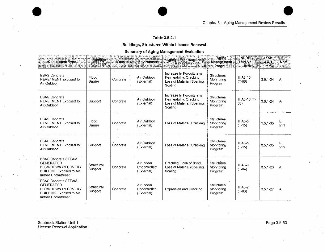
Chapter 3 -Aging Management Review Results
Table 3.5.2-1
Buildings, Structures Within License Renewal
Summary of Aging Management Evaluation
BSAS Concrete FodArOtor Increase In Porosity and Structures IIA1REETETlxosdto Brre Concrete (Etra) PemaiiyCakn, Monitoring (T0)3.5.1-24 A.Loss of Material (Spalling, Po "gr
Air Outdoor Scaling) rin
BSAS Concrete Increase In Porosity and StructuresREVETMENT Exposed to o Concrete Air Outdoor Permeability, Cracking, Monitoring (- 3.5.1-24 A
Air Outdoor (External) Loss of Material (Spalling, Program 06)Scaling)
BSAS Concrete Flood Ai Outdoor StructuresREVETMENT Exposed to Barpiet Concrete (Extern Loss of Material, Cracking Monitoring (T-15) 3.5.1-E4 AAir Outdoor Barrier Program
BSAS Concrete Air Outdoor Structures IS' 51REVETMENT Exposed to Support Concrete Ai (Exteornl Program E
AREEMN Exosdto Baroorocrt (External) Loss of Material, Cracking Monitoring (T- 15) 3.5.1-35 511
Air Outdoor Program
BSAS Concrete STEAMGENERATOR Structural Air Indoor Cracking, Loss of Bond, Structures III.A3-9BLOWDOWN RECOVERY Support Concrete Uncontrolled Loss of Material (Spalling, Monitoring (T-04) 3.5.1-23 ABUILDING Exposed to Air (External) Scaling) ProgramIndoor Uncontrolled
BSAS Concrete STEAMGENERATOR Structural Air Indoor StructuresBLOWDOWN RECOVERY Support Concrete Uncontrolled Expansion and Cracking Monitoring (T-03) 3.5.1-27 ABUILDING Exposed to Air (External) Program
Indoor Uncontrolled
Seabrook Station Unit 1License Renewal Application
Page 3.5-63

Chapter 3 -Aging Management Review Results
Table 3.5.2-1
Buildings, Structures Within License Renewal
Summary of Aging Management Evaluation
IntendedEM eaz Evon t Aginig:Effect Requiring A~q~= NRGi alCom~ponent Type Maera Eniomn. Maaeet ~ ~ n ent. 1806f l. -,3.Xý-1 Nt
BSAS Concrete STEAMGENERATOR Structural Air Indoor Increase In Porosity and Structures IlI.A310BLOWDOWN RECOVERY Strt Concrete Uncontrolled PerMeail Cracking, Monitoring (T-06) 3.5.1-24 ABUILDING Exposed to Air Support (External) Loss of Material (Spalling, ProgramIndoor Uncontrolled Scaling)
BSAS Concrete STEAMGENERATOR Structural C r Air Outdoor Cracking, Loss of Bond, Structures II1.A3-9BLOWDOWN RECOVERY Concrete Loss of Material (Spalling, Monitoring (T04)3.5.1-23BUILDING Exposed to Air Support (External) Scaling) ProgramOutdoorBSAS Concrete STEAM
GENERATOR Structural Air Outdoor Expansion IIa.A3-2 (T-BLOWDOWN RECOVERY Support Concrete (External) Expansion and Cracking Programnitring 03) 3.5.1-27BUILDING Exposed to AirPrgaOutdoor
BSAS Concrete STEAMGENERATOR Increase In Porosity and StructuresBLOWDOWN RECOVERY Structural Concrete Air Outdoor Permeability, Cracking, Monitoring II.A3-10BLDIN E RY Support (External) Loss of Material (Spalling, (T-06) 3.5.1-24 ABUILDING Exposed to Air Scln)ProgramOutdoor Scaling)
BSAS Concrete STEAMGENERATOR Structural. Air Outdoor Ltring Ill.A3-6BLOWDOWN RECOVERY Support Concrete (External) Loss of Material, Cracking Monitoring (T-0r1 3.5.1-26BUILDING Exposed to Air ProgramOutdoor
BSAS Rock (Riprap) Structures lA69ER ockT(RNprap) Flood Air Outdoor Loss of Material, Loss of tr g IIIA6-9 3.5.1-48 E,REVETMENT Exposed to Barrier Rock (External) Form Program (T-22) 511Air OutdoorPrga
Seabrook Station Unit 1License Renewal Application
Page 3.5-64

Chapter 3 - Aging Management Review Results
Table 3.5.2-1
Buildings, Structures Within License Renewal
Summary of Aging Management Evaluation
InenedAging NUREG- "TAbleComponent Type Material Environmient,, AigEfcReurn Management2 'IBO~l 3.X,-1 Note
Fmicton anagprnentFiictfn-~., M , .~ Prgran - ,Itemi ~jtiem~
BSAS Rock (Riprap) Air Outdoor Loss of Material, Loss of Structures II1.A6-9 E,REVETMENT Exposed to Support Rock (External) Form Monitoring (T-22) 3.5.1-48 511Air Outdoor Program
BSAS Roofing For FIRE Separation, StructuresPUMPHOUSE Exposed to Structural Roofing Air Outdoor Environmental Monitoring III.A6-12 3.5.1-44 H,Air Outdoor Support (External) Degradation, Water In- (TP-7) 505Leakage Program
BSAS Roofing For Separation, StructuresNONESSENTIAL Structural Roofing Air Outdoor Environmental .A6-12 3.5.1-44 H,SWITCHGEAR BUILDING Support (External) Degradation, Water In- Program (TP-7) 505Exposed to Air Outdoor Leakage P
BSAS Roofing For STEAM Separation,GENERATOR Structural Air Outdoor Environmental Structures Ii.A6-12 H,BLOWDOWN RECOVERY Roofing (External) Degradation, Water In-3.5.1-44BUILDING Exposed to Air Leakage - ProgramOutdoorBSAS Slide Bearing(Fluorogold®) Air Indoor StructuresNONESSENTIAL Structural FluorogoldI Uncontrolled Fretting Or Lockup Monitoring I11.B4-2 3.5.1-52 CSWITCHGEAR BUILDING Support (External) Program (TP-1)Exposed to Air IndoorUncontrolledBSAS Stainless Steel No AgingSTEAM GENERATOR Structural Stainless Air Indoor nagingBLOWDOWN RECOVERY Strt Steel Uncontrolled None Manam lIB-5 3.5.1-59 ABUILDING Exposed to Air Support Steel (External) Program (TP-5)Indoor Uncontrolled Required
Seabrook Station Unit 1License Renewal Application
Page 3.5-65
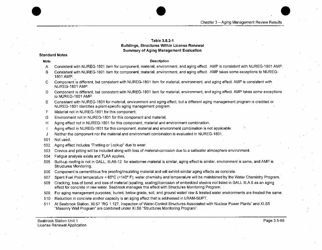
Chapter3 - Aging Management Review Results
Table 3.5.2-1Buildings, Structures Within License RenewalSummary of Aging Management Evaluation
Standard Notes
Note DescriptionA Consistent with NUREG-1801 item for component, material, environment, and aging effect. AMP is consistent with NUREG-1801 AMP.
B Consistent with NUREG-1801 item for component, material, environment, and aging effect. AMP takes some exceptions to NUREG-1801 AMP.
C Component is different, but consistent with NUREG-1 801 item for material, environment, and aging effect. AMP is consistent withNUREG-1801 AMP.
D Component is different, but consistent with NUREG-1 801 item for material, environment, and aging effect. AMP takes some exceptionsto NUREG-1801 AMP.
E Consistent with NUREG-1801 for material, environment and aging effect, but a different aging management program is credited orNUREG-1801 identifies a plant-specific aging management program.
F Material not in NUREG-1 801 for this component.
G Environment not in NUREG-1 801 for this component and material.H Aging effect not in NUREG-1 801 for this component, material and environment combination.
I Aging effect in NUREG-1801 for this component, material and environment combination is not applicable.J Neither the component nor the material and environment combination is evaluated in NUREG-1 801.
501 Not used.502 Aging effect includes "Fretting or Lockup" due to wear.
503 Crevice and pitting will be included along with loss of material-corrosion due to a saltwater atmosphere environment.504 Fatigue analysis exists and TLAA applies.
505 Built-up roofing is not in GALL; IILA6-12 for elastomer-material is similar, aging effect is similar, environment is same, and AMP isStructures Monitoring.
506 Component is cementitious fire proofing/insulating material and will exhibit similar aging effects as concrete.
507 Spent Fuel Pool temperature < 60 0C (<1400 F); water chemistry and temperature will be maintained by the Water Chemistry Program.508 Cracking, loss of bond, and loss of material (spalling, scaling)/corrosion of embedded steel-is not listed in GALL III.A.6 as an aging
effect for concrete in raw water. Seabrook manages this effect with Structures Monitoring Program.
509 For aging management purposes, buried, below grade, soil, and ground water/ raw & treated water environments are treated the same.
510 Reduction in concrete anchor capacity is an aging effect that is addressed in LRAM-SUPT.511 At Seabrook Station, XI.S7 "RG 1.127, Inspection of Water-Control Structures Associated with Nuclear Power Plants" and XI.S5
"Masonry Wall Program" are combined under XI.S6 "Structures Monitoring Program".
Seabrook Station Unit 1License Renewal Application
Page 3.5-66
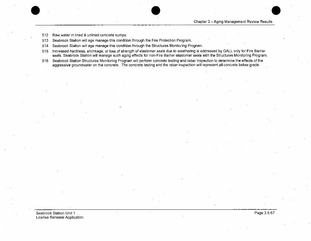
Chapter 3 -Aging Management Review Results
512 Raw water in lined & unlined concrete sumps.513 Seabrook Station will age manage this condition through the Fire Protection Program.
514 Seabrook Station will age manage this condition through the Structures Monitoring Program.515 Increased hardness, shrinkage, or loss of strength of elastomer seals due to weathering is addressed by GALL only for Fire Barrier
seals. Seabrook Station will manage such aging effects for non-Fire Barrier elastomer seals with the Structures Monitoring Program.516 Seabrook Station Structures Monitoring Program will perform concrete testing and rebar inspection to determine the effects of the
aggressive groundwater on the concrete. The concrete testing and the rebar inspection will represent all concrete below grade.
Seabrook Station Unit 1License Renewal Application
Page 3.5-67
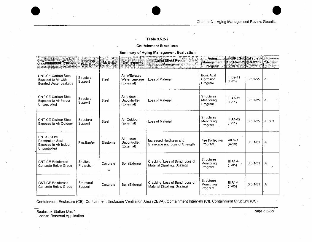
Chapter 3 - Aging Management Review Results
Table 3.5.2-2
Containment Structures
Summary of Aging Management Evaluation
Intended> aeiI Evr'mn Agingý,Effect Requiring gn yUE. ja ~ ,Component Type,; i. Materil eEvrOnment- Management 1801 Vol. 2 3X I Note
CNT-CE-Carbon Steel Structural Air w/Borated Boric Acid III.B2-11Exposed to Air with Support Steel Water Leakage Loss of Material Corrosion (T-25) 3.5.1-55 ABorated Water Leakage S (External) Program
CNT-CE-Carbon Steel Sttl Air Indoor Structures Ilt.A-12Exposed to Air Indoor Suprutu Steel Uncontrolled Loss of Material Monitoring (T-1 1) 3.5.1-25Uncontrolled (External) Program
Structures II1.A1-12 3.1-5 A50
CNT-CE-Carbon Steel Structural Steel Air Outdoor Loss of Material MonitoringExposed to Air Outdoor Support (External) Program (T-11)
CNT-CE-Fire Air IndoorPenetration Seal FireBarrier Elastomer Uncontrolled Increased Hardness and Fire Protection VII.G-1 3.3.1-61 AExposed to Air Indoor (External) Shrinkage and Loss of Strength Program (A-19)Uncontrolled
CNT-CE-Reinforced Shelter, Cracking, Loss of Bond, Loss of Structures III.A1-4Concrete Below Grade Protection ConcreteMaterial (Spalling, Scaling) Monitoring (T-05) 3.5.1-31 A
Program
Structures llA14 35-1 A
CN-E-enfre SrctrlCracking, Loss of Bond, Loss of Stutrs III.A1-4CNT-CE-Reinforced Structural Concrete Soil (External) Monitoring (T-05) 3.5.1-31 AConcrete Below Grade Support Material, (Spalling, Scaling) Program
Containment Enclosure (CE), Containment Enclosure Ventilation Area (CEVA), Containment Internals (Cl), Containment Structure (CS)
Seabrook Station Unit 1License Renewal Application
Page 3.5-68

Chapter 3 -Aging Management Review Results
Table 3.5.2-2
Containment Structures
Summary of Aging Management Evaluation
Intened Aing< NUREG~ Table~ComponentfType Function Material Environment ernal) xpansinand iracing anAgiement 1801 Vol. 2 3.X.1 Note
Coret Beow Grade PManagementrot nProgramI
CNT-CE-Reinforced Shelter, Structures III.A1-2Concrete Below Grade Protection Concrete Soil (External) Expansion and Cracking Monitoring (T-03) 3.5.1-27 A
Concete elowGrad SuportProgram
Increase in Structures III.A1-2CNT-CE-Reinforced Strctura Concrete Soil (External) Expansion and Cracking Monitoring (T-03) 3.5.1-27 AConcrete Below Grade SPorocti Program
CNT-CE-Reinforced Shelter, Increase in Porosity and Structures lll.A15
CNTCE-einorcd Srucura Cocree Sil Exernl) ncrasein oroityandStrctuesA1-5 3.5.1-31 AConcrete Below Grade Support Concrete Soil (External) Permeability, Cracking, Loss of Monitoring (T-07)Material (Spalling, Scaling) Program
CNT-CE-Reinforced Shelter, Concrete Soil uExte Increase in Porosity and Mtr uctuA-0 3.5.1-32 A, 509Concrete Below Grade Protection Cxernal Permeability, Loss of Strength onioring (T-07)
Structures ll1.A1-7
CNT-CE-Reinforced Structural Concrete Soil (External) Increase in Porosity and Monitoring (T-02) 3.5.1-32 A, 509Concrete Below Grade SProrteto Permeability, Loss of Strength Program (-2
Concrete Below Grade Support Concrete SEoil (External) Permeability, Loss of Strength M ontaing (Tr02) (CS)Program
Containment Enclosure (CE), Containment Enclosure Ventilation Area (CEVA), Containment Internals (CI), Containment Structure (CS)
Seabrook Station Unit 1License Renewal Application
Page 3.5-69
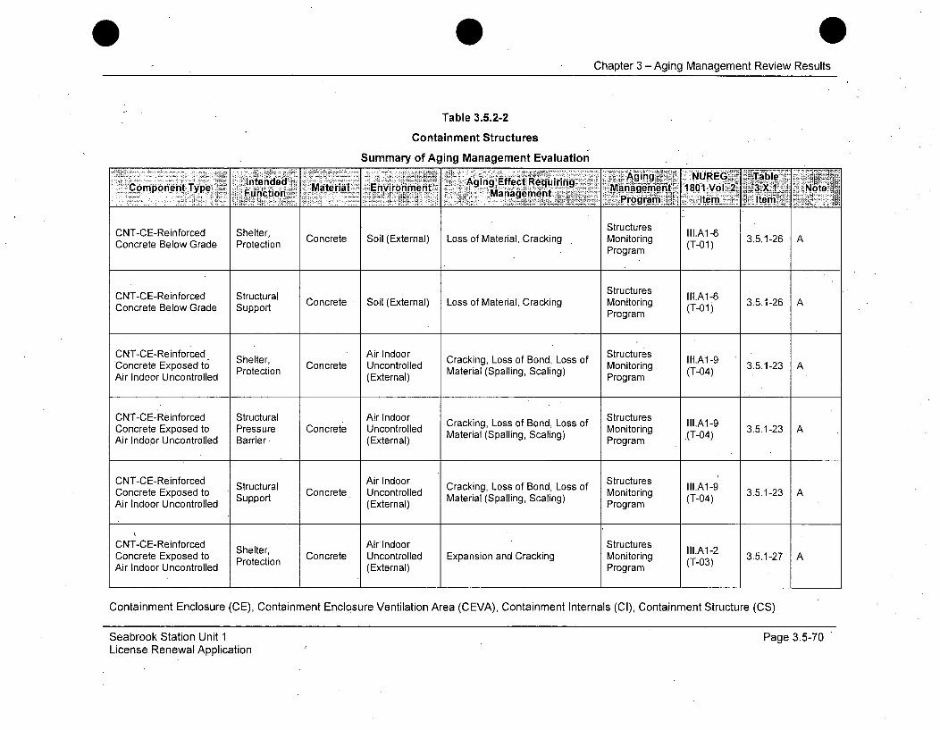
Chapter 3 - Aging Management Review Results
Table 3.5.2-2
Containment Structures
Summary of Aging Management Evaluation
Intended Aging Effect Requi1ring6 ngComponent Type Fueltion Material Environment aging Mnagemrient 1801 Vol.2 3.X.1 NoteProgCrm B aItem Item Getr
CNT-CE-Reinforced Shelter, Structures II.A1-6Concrete BelowGrade Protection Concrete Soil (External) Loss of Material, Cracking Monitoring (T-01) 3.5.1-26 A
Program
CNT-CE-Reinforced Structural Structures lll.A1-6Concrete Below Grade Support Concrete Soil (External) Loss of Material, Cracking Monitoring (T-04) 3.5.1-26 A
Program
CNT-CE-Reinforced Shelter, Air Indoor Cracking, Loss of Bond, Loss of Structures LA1-9Concrete Exposed to Protection Concrete Uncontrolled Material (Spalling Scaling) Monitoring (T04) 3.5.1-23 AAir Indoor Uncontrolled (External) Program
CNT-CE-Reinforced Structural Air Indoor Cr Structures lll.A1-9Concrete Exposed to Pressure Concrete Uncontrolled acking LSs ofaBond, Monitoring (T-04) 3.5.1-23Air Indoor Uncontrolled Barrier* (External) Maeil(plig cln)Program
Concrete Exposed to Stpprutua Concrete. Uncontrolled Material (Spalling, Scaling) Mntrn T0) 3512Air Indoor Uncontrolled (External) Program
CNT-CE-Reinforced Shelter, Air Indoor Structures lll.A1-2Concrete Exposed to Protection Concrete Uncontrolled Expansion and Cracking Monitoring (T-03) 3.5.1-27 AAir Indoor Uncontrolled (External) Program
Containment Enclosure (CE), Containment Enclosure Ventilation Area (CEVA), Containment Internals (Cl), Containment Structure (CS)
Seabrook Station Unit 1License Renewal Application
Page 3.5-70
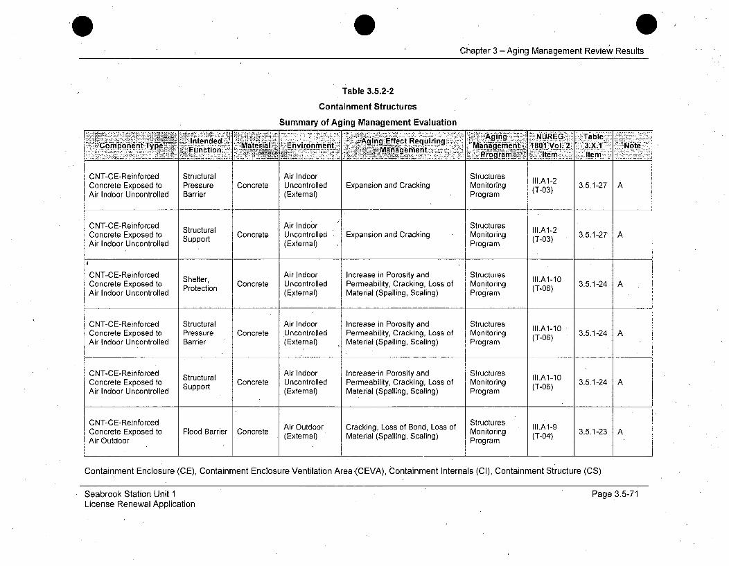
Chapter 3 -Aging Management Review Results
Table 3.5.2-2
Containment Structures
Summary of Aging Management Evaluation
_ Intended Eiomet Xgiiig Effect Requiring A ig. UEý al.. Component Typei= Function Material " Environment .- "Manageiment .::1801 Vol. 2 3X1 Note.____a Ie -item-
CNT-CE-Reinforced Structural Air Indoor StructuresConcrete Exposed to Pressure Concrete Uncontrolled Expansion and Cracking Monitoring (T-03) 3.5.1-27 AAir Indoor Uncontrolled Barrier (External) Program
CNT-CE-Reinforced Air Indoor StructuresStructural Stutue lll.A1-2Concrete Exposed to Support Concrete Uncontrolled Expansion and Cracking Monitoring (T-03) 3.5.1-27 AAir Indoor Uncontrolled (External) Program
CNT-CE-Reinforced Shelter, Air Indoor Increase in Porosity and Structures Ill.A1-10Concrete Exposed to Protection Concrete Uncontrolled Permeability, Cracking, Loss of Monitoring (T-06) 3.5.1-24Air Indoor Uncontrolled (External) Material (Spalling, Scaling) Program
CNT-CE-Reinforced Structural Air Indoor Increase in Porosity and Structures IllA1-10Concrete Exposed to Pressure Concrete Uncontrolled Permeability, Cracking, Loss of Monitoring (T-06) 3.5.1-24 AAir Indoor Uncontrolled Barrier (External) Material (Spalling, Scaling) Program
CNT-CE-Reinforced Structural Air Indoor Increase-in Porosity and Structures II1A1-10Concrete Exposed to Support Concrete Uncontrolled Permeability, Cracking, Loss of Monitoring (T-06) 3.5.1-24 AAir Indoor Uncontrolled (External) Material (Spalling, Scaling) Program
CNT-CE-Reinforced StructuresCncre oed Flood Barrier Concrete Air Outdoor Cracking, Loss of Bond, Loss of Montoring II1.A1-9 3.5.1-23
Air Outdoor e (External) Material (Spalling, Scaling) Program (T-04)
Containment Enclosure (CE), Containment Enclosure Ventilation Area -(CEVA), Containment Internals (CI), Containment Structure (CS)
Seabrook Station Unit 1License Renewal Application
Page 3.5-71
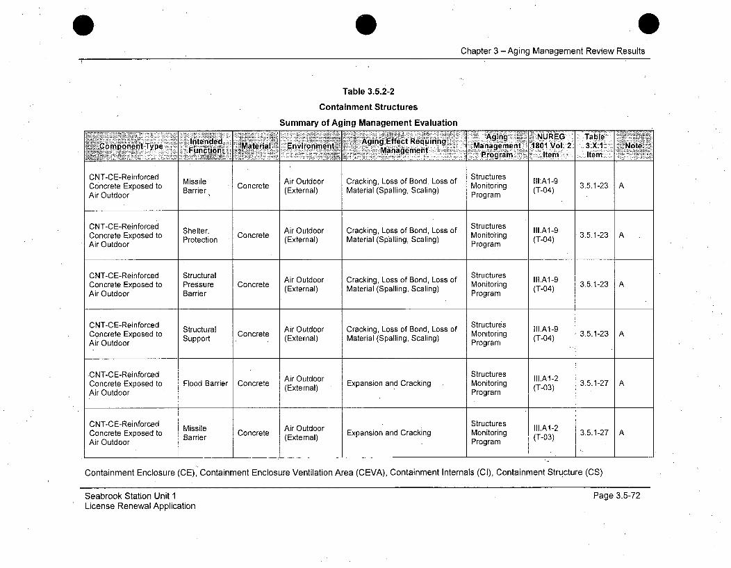
Chapter 3 - Aging Management Review Results
Table 3.5.2-2
Containment Structures
Summary of Aging Management Evaluation
CNTCEAgingce StructuresblIntended Aging Agfeng ReqREin Table-Component TyeMtra Environment EfctRqrig Manageme't'i ~1801 Vol' 3.X1 'Note.FunctionTye Mteia Management Proga ItmitemCNT-CE-Reinforced Missile Air Outdoor Cracking, Loss of Bond, Loss of ntorigA1-9
CocrteEpoedto Mssle Cocet Sntrutresg (T:A-04 3.5.1-23 AConcrete Exposed to Barrier Concrete (External) Material (Spalling, Scaling) Program (T-04)Air OutdoorPrga
CNT-CE-Reinforced SetrArOtor CaknLsofBdosof Structures IIA-Concrete Exposed to Shelter, Concrete Monitoring 3.5.1-23 AAir Outdoor Protection (External) Material (Spalling, Scaling) Program (T-04)Structures llA19 35-2 A
CNT-CE-Reinforced Structural Air Outdoor Cracking, Loss of Bond, Loss of trIIg.A1-9Concrete Exposed to Pressure Concrete (External) Material (Spalling, Scaling) Prog (T-04)Air Outdoor BarrierProgram
CN-ERifre tutrlStructures llA-9 3512 A
CNT-CE-Reinforced Structural Air Outdoor Cracking, Loss of Bond, Loss of Mtorin IIt.A1-9Concrete Exposed to Support Concrete (External) Material (Spalling, Scaling) Monitoring (T-04) 3.5.1-23 AAir Outdoor Program
CNT-CE-Reinforced Air Outdoor Structures adrkgotiConcrete Exposed to Flood Barrier Concrete (External) Mansion and Scking Monitoring (T-03) 3.5.1-27 AAir Outdoor Program
CNT-CE-Reinforced Missile Air Outdoor Structures IIa.AM-2Concrete Exposed to Barrier Concrete (External) Expansion and Cracking Monitoring (T-03) 3.5.1-27 AAir Outdoor Program
Containment Enclosure (CE), Containment Enclosure Ventilation Area (CEVA), Containment Internals (Cl), Containment Structure (CS)
Seabrook Station Unit 1License Renewal Application
Page 3.5-72

Chapter 3 -Aging Management Review Results
Table 3.5.2-2
Containment Structures
Summary of Aging Management Evaluation
lintended Maeil Evrnet~ ygn fetRequiringC~omponent Type ...cio Maeil Eniomn Management ,~net 180"1 V&]27 3`X.1 ~7 Note,
CNT-CE-Reinforced SheIer Ai OudoSrutue lII.A1-2 3."12Concrete Exposed to eterre r uExpansion and Cracking Monitoring 3..-2)Air Outdoor Protection (External) Program ItemIe
CNT-CE-Reinforced Structural StructuresAir Outdoor IIl.A1-2
Concrete Exposed to Pressure Concrete Ai udo xaso n rcigMntrn I.2 3.5.1-27 A
Concrete Exposed to Pressure Concrete (External) Expansion and Cracking Monitoring (T-03) 3.5.1-27 AAir Outdoor Barrier Program
CNT-CE-Reinforced Structural Air Outdoor Structures III.A1-2Concrete Exposed to Support Concrete (External) Expansion and Cracking Monitoring (T-03) 3.5.1-27 A
Air Outdoor Program
CNT-CE-Reinforced Air Outdoor Increase in Porosity and Structures III.Al-10Concrete Exposed to Flood Barrier Concrete (External) Permeability, Cracking, Loss of Monitoring (T-06) 3.5.1-24 AAir Outdoor Material (Spalling, Scaling) Program
CNT-CE-Reinforced Missile Air Outdoor Increase in Porosity and Structures III.Al-10 3Concrete Exposed to Barrier .Concrete (External) Permeability, Cracking, Loss of Monitoring (T-06)Air Outdoor Material (Spalling, Scaling) Program
CNT-CE-Reinforced Shelter, Air Outdoor Increase in Porosity and Structures Al-bConcrete Exposed to Protection Concrete, Outer Permeability, Cracking, Loss of Monitoring (TA-10 3.5.1-24 AAir Outdoor Material (Spalling, Scaling) Program
Containment Enclosure (CE), Containment Enclosure Ventilation Area (CEVA), Containment Internals (CI), Containment Structure (CS)
Seabrook Station Unit 1License Renewal Application
Page 3.5-73

Chapter 3 -Aging Management Review Results
Table 3.5.2-2
Containment Structures
Summary of Aging Management Evaluation
Agng NUREGý Table 1
CNT-CE-Reinforced Structural ArOtor Increase in Porosity and Structures IIIA1-10 .512Concrete Exposed to Pressure Concrete Ar Outdorn Permeability, Cracking, Loss of Monitoring (T-06) 3Air Outdoor Barrier (External) Material (Spalling, Scaling) Program
CNT-CE-Reinforced Structural Air Outdoor Increase in Porosity and Structures IIIA1-10Concrete Exposed to Strucura Concrete (External) Permeability, Cracking, Loss of Monitoring (T-06) 3.5.1-24 AAir Outdoor Suppor Material (Spalling, Scaling) Program
CNT-CE-Reinforced Air Outdoor Structures IItA1-6Concrete Exposed to Flood Barrier Concrete (External) Permabil, Cracking Monitoring (T-06) 3.5.1-24 AAir Outdoor Program
CNT-CE-Reinfrced MissileAir Outdoor Structures III.A1-6
Concrete Exposed to Concrete Loss of Material, Cracking Monitoring (T-01) 3.5.1-26 AAir Outdoor Protcio (External) Program
Structures lllA1-6CNT-CE-Reinforced Steteru Concrete Loss of Material, Cracking Monitoring 3.5.1-26 A
Concrete Exposed to Protection (External) (T-01)
CNT-CE-Reinforced Structural ArOtorStructures IIA-Concrete Exposed to Pressure Concrete (External) Loss of Material, Cracking Monitoring (T-01) 3.5.1-26 A
Air Outdoor Barrier Program
Containment Enclosure (CE), Containment Enclosure Ventilation Area (CEVA), Containment Internals (CI), Containment Structure (CS)
Seabrook Station Unit 1License Renewal Application
Page 3.5-74

Chapter 3 - Aging Management Review Results
Table 3.5.2-2
Containment Structures
Summary of Aging Management EvaluationAging NJEG .Table~t~mp~ '~Intended Maeil. nioAging Effect,,Re~qirnj' 1
CTC-enocdStructures llA16 3512C -ComponeintorceMStructural Concrete Air Outdoor LossgofeMat1e1r6ial, Crckn Mnoi
Concrete Exposed to Supprutua (oce e xternal)ril cakigMoiorn (T-01) 3.1-•AAir Outdoor Supr Etra)Program
Structures.- l.BI 3.5.1-50 A
• CNT-CE-Stainless Steel Structural Stainless. Air Outdoor Structures III.B2-6Exposed to Air Outdoor Support Steel (External) Loss of MaterialP Monitoring (Tr-m 3.5.1-26 A
ArOtorProgram -
CNT-CEVA-Built-Up Shelter, Structures III.A6-12Poiroltetn Roofing Air Outdoor Separation, Environmental Monitoring - 3.5.1-44 505,Roofing Exposed to Air otection (External) Degradation, Water In-Leakage 3TP-7)1- 5
Outdoor . Program
CNT-CEVA-Carbon Air w/Borated Boric AcidSteel Door Exposed to HELB Steel Water Leakage Loss of Material Corrosion II.B2-11 3.5.1-55 AAir with Borated Water Shielding (External) Program (T-25)Leakage
CNT-CEVA-Carbon Air w/Borated Boric AcidSteel Door Exposed to Shelter, Steel Water Leakage Loss of Material Corrosion A1.B2-11 3.5.1-55 AAir with Borated Water Protection (External Program (T-25)Leakage (
CNT-CEVA-Carbon Air w/Borated Boric AcidSteel Door Exposed to Structural AiIIort1. oi Ai l.B2-1 1Stee Dooratxpoed Wter Stcupra Steel . Water Leakage Loss of Material Corrosion (T-25 3.5.1-55 AAir with Borated Water Support (External - Program (T-25)Leakage
Containment Enclosure (CE), Containment Enclosure Ventilation Area (CEVA), Containment Internals (CI), Containment Structure (CS)
Seabrook Station Unit 1License Renewal Application
Page 3.5-75
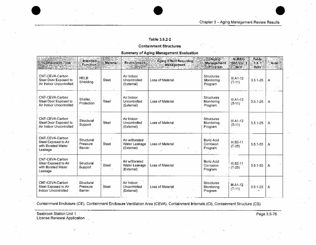
Chapter 3 -Aging Management Review Results
Table 3.5.2-2
Containment Structures
Summary of Aging Management Evaluation
Cteeleoponn Aging EffecttRequiringNU
Ste Indoor Enxontsed t hiel Steel Uncontrolled Loss of Material Monitoring ( 190-112 3.5.1-25 AS(External) Program T
CNT-CEVA-Carbon Air Indoor StructuresSteel Door Exposed to Shelterin Steel Uncontrolled Loss of Material Monitoring (T-11) 3.5.1-25 AAir Indoor Uncontrolled (External) Program
CNT-CEVA-Carbon Air Indoor StructuresSteel Door Exposed to Sura Steel Uncontrolled Loss of Material Monitoring (T-1 3.5.1-25 AAir Indoor Uncontrolled (External) Program
CNT-CEVA-CarbonSteel Exposed to Air Structural Air w/Borated Boric Acid 111.12-11with Borated Water Pressure Steel Water Leakage Loss of Material Corrosion 2 3.5.1-55 ALeakage Barrier (External) Program
C NT-C EVA-Ca rbonStelExposed o Air w/Borated Boric AcidSteel Exposed to Air Structural Steel Water Leakage Loss of Material Corrosion 1II.B2-11 3.5.1-55 Awith Borated Water Support (External) Program (T-25)Leakage
CNT-CEVA-Carbon Structural Air Indoor StructuresSteel Exposed to Air Pressure Steel Uncontrolled Loss of Material Monitoring II1.A112 3.5-1-25 AIndoor Uncontrolled Barrier (External) Programs (T-1i1)
Containment Enclosure (CE), Containment Enclosure Ventilation Area (CEVA), Containment Internals (CI), Containment Structure (CS)
Seabrook Station Unit 1License Renewal Application
Page 3.5-76
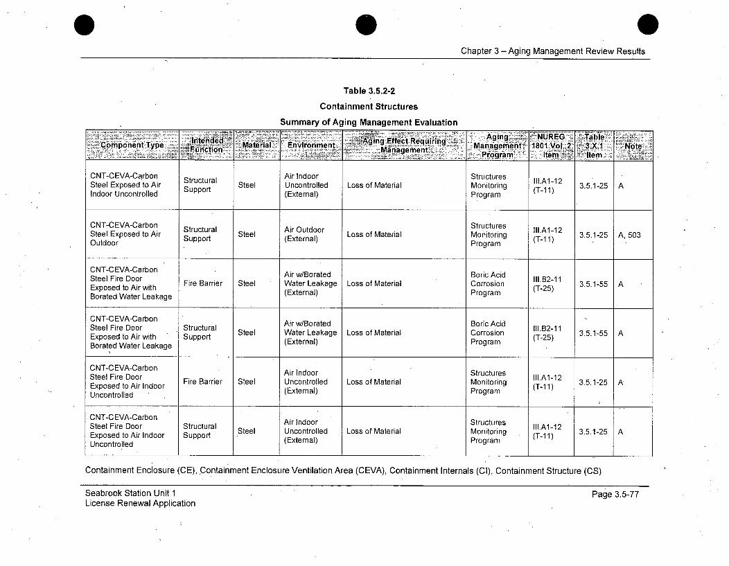
Chapter 3 -Aging Management Review Results
Table 3.5.2-2
Containment Structures
Summary of Aging Management Evaluation
-intended-C irAing Effect Requiring SAgicgures IISeComponent Type FU Marctu Sterial Enconment Management Moniogrientg 1801 Vol. 2 3.X.1 NoteP-ý,ýrogram I]tem _ Item
CNT-CEVA-Carbon Structural Air Indoor Structures Ill.A1-12Steel Exposed to Air Support Steel Uncontrolled Loss of Material Monitoring (T-1 1) 3.5.1-25 AIndoor Uncontrolled (External) Program
CNT-CEVA-Carbon Structural Sel Air Outdoor LostfMaerauMntoring (T.A-121Steel Exposed .to Air Support Sel (External) Ls fMtra oioig (- ) 35 -5A 0Outdoor Program
CNT-CEVA-Carbon Air w/Borated Boric Acid
Steel Fire Door StutrlArl/oaelorcAi I.B2-11Exposed to Air with Fire Barrier Steel Water Leakage Loss of Material Corrosion (T-25) 3.5.1-55 ABorated Water Leakage (External) Program
CNT-CEVA-CarbonSteel Fire Door Structural Steel AIr LeBkate Boric Ai l.B2-11 3.5.1-55 AExposed to Air with Spre WatroLea Loss of Material Crorion (T-25)Borated (External) Program
CNT-CEVA-Carbon Air Indoor StructuresSteel Fire Door Fire Barrier Steel Uncontrolled Loss of Material Monitoring Ill.A1-12 3.5.1-25 AExposed to Air Indoor (Exterial Mogram (T-1 1)Uncontrolled (External) Program
CNT-CEVA-Carbon Air Indoor StructuresSteel Fire Door Structural Aire Incntoldoo StrucMaera Mnturesg ll.A1-12 3512Exposed to Air Indoor Support Ste (nonrleELsxfMterial) Mronitring (T-1 1) 3512Uncontrolled (xenl rga
Containment Enclosure (CE), Containment Enclosure Ventilation Area (CEVA), Containment Internals (Cl), Containment Structure (CS)
Seabrook Station Unit 1License Renewal Application
Page 3.5-77
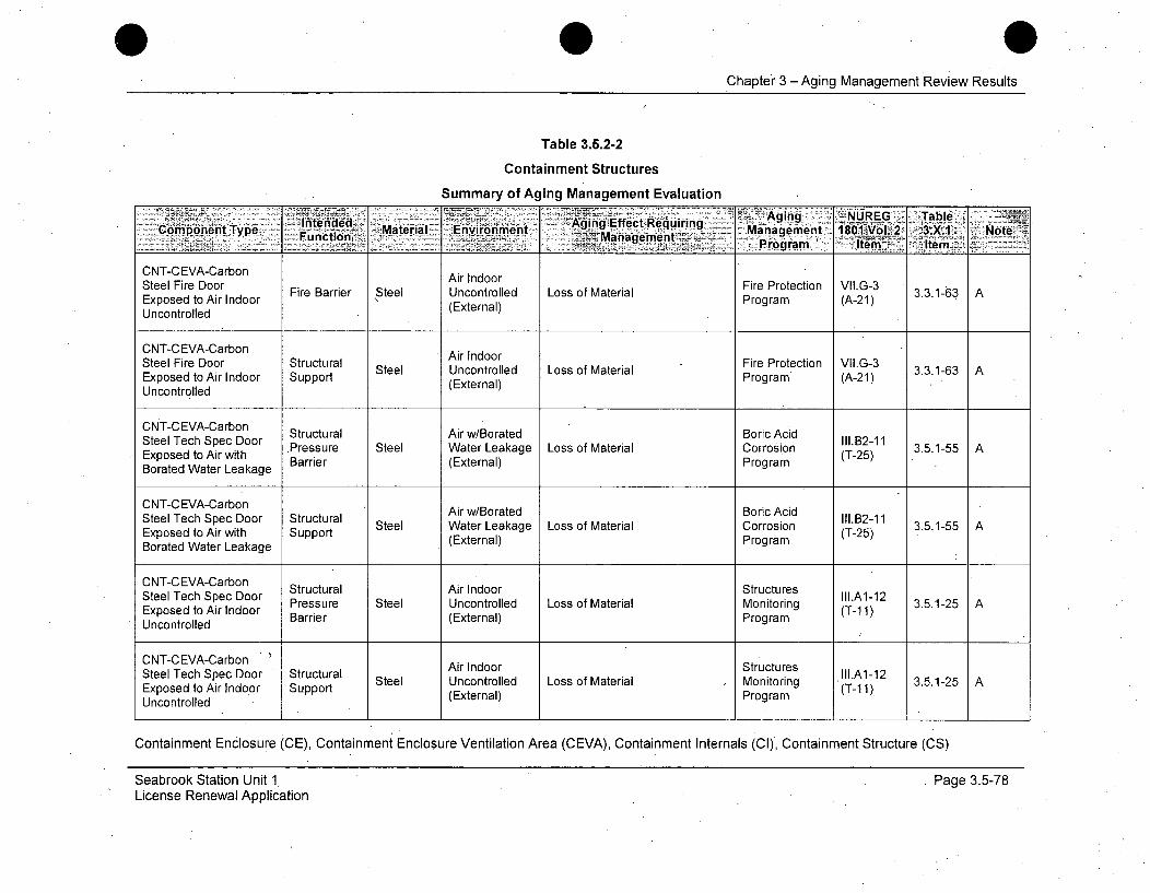
Chapter 3 - Aging Management Review Results
Table 3.5.2-2
Containment Structures
Summary of Aging Management Evaluation
ComtonnteTyp Material Environment Mgn Efec Reurn zAii N rE ablCopnetTye Function i~ManagementmPormA- tiwW 3XI Ner Id-, temý
CNT-CEVA-Carbon Air IndoorSteel Fire Door Fire Barrier Steel Uncontrolled Loss of Material Fire Protection VII.G-3 3.3.1-63 AExposed to Air Indoor (Exterial Program (A-21)Uncontrolled (External)
CNT-CEVA-CarbonSteel Fire Door Structural Air Indoor L Fire Protection VII.G-3Steel Uncontrolled Loss of Material 3.3.1-63 AExposed to Air Indoor Support (External) Program (A-21)Uncontrolled
CNT-CEVA-Carbon Structural Air w/Borated Boric AcidSteel Tech Spec Door Pressure Steel Water Leakage Loss of Material Corrosion l1.B211 3.5.1-55 AExposed to Air with • (T-25)Borated Water Leakage Barrier (External) Program
CNT-CEVA-CarbonCTCV-abnAir w/Borated Boric AcidSteel Tech Spec Door Structural AiI/oae BrcAi ll.B2-11eel To Air Door Surt Steel Water Leakage Loss of Material Corrosion (T-11 3.5.1-55 AExposed to Air with Support (External) Program (T-25)Borated Water Leakage
CNT-CEVA-Carbon Air Indoor StructuresSteel Tech Spec Door StutraItutue1l.A1-12 3512eel TocAir Indoor Pressure Steel Uncontrolled Loss of Material Monitoring (T-11) 3.5.1-25 AExposed to Barrier (External) Program
CNT-CEVA-Carbon Air Indoor StructuresSteel Tech Spec Door "Structural AirInoorStuctreeel Te Apr Door Surt Steel Uncontrolled Loss of Material Monitoring (Tl.A1-12 3.5.1-25 AExposed to Air Indoor Support (External) Program (T-1 1).Uncontrolled
Containment Enclosure (CE), Containment Enclosure Ventilation Area (CEVA), Containment Internals (Cl), Containment Structure (CS)
Seabrook Station Unit 1License Renewal Application
Page 3.5-78
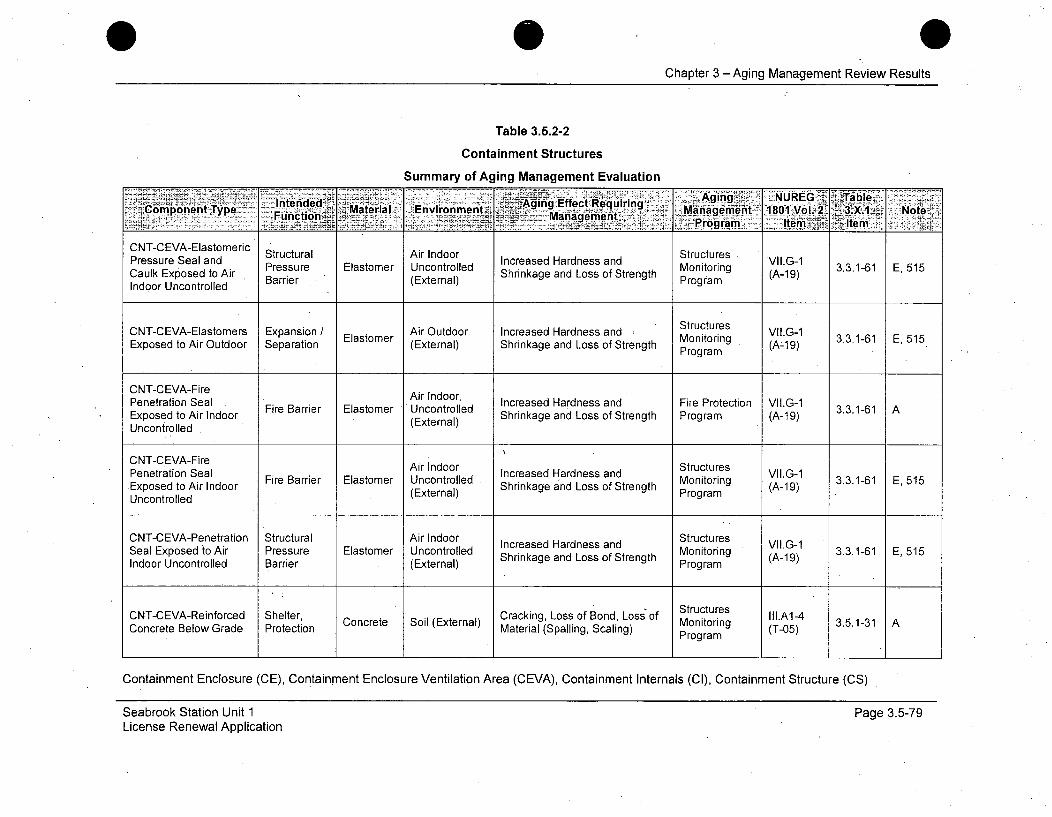
Chapter 3 - Aging Management Review Results
Table 3.5.2-2
Containment Structures
Summary of Aging Management Evaluation
Intended Agn Effect-,ReqrngAgn- NUE ae'1466mponent Type Material Environment e qurng Mngeet1181gi, 3.. ot'YComonnt~pe Function....._ Management.....aaeet10 o2 -3X1 Nt:-~;Program. Item ~Ite
CNT-CEVA-ElastomericCN-EAEatmrc Structural Air Indoor StructuresPressure Seal and Pressure E o r Uncor Increased Hardness and Monitorin VII.G-1Caulk Exposed to Air Pressure Elastomer Uncontrolled Shrinkage and Loss of Strength (A-19) 3.3.1-61 E, 515Indoor Uncontrolled Barrier (External) Program
- Structures VI.- 3..-1 E55
CNT-CEVA-Elastomers Expansion Air Outdoor Increased Hardness and Mtoring VII.G-1Exposed to Air Outdoor Separation (External) Shrinkage and Loss of Strength ProgramElasomerProgram
CNT-CEVA-FirePenetration Seal Fire Barrier Elastomer Uncontrolled Increased Hardness and Fire Protection VII.G-1 3.3.1-61 AExposed to Air Indoor Shrinkage and Loss of Strength Program (A-19)Uncontrolled .. (xenl
CNT-CEVA-FirePenetration Seal F er Uncool Increased Hardness and Structures VII.G-1.Exposed to Air Indoor Fire Barrier Elastomer Uncontrolled Shrinkage and Loss of Strength Monitoring (A-19) 3.3.1-61 E, 515Uncontrolled (External) Program
CNT-CEVA-Penetration Structural Air Indoor Structures VII.G-1Seal Exposed to Air Pressure Elastomer Uncontrolled Increased Hardness and Monitoring (A-9-1) 3.3.1-61 E, 515Indoor Uncontrolled Barrier (External) Shrinkage and Loss of Strength Program
CNT-CEVA-Reinforced Shelter, Concrete Soil (External) CrackignLo f Structures (T.A1-)4 3.5.1-31 A
ProBondo Losset ofl(Etrnl Monitoring (-5Concrete Below Grade Protection Material (Spalling, Scaling) Program
Containment Enclosure (CE), Containment Enclosure Ventilation Area (CEVA), Containment Internals (CI), Containment Structure (CS)
Seabrook Station Unit 1License Renewal Application
Page 3.5-79
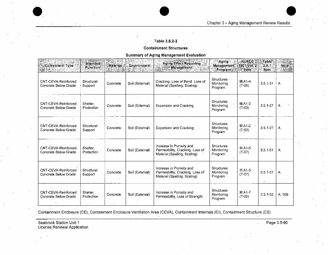
Chapter 3 -Aging Management Review Results
Table 3.5.2-2
Containment Structures
Summary of Aging Management Evaluation- 'Agin'g NUREG "TableMntende ea Einn Aging3EffectM..1 A'Component Type Material EnMaaevironment~oi~m'K~ -te Ie
Fu cto ManStuctu es t I1801 3ol 2- -3X 1 A ot
Concrete Below Grade Support Cocee Si Etra) Material (Spalling, Scaling) Program (-5
StructuresConcrete Below Grade Spprotection Splin clig Program (T-05)
CNT-CEVA-Reinforced Shelter, Structures II1.A1-2Concrete Below Grade Protection Concrete Soil (External) Expansion and Cracking Monitoring (T-03) 3.5.1-27 A
Program
CNT-CEVA-Reinforced Structural Structures.A1-Concrete Below Grade Support Concrete Soil (External) Expansion and Cracking Monitoring (T-03)
Program
CNT-CEVA-Reinforced Stctural CIncrease'in Porosity and Structures lll.A1-5Concrete Below Grade Protection Concrete Soil (External) Permeability, Cracking, Loss of Monitoring (T-07) 3.5.1-31 A
Material (Spalling, Scaling) Program
CNT-CEVA-Reinforced Structural Increase in Porosity and Structures IIl.A1-5CoceeBlwGae Spot Concrete Soil (External) Permeability, Cracking, Loss of Monitoring (T-07) 3.5.1-31 A
ConceteBelw Gade SuportMaterial (Spalling, Scaling) Program
Structures lll.A1-7
CNT-CEVA-Reinforced Shelter, Concrete Soil (External) Increase in Porosity and Monitoring (T-02) 3.5.1-32 A,509
Concrete Below Grade Protection Permeability, Loss of Strength Program
Containment Enclosure (CE), Containment Enclosure Ventilation Area (CEVA), Containment Internals (CI), Containment Structure (CS)
Seabrook Station Unit 1LicenseRenewal Application
Page 3.5-80
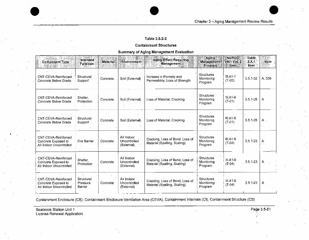
Chapter 3 -Aging Management Review Results
Table 3.5.2-2
Containment Structures
Summary of Aging Management Evaluation
CN-Enfe ute d nAging ttNUREG TableComponent Type 'ucin Material~ ~Envirobunmen't AngfetRqing Management~ 1801 Vol. 2' 3.X1 Note-~ MnageentProgram I~ tem7. Item
CN-CV-Rifocd tucualInras n oost adStructures lll.AI-7 3.1-2 A50ConTCEre e nConcrete Soil (External) Sncreasinity and Monitoring o- AConcrete Below Grade Support Permeability, Loss of Strength Program
ONT-CEVA-Reinforced Shelter, Stutue ll.A1-6Concrete Below Grade Protection Concrete Soil (External) Loss of Material, Cracking Monitoring (T-01) 3.5.1-26 A
~Program
StructuresCNT-CEVA-Reinforced Sheterucua Concrete Soil (External) Loss of Material, Cracking Monitoring (T0.1)6 3512Concrete Below Grade SPportecinPorm(-1
Concrete Below Grade Support Concrete Soil (External) Loss of Material, Cracking Monitoring (T-01) 3.5.1-26 A
Program
CNT-CEVA-Reinforced Air Indoor Cracking, Loss of Bond, Loss of Structures I.A1-9Concrete Exposed to Fire Barrier Concrete Uncontrolled Monitoring (T-04) 3.5.1-23 AAir Indoor Uncontrolled (External). Material (Spalling, Scaling) Program
CNT-CEVA-Reinforced Shelter, Air Indoor Cracking, Loss of Bond, Loss of Structures II.A1-9Concrete Exposed to Protection Concrete Uncontrolled Monitoring (T-04) 3.5.1-23 AAir Indoor Uncontrolled (External) (Spalling, Scaling)ram
Structures ll.19 35-2
CNT-CEVA-Reinforced Structural Air Indoor Cracking, Loss of Bond, Loss of triIg.A1-9Concrete Exposed to Pressure Concrete Uncontrolled Monitoring (T-04) 3.5.1-23 AAir Indoor Uncontrolled Barrier (External) Material (Spalling, Scaling) Program
Containment Enclosure (CE), Containment Enclosure Ventilation Area (CEVA), Containment Internals (Cl), Containment Structure (CS)
I
Seabrook Station Unit 1License Renewal Application
Page 3.5-81

Chapter 3 -Aging Management Review Results
Table 3.5.2-2
Containment Structures
Summary of Aging Management Evaluation
Intended Aagirng Envirnmen AgegquiEringleComponent Type MateriagigEfecleqirn Eniomn Management,' 180fN1 VoL2, 3.X.1 Note--*Functio Management. 5 PormIe- fi<
CNT-CEVA-Reinforced Structural Air Indoor Cr Structures lll.A-9AConcrete Exposed to Strt Concrete Uncontrolled acking Loss ofaBond, Monitoring (T-04) 3.5.1-23Air Indoor Uncontrolled Support (External) Material (Spalling, Scaling) Program
CNT-CEVA-Reinforced Air Indoor Structures lll.A1-2Concrete Exposed to Fire Barrier Concrete Uncontrolled Expansion and Cracking Monitoring (T-03) 3.5.1-27 AAir Indoor Uncontrolled (External) Program
CNT-CEVA-Reinforced Air Indoor StructuresShelter, III.A1-2-Concrete Exposed to Protection Concrete Uncontrolled Expansion and Cracking Monitoring (T-03) 3.5.1-27 AAir Indoor Uncontrolled (External) Program
CNT-CEVA-Reinforced Structural Air Indoor StructuresConcrete Exposed to Pressure Concrete Uncontrolled Expansion and Cracking' Monitoring I1.A1-2 3.5.1-27 AAir Indoor Uncontrolled Barrier (External) Program (T-03)
CNT-CEVA-Reinforced Structural Air Indoor Structures IIIAI-2Concrete Exposed to Support Concrete Uncontrolled Expansion and Cracking Monitoring (T-03) 3.5.1-27 AAir Indoor Uncontrolled (External) Program
CNT-CEVA-Reinforced Air Indoor Increase in Porosity and Structures II3.A1-10Concrete Exposed to Fire Barrier Concrete Uncontrolled Permeability, Cracking, Loss of Monitoring (T-06) 3.5.1-24 AAir Indoor Uncontrolled (External) Material (Spalling, Scaling) Program
Containment Enclosure (CE), Containment Enclosure Ventilation Area (CEVA), Containment Internals (CI), Containment Structure (CS)
Seabrook Station Unit 1License Renewal Application
Page 3.5-82
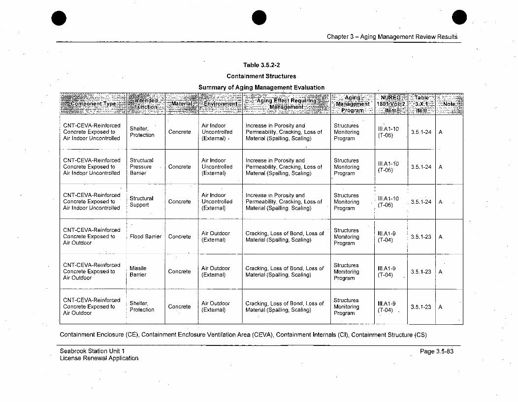
Chapter 3 -Aging Management Review Results
Table 3.5.2-2
Containment Structures
Summary of Aging Management Evaluation
Component Type Intended Materia l-Envir.nm:ngr• £Aging Effeteqint . ,NUREGW. TuablFu~nction Maera Eviomet. A .. Managementagm t 81VI2 3X. oe
ConcreteExosed to e, Air Indoor Increase in Porosity and Structures Il-.A1-10
CNT-CEVA-Reinforced Shelter, Concrete Uncontrolled Permeability, Cracking, Loss of Monitoring 3.5.1-24 AAir Indoor Uncontrolled (External) Material (Spalling, Scaling) Program
CNT-CEVA-Reinforced Structural Air Indoor Increase in Porosity and Structures II1A1-10Concrete Exposed to Pressure Concrete Uncontrolled Permeability, Cracking, Loss of Monitoring (T-06) 3.5.1-24 AAir Indoor Uncontrolled Barrier (External) Material (Spalling, Scaling) Program
CNT-CEVA-Reinforced StrucAir Indoor Increase in Porosity and Structures lAI- 3 2Concrete Exposed to Strt Concrete Uncontrolled Permeability, Cracking, Loss of Monitoring 3.5.1-24 AAir Indoor Uncontrolled Support (External) Material (Spalling, Scaling) Program (T-06)
CNT-CEVA-Reinforced StructuresConcreteExosed t FldBAir Outdoor Cracking, Loss of Bond, Loss of Struture III.A1-9Concrete Exposed to Flood Barrier Concrete (External) Material (Spalling, Scaling) Monitoring (T-04) 3.5.1-23 AAir Outdoor 'Program
CNT-CEVA-Reinforced StructuresConc reiExosed Missile Air Outdoor Cracking, Loss of Bond, Loss of Mtritg Illl.A1-9
Concrete Exposed to, Concrete Monitorirng 3.5.1-23 A
Air Outdoor Barrier C t (External) Material (Spalling, Scaling) Program (T-04)
CNT-CEVA-Reinforced Shelter, Strutnreet e MonitoA 3.5.1-23 ACocrt Epse o. Prtcto Cnree Air Outdoor Cracking, Loss of Bond, Loss of Montoringre II1.A1-AinreOtd xoor o rteto . (External) Material (Spalling, Scaling) Program
Containment Enclosure (cE), Containment Enclosure Ventilation Area (CEVA), Containment Internals (Cl), Containment Structure (CS)
Seabrook Station Unit 1License Renewal Application
Page 3.5-83

Chapter 3 -Aging Management Review Results
Table 3.5.2-2
Containment Structures
Summary of Aging Management Evaluation
Intended~~Ain Agn2fetRqiig NUREGt TableAComponent Type (Extenal)Material Environment Management Progem (T-04o
program Item ~ Item
CNT-CEVA-Reinforced Structural Air Outdoor Cracking, Loss of Bond, Loss of tr g II1.A1-Concrete Exposed to Pressure Concrete (External) Material (Spalling, Scaling) Monitoring (T-0P) 3.5.1-2 AAir Outdoor BarrierProgram
CNT-CEVA-Reinforced StructuresConcrete Exposed to Flood Barrier Concrete ArOtdr Expansion and Cracking Monitoring (T-03) 3.5.1-27 AAir Outdoor (External) Program
CNT-CEVA-Reinforced Missile Air Outdoor Structures III.A1-2Concrete Exposed to Barrier Concrete (External) Expansion and Cracking Monitoring (T-03) 3.5.1-27 AAir Outdoor Program
CNT-CEVA-Reinforced Shelter, Structures lll.A1-2
ConcrteuExosed oI3.51-272Concrete Exposed to Protection Concrete (External) Expansion and Cracking Monitoring (T-03) 3.5.1-27 AAir Outdoor Program
CNT-CEVA-Reinforced Structural ArOtorStructures IIA-Concrete Exposed to Pressure Concrete Airnio Outoo Crakin.Aoitoin 3.5.1-27 AAir Outdoor Barrier (External) ExasoPnrCakn oiogring T03
CNT-CEVA-Reinforced Air Outdoor Increase in Porosity and Structures Ill.A1-10Concrete Exposed to Flood Barrier Concrete (External) Permeability, Cracking, Loss of Monitoring (T-06) 3.5.1-24 AAir Outdoor Material (Spalling, Scaling) Program
Containment Enclosure (CE), Containment Enclosure Ventilation Area (CEVA), Containment Internals (CI), Containment Structure (CS)
Seabrook Station Unit 1License Renewal Application
Page 3.5-84
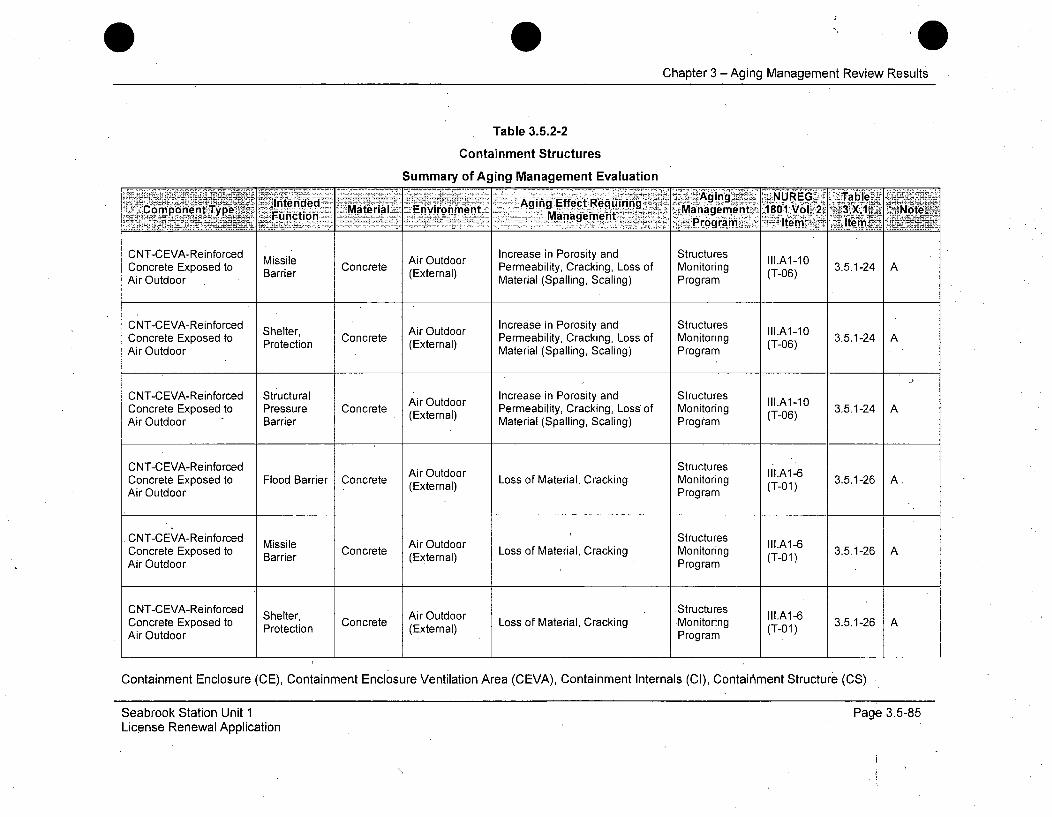
Chapter 3 -Aging Management Review Results
Table 3.5.2-2
Containment Structures
Summary of Aging Management Evaluation
.. .. Intended Aging EffectRequiringAgn NUE Talcm'p-one nt' Typ e Material Environment. Manaemen 8 1 o.'2 3 U% 31NoteFunto ýManagement rga ~ Ie Item_
CNT-CEVA-Reinforced Missile Air Outdoor Increase in Porosity and Structures II1.A1-10Concrete Exposed to Barrier Concrete (External) Permeability, Cracking, Loss of Monitoring (T-06) 3.5.1-24 AAir Outdoor Material (Spalling, Scaling) Program
CNT-CEVA-Reinforced Outdoor Increase in Porosity and Structures III.A1-10CnteCExposed ShProtection Concrete ArOtdr Permeability, Cracking, Loss of Monitoring (T-06) 3.5.1-24 AAir Outdoor Material (Spalling, Scaling) Program
CNT-CEVA-Reinforced Structural Increase in Porosity and Structures II1A1- 3.Concrete Exposed to Pressure Concrete Air Outdoor Permeability, Cracking, Loss of Monitoring (T-06) 3.5.1-24 AAir Outdoor Barrier (External) Material (Spalling, Scaling) Program
CNT-CEVA-Reinforced StructuresConcrete Exposed to Flood Barrier Concrete (External) Loss of Material, Cracking Monitoring (Tl.A1-6 3.5.1-26 A.Air Outdoor Program (T-01)
CNT-CEVA-Reinforced Missile Air Outdoor StructuresLossofiMterilirackngtMnitoing lll.A1-6 3512Concrete Exposed to Barrier Concrete (External) Loss of Material, Cracking Monitoring (T-01) 3.5.1-26 AAir Outdoor Program
CNT-CEVA-Reinforced Shelter, Air Outdoor Structures o a lCcgn gConcrete Exposed to Protection Concrete (External) Loss of Material, Cracking Monitoring (T-01) 3.5.1-26 AAir Outdoor Program
Containment Enclosure ,(CE), Containment Enclosure Ventilation Area (CEVA), Containment Internals (CI), Contair'ment Structure (CS)
Seabrook Station Unit 1License Renewal Application
Page 3.5-85
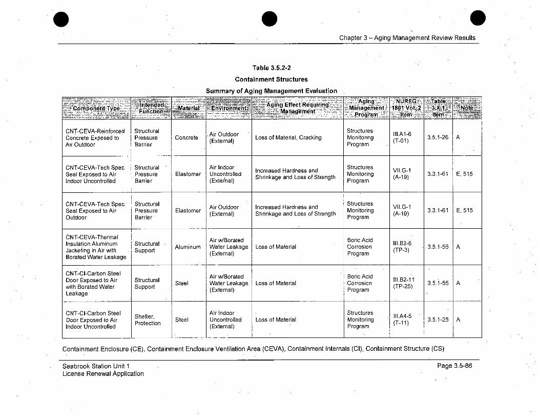
Chapter 3 -Aging Management Review Results
Table 3.5.2-2
Containment Structures
Summary of Aging Management Evaluation
1ntenrd-e- _ Aing. Agingng URG alCopdiet ye fMaera Eviane~~Effe~ct` Reurngk"Mnaenn' 81Vl. Notem-oen T eManageen ent 'Pr801a -I 2lIe
CNT-CEVA-Reinforced Structural Air Outdoor StructuresLoM r CannrConcrete Exposed to Pressure Concrete (External) Loss of Material, Cracking Monitoring (T-01) 3.5.1-26 AAir Outdoor Barrier Program
CNT-CEVA-Tech Spec Structural Air Indoor Increased Hardness and Structures VII.G-1Seal Exposed to Air Pressure Elastomer Uncontrolled incase ardness and Monitoring (A-9-1) 3.3.1-61 E, 515Indoor Uncontrolled Barrier (External) Shrinkage and Loss of Strength Program
CNT-CEVA-Tech Spec Structural Air Outdoor Increased Hardness and Structures VII.G-1Sel xpse t Ar resue latoerAi Otdor Inrese Hrdes adMonitoring Vli 3.3.1-61 E, 515Seal Exposed to Air Pressure Elastomer (External) Shrinkage and Loss of Strength (A-19)Outdoor, Barrier Program
CNT-CEVA-Thermal Air w/Borated Boric AcidInsulation Aluminum Structural Aar IIoated Borric Ail.B2-6 3.5.1-55 AJackeiing in Air with Support Aluminum Water Leakage Loss of Material Corrosion (TP-3)Borated Water Leakage (External) Program
CNT-CI-Carbon Steel Air w/Borated Boric AcidDoor Exposed to Air Structural S l ar wLoakaed Boricsidn lI.B2-11with Borated Water Support Steel Water Leakage Loss of Material Corrosion (TP-25) 3.5.1-55 A
Leakage (External) Program
CNT-CI-Carbon Steel Shelter, Air Indoor Structures III.A4-5Door Exposed to Air Protection Steel Uncontrolled Loss of Material Monitoring (T11) 3.5.1-25 AIndoor Uncontrolled (External) Program
Containment Enclosure (CE), Containment Enclosure Ventilation Area (CEVA), Containment Internals (Cl), Containment Structure (CS)
Seabrook Station Unit 1License Renewal Application
Page 3.5-86
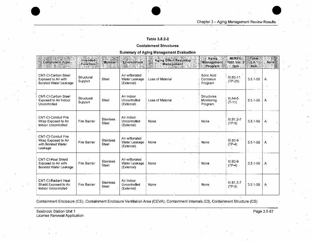
Chapter 3 - Aging Management Review Results
Table 3.5.2-2
Containment Structures
Summary of Aging Management Evaluation
-Aging NUREG Table"~6~oiei~rpe Intended _Aging 'Effect Reequli ring ~ gmn 81Vl 3X1 NtComponent Type Material _ Environment M 18..0Manage1en. Vrog .a...t e1 N
CNT-CI-Carbon Steel Structural Air w/Borated Boric Acid 111.B2- .1Exposed to Air with Support Steel Water Leakage Loss of Material Corrosion (TP-25) 3.5.1-55 ABorated Water Leakage (External) Program
CNT-CI-Carbon Steel Air Indoor StructuresExposed to Air lndoor Support Steel Uncontrolled Loss of Material Monitoring (T-11A) 3.5.1-25 AUncontrolled (External) Program
CNT-CI-Conduit Fire Stainless Air Indoor Noe.o31.217Wrap Exposed to Air Fire Barrier Steel U l.1-7 3.5.1-59 AIndoor Uncontrolled (External)
CNT-CI-Conduit Fire Air w/BoratedWrap Exposed to Air Fire Barrier Stainless Water Leakage None None II1.B2-9 3.5.1-59 A
with Borated Water Steel (TP-4)n3.5.1-59Leakage (External)
CNT-CI-Heat Shield Air w/BoratedExposed to Air with Fire Barrier Steel Water Leakage None None(TP-4) 3.5.1-59 ABorated Water Leakage (External)
CNT-CI-Radiant Heat Stainless Air Indoor 111.B1.2-7Shield Exposed to Air Fire Barrier Steel Uncontrolled None None (TP-5) 3.5.1-59 AIndoor Uncontrolled (External)
Containment Enclosure (CE), Containment Enclosure Ventilation Area (CEVA), Containment Internals (Cl), Containment Structure (CS)
Seabrook Station Unit 1License Renewal Application
Page 3.5-87

Chapter 3 -Aging Management Review Results
Table 3.5.2-2
Containment Structures
Summary of Aging Management Evaluation
Intended AirIndEffect Req
MaceeEpse o Fr arir Cnrtera Uncionmetrole Agingn, LssNfRBndLTabeIIIA4-
ArIdorncontroled (Eniromna) MR ing) Maniagement 1801 Vol. 2 3Nte,'orpnetyp Functioni- ManagementPrgaItmte
Program, lrnmCNT-CI-Reinforced Air Indoor Cr Structures Il.A4-3Concrete Exposed to Fire Barrier Concrete Uncontrolled aknLsofBdosof Monitoring 3.5.-23)Air Indoor Uncontrolled (External) Material (Spalling, Scaling) Program (-4
C NT-CI-Re info rced .Air Indoor CaknLsofBdosof Structures I.43
Concrete Exposed to Barrier Concrete Uncontrolled Material (Spalling, Scaling) Ptrong(ram
Air Indoor Uncontrolled (External)PrgaCNT-C-ReinforcedCracking, Loss of Bond, Loss of II.A4-3Concrete Exposed to Missile Concrete Uncontrolled Material (Spalling, Scaling) Monitoring (T-04) 3.5.1-23 AAir Indoor Uncontrolled Barrier (External) Program
CNT-CI-Reinforced Air Indoor Cr Structures III.A4-3Concrete Exposed to Structurae Concrete Uncontrolled Mac sing, L S o nsckling) Monitoring (T-04) 3.5.1-27 AAir Indoor Uncontrolled (External) Program
CNT-CI-Reinforced Air Indoor StructuresConcrete Exposed to Fire Barrier Concrete Uncontrolled Expansion and Cracking Monitoring (T-03) 3.5.1-27 AAir Indoor Uncontrolled (External) Program ,
CNT-CI-Reinforced l Air Indoor StructuresConcrete Exposed to Flood Barrier Concrete Uncontrolled Expansion and Cracking Monitoring (T-0A3) 3.5.1-27AAir Indoor Uncontrolled (External) Program(T3
Containment Enclosure (CE), Containment Enclosure Ventilation Area (CEVA), Containment Internals (Cl), Containment Structure (CS)
Seabrook Station Unit 1License Renewal Application
Page 3.5-88
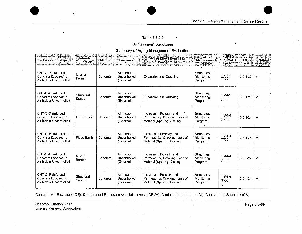
Chapter 3 - Aging Management Review Resilts
Table 3.5.2-2
Containment Structures
Summary of Aging Management Evaluation
com~n~ Tpe Intended - Aging Efec RequiringRG TblFunctimonetonp Material 'Environment EfetRqiig Management 1801 Vol. 2 3.X.1~ Note'_ . . . .. ... .: = a n e e t .= : • .Pr o g r a m • . e m ,J : Iv t e m . - !
CNT-CI-Reinforced Missile Air Indoor Structures III.A4-2Concrete Exposed to Concrete Uncontrolled Expansion and Cracking Monitoring (T-03) 3.5.1-27 AAir Indoor Uncontrolled Barrier (External) Program
CNT-CI-Reinforced Air Indoor StructuresConcrete Exposed to Support Concrete Uncontrolled Expansion and Cracking Monitoring (T-03) 3.5.1-27 AAir Indoor Uncontrolled (External) Program
CNT-CI-Reinforced Air Indoor Increase in Porosity and Structures III.A4-4Concrete Exposed to Fire Barrier Concrete Uncontrolled Permeability, Cracking, Loss of Monitoring (T-06) 3.5.1-24 AAir Indoor Uncontrolled (External) Material (Spalling, Scaling) Program
CNT-CI-Reinforced Air Indoor Increase in Porosity and Structures II1.A4-4Concrete Exposed to Flood Barrier Concrete Uncontrolled Permeability, Cracking, Loss of Monitoring (T-06) 3.5.1-24 AAir Indoor Uncontrolled (External) Material (Spalling, Scaling) Program
CNT-C-Reinforced Missile CAir Indoor Increase in Porosity and Structures lll.A4-4Concrete Exposed to Barrier Concrete Uncontrolled Permeability, Cracking, Loss of Monitoring (T-06) 3.5.1-24Air Indoor Uncontrolled (External) Material (Spalling, Scaling) Program
CNT-CI-Reinforced Structural Air Indoor Increase in Porosity and Structures III.A4-4Concrete Exposed to Surt Concrete Uncontrolled Permeability, Cracking, Loss of Monitoring (T-6 3.5.1-24 AAir Indoor Uncontrolled Support (External) Material (Spalling, Scaling) Program (T-06)
Containment Enclosure (CE), Containment Enclosure Ventilation Area (CEVA), Containment Internals (Cl), Containment Structure (CS)
Seabrook Station Unit 1License Renewal Application
Page 3.5-89
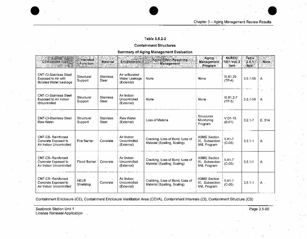
Chapter 3 -Aging Management Review Results
Table 3.5.2-2
Containment Structures
Summary of Aging Management Evaluation
-nedd- Aging. NUREG Table,-Component Type Fucin Material Envronment AggEe eqing Mngeet1801'Vol. 2 3.X.1 Note7~-~Mn---nt---- Pora Item Item
CNT-CI-Stainless Steel Air w/BoratedExposed to Air with Structural Stainless Water Leakage None None (TP-4.) 3.5.1-59 ABorated Water Leakage Support Steel (External)
CNT-CI-Stainless Steel Air IndoorExposed to Air Indoor Strt Steel Uncontrolled None None .B1.2-7 3.5.1-59 AUncontrolled Support Steel (External) (TP-5)
.CNT-CI-Stainless Steel Structural Stainless Raw Water Structures V.D1-15Raw Water Support Steel (External) Loss of Materia Monitoring (E-01) 3.2.1-7 E, 514
Program
CNT-CS- Reinforced Air Indoor ASME SectionConcrete Exposed to Fire Barrier Concrete Uncontrolled Material (Spalling, Scaling) XI, Subsection (C-05) 3.5.1-1 AAir Indoor Uncontrolled (External) IWL Program
CNT-CS- Reinforced Air Indoor. Cracking, Loss of Bond, Loss of ASME Section llA1-7Concrete Exposed to Flood Barrier Concrete Uncontrolled Material (Spalling, Scaling) XI, Subsection (C-05) 3.5.1-1 AAir Indoor Uncontrolled (External) IWL Program
CNT-CS- Reinforced HELB Air Indoor Cracking Loss of Bond, Loss of ASME Section LA1-7Concrete Exposed to helB Concrete Uncontrolled Ctrialing, Scaling) XI, Subsection (C-7 3.5.1-1 AAir Indoor Uncontrolled Shielding (External) Material (Spalling, Scaling) IWL Program (C-O5)
Containment Enclosure (CE), Containment Enclosure Ventilation Area (CEVA), Containment Internals (CI), Containment Structure (CS)
Seabrook Station Unit 1License Renewal Application
Page 3.5-90
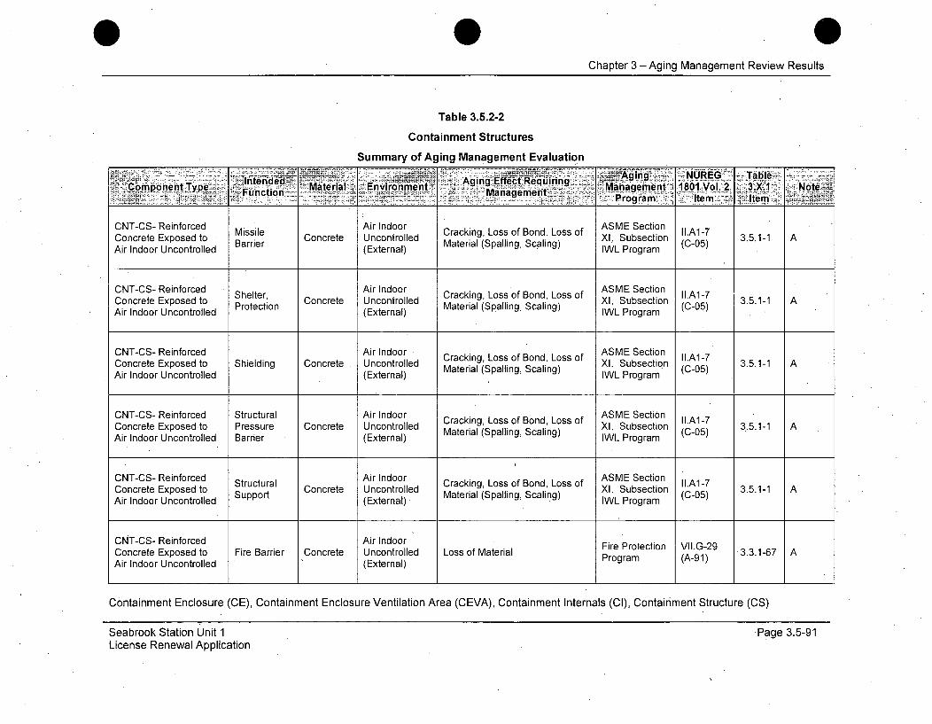
Chapter 3 - Aging Management Review Results
Table 3.5.2-2
Containment Structures
Summary of Aging Management Evaluation
'Intended Aging, Effect Requiring _~ging NR~ alComponent Type -,Function Material EnvironmentMag -Management 11 2 3X1 Note
- .- -- -'Progiram te Item
CNT-CS- Reinforced Air Indoor ASME SectionConcrete Exposed to Missile Concrete Uncontrolled Cracking, Loss of Bond, Loss of XI, Subsection C5.A1-7 3.5.1-1 ABarrier Material (Spalling, Scaling) (C-05)Air Indoor Uncontrolled (External) IWL Program
CNT-CS- Reinforced Shelter, Air Indoor Cracking, Loss of Bond, Loss of ASME Section I1.A1-7Concrete Exposed to Protection ConcreteMaterial (Spalling, Scaling) X, Subsection 3.5.1-1 AAir Indoor Uncontrolled (External) IWL Program
CNT-CS- Reinforced Air Indoor - ASME SectionConcrete Exposed to Shielding Concrete Uncontrolled Crack ing, S aBnd, XI, Subsection (A-7 3.5.1-1 A
Air Indoor Uncontrolled (External) Material (Spalling, Scaling) IWL Program
CNT-CS- Reinforced Structural Air Indoor ASME Section
Concrete Exposed to Pressure Concrete Uncontrolled Material (Spalling, Scaling) XI, Subsection I.A1-7Air Indoor Uncontrolled Barrier (External) IWL Program (C-05)
CNT-CS- Reinforced Air Indoor ASME SectionConcrete Exposed to Structural Concrete Uncontrolled Cracking, Loss of Bond, Loss of XI, Subsection II.A1-7 3.5.1-1 ACuprtMtriackng Xllg Subsectio (C-0OS)
Air Indoor Uncontrolled Support (External)* Material (Spalling, Scaling) IWL Program
CNT-CS- Reinforced Air Indoor Fire Protection VII.G-29Concrete Exposed to Fire Barrier Concrete Uncontrolled Loss of Material FProteto (A-91 .3.3.1-67 AAir Indoor Uncontrolled (External) Program (A-91)
Containment Enclosure (CE), Containment Enclosure Ventilation Area (CEVA), Containment Internals (CI), Containment Structure (CS)
Seabrook Station Unit 1License Renewal Application
Page 3.5-91
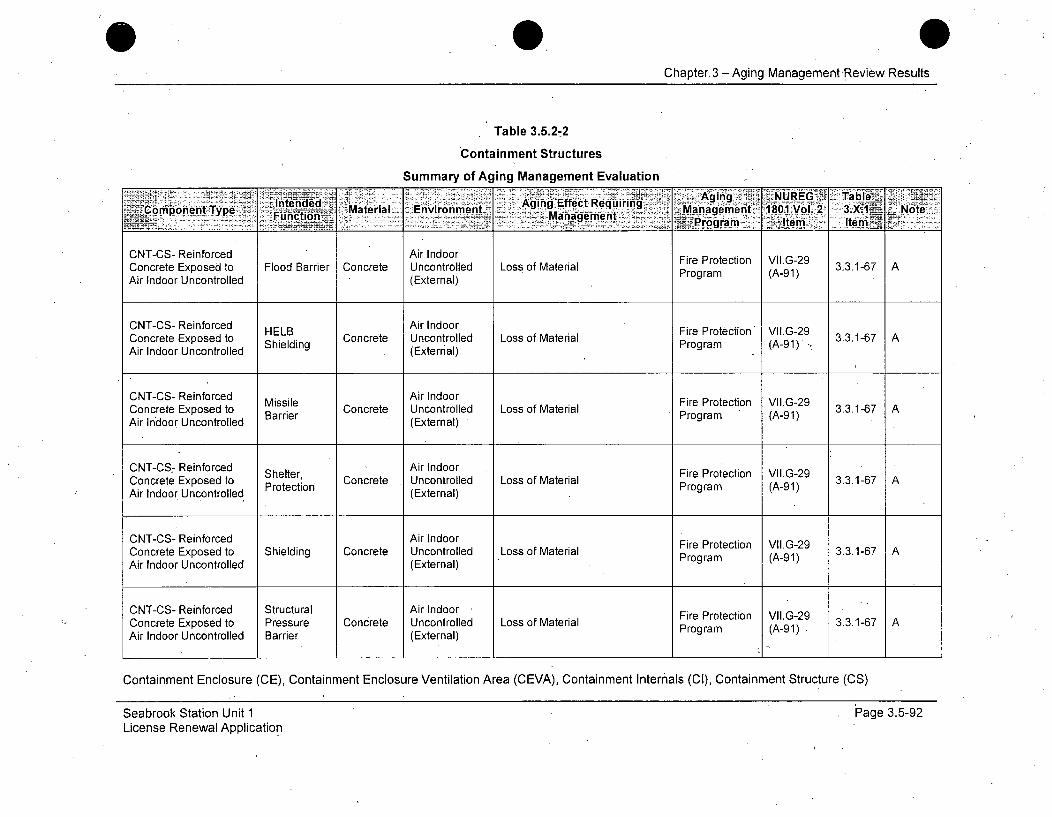
Chapter, 3 - Aging Management Review Results
Table 3.5.2-2
Containment Structures
Summary of Aging Management Evaluation.4! AgN~ NUEG Tabl11e~lnten~d Agng Effct Reuirin
:~Conmponent Type Intededifl Material Environment_ AgManagEfemet Reurn Management 1801 Vol. 2 3.X.1 NoteFucto Ma~groirm Item
CNT-CS- Reinforced Air IndoorConcrete Exposed to Flood Barrier Concrete Uncontrolled Loss of Material Fire Protection VIG29 3.3.1-67 AAir Indoor Uncontrolled (External) Program (A-91)
CNT-CS- Reinforced HELB Air IndoorConcrete Exposed to Shielding Concrete Uncontrolled Loss of Material FProteto (A-.9 3.3.1-67 AAir Indoor Uncontrolled (External) Program (A-91)
CNT-CS- Reinforced Air IndoorConcrete Exposed to Missile Concrete Uncontrolled Loss of Material Fire Protection VII.G-29 3.3.1-67 AAir Indoor Uncontrolled (External) Program (A-91)
CNT-CS 7 Reinforced Air Indoor Fire Protection VIIG-29Concrete Exposed to Shelter Concrete Uncontrolled Loss of Material Proteto (A-9 3.3.1-67 AAir Indoor Uncontrolled (External)
CNT-CS- Reinforced Air IndoorConcrete Exposed to Shielding Concrete Uncontrolled Loss of Material Fire Protection VIG29 3.3.1-67 AAir Indoor Uncontrolled (External) Program (A-91)
CNT-CS- Reinforced Structural Air Indoor Fire Protection VIIG-29Concrete Exposed to Pressure Concrete Uncontrolled Loss of Material Proteto (A-9 3.3.1-67 AAir Indoor Uncontrolled Barrier (External) Program (A-91)
Containment Enclosure (CE), Containment Enclosure Ventilation Area (CEVA), Containment Internals (CI), Containment Structure (CS)
Seabrook Station Unit 1License Renewal Application
IPage 3.5-92
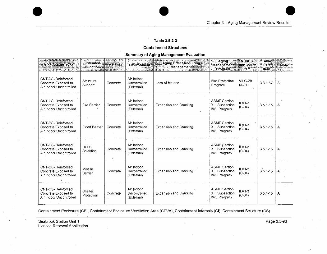
Chapter 3 -Aging Management Review Results
Table 3.5.2-2
Containment Structures
Summary of Aging Management Evaluation
-Intended ~Mjra niomn ~-Aging Effect Requiring Magig NUE TbeCop-en Tp . Materal: E- : •- Mana e.. n-Management 1801 Vol. 2 3.X.1. :NoteFunc ion: m • •=....... . . • = - ;.
___________________________________ Progra. _Iem- Item-~
CNT-CS- Reinforced Air IndoorConcrete Exposed to Structural Concrete. Uncontrolled Loss of Material Fire Protection VII.G-29 3.3.1-67 AAir Indoor Uncontrolled Support (External) Program (A-91)
CNT-CS- Reinforced Air Indoor ASME SectionConcrete Exposedto Fire Barrier Concrete Uncontrolled Expansion and Cracking XI, Subsection (LA1-3 3.5.1-15 AAir Indoor Uncontrolled (External) IWL Program (C-04)
CNT-CS- Reinforced Air Indoor ASME Section A1-3Concrete Exposed to Flood Barrier Concrete Uncontrolled Expansion and Cracking Xl, Subsection (C-3 3.5.1-15 AAir Indoor Uncontrolled (External) IWL Program (C-04)
CNT-CS- Reinforced Air Indoor ASME Section IIA1-3Concrete Exposed to held Concrete Uncontrolled Expansion and Cracking XI, Subsection 3.5.1-15 AAir Indoor Uncontrolled Shielding (External) IWL Program
CNT-CS- Reinforced Air Indoor ASME SectionMissile llA1-3
Concrete Exposed to Barrier Concrete Uncontrolled Expansion and Cracking XI, Subsection (C-04) 3.5.1-15 AAir Indoor Uncontrolled (External) IWL Program
CNT-CS- Reinforced Shelter, Air Indoor ASME Section llA1-3Concrete Exposed to Protection Concrete Uncontrolled Expansion and Cracking XI, Subsection (C-04) 3.5.1-15 AAir Indoor Uncontrolled (External) IWL Program
Containment Enclosure (CE), Containment Enclosure Ventilation Area (CEVA), Containment Internals (CI), Containment Structure (CS)
Seabrook Station Unit 1License Renewal Application
Page 3.5-93
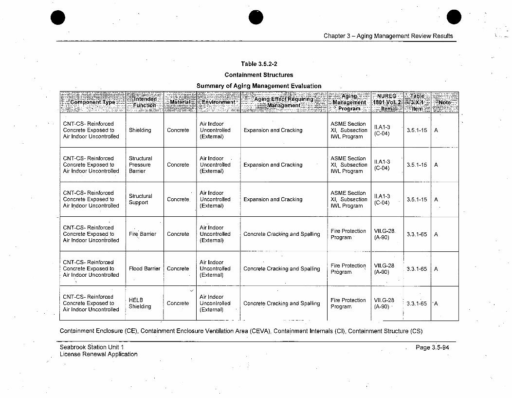
Chapter 3 - Aging Management Review Results
Table 3.5.2-2
Containment Structures
Summary of Aging Management Evaluation
Intended ~Aging Effect-RequiringA gn UE alComponent..Type Fu.ncin M M terial -Environment Program 180N1Vol..E• •• .•X• 1 iNoteF ionManagement__
CNT-CS- Reinforced Air Indoor ASME SectionConcrete Exposed to Shielding 'Concrete Uncontrolled Expansion and Cracking Xl, Subsection (C-04) 3.5.1-15 AAir Indoor Uncontrolled (External) IWL Program
CNT-CS- Reinforced Structural Air Indoor ASME SectionConcrete Exposed to Pressure Concrete Uncontrolled Expansion and Cracking XI, Subsection (A-4 3.5.1-15 AAir Indoor Uncontrolled Barrier (External) IWL Program
CNT-CS- Reinforced Air Indoor ASME SectionConcrete Exposed to Support Concrete. Uncontrolled Expansion and Cracking XI, Subsection (C-04) 3.5.1-15 AAir Indoor Uncontrolled (External) IWL Program
CNT-CS- Reinforced Air IndoorConcrete Exposed to Fire Barrier Concrete Uncontrolled Concrete Cracking and Spalling FireProtection VII.G-28. 3.1-65 AAir Indoor Uncontrolled (External) Program (A-90)
CNT-CS- Reinforced Air IndoorConcrete Exposed to Flood Barrier Concrete Uncontrolled Concrete Cracking and Spalling Proteto (A-90) 3.3.1-65 AAir Indoor Uncontrolled (External) Program (A-90)
CNT-CS- Reinforced Air IndoorConcrete Exposed to held Concrete Uncontrolled Concrete Cracking and Spalling 3.3.1-65 'AAir Indoor Uncontrolled (External) Program (A-90).
Containment Enclosure (CE), Containment Enclosure Ventilation Area (CEVA), Containment Internals (Cl), Containment Structure (CS)
Seabrook Station Unit 1License Renewal Application
Page 3.5-94
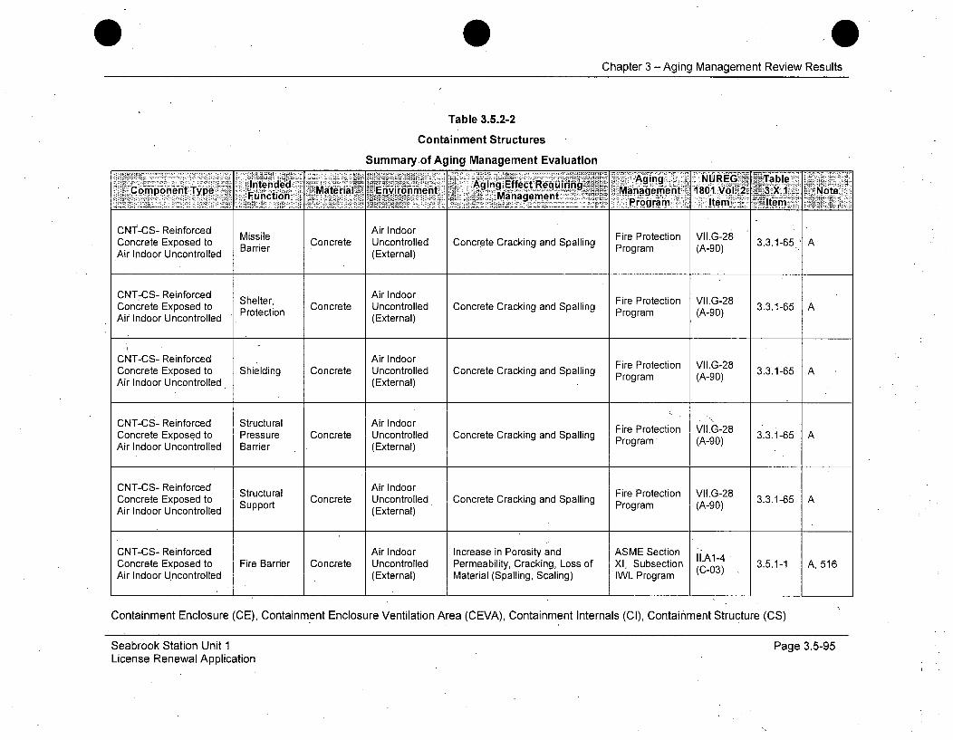
4Chapter 3 -Aging Management Review Results
Table 3.5.2-2
Containment Structures
Summary of Aging Management Evaluation
Agig .~NUREG . Table6~~ Environment ~~ A~ing Eecequiring " Mng~n 81Vl2 3X NtpoeType Material! E..r
Coincrt Exoed to Brir Cnrt nontroled Concrete 1801in Vol. Splln 3.3.1- Note
FunctionorUManagement)Program MtemgItem
CNT-CS- Reinforced Air Indoor
MisileFire Protection VII.G-28
Concrete Exposed to MSsler Concrete Uncontrolled Concrete Cracking and Spalling Proteto (Al90) 3.3.1-65 A
Concrete Exposed to Protection Ucnrle CorterakgadSplig Program (A-9o)Air Indoor Uncontrolled (External)
CNT-CS- Reinforced Air Indoor
Concrete Exposed to Shielding Concrete Uncontrolled Concrete Cracking and Spalling Fire Protection VIG-28 3.3.1-65 AAir Indoor Uncontrolled (External) Program (A-90)
CNT-CS- Reinforced Structural Air Indoor Fire Protection VIIG28
Concrete Exposed to Pressure Concrete Uncontrolled Concrete Cracking and Spalling Program (A-28 3.3.1-65 A
Air Indoor Uncontrolled Barrier (External) Program (A-90)
CNT-CS- Reinforced Structural Air IndoorConcrete Exposed to Suppore Concrete Uncontrolled Concrete Cracking and Spalling Prog - 3.3.1-65
Air Indoor Uncon .trolled Brir(External) Program (A-90)
Air Indoor Uncontrolled Spot(External)
CNT-CS- Reinforced Air Indoor Increase in Porosity and ASME Section 11.A1-4Concrete Exposed to Fire Barrier Concrete Uncontrolled Permeability, Cracking, Loss of XI, Subsection (C-03) 3.5.1-1 A, 516Air Indoor Uncontrolled (External) Material (Spalling, Scaling) IWL Program
Containment Enclosure (CE), Containment Enclosure Ventilation Area (CEVA), Containment Internals (Cl), Containment Structure (CS)
Seabrook Station Unit 1License Renewal Application
Page 3.5-95
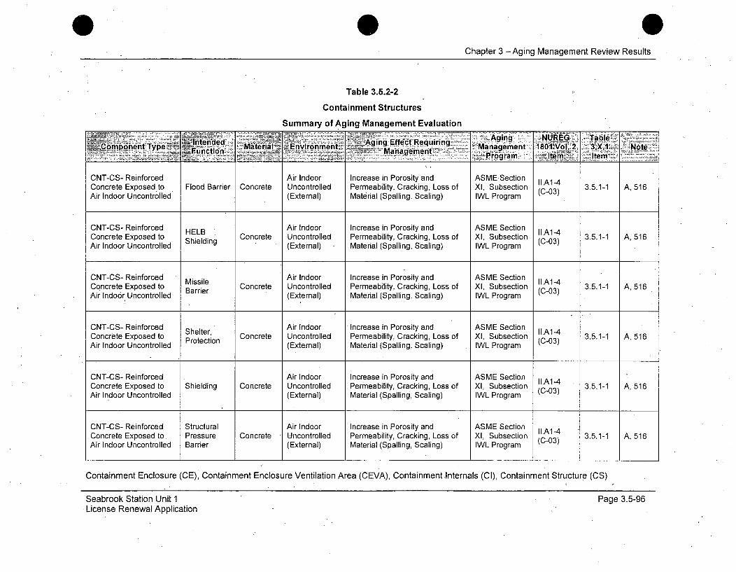
Chapter 3 -Aging Management Review Results
Table 3.5.2-2
Containment Structures
Summary of Aging Management Evaluation
Ine=ddAgng, Effect Requiring _Aging NRG Ta.~Copoen ype Itne Material Environment Maagmet 8 1'Vl.2 3;,X.1 . NoteFuinction .,. ManagementPrgaItm
CNT-CS- Reinforced Air Indoor Increase in Porosity and ASME.SectionConcrete Exposed to Flood Barrier Concrete Uncontrolled Permeability, Cracking, Loss of XI, Subsection (A-3 3.5.1-1 A, 516Air Indoor Uncontrolled (External) Material (Spalling, Scaling) IWL Program
CNT-CS- Reinforced HELB Air Indoor Increase in Porosity and ASME Section I1.A1-4Concrete Exposed to helB Concrete Uncontrolled Permeability, Cracking, Loss of XI, Subsection (C-03) 3.5.1-1 A, 516Air Indoor Uncontrolled Shielding (External) Material (Spalling, Scaling) IWL Program
CNT-CS- Reinforced Missile Air Indoor Increase in Porosity and ASME Section I1.A1-4Concrete Exposed to Barrier Concrete Uncontrolled Permeability, Cracking, Loss of Xl, Subsection (C-03) 3.5.1-1 A, 516Air Indoor Uncontrolled (External) Material (Spalling, Scaling) IWL Program
CNT-CS- Reinforced Shelter, Air Indoor Increase in Porosity and ASME Section I1.A1-4Concrete Exposed to Concrete Uncontrolled Permeability, Cracking, Loss of XI, Subsection (C-03) 3.5.1-1 A, 516Air Indoor Uncontrolled Protection (External) Material (Spalling, Scaling) IWL Program
CNT-CS- Reinforced Air Indoor Increase in Porosity and ASME Section IIA14Concrete Exposed to Shielding Concrete Uncontrolled Permeability, Cracking, Loss of XI, Subsection (C-03) 3.5.1-1 A, 516Air Indoor Uncontrolled (External) Material (Spalling, Scaling) IWL Program
CNT-CS- Reinforced Structural Air Indoor Increase in Porosity and ASME Section A-4Concrete Exposed to, Pressure Concrete Uncontrolled Permeability, Cracking, Loss of XI, Subsection (C-03) 3.5.1-1 A, 516Air Indoor Uncontrolled Barrier (External) Material (Spalling, Scaling) IWL Program
Containment Enclosure (CE), Containment Enclosure Ventilation Area (CEVA), Containment Internals (CI), Containment Structure (CS)
Seabrook Station Unit 1License Renewal Application
Page 3.5-96
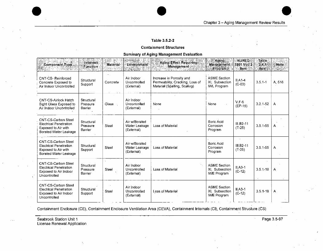
Chapter 3 - Aging Management Review Results
Table 3.5.2-2
Containment Structures
Summary of Aging Management Evaluation
Aging. NUREG Table-intended Material Evrnet Aging iffect.Requiring -Mngmh.80Vo.2 3XI Nt
Copoen~y~ Function. L iManauement - ~ ~ tmIe
CNT-CS- Reinforced Structural Air Indoor Increase in Porosity and ASME Section II.A1-4Concrete Exposed to Support Concrete Uncontrolled Permeability,-Cracking, Loss of XI, Subsection (C-03) 3.5.1-1 A, 516Air Indoor Uncontrolled (External) Material (Spalling, Scaling) IWL Program
CNT-CS-Airlock Hatch Structural Air Indoor V.F-6Sight Glass Exposed to Pressure Glass Uncontrolled None None (EP-15) 3.2.1-52 AAir Indoor Uncontrolled Barrier (External)
CNT-CS-Carbon Steel Structural Air w/Borated Boric AcidElectrical Penetration Pressure Steel Water Leakage Loss of Material Corrosion (-B2-11 3.5.1-55 AExposed to Air with Barrier (External) Program(T-25)Borated Water Leakage
CNT-CS-Carbon Steel Air w/Borated Boric AcidElectrical Penetration Structural AiIIoItdBrc~i 1.B2-11Eled tration Surt Steel Water Leakage Loss of Material Corrosion (T-11 3.5.1-55 AExposed to Air with Support (External) Program (T-25)Borated Water Leakage
CNT-CS-Carbon Steel Structural Air Indoor ASME SectionElectrical Penetration Pressure Steel Uncontrolled Loss of Material XI, Subsection (LA3-1 3.5.1-18 AExposed to Air Indoor BareIExenl WE Program (C-12)Uncontrolled Barrier (External)
CNT-CS-Carbon Steel Air Indoor ASME Section Il.A3-1Electrical Penetration Structural Steel Uncontrolled Loss of Material XI, Subsection 3.5.1-18 AExposed to Air Indoor Support (External) IWE Program (C-12)Uncontrolled
Containment Enclosure (CE), Containment Enclosure Ventilation Area (CEVA), Containment Internals (CI), Containment Structure (CS)
Seabrook Station Unit 1License Renewal Application
Page 3.5-97
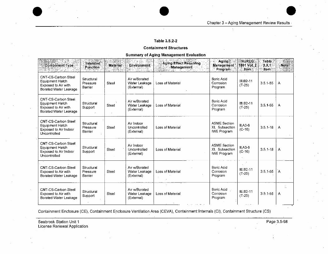
0Chapter 3 -Aging Management Review Results
Table 3.5.2-2
Containment Structures
Summary of Aging Management Evaluation
Intended~ Ag ing.Effec~t Ag ui ing NUE. TalFunction Manageelte
Equipmen Stee Structural Air w/Borated Boric AcidEquipent HtchII1.B2-11AExuposednto Hairwtch Pressure Steel Water Leakage Loss of Material Corrosion (T-25) 3.5.1-55AExposed to Air with Barrier (External) ProgramBorated Water Leakage
CNT-CS-Carbon SteelEquipment Hatch Structural Air w/Borated Boric Acid 1.21Steel Water Leakage Loss of Material Corrosion 3.5.1-55 A
Exposed to Air with Support (External) Program (T-25)Borated Water Leakage
CNT-CS-Carbon Steel Structural Air Indoor ASME SectionEquipment Hatch Pressure Steel Uncontrolled Loss of Material XI, Subsection 3-6 3.5.1-18 AExposed to Air Indoor Barrier (External) IWE Program (C-16)Uncontrolled
CNT-CS-Carbon Steel Air Indoor ASME SectionEquipment Hatch Structural Steel Uncontrolled Loss of Material XI, Subsection I1.A3-6 3.5.1-18 AExposed to Air Indoor Support (External) IWE Program (C-16)Uncontrolled
CNT-CS-Carbon Steel Structural Air w/Borated Boric AcidExposed to Air with Pressure Steel Water Leakage Loss of Material Corrosion II1.B2-11 3.5.1-55 ABorated Water Leakage Barrier (External) Program (T-25)
CNT-CS-Carbon Steel Structural Air w/Borated Boric Acid 111.12- 3.Exposed to Air with Support Steel Water Leakage Loss of Material Corrosion (T-25) 3.5.1-55 ABorated Water Leakage (External) Program
Containment Enclosure (CE), Containment Enclosure Ventilation Area (CEVA), Containment Internals (Cl), Containment Structure (CS)
Seabrook Station Unit 1License Renewal Application
Page 3.5-98

Chapter 3 -Aging Management Review Results
Table 3.5.2-2
Containment Structures
Summary of Aging Management Evaluation
Intended Aging Effect iAnging: •: TNURE : .TableComponent Type Fucin.4a~a~qrrn. a eet 801 Vol.2- 3~X1i NoFbitbiMngemient~
NT-C-a lProgram Item
CNT-CS-Carbon Steel Structural Air w/Borated Boric Acid Ill.B2-11Exposed to Air with Pressure Steel Water Leakage Loss of Material Corrosion 3.5.1-55 ABorated Water Leakage Barrier (External) Program (T-25)for HVAC Penetrations
CNT-CS-Carbon Steel Air w/Borated Boric AcidExposed to Air with Structural Steel Water Leakage Loss of Material Corrosion A1c.B2-11 3.5.1-55 ABorated Water Leakage Support (External) Program (T-25)for HVAC Penetrations
CNT-CS-Carbon Steel Structural Air Indoor ASME SectionExposed to Air Indoor Pressure Steel Uncontrolled Loss of Material XI, Subsection (LA1-1 1 3.5.1-6 AUncontrolled Barrier (External) IWE Program (C09)
CNT-CS-Carbon Steel Structural Air Indoor ASME Section Al-i 1Exposed to Air Indoor Steel Uncontrolled Loss of Material XI, Subsection (C-09) 3.5.1-6 AUncontrolled Support (External) IWE Program
CNT-CS-Carbon Steel "
ExposetAir Indoor Structural 'Air Indoor ASME SectionExposed to Pressure Steel Uncontrolled Loss of Material XI, Subsection II.A3-1 3.5.1-18 AUncontrolled For HVAC Barrier (External) WE Program (C-12)Penetrations
CNT-CS-Carbon Steel Air Indoor ASME SectionExosdtoAr ndo Srctra tel Uncontrolled Loss of Material Xl, Subsection I1.A3-1 3511Exposed to Air Indoor Structural Stel Ar ndo .(-12) 3511Uncontrolled For HVAC Support (External) IWE Program (C-12)
Penetrations
Containment Enclosure (CE), Containment Enclosure Ventilation Area (CEVA), Containment Internals (Cl), Containment Structure (CS)
Seabrook Station Unit 1License Renewal Application
Page 3.5-99

Chapter 3 -Aging Management Review Results
Table 3.5.2-2
Containment Structures
Summary of Aging Management Evaluation
Aging-~ NUREG i Table_Com ponent T ype M aterial Environm ent.:Aging.Eff.ct . . . .. . . . . . . •Mat naeg M anagem m nte•t -1801 Vol-.2 -3.X.- N o ie
CNT-CS-Carbon SteelMechanical (Piping) Structural Air w/Borated Boric Acid 111.12-11Penetration Exposed to Pressure Steel Water Leakage Loss of Material Corrosion (T-.2-11 3.5.1-55 A
Air with Borated Water Barrier (External) Program (T-25)
LeakageCNT-CS-Carbon Steel
Mechanical (Piping) Structural Air w/Borated Boric Acid II1.B2-11Penetration Exposed to Surt Steel Water Leakage Loss of Material Corrosion (T-111 3.5.1-55 AAir with Borated Water Spot(External) Program (-5
Leakage
CNT-CS-Carbon Steel Structural Air Indoor ASME SectionMechanical (Piping) Pressure Steel Uncontrolled Loss of Material XI, Subsection II.A3-1 3.5.1-18 APenetration Exposed to Barrier (External) IWE Program (C-12)Air Indoor Uncontrolled
CNT-CS-Carbon Steel Air Indoor ASME SectionMechanical (Piping) Structural Steel Uncontrolled Loss of Material Xl, Subsection llCA3-1 3.5.1-18 APenetration Exposed to Support (External) IWE Program (C-12)Air Indoor Uncontrolled
CNT-CS-Carbon Steel Structural Air w/Borated Boric AcidPersonnel HatchII.21Exposed to Air with Pressure Steel Water Leakage Loss of Material Corrosion (Cl.T2-l5 3.5.1-55 ABorated Water Leakage Barrier (External) Program . (CT-25)
CNT-CS-Carbon SteelPersonnel Hatch Structural l Air w/Borated BoricAcid III.B2-11Exposed to Air with Support Steel Water Leakage Loss of Material Corrosion (CT-25) 3.5.1-55 A
Borated Water Leakage (External) Program
Containment Enclosure (CE), Containment Enclosure Ventilation Area (CEVA), Containment Internals (CI), Containment Structure (CS)
Seabrook Station Unit 1License Renewal Application
Page 3.5-100
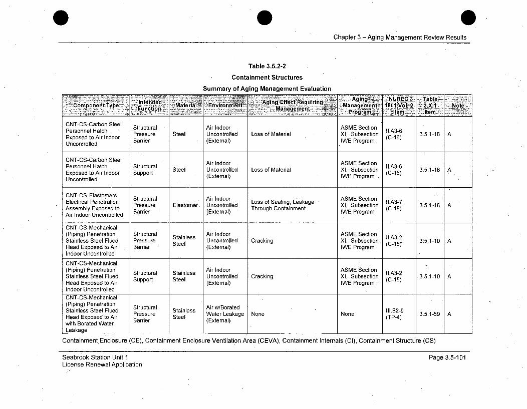
Chapter 3 - Aging Management Review Results
Table 3.5.2-2
Containment Structures
Summary of Aging Management Evaluation
lnerd~~>~ - et ~uiin:-• Aging NUREG~ .Ta bie -Component Type -Intende Mate r ial Envirornment- Aging EffetRqurn. Mana~geriWiiitV 18O1I.Vol. 2 3.A NoteFunction _ .. Management Porm tm Ie
CNT-CS-Carbon SteelPersonnel Hatch Structural Air Indoor ASME SectionExposed to Air Indoor Pressure Steel Uncontrolled Loss of Material X1, Subsection (C-16) 3.5.1-18 A
Uncontrolled Barrier (External) IWE Program
CNT-CS-Carbon Steel Air Indoor ASME Section
ersosel tch Surt Steel Uncontrolled Loss of Material Xl, Subsection IIA3-6 3.5.1-18 AExposed to Air Indoor Support (External) WE Program (C-16)Uncontrolled
CNT-CS-Elastorers Structural Air Indoor ASME Section* lcrclPntain.ArInor Ls fSaigLaae. II.A3-7Electrical Penetration Pressure Elastomer Uncontrolled Loss of Sealing, Leakage XI, Subsection (C-1 3.5.1-16 A
Assembly Exposed to Barrier (External) Through Containment IWE Program (C-18)Air Indoor Uncontrolled
CNT-CS-Mechanical(Piping) Penetration Structural Stainless Air Indoor ASME SectionStainless Steel Flued Pressure Stess Uncontrolled Cracking XI, Subsection I(A3-2 315.1-10 AHead Exposed to Air Barrier Steel (External) IWE Program (C-15)
Indoor Uncontrolled
CNT-CS-Mechanical•(Piping) Penetration Structural Stainless Air Indoor ASME Section I1A3-2Stainless Steel Flued Support Steel Uncontrolled Cracking Xl, Subsection (C-15) 3.5.1-10 AHead Exposed to Air (External) IWE Program (Indoor UncontrolledCNT-CS-Mechanical(Piping) Penetration Structural Air w/BoratedStainless Steel Flued Pressure Stainless II1.B2-9 3.5.1-59 AHead Exposed to Air Prer Steel WaterLak n (TP4)with Borated Water Barrier (External)Leakage
Containment, Enclosure (CE), Containment Enclosure Ventilation Area (CEVA), Containment Internals (CI), Containment Structure (CS)
Seabrook Station Unit 1License Renewal Application
Page 3.5-101

Chapter 3 - Aging Management Review Results
Table 3.5.2-2
Containment Structures
Summary of Aging Management Evaluation
A gigAging~ NURIEG TableComponent Type Inedd~ Material Environment~ Effecagqmernn -10 Vol 2 3.X1 . NoteFunction Management ~ ilr
- ~Program I. tem. Item%~CNT-CS-Mechanical(Piping) Penetration Air w/BoratedStainless Steel Flued Structural Stainless Water Leakage None None II.B2-9 3.5.1-59 AHead Exposed to Air Support Steel (External) (TP-4)with Borated WaterLeakage
ASME SectionCNT-CS-Reinforced Shelter, Cracking, Loss of Bond, Loss of e I.A1-7Concrete Below Grade Protection Concrete Soil (External) Material (Spalling, Scaling) XI, Subsection (C-05) 3.5.1-1 A
IWL Program
ASME SectionCNT-CS-Reinforced Structural Concrete Soil (External) Cracking, Loss of Bond, Loss of XI, Subsection IL.A1-7 3.5.1-1 AConcreteBelow Grade Support Material (Spalling, Scaling) IWL Program (C-05)
ASME SectionCNT-CS-Reinforced Shelter, Concrete Soil (External) Expansion and Cracking XI, Subsection IC.A1-3 3.5.1-15 AConcrete Below Grade Protection IWL Program (C-04)
CNT-CS-Reinforced Structural ASME Section II.A1-3
Concrete BelowGrade Support Concrete Soil (External) Expansion and Cracking XI, Subsection (C-04) 3.5.1-15 Ar IWL Program
CNT-CS-Reinforced Shelter, CIncrease in Porosity and ASME Section ll.A1.4Concrete Below Grade Protection Concrte Soil (External) Permeability, Cracking, Loss of XI, Subsection (C-03) 3.5.1-1 A,516
Material (Spalling, Scaling) IWL Program
Containment Enclosure (CE), Containment Enclosure Ventilation Area (CEVA), Containment Internals (CI), Containment Structure (CS)
Seabrook Station Unit 1License Renewal Application
Page 3.5-102
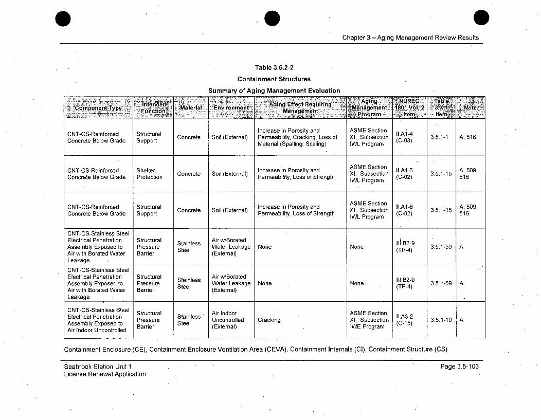
Chapter 3- Aging Management Review Results
Table 3.5.2-2
Containment Structures
Summary of Aging Management EvaluationEnvironment Aging g UR TaBlel
ComonntTye, lntende& Mteia Aging Effelct Requiring V01.'.jCopnntTp Mtra Environgmenet M~a e t 1801.-oZ 3.X.1 Note
- - __ Programi .Ae terni
CNT-CS-Reinforced Structural Increase in Porosity and ASME Section II.A1.-4Concrete BelowSoil (External) Permeability, Cracking, Loss of XI, Subsection (-03) 3.5.1-1 A,516
Material (Spalling, Scaling) IWL Program
CNT-CS-Reinforced " Shelter, Cocee Si Etra) Increase in Porosity and AXME Subection 3.5.1-15A, 509,Concrete Below Grade Protection ConcreteliySoilss(External)h IL Susetonra (C-02) 3..-5 516
ASME SectionCNT-CS-Reinforced Structural Concrete Soil (External) Increase in Porosity and XI, Subsection I1.A1-6 3.5.1-15 A, 509,Concrete Below Grade Support Permeability, Loss of Strength IWL Program (C-02) 516
IWL Program
CNT-CS-Stainless SteelElectrical Penetration Structural Stainless Air w/Borated N1o.B2-9Assembly Exposed to Pressure Steel Water Leakage None None (TP-4) 3.5.1-59 AAir with Borated Water Barrier (External)Leakage
CNT-CS-Stainless SteelElectrical Penetration Structural Stainless Air w/Borated 1l1.B2-9Assembly Exposed to Pressure Steel Water Leakage None None (TP4) 3.5.1-59 AAir with Borated Water Barrier (External)Leakage
CNT-CS-Stainless Steel Structural Air Indoor ASME SectionElectrical Penetration Pressure Stainless Uncontrolled Cracking XI, Subsection (C.A3-2 3.5.1-10 AAssembly Exposed to Steel Unotroll rcn P (C-is)Air Indoor Uncontrolled Barrier (External) IWE Program
Containment Enclosure (CE), Containment Enclosure Ventilation Area (CEVA), Containment Internals (CI), Containment Structure (CS)
Seabrook Station Unit 1License Renewal Application
Page 3.5-103
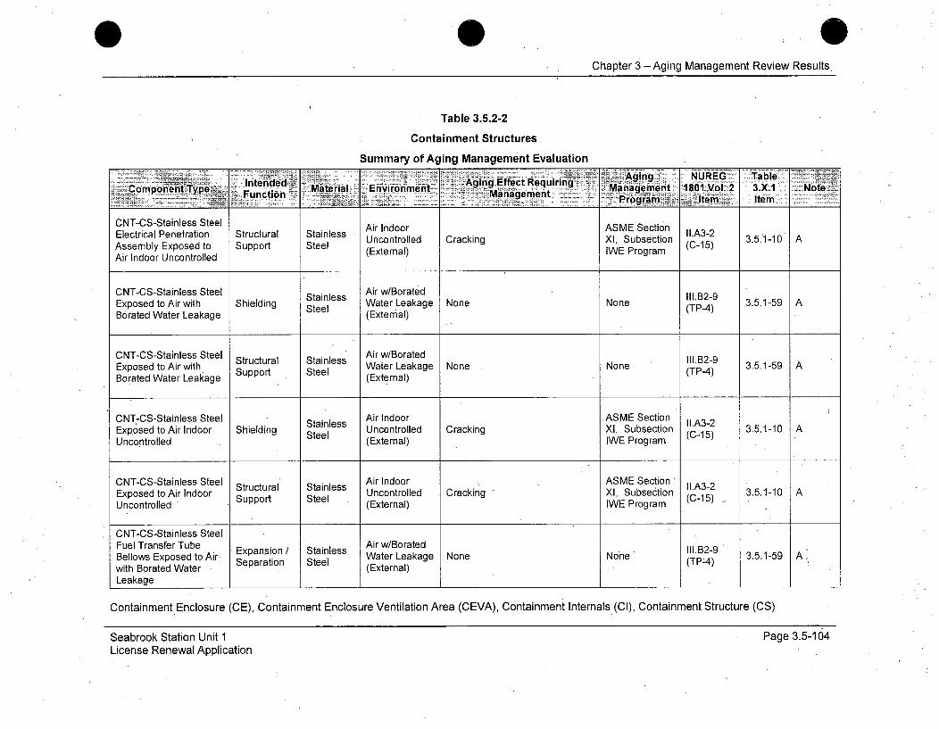
Chapter 3 -Aging Management Review Results
Table 3.5.2-2
Containment Structures
Summary of Aging Management Evaluation
Intened Agng Efect 'Aging NUREG: alComponentType ~ Maeil Eniom -g nagEfemtequrnt Maagement 1801 Vol. 2 3.X.1 Note7
_________________________ Pogi Item Item
CNT-CS-Stainless Steel Air Indoor ASME SectionElectrical Penetration Structural Stainless Uncontrolled Cracking XI, Subsection (LA3-2 3.5.1-10 AAssembly Exposed to Support Steel (External) WE Program -15)Air Indoor Uncontrolled
CNT-CS-Stainless Steel Stainless Air w/Borated III.B2-9Exposed to Air with Shielding Steel WateriLeakage None None (TP-4) 3.5.1-59 ABorated Water Leakage (External)
CNT-CS-Stainless Steel Structural Stainless Air w/Borated2-9Exposed to Air with Steel Water Leakage None None (TP-4) 3.5.1-59Borated Water Leakage Support (External)
CNT-CS-Stainless Steel Stainless Air Indoor ASME Section IIA3-2Exposed to Air Indoor Shielding Steel Uncontrolled Cracking XI, Subsection (C-15) 3.5.1-10 AUncontrolled (External) IWE Program
CNT-CS-Stainless Steel Structural Stainless Air Indoor Ccnl Section (C-1 -10Exposed to Air Indoor SupportUncontrolled Cracking X, Suection ( ) 3.5.1-0 AUncontrolled (External) IWE Program
CNT-CS-Stainless SteelFuel Transfer Tube Expansion iStainless Ar w/Borated I 11. 13--9Bellows Exposed to Air Separation Steel tera(TP4)with Borated Water (External)Leakage
Containment Enclosure (CE), Containment Enclosure Ventilation Area (CEVA), Containment Internals (Cl), Containment Structure (CS)
Seabrook Station Unit 1License Renewal Application
Page 3.5-104
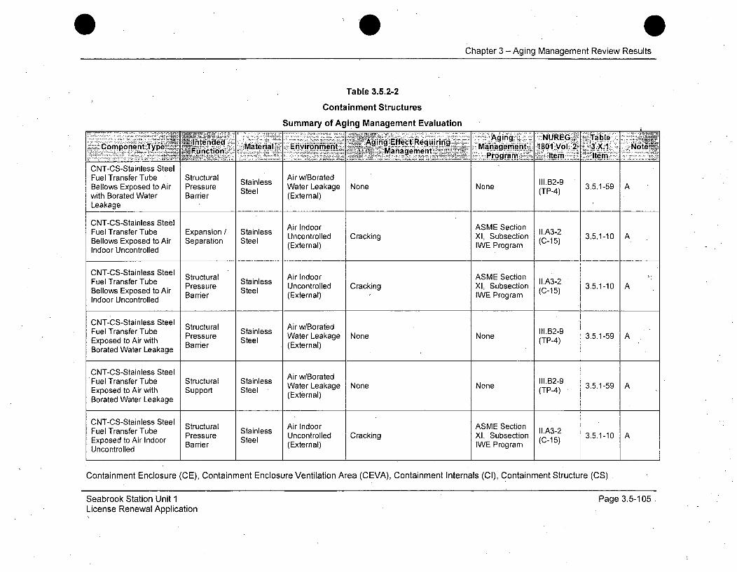
Chapter 3 - Aging Management Review Results
Table 3.5.2-2
Containment Structures
Summary of Aging Management Evaluation•w
Envromen-.Aging NUREGI- r TableComponent Type Inedd Material: Enirnmn Ma-gin Efec Reuiin-rn 80 Vl 3.X.1 Note
_L1C1n;' Managehienit I I teFuncton -r.gramn _ tem Item
CNT-CS-Stainless SteelFuel Transfer Tube Structural Air w/BoratedBellows Exposed to Air Pressure Water Leakage None None 3.5.1-59 Awith Borated Water Barrier Steel (External) (TP-4)
Leakage
CNT-CS-Stainless Steel Air Indoor ASME SectionFuel Transfer Tube Expansion / Stainless AiIIdorA3M-SctoFuell Transfer Tue A Eparaion Stainless Uncontrolled Cracking XI, Subsection (C.A3-2 3.5.1-10 ABellows Exposed to Air Separation Steel (External) IWE Program (-5Indoor Uncontrolled
Structural Air Indoor ASME SectionFuel Transfer Tube Pressure Stainless I.A3-2 3.5.1-10 ABellows Exposed to Air Barrier Steel (External) IWE Program (C-15)Indoor Uncontrolled
CNT-CS-Stainless Steel Structural StainlessFuel Transfer Tube Stainless Wate1.2-9Exoe oArwt rsue Sel Water Leakage None None ll.29 3.5.1-59AExposed to Air with Barrier (External) (TP-4)Borated Water Leakage
CNT-CS-Stainless Steel Air w/BoratedFuel Transfer Tube Structural Stainless IlN.1B2-9tAiwih Spot Sel Water Leakage None None (TP-4) 3.5.1-59AExposed to Air with Support Steel (External)Borated Water Leakage
CNT-CS-Stainless Steel Structural Air Indoor ASME SectionFuel Transfer Tube Pressure Stainless Uncontrolled Cracking X Subsection .A3-2 3.5.1-10 AExposed to Air Indoor Barrier Steel (External) IWE Program (C-15)Uncontrolled
Containment Enclosure (CE), Containment Enclosure Ventilation Area (CEVA), Containment Internals (CI), Containment Structure (CS)
Seabrook Station Unit 1License Renewal Application
Page 3.5-105

Chapter 3 - Aging Management Review Results
Table 3.5.2-2
Containment Structures
Summary of Aging Management Evaluation
= . .liitended -- -.- - AginglEfect'Requiring .gi•ng!". .. . -... TablC-ompone.ntyp.e• :• , .i. •-Material Environmentg Ma e 1801-VolI-. 3. X.,1: Note
jý2F~~nction Managiementftpont
CNT-CS-Stainless SteelCN-SSanesSelAir Indoor ASMVE SectionFuel Transfer Tube Structural Stainless AiIIdorAS3-SctoUncontrolled Cracking XI, Subsection 11-A3-2 3.5.1-10 AExposed to Air Indoor Support Steel (External) IWE*Program (C-15)Uncontrolled
CNT-CS-ThermalInsulation Stainless Structural Stainless Air w/Borated II1.B2-9Steel Jacketing in Air Support Steel Water Leakage None None (TP-4) 3.5.1-59 Awith Borated WaterLeakage
Containment Enclosure (CE), Containment Enclosure Ventilation Area (CEVA), Containment Internals (CI), Containment Structure (CS)
Seabrook Station Unit 1License Renewal Application
Page 3.5-106

Chapter 3 - Aging Management Review Results
Table 3.5.2-2Containment Structures
Summary of Aging Management EvaluationStandard Notes
Note DescriptionA Consistent with NUREG-1801 item for component, material, environment, and aging effect. AMP is consistent with NUREG-1801 AMP.B Consistent with NUREG-1801 item for component, material, environment, and aging effect. AMP takes some exceptions to NUREG-
1801 AMP.C Component is different, but consistent with NUREG-1 801 item for material, environment, and aging effect. AMP is consistent with
NUREG-1801 AMP.D Component is different, but consistent with NUREG-1801 item for material, environment, and aging effect. AMP takes some exceptions
to NUREG-1801 AMP.E Consistent with NUREG-1 801 for material, environment and aging effect, but a different aging management program is credited or
NUREG-1801 identifies a plant-specific aging management program.F Material not in .NUREG-1 801 for this component.G Environment not in NUREG-1 801 for this component and material.H Aging effect not in NUREG-1 801 for this component, material and environment combination.I Aging effect in NUREG-1 801 for this component, material and environment combination is not applicable.J Neither the component nor the material and environment combination is evaluated in NUREG-1 801.
501 Not used.502 Aging effect includes "Fretting or Lockup" due to wear.503 Crevice and pitting will be included along with loss of material-corrosion due to a saltwater atmosphere environment.504 Fatigue analysis exists and TLAA applies.505 Built-up roofing is not in GAL; II1.A6-12 is for elastomer-material is similar, aging effect is similar, environment is same, and AMP is
Structures Monitoring.506 Component is cementitious fire proofing/insulating material and will exhibit similar aging effects as concrete.507 Spent Fuel Pool temperature < 600C (<1400 F), water chemistry and temperature will be maintained by the Water Chemistry Program.508 Cracking, loss of bond, and loss of material (Spalling, Scaling)/corrosion of embedded steel-is not listed in GALL 111,A.6 as an aging
effect for concrete in raw water. Seabrook manages this effect with Structures Monitoring Program.509 For aging management purposes, buried, below grade, soil, and ground water/ raw & treated water environments are treated the same.510 Reduction in concrete anchor capacity is an aging effect that is addressed in LRAM-SUPT.
Seabrook Station Unit 1 Page 3.5-107License Renewal Application
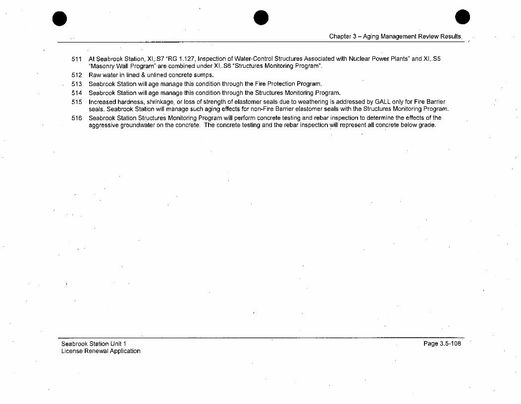
Chapter 3 -Aging Management Review Results.
511 At Seabrook Station, XI,.S7 "RG 1.127, Inspection of Water-Control Structures Associated with Nuclear Power Plants" and XI,.S5"Masonry Wall Program" are combined under XI,.S6 "Structures Monitoring Program".
512 Raw water in lined & unlined concrete sumps.
513 Seabrook Station will age manage this condition through the Fire Protection Program.514 Seabrook Station will age manage this condition through the Structures Monitoring Program.
515 Increased hardness, shrinkage, or loss of strength of elastomer seals due to weathering is addressed by GALL only for Fire.Barrierseals. Seabrook Station will manage such aging effects for non-Fire Barrier elastomer seals with the Structures Monitoring Program.
516 Seabrook Station Structures Monitoring Program will perform concrete testing and rebar inspection to determine the effects of theaggressive groundwater on the concrete. The concrete testing and the rebar inspection will represent all concrete below grade.
Seabrook Station Unit 1License Renewal Application.
Page 3.5-108
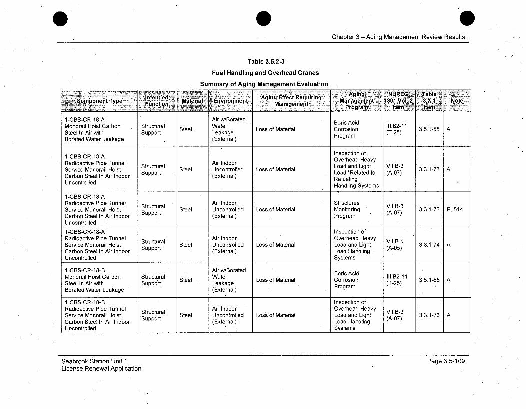
Chapter 3 -Aging Management Review Results-
Table 3.5.2-3
Fuel Handling and Overhead Cranes
Summary of Aging Management Evaluation
lnt~de&Wd ging. SNUREG7 Table'.Component Type F•nction Material Environment qAgin•o Effec Requirig -Managementj 801 Vo12 3,X.1 Note
MangemntProgram Item Item3E
1-CBS-CR-18-A Air w/Borated Boric AcidMonorail Hoist Carbon Structural Steel Water Loss of Material Corrosion III.B2-11 3.5.1-55 ASteel In Air with Support Leakage Program (T-25)Borated Water Leakage (External)
Inspection of1-CBS7CR-18-A Overhead Heavy
Radioactive Pipe Tunnel Structural Air Indoor Load and Light VIyB-3Service Monorail Hoist Strt Steel Uncontrolled Loss of Material Load and t (A-0 3.3.1-73 ACarbon Steel In Air Indoor Support (External) Load Related to (A-07)UncontolledRefueling'Uncontrolled Handling Systems
1-CBS-CR-18-A.Radioactive Pipe Tunnel Structural Air Indoor Structures VII.B-3Service Monorail Hoist Support Steel Uncontrolled Loss of Material Monitoring (A-07) 3.3.1-73 E, 514Carbon Steel In Air Indoor (External) ProgramUncontrolled
1-CBS-CR-18-A Inspection ofRadioactive Pipe Tunnel Structural Air Indoor Overhead Heavy VII3B-1Service Monorail Hoist Support Steel Uncontrolled Loss of Material Load and Light (A-05) 3.3.1-74Carbon Steel In Air Indoor (External) Load Handling,Uncontrolled Systems
1-CBS-CR-18-B Air w/Borated Boric AcidMonorail Hoist Carbon Structural Steel Water BIoricscd 111.B2-11 3.5.1-55 ASteel In Air with Support Leakage Loss of Material Corrosion (T-25) 3Borated Water Leakage (External) Program
1-CBS-CR-18-B Inspection ofRadioactive Pipe Tunnel Structural Air Indoor Overhead Heavy VII.B-3Service Monorail Hoist Support Steel Uncontrolled Loss of Material Load and Light (A-07) 3.3.1-73Carbon Steel In Air Indoor (External) Load HandlingUncontrolled Systems
Seabrook Station Unit 1License. Renewal Application
Page 3.5-109

Chapter 3 -Aging Management Review Results
Table 3.5.2-3
Fuel Handling and Overhead Cranes
Summary of Aging Management Evaluation
inen~d ~---Aging. NUREG Table~C Cmponent Type 2<Material- Environment eqiig Management 1801 Vol. 2 3.X1 : Note
- Functtion %~arnagemne'rt PV g roam Item Item V1-CBS-CR-18-BRadioactive Pipe Tunnel Structural Air Indoor Structures VII.B-3Service Monorail Hoist Support Steel Uncontrolled Loss of Material Monitoring (A-07) 3.3.1-73 E, 514Carbon Steel In Air Indoor (External) ProgramUncontrolled
1-CBS-CR-18-B Inspection ofRadioactive Pipe Tunnel Structural Air Indoor Overhead Heavy VIIB-1Service Monorail Hoist Support Steel Uncontrolled Loss of Material Load and Light (A-05) 3.3.1-74 ACarbon Steel In Air Indoor (External) Load Handling
Uncontrolled Systems
1-CC-CR-15-A Air w/Borated Boric AcidMonorail Hoist Carbon Structural Steel Water Loss of Material Corrosion 11.B2-11 3.5.1-55 ASteel In Air with Support Leakage L aorri (T-25)Borated Water Leakage (External) Program
1-CC-CR-15-A Inspection ofCC Water Pump Service Structural Air Indoor Overhead Heavy VII.B-3Monorail Hoist Carbon Support Steel Uncontrolled Loss of Material Load and Light (A-07) 3.3.1-73 ASteel In Air Indoor (External) Load HandlingUncontrolled Systems
1-CC-CR-15-ACC Water Pump Service Structural Air Indoor Structures VII.B-3Monorail Hoist Carbon Support Steel Uncontrolled Loss of Material Monitoring (A-07) 3.3.1-73 E, 514Steel In Air Indoor (External) Program
Uncontrolled
1-CC-CR-15-A Inspection ofCC Water Pump Service Structural Air Indoor Overhead Heavy .VII.B-1Monorail Hoist Carbon Steel Uncontrolled Loss of Material Load and Light (A-07' 3.3.1-74 ASteel In Air Indoor Support (External) Load Handling (0
Uncontrolled I Systems
Seabrook Station Unit 1 Page 3.5-110License Renewal Application
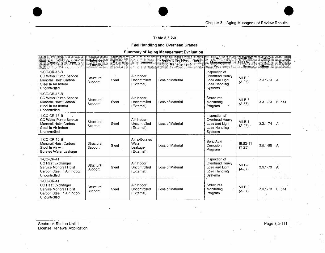
0Chapter 3 -Aging Management Review Results
Table 3.5.2-3
Fuel Handling and Overhead Cranes
Summary of Aging Management Evaluation
Intende Environment ~Aging Effect RequiringURG TalededT MateriaIL Requiring0 ýoký3X NtCopnn.ype 7Funcdtion'-.. Managemenit aenn 81Vl2 3X1 Nt
____Program.- Jteiii Item
1-CC-CR-15-B Inspection ofCC Water Pump Service Structural Air Indoor Overhead Heavy VII.B-3Monorail Hoist Carbon Support Steel Uncontrolled Loss of Material Load and Light (A-07) 3.3.1-73 ASteel In Air Indoor (External) Load HandlingUncontrolled Systems
1-CC-CR-15-BCC Water Pump Service Structural Air Indoor Structures VII.B-3Monorail Hoist Carbon Support Steel Uncontrolled Loss of Material Monitoring (A-07) 3.3.1-73 E, 514Steel In Air Indoor (External) ProgramUncontrolled
1-CC-CR-15-B Inspection ofCC Water Pump Service Structural Air Indoor Overhead Heavy VI.B-1Monorail Hoist Carbon Support Steel Uncontrolled Loss of Material Load and Light (A-07), 3.3.1-74 ASteel In Air Indoor S o(External) Load HandlingUncontrolled Systems
1-CC-CR-15-B Air w/Borated Boric AcidMonorail Hoist Carbon Structural Water Borric Aill.B2-11Steel Loso aeilCroin3.5.1-55 ASteel In Air with Support Leakage L aorri (T-25)Borated Water Leakage (External) Program
1-CC-CR-41 Inspection ofCC Heat Exchanger Structural Air Indoor Overhead Heavy VII.B-3Service Monorail Hoist Steel Uncontrolled Loss of Material Load and Light (A-.7) 3.3.1-73 ACarbon Steel In Air Indoor (External) Load Handling AUncontrolled Systems
1-CC-CR-41CC Heat Exchanger Structural Air Indoor Structures VII.B-3Service Monorail Hoist Steel Uncontrolled Loss of Material Monitoring (A-07) 3.3.1-73 E, 514Carbon Steel In Air Indoor Support (External) ProgramUncontrolled
Seabrook Station Unit 1License Renewal Application
Page 3.5-111
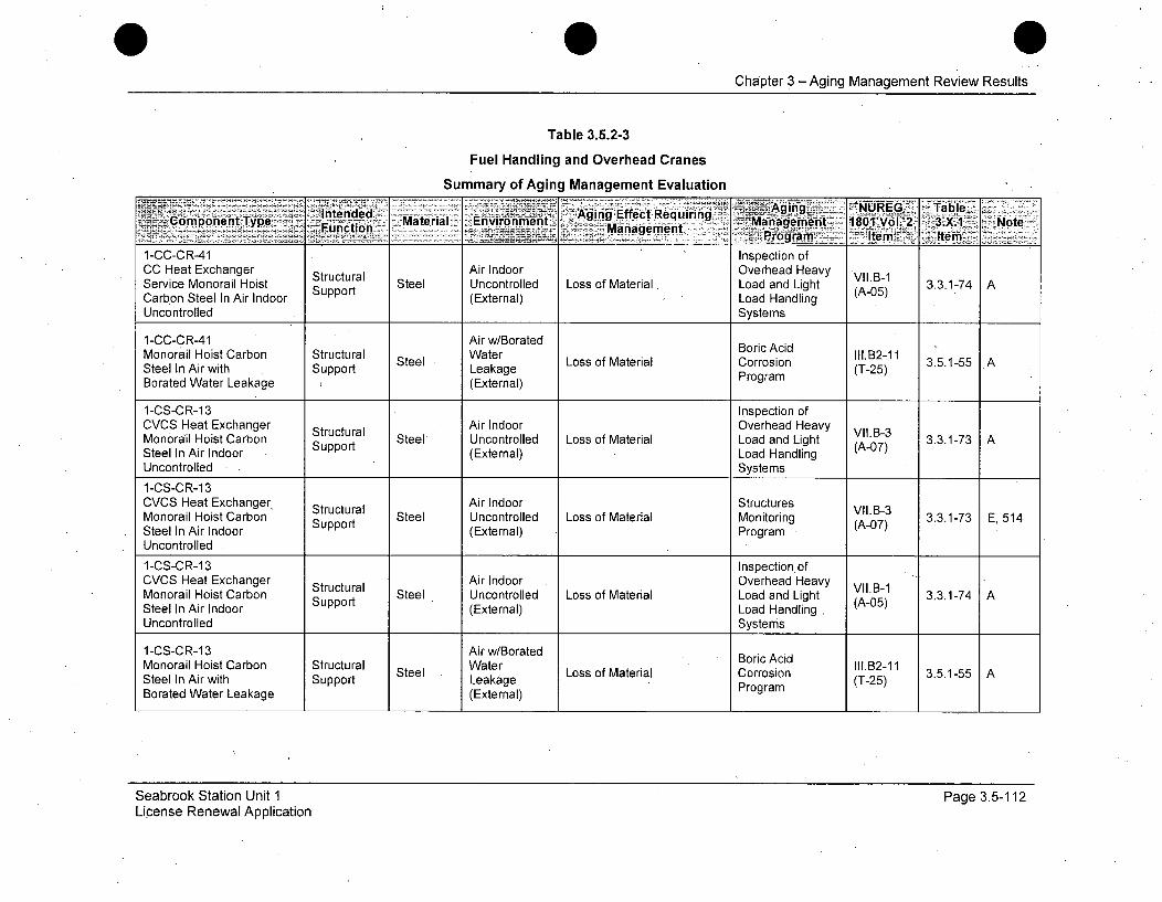
Chapter 3 -Aging Management Review Results
Table 3.5.2-3
Fuel Handling and Overhead Cranes
Summary of Aging Management Evaluation
Intended~ h~~ET gin :NUREG_ ~Table.-4 Component Type Fuctn Material Environmen 'gn fetRqiig -Management 18OIZVOL 2. 3.X1 Note
__ct Management f:an~-Ie
1-CC-CR-41 Inspection ofCC Heat Exchanger Structural Air Indoor Overhead Heavy VIIB-1Service Monorail Hoist Steel Uncontrolled Loss of Material Load and Light (A-05) 3.3.1-74 ACarbon Steel In Air Indoor Support (External) Load HandlingUncontrolled Systems
1-CC-CR-41 Air w/BoratedMonorail Hoist Carbon Structural Water Boric Acid nI1.B2-11SelIAiwihSpot Steel Lage Loss of Material Corrosion (T2) 3.5.1-55 ASteel In Air with Support Leakage Program (T-25)Borated Water Leakage (External)
1-CS-CR-13 Inspection ofCVCS Heat Exchanger Structural Air Indoor Overhead Heavy VI1.B-3Monorail Hoist Carbon Steel Uncontrolled Loss of Material Load and Light (A-07) 3.3.1-73 ASteel In Air Indoor Support (External) Load HandlingUncontrolled Systems
1-CS-CR-13CVCS Heat Exchanger, Structural Air Indoor Structures VII.B-3Monorail Hoist Carbon Steel Uncontrolled Loss of Material Monitoring (A-07) 3.3.1-73 E, 514Steel In Air Indoor Support (External) ProgramUncontrolled
1-CS-CR-13 Inspection ofCVCS Heat Exchanger Structural Air Indoor Overhead Heavy VII.B-1Monorail Hoist Carbon Steel Uncontrolled Loss of Material Load and Light (A-05) 3.3.1-74 ASteel In Air Indoor Support (External) Load Handling.Uncontrolled Systems
1-CS-CR-13 Air w/BoratedMonorail Hoist Carbon Structural Water Boric Acid oIl.B2-11Steel In Air with Support Steel Leakage Loss of Material Corrosion (T-25) 3.5.1-55 ABorated Water Leakage (External) Program
Seabrook Station Unit 1License Renewal Application
Page 3.5-112
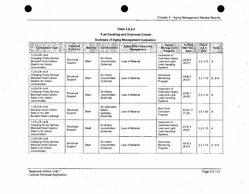
Chapter 3 -Aging Management Review Results
Table 3.5.2-3
Fuel Handling and Overhead Cranes
Summary of Aging Management Evaluation
Aging . - NUREG ITabe~CoponntTyp lt~ned'~ .Aging Effect R~equiring aneet 181NoteCopnnt "Fuction Mate'rial.; Environment Management oMana e•t 1801 1 3.X.V16 2ot__________. ~ .Program:- Item x. teiiV-
1-CS-CR-14-A Inspection ofCharging Pump Service Structural Air Indoor Overhead Heavy VII.B-3Monorail Hoist Carbon Support Steel Uncontrolled Loss of Material Load and Light (A-07)3 3.3.1-73 ASteel In Air Indoor (External) Load HandlingUncontrolled Systems
1-CS-CR-14-ACharging Pump Service Structural Air Indoor Structures VII.B-3Monorail Hoist Carbon Steel Uncontrolled Loss of Material Monitoring (A-07) 3.3.1-73 E, 514Steel In Air Indoor Support (External) ProgramUncontrolled
1-CS-CR-14-A Inspection ofCharging Pump Service Structural Air Indoor Overhead Heavy VII.B-1Monorail Hoist Carbon Steel Uncontrolled Loss of Material Load and Light (A-05) 3.3.1-74 ASteel In Air Indoor Support (External) Load Handling,Uncontrolled Systems
1-CS-CR-14-A Air w/Borated BAdMonorail Hoist Carbon Structural Water BoricAcidIlB2iSteel • Loss of Material Corrosion 111.B2-11 3.5.1-55 ASteel In Air with Support Leakage Program (T-25)Borated Water Leakage (External)
1-CS-CR-14-B Inspection ofCharging Pump Service Structural Air Indoor Overhead HeavyMonorail Hoist Carbon Support Steel Uncontrolled Loss of Material Load and Light (A-0.7) 3.3.1-73 ASteel In Air Indoor (External). Load HandlingUncontrolled Systems
1-CS-CR-14-BCharging Pump Service Structural Air Indoor Structures VII.B-3Monorail Hoist Carbon Steel Uncontrolled Loss of Material Monitoring (, 07) 3.3.1-73 E, 514Steel In Air Indoor Support (External) Program
Uncontrolled
Seabrook Station Unit 1License Renewal Application
Page 3.5-113
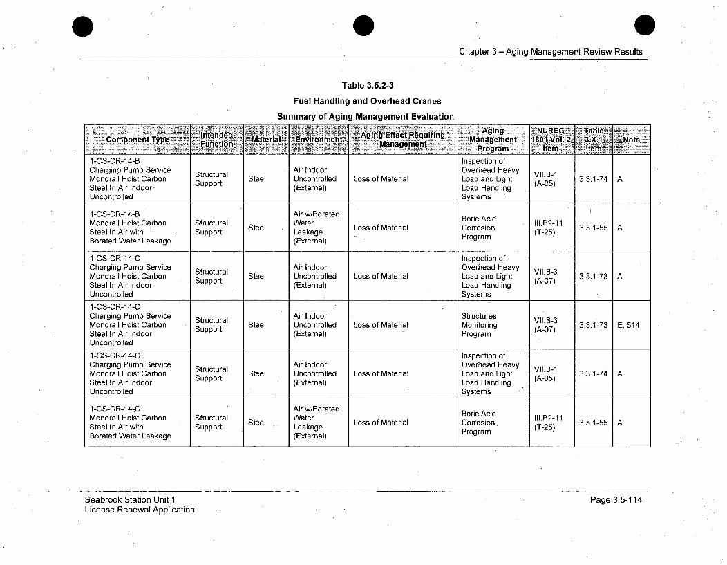
Chapter 3 -Aging Management Review Results
Table 3.5.2-3
Fuel Handling and Overhead Cranes
Summary of Aging Management Evaluation
I ntended'~eil ~~n#eA Aging Effect RequiringAigNRG TbeComponentcType n nMaterial gEnvionment - Management ibV 2 31 a NoteRa eProgram Item ltem --
1-CS-CR-14-B Inspection ofCharging Pump Service Structural Air Indoor Overhead Heavy VIIB-1Monorail Hoist Carbon Support Steel Uncontrolled Loss of Material Load and-Light (A-05) 3.3.1-74 ASteel In Air Indoor (External) Load HandlingUncontrolled Systems
1-CS-CR-14-B Air w/Borated Boric AcidMonorail Hoist Carbon Structural Water B A Il.B2-11Steel In Air with Support Steel Leakage Loss of Material Corrosion (T-25) 3.5.1-55 A
Borated Water Leakage (External) Program
1-CS-CR-14-C Inspection ofCharging Pump Service Structural Air Indoor Overhead Heavy VII.B-3Monorail Hoist Carbon Support Steel Uncontrolled Loss of Material Load and Light (A-7) 3.3.1-73 ASteel In Air Indoor (External) Load Handling (0
Uncontrolled Systems
1-CS-CR-14-CCharging Pump Service Structural Air Indoor Structures VII.B-3Monorail Hoist Carbon Steel Uncontrolled Loss of Material Monitoring (A-07) 3.3.1-73 E,514Steel In Air Indoor Support (External) ProgramUncontrolled
1-CS-CR-14-C Inspection ofCharging Pump Service Structural Air Indoor Overhead Heavy VIIB-1Monorail Hoist Carbon Steel Uncontrolled Loss of Material Load and Light - 3.3.1-74 ASteel In Air Indoor Support (External) Load HandlingUncontrolled Systems
1-CS-CR-14-C Air w/Borated Boric AcidMonorail Hoist Carbon Structural Water III.B2-11StelItArwihl ekae Loss of Material Corrosion. 3.5.-55Steel In Air with Support Leakage Program (T-25)Borated Water Leakage (External)
Seabrook Station Unit 1License Renewal Application
Page 3.5-114
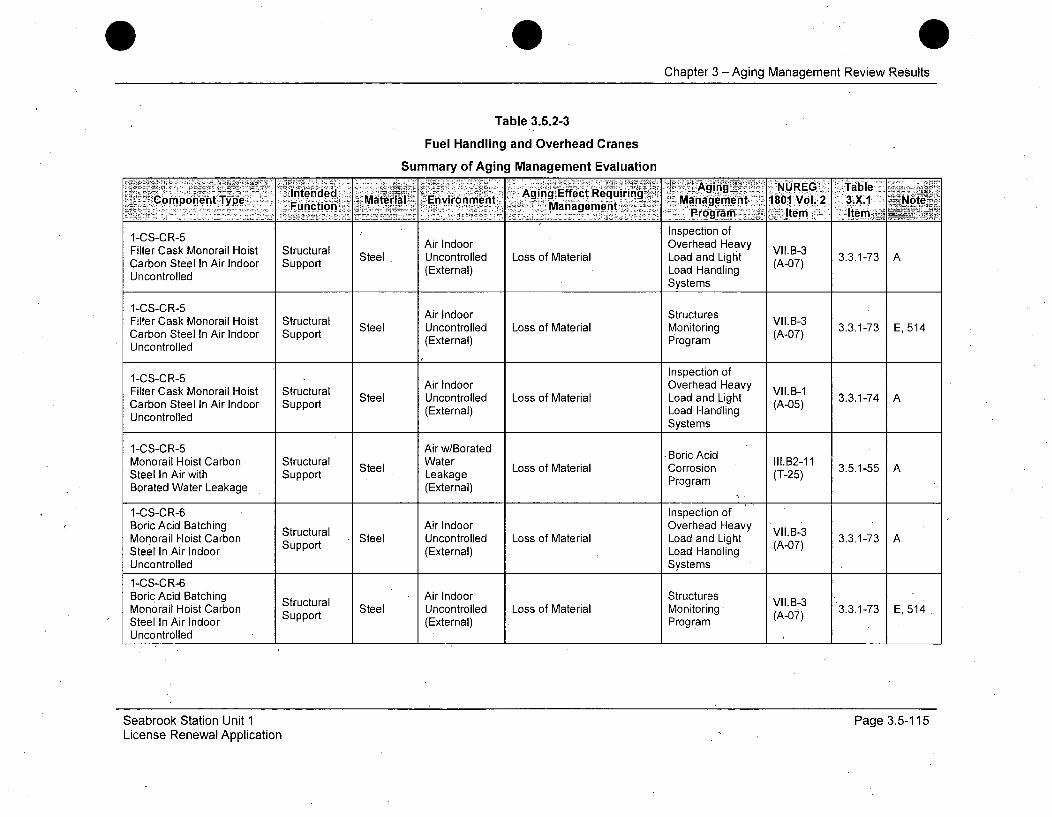
Chapter 3 - Aging Management Review Results
Table 3.5.2-3
Fuel Handling and Overhead Cranes
Summary of Aging Management Evaluation
ltdd.~ 'Agi NUREG TableComponent Type nne Material- --Environment Agn fetRqiig Ma-n~ageqment 1801 Vol.2- 3.X.1 ~Note~Function -.Management.PormIe tm _
1-CS-CR-5 Inspection ofAir Indoor Overhead HeavyFilter Cask Monorail Hoist Structural Steel Uncontrolled Loss of Material Load and Light (A-07) 3.3.1-73 A
Carbon Steel In Air Indoor Support (External) Load HandlingUncontrolled Systems
1-CS-CR-5 Air Indoor StructuresFilter Cask Monorail Hoist Structural ArIdoStuuesVII.B-3CroSte e In Aiondori Stupra Steel Uncontrolled Loss of Material Monitoring (A-07) 3.3.1-73 E, 514Carbon Steel In Air Indoor Support (External) Program (-7
Uncontrolled
1-CS-CR-5 Inspection of
Filter Cask Monorail Hoist Structural Air Indoor Overhead Heavy VII.B-1In Air Indoor Suort Steel Uncontrolled Loss of Material Load and Light (A-05) 3.3.1-74 ACarbon Steell (External) Load HandlingUncontrolled Systems
1-CS-CR-5 Air w/BoratedMonorail Hoist Carbon Structural Water ~Boric Acid II1.B2-11Steel Loss of Material Corrosion 3.5.1-55 ASteel In Air with Support Leakage Program (T-25)Borated Water Leakage (External)
1-CS-CR-6 Inspection ofBoric Acid Batching Structural Air Indoor Overhead Heavy VII.B-3Monorail Hoist Carbon Strt Steel Uncontrolled Loss of Material Load and Light (A-07) 3.3.1-73 ASteel In Air Indoor Support (External) Load HandlingUncontrolled Systems
1-CS-CR-6Boric Acid Batching Air Indoor Structures VII.B-3Monorail Hoist Carbon Strt Steel Uncontrolled Loss of Material Monitoring (A-07) 3.3.1-73 E, 514Steel In Air Indoor Support (External) ProgramUncontrolled
Seabrook Station Unit 1License Renewal Application
Page 3.5-115
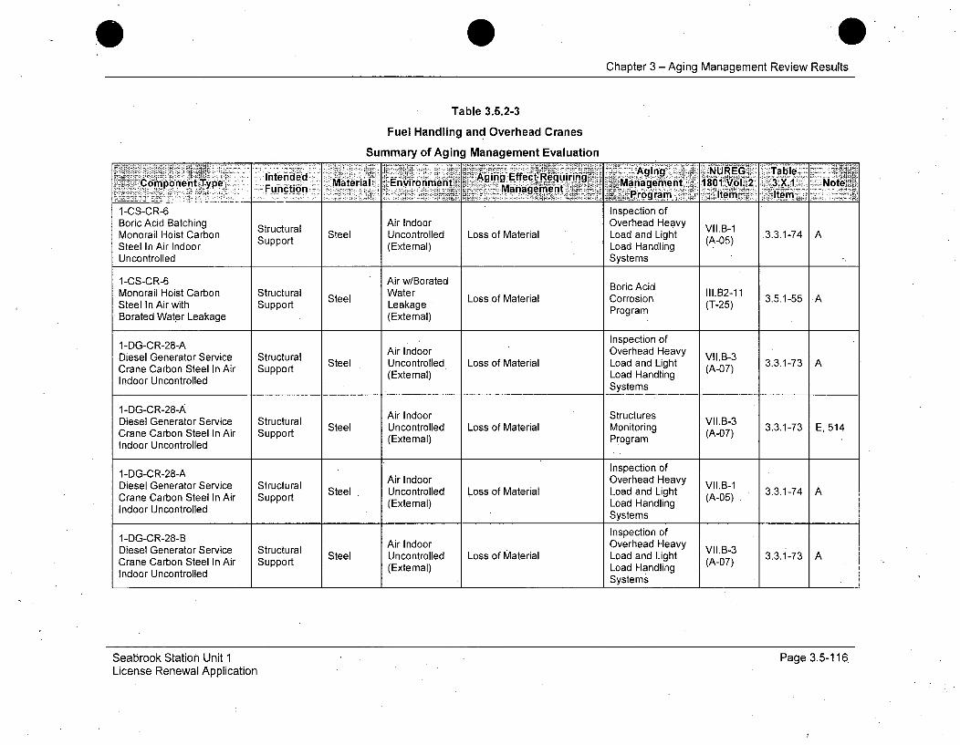
Chapter 3 -Aging Management Review Results
Table 3.5.2-3
Fuel Handling and Overhead Cranes
Summary of Aging Management EvaluationIntn.e'-Aging NUREG Table
Comnponentjype. ucto Material. Environment, AigEfcReurn 2.Management 1801Vol. 2ý 3.X.1 Note
1-CS-CR-6 Inspection ofBoric Acid Batching Structural Air Indoor Overhead Heavy IB-Monorail Hoist Carbon Support Steel Uncontrolled Loss of Material Load and Light (A-05) 3.3.1-74 ASteel In Air Indoor (External) Load HandlingUncontrolled Systems
1-CS-CR-6 Air w/Borated Boric AcidMonorail Hoist Carbon Structural Water III o.B2-11 3.5.1-55 ASteel In Air with Support Leakage L aorri (T-25)Borated Water Leakage (External) Program
1-DG-CR-28-A Inspection of
Diesel Generator Service Structural Air Indoor Overhead Heavy IB-3Steel Uncontrolled Loss of Material Load and Light (A-07) 3.3.1-73 ACrane Carbon Steel In Air Suppee (External) Load HandlingIndoor Uncontrolled Systems
1-DG-CR-28-A Air Indoor StructuresDiesel Generator Service Structural Steel Airond Structures VII.B-3 3.3.1-73 E, 514CrneCrbnSteeIlir SppdUncontrolled Loss of Material Monitoring (A-07) 3.1-3E54Crane Carbon Steel In Air Support (External) Program (-7
Indoor Uncontrolled
1 -DG-CR-28-A Inspection of
Diesel Generator Service Structural Air Indoor Overhead Heavy II.-1Steel Uncontrolled Loss of Material Load and Light (A-5 3.3.1-74 ACrane Carbon Steel In Air Support (External) Load Handling (A-05)Indoor Uncontrolled Systems
1 -DG-CR-28-B Inspection of
Diesel Generator Service Structural Air Indoor Overhead Heavy VII.B-3Cra neCrton Steervi Stprt Steel Uncontrolled Loss of Material Load and Light 3.3.1-73 ACrane Carbon Steel In Air Suppet (External) Load Handling (A-07)Indoor Uncontrolled
___________________ _________ _______ __________ ___________________ Systems _____
Seabrook Station Unit 1License Renewal Application
Page 3.5-116

Chapter 3 - Aging Management Review Results
Table 3.5.2-3
Fuel Handling and Overhead Cranes
Summary of Aging Management Evaluation
£EAging 1NRE -Tble _
+omlbnent Type Inten-ed Material Environment, :-.. -. e.. Requiring - Manaa gement 1801 Vol. 2.3 X, I NoteFuncionManagement Item:z:.r:gamY>ete
1-DG-CR-28-B Air IndoorDiesel Generator Service Structural Ste Unconr Structures VII.B-3CaeCroSteInAr Spot Steel Uncontrolled Loss of Material Monitoring (A-07) 3.3.1-73 E, 514Crane Carbon Steel In Air Support Monitol) ringr(Aa7
Indoor Uncontrolled (External) Program
1-DG-CR-28-B Inspection of
Diesel Generator Service Structural Air Indoor Overhead Heavy VII.B-1Crane Carbon Steel In Air Support Steel Uncontrolled Loss of Material Load and Light (A-05) 3.3.1-74 AIndoor Uncontrolled (External) Load HandlingSystems
1-FH-RE-1 Air w/BoratedCrane Carbon Steel In Air Structural Steel Water Boric Acid In1.B2-11- 3.3.1-55 Awith Borated Water Support Leakage L aorri (T-25)Leakage (External) Program
1-FH-RE-1 . Inspection of
Spent Fuel Cask Handling Structural Air Indoor Overhead Heavy VII.B-3Steel Uncontrolled Loss of Material Load and Light (A-0 3.3.1-73 ACrane Carbon Steel In Air Support (External) Load Handling (A07)Indoor Uncontrolled .Systems
1-FH-RE-1 1F-E1Air Indoor StructuresSpent Fuel Cask Handling Structural Steel Uncontrolled Loss of Material Monitoring V.-3 3.3.1-73 E, 514Crane Carbon Steel In Air Support Sosterial Monrin (A-07)Indoor Uncontrolled (External) Program
1-FH-RE-1 Inspection of
Spent Fuel Cask Handling Structural Air Indoor Overhead Heavy VII.B-1Crane Carbon Steel In Air Support Steel Uncontrolled Loss of Material Load and Light , 3.3.1-74 A
Indoor Uncontrolled (External) Load Handling_Systems
Seabrook Station Unit 1License Renewal Application
Page 3.5-117
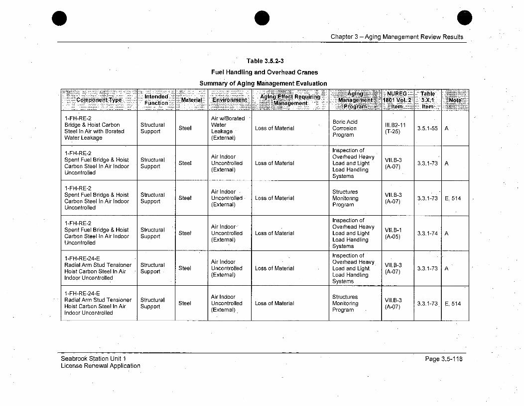
Chapter 3 - Aging Management Review Results
Table 3.5.2-3
Fuel Handling and Overhead Cranes
Summary of Aging Management Evaluation
Fucton-Aging: NUREG TableMaiia- nemTypn6 Manage~men 1te1 Item-3X Nt
1 -FH-RE-2 Air w/Borated BrcAi I.21aSteel Loss of Material Corrosion 3.5.1-55 A
Steel In Air with Borated Support Leakage P r(T-25)Water Leakage (External) Program
1 -FHRE-2Inspection of
1-FH-RE-2 Air, Indoore BovriceAcdHev
Spent Fuel Bridge & Hoist Structural Air Indor ovrhead Hay VII.B-3CabnSelI i nor Spot Steel Uncontrolled Loss of Material Load and Light (A-07) 3.3.1-73 AConSteel In Air w indor Support (External) Load Handling
WaoteroLeaed (Systems
1-FH-RE-2Spent Fuel Bridge & Hoist Structural Air Indoor OvStructuresCarbon Steel In Air Indoor Support Steel Uncontrolled Loss of Material Monitoring VII.B-3 3.3.1-73 A, 514
Uncontrolled (External) Program Hadln
1-FH-RE-2 Inspection of
Spent Fuel Bridge & Hoist Structural Steel Uncontrolled Loss of Material Hoenaviyg VII.B-1 3.3.1-74 ACarbon Steel In Air Indoor Support (External) MLoad mandlig (A-0)Uncontrolled (tnLa nl
1-FH-RE-24-E Inspection ofRadial Arm Stud Tensioner Structural Air Indoor Overhead Heavy VI.B-3Hoist Carbon Steel In Air Support Steel Uncontrolled Loss of Material Load and Light. (A-05) 3.3.1-73 AHoist UcaronStele In(External) Load Handling
rUncontrolledSystems
1-FH-RE-24-ERadial Arm Stud Tensioner Structural Air Indoor StrctrhesdHay I.-
1-HR-4EAir Indoor StructuresRadialArm Stud Tensioner Structural Steel Uncontrolled Loss of Material Monitoring VII.B-3 3.3.1-73 E, 514Hoist Carbon Steel In Air Support (External) Program (A-07)Indoor Uncontrolled
Seabrook Station Unit 1License Renewal Application
Page 3.5-118
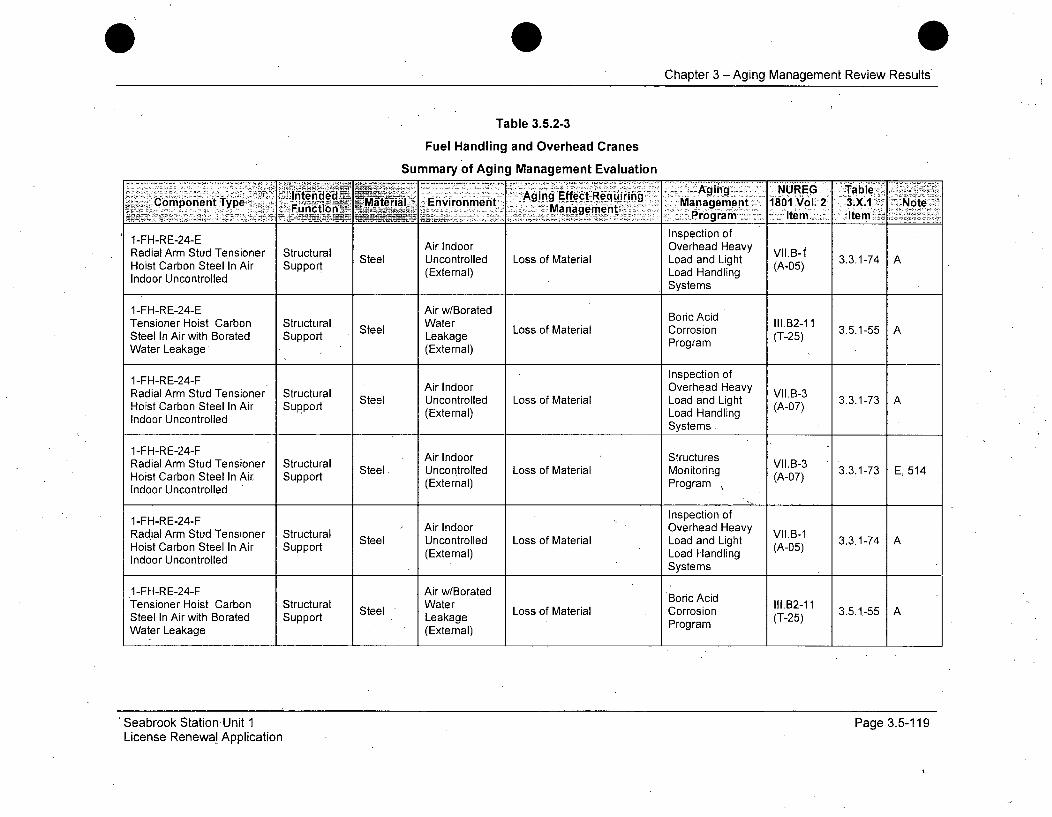
Chapter 3 -Aging Management Review Results
Table 3.5.2-3
Fuel Handling and Overhead Cranes
Summary of Aging Management Evaluation
: ~i~ned- Aging --NUREG j ableComponent Type Fu2tio- Material Environment Agig. Efec Reuiin Management 1801 Vol. 2 3.X.1 Note
I-FH-RE-24-E Inspection of
Radial Arm Stud Tensioner Structural Air Indoor Overhead Heavy IB-ISteel Uncontrolled Loss of Material Load and Light (A-.05) 3.3.1-74 AHoist Carbon Steel In Air Support (A-Onl)LodS)dln
Indoor Uncontrolled (External) Load Handling____________________Systems
1-FH-RE-24-E Air w/Borated Boric AcidTensioner Hoist Carbon Structural Water III o.B2-11Steel In Air with Borated Support Leakage L aorri (T-25)Water Leakage (External) Program
1-FH-RE-24-F Inspection ofRadial Arm Stud Tensioner Structural Air Indoor Overhead Heavy VII.B-3RaistalrAr Std TensAior Structu Steel Uncontrolled Loss of Material Load and Light (A-B-7) 3.3.1-73 AHoist Carbon Steel In Air Sueport (External) Load HandlingIndoor Uncontrolled Systems
1-FH-RE-24-F Air Indoor StructuresRadial Arm Stud Tensioner Structural Air Ind L Structures VII.B-3Hoist Carbon Steel In Air Support Steel.. Uncontrolled Loss of Material Monitoring (A-07) 3.3.1-73 E, 514Indoor Uncontrolled (External) Program
1-FH-RE-24-F Inspection of1-HR-4FAir Indoor Overhead Heavy VIB1 3317
Radial Arm Stud Tensioner Structural ArIdoOvhedHay VIL.B-1Hoist Carbon Steel In Air Support Steel Uncontrolled Loss of Material Load and Light (A-05) 3.3.1-74 AHoi conteel (External) Load HandlingIndoor UncontrolledSytm
Systems
1-FH-RE-24-F Air w/BoratedTensioner Hoist Carbon Structural Steel Water Loss of Material Boric Acid III.B2-11 35155 ASteel In Air with Borated Support Leakage Corri (T-25)Water Leakage (External) Program
'Seabrook Station Unit 1License Renewal Application
Page 3.5-119
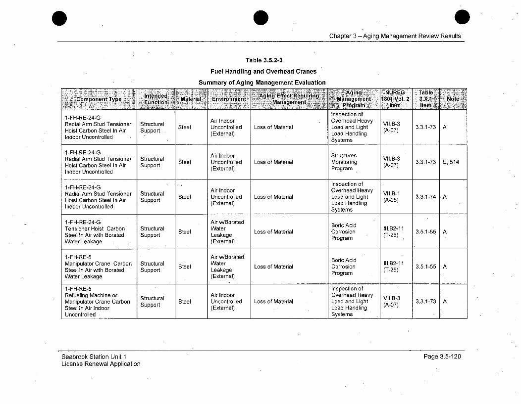
Chapter 3 -Aging Management Review Results
Table 3.5.2-3
Fuel Handling and Overhead Cranes
Summary of Aging Management Evaluation
Intended 'Aging Effect RgigquiringTabe.Component Type _ ~ Material Environment, Management_ Pr181 ol 2 3.
1-FH-RE-24-G Inspection of
Radial Arm Stud Tensioner Structural Air Indoor Overhead Heavy VII.B3-3Hoist Carbon Steel In Air Support Uncontrolled Loss of Material Load and Light (A-07) 3.3.1-73 A
Indoor Uncontrolled (External) Load HandlingSystems
1-FH-RE-24-G Air Indoor StructuresRadial Arm Stud Tensioner Structural ArIdoStuuesVII.B-3Hoit CArb Sted el nAir Stcupra Steel Uncontrolled Loss of Material Monitoring (A-07) 3.3.1-73 E, 514Hoist Carbon Steel In Air Support (External) Program (-7
Indoor Uncontrolled
1 -FH-RE-24 -G Inspection of
Radial Arm Stud Tensioner Structural Air Indoor Overhead Heavy II.B-1Hoist Carbon Steel In Air Support Steel Uncontrolled Loss of Material Load and Light (A-05) 3.3.1-74 AHoi conteel (External) Load Handling (Indoor Uncontrolled Systems
1-FH-RE-24-G Air w/Borated Boric AcidTensioner Hoist Carbon Structural Water Boric III.B2-1 1Steel In Air with Borated Support Steel Leakage Loss of Material Corrosion (T-25) 3.5.1-55 AWater Leakage (External) Program
1-FH-RE-5 Air w/Borated Boric AcidManipulator Crane Carbon Structural Steel Water Loss of Material Corrosion 1II.B2-11 3.5.1-55 ASteel In Air with Borated Support Leakage L aorri (T-25)Water Leakage (External) Program
1-FH-RE-5 Inspection ofRefueling Machine or Structural Air Indoor Overhead Heavy VII.B-3Manipulator Crane Carbon Steel Uncontrolled Loss of Material Load and Light 3.3.1-73 ASteel In Air Indoor (External) Load HandlingUncontrolled ._Systems
Seabrook Station Unit 1 Page 3.5-120License Renewal Application
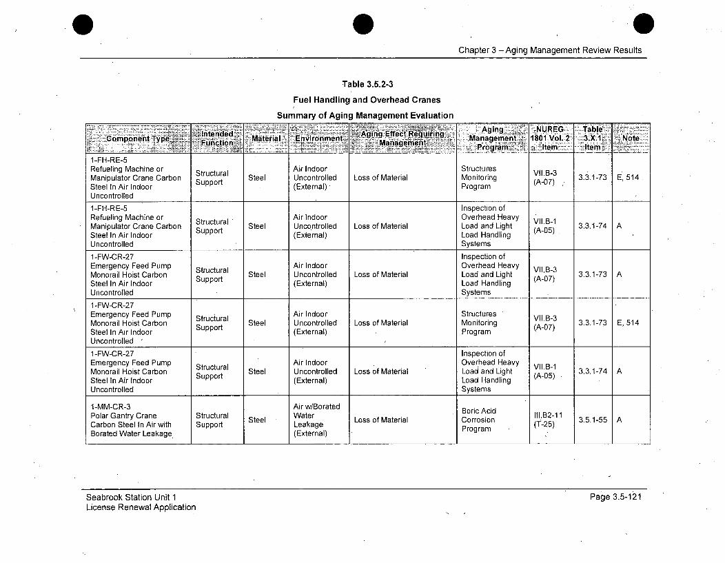
0Chapter 3 - Aging Management Review Results
Table 3.5.2-3
Fuel Handling and Overhead Cranes
Summary of Aging Management Evaluation
-l~riende . -Aging UEG TableSComponent Type Incteonde Material- Enpiironment. 5Aging Effect.Recquiing Magent-10Vl2 3X ot
Managemenit Prora 1 6 temr Item cvs--
1-FH-RE-5Refueling Machine or Structural Air Indoor Structures VII.B3 3 3Manipulator Crane Carbon Strt Steel Uncontrolled Loss of Material Monitoring (A-07) 3.3.1-73 E,514Steel In Air Indoor Support (External) - ProgramUncontrolled
1-FH-RE-5 Inspection ofRefueling Machine or Structural Air Indoor Overhead Heavy VII.B-1Manipulator Crane Carbon Support Steel Uncontrolled Loss of Material Load and Light (A-05) 3.3.1-74 A
Steel In Air Indoor (External) Load Handling (Uncontrolled Systems
1-FW-CR-27 Inspection ofEmergency Feed Pump Structural Air Indoor Overhead Heavy VII.B-3Monorail Hoist Carbon Support Steel Uncontrolled Loss of Material Load and Light (A-07) 3.3.1-73 ASteel In Air Indoor (External) Load HandlingUncontrolled Systems
1-FW-CR-27Emergency Feed Pump Structural Air Indoor Structures VII.B-3Monorail Hoist Carbon Support Steel Uncontrolled Loss of Material Monitoring (A-07) 3.3.1-73 E, 514Steel In Air Indoor (External) ProgramUncontrolled
1-FW-CR-27 Inspection ofEmergency Feed Pump Air Indoor Overhead Heavy VIIB-1Monorail Hoist Carbon Structural Steel Uncontrolled Loss of Material Load and Light (A-05)1 3.3.1-74 ASteel In Air Indoor Support (External) Load HandlingUncontrolled Systems
1-MM-CR-3 Air w/Borated Boric AcidPoarGtCttrar-- oicAcdl1.B2-11Polar Gantry Crane Structural Steel aerLoss of Material Corrosion 3.5.1-55 ACarbon Steel In Air with Support Leakage L aorrso(T-25)Borated Water Leakage (External) Program
Seabrook Station Unit 1 Page 3.5-121License Renewal Application
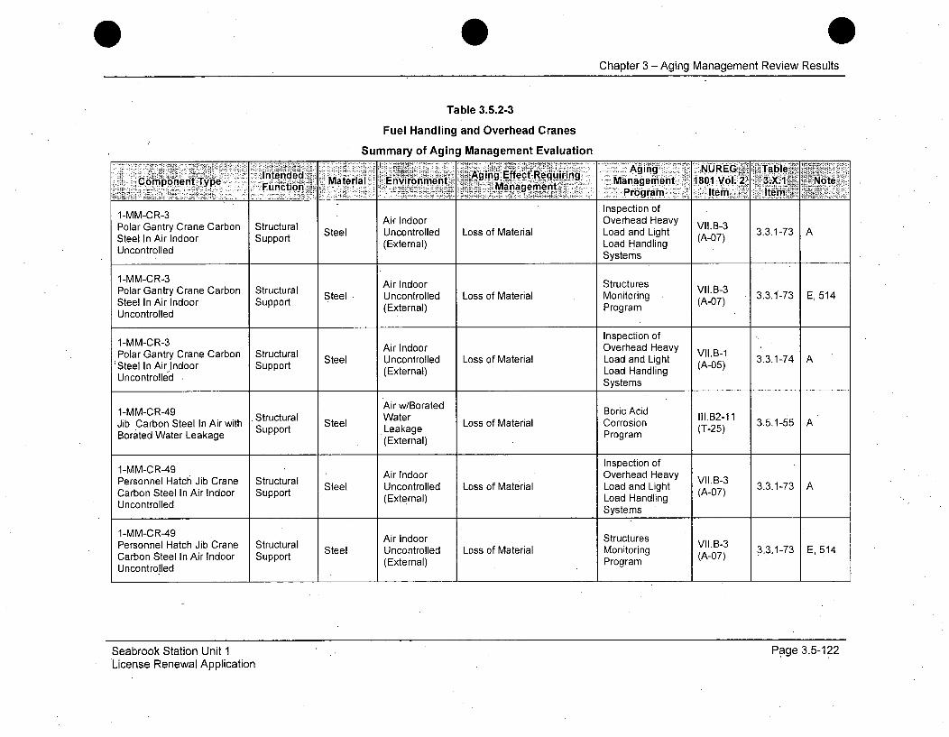
Chapter 3 -Aging Management Review Results
Table 3.5.2-3
Fuel Handling and Overhead Cranes
Summary of Aging Management Evaluation
Intended Aging Effect. Requ ring, Aging NUREG Table..,Component Type Fu~i~ Material Environment~ Maa~m~ Mnagement V1801 Vol. 2~ 3.X.1 Note
Pro m Item leL~Inspection of1-MM-CR-3 Air Indoor Overhead Heavy
Polar Gantry Crane Carbon Structural Ai norOeha e Vy II.B-3Sel In AraIndoor Steel Uncontrolled Loss of Material Load and Light (A-07) 3.3.1-73 ASteel In Air Indoor Support (EAenl)Lo07)dln
Uncontrolled (External) Load Handling___________Systems
1-MM-CR-3 Air Indoor StructuresPola GatryCrae Cabon Strctual ir Idoo StuctresVII.B-3Polar Gantry Crane Carbon Structural Steel Uncontrolled Loss of Material Monitoring (A-07) 3.3.1-73 E, 514Steel In Air Indoor Support (External) Program (-7
Uncontrolled
1-MM-C R-3 Inspection of
Polar Gantry Crane Carbon Structural Air Indoor Overhead Heavy VII.B-1'Steel In Air Indoor Support Steel Uncontrolled Loss of Material Load and Light (A-05) 3.3.1-74
Uncontrolled up(External) Load HandlingSystems
1-MM-CR-49 Air w/Borated Boric AcidJib Carbon Steel In Air with Structural Steel Loss of Material Corrosion 3.5.1-55 ABorated Water Leakage Support Leakage (T-25)
(External) Program
Inspection ofPersonnel Hatch Jib Crane Structural Air Indoor Overhead Heavy VII.B-3Personnel HAtc I Steel Uncontrolled Loss of Material Load and Light (A-07) 3.3.1-73 ACarbon Steel In Air Indoor Support (External) Load HandlingUncontrolledSytm
________Systems
1-MM-CR-49 Air Indoor StructuresPersonnel Hatch Jib Crane Structural ArIdoStuuesVII.B-3Steel Uncontrolled Loss of Material Monitoring (A-7 3.3.1-73 E, 514
Carbon Steel In Air Indoor Support (External) Program (A-07)Uncontrolled
Seabrook Station Unit 1License Renewal Application
Page 3.5-122

Chapter 3 -Aging Management Review Results
Table 3.5.2-3
Fuel Handling and Overhead Cranes
Summary of Aging Management Evaluation
Intended~ Agi q : Aig _ NRG~~aC pnent.Type, '- MaterialI ..Environment Aging Effe.---. e -ir Management•. 1801Vol:.2NCorn~~~i~penta Fu4iof~Maaeehm Item
1-MM-CR-49 Inspection of
Personnel Hatch Jib Crane Structural Air Indoor Overhead Heavy VII.B-1Air Indoor Support Uncontrolled Loss of Material Load and Light (A-05) 3.3.1-74 ACarbon Steel In (External) Load HandlingUncontrolledSytm
Systems
1-MS-CR-25-A Inspection ofMS/FW West Pipechase Structural Air Indoor Overhead Heavy VII.B-3Service Crane Carbon Strt Steel Uncontrolled Loss of Material Load and Light (A-07) 3.3.1-73 ASteel In Air Indoor Support (External) Load HandlingUncontrolled Systems
1-MS-CR-25-AMS/FW West Pipechase Structural Air Indoor Structures VII.B-3Service Crane Carbon Support Steel Uncontrolled Loss of Material Monitoring (A-07) 3.3.1-73 E, 514Steel In Air Indoor (External) ProgramUncontrolled
1-MS-CR-25-A Inspection ofMS/FW West Pipechase Structural Air Indoor Overhead Heavy VII.B-1Service Crane Carbon Steel Uncontrolled Loss of Material Load and Light 3.3.1-74 ASteel In Air Indoor (External) Load HandlingUncontrolled Systems
1-MS-CR-25-B Inspection ofMS/FW East Pipechase Structural Air Indoor Overhead Heavy VIIB-3Service Crane Carbon Strt Steel Uncontrolled Loss of Material Load and Light (A-07) 3.3.1-73 ASteel In Air Indoor SUPPOrt (External) Load HandlingUncontrolled Systems
1-MS-CR-25-BMS/FW East Pipechase Structural Air Indoor Structures VII.B-3Service Crane Carbon Support Steel Uncontrolled Loss of Material Monitoring (A-07) 3.3.1-73 E, 514Steel In Air Indoor (External) ProgramUncontrolled
Seabrook Station Unit 1License Renewal Application
.Page 3.5-123
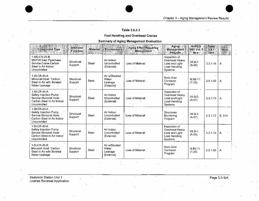
Chapter 3 -Aging Management Review Results
Table 3.5.2-3
Fuel Handling and Overhead Cranes
Summary of Aging Management Evaluation
~Intended s ~*'~' Aging ,Effect Requiring . AngNUE TalComponent Type Fnto Material Environment ManagementMaaenet 1801 Vol.2 3 XI Note- ..Pro~gram Item Itemh
1-MS-CR-25-B Inspection ofMS/FW East Pipechase Structural Air Indoor Overhead Heavy VII.B-1Service Crane Carbon Support Steel Uncontrolled Loss of Material Load and Light (A-05) 3.3.1-74 ASteel In Air Indoor (External) Load HandlingUncontrolled Systems
1-SI-CR-40-A Air w/Borated "Monorail Hoist Carbon Structural BWater oric Acid II.B2-1 1Steel In Air with Borated Support Leakage Loss of Material Corrosion (T-25)Water Leakage (External) Program
1-SI-CR-40-A Inspection ofSafety Injection Pump Structural Air Indoor Overhead Heavy VII.B-3Service Monorail Hoist Steel Uncontrolled Loss of Material Load and Light (A-07) 3.3.1-73 ACarbon Steel In Air Indoor Support (External). Load HandlingUncontrolled Systems1-SI-CR-40-ASafety Injection Pump Structural Air Indoor Structures VIL.B-3Service Monorail Hoist Support Steel Uncontrolled Loss of Material Monitoring (A-07) 3.3.1-73 E, 514Carbon Steel In Air Indoor (External) Program AUncontrolled
1-SI-CR-40-A Inspection ofSafety Injection Pump Structural Air Indoor Overhead Heavy VII.B-1Service Monorail Hoist Support Steel Uncontrolled Loss of Material Load and Light. (A-05) 3.3.1-74 ACarbon Steel In Air Indoor (External) Load Handling (OUncontrolled. Systems
1-SI-CR-40-B Air w/BoratedMonorail Hoist Carbon Structural Water Boric Acid ll.B2-11MoorilHostCabo Srutual Steel WtrLoss of Material Corrosion. 3.3.1-55 ASteel In Air with Borated Support Leakage L aorri (T-25)Water Leakage (External) Program
Seabrook Station Unit 1License Renewal Application
Page 3.5-124
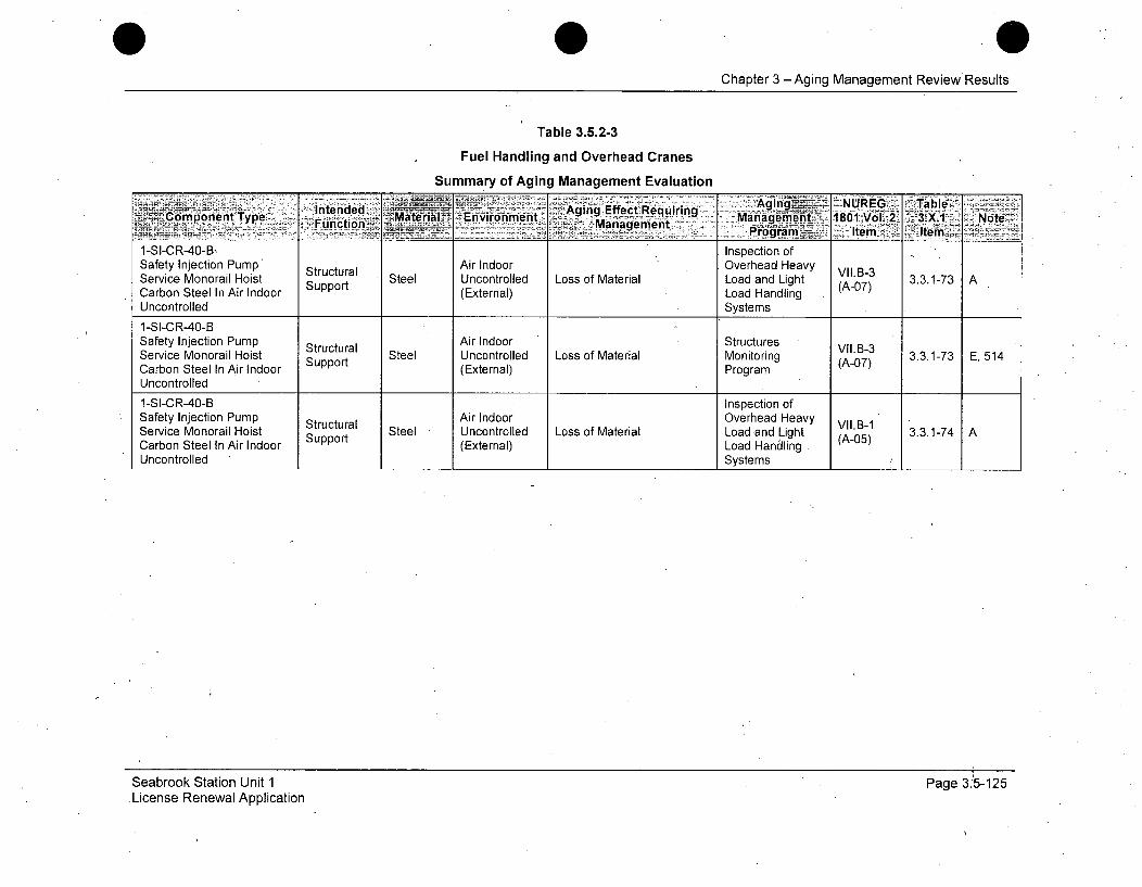
Chapter 3 -Aging Management Review Results
Table 3.5.2-3
Fuel Handling and Overhead Cranes
Summary of Aging Management Evaluation
IntededAging~-, NUREG Table.ý...,Component Type - Material Environment Ai Eeceqrng Manag!ýmerit.~ 1801 Vol.2_- 3.X.1 Nt
1-S-C~OB.Function> ___.i Management4rgai~x tm~Ae1-SI-CR-40-B, Inspection ofSafety Injection PumpH Structural Air Indoor Overhead Heavy VII.B-3Service Monorail Hoist Support Steel Uncontrolled Loss of Material Load and Light (A-07) 3.3.1-73 ACarbon Steel In Air Indoor (External) Load HandlingUncontrolled Systems
1-SI-CR-40-BSafety Injection Pump Structural Air Indoor Structures VIIB-3Service Monorail Hoist Support Steel Uncontrolled Loss of Material Monitoring (A-07) 3.3.1-73 E, 514Carbon Steel In Air Indoor (External) ProgramUncontrolled
1-SI-CR-40-B Inspection ofSafety Injection Pump Structural Air Indoor Overhead Heavy VII.B-1Service Monorail Hoist Support Steel Uncontrolled Loss of Material Load and Light (A-05) 3.3.1-74 ACarbon Steel In Air Indoor Support (External) Load HandlingUncontrolled Systems
Seabrook Station Unit 1License Renewal Application
Page 3.5-125
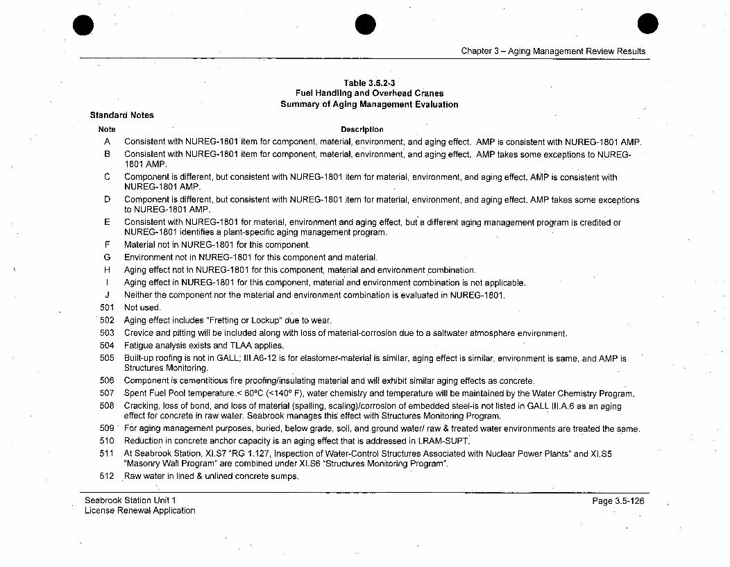
0Chapter 3 -Aging Management Review Results
Table 3.5.2-3Fuel Handling and Overhead Cranes
Summary of Aging Management EvaluationStandard Notes
Note Description
A Consistent with NUREG-1 801 item for component, material, environment, and aging effect. AMP is consistent with NUREG-1 801 AMP.
B Consistent with NUREG-1 801 item for component, material, environment; and aging effect. AMP takes some exceptions to NUREG-1801 AMP.
C Component is different, but consistent with NUREG-1 801 item for material, environment, and aging effect. AMP is consistent withNUREG-1801 AMP.
D Component is different, but consistent with NUREG-1 801 item for material, environment, and aging effect. AMP takes some exceptionsto NUREG-1801 AMP.
E Consistent with NUREG-1 801 for material, environment and aging effect, but a different aging management program is credited orNUREG-1801 identifies a plant-specific aging management program.
F Material not in NUREG-1 801 for this component.
G Environment not in NUREG-1 801 for this component and material.
H Aging effect not in NUREG-1 801 for this component, material and environment combination.I Aging effect in NUREG-1 801 for this component, material and environment combination is not applicable.
J Neither the component nor the material and environment combination is evaluated in NUREG-1 801.
501 Not used.
502 Aging effect includes "Fretting or Lockup" due to wear.
503 Crevice and pitting will be included along with loss of material-corrosion due to a saltwater atmosphere environment.
504 Fatigue analysis exists and TLAA applies.505 Built-up roofing is not in GALL; II1.A6-12 is for elastomer-material is similar, aging effect is similar, environment is same, and AMP is
Structures Monitoring.
506 Component is cementitious fire proofing/insulating material and will exhibit similar aging effects as concrete.
507 Spent Fuel Pool temperature.< 60 0C (<1400 F), water chemistry and temperature will be maintained by the Water Chemistry Program.
508 Cracking, loss of bond, and loss of material (spalling, scaling)/corrosion of embedded steel-is not listed in GALL III.A.6 as an agingeffect for concrete in raw water. Seabrook manages this effect with Structures Monitoring Program.
509 For aging management purposes, buried, below grade, soil, and ground water/ raw & treated water environments are treated the same.510 Reduction in concrete anchor capacity is an aging effect that is addressed in LRAM-SUPT.
511 At Seabrook Station, XI.S7 "RG 1.127, Inspection of Water-Control Structures Associated with Nuclear Power Plants" and XI.S5"Masonry Wall Program" are combined under XI.S6 "Structures Monitoring Program".
512 Raw water in lined & unlined concrete sumps.
Seabrook Station Unit 1License Renewal Application
Page 3.5-126
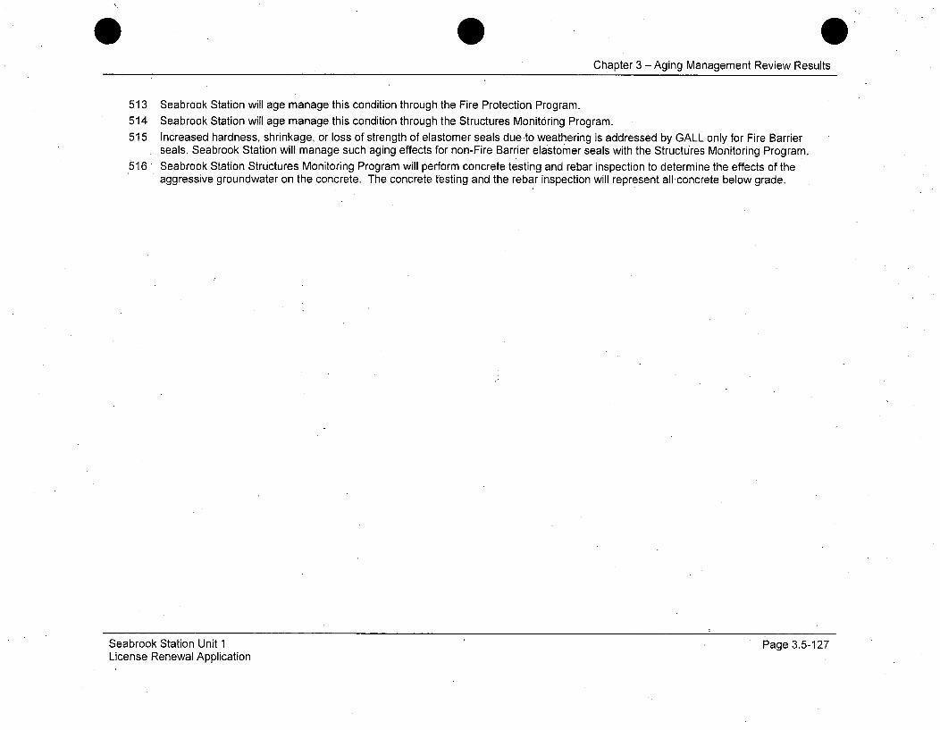
Chapter 3 - Aging Management Review Results
513 Seabrook Station will age manage this condition through the Fire Protection Program.514 Seabrook Station will age manage this condition through the Structures Monitoring Program.515 Increased hardness, shrinkage, or loss of strength of elastomer seals due to weathering is addressed by GALL only for Fire Barrier
seals. Seabrook Station will manage such aging effects for non-Fire Barrier elastomer seals with the Structures Monitoring Program.516 Seabrook Station Structures Monitoring Program will perform concrete testing and rebar inspection to determine the effects of the
aggressive groundwater on the concrete. The concrete testing and the rebar inspection will represent allconcrete below grade.
Seabrook Station Unit 1License Renewal Application
Page 3.5-127

eChapter 3 - Aging Management Review Results
Table 3.5.2-4
Miscellaneous Yard Structures
Summary of Aging Management Evaluation
Intenided :Aging Effect AginquUiGiablComponent Type Material rEnvironment-CE ,e.,ir-ng Management: 1801Vol.2, 3AX.1 NoteFunction - Management:%f .. Pror.am - I . Itm.e -. ____
MYS -Aluminum StructuresSTATION BLACKOUT Structural Air Outdoor Crack Initiation and t1u.B2-7Aluminum Monitoring 3.5.1-50 H, 514STRUCTURES Exposed Support (External) Growth Monrin (Tp-6)to Weather Program
MYS -Aluminum StructuresSTATION BLACKOUT Structural A Air Outdoor Loss Ile.B2-7STRUCTURES Exposed Support (External) Loss of Material Monitoring (TP-6)to Weather Program
MYS - Carbon SteelCONTROL ROOM Air Indoor Structures Ii.A3-12MAKEUP AIR INTAKE Structural Steel Uncontrolled Loss of Material Monitoring (T-11) 3:5.1-25 ASTRUCTURE Air Indoor Support (External) ProgramUncontrolled
MYS - Carbon SteelCONTROL ROOM StructuresCOTO OMStructu ral Air Outdoor Stutrs II1.A3-12MAKEUP AIR. INTAKE Sura Steel ArOtdr Loss of Material Monitoring (A-1 3.5.1-25 A, 503STRUCTURE Exposed to ProgramWeather
MYS - Carbon Steel DoorENCLOSURE FOR Structural Air Indoor Structures Ili.A3-12CONDENSATE Support Steel Uncontrolled Loss of Material Monitoring (T-11) 3.5.1-25 ASTORAGE TANK Air (External) ProgramIndoor UncontrolledMYS - Carbon Steel DoorENCLOSURE FOR Structural Air Outdoor Structures III.A3-12CONDENSATE Strt Steel ArOtdr Loss of Material Monitoring 3.5.1-25 A, 503
STORAGE TANK. Support (External) Program (--1)Exposed to Weather
Seabrook Station Unit 1License Renewal Application
Page 3.5-128
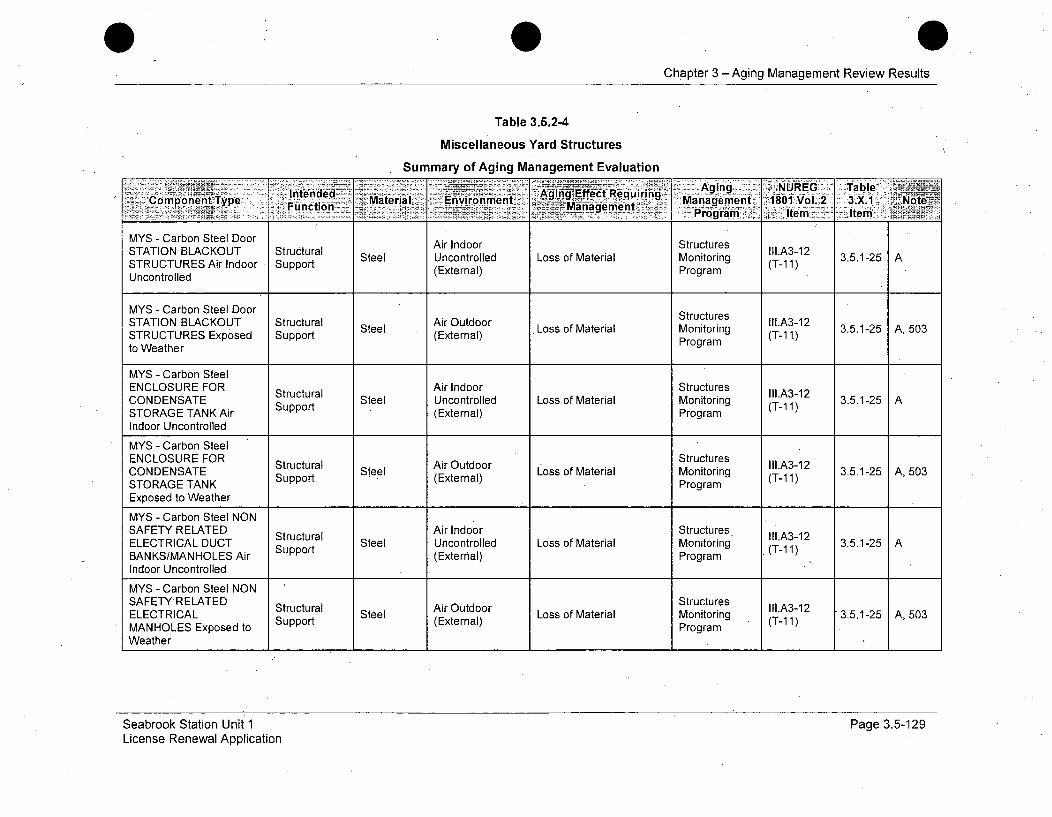
Chapter 3 -Aging Management Review Results
Table 3.5.2-4
Miscellaneous Yard Structures
Summary of Aging Management EvaluationAgng - NRG Table
Component Type lnedd Material E'nvironment Management 1~urn 801 Vol. 2 3 Xl Note~~v~nagmen - Program - Item Item
MYS - Carbon Steel Door Air Indoor StructuresSTATION BLACKOUT Structural Steel Uncontrolled Loss of Material Monitoring TI.A3-12 3.5.1-25 ASTRUCTURES Air Indoor Support (External) Program (T-1 1)Uncontrolled
MYS - Carbon Steel Door StructuresSTATION BLACKOUT Structural Air Outdoor .. li.A3-12STRTURE ExpOse Sura Steel (E xter Loss of Material Monitoring (T-121) 3.5.1-25 A, 503STRUCTURES Exposed Support (External) Program (- .
to Weather
MYS - Carbon SteelENCLOSURE FOR Air Indoor StructuresCONDENSATE Suctura Steel Uncontrolled Loss of Material Monitoring (A-1 3.5.1-25 ASTORAGE TANK Air Support (External) Program (T-1 1)
Indoor Uncontrolled
MYS - Carbon SteelENCLOSURE FOR StructuresCONDENSATE Structural Steel ALoss of Material Monitoring (T-12 3.5.1-25 A, 503STORAGE TANK Support (External) Program (T-1 1)
Exposed to Weather
MYS - Carbon Steel NONSAFETY RELATED Sttl Air Indoor StructuresELECTRICAL DUCT Srucura Steel Uncontrolled Loss of Material Monitoring (IA3-12 3.5.1-25 ABANKS/MANHOLES Air Support (External) Program (T-1 1)
Indoor UncontrolledMYS - Carbon Steel NON
SAEYRLTDStructures IlA31 3..-5 ,50SAFETY RELATED Structural Air Outdoor Ltrin III.A3-12ELECTRICAL Support Steel (External) Loss of Material Monitoring (T-11) 3.5.1-25 A, 503MANHOLES Exposed to ProgramWeather
Seabrook Station Unit 1License Renewal Application
Page 3.5-129

0Chapter 3 - Aging Management Review Results
Table 3.5.2-4
Miscellaneous Yard Structures
Summary of Aging Management Evaluation
lIntended ~ 5>-Aging Effiect Re~~W Agig: NIRG -al
Compnetp Fý :-aeil:>-E~r~net Management -1801 Vol. 2: 3.,X.1 ..NoteFunc tion .. Management- ~ Porm -ie Ie
MYS - Carbon SteelSAFETY RELATED Air Indoor StructuresELECTRICAL DUCT Surt Steel Uncontrolled Loss of Material Monitoring , (T-11) 3.5.1-25 ABANKS/MANHOLES Air Support (External) Program
Indoor Uncontrolled
MYS - Carbon SteelSAFETY RELATED Structural Air Outdoor Structures II1.A3-12ELECTRICAL DUCT Support Steel (External) Loss of Material Monitoring (T-11) 3.5.1-25 A, 503BANKS/MANHOLES ProgramExposed to Weather
MYS - Carbon SteelSERVICE WATER Structural Air Indoor Structures II1.A3-12Steel Uncontrolled Loss of Material Monitoring 3.5.1-25 AACCESS VAULT Air Support (External) Program (T-li)Indoor Uncontrolled
MYS - Carbon SteelMY abnSelAir Indoor StructuresSTATION BLACKOUT Structural AiInooItutue1l.A3-1 2STRTURE AiIOor Surt Steel Uncontrolled Loss of Material Monitoring (T-i11) 3.5.1-25 ASTRUCTURES Air Indoor Support (External) Program (-1
Uncontrolled
'MYS - Carbon SteelSTATION BLACKOUT Shelter, Air Outdoor L Structures III.A3-12STRUCTURES Exposed Protection Steel (External) Loss of Material Monitoring (T-1i) 3.5.1-25 A, 503to Weather Program
MYS - Carbon Steel Structures
STATION BLACKOUT Structural Steel Air Outdoor Loss of Material Monitoring II.A3-12STRUCTURES Exposed Support (External) Proram (T-11)to Weather Program
Seabrook Station Unit 1License Renewal Application
Page 3.5-130
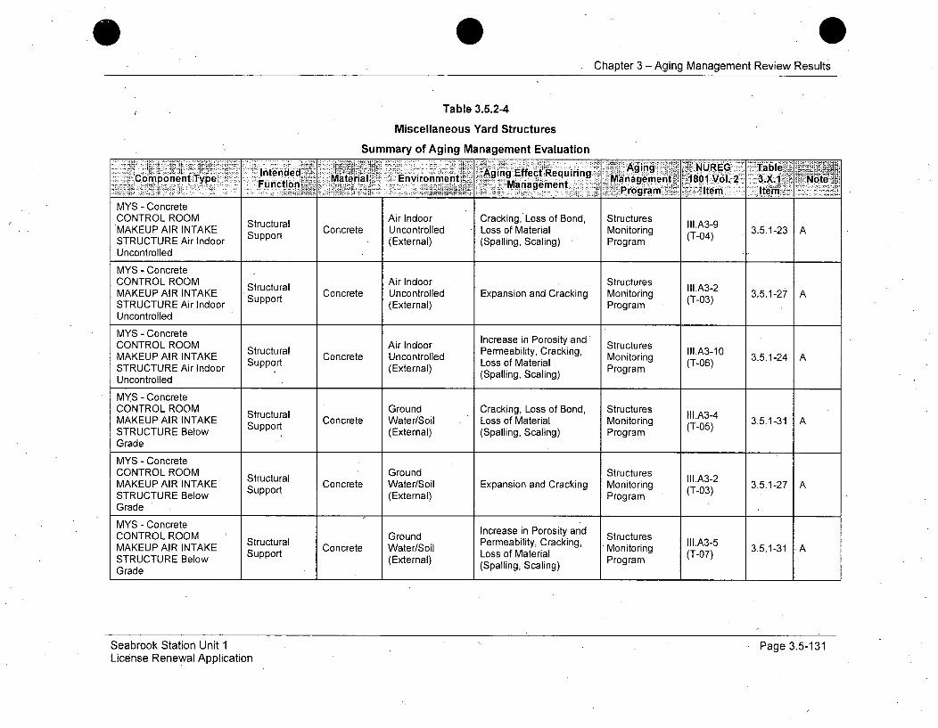
Chapter 3 -Aging Management Review Results
Table 3.5.2-4
Miscellaneous Yard Structures
Summary of Aging Management EvaluationIntended Agiag :e Requiring
Copnn yeMaterial, Environment~ Agingmn Effectl Reurn Agin NUoEe TalCmonnTye Function ,ino-.: Management nagement8,l 31 tiProgjram' item itemi,
MYS - ConcreteCONTROL ROOM Structural Air Indoor Cracking, Loss of Bond, Structures II1.A3-9MAKEUP AIR INTAKE Support Concrete Uncontrolled Loss of Material Monitoring (T-04) 3.5.1-23 ASTRUCTURE Air Indoor (External) (Spalling, Scaling) ProgramUncontrolled
MYS - ConcreteCONTROL ROOM Structural Air Indoor Structures II1.A3-2MAKEUP AIR INTAKE Suppoructu Concrete Uncontrolled Expansion and Cracking Monitoring (T-03) 3.5.1-27STRUCTURE Air Indoor Support (External) ProgramUncontrolled
MYS - ConcreteCONTROL ROOM Air Indoor PereabilPorosity and StructuresIncreas inIl1.A3-1OMAKEUP AIR INTAKE Structural Concrete Uncontrolled Permeability, Cracking, Monitoring (T-06) 3.5.1-24 ASTRUCTURE Air Indoor Support (External) Loss of Material ProgramUncontrolled (Spalling, Scaling)
MYS - ConcreteCONTROL ROOM Structural Ground Cracking, Loss of Bond, Structures II1.A3-4MAKEUP AIR INTAKE Support Concrete Water/Soil Loss of Material Monitoring (T-05) 3.5.1-31 ASTRUCTURE Below (External) (Spalling, Scaling) ProgramGrade
MYS - ConcreteCONTROL ROOM Structural Ground Structures III.A3-2MAKEUP AIR INTAKE Support Concrete Water/Soil Expansion and Cracking Monitoring (T-03) 3.5.1-27STRUCTURE Below (External) ProgramGrade
MYS - ConcreteCONTROL ROOM Ground Increase in Porosity and StructuresMAKEUP AIR INTAKE Structural Concrete Water/Soil Permeability, Cracking, Monitoring III.A3-5 3.5.1-31 ASTRUCTURE Below Support (External) Loss of Material Program (T-07)
Grade (Spalling, Scaling)
Seabrook Station Unit 1License Renewal Application
Page 3.5-131
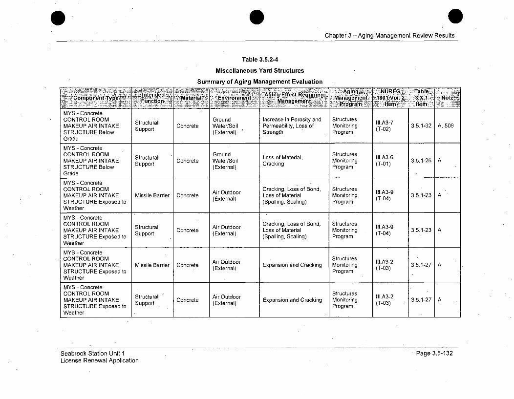
Chapter 3 -Aging Management Review Results
Table 3.5.2-4
Miscellaneous Yard Structures
Summary of Aging Management Evaluation
'4- ~~> -- Agin-'- "NUREG 'Table,Intended. Aging Effect Requiringy a 1CuponARIent TypeK "uppor octMaatrial I SEnvironment Marmeail Losso Managent Vol. 2 3X..1-2 NoteA
Prqgraprm It'em ItemMYS - ConcreteCONTROL ROOM Structural Ground Increase in Porosity and Structures lll.A3-7MAKEUP AIR INTAKE Supporl Concrete Water/Soil Permeability, Loss of Monitoring (T-02)STRUCTURE Below (External) Strength ProgramGrade
MYS - ConcreteCONTROL ROOM Aur Ground Loss of Bond, Structures II1.A3-9MAKEUP AIR INTAKE Stirtl Concrete Water/Soil Loss of Material Strucue (T-0A) 3.5.1-26 ASTRUCTURE Below Suppt(External) Cracking ProgramGrade
MYS - ConcreteCONTROL ROOM Cracking, Loss of Bond, StructuresMAKEUP AIR INTAKE Missile Barrier Concrete (External) Loss of Material Monitoring (T-04) 3.5.1-23 ASTRUCTURE Exposed to (Spalling, Scaling) ProgramWeather
MYS - ConcreteCONTROL ROOM AirCracking, Loss of Bond, Structures III.A3-2MAKEUP AIR INTAKE Stirtl Concrete (External) Loss of Material Monitoring (T-0)3 3.5.1-23 ASTRUCTURE Exposed to (Spalling Scaling) ProgramWeather
MYS - ConcreteCONTROL ROOM A. StructuresMAKEUP AIR INTAKE Missile Barrier Concrete (External) Expansion and Cracking Monitoring (T-03) 3.5.1-27 ASTRUCTURE Exposed to ProgramWeather
MYS 7ConcreteCNRLROStutrlAir Outdoor Exaso n rcig Structures III.A3-2 3512MAKEUP AIR INTAKE Stpprutua Concrete (External)ExasoanCrcig Mitig (T0) 3512 A
STRUCTURE Exposed to SpotProgramWeather II _
Seabrook Station Unit 1License Renewal Application
. Page 3.5-132
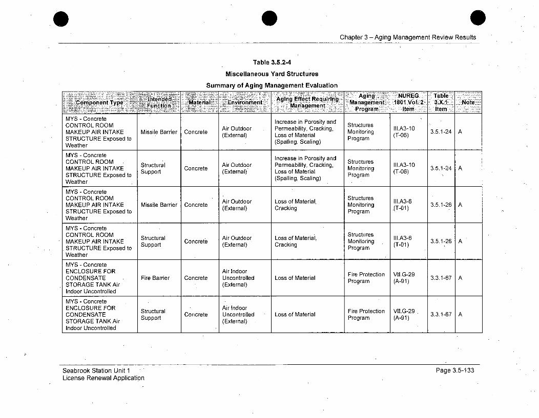
Chapter 3 -Aging Management-Review Results
Table 3.5.2-4
Miscellaneous Yard Structures
Summary of Aging Management Evaluation
CONTROLROOMnAirOnmenr P eaging EffctiRq Aging .ANUREG Table
MAKEUP AIR INTAKE MIntiendrred Effectt Requirnging1-4
Component Type toMaterial (Enirunin Management 1801 Volo2 3.X.1 NoteFuncion (Spalnagcang Program Item Item
MYS - Concrete Increase in Porosity andCONTROL ROOM Air Outdoor Permeability, Cracking, Structures III.A3-10MAKEUP AIR INTAKE Missile Barrier Concrete ( PerMatyrac Monitoring (T06) 3.5.1-24 ASTRUCTURE Exposed to xernal Loss of Material ProgramWeather (Spalling, Scaling)
MYS - Concrete
MY oceeIncrease in Porosity and lA31CONTROL ROOM Air Outdoor Permeability, Cracking, Structures III.A3-6
Strctral CocrtenExeral)Los.f1Mteia
MAKEUP AIR INTAKE MSonitorri Concrete (External) Loss .(T-0) 3.5.1-24 ASTRUCTURE Exposed to t ProgramWeather
MYS - ConcreteCONTROL ROOM StructuresMAKEUP AIR INTAKE Missile Barrier Concrete Air Outdoor Loss of Material, Monitoring III.A3-6 3.5.1-26 ASTRUCTURE Exposed to (External) Cracking Program (T-01)Weather
MYS - ConcreteCONTROL ROOM Air Outdoor Loss of Material, Structures c II.A3-6MAKEUP AIR INTAKE S tral Concrete (Extrnl)riMonitoring 3.5.1-26 ASTRUCTURE Exposed (External) Program (T-01)Weather
MYS - ConcreteENCLOSURE FOR Air IndoorCONDENSATE Fire Barrier Concrete Uncontrolled Loss of Material Proteto (A-9 3.3.1-67 ASTORAGE TANK Air (External) Program (A-91)Indoor Uncontrolled
MYS - ConcreteENCLOSURE FOR Structural Air Indoor Fire Protection VII.G-29 3316CONDENSATE Concrete Uncontrolled Loss of Material Program7 AA9STORAGE TANK Air Support (External) Porm(-1
Indoor Uncontrolled IIII
Seabrook Station Unit 1 - 'License Renewal Application
Page 3.5-133
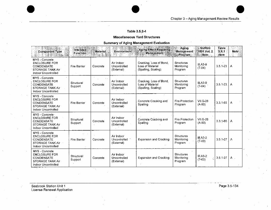
Chapter 3 -Aging Management Review Results
Table 3.5.2-4
Miscellaneous Yard Structures
Summary of Aging Management Evaluation
Copoet ye I ntenided Mtra Eninm, AgingEfetquri iaAiet NUREG TableFunctiont TyeAigfetReurn Management i.Poga 1801 Vol. 2 3AX.1 Noteý
____ ___ ___ ____ ___ ___ ___ rn tem Item _ _ _
MYS - ConcreteENCLOSURE FOR Air Indoor Cracking, Loss of Bond, Structures III.A39CONDENSATE Fire Barrier Concrete Uncontrolled Loss of Material Monitoring (T-04) 3.5.1-23 ASTORAGE TANK Air (External) (Spalling, Scaling) ProgramIndoor Uncontrolled
MYS - ConcreteENCLOSURE FOR Structural Air Indoor Cracking, Loss of Bond, Structures III.A3-9CONDENSATE Support Concrete Uncontrolled Loss of Material Monitoring (T-04) 3.5.1-23 ASTORAGE TANK Air (External) (Spalling, Scaling) ProgramIndoor Uncontrolled
MYS - ConcreteENCLOSURE FOR Air Indoor Concrete Cracking and Fire Protection vii.G-28CONDENSATE Fire Barrier Concrete Uncontrolled 3.3.1-65 ASTORAGE TANK Air (External) Spalling Program (A-90)
Indoor Uncontrolled
MYS - ConcreteENCLOSURE FOR Air IndoorCONDENSATE Structural Concrete Uncontrolled Concrete Cracking and Fire Protection VII.G-28 3.3.1-65 ASTORAGE TANK Air Support (External) Spalling Program (A-90)
Indoor Uncontrolled
MYS - ConcreteENCLOSURE FOR Air Indoor Structures III.A3-2CONDENSATE Fire Barrier Concrete Uncontrolled Expansion and Cracking Monitoring (T-03) 3.5.1-27 ASTORAGE TANKAir (External) ProgramIndoor Uncontrolled
MYS - ConcreteENCLOSURE FOR Structural Air Indoor Structures IIl.A3-2CONDENSATE Support Concrete Uncontrolled Expansion and Cracking Monitoring (T-03) 3.5.1-27 ASTORAGE TANK Air (External) Program
Indoor Uncontrolled
Seabrook Station Unit 1License Renewal Application
Page 3.5-134
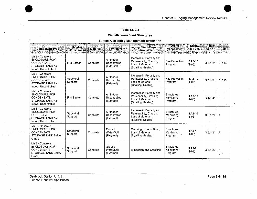
Chapter 3 -Aging Management Review Results
Table 3.5.2-4
Miscellaneous Yard Structures
Summary of Aging Management Evaluation
Componenttrite lntdedr Aging Effect Requiring.A igNRG 'al,,omonn Type': T Fito Material niomet . Man agement> 8019 Vol. 21t3i. Nt
.- , ,. '. Program. Item Iltem
MYS - Concrete increase in Porosity andENCLOSURE FOR' Air Indoor Inreasinity andCONDENSATE Fire Barrier Concrete Uncontrolled Permeability, Cracking, Fire Protection lll.A3-1O 3.5.1-24 E, 513STO RAG E TANK Air (External) Loss of Material Program (T-06)Indoor Uncontrolled (Spalling, Scaling)
MYS - Concrete Increase in Porosity andENCLOSURE FOR Air Indoor Ices nPrst nENSATE Structural Concrete Uncontrolled Permeability, Cracking, Fire Protection II1.A3-10CONDENSATE Support Loss of Material Program (T-06) 3.5.1-24 E, 513STORAGE TANK Air (External) (Spalling, Scaling)Indoor Uncontrolled
MYS - ConcreteENCLOSURE FOR Air Indoor PereabintPorosity and Structures
CONDENSATE Fire Barrier Concrete Uncontrolled LsomerilMonitoring -Tn1 3.5.1-24 ASTORAGE TANK Air (External) Loss Scalial ProgramIndoor Uncontrolled (Spalling, Scaling)
MYS - ConcreteENCLOSURE FOR Structural Air Indoor Increase in Porosity and Structures Ill.A3-1OCONDENSATE Strt Concrete Uncontrolled Losslof Material Monitoring (T-0 3.5.1-24 ASTORAGE TANK Air uppo (External) Loss Scalial ProgramIndoor Uncontrolled (Spalling, Scaling)
MYS - ConcreteENCLOSURE FOR Structural Ground Cracking, Loss of Bond, Structures II1.A3-4CONDENSATE Strt Concrete Water/Soil Loss of Material Monitoring 3.5.1-31 ASTORAGE TANK Below (External) (Spalling, Scaling) ProgramGrade
MYS - ConcreteENCLOSURE FOR Structural Ground Structures III.A3-2CONDENSATE Strt Concrete Water/Soil Expansion and Cracking Monitoring (T-03) 3.5.1-27 ASTORAGE TANK Below Support (External) ProgramGrade
Seabrook Station Unit 1License Renewal Application
Page 3.5-135
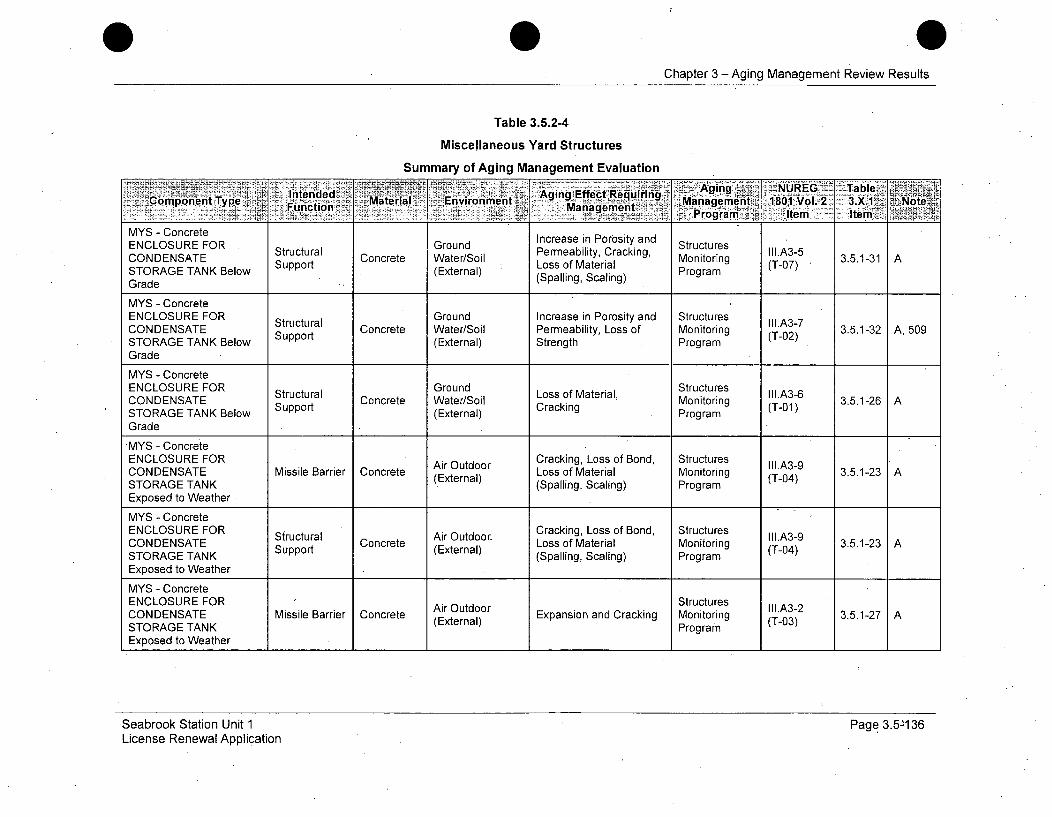
Chapter 3 - Aging Management Review Results
Table 3.5.2-4
Miscellaneous Yard Structures
Summary of Aging Management Evaluation
StIntende~d .'Aging Effect Agngequiringb~~L.~~Cunpoencit~ype~ Material Environmenit B'R~ii~ Manageen 1801 Vol. 2 3X~l:Function ManagementPormItmte Nte
MYS - Concrete Increase in Porosity andENCLOSURE FOR Structural Ground Pnreaein Prosind Structures lll.A3-5CONDENSATE Strt Concrete Water/Soil Permeability, Cracking, Monitoring (T-07) 3.5.1-31 ASTORAGE TANK Below (External) (Spalling, Scaling) ProgramGrade Si
MYS - ConcreteENCLOSURE FOR Structural Ground Increase in Porosity and Structures III.A3-7CONDENSATE Support Concrete Water/Soil Permeability, Loss of Monitoring (T-02) 3.5.1-32 A, 509STORAGE TANK Below (External) Strength ProgramGrade
MYS - ConcreteENCLOSURE FOR Structural Croil Structures II1.A3-6CONDENSATE Srt Concrete Water/Soil Loss of Material, Monitoring (T-01) 3.5.1-26
STORAGE TANK Below Support (External) Cracking ProgramGradeMYS - ConcreteENCLOSURE FOR Air Outdoor Cracking, Loss of Bond, Structures Ii.A3-9CONDENSATE Missile Barrier Concrete (External) Loss of Material Monitoring (T-04) 3.5.1-23 ASTORAGE TANK (Spalling, Scaling) ProgramExposed to Weather
MYS - ConcreteENCLOSURE FOR Structural Air Outdoor Cracking, Loss of Bond, Structures II1.A3-9CONDENSATE Support Concrete (External) Loss of Material Monitoring (T-04) 3.5.1-23STORAGE TANK (Spalling, Scaling) ProgramExposed to WeatherMYS - Concrete
ENCLOSURE FOR Air Outdoor Structures adrkg otiCONDENSATE Missile Barrier Concrete (External) Expansion and Cracking Monitoring (T-03) 3.5.1-27STORAGE TANK ProgramExposed to Weather
Seabrook Station Unit 1License Renewal Application
Page 3.5136

Chapter 3 -Aging Management Review Results
Table 3.5.2-4
Miscellaneous Yard Structures
Summary of Aging Management EvaluationIntendeed :Matgrial Enviro nmentN Aging Effect Re6quirig ANREG Table
Component Type>, FuntioironMaaeeen Management 1801 .V6L.!2' 3.X.1l Note'. Program",, leh7 Iem
MYS - Concrete
Structural Air Outdoor III.A3-2CONDENSATE Strt Concrete ArOtdr Expansion and Cracking Monitoring (T-03) 3.5.1-27 A
STORAGE TANK Support (External) Program .Exposed to WeatherMYS - ConcreteENCLOSURE FORIncrease in Porosity andCNENCOSUE Ol BAir Outdoor Permeability, Cracking, Structures II1.A3-10CONDENSATE Missile Barrier Concrete Perternal)L fMeabityriac Monitoring 3.5.1-24 ASTOAG TNK(External) Loss of Material (-6STORAGE TANK (Spalling, Scaling) ProgramExposed to Weather
MYS - ConcreteENCLOSURE FOR Structural Air Outdoor Increase in Porosity and Structures IIIA3-1OCONDENSATE Stutrl Concrete ArOtor Permeability, Cracking, Monitoring ItA-0 3512STORAGE TANK Support (External) Loss of Material (T-06) 3.5.1-24 AExposed to Weather (Spalling, Scaling) Program
MYS - ConcreteENCLOSURE FOR Structures- Air Outdoor Loss of Material, Monitoring III.A3-6CONDENSATE Missile Barrier Concrete (External) Cracking PrASTORAGE TANK ProgramExposed to WeatherMYS -•Concrete
ECOUEFRStructures lI1.A3-6 3512ENCLOSURE FOR Structural Air Outdoor Loss of Material, Monitoring (T-0STORAGE TANK Support. Concrete (External) Cracking Program (T-01)
Exposed to Weather,
MYS - Concrete MasonryUnit (CMU) STATION Concrete Air Outdoor Fire Protection II1.A3-11BLACKOUT - Fire Barrier Block (External)3.5.1-43 E, 513STRUCTURES Exposedto Weather
Seabrook Station Unit 1License Renewal Application
Page 3.5-137
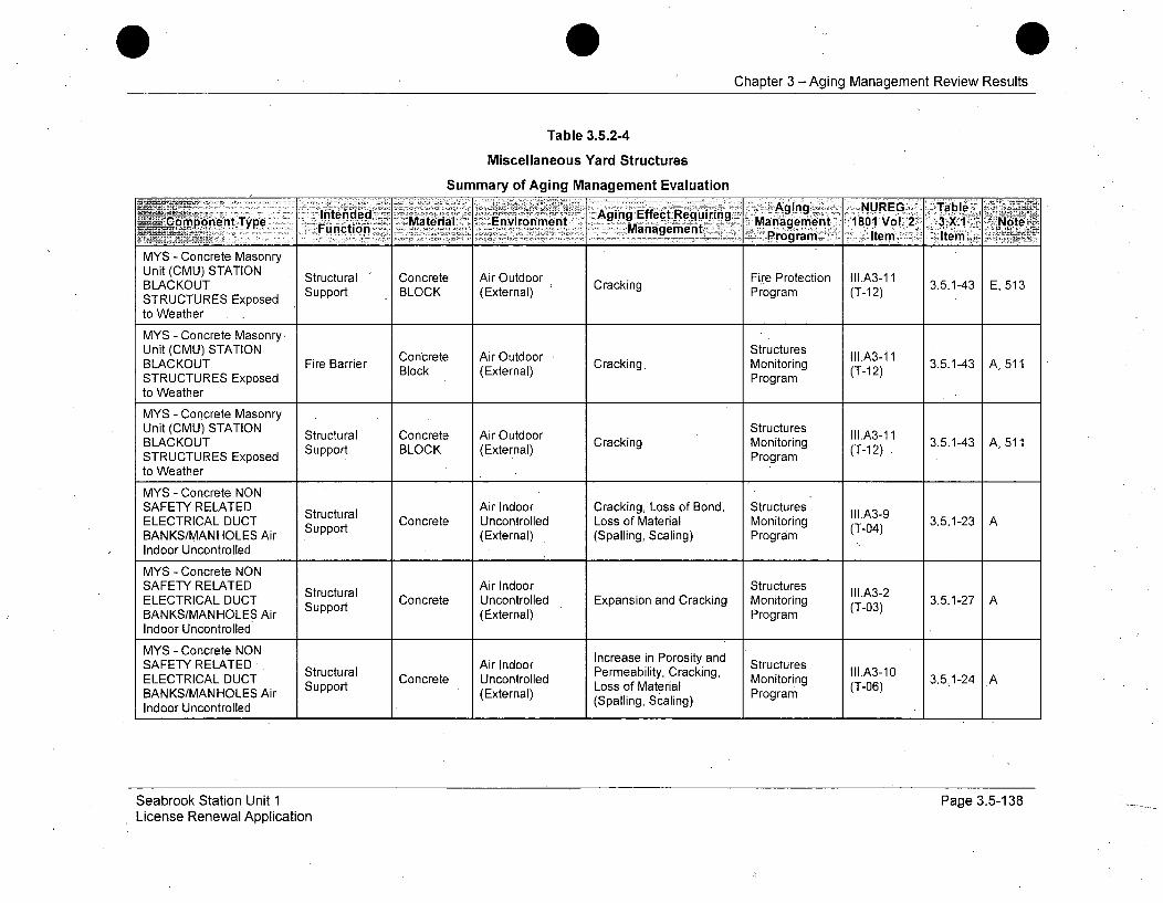
Chapter 3 -Aging Management Review Results
Table 3.5.2-4
Miscellaneous Yard Structures
Summary of Aging Management Evaluation
lIntended -. Aging Effect Requlinn 9 A4g NRG al~Component Type -zrFcin Material.- -Enivironiment - -_ - _&Managem~ent.. 1801 Vol.'2 ,3AX.1- Note--- - - . - - ~~~~~anagernent iPornŽ III
MYS - Concrete MasonryBLACKOUT Stutrl" Cnrt i udo rcigFire Protection t11.A3-11 3.5.1-43 E, 513Unit (CMU) STATION Structural Concr Iete Air Outdoor Cracking Program io (T.A-12STRUCTURES Exposed Support BLOCK (External) Program (T-12)
to WeatherMYS - Concrete Masonry-
Unit (CMU) STATION Concrete Air Outdoor kStructures IIM.A3-iBLACKOUT Fire Barrier Block (External) Cracking Monitoring (T-12) 3.5.143 A, 511STRUCTURES Exposed Programto WeatherMYS - Concrete Masonry
Unit (CMU) STATION Structural Concrete Air Outdoor Structures IMt.A3-11BLACKOUT Support BLOCK (External) Cracking Monitoring (T-12) 3.5.1-43 A, 511STRUCTURES Exposed Programto Weather
MYS - Concrete NONSAFETY RELATED Structural Air Indoor Cracking, Loss of Bond, Structures III.A3-9ELECTRICAL DUCT Support Concrete Uncontrolled Loss of Material Monitoring (T-04) 3.5.1-23 ABANKS/MANHOLES Air (External) (Spalling, Scaling) ProgramIndoor Uncontrolled
MYS - Concrete NONSAFETY RELATED Structural Air Indoor Structures III.A3-2ELECTRICAL DUCT Support Concrete Uncontrolled Expansion and Cracking Monitoring (T03) 3.5.1-27 ABANKS/MANHOLES Air (External) Program
Indoor Uncontrolled
MYS - Concrete NON Increase in Porosity andSAFETY RELATED Air Indoor Pereabiin Crosind StructuresELECTRICALPermeability, Cracking, Monitoring 3.5.1-24ASupport Loss of Material (T-06)BANKS/MANHOLES Air (External) (Spalling, Scaling) ProgramIndoor Uncontrolled
Seabrook Station Unit 1License Renewal Application
Page 3.5-138
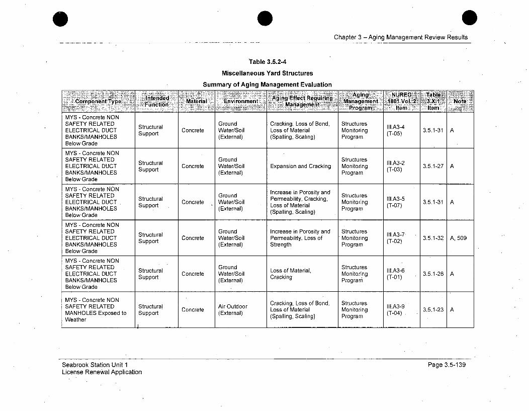
Chapter 3 - Aging Management Review Results
Table 3.5.2-4
Miscellaneous Yard Structures
Summary of Aging Management Evaluation
gAging NUEG TableComponenht Type .. Materia[ Envirolnment EfetRqiig~ Management 1801 Vof. 2 .1 Nt
MYS - Concrete NON
SAFETY RELATED GroundCracking, Loss of Bond, Structures
GrounduralII1.A3-2 .. 13
ELECTRICAL DUCT Strt Concrete Water/Soil Loss of Material Monitoring (T-05) 3.5.1-31 ABANKS/MANHOLES Support (External) (Spalling, Scaling) ProgramBelow Grade
MYS - Concrete NONSAFETY RELATED Ground StructuresELECTRICAL DUCT Structural Concrete Water/Soil Expansion and Cracking Monitoring (T-03) 3.5.1-27 ABANKS/MANHOLES Support (External) ProgramBelow Grade
MYS - Concrete NONSAFETY RELATED Structural Ground Pereabiin Crosind Structures II1.A3-7ELECTRICAL DUCT Support Concrete Water/Soil Loss of Material Monitoring (T-07) 3.5.1-31 ABANKS/MANHOLES (External) Strengt ProgramBelow Grade
MYS - Concrete NONSAFETY RELATED Structural Ground Increase in Porosity and Structures lll.A3-7ELECTRICAL DUCT Concrete Water/Soil Permeability, Loss of Monitoring (T-02) 3.5.1-32 A, 509BANKS/MANHOLES Support (External) Strength ProgramBelow Grade
MYS - Concrete NONSAFETY RELATED Ground StructuresELECTRICAL DUCT Structural Concrete Water/Soil Loss of Material, Monitoring (T.A3-6 3.5.1-26 ABANKS/MANHOLES Support (External) Cracking Program (T-01)Below Grade
MYS - Concrete NON CaknLs fBn, SrcueSAFETY RELATED Structural Air Outdoor Crckng Loso od tutrs llA3-9 3512MANHOLES Exposed to Support Concrete (External) Loss of Material Monitoring (T-04)
Weather (Spalling, Scaling) Program
Seabrook Station Unit 1License Renewal Application
Page 3.5-139
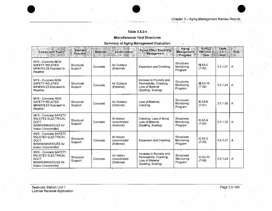
Chapter 3 -Aging Management Review Results
Table 3.5.2-4
Miscellaneous Yard Structures
Summary of Aging Management Evaluation
-~ i~eide Aing ,. NUREG ...Table.
MYS - Concrete NON'
SAFETY RELATED • Structural Air Outdoor Exaso ndCaknItrcue1l.A3-2 3512MANHOLES Exposed to Support Cg(External) MrigrWeatherProgram
MYS - Concrete NON Increase inPorosity and uresSAFETY RELATED Structural Concrete Air Outdoor Permeability, Cracking, Monitoring II1.A3-10 3.5.1-24 AMANHOLES Exposed to Support (External) Loss of Material (T-06)Weather (Spalling, Scaling) Program
MYS - Concrete NON StructuresSAFETY RELATED Structural Air Outdoor Loss of Material, Monitoring (T.A3-60 3.5.1-26 AMANHOLES Exposed to Support Concrete (External) Cracking MProgram (T-06)
Weather Program
MYS- Concrete SAFETY
DUCATE ELCRCL Structural I ocee Air Indoor Cracking, Loss of Bond, Structures II1.A3-9 3512ETY R D Sttupra Concrete Uncontrolled Loss of Material Monitoring (T-04) 3.5.1-26 ABANKS/MANHOLES Air Support (External) (Spalling, Scaling) Program
Indoor Uncontrolled
MYS - Concrete SAFETYRELATED ELECTRICAL Structural Air Indoor Structures
StutuaIArInorIl.A3-2 " 35i2DUCT Support Concrete Uncontrolled Expansion and Cracking Monitoring (T-0) 3.5.1-2 ABANKS/MANHOLES Air (External) ProgramIndoor Uncontrolled
MYS - Concrete SAFETYRELATED ELECTRICAL Air Indoor Structures III.A3-1DUCT Structural Concrete Uncontrolled pability, Cracking Monitoring 3.5.1-24 A
BANKS/MANHOLES Air (External) LSs oMatProgramIndoor Uncontrolled
Seabrook Station Unit 1License Renewal Application
Page 3.5-140

Chapter 3 - Aging Management Review Results
Table 3.5.2-4
Miscellaneous Yard Structures
Summary of Aging Management Evaluation
Inedd Material Envnagement ani 8O1-vo-v.2-3.X(.1 , Note'r,<Component Type Fu2in-_ -- Mngmnt ~ aAigNRG: fi
- - Prog. ..... Ma tt- m Item'
MYS - Concrete SAFETYRELATED ELECTRICAL Structural Ground Cracking, Loss of Bond, Structures IIIA3_4DUCT Support Concrete Water/Soil Loss of Material Monitoring (T-05) 3.5.1-31 ABANKS/MANHOLES (External) (Spalling, Scaling) ProgramBelow Grade
MYS - Concrete SAFETYRELATED ELECTRICAL Structural Ground Structures lII.A_2DUCT. S•ura Concrete Water/Soil Expansion and Cracking Monitoring (T-03) 3.5.1-27 ABANKS/MANHOLES Support (External) Program
Below Grade
MYS - Concrete SAFETYRELATED ELECTRICAL Ground Increase in Porosity and StructuresDUCT Structural Concrete Water/Soil Permeability, Cracking, Monitoring 3.5.1-31 ABANKS/MANHOLES Support (External) Loss of Material Program(T-07)
Below Grade (Spalling, Scaling)
MYS - Concrete SAFETYRELATED ELECTRICAL Ground Increase in Porosity and Structures Ill.A3-7DUCT Structural Concrete Water/Soil Permeability, Loss of Monitoring (T-02). 3.5.1-32 A, 509BANKS/MANHOLES (External) Strength Program -0- :Below GradeMYS - Concrete SAFETY
RELATED ELECTRICAL Ground Loss of Material, StructuresDUCT Structural Concrete Water/Soil- Monitoring (T-0 3.5.1-26 ABANKS/MANHOLES (External) Cracking Program TBelow Grade
MYS - Concrete SAFETY Air Outdoor Cracking, Loss of Bond, Structures' III.A3-9RELATED MANHOLES Missile Barrier Concrete (External) Loss of Material Monitoring (T-04) 3.5.1-23 AExposed to Weather (Spalling, Scaling) Program
Seabrook Station Unit 1License Renewal Application
Page 3.5-141
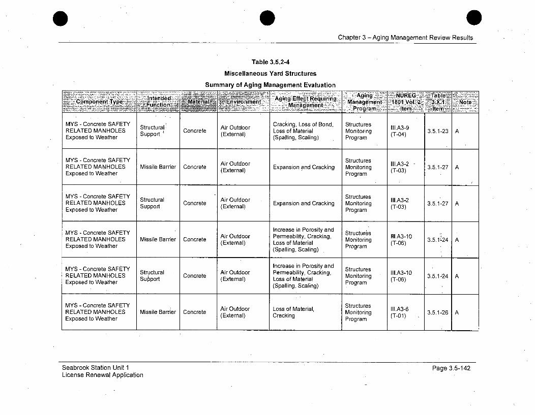
Chapter.3 -Aging Management Review Results
Table 3.5.2-4
Miscellaneous Yard Structures
Summary of Aging Management Evaluation
Intended Aging Effect Requirn Ag'ing NUREG ,-TableComponentType . , Material 1 Environment Note p rograrn: 2, Item : .:±Type unct~p~::Manaeent iing.Management.1801 Vol. 2.:,X Nt
MYS - Concrete SAFETY Structural' Air Outdoor Cracking, Loss of Bond, Structures III.A3-9RELATED MANHOLES Support Concrete (External) Loss of Material Monitoring (T-04) 3.5.1-23 AExposed to Weather (Spalling, Scaling) Program
MYS - Concrete SAFETY Air Outdoor Structures II1.A3-2RELATED MANHOLES Missile Barrier Concrete rExpansion and Cracking Monitoring - 3.5.1-27 AExposed to Weather (External) Program (T03)
MYS - Concrete SAFETY Structural Air Outdoor StructuresoringRELATED MANHOLES Concrete Expansion and Cracking Monitoring (T-03) 3.5.1-27 AExposed to Weather Program
MYS - Concrete SAFETY Increase in Porosity and StructuresMYLATED MA S Concrete SAir Outdoor Permeability, Cracking, trI.A3-10RELATED MANHOLES Missile Barrier Concrete (ElMonitoring 3.5.1'24 AExposed to Weather (External) Loss of Material Porm(T-06)
Expose toWeathe(Spalling, Scaling) . Program
MYS - Concrete SAFETY Increase in Porosity and StructuresRELATED MANHOLES tructural Air Outdoor Permeability, Cracking, Monitoring II.A3-10 3.5.124 AELATed MaStructua Concrete (External) Loss of Material Mogram (T-06)Expsedto eaterProgram(Spalling, Scaling)
MYS - Concrete SAFETY Air Outdoor Loss of Material, Structures IIIA3-6RELATED MANHOLES Missile.Barrer Concrete (External) Cracking ( )Monitoring II1. 3.5.1-26 AExposed to Weather Program
Seabrook Station Unit 1License Renewal Application
Page 3.5-142
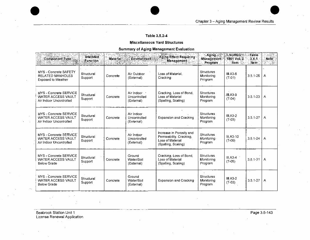
Chapter 3 - Aging Management Review Results
Table 3.5.2-4
Miscellaneous Yard Structures
Summary of Aging Management Evaluation
- ging -,.NUREG> TableýConpoen Tpe Intended Maeil niomn Aging Effect Requiring
Function _..*' - 7 Management ,* Mne~n-181Vl2 3X Nt_Program Item Item
MYS - Concrete SAFETY Structural Cocee Air Outdoor Loss of Material, Montoringes IIARELATED MANHOLES Support Concrete (External) Cracking Monitoring (T-01) 3.5.1-26 AExposed to Weather Program
MYS -. Concrete SERVICE Structural Air Indoor Cracking, Loss of Bond, Structures II1.A3-9WATER ACCESS VAULT Support Concrete Uncontrolled Loss of Material Monitoring (T-04) 3.5.1-23 AAir Indoor Uncontrolled (External) (Spalling, Scaling) Program
MYS - Concrete SERVICE Structural Air Indoor Structures III.A3-2WATER ACCESS VAULT Concrete Uncontrolled Expansion and Cracking Monitoring (T-03) 3.5.1-27 AAir Indoor Uncontrolled Support (External) Program
MYS - Concrete SERVICE Air Indoor Increase in Porosity and StructuresWATER ACCESS VAULT Structural Uncontrolled Permeability, Cracking, Monitoring III.A3-10Air Indoor Uncontrolled Support (Extrol) Loss of Material (T-06) 3.5.1-24 A
WATRACESt(External) (Spalling, Scaling) Program
MYS - Concrete SERVICE Structural Ground Cracking, Loss of Bond, Structures III.A3-4WATER ACCESS VAULT Support Concrete Water/Soil Loss of Material Monitoring (T-05) 3.5.1-31 ABelow Grade (External) (Spalling, Scaling) Program
MYS - Concrete SERVICE Structural Ground Structures III.A3-2WATER ACCESS VAULT Support Concrete Water/Soil Expansion and Cracking Monitoring (T-03) 3.5.1-27 ABelow Grade (External) Program
Seabrook Station Unit 1 Page 3.5-143License Renewal Application
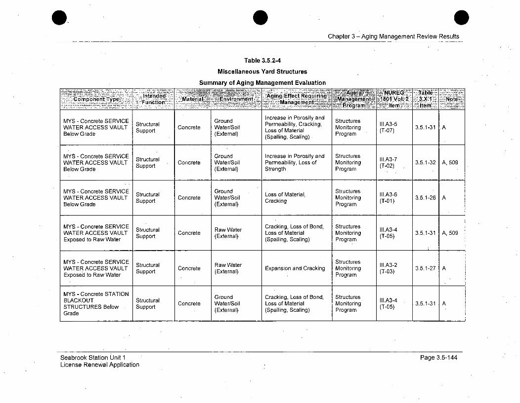
0Chapter 3 - Aging Management Review Results
Table 3.5.2-4
Miscellaneous Yard Structures
Summary of Aging Management Evaluation
- ~ ~ ntne Aging Effect Requiring ~ Aig~ 5UE al~Component Type~ *. Fcto materials -Environment% - _ -anagement -1801 Vol.2. 3.X:1 Note~-. ucto Management lt mi
MYS - Concrete SERVICE Ground Increase in Porosity and StructuresWATER ACCESS VAULT Structural Concrete Water/Soil Permeability, Cracking, Monitoring IIIA3-5Below Grade Loss of Material (T-07) 3.5.1-31 AWATeR GraCCeSSVAUL Support (External) (Spalling, Scaling) Program
MYS - Concrete SERVICE Structural Ground Increase in Porosity and Structures III.A3-7WATER ACCESS VAULT Supportua Concrete Water/Soil Permeability, Loss of Monitoring (T-02) 3.5.1-32 A, 509Below Grade (External) Strength Program
MYS - Concrete SERVICE tGround Structures II1.A3-6
WATER ACCESS VAULT ructural Concrete Water/Soil Monitoring (T01) 3.5.1-26 ABelow Grade Support (External) Cracking Program
MYS - Concrete SERVICE Structural Raw Water Cracking, Loss of Bond, Structures III.A3-4WATER ACCESS VAULT Support Concrete (External) Loss of Material Monitoring (T-05) 3.5.1-31 A, 509Exposed to Raw Water (Spalling, Scaling) Program (
MYS - Concrete SERVICE Structural Raw Water Structures III.A3-2WATER ACCESS VAULT Strt Concrete Expansion and Cracking Monitoring (T-03) 3.5.1-27 AExposed to Raw Water Support (External) Program
MYS - Concrete STATION
BLACKOUT Structural Ground Cracking, Loss of Bond, Structures III.A3-4STRUCTURES Below Support Concrete Water/Soil Loss of Material Monitoring (T-05) 3.5.1-31 ATrU E op(External) (Spalling, Scaling) Program
Grade
Seabrook Station Unit 1License Renewal Application
Page 3.5-144
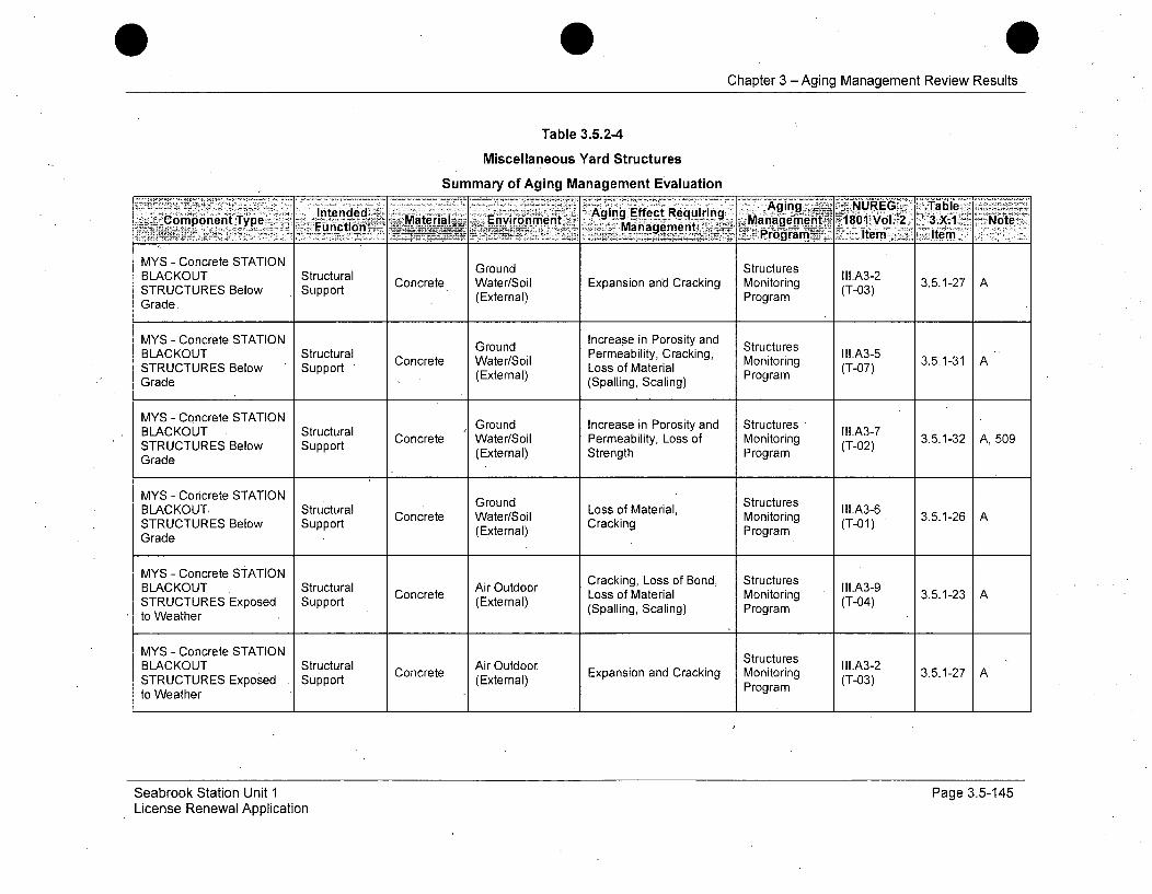
0Chapter 3 - Aging Management Review Results
Table 3.5.2-4
Miscellaneous Yard Structures
Summary of Aging Management Evaluation
Intended .. Aging Effect~uinAgn -. -NURIEGr~~a~m nenye: . Material• Environment Mnageen _Management 18001V4l.2 N3ot.1: N ,N
_______ ______ _________- ar~ni5 Item<1 It"em.
MYS - Concrete STATION Ground StructuresBLACKOUT Structural GrudSrcue ll.A3-2STRUTURESuBlowaS Concrete Water/Soil Expansion and Cracking Monitoring (T-03) 3.5.1-27 ASTRUCTURES Below Support (External) ProgramGrade
MYS - Concrete STATION Ground Increase in Porosity and StructuresBLCOTS t rudPereblity Cracking, StucursIl.A3-5 .BLACKOUT Structural Concrete Water/Soil ermeaily, Monitoring 3.5.1-31 A•Loss of Material (T-07)STRUCTURES Below Support (External) (spatigSalProgramngGrade (Spalling, Scaling)
MYS - Concrete STATION Ground Increase in Porosity and StructuresBLACKUT Strt Concrete Water/Soil Permeability, Loss of Monitoring (T-02) 3.5.1-32 A, 509STRUCTURES Below Support (External) Strength ProgramGrade
GrudStructures lI1.A3-6 3512MYS - Concrete STATION Ground LosoSaeraMntoringtuTresBLACKOUT, Structural Concrete Water/Soil Loss of Material, Monitoring Crai-n 3.5.1-26 ASTRUCTURES Below Support (External) Cracking ProgramGrade
MYS - Concrete STATIONBLACKOUT Structural Air Outdoor Cracking, Loss of Bond, Structures II1.A3-9 3.5.1-23 ASTRUCTURES Exposed Support Concrete (External) Loss of Material Monitoring (T-04)toWahr(Spalling, Scaling) Programto Weather
MYS - Concrete STATION StructuresBLACKOUT Structural Air Outdoor Expansion and Cracking Monitoring (T.A3-23 3.5.1-27 ASTRUCTURES Exposed Support (External) Program (T03)to Weather Program
Seabrook Station Unit 1License Renewal Application
Page 3.5-145
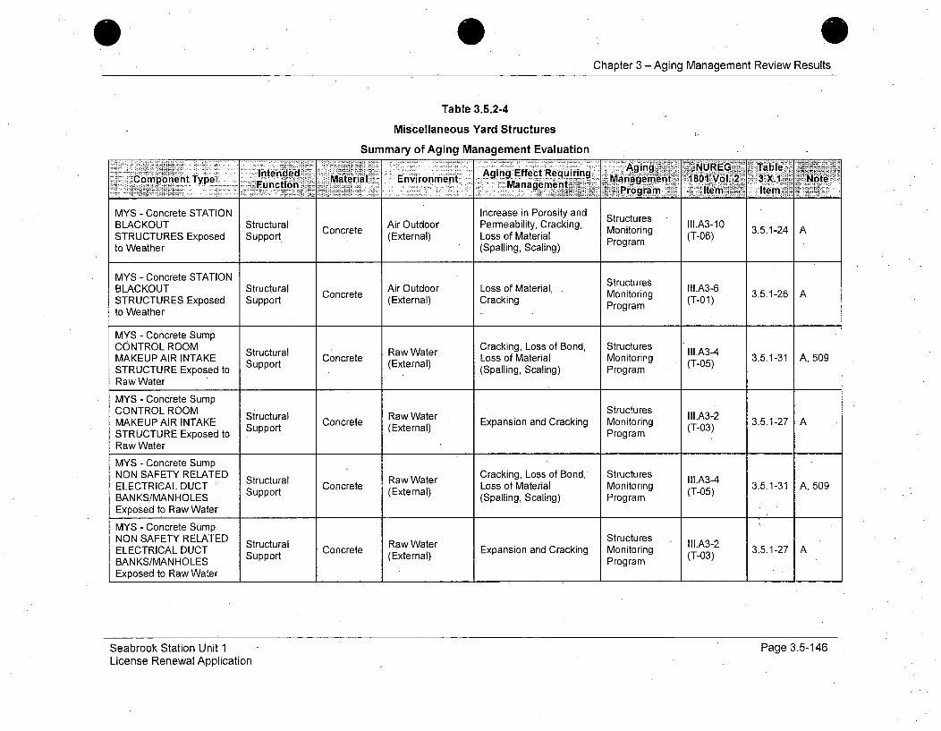
Chapter 3 - Aging Management Review Results
Table 3.5.2-4
Miscellaneous Yard Structures
Summary of Aging Management Evaluation
Component Type Mnten-ed Material Aging Efec Requir-ng AgMngemUREtI :.abIF2unction Eniomn anagemenLgent 10Vo.2 .X Ne~½ Progra Item' Item
MYS - Concrete STATION Increase in Porosity and MtrBAKUStutrlAir Outdoor Perebilty Craki Stuctre IIl.A3-10
STRUCTURES Exposed Support (External) Loss of Material Monitoring T-06) 3.5.1-24 A
to Weather (Spalling, Scaling) Program
MYS - Concrete STATION StructuresBLACKOUT Structural Concrete Air Outdoor Loss of Material, Monitoring I.A3-6 3.5.1-26 ASTRUCTURES Exposed Support (External) Cracking Program (T-0)to Weather
MYS - Concrete SumpCONTROL ROOM Structural Raw Water Cracking, Loss of Bond, Structures III.A3-4MAKEUP AIR INTAKE Strt Concrete raLoss of Material Monitoring-STRUCTURE Exposed to Support (External)(Spalling, Scaling) Program (T-05)Raw Water
MYS - Concrete SumpCONTROL ROOM StructuresMAKEUPAIR INTAKE Structural Concrete RawWater Expansion and Cracking Monitoring III.A3-2 3.5.1-27 ASTRUCTURE Exposed to ProgramRaw Water
MYS - Concrete SumpNON SAFETY RELATED Structural Raw Water Cracking, Loss of Bond, Structures III.A3-4ELECTRICAL DUCT Support Concrete (External) Loss of Material Monitoring (T-05) 3.5.1-31 A, 509BANKS/MANHOLES (Spalling, Scaling) ProgramExposed to Raw Water
MYS - Concrete SumpNON .SAFETY RELATED Stut rlR w W trStructures IIA -ELECTRICAL DUCT Support Concrete (External) Expansion and Cracking Monitoring (T-03) 3.5.1-27 A
BANKS/MANHOLES ProgramExposed to Raw Water
Seabrook Station Unit 1 Page 3.5-146License Renewal Application

Chapter 3 - Aging Management Review Results
Table 3.5.2-4
Miscellaneous Yard Structures
Summary of Aging Management Evaluation
~ Mteral nvronent Agig ging NUREG TableCtomponent Type . .... Eet g Ma ali Environment, . Management: 1801VOl. 2 3.X1 NoteFu~nCtion Management~~... ~ n:. Ie
MYS - Concrete SumpSAFETY RELATED Structural Raw Water Cracking, Loss of Bond, Structures III.A3-4ELECTRICAL DUCT Concrete awaer Loss of Material Monitoring (T-05) 3.5.1-31 A, 509BANKS/MANHOLES Support (External) (Spalling, Scaling) ProgramExposed to Raw Water
MYS - Concrete SumpSAFETY RELATED SrcueELETRICALED Structural Raw Water Structures II1.A3-2ELECTRICAL DUCT Support Concrete (External) Expansion and Cracking Monitoring (T-03) 3.5.1-27 ABAN KS/MVAN HOLES Program
Exposed to Raw Water
MYS - EPDM RoofENCLOSURE FOR Shelter, Air Outdoor Separation, Structures lll.A6-12CONDENSATE Shection Roofing envionmental Monitoring (TP-7) 3.5.1-44 A, 505STORAGE TANK Protection (External) Degradation, Water In- ProgramExposed to Weather Leakage
MYS - EPDM Roof Separation, StructuresSTATION BLACKOUT Shelter, Roofing A Outdoor Environmental tr3.5.1-44 A, 505STRUCTURES Exposed Protection (External) Degradation, Water In- Program (TP7)to Weather Leakage
MYS - Penetration SealENCLOSURE FOR Shelter, Air Outdoor Increased Hardness and Structures VII.G-2CONDENSATE Shection Elastomer Shrinkage and Loss of Monitoring (A-20) 3.3.1-61 E, 515STORAGE TANK Protection (External) Strength ProgramExposed to Weather
MYS - Seismic IsolationJoint SAFETY RELATED Air Indoor Increased Hardness and Structures VII.G-1ELECTRICAL DUCT Separation Elastomer Uncontrolled Shrinkage and Loss of Monitoring (A-19) 3.3.1-61 E, 515BANKS/MANHOLES Air (External) Strength Program
.Indoor Uncontrolled
Seabrook Station Unit 1License Renewal Application
Page 3.5-147
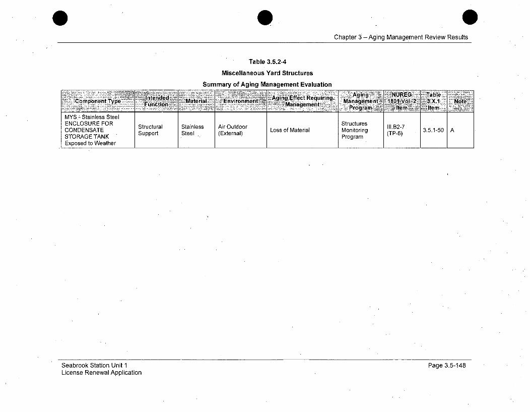
Chapter 3- Aging Management Review Results
Table 3.5.2-4
Miscellaneous Yard Structures
Summary of Aging Management Evaluation
Co6nn Ilntended~ Mtra niomn Aging Effect Requiring. AgngtN E T18le Not&3X.Type -~~~~Function ~~Maiiagement <mni181V2 ,Ie ___
MYS.- Stainless SteelECOUEFRStructures II.27 3510A
ENCLOSURE FOR Structural Stainless Air Outdoor LosocMtrasMntr.1n2-7CONDENSATE Support Steel (External) Loss of Material Monitoring (TP-6) 3.5.1-50 ASTORAGE TANK ProgramExposed to Weather
Seabrook Station Unit 1License Renewal Application
Page 3.5-148
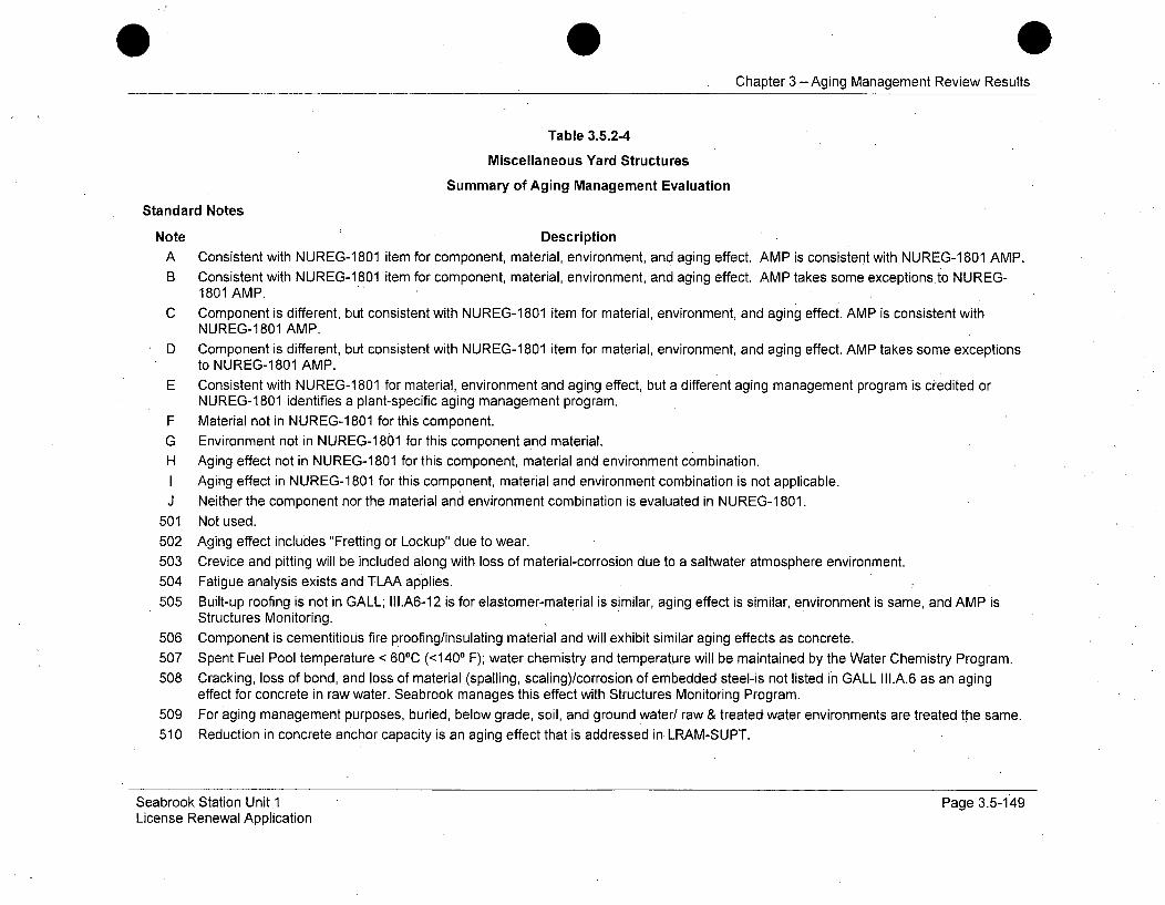
Chapter 3 -Aging Management Review Results
Table 3.5.2-4
Miscellaneous Yard Structures
Summary of Aging Management Evaluation
Standard Notes
Note DescriptionA Consistent with NUREG-1801 item for component, material, environment, and aging effect. AMP is consistent with NUREG-1 801 AMP.B Consistent with NUREG-1801 item for component, material, environment, and aging effect. AMP takes some exceptions to NUREG-
1801 AMP.C Component is different, but consistent with NUREG-1 801 item for material, environment, and aging effect. AMP is consistent with
NUREG-1801 AMP.D Component is different, but consistent with NUREG-1801 item for material, environment, and aging effect. AMP takes some exceptions
to NUREG-1801 AMP.E Consistent with NUREG-1 801 for material, environment and aging effect, but a different aging management program is credited or
NUREG-1 801 identifies a plant-specific aging management program.F Material not in NUREG-1 801 for this component.G Environment not in NUREG-1 801 for this component and material.H Aging effect not in NUREG-1 801 for this component, material and environment combination.I Aging effect in NUREG-1 801 for this component, material and environment combination is not applicable.J Neither the component nor the material and environment combination is evaluated in NUREG-1 801.
501 Not used.502 Aging effect includes "Fretting or Lockup" due to wear.503 Crevice and pitting will be included along with loss of material-corrosion due to a saltwater atmosphere environment.504 Fatigue analysis exists and TLAA applies.505 Built-up roofing is not in GALL; II1.A6-12 is for elastomer-material is similar, aging effect is similar, environment is same, and AMP is
Structures Monitoring.506 Component is cementitious fire proofing/insulating material and will exhibit similar aging effects as concrete.507 Spent Fuel Pool temperature < 60°C (<1400 F); water chemistry and temperature will be maintained by the Water Chemistry Program.508 Cracking, loss of bond, and loss of material (spalling, scaling)/corrosion of embedded steel-is not listed in GALL III.A.6 as an aging
effect for concrete in raw water. Seabrook manages this effect with Structures Monitoring Program.509 For aging management purposes, buried, below grade, soil, and ground water/ raw & treated water environments are treated the same.510 Reduction in concrete anchor capacity is an aging effect that is addressed in LRAM-SUPT.
Seabrook Station Unit 1 Page 3.5-149License Renewal Application
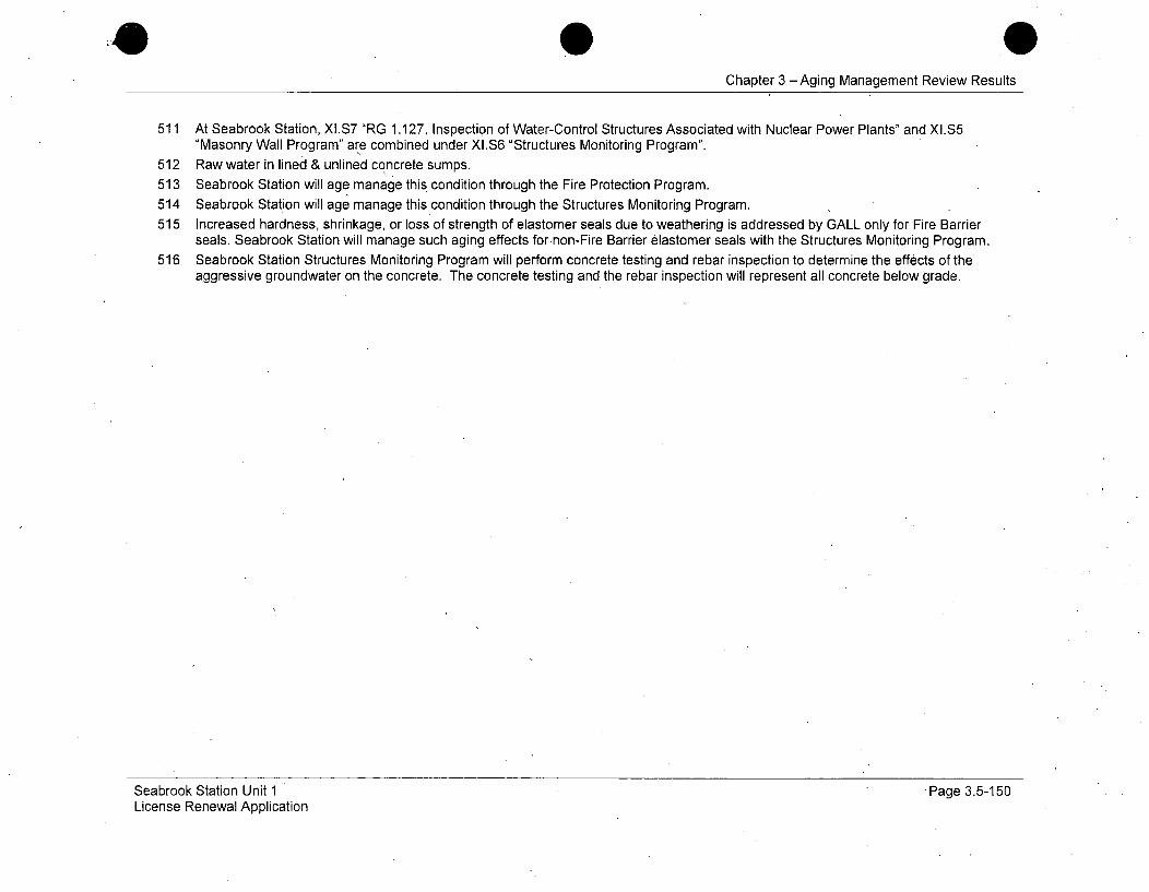
Chapter 3 -Aging Management Review Results
511 At Seabrook Station, XI.S7 "RG 1.127, Inspection of Water-Control Structures Associated with Nuclear Power Plants" and XI.S5"Masonry Wall Program" are combined under XI.S6 "Structures Monitoring Program".
512 Raw water in lined & unlined concrete sumps.513 Seabrook Station will age manage this condition through the Fire Protection Program.514 Seabrook Station will age manage this condition through the Structures Monitoring Program.515 Increased hardness, shrinkage, or loss of strength of elastomer seals due to weathering is addressed by GALL only for Fire Barrier
seals. Seabrook Station will manage such aging effects fornon-Fire Barrier elastomer seals with the Structures Monitoring Program.516 Seabrook Station Structures Monitoring Program will perform concrete testing and rebar inspection to determine the effects of the
aggressive groundwater on the concrete. The concrete testing and the rebar inspection will represent all concrete below grade.
Seabrook Station Unit 1License Renewal Application
*Page 3.5-150

Chapter 3 - Aging Management Review Results
Table 3.5.2-5
Primary Structures
Summary of Aging Management Evaluation
Intended Mtra Ei1Omt Aging Effect Agig NuEGV, ab_-opnntTp Matria Man Requiringt - anagement 180.1-Vol. 2~ 3.X.1 NoteCopoen ~agmetProgra m< Item Item
PST - (Structural) Fire Non- Air IndoorProofing - CDG- Exposed to Fire Barrier Metallic Andoor Fire Protection VII.G-29 3.3.1-67 C, 506Uncontrolled Loss of Material 3.Program C,-506
Air Indoor Uncontrolled Fire ngProofing (xenl
Non-PST - (Structural) Fire Metallic Air Indoor Structures VII.G-29Proofing - CDG- Exposed to Fire Barrier Me- Uncontrolled Loss of Material Monitoring (A-91) 3.3.1-67 C, 506Air Indoor Uncontrolled Fire- (External) ProgramProofing
PST - (Structural) Fire Non- Air IndoorBrir Metallic Ai norFire Protection VII.G-29Proofing - CDG- Exposed to Fire Uncontrolled Loss of Material Prog (A-9 3.3.1-67 C, 506Air Indoor Uncontrolled Fire-ng
Proofing (xenlPST - (Structural) Fire Non-Proig-CG xoe o ieBrir Metallic Air Indoor - Structures VII.G-29 337 C50Uncontrolled Loss of Material Monitoring (A-91) 3.1-7 C56
Air Indoor Uncontrolled Fireoin
PST - Built-Up Roofing - Shelter, Roig Air Outdoor Separation, Environmental Structures lI1.A6-12 3514 H 0
CDG- Exposed to Air Proteto Roofing (Exter Degradation, Water In- Monitoring I (TP-7) 3.5.1-44 H, 505Outdoor Protection (External) Leakage Program
Control Building and Diesel Generator Building (CDG), Containment Equipment Hatch Missile Shield (CEHMS), Emergency Feedwater Pump Building Including Electrical CableTunnels and Penetration Area (Control Building to Containment) and Pre-Action Valve Building (EFP), Fuel Storage Building (FSB), Primary Auxiliary Building and the Residual HeatRemoval Equipment Vault (PAB), Main Steam and Feedwater Pipe Chases - East & West (PCEW), Personnel Hatch Area (PHA), Tank Farm (Tunnels) - Including Dikes andFoundation for Refueling Water Storage Tank and Reactor Makeup Water Storage Tank (TFA), Waste Process Building (WPB)
Seabrook Station Unit 1License Renewal Application
Page 3.5-151

Chapter 3 -Aging Management Review Results
Table 3.5.2-5
Primary Structures
Summary of Aging Management Evaluation
Intended AAion Efanagemirent Agiang NUREGS ITable'ZCoinwonent Type. ~ Fnto Material Environment ~AigEfetRqrng Manag4ement. .1801 Vol. 2 I3.X.1' Note
Outdoor P n Leakage Program
PST - Built-Up Roofing - Shelter, Air Outdoor Separation, Environmental Structures II1.A6-12
FSB- Exposed to.Air . Protection Roofing (External) Degradation, Water In- Monitoring (TP-7) 3.5.1-44 H, 505Outdoor Leakage Program
PST - Built-Up Roofing - Shelter Air Outdoor Separation, Environmental Structures II1.A6-12PAB- Exposed to Air Sheter, Roofing ArOtdr Degradation, Water In- Monitoring (TP-7) 3.5.1-44 H, 505Outdoor Protection (External) Leakage Program (T-.7)
PST - Built-Up Roofing - Shelter, Air Outdoor Separation, Environmental Structures II.A6-12PCEW- Exposed to Air Protection Roofing (External) Degradation, Water In- Monitoring (TP-7) 3.5.1-44 H,505Outdoor Leakage Program
PST - Built-Up Roofing - Shelter, Air Outdoor Separation, Environmental Structures IIlA6-12
PHA- Exposed to Air Protection RExternal) Degradation, Water In- Monitoring (TP-7) 3.5.1-44 H,505Outdoor Leakage Program
Control Building and Diesel Generator Building (CDG), Containment Equipment Hatch Missile Shield (CEHMS), Emergency Feedwater Pump Building Including Electrical CableTunnels and Penetration Area (Control Building to Containment) and Pre-Action Valve Building (EFP), Fuel Storage Building (FSB), Primary Auxiliary Building and the Residual HeatRemoval Equipment Vault (PAB), Main Steam and Feedwater Pipe Chases - East & West (PCEW), Personnel Hatch Area (PHA), Tank Farm (Tunnels) - Including Dikes andFoundation for Refueling Water Storage Tank and Reactor Makeup Water Storage Tank (TFA), Waste Process Building (WPB)
Seabrook Station Unit 1License Renewal Application
Page 3.5-1 52
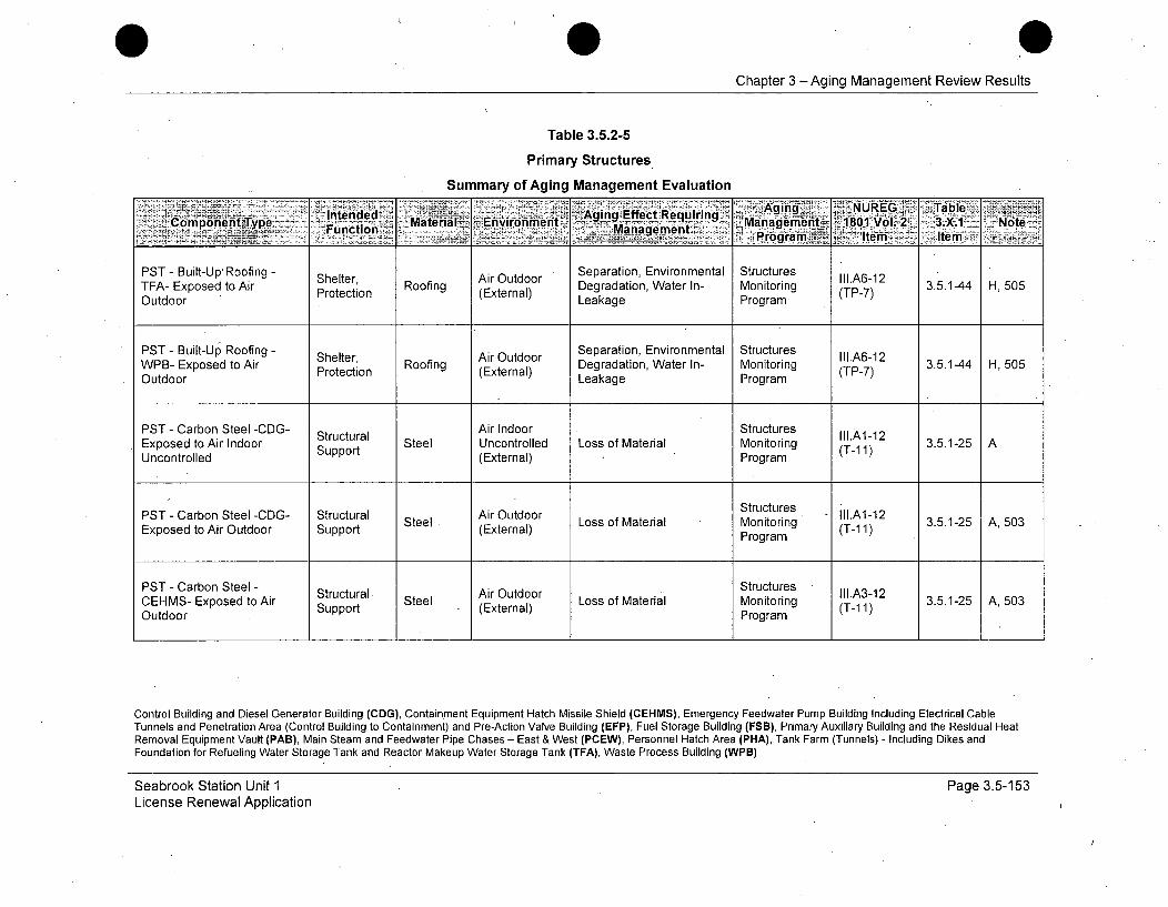
SChapter 3 -Aging Management Review Results
Table 3.5.2-5
Primary Structures
Summary of Aging Management Evaluation
-; 'Intended' ~ ~ ~ 1 ~'Aging~ UEGg*TbeEnene 1 Aging Effect Requiring 8i.L2Compppent Type Fucin~ Material~ Evironment *.§~a gmn . Managnet. 1801 Nte- , i ''Item ,_gement
PST - Built-Up'Roofing - Shelter, Ai Outdoor Separation, Environmental Structures II1.A6-12TEA- Exposed to Air Protection Roofing (Extrnal) Degradation, Water In- Monitoring (TP-7) 3.5.1-44 H, 505Outdoor Leakage Program
PST - Built-Up, Roofing - Shelter, Air Outdoor Separation, Environmental Structures II1.A6-12WPB- Exposed to Air Shectirn Roofing ArOtdr Degradation, Water In- Monitoring (TP-7) 3.5.1-44 H, 505Outdoor Protection (External) Leakage Program
PST - Carbon Steel -CDG- Structural Air Indoor Structures II1.A1-12Exposed to Air Indoor Support Steel Uncontrolled Loss of Material Monitoring (T-11) 3.5.1-25 AUncontrolled (External) Program
PST - Carbon Steel -CDG- Structural IOutdoor StructuresSteel Air Loss of Material Monitoring (T-1 3.5.1-25 A, 503
Exposed to Air Outdoor Support (External) Program (T-11)
PST - Carbon Steel - Structural Air Outdoor Structures IIIA3-12CEHMS- Exposed to Air Support Steel Loss of Material Monitoring (T-11) 3.5.1-25 A,503Outdoor Program
Control Building and Diesel Generator Building (CDG), Containment Equipment Hatch Missile Shield (CEHMS), Emergency Feedwater Pump Building Including Electrical CableTunnels and Penetration Area (Control Building to Containment) and Pre-Action Valve Building (EFP), Fuel Storage Building (FSB), Primary Auxiliary Building and the Residual HeatRemoval Equipment Vault (PAB), Main Steam and Feedwater Pipe Chases - East & West (PCEW), Personnel Hatch Area (PHA), Tank Farm (Tunnels) - Including Dikes andFoundation for Refueling Water Storage Tank and Reactor Makeup Water Storage Tank (TFA), Waste Process Building (WPB)
Seabrook Station Unit 1License Renewal Application
Page 3.5-153
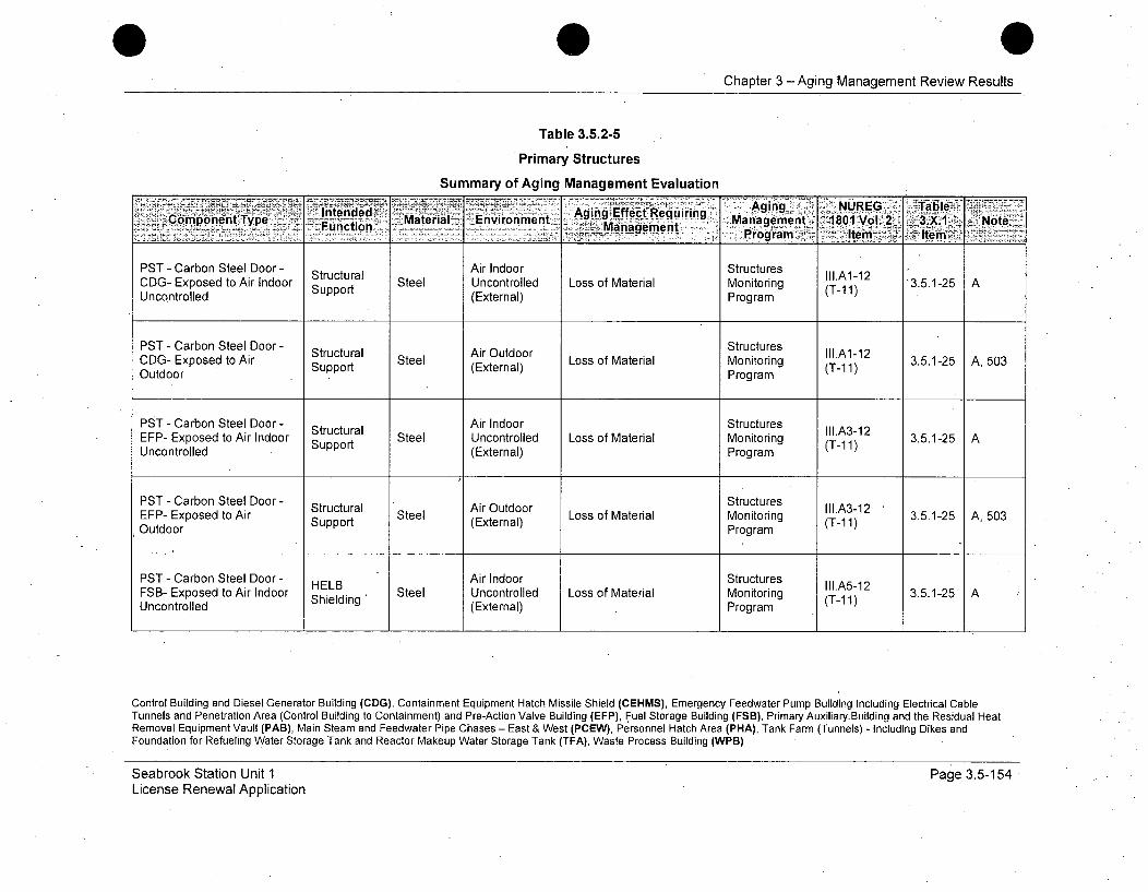
Chapter 3 -Aging Management Review Results
Table 3.5.2-5
Primary Structures
Summary of Aging Management Evaluation
olntendedTyp Materials Environment -Angfeteurg ...... IanagiemtX 1801 Vol. Z: ..3._1X.l Noteomoeye Function _ anagement , Po~m' -Ie
PST - Carbon Steel Door - Air Indoor StructuresStructural III.A1-12CDG- Exposed to Air Indoor Support Steel Uncontrolled Loss of Material Monitoring (T-11) 3.5.1-25 AUncontrolled (External) Program
PST - Carbon Steel Door - Structural Air Outdoor Structures Il.A1-12CDG- Exposed to Air Support Steel (External) Loss of Material Monitoring (T-1 1) 3.5.1-25 A, 503Outdoor Program
PST - Carbon Steel Door- Structural Air Indoor Structures II1.A3-12EFP- Exposed to Air Indoor Support Steel Uncontrolled Loss of Material Monitoring (T-11) 3.5.1-25 AUncontrolled (External) Program
PST-Carbon Steel Door- Structural StructuresEFP- Exposed to Air Steel ArOtdr Loss of Material Monitoring (T-1 3.5.1-25 A, 503Outdoor Support (External) Program (T-11)
PST - Carbon Steel Door - HELB Air Indoor StructuresFSB- Exposed to Air Indoor Shielding Steel Uncontrolled Loss of Material Monitoring (T-1A1) 3.5.1-25 AUncontrolled (External) Program
Control Building and Diesel Generator Building (CDG), Containment Equipment Hatch Missile Shield (CEHMS), Emergency Feedwater Pump Building Including Electrical CableTunnels and Penetration Area (Control Building to Containment) and Pre-Action Valve Building (EFP), Fuel Storage Building (FSB), Primary Auxiliary.Building and the Residual HeatRemoval Equipment Vault (PAB), Main Steam and Feedwater Pipe Chases - East & West (PCEW), Personnel Hatch Area (PHA), Tank Farm (Tunnels) - Including Dikes andFoundation for Refueling Water Storage Tank and Reactor Makeup Water Storage Tank (TFA), Waste Process Building (WPB)
Seabrook Station Unit 1License Renewal Application
Page 3.5-154
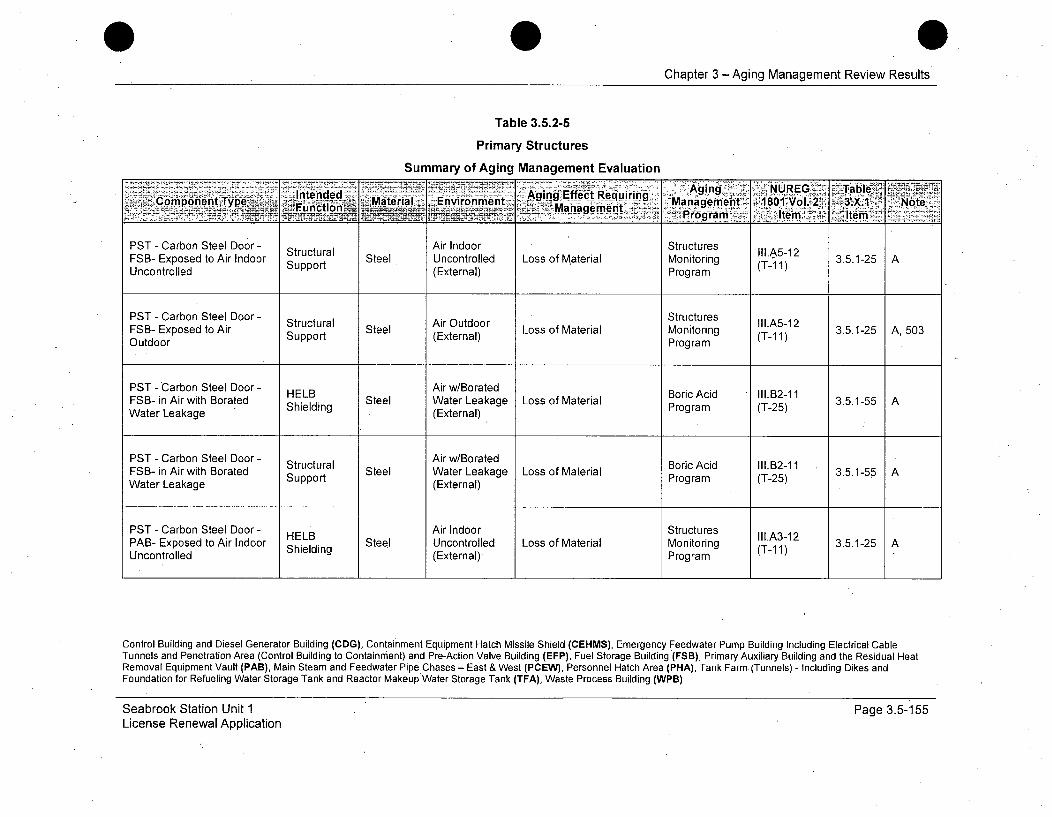
Chapter 3 - Aging Management Review Results
Table 3.5.2-5
Primary Structures
Summary of Aging Management Evaluation
kIII.A5-12
oSB-xposed ty A o InteSruc Mteal Envonmen Aging Effect Requiri trng (-1 3.5.1' C t Manae
gupport (Extra Proram x lo
PST - Carbon Steel Door - Air Indoor Structures
Structural ArutorII1.A5-12
FSB- Exposed to Air Indoor Steel Uncontrolled Loss of Material Monitoring (T11) 3.5.1-25 AUncontrolled Support (External) Program
PST - Carbon Steel Door - Steel Air Outdoora LostoeMaerildSrucureFSB- O o Air Support Steel Waternal) Loss of Material(T-11) 3.5.1-25 A, 503Oute Eosedta Support (External) Program
PST - Carbon Steel Door - HELB Air w/Borated Boric Acid 111.12-11FSB- in Air with Borated Support Steel Water Leakage Loss of Material Program (T-25)AWater Leakage (External)
PST -Carbon Steel Door- StutrlAir w/Borated Boric Acid 11l.132-11 3515FSB- in Air with Borated Stpprutua Steel Water Leakage Loss of Material Program (T-25) 3515Water Leakage Spot(External)
PST - Carbon Steel Door - HELB Air Indoor StructuresPAB- Exposed to Air Indoor Steel Uncontrolled Loss of Material Monitoring (T-1 3.5.1-25 AUncontrolled Shielding (External) Program (T-11)
Control Building and Diesel Generator Building (CDG), Containment Equipment Hatch Missile Shield (CEHMS), Emergency Feedwater Pump Building Including Electrical CableTunnels and Penetration Area (Control Building to Containment) and Pre-Action Valve Building (EFP), Fuel Storage Building (FSB), Primary Auxiliary Building and the Residual HeatRemoval Equipment Vault (PAB), Main Steam and Feedwater Pipe Chases - East & West (PCEW), Personnel Hatch Area (PHA), Tank Farm (Tunnels) - Including Dikes andFoundation for Refueling Water Storage Tank and Reactor Makeup Water Storage Tank (TFA), Waste Process Building (WPB)
Seabrook Station Unit 1License Renewal Application
Page 3.5-155
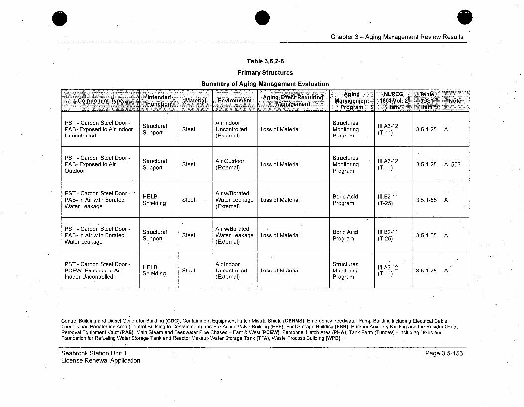
Chapter 3 -Aging Management Review Results
Table 3.5.2-5
Primary Structures
Summary of Aging Management Evaluation
Inten'ded Aging NUREG jabuiriegC,,omponent Type Fnto Material Environment Agn fetRqiig Management 1801 Vol. 2 3.X.1~ Noteý
PST - Carbon Steel Door - Structural Air Indoor Structures Ill.A312PAB- Exposed to Air Indoor Steel Uncontrolled Loss of Material Monitoring (T-11). 3.5.1-25 AUncontrolled (External) Program
PST - Carbon Steel Door - StructuresStructural Air Outdoor . II1.A3-12PAB- Exposed to Air Support Steel (External) Loss of Material Monitoring (T-11) 3.5.1-25 A, 503Outdoor Program
PST - Carbon Steel Door - " Air w/BoratedPBnirthBrtd HELB Sel ArwBatdBoric Acid II1.B2-11 3515PAB- in Airwith Borated Shielding Steel Water Leakage Loss of Material Program (T-25)AWater Leakage (External)
PST - Carbon Steel Door - Air w/Borated BoricAcid 111.12-11PAB- in Air with Borated Structural Steel Water Leakage Loss of Material ProgricA (TA2-PA-inAr ih oatd Support Program (T-25) 3515Water Leakage (External)
PST - Carbon Steel Door - HELB Air Indoor Structures III.A3-12PCEW- Exposed to Air Shielding Steel Uncontrolled Loss of Material Monitoring (T-11) 3.5.1-25 AIndoor Uncontrolled (External) Program
Control Building and Diesel Generator Building (CDG), Containment Equipment Hatch Missile Shield (CEHMS), Emergency Feedwater Pump Building Including Electrical CableTunnels and Penetration Area (Control Building to Containment) and Pre-Action Valve Building (EFP), Fuel Storage Building (FSB), Primary Auxiliary Building and the Residual HeatRemoval Equipment Vault (PAB), Main Steam and Feedwater Pipe Chases - East &,West (PCEW), Personnel Hatch Area (PHA), Tank Farm (Tunnels) - Including Dikes andFoundation for Refueling Water Storage Tank and Reactor Makeup Water Storage Tank (TFA), Waste Process Building (WPB)
Seabrook Station Unit 1License Renewal Application
Page 3.5-156

0Chapter 3 - Aging Management Review Results
Table 3.5.2-5
Primary Structures
Summary of Aging Management Evaluation
Int~de . . 'inEffct e urin -Aging ZNUREG 7I Table~-~Component Type Material AEvrnet ging Efec geqManan-Manctional: 5 Management Mngement- 1801IVol. 2 3.XI1 Note
PST - Carbon Steel Door- Structural Air Indoor Structures Ill.A3-12PCEW- Exposed toSupport Steel Uncontrolled Loss of Material Monitoring (T-11) 3.5.1-25 AIndoor Uncontrolled (External) Program
PST - Carbon Steel Door - Structural Air Outdoor Structures III.A3-12PCEW- Exposed to Air Support Steel (Externa!) Loss of Material Monitoring (T-11) 3.5.1-25 A, 503Outdoor Program
PST - Carbon Steel Door - Structural Air Indoor StructuresWPB- Exposed to Air Indoor Support Steel Uncontrolled Loss of Material Monitoring (T-11) 3.5.1-25 AUncontrolled (External) Program
PST - Carbon Steel Door - Structural Air Outdoor Structures Ill.A3-12WPB- Exposed toAir Support Steel (Etea Loss of Material Monitoring (T-11) 3.5.1-25 A, 503Outdoor Program
PST - Carbon Steel Door - Structural Air w/Borated BoricAcid 111.12-11WPB- in Air with Borated Strt Steel Water Leakage Loss of Material Program (T-25) 3.5.1-55 AWater Leakage Support (External)
Control Building and Diesel Generator Building (CDG), Containment Equipment Hatch Missile Shield (CEHMS), Emergency Feedwater Pump Building Including Electrical CableTunnels and Penetration Area (Control Building to Containment) and Pre-Action Valve Building (EFP), Fuel Storage Building (FSB), Primary Auxiliary Building and the Residual HeatRemoval Equipment Vault (PAB), Main Steam and Feedwater Pipe Chases - East & West (PCEW), Personnel Hatch Area (PHA), Tank Farm (Tunnels) - Including Dikes andFoundation for Refueling Water Storage Tank and Reactor Makeup Water Storage Tank (TFA), Waste Process Building (WPB)
Seabrook Station Unit 1License Renewal Application
Page 3.5-157
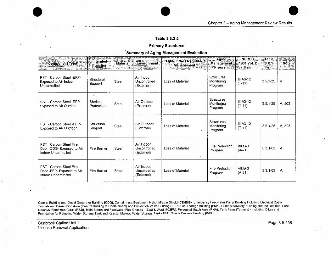
Chapter 3 -Aging Management Review Results
Table 3.5.2-5
Primary Structures
Summary of Aging Management Evaluation
Ilitended -~ Aging Effect Requiring Agn__ NUG Tal7Component Ty~pe Material Managementt ManagebmeritL. 1801 Vol.'2_ - 3.X.1 Note2ý___ ~ ..... Program--a.~ Item 1tM.
PST - Carbon Steel -EFP- Structural Air Indoor Structures II1.A3-12Exposed to Air Indoor Support Steel Uncontrolled Loss of Material Monitoring (T-11) 3.5.1-25 A
Uncontrolled (External) Program
StructuresPS abnSel-F- SetrAir Outdoor Stucurs 1l.A3-12PST - Carbon Steel -EFP- Shelter, Steel AEtdo Loss of Material Monitoring (T-11) 3.5.1-25 A, 503Exposed to Air Outdoor Protection (External) Program
PST - Carbon Steel -EFP- Structural Air Outdoor Structures III.A3-12Steel ArOtor Loss of Material Sontoructures .51-5 ,Exposed to Air Outdoor Support (External) Program (T-11) 3.5.1-25 A,503
PST - Carbon Steel Fire Air Indoor Fire Protection VII.G-3Door-CDG- Exposed to Air Fire Barrier Steel Uncontrolled Loss of Material Program (A-21) 3.3.1-63 AIndoor Uncontrolled (External)
PST - Carbon Steel Fire Air Indoor Fire Protection VII.G-3Door -EFP- Exposed to Air Fire Barrier Steel Uncontrolled Loss of Material Program (A-21)AIndoor Uncontrolled (External)
Control Building and Diesel Generator Building (CDG), Containment Equipment Hatch Missile Shield (CEHMS), Emergency Feedwater Pump Building Including Electrical CableTunnels and Penetration Area (Control Building to Containment) and Pre-Action Valve Building (EFP), Fuel Storage Building (FSB), Primary Auxiliary Building and the Residual HeatRemoval Equipment Vault (PAB), Main Steam and Feedwater Pipe Chases - East & West (PCEW), Personnel Hatch Area (PHA), Tank Farm (Tunnels) - Including Dikes andFoundation for Refueling Water Storage Tank and Reactor Makeup Water Storage Tank (TFA), Waste Process Building (WPB)
Seabrook Station Unit 1License Renewal Application
Page 3.5-158
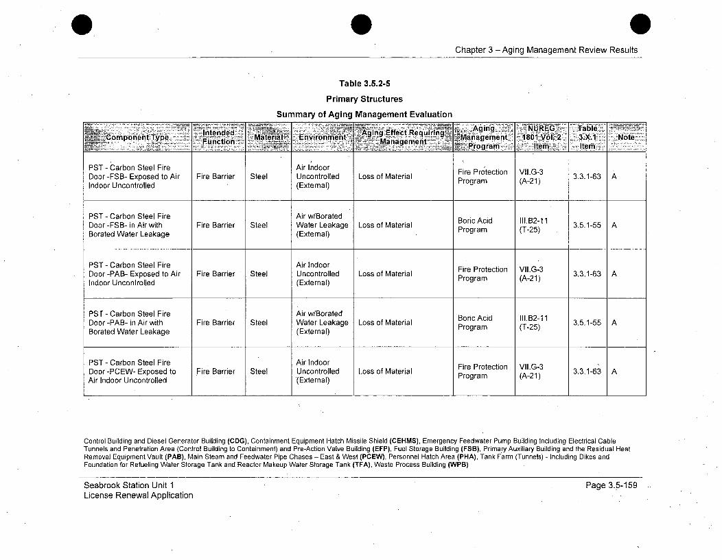
Chapter 3 - Aging Management Review Results
Table 3.5.2-5
Primary Structures
Summary of Aging Management Evaluation
_ ~~Intended Agin Effec.1t Agng-iNUEG Tbl__Component Type Functionvionen Managenent~ 1801 VoL-2- ý3.X1 Note- __irogram :- Item-i'2 Item
PST - Carbon Steel Fire Air Indoor Fire Protection VII.G-3Door -FSB- Exposed to Air Fire Barrier Steel Uncontrolled Loss of Material Program (A-21)3.3.1-63Indoor Uncontrolled (External)
PST - Carbon Steel Fire Air w/Borated Boric Acid II1.B2-11Door -FSB- in Air with Fire Barrier Steel Water Leakage Loss of Material Borac (T-25) 3.5.1-55 ABorated Water Leakage (External) Program (T-25)
PST - Carbon Steel Fire Air Indoor Fire Protection VII.G-3Door -PAB- Exposed to Air Fire Barrier Steel Uncontrolled Loss of Material Prog -3.3.1-63Indoor Uncontrolled (External) Program (A-21)
PST - Carbon Steel Fire Air w/Borated Boric Acid II1.B2-11Door -PAB- in Air with Fire Barrier Steel Water Leakage Loss of Material Program (T-25)3.5.1-55Borated Water Leakage (External)
PST - Carbon Steel Fire Air Indoor Fire Protection VII.G-3Door -PCEW- Exposed to Fire Barrier Steel Uncontrolled Loss of Material Program (A-21)3.3.1-63Air Indoor Uncontrolled (External)
Control Building and Diesel Generator Building (CDG), Containment Equipment Hatch Missile Shield (CEHMS), Emergency Feedwater Pump Building Including Electrical CableTunnels and Penetration Area (Control Building to Containment) and Pre-Action Valve Building (EFP), Fuel Storage Building (FSB), Primary Auxiliary Building and the Residual HeatRemoval Equipment Vault (PAB), Main Steam and Feedwater Pipe Chases - East & West (PCEW), Personnel Hatch Area (PHA), Tank Farm (Tunnels) - Including Dikes andFoundation for Refueling Water Storage Tank and Reactor Makeup Water Storage Tank (TFA), Waste Process Building (WPB)
Seabrook Station Unit 1License Renewal Application
Page 3.5-159
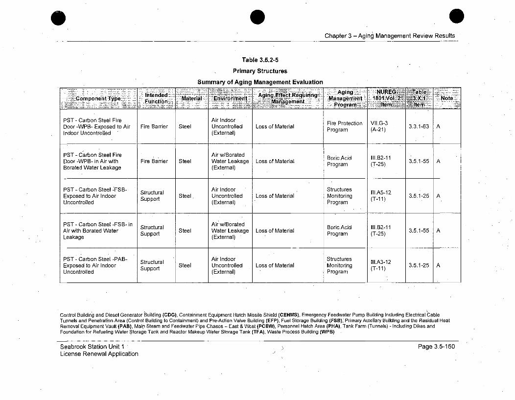
Chapter 3 -Aging Management Review Results
Table 3.5.2-5
Primary Structures
Summary of Aging Management Evaluation
'Coponnt ype Intended Maeil -Evrnet Aging Efect Requrn ging NUE 'aCopoennct Mtrilonirnmn _ _quirimng7 Management 1801 Vol. 2 ~3.X.1 -Note
Programs Item Item
PST - Carbon Steel Fire Air Indoor Fire Protection VII.G-3Door -WPB- Exposed to Air Fire Barrier Steel Uncontrolled Loss of Material Program (A-21)AIndoor Uncontrolled (External)
PST - Carbon Steel Fire Air w/Borated Boric Acid I1.B2-11Door -WPB- in Air with Fire Barrier Steel Water Leakage Loss of Material Program (T25) 3.5.1-55 ABorated Water Leakage (External)
PST - Carbon Steel -'FSB- Structural Air Indoor Structures lll.A512Exposed to Air Indoor Support Steel Uncontrolled Loss of Material Monitoring (T11) 3.5.1-25 AUncontrolled (External) Program
PST - Carbon Steel -FSB-in Structural Air w/Borated Boric Acid 111.12-11Air with Borated Water Support Steel Water Leakage Loss of Material Program (T-25) 3.5.1-55 ALeakage (External)
PST - Carbon Steel -PAB- Structural Air Indoor Structures III.A3-12Exposed to Air Indoor Sur Steel Uncontrolled Loss of Material Monitoring (T-1 3.5.1-25 A
Uncontrolled (External) Program1)
Control Building and Diesel Generator Building (CDG), Containment Equipment Hatch Missile Shield (CEHMS), Emergency Feedwater Pump Building Including Electrical CableTunnels and Penetration Area (Control Building to Containment) and Pre-Action Valve Building (EFP), Fuel Storage Building (FSB)," Primary Auxiliary Building and the Residual HeatRemoval Equipment Vault (PAB), Main Steam and Feedwater Pipe Chases - East & West (PCEW), Personnel Hatch Area (PHA), Tank Farm (Tunnels) - Including Dikes andFoundation for Refueling Water Storage Tank and Reactor Makeup Water Storage Tank (TFA), Waste Process Building (WPB)
Seabrook Station Unit 1License Renewal Application
Page 3.5-160
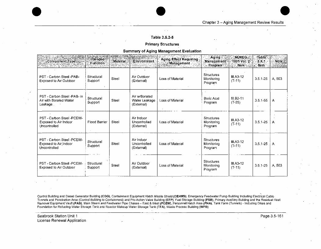
Chapter 3 -Aging Management Review Results
Table 3.5.2-5
Primary Structures
Summary of Aging Management Evaluation
UAging )NOR . -Table.
PST - Carbon Steel -PAB- Structural Stee (Exteornl PtrogtramII.3Exoe oArOtor Spot Steel (Etra) Loss of Material Monitoring (T-1 1) 3.5.1-25 A, 503Exposed to Air Outdoor Support (Program
PST - Carbon Steel -PAB- in Air w/BoratedAir with Borated Water Structural Steel Water Leakage Loss of Material Boric Acid (-B2-11 3.5.1-55 ALeakage. Support (External) Program (T-25)
PST - Carbon Steel -PCEW- Air Indoor StructuresExposed to Air Indoor Flood Barrier Steel Uncontrolled Loss of Material Monitoring (T-11) 3.5.1-25 AUncontrolled (External) Program
PST - Carbon Steel -PCEW- Air Indoor StructuresExposed to Airindoor Support Steel Uncontrolled Loss of Material Monitoring (T-1A1) 3.5.1-25 AUncontrolled .(Exteal) Program
PST- Carbon Steel -PCEW- Structural Air Outdoor Structures II1.A3-12Exposed to Air Outdoor Support Steel (External) Loss of Material Monitoring (T-11) 3.5.1-25 A, 503
Program
Control Building and Diesel Generator Building (CDG), Containment Equipment Hatch Missile Shield (CEHMS), Emergency Feedwater Pump Building Including Electrical CableTunnels and Penetration Area (Control Building to Containment) and Pre-Action Valve Building (EFP), Fuel Storage Building (FSB), Primary Auxiliary Building and the Residual HeatRemoval Equipment Vault (PAB), Main Steam and Feedwater Pipe Chases - East & West (PCEW), Personnel Hatch Area (PHA), Tank Farm (Tunnels) - Including Dikes andFoundation for Refueling Water Storage Tank and ReactorMakeup Water Storage Tank (TFA), Waste Process Building (WPB)
Seabrook Station Unit 1License Renewal Application
Page 3.5-161
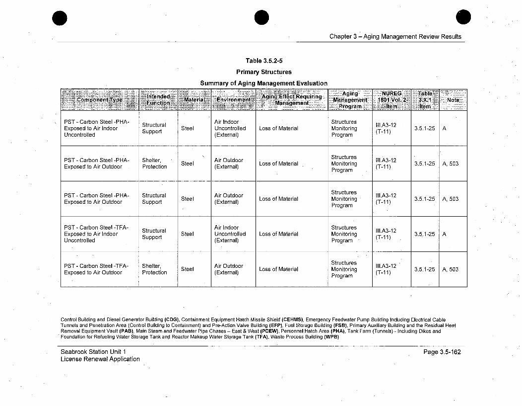
Chapter 3 -Aging Management Review Results
Table 3.5.2-5
Primary Structures
Summary of Aging Management Evaluation
Intended AgingEffect.Reqiri Aig NRE abeFunctiontTyp Material EnvironmentE g ~ u n Managemnent 1801 Vol. 2 ,3..X-1 Note
SPro gram IJtem itm
PST - Carbon Steel -PHA- Structural Air Indoor Structures Ill.A3-12Exposed to Air Indoor Support Steel Uncontrolled Loss of Material Monitoring (T-11)3.5.1-25 AUncontrolled (External) Program
StructuresPST - Carbon Steel -PHA- Shelter, Steel Air Outdoor Loss of Material Monitoring (TI.A3-12 3.5.1-25 A,503Exposed to Air Outdoor Protection (External) Program (T-11)
PST - Carbon Steel -PHA- Structural Air Outdoor Structures III.A3-12Exposed to Air Outdoor Support Steel (Eternal) Loss of Material Monitoring (T-11) 3.5.1-25 A, 503
Program
PST - Carbon Steel -TFA- Structural Air Indoor Structures III.A3.12Exposed to Air Indoor Support Steel Uncontrolled Loss of Material Monitoring (T-11) 3.5.1-25 AUncontrolled (External) Program
PST - Carbon Steel -TFA- Shelter, Steel AirLoss of Material Stru eg 3.5.1-25 A, 503Exposed to Air Outdoor Protection (External) Monitoring (T-11)
Program
Control Building and Diesel Generator Building (CDG), Containment Equipment Hatch Missile Shield (CEHMS), Emergency Feedwater Pump Building Including Electrical CableTunnels and Penetration Area (Control Building to Containment) and Pre-Action Valve Building (EFP), Fuel Storage Building (FSB), Primary Auxiliary Building and the Residual HeatRemoval Equipment Vault (PAB), MainSteam and Feedwater Pipe Chases - East & West (PCEW), Personnel Hatch Area (PHA), Tank Farm (Tunnels) - Including Dikes andFoundation for-Refueling Water Storage Tank and Reactor Makeup Water Storage Tank (TFA), Waste Process Building (WPB)
Seabrook Station Unit 1License Renewal Application
Page 3.5-162
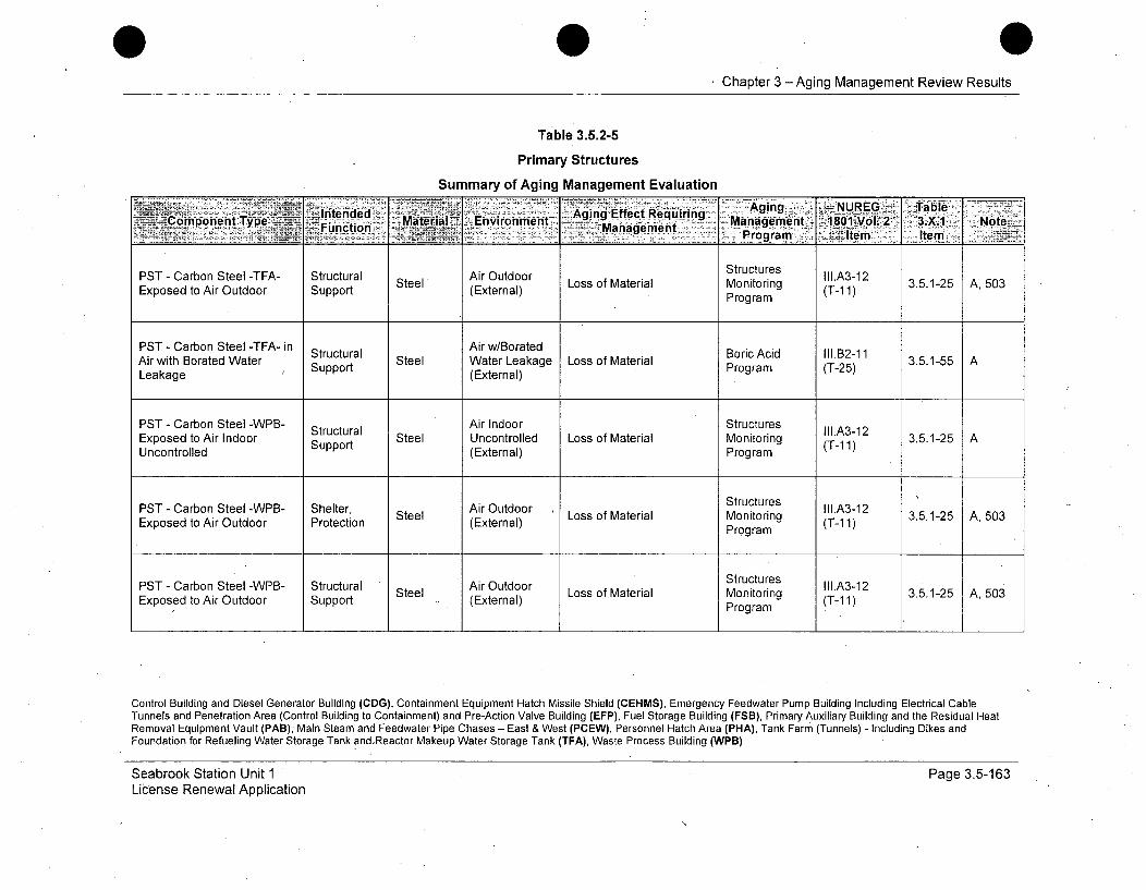
I Chapter 3 - Aging Management Review Results
Table 3.5.2-5
Primary Structures
Summary of Aging Management Evaluation
Intended.-Aging ,NUREG Table.:C-- omponent Type __ Fu•nto ..Material., Environment Ag ng Effect Requiring.- - Management,• -.1801oV 2 . .2X.1 3 Note
___TaaeetProgram I~~tem Item
PST - Carbon Steel -TFA- Structural Air Outdoor Structures II1.A3-12pse t Ar Stel-E Strt Steel (External) Loss of Material Monitoring (T-1 1) 3.5.1-25 A, 503
Exposed to Air Outdoor Support (Program
PST - Carbon Steel -TFA- in Structural Air w/Borated Boric Acid lll.B2-11Air with Borated Water Support Steel Water Leakage Loss of Material 3.5.1-55 ALeakage S o(External) Program (T-25)
PST - Carbon Steel -WPB- Structural Air Indoor Structures III.A3-12Exposed to Air Indoor Support Steel Uncontrolled Loss of Material Monitoring (T-11) 3.5.1-25 AUncontrolled (External) Program
PST - Carbon Steel -WPB- Shelter Air Outdoor Structures II1.A3-12EPoSed tron AirSOtdoor -Steel Loss of Material Monitoring (T-il) 3.5.1-25 A, 503Exposed to Air Outdoor Protection (External) Program
PST - Carbon Steel -WPB- Structural Air Outdoor Structures II1.A3-12Exposed to Air Outdoor Support Steel (External) Loss of Material Monitoring (T-11) 3.5.1-25 A, 503
Program
Control Building and Diesel Generator Building (CDG), Containment Equipment Hatch Missile Shield (CEHMS), Emergency Feedwater Pump Building Including Electrical CableTunnels and Penetration Area (Control Building to Containment) and Pre-Action Valve Building (EFP), Fuel Storage Building (FSB), Primary Auxiliary Building and the Residual HeatRemoval Equipment Vault (PAB), Main Steam and Feedwater Pipe Chases - East & West (PCEW), Personnel Hatch Area (PHA), Tank Farm (Tunnels) - Including Dikes andFoundation for Refueling Water Storage Tank and.Reactor Makeup Water Storage Tank (TFA), Waste Process Building (WPB)
Seabrook Station Unit 1 +License Renewal Application
Page 3.5-163
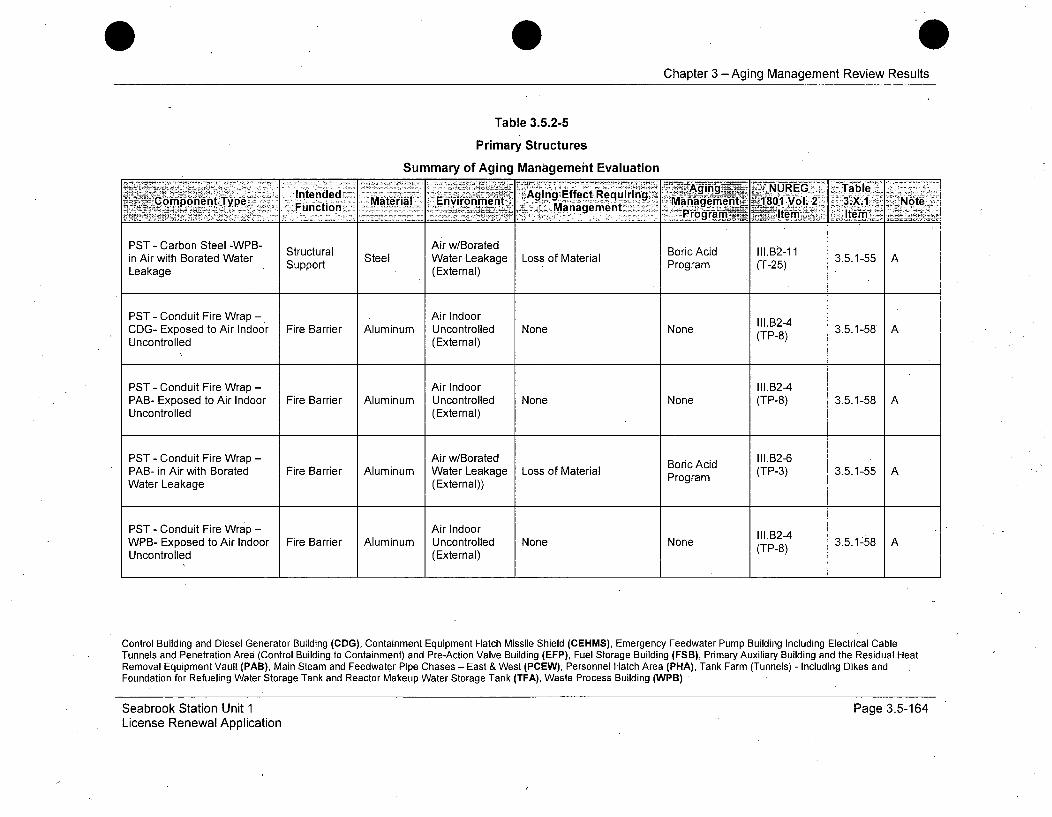
Chapter 3 -Aging Management Review Results
Table 3.5.2-5
Primary Structures
Summary of Aging Management Evaluation
Inedd- .~ging ~ _ UREG_ Table__Componiant~ype Material Environmenit AgingEfc. ~~n ;~MjanA'enent~ 1,1301 Vol'. 2 3.X.1 Note.. ~Function ... ~ Management 9_r a .~i tm
PST - Carbon Steel -WPB- Air w/Borated Boric Acid 111.12-31in Air with Borated Water Sura Steel Water Leakage Loss of Material 3.5.1-55 TLeakage Support (External) Program (T-25)
PST - Conduit Fire Wrap - Air Indoor 111.B24CDG- Exposed to Air Indoor Fire Barrier Aluminum Uncontrolled None None (TP-8) 3.5.1-58 AUncontrolled (External)
PST - Conduit Fire Wrap - Air Indoor I11.B2-4PAB- Exposed to Air Indoor Fire Barrier Aluminum Uncontrolled None None (TP-8) 3.5.1-58 AUncontrolled (External)
PST - Conduit Fire Wrap - Air w/Borated Boric Acid I11.B2-6PAB- in Air with Borated Fire Barrier Aluminum Water Leakage Loss of Material Program (TP-3) 3.5.1-55 AWater Leakage (External))
PST - Conduit Fire Wrap - Air Indoor II1.B24WPB- Exposed to Air Indoor Fire Barrier Aluminum Uncontrolled None None (TPB2) 3.5.1-58 AUncontrolled (External) (TP-8)
Control Building and Diesel Generator Building (CDG), Containment Equipment Hatch Missile Shield (CEHMS), Emergency Feedwater Pump Building Including Electrical CableTunnels and Penetration Area (Control Building to Containment) and Pre-Action Valve Building (EFP), Fuel Storage Building (FSB), Primary Auxiliary Building and the Residual HeatRemoval Equipment Vault (PAB), Main Steam and Feedwater Pipe Chases - East & West (PCEW), Personnel Hatch Area (PHA), Tank Farm (Tunnels) - Including Dikes andFoundation for Refueling Water Storage Tank and Reactor Makeup Water Storage Tank (TFA), Waste Process Building (WPB)
Seabrook Station Unit 1License Renewal Application
Page 3.5-164

Chapter 3 -Aging Management Review Results
Table 3.5.2-5
Primary Structures
Summary of Aging Management Evaluation
Intended Aging Effect Requiring AigNRG. al~Com'ponent Type' Fnto Material Environment Management geet' 18011Vol. 2 3.X1 _Note'- rogramK Item -A tern
PST - Conduit Fire Wrap - Air w/Borated Boric Acid 1I1.B2-6WPB- in Air with Borated Fire Barrier Aluminum Water Leakage Loss of Material Program (TP-3) 3.5.1-55 AWater Leakage (External))
PST - Elastomers -CDG- C B Air Indoor Increased Hardness, StructuresPS-Eatmr CG ontro Bd VII.G-1 33.-1 E55Exposed to Air Indoor Elastomer Uncontrolled Shrinkage and Loss of Monitoring (A-19)3.3.1-61 E, 515Uncontrolled (External) Strength Program
PST - Elastomers -CDG- Air Indoor Increased Hardness, StructuresExposed to Air Indoor Flood Barrier Elastomer Uncontrolled Shrinkage and Loss of Monitoring (A-19) 3.3.1-61 E, 515Uncontrolled (External) Strength Program
PST - Elastomers -CDG- Expansion/ Air Outdoor Increased Hardness, Structures VI.G-2Air Outdoor Separation Elastomer Shrinkage and Loss of Monitoring (AG-20 3.3.1-61 E, 515Strength Program
PST - Elastomers -CDG- Shelter, Air Outdoor Increased Hardness, Structures VIi.G-2Ehrnastomerss f ontoin 3.3.1-61 E, 515Exposed to Air Outdoor Protection (External) Shrinkage and Loss of Monitoring (A-20)
Strength Program
Control Building and Diesel Generator Building (CDG), Containment Equipment Hatch Missile Shield (CEHMS), Emergency Feedwater Pump Building Including Electrical CableTunnels and Penetration Area (Control Building to Containment) and Pre-Action Valve Building (EFP), Fuel Storage Building (FSB), Primary Auxiliary Building and the Residual HeatRemoval Equipment Vault (PAB), Main Steam and Feedwater Pipe Chases - East & West (PCEW), Personnel Hatch Area (PHA), Tank Farm (Tunnels) - Including Dikes andFoundation for Refueling Water Storage Tank and Reactor Makeup Water Storage Tank (TFA), Waste Process Building (WPB)
Seabrook Station Unit 1License Renewal Application
Page 3.5-165

Chapter 3 -Aging Management Review Results
Table 3.5.2-5
Primary Structures
Summary of Aging Management Evaluation
Intended - Agn Effgct RequirinTablCompobnent Type Fucin Material Environment Agin ý!Manaemfent >i80Y1 Vl.2 3,X.1 I -Note--Program..<tern: . Item.
PST - Elastomers -EFP- Expansion! Air Outdoor Increased Hardness, Structures VII.G-2Exposed to Air Outdoor Separation Elastomer (Exter Shrinkage and Loss of Monitoring (A-20) 3.3.1-61 E, 515
(External) Strength Program
PST - Elastomers -EFP- Shelter,Air Outdoor Increased Hardness, Structures VII.G-2Exposed to Air Outdoor Prtectin Elastomer (External) Shrinkage and Loss of Monitoring (A-20) 3.3.1-61 E, 515Strength Program
PST - Elastomers -FSB- Expansion/ Air Outdoor Increased Hardness, Structures VII.G-2Exposed to Air Outdoor Separation Elastomer (External) Shrinkage and Loss of Monitoring (A-20) 3.3.1-61 E, 515Strength Program
PST - Elastomers -FSB- Shelter,Air Outdoor Increased Hardness, Structures VI.G-2Exposed to Air Outdoor Prhtete n Elastomer (External) Shrinkage and Loss of Monitoring (A-20) 3.3.1-61 E, 515Strength Program
PST - Elastomers -PAB- Expansion/ Air Outdoor Increased Hardness, Structures VIL.G-2Exposed to Air Outdoor Separation Elastomer (External) Shrinkage and Loss of Monitoring (A-20) 3.3.1-61 E, 515
Strength Program
Control Building and Diesel Generator Building (CDG), Containment Equipment Hatch Missile Shield (CEHMS), Emergency Feedwater Pump Building Including Electrical CableTunnels and Penetration Area (Control Building to Containment) and Pre-Action Valve Building (EFP), Fuel Storage Building (FSB), Primary Auxiliary Building and the Residual HeatRemoval Equipment Vault (PAB), Main Steam and Feedwater Pipe Chases - East & West (PCEW), Personnel Hatch Area (PHA), Tank Farm (Tunnels) - Including Dikes andFoundation for Refueling Water Storage Tank and Reactor Makeup Water Storage Tank (TFA), Waste Process Building (WPB)
Seabrook Station Unit 1License Renewal Application
Page 3.5-166
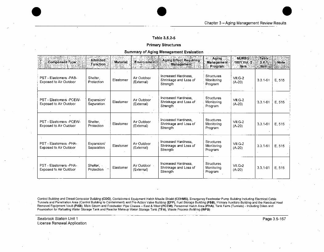
Chapter 3 -Aging Management Review Results
Table 3.5.2-5
Primary Structures
Summary of Aging Management Evaluation
Intended Maeil Evrnet Aging Effect Requjirin ~nag -. EG e S e d"'able1vo.2 3..ý .NtComponent Type Function M eMn 12nment Ma= , Pogra - tem Itr
PST - Elastomers -PAB- Shelter, Air Outdoor Increased Hardness, Structures VLG-2Exposed to Air Outdoor Protection (External) Shrinkage and Loss of Monitoring (A-20) 3.3.1-61 E, 515
Strength Program
PST - Elastomers -PCEW- Expansion/ Air Outdoor Increased Hardness, Structures VII.G-2Exposed to Air Outdoor Separation Elastomer (External) Shrinkage and Loss of Monitoring (A-20) 3.3.1-61 E, 515Strength Program
PST - Elastomers -PCEW- Shelter, Air Outdoor Increased Hardness, Structures VIIG2(External) Shrinkage and Loss of Monitoring (A20) 3.3.1-61 E, 515Strength Program
PST - Elastomers -PHA- Expansion/ Air Outdoor Increased Hardness, Structures VIL.G-2Exposed to Air Outdoor Separation Elastomer (External) Shrinkage and Loss of Monitoring (A-20) 3.3.1-61 E, 515Strength Program
PST - Elastomers -PHA- Shelter, Air Outdoor Increased Hardness, Structures VLG-2 3
E sc (External) Shrinkage and Loss of Monitoring (A-20) 3.3.1-61 E, 515Strength Program
Control Building and Diesel Generator Building (CDG), Containment Equipment Hatch Missile Shield (CEHMS), Emergency Feedwater Pump Building Including Electrical CableTunnels and Penetration Area (Control Building to Containment) and Pre-Action Valve Building (EFP), Fuel Storage Building (FSB), Primary Auxiliary Building and the Residual HeatRemoval Equipment Vault (PAB), Main Steam and Feedwater Pipe Chases - East & West (PCEW), Personnel Hatch Area (PHA), Tank Farm (Tunnels) - Including Dikes andFoundation for Refueling Water Storage Tank and Reactor Makeup Water Storage Tank (TFA), Waste Process Building (WPB)
Seabrook Station Unit 1License Renewal Application
Page 3.5-167
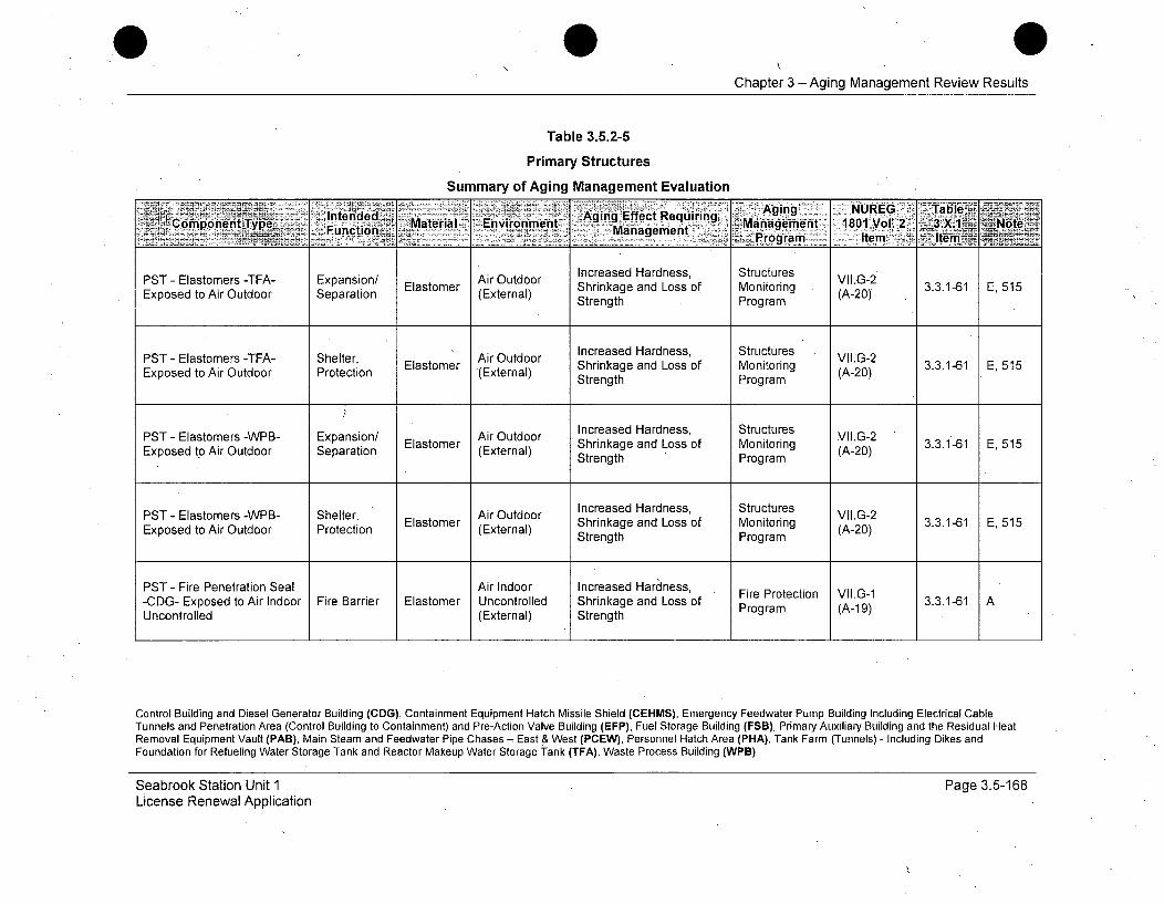
Chapter 3 -Aging Management Review Results
Table 3.5.2-5
Primary Structures
Summary of Aging Management Evaluation
pttntrded AgingcEffect Requisg, S gunge NUREG-2
PS -cP Elsomr -TF- Epni/ Elsoe hinaeadLs of Moitringr (A tem 3..-1 E1os toAentTyped S tion rial Evironment Management 1801V V.2 r X.gNote
PST-~~~~~~~ --somr -TFA Shelter, lsoetEtrnlehikg adLs f Mnioig (-0 .m.-61E 1PST - Elastomers -TEA- Expansion/ Air Outdoor Increased Hardness, Structures VII.G-2Exposed to Air Outdoor Separation Elastomer (External) Shrinkage and Loss of Monitoring (A20)3.3.1-61 E, 515
Strength Program
PST - Elastomers -TEA- Shelter, Air Outdoor Increased Hardness, Structures VIIG2Elastom (External) Shrinkage and Loss of Monitoring (A-20) 3.3.1-61 E, 515
Strength Program
PST - Elastomers -WPB- Expansion/ Air Outdoor Increased Hardness, Structures VII.G-2-EExposed to Air indoor Separrion Elastomer (Extrol) Shrinkage and Loss of Monitoring (A-) 3.3.1-61 E, 515
Expostroed t r(External) Strength Program
PST - Elastomers -WPB- Shelter, Eatmr Air Outdoor Increased Hardness, Structures VII.G-23.1-1 E55Exposed to Air Outdoor Protection Eatmr(External) Shrinkage and Loss of Monitoring (A-20)3.161 E55
Strength Program
PST - Fire Penetration Seal Air Indoor Increased Hardness, FiePoctn VI.1-CDG- Exposed to Air Indoor Fire Barrier Elastomer Uncontrolled Shrinkage and Loss of FrPotcin V.G1 3.3.1-61 AUncontrolled (External) StrengthPrga(A19
Control Building and Diesel Generator Building (CDG), Containment Equipment Hatch Missile Shield (CEHMS), Emergency Feedwater Pump Building Including Electrical CableTunnels and Penetration Area (Control Building to Containment) and Pre-Action Valve Building (EFP), Fuel Storage Building (FSB), Primary Auxiliary Building and the Residual HeatRemoval Equipment Vault (PAB), Main Steam and Feedwater Pipe Chases - East & West (PCEW), Personnel Hatch Area (PHA), Tank Farm (Tunnels) - Including Dikes andFoundation for Refueling Water Storage Tank and Reactor Makeup Water Storage Tank (TFA), Waste Process Building (WPB)
Seabrook Station Unit 1License Renewal Application
Page 3.5-168.
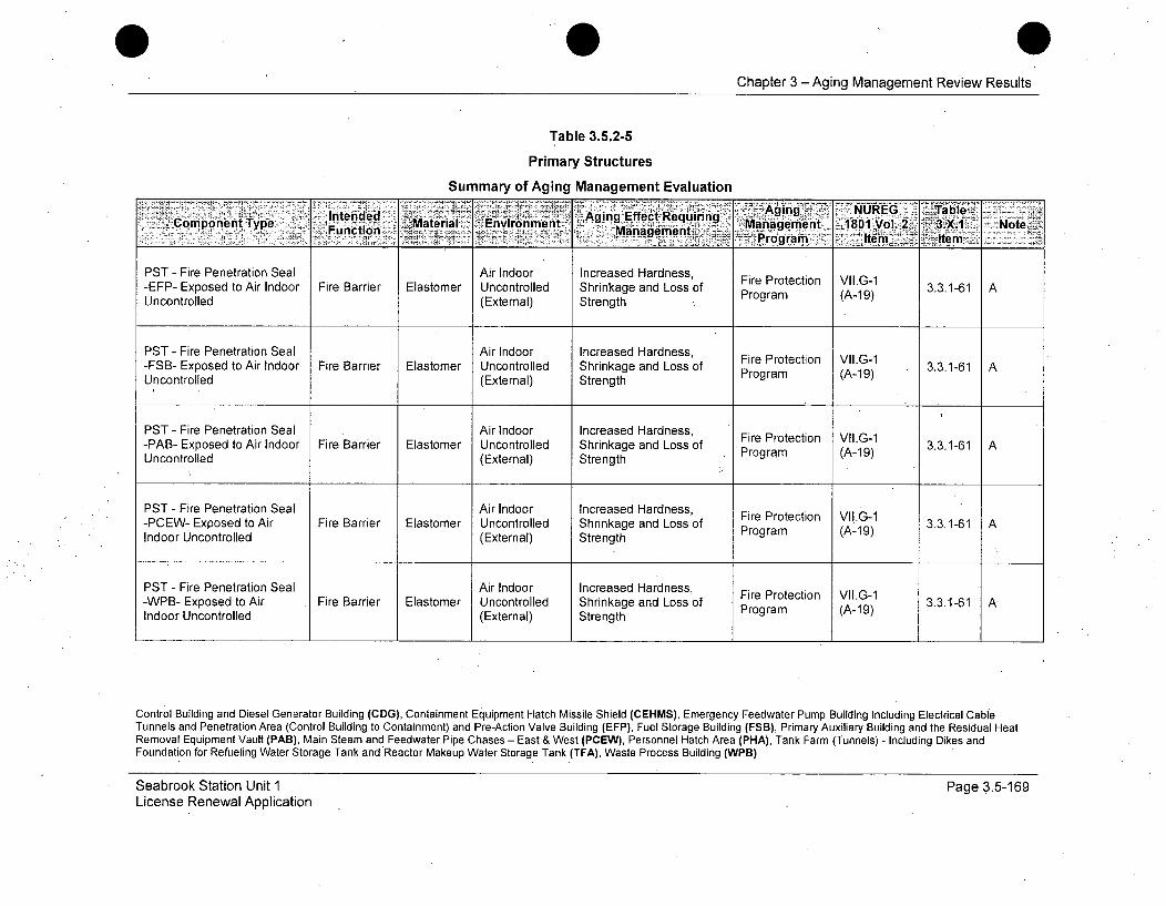
Chapter 3 - Aging Management Review Results
Table 3.5.2-5
Primary Structures
Summary of Aging Management Evaluation
K -Agig .5) NUREG TableC peTI Type unc' d iMatenrial-E..iroem-nt Aging Effect Requiring Maractmonnonp Envronen ... <::qqMnaeen!O~..ernent] -1-801 Vol. 2 3.X.1 - NoterogranimIe
PST - Fire Penetration Seal Air Indoor Increased Hardness, Fire Protection VII.G-1-EFP- Exposed to Air Indoor Fire Barrier Elastomer Uncontrolled Shrinkage and Loss of Program (A-19) 3.3.1-61 AUncontrolled (External) Strength
PST - Fire Penetration Seal Air Indoor Increased Hardness,-FSB- Exposed to Air Indoor Fire Barrier Elastomer Uncontrolled Shrinkage and Loss of Fire Protection VII.G-1 3.3.1-61 AUncontrolled (External) Strength Program (A-19)
PST - Fire Penetration Seal Air Indoor Increased Hardness, Fire Protection VII.G-1-PAB- Exposed to Air Indoor Fire Barrier Elastomer Uncontrolled Shrinkage and Loss of Program (A-19)Uncontrolled (External) Strength
PST - Fire Penetration Seal Air Indoor Increased Hardness, Fire Protection VII.G-1-PCEW- Exposed to Air Fire Barrier Elastomer Uncontrolled Shrinkage and Loss of Program (A-19) 3.3.1-61 AIndoor Uncontrolled (External) Strength
PST - Fire Penetration Seal Air Indoor Increased Hardness, Fire Protection VII.G-1-WPB- Exposed to Air Fire Barrier Elastomer Uncontrolled Shrinkage and Loss of Program (A-19) 3.3.1-61 AIndoor Uncontrolled (External) Strength
Control Building and Diesel Generator Building (CDG), Containment Equipment Hatch Missile Shield (CEHMS), Emergency Feedwater Pump Building Including Electrical CableTunnels and Penetration Area (Control Building to Containment) and Pre-Action Valve Building (EFP), Fuel Storage Building (FSB), Primary Auxiliary Building and the Residual HeatRemoval Equipment Vault (PAB), Main Steam and Feedwater Pipe Chases - East & West (PCEW), Personnel Hatch Area (PHA), Tank Farm (Tunnels) - Including Dikes andFoundation for Refueling Water Storage Tank and Reactor Makeup Water Storage Tank (TFA), Waste Process Building (WPB)
Seabrook Station Unit 1License Renewal Application
Page 3.5-169
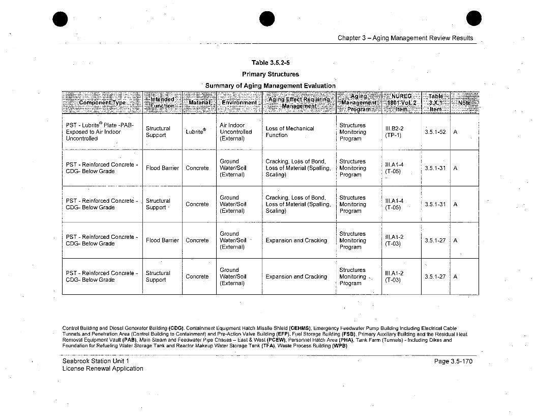
Chapter 3 -Aging Management Review Results
Table 3.5.2-5
Primary Structures
Summary of Aging Management Evaluation
In~tdEvrnentded Aging NURkEG TableComponent Type Material Envionmn ng Effeemnt 18iuVoli2ng1"'~Function m-Manage11ijient Maaemn 180 -ol. 3X11 Note:
S *.. _____Programi r-L Itemi-T - temn
PST - Lubrite® Plate -PAB- Air Indoor StructuresExposed to Air Indoor Support Lubrite Uncontrolled Function Monitoring (TP-1) 3.5.1-52 AUncontrolled (External) Program
PST - Reinforced Concrete - Ground Cracking, Loss of Bond, Structures III.A1-4CDG- Below Grade Flood Barrier Concrete Water/Soil Loss of Material (Spalling, Monitoring (T-05) 3.5.1-31 A
(External) Scaling) Program
PST - Reinforced Concrete - Structural Ground Cracking, Loss of Bond, Structures III.A1-4
CIDG- Below Grade Support Concrete Water/Soil Loss of Material (Spalling, Monitoring (T-05) 3.5.1-31 A(External) Scaling) Program
PST - Reinforced Concrete - Ground Structures III.A1-2PST - Reiorcd e Flood Barrier Concrete Water/Soil Expansion and Cracking Monitoring (T-03) 3.5.1-27 ACOG- Below Grade (External) Program
Ground StructuresPST - Reinforced Concrete - Struc tural GonStuurs III.A1-2CDG- BelowrGrade Support Concrete Water/Soil Expansion and Cracking Monitoring .. (T-03) 3.5.1-27 A
(External) Program
Control Building and Diesel Generator Building (CDG), Containment Equipment Hatch Missile Shield (CEHMS), Emergency Feedwater Pump Building Including Electrical CableTunnels and Penetration Area (Control Building to Containment) and Pre-Action Valve Building (EFP), Fuel Storage Building (FSB), Primary Auxiliary Building and the Residual HeatRemoval Equipment Vault (PAB), Main Steam and Feedwater Pipe Chases - East & West (PCEW), Personnel Hatch Area (PHA), Tank Farm (Tunnels) - Including Dikes andFoundation for Refueling Water Storage Tank and Reactor Makeup Water Storage Tank (TFA), Waste Process Building (WPB)
Seabrook Station Unit 1License Renewal Application
Page 3.5-170

Chapter 3 -Aging Management Review Results
Table 3.5.2-5
Primary Structures
Summary of Aging Management Evaluation
Groundgin Increas inb' Pooiy2nd SrcueIntended WAging Effect Requiring, I.U1TbComponent Type Material Environentn Management 1801 Vol. 2 3.X.11 Note
C -eoGdExrl SlgPr6gram item Itemam
Ground Increase in Porosity and StructuresPST - Reinforced Concrete - F dr ier Permeability, Cracking, III.A1-5CDG- Below Grade Floort Concrete Water/Soil Loss of Material (Spalling, Monitoring (T-07) 3.5.1-31 A
(External) Ssa tinang ProgramScaling)
PST - Reinforced Concrete - StructGround Increase in Porosity and StructuresPST -arrier Concrete Water/Soil Permeability, Cracking Monitoring (.A1-5 3.5.1-31 ACD-BlwGaeSpotLoss of Material (Spalling, Prgrm-07)COG- Below Grade (External) Scaling) Program
PST - Reinforced Concrete - Ground Increase in Porosity and Structures III.A1-7COG- Below Grade Flood Barrier Concrete Water/Soil Permeability, Loss of Monitoring (T-02) 3.5.1-32 A, 509
(External) Strength Program
PST- Rinorcd oncet - trctualGround Increase in Porosity and Structures I.l7COG- Below Grade Support Concrete Water/Soil Permeability, Loss of Monitoring (T-02) 3.5.1-32 A, 509
PST- Reinforced Concrete - Ground Structures II1.A3-6CDG- BelowrGrade Flood Barrier Concrete Water/Soil Loss of Material, Cracking Monitoring (T-01) 3.5.1-26 A
(External) Program
Control Building and Diesel Generator Building (CDG), Containment Equipment Hatch Missile Shield (CEHMS), Emergency Feedwater Pump Building Including Electrical CableTunnels and Penetration Area (Control Building to Containment) and Pre-Action Valve Building (EFP), Fuel Storage Building (FSB), Primary Auxiliary Building and the Residual HeatRemoval Equipment Vault (PAB), Main Steam and Feedwater Pipe Chases - East & West (PCEW), Personnel Hatch Area (PHA), Tank Farm (Tunnels) - Including Dikes andFoundation for Refueling Water Storage Tank and Reactor Makeup Water Storage Tank (TFA), Waste Process Building (WPB)
Seabrook Station Unit 1License Renewal Application
Page 3.5-171
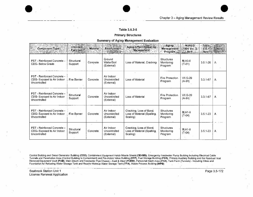
0 0Chapter 3-Aging Management Review Results
Table 3.5.2-5
Primary Structures
Summary of Aging Management Evaluation
IntenidedJ- - Aging Effect R '.Agin UE alComponent Type Material __ Mniumn gequrng....Manaigemnent 1801 Vol.ý2 &X XI Note
- ___ Program . I~tem Item .
PST- Reinforced Concrete - Structural Ground Structures II1.A3-6PST- Reiorcd e Strt Concrete Water/Soil Loss of Material, Cracking Monitorinrg -(T-01) 3.5.1-26 ACDG- Below Grade Support (External) Program
PST- Reinforced Concrete - Air Indoor Fire Protection VII.G-29CDG- Exposed to Air Indoor Fire Barrier Concrete Uncontrolled Loss of Material Program (A-91)3.3.1-67Uncontrolled (External)
PST- Reinforced Concrete - Structural Air Indoor Fire Protection VII.G-29CDG- Exposed to Air Indoor Support Concrete Uncontrolled Loss of Material Program (A-91)3.3.1-67Uncontrolled (External)
PST - Reinforced Concrete - Air Indoor Cracking, Loss of Bond, StructuresCDG- Exposed to Air Indoor Fire Barrier Concrete Uncontrolled Loss of Material (Spalling, Monitoring (T-0) 3.5.1-23AUncontrolled (External) Scaling) Program (T04)
PST - Reinforced Concrete - Structural Air Indoor Cracking, Loss of Bond, Structures II1.A1-9CDG- Exposed to Air Indoor Support Concrete Uncontrolled Loss of Material (Spalling, Monitoring (T-04) 3.5.1-23 AUncontrolled (External) Scaling) Program
Control Building and Diesel Generator Building (CDG), Containment Equipment Hatch Missile Shield (CEHMS), Emergency Feedwater Pump Building Including Electrical CableTunnels and Penetration Area (Control Building to Containment) and Pre-Action Valve Building (EFP), Fuel Storage Building (FSB), Primary Auxiliary Building and the Residual HeatRemoval Equipment Vault (PAB), Main Steam and Feedwater Pipe Chases - East & West (PCEW), Personnel Hatch Area (PHA), Tank Farm (Tunnels) - Including Dikes andFoundation for Refueling Water Storage Tank and Reactor Makeup Water Storage Tank (TFA), Waste Process Building (WPB)
Seabrook Station Unit 1License Renewal Application
Page 3.5-172
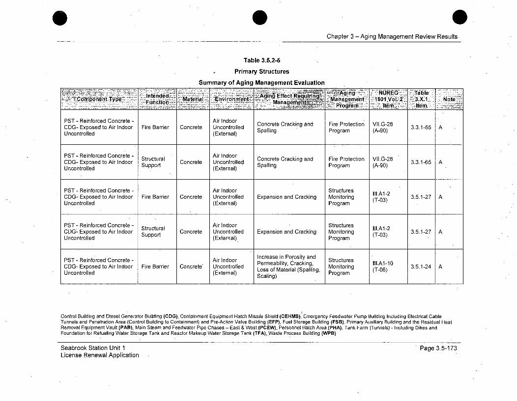
Chapter 3 -Aging Management Review Results
Table 3.5.2-5
Primary Structures
Summary of Aging Management Evaluation
Inteide'd AgingI nvrnmn Effect RequirinAgn NRE TalCoGomponent-Type FunctioEnvir t Manaent 1801MVol.r 2 3.X. Note-. - gra Item'. Itm
PST - Reinforced Concrete - Air Indoor Concrete Cracking and Fire Protection VII.G-28CDG- Exposed to Air Indoor Fire Barrier Concrete Uncontrolled Spalling Program (A-90)AUncontrolled (External)
PST - Reinforced Concrete - Structural Air Indoor Concrete Cracking and Fire Protection VII.G-28CDG- Exposed to Air Indoor Strt Concrete Uncontrolled Spalling Program (A-0G) 3.3.1-65 AUncontrolled Support (External)
PST - Reinforced Concrete - Air Indoor StructuresCDG- Exposed to Air Indoor Fire Barrier Concrete Uncontrolled Expansion and Cracking Monitoring (T-0 3.5.1-27 AUncontrolled (External) Program (T03)
PST - Reinforced Concrete - Structural Air Indoor Structures III.A1-2CDG- Exposed to Air Indoor Strt Concrete Uncontrolled Expansion and Cracking Monitoring (T-03) 3.5.1-27 AUncontrolled Support (External) Program
PST - Reinforced Concrete - Air Indoor Increase in Porosity and StructuresCDG- Exposed to Air Indoor Fire Barrier Concrete' Uncontrolled Permeability, Cracking, Monitoring II.A1-10 3.5.1-24 AUncontrolled (External) Loss of Material (Spalling, Mogram (T-06)Scaling)(Program
Control Building and Diesel Generator Building (CDG), Containment Equipment Hatch Missile Shield (CEHMS), Emergency Feedwater Pump Building Including Electrical CableTunnels and Penetration Area (Control Building to Containment) and Pre-Action Valve Building (EFP), Fuel Storage Building (FSB), Primary Auxiliary Building and the Residual HeatRemoval Equipment Vault (PAB), Main Steam and Feedwater Pipe Chases - East & West (PCEW), Personnel Hatch Area (PHA), Tank Farm (Tunnels) - Including Dikes andFoundation for Refueling Water Storage Tank and Reactor Makeup Water Storage Tank (TFA), Waste Process Building (WPB)
Seabrook Station Unit 1License Renewal Application
' Page 3.5-173
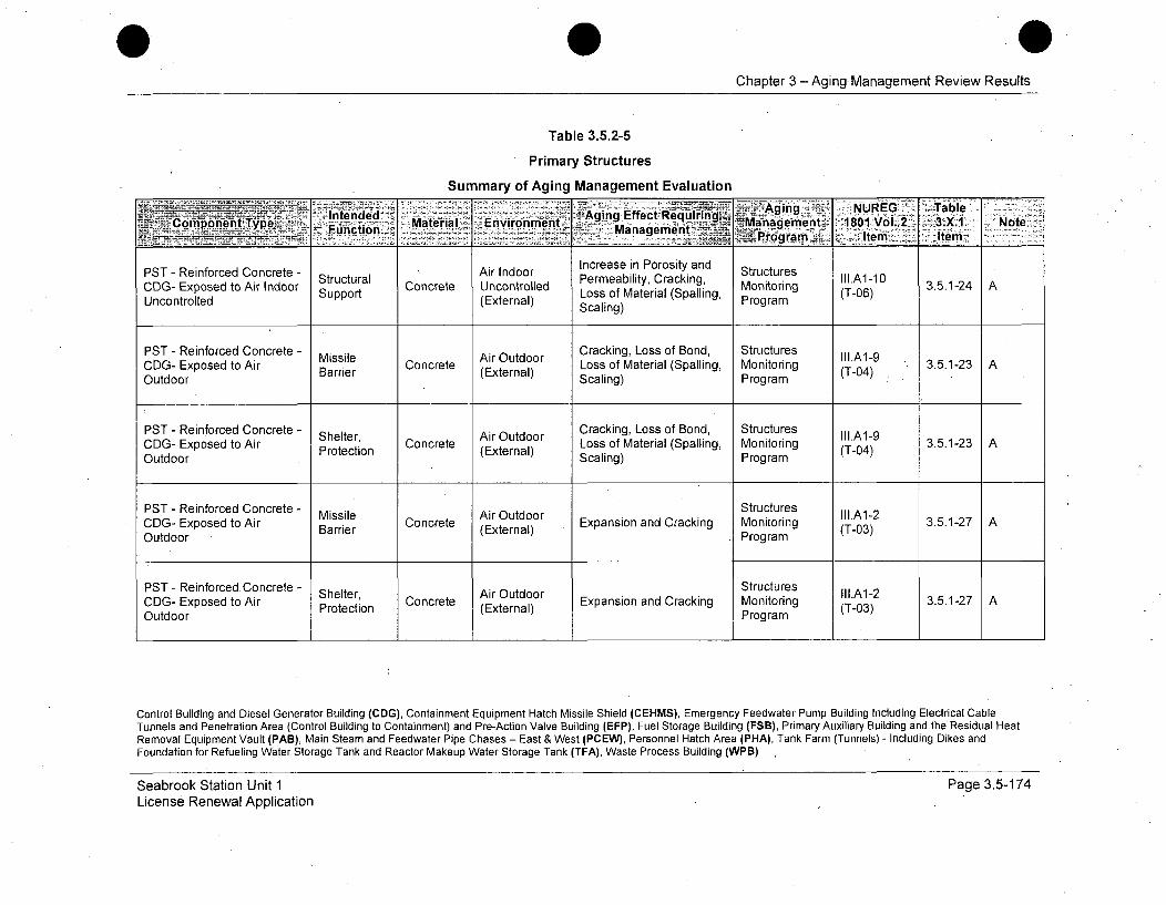
Chapter 3 -Aging Management Review Results
Table 3.5.2-5
Primary Structures
Summary of Aging Management Evaluation
__ - ~gig eql!Adfgý=ng.,-: ýNUREG. i ,Table,
PST - Reinforced Concrete - StucurlAir Indoor Increase in Porosity and StructuresC mponentSupport Loss of Material (Spalling, ri (T-06)
Uncontrolled (External) Scaling) Program
PST - Reinforced Concrete - Missile Air Outdoor Cracking, Loss of Bond, Structures III.A1-9CDG- Exposed to Air Barrier Concrete (Extroll) Loss of Material (Spalling, Monitoring (T-04) 3.5.1-23 AOutdoor (External) Scaling) Program
PST - Reinforced Concrete - Cracking, Loss of Bond, Structures
COG- Exposed to Air Shelter, Concrete ArOtdr Loss of Material (Spalling, Monitoring (T-0 3.5.1-23 AOutdoor Poeto(Etra) Scaling) Program (-4PST - Reinforced Concrete - Ssle Air Outdoor I,1Structures .A1-9CDG- Exposed to Air Protection Concret (External) E sion a racing Monitoring (T-0)3.5.1-2 AOutdoor Scaling) Program
PST - Reinforced Concrete - StructuresCDG- Exposed to Air Barrier Concrete (External) Expansion and Cracking Monitoring (T-03) 3.5.1-27 AOutdoor Program
PST- Reinforced. Concrete- Shelter, Air Outdoor rrI.A1-2CDG- Exposed to Air Protection Concrete (External) Expansion and Cracking Monitoring (T-03) 3.5.1-27 AOutdoor Program
Control Building and Diesel Generator Building (CDG), Containment Equipment Hatch Missile Shield (CEHMS), Emergency Feedwater Pump Building Including Electrical CableTunnels and Penetration Area (Control Building to Containment) and Pre-Action Valve Building (EFP), Fuel Storage Building (FSB), Primary Auxiliary Building and the Residual HeatRemoval Equipment Vault (PAB), Main Steam and Feedwater Pipe Chases - East & West (PCEW), Personnel Hatch Area (PHA), Tank Farm (Tunnels) - Including Dikes andFoundation for Refueling Water Storage Tank and Reactor Makeup Water Storage Tank (TFA), Waste Process Building (WPB)
Seabrook Station Unit 1License Renewal Application
Page 3.5-174
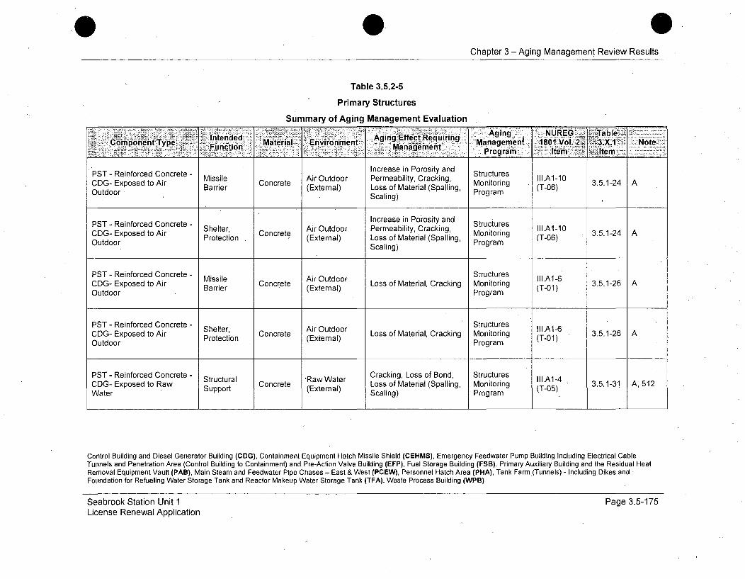
0Chapter 3 - Aging Management Review Results
Table 3.5.2-5
Primary Structures
Summary of Aging Management Evaluation
Intended Aging NUfect Requirin- C"omponentType F Material: Environment gq Managerien 1801 Vol.2 . Note'
PST - Reinforced Concrete - Increase in Porosity and StructuresMissile Air Outdoor Permeability, Cracking, III.A1-10
CDG- Exposed to Air Barrier Concrete (External) Loss of Material (Spalling, Monitoring (T-06) 3.5.1-24 AOu tdoor Scaling) Program
PST - Reinforced Concrete - Increase in Porosity and StructuresCDG- Exposed to Air Shelter, Concret Air Outdoor Permeability, Cracking, Monito Ill.A1-10
Outdoor Protection (External) Loss of Material (Spalling, Mogram (T-06)Scaling) Program
PST - Reinforced Concrete - Mssi A Otd StructuresCDG- Exposed to Air Bie Concrete irnuoor Loss of Material, Cracking Monitoring (T-01) 3.5.1-26 AOutdoor Barrier (External) Program
PST - Reinforced Concrete - Shelter, Air Outdoor c Structures II.A1-6CDG- Exposed to Air Protection Concrete Loss of Material, Cracking Monitoring (T-01) 3.5.1-26 AOutdoor Program
PST - Reinforced Concrete - Structural -Raw Water Cracking, Loss of Bond, Structures III.A1-4CDG- Exposed to Raw Concrete Loss of Material (Spalling, Monitoring (T-5 3.5.1-31 A, 512Water Support (External) Scaling) Program (T-05)
Control Building and Diesel Generator Building (CDG), Containment Equipment Hatch Missile Shield (CEHMS), Emergency Feedwater Pump Building Including Electrical CableTunnels and Penetration Area (Control Building to Containment) and Pre-Action Valve Building (EFP), Fuel Storage Building (FSB), Primary Auxiliary Building and the Residual HeatRemoval Equipment Vault (PAB), Main Steam and Feedwater Pipe Chases - East & West (PCEW), Personnel Hatch Area (PHA), Tank Farm (Tunnels) - Including Dikes andFoundation for Refueling Water Storage Tank and Reactor Makeup Water Storage Tank (TFA), Waste Process Building (WPB)
Seabrook Station Unit 1License Renewal Application
Page 3.5-175

Chapter 3 -Aging Management Review Results
Table 3.5.2-5
Primary Structures
Summary of Aging Management Evaluation
gnteg ed Aginigi ~NUREG' TableComponent~ye Intended Material Environment 'Agn Effect Requidring M iiV'2 3X1 Nt
7,_______ ___ grdm _____fi
PST - Reinforced Concrete - Sttu R Water StructuresSructural Conaw Wa3.5.1-27IA, 512CDG- Exposed to Raw Support Concrete (External) Expansion and Cracking Monitoring (T-03) 3.5.1a27 A,512Water Program
PST - Reinforced Concrete - Structural Ground Cracking, Loss of Bond, Structures II.A3-4Concrete Water/Soil Loss of Material (Spalling, Monitoring (T-05) 3.5.1-31 ACEHMS- Below Grade Support (External) Scaling) Program
Ground Structures III.A3-2PST - Reinforced Concrete - Structural Concrete Water/Soil Expansion and Cracking Monitoring (T-03) 3.5.1-27 ACEHMS- Below Grade Support (External) Program
Ground Increase in Porosity and StructuresPST- Reinforced Concrete - Structural Concrete Water/Soil Permeability, Cracking, Monitoring II1.A3-5 3.5.1-31 ALoss of Material (Spalling, Program (T-07)CEHMS- Below Grade Support (External) Scaling)
PST - Reinforced Concrete - Structural Ground Increase in Porosity and Structures Ill.A3-7PEMST- BefowredCne Strutu Concrete Water/Soil Permeability, Loss of Monitoring (T-02) 3.5.1-32 A, 509CEHMS- Below Grade Support (External) Strength, Program
Control Building and Diesel Generator Building (CDG), Containment Equipment Hatch Missile Shield (CEHMS), Emergency Feedwater Pump Building Including Electrical CableTunnels and Penetration Area (Control Building to Containment) and Pre-Action Valve Building (EFP), Fuel Storage Building (FSB), Primary Auxiliary Building and the Residual HeatRemoval Equipment Vault (PAB), Main Steam and Feedwater Pipe Chases - East & West (PCEW), Personnel Hatch Area (PHA), Tank Farm (Tunnels) - Including Dikes andFoundation for Refueling Water Storage Tank and Reactor Makeup Water Storage Tank (TFA), Waste Process Building (WPB)
Seabrook Station Unit 1License Renewal Application
Page 3.5-176
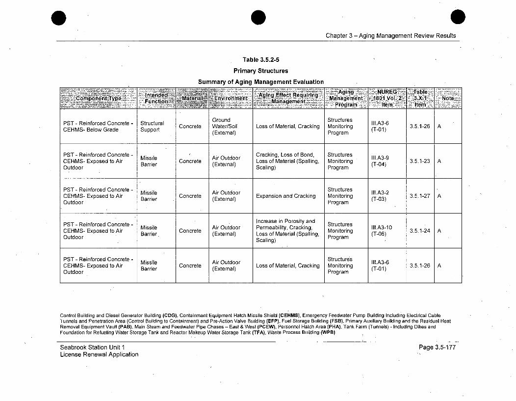
Chapter 3 -Aging Management Review Results
Table 3.5.2-5
Primary Structures
Summary of Aging Management EvaluationAgngýglp :jr"'n'j~i Agir; .n U EG ITable-
CEHS Bntended t ntaamnC oHMS ponento Type Concren _Mtera Ls oEvironment AiEftReri i Mngement 2- .3.X.1-2 A*Fmictio nMf~l an '... ...-- - -~ - - , ,-.'.~ rogrami -- tm It'em
uGround Structures
CEHS-Belw rae Spprt(External) Program (-1
PST - Reinforced Concrete - Missile Air Outdoor Cracking, Loss of Bond, Structures III.A3-9CEHMS- Exposed to Air Barrier Concrete pra Loss of Material (Spalling, Monitoring (T04) 3.5.1-23 AOutdoor BarrierScaling) Program
PST - Reinforced Concrete - Missile Air Outdoor Structures II3.A3-2CEHMS- Exposed to Air Barrier Concret (External) Expansion and Cracking Mnitoring (T-03) 3.5.1-27 AOutdoor ' (Extenal)Program
PST - Reinforced Concrete - Increase in Porosity and StructuresCEHMS- Exposed to Air Missile Concrete Air Outdoor Permeability, Cracking, Monitoring lI.IA3-1O 3.5.1-24 A
OtorBarrier (External) Loss of Material (Spalling, Porm(T-06)Outdoor ~Scaling)Prga
PST - Reinforced Concrete - Missile Air Outdoor Structures III.A3-6CEHMS- Exposed to Air Barrier Concrete (External) Loss of Material, Cracking Monitoring (T-01) 3.5.1-26 AOutdoor Program
Control Building and Diesel Generator Building (CDG), Containment Equipment Hatch Missile Shield (CEHMS), Emergency Feedwater Pump Building Including Electrical CableTunnels and Penetration Area (Control Building to Containment) and Pre-Action Valve Building (EFP), Fuel Storage Building (FSB), Primary Auxiliary Building and the Residual HeatRemoval Equipment Vault (PAB), Main Steam and Feedwater Pipe Chases - East & West (PCEW), Personnel Hatch Area (PHA), Tank Farm (Tunnels) - Including Dikes andFoundation for Refueling Water Storage Tank and Reactor Makeup Water Storage Tank (TFA), Waste Process Building (WPB)
Seabrook Station Unit 1License Renewal Application
Page 3.5-177

0Chapter 3 -Aging Management Review Results
Table 3.5.2-5
Primary Structures
Summary of Aging Management Evaluation
Intended -- inii 7 . ...... .. otAgingComponent Type Fucin -Material- Environment AigEfJjujn Managemrent ~18Oi Vol. 2' 3.X.1- Not_MihgmitPraga" I tem- 'Item
PST - Reinforced Concrete - Ground Cracking, Loss of Bond, Structures II1.A34Flood Barrier Concrete Water/Soil Loss of Material (Spalling, Monitoring (T-05) 3.5.1-31 AEFP- Below Grade (External) Scaling) Program
PST - Reinforced Concrete - Structural Ground Cracking, Loss of Bond, Structures II1.A3-4Concrete Water/Soil Loss of Material (Spalling, Monitoring (T-05) 3.5.1-31 AEFP- Below Grade Support (External) Scaling) Program
PST - Reinforced Concrete - Ground Structures III.A3-2P- Reiorcd e Flood Barrier Concrete Water/Soil Expansion and Cracking Monitoring (T-03) 3.5.1-27 AEFP- Below Grade (External) Program
PST - Reinforced Concrete - Structural Ground Structures II1.A3-2Belorade Sura Concrete Water/Soil Expansion and Cracking Monitoring (T-03) 3.5.1-27 AEFP-,BelowGrade Support (External) Program
Ground Increase in Porosity and StructuresPST - Reinforced Concrete - Flood Barrier Concrete Water/Soil Permeability, Cracking, Monitoring I11.A3-5 3.5.1-31 AEFP- Below Grade (External) Loss of Material (Spalling, ring (T-07)Scaling) Program
Control Building and Diesel Generator Building (CDG), Containment Equipment Hatch Missile Shield (CEHMS), Emergency Feedwater Pump Building Including Electrical CableTunnels and Penetration Area (Control Building to Containment) and Pre-Action Valve Building (EFP), Fuel Storage Building (FSB), Primary Auxiliary Building and the Residual HeatRemoval Equipment Vault (PAB), Main Steam and Feedwater Pipe Chases - East & West (PCEW), Personnel Hatch Area (PHA), Tank Farm (Tunnels) - Including Dikes andFoundation for Refueling Water Storage Tank and Reactor Makeup Water Storage Tank (TFA), Waste Process Building (WPB)
Seabrook Station Unit 1License Renewal Application
Page 3.5-178
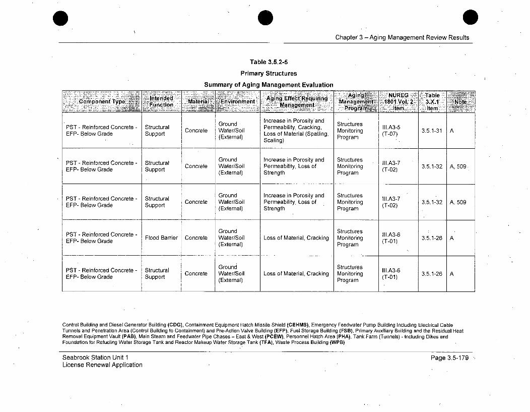
Chapter 3 - Aging Management Review Results
Table 3.5.2-5
Primary Structures
Summary of Aging Management Evaluation
intended Aging Effect Aginq NREG ablComponent Type Material ,Environment Reu7 n Management ~1601 Vol. 2. 3.X1 ~Note- _
Funiction Ma ~...nagement ~ie, .Ie
Ground Increase in Porosity'and StructuresPST- Reinforced Concrete - Structural Concrete Water/Soil Permeability, Cracking, Monitoring III.A3-5 3.5.1-31 ALoss of Material (Spalling, Program (T-07)EFP- Below Grade Support (External) Scaling)
PST - Reinforced Concrete - Structural Ground Increase in Porosity and Structures II1.A3-7EFP- Below Grade Support Concrete Water/Soil Permeability, Loss of Monitoring (T-02) 3.5.1-32 A, 509.
(External) Strength Program
PST - Reinforced Concrete - Structural Ground Increase in Porosity and Structures III.A3-7Concrete Water/Soil Permeability, Loss of Monitoring 3.5.1-32 A, 509EFP- Below Grade Support (External) Strength Program
PST- Reinforced Concrete - Ground Structures III.A3-6P- Reiorcd e Flood Barrier Concrete Water/Soil Loss of Material, Cracking Monitoring (T-01) 3.5.1-26 AEFP- Below Grade (External) Program
Ground StructuresPST- Reinforced Concrete - Structural Concrete Water/Soil Loss of Material, Cracking Monitoring (T-01) 3.5.1-26 AEFP- Below Grade Support (External) Program
Control Building and Diesel Generator Building (CDG), Containment Equipment Hatch Missile Shield (CEHMS), Emergency Feedwater Pump Building Including Electrical CabJeTunnels and Penetration Area (Control Building to Containment) and Pre-Action Valve Building (EFP), Fuel Storage Building (FSB), Primary Auxiliary Building and the Residual HeatRemoval Equipment Vault (PAB), Main Steam and Feedwater Pipe Chases - East & West (PCEW), Personnel Hatch Area (PHA), Tank Farm (Tunnels) - Including Dikes andFoundation for Refueling Water Storage Tank and Reactor Makeup Water Storage Tank (TFA), Waste Process Building (WPB)
Seabrook Station Unit 1License Renewal Application
Page 3.5-179 :
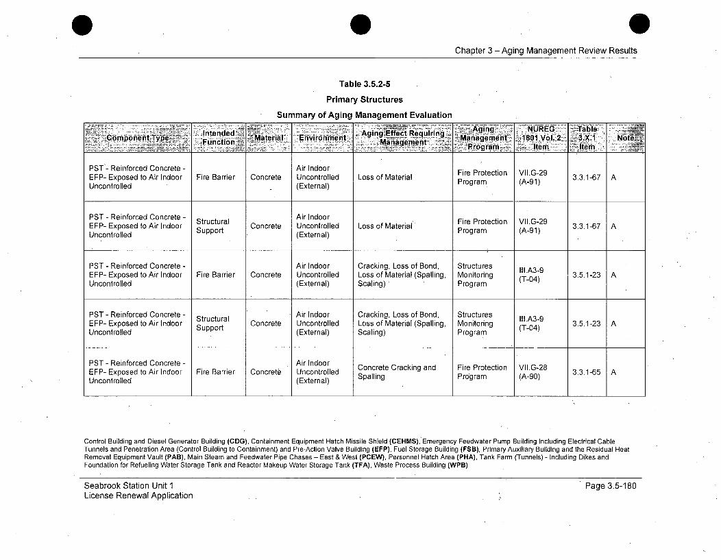
Chapter 3 - Aging Management Review Results
Table 3.5.2-5
Primary Structures
Summary of Aging Management Evaluation
Ai N T-ntended . - Requiring ........ ... U - ale-Mtril Environment Agny Effect Reurig Mnagement 181Vo.23_.1Co.mpo'entType Function Management ,. Ma8a-_Vol.2 3... Not•=•
_________ ro'gram. Item Item -
PST- Reinforced Concrete - Air Indoor Fire Protection VII.G-29EFP- Exposed to Air Indoor Fire Barrier Concrete Uncontrolled Loss of Material Program (A-91)3.3.1-67Uncontrolled (External)
PST - Reinforced Concrete - Air IndoorEFP- Exposed to Air Indoor Structural Concrete Uncontrolled Loss of Material Fire Protection VII.G-29 3.3.1-67 AUncontrolled Support (External) Program (A-91)
PST - Reinforced Concrete - Air Indoor Cracking, Loss of Bond, Structures Il.A39EFP- Exposed to Air Indoor Fire Barrier Concrete Uncontrolled Loss of Material (Spalling, Monitoring (T-04) 3.5.1-23 AUncontrolled (External) Scaling) Program
PST - Reinforced Concrete - Structural Air Indoor Cracking, Loss of Bond, Structures III.A3-9EFP- Exposed to Air Indoor Support Concrete Uncontrolled Loss of Material (Spalling, Monitoring (T-04) 3.5.1-23 AUncontrolled (External) Scaling) Program
PST - Reinforced Concrete - Air Indoor Concrete Cracking and Fire Protection VII.G-28EFP- Exposed to Air Indoor Fire Barrier Concrete Uncontrolled Spalling Program (A-90) 3.3.1-65 AUncontrolled (External)
Control Building and Diesel Generator Building (CDG), Containment Equipment Hatch Missile Shield (CEHMS), Emergency Feedwater Pump Building Including Electrical CableTunnels and Penetration Area (Control Building to Containment) and Pre-Action Valve Building (EFP), Fuel Storage Building (FSB), Primary Auxiliary Building and the Residual HeatRemoval Equipment Vault (PAB), Main Steam and Feedwater Pipe Chases - East & West (PCEW), Personnel Hatch Area (PHA), Tank Farm (Tunnels) - Including Dikes andFoundation for Refueling Water Storage Tank and Reactor Makeup Water Storage Tank (TFA), Waste Process Building (WPB)
Seabrook Station Unit 1License Renewal Application
Page 3.5-1 80
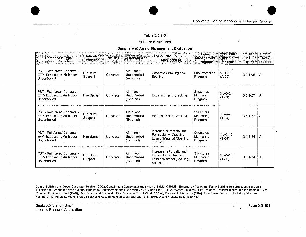
Chapter 3-Aging Management Review Results
Table 3.5.2-5
Primary Structures
Summary of Aging Management Evaluation
Intended - Aging Effect Reqirn , Agig -A NUREG Table...... ni MMaterial, Environment ....... nt. 3 .Managemen, -IIOI 2 3."1 -. Note~Compoent~yp - -MnPogram IJtem -Item>
PST - Reinforced Concrete - Structural Air IndoorEFP- Exposed to Air Indoor Strt Concrete Uncontrolled Concrete Cracking and Fire Protection VII.G-28 3.3.1-65 AUncontrolled Support (External) Spalling Program (A-90)
PST - Reinforced Concrete - Air Indoor StructuresEFP- Exposed to Air Indoor Fire Barrier Concrete Uncontrolled Expansion and Cracking Monitoring (T-03) 3.5.1-27 AUncontrolled (External) Program
PST - Reinforced Concrete - Structural Air Indoor Structures Ill.A3-2EFP- Exposed to Air Indoor Support Concrete Uncontrolled Expansion and Cracking Monitoring (T-03) 3.5.1-27 AUncontrolled (External) Program
PST - Reinforced Concrete - Air Indoor Increase in Porosity and StructuresEFP- Exposed to Air Indoor Fire Barrier Concrete Uncontrolled Loss of Material (Spalling, Monitoring (T-06) 3.5.1-24 AUncontrolled (External) Scaling) Program
PST - Reinforced Concrete - Air Indoor Increase in Porosity and StructuresEFP- Exposed to Air Indoor Structural Concrete Uncontrolled Permeability, Cracking, Monitoring III.A3-10 3.5.1-24 ASupport(External) Loss of Material (Spalling, Mogram (T-06)Scaling) Program
Control Building and Diesel Generator Building (CDG), Containment Equipment Hatch Missile Shield (CEHMS), Emergency Feedwater Pump Building Including Electrical CableTunnels and Penetration Area (Control Building to Containment) and Pre-Action Valve Building (EFP), Fuel Storage Building (FSB), Primary Auxiliary Building and the Residual HeatRemoval Equipment Vault (PAB), Main Steam and Feedwater Pipe Chases - East & West (PCEW), Personnel Hatch Area (PHA), Tank Farm (Tunnels) - Including Dikes andFoundation for Refueling Water Storage Tank and Reactor Makeup Water Storage Tank (TFA), Waste Process Building (WPB)
Seabrook Station Unit 1License Renewal Application
Page 3.5-181

Chapter 3 - Aging Management Review Results
Table 3.5.2-5
Primary Structures
Summary of Aging Management Evaluation
Intended MaterialMse AirOuteoo Aging Effect BRquirind, Aging NURGATblComponent Type: Funcion C Material Eng, Mantag ent 1801 Vol. 2 3.X.1 NoteOtoSlgProgram Item Item
PST - Reinforced Concrete - ssle Air Outdoor Cracking, Loss of Bond, Structures II1.A3-9EFP- Exposed to Air Mirsier Concrete (External) Loss of Material (Spalling, Monitoring (T-04) 3.5.1-23 AOutdoor Scaling) Program
PST - Reinforced Concrete - Air Outdoor Cracking, Loss of Bond, StructuresEFP- Exposed to Air Shelter Concrete Loss of Material (Spalling Monitoring (T-0 3.5.1-23 AOutdoor Protection (External) Scaling) Program (T-04)
PST - Reinforced Concrete - Missile Air Outdoor Structures lll.A3-2EFP- Exposed to Air Concrete Expansion and Cracking Monitoring 3.5.1-27 AOutdoor Barrier (External) Program (T-03)
PST - Reinforced Concrete - Shelter, Concrete Expansion and Cracking Structures II1.A3-2EFP- Exposed to Air Protectio (External) racin Monitoring 3.5.-27)Outdoor Program
PST - Reinforced Concrete - Increase in Porosity and StructuresMissieAir Outdoor Permeability, Cracking, III.A3-10EFP- Exposed to Air Barrier Concret (External) Loss of Material (Spalling, ring (T-06) 3.5.1-24 A
Outdoor Scaling) Program
Control Building and Diesel Generator Building (CDG), Containment Equipment Hatch Missile Shield (CEHMS), Emergency Feedwater Pump Building Including Electrical CableTunnels and Penetration Area (Control Building to Containment) and Pre-Action Valve Building (EFP), Fuel Storage Building (FSB), Primary Auxiliary Building and the Residual HeatRemoval Equipment Vault (PAB), Main Steam and Feedwater Pipe Chases - East & West (PCEW), Personnel Hatch Area (PHA), Tank Farm (Tunnels) - Including Dikes andFoundation for Refueling Water Storage Tank and Reactor Makeup Water Storage Tank (TFA), Waste Process Building (WPB)
Seabrook Station Unit 1License Renewal Application
Page 3.5-182
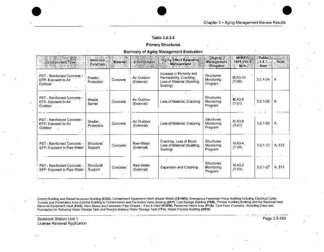
Chapter 3 -Aging Management Review Results
Table 3.5.2-5
Primary Structures
Summary of Aging Management Evaluation
Intededl Mtr Aging NREG < TablelCopnnIp~ Fnctioe.Evromn Aging Effect Requiring Management 1801""ý Vo1.,2k 3.X.1 NoteManage..ent 6Prganme Item n.Item
PST - Reinforced Concrete - Increase in Porosity and StructuresEFP- Exposed to Air Concrete Air Outdoor Permeability, Cracking, Monitoring III.A3-10 3.5.1-24 APTRenocdCnrt-Shelter, Scaling)eProgitram.35.-2
Outdoor Protection (External) Loss of Material (Spalling, (T-06)OutdoorScaling)
PST - Reinforced Concrete - Missile CoAir Outdoor Structures I.A3-6EFP- Exposed to Air Barrier Concret (External) Loss of Material, Cracking Monitoring (T-01) 3.5.1-26 AOutdoor Program
PST - Reinforced Concrete - Shelter: Air Outdoor . StructuresEFP- Exposed to Air Protection Concrete Loss of Material, Cracking Monitoring 3.5.1-26 AOutdoor (External) Program (T-01)
PST - Reinforced Concrete - Structural Raw Water Cracking, Loss of Bond, Structures III.A3-4EFP- Exposed to Raw Water Support Concrete (External) Loss of Material (Spalling, Monitoring (T-0) 3.5.1-31 A, 512
Scaling) Program
PST - Reinforced Concrete - Structural Raw Water Structures II1.A3-2EFP- Exposed to Raw Water Support Concrete (External) Expansion and Cracking Monitoring (T-03) 3.5.1-27 A, 512
Program
Control Building and Diesel Generator Building (CDG), Containment Equipment Hatch Missile Shield (CEHMS), Emergency Feedwater Pump Building Including Electrical CableTunnels and Penetration Area (Control Building to Containment) and Pre-Action Valve Building (EFP), Fuel Storage Building (FSB), Primary Auxiliary Building and the Residual HeatRemoval Equipment Vault (PAB), Main Steam and Feedwater Pipe Chases - East & West (PCEW), Personnel Hatch Area (PHA), Tank Farm (Tunnels) - Including Dikes andFoundation for Refueling Water Storage Tank and Reactor Makeup Water Storage Tank (TFA), Waste Process Building (WPB)
Seabrook Station Unit 1License Renewal Application
Page 3.5-183
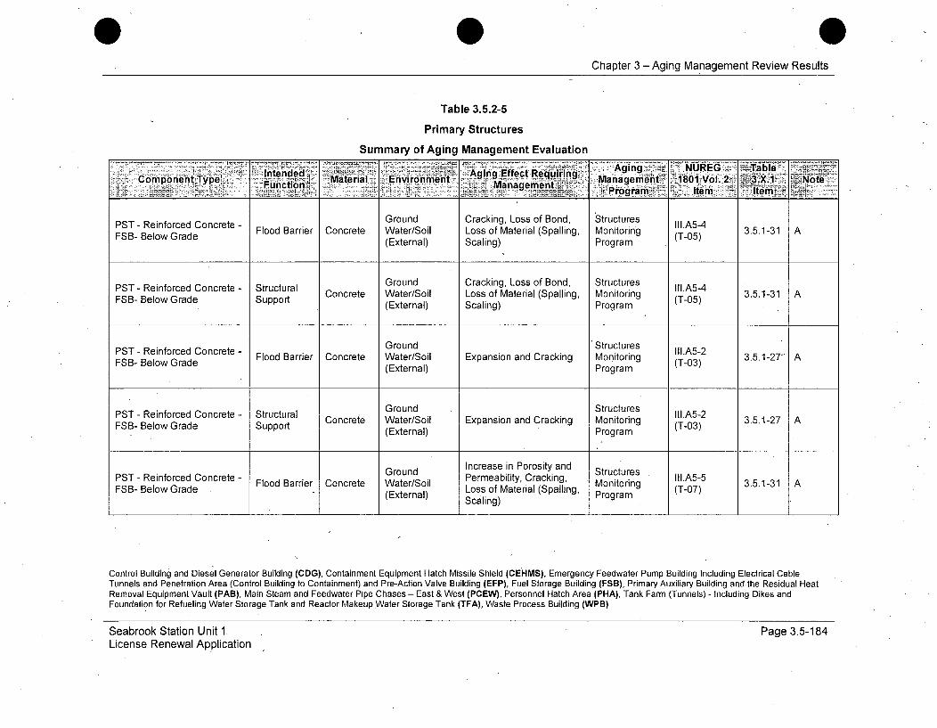
Chapter 3 -Aging Management Review Results
Table 3.5.2-5
Primary Structures
Summary of Aging Management Evaluation
ComponeintoType IntendAgin Aging NURGu CoTableAFuondBarierCo Material Environment Effect M erlping Managementg 1801 Vol. 2 3.51X j ANt
FSB-BelowGrade(External) SProgram Iem em
PST - Reinforced Concrete - Ground Cracking, Loss of Bond, Structures III.A5-4FSB- Below Grade Flood Barrier Concrete Water/Soil Loss of Material (Spalling, Monitoring (T-05) 3.5.1-31 A
(External) Scaling) Program
PST - Reinforced Concrete - Structural Ground Cracking, Loss of Bond, Structures III.A5-4FloodwBarrier Concrete Water/Soil Loss of Material (Spalling, Monitoring (T-05) 3.5.1-31 A
FSB- Below Grade (External) Scaling) Program
Ground 'Structures III.A5-2FSB- Below Grade Flood Barrae Concrete Water/Soil Expansion and Cracking Monitoring (T-03) 3.5.1-27 A(External) Program
PS enocdCnrt tutrlGround .Structures IIA-PST- eifocedCocrte- Srutual Concrete Water/Soil Expansion and Cracking Monitoring ll.523.5.1-27 AFSB- Below Grade Support (External) Program(T-03)
Ground Increase in Porosity and StructuresPST - Reinforced Concrete - Flood Barrier Concrete Water/Soil Permeability, Cracking, Monitoring III.A5-5 3.5.1-31 ALoss of Material (Spalling, Mogram (T-07)FSB- Below Grade . - (External) Scaling) Program
Control Building and Diesel Generator Building (CDG), Containment Equipment Hatch Missile Shield (CEHMS), Emergency Feedwater Pump Building Including Electrical CableTunnels and Penetration Area (Control Building to Containment) and Pre-Action Valve Building (EFP), Fuel Storage Building (FSB), Primary Auxiliary Building and-the Residual HeatRemoval Equipment Vault (PAB), Main Steam and Feedwater Pipe Chases - East & West (PCEW), Personnel Hatch Area (PHA), Tank Farm (Tunnels) - Including Dikes andFoundation for Refueling Water Storage Tank and Reactor Makeup Water Storage Tank (TFA), Waste Process Building (WPB)
Seabrook Station Unit 1.License Renewal Application
Page 3.5-184
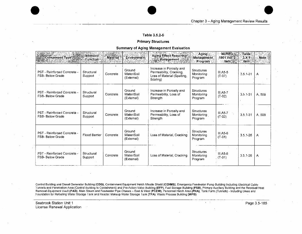
0Chapter 3 -Aging Management Review Results
Table 3.5.2-5,
Primary Structures
Summary of Aging Management Evaluation
Inede Rqii 4 -Aging... NUEB:Table
Component Type, Fnto Mate~rial' nirment Managpmen - 't'Eviom Management 1801 -VoI.-Z 3-.X.1 I Note- -. ,~.* '~.<Program -j Item.1~ Item
Ground Increase in Porosity and StructuresPST - Reinforced Concrete - Structural Concrete Water/Soil Permeability, Cracking, Monito III.A5-5 3.5.1-31 AFSB- Below Grade Support Loss of Material (Spalling, ring (T-07)(External) Scaling) Program
PST - Reinforced Concrete - Structural Ground Increase in Porosity and Structures Ill.A5-7Concrete Water/Soil Permeability, Loss of Monitoring (T-02) 3.5.1-31 A, 509FSB- Below Grade Support (External) Strength Program
PST - Reinforced Concrete - Structural Ground Increase in Porosity and Structures II1.A5-7 .FSB- Below Grade Support Water/Soil Permeability, Loss of Monitoring, (T-02) 3.5.1-31 A, 509
(External) Strength Program
PST - Reinforced Concrete - Ground Structures II1.A5-6FSB- Below Grade Flood Barrier Concrete Water/Soil Loss of Material, Cracking Monitoring (T-01) 3.5.1-26 A
(External) Program
Ground StructuresPST - Reinforced Concrete - Structural GonStuurs II1.A5-6FSB- Below Grade Support Concrete Water/Soil Loss of Material, Cracking Monitoring (T-01) 3.5.1-26 A
(External) Program
Control Building and Diesel Generator Building (CDG), Containment Equipment Hatch Missile Shield (CEHMS), Emergency Feedwater Pump Building Including Electrical CableTunnels and Penetration Area (Control Building to Containment) and Pre-Action Valve Building (EFP), Fuel Storage Building (FSB), Primary Auxiliary Building and the Residual HeatRemoval Equipment Vault (PAB), Main Steam and Feedwater Pipe Chases - East & West (PCEW), Personnel Hatch Area (PHA), Tank Farm (Tunnels) - Including Dikes andFoundation for Refueling Water Storage Tank and Reactor Makeup Water Storage Tank (TFA), Waste Process Building (WPB)
Seabrook Station Unit 1License Renewal Application
Page 3.5-185

Chapter 3 -Aging Management Review Results
Table 3.5.2-5
Primary Structures
Summary of Aging Management Evaluation
IntendedS Aging Effect Requiring Agi n VII.G-TbFBComponentoTirI Funcione CMaterial Environment g Mansgefme ae1801Voa. 32 3.X1 NoteUctoe(ta Program Item Item
PST - Reinforced Concrete - Air Indoor Fire Protection VII.G-29FSB- Exposed to Air Indoor Fire Barrier Concrete Uncontrolled Loss of Material 3.3P1-67 AUncontrolled (External) Program (A-91)
PST - Reinforced Concrete- Air Indoor Fire Protection VII.G-29FSB- Exposed to Air Indoor Shielding Concrete Uncontrolled Loss of Material' Proteto (A-9 3.3.1-67 AUncontrolled (External) Program (A-91)
PST - Reinforced Concrete - Structural Air Indoor Fire Protection VII.G-29 316 AFSB- Exposed to Air Indoor Concrete Uncontrolled Loss of Materia[' Program7 AA9Uncontrolled Support (External) Porm(-1
PST - Reinforced.Concrete - Air Indoor Cracking, Loss of Bond, Structures III.A5-9FSB- Exposed to Air Indoor Fire Barrier Concrete Uncontrolled Loss of Material (Spalling, Monitoring (T-04) 3.5.1-23 AUncontrolled (External) Scaling) Program
PST - Reinforced Concrete - Air Indoor Cracking, Loss of Bond, StructuresFSB- Exposed to Air Indoor Shielding Concrete Uncontrolled Loss of Material (Spalling, Monitoring (T-04) 3.5.1-23 AUncontrolled (External) Scaling) Program
Control Building and Diesel Generator Building (CDG), Containment Equipment Hatch Missile Shield (CEHMS), Emergency Feedwater Pump Building Including Electrical CableTunnels and Penetration Area (Control Building to Containment) and Pre-Action Valve Building (EFP), Fuel Storage Building (FSB), Primary Auxiliary Building and the Residual HeatRemoval Equipment Vault (PAB), Main Steam and Feedwater Pipe Chases - East & West (PCEW), Personnel Hatch Area (PHA), Tank Farm (Tunnels) - Including Dikes andFoundation for Refueling Water Storage Tank and Reactor Makeup Water Storage Tank (TFA), Waste Process Building (WPB)
Seabrook Station Unit 1License Renewal Application
Page 3.5-486
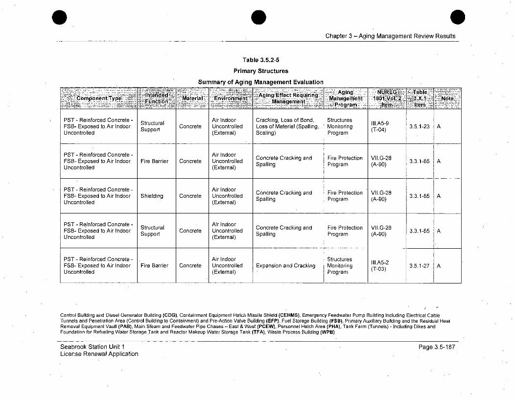
Chapter 3 -Aging Management Review Results
Table 3.5.2-5
Primary Structures
Summary of Aging Management Evaluation
- nedd: -- 'Agin'g- NAUMEz'G-P! sTableateria Enirnmn Aging Effect Requiring . aa
PST - Reinforced Concrete - Structural Air Indoor Cracking, Loss of Bond, Structures III.A5-9FSB- Exposed to Air Indoor Concrete Uncontrolled Loss of Material (Spalling, Monitoring (T04) 3.5.1-23 AUncontrolled Support (External) Scaling) Program
PST - Reinforced Concrete - Air Indoor Concrete Cracking and Fire Protection VII.G-28FSB- Exposed to Air Indoor Fire Barrier Concrete Uncontrolled Spalling Program (A-0G) 3.3.1-65 AUncontrolled (External)
PST - Reinforced Concrete - Air Indoor Concrete Cracking and Fire Protection VII.G-28FSB- Exposed to Air Indoor Shielding Concrete Uncontrolled Spalling Program (A-0G) 3.3.1-65 AUncontrolled (External)
PST - Reinforced Concrete - Structural Air Indoor Concrete Cracking and Fire Protection VII.G-28FSB- Exposed to Air Indoor Support Concrete Uncontrolled Spalling Program (A-90) 3.3.1-65 AUncontrolled (External)
PST - Reinforced Concrete - Air Indoor StructuresFSB-*Exposed to Air Indoor Fire Barrier Concrete Uncontrolled Expansion and Cracking Monitoring (T-03) 3.5.1-27 AUncontrolled (External) Program (T03)
Control Building and Diesel Generator Building (CDG), Containment Equipment Hatch Missile Shield (CEHMS), Emergency Feedwater Pump Building Including Electrical CableTunnels and Penetration Area (Control Building to Containment) and Pre-Action Valve Building (EFP), Fuel Storage Building (FSB), Primary Auxiliary Building and the Residual HeatRemoval Equipment Vault (PAB), Main Steam and Feedwater Pipe Chases - East & West (PCEW), Personnel Hatch Area (PHA), Tank Farm (Tunnels) - Including Dikes andFoundation for Refueling Water Storage Tank and Reactor Makeup Water Storage Tank (TFA), Waste Process Building (WPB)
Seabrook Station Unit 1License Renewal Application
Page 3.5-187

Chapter 3 - Aging Management Review Results
Table 3.5.2-5
Primary Structures
Summary of Aging Management Evaluation
1 -lt d ffct~ ging, NUREG TableComnponent Type nee Material Environm~ent Agn Nuln anage'ment 1801 Vol. 2, .3~XI Note
_ 2 ~~Function_____ __ Management -P~im .Itrv
PST - Reinforced Concrete - Air Indoor StructuresFSB- Exposed to Air Indoor Shielding Concrete Uncontrolled Expansion and Cracking Monitoring (T-03) 3.5.1-27 AUncontrolled (External) Program (T03)
PST - Reinforced Concrete - Structural Air Indoor Structures lll.A5-2FSB- Exposed to Air Indoor Concrete Uncontrolled Expansion and Cracking Monitoring (T-03) 3.5.1-27 AUncontrolled (External) Program
PST - Reinforced Concrete - Air Indoor Increase in Porosity and StructuresFSB- Exposed to Air Indoor Fire Barrier Concrete Uncontrolled Permeability, Cracking, Monitoring I(TA-06 3.5.1-24 AUncontrolled (External) Scaling) Program
PST - Reinforced Concrete - Air Indoor Increase in Porosity and StructuresFSB- Exposed to Air Indoor Shielding Concrete Uncontrolled Permeability, Cracking, Monitoring IITA-0 3.5.1-24 AUncontrolled (External) Loss of Material Program -06)
Uncontrolled ~~Scaling) (plig ig (
PST -. Reinforced Concrete - Air Indoor Increase in Porosity and StructuresFSB- Exposed to Air Indoor Structural. Permeability, Cracking, Monito III.A5-10Uncontrolled Support Concrt E x nternal) Loss of Material (Spalling, Program (T-06)Epsdtit(External) Scaling)
Control Building and Diesel Generator Building (CDG), Containment Equipment Hatch Missile Shield (CEHMS), Emergency Feedwater Pump Building Including Electrical CableTunnels and Penetration Area (Control Building to Containment) and Pre-Action Valve Building (EFP), Fuel Storage Building (FSB), Primary Auxiliary Building and the Residual HeatRemoval Equipment Vault (PAB), Main Steam and Feedwater Pipe Chases - East & West (PCEW), Personnel Hatch Area (PHA), Tank Farm (Tunnels) - Including Dikes andFoundation for Refueling Water Storage Tank and Reactor Makeup Water Storage Tank (TFA), Waste Process Building (WPB)
Seabrook Station Unit 1License Renewal Application
Page 3.5-188
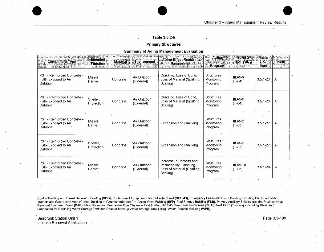
Chapter 3 -Aging Management ReviewResults
Table 3.5.2-5
Primary Structures.
Summary of Aging Management Evaluation
AgingGŽ ~Tabl6I'n- tded AAing, LossEffect Requir in
FB Component TBype ConeMater(al xtEnvironmenl 's %W MateriulSpalin, Manageiint .1801 Vol. 2 3.X.1-3 Note
Functi)Program Item ItemPST - Reinforced Concrete - Missile Air Outdoor Cracking, Loss of Bond, Structures 1.A5-9
FSB- Exposed to Air Barrir Concrete (Loss of Material (Spalling, Monitoring (T-04) 3.5.1-23Outdoor Scaling) Program
PST - Reinforced Concrete - Shele Air Outdoor Cracking, Loss of Bond, Structures II1.A5-2FSB- Exposed to Air Shelter Concrete Loss of Material (Spalling Monitoring (T-0 3.5-1-23 AOutdoor Protection (External) Scaling) Program (T-04)
PST - Reinforced Concrete - Missile Air Outdoor Structures III.A5-2FSB- Exposed to Air Barrier Concrete Expansion and Cracking Monitoring (T03) 3.5.1-27 AOutdoor Program
PST - Reinforced Concrete - Setr-Air Outdoor Structures IIA-FSB- Exposed to Air Shle, Concrete Expansion and Cracking Monitoring ll.523.5.1-27 AOutdoor Protection (External) ,Program (T-03)
PST - Reinforced Concrete - Increase in Porosity and Structures
FSB Exposed to Air Bissile Concrete Air Outdoor Permeability, Cracking, III.A5-10Barrier (External) Loss of Material (Spalling, (T-06)Outdoor Scaling) Program
Control Building and Diesel Generator Building (CDG), Containment Equipment Hatch Missile Shield (CEHMS), Emergency Feedwater Pump Building Including Electrical CableTunnels and Penetration Area (Control Building to Containmerit) and Pre-Action Valve Building (EFP), Fuel Storage Building (FSB), Prirmary Auxiliary Building and the Residual -leatRemoval Equipment Vault (PAB), Main Steam and FeedwaterPipe Chases - East & West (PCEW), Personnel Hatch Area (PHA), Tank Farm (Tunnels) - Including Dikes andFoundation for Refueling Water Storage Tank and Reactor Makeup Water Storage Tank (TFA), Waste Process Building (WPB)
Seabrook Station Unit 1License Renewal Application
Page 3.5-189

Chapter 3 -Aging Management Review Results
Table 3.5.2-5
Primary Structures
Summary of Aging Management Evaluation
.-- Ag ing; -NUREG' ~Table
PST - Reinforced Concrete - iro Increase in Porosity and StructuresPST -udo RenocePcet nrmeaseiniy Poroiyackng, Structures
FSB- Exposed to Air Shelter Concrete Permeability, Cracking, Monitoring .A5-1 3.5.1-24 AProtection (External) Loss of Material (Spalling, rig (T-06)Outdoor . Scaling) Program
PST - Reinforced Concrete - M Air Otd StructuresFSB- Exposed to Air Barrier Concrete (External) Loss of Material, Cracking Monitoring (T-01) 3.5.1-26 AOutdoor Program
PST - Reinforced Concrete - Shelter, Air Outdoor Structures II.A5-6FSB-. Exposed to Air Protection Concrete (External) Loss of Material, Cracking Monitoring (T-01) 3.5.1-26 AOutdoor Program
PST - Reinforced Concrete - Structural Raw Water Cracking, Loss of Bond, Structures III.A5-4FSB- Exposed to Raw Water Support (External) Loss of Material (Spalling, Monitoring (T-05) 3.5.1-31 A, 512
Scaling) Program
PST - Reinforced Concrete - Structural Raw Water Structures IILA5-2 /
FSB- Exposed to Raw Water Support (External) Expansion and Cracking Monitoring (T-03) 3.5.1-27 A, 512Program
Control Building and Diesel Generator Building (CDG), Containment Equipment Hatch Missile Shield (CEHMS), Emergency Feedwater Pump Building Including Electrical CableTunnels and Penetration Area (Control Building to Containment) and Pre-Action Valve Building (EFP), Fuel Storage Building (FSB), Primary Auxiliary Building and the Residual HeatRemoval Equipment Vault (PAB), Main Steam and Feedwater Pipe Chases - East & West (PCEW), Personnel Hatch Area (PHA), Tank Farm (Tunnels) - Including Dikes andFoundation for Refueling Water Storage Tank and Reactor Makeup Water Storage Tank (TFA), Waste Process Building (WPB)
Seabrook Station Unit 1License Renewal Application
Page 3.5-190

Chapter 3 -Aging Management Review Results
Table 3.5.2-5
Primary Structures
Summary of Aging Management Evaluation
Pr - Intended ru Cranking, sf Bctu ReII1.Clondent Typecion Mateial WEnvironimentl Agssof c .2euiring, Mn.PB Below Grade (Extergnealnt IScai ng) PNote
PST - Reinforced Concrete - Ground Cracking, Loss of Bond, Structures IIL.A3-4Flood Barrier Concrete Water/Soil Loss of Material (Spalling, Monitoring (T-05) 3.5.1-31 A
PAB- Below Grade Supp(External) Scaling) Program
PST - Reinforced Concrete - Structural Ground Cracking, Loss of Bond, Structures III.A3-4PAB- Below Grade Support Concrete Water/Soil Loss of Material (Spalling, Monitoring (T-05) 3.5.1-31 A
(External) Scaling) Program
Ground StructuresPST - Reinforced Concrete- Grounucturalre II1.A3-2
PS - ReiowGredCe Flood Barrier Concrete Water/Soil Expansion and Cracking Monitoring (T-03) 3.5.1-27 APAB- Below Grade Supp(External) Program
PST - Reinforced Concrete - Ground StructuresPST - Reinow rcedCoet- Stpprutua Concrete Water/Soil Expansion and Cracking Monitoring (Tl.03) 3.5.1-27 APAB Blo GadeSupot External) Program (-3
Ground Inraei ooiyad StructuresPST:- Reinforced Concrete Permeability, Cracking, IId.A3-5Flood Barrier Concrete Water/Soil Monitoring 3.5.1-31 A(External) Loss of Material (Spalging, Program -07)
Scaling)
Control Building and Diesel Generator Building (CDG), Containment Equipment Hatch Missile Shield (CEHMS), Emergency Feedwater Pump Building Including Electrical CableTunnels and Penetration Area (Control Building to Containment) and Pre-Action Valve Building (EFP), Fuel Storage Building (FSB), Primary Auxiliary Building and the Residual HeatRemoval Equipment Vault (PAB), Main Steam and Feedwater Pipe Chases - East & West (PCEW), Personnel Hatch Area (PHA), Tank Farm (Tunnels) - Including Dikes andFoundation for Refueling Water Storage.Tank and Reactor Makeup Water Storage Tank (TFA), Waste Process Building (WPB)
Seabrook Station Unit 1License Renewal Application
Page 3.5-191

0Chapter 3 -Aging Management Review Results
Table 3.5.2-5-
Primary Structures
Summary of Aging Management Evaluation
-Intended Aging, NUREGt TabeingComponent Type -z. r Material Enviro~nment. Aig fetReurn Management 0 081Vo. 2, 3.X.V- .NoteFucin: .Mnaeet_ .~rrogram ~~jtm---Item-
Ground Increase in Porosity and StructuresPST - Reinforced Concrete - Structural Concrete Water/Soil Permeability, Cracking, Monitoring I.A3-5 3.5.1-31 APAB- Below Grade Support (External) Scaling) Program
PsT - Reinforced Concrete - Structural - Ground Increase in Porosity and Structures III.A3-7PAB- BelowGrade Support Concrete Water/Soil Permeability, Loss of Monitoring (T-02) 3.5.1-32 A, 509
(External) Strength Program
PST - Reinforced Concrete - Structural Ground Increase in Porosity and Structures III.A3-7PAB- BelowGradeC Support Concrete Water/Soil Permeability, Loss of Monitoring (T-02) 3.5.1-32 A, 509
(External) Strength Program
PST- Reinforced Concrete - Ground Structures II1.A3-6PST- Reiorcd e Flood Barrier Concrete Water/Soil Loss of Material, Cracking Monitoring (T-01) 3.5.1-26 APAB- Below Grade (External) Program
PST - Reinforced Concrete - Structural Ground Structures II1.A3-6PAB-S BeloweGradeSupport Concrete Water/Soil Loss of Material, Cracking Monitoring (T-01) 3.5.1-26 A
PA-BlwGaeSpot(External) Program (-1
Control Building and Diesel Generator Building (COG), Containment Equipment Hatch Missile Shield (CEHMS), Emergency Feedwater Pump Building Including Electrical CableTunnels and Penetration Area (Control Building to Containment) and Pre-Action Valve Building (EFP), Fuel Storage Building (FSB), Primary Auxiliary Building and the Residual HeatRemoval Equipment Vault (PAB), Main Steam and Feedwater Pipe Chases - East & West (PCEW), Personnel Hatch Area (PHA), Tank Farm (Tunnels) - Including Dikes andFoundation for Refueling Water Storage Tank and Reactor Makeup Water Storage Tank (TFA), Waste Process Building (WPB)
Seabrook Station Unit 1License Renewal Application
Page 3.5-192

0 0Chapter 3 -Aging Managemeiht Review Results
Table 3.5.2-5
Primary Structures
Summary of Aging Management Evaluation
-~ AingAging .. NUREG <TableComponentInte T lntendd Agin Effect Requiring MnCopnnt-p Function> Mateirial ~Environment Mangemntgement >,.1801 Vol. 2 3.X1 -Note
-~ _______________________ ýrogram I4 tem-, . Item
PST - Reinforced Concrete - Air Indoor Fire Protection VII.G-29PAB- Exposed to Air Indoor Fire Barrier Concrete Uncontrolled Loss of Material Program (A-91)3.3.1-67Uncontrolled (External)
PST --Reinforced Concrete - Structural Air Indoor Fire Protection VII.G-29PAB- Exposed to Air Indoor Support Concrete Uncontrolled Loss of Material Program (A-91) 3.3.1-67 AUncontrolled (External)
PST - Reinforced Concrete - . Air Indoor Cracking, Loss of Bond, Structures III.A3-9PAB- Exposed to Air Indoor Fire Barrier Concrete Uncontrolled Loss of Material (Spalling, Monitoring (T-04) 3.5.1-23 AUncontrolled (External) Scaling) Program
PST - Reinforced Concrete - Air Indoor Cracking, Loss of Bond, StructuresPAB- Exposed to Air Indoor Structural Concrete Uncontrolled Loss of Material (Spalling, Monitoring (T-04) 3.5.1-23 AUncontrolled S o(External) Scaling) Program
PST - Reinforced Concrete - Air Indoor Concrete Cracking and Fire Protection VII.G-28PAB- Exposed to Air Indoor Fire Barrier Concrete Uncontrolled Spalling Program (A-90) 3.3.1-65 AUncontrolled (External)
Control Building and Diesel Generator Building (CDG), Containment Equipment Hatch Missile Shield (CEHMS), Emergency Feedwater Pump Building Including Electrical CableTunnels and Penetration Area (Control Building to Containment) and Pre-Action Valve Building (EFP), Fuel Storage Building (FSB), Primary Auxiliary Building and the Residual HeatRemoval Equipment Vault (PAB), Main Steam and Feedwater Pipe Chases - East & West (PCEW), Personnel Hatch Area (PHA), Tank Farm (Tunnels) - Including Dikes andFoundation for Refueling Water Storage Tank and Reactor Makeup Water Storage Tank (TFA), Waste Process Building (WPB)
Seabrook Station Unit 1License Renewal Application
Page 3.5-193
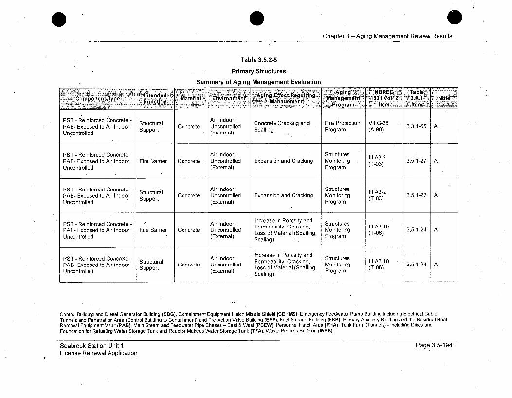
0Chapter 3 -Aging Management Review Results
Table 3.5.2-5
Primary Structures
Summary of Aging Management Evaluation
.Intended -i ReAgingced Concrete-AiComponent Type Fucin Material Environment gn fet eurn an~agem ent '180Vol. '2 . 3.X.1 Note
Man~e~n~' Program Item Item
PST - Reinforced Concrete - Structural Concrete AIndoor Concrete Cracking and Fire Protection VII.G-28 3.3.1-65 APAB- Exposed to Air Indoor Support Cocrt (Exoternal)e plgPorm A9)3316Uncontrolled (External) Spalling Program (A-90)
PST - Reinforced Concrete - Air Indoor Structures III.A3-2PAB- Exposed to Air Indoor Fire Barrier Concrete Uncontrolled Expansion and Cracking Monitoring (T-03) 3.5.1-27 AUncontrolled (External) Program
PST - Reinforced Concrete - Air Indoor StructuresPAB- Exposed to Air Indoor Structural Concrete Uncontrolled Expansion and Cracking Monitoring (TI.A3-2 3.5.1-27 AUncontrolled Support (External) Program (T-03)
PST - Reinforced Concrete - Air Indoor Increase in Porosity and StructuresPermeability, Cracking, MoioIll.A3-10 3512PAB- Exposed to Air Indoor Fire Barrier Concrete Uncontrolled Loss of Material (Spalling, Monitorin (T-0 3.5.1-24 AUncontrolled (External) Scaling) o Program -06)
PST - Reinforced Concrete - StructuralAir Indoor Increase in Porosity and StructuresPAB- Exposed to Air Indoor Concrete Uncontrolled Permeability, Cracking, Monitoring III.A3-10 3.5.1-24 A
Support Loss of Material (Spalling, Mo ring (T-06)Uncontrolled (External) Scaling) Program
Control Building and Diesel Generator Building (CDG), Containment Equipment Hatch Missile Shield (CEHMS), Emergency Feedwater Pump Building Including Electrical CableTunnels and Penetration Area (Control Building to Containment) and Pre-Action Valve Building (EFP), Fuel Storage Building (FSB), Primary Auxiliary Building and the Residual HeatRemoval Equipment Vault (PAB), Main Steam and Feedwater Pipe Chases - East & West (PCEW), Personnel Hatch Area (PHA), Tank Farm (Tunnels) - Includihg Dikes andFoundation for Refueling Water Storage Tank and Reactor Makeup Water Storage Tank (TFA), Waste Process Building (WPB)
Seabrook Station Unit 1License Renewal Application
Page 3.5-194
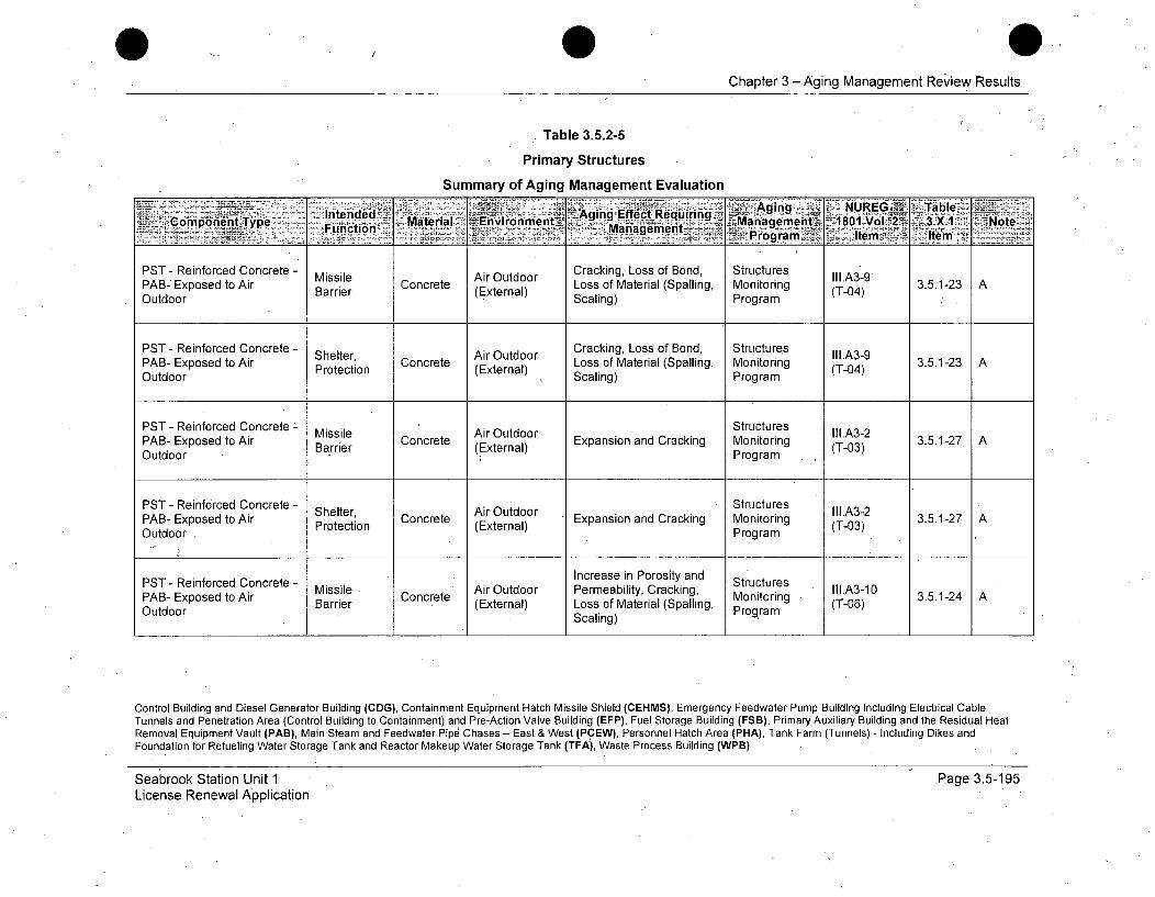
Chapter 3 -Aging Management Review Results
Table 3.5.2-5
Primary Structures
Summary of Aging Management Evaluation
Intended~ Aging EffecitRequiring Ain __ URGiae _Copnn yeMa~terial -Environnient~ ManManat~gement 1L80.o1 - .1 NtCopoen Tpe Fun~ctio6-n - _ emaVent~7 3X1~-Nt
PST - Reinforced Concrete - Missile Air Outdoor Cracking, Loss of Bond, Structures III.A3-9PAB- Exposed to Air Barrier Concrete (External) Loss of Material (Spalling, Monitoring (T-04) 3.5.1-23 AOutdoor BEScaling) Program
PST - Reinforced Concrete - Shelter,Cracking, Loss of Bond, Structures III.A3-9PAB- Exposed to Air Shelter, Concrete ArOtdr Loss of Material (Spalling, Monitoring (T-04) 3.5.1-23 AOutdoor Protection (External), Scaling) Program
PST - Reinforced Concrete - StructuresMissile Air Outdoor III.A3-2PAB- Exposed to Air Barrier Concrete (External) Expansion and Cracking Monitoring (T-03) 3.5.1-27 AOutdoor ( rProgram
PST - Reinforced Concrete - Air Outdoor StructuresPAB- Exposed tonAr Shelter, Concrete Expansion and Cracking Monitoring .A3-2 3.5.1-27 AOutdoor Protection (External) Program (T-03)
PST - Reinforced Concrete - Increase in Porosity and StructuresMissile Air Outdoor Permeability, Cracking, II1.A3-10PAB- Exposed to Air Barrie Concrete Monitoring 3.5.1-24 AOutdoor (External) Loss of Material (Spalling, g(T-06)
Scaling)
Control Building and Diesel Generator Building (CDG), Containment Equipment Hatch Missile Shield (CEHMS), Emergency Feedwater Pump Building Including Electrical CableTunnels and Penetration Area (Control Building to Containment) and Pre-Action Valve Building (EFP), Fuel Storage Building (FSB), Primary Auxiliary Building and the Residual HeatRemoval Equipment Vault (PAB), Main Steam and Feedwater Pipe Chases - East & West (PCEW), Personnel Hatch Area (PHA), Tank Farm (Tunnels) - Including Dikes andFoundation for Refueling Water Storage Tank and Reactor Makeup Water Storage Tank (TFA), Waste Process Building (WPB)
Seabrook Station Unit 1License Renewal Application
Page 3.5-195
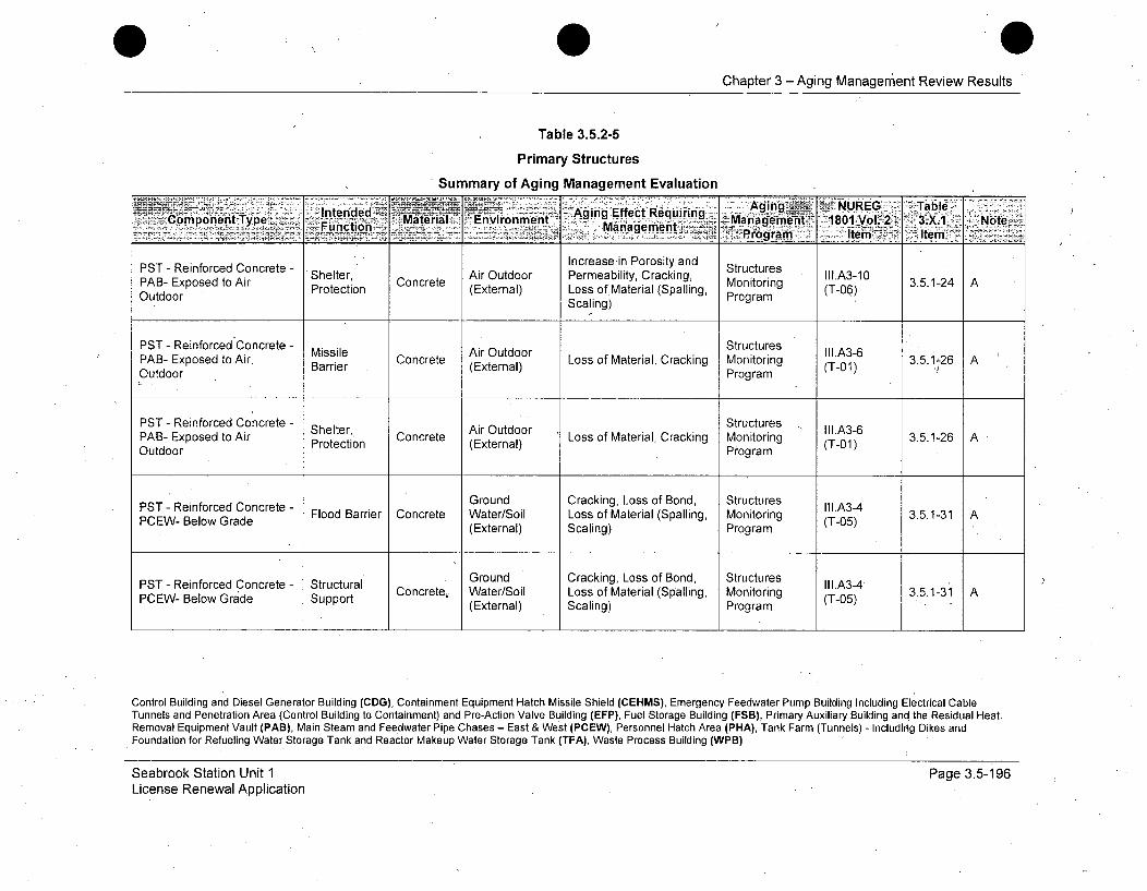
Chapter 3 -Aging Management Review Results
Table 3.5.2-5
Primary Structures
Summary of Aging Management Evaluation
"i INUREG Tab eCopoet ypIntended-~ .~~---~iinen Aging Effect Requirin~g Aig 1OyL~31 Nt
Function _ Mtra-Manlagement .......aeen Iem Ie
PST- Reinforced Concrete - Shelter, Air Outdoor Increase in Porosity and StructuresPAB- Exposed to Air Shle, Concrete ArOtor Permeability, Cracking, Monitoring lll.A3-10 3.5.1-24 AOutooe tProtection (External) Loss of Material (Spalling, (T-06)Outdoor Scaling) Program
PST - Reinforced -Concrete - Missile Air Outdoor Structures 'I.A3-6PAB- Exposed to Air. Concrete Loss of Material, Cracking Monitoring (T ) 31-26 AOutdoor B (External) Program "
PST - Reinforced Concrete - Shelter, Concrete AirLoss of Material, Cracking Stuructr 3.5.1-26 A'PAB- Exposed to Air Protection (External) Monitoring (T-01)Outdoor Program
PST - Reinforced Concrete - Ground Cracking, Loss of Bond, Structures II1.A3-4PCEW- Below Grade Flood Barrier Concrete Water/Soil Loss of Material (Spalling, Monitoring (T-05) 3.5.1-31 A
(External) Scaling) Program
PST - Reinforced Concrete - Structural Ground Cracking, Loss of Bond, Structures Ill.A3-4Grade Support Concrete, Water/Soil Loss of Material (Spalling, Monitoring T53.5.1-31 APCEW- Below (External) Scaling) Program (
Control Building and Diesel Generator Building (CDG), Containment Equipment Hatch Missile Shield (CEHMS), Emergency Feedwater Pump Building Including Electrical CableTunnels and Penetration Area (Control Building to Containment) and Pre-Action Valve Building (EFP), Fuel Storage Building (FSB), Primary Auxiliary Building and the Residual Heat.Removal Equipment Vault (PAB), Main Steam and Feedwater Pipe Chases - East & West (PCEW), Personnel Hatch Area (PHA), Tank Farm (Tunnels) - Includirig Dikes andFoundation for Refueling Water Storage Tank and Reactor Makeup Water Storage Tank (TFA), Waste Process Building (WPB)
Seabrook Station Unit 1License Renewal Application
Page 3.5-196
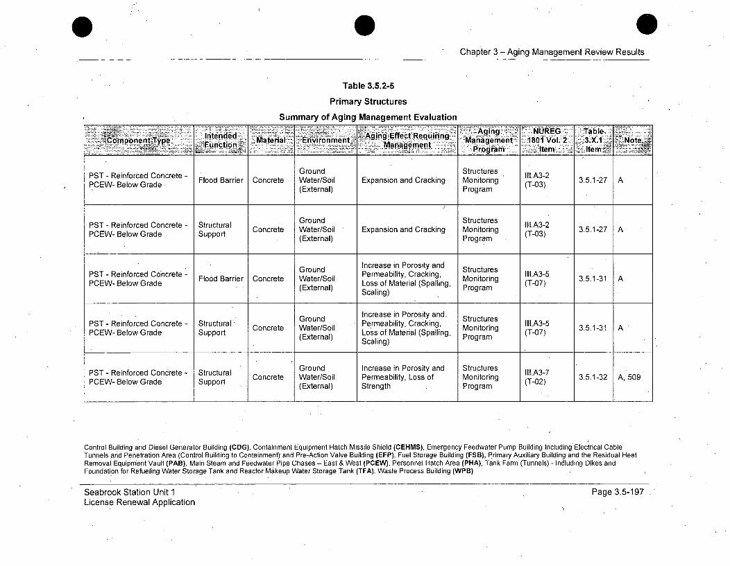
Chapter 3 -Aging Management Review Results
Table 3.5.2-5
Primary Structures
Summary of Aging Management Evaluation
Aging'. NUREG TableComponent Type Intended Material Environment, ',.,:,ing..E:f-,t:e-u-r. n Management- 1801 Vol. 2 3.X 1 Note
Functio Management ýPrga Itemn Item"
PST - Reinforced Concrete - Ground Structures Ill.A3-2PCEW- Below G rade Flood Barrier Concrete Water/Soil Expansion and Cracking Monitoring (T-03) 3.5.1-27 A(External) Program
Ground StructuresPST - Reinforced Concrete - Structural GonStuurs Ili.A3-2PST -Reiow redCe Stprutu Concrete Water/Soil Expansion and Cracking Monitoring (T-03) 3.5.1-27 APCEW- Below Grade Support (External) Program
Ground Increase in Porosity and StructuresPST - Reinforced Concrete - Flood Barrier Concrete Water/Soil Permeability, Cracking, Monitoring (.A3-5 3.5.1-31 APCEW- Below Grade (External) Loss of Material (Spalling, rg (T
(External) Scaling) Porm-7
Ground Increase in Porosity and. StructuresPST - Reinforced Concrete - Structural'. Concrete Water/Soil Permeability, Cracking, M lII.A3-5 3.5.1-31 APCEW- Below Grade Support (External) Loss of Material (Spalling, Monrin (T-07)Scaling) Program
PST - Reinforced Concrete - Structural Ground Increase in Porosity and Structures Ill.A3-7PCEW- Below Grade Support Concrete Water/Soil Permeability, Loss of Monitoring (T-02) 3.5.1-32 A, 509(External) Strength Program
Control Building and Diesel Generator Building (CDG), Containment Equipment Hatch Missile Shield (CEHMS), Emergency Feedwater Pump Building Including Electrical CableTunnels and Penetration Area (Control Building to Containment) and Pre-Action Valve Building (EFP), Fuel Storage Building (FSB), Primary Auxiliary Building and the Residual HeatRemoval Equipment Vault (PAB), Main Steam and Feedwater Pipe Chases - East & West (PCEW), Personnel Hatch Area (PHA), Tank Farm (Tunnels) - Indluding Dikes andFoundation for Refueling Water Storage Tank and Reactor Makeup Water Storage Tank (TFA), Waste Process Building (WPB)
Seabrook Station Unit 1License Renewal Application
Page 3.5-197

Chapter 3 -Aging Management Review Results
Table 3.5.2-5
Primary Structures
Summary of Aging Management EvaluationAgig NUREG Table~
Component Type tended MaterialEnvronment Aging Effect Requiring -;-"24.o'Manat__prin puecto Materialnt EvrnetM agement .1801 Vol. 3X 1 Noe
________________________________________________ iPdgram- Itemf~ Itemii
PST - Reinforced Concrete - Structural Ground Increase in Porosity and Structures II1.A3-7PCEW- Below Grade Support Water/Soil Permeability, Loss of Monitoring (T-02) 3.5.1-32 A,509
(External) Strength Program
Ground Structures III.A3-6PST - Reinforced Concrete- Flood Barrier Concrete Water/Soil Loss of Material, Cracking Monitoring (T-01) 3.5.1-26 APCEW- Below Grade (External) Program
PnGround StructuresPST - Reinforced Concrete - Structural Concrete Water/Soil Loss of Material, Cracking Monitoring (TI.A3-6 3.5.1-26 APCEW- Below Grade Support (External) Program(T-01)
PST - Reinforced Concrete - Air Indoor Fire Protection VII.G-29PCEW- Exposed to Air Fire Barrier Concrete Uncontrolled Loss of Material Program (A-91-AIndoor Uncontrolled (External)
PST- Reinforced Concrete - HELB Air Indoor Fire Protection VII.G-29PCEW- Exposed to Air Shielding Concrete Uncontrolled Loss of Material Program (A-91)AIndoor Uncontrolled (External)
Control Building and Diesel Generator Building (CDG), Containment Equipment Hatch Missile Shield (CEHMS), Emergency Feedwater Pump Building Including Electrical CableTunnels and Penetration Area (Control Building to Containment) and Pre-Action Valve Building (EFP), Fuel Storage Building (FSB), Primary Auxiliary Building and the Residual HeatRemoval Equipment Vault (PAB), Main Steam and Feedwater Pipe Chases - East & West (PCEW), Personnel Hatch Area (PHA), Tank Farm (Tunnels) - Including Dikes andFoundation for Refueling Water Storage Tank and Reactor Makeup Water Storage Tank (TFA), Waste Process Building (WPB)
Seabrook Station Unit 1License Renewal Application
Page 3.5-198
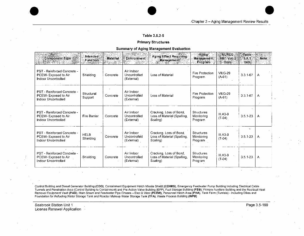
Chapter 3 - Aging Management Review Results
Table 3.5.2-5
Primary Structures
Summary of Aging Management Evaluation
Intndd Aging fNUREG -- L-Tablei.Comfponent Type F2-,ion Material ~Environment M.in ffc RAtin Mngmet 180 Vol. 2~ 3.X.1 Note
j~anaementProgram~ Atem Ie
PST - Reinforced Concrete - Air Indoor Fire Protection VII.G-29PCEW- Exposed to Air Shielding Concrete Uncontrolled Loss of Material Program (A-91)AIndoor Uncontrolled (External)
PST - Reinforced Concrete - Air IndoorPCEW- Exposed to Air Structural Concrete Uncontrolled Loss of Material Fire Protection VAG-29 3.3.1-67 AIndoor Uncontrolled Support (External) Program (A-91)
PST - Reinforced Concrete - Air Indoor Cracking, Loss of Bond, Structures Ill.A3-9PCEW- Exposed to Air Fire Barrier Concrete Uncontrolled Loss of Material (Spalling, Monitoring 3.5.1-23 AIndoor Uncontrolled (External) . Scaling) Program (
PST - Reinforced Concrete - Air Indoor Cracking, Loss of Bond,' Structures I11.A3-9PCEW- Exposed to Air HELB Concrete Uncontrolled Loss of Material (Spalling, Monitoring (Tl04) 3.5.1-23 AIndoor Uncontrolled (External) Scaling) Program
PST - Reinforced Concrete - Air Indoor Cracking, Loss of Bond, Structures IlI.A3- 3PCEWZ Exposed to Air Shielding Concrete Uncontrolled Loss of Material (Spalling, Monitoring -3.5.1-23 AIndoor Uncontrolled (External) Scaling) Program (T-04)
Control Building and Diesel Generator Building (CDG), Containment Equipment Hatch Missile Shield (CEHMS), Emergency Feedwater Pump Building Including Electrical CableTunnels and Penetration Area (Control Building to Containment) and Pre-Action Valve Building (EFP), Fuel Storage Building (FSB); Primary Auxiliary Building and the Residual HeatRemoval Equipment Vault (PAB); Main Steam and Feedwater Pipe Chases - East & West (PCEW), Personnel Hatch Area (PHA), Tank Farm (Tunnels) - Including Dikes andFoundation for Refueling.Water Storage Tank and Reactor Makeup Water Storage Tank (TFA), Waste Process Building (WPB)
Seabrook Station Unit 1License Renewal Application
Page 3.5-199

Chapter 3 -Aging Management Review Results
Table 3.5.2-5
Primary Structures
Summary of Aging Management EvaluationAgn E e 6"Aging~ NUREG Table~
onpnent Type. Materal-: Envvironment A g E e...quiring ..-Management -1801 Vol. -3.X.1 Note,Copoen Tpe Function .- a..agementMirf rogram -tmIe
PST - Reinforced Concrete - Structural Air Indoor Cracking, Loss of Bond, Structures III.A3-9PCEW- Exposed to Air Support Concrete Uncontrolled Loss of Material (Spalling, Monitoring (T-04) 3.5.1-23 AIndoor Uncontrolled (External) Scaling) Program
PST - Reinforced Concrete - 'Air IndoorPCEW- Exposed to Air Fire Barrier Concrete Uncontrolled Concrete Cracking and Fire Protection VII.G-28 3.3.1-65 AIndoor Uncontrolled (External) Spalling Program (A-90)
PST - Reinforced Concrete - HELB Air Indoor Concrete Cracking and Fire Protection VII.G-28PCEW- Exposed to Air helB Concrete Uncontrolled Conc Program (A-28 3.3.1-65 AIndoor Uncontrolled Shielding (External) Spalling Program (A-90)
PST - Reinforced Concrete - Air Indoor Concrete Cracking and Fire Protection VII.G-28PCEW- Exposed to Air Shielding Concrete Uncontrolled Spalling Program (A-90) 3.3.1-65 AIndoor Uncontrolled (External)
PST - Reinforced Concrete - Structural Air Indoor Concrete Cracking and Fire Protection VII.G-28PCEW- Exposed to Air Strt Concrete Uncontrolled Spalling C Program (A-90) 3.3.1-65 AIndoor Uncontrolled uppo (External)
Control Building and Diesel Generator Building (CDG), Containment Equipment Hatch Missile Shield (CEHMS), Emergency Feedwater Pump Building Including Electrical CableTunnels and Penetration Area (Control Building to Containment) and Pre-Action Valve Building (EFP), Fuel Storage Building (FSB), Primary Auxiliary Building and the Residual HeatRemoval Equipment Vault (PAB), Main Steam and Feedwater Pipe Chases - East & West (PCEW), Personnel Hatch Area (PHA), Tank Farm (Tunnels).- Including Dikes andFoundation for Refueling Water Storage Tank and Reactor Makeup Water Storage Tank (TFA), Waste Process Building (WPB)
Seabrook Station Unit 1License Renewal Application
Page 3.5-200
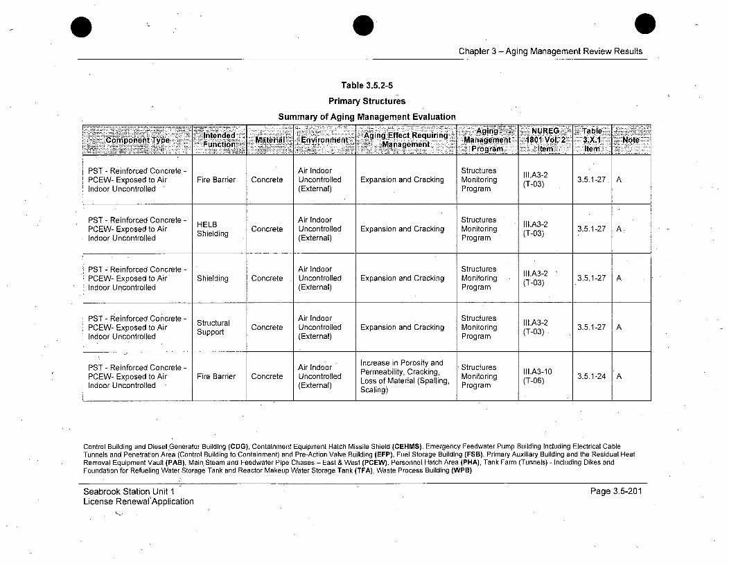
0 0Chapter 3 - Aging Management Review Results
Table 3.5.2-5
Primary Structures
Summary of Aging Management Evaluation
A'igv NUREG TableComponent Ty Ie d Material Enironment Agingq Effect Requirng Manageent 1801ivol. 2 3.. : Note
-------- Fncton ., Mnagmet rogram Item Item:
PST - Reinforced Concrete - Air Indoor StructuresPCEW- Exposed to Air Fire Barrier Concrete Uncontrolled Expansion and Cracking Monitoring (T-03) 3.5.1-27. AIndoor Uncontrolled (External) Program (
PST - Reinforced Concrete - HELB Air Indoor Structures Ill.A3-2PCEW- Exposed to Air Concrete Uncontrolled Expansion and Cracking Monitoring 3.5.1-27 AIndoor Uncontrolled Shielding (External) Program
PST - Reinforced Concrete - Air Indoor StructuresPCEW- Exposed to Air Shielding Concrete Uncontrolled Expansion and Cracking Monitoring (T-A3) 3.5.1-27 AIndoor Uncontrolled (External) Program (T-03)
PST - Reinforced Concrete - Structural Air Indoor Structures IfI.A3-2PCEW- Exposed to Air Strt Concrete Uncontrolled Expansion and Cracking Monitoring (T-03) 3.5.1-27 AIndoor Uncontrolled Support (External) Program
PST - Reinforced Concrete - Air Indoor Increase in Porosity and StructuresPCEW- Exposed to Air Fire Barrier Concrete Uncontrolled Permeability, Cracking, Monitoring III.A3-10 3.5.1-24 AIndoor Uncontrolled (External) Loss of Material (Spalling, Program (T-06)
Scaling)
Control Building and Diesel Generator Building (CDG), Containment Equipment Hatch Missile Shield (CEHMS), Emergency Feedwater Pump Building Including Electrical CableTunnels and Penetration Area (Control Building to Containment) and Pre-Action Valve Building (EFP), Fuel Storage Building (FSB), Primary Auxiliary Building and the Residual HeatRemoval Equipment Vault (PAB), Main Steam and Feedwater Pipe Chases - East & West (PCEW), Personnel Hatch Area (PHA), Tank Farm (Tunnels) - Including Dikes andFoundation for Refueling Water Storage Tank and Reactor Makeup Water Storage Tank (TFA), Waste Process Building (WPB)
Seabrook Station Unit 1License Renewal'Application
Page 3.5-201

Chapter 3 -Aging Management Review Results
Table 3.5.2-5
PrimaryStructures
Summary of Aging Management Evaluation- AgEfftReui A NUREG TabtnW
Intenemponend Type Material Environment g1 ngecequrlng ManagementY 1801 Vol. 2 3.X.1. NoteComponentý Typeeen Functin ~ Mnagemet ~ 1Prograni Item I temny_____
PST - Reinforced Concrete - Air Indoor Increase in Porosity and StructuresHELB Permeability, Cracking, M (Tl.A3-10 3.5.1-24 APCEW- Exposed to Air Shielding Concrete Uncontrolled Loss of Material (Spalling Monitoring (T-06)Indoor Uncontrolled th(External) Scaling) Program
PST - Reinforced Concrete - Air Indoor Increase in Porosity and StructuresPCEW- Exposed to Air Shielding Concrete Uncontrolled Permeability, Cracking, Monito III.A3-10 3.5.1-24 A
(External) Loss of Material (Spalling, Mogram (T-06)Indoor Uncontrolled. (External) Scaling) (rigr(T
PST - Reinforced Concrete - Air Indoor Increase in Porosity and StructuresPCEW- Exposed to Air Structural Concrete Uncontrolled Permeability, Cracking, Monitoring II.A3-10 3.5.1-24 AIndoor Uncontrolled Support (External) Loss of Material (Spalling, Program
Scaling)
PST - Reinforced Concrete - Missile Air Outdoor Cracking, Loss of Bond, Structures IIl.A3-9PCEW- Exposed to Air Barrier Concrete (Etea Loss of Material (Spalling, Monitoring (T-04) 3.5.1-23 AOutdoor Bxernal Scaling) Program
PST - Reinforced Concrete - ShelteAir Outdoor Cracking, Loss of Bond, Structures I11.A3-9PCEW- Exposed to i Shelter, Concrete Loss of Material (Spalling, Monitoring (T-0 3.5.1-23 AOutdoor Protection (External) Scaling) Program
Outdor Prgram T-0I
Control Building and Diesel Generator Building (CDG),-Containment Equipment Hatch Missile Shield (CEHMS), Emergency Feedwater Pump Building Including Electrical CableTunnels and Penetration Area (Control Building to Containment) and Pre-Action Valve Building (EFP), Fuel Storage Building (FSB), Primary Auxiliary Building and the Residual HeatRemoval Equipment Vault (PAB), Main Steam and Feedwater Pipe Chases - East & West (PCEW), Personnel Hatch Area (PHA), Tank Farm (Tunnels) - Including Dikes andFoundation for Refueling Water Storage Tank and Reactor Makeup Water Storage Tank (TFA), Waste Process Building (WPB)
Seabrook Station Unit 1License Renewal Application
Page 3.5-202
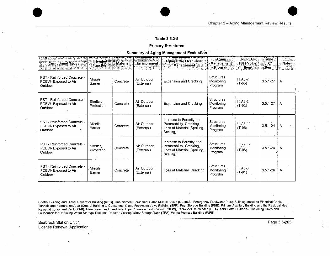
Chapter 3 -Aging Management Review Results
Table 3.5.2-5
Primary Structures
Summary of Aging Management Evaluation
Inteded ~ - A Eff..RýAging ,NUREG .. Table.Component Type T.MaKterial Envirornment gg ec eurng Minagement 180 Vo. 31 :Note-
"Funiction' a... Man~agement -7.ganItm ~ tm-
PST - Reinforced Concrete - StructuresPCEW- Exposed to Air Missile Concrete Expansion and Cracking Monitoring (T03) 3.5.1-27 AOutdoor (External) Program
PST - Reinforced Concrete - Shelter, Air Outdoor Structures II.A3-2PCEW- Exposed to Air Protection Concrete (External) Expansion and Cracking Monitoring (T-03) 3.5.1-27 AOutdoor Program
• ~~~Increase in Porosity and SrcuePST - Reinforced Concrete - Missile Air Outdoor Permeability, Cracking, Structures II1.A3-10PCEW- Exposed to Air Barrier Concrete Loss of Material (Spalling, Monitoring -06) 3.5.1-24 AOutdoor . Scaling) Program
PST - Reinforced Concrete - Increase in Porosity and StructuresPCon- cEreoed toncre Shelterte Air Outdoor Permeability, Cracking, Monitog III.A3-10 3.5.1-24PCEW- Exposed to Air Protection (External) Loss of Material (Spalling, Program (T-06)Outdoor -Scaling)
PST - Reinforced Concrete - Missile Air Outdoor Structures II1.A3-6PCEW- Exposed to Air Missie Concrete Loss of Material, Cracking Monitoring (T-01 3.5.1-26 AOutdoor Barrier (External) Program
Control Building and Diesel Generator Building (CDG), Containment Equipment Hatch Missile Shield (CEHMS), Emergency Feedwater Pump Building Including Electrical CableTunnels and Penetration Area (Control Building to Containment) and Pre-Action Valve Building (EFP), Fuel Storage Building (FSB), Primary Auxiliary Building and the Residual HeatRemoval Equipment Vault (PAB), Main Steam and Feedwater Pipe Chases - East & West (PCEW), Personnel Hatch Area (PHA), Tank Farm (Tunnels) - Including Dikes andFoundation for Refueling Water Storage Tank and Reactor Makeup Water Storage Tank (TFA), Waste Process Building (WPB)
Seabrook Station Unit 1License Renewal Application
Page 3.5--203

Chapter 3 -Aging Management Review Results
Table 3.5.2-5
Primary Structures
Summary of Aging Management Evaluation
Intrijed - Aging. _ NUREG Table77 Component Type. -ucin Material Environment% gnEfeteurn. Man aemeflti ~1O o.2 3X1 NoteFucto Management asPorm tm
PST - Reinforced Concrete - Shelter- Air Outdoor Structures Ii1.A3-6PCEW- Exposed to Air Protection Concrete (External) Loss of Material, Cracking Monitoring (T-01) 3.5.1-26 AOutdoor Program
PST - Reinforced Concrete - Structural Raw Water Cracking, Loss of Bond, Structures IIl.A3-4PCEW- Exposed toRaw Concrete xternal) Loss of Material (Spalling, Monitoring (T )3.5.1-31 A, 512Waterxposedrto(awtSuppor Scaling) Program
PST - Reinforced Concrete - Structural Raw Water Structures II1.A3-2PCEW- Exposed to Raw Support Concrete (External) Expansion and Cracking Monitoring (T-03) 3.5.1-27 A, 512Water Program
PST - Reinforced Concrete - Ground Cracking, Loss of Bond, Structures II1.A3-4PHA- Below Grade Flood Barrier Concrete Water/Soil Loss of Material (Spalling, Monitoring (T-05) 3.5.1-31 A
(External) Scaling) Program
PST - Reinforced Concrete - Structural Ground Cracking, Loss of Bond, Structures III.A3-4PHA- Belorad e Sura Concrete Water/Soil Loss of Material (Spalling, Monitoring (T-05) 3.5.1-31 APHA- Below Grade Support (External) Scaling) Program
Control Building and Diesel Generator Building (CDG), Containment Equipment Hatch Missile Shield (CEHMS), Emergency Feedwater Pump Building Including Electrical CableTunnels and Penetration Area,(Control Building to Containment) and Pre-Action Valve Building (EFP), Fuel Storage Building (FSB), Primary Auxiliary Building and the Residual HeatRemoval Equipment Vault (PAB), Main Steam and Feedwater Pipe Chases - East & West (PCEW), Personnel Hatch Area (PHA), Tank Farm (Tunnels) 7 Including Dikes andFoundation for Refueling Water Storage Tank and Reactor Makeup Water Storage Tank (TFA), WasteProcess Building (WPB)
Seabrook Station Unit 1License Renewal Application
Page 3.5-204
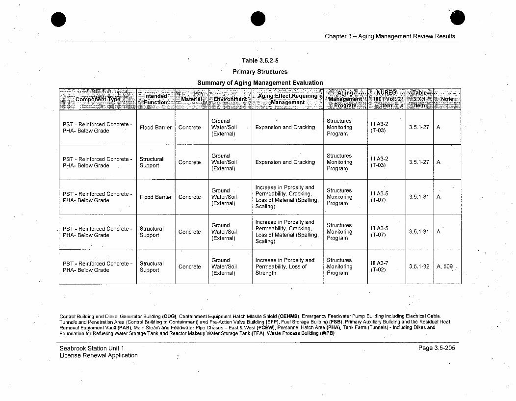
Chapter 3 -Aging Management Review Results
Table 3.5.2-5
Primary Structures
Summary of Aging Management Evaluation
PST Int ended Agingce Effect -eGrodAging SNUREG ATableComponent Type FnrMaterial Environment agin Ec riing Managrment 1801 Vol.2 3.X.17 N oe
PHA-anagementadePr(External)mPrtemaGround Structures
PST - Reinforced Concrete - StutrlIII.A3-2
PSA- ReiowGrcdCe Flood Barrier Concrete Water/Soil Expansion and Cracking Monitoring (T-03) 3.5.1-27 APHA- Below Grade Supp(External) Program
PST - Reinforced Concrete - Structural Ground Structures iII.A3-2PHA- Below Grade Support Concrete Water/Soil Expansion and Cracking Monitoring (T-03) 3.5.1-27 A
(External) Program
Ground Increase in Porosity and StructuresPST - Reinforced Concrete - Flood Barrier Concrete Water/Soil Permeability, Cracking, Monitoring (TI.A3-5 3.5.1-31 APHA- Below Grade Lossof Material (Spalling,S(External) Scaling) Program
Concrete - Structural Ground Increase in Porosity and StructuresPST - Reinforced Cnrt-Sruual Concrete Water/Soil Permeability, Cracking, Monitoring Ill.A3-5 3.5.1-31 A
PH-BlwGaeSpotLoss of Material (Spalling, (T07PHA-Belw GadeSuport(External) Scaling) Program -7
PST- eifocedCocrte- SrutualGround Increase in Porosity and Structures IIA-PHA- Reiowrcd e Strt Concrete Water/Soil Permeability, Loss of -Monitoring (T-02) 3.5.1-32 A, 509PHA- Below Grade Support (External) Strength Program
Control Buildingand Diesel Generator Building (CDG), Containment Equipment Hatch Missile Shield (CEHMS), Emergency Feedwater Pump Building Including Electrical CableTunnels and Penetration Area (Control Building to Containment) and Pre-Action Valve Building (EFP), Fuel Storage Building (FSB), Primary Auxiliary Building and the Residual HeatRemoval Equipment Vault (PAB), Main Steam and Feedwater Pipe Chases - East.& West (PCEW), Personnel Hatch Area (PHA), Tank Farm (Tunnels) - Including Dikes andFoundation for Refueling Water Storage Tank and Reactor Makeup Water Storage Tank (TFA), Waste Process Building (WPB)
Seabrook Station Unit 1License Renewal Application
Page 3.5-205
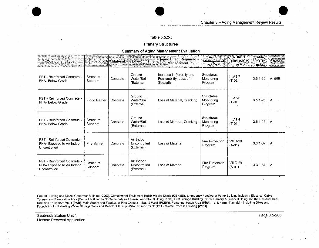
Chapter 3 - Aging Management Review Results
Table 3.5.2-5
Primary Structures
Summary of Aging Management EvaluationAgig Efec ~ Aing XNUREG Tabl
Intenided EfcRequiring- rn2.Fnctoni geiUyp Mn~ ment 1801- Vl.Z 2 3X.1 Note.'.:Compont-,Type -MatralMaterial Environment......Managem t P ragme Im I
Ground Increase in Porosity and Structures II1.A3-7
PHA- Below Grade Support Concrete Water/Soil Permeability, Loss of Monitoring (T-02) 3.5.1-32 A, 509(External) Strength Program
PST- Reinforced Concrete - Ground Structures II1.A3-6Flood Barrier Concrete Water/Soil Loss of Material, Cracking Monitoring (T-01) 3.5.1-26 A
PHA- Below Grade (External) Program(T-01)
Ground StructuresPST - Reinforced Concrete - Structural Concrete Water/Soil Loss of Material, Cracking Monitoring (T-01) 3.5.1-26 APHA- Below Grade Support (External) Program
PST - Reinforced Concrete - Air Indoor Fire Protection VII.G-29PHA- Exposed to Air Indoor Fire Barrier Concrete Uncontrolled Loss of Material Prog3.3.1-67 AUncontrolled (External) Program (A-91)
PST - Reinforced Concrete - Structural Air Indoor Fire Protection VII.G-29PHA- Exposed to Air Indoor Concrete Uncontrolled Loss of Material Proteto (A-9 3.3.1-67 AUnotoldSupport (Etra)Program (A-91)Uncontrolled .. (External)
Control Building and Diesel Generator Building (CDG), Containment Equipment Hatch Missile Shield (CEHMS), Emergency Feedwater Pump Building Including Electrical CableTunnels and Penetration Area (Control Building to Containment) and Pre-Action Valve Building (EFP), Fuel Storage Building (FSB), Primary Auxiliary Building and the Residual HeatRemoval Equipment Vault (PAB), Main Steam and Feedwater Pipe Chases - East & West (PCEW), Personnel Hatch Area (PHA), Tank Farm (Tunnels) - Including Dikes andFoundation for Refueling Water Storage Tank and Reactor Makeup Water Storage Tank (TFA), Waste Process Building (WPB)
Seabrook Station Unit 1.License Renewal Application
Page 3.5-206

Chapter 3 -Aging Management Review Results
Table 3.5.2-5
Primary Structures
Summary of Aging Management Evaluation
~liedd ~-~ ging- . NUJREG.ý -- Table<. ..~,C oetType Fiton Material Environment a irE~rc Reiiig Ma2 -- a2 3X1 Nt
PHA- Exposed to Air Indoor Fire Barrier Concrete Uncontrolled Loss of Material (Spalling, Monitoring (T-A4) 3.5.1-23AUncontrolled (External). Scaling) Program (-4
PST - Reinforced Concrete - Air Indoor Cracking, Loss of Bond, Structures II1.A3-9PHA- Exposed to Air Indoor Fire Concrete Uncontrolled Loss of Material (Spalling, Monitoring (T-04) 3.5.1-23 AUncontrolled (External) Scaling) Program
PST - Reinforced Concrete - S Air Indoor Cracking and Firection II.G-2
PHA- Exposed to Air Indoor FireBarrier Concrete Uncontrolled Loncreterack ing Monitorin (T-28 3.3.1-65 AUncontrolled (External) Spalling .) Program (A-90)
PST - Reinforced Concrete - Structural Indoor Concrete Cracking and Fire Protection VII.G-28PHA-Exposed to Air Indoor Concrete Uncontrolled Sun Program (A-90) 3.3.1-65 AUncontrolled " Support (External) paig
PST - Reinforced Concrete - Air Indoor StructuresPST RenfocedConret - Ar Idoo Stuctres III.A3-2
PHA- Exposed to Air Indoor Fire Barrier Concrete Uncontrolled Expansion and Cracking Monitoring (T-03) 3.5.1-27 AUncontrolled (External) Program (T-03)
Control Building and Diesel Generator Building (CDG), Containment Equipment Hatch Missile Shield (CEHMS), Emergency Feedwater Pump Building Including Electrical CableTunnels and Penetration Area (Control Building to Containment) and Pre-Action Valve Building (EFP), Fuel Storage Building (FSB), Primary Auxiliary Building and the Residual HeatRemoval Equipment Vault (PAB), Main Steam and Feedwater Pipe Chases - East & West (PCEW), Personnel Hatch Area (PHA), Tank Farm (Tunnels) - Including Dikes andFoundation for Refueling Water Storage Tank and Reactor Makeup Water Storage Tank (TFA), Waste Process Building (WPB)
Seabrook Station Unit 1License Renewal Application
Page 3.5-207

Chapter 3 -Aging Management Review Results
Table 3.5.2-5
Primary Structures
Summary of Aging Management Evaluation.
Inened-,7 -Aýglng, ~NUREG 'Table - _
iComponent Type Fnio Material _ ..Environmenit iii ~fetRqiiij Managemhent ý-1J801 Vol. 2 3.X. Note~fittiom Manaigemfent_. ~ ______________ . 2~• Programn >-Ite .Item
PST - Reinforced Concrete - Structural Air Indoor Structures II.A3-2PHA- Exposed to Air Indoor Surt Concrete Uncontrolled Expansion and Cracking Monitoring (T-0 3.5.1-27 AUncontrolled Support (External) Program
Air ~ndoor Increase in Porosity andPST - Reinforced Concrete - Air Indoor Permease Crositnd StructuresPHA- Exposed to Air Indoor Fire Barrier Concrete Uncontrolled PerMabil Cracking, Monitoring (T-16 3.5.1-24 AUncontrolled (External) Scaling) Program (
PST - Reinforced Concrete - Air Indoor Increase in Porosity and StructuresPHA- Exposed to Air Indoor Structural , Concrete Uncontrolled Permeability, Cracking, Monito III.A3-10 3.5.1-24 AUncontrolled Support Loss of Material (Spalling, P ring r2(T-06)
Scaling) Program
PST - Reinforced Concrete - Shelter, Air Outdoor Cracking, Loss of Bond, Structures III.A3-9PHA- Exposed to Air Concrete Loss of Material (Spalling, Monitoring 3.5.1-23 AOutdoor Protection (External) Scaling) Program (T-04)
PST - Reinforced Concrete - Air Outdoor StructuresPHA- Exposed to Air Shelter, Concrete Expansion and Cracking Monitoring II.A3-2 3.5.1-27 AOutdoor . Protection (External) Proram (T-03)OutdoorProgram
Control Building and Diesel Generator Building (CDG), Containment Equipment Hatch Missile Shield (CEHMS), Emergency Feedwater Pump Building Including Electrical CableTunnels and Penetration Area (Control Building to Containment) and Pre-Action Valve Building (EFP), Fuel Storage Building (FSB), Primary Auxiliary Building and the Residual HeatRemoval Equipment Vault (PAB), Main Steam and Feedwater Pipe Chases - East & West (PCEW), Personnel Hatch Area (PHA), Tank Farm (Tunnels) - Including Dikes andFoundation for Refueling Water Storage Tank and Reactor Makeup Water Storage Tank (TFA), Waste Process Building (WPB)
Seabrook Station Unit 1'License Renewal Application
Page 3.5-208

0Chapter 3 -Aging Management Review Results
Table 3.5.2-5
Primary Structures
Summary of Aging Management Evaluation
'9 ~Intended Agn fetRqiigI Aging' . I~UE Tbe~Component Type~ Fucin Material £Enviro~nment AgnEfetRqi ing Management 1861ol 2 31.X.1 ot
F- `. -io - Management ~ rga< Jl~ tm ___Increase in Porosity and
PST - Reinforced Concrete -Air Outdoor Permeability, Cracking StructuresPHA- Exposed to Air e Concrete Monitoring .A3-1 3.5.1-24 AOutdoor Protection (External) Loss of Material (Spalling, rg (T-06)
Scaling) Program
PST - Reinforced Concrete - Shelter, Air Outdoor Structures II1.A3-6PHA- Exposed to Air Concrete Loss of Material, Cracking Monitoring 3.5.1-26 AOutdoor Protection (External) Program(T01)
PST - Reinforced Concrete - Ground Cracking, Loss of Bond, Structures III.A3-4T - Reiorcd e Flood Barrier Concrete Water/Soil' Loss of Material (Spalling, Monitoring (T-05)' 3.5.1-31 A
TEA- Below Grade (External) Scaling) Program
PST- Reinforced Concrete - Structural Ground Cracking, Loss of Bond, StructuresConcrete Water/Soil Loss of Material (Spalling, Monitoring' 3.5.1-31 A(External), Scaling) Program (T-05)
PST - Reinforced Concrete - Ground Structures III.A3-2TEA- Below Grade Flood Barrier Concrete Water/Soil Expansion and Cracking Monitoring (T-03) 3.5.1-27 A
(External) Program
Control Building and Diesel Generator Building (CDG), Containment Equipment Hatch Missile Shield (CEHMS), Emergency Feedwater Pump Building Including Electrical CableTunnels and Penetration Area (Control Building to Containment) and Pre-Action Valve Building (EFP), Fuel Storage Building (FSB), Primary Auxiliary Building and the Residual HeatRemoval Equipment Vault (PAB), Main Steam and Feedwater Pipe Chases - East & West (PCEW), Personnel Hatch Area (PHA), Tank Farm (Tunnels) - Including Dikes andFoundation for Refueling Water Storage Tank and Reactor Makeup Water Storage Tank (TFA), Waste Process Building (WPB)
Seabrook Station Unit 1License Renewal Application
Page 3.5-209

Chapter 3 - Aging Management Review Results
Table 3.5.2-5
Primary Structures
Summary of Aging Management Evaluation
Itdd ~ 7ll2:m:....7. ~ - ~~Ii-'Agig~ -NUREGý .- TablComponentj :.Typ e ene Materl i e *****:. Requiring -E __o -:Mana -ent 1801 -Vol._2 2 3,X,1I Note
-.Functi'on<. ItemManagement •Pr.g ==Ii lt=m Item.........
GroundStructuresPST - Reinforced Concrete - Structural Ground III.A3-2TEA- Below Grade Support Concrete Water/Soil Expansion and Cracking Monitoring (T-03) 3.5.1-27 A
(External) Program
Ground Increase in Porosity and StructuresPST - Reinforced Concrete - Flood Barrier Concrete Water/Soil Permeability, Cracking, Monitoring (.A3-5 3.5.1-31 ATFA- Below Grade (External) Loss of Material (Spalling, rg (T
(External) Scaling) Porm-7
Ground Increase in Porosity and StructuresPST - Reinforced Concrete - Structural Concrete Water/Soil Permeability, Cracking, Monitoring IH.A3-5 3.5.1-31 ATFA- Below Grade Support (External) Loss of Material (Spalling, Program (T-07)
Scaling)
PST - Reinforced Concrete - Structural Ground Increase in Porosity and Structures III.A3-7PTE- Belowrad e Stupra Concrete Water/Soil Permeability, Loss of Monitoring (T-.02) 3.5.1-32 A, 509TFA- Below Grade Support (External) Strength Program
PST - Reinforced Concrete - Structural Ground Increase in Porosity and Structures III.A3-7TEA- Below Grade Support Concrete Water/Soil Permeability, Loss of Monitoring (T-02) 3.5.1-32 A, 509
(External) Strength Program
Control Building and Diesel Generator Building (CDG), Containment Equipment Hatch Missile Shield (CEHMS), Emergency Feedwater Pump Building Including Electrical CableTunnels and Penetration Area (Control Building to Containment) and Pre-Action Valve Building (EFP), Fuel Storage Building (FSB), Primary Auxiliary Building and the Residual HeatRemoval Equipment Vault (PAB), Main Steam and Feedwater Pipe Chases - East & West (PCEW), Personnel Hatch Area (PHA), Tank Farm (Tunnels) - Including Dikes andFoundation for Refueling Water Storage Tank and Reactor Makeup Water Storage Tank (TFA), Waste Process Building (WPB)
Seabrook Station Unit 1License Renewal Application
Page 3.5-210
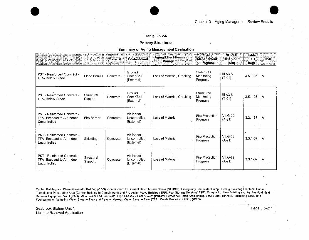
0Chapter 3 -Aging Management Review Results
Table 3.5.2-5
Primary Structures
Summary of Aging Management Evaluation
K ntnd& 'Aging NUREG "Table'Mterial Enronen Aging Effect RequiringComponent Type, Maera Eucto Management Management 1801 Vol. 2 3.X.1 Note
Program ltm Ite
PST - Reinforced Concrete - Ground Structures III.A3-6PT - Reiorcd e Flood Barrier Concrete Water/Soil Loss of Material, Cracking Monitoring (T-01) 3.5.1-26 ATEA- Below Grade (External) Program
PST - Reinforced Concrete - Structural Ground Structures Ill.A3-6Concrete Water/Soil Loss of Material, Cracking Monitoring (T-O1) 3.5.1-26 ATFA- Below Grade Support (ET-01) rora
(External) Program
PST - Reinforced Concrete - Air Indoor Fire Protection VII.G-29TFA- Exposed to Air Indoor Fire Barrier Concrete Uncontrolled Loss of Material Program (A-91)AUncontrolled (External)
PST - Reinforced Concrete - Air Indoor Fire Protection VII.G-29TFA- Exposed to Air Indoor Shielding Concrete Uncontrolled Loss of Material 3.3.1-67 AUncontrolled (External) Program (A-91)
PST " Reinforced Concrete - Structural Air Indoor Fire Protection VII.G-29TFA- Exposed to Air Indoor Support Concrete Uncontrolled Loss of Material Program (A-91)3.3.1-67 AUncontrolled (External)
Control Building and Diesel Generator Building (CDG), Containment Equipment Hatch Missile Shield (CEHMS), Emergency Feedwater Pump Building Including Electrical CableTunnels and Penetration Area (Control Building to Containment) and Pre-Action Valve Building (EFP), Fuel Storage Building (FSB), Primary Auxiliary Building and the Residual HeatRemoval Equipment Vault (PAB), Main Steamand Feedwater Pipe Chases - East & West (PCEW), Personnel Hatch Area (PHA), Tank Farm (Tunnels) - Including Dikes andFoundation for Refueling Water Storage Tank and Reactor Makeup Water Storage Tank (TFA), Waste Process Building (WPB)
Seabrook Station Unit 1License Renewal Application
Page 3.5-211

Chapter 3 -Aging Management Review Results
Table 3.5.2-5
Primary Structures
Summary of Aging Management Evaluation
~A Effect Requirin -agig 1UE 131able-Coh.onent 1 Pe n . Material Environment .. :..n . - Management 180ZVo12 3.X.1 Note
Functon - - ~.ro gram -. -IteFm1§ Itemn
PST - Reinforced Concrete - Air Indoor Cracking, Loss of Bond, Structures Il.A3-9TFA- Exposed to Air Indoor Fire Barrier Concrete Uncontrolled Loss of Material (Spalling, Monitoring (T-4) 3.5.1-23 AUncontrolled (External) Scaling) Program
PST - Reinforced Concrete - Air Indoor Cracking, Loss of Bond, Structures II1.A3-9TFA- Exposed to Air Indoor Shielding Concrete Uncontrolled Loss of Material (Spalling, Monitoring (T-04) 3.5.1-23 AUncontrolled (External) Scaling) Program
PST - Reinforced Concrete - Structural Air Indoor Cracking, Loss of Bond, Structures II1.A3-9TFA- Exposed to Air Indoor Support Concrete Uncontrolled Loss of Material (Spalling, Monitoring (T_04) 3.5.1-23 AUncontrolled (External) Scaling) Program
PST - Reinforced Concrete - Air Indoor Concrete Cracking and Fire Protection VII.G-28TFA- Exposed to Air Indoor Fire Barrier Concrete Uncontrolled Spalling Program (A-90) 3.3.1-65 AUncontrolled (External)
PST - Reinforced Concrete - Air Indoor Concrete Cracking and Fire Protection VII.G-28TFA- Exposed to Air Indoor Shielding Concrete Uncontrolled Spalling Program (A-90) 3.3.1-65 A.Uncontrolled (External)
Control Building and Diesel Generator Building (CDG), Containment Equipment Hatch Missile Shield (CEHMS), Emergency Feedwater Pump Building Including Electrical CableTuhnels and Penetration Area (Control Building to Containment) and Pre-Action Valve Building (EFP), Fuel Storage Building (FSB), Primary Auxiliary Building and the Residual HeatRemoval Equipment Vault (PAB), Main Steam and Feedwater Pipe Chases - East & West (PCEW), Personnel Hatch Area (PHA), Tank Farm (Tunnels) - Including Dikes andFoundation for Refueling Water Storage Tank and Reactor Makeup Water Storage Tank (TFA), Waste Process Building (WPB)
Seabrook Station Unit 1License Renewal Application
Page 3.5-212
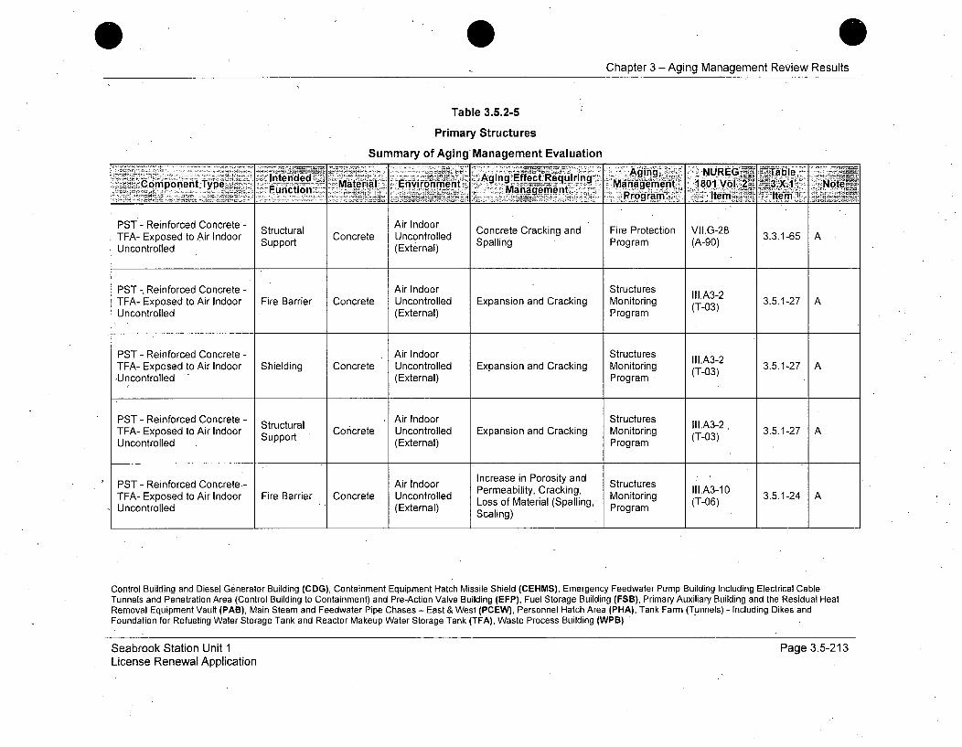
0Chapter 3 - Aging Management Review Results
Table 3.5.2-5
Primary Structures
Summary of Aging Management EvaluationIY~dd . 4ing NUREG _~T.Able
IneddAging Effect.116uiring Maaeet 10Vo.23X1 NteComponent Type : Function Material Environment . .Mnagement m1801 eol.2 •-••-Note
PST - Reinforced Concrete - Structural Air IndoorTFA- Exposed to Air Indoor Concrete Uncontrolled Concrete Cracking and Fire Protection VII.G-28AUncontrolled Support (External) Spalling Program (A-90)
PST -, Reinforced Concrete - Air Indoor StructuresTFA- Exposed to Air Indoor Fire Barrier Concrete Uncontrolled Expansion and Cracking Monitoring (T-03) 3.5.1-27 AUncontrolled (External) Program
PST - Reinforced Concrete - Air Indoor StructuresTFA- Exposed to Air Indoor Shielding Concrete Uncontrolled Expansion and Cracking Monitoring (T-03) 3.5.1-27 A,Uncontrolled (External) Program •
PST - Reinforced Concrete - Structural Air Indoor Structures Ill.A32TEA- Exposed to Air Indoor u Concrete Uncontrolled Expansion and Cracking Monitoring TI03) 3.5.1-27 AUncontrolled (External) Program
PST - Reinforced Concrete.- Air indoor Increase in Porosity and StructuresPermeability, Cracking, II1.A3-10TFA- Exposed to Air Indoor Fire Barrier Concrete Uncontrolled Prof Material Cracking, Monitoring (T-0 3.5.1-24 AUncontrolled (External) Scaling) Program -06)
Control Building and Diesel Generator Building (CDG), Containment Equipment Hatch Missile Shield (CEHMS), Emergency Feedwater Pump Building Including Electrical CableTunnels and Penetration Area (Control Building to Containment) and Pre-Action Valve Building (EFP), Fuel Storage Building (FSB), Primary Auxiliary Building and the Residual HeatRemoval Equipment Vault (PAB), Main Steam and Feedwater Pipe Chases - East & West (PCEW), Personnel Hatch Area (PHA), Tank Farm (Tunnels) - Including Dikes andFoundation for Refueling Water Storage Tank and Reactor Makeup Water Storage Tank (TFA), Waste Process Building (WPB) "
Seabrook Station Unit 1License Renewal Application
Page 3.5-213

Chapter 3 -Aging Management Review Results
Table 3.5.2-5
Primary Structures
Summary of Aging Management Evaluation
Aginas in PorosityaandIntended "Aging Strc Agis eComponent Type Materia ir IEndronment .efect R iring M g 1.310UcnFunction _ Management 1801 WProgram Z 3. No
PST - Reinforced Concrete - Air Indoor Increase in Porosity and StructuresTFA- Exposed to Air Indoor Shielding Concrete Uncontrolled Permeability, Cracking, Monitoring II1.A3-10 3.5.1-24 A
(External) Loss of Material (Spalling, Program (T-06)Uncontrolled Support (External) Scaling)
Inraein Porosity andPST - Reinforced Concrete - Ssil Air Indoor ICrmeaseity, Cr d, Structures II1.A3-9TFA- Exposed to Air Indoor Strt Concrete Uncontrolled Loss of Material (Spalling, Monitoring (T-06) 3.5.1-24 A
UnotroorlBar (External) Scaling) Program
PST - Reinforced Concrete - Missile Air Outdoor Cracking, Loss of Bond, Structures II1.A3-9TFA- Exposed to Air Barrier Concrete (External) Loss of Material (Spalling, Monitoring (T-04) 3.5.1-23 AOutdoor Scaling) Program
PST - Reinforced Concrete - Shelter Air Outdoor Cracking, Loss of Bond, Structures III.A3-9TFA- Exposed to Air Concrete Loss of Material (Spalling, Monitoring 3.5.1-23 AOutdoor (External) Scaling) Program
PST - Reinforced Concrete - Missile CAir Outdoor aStructures r.A3-2TEA- Exposed to Air Barrier Cnr te Extenl) Expansion an rcig Monitoring (T- .03), 3512 AOutdoor xenProgram
Control Building and Diesel Generator Building (CDG), Containment Equipment Hatch Missile Shield (CEHMS), Emergency Feedwater Pump Building Including Electrical CableTunnels and Penetration Area (Control Building to Containment) and Pre-Action Valve Building (EFP), Fuel Storage Building (FSB), Primary Auxiliary Building and the Residual HeatRemoval Equipment Vault (PAB), Main Steam and Feedwater Pipe Chases - East & West (PCEW), Personnel Hatch Area (PHA), TankFarm (Tunnels) - Including Dikes andFoundation for Refueling Water Storage Tank and Reactor Makeup Water Storage Tank (TFA), Waste Process Building (WPB)
Seabrook Station Unit 1License Renewal Application
Page 3.5-214

0Chapter 3 - Aging-Management Review Results
Table 3.5.2-5
Primary Structures
Summary of Aging Management Evaluation
PSTn e Aging Reinforced C tA ging NUREG Tuable.Comnponent Type lned ~ Mtra 'niomn gn fefeurn Mafiagement =1801..Vol. 2. A-.X.1~ NoteFunction~ Managemlent ~r g mIe le~
PST - Reinforced Concrete - Shelter, Cocee Air Outdoor Exasinanrrakng Mntoring lll.A3-2 3512TFA- Exposed to Air Protection Concrete (External) Expansion and Cracking Monitoring (T-03) 3.5.1-27 AOutdoor Program
PST - Reinforced Concrete - Increase in Porosity and StructuresMissile Air Outdoor Permeability, Cracking, III.A3-10TFA- Exposed to Air Barrier Concrete PeoMabil Cracking, Monitoring (T06) 3.5.1-24 AOutdoor (External) Loss of Material (Spalling, Program
Scaling)
PST - Reinforced Concrete - Shelter, Air Outdoor Increase in Porosity and StructuresTEA- Exposed to Air Concrete Permeability, Cracking, Monitoruct 3.5.1-24 AOutdoor Protection (External) Loss of Material (Spalling, rig (T-06)
Scaling) Program
PST - Reinforced Concrete - Missile Air Outdoor Structures III.A3-6TEA- Exposed to Air Barrier Concrete Loss of Material, Cracking Monitoring (T-1) 3.5.1-26 AOutdoor Program
PST - Reinforced Concrete - Shelter, Concrete Air Outdoor Loss ofMaterial, Cracking Structures III.A3-6 3.5.1-26 ATFA- Exposed to Air Protection (External) (T-0)Monitoring 3Outdoor Program
Control Building and Diesel Generator Building (CDG), Containment Equipment Hatch Missile Shield (CEHMS), Emergency Feedwater Pump Building Including Electrical CableTunnels and Penetration Area (Control Building to Containment) and Pre-Action Valve Building (EFP), Fuel Storage Building (FSB), Primary Auxiliary Building and the Residual HeatRemoval Equipment Vault (PAB), Main'Steam and Feedwater Pipe Chases - East & West (PCEW), Personnel Hatch Area (PHA), Tank Farm (Tunnels) - Including Dikes andFoundation for Refueling Water Storage Tank and Reactor Makeup Water Storage Tank (TFA), Waste Process Building (WPB)
Seabrook Station Unit 1License Renewal Application
Page 3.5-215

Chapter 3 -Aging Management Review Results
Table 3.5.2-5
Primary Structures
Summary of Aging Management Evaluation
IPnntendd nAing, LossofNURBond SuComponintnment Mat eI Environmentg ManagemerltZ 1801 Vol.A 2 3.X.1 Note
oFl Bie tea Mana tComonntTng)ProgramItem item
PST - Reinforced Concrete - Ground Cracking, Loss of Bond, Structures II1.A3-4WPB- Below Grade Flood Barrier Concrete Water/Soil Loss of Material (Spalling, Monitoring (T-05) 3.5.1-31 A
(External) Scaling) Program
PST - Reinforced Concrete - Structural Ground Cracking, Loss of Bond, Structures III.A3-4WPB- Below Grade Support Concrete Water/Soil Loss of Material (Spalling, Monitoring (T-05) 3.5.1-31 A
(External) Scaling) Program
PST - Reinforced Concrete - Ground Structures III.A3-2WPB- BelnowradCe Flood Barrier Concrete Water/Soil Expansion and Cracking Monitoring (T-03) 3.5.1-27 A
(External) Program
PST - Reinforced Conc rete - Structural Ground Structures lll.A3-2WPB- Below Grade Support Concrete Water/Soil Expansion and C~racking Monitoring (T-03) 3.5.1-27 A
(External) Program
Ground Increase in Porosity and StructuresPST- Reinforced Concrete - Flood Barrier Concrete Water/Soil Permeability, Cracking, Monitoring (.A3-5 3.5.1-31 AWPB- Below Grade (External) Loss of Material (Spalling, rg (T
(Exteriial) Scaling) Porm-7
Control Building and Diesel Generator Building (CDG), Containment Equipment Hatch Missile Shield (CEHMS),Emergency Feedwater Pump Building Including Electrical CableTunnels and Penetration Area (Control Building to Containment) and Pre-Action Valve Building (EFP), Fuel Storage Building (FSB), Primary Auxiliary Building and the Residual HeatRemoval Equipment Vault (PAB), Main Steam and Feedwater Pipe Chases - East & West (PCEW), Personnel Hatch Area (PHA), Tank Farm (Tunnels) - Including Dikes andFoundation for Refueling Water Storage Tank and Reactor Makeup Water Storage Tank (TFA), Waste Process Building (WPB)
Seabrook Station Unit 1License Renewal Application'
Page 3.5-216
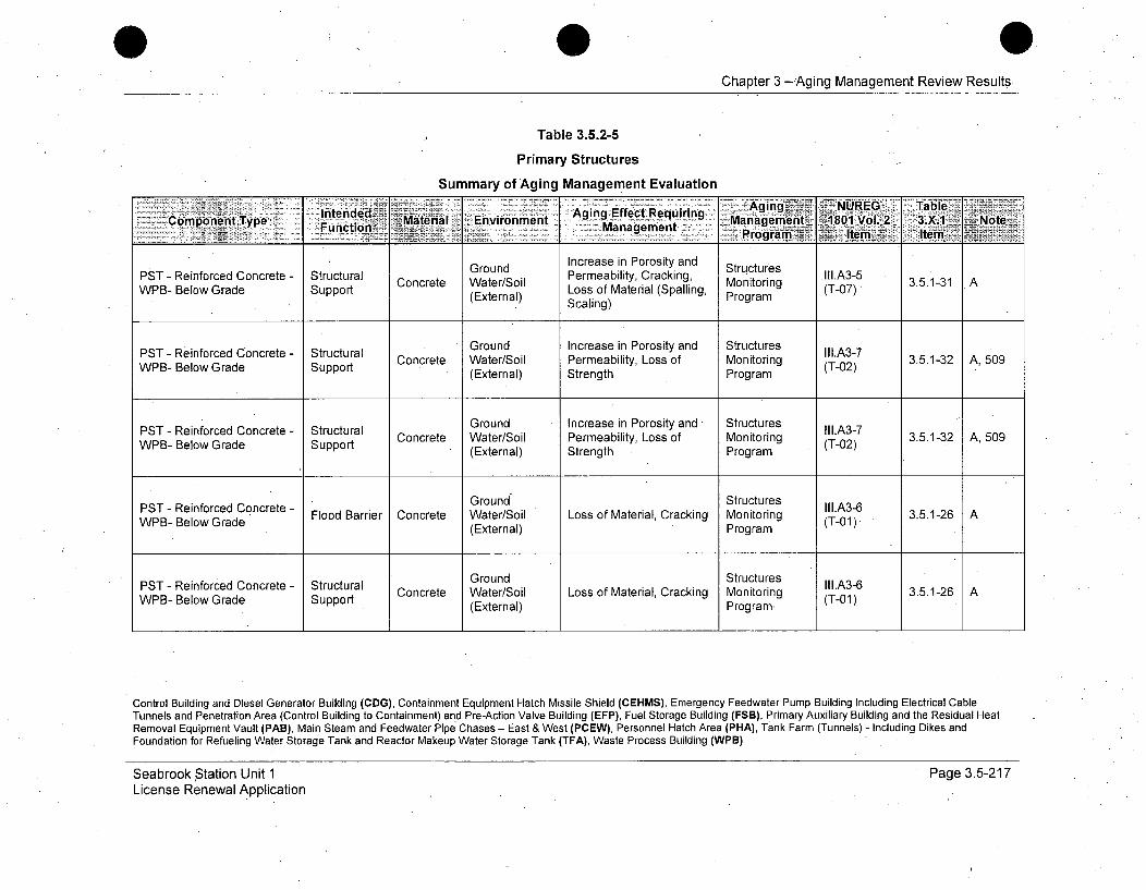
0 0Chapter 3 -Aging Management Review Results
Table 3.5.2-5
Primary Structures
Summary of Aging Management Evaluation
Intended v~aeil Evrnet Aging Effect' Requiring Agnji NRG TalMaera Mvromnn4agemen 1801 V6L~ 1.X.1 7Noteý11Compobent Type Fucin __ .en Maaeen,-ga2ilen ~ Ie
Ground Increase in Porosity and StructuresPST - Reinforced Concrete - Structural Concrete Water/Soil Permeability, Cracking, Monitoring II1.A3-5 3.5.1-31 AWPB- Below Grade Support (External) Loss of Material (Spalling, (T-07)(Extenal)Program
Scaling)
PST - Reinforced Concrete - Structural Ground Increase in Porosity and Structures II1.A3-7WPB- Below Grade Support Concrete Water/Soil Permeability, Loss of Monitoring (T02) 3.5.1-32 A, 509
(External) Strength Program
PST - Reinforced Concrete - Structural Ground Increase in Porosity and Structures lI1.A37WPB- Belowrad e Stupra Concrete Water/Soil Permeability, Loss of Monitoring (T-02) 3.5.1-32 A, 509WPB- Below Grade Support (External) Strength Program
PST- Reinforced Concrete - Ground Structures III.A3-6Flood Barrier Concrete Water/Soil Loss of Material, Cracking Monitoring (T-0 3.5.1-26 AWPB- Below Grade (External) Program (T-01)
PST- Reinforced Concrete- Structural Ground Structures II1.A3-6WPBT- ReiowrcedCe Strutu Concrete Water/Soil Loss of Material, Cracking Monitoring (T-01) 3.5.1-26 AWPB- Below Grade Support (External) Program,
Control Building and Diesel Generator Building (CDG), Containment Equipment Hatch Missile Shield (CEHMS), Emergency Feedwater Pump Building Including Electrical CableTunnels and Penetration Area (Control Building to Containment) and Pre-Action Valve Building (EFP), Fuel Storage Building (FSB), Primary Auxiliary Building and the Residual HeatRemoval Equipment Vault (PAB), Main Steam and Feedwater Pipe Chases - East & West (PCEW), Personnel Hatch Area (PHA), Tank Farm (Tunnels) - Including Dikes andFoundation for Refueling Water Storage Tank and Reactor Makeup Water Storage Tank (TFA), Waste Process Building (WPB)
Seabrook Station Unit 1License Renewal Application
Page 3.5-217
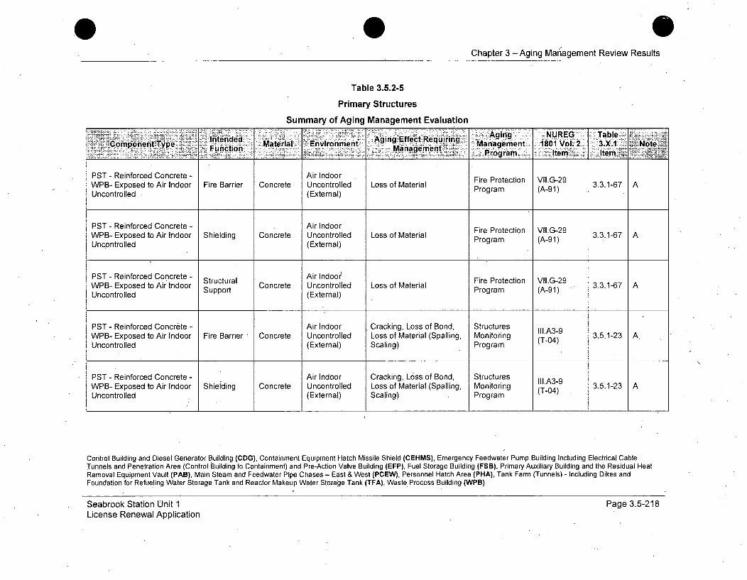
Chapter 3 -Aging Marnagement Review Results
Table 3.5.2-5
Primary Structures
Summary of Aging Management Evaluation
l~iened ' Aging NUREG Table-PSTnene -gnEc RenfrcduonreeriArnndo
WP-ComEponent Type Fuio Material Environment roldgs f ReuirPManagoment 1801 Vol. 2 3.X.1 NoteManrleementa)Program -Item Item
PST - Reinforced Concrete - Air Indoor Fire Protection VII.G-29WPB- Exposed to Air Indoor Fire Barrier Concrete Uncontrolled Loss of Material 3.3.1-67 AUncontrolled (External) Program (A-91)
PST - Reinforced Concrete - Air Indoor Fire Protection VII.G-29WPB- Exposed to Air Indoor Shielding Concrete Uncontrolled Loss of Material Proteto (A-9 3.3.1-67 AUncontrolled (External) Program (A-91)
PST - Reinforced Concrete - . Air lndoor Fire Protection VII.G-29WPB- Exposed to Air Indoor Stuctrta Concrete Uncontrolled Loss of Material Program (A-91) 3.3.1-67 AUncontrolled (External)
PST - Reinforced Concrete - Air Indoor Cracking, Loss of Bond, Structures II1.A3-9WPB- Exposed to Air Indoor Fire Barrier Concrete Uncontrolled Loss of Material (Spalling, Monitoring (T-04) 3.5.1-23 A.Uncontrolled (External) Scaling) Program
PST - Reinforced Concrete - Air Indoor Cracking, Loss of Bond, Structures III.A3-9WPB- Exposed to Air Indoor Shielding Concrete Uncontrolled Loss of Material (Spalling, Monitoring '4 3.5.1-23 AUncontrolled (External) Scaling) . Program (-4
Control Building and Diesel Generator Building (CDG), Containment Equipment Hatch Missile Shield (CEHMS), Emergency Feedwater Pump Building Including Electrical CableTunnels and Penetration Area (Control Building to Containment) and Pre-Action Valve Building (EFP), Fuel Storage Building (FSB), Primary Auxiliary Building and the Residual HeatRemoval Equipment Vault (PAB), Main Steam and Feedwater Pipe Chases - East & West (PCEW), Personnel Hatch Area (PHA), Tank Farm (Tunnels) - Including Dikes andFoundation for Refueling Water Storage Tank and Reactor Makeup Water Storage Tank (TFA), Waste. Process Building (WPB)
Seabrook Station Unit 1License Renewal Application
Page 315-218

Chapter 3 -Aging Management Review Results
Table 3.5.2-5
Primary Structures
Summary of Aging Management Evaluation
Intnde ,Aging NUIREG: ' Table,ComnponentType ,cto Material, Environment Agn fetRqiig Management 1801 Vol. 2 3. X.1 ~Note
- Mnaemet~Progfti _ Item I, temL
PST - Reinforced Concrete - Structural Air Indoor Cracking, Loss of Bond, Structures II1'-A3-9WPB- Exposed to Air Indoor Support Concrete Uncontrolled Loss of Material (Spalling, Monitoring (T-04) 3.5.1-23 AUncontrolled S o(External) Scaling) Program
PST - Reinforced Concrete - Air Indoor Concrete Cracking and Fire Protection VI1.G-28WPB- Exposed to Air Indoor Fire Barrier Concrete Uncontrolled Spalling Program (A--90) 3.3.1-65 AUncontrolled (External)
PST - Reinforced Concrete - Air Indoor Concrete Cracking and Fire Protection VII.G-28WPB- Exposed to Air Indoor Shielding Concrete Uncontrolled Spalling Program (A-90)3.3.1-65Uncontrolled (External)
PST - Reinforced Concrete - Structural AiroIndoorWPB- Exposed to Air Indoor Stuprt Concrete Uncontrolled Concrete Cracking and Fire Protection VII.G-28 3.3.1-65 AUncontrolled Support (External) Spalling Program (A-90)
PST - Reinforced Concrete - Air Indoor StructuresWPB- Exposed to Air Indoor Fire Barrier Concrete Uncontrolled Expansion and Cracking Monitoring (T-03) 3.5.1-27 AUncontrolled (External) Program
Control Building and Diesel Generator Building (CDG), Containment Equipment Hatch Missile Shield (CEHMS), Emergency Feedwater Pump Building Including Electrical CableTunnels and Penetration Area (Control Building to Containment) and Pre-Action Valve Building (EFP), Fuel Storage Building (FSB), Primary Auxiliary Building and the Residual HeatRemoval Equipment Vault (PAB), Main Steam and Feedwater Pipe Chases - East & West (PCEW), Personnel Hatch Area (PHA), Tank Farm (Tunnels) - Including Dikes andFoundation for Refueling Water Storage Tank and Reactor Makeup Water Storage Tank (TFA), Waste Process Building (WPB)
Seabrook Station Unit 1License Renewal Application
Page 3.5-219
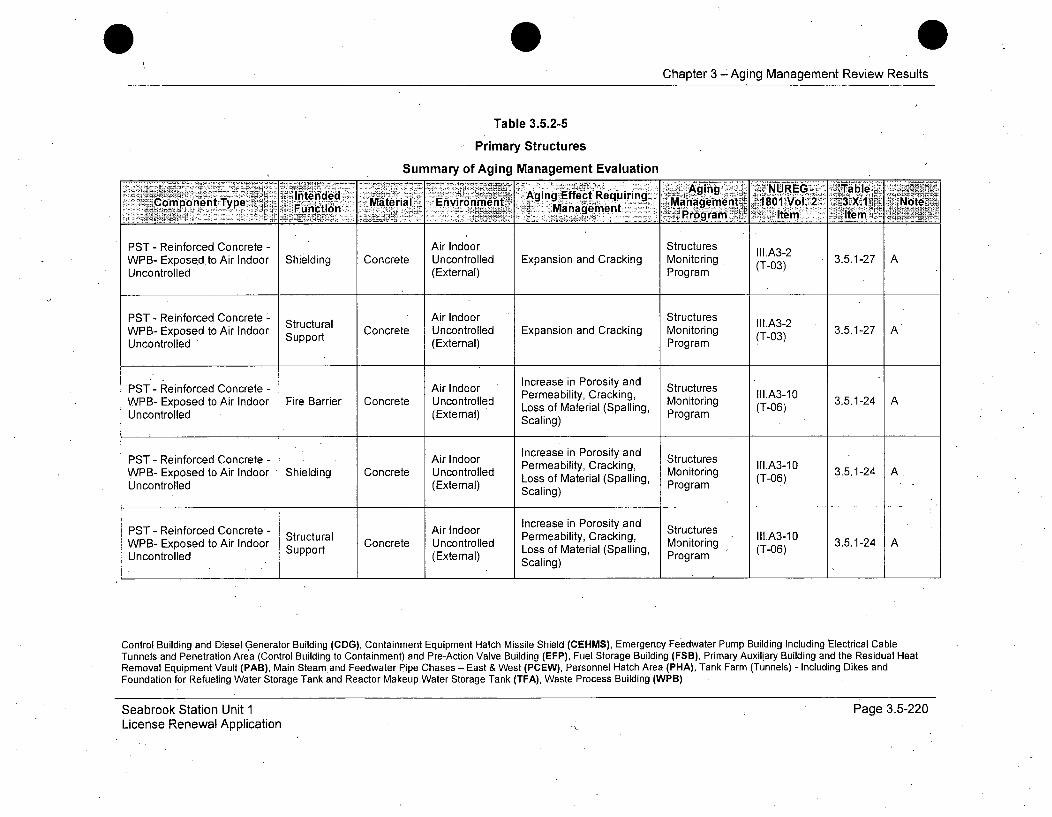
Chapter 3 -Aging Management Review Results
Table 3.5.2-5
Primary Structures
Summary of Aging Management Evaluation
Intended AAging EfetReciring %, ging oURdmenalComponentlType .. .. n.... n Material Environment Efft u 3X•1 NtMnagemene, ,1801 Vo12MaaeetProgram ltm - p~m
PST - Reinforced Concrete - Air Indoor StructuresWPB- Exposed.to Air Indoor Shielding Concrete Uncontrolled Expansion and Cracking Monitoring (T-03) 3.5.1-27 AUncontrolled (External) • Program
PST - Reinforced Concrete - Structural Air Indoor Structures III.A3-2WPB- Exposed to Air Indoor Strt Concrete Uncontrolled Expansion and Cracking Monitoring (T-03) 3.5.1-27 AUncontrolled Support (External) Program
PST - Reinforced Concrete - Air Indoor Increase in Porosity and StructuresWPB- Exposed to Air Indoor Fire Barrier Concrete Uncontrolled Permeability, Cracking, Monitoring .A3-10 3.5.1-24 AUncontrolled (External) Scaling) Program
PST - Reinforced Concrete - Air Indoor Increase in Porosity and StructuresWPB- Exposed to Air Indoor Shielding Concrete Uncontrolled Permeability, Cracking, Monitog II1.A3-10 3.5.1-24 A.Uncontrolled (External) Loss of Material (Spalling, Mogram (T-06)
Scaling)
PST - Reinforced Concrete - Air Indoor Increase in Porosity and StructuresWPB- Exposed to Air Indoor Structural Concrete Uncontrolled Permeability, Cracking, Monitoring Ill.A3-10 3.5.1-24 AUncontrolled Support (External) Loss of Material (Spalling, Program (T-06)
Scaling)
Control Building and Diesel Generator Building (CDG), Containment Equipment Hatch Missile Shield (CEHMS), Emergency Feedwater Pump Building Including Electrical CableTunnels and Penetration Area (Control Building to Containment) and Pre-Action Valve Building (EFP), Fuel Storage Building (FSB), Primary Auxiliary Building and the Residual HeatRemoval Equipment Vault (PAB), Main Steam and Feedwater Pipe Chases - East & West (PCEW), Personnel Hatch Area (PHA), Tank Farm (Tunnels) - Including Dikes andFoundation for Refueling Water Storage Tank and Reactor Makeup Water Storage Tank (TFA), Waste Process Building (WPB)
Seabrook Station Unit 1License Renewal Application
Page 3.5-220
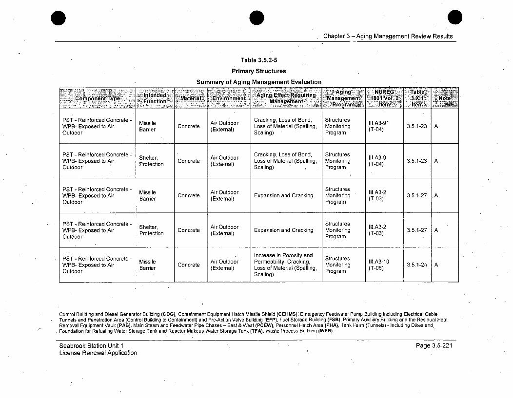
Chapter 3 -Aging Management Review Results
Table 3.5.2-5
Primary Structures
Summary of Aging Management Evaluation
Intended AirOudo CaingosoReiBuirind Aring IUI G2 TalWBCoEposnentoABi Material Environment Management (T-04) 3.X.1-23 ATye Function -_ angTet.Management~ ~ 10 o. 3X. ~ &.udorcain)Pirogram It ti
PST - Reinforced Concrete - Cracking, Loss of Bond, StructuresWPB- Exposed to Air Barrie Concrete Loss of Material (Spalling, Monitoring (T-04) 3.5.1-23 AOutdoor Prier (External) Scaling) Program
PST - Reinforced Concrete - Air Outdoor Cracking, Loss of Bond, StructuresWPB- Exposed to Air Shelter Concrete Loss of Material (Spalling Monitoring (T-03)-• 3.5.1-23 AOutdoor Protection (External) Scaling) Program (T-04)
PST - Reinforced Concrete - Missile Air Outdoor Structures lll.A3-2WPB- Exposed to Air Barrier Concrete Expansion and Cracking Monitoring (T-03) 3.5.1-27 AOutdoor Program
PST -, Reinforced Concrete - ShleAir Outdoor Structures IIA-WPB- Exposed to Air Shoelter, Concrete (xenl Expansion and Cracking Monitoring (Tl.A3) 3.5.1-27 AOutdoor Poeto(Etra)Program (-3
PST - Reinforced Concrete - Missile Air Increase in Porosity and StructuresAir Outdoor Permeability, Cracking, Moito Illl.A3-10WPB- Exposed to Air Barrier Concret (External) Loss of Material (Spalling, ring (T-06) 3.5.1-24 A
Outdoor Scaling) Program
Control Building and Diesel Generator Building (CDG), Containment Equipment Hatch Missile Shield (CEHMS), Emergency Feedwater Pump Building Including Electrical CableTunnels and Penetration Area (Control Building to Containment) and Pre-Action Valve Building (EFP), Fuel Storage Building (FSB), Primary Auxiliary Building and the Residual HeatRemoval Equipment Vault (PAB), Main Steam and Feedwater Pipe Chases - East & West (PCEW), Personnel Hatch Area (PHA), Tank Farm (Tunnels) - Including Dikes andFoundation for Refueling Water Storage Tank and Reactor Makeup Water Storage Tank (TFA), Waste Process Building (WPB)
Seabrook Station Unit 1License Renewal Application
Page 3.5-221
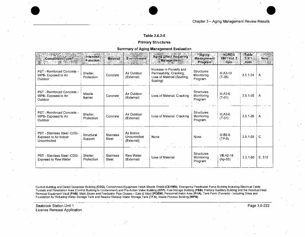
Chapter 3 -Aging Management Review Results
Table 3.5.2-5
Primary Structures
Summary of Aging Management Evaluation
IntendedI.a Mging Pmtyn aComponent.Type Fucin Material-., Enviroinment ect Recjuirv - 81'Vol.2~ 3X Notei- ~~~ i~~.M-ainagernet. rgamlem Ie
PSTI- Reinforced Concrete - Shelter, Air Outdoor Increase in Porosity and StructuresWBExoetoAr Setr Concrete ArOtor Permeability, Cracking, Monitorn IlI.A3-10 3.5.1-24 AWpB- Exposed to Air Protection (External) Loss of Material (Spalling, Program (T-06)Outdoor Scaling)
PST - Reinforced Concrete - Missile Air Outdoor Structures II1.A3-6WPB- Exposed to Air issie Concrete Loss of Material, Cracking Monitoring (T-01) 3.5.1-26 AOutdoor Barrier (External) Program (T
PST - Reinforced Concrete - Shelter, Concrete Loss of Material, Cracking Structures 3.5.1-26 AWPB- Exposed to Air Protection (External) Monitoring (T-01)Outdoor Program
PST - Stainless Steel -CDG- Structural S Air Indoor IExposed to Air Indoor Support Steel Uncontrolled None None (TP-5) 3.5.1-59 CUncontrolled Spt e (External)
PST - Stainless Steel -CDG- Shelter, Stainless Raw Water Structures VII.H2-18Exposed to Raw Water Protection Steel (External) Loss of Material Monitoring (Ap-55) 3.3.1-80 E, 512
t (Program
Control Building and Diesel Generator Building (CDG), Containment Equipment Hatch Missile Shield (CEHMS), Emergency Feedwater Pump Building Including Electrical CableTunnels and Penetration Area (Control Building to Containment) and Pre-Action Valve Building (EFP), Fuel Storage Building (FSB), Primary Auxiliary Building and the Residual HeatRemoval Equipment Vault (PAB), Main Steam and Feedwater Pipe Chases - East & West (PCEW), Personnel Hatch Area (PHA), Tank Farm (Tunnels) - Including Dikes andFoundation for Refueling Water Storage Tank and Reactor Makeup Water Storage Tank (TFA), Waste Process Building (WPB)
Seabrook Station Unit 1License Renewal Application
Page 3.5-222
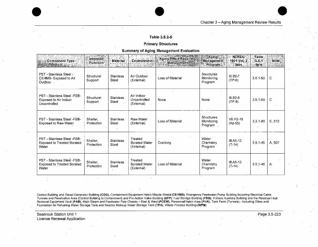
Chapter 3 -Aging Management Review Results
Table 3.5.2-5
Primary Structures
Summary of Aging Management Evaluation
T lntend~d Material nvironmen Aging -Effect ReqlUiring Aig.~ NRGS~alComponent Type Functial EnvirMangement ana-i1it 4801VoL.-2K 3.X. -Noter____________________________________ ~ Frgram'! "ItemU tm>_ __
PST - Stainless Steel - Structural Stainless Air Outdoor LsoMtrlo es I1P-7CEHMS- Exposed to Air Support Steel (External) Loss of Material Monitoring (TP-6) 3.5.1-50Outdoor Program
PST - Stainless Steel -FSB- Air IndoorExposed to Air Indoor Structural Stainless None NoneB28 3.5.1-59 C
Uncontrolled Support Steel (External) (TP-5)
PST - Stainless Steel -FSB- Shelter, Stainless Raw Water Structures VII.H2-18Loss of Material Monitoring (Ap-55) 3.3.1-80 E, 512
Exposed to Raw Water Protection Steel (External) Program
PST - Stainless Steel -FSB- Shelter Stainless Treated Water IIl.A513Exposed to Treated Borated Protection Steel Borated Water Cracking Chemistry T143.5.1-46 A, 507Water (External) Program
PST -Stainless Steel -FSB- Treated WaterShelter, Sanes Borated WtrLs fMtra hmsr I.51Exposed to Treated Borated Stainls Water Loss of Material Chemistry 3.5.1-46 AWater (External) Program T-14)
Control Building and Diesel Generator Building (CDG), Containment Equipment Hatch Missile Shield (CEHMS), Emergency Feedwater Pump Building Including Electrical CableTunnels and Penetration Area (Control Building to Containment) and Pre-Action Valve Building (EFP), Fuel Storage Building (FSB), Primary Auxiliary Building and the Residual HeatRemoval Equipment Vault (PAB), Main Steam and Feedwater Pipe Chases - East & West (PCEW), Personnel Hatch Area (PHA), Tank Farm (Tunnels) - Including Dikes andFoundation for Refueling Water Storage Tank and Reactor Makeup Water Storage Tank (TFA), Waste Process Building (WPB)
Seabrook Station Unit 1License Renewal Application
Page 3.5-223

Chapter 3 - Aging Management Review Results
Table 3.5.2-5
Primary Structures
Summary of Aging Management Evaluation
.Iended :Aging NA e NUE. fTab-Component Type _F•unction Material: Environment Ag: Efc :rManagement 1f801 Vol.-2 3.(." X' Note
__ MangementProgra >~' Item Item.....
PST - Stainless Steel -FSB- Structural Stainless Air w/Borated III.B2-9Fuel Transfer Tube in Air Water Leakage None None . 3.5.1-59 Awith Borated Water Leakage Support Steel (External) (TP-5)
PST - Stainless Steel -FSB- Air IndoorSut s.B2-8Fuel Transfer Tube in Air Strt Stail Uncontrolled None None (TP-5) 3.5.1-59 CIndoor Uncontrolled Support Steel (External)
PST - Stainless Steel -FSB- Stainless Air w/Boratedin Air with Borated Water Supportura Water Leakage None None (TP-5) 3.5.1-59 ALeakage (External)
PST - Stainless Steel -PAB- Structural Stainless Air Ind'oor 111.12-8Exposed to Air Indoor Support Steel Uncontrolled None None (TP-5) 3.5.1-59 CUncontrolled (External)
PST - Stainless Steel -PAB- Shelter, Stainless Raw Water Structures VII.H2-18Exposed toRaw Water Protection Steel (External) Loss of Material Monitoring (Ap-55)Program
Control Building and Diesel Generator Building (CDG), Containment Equipment Hatch Missile Shield (CEHMS), Emergency Feedwater Pump Building Including Electrical CableTunnels and Penetration Area (Control Building to Containment) and Pre-Action Valve Building (EFP), Fuel Storage Building (FSB), Primary Auxiliary Building and the Residual HeatRemoval Equipment Vault (PAB), Main Steam and Feedwater Pipe Chases - East & West (PCEW), Personnel Hatch Area (PHA), Tank Farm (Tunnels) - Including Dikes andFoundation for Refueling Water Storage Tank and Reactor Makeup Water Storage Tank (TFA), Waste Process Building (WPB)
Seabrook Station Unit 1License Renewal Application
Page 3.5-224
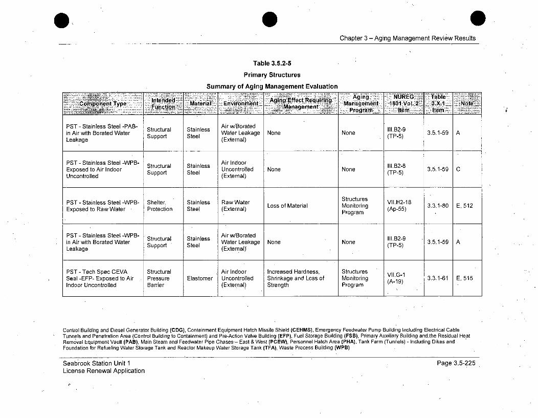
Chapter 3 -Aging Management Review Results
Table 3.5.2-5
Primary Structures
Summary of Aging Management Evaluation
P t S -Aging NUREG abrleGo in ponetntType nteMaterial EnvironmentSAging-tanestWtreke Manage 1801 Vol. 2 3.X1 o A tFu~ncin._ jManagemnent - gmn -. .- oLeakage Programuo SItelm (tnItem(P
PST - Stainless Steel -PAB- Structural Stainless Air w/BoratediAiwihBrtdWtrWater Leakage None None 3.5.1B599ineairwihBoatdWae Support Steel (External) (P5
PST - Stainless Steel -WPB- Stutrl Sanes Air Indoor. 11.132-8Exposed to Air Indoor Support Steel Uncontrolled None None (TP-5) 3.5.1-59 CUncontrolled (External)
PST - Stainless Steel -WPB- Shelter, Stainless Raw Water Structures VII.H2-18Exposed to Raw Water Protection Steel (External) Loss of Material Monitoring (Ap-55) 3.3.1-80 E, 512
Program
PST - Stainless Steel -WPB- Structural Stainless Air w/Borated 111.B2-9in Air with Borated Water Support Steel Water Leakage None None (TP-5)Leakage (External)
PST - Tech Spec CEVA Structural Air Indoor Increased Hardness, Structures VII.G-1Seal -EFP- Exposed to Air Pressure Elastomer Uncontrolled Shrinkage and Loss of Monitoring (A-19) 3.3.1-61 E, 515Indoor Uncontrolled Barrier (External) Strength Program
Control Building and Diesel Generator Building (CDG), Containment Equipment Hatch Missile Shield (CEHMS), Emergency Feedwater Pump Building Including Electrical CableTunnels and Penetration Area (Control Building to Containment) and Pre-Action Valve Building (EFP), Fuel Storage Building (FSB), Primary Auxiliary Building andthe Residual HeatRemoval Equipment Vault (PAB), Main Steam and Feedwater Pipe Chases'- East & West (PCEW), Personnel Hatch Area (PHA), Tank Farm (Tunnels) - Including Dikes andFoundation for Refueling Water Storage Tank and Reactor Makeup Water Storage Tank (TFA), Waste Process Building (WPB)
Seabrook Station Unit 1License Renewal Application
Page 3.5-225
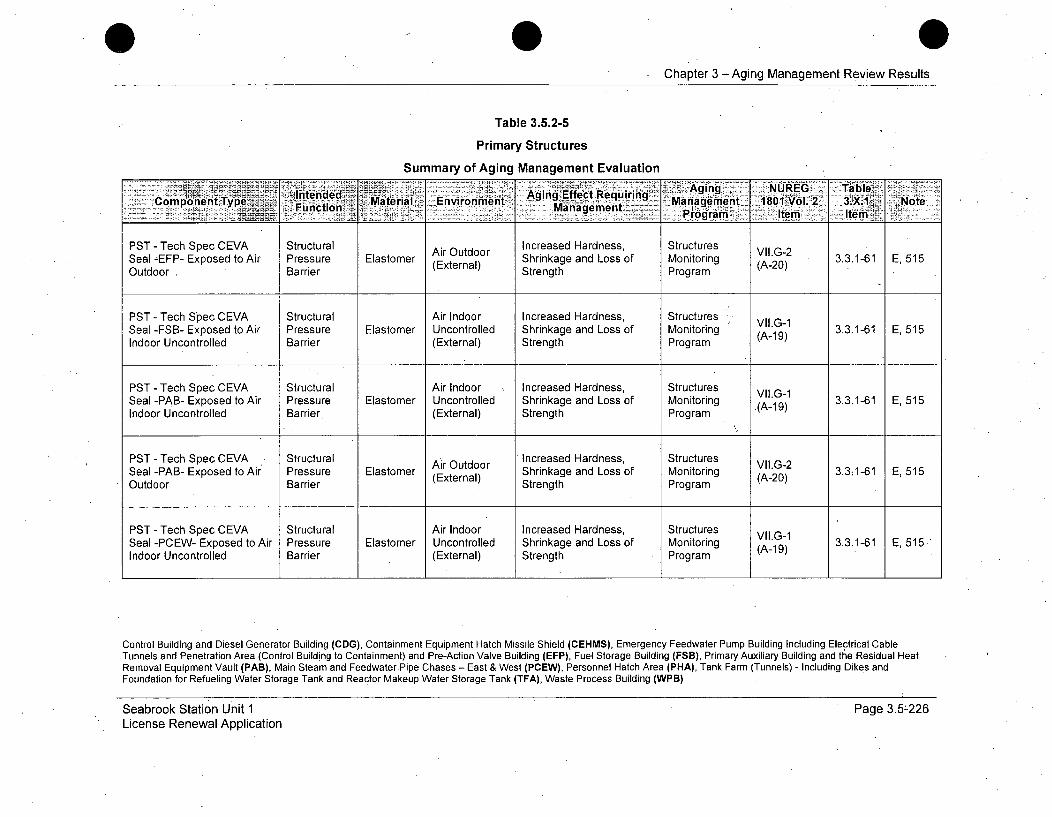
Chapter 3 -Aging Management Review Results
Table 3.5.2-5
Primary Structures
Summary of Aging Management Evaluation
'Intended AigNRE alComponent Type.~~ucin Mtra Aging Effect Requiring ~10,o. ~.. NtnMaterial ,E vironm ent M anage m ent P rMana m e . It om - Item N
PST - Tech Spec CEVA Structural Air Outdoor Increased Hardness, Structures VII.G-2Seal -EFP- Exposed to Air Pressure Elastomer (External) Shrinkage and Loss of Monitoring (A-20) 3.3.1-61 E, 515Outdoor . Barrier Strength Program
PST - Tech Spec CEVA Structural Air Indoor Increased Hardness, Structures Vll.G-1Seal -FSB- Exposed to Air Pressure Elastomer Uncontrolled Shrinkage and Loss of Monitoring (A- 19) 3.3.1-61 E, 515Indoor Uncontrolled Barrier (External) Strength Program
PST -Tech Spec CEVA Structural Air Indoor Increased Hardness, Structures Vll.G1Seal -PAB- Exposed to Air Pressure Elastomer Uncontrolled Shrinkage and Loss of Monitoring (A- 19) 3.3.1-61 E, 515Indoor Uncontrolled Barrier (External) Strength Program
PST - Tech Spec CEVA Structural Air Outdoor Increased Hardness, Structures VII.G-2Seal -PAB- Exposed to Air Pressure Elastomer (External) Shrinkage and Loss of Monitoring (A-20) 3.3:1-61 E, 515Outdoor Barrier Strength Program
PST - Tech Spec CEVA Structural Air Indoor Increased Hardness, StructuresSeal -PCEW- Exposed to Air Pressure Elastomer Uncontrolled Shrinkage and Loss of Monitoring (A-19) 3.3.1-61 E, 515kIndoor Uncontrolled Barrier (External) Strength Program
Control Building and Diesel Generator Building (CDG), Containment Equipment Hatch Missile Shield (CEHMS), Emergency Feedwater Pump Building Including Electrical CableTunnels and Penetration Area (Control Building to Containment) and Pre-Action Valve Building (EFP), Fuel Storage Building (FSB), Primary Auxiliary Building and the Residual HeatRemoval Equipment Vault (PAB), Main Steam and FeedwaterPipe Chases - East & West (PCEW), Personnel Hatch Area (PHA), Tank Farm (Tunnels) - Including Dikes andFoundation for Refueling Water Storage Tank and Reactor Makeup Water Storage Tank (TFA), Waste Process Building (WPB)
Seabrook Station Unit 1License Renewal Application
Page 3.5-226

Chapter 3 -Aging Management Review Results
Table 3.5.2-5
Primary Structures
Summary of Aging Management Evaluation
'F euirin UE<component Type Inýdd Material Environment A M aEfctRe Aging l8lo ýl.2 3X.1 NoteF_ rFuction~ p7aagement. tiin:- iLtT te-
PST - Tech Spec CEVA Structural Air Outdoor Increased Hardness, Structures VLG-2Seal -PCEW- Exposed to Air Pressure Elastomer Shrinkage and Loss of Monitoring A2031-61 E, 515Outdoor Barrier (External) Strength Program
J
PST - Tech Spec Control Control Bldg Air Indoor Increased Hardness, Structures VII.G-1Room Seal -CDG- Exposed Habitability Elastomer Uncontrolled Shrinkage and Loss of Monitoring (A-19) 3.3.1-61 E, 515to Air Indoor Uncontrolled (External) Strength Program
PST - Tech Spec Fuel Structural Air Indoor Increased Hardness, StructuresStorage Bulin.el-S-VII.G-1 3..-1 E55oreBuilding Seal -FSB- Pressure Elastomer Uncontrolled Shrinkage and Loss of Monitoring (A-19) 3.3.1-61 E, 515
Exposed to Air Indoor Barrier (External) Strength ProgramUncontrolled
PST -Thermal Insulation Air w/Borated Boric Acid 111.B2-6Aluminum Jacketing -FSB- Structural Aluminum Water Leakage Loss of Material 3.5.1-55Ain Air with Borated Water Support (External) Program (TP-3)
Leakage (External)
PST- Thermal InsulationAluminum Jacketing -PAB- Structural Aluminum Water Leakage Loss of Material Boric Acid III.B2-6 3.5.1-55 Ain Air with Borated Water Support (External) Program (TP-3)Leakage
Control Building and Diesel Generator Building (CDG), Containment Equipment Hatch Missile Shield (CEHMS), Emergency Feedwater Pump Building Including Electrical CableTunnels and Penetration Area (Control Building to Containment) and Pre-Action Valve Building (EFP), Fuel Storage Building (FSB), Primary Auxiliary Building and the Residual HeatRemoval Equipment Vault (PAB), Main Steam and Feedwater Pipe Chases - East & West (PCEW), Personnel Hatch Area (PHA), Tank Farm (Tunnels) - Including Dikes andFoundation for Refueling Water Storage Tank and Reactor Makeup Water Storage Tank (TFA), Waste Process Building (WPB)
Seabrook Station Unit 1License Renewal Application
Page 3.5-227

Chapter 3 - Aging Management Review Results
Table 3.5.2-5
Primary Structures
Summary of Aging Management Evaluation
PSTInt-ended 2r Inslaton Air ffa ora 1AlumJCoponentFType Fuctin Materinlu Environment os of Material orMAae n 1801 Vol. 2 3.k.! NoteinAirwithBoraPrdgramer SueportExternal)Program ItemP
PST - Thermal Insulation Air w/BoratedAluminum Jacketing -TEA- Structural Aluminum Water Leakage Loss of Material Boric Acid I11.B2-6 3.5.1-55 Ain Air with Borated Water Support (External) e Program (TP-3)Leakage
PST - Thermal InsulationAi /oaeAluminum Jacketing -WPB- Structural, Aluminum Waier LeBorated Ls fMtra oi cd 11126 35 5 Ain Air with Borated Water Support WaePekgros fMtra ogric Acd TPB-6 31Leakage (External) Porm(P3
I
Control Building and Diesel Generator Building (CDG), Containment Equipment Hatch Missile Shield (CEHMS), Emergency Feedwater Pump Building Including Electrical CableTunnels and Penetration Area (Control Building to Containment) and Pre-Action Valve Building (EFP), Fuel Storage Building (FSB), Primary Auxiliary Building and the Residual HeatRemoval Equipment Vault (PAB), Main Steam and FeedwaterPipe Chases - East & West (PCEW), Personnel Hatch Area (PHA), Tank Farm (Tunnels) - Including Dikes andFoundation for Refueling Water Storage Tank and Reactor Makeup Water Storage Tank (TFA), Waste Process Building (WPB)
Seabrook Station Unit 1License Renewal Application
Page 3.5-228
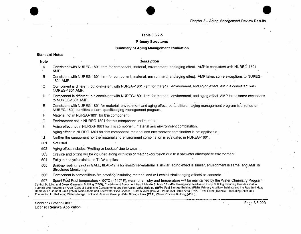
Chapter 3 - Aging Management Review Results
Table 3.5.2-5
Primary Structures
Summary of Aging Management Evaluation
Standard Notes
Note Description
A Consistent with NUREG-1801 item for component, material, environment, and aging effect. AMP is consistent with NUREG-1801AMP.
B Consistent with NUREG-1 801 item for component, material, environment, and aging effect. AMP takes some exceptions to NUREG-1801 AMP.
C Component is different, but consistent with NUREG-1801 item for material, environment, and aging effect. AMP is consistent withNUREG-1 801 AMP.
D Component is different, but consistent with NUREG-1801 item for material, environment, and aging effect. AMP takes some exceptionsto NUREG-1801 AMP.
E Consistent with NUREG-1 801 for material, environment and aging effect, but a different aging management program is credited orNUREG-1801 identifies a plant-specific aging management program.
F Material not in NUREG-1801 for this component.
G Environment not in NUREG-1 801 for this component and material.
H Aging effect not in NUREGý-1 801 for this component, material and environment combination.
I Aging effect in NUREG-1 801 for this component, material and environment combination is not applicable.J Neither the component nor the material and environment combination is evaluated in NUREG-1 801.
501 Not used.
502 Aging effect includes "Fretting or Lockup" due to wear.
503 Crevice and pitting will be included along with loss of material-corrosion due to a saltwater atmosphere environment.
'504 Fatigue analysis exists and TLAA applies.
505 Built-up roofing is not in GALL; III.A6-12 is for elastomer-material is similar, aging effect is similar, environment is same, and AMP isStructures Monitoring. ,
506 Component is cementitious fire proofing/insulating material and will exhibit similar aging effects as concrete.
507 Spent Fuel Pool temperature < 60 0C (<1400 F); water chemistry and temperature will be maintained by the Water Chemistry Program.Control Building and Diesel Generator Building (CDG), Containment Equipment Hatch Missile Shield (CEHMS), Emergency Feedwater Pump Building Including Electrical Cable
,Tunnels and Penetration Area (Control Building to Containment) and Pre-Action Valve Building (EFP), Fuel Storage Building (FSB), Primary Auxiliary Building and the Residual HeatRemoval Equipment Vault (PAB), Main Steam and Feedwater Pipe Chases - East & West (PCEW), Personnel Hatch Area (PHA), Tank Farm (Tunnels) - Including Dikes andFoundation for Refueling Water Storage Tank and Reactor Makeup Water Storage Tank (TFA), Waste Process Building (WPB)
Seabrook Station Unit 1 Page 3.5-229License Renewal Application
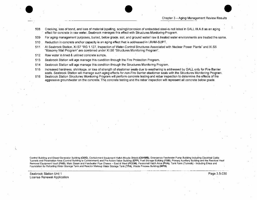
Chapter 3 -Aging Management Review Results
508 Cracking, loss of bond, and loss of material (spalling, scaling)/corrosion of embedded steel-is not listed in GALL III.A.6 as an agingeffect for concrete in raw water. Seabrook manages this effect with Structures Monitoring Program.
509 For aging management purposes, buried, below grade, soil, and ground water/ raw & treated water environments are treated the same.
510 Reduction in concrete anchor capacity is an aging effect that is addressed in LRAM-SUPT.
511 At Seabrook Station, XI.S7 "RG 1.127, Inspection of Water-Control Structures Associated with Nuclear Power Plants" and XI.S5"Masonry Wall Program" are combined under XI.S6 "Structures Monitoring Program".
512 Raw water in lined & unlined concretesumps.
513 Seabrook Station will age manage this condition through the Fire Protection Program.
514 Seabrook Station will age manage this condition through the Structures Monitoring Program.
515 Increased hardness, shrinkage, or loss of strength of elastomer seals due to weathering is addressed by GALL only for Fire Barrierseals. Seabrook Station will manage such aging effects for non-Fire Barrier elastomer seals with the Structures Monitoring Program.
516 Seabrook Station Structures Monitoring Program will perform concrete testing and rebar inspection to determine the effects of theaggressive groundwater on the concrete. The concrete testing and the rebar inspection will represent all concrete below grade.
Control Building and Diesel Generator Building (CDG), Containment Equipment Hatch Missile Shield (CEHMS), Emergency Feedwater Pump Building Including Electrical CableTunnels and Penetration Area (Control Building to Containment) and Pre-Action Valve Building (EFP), Fuel Storage Building (FSB), Primary Auxiliary Building and the Residual HeatRemoval Equipment Vault (PAB), Main Steam and Feedwater Pipe Chases - East & West (PCEW), Personnel Hatch Area (PHA), Tank Farm (Tunnels) - Including Dikes andFoundation for Refueling Water Storage Tank and Reactor Makeup Water Storage Tank (TFA), Waste Process Building (WPB)
Seabrook Station Unit 1License Renewal Application
Page 3.5-230
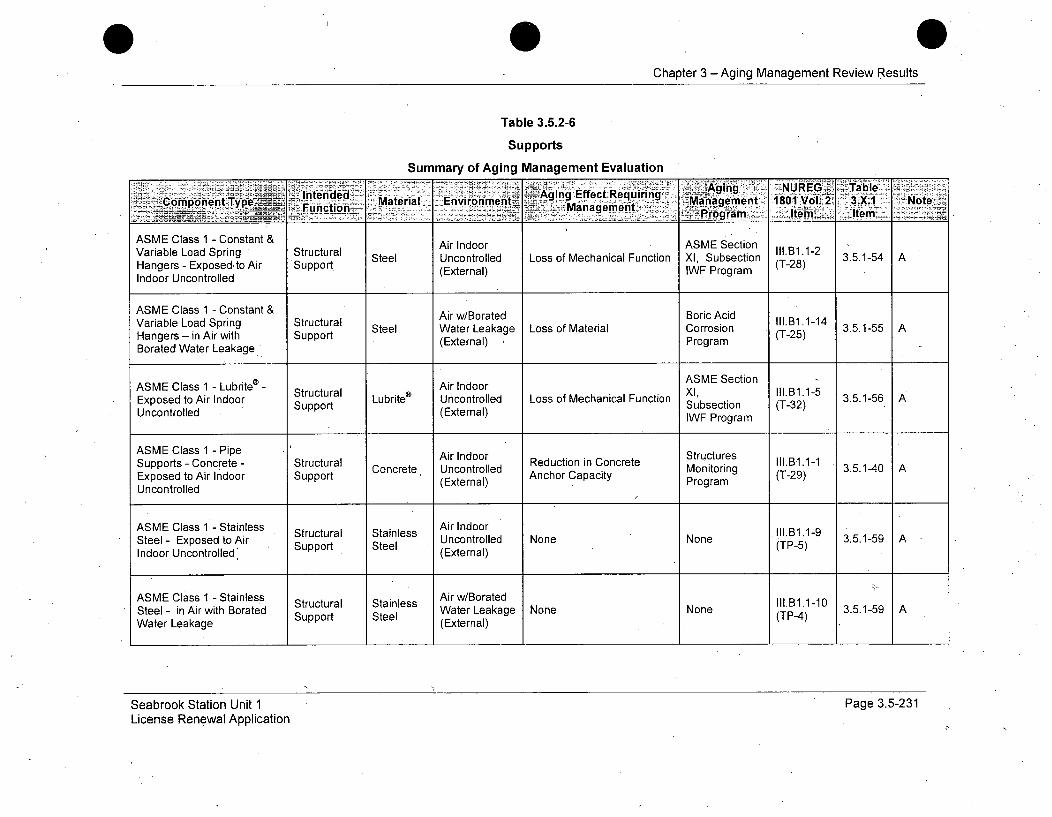
Chapter 3 - Aging Management Review Results
Table 3.5.2-6
Supports
Summary of Aging Management Evaluation
Intended Aging NUREGt RequTableComponent Type Fnto_ Material Environment~ MariAgingn Effecto Requiring NotFucinManagement _P.:r 'aeet101Vl2 3XIt Not
ASME Class 1 - Constant & Air Indoor ASME SectionVariable Load Spring Structural Steel Uncontrolled Loss of Mechanical Function XI, Subsection (Ti.B1.1-2 3.5.1-54 AHangers - Exposed, to Air Support (External) IWF Program (T-28)Indoor Uncontrolled
ASME Class 1 - Constant & Air w/Borated Boric AcidVariable Load Spring Structural Steel Water Leakage Loss of Material Corrosion II1.11.1-14 3.5.1-55 AHangers - in Air with Support (External) Program (T-25)Borated Water Leakage
ASME Class 1 - Lubrite® - Air Indoor ASME SectionStructural Lubrite® Uncontrolled Loss of Mechanical Function Xl 111.11.1-5 3.5.1-56 A
Uncontrolled Supportn(ExteupportSubsection (T-32)Expostred toAt(External) IWF Program
ASME Class 1 - Pipe Air Indoor StructuresSupports - Concrete - Structural Reduction in Concrete Prg.at.1-1Exposed to Air Indoor Support Concrete x Uncontrolled Monitoring (T-29) 3.5.1-40 A
Uncontrolled (External) Program
ASME Class 1 - Stainless Air IndoorStrucural tainlssIII.B1.1-9Steel - Exposed to Air Support Steel Uncontrolled None None (TP-5) 3.5.1-59 AIndoor Uncontrolled' (External)
ASME Class 1 - Stainless Air w/BoratedSteel - in Air with Borated Support Steel Water Leakage None None (TP-4) 3.5.1-59 AWater Leakage (External)
Seabrook Station Unit 1License Renewal Application
Page 3.5-231

Chapter 3 - Aging Management Review Results
Table 3.5.2-6
Supports
Summary of Aging Management Evaluation
- -- -Aging~E NUREG Table± C0omppnent Type - Intended Material- _-Environment . Management' 1801 Vol 2 3.X Note
_ ~Function - Anagement. P griIen:.<erz ____
ASME Class 1 Support - Structural Air Indoor ASME Section 1ll.B1.1-13Carbon Steel - Exposed to Support Steel Uncontrolled Loss of Material X1, Subsection (T-24) 3.5.1-53 AAir Indoor Uncontrolled (External) IWF Program
ASME Class 1 Support - Structural Air w/Borated Boric Acid II1.B1.1-14Carbon Steel - in Air with Steel Water Leakage Loss of Material Corrosion ( .- 14 3.5.1-55 ABorated .Water Leakage Support (External) Program (T-25)
ASME Class 2/3 - Constant Air Indoor ASME Sectionand Variable Load Spring Structural Steel Uncontrolled Loss of Mechanical Function XI, Subsection l1l.B1.2-2 3.5.1-54. AHangers - Exposed to Air Support (External) IWF Program (T-28)Indoor Uncontrolled
ASME Class 2/3 - Constant Air w/Borated Boric Acid& Variable Load Spring Structural Steel Water Leakage Loss of Material Corrosion Ad1.3B1.2-11 3.5.1-55 AHangers - in Air with Support (External) Program (T-25) 3Borated Water Leakage
ASME Class 2/3 - Lubrite® - Air Indoor ASME SectionExposed to Air Indoor Structural Lubite® Uncontrolled Loss of Mechanical Function XI, Subsection I1.B1.2-3 3.5.1-56 AUncontrolled Support (External) WF Program (T-32)
ASME Class 2/3 Pipe Air Indoor StructuresSupports - Concrete- Structural Reduction in Concrete Sc s.B1.2-1Exposed to Air Indoor Support Concrete Uncontrolled Anchor Capacity Monitoring (T-29) 3.5.1-40 A
Uncontrolled (External) A Program
Seabrook Station Unit 1License Renewal Application
Page 3.5-232
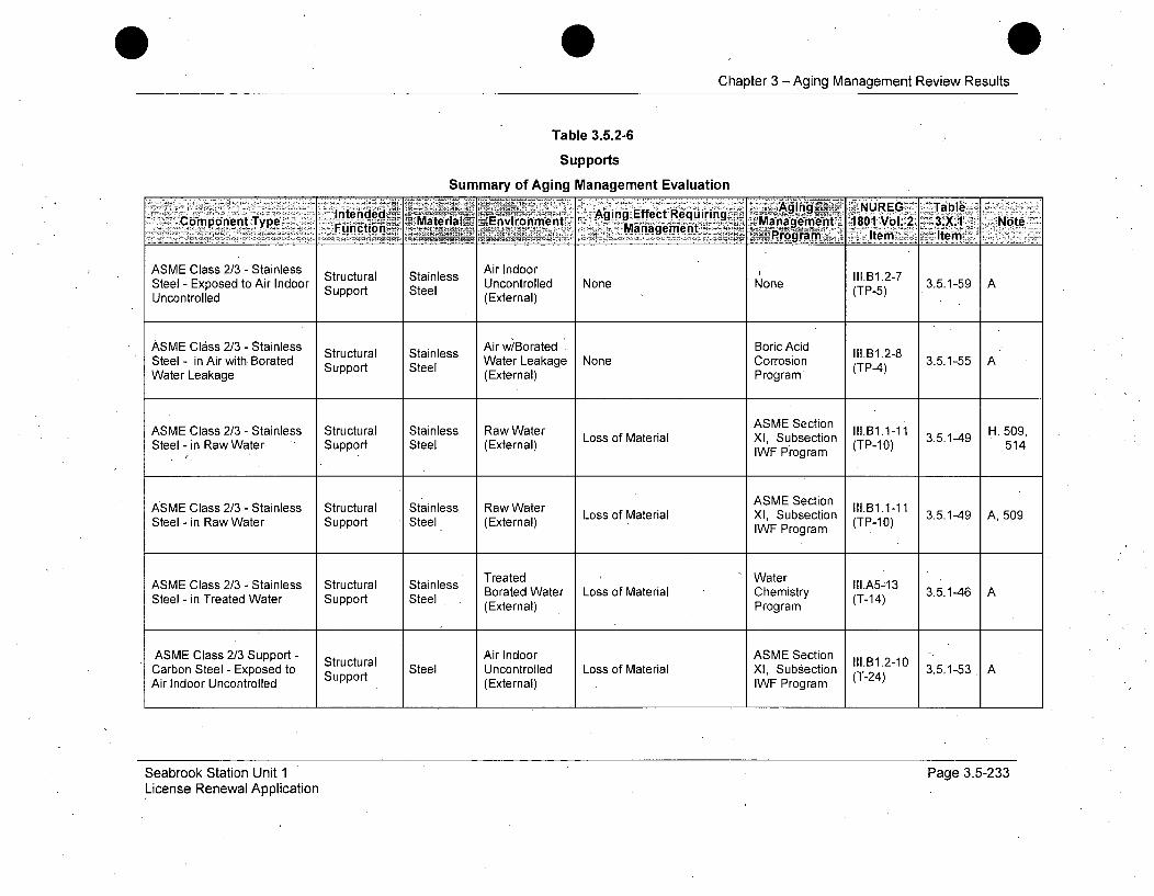
0Chapter 3- Aging Management Review Results
Table 3.5.2-6
Supports
Summary of Aging Management Evaluation
ASME Class 2/3 - Stainless Structural Stainless Air Indoor llB.-Steel-IExposed to Air Indoor SUncontrolled None None ITP-5) 3.5.1-59 AUncontrolled Suppor (External)
ASME Class 2/3 - Stainless Air w/Borated . Boric AcidStructural Stainless Ili.B1.2-8Water Leakage None Corrosion 3.5.1-5Steel - in Air with. Borated Support Steel (Eternal) (TP-4)Pr
Water Leakage (External) Program
ASME Section III.B1.1-1 3..14 H, 509,
ASME Class 2/3 - Stainless Structural Stainless Raw Water Loss of Material XI, Subsection H,5509,Steel - in Raw Water Support Steel (External) IWF PoX ogram (TP-10) 514
IWF Program
ASMVE Section lli-i 3..49A50
ASME Class 2/3 - Stainless Structural Stainless Raw Water Loss of Material XI, Subsection II.131.1-113Steel - in Raw Water Support Steel (External) IWF Program (TP-10)
ASME Class 2/3 - Stainless Structural Stainless Treated Water III.A5A13Borated Water Loss of Material Chemistry (T-14) 3.5.1-46 ASteel - in Treated Water Support Steel (External) Program
ASME Class 2/3 Support - Structural Air Indoor ASME Section 1I1.B1.2-10Carbon Steel - Exposed to Support Steel Uncontrolled Loss of Material XI, Subsection (T-24) 3.5.1-53 AAir Indoor Uncontrolled (External) IWF Program
Seabrook Station Unit 1License Renewal Application
Page 3.5-233
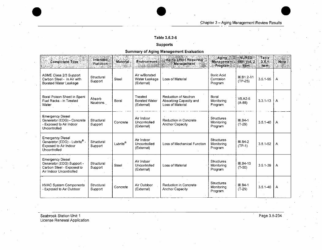
Chapter 3 - Aging Management Review Results
Table 3.5.2-6
Supports
Summary of Aging Management Evaluation
CmoetTpIntended - Agirigfict Requirinig Ain -NUEG2 abe
ASME Class 2/3 Support Structural Air w/Borated Boric Acid 1Il.B1.2-11Carbon Steel - in Air with Support Steel Water Leakage Loss of Material Corrosion (TP-25) 3.5.1-55 ABorated Water Leakage (External) Program
Boral Poison Sheet in Spent Absorb Treated Reduction of Neutron Boral VI.A2-5Fuel Racks - in Treated Neutrons Boral Borated Water Absorbing Capacity and Monitoring (A-88) 3.3.1-13 AWater N (External) Loss of Material Program
Emergency Diesel Air Indoor StructuresGenerator (EDG) - Concrete Structural Concrete Uncontrolled Reduction in Concrete Monitoring I(T.B4-1 3.5.1-40 A- Exposed to Air Indoor Support (External) Anchor Capacity Program (T-29)Uncontrolled
Emergency Diesel Air Indoor StructuresGenerator (EDG) - Lubrite® - Structural Lubrite Uncontrolled Loss of Mechanical Function Monitoring d 14-2 3.5.1-52 AExposed to Air Indoor Support (External) Program (TP-1)Uncontrolled
Emergency Diesel Air Indoor StructuresGenerator (EDG) Support - Structural Steel Uncontrolled Loss of Material Monitoring 11.14-10 3.5.1-39 A,Carbon Steel - Exposed to Support (External) Program (T-30)Air Indoor Uncontrolled
HVAC System Components Structural Concrete Air Outdoor Reduction in Concrete Structures Ill.B4-1 3.5.10 AExposed to Air Outdoor Support Concrete Monitogrin (T-29)- xpsd oAi utor upot(External) Anchor Capacity Program (-9
Seabrook Station Unit 1License Renewal Application
Page 3.5-234
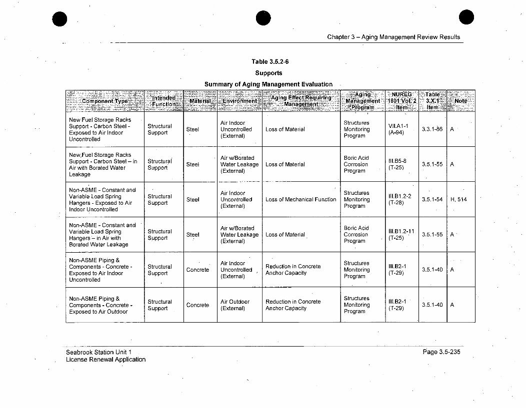
Chapter 3 - Aging Management Review Results
Table 3.5.2-6
Supports
Summary of Aging Management Evaluation
Intended MaeilAging Effect Reqgin.. NURG TblCmoetTpMaeil En)vironment~r ~c~rn Management 1801 Vol.2 3.X.1 _NoteCopoen Tpe Function~.._ Managemnent Pgrmtm- te . 7
New Fuel Storage Racks Air Indoor StructuresSupport - Carbon Steel - Structural Steel Uncontrolled Loss of Material Monitoring VILA-9 3.3.1-86 AExposed to Air Indoor Support (External) Program (A-94)
Uncontrolled
New,Fuel Storage RacksSupport - Carbon Steel - in Structural Steel WAir w/Borated Boric Acid II.B5-8 3.5.1-55 AArwtBoaeWae Sppr*Water Leakage Loss of Material Corrosion (T-25) 3515Air with Borated Water Support (External) ProgramLeakage
Non-ASME - Constant and Air Indoor StructuresVariable Load Spring Structural Steel Uncontrolled Loss of Mechanical Function Monitoring (TlB12-2 3.5.1-54 H, 514Hangers - Exposed to Air Support (External) Program (T-28)Indoor Uncontrolled
Non-ASME - Constant and Air w/Borated Boric AcidVariable Load Spring Structural ArwBatdoiccd II1.B1.2-11Steel Water Leakage Loss of Material Corrosion (T-25) 3.5.1-55 A
Hangers in Air with Support (External)Borated Water Leakage Program
Non-ASME Piping & Air Indoor StructuresReductin in Cncretectures-Components - Concrete - Structural Concrete Uncontrolled nchor Cacity Monitoring (T-29)Exposed to Air Indoor Support (External) Anchor Capacity ProgramUncontrolled
Non-ASME Piping & Structural Air Outdoor Reduction in Concrete Structures in1.g2-1Components - Concrete - Support Concrete (External) Anchor Capacity Monitoring (T-29) 3.5.1-40 AExposed to Air Outdoor Program
Seabrook Station Unit 1License Renewal Application
Page 3.5-235
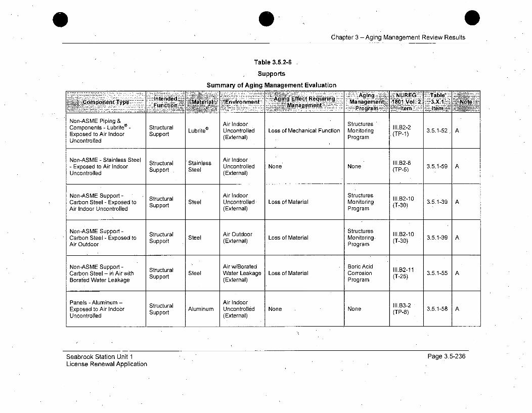
Chapter 3 -Aging Management Review Results
Table 3.5.2-6
Supports
Summary of Aging Management Evaluationii;!i~~lIntended,:: • : -: • •::::::•~: ::.::::,:::Aging Effect-Requi~ring:•: :•••:•• ....em . .. - /•: 1:801 ........ 2 -.-•: • = :
Comp.rent Type Material. --Environment Re.ui-ing -• Mag enVg.-mr t33let 3NoteCopoen Tpe Fu nction~ ___m~anaggrnent ngeet 8O:oV2 .. K
- - ~~Program<--item teV'
Non-ASME Piping & Air Indoor Structures " l.B2-2Components - Lubrite®- Structural Lubrite® Uncontrolled Loss of Mechanical Function Monitoring (TP-1 3.5.1-52 AExposed to Air Indoor Support (External) Program (TP-1)Uncontrolled
Non-ASME - Stainless Steel Structural Stainless Air Indoor lll.B2-8- Exposed to Air Indoor Support Steel Uncontrolled None None (TP-5) 3.5.1-59 AUncontrolled (External)
Non-ASME Support - Structural Air Indoor Structures 111.B2-10Carbon Steel - Exposed to Support Steel Uncontrolled Loss of Material Monitoring (T-30) 3.5.1-39 AAir Indoor Uncontrolled (External) Program
Non-ASME Support - Structural Air Outdoor Structures 11.B2-10Carbon Steel - Exposed to Support Steel (External) Loss of Material Monitoring. (T-30)Air Outdoor Program
Non-ASME Support - Structural Air w/Borated Boric Acid 111.B2-11Carbon Steel - in Air with Steel Water Leakage Loss of Material Corrosion 3.5.1-56 ABorated Water Leakage Support (External) Program (T-25)
Panels - Aluminum - Structural Air Indoor 111.13-2Exposed to Air Indoor Aluminum Uncontrolled None None (TP-8) 3.5.1-58 AUncontrolled Support (External)
Seabrook Station Unit 1License Renewal Application
Page 3.5-236
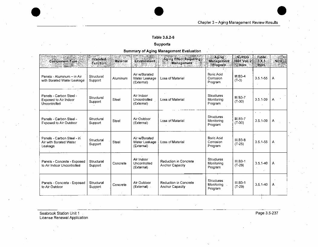
Chapter 3 - Aging Management Review Results
Table 3.5.2-6
Supports
Summary of Aging Management EvaluationC '-- -. ----- -~
Intended ý.,Aging, Effect RM qUREG TablComponentT•ype Funtin Material E•nvironment Mag emiea18nt0 v, 3 N•80 l2 ii---.. Function Mangeen ' '' 0ngenient181VL 3X Nt'
Panels -Aluminum -in Air Structural Air w/Borated Boric Acid ll.134with Borated Water Leakage Support Aluminum Water Leakage Loss of Material Corrosion (T-3) 3.5.1-55 A
(External) Program
Panels - Carbon Steel - Air Indoor StructuresExposed to Air Indoor Support Steel Uncontrolled Loss of Material Monitoring (T-30) 3.5.1-39 AUncontrolled (External) Program
Panels - Carbon Steel - Structural Air Outdoor Structures l1.B3-7Exposed to Air Outdoor Support (External) Monitoring r30)3g
Program
Panels - Carbon Steel - ir Structural Air w/Borated Boric Acid lll.13-8Air with Borated.Water Support Steel Water Leakage Loss of Material Corrosion (T-25) 3.5.1-55 ALeakage (External) Program
Panels - Concrete - Exposed Structural Concrete AIndoor Reduction in Concrete Structures I11.B3-1 351-4 Ato Air Indoor Uncontrolled Support eUncontrolled Anchor Capacity Monitoring (T-29) .
(External) Program
Structures llB31 .5-4
Panels - Concrete - Exposed Structural Air Outdoor Reduction in Concrete Monitoring III.13-1 3to Air Outdoor Support C (External) Anchor Capacity Program (T-29)
Seabrook Station Unit 1 -
License Renewal ApplicationPage 3.5-237
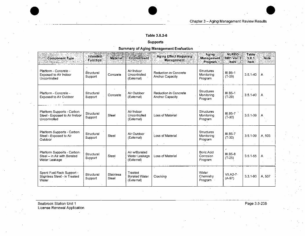
Chapter 3 - Aging Management Review Results
Table 3.5.2-6
Supports
Summary of Aging Management Evaluationi • , • •;•i i l• ! • ! • ! • : ? ? • • • • , ! i • • ÷ • -: • , • • •• : • • •A gii• : A n ~g ; • ! ! • : N U IR E G ? i I i T a b l e • :i i :
ComonntTye ateialEi-nt Aging Effect Requiring' M gngXR. ,TalCompoapagetiien Mtra EniomtManagement 1961 ol. 2 -- 3.X.1 'NoiteProgram Item . ItemPlatform - Concrete - Structural Air Indoor Reduction in Concrete Structures olld5-1Exposed to Air Indoor Reutini Concrete Uncontrolled Monitoring (T-29) 3.5.1-40 AUncontrolled Support (External) Anchor Capacity Program
Structures llB-
Platform - Concrete - Structural Air Outdoor Reduction in Concrete Mntorin g 1135-1Exposed to Air Outdoor Support Concrete (External) Anchor Capacity Program
Platform Supports - Carbon Structural Air Indoor Structures 111.15-7Steel 7 Exposed to Air Indoor Support Steel Uncontrolled Loss of Material Monitoring (T-30) 3.5.1-39 AUncontrolled (External) Program
Platform Supports - Carbon Structural Air Outdoor LosocaeiesalIontoinStructures AirlOutdo351391A,3503Steel - Exposed to Air Support Steel (External) Loss of Material Monitoring (T-30) 35.1-39 A, 503
Outdoor Program
Platform Supports - Carbon Structural Air w/Borated Boric Acid III.B5-8Steel- in Air with Borated Support Steel Water Leakage Loss of Material Corrosion (T-25) 3.5.1-55 A
Water Leakage (External) Program
Spent Fuel Rack Support - Structural Stainless Treated Water VIIA2-7Stainless Steel - in Treated Support Steel Borated Water Cracking Chemistry (A-97) 3.3.1-90 A, 507Water (External) Program
Seabrook Station Unit 1License Renewal Application
Page 3.5-238
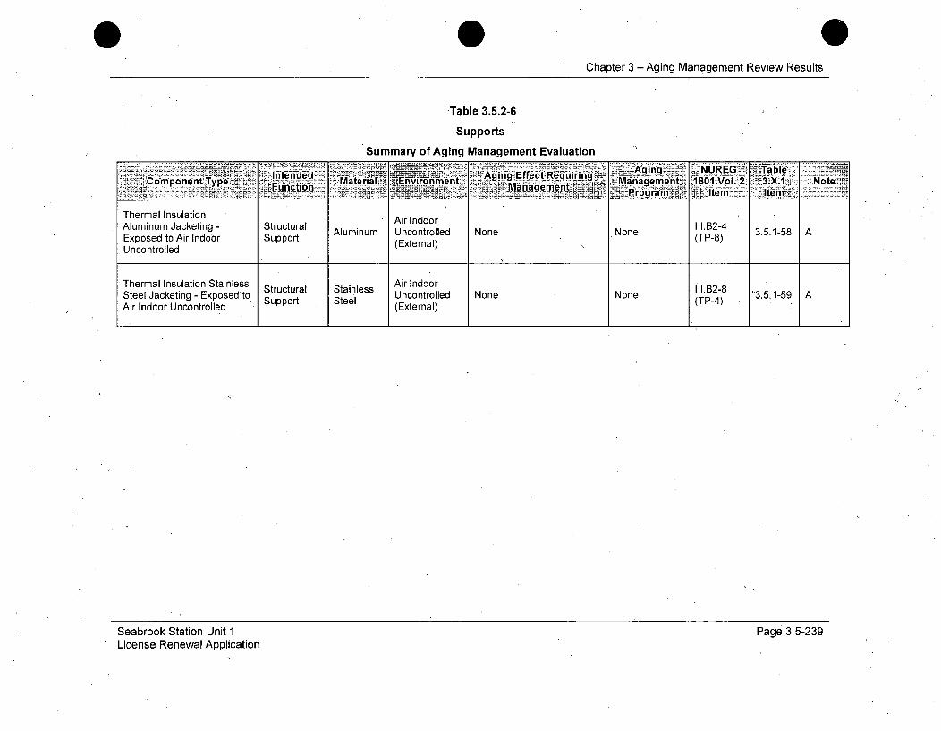
Chapter 3 - Aging Management Review Results
Table 3.5.2-6
Supports
Summary of Aging Management Evaluation
Int~ii~ - -- K~ng- Aging NUREG ~TbleComponent ~ ~ ~ ~ ~ ~ ~ ~ ~ in TpFucin Mtra EVinmtEfect Requiring__-CManagemen Tatra niofbtManagemnent 1801 Vol. 2 ý3.X.1 Note
_____________________ rogram~ Itemi Iten
Thermal Insulation Air IndoorAluminum Jacketing - Structural Aluminum Uncontrolled None None III.B2-4 3.5.1-58 AExposed to Air Indoor Support (External) (TP-8)Uncontrolled
Thermal Insulation Stainless Air Indoor .. 2-8Structural Stainless I1B-Steel Jacketing - Exposed'to, Support Steel Uncontrolled None None (TP-4) '3.5.1-59 AAir Indoor Uncontrolled (External)
Seabrook Station Unit 1License Renewal Application
Page 3.5-239
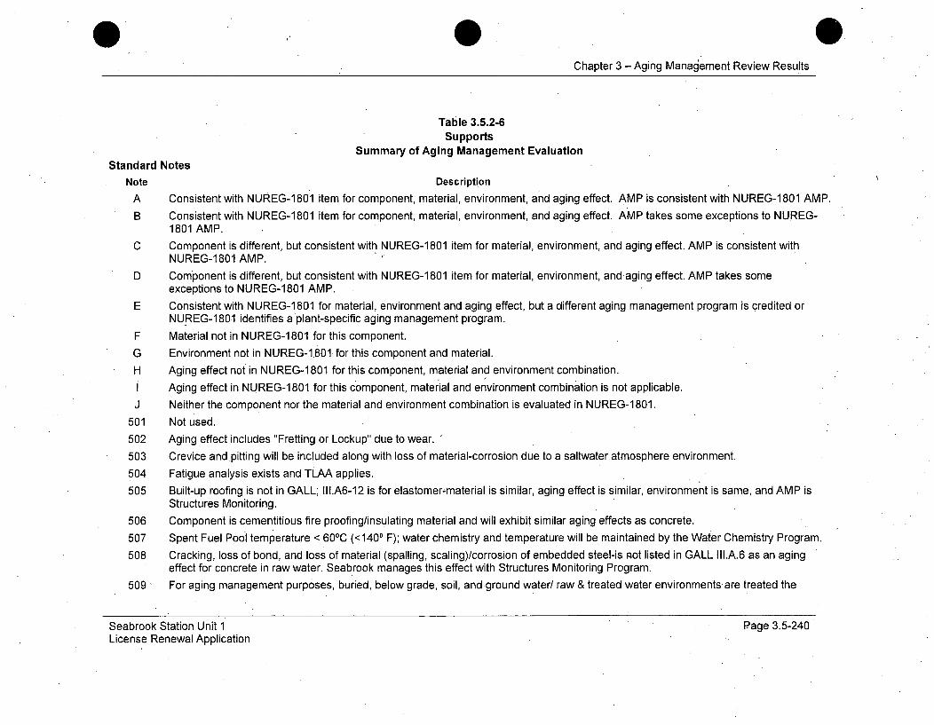
Chapter 3 -Aging Management Review Results
Table 3.5.2-6Supports
Summary of Aging Management EvaluationStandard Notes
Note Description
A Consistent with NUREG-1801 item for component, material, environment, and aging effect. AMP is consistent with NUREG-1801 AMP.
B Consistent with NUREG-1801 item for component, material, environment, and aging effect. AMP takes some exceptions to NUREG-1801 AMP.
C Component is different, but consistent with NUREG-1 801 item for material, environment, and aging effect. AMP is consistent withNUREG-1801 AMP.
D Component is different, but consistent with NUREG-1 801 item for material, environment, and-aging effect. AMP takes someexceptions to NUREG-1801 AMP.
E Consistent with NUREG-1 801 for material, environment and aging effect, but a different aging management program is credited orNUREG-1 801 identifies a plant-specific aging management program.
F Material not in NUREG-1 801 for this component.
G Environment not in NUREG-1.801 for this component and material.
H Aging effect not in NUREG-1 801 for this component, material and environment combination.
I Aging effect in NUREG-1 801 for this component, material and environment combination is not applicable.
J Neither the component nor the material and environment combination is evaluated in NUREG-1 801.
501 Not used.
502 Aging effect includes "Fretting or Lockup" due to wear.
503 Crevice and .pitting will be included along with loss of material-corrosion due to a saltwater atmosphere environment.
504 Fatigue analysis exists and TLAA applies.
505 Built-up roofing is not in GALL; III.A6-12 is for elastomer-material is similar, aging effect is similar, environment is same, and AMP isStructures Monitoring.
506 Component is cementitious fire proofing/insulating material and will exhibit similar aging effects as concrete.
507 Spent Fuel Pool temperature < 600C (<1400 F); water chemistry and temperature will be maintained by the Water Chemistry Program.
508 Cracking, loss of bond, and loss of material (spalling, scaling)/corrosion of embedded steel-is not listed in GALL III.A.6 as an agingeffect for concrete in raw water. Seabrook manages this effect with Structures Monitoring Program.
509 For aging management purposes, buried, below grade, soil, and ground water/ raw & treated water environments are treated the
Seabrook Station Unit 1License Renewal Application
Page 3.5-240

Chapter 3 -Aging Management Review Results
same.510 Reduction in concrete anchor capacity is an aging effect that is addressed in LRAM-SUPT.511 AtSeabrook Station, XI,.S7 "RG 1.127, Inspection of Water-Control Structures Associated with Nuclear Power Plants" and XI,.S5
"Masonry Wall Program" are combined under XI,.S6 "Structures Monitoring Program".512 Raw water in lined & unlined concrete sumps.513 Seabrook Station will age manage this condition through the Fire Protection Program.514 Seabrook Station will age manage this condition through the Structures Monitoring Program.515 Increased hardness, shrinkage, or loss of strength of elastomer seals due to weathering is addressed by GALL only for Fire Barrier
seals. Seabrook Station will manage-such aging effects for non-Fire Barrier elastomer seals with the Structures Monitoring Program.516 Seabrook Station Structures Monitoring Program will perform concrete testing and rebar inspection to determine the effects of the
aggressive groundwater on the concrete. The concrete testing and the rebar inspection will represent all concrete below grade.
Seabrook Station Unit 1License Renewal Application
Page 3.5-241
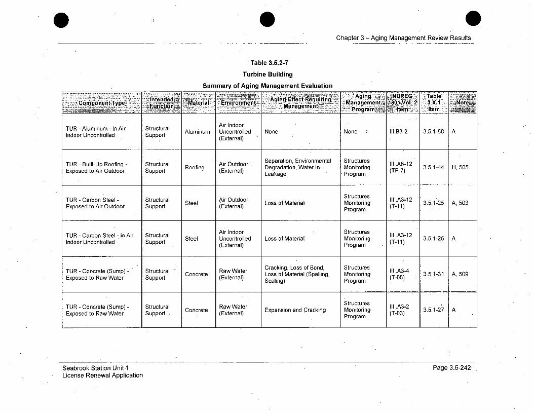
Chapter 3 -Aging Management Review Results
Table 3.5.2-7
Turbine Building
Summary of Aging Management Evaluation
Aging ENUREG Table_ -~F~uictiii~.~. MaProgram4• Item Item ____
TUR - Aluminum - in Air Structural Air IndoorAluminum Uncontrolled None None 11I.B3-2 3.5.1-58 A
Indoor Uncontrolled Support (External)
TUR - Built-Up Roofing - Structural Air Outdoor, Separation, Environmental Structures Ill .A612Exposed to Air Outdoor Support Roofing (External) Degradation, Water In- Monitoring (TP-7) 3.5.1-44 H, 505
Exern Leakage Program
TUR - Carbon Steel - Structural Air Outdoor Structures III A3-12Steel~~I LosA3-12ralMniorn 3.5.1-25 A, 503Exposed to Air Outdoor Support Steel (External) Loss of Material Monitoring (T-11)Program
TUR - Carbon Steel - in Air Structural Air Indoor StructuresIndoor Uncontrolled Support Steel Uncontrolled Loss of Material Monitoring Ill.-25-1)(External) Program
TUR - Concrete (Sump) - ' Structural • Raw Water Cracking, Loss of Bond, Structures III A3-4Txponete (up - Strtu Concrete RwWter Loss of Material (Spalling, Monitoring (T-05) 3.5.1-31 A,509Exposed to Raw Water Support (External) Scaling) Program
TR-Cnrt(um)- Srcua CoceeStructures Ill .A3-2 3.5.1-27 ATUR - Concrete (Sump) - Structural Concrete Raw Water Expansion and Cracking Monitoring A3-2 .17Exposed to Raw Water Support , (External) Program (T-03)
Seabrook Station Unit 1License Renewal Application
Page 3.5-242,
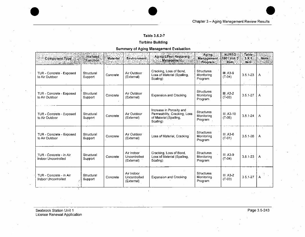
Chapter 3 -Aging Management Review Results
Table 3.5.2-7
Turbine Building
Summary of Aging Management Evaluation
.....Inten ded :AgingE•f - -Requir- Aging NUREG - TableCopoen ype unýi Mate rialI Environment Ma._Managmn 1801 Vol.2, 3.X1 Note-
________ _______..j-rogramm item-.. Item
TUR - Concrete Exposed Structural Concrete Air Outdoor Cracking, Loss of Bond, Structures .A3-9to A Ooor Support Concrete Loss of Material (Spalling, Monitoring (T-04) 3.5.1-23 Ato Air Outdoor Support (External) Scaling) Program
TUR - Concrete - Exposed Structural Concrete Air Outdoor Expansion and Cracking Structures III .A3,2 3.5.1-27 Ato Air Outdoor Support (External) Monitoring (T-03)
Program
Increase in Porosity and StructuresTUR - Concrete - Exposed Structural Air Outdoor Permeability, Cracking, Loss III3.5.1-24 Ato Air Outdoor Support Concrete (External) of Material (Spalling, Monitoring (T-06)
Scaling) Program
TUR - Concrete - Exposed Structural C tc AirOu Loss of Material, Cracking Str res (TA3-6 3.5.1-26 Ato Air Outdoor Support oncree (External) Monitoring (T-01)
Program
TUR - Concrete - in Air Structural Air Indoor Cracking, Loss of Bond, Structures III .A3-9Indoor Uncontrolled Support Concrete Uncontrolled Loss of Material (Spalling, . Monitoring (T-04) 3.5.1-23 A
(External) Scaling) Program
TUR - Concrete - in Air Structural Air Indoor Structures III .A3*2Concrete Uncontrolled Expansion and Cracking Monitoring 3.5.1-27 AIndoor Uncontrolled Support (External) Program (T-03)
Seabrook Station Unit 1License Renewal Application
Page 3.5-243
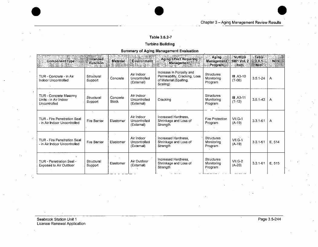
0Chapter 3 - Aging Management Review Results
Table 3.5.2-7
Turbine Building
Summary of Aging Management Evaluation
IneddAging NUREG TableiComponent Type Fucin Mateia ' :M'Environmn -gngEfeteqirn i Management.: -1801 Vol. 2 ~..
,, .....~.Mangemnt2Program~ ,,Item Ie
Air Indoor Increase in Porosity and StructuresTUR - Concrete - in Air Structural tir Uncoor Permeability, Cracking, Loss Monitoring III A3-10Indoor etei Sura Concrete Uncontrolled of Material (Spalling, Program (T-06)Indoord(External) Scaling)
TUR - Concrete Masonry Structural Concrete Air Indoor Structures III .A3-11Units - in Air Indoor Support Block Uncontrolled Cracking Monitoring (T-12) 3.5.1-43 AUncontrolled (External) Program
TUR - Fire Penetration Seal Air Indoor Increased Hardness, Fire Protection VII.G-1- in Air Indoor'Uncontrolled Fire Barrier Elastomer Uncontrolled Shrinkage and Loss of Program (A-19) 3.3.1-61 A
(External) Strength
TUR - Fire Penetration Seal Air Indoor Increased Hardness, Structures VII.(-1- in Air Indoor Uncontrolled Fire Barrier Elastomer Uncontrolled Shrinkage and Loss of Monitoring -1 3.3.1-61 E, 514- (External) Strength Program. (A-19)
TUR - Penetration Seal - Structural Air Outdoor Increased Hardness, Structures VII.G-2Exposed to Air Outdoor Support Elastomer (External) Shrinkage and Loss of Monitoring (A-20) 3.3.1-61 E, 515
Strength Program
Seabrook Station Unit 1License Renewal Application
Page 3.5-244
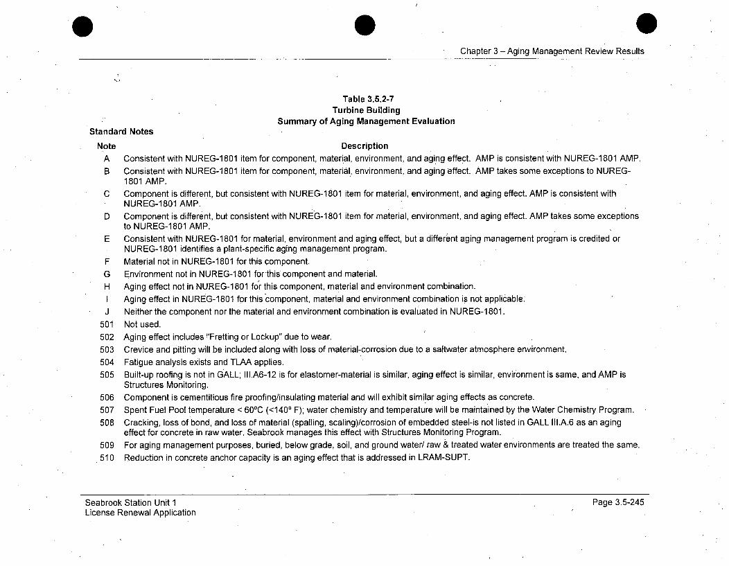
Chapter 3 -Aging Management Review Results
Table 3.5.2-7Turbine Building
Summary of Aging Management EvaluationStandard Notes
Note Description
A Consistent with NUREG-1 801 item for component, material, environment, and aging effect. AMP is consistent with NUREG-1 801 AMP.B Consistent with NUREG-1 801 item for component, material, environment, and aging effect. AMP takes some exceptions to NUREG-
1801 AMP.
C Component is different, but consistent with NUREG-1801 item for material, environment, and aging effect. AMP is consistent withNUREG-1801 AMP.
D Component is different, but consistent with NUREG-1801 item for material, environment, and aging effect. AMP takes some exceptionsto NUREG-1801 AMP.
E Consistent with NUREG-1 801 for material, environment and aging effect, but a different aging management program is credited orNUREG-1 801 identifies a plant-specific aging management program.
F Material not in NUREG-1 801 for this component.
G Environment not in NUREG-1 801 for'this component and material.H Aging effect not in NUREG-1 801 for this component, material and environment combination.I Aging effect in NUREG-1 801 for this component, material and environment combination is not applicable.
J Neither the component nor the material and environment combination is evaluated in NUREG-1 801.
501 Not used.502 Aging effect includes "Fretting or Lockup" due to wear.503 Crevice and pitting will be included along with loss of material-corrosion due to a saltwater atmosphere environment.504 Fatigue analysis exists and TLAA applies.505 Built-up roofing is not in GALL; III.A6-12 is for elastomer-material is similar, aging effect is similar, environment is same, and AMP is
Structures Monitoring.506 Component is cementitious fire proofing/insulating material and will exhibit similar aging effects as concrete.
507 Spent Fuel Pool temperature < 601C (<1400 F); water chemistry and temperature will be maintained by the Water Chemistry Program.
508 Cracking, loss of bond, and loss of material (spalling, scaling)/corrosion of embedded steel-is not listed in GALL III.A.6 as an agingeffect for concrete in raw water. Seabrook manages this effect with Structures Monitoring Program.
509 For aging management purposes, buried, below grade, soil, and ground water/ raw & treated water environments are treated the same.510 Reduction in concrete anchor capacity is an aging effect that is addressed in LRAM-SUPT.
Seabrook Station Unit 1License Renewal Application
Page 3.5-245
Chapter 3 - Aging Management Review Results
511 At Seabrook Station, Xl.S7 "RG 1.127, Inspection of Water-Control Structures Associated with Nuclear Power Plants" and XI.S5"Masonry Wall Program" are combined under XI.S6 "Structures Monitoring Program".
512 Raw water in lined & unlined concrete sumps.513 Seabrook Station will age manage this condition through the Fire Protection Program.
514 Seabrook Station will age manage this condition through the Structures Monitoring Program.
515 Increased hardness, shrinkage, or loss of strength of elastomer seals due to weathering is addressed by GALL only for Fire Barrierseals. Seabrook Station will manage such aging effects for non-Fire Barrier elastomer seals with the Structures Monitoring Program.
516 Seabrook Station Structures Monitoring Program will perform concrete testing and rebar inspection to determine the effects of theaggressive groundwater on the concrete. The concrete testing and the rebar inspection will represent all concrete below grade.
Seabrook Station Unit 1License Renewal Application
Page 3.5-246

Chapter 3 -Aging Management Review Results
Table 3.5.2-8
Water Control Structures
Summary of Aging Management Evaluation
lntnde~ Agig~Efef~euirn Aging- NUREG Table~'Component Type Maera EnvironmentmnMaroa ii8OfVol. 21 3,XAI- ~Noter
Pro__gramW Item, Item
WCS - Built-Up Roofing -SERVICE WATER Shelter, Air Outdoor Separation, Environmental Structures III.A6-12COOLING TOWER Shection Roofing Degradation, Water In- Monitoring (TP-7) 3.5.1-44 H, 505Including Switchgear Rooms Protection ternal) Leakage Programin Air Outdoor
WCS - Built-Up Roofing - Separation, Environmental StructuresSERVICE WATER Shelter, Roofing Air Outdoor Depradion, Environm M III.A6-12 3PUMPHOUSE in Air Protection (External) Degradation, Water In- Monitoring (TP-7) 3.5.1-44 H, 505Outdoor Leakage Program
WCS - Carbon Steel Door -SERVICEAir Outdoor Structures II.A3-12COOLING TOWER Shelter, Steel ArOtdr Loss of Material Monitoring (T-1 3.5.1-25 A, 503Including Switchgear Rooms Programin Air Outdoor
WCS - Carbon Steel Door -
SERVICE WATER S Air Indoor Structures III.A3-12COOLING TWR Including Structural Steel Uncontrolled Loss of Material Monitoring (T-11) .3.5.1-25 ASwgr Rms in Air Indoor Support (External) ProgramUncontrolled
WCS - Carbon Steel Door - Air Indoor StructuresSERVICE WATER Structural Steel Uncontrolled Loss of Material Monitoring II1A3-12 3.5.1-25 APUMPHOUSE in Air Indoor Support (Exterial Mogram (T-11)Uncontrolled (External) Program
WCS - Carbon Steel Door - StructuresSERVICE WATER Shelter, Steel Air Outdoor Loss of Material Monitoring (II.A3-12 3.5.1-25 A, 503PUMPHOUSE in Air Protection (External) Program (T-11)Outdoor
Seabrook Station Unit 1License Renewal Application
Page 3.5-247
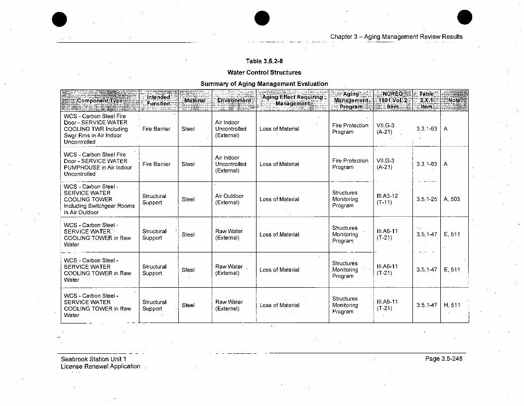
Chapter 3 -Aging Management ReviewResults
Table 3.5.2-8
Water Control Structures
Summary of Aging Management Evaluation
- lted~~ Aging ,NUREGE Talble7Componient Type. Functiond Mteia nvronet Agi ng EfetRqiring Management 1801IVol.--2- 3 i Note
Mangeen+. Program. Item Item,
WCS - Carbon Steel FireDoor - SERVICE WATER Air Indoor Fire Protection VII.G-3COOLING TWR Including Fire Barrier Steel Uncontrolled Loss of Material 3.3.1-63 ASwgr Rms in Air Indoor (External) Program (A-21)
Uncontrolled
WCS - Carbon Steel Fire Air IndoorDoor-SERVICE WATER Fire Barrier Steel Uncontrolled Loss of Material 3.3.1-63 APUMPHOUSE in Air Indoor (External) Program (A-21)Uncontrolled
WCS - Carbon Steel -SERVICE WATER Structural Air Outdoor Structures II1.A3-12COOLING TOWER Support Steel (External) Loss of Material Monitoring (T-1A1) 3.5.1-25 A, 503Including Switchgear Rooms Programin Air Outdoor
WCS - Carbon Steel - StructuresSERVICE WATER ' Structural Raw Water Stutue 111.A6-11COOIGTER Surt Steel (Exter Loss of Material Monitoring (T-21) 3.5.1-47 E, 511COOLING TOWER in Raw Support (External) Program (-1
Water
WCS - Carbon Steel - StructuresSERVICE WATER Structural Steel Raw Water Loss of Material Monitoring I(IAB-21 3.5.1-47 E, 511COOLING TOWER in Raw Support (External) Program (T-21)Water
WCS - Carbon Steel - StructuresSERVICE WATER Structural Raw Water III.A6-11Steel Loss of Material Monitoring (T2) 3.5.1-47 H, 511COOLING TOWER in Raw Support (External) Program (T21)WaterP
Seabrook Station Unit 1License Renewal Application
Page 3.5-248
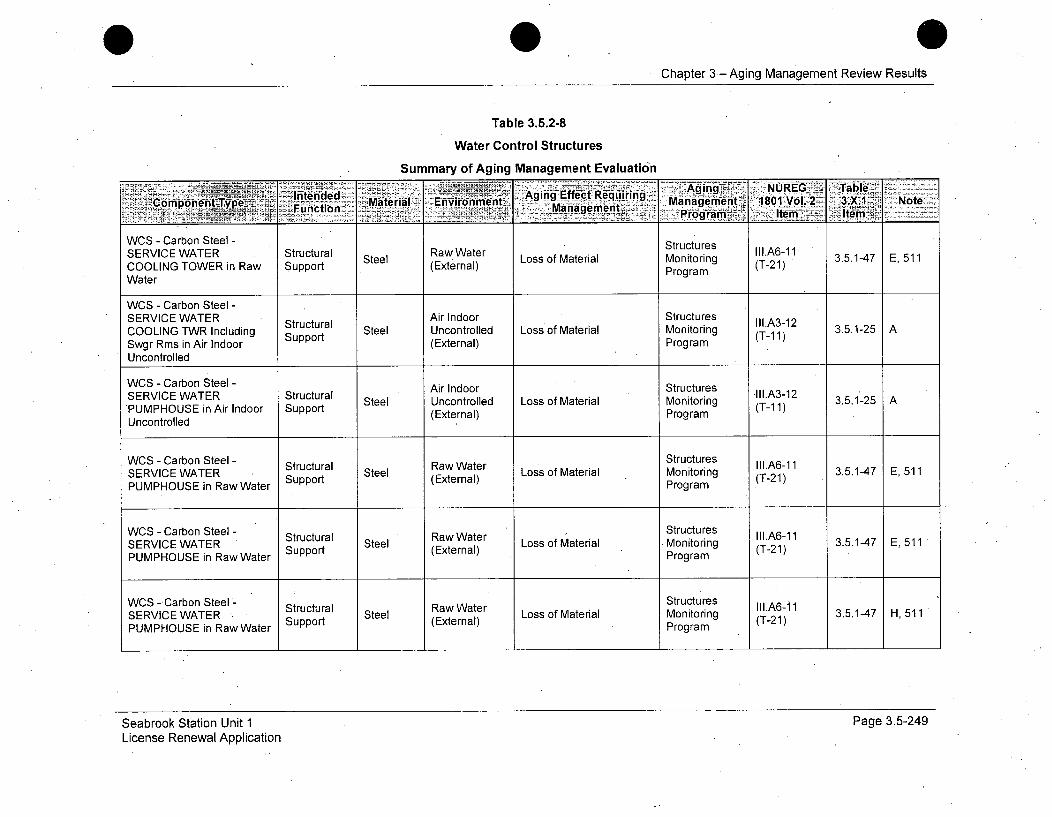
Chapter 3- Aging Management Review Results
Table 3.5.2-8
Water Control Structures
Summary of Aging Management Evaluation
-In"tened....-Agin.g. NUREG .Table.........Component Aging'Effect RequiringCopr 'tType Fuc .on Materialý .EnvironmeMaagmnt Managemnent 1801t Vol.2 3X1 Note
WOS - Carbon Steel - SrcueSERVICE WATER Structural Steel Raw Water L oMrotorin III.A6-11COOLING TOWER in Raw Support Sel (External) LsofMtraMnirng (T-21)3.1-7E51
WaterProgramWater
WCS - Carbon Steel -SERVICE WATER Structural Air Indoor Structures III.A3-12COOLING TWR Including Support Steel Uncontrolled Loss of Material Monitoring (T-11) 3.5.1-25 ASwgr Rms in Air Indoor (External) ProgramUncontrolled
WCS - Carbon Steel - Air Indoor StructuresSERVCE WTER trucural. Ar Inoor trucures 111.A3-12
SERVICE WATER Structural Steel Uncontrolled Loss of Material Monitoring (T-1 3.5.1-25 APUMPHOUSE in Air Indoor Support (External) Program (T-1 1)Uncontrolled
WCS - Carbon Steel - Structural StutueRaw Water s II.A6-11SERVICE WATER Support (External) Loss of Material Monitoring (T-21) 3.5.1-47 E, 511PUMPHOUSE in Raw Water Program
WCS - Carbon Steel - Structural Ra Water Structures III.A6-11SERVICE WATER Water (External) Loss of Material Monitoring (T21)3.5.1-47 E, 511PUMPHOUSE in Raw Water Program
WCS - Carbon Steel'- Structural Raw Water Structures III.A6-1SERVICE WATER Surt Steel (Exter Loss of Material Monitoring T.-1) 3.5.1-47 H, 511PUMPHOUSE in Raw Water Support (External) Program (T21)
Seabrook Station Unit 1License Renewal Application
Page 3.5-249
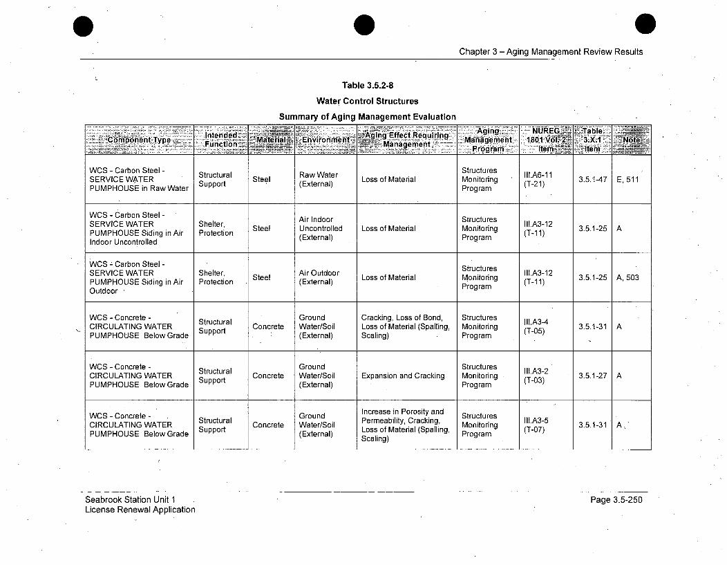
Chapter 3 - Aging Management Review Results
Table 3.5.2-8
Water Control Structures
Summary of Aging Management Evaluation
- Inende -____ S -Agin ~ -NUREG§LI TableI"'t.ntended A•nvirgnm'nr- = ing Effect Requiring•~Maponent Type a a: " "etgem..t,1801 W -V 2• 3.X. NoteWCS- CarbonFutee -- 1 -31rutres
StructuralTyp .Notee I1A61
WCS -Carbon Steel - Structural Sel Raw Water Loso aeilStructures IIl.A6-11 3.1-7 ,51SERVICE WATER Support Steel Loss of Material Monitoring 3.5.1-47 E, 511PUMPHOUSE in Raw Water (External) Program (T-21)
WCS - Carbon Steel - Air Indoor StructuresSERVICE WATER Shelter, Steel Uncontrolled Loss of Material Monitoring II.A3-12 3.5.1-25 APUMPHOUSE Siding in Air Protection (External) ProgramIndoor Uncontrolled
WCS - Carbon Steel - StructuresSERVICE WATER Shelter, Steel Air Outdoor Loss of Material Strutr II1.A3-12 3.5.1-25 A, 503PUMPHOUSE Siding in Air Protection (External) Monitoring (T-1i1)Outdoor Program
WCS - Concrete - Structural Ground Cracking, Loss of Bond, Structures III.A3-4CIRCULATING WATER Support Concrete Water/Soil Loss of Material (Spalling, Monitoring (T-05) 3.5.1-31 APUMPHOUSE Below Grade Spr(External) Scaling) Program
WCS - Concrete - Structural Ground Structures II1.A3-2CIRCULATING WATER Strt Concrete Water/Soil Expansion and Cracking Monitoring (T-03) 3.5.1-27 APUMPHOUSE BelowGrade Support (External) Program
WCS - Concrete - Ground Increase in Porosity and StructuresCIRCULATING WATER Structural Permeability, Cracking, Monitorg II.A3-5 3.5.1-31 A,Strte ter/l Loss of Material (Spalling, Potrm 307)PUMPHOUSE BelowGrade I(External) Scaling) Program
Seabrook Station Unit 1License Renewal Application
Page 3.5-250
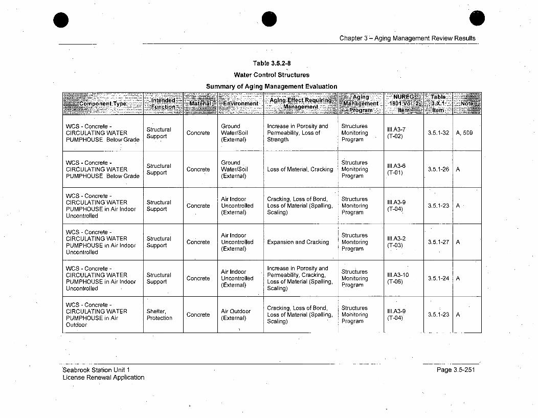
Chapter 3-Aging Management Review Results
Table 3.5.2-8
Water Control Structures
Summary of Aging Management Evaluation
WCS - Concrete - Structural Ground Increase in Porosity and Structures II1.A3-7CIRCULATING WATER Support Concrete Water/Soil Permeability, Loss of Monitoring 0 2 3.5.1-32 A, 509
WCS - Concrete - Ground StructuresCIRCULATING WATER Support Concrete Water/Sil Loss of Material, Cracking Monitoring (T-02) 3.5.1-26 A
PUMPHOUSE BelowGrade (External) ProgramWCS - Concrete -StutrlGonStuues I.A-
WCS - Concrete - Air Indoor Cracking, Loss of Bond, StructuresConcrete Uncontrolled Loss of Material (Spalling, Monitoring (T-4 3.5.1-23 A
PUMPHOUSE in Air Indoor Support (External) Scaling) Program (T-04)Uncontrolled
WCS - Concrete - Air Indoor StructuresCIRCULATING WATER Structural AIII.A3-2PUMPHOUSE in Air Indoor Support Concrete Uncontrolled Expansion and Cracking Monitoring (T-03) 3.5.1-27 A
Uncontrolled (External) Program
WCS - Concrete - Increase in Porosity andCIRCULATING WATER Structural Concrete nor Permeability, Cracking, otructus3.5.1-24 APUMPHOUSE in Air Indoor Support (External) Loss of Material (Spalling, (T-06)Uncontrolled Scaling)
WCS - Concrete - Cracking, Loss of Bond, Structures
CIRCULATING WATER Shelter, Concrete Air Outdoor Loss of Material (Spalling, Monitoring III.A3-9 3.5.1-23 APUMPHOUSE in Air Protection (External) Scaling) Program (T-04)Outdoor
Seabrook Station Unit 1License Renewal Application
Page 3.5-251
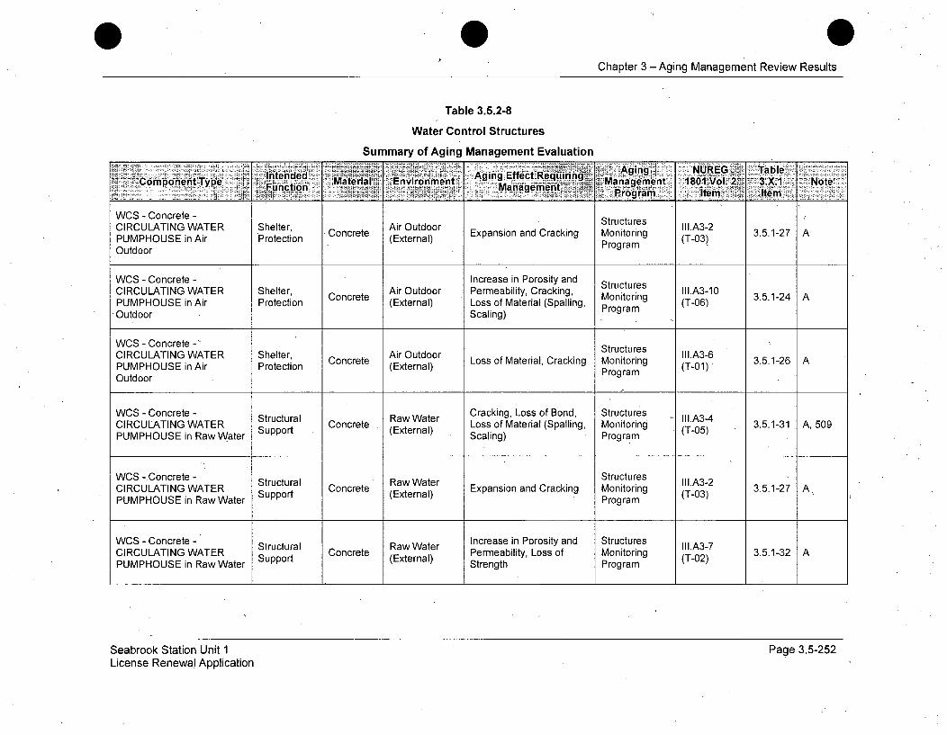
Chapter 3 -Aging Management Review Results
Table 3.5.2-8
Water Control Structures
Summary of Aging Management Evaluation
Intended AigEfc eurnCompnen Typecio Material Environment gigEfcNiI~g~ anag e ment. 1861Vol' 2 ' 3.X.1 * Note'~ .~ 1= >. rog' Item'' Item:
WCS - Concrete - StructuresCIRCULATING WATER Shelter, Air Outdoor III.A3-2PULATING WAiR 'Protection Concrete (Exter Expansion and Cracking Monitoring (T-03) 3.5.1-27 APUMPHOUSE in Air Prtcin(External) ProgramOutdoor Program
WCS - Concrete - Increase in Porosity and StructuresCIRCULATING WATER Shelter, Air Outdoor Permeability, Cracking, III.A3-10
Concete onitring (T.-2PUMPHOUSE in Air Protection (External) Loss of Material (Spalling, Program (T-06)Outdoor Scaling)
WCS - Concrete - StructuresCIRCULATING WATER Shelter, Concrete Air Outdoor Loss of Material, Cracking Monitoring III.A3-6 3.5.1-26 APUMPHOUSE in Air Protection (External) Program (T-01)Outdoor
WCS - Concrete - Structural Raw Water Cracking, Loss of Bond, Structures II1.A3-4CIRCULATING WATER Support Concrete (External) Loss of Material (Spalling, Monitoring (T-05) 3.5.1-31 A, 509PUMPHOUSE in Raw Water Scaling) Program
WCS -Concrete - Structural Raw Water Structures III.A3-2CIRULAINGWAERa oncet Raw3.5.1-27.A3ACIRCULATING WATER Support Concrete (External) Expansion and Cracking Monitoring (T-03) 3.5.1-27 APUMPHOUSE in Raw Water Program
WCS - Concrete - Structural Raw Water Increase in Porosity and Structures II1.A3-7CIRCULATING WATER Support Concrete (External) Permeability, Loss of Monitoring (T-02) 3.5.1-32PUMPHOUSE in Raw Water Strength Program
Seabrook Station Unit 1License Renewal Application
Page 3.5-252

Chapter 3 -Aging Management Review Results
Table 3.5.2-8
Water Control Structures
Summary of Aging Management Evaluation
.ý Aging~? NUREG Tableiz'intende Aging Effect RequiringComponent Type Snpeort CMaterial Environment aeer t Managementg 1801 Vol.2 3.5.1 Note,1Function in RMaan atrIteoga
WCro ra Conret lie
WCS - Concrete - Watertor L oss of Matel Structures III.A6-7UInd NG SW ATcErRo S Concrete Loss of Material Monitoring (T-0) 3.5.1-5 E, 511
PUMPHOUSE in Raw Water Support (External) Program
WCS - Concrete - SERVICE Ground StructuresWATER COOLING TOWER Structural Concrete Water/Soil rackinLoss of Backing Monitoring ur-e 3.5.1-31 AIncluding Switchgear Rooms Support e terlMaterial rg(T-05)Below Grade (External) Scaling) Program
WCS - Concrete - SERVICE Ground StructuresWATER COOLING TOWER Structural Concrete Water/Soil Expansion and Cracking Monitoring IIIA3-2 3.5.1-27 AIncluding Switchgear Rooms Support (External) Program (T-03)Below Grade S
WCS - Concrete - SERVICE Ground Increase in Porosity and StructuresWATER COOLING TOWER Structural Concrete Water/Soil Permeability, Cracking, Monitoring (I.A3-5 3.5.1-31 A
Including Switchgear Rooms Support (External) strength ProgramS
Below Grade ScligWCS - Concrete - SERVICE Ground Increase in Porosity and StructuresWATER COOLING TOWER Structural Concrete Water/Soil L PerMeabialty, Loss kio Monitoring 3.5.1-32 AIncluding Switchgear Rooms Support CeWter/Silo (T-0S)trength3PrBelow Grade (External) Program
WCS - Concrete - SERVICEGrudSucreWATER COOLING TOWER Structural GrudISrcue II.A3-6Including Switchgear Rooms Support Concrete Water/Soil Loss of Material, Cracking Monitoring (T-01) 3.5.1-26 ABelow Grade '(External) Program
Seabrook Station Unit 1License Renewal Application
Page 3.5-253
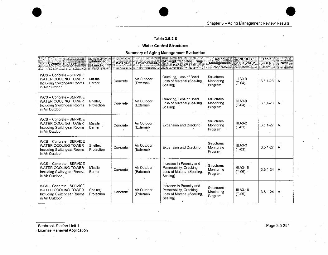
Chapter 3 -Aging Management Review Results
Table 3.5.2-8
Water-Control Structures
WCS - Concrete - SERVICEWATER COOLING TOWERIncluding Switchgear Roomsin Air Outdoor
MissileBarrier Concrete
Air Outdoor(External)
Cracking, Loss of Bond,Loss of Material (Spalling,Scaling)
StructuresMonitoringProgram
III.A3-9(T-04) 3.5.1-23 1 A
WCS - Concrete - SERVICE Cracking, Loss of Bond, StructuresWATER COOLING TOWER Shelter, Concree Airn) Loss of Material (Spalling, Monitoring Iii.A3-9Including Switchgear Rooms Protection (External) Scaling) Program (T-04)in Air Outdoor
WCS - Concrete - SERVICE StructuresWATER COOLING TOWER Missile Air Outdoor Stucurs1l.A3-2Including Switchgear Rooms Barrier Concrete Expansion and Cracking Monitoring (T03) 3.5.1-27 A
Inldn wtherRosBrir(External1 ) Program (-3in Air Outdoor
WCS - Concrete - SERVICE StructuresWATER COOLING TOWER Shelter, Concrete Air Outdoor Expansion and Cracking Monitoring III.A3-2 3.5.1-27 AIncluding Switchgear Rooms Protection (External) Program (T-03)in Air Outdoor
WCS - Concrete - SERVICE Increase in Porosity and StructuresWATER COOLING TOWER- Missile Air Outdoor Permeability, Cracking, Mot g III.A3-10 35124 AIncluding Switchgear Rooms Barrier (External) Loss of Material (Spalling, onioring (T306)in Air Outdoor Scaling) Program
WCS - Concrete - SERVICE Increase in Porosity and StructuresWATER COOLING TOWER Shelter, Concrete Air Outdoor Permeability, Cracking, Monitoring II1.A3-10 3.5.1-24 AIncluding Switchgear Rooms Protection (External) Loss of Material (Spalling, Program (T306)in Air Outdoor Scaling)
Seabrook Station Unit 1License Renewal Application
Page 3.5-254

0Chapter 3 - Aging Management Review Results
Table 3.5.2-8
Water Control Structures
Summary of Aging Management Evaluation
IienAir Outdoor SeI.A3-6COONG TOiConcrete Eti Loss of Material, Cracking Monitoring 'T ol. 3.5.1-26 A
Including Switchgear Rooms Barrierin Air Outdoor Program
WCS - Concrete - SERVICE StructuresWTRCOIGTWR SetrAir Outdoor Stutue III.A3-6 3512WATER COOLING TOWER ssle Concrete Loss of Material, Cracking Monitoring -3.5.1-26 A
Including Switchgear Rooms Protection (External) Programin Air Outdoor
WCS - Concrete - SERVICE Structural Raw Water Cracking, Loss of Bond, Structures III.A3-4WATER COOLING TOWER Suppor, Concrete (External) Loss of Material (Spalling, Monitoring (T-O5) 3.5.1-26 Ain Raw Water suPpot Scaling) Program
WCS - Concrete - SERVICE uctural Raw Water Cracking, Loss of Bond, Structures II1.A3-4WATER COOLING TOWER Sultmate Concrete (External) Loss of Material (Spalling, Monitoring (T-05) 3.5.1-31 A, 509in Raw Water Scaling) Program
WCS - Concrete- SERVICE Stimate Raw Water Structures Iii.A3-2WATER COOLING TOWER Sura Concrete RwWternl Expansion and Cracking Monitoring (T-0 3.5.1-27 Ain Raw Water Spot (External) Program .(T-0)WCS - Concrete - SERV'ICE StutrlRwWtrStructures IIA-
WCS - Concrete - SERVICE Ultimate Raw Water E Structures II1.A3-2 3.5127 AWATER COOLING TOWER Heat Sink Concret (External) Expansion and Cracking Monitoring (T-03)in Raw Water Program
Seabrook Station Unit 1License Renewal Application
I Page 3.5-255
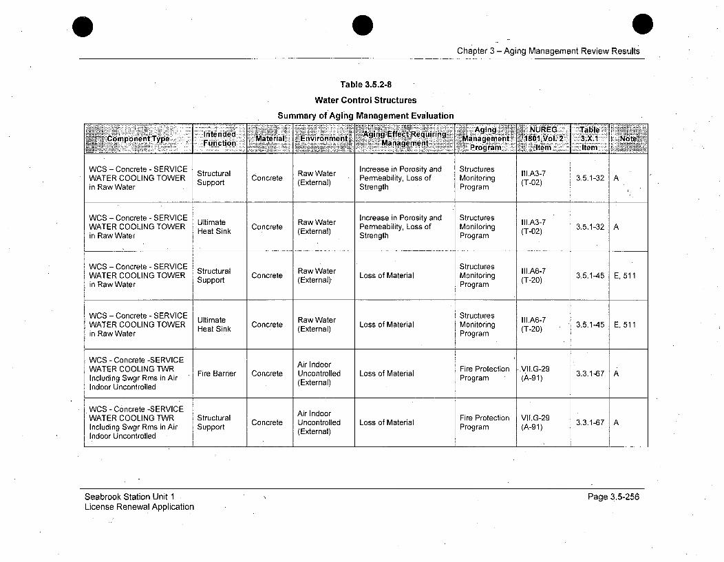
0Chapter 3 -Aging Management Review Results
Table 3.5.2-8
Water Control Structures
Summary of Aging Management EvaluationIntended Aging s) NUREG TablIeK
Intend d . AgingEffect Requiring ... .........'Comp'o'nent Type Fucin Material _Environment Ma nt 180O1 Vol. 2- 3.X. NoteFuncionManagemnent_______________________________ _______ ___________ rogram '. tem - Item
WCS - Concrete - SERVICE Structural Raw Water Increase in Porosity and Structures II1.A3-7WATER COOLING TOWER Support Concrete (External) Permeability, Loss of Monitoring (T-02) 3.5A-32 Ain Raw Water Strength Program
WCS - Concrete - SERVICE Ultimate Raw Water Increase in Porosity and Structures II1.A3-7WATER COOLING TOWER Concrete Permeability, Loss of Monitoring (T-02) 3.5.1-32 Ain Raw Water Heat Sink (External) Strength Program (T-02)
WCS - Concrete - SERVICE StructuresWATER COOLING TOWER Support Concret (External) Loss of Material Monitoring (T-20) 3.5.1-45 E, 511in Raw Water Program
WCS - Concrete - SERVICE Ultimate Raw Water Structures III.A6-7WATER COOLING TOWER Heat Sink Concrete (External) Loss of Material Monitoring (T-20) 3.5.145 E, 511in Raw Water Program
WCS - Concrete -SERVICE Air IndoorWATER COOLING TWR Fire Barrier Concrete Uncontrolled Loss of Material Fire Protection .VII.G-29 3.3.1-67 AIncluding Swgr Rms in Air (e xterial Program (A-91)
Indoor Uncontrolled (External)
WCS - Concrete -SERVICE Air IndoorW ATER COOLING TW R Structural Co cee U c nrle o so aeilFire Protection VII.G-29 3316Concrete Uncontrolled Loss of Material 3.3.1-67A
Including Swgr Rms in Air Support (External) Program (A-91)Indoor Uncontrolled
Seabrook Station Unit 1 ýLicense Renewal Application
Page 3.5-256
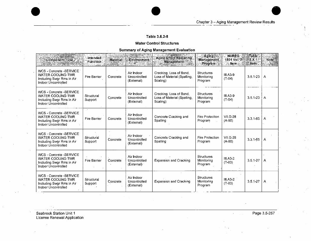
Chapter 3 -Aging Management Review Results
Table 3.5.2-8
Water Control Structures
Summary of Aging Management Evaluation
:Int.en..e... Ag ingEE, NUREG j Table<2:•,:,Com gpo nenlt Type•; Function.. ;•; M::::•:::: :•,ate rial .j;;' i•-nvlronmhentl ,AigEf.ltiig Mngmet 81o2~.. orJ
WCS - Concrete -SERVICE Air Indoor Cracking, Loss of Bond, Structures
WAcTE COgr sn Ar Fire Barrier Concrete Uncontrolled Loss of Material (Spalling, Monitoring (T-04) 3.51-23 AIndoor Uncontrolled (External) Scaling) Program
WCS - Concrete -SERVICE Air Indoor Cracking, Loss of Bond, StructuresWATER COOLING TWR Structural Material (SpallingI Monitoring II.A3-9Including Swgr Rms in Air Support Concrete Uncontrolled Loss ofor (T-04)Indoor Uncontrolled (External) Scaling) Program
WCS - Concrete -SERVICE Air Indoor
Incldin COOLIN Rm'iWAr Fire Barrier Concrete Uncontrolled Concrete Cracking and Fire Protection VII.G-28 3.3.1-65 AWATER COOLING TWR Structur~al Concrete Uncontrolled LspafMteilllingg Mnioig I.3- .. 12Including Swgr Rms in Air Support (External) Scaling Program (A-90)Indoor Uncontrolled
WCS - Concrete -SERVICEWATERAir Indoor Concrete Cracking and Fire Protection VII.G-28
FiE OLIGTR SrecBarrier Concrete Uncontrolled EpninadCckg Motrng3.5.1-27 A
Including Swgr Rms in Air Fire (External) Spalling Program (A-90)Indoor Uncontrolled
WCS - Concrete -SERVICE Air Indoor StructuresWATER COOLING TWR Structural Concrete Uncontrolled Expansion and Cracking Monitoring o II.A3-2 3.5.1-27 AIncluding Swgr Rms in Air Support 3. 7 (A-0)Indoor Uncontrolled (External) ProgramWCS - Concrete -SERVICE Air Indoor StructuresWATER COOLING TWR Firecturral Concrete Uncontrolled Expansion and Cracking Monitoring (T.A-03 3.5.1-27 AIncluding Swgr Rms in Air Spot(External) Program (-3Indoor Uncontrolled
Seabrook Station Unit 1License Renewal Application
Page 3.5-257
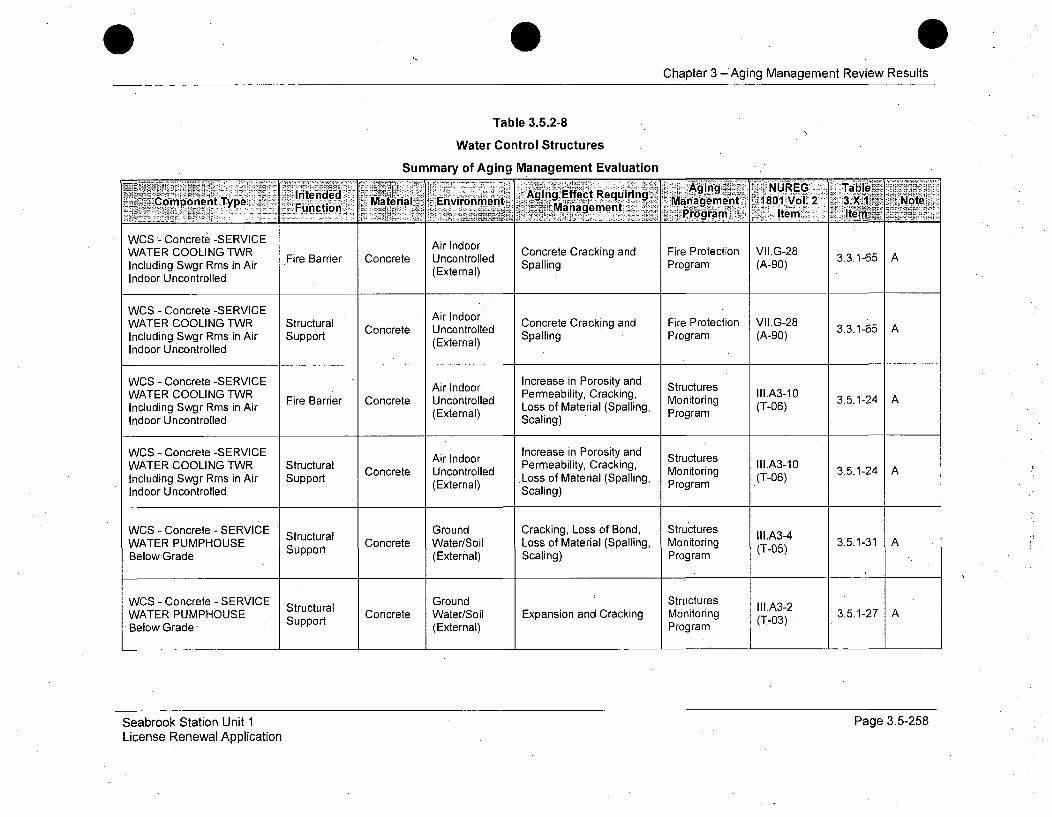
0Chapter 3 -Aging Management Review Results
Table 3.5.2-8
Water Control Structures
Summary of Aging Management Evaluation
WCS - Cnrt Aging Effect RequiringAWTRpCOeINt Type inender Material Environment Manactgemient 18 F tVI.G 2 3X1-5Function AiEr)a n Program (A-0) Man2gemeoageen Item Item~i
WCS - Concrete -SERVICE Air IndoorWATER COOLING TWR Fire Barrier Concrete Uncontrolled Concrete Cracking and Fire Protection VIgG-28 3.3.1-65 AIncluding Swgr Rms in Air (External) Spalling Program (A-90)Indoor Uncontrolled
WCS - Concrete -SERVICEWATER COOLING TWR Structural Air Indoor Concrete Cracking and Fire Protection VIG-28 3..1-Including Swgr Rms in Air Support eUncontrolled Spalling Program (A-90)Indoor Uncontrolled (External)
WCS - Concrete -SERVICE Air Indoor Increase in Porosity and Structures
WATERbiitCOOLINGg, II.3-R
WATER COOLING TWR StBarrier Concrete Uncontrolled Permeability, Cracking, Monitoring (.A3-10 3.5.1-24 AIncluding Swgr Rms in Air Loss of Material (Spalling, Prgn (T-06)Indoor Uncontrolled Scaling)
WCS - Concrete -SERVICE AiroInd Increase in Porosity and StructuresWATER COOLING TWR Structural Conret Uncoonrole Permeability, Cracking, Monitore lll.A3-10 3512InudooR PUM SE Support Concrete Watroll Loss of Material (Spalling, Monitoring (T-06) 3.5.1-31Incloudingw•Grade (External) Scaling) Program
WCS - Concrete - SERVICE Structural Ground Cracking, Loss of Bond, Structures II1.A3-4WATER PUMPHOUSE Support Concrete Water/Soil Loss of Material (Spalling, Monitoring (T-05) 3.5.1-31 ABelow Grade (External) Scaling) Program
WCS - Concrete - SERVICE Structural Ground Structures IIl.A3-2WATER PUMPHOUSE Spot Concrete Water/Soil Expansion and Cracking Monitoring (T-03) 3.5.1-27 A*Below Grade upp (External) Program
Seabrook Station Unit 1 Page 3.5-258License Renewal Application
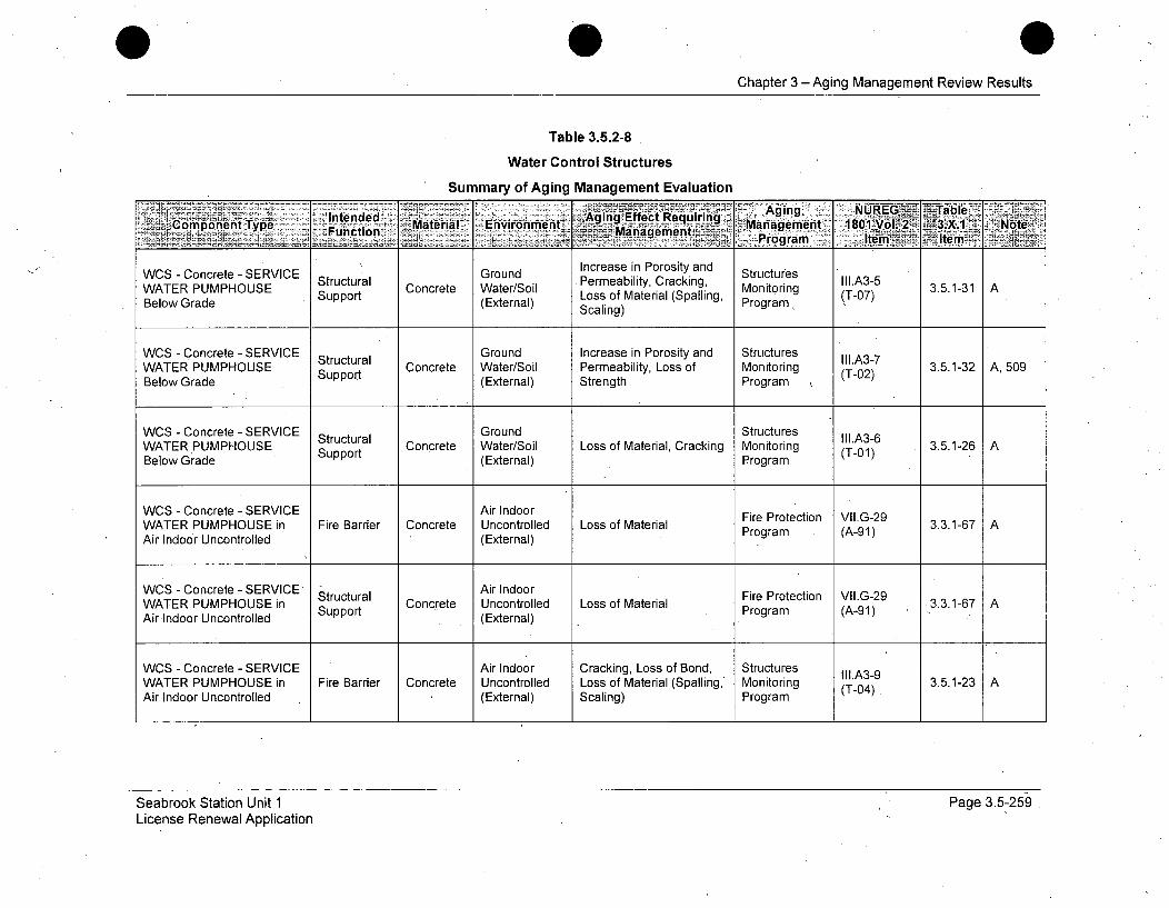
Chapter 3 - Aging Management Review Results
Table 3.5.2-8
Water Control Structures
Summary of Aging Management Evaluation
'~~~n Inres anPrst nWSCo t- SIntended Aging P er Reqmi iring, A g IA-5WATRompoUnent Type ConcrMterial evironment 9 Mnig ent3.51 NA t
Loss_ oMaei(Saln ~Program Item 7te
WCS - Concrete - SERVICE Ground Increase in Porosity and StructuresWATER PUMPHOUSE Concrete Water/Soil Permeability, Cracking, Monitoring (.A3-5 3.5.1-31 ABelow Grade Support (External) Loss of Material (Spalling Program (T-07)Below Grade Scaling)Prga
WCS - Concrete - SERVICE Structural Ground Increase in Porosity and Structures III.A3-7WATER PUMPHOUSE Support Concrete Water/Soil Permeability, Loss of Monitoring (T-02) 3.5.1-2 ABelow Grade (External) Strength Program
WCS - Concrete - SERVICE Structural Ground Structures VII.A3-6WATER PUMPHOUSE Support Concrete Water/Soil Loss of Material, Cracking Monitoring (T-01) 3.5.1-26 ABelow Grade uppoe(External) Program
WCS - Concrete - SERVICE Air Indoor Fire Protection VII.G-29WATER PUMPHOUSE in Fire Barrier Concrete Uncontrolled Loss of Material •Proga 3.3.1-67Air Indoor Uncontrolled (External) Program (A-91)
WCS - Concrete - SERVICE' Air IndoorFiePoctn VIG-9 3316 AWATER PUMPHOUSE in Structural Concrete Uncontrolled Loss of Material Fr rtcin VIG2 3316Air Indoor Uncontrolled Support (External) . Program (A-91)
WCS - Concrete - SERVICE Air Indoor Cracking, Loss of Bond, Structures III.A39WATER PUMPHOUSE in Fire Barrier Concrete Uncontrolled Loss of Material (Spalling, Monitoring (T-04) 3.5.1-23 AAir Indoor Uncontrolled (External) Scaling) Program
Seabrook Station Unit 1License Renewal Application
Page 3.5-259
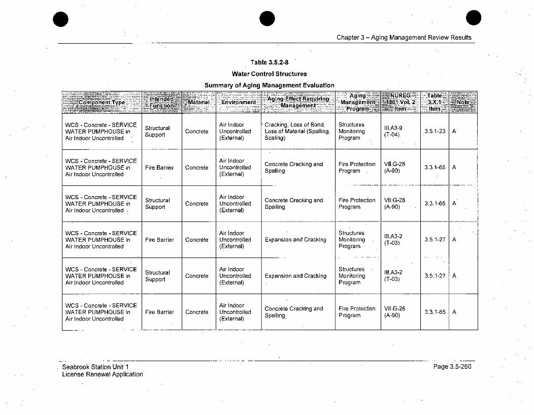
Chapter 3-Aging Management Review Results
Table 3.5.2-8
Water Control Structures
Summary of Aging Management EvaluationInene Aging - -ENUREG. Table
Component Type Inedd Material Environmient 'A~. qiig Management ~180.Vol. 2 3.X.1 NOte______ Funtion rogram lem Item
WCS - Concrete - SERVICE Structural Air Indoor Cracking, Loss of Bond, Structures III.A3-gWATER PUMPHOUSE in Support Concrete Uncontrolled Loss of Material (Spalling, Monitoring J-04) 3.5.1-23 AAir Indoor Uncontrolled (External), Scaling) Program
WCS -'Concrete - SERVICE Air Indoor Concrete Cracking and Fire Protection VI.G-28WATER PUMPHOUSE in Fire Barrier Concrete Uncontrolled Spalling Program V.(A-90) 3.3.1-65 AAir Indoor Uncontrolled (External)
WCS - Concrete -SERVICE Air IndoorWATER PUMPHceSERV Structural CIncool Concrete Cracking and Fire Protection VII.G-28WATER PUMPHOUSE in Supprutua Concrete Uncontrolled SalnPrgm(A9) 3.3.1-65 A:
Air Indoor Uncontrolled Support (External) Spalling Program (A-90)
WCS - Concrete - SERVICE Air Indoor StructuresWATER PUMPHOUSE in Fire Barrier Concrete Uncontrolled Expansion and Cracking Monitoring (T0A32 3.5.1-27 AAir Indoor Uncontrolled (External) Program (T03)
WCS - Concrete - SERVICE Air Indoor StructuresStructural II1.A3-2WATER PUMPHOUSE in Support Concrete Uncontrolled Expansion and Cracking Monitoring (T-03) 3.5.1-27 AAir Indoor Uncontrolled (External) Program
WCS - Concrete - SERVICE Air Indoor Concrete Cracking and Fire Protection VIIG-28WATER PUMPHOUSE in Fire Barrier Concrete Uncontrolled Spallingc Program (A-0G) 3.3.1-65Air Indoor Uncontrolled (External)
Seabrook Station Unit 1License Renewal Application
Page 3.5-260

Chapter 3 -Aging Management Review Results
Table 3.5.2-8
Water Control Structures
Summary of Aging Management EvaluationE ~A~gingio NUREG Jab le-
Componnt Typ Material Environment ecl Reuiinuct8-mag nagmn _Management '101 Vol. 2 3.X1 Note
Manaemejt yogra ,Item~ ite
WCS - Concrete - SERVICE Structural Air Indoor Concrete Cracking and Fire Protection VII.G-28WATER PUMPHOUSE in Sura Concrete Uncontrolled ping Program (A-90 3.3.1-65 AAir Indoor Uncontrolled Support (External) Spalling Program (A-90)
WCS - Concrete - SERVICE Air Indoor Increase in Porosity and StructuresWATER PUMPHOUSE in Fire Barrier Concrete Uncontrolled Permeability, Cracking, Monitoring II.A3-10 3.5.1-24 A
Loss of Material (Spalling, M (T-06)Air Indoor Uncontrolled (External) Scaling) Program
WCS - Concrete - SERVICE Air Indoor Increase in Porosity and StructuresWATER PUMPHOUSERin Structural Concrete Uncontrolled Permeability, Cracking, Monitoring III.A3-10 3.5.1-24 AATER PUMPHOUSe Support Loss of Material (Spalling, Mogram (T-06)
Air.Indoor Uncontrolled , (External) Scaling) Program
WCS - Concrete - SERVICE Cracking, Loss of Bond, StructuresWATER PUMPHOUSERin Missile Concrete Air Outdoor Loss of Material (Spalling, Monitoring II1.A3-9 3.5.1-23 AAir Outdoor Barrier (External) Scaling) Program (T-04)
WCS - Concrete - SERVICE Shelter Air Outdoor Cracking, Loss of Bond, Structures III.A3-9WATER PUMPHOUSE in Protection Concrete Loss of Material (Spalling, Monitoring 3.5.1-23 AAir Outdoor <P, Scaling) Program
WCS- Concrete - SERVICE Missile Air Outdoor Structures III.A3-2WATER PUMPHOUSE in Barrier Concrete (Exter Expansion and Cracking Monitoring (T-03) 3.5.1-27 AAir Outdoor (External) Program
Seabrook Station Unit 1 Page 3.5-261License Renewal Application
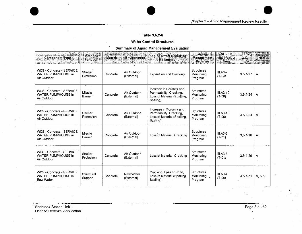
Chapter 3 - Aging Management Review Results
Table 3.5.2-8
Water Control Structures
Summary of Aging Management Evaluation
Itd : 'gin EfectReqinnAging NUREG Table-:'-pmoetType ene Material Environment, g Management 1801 Vol.2 3X .. oeCmoetFunction 'Management ý ie Ie
Air -OCncetdooERIC Structures. I.A-
WCS - Concrete - SERVICE Shelter, Concrete Air Outdoor Expansion and Cracking Monitoring l.A3-2 3.5.1-27 AWATER PUMPHOUSE in Protection (External) Monrin (T-03)Air Outdoor Program
WCS - Concrete - SERVICE Increase in Porosity and StructuresWATER PUMPHOUSE in Missiler Concrete Air Outdoor Permeability, Cracking, Monito III.A3-10 3.5.1-24 AAir Outdoor (External) Loss of Material (Spalling, P ring (T-06)
Scaling) Program
WCS - Concrete - SERVICE Increase in Porosity and StructuresShelter, C Air Outdoor Permeability, Cracking, IIo.A3-10WATER PUIMPHOUSE in Protection Concrete (External) Loss of Material (Spalling, Monitoring (Tr06) 3.5.1-24Air Outdoor Scaling) Program
WCS - Concrete - SERVICE StructuresWATER PUMPHOUSE in Barrie Concrete Loss of Material, Cracking Monitoring (T-01) 3.5.1-26 AAir Outdoor Barrier (External) Program
WCS - Concrete - SERVICE S Air Outdoor Structures III.A3-6WATER PUMPHOUSE in Shelter, Concrete (Exter Loss of Material, Cracking Monitoring (T-01) 3.5.1-26 AAir Outdoor Protection (External) Program
WCS - Concrete - SERVICE Raw Water Cracking, Loss of Bond, Structures II1.A3-4WATER PUMPHOUSE in ' Concrete Loss of Material (Spalling, Monitoring - CT-) 3.5.1-31 A, 509
Raw Water Support (External) Scaling) (T-05)
Seabrook Station Unit 1License Renewal Application
Page 3.5-262
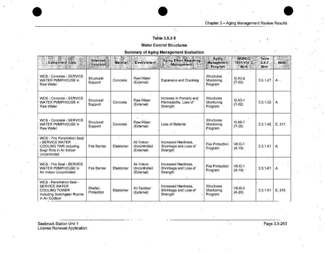
Chapter 3 - Aging Management Review Results
Table 3.5.2-8
Water Control Structures
Summary of Aging Management Evaluation
IntendedWeE R A g f Rru Aging ctRs I.TableComponentUType Ma Support ter Environment M a nd C Monament 1801gVoT . 2 3.5.1 Notewrogram IteWo Item
WCS - Concrete - SERVICE Structural Raw Water Expansion andoCracking Structures II1.A3-AWATER PUMPHOUSE in Support Concret (External) pansion of Monitoring (T-03) 3.5.1-2 ARaw Water Strengt Program
WCS - Concrete - SERVICE Increase in Porosity and StructuresStructural (exRaw i) Permeability, Loss of Monitoring eII1.A-7
WATER PUMPHOUSE in Structural Concrete (EWter Loss of Material Monitoring IIIA67 3.5.1-45, E, 511Raw Water (External) Program
WCS - Fire Penetration Seal- SERVICE WATER Air Indoor Increased Hardness, Fire Protection VII.G-1COOLING TWR including Fire Barrier Elastomer Uncontrolled Shrinkage and Loss of Program (A-19) 3.3.1-61 ASwgr Rms in Air Indoor (External) StrengthUncontrolled
WCS - Fire Seal - SERVICE Air Indoor Increased Hardness, Fire Protection VII.G-1WATER PUMPHOUSE in Fire Barrier Elastomer Uncontrolled Shrinkage and Loss of Proteto (A-19 3.3.1-61 AAir Indoor Uncontrolled (External) Strength Program (A-19)
WCS - Penetration Seal -
SERICOO TOWER Shelter, EAir Outdoor Increased Hardness, Structures VII.G-2COoLISERVICENGWAER S ,Protection Elastomer (External) Shrinkage and Loss of Monitoring (A-20) 3.3.1-61 E, 515Including Switchgear Rooms Strength Programin Air Outdoor
Seabrook Station Unit 1License Renewal Application
Page 3.5-263
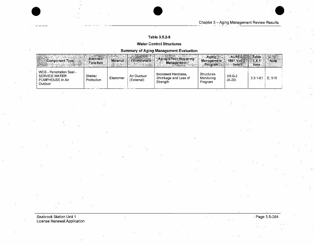
Chapter 3 -Aging Management Review Results
Table 3.5.2-8
Water Control Structures
Summary of Aging Management EvaluationInedeAging Effect-Kediri Agn UREG T•able
•-:Ž*.i..:',Cpmponent Type , Material Envir-nm-ent V. . 1Manage t., 1801I 3.X. -NoteFuctn. ManageiMent Progi-MT: ten)___ Ie
WCS - Penetration Seal -SERVICE WATER Shelter, Elastomer Air Outdoor incase Hardness, Structures VII.G-2 331-61 E, 515PUMPHOUSE in Air Protection (External) Shrinkage and Loss of Monitoring (A-20)Outdoor Strength Program
Seabrook Station Unit 1License Renewal Application
Page 3.5-264

Chapter 3 - Aging Management Review Results
Table 3.5.2-8Water Control Structures
Summary of Aging Management EvaluationStandard Notes
Note DescriptionA Consistent with NUREG-1 801 item for component, material, environment, and aging effect. AMP is consistent with NUREG-1 801 AMP.
B Consistent with NUREG-1 801 item for component, material, environment, and aging effect. AMP takes some exceptions to NUREG-1801 AMP.
C Component is different, but consistent with NUREG-1801 item for material, environment,-and aging effect. AMP is consistentwithNUREG-1801 AMP.
D Component is different, but consistent with NUREG-1801 item for material, environment, and aging effect. AMP takes some exceptionsto NUREG-1801 AMP.
E Consistent with NUREG-1 801 for material, environment and aging effect, but a different aging management program is credited orNUREG-1 801 identifies a plant-specific aging management program.
F Material not in NUREG-1 801 for this component.G Environment not in NUREG-1 801 for this component and material.
H Aging effect not in NUREG-1 801 for this component, material and environment combination.
I Aging effect irn NUREG-1 801 for this component, material and environment combination is not applicable.J Neither the component nor the material and environment combination is evaluated in NUREG-1 801.
501 Not used.502 Aging effect includes "Fretting or Lockup" due to wear.503 Crevice and pitting will be included along with loss of material-corrosion due to a saltwater atmosphere environment.504 Fatigue analysis exists and TLAA applies.
505 Built-up roofing is not in GALL; III.A6-12 is for elastomer-material is similar, aging effect is similar, environment is same, and AMP isStructures Monitoring.
506 Component is cementitious fire proofing/insulating material and will exhibit similar aging effects as concrete.507 Spent Fuel Pool temperature < 60 0C (<1400 F); water chemistry and temperature will be maintained by the Water Chemistry Program.
508 Cracking, loss of bond, and loss of material (spalling, scaling)/corrosion of embedded steel-is not listed in GALL III.A.6 as an agingeffect for concrete in raw water. Seabrook manages this effect with Structures Monitoring Program.
509 For aging management purposes, buried, below grade, soil, and ground water/ raw & treated water environments are treated the same.510 Reduction in concrete anchor capacity is an aging effect that is addressed in LRAM-SUPT.511 At Seabrook Station, XI.S7 "RG 1.127, Inspection of Water-Control Structures Associated with Nu6lear Power Plants" and XI.S5
"Masonry Wall Program" are combined under XI.S6 "Structures Monitoring Program".
Seabrook Station Unit 1License Renewal Application
Page 3.5-265

0Chapter 3 -Aging Management Review Results
512 Raw water in lined & unlined concrete sumps.513 Seabrook Station will age manage this condition through the Fire Protection Program.
514 Seabrook Station will age manage'this condition through the Structures Monitoring Program.515 Increased hardness, shrinkage, or loss of strength of elastomer seals due to weathering is addressed by GALL only for Fire Barrier
seals. Seabrook Station will manage such aging effects for, non-Fire Barrier elastomer seals with the Structures Monitoring Program.
516 Seabrook Station Structures Monitoring Program will perform concrete testing and rebar inspection to determine the effects of theaggressive groundwater on the concrete. The concrete testing and the rebar inspection will represent all concrete below grade.
Seabrook Station Unit 1License Renewal Application
Page 3.5-266
Chapter 3 - Aging Management Review Results
3.6 AGING MANAGEMENT OF ELECTRICAL ANDINSTRUMENTATION AND CONTROLS
3.6.1 INTRODUCTION
This section provides the results of the aging management review for theelectrical commodity groups identified in Section 2.5, Scoping and ScreeningResults: Electrical and Instrumentation and Control (I&C)Systems/Commodity Groups.
The electrical and instrumentation and control commodity groups requiringaging management review are listed below. The following sections identifymaterials, environments, aging effects requiring management and associatedaging management programs (AMPs) for each electrical commodity groupidentified in Section 2.5.4.
* Non-EQ Electrical Cables and Connections
* Metal Enclosed Bus
* Fuse Holders (Not Part of a Larger Assembly) Metallic Clamps
" Cable Connections (Metallic Parts)
* SF6 Insulated Bus, Connections and Insulators
3.6.2 RESULTS
The following tables summarize the results of the aging management review.
* Table 3.6-1 Summary Of Aging Management Evaluations for theElectrical / I&C Components / Commodities
* Table 3.6-2 Summary Of Aging Management Evaluations - Electrical /I&C Components / Commodities.
Seabrook Station Unit 1 Page 3.6-1License Renewal Application

Chapter 3 -' Aging Management Review Results
3.6.2.1 Materials, Environments, Aging Effects Requiring Managementand Aging Management Programs
316.2.1.1 Non-EQ Electrical Cables and Connections
Materials
The materials of construction for the Non-Environmentally Qualified (Non-EQ)electrical cables and connections are:
* Various Organic Polymers
Environments
The Non-EQ electrical cables and connections are exposed to the followingenvironments:
" Adverse localized environment caused by heat, radiation, or moisturein the presence of oxygen
* Adverse localized environment caused by exposure to moisture andvoltage
Aging Effects Requiring Management
The following aging effects associated with Non-EQ electrical cable andconnections require management:
* Embrittlement, cracking, melting, discoloration, swelling, or loss ofdielectric strength leading to reduced insulation resistance (IR);electrical failure
" -Localized damage and breakdown of insulation leading to electricalfailure
Aging Management Programs
The following aging management programs manage the aging effects for theNon-EQ electrical cables and connections:
* Electrical Cables and Connections Not Subject to 10 CFR 50.49Environmental Qualification Requirements (B.2.1.32)
Seabrook Station Unit 1 Page 3.6-2License Renewal Application

Chapter-3 --Aging Management Review Results
* Electrical Cables and Connections Not Subject to 10 CFR 50.49
Environmental Qualification Requirements Used in Instrumentation
Circuits (B.2.1.33)
* Inaccessible Medium Voltage Cables Not Subject to 10 CFR 50.49
Environmental Qualification Requirements (B.2.1.34)
3.6.2.1.2 Metal Enclosed Bus
Materials
The materials of construction for the Metal Enclosed Bus are:
* Aluminum
* Copper
* Elastomer
* Epoxy
• Polyester glass
e Porcelain
* Silver plated aluminum
* Silver plated copper-
* Stainless Steel
* Steel
Environments
The Metal Enclosed Bus are exposed to the following environments:
" Air - Indoor Uncontrolled
* Air-Outdoor
Seabrook Station Unit 1License Renewal Application
Page 3.6-3

Chapter 3 -Aging Management Review Results
Aging Effects Requiring Management
The following aging effects associated with Metal Enclosed Bus require
management:
a Loosening of bolted connections
* Embrittlement, cracking, melting, discoloration, swelling, or loss of
dielectric strength leading to reduced insulation resistance (IR);
electrical failure.
* Moisture and debris intrusion
Aging Management Programs
The following aging management programs manage the aging effects for the
Metal Enclosed Bus
" Metal Enclosed Bus (B.2.1.35)-
" Structures Monitoring Program (B.2.1.31)
3.6.2.1.3 Fuse Holders (Not Part of a Larger Assembly) Metallic Clamps
Materials
The materials of construction of Fuse Holders (Not Part of a Larger
Assembly) Metallic Clamps are:
V various conductive metals including copper alloy.
Environments
The metallic clamps of Fuse Holders (Not Part of a Larger Assembly) Metallic
Clamps are exposed to the following environments:
* Air Indoor Uncontrolled
Aging Effects Requiring Management
The following aging effect associated with Fuse Holders (Not Part of a Larger
Assembly) Metallic Clamps requires management:
Seabrook Station Unit 1 Page 3.6-4License Renewal Application
Chapter 3 - Aging Management Review Results
0 Thermal fatigue in the form of high resistance
Aging Management Programs
The following aging, management programs manage the aging effects for theFuse Holders (Not Part of a Larger Assembly) Metallic Clamps:
* Fuse Holders (B.2.1.36)
3.6.2.1.4 Cable Connections (Metallic Parts)
Materials
The materials of construction for the Cable Connections (Metallic Parts) are:
* Various conductive metals used for electrical contacts
Environments
The Cable Connections (Metallic Parts) are exposed to the following
environments:
* Air Indoor Controlled
* Air Indoor Uncontrolled
" Air Outdoor
" Air with Borated Water Leakage
Aging Effects Requiring Management
The following aging effects associated with Cable Connections (Metallic
Parts) require management:
* Loosening of bolted connections
* Corrosion of connector contact surfaces
Aging Management Programs
The following aging 'management programs manage the aging effects for
Cable Connections (Metallic Parts):
Seabrook Station Unit 1 Page 3.6-5License Renewal Application
Chapter 3 - Aging Management Review Results
* Electrical Cable Connections Not Subject To 10 CFR 50.49Environmental Qualification Requirements (B.2.1.37)
• Boric Acid Aging Management Program (B.2.1.4)
3.6.2.1.5 SF 6 Insulated Bus, Connections and Insulators
Materials
The materials of construction for the Sulfur Hexafluoride (SF 6) Insulated Bus,Connections and Insulators are:
* Aluminum
* Elastomer
* Epoxy
* Gas (SF6)
* Stainless Steel
* Silver Plated Aluminum
Environments
The SF6 Insulated Bus, Connections and Insulators are exposed to thefollowing environments:
* Gas (SF6)
• Air-Outdoor
Aging Effects Requiring Management
The following aging effects associated with SF 6 Insulated Bus, Connectionsand Insulators require management:
* Loss of pressure boundary
* Loss of insulating properties due to changes in SF 6 properties.
Seabrook Station Unit 1, Page 3.6-6License Renewal Application

Chapter 3 - Aging Management Review Results
Aging Management Programs
The following aging management programs manage the aging effects for the
SF 6 Bus:
345 kV SF 6 Bus (B.2.2.1)
3.6.2.2 AMR Results for Which Further Evaluation is Recommended
by the GALL Report
NUREG-1801 provides the basis for identifying those programs that warrantfurther evaluation by thereviewer in the License Renewal Application (LRA).For the Electrical / I&C commodities, those programs are addressed in thefollowing subsections.
3.6.2.2.1 Electrical Equipment Subject to Environmental Qualification
Environmental qualification is a Time Limited Aging Analysis (TLAA) asdefined in 10 CFR 54.3. TLAAs are required to be evaluated in accordancewith 10 CFR 54.21(c)(1). The evaluation of this TLAA is addressed in Section
4.4, "Environmental Qualification (EQ) of Electric Equipment," of this
application.
3.6.2.2.2 Degradation of Insulator Quality due to Presence of Any SaltDeposits and Surface'Contamination, and Loss of Material due
to Mechanical Wear
The SF 6 switchyard connects Seabrook Station to the off site transmission
grid. The SF6 bus is included as part of the recovery path in the event- of aStation Blackout event.
The design of the SF 6 switchyard does not include high voltage insulators that
are commonly associated with an open air switchyard design.
Conclusion
The Seabrook Station switchyard design does not include high voltage
insulators, therefore the aging mechanisms and effects are not applicable.
Seabrook Station Unit 1 Page 3.6-7License Renewal Application

Chapter 3 - Aging Management Review Results
3.6.2.2.3 Loss of Material due to Wind Induced Alfasion and Fatigue,Loss of Conductor Strength due to Corrosion, and IncreasedResistance of Connection due to Oxidation or Loss of Pre-load
The SF6 switchyard connects Seabrook Station to the off site transmission_grid.
The in-scope portion of the SF 6 switchyard does not include transmissionconductors and connections or switchyard bus and connections that arecommonly associated with an open air switchyard design.
Conclusion
The in-scope portion of the Seabrook Station switchyard design does notinclude transmission conductors and connections or switchyard bus andconnections, therefore the aging mechanisms and effects are not applicable.
3.6.2.2.4 Quality Assurance for Aging Management of Nonsafety-Related Components
Quality Assurance (QA) provisions applicable to License Renewal arediscussed in Section B.1.3.
3.6.2.3 AMR Results Not Consistent with or Not Addressed in theGALL Report
The 345kV SF6 switchyard connects Seabrook Station to the off site.transmission grid. The SF6 bus is included as part of the recovery path in theevent of a Station Blackout event. As discussed in Section 3.6.2.2.2 and3.6.2.2.3, the design of the SF6 switchyard does not include high voltageinsulators and transmission lines that are normally associated with an openair switchyard. The SF6 bus is a phase isolated and independent bus in whicheach phase conductor is enclosed by an individual metal housing separatedfrom adjacent conductor housings by an air space. The conductor is centeredin the housing by insulators. The insulating parameters are accomplished bymaintaining the space achieved by the insulators and the insulating propertiesof the SF 6 gas.
The critical conditions which are essential to the bus operation aremaintaining the pressure boundary and the air, moisture and sulfur dioxide
(SO2) content.
Seabrook Station Unit 1 Page 3.6-8License Renewal Application

Chapter 3 - Aging Management Review Results
The presence of moisture could lead to electrical failure and the presence of
SO2 is an indication of partial discharge in the system.
The external surface of the SF6 bus is managed for loss of material. Thepressure boundary and the quality of the SF 6 gas is managed by the 345kV
SF6 Bus Aging Management Program (B.2.2.1).
3.6.3 CONCLUSION
The electrical commodity groups that are subject to aging managementreview have been, identified in accordance with the scoping criteria of 10 CFR54.4. Aging effects have been identified based on plant and industryoperating experience as well as industry literature. Programs to managethese aging effects have been identified in this section, and detailed programdescriptions are provided in Appendix B. These activities demonstrate thatthe aging effects associated with the electrical commodity groups will- beadequately managed such that there is reasonable assurance that theintended functions will be maintained consistent with the current licensingbasis during the period of extended operation.
Seabrook Station Unit 1License Renewal Application
Page 3.6-9

Chapter 3 - Aging Management Review Results
Table 3.6.1
Summary of Aging Management Evaluations for the Electrical / I&C Components / Commodities
Item Number - ~Comnponent Agg~ gigMnement, Furthie;E~ilito _ isuso- fet/Mechfani4mz Program-Fs - Reco'mriinded __
3.6.1-1 Electrical equipment subject Degradation due to Environmental Yes, TLAA (See Environmental Qualification (EQ) ofto 10 CFR 50.49 various aging Qualification Of Subsection Electric Components is a TLAA. Furtherenvironmental qualification mechanisms Electric Components 3.6.2.2.1) evaluation is documented in Section 4.4(EQ) requirements and Subsection 3.6.2.2.1
3.6.1-2 Electrical cables, connections -Reduced insulation Electrical Cables No Consistent with NUREG-1801. Theand fuse holders (insulation) resistance and and Connections Electrical Cables and Connections Notnot subject to 10 CFR 50.49 electrical failure due Not Subject To 10 Subject to 10 CFR 50.49 EnvironmentalEQ requirements to various physical, CFR 50.49 EQ Qualification Requirements Program,
thermal, radiolytic, Requirements B.2.1.32, will be used to managephotolytic, and reduced insulation resistance andchemical electrical failure due to variousmechanisms mechanisms, in adverse localized
environments, for insulated cables andconnections, including connectioninsulation for splices, terminal blocksand fuse holders.
3.6.1-3 Conductor insulation for Reduced insulation Electrical Cables No Consistent with NUREG-1801. Thiselectrical cables and resistance and And Connections AMP manages the aging of the Nuclearconnections used in electrical failure due Used In Instrumentation cables. Radiationinstrumentation circuits not to various physical, Instrumentation Monitoring cables are included in thesubject to .10 CFR 50.49 EQ thermal, radiolytic, Circuits Not Subject EQ Program.The Electrical Cables andrequirements that are.. photolytic, and. To 10 CFR 50.49 Connections NotSubject to 10 CFRsensitive to reduction in chemical EQ Requirements 50.49 Environmental Qualificationconductor insulation mechanisms Requirements Used In Instrumentationresistance (IR) Circuits Program, B.2.1.33, will be used
to manage reduced insulationresistance and electrical failure, due tovarious mechanisms, in adverselocalized environments, for insulatedcables and connections used in nuclearinstrumentation circuits.
Seabrook Station Unit 1License Renewal Application
Page 3.6-10
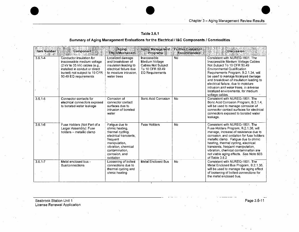
Chapter 3 - Aging Management Review Results
Table 3.6.1
Summary of Aging Management Evaluations for the Electrical / I&C Components / Commodities
Item~umbr :jI' omponen R~gingAying Management "Further E~valail icsiItem~~ Nube Ef C~caim r'riiecommiendedJ
3.6.1-4 Conductor insulation for Localized damage Inaccessible No Consistent with NUREG-1801. Theinaccessible medium voltage and breakdown of Medium Voltage Inaccessible Medium Voltage Cables(2 kV to 35 kV) cables (e.g., insulation leading to Cables Not Subject Not Subject To 10 CFR 50.49installed in conduit or direct electrical failure due To 10 CFR 50.49 Environmental Qualificationburied) not subject to 10 CFR to moisture intrusion, EQ Requirements Requirements Program, B.2.1.34, will50.49 EQ requirements water trees be used to manage localized damage
and breakdown of insulation leading toelectrical failure, due to moistureintrusion and water trees, in adverselocalized environments, for mediumvoltage cables.
3.6.1-5 Connector contacts for Corrosion of Boric Acid Corrosion No Consistent with NUREG-1801. Theelectrical connectors exposed connector contact Boric Acid Corrosion Program, B.2.1.4,to borated water leakage surfaces due to will be used to manage corrosion of
intrusion of borated connector contact surfaces for electricalwater connectors exposed to borated water
leakage.
3.6.1-6 Fuse Holders (Not Part of a Fatigue due to Fuse Holders No Consistent with NUREG-1801. TheLarger Assembly): Fuse ohmic heating, Fuse Holders Program, B.2.1.36, willholders - metallic clamp thermal cycling, manage, increase of resistance due to
electrical transients, corrosion, and oxidation for fuse holdersfrequent metallic clamp. Fatigue due to ohmicmanipulation, heating, thermal cycling, electricalvibration, chemical transients, frequentmanipulation,contamination, vibration, chemical contamination arecorrosion, and not viable aging effects. See Note 603oxidation of Table 3.6.2
3.6.1-7 Metal enclosed bus - Loosening of bolted Metal Enclosed Bus No Consistent with NUREG-1 801. TheBus/connections connections due to Metal Enclosed Bus Program, B.2.1.35,
thermal cycling and will be used to manage the aging effectohmic heating of loosening of bolted connections for
the metal enclosed bus.
Seabrook Station Unit 1License Renewal Application
Page 3.6-11

0Chapter 3 - Aging Management Review Results
Table 3.6.1
Summary of Aging Management Evaluations for the Electrical I&C Components / Commodities
lte'mNumbe CompnentAging Agifig:anagement FurftheirEvaluation DsusoEfetMcaim -Progmrams Recommended -2
3.6.1-8 Metal enclosed bus - Reduced insulation Metal Enclosed Bus No Consistent with NUREG-1801. TheInsulation/insulators resistance and Metal Enclosed Bus Program, B.2.1.35,
electrical failure due will be used to manage the agingto various physical, effects of reduced insulation resistancethermal, radiolytic, and electrical failure for metal enclosedphotolytic, and buschemicalmechanisms
3.6.1-9 Metal enclosed bus - Loss of material due Structures No Consistent with NUREG-1 801. TheEnclosure assemblies to general corrosion Monitoring Program Structures Monitoring Program, .
B.2.1.31, will be used to manage theaging effect of loss of material due togeneral corrosion for metal enclosedbus.
3.6.1-10 Metal enclosed bus - Hardening and loss Structures No Consistent with NUREG-1801. TheEnclosure as'semblies of strength due to Monitoring Program Structures Monitoring Program,
elastomer B.2.1.31, will be used to manage thedegradation aging effects of hardening and loss of
strength due to elastomer degradationfor metal enclosed bus.
3.6.1-11 High voltage insulators Degradation of A plant-specific Yes, plant specific The Seabrook Station design does notinsulation quality aging (See subsection contain high-voltage insulators that aredue to presence of management 3.6.2.2.2) typically associated with an open airany salt deposits program is to be switchyards. (See subsection 3.6.2.2.2)
and surface evaluated.contamination,Loss of materialcaused bymechanical weardue to windblowing ontransmissionconductors
Seabrook Station Unit 1License Renewal Application
Page 3.6-12

Chapter 3 -Aging Management Review Results
Table 3.6.1
Summary of Aging Management Evaluations for the Electrical / I&C Components / Commodities
Agn AgingManagement- 'F'urftheLr Evaluation-Item Number,. C~ompone"'nt, Efciehnsv- Porasi:-*Rcmene Discussion -.
3.6.1-12 Transmission conductors Loss of material A plant-specific Yes, plant specific The Seabrook Station design doesand connections, due to wind aging (See subsection not contain transmission conductorsSwitchyard bus and induced abrasion management 3.6.2.2.3) and connections, or switchyard busconnections and fatigue, Loss program is to be and connections that are typically
of conductor evaluated, associated with an open airstrength due to switchyards (See subsectioncorrosion, 3.6.2.2.3)Increasedresistance ofconnection due tooxidation or loss ofpreload
3.6.1-13 Cable Connections - Metallic Loosening of bolted Electrical Cable No Consistent with NUREG-1801. Theparts connections due to Connections Not Electrical Cable Connections Not
thermal cycling, Subject To 10 CFR Subject To 10 CFR 50.49ohmic heating, 50.49 Environmental Environmental Qualificationelectrical transients, Qualification Requirements Program, B.2.1.37, willvibration, chemical Requirements be used to manage loosening of boltedcontamination, connections due to thermal cycling,corrosion, and ohmic heating, electrical transients,oxidation vibration, chemical contamination,
corrosion, and oxidation of the metallicparts of cable connections. TheSeabrook Station AMP is consistentwith the final issue of LR ISG 2007-02.
3.6.1-14 Fuse Holders (Not Part of a None None No Aging Effect Consistent with NUREG-1801.Larger Assembly) Insulation Requiringmaterial Management or
Aging ManagementProgram is required.
Seabrook Station Unit 1License Renewal Application
Page 3.6-13
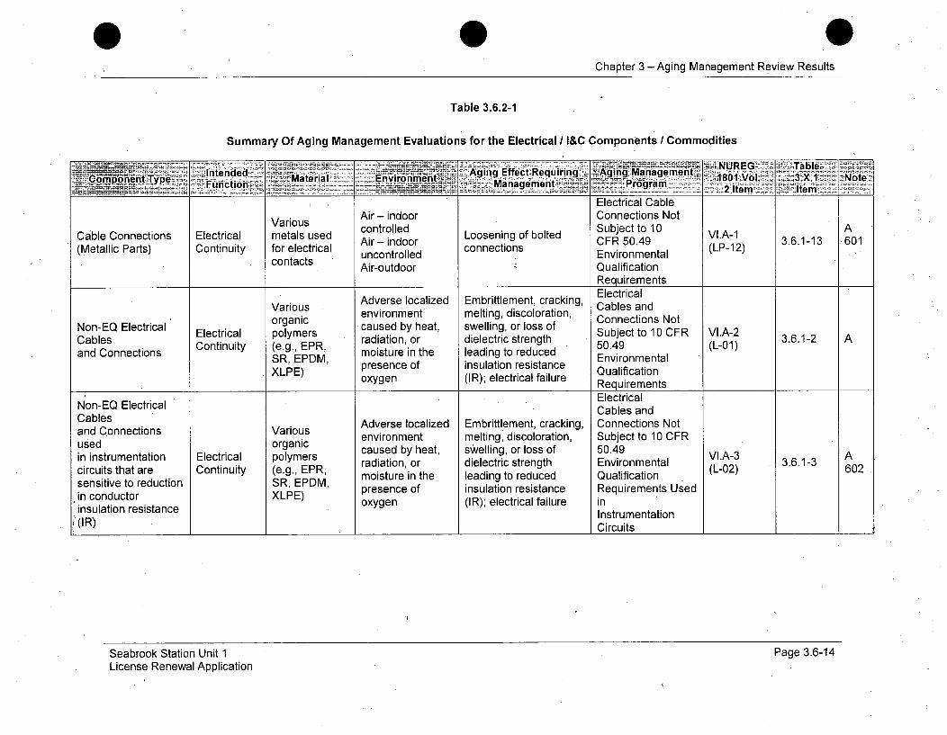
Chapter 3 -Aging Management Review Results
Table 3.6.2-1
Summary Of Aging Management Evaluations for the Electrical I&C Components / Commodities
Intnde ---- ~-~- NUREG"- - TableCompon-ent Type Futin Material Environmenht Agn fet.eurn:~~igaaee 1801 Vol. 3.X.1 :NoteUcinManagiement P~rogram 2Ie le
Electrical Cable
Various Air - indoor Connections Not
Cable Connections Electrical metals used controlled Subject to 10 VIA-i AAir -oor Loosening of bolted CFRA-1 5
(Metallic Parts) Continuity for electrical uncontrolled connections Environmental (LP-12)contacts Air-outdoor Qualification
RequirementsElectrical
Various Adverse localized Embrittlement, cracking, Cables andenvironment melting, discoloration, Connections Not
Non-EQ Electrical Electri organic caused by heat, swelling, or loss of Subject to1
Cables Contrinut polymers radiation, or dielectric strength 50.49 (L-1 3.6.1-2 Aand Connections (e.g., EPR, moisture in the leading to reduced Environmenta
SR, EPDM, presence of insulation resistance QualificationXLPE) oxygen (IR); electrical failure Requirements
NIon-EQ Electrical Electrical
Cables Cables anddConec Adverse localized Embrittlement, cracking, Connections Not
and Connections Various environment melting, discoloration, Subject to 10 CFRused organic caused by heat, swelling, or loss of 50.49 Ain instrumentation Electrical polymers radiation, or dielectric strength Environmental VI.A-3 3.6.1-3 602circuits that are Continuity (e.g., EPR, moisture in the leading to reduced Qualification (L-02)sensitive to reduction SR, EPDM, presence of insulation resistance Requirements Used
incucator XLPE)tancoxygen (IR); electrical failure ininsulation resistance Instrumentation(IR) Circuits
Seabrook Station Unit 1License Renewal Application
Page 3.6-14
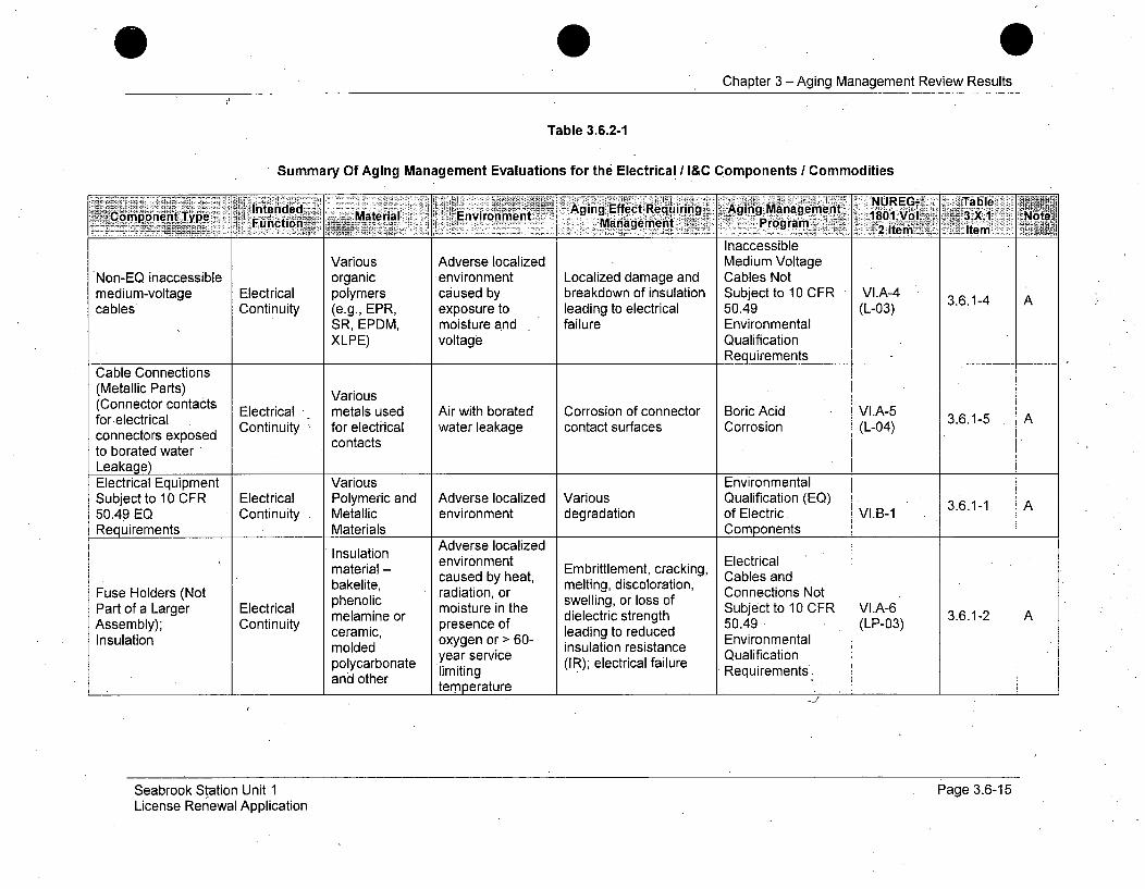
0Chapter 3 -Aging Management Review Results
Table 3.6.2-1
Summary Of Aging Management Evaluations for the Electrical / I&C Components / Commodities
Material Angingen EfetRqiig Aging Managjement NRG al;rCompqnent Typ Mnterial Effectmen Riirn18"01 Vol1. 3.X.1,,4 NoteFunctionr- Management -Program '~Ie tm '½
InaccessibleVarious Adverse localized Medium Voltage
Non-EQ inaccessible organic *environment Localized damage and Cables Notmedium-voltage Electrical polymers caused by breakdown of insulation Subject to 10 CFR VI.A-4cables Continuity (e.g., EPR, exposure to leading to electrical 50.49 (L-03)
SR, EPDM, moisture and failure EnvironmentalXLPE) voltage Qualification
RequirementsCable Connections(Metallic Parts) Various(Connector contacts Electrical metals used Air with borated Corrosion of connector Boric Acid VIA-5for electrical E 3.6.1-5 Aconnectors exposed Continuity for electrical water leakage contact surfaces Corrosion (L-04)
contactsto borated waterLeakage)Electrical Equipment Various EnvironmentalSubject to 10 CFR Electrical Polymeric and Adverse localized Various Qualification (EQ) 3.6.1-1 A50.49 EQ Continuity Metallic environment degradation of Electric. VI.B-1Requirements Materials Components
Adverse localizedenvironment ElectricalInuaterion - environment Embrittlement, cracking, Clesranmaterial- caused by heat, melting, discoloration, Cables and
Fuse Holders (Not phenolic radiation, or swelling, or loss of Connections NotPart of a Larger Electrical melin moisture in the s lSubject to 10 CFR VofA-6Assembly); Continuity melamine presence of dielectric strength 50.49 (LP-03) 3.6.1-2 Amoldede of leading to reduced 504•(L-3
Insulation ceramic, oxygen or > 60- Environmentalmoldedtioarmolrvice insulation resistance Qualificationpolycarbonat year service (IR); electrical failure Quiremetsand other limiting Requirements'
temperature
Seabrook Station Unit 1License Renewal Application
Page 3.6-15
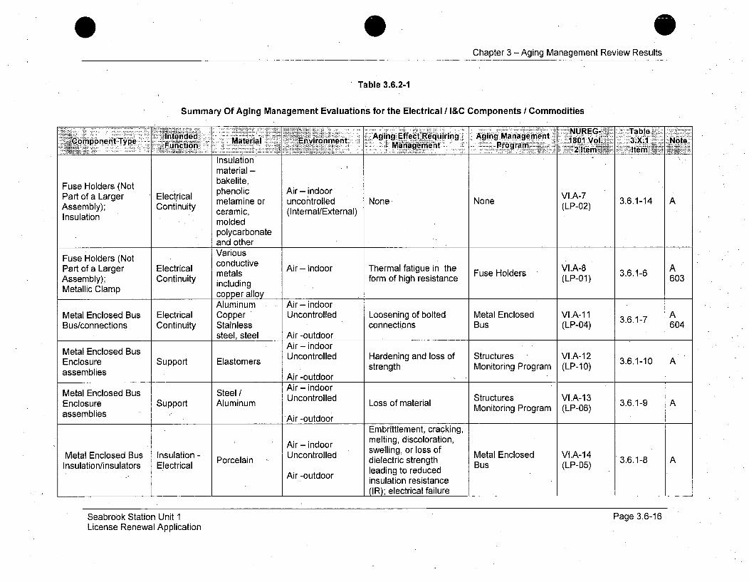
0Chapter 3 - Aging Management Review Results
Table 3.6.2-1
Summary Of Aging Management Evaluations for the Electrical / I&C Components / Commodities
Materiad Aging Effect Requiring Aging Manuag-ement NRG ~ TbefComponenit.Type ý' Materia Environment MIamn PrgaS10 ol. 3.. 1. Notgý FLnto Management Program
Insulationmaterial -
Fuse Holders (Not bakelite,Part of a Larger Electrical phenolic Air - indoor VI.A-7melamine or uncontrolled None None 3.6.1-14 AAssembly); Continuity ceramic, (Internal/External) (LP-02)Insulation m le
moldedpolycarbonateand otherVarious
Fuse Holders (Not conductivePart of a Larger Electrical metals Air - indoor Thermal fatigue in the Fuse Holders VIA-8 3.6.1-6 AAssembly); Continuity including form of high resistance (LP-01) 603Metallic Clamp copper alloy
Aluminum Air - indoorMetal Enclosed Bus Electrical Copper Uncontrolled Loosening of bolted Metal Enclosed VI.A-1 1 3.6.1-7 ABus/connections Continuity Stainless connections Bus (LP-04) 604
steel, steel Air -outdoor
Metal Enclosed Bus Air - indoor
Enclosure Support Elastomers Uncontrolled Hardening and loss of Structures VI.A-12 3.6.1-10 Aassemblies strength Monitoring Program (LP-10)
Air -outdoor
Metal Enclosed Bus Steel/ Air - S indoorEnclosure Support Aluminum Uncontrolled Loss of material Structures VPLA-13 3.6.1-9 A
asseblis Ai -otdooI rMonitoring Program (LP-06)assemblies Air -outdoor
Embrittlement, cracking,
Air - indoor melting, discoloration,Metal Enclosed Bus Insulation - Uncontrolled swelling, or loss of Metal Enclosed VI.A-14Insulation/insulators Electrical Porcelain dielectric strength Bus (LP-05) 3.6.1-8 A
Air -outdoor leading to reducedinsulation resistance(IR); electrical failure
Seabrook Station Unit 1License Renewal Application
Page 3.6-16

Chapter 3 - Aging Management Review Results
Table 3.6.2-1
Summary Of Aging Management Evaluations for the Electrical / I&C Components / Commodities
Aging Managemenit~ ia180 l: 3.X.Program-2Iem em Note]
Metal Enclosed BusInsulation/insulators
InsulationElectrical
Polyesterglass, Epoxy
Air - indoorUncontrolled
Air -outdoor
Embrittlement, cracking,melting, discoloration,swelling, or loss of-dielectric strengthleading to reducedinsulation resistance(IR); electrical failure
Metal Enclosed-Bus VI.A-14(LP-05)
F3.6.1-8
SF 6 Insulated Bus, Gas (SF6)Connections and Insulation - SF Gas (StFa) Loss of dielectric 345KV SF6 Bus None NoneInsulators Electrical gas Epoxy (internal) strength(Insulation/insulators)
SF 6 Insulated Bus, Gas (SF6)
Connections and Pressure Aluminum (internal) Loss of material 345KV SF6 Bus None NoneInsulators (Enclosure ,Boundary. Stainless Steel Air-Outdoor
Assemblies) (external)
SF6 Insulated Bus, Gas (SF6)
Connections and Pressure Elastomer (internal) Hardening and loss of 345 KV SF 6 Bus None NoneInsulators (Enclosure Boundary Air-Outdoor, strengthAssemblies) Air-(utdrn(external)________________________________________
Seabrook Station Unit 1 Page 3.6-17License Renewal Application
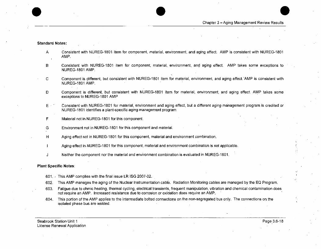
Chapter 3 -Aging Management Review Results
Standard Notes:
A Consistent with NUREG-1801 item for component, material, environment, and aging effect. AMP is consistent with NUREG-1801AMP.
B Consistent with NUREG-1801 item for component, material, environment, and aging effect. AMP takes some exceptions toNUREG-1801 AMP.
C Component is different, but consistent with NUREG-1 801 item for material, environment, and aging effect.'AMP is consistent withNUREG-1801 AMP.
D Component is different, but consistent with NUREG-1801 item for material, environment, and aging effect. AMP takes someexceptions to NUREG-1 801 AMP
E Consistent with NUREG-1801 for material, environment and aging effect, but a different aging management program is credited orNUREG-1 801 identifies a plant-specific aging management program
F Material not in NUREG-1 801 for this component.
G Environment not in NUREG-1 801 for this component and material.
H Aging effect not in NUREG-1 801 for this component, material and environment combination.
I Aging effect in NUREG-1 801 for this component, material and environment combination is not applicable.
J Neither the component nor the material and environment combination is evaluated in NUREG-1 801.
Plant Specific Notes:
601. , This AMP complies with the final issue LR ISG 2007-02.
602. This AMP manages the aging of the Nuclear Instrumentation cable. Radiation Monitoring cables are managed by the EQ Program.
603. Fatigue due to ohmic heating, thermal cycling, electrical transients, frequent manipulation, vibration and chemical contamination doesnot require an AMP. Increased resistance due to corrosion or oxidation does require an AMP.
604. This portion of the AMP applies to the intermediate bolted connections on the non-segregated bus only. The connections on theisolated phase bus are welded.
Seabrook Station Unit 1 Page 3.6-18License Renewal Application
CHAPTER 4
TIME-LIMITED AGING ANALYSES

Chapter 4 - Time Limited Aging Analyses
4.0 TIME-LIMITED AGING ANALYSES
Chapter 4 describes the Time-Limited Aging Analyses (TLAAs) for SeabrookStation Unit 1 in accordance with 10 CFR 54.3(a) and 54.21(c). Subsequentsections describe TLAAs within these common general categories:
" Reactor Vessel Neutron Embrittlement Analysis (4.2)
* Metal Fatigue Analysis of Piping And Components (4.3)
* Environmental Qualification (EQ) of Electric Components (4.4)
* Absence of TLAA for Concrete. Containment Tendon Prestress (4.5)'
* Containment Liner Plate Fatigue Usage and Containment PenetrationPressurization Cycles (4.6)
* Plant-Specific Time Limited Aging Analyses (4.7)
The information on each specific TLAA within these general categories isorganized under three subsections:
Summary Description
A brief description of the TLAA topic and affected components will bepresented.
Analysis
The current licensing basis (CLB) analysis of the TLAA including implicationsof the period of extended operation (PEO).
Disposition
The disposition of the TLAA for the PEO, in accordance with 10 CFR54.21 (c)(1):
* Validation - 10 CFR 54.21 (c)(1)(i) - The analysis remains valid for theperiod of extended operation.
* Revision - 10 CFR 54.21 (c)(1)(ii) - The analysis has been projected tothe end of the period of extended operation, or
* Aging Management - 10 CFR 54.21 (c)(1)(iii) - The effects of aging onthe intended function(s) will be adequately managed for the period of.extended operation.
In some instances, a discussion is provided regarding the absence of a TLAAfor components at Seabrook Station. In these cases a conclusion ispresented in lieu of a'disposition statement.
Seabrook Station Unit.1License Renewal Application
Page 4.0-1
Chapter 4 - Time Linited Aging Analyses
4.1 IDENTIFICATION OF TIME-LIMITED AGING ANALYSES
4.1.1 BACKGROUND
10 CFR 54.3 and 10 CFR 54.21 address time-limited aging analyses (TLAAs)in license renewal applications. 10 CFR 54.21(c) provides the followingcontent requirements for TLAAs:
(c) An evaluation of time-limited aging analyses.
(1) A list of time-limited aging analyses, as defined in §54.3, must beprovided. The applicant shall demonstrate that -
(i) The analyses remain valid for the period of extended operation;
(ii) The analyses have been projected to the end of the period ofextended operation; or
(iii) The effects of aging on the intended function(s) will beadequately managed for the period of extended operation.
(2) A list must be provided of plant-specific exemptions grantedpursuant to 10 CFR 50.12 and in effect that are based on time-limited aging analyses as defined in §54.3. The applicant shallprovide an evaluation that justifies the continuation of theseexemptions for the period of extended operation.
10 CFR 54.3 defines a time-limited aging analysis as:
Time-limited aging analyses, for the purposes of this part, are thoselicensee calculations and analyses that:
(1) Involve systems, structures, and components within the scope oflicense renewal, as delineated in §54.4(a);
(2) Consider the effects of aging;
(3) Involve time-limited assumptions defined by the current operatingterm, for example, 40 years;
(4) Were determined to be relevant by the licensee in making a safetydetermination;
Seabrook Station Unit 1 Page 4.1-1License Renewal Application

Chapter 4 - Time Limited Aging Analyses
(5) Involve conclusions or provide the basis for conclusions related tothe capability of the system, structure, and component to performits intended functions, as delineated in §54.4(b); and
(6) Are contained or incorporated by reference in the CLB.
4.1.2 METHODOLOGY
The process used to identify time-limited aging analyses for Seabrook Stationis consistent with the guidance provided in NEI 95-10. Site-specific analysesand evaluations that could potentially meet the six criteria of 10 CFR 54.3were identified by performing electronic keyword searches and by manuallysearching current licensing basis documents, including:
* Updated Final Safety Analysis Report (UFSAR)
* Docketed licensing correspondence
* Design Basis Documents
" Analyses, calculations, evaluation reports, and capsule surveillancereports from Westinghouse
* Applicable Westinghouse Owner's Group (WOG) reports, analyses,and supporting calculations
* Site-specific analyses, calculations, and evaluations
* Technical Specifications and Technical Specification BasesDocuments
* Previous Applicant's License Renewal Applications
Industry documents that list generic time-limited aging analyses were alsoreviewed to provide additional assurance of the completeness of the plant-specific list. These documents included Generic Aging Lessons Learned(GALL) Report, NUREG-1801, Vol. 2, Rev. 11 Standard Review Plan forLicense Renewal, NUREG-1800, Chapter 4, Rev. 1, NEI 95-10, IndustryGuidance for Implementing the Requirements of 10 CFR 54 the LicenseRenewal Rule, and previously submitted License Renewal Applications fromother plants.
NUREG-1801 identifies numerous aging effects that require evaluation .aspossible TLAAs in accordance with 10 CFR 54.21(c). Each of these wasreviewed in the appropriate aging management review, or in this chapter, anddispositioned as a TLAA if identified as such- under the 10 CFR 54.3(a)
Seabrook Station Unit 1 Page 4.1-2License Renewal Application
Chapter 4 - Time Limited Aging Analyses
criteria. Tables 3.1.1, 3.2.1, 3.3.1, 3.4.1, 3.5.1 and 3.6.1, as discussed inSection 3.0, Aging Management Reviews, list the TLAA line items of theNUREG-1801 Volume 1 Summary Tables, and identify the specific sectionsrelating to the required further evaluations.
4.1.3 IDENTIFICATION OF EXEMPTIONS
Summary Description
The requirements of 10 CFR 54.21(c) stipulate that the application for arenewed operating license should include a list of unit-specific exemptionsgranted pursuant to 10 CFR 50.12, that are in effect, based on time-limitedaging analysis, as defined in 10 CFR 54.3. Each active exemption has beenreviewed to determine exemptions that are based on time-limited aginganalyses.
The UFSAR, Facility Operating License, Safety Evaluation Report andassociated supplements, and docketed correspondence was searched foractive exemptions granted under 10 CFR 50.12 to determine exemptions thatare based on time-limited aging analyses.
Analysis
The NextEra Energy Seabrook Facility Operating License identifies twoexemptions granted pursuant to 10 CFR 50.12.
NextEra Energy Seabrook, LLC, is exempt from the SectionIIl.D.2(b)(ii) containment airlock testing requirements of Appendix J to,10 CFR 50, because of the special circumstances described in Section6.2.6 of SER Supplement 5 and authorized by 10 CFR 50.12(a)(2)(ii)and (iii) (51 FR 37684 October 23, 1986).
* NRC Materials License No. SNM-1963, issued December 19, 1985,granted an exemption pursuant to 10 CFR 70.24 with respect torequirements for criticality alarms. NextEra Energy Seabrook, LLC, ishereby exempted from provisions of 10 CFR 70.24 insofar as thissection applies to the storage and handling of new fuel assemblies inthe new fuel storage vault, spent fuel pool (when dry), and shippingcontainers.
UFSAR" Section 3.9(N) identifies an exemption from a portion of 10 CFR Part50, "Domestic Licensing of Production and Utilization Facilities" Appendix A,General Design Criterion 4 "Environmental and Dynamic Effects DesignBases". Acceptance of this exemption is documented in NUREG-0896Supplement 5, Appendix K. The exemption permitted Seabrook Station toeliminate the protective devices and the dynamic loading effects associated
Seabrook Station Unit 1 Page 4.1-3License Renewal Application
Chapter 4 - Time Limited Aging Analyses
with the postulated primary loop pipe breaks for Seabrook Station, Units 1.The exemption was limited until the completion of the second refueling outagepending outcome of commission rulemaking regarding Leak-Before Breakanalysis.
Conclusion
No active exemptions granted pursuant to 10 CFR 50.12 and batsed on atime-limited aging analysis, as defined in 10 CFR 54.3, have been identifiedfor Seabrook Station.
4.1.4 SUMMARY OF RESULTS
Table 4.1-1: Time-Limited Aging Analyses Applicable to Seabrook Station,summarizes TLAAs identified within the current licensing basis of SeabrookStation. This table provides a list of Seabrook Station TLAAs with thedisposition method used for each and the section of the LRA where each isdiscussed.
NUREG-1800, Table 4.1-2 and NUREG-1800, Table 4.1-3, list examples ofpotential TLAAs, depending upon the applicant's current licensing basis(CLB). Table 4.1-2: Review of Analyses Listed in NUREG-1800Tables 4.1-2 and 4.1-3 summarizes the results of the Seabrook Stationapplicability review of these potential TLAAs and the section of the LRAwhere each is discussed.
Seabrook Station Unit 1License Renewal Application
Page 4.1-4
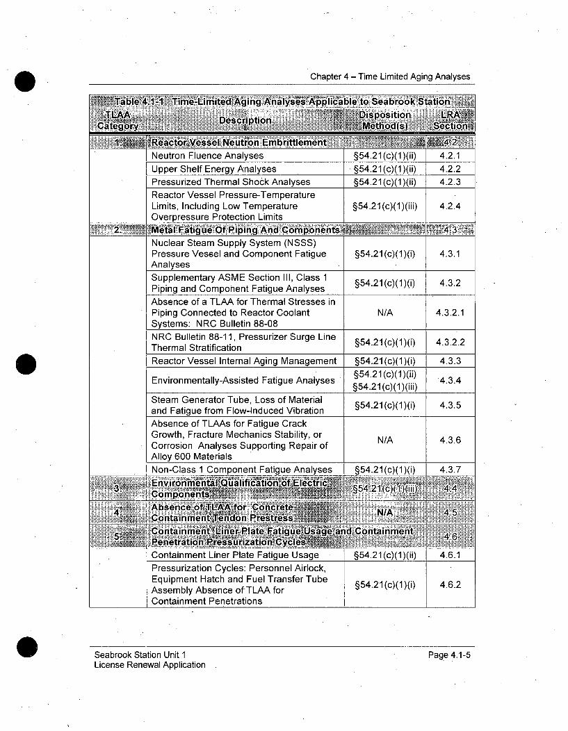
Chapter 4 - Time Limited Aging Analyses
Neutron Fluence Analyses §54.21 (c)(1)(ii) 4.2.1
Upper Shelf Energy Analyses . §54.21 (c)(1)(ii) 4.2.2Pressurized Thermal Shock Analyses §54.21 (c)(1)(ii) 4.2.3
Reactor Vessel Pressure-TemperatureLimits, Including Low TemperatureOverpressure Protection Limits
§54.21 (c)(1)(iii) 4.2.4
,' Of P i ppig! An asNuclear Steam Supply System (NSSS)Pressure Vessel and Component FatigueAnalyses
§54.21 (c)(1)(i) 4.3.1
Supplementary ASME Section III, Class 1 §54.21(c)(1)(i) 4.3.2Piping and Component Fatigue Analyses
Absence of a TLAA for Thermal Stresses inPiping Connected to Reactor Coolant N/A 4.3.2.1Systems: NRC Bulletin 88-08NRC Bulletin 88-11, Pressurizer Surge Line §54.21 (c)(1)(i) 4.3.2.2Thermal Stratification
Reactor Vessel Internal Aging Management §54.21 (c)(1)(i) 4.3.3Environmentally-Assisted Fatigue Analyses §54.21(c)(1)(ii) 4.3.4
§54.21(c)(1)(iii)
Steam Generator Tube, Loss of Material §54.21 (c)(1)(i) 4.3.5and Fatigue from Flow-Induced Vibration
Absence of TLAAs for Fatigue CrackGrowth, Fracture Mechanics Stability, orCorrosion Analyses Supporting Repair ofAlloy 600 MaterialsNn~n-r'ln-_- 1 Cnimnonnint Fql
I onmainmenm Liner niate r-atigue usage I + .z-I kc)kI)kl) I 1+ .b0. I1
Pressurization Cycles: Personnel Airlock,Equipment Hatch and Fuel Transfer TubeAssembly Absence of'TLAA forContainment Penetrations
§54.21 (c)(1)(i) 4.6.2
Seabrook Station Unit 1License Renewal Application
Page 4.1-5
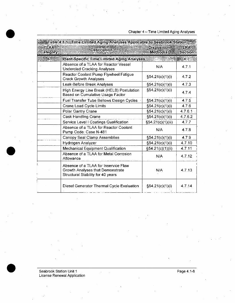
Chapter 4 - Time Limited Aging.Analyses
~Ti LI A 1 ý11<Ti7i Di t-os iebon.--aio
SPantP-Secifi 6,,fnt Anlye i<4 'm47Absence of a TLAA for Reactor Vessel N/A 4.7.1Underclad Cracking AnalysesReactor Coolant Pump Flywheel Fatigue §54.21 (c)(1)(i) 4.7.2Crack Growth AnalysesLeak-Before Break Analyses §54.21 (c)(1)(i) 4.7.3
High Energy Line Break (HELB) Postulation §54.21(c)(1)(i) 474Based on Cumulative Usage Factor
Fuel Transfer Tube Bellows Design Cycles §54.21 (c)(1)(i) 4.7.5
Crane. Load Cycle Limits §54.21(c)(1)(i) 4.7.6Polar Gantry Crane §54.21(c)(1)(i) 4.7.6.1
Cask Handling Crane §54.21 (c)(1)(i) 4.7.6.2Service Level I Coatings Qualification §54.21 (c)(1)(iii) 4.7.7Absence of a TLAA for Reactor Coolant N/A 4.7.8Pump Code: Case N-481
Canopy Seal Clamp Assemblies §54.21 (c)(1)(i) 4.7.9
Hydrogen Analyzer §54.21 (c)(1)(i) 4.7.10Mechanical Equipment Qualification §54.21 (c)(1)(ii) 4.7.11Absence of a TLAA for Metal Corrosion N/A 4.7.12Allowance
Absence of a TLAA for Inservice FlawGrowth Analyses that Demonstrate N/A 4.7.13Structural Stability for 40 years
Diesel Generator Thermal Cycle Evaluation §54.21(c)(1)(i) 4.7.14
Seabrook Station Unit 1License Renewal Application
Page 4.1-6

Chapter 4 - Time Limited Aging Analyses
'4 1- Lite Rin-NUREG MI 80E
Applicability to MAOIUREG-1800 ExamplesSebok Se
NUMRd•-4800,o able 4.1-2 - Exafm-* p.,!es ofpotentia, TLAAsReactor vessel neutron embrittlement Yes 4.2Concrete containment tendon prestress No 4.5Metal Fatigue Yes 4.3Environmental qualification of electrical equipment Yes 4.4Metal corrosion allowance No 4.7.12Inservice flaw growth analyses that demonstrate No 4.7.13structure stability for 40 yearsInservice local metal containment corrosion analyses No N/AHigh-energy line break postulation based on fatigue Yes 4.7.4CUFNURE.-1800able 4.17,37AdMtionaI, Examples of Plant-S ecific TLAAsIntergranular separation in the heat-affected zone(HAZ) of reactor vessel low-alloy steel under austenitic No 4.7.1SS claddingLow-temperature overpressure protection (LTOP) Yes 4.2.4analysesFatigue analyses for the main steam supply lines to theIYes 4.3.7turbine-driven auxiliary feedwater pumpsFatigue analyses for the reactor coolant pump flywheel Yes 4.7.2Fatigue analysis of polar crane Yes 4.7.6.1Flow-induced vibration endurance limit, for the reactorvessel internalsTransient cycle count assumptions for the reactor Yes 4.3.3
vessel internalsDuctility reduction of fracture toughness for the reactor
vessel internalsLeak-before-break Yes, 4.7.3Fatigue analysis for the containment liner plate Yes. 4.6.1Concrete penetration pressurization cycles Yes 4.6.2Reactor vessel circumferential weld inspection relief N/A N/A(BWR)
Seabrook Station Unit 1License Renewal Application
Page 4.1-7
Chapter 4 - Time Limited Aging Analyses
4.2 REACTOR VESSEL NEUTRON EMBRITTLEMENT
Carbon and low-alloy steels exposed to high levels of high-energy neutronirradiation exposure (fluence) are susceptible to reduction of fracturetoughness, an increase in material strength and decrease in ductility.Fracture toughness is temperature dependent, and is indirectly measured infoot-pounds of absorbed energy in a Charpy impact test. In most materials,toughness increases with temperature up to a maximum value called UpperShelf Energy (USE). Neutron embrittlement is measured in terms of Charpytransition temperature shift, Charpy upper-shelf energy decrease, and yieldand ultimate tensile strength increase. Neutron embrittlement varies withmaterial but is directly dependent upon the integrated total neutron exposurefor energy levels above 1 MeV. Based- upon the materials and projectedfluence levels, the only reactor vessel shell items expected to be susceptibleto neutron embrittlement are the reactor vessel shell components in thebeltline region immediately surrounding the core.
In order to reduce the potential for brittle fracture during reactor vesseloperation, Pressure-Temperature (P-T) limit curves are developed thatrequire the reactor vessel temperature to reach specified minimum limits priorto the application of significant pressure loading to assure the materials haveadequate ductility to resist the loads. Since these minimum temperatures areincreased as a function of predicted cumulative fluence, the reduced materialtoughness as a function of fluence is offset. Adequate fracture toughness isassured at or above the minimum temperatures specified by the P-T limitcurves.
In order to develop P-T limit curves, a number of tests and calculations mustfirst be performed. The initial nil-ductility reference temperature (RTNDT) is thetemperature at which a material transitions from brittle-to-ductile behavior,and this temperature is determined for each reactor vessel beltline materialprior to neutron exposure. Samples of each material are tested again aftervarious degrees of neutron exposure up to end-of- life (EOL) fluence levels todetermine how much this transition temperature will increase during plantoperation as a function of neutron irradiation. This is performed as part of thereactor vessel surveillance program, and the acceptable fluence intervals forthese tests are specified by ASTM E-185 requirements. This increase or shiftin the nil-ductility reference temperature (ARTNDT) is the amount oftemperature increase required for the material to continue to act in a ductilemanner for a given fluence level. The P-T curves are periodically updated foran incremental fluence increase using the initial RTNDT and ARTNDT valuesassociated with the fluence value used, along with appropriate uncertaintymargins. As the actual plant exposure approaches the fluence value used in
Seabrook Station Unit 1 Page 4.2-1 .License Renewal Application
Chapter 4 - Time Limited Aging Analyses
a particular set of P-T limit curves, new curves are prepared for higher fluencevalues, up to the EOL fluence value.
For Seabrook Station, the reactor vessel material ARTNDT and USE values,calculated on the basis of predicted 40-year End-of-Life (EOL) neutronfluence, are determined as part of the current licensing basis, and supportsafety determinations. Therefore, these calculations are TLAAs. For licenserenewal, these must be updated to account for the fluence expected to occurduring 60 years of plant operation (55 Effective Full Power Years). Thegoverning requirements for these updated analyses are summarized below.
NRC Regulations 10 CFR-50.60. and 10 CFR 50.61 provides fracturetoughness requirements and acceptance criteria applicable to the SeabrookStation reactor vessel. NRC Regulation 10 CFR 50.60, "Acceptance CriteriaFor Fracture Prevention Measures For Light Water Nuclear Power ReactorsFor Normal Operation," requires that all light water nuclear power reactorsmeet the requirements of 10 CFR 50, Appendix G, "Fracture ToughnessRequirements," and 10 CFR 50, Appendix H, "Reactor Vessel MaterialSurveillance Program Requirements." Appendix G specifies fracturetoughness requirements for the reactor coolant pressure boundary to providemargins of 'safety against fracture during any condition of normal plantoperation, including anticipated operational occurrences and systemhydrostatic tests. The Seabrook Station Reactor Vessel Integrity SurveillanceProgram, B.2.1.19 is required to monitor changes in the fracture toughnessproperties of ferritic materials in the reactor vessel beltline region of lightwater nuclear power reactors resulting from exposure of these materials toneutron irradiation and the thermal environment. Materials and fluence dataobtained from this program are used in these fracture toughness analyses.
NRC Regulation 10 CFR 50.61, "Fracture toughness requirements forprotection against pressurized thermal shock events," provides requirementsfor computing the reference temperature, RTPTS, for the (EOL) fluence foreach of the reactor vessel beltline materials, which is a measure of thefracture toughness after exposure to EOL fluence. It also provides aPressurized Thermal Shock (PTS) screening criterion for each type of beltlinematerial, which limits how high the minimum reference temperature can beraised. The RTPTS screening criteria serve as limits on the degree of ARTNDTthat can be applied to account for neutron embrittlement. The' RTPTS valuesare a function of material composition and neutron fluence, and they increaseas cumulative fluence increases, possibly approaching the screening criterionif the material is highly susceptible to neutron embrittlement. If the RTPTSvalue is projected to exceed the screening criterion using the EOL fluence,licensees are required to implement flux reduction programs to prevent thisfrom occurring.
Seabrook Station Unit 1 Page 4.2-2License Renewal Application
Chapter 4 - Time Limited Aging Analyses
4.2.1 NEUTRON FLUENCE ANALYSES
Summary Description
The current license period reactor vessel embrittlement analyses thatevaluate reduction of fracture toughness of the Seabrook Station reactorvessel beltline materials are based on predicted 40-year EOL fluence values.The fluence analysis and the neutron embrittlement analyses that are basedupon the fluence analysis are TLAAs as defined by 10 CFR 54.21(c) thatmust be evaluated for the increased neutron fluence associated with 60 yearsof operation. These TLAAs include the analyses for fracture toughness, orupper shelf energy, Pressurized Thermal Shock limits, RTNDT (nil-ductilitytransition temperature), Adjusted Reference Temperatures (ART), Low-Temperature.Overpressure Protection limits, and Reactor Vessel Pressure-Temperature limit curves. The neutron fluence TLAA is evaluated in thissubsection, and the others are evaluated in subsections 4.2.2, 4.2.3, and4.2.4.
Analysis
Estimation of EFPY for Seabrook Station based on 60-years of Plant Life
End-of-Life fluence is based on a predicted value of EFPY over the life of theplant. Seabrook Station began commercial operation on August 19, 1990.As of October 30, 2009, Seabrook Station has been operated forapproximately 17 EFPY. If Seabrook Station is operated at the maximumlicensed power level at a 100% capacity factor between outages until the endof period of extended operation on March 15, 2050, Seabrook Station willreach approximately 55 EFPY. This capacity factor is based on assumedoutage durations of twenty (20) days during refueling outages and 100percent power levels at all times other than during these outages.
60-Year Neutron Fluence Projections
For license renewal, Seabrook Station updated fluende projections basedupon 55 EFPY as input, to the neutron embrittlement analyses prepared for60 years of operation.
The reactor vessel beltline neutron fluence values for 60 years of operationwere calculated for the Seabrook Station reactor -pressure vessel beltlinematerial. The analysis methods used to calculate the predicted 60-yearSeabrook Station vessel fluence values satisfy the requirements set forth inRegulatory Guide 1.190, "Calculational and Dosimetry Methods forDetermining Pressure Vessel Neutron Fluence". In compliance with theseguidelines, comparisons to surveillance capsule flux wire and dosimetermeasurements were performed to determine the accuracy of the RPV fluence
Seabrook Station Unit 1 Page 4.2-3License Renewal Application
Chapter 4 - Time Limited Aging,,Analyses
model. An uncertainty analysis was also performed to determine if astatistical bias exists in the model. It was determined that the SeabrookStation fluence model does not have a statistical bias and that the best-estimate fluence presented is suitable for use in evaluating the effects ofembrittlement on RPV material as specified in (CFR) 10 CFR 50, Appendix G,"Fracture Toughness Requirements" and NRC Regulatory Guide 1.99,"Radiation Embrittlement of Reactor Vessel Materials".
The fluence values were calculated using the RAMA Fluence Methodology(RAMA). The'RAMA Fluence Methodology was developed for the ElectricPower Research Institute, Inc. (EPRI) for the purpose of calculating fastneutron fluence in reactor pressure vessels and vessel internal components.As prescribed in NRC Regulatory Guide 1.190, RAMA has beenbenchmarked against industry standard benchmarks for both pressurizedwater reactor (PWR) and boiling water reactor designs. In addition, RAMAhas been compared with several plant-specific dosimetry measurements andreported fluence from several commercial operating reactors. The results ofthe benchmarks and comparisons to measurements show that RAMAaccurately predicts specimen activities, RPV fluence, and vessel componentfluence in all light water reactor types. Under funding from EPRI and theBoiling Water Reactor Vessel and Internals Project, the RAMA methodologyhas been reviewed by the NRC and subsequently given generic approval fordetermining fast neutron fluence in boiling water reactor pressure vessels andvessel internal components that include the core shroud and top guide. Thisprior work has been extended in the Seabrook Station analysis to additionalPWR benchmarks and plant-specific dosimetry comparisons, furthervalidating the use of RAMA for all light water reactor designs.
In accordance with 10 CFR 50, Appendix H, "Reactor Vessel MaterialSurveillance Program Requirements," any materials exceeding neutronfluence exposure greater than 1.0x10 17 n/cm 2 (E > 1.0 MeV) must beevaluated for changes in fracture toughness due to neutron embrittlement.Reactor pressure vessel materials that were not originally considered to bepart of the vessel beltline, because neutron radiation exposure was less than1.0x1017 n/cm 2 (E > 1.0 MeV), were evaluated to determine their cumulativeneutron radiation exposure at 55 EFPY., Fluence calculations were performedfor the Seabrook Station reactor pressure vessel upper shell plates and weldsto determine if they would exceed a neutron radiation exposure of 1.0x10 17
n/cm 2 (E > 1.0 MeV) at 55 EFPY. The materials that exceed this thresholdwere included as the extended beltline materials. Table 4.2.1-1 summarizesthe results of the fluence projections to 55 EFPY for Seabrook Station. Referto Table 4.2.3-1 for the Heat Numbers associated with the Seabrook Stationvessel materials. It should be noted that the intermediate/upper shellcircumferential weld, the upper shell plates, and axial welds are part of theextended beltline. The nozzles and the nozzle welds are projected to be
Seabrook Station Unit 1 Page 4.2-4License Renewal Application
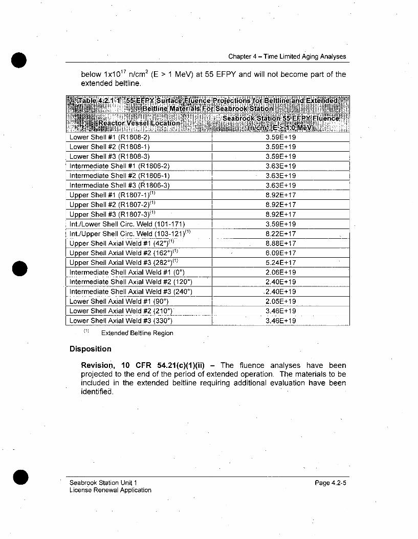
Chapter 4 - Time Limited Aging Analyses
below lx1017 n/cm 2 (E > 1 MeV) at 55 EFPY and will not become part of theextended beltline.
'TabIle 4.Z.1- - tEtj "'J" fI1 ,: a lenBce, Projections frBeltllne and ExiteAdecdf
9 ~~Beltline MAt6efals~ For Searo StationS ... " or •'• ] " ' .. "Oro...totio••n 55 EF Y F'Uience,
RatrVessel Location .. j
Lower Shell #1 (R1 808-2) 3.59E+19
Lower Shell #2 (R1808-1) 3.59E+19
Lower Shell #3 (R1 808-3) 3.59E+19
Intermediate Shell #1 (R1806-2) 3.63E+19
Intermediate Shell #2 (R1806-1) 3.63E+19
Intermediate Shell #3 (R1806-3) 3.63E+19
Upper Shell #1 (R1807-I)(1) 8.92E+17
Upper Shell #2 (R1807-2)(1 ) 8.92E+17
Upper Shell #3 (R1807-3)(1 ) 8.92E+ 17
Int./Lower Shell Circ. Weld (101-171) 3.59E+19
Int./Upper Shell Circ. Weld (103-121)(1) 8.22E+17
Upper Shell Axial Weld #1 (420)(1) 8.88E+17
Upper Shell Axial Weld #2 (1620)(1) 6.09E+17
Upper Shell Axial Weld #3 (2820)(1) 5.24E+17
Intermediate Shell Axial Weld #1 (00) 2.06E+1 9
Intermediate Shell Axial Weld #2 (120') 2.40E+1 9
Intermediate Shell Axial Weld #3 (240') -2.40E+1 9
Lower Shell Axial Weld #1 (90') 2.05E+1 9
Lower Shell Axial Weld #2 (2100) 3.46E+1 9
Lower Shell Axial Weld #3 (3300) 3.46E+1 9
(1) Extended Beltline Region
Disposition
Revision, 10 CFR 54.21(c)(1)(ii) - The fluence analyses have beenprojected to the end of the period of extended operation. The materials to beincluded in the extended beltline requiring additional evaluation have beenidentified.
Seabrook Station Unit 1License Renewal Application
Page 4.2-5

Chapter 4 - Time Limited Aging Analyses
4.2.2 UPPER SHELF ENERGY ANALYSES
Summary Description
The current Charpy Upper Shelf Energy (USE) analyses were prepared foreach reactor vessel beltline material for Seabrook Station based uponprojected neutron fluence values for 40 years of service. These are TLAAsrequiring evaluation using the projected 60-year fluence values.
Analysis
Title 10 CFR Part 50 Appendix G "Fracture Toughness Requirements"contains screening criteria that establish limits on how far the USE value for areactor pressure vessel material may be allowed to decrease due to neutronirradiation exposure. The regulation requires the initial USE value to begreater than 75 ft-lbs in the non-irradiated condition and that the value isgreater than 50 ft-lbs in the fully irradiated conditions as determined byCharpy V-notch testing on pulled capsules throughout the licensed life of theplant.
Per Regulatory Guide 1.99, Revision 2, the Charpy USE should be assumedto decrease as a function of fluence, according to Figure 2 of the RegulatoryGuide, when surveillance data is not used (Position 1.2 of the RegulatoryGuide). If surveillance data is used, the decrease in USE may be obtained byplotting the reduced plant surveillance data on Figure 2 of the RegulatoryGuide and fitting the data with a line drawn parallel to the existing lines as theupper bound of all of the data (Position 2.2 of the Regulatory Guide). CharpyUSE for the beltline forgings and welds' and for the extended beltline materialswas evaluated without the use of surveillance data which was determined tobe conservative.
-Predictions of the Charpy USE for EOL (55 EFPY) are summarized in Table4.2.2-1 for Seabrook Station, using the corresponding 1/4T fluence projection,the copper content of the beltline materials and using Figure 2 in RegulatoryGuide 1.99.
The USE values for the beltline and extended beltline materials are projectedto remain above the 50 ft-lbs requirement through the period of extendedoperation for Seabrook Station as indicated in Table 4.2.2-1.
Seabrook Station Unit 1 Page 4.2-6License Renewal Application
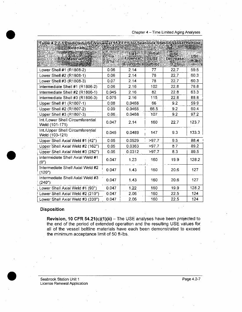
Chapter 4 - Time Limited Aging Analyses
Disposition
Revision, 10 CFR 54.21(c)(1)(ii) - The USE analyses have been projected tothe end of the period of extended operation and the resulting USE values forall of the vessel beltline materials have each been demonstrated to exceedthe minimum acceptance limit of 50 ft-lbs.
Seabrook Station Unit 1License Renewal Application
Page 4.2-7
Chapter 4 - Time Limited Aging Analyses
4.2.3 PRESSURIZED THERMAL SHOCK ANALYSES
Summary. Description
Title 10 CFR Part 50.61(b)(1) provides rules for the protection of PWRsagainst pressurized thermal shock (PTS). Licensees are required to assessthe projected values of nil-ductility reference temperature whenever asignificant change occurs in the projected values of RTPTS, or upon requestfor a change in the expiration date for the. facility operating license. Thecurrent RTPTs analyses, evaluated for 32 EFPY fluence values predicted for40 years of operation, are TLAAs requiring evaluation for 60 years.
Analysis
Reactor vessel beltline fluence is one of the factors used in determining themargin of acceptability of the reactor vessel to PTS as a result of neutronembrittlement. The margin is the difference between the maximum nil-ductility reference temperature in the limiting beltline material and thescreening criteria established in accordance with' 10 CFR 50.61(b)(2). Thescreening criteria for the limiting reactor vessel materials are 270°F forbeltline plates, forgings, and axial weld materials, and 300°F for beltlinecircumferential weld materials.
In a letter submittal to NRC dated January 18, 1999, a revision to the limitingSeabrook Station reactor vessel beltline material was documented. Thatsubmittal identified the limiting material to be plate R1808-1 having acalculated RTPTS @ EOL of 120'F. This RTPTS value corresponds to fluenceat the reactor vessel inside diameter of 2.37x10¹⁹ n/cm 2. The results of thenew RTPTs analyses, evaluated for 55 EFPY (or 60 years of operation), arepresented in Table 4.2.3-1. The limiting RTPTS value for the Seabrook Stationaxially-oriented welds and plates is 123.3 0 F, which corresponds to the LowerShell #2 plate (R1808-1) with a projected fluence at 55 EFPY of 3.59x10 19
n/cm 2. The limiting RTPTS value for the Seabrook Station circumferentially-oriented welds at 55 EFPY is 80F, which corresponds to the Intermediate-to-Lower Shell Circumferential Weld Seam (101-171). All of the SeabrookStation reactor vessel materials that have a surface fluence value exceeding1.0x1017 n/cm 2 (E > 1.0 MeV) at 55 EFPY have been demonstrated to havean RTPTS value less than the applicable screening criterion, which is 270°F forplates, forgings, and axially-oriented welds (longitudinal welds), and is 300'Ffor circumferentially-oriented welds. Therefore, the RTPTs analyses havebeen satisfactorily projected for 60 years of operation.
Seabrook Station Unit 1 Page 4.2-8License Renewal Application
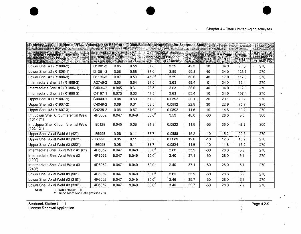
Chapter 4 - Time Limited Aging Analyses
C h !~i -Cern "Sij', ace Rpý ",Reactor Vessel Beitline Rgion CLI acb N.Flien ART'P. !RTt
Chapter 4 - Time Limited Aging Analyses
Disposition
Revision, 10 CFR 54.21(c)(1)(ii-) - The RTPTs analyses have been projectedto the end of the period of extended operation and are shown to be within themaximum allowable PTS screening criteria limits.
4.2.4 REACTOR VESSEL PRESSURE-TEMPERATURE LIMITS,INCLUDING LOW TEMPERATURE OVERPRESSUREPROTECTION LIMITS
Summary Description
Title 10 Part 50, Appendix G, "Fracutre Toughness Requirements" requiresthat the reactor pressure vessel be maintained within established pressure-temperature (P-T) limits, including heatup and cooldown operations. Theselimits specify the maximum allowable pressure as a function of reactorcoolant temperature. As the reactor pressure vessel is exposed to increasedneutron irradiation, its fracture toughness is reduced. The P-T limits mustaccount for the anticipated reactor vessel fluence.
The calculations associated with the operating P-T limit curves involve time-limited assumptions defined by the current operating term, for example, 40years, and they must satisfy the criteria of 10 CFR 54.3(a) for licenserenewal. For example, the P-T limit curves are based upon fluence valuesassociated with 40 years of operation. Therefore, P-T limit curves are TLAAsrequiring evaluation for 60 years of operation.
Analysis
The provisions of 10 CFR 50, Appendix G, require Seabrook to operate withinthe currently licensed P-T limit curves. These curves are required to bemaintained and updated as necessary to maintain plant operation consistentwith 10 CFR 50. The Reactor Vessel Integrity Surveillance Program maintainsthe P-T limit curves for the period of extended operation. Prior to the periodof extended operation, updated P-T limit calculations will be prepared usingfluence values valid for the Seabrook Station reactor vessel beltline regionmaterials, inlet and outlet nozzles, and closure head flange locations fornormal heatup, normal cooldown, and in-service leak and hydrostatic testconditions. The current heatup and cooldown limit curves are valid for 20EFPY. In determining the allowable operating pressure-temperature limits,the minimum bolt-up temperatures, minimum temperature of core. criticality,pressure test limits and low-temperature overpressure protection (LTOP)system limits are determined. These P-T limits are expressed in the form of aset of curves of allowable pressure versus temperature (P-T limit curves).These curves are updated on a periodic basis to account for increasingvessel fluence.
Seabrook Station Unit 1 Page 4.2-10License Renewal Application
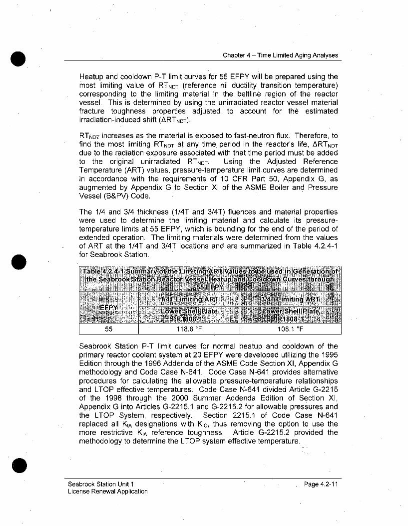
Chapter 4 - Time Limited Aging Analyses
Heatup and cooldown P-T limit curves for 55 EFPY will be prepared using themost limiting value of RTNDT (reference nil ductility transition temperature)corresponding to the limiting material in the beltline region of the reactorvessel. This is determined by using the unirradiated reactor vessel materialfracture toughness properties adjusted- to account for the estimatedirradiation-induced shift (ARTNDT).
RTNDT increases as the material is exposed to fast-neutron flux. Therefore, tofind the most limiting RTNDT at any time period in the reactor's life, ARTNDT
due to the radiation exposure associated with that time period must be addedto the original unirradiated RTNDT. Using the Adjusted ReferenceTemperature (ART) values, pressure-temperature limit curves are determinedin accordance with the requirements of 10 CFR Part 50,.Appendix G, asaugmented by Appendix G to Section XI of the ASME Boiler and PressureVessel (B&PV) Code.
The 1/4 and 3/4 thickness (1/4T and 3/4T) fluences and material propertieswere used to determine the limiting material and calculate its pressure-temperature limits at 55 EFPY, which is bounding for the end of the period ofextended operation. The limiting materials were determined from the valuesof ART at the 1/4T and 3/4T locations and are summarized in Table 4.2.4-1for Seabrook Station.
Table•'y 4.2.4-1umma tme ILimingi•a '164e used lln, enerauon1
I the Seabrook Station Reactor Vesseli leatLup and Coolown Curves througIh1l5f 1 55 I ,
14Liiing ART 3/4 Liiin R
55 118.6 OF 108.1 F
Seabrook Station P-T limit curves for normal heatup and cooldown of theprimary reactor coolant system at 20 EFPY were developed utilizing the 1995Edition through the 1996 Addenda of the ASME Code Section XI, Appendix Gmethodology and Code Case N-641. Code Case N-641 provides alternativeprocedures for calculating the allowable pressure-temperature relationshipsand LTOP effective temperatures. Code Case N-641 divided Article G-2215of the 1998 through the 2000 Summer Addenda Edition of Section XI,Appendix G into Articles G-2215.1 and G-2215.2 for allowable pressures andthe LTOP System, respectively. Section 2215.1 of Code Case N-641replaced all KIA designations with Kic, thus removing the option to use themore restrictive KIA reference toughness. Article G-2215.2 provided themethodology to determine the LTOP system effective temperature.
Seabrook Station Unit 1 Page 4.2-11License Renewal Application
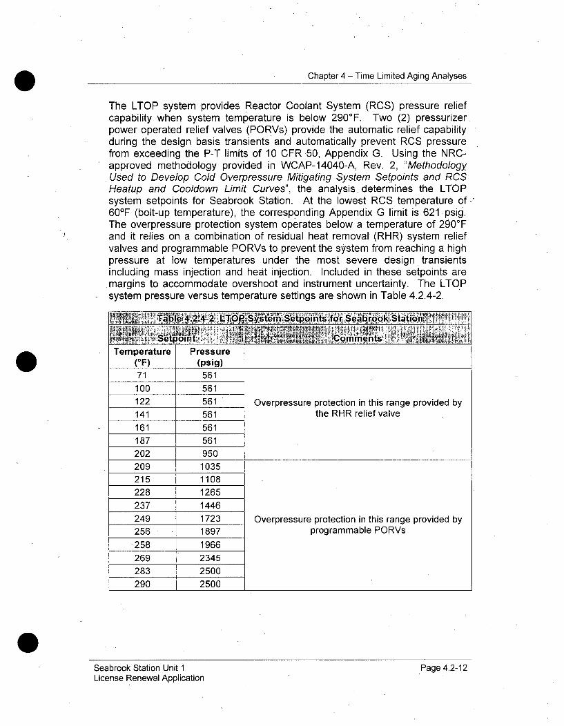
Chapter 4 - Time Limited Aging Analyses
The LTOP system provides Reactor Coolant System (RCS) pressure reliefcapability when system temperature is below 290'F. Two (2) pressurizerpower operated relief valves (PORVs) provide the automatic relief capabilityduring the design basis transients and automatically prevent RCS pressurefrom exceeding the P-T limits of 10 CFR 50, Appendix G. Using the NRC-approved methodology provided in WCAP-14040-A, Rev. 2, "MethodologyUsed to Develop Cold Overpressure Mitigating System Setpoints and RCSHeatup and Cooldown Limit Curves", the analysis determines the LTOPsystem setpoints for Seabrook Station. At the lowest RCS temperature of60OF (bolt-up temperature), the corresponding Appendix G limit is 621 psig.The overpressure protection system operates below a temperature of 2900 Fand it relies on a combination of residual heat removal (RHR) system reliefvalves and programmable PORVs to prevent the system from reaching a highpressure at low temperatures under the most severe design transientsincluding mass injection and heat injection. Included in these setpoints aremargins to accommodate overshoot and instrument uncertainty. The LTOPsystem pressure versus temperature settings are shown in Table 4.2.4-2.
TaL~p 4.2.4-2 LtLOP'Sý ysý toi foeabrookj Stationl 1 ~
2r Seoont ,~ , CmetsTemperature Pressure
(OF) (psig)71 561
100 561122 561 Overpressure protection in this range provided by141 561 the RHR relief valve161 561187 561202 950209 1035215 1108228 1265237 1446249 1723 Overpressure protection in this range provided by256 1897 programmable PORVs
258 1966269 2345283 2500290 2500
Seabrook Station Unit 1License Renewal Application
Page 4.2-12
Chapter 4 - Time Limited Aging Analyses
Disposition
Aging Management, 10 CFR 54.21(c)(1)(iii) - The provisions of 10 CFR 50,Appendix G, require Seabrook to operate within the currently licensed P-T limitcurves. These curves are required to be maintained and updated as necessaryto maintain plant operation consistent with 10 CFR 50. The Reactor VesselIntegrity Surveillance Program maintains the P-T limit curves for the period ofextended operation. Therefore, the P-T limit curves TLAA has beendispositioned in accordance with 10 CFR 54.21(c)(1)(iii). Prior to the period ofextended operation, updated P-T limit calculations will be prepared for theSeabrook Station reactor vessel beltline region materials, inlet and outletnozzles, and closure head flange locations for normal heatup, normalcooldown, and in-service leak and hydrostatic test conditions. The ReactorVessel Integrity Surveillance Program, B.2.1.19 monitors reactor vesselembrittlement. This program provides data to update the P-T limits and,therefore, permits Seabrook Station to manage the P-T limits going forward inaccordance with 10 CFR 54(c)(1)(iii). Seabrook Station will submit updates tothe P-T curves and LTOP limits to the NRC at the appropriate time to complywith 10 CFR 50 Appendix G.
Seabrook Station Unit 1License Renewal Application
Page 4.2-13
Chapter 4 - Time Limited Aging Analyses
4.3 METAL FATIGUE ANALYSIS OF PIPING AND COMPONENTS
Metal fatigue was evaluated in the design process for Seabrook Stationpressure boundary components, including the reactor vessel, reactor coolantpumps, steam generators, pressurizer, piping, valves, and components ofprimary, secondary, auxiliary, steam, and other systems. The current designanalyses for these components have been- determined to be Time-LimitedAging Analyses (TLAAs) requiring evaluation for the period of extendedoperation. Fatigue TLAAs for Seabrook Station pressure -boundarycomponents are characterized by determining the applicable design code anddesign specifications that specify the fatigue design requirements. Thesedesign codes are listed in- Table 4.3.1-1. NUREG-1801 provides a listing ofcomponents that are likely to have TLAAs in place that require evaluation forLicense Renewal. Each of these has been reviewed and the applicableTLAAs are evaluated in the following sections, as appropriate.
This section is divided into seven subsections that each addresses a specificgrouping of components that were analyzed in accordance with the samedesign requirements.
These Sections are as follows:
* Nuclear Steam Supply System (NSSS) Pressure Vessel AndComponent Fatigue Analyses (4.3.1)
* Supplementary ASME Section III, Class 1 Piping And ComponentFatigue Analyses (4.3.2)
" Reactor Vessel Internals Aging Management (4.3.3)
" Environmentally-Assisted Fatigue Analyses (4.3.4)
" Steam Generator Tube, Loss Of Material And Fatigue Usage FromFlow-Induced Vibration (4.3.5)
* Absence Of TLAAs For Fatigue Crack Growth, Fracture MechanicsStability, Or Corrosion Analyses Supporting Repair Of Alloy 600Materials (4.3.6)
* Non-Class 1 Component Fatigue Analyses (4.3.7)
The evaluations referenced in these sections fall into the following categories:
* Explicit fatigue analyses for NSSS pressure vessels and componentsprepared. in accordance with ASME Section III, Class A or Class 1rules developed as part of the original design.
Seabrook Station Unit 1 Page 4.3-1License Renewal Application

Chapter 4 - Time Limited Aging Analyses
Supplemental explicit fatigue analyses for piping and components thatwere prepared in accordance with ASME Section III rules to evaluatetransients that were identified after the original design analyses werecompleted, such as pressurizer surge line thermal stratification, andreactor vessel internal component fatigue analyses.
New fatigue analyses were prepared for license renewal to evaluatethe effects of the reactor water environment on the sample of high-fatigue locations applicable to newer vintage Westinghouse Plants, asidentified in Section 5.5 of NUREG/CR-6260. The environmentalfatigue methodology and results of these analyses are presented inSection 4.3.4. New explicit analyses were prepared in accordancewith, ASME Section III, Class 1 rules for each of these components.For these locations environmental fatigue correction factors werecomputed and applied to the Cumulative Usage Factor (CUF) valuesdeveloped in the Class 1 fatigue analyses:
4.3.1 NUCLEAR STEAM SUPPLY SYSTEM (NSSS) PRESSURE
VESSEL AND COMPONENT FATIGUE ANALYSES
Summary Description
Nuclear Steam Supply System (NSSS) pressure vessels and primarycomponents for Seabrook Station were designed in accordance with ASMESection III, Class 1 requirements and are required to have explicit analyses ofcumulative fatigue usage. Table 4.3.1-1 identifies the applicable designcodes for these components.
Seabrook Station Unit 1 Page 4.3-2*License Renewal Application

Chapter 4 - Time Limited Aging Analyses
Table 4.3.1-1Original Design Codes for NSSS Components at Seabrook Station
Reactor Vessel ASME Section III, Class 1 1971 with Addenda throughSummer 1972
Reactor Vessel ASME Section III, Class 1 1971 with Addenda throughClosure Head Summer 1972Pressurizer ASME Section III, Class 1 1971 with Addenda through
Summer 1972Steam Generators ASME Section III, Class 1 1971 with Addenda through
Summer 1972Reactor Coolant ASME Section III, Class 1 1971 with Addenda throughPump Casings Summer 1972
ASME Section III, Class 1 fatigue analyses determine the CUF value thatresults from the component being exposed to the list of postulated transientsduring the expected life of the component (Table 4.3.1-2). This analysis isperformed using the appropriate S-N (Stress amplitude / Number of cycles)fatigue curve from ASME Section III for the component material type. Thecurve shows the number of cycles the component can withstand withoutcracking for given amplitude of applied alternating stress. The resulting CUFof less than 1.0 indicates the cumulative effects from the postulated transientswill not result in the initiation of fatigue cracking.
These ASME Section III, Class 1 fatigue analyses are based upon explicitnumbers and amplitudes of thermal and pressure transients described in thedesign specifications. The intent of the design basis transient definitions is tobound not just specific operations but a wide range of possible events withvarying ranges of severity in temperature, pressure, and flow. The mostlimiting numbers of transients used in these NSSS component analyses areshown in Table 4.3.1-2, and are considered to be design limits.
Seabrook Station Unit 1License Renewal Application
Page 4.3-3
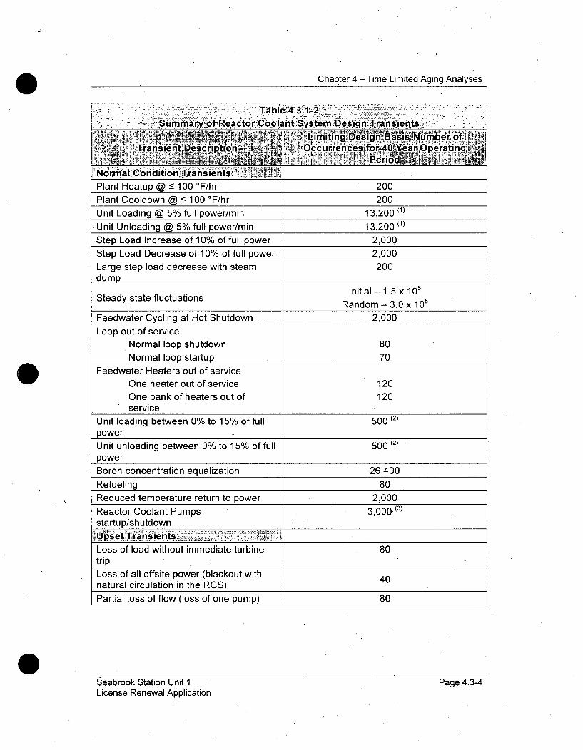
Chapter 4 - Time Limited. Aging Analyses
Table 4312 .;7~
Sum mar~y oflReactor Colat Systemý DsignTaset
dim~ iti~nirg ~Design Bai '6 ,Transent Dscripion CCuirre~nces for 40 Year dperati'ng~
Nqo•;malý Condit ion Transients:Plant Heatup @ - 100 °F/hr 200
Plant Cooldown @ -< 100 °F/hr 200
Unit Loading @ 5% full power/min 13,200 (1)
Unit Unloading @ 5% full power/min 13,200 (l)
Step Load Increase of 10% of full power 2,000
Step Load Decrease of 10% of full power 2,000Large step load decrease with steam 200dump
Initial- 1.5 x 10⁵
Steady state fluctuations Random - 3.0 x 10⁵
Feedwater Cycling at Hot Shutdown 2,000Loop out of service
Normal loop shutdown 80Normal loop startup 70
Feedwater Heaters out of serviceOne heater out of service 120
One bank of heaters out of 120service
Unit loading between 0% to 15% of full 500 (2)
powerUnit unloading between 0% to 15% of full 500 (2)
power
Boron concentration equalization 26,400
Refueling 80Reduced temperature return to power 2,000
Reactor Coolant Pumps 3,000 (3)
startup/shutdownI'set T "ans"ients:
Loss of load without immediate turbine 80tripLoss of all offsite power (blackout with 40natural circulation in the RCS)
Partial loss of flow (loss of one pump) 80
Seabrook Station Unit 1License Renewal Application
Page 4.3-4
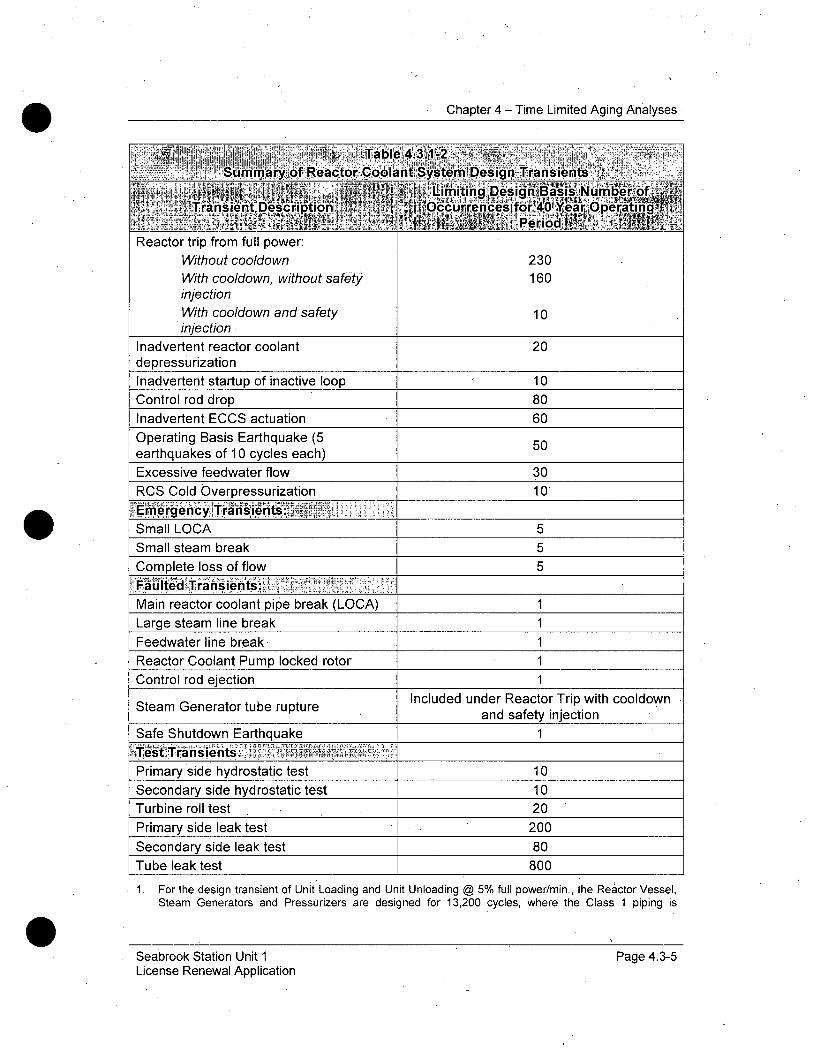
Chapter 4 - Time Limited Aging Analyses
Tablle,4.3.-2'Summary of Reactor Coolant System Design Transients
Tra~ie•t Ii'miting Design, Basis:Nurner' ofTrnset ecription~ ~ O ~eces. for 40,Near rpeating
Reactor trip from full power:
Without cooldown 230With cooldown, without safety 160injectionWith cooldown and safety 10injection
Inadvertent reactor coolant 20depressurizationInadvertent startup of inactive loop 10Control rod drop 80Inadvertent ECCS actuation 60Operating Basis Earthquake (5 50earthquakes of 10 cycles each)Excessive feedwater flow 30
RCS Cold Overpressurization 101• I i e rg e ncyl rajns~ie n tS;!ii~!i,, ii;;~••;,i ;,=. :
Small LOCA 5Small steam break 5
Complete loss of flow 5
Main reactor coolant pipe break (LOCA) 1Large steam line break 1
Feedwater line break, 1Reactor Coolant Pump locked rotor 1Control rod ejection 1
Included under Reactor Trip with cooldownSteam Generator tube rupture and safety injectionSafe Shutdown Earthquake 1
P trianysidhyents:tPrimary side hydrostatic test 10Secondary side hydrostatic test 10Turbine roll test 20Primary side leak test 200
Secondary side leak test 80Tube leak test 800
1. For the design transient of Unit Loading and Unit Unloading @ 5% full power/min., the Reactor Vessel,Steam Generators and Pressurizers are designed for 13,200 cycles, where the Class 1 piping is
Seabrook Station Unit ILicense Renewal Application
Page 4.3-5

Chapter 4 - Time Limited Aging Analyses
designed for 18,300 cycles. The most limiting value of these major components is used as a monitoringlimit in the Metal Fatigue of Reactor Coolant Pressure Boundary Program, B.2.3.1.
2. For the design transients of Unit load and unload between 0% to 15% of full power, the Reactor Vessel,Steam Generators and Class 1 piping are designed for 500 cycles, where the Pressurizer is designedfor 1,510 cycles. The most limiting value of these major components is used as a monitoring limit in theMetal Fatigue of Reactor Coolant Pressure Boundary Program, B.2:3.1.
3. For the design transient of Reactor Coolant Pump startup/shutdown, the limit specified in the UFSAR is3800 cycles. The Pressurizer is designed for 4,000 cycles, where Steam Generators are designed for3,000 cycles. The Steam Generators has the most limiting value (3,000 cycles) of these components isused as a monitoring limit in the Metal Fatigue of Reactor Coolant Pressure Boundary Program, B.2.3. 1.
Each Seabrook component designed in accordance with ASME Section III,Class 1 rules was analyzed and shown to have a CUF less than the designlimit of 1.0. Since each Class 1 fatigue analysis is based upon a number ofcycles postulated to bound 40 years of service, they have been identified asTLAAs that require evaluation for 60 years.
Analysis
In order to determine if the ASME Section III, Class 1 fatigue analyses willremain valid for 60 years of service, a review of fatigue monitoring data wasperformed to determine the number of cumulative cycles for each transienttype that have occurred during past plant operations. Then, the average rateof occurrence was determined, and predictions of future transientoccurrences were made. For each transient type, the 60-year projectednumber of occurrences was determined by adding the number of pastoccurrences to the number of predicted future occurrences. These 60-yearprojections were then compared to the number' of design cycles used in thefatigue analyses to determine if the design cycles remain bounding for 60years of operations. If the 60-year projected numbers of cycles is less thanthe number of cycles used in the design fatigue analyses, then the fatigueanalyses based upon the design transients will remain valid for 60 years ofoperation; if the design transient severity is also bounding of the actualtransient severity.
Therefore, an evaluation was performed to determine if the severity of theactual plant transients that have occurred during past operations remainsbounded by the transient severity provided for each transient definition in thedesign specification. This evaluation was to assure that the past cycles wereappropriately characterized during fatigue monitoring activities in the past.The administrative and operating procedures were also reviewed in order toassess the effectiveness of the design transient cycle counting program andto validate the cyclic assumptions. This evaluation determined that the actualtransient severity was bounded by the design transient severity for eachtransient type. The cycle counting procedure was also determined to havebeen effective in properly characterizing actual plant transients.
Seabrook Station Unit 1 Page 4.3-6License Renewal Application
Chapter 4 - Time Limited Aging Analyses
The overall conclusion of these evaluations is that the existing designtransients bound transients projected for 60 years of plant operations.
60-Year Transient Projection Methodology
Projection Methodology
For Seabrook Station, the baseline period started on August 19, 1990 andended on April 1, 2009, a total of 18.6 calendar years. For each transienttype, the average rate of occurrence was determined by dividing thecumulative number of occurrences as of April 1, 2009 by 18.6 years of pastoperation. For each transient type, future cycles were predicted bymultiplying the average rate of past occurrences by the number of calendaryears remaining between April 1, 2009 and March 15, 2050. The 60-yearprojection was determined by adding the cumulative number of occurrencesas of April 1, 2009 to the number of cycles predicted to occur in the 41 yearsof future operation. This methodology is considered to produce aconservative estimate of cycle values due to the declining trend of most of thetransients since the beginning of plant operation.
Testing Events
One cycle has occurred for the following plant events:
* Turbine Roll Test
* Primary Side Leakage Test
" RCS Hydrostatic Pressure Test
" Secondary Side Leakage Test
" Tube Leakage Test
* Secondary Side Hydrostatic Pressure Test
These cycles occur before initial startup or during component installation andthen typically do not occur again in the plant's lifetime. Therefore, the 60-yearcycle projection for these events was taken as the current cycle count of one.
Events with Zero Cycles
No cycles have occurred for the following plant events:
° Operating Basis Earthquake
" RCS Loop Out of Service
Seabrook Station Unit I Page 4.3-7License Renewal Application
Chapter 4 - Time Limited Aging Analyses
- Inadvertent RCS Depressurization
* Inadvertent startup of inactive loop
* Excessive Feedwater Flow
o Reactor Trip with cooldown and safety injection
* Partial Loss of Flow
* Inadvertent Reactor Coolant Pump Startup
• RCS Cold Overpressurization
These events occur infrequently over the lifetime of a plant. Therefore, onecycle was predicted for the 60-year cycle projection for each of these plantevents. The only. exception is RCS Loop Out of Service. It is assumed tohave zero cycles occur for the 60-year cycle projection, because the plant isnot licensed to operate in this state.
Relatively Frequent Events'
The following plant events occur frequently over the course of the lifetime of aplant:
* Feedwater Cycling
* RCP Startup and RCP Shutdown
The 60-year cycle projection for the RCP Startup and Shutdown cycles waslinearly extrapolated based on the rate of accumulation for the data availablethrough April 1, 2009 and additional 10% of cycles were included toaccommodate any slight increase in occurrence over the years up to 60years. The Feedwater Cycling events were not counted in the plant recordsand were prorated annually on the basis of the design number of cycles asthe design number provides a conservative estimate for the non-monitoredevents considered.
Relatively Infrequent Events
The following plant events occur infrequently over the course of the lifetime ofa plant:
o Step Load Increase < 10%
* Step Load Decrease 10%
Seabrook Station Unit 1 Page 4.3-8License Renewal Application
Chapter 4 - Time Limited Aging Analyses
* Large Step Load Decrease with Steam Dump
* Unit Loading Between 0% and 15% Power
* Unit Unloading Between 0% and 15% Power
" Loss of Load without Immediate Reactor Trip
" Loss of Power
* Reactor Trip with cooldown but not safety injection
* Control Rod Drop
* Inadvertent Safety Injection (SI) Actuation
* Auxiliary Spray Actuation
The 60-year cycle projection for these events was linearly extrapolated basedon the rate of accumulation for the data available through 4/1/2009.
Fatigue-Insignificant Events
Steady State Fluctuation and Boron Concentration Equalization occurfrequently over the course of the lifetime of a plant, but have an insignificanteffect on fatigue usage for any Class 1 component. No 60-year cycleprojection is made for these events and they are not included Table 4.3.1-3.
Seabrook Station Unit 1-License Renewal Application
Page 4.3-9
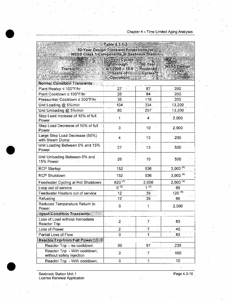
Chapter 4 - Time Limited Aging Analyses
NormalC Condition Transients::Plant Heatup < 100°F/hr 27 87 200Plant Cooldown < 100°F/hr 26 84 200.
Pressurizer Cooldown 5 200°F/hr 36 116 200Unit Loading @ 5%/min 104 334 13,200Unit Unloading@ 5%/min 80 257 13,200Step Load Increase of 10% of full 1 4 2,000PowerStep Load Decrease of 10% of full 10 2,000PowerLarge Step Load Decrease (50%) 4 13 200with Steam DumpUnit Loading Between 0% and 15% 27 13 500Power
Unit Unloading Between 0% and 26 10 50015% Power
RCP Startup 152 536 3,000 (4)
RCP Shutdown 152 536 3,000 (4)
Feedwater Cycling at Hot Shutdown 620 (1) 2,000 2,000 (5)
Loop out of service 0 (2) 1 (2) 80Feedwater Heaters out of service 12 39 120 (5)Refueling 12 39 80Reduced Temperature Return to0 2,000Power
ý.Upset,-Condition Transients:.Loss of Load without Immediate 2 7 80Reactor TripLoss of Power 2 7 40Partial Loss of Flow 0 1 80
Reactor Trip - no cooldown 30 97 230Reactor Trip - With cooldown, 2 7 160without safety injectionReactor Trip - With cooldown, 0 1 10
Seabrook Station Unit 1License Renewal Application
Page 4.3-10
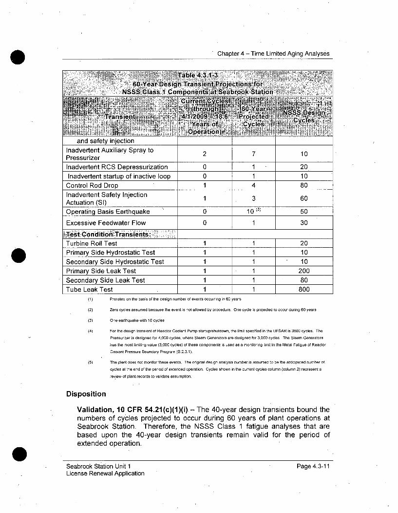
Chapter 4 - Time Limited Aging Analyses
Inadvertent Safety InjectionActuation (SI)
Operating Basis Earthquake
Excessive Feedwater Flow
Test ConditiOi ''Transie nts:
Primary Side Hydrostatic Test
Secondary Side Hydrostatic Test
Primary Side Leak Test
Secondary Side Leak Test
(1) Prorated on the basis of the design number of events occurring in 60 years.
(2) Zero cycles assumed because the event is not allowed by procedure. One cycle is projected to occur during 60 years
(3) One earthquake with 10 cycles
(4) For the design transient of Reactor Coolant Pump startup/shutdown, the limit specified in the UFSAR is 3800 cycles. The
Pressurizer is designed for 4,000 cycles, where Steam Generators are designed for 3,000 cycles. The Steam Generators
has the most limiting value (3,000 cycles) of these components is used as a monitoring limit in the Metal Fatigue of Reactor
Coolant Pressure Boundary Program (B.2.3.1).
(5) The plant does not monitor these events. The original design analysis number is assumed to be the anticipated number of.
cycles at the end of the period of extended operation. Cycles shown in the current cycles column (column 2) represent a
review of plant records to validate assumption.
Disposition
Validation, 10 CFR 54.21 (c)(1)(i) - The 40-year design transients bound thenumbers of cycles projected to occur during 60 years of plant operations atSeabrook Station. Therefore, the NSSS Class 1 fatigue analyses that arebased upon the 40-year design transients remain valid for the period ofextended operation.
Seabrook Station Unit 1 Page 4.3-11License Renewal Application
Chapter 4 - Time Limited Aging Analyses
4.3.2 SUPPLEMENTARY ASME SECTION III, CLASS 1 PIPING ANDCOMPONENT FATIGUE ANALYSES
Summary Description
In addition to the original design assumptions, the Seabrook StationPressurizer fatigue evaluations were updated to include the added thermalstratification effects of insurge and outsurge events on the pressurizer lowerhead and surge nozzle. These new conditions did not change the number oforiginal design cycles, but rather incorporated the effects as new sub-eventswithin the original design transients.
Each of the Seabrook Station piping systems, including the Reactor CoolantSystem main loop piping, were originally designed in accordance with ASMESection III 1971 Edition with addenda through Winter 1972. Since then, anumber of updated fatigue analyses have been prepared for piping systemsand components to address transients that have been identified in theindustry that were not originally considered. These analyses have beenperformed in accordance with ASME Section III, Class 1 rules to enable thesetransients to be thoroughly evaluated. These transients include thoseassociated with potential valve leakage transients identified in NRC Bulletin88-08 for the auxiliary spray line, charging lines, safety injection lines, andthermal stratification of the pressurizer surge line, as described in NRCBulletin 88-11.
These analyses are separated from those evaluated in the previous sectionsbecause the transient definitions have been modified, or additional transientshave been postulated for these components, in addition to those previouslydescribed. Therefore, the cycle projections for these components mustaddress these revised transients or additional transient types to determine ifthey also remain bounded for 60 years of service. Each of these analyses isdispositioned separately within this section for clarity.
4.3.2.1 Absence of a TLAA for Thermal Stresses in Piping Connected
to Reactor Coolant Systems: NRC Bulletin 88-08
Summary Description
NRC Bulletin 88-08 "Thermal Stresses in Piping Connected to ReactorCooling Systems" was issued June 22, 1988, because of observed pipecracking due to valve leakage in unisolable lines. Three supplements wereissued on June 24, 1988, August 4, 1988, and April 11, 1989, respectively.The Bulletin and supplements required licensees to identify potential locationsthat might be subject to high thermal stresses either from thermal stratificationor temperature oscillations due to leaking valves and inspect the potential
Seabrook Station Unit 1 Page 4.3-12License Renewal Application

Chapter 4 - Time Limited Aging Analyses
locations to assure that susceptible locations will not fail for the remaining lifeof the unit.
Seabrook Station evaluated the effects of thermal stresses due to leakingvalves in seven piping sections that are unisolable from the RCS that werepressurized by the charging pumps and could potentially experience in-leakage to the RCS from leaking valves. Prior to initial criticality, a one-timenon-destructive examination was performed for the four high head safetyinjection lines with acceptable results. A temperature monitoring programwas deployed for potentially susceptible lines. The monitoring is still installedand credited in the Seabrook Station Management of Thermal FatigueProgram for Normally Stagnant Non-Isolable Reactor Coolant System BranchLines (MRP-146/146S).
The NRC approved Seabrook Station's response to NRC Bulletin 88-0&
Analysis
NRC Bulletin 88-08 and Supplements 1 and 2 addressed the evaluation ofthermal stresses in unisolable piping from cold fluid in-leakage to the RCSthrough leaking valves. NRC Bulletin 88-08 Supplement 3 addressed theevaluation of thermal stresses in unisolable piping from hot fluid out-leakagefrom the RCS through leaking valves.
Seabrook Station evaluated the possibility and effects of fluid in-leakage byidentifying seven piping sections that are unisolable from the RCS andpressurized by the charging pumps where the effects of thermal stresses dueto leaking valves could potentially experience in-leakage to the RCS fromleaking valves. Four of these lines are the high head safety injection linesand three of these lines are charging system lines (the normal and alternatecharging loop charging lines and the pressurizer auxiliary spray line).
In 1988, prior to initial criticality, a one-time non-destructive examination wasperformed for the four high head safety injection lines, which showedacceptable results. Non-destructive examinations were not considered to benecessary for the three charging system lines because they had not yet beensubjected to excessive thermal cycling at that time.
Seabrook Station deployed a temperature monitoring program for the highhead safety injection lines and three charging system lines in 1989, prior toinitial criticality. This program installed temperature detectors on theunisolable piping sections to detect adverse temperature distributions, andestablished appropriate temperature limits, requirements for periodic reviewof the temperature instrument values and action limits in the event ofexceeding the temperature limit.
Seabrook Station Unit 1 Page 4.3-13License Renewal Application

Chapter 4 - Time Limited Aging Analyses
Seabrook Station evaluated the possibility and effects of fluid out-leakage andconcluded that unisolable piping sections connected to the Reactor CoolantSystem at Seabrook Station. are not subject to stresses from thermalstratification or temperature oscillations resulting from the mechanismdescribed in NRC Bulletin Supplement 3. There is no specific TLAA for theseseven locations addressed by NRC Bulletin 88-08 and related supplements.
Conclusion
Unisolable piping sections connected to the Reactor Coolant System atSeabrook Station are not subject to stresses from thermal stratification ortemperature oscillations resulting from the mechanism described in NRCBulletin 88-08 and related supplements. There is no specific TLAA forlocations addressed by NRC Bulletin 88-08 and related supplements.
4.3.2.2 NRC Bulletin 88-11, Pressurizer Surge Line ThermalStratification
Summary Description
NRC Bulletin 88-11, issued on December 20, 1988, requested utilities toestablish and implement a program to confirm the integrity of the pressurizersurge line. The program required both visual inspection of the surge line anddemonstration that the design requirements of the surge line are satisfied,including the consideration of stratification effects.
The Pressurizer Surge Line piping and nozzles were previously evaluated forthe effects of thermal stratification and plant-specific transients (1990) and itwas determined that the surge line will remain within the ASME Coderequirements for the design life of the unit. The controlling fatigue locationwas the hot leg surge line nozzle safe-end. In later evaluations, plant-specificASME Section III, Class 1 evaluations were performed for the hot leg surgeline nozzle and pressurizer surge nozzle.
Hot Leg Surge Line Nozzle
The hot leg surge line nozzle was evaluated for the effects of pressurizerinsurge and outsurge transients and surge line stratification. This evaluationwas part of an evaluation of reactor water environmental effects on the surgeline. The model from that analysis was also used to evaluate the designcycles for the NSSS transients and projected 60-year cycles of surge linestratification and insurge and outsurge transients, to calculate CUF at the hotleg surge line nozzle, without environmentally-assisted fatigue effects. Sincethe analysis envelopes the 60-year cycles, it remains valid for 60 years. Theevaluation incorporating these models in the evaluation of environmentally-,assisted fatigue is described further in section 4.3.4 Environmentally-AssistedFatigue Analyses
Seabrook Station Unit 1 Page 4.3-14License Renewal Application
Chapter 4 - Time Limited Aging Analyses
Pressurizer Surge Nozzle
The pressurizer surge nozzle was evaluated for the effects of pressurizerinsurge and outsurge transients and surge' line stratification. This evaluationwas part of an evaluation of the structural weld overlay applied to thepressurizer surge nozzle. The- model from that analysis was also used toevaluate the design cycles for the NSSS transients and design cycles ofsurge line stratification and insurge and outsurge transients, to calculate CUFat the pressurizer surge nozzle. Since the analysis envelopes the 60-yearcycles, it remains valid for 60 years.
Analysis
Hot Leg Surge Line Nozzle
The hot leg surge line nozzle has been evaluated using an ASME Section III,Class 1 fatigue analysis. This analysis was part of the evaluation of theenvironmental effects of reactor coolant (Section 4.3.4). In addition, thatanalysis was used to evaluate CUF without environmental effects. Theanalysis performed to demonstrate compliance with design requirementsconsidered ASME Code requirements and utilized the design set of NSSStransients. Pressurizer surge line stratification sub-transients were developedbased on NSSS-vendor Seabrook Station-specific evaluations for pre-MOP(Modified Operating Procedure) plant operating procedures and NSSS-vendor evaluations of surge line monitoring data from similar units andhistorical records for Seabrook Station for post-MOP operating procedures.Projected 60-year cycles of surge line stratification and insurge and outsurgetransients were used when these were greater than previously evaluateddesign cycles. These evaluations resulted in CUF less than 1.0 at the hot legsurge line nozzle.
Pressurizer Surge Nozzle
The pressurizer surge nozzle has been evaluated using an ASME Section III,Class I fatigue analysis. This analysis was part of the evaluation of thestructural weld overlay applied to the pressurizer surge nozzle. The analysisperformed to demonstrate compliance with design requirements consideredASME Code requirements and utilized the design set of NSSS transients andsurge line stratification sub-transients were developed based on NSSS-vendor Seabrook Station specific evaluations for pre-MOP operating plantoperating procedures and NSSS-vendor evaluations of surge line monitoringdata from similar units and historical records for Seabrook for post-MOPoperating procedures. This evaluation included an elastic-plastic formulationand resulted in CUE less than 1.0 at the pressurizer surge nozzle.
Seabrook Station Unit 1 Page 4.3-15License Renewal Application
Chapter 4 - Time Limited Aging Analyses
Disposition
Validation, 10 CFR 54.21(c)(1)(i) - The analyses remain valid for the periodof extended operation for the Pressurizer Surge Line, Pressurizer SurgeNozzle and Hot Leg Surge Line Nozzle
4.3.3 REACTOR VESSEL INTERNALS AGING MANAGEMENT
Summary Description
The Seabrook Station Reactor Vessel Internals were designed andconstructed prior to the development of ASME Code requirements for coresupport structures, but the reactor coolant system functional designrequirements were considered in the design. The Reactor Vessel Internalswere further analyzed for fatigue as part of the Seabrook Station poweruprate and determined that cumulative usage factors would remain less than1.0.
Demonstration that the effects of aging are adequately managed is essentialfor assuring continued functionality of the reactor internals during the desiredplant operating period, including license renewal. The recently-publishedEPRI Materials Reliability Program (MRP) Reactor Internals Inspection &Evaluation (I&E) Guidelines, MRP-227, are intended to support thatdemonstration, with requirements for inspection to detect the effects of agingdegradation.
Analysis
The mechanisms of aging of PWR internals are described below:
Stress -Corrosion Cracking
Stress Corrosion Cracking (SCC) refers to local, non-ductile cracking of amaterial due to a combination of tensile stress, environment, andmetallurgical properties. The actual mechanism that causes SCC involves acomplex interaction of environmental and metallurgical factors. The agingeffect is cracking.
Irradiation-Assisted Stress Corrosion Cracking
Irradiation-assisted stress corrosion cracking (IASCC) is a unique form ofSCC that occurs only in highly-irradiated components. The aging effect iscracking.
Seabrook Station Unit 1 Page 4.3-16License Renewal Application

Chapter 4 - Time Limited Aging Analyses
Wear
Wear is caused by the relative motion between adjacent surfaces, with theextent determined by the relative properties of the adjacent materials andtheir surface condition. The aging effect is loss of material.
Fatigue
Fatigue is defined as the structural deterioration that can occur as the resultof repeated stress/strain cycles caused by fluctuating loads andtemperatures. After repeated cyclic loading of sufficient magnitude,microstructural damage can accumulate, leading to macroscopic crackinitiation at the most highly affected locations. Subsequent mechanical orthermal cyclic loading can lead to growth of the initiated crack. Corrosionfatigue is included in the degradation description.
Low-cycle fatigue is defined as cyclic loads that cause significant plastic strainin the highly stressed regions, where the number of applied cycles isincreased to the point where the crack eventually initiates. When the cyclicloads are such that significant plastic deformation does not occur in the highlystressed regions, but the loads are of such increased frequency that a fatiguecrack eventually initiates, the damage accumulated is said to have beencaused by high-cycle fatigue. The aging effects of low-cycle fatigue and high-cycle fatigue are additive. Fatigue crack initiation and growth resistance isgoverned by a number of material, structural and environmental, factors, suchas stress range, loading frequency, surface condition and presence ofdeleterious chemical species. Cracks typically initiate at local geometricstress concentrations, such as notches, surface defects, and structuraldiscontinuities. The aging effect is cracking.
Thermal Aging Embrittlement
Thermal aging embrittlement is the exposure of delta ferrite within castaustenitic stainless steel (CASS) and precipitation-hardenable stainless steelto high inservice temperatures, which can result in an increase in tensilestrength, a decrease in ductility, and a loss of fracture toughness. Somedegree of thermal aging embrittlement can also occur at normal operatingtemperatures for CASS and precipitation-hardenable stainless steel internals.CASS components have a duplex microstructure and are particularlysusceptible to this mechanism. While the initial aging effect is loss of ductilityand toughness, unstable crack extension is the eventual aging effect if acrack is present and the local applied stress intensity exceeds the reducedfracture toughness.
Seabrook Station Unit 1 Page 4.3-17License Renewal Application
Chapter 4 - Time Limited Aging Analyses
Irradiation Embrittlement
Irradiation embrittlement is also referred to as neutron embrittlement. Whenexposed to high energy neutrons, the mechanical properties of stainless steeland nickel-base alloys can be changed. Such changes in mechanicalproperties include increasing yield strength, increasing ultimate strength,decreasing ductility, and a loss of fracture toughness. The irradiationembrittlement aging mechanism is a function of both temperature and neutronfluence. While the initial aging effect is loss of ductility and toughness,unstable crack extension is the eventual aging effect if a crack is present andthe local applied stress intensity exceeds the reduced fracture toughness.
Void Swelling and Irradiation Growth
Void swelling is a gradual increase in the volume of a component caused byformation of microscopic cavities in the material. These cavities result fromthe nucleation and growth of clusters of irradiation produced vacancies.Helium produced by nuclear transmutations can have a significant impact onthe nucleation and growth of cavities in the material. Void swelling mayproduce dimensional changes that exceed the tolerances on a component.Strain gradients produced by differential swelling in the system may producesignificant stresses. Severe swelling (>5% by volume) has been correlatedwith extremely low fracture toughness values. Also included in thisdescription is irradiation growth of anisotropic materials, which is known tocause significant dimensional changes in in-core instrumentation tubes,fabricated from zirconium alloys. While the initial aging effect is dimensionalchange and distortion, severe void swelling may result in cracking understress.
Thermal and Irradiation-Enhanced Stress Relaxation or Irradiation-Enhanced Creep
The loss of preload aging effect can be caused by the aging mechanisms ofstress relaxation or creep. Thermal stress relaxation (or, primary creep) isdefined as the unloading of preloaded components due to long-term exposureto elevated temperatures, such as seen in PWR internals. Stress relaxationoccurs under conditions of constant strain where part of the elastic strain isreplaced with plastic strain. Available data show that thermal stressrelaxation appears to reach saturation in a short time (< 100 hours) at PWRinternals temperatures.
Creep (or more precisely, secondary creep) is a slow, time and temperaturedependent, plastic deformation of materials that can occur when subjected tostress levels below the yield strength (elastic limit). Creep occurs at elevatedtemperatures where continuous deformation takes place under constantstrain. Secondary creep in austenitic stainless steels is associated with
Seabrook Station Unit 1 Page 4.3-18License Renewal Application
Chapter 4 - Time Limited Aging Analyses
temperatures higher than those relevant to PWR internals even after takinginto account gamma heating. However, irradiation-enhanced creep (or moresimply, irradiation creep) or irradiation enhanced stress relaxation (ISR) is an,,athermal process that depends on the neutron fluence and stress; and, it canalso be affected by void swelling should it occur. The aging effect is a loss ofmechanical closure integrity (or, preload) that can lead to unanticipatedloading which, may eventually cause subsequent degradation by fatigue orwear and result in cracking.
Disposition
Aging Management, 10 CFR 54.21(c)(1)(iii) The PWR Vessel InternalsProgram, B.2.1.7 will manage the aging effects including changes indimensions, cracking, loss of fracture toughness, and loss of preload of theReactor Vessel Internals components for the period of extended operation per10 CFR 54.21 (c)(1)(iii).
4.3.4 ENVIRONMENTALLY-ASSISTED FATIGUE ANALYSES
Summary Description
Environmentally-assisted fatigue analyses do not meet the definition, of time-limited aging analyses under 10 CFR 54.3 because they are not contained orincorporated by reference in Seabrook Station's current licensing basis. Thissubsection is included in response to therequest in NUREG-1800 that licenserenewal applicants address the effects of the coolant environment oncomponent fatigue life as aging management programs are formulated insupport of license renewal. This discussion of environmentally-assistedfatigue calculations is provided, in accordance with NUREG-1800, to assistwith the formulation of aging management programs.
NUREG-1801, Revision 1, Generic Aging Lessons Learned, containsrecommendations on specific areas for which existing programs should beaugmented for license renewal. The program description for AgingManagement Program X.M1, Metal Fatigue of Reactor Coolant PressureBoundary Program, provides guidance for addressing environmental fatiguefor license renewal. It states that an acceptable program addresses theeffects of the reactor coolant environment on component fatigue life byassessing the impact of the reactor coolant environment on a sample ofcritical components for the plant. Examples of these components areidentified in NUREG/CR-6260, "Application of NUREG/CR-5999 InterimFatigue Curves to Selected Nuclear Power Plant Components".
This sample of components can be evaluated by applying environmental lifecorrection factors to the existing ASME Code fatigue analyses using formulaecontained in NUREG/CR-6583, "Effects of LWR Coolant Environments on
Seabrook Station Unit 1 Page 4.3-19License Renewal Application
Chapter 4 - Time Limited Aging Analyses.
Fatigue Design Curves of Carbon and Low Alloy Steels" and in NUREG/CR-5704, "Effects of LWR Coolant Environments on Fatigue Design Curves ofAustenitic Stainless Steels". Demonstrating that these components have anenvironmentally adjusted cumulative usage factor less than or equal to thedesign limit of 1.0 for the 60-year period of extended operation is anacceptable option for managing metal fatigue for the reactor coolant pressureboundary. Another acceptable option is to manage fatigue of thesecomponents in the Metal Fatigue of Reactor Coolant Pressure BoundaryProgram, B.2.3.1 by tracking the number and severity of plant transients tocompare to the established trigger number for each plant transient. Under theB.2.3.1 option, when the counted number of a specific plant transient reachesthe trigger number associated with that specific plant transient, a preemptiveremedial action will be undertaken appropriate to the plant transient and thecomponents affected by it. This remedial action may encompass one ofseveral activities, as described in B.2.3.1:
1. Reanalyze affected components for an increase in the number of thatspecific transient while accounting for other component-affecting planttransients that may be projected not to achieve their analyzed levels.
2. Perform a fracture mechanics evaluation of a postulated flaw inaffected plant components, which when coupled with an inserviceinspection program, will serve to demonstrate flaw tolerant behavior.
3. Repair the affected component.
4. Replace the affected component.
NUREG/CR-6260 provides environmental fatigue calculations for a newervintage Westinghouse plant (like Seabrook Station) using the interim fatiguecurves from NUREG/CR-5999 for the locations of highest design CUF for thecomponents listed below:
* Reactor Vessel Shell and Lower Head
o Reactor Vessel Inlet and Outlet Nozzles
o RCS Pressurizer Surge Line
o RCS Charging Nozzle
o RCS Safety Injection Nozzle
o RCS Residual Heat Removal System Class 1 Piping
Seabrook Station Unit 1 Page 4.3-20License Renewal Application
Chapter 4 - Time Limited Aging Analyses
Analysis
For the NUREG/CR-6260 locations identified above, the plant-specificcomponents were identified and the design ASME fatigue usage factors wereadjusted by the environmentally-assisted fatigue penalty factors (Fen) toobtain the environmentally-assisted fatigue (EAF) results for the RV Inlet andOutlet Nozzles, RV Shell and Lower Head and RHR Hot Leg Nozzle.
Table 4.3.4-1 summarizes the locations where ASME 60-Year air-curve andEAF results were calculated as well as the results. All locations were shownto achieve air-curve cumulative usage factors less than 1.0 for the 60 years ofservice. The-evaluations show that 60-year EAFs exceed 1.0 for 60 years ofservice for the hot leg surge line nozzle and charging nozzle.
In the EAF evaluations for Hot Leg Surge Nozzle, Charging Nozzle andSafety Injection Nozzle, Fen factors for each transient pair were calculatedusing the integrated strain rate method from MRP-47, Rev. 1.
The Effective Fen Multipliers shown in Table 4.3.4-1 for Hot Leg Surge Nozzle,Charging Nozzle and Safety Injection Nozzle, were computed as(Environmentally-Assisted Fatigue CUF) / (Air-Curve CUF).
Seabrook Station Unit 1License Renewal Application
Page 4.3-21
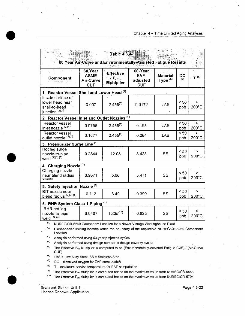
Chapter 4 - Time Limited Aging Analyses.
6. RHR System Class 1 Piping ("RHR hot leg 1 101>
nozzle-to-pipe 0.0407 15:35(1°) 0.625 SS0weld (2)(4) S _ppb 200jC_
(1) NUREG/CR-6260 Component Location for a Newer Vintage Westinghouse Plant
(2) Plant-specific limiting location within the boundary of the applicable NUREG/C(R,-6260 Component
Location(3) Analysis performed using 60-year projected cycles(4) Analysis performed using design number of design-severity cycles(5) The Effective Fen Multiplier is computed to be (Environmentally-Assisted Fatigue CUF) / (Air-Curve
CUF)(6) LAS = Low Alloy Steel; SS = Stainless Steel•(7) DO - dissolved oxygen for EAF computation
(8) T - maximum service temperature for EAF computation(9) The Effective Fen Multiplier is computed based on the maximum value from NUREG/CR-6583
(10) The Effective Fen Multiplier is computed based.on the maximum value from NUREG/CR-5704
Seabrook Station Unit 1 Page 4.3-22License Renewal Application
Chapter 4 - Time Limited Aging Analyses
Disposition
Revision 10 CFR 54.21(c)(1)(ii) The evaluation of environmental fatigueeffects for the Reactor Vessel Shell and Lower Head and Reactor Vessel Inletand Outlet Nozzles determined that the CUF will remain below the ASMEcode allowable fatigue limit of 1.0 using the maximum applicable Fen, appliedto CUF based on the design number of transients for these locations, whenextended to 60 years. The evaluation of fatigue effects for these locations hasthereby been validated for the period of extended operation, in accordancewith 10 CFR 54.21(c)(1)(i), including effects of the reactor coolantenvironment. Therefore, no aging management program is necessary toaddress environmentally-assisted fatigue for these components.
Aging Management 10 CFR 54.21(c)(1)(iii) The remainder of theselocations, RCS Pressurizer Surge Line Nozzle, RCS Charging Nozzle, RCSSafety Injection Nozzle, and RCS Residual Heat Removal System Class 1Piping, were analyzed in accordance with ASME Code Section III, SubarticleNB-3200 using all six stress components. These analyses were based onSeabrook Station Specific conditions and these locations will be monitored forfatigue usage including environmental effects by the Metal Fatigue of ReactorCoolant Pressure Boundary Program, B.2.3.1. Specifically, this program willmonitor critical transients to verify cycle limits are maintained below limitsspecified in the UFSAR. Pre-established action limits will permit completion ofcorrective actions before the design basis number of events is exceeded, andbefore the cumulative usage factor, including environmental effects, exceedsthe AMSE Code limit of 1.0.
At least 2 years prior to entering the period of extended operation, SeabrookStation will implement the following aging management program for the plant-specific locations listed in NUREG/CR-6260 for the newer vintageWestinghouse plants.
(1) Consistent with the Metal Fatigue of Reactor Coolant Pressure BoundaryProgram, B.2.3.1 Seabrook Station will update the fatigue usagecalculations using refined fatigue analyses, if necessary, to determineacceptable CUFs (i.e., less than 1.0) when accounting for the effects ofthe reactor water environment. This includes applying the appropriate Fen
factors to valid CUFs determined from an existing fatigue analysis valid forthe period of extended operation or from an analysis using an NRC-approved version of the ASME Code or NRC-approved alternative (e.g.,NRC-approved code case). Formulas for calculating the environmentallife correction factors for carbon and low alloy steels are contained inNUREG/CR-6583 and those for austenitic stainless steels are contained inNUREG/CR-5704. NUREG/CR-6909 includes alternate formulas forcalculating environmental life correction factors, in addition to updatedfatigue design curves.
Seabrook Station Unit 1 Page 4.3-23License Renewal Application

Chapter 4 - Time Limited Aging Analyses
(2) If acceptable CUFs cannot be demonstrated for all the selected locations,then additional plant-specific locations will be evaluated. For theadditional plant-specific locations, if CUF, including -environmental effectsis greater than 1.0, then Corrective Actions will be initiated, in accordancewith the Metal Fatigue of Reactor Coolant Pressure Boundary Program,B.2.3.1. Corrective Actions will include inspection, repair, or replacementof the affected locations before exceeding a CUF of 1.0 or the effects offatigue will be managed by an inspection program that has been reviewedand approved by the NRC (e.g., periodic non-destructive examination ofthe affected locations at inspection intervals to be determined by a methodaccepted by the NRC).
Therefore, the effects of the reactor coolant environment on fatigue usagefactors in the remaining locations will be managed for the period of extendedoperation in accordance with 10 CFR 54.21 (c)(1)(iii).
4.3.5 STEAM GENERATOR TUBE, LOSS OF MATERIAL ANDFATIGUE USAGE FROM FLOW-INDUCED VIBRATION
Summary Description
The Seabrook Station Model F steam generators were evaluated with respectto flow induced vibration (tube wear and fatigue usage) for the powerincreases that were implemented as part of the Seabrook Station PowerUprates. The analysis of the effects of steam generator flow-inducedvibration on tube wear and fatigue usage assumed 40 years of operation.
Analysis
The maximum predicted tube wall wear for a 40-year operating life was0.0032 inch for the pre-power uprate conditions. As a result of the 56%increase in the tube wear rate as a result of the power uprates, the maximum40-year tube wall wear is less than 0.0050 inch. The maximum 60-year tubewall wear is 0.0075 inch (-20% through-wall wear). This amount of tube wallwear is less than the limit of acceptability of 40% of wall thickness and isdeemed not to significantly affect tube integrity.
The evaluation showed that significant levels of tube vibration will not occurfrom either the fluidelastic or turbulent mechanisms above those associatedwith the pre-uprated condition.
Low-cycle fatigue usage for the most limiting tube in the most limiting power-uprated operating condition resulting from the flow-induced vibration tubebending stress is 0.2 ksi. This value is well below the fatigue endurance limitof 20 ksi at 1 E+1 1 cycles, resulting in a computed fatigue usage of 0.0. High-cycle fatigue usage of U-bend tubes was evaluated. One of the prerequisites
Seabrook Station Unit 1 Page 4.3-24License Renewal Application
Chapter 4 - Time Limited Aging Analyses
for high-cycle U-bend fatigue is a dented support condition at the upper plate.Seabrook Station steam generator tube support plates are manufactured fromstainless steel therefore there is no potential for the necessary conditions tooccur. It was concluded that the support condition leading to a dentedsupport condition necessary for high-cycle fatigue cannot occur in the ModelF steam generators.
Disposition
Validation, 10 CFR 54.21(c)(1)(i) - The analyses remain valid for the periodof extended operation.
4.3.6 ABSENCE OF TLAAS FOR FATIGUE CRACK GROWTH,FRACTURE MECHANICS STABILITY, OR CORROSIONANALYSES SUPPORTING REPAIR OF ALLOY 600 MATERIALS
Summary Description
Both Alloy 600 base material and Alloy 82/182 weld material have exhibitedsusceptibility to primary water stress corrosion cracking (PWSCC).Evaluations of these effects, or analyses in support of repairs to affectedlocations, can be TLAAs.
Analysis
Pressurizer
The pressurizer contains Alloy 600 material only as Alloy 82/182 weldsattaching the surge, spray, and relief valve nozzles to the safe ends, and thesafe ends to the connecting piping. Complete Alloy 690 structural weldoverlays were completed on all of these locations during -Refueling Outage 12(Spring 2008). The overlays were supported by fatigue crack growthanalyses. These fatigue crack growth analyses were projected for a 60-yearlife, to the end of the period of extended operation, and are therefore notTLAAs.
No base-metal corrosion analyses exist for the pressurizer, since no half-nozzle or similar repairs have exposed the base metal to reactor coolant.
Reactor Vessel
A reactor vessel hot leg nozzle Alloy 600 weld was mitigated throughMechanical Stress Improvement Process (MSIP) repair during Outage 13(Fall 2009). The MSIP repair was supported by fatigue crack growth analysis.This fatigue crack growth analysis was projected, to the end of the period ofextended operation, and is therefore not a TLAA.
Seabrook Station Unit 1 Page 4.3-25License Renewal Application

Chapter 4 - Time Limited Aging Analyses
There have been no other MSIP, Mechanical Nozzle Seal Assembly (MNSA),half-nozzle, or weld overlay repairs to reactor vessel Alloy 600 nozzlelocations. Since there have been no MSIP, MNSA, half-nozzle, or weldoverlay repairs to reactor vessel Alloy 600 nozzle locations, no other TLAAexists supporting their installation.
Steam Generators
The steam generator channel head drains (a/k/a bowl drains) contain Alloy600 material. The channel head drains will be inspected periodically until thesusceptible material is mitigated by replacing the alloy 600 welds.
Conclusion
No TLAAs for Fatigue Crack Growth, Fracture Mechanics Stability, orCorrosion Analyses Supporting Repair of Alloy 600 Materials exist forSeabrook Station. Components containing Alloy 600 material are monitoredin accordance with B.2.1.1 ASME Section Xl Inservice Inspection,Subsections IWB, IWC, and IWD Program.
4.3.7 NON-CLASS 1 COMPONENT FATIGUE ANALYSES
This section describes fatigue-related TLAAs arising within design analyses ofthe Non-Class 1 piping and components. These piping and tubingcomponents can be designed in accordance with ASME Section III Class 2and 3.
Summary Description
Non-Class 1 piping designed in accordance with ASME Code Section .111Class 2 and 3 Piping is not required to have an analysis of cumulative fatigueusage, but cyclic loading is considered in a simplified manner in the designprocess. When the non-Class 1 Seabrook Station components weredesigned, the overall number of thermal and pressure cycles expected duringthe 40-year lifetime of these components was determined. The total number.of cycles expected during 40 years was compared to cycle ranges specified inASME Section III Class 2 and 3 design codes for consideration of allowablestress reduction. If the total number of cycles exceeded 7,000 cycles, astress range reduction factor was applied to the allowable stress range forsecondary stresses (expansion and displacement) to account for thermalcycling. This method is considered to be an implicit fatigue analysis becauseit is based upon a total number of cycles projected to occur in 40 years, butno explicit Cumulative Usage Factor (CUF) is computed. Because the overallnumber of cycles could potentially increase during the period of extendedoperation, which could potentially result in further reduction of the allowablestress range, these implicit fatigue analyses are also considered to be TLAAsrequiring evaluation for the period of extended operation.
Seabrook Station Unit 1 Page 4.3-26License Renewal Application
Chapter 4 - Time Limited Aging Analyses
The following non-Class 1 Seabrook Station systems that are in scope forlicense renewal were designed in accordance with ASME Section III Class 2and 3 requirements:
* Reactor Coolant System (including primary loop piping and pressurizersurge line piping)
* Chemical and Volume Control System
" Safety Injection System
* Primary Component Cooling Water
" Service Water
" Sample System
" Residual Heat Removal System
• Main Steam System
* Condensate and Feedwater Systems
" Steam Generator Blowdown System
Analysis
In order to evaluate these TLAAs for 60 years, the number of cycles expectedto occur within the 60-year operational period should be compared to thenumbers of cycles that were originally considered in the design of thesecomponents. If the number of expected cycles does not exceed 7,000 cycles,the minimum number of cycles required that would result in reduction of theallowable stress range, then there is no impact from the added years ofservice and the original analyses remain valid. If the total number of cyclesexceeds 7,000 cycles, then additional evaluation is required.
The 60-year transient projection results shown in Table 4.3.1-3 for SeabrookStation show that even if all of the projected operational transients are addedtogether, the total number of cycles projected for 60 years will not exceed7,000 cycles. Therefore, there is no impact upon the implicit fatigue analysesused in the component design for the systems designed to ASME Section IIIClass 2 and 3 requirements.
The Sample System thermal cycles do not trend along with operational cyclesbecause sampling is required on a periodic basis, as opposed to anoperational basis. However, only the portion of the sampling lines that
Seabrook Station Unit 1 Page 4.3-27License Renewal Application

Chapter 4 - Time Limited Aging Analyses
constitutes piping need be considered here. In this case that portion turns outto be a very short section of piping directly connected to the RCS loop piping.Since this section of piping has no isolation valve and no bends, it is assumedto always be exposed to primary loop temperature and pressure condition.Similarly since there are no other external piping connections (only the tubingconnection exits), the line will not experience any other externally appliedloads. Therefore, that section of the sampling line that constitutes ASMESection III Class 2 and 3 piping will only experience the RCS loop transientswhich have already been shown to be less than 7,000 cycles and the line is,therefore, acceptable.
Disposition
Validation, 10 CFR 54.21 (c)(1)(i) - The analyses remain valid for 60 yea-rs ofoperation.
Seabrook Station Unit 1License Renewal Application
Page 4.3-28
Chapter 4 - Time Limited Aging Analyses
4.4 ENVIRONMENTAL QUALIFICATION (EQ) OF ELECTRICCOMPONENTS
Summary Description
Thermal, radiation, and cyclical aging analyses of plant electrical and I&Ccomponents, developed to meet 10 CFR 50.49, "Environmental qualificationof electric equipment important to safety for nuclear power plants"requirements, have been identified as time-limited aging analyses (TLAAs) forSeabrook Station. In accordance with 10 CFR 50.49, all electrical equipmentimportant to safety located in a harsh environment and required to function inthat environment must be environmentally qualified. In order for a componentto have sufficient design margin to perform its important to safety functionunder harsh environment conditions, the component may need to beperiodically rebuilt or replaced. For these EQ components, the EQ programinsures that they are rebuilt, replaced or reevaluated at the necessaryinterval. All qualified lives of components within the scope of the EQ programare managed under the EQ Program.
The Seabrook Station Environmental Qualification (EQ) of ElectricComponents Program implements aging management activities which arecredited for the management of aging in selected components within thescope of 10 CFR 54. The Seabrook Station EQ Program is an existingprogram that is consistent with NUREG-1801, Generic Aging LessonsLearned (GALL) report Section X.E1, "Environmental Qualification (EQ) ofElectric Components". The program is administered in accordance with theSeabrook Station Environmental Qualification Manual, SSEQ.
As required by 10 CFR 50.49, EQ components not qualified for the currentlicense term are to be refurbished, replaced, or have their qualificationextended prior to reaching the aging limits established in the evaluation.Aging evaluations for electrical components in the Seabrook Station EQProgram that specify a qualification of at least 40 years are TLAAs for licenserenewal because the criteria contained in 10 CFR 54.3 are met.
Analysis
Under 10 CFR Part 54.21(c)(1)(iii), the Seabrook Station EQ Program, whichimplements the requirements of 10 CFR 50.49 (as further defined andclarified by NUREG-0588, and RG 1.89, Rev. 1), is viewed as an agingmanagement program for License Renewal. Reanalysis of an agingevaluation to extend the qualifications of components is performed on aroutine basis as part of the Seabrook Station EQ Program. Importantattributes for the reanalysis of an aging evaluation include analytical methods,data collection and reduction methods, underlying assumptions, acceptancecriteria, and corrective actions (if acceptance criteria are not met). NUREG-
Seabrook Station Unit 1 Page 4.4-1License Renewal Application
Chapter 4 - Time Limited Aging Analyses
1800 states that the Staff evaluated the EQ program (10 CFR 50.49) anddetermined that it is an acceptable aging management program to addressenvironmental qualification according to 10 CFR 54:21(c)(1)(iii). Theevaluation referred to in the Standard Review Plan for License Renewalcontains sections on "EQ Component Reanalysis Attributes, Evaluation, andTechnical Basis" that is the basis of the description provided below.
EQ Component Reanalysis Attributes
The reanalysis of an aging evaluation is normally performed to extend thequalification by reducing excess conservatism incorporated in the priorevaluation. Reanalysis of an aging evaluation to extend the qualification of acomponent is performed on a routine basis pursuant to 10 CFR 50.49(e) aspart of the Seabrook Station EQ Program. While a component life-limitingcondition may be due to thermal, radiation or cyclical aging, the vast majorityof component aging limits are based on thermal conditions. Conservatismmay exist in aging evaluation parameters such as the assumed ambienttemperature of the component, unnecessarily low activation energy, in thestate of a component (de-energized versus energized), or equipmentoperating times. The reanalysis of an aging evaluation is documentedaccording to Seabrook Station quality assurance program requirements,which require the verification of assumptions and conclusions. As alreadynoted, important attributes of a reanalysis include analytical methods, datacollection and reduction methods, underlying assumptions, acceptancecriteria, and corrective actions (if acceptance criteria are not met). Theseattributes are discussed below.
Analytical Methods
The Seabrook Station EQ Program uses the same analytical models in thereanalysis of an aging evaluation as those applied during the prior evaluation.The Arrhenius methodology is an acceptable thermal model for performing athermal aging evaluation. The analytical method used for a radiation agingevaluation is to demonstrate qualification for the total integrated dose, whichis the normal radiation dose for the projected installed life plus accidentradiation dose. For license renewal, one acceptable method of establishingthe 60-year normal radiation dose is to multiply the 40-year normal radiationdose by 1.5 (that is, 60 years/40 years). The result is added to the accidentradiation dose to obtain the total integrated dose for the component. Forcyclical aging, a similar approach may be used. Other models may bejustified on a case-by-case basis. Seabrook has a specific 60 year radiationdose calculation prepared as part of the power up-rate project.
Seabrook Station Unit 1 Page 4.4-2License Renewal Application
Chapter 4 - Time Limited Aging Analyses
Data Collection & Reduction Methods
The chief method used for a reanalysis per the Seabrook Station EQ Programis reduction of excess conservatism in the component service conditions usedin the prior aging evaluation, including temperature, radiation, and cycles.Temperature data used in an aging evaluation is conservative when based onplant design temperatures. Actual plant temperature data are obtained inseveral ways, including monitors used for technical specification compliance,other installed monitors, measurements made by plant operators duringrounds, and temperature sensors on large motors. A representative numberof temperature measurements are conservatively evaluated to establish thetemperatures used in an aging evaluation. Plant temperature data is used inan aging evaluation in different ways, such as: (a) directly applying the planttemperature data in the evaluation or (b) using- the plant temperature data todemonstrate conservatism when using plant design temperatures for anevaluation. Any changes to material activation energy values as part of areanalysis must be justified and documented via the design control program.Similar methods of reducing excess conservatism in the component serviceconditions used in prior aging evaluations can be used for radiation andcyclical aging.
Underlying Assumptions
Seabrook Station EQ Program component aging evaluations containsufficient conservatism to account for most environmental changes occurringdue to plant modifications and events. When unexpected adverse conditionsare identified during operational or maintenance activities that affect thenormal operating environment of a qualified component, the affected EQcomponent is evaluated and appropriate corrective actions are taken, whichmay include changes to the qualification bases and conclusions.
Acceptance Criteria and Corrective Actions
Under the Seabrook Station EQ Program, the reanalysis of an agingevaluation could extend the qualification of the component. If the qualificationcannot be extended by reanalysis, the component must be refurbished,replaced, or requalified prior to exceeding the period for which the currentqualification remains valid. A reanalysis is to be performed in a timelymanner such that sufficient time is available to refurbish, replace, or requalifythe component if the reanalysis is unsuccessful.
Disposition
Aging Management, 10 CFR 54.21(c)(1)(iii) - The effects of aging on theintended functions will be adequately managed for the period of extendedoperation. The Seabrook Station EQ Program has been demonstrated to be
Seabrook Station Unit 1 Page 4.4-3License Renewal Application
Chapter 4 - Time Limited Aging Analyses
capable of programmatically managing the qualified lives of the componentswithin the scope of the program for License Renewal. The continuedimplementation of the Seabrook Station EQ Program insures that the agingeffects will be managed and that EQ components will continue to performtheir intended functions for the period of extended operation. This resultmeets the requirements of 10 CFR 54.21 (c)(iii).
Seabrook Station Unit 1License Renewal Application
Page 4.4-4
Chapter 4 - Time Limited Aging Analyses
4.5 ABSENCE OF TLAA FOR CONCRETE CONTAINMENT TENDONPRESTRESS
Summary Description
The Seabrook Station Containment and Containment Enclosure Buildingstructures are designed without the use of prestressed tendons. Tendons inpresetressed concrete containments lose their prestressing forces over timedue to creep and shrinkage of concrete, and relaxation of the prestressedsteel tendons. This relaxation is predicted over the period of operating life.Operating experience with the trend of prestressing forces indicates that theprestressed tendons lose their prestressing forces at a rate higher thanpredicted due to sustained higher temperature. Thus, it is necessary toensure that the rate of loss of prestressed forces is addressed as TLAAs forthe period of extended operation.
Analysis
The Seabrook Station Unit 1 containment is a seismic Category I reinforcedconcrete dry structure, designed to function at atmospheric conditions. Itconsists of an upright cylinder topped with a hemispherical dome, supportedon a reinforced concrete foundation mat keyed into the bedrock by thedepression for the reactor pit and by continuous bearing around the peripheryof the foundation mat.
Located outside the Containment Building and having a similar geometry isthe Containment Enclosure Building. This structure provides leak protectionfor the containment and protects it from certain loads.
Conclusion
The Containment and Containment Enclosure Building structures aredesigned without the use of prestressed tendons. Loss of prestressing forcesis not applicable to this containment, and therefore not a TLAA.
Seabrook Station Unit 1 Page 4.5-1License Renewal Application

Chapter 4 - Time Limited Aging Analyses
4.6 CONTAINMENT LINER PLATE FATIGUE USAGE ANDCONTAINMENT PENETRATION PRESSURIZATION CYCLES
4.6.1 CONTAINMENT LINER PLATE FATIGUE USAGE
Summary Description
The Containment structure is designed to contain the radioactive materialreleased in the unlikely event of a Loss of Coolant Accident (LOCA). Awelded carbon steel liner is attached to the inside face of the concrete shell toprovide a leak-tight membrane. Fatigue of the containment liner plate was,considered in the original design based on the assumed number of loadingcycles that would occur during the life of the plant and is therefore considereda TLAA.
Analysis
The original design analysis for the Seabrook Station containment liner platedetermined that all of the criteria specified in ASME Section III, Article NE-3221.5(d) required for exemption from the requirement to perform a cyclicoperation analysis were met. The six criteria to support a fatigue exemptionare:
(1) Atmospheric-to-Service Pressure Cycles
(2) Normal Service Pressure Fluctuations
(3) Temperature Difference - Startup and Shutdown
(4) Temperature Difference - Similar Material
(5) Temperature Difference - Dissimilar Materials
(6) Mechanical Loads
The Seabrook Station analyses confirmed the 40-year anticipated stresscycles listed below would satisfy the exemption criteria of NE 3221.5(d).
* Atmospheric-to-service pressure cycles (120 cycles)
. "Temperature difference from Startup to Shutdown (120 cycles)
• Operating Basis Earthquake (500 cycles)
LOCA (10 cycles)
Seabrook Station Unit 1 Page 4.6-1License Renewal Application
Chapter 4 - Time Limited Aging Analyses
To address these 40-year cycles during the period of extended operation, are-evaluation of the six fatigue exemption requirements utilizing anticipated60-year stress cycles specified below was performed.
Atmospheric-to-service pressure cycles (180 cycles)
Temperature difference from Startup to Shutdown (180 cycles)
* Operating Basis Earthquake (750 cycles)
* LOCA (15 cycles)
The result of this analysis determined that the specified conditions throughthe period of extended operation continue to satisfy the requirement forexemption from analysis for cyclic operation in accordance with in ASMESection III Article NE-3221.5(d).
Disposition
Revision, 10 CFR 54.21(c)(1)(ii) - The analysis has been projected to theend of the period of extended operation
4.6.2 PRESSURIZTAION CYCLES: PERSONNEL AIRLOCK,EQUIPMENT HATCH AND FUEL TRANSFER TUBE ASSEMBLYABSENCE OF TLAA FOR CONTAINMENT PENETRATIONS
Summary Description
Similar to the steel Containment Liner Plate discussed in Section 4.6.1,containment penetrations are designed to ensure a leak-tight membrane tocontain the radioactive material released in the unlikely event of a Loss ofCoolant Accident (LOCA). The design of the containment penetrations did notinvolve cyclic evaluations and therefore are not considered TLAAs. Specificcyclic evaluations are listed in the Seabrook Station UFSAR for the PersonnelAirlock, Equipment Hatch and Fuel Transfer Tube therefore TLAAs areconsidered.
Analysis
The design of the Seabrook Station containment penetrations was searchedfor evidence of cyclic evaluations. In each case, the design process was acomparison of design stresses to a stress limit independent of the number ofload cycles and with no fatigue analysis. Comparison to other containmentsystems designed by United Engineers and Constructors (UE&C) resulted insimilar design criteria.
Seabrook Station Unit 1 Page 4.6-2License Renewal Application
Chapter 4 - Time Limited Aging Analyses
UFSAR Section, 3.8.2.3 lists the cyclic loads considered in the design of thepersonnel airlock and equipment hatch which include:
- 120 cycles of plant startup and shutdown
- 400 OBE cycles
- 1.00 SSE cycles
- 1 accident cycle (LOCA)
- 160 pressure test cycles
UFSAR section 3.8.2.3 lists the cyclic considered in the design of the fueltransfer tube assembly which include:
- 400 OBE cycles
- 1 accident cycle (LOCA)
- 160 pressure test cycles
- 1000 temperature cycles
The anticipated number of cycles for the Personnel Airlock, Equipment Hatchand Fuel Transfer Tube Assembly projected to occur during the period ofextended operation is bounded by the original design.
Disposition
Personnel Airlock. Equipment Hatch and Fuel Transfer Tube
Validation, 10 CFR 54.21 (c)(1)(i) - The analyses for the Personnel Airlock,Equipment Hatch and Fuel Transfer Tube remains valid for the period ofextended operation as the anticipated number of cycles anticipated during theperiod of extended operation is bounded by the original design.
Containment Penetrations
Conclusion, Because the design of the containment penetrations did notinvolve cyclic analysis, and the plant will continue to operate within the designenvelope in the period of extended operation, the analyses of the containmentpenetrations are not considered TLAAs.
Seabrook Station Unit 1 Page 4.6-3License Renewal Application
Chapter 4 - Time Limited Aging Analyses
4.7 PLANT-SPECIFIC TIME LIMITED AGING ANALYSES
4.7.1 ABSENCE OF A TLAA FOR REACTOR VESSEL UNDERCLADCRACKING ANALYSES
Summary Description
Crack growth due to cyclic loading could occur in reactor vessel shell forgingsclad with stainless steel by a high-heat-input welding process. Growth ofintergranular separations (underclad cracks) in the heat-affected zone underaustenitic stainless steel cladding is a TLAA to be evaluated for the period ofextended operation for all SA-508 Class 2 forgings with cladding deposited byhigh-heat-input welding.
Growth of intergranular separations (underclad cracks) in the heat-affectedzone under austenitic steel cladding is not an applicable aging effect. Thesupplementary criteria identified in Regulatory Guide 1.43 were implementedto give reasonable assurance that underclad cracking was avoided inproduction weld cladding. From Table 5.3-3 of UFSAR:
Closure Head Flange, Vessel Flange, Inlet Nozzle and Outlet Nozzle -SA-508 Class '2 from UFSAR 5.3.1.2 Special Processes Used ForManufacturing and Fabrication:
i. The procedure qualification for cladding low alloy steel (SA-508,Class 2) requires a special evaluation to assure freedom fromunderclad cracking.
Analysis
For the Seabrook Station reactor vessel, the cladding of the reactor vesselSA-508 Class 2 forgings did not use a high-heat-input welding process whichcould induce underclad cracking; therefore, the Seabrook Station reactorvessel is not susceptible to underclad cracking.
Conclusion
No TLAA is assigned for Reactor Vessel underclad cracking analyses atSeabrook Station. The application of cladding to the Reactor Vessel SA-508,Class 2 forgings is not susceptible to underclad cracking, because high-heat-input welding processes, which could induce underclad cracking, were notused.
Seabrook Station Unit 1 Page 4.7-1License Renewal Application
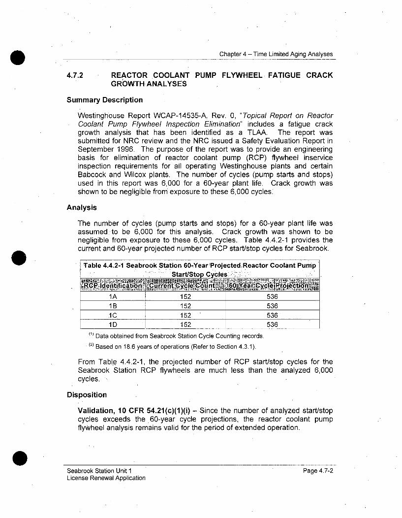
Chapter 4 - Time Limited Aging Analyses
4.7.2 REACTOR COOLANT PUMP FLYWHEEL FATIGUE CRACKGROWTH ANALYSES
Summary Description
Westinghouse Report WCAP-14535-A, Rev. 0, "Topical Report on ReactorCoolant Pump Flywheel Inspection Elimination" includes a fatigue crackgrowth analysis that has been identified as a TLAA. The report wassubmitted for NRC review and the NRC issued a Safety Evaluation Report inSeptember 1996. The purpose of the report was to provide an engineeringbasis for elimination of reactor coolant pump (RCP) flywheel inserviceinspection requirements for all operating Westinghouse plants and certainBabcock and Wilcox plants. The number of cycles (pump starts and stops)used in this report was 6,000 for a 60-year plant life. Crack growth wasshown to be negligible from exposure to these 6,000 cycles.
Analysis
The number of cycles (pump starts and stops) for a 60-year plant life wasassumed to be 6,000 for this analysis. Crack growth was shown to benegligible from exposure to these 6,000 cycles. Table 4.4.2-1 provides thecurrent and 60-year projected number of RCP start/stop cycles for Seabrook.
Table 4.4.2-1 Seabrook Station 60-Year ProjectedReactor Coolant PumpStart/Stop Cycles -
1A 152 5361 B 152 536
J1C 152 5361 D 152 536
(1) Data obtained from Seabrook Station Cycle Counting records.(2) Based on 18.6 years of operations (Refer to Section 4.3.1).
From Table 4.4.2-1, the projected number of RCP start/stop cycles for theSeabrook Station RCP flywheels are much less than the analyzed 6,000cycles.
Disposition
Validation, 10 CFR 54.21(c)(1)(i) - Since the number of analyzed start/stopcycles exceeds the 60-year cycle projections, the reactor coolant pumpflywheel analysis remains valid for the period of extended operation.
Seabrook Station Unit 1 Page 4.7-2License Renewal Application
Chapter 4 - Time Limited Aging Analyses
4.7.3 LEAK-BEFORE-BREAK ANALYSES
Summary Description
Title 10 Part 50 Appendix A, General Design "Criteria for Nuclear PowerPlants" Criterion 4 of the Code of Federal Regulations allows for the use ofleak-before-break (LBB) methodology for excluding the dynamic effects ofpostulated ruptures in reactor coolant system piping. The fundamentalpremise of the LBB methodology is that the materials used in nuclear powerplant piping are sufficiently tough, that even a large through-wall crack wouldremain stable and would not result in a double-ended pipe rupture.Application of the LBB methodology is limited to those high-energy fluidsystems not considered to be overly susceptible to failure from suchmechanisms as corrosion, water hammer, fatigue, thermal aging or indirectlyfrom such causes as missile damage or the failure of nearby components.The analyses involved with LBB are considered TLAAs.
Analysis
A LBB analysis was initially performed for Seabrook Station primary looppiping in 1984. To demonstrate the elimination of RCS primary loop pipebreaks, the following objectives had to be achieved:
" Demonstrate that margin exists between the "critical" crack sizeand a postulated crack that yields a detectable leak rate.
* Demonstrate that there is sufficient margin between the leakage
through a postulated crack and the leak detection capability.
" Demonstrate margin on the applied load.
* Demonstrate that fatigue crack growth is negligible.
The initial analysis was reviewed to demonstrate compliance with LBBtechnology for Seabrook Station. Review of the 40-year LBB analysisconsidered input from the Stretch Power Uprate (2005) and the MechanicalStress Improvement Process (MSIP) application at one of the reactor vesselprimary hot leg nozzle locations (2009). Review for the period of extendedoperation was based on the same set of design transients as the originalanalyses; therefore the conclusions of the original evaluation remain valid forthe 60-year period.
Plant specific geometry, operating parameters, loading, and materialproperties were used in the fracture mechanics evaluation. The mechanicalproperties were determined at operating temperatures. Since the pipingsystems also include cast austenitic stainless steel (CASS) piping
Seabrook Station Unit 1 Page 4.7-3License Renewal Application

Chapter 4 - Time Limited Aging Analyses
components, fracture toughness considering thermal aging was determinedfor each affected component's heat of material for the fully aged condition.
Based on loading, pipe geometry, and fully aged fracture toughnessconsiderations, enveloping governing locations were determined at whichLBB crack stability evalu'ations were made. Through-wall flaw sizes werefound which would cause a leak at a rate of ten (10) times the leakagedetection system capability of the plant. Large margins for such flaw sizeswere demonstrated against flaw instability. Finally, fatigue crack growth wasshown not to be an issue for the reactor coolant system primary loop piping.The thermal transients used in the fatigue crack growth analysis wereSeabrook Station design transients and projected cycles, which are reportedin Table 4.3.1-3. The corresponding 60-year projected cycles, also shown inTable 4.3.1-3 are lower than the 40-year design values. Therefore, thenumbers of design cycles assumed in the analysis bound the numbers ofdesign cycles projected for 60 years of operation.
Disposition:
Validation, 10 CFR 54.21(c)(1)(i) - The analyses remain valid for the periodof extended operation. The LBB review demonstrates that the previous LBBconclusions still remain valid, and the dynamic effects of the pipe ruptureresulting from postulated breaks in the reactor coolant primary loop pipingneed not be considered in the Seabrook Station design basis for the period ofextended operation.
4.7.4 HIGH ENERGY LINE BREAK POSTULATION BASED ON
CUMULATIVE USAGE FACTOR
Summary Description
The Seabrook Station High Energy Line Break (HELB) analysis used ascreening criterion of CUF greater than 0.1 to identify areas of investigation.The Seabrook Station Updated Final Safety Analysis Report (UFSAR)Section 3.6(B).2.1(a) provided a basis to eliminate locations in each pipingrun or branch run from further consideration as high energy line breaklocations on the basis of low fatigue usage, including intermediate locationswhere the cumulative usage factor was less than 0.1. These locations areconsidered TLAAs as the HELB analysis is based on a set of anticipateddesign transients and must be evaluated for the period of extended operation.
Selection of pipe failure locations for evaluation of the consequences onnearby essential systems, components, and structures, except for the reactorcoolant loop, is in accordance with Regulatory Guide 1.46, and NRC BranchTechnical Positions ASB 3-1 and MEB 3-1. A revised stress analysis alsopermitted omission of the surge line intermediate breaks. A leak-before-break
Seabrook Station Unit 1 Page 4.7-4License Renewal Application

Chapter 4 - Time Limited Aging Analyses
(LBB) analysis eliminated large breaks in the main reactor coolant loops. SeeSection 4.7.3.
Analysis
The citation of MEB 3-1 means that break locations in piping with ASMESection III Class 1 fatigue analyses are identified based on cumulative usagefactor (with the stated exception of the reactor coolant system primary loops),and that these determinations are therefore TLAAs.
The surge line intermediate break locations were eliminated based on usagefactor. The most recent piping analysis confirmed the elimination of thesebreak locations. The analysis that justified the elimination of theseintermediate locations in the surge line is therefore a TLAA.
The same would be true of other line sections with no intermediate locationswith fatigue usage factors above -0.1, if this analysis result were used toeliminate intermediate breaks, that is, the determination that there are nointermediate breaks in these sections based on a low usage factor would, forthe same reason, be a TLAA. However, no additional cases similar to thesurge line occur in the Seabrook Station licensing basis.
The scope of these HELB location TLAAs is therefore limited to ASMESection III Class 1 piping connected to the RCS from the RCS primarycoolant loops, to the ASME Class 1/11 piping interface. Since the 60 yearprojected cycles are bounded by the original design cycles, the presentintermediate locations with CUF less than 0.1 remain valid for the period ofextended operation.
Seabrook Station has containment penetration break exclusion regions.However, these break exclusion regions do not contain any ASME Section IIIClass 1 piping with fatigue analyses, and their qualification is therefore basedonly on calculated stress. The break locations in these no break zones aretherefore independent of time and are not supported by a TLAA.
Disposition
Validation, 10 CFR 54.21(c)(1)(i) - The analyses remain valid for the periodof extended operation.
4.7.5 FUEL TRANSFER TUBE BELLOWS DESIGN CYCLES
Summary Description
The fuel transfer tube assembly connects the fuel transfer canal (inside thecontainment structure) to the transfer pool (inside the spent fuel handlingbuilding). The fuel transfer tube assembly passes through the containment
Seabrook Station Unit 1 Page 4.7-5License Renewal Application

Chapter 4 - Time Limited Aging Analyses
wall and through the exterior wall of the spent fuel handling building. The fueltransfer tube assembly is comprised of a 24-inch diameter penetration sleevepenetrating through the containment and spent fuel building walls and three(3) sets of expansion joints (bellows). The penetration sleeve and the threebellows perform a water-retaining intended function, and are within the scopeof license renewal.
The fatigue analysis for each of the three bellows, is based on theconsideration of 20 occurrences of the Operating Basis Earthquake, eachoccurrence having 20 cycles of maximum response therefore, this designanalysis is a TLAA requiring evaluation for the period of extended operation.
Analysis
In order to determine if the design analyses remain valid for 60 years ofoperation, the number of seismic cycles for 60 years has been projected. Asof January 2010, the Seabrook transfer tube bellows will have been exposedto zero (0) Operating Basis Earthquake (OBE) cycles. It is projected that 1OBE would occur for Seabrook in 60 years of operation. Therefore, since thenumber of cycles in 60 years is well below the 20 seismic movement cyclesanalyzed for these bellows, these design analyses remain valid for the periodof extended operation.
Disposition
Validation, 10 CFR 54.21(c)(1)(i) - The analyses remain valid for the periodof extended operation.
4.7.6 CRANE LOAD CYCLE LIMITS
4.7.6.1 POLAR GANTRY CRANE
Summary Description
The design specification for the 420/50-ton Polar Crane in the containmentstructure at Seabrook Station required that the crane conform to the designrequirements of Crane Manufacturers Association -of America (CMAA)Specification 70, "Specifications for Electric Overhead Traveling Cranes".Service requirements specified for the design of this crane correspond to thecyclic loading requirements of CMAA 70, Class A. This evaluation of cyclesover the 40 year life is the basis of a safety determination and is, therefore, aTLAA.
The Polar Crane was designed for up to 100,000 load cycles per criteria ofCMAA Specification 70 for service Class A. This service class covers craneswhich may be used in installations such as power houses, public utilities,turbine rooms, motor rooms and transformer stations where precise handling
Seabrook Station Unit 1 Page 4.7-6License Renewal Application
Chapter 4 - Time Limited Aging Analyses
of equipment at slow speeds with long, idle periods between lifts are required.Capacity loads may be handled for initial installation of equipment and forinfrequent maintenance..
Analysis
The estimated number of lifts for the Polar Crane over the remaining 40 yearsof service (which includes 20 years of Extended Operation) is 19,440 withmost of the lifts being less than 2500 pounds. This rate is based on refuelingoutage use, therefore, the first 20 years of service life for the Polar Cranewould include approximately 10,000 load cycles. Thus, the total service lifeload cycles will be approximately 30,000. Since the total number of lifts is atthe low end of the allowable design value of up to 100,000 cycles, the PolarCrane load cycle fatigue analyses for Seabrook Station remains valid for 60years of plant operation.
Disposition
Validation, 10 CFR 54.21(c)(1)(i) - The analyses remain valid for the periodof extended operation.
4.7.6.2 CASK HANDLING CRANE
Summary Description
The original Seabrook Station Cask Handling Crane was replaced in 2008 bya single failure-proof crane rated for 130 tons (main hoist) and 5 tons (each oftwo auxiliary hoists). To meet single failure criteria, each of these cranes wasdesigned to the requirements of ASME NOG-1-2004, NUREG-0554, andNUREG-0612. The cranes were also designed to Crane ManufacturersAssociation of America (CMAA) Specification 70, "Specifications for ElectricOverhead Traveling Cranes", with an allowable design life cycle range of upto 100,000 cycles. This evaluation of cycles over the projected 40-year life isthe basis of a safety determination and has been identified as a TLAArequiring evaluation for the period of extended operation.
Analysis
Although the new crane became operational in 2008, the bridge structure isoriginal equipment. The period of extended operation expires in 2050,resulting in 60 years of operation. The projected number of lifts for the CaskHandling Crane is less than 500. This estimate is based upon the expectednumber of casks that must be handled during each cask loading campaignand the projected number of campaigns through the period of extendedoperation. Allowing for double that number for minor lifts, or 1000 cycles, theestimated number of lifts for the Cask Handling Crane, 1500 cycles, is muchless than the maximum allowable design value of 100,000 cycles, the Cask
Seabrook Station Unit 1 Page 4.7-7License Renewal Application

Chapter 4 - Time Limited Aging Analyses
Handling Crane load cycle fatigue analyses remain valid for 60 years of plantoperation.
Disposition
Validation, 10 CFR 54.21(c)(1)(i) - The analyses remain valid for the periodof extended operation.
4.7.7 SERVICE LEVEL I COATINGS QUALIFICATION
Summary Description
Service Level 1 coatings used at Seabrook Station are in compliance with theapplicable ANSI standards for coating systems inside containment. In adesign base accident, the Emergency Core Cooling System (ECCS) atSeabrook Station pumps -water from inside the containment sump to thereactor vessel to keep the core covered with water and make up losses fromthe pipe break location. These coatings could potentially detach during adesign basis accident and the coating debris could contribute to flow blockageof ECCS suction strainers. The ECCS has suction piping located below thewaterline inside the sump. Since it is assumed that the degree of radiationexposure used in the original qualification testing was intended -to bound 40years of operation, qualification of Service Level 1 coatings is considered aTLAA.
Analyses
Industry operating history has shown that undesirable degradation,detachment, and other types of failures of coatings have occurred. Detachedcoatings from the substrate-that are transported to Emergency Core CoolingSystem (ECCS) suction strainers could make those systems unable to satisfythe requirement in 10 CFR 50.46(b)(5) to provide long-term cooling.
Significant quantities of coated surfaces inside containment that would beexposed to the post Loss of Coolant Accident environment are listed inUFSAR Table 6.1(B)-2. The coating systems for these surfaces are epoxy-based Keeler & Long coating systems designed for a 40-year life and are incompliance with the applicable ANSI standards for coating systems insidecontainment. The qualification of the coatings to withstand the effects ofradiation and the design basis accident conditions assures these coatings willremain in place and not contribute to clogging of ECCS strainers beyondanalyzed limits.
The coatings used for Service Level 1 applications at Seabrook Station werequalified and applied in accordance with the requirements of the followingdocuments:
Seabrook Station Unit 1 Page 4.7-8License Renewal Application

Chapter 4 - Time Limited Aging Analyses
NRC Regulatory Guide 1.54, "Quality Assurance Requirements forProtective Coatings Applied to Water-Cooled Nuclear Power Plants,"June, 1973
* ANSI N 101.4-1972, "Quality Assurance for Protective Coatings Appliedto Nuclear Facilities"
• ANSI N101.2 - 1972, "Protective Coatings (Paints) for Light WaterNuclear Containment Facilities"
* ANSI N512-1974, "Protective Coatings (Paints) for the Nuclear
Industry"
The maintenance rule, 10 CFR 50.65, "Requirements for Monitoring theEffectiveness of Maintenance at Nuclear Power Plants," includes in its scopesafety-related SSCs that are relied upon to remain functional during andfollowing design basis events with respect to specified functions and non-safety-related SSCs
(1) That are relied upon to mitigate accidents or transients or are used inplant emergency operating procedures,
(2) Whose failure could prevent safety-related SSCs from fulfilling theirsafety-related function, and
(3) Whose failure could cause a reactor scram or an actuation of a safety-related system.
To the extent that protective coatings meet these criteria, they are within thescope of the maintenance rule. The maintenance rule requires that SeabrookStation monitor the effectiveness of maintenance for protective coatingswithin its. scope, (as discrete systems or components or as part of any SSC),or demonstrate that their performance or condition is being effectivelycontrolled through the performance of appropriate preventive maintenance, inaccordance with 10 CFR 50.65(a)(1) or (a)(2), as appropriate.
Disposition
Aging Management - 10 CFR 54.21(c)(1)(iii) - Seabrook Station ServiceLevel I Coatings are managed by the ASME Section XI, [nservice Inspection,Subsection IWE Program, B.2.1.27 and Procedure for Application of ServiceLevel I Coatings. Seabrook Station periodically conducts conditionassessments of Service Level I coatings inside containment.* Coatinginspections are performed at the beginning and at the end of each refuelingoutage. Inspections at the beginning of the refueling outage are performed bya NextEra Energy Coating Supervisor and a Design Engineer for peelingcoatings that have the potential of falling into the reactor or ContainmentBuilding Spray recirculation sumps.
Seabrook Station unit 1 Page 4.7-9License Renewal Application

Chapter 4 - Time Limited Aging Analyses
At the end of the refueling outage, the NextEra Energy Coating Supervisornotifies the design engineer and Nuclear Coating Specialist to perform theContainment Closeout Inspection. The inspection assesses the condition of.the Containment coating. The inspection includes accessible coated areas ofthe Containment and equipment including, but not limited to, the followingitems: concrete and steel surfaces, liner plate wall to concrete floor joint, linerplate wall penetrations, personnel and equipment hatches, and personnel airlocks. As localized areas of degraded coatings are identified, those areasare evaluated and scheduled for repair or replacement, as necessary. Theperiodic condition assessments, and the resulting repair/replacementactivities, assure that the amount of Service Level 1 coatings which may besusceptible to detachment from the substrate during a LOCA event isminimized.
4.7.8 ABSENCE OF A TLAA FOR REACTOR COOLANT PUMP: CODECASE N-481
Summary Description
ASME Boiler and Pressure Vessel Code, Section XI, specifies that avolumetric inspection of the reactor coolant pump casing welds and a visualinspection of pump casing internal surfaces be performed on -a reactorcoolant pump within each 10-year inspection period. These 10-yearvolumetric inspections are significant because the reactor coolant pumpshave already been welded to the piping and the pumps- must bedisassembled in order to gain access to the inside surface of the caststainless steel casings. In recognition of these difficulties, ASME Code CaseN-481, "Alternative Examination Requirements for Cast Austenitic PumpCasings", was developed to allow for the replacement of volumetricexaminations with fracture mechanics, based evaluation and supplementedby specific visual inspections.
Analyses
The Seabrook Station UFSAR Section 5.4.1.4 "Tests and Inspections" states,"The reactor coolant pumps can be inspected in accordance with the ASMECode, Section XI, for in-service inspection of nuclear reactor coolantsystems." The Seabrook Station pump casings are cast in one piece,eliminating welds in the casing. In addition, support feet are cast integral withthe casing to eliminate a weld region.
Conclusion
The Seabrook Station Reactor Coolant Pump (RCP) casings are singlecastings, which contain no welds. Therefore, Code Case N-481, "Alternative,Examination Requirements for Cast Austenitic. Pump Casings", is notapplicable to Seabrook Station RCP.
Seabrook Station Unit 1 Page 4.7-10License Renewal Application

Chapter 4 - Time Limited Aging Analyses
4.7.9 CANOPY SEAL CLAMP ASSEMBLIES
Summary Description
The canopy seal clamp assemblies were designed for a 40 year design life onthe basis of meeting stress limits. The original fatigue analysis consideredthe forces that would be applied to the center head adapter which maximizedthe moments ,on the J-Grove weld and moment along the length of theadapter. The fatigue analysis for the Canopy Seal Clamps is based on theconsideration of 400 cycles consisting of 20 occurrences of the OperatingBasis Earthquake, each occurrence having 20 cycles of maximum response.This design analysis is a TLAA requiring evaluation for the period of extendedoperation.
Analysis
In. order to determine if the design analyses remain valid for 60 years ofoperation, the number of seismic cycles for 60 years has been projected. Asof January 2010, the Seabrook Station Canopy Seal Clamps have beenexposed to zero (0) Operating Basis Earthquake (OBE) cycles. It is projectedthat 1 OBE would occur for Seabrook Station in 60 years of operation.Therefore, since the number of cycles in 60 years is well below the 20 seismicmovement cycles analyzed for these clamps, these design analyses remainvalid for the period of extended operation.
Disposition
Validation, 10 CFR 54.21(c)(1)(i) - The analyses remain valid for the periodof extended operation. The canopy seal clamp assemblies are projected tocontinue to operate within the same stress limits in the extended operatingperiod and will remain acceptable for the period of extended operation.
4.7.10 HYDROGEN ANALYZER
Summary Description
The Seabrook Station Hydrogen Analyzer was evaluated with respect toradiation exposure. The UFSAR contains accumulated radiation dose limitsfor a -40 year operating period. The Hydrogen Analyzer is a safety relatedcomponent. The analysis of the effects of radiation considered the annualaccumulated dosage, and projected these values, to demonstrate that themaximum dose limits specified in the UFSAR will not be exceeded in a 60year operating period.
Seabrook Station Unit 1 Page 4.7-11License Renewal Application
Chapter 4 - Time Limited Aging Analyses
Analysis
The post accident Hydrogen Analyzer must perform a safety functionfollowing a Loss of Coolant Accident (LOCA). Excessive radiation exposurecould jeopardize the ability to perform this safety function. The SeabrookStation UFSAR Table 6.2-84 defines the Hydrogen Analyzer designparameters and maximum radiation dose limits for forty years of normaloperation.
The operational dose for 40 years is 5 x 10⁶ rads.
The projected maximum 40 year exposure comes from three sources; the gasin the analyzers themselves, the gas in .the piping in the room, and the shinefrom the containment atmosphere through the penetrations into the room.
The predicted one year total integrated dose for the Seabrook StationHydrogen Analyzer is comprised as follows:
From the analyzers, 5.8x10 6 rnradsFrom the piping, 0.2x10 6 mradsFrom the penetrations, 1.2x10 6 mrads
Total 7.2x10 6 mrads = 7.2x10 3 rads
Thus, the maximum predicted dose for a 60 year plant operating period is 60-years x 7.2x10 3 rads/year. = 4.32x10 5 rads. This'is an order of magnitudeless than the specified UFSAR radiation dose limit. Therefore, the SeabrookStation Hydrogen Analyzer is shown to be acceptable for the period ofextended operation.
Disposition
Validation, 10 CFR 54.21 (c)(1)(i) - The analysis remains valid for the periodof extended operation.
4.7.11 MECHANICAL EQUIPMENT QUALIFICATION
Summary Description
The Seabrook Station CLB commits to the review and evaluation of theenvironmental qualification of mechanical equipment to demonstratecompliance with General Design Criteria 4 of Appendix A to 10 CFR Part 50.
Results of this evaluation demonstrate safety-related active mechanicalequipment located in harsh environments had been adequately addressed.
Seabrook Station Unit 1 Page 4.7-12License Renewal Application
Chapter 4 - Time Limited Aging Analyses
Since a period of 40 years was used to determine the normal serviceradiation exposure to the equipment, mechanical equipment qualification(MEQ) is considered a TLAA.
Analysis
The design basis event conditions during the period of extended operation willremain the same as those in the current license period, which have beenadjusted to account for previously approved power uprate conditions.Therefore, the design basis event parameters, including the temperature,pressure, and time profiles, do not require further evaluation as TLAAs forlicense renewal.
Disposition
Revision, 10 CFR 54.21(c)(1)(ii) - The effects of aging on the intendedfunction(s) of equipment included under Mechanical Equipment Qualificationwill be adequately addressed for the period of extended operation.Calculations for Mechanical Equipment Qualification will be revised prior toentering the period of extended operation. Revision of MEQ calculations willbe accomplished using techniques currently used under the CLB forequipment qualification including analytical methods, replacement of radiationsensitive materials or equipment replacement.
4.7.12 ABSENCE OF A TLAA FOR METAL CORROSIONALLOWANCESAND CORROSION EFFECTS
Summary Description
Nuclear plant components are commonly designed with corrosion allowances,and TLAAs of corrosion effects for the 40-year design life.
Analysis
A review of the Seabrook Station licensing basis found no description of time-dependent corrosion allowances, rates, or corrosion-dependent design livesof pressure vessels, system components, piping, or metal containmentcomponents.
Conclusion
There are no TLAAs for metal corrosion allowances and corrosion effects.
Seabrook Station Unit 1 Page 4.7-13License Renewal Application

Chapter 4 - Time Limited Aging Analyses
4.7.13 ABSENCE OF A TLAA FOR INSERVICE FLAW GROWTHANALYSES THAT DEMONSTRATE STRUCTURAL STABILITYFOR 40 YEARS
Summary Description
Defects discovered by inservice inspection or component failures may berepaired or replaced to restore the basis of the original design analysis; maybe repaired or replaced to a different configuration, or may be analyzed toconfirm that the as-found condition is acceptable. For ASME componentsthese activities are controlled by Section XI, "Rules for Inservice Inspection ofNuclear Power Plant Components." A flaw analysis of a Class 1 componentusually requires a fatigue crack growth analysis, which is a TLAA if it qualifiesthe component for the plant design life.
Analysis
A thorough review of the Seabrook Station licensing basis, supported byinterviews with plant staff familiar with the history of Class 1 components,found the following fatigue crack growth analyses:
* Fatigue, crack growth and fracture mechanics stability analyses insupport of pressurizer nozzle overlays. The overlays were supportedby fatigue crack growth analyses. These fatigue crack growthanalyses were projected to the end of the period of extendedoperation, and are therefore not TLAAs. See Section 4.3.6.
* Fatigue crack growth assessments and fracture mechanics stabilityanalyses in support of the leak-before-break (LBB) evaluation. Reviewfor the period of extended operation was based on the same set ofdesign transients as the 40-year analyses; therefore the conclusions ofthe original evaluation remain valid for the 60-year period and aretherefore not TLAAs. See Section 4.7.3.
o Fatigue crack growth and fracture mechanics stability analyses ofMechanical Stress Improvement Process (MSIP) repairs to Alloy 600material in reactor coolant hot legs. The MSIP repair was supportedby fatigue crack growth analysis. This fatigue crack growth analysiswas projected to the end of the period of extended operation, and istherefore not a TLAA. See Section 4.3.6.
Conclusion.
These fatigue crack growth analyses are not TLAAs/because they qualify theaffected components for the period of extended operation.
Seabrook Station Unit 1 Page 4.7-14License Renewal Application

Chapter 4 - Time Limited Aging Analyses
4.7.14 DIESEL GENERATOR THERMAL CYCLE EVALUATION
Summary Description
The Emergency Diesel Generators were designed for a 40 year design life onthe basis of 5454 Total Equivalent Full Temperature Cycles.
Analysis
The Emergency Diesel Generators provide Emergency Power to Buses 5 and6. The Emergency Diesel Generators were analyzed for thermal cycling bythe engine manufacturer for Environmental Qualification in accordance withIEEE 323. The manufacturer qualified the Diesel Generator for 5454 FullTemperature Cycles for the forty year design life of the plant. This wouldamount to starting the Diesel once per week since installation to the end ofthe period for extended operation. Under current plant operating practices,the Emergency Diesel Generators are operated only occasionally duringperiodic surveillance and maintenance testing. Monthly testing over 60 yearswould contribute 720 cycles assuming an equal number of starts formaintenance and actual events an additional 1440 cycles could occur. Theseactual and potential cycles combined equal slightly more than 2000 cycles forthe Emergency Diesel Generators. It is, therefore, unlikely that the 5454assumed cycles will be approached during the period of extended operation.Thus, the existing analysis is considered to remain valid for the period ofextended operation, and there is reasonable assurance that the intendedfunction will be maintained.
Disposition
Validation, 10 CFR 54.21(c)(1)(i) - The analyses remain valid for the periodof extended operation.
Seabrook Station Unit,1 Page 4.7-15License Renewal Application
Chapter 4 - Time Limited Aging Analyses
4.8 GENERAL REFERENCES
4-1. NEI 95-10, Revision 6, "Industry Guidance for Implementing theRequirements of 10 CFR Part 54 - The License Renewal Rule,"June 2005.
4-2. NUREG-1800, Revision 1, "Standard Review Plan for Review ofLicense -Renewal Applications for Nuclear Power Plants,"September 2005.
4-3. USNRC Regulatory Guide 1.190, "Calculational and DosimetryMethods for Determining Pressure Vessel Neutron Fluence," March2001.
4-4. USNRC Regulatory Guide 1.99, Revision 2, ""RadiationEmbrittlement of Reactor Materials," May 1988.
4-5. 10 CFR 50.49, Environmental Qualification of Electrical EquipmentImportant to Safety for Nuclear Power Plants, U. S. NuclearRegulatory Commission.
4-6. USNRC_ Regulatory Guide 1.89, Rev. 1, 6/84, EnvironmentalQualification of Certain Electrical Equipment Important to Safety forNuclear Power Plants,
4-7. USNRC Regulatory Guide 1.97, Rev. 0, 3/76, Instrumentation ofLight-Water-Cooled Nuclear Power Plants to Assess Plant andEnvirons Conditions During and Following an Accident.
4-8. USNRC Generic Safety Issue-190, Fatigue Evaluation of MetalComponents for 60-Year Plant Life.
4-9. 10 CFR 50.60, Acceptance Criteria for Fracture PreventionMeasures for Light Water Nuclear Power Reactors for NormalOperation, Code of Federal Regulations, U. S. Nuclear RegulatoryCommission.
4-10. Appendix G, 10 CFR 50, Fracture Toughness Requirements, Codeof Federal Regulations, U. S. Nuclear Regulatory Commission.
4-11. Appendix H, 10 CFR 50, Reactor Vessel Material SurveillanceRequirements, 'Code of Federal Regulations, U. S. NuclearRegulatory Commission.
Seabrook Station Unit 1 Page 4.8-1License Renewal Application
Chapter 4 - Time Limited Aging Analyses
4-12. Section XI, Rules for Inservice Inspection of Nuclear Power PlantComponents, ASME Boiler and Vessel Pressure Code, American'Society of Mechanical Engineers, July 1986.
4-13. 10 CFR 50.61, "Fracture toughness requirements for protectionagainst pressurized, thermal shock events, U. S. NuclearRegulatory Commission.
4-14. USNRC Inspection and Enforcement Bulletin 88-08, "ThermalStresses in Piping Connected to Reactor Cooling Systems," June1988.
4-15. USNRC Inspection and Enforcement Bulletin 88-11, "PressurizerSurge Line Thermal Stratification," December 1988.
4-16. NUREG/CR-6260, "Application of NUREG/CR-5999 Interim FatigueCurves to Selected Nuclear Power Plant Components," March1995.
4-17. NUREG/CR-5704, "Effects of LWR Coolant Environments ofFatigue Design Curves of Austenitic Stainless Steels."
4-18. NUREG/CR-6583, "Effects of LWR Coolant Environments onFatigue Design Curves of Carbon and Low-Alloy Steels."
4-19. NUREG-0554, "Single-Failure-Proof Cranes for Nuclear PowerPlants", May 1979
4-20. NUREG-0612, "Control of Heavy Loads at Nuclear Power Plants",July 1980
4-21. ANSI N45.2, 1971, "Quality Assurance Program Requirements forNuclear Power Plants,"
4-22. USNRC Regulatory Guide 1.54, Quality Assurance Requirementsfor Protective Coatings Applied to Water-Cooled Nuclear PowerPlants, June, 1973
4-23. ANSI N101.4-1972, Quality Assurance for Protective CoatingsApplied to Nuclear Facilities
4-24. ANSI N101.2 - 1972, Protective Coatings (Paints) for Light WaterNuclear Containment Facilities
4-25. ANSI N512-1974, Protective Coatings (Paints) for the NuclearIndustry
Seabrook Station Unit 1 Page 4.8-2License Renewal Application
Chapter 4 - Time Limited Aging Analyses
4-26. WCAP-14535A, "Topical Report on Reactor Coolant PumpFlywheel Inspection Elimination," November 1996.
4-27. Technical Specifications NextEra Energy Seabrook, LLC, Et Ai.*Docket No. 50-443 Seabrook Station, Unit No. 1.
4-28. Seabrook Station -Updated Final Safety Analysis Report, Revision13
4-29. Westinghouse. Report WCAP-14535-A, Rev. 0, "Topical Report onReactor Coolant Pump Flywheel Inspection Elimination
4-30. Westinghouse. Report WCAP-10567, "Technical Bases forEliminating Large Primary Loop- Pipe Rupture as the StructuralDesign Basis for Seabrook Units 1 and 2," June 1984.
4-31. Westinghouse. Report WCAP 14040-NP-A Rev 2 " Methodologyused to Develop Cold Overpressure Mitigating system Setpointsand RCS Heatup and Cooldown Limit Curves" January 1996
4-32. Westinghouse. Report WCAP 15745, Seabrook Unit 1 Heatup andCooldown Limit Curves for Normal Operation, December 2001
4-33. Standard Review Plan; Public Comment Solicited; 3.6.3 Leak-Before-Break Evaluation Procedures; Federal Register/Vol. 52, No.167/Friday, August 28, 1987/Notices, pp. 32626-32633.
4-34. Crane Manufacturers Association of America (CMAA) Specification70. Specifications for Electric Overhead Traveling Cranes, 2004
4-35. North Atlantic Energy Service Company T. C. Feigenbaum(NAESC) to the USNRC Document Control Desk, : Revision toLimiting Reactor Vessel ,Beltline Material January 18, 1999
USNRC, "Potential for Degradation of the Emergency Core CoolingSystem and the Containment Spray System After a Loss-of-CoolantAccident Because of Construction and Protective CoatingDeficiencies and Foreign Material in Containment," Generic Letter98-04, July 14, 1998.2
4-36. Subsection IWE, "Requirements for Class MC and Metallic Linersof Class CC Components of Light-Water Cooled Plants," IWE-1000.
Seabrook Station Unit I Page 4.8-3License Renewal Application

APPENDIX A
UPDATED FINAL SAFETY ANALYSIS REPORTSUPPLEMENT
Appendix A - Final Safety Report Supplement
APPENDIX A - Table of Contents
A.1 INTRODUCTION ....................................... ...... --- A-3A. 1.1 NU REG-1 801 Chapter XI Aging Management Programs ........................................... A-4A.1.2 Plant Specific Aging Management Programs .............................................................. A-5A.1.3 NUREG-1 801 Chapter X Aging Management Programs ....................................... A-5A.1.4 Timne-Limited Aging Analysis Summaries ..................................................................... A-5A.1.5 Quality Assurance Program and Administrative Controls ............................................ A-6
A.2 AGING MANAGEMENT PROGRAMS ......... .......... ................. A-7A.2.1 NUREG-1801 Chapter X1 Aging Management Programs ........................................... A-7A.2.1.1 ASME Section Xl Inservice Inspection, Subsections
IW B , IW C , a n d IW D ..................................................................................................... A -7A .2.1.2 W ater C hem istry .. .......................... ...... ....... ..................... A -7A .2.1.3 R eactor H ead C losure S tuds ....................................................................................... A -7A .2 .1.4 B o ric A cid C o rrosio n ..................................................................................................... A -7A.2.1.5 Nickel-Alloy Penetration Nozzles Welded to the Upper RV
Closure Heads of PWRs ..................... .. A-8A .2 .1 .6 (N o t U s e d ) .................................................................................................................... A -8A .2 .1.7 P W R V esse l Inte rna ls ................................................................................................... A -8A .2.1.8 Flow -A ccelerated C orrosion ......................................................................................... A -9A .2 .1 .9 B o ltin g Inte g rity ....................................................................... ........................... ......... A -9A.2.1.10 Steam Generator Tube Integrity ........................................................................... A-10A.2.1.11 Open-Cycle Cooling Water System ..................................................................... A-1 0A.2.1.12 Closed-Cycle Cooling Water System ................................................................... A-10A.2.1.13 Inspection of Overhead Heavy Load and Light Load
(Related to Refueling) Handling Systems ............................................................ A-11A .2.1.14 Com pressed A ir M onitoring ................................................................................. A -11A.2.1.15 Fire Protection .............................................. A-11A .2.1.16 Fire W ater S ystem ............................................................................................ . . A -11A .2.1.17 A boveground S teel Tank ............................................................................................ A -12A .2 .1.18 F ue l O il C he m istry ...................................................................................................... A -12A .2.1.19 R eactor V essel S urveillance ...................................................................................... A -12A.2.1.20 One-Time Inspection .................. ........................ A-13A.2.1.21 Selective Leaching of Materials ............................................................................ A-1 3A .2.1.22 Buried Piping and Tanks Inspection ........................................................................... A -14A.2.1.23 One-Time Inspection of ASME Code Class 1 Small Bore-Piping ............. ....A-14A .2.1.24 External S urfaces M onitoring ..................................................................................... A -14A.2.1.25 Inspection of Internal Surfaces in Miscellaneous Piping
and Ducting Components ............................................ A-15A .2.1.26 Lubricating O il A nalysis ........................................................................................ A -15A.2.1.27 ASME Section XI, Subsection IWE ...................................................................... A-15A .2.1.28 A SM E Section X I, Subsection IW L ............................................................................ A -16A.2.1.29 ASME Section XI, Subsection IWF ................... A........................................................ A-16A .2 .1.30 10 C F R 50, A ppendix J ........................................ : ..................................................... A -16A .2.1.31 Structures M onitoring P rogram .................................................................................. A -16A.2.1.32 Electrical Cables and Connections Not Subject to
10 C FR 50.49 EQ R equirem ents ............................................................................... A -17A.2.1.33 Electrical Cables and Connections Not Subject to
10 CFR 50.49 EQ Requirements Used in Instrumentation Circuits .......................... A-17A.2.1.34 Inaccessible Medium Voltage Cables Not Subject to
10 CFR 50.49 EQ Requirements ....... : ........................... A-18
Seabrook Station Unit 1 Page A-1License Renewal Application

Appendix A - Final Safety Report Supplement
A .2 .1.35 M eta l E nclosed B us .................................................................................................... A -18A.2.1.36 Fuse Holders .......................................... A-19A.2.1.37 Electrical Cable Connections Not Subject to 10 CFR 50.49
Equipment Qualification Requirements .............................. ....... ....... .............. A-19A.2.2 Plant-Specific Aging Management Programs ............................................................ A-19A.2.2.1 345 kV SF 6 Bus ................................................... A-1 9A .2 .2 .2 B o ra l M o n ito ring .......................................................................................................... A -2 0A.2.2.3 Nickel-Alloy Nozzles and Penetrations ...................................................................... A-20A.2.3 NUREG-1801 Chapter X Aging Management Programs .......................................... A-20A.2.3.1 Metal Fatigue of Reactor Coolant Pressure Boundary .............................................. A-20A.2.3.2 Environmental Qualification (EQ) of Electric Components ................. A-21A.2.4 Time-Limited Aging Analyses ..................................................................................... A-22A.2.4.1 Neutron Embrittlement of the Reactor Vessel ............................................................ A-22A.2.4.1.1 Neutron Fluence Analyses ......................................................................................... A-22A .2 .4 .1.2 U ppe r S he lf A na lyses ................................................................................................. A -22A.2.4.1.3 Pressurized Thermal Shock ....................................................................................... A-23A.2.4.1.4 Reactor Vessel Pressure-Temperature Limits, Including Low
Temperature Overpressure Protection Limits ............................................................ A-23A.2.4.2 Metal Fatigue of Vessels and Piping ...................................... A-24A.2.4.2.1 Nuclear Steam Supply (NSSS) Pressure Vessel and Component
F a tig u e A n a ly s e s ........................................................................................................ A -2 4A.2.4.2.2 Supplementary ASME Section III, Class 1 Piping and Component
F a tig ue A n a ly s e s .......................................................................... ............................. A -2 5A.2.4.2.2.1 NRC Bulletin 88-11, Pressurizer Surge Line Thermal Stratification ......................... A-25A.2.4.2.2.2 Reactor Vessel Internals Aging Management ............................................................ A-26A.2.4.2.3 Environmentally-Assisted Fatigue Analyses .............................................................. A-26A.2.4.2.4 Steam Generator Tube, Loss of Material and Fatigue Usage from
F low -Ind uce d V ib ratio n ............................................................................................... A -2 8A.2.4.2.5 Non-Class 1 Component Fatigue Analyses ............................................................. A-29A.2.4.3 Environmental Qualification (EQ) of Electric Components ....................................... A-30A.2.4.4 Fatigue of the Containment Liner and Penetrations .................................................. A-30A.2.4.5 Other Plant-Specific TLAAs ........................................................................................ A-30A.2.4.5.1 Reactor Coolant Pump Flywheel Crack Growth Analyses ......................................... A-30A.2.4.5.2 Leak-Before-Break Analyses ...................................................................................... A-31A.2.4.5.3 High Energy Line. Break Postulation Based on Cumulative
U s a g e F a c to r .............................................................................................................. A -3 1A.2.4.5.4 Fuel Transfer Tube Bellows Design Cycles ............................................................... A-32A.2.4.5.5 Crane Load Cycle Limits ........................................................................................... A-32A .2 .4 .5 .5 .1 P ola r G a ntry C ra ne ..................................................................................................... A -32A .2 .4 .5.5.2 C ask H andling C rane ................................................................................................. A -33A.2.4.5.6 Service Level I Coatings Qualification ........................................................................ A-33A.2.4.5.7 Canopy Seal ClampAssemblies ................................................................................ A-34A .2 .4 .5 .8 H yd rogen A na lyze r .................................. : .................................................................. A -34A.2.4.5.9 Mechanical Equipment Qualification .......................................................................... A-35A.2.4.5.10 Diesel Generator Thermal Cycle Evaluation .............................................................. A-35
A.3 LICENSE RENEWAL COMMITMENT LIST .............................................................. A-36
Seabrook Station Unit 1 Page A-2License Renewal Application
Appendix A - Final Safety Report Supplement
A.1 INTRODUCTION
The application for a renewed operating license is required by 10 CFR54.21(d) to include a Updated Final Safety Analysis Report (UFSAR)Supplement. This appendix, which includes the following sections, comprisesthe UFSAR supplement:
Section A.1.1
Section A.1.2
Section A.1.3
Section A. 1.4
Section A.1.5
Section A.2.1
Section A.2.2
Section A.2.3
Section A.2.4
Section A.3
contains a listing of the aging management.programs thatcorrespond to NUREG-1801 Chapter XI programs.
contains a listing of the plant-specific aging managementprograms.
contains a listing of aging management programs thatcorrespond to NUREG-1801 Chapter X programsassociated with Time- Limited Aging Analyses.
contains a listing of the Time-Limited Aging Analyses(TLAA).
contains a discussion of the Quality Assurance Programand Administrative Controls.
contains a summarized description of the NUREG-1801Chapter XI programs for managing the effects of aging.
contains a summarized description of the plant-specificprograms for managing the effects of aging.
contains a summarized description of the NUREG-1801Chapter X programs that support the TLAAs.
contains a summarized description of the TLAAsapplicable to the period of extended operation.
contains the License Renewal Commitment List.
The integrated plant assessment for license renewal identified new andexisting aging management programs necessary to provide reasonableassurance that system, structures, and components (SSC) within the scope oflicense renewal will continue to perform their intended functions consistentwith the Current Licensing Basis (CLB) for the period of extended operation.
Seabrook Station Unit 1License Renewal Application
Page A-3
Appendix A - Final Safety Report Supplement
A.1.1 NUREG-1801 CHAPTER XI AGING MANAGEMENT PROGRAMS
The following list of aging management programs correspond to NUREG-1801 Chapter XI programs.
1. ASME Section XI Inservice Inspection, Subsections IWB, IWC, andIWD (A.2.1.1)
2. Water Chemistry (A.2.1.2)
3. Reactor Head Closure Studs (A.2.1.3)
4. Boric Acid Corrosion (A.2.1.4)
5. Nickel-Alloy Penetration Nozzles Welded to the Upper ReactorVessel Closure Heads of Pressurized Water Reactors (A.2.1.5)
6. (Not Used)
7. PWR Vessel Internals (A.2.1.7)
8. Flow-Accelerated Corrosion (A.2.1.8)
9. Bolting Integrity (A.2.1.9)
10. Steam Generator Tube Integrity (A.2.1.10)
11. Open-Cycle Cooling Water System (A.2.1.11)
12: Closed-Cycle Cooling Water System (A.2.1.12)
13. Inspection of Overhead Heavy Load and Light Load (Related toRefueling) Handling Systems (A.2.1.13)
14. Compressed Air Monitoring (A.2.1.14)
15. Fire Protection (A.2.1.15)
16. Fire Water System (A.2.1.16)
17. Aboveground Steel Tanks (A.2.1.17)
18. Fuel Oil Chemistry (A.2.1.18)
19. Reactor Vessel Surveillance (A.2.1.19)
20. One-Time Inspection (A.2.1.20)
21. Selective Leaching of Materials (A.2.1.21)
22. Buried Piping and Tanks Inspection (A.2.1..22)
23. One-Time Inspection of ASME Code Class 1 Small Bore-Piping(A.2.1.23)
24. External Surfaces Monitoring (A.2.1'.24)
25. Inspection of Internal Surfaces in Miscellaneous Piping and DuctingComponents (A.2.1.25)
Seabrook Station Unit 1 Page A-4
License Renewal Application

Appendix A - Final Safety Report Supplement
26. Lubricating Oil Analysis (A.2.1.26)
27. ASME Section XI, Subsection IWE (A.2.1.27)
28. ASME Section XI, Subsection IWL (A.2.1.28)
29. ASME Section XI, Subsection IWF (A.2.1.29)
30. 10 CFR 50, Appendix J (A.2.1.30)
31. Structures Monitoring Program (A.2.1.31)
32. Electrical Cables and Connections Not Subject to 10 CFR 50.49 EQRequirements (A.2.1.32)
33. Electrical Cables and Connections Not Subject to .10 CFR 50.49 EQRequirements Used in Instrumentation Circuits (A.2.1.33)
34. Inaccessible Medium Voltage Cables Not Subject to 10 CFR 50.49EQ Requirements (A.2.1.34)
35. Metal Enclosed Bus (A.2.1.35)
36. Fuse Holders (A.2.1.36)
37. Electrical Cable Connections Not Subject to 10 CFR 50.49 EQRequirements (A.2.1.37)
A.1.2 PLANT SPECIFIC AGING MANAGEMENT PROGRAMS
The plant-specific aging management programs are listed below.
1. 345 KV SF 6 Bus (A.2.2.1)
2. Boral Monitoring (A.2.2.2)
3. Nickel Alloy Nozzles and Penetrations (A.2.2.3.)
A.1.3 NUREG-1 801 CHAPTER X AGING MANAGEMENT PROGRAMS
The following list of aging management programs correspond to NUREG-1801 Chapter X programs associated with Time-Limited Aging Analysis.
1. Metal Fatigue of Reactor Coolant Pressure Boundary (A.2.3.1)]
2. Environmental. Qualification (EQ) of Electrical Components (A.2.3.2)]
A.1.4 TIME-LIMITED AGING ANALYSIS SUMMARIES
Summaries of the Time-Limiting Aging Analyses applicable for the period ofextended operation are listed below.
1. Neutron Embrittlement of the Reactor Vessel (A.2.4. 1)
2. Metal Fatigue of Vessels and Piping (A.2.4.2)
3. Environmental Qualification (EQ) of Electrical Equipment (A.2.4.3)
4. Fatigue of the Containment Liner and Penetrations. (A.2.4.4)
5. Other Plant-Specific TLAAs (A.2.4.5)
Seabrook Station Unit 1License Renewal Application
Page A-5
Appendix A - Final Safety Report'Supplement
A.1.5 QUALITY ASSURANCE PROGRAM AND ADMINISTRATIVECONTROLS
The Quality Assurance Program implements the requirements of 10 CFR 50,Appendix B, and is consistent with the summary in Appendix A.2, "QualityAssurance For Aging Management Programs (Branch Technical PositionIQMB-1)" of NUREG-1800 "Standard Review Plan for Review of LicenseRenewal Applications for Nuclear Power Plants". The Quality AssuranceProgram includes the elements of corrective action, confirmation process, andadministrative controls, and these elements are applicable.-to the safety-relatedand non-safety related systems, structures, and components (SSC) that aresubject to Aging Management Review (AMR).
Seabrook Station Unit 1License Renewal Application
Page A-6
Appendix A - Final Safety Report Supplement
A.2 AGING MANAGEMENT PROGRAMS
A.2.2.1 NUREG-1801 CHAPTER Xl AGING MANAGEMENT PROGRAMS
A.2.1.1 ASME SECTION XI INSERVICE INSPECTION, SUBSECTIONSIWB, IWC, AND IWD
American Society of Mechanical Engineer (ASME) Section XI, SubsectionsIWB, IWC, IWD Inservice Inspection Program facilitates inspections to identifyand correct degradation in Class 1, 2, and 3 piping, components, and integralattachments. The program includes periodic visual, surface and/or volumetricexaminations of all Class 1, 2 and 3 pressure-retaining components, theirsupports and integral attachments (including welds, pump casings, valvebodies and pressure-retaining bolting) and leakage tests of pressure retainingcomponents.
The program is implemented in accordance with the requirements of 10 CFR50.55a, with specified , limitations, .modifications and NRC-approvedalternatives.
A.2.1.2 WATER CHEMISTRY
The Water Chemistry Program includes periodic monitoring and control ofdetrimental contaminants below the levels known to cause cracking, loss ofmaterial, or reduction of heat transfer. The primary scope of this programconsists of the Reactor Coolant system and related auxiliary systemscontaining treated water, reactor coolant, treated borated water and steam.The program is based on Electric Power Research Institute (EPRI) PWRprimary water chemistry guidelines and Pressurized Water Reactor (PWR)secondary water chemistry guidelines.
A.2.1.3 REACTOR HEAD CLOSURE STUDS
The Reactor Head Closure Studs Program conducts inspections of reactorvessel flange stud hole threads, reactor head closure studs, nuts, and washersto manage cracking and loss of material per the requirements of ASME, Boilerand Pressure Vessel Code, Section XI, "Rules for Inservice Inspection ofNuclear Power Plant Components."
A.2.1.4 BORIC ACID CORROSION
The Boric Acid Corrosion Program implements the recommendations ofNuclear Regulatory Commission (NRC) Generic Letter 88-05 "Boric AcidCorrosion of Carbon Steel Reactor Pressure Boundary Components in PWRPlants," and manages aging of structures and components resulting, fromborated water leakage. The program requires periodic visual inspection of allsystems within the scope of license renewal that contain borated water forevidence of leakage, accumulations of dried boric acid, or boric acid damage.The program provides for visual inspections and early discovery of boratedwater leaks such that mechanical, electrical, and structural components thatmay be contacted by leaking borated water will not be adversely affected or
Seabrook Station Unit 1 Page A-7License Renewal Application

Appendix A - Final Safety Report Supplement
their intended functions impaired. The program identifies componentsexhibiting boric acid accumulations or leakage, evaluates the acceptability forcontinued service of components exhibiting boric acid accumulations orleakage, trends and tracks previously identified leaks or boric acidaccumulations and provides corrective actions for the observed leakagesources and any other affected structures and components.
A.2.1.5 NICKEL-ALLOY PENETRATION NOZZLES WELDED TO THEUPPER REACTOR VESSEL CLOSURE HEADS OFPRESSSURIZED WATER
The Nickel-Alloy Penetration Nozzles Welded to the Upper Reactor VesselClosure Heads of Pressurized Water Reactors Program manages the agingeffect of cracking due to primary water stress corrosion cracking of thenickel-alloy used in the fabrication of the upper vessel head penetrationnozzles. The NRC has approved ASME Code Case N-729-1, "ExaminationRequirements for PWR Reactor Vessel Upper Heads with Nozzles HavingPressure-Retaining Partial-Penetration Welds, Section X1, Division" withconditions in accordance with the requirements of 10 CFR 50.55a (g)(6)(ii)(D).Repair, replacement, and mitigation activities are conducted in accordance withthe Seabrook Station ASME Section XI Repair/Replacement program.
A.2.1.6 (NOT USED)
A.2.1.7 PWR VESSEL INTERNALS
The PWR Vessel internals Program manages aging effects in reactor vesselinternals components. It is based on the EPRI-MRP-227, "Pressurized WaterReactor Internals Inspection and Evaluation Guidelines" and the ASME SectionXI Inservice Inspection, Subsections IWB, IWC, and IWD Program.
The aging management approach for PWR vessel internals consists of fourmajor elements:
(1) component categorization and aging management strategydevelopment;
(2) selection of aging management methodologies for PWR vessel internalsthat are both appropriate and based on an adequate level of applicableexperience;
(3) qualification of the recommended methodologies that is based onadequate technical justification; and
(4) implementation of the recommendations based on the Industry Initiativefor the Management of Materials Issues, NEI 03-08 "Guideline for theManagement of Materials Issues".
Seabrook Station Unit 1 Page A-8License Renewal Application
Appendix A - Final Safety Report Supplement
A.2.1.8 FLOW-ACCELERATED CORROSION
The Flow-Accelerated Corrosion (FAC) Program manages aging effects of lossof material due to wall thinning on the internal surfaces of carbon or low alloysteel piping, elbows, reducers, tees, expanders, and valve bodies containinghigh energy fluids (both single phase and two phase flow). The program isbased on the EPRI guidelines in NSAC-202L, "Recommendations for anEffective Flow Accelerated Corrosion Program" and uses the Chexal HorowitzEngineering/ Corrosion Workstation (CHECWORKS) software program as apredictive tool. Included in the FAC program are:
(a) an analysis to determine FAC susceptible lines,
(b) performance of baseline inspections,
(c) follow-up inspections to confirm the predictions
(d) repairing or replacing components, as necessary.
A.2.1.9 BOLTING INTEGRITY
The Bolting Integrity Program manages the aging effects associated withbolting through the performance of periodic inspections for indications ofcracking and loss of material and loss of preload. The program also includesrepair/replacement controls for ASME Section XI related bolting and genericguidance regarding material selection, thread lubrication and assembly ofbolted joints. The program follows the guidelines and recommendationsdelineated in NUREG-1339,"Resolution of Generic Safety Issue 29: BoltingDegradation or Failure in Nuclear Power Plants," EPRI NP-5769,"Degradation and Failure of Bolting in Nuclear Power Plants,".and EPRI TR-104213," Bolted Joint Maintenance & Application Guide" for comprehensivebolting maintenance.
The Bolting Integrity Program credits other aging management programs forthe inspection of bolting. Operator rounds and system walkdowns will alsoidentify joint leakage.
The Bolting Integrity Program credits six separate aging managementprograms for the inspection of bolting.
1. ASME Section XI, Inservice Inspection, Subsections IWB, IWC, and IWDprovides the requirements for inservice inspection of ASME Class 1, 2, and3 piping, which includes pressure retaining bolting.
2. ASME Section XI, Subsection IWE Program, includes steel containmentshells and their integral attachments.
3. ASME Section XI, Subsection IWF Program, provides the requirements forinservice inspection of ASME Class 1, 2, and 3 component supports.
4. Buried Piping and Tanks Program, provides the requirements for theperiodic visual inspections of corrosion on buried piping and tanks, includingbolting.
Seabrook Station Unit 1 Page A-9License Renewal Application
Appendix A - Final Safety Report Supplement
5. External Surfaces Monitoring Program provides the requirements for theinspection of bolting for steel components such as piping, pipingcomponents, ducting and other components within. the scope of licenserenewal.
6. Structures Monitoring Program provides the requirements for the inspectionof structural support bolting.
A.2.1.10 STEAM GENERATOR TUBE INTEGRITY
The Steam Generator Tube Integrity Program manages the aging effects ofcracking, loss of material, reduction of heat transfer and wall thinning fromflow accelerated corrosion of the Steam Generator components. The programis based on NEI 97-06 Rev. 2,, "Steam Generator Program Guidelines", theresponse and commitment to Generic Letter 97-06, "Steam GeneratorProgram Guidelines", and Seabrook Station Technical Specification 3/4.4.5"Steam Generators" which ensure that the performance criteria for structuralintegrity, accident-induced leakage, and operational leakage are notexceeded. Seabrook Station has implemented the operational leakage limitsfound in NUREG-1431, "Standard Technical Specifications for WestinghousePressurized Water Reactors".
A.2.1.11 OPEN-CYCLE COOLING WATER SYSTEM
The Open-Cycle Cooling Water System Program manages the aging effects ofhardening and loss of strength, loss of material, and reduction of heat transfer.This program relies on the implementation of the recommendations of NRCGeneric Letter 89-13,"Service Water System Problems Affecting Safety-Related Equipmenf'. The program manages aging effects for components inthe circulating water, primary component cooling water, service water, anddiesel generator systems.
A.2.1.12 CLOSED-CYCLE COOLING WATER SYSTEM
The Closed-Cycle Cooling Water Program manages aging effects of cracking,loss of material and reduction of heat transfer in closed cycle cooling watersystems. Closed-Cycle Cooling Water (CCCW) systems are described assystems not subject to significant sources of contamination, in which waterchemistry is controlled and in which heat is not directly rejected to the ultimateheat sink. The program scope includes activities to manage aging in thePrimary Component Cooling Water system and Emergency Diesel GeneratorJacket Water cooling systems. The program also includes fire pump dieselengine glycol coolant system, the Control Building Air Handling glycol coolantsystem (safety-related), and the Thermal Barrier Cooling Water system.
The program includes maintenance of system corrosion inhibitorconcentrations to minimize degradation and inspections of opportunity toassess management of component aging. The program is based on the EPRI"Closed Cycle Cooling Water Chemistry Guidelines".
Seabrook Station Unit 1 Page A-10License Renewal Application
Appendix A - Final Safety Report Supplement
A.2.1.13 INSPECTION OF OVERHEAD HEAVY LOAD AND LIGHT LOAD(RELATED TO REFUELING) HANDLING SYSTEMS
The Inspection of Overhead Heavy Load and Light Load (Related to Refueling)Handling Systems Program manages loss of material of structural componentsand wear on the rails of lifting systems within the scope of license renewal.
The program employs the use of visual inspections to identify aging effectsprior to loss of function. Preventive actions are not associated 'with theseactivities.
Only the structural portions of the in-scope cranes and monorails are in thescope of this program.
A.2.1.14 COMPRESSED AIR MONITORING
The Compressed Air Monitoring Program manages aging effects of hardeningand loss of strength, loss of material, and reduction of heat transfer andassures an oil free, dry air environment in the plant compressed air system,Diesel Generator compressed air subsystem and containment compressedair system components.
Seabrook Station committed to maintain instrument air quality in accordancewith the Quality Standard for Instrument Air, ISA-$7.3; "Quality Standard forInstrument Air". Compliance with ISA-$7.3 is verified by continuousmonitoring or periodic testing. In-line dew point monitors are used to verifythat the dew point of instrument air at the outlet of the instrument air systemdryers is at or below a calculated limit. In-line filters are installed which limitair system maximum entrained particle size. These in-line filters meet orexceed the requirements of the quality standard. Periodic replacement offilters is part of the preventative maintenance program for instrument airsystems. Air samples are obtained at least annually and tested for to ensurecompliance with air quality standards.
A.2.1.15 FIRE PROTECTION
The Fire Protection Program manages aging effects to the fire protection andsuppression components through detailed inspections. Age-relateddegradation of the diesel-driven fire pump's fuel oil supply-line is managedthrough regularly scheduled fire pump performance tests.
The Fire Protection Program includes but is not limited to inspections of firebarrier penetration seals, fire barrier walls, ceilings, floors, fire doors andtesting to prove functionality of the diesel driven fire pump fuel oil supply line.
A.2.1.16 FIRE WATER SYSTEM
The Fire Water System Program manages the aging effects of loss of materialand reduction of heat transfer due to fouling of the Fire Water Systemcomponents through detailed inspections via the Seabrook Station SurveillanceTest Procedures.
Seabrook Station Unit 1 Page A-11License Renewal Application

Appendix A - Final Safety Report Supplement
The Fire Water System Program is established in accordance with theapplicable National Fire Protection Association (NFPA) codes and standards.
The chemistry program provides methods and directions for adding variouschemicals to various plant systems including the Fire. Water Tanks. Thesechemicals prevent microbiological growth, inhibit scale formation, dispensesolids contained in water, improve chlorination efficiency and maintain pHlevel to prevent corrosion of piping and components.
A.2.1.17 ABOVEGRO'UND STEEL TANKS
The Aboveground Steel Tanks Program manages aging effects throughpreventive measures to mitigate corrosion and through periodic inspections tomanage any effects of corrosion on aboveground steel tanks within the scopeof License Renewal.
The program utilizes the application of protective coatings on the exteriorsurfaces of the in-scope steel tanks to mitigate corrosion development due toenvironmental factors. To ensure that the exterior surfaces of the tanks remainprotected, the protective coatings are visually inspected.
Inaccessible locations, such as the tank bottom, will be surveyed by ultrasonicthickness measurements from inside the tank. to detect any materialdegradation" The ultrasonic thickness measurements of fuel oil tanks withinthe scope of this program will be performed in accordance with the Fuel OilChemistry Program.
A.2.1.18 ` FUEL OIL CHEMISTRY
The Fuel Oil Chemistry Program manages loss of material in the diesel fueloil systems for the emergency diesel generators, diesel driven fire waterpumps and the Auxiliary Boiler fuel oil system through monitoring andmaintenance of diesel fuel oil quality.
New fuel oil is sampled and verified to meet the requirements of applicableAmerican Society for Testing and Materials (ASTM) standards prior tooffloading to the storage tanks. The program monitors fuel oil quality and thelevels of water in the fuel oil which may cause the loss of material of the tankinternal surfaces. The program monitors water and sediment contaminationin diesel fuel.
Fuel Oil storage tanks are periodically drained and inspected. This inspectionincludes ultrasonic thickness measurements of the tank bottom surface toensure that significant degradation has not occurred.
A.2.1.19 REACTOR VESSEL SURVEILLANCE.
The Reactor Vessel Surveillance Program manages the aging effect of loss offracture toughness due to neutron embrittlement of the low alloy steel ReactorVessel. The extent of reactor vessel embrittlement for upper-shelf energy andpressure temperature limits for 60 years is projected in accordance with the
Seabrook Station Unit 1 Page A-12License Renewal Application

Appendix A - Final Safety Report Supplement
NRC Regulatory Guide 1.99, "Radiation Embrittlement of Reactor VesselMaterials". The program utilizes the methodology of projecting neutronembrittlement using surveillance data. Monitoring methods are in accordancewith 10 CFR 50, Appendix H "Reactor Vessel Material SurveillanceRequirements". Testing methods are in accordance with ASTM E 185-82"Radiation Embrittlement of Reactor Vessel Materials".
A.2.1.20 ONE-TIME INSPECTION
The One-Time Inspection Program addresses potentially long incubationperiods for certain aging effects and provides a means of verifying that anaging effect is either not occurring or is progressing so slowly as to havenegligible effect on the intended function of the structure or components. TheOne-Time Inspection Program provides measures for verifying that an agingmanagement program is not needed, for verifying the effectiveness of anexisting program, or for determining that degradation is occurring which willrequire evaluation and corrective action.
The One-Time Inspection Program includes determination of appropriateinspection sample size, identification of inspection locations, selection ofexamination technique, specification of acceptance criteria, and evaluation ofresults to determine the need for additional inspections or other correctiveactions. The inspection sample includes locations where the most severe agingeffect(s) would be expected to occur. Inspection methods may include visual(or remote visual), surface or volumetric examinations, or other establishedNDE techniques.
This Program:
* Verifies the effectiveness of the Plant Chemistry Program for managingthe effects of aging in portions of piping and components exposed to atreated water environment.
* Verifies the effectiveness of the Fuel Oil Chemistry Program formanaging the effects of aging of piping and components in systems thatcontain fuel oil.
• Verifies the effectiveness of the Lubricating Oil Analysis Program formanaging the effects of aging of piping and components in systems thatcontain lube oil.
A.2.1.21 SELECTIVE LEACHING OF MATERIALS
The Selective Leaching of Materials Program manages the aging effects of lossof material in components susceptible to selective leaching that are exposed toraw water, brackish water, treated water (including closed cycle cooling), orgroundwater environment.
The Selective Leaching of Materials Program will include a one-timeexamination of selected components that may be susceptible to selectiveleaching. Visual inspection and mechanical examination techniques (Brinell
Seabrook Station Unit 1 Page A-13License Renewal Application
Appendix A - Final Safety Report Supplement
hardness testing or other mechanical examination techniques such asdestructive testing (when appropriate), scraping, chipping or other types ofhardness testing), or additional examination methods that become available tothe nuclear industry, will be used to determine if selective leaching is occurringon the surfaces of a selected set of components.
A.2.1.22 BURIED PIPING AND TANKS INSPECTION
The Buried Piping and Tanks Inspection Program manages loss of materialfrom the external surfaces of buried steel (including cast iron) and stainlesssteel components. The plant has no buried-steel tanks in scope for licenserenewal. The program includes preventive measures to mitigate corrosion andperiodic inspections that manage the aging effects of corrosion on thepressure-retaining capacity of buried piping in the scope for license renewal.
The program includes provisions for visual inspections of the protective wrapsand coatings on buried steel and stainless steel piping when the pipes areexposed during maintenance. If damage to the protective wraps or coatings isfound, the outer surface of the pipe is inspected for loss of material due togeneral, pitting, crevice or microbiologically-influenced corrosion.
This program requires that at least one opportunistic or focused inspection beperformed within the ten year period prior to entering the period of extendedoperation. Upon entering the period of extended operation a plannedinspection will be performed within ten years, unless an opportunisticinspection has occurred within that ten year period.
A.2.1.23 ONE-TIME INSPECTION OF ASME CODE CLASS I SMALLBORE-PIPING
The One-Time Inspection of ASME Code Class 1 Small Bore Piping Programapplies to small-bore ASME Code Class 1 piping less than 4 inches nominalpipe size (NPS), including pipe, fittings, and branch connections. While theASME Boiler and Pressure Vessel Code, Section XI, "Rules for lnserviceInspection of Nuclear Power Plant Components", does not require volumetricexamination of Class 1 small-bore piping, the Seabrook Station One-TimeInspection of ASME Code Class 1 Small Bore Piping Program will be used toidentify cracking by performing volumetric examinations of selected piping.
The inspection sample determination will include both socket welds and buttwelds. If non-destructive volumetric inspection techniques have not beenqualified, Seabrook will have the option to remove the weld for destructiveexamination.
A.2.1.24 EXTERNAL SURFACES MONITORING
The External Surfaces Monitoring Program manages aging effects throughvisual inspection of external surfaces for evidence of hardening and loss ofstrength, reduction of heat transfer and loss of material (galvanic, general,crevice and pitting corrosion, and wear). This program consists of periodic
Seabrook Station Unit 1 Page A-14License Renewal Application
Appendix A - Final Safety Report Supplement
inspections of aluminum, Cast. Austenitic Stainless Steel (CASS), copper alloy,copper alloy >15% zinc, elastomer, galvanized steel, gray cast iron, nickelalloy, stainless steel and steel components such as piping, piping components,ducting, pipe supports and other components to manage aging effects.
The External Surfaces Monitoring Program utilizes periodic plant systeminspections and walkdowns to monitor for materials degradation -and leakage.This program inspects components such as piping, piping components, ductingand other components, including bolting. Coatings deterioration is monitoredas an indication of possible underlying degradation..
A.2.1.25 INSPECTION OF INTERNAL SURFACES IN MISCELLANEOUSPIPING AND DUCTING COMPONENTS
The Inspection of Internal Surfaces in Miscellaneous Piping and DuctingComponents Program manages the aging effects of cracking, loss of material,fouling, reduction of heat transfer and hardening and loss of strength. Thisprogram consists of inspections of the internal surfaces of aluminum, CASS,copper alloy, copper alloy >15% zinc, elastomer, galvanized steel, gray castiron, nickel alloy, stainless steel, and steel piping, piping components, ductingand other components that are not covered by other aging managementprograms.
The program inspections are inspections of opportunity, performed during pre-planned periodic system and component surveillances or during maintenanceactivities when the systems are opened and the surfaces made accessible forvisual inspection. This maintenance may occur during power operations orrefueling outages when many systems are opened. The visual inspectionsassure that existing environmental conditions are not causing materialdegradation that could result in a loss of the component intended function.
A.2.1.26 LUBRICATING OIL ANALYSIS
The Lubricating Oil Analysis Program obtains and analyzes lubricating oilsamples from plant equipment to ensure that the oil quality is maintainedwithin established limits. The program provides an early indication of adverseequipment condition in lubricating oil environments.
The Seabrook Station Lubricating Oil Analysis Program includes samplingand analysis of lubricating oil for components within the scope of licenserenewal 'and subject to aging management review, that are -exposed tolubricating oil and for which pressure boundary integrity or heat transfer isrequired for the component to perform its intended function.
A.2.1.27 ASME SECTION XI, SUBSECTION IWE
The ASME Section Xl, Subsection IWE Program manages aging effects to thecontainment liner, electrical penetrations, mechanical penetrations (piping,ventilation, and spares), personnel lock, equipment hatch, recirculation sump,reactor pit, moisture barriers, seals, gaskets, and supports.
Seabrook Station Unit 1 Page A-15License Renewal Application
Appendix A - Final Safety Report Supplement
The program performs inspections using the same primary Inservice Inspectionmethod as specified in ASME Section XI, Subsection IWE "Requirements forClass MC and Metallic Liners of Class CC Components of Light-Water CooledPower Plants "; visual examination (general visual, VT-3, VT-1).
A.2.1.28 ASME SECTION XI, SUBSECTION IWL
The ASME. -Section XI, Subsection IWL, Inservice Inspection Programmanages aging effects to the steel reinforced concrete for the containmentbuilding and complies with the requirement of examination requirements of 10CFR 50.55a in accordance with ASME Boiler and Pressure Vessel Code,Section XI, Subsection IWL "Requirements for Class CC ConcreteComponents of Light-Water Cooled Power Plants".
The primary inspection methods used are VT-1C visual examination, VT-3Cvisual examination and alternative examination methods. (in accordance withIWA-2240). All accessible containment reinforced concrete components arewithin the scope of this program.
A.2.1.29 ASME SECTION XI, SUBSECTION IWF
The ASME Section XI, Subsection IWF "Requirements for Class 1,2,3, andMC Component Supports of Light-Water Cooled Power Plants," Inserviceinspection Program (ISI) provides inspections of Class 1, 2, and 3Component Supports. For supports other than piping supports, the supportsof only one component of a group having similar design, function, and servicemust be examined. Supports of piping and other items exempted fromvolumetric or surface examination are also exempt.
The program uses VT-3 visual examination for detection of degradation. Theperformance requirements for VT-3 examination are conducted to determinethe general mechanical and structural condition of components and theirsupports.
A.2.1.30 10 CFR 50, APPENDIX J
The 10 CFR Part 50, Appendix J Program implements Title 10 Code of FederalRegulations Part '50 Appendix J, "Primary Reactor Containment LeakageTesting for Water-Cooled Power Reactors" Option B. The test requirements ofAppendix J provide for periodic verification by tests of the leak-tight integrity ofthe primary reactor containment. The purposes of the tests are to assure that1) leakage through the containment or systems and components penetratingthe containment does not exceed the allowable leakage rate specified in theTechnical Specifications and Updated Final Safety Analysis Report, and 2)integrity of the containment structure is maintained during its service life.
A.2.1.31 STRUCTURES MONITORING PROGRAM
The Structures Monitoring Program includes the Masonry Wall Program andthe Inspection of Water Control Structures Associated with Nuclear PowerPlants Program.
Seabrook Station Unit 1 Page A-16License Renewal Application
Appendix A - Final Safety Report Supplement
The Structures Monitoring Program is implemented through the plantMaintenance Rule Program, which is based on the guidance provided in NRCRegulatory Guide 1.160 "Monitoring the Effectiveness of Maintenance atNuclear power Plants" and NUMARC 93-01 "Industry Guideline for Monitoringthe Effectiveness of Maintenance at Nuclear Power Plants". The StructuresMonitoring Program was developed using the guidance of these twodocuments. The Program is implemented to, monitor the condition of structuresand structural components within the scope of the Maintenance Rule, such thatthere is no loss of structure or structural component intended function.
A.2.1.32 ELECTRICAL CABLES AND CONNECTIONS NOT SUBJECT TO10 CFR 50.49 EQ REQUIREMENTS
The Electrical Cables and Connections Not Subject to 10 CFR 50.49Environmental Qualification Requirements Program manages the aging ofaccessible non-EQ cables and connections. Accessible cables andconnections located in adverse localized environments shall be visuallyinspected for indications of accelerated insulation aging such asembrittlement, discoloration, cracking, swelling, or surface contamination. Anadverse localized environment is a condition in a limited plant area that issignificantly more severe than the specified service environment for the cableor connection. Accessible cables and connections shall be inspected prior toentering the period of extended operation, and at least once every 10 yearsthereafter.
A.2.1.33 ELECTRICAL CABLES AND CONNECTIONS NOT SUBJECT TO10 CFR 50.49 EQ REQUIREMENTS USED ININSTRUMENTATION CIRCUITS
The Electrical Cables and Connections Not Subject to 10 CFR 50.49Environmental Qualification Requirements Used in Instrumentation CircuitsProgram manages the aging of in-scope cables and connections. Theprogram applies to sensitive instrumentation cable and connection circuitswith low-level signals that are in scope for license renewal and are located inareas where the cables and connections could be exposed to adverselocalized environments caused by heat, radiation, or moisture. These adverselocalized environments can result in reduced insulation resistance causingincreases in leakage currents.
The program shall perform insulation resistance tests on the in-core neutronflux monitoring cable and connections in the Nuclear Instrumentation System.
The frequency of the tests on these cables shall be based on engineeringevaluation, but the test frequency shall be at least once every ten years. Thefirst test shall be performed prior to entering the period of extended operation.
Seabrook Station Unit 1 Page A-17License Renewal Application
Appendix A - Final Safety Report Supplement
A.2.1.34 INACCESSIBLE MEDIUM VOLTAGE CABLES NOT SUBJECTTO 10 CFR 50.49 EQ REQUIREMENTS
The Inaccessible Medium-Voltage Cables Not Subject to 10 CFR 50.49Environmental Qualification Requirements Program manages the aging ofinaccessible medium Ivoltage cables exposed to adverse localizedenvironments caused by significant moisture while energized.
The program includes the following two components:
* Periodic Inspections Of Manholes Containing In-Scope MediumVoltage Cables.
In-scope manholes shall be periodically inspected for water collection.-Water found in the manholes shall be drained.
The frequency of manhole inspections shall be adjusted based oninspection results. However, the maximum time between inspections shallbe no more than two years. The first inspections shall be performed prior toentering the period of extended operation.
* Testing Of In-Scope Inaccessible Medium Voltage Cables
The specific type of test performed shall be determined prior to the initialtest, and shall be a proven test for detecting deterioration of the insulationsystem due to wetting, such as power factor, partial discharge, orpolarization index, as described in EPRI guidelines for "Effects of Moistureon the Life of Power Plant Cables" or other testing that is state-of-the-art atthe time the test is performed. Cable testing shall be performed prior toentering the period of extended operation and at least once every 10 yearsthereafter.
A.2.1.35 METAL ENCLOSED BUS
The Metal Enclosed Bus Program manages the aging of in-scope metalenclosed buses. The internal portions of the in-scope metal enclosed busenclosures are inspected for cracks, corrosion, foreign debris, excessive dustbuildup and evidence of moisture intrusion. The bus insulation is visuallyinspected for signs of embrittlement, cracking, melting, swelling, ordiscoloration, which may indicate overheating or aging degradation. Theinternal bus supports are visually inspected for structural integrity and signs ofcracks. Accessible bolted bus connections are checked for looseness usingthermography from outside the metal enclosed bus.
The inspections and tests shall be performed prior to entering the period ofextended operation and at least once every 10 years thereafter.
Aging management of the Metal Enclosed Bus enclosures and. elastomers isincluded in the Structures Monitoring Program.
Seabrook Station Unit 1 Page A-18License Renewal Application
Appendix A - Final Safety Report Supplement
A.2.1.36 FUSE HOLDERS
The Fuse Holders Program manages the aging of in-scope metallic clamps'of fuse holders.
The Fuse Holders Program performs tests on in-scope fuse holders (metallicclamps). The type of test is a proven test, such as thermography or contactresistance which detects thermal fatigue in the form of high resistancecaused by corrosion or oxidation. The type of test performed is determinedprior to the initial test. The first test shall be performed prior to entering theperiod of extended operation and at least once every 10 years thereafter.
A.2.1.37 ELECTRICAL CABLE CONNECTIONS NOT SUBJECT TO 10CFR 50.49 EQ REQUIREMENTS
The Electrical Cable Connections Not Subject to 10 CFR 50.49Environmental Qualification Requirements Program is a one-time testingprogram that shall be used to verify the absence of aging effects on themetallic portion of electrical cable connections. The aging effect andmechanism of concern is the loosening of bolted connections due to thermalcycling, ohmic heating, electrical transients, vibration, chemicalcontamination, corrosion, and oxidation.
The scope of this sampling program considers application (medium and lowvoltage), circuit loading (high loading), and location (high temperature, highhumidity, vibration, etc).
The specific type of test performed is a proven test for detecting looseconnections, such as thermography or contact resistance measurement, asappropriate for the application.
The one-time test shall be performed prior to entering the period of extendedoperation.
A.2.2 PLANT-SPECIFIC AGING MANAGEMENT PROGRAMS
A.2.2.1 345 kV SF6 BUS
The 345kV SF6 Bus Program manages the aging that could lead to loss ofpressure boundary due to elastomer degradation, loss of material due tocorrosion and loss of function due to unacceptable air, moisture or SO2 levels.Sulfur Hexafluoride (SF6) is an inert gas which is used to insulate the busconductor.
The program inspects for corrosion on the exterior of the bus duct housing,tests for leaks and tests gas samples to determine air, moisture and SO 2 levels.
The presence of air or moisture may lead to the loss of intended function. SO2levels are an indication of partial discharge internal to the bus.
The tests and inspections shall be performed prior to entering the period ofextended of operation and at least once every six months thereafter.
Seabrook Station Unit 1 Page A-19License Renewal Application

Appendix A - Final Safety Report Supplement
A.2.2.2 BORAL MONITORING
The Boral Monitoring Program assures the Boral neutron absorbers in thespent fuel racks maintain the validity of the criticality analysis in support of therack design. The program relies on representative coupon samples mountedina coupon "train" located in the spent fuel pool to monitor performance of theabsorber material without disrupting the integrity of the storage system.Coupon samples are removed from the spent fuel pool on a prescribedschedule and physical, chemical and neutronic absorptive properties aremeasured. From these data, the physical condition and neutron-absorbingcapacity of the Boral in the storage cells are assessed.
A.2.2.3 NICKEL-ALLOY NOZZLES AND PENETRATIONS
The Nickel-Alloy Nozzles and Penetrations Program manages the aging effectof cracking due to primary water stress corrosion cracking (PWSCC) of nickel-alloy pressure boundary and structural components exposed to primarycoolant.
The Nickel-Alloy Nozzles and Penetrations Program ranked the Alloy600/82/182 locations based on four main criteria: PWSCC susceptibility (e.g.,operational time and temperature), failure consequence, leakage detectionmargin, and radiation dose rates. Additionally, material heat susceptibility andother industry experience were considered.
The program incorporates the inspection schedules and frequencies for thenickel-alloy components in accordance with the plant ASME Section XIInservice Inspection, Subsections IWB, IWC, and IWD Program and, whereapplicable, ASME Code Case N-722 "Additional Examinations for PWR[pressurized water reactor (PWR)] Pressure Retaining Welds in Class 1Components Fabricated with Alloy 600/82/182 Materials, Section X1, Division1," subject to the conditions specified in 10 CFR 50.55a(g)(6)(ii)(E).
The program complies with applicable NRC Orders, and implements applicableNRC Bulletins, Generic Letters, and staff-accepted industry guidelines.
A.2.3 NUREG-1801 CHAPTER X AGING MANAGEMENT PROGRAMS
A.2.3.1 METAL FATIGUE OF REACTOR COOLANT PRESSUREBOUNDARY
The. Metal Fatigue of Reactor Pressure Boundary Program is a preventiveprogram that monitors and tracks the number of critical thermal and pressuretransients to verify that the Cumulative Usage Fatigue (CUF) for reactor coolantsystem components remain less than 1.0 through the period of extendedoperation. The program determines the number of transients that occur andupdates 60-year projections on a periodic basis.
The program is credited with monitoring reactor coolant system designtransients. Cumulative Usage Fatigue of the Reactor Vessel, the pressurizer,
Seabrook Station Unit 1 Page A-20License Renewal Application
Appendix A - Final Safety Report Supplement
the Steam Generators, Class 1 and non-Class 1 piping, and Class 1components subject to the reactor coolant, treated borated water, and treatedwater environments. The program will use fatigue monitoring. software tomonitor the number of cycles a system or components endure. Pre-established limits will identify components approaching design limits.Componentsapproaching design limits will be reanalyzed, repaired, replacedor inspected in accordance with applicable design codes.
A.2.3.2 ENVIRONMENTAL QUALIFICATION (EQ) OF ELECTRICCOMPONENTS
The 'Environmental Qualification (EQ) of Electric Components Programprovides a summary of the components that are managed for EQ aging. Theprogram meets the requirements of 10 CFR 50.49 for the applicable electricalcomponents important to safety. 10 CFR 50.49 defines the scope- ofcomponents to be included, requires the preparation and maintenance of a listof in-scope components, and requires the preparation and maintenance of aqualification file that includes component performance specifications, electricalcharacteristics and the environmental conditions to which the componentscould be subjected. 10 CFR 50.49(e)(5) contains provisions for aging thatrequire, in part, consideration of all significant types of aging degradation thatcan affect component functional capability. 10 CFR 50.49(e)(5) also requiresreplacement or refurbishment of components not qualified for the currentlicense term prior to the end of designated life, unless additional life isestablished through ongoing qualification. Supplemental EQ regulatoryguidance for compliance with these different qualification criteria is provided inNUREG-0588, "Interim Staff Position on Environmental Qualification of Safety-Related Electrical Equipment," July 1981, and RG 1.89, Rev. 1, "EnvironmentalQualification of Certain Electric Equipment Important to Safety for NuclearPower Plants, June 1984". Seabrook Station conforms to NUREG-0588Category 1 requirements.
Seabrook Station's compliance with 10 CFR 50.49 ensures that the componentcan perform its intended functions during accident conditions after experiencingthe effects of in-service aging. The EQ Program manages component thermal,radiation and cyclical aging, as applicable, through the use of aging evaluationsbased on 10 CFR 50.49(f) qualification methods. As required by 10 CFR50.49, EQ components not qualified for the current licenseterm are to berefurbished, replaced, or have their qualification extended prior to reaching theaging limits established in the evaluation. Aging evaluations for electricalcomponents in the EQ Program that specify a qualification of at least 40 yearsare TLAAs for license renewal because the criteria contained in 10 CFR 54.3are met.
Important attributes for the reanalysis of an aging evaluation include, analyticalmethods, data collection and reduction methods, underlying assumptions,acceptance criteria, and corrective actions (if acceptance criteria are not met).
Seabrook Station Unit 1 Page A-21License Renewal Application
Appendix A - Final Safety Report Supplement
TLAA disposition option 10 CFR 54.2(c)(1)(iii), which states that the effects ofaging will be adequately managed for the period of extended operation, ischosen and the EQ Program will manage the aging effects of the components.
A.2.4 TIME-LIMITED AGING ANALYSES
A.2.4.1 NEUTRON EMBRITTLEMENT OF THE REACTOR VESSEL
The current license period reactor vessel embrittlement analyses that evaluatereduction of fracture toughness of the Seabrook Station reactor vessel beltlinematerials are based on a 40-year End-of-Life (EOL) fluence values. Theanalyses associated with neutroh embrittlement of reactor vessel materials dueto neutron irradiation are Time-Limited Aging Analyses (TLAAs) as defined by10 CFR 54.21(c) and must be evaluated for the increased neutron fluenceassociated with 60 years of operation.
The following Seabrook Station analyses are TLAAs that address the effects ofneutron irradiation on the reactor vessel.
a Neutron Fluence
* Upper-Shelf Energy (USE)
* Pressurized Thermal Shock
* Pressure-Temperature (P-T) Limits
A.2.4.1.1 Neutron Fluence Analyses
The neutron fluence analysis is a TLAA as defined by 10 CFR 54.21(c) andmust be evaluated for the increased neutron fluence associated with 60 yearsof operation. These neutron fluence projections are used as input to theanalyses for fracture toughness, or Upper Shelf Energy (USE), PressurizedThermal Shock (PTS) limits, Reverence Temperatures - Nil Ductility Transition(RTNDT), Adjusted Reference Temperatures (ART), Low-TemperatureOverpressure Protection (LTOP) limits, and 'Reactor Vessel Pressure-Temperature Limit (P-T limit) curves.
A.2.4.1.2 Upper Shelf Analyses
The current Charpy Upper Shelf Energy (USE) analyses were prepared for thereactor vessel beltline materials for Seabrook Station based upon projectedneutron fluence values for 40 years of service. These are TLAAs requiringevaluation using the projected 60-year fluence values.
The Seabrook Station analyses have been projected to the end of the period ofextended operation for reactor vessel materials with projected fluenceexceeding 1 x 10¹⁷ n/cm2 (MeV > 1.0). The USE values for the beltline andextended beltline materials are projected to remain above the 50 ft-lbrequirement through the period of extended operation for Seabrook Station inaccordance with 10 CFR 54.21 (c)(1)(ii).
Seabrook Station Unit 1 Page A-22License Renewal Application
Appendix A - Final Safety Report Supplement
A.2.4.1.3 Pressurized Thermal Shock
10 CFR 50.61(b)(1) provides rules for the protection of pressurized waterreactors against pressurized thermal shock. Licensees are required to assessthe projected values of .nil-ductility reference temperature whenever asignificant change occurs in the projected values of Reference Temperature -
Pressurized Thermal Shock (RTPTS), or upon request for a change in theexpiration date for the facility operating license. The current RTPTs analyses,evaluated for 32 Effective Full Power Years (EFPY) fluence values predictedfor 40 years of operation, are TLAAs requiring evaluation for 60 years.
The margin is the difference between the maximum nil-ductility referencetemperature (RTPTS) in the limiting beltline material and the screening criteriaestablished in accordance with 10 CFR 50.61(b)(2). The screening criteria forthe limiting reactor vessel materials are 270'F for beltline plates, forgings, andaxial weld materials, and 300OF for beltline circumferential weld materials. If thecalculated value reference temperature is less than the specified screeningcriterion, then the vessel is acceptable with respect to reactor vessel duringpostulated transients during the period of extended operation.
The RTPTs analyses have been projected to the end of the period of extendedoperation and are shown to be within the maximum allowable PTS screeningcriteria limits in accordance with 10 CFR 54.21 (c)(1)(ii).
A.2.4.1.4 Reactor Vessel Pressure-Temperature Limits, Including LowTemperature Overpressure Protection Limits
Title 10 CFR Part 50, Appendix G requires that the reactor pressure vessel bemaintained within established pressure-temperature (P-T) limits, includingheatup and cooldown operations. The P-T limits must account for theanticipated reactor vessel fluence. The current minimum Low TemperatureOverpressure Protection (LTOP) setpoint for Seabrook Station-is 561 psig.
The current Seabrook Station P-T and LTOP limit calculations are effectivethrough 20 EFPY. Heatup and cooldown P-T limit curves for 55 EFPY will beprepared using the most limiting value of RTNDT (reference nil ductility transitiontemperature) corresponding to the limiting material in the beltline region of thereactor vessel. This is determined by using the unirradiated reactor vesselmaterial fracture toughness properties adjusted to account for the estimatedirradiation-induced shift in the Reference Temperature - Nil Ductility Transition(ARTNDT).
The P-T and LTOP limit analyses will not be submitted at this time. The effectsof aging on the intended function(s) will be adequately managed for the periodof extended operation in accordance with 10 CFR 54(c)(1)(iii). SeabrookStation will submit updates to the P-T curves and LTOP limits to the NRC at theappropriate time to comply with 10 CFR 50 Appendix G.
Seabrook Station Unit 1 Page A-23
License Renewal Application
Appendix A - Final Safety Report Supplement
A.2.4.2. METAL FATIGUE OF VESSELS AND PIPING
Metal fatigue was evaluated in the design process for Seabrook Stationpressure boundary components, including the reactor vessel, reactor coolantpumps steam generators, pressurizer, piping, valves, and components ofprimary, secondary, auxiliary, steam, and other systems. The current designanalyses for these components have been determined to be Time-LimitedAging Analyses (TLAAs) requiring evaluation for the period of extendedoperation. This section is divided into seven subsections that each addresses aspecific grouping of components that were analyzed -in accordance with thesame design requirements.
These groupings are as follows:
" Nuclear Steam Supply System (NSSS) Pressure Vessel andComponent Fatigue Analyses
" Supplementary ASME Section III, Class 1 Piping and ComponentFatigue Analyses
" Reactor Vessel Internals Fatigue Analyses
• Environmentally-Assisted Fatigue Analyses
* Steam Generator Tube, Loss of Material and Fatigue Usage from Flow-induced Vibration .
* Absence of TLAAs For Fatigue Crack Growth, Fracture MechanicsStability, or Corrosion Analyses Supporting Repair of Alloy 600 Materials
" Non-class I Component Failure Analysis.
A.2.4.2.1 Nuclear Steam Supply System (NSSS) Pressure Vessel andComponent Fatigue Analyses
Nuclear Steam Supply System (NSSS) pressure vessels and components forSeabrook were designed in accordance with ASME Section III, Class 1requirements and were required to have explicit analyses of cumulative usagefatigue. The major components are the Reactor Vessel, Vessel Closure Head,Steam Generators and the Reactor Coolant Pump Casings. The applicabledesign codes for these components have been identified.
In order to determine if the ASME Section III, Class 1 fatigue analyses willremain valid for 60 years of service, a review of fatigue monitoring data wasperformed to determine the number of cumulative cycles of each transient typethat have occurred during past plant operations. Then the average rate ofoccurrence was determined, and predictions of future transient occurrenceswere made. For each transient type, the 60-year projected number ofoccurrences was determined by adding the number of past occurrences to thenumber of predicted future occurrences. These 60-year projections were thencompared to the numbers of design cycles used in the fatigue analyses todetermine if the design cycles remain bounding for 60 years of operations. If
Seabrook Station Unit 1. Page A-24License Renewal Application

Appendix A - Final Safety Report Supplement
the 60-year projected numbers of cycles is less than the numbers of cyclesused in the design fatigue analyses, then the fatigue analyses based upon thedesign transients will remain valid for 60 years of operation if the designtransient severity is also bounding of the actual transient severity.
The 40-year design transients bound the numbers of cycles projected to occurduring 60 years of plant operations at Seabrook. Therefore, the NSSS Class 1fatigue analyses that are based upon the 40-year design transients remainvalid for the period of extended operation.
A.2.4.2.2 Supplementary ASME Section III, Class 1 Piping andComponent Fatigue Analyses
In addition to the original design assumptions, the Seabrook Pressurizer fatigueevaluations were updated to include the added thermal stratification effects ofinsurge and outsurge events on the pressurizer lower head and surge nozzle.
Each of the Seabrook Station piping systems, including the Reactor CoolantSystem main loop piping, were originally designed in accordance with ASMESection III 1971 Edition with addenda through Winter 1972 . Since then, anumber of updated fatigue analyses have been prepared for piping systemsand components to address transients that have been identified in the industrythat were not originally considered. These analyses have been performed inaccordance with ASME Section III, Class 1 rules to enable these transients tobe thoroughly evaluated. These transients included thermal stratification of thepressurizer surge line, as described in NRC Bulletin 88-11:
These analyses are separated from those evaluated in the previous sectionsbecause the transient definitions have been modified, or additional transientshave been postulated for these components, in addition to those previously.described. Therefore, the cycle projections for these components mustaddress these revised transients or additional transient types to determine ifthey also remain bounded for 60 years of service.
A.2.4.2.2.1 NRC Bulletin 88-11, Pressurizer Surge Line ThermalStratification
NRC Bulletin 88-11, issued in December 1988, requested utilities to establishand implement a program to confirm the integrity of the pressurizer surge line.The program required both visual inspection of the surge line anddemonstration that the design requirements of the surge line are satisfied,including the consideration of stratification effects.
The Pressurizer Surge Line piping and nozzles were previously evaluated forthe effects of thermal stratification and plant-specific transients (1990) anddetermined that the surge line will remain within the ASME Code requirementsfor the design life of the unit. The controlling fatigue location was the surge linehot leg nozzle safe-end. In later evaluations, plant-specific ASME Section III,Class 1 evaluations were performed for the surge line hot leg nozzle andpressurizer surge nozzle.
Seabrook Station Unit 1 Page A-25License Renewal Application

Appendix A - Final Safety Report Supplement
The hot leg surge line nozzle was evaluated for the effects of pressurizerinsurge and-outsurge transients and surge line stratification. Projected 60-yearcycles of surge line stratification and insurge and outsurge transients wereused when these were greater than previously evaluated design cycles. Theseevaluations resulted in CUF less than 1.0 at the hot let surge line nozzle.
The pressurizer surge nozzle was evaluated for the effects of pressurizerinsurge and outsurge transients and surge line stratification. The pressurizersurge nozzle has been evaluated using an ASME Section III, Class 1 fatigueanalysis. This analysis was part of the evaluation of the structural weld overlayapplied to the pressurizer surge nozzle. This evaluation resulted in aCumulative Usage Factor (CUF) less than 1.0 at the pressurizer surge nozzle.
The analyses remain valid for the period of extended operation for thePressurizer Surge Line, Pressurizer Surge Nozzle and Surge Line Hot LegNozzle in accordance with 10 CFR 54.21 (c)(1)(i).
A.2.4.2.2.2 Reactor Vessel Internals Aging Management
The Seabrook Reactor Vessel Internals were designed and constructed prior tothe development of ASME Code requirements for core support structures.Demonstration that the effects of aging degradation are adequately managed isessential for assuring continued functionality of the reactor internals during thedesired plant operating period, including license renewal. The EPRI MaterialsReliability Program (MRP) Reactor Internals Inspection & Evaluation (I&E)Guidelines (MRP-227) inspection requirements will manage aging effects.
In accordance with 10 CFR 54.21(c), the Aging Management Program forreactor vessel internals will provide assurance that the effects of aging will beadequately managed for the period of extended operation per 10 CFR54.21(c)(1)(iii).
A.2.4.2.3 Environmentally-Assisted Fatigue Analyses
NUREG-1801, Revision 1, "Generic Aging Lessons Learned', containsrecommendations on specific areas for which existing programs should beaugmented for license renewal. The program description for AgingManagement Program X.M1, Metal Fatigue of Reactor Coolant PressureBoundary Program, provides guidance for addressing environmental fatigue forlicense renewal. It states that an acceptable program addresses the effects ofthe reactor coolant environment on component fatigue life by assessing theimpact of the reactor coolant environment on a sample of critical componentsfor the plant. Examples of these components are identified in NUREG/CR-6260, "Application of NUREG/CR-5999 Interim Fatigue Curves to SelectedNuclear Power Plant Components".
This sample of components can be evaluated by applying environmental lifecorrection factors to the existing ASME Code fatigue analyses using formulaecontained in NUREG/CR-6583, "Effects of.LWR Coolant Environments onFatigue Design Curves of Carbon and Low Alloy Steels" and in NUREG/CR-
Seabrook Station Unit 1 Page A-26License Renewal Application
Appendix A - Final Safety Report Supplement
5704, "Effects of LWR Coolant Environments on Fatigue Design Curves ofAustenitic Stainles's Steels". Demonstrating that these components have anenvironmentally adjusted cumulative usage factor less than or equal to thedesign limit of 1.0 is an acceptable option for managing metal fatigue for thereactor coolant pressure boundary.
NUREG/CR-6260 provided environmental fatigue calculations for a newervintage Westinghouse plant using the interim fatigue curves from NUREG/CR-5999 for the locations of highest design CUF for the components listed below:
1. Reactor Vessel Shell and Lower Head
2. Reactor Vessel Inlet and Outlet Nozzles
3. Pressurizer Surge Line
4. Charging Nozzle
5. Safety Injection Nozzle
6. Residual Heat Removal System Class 1 Piping
For the NUREG/CR-6260 locations identified above, the plant-specificcomponents were identified and the design ASME fatigue usage factors wereadjusted by the environmentally-assisted fatigue penalty factors (Fen) to obtainthe environmentally-assisted fatigue (EAF) result.
All locations were shown to achieve air-curve cumulative usage factors lessthan 1.0 for the 60 years of service. The evaluation of environmental fatigueeffects for the Reactor Vessel Shell and Lower Head and Reactor Vessel Inletand Outlet Nozzles determined that the CUF will remain below the ASMEcode allowable fatigue limit of 1.0 using the maximum applicable Fen, appliedto CUF based on the design number of transients for these locations, whenextended to 60 years. The remainder of these locations, Reactor CoolantSystem (RCS) Pressurizer Surge Line Nozzle, RCS Charging Nozzle, RCSSafety Injection Nozzle, and RCS Residual Heat Removal System Class 1Piping, were analyzed in accordance with ASME Code Section III, SubarticleNB-3200 using all six stress components. The evaluations show that EAFsexceed 1.0 for 60-years of service for the hot leg surge line nozzle andcharging nozzle. These analyses were based on Seabrook Station specificconditions and these locations will be monitored for fatigue usage includingenvironmental effects by the Metal Fatigue of Reactor Coolant PressureBoundary Program, B.2.3.1. Specifically, this program will monitor criticaltransients to verify cycle limits are maintained below limits specified in theUFSAR. Pre-established action limits will permit completion of correctiveactions before the design basis number of events is exceeded, and before thecumulative usage factor, including environmental effects, exceeds the AMSECode limit of 1.0. At least 2 years prior to entering the period of extendedoperation, Seabrook Station will implement the following aging management
Seabrook Station Unit 1 Page A-27License Renewal Application
Appendix A - Final Safety Report Supplement
program for the plant-specific locations listed in NUREG/CR-6260 for thenewer vintage Westinghouse plants.
(1) Consistent with the Metal Fatigue of Reactor Coolant Pressure BoundaryProgram, B.2.3.1 Seabrook Station will update the fatigue usagecalculations using refined fatigue analyses, if necessary, to determineacceptable CUFs (i.e., less than 1.0) when accounting for the effects ofthe reactor water environment. This includes applying the appropriate Fen
factors to valid CUFs determined from an existing fatigue analysis valid forthe period of extended operation or from an analysis using an NRC-approved version of the ASME code or NRC-approved alternative (e.g.,NRC-approved code case). Formulas for calculating the environmentallife correction factors for carbon and low alloy steels are contained inNUREG/CR-6583 and those for austenitic stainless steels are contained inNUREG/CR-5704. NUREG/CR-6909 includes alternate formulas forcalculating environmental life correction factors, in addition to updatedfatigue design curves.
(2) If acceptable CUFs cannot be demonstrated for all the selected locations,then additional plant-specific locations will be evaluated. For theadditional plant-specific locations, if CUF, including environmental effectsis greater than 1.0, then Corrective Actions will be initiated, in accordancewith the Metal Fatigue of Reactor Coolant Pressure Boundary Program,B.2.3.1. Corrective Actions will include inspection, repair, or replacementof the affected locations before exceeding a CUF of 1.0 or the effects offatigue will be managed by an inspection program that has been reviewedand approved by the NRC (e.g., periodic non-destructive examination ofthe affected locations at inspection intervals to be determined by a methodaccepted by the NRC).
Therefore, the effects of the reactor coolant environment on fatigue usagefactors in the remaining locations will be managed for the period of extendedoperation in accordance with 10 CFR 54.21 (c)(1)(iii).
A.2.4.2.4. Steam Generator Tube, Loss of Material and Fatigue Usagefrom Flow-Induced Vibration
The Seabrook Station Model F steam generators were evaluated with respectto flow induced vibration (tube wear and fatigue usage) for the power increasesthat were implemented as part of the Seabrook Station Power Uprates. Theanalysis of the effects of steam generator flow-induced vibration on tube wearand fatigue usage assumed 40 years of operation.
Low-cycle fatigue usage for the most limiting tube in the most limiting power-uprated operating condition resulting from the flow-induced vibration tubebending'stress is 0.2 ksi. This value is well below the fatigue endurance limit of20 ksi at 1 E+11 cycles, resulting in a computed fatigue usage of 0.0. High-
Seabrook Station Unit 1 Page A-28License Renewal Application
Appendix A - Final Safety Report Supplement
cycle fatigue usage of U-bend tubes was evaluated. One of the prerequisitesfor high-cycle U-bend fatigue is a dented support condition at the upper plate.Seabrook Station steam generator tube support plates are manufactured fromstainless steel therefore there is no potential for the necessary conditions tooccur. It was concluded that the support condition leading to a dented supportcondition necessary for high-cycle fatigue cannot occur in the Seabrook StationModel F steam generators.
A.2.4.2.5 Non-Class 1 Component Fatigue Analyses
This section describes fatigue-related TLAAs arising within design analyses ofthe Non-Class 1 piping and components. These piping and tubing componentscan be designed in accordance with ASME Section III Class 2 and 3.
The following non-Class 1 Seabrook Station systems that are in scope forlicense renewal were designed in accordance with ASME Section III Class 2and 3, requirements: Reactor Coolant System (including primary loop pipingand pressurizer surge line piping), Chemical and Volume Control System,Safety Injection System, Primary Component Cooling Water, Service Water,Sample System, Residual Heat Removal System, Main Steam System, MainCondensate and Feedwater, and the Steam Generator Blowdown System.
In order to evaluate these TLAAs for 60 years, the number of cycles expectedto occur within the 60-year operational period should be compared to thenumbers of cycles that were originally considered in the design of thesecomponents. If this number does not exceed 7,000 cycles, the minimumnumber of cycles required that would result in reduction of the allowable stressrange, then there is no impact from the added years of service and the originalanalyses remain valid. If the total number of cycles exceeds 7,000 cycles, thenadditional evaluation is required.
The 60-year transient projection results for Seabrook show that even if all ofthe projected operational transients are added together, the total number ofcycles projected for 60 years will not exceed 7,000 cycles. Therefore, there isno impact upon the implicit fatigue analyses used in the component design forthe systems designed to ASME Section III Class 2 and 3, requirements.
The Sample System thermal cycles do not trend along with operational cyclesbecause sampling is required on a periodic basis, as opposed to an operationalbasis. However, only the portion of the sampling lines that constitutes pipingneed be considered here. In this case that portion turns out to be a very shortsection of piping directly connected to the Reactor Coolant System (RCS) looppiping. Since this section of piping has no isolation valve, and no bends, it isassumed to always be exposed to primary loop temperature and pressurecondition. Similarly since there are no other external piping connections (onlythe tubing connection exits), the line will not experience any other externallyapplied loads. Therefore, that section -of the sampling line that constitutesASME Section III Class 2 and will only experience the RCS loop transients
Seabrook Station Unit 1 Page A-29License Renewal Application

Appendix A - Final Safety Report Supplement
which have already been shown to be less than 7,000 cycles and the line is,therefore, acceptable.
The analyses remain valid for the period of extended operation in accordancewith 10 CFR 54.21 (c)(1)(i).
A.2.4.3 ENVIRONMENTAL QUALIFICATION (EQ) OF ELECTRICCOMPONENTS
In accordance with 10CFR50.49, all electrical equipment important to safetylocated in a harsh environment and required. to function in that environmentmust be environmentally qualified. In order for a component to have sufficientdesign margin to perform its important to safety function under harshenvironment conditions, the component may need to be periodically rebuilt orreplaced. For these EQ components, the EQ program insures that they arerebuilt, replaced or reevaluated at the necessary interval. All qualified liveswithin the scope of the EQ program are managed under the EQ Program.
The Seabrook Station Environmental Qualification (EQ) of Electric ComponentsProgram implements aging management activities which are credited for themanagement of aging in selected components within the scope of 10 CFR 54.
A.2.4.4 FATIGUE OF THE CONTAINMENT LINER AND PENETRATIONS
The original design analysis for the Seabrook Station containment liner platedetermined that all of the criteria specified in ASME Section III Article NE-3221.5(d) required for exemption from the requirement to perform a cyclicoperation analysis were met. To address these 40-year cycles during theperiod of extended operation, a re-evaluation of the six fatigue exemptionrequirements utilizing anticipated 60-year stress cycles was performed. Theresult of this analysis determined that the specified conditions through theperiod of extended operation continue to satisfy the requirement for exemptionfrom analysis for cyclic operation in accordance with in ASME Section III ArticleNE-3221.5(d). The analysis has been projected to the end of the period ofextended operation in accordance with 10 CFR 54.21(c)(1)(ii).
A.2.4.5 OTHER PLANT-SPECIFIC TLAAS
A.2.4.5.1 Reactor Coolant Pump Flywheel Fatigue Crack GrowthAnalyses
Westinghouse Report WCAP-14535-A, Rev. 0, "Topical Report on ReactorCoolant Pump Flywheel Inspection Elimination" includes a fatigue crack growthanalysis that has been identified as a TLAA. The report was submitted forNRC review and the NRC issued a Safety Evaluation Report in September1996. The purpose of the report was to provide an engineering basis forelimination of reactor coolant pump (RCP) flywheel inservice inspectionrequirements for all operating Westinghouse plants and certain Babcock andWilcox plants. The number of cycles (pump starts and stops) used in this
Seabrook Station Unit 1 Page A-30License Renewal Application
Appendix A - Final Safety Report Supplement
report was 6,000 for a 60-year plant life. Crack growth was shown to benegligible from exposure to these 6,000 cycles.
Based on the current cycle count projected to 60 years, the projected cyclecount is much less than the analyzed cycle counts of 6,000 cycles. The reactorcoolant pump flywheel analysis remains valid for the period of. extendedoperation in accordance with 10 CFR 54.21 (c)(1)(i).
A.2.4.5.2 Leak-Before-Break Analyses
.Title 10 Code of Federal Regulations Part 50 Appendix A, Criterion 4 allows forthe use of leak-before-break (LBB) methodology for excluding the dynamiceffects of postulated ruptures in •reactor coolant system piping. Thefundamental premise of the LBB methodology is that the materials used innuclear power plant piping are sufficiently tough that even a large through-wallcrack would remain stable and would not result in a double-ended pipe rupture.Application of the LBB methodology is limited to those high-energy fluidsystems not considered to be overly susceptible to failure from suchmechanisms as corrosion, water hammer, fatigue, thermal aging or indirectlyfrom such causes as missile damage or the failure of nearby components. Theanalyses involved with LBB are considered TLAAs.
Based on loading, pipe geometry, and fracture toughne ss considerations,enveloping governing locations were, determined at which LBB crack stabilityevaluations were made. Through-wall flaw sizes were found which wouldcause a leak at a rate of ten (10) times the leakage detection system capabilityof the plant. Large margins for such flaw sizes were demonstrated against flawinstability. Finally, fatigue crack growth was shown not to be an issue for thereactor coolant system primary loop piping. The thermal transients used in thefatigue crack growth analysis were the design transients listed in the NSSSDesign Limits for 40 years at Seabrook Station. The corresponding 60-yearprojected cycles are lower than the 40-year design values. Therefore, thenumbers of design cycles assumed in the analysis bound the numbers ofdesign cycles projelcted for the period of extended operation.
The analyses remains valid for the period of extended operation in accordancewith -10 C FR 54.21 (c) (1 )(i). I
A.2.4.5.3 High Energy Line Break Postulation Based on CumulativeUsage Factor
The Seabrook Station High Energy Line Break (HELB) analysis used ascreening criterion of CUF greater than 0.1 to identify areas of investigation.The Seabrook Station Updated Final Safety Analysis Report (UFSAR) Section3.6(B).2.1(a) provided a basis to eliminate locations in -each piping run orbranch run from further consideration as high energy line break, locations onthe basis of low fatigue including intermediate location when the CUF was lessthan 0.1.
Seabrook Station Unit 1 Page 'A-31
License Renewal Application
Appendix A - Final Safety Report Supplement
Selection of pipe failure locations for evaluation of the consequences on nearbyessential systems, components, and structures, except for the reactor coolantloop, is in accordance with Regulatory Guide 1.46, and NRC Branch TechnicalPositions ASB 3-1 and MEB 3-1. A revised stress analysis also permittedomission of the surge line ,intermediate breaks. A leak-before-break (LBB)analysis eliminated large breaks in the main reactor coolant loops.
The surge line intermediate break locations were eliminated based on -usagefactor. The most recent piping analysis confirmed the elimination of thesebreak locations. The analysis that justified the elimination of these intermediatelocations in the surge line is therefore a TLAA.
Since the 60 year projected cycles are bounded by the original design cycles,the present intermediate locations with CUF less than 0.1 remain valid for theperiod of extended ope-ration.
The analyses remains valid for the period of extended operation in accordancewith 10 CFR 54.21(c)(1)(i).
A.2.4.5.4 Fuel Transfer Tube Bellows Design Cycles
The fuel transfer tube assembly connects the fuel transfer canal (inside thecontainment structure) to the transfer pool (inside the spent fuel handlingbuilding). The fuel transfer tube assembly passes through the containment walland through the exterior wall of the spent fuel handling building. The fueltransfer tube assembly is comprised of a 24-inch diameter penetration sleevepenetrating through the containment and spent fuel building walls and three (3)sets of expansion joints (bellows). The penetration sleeve and the threebellows perform a water-retaining intended function, and are within the scopeof license renewal.
The fatigue analysis for each of the three bellows is based on the considerationof 20 occurrences of the Operating Basis Earthquake, each occurrence having.20 cycles of maximum response therefore, this design analysis is a TLAArequiring evaluation for the period of 'extended operation.
It is projected that 1 OBE would occur for Seabrook Station in 60 years ofoperation. Since the number of occurrences projected for 60 years is belowthe design limit of 5 occurrences of 10 cycles the design analysis remains validfor the period of extended operation.
The analyses remains yalid for the period of extended operation in accordancewith 10 CFR 54.21(c)(1)(i).
A.2.4.5.5 Crane Load Cycle Limits
A.2.4.5.5.1 Polar Gantry Crane
The design specification for the 420/50-ton Polar Crane in the containmentstructure at Seabrook Station required that the crane conform to the designrequirements of Crane Manufacturers Association of America (CMAA)
Seabrook Station Unit. 1 Page A-32License Renewal Application
Appendix A - Final Safety Report Supplement
Specification 70, "Specifications for Electric Overhead Traveling Cranes".Service requirements specified for the design of this crane correspond to thecyclic loading requirements of CMAA 70, Class A. This evaluation of cyclesover the 40 year life is the basis of a safety determination and is, therefore, aTLAA.
The estimated number of lifts for the Polar Crane over the remaining 40 yearsof service (which includes 20 years of Extended Operation), is 19,440 with mostof the lifts being less than 2500 pounds. This rate is based on refueling outageuse, therefore, the first 20 years of service life for the Polar Crane wouldinclude approximately 10,000 load cycles. Thus, the total service life loadcycles will be approximately 30,000. Since the total number of lifts is less thanthe allowable design value of up to 100,000 cycles, the Polar Crane load cyclefatigue analyses for Seabrook Station remains valid for 60 years of plantoperation.
The analyses remain valid for the period of extended operation in accordancewith 10 CFR 54.21(c)(1)(i).
A.2.4.5.5.2 Cask Handling-Crane
The original Seabrook Station Cask Handling Crane was replaced in 2008 by asingle failure-proof crane rated for 130 tons (main hoist) and 5 tons (each oftwo auxiliary hoists). To meet single failure criteria, each of these cranes wasdesigned to the requirement of ASME NOG-1-2004, NUREG-0554, andNUREG-0612. The cranes were also designed to Crane ManufacturersAssociation of America (CMAA) Specification 70, "Specifications for ElectricOverhead Traveling Cranes", with an allowable design life cycle range of up to100,000 cycles. This evaluation of cycles over the projected 40-year life is thebasis of a safety determination and has been identified as a TLAA requiringevaluation for the period of extended operation.
The projected number of major lifts. for the Cask Handling Crane is less than500 cycles. This estimate is based upon the expected number of casks thatmust be handled during each cask loading campaign and the projected numberof campaigns through the period of extended operation. Allowing for doublethat number for minor lifts, or 1000 cycles, the estimated number of lifts for theCask Handling Crane, 1500 cycles, is much less than the maximum allowabledesign value of 100,000 cycles, the Cask Handling Crane load cycle fatigueanalyses remain valid for 60 years of plant operation.
The analyses remain valid for the period of extended operation in accordancewith 10 CFR 54.21 (c)(1)(i).
A.2.4.5.6 Service Level I Coatings Qualification
Service Level 1 coatings used at Seabrook Station are in compliance with theapplicable ANSI standards for coating systems inside containment. In adesign basis accident, the Emergency Core Cooling System (ECCS) atSeabrook Station pumps water from inside the containment sump to the reactor
Seabrook Station Unit 1 Page A-33License Renewal Application
Appendix A - Final Safety Report Supplement
vessel to keep the core covered with water and make up losses from the pipebreak location. These coatings could potentially detach during a design basisaccident and the coating debris could contribute to flow blockage of ECCSsuction strainers. The ECCS has suction piping located below the waterlineinside the sump. Since it is assumed that the degree of radiation exposureused in the original qualification testing was intended to bound 40 years ofoperation, qualification ofService Level 1 coatings is considered a TLAA.Seabrook Station Service Level I Coatings are managed by the ASME SectionXI, Inservice Inspection, Subsection IWE Program, B.2.1.27 and Procedure forApplication of Service Level I Coatings. Seabrook Station periodically conductscondition assessments of Service Level I coatings inside containment.
The periodic condition assessments, and the resulting repair/replacementactivities, assure that the amount of Service Level 1 coatings which may besusceptible to detachment from the substrate during a LOCA event isminimized. The program provides for maintenance of coatings for the period ofextended operation in accordance with 10 CFR 54.21 (c)(1)(iii).
A.2.4.5.7 Canopy Seal Clamp Assemblies
The canopy seal clamp assemblies were designed for a 40 year design life onthe basis of meeting stress limits. The original fatigue analysis considered theforces that would be applied to the center head adapter which maximized themoments on the J-Grove weld and moment along the length of the adapter.The fatigue analysis for the Canopy Seal Clamps is based on the considerationof 400 cycles consisting of 20 occurrences of the Operating Basis Earthquake,each occurrence having 20 cycles of maximum response. This design analysisis a TLAA requiring evaluation for the period of extended operation.
It is projected that 1 OBE would occur for Seabrook Station in 60-years ofoperation. Since the number of occurrences projected for 60-years is belowthe design limit of 5 occurrences of 10 cycles the design analysis remains validfor the period of extended operation.
The analysis remains valid for the period of extended operation in accordancewith 10 CFR 54.21(c)(1)(i).
A.2.4.5.8 Hydrogen Analyzer
The Seabrook Station Hydrogen Analyzer was evaluated with respect toradiation exposure. The UFSAR contains accumulated radiation dose limits fora 40-year operating period.
The operational dose for 40-year is 5 x 10⁶ rads.
The projected maximum 40-year exposure comes from three sources; the gasin the analyzers themselves; the gas in the piping in the room, and the shinefrom the containment atmosphere through the penetrations into the room. Thedose to the recombiner from these three sources is 7.2 x 10³ rads annually.This leads to a projected 60-year dose of 4.32 x 10⁵ rads which is less than the40-year design dose.
Seabrook Station Unit 1 Page A-34License Renewal Application
Appendix A - Final Safety Report Supplement
The analysis remains valid for the period of extended operation in accordancewith 10 CFR 54.21(c)(1)(i).
A.2.4.5.9 Mechanical Equipment Qualification
The Seabrook Station CLB commits to the review and evaluation of theenvironmental qualification of mechanical equipment to demonstratecompliance with 10 CPR Part 50 General Design Criteria Appendix A.
Results of this evaluation demonstrate safety-related active mechanicalequipment located in harsh environments had been adequately addressed.
Since a period of 40 years was used to determine the normal service radiationexposure to the equipment, mechanical equipment qualification (MEQ) isconsidered a TLAA.
The design basis event conditions during the period of extended operation willremain the same as those in the current license period which have beenadjusted to account for previously approved power uprate conditions.Therefore, the design basis event parameters, including the temperature,pressure and time profiles, do- not require further evaluation as TLAAs forlicense renewal.
The effects of aging on the intended function(s) of equipment included underMechanical Equipment Qualification will be adequately addressed for theperiod of extended operation. Calculations for Mechanical EquipmentQualification will be revised prior to entering the period of extended operation.Revision of MEQ calculations will be accomplished using techniques currentlyused under the CLB for equipment qualification including analytical methods,replacement, of radiation sensitive materials or equipment replacement, inaccordance with 10 CFR 54.21 (c)(1)(ii).
A.2.4.5.1 0 Diesel Generator Thermal Cycle Evaluation
The Emergency Diesel Generators provide Emergency Power to Buses 5 and6. The Emergency Diesel Generators were analyzed for thermal cycling by theengine manufacturer for Environmental Qualification in accordance with IEEE-323. The manufacturer qualified the Diesel Generator for 5454 Full-Temperature Cycles for the forty year design life of the plant. Under currentplant operating practices, the Emergency Diesel Generators are operated onlyoccasionally during periodic surveillance and maintenance testing. Monthlytesting over 60 years would contribute 720 cycles. Assuming an equal numberof starts for maintenance and actual events an additional 1440 cycles couldoccur. These actual and potential cycles combined equal slightly more than2160 cycles for the Emergency Diesel Generators. The projected 60 yearcycles is much less than the design basis thermal cycling for 40 years.
The analyses will remain valid for the period of extended operation inaccordance with 10 CFR 54.21(c)(1)(i).
Seabrook Station Unit 1 Page A-35License Renewal Application

Appendix A - Final Safety Report Supplement
A.3 LICENSE RENEWAL COMMITMENT LIST
UFSARNo. PROGRAM or TOPIC COMMITMENT LOCATION SCHEDULE
PWR Vessel Internals An inspection plan for Reactor Vessel Internals will be A.2.1.7 Program to besubmitted for NRC review and approval at least twenty- implemented prior to thefour months prior to entering the period of extended period of extended
1. operation. operation. Inspection planto be submitted to NRCnot less than 24 monthsprior to the period ofextended operation.
Closed-Cycle Cooling Enhance the program to include visual inspection for A.2.1.12 Prior to the period of2. Water cracking, loss of material and fouling when the in-scope extended operation
systems are opened for maintenance.Inspection of Overhead Enhance the program to monitor general corrosion on the A.2.1.13 Prior to the period ofHeavy Load and Light crane and trolley structural components and the effects of extended operation
3. Load (Related to wear on the rails in the rail system.Refueling) HandlingSystemsInspection of Overhead Enhance the program to list additional cranes for A.2.1.13 Prior to the period ofHeavy Load and Light monitoring. extended operation
4. Load (Related toRefueling) HandlingSystemsCompressed Air A.21.14 Prior to the period ofMonitoring Enhance the program to include an annual air quality test extended operation
requirement for the Diesel Generator compressed air sub5. system.
Fire Protection Enhance the program to perform visual inspection of A.2. 1.15 Prior to the period of6. penetration seals by a fire protection qualified inspector, extended operation.
Seabrook Station Unit 1License Renewal Application
Page A-36
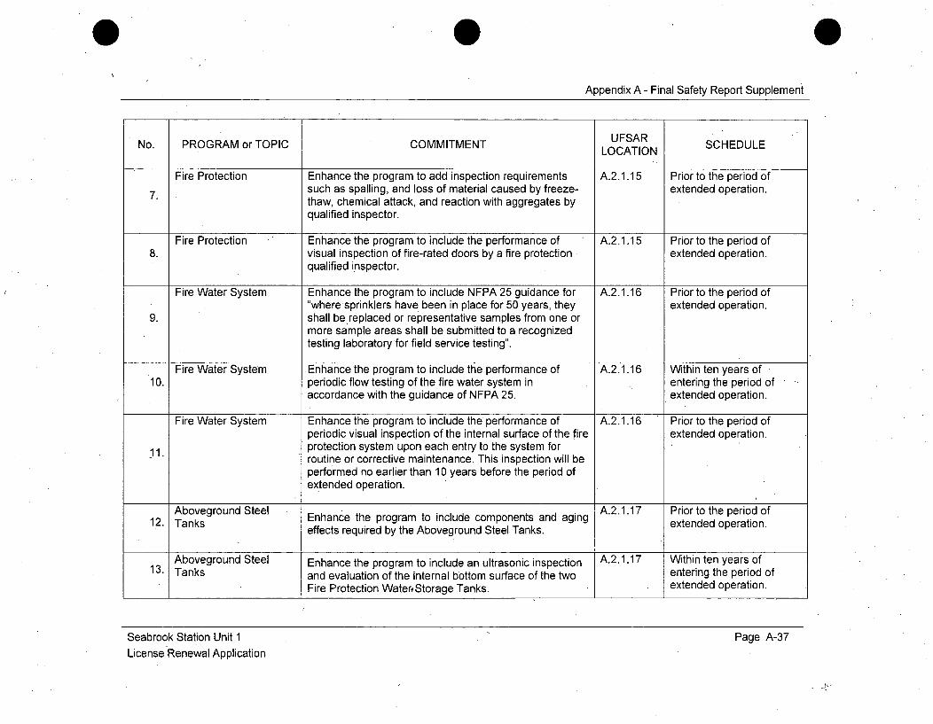
0 0
Appendix A - Final Safety Report Supplement
UFSARNo. PROGRAM or TOPIC COMMITMENT LOCAT SCHEDULELOCATION
Fire Protection Enhance the program to add inspection requirements A.2.1.15 Prior to the period of7. such as spalling, and loss of material caused by freeze- extended operation.
thaw, chemical attack, and reaction with aggregates byqualified inspector.
Fire Protection Enhance the program to include the performance of A.2.1.15 Prior to the period of8. visual inspection of fire-rated doors by a fire protection extended operation.
qualified inspector.
Fire Water System Enhance the program to include NFPA 25 guidance for A.2.1.16 Prior to the period of"wheresprinklers have been in place for 50 years, they extended operation.
9. shall be replaced or representative samples from one ormore sample areas shall be submitted to a recognizedtesting laboratory for field service testing".
Fire Water System Enhance the program to include the performance of A.2.1.16 Within ten years of10. periodic flow testing of the fire water system in entering the period of
accordance with the guidance of NFPA 25. extended operation.
Fire Water System Enhance the program to include the performance of A.2.1.16 Prior to the period ofperiodic visual inspection of the internal surface of the fire extended operation.
11. protection system upon each entry to the system forroutine or corrective maintenance. This inspection will beperformed no earlier than 10 years before the period ofextended operation.
Aboveground Steel Enhance the program to include components and aging A.2.1.17 Prior to the period of1.2. Tanks effects required by the Aboveground Steel Tanks. extended operation.
Aboveground Steel Enhance the program to include an ultrasonic inspection A.2.1.17 Within ten years of
13. Tanks and evaluation of the internal bottom surface of the two entering the period of
Fire Protection Water, Storage Tanks. extended operation.
Seabrook Station Unit 1License Renewal Application
Page A-37
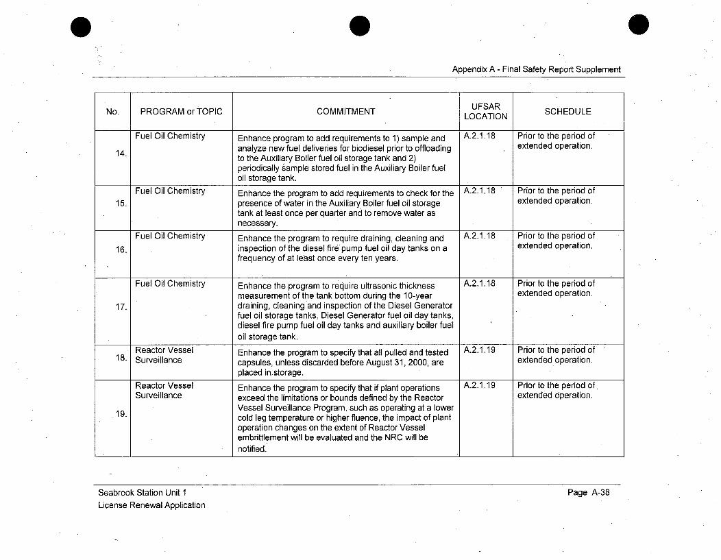
Appendix A - Final Safety Report Supplement
No. PROGRAM or TOPIC. COMMITMENT UFSAR SCHEDULELOCATION
Fuel Oil Chemistry Enhance program to add requirements to 1) sample and A.2.1.18 Prior to the period of14. analyze new fuel deliveries for biodiesel prior to offloading extended operation.
to the Auxiliary Boiler fuel oil storage tank and 2)
periodically sample stored fuel in the Auxiliary Boiler fueloil storage tank.
Fuel Oil Chemistry Enhance the program to add requirements to check for the A.2.1.18 Prior to the period of15. presence of water in the Auxiliary Boiler fuel oil storage extended operation.
tank at least once per quarter and to remove water asnecessary.
Fuel Oil Chemistry Enhance the program to require draining, cleaning and A.2.1.18 Prior to the period of
16. inspection of the diesel fire pump fuel oil day tanks on a extended operation.frequency of at least once every ten years.
Fuel Oil Chemistry Enhance the program to require ultrasonic thickness A.2.1.18 Prior to the period ofmeasurement of the tank bottom during the 10-year extended operation.
17. draining, cleaning and inspection of the Diesel Generatorfuel oil storage tanks, Diesel Generator fuel oil day tanks,diesel fire pump fuel oil day tanks and auxiliary boiler fueloil storage tank.
Reactor Vessel Enhance the program to specify that all pulled and tested A.2.1.19 Prior to the period of18. Surveillance capsules, unless discarded before August 31, 2000, are extended operation.
placed in~storage.Reactor Vessel Enhance the program to specify that if plant operations A.2.1.19 Prior to the period of.Surveillance exceed the limitations or bounds defined by the Reactor extended Operation.
Vessel Surveillance Program, such as operating at a lower19. cold leg temperature or higher fluence, the impact of plant
operation changes on the extent of Reactor Vesselembrittlement will be evaluated and the NRC will benotified.
Seabrook Station Unit 1License Renewal Application
Page A-38
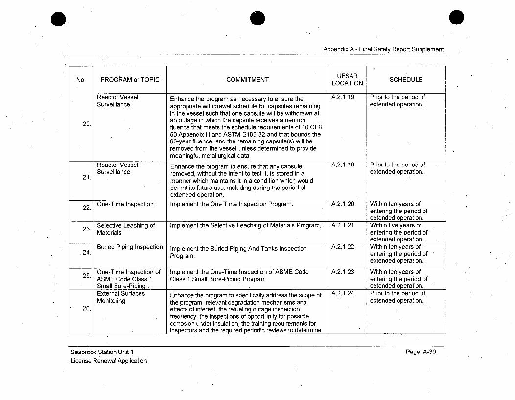
Appendix A - Final Safety Report Supplement
No. PROGRAM or TOPIC COMMITMENT UFSAR SCHEDULELOCATION
Reactor Vessel Enhance the program as necessary to ensure the A.2.1.19 Prior to the period ofSurveillance appropriate withdrawal schedule for capsules remaining extended operation.
in the vessel such that one capsule will be withdrawn at20. an outage in which the capsule receives a neutron
fluence that meets the schedule requirements of 10 CFR50 Appendix H and ASTM E185-82 and that bounds the60-year fluence, and the remaining capsule(s) will beremoved from the vessel unless determined to providemeaningful metallurgical data.
Reactor Vessel Enhance the program to ensure that any capsule A.2.1.19 Prior to the period ofSurveillance removed, without the intent to test it, is stored in a extended operation.
21. manner .which maintains it in a condition which wouldpermit its future use, including during the period ofextended operation.
22. One-Time Inspection Implement the One Time Inspection Program. A.2.1.20 Within ten years ofentering the period ofextended operation.
Selective Leaching of Implement the Selective Leaching of Materials Programh. A.2.1.21 Within five years ofMaterials entering the period of
extended operation.Buried Piping Inspection Implement the Buried Piping And Tanks Inspection A.2.1.22 Within ten years of,
.24. Program. entering the period ofextended operation.
25 One-Time Inspection of Implement the One-Time Inspection of ASME Code A.2.1.23 Within ten years ofASME Code Class 1 Class 1 Small Bore-Piping Program. entering the period ofSmall Bore-Piping . extended operation.External Surfaces Enhance the program to specifically address the scope of A.2.1.24 Prior to the period ofMonitoring the program, relevant degradation mechanisms and extended operation.
26. effects of interest, the refueling outage inspectionfrequency, the inspections of opportunity for possiblecorrosion under insulation, the training requirements forinspectors andthe required periodic reviews to determine
Seabrook Station Unit 1License Renewal Application
Page A-39
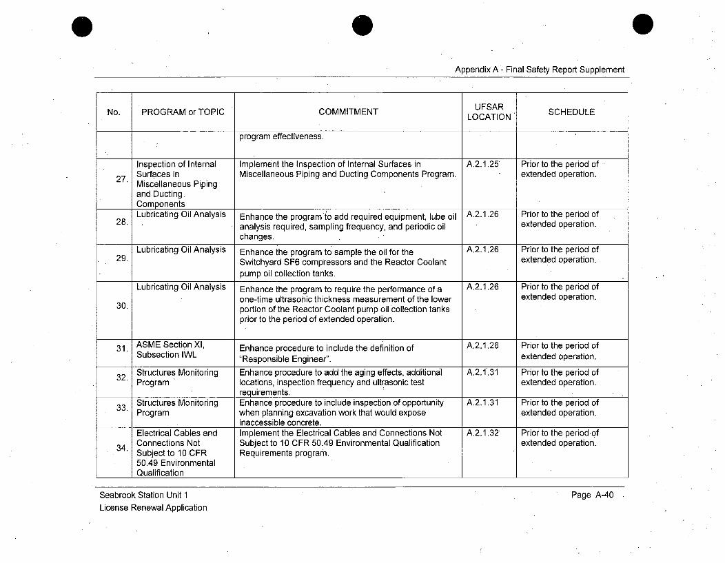
Appendix A - Final Safety Report Supplement
No. PROGRAM or TOPIC COMMITMENT LOCATIN SCHEDULE
program effectiveness.
Inspection of Internal Implement the Inspection of Internal Surfaces in A.2.1 .25 Prior to the period of27. Surfaces in Miscellaneous Piping and Ducting Components Program. extended operation.
Miscellaneous Pipingand Ducting.ComponentsLubricating Oil Analysis Enhance the program to add required equipment, lube oil A-2-1-.26 Prior to the period of
28. analysis required, sampling frequency, and periodic oil extended operation.changes.
Lubricating, Oil Analysis Enhance the program to sample the oil for the A.2.1 .26 Prior to the period of29. Switchyard SF6 compressors and the Reactor Coolant extended operation.
pump oil collection tanks.Lubricating Oil Analysis Enhance the program to require the performance of a A.2.1 .26 Prior to the period of
one-time ultrasonic thickness measurement of the lower extended operation.30. portion of the Reactor Coolant pump oil collection tanks
prior to the period of extended operation.
31. ASEScinX, Enhance procedure to include the definition ofA2i28 PortthpeodfSubsection IWL "Responsible Engineer", extended operation.
3.Structures Monitoring Enhance procedure to add the aging effects, additional A.2.1 .31 Prior to the period of3.Program locations, inspection frequency and ultrasonic test extended operation.
requirements.3.Structures Monitoring Enhance procedure to include inspection of opportunity A.2.1 .31 Prior 'to the period of
Program when planning excavation work that would expose extended operation.inaccessible concrete.
Electrical Cables and Implement the Electrical Cables and Connections Not A.2.1 .32 Prior to the period-of3.Connections Not Subject to 10 CFR 50.49 Environmental Qualification extended operation.
Subject to 10 CFR Requirements program.50.49 Environmental
____Qualification _________________________________ ____________
Seabrook Station Unit 1License Renewal Application
Page A-40
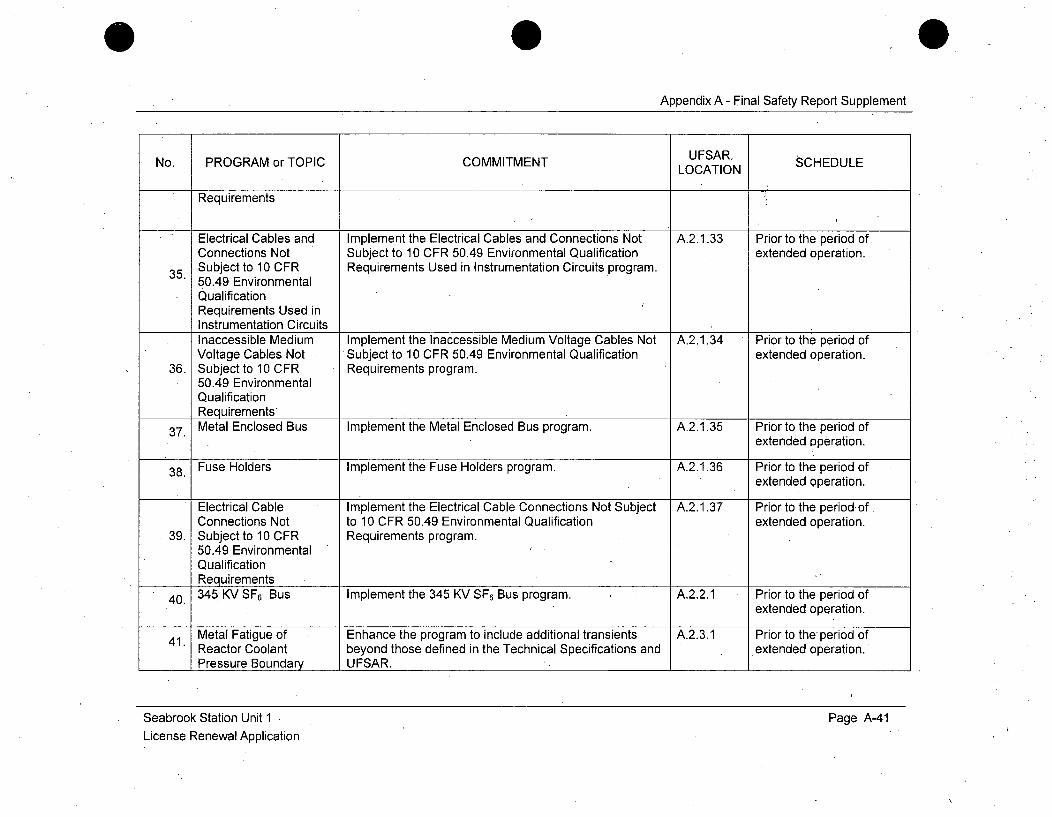
Appendix A - Final Safety Report Supplement
No. PROGRAM or TOPIC COMMITMENT UFSART SCHEDULELOCATION
Requirements i
Electrical Cables and Implement the Electrical Cables and Connections Not A.2.1.33 Prior to the period ofConnections Not Subject to 10 CFR 50.49 Environmental Qualification extended operation.
35. Subject to 10 CFR Requirements Used in Instrumentation Circuits program.50.49 EnvironmentalQualificationRequirements Used inInstrumentation CircuitsInaccessible Medium Implement the Inaccessible Medium Voltage Cables Not A.2.1.34 Prior to the period ofVoltage Cables Not Subject to 10 CFR 50.49 Environmental Qualification extended operation.
36. Subject to 10 CFR Requirements program.50.49 EnvironmentalQualificationRequirements
37. Metal Enclosed Bus Implement the Metal Enclosed Bus program. A.2.1.35 Prior to the period ofextended operation.
38. Fuse Holders Implement the Fuse Holders program. A.2.1.36 Prior to theperiod ofextended operation.
Electrical Cable Implement the Electrical Cable Connections Not Subject A.2.1.37 Prior to the period ofConnections Not to 10 CFR 50.49 Environmental Qualification extended operation.
39. Subject to 10 CFR Requirements program.50.49 EnvironmentalQualificationRequirements
40. 345 KV SF 6 Bus Implement the 345 KV SF6 Bus program. A.2.2.1 Prior to the period ofextended operation.
41. Metal Fatigue of Enhance the program to include additional transients A.2.3.1 Prior to the period ofReactor Coolant beyond those defined in the Technical Specifications and extended operation.Pressure Boundary UFSAR. '
Seabrook Station Unit 1License Renewal Application
Page A-41
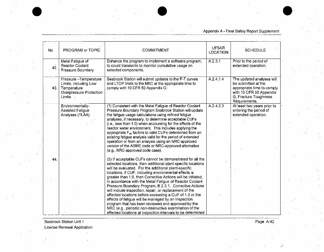
Appendix A - Final Safety Report Supplement
No. PROGRAM or TOPIC COMMITMENT UFSAR SCHEDULELOCATION
Metal Fatigue of Enhance the program to implement a software program, A.2.3.1 Prior to the period ofReactor Coolant to count transients to monitor cumulative usage on extended operation.42. Pressure Boundary selected components.
Pressure -Temperature Seabrook Station will submit updates to the P-T curves A.2.4.1.4 The updated analyses willLimits, including Low and LTOP limits to the NRC at the appropriate time to be submitted atthe
43. Temperature comply with 10 CFR 50 Appendix G. appropriate time to complyOverpressure Protection with 10 CFR 50 AppendixLimits G, Fracture Toughness
Requirements.Environmentally- (1) Consistent with the Metal Fatigue of Reactor Coolant A.2.4.2.3 At least two years prior toAssisted Fatigue Pressure Boundary Program Seabrook Station will update entering the period ofAnalyses (TLAA) the fatigue usage calculations using refined fatigue extended operation.
analyses, if necessary, to determine acceptable CUFs(i.e., less than 1.0) when accounting for the effects of thereactor water environment. This includes applying theappropriate Fen factors to valid CUFs determined from anexisting fatigue analysis valid for the period of extendedoperation or from an analysis using an NRC-approvedversion of the ASME code or NRC-approved alternative(e.g., NRC-approved code case).
44. (2) If acceptable CUFs cannot be demonstrated for all theselected locations, then additional plant-specific locationswill be evaluated. For the additional plant-specificlocations, if CUF, including environmental effects isgreater than 1.0, then Corrective Actions will be initiated,in accordance with the Metal Fatigue of Reactor CoolantPressure Boundary Program, B.2.3.1. Corrective Actionswill include inspection, repair, or replacement of theaffected locations before exceeding a CUF of 1.0 or theeffects of fatigue will be managed by an inspectionprogram that has been reviewed and approved by theNRC (e.g., periodic non-destructive examination of theaffected locations at inspection intervals to be determined
Seabrook Station Unit 1License Renewal Application
Page A-42
1j
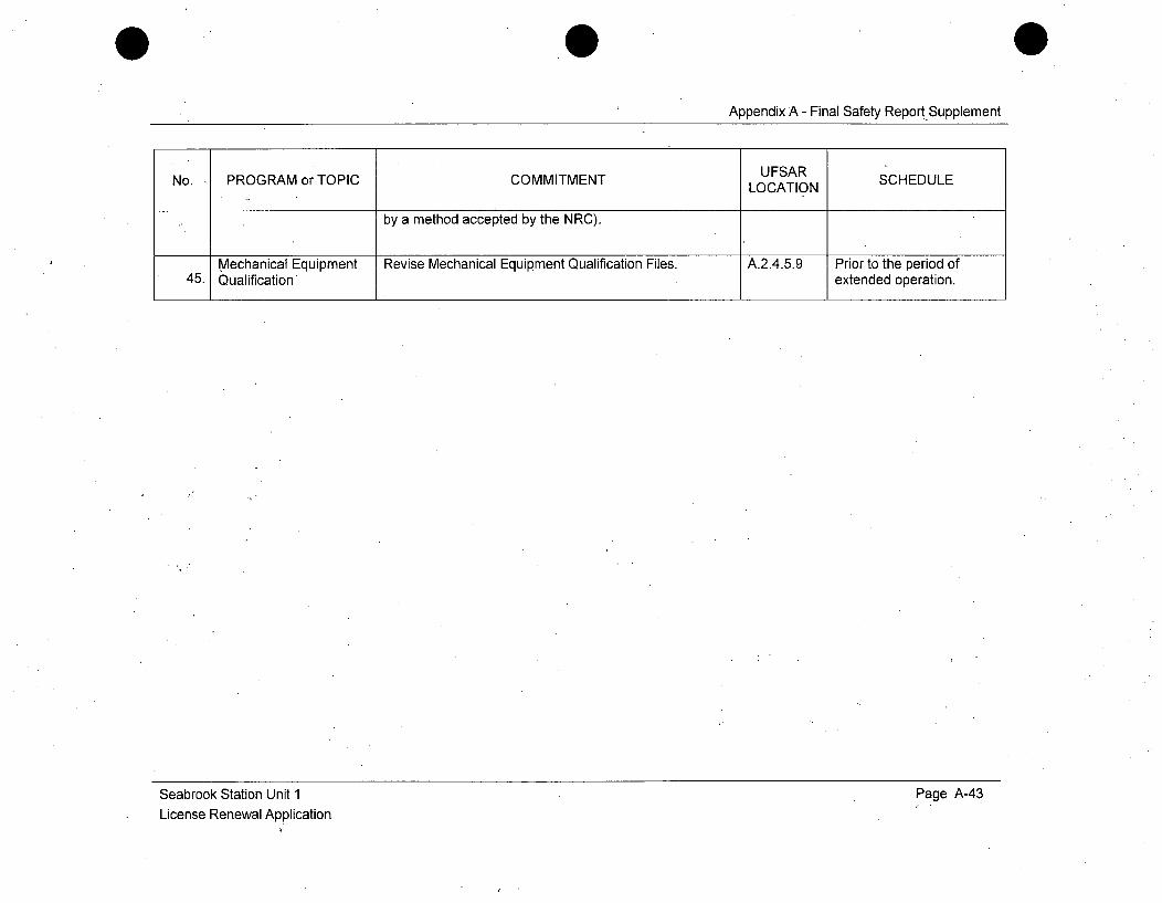
Appendix A - Final Safety Report-Supplement
UFSARNo. PROGRAM or TOPIC COMMITMENT LOCATION SCHEDULE
by a method accepted by the NRC).
Mechanical Equipment Revise Mechanical Equipment Qualification Files. A.2.4.5.9 Prior to the period of45. Qualification extended operation.
Seabrook Station Unit 1License Renewal Application
Page A-43

APPENDIX B
AGING MANAGEMENT PROGRAMS
Appendix B - Aging Management Programs
APPENDIX B - TABLE OF CONTENTS
B .1 IN T R O D U C T IO N ............................................................................................... B-3B. 1. 1 Overview .................................................. B-3B .1.2 P rogram P resentation ...... ...................................................................................... B -3B.1.3 Quality Assurance Program and Administrative Controls ...................................... B-5B .1.4 O perating Experience ...................................................................................... B-6B.1.5 NUREG-1 801 Chapter XI Aging Management Programs ................................. B-8B. 1.6 NUREG-1 801 Chapter X Aging Management Programs .............................. B-10
B.2 AGING MANAGEMENT PROGRAMS ........................................................... B-i 1B.2.0 Aging Management Correlation Chart- NUREG-1801 to
Seabrook Station Programs ........................................................................... B-i 1B.2.1 NUREG-1 801 Chapter XI Aging Management Programs .............................. B-15B.2.1.1 ASME Section XI Inservice Inspection, Subsections
IWB, IWC, and IWD ........... ............................... B-15B .2 .1.2 W ate r C he m istry ................................................................................................... B -228.2.1.3 Reactor Head Closure Studs ................................................................................ B-298 .2 .1.4 B oric A cid C orrosion ............................................................................................. B -35B.2.1.5 Nickel-Alloy Penetration Nozzles Welded to the Upper Reactor
Vessel Closure Heads of Pressurized Water Reactors ....................................... B-39B.2.1.6 Thermal Aging Embrittlement of Cast Austenitic Stainless
S teel (C A S S ) [N ot U sed] ...................................................................................... B -42B .2.1.7 PW R V essel Internals ........................................................................................... B-43B .2.1.8 Flow A ccelerated C orrosion ................................................................................. B-51B .2 .1 .9 B o lting Inte g rity .................................................................................................... B -56B.2. 1.10 Steam Generator Tube Integrity ........................................................................... B-61B.2.1.11 Open-Cycle Cooling Water System ..................................................................... B-67B.2.1.12 Closed - Cycle Cooling Water System ................................................................ B-76B.2.1.13 Inspection of Overhead Heavy Load And Light Load (Related To
Refueling) Handling Systems ................................... B-86B .2.1.14 C om pressed A ir M onitoring ................................................................................. B-898 .2 .1.15 F ire P rote ctio n ...................................................................................................... B -94B .2 .1.16 Fire W ater S ystem ................................................................................................ B -988.2.1.17 A boveground Steel Tanks .................................................................................. B-10313.2.1.18 Fuel O il C hem istry ........................................................................................ B-10613.2.1.19 Reactor Vessel Surveillance .......................................................................... B-1131 .2.1.20 O ne-Tim e Inspection ................................................................................... B-117B.2.1.21 Selective Leaching of Materials .................................................................... B-121B.2.1.22 Buried Piping and Tanks Inspection ............................................................. B-125B.2.1.23 One-Time Inspection of ASME Code Class 1 Small Bore Piping ...................... B-129B.2.1.24 External Surfaces Monitoring ............................................................................ B-132B.2.1.25 Inspection of Internal Surfaces in Miscellaneous Piping and Ducting
C o m po ne nts................................................................................................ . . B -1398 .2.1.26 Lubricating O il A nalysis ..................................................................................... B-145E3.2.1.27 ASME Section XI, Subsection IWE ............... ................................ .B-151B.2.1.28 ASME Section XI,Subsection IWL ................................................................. B-153B.2.1.29 ASME Section XI, Subsection IWF .............................. B-1578.2.1.30 10 CFR Part 50 Appendix J ................................................ B-161
Seabrook Station Unit 1 Page B-1
License Renewal Application

Appendix B - Aging Management Programs
B.2.1.31B.2.1.32
B.2.1.33
B.211.34
B.2.1.35B.2.1.36B.2.1.37
B.2.2B.2.2.1B.2.2.2B.2.2.3B.2.3B.2.3.1B.2.3.2
Structures Monitoring Program .................................................................... B-.164Electrical Cables and Connections Not Subject to 10 CFR 50.49EQ Requirements .......................................... B-1 74Electrical Cables and Connections Not Subject to 10 CFR 50.49EQ Requirements Used in Instrumentation Circuits ........................................... B-1 78Inaccessible Medium-Voltage Cables Not Subject To 10 CFR 50.49E Q R eq uire m e nts .............................................................................................. B -18 0M eta l E nclo sed B us ................................. ........................................................... B -184F u se H o ld e rs .................................................................................................. ...B -18 7Electrical Cable Connections Not Subject To 10 CFR 50.49E Q R equirem ents .................................................................................... B -190Plant Specific Aging Management Programs ....................... B-19334 5 kV S F 6 B us .................................................................................................. B -19 3B o ra l M o n ito ring ................................................................................................. B -19 7Nickel-Alloy Nozzles and Penetrations ....................................................... ..... B-204NUREG-1 801 Chapter X Aging Management Programs .................................. B-214Metal Fatigue of Reactor Coolant Pressure Boundary ...................................... B-214Environmental Qualification (EQ) of Electric Components ................................ B-220
Seabrook Station Unit 1License Renewal Application
Page B-2

Appendix B - Aging Management Programs
B.1 INTRODUCTION
B.1.1 OVERVIEW
The license renewal Aging Management Program descriptions are provided inthis appendix for each program credited for managing aging effects.
The demonstration that aging effects will be adequately managed is performed-by evaluating the aging management programs and associated activitiesagainst certain required attributes. Each of the aging management programsdescribed in this appendix has ten elements which are consistent with theattributes described in NUREG-1800 Appendix A.1, "Aging ManagementReview - Generic (Branch Technical Position RLSB-1)" and in NUREG-1800Table A.1-1 "Elements of An Aging Management Program for LicenseRenewal". The ten element detail is only provided when the program is plantspecific.
Credit for existing plant programs was considered and taken whereappropriate. The program applicability to Systems, Structure and Components(SSCs) and commodities was considered and a'determination made withrespect to the effectiveness of the program in managing the aging effects.
Plant existing programs applied to age management are frequently associatedwith regulatory commitments or requirements. Upon evaluation many of theexisting programs meet the license renewal 10 element attributes. If anexisting program did not adequately manage the identified aging effect, theprogram was enhanced as necessary. New programs were created when noprogram existed.
B.1.2 PROGRAM PRESENTATION
For those aging management programs that are comparable to the programsdescribed in Sections X and XI of NUREG-1 801, or are consistent withexceptions, each program discussion is presented in the following format:
1. Program Description - Summary description of the Seabrook Stationprogram
2. NUREG-1801 Consistency - A statement of the consistency of. theprogram with respect to the NUREG-1801 program
3. Exceptions to NUREG-1801 - Statement of exception(s) to theNUREG-1 801 program with justification
4. Enhancements - Summary of enhancements, if needed, to attainconsistency With NUREG-1 801
Seabrook Station Unit 1 Page B-3License Renewal Application
Appendix B - Aging Management Programs
5. Operating Experience - Relevant operating experience pertaining to theprogram
6. Conclusion- A statement attesting to the program adequacy formanaging associated aging effects
The statement of consistency of the Seabrook Station Aging ManagementProgram with respect to the NUREG-1801 program will take one of the threefollowing forms:
1. The Aging Management Program states that the plant program isconsistent with the recommendations of NUREG-1801, identifies noexceptions to NUREG-1801, and identifies no enhancements. Thisstatement affirms that
a. the plant program corresponds to and contains the elements of thereferenced NUREG-1801 program;
b. the conditions at the plant are bounded by the conditions for whichthe NUREG-1801 program was evaluated to the extent suchconditions are specified in the NUREG-1801 program description;and
c. verifications have been completed and documented.
Therefore, the Aging Management Program identified in NUREG-1801is being used.
2. The Aging Management Program states that the plant program isconsistent with the recommendations of NUREG-1801 with exception(s),and either identifies enhancements or identifies no enhancements. Thisstatement affirms that
a. with the exception(s) identified, and enhancements, if any, the plantprogram corresponds to and contains the elements of the referencedNUREG-1801 program;
b. the conditions at the plant are bounded by the conditions for whichthe NUREG-1801 program was evaluated to the extent suchconditions are specified in the NUREG-1801 program description;and
c. verifications have been completed and documented.
Seabrook Station Unit 1 Page B-4License Renewal Application
Appendix B - Aging Management Programs
Therefore the Aging Management Program identified in NUREG-1801 isbeing used, as modified by the exceptions. A justification for eachidentified exception is provided.
3. The Aging Management Program states" that the plant program isconsistent with the recommendations of NUREG-1.801, identifies noexceptions to NUREG-1801, but identifies enhancements. Thisstatement affirms that
a. with.those enhancements, the plant program corresponds to andcontains the elements of the referenced NUREG-1 801 program;
b. the conditions at the plant are bounded by the conditions for whichthe NUREG-1801 program was evaluated to the extent suchconditions are specified in the NUREG-1801 description; and
c. verifications have been completed and are documented.
Therefore the Aging Management Program identified in NUREG-1801 isbeing used.
The plant specific aging management programs are described in terms of the10 program elements in NUREG-1800, Section A.1.2.3 "Aging Managementprogram Elements".
B.1.3 QUALITY ASSURANCE PROGRAM AND ADMINISTRATIVECONTROLS
The FPL/NextEra Energy Quality Assurance Program implements therequirements of 10 CFR 50, Appendix B, and is consistent with the summary inAppendix A of NUREG-1801. The elements of corrective action, confirmationprocess, and administrative controls in the Quality Assurance Program areapplicable to both safety related and non-safety related systems, structures,and components that are subject to an Aging Management Review. Eachelement will be implemented as follows:
Corrective Actions
FPL/NextEra Energy Quality Assurance procedures, review and approvalprocesses, and administrative controls are implemented in accordance with therequirements of 10 CFR Part 50, Appendix B. Conditions adverse to quality,such as failures, malfunctions, deviations, defective material and equipment,and non-conformances, are promptly identified and corrected. In the case ofsignificant conditions adverse to quality, measures are implemented to ensurethat the cause of the nonconformance is determined and that corrective actionis taken to preclude recurrence. In addition, the root cause of the significant
Seabrook Station Unit 1 Page B-5License Renewal Application

Appendix B - Aging Management Programs
condition adverse to quality and the corrective action implemented aredocumented and reported to appropriate levels of management.
Confirmation Process
FPL/NextEra Energy Quality Assurance procedures, review and approval,processes, and administrative controls are implemented in accordance with therequirements of 10 CFR Part 50, Appendix B. Corrective actions andadministrative controls are accomplished by the implementation of theCorrective Action Program and Nuclear Fleet procedures. The confirmationprocess is part of the Corrective Action Program and includes:
1. review to assure that proposed actions are adequate
2. tracking and reporting of open corrective actions
3. review of corrective action effectiveness
Any follow-up activities required by the confirmation process are documented inaccordance. with the Corrective Action Program. The Corrective ActionProgram encompasses the confirmation process for Aging ManagementPrograms and activities.
Administrative Controls
FPL/NextEra Energy Quality Assurance procedures, review and approvalprocesses, and administrative controls are implemented in accordance with therequirements of 10 CFR Part 50, Appendix B. These administrative controlsinclude the provisions related to organization and management, procedures,record keeping, review and audit, and reporting.
B.1.4 OPERATING EXPERIENCE
Operating experience is an important resource in identifying aging effects andevaluating the effectiveness of Aging Management Programs. The CorrectiveAction Program, system health reports, self assessments, Nuclear OversightAudits, and interviews with site personnel were the primary sources of plant-specific operating experience related to these Aging Management Programs.
Since the materials used for structures and components at Seabrook Stationare common to most nuclear power plants and many non-nuclear power plantsthat have long operating histories, industry-wide operating experience is alsovaluable.- Screening of a large body of operating data yielded much useful datarelating to aging of plant structures and components.
Seabrook Station Unit 1 Page B-6License Renewal Application

Appendix B - Aging Management Programs
The Seabrook Station plant-specific data and the industry-wide operating datawere valuable in:
1. Providing bases for determining which aging effects requiremanagement.
2. Demonstrating that existing programs are adequately managing theaging effects.
3. Pointing out the need to enhance existing programs or the need forentirely new programs.
The effects and mechanisms of age related degradation for SSCs at SeabrookStation were developed from several sources. They include plant-specific andindustry operating experience and interviews with site personnel. No newaging effects were identified. Known, aging effects and mechanisms for a givenenvironment and material were incorporated into NUREG-1801, up to the timeof its publication in Sept. 2005.
With respect to Aging Management Programs, existing programs/ activitiesmust demonstrate, with objective evidence, that they are effective in managingthe aging effects if credited. Operating experience related to theprogram/activity, including past corrective actions resulting in programenhancements, provides objective evidence the program adequately managesthe aging effects.
The FPUNextEra Energy Operating Experience Program provides guidance forusing, sharing, and evaluating operating experience information atFPUNextEra Energy Nuclear Division sites. The procedure governing thisprogram provides guidance on the effective and efficient use of operatingexperience information. The primary objectives of the FPL/NextEra EnergyOperating Experience Program are:
1. Systematic evaluation of significant nuclear plant operating experiences.
2. Incorporation of lessons learned into appropriate plant practices,policies, programs, and procedures with the objective of preventingsimilar issues.
3. Sharing of lessons learned internally and with other utilities to promoteindustry-wide safety and reliability.
By increasing awareness of previous FPLJNextEra Energy Nuclear Divisionand industry events and issues, the FPUNextEra Energy Operating ExperienceProgram expects to prevent similar events from occurring at FPL/NextEraEnergy Nuclear Division sites. The FPUNextEra Energy Operating Experience
Seabrook Station Unit 1 Page B-7License Renewal Application

Appendix B - Aging Management Programs
Program ensures that information that has the potential to affect safe andreliable station operation is properly screened and addressed to ensure timelyresponse. This program promotes the identification and transfer of lessonslearned from industry, and internal events' such that these lessons are sharedbetween the FPL/NextEra Energy Nuclear Division and the nuclear industry.This program describes the methodology for receiving, processing, statusreporting, screening, reviewing, evaluating, and taking_ preventive/correctiveactions in response to operating experience information. This programsatisfies the requirements of NUREG-0737, I.C.5, "Procedures for Feedback ofOperating Experience to Plant Staff' and 10 CFR 50.65, "Requirements forMonitoring the Effectiveness of Maintenance at Nuclear Power Plants",Sections (a)(1) and (a)(2).
B.1.5 NUREG-1801 CHAPTER Xl AGING MANAGEMENT PROGRAMS
The following Aging Management Programs are described in this appendix.The programs are either generic in nature as discussed in NUREG-1801,Chapter XI, "Aging Management Programs (AMPs)" or are plant-specific.NUREG-1801 Chapter XI programs are listed in Section B.2.1. Plant-specificprograms are listed in Section B.2.2. All generic programs are either fullyconsistent with or are consistent with some exceptions with programsdiscussed in NUREG-1801. Programs are identified as either existing or new.
1. ASME Section XI Inservice Inspection, Subsections IWB, IWC,. andIWD (B.2.1.1) [Existing]
2. Water Chemistry (B.2.1.2) [Existing]
3. Reactor Head Closure Studs (B.2.1.3) [Existing]
4. Boric Acid Corrosion (B.2.1.4) [Existing]
5. Nickel-Alloy Penetration Nozzles Welded to the Upper Reactor VesselClosure Heads of Pressurized Water Reactors (B.2.1.5) [Existing]
6. Thermal Aging Embrittlement of Cast Austenitic Stainless Steel (CASS)(B.2.1.6) [Not Used]
7. PWR Vessel Internals (B.2.1.7) [New]
8. Flow-Accelerated Corrosion (B.2.1.8) [Existing]
9. Bolting Integrity (B.2.1.9) [Existing]
10. Steam Generator Tube Integrity (B.2.1.10) [Existing]
11. Open-Cycle Cooling Water System (B.2.1.11) [Existing]
12. Closed-Cycle Cooling Water System (B.2.1.12) [Existing]
Seabrook Station Unit 1 Page B-8License Renewal Application
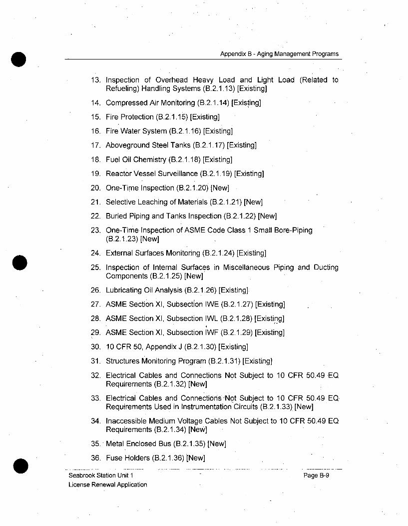
Appendix B - Aging Management Programs
13. Inspection of Overhead Heavy Load and Light Load (Related to
Refueling) Handling Systems (B.2.1.13) [Existing]
14. Compressed Air Monitoring (B.2.1.14) [Existing]
15. Fire Protection (B.2.1.15) [Existing]
16. Fire Water System (B.2.1.16) [Existing]
17. Aboveground Steel Tanks (B.2.1.17) [Existing]
18. Fuel Oil Chemistry (B.2.1.18) [Existing]
19. Reactor Vessel Surveillance (B.2.1.19) [Existing]
20. One-Time Inspection (B.2.1.20) [New]
21. Selective Leaching of Materials (B.2.1.21) [New]
22. Buried Piping and Tanks Inspection (B.2.1.22) [New]
23. One-Time Inspection of ASME Code Class 1 Small Bore-Piping(B.2.1.23) [New]
24. External Surfaces Monitoring (B.2.1.24) [Existing]
25. Inspection of Internal Surfaces in Miscellaneous Piping and DuctingComponents (B.2.1.25) [New]
26. Lubricating Oil Analysis (B.2.1.26) [Existing]
27. ASME Section XI, Subsection IWE (B.2.1.27) [Existing]
28. ASME Section XI, Subsection IWL (B.2.1.28) [Existing]
29. ASME Section XI, Subsection IWF (B.2.1.29) [Existing]
30. 10 CFR 50, Appendix J (B.2.1.30) [Existing]
31. Structures Monitoring Program (B.2.1.31) [Existing]
32. Electrical Cables and Connections Not Subject to 10 CFR 50.49 EQRequirements (B.2.1.32) [New]
33. Electrical Cables and Connections'Not Subject to 10 CFR.50.49 EQRequirements Used in Instrumentation Circuits (B.2.1.33) [New]
34. Inaccessible Medium Voltage Cables Not Subject to 10 CFR 50.49 EQRequirements (B.2.1.34) [New]
35. Metal Enclosed Bus (B.2.1.35) [New]
36. Fuse Holders (B.2.1.36) [New]
Seabrook Station Unit 1 Page B-9License Renewal Application
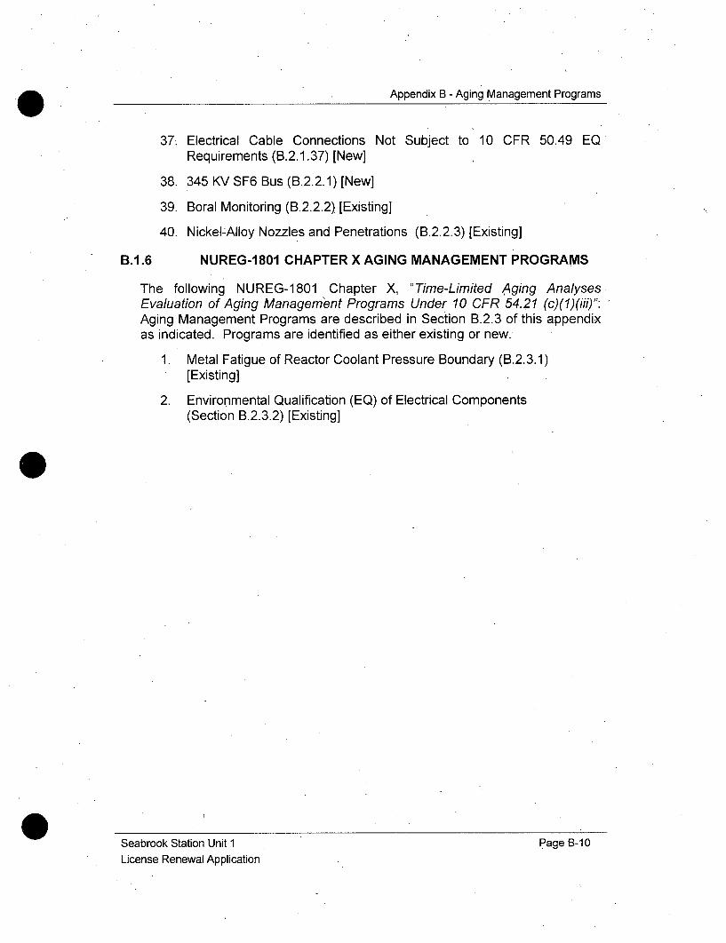
Appendix B - Aging Management Programs
37. Electrical Cable Connections Not Subject to 10 CFR 50.49 EQRequirements (B.2.1.37) [New]
38. 345 KV SF6 Bus (B.2.2.1) [New]
39. Boral Monitoring (B.2.2.2) [Existing]
40. Nickel-Alloy Nozzles and Penetrations (B.2.2.3) [Existing]
B.1.6 NUREG-1801 CHAPTER X AGING MANAGEMENT PROGRAMS
The following NUREG-1801 Chapter X, "Time-Limited Aging AnalysesEvaluation of Aging Management Programs Under 10 CFR 54.21 (c)(1)(iii)":Aging Management Programs are described in Section B.2.3 of this appendixas indicated. Programs are identified as either existing or new.
1. Metal Fatigue of Reactor Coolant Pressure Boundary (B.2.3.1)[Existing]
2. Environmental Qualification (EQ) of Electrical Components(Section B.2.3.2) [Existing]
Seabrook Station Unit 1License Renewal Application
Page B-10
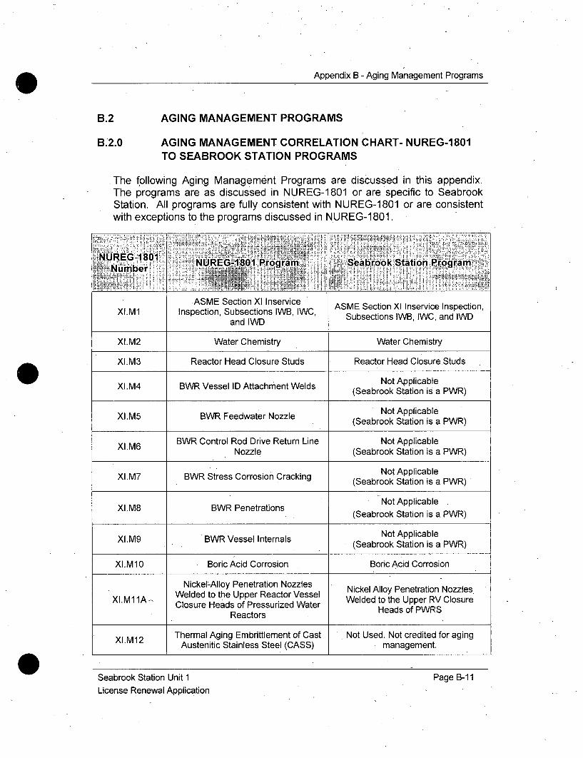
Appendix B - Aging Management Programs
B.;
B.;
AGING MANAGEMENT PROGRAMS
2.0 AGING MANAGEMENT CORRELATION CHART- NUREG-1801TO SEABROOK STATION PROGRAMS
The following Aging Management Programs are discussed in this appendix.The programs are as discussed in NUREG-1801 or are specific to SeabrookStation. All programs are fully consistent with NUREG-1801 or are consistentwith exceptions to the programs discussed in NUREG-1801.
NUmber G NUREG -.1..1 Program Seabro:ok Station P rogram.
ASME Section XI Inservice ASME Section Xl Inservice Inspection,XI.M1 Inspection, Subsections IWB, IWC, Subsections IWB, IWC, and IWD
and IWD
XI.M2 Water Chemistry Water Chemistry
XI.M3 Reactor Head Closure Studs Reactor Head Closure Studs
XI.M4 BWR Vessel ID Attachment Welds Not Applicable(Seabrook Station is a PWR)
XI.M5 BWR Feedwater Nozzle Not Applicable(Seabrook Station is a PWR)
BWR Control Rod Drive Return Line Not ApplicableXI.M6 Nozzle (Seabrook Station is a PWR)
XI.M7 BWR St ress Corrosion Cracking Not Applicable
(Seabrook Station is a PWR)
XI.M8 BWR Penetrations Not Applicable(Seabrook Station is a PWR)
XI.M9 BWR Vessel Internals Not Applicable(Seabrook Station is a PWR)
XI.M10 Boric Acid Corrosion Boric Acid Corrosion
Nickel-Alloy Penetration Nozzles Nickel Alloy Penetration NozzlesWelded to the Upper Reactor Vessel Weldedlo te Uer RV zClosu
XI.M11A - Closure Heads of Pressurized Water Welded to the Upper RV ClosureReactorsHeads of PWRSReactors
Thermal Aging Embrittlement of Cast Not Used. Not credited for agingAustenitic Stainless Steel (CASS) management.
Seabrook Station Unit 1License Renewal Application
Page B-11

Appendix B - Aging Management Programs
......... NUREG-1801 Programr Seabrook Statilon ProgramNumber
Thermal Aging and neutron IrradiationXI.M13 Embrittlement of Cast Austenitic maNagement.
Stainless Steel (CASS)
Not Used. Not credited for agingXI.M14 Loose Part Monitoring management.
Not Used. Not credited for agingXI.M15 Neutron Noise Monitoring management.
XI.M16 PWR Vessel Internals PWR Vessel Internals
XI.M17 Flow-Accelerated Corrosion Flow Accelerated Corrosion
XI.M18 Bolting Integrity Bolting Integrity
XI.M19 Steam Generator Tube Integrity Steam Generator Tube Integrity
XlM20 Open-Cycle Cooling Water System Open-Cycle Cooling Water System
XI.M21 Closed-Cycle Cooling Water System Closed-Cycle Cooling Water System
Not Used. Not credited for agingXI.M22 Boraflex Monitoring management. This material is not
credited in the Spent Fuel Pool
Criticality Analysis
Inspection of Overhead Heavy Load Inspection of Overhead Heavy LoadXI.M23 and Light Load (Related to And Light Load (Related to Refueling)
Refueling)Handling Systems Handling Systems
XI.M24 Compressed Air Monitoring Compressed Air Monitoring
Xl M25 BWR Reactor Water Cleanup System Not Applicable
(Seabrook Station is a PWR)
XI.M26 Fire Protection Fire Protection
XI.M27 Fire Water System Fire Water System
Not Used. The aging effectsassociated with buried piping and
XI.M28 Buried Piping and Tanks Surveillance tanks will be adequately managed byX.M34, Buried Piping Inspection
Program (B.2.1.22).
XI.M29 Aboveground Steel Tanks Above Ground Steel Tanks
Seabrook Station Unit 1License Renewal Application
Page B-12
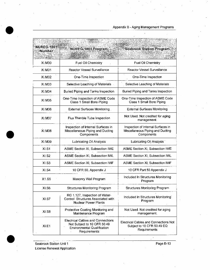
Appendix B - Aging Management Programs
NUE-Bl NURE.G-1,801 Prga Seabrook Station ProgramiNutniber aia,- .
XlIM30 Fuel Oil Chemistry Fuel Oil Chemistry
XI.M31 Reactor Vessel Surveillance Reactor Vessel Surveillance
XI.M32 One-Time Inspection .One-Time Inspection
XI.M33 Selective Leaching of Materials Selective Leaching of Materials
XI.M34 Buried Piping and Tanks Inspection Buried Piping and Tanks Inspection
One-Time Inspection of ASME Code One-Time Inspection of ASME CodeX.M35 Class 1 Small Bore-Piping Class 1 Small Bore Piping
XI.M36 External Surfaces Monitoring External Surfaces Monitoring
Not Used. Not credited for agingXI.M37 Flux Thimble Tube Inspection management.
Inspection of Internal Surfaces in Inspection of Internal Surfaces inXI.M38 Miscellaneous Piping and Ducting Miscellaneous Piping and Ducting
Components Components
XI.M39 Lubricating Oil Analysis Lubricating Oil Analysis
XI.S1 ASME Section XI, Subsection IWE ASME Section Xl, Subsection IWE
XI.S2 ASME Section XI, Subsection IWL ASME Section Xl, Subsection IWL
XI.S3 ASME Section XI, Subsection IWF ASME Section Xl, Subsection IWF
XI.S4 10 CFR 50, Appendix J 10 CFR Part 50 Appendix J
Included In Structures MonitoringXl .S5 Masonry Wall Program Program
XI.S6 Structures Monitoring Program Structures Monitoring Program
RG 1.127, Inspection of Water- Included In Structures Monitoring'XI.S7 Control Structures Associated with Program
Nuclear Power Plants
Protective Coating Monitoring and Not Used. Not credited for agingMaintenance Program management.
Electrical Cables and Connections Electrical Cables and Connections NotXLE1 Not Subject to 10 CFR 50.49 Subject to 10 CFR 50.49 EQ
Environmental Qualification RequirementsRequirements*
Seabrook Station Unit 1License Renewal Application
Page B-13

Appendix B - Aging Management Programs
N~UREG-1801 .. . . . . . . . . . . . .
Number NUREG-1801 Program Seabrook Station Program
Electrical Cables and ConnectionsNot Subject to 10 CFR 50.49 Electrical Cables and Connections Not
XI.E2 Environmental Qualification Subject to 10 CFR 50.49 EQ.Requirements Used in Requirements Used in Inst. CircuitsInstrumentation Circuits
Inaccessible Medium Voltage Cables Inaccessible Medium-VoltageCNot Subject to 10 CFR 50.49 n otc s ubje t o 1 CF 504
XI.E3 Environmental QWalification Not Subject to 10 CFR 50.49
Requirements Requirements
XI.E4 Metal Enclosed Bus Metal Enclosed Bus
XI.E5 Fuse Holders . Fuse Holders
Electrical Cable Connections Not Electrical Cable Connections NotXIE6 Subject To 10 CFR 50.49 Subject to 10 CFR 50.49Environmental Qualification Environmental Qualification
Requirements Requirements
Metal Fatigue Of Reactor Coolant Metal Fatigue of Reactor CoolantPressure Boundary Pressure Boundary Program
Concrete Containment Tendon Not Used. Not credited for agingPrestress management.
Environmental Qualification (EQ) Of Environmental Qualification (EQ) ofElectrical Components Electric Components
N/A - Seabrook Station Plant Specific 345 KV SF6 BusProgram
Seabrook Station Plant Specific Boral MonitoringN/A oaIMntrgProgram
N/A Seabrook Station Plant Specific Nickel-Alloy Nozzles and PenetrationsProgram
Seabrook Station Unit ILicense Renewal Application
Page B-14

Appendix B - Aging Management Programs
B.2.1 NUREG-1 801 CHAPTER XI AGING MANAGEMENTPROGRAMS
B.2.1.1 ASME SECTION XI INSERVICE INSPECTION, SUBSECTIONS
IWB, IWC, AND IWD
Program Description
The Seabrook Station ASME Section XI, Subsections IWB, IWC and IWDInservice Inspection Program is an existing program that manages the agingeffects of cracking due to cyclic loading, primary water stress corrosioncracking, stress corrosion cracking, cracking, due to thermal and mechanicalloading, loss of fracture toughness due to thermal aging embrittlement, loss ofmaterial due to general, pitting and crevice corrosion, and loss of material dueto wear in ASME Code Class 1, 2, and 3 piping and components within thescope of License Renewal. The program includes periodic visual, surfaceand/or volumetric examinations of all ASME Code Class 1, 2 and 3 pressure-retaining components, their supports and integral attachments (includingwelds, pump casings, valve bodies and pressure-retaining bolting) andleakage tests of pressure retaining components. These are identified inASME Section XI, "Rules for Inservice Inspection of Nuclear Power PlantComponents", or commitments requiring augmented Inservice Inspections,and are within the scope of license renewal.
The Code of Federal Regulations, 10 CFR 50.55a, "Codes and Standards",requires that Inservice Inspection of ASME Code Class 1, 2, and 3 pressureretaining components, their integral attachments and supports be conducted inaccordance with the latest edition of ASME Section XI approved by the NRCtwelve months prior to the start of a ten-year interval. The Inservice InspectionProgram for the second (2 nd) ten-year interval, which began on August 19,2000 for Seabrook Station, implements the 1995 edition with the 1996addenda, of ASME Section XI. The program is implemented in accordancewith the requirements of 10 CFR 50.55a, with specified limitations,modifications and NRC-approved alternatives, and utilizes ASME Section Xl,Subsections IWB, IWC, and IWD. The program provides for augmentedinspections of components and their attachments as required or recommendedby regulatory, or Nuclear Steam System Supplier (NSSS) technicalpublications.
The Seabrook Station ASME Section XI Program provides the requirements forInservice Inspection, repair, and replacement of all ASME Code Class 1, 2, and3 components within scope, for license renewal. The program includes thosecomponents specified in subsections IWB-1 100, IWC-1 100, and IWD-1 100 forClass 1, 2, and 3 components, respectively, and includes all pressure retainingcomponents and their integral attachments.- The components described in sub-
Seabrook Station Unit 1 Page B-15License Renewal Application
Appendix B - Aging Management Programs
articles IWB-1220, IWC-1220 and IWD-1220 (Components Exempt fromExamination) are exempt from the examination and pressure test requirementsof sub-articles IWB-2500, IWC-2500 and IWD-2500. The components in scopeof the Seabrook Station ASME Section Xl program are included in the InserviceInspection program and repair and replacement activities, and are implementedin accordance with the requirements of ASME Section XI, subsection IWA-4000.
The Technical Specification commitments for the scope of this program, asdescribed inthe Seabrook Station In-service Inspection Reference Manual, areaddressed in Technical Specification Sections 4.0.5, "SurveillanceRequirements for Inservice Inspection", and 6.7, "Programs and Procedures".
The Seabrook Station Inservice Inspection Program consists of conditionmonitoring activities that detect degradation of components before loss ofintended function. No preventive or mitigating attributes are associated withthese activities.
The Seabrook Inservice Inspection program utilizes ASME Section XI TablesIWB-2500-1, IWC-2500-1 and IWD-2500-1, for Class 1, 2 and 3 componentsrespectively, to determine the examination requirements, develop theexamination procedures, and schedule the examinations required for eachinspection interval and the examinations for each inspection period. Thetables specify the extent and schedule of the inspection and the examinationmethods for the components of pressure-retaining boundaries.
The Seabrook Station ASME Section X1 Inservice Inspection Programincludes a variety of inspection and testing activities that are designed todetect degradation due to aging effects prior to loss of intended function.
The extent and schedule of the inspection and test techniques prescribed bythe program are designed to maintain structural integrity and ensure thataging effects will be discovered and repaired before the loss of a componentintended function. Inspection can reveal crack initiation and growth, loss ofmaterial due to corrosion, leakage, and indications of degradation caused bywear or stress relaxation, such as verification of clearances, settings, physicaldisplacements, loose or missing parts, debris, wear, erosion, or loss ofintegrity at bolted or welded connections.
The program uses three types of examination; visual, surface, and volumetricin accordance with the general requirements of Article IWA-2000. VT-1 visualexamination detects discontinuities and imperfections, such as cracks,corrosion, wear, or erosion, on the surface of components. VT-2 Visualexamination detects evidence of leakage from pressure-retainingcomponents, as required during the system pressure test. VT-3 visualexamination (a) determines the general mechanical and structural condition of
Seabrook Station Unit 1 Page B-16License Renewal Application
Appendix B - Aging Management Programs
components by verifying parameters, such as clearances, settings, andphysical displacements; and (b) detects discontinuities and imperfections,such as loss of integrity at bolted or welded connections, loose or missingparts, debris, corrosion, wear, or erosion.
Surface examination uses magnetic particle, liquid penetrant, or eddy currentexaminations to indicate the presence of surface discontinuities and flaws.
Volumetric examination uses radiographic, ultrasonic, or eddy current (forsteam generator tubing only) examinations to indicate the presence ofdiscontinuities or flaws throughout the volume of material. If used forexaminations other than steam generator tube inspections, eddy current isconsidered a surface examination technique. The non-destructiveexamination (NDE) techniques used to inspect ASME Code Class 1, Class 2,and Class 3 components are consistent with the referenced ASME Section XICode for those components.
Examination requirements for Class 1 and 2 pressure-retaining bolting are inaccordance with ASME Section Xl, Table IWB 2500-1 or IWC 2500-1. ForClass 1 components, Table IWB 2500-1, examination category B-G-1, forbolting greater than 2 inches in diameter, specifies volumetric examination ofstuds and bolts and VT-1 visual examination of surfaces of nuts, washers,bushings, and flanges. - Examination category B-G-2, for bolting 2 inches orsmaller requires VT-1 visual examination of surfaces of bolts, studs, and nuts.
Examination Categories B-P and C-H, require VT-2 visual examination(IWA-5240) during system leakage testing of all pressure-retaining ASMECode Class 1 and 2 components, according to Tables IWB-2500-1 and IWC-2500-1 respectively. The extent and schedule of inspections, in accordancewith Tables IWB-2500-1 and IWC-2500-1 ensure detection of agingdegradation before the loss of the intended function. The Seabrook StationASME Section XI Inservice Inspection Program performs the necessaryinspections per the requirements of tables IWB-2500-1, IWC-2500-1, andIWD-2500-1. These inspections include the applicable portions ofexamination categories; B-A, B-B, B-D, B-G-1, B-G-2, B-K, B-L-2, B-M-2, B-N-I, B-N-2, B-N-3 B-O, B-P, C-A, C-B, C-C, C-F-i, C-F-2, C-H, D-A, and D-B.The applicable portions of categories B-F and B-J are currently included inthe Risk Informed Inservice Inspection Program. Examination categories notlisted above are not applicable to Seabrook Station.
The examinations listed above are based on specific ASME Code Editionsand Addenda and will change throughout the extended period as requiredand/or allowed by 10 CFR 50.55a.
The examination schedules contained in the Seabrook Station InserviceInspection Program meet the requirements of ASME Section XI, IWB-2412,
Seabrook Station Unit 1 Page B-1ý7License Renewal Application
Appendix B - Aging Management Programs
IWC-2412, and IWD-2412, respectively (Inspection Program B). TheInservice Inspection Program also meets the requirements for the extent andfrequency of examinations specified by the ASME Section XI, IWB-2500-1,IWC-2500-1, and IWD-2500-1 and in accordance with the requirements of 10CFR 50.55a, with specified limitations, modifications and NRC-approvedalternatives. If flaw indications or relevant conditions of degradation arefound, additional examinations, may be necessary.
In some cases, an evaluation in accordance with ASME Section XI,IWB-3100, IWC-3100, or IWD-3100 may be used to quality a component withflaw indications as acceptable for continued service. In such cases, the areascontaining such flaw indications and relevant conditions are reexaminedduring the next three inspection periods of IWB-2400 for Class 1 componentsand for the next inspection period of IWC-2400 and IWD-2400 for Class 2 andClass 3 components, respectively. Examinations that reveal indications thatexceed the acceptance standards are extended to include additionalexaminations in accordance with ASME Section XI, IWB-2430, IWC-2430, orIWD-2430 for Class 1, 2, or 3 components, respectively, The SeabrookStation Inservice Inspection Program meets the ASME Section Xlrequirements with respect to inspection schedules, extent, method, .andfrequency of examination, flaw evaluations, and additional examinations.
Indications or relevant conditions are evaluated in accordance with IWB-3000,IWC-3000, or IWD-3000 for Class 1, 2, or 3 components, respectively.Examination results are evaluated in accordance with IWB-3100, IWC-3100, orIWD-3100 by comparing the results with the acceptance standards ofIWB-3400 and IWB-3500 or IWC-3400 and IWC-3500 or IWD-3400 and IWD-3500 for Class 1 or Class 2 and 3 components, respectively. In rare cases,flaws exceeding the size of allowable flaws, as defined in IWB-3500 orIWC-3500 may be evaluated by using the analytical procedures of IWB-3600 orIWC-3600.Repairs and replacements are performed in accordance with the Seabrook
Station ASME Section XI Repair and Replacement Program.
NUREG-1801 Consistency
NUREG-1801, Rev 1, discusses the use of the 2001 edition including the2002 and 2003 addenda of ASME Section Xl code, but allows use of othereditions of the ASME Code as long as there is justification. The SeabrookStation Inservice Inspection Program Plan for the second ten-year inspectioninterval effective from August 19, 2000 through August 18, 2010, approvedper 10 CFR 50.55a, is based on the 1995 edition including the 1996 addenda.The next and subsequent 120-month inspection intervals for SeabrookStation will incorporate the requirements specified in the version of the ASME
Seabrook Station Unit 1 Page B-18License Renewal Application
Appendix B - Aging Management Programs
Code incorporated into 10 CFR 50.55a twelve months before the start of theinspection interval.
Thisprogram is consistent with NUREG-1801 XI.M1.
Exceptions to NUREG-1801
None
Enhancements
None
Operating Experience
The Seabrook Station Corrective Action Program is used to track, trend andevaluate plant issues and events. Those issues and events, whether externalor plant specific, that are potentially significant to the ASME Section XIInserviceInspection Program are evaluated. The ASME Section XI InserviceInspection Program is augmented, as appropriate, if these evaluations showthat program changes will enhance program effectiveness.
Site specific Operating Experience is included below.
1. In February 2001, a post-outage review of the work performed on twovalves to replace the body to bonnet gaskets revealed that there had beenan opportunity to perform a VT-3 visual examination of the internal surfaceof the valve body during that work. ASME Section XI, Table IWB-2500-1,Examination Category B-M-2, Item No. B12.50 requires an internal surfaceexamination of at least one valve in each group of similar valves during theTen-Year Inservice Inspection Interval. These valves are two of six in aparticular group. Although there was no requirement to perform a VT-3visual examination during this work, doing so might have precluded theneed to open and inspect another valve in this group during the ten yearinterval.
As a result of this discovery, the applicable maintenance valve procedureswere revised to add a note to the prerequisites section. The note statesthat a VT-3 visual examination may be required when a Class 1 valve,greater than 4 inches is disassembled. A sign off step was added thatstates that engineering has evaluated the need for a VT-3 visualexamination.
This example demonstrates that deficiencies in procedures are identifiedand updated as necessary to ensure the program remains effective.
Seabrook Station Unit 1 Page B-19License Renewal Application
Appendix B - Aging Management Programs
2. In March, 2008, while performing a VT-2 visual examination during anASME Section XI Inservice Inspection of the Containment Building Spraysystem, the VT-2 visual examiner identified excessive dry boric acidaccumulation on Containment Building Spray system valve (CBS-V-17)gland leak-off plug. Subsequently, the boric acid leakage was evaluated perthe Seabrook Station Boric Acid Corrosion Program and the gland leak-offplug was tightened and the leakage was stopped.
Similarly, on September 6, 2006, while performing a VT-2 visualexamination during an ASME Section Xl Inservice Inspection of the MainSteam supply to the Emergency Feedwater Pump turbine, the VT-2inspector identified a packing leak on a Main Steam valve (MS-V-402) withthe Emergency Feedwater steam supply header pressurized to Main Steamheader pressure. Subsequently, the packing was adjusted to stop thepacking leak.
These examples demonstrate that the VT-2 inspections per the ASMESection Xl Inservice Inspection Program have been effective in identifyingdegraded conditions and corrective actions have been taken prior to loss ofintended function.
3. Prior to all refueling outages in which ASME Section XI InserviceInspections are scheduled to be performed, a review is conducted of all ofthe previous Inservice Inspection data reports. During data review for theupcoming Refueling Outage 12 (Spring of 2008) Inservice Inspectionactivity, an observation was made related to the regenerative heatexchanger shell circumferential welds. The two welds at issue were lastexamined during Refueling Outage 9 (Fall of 2003)-and were not part of theplanned Refueling Outage 12 Inservice Inspection scope.
The previous data indicated that the examination area only included theinner 1/3 thickness of the weld plus 1/2 inch of the adjacent base materialand not the required full volume of the weld plus 1/2 inch of the adjacentbase material required by ASME Section X1 table IWC-2500-1. This meantthat the examination was performed only on a portion of the examinationvolume specified in ASME Section Xl and the Seabrook Station InserviceInspection Reference Manual.
As a result of this limited inspection, a procedure update was processed toprevent recurrence. The required examination volume was inspectedduring that upcoming outage.
This example demonstrates that deficiencies in procedures are identifiedand updated as necessary to ensure that the program remains effective.
• Seabrook Station Unit I Page B-20License Renewal Application
Appendix B - Aging Management Programs
4. In July 2009, a Nuclear Oversight Audit was performed on the SeabrookStation ASME Section XI Inservice Inspection Program. The InserviceInspection audit evaluated the Seabrook Station Inservice InspectionProgram, processes, personnel qualifications, and documentation/recordsfor compliance with Regulatory and Seabrook Station requirements. Theaudit was performed through document review, personnel interviews, andfield observations.
The audit team concluded that Seabrook Station's implementation of theInservice Inspection Program and related activities, and related InserviceInspection Technical Specification surveillances are being performed atthe required frequency and are effectively implemented in accordance withRegulatory, ASME Code, Seabrook Station, and Industry requirements.
This example demonstrates that periodic assessments are performed toevaluate the effectiveness of the program and to identify the areas thatneed improvement to maintain the effective performance of the program.
5. During Refueling Outage 13 (Fall of 2009), an ultrasonic examination wasperformed on Train "B" Residual Heat Removal (RH) Mixing Tee to detectthermal fatigue cracking as recommended by Electric Power ResearchInstitute Material Reliability Program (EPRI MRP-192), "Materials ReliabilityProgram: "Assessment of RHR Mixing Tee Thermal Fatigue in PWRPlants". The area examined included the downstream tee-to-pipe weld andthe adjacent base material for 0.25 inch past the counterbore. Theultrasonic examination identified a rejectable indication in the pipe walldownstream of the Mixing Tee.
Evaluation of the condition concluded that the flaw was indicative of thermalfatigue cracking in the 'B' Train Residual Heat Removal piping downstreamof the mixing tee. Thermal fatigue cracking had been identified at thelocation of hot and cold water mixing in Residual Heat Removal Systems inforeign nuclear power plants as discussed in EPRI MRP-1 92. Mixing of hotand cold fluids at the mixing tee downstream of the heat exchanger hadcaused thermal fatigue cracking of the piping as specifically described in theEPRI MRP.
An Operability Determination was performed to demonstrate the continuedoperability of the system. As part of the extent of condition review, anultrasonic examination of the Train "A" Residual Heat Removal Mixing Teewas performed and no indications of cracking were identified. The pipingdownstream of the Train "B" Residual Heat Removal Mixing Tee wasreplaced after full core offload. Residual Heat Removal system run timehistory was reviewed and documented for both trains from plant startupthrough and including Cycle 13 in support of developing re-inspection
Seabrook Station Unit 1 Page B-21License Renewal Application
Appendix B - Aging Management Programs
intervals in accordance with MRP-192. The affected areas were included inthe ASME Section XI Inservice Inspection Program for inspection at afrequency commensurate with that defined in MRP-192.
This example demonstrates that augmented inspections are conducted andappropriate actions taken in response to industry events.
These examples provide objective evidence that the Seabrook Station ASMESection XI Inservice Inspection, Subsections IWB, IWC, and IWD program hasbeen effective in identifying degraded- conditions in advance of any loss, ofintended function. Appropriate guidance for evaluation, repair, or replacementis provided for. locations where degradation is found. Assessments of theASME Section Xl Inservice Inspection program are-performed to identify theareas that need improvement to maintain the effective performance of theprogram.
Conclusion
The Seabrook Station ASME Section XI Inservice Inspection, SubsectionsIWB, IWC, and IWD Program provides reasonable assurance that the agingeffects will be adequately managed such that applicable components willcontinue to perform their intended functions consistent with the currentlicensing basis for the period of extended operation.
B.2.1.2 WATER CHEMISTRY
Program Description
The Seabrook Station Water.Chemistry Program is an existing program thatmanages the aging effects of cracking, loss of material, and reduction of heattransfer in the primary and secondary water systems. The primary scope ofthis program consists of the Reactor Coolant system and related auxiliarysystems containing treated water, reactor coolant, treated borated water andsteam. Chemistry programs are used to control water chemistry for impuritiesand rely upon periodic monitoring and control of detrimental contaminantsbelow the levels known to cause cracking, loss of material or reduction of heattransfer. Seabrook Station is a pressurized water reactor and subscribes tothose objectives and guidelines applicable to pressurized water reactors(PWRs).
NUREG-1801 Section XI.M2 for Water Chemistry.. state that the waterchemistry program for PWRs relies on monitoring and control of reactor waterchemistry based on industry guidelines such as the Electric Power ResearchInstitute (EPRI) technical reports TR-105714, Rev. 3 and TR-102134, Rev. 3,or later revisions. The latest revisions to these industry guidance documentswere published as 1014986, "Pressurized Water Reactor Primary WaterChemistry Guidelines - Revision 6", and 1016555, "Pressurized Water
Seabrook Station Unit 1 Page B-22
License Renewal Application
Appendix B - Aging Management Programs
Reactor Secondary Water Chemistry 'Guidelines - Revision 7". SeabrookStation uses these latest revisions as the bases for the plant water chemistryprogram, as allowed by NUREG-1801.
Seabrook Station uses a One-Time Inspection Program of selectedcomponents at susceptible (low-flow or stagnant) locations to verify theeffectiveness of the chemistry control program.
The Water Chemistry Program mitigates the aging effects of loss of materialdue to general, pitting, and crevice corrosion; cracking due to StressCorrosion Cracking (SCC); Steam Generator tube degradation caused byintergranular attack (IGA) and outer diameter stress corrosion cracking(ODSCC); and reduction of heat transfer caused by fouling for the internalsurfaces of primary and secondary systems by controlling the chemicalspecies that cause the underlying aging mechanisms that result in the agingeffects. The chemistry parameters measured are defined and listed- in theSeabrook Station Primary and Secondary Water Chemistry MonitoringPrograms for all modes of operation. Because it is a mitigation program, theWater Chemistry Program does not detect aging effects directly. However, inselected areas it does monitor for the presence of iron and copper, whichcould indicate loss of material in some components.
The chemistry parameters, including chlorides, fluorides, dissolved oxygenand sulfate concentrations, are measured utilizing standard proven industrytechniques. Water chemistry control is in accordance with EPRI 1014986,"Pressurized Water Reactor Primary Water Chemistry Guidelines - Revision6", for primary water chemistry and EPRI 1016555, "Pressurized WaterReactor Secondary Water Chemistry Guidelines - Revision 7", for secondarywater chemistry.
The Seabrook Station Water Chemistry Program establishes the plant waterchemistry specifications for chemical species, sampling and analysisfrequencies, and corrective actions (e.g., actions levels and responses toout-of-specification water chemistry conditions). This program is administeredin accordance with the Seabrook Station Chemistry Manual, including theSeabrook Station Primary Chemistry Control Program and SecondaryChemistry Control Program. These programs and procedures provide thenecessary primary and secondary water chemistry controls to minimizecontaminant concentrations and to mitigate loss of material due to general,crevice and pitting corrosion and cracking caused by SCC.
PWR Primary Water Chemistry:
The Seabrook Station Primary Chemistry Control Program presents arecommended sampling schedule, species to be analyzed, their limits, andshort-term corrective actions for anomalous results for the following systems
Seabrook. Station Unit 1 Page B-23
License Renewal Application
Appendix B - Aging Management Programs
and components:
a. Reactor Coolantb. Accumulatorsc. Spent Fuel Poold. Refueling Canale. Demineralized-Water Headerf. Chemical and Volume Controlg. Boric Acid Storage Tanksh. Refueling Water Storage Tanki. Reactor Makeup Water Storage Tankj. Spray Additive Tank
Additionally, the Seabrook Station Primary Chemistry Control Programprovides parameter control limits for the respective sample points, as well asappropriate short-term responses to anomalous or out-of-control analysisresults. The Primary Water Chemistry procedure follows EPRI waterchemistry guidelines in monitoring the concentration of chlorides, fluorides,sulfates, lithium, and dissolved oxygen and hydrogen. One of the objectivesof the Primary System Strategic Water Chemistry Plan is contaminantminimization. This objective is implemented through a routine sampling andanalysis program, with the data reviewed by personnel at three differentlevels in the Seabrook organization.
PWR Secondary Water Chemistry:.
The Seabrook Station Secondary Chemistry Control Program sets the normalsampling schedule, limits, and corrective actions when limits are exceeded forsteam generator blow down, feed water and condensate under poweroperation, start-up, shutdown, and wet lay-up conditions. This procedurefollows EPRI water chemistry guidelines in monitoring secondary plantparameters such as calculated concentration of hydrogen ions (pH) level,cation conductivity, sodium, chloride, sulfate, lead, dissolved oxygen, iron,copper, and hydrazine. The program also includes sampling and control ofchemistry parameters for the auxiliary systems such as the Auxiliary Boiler,Demineralized Water and Condensate Storage Tank.
The Seabrook Station Water Chemistry Program specifies the frequency ofsampling. Routine primary and secondary system sampling frequencies arespecified in station procedures in accordance with EPRI water chemistryguidelines. The Seabrook Station Water Chemistry Program containsguidance on increasing sampling frequency to address an abnormalchemistry condition.
The Seabrook Station Water Chemistry Program contains the acceptancecriteria for various contaminants including limits specified in the EPRI water
Seabrook Station Unit 1 Page B-24License Renewal Application
Appendix B - Aging Management Programs,
chemistry guidelines. The program also contains the actions to be taken fordifferent levels of the contaminants. Actions to be taken upon reaching eachchemistry action level are described in Seabrook Station procedures as,required by the EPRI water chemistry guidelines. Evidence of aging effectsor unacceptable water chemistry results are evaluated using theseprocedures and. addressed by the Seabrook Station Corrective ActionProgram.
The Seabrook Station Water Chemistry Program follows the EPRI waterchemistry guidelines in identifying actions to be taken and time periods to beimposed when returning parameters found to be outside the specified limitsback within the acceptable range. Unexpected and unacceptable chemistryconditions are documented and evaluated in accordance with the SeabrookStation Corrective Action Program.
NUREG-1801 Consistency
This program is consistent with NUREG-1801 XI.M2.
Exceptions to NUREG-1801
None
Enhancements
None
Operating Experience
The Water Chemistry Program is a mitigation program that assurescontaminants are maintained below applicable limits to mitigate the aging ofplant piping and components. Demonstrations that the aging effects areeffectively managed are achieved through objective evidence that shows thatcracking, loss of material and reduction of heat transfer are being adequatelymanaged. The following examples of operating experience provide objectiveevidence that the Seabrook Water Chemistry aging management program willbe effective in ensuring that intended functions will be maintained consistentwith the current licensing bases for the period of extended operation.
1. In December 2001, Condensate Storage Tank oxygen levels trendedupwards, increasing above 75 ppb. Review of the data indicated a potentialsource of air in-leakage into the Condensate Storage Tank. TheDemineralized Water Storage Tanks were verified to have low oxygenlevels indicating the condition did n6t involve Demineralized Waterproduction or storage in the Water Treatment and Demineralized Watersystems.
Seabrook Station Unit 1 Page B-25License Renewal Application
Appendix B - Aging Management Programs
The oxygen levels did not decrease as expected when the SteamGenerator Blowdown system was aligned to the ocean and the CondensateStorage Tank was partially refilled several times from the DemineralizedWater Storage Tank. As part of the corrective actions; a) the affectedportions of the Condensate and Demineralized Water systems were walkeddown, b) oxygen samples were taken from alternate sample points tovalidate the samples taken from the Condensate Storage Tank, c) a workorder was initiated to inspect the floating seal on the Condensate StorageTank, d) a work order was initiated to rework the mechanical seal on 1-CO-P-233 (Condensate transfer pump), and e) the affected Condensate systempiping was inspected with 1-CO-P-233 shutdown for potential leakage fromthe mechanical joints. Based on troubleshooting results and samples takenby the Chemistry Department, the Condensate transfer pumpl-CO-P-233was identified as the most likely source for the air in-leakage. Followingrepair of the mechanical seal on 1-CO-P-233, the Condensate StorageTank chemistry returned to within Chemistry Program's specifications. Thisexample demonstrates that the Seabrook Station program is able to detectadverse changes in chemistry parameters, identify the source of thecondition by the current monitoring and troubleshooting techniques, andcorrect the condition to return the chemistry parameters to acceptablelevels.
2. During Refueling Outage 9 (Fall of 2003) Steam Generator SludgeAnalysis results indicated that low or less than detectable concentration ofcontaminants (e.g. chloride, sulfate, and fluoride) and sulfur were detectedby bulk deposit analysis. This detection confirmed that chemistry controlwas within EPRI Secondary Chemistry Control Guidelines. This exampledemonstrates the effectiveness of the Secondary Chemistry Controlprogram.
3. In May 2005, during the planned down power for the "A" Main FeedwaterPump lubricating oil strainer work, the control room was notified (at 85%power) that the sodium levels in the Steam Generators were elevated. TheChemistry Department was asked to perform a backup analysis of theSteam Generators and the down power was stopped at the request of theChemistry Department Supervisor.
During the down power, the "C" Steam Generator exceeded action level 2for sodium at approximately 61 ppb. The down power was stopped todetermine the reason for the elevated sodium levels and develop a courseof action. The reason for the sodium increase was determined' to be due tohideout return of the sodium deposited in the Steam Generator crevicesfrom the Moisture Separator Reheater'replacement that occurred duringRefueling Outage 10 (Spring of 2005). The down power was continued at arate of 5% per hour after clearing action level 2 to allow continued cleanupof the Steam Generators. Upon completion of the Main Feedwater Pump
Seabrook Station Unit 1 Page B-26License Renewal Application
Appendix B - Aging Management Programs
filter swap, the plant was held at approximately 55% power until all fourSteam Generators had cleared action level 1 for sodium. The plant thenwas returned to full power. The Chemistry Department's discovery of thehideout return was determined to be beneficial in that it allowed cleanup ofsodium from the crevices of the Steam Generators. This exampledemonstrates that the Seabrook Station Water Chemistry program is ableto detect and identify the source of the small excursions using the currentmonitoring and troubleshooting techniques.
4. In May 2005, when placing the Condensate Polishing System demineralizerCPS-DM-35C into service, the Condensate system oxygen level spiked upto 226 ppb by local analyzer indication. Condensate system oxygen levelexceeded the action level 2 value of 30 ppb for approximately 38 minutes.
Chemistry trouble shooting activities identified that the cause of the oxygenspike was inadequate venting of the cation bed after the resin transfer andprior to placing the standby cation bed on recycle. Due to the steps requiredto ensure complete resin transfer from the cation storage tank (CPS-TK-278) to any of the service vessels (CPS-DM-35 A/B/C), the water in thestandby vessel is saturated with air. It was determined that when theCondensate Polisher is first started to support plant startup after an outage,oxygen is not an issue when the condenser vacuum is broken. However,once vacuum is established and the plant is in Mode 1, oxygen intrusionfrom the Condensate Polishing System directly impacts Condensate systemoxygen levels.
As part of the evaluation of the condition, it was determined that oxygen willbe an issue after a resin charge is transferred into its service vessel. Thetransfer process will introduce air into a service vessel, especially the airmix step to ensure that mixed bed resin is properly mixed in the servicevessel. Subsequently, certain 'steps in the procedures were identified aspoints in the resin transfer process where oxygen monitoring can occur.Accordingly, procedure changes were implemented into Chemistry andOperations procedures to support oxygen monitoring and to preventrecurrence of this issue.
Although the Condensate Polishing system is not within the scope ofLicense Renewal, this example demonstrates that the Seabrook StationChemistry program is able to detect and identify the source of the smallexcursions and take corrective actions to prevent recurrence using thecurrent monitoring and troubleshooting techniques.
5. -In November 2009, a Nuclear Oversight Audit was performed on theSeabrook Station's Chemistry Control Program. The audit included a review
Seabrook Station Unit 1 Page B-27License Renewal Application
Appendix B - Aging Management Programs
of the Primary and Secondary Chemistry Control Programs. The auditresults were as follows:
Primary Water Chemistry:
The audit reviewed Chemistry Department sample results for the followingfive primary systems:
- Reactor Coolant System- Reactor Makeup Water Storage Tank- Boric Acid Storage Tanks- Safety Injection Accumulators- Pressurizer Liquid
The audit found that the sample data met the sampling frequency andrequirements of the Seabrook Station Chemistry Manual and EPRIGuidelines.
The audit also-found that the Chemistry Department, with coordination andsupport from the Operations Department, continued to maintain control ofReactor Coolant system lithium within tight limits, which results in a stablepH and low Reactor Coolant system corrosion rates.
The audit also reviewed the Chemistry Department efforts to reduce thetransport of silica from the Spent Fuel Pool, Reactor Coolant system, andthe Refueling Water Storage Tank. The audit determined that SeabrookStation is effectively addressing the Boraflex deterioration in the Spent FuelPool, which results in the release of silica to the Reactor Coolant Systemand Refueling Water Storage Tank during refueling outages. The additionand use of the Silica Removal Skid (CBS-SKD-161) installed during cycle13, which employs the use of reverse osmosis to remove silica from theRefueling Water Storage Tank, was determined by the audit to have beeneffectively implemented.
The audit concluded that Primary Chemistry Control met the requirementsof the Seabrook Station Chemistry Manual and EPRI Primary ChemistryControl Guidelines.
Secondary Water Chemistry:
The audit reviewed the- Chemistry Department sample results for thefollowing six secondary systems:
- Steam Generator Blowdown- Feedwater System- Condensate System- Demineralized Water Storage Tank
Seabrook Station Unit 1 Page B-28License Renewal Application

Appendix B - Aging Management Programs
- Auxiliary Demineralized Water Storage Tank- Condensate Storage Tank
The audit found that the sampling frequency and analytical results met therequirements of the Seabrook Station Chemistry Manual and EPRISecondary Chemistry Control Guidelines.
The audit concluded that the Seabrook Station Chemistry Programminimized corrosion product transport and scale formation in SteamGenerators to prevent fouling and additional risk of stress corrosioncracking by controlling secondary system pH. The audit also concludedthat volatile amines including Hydrazine (N2H4), Methoxypropylamine (MPA)and Ethanolamine (ETA) were added as necessary to control system pH.
The audit concluded that the Secondary Plant Chemistry control wassatisfactory.
The operating experiences discussed above include examples of abnormaltransients that were identified by routine monitoring activities and correctiveactions that were put in place to correct or prevent reoccurrence of suchtransients in the future. Assessments of the Water Chemistry program areperformed to identify the areas that need improvement to maintain the effectiveperformance of the program.
Conclusion
The Seabrook Station Water Chemistry Program provides reasonableassurance that the aging effects will be adequately managed such thatapplicable components will continue to perform their intended functionsconsistent with the current licensing basis for the period of extendedoperation.
B.2.1.3 REACTOR HEAD CLOSURE STUDS
Program Description
The Seabrook Station Reactor Head Closure Studs Program is an existingprogram that manages the aging effects of cracking and loss of material in theReactor Vessel flange stud hole threads, reactor head closure studs, nuts,and washers per the requirements of ASME Section Xl, "Rules for InserviceInspection of Nuclear Power Plant Components". The Seabrook Stationprogram implements the requirements of ASME Section XI code as describedin the Seabrook Station ASME Section XI Inservice Inspection, SubsectionsIWB, IWC, and IWD Program. Seabrook Station implements the guidanceoutlined in Regulatory Guidance (RG) 1.65, "Material and Inspection for
Seabrook Station Unit 1 Page B-29License Renewal Application
Appendix B - Aging Management Programs
Reactor Vessel Closure Studs", for preventive measures. These preventivemeasures include material selection, appropriate coatings, and lubricants.
Potential cracking and loss of material in Reactor Vessel flange Stud holethreads, reactor head closure studs, nuts, and washers are detected throughvisual or volumetric examinations in accordance with ASME Section Xlrequirements. These inspections are conducted during refueling outageswhile the vessel studs are removed. Studs, nuts, and washers are stored inprotective racks after removal. Reactor Vessel flange holes are plugged withwater tight plugs during cavity flooding. These methods assure the holes,studs, nuts, and washers are protected from borated water during cavityflooding.
The reactor flange and head are sealed by. two metallic O-rings. Leak-offconnections are provided between the O-rings and beyond the outer O-ring.Reactor Vessel flange leakage is monitored prior to reactor startup duringReactor Coolant system pressure testing each refueling outage. Followingreactor startup, any flange leakage is piped to the Reactor Coolant DrainTank. A high temperature indication in the piping indicates Reactor Coolantleakage.
Seabrook Station follows ASME Subsection IWB, Examination CategoryB-G-1 for pressure retaining bolting greater than 2 inches in diameter. Theappropriate examinations, as specified in ASME Section XI, TableIWB-2500-1 and Code Case N307-3, "Ultrasonic Examination of Class IBolting, -Table IWB-2500-1, Examination Category B-G-1 Section X1,Division 1," are used to manage the aging effects of loss of material due tocorrosion or wear, crack initiation and crack growth due to stress corrosionand intergranular stress corrosion cracking on the reactor head closurecomponents.
Seabrook Station uses ASME Section XI Table IWB 2500, ExaminationCategory B-P visual (VT-2) inspections during pressure testing to detectleakage from the Reactor Vessel head to vessel interface.
Seabrook Station implements the guidance outlined in RG 1.65 for preventivemeasures. These preventive measures include material selection and use ofappropriate coatings and lubricants. Seabrook Station has 54 reactor headclosure studs and 54 spare studs. All are manufactured from SA-540, Class3, Grade B24 material UFSAR Table 5.2-2). The maximum tensile strength isless than 170 ksi (UFSAR Section 1.8). The reactor head closure studs arecoated with an anti-galling compound (PlasmaBond) and a station approvedlubricant is utilized during installation/removal of the studs that do not containmolybdenum disulfide (MoS 2).
Seabrook Station Unit 1 Page B-30License Renewal Application

Appendix B - Aging Management Programs
The Seabrook Reactor Head Closure Studs Program schedules and performsinspections to insure that degradation of vessel flange stud hole threads,closure studs, nuts, and washers is discovered before loss of intendedfunction. The program utilizes visual and volumetric examinations inaccordance with the general requirements of Subsection IWA-2000 of ASMESection XI to detect the presence of surface discontinuities, flaws, crackingand loss of material by corrosion or wear. The frequency of the inspections isin accordance with the requirements of ASME Section XI, Table IWB-2500-1,Examination Category B-G-1. Seabrook Station does not have bushings onthe reactor head studs.
Reactor closure head studs are removed from the Reactor Vessel eachrefueling outage. ASME Section XI Inservice Inspection examinations areperformed with the studs removed and consist of a volumetric examination inaccordance with Code Case N-307-3. The Code Case states that whenconducting ultrasonic examinations from the end of the stud or from thecenter-drilled hole to satisfy the requirements of Table IWB-2500-1, thesurface examination requirement of the table (Item No. B6.30) may beeliminated. The Reactor Vessel threads in the flange (Table IWB-2500-1 ItemB6.40) are inspected by volumetric examination. The closure head nuts andwashers are inspected by visual, VT-1, examination.
The Seabrook Station inspection schedule provides for timely detection ofcracks, loss of material, and leakage. The program complies with theschedule requirements of ASME Section XI, IWB-2400, Inspection ProgramB, and the extent and frequency of Table IWB-2500-1.
The Seabrook Station program requires that any indication or relevantcondition of degradation in the Reactor Vessel flange stud holes or theclosure stud bolting is evaluated in accordance with IWB-3100 by comparingthe inspection results with the acceptance standards of IWB-3400 andIWB-3500.
Repairs and replacements are performed in accordance with the requirementsof ASME Section XI as identified in Seabrook Station ASME Section XI Repairand Replacement Program and the material and inspection guidance of RG1.65. NUREG-1801 specifies that repair and replacement should be performedin accordance with the requirements of IWB-4000 and IWB-7000, respectively.Sections IWB-4000 and IWB-7000 no longer exist in ASME Section XI. Theapplicable repair and replacement guidance in the 1995 edition of ASMESection XI is contained in Section IWA-4000. The Seabrook Station does notconsider this to be an exception to NUREG-1 801.
Seabrook Station Unit 1 Page B-31License Renewal Application
Appendix B - Aging Management Programs
NUREG-1801 Consistency
NUREG-1801, Rev 1, discusses the use of the 2001 edition including the2002 and 2003 addenda of ASME Section XI code, but allows use of othereditions of-the ASME Code as long as there is justification. The SeabrookStation Inservice Inspection Program Plan for the second ten-year inspectioninterval effective from August 19, 2000 through August 18, 2010, approvedper 10 CFR 50.55a, is based on the 1995 edition including the 1996 addenda.The next and subsequent 120-month inspection intervals for SeabrookStation will incorporate the requirements specified in the version of the ASMECode incorporated into 10 CFR 50.55a twelve months before the start of theinspection interval.This program, with the exception noted below, is consistent with
NUREG-1801 XI.M3.
Exceptions to NUREG-1801
1. NUREG-1801 XI.M3 states "Components are examined and tested asspecified in Table IWB-2500-1. Examination category B-G-1 for pressure-retaining bolting greater than 2 in. diameter in reactor vessels specifiesvolumetric examination of studs in place, from the top of the nut to thebottom of the flange .hole, and surface and volumetric examination of studswhen removed"':
At Seabrook Station, the reactor closure head studs are removed from theReactor Vessel during each refueling outage. ASME Section XI InserviceInspections are performed with the, studs removed and consist of avolumetric examination only as allowed by Code Case N-307-3,"Ultrasonic Examination of Class I Bolting, Table IWB-2500-1,Examination Category B-G-1 Section Xl, Division 1", and current versionof the ASME Section Xl Code.
Justification for the Exception
The Generic Aging Lessons Learned (GALL) aging management programinspection requirements for Reactor Head Closure Studs are based theASME Section Xl Code requirements. NUREG 1801, .-Revision 0requirements were based on Table IWB 2500-1 of the 1995 Editionthrough the 1996 addenda of the ASME Code, Section XI. This codeedition included requirements for surface and volumetric examination ofreactor head closure studs when removed. The later version of the codenow endorsed by NUREG 1801, Revision 1 program (2001 editionincluding the 2002 and 2003 addenda) has been updated to include the.Code Case N-307-3 allowance not to require surface examination whenstuds are removed. However, the detection of aging effects section of
Seabrook Station Unit 1 Page B-32
License Renewal Application
Appendix B - Aging Management Programs
NUREG 1801 Revision 1 for this program still makes reference to the"surface" examination as a requirement from the 1995 edition with 1996addenda of the ASME Section XI Code.
The Seabrook Station Inservice Inspection Program Plan for the secondten-year inspection interval effective from August 19, 2000 through August18, 2010, approved per 10 CFR 50.55a, is based on the 1995 editionincluding the 1996 addenda of the ASME Section XI Code including theprovisions of Code Case N-307-3. As allowed under the Code Case,Seabrook Station no longer performs surface examinations and onlyperforms volumetric examination of the reactor head closure studs whenremoved.
Program Elements Affected: Element 4 (Detection of Aging Effects).
Enhancements
None
Operating Experience
Review of plant-specific operating experience has not revealed any cases ofcracking or wear with the Seabrook Station Reactor Vessel studs, nuts, flangestud holes, or washers.
The Inservice Inspection Program at Seabrook Station is updated to accountfor industry operating experience. ASME Section XI is also revised every threeyears and addenda issued in the interim, which allows the code to be updatedto reflect operating experience. The requirement to update the InserviceInspection Program to reference more recent editions of ASME'Section XI atthe end of each inspection interval ensures the Inservice Inspection Programreflects enhancements due to operating experience that have beenincorporated into ASME Section XI.
1. During Refueling Outage.5 (Spring of 1997), Seabrook Station experiencedone stuck reactor head closure stud. This stud was cut out and appropriateASME Section Xl repairs/retests completed. The condition was attributed togalling, which prompted an investigation into suitable anti-gallingcompounds. In 2000, a spare set of reactor head closure studs werecoated with a nickel-silver palladium anti-galling compound. This coatingprocess was initially developed by Westinghouse and Texas Utilities underthe name of PlasmaBond (formerly known as Maglon). The coating processhas been successfully used at other nuclear power plants. ThePlasmaBond process was qualified for use at Seabrook Station by anEngineering Change document. A pre-service inspection of these studs(ultrasonic and magnetic particle testing) was performed in accordance with
Seabrook Station Unit 1 Page B-33License Renewal Application

Appendix B - Aging Management Programs
ASME Section XI prior to coating. During Refueling Outage 7 (Fall of2000), the Seabrook Station reactor head closure studs were replaced withthe PlasmaBond coated studs. The studs removed were also coated usingthe PlasmaBond process and stored as spares. These spare reactor headclosure studs were installed during Refueling Outage 13 (Fall of 2009) aspart of a periodic replacement of the PlasmaBond coated reactor headstuds. This example demonstrates that the Plasmabond coating has beensuccessful as an anti-galling treatment and has not adversely affected thestud function.
2. During Refueling Outage 8 (Spring of 2002), during Reactor Vesseldisassembly, a condition report was generated when the workers reporteddifficulty in removing the reactor head closure studs compared to previousoutages. Discoloration was also reported on some of the studs.Subsequent inspections did not indicate any thread damage on any of thestuds. The discoloration on the PlasmaBond coating was determined to bethe lubricant used for stud removal and was considered to be normal andnot an indication of a degraded condition. Further evaluation and resolutionof this issue resulted in: a) purchase of a new stud removal tool, b) revisionto the Maintenance procedures to provide better direction to ensure that thestuds are protected from damage during installation and removal, and c)development of a new maintenance procedure for inspection of thePlasmaBond coating on the reactor closure head studs.
3. During Refueling Outage 10 (Spring of 2005), while performing verificationof the final elongation values of the reactor head studs, a condition report
-was initiated, which identified that Stud No. 30 was out of specifiedelongation range by 0.002 inches. The acceptance values for finalelongation of the studs post tensioning were from 0.049 inches to 0.056inches. Stud No. 30 was found to be tensioned to an elongation of 0.047inches. Subsequently, an engineering evaluation was performed. Thisevaluation concluded that the preload induced by the post tensioned finalelongation value of 0.047 inches for Stud No. 30 was more than adequateto carry the Reactor Vessel pressure design loads. This condition did notalter the original design intent or the function of the.stud to maintain ReactorCoolant system pressure boundary and structural integrity of the reactorhead and flange connection for all service conditions.
4. The Seabrook Station Reactor Vessel studs, nuts and washers are 160%ultrasonically inspected once every Inservice Inspection ten year interval.The ultrasonic inspections of the 54 studs were divided up between thescheduled refueling outages during the ten year interval. During RefuelingOutage .13 (Fall of 2009), which was the last scheduled outage for thesecond ten year interval, the final 9 of the 54 studs were ultrasonically
Seabrook Station Unit 1 Page B-34
License Renewal Application

Appendix B - Aging Management Programs
inspected with acceptable results. No unacceptable results have beenidentified through these inspections.
The operating experience of the Reactor*Head Closure Studs Program showsthat there are no signs of age related degradation. The above examplesprovide objective evidence that any anomalies or deficiencies are entered intothe corrective action process, the conditions are evaluated, and correctiveactions are taken when necessary to prevent recurrence.
Conclusion
The Seabrook Station Reactor Head Closure Studs Program providesreasonable assurance that the aging effects will be adequately managed suchthat applicable components will continue to perform their intended functionsconsistent with the current licensing basis for the period of extendedoperation.
B.2.1.4 BORIC ACID CORROSION
Program Description
The Seabrook Station Boric Acid Corrosion Program is an existing programthat manages the aging effects of loss of material in mechanical, electrical, andstructural components due to leakage from systems containing borated water.The Seabrook Station Boric Acid Corrosion Program implements therecommendations of NRC Generic Letter (GL) 88-05, "Boric Acid Corrosion ofCarbon Steel Reactor Pressure Boundary Components in PWR Plants".Degradation of the component due to boric acid corrosion can not occurwithout leakage of borated water. Therefore, the program requires periodicvisual inspection of all systems within the scope of license renewal that containborated water for evidence of leakage, accumulations of dried boric acid, orboric acid wastage. The scope of this program includes sources of boratedwater-leakage that are outside the scope of GL 88-05 but are in proximity tostructures and components that are subject to aging management review.The program provides for visual inspections and early discovery*of boratedwater leaks such that mechanical, electrical, and structural components thatmay be contacted by leaking borated water will not be adversely affected ortheir intended functions impaired.
The Boric Acid Corrosion Program includes provisions for identification ofcomponents exhibiting boric acid accumulations or leakage, evaluation of theacceptability for continued service of components exhibiting boric acidaccumulations or leakage, trending and tracking of previously identified leaksor boric acid accumulations, and taking appropriate corrective actions.
Seabrook Station Unit 1 Page B-35License Renewal Application
Appendix B - Aging Management Programs
As part of the 'Boric Acid Corrosion Program, Seabrook Station monitorsoperating experience related to boric acid leaks and takes appropriatecorrective actions. By conducting visual inspections, locating the source ofthe leaks when they are discovered, performing engineering evaluations, andreviewing internal and external operating experience, the program ensuresthat Structures, Systems and Components (SSCs) within the scope of licenserenewal will continue to perform their intended functions.
Loss of material by boric acid wastage is also discussed for the Reactor.Vessel (RV) head by the Nickel-Alloy Penetration Nozzles Welded to theUpper RV Closure Heads of PWRs Program, B.2.1.5, and for the ReactorHead closure studs by the Reactor Head Closure Studs Program, B.2.1.3.
The Seabrook Station Boric Acid Corrosion program includes requirements for:
a. monitoring of borated water systems for boric acid leakage,
b. visual inspections of mechanical, electrical, and structural componentsurfaces that are potentially exposed to borated water leakage,
c. inspections for boric acid leakage during pressure testing,
d. timely discovery of the principal location of the leak, the leakagepathway, and extent of condition,
e. removal of boric acid residue,
f. assessment of the corrosion and evaluation of the effects of leakage andcorrosion on components in a timely manner to maintain componentintegrity, and
g. follow-up inspection for adequacy of corrective actions.
Preventive actions include improving maintenance practices such as revisingthe valve packing program to improve packing design and techniques,performance of periodic walk downs and leakage surveillances to identifycomponents that may require corrective maintenance, and monitoring locationswhere potential leakage could occur. Timely 'repair of detected leakageprevents or mitigates boric acid corrosion, and is accomplished in accordancewith the program's corrective action process.
The program relies on visual inspections conducted during normal plantoperation and when the plant is shutdown for refuelingl Visual inspectionsinclude both focused inspections and observations by plant personnel duringnormal operational activities. Personnel in'the plant look for boric acid residueas a white crystal-like substance or any discoloration or moisture. The programfollows the guidelines in NRC GL 88-05 and provides for timely detection ofleakage during pressure testing or by observance of boric acid crystal depositsduring plant walkdowns and maintenance.
Seabrook Station Unit 1 Page B-36
License Renewal Application

Appendix B - Aging Management Programs
The Seabrook Station program includes trending of boric acid leaks and statusfor adverse conditions.
The Seabrook Station program acceptance criterion requires corrective actionsand/or further evaluation if any leakage or residue of boric acid is observed.The Seabrook Station maintenance procedure for cleaning and inspection ofcomponents subjected to boric acid leakage provides direction for performinginitial screening, inspection, cleaning and follow-up inspection of componentsidentified as boric acid leaking components. Engineering evaluation of boricacid leakage effects on structures and components are performed per aSeabrook Station procedure to -ensure that the intended functions of theaffected structures and components remains consistent with the design basis.
When boric acid leaks are discovered, they are entered into the CorrectiveAction Program, evaluated, and are corrected through the correctivemaintenance process. This approach ensures that identified problems arecorrected and that component aging related to boric acid corrosion is effectivelymanaged.
NUREG-1801 Consistency
This program is consistent with NUREG-11801 XI.MIO.
Exceptions to NUREG-1801
None -
Enhancements
None
Operating Experience
Industry operating experience indicates that boric acid leaks can causesignificant corrosion damage to susceptible plant structures and components.Program effectiveness reviews and self assessments of the boric acidcorrosion program identify the areas that need improvement to maintain thequality of the program. Performance indicators for the Boric Acid CorrosionProgram show that the program is compliant with existing regulations and willbe able to manage boric acid corrosion during the period of extendedoperation.
1. In August 2005, Institute of Nuclear Power Operations (INPO) conducted aPrimary Systems Review at Seabrook Statioil. This review noted a largeboric acid leakage backlog of work orders related to boric acid leakage.Subsequent INPO mid-term and scheduled evaluation and assessment
Seabrook Station Unit 1 Page B-37License Renewal Application

Appendix B - Aging Management Programs
visits noted a continuing growth in the backlog. Subsequently, SeabrookStation conducted benchmarking visits of INPO-recommended programs.These visits identified common methods that had proved 'effective inaddressing boric acid leaks. Many of these methods were incorporated intothe Seabrook Station Boric Acid Corrosion Program. These changesreduced the significant work order backlog from several hundred to lessthan twenty within one operating cycle.
2. Several Seabrook Station condition reports document the effectiveness ofthe Boric Acid Corrosion Program. Through field observations, the conditionreports document that when a boric acid deposit is observed, it is promptlyreported, evaluated, and repaired. One example is the discovery of boricacid residue on a Chemical and Volume Control system valve (CS-V-158)during a plant walkdown in 2008. The valve was categorized as an activeleak per the Boric Acid Corrosion Program. The boric acid leakage wasevaluated and the packing leak was repaired to eliminate the leakage.Another example is the discovery of medium boric -acid buildup on aResidual Heat Removal system valve (RH-V-15), in 2005, during ASMESection XI Inservice Inspection of the Residual Heat Removal system. Thedry boric acid build up was at the body to bonnet joint on the valve. Theboric acid leakage was evaluated per the Seabrook Station Boric AcidCorrosion Program and the body to bonnet gasket was replaced toeliminate the leakage.
3. In November 2008, a self-assessment of the Boric Acid Corrosion Programwas performed. This self-assessment compared the Seabrook Station BoricAcid Corrosion Program against the current industry guidance document,which is WCAP-15988-NP, Revision 1, "Generic Guidance for an EffectiveBoric Acid Inspection Program for Pressurized Water Reactors". ThisWCAP was issued in February 2005 and identifies potential enhancementsto the Boric Acid Corrosion Programs described in the utility responses tothe GL 88-05.
Using the eleven Westinghouse Commercial Atomic Power (WCAP)objectives, the Seabrook Station Boric Acid Corrosion Program wasassessed. This self-assessment identified the process as operationally'sound and in a mode .of continuous improvement. Enhancements wereidentified that would more closely align the Seabrook Station Boric AcidCorrosion Program to the guidance document. The self-assessmentidentified that the Seabrook Boric Acid Corrosion Program could benefit bybeing more prescriptive in addressing some of the WCAP objectives. Fourcondition reports were generated during the course of this Self Assessment.None of these condition reports identified programmatic failures and allwere directed towards future boric acid program enhancements.
Seabrook Station Unit 1 Page B-38License Renewal Application
Appendix B - Aging Management Programs
These examples provide objective evidence that appropriate guidance existsfor identification, evaluation, and repaif/replacement of locations where boricacid deposits are observed. Assessments of the Boric Acid. Corrosion Programare performed to identify the areas that need improvement to maintain theeffective performance of the program.
Conclusion
The Seabrook. Station Boric Acid Corrosion Program provides reasonableassurance that the aging effects will be adequately managed such thatapplicable components will continue to perform their intended functionsconsistent with the current licensing basis during the period of extendedoperation.
B.2.1.5 NICKEL-ALLOY PENETRATION NOZZLES WELDED TO THEUPPER REACTOR VESSEL CLOSURE HEADS OFPRESSURIZED WATER REACTORS
Program Description
The Seabrook Station Nickel-Alloy Penetration Nozzles Welded to the UpperReactor Vessel Closure Heads of Pressurized Water Reactors Program is anexisting program that is part of the Inservice Inspection program and managesthe aging effects of cracking due to primary water stress corrosion cracking inthe reactor coolant environment. This program was established to ensure thataugmented In-Service Inspections of all nickel-alloy penetration nozzles weldedto the upper Reactor Vessel head will continue to be performed as mandatedby the latest requirements. The original program requirements were containedin NRC Order EA-03-009, "Issuance of Order Establishing Interim InspectionRequirements for Reactor Vessel Heads at Pressurized Water Reactors", asamended by the First Revision of~the Order. The GALL program incorporatesany subsequent NRC requirements that may be established to supersede therequirements of NRC Order EA-03-009. On September 10, 2008, the NRCrevoked Order EA-3-009 and replaced it with ASME Code Case N-729-1,"Alternative Examination Requirements for PWR Reactor Vessel Upper HeadsWith Nozzles Having Pressure-Retaining Partial-Penetration Welds, Section X1,Division 1, Supp 4," as modified in 10 CFR 50.55a (g)(6)(ii)(D). Therefore, theNRC requirements contained in 10 CFR 50.55a (g)(6)(ii)(D) are the currentlyapplicable NUREG-1801 aging management program for nickel-alloypenetration nozzles welded to the upper RV closure heads of PWRs. -
The program is focused on managing the effects of cracking due to primarywater stress corrosion cracking of the nickel-alloy used in the fabrication of theupper vessel head penetration nozzles.
Seabrook Station Unit 1 Page B-39License Renewal Application
Appendix B - Aging Management Programs
The program monitors for cracking due to primary water stress corrosioncracking and loss of material due to boric acid corrosion in the upper vesselhead penetration nozzles to ensure that flaw indications are detected prior toloss of their intended safety function and prior to any challenge to the structuralintegrity of the nozzles. The program also monitors for evidence of ReactorCoolant system leakage as a result of through-wall cracks that may exist in theupper vessel head penetration nozzles or their associated partial penetrationJ-groove welds. -The Seabrook Station inspections include bare metal visualinspections of 100% of the Reactor Vessel head surface and ultrasonic testingof each Reactor Vessel head penetration nozzle on a frequency prescribed byASME Code Case N-729-1, as modified in 10 CFR 50.55a.
Inspections in accordance with EA-03-009 or the First Revision to the Orderhave been completed during Refueling Outage 8 (Spring of 2002), RefuelingOutage 9 (Fall of 2003), and Refueling Outage 11 (Fall of 2006). Nodegradation of Reactor Vessel head penetration nozzles has been discoveredduring these inspections. Based on degradation-free inspection results, ASMECode Case ranking and operating schedule, the next inspection is scheduledfor Refueling Outage 14 (Spring of 2011), and will be performed in accordancewith ASME Code Case N-729-1, as modified in 10 CFR 50.55a (g)(6)(ii)(D).
The Seabrook Station program meets the requirements of the ASME CodeCase N-729-1, as modified in 10 CFR 50.55a, and is included as part of theSeabrook Station Reference Manual - RCS Materials DegradationManagement Reference. The Seabrook Station Reactor Vessel headpenetrations are Alloy 600 and include one (1) penetration for the top headvent and seventy-eight (78) -penetrations for control rod drives andinstrumentation. Initial evaluations performed in accordance with NRC OrderEA-03-009 determined that Seabrook Station fell into the low susceptibilitycategory for primary water stress corrosion cracking. ASME Code Case N-729-1, as modified in 10 CFR 50.55a, requires calculations for EffectiveDegradation Years (EDY) and Re-Inspection Years (RIY). These numbers areused as a basis for determining inspection frequency. Seabrook Station has acurrent value for EDY of 3.03 and the RIY value is 0.95 at the end of cycle 13which ended in the fall of 2009. In accordance with Table 1, including note (4)of ASME Code Case N-729-1, as modified in 10 CFR 50.55a, these valuesresult in an re-inspection frequency for visual exams of every third refuelingoutage or 5 calendar years, and for volumetric examinations of every 8calendar years.
The Seabrook Station Water Chemistry Program (B.2.1.2) is credited as apreventive' measure to mitigate primary water stress corrosion cracking.
Repair, replacement, and mitigation activities are conducted in accordance withthe Seabrook Station ASME Section XI Repair/Replacement program.
Seabrook Station Unit 1 Page B-40License Renewal Application

Appendix B - Aging Management Programs
If flaw indications attributed to primary water stress corrosion cracking areidentified, whether acceptable or not for continued service under paragraphs3130 or 3140 of ASME Code Case N-729-1, as modified in 10 CFR 50.55a, there-inspection frequency must be increased to each refueling outage instead ofthe re-inspection intervals in accordance with Table 1, note (8),of ASME CodeCase N-729-1, as modified in 10 CFR 50.55a.
NUREG-1801 Consistency
This program is consistent with NUREG-1801 XI.M11A.
Exceptions to NUREG-1801
None
Enhancements
None
Operating Experience
Seabrook Station has not detected primary water stress corrosion cracking inthe Reactor Vessel head penetration nozzles and J-groove welds of theReactor Vessel closure head penetrations. Seveeal inspections 'have beenperformed and no evidence of degradation of the vessel head penetrationnozzles and J-groove welds was found. A summary of these inspection resultsfrom the past refueling outages is listed below.
1. During Refueling Outage 8 (Spring of 2002), a bare metal visual inspectionof the Reactor Vessel top head was performed. The robotic inspectionprovided a 3600 view of each penetration and adjacent surfaces. Noevidence of penetration leakage was observed.
2. During Refueling Outage 9 (Fall of 2003), a control rod drive mechanismcanopy seal weld leak was discovered by evidence of boric acid on theReactor Vessel head flange during Reactor Vessel disassembly. An underinsulation inspection was conducted and another canopy seal weld leakwas discovered. Subsequently, the boric acid. deposits were removed andthe Reactor Vessel head was inspected. No underlying corrosion was.found. The remaining control rod drive mechanism canopy seal welds werealso inspected and no additional leaks were discovered and no evidence of
,penetration leakage was observed. The evaluation of the conditiondetermined that the canopy seal weld failure mechanism was transgranularstress corrosion cracking due to the presence of halogen species, mostlikely chloride, in combination with oxygen. These types of canopy sealweld leaks had been previously observed -in other PWRs. Approximatelyforty-six canopy seal weld leaks had been reported in the industry as of
Seabrook Station Unit 1 Page B-41License Renewal Application
Appendix B - Aging Management Prograrms
October of 2003. The canopy seal weld is a non-structural- weld thatprovides a seal to prevent Reactor Coolant leakage onto the ReactorVessel head. During Refueling Outage 9, these two leaks were repaired bythe installation of canopy seal clamp assemblies. The canopy seal. clampassembly is a mechanical device that seals the leaking weld by introducinga compressive load into the weld to close the crack and precludes furtherflaw propagation. This repair developed by Westinghouse is considered apermanent fix.
Follow up inspections were performed during Refueling Outage 10 (Springof 2005) and again during Refueling Outage 11 (Fall of 2006), and noadditional canopy seal weld leaks were identified.
3. During Refueling Outage 11 (Fall of 2006), the Reactor Vessel headinspections were conducted as required by First Revised NRC Order EA-03-009. The inspections included a robotic bare metal visual inspection ofeach penetration and head surface from the'top. A robotic inspection of J-Groove welds and penetration tubes from the underside of the head wasperformed using ultrasonic and surface examination techniques. Nounacceptable indications were discovered.
The next scheduled bare metal visual inspection of the Reactor Vessel tophead penetrations is scheduled for Refueling Outage 14 (Spring of 2011).
The review of operating experience provides objective evidence that theclosure head components are in good condition and that the Nickel-AlloyPenetration Nozzles Welded to the Upper RV Closure Heads of PWRs
.Program is effective in detecting any flaw indications prior to the loss ofintended function. Appropriate guidance for evaluation, repair, or replacementis provided for locations where degradation is found.
Conclusion
The Seabrook Station Nickel-Alloy Penetration Nozzles Welded to the UpperRV Closure Heads of PWRs Program provides reasonable assurance that theaging effects will be will be adequately managed such that applicablecomponents will continue to perform their intended functions consistent withthe current licensing basis for the period of extended operation.
B.2.1.6 THERMAL AGING EMBRITTLEMENT OF CAST AUSTENITICSTAINLESS STEEL (CASS)
This program is not used at Seabrook Station. The Seabrook Station ReactorCoolant system contains statically cast fittings constructed of SA-351 GradeCF8A material in a service condition greater than 482°F. However, the agingeffect in NUREG-1801 for this material and environment combination is not
Seabrook Station Unit 1 Page B-42License Renewal Application
Appendix B - Aging Management Programs
applicable because the molybdenum and ferrite contents for these componentsare below the industry accepted threshold (<0.5% molybdenum and <20%ferrite). Therefore, loss of fracture toughness due to thermal agingembrittlement is not applicable.
B.2.1.7 PWR VESSEL INTERNALS
Program Description
The Seabrook Station PWR Vessel Internals Program is a new program thatwill manage the aging effects of crack initiation and growth due to irradiation-assisted stress corrosion cracking, primary water stress corrosion cracking andstress corrosion cracking; reduction of fracture toughness due to radiation andthermal embrittlement and void swelling; changes in dimensions due to voidswelling; and loss of preload due to stress relaxation, in Reactor VesselInternals components.
The Seabrook Station PWR Vessel Internals Program will be based oninspection guidance provided in MRP-227 Rev. 0, "Material Reliability Program:Pressurized Water Reactor Internals Inspection and Evaluation Guidelines" andthe ASME Section XI Inservice Inspection, Subsections IWB, IWC, and IWDProgram. MRP-227 is based upon industry operating experience, researchdata, and vendor evaluations. The examination methods, coverage, andschedule prescribed in MRP-227 account for aging experience in bothdomestic and international Reactor Vessel Internals.
Industry operating experience related to the aging degradation of PWR VesselInternals is described in the Operating Experience program element. TheSeabrook Station PWR Vessel Internals Program will continue to evolve asadditional inspection experience is gained through FPUNextEra participation inEPRI material reliability program activities.
The Seabrook Station PWR Vessel Internals aging management will consist offour major elements: (1) component categorization and aging managementstrategy development; (2) selection of aging management methodologies forvessel internals that are both appropriate and based on an adequate level ofapplicable experience; (3) qualification of the recommended methodologiesthatis based on adequate technical justification; and (4) implementation of therecommendations based on the Industry Initiative for the Management ofMaterials Issues, NEI Guideline, 03-08.
Program Elements
The following provides the results of the evaluation of each program element
against the 10 elements described in Appendix A of NUREG-1800 Rev. 1,
Seabrook Station Unit 1 Page BA43License Renewal Application
Appendix B - Aging Management Programs
"Standard Review Plan for Review of License Renewal Applications forNuclear Power Plants".
Element 1 - Scope of Progqram
The Seabrook Station PWR Vessel Internals Program addresses themanagement of aging effects of the Seabrook Station Reactor Vessel internalscomponents, both non-bolted and bolted. The Seabrook Station ReactorVessel internals consist of two basic assemblies, the upper internals assemblythat is removed during each refueling operation to obtain access to the reactorcore, and the lower internals assembly that can be removed, if desired,following a complete core off-load.
The scope does not include fuel assemblies, control rod drive assemblies,nuclear instrumentation, and welded attachments. Fuel assemblies areperiodically replaced (i.e., short lived), and therefore, are not subject to agingmanagement review. Control rod drive assemblies are active components andtherefore, are not subject to aging management review. NuclearInstrumentation (i.e., incore neutron flux detectors) are active electricalcomponents, and therefore, are not subject to aging management review. Thescope also does not include welded attachments to the Reactor Vessel.Welded attachments to the Reactor Vessel interior are subject to examinationin accordance with the ASME Section XI Inservice Inspection, SubsectionsIWB, IWC, and IWD Program, B.2.1.1. The IWB, IWC, and IWD Programconducts visual inspection of the accessible interior attachment welds per,ASME Section XI, Table IWB-2500-1, examination category B-N-2, WeldedCore Support Structures and Interior Attachments to Reactor Vessels.
The Seabrook Station PWR Vessel Internals Program will be focused onmanaging crack initiation and growth due to irradiation-assisted stresscorrosion cracking, primary water stress corrosion cracking and stresscorrosion cracking; reduction of fracture toughness due to radiation andthermal embrittlement and void swelling; changes in dimensions due to voidswelling; and loss of preload due to stress relaxation, in Reactor Vesselinternals components. Loss of fracture toughness due to radiation and thermalembrittlement is of consequence only if cracks exist and the local appliedstress intensity exceeds the reduced fracture toughness. Cracking, if it occurs,is expected to initiate at the surface and is detectable by the augmentedinspections performed under this program.
The Seabrook Station PWR Vessels Internals Program complies with NRCguidance and includes the following commitments:
1. A PWR Vessel Internals Program will be implemented, prior to period ofextended operation, as-described in this section.
Seabrook Station Unit 1 Page B-44License Renewal Application
Appendix B - Aging Management Programs
2. An inspection plan for Reactor Vessel Internals will be submitted for NRCreview and approval at least twenty-four months prior to entering the periodof extended operation.
This'submittal will include any necessary revisions to the Seabrook StationPWR Vessel Internals Program, as well as any related changes to theSeabrook Station scoping, screening, and aging management review resultsfor PWR Vessel Internals, to conform to the NRC approved inspection andevaluation guidelines.
MRP-227 inspection and evaluation guidelines were 'organized around aframework and strategy for managing the effects of aging in PWR internalstogether with a substantial database of material data and supporting results.This process permitted further categorization of PWR vessel internals into thefunctional groups that follow:
a. Primary: Those PWR vessel internals that are highly susceptible to theeffects of at least one of the aging mechanisms were placed in the Primarygroup. The aging management requirements that are needed to ensurefunctionality of Primary components are described in MRP-227.
b. Expansion: Those PWR vessel internals that are highly or moderatelysusceptible to the effects of at least one of the aging mechanisms, but forwhich functionality assessment has shown a degree of tolerance to thoseeffects, were placed in the Expansion group.
c. Existing Programs: Those PWR vessel internals that are susceptible to theeffects of at least one of the aging mechanisms, and for which generic andplant-specific existing aging management program requirements arecapable of managing those aging effects, were placed in the ExistingPrograms group.
d. No Additional Measures: Those PWR vessel internals for which the effectsof all aging mechanisms are below the screening criteria were placed in theNo Additional Measures group. No further action is required by MRP-227for managing the aging of the No Additional Measures components.
This categorization process does not supersede the ASME Section XI Inservice
Inspection requirements.
Element 2 - Preventive Actions
The Seabrook Station PWR Vessel Internals Program will be a conditionmonitoring program and does not include any preventive or mitigative actions.Preventive and mitigative actions for the Reactor Vessel Internalscomponents are established and implemented in accordance with the
Seabrook Station Unit 1 Page B-45License Renewal Application
Appendix B - Aging Management Programs
Seabrook Station Water Chemistry Program described in B.2.1.2. The WaterChemistry Program manages aging effects by controlling concentrations ofknown detrimental chemical species, such as chlorides, fluorides, sulfates
-and dissolved oxygen, below the levels known to cause degradation. Theprogram includes specifications for chemical species, sampling and'analysisfrequencies, and corrective actions for control of water chemistry.
Element 3 - Parameters Monitored/Inspected
The Seabrook Station PWR Vessel Internals Program will monitor the effects ofaging related degradation mechanisms on the intended function of ReactorVessel Internals components through one-time, periodic, and .conditionalexaminations, and other aging management program methodologies, asneeded, in accordance with the MRP-227 and ASME Section XI InserviceInspection, Subsections IWB, IWC, and IWD Program. This program will becredited for managing cracking due to irradiation-assisted stress corrosioncracking, primary water stress corrosion cracking and stress corrosioncracking; reduction of fracture toughness due to radiation and thermalembrittlement and void swelling; changes in dimensions due to void swelling
-and loss of preload due to stress relaxation in PWR Vessel Internalscomponents.
The Seabrook Station PWR Vessel Internals Program aging managementmethodologies will include visual examinations, surface examinations,volumetric examinations, and physical measurements. VT-3 visualexaminations detect the general degradation conditions, whereas VT-1 visualand enhanced EVT-1 visual examinations will be conducted to detectdiscontinuities and imperfections on the surface of components. Surfaceexaminations will characterize discontinuities on the surface of components,and the volumetric inspections will indicate the presence of discontinuities orflaws throughout the volume of material. Aging effects may involve changes inclearances, settings, and physical displacements that will be monitored byvisual means or physical measurements.
Once per Inservice Inspection interval, the ASME Section XI InserviceInspection, Subsections IWB, IWC, and IWD Program requires a VT-3 visualexamination of the Reactor Vessel removable core support structures inaccordance with Table IWB-2500-1, Examination Category B-N-3.
The inspection and test techniques prescribed by the ASME Code, Section XIand augmented by MRP-227 are designed to maintain structural integrity byensuring the aging effects will be detected and corrective actions taken,before the loss of intended function of the Seabrook Station Reactor VesselInternals.
Seabrook Station Unit 1 Page B-46-License Renewal Application
Appendix B - Aging Management Programs
Element 4 - Detection of Aging Effects
Inspection and evaluation to manage aging of Reactor Vessel Internals will
consist of the following:
a. selection of items for aging management
b. selection of the type of examination or other methodologies appropriate foreach applicable degradation mechanism
c. specification of the required level of examination qualification
d. schedule of first examination and frequency of any subsequentexaminations
e. sampling and coverage
f. expansion of scope if sufficient evidence of degradation is observed;
g. examination acceptance criteria
h. methods for evaluating examination results not meeting the examinationacceptance criteria
i. 1 updating the program based on industry-wide results, and
j. contingency measures to repair, replace, or mitigate
The Seabrook Station PWR Vessel Internals Program will use visualinspection, surface examination and volumetric inspection techniques tomanage the applicable effects of aging. Aging management methodologiesdescribed in MRP-227 are based on either existing inservice examinationsrequired by the ASME Code, Section XI or on well-documented and well-demonstrated examination methods with which the industry has considerableexperience. The inspection techniques are described below:
a. VT-3 visual examinations will be conducted to determine the generalmechanical and structural condition of components by detectingdiscontinuities and imperfections, such as loss of integrity at bolted orwelded connections, loose or missing parts, debris, or corrosion; and byidentifying conditions that could affect operational or functional adequacy ofcomponents. VT-3 visual examinations of internals will be conducted usingremote examination techniques, due to personnel radiation exposureissues.
b. The VT-1 visual examination and the enhanced EVT-1 visual examinationwill be utilized where a greater degree of detection capability than VT'3
Seabrook Station Unit 1 Page B-47
License Renewal Application
Appendix B - Aging Management Programs
visual examination is needed to manage the aging effect. Unlike thedetection of general degradation conditions by VT-3 visual examination, VT-1 visual and enhanced EVT-1 visual examinations will be conducted todetect discontinuities and imperfections on the surface of components,including such conditions as cracks, corrosion, or erosion.
c. Surface examination may be used to supplement either VT-3 visual orVT-1/EVT-1 visual examinations, in order to further characterizediscontinuities. on the surface of components. This supplementalexamination may thus be used to reject or accept relevant indications. Asurface examination is an examination that indicates the presence ofsurface discontinuities. Surface examinations may be conducted using theeddy current (ET) inspection method.
d. An ultrasonic examination will be utilized where visual or surfaceexamination is unable to detect the effect of the age-related degradation forsome PWR vessel internals. The ultrasonic examination detects thepresence of discontinuities or flaws throughout the .volume of material.
e. Physical measurements, in some cases, can manage the loss of preload orclamping force caused by thermal and irradiation-enhanced stressrelaxation, and excessive distortion or deflection caused by void swelling.These aging effects may involve changes in clearances, settings, andphysical displacements that can be monitored' by visual means,supplemented by physical measurements that characterize the magnitudeof the effects. This methodology may be used in conjunction with VT-3visual examination, which includes verifying parameters, such asclearances, settings, and physical displacements.
Components designated as having no significant aging effects will require noadditional measures for future inspections other than the ASME Codeinspections per Section XI, Examination Category B-N-3, for removable internalstructures. Once per Inservice Inspection interval the ASME Section XIInservice Inspection, Subsections IWB, IWC, and IWD Program conducts a VT-3 visual examination of the Reactor Vessel removable core support structuresunder Table IWB-2500-1, Examination Category B-N-3.
Documentation of inspection results associated with the PWR Vessel InternalsProgram will be in accordance with approved inspection procedures. Allnecessary program implementing documents, including inspection procedures,will be developed in accordance with the FPL/NextEra Energy QualityAssurance Program which implements the requirement of 10 CFR Part 50,Appendix B. The inspections will be performed by qualified personnel followingprocedures consistent with the ASME Code and 10 CFR Part 50, Appendix B.
Seabrook Station Unit 1 Page B-48License Renewal Application
Appendix B - Aging Management Programs
Examination methods, coverage, and schedule of the inspections prescribed byASME Section XI and MRP-227 are intended to maintain structural integrity byensuring the aging effects will be detected and corrective actions taken, beforethe loss of intended function of the Seabrook Station Reactor Vessel Internals.
FPL/NextEra Energy participates in the industry programs for investigatingand managing aging effects on reactor internals. The program will implementapplicable results of the industry programs.
Element 5 - Monitoring and Trending
Implementation of one-time, periodic, and conditional examinations and otheraging management methodologies, scheduled in accordance with the ASMESection XI and MRP-227 will provide timely detection of aging effects. Inaddition to the primary components, program expansion components havebeen defined should the scope of examination and re-examination need to beexpanded beyond the primary group due to detection of significant agingeffects. Any flaw indications detected during the required examinations willbe dispositioned in accordance with the acceptance criteria and correctiveactions program elements that follow.
Element 6 - Acceptance Criteria
Seabrook Station PWR Vessel Internals Program inspections, indications andrelevant conditions detected during examination will be evaluated inaccordance with ASME Section Xl, Article IWB-3500. MRP-227 providesadditional information for the examination acceptance criteria for the primaryand expansion components. The criteria for expanding the examinationsbeyond the Primary Components will include the Expansion Components. Theexamination acceptance criteria will include: (i) specific, descriptive relevantconditions for the VT-3 visual examinations; (ii) requirements for recording anddispositioning surface breaking. indications that are detected and sized forlength by the VT-1/EVT-1 visual examinations; and (iii) requirements forsystem-level assessment of bolted or pinned assemblies with volumetric (UT)examination indications that exceed specified limits.
Detected conditions that do not satisfy these examination acceptance criteriawill be dispositioned using the Seabrook Station Corrective Action Program.The acceptance criteria, for any indications, will document that the componentintended functions will be maintained during the period of extended operation.
Element 7 - Corrective Actions
All indications will be evaluated per the acceptance criteria. Unacceptableindications will be corrected through implementation of appropriate repair orreplacement activities.
Seabrook Station Unit 1 Page B-49License Renewal Application
Appendix B - Aging Management Programs
Indications noted will be entered into the Seabrook Station Corrective ActionProgram for appropriate disposition- A repair, replacement, or evaluation willbe performed for all flaws that exceed the acceptance standards. Additionalguidance for disposition of unacceptable conditions for reactor vessel internalswill be found in the ASME Code, Section XI; in MRP-227 Guidelines; and inreports referenced therein or demonstrated through an appropriate technicaljustification. MRP-227 provides information :on rri6thodology that will be usedfor the evaluation of detected conditions that exceed the examinationacceptance criteria. The flaw evaluation methodology accounts for theaccumulated neutron exposure and the resulting loss of fracture toughness dueto radiation embrittlement in assessing the suitability of the component forcontinued service. Justification for flaw evaluation fracture toughness limits isprovided in Section 6 of MRP-227.
Repair or replacement activities comply with ASME Section XI as invoked by10 CFR 50.55a or approved ASME Code Cases as referenced in the latestversion of NRC Regulatory Guide 1.147, "lnservice Inspection Code CaseAcceptability, ASME Section X1, Division 1." Proposed alternativerepair/replacement activities, if any, will be submitted to the NRC for review andapproval in accordance with 10 CFR 50.55a(a)(3)(i) or 10 CFR 50.55a(a)(3)(ii).
The FPL/NextEra Energy Quality Assurance Program and Nuclear Fleetprocedures will be utilized to meet Element 7 Corrective Actions.
Element 8 - Confirmation Process
The FPL/NextEra Energy Quality Assurance Program and Nuclear Fleetprocedures will be utilized to meet Element 8 Confirmation Process.
Element 9 - Administrative Controls
The FPL/NextEra Energy Quality Assurance Program and Nuclear Fleetprocedures will be utilized to meet Element 9 Administrative Controls.
Element 10 - Operating Experience
As discussedin MRP-227, the PWR Vessel Internals aging degradation hasbeen observed in foreign PWRs, with emphasis on cracking of baffle-formerbolting. Because of the foreign operating experience, the U.S. PWR ownersand operators began a program a decade ago to inspect the baffle-formerbolting in order to determine whether similar problems might be expected inU.S. plants. To support future inspections and evaluations the industry alsobegan substantial laboratory testing projects in order to gather the materialsdata necessary.
Seabrook Station Unit 1 Page B-50License Renewal Application
Appendix B - Aging Management Programs
The Seabrook Station PWR Vessel Internals Program is a new program to beimplemented prior to the period of extended operation. A review of plantspecific operating experience related to the Seabrook Station Reactor VesselInternals identified no aging management issues. The ASME Section XIInservice Inspection, Subsections IWB, IWC, and IWD Program, Table IWB-2500-1, Examination Category B-N-3 inspections of the Seabrook StationReactor Vessel Internals, have not identified any unacceptable indications.
The EPRI Pressurized Water Reactor Internals Inspection and EvaluationGuidelines, which forms the basis of the Seabrook Station PWR VesselInternals Program, is based upon industry operating experience, research data,and vendor evaluations. Development of the program relies on the consensusreview and inputs of the MRP Reactor Internals Core and Focus Groups, whichinclude representatives from utilities, research scientists, and vendors. Thisprogram will continue to evolve as additional experience is gained. ReactorVessel internals failures, both domestic and foreign, have been considered inthe development of MRP-227.
FPL participates in the industry programs for investigating and managing agingeffects on PWR Vessel Internals. Through its participation in EPRI MRPactivities, FPL and Seabrook Station will continue to benefit from the reportingof PWR Vessel Internals inspection information, and will share its own internalsinspection results with the industry, as appropriate. The Seabrook StationPWR Vessel Internals Program will implement applicable results of the industryprograms.
Exceptions to NUREG-1800
None
Enhancements
None
Conclusion
The Seabrook Station PWR Vessel Internals Program provides reasonableassurance that the aging effects will be adequately managed such thatapplicable components will continue to perform their intended functionsconsistent with the current licensing basis for the period of extended operation.
B.2.1.8 FLOW-ACCELERATED CORROSION
Program Description
The Seabrook Station Flow-Accelerated Corrosion (FAC) Program is anexisting program that manages the aging effects of loss of material due to wall
Seabrook Station Unit 1 Page B-51License Renewal Application
Appendix B - Aging Management Programs
thinning on the internal surfaces of carbon or low alloy steel piping, elbows,reducers, tees, expanders, and valve bodies which contain high energy fluids(both single phase and two phase flow). The program is based on the EPRIguideline NSAC-202L-R2, "Recommendations for an Effective FlowAccelerated Corrosion Program" and uses Chexal Horowitz Engineering/Corrosion. Workstation (CHECWORKS).as a predictive tool. Included in theprogram- are: (a) an analysis to determine FAC susceptible lines, (b).performance of baseline inspections, (c) follow-uO inspections to confirm thepredictions, and (d) repairing or replacing components, as necessary.
The Seabrook Station FAC Program includes component susceptibilitydetermination, inspection requirements, acceptance criteria, repair andreplacement criteria, expansion criteria, and reporting requirements.
The Seabrook Station FAC Program is an analysis, inspection and verificationprogram; thus, there is no preventive action.
The Seabrook Station Water Chemistry program, B.2.1.2, is utilized to controlpH and dissolved oxygen. When the FAC Program identifies components tobe repaired or replaced, the use of FAC resistant materials and or configurationchanges are considered.
This aging management program monitors the aging effects of flow-accelerated corrosion on the intended function of piping and components bymeasuring wall thickness using non-destructive examination and performinganalytical evaluations.
Components are inspected for wall thinning due to flow-accelerated corrosionusing ultrasonic or radiography examinations. Ultrasonic examination providesmore complete data for measuring the remaining wall thickness. As describedin the EPRI Recommendations for an Effective Flow Accelerated CorrosionProgram, radiography is commonly used on small-bore piping because it canbe performed without removing pipe insulation and during plant operation withcomponents in service. Evaluation of the results is performed by FACengineers and is not used to identify other mechanisms (i.e., cracking or weldindications). Valves, orifices, equipment nozzles, and other like componentsthat cannot be inspected completely with ultrasonic examinations due to theirshape and thickness are evaluated based on the- wear of piping locatedimmediately downstream. Analytical models developed with computer.programs, including CHECWORKS, are used to predict locations that aresusceptible to flow-accelerated corrosion in piping systems based on specificplant data including material, configuration, hydrodynamic conditions, andoperating conditions.
The FAC inspection schedule is developed based .bn the CHECWORKSpredictive code, re-examinations from previous outages, and plant specific and
Seabrook Station Unit 1 Page B-52License Renewal Application

Appendix B - Aging Management Programs
industry operating experience. The predicted extent of wall thinning, forsusceptible components is updated after each refueling outage. Thecomponent examination data is compiled and maintained with identification ofthe specific outage or time of inspection. The next scheduled inspection isbased on the remaining service life recalculated after each inspection. TheFAC Program inspection results are used to calculate the number of operating'cycles remaining before the component reaches minimum allowable wallthickness. If calculations indicate that an area will reach the minimum wallthickness before the next inspection interval, the component must be repaired,replaced, or re-evaluated.
The CHECWORKS model was revised in January 2005 to reflect plantconditions following the Seabrook Station power uprate. Operating conditionsaffecting flow accelerated corrosion were updated in CHECWORKS and thepredictive model rerun to identify additional areas of susceptibility and any re-ranking of highly-susceptible locations. The current scope and frequency ofFAC related inspections are based on those conditions.
NUREG-1801 Consistency
This program is consistent with NUREG-1801 XI.M17.
Exceptions to NUREG-1801
None
Enhancements
None
Operating Experience
Wall thinning problems in single-phase systems have occurred throughout theindustry in Feedwater and Condensate systems, and in two-phase piping inExtraction Steam lines and Moisture Separator Reheater and Feedwater heaterdrain lines. The FAC Program was originally outlined in NUREG-1344,"Erosion/Corrosion-Induced Pipe Wall Thinning in U.S . Nuclear Power Plants"
(April 1989) and implemented through GL 89-08, "Erosion/Corrosion-InducedPipe Wall Thinning" (May 1989). The Seabrook Station program has evolvedthrough industry experience and is now implemented using the guidelines ofEPRI NSAC-202L-R2 and CHECWORKS as a predictive tool. Selection ofmonitoring locations and inspection methods have improved over time basedon industry and plant operating experience.
Seabrook Station has not experienced any failures of piping covered by theFAC program with the exception of a minor leak in a non-safety related small-bore socket welded fitting not modeled in CHECWORKS. Wall loss by flow-
Seabrook Station Unit 1 Page B-53License Renewal Application
Appendix B - Aging Management Programs
accelerated corrosion within a socket welded fitting cannot be found usingultrasonic inspection techniques. Seabrook Station has implemented aradiography inspection program to screen susceptible small-bore piping forpotential FAC related degradation. This inspection is focused on areas wherepersonnel hazards may be created in the event of a through wall leak.
Further review of operating experience at Seabrook Station, as discussedbelow, demonstrates that the FAC Program is effective at detection, correction,and resolution of conditions leading to and resulting from flow acceleratedcorrosion.
1. Following the initial CHECWORKS implementation in 1991, the SeabrookStation high pressure Extraction Steam piping was determined to be highlysusceptible to FAC and several areas were inspected as part of the firstFAC inspections. As a result, a significant portion of this piping was foundto be degraded and was replaced with a more FAC-resistant material(Chrome-Moly). No failure of this piping occurred prior to replacement andno degradation has been noted in the replacement piping.
2. In September 2006, a self-assessment of the FAC Program was performed.No program weaknesses were identified during the self-assessment. Thefollowing were identified as strengths: a) Detailed FAC SusceptibilityAnalysis, b) Incorporation of power uprate condition into theCHECKWORKS model, c) Conversion of CHECKWORKS to the latestEPRI Steam/Feedwater Application version, and d) Use of operatingexperience for evaluating applicability to Seabrook Station. Areas forcontinued program improvement were identified for future inclusion tostrengthen the overall program.
Additionally, the FPL/NextEra Energy Corporate input to the 2006 SeabrookStation FAC Self-Assessment cited the following as examples ofappropriate assessment and response to industry operating experience:
a. In August 2004, a 22 inch pipe downstream of a condensate systemflow orifice ruptured killing five workers in the Mihama [Japan] nuclearpower plant. The cause of the accident was attributed to pipe wallthinning due to flow accelerated corrosion immediately downstream of aflow orifice. Piping and component configuration play an integral part inthe FAC process. The Mihama event was assessed for applicability toSeabrook Station by the FAC Engineer. It was determined thatcondensate and Feedwater system flow measuring devices at SeabrookStation use venturis and not orifice.plates as was the case at Mihama.Piping downstream of five of the six venturis had previously beeninspected with no unacceptable wear noted. The sixth downstreamlocation was included in the scope for the subsequent outage and foundto have no unacceptable degradation.
Seabrook Station Unit 1 Page B-54License Renewal Application

Appendix B - Aging Management Programs
b. Subsequent to the discovery of degradation/failure of Feedwater heatersin the industry, Seabrook Station developed a program to assess thecondition of Feedwater heaters. Based on the guidance of theCHECKWORKS Users Group recommendations, Seabrook Stationdeveloped and implemented an inspection plan to systematicallyevaluate the conditions of these heaters.
As of Refueling Outage 13 (Fall of 2009), Seabrook Station hascompleted inspection of all Feedwater heaters for degradation. -InRefueling Outage 08 (Spring of 2002), only one heater, CO-E-25A, wasfound to have wall thinning. The thinning was in an area below theExtraction Steam inlet nozzle. The area was repaired using weldoverlay and is being monitored each refueling outage. No additionalwall thinning has been noted since this repair.
3. During Refueling Outage 13 (Fall of 2009), a section of 18 inch Feedwaterpipe immediately downstream of a main Feedwater control valve wasreplaced after being monitored for several cycles and showing signs ofcontinued wear. An engineering change document was developed for thereplacement of this pipe section. The use of a FAC-resistant material(chrome-moly) was considered, however, the pipe section was replacedwith the original material (carbon steel) due to concerns identified by EPRIthat the creation of a chrome-moly to carbon steel interface could create adownstream location that is more susceptible to FAC. The replaced pipingwill remain in the FAC program and be monitored for wall thinning.
The operating experience of the Seabrook Station Flow-Accelerated CorrosionProgram provides objective evidence that the program effectively monitors andtrends the aging effects of FAC on piping and components and takesappropriate corrective action prior to the loss of an intended function.Assessments of the Flow-Accelerated Corrosion Program are performed toidentify the areas that need improvement to maintain the effective performanceof the program.
Conclusion
The Seabrook Station Flow-Accelerated Corrosion Program providesreasonable assurance that the aging effects will be adequately managed suchthat applicable components will continue to perform their intended functionsconsistent with the current licensing basis for the period of extendedoperation.
Seabrook Station Unit 1 Page B-55License Renewal Application
Appendix B - Aging Management Programs
B.2.1.9 BOLTING INTEGRITY
Program Description
The Seabrook Station Bolting Integrity Program is an existing program thatmanages the aging effects of cracking due to stress corrosion cracking, lossof material due to general, crevice, pitting, and galvanic corrosion,microbiologically influenced corrosion, fouling and wear, and loss of preloaddue to thermal effects, gasket creep, and self loosening associated withbolting. The program manages these aging effects through the performanceof periodic inspections. The program also includes repair/replacementcontrols for ASME Section XI related bolting and generic guidance regardingmaterial selection, thread lubrication and assembly of bolted joints. Theprogram follows the guidelines and recommendations delineated in NUREG-1339, "Resolution of Generic Safety Issue 29; Bolting Degradation or Failureof Bolting in Nuclear Power Plants", EPRI NP-5769, "Degradation and Failureof Bolting in Nuclear Power Plants" (with the exceptions noted in NUREG-1339), and EPRI TR-1 04213, "Bolted Joint Maintenance and ApplicationGuide" for comprehensive bolting maintenance. The Seabrook StationBolting Integrity Program credits other aging management programs for theinspection of bolting. These programs and their scopes are:
a. The Seabrook Station ASME Section XI, Inservice Inspection,Subsections IWB, IWC, and IWD Program (B.2.1.1) provides therequirements for Inservice Inspection of ASME Class 1, 2, and 3piping, which includes pressure retaining bolting.
b. The Seabrook Station ASME Section XI, Subsection IWE Program(B.2.1.27) includes steel containment shells and their integralattachments.
c. The Seabrook Station ASME Section XI, Subsection IWF Program(B.2.1.29) provides the requirements for Inservice Inspection of ASMEClass 1, 2, and 3 component supports.
d. The Seabrook Station Buried Piping and Tanks Program (B.2.1.22)provide the requirements for the periodic visual inspections ofcorrosion on buried piping and tanks, including bolting.
e. The Seabrook Station External Surfaces Monitoring Program(B.2.1.24) provides the requirements for the inspection of bolting forsteel components such as piping.
f. The Seabrook Station Structures Monitoring Program (B.2.1.31)provides the requirements -for the inspection of structural supportbolting.
Seabrook Station Unit 1 Page B-56License Renewal Application

Appendix B - Aging Management Programs
The program includes periodic inspection of closure bolting assemblies todetect signs of leakage that may be indicative of loss of preload, loss ofmaterial, or crack initiation. Periodic inspection of bolted closures in conjunctionwith the Seabrook Station Inservice Inspection Program and Seabrook StationExternal Surfaces Monitoring 'Program. will detect the aging effects and jointleakage. Operator rounds and system walkdowns will. also identify jointleakage.
This program covers bolting within the scope of license renewal, including: 1)safety-related bolting, 2) bolting for nuclear steam supply system componentsupports, 3) bolting for other pressure retaining components, including non-safety related bolting, and 4) structural bolting. The aging management ofreactor head closure studs is addressed by Seabrook Station Reactor HeadClosure Studs Program (B.2.1.3) and is not included in this program.
The Seabrook Station Bolting Integrity Program manages the aging effectsassociated with bolting through material selection and testing, boltingassembly and pre-load control, operation, maintenance, and the performanceof periodic inspections. The program also includes repair and replacementcontrols and requirements on the selection of thread lubricants, considerationof lubricant use on torque determination, and assembly requirements(bolting/torque patterns).
The selection of bolting materials and the use of lubricants at SeabrookStation are based on design specifications, vendor and industryrecommendations, and station specifications for torque and bolting materialsubstitution, and follow the guidance of EPRI NP-5769 and NUREG-1339 toprevent or mitigate degradation and failure of safety-related bolting. Boltingreplacement activities include the application of appropriate gasket alignment,torque, and preload, based on EPRI documents.
ASME Class 1, 2, and 3 pressure boundary closures are inspected for leakage,loss of material, cracking, and loss of preload by Seabrook Station ASMESection XI, Inservice Inspection, Subsections IWB, IWC, and IWD Program(B.2.1.1). ASME Class 1, 2, and 3 component support bolting is managed bySeabrook Station ASME Section XI, Subsection IWF Program (B.2.1.29). Highstrength bolts (> 150KSI) are used in ASME Section XI component supportapplications. These bolts use slotted holes and double nuts in lieu. ofprestressing, thereby avoiding concerns for stress corrosion crackingassociated with high pre-stress loads. Additionally, these bolts (are notsubjected to molybdenum disulfide lubricants - a potential driver of stresscorrosion cracking.
ASME Class 1, 2, and 3 pressure boundary closure inspection requirementsare in accordance with the requirements of ASME Section XI, Tables IWB
Seabrook Station Unit 1 Page B-57License Renewal Application
Appendix B - Aging Management Programs
2500-1, IWC 2500-1, and IWD-2500-1, editions endorsed in 10 CFR50.55a(b)(2) and the recommendations of EPRI-5769.
-The ASME Section XI programs use three types of examination: surface,volumetric, and visual. .Surface examinations indicate the presence ofsurface discontinuities and may be conducted by magnetic particle, liquidpenetrate, or an eddy current test method. Volumetric examination indicatesthe presence of discontinuities throughout the volume of material and may beconducted from either the inside or outside of a component. Structural boltingand fasteners are inspected by visual examinations. Components founddefective are further inspected to assess the extent of degradation.I
Visual examinations cover a number of observation techniques. VT-1 visualexaminations detect discontinuities and imperfections on the surface ofcomponents, including such conditions as cracks, wear, or corrosion. VT-2 .visual examinations detect evidence of leakage from pressure retainingcomponents. VT-3 visual examinations determine the general mechanicaland structural condition of components and their supports by verifyingparameters such as clearances, settings, and physical displacements and bydetecting discontinuities and imperfections, such as loss of integrity at boltedconnections, loose or missing parts, debris, corrosion, wear, or erosion.These inspection techniques will identify incipient degradation such as crackinitiation or loss of material due to corrosion which could result in closurebolting leakage.
Examination schedules meet the requirements of ASME Section XI,Subsections IWB, IWC, and IWD for Class 1, 2, and 3 pressure retainingbolting. Examination schedules also meet the requirements of ASME SectionXI, Subsection IWF for Class 1, 2, and 3 component supports bolting.
For bolting covered by other inspection programs, identified leakage isevaluated through the site Corrective Action Program and appropriate actionssuch as immediate repair, increased monitoring, etc. are implemented basedon the significance and impact of the leak. This may include daily checks,such as those performed during operations walk downs, or other actionsdepending on the significance, trend, and As Low As Reasonably Achievable(ALARA) considerations.
Indications of aging identified in ASME pressure retaining bolting duringInservice Inspection are evaluated per ASME Section XI, Subsections 3600.Indications of aging identified in other pressure retaining bolting, nuclearsteam supply system component supports, or structural bolting are evaluatedthrough the Corrective Action Program.
Upon detection of degraded conditions, follow-up inspections, repairs,replacements, or application of additional testing methods are performed as
Seabrook Station Unit 1 Page B-58License Renewal Application
Appendix B - Aging Management Programs
required by the site Corrective Action Program and applicable acceptancecriteria of ASME Section XI. Follow-up actions could include torque checks,bolt removal, ASME Section XI type examinations, or use of other diagnostictechniques. For ASME pressure retaining bolting, repairs and replacementsare performed in accordance with the Seabrook Station ASME Section XI,Inservice Inspection, Subsections IWB, IWC, and IWD Program (B.2.1.1).
NUREG-1801 Consistency
This program is consistent with NUREG-1801 XI.M18.
Exceptions to NUREG-1801
None
Enhancements
None
Operating Experience
Both the industry and NRC have revealed a number of concerns involvingbolting ranging from material control and certification to bolting practices andthe impact of aging mechanisms. The Seabrook Station Bolting IntegrityProgram is effective at identifying, correcting, or improving issues associatedwith these concerns. Examples of supporting Operating Experience includethe following.
1. In August 2000, during a System Engineer's periodic system walkdown,several deficiencies were noted in the Residual Heat Removal EquipmentVault, including corroded pipe. support bolting. Engineering evaluated thearea and found most of the support bolting in acceptable condition. Theactual rusted bolts were not in severe condition and a work order wasissued to correct the condition. The support was painted in June 2001 topreventing further degradation.
2. In June 2001, the inspection of bolting on a Train "A" Primary -ComponentCooling Water valve revealed surface corrosion. Subsequently, the subjectbolting was inspected by engineering and it was determined that thestructural integrity of the flanged bolting was not an immediate concern.However, it was determined that the bolting needed to be replaced as soonas possible. A design change was issued to allow the use of coated bolts asreplacements for the originals. Accordingly, the bolting on Train "A" valvewas replaced in September 2001. As part of the extent of condition review,the bolting on Train "B" Primary Component Cooling Water valve was alsoreplaced with coated bolts.
Seabrook Station Unit 1 Page B-59License Renewal Application
Appendix B - Aging Management Programs
3. In July 2001, during a system engineer's periodic system containment walk-down, the Primary Component Cooling Water system inlet and outlet valvesassociated with the Containment Air Handling coolers were identified ashaving corrosion on the valve bonnets and body to bonnet bolting due tocondensation. Corrective action included painting the valve bonnets andassociated bolting as previous painting of the affected valve bodies hadbeen shown to be effective at preventing further degradation of the' carbonsteel components caused by condensation.
4. During Refueling Outage 8 (Spring of 2002), bolting replacement on thePrimary Component Cooling Water system piping flanges associated withone of the Containment Air Handling Coolers showed signs of galvaniccorrosion. The corrosion was attributed to condensation and thecombination of carbon steel bolting and copper alloy flanges. Correctiveactions included issuing a design, change to authorize the substitution ofstuds and nuts made of stainless steel material in place-of the carbon steelstuds and nuts originally specified. Subsequently, between July,2003 andApril 2004, all of the studs and nuts associated with all six Containment AirHandling Coolers were replaced.
5. In February 2005, during the performance of an ASME Section XI 18 monthleakage reduction walkdown, a small boric acid leak was noted onContainment Building Spray heat exchanger channel head boltedconnection. An engineering review concluded that there was nodegradation of materials that would affect system operability at that time.The subject gasket was scheduled for replacement at the next outage andthe subject joint was identified for increased monitoring during systemwalkdowns. Subsequently, the gasket was replaced during Refueling.Outage 11 (Fall of 2006). The same bolted connection was reported to beleaking on February 8, 2007. On March 16, 2007, the torque value wasincreased to stop the leakage.
These examples demonstrate that the deficiencies associated with bolted joints
are effectively identified and corrected.
Conclusion
The Seabrook Station Bolting Integrity Program provides reasonableassurance that the aging effects will be adequately managed such thatapplicable components will continue to perform their intended functionsconsistent with the current licensing basis for the period of extendedoperations.
Seabrook Station Unit 1 Page B-60License Renewal Application
Appendix B - Aging Management Programs
B.2.1.10 STEAM GENERATOR TUBE INTEGRITY
Program Description
The Seabrook Station Steam Generator Tube Integrity Program is an existingprogram that manages the aging effects of cracking due to intergranularattack, outer diameter stress corrosion cracking, primary water stresscorrosion cracking, and stress corrosion cracking; loss of material due togeneral, crevice and pitting corrosion, erosion, fretting and wear; reduction ofheat transfer due to fouling, and wall thinning from flow accelerated corrosionof the Steam Generator components. The Seabrook Station program isapplicable to managing the aging of Steam Generator tubes, tube plugs, andtube supports. Seabrook Station has not used tube sleeving repair.
Industry experience has shown that mill annealed alloy 600 Steam Generatortubes have experienced tube degradation due to corrosion, primary waterstress corrosion cracking, outside diameter stress corrosion cracking,intergranular attack, pitting, and wastage, along with other mechanicallyinduced degradation, such as denting, wear, impingement damage, andfatigue. The Seabrook Station Steam Generator tubes are Alloy 600thermally treated tubes. The dominant degradation mode at this time forthermally treated alloy 600 tubes is wear.
The Seabrook Station Steam Generator Tube Integrity Program is based onNEI 97-06 Rev. 2, "Steam Generator Program Guidelines", the response andcommitment to Generic Letter 97-06, "Degradation of Steam GeneratorInternals", and Seabrook Station Technical Specification 3/4.4.5, "SteamGenerators," which ensure that the performance criteria for structural integrity,accident-induced leakage, and operational leakage are not exceeded.Seabrook Station has implemented the operational leakage limits found inNUREG-1431, "Standard Technical Specifications for WestinghousePressurized Water Reactors".
This-program identifies and maintains Steam Generator design and licensingbasis, and 'establishes a framework for prevention, inspection, evaluation,repair and leakage monitoring measures to ensure that program requirementsare met. Operational leakage limits are included to ensure that, shouldsubstantial tube leakage develop, prompt action is taken. These limits aredescribed in Seabrook Station Technical Specifications.
Seabrook Station Technical Specification 6.7.6.k, "Steam Generator (SG)Program", specifies Steam Generator inspection scope, frequency, andacceptance criteria for the plugging and repair of flawed tubes. NRCRegulatory Guide (RG) 1.121, "Bases for Plugging Degraded SteamGenerator Tubes", provides guidelines for determining the tube repair criteriaand operational leakage limits.
Seabrook Station Unit I Page B-61License Renewal Application

Appendix B - Aging Management Programs
The program includes preventive measures to mitigate degradation related tocorrosion phenomena through water chemistry control and the secondary sidecleaning and inspection. The Water Chemistry Program, B.2.1.2, mitigates thepotentially corrosive effects of the primary and secondary water on the interiorand exterior surfaces of the Steam Generator tubes and other SteamGenerator internals.
The Steam Generator Tube Integrity Program includes foreign materialexclusion guidance, consistent with NEI 97-06. The program includesprevention and detection of foreign objects in the secondary side of the SteamGenerators as a means to inhibit wear degradation by performing foreign objectsearch and retrieval at each inspection outage when the hand-hole covers areremoved for Steam Generator cleaning.
The objectives of the secondary side inspection plan are to inspect the SteamGenerators for foreign objects, perform visual assessments of sludge andvisual inspections for secondary side integrity and corrosion. The secondaryside inspections have been expanded to examine additional areas of theupper tube bundle and inner tube bundle. The upper internal regions of thetube bundle are inspected for sludge accumulation on the tube support plates.Secondary side inspections are performed every third refueling outage.
The program provides criteria for the qualification of personnel, specificinspection techniques, and associated acquisition and analysis of data,including procedures, probe selection, analysis protocols, and reportingcriteria. The performance criteria pertain to structural integrity, accident-induced leakage, and operational leakage.
Nondestructive examination techniques are used to inspect all tubingmaterials to identify tubes with degradation that may need to be removedfrom service or repaired. Tubes containing flaws that do not meet theacceptance criteria are plugged. Assessment of tube integrity and pluggingor repair criteria of flawed tubes is in accordance with Seabrook StationTechnical Specifications.
Degraded plugs and tube supports are evaluated in accordance with theSeabrook Station Corrective Action Program. The program includesrequirements for assessment of degradation mechanisms that consideroperating experience from similar steam generators and, for eachmechanism, defines the inspection techniques as well as the samplingstrategy. Compliance with NRC Regulatory Guide 1.121 for plugging orrepairing steam generator tubes is achieved through implementation of theNEI 97-06 criteria as incorporated into the program and Seabrook StationTechnical Specifications.
Seabrook Station Unit 1 Page B-62License Renewal Application
Appendix B Aging Management Programs
Tube inspection scope and frequency, plugging or repair, and leakagemonitoring are in accordance with the Seabrook Station TechnicalSpecifications and the Seabrook Station Steam Generator Tube IntegrityProgram implemented in accordancewith NEI 97-06.
Plug inspection scope and frequency, plugging or repair, and leakagemonitoring are in accordance with the Seabrook Station Steam GeneratorTube Integrity Program implemented in accordance with NEI 97-06.
Tube support plate inspection scope and frequency are in accordance withthe Seabrook Station Steam Generator Tube Integrity Program implementedin accordance with NEI 97-06 as well as the program enhancementscommitted to in Seabrook Station's response to GL 97-06.
Tube integrity is demonstrated by satisfying the structural integrity andleakage performance criteria in conjunction with the performance acceptancestandards. Condition monitoring and assessments are performed afterinspections to verify that structural and leakage integrity will be maintained forthe operating interval between inspections. Comparison of the results of thecondition monitoring assessment with the predictions of the previousoperational assessment provides feedback for evaluation of the adequacy ofthe operational assessment and additional insights that can be incorporatedinto the next operational assessment.
NUREG-11801 Consistency
This program, with the exception noted below, is consistent withNUREG-1801-XI.M19.
Exceptions to NUREG-1801
1. NUREG-1801 XI.M19 states "... the licensee's commitment to implementthe SG degradation management program described in NEI 97-06, areadequate to manage the effects of aging on the SG tubes, plugs, sleeves,and tube supports." The References section for NUREG-1801 XI.M19identifies NEI 97-06, "Steam Generator Program Guidelines" as Revision 1,dated January 2001.
The Seabrook Station Steam Generator Tube Integrity Program is based onNEI 97-06, "Steam Generator Program Guidelines", Revision 2, dated May2005.
Justification for Exception
Revision 2 of NEI 97-06 did not reduce the functional requirements ofRevision 1. In NEI correspondence with the NRC (Alex Marion to Dr. Brian
Seabrook Station Unit 1 Page B-63License Renewal Application
Appendix B - Aging Management Programs
W Sheron) dated September 9, 2005, "Steam Generator ProgramGuidelines, Revision 2", NEI states that Revision 2 of NEI 97-06 isconsistent with Technical Specification Task Force Traveler TSTF-449Revision 4, "Steam Generator Tube Integrity." The NRC staff review andapproval of TSTF-449, Revision 4, was documented in Generic Letter2006-01, "Steam Generator Tube Integrity and Associated TechnicalSpecifications". Seabrook Station implemented TSTF-449 with LicenseAmendment 115 to Technical Specifications in June of 2007. The approvalof TSTF-449 Revision 4 justifies the use of Revision 2 of NEI 97-06.
Program Elements Affected: Element I (Scope of Program).
Enhancements
None
Operating Experience
1. Seabrook Station is a four-loop plant with Westinghouse Model F SteamGenerators. There are 5626 tubes in each of the four Steam Generators.The design of these Steam Generators includes Alloy 600 thermally treatedtubing, full-depth hydraulically expanded tubesheet joints, with urethane(hydrostatic) tack expansions at the tube ends. The tube support plates arebroach-holed quatrefoil plates fabricated of Type 405 stainless steel. TheU-bends of the first ten rows of tubing were stress relieved after bending.Seabrook Station has completed 13 cycles of plant operations. To date,Seabrook Station has identified the following tube degradationmechanisms:
a. anti-vibration bar wear due to flow induced vibration in the U-bends oflarger radius tubes
b. minor wear at flow distribution baffles associated with pressure pulsecleaning
c. possible wear due to foreign objects
d. outside diameter stress corrosion cracking in a small subset of tubeswith elevated residual stress in Steam Generator "D"
e. top of tubesheet outside diameter stress corrosion cracking in one tubein Steam Generator "C"
2. During Refueling Outage 8 (Spring of 2002), axial indications were identifiedon several Steam Generator tubes at the quatrefoil tube support plates inSteam Generator "D" with eddy current testing and confirmed withultrasonic examination. A root cause evaluation was performed andconcluded that outside diameter stress corrosion cracking was thedegradation mechanism for the Seabrook Station's Steam Generators. The
Seabrook Station Unit 1 Page B-64License Renewal Application

* Appendix B - Aging Management Programs
root cause of the cracking has been determined to be high residual stressdue to a manufacturing anomaly in a defined subset of Seabrook StationSteam Generator tubes. A total of 21 tubes were identified in the subset, 15of which had cracks and were plugged. The remaining 6 tubes wereinspected and plugged in Refueling Outage 9 (Fall of 2003). Subsequentinspections have shown that outside diameter stress corrosion crackingwas limited to the defined subset of the tube population and no longer existsin the, Seabrook Station Steam Generators for tubes with high residualstress.
3. During Refueling Outage 12 (Spring of 2008), foreign objects werediscovered in Steam Generator "B" during the inspection of the steam drumarea. The root cause evaluation was performed, which concluded that thecause of the foreign objects being in the Steam Generator was inadequateforeign material exclusion controls of material used in Steam Generator "B"steam drum inspection. The root cause evaluation's recommendedcorrective action to prevent re-occurrence was to revise the job plan forSteam Generator inspection to include a pre-use inspection of all materialsbrought into the Steam Generators for concealed/loose foreign material.This corrective action has been implemented.
4. The Steam Generator degradation assessment for Refueling Outage 13(Fall of 2009) identified operating experience at Vogtle Unit 1 where axialand circumferential outside diameter stress corrosion cracking was reportedat the top of the hot leg tubesheet. Vogtle has Westinghouse Model FSteam Generators with Alloy' 600 thermally treated tubing similar toSeabrook Station. Vogtle Unit 1 was the first U.S. plant to report axialoutside diameter stress corrosion cracking at the top of the tube sheet in aModel F Steam Generator. Accordingly, this operating experience wasincorporated into the implementation plan for Refueling Outage 13 (Fall of2009) as part of the Steam Generator inspections.
Subsequently, during Seabrook station's Refueling Outage 13, top of tubesheet inspections were completed. An axial outside diameter stresscorrosion cracking indication was found on one tube in Steam Generator"C" hot leg. The indication was approximately 0.2 inches below the top ofthe) tube sheet and was 0.10 inches long. The tube was plugged on boththe hot leg and cold leg sides.
The Steam Generator degradation assessment for Refueling Outage 13also discusses the status of anti-vibration bar wear and the minor wear atflow distribution baffles associated with pressure pulse cleaning.
The flow distribution baffle wear was discovered in Steam Generators "A"and "D'. A single wear indication was reported during Refueling Outage 9
Seabrook Station Unit 1 Page B-65License Renewal Application

Appendix B - Aging Management Programs
(Fall of 2003) at the flow distribution baffle. These indications wereretested at Refueling Outage 11 (Fall 2006) to determine if there was anyprogression of the wear. These indications are attributed to a priorpressure pulse cleaning of the steam generators, based on the location ofthe indications relative to the pressure pulse locations. Similar indicationshave been observed in other Model F steam generators at other plantsthat have applied the pressure pulse cleaning process. The re-examination of these indications at Refueling Outage 11 (Fall of 2006)resulted in no degradation found at the location in Steam Generator "A"and no progression of the wear of the indication in Steam Generator "D".
The anti-vibration bar wear is flow induced vibration at the intersections ofthe tubes with the anti-vibration bars and is an existing indication in all four.Steam Generators. Analysis has determined that for Model F SteamGenerators, the number of tubes considered susceptible to anti-vibrationbar wear is typically less than 3% of the total number of tubes, with only afraction of the susceptible tubes expected to require plugging. Tubes thatwere plugged for anti-vibration bar wear continue to wear after pluggingand have been observed to wear through wall after a period of time.Analysis for Seabrook Station concluded that the originally worn pluggedtubes would not achieve a condition that could present risk of. tubeseparation before contacting the adjacent tubes. It was further determinedthat, if an active tube is adjacent to a worn, plugged tube, the progressionof contact wear on the active tube would be very slow and sufficientoperating time is available under the current Seabrook Station inspectionplan (4 Steam Generators per outage, every other outage) that wearwould be identified during the planned inspections. Continuing wear on aplugged tube is benign with respect to tube separation since no risk oftube separation was identified for any axially oriented degradationmechanisms.
5. Through Refueling Outage 13 (Fall of 2009), Seabrook Station has pluggeda total of 173 tubes in the Steam Generators (A-34, B-25, C-50, and D-64).
The operating experience of the Seabrook Station Steam Generator TubeIntegrity Program provides objective evidence that the program effectivelyidentifies degradation prior to loss of intended function. Appropriate guidancefor evaluation, repair, or replacement is provided for locations wheredegradation is found. External operating experience is effectively reviewed andincorporated into the Seabrook Station Steam Generator Tube IntegrityProgram.
Seabrook Station Unit 1 Page B-66License Renewal Application
Appendix B - Aging Management Programs
Conclusion
The Seabrook Station Steam Generator Tube Integrity Program providesreasonable assurance that the aging effects will be adequately managed suchthat applicable components will continue to perform their intended functionsconsistent with the current licensing basis for the period of extendedoperation.
B.2.1.11 OPEN-CYCLE COOLING WATER SYSTEM,
Program Description
The Seabrook Station Open-Cycle Cooling Water System Program is anexisting program that manages the aging effects of:
a. hardening and loss of strength due to elastomer degradation,
b. loss of material due to erosion, due to general, pitting, crevice andgalvanic corrosion, due to microbiologically influenced corrosion andfouling and due to liner/coating degradation, and
c. reduction of heat transfer by fouling of specific components.
The program manages aging effects in both safety related and non-safetyrelated components in portions of the Circulating Water, Primary ComponentCooling Water, Service Water and Diesel Generator systems. At SeabrookStation, the ultimate heat sink complex consists of the Atlantic Ocean and thedraft evaporative cooling tower.
This program relies on the implementation of the recommendations of NRCGeneric Letter (GL) 89-13, "Service Water System Problems Affecting Safety-Related Equipment' to ensure that the aging effects on the open-cycle coolingwater systems will be adequately managed for the period of extendedoperation. The program, as mandated by GL 89-13, includes (a) surveillanceand control of corrosion, erosion, protective coating failure, bio-fouling, silting,and heat transfer degradation, (b) tests to verify heat transfer, (c) routineinspection and maintenance of plant components, (d) system walk downs toensure compliance with the stations licensing basis and (e) a review ofmaintenance, operating and training practices and procedures to ensure theeffectiveness of established programs.
The Seabrook Station Chlorine Management Program controls micro-biological and macro-biological fouling. Periodic visual inspection of pipingand periodic inspection and cleaning of Service Water supply structuresensure adequate monitoring and removal of biofouling agents, corrosionproducts and silt. Heat transfer capabilities aire ensured by- periodic
Seabrook Station Unit 1 Page B-67License Renewal Application

Appendix B - Aging Management Programs
performance verification of the heat exchangers within the scope of thisprogram.
Subsequent to the receipt of NRC GL 89-13, Seabrook Station completed therecommended system walk down and review of maintenance, operating andtraining practices and procedures to ensure the effectiveness of establishedprograms. The Seabrook Station Open-Cycle Cooling Water System Programcomplies with NRC-GL 89-13 recommendations.
The Open-Cycle Cooling Water System piping and components within thescope of this program are constructed of various materials with specificconsideration given to their suitability for service in this environment. Materialsof construction include carbon steel (lined and unlined), stainless steels, copperand nickel alloys, titanium and elastomers. Where appropriate, piping andcomponents are lined with cement, polyurethane, rubber, or other material toprovide protection to the underlying metal surfaces from aggressive coolingwater environments. New and replacement materials (such as AL6XNstainless steel) which are highly resistant to corrosion in a salt waterenvironment are included in engineering design change considerations.
The Seabrook Station Open-Cycle Cooling Water System Program includes avariety of inspection and testing methods such as visual, eddy current andultrasonic test (UT) inspections on plant heat exchangers and piping Theseactivities are designed to detect degradation due to corrosion,microbiologically influenced corrosion, biofouling, silt, debris, and scaling priorto loss of intended function. Visual inspections of elastomers (e.g., rubberexpansion joints) are performed to detect erosion and elastomer degradation.Rubber expansion joints are also examined when removed for maintenanceactivities to provide a more detailed evaluation of condition.
Loss of material due to microbiologically influenced corrosion, fouling,erosion, and corrosion (general, pitting, crevice and galvanic) is managed bySeabrook Station's Chlorine Management Program through aggressivecontrol of the attachment and growth of marine organisms within thesesystems. Where the piping is lined, the condition of the liner providessufficient evidence to verify that water has not penetrated the liner materialwhere it could contribute to loss of material by corrosion. If there is indicationof possible liner degradation, the portion of the liner is removed and theaffected area inspected by UT measurement for wall loss. Following anynecessary repairs, the liner is repaired with a suitable material. .
Commitments to NRC GL 89-13 established routine inspections and methodsof testing for Service Water system piping and components such that corrosion,erosion, silting, and biofouling do not degrade the performance of the Open-Cycle Cooling Water System components.
Seabrook Station Unit 1 Page B-68License Renewal Application

Appendix B - Aging Management Programs
System Engineers routinely perform system walk downs in accordance withPlant Engineering Guidelines to assess system health and material condition.Service Water flow is routinely monitored by System Engineers as-part ofnormal system performance monitoring to ensure design flow requirementsare available for the intended functions.
Performance of Primary Component Cooling Water system and DieselGenerator system safety related heat exchangers is monitored in accordancewith Seabrook Station's Service Water Heat Exchanger Program to ensurethat heat transfer capabilities comply with the design bases requirements ofthe systems. These are the only heat exchangers within the scope of LicenseRenewal that are supplied by. Service Water. The key elements of thismonitoring program are:
a. Temperature Ratio Monitoring of Primary Component Cooling Water heatexchangers is performed at least monthly, and increased to weekly if thecondenser pressure deviates by a specified amount from the cleancondenser baseline curve. Due to similarities in materials (titanium tubes)and flow media (low temperature sea water), sensitive and readilyindicated parameters in the condensers are used as leading indicators ofconditions in the Primary Component Cooling Water heat exchangers.
b. Fouling Factor Determination of Diesel Generator Jacket Water Coolingheat exchangers is performed at least once per year. These heatexchangers are normally idle, but are placed in service at least weekly toeliminate stagnant flow conditions.
c. Micro-biological fouling monitoring is performed at least weekly on thePrimary Component Cooling Water system and Diesel Generator systemheat exchangers while the plant is between 90% and 100% power.
d. The System Engineer documents and trends results and, as necessary,coordinates disposition of unusual or unexpected result with Operations,Chemistry or Engineering personnel. Any unusual or unexpected resultsare documented and tracked by the Seabrook Station Corrective ActionProgram.
Selected portions of the Open-Cycle Cooling Water System are subjected toperiodic functional and pressure tests as required for safety-relatedcomponents by ASME Section XI Inservice Inspection.
The Seabrook Station Open-Cycle Cooling Water System Program ensuresremoval of biofouling agents, corrosion products and silt by periodic visualinspection of piping and by periodic inspection and cleaning of Service Watersupply structures. Each Service Water train contains an in-line strainer that islocated downstream of both the ocean and the cooling tower pumps and
Seabrook Station Unit 1 Page B-69License Renewal Application

Appendix B - Aging Management Programs
upstream of all other major components in this system. Accumulation ofbiofouling agents, corrosion products and silt in the in-line Service Waterstrainers would be indicated by increasing differential pressure across anaffected strainer. This differential pressure is monitored each shift byOperations personnel and high differential pressure alarms in the controlroom.
Open-Cycle Cooling Water System water supply structures, including the seawater inlet and outlet transition structures, the Service Water and CirculatingWater pumphouse forebays and the Service Water Cooling Tower basin, areperiodically inspected and cleaned to minimize accumulation of biofoulingagents, corrosion products, biological material, and silt. The pumphouseforebays are inspected and cleaned each refueling outage and the coolingtower basin is inspected and cleaned, if required, every third refueling outage.Aging effects for these structures will be adequately managed by theStructural Monitoring Program (B.2.1.31).
Inspection and cleaning of the on-shore and off-shore Circulating WaterIntake and Discharge Structures is performed periodically to minimizeattraction of marine animals and to ensure that there is no impediment tocooling water flow. The on-shore intake and discharge structures areinspected and cleaned at least once every fourth fuel cycle. The off-shoreintake and discharge structures are inspected and cleaned at least onceevery other fuel cycle.
The Seabrook Station Chlorine Management Program provides proceduralizedpreventive measures to monitor and'inject chemicals (chlorine) to mitigatemicrobiologically influenced corrosion and buildup of macroscopic biologicalfouling species, such as blue mussels, oysters or clams, and to inhibit scaleformation on heat transfer surfaces in the Open-Cycle Cooling Water systems.
Seabrook Station does not have a history of significant, biofouling ormicrobiologically influenced corrosion in the Open-Cycle Cooling Watersystems. This is attributable to an aggressive chlorination program, andsubstantiated by the recent lack of indication of any notable form of bio-fouling documented during the internal surfaces inspections.
In addition to inspection for evidence of fouling, internal piping inspections areused to monitor for potential loss of material. Each refueling outage, a portionof, the Service Water system is chosen for inspection of internal surfaces.The primary objective of these inspections is detection of liner degradation,conditions, that could lead to liner degradation, and'signs of behind-linercorrosion. A video record of each inspection is provided to the SystemEngineer for review. Indications of liner degradation are evaluated during the
Seabrook Station Unit 1 Page B-70License Renewal Application
Appendix B - Aging Management Programs
outage in which they are identified and any necessary repairs or extent ofcondition evaluations performed prior to plant startup.
Indication of pipe liner degradation is evaluated for potential loss of materialdue to general, pitting, crevice and galvanic corrosion in the piping materialbeneath. Where necessary, the suspect pipe liner is removed and the pipewall internal surface inspected for corrosion and loss of material. TheExternal Surfa1es Monitoring Program (B.2.1.24), is credited for monitoringand trending of above ground Open-Cycle Cooling Water System piping andcomponents for loss of material where that loss of material mechanism mayoriginate from the internal surface (pitting, general corrosion, etc) but beundetected by indications in the liner material. These indications wouldbecome evident as through-wall leaks. The Buried Piping and TankInspection Program (B.2.1.22), is credited for monitoring and trending ofburied Open-Cycle Cooling Water System piping and components for loss ofmaterial that may originate from the internal surface but be undetected byindications in the liner material. These programs are also credited formonitoring and trending Open-Cycle Cooling Water System piping andcomponents for external surface aging effects.
The acceptance criteria are specified in the procedures that, control theinspections of components. Pipe wall thickness is measured and comparedto the minimum wall thickness for fabrication specified in the applicable pipespecification. Any area found to be below this minimum wall thickness isevaluated by engineering for adherence to design minimum wall thickness forthe specific application.
Biofouling is chemically controlled or removed as part of the activitiesperformed under this program. Seabrook Station Open-Cycle Cooling WaterSystem heat exchangers are monitored, cleaned, inspected and tested asnecessary to ensure the components are maintained and not degraded suchthat the component and system heat transfer function is maintained andreliable. Acceptance criteria are based on maintaining the system free ofsignificant sediment and biofouling, and surveillances to ensure the Open-Cycle Cooling Water System is able to perform its intended functions.
Unusual or unexpected conditions noted during Open-Cycle Cooling WaterSystem inspections are documented in accordance with the Seabrook StationCorrective Action Program. Such conditions are evaluated by engineeringpersonnel to ensure the continued reliability of the Open-Cycle Cooling WaterSystem.
NUREG-1801 Consistency
This program, with the exception noted below, is consistent withNUREG-1801 XI.M20.
Seabrook Station Unit 1 Page B-71License Renewal Application
Appendix B - Aging Management Programs
Exceptions to NUREG-1801
1. NUREG-1801 XI.M20 states "The system components are constructed ofappropriate materials and lined or coated to protect the underlying metalsurfaces from being exposed to aggressive cooling water environments".The Seabrook Station Open Cycle Cooling Water System includes bothunlined and.lined piping as part of its design. Since NUREG 1801 programonly addresses lined piping and the fact that the Seabrook Station systemdesignf includes unlined piping is considered an exception to the NUREG-1801 program.
Justification for the Exception
The selection of materials for use in this cooling water environment (saltwater) included the installation of unlined piping and components ofmaterials such as Inconel, copper-nickel, aluminum-bronze and stainlesssteels (including newer stainless steels such as AL6XN) specifically for theirresistance to the effects of salt water. These materials are subjected to thesame aging mechanisms as if they were lined or coated, and are subject tothe same aging management activities described the NUREG-1801XI.M020 Open-Cycle Cooling Water System aging management program.Therefore, this program will manage unlined piping as well as it will managelined piping.
Program Elements Affected: Element 2 (Preventive Actions).
Enhancements
None
Operating Experience
1. During initial installation of Service Water cement lined piping, X-Pando jointcompound was used to seal the gaps in the cement lining at the fieldwelded joints. Improper application or long term degradation of this jointcompound resulted in localized corrosion of the carbon steel pipe due tosea water intrusion through the gap at the joints. The followingimprovements have been made to the Service Water piping in order toprevent degradation of the Service Water piping at the field-welded joints.
a. The cement lined underground piping has been refurbished by installingAMEX-10/WEKO seals at the field welded, joints. The AMEX-10/WEKOseal is an elastomer boot seal installed from inside the pipe to preventsea water from reaching the welded joint. Follow up inspections havebeen performed to confirm that the seals have been effective inpreventing corrosion of the field welded joints. Selected seals willcontinue to be inspected during refueling outages to ensure that seals
Seabrook Station Unit 1 Page B-72License Renewal Application
Appendix B - Aging Management Programs
are not degraded and continue to be effective in sealing the field weldedjoints from sea water intrusion.
b. The cement lined above ground piping associated witht the DieselGenerator heat exchangers has been replaced with flanged PlastisolPVC lined carbon steel spool pieces. The size and accessibility of thispiping did not permit the use of AMEX-10NVEKO seals. Follow upinspections of weld areas by ultrasonic testing and internal visualexaminations during refueling outages have confirmed that theengineering design change has been effective in preventing loss ofmaterial.
c. Above ground piping located in the turbine building has been refurbishedby installing AMEX-10/AEKO seals at field welded joints similar to themethodology utilized for refurbishing the underground piping discussedabove.
d. Ultrasonic examinations have been performed on above ground fieldwelded joints where AMEX-10NVEKO seals had not been installed (orcould not be installed due to piping configuration) to assess thecondition of the piping at the field-welded joints. Joints which revealedwall thinning have been repaired.
2. The original Primary Component Cooling Water system heat exchangerswere fabricated with 90-10 CuNi tubing. Both heat exchangers wereretubed with 90-10 CuNi tubes due to evidence of tube leakage. As a resultof the issues with CuNi tubing, both Primary Component Cooling Watersystem heat exchangers were subsequently replaced with titanium tubedheat exchangers during Refueling Outage 5 (Spring of 1997). The follow upeddy current inspections in Refueling Outages 10-(Spring of 2005) and 13(Fall of 2009) have shown that the performance of the titanium tubes hasbeen excellent.
3. The Service Water pump house forebays are inspected and cleaned duringeach refueling outage. During the cleaning of the Service Water pumphouse forebay during Refueling Outage 7 (Spring of 2001), an increase inthe amount of silt and debris was observed in the area of the Service Waterpumps. The normal levels of silt in previous outages were up to 3 feetstarting at the traveling screens tapering down to zero around the pumpsuction bell. Refueling Outage 7'inspections revealed levels of up to 6 feetat the traveling screens tapering down to zero at the pump suction bell. It isapproximately 32 feet from the screens to the pump suction. The materialwas sand, silt, and mussel shells. Evaluation of the condition indicated thatthe additional debris accumulation was caused by a combination of eventsas described below.
Seabrook Station Unit 1 Page B-73
License Renewal Application
Appendix B - Aging Management Programs
Seabrook Station experienced an unusually high mussel shell impingementduring the summer of 2000. This was attributed to an extended cessationof intake tunnel chlorination from late October 1999 to early May 2000. Fora six month period, mussel larvae entrained by the tunnel had an enhancedopportunity to settle and grow on the intake, tunnel wall surface, in achlorine-free environment. Although the Service Water pumphouseforebays were continuously chlorinated during that period, on resumption ofintake tunnel chlorination, a large number of mussels were released in theintake tunnel and carried to the forebay. This increase in shells in theforebay led to shell pieces being carried over the traveling screens whenscreen washing was initiated.
Service Water system strainer valve isolation issues during this sameperiod precluded the ability to isolate the Service Water strainers forcleaning. To minimize the likelihood of carryover of mussel shells to thestrainers and possibly creating a high differential pressure condition, screenwash activities were minimized until Refueling Outage 7 at which time thestrainer isolation valves could be repaired or replaced. This allowed sandand silt to build up at a higher rate than normal due to the fact we were nolonger upsetting the areas around the traveling screens.
Sand and silt is small enough to pass through the system with nointerruption of flow. Large amounts of sand and silt may affect the bearingsurfaces on the Service Water pump shafts, but the pumps will continue toprovide sufficient Service Water flow. Increased wear on the bearings fromexcessive silt would be first noticed with an increase in vibration levels.Pump vibration levels, flows, and differential pressures are tested quarterly.This condition (silt accumulation in the forebay) did not present a plantoperability issue.
As a result of this condition, the Seabrook Station Chemistry Departmenthas re-evaluated the period during which the ocean water intake tunnelsshould be continuously chlorinated. This expanded chlorination period, inaddition to batch chlorination of the Service Water forebay as necessaryduring the rest of the year has resulted in no further carryover of debris atthe traveling screens. Inspections of the Service Water forebay duringsubsequent inspections have showed no excessive accumulations. TheService Water strainer isolation valves have been restored to service andare available if needed. Traveling screen washing activities were returnedto original schedules.
Although the events contributing to this condition are not necessarily agingrelated, this example does demonstrate that monitoring and control of siltand fouling mechanisms is effective in preventing conditions that couldadversely affect the intended function of Service Water components. Suchconditions are evaluated and corrected in accordance with GL 89-13requirements for surveillance and control of biofouling to ensure that silting
Seabrook Station Unit 1 Page B-74License Renewal Application
Appendix B - Aging Management Programs
and biofouling cannot degrade the performance of safety related systemsserviced by Open Cycle Cooling Water.
4. As discussed above in example 1, during initial installation of ServiceWater cement lined piping, X-Pando joint compound was used to seal thegaps in the cement lining at the field welded joints. Improper applicationor long term degradation of this joint compound results in localizedcorrosion. An upgrade project was initiated due to the localized corrosionof the carbon steel pipe due to sea water intrusion through the gap at fieldwelded joints. Since the completion of the Service Water Upgrade Projectand installation of drop-out spools and AMEX-10/WEKO seals in the mid1990's, ten through wall leaks have developed. In January 2006, theService Water System Engineer initiated a Service Water ImprovementPlan to evaluate and resolve issues pertaining to these leaks in theService Water system. __
The Service Water Improvement Plan evaluated current practices forAMEX-10/WEKO seal installation, inspection and testing, field weldultrasonic examinations, and the history of pipe leaks following theupgrade project. Of particular note was that following the upgrade project,there had been no leaks at Service Water welded joints except for a singleoccurrence of weepage from a 2 inch Weldolet to pipe weld. The resultsindicated that the Upgrade Project had adequately resolved the issue ofthrough wall leaks at field welded joints.
Based on the history of leaks and the areas where those leaks were beingfound, the System Engineer concluded that the surface ultrasonicexaminations performed at welded joints was ineffective because theexamination area was not where the leaks were developing and thetechnique did not work well to detect minor, pin-hole leaks as they weredeveloping. Visual examination of the pipe liner had proved to be a moreefficient way to identify areas of pipe wall degradation. Review of videotapes of prior AMEX-1O/WEKO seal inspections showed indications on theconcrete liner where through wall leaks later developed.Recommendations from this Plan included preparation of a long term planfor visual inspections of above ground pipe through either direct or remotevisual methods, enhancement of the current plan for visual inspections ofburied pipe to include a specific long range scope and schedule, removaland analysis of a section of installed cement lined Service Water pipe toevaluate- the condition of the liner material after more than 25 years ofservice, and enhancement of the AMEX-10/WEKO seal testing andinspection activity to specifically include monitoring for surface conditionsthat may indicate beneath-liner corrosion.
Seabrook Station Unit 1 Page B-75License Renewal Application
Appendix B - Aging Management Programs
Implementation of the Service Water Improvement Plan recommendationswas completed by January 2007, with the exception of the laboratoryanalysis of the cement lined pipe section. The laboratory analysis of thecement lined pipe section was completed in 2008 and concluded that thecement liner material was still in excellent condition and. would continue toprovide adequate protection of the pipe.I
While individual problems, such as, those discussed above, have beenidentified, the conditions identified did not cause impact on the safe operationof the plant, and adequate corrective actions were taken to prevent recurrence.Appropriate guidance for evaluation, repair, or replacement is provided forlocations where degradation is found. Assessments of the Open-Cycle CoolingWater System Program are performed to identify the areas that needimprovement to maintain the effective performance of the program. Theprevious examples of operating experience provide objective evidence that theSeabrook Station Open-Cycle Cooling Water System Program will be effectivein ensuring that intended function(s) will be maintained consistent with thecurrent licensing basis for the period of extended operation.
Conclusion
The Seabrook Station Open-Cycle Cooling Water Systems Program providesreasonable assurance that the aging effects will be adequately managed suchthat applicable components will continue to perform their intended functionsconsistent with the current licensing basis for the period of extendedoperation.
B.2.1.12 CLOSED - CYCLE COOLING WATER SYSTEM
Program Description
The Seabrook Station Closed-Cycle Cooling Water System Program is anexisting program that manages the aging effects of (a) cracking due to stresscorrosion cracking, (b) loss of material due to general, crevice, pitting andgalvanic corrosion, and (c) reduction of heat transfer due to fouling. Theseaging effects are managed in closed cycle cooling water systems that are notsubject to significant sources of contamination, in which water chemistry iscontrolled and in which heat is not directly rejected to the ultimate heat sink.The program scope includes activities to manage aging in the PrimaryComponent Cooling Water system and Emergency Diesel Generator JacketWater cooling systems. The program also includes the fire pump diesel engineglycol coolant system, the Control Building Air Handling glycol coolant system(safety-related), and the Thermal Barrier Cooling Water system.
The chemical treatment used for the Primary Component Cooling Water andthe Thermal Barrier Cooling Water is hydrazine. The chemical treatment used
Seabrook Station Unit 1 Page B-76License Renewal Application
Appendix B - Aging Management Programs
for the Diesel Generator Jacket Water, the fire pump diesel coolant, and theControl Building Air Handling coolant is glycol.
The ,Seabrook Station design control program ensures that appropriatematerials are used within the system to minimize corrosion and stresscorrosion cracking. The systems included in the Seabrook StationClosed-Cycle Cooling Water System Program contain no lined pipe and relyupon appropriate system material selection to minimize corrosion.
The program includes maintenance of system corrosion inhibitorconcentrations to minimize degradation, and inspections of opportunity toassess management of component aging.
Seabrook Station implements the industry standards established by EPRITechnical Report 1007820, "Closed Cooling Water Chemistry Guideline,Revision 1", which was issued in April 2004. The program includes monitoringand control of cooling water chemistry to minimize exposure to aggressiveenvironments and use of corrosion inhibitors in the closed cycle cooling watersystems to mitigate general, crevice, and pitting corrosion as well as stresscorrosion cracking. The program provides the action levels associated withcriteria being outside normal operating levels. EPRI 1007820, issued in April2004, is Revision 1 to EPRI TR-107396 which was issued in October 1997.Since NUREG-1801 refers to EPRI TR-107396 "Closed Cooling WaterChemistry Guideline", Seabrook Station has identified this as an exception.
The Seabrook Station Closed-Cycle Cooling Water System Program identifiesthe water chemistry parameters to be monitored to ensure that corrosioninhibitor concentrations are maintained within the specified EPRI 1007820guidelines for the closed-cycle cooling water systems. The program includesguidance to control and monitor the inhibitor concentrations, and the actionlevels associated with criteria being outside normal operating levels. Theprogram also identifies the normal range, as well as administrative limits(where applicable), sampling frequency, and corrective actions. Samplingfrequencies are based on the EPRI 1007820 guidelines.
The system corrosion inhibitor concentrations are maintained within the limitsspecified in the EPRI 1007820 "Closed Cooling Water Chemistry Guideline,Revision 1" except as noted below.
a. Seabrook Station's normal operating range for hydrazine in the ThermalBarrier. Cooling Water (a separate closed-cycle cooling loop within thePrimary Component Cooling Water system) is specified as 5-300 parts permillion .(ppm). The EPRI Guidelines consider a normal operating range of5-50 ppm (5-200 ppm for all-ferrous metallurgy). The higher limit to theoperating range was established as a method to minimize radiationexposure required for hydrazine makeup during power operations. Action
Seabrook Station Unit 1 Page B-77License Renewal Application
Appendix B - Aging Management Programs
Levels 1 and 2 (<5 ppm and <1 ppm, respectively) remain consistent withthose specified by the EPRI 1007820 guideline.
b. The Seabrook Station normal range for sulfates in Thermal Barrier CoolingWater is specified as 100-500 parts per billion (ppb) with Action Level 1 and2 limits of >500 ppb and >1000 ppb, respectively. The EPRI Guidelinesconsider a normal operating range of <150 ppb with Action Level 1 and 2limits of >150 ppb and >1000 ppb, respectively. The higher operating rangeand the higher Action Level 1 limit were assigned prior to issuance of EPRI1007820 "Closed Cooling Water Chemistry Guideline, Revision 1." Theprevious revision did not specify an operating range. The current valueswere evaluated in a plant Chemistry Study / Technical InformationDocument. The Action Level 2 limit is consistent with that specified in EPRI1007820 guideline.
c. The frequency of sampling Thermal Barrier Cooling Water hydrazine andpH remains at a monthly interval based on Seabrook Station operatingexperience instead of weekly as shown in the EPRI 1007820 guideline forTier 1 Systems. Data trends support the fact that hydrazine concentrationand system pH remain stable between the monthly entries into Containmentto obtain samples.
The fire pump diesel engine glycol coolant system, the Control Building AirHandling glycol coolant system, and the Diesel Generator Jacket Water glycolcoolant system are periodically monitored. Frequencies of testing and controlparameters are consistent with the EPRI guidelines for blended glycolformulations.
Corrosion test coupons are placed in the Primary Component Cooling Waterand Thermal Barrier Cooling Water systems to check the effectiveness of theinhibitor and/or' the corrosion rates. The criteria for and frequency of couponinspection is specified in the Seabrook Station Chemistry Procedure "CorrosionDetermination by Coupons".
The Seabrook Station Closed-Cycle Cooling, Water System Programrecognizes that component inspections are an important part of an overallchemistry program to assess corrosion control and chemistry controleffectiveness. Seabrook Station Chemistry Procedure, "Visual InspectionFormat for Plant Components" provides instructions for visual inspection ofindividual components (e.g., valves, pumps, piping segments, heatexchangers) looking for pitting, general corrosion film presence, biologicalactivity, deposits, etc. when a system or component is open for maintenance.Historical records of these inspections, including photographs, are maintainedfor comparative purposes.
Seabrook Station Unit 1 Page B-78License Renewal Application
Appendix B - Aging Management Programs
System walkdowns, System Engineer monitoring and trending, andpreparation of periodic system health reports .help to ensure the systems'performance meets established design basis requirements.
NUREG-1801 Consistency
This program, with the exceptions noted below, is consistent withNUREG-1801 XI.M21.
Exceptions to NUREG-1801
1. NUREG-1801 XI.M21 states "The program relies on the maintenance ofsystem corrosion inhibitor concentrations within the specified limits ofElectric Power Research Institute (EPRI) TR-10 7396 to minimize corrosionand SCC."
EPRI TR-107396, "Closed Cooling Water Chemistry Guideline", wasissued in October 1997. Seabrook Station implements the guidanceprovided in EPRI 1007820, "Closed Cooling Water Chemistry Guideline,Revision 1", issued in 2004.
Justification for the Exception
Seabrook Station has reviewed EPRI 1007820 and determined that themost significant difference is that the revision provides more prescriptiveguidance. EPRI 1007820 meets the same requirements of EPRITR-107396 for maintaining conditions to minimize corrosion andmicrobiological growth in closed cooling water systems for effectivelymitigating aging effects. The NUREG-1801 aging management programrequirements are unchanged by the transition from EPRI TR-107396 toEPRI 1007820 guideline.
Program Elements Affected: Element 2 (Preventive Actions), Element 5(Monitoring and Trending), and Element 6 (Acceptance Criteria).
2. EPRI 1007820, "Closed Cooling Water Chemistry Guideline, Revision 1",in Section 5.6 "Hydrazine-Based Programs" Table 5-5, "Operating Rangesand Monitoring Frequencies for Hydrogen-Based Programs", provides thefollowing normal operating range for hydrazine:
Parameter Normal Operating Range
Hydrazine, mixed 5-50 ppm asmetallurgy N2H4
Hydrazine, all-ferrous 5-200 ppm as
Seabrook Station Unit 1 Page B-79License Renewal Application

Appendix B - Aging Management Programs
metallurgy N2H4
Seabrook Station's Thermal Barrier Cooling Water system is a separateclosed-cycle cooling water. system that is age managed under theSeabrook Station Closed-Cycle Cooling Water System Program.Seabrook Station has specified the normal operating range for hydrazinein this system at between 5-300 ppm.
Justification for the Exception
The Thermal Barrier Cooling System is located entirely inside thecontainment. The higher limit to the hydrazine operating range Wasestablished to minimize radiation exposure required for hydrazine makeupduring power operations. Action Levels 1 and 2 (<5 ppm and <1 ppm,respectively) remain consistent with those specified by the latest revisionof the EPRI guidelines. Seabrook Station Chemistry evaluated thesignificance of operation of the system within this range for hydrazine anddetermined it to be acceptable based on a review of the potential effectson components and materials and a plan to slowly increase theconcentration while monitoring system parameters. In September of 2002,it was decided to raise the upper band for hydrazine in the system from150 ppm to 300 ppm. The increase was performed in 50 ppm incrementsevery six months until 300 ppm was reached or until there was evidence ofincreased copper corrosion. The upper limit of 300 ppm was reachedwithout indication of increased copper corrosion.
Corrosion strip test coupons are placed in the Thermal Barrier CoolingSystem to check the effectiveness of the inhibitor and its effect oncorrosion rates.
Program Elements Affected: Element 2 (Preventive Actions),. Element 5(Monitoring and Trending), and Element 6 (Acceptance Criteria)
3. EPRI 1007820, "Closed Cooling Water Chemistry Guideline, Revision 1",in Section 5.6 "Hydrazine-Based Programs" Table 5-5, "Operating Rangesand Monitoring Frequencies for Hydrogen-Based Programs" provides thefollowing normal operating range for sulfates.
Normal Operating Action LevelsParameter (AL 1 - 90 days,Range AL 2 - 30 days)
Chloride, Fluoride, :150 ppb as AL 1: >150 ppbSulfate ion (each) AL 2: >1000 ppb
Seabrook Station Unit 1 Page B-80License Renewal Application
Appendix B - Aging Management Programs
The Seabrook Station Thermal Barrier Cooling Water System is aseparate closed-cycle cooling water system that is age managed underthe Closed Cycle Cooling Water Program. Seabrook Station has specifieda normal operating range for Sulfates in this system between 100-500 ppbwith Action Level 1 and 2 limits of >500 ppb and >1000 ppb, respectively.
Justification for the Exception
The higher allowable sulfate operating range (100 to 500 ppb) and thehigher Action Level 1 limit (> 500 ppb) for the Thermal Barrier CoolingWater were assigned prior to issue of EPRI 1007820. The previousrevision did not specify an operating range. The Action Level 2 limit isconsistent with that specified in the latest revision of the EPRI guidelines.Seabrook Station Chemistry. evaluated the significance of continuedoperation of the system within this range for sulfates. The evaluation wasto assess the current corrosion environment and estimate the future effectin the Thermal Barrier System based on the current system chemistryparameters, particularly, sulfate. The conclusion of this evaluation wasthat the low oxygen levels, alkaline pH and absence of sulfides exhibitedin the Seabrook Station Thermal Barrier Cooling Water would mitigate theconcern regarding the levels of sulfate above 150 ppb.
Program Elements Affected: Element 2 (Preventive Actions) and Element5 (Monitoring and Trending).
4. EPRI 1007820, "Closed Cooling Water Chemistry Guideline, Revision 1",Section 5.6 "Hydrazine-Based Programs" Table 5-5, "Operating Rangesand Monitoring Frequencies for Hydrogen-Based Programs" provides thefollowing monitoring frequency for hydrazine and pH for Tier 1 systems.
Monitoring FrequencyParameter
Tier 1 Systems
Hydrazine, mixed metallurgy Weekly
Hydrazine, all-ferrous metallurgy Weekly
pH, mixed metallurgy Weekly
pH, all-ferrous metallurgy Weekly
Seabrook Station has kept the Thermal Barrier Cooling Water systemmonitoring frequency for hydrazine and pH at monthly instead of weeklyas shown in the latest revision of the EPRI guidelines for Tier 1 Systems.
*Seabrook Station Unit 1 Page B-81License Renewal Application
Appendix B - Aging Management Programs
Justification for the Exception
The Thermal Barrier Cooling Water system is located entirely inside theContainment. Keeping the monitoring frequency at monthly was desired tominimize radiation exposure. System data trends show that hydrazineconcentration and system pH remain stable between the monthly entriesinto Containment to obtain samples, which demonstrates that a monthlymonitoring frequency is sufficient.
Program Elements Affected. Element 3 (Parameters Monitored/Inspected)and Element 5 (Monitoring and Trending).
5. NUREG-1801 XI.M21 states; "The aging management program monitorsthe effects of corrosion and stress corrosion cracking by testing andinspection in accordance with guidance in EPRI TR-107396 to evaluatesystem and component condition. For pumps, the parameters monitoredinclude flow, discharge pressures, and suction pressures. For heatexchangers the parameters include flow, inlet and outlet temperatures,and differential pressure."
The Seabrook Station Closed-Cycle Cooling Water System Program doesnot rely on performance and functional testing to verify the effectiveness ofchemistry controls and management of aging effects.
Justification for the Exception
EPRI. 1007820 notes that •performance testing is typically part of anengineering program that verifies the component active functions. Theseactivities would fall under the Maintenance Rule (10 CFR 50.65). Thisbeing the case, performance and functional testing is not included as apart of the Seabrook Station Closed-Cycle Cooling Water SystemProgram. Seabrook Station uses corrosion monitoring and internalinspections of opportunity to monitor program effectiveness at managingcomponent degradation that could impact a passive function. Corrosionmonitoring is accomplished through trending of the normal plant periodicsampling, and monitoring of corrosion coupons. The periodic samplingtests for corrosion products which'when trended will give an indication ofthe rate of corrosion ongoing in a system. Seabrook Station also placestest coupons in the Primary Component Cooling Water system andThermal Barrier Cooling Water System to check the effectiveness of thecorrosion inhibitor by quantifying the corrosion rates of the coupons.,Seabrook Station Chemistry procedure, "Visual Inspection -Format forPlant Components" provides instructions for visual inspection of individualcomponents (e.g., valves, pumps, piping segments, heat exchangers)looking for pitting, general corrosion film presence, biological activity,deposits, etc. This procedure is used to monitor for corrosion in the
Seabrook Station Unit 1 Page B-82License Renewal Application

Appendix B - Aging Management Programs
component cooling water systems when the system or components areopened for maintenance.
Program Elements Affected: Element 3 (Parameters Monitored/Inspected),Element 4 (Detection of Aging Effects), Element 5 (Monitoring andTrending), and Element 6 (Acceptance Criteria)
Enhancements
The following enhancement will be made prior to entering the period ofextended operation.
1. The Seabrook Station Closed-Cycle Cooling Water System Program will beenhanced to include visual inspection for cracking, loss, of material andfouling in the Primary Component Cooling Water system, Thermal BarrierCooling Water system, Diesel Generator Jacket Water cooling system, FirePump Diesel Engine coolant system, and the Control Building Air Handlingcoolant system when these systems are opened for maintenance.
Program Elements Affected: Element 4 (Detection of Aging Effects).
Operating Experience
Seabrook Station has a comprehensive operating experience program thatmonitors industry issues/events and assesses these for applicability to its ownoperations. In addition, the Seabrook Station Corrective Action Program isused to track, trend and evaluate plant issues/events. Those issues andevents, whether external or plant specific, that are potentially significant to theclosed,-cycle cooling water systems at Seabrook Station are evaluated. TheSeabrook Station Closed-Cycle Cooling Water System Program is augmented,as appropriate, if these evaluations show that program changes will enhanceprogram effectiveness.
1. During Operating Cycle 9 (May 2002 - October 2003), ChemistryDepartment personnel reported that the hydrazine consumption in theThermal Barrier Cooling Water system had gone up significantly sinceRefueling Outage 7 (Fall of 2000). Chemistry personnel reported that onlytwo chemical additions were required during each of Cycles 5, 6 and 7.However, the chemical additions had increased to four during Cycle 8 andto six by middle of Cycle 9. Investigation of the condition identified potentialair entrapment in the Thermal Barrier Cooling Water system. As a result,during Refueling Outage 9 (Fall of 2003), the Thermal Barrier CoolingWater system was statically and dynamically vented, which resolved. theissue.
Seabrook Station Unit 1 Page B-83-License Renewal Application

Appendix B - Aging Management Programs
2. A 2003 Industry Operating Experience notice was reviewed by SeabrookStation Chemistry Department for applicability. The issue was cracking ofbrass bolting in the Diesel Generator Jacket Water cooling system.Evaluation showed that Seabrook Station utilizes a glycol mixture which issimilar in constituents, but much higher in concentration than that used atthe facility issuing the operating experience. For example, tolytriazole in thereporting facility's system is maintained between 5-20 ppm while theminimum specification for tolytriazole at Seabrook Station is 300 ppm.Seabrook Station's limits are based on recommendations from the vendor,a contract laboratory, and EPRI guidelines for closed-cycle cooling watersystems. The tolytriazole is specifically added to minimize copper (brass)corrosion. The EPRI guidelines on Closed Cooling Water Chemistry statesthat tolytriazole reacts with the copper ion to form a thin film that reinforcesthe oxide film on the copper layer. This film helps to protect the copperfrom degrading. The tolytriazole levels are checked on a semi-annual basiswhich has been proven to be sufficient through trending. The evaluationconcluded that Seabrook Station's tolytriazole dosage levels are sufficientto minimize brass degradation. The evaluation shows Seabrook Station'suse of industry experience to challenge existing program practices, andvalidate existing program procedures through experiences or standardsapplied at other nuclear power plants.
3. In November 2009, a Nuclear Oversight audit of the Seabrook Station'sChemistry Control Program was conducted. This audit included a review thechemistry control of the Closed Cooling Water systems at Seabrook Station.The audit results were as follows:
The audit found that the "Seabrook Strategic Water Chemistry OptimizationPlan - Closed Cooling Water Systems" is used to establish site-specificWater Chemistry Program that represents the best approach for minimizingcorrosion damage and performance losses in the various closed coolingwater systems. Seabrook Station "Miscellaneous Systems / Closed CoolingWater Systems Chemistry Control Program" provided the details forsampling and analysis of Closed Cooling Water systems.
The audit concluded that the Seabrook Station Closed Cycle Cooling WaterSystem Program contained all the required attributes found in the EPRIClosed Cooling Water Chemistry Guidelines, Revision 01, Section One"Instructions", and Section 10 "Methodology for Plant Specific TreatmentOptimization."
The audit reviewed Chemistry Department logs and Nuclear Oversight DailyQuality Summary Reports associated with closed cycle cooling watersystem chemistry for compliance with the schedule and analyses specifiedin the Seabrook Station "Miscellaneous Systems / Closed Cooling Water
Seabrook Station Unit 1 Page B-84License Renewal Application
Appendix B - Aging Management Programs
Systems Chemistry Control Program" and EPRI "Closed Cooling WaterChemistry Guideline, Revision 1."
During the audit, all sample data for the Closed Cooling Water systemslisted below were reviewed for sampling frequency and analytical results:
a. Primary Component Cooling Waterb. Thermal Barrier Cooling Waterc. Secondary Component Cooling Waterd. Diesel Generator Cooling Watere. Diesel Fire Pump Cooling Waterf. Safety Related Control Building Air Handling Train "A"g. Safety Related Control Building Air Handling Train "B"h. Control Building Air Handling (Non-Safety)
The audit found no instances where required samples were not obtained orprogrammatic requirements were not met for Closed Cooling Water. Areview of sample results indicated that samples are obtained and evaluatedas detailed in the Seabrook Station "Miscellaneous Systems / ClosedCooling Water Systems Chemistry Control Program" and the ChemistryDepartment uses the Corrective Action Program to document theoccurrence of out-of-specification Closed Cooling Water system results.
The audit concluded that the Closed Cooling Water Systems ChemistryControl Program met the requirements of Station Chemistry Manual and theEPRI Closed Cooling Water Chemistry Control Guidelines and that theChemistry control of the Closed Cooling Water systems was satisfactory.
I
These operating experience examples provide objective evidence that theSeabrook Station Closed-Cycle Cooling Water Program is effective inmonitoring closed-cycle cooling water chemistry parameters, identifyinganomalies,- initiating corrective actions, and effectively evaluating externaloperating experience. Assessments of the Closed-Cycle Cooling Water SystemProgram are performed to identify the areas that need improvement to maintainthe effective performance of the program.
Conclusion
The Seabrook Station Closed-Cycle Cooling Water System Program providesreasonable assurance that the aging effects will be adequately managed suchthat applicable components will continue to perform their intended functionsconsistent with the current licensing basis for the period of extended operation.
Seabrook Station Unit 1 Page B-85License Renewal Application
Appendix B - Aging Management Programs
B.2.1.13 INSPECTION OF OVERHEAD HEAVY LOAD AND LIGHT LOAD(RELATED TO REFUELING) HANDLING SYSTEMS
Program Description
The Seabrook Station Inspection of Overhead Heavy Load and Light Load(Related to Refueling) Handling Systems Program is an existing program thatmanages the aging effects of loss of material due to general corrosion and dueto wear of structural components of lifting systems and the effects of. loss ofmaterial due to wear on the rails in the rail system, for lifting systems within thescope of license renewal. Included in scope are those cranes encompassed bythe Seabrook Station commitments to NUREG-0612, "Control of Heavy Loadsat Nuclear Power Plants," plus two cranes related to fuel handling.
The program manages loss of material due to general corrosion on structuralsteel members and rails of the cranes within the scope of license renewal.Included are the structural steel members of the bridges, trolleys andmonorails. The program also manages loss of material due to wear on rails.Only the structural portions of the in-scope cranes and monorails are in thescope of this program. The individual components of these overhead handlingsystems that are subject to periodic replacement, or those which perform theirintended function through moving parts or a change in configuration, are not inthe scope of this program.
The program employs the use of visual inspections to identify aging effectsprior to loss of function. Preventive actions are not associated with theseactivities.
The design of the cranes within the scope of this program did not impose a limitto the number of overcapacity lifts that they would withstand. Additionally, thesesystems have their loads limited to those within their rated capacity. Becauseof these procedural controls and the design basis, deterioration of the structuralmembers due to operational fatigue is not expected, and usage of thesesystems is not recorded.
Structural inspections are conducted under the Seabrook Station liftingsystems manual. Periodic inspections are conducted at the frequencies, andinclude the applicable items, delineated in ANSI B30.2, "Overhead and GantryCranes," ANSI B30.11, "Monorails and Underhung Cranes," ANSI B30.16,Overhead Hoists (Underhung)," and ANSI B30.17, "Overhead and GantryCranes (Top Running Bridge, Single Girder, Underhung Hoist)" for a periodicinspection and in accordance with appropriate manufacturer'srecommendations. Inspections are conducted yearly. All periodic inspectionsare documented on work orders.
Seabrook Station Unit 1 Page B-86License Renewal Application
Appendix B - Aging Management Programs
Because the program is an inspection program, there are no monitoring andtrending activities required.
Degradation of the crane structure due to loss of material through corrosion orwear is evaluated according to vendor recommendations and applicableindustry standards as specified in the respective crane inspection procedures.If the crane was designed to a specific Crane Manufacturers Association ofAmerica Service Class, the specification that was applicable at the time thecrane was manufactured is used.
NUREG-1801 Consistency
This program is consistent with NUREG-1801 XI.M23.
Exceptions to NUREG-1801
None
Enhancements
The following enhancements will be made prior to entering the period ofextended operation.
1. The Seabrook Station Inspection of Overhead Heavy Load and Light Load(Related to Refueling) Handling Systems Program Lifting System Manualwill be enhanced to include monitoring of general corrosion on the craneand trolley structural components and the effects of wear on the rails in therail system.
Program Elements Affected: Element I (Scope of Program) and Element 3(Parameters Monitored/Inspected)
2. The Seabrook Station Inspection of Overhead Heavy Load and Light Load(Related to Refueling) Handling Systems Program Lifting Systems Manualwill be enhanced to list additional cranes related to the refueling handlingsystem.
Program Elements Affected: Element 1 (Scope of Program) and Element 4(Detection of Aging Effects)
Seabrook Station Unit 1 Page B-87License Renewal Application
Appendix B - Aging Management Programs
Operating Experience
There has been no history of corrosion-related degradation that has impairedcranes. Likewise, because cranes have not been operated beyond their designlifetime, there have been no significant fatigue-related- structural failures notedby industry experience. Seabrook Station has a comprehensive OperatingExperience Program that monitors and assesses industry issues/events forapplicability. In addition, the Seabrook Station Corrective Action Program isused to track, trend and evaluate plant issues/events. Preventive MaintenanceWork Orders are used for tracking, identifying, and maintaining crane structuralcomponents of lifting systems and crane rail systems.
1. A review of a sample of Preventive Maintenance Work Orders, for thecranes within the scope of license renewal reveals no history of wear orstructural degradation. Examples include periodic inspections of the SpentFuel Pool Crane and the Cask Handling Crane, and refueling outageinspection of the Containment Polar Gantry Crane.
2. A review of the Seabrook Station Corrective Action Program by tag numbershows that there has been no history of rail or structural wear or corrosionrelated degradation due to aging related mechanisms that has impairedprevented these cranes from performing their intended function.
3. A condition report generated in 1997 identified a potential for an over loadlift by overhead cranes in the Diesel Generator rooms. Evaluation of thecondition report determined that no over load lifts had occurred, andprovided modifications to the two cranes to preclude any future overload.
The above operating experience review provides evidence that the SeabrookStation Inspection of Overhead Heavy Load and Light Load (Related toRefueling) Handling Systems Program is effective in maintaining equipmentcondition, identifying potential deficiencies, and taking effective correctiveactions to resolve issues that may challenge the long-term operability andreliability of the associated systems, structures and components.
Conclusion
The Seabrook Station Inspection of Overhead Heavy Load and Light Load(Related to Refueling) Handling Systems Program provides reasonableassurance that the aging effects will be adequately managed such thatapplicable components will continue to perform their intended functionsconsistent with the current licensing basis for the period of extended operation.
Seabrook Station Unit 1 Page B-88License Renewal Application

Appendix B - Aging Management Programs
B.2.1.14 COMPRESSED AIR MONITORING
Program Description
The Seabrook Station Compressed Air Monitoring Program is an existingprogram that manages the aging effects of (a) hardening and loss of strengthdue to elastomer degradation, (b) loss of material" due to crevice, general,galvanic, and pitting corrosion, and (c) reduction of heat transfer due to foulingof the plant compressed air systems components. The Seabrook CompressedAir Program, manages aging in three systems: the plant compressed airsystem, the containment compressed air system, and the Diesel Generatorcompressed air subsystem. The program ensures an oil free dry airenvironment in the compressed air'systems. The systems are comprised ofcomponents made of stainless steel, carbon steel and copper alloys.
The Seabrook Station Compressed Air Monitoring Program was developedusing:
a. Generic Letter (GL) 88-14, "Instrument Air Supply Problems AffectingSafety related Equipment",
b. INPO SOER 88-01, "Instrument Air System Failures",c. ANSI.ISA-7.0.01, "Quality Standard for Instrument Air - formerly
ANSI/ISA S7.0.01-1996",d. ISA-$7.3, "Quality Standard for Instrument Air";e. NRC information Notice (IN) 81-38, "Potentially Significant Equipment
Failures Resulting From Contamination of Air-Operated Systems",f. IN 87-28, "Air System Problems at U.S. Light Water Reactors",g. EPRI guidance document NP-7097, "Instrument Air Systems, A Guide
for Power Plant Maintenance Personnel", issued in 1990,h. Technical Report TR-1 08147, "Compressor and Instrument Air System
Maintenance Guide", andi. The Standard and Guide for Operation and Maintenance of Nuclear
Power Plants, ASME OM-S/G-1998, Part 17, "Performance Testing ofInstrument Air Systems in Light Water Reactor Power Plants".
In its response to Generic Letter 88-14, Seabrook Station committed tomaintain instrument air quality in accordance with the Quality Standard forInstrument Air, ISA-$7.3, "Quality Standard for Instrument Air". Compliancewith ISA-$7.3 is verified by continuous monitoring and periodic testing. In-linedew point monitors are used to verify that the dew point of instrument air at theoutlet of the instrument air system dryers is at or below a calculated limit. In-linefilters are installed which limit air system maximum entrained particle size.These in-line filters meet or exceed the requirements of the quality standard.Periodic replacement of filters is part of the preventative maintenance programfor instrument air systems. Air samples are obtained at least annually andtested to ensure compliance with air quality standards. Additionally, a
Seabrook Station Unit 1 Page B-89License Renewal Application
Appendix B - Aging Management Programs
preventative maintenance program encompassing air system componentinspection and repair has been in place since the system was initially placed inservice.
The Seabrook Station Compressed Air Monitoring Program includes preventivemaintenance activities to check compressed air quality at several locations inthe system. The testing includes samples from the compressed air systems onan annual frequency. The program includes leak testing (monitoring) of systemcomponents.
Air samples are taken at several locations in the plant compressed air andcontainment compressed air systems at least annually and tested to ensurecompliance with air quality standards. The testing includes samples from thecompressed air systems. Dew point is not tested during this annual samplingfor the plant compressed air system and the containment compressed airsystem. Dew point is measured continuously at the discharge of the air dryersin these systems so the sample frequency for dew point is continuous insteadof being annual. This is not considered an exception from NUREG 1801.
In-line dew point monitors in the plant compressed air system and thecontainment compressed air system are used to continuously verify that thedew point of instrument air at the outlet of the air dryers is at or below acalculated limit. The dew point at the outlet of the plant compressed airsystem dryers is maintained at or below -40 OF. Containment compressed airdew point is maintained at least less than 180 F below containment ambienttemperature. The Diesel Generator compressed air sub system dew point ismaintained at least 180F below the lowest-expected ambient temperature andis not higher than 390F.
In-line filters are installed which limit air system maximum entrained particlesize. Particles are removed by duplex filters in each instrument air headerand filter/regulators supplied with each end user. These in-line filters meet orexceed the 40 micron particle size in the industry standard (ISA-S7.3). Allduplex filters are inspected and cleaned or replaced every 5 years.
The instrument air headers are blown-down at various low points on anapproximately 18 month frequency. As part of this process, the air quality isobserved by, looking for moisture and loose particulate. The blow downobservations are documented to allow for trending of instrument air headerquality. The compressed air system air receiver tanks are blown down on aweekly basis.
The plant compressed air system, containment compressed air system andDiesel Generator compressed air sub system air receiver tanks are subject to aNew Hampshire State inspection, which is a visual inspection of the (1) vessel
Seabrook Station Unit 1 Page B-90License Renewal Application

Appendix B - Aging Management Programs.,
internal for structural integrity, (2) the code stamp and (3) relief valve. Theinspection removes the tank access covers for internal tank inspection.
The system operating' parameters trended by the System Engineer includethe instrument air and containment compressed air discharge headerpressures, containment header and instrument air header dew points, aircompressor operating parameters, and air dryer operating parameters.
The annual testing results are analyzed to verify that the performance of thesystem is in accordance with its intended function.
NUREG-1801 Consistency
This program is consistent with NUREG-1 801 XI.M24.
Exceptions to NUREG-1801
None
Enhancements
The following enhancement will be made prior to entering the period ofextended operation.
1. An annual air quality test requirement will be added to ensure compliancewith air quality standards for the Diesel Generator compressed air subsystem.
Program Elements Affected: Element I (Scope of Program), Element 2(Preventive Actions), and Element 3 (Parameters Monitored/Inspected),Element 4 Detection of Aging Effects), and Element 6 (AcceptanceCriteria)
Operating Experience
The following examples of operating experience provide objective evidencethat the Seabrook Station Compressed Air Monitoring Program is effective inensuring that intended function(s) will be maintained consistent with the currentlicensing basis for the period of extended operation.
1. Investigation of the failure of a containment air compressor in Feb. 2001identified rust on the compressor cylinder in the area of the piston and riderrings. The rust was caused by condensation that formed in the compressorcylinder from the Primary Component Cooling Water system piping whenthe compressor was shutdown. In addition to rebuilding the compressor,operations procedures were revised to isolate Primary Component Cooling
Seabrook Station Unit I Page B-91License Renewal Application
Appendix B - Aging Management Programs
Water to the containment air compressors when that compressor ,isshutdown.
2. In August 2006, a minor secondary plant transient occurred at SeabrookStation due to an air leak in the tubing to a Heater Drain System levelcontrol valve. The leak developed due to fretting of the instrument tubing ina stainless steel support clamp. As part of the corrective actions, guidanceand operating experience was added to system walkdown guidelines tolook for fretting of tubing in supports. A material change from copper tostainless steel for smaller instrument lines was also added to maintenanceprocedures. Walkdowns of critical air-operated valves in high risk systemswere completed for extent of condition. All of the required actions to preventrecurrence have been completed.
3. Seabrook Station reviewed industry operating experience presented in the2007 INPO Digest "Recent Experiences Involving Instrument Air LineFailures" for applicability. The operating experience discussed the failure ofan Instrument Air line due to poor workmanship in soldering the copper pipein the Instrument Air header during initial plant construction. SeabrookStation's piping specification does not allow for soldered joints in InstrumentAir piping. Connections must be welded or threaded. The Seabrook Stationpiping specification requires the 2-inch and 3-inch air headers to befabricated from carbon steel. Smaller piping downstream of the duplexfilters is red brass. Instrument tubing, 1/2-inch or smaller, is either copperor stainless steel. The Instrument air piping and tubing is inspected duringsystem walkdowns. An ultrasonic leak detector has been used to inspect forair leakage. Regularly performed system walkdowns have been performedto identify any system air leakage and corrective actions were initiated tocorrect any identified leakage.
4. Industry operating experience documented a failure of instrument air un-annealed red brass piping at a nuclear facility in March 2008. The cause ofthe failure was determined to be stress corrosion cracking due to exposureto ammonia-or sulfur during fabrication or construction process.
The instrument air system piping at Seabrook Station is constructed ofeither A-106 Grade B carbon steel, or ASTM B-43 red brass, per the pipingspecification. Typically, carbon steel pipe was used for the larger airheaders upstream of the duplex filters, and red brass pipe was used for the1-inch lines downstream of the duplex filters, up to the point where the linesize is reduced to tubing. Per ANSI B31.1, the B-43 red brass material is.annealed.
Failures of the red brass piping (longitudinal cracks) were experienced atSeabrook Station in the early 1990's. The failed piping was analyzed and
Seabrook Station Unit 1 Page B-92License Renewal Application
Appendix B - Aging Management Programs
found to not have been properly annealed. The cause of the failure wasattributed to stress corrosion cracking, which may occur when theimproperly annealed piping is exposed to ammonia or sulfur-basedcompounds during fabrication or construction process. All cracks identifiedwere from the outside diameter of the pipe.
As a corrective action, all red brass piping that was in stock (not installed) atthe time was disposed of, and proper annealing requirements werespecified for all replacement piping. Engineering -review concluded thatwholesale replacement of all the installed red brass piping was notwarranted, as none of the piping failures were catastrophic and air flow toend users was not interrupted. In the case that any piping failures shouldresult in an increased air load exceeding the capacity of the operating aircompressor, the Instrument Air system is designed with multiple redundantcompressors that will auto-start on a reduction in air pressure.
5. A self assessment of the compressed air monitoring system was completedby Seabrook Station in June 2008 to ensure completeness and properdocumentation. The self assessment determined that previously performedresponse actions for key recommendations were determined to beadequate and that the required maintenance and air quality testing werebeing performed as specified. This self assessment and corrective action toensure that commitments are protected served to document that thecommitments made in the response to SOER 88-01 are in place and havebeen effective.
As demonstrated in the operating experience examples above, the SeabrookStation Compressed Air Monitoring Program is effectively managing- the agingeffects. Conditions identified would not have caused significant impact to thesafe operation of the plant, and adequate corrective actions were taken toprevent recurrence. There is sufficient confidence that the implementation ofthe Compressed Air Monitoring Program will effectively identify degradationprior to failure. Appropriate guidance for evaluation, repair, or replacement isprovided for locations where degradation is found. The previous examples ofoperating experience provide objective evidence that the Seabrook StationCompressed Air Monitoring Program is effective in ensuring that intendedfunction(s) will be maintained consistent with the current licensing basis forthe period of extended operation.
Conclusion
The Seabrook Station Compressed Air Monitoring Program providesreasonable assurance that the aging effects will be adequately managed suchthat applicable components will continue to perform their intended functions
Seabrook Station Unit 1 Page B-93License Renewal Application.
Appendix B - Aging Management Programs
consistent with the current licensing basis for the period of extendedoperation.
B.2.1.15 FIRE PROTECTION
Program Description
The Seabrook Station Fire Protection Program is an existing program thatmanages the effects of aging on fire protection and suppression componentsthrough detailed inspections in accordance with the Seabrook StationSurveillance Test Procedures. Specifically, the program manages thefollowing aging effects: (a) cracking due to restraint, shrinkage, creep, andaggressive environment, (b) cracking, loss of bond, loss of material (spalling,scaling) due to corrosion of embedded' steel, (c) expansion and cracking dueto reaction with aggregates, (d) increased hardness, shrinkage, and loss ofstrength due to weathering, (e) increase in porosity and permeability,cracking, loss of material (spalling, scaling) due to aggressive chemicalattack, and (f) loss of material due to, general, pitting, crevice, galvanic,microbiologically influenced corrosion, abrasion, flaking, fouling, and wear offire protection and suppression components. Age-related degradation of thediesel-driven fire pump's fuel oil supply line is managed through regularlyscheduled fire pump performance tests.
Seabrook Station does not use a C02 Fire Suppression System. The HalonFire Suppression System is used in a non safety-related Computer Room inthe Control Building and therefore is not in-scope for License Renewal.
The Seabrook Station Fire Protection Program is an existing program that isincluded in the Seabrook Station Fire Protection Manual. The programprovides for managing aging of the penetration seals, fire barrier walls,ceilings and floors and all fire rated doors (automatic or manual) that performa fire barrier function. The program also manages the aging effects on theintended function of the fuel supply line to the Diesel Fire pumps.
The Fire Protection Evaluation and Comparison to BTP APCSB 9.5-1,Appendix A and Safe Shutdown Capability Report Appendix Rquantifies thecombustible loading .and assesses the fire severity for all plant fire areas.
The Seabrook Station Administrative Procedure for Fire- ProtectionMaintenance and Surveillance Testing incorporates activities that serve toprevent, detect or manage aging of the Fire Protection System. Theseinclude regular inspections of fire barriers, penetration seals, and fire rateddoors. Performance tests and flushes are performed on fire pumps. Theseinspections and tests ensure that aging related degradation will be detected inits early stages in order to prevent loss of intended function.
Seabrook Station Unit 1 Page B-94License Renewal Application
Appendix B - Aging Management Programs
Procedures are established to test and inspect penetration seals, fire barriers,fire doors, and diesel-driven fire pumps for indications of degradation. TheSeabrook Station Fire Protection Program activities monitor a variety ofparameters to prevent loss of intended function due to age-relateddegradation prior to loss of intended function. These parameters include:
Penetration Seals
Fire rated assembly penetration seals are inspected every 18 months.Seabrook Station procedural guidelines specify visual inspection of 10% of theTechnical Requirement fire rated penetration seals within each category ofseals for signs of deficiencies and degradation such as cracking, sealseparation from walls, and components, separation of layers of material, andrupture and puncture of seals, which are directly caused by increased hardnessand shrinkage.
Such Within each seal category, if non-functional penetration seals resultingfrom deterioration are found, an additional 10% of that. category are sampledand inspected.
Fire Barriers walls, floors and ceilingqs
Fire rated assembly exposed surfaces (barrier walls, floors, and ceilings) areinspected every 18 months. Seabrook Station procedural guidelines specifyvisual inspection of fire barriers by a fire protection qualified inspector for signsof degradation such as cracking, spalling, and loss of material caused byfreeze-thaw, chemical attack, and reaction with aggregates.
Fire Doors
The Seabrook Station procedure requires surveillance and post maintenanceinspection of technical requirements fire rated doors every 6 months andensures that fire rated doors will be inspected for clearance (gaps) and wear,missing parts on automatic closer mechanisms and latches by a fire protectionqualified inspector. The inspections will detect degradation before there is aloss of intended function.
Diesel-Driven Fire Pump
The Seabrook Station procedure requires performance of a flow capacitycheck on both the "A" and "B" Diesel Fire Pumps every 18 months. Theperformance of the fire pumps is monitored during testing in order to detectany degradation on the fuel supply line. The Diesel Fire Pumps operationprocedure documents test data. If the test data exceeds the acceptancecriteria, corrective action will be taken and trended as necessary., The testswill detect degradation before there is a loss of intended function.
Seabrook Station Unit 1 Page B-95License Renewal Application
Appendix B - Aging Management Programs
Acceptance criteria are defined in the Seabrook Station procedures used toperform tests and inspections of the Fire Protection System. Fire penetrationseal inspection results are acceptable if there are no visual indications (outsidethose allowed by approved penetration seal configurations) of cracking,separation of seals from building structures and components, and no rupture orpuncture of seals. Fire barrier inspection results are acceptable if there are novisual indications of cracking, spalling and loss of material caused by freeze-thaw, chemical attack and reaction with aggregates. Fire door inspectionresults are acceptable if there are no visual indications of wear, holes,damaged or missing parts, and clearances are within limits. Diesel-driven firepump inspections are acceptable if there is no evidence of loss of material orleaks on the fuel oil supply line. Acceptance criteria for diesel-driven fire pumpcapacity are contained within the test procedure.
NUREG-1801 Consistency
This program is consistent with NUREG-1801 XI.M26.
Exceptions to NUREG-1801
None
Enhancements
The following enhancements will be made prior to entering the period ofextended operation.
1. The Seabrook Station Fire Protection Program implementing documentswill be enhanced to perform visual ihspection of penetration seals by a fireprotection qualified inspector.
Program Elements Affected: Element 4 (Detection of Aging Effects)
2. The Seabrook Station Fire Protection Program implementing documentswill be enhanced to include specific age related degradation and inspectionqualification as follows:
a. Enhance existing inspection requirements to list additional age relateddegradation such as spalling and loss of material caused by freeze-thaw, chemical attack, and reaction with aggregates.
b. Enhanced to perform visual inspection of fire-rated exposed surfaces(Barrier walls, floors and ceilings) by a fire protection qualified inspector.
Program Elements Affected: Element 3 (Parameters Monitored/Inspected)and Element 4 (Detection of Aging Effects)
Seabrook Station Unit 1 Page B-96License Renewal Application

Appendix B - Aging Management Programs
3. The Seabrook Station Fire Protection Program implementing documentswill be enhanced to perform visual inspection of fire-rated doors by a fireprotection qualified inspector.
Program Elements Affected: Element 4 (Detection of Aging Effects)
Operating Experience
Seabrook Station has a comprehensive Operating Experience Program thatmonitors industry issues/events and assesses these for applicability to its ownoperations. In addition, the Seabrook Station Corrective Action Program: isused to track, trend and evaluate plant issues/events. Preventive MaintenanceWork Orders are used for tracking, identifying, and repairing any minor repairsneeded to Fire Protection systems, structures and components identified duringsurveillances. Those issues and events, whether external or plant specific, thatare potentially significant to fire protection at Seabrook Station are evaluated..
The Fire Protection Program has been rigorously inspected through variousaudits such as NRC Triennial Inspections, Nuclear Oversight audits andQuarterly Health Performance Reports listed below are some results of theseaudits.
1. In September 2002, during surveillance testing of the diesel driven firepump, a leak was identified on. the pump casing vent. The pump wasstopped and a work order was issued to repair the leak. This exampleprovides objective evidence that the Fire Protection program satisfactorilyidentifies degraded conditions in fire suppression systems and that deficientconditions are entered into the Corrective Action Program and corrected.
2. In October 2002, during a surveillance activity, two degraded Appendix Rfire barriers were identified. Work orders were issued to repair the twobarriers. This example provides objective evidence that during surveillanceactivities, deficient conditions are identified, entered into the CorrectiveAction Program, and corrected.
3. In April 2003, a broken door handle was identified on an Appendix R firedoor. A work order was issued to repair and retest the door. This exampleprovides objective evidence that the Fire Protection program satisfactoryidentifies deficient fire door conditions; the deficient condition was entered-into the Corrective Action Program and was corrected.
4. In February 2008, an Appendix A fire door was identified as not latchingcompletely and as difficult to open. A work order was issued to repair andretest the door. This example provides objective evidence that the FireProtection program satisfactory identifies deficient fire door conditions; thedeficient' condition was entered into the Corrective Action Program and wascorrected.
Seabrook Station Unit 1 Page B-97License Renewal Application

Appendix B - Aging Management Programs
5. The NRC Triennial Fire Inspection Report dated 07/31/2008 identified nofindings of significance.
6. A Nuclear Oversight audit report dated 12/7/09 concluded that on an overallbasis, the Fire Protection Program was being effectively implemented.Findings were identified related to Combustible Material Controls, Area PreFire Strategies, documentation of. Action Requests,, and Remote SafeShutdown Panel equipment tagging. None of these findings were related tomanaging the effects of aging in the Fire Protection system.
7. Review of the Fire Protection Quarterly System Health Reports for 2009indicated that the overall system performance was acceptable, with lowsignificance findings related'to manpower, design, and fire alarms. None ofthese findings were related to managing the effects of aging in the FireProtection system.
In summary, Seabrook Station routinely evaluates NRC and industrycommunications on fire protection issues for applicability. The Station alsoinitiates and evaluates condition reports during Seabrook Station FireProtection Program Surveillances and through the Seabrook Station CorrectiveAction Program
Conclusion
The Seabrook Station Fire Protection Program provides reasonable assurancethat the aging effects will be adequately managed such that applicablecomponents will continue to perform their intended functions consistent with thecurrent licensing basis for the period of extended operation.
B.2.1.16 FIRE WATER SYSTEM
Program Description
The Seabrook Station Fire Water System Program is an existing program thatmanages the effects of aging on Fire Water System components throughdetailed inspections in accordance with the Seabrook Station Surveillance TestProcedures. Specifically, the program manages the following aging effects:(a) loss of material due' to general, crevice, pitting, galvanic, andmicrobiologically influenced corrosion, (b) fouling, and (c) reduction of heattransfer due to fouling of the Fire Water System components..
Fire Water System components are tested in accordance with the applicableNational Fire Protection Association codes and standards. The water supplyfor the plant Fire Protection system is obtained from two 500,000-gallon heatedwater storage tanks, of which 300,000 gallons in each tank is reserved for fireprotection. Domestic water from the town of Seabrook is used to fill the fire
Seabrook Station Unit 1 Page B-98License Renewal Application
Appendix B - Aging Management Programs
water tanks. A metering pump automatically injects sodium hypochlorite intothe fire water tank fill line as required. Water for fire protection is supplied tothe system by one motor-driven fire pump and one diesel-driven pump. Asecond diesel-driven fire pump is provided as a spare. Each pump is capableof taking suction from either tank.
Two, motor-driven jockey pumps maintain the fire system pressure, and preventunnecessary starting of the main fire pumps. System operating pressure ismonitored continuously and low pressure is alarmed in the Control Room.
Systems, structures and components included within the scope of theSeabrook Station Fire Water System Program include both fire suppressionand fire mitigation components. The program focuses on managing loss ofmaterial due to corrosion, microbiologically influenced corrosion, or biofoulingof copper alloy, copper alloy > 15% Zn galvanized steel, stainless steel, steeland gray cast-iron components exposed to water, and age-relateddegradation of components.
The Seabrook Station Fire Water System Program manages aging of thefollowing system components: . sprinklers, nozzles, fittings, filters, valves,hydrants, hose stations, flow gages and flow elements, pumps, standpipes,aboveground and underground Piping and Components, water storage tanksand heat exchangers.
The Seabrook Station Fire Protection Manual incorporates many activities thatserve to prevent or manage aging of the Fire Water System. These includeregular inspections of the Fire Water components, periodic flushing, systemperformance testing and inspections are conducted to ensure no significantcorrosion, microbiologically influenced corrosion or biofouling has occurred inthe Fire Water System.
The Seabrook Station Chemistry Manual provides method and directions foradding chemicals to plant systems in order to prevent microbiological growth,inhibit scale formation, dispense solids contained in water, improvechlorination efficiency, and maintain pH level to prevent corrosion of pipingand components, including the Fire Water Tanks.
Seabrook Station procedures require the performance of visual inspection of allspray or sprinkler headers for damage and obstruction, visual inspection of drypipe spray and sprinkler systems for integrity and obstruction, and autoinitiation of deluge and preaction sprinkler valves.
Procedures are established to test and inspect fire protection piping andcomponents for indications. of degradation. The Fire Water System Programwill be enhanced to perform periodic flow testing of the fire water system inaccordance with National Fire Protection Association (NFPA) 25.guidelines.
Seabrook Station Unit 1 Page B-99License Renewal Application

Appendix B - Aging Management Programs
Seabrook Station procedures provide guidance to flush external ring headerof the fire suppression water system and to simultaneously conduct thehydraulic performance test. Flushing the header reduces the possibility ofcorrosion, microbiologically influenced corrosion, and biofouling, whichprevents pipe wall thickness reduction.
Seabrook Station procedures require the performance of periodic flow tests toverify required operating pressure and visual inspection for corrosion,deterioration and or damage for all Fire Water Sprinkler System piping andcomponents. Fire Protection System buried pipes are either polyvinylchlorideor carbon steel pipe with an internal cement liner and a coal tar epoxy coatingon the exterior. Seabrook Station procedures require the performance of athorough inspection of all internal parts including corrosion and replace anyworn or damaged parts.
The Seabrook Station Aboveground Steel Tanks Program, B.2.1.17, includesrequired inspections of the fire water tanks and fire protection fuel oil tanks.
Seabrook Station procedures require the performance of a visual inspectionof fire hose houses, an inspection to ensure required equipment is present ateach hose house, a hydrant inspection and operability test, a fire hydranthose hydrostatic tests, and a hose replacement and gasket inspection andreplacement monthly, semi-annually and annually.
Seabrook Station procedures require the performance of cleaning and a tubeinspection of the Fire Pump House Heat Exchangers.
Acceptance criteria are defined in the Seabrook Station procedures used forperforming tests and inspections of the Fire Water System Program. Sprinklerinspections are acceptable if there is no indication of biofouling in the sprinklersystem. Piping inspections and tests are acceptable if there are no indicationsof unacceptable signs of degradation such as corrosion, microbiologicallyinfluenced corrosion or biofouling and that the fire protection system is able tomaintain required pressure. Hydrant inspections are acceptable if there is noindication of degradation, such as corrosion.
NUREG-1801 Consistency
This program is consistent with NUREG-1 801 XI.M27.
Exceptions to NUREG-1801
None
Seabrook Station Unit 1 Page B-100License Renewal Application

Appendix B - Aging Management Programs
Enhancements
The following enhancements will be made- prior to entering the period ofextended operation.
1. The Seabrook Station Fire Water System Program will be enhanced toinclude NFPA 25 criteria for "where sprinklers have been in place for 50years, they will be replaced or representative samples from one or moresample areas will be submitted to a recognized testing laboratory for fieldservice testing". This sampling will be performed every 10 years after theinitial field service testing to ensure that signs of degradation, such ascorrosion, are detected in a timely manner.
Program Elements Affected. Element 4 (Detection of Aging Effects)
2. The Seabrook Station Fire Water System Program will be enhanced toinclude the performance of periodic flow testing of the fire water system inaccordance with NFPA 25 guidelines.
Program Elements Affected: Element 3 (Parameters Monitored/Inspected)
3 The Seabrook Station Fire Water System Program will be enhanced toinclude the performance of periodic visual inspection or volumetricinspection, as required, of the internal surface of the fire protection systemupon each entry to the system for routine or corrective maintenance toevaluate wall thickness and inner diameter of the fire protection piping. Thisinspection will be performed no earlier than 10 years before the period ofextended operation.
Program Elements Affected: Element 4 (Detection of Aging Effects)
Operating Experience
Both the industry and NRC have revealed a number of instances of potentialproblems with sprinklers and hydrants. Seabrook Station has a comprehensiveOperating Experience Program that monitors industry issues/events andassesses these for applicability to its own operations. In addition, theSeabrook Station Corrective Action Program is used to track, trend andevaluate plant issues/events.
The Fire Water System is audited along with the Fire Protection Program. Theprogram has been rigorously inspected through various audits such as NRCTriennial Inspections, Quality Assurance Department audits and QuarterlySystem Health Reports. Review of recent operating experience revealed thefollowing:
1. In July 2003, a surveillance activity identified a failure to develop requireddischarge pressure for the Fire Protection Booster Pump (1-FP-P-374).
Seabrook Station Unit 1 Page B-101
License Renewal Application
Appendix B - Aging Management Programs
Engineering evaluation concluded the pump sizing requirementassumptions were incorrect and re-calculated pump design requirements.An engineering change document was developed to replace the pumpimpeller to increase total design head. In February 2004 the pump impellerwas replaced and the surveillance was re-run with acceptable results. Thisoperating experience provides objective evidence that routine systemsurveillances discover deficient conditions that are evaluated and correctedper the Corrective Action Program.
2. In July 2004, while performing maintenance on a leaking valve, amaintenance mechanic observed pipe corrosion in the fire pump.recirculation header. The mechanic wrote a work order and the pipe wasreplaced in November of 2005. This example- provides objective evidencethat through routine system maintenance and inspections, conditions on tliFire Water System piping are monitored, degraded conditions are.discovered, and identified deficient conditions are properly repaired andentered into the Corrective Action Program.
3. In September 2006, a section of 4 inch Fire Protection piping that wasremoved to facilitate installation of a Feedwater spool was found to havesignificant pitting inside the pipe. Subsequently, engineering performed avisual inspection of the removed piping section (approximately 21 feet) andfound the pitted area was approximately 1. inch x 3/8 inch at one end of theremoved pipe. It was recommended that the entire piping section bereplaced and reinstalled. The pitting appeared to be an isolated case.Based on the service condition and the water being used, no othercorrective actions were required. This example provides objective evidencethat through routine system maintenance and inspections, conditions onthe Fire Water System piping are momitored, degraded conditions arediscovered, and identified deficient conditions are properly repaired andentered into the Corrective Action Program.
4. The NRC Triennial Fire Inspection Report dated 07/31/2008 identified nofindings of significance.
5. A Nuclear Oversight audit report dated 12/7/09 concluded that on an overallbasis, the Fire Protection Program was being effectively implemented.Findings were identified related to Combustible Material Controls, Area PreFire Strategies, documentation of Action Requests, and -Remote SafeShutdown Panel equipment tagging. None of these findings were related tomanaging the effects of aging in the Fire Water system
6. Review of the Fire Protection Quarterly System Health Reports for 2009indicated that the overall system performance was acceptable, with lowsignificance findings related to manpower, design, and fire alarms. These
Seabrook Station Unit 1 Page B-102License Renewal Application
Appendix B - Aging Management Programs
findings have no impact on managing the effects of aging in the Fire WaterSystem.
Conclusion
The Seabrook Station Fire Water'System Program provides reasonableassurance that the aging effects will be adequately managed such thatapplicable components will continue to perform their intended functionsconsistent with the current licensing basis for the period of extended operation.
B.2.1.17 ABOVEGROUND STEEL TANKS
Program Description
The Seabrook Station Aboveground Steel Tanks Program is an existingprogram that manages the aging effects of loss of material due to general,pitting, and crevice corrosion for aboveground steel tanks within the scope ofLicense Renewal. The Program includes preventive measures to mitigatecorrosion and periodic inspections to validate the effectiveness of thepreventive actions.
The Seabrook Station Program utilizes the application of protective coatings onthe exterior surfaces of the in-scope steel tanks to protect from environmentalfactors. To ensure that the exterior surfaces of the tanks remain protected, theprotective coatings are visually inspected in accordance with the SeabrookStation Structures Monitoring Program.
Inaccessible locations, such as a tank bottom, are surveyed by ultrasonicthickness measurements from inside the tank to detect any exterior materialdegradation. The ultrasonic thickness measurements of fuel oil tanks withinthe scope of this program will be performed in accordance with the SeabrookStation Fuel Oil Chemistry Program, Section B.2.1,18. In addition, the structuralintegrity of the tank foundations and anchor bolts is managed by the SeabrookStation Structures Monitoring Program, Section B.2.1.31.
Caulking and flashing are applied along the tank and ground interface of theAuxiliary Boiler fuel oil storage tank and the two Fire Protection water storagetanks. The tanks are on concrete foundations with a compacted oiled sandfoundation. The two diesel fire pump fuel oil tanks are raised on steel supports,clear of their concrete foundations.
Inspections of protective coatings are performed and any degradation of paint,coating, sealant, and caulking is reported through the corrective action systemfor evaluation. This evaluation assesses and reports the extent of anydegradation - cracking, flaking, or peeling of paint, or drying, cracking ormissing sealant and caulking.
Seabrook Station Unit 1 Page B-103License Renewal Application

Appendix B - Aging Management Programs
NUREG-1801 Consistency
This program is consistent with NUREG-1 801 XI.M29.
Exceptions to NUREG-1801
None
Enhancements
The following enhancements will be made prior to entering the period ofextended operation.
1. Enhance the Seabrook Station Aboveground Steel Tanks Programimplementing procedures to:
a) Include the Fire Protection Fuel Oil Tanks, Auxiliary Boiler Fuel OilStorage Tank, and Fire Protection Water Storage tanks as part of thescope of tanks.
b) Add paint flaking and drying, cracking, or missing sealant and caulkingas examples of minor structural deficiencies.
c) Add a requirement that discrepant conditions be reported through thestation Corrective Action Program.
Program Elements Affected: Element 1 (Scope of Program), Element 3(Parameters Monitored/Inspected), Element 4 (Detection of Aging Effects),Element 5 (Monitoring and Trending,) and Element 6 (Acceptance Criteria)
2. Enhance the Seabrook Station Aboveground Steel Tanks Programimplementing procedures to require the performance of an ultrasonicexamination and evaluation of the internal bottom surface of the two FireProtection Water Storage Tanks within 10 years prior to the period ofextended operation.
Program Elements Affected: Element I (Scope of Program), Element 3(Parameters Monitored/Inspected), Element 4 (Detection of Aging Effects),Element 5 (Monitoring and Trending), and Element 6 (Acceptance Criteria)
Operating Experience
Seabrook Station has a comprehensive Operating Experience Program thatmonitors industry issues/events and assesses these for applicability to its ownoperations. In addition, the Seabrook Station Corrective Action Program isused to track, trend and evaluate plant issues/events. Preventive Maintenancework orders are used for tracking, identifying, and repairing Aboveground SteelTanks during surveillances. Those issues and conditions, whether external or
Seabrook Station Unit 1 Page B-104License Renewal Application
Appendix B - Aging Management Programs
plant specific, that are potentially significant to the Aboveground Steel Tanks atSeabrook Station are evaluated.
Seabrook Station has encountered minor exterior coating degradation on tankswithin the scope of License Renewal, as noted from a screening of theCorrective Action Program and work control data bases. Periodic inspections,followed by any necessary corrective actions, have assured the continuedcapability of the tanks to perform their intended functions.
The aging management activities that have been applied to aboveground steeltanks at Seabrook Station include:
1. In 1995, three large above ground steel tanks, the Auxiliary Boiler Fuel OilStorage Tank and Fire Protection Water Storage Tanks "A" and "B" weretotally reconditioned to ensure their continued resistance to environmentalfactors that could lead to degradation and loss of function.
2. In September 1999, degradation of coatings was reported on FireProtection Fuel Oil Tanks "A" and "B". The tanks were surface prepped and.re-coated to an upgraded condition.
3. In May 2001, in response to a condition of chipped paint and exposed,rusting surface metal around the lower manways of the Fire ProtectionWater Storage Tank "A", a work order was initiated. As part of the remedialwork, Fire Protection Water Storage Tank "B" was surveyed and found tohave a similar condition. Both tanks were surface prepped and re-coated toeffect a repair that would maintain the structural integrity of the tank.
4. In June 2001, an inspection of the internal bottom surface of the AuxiliaryBoiler Fuel Oil Storage Tank (1-AB-TK-29) was performed by certifiedpersonnel under a work order and in accordance with "Specification forCleaning, Inspection and Repair of Bulk Fuel Oil Storage Tank 1-AB-TK-29for North Atlantic Energy Co." Inspection results were captured in a reporttitled, "Technical Inspection & Engineering Analysis Report". The reportindicated minimal thickness loss on the nominal /" thick floor after 26years. No degradation of the tank floor was characterized as major.
The above examples demonstrate that the Seabrook Station AbovegroundSteel Tanks Program is effective in managing the aging affects during theperiod of extended operation.
Seabrook Station Unit 1 Page B-105License Renewal Application
Appendix B - Aging Management Programs
Conclusion -
The Seabrook Station Aboveground Steel Tanks Program provides reasonableassurance that the aging effects will be adequately managed such thatapplicable components will continue to perform their intended functionsconsistent with the current licensing basis for the period of extended operation.
B.2.1.18 FUEL OIL CHEMISTRY
Program Description
The Seabrook Station Fuel Oil Chemistry Program is an existing program thatmanages the aging effects of loss of material due to general, pitting, crevice,galvanic, and microbiologically influenced corrosion, and due to fouling in thediesel fuel oil systems for the Emergency Diesel Generators, diesel enginedriven Fire Protection system pumps, and the Auxiliary Boiler fuel oil system,through monitoring and maintenance of diesel fuel oil quality. The programcomplies with the Seabrook Station Technical Specifications and associatedTechnical Requirements.
This program manages aging effects for the Diesel Generator Fuel OilStorage Tanks (1-DG-TK-26A & B), the Diesel Generator Fuel Oil Day Tanks(1-DG-TK-78A & B), the Diesel Fire Pump Fuel Oil Day Tanks (1-FP-TK-35A& B) and the Auxiliary Boiler Fuel Oil Storage Tank (1-AB-TK-29) and theassociated piping, tubing and valves. By maintaining fuel oil chemistry,removing water and cleaning and inspecting the tanks, this program managesthe aging effects to these components.
Seabrook Station monitors new fuel oil deliveries to ensure they meet therequirements of Technical Requirements Program 5.1, "Diesel Fuel OilTesting Program," and Technical Requirement 7, "Fire Suppression WaterSystem," when they are added to the Diesel Generator Fuel Oil StorageTanks and Diesel Fire Pump Fuel Oil Day Tanks.
.New fuel oil samples are taken in accordance with ASTM D4057, "StandardPractice for Manual Sampling of Petroleum and Petroleum Products"guidelines. The sample is Verified to meet the requirements of applicableASTM standards prior to offloading to the applicable storage tank.
Seabrook Station uses ASTM Standards D4176, "Standard Test Method forFree Water and Particulate Contamination in Distillate Fuels (VisualInspection Procedures)" and D2709, "Standard Test Method for Water andSediment in Middle Distillate Fuels by Centrifuge", for the determination ofwater and sediment contamination in diesel fuel as specified by SeabrookStation Technical Requirements, and uses the non-modified ASTM D2276,"Standard test Method for Particulate Contaminant in Aviation Fuel by Line
Seabrook Station Unit 1 Page B-106License Renewal Application

Appendix B - Aging Management Programs
Sampling" for measurement of particulates. Fuel oil sampling and analysis isperformed in accordance with approved procedures for new fuel and storedfuel.
Checking for the presence of water and removing water, as necessary,eliminates the necessary environment for bacterial survival. Seabrook StationTechnical Requirements require that the Diesel Generator Fuel Oil StorageTanks and the Diesel Generator Fuel Oil Day Tanks are checked for thepresence of water every 31 days and water is removed as necessary.Technical Requirement 7 requires that the Diesel Fire Pump Fuel Oil DayTanks are checked for the presence of water at least once every 92 days andwater is removed as necessary. The Auxiliary Boiler Fuel Oil Storage Tank ischecked for the presence of water at least once per quarter and water isremoved as necessary.
Biological growth and loss of material due to corrosion require the presenceof a water interface, therefore the monitoring for and draining of water fromthe tanks will mitigate the related aging effects. Microbiological organismsare identified as part of the periodic particulate (water/sediment) testing forfuel oil storage tanks. If microbiological organisms are identified as part of theparticulate analysis, appropriate actions will be taken as identified during thecorrective action evaluation. The Technical Specification surveillance testprocedures for fuel oil prescribe that if any values are outside of procedurallimits, actions to restore the values to within limits will be immediatelyinitiated.
Stability additives and corrosion inhibitors are not added to fuel oil atSeabrook Station based on the turnover rate, new fuel quality and periodicmonitoring of the fuel oil storage tanks. A microbiocide is added to the DieselGenerator Fuel Oil Storage Tanks and monitored quarterly. Biocides are notadded to the other tanks as a standard practice. Seabrook Station proceduresallow for fuel oil stabilizers to be added to the Diesel Generator fuel oilstorage tanks to improve fuel quality during long term storage.
Seabrook Station monitors fuel oil quality and the levels of water in the fueloil, which cause the loss of material of the tank internal surfaces. The ASTMStandard D4057 is used for guidance in the Seabrook Station fuel oilsampling procedure.
Seabrook Station uses ASTM Standards D4176, "Standard Test Method forFree Water and Particulate Contamination in Distillate Fuels (VisualInspection Procedures)" and ASTM D2709, "Standard Test Method for Waterand Sediment in Middle Distillate Fuels by Centrifuge" for determination- ofwater and sediment contamination in diesel fuel as specified by SeabrookStation Technical Requirements.
Seabrook Station Unit 1 Page B-107License Renewal Application
Appendix B - Aging Management Programs
Seabrook Station uses the non-modified ASTM D2276 for particulate testing.This method uses a 0.8 pm filter pore size versus the 3 p1m size described inthe modified ASTM D2276, Method A. The smaller filter pore size allowscollection of particulates indicating biological degradation that may be muchsmaller than 3 pm.
The Seabrook Station Fuel Oil Chemistry Program complies with applicablediesel fuel oil standards as defined by Technical Specifications and TechnicalRequirements and performs periodic multi-level sampling which providesreasonable assurance that fuel oil contaminants are within unacceptablelevels
The Diesel Generator Fuel Oil Storage Tanks, Diesel Generator Fuel Oil DayTanks, the Diesel Fire Pump Fuel Oil Day Tanks and the Auxiliary Boiler FuelOil Storage Tank are drained, cleaned and inspected on a frequency of atleast once every ten years. This inspection includes ultrasonic thicknessmeasurements of the tank bottom surface to ensure that degradation has notoccurred.
A sample of components in systems that contain fuel oil will also be inspectedfor evidence of effective management of the aging effects of loss of materialin accordance with the Seabrook Station One-Time Inspection Program(B.2.1.20).
The fuel oil analyses results for the fuel oil storage tanks and the new fueltankers are documented and reviewed against acceptance criteria specified inthe Chemistry Department procedures. New fuel deliveries are sampled andverified prior to off-loading the fuel to the storage tanks. The results are alsologged in the Chemistry Department data management system to providelong term trending. The frequency of sampling and trending assure timelydetection of conditions conducive to corrosion of the internal surface of thediesel fuel oil tanks before the potential loss of intended function.
NUREG-1801 Consistency
This program, with exceptions noted below, is consistent with NUREG-1801XI.M30.
Exceptions to NUREG-1801
1. NUREG-1801 XI.M30 states "The quality of fuel oil is maintained byadditions of biocides to minimize biological activity, stabilizers to preventbiological breakdown of the diesel fuel, and corrosion inhibitors to mitigatecorrosion."
Seabrook Station Unit 1 Page B-108License Renewal Application
Appendix B - Aging Management Programs
Seabrook Station does not use stabilizers or corrosion inhibitors in thediesel fuel oil. Biocide is added only to the Diesel Generator Fuel OilStorage Tanks.
Justification for the Exception
Monthly testing for and removal of water and the purchase of quality fueloil negates the need for stabilizers or corrosion inhibitors. SeabrookStation Operating Experience has shown this to be an acceptablealternative based on favorable sample results. New fuel oil is sampledfrom the delivery tanker per ASTM D4057 guidelines and the sample isverified to meet the requirements of applicable ASTM standards prior tooffloading to the applicable storage tank. The program manages the agingeffects of the components by maintaining fuel. oil chemistry, removing anyaccumulated water, and cleaning and inspecting the tanks. These fuel oilstorage tanks are periodically drained and inspected. The fuel oil is usedand topped off often enough to negate the need for stabilizers or corrosioninhibitors.
Program Elements Affected: Element 2 (Preventive Actions).
2. NUREG-1801 XI.M30 states "The ASTM Standards D1796 and D2709 areused for determination of water and sediment contamination in diesel fuel.For determination of particulates, modified ASTM D2276, method A isused. The modification consists of using a filter with a~pore size of 3.0 pm,instead of 0. 8 pm."
The Seabrook Station Fuel Oil Chemistry Program does not use modifiedASTM D2276, "Standard Test Method for Particulate Contaminant inAviation Fuel by Line Sampling" method A to sample for particulates.
Justification for the Exception
Seabrook Station uses the non-modified ASTM D2276 which uses a filterpore size of 0.8pm verses the 3.Opm as used by the Modified ASTMD2276, method A. The smaller pore size retains smaller particles and is aconservative practice since the analysis for particulates is based on thetotal weight of particulates captured.
Program Elements Affected: Element 3 (Parameters Monitored/Inspected)and Element 6 (Acceptance Criteria).
3. NUREG-1801 XIM30 states "The ASTM Standards D1796 and D2709 areused for determination of water and sediment contamination in diesel fuel."
Seabrook Station Unit 1 Page B-109License Renewal Application
Appendix B - Aging Management Programs
Seabrook Station does not use ASTM D1796, "Standard Test Method forWater and Sediment in Fuel Oils by the Centrifuge Method (LaboratoryProcedure)", for determination of water and sediment in diesel fuel due tothe type of fuel.
Justification for the Exception
Seabrook Station uses the ASTM Standard D4176, "Standard TestMethod for Free Water and Particulate Contamination in Distillate Fuels(Visual Inspection Procedures)" as well as ASTM D2709, "Standard TestMethod for Water and Sediment in Middle Distillate Fuels by Centrifuge"for determination of water and sediment contamination in diesel fuel asspecified by Seabrook Station Technical Requirements. ASTM StandardD2709 is for testing of middle distillate fuels and ASTM Standard D1796 isfor fuel oils. Both are standards for laboratory testing for water andsediment. By contrast, Seabrook Station uses ASTM Standard D4176 toperform a Clear and Bright Test of Light Fuel Oil and only ASTM StandardD2709 is used for determination of water and sediment contamination aspart of a lab test. The clear and bright test can be performed in the fieldas well as in the lab and is an easy first screening to determine quality ofthe fuel oil. Seabrook Station has determined that using one lab test toanalyze for water and particulate coupled with the field clear and brighttest provides an acceptable approach for detecting water and particulatesin the delivered Diesel Generator Fuel Oil.
Program Elements Affected: Element 3 (Parameters Monitored/Inspected)
and Element 6 (Acceptance Criteria)
Enhancements
The following enhancements will be made prior to entering the period ofextended operation.
1. The Seabrook Station Fuel Oil Chemistry Program will be revised to includerequirements to
a. Sample and analyze new fuel deliveries including testing for biodieselprior to offloading to the auxiliary boiler fuel oil storage tank.
b. Periodically sample stored fuel in the Auxiliary Boiler Fuel Oil StorageTank.
Program Elements Affected: Element I (Scope of Program), Element 2(Preventive Actions), Element 3 (Parameters Monitored/Inspected), andElement 5 (Monitoring and Trending)
Seabrook Station Unit 1 Page B-110License Renewal Application
Appendix B - Aging Management Programs
2. The Seabrook Station Fuel Oil Chemistry Program will be revised to includea requirement to check for the presence- of water in the auxiliary boiler fueloil storage tank at least once per quarter and to remove water asnecessary.
Program Elements Affected: Element 2 (Preventive Actions)
3. Seabrook Station Fuel Oil Chemistry Program will be revised to requiredraining, cleaning and inspection of the diesel fire pump fuel oil day tankson a frequency of at least once every ten years.
Program Elements Affected: Element I (Scope of Program), Element 2(Preventive Actions), Element 3 (Parameters Monitored/Inspected), andElement 5 (Monitoring and Trending)
4. Seabrook Station Fuel Oil Chemistry Program will be revised to includeultrasonic thickness measurement of the tank- bottom during the 10-yeardraining, cleaning and inspection of the Diesel Generator fuel oil storagetanks, Diesel Generator fuel oil day tanks, diesel fire pump fuel oil day tanksand auxiliary boiler fuel oil storage tank.
Program Elements Affected: Element 2 (Preventive Actions) and Element 4(Detection of Aging Effects)
Operating Experience
Seabrook Station has a comprehensive operating experience program thatmonitors industry issues/events and assesses these for applicability to its ownoperations. In addition, the Seabrook Station Corrective Action Program isused to track, trend and evaluate plant issues/events. Those issues andevents, whether external or plant specific, that are potentially significant to thefuel oil systems at Seabrook Station are evaluated. The Seabrook Station FuelOil Chemistry Program is augmented, as appropriate, if these evaluations showthat program changes will enhance program effectiveness.
1. In November- 2000, a trend of increasing particulates was identified inDiesel Generator fuel oil storage tank, 1-DG-TK-26B. Test results from twosamples showed particulate matter at 11.8 mg/L and 11.2 mg/L whichexceeded the limit of 10 mg/L. As a corrective action, both DieselGenerator Fuel Oil storage tanks (1-DG-TK-26A and 26B) were filtered toa particulate matter of less than <0.3 mg/L. A condition report was writtenalong with a work order to correct the issue. A cause analysis wasperformed. The cause analysis determined that a combination of factorswere potential contributors to the high particulate count. Corrective actionsincluded cleaning of the diesel generator day tanks at the next opportunity,more frequent replacement of the associated fuel oil filters (every 6
Seabrook Station Unit 1 Page B-111License Renewal Application

Appendix B - Aging Management Programs
months), review the lube oil - fuel oil interfaces to rule out lube oilcontamination of the fuel as a major contributor and to plan for futurepotential particulate clean-up activities. The plant did not experience aloss of intended function of the Diesel Generator due to the highparticulate count.
2. A review of work orders associated with the cleaning and inspection ofDiesel Generator fuel oil storage tanks and day tanks and the fire pumpfuel oil day tanks indicate no degradation of the tanks. The "A" DieselGenerator fuel oil storage tank was drained and the bottom UT inspectedin 1994 and 2003. The "B" Diesel Generator fuel oil storage tank wasdrained and the bottom ultrasonic inspection examination was performedon the tank bottom in 1994 and 2005. The "A" Diesel Generator fuel oilday tank was drained, cleaned and inspected in 2003. The "B" DieselGenerator fuel oil day tank was drained, cleaned and inspected in 2005.
3. In June 2001, an inspection of the internal bottom surface of the AuxiliaryBoiler Fuel Oil Storage Tank (AB-TK-29) was performed by certifiedpersonnel under awork order and in accordance with a Seabrook Stationspecification for cleaning, inspection and repair of the bulk fuel oil storagetank. Inspection results were captured in a technical inspection andengineering analysis report. The report indicated minimal thickness losson the nominal /" thick floor after 26 years. No degradation of.the tankfloor was characterized as major.
4. A review of Seabrook Station condition reports identified instances whenthe new fuel oil deliveries were rejected due to the presence of water.
In December of 2004, a fuel shipment for the Emergency DieselGenerators did not meet the acceptance criteria of the clear and brighttest. Samples were analyzed for water, particulate, and haze. Visiblewater droplets could be seen at the bottom of the clear and bright bottle. Asecond sample was taken and it also had visible water droplets in thesample bottle and therefore, the tanker fuel oil shipment was rejected.
In September of 2005, a fuel shipment for the Emergency DieselGenerators did not meet the acceptance criteria for. flashpoint. Theflashpoint reading of 117'F was below the minimum requirement of 125°Fand therefore, the tanker fuel oil shipment was rejected.
In these instances corrective actions were taken to correct the out ofspecification condition prior to offloading the fuel oil into the DieselGenerator Fuel Oil Storage Tank.
5. Although not called out in NUREG-1801 XI.M30, the NRC has recentlyissued Information Notice 2009-02, "Biodiesel in Fuel Oil Could Adversely
Seabrook Station Unit 1 Page B-112License. Renewal Application

Appendix B - Aging Management Programs
Impact Diesel Engine Performance". This document indicates that No. 2diesel fuel could contain up to a 5 percent bio-diesel fuel (B5) blendwithout labeling the blend in accordance with ASTM D 975-08a, "StandardSpecification for Diesel Fuel Oils". Bio-diesel B5 blend: (a) can have acleansing effect that can increase sediment that could plug filters, (b)could form "dirty water" which leads to algae growth, (c) is biodegradablesuch that long term storage is not recommended and (d) can be moresusceptible to gel creation in the presence of brass, bronze and copperfittings, piping and tanks. These effects could lead to plant specificoperating experience outside the bounds of industry operating experience.
Existing Seabrook Station plant procedures test for bio-diesel prior to off-load of fuel oil to the Diesel Generator fuel oil storage tanks and fire pumpfuel oil day tanks. Acceptance criteria for bio-diesel is <2% (non-detectable).
The operating experiences discussed above show examples of abnormalconditions that were identified by routine monitoring activities and correctiveactions that were put in place to correct or prevent reoccurrence or proactiveimprovements to the program. The previous examples of operatingexperience provide objective evidence that the Seabrook Station Fuel OilChemistry Program will be effective in managing aging effects through theperiod of extended operation.
Conclusion
The Seabrook Station Fuel Oil Chemistry Program provides reasonableassurance that the aging effects will be adequately managed such thatapplicable components will continue to perform their intended functionsconsistent with the current licensing basis for the period of extendedoperation.
B.2.1.19 REACTOR VESSEL SURVEILLANCE
Program Description
The Seabrook Station Reactor Vessel Surveillance Program is an existingprogram that manages the aging effect of loss of fracture toughness due toneutron embrittlement of the low alloy steel Reactor Vessel.
The extent of Reactor Vessel embrittlement for upper-shelf energy andpressure-temperature limits for 60 years is projected in accordance with theNRC Regulatory Guide (RG) 1.99, Revision 2, "Radiation Embrittlement ofReactor Vessel Materials". Seabrook Station utilizes the NUREG-1801methodology of projecting neutron embrittlement using surveillance data.Monitoring methods are in accordance with 10 CFR 50, Appendix H, "Reactor
Seabrook Station Unit 1 Page B-113License Renewal Application
Appendix B - Aging Management Programs
Vessel Material Surveillance Program Requirements". Testing methods arein accordance with ASTM E 185-82, "Standard Practice for ConductingSurveillance Tests for Light-Water Cooled Power Reactors Vessels".
The initial surveillance program for Seabrook Station was prepared byWestinghouse in 1983 and issued as WCAP-10110, "Public ServiceCompany of New Hampshire, Seabrook Station Unit No. 1, Reactor VesselRadiation Surveillance Program".
Aging effects are detected through testing of specimens from surveillancecapsules that are periodically withdrawn from the vessel. Testing isperformed to determine the increase in transition temperature, ReferenceTemperature - Nil Ductility Transition (RTNDT), and the decrease in upper shelfenergy for materials- that closely match Reactor Vessel beltline materials.Trending is accomplished utilizing RG 1.99 methods for projection of RTNDTand upper shelf energy. Projection of the increase in RTNDT and the decreasein upper shelf energy provides early indication of whether the fracturetoughness properties of the Reactor Vessel beltline materials will fail to meetregulatory requirements.
Neutron embrittlement is evaluated through surveillance capsule testing andevaluation, fluence calculations and monitoring of effective full power years.All capsules pulled to date have met the testing and reporting requirements ofASTM E185-82.
Seabrook Station falls under the NUREG-1801 XI.M31 item 6 condition ofhaving a surveillance program that consists of capsules with a projectedfluence exceeding the 60-year fluence at the end of 40 years. The SeabrookStation Reactor Vessel Surveillance Program will withdraw one remainingcapsule at an outage in which the capsule receives a neutron fluence thatmeets the schedule requirements of 10 CFR 50 Appendix H and ASTM E185-82 and that bounds the 60-year fluence and test the capsule in accordancewith the requirements of ASTM E185-82. Any capsules remaining in theReactor Vessel will be removed at that time unless determined that thecapsule(s) might provide meaningful metallurgical data if left in place.
Although the regulatory requirements applicable to Reactor Vesselsurveillance are not changed as a result of license renewal, several actionsare required to show that regulatory requirements will continue to be metthrough the period of extended operation. For example, the neutron fluenceprojection used to determine compliance with the Pressurized Thermal Shockscreening criteria of 10 CFR 50.61, "Fracture Toughness Requirements forProtection Against Pressurized Thermal Shock Events", must account for theadditional effective full power years to be accrued during the period ofextended operation.
Seabrook Station Unit 1 Page B-114
License Renewal Application
I
Appendix B - Aging Management Programs
NUREG-1801 Consistency
This program is consistent with NUREG-1801 XI.M31.
Exceptions to NUREG-1801
None
Enhancements
The following enhancements will be made prior to entering the period ofextended operation.
1. The Seabrook Station Reactor Vessel Surveillance Program will beenhanced to specify that all pulled and tested capsules, unless discardedbefore August 31, 2000, are placed in storage.
Program Elements Affected: Element I (Scope of Program)
2. The Seabrook Station Reactor Vessel Surveillance Program will beenhanced to specify that if plant operations exceed the limitations orbounds defined by the Reactor Vessel Surveillance Program, such asoperating at a lower cold leg temperature or higher fluence, the impact ofplant operation changes on the extent of Reactor Vessel embrittlement willbe evaluated and the NRC will be notified.
Program Elements Affected: Element I (Scope of Program)
3. The Seabrook Station Reactor Vessel Surveillance Program will beenhanced as necessary to ensure the appropriate withdrawal schedule forcapsules remaining in the vessel such that one capsule will be withdrawnat an outage in which the capsule receives a neutron fluence that meetsthe schedule requirements of 10 CFR 50 Appendix H and ASTM E185-82and that bounds the 60-year fluence, and the remaining capsule(s) will beremoved from the vessel unless determined to provide meaningfulmetallurgical data.
Program Elements Affected: Element 5 (Monitoring anrd Trending)
4. The Seabrook Station Reactor Vessel Surveillance Program will beenhanced to ensure that any capsule removed, without the intent to test it,is stored in a manner which maintains it in a condition which would permitits future use, including during the period of extended operation.
Program Elements Affected: Element 5 (Monitoring and Trending)
Seabrook Station Unit 1 Page B-115License Renewal Application
Appendix B - Aging Management Programs
Operating Experience
1. The first surveillance capsule, "U", was removed from the Seabrook StationReactor Vessel in August 1991 after 0.913 effective full power years ofreactor operation. The second surveillance capsule, "Y", was removed inMay 1997 after 5.572 effective full power years of reactor operation. Thethird surveillance capsule, "V", was removed in April 2005 after 12.39effective full power years of reactor operation. The results of the capsule Vanalysis were submitted to the NRC as required by 10 CFR 50 Appendix..-Iby WCAP-16526-NP "Analysis of Capsule V from FPL Energy-SeabrookUnit 1 Reactor Vessel Radiation Surveillance Program". This reportsummarizes results from all three capsules ("U", "Y", and "V") and the initialun-irradiated mechanical tests for comparison. Seabrook Station evaluationof these results is documented by an engineering evaluation and found thatthe Pressure/Temperature limit curves and Low Temperature OverpressureProtection set points remained valid for the 20 effective full power yearperiod of applicability. All surveillance materials exhibited adequate uppershelf energy.
2. The Reactor Vessel lower shell plate material and beltline weld wereincluded in the surveillance capsules as the limiting beltline materials in allthree capsules. The radiation induced transition temperature shifts (deltaRTNDT) for the limiting plate and weld materials, from all three capsules,were within the standard two deviations of Regulatory Guide 1.99, Revision2 predictions. The rirradiated upper shelf energy values for the vessel weldmetal and base materials samples were well in excess of the 50 ft-lb. lowerlimit for continued safe operation and are expected to be maintained above50 ft-lbs. throughout vessel life as required by 10 CFR 50 Appendix G,"Fracture Toughness Requirements".
3. Following removal of capsule "V" during Refueling Outage 10 (April of2005), the surveillance capsule removal schedule was revised by UFSARChange 06-019, "Revise Reactor Vessel Surveillance Program WithdrawalSchedule," incorporating the actual capsule "V" fluence and effective fullpower years of exposure, and recommending that the extra capsules ("W'and "Z") be withdrawn within one cycle of the removal of capsule "X". Thiswould allow for meaningful metallurgical data for approximating 60 years ofplant operation. This change also recommended that these capsules beplaced in storage upon removal.
4. In 2004, another nuclear facility found damage to the lower internalssupport flange and the surveillance capsule access plug in the lowerinternals flange. The surveillance capsule access plug appeared to havebeen partially tilted in its access hole when the upper internals wereinstalled at a prior outage. The weight of the upper internals and Reactor
Seabrook Station Unit 1 Page B-116License Renewal Application -

Appendix B - Aging Management Programs
Vessel head, combined with the bolted closure force to crush the accessplug to the height of the lower internals hold down spring. A review of thisoperating experience identified a similarity between the Seabrook StationReactor Vessel surveillance capsule access plug locations and those at theother facility. The applicable Seabrook Station maintenance procedure wasrevised to address verifying with an underwater camera, that thesurveillance capsule access plugs are in their proper location and seatedflat against the flange prior to installing the upper internals as part of fuelloading. Although this event was not aging related, this exampledemonstrates the rigor that Seabrook Station maintains in responding toindustry operating experience that could impact the Seabrook StationReactor Vessel Surveillance Program.
These examples of Seabrook Station operating experience provide evidencethat the current Reactor Vessel Surveillance Program is adequately monitoringthe aging effect of loss of fracture toughness due to neutron embrittlement ofthe low alloy steel Reactor Vessel, and that Seabrook Station is maintaining anawareness and sensitivity to operating experiences throughout the industry thatcould impact this program.
Conclusion
The Seabrook Station Reactor Vessel Surveillance Program providesreasonable assurance that the aging effects will be adequately managed suchthat applicable components will continue to perform their intended functionsconsistent with the current licensing basis through the period of extendedoperation.
B.2.1.20 ONE-TIME INSPECTION
Program Description
The Seabrook Station One-Time Inspection Program is a new program. Thisprogram addresses potentially long incubation periods and provides a meansof verifying that aging effects are either not occurring or are progressing soslowly as to have negligible effect on the intended function of the structure orcomponents through the period of extended operation. The Seabrook StationOne-Time Inspection Program provides measures for verifying that an agingmanagement program is not needed, for verifying the effectiveness of anexisting program, or for determining that degradation is occurring which willrequire evaluation and corrective action.
The program elements include (a) determination of appropriate inspectionsample size, (b) identification of inspection locations, (c) selection ofexamination techniques, including acceptance criteria, and (d) evaluation ofresults to determine the need for additional inspections or other corrective
Seabrook Station Unit 1 Page B-117License Renewal Application

Appendix B - Aging Management Programs
actions. The inspection sample includes locations where the most severeaging effect(s) would be expected to occur. Inspection methods may includevisual (or remote visual), surface or volumetric examinations, or otherestablished nondestructive examination techniques.
This Program will be used to:
" Verify the effectiveness of the Seabrook Station Water ChemistryProgram (B.2.1.2) for managing the aging effects in portions of pipingand components exposed to a treated water environment.
" Verification of the effectiveness of the Seabrook Station Fuel OilChemistry Program (B.2.1.18) for managing the aging effects of pipingand components in systems that contain fuel oil.
" Verification of the effectiveness of the Seabrook Station Lubricating OilAnalysis Program (B.2.1.26) for managing the aging effects of pipingand components in systems that contain lube oil.
This program will perform a one-time inspection of selected componentsdetermined to be most susceptible to the potential degradation mechanisms.The components to be inspected will be chosen from the systems within thescope of the Seabrook Station Water Chemistry Program, Seabrook StationFuel Oil Chemistry Program, and the Seabrook Station Lubricating Oil AnalysisProgram. From these groups of components, a sample of the population willbe selected for inspection as part of the Seabrook Station One-Time InspectionProgram. The inspection population will be based on such aspects of thesystems and components as similarity of materials of construction, operatingenvironment, and aging effects. The sample size will be based on suchaspects of the systems and components as the specific aging effect, location,system, and structure design, materials of construction, service environment, orprevious failure history. The selection criteria will include stagnant or low-flowareas.
This program assesses aging effects of loss of material due to corrosion(general, pitting, crevice, or galvanic); loss of material due to microbiologicalinfluenced corrosion; loss of material due to fouling; reduction of heat transferdue to fouling; and cracking due to stress corrosion cracking and cyclic loadingof susceptible components within License Renewal scope. This program willselect the locations to be inspected, provide the inspection criteria, evaluate theresults of the inspections and provide recommendations for additionalinspections, as necessary. The results of these inspections will be evaluatedfor impact throughout the relevant systems at Seabrook Station. They will alsodetermine the need for additional inspections to manage this aging effect.
Seabrook Station Unit 1 Page B-118License Renewal Application

Appendix B - Aging Management Programs
The inspections will be scheduled as close to the end of the current operatinglicense period as practical, with margin provided to ensure completion prior tocommencing the period of extended operation. The inspection requirements-may be satisfied by a review of repair or other inspection records to confirmthat the component has been inspected for aging degradation and nosignificant degradation has occurred within ten years prior to the period ofextended operation.
The Seabrook Station One-Time Inspection Program is intended to verify thataging degradation is either not occurring or is occurring at such a slow rate thatthe component or structure's intended function is not affected. By definition, theinspections are one-time, and therefore they do not include any methods toprevent or mitigate degradation.
The examination techniques will be visual, surface, volumetric, or otherappropriately established non-destructive examination (NDE) methods. TheNDE will be performed by qualified personnel following procedures consistentwith ASME Code and 10 CFR 50, Appendix B, "Quality Assurance Criteria forNuclear Power Plants and Fuel Processing Plants".
Any indication or relevant conditions of degradation detected are evaluated.Acceptance criteria may be based on applicable ASME or other appropriatestandards, design basis information, or vendor-specified requirements andrecommendations.
NUREG-1801 Consistency
This program is consistent with NUREG-1801 XI.M32.
'Exceptions to NUREG-1801
None
Enhancements
None
Operating Experience
There is no programmatic operating experience specifically applicable to thenew one-time inspections. However, plant and industry operating experiencewill be considered in the selection of the initial component sample sets. Thefollowing examples demonstrate that the existing condition monitoring andcondition reporting programs are effective in identifying, evaluating andcorrecting aging effects typical of the scope of this program.
Seabrook Station Unit 1 Page B-119License Renewal Application
Appendix B - Aging Management Programs
1. In July of 2001, during replacement of Train "B" Service Water CoolingTower pump with a new style pump, corrosion was observed on the pumpdischarge head flange. The discharge head was replaced with a morecorrosion resistant material during the installation of the new style pump.
2. In February of- 2002, two Service Air system. receiver inlet isolation valveswere scheduled for replacement due to seat leakage. When these valveswere removed, corrosion was discovered inside the piping adjacent to thevalves. Engineering was contacted to perform a minimum wall evaluation,which concluded that the measured wall thickness satisfied the pipingsystem requirements for design pressure as well as'mechanical loading.
During internal inspection, a large amount of rust and scale was also foundlying in the piping between the valves and the air receivers. All loose scalewas removed from the tank and inlet piping. The inlet piping to this receiverwas inspected by the system engineer and design engineering. Allcorrosion products appeared to be surface corrosion. No evidence of pittingor wall thinning was found.
Additionally, when the receiver inlet isolation valves were removed, theadjacent check valves were found to be corroded. Corrective work orderswere generated to replace these check valves. Regular preventivemaintenance work orders were also created for the check valves to ensuretheir proper operation in the future.
Several condition reports had previously documented rust in the Service Airsystem piping and seat leakage on valves due to rust in the system. Rust isexpected in this system because the air is not dried and the piping is carbonsteel. However, there was no piping integrity issue and therefore, completepiping replacement was not warranted at that time. The valves with seatleakage were gate valves used to isolate the air receivers and to split theService Air headers. The present condition of the valves had not preventedrequired work from being completed. Receiver inspections could still becompleted using these valves as isolation. Additionally, seat leakage onthese valves was determined to have no adverse effect on the system sincethey are normally full open. It was concluded that if the seat leakage onthese valves worsened then they could be replaced with stainless steel ballvalves in the future.
3. In October of 2002, during an inspection of the internal surface of the SteamGenerator Blowdown system acid tank corrosion and pitting of the tank wallbase metal was noted. Tank thickness measurements were performed byultrasonic examination and by using a pit gage. As found readings werecompared to tank minimum wall thickness, which determined that base,metal repair of the tank wall was not necessary. The inside surface of. the
Seabrook Station Unit 1 Page B-120License Renewal Application
Appendix B - Aging Management Programs
tank was coated with corrosion resistant material eliminating any furtherdegradation in the tank.
.4. During Refueling Outage 12 (Spring of 2008), internal inspections of theTrain "B" Service Water strainer bypass line was performed, which identifiedseveral areas of rust staining and rust build-up. Ultrasonic thicknessmeasurements were taken of the identified areas of concern. Subsequently,an engineering evaluation was performed, which concluded that the pipingwas acceptable for continued operation. The piping is currently scheduledto be repaired and/or replaced during Refueling Outage 14 (Spring of2011).
The operating experience review revealed the aging effects falling under theSeabrook Station One-Time Inspection Program 'are not contributing to anyadverse trend in performance or loss of component intended functions. Theprevious examples of operating experience provide objective evidence that theSeabrook Station One-Time Inspection Program will be effective in assuringthat intended function(s) will be maintained consistent with the current licensingbases for the period of extended operation.
Conclusion
The Seabrook Station One-Time Inspection Program provides reasonableassurance that the aging effects -will be adequately managed such thatapplicable components will continue to perform their intended functionsconsistent with the current licensing basis for the period of extended operation.
B.2.1.21 SELECTIVE LEACHING OF MATERIALS
Program Description
The Seabrook Station Selective Leaching of Materials Program is a newprogram that manages the aging effect of loss of material due to selectiveleaching in components made of gray cast iron and copper alloys with greaterthan 15 percent zinc that are exposed to raw water, brackish water, treatedwater (including closed cycle cooling), or groundwater environment. SeabrookStation has also identified copper alloys with greater than 8 percent aluminum(e.g., aluminum bronze) as susceptible to selective leaching. Because.NUREG-1801 does not include this material type, Seabrook Station hasincluded it with the copper alloys with greater than 15 percent zinccomponents.
The Seabrook Station Selective Leaching of Materials Program will include aone-time inspection of selected components that may be susceptible toselective leaching. Because selective leaching is a slow acting corrosion
Seabrook Station Unit 1 Page B-121License Renewal Application
Appendix B - Aging Management Programs
process, the one-time inspection for selective leaching will be performedwithin the last five years prior to entering the period of extended operation.
Where practical, the inspection will include a representative sample of thepopulation and focus on the bounding of lead components most susceptibleto aging due to time in service, severity of operating conditions, and lowestdesign margin. Twenty percent of the population with a maximum sample of25 constitutes a representative sample size. Otherwise, a technicaljustification of the methodology and sampre size, used for selectingcomponents for a one-time inspection will be included in the Seabrook StationSelective Leaching of Materials Program. Each group of components withdifferent material/environment combinations will be considered a separatepopulation.
Visual inspection and mechanical examination techniques (Brinell hardnesstesting or other mechanical examination techniques such as destructive testing,when appropriate, scraping, chipping or other types of hardness testing), oradditional examination methods that become available to the nuclear industry,will be used to determine if selective leaching is occurring on the surfaces of aselected set of components. NUREG-1801 XI.M33, "Selective Leaching ofMaterials," recommends that visual inspections be performed with Brinellhardness testing.
Visual inspection is capable of detecting corrosion while the mechanical testtechniques such as chipping, scraping or hardness testing are capable ofdetecting a corroded or weakened component structure.
If it is determined that selective leaching is occurring, then an engineeringevaluation will be initiated to determine acceptability of the affected,components for continued service. Follow-up of unacceptable inspectionfindings will include an expansion of the inspection sample size and location.
NUREG-1801 Consistency
This program, with the exception noted below, is consistent with NUREG-1 801XI.M33.
Exceptions to NUREG-1801
1. NUREG-1801 XI.M33 states "One acceptable procedure is to visuallyinspect the susceptible components closely and conduct Brinell Hardnesstesting on the inside surfaces of the selected set of components todetermine if selective leaching has occurred."
Seabrook Station will utilize visual inspections and mechanical examinationtechniques [(Brinell hardness testing or other mechanical examination
Seabrook Station Unit 1 Page B-122
License Renewal Application
Appendix B -Aging Management Programs
techniques such as destructive testing (where appropriate), scraping,chipping or other types of hardness testing)], or additional examinationmethods that become available to the nuclear industry, to determine ifselective leaching is occurring on the surfaces of a selected set -ofcomponents.
Justification for the Exception
The form and configuration of many components do not physically allowaccess for Brinell hardness testing. This is particularly an issue with testingfrom the inside surface. In such cases, additional mechanical testtechniques are needed,
The visual inspection is capabie of detecting corrosion while the mechanicaltest techniques such as chipping, scraping or hardness testing are capableof detecting a corroded or weakened component structure.
Program Elements Affected. Element 4 (Detection of Aging Effects).
Enhancements
None
Operating Experience
Seabrook Station has experienced instances of de-aluminization of aluminum-bronze components having an internal environment of raw sea water.Seabrook Station has already recognized this aging mechanism and ispro-active in addressing the condition as it is discovered.
1. A 1998 condition report noted that throughout the sea water piping systemsat Seabrook Station there are aluminum bronze pipe fittings which showsigns of leakage. The condition report notes that some aluminum-bronzefittings have been replaced with copper-nickel fittings as permitted by anexisting engineering change document. The condition report also identifiedrelated programmatic issues associated with aluminum-bronze pipe fittings.
Actions taken as a result of this condition report include:
a. Piping specifications for pipe classes applicable to small (less than 4inch) non-ferrous piping and fittings in seawater service, non-safetyrelated and safety-related, were revised to specify the use of coppernickel fittings, flanges and unions for the piping systems within these twopipe classes instead of the previously specified aluminum bronze.
Seabrook Station Unit 1 Page B-123License Renewal Application
Appendix B - Aging Management Programs
b. The procurement department identified all stock codes foraluminum-bronze fittings, flanges and unions specified by the pipingspecifications noted above and disposed of in stock items, cancelledoutstanding purchase orders and set affected stock codes to theappropriate status code.
c. Planning reviewed all outstanding Service Water work requests thatspecified the use of aluminum-bronze and changed the stock codes toreflect the new material fittings.
d. Piping designers were directed to specify copper nickel in lieu ofaluminum-bronze for the affected piping systems. Engineering alsoreviewed and revised outstanding piping design change documentswhich specified the use of aluminum-bronze, fittings, flanges and unions.
2. A December 2002 condition report documented weepage through the valvebody of Service Water system valve, 1-SW-V-48. The valve was a 3 inchaluminum-bronze plug valve. The condition report noted that sand castaluminum-bronze valves are subject to de-aluminization, and that this is aknown mechanism. The de-aluminized area was localized on the valvebody downstream of the plug seating assembly. An engineering evaluationdetermined that, although weeping, the valve maintained its structuralintegrity. The valve was replaced during the subsequent Refueling OutageOR9 (Fall of 2003).
3. A 2007 condition report noted that three aluminum-bronze valves werescheduled for replacement and several others identified as no longeravailable from the original vendor. Seabrook Station Procurement identifieda replacement bar stock ball valve that would eliminate the de-aluminizationissue with the previous cast aluminum-bronze valves in sea water service.
These examples demonstrate that Seabrook has identified and addressed oneform of selective leaching and has taken corrective actions to monitor andrefurbish susceptible materials. Appropriate guidance for evaluation, repair, orreplacement is provided for locations where de-aluminization was found. Theprevious examples of operating experience also provide objective evidencethat the Seabrook Station Selective Leaching of Materials program will beeffective in identifying other forms of selective leaching and ensuring that theintended function of components susceptible to such aging effects will bemaintained.
Conclusion
The Seabrook Station Selective Leaching of Materials Program providesreasonable assurance that the aging effects will be adequately managed such
Seabrook Station Unit 1 Page B-124License Renewal Application

Appendix B - Aging Management Programs
that applicable components will continue to perform their intended functionsconsistent with the current licensing basis for the period of extended operation.
B.2.1.22 BURIED PIPING AND TANKS INSPECTION
Program Description
The Seabrook Station Buried Piping and Tanks Inspection Program is a newprogram that will manage the aging effects of loss of material due to generalpitting, crevice, and microbiologically influenced corrosion from the externalsurfaces of buried steel (including cast iron) and stainless steel components.Although the program refers to buried tanks as well as piping, Seabrook Stationhas no buried tanks in scope for license renewal. The systems that containburied piping that credit this program are the Auxiliary Boiler, Control BuildingAir Handling, Condensate, Plant Floor Drain, Diesel Generator, FireProtection and Service Water systems.
The Seabrook Station program will include preventive measures to mitigatecorrosion and periodic inspections that manage the aging effects of corrosionon the pressure-retaining capacity of buried piping and bolting in the scope forlicense renewal.
The initial installation of in-scope buried steel and stainless steel piping atSeabrook Station included external coatings and wrappings. The SeabrookStation program will include provisions for visual inspections of the protectivewraps and coatings on buried steel and stainless steel piping in the scope forlicense renewal. The visual inspections for damage will be performed when thepipes are excavated during maintenance or other activities and when- a pipe isdug up and inspected. The inspections will look for evidence of damagedwrapping or coating defects, such as coating perforation, holidays, or otherdamage. If damage to the protective wraps or coatings is found, and the pipingsurface is exposed, the outer surface of the pipe will be inspected for loss ofmaterial.
Inspections intended to identify aging effects of corrosion on the pipe mayalso be performed by methods other than visual where such technologypermits. An example of this type of emerging technology is ultrasonicinspection of pipe wall from the internal surface of the pipe designed to detectloss of material at the pipe external surface.
At least one opportunistic or focused inspection will be performed within the 10year period prior to entering the period of extended operation. Upon enteringthe period of extended operation a planned inspection will be performed withinten years, unless an opportunistic inspection has occurred within that ten yearperiod.
Seabrook Station Unit 1, Page B-125
License Renewal Application
Appendix B - Aging Management Programs
Opportunistic and/or focused visual inspections will be performed in areaswith the highest likelihood of corrosion problems or areas with a history ofcorrosion problems.
The results of previous inspections will be evaluated, and used to assess thecondition of the external surfaces of other buried steel and stainless steelcomponents, and to identify susceptible locations that may warrant furtherinspections.
Any coating and wrapping degradations will be documented, repaired andevaluated under the Corrective Action Program.
NUREG-1801 Consistency
This program, with the exceptions noted below, is consistent with NUREG-1801 XI.M034.
Exceptions to NUREG-1801
1. NUREG-1801, XIVM34 states "The program relies on preventive measuressuch as coating, wrapping and periodic inspection for loss of materialcaused by corrosion of the external surface of buried steel piping andtanks".
Seabrook Station includes stainless steel piping in the Buried Piping andTanks Inspection Program.-
Justification for the Exception
The program will inspect buried stainless steel piping when it is excavated.The inspection methods used for buried cast iron and carbon steel areapplicable to buried stainless steel piping as well. Buried stainless steelpiping is more resistant to pitting and crevice corrosion than carbon steelsand other materials addressed in NUREG-1801 XI.M34 when exposed tosoil and inspection of the buried stainless steel piping will detectunacceptable loss of material. Buried stainless steel pipes will be inspectedfor loss of material due to pitting and crevice corrosion and microbiologicallyinfluenced corrosion (MIC).
Program Elements Affected: Element 1 (Scope of Program) and Element 3(Parameters Monitored/Inspected).
Enhancements
None
Seabrook Station Unit 1 Page B-126License Renewal Application
Appendix B - Aging Management Programs
Operating Experience
The Seabrook Station Corrective Action Program is used to track, trend andevaluate plant issues and events. Those issues and events, whetherexternal or plant specific, that are potentially significant to the Buried Pipingand Tanks Program Inspection Program are evaluated. The Buried Pipingand Tanks Program Inspection Program is augmented, as appropriate, ifthese evaluations show that program changes will enhance programeffectiveness.
1. Extensive visual inspection of buried Service Water system pipinginterior surfaces has been conducted since Refueling Outage 4 (Fall of1995) with no indications of pipe wall degradation. The piping iscement lined, but degradation from the exterior surface is expected' tolead to staining of the cement liner as water and corrosion productsreach the inner surface of the pipe wall. When staining of the cementliner is found, the liner material is removed in order to evaluate thesurface condition of the underlying pipe. Ultrasonic thicknessmeasurements are taken to determine any degradation of the pipewall. Such information, combined with no indication of interior pipesurface degradation, would indicate' wall thinning cause by externalenvironmental conditions. To date, there has been no indication ofthrough wall leakage in the buried Service Water piping eitheroriginating from the inside surface or the outside surface. This exampledemonstrates one alternate indirect inspection method used to identifyexterior surface degradation.
2. In November 2000, the Auxiliary Boiler buried fuel supply line wasdetermined to be leaking diesel fuel into the surrounding soil. A smallleak was discovered in the buried carbon steel pipe in an area wherethe bituminous wrap had been damaged. The fuel-contaminated soilwas removed and with the concurrence of the New HampshireDepartment of Environmental Services, the leak was temporarilyrepaired. In June 2001, after an examination of the failed section ofpipe and visual/ultrasonic inspections at several excavations afong thepiping run further pipe deterioration was discovered and it wasultimately decided that the existing pipe would not be returned toservice. A design change was initiated to replace the piping with dual-wall pipe meeting newly passed state requirements. A temporarymodification was created to provide fuel oil, during the period, ofimplementation of this design change. I
3. In March of 2001, a service vendor noticed oil drops coming from theground around the fuel oil. pumps at the vehicle maintenance shop.After excavation, the source of the leak was found to be at a threaded
Seabrook Station Unit 1 Page B-127
License Renewal Application
Appendix B - Aging Management Programs
joint. An evaluation of the condition determined that the most likelycause of the.pipeline leakage was the loosening of the joints over timedue, to temperature changes and frost heaving. The pumping stationand underground piping were removed and a new pumping station anddual-wall underground piping with leak detection capability installed.This piping is not in the scope of license renewal, but the exampledembnstrates appropriate investigation of and response to identifieddegradation of buried piping.
4. A branch connection was installed in a 6 inch buried Fire Protectionsystem line in 2007. When excavated, the existing carbon steel pipewas inspected and showed no degradation of the coating or externalsurfaces.
5. Following excavation to repair a Fire Protection valve in September2008, minor damage to the external tape coat on a 12" carbon steelFire Protection line was found. Engineering was notified and thecondition documented in the Seabrook Station Corrective ActionProgram. An inspection report was issued, which includeddocumentation that the coating was worn but no metal (pipe) wasexposed, and that there were no signs of backfill embedded in thecoating. The coating was repaired and the area backfilled. Thisexample demonstrates the appropriate notifications and inspectionsutilized when opportunistic observations detect evidence of conditionsthat could affect the integrity of buried piping.
6. Following an EPRI workshop on buried piping, the Seabrook Stationattendees initiated the development of a buried piping program. A planwas developed and appropriate actions assigned in the SeabrookStation Corrective Action Program to implement this program. Specificactions were assigned in under the Corrective Action Program inNovember 2007. Underground piping was identified and inventoried bythe respective system engineers, and a Buried Piping System HealthReport generated. This health report is issued periodically by theassigned System Engineer. Seabrook Station procedures are beingdeveloped and will form the bases for this program.
These examples of Seabrook Station operating experience provide evidencethat the Buried Piping and Tanks Inspection Program will adequately monitorthe aging effects and that Seabrook Station is maintaining an awareness andsensitivity to operating experiences throughout the industry that could impactthis program.
Seabrook Station Unit 1 Page B-128License Renewal Application

Appendix B - Aging Management Programs
Conclusion
The Seabrook Station Aging Management Program for Buried Piping andTanks Inspection provides reasonable assurance that the aging effects will beadequately managed such that applicable components will continue toperform their intended functions consistent with the current licensing basis forthe period of extended operation.
B.2.1.23 ONE-TIME INSPECTION OF ASME CODE CLASS 1 SMALL
BORE PIPING
Program Description
The Seabrook Station One-Time Inspection of ASME Code Class 1 SmallBore Piping Program is a new program that will manage the aging effect ofcracking in stainless steel small-bore ASME Code Class 1 piping less than 4inches nominal pipe size, including pipe, fittings, and branch connections.While the ASME Boiler and Pressure Vessel Code, Section XI, "Rules forInservice Inspection of Nuclear Power Plant Components", does not requirevolumetric examination of Class 1 small-bore piping, the Seabrook StationOne-Time Inspection of ASME Code Class 1 Small Bore Piping Program willbe used to identify cracking due to stress corrosion cracking and thermal andmechanical loading by performing volumetric examinations of selected piping.
Seabrook Station has not experienced cracking of ASME Code Class 1 small-bore piping resulting from stress corrosion or thermal and mechanical loading.
NUREG-1801 Section XI.M35, "One-Time Inspection of ASME Code Class ISmall-Bore Piping", includes piping "less than or equal to NPS 4 inch" with areference to ASME Section XI, Table IWB-2500-1, Examination Category BJ,item number B9-21; however, according to the ASME Code, a volumetricexamination already is required for piping equal to 4 inches nominal pipe size.Consistent with the Code, NUREG-1801 Item IV.C2-1 applies the One-TimeInspection of ASME Code Class 1 Small Bore Piping Program (XI.M35) onlyto Class 1 piping less than 4 inches nominal pipe size. On this basis,Seabrook Station concludes that the intent of the NUREG-1801 program isnot to include 4 inch pipe.
The Seabrook Station ASME Section XI Inservice Inspection, SubsectionsIWB, IWC and IWD Program, B.2.1.1, currently includes volumetricexamination of welds on Class 1 pipe 4 inches nominal pipe size and larger.The Seabrook Station One-Time Inspection of ASME Code Class 1 SmallBore Piping Program will select a sample from the total population of ASMECode Class 1 small bore (less than 4 inches nominal pipe size) pipinglocations based on susceptibility, inspectability, dose considerations,operating experience, and limiting locations using the recommendations of
Seabrook Station Unit 1 Page B-129License Renewal Application

Appendix B - Aging Management Programs
MRP-146, "Material Reliability Program: Management of Thermal Fatigue inNormally Stagnant Non-Isolable Reactor Coolant System Branch Lines", orlater updated guidance. The inspection sample determination will includeboth socket welds and butt welds. If non-destructive volumetric inspectiontechniques have not been qualified, Seabrook will have the option to removethe weld for destructive examination.
When a one-time inspection reveals evidence of cracking due to stresscorrosion cracking or thermal and mechanical loading, evaluation of theinspection results will develop appropriate corrective actions which mayinclude periodic inspections. Flaws or indications exceeding the acceptancecriteria of ASME Section XI Paragraph IWB-3400 will be evaluated inaccordance with ASME Section XI Paragraph IWB-3131, and any additionalexaminations will be performed in accordance with ASME Section XIParagraph IWB-2430.
A count of Class 1 welds less than 4 inches nominal pipe size- notedapproximately 400 welds in the Reactor Coolant (RC), Chemical and VolumeControl (CS) and Safety Injection (SI) systems. Approximately 25% of theseare socket welds. The number of welds on pipe less than 2 inches nominalpipe size (which includes small branch connections) is less than 50% of thetotal population.
This program will be an inspection activity independent of methods to mitigateor prevent degradation. No preventative actions will be required.
The Seabrook Station One-Time Inspection of ASME Code Class 1 SmallBore Piping Program will inspect for cracking in ASME Code Class 1 small-bore piping using volumetric examination techniques available. Should,evaluation of the inspection results indicate the need for additional-examinations, such examinations will be consistent with ASME Section XI,Subsection IWB.
If flaws or indications exceed the acceptance criteria of ASME Code, SectionXl, Paragraph IWB-3400, they will be evaluated in accordance with ASMECode, Section XI, Paragraph IWB-3131, and additional examinations will beperformed in accordance with ASME Code, Section XI, Paragraph IWB-2430.
Repairs and replacements will be performed in accordance with applicableSection XI rules and requirements.
NUREG-1801 Consistency
This program, with the exception noted below, is consistent with NUREG-1801Section XI.M35.
Seabrook Station Unit 1.. Page B-130License Renewal Application
Appendix B - Aging Management Programs
Exceptions to NUREG-1801
1. NUREG 1801 XI.M35 states "Guidelines for identifying piping susceptible topotential effects of thermal stratification or turbulent penetration areprovided in EPRI report 1000701, 'Interim Thermal Fatigue ManagementGuideline (MRP-24)', January 2001."
When identifying piping susceptible to potential effects of thermalstratification or turbulent penetration, Seabrook Station will follow theguidance issued as EPRI Report 1011955, "Materials Reliability Program:Management of Thermal Fatigue in Normally Stagnant Non-IsolableReactor Coolant System Branch Lines (MRP-146)" issued in June of 2005and the supplemental guidance issued in EPRI Report 1018330, "MaterialsReliability Program: Management of Thermal Fatigue in Normally StagnantNon-Isolable Reactor Coolant System Branch Lines - SupplementalGuidance (MRP-146S)" issued in December of 2008.
Justification for the Exception
EPRI MRP-24 was an interim report. This interim report was meant toprovide early feedback to PWR plant operators prior to completion of theMRP project and provide a common industry approach that may be used toassess the potential for thermal fatigue cracking in piping systems wherethrough-wall leakage has been observed in other plants in the past.
EPRI MRP-146 was issued in June of 2005 to expand on an interimguideline and to provide an ongoing fatigue management program inaffected lines.
EPRI MRP-146S issued in December of 2008 provides supplementalguidance for assessment of normally stagnant non-isolable reactor coolantsystem branch lines as required by MRP-146, including an implementationschedule for requirements. Seabrook Station will review and incorporateinformation as it is made available by EPRI.
Program Elements Affected: Element I (Scope of Program).
Enhancements
None
Operating Experience
The Seabrook Station One-Time Inspection of ASME Code Class 1 SmallBore Piping Program is a new program. Both plant and' industry operatingexperience will be used to establish the program and to ensure that this
Seabrook Station Unit 1 Page B-131License Renewal Application
Appendix B - Aging Management Programs
inspection uses volumetric inspection techniques With demonstratedcapability and a proven industry record to detect cracking in piping weld andbase material. The specific examination techniques utilized will be qualifiedprior to performing the examinations.
The Seabrook Station Second Ten-Year Period Inservice Inspectionsincluded volumetric examination of twenty-seven 2 inch and 3 inch Class 1butt welds. No indication of cracking was noted in any of those locations. Asearch of the Seabrook Station condition reports also showed no reporteddegradation or failures in Class 1 piping less than 4 inches nominal pipe size.
Conclusion
The Seabrook Station One-Time Inspection of ASME Code Class 1 SmallBore Piping Program provides reasonable assurance that the aging effectswill be adequately managed such that applicable components will continue toperform their intended functions consistent with the current licensing basis forthe period of extended operation.
B.2.1.24 EXTERNAL SURFACES MONITORING
Program Description
The Seabrook Station External Surfaces Monitoring Program is an existingprogram that manages the aging effects of (a) hardening and loss of strengthdue to elastomer degradation, (b) reduction of heat transfer due to fouling, (c)loss of material due to general, pitting, crevice, galvanic, and microbiologicallyinfluenced corrosion and due to fouling, and (d) loss of material due to wear;through visual inspection and non-visual tactile inspections of externalsurfaces. This program consists of periodic inspections of aluminum, castaustenitic stainless steel, copper alloy, copper alloy >15% zinc (Zn), elastomer,galvanized steel, gray cast iron, nickel alloy, stainless steel and steelcomponents. The aging effect of loss of material due to boric acid corrosion ismanaged by the Boric Acid Corrosion Program, B.2.1.4. The aging effect ofloss of material for buried piping and components is managed by the BuriedPiping and Tanks Program, B.2.1.22. The aging effect of loss of material forsupports and structural components is managed by the Structures MonitoringProgram, B.2.1.31.
The Seabrook Station External Surfaces Monitoring Program utilizes periodicsystem inspections and walk downs to monitor for materials degradation andleakage. This program inspects components such as piping, pipingcomponents, ducting and other components, including bolting, within the scopeof license renewal. Coatings deterioration is monitored as an indication ofpossible underlying degradation.
Seabrook Station Unit 1 Page B-132License Renewal Application
Appendix B - Aging Management Programs
The Seabrook Station External Surfaces Monitoring Program conducts visualinspection of component surfaces at least once per refueling cycle. Thisfrequency accommodates inspections of components that may be in locationsthat are normally only accessible during outages. The intervals of inspectionsmay be adjusted as necessary based on plant-specific-inspection results andindustry experience.
For surfaces that are insulated, inspections of opportunity will be performed toassess the external condition when insulation is removed for maintenatlce orinspection and the external surface is exposed. The insulated piping andcomponents of interest are those within the scope of this program with lownormal operating temperatures and in indoor or outdoor environment such thatthe piping could be wetted under its insulation.
The Seabrook Station External Surfaces Monitoring Program will require aperiodic review of documented under-insulation inspection results to verify thatthere were a sufficient number of inspection opportunities to provide arepresentative indication of system condition, and to assess the need forfurther inspections.
Seabrook Station does not credit the External Surfaces Monitoring Program forage managing loss of material on internal surfaces.
The Seabrook Station External Surfaces Monitoring Program is a visualmonitoring and inspection program that does not include preventive actions.
Examples of inspection parameters include:
a. corrosion and material wastage (loss of material),b. leakage from or onto external surfaces,c. worn, flaking, or oxide-coated surfaces,d. corrosion stains on thermal insulation,e. insulation damage or wetting,f. protective coating degradation (blistering, cracking and flaking),.g. cracking or flaking of non-metallic componentsh. accumulation of dirt or debris contributing to loss of heat transferi. surface breaking flaw (i.e., cracks or surface areas that have exhibited
loss of material)j. discontinuities and imperfections
Degradation of coated metallic surfaces cannot occur without the degradationof the paint or coating. Confirmation of the integrity of the paint or coating is aneffective method for managing the effects of corrosion on the steel surface. Nocredit is taken for coatings to protect equipment from corrosion, but loss ofintegrity of coating can indicate evidence of corrosion.
Seabrook Station Unit 1 Page B-133License Renewal Application
Appendix B - Aging Management Programs
Metallic components including aluminum, cast austenitic stainless steel, copperalloy, copper alloy >15% Zn, galvanized steel, gray cast-iron, nickel alloy andstainless steel would exhibit indications of loss of material on the surfacesimilar to steel material and visual inspections will be capable of detecting anysurface breaking flaws (i.e., cracks or surface areas that have exhibited loss ofmaterial).
The program inspects for hardening and loss of strength in components madefrom elastomers by visual examinations to detect discontinuities andimperfections of the surface of the component, and non-visual examinationssuch as tactile techniques, which include scratching, bending, folding,stretching and pressing in conjunction with the visual examinations. Scratchingthe material will screen for residues that may indicate a breakdown of theelastomer material, bending or folding of the component may indicate surfacecracking, stretching to evaluate resistance of the elastomer material andpressing on the material to evaluate the resiliency.
The program inspects for loss of material due to wear for elastomers only. Thesame visual examination and tactile techniques used to detect hardening andloss of strength in elastomers are used to detect wear in the components madefrom elastomers.
The program inspects for loss of material due to general, crevice and pittingcorrosion using visual inspection.
The program inspects for loss of material due to galvanic corrosion. This agingmechanism will be detectible as the galvanic corrosion mechanism will create acorrosion product detectable by visual inspection similar to general corrosion.
The program inspects for reduction of heat-transfer due to fouling. The programis only credited for management of heat transfer degradation due to fouling ofthe external surface of cooling coils that are exposed to an external airenvironment. Visual examinations performed as part of this program arecapable of identifying corrosion, discoloration and accumulation of dirt/debriswhich are indicative of heat transfer degradation due to fouling.
Visual inspection activities are performed and associated personnel arequalified in accordance with site controlled procedures and processes.Personnel having the responsibility to perform ithese system 'specificwalkdowns will be trained and qualified to perform these inspections.
Seabrook Station has existing guidance documents that support a monitoringand trending process to track degradation. The "Systems Walkdowns"guideline sets the parameters and expectations for conducting system engineerwalkdown. The "Performance Monitoring Guidelines" provides the expectationsfor trending, analyzing and benchmarking system performance down to the
Seabrook Station Unit 1 Page B-134License Renewal Application

Appendix B - Aging Management Programs
component level. The "System Health Reports" guideline describes how thereview of the system performance is documented.
Acceptance criteria will be applied to the results of corrective action evaluationsand will include design standards, procedural requirements, current licensingbasis, industry codes or standards, and engineering evaluation. The results ofthe evaluation will determine a threshold for action.
NUREG-1801 Consistency
This program, with the exceptions noted below, is consistent withNUREG-1801 XI.M36.
Exceptions to NUREG-1801
1. NUREG 1801 XI.M36 states "This program visually inspects the externalsurface of in-scope components and monitors external surfaces of steelcomponents in systems within the scope of license renewal and subject toAMR for loss of material and leakage."
Seabrook Station includes components made from additional materialssuch as aluminum, cast austenitic stainless steel (CASS), copper alloy,copper alloy >15% Zn, elastomer, galvanized steel, gray cast iron, nickelalloy, and stainless steel and have included them in the scope of thisprogram.
Justification for the Exception
Seabrook Station has identified components made from materials otherthan steel that have surfaces exposed to an external environment. Thesecomponents may also be subject to potential aging effects that should bemanaged under a license renewal aging management program.
Program Elements Affected. Element I (Scope of Program).
2. NUREG-1801 XI.M36 states: "This program is credited with managing thefollowing aging effects.
a. Loss of material for external surfaces;
b. Loss of material for internal surfaces exposed to the sameenvironment as the external surface"
NUREG-1801 XI.M36 also states "Therefore, this program is acceptablefor use in inspecting for loss of material for general, pitting and crevicecorrosion."
Seabrook Station Unit 1 Page B-135License Renewal Application
Appendix B - Aging Management Programs
Seabrook Station includes the additional aging effects of hardening andloss of strength, reduction of heat transfer, and loss of material due togalvanic corrosion and wear.
Justification for the Exception
The NUREG-1801 program limits its discussion of those aging effects(general, pitting and crevice corrosion) that are likely to occur on theexternal surface, of steel components, which is Ithe singular materialaddressed by the program. Since Seabrook Station also includescomponents made from aluminum, cast austenitic stainless steel, copperalloy, copper alloy >15% Zn, elastomer, galvanized steel, gray cast iron,nickel alloy, and stainless steel, the additional aging effects of hardeningand loss of strength, reduction of heat transfer, and loss of material due togalvanic corrosion and wear need to be addressed.
Aluminum, cast austenitic stainless steel, copper alloy, copper alloy >15%Zn, galvanized steel, gray cast iron, nickel alloy and stainless steelcomponents would exhibit indications of loss of material on the surfacesimilar to steel material and visual inspections will be capable of detectingany surface breaking flaws (i.e., cracks or surface areas that have exhibitedloss of material) that occur on the same side as that being examined.
The program inspects for hardening and loss of strength in componentsmade from elastomers by visual examinations to detect discontinuities andimperfections ofthe surface of the component, and non-visual examinationssuch as tactile techniques, which include scratching, bending, folding,stretching and pressing in conjunction with the visual examinations.Scratching the material will screen for residues that may indicate abreakdown of the polymer material, bending or folding of the componentmay indicate surface cracking, stretching to evaluate resistance of theelastomer material and pressing on'the material to evaluate the resiliency.
The program also inspects for loss of material due to wear for elastomersonly. The same visual examination and tactile techniques used to detecthardening and loss of strength in elastomers are used to detect wear in thecomponents made from elastomers.
Program Elements Affected. Element I (Scope of Program) and Element 4(Detection of Aging Effects).
Seabrook Station Unit 1 Page B-136
License Renewal Application

Appendix B - Aging Management Programs
Enhancements
The following enhancement will be made prior to entering the period ofextended operation.
1. Seabrook Station procedures will be enhanced to more specifically addressthe scope of the program, relevant degradation mechanisms and effects ofinterest, the refueling outage inspection frequency, the inspections ofopportunity for possible corrosion under insulation, the trainingrequirements for inspectors and the required periodic reviews to determineprogram effectiveness.
Program Elements Affected: Element I (Scope of Program), Element 3(Parameters Monitored/Inspected), Element 5 (Monitoring and Trending),and Element 6 (Acceptance Criteria)
Operating Experience
The existing walkdowns at Seabrook Station have been effective in identifyingleakage or corrosion in systems. The following operating experiencedemonstrates program effectiveness:
1. In July 2002, during a system walkdown, the system engineer noted that thePrimary Component Cooling Water heat exchanger outlet lines weresubject to external corrosion due to condensation. Further review of thecondition by the System Engineer revealed that the type of insulationinstalled on the subject piping was incorrect and not in accordance with thepiping specification. The system engineer identified that the subject pipingshould have the Armoflex anti sweat insulation instead of the fiberglassthermal insulation. The system engineer also identified that in its currentcondition, the condensation was being absorbed by the fiberglassinsulation, creating a corrosion cell on the carbon steel piping substrate. Asa result, the existing fiberglass insulation was removed and replaced withanti sweat type insulation. Additionally, upon removal of the fiberglassinsulation, the carbon steel piping external surfaces were inspected toensure that no unacceptable surface corrosion had taken place.
2. In July 2004, a condition report was initiated describing Service Water linesin the intake transition structure exhibiting a heavy coating of corrosionproduct over the entire length of piping. Ultrasonic thickness measurementswere taken on the pipe, which showed no notable wall loss from externalcorrosion. This issue was presented to the plant health committee whichapproved funding for painting the pipe. Subsequently, the piping waspainted in 2008 to preclude further corrosion.
Seabrook Station Unit 1 Page B-137License Renewal Application

Appendix B - Aging Management Programs
3. In August 2004, a condition report was initiated to report external surfacecorrosion on Diesel Generator piping. Ultrasonic thickness measurementswere taken and indicated pipe wall thickness below the original installation.value. An engineering evaluation was performed to assess the degradedcondition. The results of the engineering evaluation determined that theapplicable design code requirements for all design conditions weresatisfied, and therefore, the measured reduced wall thickness wasdetermined to be acceptable.
The condition report evaluation determined the cause of corrosion was dueto condensation dripping from the Service Water system piping locateddirectly above the Diesel Generator piping. As part of the corrective actions,the corroded piping was cleaned and recoated under a work order. Toprevent recurrence, a sheet metal diverter was installed above the DieselGenerator piping per an engineering change to prevent condensation fromdripping onto the Diesel Generator piping.
4. In August 2008, "B" Emergency Feedwater pump FW-P-37B seal waterflange fastener nuts were reported to exhibit evidence of corrosion.Subsequently, the condition was evaluated by engineering and the cause ofthe corrosion was determined to be leakage from the pump vent, which wasused when refilling the pump following maintenance. A work order wasgenerated to correct the leakage from the vent cap on the pump. As part ofthe extent of condition review, the "A" Emergency Feedwater pump wasalso inspected and a similar leakage from the vent cap for this pump wasnoted. A second work order was initiated to correct the leakage from thevent cap on the "A" Emergency Feedwater pump.
The above examples provide objective evidence that when surface corrosion isidentified, it is entered into the corrective action process so that correctiveactions will be taken to address the issues. Appropriate guidance forevaluation, repair, or replacement is provided for locations where degradationis found. The previous examples of operating experience provide objectiveevidence that the Seabrook Station External Surfaces Monitoring Program willbe effective in ensuring that intended function(s) will be maintained.
Conclusion
The Seabrook Station External Surfaces Monitoring Program providesreasonable assurance that the aging effects will be adequately managed suchthat applicable components will continue to perform their intended functionsconsistent with the current licensing basis for the period of extended operation.
Seabrook Station Unit 1 Page B-138
License Renewal Application
Appendix B - Aging Management Programs
B.2.1.25 INSPECTIONOF INTERNAL SURFACES IN MISCELLANEOUSPIPING AND DUCTING COMPONENTS
Program Description
The Seabrook Station Inspection of Internal Surfaces in Miscellaneous Pipingand Ducting Components Program is a new program that will manage theaging effects of (a) cracking due to stress corrosion cracking, (b) loss ofmaterial due to general, pitting, crevice, galvanic and microbiologicallyinfluenced corrosion and due to fouling (c) loss of material due to erosion andwear (d) reduction of heat transfer due to fouling, and (e) hardening and loss ofstrength due to elastomer degradation. This program will consist of inspectionsof the internal surfaces of aluminum, cast austenitic stainless steel, copperalloy, copper alloy >15% Zn, elastomer, galvanized steel, gray cast iron, nickelalloy, stainless steel, and steel piping, piping components, ducting and othercomponents that are not covered by other aging management programs.
The program inspections will be inspections of opportunity, performed duringpre-planned periodic system and component surveillances or duringmaintenance activities when the systems are opened and the surfaces madeaccessible for visual inspection. This maintenance may occur during poweroperations or refueling outages when many systems are opened. The visualinspections will assure that existing environmental conditions are not causingmaterial degradation that could result in a loss of the component intendedfunction. The program will include indication of borated water leakage oninternal, surfaces. The Seabrook Station program will provide for visualinspection activities performed by personnel who are qualified in accordancewith site controlled procedures and processes.
On implementation of this program, the maintenance planning process willinclude the opportunity for an internal inspection for work orders planned for thesystem or components identified as requiring aging management under theSeabrook Station Inspection of Internal Surfaces in Miscellaneous Piping andDucting Components Program. The program will then be implemented to themaximum extent practical.
All inspection results will be sent to the associated system engineer. Theresults of these inspections of opportunity will be evaluated and tracked as partof the system health assessment program and integrated with the plantcorrective action process. Condition reports associated with a particular systemwill be subject to the system engineer's review on a periodic basis.
Periodic inspections will provide for detection of aging effects prior to the loss ofcomponent function. The inspections of internal surfaces will detect the agingeffects of cracking, hardening and loss of strength, loss of material, andreduction of heat transfer. For painted or coated surfaces, degradation of steel
Seabrook Station Unit 1 Page B-139License Renewal Application

Appendix B - Aging Management Programs
surfaces cannot occur without the degradation of the paint or coating.Confirmation of the integrity of the paint or coating is an effective method formanaging the effects of corrosion on the steel surface. Paint or coatingdegradation will be identified by the presence of blistering, cracking, rusting,loss of adhesion, and mechanical damage. For uncoated surfaces, visualinspections will directly monitor for surface degradation including indications ofgeneral corrosion.
The program will be an inspection and condition monitoring program; thereforeno preventive actions or steps exist to mitigate or prevent componentdegradation.
Visual inspections of internal surfaces of plant components will be performedduring maintenance or surveillance activities. The presence of corrosion orfouling will be identified by visual inspection as localized discoloration andsurface irregularities such as rust, scale/deposits, surface pitting, surfacediscontinuities and coating degradation. Metallic components including,aluminum, brass or bronze, cast austenitic stainless steel, copper alloy, coppernickel and stainless steel will exhibit indications of loss of material on thesurface similar to steel material and visual inspections will be capable ofdetecting any surface breaking flaws (i.e., cracks or surface areas that haveexhibited loss of material) that occur on the same side as that being examined.
The program will be used to detect cracking due to stress corrosion cracking ina limited number of stainless steel components exposed to steam or dieselexhaust. The Auxiliary Heating Steam System has some stainless steelcomponents in steam while the Diesel Generator and Fire Protection systemshave some stainless steel components with an internal environment of dieselexhaust. The inspection techniques utilized to detect this aging effect will beeither visual inspection with a magnified resolution as described in 10 CFR50.55a (b)(2)(xxi)(A) or an ultrasonic inspection method. The inspections willbe performed by qualified personnel using proven techniques in accordancewith Seabrook Station procedures and processes.
The program will be used to detect hardening and loss of .strength incomponents made from elastomers by visual examinations and non-visualexaminations such as tactile techniques, which include scratching, bending,folding, stretching and pressing in conjunction with the visual examinations.Scratching the material will screen for residues that may-indicate a breakdownof the elastomer material, bending or folding of the component may indicatesurface cracking, stretching to evaluate resistance of the elastomer materialand pressing on the material to evaluate the resiliency.
The inspection results will be reviewed as part of the system health reports.The reviews will include tracking and trending over time to determine if anappropriate number of locations and inspection intervals will be able to provide
Seabrook Station Unit 1 Page B-140License Renewal Application
Appendix B - Aging Management Programs
reasonable assurance that the effects of aging will be adequately managedconsistent with the current licensing basis for the period of extended operation.
The system engineer review of inspection results will help ensure that theextent and schedule of inspections and testing detect component degradationprior to loss of intended function.
Acceptance criteria for indications of various corrosion mechanisms or foulingwill be identified in the appropriate inspection procedure and will be part of thetraining/qualification program required for inspectors. Visual inspection willmonitor parameters such as corrosion, corrosion byproducts, coatingdegradation, discoloration on the surface, scale/deposits, pits and surfacediscontinuities. The degree to which these conditions exist will be used toestablish baseline acceptance criteria for future inspections. For painted orcoated surfaces, any evidence of damaged or degraded coating may be anindicator of corrosion damage to the surface underneath. Therefore, evidenceof damaged or degraded coatings will be documented and evaluated using theSeabrook Station Corrective Action Program. For materials susceptible tocorrosion heavy corrosion, localized corrosion, blistering, pitting, or visible lossof material due to corrosion will be documented and evaluated using theSeabrook Station Corrective Action Program. A thin, light, even layer ofoxidation provides protection against further corrosion. Oxidation is expected insome systems, and is acceptable.
Other inspection results identified as having the potential to degrade thecomponent or -system intended function will also be documented andprocessed in accordance with the Seabrook Station Corrective Action Program.
NUREG-1801 Consistency
This program, with the exceptions noted below, is consistent withNUREG-1801 XI.M38.
Exceptions to NUREG-1801
1. NUREG 1801 XI.M38 states "The program visual inspections includeinternal surfaces of steel piping, piping elements, ducting, and componentsin an internal environment (such as indoor uncontrolled air, condensation,and steam) that are not included in other aging management programs forloss .of material. Inspections are performed when the internal surfaces areaccessible during the performance of periodic surveillances, duringmaintenance activities or during scheduled outages".
The Seabrook Station program will also apply to components made fromother materials such as aluminum, cast austenitic stainless steel, copper
Seabrook Station Unit 1 Page B-141License Renewal Application
Appendix B - Aging Management Programs
alloy, copper alloy >15% Zn, elastomer, galvanized steel, gray cast iron,nickel alloy, and stainless steel.
Justification for the Exception
Seabrook Station has identified components made from materials otherthan steel having surfaces exposed to internal environments which are notcovered by other aging management programs. These components mayalso be subject to potential aging effects and should be managed under alicense renewal aging management program. Seabrook Station hasincluded these components in the Seabrook'Station Inspection of InternalSurfaces in Miscellaneous Piping and Ducting Components program.
Program Elements Affected: Element I (Scope of Program).
2. NUREG-1801 XI.M38 states "Visual inspections of internal surfaces of plantcomponents are performed during maintenance or surveillance activities.Parameters monitored or inspected include visible evidence of corrosion toindicate possible loss of materials".
The Seabrook Station program will include the additional aging effectscracking, reduction of heat transfer, and hardening and loss of strength.
Justification for the Exception
Since NUREG-1801 Section XI.M38 limits the scope of inspections to steelcomponents with the aging effect of loss of material, aging effects forcomponents made from other materials having other aging effects, areidentified as exceptions to the program. NUREG-1801 Section XI.M38requirements state that the applicant should identify and justify theinspection technique used for detecting the aging effects of concern. Thisdiscussion for the additional aging effects, other than loss of material,follows.
The Seabrook Station program will allow for visual inspection to detectreduction of heat transfer due to fouling. The heat exchangers agemanaged under this program do not require precise determination of heattransfer capability, and a visual inspection of the heat exchanger internalswill be able to determine whether or not the overall heat transfer function ofthe component is degraded.
The program will be used to detect cracking due to stress corrosioncracking in a limited number of stainless steel components exposed tosteam or diesel exhaust. The Auxiliary Steam Heating System has somestainless steel components in steam while the Diesel Generator FireProtection systems have some stainless steel components with an internal
Seabrook Station Unit 1 Page B-142License Renewal Application
Appendix B - Aging Management Programs
environment of diesel exhaust. The inspection techniques utilized to detectthis aging effect will be either visual inspection with a magnified resolutionas described in 10 CFR 50.55a(b)(2)(xxi)(A) or an ultrasonic inspectionmethod. Note that NUREG 1801 Section XI.M32 "One Time Inspection"recommends the use of an enhanced VT-I1 visual inspection or ultrasonicinspection technique as an acceptable means to detect cracking due tostress corrosion cracking. The inspections will be performed by qualifiedpersonnel using proven techniques in accordance with Seabrook Stationprocedures and processes.
The program will be used to detect hardening and loss of strength incomponents made from elastomers by visual examinations and non-visualexaminations such as tactile'techniques, which include scratching, bending,folding, stretching and pressing in conjunction with the visual examinations.Scratching the material will screen for residues that may indicate abreakdown of the elastomer material, bending or folding of the componentmay indicate surface cracking, stretching to evaluate resistance of theelastomer material and pressing on the material to evaluate the resiliency.
Program Elements Affected: Element 3 (Parameters Monitored/Inspected).
Enhancements
None
Operating Experience
While the Seabrook Station Inspections of Internal Surfaces in MiscellaneousPiping and Ducting Components is a new program, Seabrook Station has beencompleting inspections of the internal surfaces of components during theperformance of maintenance activities. During the normal course ofmaintenance, it is a natural part of the work process to identify the as-foundconditions of the equipment or system that is the subject of the work activity.The FPL/NextEra Corporate Guidance for Maintenance sets expectations fordocumenting as-found conditions as part of the conduct of maintenance. Thisdocumentation includes non-conformances that needed to be resolved and anycondition reports written.
The Seabrook Station Corrective Action Program has been successful inidentifying potentially adverse conditions that were found when components orsystems were opened for maintenance or surveillance. The corrective actionprocess drives the evaluation and actions needed to resolve the identifiedcondition. Below are examples of equipment internal surface degradationidentified during maintenance and walk down activities.
Seabrook Station Unit 1 Page B-143License Renewal Application

Appendix B - Aging Management Programs
1,. In May of 2001, during an inspection of the Fire' Protection fire waterstorage tank heat exchanger, 1-FP-E-46, evidence of corrosion was foundinside the shell of the heat exchanger. The corrosion was evaluated anddetermined to be minor and no further action was required at that time.
In August of 2001, during an inspection of the fire water storage tank heatexchanger, 1-FP-E-47, localized pitting was discovered inside the heatexchanger shell at the steam inlet similar to the condition previouslyobserved in 1-FP-E-46. A weld repair was performed to repair the localizedarea of wall damage.
In August 2005, during a repeat inspection of the fire.water storage tankheat exchanger 1-FP-E-46 localized pitting was observed inside the shell ofthe heat exchanger. Plant engineering was notified and an ultrasonicexamination was performed. Parts of the heat exchanger were belowminimum wall thickness and a base metal repair was performed prior toreturning the heat exchanger to service.
2. In February 2002, during a maintenance activity on Screen Wash Systemvalve, 1-SCW-V-3, corrosion was found on the check valve internals. Thevalve was replaced. An extent of condition evaluation was performed,which identified two other valves (1-SCW-V-5 and 1-SCW-V-10) that couldhave the same condition as 1-SCW-V-3. As a result, preventivemaintenance activities were developed for the disassembly and inspectionof all three valves with a frequency of every six years. Subsequently, thedisassembly and inspection of 1-SCW-V-5 was performed in April 2003.The disassembly and inspection of 1-SCW-V-10 was performed inNovember 2004. The second disassembly and inspection of 1-SCW-V-3was performed in December 2008.
3. During Refueling Outage 12 (Spring of 2008), an area of concrete linerdegradation was detected inside the Service Water cement lined carbonsteel piping during internal inspections of AMEX-10NVEKO elastomer seals.The base metal was inspected and no evidence of metal loss was detected.The effected area of the liner was repaired with an epoxy coating materialprior to being returned to service.
4. In January 2009, during Train "B" Diesel Generator outage, a black materialsimilar to sand and small corrosion products were found in the jacket watercooling piping. A material sample was sent out for analysis, the review ofthe report showed similar material results to previous condition reportfindings for the system. There was nothing in the evaluation indicating thatthis was a new issue. The evaluation concluded that the particles are smallenough that no blockage would be expected in any of the smaller passagesof the engine. This issue is currently being trended by the System Engineer.
Seabrook Station Unit 1 Page B-144License Renewal Application
Appendix B - Aging Management Programs
The above operating experience examples provides objective evidence thatexisting maintenance activities will identify internal degradation prior to loss ofsystem components intended functions.
Conclusion.
The Seabrook Station Inspection of Internal Surfaces in Miscellaneous Pipingand Ducting Components Program provides reasonable assurance that theaging effects will be adequately managed such that applicable componentswill continue to perform their intended functions consistent with the .currentlicensing basis for the period of extended operation.
B.2.1.26> LUBRICATING OIL ANALYSIS
Program Description
The Seabrook Station. Lubricating Oil Analysis Program is an existingprogram that performs oil condition monitoring activities to manage the agingeffects of loss of material due to galvanic, general, pitting, crevice, andmicrobiologically influenced corrosion, and fouling and heat transferdegradation due to fouling. Seabrook Station has no components within thescope of this program with an aging mechanism of cracking.
The purpose of the Seabrook Station Lubricating Oil Analysis Program is toobtain and analyze lubricating oil samples from plant equipment to ensurethat the oil quality is maintained within established limits. The frequency ofmonitoring will vary depending on such factors as regulatory guidance,Technical Specification requirements of the equipment being worked on,vendor recommendations, continuous versus standby. use, plant and industryexperience with similar equipment, engineering analysis of equipmentperformance, the relative importance of the equipment to plant operation/safety, and the maintenance history of the equipment.
The Seabrook Station Lubricating Oil Analysis Program includes samplingand analysis of lubricating oil for components within the scope of licenserenewal and subject to aging management review, that are exposed tolubricating oil and for which pressure boundary integrity or heat transfer isrequired for the component to perform its intended function. The One-TimeInspection Program (B.2.1.20) is used to verify the effectiveness of thisprogram for managing the aging effects of piping and components in systemsthat contain lubricating oil.
The Seabrook Station Lubricating Oil Analysis Program provides an earlyindication of adverse equipment condition in lubricating oil environments.This program is administered and controlled by Seabrook Stationmaintenance program and procedures.
Seabrook Station Unit 1 Page B-145License- Renewal Application
Appendix B - Aging Management Programs
For components that undergo periodic oil changes -in accordance withmanufacturer's recommendations, a particle count and check for water areperformed to detect, evidence of abnormal wear rates, moisturecontamination, or excessive corrosion. For components that do not haveregular oil changes, the Seabrook Station Lubricating Oil Analysis Programdetermines percent water, viscosity, neutralization number and fuel dilution asapplicable to verify the oil is suitable for continued use. In addition, analyticalferrography and elemental analysis are performed to identify wear particles.
Periodic oil sampling and compliance with the established acceptance criteriaprovide assurance that oil contaminants do not exceed acceptable levels.This practice preserves an environment that is not conducive to aging-mechanisms that could lead to the aging effects of loss of material and heattransfer degradation.
Oil analysis results are reviewed to determine if alert levels or limits havebeen reached or exceeded. This review also checks for unusual trends. TheCondition Based Maintenance Engineer determines routine test requirementsfor each equipment type, determines additional testing when need is indicatedby test results, trend test results and in conjunction with other predictivemaintenance program owners, makes recommendation to systemengineering for maintenance or other corrective actions.
Sample analysis reports are reviewed to verify that contaminants (water andparticulates) do not exceed limits based on manufacturer's recommendationsor industry standards recommended for each component type.
Particle size and count or concentration is determined in accordance withindustry standard ASTM D 6224, "Standard Practice for In-Service Monitoringof Lubricating Oil for Auxiliary Power Plant Equipment". ASTM D 6224 particlecount is based on ISO 4406, "Hydraulic Fluid Power - Fluids - Method forCoding the Level of Contamination by Solid Particles". Water and particleconcentration is tested, not to exceed limits based on manufacturer'srecommendation and industry standard recommendation for each componenttype.
Viscosity bands are based on a tolerance around the manufacturer's typicalviscosity value, baseline value or point reference of the lubricating oil asrecommended by the component manufacturer, analysis of equipment data orindustry standards.
Metal limits as determined by spectroscopic analysis (spectral analysis orferrography) are based on original baseline data and manufacturer'srecommendations and industry standards.
Seabrook Station Unit 1 Page B-146License Renewal Application
Appendix B - Aging Management Programs
NUREG-1801 Consistency
This program, with the exception noted below, is consistent withNUREG-1801 XI.M39.
Exceptions to NUREG-1801
1. NUREG-1801 XI.M39 states "For components with periodic oil changes inaccordance with manufacturer's recommendations, a particle count andcheck for water are performed to detect evidence of abnormal wear rates,contamination by moisture, or excessive corrosion. For components that donot have regular oil changes, viscosity, neutralization number, and flashpoint are also determined to verify the oil is suitable for continued use. Inaddition, analytical ferrography and elemental analysis are performed toidentify wear particles".
Seabrook Station does not sample for flash point in lubricating oilsamples:
Justification for Exception
Testing for flash point of lubricating oil is only needed for lubricating oil thatcould become contaminated by fuel. Lubricating oil in many applications isnot subject to this contamination (such as steam driven turbines or motordriven pumps) and testing for flash point is not needed. When there is nopotential for contamination the lube oil will not be tested for flash point. Infact, ASTM D6224, "Standard Practice for In-Service Monitoring ofLubricating Oil for Auxiliary Power Plant Equipment", states that flash pointtesting is optional for diesel engines.
When there is a potential for contamination by fuel Seabrook Station willtest the samples for fuel dilution. This is equivalent to testing for flash pointas either test will provide an indication of fuel in-leakage. An example of theability to detect fuel in-leakage using this method is included in operatingexperience.
Program Elements Affected: Element 3 (Parameters Monitored/Inspected).
Enhancements
The following enhancements will be made prior to entering the period of
extended operation.
1. The Seabrook Station Lubricating Oil Analysis Program will be enhancedto provide an attachment with required equipment, and include the lube oilanalysis required, sampling frequency, and required periodic oil changes.
Seabrook Station Unit I Page B-147License Renewal Application

Appendix B - Aging Management Programs
Program Elements Affected: Element 3 (Parameters Monitored/Inspected)and Element 4 (Detection df Aging Effects)
2. The Seabrook Station Lubricating Oil Analysis Program will be enhancedto sample the oil for the Switchyard SF 6 compressors and the ReactorCoolant pump oil collection tanks.
Program Elements Affected: Element 4 (Detection of Aging Effects)
3. The Seabrook Station Lubricating Oil Analysis Program will be enhancedto require the performance of a one-time ultrasonic thicknessmeasurement of the lower portion of the Reactor Coolant pump oilcollection tanks prior to the period of extended operation.
Program Elements Affected: Element 4 (Detection of Aging Effects)
Operating Experience
Seabrook Station has a comprehensive Operating Experience Program thatmonitors industry issues/events and assesses these for applicability to its ownoperations. In addition, the Seabrook Station Corrective Action Program isused to track, trend and evaluate plant issues/events. While no instances ofcomponent failure attributed to lubricating oil contamination or degradationwere identified, the following examples demonstrate that the SeabrookStation Lubricating Oil Analysis Program provides prudent recommendationsand appropriate corrective actions based on oil analysis results. The programprovides input to preventive and corrective maintenance activities to ensurethe integrity of the components within the scope of the program.
1. In May 2001, following an oil change in Train "B" Service Water CoolingTower fan gear boxes, both fans were operated for approximately 1 hour.Vibration data was collected while the fans were running and oil sampleswere taken within 10 minutes of shut-down. The oil sample taken from fan#2 gear box was much darker in color than the sample from fan #1 gearbox. A ferrographic examination of the two samples showed that therewas significantly more wear debris in the oil from fan #2. Both fans hadsimilar vibration magnitudes and spectrums and were consideredacceptable. The condition was entered into the Corrective Action Programand another oil change was requested.
During the requested oil change, the gear surfaces were inspected. Noabnormal wear was identified. A build up of dark residue, possiblybyproducts of oil subjected to elevated temperatures, was noted aroundthe thermowell of the gearbox heater. A sample of this residue was sentto an outside lab for analysis. The results of the analysis showed noincrease in iron concentration in the oil sample but noted a polymer gel in
Seabrook Station Unit 1 Page B-148License Renewal Application
Appendix B - Aging Management Programs
the analysis of the residue sample. The lab noted that a friction polymergel can be created by gear forces which would be embedded with wearparticles or a thermal polymer gel can form from exposure to heatsources. Since the polymer did not have embedded wear particles, thelab concluded that the material was created by exposure to heat as initiallysuspected. To preclude contamination of the oil reservoir with thispolymer, the gearbox was cleaned and the gearbox heater was replaced.
In June 2001, after gearbox cleaning and subsequent refilling of reservoir,new samples were taken during fan operation. The results of thesesamples showed normal oil signatures. The actions taken to clean theheater element and gearbox were successful in correcting the condition.Normal monitoring was re-established.
2. In May 2002, an oil sample was taken from Fire Protection pump, 1-FP-P-20A, per the predictive maintenance program. The oil analysis resultsindicated that the total base number had decreased indicating the oil wasnear the end of its life. Based on this test, the oil was changed in May2002. Following the oil change, a review was performed to adjust the oilchange frequency on the Fire Protection pumps (1-FP-P-20A and 20B).Subsequently, the preventive maintenance program was revised tochange the oil change frequency on these pumps from "upon request" to"every 18 months".
3. In May, 20004, an oil sample taken from 1-FW-P-37A pump outboardbearing indicated elevated iron content and wear particles. Subsequently,vibration data was taken and showed no abnormal trends. Based ondiscussions with two different laboratories and the FPL St. Lucie programsupervisor, the condition report evaluation concluded that the pumpoutboard bearing was the source of the elevated iron and wear particles. Arecommendation was made to inspect or replace the pump outboardbearing. Immediate replacement was not deemed necessary at that time.Accordingly, in December 2004, the pump outboard bearing was replacedon 1-FW-P-37A.
4. In May 2004, the oil sample taken from the "D" Primary -ComponentCooling Water pump motor inboard bearing indicated that the copper andparticle count had increased. Evaluation of the condition determined thatthe cause of the problem was due to wear of the motor inboard bearingslinger ring. Subsequently, the slinger ring was replaced.
5. On May 5, 2005, an oil sample taken from the "B" Emergency DieselGenerator rocker arm lube oil tank indicated a fuel dilution of 3.7%. Nodetectable fuel oil should have been present in the rocker arm lube oilsystem.
Seabrook Station Unit 1 Page B-149License Renewal Application
Appendix B - Aging Management Programs
An apparent cause evaluation was performed, which concluded that the fuelinjector was found to be leaking across the injector tip to injector bodymating surface. This mating surface also aligns the cooling water passages.It was determined that the condition was most likely caused by one of twofactors:
a. Improper mating surface of the injector tip to injector body.
b. The injector tip nut was under torqued:
As part of the extent of condition review, all sixteen injectors on the "B"Emergency Diesel Generator were observed at full load with the rockerhousing covers removed. The two suspect injectors were removed from the"B" Emergency Diesel Generator and tested. There had been noindications of fuel dilution in "A" Emergency Diesel since these nozzleswere installed in October of 2003. The injector nozzle' maintenanceendorsed by the vendor and the owners group was performed on theinjectors installed in the "A" Emergency Diesel Generator. Hence, no furtheractions were deemed necessary on the "A" Emergency Diesel Generator.
Corrective actions included 1) the maintenance procedure was updated tocheck the torque value of the injector tip nut during Emergency DieselGenerator engine injection nozzle maintenance and 2) the vendor wasrequested to conduct an evaluation of the failed injector to the determinethe cause of this condition.
The vendor review of the condition determined that the tip nut was undertorqued. This would have occurred at the vendor's factory becauseSeabrook Station does not take the tip off of the injector body. As statedabove, Seabrook Station had already incorporated a procedure step tocheck the tip nut torque prior to installation into the Diesel Generator, whichshould prevent a recurrence of this condition.
These examples provide objective evidence that the Seabrook StationLubricating Oil Analysis Program effectively manages aging effects insystems and components within the scope of license renewal by maintainingoil quality within established limits.
Conclusion
The Seabrook Station Lubricating Oil Analysis Program provides reasonableassurance that the aging effects will be adequately managed such that applicablecomponents will continue to perform their intended functions consistent with thecurrent licensing basis during the period of extended operation.
Seabrook Station Unit 1 Page B-150License Renewal Application
Appendix B - Aging Management Programs
B.2.1.27 ASME SECTION XI, SUBSECTION IWE
Program Description
The Seabrook Station ASME Section XI, Subsection IWE Program is anexisting program and performs inspections using the same primary InserviceInspection method as specified in ASME Section XI, Subsection IWE,"Requirements for Class MC and Metallic Liners of Class CC Components ofLight-Water Cooled Power Plants", visual examination (general visual, VT-3,VT-1). IWE specifies acceptance criteria, corrective actions, and expansionof the inspection scope when degradation exceeding the acceptance criteriais found.
Seabrook Station is in the first inspection interval which utilizes therequirements of the 1995 Edition, including the 1996 Addenda, of ASMESection XI, Sub-Section IWE. The components managed by the programinclude the containment liner, electrical penetrations, mechanical penetrations(piping, ventilation, and spares), personnel lock, equipment hatch,recirculation sump, reactor pit, moisture barriers, seals, gaskets, pressureretaining bolting, and supports.
NUREG-1801, Rev 1, discusses the use of the 2001 edition including the2002 and 2003 addenda of ASME Section XI code, but allows use of othereditions of the ASME Code as long as there is justification. The SeabrookStation ASME Section Xl, Subsection IWE Program for the first ten-yearinspection interval effective from August 19, 2000 through August 18, 2010,approved per 10 CFR 50.55a, is based on the 1995 edition including the 1996addenda. The next and subsequent 120-month inspection intervals forSeabrook Station will incorporate the requirements specified in the version ofthe ASME Code incorporated into 10 CFR 50.55a twelve months before thestart of the inspection interval. The Seabrook Station ASME Section XI,Subsection IWE Program is consistent with NUREG-1801 XI.S1.
NUREG-1801 Consistency
This program is consistent with NUREG-1801 XI.S1.
Exceptions to NUREG-1801
None
Enhancements
None
Operating Experience
Seabrook Station Unit 1 Page B-151License Renewal Application

Appendix B - Aging Management Programs
There is considerable industry operating experience; NRC Information Notice(INs) 86-99, "Degradation of Steel Containments", 88-82, "Torus Shells withCorrosion and Degraded Coatings and Degraded Coatings in BWRContainments", and 89-79, "Degraded Coatings and Corrosion of SteelContainment Vessels", that described occurrences of corrosion in steelcontainment shells. More recently, NRC IN 97-10, "Liner Plate Corrosion inConcrete Containment", identified specific locations where concretecontainments are susceptible to liner plate corrosion.
Seabrook Station engineering has reviewed the containment liner issue fromBeaver Valley where inspectiols during the Beaver Valley refueling outageRFO17 (2006) revealed degradation from the inaccessible side of the steelliner. In addition to the ASME Section XI IWE examinations, SeabrookStation performs routine containment liner visual inspections on a 40 monthfrequency. No potentially through-liner corrosion issues have been noted.
Several condition reports were found in a search for "containment liner'documenting material found to be in contact with the containment liner (e.g.,scaffolding, grating hose reels, and outage contractor storage boxes) duringoutage activities. These were promptly and appropriately dispositioned.
Seabrook Station Nuclear Oversight performed an audit of key activitiesduring Refueling Outage 7 (Fall of 2000). There was only one materialrelated observation from this audit stating that there was a faulty moisturebarrier documented at the minus 26' level, azimuth 250'. A condition reportwas initiated and the barrier repaired.
An IWE inspection in November 2000 documented an observation of debrison top of the moisture barrier behind the shield at the -26' elevation, approx.200 to 240 degrees. The area required vacuuming in order to complete theIWE examination. This condition report documents the degree of complianceand attention to detail exhibited during implementation of this program.
A November 2001 condition report documented the opportunity that wasrecognized to complete IWE examinations for an area that had beeninaccessible during the refueling outage window for containment linerinspection. The containment recirculation sump had been barricaded duringthe outage for modifications that were in progress. Upon completion of thesump modifications, the barriers were 'removed. Station personnelrecognized that this now provided an opportunity to complete this portion ofthe examination. This condition report documents the understanding of thescope of this program and the ability -to recognize respective windows ofopportunity.
Seabrook Station Unit 1 Page B-152License Renewal Application

Appendix B - Aging Management Programs
Conclusion
The Seabrook Station ASME Section XI, Subsection IWE Program providesreasonable assurance that the aging effects will be adequately managed suchthat applicable components will continue to perform their intended functionsconsistent with the current licensing--basis for the period of extendedoperation.
B.2.1.28 ASME SECTION Xl, SUBSECTION IWL
Program Description
The Seabrook Station ASME Section Xl, Subsection IWL Program is anexisting program that manages the aging effects of cracking, loss of bond,loss of material (spalling, scaling) due to corrosion of embedded steel,expansion and cracking due to reaction with aggregates, increase in porosityand permeability, cracking, loss of material (spalling, scaling) due toaggressive chemical attack, and increase in porosity and permeability, loss ofstrength due to leaching of calcium hydroxide and invokes the requirementsof ASME Section XI, Sub-Section IWL, "Requirements for Class CC ConcreteComponents of Light-Water Cooled Power Plants". The componentsmanaged by the program include steel reinforced concrete for the SeabrookStation containment building and complies with the requirement forexamination contained in 10 CFR 50.55a in accordance with ASME Boilerand Pressure Vessel' Code, Section XI, Subsection IWL.:
NUREG-1801, Rev 1, discusses the use of the 2001 edition including the2002 and 2003 addenda of ASME Section XI code, but allows use of othereditions of the ASME Code as long as there is justification. The SeabrookStation Inservice Inspection Program Plan for the current ten-year inspectioninterval effective from August 19, 2000 through August 18, 2010, approvedper 10 CFR 50.55a, is based on the.1995 edition including the 1996 addenda.The next and subsequent 120-month inspection intervals for SeabrookStation will incorporate the requirements specified in the version of the ASMECode incorporated into 10 CFR 50.55a twelve months before the start of theinspection interval.
The primary inspection methods used at Seabrook Station are VT-1C visualexamination, VT-3C visual examination and alternative examination. methods(in accordance with IWA-2240). The Seabrook Station ASME Section XI,Subsection IWL Program provides acceptance criteria and corrective actionsfor each exam type.
As discussed in the NUREG-1801, Chapter 2, plants -with aggressivegroundwater/soil, -and/or where the concrete structural elements haveexperienced degradation, a plant specific aging management program to
Seabrook Station Unit 1 Page B-153
License Renewal Application
Appendix B - Aging Management Programs
account for the extent of the degradation experienced should be implementedto manage the concrete aging during the period of extended operation.
Concrete degradation due to aggressive chemical attack is an aging effectapplicable to Seabrook Station. The Seabrook Station Structures MonitoringProgram (B.2.1.31) addresses the plan and specific details to determine theeffects of aggressive chemical attack-on the concrete. An evaluation will beperformed after the testing performed in the plan and, if required, actions willbe provided using the corrective action process for concrete under SeabrookStation Structures Monitoring and ASME Section Xl, Subsection IWLprograms.
The Seabrook Station containment is a steel reinforced concrete structure.No prestressed concrete or unbonded post-tensioning systems are used inthe Seabrook Station containment.
All accessible containment reinforced concrete components are within thescope of this program. Inaccessible containment concrete portions areexempted from examination (e.g., concrete covered by liner, foundationmaterial, or backfill, or obstructed by adjacent structures or other components)as per Subsection IWL. 10 CFR 50.55a(b)(2)(viii) specifies additionalrequirements for inaccessible areas. Seabrook Station will evaluate theacceptability of concrete in inaccessible areas when conditions exist inaccessible areas that could indicate the presence of or result in degradation tosuch inaccessible areas. Steel liners and their integral attachments are notwithin the scope of Subsection IWL,'but are included within the scope of ASMESection XI, Subsection IWE (B.2.1.27).
The Seabrook Station ASME Section XI, Subsection IWL Program is aninspection program and no preventive actions are specified. SeabrookStation does not credit a coating program for managing the effects of aging ofconcrete surfaces.
Seabrook Station procedures provide instructions to perform visualexamination of the concrete surfaces of the primary containment, inaccordance with requirements of Subsection IWL-2500. Seabrook Stationdoes not have concrete surfaces surrounding tendon anchors. Concretesurfaces are inspected by VT-3C visual examination for evidence of damageordegradation such as;
a. Chemical attack, abrasion or erosion sufficient to expose coarseaggregate.
b. Water flowing from, or on the surface of, the concrete (exceptbasement Annulus).
Seabrook Station Unit I Page B-154License Renewal Application
Appendix B - Aging Management Programs
c. Scaling and/or disintegration sufficient to expose coarse aggregate.
d. Cracks, spalls, voids or popouts.
e. Efflorescence, exudation and/or encrustation.
f. Discoloration indicative of corrosion of embedded steel.
g. Exposure of reinforcing steel.
h. Cracking, blistering and/or peeling of coatings.
The scope of examinations is in compliance with 10 CFR 50.55a andSubsection IWL to ensure that aging effects would be detected before theywould compromise the design-basis requirements. The frequency ofexaminations is five years. All accessible concrete surfaces receive a VT-3Cvisual examination. Areas detected during the VT-3C exams that indicatesuspect conditions, receive a more rigorous VT-1C examination. Thesevisual examination methods and testing would identify the aging effects ofaccessible concrete components at Seabrook Station containment.
Except in inaccessible areas, all concrete surfaces are monitored on a regularbasis by virtue of the examination requirements. Seabrook Stationprocedures provide monitoring and trending information over the life of theplant.
Acceptance criteria in accordance with IWL-3000 for concrete containmentare provided in Seabrook Station procedures. For concrete surfaces, theacceptance criteria rely on the determination of the "Responsible Engineer'regarding whether there is any evidence of damage or degradation sufficientto warrant further evaluation or repair in accordance with IWL-3300. Theacceptance criteria are qualitative. Seabrook Station procedures also requirethat the Responsible Engineer be a registered professional engineerexperienced in evaluating the inservice condition of structural concrete andknowledgeable of the design and construction codes and other criteria usedin design and construction of concrete containments.
Repair activities are performed on the concrete containment as specified inSubsection IWL-4000. Testing performed following repair of modifications isdone in accordance with Subsection IWL-5000.
NUREG-1801 Consistency
NUREG-1801, Rev 1, discusses the use of the 2001 edition including the2002 and 2003 addenda of ASME Section Xl code, but allows use of othereditions of the ASME Code as long as there is justification. The Seabrook
Seabrook Station Unit 1 Page B-155License Renewal Application
Appendix B - Aging Management Programs
Station Inservice Inspection Program Plan for the current ten-year inspectioninterval effective from August 19, 2000 through August 18, 2010, approvedper 10 CFR 50.55a, is based on the 1995 edition including the 1996 addenda.,The next and subsequent 120-month inspection intervals for SeabrookStation will incorporate the requirements specified in the version of the ASMECode incorporated into 10 CFR 50.55a twelve months before the start of theinspection interval.
This program is consistent with NUREG-1801 XI.S2.
Exceptions to NUREG-1801
None
Enhancements
The following enhancement will be made prior to entering the period ofextended operation.
1. The Seabrook Station ASME Section XI, Inservice Inspection, SubsectionIWL Program implementing procedures will be enhanced to include thedefinition of "Responsible Engineer".
Program Elements Affected: Element 6 (Acceptance Criteria).
Operating Experience
Seabrook Station has a comprehensive Operating Experience Program thatmonitors industry issues/events and assesses these for applicability to its ownoperations. In addition, the Seabrook Station Corrective Action Program isused to track, trend and evaluate plant issues/events.
Preventive maintenance work orders are used for tracking and identifyingconditions identified during surveillances. Issues and events, whether externalor plant specific, that are potentially significant to containment reinforcedconcrete at Seabrook Station, or which show deficiencies in excess ofacceptance criteria are evaluated.
The Seabrook Station ASME Section XI, Subsection IWL Program isimplemented through the Seabrook Station Containment Surface InspectionProgram. Some of the results of the inspection. conclusions are based on thefollowing reviews:
1. Containment inspections performed during Refueling Outage 8 (Springof 2002) were completed satisfactorily with no indication of degradationof the concrete surfaces.
Seabrook Station Unit 1 Page B-156License Renewal Application
Appendix B - Aging Management Programs
2. Containment inspections performed during Refueling Outage 10(Spring of 2005) were completed satisfactorily with no indication ofdegradation of the concrete surfaces.
3. Containment inspections performed during Refueling Outage 12(Spring of 2008) were completed satisfactorily with no indication ofdegradation of the concrete surfaces.
The Containment Structure concrete has been found to be in good conditionduring inspections performed in accordance with ASME Section XI, SubsectionIWL. There is sufficient confidence that the implementation of the ASMESection XI, Subsection IWL program will effectively identify degradation prior tofailure. Appropriate guidance for reevaluation, repair, or replacement isprovided if degradation is found.
Conclusion
The Seabrook Station ASME Section XI, Subsection IWL Program providesreasonable assurance that the aging effects will be adequately managed suchthat applicable components will continue to perform their intended functionsconsistent with the current licensing basis for the period of extended operation.
B.2.1.29 ASME SECTION Xl, SUBSECTION IWF
Program Description
The Seabrook Station ASME Section XI, Subsection IWF Program isencompassed by Seabrook Station "Inservice Inspection Reference Manual",Inservice Inspection (ISI) Visual Examination Procedure, and StationProcedure "Inservice Inspection of Class 1, 2, and 3 Components", whichinvoke the requirements of ASME Section XI, Sub-Section IWF,"Requirements for Class 1,2,3 and MC Component Supports of Light-WaterCooled Power Plants". The program specifies the percentage of supports thatmust be examined. For supports, other than piping supports, the supports ofonly one component of a group having similar design, function, and servicemust-be examined. Supports of piping and other items exempted fromvolumetric or surface examination are also exempt.
The Code of Federal Regulations, 10 CFR 50.55a, "Codes and Standards",requires that Inservice Inspection of ASME Code Class 1, 2, and 3 pressureretaining components, their integral attachments and supports be conductedin accordance with the latest edition of ASME Section XI approved by theNRC twelve months prior to the start of a ten-year interval. The InserviceInspection Program for the second (2 nd) ten-year interval, which began onAugust 19, 2000 for Seabrook Station, implements the 1995 edition with the1996 addenda, of ASME Section XI. The program is implemented in
Seabrook Station Unit 1 Page B-157License Renewal Application
Appendix B - Aging Management Programs
accordance with the requirements of 10 CFR 50.55a, with specifiedlimitations, modifications and NRC-approved alternatives.
As specified by the Inservice Inspection Reference Manual, the program usesVT-3 visual examination for detection of degradation. The performancerequirements for VT-3 visual examination are provided in Inservice Inspection(ISI) Visual Examination Procedure. Per this procedure, VT-3 visualexaminations are conducted to determine the general mechanical andstructural condition of components including bolting and their supports byverifying parameters such as clearances, settings, and physical displacement,and to detect discontinuities and imperfections, such as loss of integrity ofbolted or welded connections, loose or missing parts, debris, corrosion, wear,or erosion.
The Seabrook Station ASME Section XI, Subsection IWF Program isimplemented on a 10-year cycle. The program implements the requirementsfor inservice inspection of ASME Class 1, 2, and 3 supports.
The sample of pipe supports to be inspected is based on Table IWF-2500-1which specifies that 25% of the Class 1 supports for the nonexempt Class 1piping; 15% of the Class 2 supports for the nonexempt Class 2 piping; 10% ofthe Class 3 supports for the nonexempt Class 3 piping; and 100% of the Class1, 2, 3, and MC supports other than piping supports are to be examined.
The supports to be selected and examined for components (vessels, pumps,etc.), are the supports for the components that are required to be examinedunder IWB-2500, IWC-2500, IWD-2500, and IWE-2500.
Supports exempt from the examination requirements of IWF-2000 are thoseconnected to piping and other items exempted from volumetric, surface, or VT-1 or VT-3 visual examination by IWB-1220, IWC-1220, IWD-1220, and IWE-1220. In addition, portions of supports that are inaccessible by being encasedin concrete, buried underground, or encapsulated by guard pipe are alsoexempt from the examination requirements of IWF-2000, in accordance withIWF-1230.
The same supports are inspected in each 10-year inspection interval, to theextent practical. The examinations listed above are based on specific CodeEditions and Addenda and may change throughout the extended period asrequired and/or allowed by 10 CFR 50.55a.
The Seabrook Station ASME Section XI, Subsection IWF Program is aninspection program and no preventive actions are specified.
For piping and component support inspections, unacceptable conditions, asdescribed in Seabrook Station ASME Section XI, Subsection IWF Program,
Seabrook Station Unit 1 Page B-158License Renewal Application
Appendix B - Aging Management Programs
are noted for correction or further evaluation. Supports are not monitored andtrended for time dependent degradation.
The Seabrook Station ASME Section XI, Subsection IWF Program forcomponent supports utilizes the acceptance standards for visual examinationspecified in ASME Section XI, Subsection IWF-3410. The followingconditions have been identified as unacceptable:
a. Deformations or structural degradations of fasteners, springs, clamps,
or other support items;
b. Missing, detached,. or loosened support items;
c. Arc strikes, weld spatter, paint, scoring, roughness, or generalcorrosion on close tolerance machined or sliding surfaces;
d. Improper hot or cold positions of spring supports and constant loadsupports;
e. Misalignment of supports; and
f. Improper clearances of guides and stops.
Additional examinations will be performed in accordance with IWF-2430 whenexaminations reveal indications exceeding the acceptance standards. If acomponent support is accepted for continued service in accordance with IWA-2110(a)(1)(i) and IWF-2420(b) and (c) the component support will bereexamined during the next inspection period.
NUREG-1801 Consistency
NUREG-1801, Rev 1, discusses the use of the 2001 edition including the2002 and 2003 addenda of ASME Section XI code, but allows use of othereditions of the ASME Code as long as there is justification. The SeabrookStation Inservice Inspection Program Plan for the second ten-year inspectioninterval effective from August 19, 2000 through August 18, 2010, approvedper 10 CFR 50.55a, is based on the 1995 edition including the 1996 addenda.The next and subsequent 120-month inspection intervals for SeabrookStation will incorporate the requirements specified in the version of the ASMECode incorporated into 10 CFR 50.55a twelve months before the start of theinspection interval.
This program is consistent with NUREG-1801 XI.S3.
Exceptions to NUREG-1801
None
Seabrook Station Unit 1 Page B-159License Renewal Application
Appendix B - Aging Management Programs
Enhancements
None
Operating Experience
A review of the plant specific operating experience found instances ofselected supports being deficient, but operable. These conditions werereported and evaluated in accordance with the Corrective Action Program.There is reasonable assurance that the Seabrook Station ASME Section XI,Subsection IWF 'Program will be effective through the period of extendedoperation. Examples supporting this conclusion include:
1. Inservice Inspection activities conducted during Refueling Outage 5(Spring of 1997) resulted in thirteen condition reports documenting thirty-six support deficiencies that were identified in "OR05 (Refueling Outage 5)Inservice Inspection Document Package". All deficiencies were evaluatedand dispositioned by Engineering.
2. In 1999, an "lnservice Inspection Examination Report" was generated todocument the results of the Inservice Inspections conducted duringRefueling Outage 6 (Spring of 1999). The report identifies five supportswith deficient conditions. These were reported to Engineering oncondition reports. All were found to be acceptable by engineeringevaluation, based on conformance with design tolerances.
3. During Refueling Outage10 (Spring of 2005), twenty eight supports wereselected for Inservice Inspection. According to "OR10 (Refueling Outage10) Inservice Inspection Document Package", no deficiencies requiringfurther evaluation were identified.
These examples provide objective evidence that the Seabrook Station ASMESection XI, Subsection IWF Program is effective in identifying and evaluatingconditions which may challenge the ability of ASME Section X1 supports toperform their intended function.
Conclusion
The Seabrook Station ASME Section XI, Subsection IWF Program providesreasonable assurance that the aging effects will be adequately managed such thatapplicable components will continue to perform their intended functions consistentwith the current licensing basis for the period of extended operation.
Seabrook Station Unit 1 Page B-160License Renewal Application
Appendix B - Aging Management Programs
B.2.1.30 10 CFR PART 50 APPENDIX J
Program Description
The Seabrook Station 10 CFR Part 50, Appendix J Program is an existingperformance based containment leak rate test program as described in theSeabrook Station Technical Requirements Program and Leakage TestReference Manual.
The Seabrook Station Containment Leakage Rate Testing Program, requiredby Seabrook Station Technical Specification, implements Option B ofAppendix J of 10 CFR Part 50, "Primary Reactor Containment Leakage Testingfor Water-Cooled Power Reactors". The test requirements of Appendix Jprovide for periodic verification by tests of the leak-tight integrity of the primaryreactor containment. The purposes of the tests are to assure that 1) leakagethrough the containment or systems and components penetrating thecontainment does not exceed the allowable leakage rate specified in theTechnical Specifications and Updated Final Safety Analysis Report, and 2)integrity of the containment structure is maintained during its service life.
10 CFR Part 50 Appendix J, Option B applies guidance provided in NRCRG 1.163, "Performance-Based Containment Leak-Test Program", forperformance based leak testing. NRC RG 1.163 accepts methods provided inNEI 94-01, "Industry Guideline for Implementing Performance-Based Option of10 CFR Part 50, Appendix J", for implementing performance based testing withrestrictions. NRC RG 1.163 also accepts the methods and techniques forperforming Type A, B and C tests contained in ANSI/ANS-56.8-1994,"Containment System Leakage Testing Requirements". The Seabrook StationLeakage Test Reference is based on the guidance provided in NEI 94-01 andANSI / ANS-56.8-1994 with the restrictions identified in RG 1.163.
The Seabrook Station 10 CFR Part 50 Appendix J Program includesintegrated and local leak rate tests of components that make up the primarycontainment pressure boundary. The program includes Type A, B, and Ctype testing as described in 10 CFR Part 50, Appendix J.
The Seabrook Station 10 CFR Part 50 Appendix J Program is a containmentleak rate monitoring program and does not specify preventive actions. The testrequirements of Appendix J provide for periodic verification by tests of the leak-tight integrity of the primary reactor containment. The Seabrook Station 10CFR Part 50 Appendix J Program, in conjunction with the implementation ofprograms ASME Section XI, Subsection IWE Program (B.2.1.27), and ASMESection XI, Subsection IWL Program (B.2.1.28), provides an- agingmanagement program that is effective at detecting degradation of thecontainment boundary.
Seabrook Station Unit 1 Page B-161License Renewal Application

Appendix B - Aging Management Programs
Periodic integrated leakage rate tests (Type A tests) are conducted inaccordance with the UFSAR Section 6.2.6, Containment Leak Rate Testingand Technical Specification 4.6.1, Primary Containment - ContainmentIntegrity. These tests monitor leakage rates through primary containmentshells, liners, penetrations, fittings, access openings, and the isolation valves.
Type B tests are required on all containment penetrations with resilient seals,gaskets, or expansion bellows. These include, but are not limited to, air locks,air lock door seals, piping penetrations with expansion bellows and blindflanges, and electrical seals.
Type C tests are required on all lines that penetrate the primary containmentand present a potential leakage path between the inside and ,outsideatmospheres of the primary containment under postulated accident conditions.
The Seabrook Station acceptance criteria for containment leakage rates aredefined in plant technical specifications and technical requirements. TheSeabrook Station 10 CFR Part 50 Appendix J Program ensures that thecontainment leakage meets the defined acceptance criteria.
During Appendix J testing, if leakage rates do not meet the acceptance criteria,corrective actions are taken in accordance with 10 CFR Part 50, Appendix J,and NEI 94-01. An evaluation is performed to identify the cause of theunacceptable performance and appropriate corrective actions are taken torestore the leakage to an acceptable level. When excessive leakage results incorrective actions to repair a degraded condition, leak rate testing is performedafter completion of repairs to confirm that the deficiency has been corrected.
The Appendix J Program monitors the results of the type A, B and C leak ratetests to demonstrate that the acceptance criteria for leakage have beensatisfied. The test results that exceed the performance criteria are assessed asrequired by 10 CFR 50.72, "Immediate Notification Requirements for OperatingNuclear Power Reactors" and 10 CFR 50.73, "Licensee Event Report System."
NUREG-1801 Consistency
This program is consistent with NUREG-1801 XI.S4.
Exceptions to NUREG-1801
None
Enhancements
None
Seabrook Station Unit 1 Page B-162LicenseRenewal Application
Appendix B - Aging Management Programs
Operating Experience
To date the industry wide 10 CFR Part 50, Appendix J, leak rate testingprograms have been effective in preventing unacceptable leakage through thecontainment pressure boundary SeabrookStation implementation of Option Bfor testing frequency is consistent with ,plant operating experience. Theexamples below demonstrate the effectiveness of the Seabrook Station leakrate testing program in identifying and correcting conditions that could lead tounacceptable containment pressure boundary leakage.
1. During Refueling Outage 9 (Fall of 2003) performance of the as-foundlocal leak rate test for the Containment On-line Purge penetration theleakage rate was determined to have increased from the previous test inAugust 2001. Immediate evaluation of this condition determined that theinside containment isolation valve was responsible for the leakage. Theactuator and quick exhauster diaphragm of this valve were replaced andthe penetration retested. The leak rate remained unchanged.Subsequently, the inside containment isolation valve was replaced with aspare valve and the penetration retested. The as-left local leak rate testresults were acceptable and comparable to those from the test performedin 2001.
2. During Refueling Outage 10 (Spring of 2005), fifty-three penetrations weretested and the results were compared to local leak rate test resultsperformed during previous outages. Any changes in the results wereevaluated. As a result of this comparative review, there were no degradingtrends attributed to the containment isolation valves. However, during theperformance of the local leak rate test for Combustible Gas Control PurgeExhaust penetration, the test results indicated an increase in leakage fromRefueling Outage 7 (Fall of 2000). Both valves in the penetration indicatedapproximately the same leakage. It was determined that this can occurwhen a test boundary valve is leaking. The boundary valves were checkedwith liquid leak detector and one valve was found to have a packingleakage. Having identified the leakage path, the penetration was accepted.The leaking test boundary valve was repacked during Refueling Outage 12(Spring of 2008).
3. During Refueling Outage 11 (Fall of 2006), twelve Type B penetrations andtwenty-one Type C penetrations were tested. There were no major issuesidentified during the refueling outage but there was an increasing leakagetrend noted on both of the Containment On-line Purge penetrations. Acondition report was generated -to evaluate this change observed duringRefueling Outage 11. The penetration leakage rate was well withinacceptable limits and the noted increase was determined to be acceptable.
Seabrook Station Unit 1 Page B-163
License Renewal Application
Appendix B - Aging Management Programs
4. During Refueling Outage 12 (Spring of 2008), seven Type B penetrationsand twenty-eight Type C penetrations were tested; There were no majorissues identified but one of the Containment On-line Purge penetrations stillshowed an increase in leak rate from Refueling Outage 11 (Fall of 2006).The leakage was evaluated and determined to be still acceptable andtherefore, no corrective maintenance work was performed on the valves.The Containment On-Line Purge penetrations are tested each refuelingoutage. The results of these tests are trended by engineering to ensure thatleakage rates will not exceed acceptance criteria or challenge the ability ofthe penetration valves to perform their intended function.
5. A 2008 condition report identified that the containment equipment hatchairlock barrel test and the test on the other testable penetrations areperformed on an every other refueling outage frequency. This frequencyrequires the use of the allowable grace period to perform these during arefueling outage. To ensure that the grace period is not routinely used,these tests were rescheduled to be 'performed every refueling outage.This action is consistent with the Appendix J Program Owner's GroupTechnical Position Paper 2004-03 regarding the use of the -25% graceperiod.
These examples provide objective evidence that the Seabrook Station 10 CFRPart 50, Appendix J program is effective in preventing unacceptable leakagethrough the containment pressure boundary by monitoring, testing andevaluation of system and component conditions.
Conclusion
The Seabrook Station 10 CFR Part 50, Appendix J Program providesreasonable assurance that the aging effects will be adequately managed suchthat applicable components will continue to perform their intended functionsconsistent with the current licensing basis for the period of extended operation.
B.2.1.31 STRUCTURES MONITORING PROGRAM
Program Description
The Seabrook Station Structures Monitoring Program is an existing programthat will be enhanced to ensure provision of aging management for structuresand structural components including bolting within the scope of this program.The Structures Monitoring Program is implemented through the SeabrookStation Maintenance Rule Program, which is based on the guidance providedin NRC Regulatory Guide 1.160, Revision 2, "Monitoring the Effectiveness ofMaintenance at Nuclear Power Plants" and NUMARC 93-01, Revision 2,"Industry Guidance for Monitoring the Effectiveness of Maintenance atNuclear Power Plants". The Seabrook Station Structures Monitoring Program
Seabrook Station Unit 1 Page B-164License Renewal Application

Appendix B - Aging Management Programs
was developed using the guidance of these two documents to monitor thecondition of structures and structural components within the scope of theMaintenance Rule, such that there is no loss of structure or structuralcomponent intended function.
The Seabrook Station Structures Monitoring Program includes periodic visualinspection of structures, and structural components for the detection of agingeffects specific for that structure. These inspections are completed byqualified individuals at a frequency determined by the characteristics of theenvironment in which the. structure is found. A structure found in a harshenvironment is defined as one that is in an area that is routinely subject tooutside ambient conditions, very high temperature, high moisture or humidity,frequent large cycling of temperatures, frequent exposure to causticmaterials, or extremely high radiation levels. For structures in these harshenvironments, the inspection is conducted on a five year basis (plus or minusone year due to outage schedule and two inspections within ten years).Structures not found in areas qualifying as a harsh environment are classifiedas being in a mild environment, and are inspected on a ten year basis (plus orminus one year due to outage schedule and two inspections within twentyyears).
Individuals conducting the inspection and reviewing the results are qualifiedper the Seabrook Station Structures Monitoring Program, which is inaccordance with the requirements specified in ACI 349.3R-96, "Evaluation ofExisting Nuclear Safety related Concrete Structures". Individuals conductingthe inspection and reviewing the results are to possess expertise in thedesign and inspection of steel, concrete and masonry structures. These.individuals must either be a licensed Professional Engineer experienced inthis area, or will work under the direction of a licensed Professional Engineerexperienced in this area.
Detection of aggressive subsurface environments will be completed throughthe sampling of groundwater. This procedure monitors groundwater forchloride concentration, sulfate concentration and pH on a 5 year basis
Examination of inaccessible areas, such as buried concrete foundations, willbe completed during inspections of opportunity or during focused inspections.An evaluation of these opportunistic or focused inspections for buriedconcrete will be performed under the Maintenance Rule Program every 5years (if no opportunistic inspection was performed during a 5-year period, afocused 5 year inspection is required) -to ensure that the condition of buriedconcrete foundations on site is characterized sufficiently to providereasonable assurance that the foundations on site will perform their intendedfunction through the period of extended operation. Additional inspectionsmay be performed in the event that an opportunistic or focused inspection or
Seabrook Station Unit 1 Page B-165License Renewal Application
Appendix B - Aging Management Programs
visible portions of the concrete foundation reveal degradation and will beentered into the Corrective Action Program (CAP).
Concrete structures were constructed equivalent to recommendations in ACI201.2R, "Guide for Making a Condition Survey of Concrete in Service". Loss ofmaterial due to leaching of calcium hydroxide is considered to be an agingeffect requiring management for Seabrook Station. There have beenindications of leaching in below grade concrete in Seabrook Station structures.Leaching of calcium hydroxide from reinforced concrete becomes significantonly if the concrete is exposed to flowing water. Resistance to leaching isenhanced by using a dense, well-cured concrete with low permeability. Thesestructures are designed in accordance with ACI 318 and constructed inaccordance with ACI 301 and ASTM standards. Nevertheless, SeabrookStation manages loss of material due to leaching of calcium hydroxide withvisual inspection through the Structures Monitoring Program.
Seabrook Station has scheduled specific actions to determine the effects ofaggressive chemical attack due to high chloride levels in the groundwater.Seabrook Station has scheduled concrete testing during the second and thirdquarter of 2010. An evaluation will be performed based on the results of thetesting and a determination of the concrete condition which may lead toadditional testing or increased inspection frequency. Testing of concrete mayconsist of the following:
a. concrete core samples
b. penetration resistance tests
c. petrographic analysis of the concrete core samples
d. visual inspection of rebar as they are exposed during the concretecoring
Seabrook will evaluate the results of the testing and, if required, undertakeadditional corrective actions in accordance with the Structures MonitoringProgram CAP.
The Seabrook Station Structures Monitoring Program does not creditprotective coatings for management of aging effects on structures andstructural components within the scope of this program.
There are no preventative actions specified in the Seabrook StationStructures Monitoring Program, which includes implementation of NUREG-'1801 XI.S5, XI.S6, and XI.S7. These are monitoring programs only.
Seabrook Station Unit 1 Page B-166License Renewal Application
Appendix B - Aging Management Programs
The parameters monitored in the Seabrook Station Structures MonitoringProgram are in agreement with ACI 349.3R-96 and ASCE 11-90, "StructuralCondition Assessment of Buildings".
Concrete deficiencies. are classified using the criteria specified in theSeabrook Station Structures Monitoring Program, which is based on theguidance provided in ACI 201.1R-2, "Guide for Making a Condition Survey ofConcrete in Service".
As noted in the Seabrook Station response to NRC IN 98-26, "SettlementMonitoring and Inspection of Plant Structures Affected by Degradation ofPorous Concrete Sub foundations", porous 'concrete was not used in theconstruction of building sub-foundations at Seabrook.
Monitoring of structures and structural components, in the scope of the:Seabrook Station Structures Monitoring Program is performed in compliancewith Regulatory Position 1.5 of NRC Regulatory Guide 1.160 The condition ofall structures within the scope of this program is assessed on a periodic basisas specified by 10 CFR 50.65. Structures that do not meet their design basisat the time of inspection due to the extent of degradation, or that may notmeet their design basis at the next normally scheduled inspection due tofurther degradation without intervention are entered into the Corrective ActionProgram and evaluated for corrective action and/or additional inspections asdelineated in 10 CFR 50.65(a)(1). In addition, structures may also bescheduled for follow-up inspections following the completion of any correctiveactions to that structure.
The condition of any structure subject to additional inspections or correctiveactions is recorded through Seabrook Station Structures Monitoring Programreports to provide a basis for scheduling additional inspections and anyrequired corrective actions in the future, as specified the Seabrook StationStructures Monitoring Program.
Structures that are determined to be acceptable under the Maintenance Rulestructural inspections are monitored as specified in 10 CFR 50.65(a)(2).
Evaluations of a structure's condition assess the extent of any degradation ofthe structural member in accordance with industry standards and thejudgment of the qualified individuals performing the inspections.
The acceptance guidelines in the Seabrook Station Structures MonitoringProgram are a three-tier hierarchy similar to that described in ACI 349.3R-96,which provides quantitative degradation limits. Under this system, structuresare evaluated as being acceptable, acceptable with deficiencies, orunacceptable. Evaluations of a structure's condition are completed according
Seabrook Station Unit 1. Page B-167License Renewal Application
Appendix B - Aging Management Programs
to the guidelines set forth in the Seabrook Station Structures MonitoringProgram.
XI.S5 - Masonry Wall Program
The existing Seabrook Station Structures Monitoring Program also integratesthe required elements of NUREG-1801 XI.S5 Masonry Wall Program.
There are no block or concrete masonry walls utilized in any category Istructures at Seabrook Station. Therefore, requirements of NUREG-1801XI.S5 including NRC IE Bulletin (IEB) 80-11, "Masonry Wall Design" and' IN87-67, "Lessons Learned From Regional Inspections of License Actions inResponse to IE Bulletin 80-11" are not applicable at Seabrook Station. Themasonry walls in the structures/buildings (Fire Pump House; Nonessentialswitchgear room; Turbine Building, and Yard Structure Station Blackout)performing non-(a)(1) functions are monitored under the StructuresMonitoring Program portion of the Maintenance Rule Program, including theattributes as specified in XI.S5.
The primary parameter monitored for masonry walls is cracking of the walls.
Monitoring for cracking and degradation of masonry walls at Seabrook Stationis completed through periodic visual inspections conducted under theSeabrook Station Structures Monitoring Program.
Acceptance criteria for non-safety-related masonry walls within the scope ofthis program are based upon the extent of cracking or other wall degradation.The ability of the masonry wall to perform its intended function is evaluated inthe Structures Monitoring Program.
XI.S7 - Inspection of Water Control Structures Associated with NuclearPower Plants
The existing Seabrook Station Structures Monitoring Program also integratesthe required elements of NUREG-1801 XI.S7 and RG 1.127, ."Inspection ofWater Control Structures Associated with Nuclear Power Plants". Therecommendations of Regulatory Guide 1.127 are met by implementing anappropriate inservice inspection and surveillance program for the floodprotective structures and the Water Control Structures.
Flood protective structures (stone revetments, reinforced concrete verticalseawall and the sheet pile retaining wall). are within the scope of this programand are inspected under the Maintenance Rule Program.
Water Control Structures (includes Service Water Cooling, Service WaterPump House and Circulating Water Pump House Building (below elevation
Seabrook Station Unit 1 Page B-168
License Renewal Application
Appendix B - Aging Management Programs
21'-0), and Intake & Discharge Transition Structures) are inspected under theMaintenance Rule Program.
Periodic visual inspections of Water Control Structures and Flood ProtectiveStructures are conducted by the Seabrook Station Structures MonitoringProgram. The visual inspections will detect cracking; movement due tosettlement, heaving or deflection; conditions at junctions with abutments andembankments, erosion, cavitation, seepage, and leakage.
Monitoring for aging effects on flood protective structures and Water ControlStructures is completed through periodic visual inspections conducted underthe Seabrook Station Structures Monitoring Program.
The -acceptance of the flood protective structures and Water-.SupplyStructures condition is evaluated according to the criteria set forth in theSeabrook Station Structures Monitoring Program. This criterion includes theevaluation of concrete deficiencies in accordance with ACI 201.1 R-2 and asdescribed above. in the Structures Monitoring Program, which is inaccordance with ACI 349.3R-96.
There are no earthen .structures at Seabrook Station within the scope of thisprogram.
NUREG-1801 Consistency
This existing program is consistent with NUREG-1801, Chapter XI, ProgramsXI.S5, XI.S6, and XI.S7.
Exceptions to NUREG-1801
None
Enhancements
The following enhancements will be made prior to entering the period ofextended operation.
1. Enhance procedure to add the aging effects, additional locations,inspection frequency and ultrasonic test as follows:
a. Elastomers: Loss of sealing, leakage, deterioration for CEVA sealsonly, Aluminum: Cracking, Non-Metallic Fire Proofing: Abrasion andFlaking, Lubrite: Corrosion, Distortion, Dirt etc.
Seabrook Station Unit 1 Page B-169License Renewal Application
Appendix B - Aging Management Programs
Additional Locations
a. Overhead and Fuel Handling Cranes and NUREG-0612 Cranes, Allsupports, Tanks 1-FP-TK-35-A, 1-FP-TK-35-B, 1-FP-TK-36-A, 1-FP-TK-36-B, 1-FP-TK-29, and their supports and foundations, Fire PumpHouse Boiler Building,
b. Safety-Related and Non-Safety-Related Electrical Cable Manhole,Duct Bank Yard Structures
c. A below grade inspection for buried concrete is required at least onceevery 5 years and it may either opportunistic or focused inspectiondue do aggressive groundwater inleakage.
Ultrasonic Testing Inspections
a. Perform Ultrasonic testing inspections and evaluation of the internalbottom surface of the two Fire Protection Water Storage Tanks within5 years prior to the period of extended operation (in support ofAboveground Steel Tanks program).
Program Elements Affected: Scope of Program (Element 1), ParametersMonitored or Inspected (Element 3), Monitoring and Trending (Element 5).
2. Enhance procedure to include inspection of opportunity when planningexcavation work that would expose inaccessible concrete.
a. Procedure SH 6.4, "Dig Safe" will be enhanced to include inspectionof opportunity when planning excavation work that would exposeinaccessible concrete.
Program Elements Affected: Element I (Scope of Program), Element 3(Parameters Monitored/Inspected).
Operating Experience
1. XL. S6 - Structures Monitoring Program
Structures Monitoring Program is an existing program that was establishedin 1996 in response to the Regulatory requirements resulting from theestablishment of the Maintenance Rule, 10 CFR 50.65. Upon completionof this program, a baseline inspection was completed for both online andoutage-accessible structures found in mild and harsh environments atSeabrook Station.
According to the Periodic Assessments of the Maintenance Rule Program"October 2004 through March 2006", and "April 2006 through March
Seabrook Station Unit I Page B-170License Renewal Application
Appendix B - Aging Management Programs
2008", the baseline inspection was performed at Seabrook Station fromNovember 1995 to June 1996 of online-accessible structures includedconcrete, masonry, and steel structures used to house plant equipment.This included the walls, floors, and roofs of buildings, along with thepedestals of mechanical and electrical equipment. The second series ofinspections was conducted in 2001, with, the most current inspectionscompleted in 2006. The results of this inspection are identified undervarious preventive maintenance work orders for structures monitoringwalkdowns.
The Seabrook Station Maintenance Rule Program is reviewed by anExpert Panel at least once every refueling cycle, not to exceed an intervalof 24 months between assessments, in accordance with 10 CFR50.65(a)(3).
Ground water testing performed in November 2008 and September 2009found pH values between 6.01 and 7.51, chloride values between 19 ppmand 3900 ppm, and sulfate values between 10 ppm and 100 ppm.Aggressive chemical attack becomes a concern when environmentalconditions exceed threshold values (Chlorides > 500 ppm, Sulfates >1500ppm, or pH < 5.5). Seabrook Station is not located in areas exposed tosulfate attack, nor is it located near industrial plants whose emissions couldalter environmental parameters, but is exposed to chloride attack.
Seabrook Station has experienced groundwater infiltration through cracks,capillaries, pore spaces, seismic isolation joints and construction joints inthe concrete walls and floor slabs of below-grade concrete structures.
Various materials and methods have been utilized for remediation ofgroundwater infiltration. For example, Seabrook Station installed below-grade dewatering wells that are included in the Dewatering System. Thesewells were designed to pump down groundwater levels to reduce the statichydraulic head on the outside concrete. The wells were successful atreducing inleakage. Other remediation methods include the application ofwaterproofing materials, such as:
a. Vandex waterproofing
b. De Neef Chemical Corporation's Denepox 1-40, Denepox 1-300, andDenepox Rapid Gel epoxy.
c. De Neef Chemical Corporation's polyurethane resin systemsincluding: Hydro Active Cut, Hydro Active Flex, Hydro Active FlexSLV, and Hydro Active Sealfoam.
Seabrook Station Unit 1 Page B-171License Renewal Application
Appendix B - Aging Management Programs
d. Aqua-Tech W.P. forwaterproofing exterior concrete surfaces abovegrade.
Currently, three cementitious products manufactured by Xypex ChemicalCorporation are approved and authorized for use at Seabrook Station. TheXypex products are: Xypex Concentrate, Xypex Modified and XypexPatch'N Plug. The Xypex products have had limited success in reducinggroundwater infiltration.
An Engineering Evaluation was performed in 1987 for "Corrosion ofConcrete Reinforcing Steel Due to Groundwater Inleakage". This evaluationwas performed to evaluate the long term corrosion effects on reinforcing.steel due to cracking of concrete walls and inleakage of groundwater. TheEngineering Evaluation concluded that inleakage through cracks inconcrete walls at Seabrook Station would not lead to corrosion ofreinforcing steel on either a short-term or a long-term basis. TheEngineering Evaluation found that the environment of the concrete remainsnon-corrosive due to the low chloride concentration in the concrete placedduring construction and the low concentration of chlorides in thegroundwater on site. In addition, the Engineering Evaluation concluded thatsite conditions are such that, even if the passive environment of theconcrete had been impaired, corrosion of reinforcing steel would not occurdue to the lack of necessary oxygen to complete the electro-chemicalprocess.
The groundwater testing discussed above indicated chloride levels in theaggressive range for concrete. As a result, additional testing, as describedbelow, is planned to validate the existing Engineering Evaluation.Specifically, Seabrook Station will perform concrete testing during thesecond quarter of 2010, in areas that have experienced groundwaterinfiltration, to determine the effects of aggressive chemical attack onstructural concrete. The concrete testing will consist of the following:
a. Concrete core samples
b. Penetration- resistance testing
c. Petrographic analysis on concrete core samples-
d. Visual inspection of rebar as they are exposed during the concretecoring
The testing is intended to demonstrate whether the concrete and reinforcingsteel show any indication of degradation that could, in time, lead to a loss ofcapacity of the concrete to perform its intended functions. Based on theresults -of the testing, the Seabrook Station Structures Monitoring Program
Seabrook Station Unit 1 Page B-172License Renewal Application
Appendix B - Aging Management Programs
will evaluate the need for additional measures, such as additional testing ofthe type listed above, the imposition of a five-year frequency of the type oftesting listed above, or other remedial actions. Other actions may includethe implementation of an aggressive crack and void sealing program and/orwater sealing of entire walls. All actions will be based on the guidelines ofACI-349.3R-96 and evaluated by a registered professional engineer,knowledgeable in the design, evaluation, and in-service inspection ofconcrete structures and performance requirements of nuclear safety-related structures.
The actions discussed above provide reasonable assurance that theStructures Monitoring Program will manage the aging effects of concreteand reinforcing steel such that they will continue to perform their intendedfunctions consistent with the current licensing basis for the period ofextended operation
2. Xl. S5 - Masonry Wall Program
There are no block or concrete masonry walls utilized in any category Istructures at Seabrook Station. The masonry walls in thestructures/buildings (Fire Pump House; Nonessential switchgear room;Turbine Building, and Yard Structure SBO) performing non-(a)(1) functionsare monitored as required. NRC IE Bulletin 80-11 and NRC IN 87-67require actions to "to ensure that the evaluation basis fora wall is notinvalidated through a physical plant change or system reclassification".The design control process assures no changes are made to the status ofany block walls.- Visual inspection of non-safety related masonry includesexamination for any cracking and degradation of masonry walls within theareas listed in the Monitoring Checklist of Structures Monitoring Programportion of the Maintenance Rule Program.
3. Xl.S7 - Inspection of Water Control Structures Associated with NuclearPower Plants
During refueling Outage 11 (Fall of 2006), divers discovered concretedebris in the Circulating Water Pump House Forebay during the scheduledinspection. Site engineering evaluated the impact on the CirculationWater structure and concluded that there is no effect on the structuralintegrity of the Circulating Water Pump House. During this inspection noother concrete degradation was reported.
The condition of the Water Control Structures and Flood ProtectionStructures at Seabrook Station has been assessed through visualinspection conducted through Structure Monitoring Program procedures inthe Maintenance Rule Program.
Seabrook Station Unit 1 Page B-173License Renewal Application

Appendix B - Aging Management Programs
The Maintenance Rule inspections began in 1996 with the initial baselineinspection, as described previously.
The deficiencies that were recorded during these baseline inspectionswere evaluated by Seabrook 'Station personnel in accordance with theMaintenance Rule Program. 'The evaluation included a review of thedeficiency report and initiation of any necessary corrective actions.
A review of both operatingr experience at Seabrook Station and the resultsof the Maintenance Rule Program inspections did not indicate any adversedegradation of Water Control Structures or Flood Protection Structures.
Conclusion
The Seabrook Station Aging Management Program for Structures Monitoringprovides reasonable assurance that the aging effects will be adequately managedsuch that applicable components will continue to perform their intended functionsconsistent with the current licensing basis for the period of extended operations.
B.2.1.32 ELECTRICAL CABLES AND CONNECTIONS NOT SUBJECT TO10 CFR 50.49 EQ REQUIREMENTS
Program Description
The Electrical Cables and Connections Not Subject To 10 CFR 50.49Environmental Qualification Requirements Program is a new program that willmanage the aging effects of embrittlement, cracking, discoloration or surfacecontamination leading to reduced insulation resistance or electrical failure ofaccessible cables and connections due to exposure to an adverse localizedenvironment caused by heat, radiation or moisture in the presence of oxygen.This program applies to accessible cables and connections installed in in-scope structures.
The program consists of a visual inspection of the cable or connectionsexterior surfaces. Accessible electrical cables and connections exposed toadverse localized environments or ambient conditions in excess of 60-yearservice limiting environments will be visually inspected for signs ofaccelerated age related degradation.
Connections included in the scope of this program are splices, terminal blocks,connectors, and the insulation portion of fuse blocks.
This program considers the technical information and guidance provided in thefollowing:
a. NUREG/CR-5643, "Insights Gained From Aging Research"
Seabrook Station Unit 1 Page B-174License Renewal Application
Appendix B - Aging Management Programs
b. I EEE Std. P1205, "IEEE Guide for Assessing, Monitoring and MitigatingAging Effects on Class 1E Equipment Used in Nuclear PowerGenerating Stations"
c. SAND96-0344, "Aging Management Guidelines for Commercial NuclearPower Plants - Electrical Cable and Terminations"
d. EPRI TR-1 09619, "Guideline for the Management of Adverse LocalizedEquipment Environments"
An Adverse Localized Environment is a condition in a limited plant area that issignificantly more severe than the specified service environment (i.e.temperature, radiation, or moisture) for the cable or connections. An adversevariation in environment is significant if it could appreciably increase the rate ofaging of a component or have an immediate adverse effect on operability.
Seabrook Station has determined that Polyvinyl Chloride has the limitingtemperature and radiation thresholds of all cable and connection material. Theambient temperature and radiation threshold values for Polyvinyl Chloride are112°F (44.2°C) and 2 x 10⁷ Rads. Seabrook Station has chosen these limitingtemperature and radiation values to define the threshold for adverse localized,environments.
The scope of the Electrical Cables and Connections Not Subject To 10 CFR50.49 Environmental Qualification Requirements Program includes insulatedcable and connections identified in walkdowns that will be performed utilizingthe guidance provided in EPRI TR-109619. The inspection area includes allbuildings or structures that are in-scope for License Renewal. The walkdownof the in-scope buildings or structures will include a temperature measuringmethod such as thermography to assist in identifying adverse localizedenvironments. Accessible insulated cable and connections within the in-scopebuildings or structures which contain temperatures or radiation values that areequal to or exceed 112 0F ,(44.20C) or 2 x 10⁷ Rads identified during thewalkdown will be inspected for surface anomalies.
The non-EQ insulated cables and connections managed by this program willinclude power, instrumentation, control, and communication applicationslocated in accessible adverse localized environments throughout the plant.Accessible is defined as those cables and connections that can be viewed fromground level and without opening electrical enclosures.
The Electrical Cables and Connections Not Subject to 10 CFR 50.49Environmental Qualification Requirements Program is an inspection programand contains no actions to prevent or mitigate aging degradation.
This program will visually inspect accessible electrical cables and connectionsinstalled in adverse localized environments at least once every 10 years. The
Seabrook Station Unit 1 Page B-175
License Renewal Application

Appendix B - Aging Management Programs
first inspection for license renewal is to be completed before the period ofextended operation.
The Electrical Cables and Connections. Not Subject to 10 CFR 50.49Environmental Qualification Requirements Program- requires that accessibleinsulated cables and connections are free from unacceptable, visualindications of cable and connection surface anomalies, such asembrittlement, discoloration, cracking, or surface contamination, whichsuggest that conductor insulation or connection insulation 'degradation exists.The Seabrook Station program defines an unacceptable indication as a notedcondition or situation that, if left unmanaged, could lead to a loss of theintended function.
The Electrical Cables and Connections Not Subject to 10 CFR 50.49Environmental Qualification Requirements Program requires that allunacceptable visual indications of cable and connection surface anomalies beentered into the Corrective Action Program and be subjected to an engineeringevaluation. The engineering evaluation will consider the age and operatingenvironment of the component, as well as the severity of the anomaly andwhether such an anomaly has previously been correlated to degradation ofconductor insulation or connections. If cable and connection surface anomaliesare detected, the corrective actions may include, but are not limited to, testing,shielding or otherwise changing the environment, or relocation or replacementof the affected cable or connection. When an unacceptable condition orsituation is identified, a determination is made as to whether the samecondition or situation is applicable to other accessible or inaccessible cables orconnections.
NUREG-1801 Consistency
This program is consistent with NUREG-1801 XI.E1.
Exceptions to NUREG-1801
None
Enhancements,
None
Operating Experience
Plant-specific and industry wide operating experience was considered in thedevelopment of this program. The review of plant-specific and industry-wideoperating experience ensures that the corresponding NUREG-1801, ChapterXI.E1 Program will be an effective Aging Management Program for the periodof extended operation.
Seabrook Station Unit 1 Page B-176License Renewal Application

Appendix B - Aging Management Programs
1. This program considered the operating experience in NUREG-1801,Chapter XI, Section El. Industry operating experience noted in NUREG-1801 has shown that adverse localized environments caused by heat,radiation or moisture for electrical cables and connections have beenshown to exist and have been found to produce degradation of insulatingmaterials that is visually observable. These visual indications, such as colorchanges or surface cracking, can be used as indicators of degradation. Thisdemonstrates that Seabrook Station considered industry operatingexperience in the p-reparation of this program.
2 As nuclear plants approach or enter the period of extended operation,several utilities have begun to implement their Electrical Aging ManagementPrograms: Seabrook Station License Renewal personnel are activelyinvolved in industry groups such as the NEI License Renewal ElectricalWorking Group. Experience of other utilities is shared in this working group.As an example, several plants presented the results of their GALL SectionXI.E1 programs at the 2009 and 2010 License Renewal Electrical WorkingGroup meeting, This operating experience demonstrates that SeabrookStation actively participates in industry activities relative to the subjectprogram.
3. Plant operating experience has shown that the Corrective Action Programhas addressed issues of cable degradation in recent years. Cables havebeen identified with degraded insulation, primarily as a result of exposure toexcessive localized overheating. For example, insulated cable associatedwith heater terminations was found to be degraded. Also, power cords tovarious non-essential instruments and wiring internal to lighting fixtureswere found to be cracked. Seabrook Station is continuing to monitor fordegraded connections and is systematically replacing the power cords andinternal lighting wire. This operating experience demonstrates that plant-specific operating experience was used in the development of this program.
4. Seabrook Station Plant Engineering Guidelines for system walkdownsincludes steps that prompt engineers to observe the condition of cable andconnections. This operating experience demonstrates that SeabrookStation monitors the condition of accessible cables and connections.
The above operating experience demonstrates Seabrook Station'sconsideration of industry operating experience, its involvement in industryactivities directly related to the subject program, and that plant processes arebeing implemented to manage the aging of accessible cables and connections.
Conclusion
The Electrical Cables and Connections Not Subject to 10 CFR 50.49Environmental -Qualification Requirements Program provides reasonable
Seabrook Station Unit 1 Page B-177License Renewal Application
Appendix B - Aging Management Programs
assurance that the aging effects will be adequately managed such thatapplicable components will continue to perform their intended functionsconsistent with the current licensing basis for the period of extendedoperation.
B.2.1.33 ELECTRICAL CABLES AND CONNECTIONS NOT-SUBJECT TO10 CFR 50.49 EQ REQUIREMENTS USED ININSTRUMENTATION CIRCUITS
Program Description
The Electrical Cables and Connections Not Subject to 10 CFR 50.49Environmental Qualification Requirements Used in Instrumentation CircuitsProgram is a new program that will manage the aging effects of reducedinsulation resistance due to exposure to adverse localized environmentscaused by heat, radiation, or moisture in, the presence of oxygen, causingincreased leakage currents. This program applies to sensitiveinstrumentation cable and connection circuits with low-level signals in the in-scope portions of in-core neutron flux monitoring cable in the NuclearInstrumentation System. These cables are not included in the SeabrookStation EQ Program.
This program considers the technical information and guidance provided in thefollowing:
a. NUREG/CR-5643, "Insights Gained From Aging Research"
b. I EEE Std. P1205, "IEEE Guide for Assessing, Monitoring and MitigatingAging Effects on Class 1E Equipment Used in Nuclear PowerGenerating Stations"
c. SAND96-0344, "Aging Management Guidelines for Commercial NuclearPower Plants - Electrical Cable and Terminations"
d. EPRI TR-109619, "Guideline for the Management of Adverse LocalizedEquipment Environments"
These in-scope in-core neutron flux monitoring cables and connections in theNuclear Instrumentation System are routed inside containment and potentiallyexposed to moisture, radiation, and high temperatures. The high voltage low-level signal instrumentation circuits from the Radiation Monitoring System arenot included in this program. These cables are included in the SeabrookStation EQ program.
The Seabrook Station program contains no actions to prevent or mitigateaging degradation.
Seabrook Station Unit 1 Page B-178
License Renewal Application
Appendix B - Aging Management Programs
The Seabrook Station program specifies insulation resistance tests to beperformed on in-scope cable to determine the cable insulation condition.Insulation resistance testing of cable systems is a proven method for detectingdeterioration of the insulation system. The frequency of the tests on thesecables will be based on engineering evaluation, but the test frequency will beat least once everyten years. The first test will be completed before enteringthe period of extended operation. The program will develop acceptableinsulation resistance values. The acceptable insulation resistance values forthe test will provide reasonable assurance that the cable will perform itsintended function.
Unacceptable test results are entered into the Corrective Action Program. Theprogram's corrective actions component requires that an engineeringevaluation to be performed when the test acceptance criteria are not met inorder to ensure that the intended functions of the electrical cable system canbe maintained consistent with the current licensing basis. The evaluationconsiders the significance of the test results, the operability of the component,the reportability of the event, the extent of the concern, the potential rootcauses for not meeting the test acceptance criteria, the corrective actionsrequired, and likelihood of recurrence.
NUREG-1801 Consistency
This program is consistent with NUREG-1801 XI.E2.
Exceptions to NUREG-1801
None
Enhancements
None
Operating Experience
Plant-specific and industry wide operating experience was considered in thedevelopment of this program. The review of plant-specific and industry-wideoperating experience ensures that the corresponding NUREG-1801, ChapterXI.E2 Program will be an effective Aging Management Program for the periodof extended operation.
1. Industry operating experience that forms the basis for this program isincluded in the operating experience element of the corresponding NUREG-1801, Chapter Xl Program. Industry operating experience noted inNUREG-1801 has shown that exposure of electrical cables to adverselocalized environments caused by heat, radiation, or moisture can result in
Seabrook Station Unit 1 Page B-179
License Renewal Application
Appendix B - Aging Management Programs
reduced insulation resistance. Reduced insulation resistance causes anincrease in leakage currents between conductors and from individualconductors to ground. A reduction in insulation resistance is a concern forcircuits with sensitive high voltage, low-level signals such as nuclearinstrumentation circuits since it may contribute to signal inaccuracies.Insulation resistance testing is an acceptable method for determining thecables condition. Seabrook Station considered this industry operatingexperience in the development of the program.
2. Plant specific operating experience was reviewed. Insulation resistancetests have been performed on the in-scope sensitive instrumentation cableand connections.
In 2008, testing was performed on all in-core neutron flux monitoringcables and connections. The test results documented a less thanexpected insulation resistance reading between the inner and outer shield.The low insulation resistance reading was attributed to the connectordesign. The design issue was resolved and retesting found the cable andconnection to. be acceptable. Although this example is not representativeof age related degradation, it does demonstrate that the test method is anacceptable for identifying degraded conditions.
The above plant specific operating experience shows that insulationresistance testing is an effective method to determine the acceptability ofcables and connections used in nuclear instrumentation circuits
Conclusion
The Seabrook Station Electrical Cables and Connections Not Subject to 10CFR 50.49 Environmental Qualification Requirements Used inInstrumentation Circuits Program provides reasonable assurance that theaging effects will be adequately managed such that applicable componentswill continue to perform their intended functions consistent with the currentlicensing basis for the period of extended operation.
B.2.1.34 INACCESSIBLE MEDIUM-VOLTAGE CABLES NOT SUBJECTTO 10 CFR 50.49 EQ REQUIREMENTS
Program Description
The Inaccessible Medium-Voltage Cables Not Subject to 10 CFR 50.49Environmental Qualification Requirements Program is a new program that willmanage the aging effects of localized damage and breakdown of insulationleading to electrical failure of inaccessible medium voltage cables due toadverse localized environments caused by exposure to significant moistureand voltage.
Seabrook Station Unit 1 Page B-180License Renewal Application

Appendix B - Aging Management Programs
Seabrook Station defines an adverse localized environment for medium-voltage cables as exposure to moisture for more than a few days whileenergized at the system voltage for more than 25 percent of the time.
The Seabrook Station program includes periodic inspections of manholescontaining in-scope medium voltage cables. The inspection focuses on watercollection in cable manholes, and draining water, as needed. The frequency ofmanhole inspections for accumulated water and subsequent pumping will bebased on inspection results. The objective of the inspections is to keep thecables from becoming submerged thereby minimizing their exposure tosignificant moisture. To meet this objective, adjustments in inspectionfrequency may be required. The maximum time between inspections will beno more than two years. The first inspections will be completed prior toentering the period of extended operation.
In addition to periodic manhole inspections,' in-scope, medium-voltage cablesexposed to significant moisture and energized at the system voltage for morethat 25 percent of the time are tested to provide an indication of the condition of.the conductor insulation. The specific type of test performed will be determinedprior to the initial test, and is a proven test for detecting deterioration of theinsulation system due to wetting, such as power factor, partial discharge, orpolarization index, as described in EPRI TR-103834-P1-2, "Effects of Moistureon the Life of Power Plant Cables" or other testing that is state-of-the-art at thetime the test is performed. Cable testing will be performed prior to enteringthe period of extended operation and at least every 10 years thereafter.
Development of this program considers the technical information and guidance
provided in the following:
a. NUREG/CR-5643, "Insights Gained From Aging Research"
b. IEEE Std. P1205, "IEEE Guide for Assessing, Monitoring and MitigatingAging Effects on Class 1E Equipment Used in Nuclear PowerGenerating Stations"
c. SAND96-0344, "Aging Management Guidelines for Commercial NuclearPower Plants - Electrical Cable and Terminations"
d. EPRI TR-109619, "Guideline for the Management of Adverse LocalizedEquipment Environments"
Seabrook Station defines significant moisture as periodic exposures tomoisture that last more than a few days (e.g., cable in standing water).Seabrook Station considers periodic exposures to moisture that last less than afew days (i.e., normal rain and drain) as not being significant. Significant
Seabrook Station Unit 1 Page B-181License Renewal Application
Appendix B - Aging Management Programs
voltage exposure is defined as being subjected to system voltage for more thantwenty-five percent of the time.
The Seabrook Station program includes periodic actions taken to preventcables from being exposed to significant moisture, such as inspecting forwater collection (and draining if needed) in manholes that contain in-scopeinaccessible medium-voltage cables.
The Seabrook Station program acceptance criteria for the electrical cable testis defined by the specific type of test performed and the specific cable tested.If water is found in manholes, the water will be drained and the inspectionfrequency will be increased.
Unacceptable tests or inspections will be entered into the Corrective ActionProgram. The corrective action will include an engineering evaluation when thecable testing test acceptance criteria are not met to determine the acceptabilityof the cable to perform its intended function consistent with the currentlicensing basis. The evaluation will also consider the significance of the testresults, the operability of the component, the reportability of the event, theextent of the concern, the potential root causes for not meeting the testacceptance criteria, the corrective actions required, and the likelihood ofrecurrence. The corrective action process will include a determination as towhether the same condition or situation is applicable to other inaccessible, in-scope, medium-voltage cables.
NUREG-1801 Consistency
This program is consistent with NUREG-1 801 XI.E3.
Exceptions to NUREG-1801
None
Enhancements
-None
Operating Experience
Plant-specific and industry wide operating experience was considered in thedevelopment of this program. The review of plant-specific and industry-wideoperating experience ensures that the corresponding NUREG-1801, ChapterXI.E3 Program will be an effective Aging Management Program for the periodof extended operation.
Seabrook Station Unit 1 Page B-182License Renewal Application

Appendix B - Aging Management Programs
1. The Seabrook Station program considered NUREG-1801 as part of theoperating experience review. NUREG-1801 compiled the industryoperating experience for inaccessible medium voltage cables. Thisinformation is current through the September 2005 issue date of theNUREG. This demonstrates that Seabrook Station considered industryoperating experience in the formation of this aging management program.
2. Seabrook Station reviewed NRC Generic Letter 2007-01, "Inaccessible orUnderground Power Cable Failures That Disable Accident MitigationSystems or Cause Plant -Transients". The Generic Letter informedlicensees of failure of certain power cables can affect the functionality ofmultiple accident mitigation systems or cause plant transients. As part ofthe Generic Letter, the NRC provided examples of medium voltage cablefailures at other Utilities. In response to Generic Letter 2007-01, SeabrookStation described periodic testing of representative low voltage cables,testing of medium voltage cables and periodic inspections of manholes.The response concluded that no failures have occurred in power cables inthe scope of Maintenance Rule. This operating experience demonstratesSeabrook's involvement in regulatory activities relative to inaccessiblecables.
3. Seabrook Station performed reviews of plant specific operatingexperience. The review focused on test data of in-scope cables andmanhole inspections.
In 1994, a commitment was made to inspect 10 percent of the safetyrelated manholes every five years. This commitment is reiterated in theSeabrook Station response to Generic Letter 2007-01.
In 2009, a fleet procedure was issued which provided a dewateringstrategy for electrical cables. The strategy is that all medium voltagecables important to generation and nuclear safety are to be maintained ina dry (not submerged) condition. The fleet procedure states that theinspection frequency should be based on operating experience that hasdemonstrated successful methods for keeping the cable dry. SeabrookStation has issued guidelines to implement the fleet procedure and hasbegun the process of complying with the fleet procedure.
Seabrook Station performed inspections in late 2009 and early 2010 of allsafety related manholes containing medium voltage cables. Water wasremoved from the manholes. The inspection frequency was increased asrequired to prevent the medium voltage cables from becomingsubmerged.
Results of tests performed in 2008 were reviewed. All in-scope cablesmet the acceptance criteria of the test performed.
Seabrook Station Unit 1 Page B-183License Renewal Application
Appendix B - Aging Management Programs
This operating experience demonstrates that Seabrook Station isproactively managing the water levels in manholes containing safetyrelated medium voltages cables and testing medium voltage cables.
The above operating experience demonstrates that Seabrook Stationconsidered industry operating experience while preparing this program, andparticipated in regulatory activities related to inaccessible medium voltagecables. The operating experience also demonstrates that Seabrook Station isproactive in managing the aging of inaccessible medium voltage safetyrelated cables.
Conclusion
The Seabrook Station Inaccessible Medium-Voltage Cables Not Subject to 10CFR 50.49 Environmental Qualification Requirements Program providesreasonable assurance that the aging effects will be adequately managed suchthat applicable components will continue to perform their intended functionsconsistent with the current licensing basis for the period of extendedoperation.
B.2.1.35 METAL ENCLOSED BUS
Program Description
The Metal Enclosed Bus (MEB) Program is a new program that will managethe following aging effects of in-scope metal enclosed busses:
a. Loosening of bolted connections due to thermal cycling and ohmicheating
b. Hardening and loss of strength due to elastomer degradation
c. Loss of material due to general corrosion
d. Embrittlement, cracking, melting, swelling, or discoloration due tooverheating or aging degradation
This new program, will be implemented prior to entering the period ofextended operation and at least once every 10 years thereafter.
The in-scope MEB's are the non-safety related 4160V non-segregated busducts 1-ED-BD-1 thru -4, the non-safety related 13800V non-segregated busducts 1-ED-BD-5 thru -8, the safety related 4160V non-segregated bus ducts 1-EDE-BD-9 thru -12 and the non-safety related 25kV isolated phase bus duct 1-ED-BD-13.
Seabrook Station Unit 1 Page B-184License Renewal Application
Appendix B - Aging Management Programs
Aging management of the exterior housing and elastomers of the in-scopeMEB's is included in the Structures Monitoring Program. The inspectionfrequency and acceptance criteria for these components will be defined by theStructures Monitoring Program.
The internal portions of the in-scope metal enclosed bus enclosures will bevisually inspected for aging degradation of insulating material and for cracks,corrosion, foreign debris, excessive dust buildup, and evidence of moistureintrusion. The bus insulation will be. visually inspected for signs ofembrittlement, cracking, melting, swelling, or discoloration, which mayindicate overheating or aging degradation. The isolated phase bus conductoris not insulated. The internal bus supports will be visually inspected forstructural integrity and signs of cracks. The accessible bus sections will beinspected for loose connections using thermography from outside the metalenclosed bus while the bus is energized.
The program requires that bolted connections be below the maximum allowedtemperature for the application, and free of unacceptable visual defects.
Unacceptable thermography heat signatures or unacceptable visual indicationsare entered into the Corrective Action Program.
The corrective action process will perform further investigations andevaluations when inspections do not meet the acceptance criteria. Correctiveactions applied to inspections that do not meet the acceptance criteria mayinclude but are not limited to cleaning, drying, increased inspection frequency,replacement, or repair of the affected MEB components. If an unacceptablecondition or situation is identified, a determination is made as to whether thesame condition or situation is applicable to other accessible or inaccessibleMEBs.
NUREG-1801 Consistency
This program is consistent with NUREG-1 801 XI.E4.
Exceptions to NUREG-1801
None
Enhancements
None
Operating Experience
Seabrook Station Unit 1 Page B-185License Renewal Application

Appendix B - Aging Management Programs
Plant-specific and industry wide operating experience was cbnsidered in thedevelopment of this program. The review of plant-specific and industry-wideoperating experience ensures that the corresponding NUREG-1801, ChapterXI.E4 Program will be an effective Aging Management Program for the period-of extended operation-
1. Industry operating experience that forms the basis for the Seabrook StationProgram is included in the operating experience element of thecorresponding NUREG-1801, Chapter Xl Program. Industry operatingexperience noted in NUREG-1801 has shown that failures have occurredon MEBs caused by cracked insulation and moisture or debris buildupinternal to the MEB. Industry operating experience noted in NUREG-1801has also shown that MEB exposed to appreciable ohmic or ambient heatingduring operation may experience loosening of bolted connections related tothe repeated cycling of connected loads or of the ambient temperatureenvironment. This condition can occur in heavily loaded circuits (i.e., thoseexposed to appreciable ohmic heating ,or ambient heating) that are routinelycycled. This operating experience demonstrates that Seabrook Stationconsidered industry operating experience in the development of thisprogram.
2. INPO issued a Special Event Report, SER 5-09, "6.9-kV NonsegregatedBus Failure and Complicated Scram." The event report documents thecatastrophic failure of a 6.9-kV nonsegregated bus. The cause of the eventwas attributed to the overheating of the center bus bar at the flexconnection. This operating experience demonstrates that Seabrook Stationconsidered industry operating experience in the development of thisprogram.
3. Seabrook Station performs periodic visual inspections and infraredthermography tests on all in-scope non-segregated bus and the isolatedphase bus.
In 2005, during the inspection of a non- segregated phase bus, whitecorrosion was found .on a bolted connection surface near a flat washer. Inaddition, a green residue was noted on the surface area of the bus near theconnection area. The connection was broken to facilitate a completeinspection of the connection for additional corrosion. The connection wasremade and successfully tested. The same duct was noted that anexpansion joint was not sealing. The deficiency was corrected. Thisoperating experience demonstrates the effectiveness of visual inspections.
In 2007, a condition report was issued to document the results ofthermography inspections performed after power up-rate modifications. TheCondition Report_ reports increasing temperature on the generator neutral
Seabrook Station Unit 1 Page B-186License Renewal Application

Appendix B - Aging Management Programs
bus conductor. The root cause analysis prescribed several remediesincluding design changes for the connections, increased ventilation and airflow. Subsequent thermography inspections found the bus temperatures tobe within the design limits. Although this operating experience is not agerelated it demonstrates the effectiveness of thermography inspections.
In 2008, a condition report was issued to document an inspection of theIsolated Phase Bus. During the inspection, a black substance on theoutside of the duct was discovered. The substance was determined to beelastomer deterioration. Work orders were initiated to inspect buselastomers and replace as necessary. This operating experiencedemonstrates the effectiveness of visual inspections.
A review of recent inspection data for the other in-scope metal enclosed busdid not reveal any other anomalies.
4. Recent MEB thermography inspection results were reviewed. Noanomalies were identified. This operating experience demonstrates thatSeabrook Station is proactive by inspecting for loose connections.
The above operating experience demonstrates that Seabrook Stationconsidered industry and plant specific operating experience in the developmentof this program, that visual inspection is an acceptable method in findinganomalies and that the plant is proactive by inspecting for loose connections.
Conclusion
The Seabrook Station Metal Enclosed Bus Program provides reasonableassurance that the aging effects will be adequately managed such thatapplicable components will continue to perform their intended functionsconsistent with the current licensing basis for the period of extended operation.
B.2.1.36 FUSE HOLDERS
Program Description
The Fuse Holders Program is a new program that will manage the agingeffects of thermal fatigue in the form of high resistance due to corrosion oroxidation of in-scope metallic clamps of fuse holders.
The Seabrook Station program, "Electrical Cables and Connections NotSubject to 10 CFR 50.49 Environmental Qualification Requirements", willmanage the aging of insulating material but not the metallic clamps of thefuse holders.
The program will perform tests on the in-scope fuse holders (metallic clamps).The test will be a proven test such as thermography, or contact resistance
Seabrook Station Unit 1 Page B-187
License Renewal Application
Appendix B - Aging Management Programs
which detects thermal fatigue in the form of high resistance caused bycorrosion or oxidation. The type test performed will be determined prior to theinitial test. The first test will be completed prior to entering the period ofextended operation and at least once every 10 years thereafter.
The program applies to the metallic portions of fuse holders located outside ofactive devices and considered susceptible to aging effects. Fuse holders insidean active device (e.g., switchgears, power supplies, power inverters, batterychargers, and circuit boards) are not within the scope of this program. Thefuse holders in the scope of this program have been identified and are locatedin 19 fuse panels.
No actions are taken as part of this program to prevent or mitigate agingdegradation.
This program inspects for high resistance due to corrosion and oxidation on themetallic clamp portion of the fuse holder.
The Seabrook Station analysis shows that the aging effects due to thermalfatigue in the form of high resistance caused by ohmic heating, thermal cyclingor electrical transients, mechanical fatigue caused by frequentremoval/replacement of the fuse or vibration do not require aging management.
The program will define the acceptance criteria for each specific type of testand inspection performed and the specific type of fuse holder tested. Ifthermography is used, a heat signature should not indicate abnormaltemperatures for the application. If contact resistance test is used, theresistance value should be appropriate for the application.
Unacceptable inspection or test results will be entered into the CorrectiveAction Program. An engineering evaluation will be performed to ensure that theintended functions of the fuse holders can be maintained consistent with thecurrent licensing basis. The evaluation considers the significance of the testresults, the operability of the component, the reportability of the event, the -extent of the concern, the potential root causes for not meeting the testacceptance criteria, the corrective action necessary, and the likelihood ofrecurrence.
NUREG-1801 Consistency
The program is consistent with NUREG-1 801 XI.E5.
Exceptions to NUREG-1801
None
Enhancements
Seabrook Station Unit 1 Page B-188License Renewal Application

Appendix B - Aging Management Programs
None
Operating Experience
Plant-specific and industry wide operating experience was considered in thedevelopment of this program. The review of plant-specific and industry-wideoperating experience ensures that the corresponding NUREG-1801, ChapterXI.E5 Program will be an effective Aging Management Program for the periodof extended operation.
1. Industry operating experience that forms the basis for this program isincluded in the operating experience element of the corresponding NUREG-1801, Chapter XI Program. NUREG-1801 notes that loosening of fuseholders and corrosion of fuse clips are aging mechanisms that, if leftunmanaged, can lead to a loss of electrical continuity function. Also, asstated in NUREG-1760, "Aging Assessment of Safety-Related Fuses Usedin Low and Medium Voltage Applications in Nuclear Power Plants", fuseholders experience a number of age-related failures. The major concern isthat failures of a deteriorated fuse holder might be induced during accidentconditions since they are not subject to the environmental qualificationrequirements of 10 CFR 50.49. This operating experience demonstratesthat Seabrook Station considered industry operating experience in thedevelopment of this program.
2. Seabrook Station routinely performs infrared ,thermography tests onnumerous pieces of equipment including electrical connections as part ofthe preventive maintenance program.
In 2008, during a routine' infrared thermography test, a fuse holder wasfound to be 50' F hotter than similar fuses in the cabinet. The problem wasdiagnosed as a defective fuse holder. The documentation identified thisanomaly as defective equipment and not age related. This operatingexperience demonstrates the effectiveness of the thermography test.
3. Seabrook Station has performed thermography or resistance tests on fuseslocated in the in-scope fuse panels. All recent tests were reviewed andfound to be satisfactory. This operating experience demonstrates thatSeabrook Station is proactive in efforts to detect heat due to increasedresistance of fuse holders.
4. In 2009, members of the Seabrook Station License Renewal teamperformed a walkdown of the in-scope Train, "B" fuse cabinets. Thewalkdown was performed to assess the current condition of the in-scopefuse panels. The walkdown results concluded that fuse blocks showed nosigns of excessive heating, discoloration, corrosion, degradation orlooseness. However, a Condition Report was written to document thepresence of a residue on the fuse cabinet mounting bolts. The evaluation of
Seabrook Station Unit 1 Page B-189License Renewal Application
Appendix B - Aging Management Programs
the anomaly concluded that residue on the bolts had no affect on the fuseholders. This operating experience confirms that the current condition ofthe in-scope fuse holders viewed during the walkdown is free of corrosionand oxidation.
Conclusion
The Seabrook Station Fuse Holders Program provides reasonable assurancethat the aging effects will be adequately managed such that components willcontinue to perform their intended functions consistent with the currentlicensing basis for the period of extended operation.
B.2.1.37 ELECTRICAL CABLE CONNECTIONS NOT SUBJECT TO 10CFR 50.49 EQ REQUIREMENTS
Program Description
The Electrical Cable Connections Not Subject to 10 CFR 50.49Environmental Qualification Requirements Program is a new, one-time testingprogram that will be used to verify that the aging effect of loosened boltedconnections due to thermal cycling, ohmic heating, electrical transients,vibration, chemical contamination corrosion and oxidation on the metallicportion of electrical cable connections does not require management.
A representative sample of cable connections within the scope of licenserenewal will be selected for one-time testing prior to the period of extendedoperation. The scope of this sampling program will consider application(medium and low voltage), circuit loading (high loading), and location (hightemperature, high humidity, vibration, etc). The technical basis for the sampleselection will be documented.
The specific type of test performed will be a proven test for detecting looseconnections, such as thermography or contact resistance measurement, asappropriate for the application.
The program scope includes external connections terminating at active orpassive devices. Wiring connections internal to an active assembly areconsidered a part of the active assembly and therefore not within the scope ofthe program. The program does not include high-voltage (>35 kV) switchyardconnections. Seabrook Station cable connections covered under the *EQprogram are not included in the scope of this program.
No actions are taken as part of this program to prevent or mitigate agingdegradation.
Seabrook Station Unit 1 Page B-190
License Renewal Application
Appendix B - Aging Management Programs
The Seabrook Station program will perform tests on a representative sample ofelectrical connections within the scope of license renewal at least once prior tothe period of extended operation to confirm that there are no aging effectsrequiring management during the period of extended operation. The testingmethods will include either thermography or contact resistance testing. The testwill not remove connection insulation such as heat shrink tape, sleeving,insulating boots, etc. The program is a one-time inspection which providesadditional confirmation to support industry operating experience that showselectrical connections have not experienced a high degree of failures, and thatexisting installation and maintenance practices are effective.
The acceptance criteria for bolted connections will meet the criteria as definedfor the specific type of test performed and the specific type of cableconnections tested. If thermography is used, a heat signature should notindicate abnormal temperatures for the application. If contact resistance test isused, the resistance value should be appropriate for the application.
If test acceptance criteria are not met, the results will be entered into theCorrective Action Program. The corrective action process will be used toperform an evaluation that will consider the extent of the condition, theindications of aging effect, and changes to the one-time inspection program.Corrective actions may include, but are not limited to sample expansion,increased inspection frequency, and replacement or repair of the affected cableconnection components.
NUREG-1801 Consistency
This program is consistent with NUREG-1801 XI.E6 as modified by LR-ISG-2007-02.
Exceptions to NUREG-1801
None
Enhancements
None
Operating Experience
Plant-specific and industry wide operating experience was considered in thedevelopment of this program. The review of plant-specific and industry-wideoperating experience ensures that the one-time inspection corresponding toNUREG-1801, Chapter XI.E6 Program will confirm the absence or presence ofage-related degradation of cable connections caused thermal cycling, ohmicheating, corrosion and oxidation.
Seabrook Station Unit 1 Page B-191License Renewal Applicatioh
Appendix B.- Aging Management Programs
1. Seabrook Station routinely performs infrared thermography tests onnumerous pieces of equipment, including electrical connections, as part ofthe preventive maintenance program.
In 2002, during an infrared thermography inspection of a 480 volt circuitbreaker, a hot connection was found. The connection was approximately1500 F hotter than similar connections. Seabrook Station proceduresrequired that the connection be corrected within one week. Infraredthermography was used to monitor the connection on a daily basis untilcorrective action could be taken to correct the hot connection. Thisoperating experience shows that the maintenance practices at SeabrookStation are effective in identifying electrical connection anomalies prior toloss of intended function.
In 2005, an infrared thermography inspection identified heating on threeconnections in a control panel. The connections were 30°F to 50°F higherthan expected. Seabrook Station procedures require that this condition becorrected in 12 weeks. The hot connections were repaired. Theconnections were found to be tight and the hot spot was attributed todefective connectors. This operating experience shows that themaintenance practices at Seabrook Station are effective in identifyingelectrical connection anomalies prior to loss of intended function.
The above examples of operating experience provides evidence that thetesting method utilized by Electrical Cable Connections Not Subject to 10CFR 50.49 Environmental Qualification Requirements will be effective infinding loose electrical connections prior to failure. Additionally it shows thatSeabrook Station's experience is in alignment with the industry in thatelectrical connections have not experienced a high degree of failures.
Conclusion
The Seabrook Station Electrical Cable Connections Not Subject to 10 CFR50.49 Environmental Qualification Requirements Program providesreasonable assurance that the aging effects will be adequately managed suchthat applicable components will continue to perform their intended functionsconsistent with the current licensing basis for the period of extendedoperation.
Seabrook Station Unit 1 Page B-192License Renewal Application
Appendix B - Aging Management Programs
B.2.2 PLANT SPECIFIC AGING MANAGEMENT PROGRAMS
B.2.2.1 345 kV SF6 BUS
Program Description
The Seabrook Station 345kV SF 6 Bus Program is a new plant-specificprogram that will manage the following aging effects on the 345kV SF6 Bus:
a. Loss of pressure boundary due to elastomer degradation
b. Loss of material due to pitting, crevice and galvanic corrosion
c. Loss of function due to unacceptable air, moisture or sulfur dioxide(SO 2) levels
Sulfur Hexafluoride (SF6) is an inert gas used to insulate the bus conductor.
The program will inspect for corrosion on the exterior of the bus duct housing,test for leaks at elastomers and periodically test gas samples to determine air,moisture and SO2 levels.
Program Elements
The following provides the results of the evaluation of each program elementagainst the 10 elements described in Appendix A of NUREG-1800 Rev. 1,"Standard Review Plan for Review of License Renewal Applications forNuclear Power Plants".
Element 1 - Scope of Program
The Seabrook Station program is a new plant specific program that applies toSF6 bus within the scope of license renewal.
The in-scope Seabrook Station SF 6 bus segments are those included in therecovery path for a Station Black Out event. Two possible recovery paths areidentified. The components are shown on Figure 2.5-1.
The first path includes the SF6 bus from 345 kV Power Circuit Breakers 11 and163 to the Generator Step Up transformer. This path continues from theGenerator Step Up transformer to Unit Auxiliary Transformers via the IsolatedPhase Bus.
The second path includes the SF6 bus from 345 kV Power Circuit Breakers 52and 695 to the Reserve Auxiliary Transformers.
Seabrook Station Unit 1 Page B-193
License Renewal Application

Appendix B - Aging Management Programs
The purpose of the program is to maintain the pressure boundary formed bythe bus exterior metal housing and elastomers. The program also monitorscritical SF6 parameters such as air, moisture and SO2 levels.
The integrity of the elastomers will'be routinely monitored by performing leaktests as part of the SF6 Bus Program.
Element 2 - Preventive Actions
The Seabrook Station program performs tests and inspections. No actions aretaken as part of this program to prevent or mitigate aging degradation.
Element 3 - Parameters Monitored/inspected
Critical parameters of the SF 6 bus system are mechanical integrity of thesystem to maintain a pressure boundary, maintain acceptable air, moistureand SO 2 levels.
The Seabrook Station program maintains the integrity of the SF6 pressureboundary. The program includes pressure monitoring of the SF 6 gas to insurethat adequate insulating properties are maintained.
The Seabrook Station program performs periodic tests on samples of the SF6gas. These tests determine the air, moisture and SO2 levels The SO2measurements provide an indication of arcing internal to the bus.
The SeabrookStation program performs inspections for loss of materials onthe exterior surfaces of the duct.
Element 4 - Detection of Aging Effects
The Seabrook Station program tests samples of the SF6 gas to determine ifthe insulating properties are adequate. These tests are focused on air,moisture and SO2 levels. The SO 2 measurements provide an indication ofarcing internal to the bus. The gas is sampled prior to entering the period ofextended operation and .at least once every six months thereafter.
This Seabrook Station program maintains the pressure boundary bymonitoring the pressure of SF 6 gas and inspecting for leaks. The system SF6bus is inspected for leaks prior to entering the period of extended operationand at least once every six months thereafter.
This Seabrook Station program performs visual inspections on the exteriorsurfaces of the duct prior to entering the period of extended operation and atleast once every six months thereafter.
Seabrook Station Unit 1 Page B-194License Renewal Application

Appendix B - Aging Management Programs
Element 5 - Monitoring and Trending
The Seabrook Station program does include trending actions of the SF6properties. Trending provides additional data which can be analyzed todetermine the rate of change in the measured parameter.
Element 6 - Acceptance Criteria
The Seabrook Station program performs leak tests, tests the quality of SF 6
gas, and inspects for loss of material.
The Seabrook Station program maintains the pressure boundary byinspecting for leaks and monitoring SF 6 gas pressure. The minimumacceptable pressure value is sufficient to provide adequate insulationbetween the conductor and the exterior housing. The SO 2 measurements ofthe SF6 gas provide an indication of partial discharge occurring internal to thebus. Any indication of the presence of SO2 will be evaluated by Engineering. -The evaluation will provide any corrective actions required.
A dew point check is used to determine the moisture content of the SF 6 gas.The maximum allowable dew point measurement is below the dew pointvalue that would lead to breakdown of the insulation.
A purity check is used to determine the air content of the SF 6 gas. Themaximum allowable air content is below the value that would lead tobreakdown of the insulation.
The presence of pitting, crevice and galvanic corrosion will be detected byvisual inspections on the exterior surfaces of the duct. Engineeringevaluations will be performed if corrosion is found on the SF 6 duct. Theevaluation will include a determination of the ability of the remaining wallthickness to maintain the required pressure boundary.
Element 7 - Corrective Actions
The FPL/NextEra Energy Quality Assurance Program and Nuclear Fleetprocedures will be utilized to meet Element 7 Corrective Actions.
Element 8 - Confirmation Process
The FPL/NextEra Energy Quality Assurance Program and Nuclear Fleetprocedures will be utilized to meet Element 8 Confirmation Process.
Element 9 - Administrative Controls
The FPL/NextEra Energy Quality Assurance Program and Nuclear Fleetprocedures will be utilized to meet Element 9 Administrative Controls.
Seabrook Station Unit 1 Page B-195License Renewal Application
Appendix B - Aging Management Programs
Element 10 - Operating Experience
Seabrook Station routinely performs monitoring and test activities for variousparameters of the SF 6 bus. The inspections and tests are performed as part ofthe preventive maintenance activities. Results that are not acceptable aredocumented in the Corrective Action Program.
1. Seabrook Station relied on a review of the Corrective Action Programdatabase to provide the basis of this review.
In 2001 EPRI conducted SF6 leak inspections at Seabrook Station. Thisoperating experience demonstrates Seabrook's involvement in the industryto increase the reliability of the SF 6 switchyard.
In 2008 an increase in the level of SO 2 was found in a sample of the SF6gas. An engineering evaluation attributed the increase to thermal cycling orpartial discharge which occurs with normal switch operation. The SF 6 gaswas filtered. Follow up tests were within acceptable limits. This operatingexperience demonstrates the ability of the Station to detect and analyzeanomalies prior to loss of intended function.
2. Seabrook Station is performing extensive modifications to increase thereliability of the SF6 switchyard. The first stages of the modifications werecompleted in 2009. Seabrook Station has additional long term plans toperform additional modifications to increase the reliability of the SF 6switchyard. These modifications include realignment of high voltage breakerscheme, installation of new breakers, and bus sections. This operatingexperience demonstrates Seabrook Station's effort to upgrade the reliabilityof the switchyard.
3. SF6 emissions are not currently subject to federal regulations, but areregulated under New Hampshire Air Toxic rules and subject to emissioninventory reporting requirements under Seabrook Station's Title V Permit.Seabrook Station has partnered with Environmental Protection Agency(EPA) voluntary SF6 Emission Reduction Partnership to reduce SF 6emissions.
Since 1999 Seabrook Station has submitted annual reports to the EPA toprovide updates of the previous year's results. To meet the EPA goalsaggressive maintenance and leak detection activities aimed at reducing SF6emissions are performed. In addition to environmental stewardship,maintaining low SF6 leakage enhances the ability of the SF6 bus to performits intended function. This operating experience demonstrates thatmaintenance activities are effective in maintaining a safe environment andreliable switchyard.
Seabrook Station Unit 1 Page B-196License Renewal Application
Appendix B - Aging Management Programs
The above operating experience demonstrates efforts to improve reliability ofthe SF6 switchyard, involvement with industry, and ability to detect gasdeficiencies.
Exceptions to NUREG-1800
None
Enhancements
None
Conclusion
The Seabrook Station 345kV SF 6 Bus Program provides reasonableassurance that the aging effects will be adequately managed such thatapplicable components will continue to perform their intended functionsconsistent with the current licensing basis for the period of extended operation.
B.2.2.2 BORAL MONITORING
Program Description
The Seabrook Station Boral Monitoring Program is an existing, plant specificprogram that manages the aging effects of reduction of neutron absorbingcapacity due to Boral degradation and changes in dimensions and loss 'ofmaterial due to general corrosion of the Boral neutron absorbing material in theSpent Fuel storage racks. The program assures the Boral neutron absorbersin the Spent Fuel racks maintain the validity of the criticality' analysis in supportof the rack design. The program relies on representative coupon samplesmounted in a coupon "train" .located in the Spent Fuel Pool to monitorperformance of the absorber material without disrupting the integrity of thestorage system. The program is performed on a fuel cycle basis so that thesecoupons receive the maximum available radiation exposure from each coreoff-load to the Spent Fuel Pool. The coupons are examined and evaluatedprior to the next core off-load after most of the available coupon exposure hasbeen realized. This typically occurs 2 to 4 months prior to the next refuelingoutage. .Coupon samples are removed from the Spent Fuel Pool on aprescribed schedule and physical, chemical and neutronic absorptiveproperties are measured. From these data, the physical condition and neutron-absorbing capacity of the Boral in the storage cells are assessed. Thecoupons are placed back into the coupon train after inspection and testing.The train is returned to the Spent Fuel Pool 1 to 2 months prior to the nextcore off-load to support proper rehydration and acclimation of the coupons tothe Spent Fuel Pool conditions. Location of the coupon train in the Spent Fuel
Seabrook Station Unit 1 Page B-197License Renewal Application

Appendix B - Aging Management Programs
Pool and the loading pattern for spent fuel in the upcoming outage aredetermined at this time in order to optimize exposure to the Boral coupons.
Reduction of neutron-absorbing capacity, change in dimensions, and loss ofmaterial due to the effects of the Spent Fuel Pool environment are aging effectsrequiring management for Boral exposed to a treated borated waterenvironment as described in Draft LR-ISG-2009-01, "Staff Guidance RegardingPlant-Specific Aging Management Review and Aging Management Program forNeutron-Absorbing Material in Spent Fuel Pools". Because NUREG-1801,Section XI does not contain an Aging Management Program for monitoring theaging effects on Boral, the guidance provided in Draft LR-ISG-2009-01 wasused to evaluate the Seabrook Station Boral Monitoring Program. SeabrookStation has reviewed the final LR-ISG-2009-01, "Aging Management of SpentFuel Pool Neutron-Absorbing Materials Other than Boraflex", dated May 4,2010 and determined that the Seabrook Station Boral Monitoring ProgramMeets the requirements of the final guidance.
The Boral Monitoring Program is used to manage the aging effect of reductionof neutron-absorbing capacity. Inspection of the surveillance coupons forevidence of change in dimensions and loss of material due to the effects of theSpent Fuel Pool environment is included in the Boral Monitoring Program andserves as the indicator of similar degradation of the actual Boral sheets in theSpent Fuel racks.
Boral sheets consist of a core of uniformly distributed boron carbide in an alloy1100 aluminum matrix with a thin aluminum clad on both sides. The core"cermef' (ceramic-metallic) is slightly porous and exposed to the wet poolenvironment along the sheared edges of each sheet.
Two degradation mechanisms have been observed and identified in theSeabrook Station Boral Monitoring Program. The first mechanism indicatesblisters in the Boral clad formed as the clad separates at the clad-cermetinterface under the influence of internal gas pressure generated within thecermet porosity under Spent Fuel Pool conditions. A Part 21 (2003-0022-00)notification was initiated by Seabrook Station on discovery of these blisters.The second observed degradation process involves aluminum corrosion withinthe Boral clad and core matrix. Corrosion through the clad and into the cermetmatrix frees boron carbide particulate to be eroded away from the racks by poolwater.
The Seabrook Station Boral Monitoring Program will continue to monitor theneutron absorbing capacity of the Boral sheets in the Spent Fuel Pool throughthe period of extended operation., Should this program show, throughevaluation of the Boral coupons, that this capacity has degraded such that thesubcriticality margin in the pool becomes challenged, appropriate evaluation
Seabrook Station Unit 1 Page B-198License Renewal Application
Appendix B - Aging Management Programs
and actions will be determined in accordance with the Seabrook StationCorrective Action Program.
Program Elements
The following provides the results of the evaluation of each program elementagainst the 10 elements described 'in Appendix A of NUREG-1800 Rev. 1,-"Standard Review Plan for Review of License Renewal Applications forNuclear Power Plants".
Element 1 - Scope of Program
The Seabrook Station Spent Fuel Pool is divided into two regions with twelvefree standing and self-supporting racks. Region 1 has six racks with Boral asthe neutron absorber that allow space for 576 fuel assemblies and Region 2has six racks with Boraflex that allow space for 660 fuel assemblies. TheBoraflex utilized in the Region 2 racks is not credited in the criticality analysesand is therefore not within the scope of License Renewal. The scope of thisSeabrook Station Boral Monitoring Program is the management of thereduction of neutron-absorbing capacity of the Boral sheets in Region 1. Thisis accomplished. by monitoring neutron-absorbing capacity, inspecting forchanges in dimensions and inspecting for loss of material due to generalcorrosion caused -by the effects of the Spent Fuel Pool environment onrepresentative Boral coupons.
Element 2 - Preventive Actions
This is a condition monitoring and inspection program and therefore there areno preventive actions required.
-Element 3 - Parameters Monitored/Inspected
Seabrook Station utilizes standard Boral coupons of the same design as, andtraceable to, the specific Boral heat lot material used in the fabrication of theSpent Fuel Racks. The standard coupons are placed in the Spent Fuel Poolfor monitoring of the aging effects. Control coupons were supplied in addition tostandard coupons to benchmark coupon initial conditions, monitor possibleuncontrolled changes in Boral material that are unrelated to the Spent FuelPool conditions, and to demonstrate comparisons between differentexamination techniques and service contractors. The control coupons are keptout of the Spent Fuel Pool unless needed to replace a standard coupon thathas become unavailable.
Seabrook Station Unit 1 Page B-199License Renewal Application

Appendix B - Aging Management Programs
The program monitors changes in the following physical properties of the Boralmaterial by visual examination of the Boral coupons by Seabrook Stationpersonnel. Selected control coupons are used for comparison.
a.. Blistering, pitting, cracks, corrosion and spalling, loss of material, and
other damage or condition
b. Dimensional measurements (length, width and thickness)
Two or more Boral coupons are selected each refueling outage for examinationby an outside contractor. Neutron attenuation, neutron radiographyexamination and other nondestructive examinations are performed. The Boralmonitoring cycle engineering evaluation provides guidance in determining thespecific examinations to be performed during a given monitoring cycle.
A control coupon with traceability to the Boral sheets installed in the Spent FuelPool racks is also examined by neutron attenuation and radiography forcomparison.
Contractor examinations support the determination of boron-10 (B1°) arealdensity and the boron distribution within the Boral coupons. This information isused to evaluate any reduction of neutron-absorbing capacity noted in theBoral coupons. These examinations also provide information related to thesize and volume of blisters on the coupons. Boral blisters can result in smallbut quantifiable reactivity effects due to moderator or dissolved borondisplacement. This information is used to determine the overall effect ofaccrued blistering of the Boral sheet surfaces on the Spent Fuel Pool criticalityanalysis.
Element 4 - Detection of Aging Effects
The program monitors coupon samples located in the Spent Fuel Pool todetermine the condition of the neutron absorber material without disrupting theintegrity of the Spent Fuel storage system. The program measures certainphysical and chemical properties of these sample coupons each refuelingoutage as described above. From these data, the stability and integrity of theBoral in the Spent Fuel racks are assessed relative to any reduction in theneutron-absorbing capacity of the Boral sheets and to any degradation of thesheets as a result of corrosion or blistering.
The Seabrook Station Boral Monitoring Program maintains'the coupon trainwithin the Spent Fuel Pool positioned such that the coupons experience thesame conditions as the Boral panels built into the actual fuel racks. Thecoupons are mounted in stainless steel jackets and stainless steel coupon trainmimicking the construction of the fuel racks. This realism in the program isdesigned to recreate the Spent Fuel Pool environment for known effects and
Seabrook Station Unit 1 Page B-200License Renewal Application
Appendix B - Aging Management Programs
potential effects that may be unknown at this time. Early Boral couponprograms in the industry did not recognize that the radiation and electrolyticeffects, water temperature, thermodynamic response of the coupon in itsjacket, gamma heating of the coupon and jacket as well as radiolytic chemicalspecies generated in the racks all contribute to the reactions affecting the Boralmaterial.
Element 5 - Monitoring and Trending
Neutron attenuation tests are trended to ensure that degradation does notchallenge the assumptions within the Spent Fuel Pool Criticality Analysis ofrecord. Observable loss in neutron attenuation ability, if any, is projected todetermine when neutron attenuation may fall below acceptance criteria. Sizeand weight measurements determine the extent of shrinkage or loss ofmaterial. These data are trended for indications of degradation. Blister shapeand size are recorded and trended to determine whether new blisters areforming, the rate of growth of existing blisters, and the rate of increase in blisterthickness. By the Seabrook Station design, all blister growth is directed into theflux trap space between fuel cells and not into the cell. This design, combinedwith the thickness of the cell box wall (90 mils), precludes blister impingementon or interference with the fuel assembly.
Element 6 - Acceptance Criteria
Acceptance criteria for the following properties are applied to each exposedStandard Boral coupon inspected. Failure to meet an acceptance criterion isaddressed by subsequent engineering evaluations.
a. Voided Blister Displacement - The total blister void volume for all blisterspresent on both sides of a coupon will be less than a 45 mil uniform voidover the area of the coupon. The rate of change in blister displacementprovides indication of availability of sufficient margin to avoid exceedingthe 45 mil uniform void prior to the next Boral coupon examination.
b. Boron Carbide Loss - B10 areal density measured by thermal neutronattenuation will be greater than 0.02 gm/cm 2 as specified within thecriticality analysis and material specification. The rate of change in boroncarbide loss provides indication of availability of sufficient margin tomaintain the 0.02 gm/cm 2 B10 areal density beyond the next Boral couponexamination.
c. Boron Carbide Redistribution - Boron carbide distribution will be uniformas observed by thermal neutron radiography. Thinned or depleted areaswill satisfy the criterion for boron carbide loss discussed above.
Seabrook Station Unit 1 Page B-201
License Renewal Application
Appendix B - Aging Management Programs
The purpose of the Seabrook Station Boral Monitoring Program is to ensurethat degradation does not challenge the design bases and assumptions withinthe Spent Fuel Pool Criticality Analysis of record. The design of the Region 1Spent Fuel racks containing Boral as a neutron absorbing material assures aKeff < 0.95 (5% subcriticality margin).
Element 7 - Corrective Actions
A set of remedial action recommendations is prepared as required to maintainthe acceptable Boral function within the Spent Fuel Pool. These remedialaction recommendations are prescribed based on current Boral couponinspections. Specific recommendations for the selection of coupons forexamination and inspection during the next monitoring cycle are specified.
The FPL/NextEra Energy Quality Assurance Program and Nuclear Fleet
procedures will be utilized to meet Element 7 Corrective Actions.
Element 8 - Confirmation Process
The FPL/NextEra Energy Quality Assurance Program and Nuclear Fleetprocedures will be utilized to meet Element 8 Confirmation Process.
Element 9 - Administrative Controls
The FPL/NextEra Energy Quality Assurance Program and Nuclear Fleetprocedures will be utilized to-meet Element 9 Administrative Controls.
Element 10 - Operatinq Experience
1. During planned work involving an inspection of the Spent Fuel Pool Boralcoupon tree in 2003, an unexpected blistering of the Boral material wasidentified when one of the Boral coupons was examined.
The condition report evaluation concluded that the effect on the currentSpent Fuel Pool criticality analysis was insignificant and the currentblistered condition was acceptable as is. The evaluation stated that thedegree of Boral blistering was expected to increase with repeatedexposure to gamma energies present during offload; as such a Boral-monitoring program was established to evaluate future changes in theBoral material. Since the Boral monitoring program would- not gather anyadditional data on the blistering events until after the next core offload, awater reduction in the flux trap equal to 90 mils was analyzed and appliedto the revised criticality analyses to formally accommodate any increasedblistering at offload. The revised type determination curves areconservative to the existing curves at all points, and were implementedprior to core offload. The type determination curves with the 90 mil
• Seabrook Station Unit 1 Page B-202License Renewal Application

Appendix B - Aging Management Programs
allowance were included to accommodate any future blistering. Thisallowance is used as an acceptance criterion for the Boral monitoringprogram. Other acceptance criteria will include the Boron1° areal density.
2. As of January 2003, a Boral Monitoring Program had not yet been formallyestablished following implementation of the engineering change toincorporate Boral instead of Boraflex in the second set of fuel racks.Although no commitment had been made to implement such a program,Seabrook Station opted to establish a Boral coupon monitoring program asa good practice.
3. During the Cycle 10 monitoring program (Spring of 2005), aluminumcladding oxidation and spalling was observed on Boral coupons. Photos ofthese coupons taken in the previous monitoring cycle were reviewed andshowed oxidation but no evidence of spalling. The progression and effectof this oxidation and spalling was evaluated and predicted to remain withinthe program acceptance criteria through the next coupon examination inCycle 11, when the material would be re-evaluated.
The Boral oxidation and spalling condition was described and posted withINPO as operating experience on August 26, 2005.
The Cycle 11 examinations (Fall of 2006) indicated continued aluminumcladding oxidation on most coupons. The potential degradation of neutronabsorbing capacity due to continued, and eventually through-wall, oxidationand spalling was evaluated by observing previously dissected blisters onspecial coupon A131. Blisters on this coupon had been intentionallydissected to investigate the effect on the Boral should a blistered area breakthrough. By dissecting the blisters, the cermet compound was nowexposed directly to the Spent Fuel Pool water. The altered coupon A131with dissected blisters had been exposed to the Spent Fuel Pool conditionsfor approximately 3 years, and was then indicating measurable change inB10 areal density in the bare cermet.
The results of the Cycle 11 examinations indicated continued aluminumcladding oxidation. The Boral coupons did, however, remain well within theareal density specification. The change in B10 areal density was just abovethe lower limit of detection. by visual examination. -The corrosion processappeared to be proceeding very slowly.
The potential for measurable B10 loss in the unaltered coupons wasreasonably expected within the next few cycles. Therefore long term B10
areal density monitoring, via neutron attenuation, was also implemented toensure conformance to Boral specifications.
These operating experience items illustrate the effectiveness of the SeabrookStation Boral Monitoring Program in identifying and addressing issues that may
Seabrook Station Unit 1 Page B-203License Renewal Application
Appendix B - Aging Management Programs
impact the neutron absorbing capacity of the Boral materials. Agingmechanisms of reduction of neutron absorbing capacity and loss of material areadequately managed through the Seabrook Station Boral Monitoring Programas evidenced by this type of operating experience.
Exceptions to NUREG-1800
None
Enhancements
None
Conclusion
The Seabrook Station Aging Management Program for Boral Monitoringprovides reasonable assurance that the aging effects will be adequatelymanaged such that applicable components will continue to perform theirintended functions consistent with the current licensing basis for the period ofextended operation.
B.2.2.3 NICKEL-ALLOY NOZZLES AND PENETRATIONS
Program Description
The Nickel-Alloy Nozzles and Penetrations Program is an existing plant specificprogram that manages the aging effect of cracking due to primary water~stresscorrosion cracking (PWSCC) of nickel based alloy pressure boundary andstructural components exposed to reactor coolant.
Pro~gram Elements
The following provides the results of the evaluation of each program elementagainst the 10 elements described in Appendix A of NUREG-1 800 Rev.- 1,"Standard Review Plan for Review of License Renewal Applications forNuclear Power Plants".
Element 1 - Scope of Program
The Seabrook Station Nickel-Alloy Nozzles and Penetrations Program isdescribed in the Seabrook Station Reference Manual- RCS MaterialsDegradation Management Reference.
The scope of the program includes;
a. Pressurizer Nozzles
Seabrook Station Unit 1 Page B-204License Renewal Application
Appendix B - Aging Management Programs
b. Steam Generator Channel Head Drain Tube and Welds
c. Reactor Vessel Core Support Pad/Lug, and Clevis Inserts
d. Reactor Vessel Hot Leg Nozzles
e. Reactor Vessel Cold Leg Nozzles
f. Reactor Vessel'Bottom Mounted Instrumentation Penetrations
The program does not include Steam Generator tubes or secondary sidecomponents (included in the Steam Generator Tube Integrity Program,B.2.1.10), Reactor Vessel Internals (included in the PWR Vessel InternalsProgram, B.2.1.7), or control rod drive mechanism nozzles and reactor headvent nozzle (included in the Nickel-Alloy Penetration Nozzles Welded to theUpper Reactor Vessel Closure Heads of Pressurized Water Reactors Program,B.2.1.5).
The program is based upon the industry guidance provided in EPRI MRP-126,"Materials Reliability Program: Generic Guidance for Alloy 600 Management",NEI 03-08, "Guideline for the Management of Materials Issues", EPRIMRP-139 Rev 1, "Materials Reliability Program: Primary System Piping ButtWeld Inspection and Evaluation Guideline", and ASME Section Xl includingCode Case N-722, "Additional Examinations for PWR Pressure RetainingWelds in Class I Components Fabricated with Alloy 600/82/182 Materials,Division 1." as approved for incorporation under 10CFR 50.55a with conditionsin accordance with the requirements in paragraphs (g)(6)(ii)(E).
The Seabrook Station Nickel Alloy Nozzles and Penetrations Program complieswith applicable NRC Orders and implements applicable NRC Bulletins, GenericLetters and staff-accepted industry guidelines..
Element 2 - Preventive Actions
The Seabrook Station Nickel-Alloy Nozzles and Penetrations Programconsiders various mitigative and repair options to ensure that nickel-alloycomponents continue to perform their intended functions during the period ofextended operation. Some of the currently available mitigation techniquesinclude mechanical stress improvement, induction heat stress improvement,weld overlay, mechanical nozzle seal assembly, zinc injection, abrasive waterjet, nickel plating or replacement with Alloy 690/52/152 components.
Most mitigative actions implemented by- the industry since the mid-1 990s haveutilized primary water stress corrosion cracking resistant Alloy 690/52/152materials.
Additional preventive measures to mitigate primary water stress corrosioncracking are in accordance with the Seabrook Station Water Chemistry
Seabrook Station Unit 1 Page B-205License Renewal Application
Appendix B - Aging Management Programs
Program (B.2.1.2). The Water Chemistry Program manages aging effects bycontrolling concentrations of known detrimental chemical species such aschlorides, fluorides, sulfates and dissolved oxygen below the levels known tocause degradation. The program includes specifications for chemical species,sampling and analysis frequencies and corrective actions for control of waterchemistry. This program conforms to the EPRI "Pressurized Water ReactorPrimary Water Chemistry Guidelines.
Element 3 - Parameters Monitored/Inspected
The Seabrook Station Nickel-Alloy Nozzles and Penetrations Programincorporates the inspection schedules and frequencies for the nickel-alloycomponents in accordance with the Seabrook ASME Section XI InserviceInspection, Subsections IWB, IWC, and IWD Program and, where applicable,ASME Code Case N-722, subject to the conditions specified in 10 CFR50.55a(g)(6)(ii)(E).
The program administers component evaluations, examination methods,scheduling, and site documentation as required to comply with regulatory, codeor industry commitments related to Nickel Alloy issues.
The Seabrook Station Nickel-Alloy Nozzles and Penetrations Program monitorsfor cracking due to primary water stress corrosion cracking of Alloy 600/82/182materials exposed to reactor coolant. The program performs conditionmonitoring examinations of the lower Reactor Vessel head surface and eachbottom-mounted instrumentation tube penetration. These examinationsmonitor for through-wall cracks that may exist in the nozzles or their associatedpartial penetration J-groove welds. For other in-scope pressure boundarycomponents, the program monitors for evidence of Reactor Coolant leakagewhich may manifest itself in the form of boric acid residues or corrosionproducts.
The core support pads/lugs and clevis insert are monitored for evidence ofcracking. They are identified in the Seabrook Station Inservice InspectionReference Manual as Category B-N-2 Welded Core Support Structures andInterior Attachments to Reactor Vessels that are VT-3 inspected once perinterval.
Element 4 - Detection of Aging Effects
The Seabrook Station Nickel-Alloy Nozzles and Penetrations Program utilizesvisual and volumetric examination techniques to detect cracking in Alloy600/82/182 materials. This Program implements the inspection of the Alloy600/82/182 materials through the ASME Section XI Inservice Inspection,Subsections IWB, IWC, and IWD Program.
Seabrook Station Unit 1 Page B-206License Renewal Application,
Appendix B - Aging Management Programs
The Seabrook Station Nickel-Alloy Nozzles and Penetrations Program uses anumber of inspection techniques to detect cracking due to primary water stresscorrosion cracking. These include surface examinations, volumetricexaminations, and bare metal visual examinations.
Bare metal visual examinations are similar to VT-2 examinations but requireremoval of insulation to allow direct access to the metal surface whilepressurized or not pressurized. The nickel alloy components have beenranked based on susceptibility, safety, and economic consequences ofdegradation/failure. Where applicable, EPRI MRP-139 PWSCC susceptibilitycategories have been assigned to the components. This information iscontained in the Seabrook Station Reference Manual - RCS MaterialsDegradation Management Reference and includes the categorization,description of the weldments and the examination extent and schedule.
Detection of cracking due to PWSCC is used to ensure that nickel alloycomponents meet required design attributes and maintain their availability toperform their intended function as designed when called upon. This programwill detect age-related degradation prior to component failure. When required,repair or mitigation is used to ensure that components ,will meet the designrequirements required to perform their intended function.
Element 5 - Monitoring and Trendinq
The Seabrook Station Nickel-Alloy Nozzles and Penetrations Program rankedthe Alloy 600/82/182 locations based on four main criteria: PWSCCsusceptibility (e.g., operational time and temperature), failure consequence,leakage detection margin, and radiation dose rates. Additionally, material heatsusceptibility and other industry experience were considered.
The program incorporates the inspection schedules and frequencies for thenickel-alloy components in accordance with the Seabrook ASME Section XlInservice Inspection, Subsections IWB, IWC, and IWD Program and, whereapplicable, ASME Code Case N-722, subject to the conditions specified in 10CFR 50.55a(g)(6)(ii)(E).
Flaw indications detected during the required examinations are dispositioned inaccordance with the Acceptance Criteria and Corrective Actions programelements discussed below.
In accordance with ASME Code Case N-722, visual examinations of highlysusceptible Alloy 600/82/182 pressure retaining components are requiredduring each refueling outage. Other Alloy 600/82/182 pressure retainingcomponents that are considered less susceptible to primary water stresscorrosion cracking are required to be examined by visual examinations everyother refueling outage or once per interval.
Seabrook Station Unit 1 Page B-207License Renewal Application
Appendix B - Aging Management Programs
The Alloy 600 inspections and schedule are specified in the Seabrook StationReference Manual - RCS Materials Degradation Management Reference.
a. Pressurizer Nozzles:
In accordance with 10 CFR 50.55a(g)(6)(ii)(E)(1), the inspectionrequirements of ASME Code Case N-722 do not apply to components withpressure retaining welds fabricated with Alloy 600/82/182 materials thathave been mitigated by weld overlay. The six pressurizer nozzles that weremitigated with full structural weld overlays will revert to regular 10 yearInservice Inspection period following volumetric inspection in the first orsecond outage following installation. The near term schedule for theirinspection calls for ultrasonic examinations during Refueling Outages 14(Spring of 2011) and 17 (Fall of 2015).
b. Steam Generator Channel Head Drain Tube and Welds:
The Steam Generator channel head (bowl drains) tube and welds aresubject to a bare metal visual inspection every refueling outage.
c. Reactor Vessel Core Support Pads/Lugs, Clevis Inserts:
The Reactor Vessel core support pad/lugs, clevis inserts are subject tovisual examination of accessible welds under the Seabrook Station ASMESection XI Inservice Inspection, Subsections IWB, IWC, and IWD Program.No additional or augmented inspections are required under the SeabrookStation Nickel-Alloy Nozzles and Penetrations Program at this time.
d. Reactor Vessel Hot Leg Nozzles:
The Reactor Vessel hot legs were ultrasonically examined during RefuelingOutage 13 (Fall of 2009). Visual and Ultrasonic Thickness inspections arespecified in the Seabrook Station Reference Manual - RCS MaterialsDegradation Management Reference. The near term inspection schedule.for the hot leg nozzles for hot legs A, B, and C, calls for bare metal visualinspections during Refueling Outages 14 (Spring of 2011), 15 (Fall of 2012),17 •(Fall of 2015), and 18 (Spring of 2016) and ultrasonic examinationsduring Refueling Outage 16 (Spring of 2014). The nozzle for hot leg Dunderwent a mechanical stress improvement process during RefuelingOutage 13 (Fall of 2009). Near term inspections for this nozzle call forultrasonic inspections during Refueling Outages 14 (Spring of 2011), 16(Spring of 2014), and 18 (Spring of 2016).
e. Reactor Vessel Cold Leg Nozzles:
The Reactor Vessel cold legs were ultrasonically examined duringRefueling Outage 13 (Fall of 2009). Future visual and ultrasonic
Seabrook Station Unit 1 Page B-208License Renewal Application

Appendix B - Aging Management Programs
examinations are contained in the Seabrook Station Reference ManualRCS Materials Degradation Management Reference. The near terminspection schedule for the cold leg nozzles A, B, C, and D, calls for a baremetal visual inspection during refueling outage 16 (Spring of 2014) andultrasonic examination during refueling outage 17 (Fall of 2015).
f. Reactor Vessel Bottom Mounted Instrumentation Penetrations:
ASME Code Case N-722 requires bare metal visual inspection of theReactor Vessel bottom head penetrations every other refueling outage.
Element 6 - Acceptance Criteria
For the Reactor Vessel core support pads/lugs and clevis inserts,.the SeabrookASME Section XI Inservice Inspection, Subsections IWB, IWC, and IWDProgram conducts visual VT-1 examination of the accessible welds. TheSeabrook ASME Section XI Inservice Inspection, Subsections IWB, IWC, andIWD Program require that indications and relevant conditions detected duringexamination be evaluated in accordance with ASME Section XI, ParagraphIWB-3520. 1.
The acceptance standards of ASME Section XI, Paragraph IWB-3522 are alsoapplied to relevant indications identified during system pressure testingperformed in accordance with ASME Section XI, Table IWB-2500-1,Examination Category B-P.
Reactor Vessel bottom head bare metal visual examinations are performed inorder to identify very small volumes of boric acid that may result from Alloy 600PWSCC. The acceptance criteria for this examination is the lack of anyrelevant indication, namely evidence of any leakage arising from thepenetration to head interface, and the lack of any boric acid accumulations onthe carbon steel head surfaces that may result in corrosion. The acceptancestandards are in accordance with ASME Section XI, Paragraph IWB-3522 perASME Code Case N-722, subject to the conditions specified in 10 CFR50.55a(g)(6)(ii)(E).
The acceptance criteria, against which the need for corrective actions areevaluated, ensure that the component intended functions are maintained underall current licensing basis design conditions during the period of extendedoperation.
Element 7 - Corrective Actions
Indications are evaluated per the acceptance criteria, which determine relevantflaw indications that are unacceptable for further service. Unacceptable flaw
Seabrook Station Unit 1 Page B-209License Renewal Application
Appendix B'- Aging Management Programs
indications are corrected through implementation of appropriaterepair/replacement activities.
If visual examination of the Reactor Vessel instrumentation tube penetrations(bottom head) in accordance with ASME Code Case N-722 identifies leakageor evidence of cracking, additional actions will be performed as specified inparagraphs 10 CFR 50.55a(g)(6)(ii)(E)(2) through (4).
If PWSCC related indications are detected in the pressurizer surge nozzle fullstructural weld overlay, the repair/replacement activity will include removal ofthe weld overlay and the original dissimilar metal weld.
Repair/replacement activities comply with ASME Section XI as invoked by 10CFR 50.55a or approved ASME Code Cases as referenced in the latestversion of NRC Regulatory Guide 1.147, "lnservice Inspection Code Case-Acceptability, ASME Section XI, Division 1." Proposed alternativerepair/replacement activities, if any, will be submitted to the NRC for review andapproval in accordance with 10 CFR 50.55a (a)(3)(i) or 10 CFR 50.55a(a)(3)(ii).
Identified flaw indications are entered into the Seabrook Station CorrectiveAction Program for appropriate disposition. A repair, replacement or evaluationis performed for all flaw indications that exceed the acceptance criteria.
The FPL/NextEra Energy Quality Assurance Program and Nuclear Fleetprocedures will be utilized to meet Element 7 Corrective Actions.
Element 8 - Confirmation Process
The FPL/NextEra Energy Quality Assurance Program and Nuclear Fleetprocedures will be utilized to meet Element 8 Confirmation Process.
Element 9 - Administrative Controls
The FPL/NextEra Energy Quality Assurance Program and Nuclear Fleetprocedures will be utilized to meet Element 9 Administrative Controls.
Element 10 - Operating Experience
A review of operating experience for the Seabrook Station Nickel-Alloy Nozzlesand Penetrations Program identified no adverse trends - with programperformance. The review of operating experience, as discussed below,indicates that the Nickel-Alloy Nozzles and Penetrations Program is effective inutilizing inspections, mitigation techniques, and repair/replacement activities.
1. During Refueling Outage 7 (Fall of 2000), insulation was removed from theReactor Vessel hot leg nozzles and a bare metal visual examination
Seabrook Station Unit 1 Page B-210License Renewal Application
Appendix B - Aging Management Programs
conducted. This was in response to through-wall leakage discovered atV.C.Summer. No evidence of pressure boundary leakage was observed.
2. During Refueling Outage 9 (Fall of 2003), inspection of the lower ReactorVessel head bottom mounted instrumentation penetrations was conducted.No evidence of boric-acid leakage was observed on the 58 bottom mountedinstrumentation penetrations. Tape residue and boric acid trails wereobserved on the bottom head surface. Subsequently, the tape residue wasevaluated by Engineering and determined to be acceptable. Additionally,three small boric acid drip ends were obtained for analysis, which revealed.the boric acid to be greater than 7 years old. This was consistent withprevious analysis and known cavity seal ring leakage prior to installation ofthe permanent cavity seal ring. The three subject locations were cleanedand inspected. The inspection results revealed no areas of metaldegradation.
3. During Refueling Outage 10 (Spring of 2005), bare metal visual inspectionof six Pressurizer butt welds and four Steam Generator bowl drainconnections were conducted. The Pressurizer butt welds included a surgenozzle on the bottom, three safety nozzles, one relief nozzle, and a spraynozzle on top. The four Steam Generator bowl drains and four Pressurizernozzles showed no evidence of leakage. Two nozzle welds on thePressurizer exhibited white residue believed to be liquid penetrantdeveloper. These two nozzles were Liquid Penetrant tested to verify noweld indications existed.
4. During Refueling Outage 11 (Fall of 2006), bare metal visual inspection wasperformed on six Pressurizer butt welds;, four Steam Generator bowl drains,eight Reactor Vessel butt welds, Reactor Vessel O-ring leak taps, andReactor Vessel Bottom Mounted Nozzles. None of these inspectionsshowed evidence of leakage.
5. During Refueling Outage 12 (Spring of 2008), the six pressurizer nozzleswere mitigated by installing full structural weld overlays using Alloy 52Mweld material. Additionally, Bare Metal Visual examinations wereperformed on the four Steam Generator bowl drains with satisfactoryresults.
6. During Refueling Outage 13 (Fall of 2009), all eight Reactor Vessel nozzlebutt welds were volumetrically inspected to satisfy the requirements ofASME Section XI and EPRI MRP-139 examination requirements. Thismeets the mandatory inspection deadline of December 31, 2009, for the hotlegs and December 31, 2010, for the cold legs. During the inspection anaxial flaw indication was found on Reactor Vessel loop "D" hot leg nozzle inthe alloy 82/182 material connected to the inner diameter. That nozzle was
Seabrook Station Unit 1 Page B-211License Renewal Application

Appendix B - Aging Management Programs
subsequently mitigated by the Mechanical Stress Improvement Process.Other alloy 600 locations inspected in Refueling Outage 13 were -theReactor Vessel bottom mounted nozzles, Reactor Vessel o-ring leak offlines, and the steam generator bowl drains. These inspections weresatisfactory
The "D" hot leg nozzle axial flaw indication was identified as an insidediameter connected planar flaw in the Reactor Vessel outlet nozzle-to-safe-end dissimilar metal weld located at vessel orientation 1580. Thisapproximately 21% through-wall flaw exceeded the acceptance standardscontained in ASME Section Xl, Table IWB-3410-1.
The ASME Code allows flaw acceptance if they meet specific analyticalanalysis. A Seabrook Station document "Seabrook Reactor Vessel OutletNozzle Dissimilar Metal Weld Flaw Evaluation" provides an analysis thatconcluded the flaw has an allowable service life of just under 36 months toremain in compliance with ASME Section XI. However, Seabrook Stationelected to mitigate the subject location during Refueling Outage 13 toprevent flaw propagation through the next operating cycle. The mitigationtechnique of mechanical stress improvement process was chosen. This isa proven and accepted process, which prevents flaw initiation and flawpropagation.
The cause evaluation concluded that based on published information, thelikely cause of the flaw was the susceptible Alloy 600 material beingexposed to primary system fluid at hot leg temperature for 16.53 effectivefull power years.
Corrective actions taken included:
a) A detailed review of the previous 1999 electronic ultrasonic data for theReactor Vessel outlet nozzle-to-safe-end weld at 1580 was performed todetermine if the newly detected flaw was present in the 1999 data. Thisreview was performed using the same data analysis software that was usedfor the 2009 examination. After a thorough review of the data by thevendor, EPRI, and the Seabrook Station Level III UT examiner, it wasdetermined that the newly reported flaw was not present in the 1999 data;and
b) An extent of condition review was performed. The Seabrook StationReference Manual - RCS Materials Degradation Management Referencewas previously issued to address Seabrook Station's plan to mitigate thesewelds. The manual lists the Alloy 600 locations (including the 4 hot and 4cold legs) and inspection schedules. The Seabrook Station manual alsoincorporates the guidance published in EPRI MRP-139. The six butt weldson the Pressurizer had already been mitigated during Refueling Outage 12
Seabrook Station Unit 1 Page B-212License Renewal Application
Appendix B - Aging Management Programs
(Spring of 2008) by full structural weld overlay. This process adds non-susceptible weld material over the susceptible area essentially rendering anew pressure boundary. Future plans include mitigation of remaining buttwelds on the Reactor Vessel nozzle to safe-end welds using an approvedmitigation- technique. Currently, mechanical stress improvement processand weld overlay are approved techniques.
The above operating experience examples provide objective evidence that theSeabrook Station Nickel-Alloy Nozzles and Penetrations Program effectivelymonitors the condition of components Within the license, renewal boundary andensures aging effects are acceptably managed.
Exceptions to NUREG-1800
None
Enhancements
None
Conclusion
The Seabrook Station Nickel-Alloy Nozzles and Penetration Program providesreasonable assurance that the aging effects will be adequately managed suchthat applicable components will continue to perform their intended functionsconsistent with the current licensing basis for the period of extended operation.
Seabrook Station Unit 1License Renewal Application
Page B-213

Appendix B - Aging Management Programs
B.2.3 NUREG-1 801 CHAPTER X AGING MANAGEMENTPROGRAMS
B.2.3.1 METAL FATIGUE OF REACTOR COOLANT PRESSUREBOUNDARY
Program Description
The Metal Fatigue of the Reactor Coolant Pressure Boundary Program is anexisting program that includes measures to prevent fatigue cracking caused byanticipated cyclic strains in metal components of the Reactor Coolant pressureboundary. This is accomplished by monitoring and tracking critical thermalpressure transients for select Reactor Coolant system components ensuringthe number of design transient cycles is not exceeded during the operating life.Based on design basis screening criteria, a list of fatigue-sensitive componentsis developed and maintained. Fatigue-sensitive components include locationssuch as the Reactor Vessel Shell and Lower Head, Reactor Vessel Inlet andOutlet Nozzles, Pressurizer Surge Line (Hot Leg and Pressurizer Nozzles),Reactor Coolant Piping Charging System Nozzle, Reactor Coolant PipingSafety Injection Nozzle, and Residual Heat Removal (RHR) System Class 1Piping.
The Metal Fatigue of Reactor Pressure Boundary Program is a preventiveprogram that monitors and tracks the number of critical thermal and pressuretransients to ensure that the cumulative usage fatigue (CUF) for select reactorcoolant system components remain less than 1.0 through the period ofextended operation. The program determines the number of transients thatoccur and updates 60-year projections on an annual basis. The program iscredited with monitoring CUF of the reactor vessel, the pressurizer, the steamgenerators, Class I and non-Class 1 piping, and Class 1 components subjectto the reactor coolant, treated borated water, and treated water environments.The program will use fatigue monitoring software to monitor the number ofcycles a system or component endures. Pre-established cycle limits willidentify components approaching design limits. Components approachingdesign limits will be reanalyzed, inspected, repaired or replaced in accordancewith applicable design codes.
NUREG/CR-6260, "Application of NUREG/CR-5999 Interim Fatigue Curves toSelected Nuclear Power Plant Components", provides specific guidance toaddress environmental effects and recommendations for selection of criticalcomponents in high-fatigue usage locations that should be monitored.Formulas for calculating the environmental correction factors for carbon andlow alloy steel, and stainless steel are contained in NUREG/CR-6583, "Effectsof LWR Coolant Environments on Fatigue Design Curves of Carbon and Low-
Seabrook Station Unit 1 Page B-214License Renewal Application
Appendix B - Aging Management Programs
Alloy Steels", and NUREG/CR-5704, "Effects of LWR Coolant Environments onFatigue Design Curves of Austenitic Stainless Steels", respectively.
Seabrook Station has ensured the environmental effect on fatigue sensitivelocations are addressed for the period of extended operation. Where specificcomponent monitoring is required, software will track individual cycles andevents. Locations with CUF approaching the design limit will be reanalyzed,inspected, repaired, or replaced as necessary in accordance with applicabledesign codes. Corrective action may encompass one of several activities:
1. Reanalyze affected component(s) for an increase in the number of thatspecific transient while accounting for other component-affecting planttransients that may be projected not to achieve. their analyzed levels.
2. Perform a fracture mechanics evaluation of a postulated flaw in affectedplant components, which, when coupled with an inservice inspectionprogram, will serve to demonstrate flaw tolerant behavior.
3. Repair the affected component.
4. Replace the affected component.
The evaluation of environmental fatigue effects for the Reactor Vessel Shelland Lower Head and Reactor Vessel Inlet and Outlet Nozzles found that theCUF will remain below the ASME code allowable fatigue limit of 1.0 using themaximum applicable Fen, when extended to 60 years. The evaluation of fatigueeffects for these locations has thereby been validated for the period ofextended operation, in accordance with 10 CFR 54.21(c)(1)(i), including effectsof the reactor coolant environment.
The remainder of these locations, RCS Pressurizer Surge Line Nozzle, RCSCharging Nozzle, RCS Safety Injection Nozzle, and Rcs Residual HeatRemoval System Class 1 Piping, were analyzed in accordance with NB-3200,based on Seabrook Specific conditions and will be monitored for fatigue usageincluding environmental effects by the Metal Fatigue of Reactor CoolantPressure Boundary, Program. Pre-established action limits will permitcompletion of corrective actions before the design basis number of events isexceeded, and before the cumulative usage factor, including environmentaleffects, exceeds the ASME Code limit of 1.0.
Two locations that were analyzed to have a CUF, including environmentaleffects, greater than 1.0, during the period of extended operation, are theSurge Line Hot Leg Nozzle-to-Pipe Weld and the Charging Nozzle near BlendRadius. At least two (2) years prior to entering the period of extendedoperation, for the plant-specific locations listed in NUREG/CR-6260 for newervintage Westinghouse plants, Seabrook Station will implement the following.
Seabrook Station Unit 1 Page B-215License Renewal Application
Appendix B - Aging Management Programs
1 Seabrook Station will update the fatigue usage calculations using refinedfatigue analyses, if necessary, to determine acceptable CUFs (i.e., lessthan 1.0) when accounting for the effects of the reactor water environment.This includes applying the appropriate Fen factors to valid CUFsdetermined from an existing fatigue' analysis valid for the period ofextended operation or from an analysis using an NRC-approved version ofthe ASME code or NRC-approved alternative (e.g., NRC-approved codecase). Formulas for calculating the environmental life correction factorsfor carbon and low alloy steels are contained in NUREG/CR-6583 andthose for austenitic stainless steels are contained in NUREG/CR-5704.NUREG/CR-6909 includes alternate formulas for calculatingenvironmental life correction factors, in addition to updated fatigue designcurves.
2. If acceptable CUFs cannot be demonstrated for the selected locations,then additional plant-specific locations will be evaluated. For theadditional plant-specific locations, if CUF including environmental effectsare greater than 1.0, then Corrective Actions will be initiated. CorrectiveActions will include inspection, repair, or replacement of the affectedlocations before exceeding a CUF of 1.0 or the effects of fatigue will bemanaged by an inspection program that has been reviewed and approvedby the NRC (e.g., periodic non-destructive examination of the affectedlocations at inspection intervals to be determined by a method accepted.by the NRC).
The Metal Fatigue of Reactor Coolant Pressure Boundary Program willmaintain fatigue within the design code limit through the period of extendedoperation. The software program will monitor cycles to verify cycle limits aremaintained below limits specified in the UFSAR.
The program includes generation of a periodic fatigue monitoring report,including a. listing of transient events, cycle summary event details,cumulative usage factors, a detailed fatigue analysis report, and a cycleprojection report. If the fatigue usage for any location has had anunanticipated increase based on cycle accumulation trends or if the numberof cycles is approaching their limit, the corrective action program is used toevaluate the condition and determine the corrective action. Acceptablecorrective actions include a more rigorous analysis of the component todemonstrate that the design code limit will not be exceeded during the periodof extended operation, inspection of the component, repair of the component,and replacement of the component. Corrective actions include a review ofadditional affected reactor coolant pressure boundary locations.
Seabrook Station Unit 1 Page B-216License Renewal Application
Appendix B - Aging Management Programs
NUREG-1801 Consistency
This program is consistent with NUREG-1801 X.M1.
Exceptions to NUREG-1801
None
Enhancements
The following enhancements will be made prior to entering the period ofextended operation.
1. The Metal Fatigue of Reactor Coolant Pressure Boundary program will beenhanced to include additional transients beyond those defined in theTechnical Specifications and UFSAR.
Program Elements Affected: Element 3 (Parameters Monitored/Inspected).
2. The program will be enhanced to use a software program to counttransients to monitor cumulative usage on select components.
Program Elements Affected: Element I (Scope of Program), Element 3(Parameters Monitored/Inspected), Element 5 (Monitoring and Trending),and Element 6 (Acceptance Criteria).
Operating Experience
Demonstration that the aging effects are effectively managed is achievedthrough objective evidence that shows aging effects and mechanisms arebeing adequately managed. The following examples provide objectiveevidence that the Metal Fatigue of Reactor Coolant Pressure Boundary
,program will be effective in assuring that the intended function(s) will bemaintained consistent with the current licensing basis for the period ofextended operation.
1. NRC Bulletin 88-11, issued in December 1988, requested utilities toestablish and implement a program to confirm the integrity of thepressurizer surge line. The program required both visual inspection of thesurge line and demonstration that the design requirements of the surge lineare satisfied, including the consideration of stratification effects.
In 1989, Seabrook Station responded to the NRC Bulletin 88-11, byanalyzing and demonstrating the acceptability of stress fatigue in the.pressurizer surge line. Seabrook Station reviewed the pressurizer surge linetemperature and displacement data collected during the first operating cycleand verified that this data was enveloped by the thermal stratification-design
Seabrook Station Unit 1 Page B-217License Renewal Application

Appendix B - Aging Management Programs
transients used in the structural and fatigue evaluation of the pressurizersurge line. The results indicated that the cumulative usage factor met theacceptance criteria of less than 1.0.
This example provides objective evidence that the existing Metal Fatigue ofReactor Coolant Pressure Boundary program is capable of utilizing industry_information in preventing cumulative fatigue damage of sample reactorcoolant system components.
2. NRC Bulletin 88-08 was issued June 22,. 1988 with supplements in 1988and 1989 because of observed pipe cracking due to valve leakage inunisolable lines. The Bulletin required that licensees identify potentiallocations that might be subject to high stresses due to leaking valves,inspect the potential locations, and to assure that susceptible locations willnot fail for the remaining life of the unit.
Seabrook Station evaluated the possibility of fluid in-leakage by identifyingseven piping sections that are unisolable from the Reactor Coolant Systemand pressurized by the charging pumps. These areas were evaluated forthe effects of thermal stresses due to leaking valves that could potentiallyexperience in-leakage to the Reactor Coolant System. Four of the lines arethe High Head Safety Injection lines and the other three are the ChargingSystem lines. In 1988, Seabrook Station performed a one-time non-destructive examination for the four High Head Safety Injection lines,showing acceptable results. Non-destructive examinations were notconsidered to be necessary for the three Charging System lines becausethey had not yet been subjected to excessive thermal cycling at that time.
Additionally, a temperature monitoring. program for the High Head SafetyInjection and Charging. System lines was deployed in 1989. In thisprogram, temperature detectors were installed on the unisolable pipingsections to detect adverse temperature distributions, appropriatetemperature limits were established, requirements for periodic review of thetemperature instrument values were established, and action limits put intoplace in the event of exceeding the temperature limit.
Seabrook Station evaluated the possibility and effects of fluid out-leakageand concluded that unisolable piping sections connected to the ReactorCoolant System at Seabrook Station are not subject to stresses fromthermal stratification or temperature oscillations resulting from themechanism described in NRC Bulletin. This example provides objectiveevidence that the existing Metal Fatigue of Reactor Coolant PressureBoundary program is capable of utilizing industry information to determinecomponents and locations subject to thermal and cyclic fatigue
Seabrook Station Unit 1 Page B-218License Renewal Application
Appendix B - Aging Management Programs
3. To validate that transient cycle design limits are not exceeded, theSeabrook Station Engineering Department tracks and reports cumulativecycles in a quarterly surveillance report. The report, performed under thecycle counting procedure, details components surveyed, transients counted,and their design and report limits. All monitored cycles have been withintheir limit, with sufficient margin in the 40-year design limits. This exampleprovides objective evidence that the existing Metal Fatigue of ReactorCoolant Pressure Boundary program is capable of monitoring aging effectsassociated with metal fatigue of reactor coolant system components.
4. To support the 60-year TLAAs associated with metal fatigue of the reactorcoolant system pressure boundary components, Seabrook Station analyzedthe projected cumulative usage factor, incorporating the environmentalfatigue effects for seven (7) NUREG/CR-6260 locations; Reactor VesselShell and Lower Head, Reactor Vessel Inlet Nozzle, Reactor Vessel OutletNozzle, Surge Line Hot Leg Nozzle, Charging System Nozzle, SafetyInjection Nozzle, and the RHR Suction Nozzle. The analyses found theenvironmentally-adjusted cumulative usage factors will exceed 1.0 for 60years of service for the surge line hot leg nozzle and the charging nozzle.Enhancements to the program will identify degradation prior to failure.Guidance for evaluation, inspection, repair, and/or replacement is 'providedfor locations where degradation is identified.
There is sufficient confidence that implementation of the Metal Fatigue ofReactor Coolant Pressure Boundary Program will effectively identifydegradation and therefore prevent failure.
Conclusion
The Metal Fatigue of Reactor Coolant Pressure Boundary Program providesreasonable assurance that the aging effects will be adequately managed suchthat applicable components will continue to. perform their intended functionsconsistent with the current licensing basis for the period of extended operation.
Seabrook Station Unit 1 Page B-219License Renewal Application

Appendix B - Aging Management Programs
B.2.3.2 ENVIRONMENTAL QUALIFICATION (EQ) OF ELECTRICCOMPONENTS
Program Description
The Seabrook Station Environmental Qualification (EQ) of Electric Componentsprogram is an existing program, implemented through station procedures andpreventive maintenance tasks. The EQ program complies with 10 CFR 50.49,"Environmental Qualification of Electrical Equipment Important to Safety forNuclear Power Plants". The EQ program manages component thermal,radiation and cyclic aging through the use of 10 CFR 50.49(f) qualificationmethods. All EQ equipment is included within the scope of License Renewal.Qualified lives are determined for equipment within the scope of the EQprogram and appropriate actions such as. replacement, refurbishment or re-evaluation are taken prior to the end of the qualified life of the equipment sothat the aging limit is not exceeded. Refer to Section 4.4 for a discussion of EQprogram reanalysis attributes.
The Environmental Qualification (EQ) of Electric Components programaddresses the low voltage I&C cable issues, consistent with those described inthe closure of Generic Safety Issue 168 (GSI 168), "EnvironmentalQualification of Electrical Equipment".
NUREG-1801 Consistency
This program is consistent with NUREG-1801 X.E1.
Exceptions to NUREG-1801
None
Enhancements
None
Operating Experience
The Seabrook Station EQ program is an existing program and has beenmaintained by on-site Engineering personnel since its inception. SeabrookStation has a comprehensive Operating Experience Program that monitorsindustry issues/events and assesses these for applicability to its ownoperations. In addition, the Seabrook Station Corrective Action Program isused to track, trend and evaluate plant issues/events. Those issues andevents, whether external or plant specific, that are potentially significant toSeabrook Station are evaluated. The EQ Coordinator is responsible forreviewing the disposition of such documents as well as subsequent assignment
Seabrook Station Unit 1 Page B-220License Renewal Application
Appendix B - Aging Management Programs
of actions to be taken at Seabrook Station and, confirming that completion ofthe actions has satisfactorily addressed potential EQ aging issues. The EQcoordinator participates in NUGEQ, the industry EQ group. The EQcoordinator reviews design changes for impact on the EQ program.
EQ System Health Reports are issued quarterly. The parameters monitoredwithin the health reports include EQ regulatory compliance, self-assessments,corrective actions, documentation updates, equipment failures and outageactivities. Areas for improvement and conditions requiring action areaddressed in action plans.
Data loggers are used in select locations to monitor area temperatures toconfirm assumptions and to adjust qualified lives, including both reduction andextension.
The EQ Program documentation underwent a significant review and updatingas part of the power uprate project in the 2005-2006 timeframe.
The following are representative condition report samples which indicate thatcritical aspects of the EQ program are being routinely monitored and evaluated.
a. A condition report addressed extending EQ activities based on actualtime of energization of solenoids.
b. A condition report addressed reducing solenoid qualified lives based ontemperature monitoring.
c. A condition report addressed documents the failure analysis for an EQcomponent which failed prior to its designed end of life.
d. A condition report addressed addresses the potential loss of the.environmental seal due to the twisting of a transmitter's electronicshousing.
e. A condition report addressed addresses potentially different greasebeing used on EQ fan motor bearings.
f. A condition report addressed addresses the inclusion of a new cable EQtest report into the EQ file.
The operating experience of the EQ program did not show any adverse trend inperformance. The problems identified would not cause significant impact to thesafe operation of the plant, and adequate corrective actions were taken toprevent recurrence. The key elements of the EQ.program are being monitoredand effectively implemented. There is sufficient confidence that theimplementation of the EQ program will effectively manage the aging of
Seabrook Station Unit I Page B-221License Renewal Application
Appendix B - Aging Management Programs
components. Guidance for the re-evaluation, refurbishment or replacement isprovided. Periodic self-assessments of the EQ program are performed toidentify the areas that need improvement to maintain the performance of theprogram.
Conclusion
The Seabrook Station Environmental Qualification (EQ) of Electric ComponentsProgram provides reasonable assurance that the aging effects will beadequately managed such that 'applicable components will continue toperform their intended functions consistent with the current licensing basis forthe period of extended operation.
Seabrook Station Unit 1License Renewal Application
Page B-222
APPENDIX C
NOT USED
APPENDIX D
TECHNICAL SPECIFICATION CHANGES(NOT. USED)

APPENDIX E
ENVIRONMENTAL REPORT FORSEABROOK STATION
(SEE ADDITIONAL BINDER)