
Southeast Asia, Maldives, Red Sea - Frogfish book / Teresa ...
Upload
independentCategory
view
1download
0
Sea-levelandocean-current controlon carbonate-platformgrowth,Maldives, Indian OceanChristian Betzler,* Jorn Furstenau,*,1 Thomas Ludmann,* Christian Hubscher,* SebastianLindhorst,* Andreas Paul,† John J. G. Reijmer† and Andre W. Droxler‡
*Department of Geosciences, University of Hamburg, Hamburg, Germany†Department of Sedimentology and Marine Geology, VU University Amsterdam, Amsterdam, TheNetherlands‡Department of Earth Science MS-126, Rice University, Houston, TX, USA
ABSTRACT
Multichannel high-resolution seismic and multibeam data were acquired from the Maldives-isolated
carbonate platform in the Indian Ocean for a detailed characterization of the Neogene bank architec-
ture of this edifice. The goal of the research is to decipher the controlling factors of platform evolu-
tion, with a special emphasis on sea-level changes and changes of the oceanic currents. The stacking
pattern of Lower to Middle Miocene depositional sequences, with an evolution of a ramp geometry
to a flat-topped platform, reflects variations of accommodation, which here are proposed to be pri-
marily governed by fluctuations of relative sea level. Easterly currents during this stage of bank
growth controlled an asymmetric east-directed progradation of the bank edge. During the late mid-
dle Miocene, this system was replaced by a twofold configuration of bank development. Bank growth
continued synchronously with partial bank demise and associated sediment-drift deposition. This
turnover is attributed to the onset and/or intensification of the Indian monsoon and related upwell-
ing and occurrence of currents, locally changing environmental conditions and impinging upon the
carbonate system. Mega spill over lobes, shaped by reversing currents, formed as large-scale pro-
grading complexes, which have previously been interpreted as deposits formed during a forced
regression. On a regional scale, a complex carbonate-platform growth can occur, with a coexistence
of bank-margin progradation and aggradation, as well as partial drowning. It is further shown that a
downward shift of clinoforms and offlapping geometries in carbonate platforms are not necessarily
indicative for a sea-level driven forced regression. Findings are expected to be applicable to other
examples of Cenozoic platforms in the Indo-Pacific region.
INTRODUCTION
Carbonate-platform development is governed by factors
such as changes of physical accommodation space, nutri-
ent content of the water, antecedent topography, water
temperature and salinity which together dictate the rela-
tion of accommodation to supply. Classification of plat-
forms and internal platform geometries providing
temporal snapshots can become equivocal because they do
not necessarily distinguish the relative importance of
these factors (Lukasik & Simo, 2008).
The Neogene was the time of the evolution of the ice-
house world (Shackleton et al., 1975; Zachos et al., 2001).During this time, fluctuations in polar ice volume appar-
ently controlled eustatic sea-level variations (Miller et al.,1991, 2005, 2011). Carbonate platforms are reliable
recorders of such sea-level fluctuations (Schlager, 1992).
Betzler et al. (2000) proposed that the major Cenozoic
carbonate banks of the Bahamas Bank (Atlantic Ocean)
and the Queensland Plateau (NE Australia) not only
recorded synchronously sea-level changes but also ocean-
ographic and atmospheric circulation events through sig-
nificant compositional and architectural changes. The
middle Miocene geometries of the Maldives tropical iso-
lated platform were introduced as an example to demon-
strate sea-level control on carbonate bank-margin
development (Tcherepanov et al., 2008; Catuneanu et al.,2009). Previous work, which was based on seismic studies,
ubiquitously related the evolution of the platform to rela-
tive sea level changes (Aubert & Droxler, 1992; Purdy &
Bertram, 1993; Aubert & Droxler, 1996; Belopolsky &
Droxler, 2003, 2004a,b) – though sequence-stratigraphic
interpretations were not straight forward. Purdy & Ber-
tram (1993) inferred a diachronous pattern of atoll devel-
opment from variations in onlap depth at the time of
carbonate bank initiation, and Aubert & Droxler (1996)
noted that banks simultaneously drowned and continued
Correspondence: Prof. Dr. Christian Betzler, Geologisch-Palaeontologisches Institut, Bundesstr. 55, 20146 Hamburg,Germany. E-mail: [email protected] Present address: PGO Oslo Norway
© 2012 The AuthorsBasin Research © 2012 Blackwell Publishing Ltd, European Association of Geoscientists & Engineers and International Association of Sedimentologists172
Basin Research (2013) 25, 172–196, doi: 10.1111/j.1365-2117.2012.00554.x
EAGE

growth and, therefore, concluded this situation to be
incompatible with a sole sea-level control.
Such a turnover in carbonate bank development can be
triggered by environmental changes (e.g. Erlich et al.,1993; Sattler et al., 2009), of which the Early–Middle
Miocene period provides numerous examples of global
paleoceanographic, -climatic and -geographic signifi-
cance. This global relatively warm phase, which peaked in
the middle Miocene climatic optimum (Zachos et al.,2001), is followed by the late Middle Miocene cooling
accompanied by a re-organization of ocean circulation
(Woodruff & Savin, 1989; Flower & Kennett, 1994),
deep-water cooling (Lear et al., 2000) and substantial
growth of the East Antarctic ice sheet (Lewis et al., 2007).Cooling and re-organization of ocean circulation is known
to have impacted on carbonate-platform geometries else-
where. At the Australian Miocene platforms on the Mar-
ion Plateau, such changes were triggered by the
increasing strength of westerly winds and provoked
drowning and subsequently re-deposition of sediments by
currents (Isern et al., 2004; Eberli et al., 2010). In the
Straits of Florida and at the flanks of the Bahamas, the
beginning of drift deposition is proposed to reflect the
onset of the modern conveyor-type circulation in the
Atlantic (Anselmetti et al., 2000).In the Indian Ocean, where the herein studied Mal-
dives carbonate platform is located, enhanced uplift of the
Himalayan and Tibetan region (Clift et al., 2008) concurswith the installation of the seasonally reversing Indian
monsoon, which provides for upwelling and terrigenous
influx (Kroon et al., 1991; Rea, 1992; Zheng et al., 2004).Betzler et al. (2009) discussed that partial drowning epi-
sodes in this carbonate edifice were triggered by the onset
of this oceanographic regime, by current-controlled injec-
tion of nutrients into the shallow-water realm. This
hypothesis relies on the discovery in multibeam data of
isolated drowned current-shaped banks overlying an
extensive bank with barrier reefs. Current control on this
drowning and on the subsequent carbonate-platform evo-
lution is corroborated by the presence of sediment-drift
bodies in the Maldives (Betzler et al., 2009).The aim of this study is to characterize the distinct seis-
mic facies and depositional geometries which occur in the
Maldives carbonate platform and to demonstrate how
these distinct architectural elements reflect sea-level and
current control. It will be shown that the partial drowning
reflects a turning point from a platform growth with a
dominant sea-level and minor current control to a more
dual control by ocean currents and sea level: Since the late
Miocene, the Maldives are strongly impinged by the
regime of monsoonal currents, which are as important for
the physical stratigraphy as sea-level changes. The style
of platform growth, by its complexity triggered by the
seasonally reversing currents, differs from other carbonate
current-controlled carbonate platforms, where windward-
leeward gradients occur under unidirectional wind and
current regimes (Hine et al., 1981; Eberli & Ginsburg,
1987, 1989; Schlager et al., 1994; Eberli et al., 2010). The
herein developed stratigraphic model for the Maldives
therefore may serve as an analogue for other carbonate
edifices in the monsoonal-controlled Indopacific realm,
and for carbonate platforms which grew under compara-
ble regimes at other times of the earth history, such for
example in the Tethys.
GEOLOGICAL SETTING
Physiogeographic situation
The Maldives archipelago in the central equatorial
Indian Ocean is an isolated tropical carbonate platform
constituting the central and largest part of the Chagos-
Laccadives Ridge, which is located southwest of India
(Fig. 1). A north–south oriented double row of atolls
enclose the Inner Sea of the Maldives. North-south-
wards the atolls are separated from each other by inter-
atoll channels, which deepen towards the Indian Ocean
(Purdy & Bertram, 1993). The Inner Sea is a bank-
internal basin with water depths of up to 550 m. The
Maldives total an almost 3-km-thick carbonate sedi-
mentary succession accumulated since the Eocene, away
from any terrigenous input (Aubert & Droxler, 1992;
Purdy & Bertram, 1993).
The archipelago comprises about 1200 smaller atolls,
lying near or slightly above sea surface. Discontinuous
marginal rims formed by such small atolls surround
lagoons with water depths of up to 50–60 m. These
rims are interrupted by deep passages, allowing for
strong currents within the atoll lagoons and subsequent
sediment reworking and re-deposition, as well as for the
growth of patch reefs (Ciarapica & Passeri, 1993). Mod-
ern marginal reefs are composed of robust-branching
corals and coralline algae, whereas the lagoonal reefs
show domal corals, and detrital sand and rubble facies
(Gischler et al., 2008). Muddy sediments are present
only in the smaller atolls’ lagoons protected by a contin-
uous marginal reef rim (Ciarapica & Passeri, 1993; Gis-
chler, 2006).
The oceanward margins of the Maldives archipelago
are generally steeply inclined, with dips of 20–30° downto 2000 m of water depth. On the Inner Sea side, stepped
atoll slopes have the same dip angles, but reach down to
water depths of only 150 m, where the gradient rapidly
declines (Furstenau et al., 2010). The Inner Sea is charac-terized by periplatform ooze deposition (Droxler et al.,1990; Malone et al., 1990), locally accumulated into sedi-
ment-drift bodies (Betzler et al., 2009).Climate and oceanographic setting of the Maldives is
dictated by the seasonally reversing Indian monsoon sys-
tem (Tomczak & Godfrey, 2003). Southwestern winds
prevail during northern hemisphere summer (April–November), whereas northeastern winds prevail during
winter (December–March). Winds generate oceanic cur-
rents, which are directed westwards in the winter and
eastwards in the summer. Interseasonally, a band of
Indian Ocean Equatorial Westerlies establish, enforcing
© 2012 The AuthorsBasin Research © 2012 Blackwell Publishing Ltd, European Association of Geoscientists & Engineers and International Association of Sedimentologists 173
Hybrid control on carbonate-platform growth

strong, eastward-flowing surface currents showing veloci-
ties of up to 1.3 m s�1. Currents reach to water depths
of 200 m and more with only slightly reduced velocities
(Tomczak & Godfrey, 2003). Within the modern atolls’
passages, currents can exhibit velocities of up to
2 m s�1 at the surface (Preu & Engelbrecht, 1991)
accounting for winnowing in the passages and in the
lagoons, where hard bottoms form (Ciarapica & Passeri,
1993; Gischler, 2006).
Structuraland stratigraphic framework
The Maldives formed on an lower Paleogene (60–50 Ma)
volcanic basement (Duncan & Hargraves, 1990). The
(a) (c)
(b)
Fig. 1. Location map of the Maldives. (a) The Maldives are situated in the central equatorial Indian Ocean. (b) The box shows the
outline of the study area. (c) Closer view of the study area. The position of seismic lines of different vintages and wells used within this
study is indicated. Please note the different seismic data sets. The thin dotted line traces the complete R/VMeteor leg M74/4 vessel
track. Isopachs trace thickness of upper middle to upper Miocene prograding complexes (re-drawn after Belopolsky & Droxler,
2004a).
© 2012 The AuthorsBasin Research © 2012 Blackwell Publishing Ltd, European Association of Geoscientists & Engineers and International Association of Sedimentologists174
C. Betzler et al.

long-term subsidence rate of the Maldives is roughly in
the range of 0.03–0.04 mm yr�1 based on deep core data
from the well ARI-1 (Fig. 2) (Aubert & Droxler, 1996;
Belopolsky & Droxler, 2004a). In contrast, sedimentologi-
cal data from Rasdhoo atoll indicate a maximum subsi-
dence rate of 0.15 mm yr�1 during the past 135 000
years (Gischler et al., 2008). Faulting of the Maldives
archipelago is reported to be restricted to pre-Miocene
times (Purdy & Bertram, 1993).
The Maldives comprise an approximately 3-km-thick
shallow-water carbonate succession (Belopolsky & Drox-
ler, 2004a). Carbonate production established during the
Early Eocene when flat-topped carbonate banks began to
form on topographic highs, which were created by the
volcanic basement during Eocene to early Oligocene
times. During the late Oligocene, bank margins were
characterized by elevated rims which separated bank-inte-
rior areas from the open ocean. During the early Miocene,
these banks partially drowned and carbonate production
became restricted to narrow bands at the respective most
oceanward exposed areas. The Miocene is characterized
by progradation of bank margins towards the Inner Sea as
recognized in different previous interpretations of reflec-
tion seismic data, irrespective of seismic resolution,
though details of the interpretation differ (Purdy & Ber-
tram, 1993; Aubert & Droxler, 1996; Belopolsky & Drox-
ler, 2004a). Aubert & Droxler (1996) differentiated the
prograding margins into four Neogene units N2–N5, with
N2 comprising the main phase of bank-margin prograda-
tion (Fig. 3). N3–N5 were mutually seen as its waning
stage, with N3 sediments interpreted as having the ten-
dency to be preferentially accumulated in front of the pro-
grading bank margins. N3 isochrones reveal that this unit
is locally linked to areas of bank-margin dismemberment,
which in turn are associated with partial drowning and
channel erosion (Aubert & Droxler, 1996). The study of
intermediate-resolution seismics of Shell (Belopolsky &
Droxler, 2004a) corroborates this general organization of
prograding units throughout the Maldives, but relabels
the N3 unit as middle Miocene prograding complexes in an
expanded sequence-stratigraphic interpretation. In the
upper Miocene and Pliocene, the Inner Sea basin was
filled, while bank margins dominantly aggraded (Belopol-
sky & Droxler, 2004a), but also showed further partial
drowning after deposition of N5 (Aubert & Droxler,
1996).
METHODSAND DATA
The study of depositional geometries is based on the
interpretation of a set of multichannel reflection seismic
lines acquired during R/V Meteor cruise leg M74/4 in
December 2007, and the integration of the published low-
to medium-resolution industrial reflection seismic lines
1973/74 shot for Elf (Purdy & Bertram, 1993; Aubert &
Droxler, 1996) and 1989/90 for Shell (Belopolsky &
Droxler, 2004a), respectively. The Shell seismic data set
covers the Inner Sea and the inter-atoll passages. The Elf
seismic grid also transects most of the Maldivian atolls
and offers good penetration depth across the atolls and
their drowned parts. Stratigraphic interpretation of seis-
mics is made via correlation to published data of explora-
tion wells NMA-1, ARI-1 and ODP Site 716. This study
is complemented by multibeam data, which was continu-
ously recorded during the cruise of R/VMeteor.The newly acquired high-resolution seismic data set
consists of approximately 1400 km of reflection seismic
profiles. Seismic signals were generated by two clustered
GI-guns, each with a volume of 45 in³ for a 105-in³ gen-erated injector volume. A digital 144-channel streamer
array with an active length of 600 m and an asymmetric
group interval was used. The data were digitized with
seven SeaMUX 24 channel 24-bit digitizing modules
(HTI, Mineral Wells, Texas, USA), configured in six
multiple arrays totalling 144 channels. The shot point
distance during the entire cruise was 12.5 m. The domi-
nant frequencies centre around 100–120 Hz. Processing
of reflection seismic data was done using the software
package ProMAX 2D (Halliburton-Landmark, Houston,
Texas, USA). The data are processed to zero phase, fil-
tered in time and f-k domain, and corrected for dip
moveout. In basinal areas, a suppression of multiple
reflections was achieved by predictive deconvolution of
prestacked data. Amplitude losses were compensated by
a power function.
The Shell and Elf seismics was digitized using the ko-
geo seismic toolkit (Philipp Konerding, Hamburg, Ger-
many). Interpretation and visualization were done using
the software package Petrel (Schlumberger, London,
UK). Depending on depth, the vertical resolution of the
newly acquired data is approximately 4–6 m compared
with only 10–25 m of the Shell seismic data (Belopolsky &
Droxler, 2004a). The vertical resolution of the Elf seismic
data is lower. Seismic interpretation was performed on
time-migrated data in time domain. As the continuity of
the reflections in part is weak, the instantaneous phase was
also used for tracing. In the following, depths are approxi-
mated using an average sonic velocity of 2500 m s�1 for
the carbonates (Anselmetti & Eberli, 2001; Belopolsky &
Droxler, 2004a), if not stated otherwise.
Exploration well ARI-1 is situated in the Inner Sea
east of Ari atoll in 348 m of water depth. A 3315-m
thick, upper Eocene to Pleistocene sedimentary column
was penetrated. Total depth was reached at 3365 m in
a 50-m thick basal unit composed of weathered basaltic
flows (Fig. 2) (Aubert & Droxler, 1996). ODP Site
716, drilled in 1987 between Male and Maalhosmadulu
atolls in 533 m of water depth documents 264 m of
upper Miocene to Pleistocene hemipelagic and periplat-
form sediments in the deepest part of Kardiva channel
in the centre of the Inner Sea (Backman et al., 1988).Exploration well NMA-1 situated at Male atoll bottom-
ned in 2222 m of depth and recovered a layer of basalts
being overlain by an early Eocene to Plio-Pleistocene
succession of dolomite, pelagic and vuggy limestone
© 2012 The AuthorsBasin Research © 2012 Blackwell Publishing Ltd, European Association of Geoscientists & Engineers and International Association of Sedimentologists 175
Hybrid control on carbonate-platform growth

with corals, algae, bryozoans and larger foraminifers
(Purdy & Bertram, 1993).
Multibeam imaging was performed with a hull-
mounted EM120 multibeam echosounder (Kongsberg
Maritime, Kongsberg, Norway). The EM120 is a high-
resolution sea-floor-mapping system with 256 simulta-
neous beams operating in the 12 kHz range and covering a
swath width of up to 5.5 times the water depth. The beams
are stabilized for roll, pitch and yaw. Data obtained were
post-processed using the software package Neptune (Kon-
gsberg Maritime). Visualization including gridding and
refining of surfaces was done using the software package
Fledermaus (IVS 3D, Banbury, UK). The data were not
corrected for tides, which have a range of 0.4–1.0 m in this
region (Gischler et al., 2008).
Well-to-seismic tie – calibrationandchronostratigraphic framework
Stratigraphic data for wells NMA-1, ARI-1 and ODP Site
716 were taken from Purdy & Bertram (1993), Aubert &
Droxler (1996), Belopolsky & Droxler (2004a) and Rio
et al. (1990). They provide the chronostratigraphic frame-
work for the seismic interpretation. Carbonate lithofacies,
paleobathymetric evaluations and biostratigraphic age
determinations based on cuttings and side wall core analy-
ses for Shell exploration well ARI-1 are first published by
Aubert & Droxler (1996). A vertical seismic profile is used
for time-depth conversion and to tie well data to seismic
data (Fig. 2). For ODP Site 716, which is covered by two
high-resolution seismic lines (Figs 1 and 3b, c), a simple
Fig. 2. (Upper panel) Well-to-seismic
tie for establishment of chronostrati-
graphic framework. Age, biostratigraphy,
gamma-ray log and lithology columns are
taken from industry well ARI-1 (modi-
fied after Belopolsky & Droxler, 2004a).
Depth conversion of seismic line NE-
OMA-P7 was done using an irregular
spaced velocity log from ARI-1 well.
High-resolution seismics is displayed in
red to yellow and blue to turquoise col-
ours corresponding to changes in peak
and trough amplitudes, respectively
(SEG normal polarity). Shell seismic line
after Belopolsky & Droxler (2004b).
(Lower panel) West–east crossing seismic
line NEOMA-P7 (vertical exaggeration–25x) with well ARI-1 (cf. Fig. 1).
1–Eocene, 2–Early Oligocene, 3–LateOligocene, 4–Early Miocene, 5–Middle
Miocene, 6–Late Miocene, 7–Plio-Pleis-tocene.
© 2012 The AuthorsBasin Research © 2012 Blackwell Publishing Ltd, European Association of Geoscientists & Engineers and International Association of Sedimentologists176
C. Betzler et al.

time-depth estimation is made based on existing whole-
core P-wave–velocity measurements.
Table 1 provides characteristics of horizons tied into
the seismic data available. The stratigraphic framework
was established for the succession above the Oligocene-
Miocene boundary, since the imaging quality of older
strata is regarded to be too poor for interpretation. It is
based on published horizons O/M, EM1, E/MM, MM3,
Fig. 3. (a) Published seismic units in the Maldives carbonate edifice.N1–N5, PP from Aubert & Droxler (1996) and E-Mio 1/2, M1–M5, L-Mio 1–LP-P according to Belopolsky & Droxler (2004b). (b) Seismic line NEOMA-P65 (vertical exaggeration–20x) runswest-east along the SouthMaalhosmadulu and Goidhoo inter-atoll channel and cross cuts the Kardiva Channel (cf. Fig. 1). (c) General
interpretation from high-resolution seismic data of this study. I–Upper Miocene, II–Lower Pliocene, III–Middle Pliocene, IV–Upper
Pliocene and V–Pleistocene.
© 2012 The AuthorsBasin Research © 2012 Blackwell Publishing Ltd, European Association of Geoscientists & Engineers and International Association of Sedimentologists 177
Hybrid control on carbonate-platform growth

MM5 (Belopolsky & Droxler, 2004a) and PB2 (Purdy &
Bertram, 1993), which set a reliable stratigraphic frame-
work throughout the Shell and Elf seismic grid, and is
tied into the newer high-resolution seismic data (Fig. 2).
In addition to the established horizons, the high resolu-
tion of the new seismic lines allow to trace a better
approximation of the base of the Middle Miocene
(bMMio), as defined by Belopolsky & Droxler (2004a) in
ARI-1, and the base of the Early Pliocene (bEPlio),
defined in ODP Site 716 (Rio et al., 1990), throughoutthe seismic grid.
RESULTS
Seismic facies
The sequence-stratigraphic interpretation of the newly
acquired high-resolution seismics is based on analysis of
seismic-reflection pattern in terms of reflector termina-
tion, geometrical relationship, reflection shape, reflection
continuity, as well as of amplitude polarity and strength
(Fontaine et al., 1987). Different seismic facies of the new
high-resolution seismic data cover a complete platform-
to-basin transect. A characteristics summary is given in
Table 2, whereas Fig. 4 provides example images.
The platform areas are mostly characterized by a weak-
amplitude and chaotic seismic-reflection pattern with
single horizontal or basinwards dipping reflections. Inter-
nal geometries generally appear masked (Fig. 4a) by a
strong top-bounding reflection. Where internal platform
geometries are imaged, the inner-platform reflections are
mostly parallel, more or less horizontal, and of high to
moderate amplitude (Fig. 4b). In the Platform zones,
reflections develop laterally into a mounded or concave-
up shape (Fig. 4c). The mound-shaped seismic features
have generally a strong top reflection and internally show
a weak chaotic or transparent reflection pattern. In parts,
these bodies also occur at the basinward margin of the
platform, i.e. towards the Inner Sea, and mark the transi-
tion from the inner-platform area to the slope. The plat-
form slope is characterized by different seismic facies.
Strata either display high to moderate amplitude, sigmoi-
dal-shaped reflections traceable over distances of up to
500 m (Fig. 4d), or form wedge-shaped reflection bun-
dles with moderate- to low-amplitude, oblique-tangential
reflections with a lateral extension of 100–200 m which
downlap the underlying strata (Fig. 4e).
Basinal periplatform to hemipelagic sediments are
shown by parallel to sub-parallel, high to moderately con-
tinuous seismic reflections (Fig. 4f). Reflection ampli-
tudes range from high to low. Parallel to sub-parallel
moderate- to low-amplitude reflections traceable for sev-
eral kilometres and of sigmoid shape are bundled into
wedge-shaped bodies, which internally show offlap, as
well as onlapping and downlapping geometries (Fig. 4g).
In some areas, up to 1 km wide and 20–30 m high ups-
lope-climbing offset wave-shaped reflections of high to
low amplitude occur in the sigmoidal sediment packages
(Fig. 4h). Single wavy seismic reflections show high to
low amplitudes and high to moderate continuity. The co-
occurrence of both depositional geometries attests that
these sedimentary bodies are current shaped, following
the seismic facies overview of contourite deposits pre-
sented by Faugeres et al. (1999). The last seismic facies
corresponds to the submarine dunes (Fig. 4i) which cover
the sea floor of the Inner Sea.
Seismic sequencesand facies distribution
In the following paragraphs, key seismic lines will be used
to illustrate the evolving platform architecture from the
Miocene to the Pleistocene. One data set illustrates the
bank evolution in an area, where an initial middle Mio-
cene drowning episode occurs, another data set allows on
discussion of younger drowning steps (Upper Miocene,
Pliocene). A third data set will be used to discuss the evo-
lution of areas with actively growing carbonate banks.
Drowned lower and middle Miocene bank
Line NEOMA-P65 runs from west to east in the south
Maalhosmadulu and Goidhoo inter-atoll channel and in
the Kardiva Channel (Fig. 1). This line has an excep-
tional quality and is the only one of the entire data set
which allows insight into the platform architecture below
the drowning unconformity which occurs in this part of
the carbonate bank. The line follows the track of a line
shown by Aubert & Droxler (1996; Fig. 13) (Fig. 3a). It
cross cuts a drowned bank towards the West, the Inner
Sea and a drowned banks towards the East. The western
bank, before drowning, prograded, the eastern bank
mostly aggraded (Fig. 3). Following the drowning uncon-
formity, the Inner Sea basin begins to fill up, mostly from
West to East (Fig. 3). Bank growth in the East terminated
later than in the West, above the upper limit of the N3
unit of Aubert & Droxler (1996) (Fig. 3a). After this late
Miocene drowning of the eastern bank, filling of the Inner
Sea is achieved by sediment bodies wedging out at their
western and eastern terminations (Fig. 3b, c).
Table 1. Seismic horizons overview and characteristics. aBelo-
polsky & Droxler (2004a); bPurdy & Bertram (1993)
Horizon
Impedance
contrast Polarity Age
Seabed Strong Positive Recent
bEPlio Weak Negative Late Miocene/Pliocene
MM5a Strong Positive Middle/Late Miocene
MM3a Unstable Positive Middle Miocene
bSN13 Unstable Negative Middle Miocene
E/MMa Strong Positive Middle Miocene
bMMio Unstable Negative Early/Middle Miocene
EM1a Unstable Positive Early Miocene
PB2bO Unstable Positive Early Miocene
O/Ma Strong Positive Oligocene/Miocene
© 2012 The AuthorsBasin Research © 2012 Blackwell Publishing Ltd, European Association of Geoscientists & Engineers and International Association of Sedimentologists178
C. Betzler et al.

Table
2.Seism
icfacies
characteristicsandinterpretation
summary
Seism
icfacies
Sedim
entological
interpretation
Externalform
Reflection
characteristics
ofupper
boundary
Internalconfiguration
Impedance
contrast
Continuity
Maskedplatform
Diagenetic
Strongupper
reflection.
Subparallelor
dow
nlapping
overlayingstrata.
Chaoticreflection
pattern,single
horizontaltosubhorizontalor
basinwarddipping
reflectionsappear
Weakor
none
Low
ornone
Inner-platform
Platform
interior
Sheetor
wedge
Strongupper
reflection.
Subparallel
ordow
nlapping
overlayingstrata.
Paralleltosubparallelor
slightly
divergingreflections
Highto
moderate
Highto
low
Reefrim/mound
Interlocking
reeffram
ework
Convex-upshaped
moundor
wedge
Strongupper
reflection
Discontinuoustochaotic
reflections
Weak
Low
Sigmoidslope
Platform
slope
Sheetor
wedge
Dow
nlapsurfacewhen
overlain
bylowstanddeposits
Sigmoidreflections
Highto
moderate,
decreasing
dow
nward
High
Tangentialslope
Platform
slope
Wedge
Strongtop-bounding
reflections
Oblique-tangentialreflections
Moderatetolow
Low
Basinalhem
ipelagics
Periplatform
to
hem
ipelagic
foraminiferaand/or
nannofossilbearingooze
Sheet
Paralleltosub-parallel
reflections
Highto
low
Highto
moderate
Drift
Current-induced
deposited
sedim
ents
Wedge
Paralleltosub-parallelsigm
oid
reflections,show
ingofflap,
aswellasonlapanddow
nlap
Moderatetolow
High
Migratingsandwaves
Bottom
current-induced
re-deposited
sedim
ents
Upslopeclim
bing,offset
wave-shaped
reflections
Highto
low
Moderate
Submarinedunes
Bottom
current-induced
re-deposited
sedim
ents
Sheet
Singlewavyreflections
Highto
low
Highto
moderate
© 2012 The AuthorsBasin Research © 2012 Blackwell Publishing Ltd, European Association of Geoscientists & Engineers and International Association of Sedimentologists 179
Hybrid control on carbonate-platform growth

Figure 3b, c shows the upper 1.5 s TWT of this suc-
cession in the newly acquired Line NEOMA-P65. The
asymmetric bank growth is well imaged in the line,
although the area of the Inner Sea contains some sediment
deformation structures which are related to gas migration
which were discussed in detail by Betzler et al. (2011). Inaddition, the sedimentary succession of the western bank
appears to be bended over fault blocks, which according
to Aubert & Droxler (1996) affect the acoustic basement.
For the description and discussion of the predrowning
bank evolution, more detail is shown in Fig. 5 for the
lower to middle Miocene bank-margin progradation
towards the Inner Sea between 0.75 and 1.25 s TWT (ca.935–1550 mbsl). Ten seismic sequences can be differenti-
ated in this succession. Sequences (S) and sequence
boundaries (SB) are numbered 1–10, from the bottom to
the top, and the aggradation/progradation ratio is given
in Table 3. All seismic sequences S1–S10 show a slight
basinward dip of 0.6–1.0°.
Seismic sequence S1. Sequence 1 (S1) (Figs 5 and 6) is the
oldest seismic sequence above the Oligocene-Miocene
boundary. The lower delimiting sequence boundary 1
(SB1) is poorly defined in the high-resolution data set,
but correlates with sequence boundary PB2 defined by
Purdy & Bertram (1993) (cf. Table 1). The platform-inte-
rior area of S1 deposits spans about 5 km from the open
Indian Ocean to the Inner Sea side. S1 is wedge shaped
showing an overall ramp-like morphology with a maxi-
mum thickness of 0.09 s TWT (ca. 110 m) facing the
Indian Ocean and thinning out towards the Inner Sea
with a gentle relief of approximately 1.5° (Fig. 5). The
seismic facies of S1 is entirely the Inner-platform seismic
facies (Fig. 4b), but reflection strength appears to increase
basinwards. The platform interior shows an approxi-
mately 1.5-km wide, progressively filled depression
(Fig. 6) which is rimmed by mound-shaped banks to the
W and E. Reflections dip slightly into this structure from
the West and East, some are characterized by downlaps
(Fig. 6). The platform margin facing the open Indian
Ocean generally aggrades (Fig. 5). The upper sequence
boundary of S1 has an irregular relief.
Seismic sequence S2. Deposits overlying SB 2 onlap this
boundary slightly basinward of the SB 2 bank edge
(Fig. 6). The seismic sequence 2 (S2) is characterized by
(a) (b) (c)
(d) (e) (f)
(g) (h) (i)
Fig. 4. Examples of seismic facies defined in the high-resolution seismic data set. Details of the different facies are listed in Table 2.
© 2012 The AuthorsBasin Research © 2012 Blackwell Publishing Ltd, European Association of Geoscientists & Engineers and International Association of Sedimentologists180
C. Betzler et al.

Fig.5.(a)Closerview
ofthewestern
partof
seismiclineNEOMA-P65
(verticalexaggeration–7.5x)runningwest-eastthrough
northernKardivaChanneland(b)interpretation.S1–S
10andSB1
–SB10
refertosequencesandsequence
boundaries,respectively,discussed
inthetext.Theblack
lineshow
sthebankedge
grow
thpath.DH–D
iffraction
hyperbola.
© 2012 The AuthorsBasin Research © 2012 Blackwell Publishing Ltd, European Association of Geoscientists & Engineers and International Association of Sedimentologists 181
Hybrid control on carbonate-platform growth

distinct basinward-directed lateral growth and steepening
of the platform margin (Fig. 5), which develops from a
ramp-like configuration into a prograding platform with
a steep high-relief margin wedging out basinwards. The
maximum vertical relief is about 0.18 s TWT (ca.225 m) at the end of the sequence. Progradation during
S2 growth led to a platform width of 10 km. The thick-
ness of the sequence ranges from 0.10 s TWT (ca.125 m) in a mostly aggrading platform-interior part, rep-
resented by Inner-platform seismic facies, to a maximum
of 0.20 s TWT (ca. 250 m) at the basinward margin.
Oblique-tangentially arranged reflection bundles with a
dip of up to 11°, interpreted as Tangential slope seismic
facies, downlap onto SB1 towards the Inner Sea. The
Fig. 7. Multibeam image of the eastern
end of Kardiva channel showing the
drowned banks in this area of the Mal-
dives carbonate edifice. Note the occur-
rence of a terrace at 750 m of water
depth, attesting a first backstepping of
the bank margins. The shape of the
drowned isolated carbonate banks attest
that currents where a major controlling
factor of platform shape. This is best
demonstrated by the shape comparison
with the current-controlled active atoll
Gaafaru Falhu (Worldwind satellite
image in the inlay), located 5-km south of
the area shown by the multibeam map.
The white line shows the trace of line
P65 (Fig. 3).
Fig. 6. (a) Closer view of seismic line
NEOMA-P65 (vertical exaggeration–5x;see frame in Fig. 5 for exact location) and
(b) line drawing. During seismic
sequence S1 a depression between 1.05
and 1.15 s TWT (ca. 1310–1435 mbsl) is
laterally filled. This structure is inter-
preted to represent a lagoon. Seismic data
are displayed with adjusted colour scale.
S1–S2 and SB2–SB3 refer to sequencesand sequence boundaries, respectively,
discussed in the text. Numbers along
horizontal axis refer to trace numbers.
Table 3. Aggradation versus progradation of seismic
sequences. Parentheses indicate minimum values, as erosion
could not be excluded
Sequence Aggradation (m) Progradation (m) A/P
S1 110 (0) –S2 125 5000 0.025
S3 60 0 –S4 0 8700 0
S5 85 1300 0.07
S6 110 2000 0.06
S7 (75) 1800 (0.04)
S8 (0) 1500 (0)
S9 (0) 1000 (0)
S10 (0) 1500 (0)
© 2012 The AuthorsBasin Research © 2012 Blackwell Publishing Ltd, European Association of Geoscientists & Engineers and International Association of Sedimentologists182
C. Betzler et al.

uppermost part within the platform has high-amplitude
reflections and a strong, irregular reflection on top of S2
which has a relief of 0.2 s TWT (ca. 150 m).
Seismic sequence S3. Although SB 3 is partly masked at
the western flank of the carbonate bank by diffraction
hyperbola (Fig. 5), the level to where the boundary
can be traced corresponds to an approximately 200 m
wide terrace in a water depth of 750 m. A comparable
step, 250 m wide in a water depth of 750 m, occurs at
the eastern flank of the Maldives carbonate edifice
(Fig. 7).
In the lower part of S3, internal reflections onlap and
downlap the slope and toe of slope of the top of the S2
carbonate bank and are gently inclined basinwards
(Fig. 5). The Inner-platform seismic facies of S3 overlies
S2 strata and shows a laterally constant thickness of 0.05 s
TWT (ca. 60 m). Slope deposits reach a thickness of
0.06 s TWT (ca. 75 m). The package of the toe-of-slope
deposits thickens to up to 0.12 s TWT (ca. 150 m). The
vertical relief at the end of S3 is 0.15 s TWT (ca. 180 m),
albeit the slope deposits are less inclined than the S2
deposits (Fig. 5). Reflection amplitude within S3 is mod-
erate to weak. Reflection continuity is moderate to low
within the platform interior, and moderate at and below
the toe of slope. During formation of S3, the platform
margins facing the Inner Sea and the Indian Ocean show
aggradation.
Seismic sequence S4. Deposits in the lower part of S4 on-
lap and downlap SB 4 (Fig. 5; traces 4300–5100), whichis imaged as a very subtle, continuous reflection with an
irregular relief. The sequence is 0.04 s TWT (ca. 50 m)
thick in its western part which faces the Indian Ocean.
Towards the East, it thickens to 0.15 s TWT (ca. 190 m),
and towards the Inner Sea thins basinwards into a Basinalhemipelagics seismic facies (Fig. 5). Internally, Inner-plat-form seismic facies reflections onlap the S3 seismic
sequence at the toe of slope and show a basinwards dip of
1.5°. Reflection amplitude is generally moderate to low,
reflection continuity increases towards the toe of slope.
Within the proximal part of the sequence, parallel to sub-
parallel reflection bundles are laterally interrupted by
convex-up or mound-shaped reflection areas of Reef rim/mound seismic facies (Fig. 8). These zones are each top-
bound by a strong reflection and show a weak-amplitude
to transparent discontinuous or chaotic internal reflection
pattern. Mounds measure around 0.01 s TWT (ca. 12 m)
in height and 200–250 m in width. During the late stage
evolution of S4, a distinct bank edge develops, overlying
(a)
(b)
Fig. 8. (a) Closer view of seismic line
NEOMA-P65 (vertical exaggeration–5x)and (b) line drawing. Sequences S4–S6are characterized by mound-shaped
reflection bundles being manifested at
the offlap break. Seismic data are dis-
played with adjusted colour scale. v–ver-tical stacking, a–back-reef apron. S4–S7and SB5–SB8 refer to sequences andsequence boundaries, respectively, dis-
cussed in the text. Numbers along hori-
zontal axis refer to trace numbers.
© 2012 The AuthorsBasin Research © 2012 Blackwell Publishing Ltd, European Association of Geoscientists & Engineers and International Association of Sedimentologists 183
Hybrid control on carbonate-platform growth

basin-dipping reflections (Fig. 8). The reef rim progrades
around 10 km towards the Inner Sea.
Seismic sequence S5. SB5 corresponds to a reflection
which truncates S4 deposits in the inner platform (Fig. 5;
interval between traces 4600 and 4750). Towards the
Inner Sea, the sequence boundary is imaged as a high-
amplitude reflection, which decreases basinwards. Fur-
ther basinwards this reflection has moderate amplitudes.
During sequence 5 (S5), the bank has a steep-flanked
rimmed platform geometry, prograding towards the Inner
Sea (Figs 5 and 8). Reflections below the offlap break
show the concave-up profile and an oblique-tangential
arrangement to each other, which are attributes combined
in the Tangential slope seismic facies. The vertical relief of
the margin develops from 0.05 s TWT (ca. 60 m) to a
maximum of 0.12 s TWT (ca. 150 m) at the end of S5.
The thickness of the S5 package ranges from 0.07 s TWT
(ca. 85 m) within the inner platform to about 0.14 s
TWT (ca. 170 m) at the platform margin. The sequence
thins basinwards and passes into the Basinal hemipelagicsseismic facies. Reflection amplitude is generally moderate
or high, as is the reflection continuity, with reflections
traceable over distances of 4 km or more (Fig. 8). In the
zone of the slope, reflection amplitude is reduced, individ-
ual reflections can be traced over distances of up to
1.5 km. During formation of seismic sequence S5, the
Inner Sea side bank margin progrades about 1.3 km,
which results in a total platform width of more than
20 km. The bank margin facing the open Indian Ocean
continuously aggraded 0.05 s TWT (ca. 75 m) (Fig. 5).
Seismic sequence S6. Sequence S6 represents a thick ag-
grading platform forms, which is accompanied by a pro-
nounced steepening of the platform flank (Figs 5 and 8).
The thickness of the total package increases towards the
margin facing the Inner Sea, from 0.09 s TWT (ca.110 m) at the Indian Ocean to a maximum of 0.23 s
TWT (ca. 285 m). S6 thins basinwards and passes into
Basinal hemipelagics seismic facies (Fig. 5). Above SB6,
the position of the Reef rim/mound seismic facies shifts
basinwards. This seismic facies generally marks the posi-
tion of the offlap break through sequence S6 and bundles
are stacked vertically to sub-vertically. The vertical relief
of the platform increases during S6 from 0.12 s TWT
(ca. 150 m) at the base to more than 0.22 s TWT (ca.275 m), and dip angles develop from 14° at the beginningto 20° at the end of the sequence. Inner-platform reflec-
tions appear to be slightly bent downwards, i.e. show a
concave-up morphology (Figs 5 and 8). Below this inner-
platform area, the almost vertically stacked Reef rim/mound seismic facies pinches out towards the bank interior
forming a back-reef apron (Fig. 8). Internal reflections
dip towards the platform interior. Both amplitudes and
continuity of reflections in the aggrading part of the plat-
form are high to moderate. In contrast, the slope seismic
facies shows concave moderate- to low-amplitude reflec-
tions of high to moderate continuity arranged in an
oblique-tangential pattern. The platform edge advances
1–2 km towards the Inner Sea.
In contrast to the Inner Sea bank margin, the margin
facing the open Indian Ocean shows a backstepping geom-
etry (Fig. 5). Overlying SB 6, a 600 m wide and 0.017 s
TWT (ca. 20 m) high body occurs, which is mound-
shaped in cross section (Fig. 5). Multibeam data show that
this body forms an irregular step fringing the Maldives
bank margin. Sequence 6 internal reflections of relatively
high-amplitude bend down and away from the margin and
(b)
(a)
Fig. 9. (a) Closer view of seismic line
NEOMA-P65 (vertical exaggeration–5x)and (b) line drawing. Sequences S7–S10are characterized by an alternation of
oblique-tangentially and sigmoidally pro-
grading geometries. Seismic data are
displayed with adjusted colour scale.
e–erosional truncation, o–oblique-tan-gential clinoforms, s–sigmoidal clino-
forms, m–current moat. S6–S10 and SB7–SB10 refer to sequences and sequenceboundaries, respectively, discussed in the
text. Numbers along horizontal axis refer
to trace numbers.
© 2012 The AuthorsBasin Research © 2012 Blackwell Publishing Ltd, European Association of Geoscientists & Engineers and International Association of Sedimentologists184
C. Betzler et al.

towards the platform interior. These reflections are on-
lapped by sub-horizontal, nearly parallel reflections of the
Inner-platform seismic facies (Fig. 5). Sequence S6 is top-
bound by a very strong reflection and in parts covered by
sediments. The sequence top is overlain by the following
sequence S7 in the platform-interior area. Basinwards, S6
is downlapped by lowermost S7 sediments.
Seismic sequence S7. SB7 correlates approximately with
the bMMio (Fig. 5, cf. Table 1). S7 comprises two dis-
tinct reflection packages (Fig. 9). One package is a 4-km
wide wedge Inner Sea-ward of the S6 bank edge. This
package consists of Tangential slope seismic facies, with
prograding growth geometry. Oblique-tangential reflec-
tions downstep and downlap onto the slope and toe of
slope of the underlying sequence S6, respectively. The
dip angle of individual reflections is up to 18°. Reflectionstrength and reflection continuity are low in the steepest
clinoform portion but increase towards the bottomset.
This sub-package is bound by a strong reflection at the
top. The overlying slope package consists of parallel or
sub-parallel sigmoidal reflections of the Sigmoid slope seis-mic facies. The sigmoids dip with up to 30°, have high to
moderate amplitudes, and the reflections are highly con-
tinuous. Single reflections can easily be traced from the
proximal part across the slope and beyond into the basin.
This sigmoidal reflection bundle aggrades 0.14 s TWT
(ca. 175 m) and progrades for more than 0.5 km. In the
bank interior, the Inner-platform seismic facies of S7 con-
formably overlies the S6 seismic sequence. The thickness
of S7 ranges from less than 0.06 s TWT (ca. 75 m) within
the aggrading portion of the platform to a maximum of
almost 0.25 s TWT (ca. 310 m) at the basinward platform
margin from where it very slowly thins distally. The max-
imum vertical relief inferable is about 0.20 s TWT (ca.250 m). Erosional truncation occurs in the upper part of
the sequence at the platform margin facing the open
Indian Ocean (Fig. 5; interval between traces 5200 and
5300). The sequence is has a strong reflection at the top,
where it is unconformably overlain by sediments of Plio-
cene or younger age.
Seismic sequences S8, S9 and S10. Sequences 8–10 (S8–S10) have a similar internal architecture with a repeated
alternation between packages of oblique-tangential and of
sigmoidal reflections. The lower part of the sequences
consist of the wedge-shaped reflection packages accroached
basinwards of the offlap break of the underlying sequence
boundaries (Fig. 9). The wedges are overlain by the bun-
dles of sigmoidal reflections. Aggradation of bank
interiors occurred mostly during phases of sigmoid pro-
gradation (Fig. 9) with maximum thicknesses for S8 of
0.17 s TWT (ca. 210 m), S9 of 0.14 s TWT (ca. 175 m)
and S10 of 0.17 s TWT (ca. 210 m). The upper 0.05 s
TWT (ca. 60 m) of the outermost part of sequence S10
has the chaotic, weak-amplitude reflection pattern of the
Masked platform seismic facies. Sequences S8–S10 show
erosional truncation removing S8–S10 platform-interior
deposits (Figs 5 and 9). Truncation of all four post-early
Miocene sequences S7–S10 starts at a depth of 0.75 s
Fig. 10. Closer view of seismic line NE-
OMA-P65 (vertical exaggeration–2x)with current-related features indicated. t
–low-angle erosional truncation, w–sedi-ment waves, o–offlapping geometries.
Fig. 11. Multibeam map of the inter-atoll passage floor between South Maalhosmadulu and Goidhoo atolls with submarine features
indicated. Water depth ranges from 750 m (pale yellowish green) to 400 m (red-orange). d–submarine dunes, u–uncovered platform.
Seismic line NEOMA-P65 runs in the centre of the stripe.
© 2012 The AuthorsBasin Research © 2012 Blackwell Publishing Ltd, European Association of Geoscientists & Engineers and International Association of Sedimentologists 185
Hybrid control on carbonate-platform growth

TWT (ca. 935 mbsl) and reaches down to 0.79 s TWT
(ca. 985 mbsl). This upper boundary is unconformably
overlain by younger sediments, which onlap the slope
(Fig. 5; position around trace 4050, Fig. 9). During depo-
sition of sequences S7–S10, the platform width between
the open Indian Ocean in the West and the youngest pat-
tern of progradation on the Inner Sea side increases by
6 km from approximately 25 km to as much as 31 km.
Post-S10 deposits. The seismic-reflection pattern changes
significantly above the E/MM sequence boundary
(Fig. 5). An eastward prograding sediment body, built of
large-scale sigmoid-shaped clinoform bundles forming a
convex-up shaped wedge, is overlying the entire slope of
S10. The body consists of the Drift seismic facies. In the
western part of the wedge, reflections are arranged in a
parallel to sub-parallel or oblique-divergent way.
Towards the Inner Sea, reflections pass into an oblique-
tangential or sigmoidal pattern, and finally thin into a
Basinal hemipelagics seismic facies (cf. Fig. 3). Internally,
reflections show off- and onlapping geometries, and
reflections or reflection bundles are erosionally truncated
at low angles (Fig. 10). Partially, these erosion surfaces
dip bankwards, i.e. away from the Inner Sea. In the
wedge, an area of laterally offset, stacked wavy reflections,
which can have an erosional base, occur. The whole sedi-
ment body is bound at the top by an erosional unconfor-
mity, which reaches a depth of 0.72 s TWT
(ca. 900 mbsl). This horizon is overlain by horizontal to
sub-horizontal, parallel reflections of high to moderate
continuity and moderate to low amplitude. Towards the
Indian Ocean reflections are wavy, interpreted as large-
scale submarine dunes based on the occurrence of such
dunes on the modern seafloor (Fig. 11).
Thickness of the prograding body decreases towards
the Inner Sea. At the eastern flank of the Inner Sea, the
Basinal hemipelagics changes into a sediment body show-
ing the characteristics of the Drift facies. The strati-
graphic relationship between this body and the eastern
bank is not resolvable, as geometries are masked by the
strong reflection at the bank top.
Upper Miocene and Pliocene drowning
The stratigraphy developed for the high-resolution set
can be correlated with the published lower-resolution
industrial lines. Table 1 provides the correlation of
sequence boundaries defined in the high-resolution seis-
mic data to horizons in the low-resolution data set. In
addition, the developed sequence-stratigraphic subdivi-
sion can be carried to the platform areas that are poorly
imaged in the new data set.
Figure 12 shows the west–east-directed seismic line
MLD-73-12 acquired by Elf (Aubert & Droxler, 1996),
which runs north of Ari atoll across the southern part of
Fuad Bank around 60-km south of line NEOMA-P65
(Fig. 1). Line MLD-73-12 images a more southerly part
of the bank and also shows progradation and steepening
of the bank margin during formation of sequences S1–S10 between 1.2 and 0.7 s TWT (ca. 1500–875 mbsl).
In contrast to the geometries imaged on line NEOMA-
P65, which show drowning after deposition of S10, the
area of the bank shown in line MLD-73-12 continued to
prograde and slightly aggrade beyond seismic horizon
E/MM, but ceased shortly after sequence boundary
MM5. In front of this bank edge, there is a package
with highly continuous, sigmoid-shaped, basinwards
dipping reflections (Fig. 12). Although resolution of the
seismic data is much lower than in the new high-resolu-
tion data, the geometrical characteristics of this package
allow assigning the Drifts seismic facies (Fig. 4g) to this
reflection pattern.
Seismic line NEOMA-P43 (Fig. 13) images the situa-
tion at the bank edge of this platform just 5 km further
Fig. 12. Published (Aubert & Droxler,
1996) (a) uninterpreted seismic line
MLD-73-12 (vertical exaggeration–5x)from Elf running north of Ari atoll west–east through Fuad Bank and (b)
interpretation. S1–S10 refer to sequencesdiscussed in the text.
© 2012 The AuthorsBasin Research © 2012 Blackwell Publishing Ltd, European Association of Geoscientists & Engineers and International Association of Sedimentologists186
C. Betzler et al.
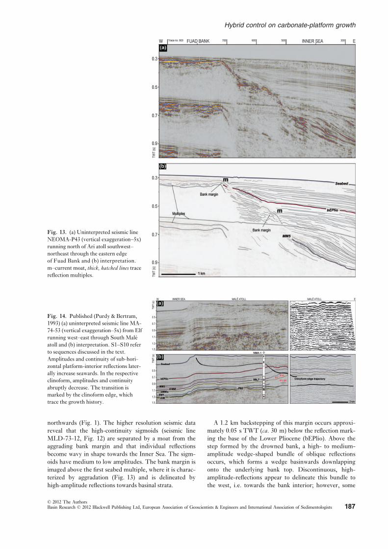
northwards (Fig. 1). The higher resolution seismic data
reveal that the high-continuity sigmoids (seismic line
MLD-73-12, Fig. 12) are separated by a moat from the
aggrading bank margin and that individual reflections
become wavy in shape towards the Inner Sea. The sigm-
oids have medium to low amplitudes. The bank margin is
imaged above the first seabed multiple, where it is charac-
terized by aggradation (Fig. 13) and is delineated by
high-amplitude reflections towards basinal strata.
A 1.2 km backstepping of this margin occurs approxi-
mately 0.05 s TWT (ca. 30 m) below the reflection mark-
ing the base of the Lower Pliocene (bEPlio). Above the
step formed by the drowned bank, a high- to medium-
amplitude wedge-shaped bundle of oblique reflections
occurs, which forms a wedge basinwards downlapping
onto the underlying bank top. Discontinuous, high-
amplitude-reflections appear to delineate this bundle to
the west, i.e. towards the bank interior; however, some
Fig. 13. (a) Uninterpreted seismic line
NEOMA-P43 (vertical exaggeration–5x)running north of Ari atoll southwest–northeast through the eastern edge
of Fuad Bank and (b) interpretation.
m–current moat, thick, hatched lines tracereflection multiples.
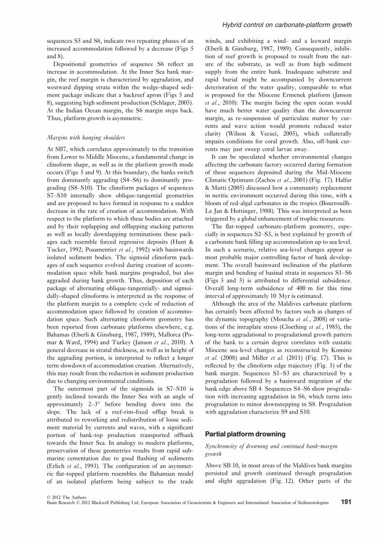
Fig. 14. Published (Purdy & Bertram,
1993) (a) uninterpreted seismic line MA-
74-53 (vertical exaggeration–5x) from Elf
running west–east through South Male
atoll and (b) interpretation. S1–S10 referto sequences discussed in the text.
Amplitudes and continuity of sub-hori-
zontal platform-interior reflections later-
ally increase seawards. In the respective
clinoform, amplitudes and continuity
abruptly decrease. The transition is
marked by the clinoform edge, which
trace the growth history.
© 2012 The AuthorsBasin Research © 2012 Blackwell Publishing Ltd, European Association of Geoscientists & Engineers and International Association of Sedimentologists 187
Hybrid control on carbonate-platform growth

reflections are traceable bankwards across this boundary.
The bank margin is backstepping, until bank growth in
this area of the Maldives terminates, which is indicated by
the occurrence of a continuous flat high-amplitude reflec-
tion draped by medium- to low-amplitude discontinuous
reflections with hummocky shapes. The bank top lies at a
depth of 0.32 s TWT (ca. 400 mbsl). Above SB bEPlio
(Fig. 2), the wedge-shaped bundle, which occurs in front
of the margin of the latest growth stage of the bank, is
overlain by a medium- to low-amplitude reflection pack-
age (Fig. 13). The package consists of high-continuity
divergent reflections, successively developing in shape
from sigmoidal to oblique-tangential. This package
wedges out at the bank edge and, in the upper part of the
succession, is separated from the bank margin by a series
of moats up to 400 m wide and some 10 s of metre deep
(Fig. 13).
Active atolls
Bathymetric maps of the sea floor indicate that the width
of the periplatform apron of the atolls in the study area
varies with respect to the proximity of the channels con-
necting the Inner Sea to the Indian Ocean (Fig. 1). The
aprons are tear-drop shaped (Betzler et al., 2009), andwidest away from the channels; flanking the channels the
apron disappear, and the slopes in front of the reef margin
plunge to the channel floor. For description of the growth
geometries of the active atolls, seismic lines from the
industrial data were chosen which are located where peri-
platform aprons are present.
Internal depositional geometries of active banks indicate
a continuous bank growth since the Early Miocene. This is
best illustrated by Elf seismic line MA-74-53 (Purdy &
Bertram, 1993), which runs west–east through South Male
atoll (Figs 1 and 14). During sequences S1–S6 the plat-
form progrades and aggrades, but only progrades during
S7–S10. Between SB E/MM and SB bEPlio, the growth
mode of the platform successively develops into an aggrad-
ing pattern. During the Miocene, the bank aggrades 0.75 s
TWT (ca. 935 m), and the bank margin progrades approx-
imately 4 km towards the Inner Sea. During Pliocene
times, the margin strongly progrades with a minor down-
stepping component. The late phase of bank growth shows
an aggrading to backstepping geometry.
The stratigraphy of seismic line MA-74-53 described
above was established by jump correlating horizons from
Shell seismic line E310NMA (Belopolsky & Droxler,
2004b) (Fig. 15). The eastern part of Elf seismic line
MA-74-2 (Purdy & Bertram, 1993) is the eastward con-
tinuation of line E310NMA and images the eastern most
part of Male atoll. Eastwards of well NMA-1, the bank
margin’s internal architecture is poorly imaged in the
medium- and in the low-resolution seismic data sets.
Nonetheless, the continuous prograding and aggrading
pattern of the Late Miocene, apparent at South Male
atoll, can also be recognized. The concave-up profile of
reflections near the position of well NMA-1, and the
upwards laterally offset stacking of high-amplitude reflec-
tions between 0.25 and 0.45 s TWT (ca. 310–560 mbsl)
east of NMA-1are interpreted to represent the platform
edge trajectory.
INTERPRETATION AND PRESENTATIONOFA NEWMODEL
Based on low- and intermediate-resolution industry seis-
mic data calibrated to two industry exploration wells
and one ODP hole, a general model for the Eocene to
recent development of the Maldives carbonate platform
has previously been delineated by Purdy & Bertram
(1993), Aubert & Droxler (1996) and Belopolsky &
Droxler (2004a). It shows the large-scale geometrical
Fig. 15. Published (Purdy & Bertram,
1993; Belopolsky & Droxler, 2004b) (a)
uninterpreted seismic line E310NMA
from Shell and eastern part of uninter-
preted seismic line MA-74-2 from Elf,
both running west–east through Male
atoll (vertical exaggeration–5x) and (b)interpretation. Well NMA-1 from Elf is
projected to Shell line. S1–S10 referto sequences discussed in the text.
A–Eocene, B–Oligocene, C–Late Oligo-cene? to Early Miocene, D–Middle Mio-
cene, E–Plio-Pleistocene?, F–Recent(ages after Purdy & Bertram, 1993).
© 2012 The AuthorsBasin Research © 2012 Blackwell Publishing Ltd, European Association of Geoscientists & Engineers and International Association of Sedimentologists188
C. Betzler et al.

Fig. 16. Set of schematic cross sections
illustrating the facies architecture devel-
opment through the Miocene to recent
time interval of the Maldives carbonate
platform.
Fig. 17. Chronostratigraphic diagram illustrating the depositional evolution of the Maldives carbonate platform. Figure is not to
scale. For colour coding please refer to Fig. 15. Platform development until earliest Miocene is adopted from Aubert & Droxler (1996).
Grey areas designate the age range of the drowning steps in the area studied. (1) Monsoon intensity is represented by the Arabian Sea
upwelling system reflected by the occurrence of the planktic foraminifer Globigerinoides bulloides (Kroon et al., 1991); (2) Sea-levelcurve fromMiller et al. (2011); (3) Sea-level curve from Kominz et al. (2008); (4) Sea-level curve from Haq et al. (1987).
© 2012 The AuthorsBasin Research © 2012 Blackwell Publishing Ltd, European Association of Geoscientists & Engineers and International Association of Sedimentologists 189
Hybrid control on carbonate-platform growth

development through time such as the seismically well
imaged dual bank-margin morphology of the platform
providing a bank-internal Inner Sea basin (Fig. 3). The
transition from Oligocene to Miocene is marked by ret-
rograding and then aggrading margins along the Inner
Sea side. These authors further proposed that the Mid-
dle Miocene and lower Upper Miocene are character-
ized by large-scale, basinwards prograding geometries.
The following middle Miocene to recent bank configu-
ration was described as partially drowned areas and
areas which resisted drowning and kept aggrading to
present sea level. This entire sequence was interpreted
in terms of accommodation variations proposed to result
from fluctuations in relative sea level.
Here, a different interpretation is presented, based
on the combined analysis of newly acquired high-reso-
lution seismic data and published lower-resolution seis-
mic lines (Figs 16 and 17). Based on the studied new
data, which for the first time provide clear insights into
the lower and middle Miocene bank architecture of the
Maldives (Fig. 5), currents together with sea-level
changes are interpreted to have contributed to the Neo-
gene platform evolution. The middle Miocene is the
key interval for the younger evolution of the Maldives,
because at this time reversing currents intensified and
triggered a turnover of platform configuration and
architecture.
A first indication showing the contribution of currents
in the evolution of the carbonate edifice is given by the
asymmetric growth of the western and eastern bank
(Fig. 3). Eastward progradation of the western bank of
around 20 km during the early and early middle Miocene
coincides with a mostly aggradational geometry of the
eastern bank. This is best explained by contribution of a
regular off-bank sediment transport to the leeward side of
the bank, similar to examples of carbonate platforms else-
where (Hine et al., 1981; Eberli & Ginsburg, 1987, 1989;
Schlager et al., 1994; Eberli et al., 2010). In this part of
the succession, variations of accommodation space can be
reconstructed from the bank-margin architecture (Figs 3
and 5).
This pattern is abandoned during the late middle
Miocene, when two different styles of platform devel-
opment existed contemporaneously. In some areas bank
margins drown, while other parts of the platform con-
tinue growing (Fig. 16). This synchroneity of different
stratigraphic stacking patterns is proposed to reflect a
change in the oceanographic and/or climatic factors
governing platform development which triggered a
change and also an intensification in the current
regime, so that currents from then on played a domi-
nant role for shaping platform geometries. The
modern current setup of seasonal balanced monsoonal
impact and strong, inter-monsoonal occurring
Indian Ocean Equatorial Westerlies, enforcing east-
wards directed Wyrtki Jets, provides a template for the
asymmetric filling of the Inner Sea basin since the late
Miocene.
Local tectonic control on relative sea level, so that dif-
ferent parts of the carbonate bank experience different
histories of relative sea level as a controlling factor, is not
supported by the available data. Aubert & Droxler (1996)
and Betzler et al. (2009) showed that individual drowning
unconformities can be traced into different parts of the
carbonate bank at the same depth, which argues against
differential subsidence.
LowerMioceneand lowerMiddleMiocenedevelopment of bankmargins
Reef-rimmed margins
At the Oligocene-Miocene boundary, the Maldives car-
bonate platform partially drowned and bank growth
became restricted to a narrow band at the platform mar-
gins facing the open Indian Ocean (Aubert & Droxler,
1996). Sequence S1 incorporates the upper part of unit
N1 into the first sequence of unit N2 as defined by Aubert
& Droxler (1996) (Fig. 3a). Sequence S1 thus constitutes
the latest stage of a large carbonate bank enclosing the
paleo-Inner Sea, which then was an enclosed basin. The
depression described in the new data is interpreted to rep-
resent a successively filled lagoon of an atoll-like config-
ured bank margin (Fig. 6). During a first progradational
phase of overlying sequence S2, the margin doubled in
width, which was accompanied by the burial of the ante-
cedent topography (SB2), formation of a flat-topped car-
bonate bank, aggradation of the bank interior, and a
severe steepening of the platform slope at the Inner Sea
side (Fig. 5). This is interpreted to be the result of the
establishment of a carbonate bank with a major area of
shallow water, i.e. euphotic, carbonate factory.
A minor backstepping of the bank margins facing the
Indian Ocean affected the Maldives above SB 3 (Figs 5
and 7). This backstepping is shown by the 200–250 m
wide terraces developed at the western and eastern flanks
of the edifice, at a distance of more than 60 km and at a
water depth of 750 m (Fig. 7). Therefore, a regional trig-
ger mechanism for this backstepping event is proposed,
although the available data do not allow for further inter-
pretation. The curve of tectonic subsidence for the North
Male Atoll presented by Purdy & Bertram (1993) do not
indicate any subsidence pulse for the lower Miocene.
During deposition of sequence S3, accommodation-
space creation is proposed to have decreased, provoking
the development of a thick basinal wedge (Fig. 5). This
geometrical arrangement with a wedge-shaped body in
front of the bank top and edge of the underlying sequence
also applies for sequence S4 (Figs 5 and 8), which is inter-
preted to reflect a response to continuing long-term
accommodation-space restriction and possibly downward
shifted carbonate production. This relies on the occur-
rence of an open shelf-like geometry developed in the
lower part of S4, where scattered patch reefs occur
(Fig. 5). Above SB5, the vertical stacking of bank edge
reefs followed by basinward progradation within both,
© 2012 The AuthorsBasin Research © 2012 Blackwell Publishing Ltd, European Association of Geoscientists & Engineers and International Association of Sedimentologists190
C. Betzler et al.
sequences S5 and S6, indicate two repeating phases of an
increased accommodation followed by a decrease (Figs 5
and 8).
Depositional geometries of sequence S6 reflect an
increase in accommodation. At the Inner Sea bank mar-
gin, the reef margin is characterized by aggradation, and
westward dipping strata within the wedge-shaped sedi-
ment package indicate that a backreef apron (Figs 5 and
8), suggesting high sediment production (Schlager, 2005).
At the Indian Ocean margin, the S6 margin steps back.
Thus, platform growth is asymmetric.
Margins with hanging shoulders
At SB7, which correlates approximately to the transition
from Lower to Middle Miocene, a fundamental change in
clinoform shape, as well as in the platform growth mode
occurs (Figs 5 and 9). At this boundary, the banks switch
from dominantly aggrading (S4–S6) to dominantly pro-
grading (S8–S10). The clinoform packages of sequences
S7–S10 internally show oblique-tangential geometries
and are proposed to have formed in response to a sudden
decrease in the rate of creation of accommodation. With
respect to the platform to which these bodies are attached
and by their toplapping and offlapping stacking patterns
as well as locally downlapping terminations these pack-
ages each resemble forced regressive deposits (Hunt &
Tucker, 1992; Posamentier et al., 1992) with basinwards
isolated sediment bodies. The sigmoid clinoform pack-
ages of each sequence evolved during creation of accom-
modation space while bank margins prograded, but also
aggraded during bank growth. Thus, deposition of each
package of alternating oblique-tangentially- and sigmoi-
dally-shaped clinoforms is interpreted as the response of
the platform margin to a complete cycle of reduction of
accommodation space followed by creation of accommo-
dation space. Such alternating clinoform geometry has
been reported from carbonate platforms elsewhere, e.g.
Bahamas (Eberli & Ginsburg, 1987, 1989), Mallorca (Po-
mar & Ward, 1994) and Turkey (Janson et al., 2010). Ageneral decrease in stratal thickness, as well as in height of
the aggrading portion, is interpreted to reflect a longer
term slowdown of accommodation creation. Alternatively,
this may result from the reduction in sediment production
due to changing environmental conditions.
The outermost part of the sigmoids in S7–S10 is
gently inclined towards the Inner Sea with an angle of
approximately 2–3° before bending down into the
slope. The lack of a reef-rim-fixed offlap break is
attributed to reworking and redistribution of loose sedi-
ment material by currents and waves, with a significant
portion of bank-top production transported offbank
towards the Inner Sea. In analogy to modern platforms,
preservation of these geometries results from rapid sub-
marine cementation due to good flushing of sediments
(Erlich et al., 1993). The configuration of an asymmet-
ric flat-topped platform resembles the Bahamian model
of an isolated platform being subject to the trade
winds, and exhibiting a wind- and a leeward margin
(Eberli & Ginsburg, 1987, 1989). Consequently, inhibi-
tion of reef growth is proposed to result from the nat-
ure of the substrate, as well as from high sediment
supply from the entire bank. Inadequate substrate and
rapid burial might be accompanied by downcurrent
deterioration of the water quality, comparable to what
is proposed for the Miocene Ermenek platform (Janson
et al., 2010): The margin facing the open ocean would
have much better water quality than the downcurrent
margin, as re-suspension of particulate matter by cur-
rents and wave action would promote reduced water
clarity (Wilson & Vecsei, 2005), which collaterally
impairs conditions for coral growth. Also, off-bank cur-
rents may just sweep coral larvae away.
It can be speculated whether environmental changes
affecting the carbonate factory occurred during formation
of these sequences deposited during the Mid-Miocene
Climatic Optimum (Zachos et al., 2001) (Fig. 17). Halfar
& Mutti (2005) discussed how a community replacement
in neritic environment occurred during this time, with a
bloom of red-algal carbonates in the tropics (Bourrouilh-
Le Jan & Hottinger, 1988). This was interpreted as been
triggered by a global enhancement of trophic resources.
The flat-topped carbonate-platform geometry, espe-
cially in sequences S2–S3, is best explained by growth of
a carbonate bank filling up accommodation up to sea level.
In such a scenario, relative sea-level changes appear as
most probable major controlling factor of bank develop-
ment. The overall basinward inclination of the platform
margin and bending of basinal strata in sequences S1–S6(Figs 3 and 5) is attributed to differential subsidence.
Overall long-term subsidence of 400 m for this time
interval of approximately 10 Myr is estimated.
Although the area of the Maldives carbonate platform
has certainly been affected by factors such as changes of
the dynamic topography (Moucha et al., 2008) or varia-tions of the intraplate stress (Cloething et al., 1985), thelong-term aggradational to progradational growth pattern
of the bank to a certain degree correlates with eustatic
Miocene sea-level changes as reconstructed by Kominz
et al. (2008) and Miller et al. (2011) (Fig. 17). This is
reflected by the clinoform edge trajectory (Fig. 5) of the
bank margin. Sequences S1–S3 are characterized by a
progradation followed by a basinward migration of the
bank edge above SB 4. Sequences S4–S6 show prograda-
tion with increasing aggradation in S6, which turns into
progradation to minor downstepping in S8. Progradation
with aggradation characterize S9 and S10.
Partialplatformdrowning
Synchroneity of drowning and continued bank-margingrowth
Above SB 10, in most areas of the Maldives bank margins
persisted and growth continued through progradation
and slight aggradation (Fig. 12). Other parts of the
© 2012 The AuthorsBasin Research © 2012 Blackwell Publishing Ltd, European Association of Geoscientists & Engineers and International Association of Sedimentologists 191
Hybrid control on carbonate-platform growth

platform drowned (Fig. 5). Left behind as persisting
atolls rose, drowned parts began to form passages, sepa-
rating carbonate banks to the north and south, and con-
necting the open Indian Ocean to the Inner Sea (Fig. 7)
(Aubert & Droxler, 1996). This turnover occurred
approximately during the late Middle Miocene (SB E/
MM) and correlates to a positive kick in gamma-ray
intensity in the well ARI-1, emphasizing a change in
lithology from limestone to marly limestone (Fig. 2).
This event of partial platform drowning can be traced
within the entire Maldives archipelago. The penultimate
southern line E970 of the Shell seismic grid (Belopolsky
& Droxler, 2004b), which transects the Maldives archi-
pelago at the southern end of the Inner Sea (ca. 2°40′N;
Fig. 1b), mirrors the situation described from the bank
margin between South Maalhosmadulu and Goidhoo
atolls (Fig. 5). It displays the drowned bank margin at the
eastern side of the Inner Sea and the SB E/MM being on-
lapped by basinwards restricted sediments. With ca.0.72 s TWT (ca. 900 mbsl), the depth of the drowning
unconformity at the bank top coincides fairly well with
the drowning depth observed throughout the high-resolu-
tion seismic grid. The synchroneity of drowning and con-
tinued bank-margin growth as well as the constant
position of the drowning unconformities contradict a sea-
level mechanism for this phenomenon (Aubert & Droxler,
1996).
The shape of a series of drowned banks in the eastern
Kardiva Channel (Kaashidhoo Kuda Kandu; Fig. 1),
probably late middle to late Miocene in age, indicates that
partial drowning of the Maldives carbonate platform coin-
cides with the onset or intensification of a current system
(Fig. 7). This is interpreted based on the perfect similar-
ity of shape elongation of this drowned bank with still
active atolls of the Maldives located just 5 km away of the
drowned edifice. Elongation of the drowned atoll indi-
cates occurrence of an westerly current, which would
complement the previously existing easterly system. The
combined effects of short-term sea-level rise as well as
current-induced upwelling and subsequent injection of
nutrients into the surface waters are proposed to have
provoked environmental stress and to have reduced or
even prevented further reef growth (Betzler et al., 2009).A similar control on drowning by current-driven nutrient
input into shallow waters was presented by Mutti et al.(2005) as a cause for Paleogene-Neogene carbonate bank
drowning at the northern Nicaraguan Rise. The differ-
ence between this established example and the herein pre-
sented case study is that the Maldives partial drowning
was triggered by a system of seasonally reversing cur-
rents.
A precursor of current-induced upwelling at the flanks
of the Maldives is proposed to be reflected by the asym-
metry of sequence S6, with its backstepping margin facing
the Indian Ocean, probably records a first charge of this
monsoonal impact. Such a margin backstepping, in other
cases, such as the Neogene Liuhua carbonate platform in
the China Sea (Erlich et al., 1990) has been related to ele-
vated nutrient input, which there is corroborated by anal-
ysis of carbonate facies and geochemistry (Sattler et al.,2009).
The interpretation of post-S10, i.e. post-drowning,
deposits rely on several observations (Figs 5 and 7). First,
the geometry of this prograding packages is characterized
by a convex-up form, as opposed to the clinoform geome-
tries of the underlying carbonate bank (Fig. 5). This and
the regular bedding is taken as indication that the pro-
grading bodies do not bear any reef bodies capable to
build a steep bank edge. Second, as shown by Belopolsky
Fig. 18. Block diagram sketch showing the middle Miocene to
Pliocene evolution of the western part of the Maldives carbonate
edifice. Partial drowning initiated in passages separating active
banks. Sediment depocentres developed at the down-current
flanks of the drowned bank and were reworked by contourite
currents. Numbers refer to location of key seismic lines dis-
cussed in the text.
© 2012 The AuthorsBasin Research © 2012 Blackwell Publishing Ltd, European Association of Geoscientists & Engineers and International Association of Sedimentologists192
C. Betzler et al.

& Droxler (2004a) in isopach maps, lobe-shaped accumu-
lation maxima are only attached to the margin of the
drowned bank adjacent to present day inter-atoll passages
and hence exclusively to areas which drowned during the
late middle Miocene (Aubert & Droxler, 1996). This is
also displayed in the line P6 (Fig. 3) which shows the
southward thinning of this sedimentary interval, away
from the area covered by line P65. This is taken as an
indication that the sediment deposited in the lobes was
delivered by a point source. Third, the prograding bodies
contain sediment waves (Fig. 5), which indicate sediment
reworking through bottom currents. According to Fau-
geres et al. (1999) such waves form through the action of
contourite currents. Fourth, the sediment bodies at their
end facing the drowned bank are separated from the bank
by a channel-like depression (Figs 5 and 8) interpreted as
a current moat as shown for contourites by Faugeres et al.(1999). Therefore, the lobe-shaped body is interpreted as
a current-reworked ‘mega spill over’ deposit, formed on
the down-current side of the drowned carbonate bank
under the co-influence of a contour-parallel current.
Figure 18 shows the main steps which are proposed for
this middle to upper Miocene evolution. The lower
middle Miocene is characterized by a carbonate bank
shedding sediment into the Inner Sea along a line source.
During the late middle Miocene, an additional point
source delivery of sediment started, feeding the lobes
(Fig. 18). Grey arrows show the different current direc-
tions affecting lobe development and are in line with the
regime of seasonally reversing monsoon-triggered flows.
The current-affected ‘mega spill over’ lobes are thought
to consist of an admixture of pelagic and neritic compo-
nents; it is proposed that neritic components are mostly
derived from the shallow carbonate banks fringing the
Inner Sea and the passages between the banks. It remains
open for speculation if the channels were also loci of a
thriving carbonate factory which may have additionally
contributed sediment into the drift bodies. Such a factory
may have been subjected to elevated nutrient contents,
triggered by the forcing of the oceanic currents through the
channels. The Kalukalukuang Bank (Roberts et al., 1987),which is situated in the southern Makassar Street between
Borneo and Sulawesi (Indonesia), may serve as a modern
analogue for environmental conditions which prevailed
within the passages. Scattered coral reefs occur on this
bank, with no corals occurring below 15 m of water depth.
On the up to 100 m deep bank, seasonally reversing mon-
soon currents are responsible for upwelling of nutrient-rich
waters, favouring growth of Halimeda bioherms in water
depths of 20–60 m. Mounds are not consolidated bodies,
and reworking of the mound crest is indicated by bedforms
at the sediment surface (Roberts et al., 1988). Therefore,such a carbonate factory can be seen as a potential source
shedding particles into the lobes.
Passages between the banks eventually widened during
the late Miocene through drowning of further bank areas
(Figs 7, 12, 13 and 18. This widening triggered a broad-
ening of the current stream, sedimentologically reflected
by a more regular sediment input into the Inner Sea and
the compensation of the lobe depositional relief during
the late Miocene and early Pliocene (Fig. 1).
In addition to the onset of bank demise in the upper
Middle Miocene (Fig. 17), two further phases of partial
platform drowning are recognized in the area studied.
Bank-interior geometries prior to drowning, however,
cannot be reconstructed with the same detail, as the
drowning unconformities mask the bank-interior succes-
sion. The drowning episodes are reflected by the upper
Miocene backstepping margin of the bank and finally the
complete lower Pliocene drowning of the bank which are
shown in Fig. 13. These two steps may be correlated with
phases of enhanced Indian monsoon intensity (Kroon
et al., 1991), based on planktic foraminiferal associations
in the Arabian Sea. These phases are found to be linked to
coeval uplift episodes of the Asian continent (Zheng
et al., 2004) and subsequent enhanced rates of erosion.
The record of enhanced erosion is provided by rates of
Himalayan and Tibetan sediment influx to the deep
Indian Ocean (Rea, 1992).
Activeatolls
The evolution of the active atolls since the middle Miocene
cannot be interpreted in great detail, as only low-resolution
industrial lines provide insights into these complexes
(Figs 14 and 15). The clinoform edge trajectory through
sequence S10 is comparable to the trajectory identified in
the drowned middleMiocene bank (Fig. 5), although over-
all progradation does not surpass 10 km. This low value
compared with the 20 km of the drowned bank corrobo-
rates the evidence for a system of easterly currents during
the early and early middle Miocene bank growth. During
the late Miocene, both bank margins of the active atolls
prograded and aggraded, the Pliocene is characterized in
both cases by pure aggradation with slight downward shift
of the bank edge (Figs 14 and 15), although the bank edge
of North Male Atoll migrated around 10 km, compared to
1–1.5 km in SouthMale Atoll.
Both bank margins shifted into an aggradational mode
approximately during the late Pliocene to early Pleisto-
cene. This trend of bank growth is in line with the long-
term eustatic sea-level lowering shown by Miller et al.(2011). As expressed by Aubert & Droxler (1996), the
change from progradation to aggradation is best explained
by initiation of the regime of high-amplitude and high-
frequency sea-level changes. It is proposed that in such a
system and under a persistent current winnowing of the
slopes, banks are forced into an aggradational mode,
because they do not develop slope aprons which are nec-
essary to allow progradation of the bank edge.
CONCLUSIONS
A detailed reconstruction of the Miocene to recent seismic
facies and geometries of the Maldives carbonate platform
© 2012 The AuthorsBasin Research © 2012 Blackwell Publishing Ltd, European Association of Geoscientists & Engineers and International Association of Sedimentologists 193
Hybrid control on carbonate-platform growth

allows to show that this edifice is subjected to two major
controlling factors: sea-level changes and currents. The
platform geometries can be explained as a result of varia-
tions of the relative impact of these factors on sediment
accumulation, but probably also on the carbonate factory.
By tracing bank-internal geometries and facies, it can be
shown that the Maldives carbonate platform during the
late Middle Miocene was subjected to a strengthening of
the current regime, which in time correlates with the
onset and/or intensification of the Indian monsoon.
Lower and middle Miocene strata are grouped into 10
sequences that formed in response to variations of accom-
modation space primarily driven by relative sea level.
Sequences 1–6 (S1–S6) show the development from an
isolated shallow ramp with downslope buildups to a
steep-flanked reef-rimmed carbonate platform. Bank edge
reefs protect the lagoon, where backreef aprons occur. At
the transition from sequence 6–7, a general switch from
dominantly aggrading to dominantly prograding bank
margins occur, which is accompanied by a fundamental
change in clinoform shape. Each of the sequences 7–10(S7–S10) is composed of deposits, which are proposed to
have formed in response to a forced regression, and is
overlain by deposits formed during re-flooding of the
bank margins. These sequences show no bank edge reefs,
similar to other carbonate platforms of the Indopacific
realm, where a community replacement in neritic envi-
ronment occurred.
The upper Middle Miocene is characterized by the
appearance of a large-scale clinoform bodies, lobate in
shape, attesting the onset of current amplification. These
bodies are attached to passages where bank segment
drowned, while in other parts bank grew on. Lobes are
interpreted as ‘mega spill overs’ fed by easterly currents,
and reworked by a current system flowing obliquely or
normally to this main stream. Such currents flowing in
different directions are in line with the seasonal reversals
linked to the monsoon. To further drowning steps
affected the Maldives, during the late Miocene and the
early Pliocene.
Hence, since late middle Miocene times the Maldives
show a twofold configuration of bank development of per-
sisting growth, which is accompanied by partial platform
drowning and associated localized deposition of contou-
rites and drifts in areas just some kilometre apart. This
interpretation implies that a downward shift of clinoform
tops and offlapping geometries in carbonate platforms are
not necessarily indicative for a sea-level driven forced
regression or aggrading bank margins. The Maldives pro-
vide an example, where stratal patterns are an equivocal
base for the interpretation of sea-level fluctuations. It
shows that sediment accumulation rate is a consequence
of rate of creation of accommodation, production rate,
and transport rate. In the case presented, the interpreta-
tion of the seismic geometries suggests that all three var-
ied both spatially and temporally. Such depositional
systems are probably more frequent in the geological
record than previously thought in sequence-stratigraphic
models that tend to ignore basic observations. Findings
are expected to be applicable to other examples of Ter-
tiary platforms in the Indo-Pacific region.
ACKNOWLEDGEMENTS
We thank the efficient technical assistance of CaptainWal-
ter Baschek, the officers and the crew of the R/V Meteor,who all together contributed significantly to the success of
the cruise, and the Shipboard Scientific Party of R/V
Meteor cruise leg M74/4 for substantial onboard support.
The Bundesministerium fur Bildung und Forschung and
the Deutsche Forschungsgemeinschaft is gratefully
acknowledged for project funding (NEOMA, 03G0667A;
Be1272/20). We wish to thank Paradigm for providing
ProMax software for seismic data processing and Schlum-
berger for providing Petrel for seismic data analysis. The
in-depth and constructive reviews of Gregor Eberli, Klaas
Verwer, Xavier Janson, Peter Burgess, KenMiller and the
journal editors significantly helped us and are greatly
acknowledged. Philipp Konerding is thanked for digitiz-
ing the Elf seismics paper prints. Torge Schumann is
thanked for helping to polish the manuscript.
REFERENCESANSELMETTI, F.S. & EBERLI, G.P. (2001) Sonic velocity in car-
bonates – a combined product of depositional lithology and
diagenetic alterations. In: Subsurface Geology of a ProgradingCarbonate Platform Margin, Great Bahama Bank: Results ofthe Bahamas Drilling Project (Ed. by Ginsburg R.N.), SEPMSpec. Publ., 70, 193–216. SEPM, Tulsa, OK.
ANSELMETTI, F.S., EBERLI, G.P. & DING, Z.-D. (2000) From the
Great Bahama Bank into the Straits of Florida: a Margin
Architecture Controlled by Sea-Level Fluctuations and
Ocean Currents. Geol. Soc. Am. Bull., 112, 829–844.AUBERT, O. & DROXLER, A.W. (1992) General cenozoic evolu-
tion of the Maldives carbonate system (equatorial Indian
Ocean). Bull. Centres Rech. Explor.-Prod. Elf-Aquitaine, 16,113–136.
AUBERT, O. & DROXLER, A.W. (1996) Seismic stratigraphy and
depositional signatures of the Maldive carbonate system
(Indian Ocean).Mar. Pet. Geol., 13, 503–536.BACKMAN, J., DUNCAN, R.A., PETERSON, L.C., BAKER, P.A., BAX-
TER, A.N. & BOERSMA, A. (1988)Mascarene Plateau - Sites 705–716. Ocean Drilling Program, College Station, TX.
BELOPOLSKY, A.V. & DROXLER, A.W. (2003) Imaging tertiary
carbonate systems - the Maldives, Indian Ocean: insights into
carbonate sequence interpretation. Lead. Edge, 22, 646–652.BELOPOLSKY, A.V. & DROXLER, A.W. (2004a) Seismic expres-
sions of prograding carbonate bank margins: middle Miocene,
Maldives, Indian Ocean. In: Seismic Imaging of Carbonate Res-ervoirs and Systems (Ed. by Eberli G.P., Masaferro J.L. & Sarg
J.F.), AAPG Mem., 81, 267–290. Am Assoc Pet Geol, Tulsa,
OK.
BELOPOLSKY, A.V. & DROXLER, A.W. (2004b) Seismic expres-
sions and interpretation of carbonate sequences: the Maldives
Platform, Equatorial Indian Ocean. AAPG Stud. Geol., 49,1–46.
© 2012 The AuthorsBasin Research © 2012 Blackwell Publishing Ltd, European Association of Geoscientists & Engineers and International Association of Sedimentologists194
C. Betzler et al.

BETZLER, C., KROON, D. & REIJMER, J.J.G. (2000) Synchroneity
of major late Neogene sea-level fluctuations and paleoceano-
graphically controlled changes as recorded by two carbonate
platforms. Paleoceanography, 15, 722–730.BETZLER, C., HUBSCHER, C., LINDHORST, S., REIJMER, J.J.G.,
ROMER, M., DROXLER, A., FURSTENAU, J. & LUDMANN, T.
(2009) Monsoon-induced partial carbonate platform drown-
ing (Maldives, Indian Ocean). Geology, 37, 867–870.BETZLER, C., LINDHORST, S., HUBSCHER, C., LUDMANN, T.,
FURSTENAU, J. & REIJMER, J.J.G. (2011) Giant pockmarks in a
carbonate platform (Maldives, Indian Ocean). Marine Geol-ogy, 289, 1–16.
BOURROUILH-LE JAN, F.G. & HOTTINGER, L.C. (1988) Occur-
rence of rhodolites in the tropical Pacific - a consequence of
Mid-Miocene paleo-oceanographic change. Sed. Geol., 60,
355–367.CATUNEANU, O., ABREU, V., BHATTACHARYA, J.P., BLUM, M.D.,
DALRYMPLE, R.W., ERIKSSON, P.G., FIELDING, C.R., FISHER,
W.L., GALLOWAY, W.E., GIBLING, M.R., GILES, K.A., HOL-
BROOK, J.M., JORDAN, R., KENDALL, C.G.S.C., MACURDA, B.,
MARTINSEN, O.J., MIALL, A.D., NEAL, J.E., NUMMEDAL, D.,
POMAR, L., POSAMENTIER, H.W., PRATT, B.R., SARG, J.F.,
SHANLEY, K.W., STEEL, R.J., STRASSER, A., TUCKER, M.E. &
WINKER, C. (2009) Towards the standardization of sequence
stratigraphy. Earth-Sci. Rev., 92, 1–33.CIARAPICA, G. & PASSERI, L. (1993) An overview of the Maldi-
vian coral reefs in Felidu and north Male Atoll (Indian
Ocean): platform drowning by ecological crisis. Facies, 28, 33–65.
CLIFT, P.D., HODGES, K.V., HESLOP, D., HANNIGAN, R., VAN
LONG, H. & CALVES, G. (2008) Correlation of Himalayan
exhumation rates and Asian monsoon intensity. Nat. Geosci.,1, 875–880.
CLOETHING, S., MCQUEEN, H. & LAMBECK, K. (1985) On a tec-
tonic mechanism for regional sealevel variations. Earth Planet.Sci. Lett., 75, 157–166.
DROXLER, A., HADDAD, G.A., MUCCIARONE, D.A. & CULLEN,
J.L. (1990) Pliocene-Pleistocene aragonite cyclic variations in
holes 714a and 716b (the Maldives) compared with hole 633a
(the Bahamas): records of climate-induced CaCO3 preserva-
tion at intermediate water depths. In: Proceedings of the OceanDrilling Program, Scientific Results (Ed. by R.A. Duncan, J.
Backman & L.C. Peterson), 115, 539–577. College Station,
Texas.
DUNCAN, R.A. & HARGRAVES, R.B. (1990) 40Ar/39Ar geochro-
nology of basement rocks from the Mascarene Plateau, the
Chagos Bank, and the Maldives Ridge. In: Proceedings of theOcean Drilling Program, Scientific Results (Ed. by Duncan
R.A., Backman J. & Peterson L.C.), 115, 43–51. College Sta-tion, Texas.
EBERLI, G.P. & GINSBURG, R.N. (1987) Segmentation and Coa-
lescence of Cenozoic Carbonate Platforms, Northwestern
Great Bahama Bank.Geology, 15, 75–79.EBERLI, G.P. & GINSBURG, R.N. (1989) Cenozoic progradation
of northwestern Great Bahama Bank, a record of lateral plat-
form growth and sea-level fluctuations. In: Controls on Car-bonate Platform and Basin Development (Ed. by Crevello P.D.,
Wilson J.L., Sarg J.F. & Read J.F.), SEPM Spec. Publ., 44,339–351. SEPM, Tulsa, OK.
EBERLI, G.P., ANSELMETTI, F.S., ISERN, A.R. & DELIUS, H.
(2010) Timing of changes in sea-level and currents along
Miocene Platforms on the Marion Plateau, Australia. In:
Cenozoic Carbonate Systems of Australia (Ed. by Morgan
W.A., George A.D., Harris P.M., J.A. Kupecz & J.F. Sarg),
SEPM Spec. Publ., 95, 219–242. SEPM, Tulsa, OK.
ERLICH, R.N., BARRETT, S.F. & JU, G.B. (1990) Seismic and
geologic characteristics of drowning events on carbonate plat-
forms. AAPG Bull., 74, 1523–1537.ERLICH, R.N., LONGO, A.P. & HYARE, S. (1993) Response of car-
bonate platform margins to drowning: evidence of environ-
mental collapse. In: Carbonate Sequence Stratigraphy (Ed. by
Loucks R.G. & Sarg J.F.), AAPGMem., 57, 241–266. Am As-
soc Pet Geol, Tulsa, OK.
FAUGERES, J.-C., STOW, D.A.V., IMBERT, P. & VIANA, A. (1999)
Seismic features diagnostic of contourite drifts. Mar. Geol.,162, 1–38.
FLOWER, B.P. & KENNETT, J.P. (1994) The middle Miocene cli-
matic transition: east Antarctic ice sheet development, deep
ocean circulation and global carbon cycling. Palaeogeogr. Pal-aeoclimatol. Palaeoecol., 108, 537–555.
FONTAINE, J.M., CUSSEY, R., LACAZE, J., LANAUD, R. & YAPAUDJ-
IAN, L. (1987) Seismic interpretation of carbonate depositional
environments. AAPG Bull., 71, 281–297.FURSTENAU, J., LINDHORST, S., BETZLER, C. & HUBSCHER, C.
(2010) Submerged reef terraces of the Maldives indicate var-
iations in the rate of deglacial sea-level rise during MWP-1A.
Geo-Marine Letters, 30, 511–515.GISCHLER, E. (2006) Sedimentation on Rasdhoo and Ari Atolls,
Maldives, Indian Ocean. Facies, 52, 341–360.GISCHLER, E., HUDSON, J.H. & PISERA, A. (2008) Late quater-
nary reef growth and sea level in the Maldives (Indian Ocean).
Mar. Geol., 250, 104–113.HALFAR, J. & MUTTI, M. (2005) Global dominance of coralline
red-algal facies: a response to Miocene oceanographic events.
Geology, 33, 481–484.HAQ, B.U., HARDENBOL, J. & VAIL, P.R. (1987) Chronology of
fluctuating sea levels since the Triassic. Science, 235, 1156–1167.
HINE, A.C., WILBER, R.J., BANE, J.M., NEUMANN, A.C. &
LORENSON, K.R. (1981) Offbank transport of carbonate sands
along open, leeward bank margins: Northern Bahamas. Mar.Geol., 42, 327–348.
HUNT, D. & TUCKER, M.E. (1992) Stranded parasequences and
the forced regressive wedge systems tract: deposition during
base-level fall. Sed. Geol., 81, 1–9.ISERN, A.R., ANSELMETTI, F.S. & BLUM, P. (2004) A neogene
carbonate platform, slope, and shelf edifice shaped by sea
level and ocean currents, Marion Plateau (Northeast
Australia). In: Seismic Imaging of Carbonate Reservoirs andSystems (Ed. by Eberli G.P., Masaferro J.L. & Sarg J.F.),
AAPG Mem., 81, 291–307. Am Assoc Pet Geol, Tulsa,
OK.
JANSON, X., VAN BUCHEM, F.S.P., DROMART, G., EICHENSEER,
H.T., DELLAMONICA, X., BOICHARD, R., BONNAFFE, F. & EB-
ERLI, G. (2010) Architecture and facies differentiation within
a Middle Miocene carbonate platform, Ermenek, Mut Basin,
Southern Turkey. In: Mesozoic and Cenozoic Carbonate Sys-tems of the Mediterranean and the Middle East: Stratigraphicand Diagenetic Reference Models (Ed. by van Buchem F.S.P.,
Gerdes K.D. & Esteban M.), SEPM Spec. PubL., 329, 265–290. Geol. Soc., London.
KOMINZ, M.A., BROWNING, J.V., MILLER, K.G., SUGARMAN,
P.J., MIZINTSEVA, S. & SCOTESE, C.R. (2008) Late Cretaceous
to Miocene sea-level estimates from the New Jersey and Dela-
ware coastal plain coreholes: an error analysis. Basin Res., 20,211–226.
© 2012 The AuthorsBasin Research © 2012 Blackwell Publishing Ltd, European Association of Geoscientists & Engineers and International Association of Sedimentologists 195
Hybrid control on carbonate-platform growth

KROON, D., STEENS, T.N.F. & TROELSTRA, S.R. (1991) Onset of
monsoonal related upwelling in the western Arabian sea as
revealed by planktonic foraminifers. In: Proc. ODP, Sci.Results (Ed. by N.J. Stewart), 117, 257–263. College Station,Texas.
LEAR, C.H., ELDERFIELD, H. & WILSON, P.A. (2000) Cenozoic
deep-sea temperature and global ice volumes from Mg/Ca in
benthic foraminiferal calcite. Science, 287, 269–272.LEWIS, A.R., MARCHANT, D.R., ASHWORTH, A.C., HEMMING,
S.R. & MACHLUS, M.L. (2007) Major Middle Miocene global
climate change: evidence from east Antarctica and Transant-
arctic Mountains. Geol. Soc. Am. Bull., 119, 1449–1461.LUKASIK, J. & SIMO, J.A. (2008) Controls on development of
Phanerozoic carbonate platforms and reefs - introduction and
synthesis. In: Controls on Carbonate Platform and Reef Devel-opment (Ed. by Lukasik J. & Simo J.A.). SEPM Spec. Publ.,89, 5–12. SEPM, Tulsa, OK.
MALONE, M.J., BAKER, P.A., BURNS, S.J. & SWART, P.K. (1990)
Geochemistry of Periplatform Carbonate Sediments, Leg
115, Site 716 (Maldives Archipelago, Indian Ocean). In: Proc.ODP, Sci. Results (Ed. by Duncan R.A., Backman J. &
Peterson L.C.), 115, 647–659. College Station, Texas.MILLER, K.G., WRIGHT, J.D. & FAIRBANKS, R.G. (1991) Unlock-
ing the ice house: oligocene-miocene oxygen isotopes, eustasy,
and margin erosion. J. Geophys. Res., 96, 6829–6848.MILLER, K.G., KOMINZ, M.A., BROWNING, J.V., WRIGHT, J.D.,
MOUNTAIN, G.S., KATZ, M.E., SUGARMAN, P.J., CRAMER,
B.S., CHRISTIE-BLICK, N. & PEKAR, S.F. (2005) The phanero-
zoic record of global sea-level change. Science, 310, 1293–1298.
MILLER, K.G., MOUNTAIN, G.S., WRIGHT, J.D. & BROWNING,
J.V. (2011) A 180-million-year record of sea level and ice vol-
ume variations from continental margin and deep-sea isotopic
records. Oceanography, 24, 40–53.MOUCHA, R., FORTE, A.M., MITROVICA, J.X., ROWLEY, D.B.,
QUERE, S., SIMMONS, N.A. & GRAND, S.P. (2008) Dynamic
topography and long-term sea-level variations: there is no
such thing as a stable continental platform. Earth Planet. Sci.Lett., 271, 101–108.
MUTTI, M., DROXLER, A.W. & CUNNINGHAM, A.D. (2005) Evo-
lution of the northern Nicaragua rise during the Oligocene-
Miocene: drowning by environmental factors. Sed. Geol., 175,237–258.
POMAR, L. & WARD, W.C. (1994) Response of a late miocene
Mediterranean reef platform to high-frequency Eustasy.
Geology, 22, 131–134.POSAMENTIER, H.W., ALLEN, G.P., JAMES, D.P. & TESSON, M.
(1992) Forced regressions in a sequence stratigraphic frame-
work: concepts, examples, and exploration significance.
AAPG Bull., 76, 1687–1709.PREU, C. & ENGELBRECHT, C. (1991) Patterns and Processes
Shaping the Present Morphodynamics of Coral Reef Islands:
Case Study from the North-Male Atoll, Maldives. In: VonDer Nordsee Bis Zum Indischen Ozean (Ed. by H. Bruckner &
U. Radke), pp. 209–220. Steiner, Stuttgart.PURDY, E. & BERTRAM, G.T. (1993) Carbonate concepts from
the Maldives, Indian Ocean. AAPG Stud. Geol., 34, 56.REA, D.K. (1992) Delivery of Himalayan Sediment to the
Northern Indian Ocean and Its Relation to Global Climate,
Sea Level, Uplift, and Seawater Strontium. In: Synthesis ofResults From Scientific Drilling in the Indian Ocean (Ed. by
Duncan R.A., Rea D.K., Kidd R.B., von Rad U. & Weissel
J.K.), Geophysical Monograph, 70, 387–402. Am. Geophys.
Union, Washington, DC.
RIO, D., FORNACIARI, E. & RAFFI, I. (1990) Late Oligocene
through early Pleistocene calcareous nannofossils from wes-
tern equatorial Indian Ocean (Leg 115). In: Proceedings of theOcean Drilling Program, Scientific Results (Ed. by Duncan
R.A., Backman J. & Peterson L.C.), 115, 175–235. CollegeStation, Texas.
ROBERTS, H., PHIPPS, C. & EFFENDI, L. (1987) Morphology of
large Halimeda bioherms, eastern Java Sea (Indonesia): a side-
scan sonar study. Geo-Mar. Lett., 7, 7–14.ROBERTS, H.H., AHARON, P. & PHIPPS, C.V. (1988) Morphology
and sedimentology of Halimeda bioherms from the eastern
Java Sea (Indonesia). Coral Reefs, 6, 151–172.SATTLER, U., IMMENHAUSER, A., SCHLAGER, W. & ZAMPETTI, V.
(2009) Drowning history of a Miocene carbonate platform
(Zhujiang Formation, South China Sea). Sed. Geol., 219, 318–331.
SCHLAGER, W. (1992) Sedimentology and sequence stratigraphy
of reefs and carbonate platforms. AAPG Cont. Educ. CourseSer., 34, 71.
SCHLAGER, W. (2005) Carbonate Sedimentology and SequenceStratigraphy. SEPM, Tulsa, OK.
SCHLAGER, W., REIJMER, J.J.G. & DROXLER, A.W. (1994) High-
stand shedding of carbonate platforms. J. Sed. Res., 64, 270–281.
SHACKLETON, N.J. & KENNETT, J.P. (1975) Paleotemperature
history of the cenozoic and the initiation of Antarctic glacia-
tion: oxygen and carbon isotope analyses in DSDP sites 277,
279, and 281. In: Init. Reports DSDP (Ed. by Kennett J.P. &
Houtz R.E. et al.), 29, 743–755. U.S. Government Printing
Office, Washington, DC.
TCHEREPANOV, E.N., DROXLER, A.W., LAPOINTE, P. & MOHN, K.
(2008) Carbonate seismic stratigraphy of the Gulf of Papua
mixed depositional system: neogene stratigraphic signature
and eustatic control. Basin Res., 20, 185–209.TOMCZAK, M. & GODFREY, J.S. (2003) Regional Oceanography:An Introduction. Daya Publ. House, Delhi.
WILSON, M.E.J. & VECSEI, A. (2005) The apparent paradox of
abundant foramol facies in low latitudes: their environmental
significance and effect on platform development. Earth-Sci.Rev., 69, 133–168.
WOODRUFF, F. & SAVIN, S.M. (1989) Miocene deepwater ocean-
ography. Paleoceanography, 4, 87–140.ZACHOS, J., PAGANI, M., SLOAN, L., THOMAS, E. & BILLUPS, K.
(2001) Trends, rhythms, and aberrations in global climate.
Science, 292, 686–693.ZHENG, H., POWELL, C.M., REA, D.K., WANG, J. & WANG, P.
(2004) Late Miocene and mid-Pliocene enhancement of the
east Asian monsoon as viewed from the land and sea. GlobalPlanet. Change, 41, 147–155.
Manuscript received 19 March 2011; In revised form 05April 2012; Manuscript accepted 30 April 2012.
© 2012 The AuthorsBasin Research © 2012 Blackwell Publishing Ltd, European Association of Geoscientists & Engineers and International Association of Sedimentologists196
C. Betzler et al.
Copyright © 2022 FDOKUMEN