Political Party Brand Identity and Brand Image: An Empirical Assessment
Upload
khangminh22Category
view
1download
0
2012 OOOccceeeaaannn BBBrrraaannnddd
World Class Rigging Products
“OCEAN” is a registered Trade Mark of Oceanside Equipment Limited
Oce
ansi
de E
quip
men
t Lim
ited
2012
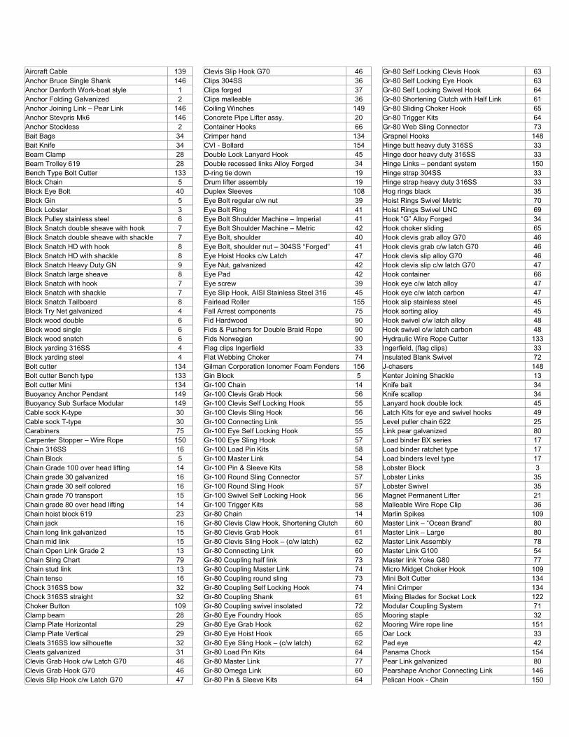
Aircraft Cable 139 Anchor Bruce Single Shank 146 Anchor Danforth Work-boat style 1 Anchor Folding Galvanized 2 Anchor Joining Link – Pear Link 146 Anchor Stevpris Mk6 146 Anchor Stockless 2 Bait Bags 34 Bait Knife 34 Beam Clamp 28 Beam Trolley 619 28 Bench Type Bolt Cutter 133 Block Chain 5 Block Eye Bolt 40 Block Gin 5 Block Lobster 3 Block Pulley stainless steel 6 Block Snatch double sheave with hook 7 Block Snatch double sheave with shackle 7 Block Snatch HD with hook 8 Block Snatch HD with shackle 8 Block Snatch Heavy Duty GN 9 Block Snatch large sheave 8 Block Snatch with hook 7 Block Snatch with shackle 7 Block Snatch Tailboard 8 Block Try Net galvanized 4 Block wood double 6 Block wood single 6 Block wood snatch 6 Block yarding 316SS 4 Block yarding steel 4 Bolt cutter 134 Bolt cutter Bench type 133 Bolt cutter Mini 134 Buoyancy Anchor Pendant 149 Buoyancy Sub Surface Modular 149 Cable sock K-type 30 Cable sock T-type 30 Carabiners 75 Carpenter Stopper – Wire Rope 150 Chain 316SS 16 Chain Block 5 Chain Grade 100 over head lifting 14 Chain grade 30 galvanized 16 Chain grade 30 self colored 16 Chain grade 70 transport 15 Chain grade 80 over head lifting 14 Chain hoist block 619 23 Chain jack 16 Chain long link galvanized 15 Chain mid link 15 Chain Open Link Grade 2 13 Chain Sling Chart 79 Chain stud link 13 Chain tenso 16 Chock 316SS bow 32 Chock 316SS straight 32 Choker Button 109 Clamp beam 28 Clamp Plate Horizontal 29 Clamp Plate Vertical 29 Cleats 316SS low silhouette 32 Cleats galvanized 31 Clevis Grab Hook c/w Latch G70 46 Clevis Grab Hook G70 46 Clevis Slip Hook c/w Latch G70 47
Clevis Slip Hook G70 46 Clips 304SS 36 Clips forged 37 Clips malleable 36 Coiling Winches 149 Concrete Pipe Lifter assy. 20 Container Hooks 66 Crimper hand 134 CVI - Bollard 154 Double Lock Lanyard Hook 45 Double recessed links Alloy Forged 34 D-ring tie down 19 Drum lifter assembly 19 Duplex Sleeves 108 Eye Bolt regular c/w nut 39 Eye Bolt Ring 41 Eye Bolt Shoulder Machine – Imperial 41 Eye Bolt Shoulder Machine – Metric 42 Eye Bolt, shoulder 40 Eye Bolt, shoulder nut – 304SS “Forged” 41 Eye Hoist Hooks c/w Latch 47 Eye Nut, galvanized 42 Eye Pad 42 Eye screw 39 Eye Slip Hook, AISI Stainless Steel 316 45 Fairlead Roller 155 Fall Arrest components 75 Fid Hardwood 90 Fids & Pushers for Double Braid Rope 90 Fids Norwegian 90 Flag clips Ingerfield 33 Flat Webbing Choker 74 Gilman Corporation Ionomer Foam Fenders 156 Gin Block 5 Gr-100 Chain 14 Gr-100 Clevis Grab Hook 56 Gr-100 Clevis Self Locking Hook 55 Gr-100 Clevis Sling Hook 56 Gr-100 Connecting Link 55 Gr-100 Eye Self Locking Hook 55 Gr-100 Eye Sling Hook 57 Gr-100 Load Pin Kits 58 Gr-100 Master Link 54 Gr-100 Pin & Sleeve Kits 58 Gr-100 Round Sling Connector 57 Gr-100 Round Sling Hook 57 Gr-100 Swivel Self Locking Hook 56 Gr-100 Trigger Kits 58 Gr-80 Chain 14 Gr-80 Clevis Claw Hook, Shortening Clutch 60 Gr-80 Clevis Grab Hook 61 Gr-80 Clevis Sling Hook – (c/w latch) 62 Gr-80 Connecting Link 60 Gr-80 Coupling half link 73 Gr-80 Coupling Master Link 74 Gr-80 Coupling round sling 73 Gr-80 Coupling Self Locking Hook 74 Gr-80 Coupling Shank 61 Gr-80 Coupling swivel insolated 72 Gr-80 Eye Foundry Hook 65 Gr-80 Eye Grab Hook 62 Gr-80 Eye Hoist Hook 65 Gr-80 Eye Sling Hook – (c/w latch) 62 Gr-80 Load Pin Kits 64 Gr-80 Master Link 77 Gr-80 Omega Link 60 Gr-80 Pin & Sleeve Kits 64
Gr-80 Self Locking Clevis Hook 63 Gr-80 Self Locking Eye Hook 63 Gr-80 Self Locking Swivel Hook 64 Gr-80 Shortening Clutch with Half Link 61 Gr-80 Sliding Choker Hook 65 Gr-80 Trigger Kits 64 Gr-80 Web Sling Connector 73 Grapnel Hooks 148 Hinge butt heavy duty 316SS 33 Hinge door heavy duty 316SS 33 Hinge Links – pendant system 150 Hinge strap 304SS 33 Hinge strap heavy duty 316SS 33 Hog rings black 35 Hoist Rings Swivel Metric 70 Hoist Rings Swivel UNC 69 Hook “G” Alloy Forged 34 Hook choker sliding 65 Hook clevis grab alloy G70 46 Hook clevis grab c/w latch G70 46 Hook clevis slip alloy G70 46 Hook clevis slip c/w latch G70 47 Hook container 66 Hook eye c/w latch alloy 47 Hook eye c/w latch carbon 47 Hook slip stainless steel 45 Hook sorting alloy 45 Hook swivel c/w latch alloy 48 Hook swivel c/w latch carbon 48 Hydraulic Wire Rope Cutter 133 Ingerfield, (flag clips) 33 Insulated Blank Swivel 72 J-chasers 148 Kenter Joining Shackle 13 Knife bait 34 Knife scallop 34 Lanyard hook double lock 45 Latch Kits for eye and swivel hooks 49 Level puller chain 622 25 Link pear galvanized 80 Load binder BX series 17 Load binder ratchet type 17 Load binders level type 17 Lobster Block 3 Lobster Links 35 Lobster Swivel 35 Magnet Permanent Lifter 21 Malleable Wire Rope Clip 36 Marlin Spikes 109 Master Link – “Ocean Brand” 80 Master Link – Large 80 Master Link Assembly 78 Master Link G100 54 Master link Yoke G80 77 Micro Midget Choker Hook 109 Mini Bolt Cutter 134 Mini Crimper 134 Mixing Blades for Socket Lock 122 Modular Coupling System 71 Mooring staple 32 Mooring Wire rope line 151 Oar Lock 33 Pad eye 42 Panama Chock 154 Pear Link galvanized 80 Pearshape Anchor Connecting Link 146 Pelican Hook - Chain 150
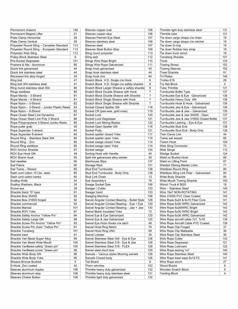
Permanent chasers 148 Permanent Magnet Lifter 21 Plate Clamp Horizontal 29 Plate Clamp Vertical 29 Polyester Round Sling – Canadian Standard 113 Polyester Round Sling – European Standard 113 Polyester Web Sling 112 Pulley Block Stainless Steel 6 Pre-Socket Degreaser 121 Pushers & fids - Aluminum 90 Quick link galvanized 44 Quick link stainless steel 44 Recessed link alloy forged 34 Ring bolt 41 Ring bolt 304 stainless steel 41 Ring round stainless steel 304 80 Rings weldless 80 Rope Manila – 3-Strand 81 Rope Manila – 4-Strand 81 Rope Nylon – 3-Strand 82 Rope Nylon – 3-Strand – Jumbo Plastic Reels 83 Rope Nylon – 8-Strand 82 Rope Ocean Steel Line Dyneema 87 Rope Ocean Steel Line Poly 3 Strand 86 Rope Polypropylene 3-Strand Jumbo Reels 85 Rope puller grab 30 Rope Superdan 3-strand 84 Rope Superdan 8-strand 84 Round Ring – Stainless Steel 304 80 Round Ring – Zinc 80 Round Ring weldless 80 ROV Anchor Shackle 97 ROV Eye Hook GN 49 ROV Shank Hook 50 Sail needles 90 Sail Palms 90 Sail Twine – Waxed 85 Sash cord cotton 10 Lbs. reels 85 Sash cord cotton hanks 85 Scallop Knife 34 Scallop Washers, Black 35 Screw eye 39 Shackle black “D”-type 91 Shackle Bow 304SS 92 Shackle Bow 316SS forged 92 Shackle commercial 92 Shackle Mandal 101 Shackle ROV Yoke 97 Shackle Safety Anchor “Yellow Pin” 94 Shackle Safety Large GN 98 Shackle Screw Pin Anchor “Yellow Pin” 93 Shackle Screw Pin chain “Yellow Pin” 91 Shackle Tonsberg 101 Shackle trawl 91 Shackle Van Beest Super Alloy 99 Shackle Van Beest Wide Mouth 100 Shackle VanBeest safety “Green pin” 100 Shackle VanBeest screw “Green pin” 99 Shackle Wide Body GN 96 Shackle Wide Body Yoke 95 Sheave Bronze Bushed 5 S-Hook, Zinc coated 42 Sleeves aluminum duplex 108 Sleeves aluminum stop 108 Sleeves Choker Button 109
Sleeves copper oval 108 Sleeves copper stop 108 Sleeves Flemish Eye Steel 107 Sleeves stainless steel 108 Sleeves steel 107 Sleeves Steel Button Stop 109 Sling round polyester 113 Sling web 112 Slings Wire Rope Bright 110 Slings Wire Rope Galvanized 111 Snap hook galvanized 45 Snap hook stainless steel 44 Snap hook zinc 44 Snatch Block H.D. Single c/w Hook 8 Snatch Block H.D. Single c/w safety shackle 8 Snatch Block Larger Sheave w safety shackle 8 Snatch Block Double Sheave with Hook 7 Snatch Block Double Sheave with Shackle 7 Snatch Block Single Sheave with Hook 7 Snatch Block Single Sheave with Shackle 7 Socket Closed Spelter GN 118 Socket CR (pee-wee, gold nose) 119 Socket Lock 120 Socket Lock Degreaser 121 Socket Lock Mixing Blades 122 Socket Open Spelter GN 116 Socket Putty 121 Socket spelter closed Yoke 117 Socket spelter open Yoke 115 Socket swage closed Yoke 114 Socket swage open Yoke 114 Socket wedge 124 Sorting Hook with Handle 45 Split link galvanized alloy lobster 35 Stenhouse Slips 137 Storage Reel 151 Stud End Turnbuckle 138 Stud End Turnbuckle - Body Only 138 Stud Link Chain 13 Sub Assembly’s 78 Swage Socket Dies 106 Swager / Cutter 133 Swager hand 133 Swaging Machine 106 Swivel Angular Contact Bearing – Bullet Style 128 Swivel Angular Contact Bearing – Eye + Eye 129 Swivel Angular Contact Bearing – Jaw + Jaw 130 Swivel Blank Insulated Yoke 72 Swivel Eye & Eye Galvanized 125 Swivel Eye & Jaw Galvanized 125 Swivel Eye Hoist Hooks c/w latch 48 Swivel Hoist Ring Metric 70 Swivel Hoist Ring UNC 69 Swivel Lobster 35 Swivel Stainless Steel 304 - Eye & Eye 126 Swivel Stainless Steel 316 - Eye & Jaw 126 Swivel Stainless Steel 316 - FLEX 126 Swivel steel short bow 125 Swivels – Various styles Mooring swivels 126 Swivels Closed body 126 Tail Board 8 Thern winches 153 Thimble heavy duty galvanized 132 Thimble heavy duty stainless steel 131 Thimble light duty galvanized 132
Thimble light duty stainless steel 131 Thimble tube 131 Tie down cargo straps c/w chain 18 Tie down cargo straps c/w ratchet 18 Tie down D-ring 19 Tie down Rubber tarp strap 18 Tie down truck winch 18 Tonsberg Shackle 101 Tools 133 Towing Shoes 152 Towing Sleeves 152 Trawl Shackle 91 Tri-Plates 149 Trolley 619 28 Try Net Block 4 Tube Thimble 131 Turnbuckle Bottle Type 137 Turnbuckle Eye & Eye - Galvanized 136 Turnbuckle Heavy Duty GN 138 Turnbuckle Hook & Hook - Galvanized 136 Turnbuckle Jaw & Eye - Galvanized 136 Turnbuckle Jaw & Jaw – Galvanized 135 Turnbuckle Jaw & Jaw 304SS - Open 137 Turnbuckle Jaw & Jaw 316SS Closed Bottle 137 Turnbuckle Lashing – Eye & Eye 137 Turnbuckle Stub End 138 Turnbuckle Stud End - Body Only 138 Twin Clevis Link 44 Twine sail waxed 85 Twitch Hook 109 Web Sling Connector 73 Web Slings 112 Wedge Socket 124 Weld on Bucket Hook 66 Weld on Lifting Point 67 Welded Oblong Master Links 77 Weldless Round Ring 80 Weldless Sling Link Pear – Galvanized 80 Wide Body Shackle 95 Wide Mouth Towing Shackle 100 Winch Truck # 5820 18 Wire – Stainless Steel 140 Wire 19x7 NON-ROTATING 141 Wire 316SS PVC Clear Coated 140 Wire Rope 6x24 & 6x19 Fiber Core 141 Wire Rope 6x26 IWRC Galvanized 142 Wire Rope 6x26IWRC Bright 143 Wire Rope 6x36 IWRC Bright 143 Wire Rope 6x36 IWRC Galvanized 142 Wire Rope aircraft cable 7x7, 7x19 139 Wire Rope Aircraft Cable PVC Coated 139 Wire Rope Clip Forged 37 Wire Rope Clip Malleable 36 Wire Rope Clip Stainless Steel 36 Wire Rope Cutter 133 Wire Rope Degreaser 121 Wire Rope Lubricant 122 Wire Rope seizing 1x7 140 Wire Rope Stainless Steel 140 Wire Rope trawl warp 6x19 FC 141 Wire Rope winch 27 Wood Blocks 6 Wooden Snatch Block 6 Yarding Block 4
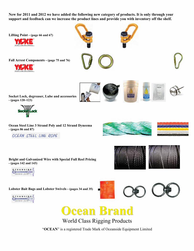
New for 2011 and 2012 we have added the following new category of products. It is only through your support and feedback can we increase the product lines and provide you with inventory off the shelf. Lifting Point - (page 66 and 67) Fall Arrest Components - (page 75 and 76) Socket Lock, degreaser, Lube and accessories - (pages 120~123) Ocean Steel Line 3 Strand Poly and 12 Strand Dyneema - (pages 86 and 87) Bright and Galvanized Wire with Special Full Reel Pricing - (pages 142 and 143) Lobster Bait Bags and Lobster Swivels - (pages 34 and 35)
OOcceeaann BBrraanndd World Class Rigging Products
“OCEAN” is a registered Trade Mark of Oceanside Equipment Limited
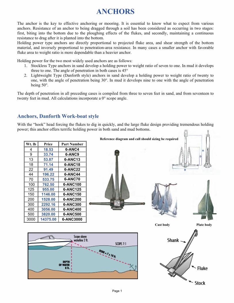
ANCHORS The anchor is the key to effective anchoring or mooring. It is essential to know what to expect from various anchors. Resistance of an anchor to being dragged through a soil has been considered as occurring in two stages: first, biting into the bottom due to the ploughing effects of the flukes, and secondly, maintaining a continuous resistance to drag after it is planted into the bottom. Holding power type anchors are directly proportional to projected fluke area, and shear strength of the bottom material, and inversely proportional to penetration-area resistance. In many cases a smaller anchor with favorable fluke area to weight ratio is more dependable than a heavier anchor. Holding power for the two most widely used anchors are as follows:
1. Stockless Type anchors in sand develop a holding power to weight ratio of seven to one. In mud it develops three to one. The angle of penetration in both cases is 45°
2. Lightweight Type (Danforth style) anchors in sand develop a holding power to weight ratio of twenty to one, with the angle of penetration being 30°. In mud it develops nine to one with the angle of penetration being 50°.
The depth of penetration in all preceding cases is compiled from three to seven feet in sand, and from seventeen to twenty feet in mud. All calculations incorporate a 0° scope angle. Anchors, Danforth Work-boat style With the “hook” head forcing the flukes to dig in quickly, and the large fluke design providing tremendous holding power; this anchor offers terrific holding power in both sand and mud bottoms. Reference diagram and call should sizing be required
Wt. lb Price Part Number 4 18.53 6-ANC4 9 33.74 6-ANC9 13 53.87 6-ANC13 18 71.14 6-ANC18 22 91.49 6-ANC22 44 196.22 6-ANC44 70 533.75 6-ANC70
100 762.50 6-ANC100 125 955.00 6-ANC125 150 1146.00 6-ANC150 200 1528.00 6-ANC200 300 2292.16 6-ANC300 400 3056.00 6-ANC400 500 3820.00 6-ANC500 3000 14375.00 6-ANC3000
Cast body Plate body
Page 1
ANCHORS
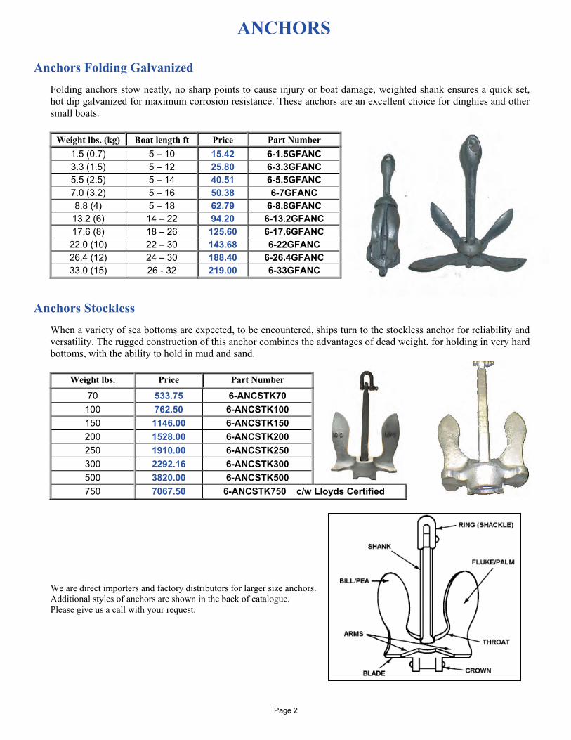
Anchors Folding Galvanized
Folding anchors stow neatly, no sharp points to cause injury or boat damage, weighted shank ensures a quick set, hot dip galvanized for maximum corrosion resistance. These anchors are an excellent choice for dinghies and other small boats.
Weight lbs. (kg) Boat length ft Price Part Number
1.5 (0.7) 5 – 10 15.42 6-1.5GFANC 3.3 (1.5) 5 – 12 25.80 6-3.3GFANC 5.5 (2.5) 5 – 14 40.51 6-5.5GFANC 7.0 (3.2) 5 – 16 50.38 6-7GFANC 8.8 (4) 5 – 18 62.79 6-8.8GFANC 13.2 (6) 14 – 22 94.20 6-13.2GFANC 17.6 (8) 18 – 26 125.60 6-17.6GFANC
22.0 (10) 22 – 30 143.68 6-22GFANC 26.4 (12) 24 – 30 188.40 6-26.4GFANC 33.0 (15) 26 - 32 219.00 6-33GFANC
Anchors Stockless
When a variety of sea bottoms are expected, to be encountered, ships turn to the stockless anchor for reliability and versatility. The rugged construction of this anchor combines the advantages of dead weight, for holding in very hard bottoms, with the ability to hold in mud and sand.
Weight lbs. Price Part Number
70 533.75 6-ANCSTK70 100 762.50 6-ANCSTK100 150 1146.00 6-ANCSTK150 200 1528.00 6-ANCSTK200 250 1910.00 6-ANCSTK250 300 2292.16 6-ANCSTK300 500 3820.00 6-ANCSTK500 750 7067.50 6-ANCSTK750 c/w Lloyds Certified
We are direct importers and factory distributors for larger size anchors. Additional styles of anchors are shown in the back of catalogue. Please give us a call with your request.
Page 2

LOBSTER BLOCKS
2,000 lb Lobster Block - c/w Swivel Eye - design factor 4:1
- Cast Aluminum Frame & Sheave Manufactured with the highest quality steel available Corrosive resistant for increased block life in a salt water environment Blocks are supplied with a pressure lube fitting on swivel eye for a longer block life Sealed bearings in roller sheave for increased block life and performance PIC code on block matched to certificate and each block individually tested for maximum safety
WLL lbs Roller Size Dimensions (inch) Weight lbs
Price each Part Number B K E F G L
2,000 5” 1.38 8.43 6.30 0.59 6.22 14.49 13.2 520.52 28-531-01
Lobster Block – c/w Roller Bearing and Grease Nipple -design factor 3:1
WLL Construction Roller size Wt. lbs Price each Part Number 2,000 lb 304 Stainless Steel 4" 19 525.94 6-4"LBSS 3,500 lb Cast Steel 5” 35 498.75 6-5”LBSC
A potential hazard exists when lifting or dragging heavy loads with tackle block assemblies. Failure to design and use tackle block systems properly may cause a load to slip or fall, the result could be serious injury or death. A tackle block system should be rigged by a qualified person as defined by ANSI/ASME B30.
Page 3
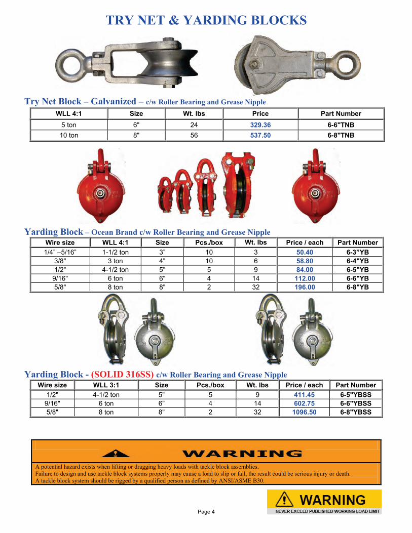
TRY NET & YARDING BLOCKS Try Net Block – Galvanized – c/w Roller Bearing and Grease Nipple
Yarding Block – Ocean Brand c/w Roller Bearing and Grease Nipple
Wire size WLL 4:1 Size Pcs./box Wt. lbs Price / each Part Number 1/4” –5/16” 1-1/2 ton 3” 10 3 50.40 6-3”YB
3/8" 3 ton 4" 10 6 58.80 6-4"YB 1/2" 4-1/2 ton 5" 5 9 84.00 6-5"YB
9/16" 6 ton 6" 4 14 112.00 6-6"YB 5/8" 8 ton 8" 2 32 196.00 6-8"YB
Yarding Block - (SOLID 316SS) c/w Roller Bearing and Grease Nipple
Wire size WLL 3:1 Size Pcs./box Wt. lbs Price / each Part Number 1/2" 4-1/2 ton 5" 5 9 411.45 6-5"YBSS
9/16" 6 ton 6" 4 14 602.75 6-6"YBSS 5/8" 8 ton 8" 2 32 1096.50 6-8"YBSS
WLL 4:1 Size Wt. lbs Price Part Number 5 ton 6" 24 329.36 6-6"TNB 10 ton 8" 56 537.50 6-8"TNB
A potential hazard exists when lifting or dragging heavy loads with tackle block assemblies. Failure to design and use tackle block systems properly may cause a load to slip or fall, the result could be serious injury or death. A tackle block system should be rigged by a qualified person as defined by ANSI/ASME B30.
Page 4
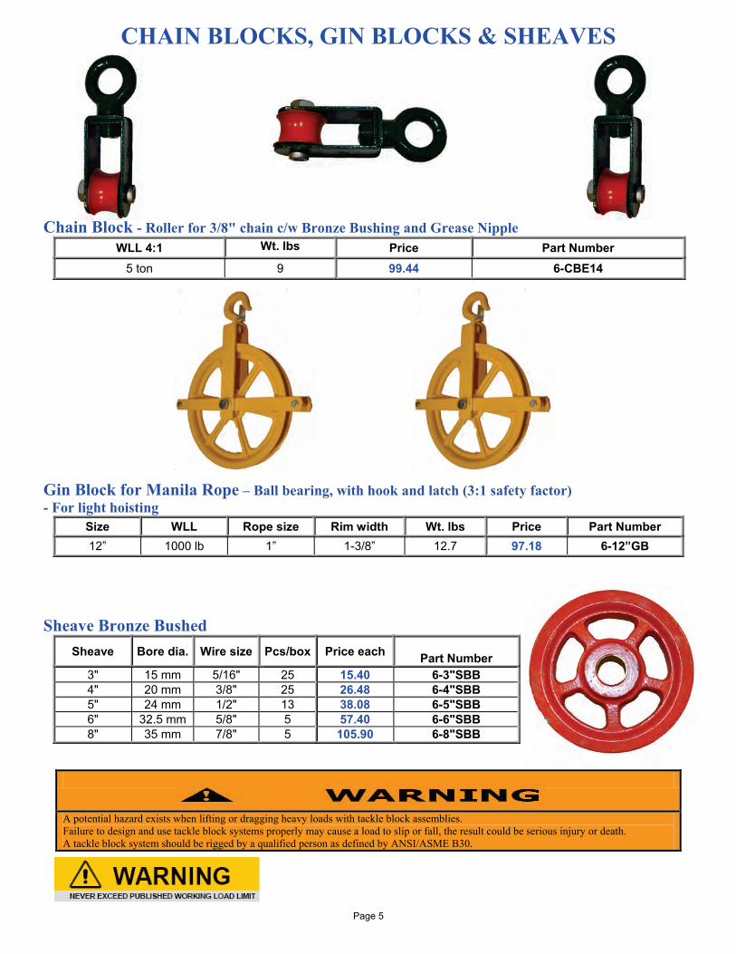
CHAIN BLOCKS, GIN BLOCKS & SHEAVES Chain Block - Roller for 3/8" chain c/w Bronze Bushing and Grease Nipple
WLL 4:1 Wt. lbs Price Part Number 5 ton 9 99.44 6-CBE14
Gin Block for Manila Rope – Ball bearing, with hook and latch (3:1 safety factor) - For light hoisting
Size WLL Rope size Rim width Wt. lbs Price Part Number 12” 1000 lb 1” 1-3/8” 12.7 97.18 6-12”GB
Sheave Bronze Bushed
Sheave Bore dia. Wire size Pcs/box Price each Part Number
3" 15 mm 5/16" 25 15.40 6-3"SBB 4" 20 mm 3/8" 25 26.48 6-4"SBB 5" 24 mm 1/2" 13 38.08 6-5"SBB 6" 32.5 mm 5/8" 5 57.40 6-6"SBB 8" 35 mm 7/8" 5 105.90 6-8"SBB
A potential hazard exists when lifting or dragging heavy loads with tackle block assemblies. Failure to design and use tackle block systems properly may cause a load to slip or fall, the result could be serious injury or death. A tackle block system should be rigged by a qualified person as defined by ANSI/ASME B30.
Page 5
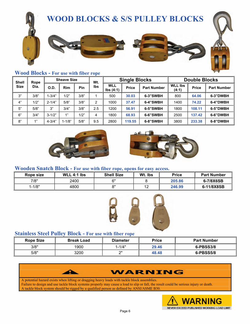
WOOD BLOCKS & S/S PULLEY BLOCKS
Wood Blocks - For use with fiber rope Shell Size
Rope Dia.
Sheave Size Wt. lbs
Single Blocks Double Blocks O.D. Rim Pin WLL
lbs (4:1) Price Part Number WLL lbs (4:1) Price Part Number
3” 3/8” 1-3/4” 1/2” 3/8” 1 500 30.03 6-3”SWBH 800 64.06 6-3”DWBH 4” 1/2” 2-1/4” 5/8” 3/8” 2 1000 37.47 6-4”SWBH 1400 74.22 6-4”DWBH 5” 5/8” 3” 3/4” 3/8” 2.5 1200 56.91 6-5”SWBH 1800 108.11 6-5”DWBH 6” 3/4” 3-1/2” 1” 1/2” 4 1800 68.93 6-6”SWBH 2500 137.42 6-6”DWBH 8” 1” 4-3/4” 1-1/8” 5/8” 9.5 2800 119.55 6-8”SWBH 3800 233.38 6-8”DWBH
Wooden Snatch Block - For use with fiber rope, opens for easy access.
Rope size WLL 4:1 lbs Shell Size Wt. lbs Price Part Number 7/8" 2400 6" 8 205.86 6-7/8X6SB
1-1/8" 4800 8" 12 246.99 6-11/8X8SB
Stainless Steel Pulley Block - For use with fiber rope
Rope Size Break Load Diameter Price Part Number 3/8" 1900 1-1/4" 29.46 6-PBSS3/8 5/8" 3200 2" 48.48 6-PBSS5/8
A potential hazard exists when lifting or dragging heavy loads with tackle block assemblies. Failure to design and use tackle block systems properly may cause a load to slip or fall, the result could be serious injury or death. A tackle block system should be rigged by a qualified person as defined by ANSI/ASME B30.
Page 6
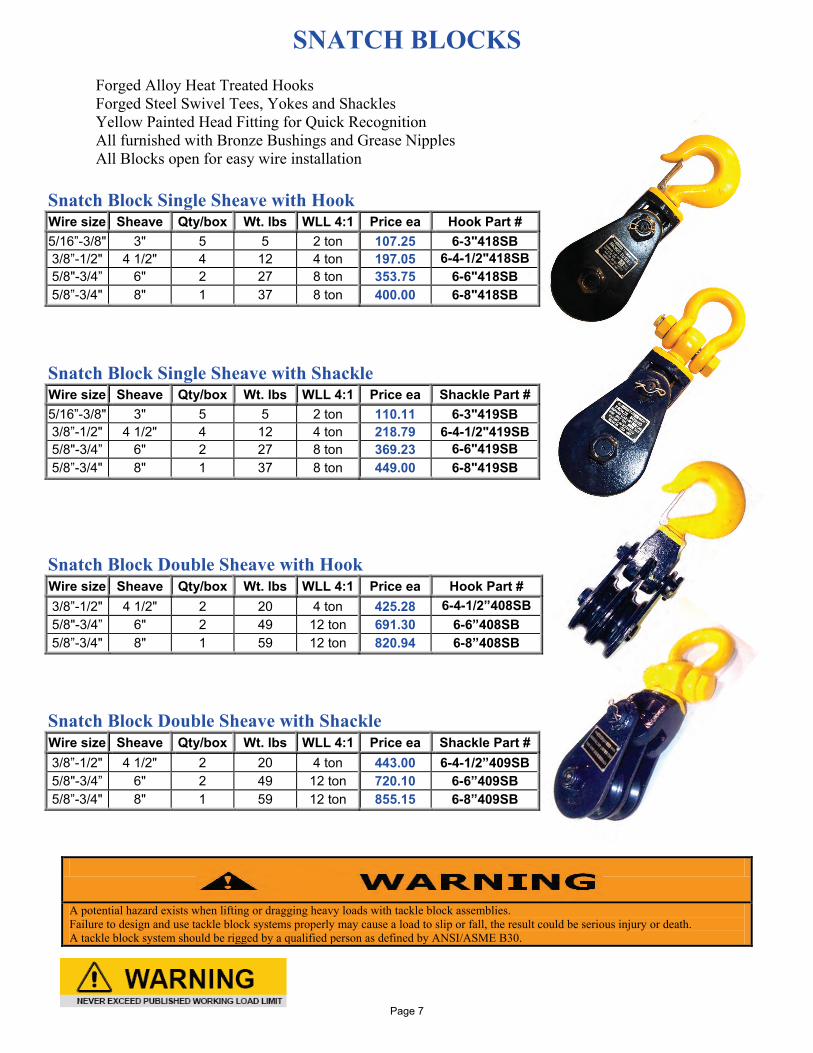
SNATCH BLOCKS
Forged Alloy Heat Treated Hooks Forged Steel Swivel Tees, Yokes and Shackles Yellow Painted Head Fitting for Quick Recognition All furnished with Bronze Bushings and Grease Nipples All Blocks open for easy wire installation
Snatch Block Single Sheave with Hook Wire size Sheave Qty/box Wt. lbs WLL 4:1 Price ea Hook Part # 5/16”-3/8" 3" 5 5 2 ton 107.25 6-3"418SB 3/8”-1/2" 4 1/2" 4 12 4 ton 197.05 6-4-1/2"418SB 5/8"-3/4” 6" 2 27 8 ton 353.75 6-6"418SB 5/8”-3/4" 8" 1 37 8 ton 400.00 6-8"418SB Snatch Block Single Sheave with Shackle Wire size Sheave Qty/box Wt. lbs WLL 4:1 Price ea Shackle Part # 5/16”-3/8" 3" 5 5 2 ton 110.11 6-3"419SB 3/8”-1/2" 4 1/2" 4 12 4 ton 218.79 6-4-1/2"419SB 5/8"-3/4” 6" 2 27 8 ton 369.23 6-6"419SB 5/8”-3/4" 8" 1 37 8 ton 449.00 6-8"419SB
Snatch Block Double Sheave with Hook Wire size Sheave Qty/box Wt. lbs WLL 4:1 Price ea Hook Part # 3/8”-1/2" 4 1/2" 2 20 4 ton 425.28 6-4-1/2”408SB 5/8"-3/4” 6" 2 49 12 ton 691.30 6-6”408SB 5/8”-3/4" 8" 1 59 12 ton 820.94 6-8”408SB
Snatch Block Double Sheave with Shackle Wire size Sheave Qty/box Wt. lbs WLL 4:1 Price ea Shackle Part # 3/8”-1/2" 4 1/2" 2 20 4 ton 443.00 6-4-1/2”409SB 5/8"-3/4” 6" 2 49 12 ton 720.10 6-6”409SB 5/8”-3/4" 8" 1 59 12 ton 855.15 6-8”409SB
A potential hazard exists when lifting or dragging heavy loads with tackle block assemblies. Failure to design and use tackle block systems properly may cause a load to slip or fall, the result could be serious injury or death. A tackle block system should be rigged by a qualified person as defined by ANSI/ASME B30.
Page 7
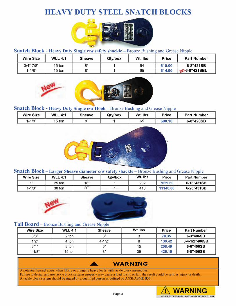
HEAVY DUTY STEEL SNATCH BLOCKS Snatch Block - Heavy Duty Single c/w safety shackle – Bronze Bushing and Grease Nipple
Wire Size WLL 4:1 Sheave Qty/box Wt. lbs Price Part Number
3/4”-7/8” 15 ton 8" 1 64 610.00 6-8"421SB 1-1/8” 15 ton 8” 1 65 614.90 6-8”421SBL
Snatch Block - Heavy Duty Single c/w Hook – Bronze Bushing and Grease Nipple
Wire Size WLL 4:1 Sheave Qty/box Wt. lbs Price Part Number 1-1/8” 15 ton 8” 1 65 600.10 6-8”420SB
Snatch Block – Larger Sheave diameter c/w safety shackle – Bronze Bushing and Grease Nipple
Wire Size WLL 4:1 Sheave Qty/box Wt. lbs Price Part Number 1” 25 ton 18” 1 292 7629.60 6-18"431SB
1-1/8” 30 ton 20” 1 418 11148.00 6-20”431SB
Tail Board – Bronze Bushing and Grease Nipple
Wire Size WLL 4:1 Sheave Wt. lbs Price Part Number 3/8” 2 ton 3” 3 70.35 6-3”406SB 1/2” 4 ton 4-1/2” 8 130.42 6-4-1/2”406SB 3/4” 8 ton 6” 15 208.49 6-6”406SB
1-1/8” 15 ton 8” 35 426.15 6-8”406SB
A potential hazard exists when lifting or dragging heavy loads with tackle block assemblies. Failure to design and use tackle block systems properly may cause a load to slip or fall, the result could be serious injury or death. A tackle block system should be rigged by a qualified person as defined by ANSI/ASME B30.
Page 8
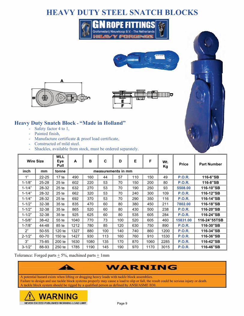
HEAVY DUTY STEEL SNATCH BLOCKS Heavy Duty Snatch Block - “Made in Holland” - Safety factor 4 to 1,
- Painted finish, - Manufacture certificate & proof load certificate, - Constructed of mild steel.
- Shackles, available from stock, must be ordered separately.
Tolerance: Forged parts + 5%, machined parts + 1mm
Wire Size WLL Eye Pull
A B C D E F Wt. Kg Price Part Number
inch mm tonne measurements in mm 1” 22-25 17 te 490 160 44 57 110 150 49 P.O.R. 116-6”SB
1-1/8” 25-28 25 te 602 220 53 70 150 200 80 P.O.R. 116-8”SB 1-1/4” 28-32 25 te 632 270 53 70 190 250 93 5508.00 116-10”SB 1-1/4” 28-32 25 te 662 320 53 70 240 300 109 P.O.R. 116-12”SB 1-1/4” 28-32 25 te 692 370 53 70 290 350 116 P.O.R. 116-14”SB 1-1/2” 32-38 35 te 835 470 60 80 380 450 211 7802.00 116-18”SB 1-1/2” 32-38 35 te 865 520 60 80 430 500 238 P.O.R. 116-20”SB 1-1/2” 32-38 35 te 925 625 60 80 535 605 284 P.O.R. 116-24”SB 1-5/8” 38-42 55 te 1040 770 73 100 520 605 460 15831.00 116-24”55TSB 1-7/8” 44-48 85 te 1212 780 85 120 630 750 890 P.O.R. 116-30”SB
2” 50-55 120 te 1327 880 100 140 740 860 1200 P.O.R. 116-34”SB 2-1/2” 60-70 150 te 1427 930 113 160 760 910 1530 P.O.R. 116-36”SB
3” 75-85 200 te 1630 1080 135 170 870 1060 2285 P.O.R. 116-42”SB 3-1/2” 88-93 250 te 1785 1190 145 190 970 1170 3015 P.O.R. 116-46”SB
A potential hazard exists when lifting or dragging heavy loads with tackle block assemblies. Failure to design and use tackle block systems properly may cause a load to slip or fall, the result could be serious injury or death. A tackle block system should be rigged by a qualified person as defined by ANSI/ASME B30.
Page 9
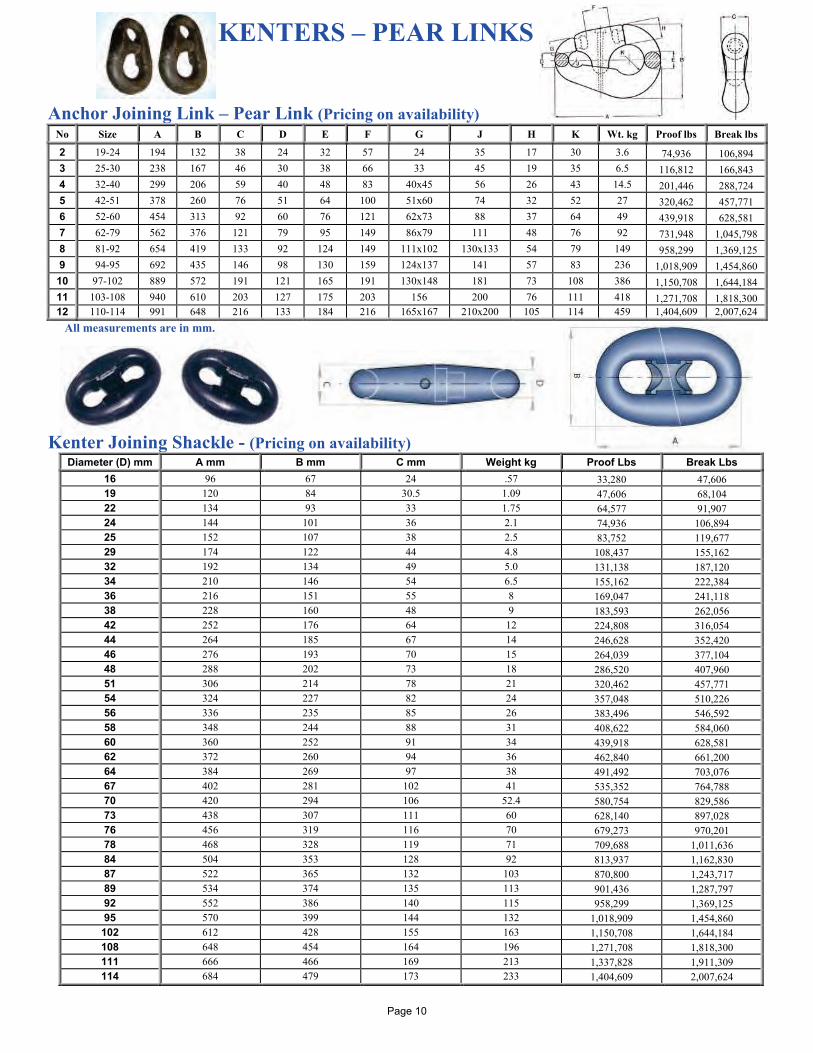
KENTERS – PEAR LINKS
Anchor Joining Link – Pear Link (Pricing on availability)
No Size A B C D E F G J H K Wt. kg Proof lbs Break lbs
2 19-24 194 132 38 24 32 57 24 35 17 30 3.6 74,936 106,894 3 25-30 238 167 46 30 38 66 33 45 19 35 6.5 116,812 166,843 4 32-40 299 206 59 40 48 83 40x45 56 26 43 14.5 201,446 288,724 5 42-51 378 260 76 51 64 100 51x60 74 32 52 27 320,462 457,771 6 52-60 454 313 92 60 76 121 62x73 88 37 64 49 439,918 628,581 7 62-79 562 376 121 79 95 149 86x79 111 48 76 92 731,948 1,045,798 8 81-92 654 419 133 92 124 149 111x102 130x133 54 79 149 958,299 1,369,125 9 94-95 692 435 146 98 130 159 124x137 141 57 83 236 1,018,909 1,454,860
10 97-102 889 572 191 121 165 191 130x148 181 73 108 386 1,150,708 1,644,184 11 103-108 940 610 203 127 175 203 156 200 76 111 418 1,271,708 1,818,300 12 110-114 991 648 216 133 184 216 165x167 210x200 105 114 459 1,404,609 2,007,624
All measurements are in mm.
Kenter Joining Shackle - (Pricing on availability) Diameter (D) mm A mm B mm C mm Weight kg Proof Lbs Break Lbs
16 96 67 24 .57 33,280 47,606 19 120 84 30.5 1.09 47,606 68,104 22 134 93 33 1.75 64,577 91,907 24 144 101 36 2.1 74,936 106,894 25 152 107 38 2.5 83,752 119,677 29 174 122 44 4.8 108,437 155,162 32 192 134 49 5.0 131,138 187,120 34 210 146 54 6.5 155,162 222,384 36 216 151 55 8 169,047 241,118 38 228 160 48 9 183,593 262,056 42 252 176 64 12 224,808 316,054 44 264 185 67 14 246,628 352,420 46 276 193 70 15 264,039 377,104 48 288 202 73 18 286,520 407,960 51 306 214 78 21 320,462 457,771 54 324 227 82 24 357,048 510,226 56 336 235 85 26 383,496 546,592 58 348 244 88 31 408,622 584,060 60 360 252 91 34 439,918 628,581 62 372 260 94 36 462,840 661,200 64 384 269 97 38 491,492 703,076 67 402 281 102 41 535,352 764,788 70 420 294 106 52.4 580,754 829,586 73 438 307 111 60 628,140 897,028 76 456 319 116 70 679,273 970,201 78 468 328 119 71 709,688 1,011,636 84 504 353 128 92 813,937 1,162,830 87 522 365 132 103 870,800 1,243,717 89 534 374 135 113 901,436 1,287,797 92 552 386 140 115 958,299 1,369,125 95 570 399 144 132 1,018,909 1,454,860
102 612 428 155 163 1,150,708 1,644,184 108 648 454 164 196 1,271,708 1,818,300 111 666 466 169 213 1,337,828 1,911,309 114 684 479 173 233 1,404,609 2,007,624
Page 10
To convert to lbs, multiply by 2.2046
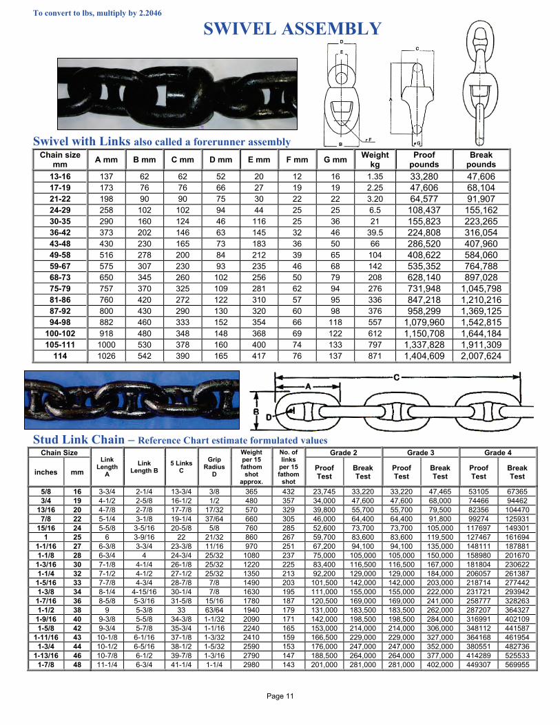
SWIVEL ASSEMBLY
Swivel with Links also called a forerunner assembly Chain size
mm A mm B mm C mm D mm E mm F mm G mm Weight kg
Proof pounds
Break pounds
13-16 137 62 62 52 20 12 16 1.35 33,280 47,606 17-19 173 76 76 66 27 19 19 2.25 47,606 68,104 21-22 198 90 90 75 30 22 22 3.20 64,577 91,907 24-29 258 102 102 94 44 25 25 6.5 108,437 155,162 30-35 290 160 124 46 116 25 36 21 155,823 223,265 36-42 373 202 146 63 145 32 46 39.5 224,808 316,054 43-48 430 230 165 73 183 36 50 66 286,520 407,960 49-58 516 278 200 84 212 39 65 104 408,622 584,060 59-67 575 307 230 93 235 46 68 142 535,352 764,788 68-73 650 345 260 102 256 50 79 208 628,140 897,028 75-79 757 370 325 109 281 62 94 276 731,948 1,045,798 81-86 760 420 272 122 310 57 95 336 847,218 1,210,216 87-92 800 430 290 130 320 60 98 376 958,299 1,369,125 94-98 882 460 333 152 354 66 118 557 1,079,960 1,542,815
100-102 918 480 348 148 368 69 122 612 1,150,708 1,644,184 105-111 1000 530 378 160 400 74 133 797 1,337,828 1,911,309
114 1026 542 390 165 417 76 137 871 1,404,609 2,007,624 Stud Link Chain – Reference Chart estimate formulated values
Chain Size Link
Length A
Link Length B
5 Links C
Grip Radius
D
Weight per 15 fathom
shot approx.
No. of links
per 15 fathom
shot
Grade 2 Grade 3 Grade 4
inches mm Proof Test
Break Test
Proof Test
Break Test
Proof Test
Break Test
5/8 16 3-3/4 2-1/4 13-3/4 3/8 365 432 23,745 33,220 33,220 47,465 53105 67365 3/4 19 4-1/2 2-5/8 16-1/2 1/2 480 357 34,000 47,600 47,600 68,000 74466 94462
13/16 20 4-7/8 2-7/8 17-7/8 17/32 570 329 39,800 55,700 55,700 79,500 82356 104470 7/8 22 5-1/4 3-1/8 19-1/4 37/64 660 305 46,000 64,400 64,400 91,800 99274 125931
15/16 24 5-5/8 3-5/16 20-5/8 5/8 760 285 52,600 73,700 73,700 105,000 117697 149301 1 25 6 3-9/16 22 21/32 860 267 59,700 83,600 83,600 119,500 127467 161694
1-1/16 27 6-3/8 3-3/4 23-3/8 11/16 970 251 67,200 94,100 94,100 135,000 148111 187881 1-1/8 28 6-3/4 4 24-3/4 25/32 1080 237 75,000 105,000 105,000 150,000 158980 201670
1-3/16 30 7-1/8 4-1/4 26-1/8 25/32 1220 225 83,400 116,500 116,500 167,000 181804 230622 1-1/4 32 7-1/2 4-1/2 27-1/2 25/32 1350 213 92,200 129,000 129,000 184,000 206057 261387
1-5/16 33 7-7/8 4-3/4 28-7/8 7/8 1490 203 101,500 142,000 142,000 203,000 218714 277442 1-3/8 34 8-1/4 4-15/16 30-1/4 7/8 1630 195 111,000 155,000 155,000 222,000 231721 293942
1-7/16 36 8-5/8 5-3/16 31-5/8 15/16 1780 187 120,500 169,000 169,000 241,000 258777 328263 1-1/2 38 9 5-3/8 33 63/64 1940 179 131,000 183,500 183,500 262,000 287207 364327
1-9/16 40 9-3/8 5-5/8 34-3/8 1-1/32 2090 171 142,000 198,500 198,500 284,000 316991 402109 1-5/8 42 9-3/4 5-7/8 35-3/4 1-1/16 2240 165 153,000 214,000 214,000 306,000 348112 441587
1-11/16 43 10-1/8 6-1/16 37-1/8 1-3/32 2410 159 166,500 229,000 229,000 327,000 364168 461954 1-3/4 44 10-1/2 6-5/16 38-1/2 1-5/32 2590 153 176,000 247,000 247,000 352,000 380551 482736
1-13/16 46 10-7/8 6-1/2 39-7/8 1-3/16 2790 147 188,500 264,000 264,000 377,000 414289 525533 1-7/8 48 11-1/4 6-3/4 41-1/4 1-1/4 2980 143 201,000 281,000 281,000 402,000 449307 569955
Page 11
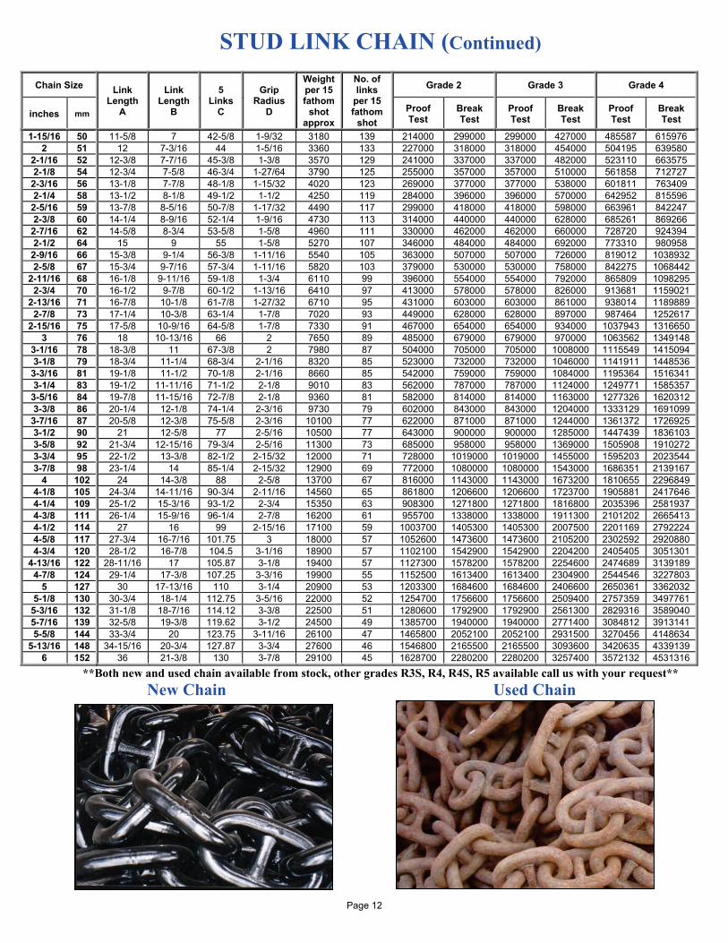
STUD LINK CHAIN (Continued)
Chain Size Link Length
A
Link Length
B
5 Links
C
Grip Radius
D
Weight per 15 fathom
shot approx
No. of links
per 15 fathom
shot
Grade 2 Grade 3 Grade 4
inches mm Proof Test
Break Test
Proof Test
Break Test
Proof Test
Break Test
1-15/16 50 11-5/8 7 42-5/8 1-9/32 3180 139 214000 299000 299000 427000 485587 615976 2 51 12 7-3/16 44 1-5/16 3360 133 227000 318000 318000 454000 504195 639580
2-1/16 52 12-3/8 7-7/16 45-3/8 1-3/8 3570 129 241000 337000 337000 482000 523110 663575 2-1/8 54 12-3/4 7-5/8 46-3/4 1-27/64 3790 125 255000 357000 357000 510000 561858 712727
2-3/16 56 13-1/8 7-7/8 48-1/8 1-15/32 4020 123 269000 377000 377000 538000 601811 763409 2-1/4 58 13-1/2 8-1/8 49-1/2 1-1/2 4250 119 284000 396000 396000 570000 642952 815596
2-5/16 59 13-7/8 8-5/16 50-7/8 1-17/32 4490 117 299000 418000 418000 598000 663961 842247 2-3/8 60 14-1/4 8-9/16 52-1/4 1-9/16 4730 113 314000 440000 440000 628000 685261 869266
2-7/16 62 14-5/8 8-3/4 53-5/8 1-5/8 4960 111 330000 462000 462000 660000 728720 924394 2-1/2 64 15 9 55 1-5/8 5270 107 346000 484000 484000 692000 773310 980958
2-9/16 66 15-3/8 9-1/4 56-3/8 1-11/16 5540 105 363000 507000 507000 726000 819012 1038932 2-5/8 67 15-3/4 9-7/16 57-3/4 1-11/16 5820 103 379000 530000 530000 758000 842275 1068442
2-11/16 68 16-1/8 9-11/16 59-1/8 1-3/4 6110 99 396000 554000 554000 792000 865809 1098295 2-3/4 70 16-1/2 9-7/8 60-1/2 1-13/16 6410 97 413000 578000 578000 826000 913681 1159021
2-13/16 71 16-7/8 10-1/8 61-7/8 1-27/32 6710 95 431000 603000 603000 861000 938014 1189889 2-7/8 73 17-1/4 10-3/8 63-1/4 1-7/8 7020 93 449000 628000 628000 897000 987464 1252617
2-15/16 75 17-5/8 10-9/16 64-5/8 1-7/8 7330 91 467000 654000 654000 934000 1037943 1316650 3 76 18 10-13/16 66 2 7650 89 485000 679000 679000 970000 1063562 1349148
3-1/16 78 18-3/8 11 67-3/8 2 7980 87 504000 705000 705000 1008000 1115549 1415094 3-1/8 79 18-3/4 11-1/4 68-3/4 2-1/16 8320 85 523000 732000 732000 1046000 1141911 1448536
3-3/16 81 19-1/8 11-1/2 70-1/8 2-1/16 8660 85 542000 759000 759000 1084000 1195364 1516341 3-1/4 83 19-1/2 11-11/16 71-1/2 2-1/8 9010 83 562000 787000 787000 1124000 1249771 1585357
3-5/16 84 19-7/8 11-15/16 72-7/8 2-1/8 9360 81 582000 814000 814000 1163000 1277326 1620312 3-3/8 86 20-1/4 12-1/8 74-1/4 2-3/16 9730 79 602000 843000 843000 1204000 1333129 1691099
3-7/16 87 20-5/8 12-3/8 75-5/8 2-3/16 10100 77 622000 871000 871000 1244000 1361372 1726925 3-1/2 90 21 12-5/8 77 2-5/16 10500 77 643000 900000 900000 1285000 1447439 1836103 3-5/8 92 21-3/4 12-15/16 79-3/4 2-5/16 11300 73 685000 958000 958000 1369000 1505908 1910272 3-3/4 95 22-1/2 13-3/8 82-1/2 2-15/32 12000 71 728000 1019000 1019000 1455000 1595203 2023544 3-7/8 98 23-1/4 14 85-1/4 2-15/32 12900 69 772000 1080000 1080000 1543000 1686351 2139167
4 102 24 14-3/8 88 2-5/8 13700 67 816000 1143000 1143000 1673200 1810655 2296849 4-1/8 105 24-3/4 14-11/16 90-3/4 2-11/16 14560 65 861800 1206600 1206600 1723700 1905881 2417646 4-1/4 109 25-1/2 15-3/16 93-1/2 2-3/4 15350 63 908300 1271800 1271800 1816800 2035396 2581937 4-3/8 111 26-1/4 15-9/16 96-1/4 2-7/8 16200 61 955700 1338000 1338000 1911300 2101202 2665413 4-1/2 114 27 16 99 2-15/16 17100 59 1003700 1405300 1405300 2007500 2201169 2792224 4-5/8 117 27-3/4 16-7/16 101.75 3 18000 57 1052600 1473600 1473600 2105200 2302592 2920880 4-3/4 120 28-1/2 16-7/8 104.5 3-1/16 18900 57 1102100 1542900 1542900 2204200 2405405 3051301
4-13/16 122 28-11/16 17 105.87 3-1/8 19400 57 1127300 1578200 1578200 2254600 2474689 3139189 4-7/8 124 29-1/4 17-3/8 107.25 3-3/16 19900 55 1152500 1613400 1613400 2304900 2544546 3227803
5 127 30 17-13/16 110 3-1/4 20900 53 1203300 1684600 1684600 2406600 2650361 3362032 5-1/8 130 30-3/4 18-1/4 112.75 3-5/16 22000 52 1254700 1756600 1756600 2509400 2757359 3497761
5-3/16 132 31-1/8 18-7/16 114.12 3-3/8 22500 51 1280600 1792900 1792900 2561300 2829316 3589040 5-7/16 139 32-5/8 19-3/8 119.62 3-1/2 24500 49 1385700 1940000 1940000 2771400 3084812 3913141 5-5/8 144 33-3/4 20 123.75 3-11/16 26100 47 1465800 2052100 2052100 2931500 3270456 4148634
5-13/16 148 34-15/16 20-3/4 127.87 3-3/4 27600 46 1546800 2165500 2165500 3093600 3420635 4339139 6 152 36 21-3/8 130 3-7/8 29100 45 1628700 2280200 2280200 3257400 3572132 4531316
**Both new and used chain available from stock, other grades R3S, R4, R4S, R5 available call us with your request** New Chain Used Chain
Page 12
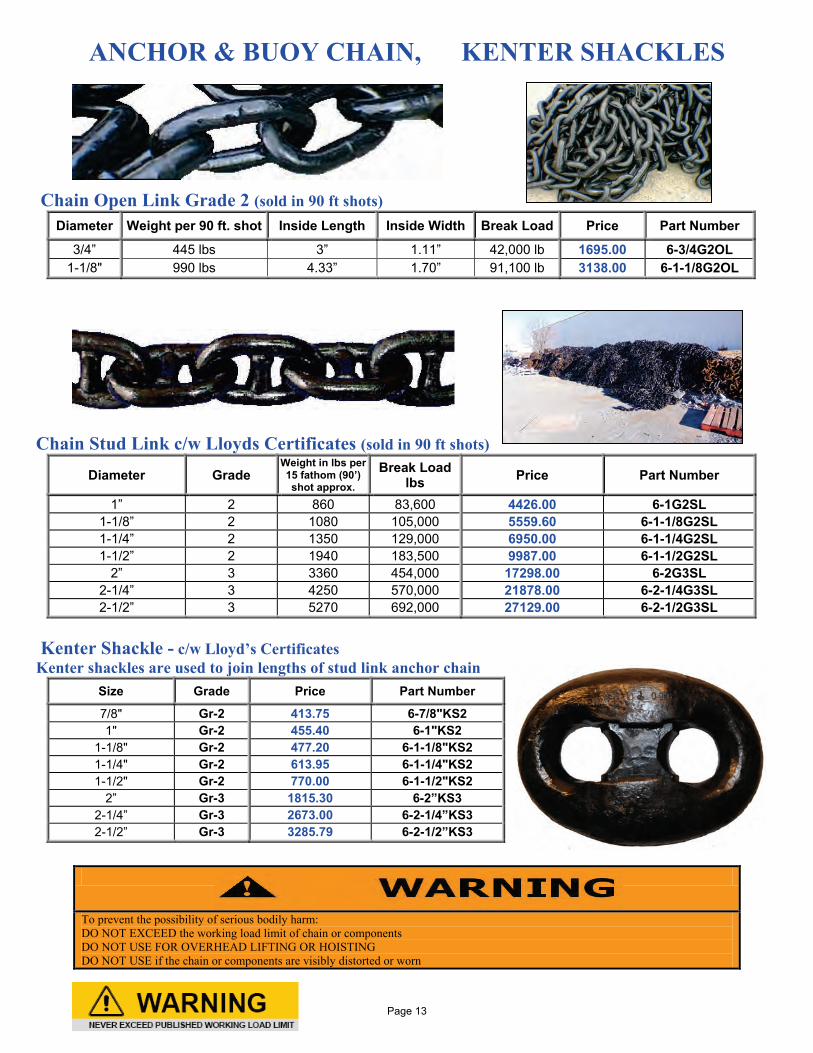
ANCHOR & BUOY CHAIN, KENTER SHACKLES
Chain Open Link Grade 2 (sold in 90 ft shots)
Diameter Weight per 90 ft. shot Inside Length Inside Width Break Load Price Part Number
3/4” 445 lbs 3” 1.11” 42,000 lb 1695.00 6-3/4G2OL 1-1/8" 990 lbs 4.33” 1.70” 91,100 lb 3138.00 6-1-1/8G2OL
Chain Stud Link c/w Lloyds Certificates (sold in 90 ft shots)
Diameter Grade Weight in lbs per 15 fathom (90’) shot approx.
Break Load lbs Price Part Number
1” 2 860 83,600 4426.00 6-1G2SL 1-1/8” 2 1080 105,000 5559.60 6-1-1/8G2SL 1-1/4” 2 1350 129,000 6950.00 6-1-1/4G2SL 1-1/2” 2 1940 183,500 9987.00 6-1-1/2G2SL
2” 3 3360 454,000 17298.00 6-2G3SL 2-1/4” 3 4250 570,000 21878.00 6-2-1/4G3SL 2-1/2” 3 5270 692,000 27129.00 6-2-1/2G3SL
Kenter Shackle - c/w Lloyd’s Certificates Kenter shackles are used to join lengths of stud link anchor chain
Size Grade Price Part Number
7/8" Gr-2 413.75 6-7/8"KS2 1" Gr-2 455.40 6-1"KS2
1-1/8" Gr-2 477.20 6-1-1/8"KS2 1-1/4" Gr-2 613.95 6-1-1/4"KS2 1-1/2" Gr-2 770.00 6-1-1/2"KS2
2” Gr-3 1815.30 6-2”KS3 2-1/4” Gr-3 2673.00 6-2-1/4”KS3 2-1/2” Gr-3 3285.79 6-2-1/2”KS3
To prevent the possibility of serious bodily harm: DO NOT EXCEED the working load limit of chain or components DO NOT USE FOR OVERHEAD LIFTING OR HOISTING DO NOT USE if the chain or components are visibly distorted or worn
Page 13
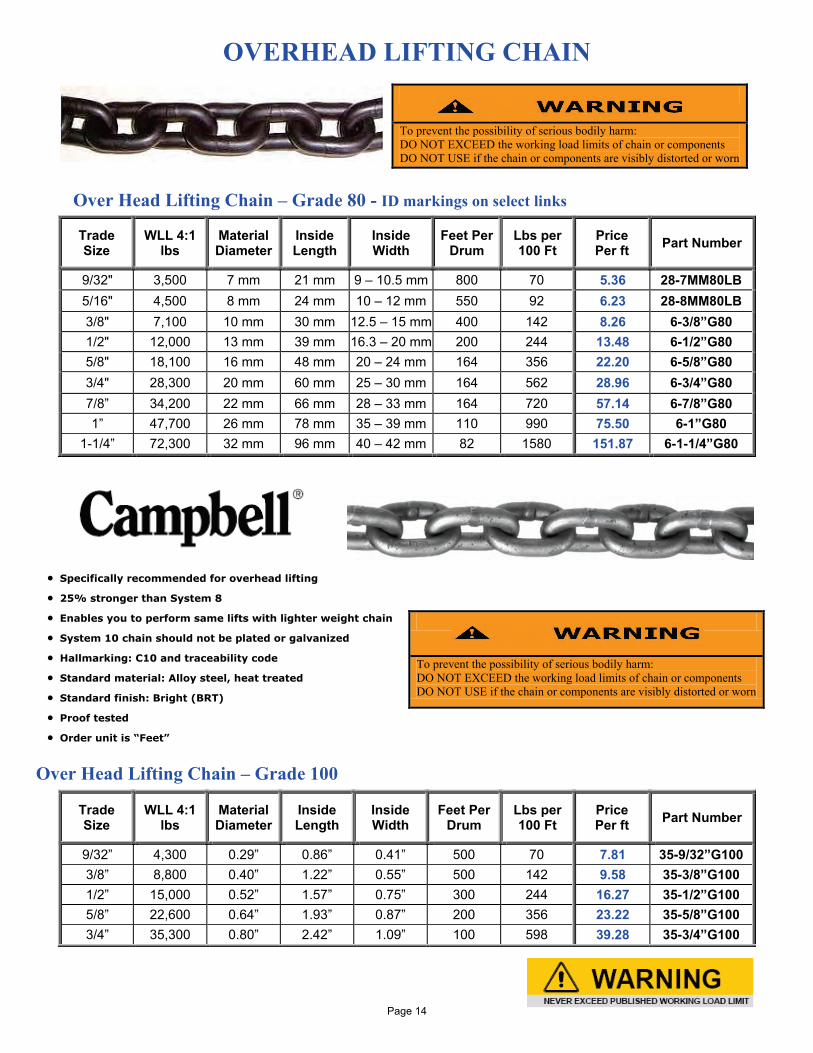
OVERHEAD LIFTING CHAIN
Over Head Lifting Chain – Grade 80 - ID markings on select links
• Specifically recommended for overhead lifting
• 25% stronger than System 8
• Enables you to perform same lifts with lighter weight chain
• System 10 chain should not be plated or galvanized
• Hallmarking: C10 and traceability code
• Standard material: Alloy steel, heat treated
• Standard finish: Bright (BRT)
• Proof tested
• Order unit is “Feet”
Over Head Lifting Chain – Grade 100
To prevent the possibility of serious bodily harm: DO NOT EXCEED the working load limits of chain or components DO NOT USE if the chain or components are visibly distorted or worn
Trade Size
WLL 4:1 lbs
Material Diameter
Inside Length
Inside Width
Feet Per Drum
Lbs per 100 Ft
Price Per ft Part Number
9/32" 3,500 7 mm 21 mm 9 – 10.5 mm 800 70 5.36 28-7MM80LB 5/16" 4,500 8 mm 24 mm 10 – 12 mm 550 92 6.23 28-8MM80LB 3/8" 7,100 10 mm 30 mm 12.5 – 15 mm 400 142 8.26 6-3/8”G80 1/2" 12,000 13 mm 39 mm 16.3 – 20 mm 200 244 13.48 6-1/2”G80 5/8" 18,100 16 mm 48 mm 20 – 24 mm 164 356 22.20 6-5/8”G80 3/4" 28,300 20 mm 60 mm 25 – 30 mm 164 562 28.96 6-3/4”G80 7/8” 34,200 22 mm 66 mm 28 – 33 mm 164 720 57.14 6-7/8”G80 1” 47,700 26 mm 78 mm 35 – 39 mm 110 990 75.50 6-1”G80
1-1/4” 72,300 32 mm 96 mm 40 – 42 mm 82 1580 151.87 6-1-1/4”G80
To prevent the possibility of serious bodily harm: DO NOT EXCEED the working load limits of chain or components DO NOT USE if the chain or components are visibly distorted or worn
Trade Size
WLL 4:1 lbs
Material Diameter
Inside Length
Inside Width
Feet Per Drum
Lbs per 100 Ft
Price Per ft Part Number
9/32” 4,300 0.29” 0.86” 0.41” 500 70 7.81 35-9/32”G100 3/8” 8,800 0.40” 1.22” 0.55” 500 142 9.58 35-3/8”G100 1/2” 15,000 0.52” 1.57” 0.75” 300 244 16.27 35-1/2”G100 5/8” 22,600 0.64” 1.93” 0.87” 200 356 23.22 35-5/8”G100 3/4” 35,300 0.80” 2.42” 1.09” 100 598 39.28 35-3/4”G100
Page 14
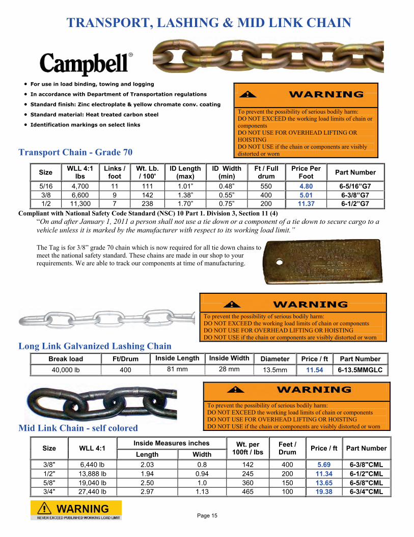
TRANSPORT, LASHING & MID LINK CHAIN
• For use in load binding, towing and logging
• In accordance with Department of Transportation regulations
• Standard finish: Zinc electroplate & yellow chromate conv. coating
• Standard material: Heat treated carbon steel
• Identification markings on select links
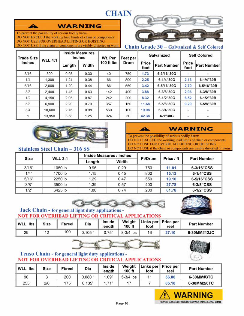
Transport Chain - Grade 70
Compliant with National Safety Code Standard (NSC) 10 Part 1. Division 3, Section 11 (4) “On and after January 1, 2011 a person shall not use a tie down or a component of a tie down to secure cargo to a vehicle unless it is marked by the manufacturer with respect to its working load limit.”
The Tag is for 3/8” grade 70 chain which is now required for all tie down chains to meet the national safety standard. These chains are made in our shop to your requirements. We are able to track our components at time of manufacturing.
Long Link Galvanized Lashing Chain
Mid Link Chain - self colored
To prevent the possibility of serious bodily harm: DO NOT EXCEED the working load limits of chain or components DO NOT USE FOR OVERHEAD LIFTING OR HOISTING DO NOT USE if the chain or components are visibly distorted or worn
Size WLL 4:1 lbs
Links / foot
Wt. Lb. / 100'
ID Length (max)
ID Width (min)
Ft / Full drum
Price Per Foot Part Number
5/16 4,700 11 111 1.01” 0.48” 550 4.80 6-5/16”G7 3/8 6,600 9 142 1.38” 0.55” 400 5.01 6-3/8”G7 1/2 11,300 7 238 1.70” 0.75” 200 11.37 6-1/2”G7
To prevent the possibility of serious bodily harm: DO NOT EXCEED the working load limits of chain or components DO NOT USE FOR OVERHEAD LIFTING OR HOISTING DO NOT USE if the chain or components are visibly distorted or worn
Break load Ft/Drum Inside Length Inside Width Diameter Price / ft Part Number 40,000 lb 400 81 mm 28 mm 13.5mm 11.54 6-13.5MMGLC
To prevent the possibility of serious bodily harm: DO NOT EXCEED the working load limits of chain or components DO NOT USE FOR OVERHEAD LIFTING OR HOISTING DO NOT USE if the chain or components are visibly distorted or worn
Size WLL 4:1 Inside Measures inches Wt. per
100ft / lbs Feet / Drum Price / ft Part Number
Length Width 3/8" 6,440 lb 2.03 0.8 142 400 5.69 6-3/8"CML 1/2" 13,888 lb 1.94 0.94 245 200 11.34 6-1/2"CML 5/8" 19,040 lb 2.50 1.0 360 150 13.65 6-5/8"CML 3/4" 27,440 lb 2.97 1.13 465 100 19.38 6-3/4"CML
Page 15
CHAIN Chain Grade 30 – Galvanized & Self Colored
Trade Size Inches WLL 4:1
Inside Measures inches Wt. Per
100 ft lbs Feet per
Drum
Galvanized Self Colored
Length Width Price foot Part Number Price
foot Part Number
3/16 800 0.98 0.30 40 750 1.73 6-3/16”30G - - 1/4 1,300 1.24 0.38 66 800 2.25 6-1/4”30G 2.13 6-1/4”30B 5/16 2,000 1.29 0.44 86 550 3.42 6-5/16”30G 2.70 6-5/16”30B 3/8 2,400 1.45 0.63 142 400 3.88 6-3/8”30G 2.96 6-3/8”30B 1/2 4,150 2.05 0.87 242 200 8.32 6-1/2”30G 6.52 6-1/2”30B 5/8 6,900 2.20 0.79 357 150 11.68 6-5/8”30G 9.29 6-5/8”30B 3/4 10,600 2.76 0.98 560 100 19.98 6-3/4”30G - - 1 13,950 3.58 1.25 924 50 42.38 6-1”30G - -
Stainless Steel Chain – 316 SS
Size WLL 3:1 Inside Measures / inches
Ft/Drum Price / ft Part Number Length Width
3/16” 1050 lb 0.96 0.29 750 11.01 6-3/16"CSS 1/4” 1700 lb 1.15 0.45 800 15.13 6-1/4"CSS
5/16” 2250 lb 1.29 0.47 550 19.10 6-5/16"CSS 3/8” 3500 lb 1.39 0.57 400 27.78 6-3/8”CSS 1/2” 6425 lb 1.80 0.74 200 61.78 6-1/2”CSS
Jack Chain - for general light duty applications - NOT FOR OVERHEAD LIFTING OR CRITICAL APPLICATIONS
WLL lbs Size Ft/reel Dia Inside length
Weight 100 ft
Links per foot
Price per reel Part Number
29 12 100 0.105 “ 0.75” 8-3/4 lbs 16 27.10 6-30MM#12JC
Tenso Chain - for general light duty applications - NOT FOR OVERHEAD LIFTING OR CRITICAL APPLICATIONS
WLL lbs Size Ft/reel Dia Inside length
Weight 100 ft
Links per foot
Price per reel Part Number
90 3 200 0.080 “ 1.09” 5-3/4 lbs 11 56.00 6-30MM#3TC 255 2/0 175 0.135” 1.71” 17 7 85.10 6-30MM2/0TC
To prevent the possibility of serious bodily harm: DO NOT EXCEED the working load limits of chain or components DO NOT USE FOR OVERHEAD LIFTING OR HOISTING DO NOT USE if the chain or components are visibly distorted or worn
To prevent the possibility of serious bodily harm: DO NOT EXCEED the working load limits of chain or components DO NOT USE FOR OVERHEAD LIFTING OR HOISTING DO NOT USE if the chain or components are visibly distorted or worn
Page 16
LOAD BINDERS
“LOAD BINDERS” Forged Steel,, Quenched & tempered Ball & Socket swivel joint at hook assembly permits a straight line pull Before use oil ball & socket for longer life
Lever Load Binder
Chain Size (in) WLL lbs
Ultimate Tension
lbs Weight
Each lbs Dimensions (in) Pcs
box Price each Part Number A B C D E F G
1/4 – 5/16 2600 9100 3.3 18.50 17.18 14.43 11.50 8.25 8.12 0.37 10 29.20 6-1/4-5/16LB 5/16 - 3/8 5400 19250 7.02 24.13 22.13 17.88 16.00 10.38 10.38 0.50 5 42.45 6-5/16-3/8LB 3/8 - 1/2 9200 33000 12.47 28.75 25.75 21.25 18.69 12.31 12.38 0.63 5 70.96 6-3/8-1/2LB
Ratchet Load Binder
Chain Size (in) WLL lbs
Ultimate Tension
lbs Weight
Each lbs Dimensions (in) Pcs
box Price each Part Number A B C E E1 F F1 G
5/16 - 3/8 6600 26000 11.23 14.00 1.38 2.75 22.94 30.94 25.13 33.13 0.50 5 53.58 6-5/16-3/8RB 3/8 - 1/2 9200 33000 12.83 14.00 1.38 2.75 25.25 33.25 27.63 35.63 0.63 5 59.54 6-3/8-1/2RB 1/2 - 5/8 13000 46000 14.25 14.00 1.38 2.75 26.38 34.38 29.44 37.44 0.72 5 73.22 6-1/2-5/8RB
Lever Load Binder BX-600, BX-800 – Load Binder Lever with Kickback Resistance
Binder Number
Chain Size (in) WLL lbs Lever length Take up
inches Weight
Each lbs Pcs box
Price each Part Number
BX-600 5/16” Gr 70 4,700 12-1/2” 4-1/2” 8.6 5 54.31 6-BX600 BX-600 3/8” Gr 40 5,400 BX-800 3/8” Gr 70 6,600 16” 4-1/2” 13.4 4 92.66 6-BX800 BX-800 1/2” Gr 40 9,200
Failure to use binders properly may result in serious injury or death. DO NOT operate load binder while standing on the load. Keep yourself out of the path of the moving handle and loose chain lying on the handle. You must be familiar with regulations regarding size and number of chain systems required for securing loads. Always consider the safety of nearby workers as well as yourself when using load binder. While under tension, load binder must not bear against an object, as this will cause side load. Do not use handle extender. Do not attempt to open or close the binder with more than one person.
Page 17

TIE DOWN EQUIPMENT Tie Down Cargo Strap c/w chain assembly WLL marked along entire length of strapping
Size WLL lbs Price / ea Part Number 3" x 30 ft 5,400 39.75 126-3”X30’WC
Compliant with National Safety Code Standard (NSC) 10 Part 1. Division 3, Section 11 (4) “On and after January 1, 2011 a person shall not use a tie down or a component of a tie down to secure cargo to a vehicle unless it is marked by the manufacturer with respect to its working load limit.”
Truck Winch # 5820 Designed for use with 3” strapping
Ratchet Tie Down Cargo Strap
Size MBS lbs WLL lbs Price / ea Part Number 2" x 10 ft 10,000 3,335 35.75 126-2”X10’RWH 2" x 15 ft 10,000 3,335 42.61 126-2”X15’RWH 2" x 20 ft 10,000 3,335 48.48 126-2”X20’RWH 2" x 25 ft 10,000 3,335 53.05 126-2”X25’RWH 2" x 30 ft 10,000 3,335 57.14 126-2”X30’RWH
Rubber Tarp Tie Down zinc ‘S’ hooks
Type Inside opening Price / ea Part Number
#5820 4-7/8” 27.94 6-#5820TW
Size Pcs/box Price / each Part Number 9” 200 1.43 6-TTD9
15” 200 1.72 6-TTD15 21” 100 1.83 6-TTD21 31” 100 2.69 6-TTD31 41” 100 3.49 6-TTD41
Page 18
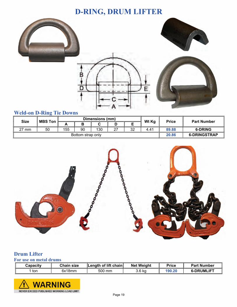
D-RING, DRUM LIFTER Weld-on D-Ring Tie Downs
Size MBS Ton Dimensions (mm) Wt Kg Price Part Number A B C D E 27 mm 50 155 90 130 27 32 4.41 89.88 6-DRING
Bottom strap only 20.86 6-DRINGSTRAP
Drum Lifter For use on metal drums
Capacity Chain size Length of lift chain Net Weight Price Part Number 1 ton 6x18mm 500 mm 3.6 kg 190.20 6-DRUMLIFT
Page 19
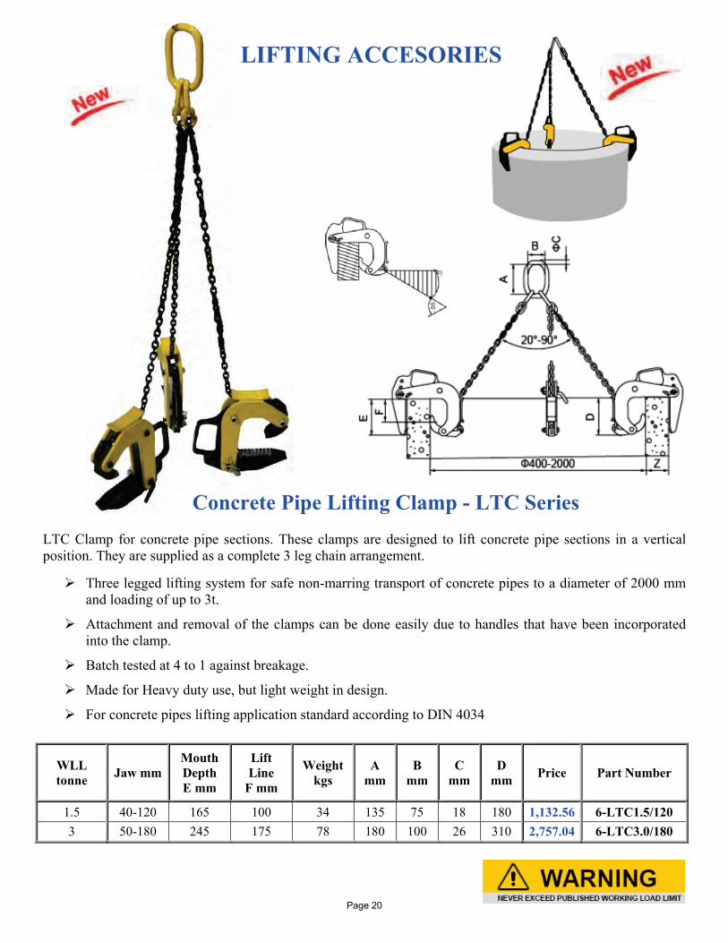
LIFTING ACCESORIES
Concrete Pipe Lifting Clamp - LTC Series
LTC Clamp for concrete pipe sections. These clamps are designed to lift concrete pipe sections in a vertical position. They are supplied as a complete 3 leg chain arrangement. Three legged lifting system for safe non-marring transport of concrete pipes to a diameter of 2000 mm
and loading of up to 3t.
Attachment and removal of the clamps can be done easily due to handles that have been incorporated into the clamp.
Batch tested at 4 to 1 against breakage.
Made for Heavy duty use, but light weight in design.
For concrete pipes lifting application standard according to DIN 4034
WLL tonne Jaw mm
Mouth Depth E mm
Lift Line
F mm
Weight kgs
A mm
B mm
C mm
D mm Price Part Number
1.5 40-120 165 100 34 135 75 18 180 1,132.56 6-LTC1.5/120 3 50-180 245 175 78 180 100 26 310 2,757.04 6-LTC3.0/180
Page 20
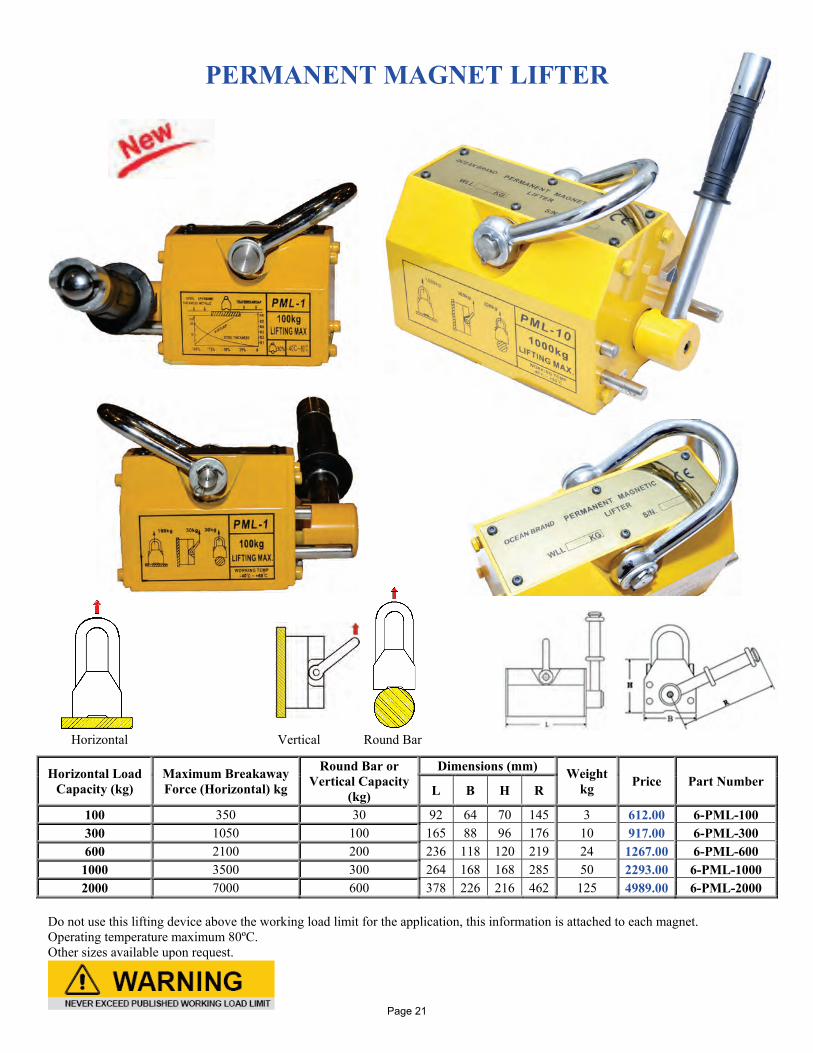
PERMANENT MAGNET LIFTER Horizontal Vertical Round Bar
Do not use this lifting device above the working load limit for the application, this information is attached to each magnet. Operating temperature maximum 80ºC. Other sizes available upon request.
Horizontal Load Capacity (kg)
Maximum Breakaway Force (Horizontal) kg
Round Bar or Vertical Capacity
(kg)
Dimensions (mm) Weight kg Price Part Number
L B H R
100 350 30 92 64 70 145 3 612.00 6-PML-100 300 1050 100 165 88 96 176 10 917.00 6-PML-300 600 2100 200 236 118 120 219 24 1267.00 6-PML-600
1000 3500 300 264 168 168 285 50 2293.00 6-PML-1000 2000 7000 600 378 226 216 462 125 4989.00 6-PML-2000
Page 21
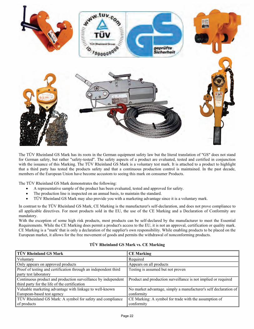
The TÜV Rheinland GS Mark has its roots in the German equipment safety law but the literal translation of "GS" does not stand for German safety, but rather "safety-tested". The safety aspects of a product are evaluated, tested and certified in conjunction with the issuance of this Marking. The TÜV Rheinland GS Mark is a voluntary test mark. It is attached to a product to highlight that a third party has tested the products safety and that a continuous production control is maintained. In the past decade, members of the European Union have become accustom to seeing this mark on consumer Products. The TÜV Rheinland GS Mark demonstrates the following:
• A representative sample of the product has been evaluated, tested and approved for safety. • The production line is inspected on an annual basis, to maintain the standard. • TÜV Rheinland GS Mark may also provide you with a marketing advantage since it is a voluntary mark.
In contrast to the TÜV Rheinland GS Mark, CE Marking is the manufacturer's self-declaration, and does not prove compliance to all applicable directives. For most products sold in the EU, the use of the CE Marking and a Declaration of Conformity are mandatory. With the exception of some high risk products, most products can be self-declared by the manufacturer to meet the Essential Requirements. While the CE Marking does permit a product's access to the EU, it is not an approval, certification or quality mark. CE Marking is a "mark' that is only a declaration of the supplier's own responsibility. While enabling products to be placed on the European market, it allows for the free movement of goods and permits the withdrawal of nonconforming products.
TÜV Rheinland GS Mark vs. CE Marking
TÜV Rheinland GS Mark CE Marking Voluntary Required Only appears on approved products Appears on all products Proof of testing and certification through an independent third party test laboratory
Testing is assumed but not proven
Continuous product and production surveillance by independent third party for the life of the certification
Product and production surveillance is not implied or required
Valuable marketing advantage with linkage to well-known European-based test agency
No market advantage, simply a manufacturer's self declaration of conformity
TÜV Rheinland GS Mark: A symbol for safety and compliance of products
CE Marking: A symbol for trade with the assumption of conformity
Page 22
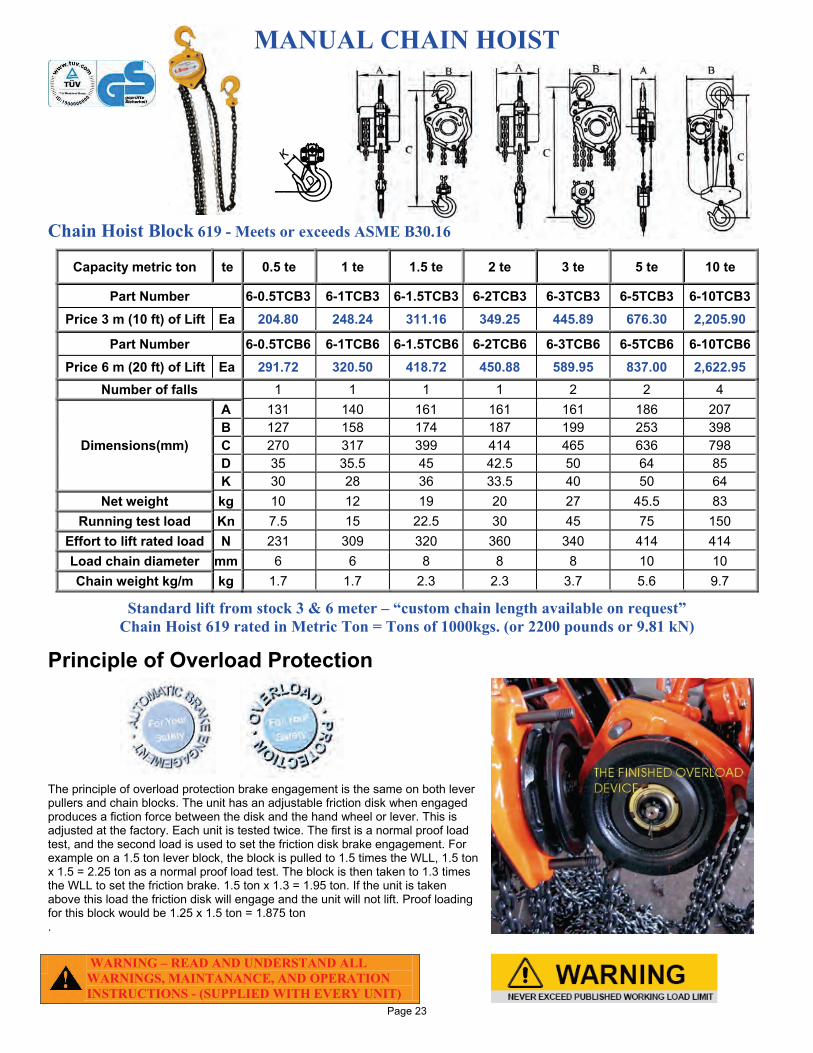
MANUAL CHAIN HOIST Chain Hoist Block 619 - Meets or exceeds ASME B30.16
Capacity metric ton te 0.5 te 1 te 1.5 te 2 te 3 te 5 te 10 te
Part Number 6-0.5TCB3 6-1TCB3 6-1.5TCB3 6-2TCB3 6-3TCB3 6-5TCB3 6-10TCB3 Price 3 m (10 ft) of Lift Ea 204.80 248.24 311.16 349.25 445.89 676.30 2,205.90
Part Number 6-0.5TCB6 6-1TCB6 6-1.5TCB6 6-2TCB6 6-3TCB6 6-5TCB6 6-10TCB6 Price 6 m (20 ft) of Lift Ea 291.72 320.50 418.72 450.88 589.95 837.00 2,622.95
Number of falls 1 1 1 1 2 2 4
Dimensions(mm)
A 131 140 161 161 161 186 207 B 127 158 174 187 199 253 398 C 270 317 399 414 465 636 798 D 35 35.5 45 42.5 50 64 85 K 30 28 36 33.5 40 50 64
Net weight kg 10 12 19 20 27 45.5 83 Running test load Kn 7.5 15 22.5 30 45 75 150
Effort to lift rated load N 231 309 320 360 340 414 414 Load chain diameter mm 6 6 8 8 8 10 10 Chain weight kg/m kg 1.7 1.7 2.3 2.3 3.7 5.6 9.7
Standard lift from stock 3 & 6 meter – “custom chain length available on request” Chain Hoist 619 rated in Metric Ton = Tons of 1000kgs. (or 2200 pounds or 9.81 kN)
Principle of Overload Protection The principle of overload protection brake engagement is the same on both lever pullers and chain blocks. The unit has an adjustable friction disk when engaged produces a fiction force between the disk and the hand wheel or lever. This is adjusted at the factory. Each unit is tested twice. The first is a normal proof load test, and the second load is used to set the friction disk brake engagement. For example on a 1.5 ton lever block, the block is pulled to 1.5 times the WLL, 1.5 ton x 1.5 = 2.25 ton as a normal proof load test. The block is then taken to 1.3 times the WLL to set the friction brake. 1.5 ton x 1.3 = 1.95 ton. If the unit is taken above this load the friction disk will engage and the unit will not lift. Proof loading for this block would be 1.25 x 1.5 ton = 1.875 ton .
WARNING – READ AND UNDERSTAND ALL WARNINGS, MAINTANANCE, AND OPERATION INSTRUCTIONS - (SUPPLIED WITH EVERY UNIT)
Page 23
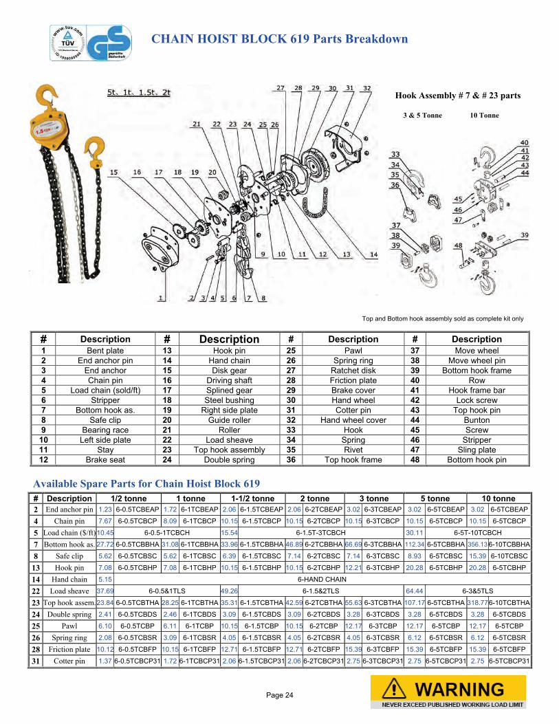
CHAIN HOIST BLOCK 619 Parts Breakdown
Hook Assembly # 7 & # 23 parts 3 & 5 Tonne 10 Tonne
Top and Bottom hook assembly sold as complete kit only
# Description # Description # Description # Description 1 Bent plate 13 Hook pin 25 Pawl 37 Move wheel 2 End anchor pin 14 Hand chain 26 Spring ring 38 Move wheel pin 3 End anchor 15 Disk gear 27 Ratchet disk 39 Bottom hook frame 4 Chain pin 16 Driving shaft 28 Friction plate 40 Row 5 Load chain (sold/ft) 17 Splined gear 29 Brake cover 41 Hook frame bar 6 Stripper 18 Steel bushing 30 Hand wheel 42 Lock screw 7 Bottom hook as. 19 Right side plate 31 Cotter pin 43 Top hook pin 8 Safe clip 20 Guide roller 32 Hand wheel cover 44 Bunton 9 Bearing race 21 Roller 33 Hook 45 Screw
10 Left side plate 22 Load sheave 34 Spring 46 Stripper 11 Stay 23 Top hook assembly 35 Rivet 47 Sling plate 12 Brake seat 24 Double spring 36 Top hook frame 48 Bottom hook pin
Available Spare Parts for Chain Hoist Block 619
# Description 1/2 tonne 1 tonne 1-1/2 tonne 2 tonne 3 tonne 5 tonne 10 tonne 2 End anchor pin 1.23 6-0.5TCBEAP 1.72 6-1TCBEAP 2.06 6-1.5TCBEAP 2.06 6-2TCBEAP 3.02 6-3TCBEAP 3.02 6-5TCBEAP 3.02 6-5TCBEAP
4 Chain pin 7.67 6-0.5TCBCP 8.09 6-1TCBCP 10.15 6-1.5TCBCP 10.15 6-2TCBCP 10.15 6-3TCBCP 10.15 6-5TCBCP 10.15 6-5TCBCP
5 Load chain ($/ft) 10.45 6-0.5-1TCBCH 15.54 6-1.5T-3TCBCH 30.11 6-5T-10TCBCH
7 Bottom hook as. 27.72 6-0.5TCBBHA 31.08 6-1TCBBHA 33.96 6-1.5TCBBHA 46.89 6-2TCBBHA 66.69 6-3TCBBHA 112.34 6-5TCBBHA 356.13 6-10TCBBHA
8 Safe clip 5.62 6-0.5TCBSC 5.62 6-1TCBSC 6.39 6-1.5TCBSC 7.14 6-2TCBSC 7.14 6-3TCBSC 8.93 6-5TCBSC 15.39 6-10TCBSC
13 Hook pin 7.08 6-0.5TCBHP 7.08 6-1TCBHP 10.15 6-1.5TCBHP 10.15 6-2TCBHP 12.21 6-3TCBHP 20.28 6-5TCBHP 20.28 6-5TCBHP
14 Hand chain 5.15 6-HAND CHAIN
22 Load sheave 37.69 6-0.5&1TLS 49.26 6-1.5&2TLS 64.44 6-3&5TLS
23 Top hook assem. 23.84 6-0.5TCBTHA 28.25 6-1TCBTHA 35.31 6-1.5TCBTHA 42.59 6-2TCBTHA 55.63 6-3TCBTHA 107.17 6-5TCBTHA 318.77 6-10TCBTHA
24 Double spring 2.41 6-0.5TCBDS 2.46 6-1TCBDS 3.09 6-1.5TCBDS 3.09 6-2TCBDS 3.28 6-3TCBDS 3.28 6-5TCBDS 3.28 6-5TCBDS
25 Pawl 6.10 6-0.5TCBP 6.11 6-1TCBP 10.15 6-1.5TCBP 10.15 6-2TCBP 12.17 6-3TCBP 12.17 6-5TCBP 12.17 6-5TCBP
26 Spring ring 2.08 6-0.5TCBSR 3.09 6-1TCBSR 4.05 6-1.5TCBSR 4.05 6-2TCBSR 4.05 6-3TCBSR 6.12 6-5TCBSR 6.12 6-5TCBSR
28 Friction plate 10.12 6-0.5TCBFP 10.15 6-1TCBFP 12.71 6-1.5TCBFP 12.71 6-2TCBFP 15.39 6-3TCBFP 15.39 6-5TCBFP 15.39 6-5TCBFP
31 Cotter pin 1.37 6-0.5TCBCP31 1.72 6-1TCBCP31 2.06 6-1.5TCBCP31 2.06 6-2TCBCP31 2.75 6-3TCBCP31 2.75 6-5TCBCP31 2.75 6-5TCBCP31
Page 24
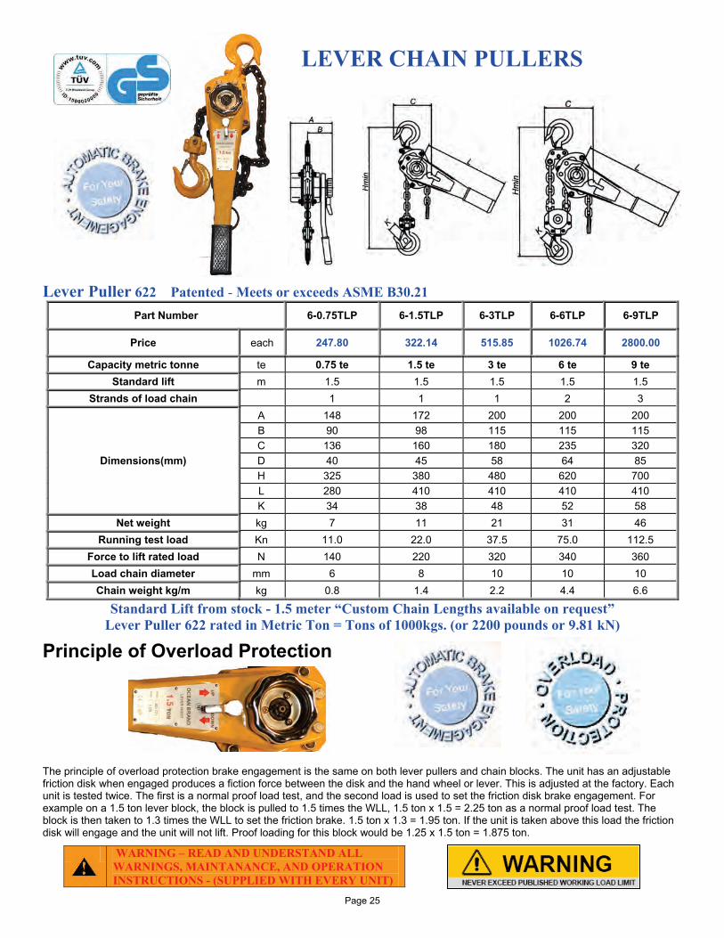
LEVER CHAIN PULLERS Lever Puller 622 Patented - Meets or exceeds ASME B30.21
Part Number 6-0.75TLP 6-1.5TLP 6-3TLP 6-6TLP 6-9TLP
Price each 247.80 322.14 515.85 1026.74 2800.00
Capacity metric tonne te 0.75 te 1.5 te 3 te 6 te 9 te Standard lift m 1.5 1.5 1.5 1.5 1.5
Strands of load chain 1 1 1 2 3
Dimensions(mm)
A 148 172 200 200 200 B 90 98 115 115 115 C 136 160 180 235 320 D 40 45 58 64 85 H 325 380 480 620 700 L 280 410 410 410 410 K 34 38 48 52 58
Net weight kg 7 11 21 31 46 Running test load Kn 11.0 22.0 37.5 75.0 112.5
Force to lift rated load N 140 220 320 340 360 Load chain diameter mm 6 8 10 10 10 Chain weight kg/m kg 0.8 1.4 2.2 4.4 6.6
Standard Lift from stock - 1.5 meter “Custom Chain Lengths available on request” Lever Puller 622 rated in Metric Ton = Tons of 1000kgs. (or 2200 pounds or 9.81 kN)
Principle of Overload Protection The principle of overload protection brake engagement is the same on both lever pullers and chain blocks. The unit has an adjustable friction disk when engaged produces a fiction force between the disk and the hand wheel or lever. This is adjusted at the factory. Each unit is tested twice. The first is a normal proof load test, and the second load is used to set the friction disk brake engagement. For example on a 1.5 ton lever block, the block is pulled to 1.5 times the WLL, 1.5 ton x 1.5 = 2.25 ton as a normal proof load test. The block is then taken to 1.3 times the WLL to set the friction brake. 1.5 ton x 1.3 = 1.95 ton. If the unit is taken above this load the friction disk will engage and the unit will not lift. Proof loading for this block would be 1.25 x 1.5 ton = 1.875 ton.
WARNING – READ AND UNDERSTAND ALL WARNINGS, MAINTANANCE, AND OPERATION INSTRUCTIONS - (SUPPLIED WITH EVERY UNIT)
Page 25
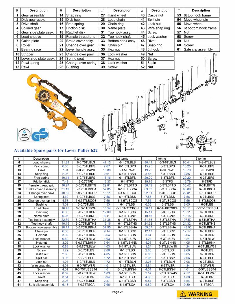
Available Spare parts for Lever Puller 622
# Description # Description # Description # Description # Description 1 Gear assembly 14 Snap ring 27 Hand wheel 40 Castle nut 53 6t top hook frame 2 Disk gear assy. 15 Disk hub 28 Load chain 41 Split pin 54 Move wheel pin 3 Drive shaft 16 Free spring 29 Chain ring 42 Lock nut 55 Move wheel 4 Splined gear 17 Friction disk 30 Name plate 43 Wire snap ring 56 6t bottom hook frame 5 Gear side plate assy. 18 Ratchet disk 31 Top hook assy. 44 Screw 57 Nut 6 Load sheave 19 Female thread grip 32 Top hook shaft 45 Lock washer 58 Screw 7 Guide plate 20 Brake cover assy. 33 Bottom hook assy. 46 Rivet 59 Nut 8 Roller 21 Change over gear 34 Chain pin 47 Snap ring 60 Screw 9 Bearing race 22 Lever handle assy. 35 Hex nut 48 6t hook 61 Safe clip assembly
10 Stripper 23 Change over pawl 36 Lock washer 49 Nut 11 Lever side plate assy. 24 Spring seat 37 Hex nut 50 Screw 12 Pawl spring 25 Change over spring 38 Lock washer 51 6t pin 13 Pawl 26 Bushing 39 Screw 52 Nut
# Description ¾ tonne 1-1/2 tonne 3 tonne 6 tonne 6 Load sheave 31.88 6-0.75TLBLS 47.13 6-1.5TLBLS 90.41 6-3-6TLBLS 90.41 6-3-6TLBLS
12 Pawl spring 6.05 6-0.75TLBPS 7.67 6-1.5TLBPS 15.25 6-3TLBPS 15.25 6-3TLBPS 13 Pawl 7.91 6-0.75TPAWL 15.80 6-1.5TPAWL 19.79 6-3TPAWL 19.79 6-6TPAWL 14 Snap ring 2.06 6-0.75TLBSR 2.61 6-1.5TLBSR 3.85 6-3TLBSR 3.85 6-3TLBSR 16 Free spring 10.11 6-0.75TLBFS 16.16 6-1.5TLBFS 20.20 6-3TLBFS 20.20 6-3TLBFS 17 Friction disk 7.42 6-0.75TFD 12.37 6-1.5TFD 19.79 6-3TFD 19.79 6-6TFD 19 Female thread grip 18.27 6-0.75TLBFTG 22.81 6-1.5TLBFTG 30.42 6-3TLBFTG 30.42 6-3TLBFTG 20 Brake cover assembly 31.19 6-0.75TLBBCA 57.85 6-1.5TLBBCA 63.89 6-3TLBBCA 63.89 6-3TLBBCA 23 Change over pawl 10.65 6-0.75TLBCOP 15.11 6-1.5TLBCOP 22.81 6-3TLBCOP 22.81 6-3TLBCOP 24 Spring seat 4.60 6-0.75TLBSS 7.56 6-1.5TLBSS 7.56 6-3TLBSS 7.56 6-3TLBSS 25 Change over spring 4.53 6-0.75TLBCOS 7.56 6-1.5TLBCOS 7.56 6-3TLBCOS 7.56 6-3TLBCOS 26 Bushing 3.02 6-0.75TLBB 4.53 6-1.5TLBB 6.05 6-3TLBB 6.05 6-3TLBB 28 Load chain 10.45 6-0.5-1TCBCH 15.54 6-1.5T-3TCBCH 30.11 6-5T-10TCBCH 30.11 6-5T-10TCBCH 29 Chain ring 6.05 6-0.75TLBCR 12.09 6-1.5TLBCR 15.11 6-3TLBCR 15.11 6-3TLBCR 30 Name plate 6.05 6-0.75TLBNP 8.11 6-1.5TLBNP 10.15 6-3TLBNP 10.15 6-3TLBNP 31 Top hook assembly 22.59 6-0.75TLBTHA 31.38 6-1.5TLBTHA 51.66 6-3TLBTHA 107.50 6-6TLBTHA 32 Top hook shaft 10.15 6-0.75TLBTHS 16.16 6-1.5TLBTHS 24.32 6-3TLBTHS 24.32 6-3TLBTHS 33 Bottom hook assembly 28.11 6-0.75TLBBHA 37.95 6-1.5TLBBHA 59.07 6-3TLBBHA 143.00 6-6TLBBHA 34 Chain pin 6.05 6-0.75TLBCP 9.14 6-1.5TLBCP 12.17 6-3TLBCP 12.17 6-3TLBCP 35 Hex nut 3.02 6-0.75TLBHN 3.64 6-1.5TLBHN 3.64 6-3TLBHN 3.64 6-3TLBHN 36 Lock washer 0.69 6-0.75TLBLW 1.03 6-1.5TLBLW 1.24 6-3TLBLW 1.24 6-3TLBLW 37 Hex nut 3.02 6-0.75TLBHNN 3.64 6-1.5TLBHNN 4.05 6-3TLBHNN 4.05 6-3TLBHNN 38 Lock washer 0.69 6-0.75TLBLW 1.03 6-1.5TLBLW 1.24 6-3TLBLW38 1.24 6-3TLBLW38 39 Screw 1.72 6-0.75TLBS 2.06 6-1.5TLBS 2.68 6-3TLBS 2.68 6-3TLBS 40 Castle nut 2.06 6-0.75TLBCN 4.05 6-1.5TLBCN 6.05 6-3TLBCN 6.05 6-3TLBCN 41 Split pin 1.03 6-0.75LBSP 1.72 6-1.5TLBSP 2.06 6-3TLBSP 2.06 6-3TLBSP 42 Lock nut 1.03 6-0.75TLBLN 1.72 6-1.5TLBLN 2.06 6-3TLBLN 2.06 6-3TLBLN 43 Wire snap ring 4.01 6-0.75TWSR 4.01 6-1.5TWSR 4.84 6-3TWSR 4.84 6-3TWSR 44 Screw 4.01 6-0.75TLBSS44 4.01 6-1.5TLBSS44 4.01 6-3TLBSS44 4.01 6-3TLBSS44 45 Lock washer 0.69 6-0.75TLBLW 1.03 6-1.5TLBLW 2.57 6-3TLBLW45 2.57 6-3TLBLW45 46 Rivet 3.54 6-0.75TLBR 3.94 6-1.5TLBR 4.38 6-3TLBR 4.38 6-3TLBR 47 Snap ring 2.06 6-0.75TLBSR 2.57 6-1.5TLBSR 6.54 6-3TLBSR 6.54 6-3TLBSR 61 Safe clip assembly 6.18 6-0.75TSCA 7.96 6-1.5TSCA 9.89 6-3TSCA 9.89 6-6TSCA
Page 26
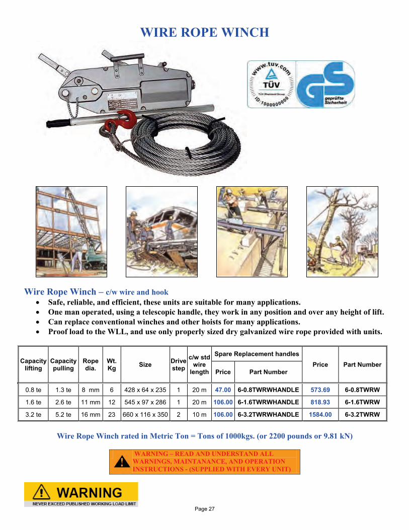
WIRE ROPE WINCH
Wire Rope Winch – c/w wire and hook • Safe, reliable, and efficient, these units are suitable for many applications. • One man operated, using a telescopic handle, they work in any position and over any height of lift. • Can replace conventional winches and other hoists for many applications. • Proof load to the WLL, and use only properly sized dry galvanized wire rope provided with units.
Capacity lifting
Capacity pulling
Rope dia.
Wt. Kg Size Drive
step c/w std
wire length
Spare Replacement handles Price Part Number
Price Part Number
0.8 te 1.3 te 8 mm 6 428 x 64 x 235 1 20 m 47.00 6-0.8TWRWHANDLE 573.69 6-0.8TWRW
1.6 te 2.6 te 11 mm 12 545 x 97 x 286 1 20 m 106.00 6-1.6TWRWHANDLE 818.93 6-1.6TWRW
3.2 te 5.2 te 16 mm 23 660 x 116 x 350 2 10 m 106.00 6-3.2TWRWHANDLE 1584.00 6-3.2TWRW
Wire Rope Winch rated in Metric Ton = Tons of 1000kgs. (or 2200 pounds or 9.81 kN)
WARNING – READ AND UNDERSTAND ALL WARNINGS, MAINTANANCE, AND OPERATION INSTRUCTIONS - (SUPPLIED WITH EVERY UNIT)
Page 27
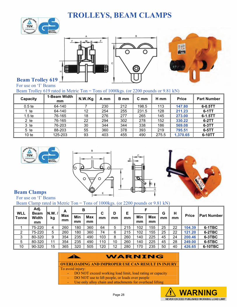
TROLLEYS, BEAM CLAMPS
Beam Trolley 619 For use on ‘I’ Beams Beam Trolley 619 rated in Metric Ton = Tons of 1000kgs. (or 2200 pounds or 9.81 kN)
Capacity 1-Beam Width mm N.W./Kg A mm B mm C mm H mm Price Part Number
0.5 te 64-140 7 230 212 198.5 113 147.80 6-0.5TT 1 te 64-140 12 254 255 231.5 128 211.23 6-1TT 1.5 te 76-165 18 276 277 265 145 273.00 6-1.5TT 2 te 76-165 22 294 302 278 152 330.22 6-2TT 3 te 76-203 30 344 344 338 186 569.08 6-3TT 5 te 88-203 55 360 378 393 219 795.51 6-5TT 10 te 125-203 93 403 455 490 275.5 1,370.65 6-10TT
Beam Clamps For use on ‘I’ Beams Beam Clamp rated in Metric Ton = Tons of 1000kgs. (or 2200 pounds or 9.81 kN)
WLL Tonne
Adj. Beam Width mm
N.W. / kg
A Max mm
B C
mm D
mm E
mm
F G
mm H
mm Price Part Number Min mm
Max mm
Min mm
Max mm
1 75-220 4 260 180 360 64 5 215 102 155 25 22 104.39 6-1TBC 2 75-220 5 260 180 360 74 6 215 102 155 25 22 121.20 6-2TBC 3 80-320 9 354 235 490 103 8 260 140 225 45 24 200.46 6-3TBC 5 80-320 11 354 235 490 110 10 260 140 225 45 28 249.00 6-5TBC 10 90-320 15 365 320 505 120 12 280 170 235 50 40 426.65 6-10TBC
OVERLOADING AND IMPROPER USE CAN RESULT IN INJURY To avoid injury:
- DO NOT exceed working load limit, load rating or capacity - DO NOT use to lift people, or loads over people - Use only alloy chain and attachments for overhead lifting
Page 28
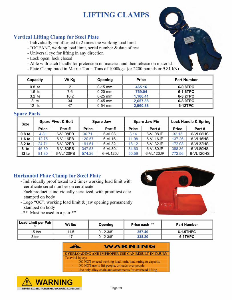
LIFTING CLAMPS
Vertical Lifting Clamp for Steel Plate
- Individually proof tested to 2 times the working load limit - “OCEAN”, working load limit, serial number & date of test - Universal eye for lifting in any direction - Lock open, lock closed - Able with latch handle for pretension on material and then release on material - Plate Clamp rated in Metric Ton = Tons of 1000kgs. (or 2200 pounds or 9.81 kN)
Spare Parts
Size Spare Pivot & Bolt Spare Jaw Spare Jaw Pin Lock Handle & Spring
Price Part # Price Part # Price Part # Price Part # 0.8 te 4.81 6-VL08PB 36.71 6-VL08J 3.14 6-VL08JP 32.15 6-VL08HS 1.6 te 12.75 6-VL16PB 120.57 6-VL16J 11.98 6-VL16JP 137.26 6-VL16HS 3.2 te 24.71 6-VL32PB 191.61 6-VL32J 18.12 6-VL32JP 172.08 6-VL32HS 8 te 46.89 6-VL80PB 347.53 6-VL80J 34.60 6-VL80JP 388.36 6-VL80HS 12 te 81.30 6-VL120PB 574.26 6-VL120J 50.59 6-VL120JP 772.56 6-VL120HS
Horizontal Plate Clamp for Steel Plate
- Individually proof tested to 2 times working load limit with certificate serial number on certificate
- Each product is individually serialized, with proof test date stamped on body
- Logo “OC”, working load limit & jaw opening permanently stamped on body
- ** Must be used in a pair **
Capacity Wt Kg Opening Price Part Number
0.8 te 2 0-15 mm 465.16 6-0.8TPC 1.6 te 7.6 0-20 mm 769.04 6-1.6TPC 3.2 te 16.2 0-25 mm 1,166.41 6-3.2TPC 8 te 34 0-45 mm 2,657.88 6-8.0TPC
12 te 47 0-54 mm 2,960.38 6-12TPC
OVERLOADING AND IMPROPER USE CAN RESULT IN INJURY To avoid injury:
- DO NOT exceed working load limit, load rating or capacity - DO NOT use to lift people, or loads over people - Use only alloy chain and attachments for overhead lifting
Load Limit per Pair ** Wt lbs Opening Price each ** Part Number
1.5 ton 11.5 0 - 2-3/8” 257.40 6-1.5THPC 3 ton 17 0 - 2-3/8” 338.20 6-3THPC
Page 29
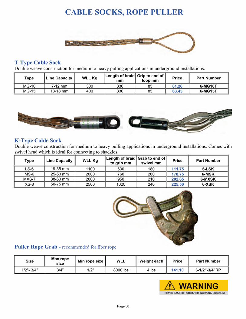
CABLE SOCKS, ROPE PULLER T-Type Cable Sock Double weave construction for medium to heavy pulling applications in underground installations.
K-Type Cable Sock Double weave construction for medium to heavy pulling applications in underground installations. Comes with swivel head which is ideal for connecting to shackles.
Puller Rope Grab - recommended for fiber rope
Size Max rope size Min rope size WLL Weight each Price Part Number
1/2"- 3/4" 3/4” 1/2" 8000 lbs 4 lbs 141.10 6-1/2"-3/4"RP
Type Line Capacity WLL Kg Length of braid mm
Grip to end of loop mm Price Part Number
MG-10 7-12 mm 300 330 85 61.26 6-MG10T MG-15 13-18 mm 400 330 85 63.45 6-MG15T
Type Line Capacity WLL Kg Length of braid to grip mm
Grab to end of swivel mm Price Part Number
LS-6 19-35 mm 1100 630 180 111.75 6-LSK MS-6 25-50 mm 2000 760 200 178.75 6-MSK
MXS-7 38-60 mm 2000 950 210 202.65 6-MXSK XS-8 50-75 mm 2500 1020 240 225.50 6-XSK
Page 30
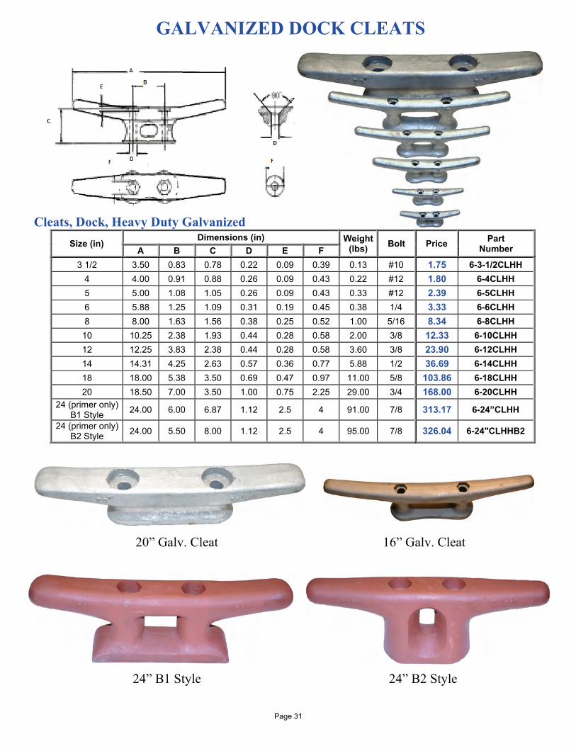
GALVANIZED DOCK CLEATS
Cleats, Dock, Heavy Duty Galvanized
Size (in) Dimensions (in) Weight (lbs) Bolt Price Part
Number A B C D E F 3 1/2 3.50 0.83 0.78 0.22 0.09 0.39 0.13 #10 1.75 6-3-1/2CLHH
4 4.00 0.91 0.88 0.26 0.09 0.43 0.22 #12 1.80 6-4CLHH 5 5.00 1.08 1.05 0.26 0.09 0.43 0.33 #12 2.39 6-5CLHH 6 5.88 1.25 1.09 0.31 0.19 0.45 0.38 1/4 3.33 6-6CLHH 8 8.00 1.63 1.56 0.38 0.25 0.52 1.00 5/16 8.34 6-8CLHH
10 10.25 2.38 1.93 0.44 0.28 0.58 2.00 3/8 12.33 6-10CLHH 12 12.25 3.83 2.38 0.44 0.28 0.58 3.60 3/8 23.90 6-12CLHH 14 14.31 4.25 2.63 0.57 0.36 0.77 5.88 1/2 36.69 6-14CLHH 18 18.00 5.38 3.50 0.69 0.47 0.97 11.00 5/8 103.86 6-18CLHH 20 18.50 7.00 3.50 1.00 0.75 2.25 29.00 3/4 168.00 6-20CLHH
24 (primer only) B1 Style 24.00 6.00 6.87 1.12 2.5 4 91.00 7/8 313.17 6-24”CLHH
24 (primer only) B2 Style 24.00 5.50 8.00 1.12 2.5 4 95.00 7/8 326.04 6-24"CLHHB2
20” Galv. Cleat 16” Galv. Cleat 24” B1 Style 24” B2 Style
Page 31
Stainless Steel - CLEATS AND CHOCKS
Cleats, Stainless Steel, 316SS
Size Price Part Number
5" 18.29 6-5"CLSS 6" 23.66 6-6"CLSS 8" 32.11 6-8"CLSS
12" 56.18 6-12"CLSS
Cleats, Stainless Steel, 316SS Low Silhouette
Size Price Part Number 6" 37.69 6-6"CLLSSS 8" 43.98 6-8"CLLSSS
Chocks, Stainless Steel, 316SS Straight
Size Price Part Number 6" 38.40 6-6"CSSS 8" 55.00 6-8"CSSS
Chocks, Stainless Steel, 316SS Bow
MOORING STAPLE
Mooring Staples, Stainless Steel, 316SS Size Length Width Price Part Number 1" 8-1/2” 8-1/2” 137.88 6-1"SSMB
Type Size set of 2 Part Number Port & Starboard 4-1/2" 39.00 6-4-1/2"CBSS Port & Starboard 6" 65.00 6-6"CBSS
Page 32
HINGES, FLAG CLIPS, OAR LOCKS
Hinge, Butt Heavy Duty, 316SS
Size Price Part Number
1-1/2 x1-1/2 13.12 6-1-1/2”BHSS 2" x 2" 14.98 6-2"BHSS 3" x 3" 29.15 6-3"BHSS 4" x 4" 51.03 6-4"BHSS
Hinge, Door Heavy Duty, 316SS
Size Price Part Number
1-1/2" x 3" 14.98 6-3"DH316 1-1/2” x 4” 16.27 6-4”DH316
Hinge, Strap Heavy Duty, 316SS
Size Price Part Number
1-1/2" x 4" 16.27 6-1-1/2"SH316
Hinge, Strap, 304SS
Size Price Part Number 3-1/2" x 1-1/2" 31.79 6-3-1/2"SH304
5" x 1-1/2" 39.65 6-5"SH304 8" x 2" 92.29 6-8"SH304
Clips, Ingerfield, (flag clips)
Price Part Number
17.27 98-FLAGCLIP
Oar Lock
Finish Description Price Part Number
Galvanized # 2 oar lock 12.19 6-HDGOL Galv. Socket Gunwhale 5.48 6-HDGGS Galv. Socket Side Mount 5.48 6-HDGSMS
Page 33
FISHING
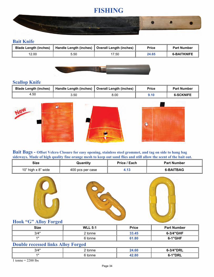
Bait Knife Blade Length (inches) Handle Length (inches) Overall Length (inches) Price Part Number
12.00 5.50 17.50 24.65 6-BAITKNIFE
Scallop Knife Blade Length (inches) Handle Length (inches) Overall Length (inches) Price Part Number
4.50 3.50 8.00 9.10 6-SCKNIFE
Bait Bags - Offset Velcro Closure for easy opening, stainless steel grommet, and tag on side to hang bag sideways. Made of high quality fine orange mesh to keep out sand flies and still allow the scent of the bait out.
Size Quantity Price / Each Part Number
10” high x 8” wide 400 pcs per case 4.13 6-BAITBAG
Hook “G” Alloy Forged
Size WLL 5:1 Price Part Number 3/4" 2 tonne 33.45 6-3/4"GHF 1" 6 tonne 61.80 6-1"GHF
Double recessed links Alloy Forged 3/4" 2 tonne 24.60 6-3/4"DRL 1" 6 tonne 42.80 6-1"DRL
1 tonne = 2200 lbs Page 34
FISHING
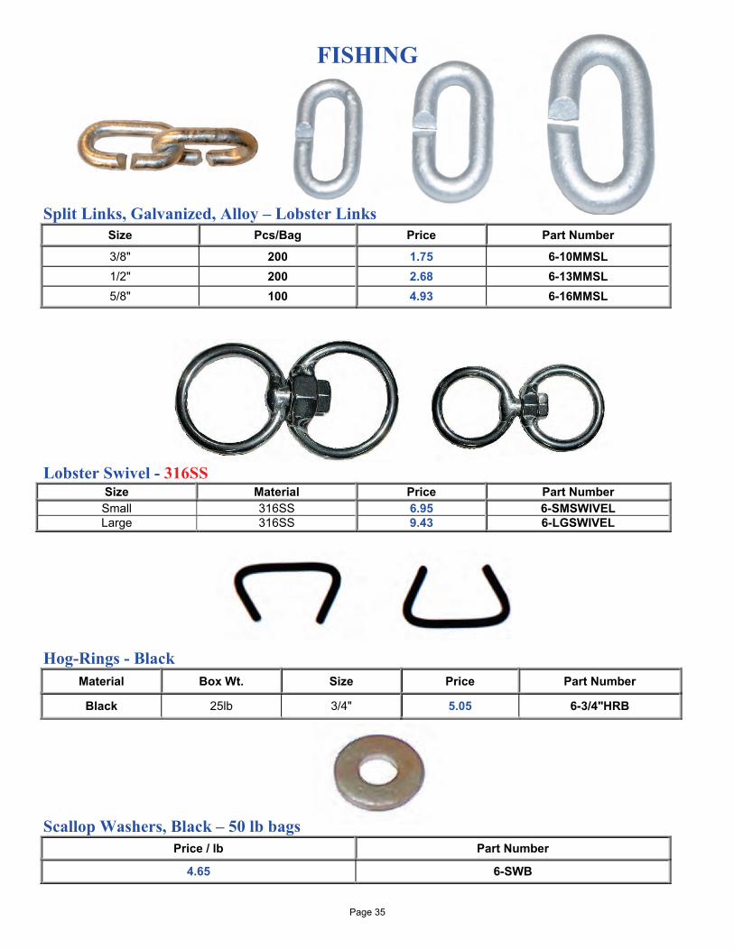
Split Links, Galvanized, Alloy – Lobster Links
Size Pcs/Bag Price Part Number
3/8" 200 1.75 6-10MMSL 1/2" 200 2.68 6-13MMSL 5/8" 100 4.93 6-16MMSL
Lobster Swivel - 316SS
Size Material Price Part Number Small 316SS 6.95 6-SMSWIVEL Large 316SS 9.43 6-LGSWIVEL
Hog-Rings - Black
Material Box Wt. Size Price Part Number
Black 25lb 3/4" 5.05 6-3/4"HRB
Scallop Washers, Black – 50 lb bags
Price / lb Part Number
4.65 6-SWB
Page 35
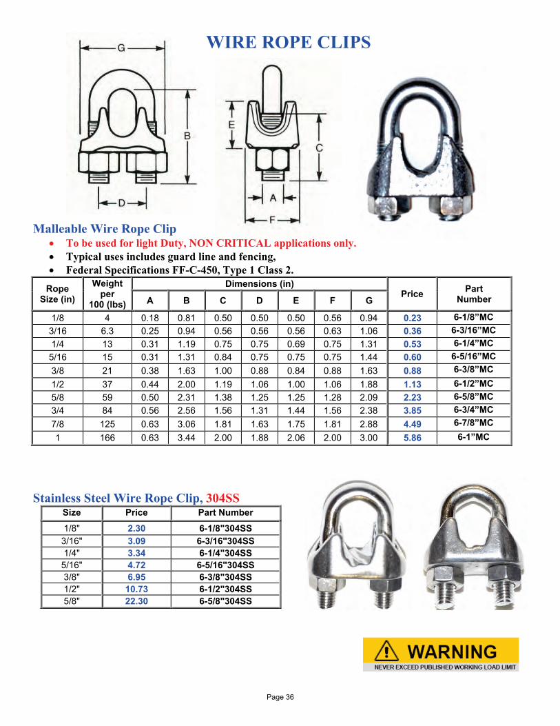
WIRE ROPE CLIPS
Malleable Wire Rope Clip
• To be used for light Duty, NON CRITICAL applications only. • Typical uses includes guard line and fencing, • Federal Specifications FF-C-450, Type 1 Class 2.
Rope Size (in)
Weight per
100 (lbs)
Dimensions (in) Price Part
Number A B C D E F G
1/8 4 0.18 0.81 0.50 0.50 0.50 0.56 0.94 0.23 6-1/8”MC 3/16 6.3 0.25 0.94 0.56 0.56 0.56 0.63 1.06 0.36 6-3/16”MC 1/4 13 0.31 1.19 0.75 0.75 0.69 0.75 1.31 0.53 6-1/4”MC 5/16 15 0.31 1.31 0.84 0.75 0.75 0.75 1.44 0.60 6-5/16”MC 3/8 21 0.38 1.63 1.00 0.88 0.84 0.88 1.63 0.88 6-3/8”MC 1/2 37 0.44 2.00 1.19 1.06 1.00 1.06 1.88 1.13 6-1/2”MC 5/8 59 0.50 2.31 1.38 1.25 1.25 1.28 2.09 2.23 6-5/8”MC 3/4 84 0.56 2.56 1.56 1.31 1.44 1.56 2.38 3.85 6-3/4”MC 7/8 125 0.63 3.06 1.81 1.63 1.75 1.81 2.88 4.49 6-7/8”MC 1 166 0.63 3.44 2.00 1.88 2.06 2.00 3.00 5.86 6-1”MC
Stainless Steel Wire Rope Clip, 304SS
Size Price Part Number 1/8" 2.30 6-1/8"304SS
3/16" 3.09 6-3/16"304SS 1/4" 3.34 6-1/4"304SS
5/16" 4.72 6-5/16"304SS 3/8" 6.95 6-3/8"304SS 1/2" 10.73 6-1/2"304SS 5/8" 22.30 6-5/8"304SS
Page 36
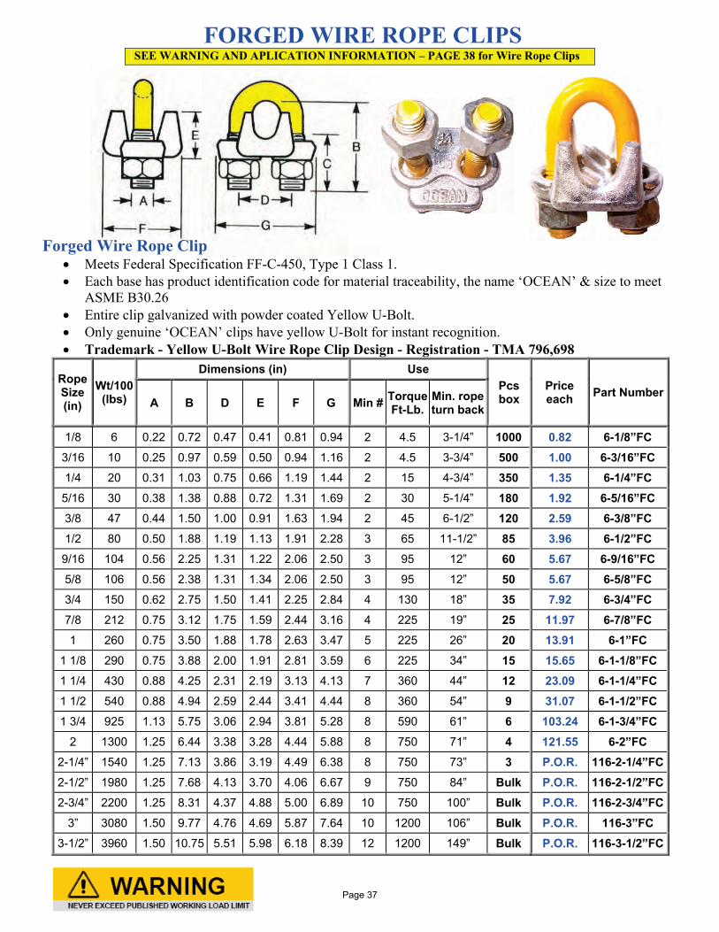
FORGED WIRE ROPE CLIPS SEE WARNING AND APLICATION INFORMATION – PAGE 38 for Wire Rope Clips
Forged Wire Rope Clip • Meets Federal Specification FF-C-450, Type 1 Class 1. • Each base has product identification code for material traceability, the name ‘OCEAN’ & size to meet
ASME B30.26 • Entire clip galvanized with powder coated Yellow U-Bolt. • Only genuine ‘OCEAN’ clips have yellow U-Bolt for instant recognition. • Trademark - Yellow U-Bolt Wire Rope Clip Design - Registration - TMA 796,698
Rope Size (in)
Wt/100 (lbs)
Dimensions (in) Use Pcs box
Price each Part Number
A B D E F G Min # Torque Ft-Lb.
Min. rope turn back
1/8 6 0.22 0.72 0.47 0.41 0.81 0.94 2 4.5 3-1/4” 1000 0.82 6-1/8”FC 3/16 10 0.25 0.97 0.59 0.50 0.94 1.16 2 4.5 3-3/4” 500 1.00 6-3/16”FC 1/4 20 0.31 1.03 0.75 0.66 1.19 1.44 2 15 4-3/4” 350 1.35 6-1/4”FC 5/16 30 0.38 1.38 0.88 0.72 1.31 1.69 2 30 5-1/4” 180 1.92 6-5/16”FC 3/8 47 0.44 1.50 1.00 0.91 1.63 1.94 2 45 6-1/2” 120 2.59 6-3/8”FC 1/2 80 0.50 1.88 1.19 1.13 1.91 2.28 3 65 11-1/2” 85 3.96 6-1/2”FC 9/16 104 0.56 2.25 1.31 1.22 2.06 2.50 3 95 12” 60 5.67 6-9/16”FC 5/8 106 0.56 2.38 1.31 1.34 2.06 2.50 3 95 12” 50 5.67 6-5/8”FC 3/4 150 0.62 2.75 1.50 1.41 2.25 2.84 4 130 18” 35 7.92 6-3/4”FC 7/8 212 0.75 3.12 1.75 1.59 2.44 3.16 4 225 19” 25 11.97 6-7/8”FC 1 260 0.75 3.50 1.88 1.78 2.63 3.47 5 225 26” 20 13.91 6-1”FC
1 1/8 290 0.75 3.88 2.00 1.91 2.81 3.59 6 225 34” 15 15.65 6-1-1/8”FC 1 1/4 430 0.88 4.25 2.31 2.19 3.13 4.13 7 360 44” 12 23.09 6-1-1/4”FC 1 1/2 540 0.88 4.94 2.59 2.44 3.41 4.44 8 360 54” 9 31.07 6-1-1/2”FC 1 3/4 925 1.13 5.75 3.06 2.94 3.81 5.28 8 590 61” 6 103.24 6-1-3/4”FC
2 1300 1.25 6.44 3.38 3.28 4.44 5.88 8 750 71” 4 121.55 6-2”FC 2-1/4” 1540 1.25 7.13 3.86 3.19 4.49 6.38 8 750 73” 3 P.O.R. 116-2-1/4”FC 2-1/2” 1980 1.25 7.68 4.13 3.70 4.06 6.67 9 750 84” Bulk P.O.R. 116-2-1/2”FC 2-3/4” 2200 1.25 8.31 4.37 4.88 5.00 6.89 10 750 100” Bulk P.O.R. 116-2-3/4”FC
3” 3080 1.50 9.77 4.76 4.69 5.87 7.64 10 1200 106” Bulk P.O.R. 116-3”FC 3-1/2” 3960 1.50 10.75 5.51 5.98 6.18 8.39 12 1200 149” Bulk P.O.R. 116-3-1/2”FC
Page 37
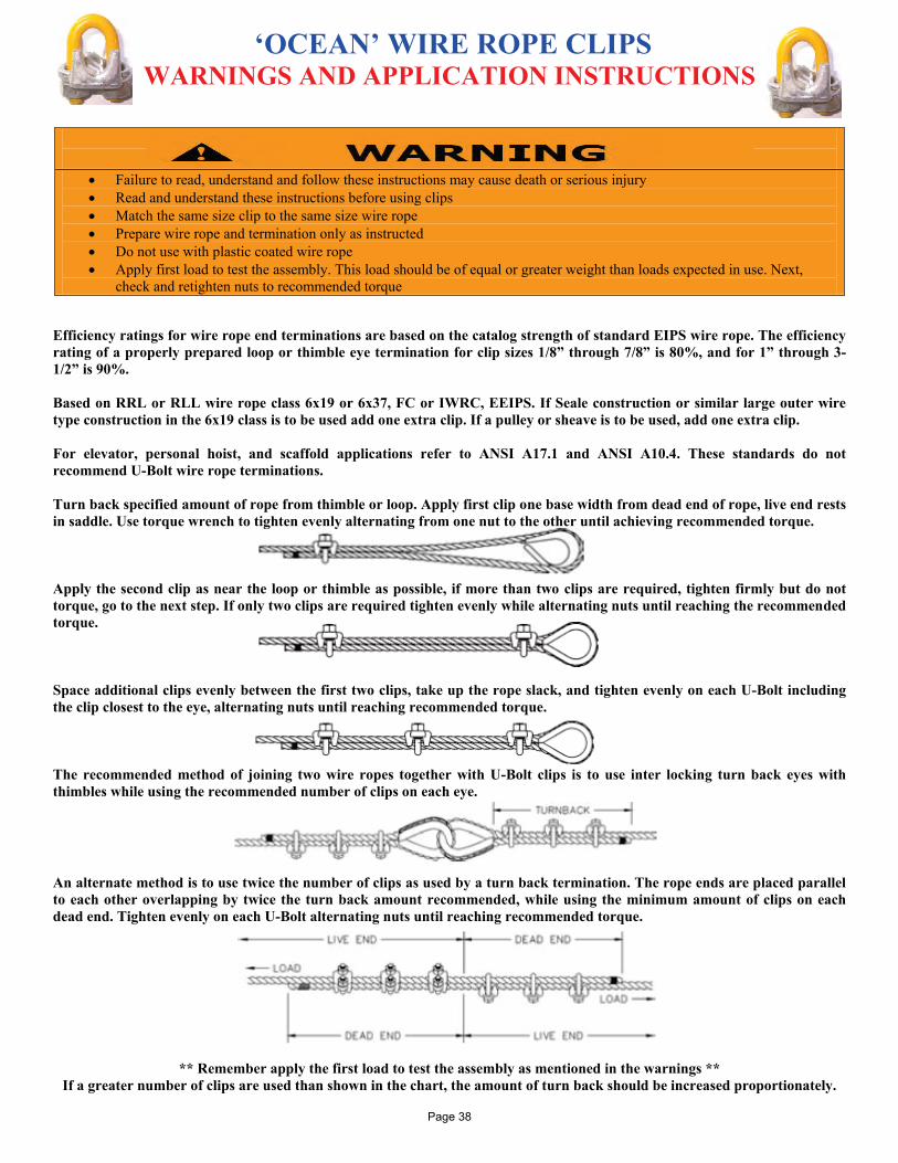
‘OCEAN’ WIRE ROPE CLIPS WARNINGS AND APPLICATION INSTRUCTIONS
• Failure to read, understand and follow these instructions may cause death or serious injury • Read and understand these instructions before using clips • Match the same size clip to the same size wire rope • Prepare wire rope and termination only as instructed • Do not use with plastic coated wire rope • Apply first load to test the assembly. This load should be of equal or greater weight than loads expected in use. Next,
check and retighten nuts to recommended torque
Efficiency ratings for wire rope end terminations are based on the catalog strength of standard EIPS wire rope. The efficiency rating of a properly prepared loop or thimble eye termination for clip sizes 1/8” through 7/8” is 80%, and for 1” through 3-1/2” is 90%. Based on RRL or RLL wire rope class 6x19 or 6x37, FC or IWRC, EEIPS. If Seale construction or similar large outer wire type construction in the 6x19 class is to be used add one extra clip. If a pulley or sheave is to be used, add one extra clip. For elevator, personal hoist, and scaffold applications refer to ANSI A17.1 and ANSI A10.4. These standards do not recommend U-Bolt wire rope terminations. Turn back specified amount of rope from thimble or loop. Apply first clip one base width from dead end of rope, live end rests in saddle. Use torque wrench to tighten evenly alternating from one nut to the other until achieving recommended torque. Apply the second clip as near the loop or thimble as possible, if more than two clips are required, tighten firmly but do not torque, go to the next step. If only two clips are required tighten evenly while alternating nuts until reaching the recommended torque. Space additional clips evenly between the first two clips, take up the rope slack, and tighten evenly on each U-Bolt including the clip closest to the eye, alternating nuts until reaching recommended torque. The recommended method of joining two wire ropes together with U-Bolt clips is to use inter locking turn back eyes with thimbles while using the recommended number of clips on each eye. An alternate method is to use twice the number of clips as used by a turn back termination. The rope ends are placed parallel to each other overlapping by twice the turn back amount recommended, while using the minimum amount of clips on each dead end. Tighten evenly on each U-Bolt alternating nuts until reaching recommended torque.
** Remember apply the first load to test the assembly as mentioned in the warnings ** If a greater number of clips are used than shown in the chart, the amount of turn back should be increased proportionately.
Page 38
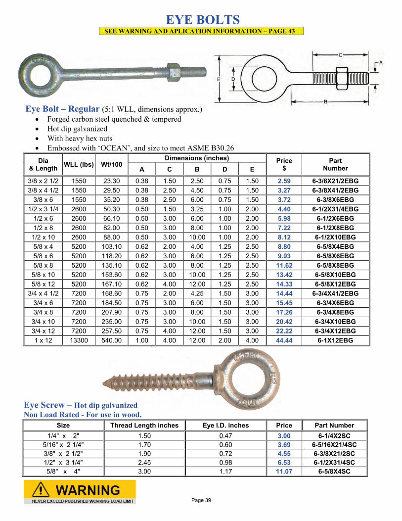
EYE BOLTS SEE WARNING AND APLICATION INFORMATION – PAGE 43
Eye Bolt – Regular (5:1 WLL, dimensions approx.)
• Forged carbon steel quenched & tempered • Hot dip galvanized • With heavy hex nuts • Embossed with ‘OCEAN’, and size to meet ASME B30.26 Dia
& Length WLL (lbs) Wt/100 Dimensions (inches) Price
$ Part
Number A C B D E
3/8 x 2 1/2 1550 23.30 0.38 1.50 2.50 0.75 1.50 2.59 6-3/8X21/2EBG 3/8 x 4 1/2 1550 29.50 0.38 2.50 4.50 0.75 1.50 3.27 6-3/8X41/2EBG
3/8 x 6 1550 35.20 0.38 2.50 6.00 0.75 1.50 3.72 6-3/8X6EBG 1/2 x 3 1/4 2600 50.30 0.50 1.50 3.25 1.00 2.00 4.40 6-1/2X31/4EBG
1/2 x 6 2600 66.10 0.50 3.00 6.00 1.00 2.00 5.98 6-1/2X6EBG 1/2 x 8 2600 82.00 0.50 3.00 8.00 1.00 2.00 7.22 6-1/2X8EBG 1/2 x 10 2600 88.00 0.50 3.00 10.00 1.00 2.00 8.12 6-1/2X10EBG 5/8 x 4 5200 103.10 0.62 2.00 4.00 1.25 2.50 8.80 6-5/8X4EBG 5/8 x 6 5200 118.20 0.62 3.00 6.00 1.25 2.50 9.93 6-5/8X6EBG 5/8 x 8 5200 135.10 0.62 3.00 8.00 1.25 2.50 11.62 6-5/8X8EBG 5/8 x 10 5200 153.60 0.62 3.00 10.00 1.25 2.50 13.42 6-5/8X10EBG 5/8 x 12 5200 167.10 0.62 4.00 12.00 1.25 2.50 14.33 6-5/8X12EBG
3/4 x 4 1/2 7200 168.60 0.75 2.00 4.25 1.50 3.00 14.44 6-3/4X41/2EBG 3/4 x 6 7200 184.50 0.75 3.00 6.00 1.50 3.00 15.45 6-3/4X6EBG 3/4 x 8 7200 207.90 0.75 3.00 8.00 1.50 3.00 17.26 6-3/4X8EBG 3/4 x 10 7200 235.00 0.75 3.00 10.00 1.50 3.00 20.42 6-3/4X10EBG 3/4 x 12 7200 257.50 0.75 4.00 12.00 1.50 3.00 22.22 6-3/4X12EBG 1 x 12 13300 540.00 1.00 4.00 12.00 2.00 4.00 44.44 6-1X12EBG
Eye Screw – Hot dip galvanized Non Load Rated - For use in wood.
Size Thread Length inches Eye I.D. inches Price Part Number 1/4" x 2" 1.50 0.47 3.00 6-1/4X2SC
5/16" x 2 1/4" 1.70 0.60 3.69 6-5/16X21/4SC 3/8" x 2 1/2" 1.90 0.72 4.55 6-3/8X21/2SC 1/2" x 3 1/4" 2.45 0.98 6.53 6-1/2X31/4SC 5/8" x 4" 3.00 1.17 11.07 6-5/8X4SC
Page 39
EYE BOLTS SEE WARNING AND APLICATION INFORMATION – PAGE 43
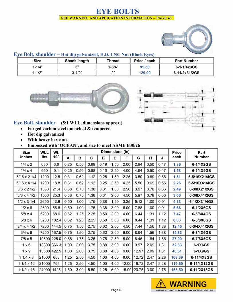
Eye Bolt, shoulder – Hot dip galvanized, H.D. UNC Nut (Block Eyes)
Size Shank length Thread Price / each Part Number 1-1/4" 3" 1-3/4" 95.38 6-1-1/4x3GS 1-1/2" 3-1/2" 2" 129.00 6-11/2x31/2GS
Eye Bolt, shoulder – (5:1 WLL, dimensions approx.)
• Forged carbon steel quenched & tempered • Hot dip galvanized • With heavy hex nuts • Embossed with ‘OCEAN’, and size to meet ASME B30.26 Size
inches WLL lbs
Wt. 100
Dimensions (in) Price each
Part Number A B C D E F G H J
1/4 x 2 650 6.6 0.25 0.50 0.88 0.19 1.50 2.00 2.94 0.50 0.47 1.36 6-1/4X2GS 1/4 x 4 650 9.1 0.25 0.50 0.88 0.19 2.50 4.00 4.94 0.50 0.47 1.58 6-1/4X4GS
5/16 x 2 1/4 1200 12.5 0.31 0.62 1.12 0.25 1.50 2.25 3.50 0.69 0.56 1.81 6-5/16X21/4GS 5/16 x 4 1/4 1200 18.8 0.31 0.62 1.12 0.25 2.50 4.25 5.50 0.69 0.56 2.26 6-5/16X41/4GS 3/8 x 2 1/2 1550 21.4 0.38 0.75 1.38 0.31 1.50 2.50 3.97 0.78 0.66 2.49 6-3/8X21/2GS 3/8 x 4 1/2 1550 25.3 0.38 0.75 1.38 0.31 2.50 4.50 5.97 0.78 0.66 3.06 6-3/8X41/2GS 1/2 x 3 1/4 2600 42.6 0.50 1.00 1.75 0.38 1.50 3.25 5.12 1.00 0.91 4.33 6-1/2X31/4GS
1/2 x 6 2600 56.8 0.50 1.00 1.75 0.38 3.00 6.00 7.88 1.00 0.91 5.66 6-1/2X6GS 5/8 x 4 5200 68.6 0.62 1.25 2.25 0.50 2.00 4.00 6.44 1.31 1.12 7.47 6-5/8X4GS 5/8 x 6 5200 102.4 0.62 1.25 2.25 0.50 3.00 6.00 8.44 1.31 1.12 8.83 6-5/8X6GS
3/4 x 4 1/2 7200 144.5 0.75 1.50 2.75 0.62 2.00 4.50 7.44 1.56 1.38 12.45 6-3/4X41/2GS 3/4 x 6 7200 167.5 0.75 1.50 2.75 0.62 3.00 6.00 8.94 1.56 1.38 14.83 6-3/4X6GS 7/8 x 5 10600 225.0 0.88 1.75 3.25 0.75 2.50 5.00 8.46 1.84 1.56 27.99 6-7/8X5GS 1 x 6 13300 366.3 1.00 2.00 3.75 0.88 3.00 6.00 9.97 2.09 1.81 32.83 6-1X6GS 1 x 9 13300 422.5 1.00 2.00 3.75 0.88 4.00 9.00 12.97 2.09 1.81 40.61 6-1X9GS
1 1/4 x 8 21000 650 1.25 2.50 4.50 1.00 4.00 8.00 12.72 2.47 2.28 108.39 6-11/4X8GS 1 1/4 x 12 21000 795 1.25 2.50 4.50 1.00 4.00 12.00 16.72 2.47 2.28 119.69 6-11/4X12GS 1 1/2 x 15 24000 1425 1.50 3.00 5.50 1.25 6.00 15.00 20.75 3.00 2.75 156.50 6-11/2X15GS
Page 40
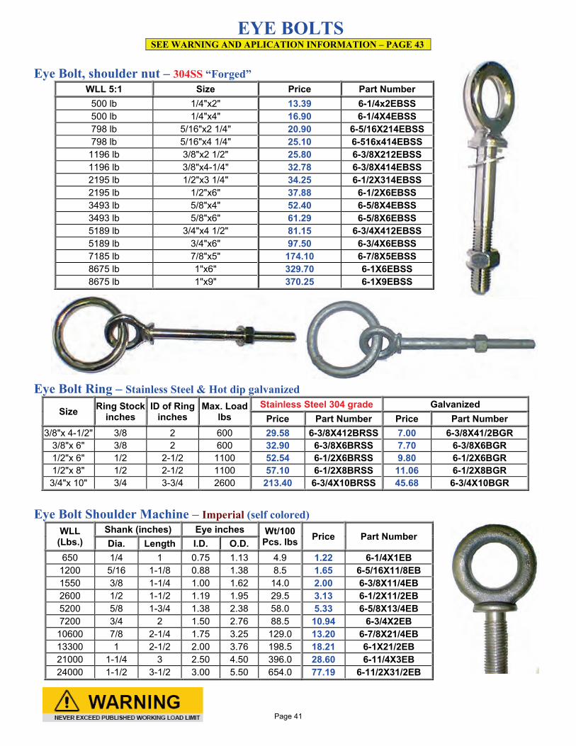
EYE BOLTS SEE WARNING AND APLICATION INFORMATION – PAGE 43
Eye Bolt, shoulder nut – 304SS “Forged”
WLL 5:1 Size Price Part Number 500 lb 1/4"x2" 13.39 6-1/4x2EBSS 500 lb 1/4"x4" 16.90 6-1/4X4EBSS 798 lb 5/16"x2 1/4" 20.90 6-5/16X214EBSS 798 lb 5/16"x4 1/4" 25.10 6-516x414EBSS
1196 lb 3/8"x2 1/2" 25.80 6-3/8X212EBSS 1196 lb 3/8"x4-1/4" 32.78 6-3/8X414EBSS 2195 lb 1/2"x3 1/4" 34.25 6-1/2X314EBSS 2195 lb 1/2"x6" 37.88 6-1/2X6EBSS 3493 lb 5/8"x4" 52.40 6-5/8X4EBSS 3493 lb 5/8"x6" 61.29 6-5/8X6EBSS 5189 lb 3/4"x4 1/2" 81.15 6-3/4X412EBSS 5189 lb 3/4"x6" 97.50 6-3/4X6EBSS 7185 lb 7/8"x5" 174.10 6-7/8X5EBSS 8675 lb 1"x6" 329.70 6-1X6EBSS 8675 lb 1"x9" 370.25 6-1X9EBSS
Eye Bolt Ring – Stainless Steel & Hot dip galvanized
Size Ring Stock inches
ID of Ring inches
Max. Load lbs
Stainless Steel 304 grade Galvanized Price Part Number Price Part Number
3/8"x 4-1/2" 3/8 2 600 29.58 6-3/8X412BRSS 7.00 6-3/8X41/2BGR 3/8"x 6" 3/8 2 600 32.90 6-3/8X6BRSS 7.70 6-3/8X6BGR 1/2"x 6" 1/2 2-1/2 1100 52.54 6-1/2X6BRSS 9.80 6-1/2X6BGR 1/2"x 8" 1/2 2-1/2 1100 57.10 6-1/2X8BRSS 11.06 6-1/2X8BGR 3/4"x 10" 3/4 3-3/4 2600 213.40 6-3/4X10BRSS 45.68 6-3/4X10BGR
Eye Bolt Shoulder Machine – Imperial (self colored)
WLL (Lbs.)
Shank (inches) Eye inches Wt/100 Pcs. lbs Price Part Number
Dia. Length I.D. O.D. 650 1/4 1 0.75 1.13 4.9 1.22 6-1/4X1EB
1200 5/16 1-1/8 0.88 1.38 8.5 1.65 6-5/16X11/8EB 1550 3/8 1-1/4 1.00 1.62 14.0 2.00 6-3/8X11/4EB 2600 1/2 1-1/2 1.19 1.95 29.5 3.13 6-1/2X11/2EB 5200 5/8 1-3/4 1.38 2.38 58.0 5.33 6-5/8X13/4EB 7200 3/4 2 1.50 2.76 88.5 10.94 6-3/4X2EB 10600 7/8 2-1/4 1.75 3.25 129.0 13.20 6-7/8X21/4EB 13300 1 2-1/2 2.00 3.76 198.5 18.21 6-1X21/2EB 21000 1-1/4 3 2.50 4.50 396.0 28.60 6-11/4X3EB 24000 1-1/2 3-1/2 3.00 5.50 654.0 77.19 6-11/2X31/2EB
Page 41
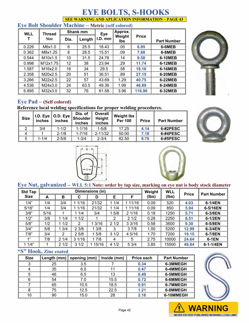
EYE BOLTS, S-HOOKS SEE WARNING AND APLICATION INFORMATION – PAGE 43
Eye Bolt Shoulder Machine – Metric (self colored) WLL
T Thread
Size
Shank mm Eye I.D. mm
Approx. Weight
lbs Price
Part Number Dia. Length
0.226 M6x1.0 6 25.5 18.43 .05 6.95 6-6MEB 0.362 M8x1.25 8 28.5 15.51 .09 7.88 6-8MEB 0.544 M10x1.5 10 31.5 24.76 .14 9.58 6-10MEB 0.998 M12x1.75 12 38 23.94 .29 11.74 6-12MEB 1.587 M16x2.0 16 34 29.5 .58 18.16 6-16MEB 2.358 M20x2.5 20 51 36.51 .89 27.15 6-20MEB 3.266 M22x2.5 22 57 43.69 1.29 40.75 6-22MEB 4.536 M24x3.0 24 63.5 49.36 1.99 46.89 6-24MEB 6.895 M32x3.0 32 76 61.58 3.96 116.96 6-32MEB
Eye Pad – (Self colored) Reference local welding specifications for proper welding procedures.
Size I.D. Eye inches
O.D. Eye inches
Dia. of Shoulder
inches
Overall Height inches
Weight lbs Per 100
Price
Part Number
2 3/4 1-1/2 1-1/16 1-5/8 17.25 4.14 6-#2PESC 4 1 2-1/8 1-7/16 2-11/32 50.00 7.18 6-#4PESC 5 1-1/4 2-5/8 1-3/4 2-3/4 82.50 8.76 6-#5PESC
Eye Nut, galvanized – WLL 5:1 Note: order by tap size, marking on eye nut is body stock diameter
Std Tap Size
Dimensions (in) Weight (lbs)
WLL (lbs) Price Part Number
A B C D E F 1/4” 1/4 3/4 1 1/16 21/32 1 1/4 1 11/16 0.09 520 4.03 6-1/4EN
5/16” 1/4 3/4 1 1/16 21/32 1 1/4 1 11/16 0.09 850 5.94 6-5/16EN 3/8” 5/16 1 1 1/4 3/4 1 5/8 2 1/16 0.18 1250 5.71 6-3/8EN 1/2” 3/8 1 1/4 1 1/2 1 2 2 1/2 0.28 2250 8.51 6-1/2EN 5/8” 1/2 1 1/2 2 1 3/16 2 1/2 3 3/16 0.58 3600 9.30 6-5/8EN 3/4” 5/8 1 3/4 2 3/8 1 3/8 3 3 7/8 1.00 5200 12.99 6-3/4EN 7/8” 3/4 2 2 5/8 1 5/8 3 1/2 4 5/16 1.70 7200 19.15 6-7/8EN 1” 7/8 2 1/4 3 1/16 1 7/8 4 5 2.75 10000 24.64 6-1EN
1 1/4” 1 2 1/2 3 1/2 1 15/16 4 1/2 5 3/4 3.85 15500 49.84 6-1-1/4EN
“S” Hook, Zinc coated
Size Length (mm) opening (mm) Inside (mm) Price each Part Number 3 25 3.5 7 0.34 6-3MMEGH 4 35 6.0 11 0.47 6-4MMEGH 5 46 6.5 13 0.49 6-5MMEGH 6 54 7.0 15.5 0.72 6-6MMEGH 7 65 10.5 18.5 0.91 6-7MMEGH 8 75 12.5 22.5 1.21 6-8MMEGH 10 90 15.0 28 2.16 6-10MMEGH
Page 42
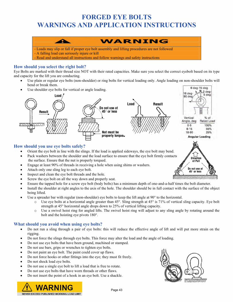
FORGED EYE BOLTS
WARNINGS AND APPLICATION INSTRUCTIONS
- Loads may slip or fall if proper eye bolt assembly and lifting procedures are not followed - A falling load can seriously injure or kill - Read and understand all instructions and follow warnings and safety instructions
How should you select the right bolt? Eye Bolts are marked with their thread size NOT with their rated capacities. Make sure you select the correct eyebolt based on its type and capacity for the lift you are conducting.
• Use plain or regular eye bolts (non-shoulder) or ring bolts for vertical loading only. Angle loading on non-shoulder bolts will bend or break them.
• Use shoulder eye bolts for vertical or angle loading.
How should you use eye bolts safely?
• Orient the eye bolt in line with the slings. If the load is applied sideways, the eye bolt may bend. • Pack washers between the shoulder and the load surface to ensure that the eye bolt firmly contacts the surface. Ensure that the nut is properly torqued. • Engage at least 90% of threads in receiving a hole when using shims or washers. • Attach only one sling leg to each eye bolt. • Inspect and clean the eye bolt threads and the hole. • Screw the eye bolt on all the way down and properly seat. • Ensure the tapped hole for a screw eye bolt (body bolts) has a minimum depth of one-and-a-half times the bolt diameter. • Install the shoulder at right angles to the axis of the hole. The shoulder should be in full contact with the surface of the object
being lifted. • Use a spreader bar with regular (non-shoulder) eye bolts to keep the lift angle at 90° to the horizontal.
o Use eye bolts at a horizontal angle greater than 45°. Sling strength at 45° is 71% of vertical sling capacity. Eye bolt strength at 45° horizontal angle drops down to 25% of vertical lifting capacity.
o Use a swivel hoist ring for angled lifts. The swivel hoist ring will adjust to any sling angle by rotating around the bolt and the hoisting eye pivots 180°.
What should you avoid when using eye bolts?
• Do not run a sling through a pair of eye bolts: this will reduce the effective angle of lift and will put more strain on the rigging.
• Do not force the slings through eye bolts. This force may alter the load and the angle of loading. • Do not use eye bolts that have been ground, machined or stamped. • Do not use bars, grips or wrenches to tighten eye bolts. • Do not paint an eye bolt. The paint could cover up flaws. • Do not force hooks or other fittings into the eye; they must fit freely. • Do not shock load eye bolts. • Do not use a single eye bolt to lift a load that is free to rotate. • Do not use eye bolts that have worn threads or other flaws. • Do not insert the point of a hook in an eye bolt. Use a shackle.
Page 43
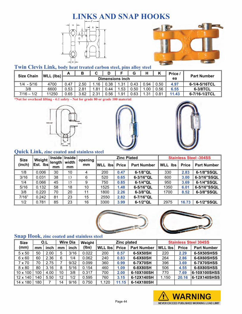
LINKS AND SNAP HOOKS
Twin Clevis Link, body heat treated carbon steel, pins alloy steel
Size Chain WLL (lbs) A B C D F G H K Price / ea Part Number Dimensions inch
1/4 - 5/16 4700 0.47 2.50 1.16 0.38 1.31 0.43 0.94 0.50 4.97 6-1/4-5/16TCL 3/8 6600 0.53 2.81 1.81 0.44 1.53 0.50 1.00 0.56 6.55 6-3/8TCL
7/16 – 1/2 11250 0.65 3.62 2.31 0.56 1.91 0.63 1.31 0.81 11.43 6-7/16-1/2TCL *Not for overhead lifting - 4:1 safety - Not for grade 80 or grade 100 material
Quick Link, zinc coated and stainless steel
Size (inch)
Weight Est. lbs
Inside length
mm
Inside width mm
opening mm
Zinc Plated Stainless Steel -304SS
WLL lbs Price Part Number WLL lbs Price Part Number
1/8 0.006 30 10 4 200 0.47 6-1/8”QL 330 2.83 6-1/8"SSQL 3/16 0.031 38 13 6 520 0.65 6-3/16"QL 600 3.00 6-3/16"SSQL 1/4 0.066 45 15 9 750 0.85 6-1/4"QL 950 3.69 6-1/4"SSQL 5/16 0.132 58 18 10 1525 1.48 6-5/16"QL 1350 6.01 6-5/16"SSQL 3/8 0.220 70 20 11 1800 2.26 6-3/8"QL 1700 8.52 6-3/8"SSQL
7/16” 0.242 81 23 15 2550 2.82 6-7/16"QL 1/2 0.781 85 23 16 3300 3.99 6-1/2"QL 2975 16.73 6-1/2"SSQL
Snap Hook, zinc coated and stainless steel
Size (mm)
O.L Wire Dia Weight (lbs)
Zinc plated Stainless Steel 304SS mm inch mm inch WLL lbs Price Part Number WLL lbs Price Part Number
5 x 50 50 2.00 5 3/16 0.022 200 0.57 6-5X50SH 220 2.29 6-5X50SHSS 6 x 60 60 2.36 6 1/4 0.062 240 0.83 6-6X60SH 264 2.86 6-6X60SHSS 7 x 70 70 2.75 7 9/32 0.099 360 0.99 6-7X70SH 396 3.69 6-7X70SHSS 8 x 80 80 3.16 8 5/16 0.154 460 1.09 6-8X80SH 506 4.55 6-8X80SHSS
10 x 100 100 4.00 10 3/8 0.317 700 2.00 6-10X100SH 770 7.69 6-10X100SHSS 12 x 140 140 5.50 12 1/2 0.595 760 3.15 6-12X140SH 1,150 20.16 6-12X140SHSS 14 x 180 180 7 14 9/16 0.750 1,120 11.15 6-14X180SH
Page 44
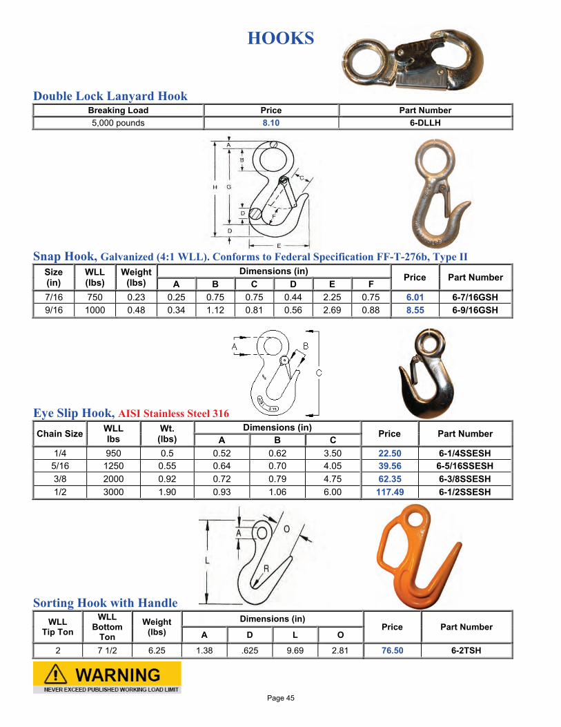
HOOKS
Double Lock Lanyard Hook Breaking Load Price Part Number 5,000 pounds 8.10 6-DLLH
Snap Hook, Galvanized (4:1 WLL). Conforms to Federal Specification FF-T-276b, Type II Size (in)
WLL (lbs)
Weight (lbs)
Dimensions (in) Price Part Number A B C D E F
7/16 750 0.23 0.25 0.75 0.75 0.44 2.25 0.75 6.01 6-7/16GSH 9/16 1000 0.48 0.34 1.12 0.81 0.56 2.69 0.88 8.55 6-9/16GSH
Eye Slip Hook, AISI Stainless Steel 316
Chain Size WLL lbs
Wt. (lbs)
Dimensions (in) Price Part Number A B C 1/4 950 0.5 0.52 0.62 3.50 22.50 6-1/4SSESH 5/16 1250 0.55 0.64 0.70 4.05 39.56 6-5/16SSESH 3/8 2000 0.92 0.72 0.79 4.75 62.35 6-3/8SSESH 1/2 3000 1.90 0.93 1.06 6.00 117.49 6-1/2SSESH
Sorting Hook with Handle
WLL Tip Ton
WLL Bottom
Ton Weight
(lbs) Dimensions (in)
Price Part Number A D L O
2 7 1/2 6.25 1.38 .625 9.69 2.81 76.50 6-2TSH
Page 45
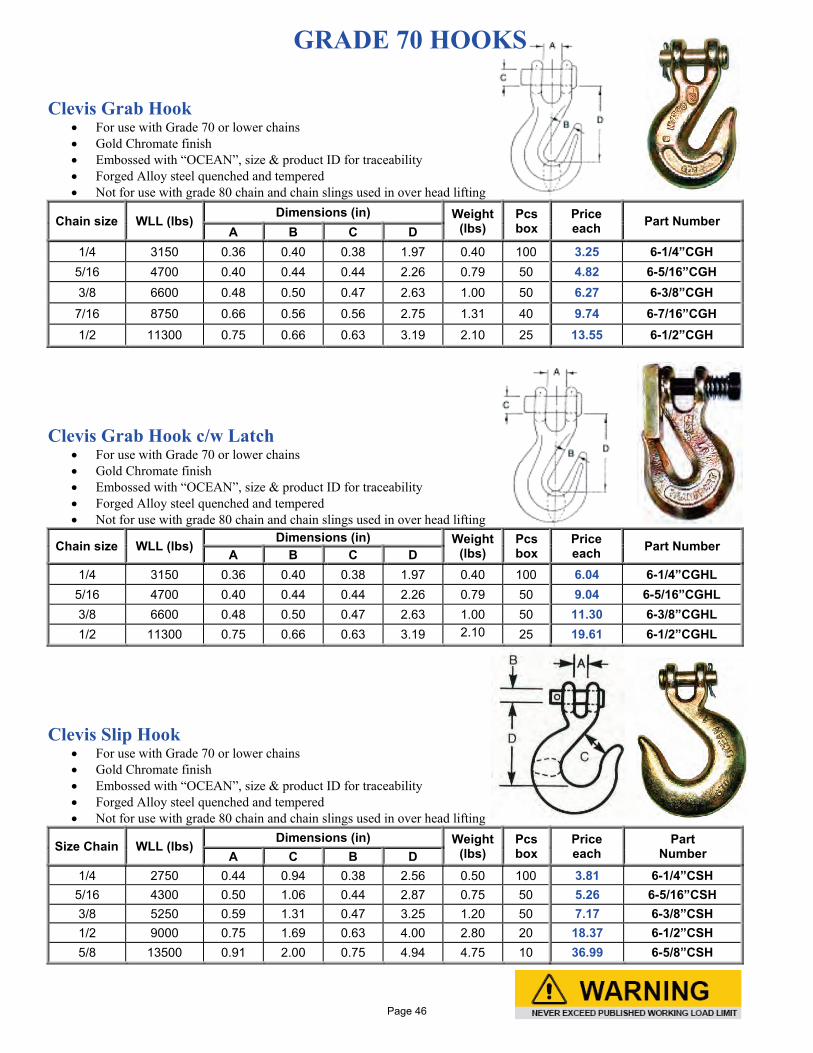
GRADE 70 HOOKS Clevis Grab Hook
• For use with Grade 70 or lower chains • Gold Chromate finish • Embossed with “OCEAN”, size & product ID for traceability • Forged Alloy steel quenched and tempered • Not for use with grade 80 chain and chain slings used in over head lifting
Chain size WLL (lbs) Dimensions (in) Weight (lbs)
Pcs box
Price each Part Number
A B C D 1/4 3150 0.36 0.40 0.38 1.97 0.40 100 3.25 6-1/4”CGH
5/16 4700 0.40 0.44 0.44 2.26 0.79 50 4.82 6-5/16”CGH 3/8 6600 0.48 0.50 0.47 2.63 1.00 50 6.27 6-3/8”CGH
7/16 8750 0.66 0.56 0.56 2.75 1.31 40 9.74 6-7/16”CGH 1/2 11300 0.75 0.66 0.63 3.19 2.10 25 13.55 6-1/2”CGH
Clevis Grab Hook c/w Latch
• For use with Grade 70 or lower chains • Gold Chromate finish • Embossed with “OCEAN”, size & product ID for traceability • Forged Alloy steel quenched and tempered • Not for use with grade 80 chain and chain slings used in over head lifting
Chain size WLL (lbs) Dimensions (in) Weight (lbs)
Pcs box
Price each Part Number A B C D
1/4 3150 0.36 0.40 0.38 1.97 0.40 100 6.04 6-1/4”CGHL 5/16 4700 0.40 0.44 0.44 2.26 0.79 50 9.04 6-5/16”CGHL 3/8 6600 0.48 0.50 0.47 2.63 1.00 50 11.30 6-3/8”CGHL 1/2 11300 0.75 0.66 0.63 3.19 2.10 25 19.61 6-1/2”CGHL
Clevis Slip Hook • For use with Grade 70 or lower chains • Gold Chromate finish • Embossed with “OCEAN”, size & product ID for traceability • Forged Alloy steel quenched and tempered • Not for use with grade 80 chain and chain slings used in over head lifting
Size Chain WLL (lbs) Dimensions (in) Weight (lbs)
Pcs box
Price each
Part Number A C B D
1/4 2750 0.44 0.94 0.38 2.56 0.50 100 3.81 6-1/4”CSH 5/16 4300 0.50 1.06 0.44 2.87 0.75 50 5.26 6-5/16”CSH 3/8 5250 0.59 1.31 0.47 3.25 1.20 50 7.17 6-3/8”CSH 1/2 9000 0.75 1.69 0.63 4.00 2.80 20 18.37 6-1/2”CSH 5/8 13500 0.91 2.00 0.75 4.94 4.75 10 36.99 6-5/8”CSH
Page 46
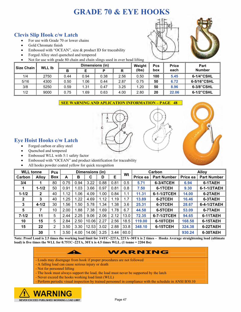
GRADE 70 & EYE HOOKS
Clevis Slip Hook c/w Latch
• For use with Grade 70 or lower chains • Gold Chromate finish • Embossed with “OCEAN”, size & product ID for traceability • Forged Alloy steel quenched and tempered • Not for use with grade 80 chain and chain slings used in over head lifting
Size Chain WLL lb Dimensions (in) Weight (lbs)
Pcs box
Price each
Part Number B E P R
1/4 2750 0.44 0.94 0.38 2.56 0.50 100 5.45 6-1/4”CSHL 5/16 4300 0.50 1.06 0.44 2.87 0.75 50 6.72 6-5/16”CSHL 3/8 5250 0.59 1.31 0.47 3.25 1.20 50 8.96 6-3/8”CSHL 1/2 9000 0.75 1.69 0.63 4.00 2.80 20 22.06 6-1/2”CSHL
SEE WARNING AND APLICATION INFORMATION – PAGE 48
Eye Hoist Hooks c/w Latch
• Forged carbon or alloy steel • Quenched and tempered • Embossed WLL with 5:1 safety factor • Embossed with “OCEAN” and product identification for traceability • All hooks powder coated yellow for quick recognition
WLL tonne Pcs Box
Dimensions (in) Wt Carbon Alloy Carbon Alloy A B C D E Price ea Part Number Price ea Part Number
3/4 1 80 0.75 0.94 3.22 0.88 0.81 0.5 5.71 6-3/4TCEH 6.94 6-1TAEH 1 1-1/2 50 0.91 1.03 3.66 0.97 0.81 0.8 7.50 6-1TCEH 9.30 6-1-1/2TAEH
1-1/2 2 40 1.12 1.06 4.09 1.00 0.84 1.1 11.31 6-1-1/2TCEH 14.00 6-2TAEH 2 3 40 1.25 1.22 4.69 1.12 1.19 1.7 13.89 6-2TCEH 16.46 6-3TAEH 3 4-1/2 30 1.56 1.50 5.78 1.34 1.38 3.6 25.31 6-3TCEH 28.67 6-4-1/2TAEH 5 7 10 2.00 1.88 7.38 1.69 1.78 6.7 44.58 6-5TCEH 53.09 6-7TAEH
7-1/2 11 5 2.44 2.25 9.06 2.06 2.12 13.0 72.35 6-7-1/2TCEH 94.65 6-11TAEH 10 15 5 2.84 2.50 10.06 2.27 2.56 18.5 119.00 6-10TCEH 168.58 6-15TAEH 15 22 2 3.50 3.30 12.53 3.02 2.88 33.8 348.10 6-15TCEH 324.38 6-22TAEH
30 1 3.50 4.00 14.06 3.25 3.44 60.0 930.24 6-30TAEH Note: Proof Load is 2.5 times the working load limit for 3/4TC~22TA, 22TA~30TA is 2 times – Hooks Average straightening load (ultimate load) is five times the WLL for 0.75TC~22TA, 30TA is 4.5 times WLL. (1 tonne = 2204 lbs)
- Loads may disengage from hook if proper procedures are not followed - A falling load can cause serious injury or death - Not for personnel lifting - The hook must always support the load, the load must never be supported by the latch - Never exceed the hooks working load limit (WLL) - Perform periodic visual inspection by trained personnel in compliance with the schedule in ANSI B30.10
Page 47
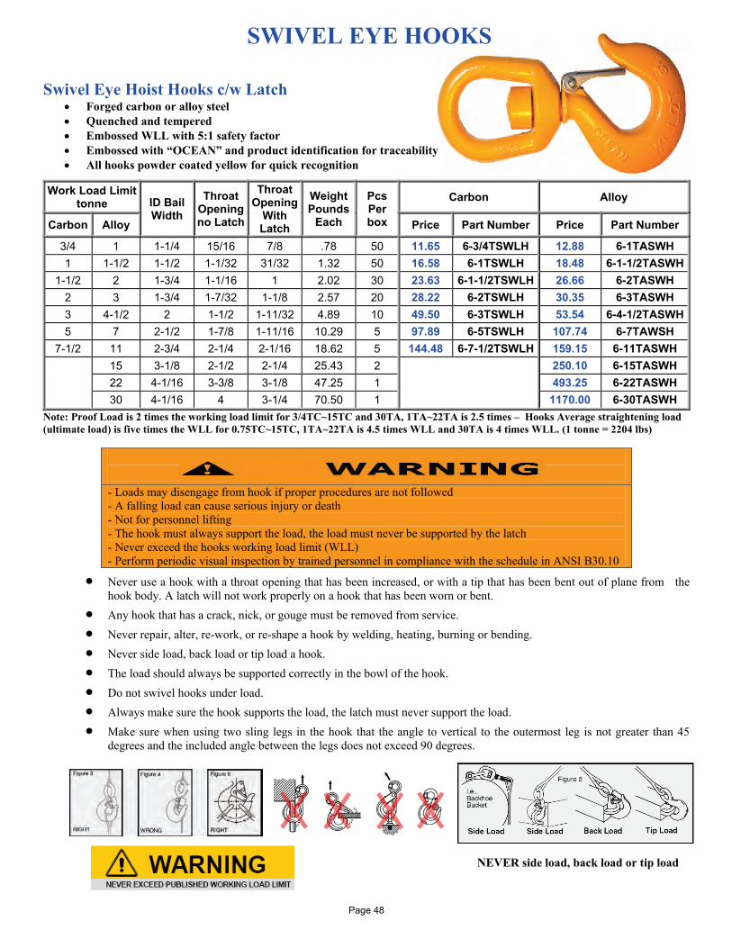
SWIVEL EYE HOOKS
Swivel Eye Hoist Hooks c/w Latch • Forged carbon or alloy steel • Quenched and tempered • Embossed WLL with 5:1 safety factor • Embossed with “OCEAN” and product identification for traceability • All hooks powder coated yellow for quick recognition
Work Load Limit tonne ID Bail
Width Throat
Opening no Latch
Throat Opening
With Latch
Weight Pounds
Each
Pcs Per box
Carbon Alloy
Carbon Alloy Price Part Number Price Part Number
3/4 1 1-1/4 15/16 7/8 .78 50 11.65 6-3/4TSWLH 12.88 6-1TASWH 1 1-1/2 1-1/2 1-1/32 31/32 1.32 50 16.58 6-1TSWLH 18.48 6-1-1/2TASWH
1-1/2 2 1-3/4 1-1/16 1 2.02 30 23.63 6-1-1/2TSWLH 26.66 6-2TASWH 2 3 1-3/4 1-7/32 1-1/8 2.57 20 28.22 6-2TSWLH 30.35 6-3TASWH 3 4-1/2 2 1-1/2 1-11/32 4.89 10 49.50 6-3TSWLH 53.54 6-4-1/2TASWH 5 7 2-1/2 1-7/8 1-11/16 10.29 5 97.89 6-5TSWLH 107.74 6-7TAWSH
7-1/2 11 2-3/4 2-1/4 2-1/16 18.62 5 144.48 6-7-1/2TSWLH 159.15 6-11TASWH 15 3-1/8 2-1/2 2-1/4 25.43 2 250.10 6-15TASWH 22 4-1/16 3-3/8 3-1/8 47.25 1 493.25 6-22TASWH 30 4-1/16 4 3-1/4 70.50 1 1170.00 6-30TASWH
Note: Proof Load is 2 times the working load limit for 3/4TC~15TC and 30TA, 1TA~22TA is 2.5 times – Hooks Average straightening load (ultimate load) is five times the WLL for 0.75TC~15TC, 1TA~22TA is 4.5 times WLL and 30TA is 4 times WLL. (1 tonne = 2204 lbs)
• Never use a hook with a throat opening that has been increased, or with a tip that has been bent out of plane from the hook body. A latch will not work properly on a hook that has been worn or bent.
• Any hook that has a crack, nick, or gouge must be removed from service. • Never repair, alter, re-work, or re-shape a hook by welding, heating, burning or bending. • Never side load, back load or tip load a hook. • The load should always be supported correctly in the bowl of the hook. • Do not swivel hooks under load. • Always make sure the hook supports the load, the latch must never support the load. • Make sure when using two sling legs in the hook that the angle to vertical to the outermost leg is not greater than 45
degrees and the included angle between the legs does not exceed 90 degrees.
NEVER side load, back load or tip load
- Loads may disengage from hook if proper procedures are not followed - A falling load can cause serious injury or death - Not for personnel lifting - The hook must always support the load, the load must never be supported by the latch - Never exceed the hooks working load limit (WLL) - Perform periodic visual inspection by trained personnel in compliance with the schedule in ANSI B30.10
Page 48
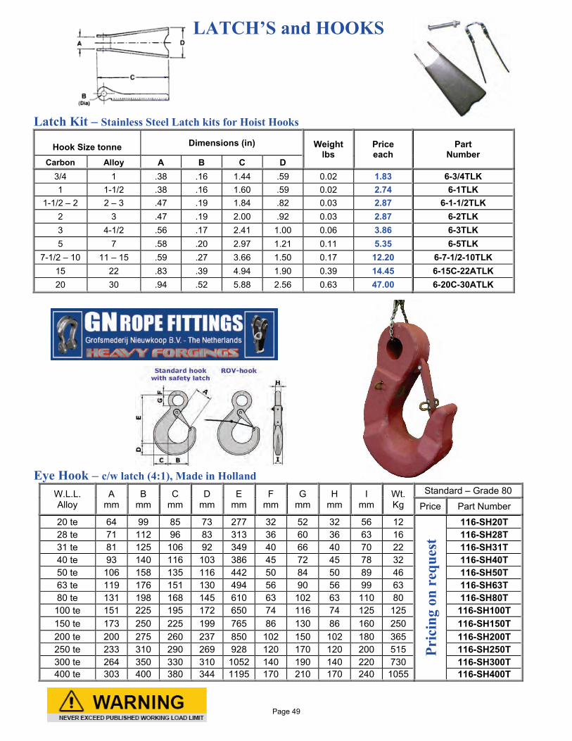
LATCH’S and HOOKS Latch Kit – Stainless Steel Latch kits for Hoist Hooks
Hook Size tonne Dimensions (in) Weight lbs
Price each
Part Number
Carbon Alloy A B C D 3/4 1 .38 .16 1.44 .59 0.02 1.83 6-3/4TLK 1 1-1/2 .38 .16 1.60 .59 0.02 2.74 6-1TLK
1-1/2 – 2 2 – 3 .47 .19 1.84 .82 0.03 2.87 6-1-1/2TLK 2 3 .47 .19 2.00 .92 0.03 2.87 6-2TLK 3 4-1/2 .56 .17 2.41 1.00 0.06 3.86 6-3TLK 5 7 .58 .20 2.97 1.21 0.11 5.35 6-5TLK
7-1/2 – 10 11 – 15 .59 .27 3.66 1.50 0.17 12.20 6-7-1/2-10TLK 15 22 .83 .39 4.94 1.90 0.39 14.45 6-15C-22ATLK 20 30 .94 .52 5.88 2.56 0.63 47.00 6-20C-30ATLK
Eye Hook – c/w latch (4:1), Made in Holland
W.L.L. Alloy
A mm
B mm
C mm
D mm
E mm
F mm
G mm
H mm
I mm
Wt. Kg
Standard – Grade 80
Price Part Number
20 te 64 99 85 73 277 32 52 32 56 12
Pric
ing
on r
eque
st
116-SH20T 28 te 71 112 96 83 313 36 60 36 63 16 116-SH28T 31 te 81 125 106 92 349 40 66 40 70 22 116-SH31T 40 te 93 140 116 103 386 45 72 45 78 32 116-SH40T 50 te 106 158 135 116 442 50 84 50 89 46 116-SH50T 63 te 119 176 151 130 494 56 90 56 99 63 116-SH63T 80 te 131 198 168 145 610 63 102 63 110 80 116-SH80T 100 te 151 225 195 172 650 74 116 74 125 125 116-SH100T 150 te 173 250 225 199 765 86 130 86 160 250 116-SH150T 200 te 200 275 260 237 850 102 150 102 180 365 116-SH200T 250 te 233 310 290 269 928 120 170 120 200 515 116-SH250T 300 te 264 350 330 310 1052 140 190 140 220 730 116-SH300T 400 te 303 400 380 344 1195 170 210 170 240 1055 116-SH400T
Page 49
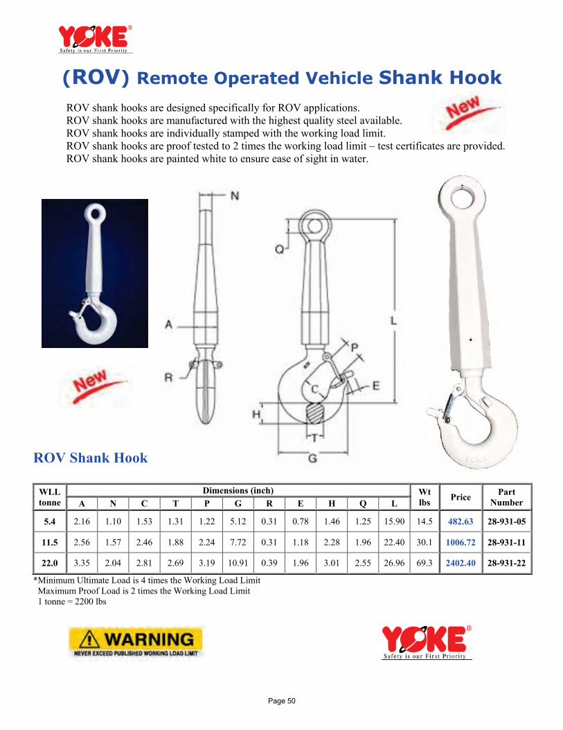
(ROV) Remote Operated Vehicle Shank Hook
ROV shank hooks are designed specifically for ROV applications. ROV shank hooks are manufactured with the highest quality steel available. ROV shank hooks are individually stamped with the working load limit. ROV shank hooks are proof tested to 2 times the working load limit – test certificates are provided. ROV shank hooks are painted white to ensure ease of sight in water. ROV Shank Hook
WLL tonne
Dimensions (inch) Wt lbs Price Part
Number A N C T P G R E H Q L
5.4 2.16 1.10 1.53 1.31 1.22 5.12 0.31 0.78 1.46 1.25 15.90 14.5 482.63 28-931-05
11.5 2.56 1.57 2.46 1.88 2.24 7.72 0.31 1.18 2.28 1.96 22.40 30.1 1006.72 28-931-11
22.0 3.35 2.04 2.81 2.69 3.19 10.91 0.39 1.96 3.01 2.55 26.96 69.3 2402.40 28-931-22
*Minimum Ultimate Load is 4 times the Working Load Limit Maximum Proof Load is 2 times the Working Load Limit 1 tonne = 2200 lbs
Page 50
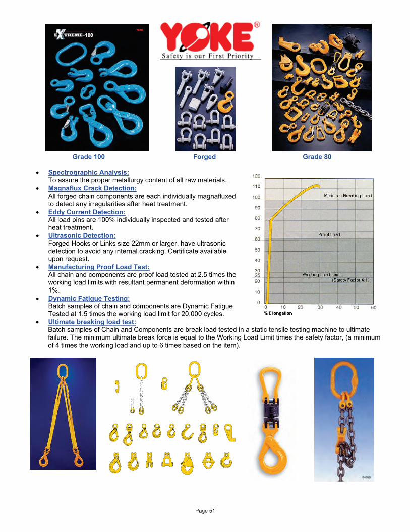
Grade 100 Forged Grade 80
• Spectrographic Analysis: To assure the proper metallurgy content of all raw materials.
• Magnaflux Crack Detection: All forged chain components are each individually magnafluxed to detect any irregularities after heat treatment.
• Eddy Current Detection: All load pins are 100% individually inspected and tested after heat treatment.
• Ultrasonic Detection: Forged Hooks or Links size 22mm or larger, have ultrasonic detection to avoid any internal cracking. Certificate available upon request.
• Manufacturing Proof Load Test: All chain and components are proof load tested at 2.5 times the working load limits with resultant permanent deformation within 1%.
• Dynamic Fatigue Testing: Batch samples of chain and components are Dynamic Fatigue Tested at 1.5 times the working load limit for 20,000 cycles.
• Ultimate breaking load test: Batch samples of Chain and Components are break load tested in a static tensile testing machine to ultimate failure. The minimum ultimate break force is equal to the Working Load Limit times the safety factor, (a minimum of 4 times the working load and up to 6 times based on the item).
Page 51
Worldwide Quality Type Approval and Certificates: All YOKE Products meet or exceed ASME B30 Requirements
Page 52
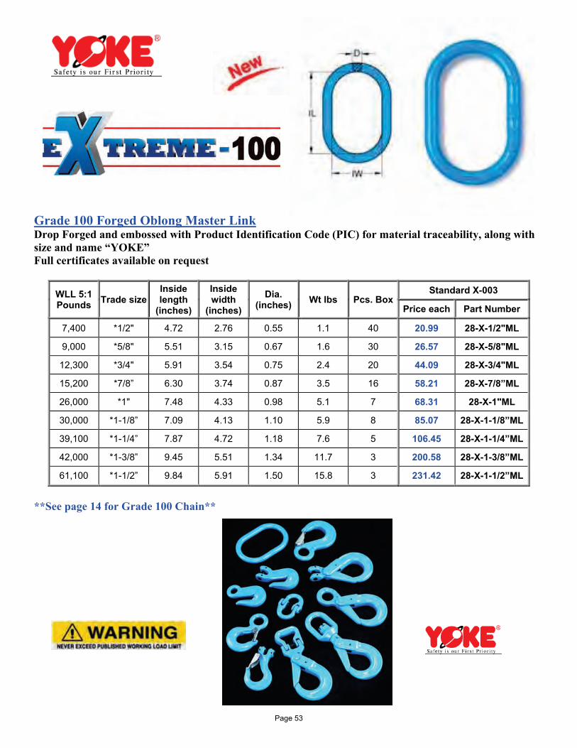
Grade 100 Forged Oblong Master Link Drop Forged and embossed with Product Identification Code (PIC) for material traceability, along with size and name “YOKE” Full certificates available on request
WLL 5:1 Pounds Trade size
Inside length
(inches)
Inside width
(inches) Dia.
(inches) Wt lbs Pcs. Box Standard X-003
Price each Part Number
7,400 *1/2" 4.72 2.76 0.55 1.1 40 20.99 28-X-1/2"ML
9,000 *5/8" 5.51 3.15 0.67 1.6 30 26.57 28-X-5/8"ML
12,300 *3/4" 5.91 3.54 0.75 2.4 20 44.09 28-X-3/4"ML
15,200 *7/8” 6.30 3.74 0.87 3.5 16 58.21 28-X-7/8”ML
26,000 *1" 7.48 4.33 0.98 5.1 7 68.31 28-X-1"ML
30,000 *1-1/8” 7.09 4.13 1.10 5.9 8 85.07 28-X-1-1/8”ML
39,100 *1-1/4” 7.87 4.72 1.18 7.6 5 106.45 28-X-1-1/4”ML
42,000 *1-3/8” 9.45 5.51 1.34 11.7 3 200.58 28-X-1-3/8”ML
61,100 *1-1/2” 9.84 5.91 1.50 15.8 3 231.42 28-X-1-1/2”ML
**See page 14 for Grade 100 Chain** Page 53
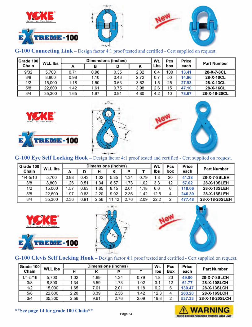
G-100 Connecting Link – Design factor 4:1 proof tested and certified - Cert supplied on request.
G-100 Eye Self Locking Hook – Design factor 4:1 proof tested and certified - Cert supplied on request.
Grade 100 Chain WLL lbs
Dimensions (inches) Wt. lbs
Pcs box
Price each Part Number A D H K P T
1/4-5/16 5,700 0.98 0.43 1.02 5.35 1.34 0.79 1.8 20 41.38 28-X-7-8SLEH 3/8 8,800 1.26 0.51 1.34 6.57 1.73 1.02 3.3 12 57.02 28-X-10SLEH 1/2 15,000 1.57 0.63 1.65 8.15 2.01 1.18 6.6 6 118.06 28-X-13SLEH 5/8 22,600 1.97 0.83 2.20 9.92 2.36 1.42 12.5 4 246.39 28-X-16SLEH 3/4 35,300 2.36 0.91 2.56 11.42 2.76 2.09 22.2 2 477.48 28-X-18-20SLEH
G-100 Clevis Self Locking Hook – Design factor 4:1 proof tested and certified - Cert supplied on request.
Grade 100 Chain WLL lbs
Dimensions (inches) Wt. lbs
Pcs Box
Price each Part Number H K P T
1/4-5/16 5,700 1.02 4.69 1.34 0.79 1.8 20 49.00 28-X-7-8SLCH 3/8 8,800 1.34 5.59 1.73 1.02 3.1 12 61.77 28-X-10SLCH 1/2 15,000 1.65 7.01 2.01 1.18 6.2 6 130.47 28-X-13SLCH 5/8 22,600 2.20 8.39 2.36 1.42 12.3 4 263.20 28-X-16SLCH 3/4 35,300 2.56 9.61 2.76 2.09 19.8 2 537.33 28-X-18-20SLCH
**See page 14 for grade 100 Chain**
Grade 100 Chain WLL lbs
Dimensions (inches) Wt. Lbs
Pcs box
Price each Part Number
A B D K 9/32 5,700 0.71 0.98 0.35 2.32 0.4 100 13.41 28-X-7-8CL 3/8 8,800 0.98 1.10 0.43 2.72 0.7 50 14.96 28-X-10CL 1/2 15,000 1.18 1.50 0.63 3.62 1.5 25 27.93 28-X-13CL 5/8 22,600 1.42 1.61 0.75 3.98 2.6 15 47.10 28-X-16CL 3/4 35,300 1.65 1.97 0.91 4.80 4.2 10 78.67 28-X-18-20CL
Page 54
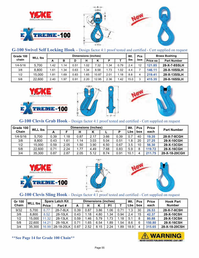
G-100 Swivel Self Locking Hook – Design factor 4:1 proof tested and certified - Cert supplied on request
G-100 Clevis Grab Hook – Design factor 4:1 proof tested and certified - Cert supplied on request
Grade 100 Chain WLL lbs
Dimensions (inches) Wt. Lbs
Pcs box
Price each Part Number A F H K L P
1/4-5/16 5,700 0.39 1.18 0.87 2.17 3.66 0.39 0.7 40 19.35 28-X-7-8CGH 3/8 8,800 0.43 1.61 1.14 3.03 5.04 0.51 1.8 20 27.25 28-X-10CGH 1/2 15,000 0.59 2.05 1.50 3.90 6.50 0.67 3.5 10 56.30 28-X-13CGH 5/8 22,600 0.71 2.24 1.77 4.49 7.68 0.83 5.9 8 119.72 28-X-16CGH 3/4 35,300 0.87 2.87 2.05 5.12 8.74 0.91 10.1 4 211.75 28-X-18-20CGH
G-100 Clevis Sling Hook – Design factor 4:1 proof tested and certified - Cert supplied on request
**See Page 14 for Grade 100 Chain**
Grade 100 chain WLL lbs
Dimensions (inches) Wt. lbs
Pcs box
Brass Bushing A B D H K P T Price ea Part Number
1/4-5/16 5,700 1.42 1.14 0.51 1.02 7.32 1.34 0.79 2.4 12 121.85 28-X-7-8SSLH 3/8 8,800 1.61 1.34 0.63 1.34 8.58 1.73 1.02 4.4 7 146.11 28-X-10SSLH 1/2 15,000 1.81 1.69 0.83 1.65 10.87 2.01 1.18 8.8 4 219.41 28-X-13SSLH 5/8 22,600 2.40 1.97 0.91 2.20 12.95 2.36 1.42 15.0 3 415.35 28-X-16SSLH
Gr 100 Chain WLL lbs
Spare Latch Kit Dimensions (inches) Wt. Lbs
Pcs box
Price each
Hook Part Number Price Part # A H K P1 T
9/32 5,700 6.77 28-7-8LK 0.39 0.87 3.86 1.06 0.71 1.3 30 26.53 28-X-7-8CSH 3/8 8,800 8.52 28-10LK 0.43 1.18 4.80 1.34 0.94 2.4 15 42.37 28-X-10CSH 1/2 15,000 11.32 28-13LK 0.59 1.46 5.79 1.73 1.18 5.1 8 80.88 28-X-13CSH 5/8 22,600 14.21 28-16LK 0.71 1.65 6.54 1.89 1.54 8.6 6 150.80 28-X-16CSH 3/4 35,300 16.99 28-18-20LK 0.87 2.52 8.15 2.24 1.89 18.9 4 315.65 28-X-18-20CSH
Page 55
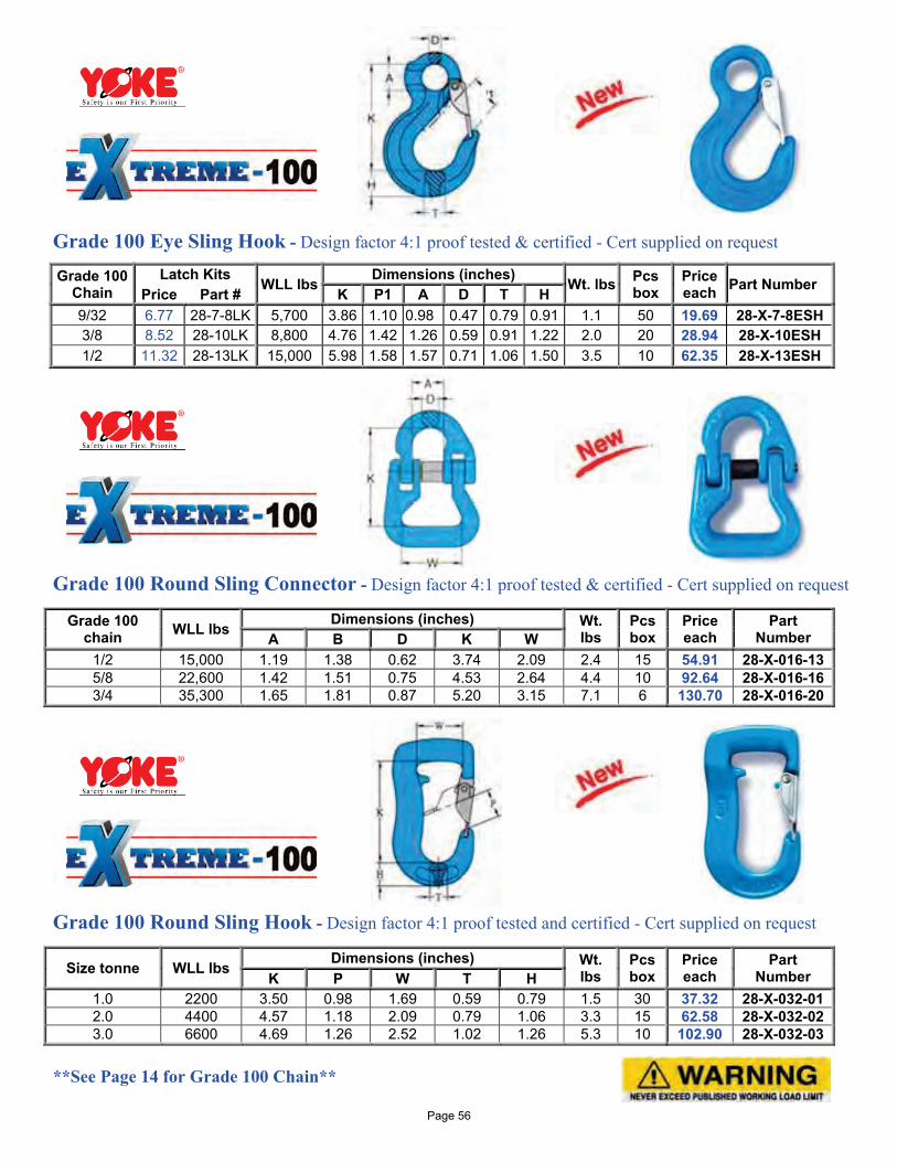
Grade 100 Eye Sling Hook - Design factor 4:1 proof tested & certified - Cert supplied on request
Grade 100 Chain
Latch Kits WLL lbs Dimensions (inches) Wt. lbs Pcs
box Price each Part Number Price Part # K P1 A D T H
9/32 6.77 28-7-8LK 5,700 3.86 1.10 0.98 0.47 0.79 0.91 1.1 50 19.69 28-X-7-8ESH 3/8 8.52 28-10LK 8,800 4.76 1.42 1.26 0.59 0.91 1.22 2.0 20 28.94 28-X-10ESH 1/2 11.32 28-13LK 15,000 5.98 1.58 1.57 0.71 1.06 1.50 3.5 10 62.35 28-X-13ESH
Grade 100 Round Sling Connector - Design factor 4:1 proof tested & certified - Cert supplied on request
Grade 100 Round Sling Hook - Design factor 4:1 proof tested and certified - Cert supplied on request
**See Page 14 for Grade 100 Chain**
Grade 100 chain WLL lbs Dimensions (inches) Wt.
lbs Pcs box
Price each
Part Number A B D K W
1/2 15,000 1.19 1.38 0.62 3.74 2.09 2.4 15 54.91 28-X-016-13 5/8 22,600 1.42 1.51 0.75 4.53 2.64 4.4 10 92.64 28-X-016-16 3/4 35,300 1.65 1.81 0.87 5.20 3.15 7.1 6 130.70 28-X-016-20
Size tonne WLL lbs Dimensions (inches) Wt. lbs
Pcs box
Price each
Part Number K P W T H
1.0 2200 3.50 0.98 1.69 0.59 0.79 1.5 30 37.32 28-X-032-01 2.0 4400 4.57 1.18 2.09 0.79 1.06 3.3 15 62.58 28-X-032-02 3.0 6600 4.69 1.26 2.52 1.02 1.26 5.3 10 102.90 28-X-032-03
Page 56
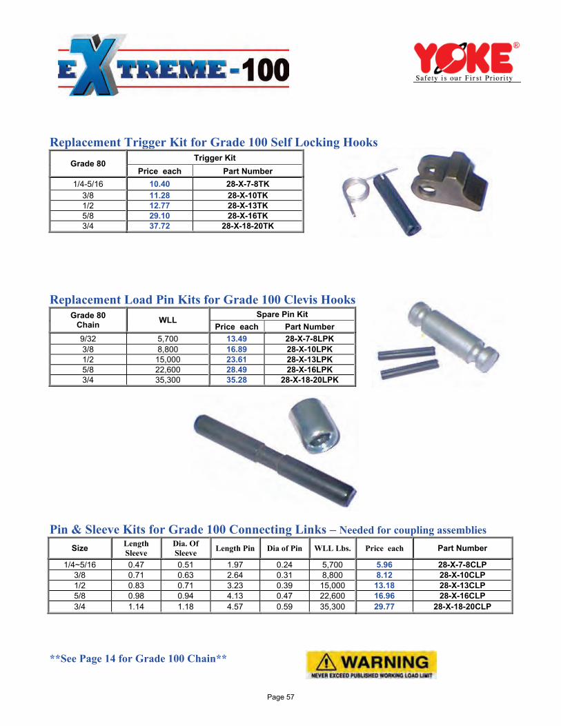
Replacement Trigger Kit for Grade 100 Self Locking Hooks
Grade 80 Trigger Kit
Price each Part Number 1/4-5/16 10.40 28-X-7-8TK
3/8 11.28 28-X-10TK 1/2 12.77 28-X-13TK 5/8 29.10 28-X-16TK 3/4 37.72 28-X-18-20TK
Replacement Load Pin Kits for Grade 100 Clevis Hooks
Grade 80 Chain WLL
Spare Pin Kit Price each Part Number
9/32 5,700 13.49 28-X-7-8LPK 3/8 8,800 16.89 28-X-10LPK 1/2 15,000 23.61 28-X-13LPK 5/8 22,600 28.49 28-X-16LPK 3/4 35,300 35.28 28-X-18-20LPK
Pin & Sleeve Kits for Grade 100 Connecting Links – Needed for coupling assemblies Size Length
Sleeve Dia. Of Sleeve Length Pin Dia of Pin WLL Lbs. Price each Part Number
1/4~5/16 0.47 0.51 1.97 0.24 5,700 5.96 28-X-7-8CLP 3/8 0.71 0.63 2.64 0.31 8,800 8.12 28-X-10CLP 1/2 0.83 0.71 3.23 0.39 15,000 13.18 28-X-13CLP 5/8 0.98 0.94 4.13 0.47 22,600 16.96 28-X-16CLP 3/4 1.14 1.18 4.57 0.59 35,300 29.77 28-X-18-20CLP
**See Page 14 for Grade 100 Chain**
Page 57
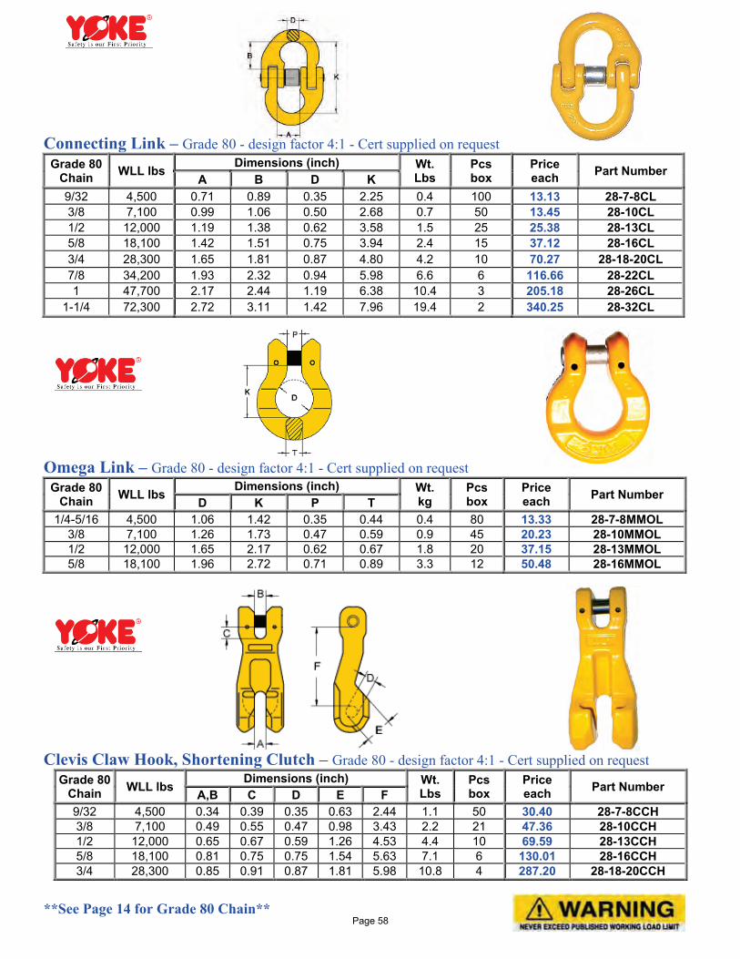
Connecting Link – Grade 80 - design factor 4:1 - Cert supplied on request Grade 80
Chain WLL lbs Dimensions (inch) Wt.
Lbs Pcs box
Price each Part Number
A B D K 9/32 4,500 0.71 0.89 0.35 2.25 0.4 100 13.13 28-7-8CL 3/8 7,100 0.99 1.06 0.50 2.68 0.7 50 13.45 28-10CL 1/2 12,000 1.19 1.38 0.62 3.58 1.5 25 25.38 28-13CL 5/8 18,100 1.42 1.51 0.75 3.94 2.4 15 37.12 28-16CL 3/4 28,300 1.65 1.81 0.87 4.80 4.2 10 70.27 28-18-20CL 7/8 34,200 1.93 2.32 0.94 5.98 6.6 6 116.66 28-22CL 1 47,700 2.17 2.44 1.19 6.38 10.4 3 205.18 28-26CL
1-1/4 72,300 2.72 3.11 1.42 7.96 19.4 2 340.25 28-32CL
Omega Link – Grade 80 - design factor 4:1 - Cert supplied on request
Grade 80 Chain WLL lbs
Dimensions (inch) Wt. kg
Pcs box
Price each Part Number D K P T
1/4-5/16 4,500 1.06 1.42 0.35 0.44 0.4 80 13.33 28-7-8MMOL 3/8 7,100 1.26 1.73 0.47 0.59 0.9 45 20.23 28-10MMOL 1/2 12,000 1.65 2.17 0.62 0.67 1.8 20 37.15 28-13MMOL 5/8 18,100 1.96 2.72 0.71 0.89 3.3 12 50.48 28-16MMOL
Clevis Claw Hook, Shortening Clutch – Grade 80 - design factor 4:1 - Cert supplied on request
Grade 80 Chain WLL lbs
Dimensions (inch) Wt. Lbs
Pcs box
Price each Part Number A,B C D E F
9/32 4,500 0.34 0.39 0.35 0.63 2.44 1.1 50 30.40 28-7-8CCH 3/8 7,100 0.49 0.55 0.47 0.98 3.43 2.2 21 47.36 28-10CCH 1/2 12,000 0.65 0.67 0.59 1.26 4.53 4.4 10 69.59 28-13CCH 5/8 18,100 0.81 0.75 0.75 1.54 5.63 7.1 6 130.01 28-16CCH 3/4 28,300 0.85 0.91 0.87 1.81 5.98 10.8 4 287.20 28-18-20CCH
**See Page 14 for Grade 80 Chain**
Page 58
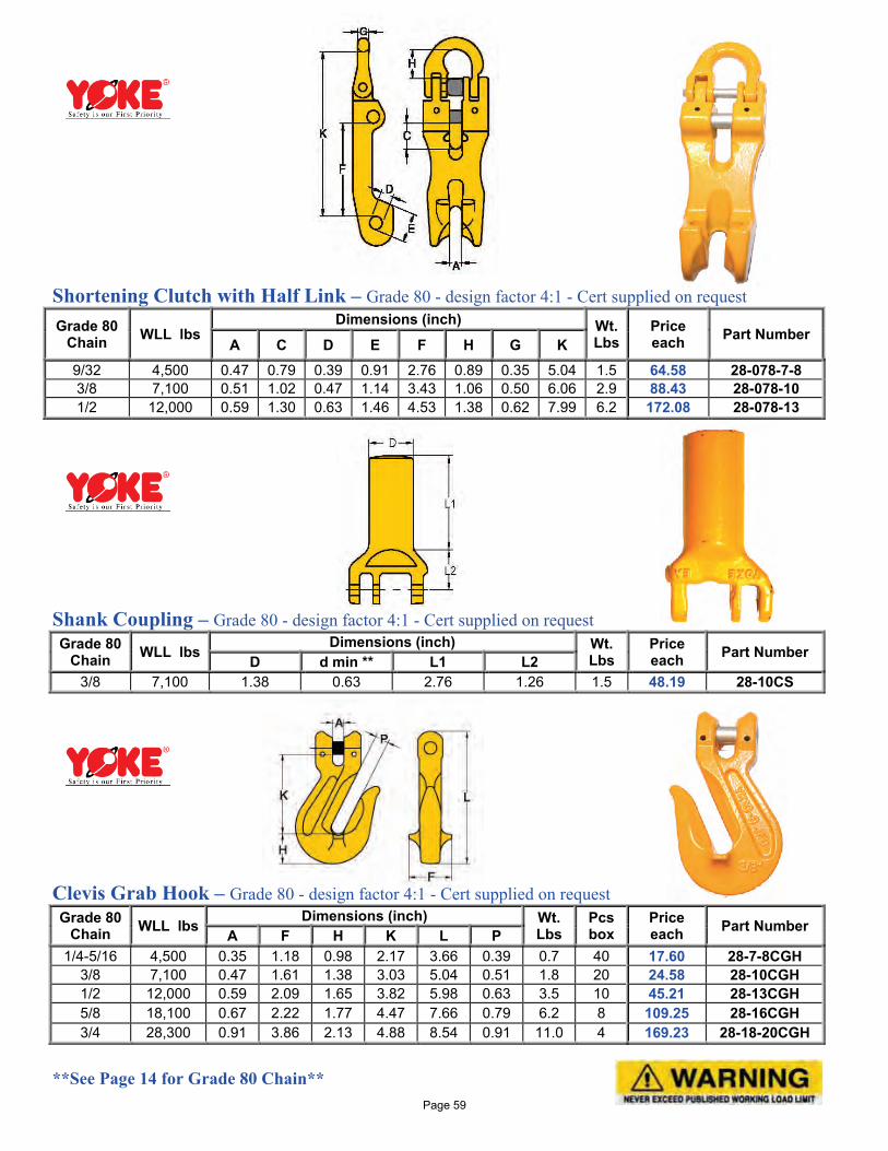
Shortening Clutch with Half Link – Grade 80 - design factor 4:1 - Cert supplied on request Grade 80
Chain WLL lbs Dimensions (inch) Wt.
Lbs Price each Part Number
A C D E F H G K 9/32 4,500 0.47 0.79 0.39 0.91 2.76 0.89 0.35 5.04 1.5 64.58 28-078-7-8 3/8 7,100 0.51 1.02 0.47 1.14 3.43 1.06 0.50 6.06 2.9 88.43 28-078-10 1/2 12,000 0.59 1.30 0.63 1.46 4.53 1.38 0.62 7.99 6.2 172.08 28-078-13
Shank Coupling – Grade 80 - design factor 4:1 - Cert supplied on request Grade 80
Chain WLL lbs Dimensions (inch) Wt.
Lbs Price each Part Number D d min ** L1 L2
3/8 7,100 1.38 0.63 2.76 1.26 1.5 48.19 28-10CS
Clevis Grab Hook – Grade 80 - design factor 4:1 - Cert supplied on request Grade 80
Chain WLL lbs Dimensions (inch) Wt.
Lbs Pcs box
Price each Part Number A F H K L P
1/4-5/16 4,500 0.35 1.18 0.98 2.17 3.66 0.39 0.7 40 17.60 28-7-8CGH 3/8 7,100 0.47 1.61 1.38 3.03 5.04 0.51 1.8 20 24.58 28-10CGH 1/2 12,000 0.59 2.09 1.65 3.82 5.98 0.63 3.5 10 45.21 28-13CGH 5/8 18,100 0.67 2.22 1.77 4.47 7.66 0.79 6.2 8 109.25 28-16CGH 3/4 28,300 0.91 3.86 2.13 4.88 8.54 0.91 11.0 4 169.23 28-18-20CGH
**See Page 14 for Grade 80 Chain** Page 59
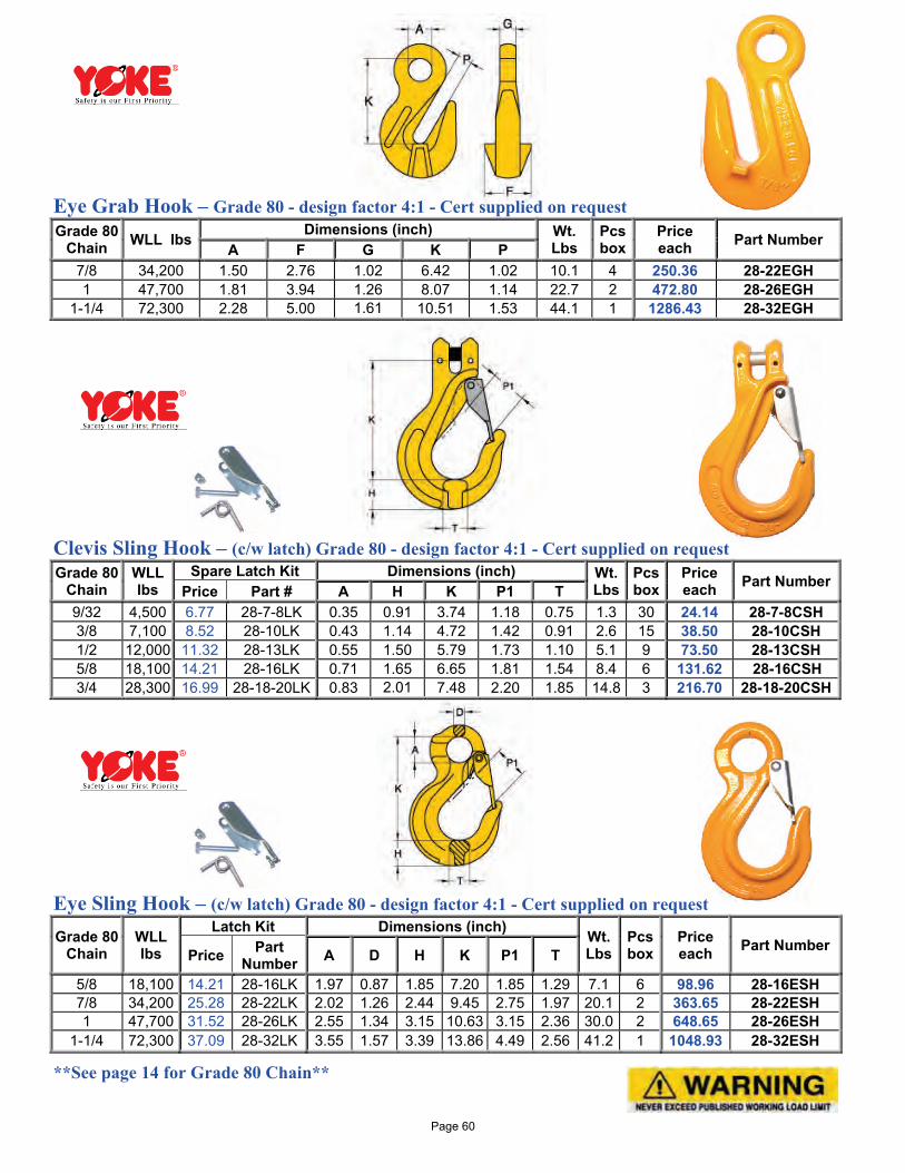
Eye Grab Hook – Grade 80 - design factor 4:1 - Cert supplied on request Grade 80
Chain WLL lbs Dimensions (inch) Wt.
Lbs Pcs box
Price each Part Number
A F G K P 7/8 34,200 1.50 2.76 1.02 6.42 1.02 10.1 4 250.36 28-22EGH 1 47,700 1.81 3.94 1.26 8.07 1.14 22.7 2 472.80 28-26EGH
1-1/4 72,300 2.28 5.00 1.61 10.51 1.53 44.1 1 1286.43 28-32EGH
Clevis Sling Hook – (c/w latch) Grade 80 - design factor 4:1 - Cert supplied on request Grade 80
Chain WLL lbs
Spare Latch Kit Dimensions (inch) Wt. Lbs
Pcs box
Price each Part Number Price Part # A H K P1 T
9/32 4,500 6.77 28-7-8LK 0.35 0.91 3.74 1.18 0.75 1.3 30 24.14 28-7-8CSH 3/8 7,100 8.52 28-10LK 0.43 1.14 4.72 1.42 0.91 2.6 15 38.50 28-10CSH 1/2 12,000 11.32 28-13LK 0.55 1.50 5.79 1.73 1.10 5.1 9 73.50 28-13CSH 5/8 18,100 14.21 28-16LK 0.71 1.65 6.65 1.81 1.54 8.4 6 131.62 28-16CSH 3/4 28,300 16.99 28-18-20LK 0.83 2.01 7.48 2.20 1.85 14.8 3 216.70 28-18-20CSH
Eye Sling Hook – (c/w latch) Grade 80 - design factor 4:1 - Cert supplied on request
Grade 80 Chain
WLL lbs
Latch Kit Dimensions (inch) Wt. Lbs
Pcs box
Price each Part Number Price Part
Number A D H K P1 T
5/8 18,100 14.21 28-16LK 1.97 0.87 1.85 7.20 1.85 1.29 7.1 6 98.96 28-16ESH 7/8 34,200 25.28 28-22LK 2.02 1.26 2.44 9.45 2.75 1.97 20.1 2 363.65 28-22ESH 1 47,700 31.52 28-26LK 2.55 1.34 3.15 10.63 3.15 2.36 30.0 2 648.65 28-26ESH
1-1/4 72,300 37.09 28-32LK 3.55 1.57 3.39 13.86 4.49 2.56 41.2 1 1048.93 28-32ESH
**See page 14 for Grade 80 Chain**
Page 60
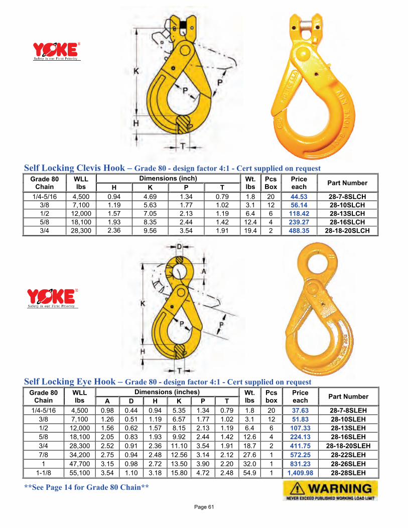
Self Locking Clevis Hook – Grade 80 - design factor 4:1 - Cert supplied on request
Grade 80 Chain
WLL lbs
Dimensions (inch) Wt. lbs
Pcs Box
Price each Part Number H K P T
1/4-5/16 4,500 0.94 4.69 1.34 0.79 1.8 20 44.53 28-7-8SLCH 3/8 7,100 1.19 5.63 1.77 1.02 3.1 12 56.14 28-10SLCH 1/2 12,000 1.57 7.05 2.13 1.19 6.4 6 118.42 28-13SLCH 5/8 18,100 1.93 8.35 2.44 1.42 12.4 4 239.27 28-16SLCH 3/4 28,300 2.36 9.56 3.54 1.91 19.4 2 488.35 28-18-20SLCH
Self Locking Eye Hook – Grade 80 - design factor 4:1 - Cert supplied on request
Grade 80 Chain
WLL lbs
Dimensions (inches) Wt. lbs
Pcs box
Price each Part Number A D H K P T
1/4-5/16 4,500 0.98 0.44 0.94 5.35 1.34 0.79 1.8 20 37.63 28-7-8SLEH 3/8 7,100 1.26 0.51 1.19 6.57 1.77 1.02 3.1 12 51.83 28-10SLEH 1/2 12,000 1.56 0.62 1.57 8.15 2.13 1.19 6.4 6 107.33 28-13SLEH 5/8 18,100 2.05 0.83 1.93 9.92 2.44 1.42 12.6 4 224.13 28-16SLEH 3/4 28,300 2.52 0.91 2.36 11.10 3.54 1.91 18.7 2 411.75 28-18-20SLEH 7/8 34,200 2.75 0.94 2.48 12.56 3.14 2.12 27.6 1 572.25 28-22SLEH 1 47,700 3.15 0.98 2.72 13.50 3.90 2.20 32.0 1 831.23 28-26SLEH
1-1/8 55,100 3.54 1.10 3.18 15.80 4.72 2.48 54.9 1 1,409.98 28-28SLEH
**See Page 14 for Grade 80 Chain**
Page 61
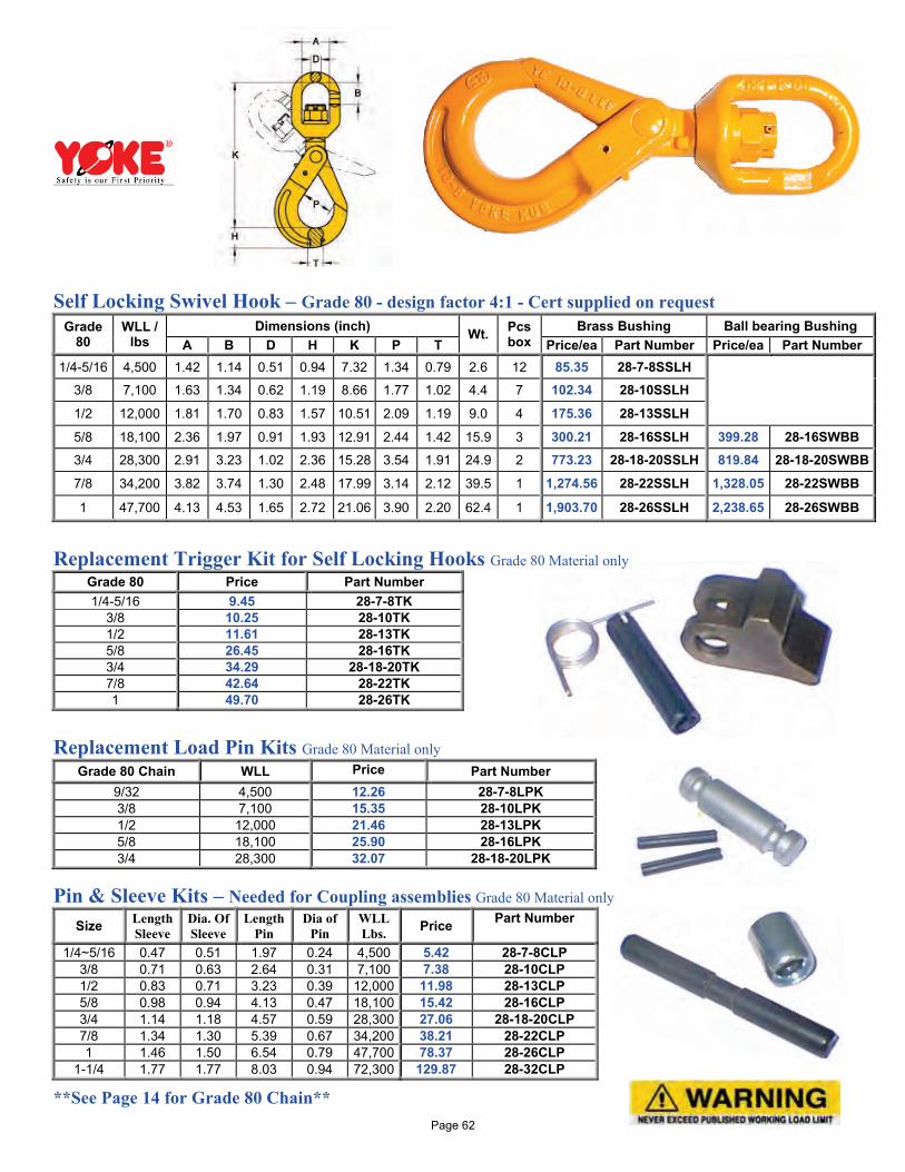
Self Locking Swivel Hook – Grade 80 - design factor 4:1 - Cert supplied on request
Grade 80
WLL / lbs
Dimensions (inch) Wt. Pcs box
Brass Bushing Ball bearing Bushing A B D H K P T Price/ea Part Number Price/ea Part Number
1/4-5/16 4,500 1.42 1.14 0.51 0.94 7.32 1.34 0.79 2.6 12 85.35 28-7-8SSLH 3/8 7,100 1.63 1.34 0.62 1.19 8.66 1.77 1.02 4.4 7 102.34 28-10SSLH
1/2 12,000 1.81 1.70 0.83 1.57 10.51 2.09 1.19 9.0 4 175.36 28-13SSLH
5/8 18,100 2.36 1.97 0.91 1.93 12.91 2.44 1.42 15.9 3 300.21 28-16SSLH 399.28 28-16SWBB 3/4 28,300 2.91 3.23 1.02 2.36 15.28 3.54 1.91 24.9 2 773.23 28-18-20SSLH 819.84 28-18-20SWBB
7/8 34,200 3.82 3.74 1.30 2.48 17.99 3.14 2.12 39.5 1 1,274.56 28-22SSLH 1,328.05 28-22SWBB
1 47,700 4.13 4.53 1.65 2.72 21.06 3.90 2.20 62.4 1 1,903.70 28-26SSLH 2,238.65 28-26SWBB
Replacement Trigger Kit for Self Locking Hooks Grade 80 Material only
Grade 80 Price Part Number 1/4-5/16 9.45 28-7-8TK
3/8 10.25 28-10TK 1/2 11.61 28-13TK 5/8 26.45 28-16TK 3/4 34.29 28-18-20TK 7/8 42.64 28-22TK 1 49.70 28-26TK
Replacement Load Pin Kits Grade 80 Material only
Grade 80 Chain WLL Price Part Number 9/32 4,500 12.26 28-7-8LPK 3/8 7,100 15.35 28-10LPK 1/2 12,000 21.46 28-13LPK 5/8 18,100 25.90 28-16LPK 3/4 28,300 32.07 28-18-20LPK
Pin & Sleeve Kits – Needed for Coupling assemblies Grade 80 Material only
Size Length Sleeve
Dia. Of Sleeve
Length Pin
Dia of Pin
WLL Lbs. Price Part Number
1/4~5/16 0.47 0.51 1.97 0.24 4,500 5.42 28-7-8CLP 3/8 0.71 0.63 2.64 0.31 7,100 7.38 28-10CLP 1/2 0.83 0.71 3.23 0.39 12,000 11.98 28-13CLP 5/8 0.98 0.94 4.13 0.47 18,100 15.42 28-16CLP 3/4 1.14 1.18 4.57 0.59 28,300 27.06 28-18-20CLP 7/8 1.34 1.30 5.39 0.67 34,200 38.21 28-22CLP 1 1.46 1.50 6.54 0.79 47,700 78.37 28-26CLP
1-1/4 1.77 1.77 8.03 0.94 72,300 129.87 28-32CLP
**See Page 14 for Grade 80 Chain** Page 62
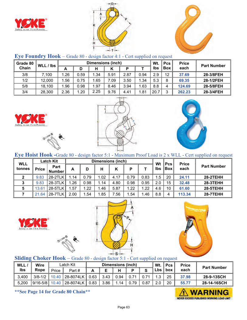
Eye Foundry Hook – Grade 80 - design factor 4:1 - Cert supplied on request Grade 80
Chain WLL / lbs Dimensions (inch) Wt.
lbs Pcs Box
Price each Part Number
A D H K P T 3/8 7,100 1.26 0.59 1.34 5.91 2.87 0.94 2.9 12 37.69 28-3/8FEH 1/2 12,000 1.56 0.75 1.65 7.09 3.50 1.34 5.3 8 69.35 28-1/2FEH 5/8 18,100 1.96 0.98 1.97 8.46 3.94 1.63 8.8 4 124.69 28-5/8FEH 3/4 28,300 2.36 1.20 2.25 9.76 4.41 1.81 20.7 3 262.23 28-3/4FEH
Eye Hoist Hook -Grade 80 - design factor 5:1 - Maximum Proof Load is 2 x WLL - Cert supplied on request
WLL tonnes
Latch Kit Dimensions (inch) Wt lbs
Pcs Box
Price each Part Number
Price Part Number A D H K P T
2 9.83 28-2TLK 1.14 0.79 1.02 4.17 0.79 0.83 1.5 20 24.11 28-2TEHH 3 9.83 28-3TLK 1.26 0.98 1.14 4.80 0.98 0.95 2.0 15 32.48 28-3TEHH 5 13.61 28-5TLK 1.57 1.22 1.46 5.87 1.22 1.22 4.6 10 61.60 28-5TEHH 7 21.64 28-7TLK 2.00 1.54 1.85 7.56 1.54 1.46 8.8 4 113.34 28-7TEHH
Sliding Choker Hook – Grade 80 - design factor 5:1 - Cert supplied on request
WLL / lbs
Wire Rope
Latch Kit Dimensions (inch) Wt. Lbs
Pcs box
Price each Part Number
Price Part # A E H P S 3,400 3/8-1/2 10.40 28-8074LK 0.63 3.43 0.94 0.71 0.71 1.3 25 37.98 28-9-13SCH 5,200 9/16-5/8 10.40 28-8074LK 0.83 3.86 1.14 0.79 0.87 2.0 20 55.77 28-14-16SCH
**See Page 14 for Grade 80 Chain**
Page 63
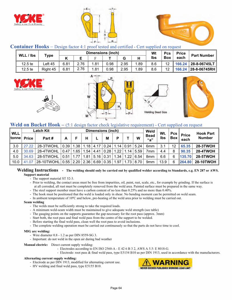
Container Hooks – Design factor 4:1 proof tested and certified - Cert supplied on request
WLL / lbs Type Dimensions (inch) Wt
lbs Pcs Box
Price each Part Number
K E F T G H 12.5 te Left 45 6.81 2.76 1.81 0.98 2.95 1.89 8.6 12 166.24 28-8-06745LT 12.5 te Right 45 6.81 2.76 1.81 0.98 2.95 1.89 8.6 12 166.24 28-8-06745RH
Weld on Bucket Hook – (5:1 design factor check legislative requirement) - Cert supplied on request
WLL tonne
Latch Kit Dimensions (inch) Weld Bead “a”
Wt. lbs
Pcs Box
Price each
Hook Part Number Price Part # A F H L M P T W
3.0 27.22 28-3TWOHL 0.39 1.38 1.18 4.17 0.24 1.14 0.91 5.24 6mm 3.1 12 65.35 28-3TWOH 4.0 30.69 28-4TWOHL 0.47 1.65 1.54 4.41 0.28 1.22 1.14 5.59 7mm 4.4 8 90.35 28-4TWOH 5.0 34.63 28-5TWOHL 0.51 1.77 1.81 5.16 0.31 1.34 1.22 6.54 8mm 6.6 6 135.70 28-5TWOH 10.0 41.07 28-10TWOHL 0.55 2.20 2.36 6.69 0.35 1.97 1.73 8.70 9mm 13.9 6 264.80 28-10TWOH
Welding Instructions - The welding should only be carried out by qualified welder according to Standards, e.g. EN 287 or AWS. Support material - The support material ST 52-3. - Prior to welding, the contact areas must be free from impurities, oil, paint, rust, scale, etc., for example by grinding. If the surface is
at all corroded, all rust must be completely removed from the weld area. Painted surface must be prepared in the same way. - The steel support member must have a carbon content of no less than 0.25% and no more than 0.40%. - The hook must be positioned that the weld is loaded only in shear. No bending moment can be permitted on weld seam. - In ambient temperature of 10ºC and below, pre-heating of the weld area prior to welding must be carried out. Seam welding - The welds must be sufficiently strong to take the required loads. - A minimum weld-seam width must be maintained to give adequate weld strength (see table) - The gauging points on the supports guarantee the gap necessary for the root pass (approx. 3mm) - Start both, the root pass and final weld pass from the centre of the support to be welded. - Before starting the final weld pass, clean well the root pass to avoid inclusions. - The complete welding operation must be carried out continuously so that the parts do not have time to cool.
MIG arc welding: - Wire diameter 0.8 - 1.2 as per DIN 8559-SG 3. - Important: do not weld in the open air during bad weather
Manual electric: Direct current supply welding: - Electrodes according to EN ISO 2560-A - E 42 6 B 3 2, AWS A 5.5: E 8018-G. - Electrode: root pass & final weld pass, type E5154 B10 as per DIN 1913, used in accordance with the manufacturers.
Alternating current supply welding: - Electrode as per DIN 1913, modified for alternating current use. - HV welding and final weld pass, type E5155 B10.
Page 64
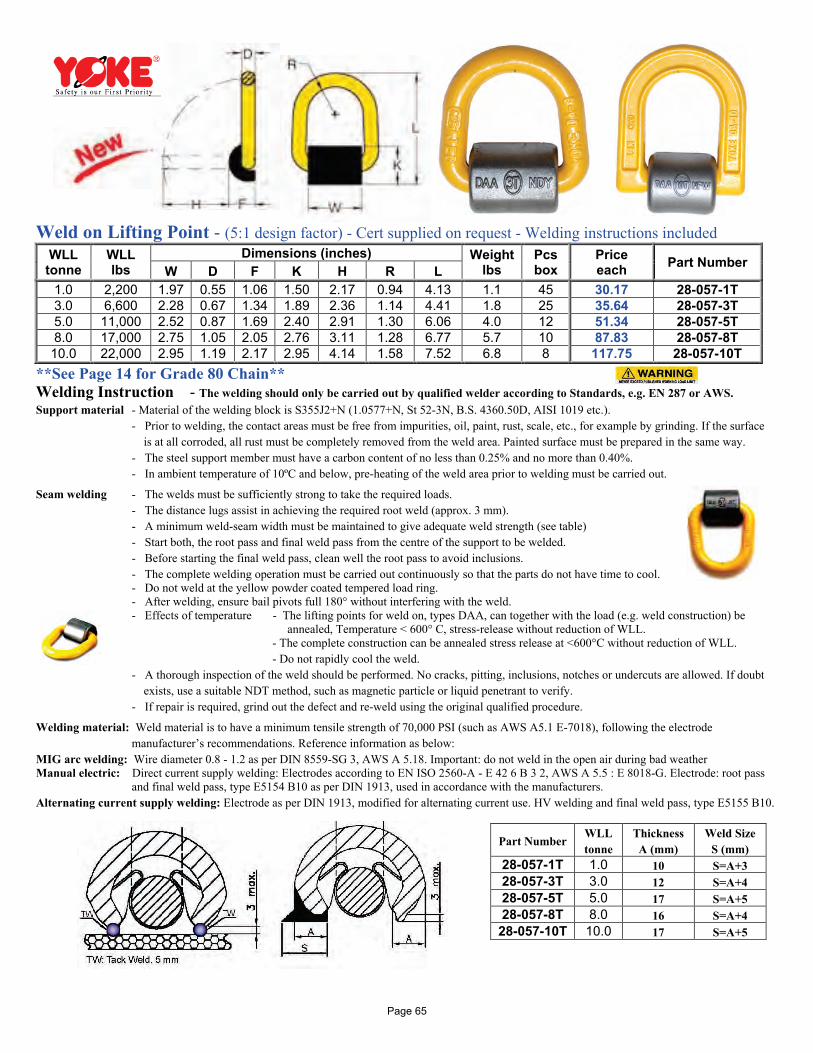
Weld on Lifting Point - (5:1 design factor) - Cert supplied on request - Welding instructions included WLL tonne
WLL lbs
Dimensions (inches) Weight lbs
Pcs box
Price each Part Number W D F K H R L
1.0 2,200 1.97 0.55 1.06 1.50 2.17 0.94 4.13 1.1 45 30.17 28-057-1T 3.0 6,600 2.28 0.67 1.34 1.89 2.36 1.14 4.41 1.8 25 35.64 28-057-3T 5.0 11,000 2.52 0.87 1.69 2.40 2.91 1.30 6.06 4.0 12 51.34 28-057-5T 8.0 17,000 2.75 1.05 2.05 2.76 3.11 1.28 6.77 5.7 10 87.83 28-057-8T 10.0 22,000 2.95 1.19 2.17 2.95 4.14 1.58 7.52 6.8 8 117.75 28-057-10T
**See Page 14 for Grade 80 Chain** Welding Instruction - The welding should only be carried out by qualified welder according to Standards, e.g. EN 287 or AWS. Support material - Material of the welding block is S355J2+N (1.0577+N, St 52-3N, B.S. 4360.50D, AISI 1019 etc.).
- Prior to welding, the contact areas must be free from impurities, oil, paint, rust, scale, etc., for example by grinding. If the surface is at all corroded, all rust must be completely removed from the weld area. Painted surface must be prepared in the same way.
- The steel support member must have a carbon content of no less than 0.25% and no more than 0.40%. - In ambient temperature of 10ºC and below, pre-heating of the weld area prior to welding must be carried out.
Seam welding - The welds must be sufficiently strong to take the required loads. - The distance lugs assist in achieving the required root weld (approx. 3 mm). - A minimum weld-seam width must be maintained to give adequate weld strength (see table) - Start both, the root pass and final weld pass from the centre of the support to be welded. - Before starting the final weld pass, clean well the root pass to avoid inclusions. - The complete welding operation must be carried out continuously so that the parts do not have time to cool. - Do not weld at the yellow powder coated tempered load ring. - After welding, ensure bail pivots full 180° without interfering with the weld. - Effects of temperature - The lifting points for weld on, types DAA, can together with the load (e.g. weld construction) be
annealed, Temperature < 600° C, stress-release without reduction of WLL. - The complete construction can be annealed stress release at <600°C without reduction of WLL. - Do not rapidly cool the weld.
- A thorough inspection of the weld should be performed. No cracks, pitting, inclusions, notches or undercuts are allowed. If doubt exists, use a suitable NDT method, such as magnetic particle or liquid penetrant to verify.
- If repair is required, grind out the defect and re-weld using the original qualified procedure.
Welding material: Weld material is to have a minimum tensile strength of 70,000 PSI (such as AWS A5.1 E-7018), following the electrode manufacturer’s recommendations. Reference information as below:
MIG arc welding: Wire diameter 0.8 - 1.2 as per DIN 8559-SG 3, AWS A 5.18. Important: do not weld in the open air during bad weather Manual electric: Direct current supply welding: Electrodes according to EN ISO 2560-A - E 42 6 B 3 2, AWS A 5.5 : E 8018-G. Electrode: root pass
and final weld pass, type E5154 B10 as per DIN 1913, used in accordance with the manufacturers. Alternating current supply welding: Electrode as per DIN 1913, modified for alternating current use. HV welding and final weld pass, type E5155 B10.
Part Number WLL tonne
Thickness A (mm)
Weld Size S (mm)
28-057-1T 1.0 10 S=A+3 28-057-3T 3.0 12 S=A+4 28-057-5T 5.0 17 S=A+5 28-057-8T 8.0 16 S=A+4 28-057-10T 10.0 17 S=A+5
Page 65
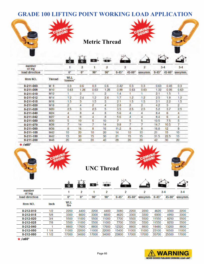
GRADE 100 LIFTING POINT WORKING LOAD APPLICATION
Metric Thread
UNC Thread
Page 66
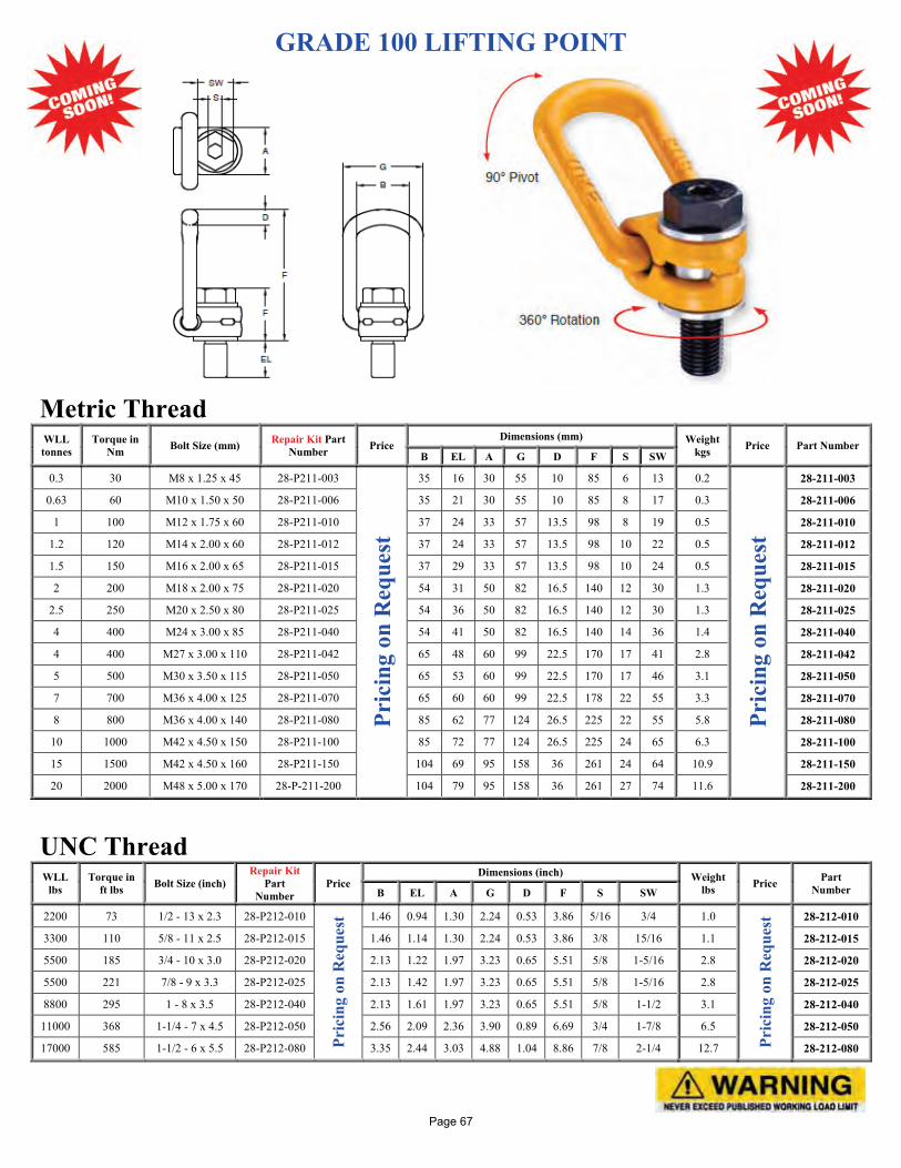
GRADE 100 LIFTING POINT
Metric Thread WLL tonnes
Torque in Nm Bolt Size (mm) Repair Kit Part
Number Price Dimensions (mm) Weight
kgs Price Part Number B EL A G D F S SW
0.3 30 M8 x 1.25 x 45 28-P211-003
Pric
ing
on R
eque
st
35 16 30 55 10 85 6 13 0.2
Pric
ing
on R
eque
st
28-211-003
0.63 60 M10 x 1.50 x 50 28-P211-006 35 21 30 55 10 85 8 17 0.3 28-211-006
1 100 M12 x 1.75 x 60 28-P211-010 37 24 33 57 13.5 98 8 19 0.5 28-211-010
1.2 120 M14 x 2.00 x 60 28-P211-012 37 24 33 57 13.5 98 10 22 0.5 28-211-012
1.5 150 M16 x 2.00 x 65 28-P211-015 37 29 33 57 13.5 98 10 24 0.5 28-211-015
2 200 M18 x 2.00 x 75 28-P211-020 54 31 50 82 16.5 140 12 30 1.3 28-211-020
2.5 250 M20 x 2.50 x 80 28-P211-025 54 36 50 82 16.5 140 12 30 1.3 28-211-025
4 400 M24 x 3.00 x 85 28-P211-040 54 41 50 82 16.5 140 14 36 1.4 28-211-040
4 400 M27 x 3.00 x 110 28-P211-042 65 48 60 99 22.5 170 17 41 2.8 28-211-042
5 500 M30 x 3.50 x 115 28-P211-050 65 53 60 99 22.5 170 17 46 3.1 28-211-050
7 700 M36 x 4.00 x 125 28-P211-070 65 60 60 99 22.5 178 22 55 3.3 28-211-070
8 800 M36 x 4.00 x 140 28-P211-080 85 62 77 124 26.5 225 22 55 5.8 28-211-080
10 1000 M42 x 4.50 x 150 28-P211-100 85 72 77 124 26.5 225 24 65 6.3 28-211-100
15 1500 M42 x 4.50 x 160 28-P211-150 104 69 95 158 36 261 24 64 10.9 28-211-150
20 2000 M48 x 5.00 x 170 28-P-211-200 104 79 95 158 36 261 27 74 11.6 28-211-200
UNC Thread WLL
lbs Torque in
ft lbs Bolt Size (inch) Repair Kit
Part Number
Price Dimensions (inch) Weight
lbs Price Part Number B EL A G D F S SW
2200 73 1/2 - 13 x 2.3 28-P212-010
Pric
ing
on R
eque
st 1.46 0.94 1.30 2.24 0.53 3.86 5/16 3/4 1.0
Pric
ing
on R
eque
st 28-212-010
3300 110 5/8 - 11 x 2.5 28-P212-015 1.46 1.14 1.30 2.24 0.53 3.86 3/8 15/16 1.1 28-212-015
5500 185 3/4 - 10 x 3.0 28-P212-020 2.13 1.22 1.97 3.23 0.65 5.51 5/8 1-5/16 2.8 28-212-020
5500 221 7/8 - 9 x 3.3 28-P212-025 2.13 1.42 1.97 3.23 0.65 5.51 5/8 1-5/16 2.8 28-212-025
8800 295 1 - 8 x 3.5 28-P212-040 2.13 1.61 1.97 3.23 0.65 5.51 5/8 1-1/2 3.1 28-212-040
11000 368 1-1/4 - 7 x 4.5 28-P212-050 2.56 2.09 2.36 3.90 0.89 6.69 3/4 1-7/8 6.5 28-212-050
17000 585 1-1/2 - 6 x 5.5 28-P212-080 3.35 2.44 3.03 4.88 1.04 8.86 7/8 2-1/4 12.7 28-212-080
Page 67
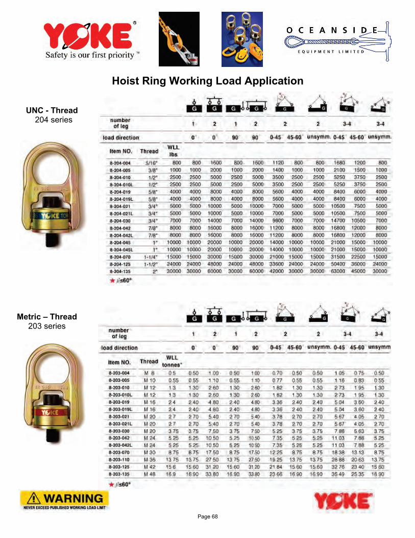
Hoist Ring Working Load Application UNC - Thread 204 series Metric – Thread 203 series
Page 68
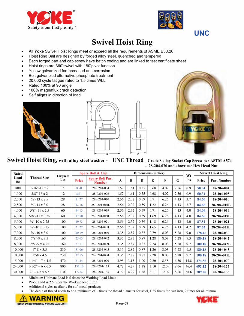
UNC Swivel Hoist Ring
• All Yoke Swivel Hoist Rings meet or exceed all the requirements of ASME B30.26 • Hoist Ring Bail are designed by forged alloy steel, quenched and tempered • Each forged part and cap screw have batch coding and are linked to test certificate sheet • Hoist rings are 360̊ swivel with 180 ̊pivot function • Yellow galvanized for increased anti-corrosion • Bolt galvanized alternative phosphate treatment • 20,000 cycle fatigue rated to 1.5 times WLL • Rated 100% at 90̊ angle • 100% magnaflux crack detection • Self aligns in direction of load
Swivel Hoist Ring, with alloy steel washer - UNC Thread – Grade 8 alloy Socket Cap Screw per ASTM A574 - 28-204-070 and above use Hex Head Nut
Rated Load lbs
Thread Size Torque ft Lbs
Spare Bolt & Clip Dimensions (inches) Wt lbs
Swivel Hoist Ring
Price Spare Bolt Part Number A B D E F G Price Part Number
800 5/16”-18 x 2 7 8.70 28-P204-004 1.57 1.61 0.35 0.68 4.02 2.56 0.9 50.34 28-204-004 1,000 3/8”-16 x 2 12 8.41 28-P204-005 1.57 1.61 0.35 0.68 4.02 2.56 0.9 50.34 28-204-005 2,500 ½”-13 x 2.5 28 11.27 28-P204-010 2.56 2.32 0.59 0.71 6.26 4.13 3.7 84.66 28-204-010 2,500 ½”-13 x 3.0 28 12.18 28-P204-010L 2.56 2.32 0.59 1.22 6.26 4.13 3.7 84.66 28-204-010L 4,000 5/8”-11 x 2.5 60 14.13 28-P204-019 2.56 2.32 0.59 0.71 6.26 4.13 4.0 84.66 28-204-019 4,000 5/8”-11 x 3.25 60 17.50 28-P204-019L 2.56 2.32 0.59 1.69 6.26 4.13 4.0 84.66 28-204-019L 5,000 ¾”-10 x 2.75 100 19.73 28-P204-021 2.56 2.32 0.59 1.18 6.26 4.13 4.0 87.52 28-204-021 5,000 ¾”-10 x 3.25 100 21.22 28-P204-021L 2.56 2.32 0.59 1.65 6.26 4.13 4.2 87.52 28-204-021L 7,000 ¾”-10 x 3.0 100 20.19 28-P204-030 3.35 2.87 0.87 0.79 8.03 5.28 9.0 178.46 28-204-030 8,000 7/8”-9 x 3.5 160 25.63 28-P204-042 3.35 2.87 0.87 1.28 8.03 5.28 9.3 180.18 28-204-042 8,000 7/8”-9 x 4.25 160 27.11 28-P204-042L 3.35 2.87 0.87 2.24 8.03 5.28 9.7 180.18 28-204-042L 10,000 1”-8 x 3.5 230 31.06 28-P204-045 3.35 2.87 0.87 1.26 8.03 5.28 9.5 180.18 28-204-045 10,000 1”-8 x 4.5 230 32.55 28-P204-045L 3.35 2.87 0.87 2.28 8.03 5.28 9.7 180.18 28-204-045L 15,000 1-1/4” – 7 x 4.5 470 81.34 28-P204-070 3.95 3.15 1.00 2.20 8.58 6.30 14.8 274.56 28-204-070 24,000 1-1/2” – 6 x 6.5 800 133.16 28-P204-125 4.72 4.29 1.38 3.10 12.09 8.66 36.4 692.12 28-204-125 30,000 2” – 4.5 x 6.5 1100 172.57 28-P204-135 4.72 4.29 1.38 3.11 12.09 8.66 38.6 709.28 28-204-135
• Minimum Ultimate Load is 5 times the Working Load Limit • Proof Load is 2.5 times the Working load Limit • Additional styles available for soft metal products • The depth of thread needs to be a minimum of 1 times the thread diameter for steel, 1.25 times for cast iron, 2 times for aluminum
Page 69
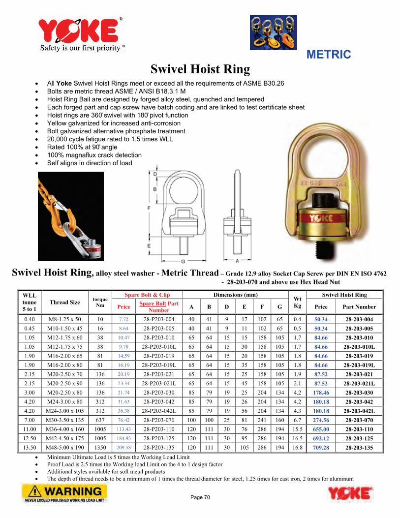
METRIC Swivel Hoist Ring
• All Yoke Swivel Hoist Rings meet or exceed all the requirements of ASME B30.26 • Bolts are metric thread ASME / ANSI B18.3.1 M • Hoist Ring Bail are designed by forged alloy steel, quenched and tempered • Each forged part and cap screw have batch coding and are linked to test certificate sheet • Hoist rings are 360̊ swivel with 180 ̊pivot function • Yellow galvanized for increased anti-corrosion • Bolt galvanized alternative phosphate treatment • 20,000 cycle fatigue rated to 1.5 times WLL • Rated 100% at 90̊ angle • 100% magnaflux crack detection • Self aligns in direction of load
Swivel Hoist Ring, alloy steel washer - Metric Thread – Grade 12.9 alloy Socket Cap Screw per DIN EN ISO 4762 - 28-203-070 and above use Hex Head Nut
WLL tonne 5 to 1
Thread Size torque Nm
Spare Bolt & Clip Dimensions (mm) Wt Kg
Swivel Hoist Ring
Price Spare Bolt Part Number A B D E F G Price Part Number
0.40 M8-1.25 x 50 10 7.72 28-P203-004 40 41 9 17 102 65 0.4 50.34 28-203-004 0.45 M10-1.50 x 45 16 8.64 28-P203-005 40 41 9 11 102 65 0.5 50.34 28-203-005 1.05 M12-1.75 x 60 38 10.47 28-P203-010 65 64 15 15 158 105 1.7 84.66 28-203-010 1.05 M12-1.75 x 75 38 9.78 28-P203-010L 65 64 15 30 158 105 1.7 84.66 28-203-010L 1.90 M16-2.00 x 65 81 14.59 28-P203-019 65 64 15 20 158 105 1.8 84.66 28-203-019 1.90 M16-2.00 x 80 81 16.19 28-P203-019L 65 64 15 35 158 105 1.8 84.66 28-203-019L 2.15 M20-2.50 x 70 136 20.19 28-P203-021 65 64 15 25 158 105 1.9 87.52 28-203-021 2.15 M20-2.50 x 90 136 23.34 28-P203-021L 65 64 15 45 158 105 2.1 87.52 28-203-021L 3.00 M20-2.50 x 80 136 21.74 28-P203-030 85 79 19 25 204 134 4.2 178.46 28-203-030 4.20 M24-3.00 x 80 312 31.63 28-P203-042 85 79 19 26 204 134 4.2 180.18 28-203-042 4.20 M24-3.00 x 10⁵ 312 36.38 28-P203-042L 85 79 19 56 204 134 4.3 180.18 28-203-042L 7.00 M30-3.50 x 135 637 76.42 28-P203-070 100 100 25 81 241 160 6.7 274.56 28-203-070
11.00 M36-4.00 x 160 1005 113.43 28-P203-110 120 111 30 76 286 194 15.5 655.00 28-203-110 12.50 M42-4.50 x 175 1005 184.93 28-P203-125 120 111 30 95 286 194 16.5 692.12 28-203-125 13.50 M48-5.00 x 190 1350 209.58 28-P203-135 120 111 30 105 286 194 16.8 709.28 28-203-135
• Minimum Ultimate Load is 5 times the Working Load Limit • Proof Load is 2.5 times the Working load Limit on the 4 to 1 design factor • Additional styles available for soft metal products • The depth of thread needs to be a minimum of 1 times the thread diameter for steel, 1.25 times for cast iron, 2 times for aluminum
Page 70
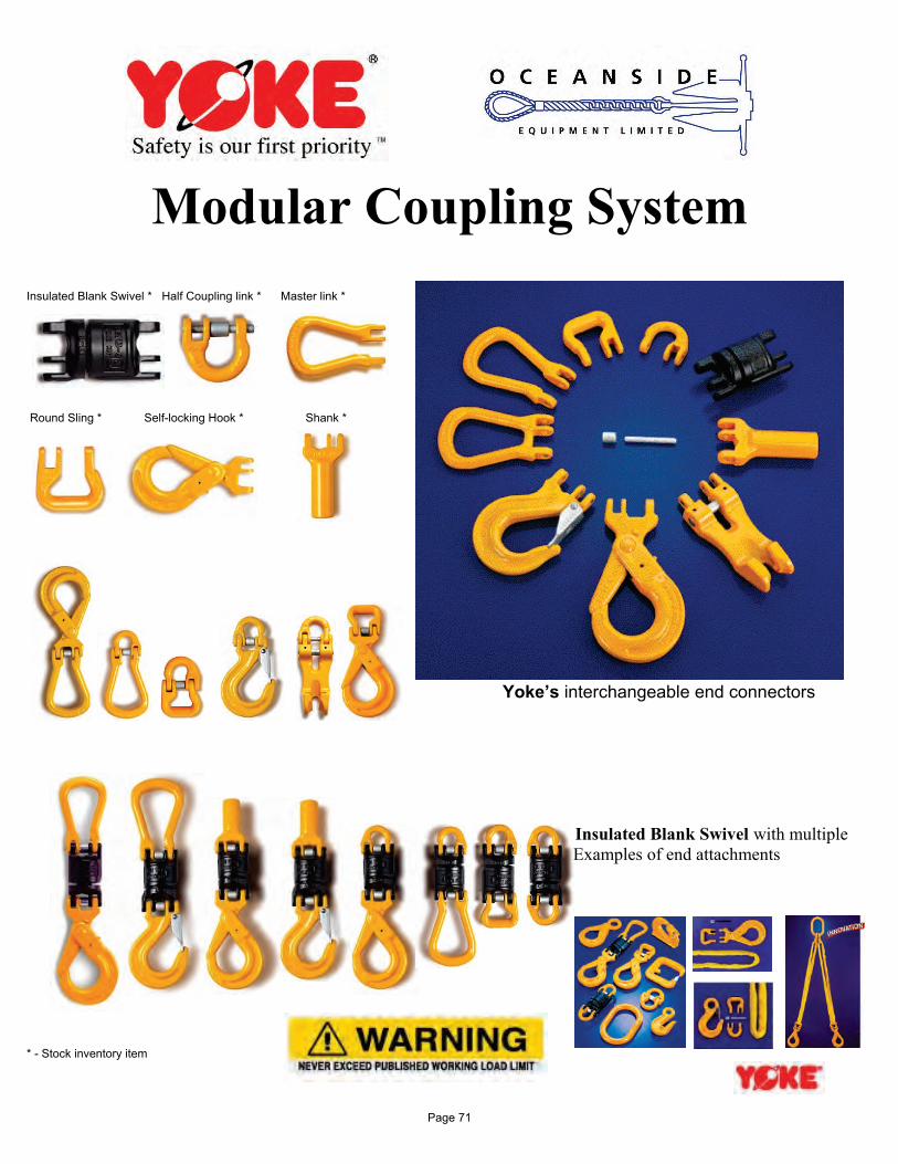
Modular Coupling System Insulated Blank Swivel * Half Coupling link * Master link * Round Sling * Self-locking Hook * Shank *
Yoke’s interchangeable end connectors
Insulated Blank Swivel with multiple Examples of end attachments * - Stock inventory item
Page 71
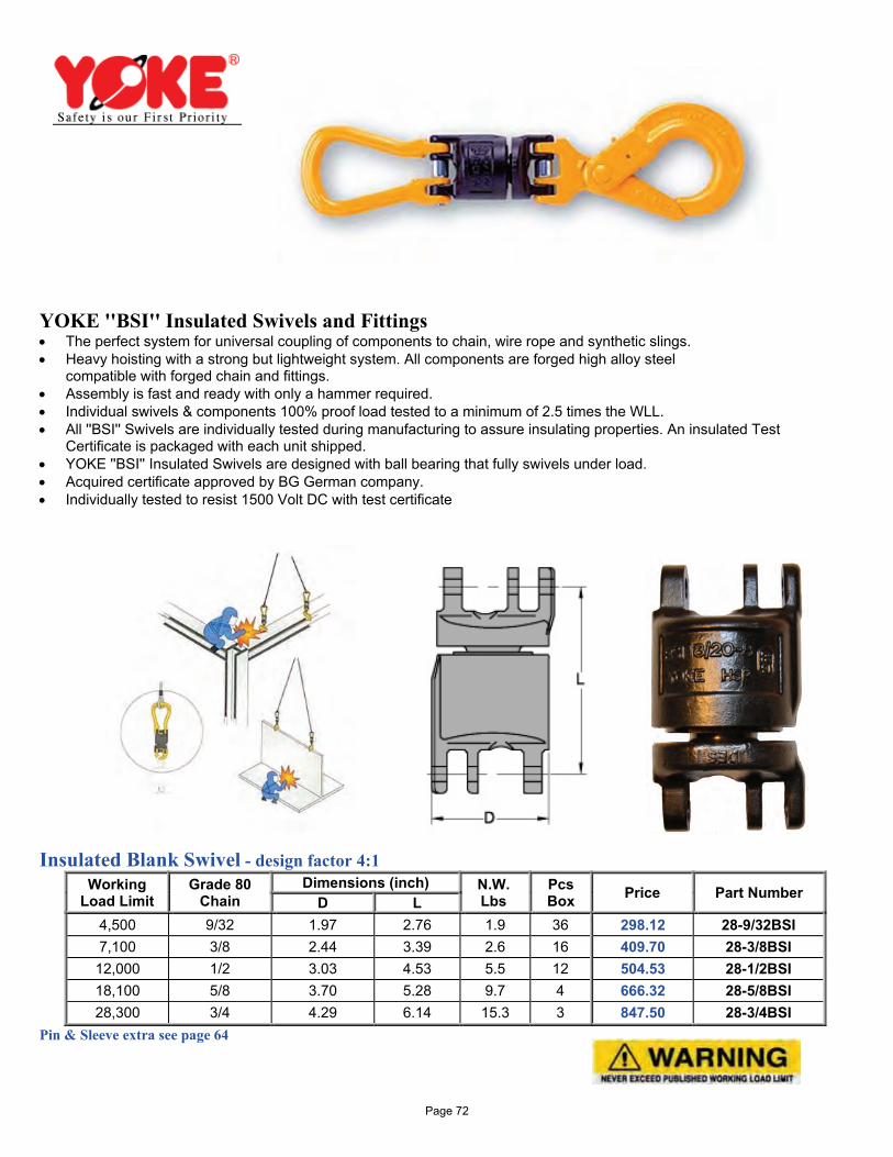
YOKE ''BSI'' Insulated Swivels and Fittings • The perfect system for universal coupling of components to chain, wire rope and synthetic slings. • Heavy hoisting with a strong but lightweight system. All components are forged high alloy steel
compatible with forged chain and fittings. • Assembly is fast and ready with only a hammer required. • Individual swivels & components 100% proof load tested to a minimum of 2.5 times the WLL. • All ''BSI'' Swivels are individually tested during manufacturing to assure insulating properties. An insulated Test
Certificate is packaged with each unit shipped. • YOKE ''BSI'' Insulated Swivels are designed with ball bearing that fully swivels under load. • Acquired certificate approved by BG German company. • Individually tested to resist 1500 Volt DC with test certificate
Insulated Blank Swivel - design factor 4:1
Working Load Limit
Grade 80 Chain
Dimensions (inch) N.W. Lbs
Pcs Box Price Part Number D L
4,500 9/32 1.97 2.76 1.9 36 298.12 28-9/32BSI 7,100 3/8 2.44 3.39 2.6 16 409.70 28-3/8BSI 12,000 1/2 3.03 4.53 5.5 12 504.53 28-1/2BSI 18,100 5/8 3.70 5.28 9.7 4 666.32 28-5/8BSI 28,300 3/4 4.29 6.14 15.3 3 847.50 28-3/4BSI
Pin & Sleeve extra see page 64
Page 72
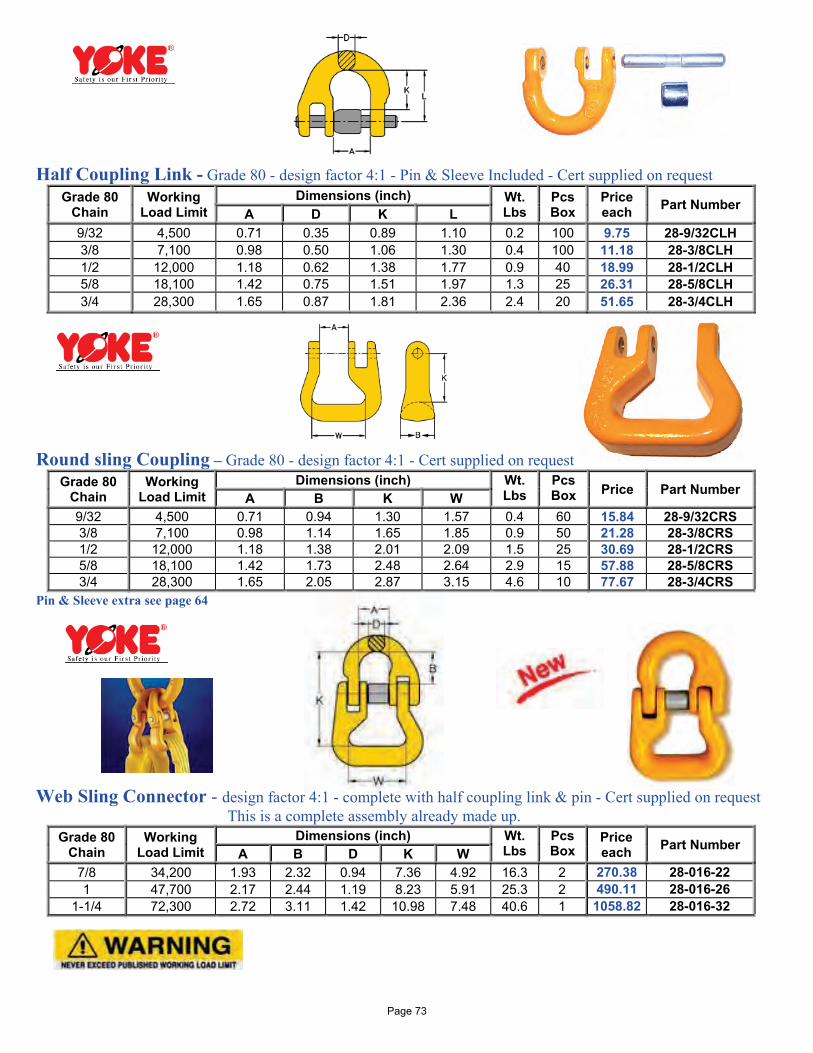
Half Coupling Link - Grade 80 - design factor 4:1 - Pin & Sleeve Included - Cert supplied on request
Grade 80 Chain
Working Load Limit
Dimensions (inch) Wt. Lbs
Pcs Box
Price each Part Number
A D K L 9/32 4,500 0.71 0.35 0.89 1.10 0.2 100 9.75 28-9/32CLH 3/8 7,100 0.98 0.50 1.06 1.30 0.4 100 11.18 28-3/8CLH 1/2 12,000 1.18 0.62 1.38 1.77 0.9 40 18.99 28-1/2CLH 5/8 18,100 1.42 0.75 1.51 1.97 1.3 25 26.31 28-5/8CLH 3/4 28,300 1.65 0.87 1.81 2.36 2.4 20 51.65 28-3/4CLH
Round sling Coupling – Grade 80 - design factor 4:1 - Cert supplied on request
Grade 80 Chain
Working Load Limit
Dimensions (inch) Wt. Lbs
Pcs Box Price Part Number A B K W
9/32 4,500 0.71 0.94 1.30 1.57 0.4 60 15.84 28-9/32CRS 3/8 7,100 0.98 1.14 1.65 1.85 0.9 50 21.28 28-3/8CRS 1/2 12,000 1.18 1.38 2.01 2.09 1.5 25 30.69 28-1/2CRS 5/8 18,100 1.42 1.73 2.48 2.64 2.9 15 57.88 28-5/8CRS 3/4 28,300 1.65 2.05 2.87 3.15 4.6 10 77.67 28-3/4CRS
Pin & Sleeve extra see page 64 Web Sling Connector - design factor 4:1 - complete with half coupling link & pin - Cert supplied on request This is a complete assembly already made up.
Grade 80 Chain
Working Load Limit
Dimensions (inch) Wt. Lbs
Pcs Box
Price each Part Number A B D K W
7/8 34,200 1.93 2.32 0.94 7.36 4.92 16.3 2 270.38 28-016-22 1 47,700 2.17 2.44 1.19 8.23 5.91 25.3 2 490.11 28-016-26
1-1/4 72,300 2.72 3.11 1.42 10.98 7.48 40.6 1 1058.82 28-016-32
Page 73
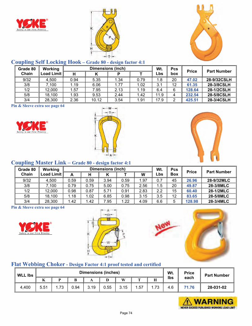
Coupling Self Locking Hook – Grade 80 - design factor 4:1
Grade 80 Chain
Working Load Limit
Dimensions (inch) Wt. Lbs
Pcs box Price Part Number H K P T
9/32 4,500 0.94 5.35 1.34 0.79 1.8 20 47.02 28-9/32CSLH 3/8 7,100 1.19 6.06 1.77 1.02 3.1 12 61.35 28-3/8CSLH 1/2 12,000 1.57 7.95 2.13 1.19 6.4 6 128.64 28-1/2CSLH 5/8 18,100 1.93 9.53 2.44 1.42 11.9 4 232.54 28-5/8CSLH 3/4 28,300 2.36 10.12 3.54 1.91 17.9 2 425.51 28-3/4CSLH
Pin & Sleeve extra see page 64 Coupling Master Link – Grade 80 - design factor 4:1
Grade 80 Chain
Working Load Limit
Dimensions (inch) Wt. Lbs
Pcs Box Price Part Number A H K T W
9/32 4,500 0.59 0.59 3.94 0.59 1.97 0.7 45 26.96 28-9/32MLC 3/8 7,100 0.79 0.75 5.00 0.75 2.56 1.5 20 49.87 28-3/8MLC 1/2 12,000 0.98 0.87 5.71 0.91 2.83 2.2 15 60.40 28-1/2MLC 5/8 18,100 1.18 1.02 6.85 0.98 3.15 3.5 12 83.65 28-5/8MLC 3/4 28,300 1.42 1.42 7.95 1.22 4.09 6.6 5 128.98 28-3/4MLC
Pin & Sleeve extra see page 64 Flat Webbing Choker - Design Factor 4:1 proof tested and certified
WLL lbs Dimensions (inches) Wt. lbs
Price each Part Number
K P B A D W T H
4,400 5.51 1.73 0.94 3.19 0.55 3.15 1.57 1.73 4.6 71.76 28-031-02
Page 74
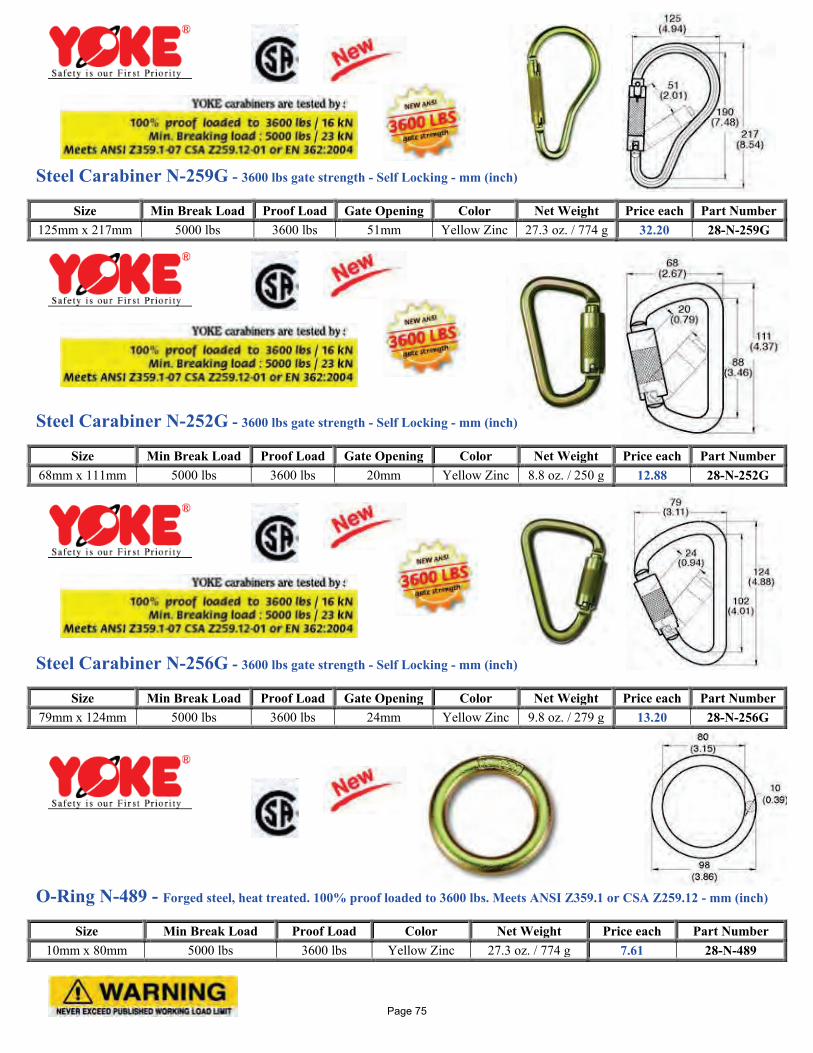
Steel Carabiner N-259G - 3600 lbs gate strength - Self Locking - mm (inch)
Steel Carabiner N-252G - 3600 lbs gate strength - Self Locking - mm (inch)
Steel Carabiner N-256G - 3600 lbs gate strength - Self Locking - mm (inch)
O-Ring N-489 - Forged steel, heat treated. 100% proof loaded to 3600 lbs. Meets ANSI Z359.1 or CSA Z259.12 - mm (inch)
Size Min Break Load Proof Load Gate Opening Color Net Weight Price each Part Number 125mm x 217mm 5000 lbs 3600 lbs 51mm Yellow Zinc 27.3 oz. / 774 g 32.20 28-N-259G
Size Min Break Load Proof Load Gate Opening Color Net Weight Price each Part Number 68mm x 111mm 5000 lbs 3600 lbs 20mm Yellow Zinc 8.8 oz. / 250 g 12.88 28-N-252G
Size Min Break Load Proof Load Gate Opening Color Net Weight Price each Part Number 79mm x 124mm 5000 lbs 3600 lbs 24mm Yellow Zinc 9.8 oz. / 279 g 13.20 28-N-256G
Size Min Break Load Proof Load Color Net Weight Price each Part Number 10mm x 80mm 5000 lbs 3600 lbs Yellow Zinc 27.3 oz. / 774 g 7.61 28-N-489
Page 75
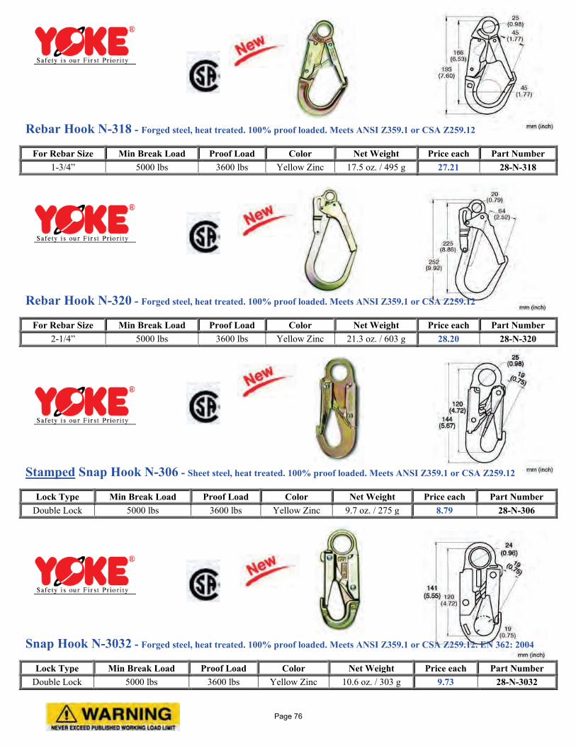
Rebar Hook N-318 - Forged steel, heat treated. 100% proof loaded. Meets ANSI Z359.1 or CSA Z259.12
Rebar Hook N-320 - Forged steel, heat treated. 100% proof loaded. Meets ANSI Z359.1 or CSA Z259.12
Stamped Snap Hook N-306 - Sheet steel, heat treated. 100% proof loaded. Meets ANSI Z359.1 or CSA Z259.12
Snap Hook N-3032 - Forged steel, heat treated. 100% proof loaded. Meets ANSI Z359.1 or CSA Z259.12. EN 362: 2004
For Rebar Size Min Break Load Proof Load Color Net Weight Price each Part Number 1-3/4” 5000 lbs 3600 lbs Yellow Zinc 17.5 oz. / 495 g 27.21 28-N-318
For Rebar Size Min Break Load Proof Load Color Net Weight Price each Part Number 2-1/4” 5000 lbs 3600 lbs Yellow Zinc 21.3 oz. / 603 g 28.20 28-N-320
Lock Type Min Break Load Proof Load Color Net Weight Price each Part Number Double Lock 5000 lbs 3600 lbs Yellow Zinc 9.7 oz. / 275 g 8.79 28-N-306
Lock Type Min Break Load Proof Load Color Net Weight Price each Part Number Double Lock 5000 lbs 3600 lbs Yellow Zinc 10.6 oz. / 303 g 9.73 28-N-3032
Page 76
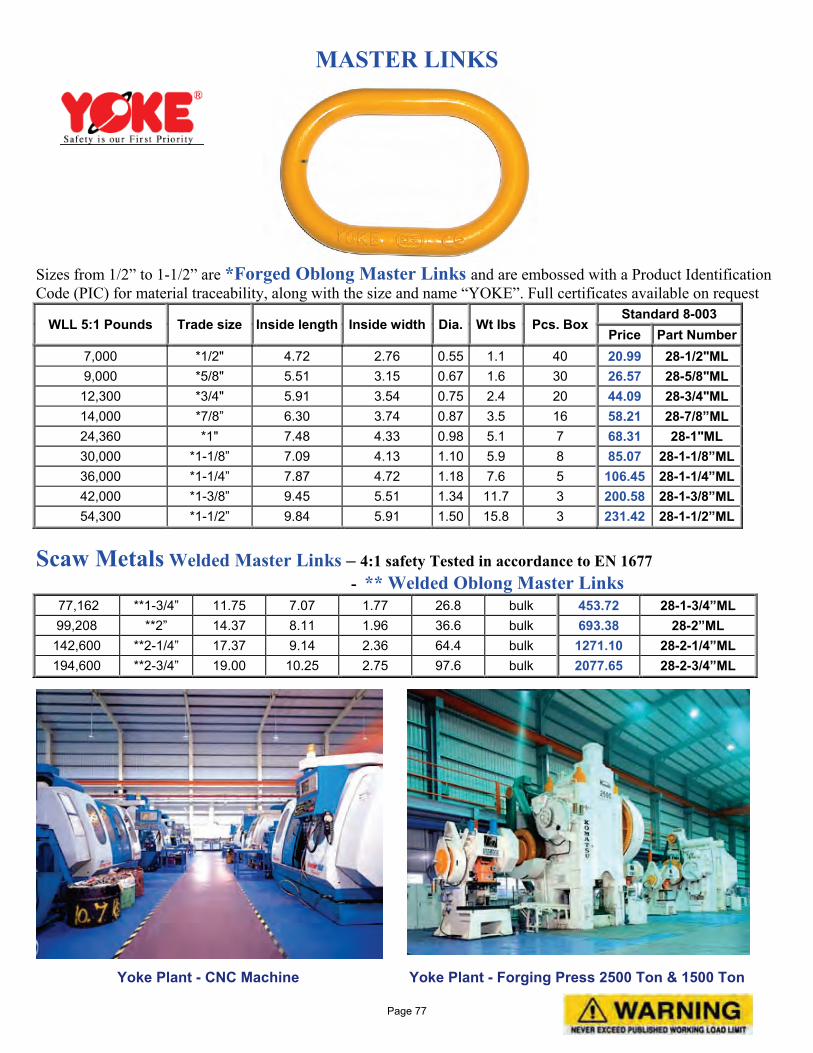
MASTER LINKS
Sizes from 1/2” to 1-1/2” are *Forged Oblong Master Links and are embossed with a Product Identification Code (PIC) for material traceability, along with the size and name “YOKE”. Full certificates available on request
WLL 5:1 Pounds Trade size Inside length Inside width Dia. Wt lbs Pcs. Box Standard 8-003
Price Part Number 7,000 *1/2" 4.72 2.76 0.55 1.1 40 20.99 28-1/2"ML 9,000 *5/8" 5.51 3.15 0.67 1.6 30 26.57 28-5/8"ML 12,300 *3/4" 5.91 3.54 0.75 2.4 20 44.09 28-3/4"ML 14,000 *7/8” 6.30 3.74 0.87 3.5 16 58.21 28-7/8”ML 24,360 *1" 7.48 4.33 0.98 5.1 7 68.31 28-1"ML 30,000 *1-1/8” 7.09 4.13 1.10 5.9 8 85.07 28-1-1/8”ML 36,000 *1-1/4” 7.87 4.72 1.18 7.6 5 106.45 28-1-1/4”ML 42,000 *1-3/8” 9.45 5.51 1.34 11.7 3 200.58 28-1-3/8”ML 54,300 *1-1/2” 9.84 5.91 1.50 15.8 3 231.42 28-1-1/2”ML
Scaw Metals Welded Master Links – 4:1 safety Tested in accordance to EN 1677 - ** Welded Oblong Master Links
77,162 **1-3/4” 11.75 7.07 1.77 26.8 bulk 453.72 28-1-3/4”ML 99,208 **2” 14.37 8.11 1.96 36.6 bulk 693.38 28-2”ML 142,600 **2-1/4” 17.37 9.14 2.36 64.4 bulk 1271.10 28-2-1/4”ML 194,600 **2-3/4” 19.00 10.25 2.75 97.6 bulk 2077.65 28-2-3/4”ML
Yoke Plant - CNC Machine Yoke Plant - Forging Press 2500 Ton & 1500 Ton
Page 77
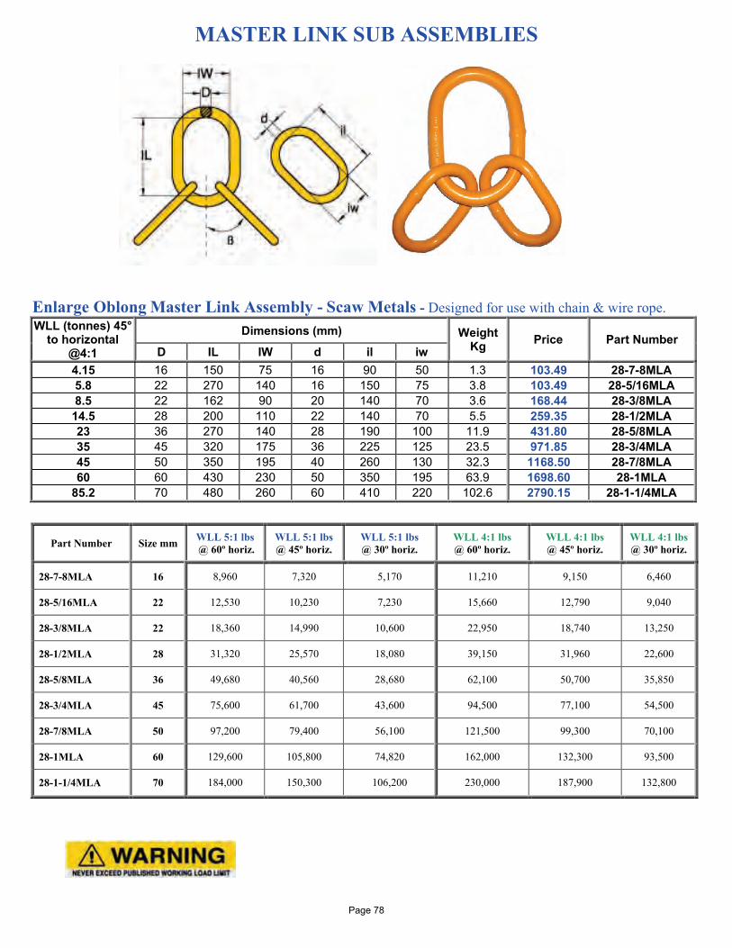
MASTER LINK SUB ASSEMBLIES
Enlarge Oblong Master Link Assembly - Scaw Metals - Designed for use with chain & wire rope. WLL (tonnes) 45°
to horizontal @4:1
Dimensions (mm) Weight Kg Price Part Number
D IL IW d il iw 4.15 16 150 75 16 90 50 1.3 103.49 28-7-8MLA 5.8 22 270 140 16 150 75 3.8 103.49 28-5/16MLA 8.5 22 162 90 20 140 70 3.6 168.44 28-3/8MLA 14.5 28 200 110 22 140 70 5.5 259.35 28-1/2MLA 23 36 270 140 28 190 100 11.9 431.80 28-5/8MLA 35 45 320 175 36 225 125 23.5 971.85 28-3/4MLA 45 50 350 195 40 260 130 32.3 1168.50 28-7/8MLA 60 60 430 230 50 350 195 63.9 1698.60 28-1MLA
85.2 70 480 260 60 410 220 102.6 2790.15 28-1-1/4MLA
Part Number Size mm WLL 5:1 lbs @ 60º horiz.
WLL 5:1 lbs @ 45º horiz.
WLL 5:1 lbs @ 30º horiz.
WLL 4:1 lbs @ 60º horiz.
WLL 4:1 lbs @ 45º horiz.
WLL 4:1 lbs @ 30º horiz.
28-7-8MLA 16 8,960 7,320 5,170 11,210 9,150 6,460
28-5/16MLA 22 12,530 10,230 7,230 15,660 12,790 9,040
28-3/8MLA 22 18,360 14,990 10,600 22,950 18,740 13,250
28-1/2MLA 28 31,320 25,570 18,080 39,150 31,960 22,600
28-5/8MLA 36 49,680 40,560 28,680 62,100 50,700 35,850
28-3/4MLA 45 75,600 61,700 43,600 94,500 77,100 54,500
28-7/8MLA 50 97,200 79,400 56,100 121,500 99,300 70,100
28-1MLA 60 129,600 105,800 74,820 162,000 132,300 93,500
28-1-1/4MLA 70 184,000 150,300 106,200 230,000 187,900 132,800
Page 78

Grade 80 and Grade 100 Chain Slings made to order! Simply call and tell us what size, type and grade you are looking for and we will get back to you right away with a competitive price. Chain slings are fully certified and proof tested. See Chain sling charts below for Working Load Limits. First symbol (basic type): S - Single chain sling C - Single choker chain sling with a standard end link on each end, no hooks D - Double branch chain sling T - Triple branch chain sling Q - Quadruple branch chain sling A - Proceeds symbol if shortening clutches are used Second symbol (type of master link or end link): O - Oblong master link of standard dimensions P - Pear shaped master link Third symbol (type of hook): S - Sling hook G - Grab hook F - Foundry hook
Grade 80 Chain Sling Working Load Limits Rated in pounds
Chain Grade 80 Size
Single Leg lbs Two Leg lbs Three and Four Leg lbs
inch mm 90° 60° 45° 30° 60° 45° 30° 7/32 6 2100 3600 3000 2500 6500 5300 3750
1/4~9/32 7 3500 6100 4900 3500 9100 7400 5200 5/16 8 4500 7800 6400 4500 11700 9500 6800 3/8 10 7100 12300 10000 7100 18400 15100 10600 1/2 13 12000 20800 17000 12000 31200 25500 18000 5/8 16 18100 31300 25600 18100 47000 38400 27100 3/4 20 28300 49000 40000 28300 73500 60000 42400 7/8 22 34200 59200 48400 34200 88900 72500 51300 1 26 47700 82600 67400 47700 123900 101200 71500
1-1/4 32 72300 125200 102200 72300 187800 153400 108400
Grade 100 Chain Sling Working Load Limits Rated in pounds
Chain Grade 100 Size
Single Leg lbs Two Leg lbs Three and Four Leg lbs
inch mm 90° 60° 45° 30° 60° 45° 30° 7/32 6 2700 4700 3800 2700 7000 5700 4000
1/4~9/32 7 4300 7400 6100 4300 11200 9100 6400 5/16 8 5700 9900 8100 5700 14800 12100 8500 3/8 10 8800 15200 12400 8800 22900 18700 13200 1/2 13 15000 26000 21200 15000 39000 31800 22500 5/8 16 22600 39100 32000 22600 58700 47900 33900 3/4 20 35300 61100 49900 35300 91700 74900 52950 7/8 22 42700 74000 60400 42700 110900 90600 64000
Page 79
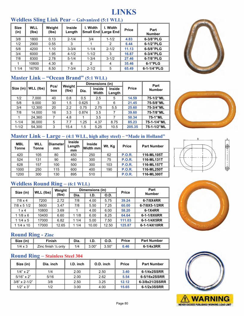
LINKS Weldless Sling Link Pear – Galvanized (5:1 WLL)
Size (in)
WLL (lbs)
Weight (lbs)
Inside Length
I. Width Small End
I. Width Large End Price
Part
Number 3/8 1800 0.13 2-1/4 3/4 1-1/2 4.83 6-3/8”PLG 1/2 2900 0.55 3 1 2 6.44 6-1/2”PLG 5/8 4200 1.10 3-3/4 1-1/4 2-1/2 11.13 6-5/8”PLG 3/4 6000 1.95 4-1/2 1-1/2 3 16.87 6-3/4”PLG 7/8 8300 2.78 5-1/4 1-3/4 3-1/2 27.46 6-7/8”PLG 1 10800 4.30 6 2 4 35.46 6-1”PLG
1 1/4 16750 8.50 7-3/4 2-1/2 5 65.49 6-1-1/4”PLG
Master Link – “Ocean Brand” (5:1 WLL)
Size (in) WLL (lbs) Pcs/ box
Weight (lbs)
Dimensions (in) Price
Part Number Dia. Inside
Width Inside Length
1/2 7,000 40 0.8 0.5 2.5 5 14.59 75-1/2”ML 5/8 9,000 30 1.5 0.625 3 6 21.45 75-5/8”ML 3/4 12,300 20 2.2 0.75 2.75 5.5 25.60 75-3/4”ML 7/8 14,000 16 3.3 0.874 3.5 7 39.60 75-7/8”ML 1 24,360 7 4.8 1 3.5 7 50.34 75-1”ML
1-1/4 36,000 5 7.7 1.25 4.37 8.75 85.23 75-1-1/4”ML 1-1/2 54,300 3 15.4 1.5 5.25 10.5 205.35 75-1-1/2”ML
Master Link – Large – (4:1 WLL, high alloy steel) – “Made in Holland” MBL
Tonne WLL
Tonne Diameter
mm Inside Length
mm Inside
Width mm Wt. Kg Price Part Number
420 105 80 450 250 62 P.O.R. 116-ML105T 524 131 90 460 300 75 P.O.R. 116-ML131T 628 157 100 500 300 103 P.O.R. 116-ML157T
1000 250 115 600 400 190 P.O.R. 116-ML250T 1200 300 130 895 510 P.O.R. 116-ML300T
Weldless Round Ring – (6:1 WLL)
Size (in) WLL (lbs) Weight (lbs)
Dimensions (in) Price
Part Number Dia. I.D. O.D.
7/8 x 4 7200 2.72 7/8 4.00 5.75 39.24 6-7/8X4RR 7/8 x 5 1/2 5600 3.47 7/8 5.50 7.25 60.00 6-7/8X5-1/2RR
1 x 4 10800 3.69 1 4.00 6.00 58.20 6-1X4RR 1 1/8 x 6 10400 6.60 1 1/8 6.00 8.25 64.64 6-1-1/8X6RR 1 1/4 x 5 17000 6.82 1 1/4 5.00 7.50 111.03 6-1-1/4X5RR
1 1/4 x 10 17000 12.65 1 1/4 10.00 12.50 125.87 6-1-1/4X10RR
Round Ring - Zinc Size (in) Finish Dia. I.D. O.D. Price Part Number 1/4 x 3 Zinc finish ¼ only 1/4 3.00” 3.50” 0.46 6-1/4x3RR
Round Ring – Stainless Steel 304 Size (in) Dia. inch I.D. inch O.D. inch Price Part Number
1/4” x 2” 1/4 2.00 2.50 3.40 6-1/4x2SSRR 5/16” x 2” 5/16 2.00 2.62 5.54 6-5/16x2SSRR
3/8” x 2-1/2” 3/8 2.50 3.25 12.12 6-3/8x21/2SSRR 1/2” x 3” 1/2 3.00 4.00 15.65 6-1/2x3SSRR
Page 80
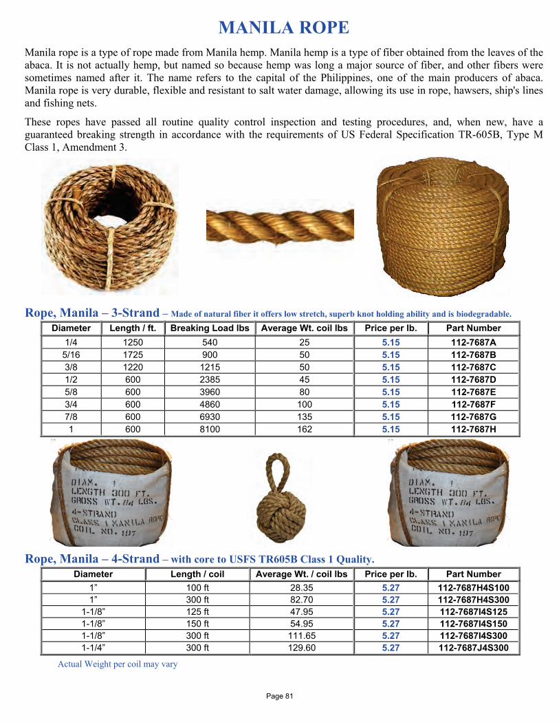
MANILA ROPE
Manila rope is a type of rope made from Manila hemp. Manila hemp is a type of fiber obtained from the leaves of the abaca. It is not actually hemp, but named so because hemp was long a major source of fiber, and other fibers were sometimes named after it. The name refers to the capital of the Philippines, one of the main producers of abaca. Manila rope is very durable, flexible and resistant to salt water damage, allowing its use in rope, hawsers, ship's lines and fishing nets.
These ropes have passed all routine quality control inspection and testing procedures, and, when new, have a guaranteed breaking strength in accordance with the requirements of US Federal Specification TR-605B, Type M Class 1, Amendment 3. Rope, Manila – 3-Strand – Made of natural fiber it offers low stretch, superb knot holding ability and is biodegradable.
Diameter Length / ft. Breaking Load lbs Average Wt. coil lbs Price per lb. Part Number 1/4 1250 540 25 5.15 112-7687A 5/16 1725 900 50 5.15 112-7687B 3/8 1220 1215 50 5.15 112-7687C 1/2 600 2385 45 5.15 112-7687D 5/8 600 3960 80 5.15 112-7687E 3/4 600 4860 100 5.15 112-7687F 7/8 600 6930 135 5.15 112-7687G 1 600 8100 162 5.15 112-7687H
Rope, Manila – 4-Strand – with core to USFS TR605B Class 1 Quality.
Diameter Length / coil Average Wt. / coil lbs Price per lb. Part Number 1” 100 ft 28.35 5.27 112-7687H4S100 1” 300 ft 82.70 5.27 112-7687H4S300
1-1/8” 125 ft 47.95 5.27 112-7687I4S125 1-1/8” 150 ft 54.95 5.27 112-7687I4S150 1-1/8” 300 ft 111.65 5.27 112-7687I4S300 1-1/4” 300 ft 129.60 5.27 112-7687J4S300
Actual Weight per coil may vary
Page 81
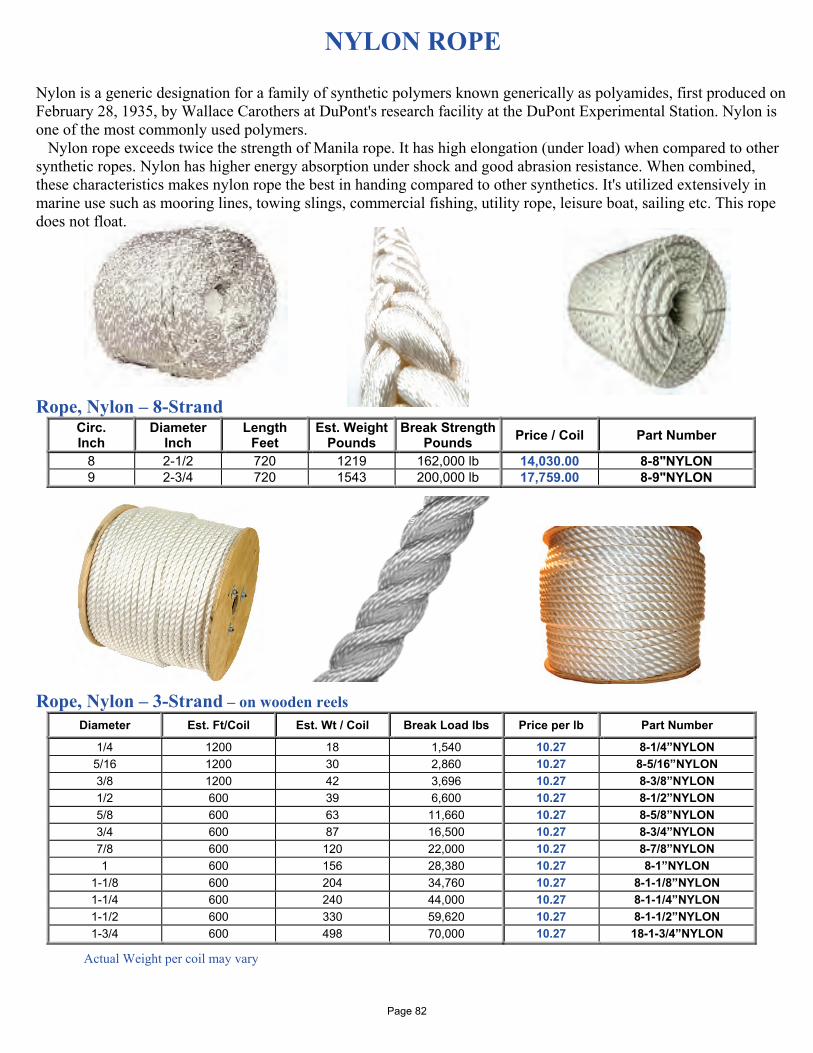
NYLON ROPE
Nylon is a generic designation for a family of synthetic polymers known generically as polyamides, first produced on February 28, 1935, by Wallace Carothers at DuPont's research facility at the DuPont Experimental Station. Nylon is one of the most commonly used polymers. Nylon rope exceeds twice the strength of Manila rope. It has high elongation (under load) when compared to other synthetic ropes. Nylon has higher energy absorption under shock and good abrasion resistance. When combined, these characteristics makes nylon rope the best in handing compared to other synthetics. It's utilized extensively in marine use such as mooring lines, towing slings, commercial fishing, utility rope, leisure boat, sailing etc. This rope does not float. Rope, Nylon – 8-Strand
Circ. Inch
Diameter Inch
Length Feet
Est. Weight Pounds
Break Strength Pounds Price / Coil Part Number
8 2-1/2 720 1219 162,000 lb 14,030.00 8-8"NYLON 9 2-3/4 720 1543 200,000 lb 17,759.00 8-9"NYLON
Rope, Nylon – 3-Strand – on wooden reels
Diameter Est. Ft/Coil Est. Wt / Coil Break Load lbs Price per lb Part Number
1/4 1200 18 1,540 10.27 8-1/4”NYLON 5/16 1200 30 2,860 10.27 8-5/16”NYLON 3/8 1200 42 3,696 10.27 8-3/8”NYLON 1/2 600 39 6,600 10.27 8-1/2”NYLON 5/8 600 63 11,660 10.27 8-5/8”NYLON 3/4 600 87 16,500 10.27 8-3/4”NYLON 7/8 600 120 22,000 10.27 8-7/8”NYLON 1 600 156 28,380 10.27 8-1”NYLON
1-1/8 600 204 34,760 10.27 8-1-1/8”NYLON 1-1/4 600 240 44,000 10.27 8-1-1/4”NYLON 1-1/2 600 330 59,620 10.27 8-1-1/2”NYLON 1-3/4 600 498 70,000 10.27 18-1-3/4”NYLON
Actual Weight per coil may vary
Page 82
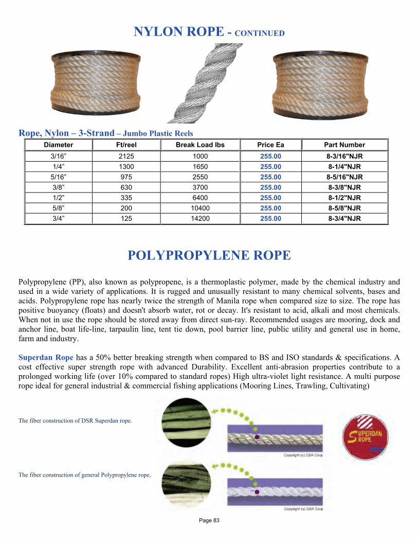
NYLON ROPE - CONTINUED
Rope, Nylon – 3-Strand – Jumbo Plastic Reels
Diameter Ft/reel Break Load lbs Price Ea Part Number 3/16” 2125 1000 255.00 8-3/16"NJR 1/4” 1300 1650 255.00 8-1/4"NJR
5/16” 975 2550 255.00 8-5/16"NJR 3/8” 630 3700 255.00 8-3/8"NJR 1/2” 335 6400 255.00 8-1/2"NJR 5/8” 200 10400 255.00 8-5/8"NJR 3/4” 125 14200 255.00 8-3/4"NJR
POLYPROPYLENE ROPE
Polypropylene (PP), also known as polypropene, is a thermoplastic polymer, made by the chemical industry and used in a wide variety of applications. It is rugged and unusually resistant to many chemical solvents, bases and acids. Polypropylene rope has nearly twice the strength of Manila rope when compared size to size. The rope has positive buoyancy (floats) and doesn't absorb water, rot or decay. It's resistant to acid, alkali and most chemicals. When not in use the rope should be stored away from direct sun-ray. Recommended usages are mooring, dock and anchor line, boat life-line, tarpaulin line, tent tie down, pool barrier line, public utility and general use in home, farm and industry. Superdan Rope has a 50% better breaking strength when compared to BS and ISO standards & specifications. A cost effective super strength rope with advanced Durability. Excellent anti-abrasion properties contribute to a prolonged working life (over 10% compared to standard ropes) High ultra-violet light resistance. A multi purpose rope ideal for general industrial & commercial fishing applications (Mooring Lines, Trawling, Cultivating) The fiber construction of DSR Superdan rope. The fiber construction of general Polypropylene rope. Page 83
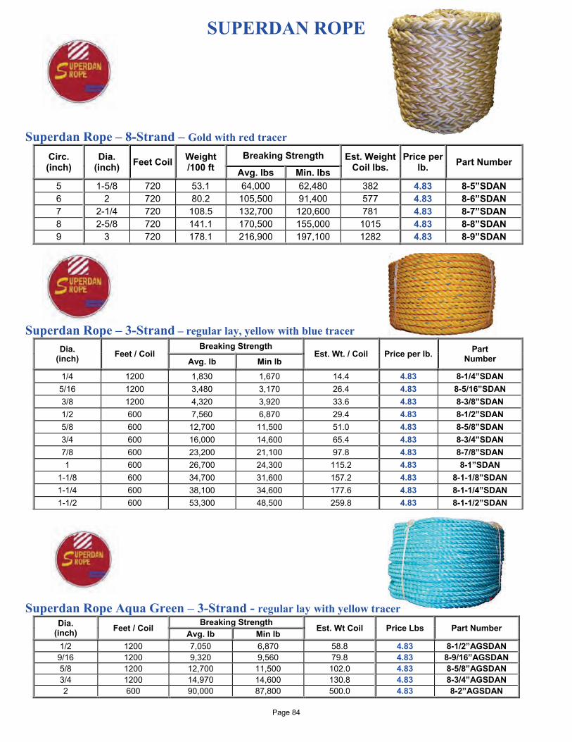
SUPERDAN ROPE Superdan Rope – 8-Strand – Gold with red tracer
Circ. (inch)
Dia. (inch) Feet Coil Weight
/100 ft Breaking Strength Est. Weight
Coil lbs. Price per
lb. Part Number Avg. lbs Min. lbs
5 1-5/8 720 53.1 64,000 62,480 382 4.83 8-5”SDAN 6 2 720 80.2 105,500 91,400 577 4.83 8-6”SDAN 7 2-1/4 720 108.5 132,700 120,600 781 4.83 8-7”SDAN 8 2-5/8 720 141.1 170,500 155,000 1015 4.83 8-8”SDAN 9 3 720 178.1 216,900 197,100 1282 4.83 8-9”SDAN
Superdan Rope – 3-Strand – regular lay, yellow with blue tracer
Dia. (inch) Feet / Coil
Breaking Strength Est. Wt. / Coil Price per lb. Part
Number Avg. lb Min lb
1/4 1200 1,830 1,670 14.4 4.83 8-1/4”SDAN 5/16 1200 3,480 3,170 26.4 4.83 8-5/16”SDAN 3/8 1200 4,320 3,920 33.6 4.83 8-3/8”SDAN 1/2 600 7,560 6,870 29.4 4.83 8-1/2”SDAN 5/8 600 12,700 11,500 51.0 4.83 8-5/8”SDAN 3/4 600 16,000 14,600 65.4 4.83 8-3/4”SDAN 7/8 600 23,200 21,100 97.8 4.83 8-7/8”SDAN 1 600 26,700 24,300 115.2 4.83 8-1”SDAN
1-1/8 600 34,700 31,600 157.2 4.83 8-1-1/8”SDAN 1-1/4 600 38,100 34,600 177.6 4.83 8-1-1/4”SDAN 1-1/2 600 53,300 48,500 259.8 4.83 8-1-1/2”SDAN
Superdan Rope Aqua Green – 3-Strand - regular lay with yellow tracer
Dia. (inch) Feet / Coil
Breaking Strength Est. Wt Coil Price Lbs Part Number
Avg. lb Min lb 1/2 1200 7,050 6,870 58.8 4.83 8-1/2”AGSDAN
9/16 1200 9,320 9,560 79.8 4.83 8-9/16”AGSDAN 5/8 1200 12,700 11,500 102.0 4.83 8-5/8”AGSDAN 3/4 1200 14,970 14,600 130.8 4.83 8-3/4”AGSDAN 2 600 90,000 87,800 500.0 4.83 8-2”AGSDAN
Page 84
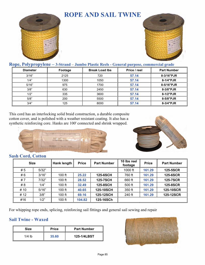
ROPE AND SAIL TWINE Rope, Polypropylene – 3-Strand – Jumbo Plastic Reels - General purpose, commercial grade
Diameter Footage Break Load lbs Price / reel Part Number 3/16” 2125 720 57.14 8-3/16"PJR 1/4” 1300 1050 57.14 8-1/4"PJR
5/16” 975 1700 57.14 8-5/16"PJR 3/8” 630 2450 57.14 8-3/8"PJR 1/2” 335 3600 57.14 8-1/2"PJR 5/8” 200 5500 57.14 8-5/8"PJR 3/4” 125 8000 57.14 8-3/4"PJR
This cord has an interlocking solid braid construction, a durable composite cotton cover, and is polished with a weather resistant coating. It also has a synthetic reinforcing core. Hanks are 100' connected and shrink wrapped. Sash Cord, Cotton
Size Hank length Price Part Number 10 lbs reel footage Price Part Number
# 5 5/32” 1000 ft 161.29 125-5SCR # 6 3/16” 100 ft 25.22 125-6SCH 760 ft 161.29 125-6SCR # 7 7/32” 100 ft 28.52 125-7SCH 660 ft 161.29 125-7SCR # 8 1/4” 100 ft 32.49 125-8SCH 500 ft 161.29 125-8SCR # 10 5/16” 100 ft 40.65 125-10SCH 350 ft 161.29 125-10SCR # 12 3/8” 100 ft 69.16 125-12SCH 240 ft 161.29 125-12SCR #16 1/2” 100 ft 104.82 125-16SCh
For whipping rope ends, splicing, reinforcing sail fittings and general sail sewing and repair Sail Twine - Waxed
Size Price Part Number
1/4 lb 35.60 125-1/4LBST
Page 85
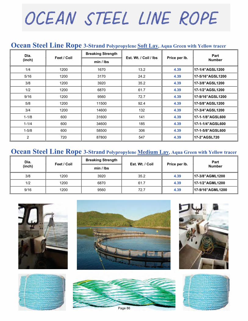
Ocean Steel Line Rope 3-Strand Polypropylene Soft Lay, Aqua Green with Yellow tracer
Dia. (inch) Feet / Coil
Breaking Strength Est. Wt. / Coil / lbs Price per lb. Part
Number min / lbs
1/4 1200 1670 13.2 4.39 17-1/4”AGSL1200
5/16 1200 3170 24.2 4.39 17-5/16”AGSL1200
3/8 1200 3920 35.2 4.39 17-3/8”AGSL1200
1/2 1200 6870 61.7 4.39 17-1/2”AGSL1200
9/16 1200 9560 72.7 4.39 17-9/16”AGSL1200
5/8 1200 11500 92.4 4.39 17-5/8”AGSL1200
3/4 1200 14600 132 4.39 17-3/4”AGSL1200
1-1/8 600 31600 141 4.39 17-1-1/8”AGSL600
1-1/4 600 34600 185 4.39 17-1-1/4”AGSL600
1-5/8 600 58500 306 4.39 17-1-5/8”AGSL600
2 720 87800 547 4.39 17-2”AGSL720
Ocean Steel Line Rope 3-Strand Polypropylene Medium Lay, Aqua Green with Yellow tracer
Dia. (inch) Feet / Coil
Breaking Strength Est. Wt. / Coil Price per lb. Part
Number min / lbs
3/8 1200 3920 35.2 4.39 17-3/8”AGML1200
1/2 1200 6870 61.7 4.39 17-1/2”AGML1200
9/16 1200 9560 72.7 4.39 17-9/16”AGML1200
Page 86
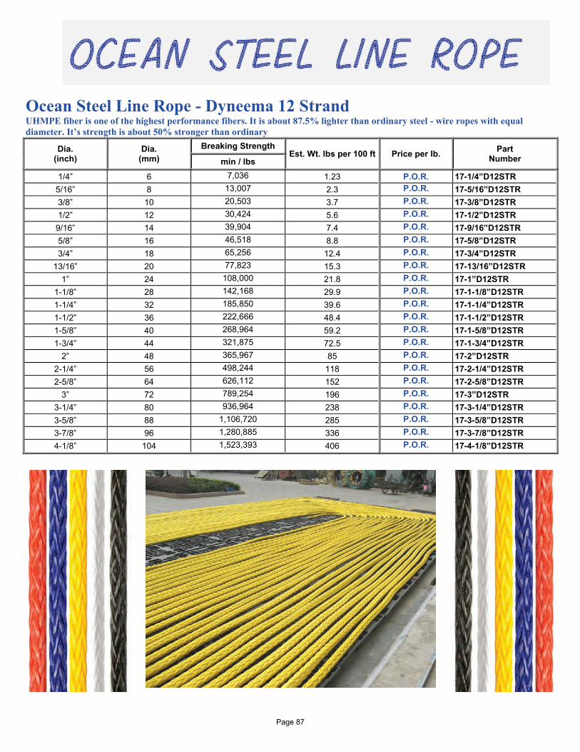
Ocean Steel Line Rope - Dyneema 12 Strand UHMPE fiber is one of the highest performance fibers. It is about 87.5% lighter than ordinary steel - wire ropes with equal diameter. It’s strength is about 50% stronger than ordinary
Dia. (inch)
Dia. (mm)
Breaking Strength Est. Wt. lbs per 100 ft Price per lb. Part
Number min / lbs
1/4” 6 7,036 1.23 P.O.R. 17-1/4”D12STR 5/16” 8 13,007 2.3 P.O.R. 17-5/16”D12STR 3/8” 10 20,503 3.7 P.O.R. 17-3/8”D12STR 1/2” 12 30,424 5.6 P.O.R. 17-1/2”D12STR
9/16” 14 39,904 7.4 P.O.R. 17-9/16”D12STR 5/8” 16 46,518 8.8 P.O.R. 17-5/8”D12STR 3/4” 18 65,256 12.4 P.O.R. 17-3/4”D12STR
13/16” 20 77,823 15.3 P.O.R. 17-13/16”D12STR 1” 24 108,000 21.8 P.O.R. 17-1”D12STR
1-1/8” 28 142,168 29.9 P.O.R. 17-1-1/8”D12STR 1-1/4” 32 185,850 39.6 P.O.R. 17-1-1/4”D12STR 1-1/2” 36 222,666 48.4 P.O.R. 17-1-1/2”D12STR 1-5/8” 40 268,964 59.2 P.O.R. 17-1-5/8”D12STR 1-3/4” 44 321,875 72.5 P.O.R. 17-1-3/4”D12STR
2” 48 365,967 85 P.O.R. 17-2”D12STR 2-1/4” 56 498,244 118 P.O.R. 17-2-1/4”D12STR 2-5/8” 64 626,112 152 P.O.R. 17-2-5/8”D12STR
3” 72 789,254 196 P.O.R. 17-3”D12STR 3-1/4” 80 936,964 238 P.O.R. 17-3-1/4”D12STR 3-5/8” 88 1,106,720 285 P.O.R. 17-3-5/8”D12STR 3-7/8” 96 1,280,885 336 P.O.R. 17-3-7/8”D12STR 4-1/8” 104 1,523,393 406 P.O.R. 17-4-1/8”D12STR
Page 87
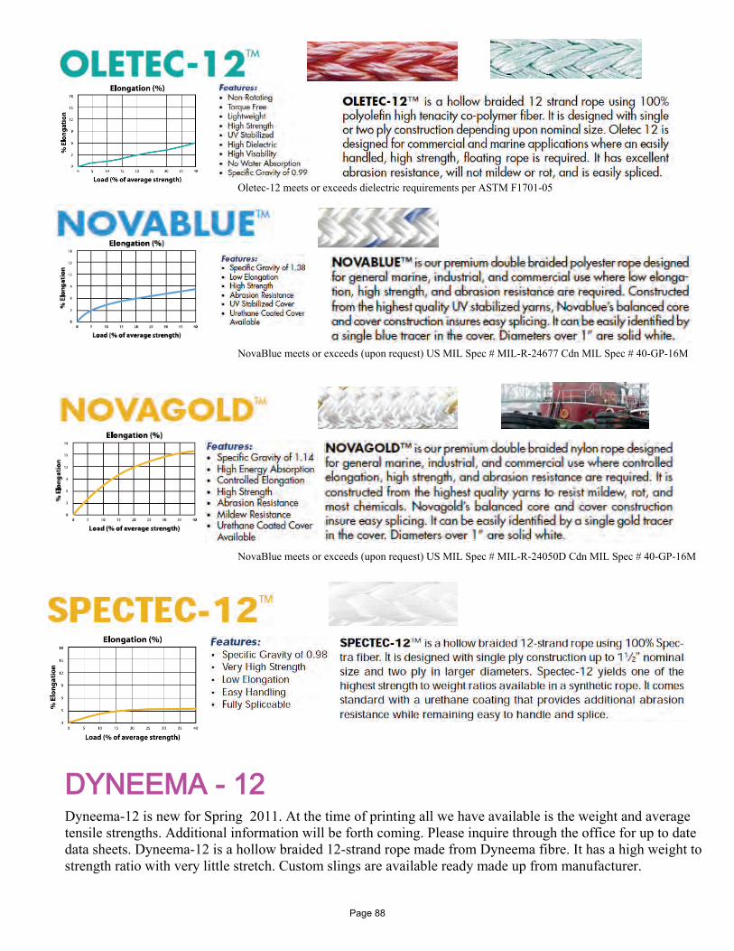
Oletec-12 meets or exceeds dielectric requirements per ASTM F1701-05
NovaBlue meets or exceeds (upon request) US MIL Spec # MIL-R-24677 Cdn MIL Spec # 40-GP-16M
NovaBlue meets or exceeds (upon request) US MIL Spec # MIL-R-24050D Cdn MIL Spec # 40-GP-16M
DYNEEMA - 12 Dyneema-12 is new for Spring 2011. At the time of printing all we have available is the weight and average tensile strengths. Additional information will be forth coming. Please inquire through the office for up to date data sheets. Dyneema-12 is a hollow braided 12-strand rope made from Dyneema fibre. It has a high weight to strength ratio with very little stretch. Custom slings are available ready made up from manufacturer.
Page 88
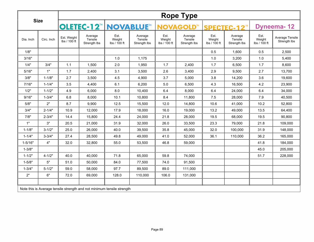
Size Rope Type
Dyneema- 12
Dia. Inch Circ. Inch Est. Weight lbs / 100 ft
Average Tensile
Strength lbs
Est. Weight
lbs / 100 ft
Average Tensile
Strength lbs
Est. Weight
lbs / 100 ft
Average Tensile
Strength lbs
Est. Weight
lbs / 100 ft
Average Tensile
Strength lbs
Est. Weight
lbs / 100 ft
Average Tensile Strength lbs
1/8" 0.5 1,600 0.5 2,500
3/16" 1.0 1,175 1.0 3,200 1.0 5,400
1/4" 3/4" 1.1 1,500 2.0 1,950 1.7 2,400 1.7 6,500 1.7 8,600
5/16" 1" 1.7 2,400 3.1 3,500 2.6 3,400 2.9 9,500 2.7 13,700
3/8" 1-1/8" 2.7 3,500 4.5 4,900 3.7 5,000 3.8 14,200 3.6 19,600
7/16" 1-1/4" 3.5 4,400 6.1 6,200 5.0 6,500 4.3 16,500 4.2 23,900
1/2" 1-1/2" 4.9 6,000 8.0 10,400 6.4 8,000 6.4 24,000 6.4 34,000
9/16" 1-3/4" 6.8 8,000 10.1 10,800 8.4 11,800 7.5 28,000 7.9 40,500
5/8" 2" 8.7 9,900 12.5 15,500 12.0 14,800 10.6 41,000 10.2 52,800
3/4" 2-1/4" 10.9 12,000 17.9 18,000 16.0 19,000 13.2 49,000 13.5 64,400
7/8" 2-3/4" 14.4 15,800 24.4 24,000 21.8 28,000 19.5 68,000 19.5 90,800
1" 3" 20.5 21,000 31.9 32,000 26.0 33,500 23.3 79,000 21.8 109,000
1-1/8" 3-1/2" 25.0 26,000 40.0 39,500 35.8 45,000 32.0 100,000 31.9 148,000
1-1/4" 3-3/4" 27.4 28,500 49.8 49,000 41.0 52,000 36.1 110,000 36.2 165,000
1-5/16" 4" 32.0 32,800 55.0 53,500 46.8 59,000 41.8 184,000
1-3/8" 45.0 205,000
1-1/2" 4-1/2" 40.0 40,000 71.8 65,000 59.8 74,000 51.7 228,000
1-5/8" 5" 51.0 50,000 84.0 77,500 74.0 91,500
1-3/4" 5-1/2" 59.0 58,000 97.7 89,500 89.0 111,000
2" 6" 72.0 69,000 128.0 110,000 106.0 131,000
Note this is Average tensile strength and not minimum tensile strength
Page 89
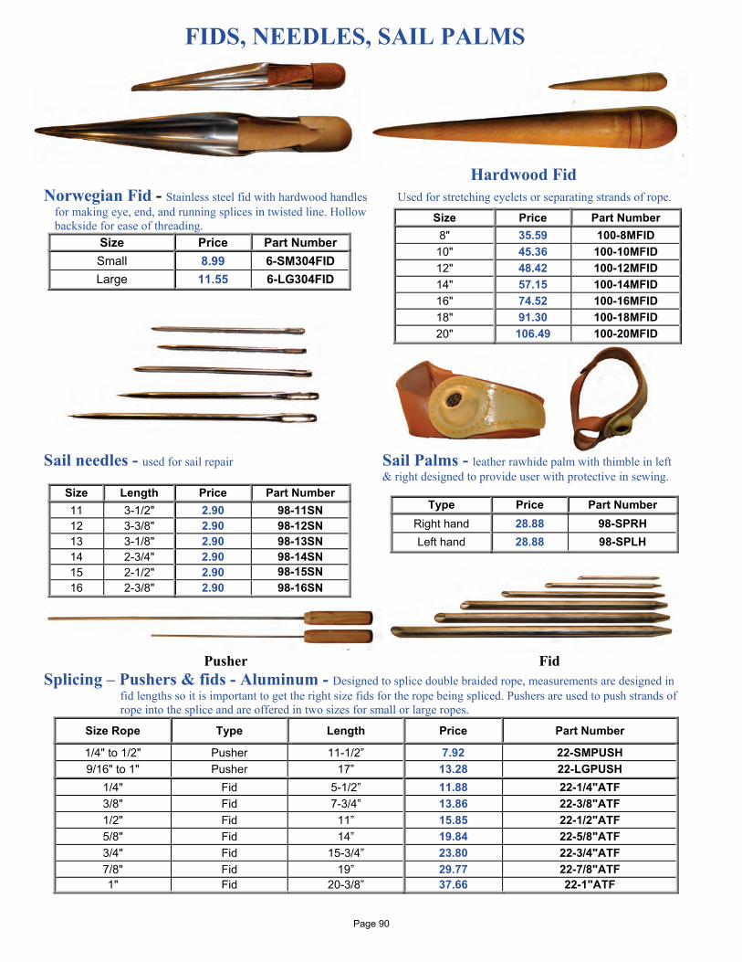
FIDS, NEEDLES, SAIL PALMS
Hardwood Fid
Norwegian Fid - Stainless steel fid with hardwood handles Used for stretching eyelets or separating strands of rope. for making eye, end, and running splices in twisted line. Hollow backside for ease of threading.
Size Price Part Number Small 8.99 6-SM304FID Large 11.55 6-LG304FID
Sail needles - used for sail repair Sail Palms - leather rawhide palm with thimble in left & right designed to provide user with protective in sewing.
Size Length Price Part Number 11 3-1/2" 2.90 98-11SN 12 3-3/8" 2.90 98-12SN 13 3-1/8" 2.90 98-13SN 14 2-3/4" 2.90 98-14SN 15 2-1/2" 2.90 98-15SN 16 2-3/8" 2.90 98-16SN
Pusher Fid
Splicing – Pushers & fids - Aluminum - Designed to splice double braided rope, measurements are designed in fid lengths so it is important to get the right size fids for the rope being spliced. Pushers are used to push strands of rope into the splice and are offered in two sizes for small or large ropes.
Size Rope Type Length Price Part Number
1/4" to 1/2" Pusher 11-1/2” 7.92 22-SMPUSH 9/16" to 1" Pusher 17” 13.28 22-LGPUSH
1/4" Fid 5-1/2” 11.88 22-1/4"ATF 3/8" Fid 7-3/4” 13.86 22-3/8"ATF 1/2" Fid 11” 15.85 22-1/2"ATF 5/8" Fid 14” 19.84 22-5/8"ATF 3/4" Fid 15-3/4” 23.80 22-3/4"ATF 7/8" Fid 19” 29.77 22-7/8"ATF 1" Fid 20-3/8” 37.66 22-1"ATF
Size Price Part Number 8" 35.59 100-8MFID
10" 45.36 100-10MFID 12" 48.42 100-12MFID 14" 57.15 100-14MFID 16" 74.52 100-16MFID 18" 91.30 100-18MFID 20" 106.49 100-20MFID
Type Price Part Number Right hand 28.88 98-SPRH Left hand 28.88 98-SPLH
Page 90
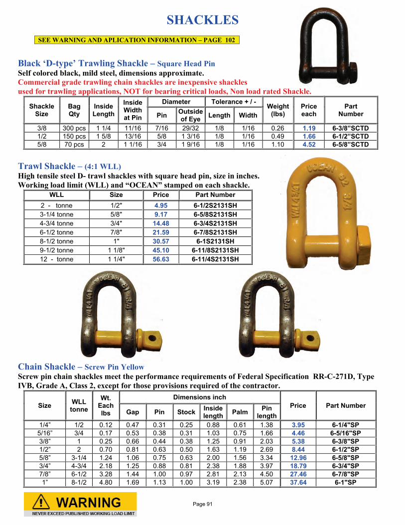
SHACKLES
Black ‘D-type’ Trawling Shackle – Square Head Pin Self colored black, mild steel, dimensions approximate. Commercial grade trawling chain shackles are inexpensive shackles used for trawling applications, NOT for bearing critical loads, Non load rated Shackle.
Shackle Size
Bag Qty
Inside Length
Inside Width at Pin
Diameter Tolerance + / - Weight (lbs)
Price each
Part Number Pin Outside
of Eye Length Width
3/8 300 pcs 1 1/4 11/16 7/16 29/32 1/8 1/16 0.26 1.19 6-3/8”SCTD 1/2 150 pcs 1 5/8 13/16 5/8 1 3/16 1/8 1/16 0.49 1.66 6-1/2”SCTD 5/8 70 pcs 2 1 1/16 3/4 1 9/16 1/8 1/16 1.10 4.52 6-5/8”SCTD
Trawl Shackle – (4:1 WLL) High tensile steel D- trawl shackles with square head pin, size in inches. Working load limit (WLL) and “OCEAN” stamped on each shackle.
WLL Size Price Part Number 2 - tonne 1/2" 4.95 6-1/2S2131SH 3-1/4 tonne 5/8" 9.17 6-5/8S2131SH 4-3/4 tonne 3/4" 14.48 6-3/4S2131SH 6-1/2 tonne 7/8" 21.59 6-7/8S2131SH 8-1/2 tonne 1" 30.57 6-1S2131SH 9-1/2 tonne 1 1/8" 45.10 6-11/8S2131SH 12 - tonne 1 1/4" 56.63 6-11/4S2131SH
Chain Shackle – Screw Pin Yellow Screw pin chain shackles meet the performance requirements of Federal Specification RR-C-271D, Type IVB, Grade A, Class 2, except for those provisions required of the contractor.
Size WLL tonne
Wt. Each lbs
Dimensions inch Price Part Number
Gap Pin Stock Inside length Palm Pin
length 1/4” 1/2 0.12 0.47 0.31 0.25 0.88 0.61 1.38 3.95 6-1/4"SP
5/16” 3/4 0.17 0.53 0.38 0.31 1.03 0.75 1.66 4.46 6-5/16"SP 3/8” 1 0.25 0.66 0.44 0.38 1.25 0.91 2.03 5.38 6-3/8"SP 1/2” 2 0.70 0.81 0.63 0.50 1.63 1.19 2.69 8.44 6-1/2"SP 5/8” 3-1/4 1.24 1.06 0.75 0.63 2.00 1.56 3.34 12.96 6-5/8"SP 3/4” 4-3/4 2.18 1.25 0.88 0.81 2.38 1.88 3.97 18.79 6-3/4"SP 7/8” 6-1/2 3.28 1.44 1.00 0.97 2.81 2.13 4.50 27.46 6-7/8"SP 1” 8-1/2 4.80 1.69 1.13 1.00 3.19 2.38 5.07 37.64 6-1"SP
SEE WARNING AND APLICATION INFORMATION – PAGE 102
Page 91
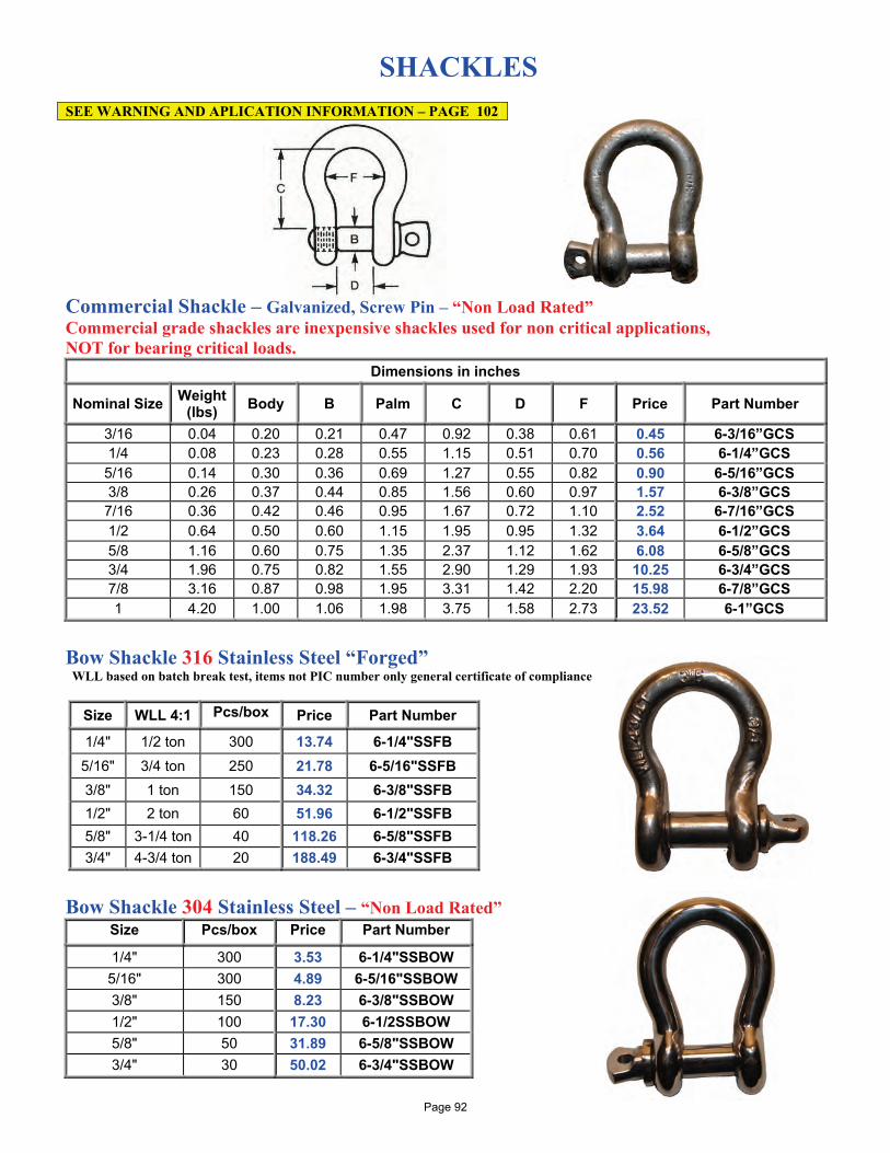
SHACKLES
Commercial Shackle – Galvanized, Screw Pin – “Non Load Rated” Commercial grade shackles are inexpensive shackles used for non critical applications, NOT for bearing critical loads.
Dimensions in inches
Nominal Size Weight (lbs) Body B Palm C D F Price Part Number
3/16 0.04 0.20 0.21 0.47 0.92 0.38 0.61 0.45 6-3/16”GCS 1/4 0.08 0.23 0.28 0.55 1.15 0.51 0.70 0.56 6-1/4”GCS 5/16 0.14 0.30 0.36 0.69 1.27 0.55 0.82 0.90 6-5/16”GCS 3/8 0.26 0.37 0.44 0.85 1.56 0.60 0.97 1.57 6-3/8”GCS 7/16 0.36 0.42 0.46 0.95 1.67 0.72 1.10 2.52 6-7/16”GCS 1/2 0.64 0.50 0.60 1.15 1.95 0.95 1.32 3.64 6-1/2”GCS 5/8 1.16 0.60 0.75 1.35 2.37 1.12 1.62 6.08 6-5/8”GCS 3/4 1.96 0.75 0.82 1.55 2.90 1.29 1.93 10.25 6-3/4”GCS 7/8 3.16 0.87 0.98 1.95 3.31 1.42 2.20 15.98 6-7/8”GCS 1 4.20 1.00 1.06 1.98 3.75 1.58 2.73 23.52 6-1”GCS
Bow Shackle 316 Stainless Steel “Forged”
WLL based on batch break test, items not PIC number only general certificate of compliance
Bow Shackle 304 Stainless Steel – “Non Load Rated”
Size Pcs/box Price Part Number
1/4" 300 3.53 6-1/4"SSBOW 5/16" 300 4.89 6-5/16"SSBOW 3/8" 150 8.23 6-3/8"SSBOW 1/2" 100 17.30 6-1/2SSBOW 5/8" 50 31.89 6-5/8"SSBOW 3/4" 30 50.02 6-3/4"SSBOW
SEE WARNING AND APLICATION INFORMATION – PAGE 102
Size WLL 4:1 Pcs/box Price Part Number
1/4" 1/2 ton 300 13.74 6-1/4"SSFB 5/16" 3/4 ton 250 21.78 6-5/16"SSFB 3/8" 1 ton 150 34.32 6-3/8"SSFB 1/2" 2 ton 60 51.96 6-1/2"SSFB 5/8" 3-1/4 ton 40 118.26 6-5/8"SSFB 3/4" 4-3/4 ton 20 188.49 6-3/4"SSFB
Page 92
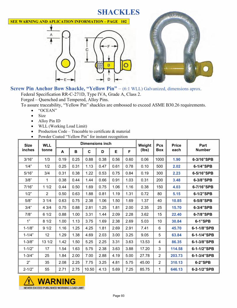
SHACKLES
Screw Pin Anchor Bow Shackle, “Yellow Pin” – (6:1 WLL) Galvanized, dimensions aprox.
Federal Specification RR-C-271D, Type IVA, Grade A, Class 2. Forged – Quenched and Tempered, Alloy Pins. To assure traceability, “Yellow Pin” shackles are embossed to exceed ASME B30.26 requirements.
• “OCEAN” • Size • Alloy Pin ID • WLL (Working Load Limit) • Production Code – Traceable to certificate & material • Powder Coated “Yellow Pin” for instant recognition
Size inches
WLL tonne
Dimensions inch Weight (lbs)
Pcs Box
Price each
Part Number A B C D E F
3/16” 1/3 0.19 0.25 0.88 0.38 0.56 0.60 0.06 1000 1.90 6-3/16”SPB
1/4” 1/2 0.25 0.31 1.13 0.47 0.61 0.78 0.10 500 2.02 6-1/4”SPB
5/16” 3/4 0.31 0.38 1.22 0.53 0.75 0.84 0.19 300 2.23 6-5/16”SPB
3/8” 1 0.38 0.44 1.44 0.66 0.91 1.03 0.31 200 3.48 6-3/8”SPB
7/16” 1 1/2 0.44 0.50 1.69 0.75 1.06 1.16 0.38 150 4.03 6-7/16”SPB
1/2” 2 0.50 0.63 1.88 0.81 1.19 1.31 0.72 80 5.15 6-1/2”SPB
5/8” 3 1/4 0.63 0.75 2.38 1.06 1.50 1.69 1.37 40 10.85 6-5/8”SPB
3/4” 4 3/4 0.75 0.88 2.81 1.25 1.81 2.00 2.35 25 15.70 6-3/4”SPB
7/8” 6 1/2 0.88 1.00 3.31 1.44 2.09 2.28 3.62 15 22.40 6-7/8”SPB
1” 8 1/2 1.00 1.13 3.75 1.69 2.38 2.69 5.03 10 30.84 6-1”SPB
1-1/8” 9 1/2 1.16 1.25 4.25 1.81 2.69 2.91 7.41 6 45.70 6-1-1/8”SPB
1-1/4” 12 1.29 1.38 4.69 2.03 3.00 3.25 9.05 5 63.84 6-1-1/4”SPB
1-3/8” 13 1/2 1.42 1.50 5.25 2.25 3.31 3.63 13.53 4 86.35 6-1-3/8”SPB
1-1/2” 17 1.54 1.63 5.75 2.38 3.63 3.88 17.20 3 114.58 6-1-1/2”SPB
1-3/4” 25 1.84 2.00 7.00 2.88 4.19 5.00 27.78 2 203.73 6-1-3/4”SPB
2” 35 2.08 2.25 7.75 3.25 4.81 5.75 45.00 2 310.13 6-2”SPB
2-1/2” 55 2.71 2.75 10.50 4.13 5.69 7.25 85.75 1 646.13 6-2-1/2”SPB
SEE WARNING AND APLICATION INFORMATION – PAGE 102
Page 93
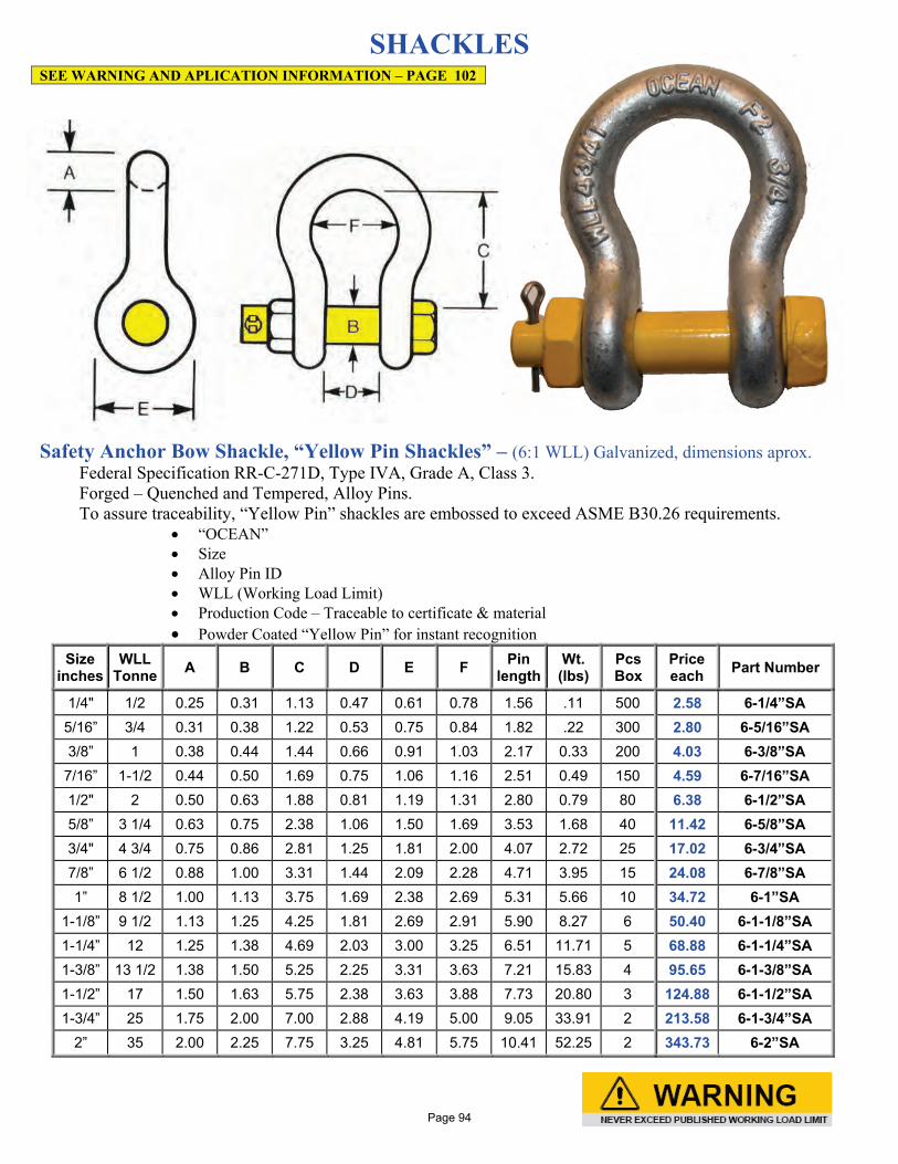
SHACKLES
Safety Anchor Bow Shackle, “Yellow Pin Shackles” – (6:1 WLL) Galvanized, dimensions aprox.
Federal Specification RR-C-271D, Type IVA, Grade A, Class 3. Forged – Quenched and Tempered, Alloy Pins. To assure traceability, “Yellow Pin” shackles are embossed to exceed ASME B30.26 requirements.
• “OCEAN” • Size • Alloy Pin ID • WLL (Working Load Limit) • Production Code – Traceable to certificate & material • Powder Coated “Yellow Pin” for instant recognition
Size inches
WLL Tonne A B C D E F Pin
length Wt. (lbs)
Pcs Box
Price each Part Number
1/4" 1/2 0.25 0.31 1.13 0.47 0.61 0.78 1.56 .11 500 2.58 6-1/4”SA 5/16” 3/4 0.31 0.38 1.22 0.53 0.75 0.84 1.82 .22 300 2.80 6-5/16”SA 3/8” 1 0.38 0.44 1.44 0.66 0.91 1.03 2.17 0.33 200 4.03 6-3/8”SA
7/16” 1-1/2 0.44 0.50 1.69 0.75 1.06 1.16 2.51 0.49 150 4.59 6-7/16”SA 1/2" 2 0.50 0.63 1.88 0.81 1.19 1.31 2.80 0.79 80 6.38 6-1/2”SA 5/8” 3 1/4 0.63 0.75 2.38 1.06 1.50 1.69 3.53 1.68 40 11.42 6-5/8”SA 3/4" 4 3/4 0.75 0.86 2.81 1.25 1.81 2.00 4.07 2.72 25 17.02 6-3/4”SA 7/8” 6 1/2 0.88 1.00 3.31 1.44 2.09 2.28 4.71 3.95 15 24.08 6-7/8”SA 1” 8 1/2 1.00 1.13 3.75 1.69 2.38 2.69 5.31 5.66 10 34.72 6-1”SA
1-1/8” 9 1/2 1.13 1.25 4.25 1.81 2.69 2.91 5.90 8.27 6 50.40 6-1-1/8”SA 1-1/4” 12 1.25 1.38 4.69 2.03 3.00 3.25 6.51 11.71 5 68.88 6-1-1/4”SA 1-3/8” 13 1/2 1.38 1.50 5.25 2.25 3.31 3.63 7.21 15.83 4 95.65 6-1-3/8”SA 1-1/2” 17 1.50 1.63 5.75 2.38 3.63 3.88 7.73 20.80 3 124.88 6-1-1/2”SA 1-3/4” 25 1.75 2.00 7.00 2.88 4.19 5.00 9.05 33.91 2 213.58 6-1-3/4”SA
2” 35 2.00 2.25 7.75 3.25 4.81 5.75 10.41 52.25 2 343.73 6-2”SA
SEE WARNING AND APLICATION INFORMATION – PAGE 102
Page 94
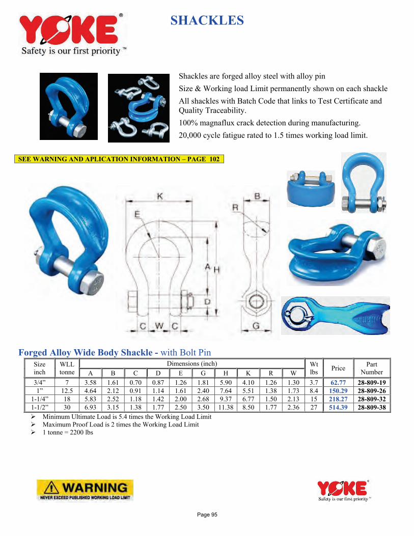
SHACKLES Shackles are forged alloy steel with alloy pin
Size & Working load Limit permanently shown on each shackle
All shackles with Batch Code that links to Test Certificate and Quality Traceability.
100% magnaflux crack detection during manufacturing.
20,000 cycle fatigue rated to 1.5 times working load limit.
Forged Alloy Wide Body Shackle - with Bolt Pin
Size inch
WLL tonne
Dimensions (inch) Wt lbs Price Part
Number A B C D E G H K R W 3/4” 7 3.58 1.61 0.70 0.87 1.26 1.81 5.90 4.10 1.26 1.30 3.7 62.77 28-809-19 1” 12.5 4.64 2.12 0.91 1.14 1.61 2.40 7.64 5.51 1.38 1.73 8.4 150.29 28-809-26
1-1/4” 18 5.83 2.52 1.18 1.42 2.00 2.68 9.37 6.77 1.50 2.13 15 218.27 28-809-32 1-1/2” 30 6.93 3.15 1.38 1.77 2.50 3.50 11.38 8.50 1.77 2.36 27 514.39 28-809-38 Minimum Ultimate Load is 5.4 times the Working Load Limit Maximum Proof Load is 2 times the Working Load Limit 1 tonne = 2200 lbs
SEE WARNING AND APLICATION INFORMATION – PAGE 102
Page 95
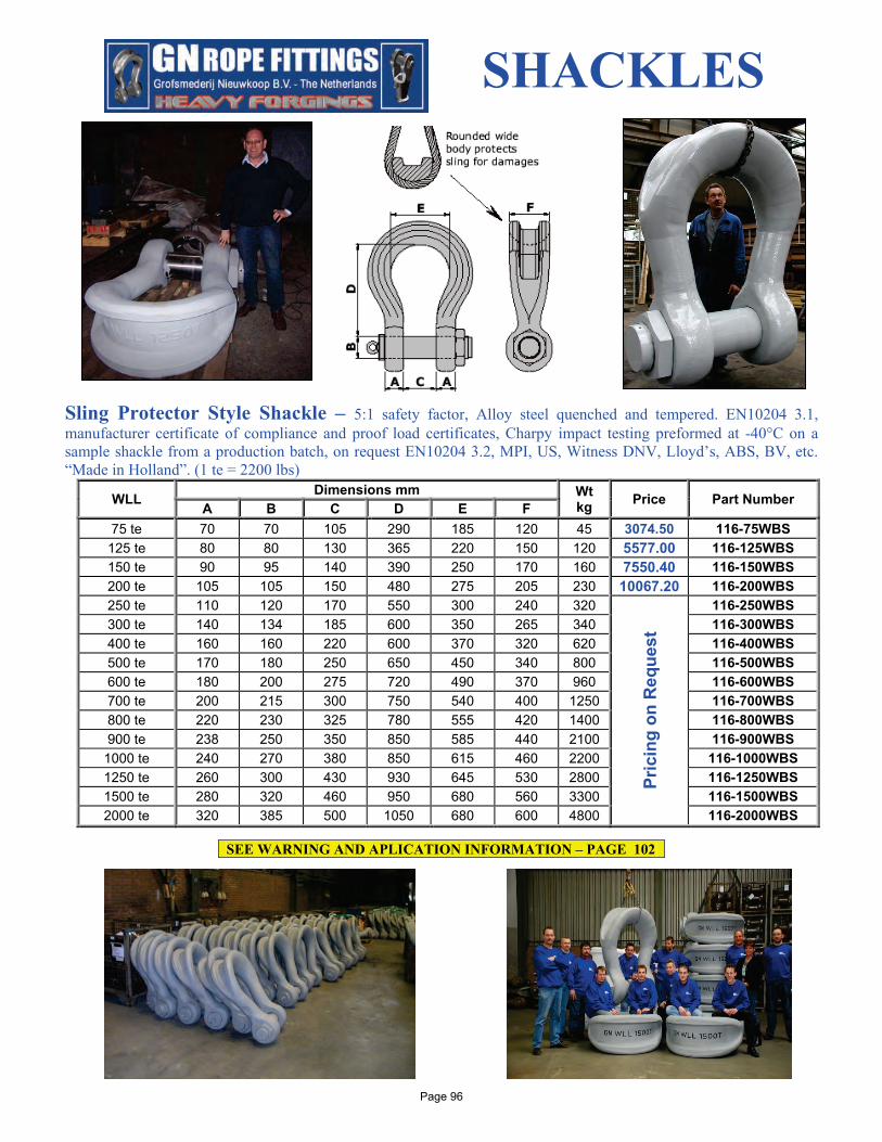
SHACKLES Sling Protector Style Shackle – 5:1 safety factor, Alloy steel quenched and tempered. EN10204 3.1, manufacturer certificate of compliance and proof load certificates, Charpy impact testing preformed at -40°C on a sample shackle from a production batch, on request EN10204 3.2, MPI, US, Witness DNV, Lloyd’s, ABS, BV, etc. “Made in Holland”. (1 te = 2200 lbs)
WLL Dimensions mm Wt kg Price Part Number A B C D E F
75 te 70 70 105 290 185 120 45 3074.50 116-75WBS 125 te 80 80 130 365 220 150 120 5577.00 116-125WBS 150 te 90 95 140 390 250 170 160 7550.40 116-150WBS 200 te 105 105 150 480 275 205 230 10067.20 116-200WBS 250 te 110 120 170 550 300 240 320
Pric
ing
on R
eque
st
116-250WBS 300 te 140 134 185 600 350 265 340 116-300WBS 400 te 160 160 220 600 370 320 620 116-400WBS 500 te 170 180 250 650 450 340 800 116-500WBS 600 te 180 200 275 720 490 370 960 116-600WBS 700 te 200 215 300 750 540 400 1250 116-700WBS 800 te 220 230 325 780 555 420 1400 116-800WBS 900 te 238 250 350 850 585 440 2100 116-900WBS
1000 te 240 270 380 850 615 460 2200 116-1000WBS 1250 te 260 300 430 930 645 530 2800 116-1250WBS 1500 te 280 320 460 950 680 560 3300 116-1500WBS 2000 te 320 385 500 1050 680 600 4800 116-2000WBS
SEE WARNING AND APLICATION INFORMATION – PAGE 102
Page 96
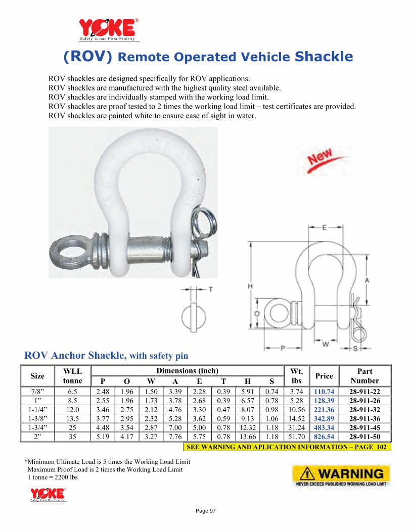
(ROV) Remote Operated Vehicle Shackle
ROV shackles are designed specifically for ROV applications. ROV shackles are manufactured with the highest quality steel available. ROV shackles are individually stamped with the working load limit. ROV shackles are proof tested to 2 times the working load limit – test certificates are provided. ROV shackles are painted white to ensure ease of sight in water. ROV Anchor Shackle, with safety pin
Size WLL tonne
Dimensions (inch) Wt. lbs Price Part
Number P O W A E T H S 7/8” 6.5 2.48 1.96 1.50 3.39 2.28 0.39 5.91 0.74 3.74 110.74 28-911-22 1” 8.5 2.55 1.96 1.73 3.78 2.68 0.39 6.57 0.78 5.28 128.39 28-911-26
1-1/4” 12.0 3.46 2.75 2.12 4.76 3.30 0.47 8.07 0.98 10.56 221.36 28-911-32 1-3/8” 13.5 3.77 2.95 2.32 5.28 3.62 0.59 9.13 1.06 14.52 342.89 28-911-36 1-3/4” 25 4.48 3.54 2.87 7.00 5.00 0.78 12.32 1.18 31.24 483.34 28-911-45
2” 35 5.19 4.17 3.27 7.76 5.75 0.78 13.66 1.18 51.70 826.54 28-911-50 *Minimum Ultimate Load is 5 times the Working Load Limit Maximum Proof Load is 2 times the Working Load Limit 1 tonne = 2200 lbs
SEE WARNING AND APLICATION INFORMATION – PAGE 102
Page 97
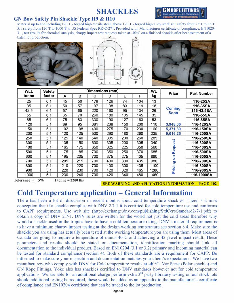
SHACKLES GN Bow Safety Pin Shackle Type H9 & H10
Material up to and including 120 T - forged high tensile steel, above 120 T - forged high alloy steel. 6:1 safety from 25 T to 85 T. 5:1 safety from 120 T to 1000 T to US Federal Spec RR-C-271. Provided with Manufacturer certificate of compliance, EN10204 3.1, test results for chemical analysis, charpy impact test requests taken at -40°C on a finished shackle after heat treatment of a batch lot production.
WLL tonne
Safety factor
Dimensions (mm) Wt. kg Price Part Number A B C D E F
25 6:1 45 50 178 126 74 104 13
Coming Soon
116-25SA 35 6:1 50 57 197 138 83 119 18 116-35SA
42.5 6:1 57 65 220 160 95 134 26 116-42.5SA 55 6:1 65 70 260 180 105 145 35 116-55SA 85 6:1 75 83 330 190 127 163 53 116-85SA
120 5:1 89 95 381 238 150 200 110 3,948.00 116-120SA 150 5:1 102 108 400 275 170 230 160 5,371.39 116-150SA 200 5:1 120 125 500 290 180 260 235 9,016.25 116-200SA 250 5:1 125 140 540 305 200 260 285
Pric
ing
on R
eque
st 116-250SA
300 5:1 135 150 600 305 200 305 340 116-300SA 400 5:1 165 175 650 325 225 350 560 116-400SA 500 5:1 175 185 700 350 250 370 685 116-500SA 600 5:1 195 205 700 375 275 405 880 116-600SA 700 5:1 205 215 700 400 300 435 980 116-700SA 800 5:1 210 220 700 400 300 435 1100 116-800SA 900 5:1 220 230 700 420 320 465 1280 116-900SA 1000 5:1 230 240 700 420 340 480 1460 116-1000SA
Tolerance + 5% 1 tonne = 2200 lbs
Cold Temperature application – General Information
There has been a lot of discussion in recent months about cold temperature shackles. There is a miss conception that if a shackle complies with DNV 2.7-1 it is certified for cold temperature use and conforms to CAPP requirements. Use web site (http://exchange.dnv.com/publishing/StdCert/Standard2-7-1.pdf) to obtain a copy of DNV 2.7-1. DNV rules are written for the world not just the cold areas therefore why would a shackle used in the tropics have to have a cold temperature rating. DNV’s material requirement is to have a minimum charpy impact testing at the design working temperature see section 8.4. Make sure the shackle you are using has actually been tested at the working temperature you are using them. Most areas of Canada are going to require a temperature of minus 40°C and achieving a 42 jewel impact result. These parameters and results should be stated on documentation, identification marking should link all documentation to the individual product. Based on EN10204 (3.1 or 3.2) primary and incoming material can be tested for standard compliance (section 4). Both of these standards are a requirement for CAPP. Be informed to make sure your inspection and documentation matches your client’s expectations. We have two manufacturers who comply with DNV for Cold temperature results at -40°C, VanBeest (Polar shackle) and GN Rope Fittings. Yoke also has shackles certified to DNV standards however not for cold temperature applications. We are able for an additional charge perform extra 3rd party libratory testing on our stock lots should additional testing be required, these would be added as an appendix to the manufacturer’s certificate of compliance and EN10204 certificate that can be traced to the lot production.
SEE WARNING AND APLICATION INFORMATION – PAGE 102
Page 98
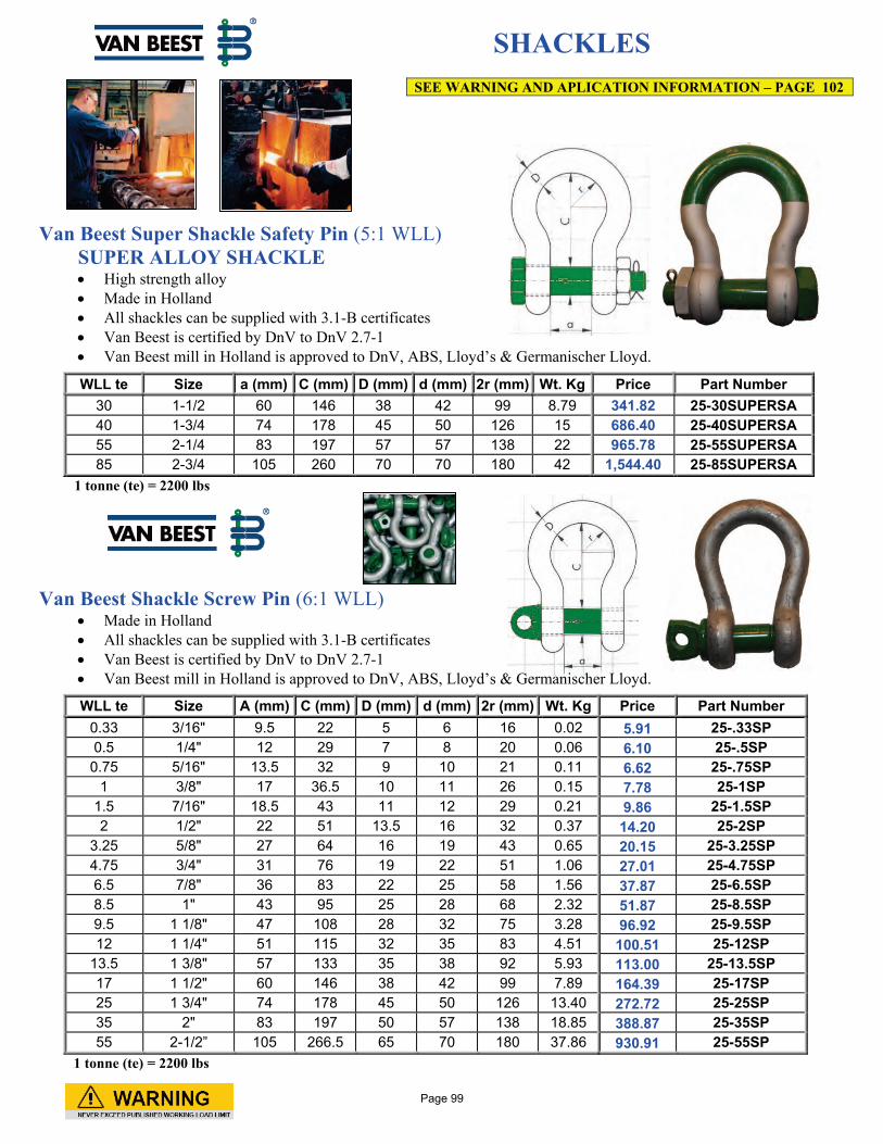
SHACKLES Van Beest Super Shackle Safety Pin (5:1 WLL)
SUPER ALLOY SHACKLE • High strength alloy • Made in Holland • All shackles can be supplied with 3.1-B certificates • Van Beest is certified by DnV to DnV 2.7-1 • Van Beest mill in Holland is approved to DnV, ABS, Lloyd’s & Germanischer Lloyd.
WLL te Size a (mm) C (mm) D (mm) d (mm) 2r (mm) Wt. Kg Price Part Number 30 1-1/2 60 146 38 42 99 8.79 341.82 25-30SUPERSA 40 1-3/4 74 178 45 50 126 15 686.40 25-40SUPERSA 55 2-1/4 83 197 57 57 138 22 965.78 25-55SUPERSA 85 2-3/4 105 260 70 70 180 42 1,544.40 25-85SUPERSA
1 tonne (te) = 2200 lbs Van Beest Shackle Screw Pin (6:1 WLL)
• Made in Holland • All shackles can be supplied with 3.1-B certificates • Van Beest is certified by DnV to DnV 2.7-1 • Van Beest mill in Holland is approved to DnV, ABS, Lloyd’s & Germanischer Lloyd.
WLL te Size A (mm) C (mm) D (mm) d (mm) 2r (mm) Wt. Kg Price Part Number 0.33 3/16" 9.5 22 5 6 16 0.02 5.91 25-.33SP 0.5 1/4" 12 29 7 8 20 0.06 6.10 25-.5SP 0.75 5/16" 13.5 32 9 10 21 0.11 6.62 25-.75SP
1 3/8" 17 36.5 10 11 26 0.15 7.78 25-1SP 1.5 7/16" 18.5 43 11 12 29 0.21 9.86 25-1.5SP 2 1/2" 22 51 13.5 16 32 0.37 14.20 25-2SP
3.25 5/8" 27 64 16 19 43 0.65 20.15 25-3.25SP 4.75 3/4" 31 76 19 22 51 1.06 27.01 25-4.75SP 6.5 7/8" 36 83 22 25 58 1.56 37.87 25-6.5SP 8.5 1" 43 95 25 28 68 2.32 51.87 25-8.5SP 9.5 1 1/8" 47 108 28 32 75 3.28 96.92 25-9.5SP 12 1 1/4" 51 115 32 35 83 4.51 100.51 25-12SP
13.5 1 3/8" 57 133 35 38 92 5.93 113.00 25-13.5SP 17 1 1/2" 60 146 38 42 99 7.89 164.39 25-17SP 25 1 3/4" 74 178 45 50 126 13.40 272.72 25-25SP 35 2" 83 197 50 57 138 18.85 388.87 25-35SP 55 2-1/2” 105 266.5 65 70 180 37.86 930.91 25-55SP
1 tonne (te) = 2200 lbs
SEE WARNING AND APLICATION INFORMATION – PAGE 102
Page 99
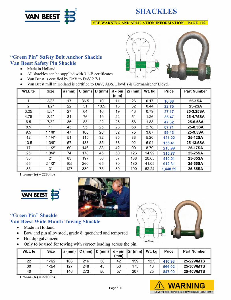
SHACKLES
“Green Pin” Safety Bolt Anchor Shackle Van Beest Safety Pin Shackle
• Made in Holland • All shackles can be supplied with 3.1-B certificates • Van Beest is certified by DnV to DnV 2.7-1 • Van Beest mill in Holland is certified to DnV, ABS, Lloyd’s & Germanischer Lloyd.
WLL te Size a (mm) C (mm) D (mm) d - pin (mm)
2r (mm) Wt. kg Price Part Number
1 3/8" 17 36.5 10 11 26 0.17 16.68 25-1SA 2 1/2" 22 51 13.5 16 32 0.44 22.70 25-2SA
3.25 5/8" 27 64 16 19 43 0.79 27.17 25-3.25SA 4.75 3/4" 31 76 19 22 51 1.26 35.47 25-4.75SA 6.5 7/8" 36 83 22 25 58 1.88 47.32 25-6.5SA 8.5 1" 43 95 25 28 68 2.78 67.71 25-8.5SA 9.5 1 1/8" 47 108 28 32 75 3.87 99.43 25-9.5SA 12 1 1/4" 51 115 32 35 83 5.26 121.22 25-12SA
13.5 1 3/8" 57 133 35 38 92 6.94 156.41 25-13.5SA 17 1 1/2" 60 146 38 42 99 8.79 210.99 25-17SA 25 1 3/4" 74 178 45 50 126 14.99 315.77 25-25SA 35 2" 83 197 50 57 138 20.65 410.01 25-35SA 55 2 1/2" 105 260 65 70 180 41.05 912.31 25-55SA 85 3" 127 330 75 80 190 62.24 1,448.59 25-85SA
1 tonne (te) = 2200 lbs “Green Pin” Shackle Van Beest Wide Mouth Towing Shackle
• Made in Holland • Bow and pin alloy steel, grade 8, quenched and tempered • Hot dip galvanized • Only to be used for towing with correct loading across the pin.
WLL te Size a (mm) C (mm) D (mm) d - pin (mm)
2r (mm) Wt. kg Price Part Number
22 1-1/2 106 216 38 42 159 12.5 410.93 25-22WMTS 30 1-3/4 127 248 45 50 175 18 566.02 25-30WMTS 40 2 146 273 50 57 207 25 847.00 25-40WMTS
1 tonne (te) = 2200 lbs
SEE WARNING AND APLICATION INFORMATION – PAGE 102
Page 100
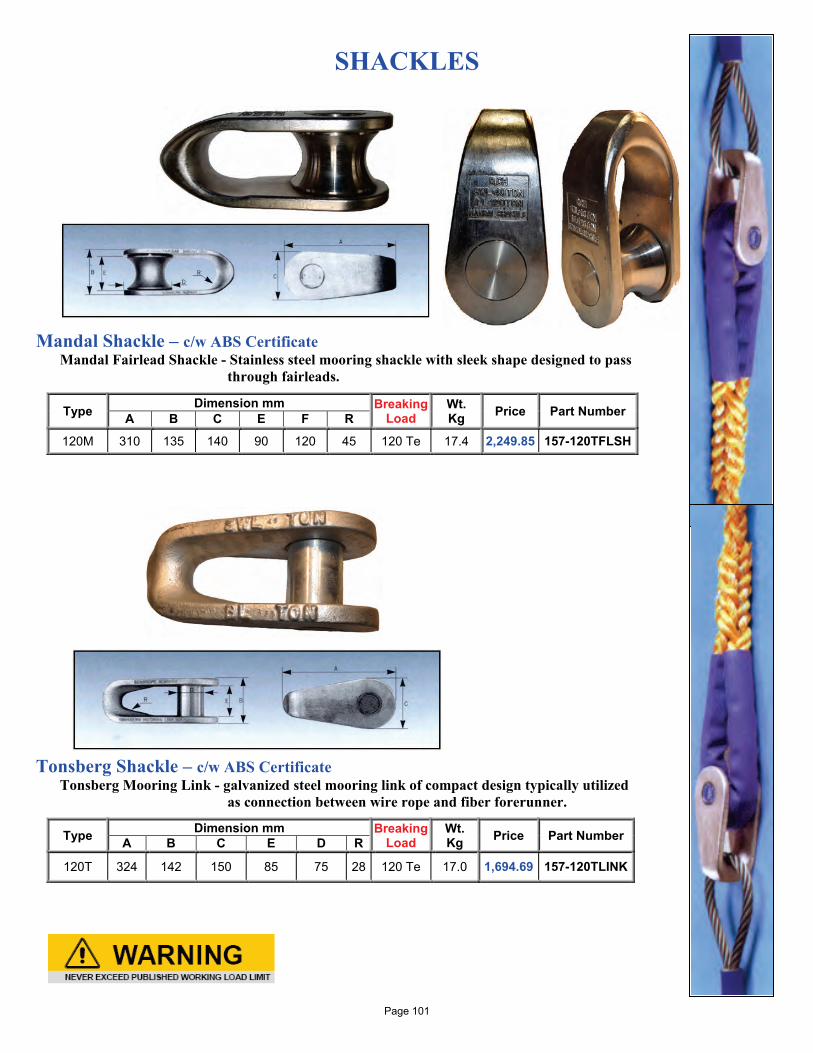
SHACKLES
Mandal Shackle – c/w ABS Certificate Mandal Fairlead Shackle - Stainless steel mooring shackle with sleek shape designed to pass
through fairleads.
Type Dimension mm Breaking Load
Wt. Kg Price Part Number A B C E F R
120M 310 135 140 90 120 45 120 Te 17.4 2,249.85 157-120TFLSH
Tonsberg Shackle – c/w ABS Certificate
Tonsberg Mooring Link - galvanized steel mooring link of compact design typically utilized as connection between wire rope and fiber forerunner.
Type Dimension mm Breaking Load
Wt. Kg Price Part Number A B C E D R
120T 324 142 150 85 75 28 120 Te 17.0 1,694.69 157-120TLINK
Page 101
OCEAN BRAND™ SHACKLE WARNINGS AND APPLICATIONS
Side and symmetrical loading data applies to screw pin and bolt nut cotter shackles only! Side and symmetrical loading not permitted on round pin shackles. Angles of Side Load 0° - In-Line - 100 % of rated WLL (Working Load Limit) 45° - From In-Line – 70% of rated WLL 90° - From In-Line – 50% of rated WLL Symmetrical Loading Shackles symmetrically loaded with two legs at a maximum angle Of 120°can be used to full Working Load Limit. -For permanent or long term installation always use nut and cotter. -Shackle must be large enough to avoid pinching or bunching of synthetic slings. -Diameter of shackle must be greater than wire rope diameter if no thimble in eye. -Mouse screw pin when used in long term or high vibration applications. Shackles should be inspected before use to ensure that: • All markings are legible • The body and pin are both identifiable as being of the same size, type and make • The threads of the pin and the body are undamaged • Never use a safety bolt type shackle without using the cotter pin • The body and the pin are not distorted or worn • The body and pin are free from nicks, gouges, cracks and corrosion • Shackles may not be heat treated as this may affect their Working Load Limit • Never modify, repair or reshape a shackle by welding, heating or bending as this will affect the Working Load Limit Assembly Ensure that the pin is correctly screwed into the shackle eye, i.e. tighten hand tight, and then secure using a wrench or other suitable tool so that the collar of the pin is fully seated on the shackle eye. Ensure that the pin is of the correct length so that it penetrates the full depth of the screwed eye and allows the collar of the pin to seat on the surface of the shackle eye. Incorrect seating of the pin may be due to a bent pin, too tight fitting thread or misalignment of the pin holes. Do not use the shackle under these circumstances. Never replace a shackle pin except with one of the same size, type and make as it may not be suitable for the loads imposed. Select the correct type of shackle and its Working Load Limit for the particular application. Should extreme circumstances or shock loading be applicable, this must be well taken into account on selecting the correct shackle. Please note that commercial shackles are not to be used for lifting applications. Make sure that the shackle is supporting the load correctly, i.e. along the axis of the shackle body centerline, avoid introduction of bending loads, unstable loads and do not overload. Wrong Right
Improper use or care of shackles can result in bodily injury or property damage To avoid injury or property damage: - Do not exceed the WLL (Working Load Limit) - Do not shock load - Do not side load – center line of load must coincide with center line of shackle - Do not replace pin or bolt with other than original equipment - Inspect before use for wear, deformation, and pin engagement Inspect shackles before each use as outlined in ASME B30.26
Page 102
Wirop Industrial Company Ltd was established in 1979 by Mr. Ben Chiu. Our modern factory is located in Kaohsiung, the southern hub of Taiwan, close to the international airport, harbour and rail ways. We have been providing for the needs of wire rope fabricators for more than 27 years. The main products we make are hydraulic swaging machines (wire rope clamping machines) [capacity 30 ton ~4000 ton for wire rope [1mm~120mm], dies, horizontal testing benches (capacity: 50 ton~3000 ton), annealing and tapering machines, recoiling machines, marking machines, auto-measuring & cutting machines as well as others. Besides this, we offer Aluminum ferrules according to EN 13411-3 (DIN 3093), Flemish eye steel sleeves from 1/4” to 6” and other swaging products for wire ropes of different kinds of material, i.e. copper, stainless steel, swage sockets and thread stud terminals.
Wire Rope Grip System 200 ton x 22.5 m Horizontal Tension tester 2600 ton x 100 m Tension tester
Measuring & Cutting Machine Marking System
Aluminum Annealing & Tapering Machine Table Swager
Coiling Machine Hand Press Portable Portable Hydraulic Press Portable Hydraulic Wire Rope Cutter Power Hydraulic Pump Unit Page 103
FAST FLEMISH SWAGE SYSTEM
This swaging is not only faster and more efficient but it greatly reduces the possibility of over or under swaging the sleeve. In the first swage step, the sleeve cannot be over swaged because of the precise notching of the die; the second step allows a controlled closing of the dies to slightly less than full closure whereby the third and final step allows full close of the dies. The end result is a nearly smooth round swaged sleeve without the usual “wrinkles” one gets from the conventional swaging methods.
Conventional swaging of a round carbon steel sleeve on the wire rope has repeated multiple closing of the dies until the sleeve is completely swaged. This "multi-swage" system of swaging requires several die closures that are dependent on the wire rope diameter. On rope diameters 1" and larger, two dies are necessary to swage the sleeve, requiring an extra die change. The total number of die closures for sleeves larger than 1” diameter can be as many as ten total closures for the two sets of dies.
In the Wirop “Fast Flemish Swage¨ system not only are the number of swages minimized and simplified, over and under swaging are eliminated, multi-swages on sleeves over 1¨ in size are greatly reduced. Die changes from 1st open stage to 2nd taper is also eliminated.
Fast Flemish Swage system is available up to 2-1/2” sleeve diameters. Bigger sizes are under development.
Wirop swaging machines are packed with functions that add to the efficiency and speed in swaging. Should the users choose to use the machine to swage sleeves conventionally; the operator is able to adjust the hydraulic pressure simply by setting the sleeve size on a round dial. This function alone eliminates the guesswork for how much pressure to apply for a given size sleeve. Another simple dial but extremely useful function allows the die openings to be fixed to any desired amount of opening. Aluminum oval ferrules are swaged in just one step as the dies have cutting edges that remove the excess flash. Fully automatic one button swage for Aluminum oval ferrules is a huge time saver. In the automatic mode the dies close and open with the push of a button. The dies opening can be pre-set to just enough space to allow the swage sleeve to be removed, again saving time to insert the next sleeve to be swaged quickly and efficiently. WIROP "FAST FLEMISH SWAGE" swaging instructions (1) Place the Flemish Eye steel sleeves on the "Flat Side" (Notched Side) by lining the center line of sleeves with the reference center line (see above Figure A) of the die as shown below in figure B
Figure A Figure B The diameter of the sleeve is A. (2) Close the dies completely. The sleeves will be swaged to 80% of diameter A and turn into an oval shape as shown below in Figure C
Figure C Actual condition of the sleeve @ 80% which has an oval shape. (3) Turn the swaged sleeve 90 degrees and place the sleeve on the die as shown below in Figure D (4) Close the die until gap is about 0.1 A as shown below in Figure E. Figure D Figure E (5) Turn the sleeve 45 degree again and close the dies completely as shown below in Figure F Figure F This picture depicts the finished swaged sleeve used with Wirop's "FAST FLEMISH SWAGE" method Page 104
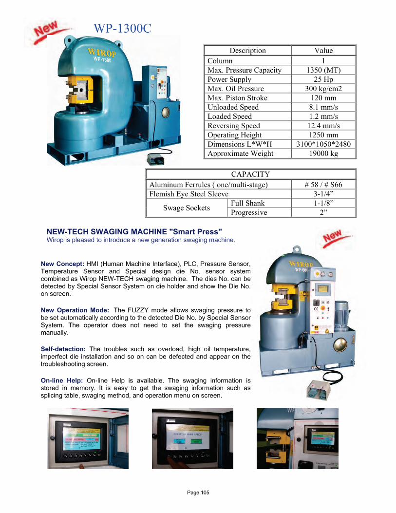
WP-1300C
Description Value Column 1 Max. Pressure Capacity 1350 (MT) Power Supply 25 Hp Max. Oil Pressure 300 kg/cm2 Max. Piston Stroke 120 mm Unloaded Speed 8.1 mm/s Loaded Speed 1.2 mm/s Reversing Speed 12.4 mm/s Operating Height 1250 mm Dimensions L*W*H 3100*1050*2480 Approximate Weight 19000 kg
CAPACITY
Aluminum Ferrules ( one/multi-stage) # 58 / # S66 Flemish Eye Steel Sleeve 3-1/4”
Swage Sockets Full Shank 1-1/8” Progressive 2”
NEW-TECH SWAGING MACHINE "Smart Press"
Wirop is pleased to introduce a new generation swaging machine.
New Concept: HMI (Human Machine Interface), PLC, Pressure Sensor, Temperature Sensor and Special design die No. sensor system combined as Wirop NEW-TECH swaging machine. The dies No. can be detected by Special Sensor System on die holder and show the Die No. on screen.
New Operation Mode: The FUZZY mode allows swaging pressure to be set automatically according to the detected Die No. by Special Sensor System. The operator does not need to set the swaging pressure manually.
Self-detection: The troubles such as overload, high oil temperature, imperfect die installation and so on can be defected and appear on the troubleshooting screen.
On-line Help: On-line Help is available. The swaging information is stored in memory. It is easy to get the swaging information such as splicing table, swaging method, and operation menu on screen.
Page 105
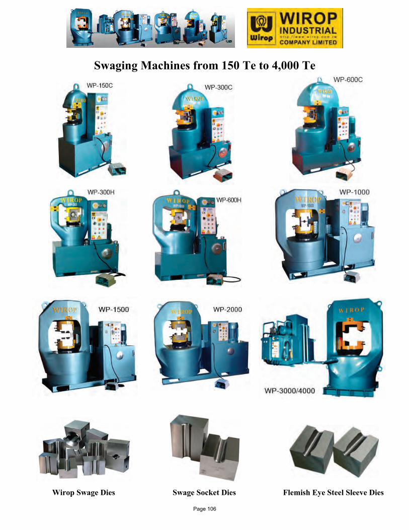
Swaging Machines from 150 Te to 4,000 Te Wirop Swage Dies Swage Socket Dies Flemish Eye Steel Sleeve Dies
Page 106
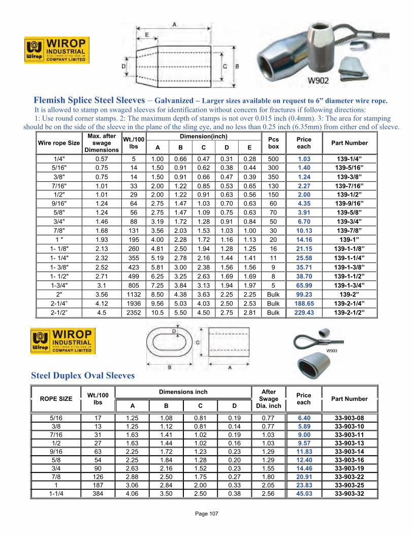
Flemish Splice Steel Sleeves – Galvanized – Larger sizes available on request to 6” diameter wire rope. It is allowed to stamp on swaged sleeves for identification without concern for fractures if following directions: 1: Use round corner stamps. 2: The maximum depth of stamps is not over 0.015 inch (0.4mm). 3: The area for stamping should be on the side of the sleeve in the plane of the sling eye, and no less than 0.25 inch (6.35mm) from either end of sleeve.
Wire rope Size Max. after
swage Dimensions
Wt./100 lbs
Dimension(inch) Pcs box
Price each Part Number
A B C D E 1/4" 0.57 5 1.00 0.66 0.47 0.31 0.28 500 1.03 139-1/4”
5/16" 0.75 14 1.50 0.91 0.62 0.38 0.44 300 1.40 139-5/16” 3/8" 0.75 14 1.50 0.91 0.66 0.47 0.39 350 1.24 139-3/8”
7/16" 1.01 33 2.00 1.22 0.85 0.53 0.65 130 2.27 139-7/16” 1/2" 1.01 29 2.00 1.22 0.91 0.63 0.56 150 2.00 139-1/2”
9/16" 1.24 64 2.75 1.47 1.03 0.70 0.63 60 4.35 139-9/16” 5/8" 1.24 56 2.75 1.47 1.09 0.75 0.63 70 3.91 139-5/8” 3/4" 1.46 88 3.19 1.72 1.28 0.91 0.84 50 6.70 139-3/4” 7/8" 1.68 131 3.56 2.03 1.53 1.03 1.00 30 10.13 139-7/8” 1 " 1.93 195 4.00 2.28 1.72 1.16 1.13 20 14.16 139-1”
1- 1/8" 2.13 260 4.81 2.50 1.94 1.28 1.25 16 21.15 139-1-1/8” 1- 1/4" 2.32 355 5.19 2.78 2.16 1.44 1.41 11 25.58 139-1-1/4” 1- 3/8" 2.52 423 5.81 3.00 2.38 1.56 1.56 9 35.71 139-1-3/8” 1- 1/2" 2.71 499 6.25 3.25 2.63 1.69 1.69 8 38.70 139-1-1/2” 1-3/4" 3.1 805 7.25 3.84 3.13 1.94 1.97 5 65.99 139-1-3/4”
2" 3.56 1132 8.50 4.38 3.63 2.25 2.25 Bulk 99.23 139-2” 2-1/4” 4.12 1936 9.56 5.03 4.03 2.50 2.53 Bulk 188.65 139-2-1/4” 2-1/2” 4.5 2352 10.5 5.50 4.50 2.75 2.81 Bulk 229.43 139-2-1/2”
Steel Duplex Oval Sleeves
ROPE SIZE Wt./100 lbs
Dimensions inch After Swage
Dia. inch
Price each Part Number
A B C D
5/16 17 1.25 1.08 0.81 0.19 0.77 6.40 33-903-08 3/8 13 1.25 1.12 0.81 0.14 0.77 5.89 33-903-10
7/16 31 1.63 1.41 1.02 0.19 1.03 9.00 33-903-11 1/2 27 1.63 1.44 1.02 0.16 1.03 9.57 33-903-13
9/16 63 2.25 1.72 1.23 0.23 1.29 11.83 33-903-14 5/8 54 2.25 1.84 1.28 0.20 1.29 12.40 33-903-16 3/4 90 2.63 2.16 1.52 0.23 1.55 14.46 33-903-19 7/8 126 2.88 2.50 1.75 0.27 1.80 20.91 33-903-22 1 187 3.06 2.84 2.00 0.33 2.05 23.83 33-903-25
1-1/4 384 4.06 3.50 2.50 0.38 2.56 45.03 33-903-32
Page 107
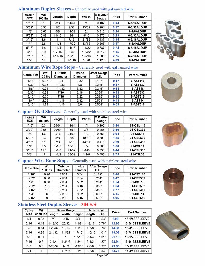
Aluminum Duplex Sleeves – Generally used with galvanized wire
Aluminum Wire Rope Stops – Generally used with galvanized wire
Copper Oval Sleeves – Generally used with stainless steel wire
Copper Wire Rope Stops – Generally used with stainless steel wire
Stainless Steel Duplex Sleeves - 304 S/S
CABLE SIZE
Wt/ 100 lbs Length Depth Width O.D.After
Swage Price
Part Number
1/16" 0.10 3/8 11/64 ¼ 0.187” 0.14 6-1/16ALDUP 3/32" 0.30 1/2 9/32 13/32 0.281” 0.17 6-3/32ALDUP 1/8" 0.66 5/8 11/32 ½ 0.312” 0.20 6-1/8ALDUP
5/32" 0.88 11/16 3/8 9/16 0.375” 0.23 6-5/32ALDUP 3/16" 1.6 1 7/16 21/32 0.437” 0.34 6-3/16ALDUP 1/4" 2.8 1-1/8 17/32 13/16 0.563” 0.57 6-1/4ALDUP 5/16” 4.6 1-1/4 11/16 1-1/32 0.687” 0.74 6-5/16ALDUP 3/8” 5.9 1-7/16 3/4 1-5/32 0.812” 1.15 6-3/8ALDUP
7/16” 12 1-11/16 15/16 1-7/16 1.000” 2.75 6-7/16ALDUP 1/2” 17 2 1-1/16 1-5/8 1.120” 4.39 6-1/2ALDUP
Cable Size Wt/ 100 lbs
Outside Diameter
Inside Diameter
After Swage O.D. Price Part Number
1/16" 0.06 1/4 3/32 0.187” 0.17 6-AST116 3/32" 0.25 11/32 1/8 0.245” 0.17 6-AST332 1/8" 0.24 11/32 5/32 0.245” 0.18 6-AST18
5/32" 0.38 7/16 3/16 0.325” 0.23 6-AST532 3/16" 0.35 7/16 7/32 0.325” 0.23 6-AST316 1/4" 2.06 11/16 9/32 0.508” 0.43 6-AST14
5/16" 1.74 11/16 3/8 0.508” 0.69 6-AST516
CABLE SIZE
Wt/ 100 lbs Length Depth Width O.D.After
Swage Price Part Number
1/16" 0.3 25/64 11/64 1/4 0.190” 0.40 91-CSL116 3/32" 0.65 29/64 15/64 3/8 0.265” 0.50 91-CSL332 1/8" 1.6 9/16 21/64 1/2 0.353” 0.94 91-CSL18
5/32" 2.3 5/8 3/8 19/32 0.390” 1.25 91-CSL532 3/16" 5.1 7/8 7/16 43/64 0.475” 2.29 91-CSL316 1/4" 7.5 1-1/8 13/16 1/2 0.585” 3.60 91-CSL14 5/16” 11.8 1-1/8 21/32 1-1/64 0.730” 6.44 91-CSL516 3/8” 17 1-1/2 23/32 1-1/8 0.795” 8.75 91-CSL38
Cable Size Wt/ 100 lbs
Outside Diameter
Inside Diameter
After Swage O.D. Price Part Number
1/16" 0.20 13/64 5/64 0.182” 0.46 91-CST116 3/32" 0.80 21/64 7/64 0.261” 0.47 91-CST332 1/8" 0.80 21/64 5/32 0.261” 0.54 91-CST18
5/32" 1.3 27/64 3/16 0.350” 0.64 91-CST532 3/16" 1.2 27/64 7/32 0.350” 0.77 91-CST316 1/4" 6 21/32 9/32 0.600” 4.15 91-CST14
5/16" 9 21/32 5/16 0.600” 5.96 91-CST516
Cable Size
Wt each lbs
Before Swage After Swage Price Part Number Length width height length Dia.
1/4 0.03 7/8 9/16 3/4 1 0.53” 8.09 15-1/4SSSLEEVE 5/16 0.18 1-19/32 25/32 1-1/8 1-9/16 0.76” 12.93 15-5/16SSSLEEVE 3/8 0.14 1-23/32 13/16 1-1/8 1-7/8 0.76” 14.81 15-3/8SSSLEEVE 7/16 0.35 2-1/32 1-1/32 1-7/16 1-15/16 1.01” 18.08 15-7/16SSSLEEVE 1/2 0.31 2 1 1-7/16 2-1/4 1.01” 21.16 15-1/2SSSLEEVE 9/16 0.6 2-1/4 1-3/16 1-3/4 2-1/2 1.27” 28.94 15-9/16SSSLEEVE 5/8 0.6 2-23/32 1-1/4 1-13/16 2-5/8 1.27” 29.63 15-5/8SSSLEEVE 3/4 1 3 1-7/16 2-1/8 3-3/8 1.53” 43.76 15-3/4SSSLEEVE
Page 108
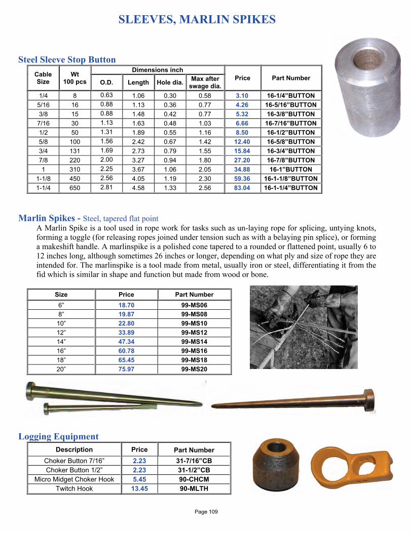
SLEEVES, MARLIN SPIKES
Steel Sleeve Stop Button Cable Size
Wt 100 pcs
Dimensions inch Price Part Number O.D. Length Hole dia. Max after
swage dia. 1/4 8 0.63 1.06 0.30 0.58 3.10 16-1/4”BUTTON
5/16 16 0.88 1.13 0.36 0.77 4.26 16-5/16”BUTTON 3/8 15 0.88 1.48 0.42 0.77 5.32 16-3/8”BUTTON
7/16 30 1.13 1.63 0.48 1.03 6.66 16-7/16”BUTTON 1/2 50 1.31 1.89 0.55 1.16 8.50 16-1/2”BUTTON 5/8 100 1.56 2.42 0.67 1.42 12.40 16-5/8”BUTTON 3/4 131 1.69 2.73 0.79 1.55 15.84 16-3/4”BUTTON 7/8 220 2.00 3.27 0.94 1.80 27.20 16-7/8”BUTTON 1 310 2.25 3.67 1.06 2.05 34.88 16-1”BUTTON
1-1/8 450 2.56 4.05 1.19 2.30 59.36 16-1-1/8”BUTTON 1-1/4 650 2.81 4.58 1.33 2.56 83.04 16-1-1/4”BUTTON
Marlin Spikes - Steel, tapered flat point
A Marlin Spike is a tool used in rope work for tasks such as un-laying rope for splicing, untying knots, forming a toggle (for releasing ropes joined under tension such as with a belaying pin splice), or forming a makeshift handle. A marlinspike is a polished cone tapered to a rounded or flattened point, usually 6 to 12 inches long, although sometimes 26 inches or longer, depending on what ply and size of rope they are intended for. The marlinspike is a tool made from metal, usually iron or steel, differentiating it from the fid which is similar in shape and function but made from wood or bone.
Size Price Part Number
6” 18.70 99-MS06 8” 19.87 99-MS08
10” 22.80 99-MS10 12” 33.89 99-MS12 14” 47.34 99-MS14 16” 60.78 99-MS16 18” 65.45 99-MS18 20” 75.97 99-MS20
Logging Equipment
Description Price
Part Number Choker Button 7/16” 2.23 31-7/16”CB Choker Button 1/2” 2.23 31-1/2”CB
Micro Midget Choker Hook 5.45 90-CHCM Twitch Hook 13.45 90-MLTH
Page 109
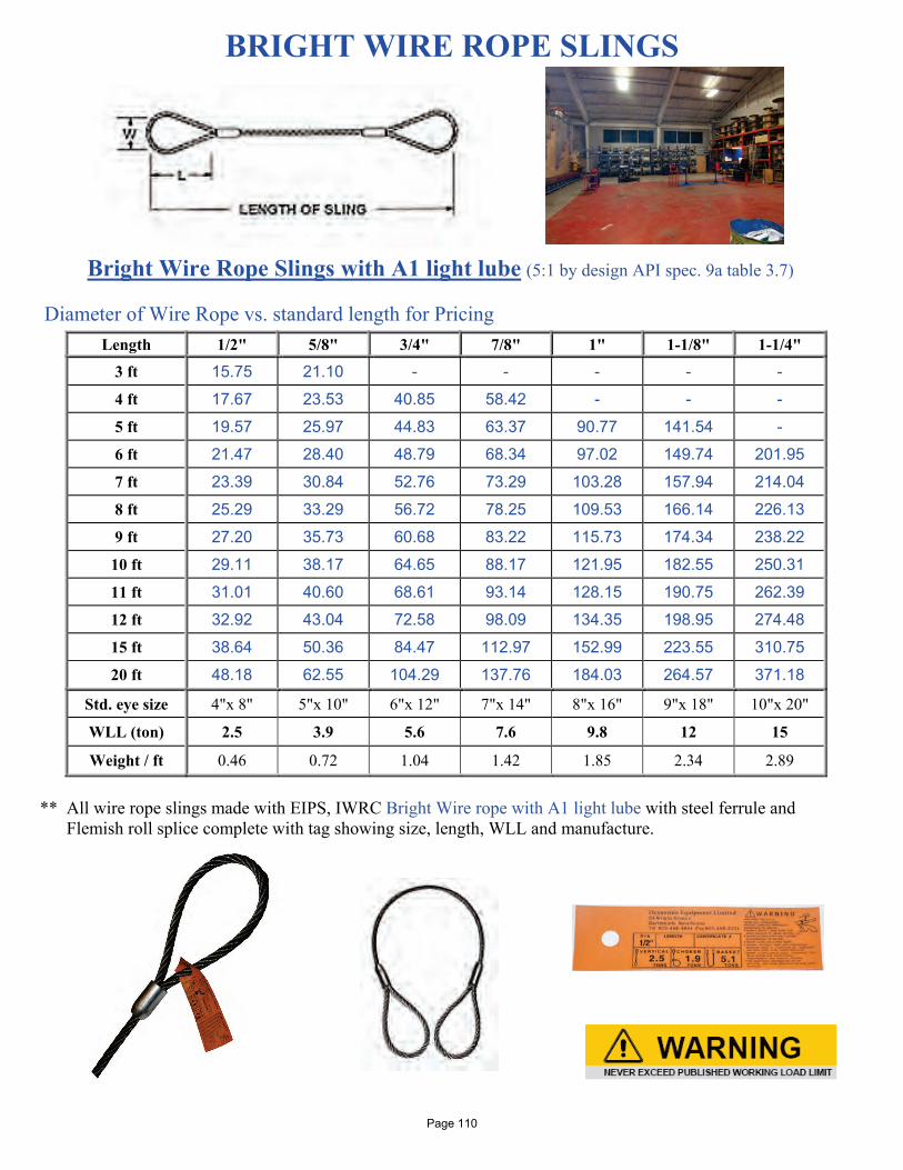
BRIGHT WIRE ROPE SLINGS Bright Wire Rope Slings with A1 light lube (5:1 by design API spec. 9a table 3.7) Diameter of Wire Rope vs. standard length for Pricing
Length 1/2" 5/8" 3/4" 7/8" 1" 1-1/8" 1-1/4"
3 ft 15.75 21.10 - - - - -
4 ft 17.67 23.53 40.85 58.42 - - -
5 ft 19.57 25.97 44.83 63.37 90.77 141.54 -
6 ft 21.47 28.40 48.79 68.34 97.02 149.74 201.95
7 ft 23.39 30.84 52.76 73.29 103.28 157.94 214.04
8 ft 25.29 33.29 56.72 78.25 109.53 166.14 226.13
9 ft 27.20 35.73 60.68 83.22 115.73 174.34 238.22
10 ft 29.11 38.17 64.65 88.17 121.95 182.55 250.31
11 ft 31.01 40.60 68.61 93.14 128.15 190.75 262.39
12 ft 32.92 43.04 72.58 98.09 134.35 198.95 274.48
15 ft 38.64 50.36 84.47 112.97 152.99 223.55 310.75
20 ft 48.18 62.55 104.29 137.76 184.03 264.57 371.18
Std. eye size 4"x 8" 5"x 10" 6"x 12" 7"x 14" 8"x 16" 9"x 18" 10"x 20"
WLL (ton) 2.5 3.9 5.6 7.6 9.8 12 15
Weight / ft 0.46 0.72 1.04 1.42 1.85 2.34 2.89
** All wire rope slings made with EIPS, IWRC Bright Wire rope with A1 light lube with steel ferrule and
Flemish roll splice complete with tag showing size, length, WLL and manufacture.
Page 110
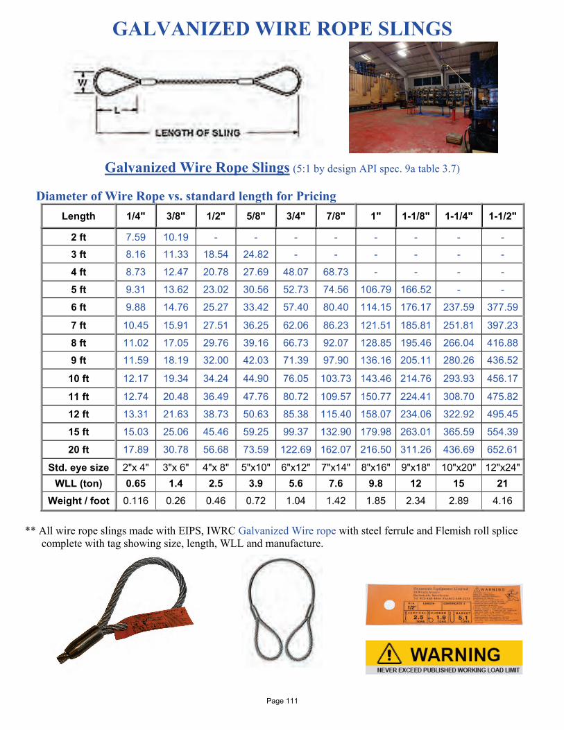
GALVANIZED WIRE ROPE SLINGS
Galvanized Wire Rope Slings (5:1 by design API spec. 9a table 3.7) Diameter of Wire Rope vs. standard length for Pricing
Length 1/4" 3/8" 1/2" 5/8" 3/4" 7/8" 1" 1-1/8" 1-1/4" 1-1/2"
2 ft 7.59 10.19 - - - - - - - -
3 ft 8.16 11.33 18.54 24.82 - - - - - -
4 ft 8.73 12.47 20.78 27.69 48.07 68.73 - - - -
5 ft 9.31 13.62 23.02 30.56 52.73 74.56 106.79 166.52 - -
6 ft 9.88 14.76 25.27 33.42 57.40 80.40 114.15 176.17 237.59 377.59
7 ft 10.45 15.91 27.51 36.25 62.06 86.23 121.51 185.81 251.81 397.23
8 ft 11.02 17.05 29.76 39.16 66.73 92.07 128.85 195.46 266.04 416.88
9 ft 11.59 18.19 32.00 42.03 71.39 97.90 136.16 205.11 280.26 436.52
10 ft 12.17 19.34 34.24 44.90 76.05 103.73 143.46 214.76 293.93 456.17
11 ft 12.74 20.48 36.49 47.76 80.72 109.57 150.77 224.41 308.70 475.82
12 ft 13.31 21.63 38.73 50.63 85.38 115.40 158.07 234.06 322.92 495.45
15 ft 15.03 25.06 45.46 59.25 99.37 132.90 179.98 263.01 365.59 554.39
20 ft 17.89 30.78 56.68 73.59 122.69 162.07 216.50 311.26 436.69 652.61
Std. eye size 2"x 4" 3"x 6" 4"x 8" 5"x10" 6"x12" 7"x14" 8"x16" 9"x18" 10"x20" 12"x24" WLL (ton) 0.65 1.4 2.5 3.9 5.6 7.6 9.8 12 15 21
Weight / foot 0.116 0.26 0.46 0.72 1.04 1.42 1.85 2.34 2.89 4.16
** All wire rope slings made with EIPS, IWRC Galvanized Wire rope with steel ferrule and Flemish roll splice
complete with tag showing size, length, WLL and manufacture.
Page 111

POLYESTER WEB SLING
All eyes tapered and covered with Cordura cover & sewn on label.
Polyester Web Sling
Polyester web slings offer several features which promote their popularity among riggers. They are often used when highly polished, fragile or delicate loads must be lifted. The softness of the web will lessen marring, or scratch loads, while its flexibility assures a firm, grip around the item being lifted. The light weight of the material, combined with flexibility allows the slings to be quickly & safely handled by riggers.
Tags sewn on each Web Sling showing WLL, length, fabric type and manufacture.
Length feet
1" , 1-ply type 3 2", 2-ply type 4 3", 2-ply type 4 4", 2-ply type 4 6", 2-ply type 4
Price Part Number Price Part
Number Price Part Number Price Part
Number Price Part Number
2 8.44 8-901x2 12.74 8-902x2 20.10 8-903x2 - - - -
4 10.44 8-901x4 15.43 8-902x4 29.87 8-903x4 39.87 8-904x4 - -
6 12.44 8-901x6 24.80 8-902x6 37.65 8-903x6 52.21 8-904x6 - -
8 14.44 8-901x8 30.98 8-902x8 46.92 8-903x8 64.55 8-904x8 - -
10 16.44 8-901x10 37.92 8-902x10 56.20 8-903x10 76.89 8-904x10 147.73 8-906x10 12 18.44 8-901x12 42.96 8-902x12 65.48 8-903x12 89.24 8-904x12 - -
15 - - 53.53 8-902x15 78.15 8-903x15 101.58 8-904x15 203.18 8-906x15
16 - - 56.93 8-902x16 83.94 8-903x16 113.92 8-904x16 - -
18 - - 63.03 8-902x18 93.48 8-903x18 126.26 8-904x18 - -
20 - - 69.79 8-902x20 102.54 8-903x20 138.61 8-904x20 265.98 8-906x20
25 - - - - 124.51 8-903x25 150.95 8-904x25 331.92 8-906x25
30 - - - - - - 186.47 8-904x30 405.80 8-906x30
Eye size 10” 10” 12” 12” 18” Vertical 1,600 lb 5,600 lb 8,400 lb 11,200 lb 16,800 lb Basket 3,200 lb 11,200 lb 16,800 lb 22,400 lb 33,600 lb Choker 1,200 lb 4,480 lb 6,720 lb 8,960 lb 13,440 lb
Type 3 (lay flat eye) – The eye is formed by folding the webbing back and sewing it against the sling body.
Type 4 (twisted eye) – The eye is formed by turning the fabric 180° before sewing to form an eye 90° to the sling body. This allows for easier choking.
Page 112
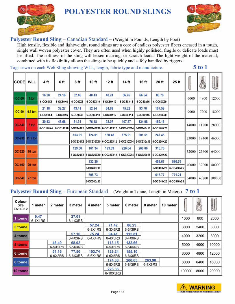
POLYESTER ROUND SLINGS
Polyester Round Sling – Canadian Standard – (Weight in Pounds, Length by Foot)
High tensile, flexible and lightweight, round slings are a core of endless polyester fibers encased in a tough, single wall woven polyester cover. They are often used when highly polished, fragile or delicate loads must be lifted. The softness of the sling will lessen marring, or scratch loads. The light weight of the material, combined with its flexibility allows the slings to be quickly and safely handled by riggers.
Tags sewn on each Web Sling showing WLL, length, fabric type and manufacture. 5 to 1
CODE WLL 4 ft 6 ft 8 ft 10 ft 12 ft 14 ft 16 ft 20 ft 25 ft
OC-60 3 ton 16.28 24.16 32.46 40.43 48.24 56.76 66.54 80.78
6000 4800 12000 6-OC60X4 6-OC60X6 6-OC60X8 6-OC60X10 6-OC60X12 6-OC60X14 6-OC60x16 6-OC60X20
OC-90 4.5 ton 21.18 32.27 43.41 52.94 64.69 75.32 93.76 107.59
9000 7200 18000 6-OC90X4 6-OC90X6 6-OC90X8 6-OC90X10 6-OC90X12 6-OC90X14 6-OC90x16 6-OC90X20
OC-140 7 ton 30.43 45.66 61.31 76.18 92.07 107.57 124.98 152.16
14000 11200 28000 6-OC140X4 6-OC140X6 6-OC140X8 6-OC140X10 6-OC140X12 6-OC140X14 6-OC140x16 6-OC140X20
OC-230 11.5 ton 103.91 124.01 150.48 175.21 201.51 247.45
23000 18400 46000 6-OC230X8 6-OC230X10 6-OC230X12 6-OC230X14 6-OC230x16 6-OC230X20
OC-320 16 ton 129.50 161.34 193.89 226.64 266.06 316.76
32000 25600 64000 6-OC320X8 6-OC320X10 6-OC320X12 6-OC320X14 6-OC320x16 6-OC320X20
OC-400 20 ton 232.30
459.67 580.76
40000 32000 80000 6-OC400x10 6-OC400x20 6-OC400x25
OC-540 27 ton 308.73
613.77 771.21
54000 43200 108000 6-OC540x10 6-OC540x20 6-OC540x25
Polyester Round Sling – European Standard – (Weight in Tonne, Length in Meters) 7 to 1
Colour DIN-
EN1492-2 1 meter 2 meter 3 meter 4 meter 5 meter 6 meter 8 meter 10 meter
1 tonne 9.47 27.01 1000 800 2000 6-1X1RS 6-1X3RS
3 tonne 57.24 71.42 86.23 3000 2400 6000 6-3X4RS 6-3X5RS 6-3X6RS
4 tonne 57.16 75.24 94.41 112.81 4000 3200 8000 6-4X3RS 6-4X4RS 6-4X5RS 6-4X6RS
5 tonne 46.49 68.02 113.15 132.66 5000 4000 10000 6-5X2RS 6-5X3RS 6-5X5RS 6-5X6RS
6 tonne 51.16 77.50 103.74 129.24 155.10 6000 4800 12000 6-6X2RS 6-6X3RS 6-6X4RS 6-6X5RS 6-6X6RS
8 tonne 174.38 200.65 263.90 8000 6400 16000 6-8X5RS 6-8X6RS 6-8X8RS
10 tonne
223.36 10000 8000 20000 6-10X5RS
Page 113
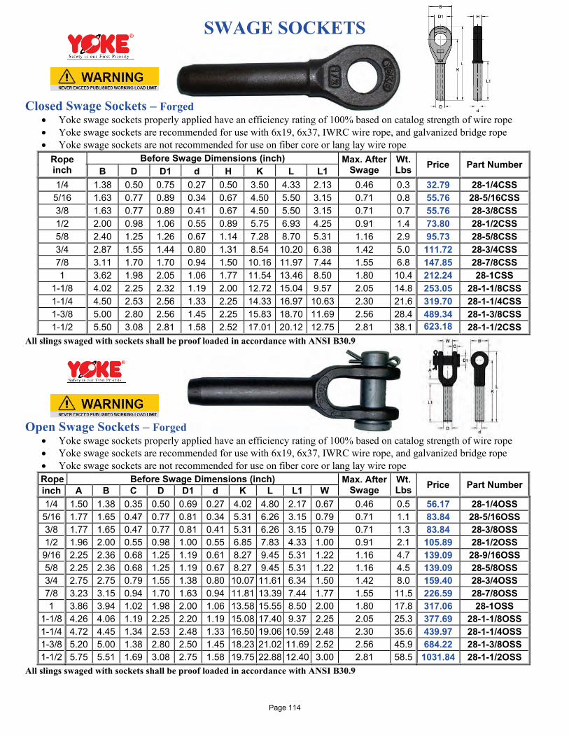
SWAGE SOCKETS Closed Swage Sockets – Forged
• Yoke swage sockets properly applied have an efficiency rating of 100% based on catalog strength of wire rope • Yoke swage sockets are recommended for use with 6x19, 6x37, IWRC wire rope, and galvanized bridge rope • Yoke swage sockets are not recommended for use on fiber core or lang lay wire rope
Rope inch
Before Swage Dimensions (inch) Max. After Swage
Wt. Lbs Price Part Number
B D D1 d H K L L1 1/4 1.38 0.50 0.75 0.27 0.50 3.50 4.33 2.13 0.46 0.3 32.79 28-1/4CSS 5/16 1.63 0.77 0.89 0.34 0.67 4.50 5.50 3.15 0.71 0.8 55.76 28-5/16CSS 3/8 1.63 0.77 0.89 0.41 0.67 4.50 5.50 3.15 0.71 0.7 55.76 28-3/8CSS 1/2 2.00 0.98 1.06 0.55 0.89 5.75 6.93 4.25 0.91 1.4 73.80 28-1/2CSS 5/8 2.40 1.25 1.26 0.67 1.14 7.28 8.70 5.31 1.16 2.9 95.73 28-5/8CSS 3/4 2.87 1.55 1.44 0.80 1.31 8.54 10.20 6.38 1.42 5.0 111.72 28-3/4CSS 7/8 3.11 1.70 1.70 0.94 1.50 10.16 11.97 7.44 1.55 6.8 147.85 28-7/8CSS 1 3.62 1.98 2.05 1.06 1.77 11.54 13.46 8.50 1.80 10.4 212.24 28-1CSS
1-1/8 4.02 2.25 2.32 1.19 2.00 12.72 15.04 9.57 2.05 14.8 253.05 28-1-1/8CSS 1-1/4 4.50 2.53 2.56 1.33 2.25 14.33 16.97 10.63 2.30 21.6 319.70 28-1-1/4CSS 1-3/8 5.00 2.80 2.56 1.45 2.25 15.83 18.70 11.69 2.56 28.4 489.34 28-1-3/8CSS 1-1/2 5.50 3.08 2.81 1.58 2.52 17.01 20.12 12.75 2.81 38.1 623.18 28-1-1/2CSS
All slings swaged with sockets shall be proof loaded in accordance with ANSI B30.9 Open Swage Sockets – Forged
• Yoke swage sockets properly applied have an efficiency rating of 100% based on catalog strength of wire rope • Yoke swage sockets are recommended for use with 6x19, 6x37, IWRC wire rope, and galvanized bridge rope • Yoke swage sockets are not recommended for use on fiber core or lang lay wire rope Rope Before Swage Dimensions (inch) Max. After
Swage Wt. Lbs Price Part Number inch A B C D D1 d K L L1 W
1/4 1.50 1.38 0.35 0.50 0.69 0.27 4.02 4.80 2.17 0.67 0.46 0.5 56.17 28-1/4OSS 5/16 1.77 1.65 0.47 0.77 0.81 0.34 5.31 6.26 3.15 0.79 0.71 1.1 83.84 28-5/16OSS 3/8 1.77 1.65 0.47 0.77 0.81 0.41 5.31 6.26 3.15 0.79 0.71 1.3 83.84 28-3/8OSS 1/2 1.96 2.00 0.55 0.98 1.00 0.55 6.85 7.83 4.33 1.00 0.91 2.1 105.89 28-1/2OSS 9/16 2.25 2.36 0.68 1.25 1.19 0.61 8.27 9.45 5.31 1.22 1.16 4.7 139.09 28-9/16OSS 5/8 2.25 2.36 0.68 1.25 1.19 0.67 8.27 9.45 5.31 1.22 1.16 4.5 139.09 28-5/8OSS 3/4 2.75 2.75 0.79 1.55 1.38 0.80 10.07 11.61 6.34 1.50 1.42 8.0 159.40 28-3/4OSS 7/8 3.23 3.15 0.94 1.70 1.63 0.94 11.81 13.39 7.44 1.77 1.55 11.5 226.59 28-7/8OSS 1 3.86 3.94 1.02 1.98 2.00 1.06 13.58 15.55 8.50 2.00 1.80 17.8 317.06 28-1OSS
1-1/8 4.26 4.06 1.19 2.25 2.20 1.19 15.08 17.40 9.37 2.25 2.05 25.3 377.69 28-1-1/8OSS 1-1/4 4.72 4.45 1.34 2.53 2.48 1.33 16.50 19.06 10.59 2.48 2.30 35.6 439.97 28-1-1/4OSS 1-3/8 5.20 5.00 1.38 2.80 2.50 1.45 18.23 21.02 11.69 2.52 2.56 45.9 684.22 28-1-3/8OSS 1-1/2 5.75 5.51 1.69 3.08 2.75 1.58 19.75 22.88 12.40 3.00 2.81 58.5 1031.84 28-1-1/2OSS
All slings swaged with sockets shall be proof loaded in accordance with ANSI B30.9
Page 114
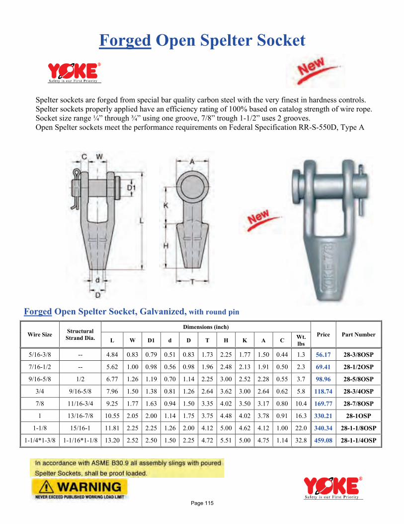
Forged Open Spelter Socket
Spelter sockets are forged from special bar quality carbon steel with the very finest in hardness controls. Spelter sockets properly applied have an efficiency rating of 100% based on catalog strength of wire rope. Socket size range ¼” through ¾” using one groove, 7/8” trough 1-1/2” uses 2 grooves. Open Spelter sockets meet the performance requirements on Federal Specification RR-S-550D, Type A
Forged Open Spelter Socket, Galvanized, with round pin
Wire Size Structural Strand Dia.
Dimensions (inch) Price Part Number
L W D1 d D T H K A C Wt. lbs
5/16-3/8 -- 4.84 0.83 0.79 0.51 0.83 1.73 2.25 1.77 1.50 0.44 1.3 56.17 28-3/8OSP
7/16-1/2 -- 5.62 1.00 0.98 0.56 0.98 1.96 2.48 2.13 1.91 0.50 2.3 69.41 28-1/2OSP
9/16-5/8 1/2 6.77 1.26 1.19 0.70 1.14 2.25 3.00 2.52 2.28 0.55 3.7 98.96 28-5/8OSP
3/4 9/16-5/8 7.96 1.50 1.38 0.81 1.26 2.64 3.62 3.00 2.64 0.62 5.8 118.74 28-3/4OSP
7/8 11/16-3/4 9.25 1.77 1.63 0.94 1.50 3.35 4.02 3.50 3.17 0.80 10.4 169.77 28-7/8OSP
1 13/16-7/8 10.55 2.05 2.00 1.14 1.75 3.75 4.48 4.02 3.78 0.91 16.3 330.21 28-1OSP
1-1/8 15/16-1 11.81 2.25 2.25 1.26 2.00 4.12 5.00 4.62 4.12 1.00 22.0 340.34 28-1-1/8OSP
1-1/4*1-3/8 1-1/16*1-1/8 13.20 2.52 2.50 1.50 2.25 4.72 5.51 5.00 4.75 1.14 32.8 459.08 28-1-1/4OSP
Page 115
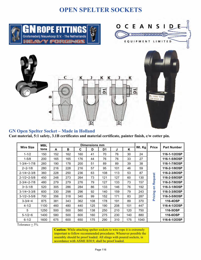
OPEN SPELTER SOCKETS
GN Open Spelter Socket – Made in Holland Cast material, 5:1 safety, 3.1B certificates and material certificate, painter finish, c/w cotter pin.
Wire Size MBL tons
Dimensions mm Wt. Kg Price Part Number A B C D D1 J K 1-1/2 150 152 162 160 41 70 76 30 24
Pric
ing
on R
eque
st
116-1-1/2OSP 1-5/8 200 165 165 176 44 76 76 33 27 116-1-5/8OSP
1-3/4~1-7/8 260 190 178 200 51 89 89 39 38 116-1-7/8OSP 2~2-1/8 280 216 228 216 57 95 101 46 59 116-2-1/8OSP
2-1/4~2-3/8 360 228 250 236 63 108 113 53 87 116-2-3/8OSP 2-1/2~2-5/8 450 248 273 264 73 121 127 60 130 116-2-5/8OSP 2-3/4~2-7/8 480 279 279 276 79 127 133 73 157 116-2-7/8OSP
3~3-1/8 520 305 286 284 86 133 146 76 192 116-3-1/8OSP 3-1/4~3-3/8 600 330 298 296 92 140 159 79 243 116-3-3/8OSP 3-1/2~3-5/8 700 356 318 340 99 152 171 83 287 116-3-5/8OSP
3-3/4~4 875 381 343 362 108 178 191 89 370 116-4OSP 4-1/2 1100 460 480 440 125 190 208 101 447 116-4-1/2OSP
5 1250 500 500 560 138 250 210 120 750 116-5OSP 5-1/2~6 1400 580 500 600 160 275 230 140 880 116-6OSP
6-1/2 1600 675 600 650 175 290 310 175 1040 116-6-1/2OSP Tolerance + 5%
Caution: While attaching spelter sockets to wire rope it is extremely important to follow recommended procedures. Whenever possible the assembly should be proof loaded. All slings with poured sockets, in accordance with ASME B30.9, shall be proof loaded.
Page 116
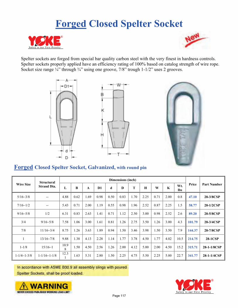
Forged Closed Spelter Socket
Spelter sockets are forged from special bar quality carbon steel with the very finest in hardness controls. Spelter sockets properly applied have an efficiency rating of 100% based on catalog strength of wire rope. Socket size range ¼” through ¾” using one groove, 7/8” trough 1-1/2” uses 2 grooves.
Forged Closed Spelter Socket, Galvanized, with round pin
Wire Size Structural Strand Dia.
Dimensions (inch) Price Part Number
L B A D1 d D T H W K Wt. lbs
5/16~3/8 -- 4.88 0.62 1.69 0.98 0.50 0.83 1.70 2.25 0.71 2.00 0.8 47.10 28-3/8CSP
7/16~1/2 -- 5.43 0.71 2.00 1.19 0.55 0.98 1.96 2.52 0.87 2.25 1.5 58.77 28-1/2CSP
9/16~5/8 1/2 6.31 0.83 2.63 1.41 0.71 1.12 2.50 3.00 0.98 2.52 2.6 89.20 28-5/8CSP
3/4 9/16~5/8 7.58 1.06 3.00 1.61 0.81 1.26 2.75 3.50 1.26 3.00 4.3 101.79 28-3/4CSP
7/8 11/16~3/4 8.75 1.26 3.63 1.89 0.94 1.50 3.46 3.98 1.50 3.50 7.9 144.37 28-7/8CSP
1 13/16~7/8 9.88 1.38 4.13 2.28 1.14 1.77 3.78 4.50 1.77 4.02 10.5 214.75 28-1CSP
1-1/8 15/16~1 10.98 1.50 4.50 2.56 1.26 2.00 4.12 5.00 2.00 4.50 15.2 315.71 28-1-1/8CSP
1-1/4~1-3/8 1-1/16~1-1/8 12.31 1.63 5.31 2.80 1.50 2.25 4.75 5.50 2.25 5.00 22.7 341.77 28-1-1/4CSP
Page 117
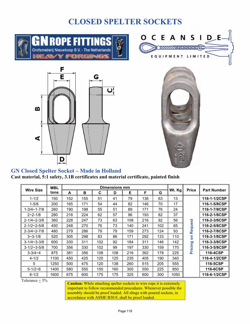
CLOSED SPELTER SOCKETS
GN Closed Spelter Socket – Made in Holland Cast material, 5:1 safety, 3.1B certificates and material certificate, painted finish
Wire Size MBL tons
Dimensions mm Wt. Kg Price Part Number A B C D E F G 1-1/2 150 152 155 51 41 79 136 63 13
Pric
ing
on R
eque
st
116-1-1/2CSP 1-5/8 200 165 171 54 44 82 146 70 17 116-1-5/8CSP
1-3/4~1-7/8 260 190 198 55 51 89 171 76 24 116-1-7/8CSP 2~2-1/8 280 216 224 62 57 96 193 82 37 116-2-1/8CSP
2-1/4~2-3/8 360 228 247 73 63 108 216 92 56 116-2-3/8CSP 2-1/2~2-5/8 450 248 270 76 73 140 241 102 65 116-2-5/8CSP 2-3/4~2-7/8 480 279 286 79 79 159 273 124 93 116-2-7/8CSP
3~3-1/8 520 305 298 83 86 171 292 133 110 116-3-1/8CSP 3-1/4~3-3/8 600 330 311 102 92 184 311 146 142 116-3-3/8CSP 3-1/2~3-5/8 700 356 330 102 99 197 330 159 170 116-3-5/8CSP
3-3/4~4 875 381 356 108 108 216 362 178 225 116-4CSP 4-1/2 1100 450 425 120 125 235 405 190 340 116-4-1/2CSP
5 1250 500 475 120 138 260 515 205 555 116-5CSP 5-1/2~6 1400 580 550 150 160 300 550 225 850 116-6CSP
6-1/2 1600 675 600 175 175 325 600 300 1050 116-6-1/2CSP Tolerance + 5%
Caution: While attaching spelter sockets to wire rope it is extremely important to follow recommended procedures. Whenever possible the assembly should be proof loaded. All slings with poured sockets, in accordance with ASME B30.9, shall be proof loaded.
Page 118
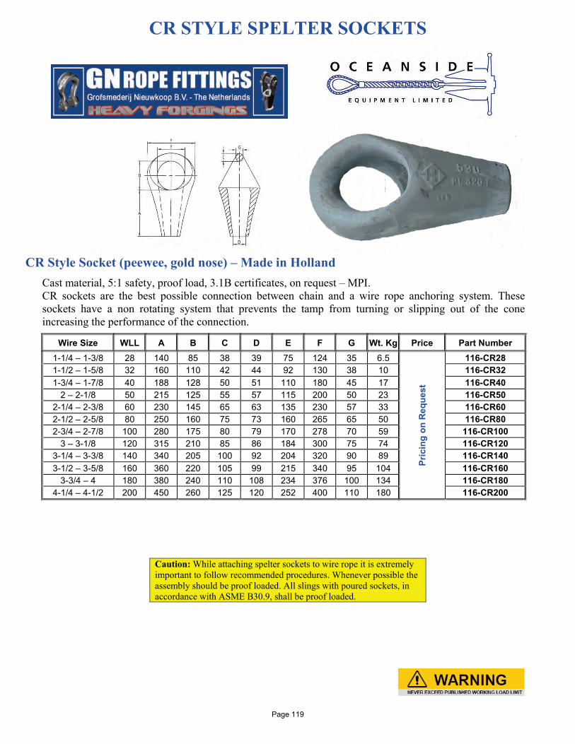
CR STYLE SPELTER SOCKETS
CR Style Socket (peewee, gold nose) – Made in Holland
Cast material, 5:1 safety, proof load, 3.1B certificates, on request – MPI. CR sockets are the best possible connection between chain and a wire rope anchoring system. These sockets have a non rotating system that prevents the tamp from turning or slipping out of the cone increasing the performance of the connection.
Wire Size WLL A B C D E F G Wt. Kg Price Part Number 1-1/4 – 1-3/8 28 140 85 38 39 75 124 35 6.5
Pric
ing
on R
eque
st
116-CR28 1-1/2 – 1-5/8 32 160 110 42 44 92 130 38 10 116-CR32 1-3/4 – 1-7/8 40 188 128 50 51 110 180 45 17 116-CR40
2 – 2-1/8 50 215 125 55 57 115 200 50 23 116-CR50 2-1/4 – 2-3/8 60 230 145 65 63 135 230 57 33 116-CR60 2-1/2 – 2-5/8 80 250 160 75 73 160 265 65 50 116-CR80 2-3/4 – 2-7/8 100 280 175 80 79 170 278 70 59 116-CR100
3 – 3-1/8 120 315 210 85 86 184 300 75 74 116-CR120 3-1/4 – 3-3/8 140 340 205 100 92 204 320 90 89 116-CR140 3-1/2 – 3-5/8 160 360 220 105 99 215 340 95 104 116-CR160
3-3/4 – 4 180 380 240 110 108 234 376 100 134 116-CR180 4-1/4 – 4-1/2 200 450 260 125 120 252 400 110 180 116-CR200
Caution: While attaching spelter sockets to wire rope it is extremely important to follow recommended procedures. Whenever possible the assembly should be proof loaded. All slings with poured sockets, in accordance with ASME B30.9, shall be proof loaded.
Page 119
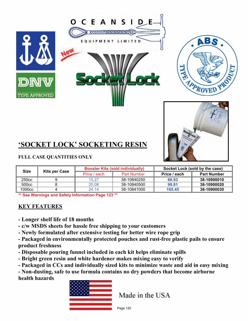
‘SOCKET LOCK’ SOCKETING RESIN FULL CASE QUANTITIES ONLY
Size Kits per Case Booster Kits (sold individually) Socket Lock (sold by the case) Price / each Part Number Price / each Part Number
250cc 9 15.27 38-10840250 68.93 38-10900010 500cc 8 20.08 38-10840500 99.81 38-10900020 1000cc 4 24.14 38-10841000 165.45 38-10900030
** See Warnings and Safety Information Page 123 ** KEY FEATURES - Longer shelf life of 18 months - c/w MSDS sheets for hassle free shipping to your customers - Newly formulated after extensive testing for better wire rope grip - Packaged in environmentally protected pouches and rust-free plastic pails to ensure product freshness - Disposable pouring funnel included in each kit helps eliminate spills - Bright green resin and white hardener makes mixing easy to verify - Packaged in CCs and individually sized kits to minimize waste and aid in easy mixing - Non-dusting, safe to use formula contains no dry powders that become airborne health hazards
Page 120
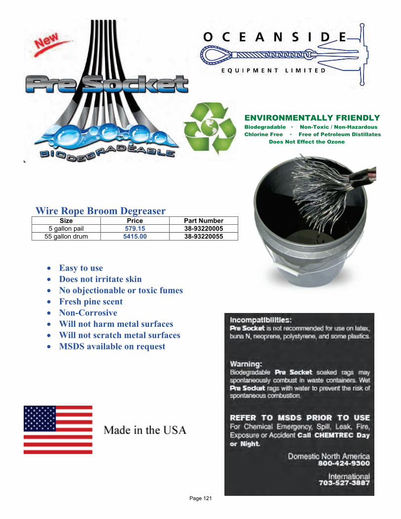
Wire Rope Broom Degreaser
Size Price Part Number 5 gallon pail 579.15 38-93220005
55 gallon drum 5415.00 38-93220055
• Easy to use • Does not irritate skin • No objectionable or toxic fumes • Fresh pine scent • Non-Corrosive • Will not harm metal surfaces • Will not scratch metal surfaces • MSDS available on request
ENVIRONMENTALLY FRIENDLY Biodegradable ∙ Non-Toxic / Non-Hazardous Chlorine Free ∙ Free of Petroleum Distillates Does Not Effect the Ozone
Page 121
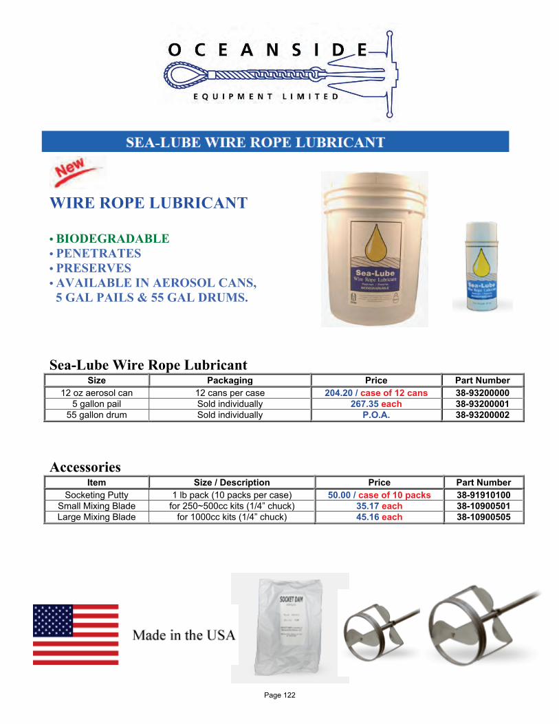
WIRE ROPE LUBRICANT • BIODEGRADABLE • PENETRATES • PRESERVES • AVAILABLE IN AEROSOL CANS, 5 GAL PAILS & 55 GAL DRUMS. Sea-Lube Wire Rope Lubricant
Size Packaging Price Part Number 12 oz aerosol can 12 cans per case 204.20 / case of 12 cans 38-93200000
5 gallon pail Sold individually 267.35 each 38-93200001 55 gallon drum Sold individually P.O.A. 38-93200002
Accessories
Item Size / Description Price Part Number Socketing Putty 1 lb pack (10 packs per case) 50.00 / case of 10 packs 38-91910100
Small Mixing Blade for 250~500cc kits (1/4” chuck) 35.17 each 38-10900501 Large Mixing Blade for 1000cc kits (1/4” chuck) 45.16 each 38-10900505
Page 122
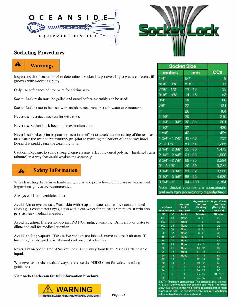
Socketing Procedures
Inspect inside of socket bowl to determine if socket has grooves. If grooves are present, fill grooves with Socketing putty. Only use soft annealed iron wire for seizing wire. Socket Lock resin must be gelled and cured before assembly can be used. Socket Lock is not to be used with stainless steel rope in a salt water environment. Never use oversized sockets for wire rope. Never use Socket Lock beyond the expiration date. Never heat socket prior to pouring resin in an effort to accelerate the curing of the resin as it may cause the resin to prematurely gel prior to reaching the bottom of the socket bowl. Doing this could cause the assembly to fail. Caution: Exposure to some strong chemicals may affect the cured polymer (hardened resin mixture) in a way that could weaken the assembly.
When handling the resin or hardener, goggles and protective clothing are recommended. Impervious gloves are recommended. Always work in a ventilated area. Avoid skin or eye contact. Wash skin with soap and water and remove contaminated clothing. If contact with eyes, flush with clean water for at least 15 minutes. If irritation persists, seek medical attention. Avoid ingestion. If ingestion occurs, DO NOT induce vomiting. Drink milk or water to dilute and call for medical attention. Avoid inhaling vapours. If excessive vapours are inhaled, move to a fresh air area. If breathing has stopped or is laboured seek medical attention. Never aim an open flame at Socket Lock. Keep away from heat. Resin is a flammable liquid. Whenever using chemicals, always reference the MSDS sheet for safety handling guidelines. Visit socket-lock.com for full information brochure
Warnings
Safety Information
Page 123
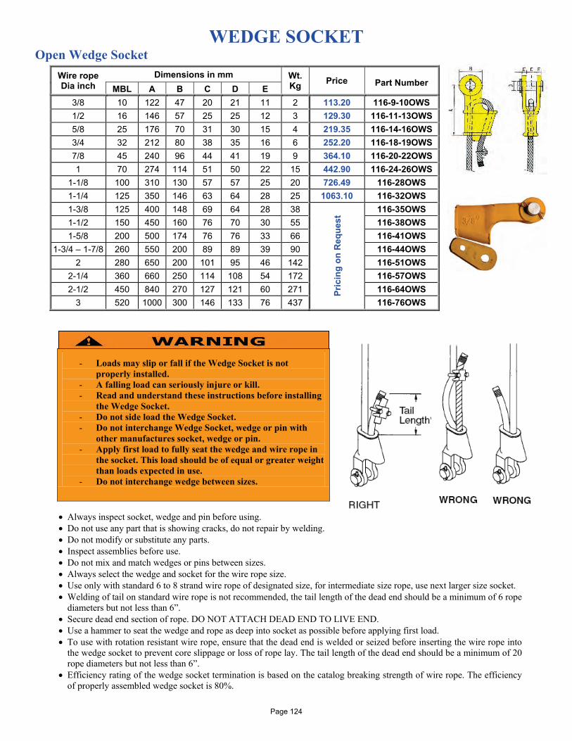
WEDGE SOCKET Open Wedge Socket
• Always inspect socket, wedge and pin before using. • Do not use any part that is showing cracks, do not repair by welding. • Do not modify or substitute any parts. • Inspect assemblies before use. • Do not mix and match wedges or pins between sizes. • Always select the wedge and socket for the wire rope size. • Use only with standard 6 to 8 strand wire rope of designated size, for intermediate size rope, use next larger size socket. • Welding of tail on standard wire rope is not recommended, the tail length of the dead end should be a minimum of 6 rope
diameters but not less than 6”. • Secure dead end section of rope. DO NOT ATTACH DEAD END TO LIVE END. • Use a hammer to seat the wedge and rope as deep into socket as possible before applying first load. • To use with rotation resistant wire rope, ensure that the dead end is welded or seized before inserting the wire rope into
the wedge socket to prevent core slippage or loss of rope lay. The tail length of the dead end should be a minimum of 20 rope diameters but not less than 6”.
• Efficiency rating of the wedge socket termination is based on the catalog breaking strength of wire rope. The efficiency of properly assembled wedge socket is 80%.
Wire rope Dia inch
Dimensions in mm Wt. Kg Price
Part Number
MBL A B C D E 3/8 10 122 47 20 21 11 2 113.20 116-9-10OWS 1/2 16 146 57 25 25 12 3 129.30 116-11-13OWS 5/8 25 176 70 31 30 15 4 219.35 116-14-16OWS 3/4 32 212 80 38 35 16 6 252.20 116-18-19OWS 7/8 45 240 96 44 41 19 9 364.10 116-20-22OWS 1 70 274 114 51 50 22 15 442.90 116-24-26OWS
1-1/8 100 310 130 57 57 25 20 726.49 116-28OWS 1-1/4 125 350 146 63 64 28 25 1063.10 116-32OWS 1-3/8 125 400 148 69 64 28 38
Pric
ing
on R
eque
st 116-35OWS
1-1/2 150 450 160 76 70 30 55 116-38OWS 1-5/8 200 500 174 76 76 33 66 116-41OWS
1-3/4 – 1-7/8 260 550 200 89 89 39 90 116-44OWS 2 280 650 200 101 95 46 142 116-51OWS
2-1/4 360 660 250 114 108 54 172 116-57OWS 2-1/2 450 840 270 127 121 60 271 116-64OWS
3 520 1000 300 146 133 76 437 116-76OWS
- Loads may slip or fall if the Wedge Socket is not
properly installed. - A falling load can seriously injure or kill. - Read and understand these instructions before installing
the Wedge Socket. - Do not side load the Wedge Socket. - Do not interchange Wedge Socket, wedge or pin with
other manufactures socket, wedge or pin. - Apply first load to fully seat the wedge and wire rope in
the socket. This load should be of equal or greater weight than loads expected in use.
- Do not interchange wedge between sizes.
Page 124

SWIVELS Swivel Eye & Eye – Forged (5:1 WLL)
- Conforms to Federal Specification RR-C-271D, Type VII, Class 2 - Forged, Hot Dip Galvanized - Quenched & Tempered
Size (in)
WLL (lbs)
Weight (lbs)
Dimensions (in) Price Part Number A B C L
3/8 2,250 0.71 0.94 1.50 1.25 4.31 7.05 6-3/8SWLEE 1/2 3,600 1.32 1.31 2.00 1.50 5.44 10.67 6-1/2SWLEE 5/8 5,200 2.49 1.56 2.38 1.75 6.56 16.45 6-5/8SWLEE 3/4 7,200 4.02 1.75 2.63 2.00 7.19 24.16 6-3/4SWLEE 1 12,500 8.95 2.31 3.50 2.50 9.63 62.37 6-1SWLEE
1 1/4 18,000 16.37 2.69 3.69 3.13 11.44 207.09 6-1-1/4SWLEE 1 1/2 45,200 45.79 4.40 6.11 3.95 17.51 584.86 6-1-1/2SWLEE
These swivels are positioning devices and are not intended to rotate under load. Swivel Jaw & Eye – Forged (5:1 WLL)
- Conforms to Federal Specification RR-C-271D, Type VII, Class 2 - Forged, Hot Dip Galvanized - Quenched & Tempered
Size (in)
WLL (lbs)
Weight (lbs)
Dimensions (in) Price Part Number A B C K R length
3/8 2,250 0.66 2.00 0.94 1.25 0.63 3.63 4.75 7.85 6-3/8SWLJE 1/2 3,600 1.34 2.50 1.31 1.50 0.75 4.50 6.06 11.05 6-1/2SWLJE 5/8 5,200 2.48 3.00 1.56 1.75 0.94 5.31 7.31 18.10 6-5/8SWLJE 3/4 7,200 3.88 3.50 1.75 2.00 1.13 6.06 8.31 27.72 6-3/4SWLJE 1 12,500 9.84 4.50 2.31 2.50 1.75 8.56 11.69 70.10 6-1SWLJE
1 1/4 18,000 15.75 5.69 2.69 3.13 2.06 9.44 13.13 285.69 6-1-1/4SWLJE These swivels are positioning devices and are not intended to rotate under load.
Swivel Steel
Type Price Part Number 1-1/4” short bow swivels 248.30 6-1-1/4”SBSWL
Page 125
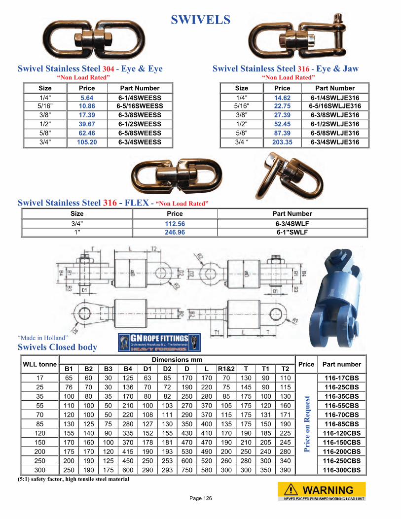
SWIVELS Swivel Stainless Steel 304 - Eye & Eye Swivel Stainless Steel 316 - Eye & Jaw “Non Load Rated” “Non Load Rated”
Swivel Stainless Steel 316 - FLEX - “Non Load Rated”
Size Price Part Number 3/4" 112.56 6-3/4SWLF 1" 246.96 6-1"SWLF
“Made in Holland” Swivels Closed body
WLL tonne Dimensions mm
Price Part number B1 B2 B3 B4 D1 D2 D L R1&2 T T1 T2
17 65 60 30 125 63 65 170 170 70 130 90 110
Pric
e on
Req
uest
116-17CBS 25 76 70 30 136 70 72 190 220 75 145 90 115 116-25CBS 35 100 80 35 170 80 82 250 280 85 175 100 130 116-35CBS 55 110 100 50 210 100 103 270 370 105 175 120 160 116-55CBS 70 120 100 50 220 108 111 290 370 115 175 131 171 116-70CBS 85 130 125 75 280 127 130 350 400 135 175 150 190 116-85CBS
120 155 140 90 335 152 155 430 410 170 190 185 225 116-120CBS 150 170 160 100 370 178 181 470 470 190 210 205 245 116-150CBS 200 175 170 120 415 190 193 530 490 200 250 240 280 116-200CBS 250 200 190 125 450 250 253 600 520 260 280 300 340 116-250CBS 300 250 190 175 600 290 293 750 580 300 300 350 390 116-300CBS
(5:1) safety factor, high tensile steel material
Size Price Part Number 1/4" 5.64 6-1/4SWEESS
5/16" 10.86 6-5/16SWEESS 3/8" 17.39 6-3/8SWEESS 1/2" 39.67 6-1/2SWEESS 5/8" 62.46 6-5/8SWEESS 3/4" 105.20 6-3/4SWEESS
Size Price Part Number 1/4" 14.62 6-1/4SWLJE316
5/16" 22.75 6-5/16SWLJE316 3/8" 27.39 6-3/8SWLJE316 1/2" 52.45 6-1/2SWLJE316 5/8" 87.39 6-5/8SWLJE316 3/4 “ 203.35 6-3/4SWLJE316
Page 126

The Inter-M®Swivel is a multi-purpose mooring swivel that can join chains of the same or dissimilar sizes together allowing for 360 degree rotational freedom while under tension. ® Inter-M Assembly Connecting directly into studless or common stud-link chain, the swivel does not require any kenters or joining shackles. This is not only an economical advantage but also a time saving hook-up benefit. The assembly of mooring equipment on the back-deck is time-critical and the Inter-M®Swivel reduces the number of connections in the system while still providing rotational freedom for assembly, anchor manipulation, wire or chain twist and overall torsional control. Inter-M® Advantages using our knowledge of Long Term Mooring (LTM) connectors and extensive experience with H-Link and shackle manufacturing, the Inter-M Swivel combines technologies that have been introduced on deepwater and general chain-to-chain connectors. These technological advances allow the Inter-M® Swivel to be a cutting edge, deeper water, longer-term mooring swivel that compliments the chain grades being installed or recovered. Inter-M® Quality Each Inter-M® Swivel is proof load tested to the chain grade loads and 1 in every 25 are taken to extreme break loads to ensure they are entirely fit for purpose. The 76mm R4 Inter-M®Swivel is proof load (PL) tested to 4731kN (1064 kips) and break load (MBL) tested to 8000kN (1799 kips).
Page 127
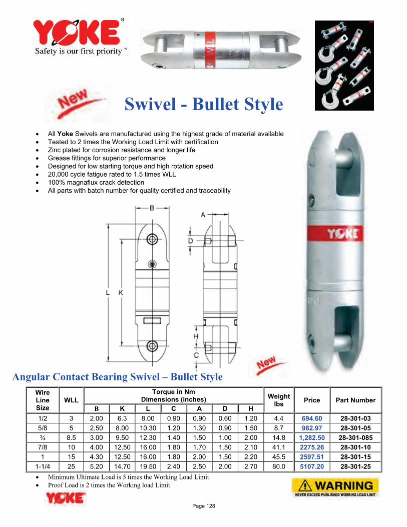
Swivel - Bullet Style
• All Yoke Swivels are manufactured using the highest grade of material available • Tested to 2 times the Working Load Limit with certification • Zinc plated for corrosion resistance and longer life • Grease fittings for superior performance • Designed for low starting torque and high rotation speed • 20,000 cycle fatigue rated to 1.5 times WLL • 100% magnaflux crack detection • All parts with batch number for quality certified and traceability
Angular Contact Bearing Swivel – Bullet Style
Wire Line Size
WLL Torque in Nm
Dimensions (inches) Weight lbs Price Part Number
B K L C A D H 1/2 3 2.00 6.3 8.00 0.90 0.90 0.60 1.20 4.4 694.60 28-301-03 5/8 5 2.50 8.00 10.30 1.20 1.30 0.90 1.50 8.7 982.97 28-301-05 ¾ 8.5 3.00 9.50 12.30 1.40 1.50 1.00 2.00 14.8 1,282.50 28-301-085
7/8 10 4.00 12.50 16.00 1.80 1.70 1.50 2.10 41.1 2275.26 28-301-10 1 15 4.30 12.50 16.00 1.80 2.00 1.50 2.20 45.5 2597.51 28-301-15
1-1/4 25 5.20 14.70 19.50 2.40 2.50 2.00 2.70 80.0 5107.20 28-301-25 • Minimum Ultimate Load is 5 times the Working Load Limit • Proof Load is 2 times the Working load Limit
Page 128
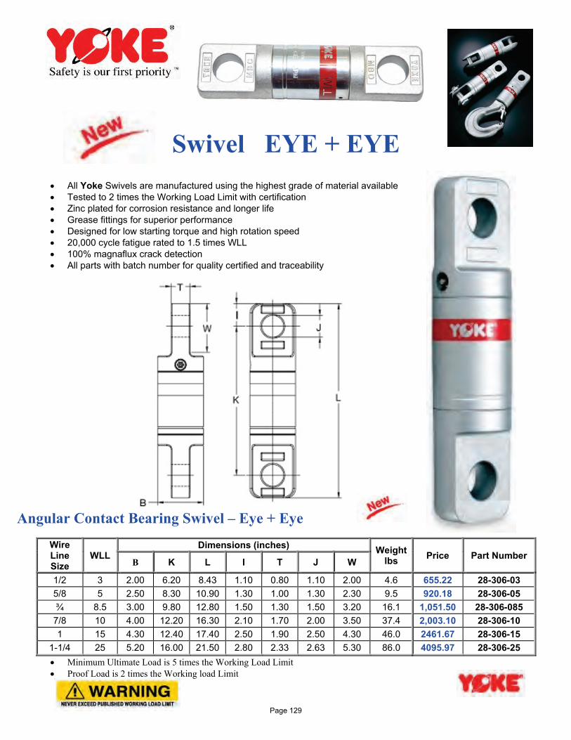
Swivel EYE + EYE
• All Yoke Swivels are manufactured using the highest grade of material available • Tested to 2 times the Working Load Limit with certification • Zinc plated for corrosion resistance and longer life • Grease fittings for superior performance • Designed for low starting torque and high rotation speed • 20,000 cycle fatigue rated to 1.5 times WLL • 100% magnaflux crack detection • All parts with batch number for quality certified and traceability
Angular Contact Bearing Swivel – Eye + Eye
Wire Line Size
WLL Dimensions (inches) Weight
lbs Price Part Number B K L I T J W
1/2 3 2.00 6.20 8.43 1.10 0.80 1.10 2.00 4.6 655.22 28-306-03 5/8 5 2.50 8.30 10.90 1.30 1.00 1.30 2.30 9.5 920.18 28-306-05 ¾ 8.5 3.00 9.80 12.80 1.50 1.30 1.50 3.20 16.1 1,051.50 28-306-085
7/8 10 4.00 12.20 16.30 2.10 1.70 2.00 3.50 37.4 2,003.10 28-306-10 1 15 4.30 12.40 17.40 2.50 1.90 2.50 4.30 46.0 2461.67 28-306-15
1-1/4 25 5.20 16.00 21.50 2.80 2.33 2.63 5.30 86.0 4095.97 28-306-25 • Minimum Ultimate Load is 5 times the Working Load Limit • Proof Load is 2 times the Working load Limit
Page 129
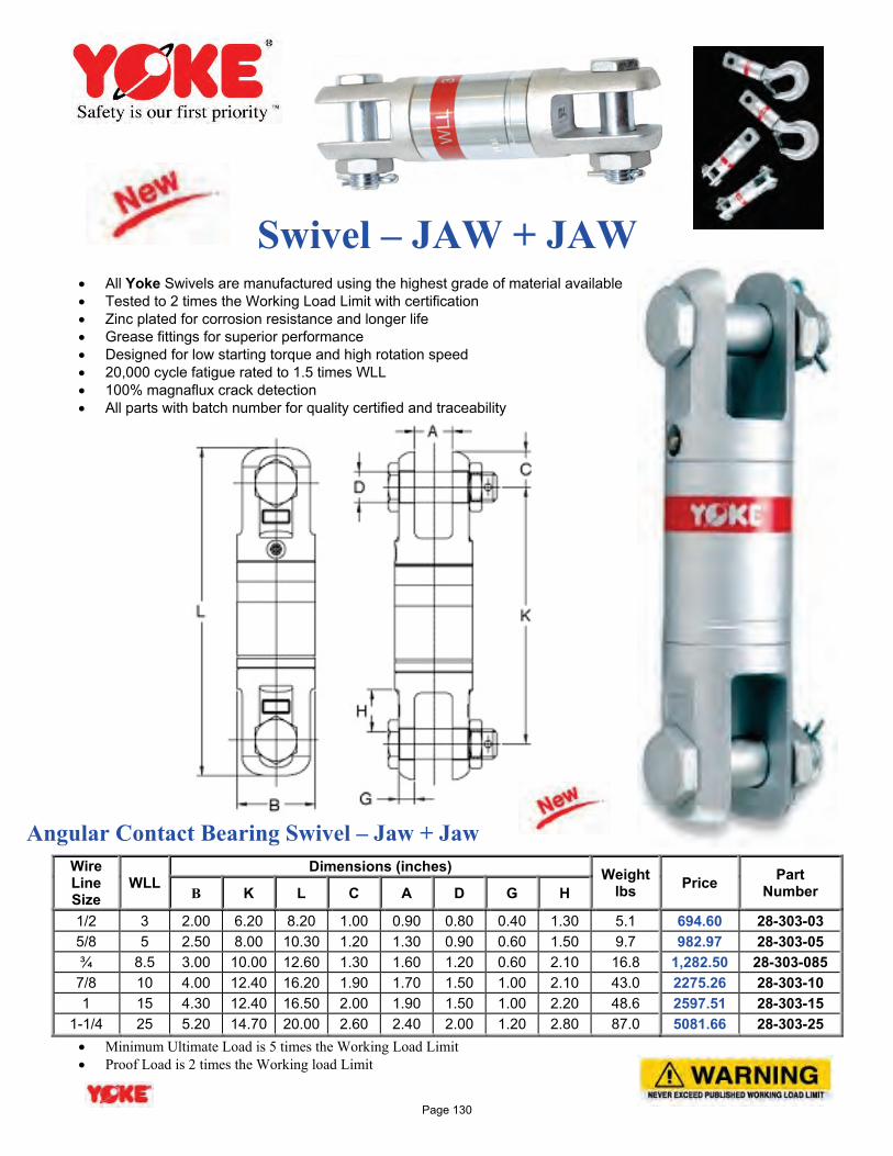
Swivel – JAW + JAW
• All Yoke Swivels are manufactured using the highest grade of material available • Tested to 2 times the Working Load Limit with certification • Zinc plated for corrosion resistance and longer life • Grease fittings for superior performance • Designed for low starting torque and high rotation speed • 20,000 cycle fatigue rated to 1.5 times WLL • 100% magnaflux crack detection • All parts with batch number for quality certified and traceability
Angular Contact Bearing Swivel – Jaw + Jaw
Wire Line Size
WLL Dimensions (inches) Weight
lbs Price Part Number B K L C A D G H
1/2 3 2.00 6.20 8.20 1.00 0.90 0.80 0.40 1.30 5.1 694.60 28-303-03 5/8 5 2.50 8.00 10.30 1.20 1.30 0.90 0.60 1.50 9.7 982.97 28-303-05 ¾ 8.5 3.00 10.00 12.60 1.30 1.60 1.20 0.60 2.10 16.8 1,282.50 28-303-085 7/8 10 4.00 12.40 16.20 1.90 1.70 1.50 1.00 2.10 43.0 2275.26 28-303-10 1 15 4.30 12.40 16.50 2.00 1.90 1.50 1.00 2.20 48.6 2597.51 28-303-15
1-1/4 25 5.20 14.70 20.00 2.60 2.40 2.00 1.20 2.80 87.0 5081.66 28-303-25 • Minimum Ultimate Load is 5 times the Working Load Limit • Proof Load is 2 times the Working load Limit
Page 130
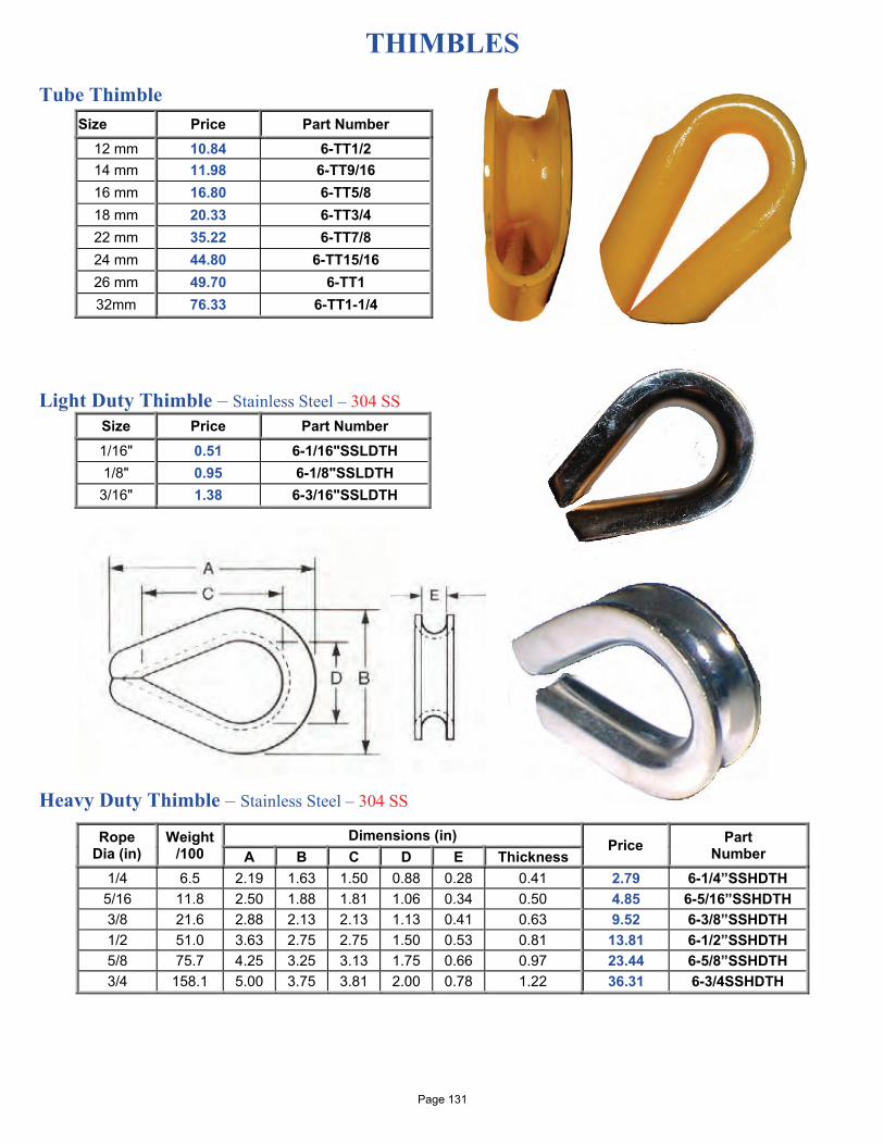
THIMBLES Tube Thimble
Light Duty Thimble – Stainless Steel – 304 SS
Size Price Part Number 1/16" 0.51 6-1/16"SSLDTH 1/8" 0.95 6-1/8"SSLDTH
3/16" 1.38 6-3/16"SSLDTH
Heavy Duty Thimble – Stainless Steel – 304 SS
Size Price Part Number 12 mm 10.84 6-TT1/2 14 mm 11.98 6-TT9/16 16 mm 16.80 6-TT5/8 18 mm 20.33 6-TT3/4 22 mm 35.22 6-TT7/8 24 mm 44.80 6-TT15/16 26 mm 49.70 6-TT1 32mm 76.33 6-TT1-1/4
Rope Dia (in)
Weight /100
Dimensions (in) Price Part Number A B C D E Thickness
1/4 6.5 2.19 1.63 1.50 0.88 0.28 0.41 2.79 6-1/4”SSHDTH 5/16 11.8 2.50 1.88 1.81 1.06 0.34 0.50 4.85 6-5/16”SSHDTH 3/8 21.6 2.88 2.13 2.13 1.13 0.41 0.63 9.52 6-3/8”SSHDTH 1/2 51.0 3.63 2.75 2.75 1.50 0.53 0.81 13.81 6-1/2”SSHDTH 5/8 75.7 4.25 3.25 3.13 1.75 0.66 0.97 23.44 6-5/8”SSHDTH 3/4 158.1 5.00 3.75 3.81 2.00 0.78 1.22 36.31 6-3/4SSHDTH
Page 131
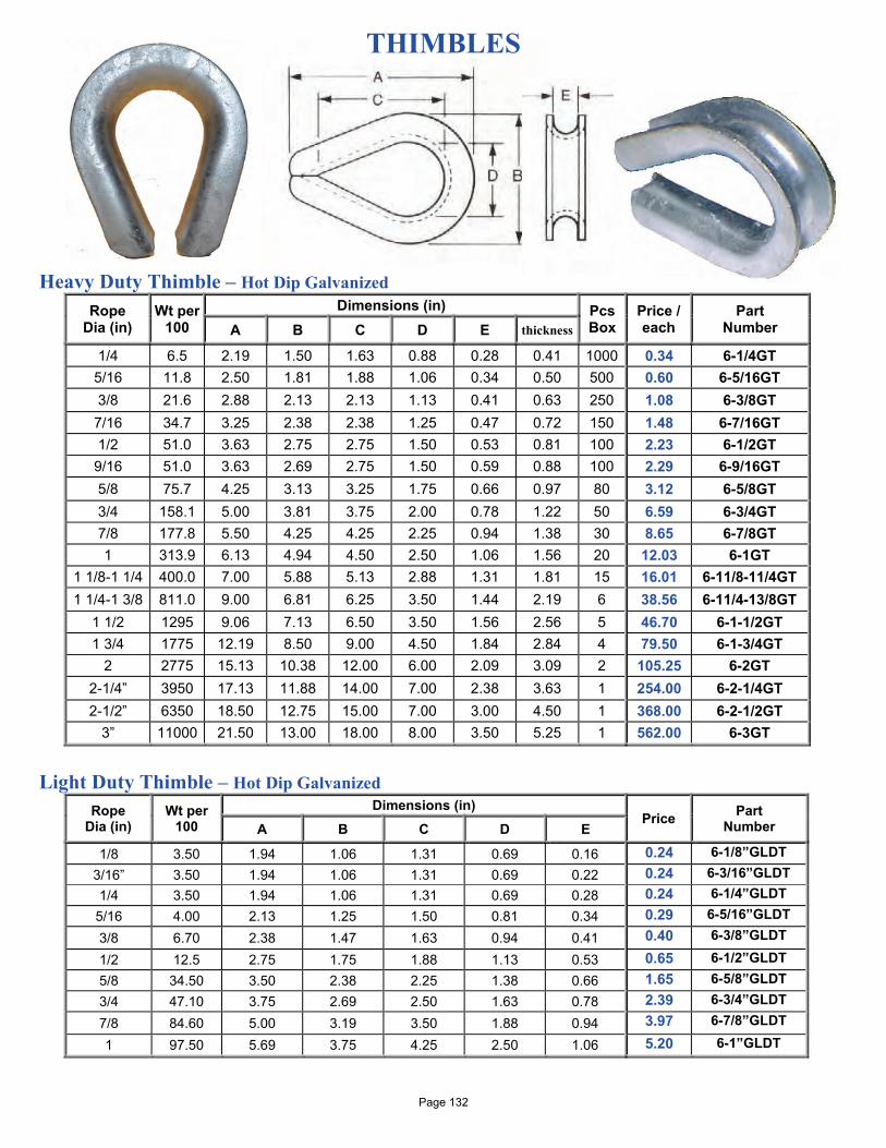
THIMBLES Heavy Duty Thimble – Hot Dip Galvanized
Rope Dia (in)
Wt per 100
Dimensions (in) Pcs Box
Price / each
Part Number A B C D E thickness
1/4 6.5 2.19 1.50 1.63 0.88 0.28 0.41 1000 0.34 6-1/4GT 5/16 11.8 2.50 1.81 1.88 1.06 0.34 0.50 500 0.60 6-5/16GT 3/8 21.6 2.88 2.13 2.13 1.13 0.41 0.63 250 1.08 6-3/8GT 7/16 34.7 3.25 2.38 2.38 1.25 0.47 0.72 150 1.48 6-7/16GT 1/2 51.0 3.63 2.75 2.75 1.50 0.53 0.81 100 2.23 6-1/2GT 9/16 51.0 3.63 2.69 2.75 1.50 0.59 0.88 100 2.29 6-9/16GT 5/8 75.7 4.25 3.13 3.25 1.75 0.66 0.97 80 3.12 6-5/8GT 3/4 158.1 5.00 3.81 3.75 2.00 0.78 1.22 50 6.59 6-3/4GT 7/8 177.8 5.50 4.25 4.25 2.25 0.94 1.38 30 8.65 6-7/8GT 1 313.9 6.13 4.94 4.50 2.50 1.06 1.56 20 12.03 6-1GT
1 1/8-1 1/4 400.0 7.00 5.88 5.13 2.88 1.31 1.81 15 16.01 6-11/8-11/4GT 1 1/4-1 3/8 811.0 9.00 6.81 6.25 3.50 1.44 2.19 6 38.56 6-11/4-13/8GT
1 1/2 1295 9.06 7.13 6.50 3.50 1.56 2.56 5 46.70 6-1-1/2GT 1 3/4 1775 12.19 8.50 9.00 4.50 1.84 2.84 4 79.50 6-1-3/4GT
2 2775 15.13 10.38 12.00 6.00 2.09 3.09 2 105.25 6-2GT 2-1/4” 3950 17.13 11.88 14.00 7.00 2.38 3.63 1 254.00 6-2-1/4GT 2-1/2” 6350 18.50 12.75 15.00 7.00 3.00 4.50 1 368.00 6-2-1/2GT
3” 11000 21.50 13.00 18.00 8.00 3.50 5.25 1 562.00 6-3GT
Light Duty Thimble – Hot Dip Galvanized
Rope Dia (in)
Wt per 100
Dimensions (in) Price Part
Number A B C D E
1/8 3.50 1.94 1.06 1.31 0.69 0.16 0.24 6-1/8”GLDT 3/16” 3.50 1.94 1.06 1.31 0.69 0.22 0.24 6-3/16”GLDT 1/4 3.50 1.94 1.06 1.31 0.69 0.28 0.24 6-1/4”GLDT
5/16 4.00 2.13 1.25 1.50 0.81 0.34 0.29 6-5/16”GLDT 3/8 6.70 2.38 1.47 1.63 0.94 0.41 0.40 6-3/8”GLDT
1/2 12.5 2.75 1.75 1.88 1.13 0.53 0.65 6-1/2”GLDT 5/8 34.50 3.50 2.38 2.25 1.38 0.66 1.65 6-5/8”GLDT 3/4 47.10 3.75 2.69 2.50 1.63 0.78 2.39 6-3/4”GLDT 7/8 84.60 5.00 3.19 3.50 1.88 0.94 3.97 6-7/8”GLDT
1 97.50 5.69 3.75 4.25 2.50 1.06 5.20 6-1”GLDT
Page 132
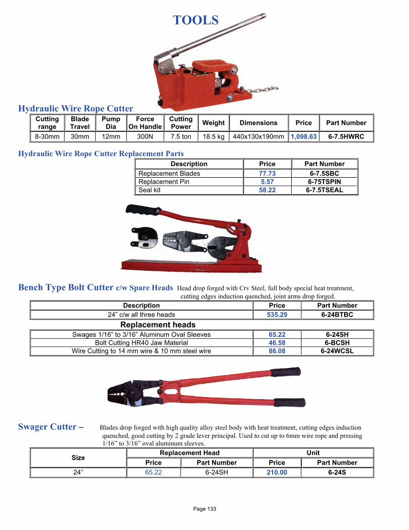
TOOLS Hydraulic Wire Rope Cutter
Cutting range
Blade Travel
Pump Dia
Force On Handle
Cutting Power Weight Dimensions Price Part Number
8-30mm 30mm 12mm 300N 7.5 ton 18.5 kg 440x130x190mm 1,098.63 6-7.5HWRC Hydraulic Wire Rope Cutter Replacement Parts
Description Price Part Number Replacement Blades 77.73 6-7.5SBC Replacement Pin 5.57 6-75TSPIN Seal kit 58.22 6-7.5TSEAL
Bench Type Bolt Cutter c/w Spare Heads Head drop forged with Crv Steel, full body special heat treatment,
cutting edges induction quenched, joint arms drop forged. Description Price Part Number
24” c/w all three heads 535.29 6-24BTBC Replacement heads
Swages 1/16” to 3/16” Aluminum Oval Sleeves 65.22 6-24SH Bolt Cutting HR40 Jaw Material 46.58 6-BCSH
Wire Cutting to 14 mm wire & 10 mm steel wire 86.08 6-24WCSL
Swager Cutter – Blades drop forged with high quality alloy steel body with heat treatment, cutting edges induction
quenched, good cutting by 2 grade lever principal. Used to cut up to 6mm wire rope and pressing 1/16” to 3/16” oval aluminum sleeves.
Size Replacement Head Unit
Price Part Number Price Part Number 24” 65.22 6-24SH 210.00 6-24S
Page 133
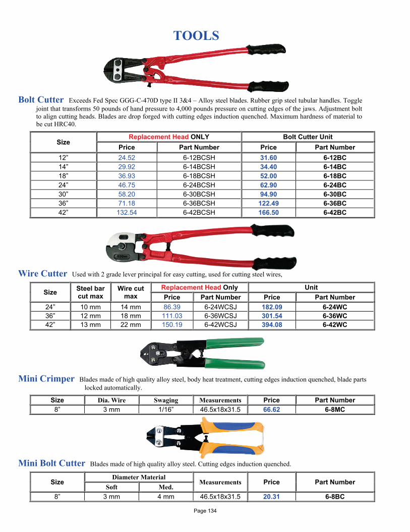
TOOLS
Bolt Cutter Exceeds Fed Spec GGG-C-470D type II 3&4 – Alloy steel blades. Rubber grip steel tubular handles. Toggle joint that transforms 50 pounds of hand pressure to 4,000 pounds pressure on cutting edges of the jaws. Adjustment bolt to align cutting heads. Blades are drop forged with cutting edges induction quenched. Maximum hardness of material to be cut HRC40.
Size Replacement Head ONLY Bolt Cutter Unit
Price Part Number Price Part Number 12” 24.52 6-12BCSH 31.60 6-12BC 14” 29.92 6-14BCSH 34.40 6-14BC 18” 36.93 6-18BCSH 52.00 6-18BC 24” 46.75 6-24BCSH 62.90 6-24BC 30” 58.20 6-30BCSH 94.90 6-30BC 36” 71.18 6-36BCSH 122.49 6-36BC 42” 132.54 6-42BCSH 166.50 6-42BC
Wire Cutter Used with 2 grade lever principal for easy cutting, used for cutting steel wires,
Size Steel bar cut max
Wire cut max
Replacement Head Only Unit Price Part Number Price Part Number
24” 10 mm 14 mm 86.39 6-24WCSJ 182.09 6-24WC 36” 12 mm 18 mm 111.03 6-36WCSJ 301.54 6-36WC 42” 13 mm 22 mm 150.19 6-42WCSJ 394.08 6-42WC
Mini Crimper Blades made of high quality alloy steel, body heat treatment, cutting edges induction quenched, blade parts
locked automatically.
Size Dia. Wire Swaging Measurements Price Part Number 8” 3 mm 1/16” 46.5x18x31.5 66.62 6-8MC
Mini Bolt Cutter Blades made of high quality alloy steel. Cutting edges induction quenched.
Size Diameter Material
Measurements Price Part Number Soft Med.
8” 3 mm 4 mm 46.5x18x31.5 20.31 6-8BC
Page 134
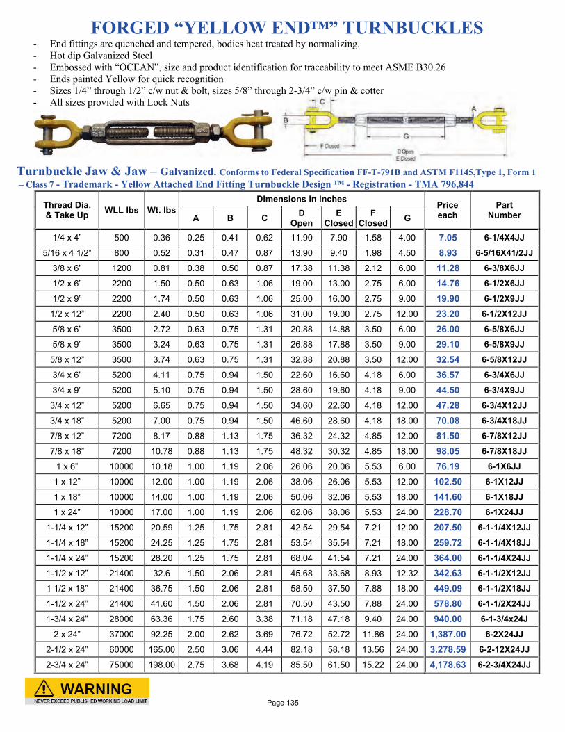
FORGED “YELLOW END™” TURNBUCKLES - End fittings are quenched and tempered, bodies heat treated by normalizing. - Hot dip Galvanized Steel - Embossed with “OCEAN”, size and product identification for traceability to meet ASME B30.26 - Ends painted Yellow for quick recognition - Sizes 1/4” through 1/2” c/w nut & bolt, sizes 5/8” through 2-3/4” c/w pin & cotter - All sizes provided with Lock Nuts
Turnbuckle Jaw & Jaw – Galvanized. Conforms to Federal Specification FF-T-791B and ASTM F1145,Type 1, Form 1 – Class 7 - Trademark - Yellow Attached End Fitting Turnbuckle Design ™ - Registration - TMA 796,844
Thread Dia. & Take Up WLL lbs Wt. lbs
Dimensions in inches Price each
Part Number A B C D
Open E
Closed F
Closed G
1/4 x 4” 500 0.36 0.25 0.41 0.62 11.90 7.90 1.58 4.00 7.05 6-1/4X4JJ
5/16 x 4 1/2” 800 0.52 0.31 0.47 0.87 13.90 9.40 1.98 4.50 8.93 6-5/16X41/2JJ
3/8 x 6” 1200 0.81 0.38 0.50 0.87 17.38 11.38 2.12 6.00 11.28 6-3/8X6JJ
1/2 x 6” 2200 1.50 0.50 0.63 1.06 19.00 13.00 2.75 6.00 14.76 6-1/2X6JJ
1/2 x 9” 2200 1.74 0.50 0.63 1.06 25.00 16.00 2.75 9.00 19.90 6-1/2X9JJ
1/2 x 12” 2200 2.40 0.50 0.63 1.06 31.00 19.00 2.75 12.00 23.20 6-1/2X12JJ
5/8 x 6” 3500 2.72 0.63 0.75 1.31 20.88 14.88 3.50 6.00 26.00 6-5/8X6JJ
5/8 x 9” 3500 3.24 0.63 0.75 1.31 26.88 17.88 3.50 9.00 29.10 6-5/8X9JJ
5/8 x 12” 3500 3.74 0.63 0.75 1.31 32.88 20.88 3.50 12.00 32.54 6-5/8X12JJ
3/4 x 6” 5200 4.11 0.75 0.94 1.50 22.60 16.60 4.18 6.00 36.57 6-3/4X6JJ
3/4 x 9” 5200 5.10 0.75 0.94 1.50 28.60 19.60 4.18 9.00 44.50 6-3/4X9JJ
3/4 x 12” 5200 6.65 0.75 0.94 1.50 34.60 22.60 4.18 12.00 47.28 6-3/4X12JJ
3/4 x 18” 5200 7.00 0.75 0.94 1.50 46.60 28.60 4.18 18.00 70.08 6-3/4X18JJ
7/8 x 12” 7200 8.17 0.88 1.13 1.75 36.32 24.32 4.85 12.00 81.50 6-7/8X12JJ
7/8 x 18” 7200 10.78 0.88 1.13 1.75 48.32 30.32 4.85 18.00 98.05 6-7/8X18JJ
1 x 6” 10000 10.18 1.00 1.19 2.06 26.06 20.06 5.53 6.00 76.19 6-1X6JJ
1 x 12” 10000 12.00 1.00 1.19 2.06 38.06 26.06 5.53 12.00 102.50 6-1X12JJ
1 x 18” 10000 14.00 1.00 1.19 2.06 50.06 32.06 5.53 18.00 141.60 6-1X18JJ
1 x 24” 10000 17.00 1.00 1.19 2.06 62.06 38.06 5.53 24.00 228.70 6-1X24JJ
1-1/4 x 12” 15200 20.59 1.25 1.75 2.81 42.54 29.54 7.21 12.00 207.50 6-1-1/4X12JJ
1-1/4 x 18” 15200 24.25 1.25 1.75 2.81 53.54 35.54 7.21 18.00 259.72 6-1-1/4X18JJ
1-1/4 x 24” 15200 28.20 1.25 1.75 2.81 68.04 41.54 7.21 24.00 364.00 6-1-1/4X24JJ
1-1/2 x 12” 21400 32.6 1.50 2.06 2.81 45.68 33.68 8.93 12.32 342.63 6-1-1/2X12JJ
1 1/2 x 18” 21400 36.75 1.50 2.06 2.81 58.50 37.50 7.88 18.00 449.09 6-1-1/2X18JJ
1-1/2 x 24” 21400 41.60 1.50 2.06 2.81 70.50 43.50 7.88 24.00 578.80 6-1-1/2X24JJ
1-3/4 x 24” 28000 63.36 1.75 2.60 3.38 71.18 47.18 9.40 24.00 940.00 6-1-3/4x24J
2 x 24” 37000 92.25 2.00 2.62 3.69 76.72 52.72 11.86 24.00 1,387.00 6-2X24JJ
2-1/2 x 24” 60000 165.00 2.50 3.06 4.44 82.18 58.18 13.56 24.00 3,278.59 6-2-12X24JJ
2-3/4 x 24” 75000 198.00 2.75 3.68 4.19 85.50 61.50 15.22 24.00 4,178.63 6-2-3/4X24JJ
Page 135
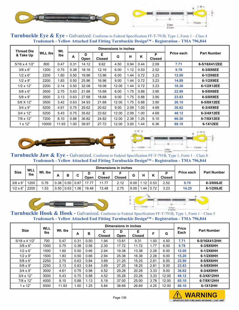
Turnbuckle Eye & Eye - Galvanized. Conforms to Federal Specification FF-T-791B, Type 1, Form 1 – Class 4
Trademark - Yellow Attached End Fitting Turnbuckle Design™ - Registration - TMA 796,844
Thread Dia & Take Up WLL lbs Wt.
lbs
Dimensions in inches Price each Part Number
A D Open
E Closed G H K P
Closed 5/16 x 4 1/2” 800 0.47 0.31 14.12 9.62 4.50 0.94 0.44 2.09 7.71 6-5/16X41/2EE
3/8 x 6” 1200 0.75 0.38 18.16 12.16 6.00 1.12 0.53 2.52 9.78 6-3/8X6EE 1/2 x 6” 2200 1.60 0.50 19.96 13.96 6.00 1.44 0.72 3.23 12.00 6-1/2X6EE 1/2 x 9” 2200 1.83 0.50 25.96 16.96 9.00 1.44 0.72 3.23 14.89 6-1/2X9EE
1/2 x 12” 2200 2.14 0.50 32.08 19.08 12.00 1.44 0.72 3.23 18.30 6-1/2X12EE 5/8 x 6” 3500 2.75 0.63 21.68 15.68 6.00 1.75 0.88 3.90 22.90 6-5/8X6EE 5/8 x 9” 3500 3.13 0.63 27.68 18.68 9.00 1.75 0.88 3.90 23.83 6-5/8X9EE
5/8 X 12” 3500 3.42 0.63 34.93 21.68 12.00 1.75 0.88 3.90 26.10 6-5/8X12EE 3/4 x 9” 5200 4.61 0.75 29.62 20.62 9.00 2.09 1.00 4.69 36.62 6-3/4X9EE
3/4 x 12” 5200 5.43 0.75 35.62 23.62 12.00 2.09 1.00 4.69 48.12 6-3/4X12EE 7/8 x 12” 7200 8.10 0.88 36.82 24.82 12.00 2.38 1.25 5.10 66.50 6-7/8X12EE 1 x 12” 10000 11.93 1.00 39.97 27.72 12.00 3.00 1.44 6.36 88.10 6-1X12EE
Turnbuckle Jaw & Eye - Galvanized. Conforms to Federal Specification FF-T-791B, Type 1, Form 1 – Class 8
Trademark - Yellow Attached End Fitting Turnbuckle Design™ - Registration - TMA 796,844
Size WLL lbs Wt. lbs
Dimensions in inches Price each Part Number
A B C D Open
E Closed
F Closed G H K P
Closed 3/8 x 6” 1200 0.76 0.38 0.50 0.87 17.77 11.77 2.12 6.00 1.12 0.53 2.52 9.70 6-3/8X6JE 1/2 x 6” 2200 1.53 0.50 0.63 1.06 19.48 13.48 2.75 6.00 1.44 0.72 3.23 14.25 6-1/2X6JE
Turnbuckle Hook & Hook - Galvanized. Conforms to Federal Specification FF-T-791B, Type 1, Form 1 – Class 5
Trademark - Yellow Attached End Fitting Turnbuckle Design™ - Registration - TMA 796,844
Size WLL lbs Wt. lbs
Dimensions in inches Price Each Part Number
A B C Closed
D Open
E Closed F G
5/16 x 4 1/2” 700 0.47 0.31 0.50 1.94 13.81 9.31 1.50 4.50 7.71 6-5/16X41/2HH 3/8 x 6” 1000 0.75 0.38 0.56 2.30 17.72 11.72 1.77 6.00 9.78 6-3/8X6HH 1/2 x 6” 1500 1.60 0.50 0.66 2.94 19.38 13.38 2.28 6.00 12.00 6-1/2X6HH 1/2 x 9” 1500 1.83 0.50 0.66 2.94 25.38 16.38 2.28 9.00 15.20 6-1/2X9HH 5/8 x 6” 2250 2.75 0.63 0.84 3.69 21.25 15.25 2.81 6.00 22.90 6-5/8X6HH 5/8 x 9” 2250 3.13 0.63 0.84 3.69 27.25 18.25 2.81 9.00 23.83 6-5/8X9HH 3/4 x 9” 3000 4.61 0.75 0.98 4.52 29.28 20.28 3.33 9.00 36.62 6-3/4X9HH
3/4 x 12” 3000 5.43 0.75 0.98 4.52 35.28 23.28 3.33 12.00 48.12 6-3/4X12HH 7/8 x 12” 4000 8.10 0.88 1.13 5.19 37.00 25.00 3.78 12.00 65.10 6-7/8X12HH 1 x 12” 5000 11.93 1.00 1.25 5.84 38.69 26.69 4.25 12.00 88.10 6-1X12HH
Page 136

Turnbuckle – Bottle Type - Galvanized
Break load Thread Dia & Take Up Price Part Number
4,500 lb 3/8"x 6" 24.55 6-3/8"BT 6,200 lb 1/2"x 7" 35.35 6-1/2"BT 9,700 lb 5/8"x 9" 68.65 6-5/8"BT
13,500 lb 3/4"x 9" 108.60 6-3/4"BT 19,200 lb 7/8"x 12" 138.10 6-7/8"BT 24,800 lb 1" x 13" 188.50 6-1"BT 45,000 lb 1-1/4"x 15" 345.59 6-1-1/4"BT
Turnbuckle – Lashing – Eye & Eye – Self Colored WLL 6:1 Thread Dia & Take Up Price Part Number
3,620 lb 3/4"x18" 41.15 6-3/4X18BLEE Turnbuckle – Jaw & Jaw – Stainless Steel 304 SS- Open
WLL 4:1 Thread Dia & Take Up Price Part Number
460 lb 1/4 x 4” 36.59 6-1/4X4SSJJ 780 lb 5/16 x 4-1/2” 50.05 6-5/16X4.5SSJ
1,160 lb 3/8 x 6” 62.15 6-3/8X6SSJJ 2,150 lb 1/2 x 6” 100.99 6-1/2X6SSJJ 3,500 lb 5/8 x 6” 143.35 6-5/8X6SSJJ 5,140 lb 3/4 x 6” 194.95 6-3/4X6SSJJ
Turnbuckle – Jaw & Jaw – Stainless Steel 316 SS – Closed, Bottle Type
A Size Dimensions in inches WLL
lbs Weight Price Part Number B C D E 1/4" 3.72 5.64 0.25 0.31 440 0.20 38.70 6-1/4”BTSS
5/16" 4.20 6.50 0.31 0.37 840 0.35 59.35 6-5/16”BTSS 3/8" 4.87 7.75 0.37 0.43 1,260 0.55 75.49 6-3/8”BTSS 1/2" 5.75 9.50 0.50 0.50 2,000 1.50 111.75 6-1/2”BTSS 5/8" 7.50 13.00 0.62 0.68 3,500 2.30 212.39 6-5/8”BTSS 3/4” 11.00 16.75 0.75 0.88 5,000 5.80 274.05 6-3/4”BTSS
\
Stenhouse Slips – Hot dip Galvanized Size
Diameter ID of Ring Inside Length Arm Price Part Number
3/8" 2-1/2 3-1/2 40.69 6-10MMGSS 1/2" 3-1/2 4-1/2 47.15 6-12MMGSS 3/4" 4-1/4 5-1/2 73.50 6-20MMGSS 1" 4-1/2 7-1/4 102.39 6-24MMGSS
Page 137
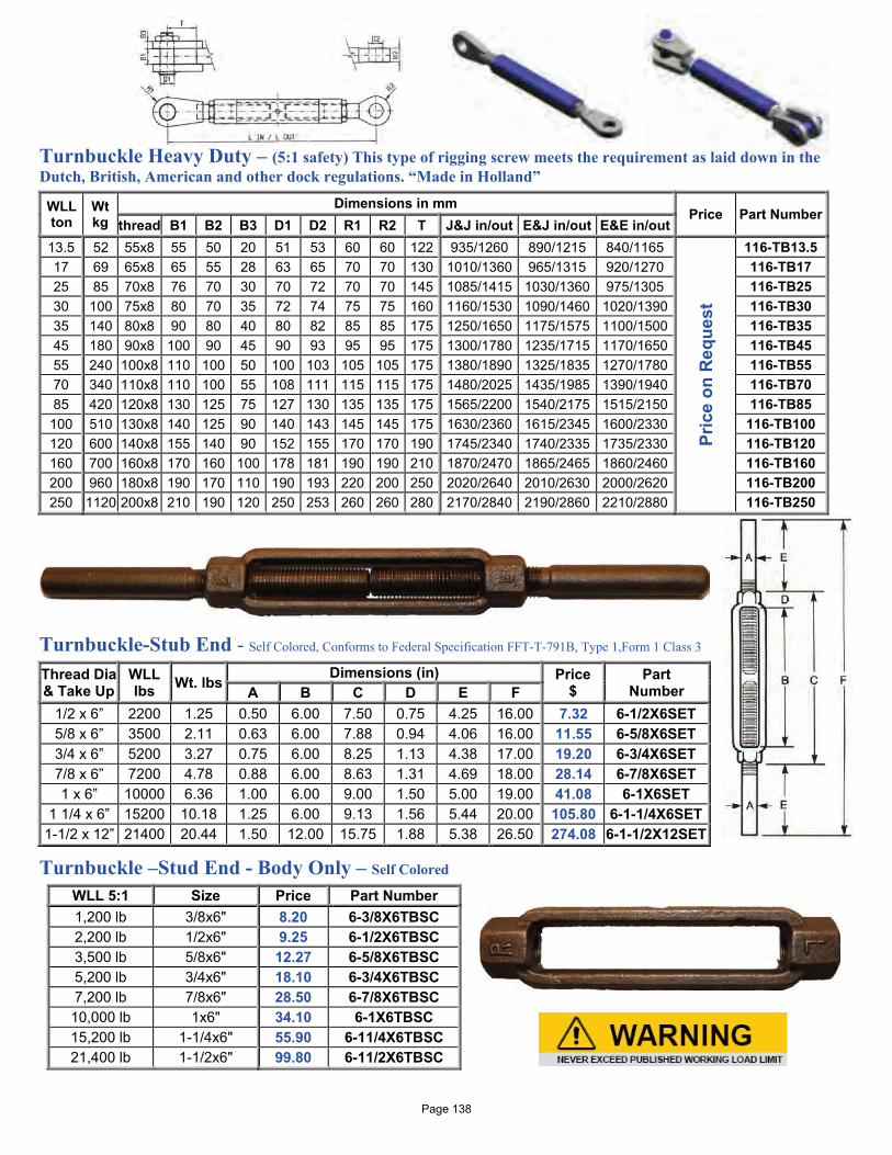
Turnbuckle Heavy Duty – (5:1 safety) This type of rigging screw meets the requirement as laid down in the Dutch, British, American and other dock regulations. “Made in Holland”
WLL ton
Wt kg
Dimensions in mm Price Part Number
thread B1 B2 B3 D1 D2 R1 R2 T J&J in/out E&J in/out E&E in/out 13.5 52 55x8 55 50 20 51 53 60 60 122 935/1260 890/1215 840/1165
Pric
e on
Req
uest
116-TB13.5 17 69 65x8 65 55 28 63 65 70 70 130 1010/1360 965/1315 920/1270 116-TB17 25 85 70x8 76 70 30 70 72 70 70 145 1085/1415 1030/1360 975/1305 116-TB25 30 100 75x8 80 70 35 72 74 75 75 160 1160/1530 1090/1460 1020/1390 116-TB30 35 140 80x8 90 80 40 80 82 85 85 175 1250/1650 1175/1575 1100/1500 116-TB35 45 180 90x8 100 90 45 90 93 95 95 175 1300/1780 1235/1715 1170/1650 116-TB45 55 240 100x8 110 100 50 100 103 105 105 175 1380/1890 1325/1835 1270/1780 116-TB55 70 340 110x8 110 100 55 108 111 115 115 175 1480/2025 1435/1985 1390/1940 116-TB70 85 420 120x8 130 125 75 127 130 135 135 175 1565/2200 1540/2175 1515/2150 116-TB85
100 510 130x8 140 125 90 140 143 145 145 175 1630/2360 1615/2345 1600/2330 116-TB100 120 600 140x8 155 140 90 152 155 170 170 190 1745/2340 1740/2335 1735/2330 116-TB120 160 700 160x8 170 160 100 178 181 190 190 210 1870/2470 1865/2465 1860/2460 116-TB160 200 960 180x8 190 170 110 190 193 220 200 250 2020/2640 2010/2630 2000/2620 116-TB200 250 1120 200x8 210 190 120 250 253 260 260 280 2170/2840 2190/2860 2210/2880 116-TB250
Turnbuckle-Stub End - Self Colored, Conforms to Federal Specification FFT-T-791B, Type 1,Form 1 Class 3
Thread Dia & Take Up
WLL lbs Wt. lbs Dimensions (in) Price
$ Part
Number A B C D E F 1/2 x 6” 2200 1.25 0.50 6.00 7.50 0.75 4.25 16.00 7.32 6-1/2X6SET 5/8 x 6” 3500 2.11 0.63 6.00 7.88 0.94 4.06 16.00 11.55 6-5/8X6SET 3/4 x 6” 5200 3.27 0.75 6.00 8.25 1.13 4.38 17.00 19.20 6-3/4X6SET 7/8 x 6” 7200 4.78 0.88 6.00 8.63 1.31 4.69 18.00 28.14 6-7/8X6SET 1 x 6” 10000 6.36 1.00 6.00 9.00 1.50 5.00 19.00 41.08 6-1X6SET
1 1/4 x 6” 15200 10.18 1.25 6.00 9.13 1.56 5.44 20.00 105.80 6-1-1/4X6SET 1-1/2 x 12” 21400 20.44 1.50 12.00 15.75 1.88 5.38 26.50 274.08 6-1-1/2X12SET
Turnbuckle –Stud End - Body Only – Self Colored
WLL 5:1 Size Price Part Number 1,200 lb 3/8x6" 8.20 6-3/8X6TBSC 2,200 lb 1/2x6" 9.25 6-1/2X6TBSC 3,500 lb 5/8x6" 12.27 6-5/8X6TBSC 5,200 lb 3/4x6" 18.10 6-3/4X6TBSC 7,200 lb 7/8x6" 28.50 6-7/8X6TBSC 10,000 lb 1x6" 34.10 6-1X6TBSC 15,200 lb 1-1/4x6" 55.90 6-11/4X6TBSC 21,400 lb 1-1/2x6" 99.80 6-11/2X6TBSC
Page 138
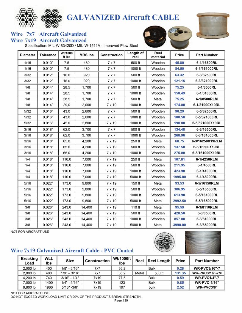
GALVANIZED Aircraft CABLE
Wire 7x7 Aircraft Galvanized Wire 7x19 Aircraft Galvanized
Specification: MIL-W-83420D / MIL-W-1511A - Improved Plow Steel
Diameter Tolerance Wt/1000 ft lbs MBS lbs Construction Length of
reel Reel
material Price Part Number
1/16 0.010” 7.5 480 7 x 7 500 ft Wooden 45.80 6-1/16500RL 1/16 0.010” 7.5 480 7 x 7 1000 ft Wooden 84.50 6-1/161000RL
3/32 0.012” 16.0 920 7 x 7 500 ft Wooden 63.32 6-3/32500RL 3/32 0.012” 16.0 920 7 x 7 1000 ft Wooden 121.15 6-3/321000RL
1/8 0.014” 28.5 1,700 7 x 7 500 ft Wooden 75.25 6-1/8500RL 1/8 0.014” 28.5 1,700 7 x 7 1000 ft Wooden 150.49 6-1/81000RL 1/8 0.014” 28.5 1,700 7 x 7 500 ft Metal 75.25 6-1/8500RLM 1/8 0.014” 29,0 2,000 7 x 19 1000 ft Wooden 174.00 6-1/81000X19RL
5/32 0.016” 43.0 2,600 7 x 7 500 ft Wooden 90.29 6-5/32500RL 5/32 0.016” 43.0 2,600 7 x 7 1000 ft Wooden 180.58 6-5/321000RL 5/32 0.016” 45.0 2,800 7 x 19 1000 ft Wooden 198.00 6-5/321000X19RL
3/16 0.018” 62.0 3,700 7 x 7 500 ft Wooden 134.48 6-3/16500RL 3/16 0.018” 62.0 3,700 7 x 7 1000 ft Wooden 268.96 6-3/161000RL 3/16 0.018” 65.0 4,200 7 x 19 250 ft Metal 68.75 6-3/16250X19RLM 3/16 0.018” 65.0 4,200 7 x 19 500 ft Wooden 137.50 6-3/16500X19RL 3/16 0.018” 65.0 4,200 7 x 19 1000 ft Wooden 275.00 6-3/161000X19RL
1/4 0.018” 110.0 7,000 7 x 19 250 ft Metal 107.81 6-1/4250RLM 1/4 0.018” 110.0 7,000 7 x 19 500 ft Wooden 211.95 6-1/4500RL 1/4 0.018” 110.0 7,000 7 x 19 1000 ft Wooden 423.90 6-1/41000RL 1/4 0.018” 110.0 7,000 7 x 19 5000 ft Wooden 1995.00 6-1/45000RL
5/16 0.022” 173.0 9,800 7 x 19 150 ft Metal 93.53 6-5/16150RLM 5/16 0.022” 173.0 9,800 7 x 19 500 ft Wooden 306.95 6-5/16500RL 5/16 0.022” 173.0 9,800 7 x 19 1000 ft Wooden 613.90 6-5/161000RL 5/16 0.022” 173.0 9,800 7 x 19 5000 ft Metal 2992.50 6-5/165000RL
3/8 0.026” 243.0 14,400 7 x 19 110 ft Metal 95.59 6-3/8110RLM 3/8 0.026” 243.0 14,400 7 x 19 500 ft Wooden 428.50 6-3/8500RL 3/8 0.026” 243.0 14,400 7 x 19 1000 ft Wooden 857.00 6-3/81000RL 3/8 0.026” 243.0 14,400 7 x 19 5000 ft Metal 3990.00 6-3/85000RL
NOT FOR AIRCRAFT USE Wire 7x19 Galvanized Aircraft Cable - PVC Coated
Breaking Load
WLL lbs Size Construction Wt/1000ft
lbs Reel Reel Length Price Part Number
2,000 lb 400 1/8" - 3/16" 7x7 36.2 Bulk 0.28 WR-PVC3/16"-7 2,000 lb 400 1/8” – 3/16” 7x7 36.2 Metal 500 ft 131.35 WR-PVC3/16”-7M 4,200 lb 740 3/16" - 1/4" 7x19 77.5 Bulk 0.59 WR-PVC1/4"-7 7,000 lb 1400 1/4" - 5/16" 7x19 123 Bulk 0.85 WR-PVC-5/16" 9,800 lb 1960 5/16" -3/8" 7x19 197 bulk 2.52 WR-PVC3/8"
NOT FOR AIRCRAFT USE DO NOT EXCEED WORK LOAD LIMIT OR 20% OF THE PRODUCT'S BREAK STRENGTH.
Page 139
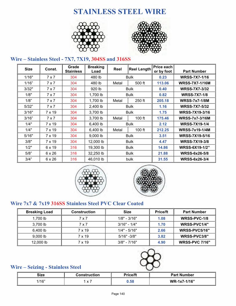
STAINLESS STEEL WIRE
Wire – Stainless Steel - 7X7, 7X19, 304SS and 316SS
Size Const. Grade Stainless
Breaking Load Reel Reel Length Price each
or by foot
Part Number 1/16" 7 x 7 304 480 lb Bulk 0.23 WRSS-7X7-1/16 1/16” 7 x 7 304 480 lb Metal 500 ft 113.06 WRSS-7X7-1/16M 3/32" 7 x 7 304 920 lb Bulk 0.40 WRSS-7X7-3/32 1/8" 7 x 7 304 1,700 lb Bulk 0.82 WRSS-7X7-1/8 1/8” 7 x 7 304 1,700 lb Metal 250 ft 205.18 WRSS-7x7-1/8M 5/32” 7 x 7 304 2,400 lb Bulk 1.16 WRSS-7X7-5/32 3/16" 7 x 19 304 3,700 lb Bulk 1.75 WRSS-7X19-3/16 3/16” 7 x 7 304 3,700 lb Metal 100 ft 175.46 WRSS-7x7-3/16M 1/4" 7 x 19 304 6,400 lb Bulk 2.12 WRSS-7X19-1/4 1/4" 7 x 19 304 6,400 lb Metal 100 ft 212.25 WRSS-7x19-1/4M 5/16" 7 x 19 304 9,000 lb Bulk 3.51 WRSS-7X19-5/16 3/8" 7 x 19 304 12,000 lb Bulk 4.47 WRSS-7X19-3/8 1/2" 6 x 19 316 19,300 lb Bulk 14.86 WRSS-6X19-1/2” 5/8” 6 x 26 316 32,250 lb Bulk 21.88 WRSS-6x26-5/8 3/4” 6 x 26 316 46,010 lb bulk 31.55 WRSS-6x26-3/4
Wire 7x7 & 7x19 316SS Stainless Steel PVC Clear Coated
Breaking Load Construction Size Price/ft Part Number 1,700 lb 7 x 7 1/8" - 3/16" 1.08 WRSS-PVC-1/8 3,700 lb 7 x 7 3/16" - 1/4" 1.70 WRSS-PVC1/4" 6,400 lb 7 x 19 1/4" - 5/16" 2.66 WRSS-PVC5/16" 9,000 lb 7 x 19 5/16" -3/8" 3.82 WRSS-PVC3/8"
12,000 lb 7 x 19 3/8" - 7/16" 4.90 WRSS-PVC 7/16" Wire – Seizing - Stainless Steel
Size Construction Price/ft Part Number 1/16” 1 x 7 0.58 WR-1x7-1/16”
Page 140
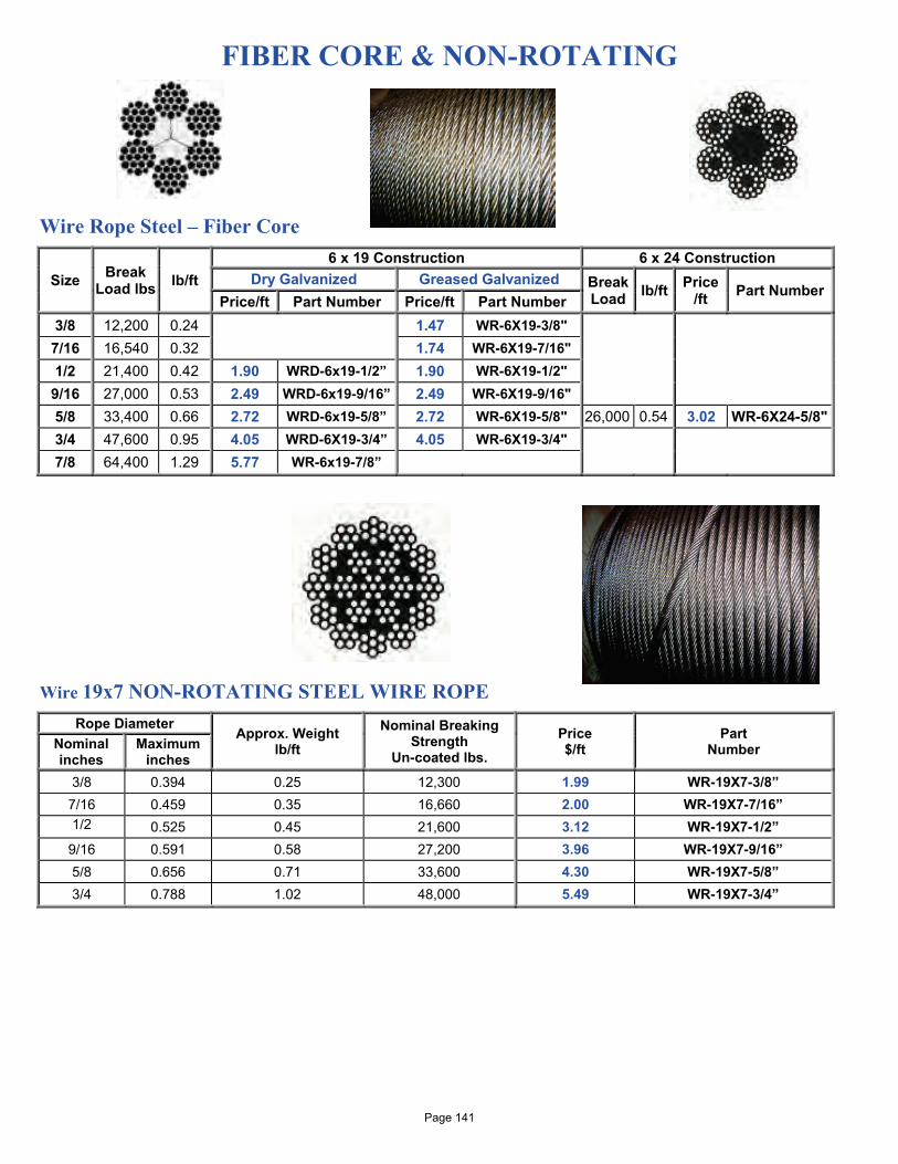
FIBER CORE & NON-ROTATING Wire Rope Steel – Fiber Core
Size Break Load lbs lb/ft
6 x 19 Construction 6 x 24 Construction Dry Galvanized Greased Galvanized Break
Load lb/ft Price /ft Part Number
Price/ft Part Number Price/ft Part Number 3/8 12,200 0.24 1.47 WR-6X19-3/8" 7/16 16,540 0.32 1.74 WR-6X19-7/16" 1/2 21,400 0.42 1.90 WRD-6x19-1/2” 1.90 WR-6X19-1/2" 9/16 27,000 0.53 2.49 WRD-6x19-9/16” 2.49 WR-6X19-9/16" 5/8 33,400 0.66 2.72 WRD-6x19-5/8” 2.72 WR-6X19-5/8" 26,000 0.54 3.02 WR-6X24-5/8" 3/4 47,600 0.95 4.05 WRD-6X19-3/4” 4.05 WR-6X19-3/4" 7/8 64,400 1.29 5.77 WR-6x19-7/8”
Wire 19x7 NON-ROTATING STEEL WIRE ROPE
Rope Diameter Approx. Weight
lb/ft Nominal Breaking
Strength Un-coated lbs.
Price $/ft
Part Number Nominal
inches Maximum
inches 3/8 0.394 0.25 12,300 1.99 WR-19X7-3/8”
7/16 0.459 0.35 16,660 2.00 WR-19X7-7/16” 1/2 0.525 0.45 21,600 3.12 WR-19X7-1/2”
9/16 0.591 0.58 27,200 3.96 WR-19X7-9/16” 5/8 0.656 0.71 33,600 4.30 WR-19X7-5/8” 3/4 0.788 1.02 48,000 5.49 WR-19X7-3/4”
Page 141
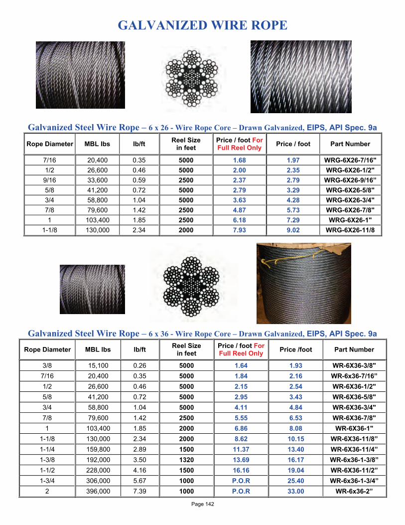
GALVANIZED WIRE ROPE
Galvanized Steel Wire Rope – 6 x 26 - Wire Rope Core – Drawn Galvanized, EIPS, API Spec. 9a
Rope Diameter MBL lbs lb/ft Reel Size in feet
Price / foot For Full Reel Only Price / foot Part Number
7/16 20,400 0.35 5000 1.68 1.97 WRG-6X26-7/16" 1/2 26,600 0.46 5000 2.00 2.35 WRG-6X26-1/2" 9/16 33,600 0.59 2500 2.37 2.79 WRG-6X26-9/16” 5/8 41,200 0.72 5000 2.79 3.29 WRG-6X26-5/8" 3/4 58,800 1.04 5000 3.63 4.28 WRG-6X26-3/4" 7/8 79,600 1.42 2500 4.87 5.73 WRG-6X26-7/8" 1 103,400 1.85 2500 6.18 7.29 WRG-6X26-1"
1-1/8 130,000 2.34 2000 7.93 9.02 WRG-6X26-11/8 Galvanized Steel Wire Rope – 6 x 36 - Wire Rope Core – Drawn Galvanized, EIPS, API Spec. 9a
Rope Diameter MBL lbs lb/ft Reel Size in feet
Price / foot For Full Reel Only Price /foot Part Number
3/8 15,100 0.26 5000 1.64 1.93 WR-6X36-3/8" 7/16 20,400 0.35 5000 1.84 2.16 WR-6x36-7/16” 1/2 26,600 0.46 5000 2.15 2.54 WR-6X36-1/2" 5/8 41,200 0.72 5000 2.95 3.43 WR-6X36-5/8" 3/4 58,800 1.04 5000 4.11 4.84 WR-6X36-3/4" 7/8 79,600 1.42 2500 5.55 6.53 WR-6X36-7/8" 1 103,400 1.85 2000 6.86 8.08 WR-6X36-1"
1-1/8 130,000 2.34 2000 8.62 10.15 WR-6X36-11/8” 1-1/4 159,800 2.89 1500 11.37 13.40 WR-6X36-11/4” 1-3/8 192,000 3.50 1320 13.69 16.17 WR-6x36-1-3/8” 1-1/2 228,000 4.16 1500 16.16 19.04 WR-6X36-11/2” 1-3/4 306,000 5.67 1000 P.O.R 25.40 WR-6x36-1-3/4”
2 396,000 7.39 1000 P.O.R 33.00 WR-6x36-2” Page 142
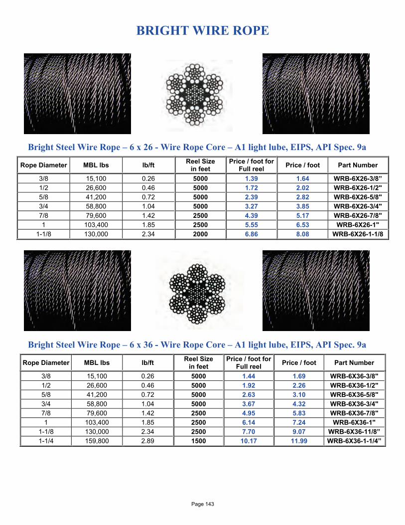
BRIGHT WIRE ROPE
Bright Steel Wire Rope – 6 x 26 - Wire Rope Core – A1 light lube, EIPS, API Spec. 9a
Rope Diameter MBL lbs lb/ft Reel Size in feet
Price / foot for Full reel Price / foot Part Number
3/8 15,100 0.26 5000 1.39 1.64 WRB-6X26-3/8” 1/2 26,600 0.46 5000 1.72 2.02 WRB-6X26-1/2" 5/8 41,200 0.72 5000 2.39 2.82 WRB-6X26-5/8" 3/4 58,800 1.04 5000 3.27 3.85 WRB-6X26-3/4" 7/8 79,600 1.42 2500 4.39 5.17 WRB-6X26-7/8" 1 103,400 1.85 2500 5.55 6.53 WRB-6X26-1"
1-1/8 130,000 2.34 2000 6.86 8.08 WRB-6X26-1-1/8 Bright Steel Wire Rope – 6 x 36 - Wire Rope Core – A1 light lube, EIPS, API Spec. 9a
Rope Diameter MBL lbs lb/ft Reel Size in feet
Price / foot for Full reel Price / foot Part Number
3/8 15,100 0.26 5000 1.44 1.69 WRB-6X36-3/8" 1/2 26,600 0.46 5000 1.92 2.26 WRB-6X36-1/2" 5/8 41,200 0.72 5000 2.63 3.10 WRB-6X36-5/8" 3/4 58,800 1.04 5000 3.67 4.32 WRB-6X36-3/4" 7/8 79,600 1.42 2500 4.95 5.83 WRB-6X36-7/8" 1 103,400 1.85 2500 6.14 7.24 WRB-6X36-1"
1-1/8 130,000 2.34 2500 7.70 9.07 WRB-6X36-11/8” 1-1/4 159,800 2.89 1500 10.17 11.99 WRB-6X36-1-1/4”
Page 143
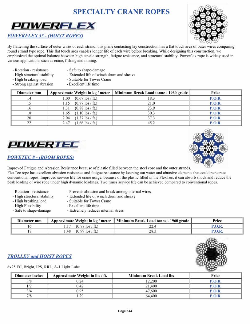
SPECIALTY CRANE ROPES
POWERFLEX 35 - (HOIST ROPES) By flattening the surface of outer wires of each strand, this plane contacting lay construction has a flat touch area of outer wires comparing round strand type rope. This flat touch area enables longer life of each wire before breaking. While designing this construction, we emphasized the optimal balance between high tensile strength, fatigue resistance, and structural stability. Powerflex rope is widely used in various applications such as crane, fishing and mining. - Rotation - resistance - Safe to shape-damage - High structural stability - Extended life of winch drum and sheave - High breaking load - Suitable for Tower Crane - Strong against abrasion - Excellent life time
POWETEC 8 - (BOOM ROPES) Improved Fatigue and Abrasion Resistance because of plastic filled between the steel core and the outer strands. FlexTec rope has excellent abrasion resistance and fatigue resistance by keeping out water and abrasive elements that could penetrate conventional ropes. Improved service life for crane usage, because of the plastic filled in the FlexTec; it can absorb shock and reduce the peak loading of wire rope under high dynamic loadings. Two times service life can be achieved compared to conventional ropes. - Rotation - resistance - Prevents abrasion and break among internal wires - High structural stability - Extended life of winch drum and sheave - High breaking load - Suitable for Tower Crane - High Flexibility - Excellent life time - Safe to shape-damage - Extremely reduces internal stress
Diameter mm Approximate Weight in kg / meter Minimum Break Load tonne - 1960 grade Price 16 1.17 (0.78 lbs / ft.) 22.4 P.O.R. 18 1.48 (0.99 lbs / ft.) 28.3 P.O.R.
TROLLEY and HOIST ROPES 6x25 FC, Bright, IPS, RRL, A-1 Light Lube
Diameter mm Approximate Weight in kg / meter Minimum Break Load tonne - 1960 grade Price 14 1.00 (0.67 lbs / ft.) 18.3 P.O.R. 15 1.15 (0.77 lbs / ft.) 21.0 P.O.R. 16 1.31 (0.88 lbs / ft.) 23.9 P.O.R. 18 1.65 (1.10 lbs / ft.) 30.3 P.O.R. 20 2.04 (1.37 lbs / ft.) 37.3 P.O.R. 22 2.47 (1.66 lbs / ft.) 45.2 P.O.R.
Diameter inches Approximate Weight in lbs / ft. Minimum Break Load lbs Price 3/8 0.24 12,200 P.O.R. 1/2 0.42 21,400 P.O.R. 3/4 0.95 47,600 P.O.R. 7/8 1.29 64,400 P.O.R.
Page 144

Partnering with InterMoor Ltd. Providing mooring equipment products and solutions to the Deepwater Oil Industries throughout the world
Page 145
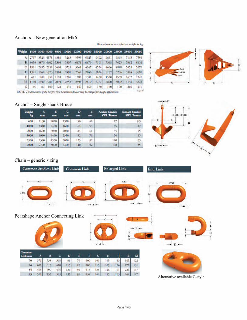
Anchors – New generation Mk6 Anchor – Single shank Bruce Chain – generic sizing Pearshape Anchor Connecting Link
Alternative available C-style
Page 146
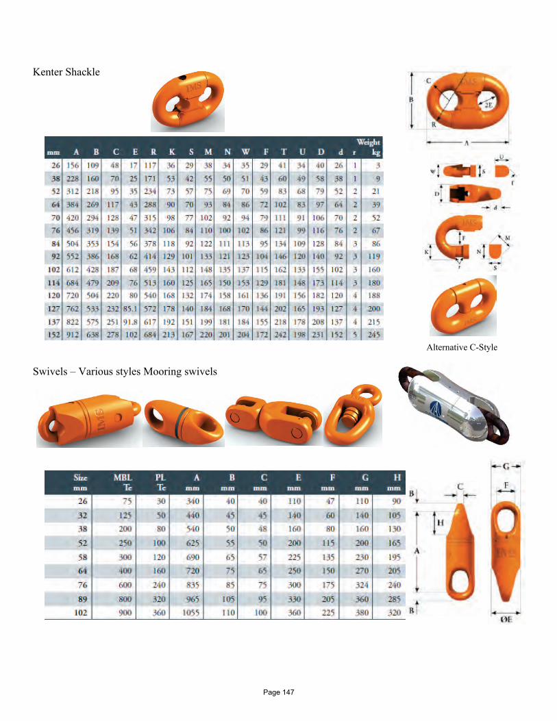
Kenter Shackle Alternative C-Style Swivels – Various styles Mooring swivels
Page 147
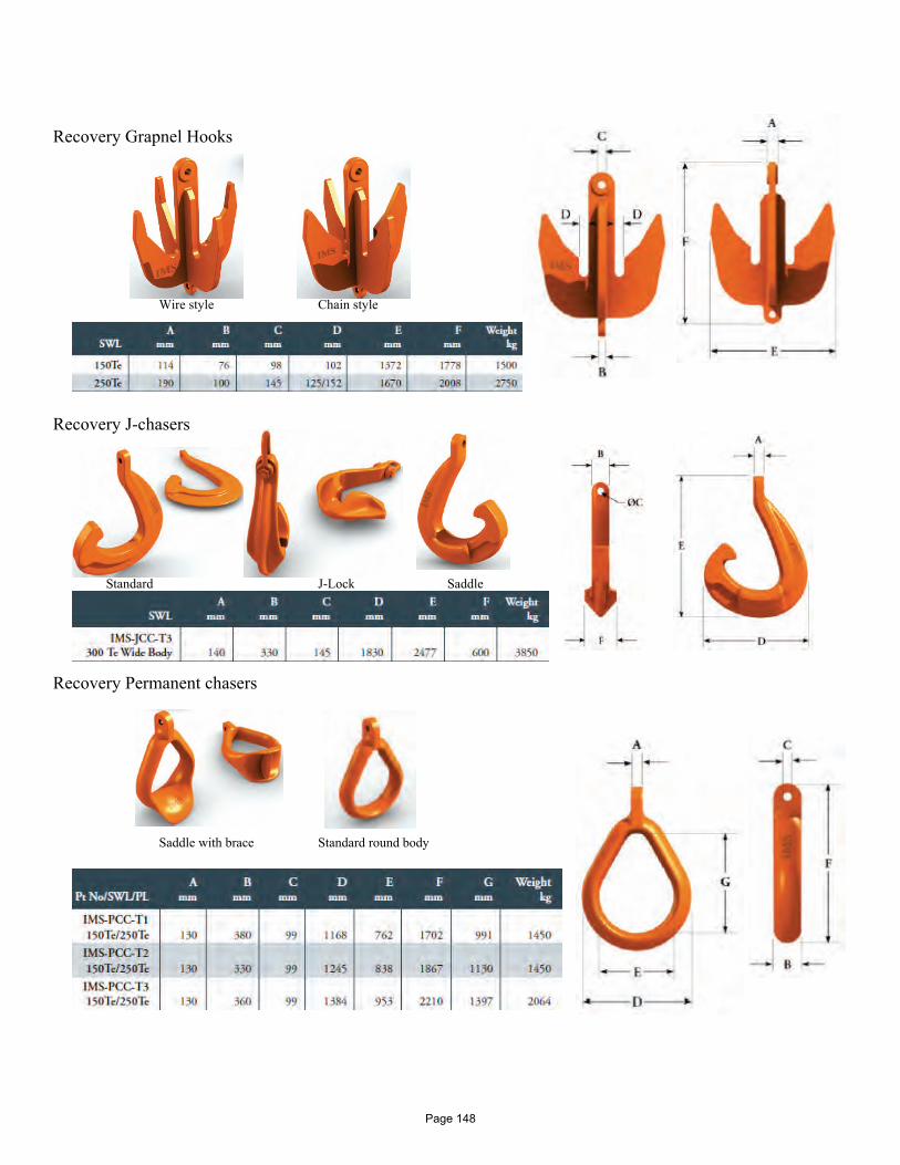
Recovery Grapnel Hooks Wire style Chain style Recovery J-chasers Standard J-Lock Saddle Recovery Permanent chasers Saddle with brace Standard round body
Page 148
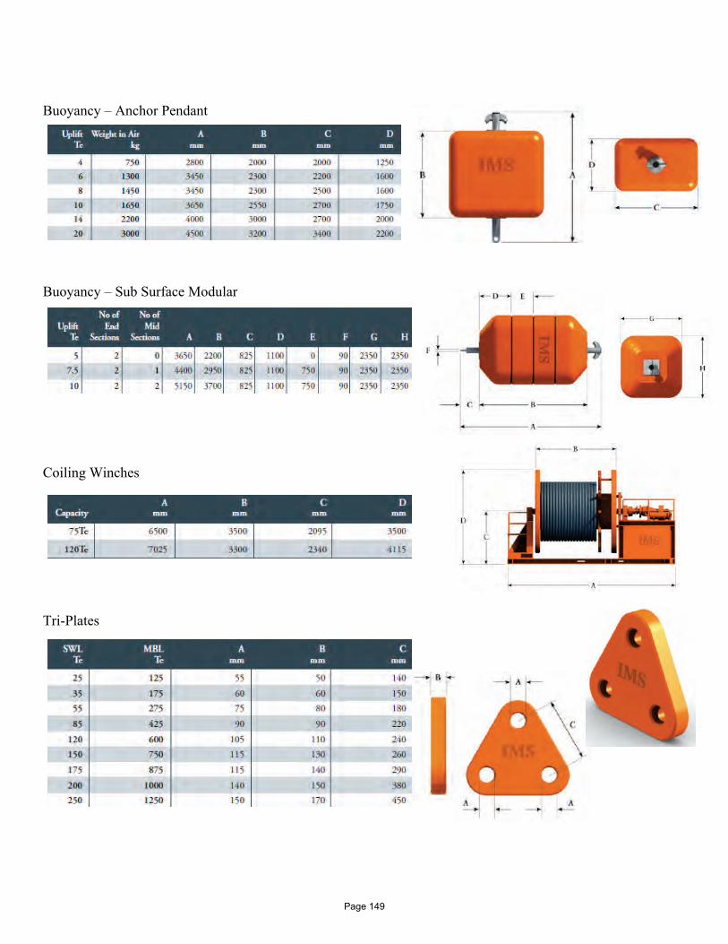
Buoyancy – Anchor Pendant Buoyancy – Sub Surface Modular Coiling Winches Tri-Plates
Page 149
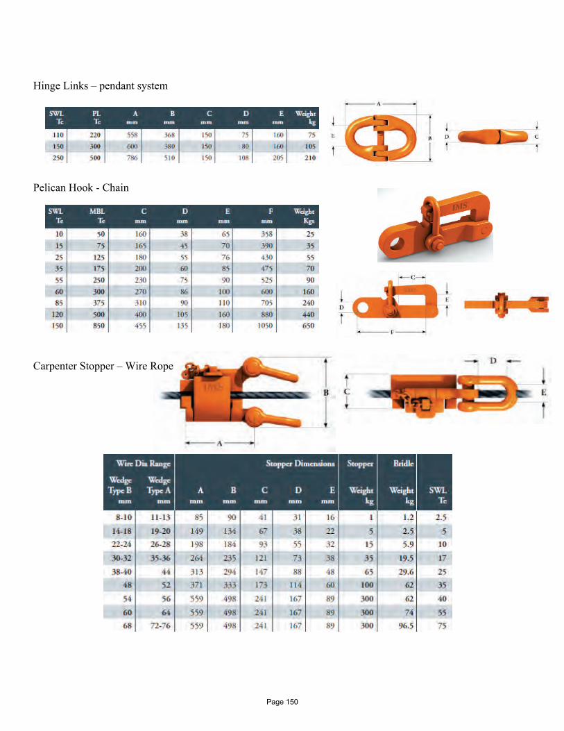
Hinge Links – pendant system Pelican Hook - Chain Carpenter Stopper – Wire Rope
Page 150
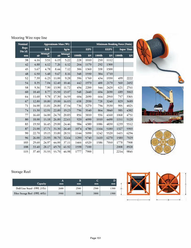
Mooring Wire rope line Storage Reel
Page 151
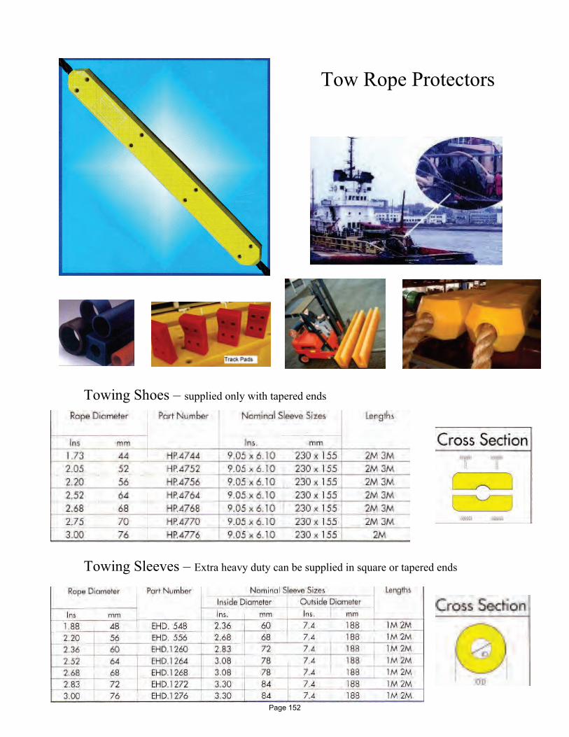
Tow Rope Protectors Towing Shoes – supplied only with tapered ends Towing Sleeves – Extra heavy duty can be supplied in square or tapered ends
Page 152
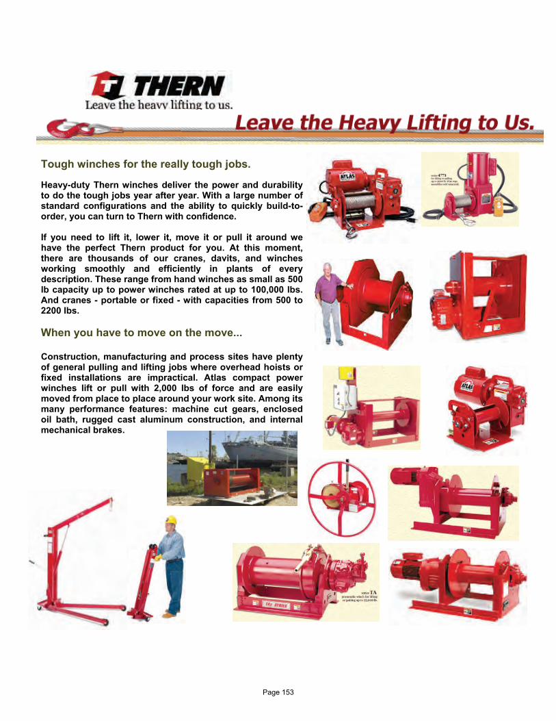
Tough winches for the really tough jobs. Heavy-duty Thern winches deliver the power and durability to do the tough jobs year after year. With a large number of standard configurations and the ability to quickly build-to-order, you can turn to Thern with confidence. If you need to lift it, lower it, move it or pull it around we have the perfect Thern product for you. At this moment, there are thousands of our cranes, davits, and winches working smoothly and efficiently in plants of every description. These range from hand winches as small as 500 lb capacity up to power winches rated at up to 100,000 lbs. And cranes - portable or fixed - with capacities from 500 to 2200 lbs. When you have to move on the move... Construction, manufacturing and process sites have plenty of general pulling and lifting jobs where overhead hoists or fixed installations are impractical. Atlas compact power winches lift or pull with 2,000 lbs of force and are easily moved from place to place around your work site. Among its many performance features: machine cut gears, enclosed oil bath, rugged cast aluminum construction, and internal mechanical brakes.
Page 153
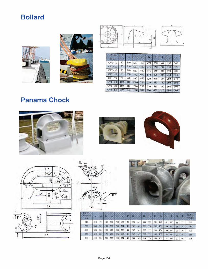
Bollard
Panama Chock Page 154
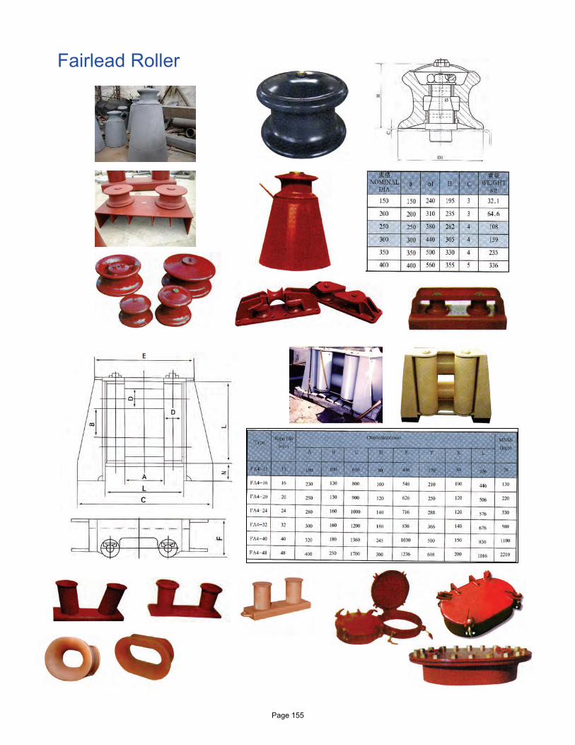
Fairlead Roller
Page 155
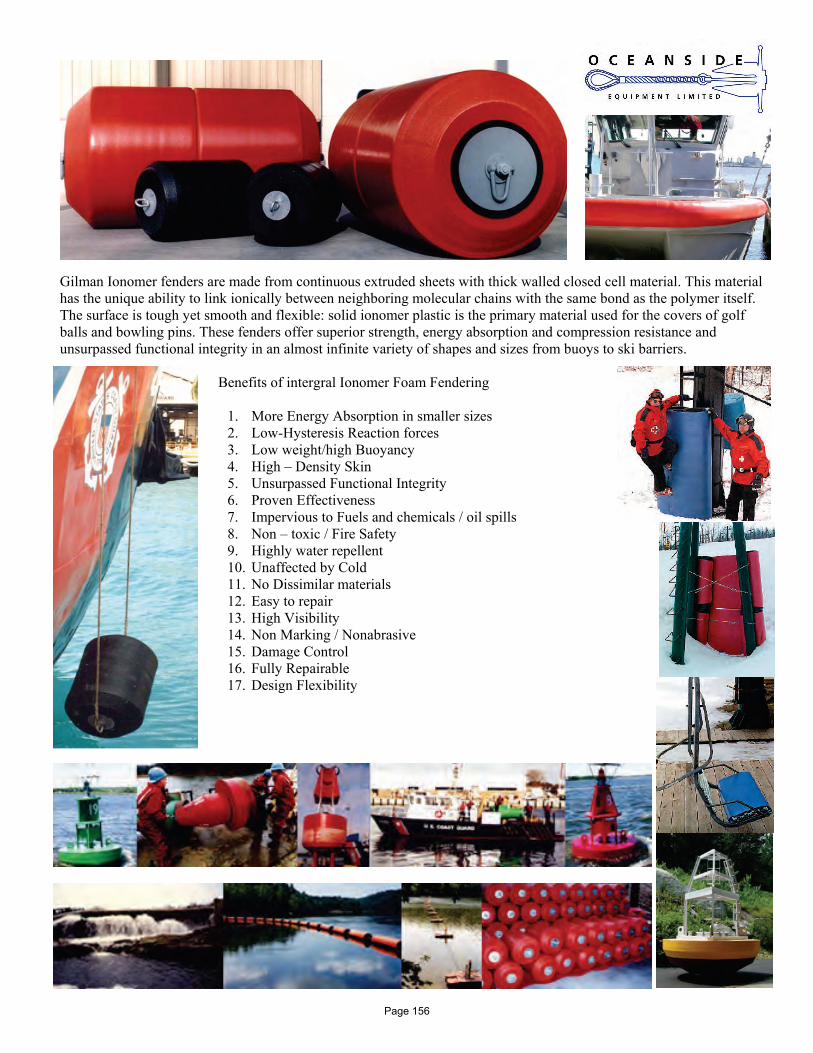
Gilman Ionomer fenders are made from continuous extruded sheets with thick walled closed cell material. This material has the unique ability to link ionically between neighboring molecular chains with the same bond as the polymer itself. The surface is tough yet smooth and flexible: solid ionomer plastic is the primary material used for the covers of golf balls and bowling pins. These fenders offer superior strength, energy absorption and compression resistance and unsurpassed functional integrity in an almost infinite variety of shapes and sizes from buoys to ski barriers.
Benefits of intergral Ionomer Foam Fendering
1. More Energy Absorption in smaller sizes 2. Low-Hysteresis Reaction forces 3. Low weight/high Buoyancy 4. High – Density Skin 5. Unsurpassed Functional Integrity 6. Proven Effectiveness 7. Impervious to Fuels and chemicals / oil spills 8. Non – toxic / Fire Safety 9. Highly water repellent 10. Unaffected by Cold 11. No Dissimilar materials 12. Easy to repair 13. High Visibility 14. Non Marking / Nonabrasive 15. Damage Control 16. Fully Repairable 17. Design Flexibility
Page 156
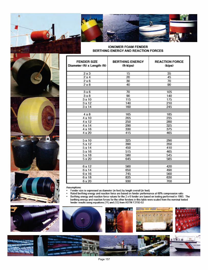
Page 157
Definition In these conditions “the Company” means the company upon whose document these conditions are endorsed. General
1. All quotations are made and all orders are accepted subject to the following conditions. All other conditions whatsoever are excluded from the contract or any variation thereof, unless expressly accepted by the Company in writing.
2. Acceptance of delivery of the goods shall where no prior agreement has been reached be conclusive evidence of acceptance of these conditions.
3. Quotations shall only be available for acceptance for a maximum period of 10 days from the date thereof and may be withdrawn or altered by the Company with in such period at any time without notice.
4. Goods sold from stock are offered subject to the same being unsold upon receipt of the order. 5. The goods are subject to specifications (including dimensions, weights, analyses and properties) stated expressly in the contract or where
none is specified, to the specification published by the company or where none is published to any relevant standards or code of practice. 6. Any typographical, clerical or other error or omission in any sales literature, quotation, price list, acceptance of offer, invoice or other
document or information issued by the Company shall be subject to correction without any liability on the part of the Company. 7. The buyer shall not be entitled to retain any more money due to the Company under a contract unless previously agreed in writing by the
Company’s authorized representative. Delivery Any date named by the Company for dispatch or delivery is given and intended as an estimate only and is not to be of the essence of the Contract. The buyer shall nevertheless be bound to accept the goods ordered whether available on or after the date stated. The Company shall be not be liable in any way in respect of late dispatch or delivery however caused nor shall failure to dispatch be deemed to be a breach of the Contract. Where drawings, specifications, instructions and materials are to be supplied by the buyer, the buyer shall supply the same in reasonable time to enable the Company to dispatch within the period named. The Company may, at its discretion, make installment deliveries and each delivery shall constitute a separate order for the purpose of payment. Damage or Loss in transit No claim for damage or corrosion in transit or shortage of delivery of goods will be entertained unless a separate notice in writing is given to the Company and /or the carrier concerned within three days of receipt of the goods followed by a complete claim in writing to the Company within five days of receipt of the goods. Non delivery No claim for loss or non-delivery of goods will be entertained unless in writing is received within seven days of the invoice date. Storage The Company reserves the right to charge for storage and /or any other costs incurred in the event of deferment or delay in delivery at the request and /or action of the Buyer. Prices The Company reserves the right to increase any prices agreed between the Company and the Buyer in accordance with market conditions and the company’s price for similar goods ruling at the date of dispatch and the buyer shall pay such additions in addition to the quoted price. Without prejudice to the generality of the foregoing market conditions shall included any increases in the cost of labor, materials, transport and any other costs between quotation and dispatch. HST and GST Taxes All taxes will be charged at the rate applicable at the date of dispatch. The quoted prices do not include any taxes. Carriage and Packaging The cost of carriage and packaging shall be paid for by the customer in addition to price payable for the goods, unless agreed beforehand between the customer and the Company. Terms of Payment 1. Terms of payment are that invoices must be settled in full within 30 days from the date of the invoice. 2. If the buyer fails to make any payment on the due date then, without prejudice to any other right or remedy available to the Company, the
Company shall be entitled to: (a) Cancel the contract and suspend any further deliveries to the buyer, (b) Appropriate any payment made by the buyer to such of the goods (as goods supplied under any other contract between the buyer and the Company) as the Company may think fit. (c) Charge the buyer interest (both before and after any judgement) on the amount unpaid, at the rate of 10% per annum over the base lending rate of the Company’s own bankers, until payment in full is made (a part of a month being treated as a full month for the purpose of calculating interest).
Defective and Damaged Goods No claim against the Company for goods represented by the defective, from whatever cause, or not to conform to the Contract can be entertained, and the Company shall incur no liability in respect thereof unless received by the Company in writing within twenty-eight days after the date of dispatch and the defective goods or goods failing to conform to contract are returned to the Company within the said period of twenty-eight days. Limit of Liability In the event of any claim against the Company in respect of any matter whatsoever the Company’s liability (if any) shall be limited to the replacement of goods sold in respect of which the liability arises if required and practicable or the buyer shall be given a credit for the invoiced value of the order in respect of which the liability arises. Under no circumstances whatsoever shall the Company be liable for any consequential loss or damage or any
personal injury or damage or loss of any property other than as stated herein howsoever and whatsoever arising. Any express or implied conditions, statement, warranty, statutory, or otherwise, are hereby excluded save where such exclusions are invalidated by statute. No claim by the Buyer shall be accepted as a reason for cancellation of the remainder of the order. Right to Inspect In the event of the Buyer making a claim against the Company for any reason whatsoever the goods in respect of which any such claim is made shall be preserved intact where delivery for a period of seven days from the notification of the claim to the Company within which time the Company shall have the right to attend at the place where the goods were delivered to investigate the complaint. No claim by the Buyer will be accepted unless this condition is strictly complied with. Design Changes The company reserves the right to effect design changes as technical developments may require without prior notice. Specifications Provided by Buyer The buyer shall indemnify the Company against any and all liability arising through execution by the Company of any order placed by a buyer in accordance with the Buyer’s specification where such execution infringes any patent, trademark, or registered design not owned by the buyer or the Company. Risk, Property and Insurance 1. Goods supplied by the Company shall be at the Buyer’s risk immediately on delivery to the buyer or into custody on the buyer’s behalf
(whichever is the sooner) the buyer should therefore arrange insurance accordingly unless the Company has specifically agreed to arrange insurance of the goods.
2. The property in the goods supplied by the Company will pass to the buyer when (1) the goods the subject of the Contract in question and (2) all other goods the subject of any contract between the Company and the buyer which have been delivered to the buyer (prior to the payment in full for the goods the subject of the contract in question) have been paid in full.
3. In the event that the buyer resells or hires out goods supplied by the Company (either ion the original form, or after alterations by the buyer and/or after they have been added to an item manufactured by the buyer) prior to the passing of the property therein to the buyer such resale or hire shall be effected by the buyer as bailee for the Company and the proceeds of such sale or hire shall be held on trust for the Company in a separate bank account opened by the buyer for this purpose and these proceeds shall be received by the buyer for and on behalf of the Company unless all debts owing to the Company by the buyer in respect to the goods supplied by the Company have been paid.
4. So long as the property and goods remain the Company and the buyer is in default of such obligation hereunder the Company shall have the right, with or without prior notice to the buyer, to take possession of the goods and for that purpose to go onto any premises occupied by the buyer) and on such retaking of possession the contract shall be deemed to have been determined without prejudice to any claim or rights the Company might otherwise make or exercise.
5. Until payment due under all contracts between the Company and buyer has been made in full the buyer shall hold upon trust for the Company the goods (either in their original form, or after alterations by the buyer and /or after they have been added to an item manufactured by the buyer) and shall in so far as may be possible store them in such a way as they may be identifiable as the property of the Company and separate from all other goods in the buyers possession.
6. Until payment due under all contracts between the buyer and the Company has been made in full the Company shall be entitled to trace all proceed of sale or hire charges received by the buyer on sale of the goods (either in their original form or after alteration by the buyer and/or after they have been added to an item manufactured by the buyer) received by the buyer through any bank or other account maintained by the buyer and the buyer will provide every assistance free of charge to the Company for the same.
7. Until payment due under all contracts between the buyer and Company has been made in full if the buyer sells or hires the goods (either in their original form or after alteration by the buyer and /or after they have been added to an item manufactured by the buyer) in the ordinary course of its business the buyer shall assign its rights to recover the selling price or hire charges from the third parties concerned to the Company if required to do so in writing by the Company.
8. Every insurable risk shall pass to the buyer as soon as the goods are delivered to it or into custody on its behalf. The buyer shall keep the goods insured in the amount of the price at which the goods are sold to the buyer against all insurable risks until payment due under all contacts between the buyer and Company has been made in full.
9. Of goods (either in their original form or after alteration by the buyer and/or after they have been added to an item manufactured by the buyer) are destroyed by an insured risk to the same being paid for by the buyer the buyer shall receive the proceeds of any such insurance as trustee for the Company.
Cancellation Once a contract has come into being between the Company and the buyer, that contract can not be cancelled only with the consent of the Company and upon terms that will indemnify it against loss. The buyer will indemnify the Company for all of the Company’s contractual losses and the Company will not be under a duty to mitigate those losses. Dispatch Abroad Goods dispatched abroad shall be deemed to have been inspected by the Buyer’s agent or representative prior to dispatch from the Company’s as no responsibility can be accepted by the Company after goods are consigned for shipment and the Company shall be under no obligation to give the buyer the notice specified. Literature Illustrations, weights, measures, performance capabilities, application suitability information and other date set out in the sales literature of the Company are statements of opinion and are provided for information only and form no part of the contract. Law of Contract and Jurisdiction All contracts for the supply of goods by the Company shall be governed by English Law and be within the exclusive jurisdiction of the Nova Scotia Courts.
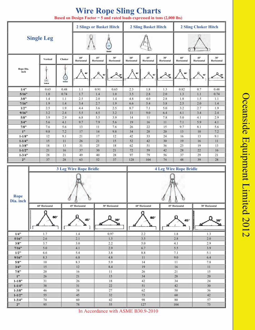
Wire Rope Sling Charts Based on Design Factor = 5 and rated loads expressed in tons (2,000 lbs)
Single Leg
2 Slings or Basket Hitch 2 Sling Basket Hitch 2 Sling Choker Hitch
Rope Dia. inch
Vertical Choker 60º Horizontal
45º Horizontal
30º Horizontal
60º Horizontal
45º Horizontal
30º Horizontal
60º Horizontal
45º Horizontal
30º Horizontal
1/4” 0.65 0.48 1.1 0.91 0.65 2.3 1.8 1.3 0.82 0.7 0.48 5/16” 1.0 0.74 1.7 1.4 1.0 3.5 2.8 2.0 1.3 1.1 0.74 3/8” 1.4 1.1 2.5 2.0 1.4 4.8 4.0 2.8 1.8 1.5 1.1
7/16” 1.9 1.4 3.4 2.7 1.9 6.6 5.4 3.8 2.5 2.0 1.4 1/2” 2.5 1.9 4.4 3.6 2.5 8.7 7.1 5.0 3.2 2.7 1.9
9/16” 3.2 2.4 5.5 4.5 3.2 11 9.0 6.4 4.1 3.4 2.4 5/8” 3.9 2.9 6.8 5.5 3.9 14 11 7.8 5.0 4.1 2.9 3/4” 5.6 4.1 9.7 7.9 5.6 19 16 11 7.1 5.9 4.1 7/8” 7.6 5.6 13 11 7.6 26 22 15 9.7 8.1 5.6 1” 9.8 7.2 17 14 9.8 34 28 20 13 10 7.2
1-1/8” 12 9.1 21 17 12 42 33 24 16 13 9.1 1-1/4” 15 11 26 21 15 52 42 30 19 16 11 1-3/8” 18 13 31 25 18 62 51 36 23 19 13 1-1/2” 21 16 37 30 21 72 59 42 28 22 16 1-3/4” 28 21 49 40 28 97 79 56 37 29 21
2” 37 28 63 52 37 128 104 74 48 39 28
Rope Dia. inch
3 Leg Wire Rope Bridle 4 Leg Wire Rope Bridle
60º Horizontal 45º Horizontal 30º Horizontal 60º Horizontal 45º Horizontal 30º Horizontal
1/4” 1.7 1.4 0.97 2.2 1.8 1.3 5/16” 2.6 2.1 1.5 3.5 2.8 2.0 3/8” 3.7 3.0 2.2 5.0 4.1 2.9 7/16” 5.0 4.1 2.9 6.7 5.5 3.9 1/2” 6.6 5.4 3.8 8.8 7.1 5.1 9/16” 8.3 6.8 4.8 11 9.0 6.4 5/8” 10 8.3 5.9 14 11 7.8 3/4” 15 12 8.4 19 16 11 7/8” 20 16 11 26 21 15 1” 26 21 15 34 28 20
1-1/8” 31 26 18 42 34 24 1-1/4” 38 31 22 51 42 30 1-3/8” 46 38 27 62 50 36 1-1/2” 55 45 32 73 60 42 1-3/4” 74 60 42 98 80 57
2” 95 78 55 127 104 73
In Accordance with ASME B30.9-2010
Oceanside Equipm
ent Limited 2012
Copyright © 2022 FDOKUMEN