SDN Controller Robustness and Distribution Framework Ficky ...
69
Network Architectures and Services SDN Controller Robustness and Distribution Framework Ficky Fatturrahman Master of Science Thesis
-
Upload
khangminh22 -
Category
Documents
-
view
0 -
download
0
Transcript of SDN Controller Robustness and Distribution Framework Ficky ...

Network Architectures and Services
SDN Controller Robustness andDistribution Framework
Ficky Fatturrahman
Mas
tero
fScie
nce
Thes
is


Faculty of Electrical Engineering, Mathematics and Computer ScienceNetwork Architectures and Services Group
SDN Controller Robustness andDistribution Framework
Ficky Fatturrahman4311809
Committee members:Supervisor: Dr. Ir. Fernando KuipersMember: Dr. Zaid Al-ArsMember: Ir. Rogier Noldus
August 22, 2017

Copyright c© 2017 by Ficky FatturrahmanAll rights reserved. No part of the material protected by this copyright may be reproducedor utilized in any form or by any means, electronic or mechanical, including photocopying,recording or by any information storage and retrieval system, without the permission fromthe author and Delft University of Technology.

Acknowledegement
I would like to thank Ministry of Communication and Informatics (MCIT) of Indonesia forgiving me a scholarship to pursue my master’s degree. I would also like to thank my super-visors Fernando Kuipers and Niels van Adrichem for their guidance. Special thanks to Nielsfor the ACRoDiF name.
Furthermore, I would like to thank my fellow students at TU Delft, my fellow housematesand my EWI classmates.
Last I want to thank my mother and father, my sister and brothers.
Master of Science Thesis Ficky Fatturrahman

ii Acknowledegement
Ficky Fatturrahman Master of Science Thesis

Abstract
SDN improves network flexibility which is constrained by network protocol in a conventionalnetwork by decoupling the control plane and the data plane of the network. This is the reasonwhy many companies and universities migrate their network to SDN, there will be more SDNnetwork in the future. Yet SDN network mainly depends on the controller in the controlplane. Hence, SDN controller robustness becomes an important issue, because a controllerfailure will result to a network outage.
OpenFlow is arguably the standard protocol for SDN network. Thus, it is necessary to in-vestigate the robustness of the OpenFlow control plane. Several open source controllers suchas OpenMul, Floodlight, Opendaylight, and ONOS have multiple controllers framework totackle a controller failure. They provide failover mechanism, when there is a controller fail-ure, a backup controller can take over to control the network. In this thesis a benchmark isconducted to measure how long the failover time of those open source controllers. Unfortu-nately their failover time is in order of seconds, which is way higher than 50ms, the acceptablestandard of carrier-grade recovery time.
This thesis presents a solution that can improve SDN robustness: A Controller Robust-ness and Distribution Framework (ACRoDiF). ACRoDiF is compatible with several opensource OpenFlow controllers such as Ryu, OpenMul, Floodlight, Opendaylight, and ONOS.ACRoDiF provides failover mechanism that has lower failover time than in the open sourcecontrollers: 76ms. It can also eliminate failover time completely if using two active primarycontrollers.
Master of Science Thesis Ficky Fatturrahman

iv Abstract
Ficky Fatturrahman Master of Science Thesis
Table of Contents
Acknowledegement i
Abstract iii
1 Introduction 1
1-1 Background . . . . . . . . . . . . . . . . . . . . . . . . . . . . . . . . . . . . . 1
1-2 Problem Definition . . . . . . . . . . . . . . . . . . . . . . . . . . . . . . . . . 2
1-3 Research Objectives . . . . . . . . . . . . . . . . . . . . . . . . . . . . . . . . . 3
1-4 Research Questions . . . . . . . . . . . . . . . . . . . . . . . . . . . . . . . . . 3
1-5 Thesis Structure . . . . . . . . . . . . . . . . . . . . . . . . . . . . . . . . . . . 4
2 SDN 5
2-1 SDN Overview . . . . . . . . . . . . . . . . . . . . . . . . . . . . . . . . . . . . 5
2-2 OpenFlow . . . . . . . . . . . . . . . . . . . . . . . . . . . . . . . . . . . . . . 6
2-2-1 OpenFlow Protocol . . . . . . . . . . . . . . . . . . . . . . . . . . . . . 8
2-2-2 OpenFlow Multiple Controllers Mechanism . . . . . . . . . . . . . . . . . 8
3 Failover Mechanisms and Related Work 13
3-1 Related Work . . . . . . . . . . . . . . . . . . . . . . . . . . . . . . . . . . . . 13
3-1-1 Distributed Controllers . . . . . . . . . . . . . . . . . . . . . . . . . . . 14
3-2 Conventional Failover Protocols . . . . . . . . . . . . . . . . . . . . . . . . . . . 15
3-2-1 Network Layer: VRRP . . . . . . . . . . . . . . . . . . . . . . . . . . . . 16
3-2-2 Transport Layer: LVS . . . . . . . . . . . . . . . . . . . . . . . . . . . . 16
Master of Science Thesis Ficky Fatturrahman

vi Table of Contents
3-3 Open Source Controllers . . . . . . . . . . . . . . . . . . . . . . . . . . . . . . 17
3-3-1 Ryu . . . . . . . . . . . . . . . . . . . . . . . . . . . . . . . . . . . . . 17
3-3-2 OpenMUL . . . . . . . . . . . . . . . . . . . . . . . . . . . . . . . . . . 18
3-3-3 Floodlight . . . . . . . . . . . . . . . . . . . . . . . . . . . . . . . . . . 19
3-3-4 OpenDayLight . . . . . . . . . . . . . . . . . . . . . . . . . . . . . . . . 19
3-3-5 ONOS . . . . . . . . . . . . . . . . . . . . . . . . . . . . . . . . . . . . 20
3-3-6 Summary . . . . . . . . . . . . . . . . . . . . . . . . . . . . . . . . . . 21
4 Failover Evaluation 23
4-1 Type of Simulated Failure . . . . . . . . . . . . . . . . . . . . . . . . . . . . . . 23
4-2 Testbed Environment . . . . . . . . . . . . . . . . . . . . . . . . . . . . . . . . 24
4-2-1 Topology . . . . . . . . . . . . . . . . . . . . . . . . . . . . . . . . . . . 24
4-2-2 Software Tools . . . . . . . . . . . . . . . . . . . . . . . . . . . . . . . . 25
4-2-3 Measurement Scenario . . . . . . . . . . . . . . . . . . . . . . . . . . . 25
4-3 Conventional Redudancy Protocols . . . . . . . . . . . . . . . . . . . . . . . . . 27
4-3-1 Network Layer: VRRP . . . . . . . . . . . . . . . . . . . . . . . . . . . . 27
4-3-2 Transport Layer: LVS . . . . . . . . . . . . . . . . . . . . . . . . . . . . 29
4-4 Open Source Controllers . . . . . . . . . . . . . . . . . . . . . . . . . . . . . . 30
4-4-1 OpenMUL . . . . . . . . . . . . . . . . . . . . . . . . . . . . . . . . . . 31
4-4-2 Floodlight . . . . . . . . . . . . . . . . . . . . . . . . . . . . . . . . . . 31
4-4-3 OpenDayLight . . . . . . . . . . . . . . . . . . . . . . . . . . . . . . . . 32
4-4-4 ONOS . . . . . . . . . . . . . . . . . . . . . . . . . . . . . . . . . . . . 33
4-5 Comparison . . . . . . . . . . . . . . . . . . . . . . . . . . . . . . . . . . . . . 33
5 ACRoDiF: A Controller Robustness and Distribution Framework 35
5-1 CDN Overview . . . . . . . . . . . . . . . . . . . . . . . . . . . . . . . . . . . . 35
5-2 Proposal . . . . . . . . . . . . . . . . . . . . . . . . . . . . . . . . . . . . . . . 37
5-2-1 ACRoDiF Requirements . . . . . . . . . . . . . . . . . . . . . . . . . . . 37
5-2-2 ACRoDiF Overview . . . . . . . . . . . . . . . . . . . . . . . . . . . . . 38
5-2-3 The Proxy Layer . . . . . . . . . . . . . . . . . . . . . . . . . . . . . . . 39
5-2-4 Experiment Evaluation . . . . . . . . . . . . . . . . . . . . . . . . . . . 40
5-2-5 Result and Analysis . . . . . . . . . . . . . . . . . . . . . . . . . . . . . 41
5-3 ACRoDiF with Two Active Primary Controllers . . . . . . . . . . . . . . . . . . 43
Ficky Fatturrahman Master of Science Thesis

Table of Contents vii
6 Conclusion 49
6-1 Research Questions Revisited . . . . . . . . . . . . . . . . . . . . . . . . . . . . 49
6-2 Future Work . . . . . . . . . . . . . . . . . . . . . . . . . . . . . . . . . . . . . 50
A Workaround for ACRoDiF and OpenMUL Testbed 53
Master of Science Thesis Ficky Fatturrahman

viii Table of Contents
Ficky Fatturrahman Master of Science Thesis

List of Figures
1-1 Total cost per minute of an ICT outage [12] . . . . . . . . . . . . . . . . . . . . 2
2-1 Conventional Network versus SDN . . . . . . . . . . . . . . . . . . . . . . . . . 6
2-2 SDN Architecture . . . . . . . . . . . . . . . . . . . . . . . . . . . . . . . . . . 7
2-3 OpenFlow Architecture . . . . . . . . . . . . . . . . . . . . . . . . . . . . . . . 9
2-4 SDN Controllers with different roles: MASTER/EQUAL/SLAVE controllers . . . 12
3-1 High-level Overview of HyperFlow [23] . . . . . . . . . . . . . . . . . . . . . . . 14
3-2 Kandoo Architecture [9] . . . . . . . . . . . . . . . . . . . . . . . . . . . . . . . 15
3-3 VRRP Network . . . . . . . . . . . . . . . . . . . . . . . . . . . . . . . . . . . 16
3-4 LVS Network . . . . . . . . . . . . . . . . . . . . . . . . . . . . . . . . . . . . . 17
3-5 OpenDaylight Architecture [15] . . . . . . . . . . . . . . . . . . . . . . . . . . . 20
3-6 ONOS Architecture [17] . . . . . . . . . . . . . . . . . . . . . . . . . . . . . . . 20
4-1 Topology . . . . . . . . . . . . . . . . . . . . . . . . . . . . . . . . . . . . . . . 24
4-2 Normal Traffic . . . . . . . . . . . . . . . . . . . . . . . . . . . . . . . . . . . . 25
4-3 Failover . . . . . . . . . . . . . . . . . . . . . . . . . . . . . . . . . . . . . . . 26
4-4 SDN Controllers with VRRP . . . . . . . . . . . . . . . . . . . . . . . . . . . . 28
4-5 SDN Controllers with LVS . . . . . . . . . . . . . . . . . . . . . . . . . . . . . . 29
5-1 CDN . . . . . . . . . . . . . . . . . . . . . . . . . . . . . . . . . . . . . . . . . 36
5-2 DNS in CDN . . . . . . . . . . . . . . . . . . . . . . . . . . . . . . . . . . . . . 37
5-3 CDN and ACRoDiF . . . . . . . . . . . . . . . . . . . . . . . . . . . . . . . . . 38
Master of Science Thesis Ficky Fatturrahman
x List of Figures
5-4 ACRoDiF . . . . . . . . . . . . . . . . . . . . . . . . . . . . . . . . . . . . . . . 39
5-5 ACRoDiF Measurement Topology . . . . . . . . . . . . . . . . . . . . . . . . . . 40
5-6 ACRoDiF Relays Message . . . . . . . . . . . . . . . . . . . . . . . . . . . . . . 41
5-7 ACRoDiF Failover . . . . . . . . . . . . . . . . . . . . . . . . . . . . . . . . . . 42
5-8 Measurement Topology . . . . . . . . . . . . . . . . . . . . . . . . . . . . . . . 44
5-9 Normal Traffic . . . . . . . . . . . . . . . . . . . . . . . . . . . . . . . . . . . . 45
5-10 Failover . . . . . . . . . . . . . . . . . . . . . . . . . . . . . . . . . . . . . . . 47
5-11 Duplicates of packet-out . . . . . . . . . . . . . . . . . . . . . . . . . . . . . . 48
Ficky Fatturrahman Master of Science Thesis

List of Tables
2-1 OpenFlow Protocol . . . . . . . . . . . . . . . . . . . . . . . . . . . . . . . . . 10
2-2 OpenFlow Controller Roles . . . . . . . . . . . . . . . . . . . . . . . . . . . . . 12
3-1 Open Source Controllers Comparison . . . . . . . . . . . . . . . . . . . . . . . . 21
4-1 Benchmark . . . . . . . . . . . . . . . . . . . . . . . . . . . . . . . . . . . . . . 34
5-1 Failover Time with ACRoDiF . . . . . . . . . . . . . . . . . . . . . . . . . . . . 43
Master of Science Thesis Ficky Fatturrahman

xii List of Tables
Ficky Fatturrahman Master of Science Thesis

Chapter 1
Introduction
1-1 Background
IP is arguably the most important network protocol in this digital age. The Internet, whichnow has become a critical infrastructure runs on top of IP. IP is also used in data centersaround the world for communication between servers, both inside the data centers and tothe outside world. A large number of critical applications traverse the Internet, such asfinancial data transactions between data centers. But IP was not designed that purpose.Present day IP networks have evolved into much more complex networks than how it wasoriginally invented, e.g. current routing tables of the Internet have reached over 600k routes.It continues to increase steadily. This is a burden for the network control plane, especiallythe Ternary Content Addressable Memory (TCAM) in routers. There is a limit to what acontrol plane can do with the current design of an IP network device. A current networkdevice has both control plane and data plane incorporated into one device. The control planeperformance of such a device is limited to the hardware itself. Most routers and switches runon hardware with limited resources. It is costly to design a router with powerful control planehardware, because an IP network consists of a lot of routers connected with each other. Tooexpensive for any organization or ISP to invest on plenty of routers with powerful controlplane hardware. Instead of solving the problem with IP network limitation, most networksonly hinder the complexity via a workaround solution.
Software-Defined Networking (SDN) is possible solution. SDN decouples the control planeand the data plane into separate devices. The data plane spreads around as switches in thenetwork. The data plane only forwards flows in the network. The control plane is logicallycentralized and controls the whole network. It organizes how the traffic flows in the network.As a separate device, the control plane can have its own powerful hardware that can performdifficult computation. For example, the control plane can run complex routing algorithmswithout being restricted by routing protocol or hardware.
As a critical infrastructure and the carrier of critical applications, the robustness of IP net-works is an important issue to address. Network outage on the Internet or data centers will
Master of Science Thesis Ficky Fatturrahman
2 Introduction
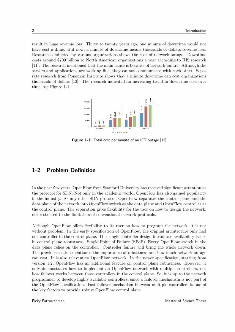
result in huge revenue loss. Thirty to twenty years ago, one minute of downtime would nothave cost a dime. But now, a minute of downtime means thousands of dollars revenue loss.Research conducted by various organizations shows the cost of network outage. Downtimecosts around $700 billion to North American organizations a year according to IHS research[11]. The research mentioned that the main cause is because of network failure. Although theservers and applications are working fine, they cannot communicate with each other. Sepa-rate research from Ponemon Institute shows that a minute downtime can cost organizationsthousands of dollars [12]. The research indicated an increasing trend in downtime cost overtime, see Figure 1-1.
Figure 1-1: Total cost per minute of an ICT outage [12]
1-2 Problem Definition
In the past few years, OpenFlow from Stanford University has received significant attention asthe protocol for SDN. Not only in the academic world, OpenFlow has also gained popularityin the industry. As any other SDN protocol, OpenFlow separates the control plane and thedata plane of the network into OpenFlow switch as the data plane and OpenFlow controller asthe control plane. The separation gives flexibility for the user on how to design the network,not restricted to the limitation of conventional network protocols.
Although OpenFlow offers flexibility to its user on how to program the network, it is notwithout problem. In the early specification of OpenFlow, the original architecture only hadone controller in the control plane. This single controller design introduces availability issuesin control plane robustness: Single Point of Failure (SPoF). Every OpenFlow switch in thedata plane relies on the controller. Controller failure will bring the whole network down.The previous section mentioned the importance of robustness and how much network outagecan cost. It is also relevant to OpenFlow network. In the newer specification, starting fromversion 1.2, OpenFlow has an additional feature on control plane robustness. However, itonly demonstrates how to implement an OpenFlow network with multiple controllers, nothow failover works between those controllers in the control plane. So, it is up to the networkprogrammer to develop highly available controllers, since a failover mechanism is not part ofthe OpenFlow specification. Fast failover mechanism between multiple controllers is one ofthe key factors to provide robust OpenFlow control plane.
Ficky Fatturrahman Master of Science Thesis

1-3 Research Objectives 3
1-3 Research Objectives
The previous section mentioned the importance of SDN robustness, specifically on OpenFlowcontrol plane failover. Therefore the main objective of this thesis is to propose a novelapproach to improve failover performance on the OpenFlow control plane. From this objectivethe following sub-objectives are derived:
• Review related works on SDN robustness and multiple OpenFlow controllers solutions.
• Identify existing conventional network protocols that can be applied to improve SDNcontrol plane robustness.
• Implement conventional network protocols to provide failover on OpenFlow controlplane and measure and evaluate their failover performance.
• Identify existing open source OpenFlow controllers with failover solution on the controlplane.
• Implement open source OpenFlow controllers to measure and evaluate their failoverperformance.
• Develop and propose a new solution that can improve failover performance and measureand evaluate the proposed solution.
1-4 Research Questions
Ideally, OpenFlow control plane should provide robust service to the data plane. Whencontroller failure occurs, there should be backup controllers that can detect it quickly. Thecontrol plane should also provide a failover mechanism with the minimum handover time fromprimary controller to the backup controller. Another important issue is that the control planealso decide which backup controllers that will take over and control the data plane duringfailover, otherwise it will cause race condition, a situation where two or more controllers tryingto take over the data plane at the same time. Based on the previous description, the researchquestions for this master thesis are the following:
• What kind of improvements are needed for the SDN control plane to overcome SPoF?
• How can the control plane detect failure when failure occurs in one of the controllers?
• How to minimize failover period when there is controller failure?
• How to avoid race condition between controllers in during failover?
Master of Science Thesis Ficky Fatturrahman

4 Introduction
1-5 Thesis Structure
This Master Thesis is organized as follows. First, in Chapter 1 the SPoF issue in OpenFlowis formulated into research objectives and research questions. Next, Chapter 2 presents anoverview of SDN and OpenFlow. Related works in controller robustness, conventional redun-dancy protocols, and failover mechanism in open source controllers are discussed in Chapter3. Chapter 4 evaluates various failover mechanisms for OpenFlow using conventional redun-dancy protocols and using open source controllers. In Chapter 5, failover mechanism formultiple controllers is proposed, experimented, measured, and analyzed. Finally, Chapter 6concludes this master thesis and recommends future work.
Ficky Fatturrahman Master of Science Thesis

Chapter 2
SDN
2-1 SDN Overview
The first chapter briefly discussed the problem that conventional IP networks are becomingtoo complex. IP was not designed to accommodate current critical applications’ require-ments. Even though IP has many limitations, it is still widely used, e.g. in the Internetand in the datacenter network. We come up with workaround solutions to overcome its lim-itation rather than innovate with better solutions. IP networks are getting convoluted withnumerous workaround devices. Those devices have different functions, from various vendors,with different operating systems. For example, Network Address Translation (NAT) boxeswere invented to counter the IPv4 exhaustion problem, Firewall, Intrusion Detection System(IDS) and Intrusion Prevention System (IPS) were invented to prevent security attacks andload balancers were invented to distribute traffic. This is a major problem for network ad-ministrators and engineers: they have to understand how all those devices work and how tointegrate all of those devices. Upgrading is also another problem, since adding new featuresor hardware upgrades to the control plane means downtime for those devices, because thecontrol plane and the data plane reside in the same device.
SDN introduces a new solution to improve networks. SDN decouples the control plane and thedata plane into separate devices, see Figure 2-1. The data plane can perform any function, itcan function as a router, a switch, firewall, or any application instructed by the control plane.The separation of the control plane and the data plane enables a logically centralized controlplane. This simplifies the network, everything can be controlled from a single control plane,no need to integrate multiple devices from various vendors with different operating systems.An SDN control plane or can be installed on a server as an SDN controller, which has morepowerful CPU than a CPU on a commodity router or switch. It is capable to implement morecomplex algorithm and it is easier to add more features, i.e. it enables programmability ofnetwork services.
Figure 2-2 shows SDN Architecture that comprises of three layers [7]:
Master of Science Thesis Ficky Fatturrahman

6 SDN
(a) Conventional Network (b) SDN
Figure 2-1: Conventional Network versus SDN
• The Data Plane LayerThe Data Plane is the network infrastructure that is controlled by the control plane.It consists of Network Elements (NE)s with forwarding capabilities such as a switch ora router. It is the underlying physical infrastructure that can be orchestrated by thecontroller through the Southbound interface in the control plane.
• The Control Plane LayerThe control plane is a logically centralized system that translates the abstract form ofthe network application in the application plane layer into instruction or action for NEin the data plane. It communicates with the application plane using its Northboundinterface. An example of Northbound interface API is REST API. It communicateswith the data plane using its Southbound interface. There are several protocols existfor SDN Southbound interface, e.g. OpenFlow, NETCONF, OVSDB.
• The Application Plane LayerThe application plane is the network application that can program the NE in the dataplane to operate the desired network behaviour. It communicates to the controllerthrough the Northbound interface in the control plane. Some examples of the networkapplications are network virtualization hypervisor such as FlowVisor [20] and DelftVisor[24], internate exchange point such as Software-Defined Internet Exchange (SDX) [8],and network monitoring system such as OpenNetMon [25].
2-2 OpenFlow
OpenFlow started out as part of the Clean Slate Program at Stanford University. The programobjective is what if the Internet is designed from scratch. Current IP networks are too difficultfor researchers to innovate new features on a realistic network, such as new routing protocols.OpenFlow solves this problem with network programmability. A programmable networkallows a researcher to experiment on a production network without having to worry about
Ficky Fatturrahman Master of Science Thesis

2-2 OpenFlow 7
Figure 2-2: SDN Architecture
Master of Science Thesis Ficky Fatturrahman

8 SDN
disrupting real traffic in the network. A researcher can program the network to provide aslice of the network, isolated from the real traffic.
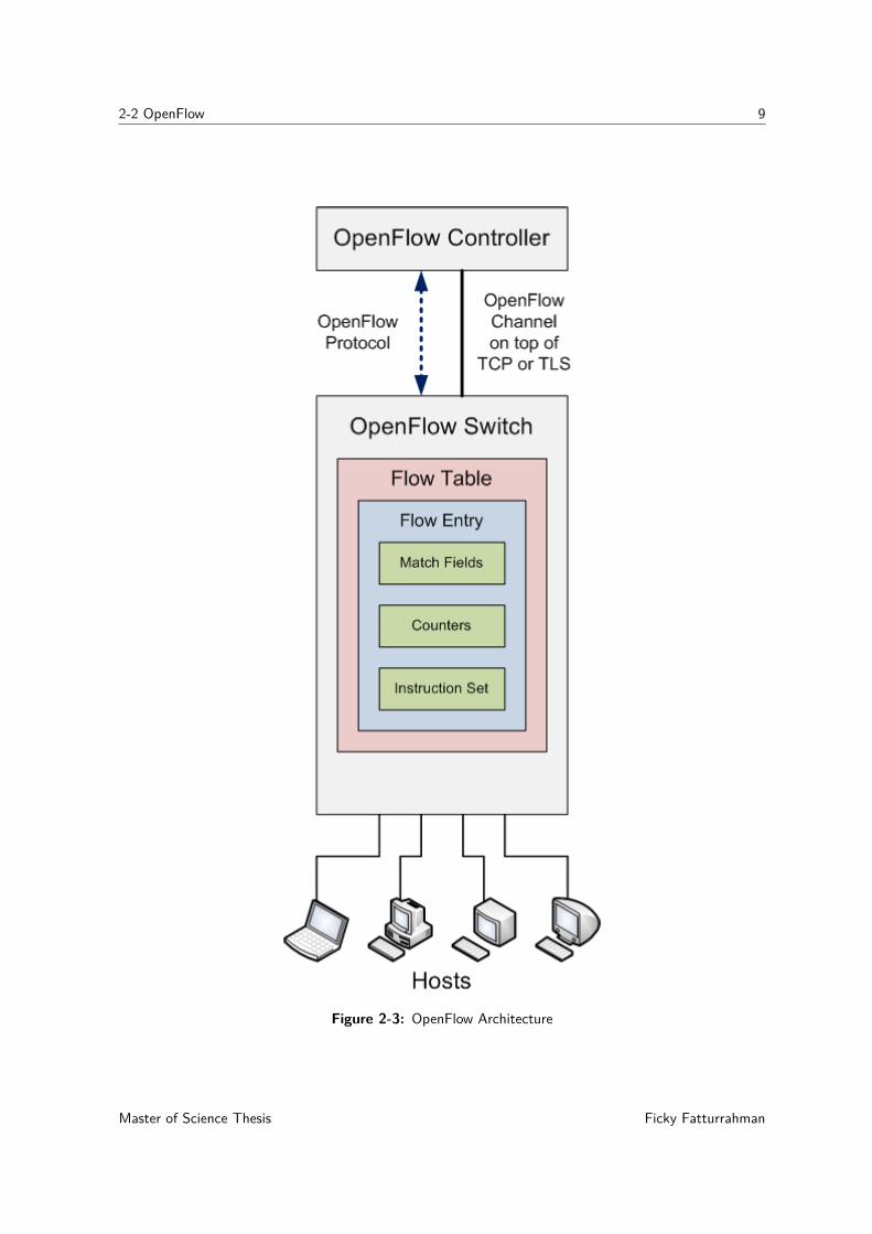
An OpenFlow network consists of OpenFlow controller in the control plane and OpenFlowswitch in the data plane. According to OpenFlow whitepaper [14], an OpenFlow switchconsists of at least three of the following: a flow table, an OpenFlow channel, and OpenFlowProtocol, see Figure 2-3. Flow table is a forwarding table based on rules configured by thecontroller. An OpenFlow switch has one or more flow table, each flow table has one or moreflow entry. A flow entry uses any of the information within the packet such as TCP port,VLAN tag, MAC/IP address, or incoming port to determine what to do with the packet, e.g.forward to the switch’s other port(or ports), drop the packet, send to the next flow table, orencapsulate and forward the packet to the controller. A flow entry has three fields: matchfields, counters for statistics, and a set of instructions to apply to matching packets. Whenthere is an incoming packet arrive at an OpenFlow switch’s port, the switch will look upto its flow table to find matching flow entry for that particular packet. If the switch find amatching flow entry, it will apply the instruction set to that packet, if there is no matchingentry, it will send the packet to the controller. The controller has the privilege to send ormodify flow entry in the switch via an OpenFlow channel. An OpenFlow channel connects acontroller and a switch, it runs on top of TCP or encrypted using TLS. The communicationbetween a controller and a switch is using OpenFlow Protocol.
2-2-1 OpenFlow Protocol
OpenFlow uses an OpenFlow channel as the interface that connects the control plane and thedata plane. The OpenFlow channel can be an in-band or out-of-band link between controlplane and data plane. Communication between the control plane and the data plane is usingOpenFlow Protocol via the OpenFlow channel. The OpenFlow protocol has three types ofmessages:
• Controller-to-SwitchController-to-Switch are the messages sent from the control plane to the data plane. Itmay expect a reply from the data plane.
• AsynchronousAsynchronous messages are the type of message that can be sent from the data planeto the control plane without request.
• SymmetricSymmetric messages are the type of messages that can be sent both from the controlplane to the data plane and the other way around.
See Table 2-1 for the list of OpenFlow protocol messages.
2-2-2 OpenFlow Multiple Controllers Mechanism
As mentioned in the previous chapter, the original OpenFlow protocol specification did notsupport multiple controllers implementation, which is a SPoF issue. To address that problem,
Ficky Fatturrahman Master of Science Thesis
2-2 OpenFlow 9
Figure 2-3: OpenFlow Architecture
Master of Science Thesis Ficky Fatturrahman

10 SDN
Table 2-1: OpenFlow Protocol
Protocol Message Description
Controller-to-Switch
Features
This message requests for the switch to reply with itscapabilities. This message is usually sent during theinitialization of OpenFlow channel between the controlplane and the data plane.
Configuration This message sets and queries configuration parametersin the switch.
Modify-State This message can add, delete, or modify flow/groupentries in the switch’s flow table.
Read-StateThis message requests for the switch to reply withvarious information such as configuration, statisticsand capabilities.
Packet-out
This message is sent from the control plane to respondto packet-in message from the data plane. It can also besent from the control plane to send packet to a specificport on the switch.
BarrierThis message is used to ensure message dependencieshave been met or to receive notifications for completedoperations.
Role-Request This message states the role of the controller to theswitch connected to it, see 2-2-2.
Asynchonous-Configuration
This message can customize the type of asynchronousmessages that can be sent from the data plane to thecontrol plane.
Asynchronous
Packet-in
Upon receiving a packet, the data plane first look up itsflow table. If there is no match in the table, it willforward the packet to the control plane as packet-inmessage.
Flow-removed
Flow entry in the flow table has a timeout. When theflow entry reaches its timeout, it will get removedfrom the table. Then the data plane sends flow-removedmessage to notify the control plane.
Port-statusThis message is sent from the data plane to notify thecontrol plane of any changes in its port status, e.g. portis down because of the link disconnected.
Error This message is sent to notify the control plane ofproblems in the data plane.
SymmetricHello This message is exchanged between a controller and a
switch during initial setup of the OpenFlow channel.
Echo
This message is used to monitor the liveness ofOpenFlow channel between the control plane and thedata plane. If echo request is sent, the receiver mustrespond with echo reply message.
Experimenter This message is used to offer additional functionalitywithin the OpenFlow message type space.
Ficky Fatturrahman Master of Science Thesis
2-2 OpenFlow 11
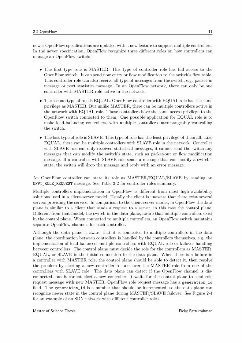
newer OpenFlow specifications are updated with a new feature to support multiple controllers.In the newer specification, OpenFlow recognize three different roles on how controllers canmanage an OpenFlow switch:
• The first type role is MASTER. This type of controller role has full access to theOpenFlow switch. It can send flow entry or flow modification to the switch’s flow table.This controller role can also receive all type of messages from the switch, e.g. packet-inmessage or port statistics message. In an OpenFlow network, there can only be onecontroller with MASTER role active in the network.
• The second type of role is EQUAL. OpenFlow controller with EQUAL role has the sameprivilege as MASTER. But unlike MASTER, there can be multiple controllers active inthe network with EQUAL role. Those controllers have the same access privilege to theOpenFlow switch connected to them. One possible application for EQUAL role is tomake load-balancing controllers, with multiple controllers interchangeably controllingthe switch.
• The last type of role is SLAVE. This type of role has the least privilege of them all. LikeEQUAL, there can be multiple controllers with SLAVE role in the network. Controllerwith SLAVE role can only received statistical messages, it cannot send the switch anymessages that can modify the switch’s state, such as packet-out or flow modificationmessage. If a controller with SLAVE role sends a message that can modify a switch’sstate, the switch will drop the message and reply with an error message.
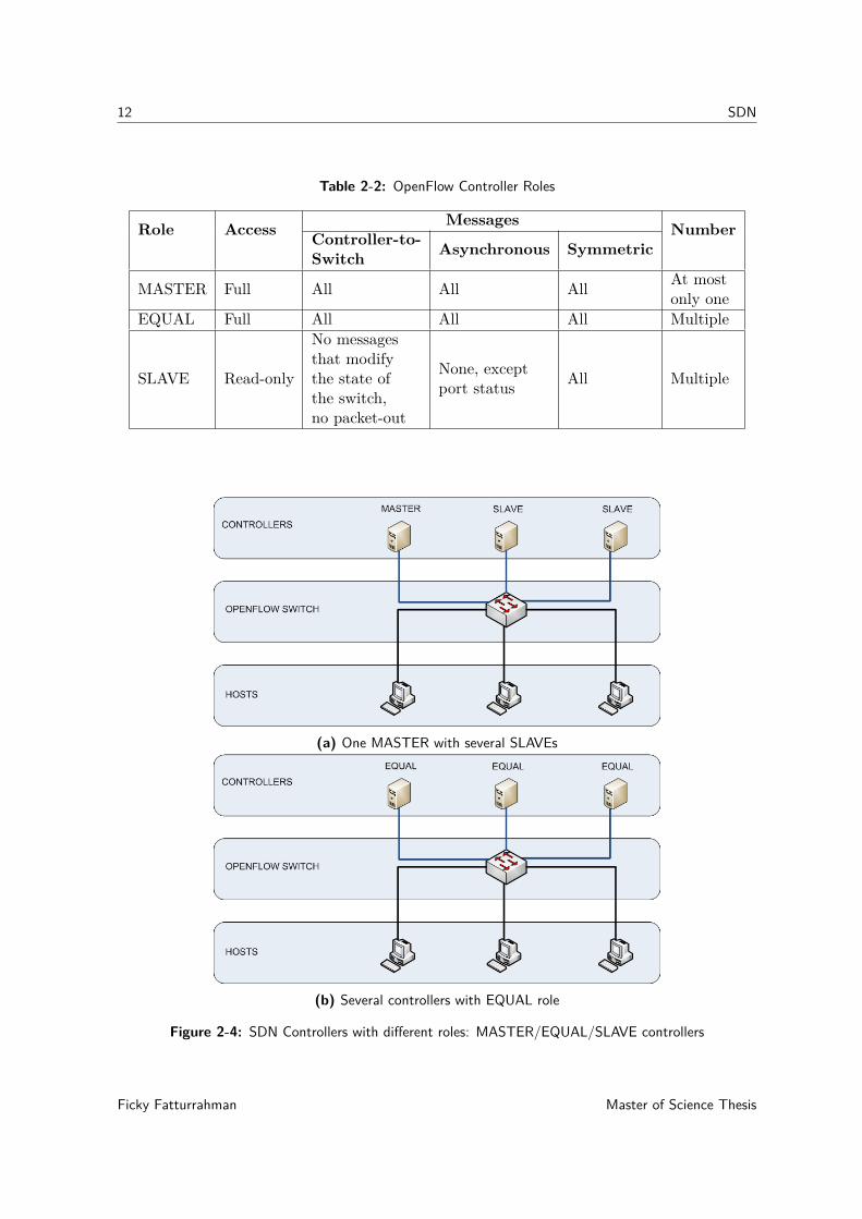
An OpenFlow controller can state its role as MASTER/EQUAL/SLAVE by sending anOFPT_ROLE_REQUEST message. See Table 2-2 for controller roles summary.
Multiple controllers implementation in OpenFlow is different from most high availabilitysolutions used in a client-server model. Usually the client is unaware that there exist severalservers providing the service. In comparison to the client-server model, in OpenFlow the dataplane is similar to a client that sends a request to a server, in this case the control plane.Different from that model, the switch in the data plane, aware that multiple controllers existin the control plane. When connected to multiple controllers, an OpenFlow switch maintainsseparate OpenFlow channels for each controller.
Although the data plane is aware that it is connected to multiple controllers in the dataplane, the coordination between controllers is handled by the controllers themselves, e.g. theimplementation of load-balanced multiple controllers with EQUAL role or failover handlingbetween controllers. The control plane must decide the role for the controllers as MASTER,EQUAL, or SLAVE in the initial connection to the data plane. When there is a failure ina controller with MASTER role, the control plane should be able to detect it, then resolvethe problem by electing a new controller to take over the MASTER role from one of thecontrollers with SLAVE role. The data plane can detect if the OpenFlow channel is dis-connected, but it cannot elect a new controller, it waits for the control plane to send rolerequest message with new MASTER. OpenFlow role request message has a generation_idfield. The generation_id is a number that should be incremented, so the data plane canrecognize newer state in the control plane during MASTER/SLAVE failover. See Figure 2-4for an example of an SDN network with different controller roles.
Master of Science Thesis Ficky Fatturrahman
12 SDN
Table 2-2: OpenFlow Controller Roles
Role Access Messages NumberController-to-Switch Asynchronous Symmetric
MASTER Full All All All At mostonly one
EQUAL Full All All All Multiple
SLAVE Read-only
No messagesthat modifythe state ofthe switch,no packet-out
None, exceptport status All Multiple
(a) One MASTER with several SLAVEs
(b) Several controllers with EQUAL role
Figure 2-4: SDN Controllers with different roles: MASTER/EQUAL/SLAVE controllers
Ficky Fatturrahman Master of Science Thesis

Chapter 3
Failover Mechanisms and RelatedWork
3-1 Related Work
Several solutions have been proposed for SDN resilience in the past few years. Yet not allof them tackle failover problem between multiple controllers. SDN resilience research can becategorized into the following:
• distributed controllers, this approach improves controller robustness by distributingthe controllers in the network, using multiple controller and divide the network intoseveral domain for each controller to handle, the examples are HyperFlow [23] andKandoo [9]
• state replication, this type focuses on state replication aspect between multiple SDNcontrollers, assuming that there are multiple controllers in the network and there is afailover mechanism between controllers whenever a controller failure occurs, the exam-ples in this category are CPRecovery [5] and SMaRtLight [3]
• load balancing/load sharing, in this subtopic the load in a controller is distributedbetween multiple controllers, reducing the possibility of CPU or other resource overloadthat can cause failure in a controller, preventing SPoF, the example is Balanceflow [10]and DALB [28]
• devolving controller, this approach delegates some of controller functions (controlplane functionality) back to the switches, to avoid resource overload in the controller,it also aims to distribute some of the control funtions to the switches to avoid SPoFproblem in the centralized controller SDN network, the examples in this category areDAIM [1], DIFANE [27], DevoFlow [4] and [21]
• data plane resilience, Not only in the control plane, but also resilience in the dataplane. In the data plane, similar work has been done to provide fast recovery during alink failure, the example for this category is in [26]
Master of Science Thesis Ficky Fatturrahman

14 Failover Mechanisms and Related Work
3-1-1 Distributed Controllers
HyperFlow
HyperFlow [23] is an OpenFlow controller application that run on top of a NOX controllerto provide a distributed control plane. HyperFlow was designed to improve shortcoming ofthe first OpenFlow specification, see Section 1-1. In the early OpenFlow specification, it onlysupports to implement one controller. But it is not scalable when production network growsin size and number, HyperFlow was designed to solve that problem. Scalability problems thatHyperFlow wants to solve are:
• increasing control traffic when the number of switches is increasing, when the number ofswitches is increasing, control traffic is also increasing, but the traffic can be distributedto distributed controllers
• high flow setup latency because of the distance between controller and switch, specif-ically in a network with large diameter, if the controllers are distributed, the networkcan be partitioned into smaller partition with its own controller
• increasing flow setup time when the network grows larger, the resource of one controllercan be exhausted if the network grows larger
HyperFlow has a physically distributed but logically centralized control plane. The dis-tributed controllers in HyperFlow partitioned the network into separate domain that con-nected to each other. Every event in each domain is handled locally by its own controller.HyperFlow uses publish/subscribe messaging paradigm to enable communication betweencontrollers. The publish/subscribe mechanism enables every event on each domain gets prop-agated to the other domain. This enables the control plane has a network-wide views of thenetwork topology. It also improves resilience and robustness to network partitioning
HyperFlow uses advertisement packet in the control plane as a healthchecking mechanism tomonitor the controller availability. It declares controller failure if there is no advertisementfrom a controller after three advertisement intervals. When there is a controller failure, thecontroller IP address configuration in the orphan switch has to be reconfigured to connectto an active controller. HyperFlow relies on proprietary configuration interface from theswitch’s hardware vendor to change the controller IP address in the switch. UnfortunatelyHyperFlow’s paper does not mention how long the advertisement interval and it also doesnot measure the failover time.
Figure 3-1: High-level Overview of HyperFlow [23]
Ficky Fatturrahman Master of Science Thesis

3-2 Conventional Failover Protocols 15
Kandoo
Kandoo [9] is a distributed OpenFlow controllers architecture that has hierarchical controllersdesign. Kandoo objective is similar to devolving controller, but instead of reverting some con-trol plane functionality back to the switches, it puts local controllers close to the switches, soit is still compatible with OpenFlow specification. Kandoo approach is using distributed con-trollers, load sharing, and controllers placement to create hierarchical distributed controllers.Kandoo has two layer of controllers: root and local, see Figure 3-2. Local controllers dealwith most of the flows from local events and application that does not require network-widestate view of the topology. Root controllers handle flows that require network-wide stateview of the topology such as elephant flows. Root controller is centralized for all the localcontrollers. Kandoo works in the following steps. First, the local controllers handle all localevents. But if there are specific flows/events that pre-specified for the root controller, localcontrollers forward the packet-in from that flow to the root controller, e.g. elephant flows thatis predefined to have more than 1 Mbps throughput. After receiving the packet-in, root con-troller sends the flow entry through local controllers so they push it to the switches. AlthoughKandoo focuses on the distributed controllers solution, unfortunately there is no mention onthe failover performance on the controllers.
Figure 3-2: Kandoo Architecture [9]
3-2 Conventional Failover Protocols
Not only in SDN, SPoF is also a problem in a conventional network. Basically, an SPoF is apart of the network, which if it fails, causes the entire network to stop operating. Redundancyis one of the solution to increase network robustness against SPoF. Making an SPoF part ofthe network redundant can decrease the risk of SPoF. Redundancy protocol enables multipledevices to operate in the network. It also provides failover mechanism between redundantdevices. There are several redundancy solution in the conventional IP network. In the networklayer, there is Virtual Router Redundancy Protocol (VRRP), and in the transport layer thereis Linux Virtual Server (LVS).
Master of Science Thesis Ficky Fatturrahman

16 Failover Mechanisms and Related Work
3-2-1 Network Layer: VRRP
Originally VRRP was designed as gateway redundancy protocol in the network layer. Themain objective of this type of network protocol is to provide redundant network gatewaythat transparent to its hosts. VRRP works using multiple network devices taking the role ofone Virtual IP (VIP) address. Figure 3-3 shows an example of a simple LAN network thatuses VRRP. The hosts are in 10.0.0.0/24 network with a gateway to VIP 10.0.0.1. Thereare two routers that take the role as the virtual gateway. Each physical router has its ownunique IP address but shares the same VIP address. Only one physical router active as theMASTER, the other one standby as BACKUP. When a host sends an ARP request for VIPhardware address, the MASTER replies it with its virtual MAC address: 00-00-5E-00-01-XX,with XX is the Virtual Router Identifier (VRID). The MASTER periodically sends VRRPadvertisement packet to the BACKUP to notify its availability. If the BACKUP does notreceive VRRP advertisement packet for longer than three times of advertisement timer, itdeclares that the MASTER is down and initiates failover process to take over the MASTERrole by sending gratuitous ARP packet to the network. Upon receiving the ARP packet, everyhost updates its own ARP cache for MAC address of the gateway with virtual MAC addressof the new MASTER.
Figure 3-3: VRRP Network
3-2-2 Transport Layer: LVS
Another option that can be applied to provide redundancy and failover for SDN controlleris LVS (Linux Virtual Server). LVS is an architecture that provides high availability at thetransport layer, commonly used on web server. LVS consists of two components: 1) a singleor a pair of load balancers, 2) a cluster of servers. Load balancer role is to distribute packetsto the cluster of servers, e.g. HTTP request packets to the cluster of web server. The loadbalancer also performs Network Address Translation (NAT) service to the cluster. Similar toVRRP, logically there is only one virtual IP address visible to the host. The host is unawareof the use of multiple servers in LVS’s cluster. NAT enables multiple servers in the cluster to
Ficky Fatturrahman Master of Science Thesis
3-3 Open Source Controllers 17
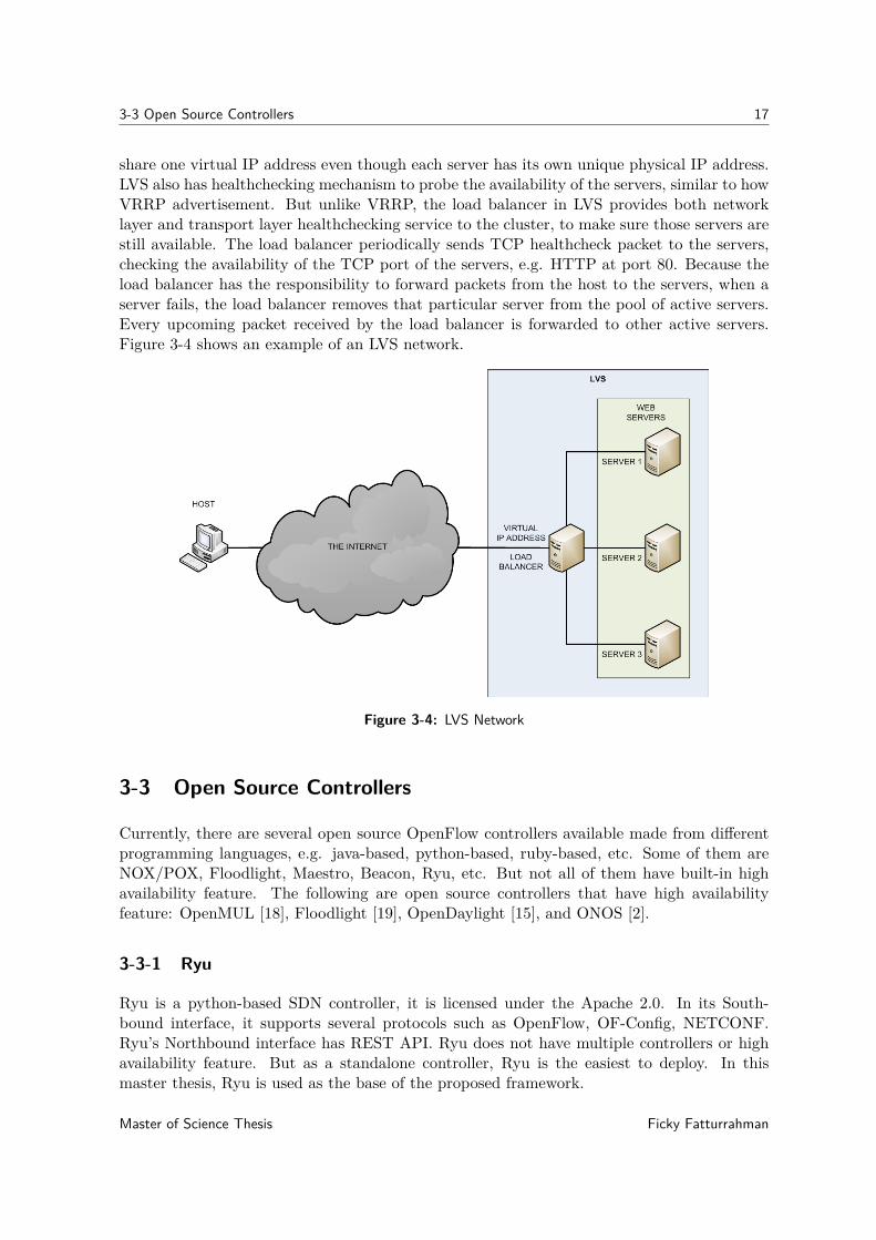
share one virtual IP address even though each server has its own unique physical IP address.LVS also has healthchecking mechanism to probe the availability of the servers, similar to howVRRP advertisement. But unlike VRRP, the load balancer in LVS provides both networklayer and transport layer healthchecking service to the cluster, to make sure those servers arestill available. The load balancer periodically sends TCP healthcheck packet to the servers,checking the availability of the TCP port of the servers, e.g. HTTP at port 80. Because theload balancer has the responsibility to forward packets from the host to the servers, when aserver fails, the load balancer removes that particular server from the pool of active servers.Every upcoming packet received by the load balancer is forwarded to other active servers.Figure 3-4 shows an example of an LVS network.
Figure 3-4: LVS Network
3-3 Open Source Controllers
Currently, there are several open source OpenFlow controllers available made from differentprogramming languages, e.g. java-based, python-based, ruby-based, etc. Some of them areNOX/POX, Floodlight, Maestro, Beacon, Ryu, etc. But not all of them have built-in highavailability feature. The following are open source controllers that have high availabilityfeature: OpenMUL [18], Floodlight [19], OpenDaylight [15], and ONOS [2].
3-3-1 Ryu
Ryu is a python-based SDN controller, it is licensed under the Apache 2.0. In its South-bound interface, it supports several protocols such as OpenFlow, OF-Config, NETCONF.Ryu’s Northbound interface has REST API. Ryu does not have multiple controllers or highavailability feature. But as a standalone controller, Ryu is the easiest to deploy. In thismaster thesis, Ryu is used as the base of the proposed framework.
Master of Science Thesis Ficky Fatturrahman
18 Failover Mechanisms and Related Work
3-3-2 OpenMUL
OpenMUL is a lightweight SDN controller. It is an open source version of MUL which isdeveloped by KulKloud. OpenMUL is licensed under GNU General Public License version 2(GPLv2). In its core, OpenMUL has a C based multi-threaded infrastructure.
OpenMUL uses REST API in its Northbound interface. In its Southbound interface, otherthan OpenFlow, OpenMUL also supports several other protocols such as NETCONF andOVSDB. The main components of OpenMUL are the following:
• MUL director/core, it is the core component of OpenMUL which in charge of :
– handling all low level switch connections and OpenFlow processing– providing API interface– providing Southbound protocols, e.g. OpenFlow– supports hooks for high speed low-latency learning (reactive) processing infrastruc-
ture– making sure all flows, groups, meters and other switch specific entities are kept in
sync across switch, controller reboots/failures
• MUL infrastructure services, this component provides basic services built on top ofMUL director/core, the following are some of the services:
– topology discovery service, this service is responsible to discover the networktopology using LLDP packets, it also responsible to detect and prevent loops inthe network
– path finding service, this service is responsible to calculate the shortest pathbetween two nodes in the network using Flloyd-Warshall algorithm, it also sup-ports ECMP with the possibility to influence route selection behavior using variousexternal parameters such as link speed and link latency, it is designed to be fastand scalable, in its web, it was mentioned that OpenMUL tested upto 128 nodes,it also provides an extremely fast shared memory based API interface to queryroutes
– path connector service, this service is responsible to provide a flexible interfacefor application to install flows across a path, it also responsible to hide networkcomplexities from the Application and App developer, another feature of this ser-vice is separating SDN domain into core and edge
• MUL system apps, the apps components are built using API provided by the previoustwo components. The following apps are compatible with OpenFlow:
– L2switch, an application to implement layer 2 learning switch– CLI app, an application to configure Mul components in command line– NBAPI webserver, python-based webserver that provide REST API for Open-
Mul controller.
Ficky Fatturrahman Master of Science Thesis
3-3 Open Source Controllers 19
OpenMUL supports multiple controllers implementation for high availability. Multiple con-trollers in OpenMUL can be deployed as hot/warm-standby failover in active-active or active-standby mode. In OpenMUL’s blog [22], MuL development team released the commercial ver-sion of OpenMUL named Mul 3.2.5 on 12th February 2014. It claims that it has HA failoverfeature with less than one second failover time. KulKloud release BEEM on its website [13],the current commercial version of OpenMUL that also has hot standby HA feature, which itclaim can mitigate outages in less than 1 second.
3-3-3 Floodlight
Floodlight is a java-based OpenFlow controller. It is licensed under Apache License version2.0 and supported by Big Switch Networks. Floodlight is based on Beacon controller fromStanford and Big Switch Networks. It only supports OpenFlow protocol in its Southboundinterface. The follwoing are the hightlighs from Floodlight’s features:
• module loading system that make it simple to extend and enhance
• requires minimal dependencies and easy to set up
• supports various virtual and physical OpenFlow switch
• capable of handling mixed OpenFlow and non-OpenFlow networks
• multithreaded
• supports OpenStack cloud orchestration platform.
Floodlight has the following built-in networking applications:
• OpenStack Quantum Plug-In, a plug-in to connect Floodlight to OpenStack asnetwork backend
• Virtual Switch, an application to implement layer 2 learning switch
• ACL (stateless FW), an application to implement Firewall based on Access ControlList (ACL)
• Circuit Pusher, an application to build bidirectional circuit using permanent flowentry on all switches between two hosts,
3-3-4 OpenDayLight
OpenDaylight is a java-based SDN controller that is built on Model-Driven Software Engineer-ing (MDSE) principles called Model-Driven Service Adaptation Layer (MD-SAL). MD-SALuses abstract representations of underlying network devices and network applications as ob-jects or models, whose interactions are processed within the Service Adaptation Layer (SAL).The SAL is the control logic int the control plane layer of OpenDaylight, its Northboundinterface translates the network application from the application layer to the data plane layervia its Southbound interface, see Figure 3-5 for OpenDaylight architecture. In addition toOpenFlow, OpenDaylight also supports other protocols in its Southbound interface, e.g. OF-Config, OVSDB or NETCONF.
Master of Science Thesis Ficky Fatturrahman

20 Failover Mechanisms and Related Work
Figure 3-5: OpenDaylight Architecture [15]
3-3-5 ONOS
ONOS is a java-based SDN controller, it is created to be an open source SDN controller tar-geted for service provider. In its Nortbound interface, ONOS has two Northbound abstractionframework: the Intent Framework and the Global Network View. The Intent Framework en-ables a network application to apply a service in the network without knowing how the servicewill be performed in the data plane. The Global Network View provides the application layera view of the network’s resources such as the hosts, switches, links, utilizations. ONOS’sNorthbound interfaces isolates the application layer from the complex underlaying networkinfrastructure. The Southbound interface in ONOS provides an abstraction of network re-sources as objects, it also enables ONOS to manage network element with different protocols,e.g. OpenFlow, OVSDB or NETCONF. Figure 3-6 shows ONOS architecture. ONOS isdesigned with the following features:
Figure 3-6: ONOS Architecture [17]
• Distributed Core, this feature allows ONOS to run as a cluster of controllers thatprovides scalability and high availability
• Northbound API, this feature enables higher-level network application to be trans-lated to the data plane
Ficky Fatturrahman Master of Science Thesis

3-3 Open Source Controllers 21
• Southbound API, this feature facilitates ONOS to control the data plane, not onlyOpenFlow-based switch, but also legacy devices
• Software Modularity, this feature makes ONOS easy to develop, maintain, debug,and upgrade.
3-3-6 Summary
Table 3-1 shows the comparison between open source SDN controllers.
Table 3-1: Open Source Controllers Comparison
Controller SouthboundProtocol Program
MultipleControllersFeature
OpenMul OpenFlow, OF-Config, OVSDB, NETCONF C YesFloodlight OpenFlow Java YesONOS OpenFlow, OF-Config, OVSDB, NETCONF Java YesOpenDaylight OpenFlow, OF-Config, OVSDB, NETCONF Java YesRyu OpenFlow, OF-Config, NETCONF Python No
Master of Science Thesis Ficky Fatturrahman

22 Failover Mechanisms and Related Work
Ficky Fatturrahman Master of Science Thesis
Chapter 4
Failover Evaluation
This chapter evaluates failover time between controllers. First, different types of controllerfailures are discussed in section 4-1. The second section explains the testbed environment.Next, the failover times using conventional redundancy protocol are measured in section 4-3,and failover times of several open source controllers are measured in section 4-4. The lastsection compares those failover times.
4-1 Type of Simulated Failure
There are several events that can cause controller failure. The following are three main typesof failures that can trigger failover:
• Network failureNetwork or connectivity failure is a failure of the link between two devices. It can becategorized into two types: between the controllers and between the controller to theswitch. Network failure can be simulated by using iptables tool in the controller. Theresult of applying iptables with the rule to drop any packet is blocking the connectivityin a link. When applied to all interfaces in a controller, it will block the OpenFlowchannel from the controller to the switch and also block the link between controllers.
• Power failureSimilar to network failure, power can also be categorized into two types: graceful shut-down and non-graceful shutdown. Simulating graceful shutdown can be done by execut-ing the shutdown command in the controller. It is possible to configure a controller tosend other controllers a message when the graceful shutdown command is executed. So,the other controllers can get notified and take over the role if necessary, e.g. failover be-tween controllers to take over MASTER role. In a non-graceful shutdown, the controllerdoes not have the opportunity to notify other controllers. So the failover process de-pends on liveness monitoring mechanism between controllers, failover is executed whenother controllers notice that they do not receive any reply after a period of time.
Master of Science Thesis Ficky Fatturrahman

24 Failover Evaluation
• Software failureSoftware failure occurs when the process/PID that handles OpenFlow requests is killedin the controller’s operating system. To simulate software failure, a command thatkills the PID process is executed in a controller. It will trigger the controller to sendFIN packet to the switch and other controllers. Thus closing the OpenFlow channel,initiating the failover process.
4-2 Testbed Environment
This section describes the testbed environment. Ubuntu Linux 14.04 servers used in theexperiment. The aforementioned linux distribution is the most compatible version with everycontrollers deployed in the testbed.
The following subsections explains the network topology and software tools used for measure-ment.
4-2-1 Topology
To simulate and measure failover time, the simplest topology is sufficient, see Figure 4-1.At least three controllers are needed to simulate failover from one controller to a secondcontroller. Although two controllers should be enough to simulate failover, some open sourcecontrollers such as OpenDaylight and ONOS require minimum three controllers to enablefailover feature. Because they implement quorum mechanism in their failover solution, seesection 4-4 for further explanation. Other nodes in the topology are one OpenFlow switchand two hosts to generate traffic that needs to be sent to the controllers as packet-in. Thefirst host generates traffic and then the second host receives the traffic.
Figure 4-1: Topology
Ficky Fatturrahman Master of Science Thesis

4-2 Testbed Environment 25
4-2-2 Software Tools
This experiment uses software-based OpenFlow switch, the openvswitch (OVS). To generatetraffic, pktgen is used. Pktgen offers higher accuracy compared to other similar tools. Becausepktgen runs in the kernel space, unlike other packet generator tools that run in the user space.Tcpdump is used to capture the packets. Network failure is simulated using iptables. Toautomate the process, all the software tools are run automatically using crontab.
4-2-3 Measurement Scenario
Figure 4-2 shows the traffic generated from H1 to H2. Failover time can be measured bycalculating the packet loss during a fixed period of time. See the numbered arrows in Figure4-2. The arrows show the path of generated packets from H1 to H2. In an ideal condition,the traffic goes from H1 to H2 in the following steps:
1. H1 generates random packets to its interface that is connected to S1. These randompackets have random source/destination IP/MAC addresses.
2. Since S1 does not have a flow entry for those packets received from H1, S1 encapsulatesthem as packet-in messages and sends them to the C1, controller with MASTER role.
3. The controller also does not have the MAC addresses of every packets it received becausethey are randomly generated. It does not know where to send those packets. Becauseof that, it sends them back as packet-out messages to S1 with instruction to broadcastthem to all interfaces except the source where S1 receive them at the first time.
4. Upon receiving packet-out messages, S1 reads the instruction to broadcast them to allinterfaces except the source. Since it has only 2 interfaces, those messages are forwardedto the interface connected to H2. H2 receives randomly generated packets from H1 andcaptures the packets it received using tcpdump.
Figure 4-2: Normal Traffic
The scenario during the failover process is explained in the following picture at Figure 4-3.In Figure 4-3 there are three phases of the failover process:
Master of Science Thesis Ficky Fatturrahman

26 Failover Evaluation
(a) Link from MASTER controller is disconnected
(b) SLAVE controller take over MASTER role
(c) The network continue to operate
Figure 4-3: Failover
Ficky Fatturrahman Master of Science Thesis
4-3 Conventional Redudancy Protocols 27
1. In the first phase, link from the MASTER controller disconnected from the network, seeFigure 4-3a. The link from MASTER controller is disconnected by configuring iptablescommand to DROP every packet it received. H1 still continuously generates packets toits interface that is connected to S1. After S1 detects there is no connectivity to theMASTER controller, all incoming packets get dropped. S1 also does not try to forwardthose packets by itself because it is configured in fail_mode: secure. So there are nopackets forwarded to H2 until another controller takes over the MASTER role.
2. The next phase is the take over phase. In Figure 4-3b, S1 still drops every packetfrom H1 when there is no controller with MASTER role available. Upon detecting theunavailability of C1, C2 notices that there is no controller with MASTER role. C2changes its role from SLAVE to MASTER by sending OFPT_ROLE_REQUEST message toS1. S1 changes C2 role from SLAVE to MASTER if the role value in the message isOFPCR_ROLE_MASTER. S1 replies back a OFPT_ROLE_REPLY message to acknowledge it.Now S1 has C2 as the new controller with MASTER role.
3. Figure 4-3c shows the final phase, in this last phase the network resumes to operateas usual, the packets traverse from H1 to H2, but through the new controller withMASTER role: C2.
In one session pktgen in H1 generates 60,000 packets with an interval of one millisecondbetween packets, one minute from the first packet to the last packet. In total there are onehundred sessions executed in a period of every four minutes between sessions. At the sametime, H2 starts tcpdump to capture those packets and write those out as separate pcap filesfor every sessions.
If there is no failure in the controllers, tcpdump reports that it captured 60,000 packets. Itmeans there is no failover between controllers. When there is a failover, tcpdump capturesless packets, those lost packets are the number of failover time in ms.
During failover simulation in Figure 4-3, packet loss before the new controller takes over therole of MASTER controller. Since there is one ms interval between packets, the packet losscan be used to calculate how long the failover times in millisecond.
4-3 Conventional Redudancy Protocols
In this section the performance of conventional redundancy protocols is evaluated. VRRPand LVS are implemented in the control plane. A controller failure is simulated. Then thefailover time is measured.
4-3-1 Network Layer: VRRP
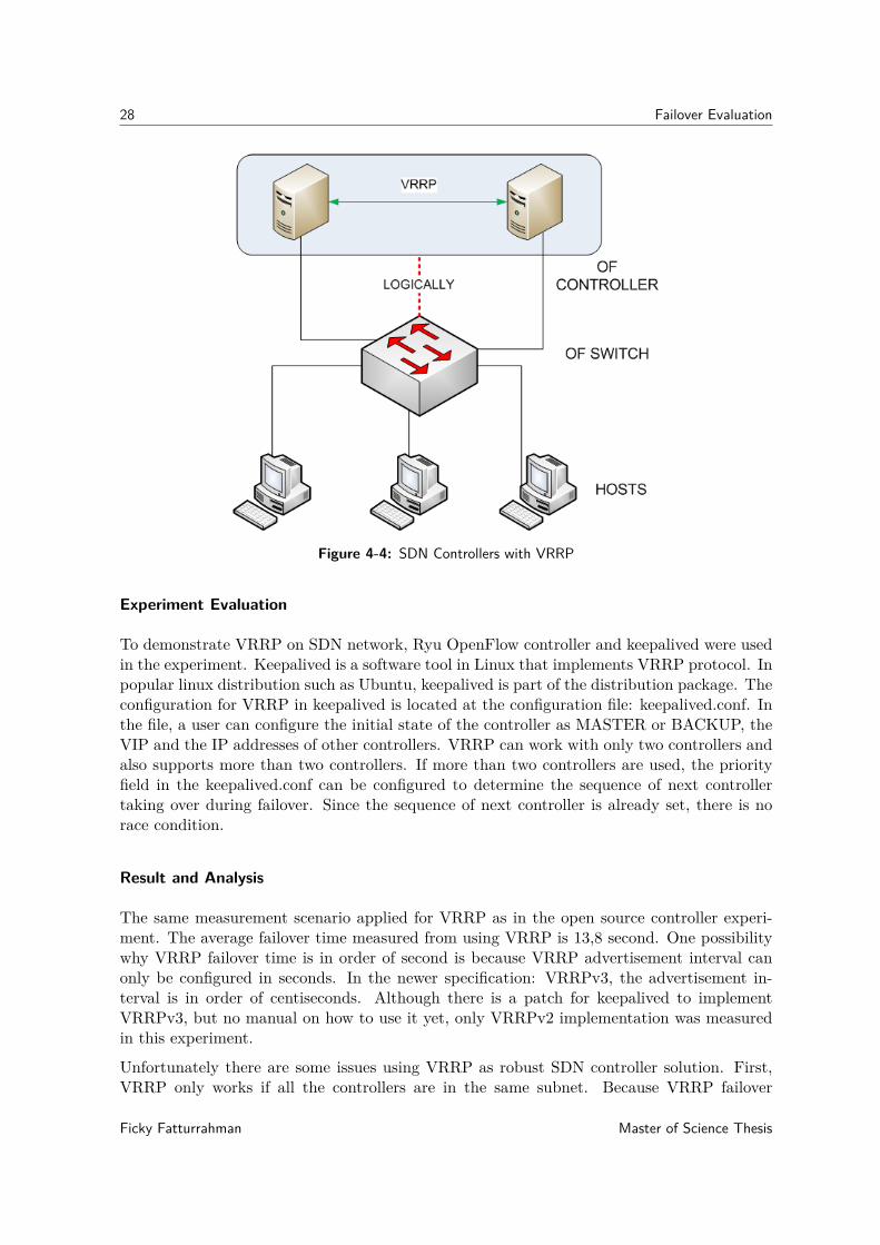
In this thesis, VRRP is adapted into SDN network. Multiple controllers share one VIP addressas one controller, see Figure 4-4. The gateways are the controllers in the control plane, andthe hosts are the OpenFlow switches in the data plane. One controller as MASTER, whichactively providing services to the switch, and the other as BACKUP, standing by waiting totake role as MASTER controller when the original MASTER fail.
Master of Science Thesis Ficky Fatturrahman
28 Failover Evaluation
Figure 4-4: SDN Controllers with VRRP
Experiment Evaluation
To demonstrate VRRP on SDN network, Ryu OpenFlow controller and keepalived were usedin the experiment. Keepalived is a software tool in Linux that implements VRRP protocol. Inpopular linux distribution such as Ubuntu, keepalived is part of the distribution package. Theconfiguration for VRRP in keepalived is located at the configuration file: keepalived.conf. Inthe file, a user can configure the initial state of the controller as MASTER or BACKUP, theVIP and the IP addresses of other controllers. VRRP can work with only two controllers andalso supports more than two controllers. If more than two controllers are used, the priorityfield in the keepalived.conf can be configured to determine the sequence of next controllertaking over during failover. Since the sequence of next controller is already set, there is norace condition.
Result and Analysis
The same measurement scenario applied for VRRP as in the open source controller experi-ment. The average failover time measured from using VRRP is 13,8 second. One possibilitywhy VRRP failover time is in order of second is because VRRP advertisement interval canonly be configured in seconds. In the newer specification: VRRPv3, the advertisement in-terval is in order of centiseconds. Although there is a patch for keepalived to implementVRRPv3, but no manual on how to use it yet, only VRRPv2 implementation was measuredin this experiment.
Unfortunately there are some issues using VRRP as robust SDN controller solution. First,VRRP only works if all the controllers are in the same subnet. Because VRRP failover
Ficky Fatturrahman Master of Science Thesis

4-3 Conventional Redudancy Protocols 29
solution relies on ARP, which is a protocol that translate network address into hardware ad-dress. Second, VRRP does not provide load-balancing mechanism. It is possible to distributecontroller function in VRRP, but it is not practical. Although VRRP supports multipleBACKUP controllers, but only one MASTER controller can serve all switches in the networkat a time. So, to distribute controller function we need to configure multiple IP addresses onevery controller and configure different controller’s IP addresss on every switches, basically alot of configuration on every devices. Third issue is transport layer failure, since VRRP is anetwork layer protocol, it can only detect network layer failure. VRRP works well on networklayer devices such as router. If there is an application failure on the MASTER controller,VRRP cannot detect it. The BACKUP controller assumes that the MASTER controller isstill functional, since it is still reachable at network layer. Another problem is reconnectionoverhead. Because the switch is only aware of one controller, it only has one OpenFlow chan-nel to the MASTER controller. If the MASTER failed, the switch initiates a new OpenFlowchannel to the new controller.
4-3-2 Transport Layer: LVS
Since network layer redundancy network protocol such as VRRP cannot solve transport layerfailure, the next option is to use redundancy solution in the transport layer: LVS. LVScan provide redundancy in SDN control plane. Instead of multiple servers, there are multiplecontrollers. The load balance monitors the availability of the controllers, different from VRRPwhich the function resides in the BACKUP controller. Figure 4-5 shows LVS adapted into anSDN network.
Figure 4-5: SDN Controllers with LVS
Master of Science Thesis Ficky Fatturrahman

30 Failover Evaluation
Experiment Evaluation
The same tools were used to implement LVS and VRRP: keepalived and Ryu controller.We install keepalived on the load balancers and Ryu on the controllers. The IP addressesof the controllers are written down in the keepalived.conf configuration file. In the file, wecan also write down the virtual IP address and the OpenFlow port so the load balancer cancheck controllers’ availability in both the network layer and the transport layer. We can alsospecify what kind of algorithm the load balancer uses to send packet to the controllers, e.g.using round robin or weighted round robin. There is no minimum or maximum number ofcontrollers can be used. There is also no synchronization between controllers, but the loadbalancer periodically sends TCP check packet on the OpenFlow port of every controllers. Wecan also specify the interval of TCP check packets, but unfortunately the interval is in orderof seconds, not ms. The number of attempts before declaring that the controller is down canalso be specified in the file, e.g. after 3 retries with no reply. If the load balancer does not getany reply after 3 attempts, it will removes that particular controller from its list of availablecontrollers. Any new packet will get forwarded to the other controllers.
Result and Analysis
The same measurement scenario also applied in this experiment. LVS improves several VRRPshortcomings. First, LVS supports load balance feature. Unfortunately this feature doesnot work for OpenFlow. OpenFlow reuires separate OpenFlow channel for each connectionbetween an OpenFlow switch and an OpenFlow controller. Because LVS is using virtual IP,the switch only acknowledge the existence of single controller. Every time the load balancerdistribute OpenFlow message from the switch to a different controller, the switch initiates anOpenFlow channel. Second, LVS provides transport layer TCP check mechanism. AlthoughLVS solves VRRP problem with transport layer failure, it still does not solve reconnectionoverhead issue. Both VRRP and LVS use single OpenFlow channel from the switch to thecontroller. Because the switch still only has one OpenFlow channel to the virtual IP addressof the controllers. So failover process requires the switch and the new controller to setup anew OpenFlow channel. This unnecessary channel reconnection overhead adds more time tofailover process. The average failover time using LVS is 10.7 seconds. LVS’s failover time isalso in order of seconds because the TCP check packets are sent in interval of seconds too, ina way similar to VRRPv2 advertisement interval which is also in order of seconds.
4-4 Open Source Controllers
The previous section shows that conventional redundancy solution such as VRRP and LVSenable multiple controllers implementation on OpenFlow, but the failover performance is stillquite slow for carrier grade network. This section discusses multiple controllers implemen-tation and failover mechanism of the open source controllers. First the setup is evaluated.Then the result is presented.
Ficky Fatturrahman Master of Science Thesis

4-4 Open Source Controllers 31
4-4-1 OpenMUL
Experiment Evaluation
Installing OpenMul was quite easy to do, its documentation is comprehensive. First, downloadOpenMul source code from git. Next, compile build.sh to build the necessary binaries. Inthis experiment, we start OpenMul by running mul.sh script and we only enable two featuresin the script: l2switch and start-ha. Both options enable OpenMul to implement layer2 learning switch and high availability feature, respectively. Running OpenMul with twocontrollers is straightforward, just execute mul script with start-ha option and the name ofthe peer controller: ./mul.sh start-ha l2switch <peer controller’s IP address>. Thecommand ./mul.sh starts OpenMul, start-ha enables HA feature, l2switch runs layer 2learning switch application. It is suggested in the documentation that the both controllersneed to be connected first in HA mode before connecting to the switch. So, the controllerscan establish a negotiation session between themselves to elect a controller with MASTERrole.
Result and Analysis
During the experiment we trace the OpenFlow packets between the controllers to the switchand between the controllers themselves. Compared to other open source controllers in thisexperiment, OpenMul was the easiest controller to deploy and to implement the multiple con-trollers feature. Although easy to deploy, unfortunately OpenMul lacks in terms of features.Specifically the multiple controllers feature, since in this experiment we evaluate that partic-ular feature. The shortcoming that we encounter in OpenMul HA feature is that it supportsno more than two controllers. It is unknown whether the commercial version of OpenMulcan support more than two controllers or not. The OpenMul controllers use TCP port 7745to communicate with each other, e.g. to check the other controller availability. The othershortcoming is that a user cannot configure the initial role of the controllers, and this cannotspecifically which particular controller gets assigned the first MASTER role.
In the initial setup, each controller sends role_request messages with its role as MASTERor SLAVE respectively, so no race-condition occurs. Since there are only two controllers,the SLAVE immediately takes over when the MASTER is disconnected from the network,it sends role_request message to the switch with incremented generation_id. We wereable to automate the process of calculating failure recovery time by using cron. The processrepeated for 200 times. On average, OpenMul’s failover time is 11.5 second.
4-4-2 Floodlight
Experiment Evaluation
Installation manual for Floodlight is available in its wiki page. The instruction is very clear,to run Floodlight, all of the prerequisite packages need to be installed, e.g. java, git, andant. Its multiple controller feature can be enabled by modifying floodlightdefault.propertiesconfiguration file. In the file, all of the controllers’ IP addressess, their initial role as MASTER
Master of Science Thesis Ficky Fatturrahman
32 Failover Evaluation
or SLAVE, and the port they use to communicate with each other need to be written down.In order for them to communicate with each other, first java keystore is generated and copiedto each of the controllers. There is no minimum number of controllers that Floodlight needto enable multiple controllers, it also supports more than two controllers.
Result and Analysis
The same process as in OpenMul experiment is implemented to calculate Floodlight’s failovertime. During tracing the packets, it is discovered that Floodlight does not have a mechanismto determine which controller is next in line to take over the MASTER role. If only twocontrollers are used, the failover process works just fine. But if more than two controllers areused, race conditions occur after the MASTER controller gets disconnected. Every SLAVEcontroller attempts to take over the MASTER role at the same time by sending role_requestmessage. There was a period of time that the switch changed the MASTER controller morethan once. The switch chooses the controller that sends the last role_request packet it re-ceived. The race condition occurs because Floodlight does not increment the generation_idfield in its role_request message, the switch will change the controller with MASTER roleevery time it received role_request message with MASTER role. On average, Floodlight’sfailover time is 29.9 second.
4-4-3 OpenDayLight
Experiment Evaluation
There are several stable versions available, we install version 4.1 Berrylium. OpenDaylightdocumentation is very comprehensive, every release has its own separate manuals for in-stallation, user, and for developer. Although OpenDaylight is much more complex thanOpenMul or Floodligth, it was actually easy to install and to implement multiple controllers.After downloading and extracting OpenDaylight on each controller, to enable multiple con-trollers feature we only need to edit three configuration files: akka.conf, modules.conf, andmodule-shards.conf. The akka.conf defines all the controllers IP and port for synchronization,modules.conf defines what kind of data shards from ODL database can be stored, module-shard defines the data-shards are replicated to which controllers. Those files can be editedeither manually or automatically. Enabling multiple controllers automatically can be done byrunning configure_cluster.sh script: configure_cluster.sh <index> <seed_nodes_list>.OpenDaylight supports more than two controllers, but the failover part of the feature onlyworks when there are at least three controllers. If implemented with two controllers, Open-Daylight can still work with the switch, one controller as MASTER, the other as SLAVE, butthere will be no failover when the MASTER is down.
Result and Analysis
After starting the controllers, they negotiate with each other to determine which one is theMASTER. Each of them sends a join command message to the other controllers. Thosecontrollers comunicate using port 2550, but it can be modified into other port in the akka.conf
Ficky Fatturrahman Master of Science Thesis

4-5 Comparison 33
configuration file. They also periodically send messages to each other for healthcheckingpurpose. Since they already negotiated which controller is the MASTER, when a switchconnected, those controllers send role_request message with their respective role, eitherMASTER or SLAVE. They also already negotiated which controller is next in line to takeover if the MASTER down. When the SLAVE controllers detect that the MASTER is down,the successor sends role_request with incremented generation_id to take over MASTERrole. Since the next MASTER controller is already set, there is no race conditions occurs.The average ODL’s failover time is 12.7 second.
4-4-4 ONOS
Experiment Evaluation
ONOS has several stable versions available. We use version 1.5.1 Falcon. Its documentationis available in its wiki page. Similar to OpenDaylight, ONOS is much more complex thanOpenMul or Floodlight, but it was easy to install. Just download ONOS source code from gitand then compile it to build the necessary binaries. ONOS provides script to execute remoteinstall: onos-install <controller IP address>. ONOS multiple controllers feature isthe easiest to install compared to other controllers. It has its own script to automate remoteinstall for multiple controllers and it also automates the clustering configuration between thecontrollers: onos-form-cluster <controllers IP addresses>.
Result and Analysis
ONOS provides very useful CLI. It can select or change the role for each controller. It makeseasier during measurement. We can configured the MASTER on C1 manually. ONOS doesnot has maximum number for controllers but it has similar quorum mechanism as OpenDay-light. In order for failover feature to work, there must be three ONOS controllers. ONOScan still works with only two controllers but it cannot execute failover when the MASTERcontroller fails. ONOS does not increment generation ID field in its role request messageduring failover, but it has its own mechanism to decide which SLAVE controllers will takeover the MASTER role during failover, preventing race condition.
4-5 Comparison
The table 4-1 is the result of measured failover time from different open source controllers.Failover time is the total amount of time from network disconnection of C1 or the time H2received the last packet-out from C1 to the time H2 received the first packet-out from C2.Failure detection time is the time measured from network disconnection of C1 to the time S1received role request message from C2. Take over time is the time measured from the timethe S1 received role request message from C2 to the time H2 received first packet-out fromC2.
Master of Science Thesis Ficky Fatturrahman

34 Failover Evaluation
Table 4-1: Benchmark
Controller Failovertime (s) Min. Max. Race
conditionIncrementedgeneration_id
OpenMul 11.5 2 2 None YesFloodlight 29.9 2 None Yes NoneONOS 2.9 3 None None NoneOpenDaylight 12.7 3 None None YesVRRP 13.8 2 None None -LVS 10.7 2 None None -
Ficky Fatturrahman Master of Science Thesis

Chapter 5
ACRoDiF: A Controller Robustnessand Distribution Framework
In the previous chapter, the failover time of several open source controllers has discussed.Unfortunately the failover time is still quite high. The fastest failover time is in ONOSwith average of 2.9 second. This is still much higher than 50ms, which is the acceptablecarrier-grade recovery time [16].
This chapter proposes ACRoDiF (A Controller Robustness and Distribution Framework) toimprove SDN control plane robustness using multiple controllers. ACRoDiF is inspired bythe Content Delivery Network (CDN) concept. CDN uses DNS to direct client traffic to theclosest server based on the source IP address of the client.
5-1 CDN Overview
CDN is a distributed system that content provider uses to distribute web pages and contentto be cached in the geographically closest web server to the client. Conventional client-servermodel that a web server uses is a centralized web server. Nowadays, the problem with acentralized web server is that many content provider have their content accessed from clientsaround the world. The latency is quite high when a client accesses content from a webserver located in a different continent. Using CDN, content provider duplicates its own webserver, distributes them around the world, and provides cached content such as text, image,or video on itw distributed web servers. CDN enables client to access a web page faster thancentralized model, see Figure 5-1.
CDN exploits the DNS server function to distribute network traffic to the closest server. InCDN, there is a hierarchy how DNS server works. Figure 5-2 shows two clients from differentcontinents access the same URL: example.com. Because example.com uses CDN, the domainresolves to several different IP addresses, e.g. each IP address for a web server in eachcontinent. The process how a client access a web page from example.com is the following:
Master of Science Thesis Ficky Fatturrahman

36 ACRoDiF: A Controller Robustness and Distribution Framework
Figure 5-1: CDN
1. When a client access a web server, first the client query the IP address of the webserver’s domain from a recursive DNS server.
2. The recursive DNS server queries the requested domain to the authoritative DNS serverof that domain.
3. The authoritative server looks up the client IP address to identify the client’s geographiclocation. Then the authoritative server replies the query with the IP address of theclosest web server to the client.
4. The recursive server replies to the client with the information from the authoritativeserver.
5. Each client accesses the web server of example.com from its own continent.
Ficky Fatturrahman Master of Science Thesis
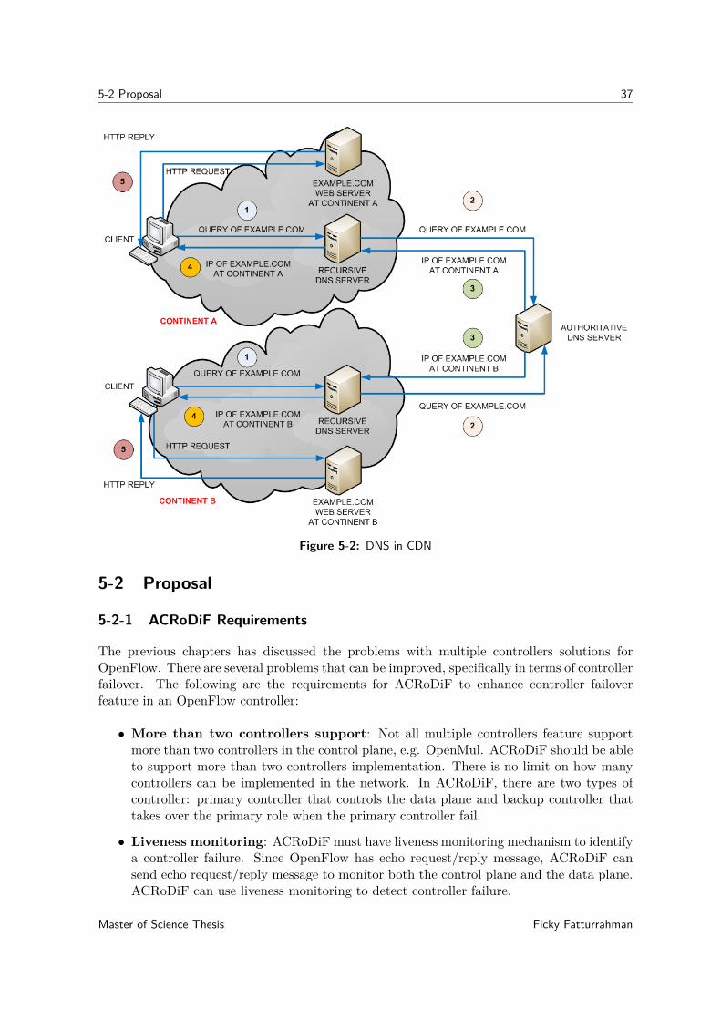
5-2 Proposal 37
Figure 5-2: DNS in CDN
5-2 Proposal
5-2-1 ACRoDiF Requirements
The previous chapters has discussed the problems with multiple controllers solutions forOpenFlow. There are several problems that can be improved, specifically in terms of controllerfailover. The following are the requirements for ACRoDiF to enhance controller failoverfeature in an OpenFlow controller:
• More than two controllers support: Not all multiple controllers feature supportmore than two controllers in the control plane, e.g. OpenMul. ACRoDiF should be ableto support more than two controllers implementation. There is no limit on how manycontrollers can be implemented in the network. In ACRoDiF, there are two types ofcontroller: primary controller that controls the data plane and backup controller thattakes over the primary role when the primary controller fail.
• Liveness monitoring: ACRoDiF must have liveness monitoring mechanism to identifya controller failure. Since OpenFlow has echo request/reply message, ACRoDiF cansend echo request/reply message to monitor both the control plane and the data plane.ACRoDiF can use liveness monitoring to detect controller failure.
Master of Science Thesis Ficky Fatturrahman

38 ACRoDiF: A Controller Robustness and Distribution Framework
• Failover mechanism: ACRoDiF must be able to execute failover upon detecting acontroller failure. When ACRoDiF detects failure in the primary controller, it promotesthe backup controller to primary controller.
• Eliminate race condition: Although Floodlight supports more than two controllersin the control plane, unfortunately it has race condition problem. ACRoDiF failovermechanism must have a solution to avoid race condition. In this experiment, we man-ually configure the priority list of the controller to be promoted as primary duringfailover.
5-2-2 ACRoDiF Overview
ACRoDiF expands distribution concept borrowed from CDN to be applied on multiple Open-Flow controllers. The switch and the controller in OpenFlow connection resembles the con-nection between a client and server. The client, in this case an OpenFlow switch sends arequest message to the server or the controller, and the switch gets a reply message fromthe controller. ACRoDiF introduces a proxy layer between the control plane layer and thedata plane layer, see Figure 5-3. This proxy layer is responsible for distribution function inACRoDiF, similar to the DNS server role in CDN. The controller and the switch are obliviousto the proxy layer. The proxy layer decides which controller is active as the primary controllerto receive packet-in from the data plane. It also monitors the status of every controller inthe control plane. Controller only detects the proxy as the switch. The switch detects theproxy as the controller. This middlebox approach enables ACRoDiF to use any OpenFlowcontroller, since it does not require any modification on the control plane or in the data plane,see Figure 5-4.
Figure 5-3: CDN and ACRoDiF
The proxy in ACRoDiF is based on a modified version of Ryu controller. As an OpenFlowcontroller, Ryu already has basic controller function. It listens to OpenFlow TCP port. Ifa switch initiates a TCP connection to establish an OpenFlow channel, it can create anOpenFlow channel to the data plane. We modify Ryu controller so when an OpenFlow
Ficky Fatturrahman Master of Science Thesis

5-2 Proposal 39
Figure 5-4: ACRoDiF
channel is created from the data plane to the proxy, it acts as a switch to the control planeand initiates TCP connection to create an OpenFlow channel to the controller.
In this experiment we use two controllers, two proxies, one switch, and two hosts, see Figure5-5. Any network topology is possible, but we decided to implement the simplest topology.The proxy connects to the two controllers if it detects a connection attempt from a switch.Each connection from a switch results to two OpenFlow channel from the proxy to the controlplane, one for each controller.
5-2-3 The Proxy Layer
In OpenFlow, the OpenFlow channel between the control plane and the data plane is initiatedby the switch in the data plane. In ACRoDiF, the switch is also initiates the channel. First, S1initiates TCP connection to both P1 and P2. After it connected to the proxies, S1 exchangeshello message to both P1 and P2 which creates an OpenFlow channel between the data planeto the proxy layer. After the OpenFlow channel between proxy layer and the data planecreated, P1 and P2 initiates TCP connection to the control plane: C1 and C2. Next P1 &P2 exchanges hello message to C1 & C2 creating an OpenFlow channel between the proxylayer to the control plane. Then P1 sends role request message as MASTER to S1, thenS1 responds with sending role reply to both P1 and P2 with different roles: MASTER andSLAVE respectively. In this simple setup we preconfigured P1 role as MASTER and P2 asSLAVE, but it is also possible to implement any algorithm to elect which one is the MASTER,e.g. an algorithm that decide proxy with the lowest latency to the switch as the MASTER,presumably it is the closest proxy. The proxy relays every message between the control planeand the data plane, see Figure 5-6. The following explains how the proxy layer works:
1. H1 generates packets to S1 with destination address of H2.
Master of Science Thesis Ficky Fatturrahman

40 ACRoDiF: A Controller Robustness and Distribution Framework
Figure 5-5: ACRoDiF Measurement Topology
2. S1 encapsulates every packet from H1 as a packet-in and forwards it to P1.
3. Then P1 forwards it to the primary controllers: C1.
4. C1 replies the packet-in from P1 with a packet-out.
5. P1 receives packet-out from C1 and then forwards it to S1
6. S1 unencapsulates packet-out from P1 and forwards it to H2
5-2-4 Experiment Evaluation
The measurement scenario is the same as in the previous chapter. When the primary con-trollers fail: C1 disconnected, Figure 5-7 shows the failover mechanism as the following:
1. C1 disconnected, P1 still receives packet-in from S1.
2. P1 periodically checks the availability of both the controllers and the switch by sendingecho request message with an interval of 15ms and receives echo reply message. Afternot receiving echo reply message from C1 for three times of the echo request interval,P1 declares that C1 is not available, P1 removes C1 from the list of primary controllers.Then P1 promotes C2 role from backup controller to primary controller. The failovertime is calculated by counting the packet loss during the failover.
Ficky Fatturrahman Master of Science Thesis
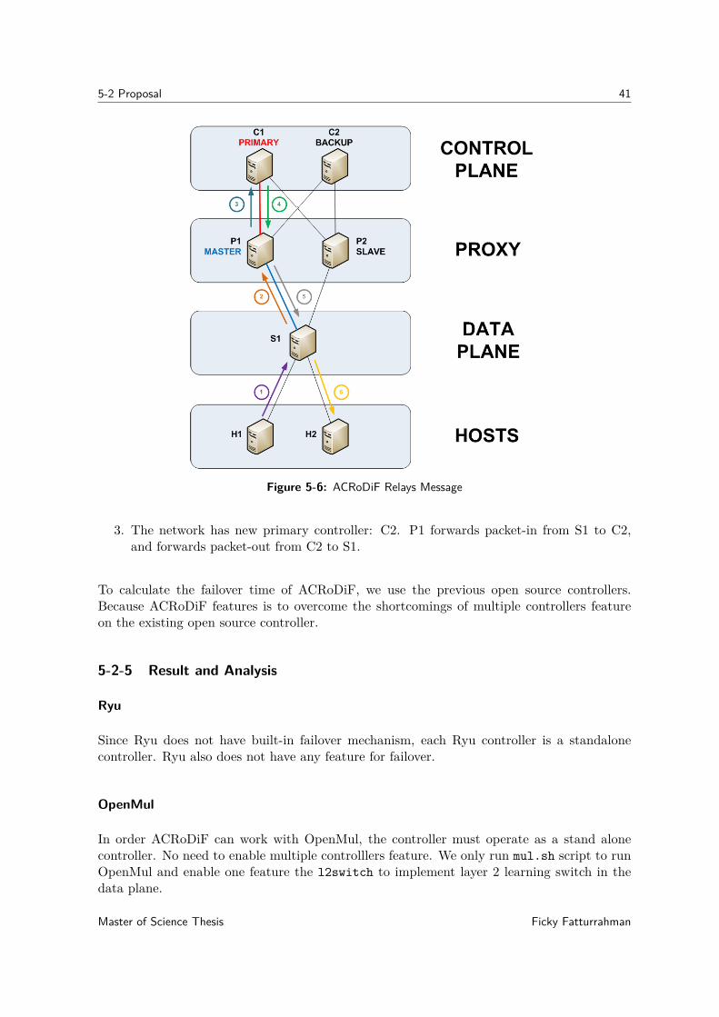
5-2 Proposal 41
Figure 5-6: ACRoDiF Relays Message
3. The network has new primary controller: C2. P1 forwards packet-in from S1 to C2,and forwards packet-out from C2 to S1.
To calculate the failover time of ACRoDiF, we use the previous open source controllers.Because ACRoDiF features is to overcome the shortcomings of multiple controllers featureon the existing open source controller.
5-2-5 Result and Analysis
Ryu
Since Ryu does not have built-in failover mechanism, each Ryu controller is a standalonecontroller. Ryu also does not have any feature for failover.
OpenMul
In order ACRoDiF can work with OpenMul, the controller must operate as a stand alonecontroller. No need to enable multiple controlllers feature. We only run mul.sh script to runOpenMul and enable one feature the l2switch to implement layer 2 learning switch in thedata plane.
Master of Science Thesis Ficky Fatturrahman
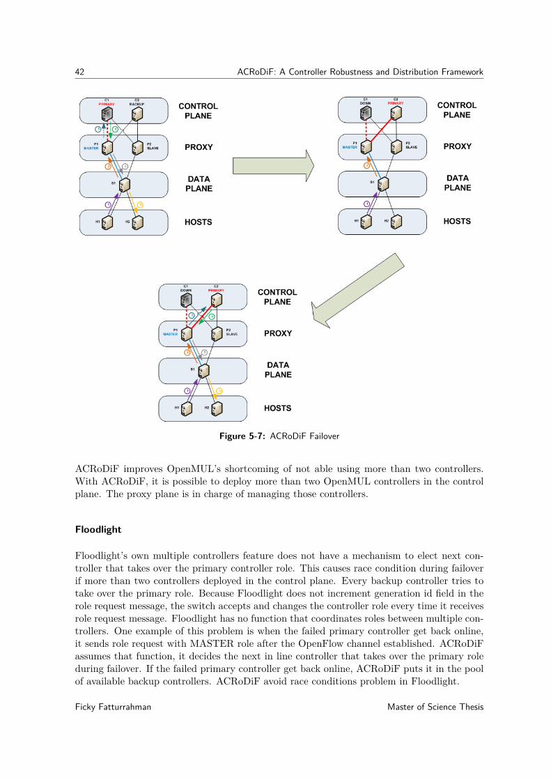
42 ACRoDiF: A Controller Robustness and Distribution Framework
Figure 5-7: ACRoDiF Failover
ACRoDiF improves OpenMUL’s shortcoming of not able using more than two controllers.With ACRoDiF, it is possible to deploy more than two OpenMUL controllers in the controlplane. The proxy plane is in charge of managing those controllers.
Floodlight
Floodlight’s own multiple controllers feature does not have a mechanism to elect next con-troller that takes over the primary controller role. This causes race condition during failoverif more than two controllers deployed in the control plane. Every backup controller tries totake over the primary role. Because Floodlight does not increment generation id field in therole request message, the switch accepts and changes the controller role every time it receivesrole request message. Floodlight has no function that coordinates roles between multiple con-trollers. One example of this problem is when the failed primary controller get back online,it sends role request with MASTER role after the OpenFlow channel established. ACRoDiFassumes that function, it decides the next in line controller that takes over the primary roleduring failover. If the failed primary controller get back online, ACRoDiF puts it in the poolof available backup controllers. ACRoDiF avoid race conditions problem in Floodlight.
Ficky Fatturrahman Master of Science Thesis
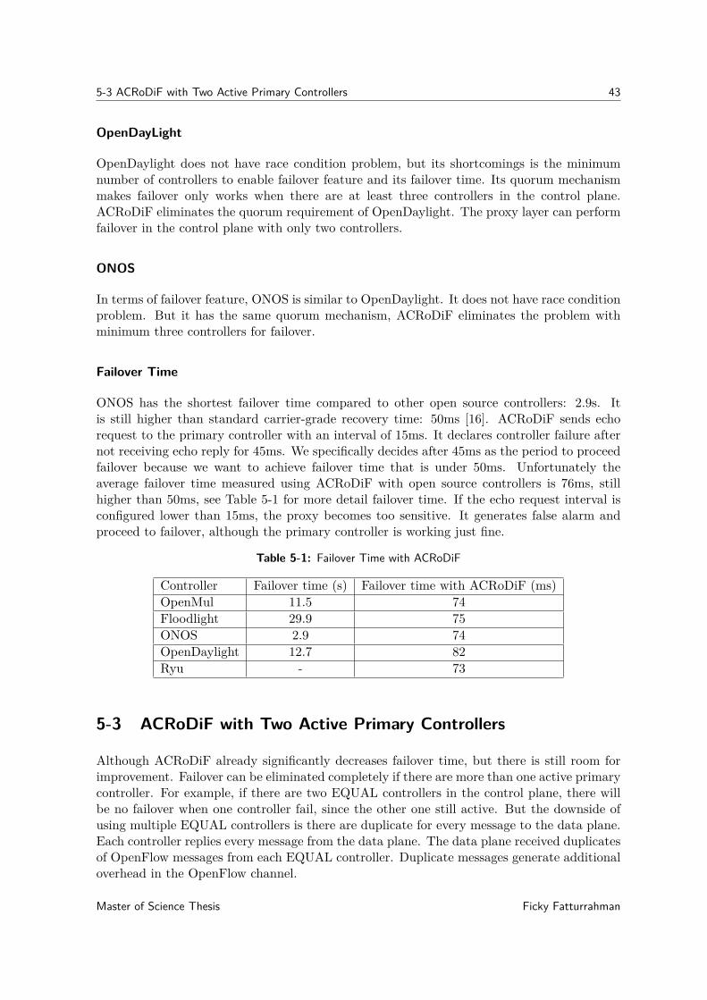
5-3 ACRoDiF with Two Active Primary Controllers 43
OpenDayLight
OpenDaylight does not have race condition problem, but its shortcomings is the minimumnumber of controllers to enable failover feature and its failover time. Its quorum mechanismmakes failover only works when there are at least three controllers in the control plane.ACRoDiF eliminates the quorum requirement of OpenDaylight. The proxy layer can performfailover in the control plane with only two controllers.
ONOS
In terms of failover feature, ONOS is similar to OpenDaylight. It does not have race conditionproblem. But it has the same quorum mechanism, ACRoDiF eliminates the problem withminimum three controllers for failover.
Failover Time
ONOS has the shortest failover time compared to other open source controllers: 2.9s. Itis still higher than standard carrier-grade recovery time: 50ms [16]. ACRoDiF sends echorequest to the primary controller with an interval of 15ms. It declares controller failure afternot receiving echo reply for 45ms. We specifically decides after 45ms as the period to proceedfailover because we want to achieve failover time that is under 50ms. Unfortunately theaverage failover time measured using ACRoDiF with open source controllers is 76ms, stillhigher than 50ms, see Table 5-1 for more detail failover time. If the echo request interval isconfigured lower than 15ms, the proxy becomes too sensitive. It generates false alarm andproceed to failover, although the primary controller is working just fine.
Table 5-1: Failover Time with ACRoDiF
Controller Failover time (s) Failover time with ACRoDiF (ms)OpenMul 11.5 74Floodlight 29.9 75ONOS 2.9 74OpenDaylight 12.7 82Ryu - 73
5-3 ACRoDiF with Two Active Primary Controllers
Although ACRoDiF already significantly decreases failover time, but there is still room forimprovement. Failover can be eliminated completely if there are more than one active primarycontroller. For example, if there are two EQUAL controllers in the control plane, there willbe no failover when one controller fail, since the other one still active. But the downside ofusing multiple EQUAL controllers is there are duplicate for every message to the data plane.Each controller replies every message from the data plane. The data plane received duplicatesof OpenFlow messages from each EQUAL controller. Duplicate messages generate additionaloverhead in the OpenFlow channel.
Master of Science Thesis Ficky Fatturrahman
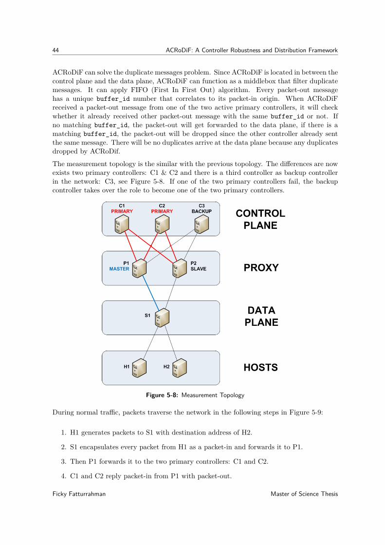
44 ACRoDiF: A Controller Robustness and Distribution Framework
ACRoDiF can solve the duplicate messages problem. Since ACRoDiF is located in between thecontrol plane and the data plane, ACRoDiF can function as a middlebox that filter duplicatemessages. It can apply FIFO (First In First Out) algorithm. Every packet-out messagehas a unique buffer_id number that correlates to its packet-in origin. When ACRoDiFreceived a packet-out message from one of the two active primary controllers, it will checkwhether it already received other packet-out message with the same buffer_id or not. Ifno matching buffer_id, the packet-out will get forwarded to the data plane, if there is amatching buffer_id, the packet-out will be dropped since the other controller already sentthe same message. There will be no duplicates arrive at the data plane because any duplicatesdropped by ACRoDif.
The measurement topology is the similar with the previous topology. The differences are nowexists two primary controllers: C1 & C2 and there is a third controller as backup controllerin the network: C3, see Figure 5-8. If one of the two primary controllers fail, the backupcontroller takes over the role to become one of the two primary controllers.
Figure 5-8: Measurement Topology
During normal traffic, packets traverse the network in the following steps in Figure 5-9:
1. H1 generates packets to S1 with destination address of H2.
2. S1 encapsulates every packet from H1 as a packet-in and forwards it to P1.
3. Then P1 forwards it to the two primary controllers: C1 and C2.
4. C1 and C2 reply packet-in from P1 with packet-out.
Ficky Fatturrahman Master of Science Thesis

5-3 ACRoDiF with Two Active Primary Controllers 45
5. P1 receives duplicates of packet-out from C1 and C2. P1 forwards the first packet-outarrived either from C1 or C2 to S1 and discards the duplicate. Since the proxy decidesto forward only the first packet-out arrived to S1, there are no duplicates of packet-outat the switch.
6. S1 unencapsulates packet-out from P1 and forwards it to H2
Figure 5-9: Normal Traffic
When one of the primary controllers fail, e.g. C1 disconnected, Figure 5-10 shows the failovermechanism as the following:
1. After C1 disconnected, P1 can only sends & receives packet-in & packet-out to & fromC2, the only primary controller available.
2. P1 periodically checks the availability of both the controllers and the switch by sendingecho request messages with an interval of 15ms and receives echo reply messages. Afternot receiving echo reply messages from C1 for three times of the echo request interval,P1 declares that C1 is not available, P1 removes C1 from the list of primary controllers.Then P1 promotes C3 role from backup controller to primary controller.
3. The network has two primary controllers, it operates just like how it normally operateswith two primary controllers.
Since there is always duplicates of packet-out from the control plane, so there is no packetloss in the data plane during failover. There is no failover time is calculated when using
Master of Science Thesis Ficky Fatturrahman

46 ACRoDiF: A Controller Robustness and Distribution Framework
two active primary controllers in ACRoDiF. The challenge when developing this feature wasidentifying the packet-outs of the same session from C1 and C2. P1 must able to identifythe same packet-outs from C1 and C2 so it does not discard the wrong packet-out message.Fortunately P1 can exploit buffer_id field in the packet-out header so it can discard anypacket-out with the same buffer_id number, see figure 5-11.
Ficky Fatturrahman Master of Science Thesis

5-3 ACRoDiF with Two Active Primary Controllers 47
(a) C1 is disconnected (b) C3 promoted to primary role
(c) The network continue to operate
Figure 5-10: Failover
Master of Science Thesis Ficky Fatturrahman

48 ACRoDiF: A Controller Robustness and Distribution Framework
Figure 5-11: Duplicates of packet-out
Ficky Fatturrahman Master of Science Thesis

Chapter 6
Conclusion
6-1 Research Questions Revisited
In this chapter, we revisit our research questions and view how they can be answered:
• What kind of improvements are needed for the SDN control plane to overcome SPoF?Chapter 3 shows that distributed controller approach is the solution for SPoF. Chap-ter 5 presents a new framework for distributed controller: ACRoDiF, it enhances thedistributed controller approach with another layer: the proxy layer. The proxy layer inACRoDiF improves the shortcomings of current SPoF solutions presented in Chapter 4benchmark.
• How can the control plane detect failure when failure occurs in one of the controllers?In Chapter 5, ACRoDiF demonstrates liveness monitoring mechanism using OpenFlow’secho request/reply message. It is possible to delegate the liveness monitoring from thecontrol plane to the proxy. In ACRoDiF, the proxy is responsible for controllers livenessmonitoring.
• How to minimize failover period when there is controller failure?The experiment in Chapter 5 shows a promising result. The proxy layer in ACRoDiFprovides failover mechanism that has lower failover time than the open source con-trollers. Furthermore, using two active primary controllers in ACRoDiF proves thatfailover time can be eliminated completely.
• How to avoid race condition between controllers in during failover?Because the distribution function resides in the proxy layer. The proxy can decide whichcontroller is next in line to take over the role of the primary controller, no more racecondition.
Master of Science Thesis Ficky Fatturrahman
50 Conclusion
6-2 Future Work
We believe that this thesis is far from complete. There are many aspects that are need to bediscussed. These are several recommendations for further research:
• Investigate on why using echo request interval that is lower than 15ms generates falsealarmCurrent solution using the interval of 15ms only gives us the average failover timeof 76ms, which is still higher than 50ms, the acceptable carrier-grade recovery timestandard. Theoretically, lowering the interval gives us lower failover time instead offalse alarm.
• Conduct another experiment with different measurement scenarioThe measurement scenario in this thesis only consumes a small amount of networkbandwidth because of the low throughput. Further experiment on different scenario isnecessary to observe ACRoDiF performance. For example with higher throughput inthe network.
• Enhance ACRoDiF featureThe following ideas present several feature that can be added to ACRoDiF in the futureto improve its performance:
– Scalability feature, adding a new controller in the cluster after a switch connectsto the proxy is not yet possible. Currently, we need to preconfigured the controllersbefore a switch connect to the proxy layer
– Preempt feature, in VRRP there is a preempt feature, which means if a failednetwork element gets back online it will take over the role, in ACRoDiF after acontroller is declared not available by the proxy, it remains unavailable eventhoughit gets back online
Ficky Fatturrahman Master of Science Thesis

Bibliography
[1] Ameen Banjar, Pakawat Pupatwibuli, and Robin Braun. “DAIM: a mechanism to dis-tribute control functions within OpenFlow switches”. In: Journal of Networks 9.1 (2014),pp. 1–9.
[2] Pankaj Berde et al. “ONOS: towards an open, distributed SDN OS”. In: Proceedings ofthe third workshop on Hot topics in software defined networking. ACM. 2014, pp. 1–6.
[3] Fábio Botelho et al. “On the design of practical fault-tolerant SDN controllers”. In:Software Defined Networks (EWSDN), 2014 Third European Workshop on. IEEE. 2014,pp. 73–78.
[4] Andrew R Curtis et al. “DevoFlow: Scaling flow management for high-performancenetworks”. In: ACM SIGCOMM Computer Communication Review. Vol. 41. 4. ACM.2011, pp. 254–265.
[5] Paulo Fonseca et al. “A replication component for resilient OpenFlow-based network-ing”. In: Network Operations and Management Symposium (NOMS), 2012 IEEE. IEEE.2012, pp. 933–939.
[6] Open Networking Foundation. OpenFlow Switch Specification V 1.3. 0 (Wire Protocol0x04), June 25, 2012.
[7] Open Networking Foundation. SDN Architecture 1.0 Overview, November, 2014.[8] Arpit Gupta et al. “Sdx: A software defined internet exchange”. In: ACM SIGCOMM
Computer Communication Review 44.4 (2015), pp. 551–562.[9] Soheil Hassas Yeganeh and Yashar Ganjali. “Kandoo: a framework for efficient and
scalable offloading of control applications”. In: Proceedings of the first workshop on Hottopics in software defined networks. ACM. 2012, pp. 19–24.
[10] Yannan Hu et al. “Balanceflow: controller load balancing for openflow networks”. In:Cloud Computing and Intelligent Systems (CCIS), 2012 IEEE 2nd International Con-ference on. Vol. 2. IEEE. 2012, pp. 780–785.
[11] IHS. Businesses Losing $700 Billion a Year to IT Downtime, Says IHS. url: http://news.ihsmarkit.com/press- release/technology/businesses- losing- 700-billion-year-it-downtime-says-ihs (visited on 06/14/2017).
Master of Science Thesis Ficky Fatturrahman

52 BIBLIOGRAPHY
[12] Ponemon Institute. Cost of Data Center Outages, January 2016. url: https://www.vertivco.com/globalassets/documents/reports/2016-cost-of-data-center-outages-11-11_51190_1.pdf (visited on 06/14/2017).
[13] KulKloud. BEEM. url: http://www.kulcloud.com/beem/ (visited on 07/20/2016).[14] Nick McKeown et al. “OpenFlow: enabling innovation in campus networks”. In: ACM
SIGCOMM Computer Communication Review 38.2 (2008), pp. 69–74.[15] Jan Medved et al. “Opendaylight: Towards a model-driven sdn controller architecture”.
In: World of Wireless, Mobile and Multimedia Networks (WoWMoM), 2014 IEEE 15thInternational Symposium on a. IEEE. 2014, pp. 1–6.
[16] B Niven-Jenkins et al. Requirements of an MPLS transport profile. Tech. rep. 2009.[17] ON.LAB. Introducing ONOS - a SDN network operating system for Service Providers,
November 2014.[18] OpenMul. url: http://http://www.openmul.org/ (visited on 07/20/2016).[19] Project Floodlight. url: http://www.projectfloodlight.org/ (visited on 05/04/2016).[20] Rob Sherwood et al. “Flowvisor: A network virtualization layer”. In: OpenFlow Switch
Consortium, Tech. Rep 1 (2009), p. 132.[21] Adrian S-W Tam, Kang Xi, and H Jonathan Chao. “Use of devolved controllers in data
center networks”. In: Computer Communications Workshops (INFOCOM WKSHPS),2011 IEEE Conference on. IEEE. 2011, pp. 596–601.
[22] MuL development team. MuL 3.2.5 Commercially available now! 2014. url: https://openmul.wordpress.com/2014/02/12/mul-3-2-5-commercially-available-now/ (visited on 07/20/2016).
[23] Amin Tootoonchian and Yashar Ganjali. “HyperFlow: A distributed control plane forOpenFlow”. In: Proceedings of the 2010 internet network management conference onResearch on enterprise networking. USENIX Association. 2010, pp. 3–3.
[24] Harmjan Treep. “Delftvisor: A network hypervisor for Openflow 1.3, Network virtual-ization for Openflow 1.3”. MA thesis. the Netherlands: Delft University of Technology,2017.
[25] Niels LM Van Adrichem, Christian Doerr, and Fernando A Kuipers. “Opennetmon:Network monitoring in openflow software-defined networks”. In: 2014 IEEE NetworkOperations and Management Symposium (NOMS). IEEE. 2014, pp. 1–8.
[26] Niels LM Van Adrichem, Benjamin J Van Asten, and Fernando A Kuipers. “Fast re-covery in software-defined networks”. In: 2014 Third European Workshop on SoftwareDefined Networks. IEEE. 2014, pp. 61–66.
[27] Minlan Yu et al. “Scalable flow-based networking with DIFANE”. In: ACM SIGCOMMComputer Communication Review 41.4 (2011), pp. 351–362.
[28] Yuanhao Zhou et al. “A Load Balancing Strategy of SDN Controller Based on Dis-tributed Decision”. In: Trust, Security and Privacy in Computing and Communications(TrustCom), 2014 IEEE 13th International Conference on. IEEE. 2014, pp. 851–856.
Ficky Fatturrahman Master of Science Thesis

Appendix A
Workaround for ACRoDiF andOpenMUL Testbed
There is one flaw on OpenMUL that require workaround solution, OpenMUL does not replyto echo request (OFPT_ECHO_REQUEST) message. Based on the OpenFlow 1.3 specification [6],both echo request and echo reply (OFPT_ECHO_REPLY) messages are categorized as symmetricmessages, which means echo request message can be sent from either data plane or controlplane and must return an echo reply message. Unfortunately OpenMUL only capable ofsending echo request message, but not capable replying to echo request message. This is aproblem for the ACRoDiF to detect whether the controller is still available or not. ACRoDiFrelies on echo request/reply message to verify the liveness of OpenFlow channel to the controlplane. It will send echo request message and wait for echo reply from the control plane. WhenACRoDiF does not receive echo reply from the control plane after three echo request interval,it will declare echo request timeout, it means controller failure.
Since OpenMUL does not reply to echo request message, iptables cannot be used to sim-ulate link failure to the control plane. Instead of blocking the link by using iptables, thecontroller’s process in the operating system is killed. When the process killed, it will sendFIN packet to close the socket connection. Upon receiving FIN packet from the controller,ACRoDiF will close the OpenFlow channel to that controller, thus activating failover mech-anism then switching to the backup controller, bakcup controller become primary controller.After failover, OpenFlow messages from the switch are forwarded to the new primary con-troller. This workaround still works just like how ACRODiF normally works, the only differ-ence is how ACRoDiF detects controller failure.
Master of Science Thesis Ficky Fatturrahman