
Screening Braids - IS Rayfast
206
Wire and Cable Heat-shrink Tubing Non-shrink Tubing Braided Sleeving Screening Braids Moulded Parts Terminals and Splices Wire and Cable Markers Accessories Connectors Backshells Bonding Leads Metal Braids Relays and Contactors Switches and Grips Adhesives and Tapes Application Equipment Added Value Services
-
Upload
khangminh22 -
Category
Documents
-
view
0 -
download
0
Transcript of Screening Braids - IS Rayfast
Wire and Cable Heat-shrink Tubing
Non-shrink TubingBraided Sleeving
Screening BraidsMoulded Parts
Terminals and SplicesWire and Cable Markers
AccessoriesConnectorsBackshells
Bonding LeadsMetal Braids
Relays and Contactors Switches and Grips
Adhesives and TapesApplication EquipmentAdded Value Services

Screening Braid
172 www.is-rayfast.com | +44(0)1793 616700
1
2
3
4
5
6
7
8
9
10
11
12
13
14
15
16
17
18
Product Type Description
Electromagnetic Shielding...
Raybraid® 90, 101 and 103 TubularTubular metal braid for electrical screening of wire bundles, with up to 99% optical coverage, with minimum of 90%.
InstaLite® 101 and 103 TubularLightweight tubular metal alloy braiding for electrical screening of wire bundles, 50% lighter than traditional copper braid
CSB TubularCommercial grade metal braid for electrical screening, offering a minimum of 90% optical coverage
HBT90 and HBT99 TubularTubular metal braid for electrical screening, offering up to 99% optical coverage HBT99.
up to 99% Optical CoverageScreening braid is a cost effective solution for shielding wire bundles from electromagnetic interference (EMI/EMC). In many applications cable screening is important to either minimise cross-talk within the cable or prevent internal or external sources of interference.
Features & Benefits• EMI/EMC Protection• Mechanical protection
INTRODUCTION Metal Screening Braids
Screening Braid
1
2
3
4
5
6
7
8
9
10
11
12
13
14
15
16
17
18
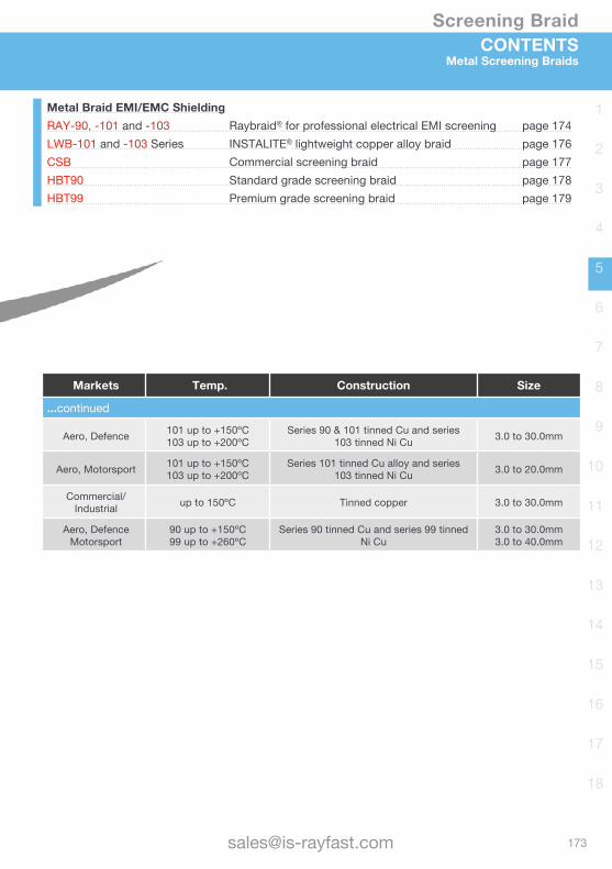
Markets Temp. Construction Size
...continued
Aero, Defence 101 up to +150ºC103 up to +200ºC
Series 90 & 101 tinned Cu and series 103 tinned Ni Cu 3.0 to 30.0mm
Aero, Motorsport 101 up to +150ºC103 up to +200ºC
Series 101 tinned Cu alloy and series 103 tinned Ni Cu 3.0 to 20.0mm
Commercial/Industrial up to 150ºC Tinned copper 3.0 to 30.0mm
Aero, Defence Motorsport
90 up to +150ºC99 up to +260ºC
Series 90 tinned Cu and series 99 tinned Ni Cu
3.0 to 30.0mm3.0 to 40.0mm
Metal Braid EMI/EMC ShieldingRAY-90, -101 and -103 Raybraid® for professional electrical EMI screening page 174LWB-101 and -103 Series INSTALITE® lightweight copper alloy braid page 176CSB Commercial screening braid page 177HBT90 Standard grade screening braid page 178HBT99 Premium grade screening braid page 179
CONTENTSMetal Screening Braids
Screening Braid
174 www.is-rayfast.com | +44(0)1793 616700
1
2
3
4
5
6
7
8
9
10
11
12
13
14
15
16
17
18
RAYBRAID®
Professional Grade, Tin or Nickel plated CopperElectromagnetic Screening Braid
Raybraid® 90 has a minimum of 90% optical coverage and is available in a wide range of sizes to cover 2mm to 36mm diameters.Raybraid® 101 and 103 have a minimum of 93% and maximum of 100% optical coverage and is available in a wide range of sizes to cover 2.5mm to 38mm diameters.Standard Raybraid 90 and 101 are tinned copper with Raybraid 103 being nickel plated copper for high temperature applications. Raybraid is supplied on a round tube former which facilitates assembly and is more robust than braid supplied in flattened form.
Operating Temperature • Raybraid 90 & 101 up to +150ºC• Raybraid 103 above +200ºC
Raybraid is fully compatible with Tinel-Lock adaptors for termination of the braid to associated connectors.
Features & Benefits • Screening military harnesses• Minimum 90% optical coverage• 101 and 103 Super flexible • Good expansion ratio• Supplied on plastic former to maintain
round profile and is more robust than braid supplied in flattened form
CSAmm2 and Resistance - General guidelines, ratings based on ambient of 20ºC
Size No.RAY-90 RAY-101 RAY-103
CSA mm2 Resistance Current CSA mm2 Resistance Current CSA mm2 Resistance
-3.0 1.0 28.0 Ω/km 17 1.3 17.00 Ω/km 18 1.3 17.30 Ω/km
-4.0 1.4 18.3 Ω/km 21 2.1 10.30 Ω/km 28 2.1 10.50 Ω/km
-5.0 1.8 13.8 Ω/km 25 - - - - -
-6.0 2.1 12.2 Ω/km 28 2.7 8.00 Ω/km 34 2.7 8.10 Ω/km
-7.5 - - - 4.3 5.20 Ω/km 42 4.3 5.23 Ω/km
-10.0 4.3 6.0 Ω/km 42 5.5 3.96 Ω/km 52 5.5 4.02 Ω/km
-12.5 4.8 6.1 Ω/km 48 6.8 3.23 Ω/km 57 6.8 3.28 Ω/km
-15.0 8.3 3.0 Ω/km 67 - - - - -
-20.0 12.8 2.2 Ω/km 81 9.7 2.32 Ω/km 69 9.7 2.35 Ω/km
-25.0 16.4 1.6 Ω/km 98 - - - - -
-30.0 26.0 1.0 Ω/km 125 - - - - -
RoHScompliant

Screening Braid
1
2
3
4
5
6
7
8
9
10
11
12
13
14
15
16
17
18
RAYBRAID®
Professional Grade, Tin or Nickel plated CopperElectromagnetic Screening Braid
Raybraid 90 Tubular Braid - Minimum 90% Optical Coverage
Part NumberFormer Ø Carrier Strand
Size Cable Bundle PackSize
WeightNom.
mm No. of Ends AWG/mm Min. mm Max. mm m kg/km
RAY-90-3.0 3.0 (±0.13) 16 5 36/0.13 2.0 3.5 100 13
RAY-90-4.0 4.0 (±0.25) 16 7 36/0.13 3.0 5.0 100 17
RAY-90-5.0 5.0 (±0.25) 24 6 36/0.13 4.0 6.0 100 21
RAY-90-6.0 6.0 (±0.25) 24 7 36/0.13 5.0 7.0 100 25
RAY-90-10.0 10.0 (±0.25) 24 9 34/0.16 7.0 12.0 100 52
RAY-90-12.5 12.5 (±0.25) 24 10 34/0.16 11.0 13.0 100 65
RAY-90-15.0 15.0 (±0.38) 24 11 32/0.20 13.0 18.0 50 100
RAY-90-20.0 20.0 (±0.38) 36 7 32/0.20 17.0 23.0 50 165
RAY-90-25.0 25.0 (±0.38) 36 9 30/0.25 22.0 28.0 50 207
RAY-90-30.0 30.0 (±0.38) 36 9 28/0.32 27.0 36.0 50 310
Raybraid 101 and 103 Tubular Braid - Minimum 93% Optical Coverage
Part NumberFormer Ø Carrier Strand
Size Cable Bundle PackSize
WeightNom.
mm No. of Ends AWG/mm Min. mm Max. mm metres kg/km
RAY-10X-3.0 3.0 (±0.13) 16 10 38/0.10 2.5 5.0 100 10.3
RAY-10X-4.0 4.0 (±0.25) 24 7 36/0.13 3.5 7.5 100 17.0
RAY-10X-6.0 6.0 (±0.25) 24 9 36/0.13 4.5 9.5 100 25.0
RAY-10X-7.5 7.5 (±0.25) 24 14 36/0.13 7.0 14.0 100 31.0
RAY-10X-10.0 10.0 (±0.25) 36 12 36/0.13 8.0 22.0 100 41.0
RAY-10X-12.5 12.5 (±0.25) 36 15 36/0.13 11.0 24.0 100 51.0
RAY-10X-20.0 20.0 (±0.38) 48 16 36/0.13 16.0 38.0 50 81.0
Notes For applications that require a limited wire shielding tape which can be wound around a cable for installation and repair, we offer 000W280. Supplied in 4.5m rolls, width 20mm, material tinned copper. For further information on this or other products in our range, or for assistance with your specific requirements, please contact us.All numeric data shows average or typical values.
Screening Braid
176 www.is-rayfast.com | +44(0)1793 616700
1
2
3
4
5
6
7
8
9
10
11
12
13
14
15
16
17
18
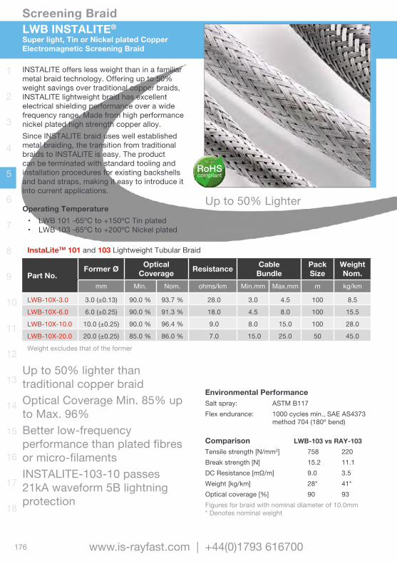
LWB INSTALITE®
Super light, Tin or Nickel plated Copper Electromagnetic Screening Braid
INSTALITE offers less weight than in a familiar metal braid technology. Offering up to 50% weight savings over traditional copper braids, INSTALITE lightweight braid has excellent electrical shielding performance over a wide frequency range. Made from high performance nickel plated high strength copper alloy.Since INSTALITE braid uses well established metal braiding, the transition from traditional braids to INSTALITE is easy. The product can be terminated with standard tooling and installation procedures for existing backshells and band straps, making it easy to introduce it into current applications.
Operating Temperature • LWB 101 -65ºC to +150ºC Tin plated• LWB 103 -65ºC to +200ºC Nickel plated
InstaLiteTM 101 and 103 Lightweight Tubular Braid
Part No.Former Ø Optical
Coverage Resistance CableBundle
PackSize
WeightNom.
mm Min. Nom. ohms/km Min.mm Max.mm m kg/km
LWB-10X-3.0 3.0 (±0.13) 90.0 % 93.7 % 28.0 3.0 4.5 100 8.5
LWB-10X-6.0 6.0 (±0.25) 90.0 % 91.3 % 18.0 4.5 8.0 100 15.5
LWB-10X-10.0 10.0 (±0.25) 90.0 % 96.4 % 9.0 8.0 15.0 100 28.0
LWB-10X-20.0 20.0 (±0.25) 85.0 % 86.0 % 7.0 15.0 25.0 50 45.0
Weight excludes that of the former
Comparison LWB-103 vs RAY-103Tensile strength [N/mm2] 758 220Break strength [N] 15.2 11.1DCResistance[mΩ/m] 9.0 3.5Weight [kg/km] 28* 41*Optical coverage [%] 90 93Figures for braid with nominal diameter of 10.0mm* Denotes nominal weight
Environmental PerformanceSalt spray: ASTM B117Flex endurance: 1000 cycles min., SAE AS4373
method 704 (180º bend)
Up to 50% lighter than traditional copper braidOptical Coverage Min. 85% up to Max. 96% Better low-frequency performance than plated fibres or micro-filamentsINSTALITE-103-10 passes 21kA waveform 5B lightning protection
RoHScompliant
Up to 50% LighterMinimum 85% Optical Coverage
Screening Braid
1
2
3
4
5
6
7
8
9
10
11
12
13
14
15
16
17
18
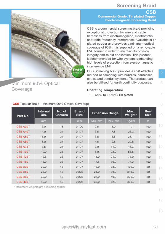
CSBCommercial Grade, Tin plated Copper
Electromagnetic Screening Braid
RoHScompliant
CSB is a commercial screening braid providing exceptional protection for wire and cable harnesses from electromagnetic, electrostatic and radio frequency interference. Available in tin plated copper and provides a minimum optical coverage of 90%. It is supplied on a removable PVC former in order to maintain its physical integrity and to aid application. This product is recommended for wire systems demanding high levels of protection from electromagnetic interference EMI.CSBScreeningbraidprovidesacosteffectivemethod of screening wire bundles, harnesses, cables and conduit systems. The product can also be utilised for earth continuity purposes.
Operating Temperature • -65ºC to +150ºC Tin plated
CSB Tubular Braid - Minimum 90% Optical Coverage
Part No.Internal
Dia.No. of
CarriersStrand
Size Expansion Range Max. Weight*
ReelSize
mm mm Min. mm Max. mm Kg/km m
CSB-030T 3.0 16 0.100 2.5 5.0 14.1 100
CSB-040T 4.0 24 0.127 3.5 7.5 23.2 100
CSB-050T 5.0 24 0.127 3.5 8.5 26.1 100
CSB-060T 6.0 24 0.127 4.5 9.5 29.5 100
CSB-075T 7.5 24 0.127 7.0 14.0 46.3 100
CSB-100T 10.0 36 0.127 8.0 22.0 58.8 100
CSB-125T 12.5 36 0.127 11.0 24.0 75.0 100
CSB-150T 15.0 36 0.127 14.5 30.0 77.2 100
CSB-200T 20.0 48 0.127 16.0 38.0 109.0 50
CSB-250T 25.0 48 0.202 21.0 39.0 218.2 50
CSB-300T 30.0 48 0.202 27.0 40.0 230.0 50
CSB-400T 40.0 48 0.202 36.0 62.0 305.0 50
* Maximum weights are excluding former
Minimum 90% Optical Coverage
Screening Braid
178 www.is-rayfast.com | +44(0)1793 616700
1
2
3
4
5
6
7
8
9
10
11
12
13
14
15
16
17
18
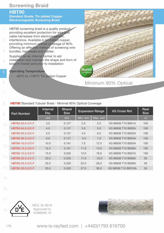
HBT90Standard Grade, Tin plated CopperElectromagnetic Screening Braid
HBT90 screening braid is a quality product providing excellent protection for wire and cable harnesses from electromagnetic, interference. Available in tin plated copper, providing minimum optical coverage of 90%. Offering an effective method of screening wire bundles, harnesses and cables.Supplied on an internal former to aid installation and maintain the shape and form of braid in transit and prior to installation
Operating Temperature • -65ºC to +150ºC Tin plated Copper
HBT90 Standard Tubular Braid - Minimal 90% Optical Coverage
Part NumberInternal
Dia.Strand
Size Expansion Range VG Cross Ref. ReelSize
mm mm Min. mm Max. mm m
HBT90-03.0-2/2-F 3.0 0.127 2.0 3.5 VG 96936 T10 B001A 100
HBT90-04.0-2/2-F 4.0 0.127 3.0 5.0 VG 96936 T10 B002A 100
HBT90-05.0-2/2-F 5.0 0.127 4.0 6.0 VG 96936 T10 B003A 100
HBT90-06.0-2/2-F 6.0 0.127 5.0 7.0 VG 96936 T10 B004A 100
HBT90-10.0-2/2-F 10.0 0.161 7.0 12.0 VG 96936 T10 B005A 100
HBT90-12.5-2/2-F 12.5 0.161 11.0 13.0 VG 96936 T10 B006A 100
HBT90-15.0-2/2-F 15.0 0.202 13.0 18.0 VG 96936 T10 B007A 100
HBT90-20.0-2/2-F 20.0 0.250 17.0 23.0 VG 96936 T10 B008A 50
HBT90-25.0-2/2-F 25.0 0.250 22.0 28.0 VG 96936 T10 B009A 50
HBT90-30.0-2/2-F 30.0 0.320 27.0 36.0 VG 96936 T10 B0010A 50
Minimum 90% Optical Coverage
RoHScompliant
REG. Nr 8319Approved toVG96936-10
Screening Braid
1
2
3
4
5
6
7
8
9
10
11
12
13
14
15
16
17
18
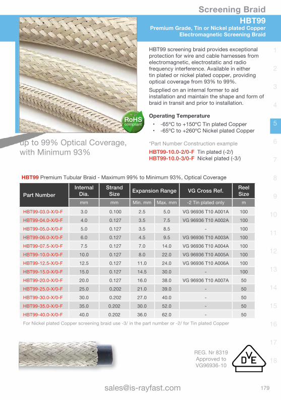
HBT99Premium Grade, Tin or Nickel plated Copper
Electromagnetic Screening Braid
HBT99 Premium Tubular Braid - Maximum 99% to Minimum 93%, Optical Coverage
Part NumberInternal
Dia.Strand
Size Expansion Range VG Cross Ref. ReelSize
mm mm Min. mm Max. mm -2 Tin plated only m
HBT99-03.0-X/0-F 3.0 0.100 2.5 5.0 VG 96936 T10 A001A 100
HBT99-04.0-X/0-F 4.0 0.127 3.5 7.5 VG 96936 T10 A002A 100
HBT99-05.0-X/0-F 5.0 0.127 3.5 8.5 - 100
HBT99-06.0-X/0-F 6.0 0.127 4.5 9.5 VG 96936 T10 A003A 100
HBT99-07.5-X/0-F 7.5 0.127 7.0 14.0 VG 96936 T10 A004A 100
HBT99-10.0-X/0-F 10.0 0.127 8.0 22.0 VG 96936 T10 A005A 100
HBT99-12.5-X/0-F 12.5 0.127 11.0 24.0 VG 96936 T10 A006A 100
HBT99-15.0-X/0-F 15.0 0.127 14.5 30.0 - 100
HBT99-20.0-X/0-F 20.0 0.127 16.0 38.0 VG 96936 T10 A007A 50
HBT99-25.0-X/0-F 25.0 0.202 21.0 39.0 - 50
HBT99-30.0-X/0-F 30.0 0.202 27.0 40.0 - 50
HBT99-35.0-X/0-F 35.0 0.202 30.0 52.0 - 50
HBT99-40.0-X/0-F 40.0 0.202 36.0 62.0 - 50
For Nickel plated Copper screening braid use -3/ in the part number or -2/ for Tin plated Copper
HBT99 screening braid provides exceptional protection for wire and cable harnesses from electromagnetic, electrostatic and radio frequency interference. Available in either tin plated or nickel plated copper, providing optical coverage from 93% to 99%. Supplied on an internal former to aid installation and maintain the shape and form of braid in transit and prior to installation.
Operating Temperature • -65ºC to +150ºC Tin plated Copper• -65ºC to +260ºC Nickel plated Copper
*Part Number Construction exampleHBT99-10.0-2/0-F Tin plated (-2/)HBT99-10.0-3/0-F Nickel plated (-3/)
RoHScompliant
up to 99% Optical Coverage, with Minimum 93%
REG. Nr 8319Approved toVG96936-10

Wire and Cable Heat-shrink Tubing
Non-shrink TubingBraided SleevingScreening Braids
Moulded Parts Terminals and Splices
Wire and Cable MarkersAccessoriesConnectorsBackshells
Bonding LeadsMetal Braids
Relays and Contactors Switches and Grips
Adhesives and TapesApplication EquipmentAdded Value Services

182
Moulded Parts
[email protected] | +44(0)1793 616700
1
2
3
4
5
6
7
8
9
10
11
12
13
14
15
16
17
18
Heat Shrinkable Boots Transitions and End Caps Glands and FeedthroughsBased on heat-shrink technology, moulded parts and shapes are available in a vast range of configurations, sizes and materials, from miniature lightweight and space saving straight boots through to large multi-way harness transitions. Moulded parts can be used to seal and protect harnessing breakouts and terminations from environmental hazards, as well as providing strain relief. Material selection enables full integration and compatibility with other harness components, producing electrical systems that can be used under the most extreme environmental conditions.
Boots Ideal for providing a high performance environmental seal and mechanical protection between the cable or wire and the connector or connector adaptor.
InstaLite BootsOffering up to 30% weight savings over similar standard boots, see 202K121 and 222K121 pages in this section. Please note that this range is being expanded, so please contact us for the latest information.
Transitions / BreakoutsIdeal replacement for tapes, mould-in-place epoxies and grease. These moulded parts can be used for cable breakouts, transitions and terminations.
End CapsProvide optimum waterproofing and environmental protection for sealing cable ends in underwater, underground, or outdoor applications.
INTRODUCTION
Features & Benefits• Mechanical protection• Chemical resistance• Electrical insulation• Electrical screening• Fluid and solvent resistance• Moisture protection• Strain relief• Flame-retardant, low smoke• Extreme temperature performance• Aesthetic enhancement• Fast & efficient installation• Wide range of materials• Pre-installed adhesives• Modification options
Glands and FeedthroughsMoulded heat shrinkable non screened bulkhead feedthroughs 207Wxxx and CESx available in various configurations for environmentally sealed enclosures.Also available are a range of screened and non-screened one piece heat shrinkable feedthroughs TCFS and TCFR
RoHScompliant
183
Moulded Parts
www.is-rayfast.com
1
2
3
4
5
6
7
8
9
10
11
12
13
14
15
16
17
18
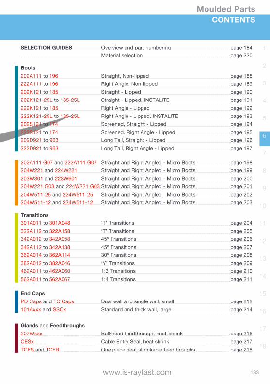
SELECTION GUIDES Overview and part numbering page 184 Material selection page 220
Boots202A111 to 196 Straight, Non-lipped page 188222A111 to 196 Right Angle, Non-lipped page 189202K121 to 185 Straight - Lipped page 190202K121-25L to 185-25L Straight - Lipped, INSTALITE page 191222K121 to 185 Right Angle - Lipped page 192222K121-25L to 185-25L Right Angle - Lipped, INSTALITE page 193202S121 to 174 Screened, Straight - Lipped page 194222S121 to 174 Screened, Right Angle - Lipped page 195202D921 to 963 Long Tail, Straight - Lipped page 196222D921 to 963 Long Tail, Right Angle - Lipped page 197
202A111 G07 and 222A111 G07 Straight and Right Angled - Micro Boots page 198204W221 and 224W221 Straight and Right Angled - Micro Boots page 199203W301 and 223W601 Straight and Right Angled - Micro Boots page 200204W221 G03 and 224W221 G03 Straight and Right Angled - Micro Boots page 201204W511-25 and 224W511-25 Straight and Right Angled - Micro Boots page 202204W511-12 and 224W511-12 Straight and Right Angled - Micro Boots page 203
Transitions301A011 to 301A048 ‘T’ Transitions page 204322A112 to 322A158 ‘T’ Transitions page 205342A012 to 342A058 45º Transitions page 206342A112 to 342A138 45º Transitions page 207362A014 to 362A114 30º Transitions page 208382A012 to 382A046 ‘Y’ Transitions page 209462A011 to 462A060 1:3 Transitions page 210562A011 to 562A067 1:4 Transitions page 211
End CapsPD Caps and TC Caps Dual wall and single wall, small page 212101Axxx and SSCx Standard and thick wall, large page 214
Glands and Feedthroughs207Wxxx Bulkhead feedthrough, heat-shrink page 216CESx Cable Entry Seal, heat shrink page 217TCFS and TCFR One piece heat shrinkable feedthroughs page 218
CONTENTS

184
Moulded Parts
[email protected] | +44(0)1793 616700
1
2
3
4
5
6
7
8
9
10
11
12
13
14
15
16
17
18
Selection Guide OverviewPart number and visual identifierProduct Type
BOOTS
Application Family Description Typical Shapes
Non-lipped Boots 202A111 to 196 Straight222A111 to 196 Right Angle
Lipped Boots 202K121 to 185 Straight222K121 to 185 Right Angle
ScreenedLipped Boots
202S121 to 174 Straight222S121 to 174 Right Angle
Lipped boots, extended tail 202D921 to 963 Straight222D921 to 963 Right Angle
MICRO MOULDED Family
Micro MouldedLipped Boots
202A111-xx-G07204W221203W301-xx-G02204W221-xx-G03204W511-12 or -25
222A111-xx-G07224W221223W601-xx224221-xx-G03224W511-12 or -25
Shown here are our more popular products, for further information on the extensive range of moulded parts and shapes available, or for assistance with your specific requirements, please contact us. A range of heat guns and adhesives are also available for installing moulded parts and shapes, please refer to the relevant sections in this catalogue. Moulded parts and shapes material performance characteristics can be found later in this section.

185
Moulded Parts
www.is-rayfast.com
1
2
3
4
5
6
7
8
9
10
11
12
13
14
15
16
17
18
Selection Guide OverviewPart number and visual identifier
Product Type
TRANSITIONS
Application Family Description Typical Shapes
‘T’ Transitions 301A011 to 048322A112 to 158
45º Transitions 342A012 to 058342A112 to 138
30º Transitions 362A014 to 114
‘Y’ Transitions 382A012 to 046
1:3 Transitions 462A011 to 060
1:4 Transitions 562A011 to 067
End CapsApplication Family Description Typical Shapes
PD and TC End caps Polyolefin heat shrink Single and dual wall
End caps 101A011 to 094SSC-1 to -7
186
Moulded Parts
[email protected] | +44(0)1793 616700
1
2
3
4
5
6
7
8
9
10
11
12
13
14
15
16
17
18
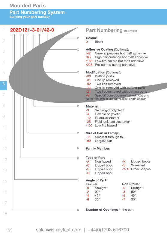
Colour:0 Black
Adhesive Coating (Optional):/42 General purpose hot melt adhesive/86 High performance hot melt adhesive/180 Low fire hazard hot melt adhesive/225 Pre-coated curing adhesive
Modification (Optional):-00 Potting ports-01 One lip removed-02 Two lips removed-11 One lip removed with potting ports-21 Two lips removed with potting ports-G Special constructions / modificationsNote: Removal of lips will reduce length of boot
Material:-3 Semi-rigid polyolefin-4 Flexible polyolefin-12 Fluoro-elastomer-25 Fluid resistant elastomer-100 Low fire hazard
Size of Part in Family:-11 Smallest through to...-99 Largest part
Family Member:
Number of Openings in the part
Part Numbering SystemBuilding your part number
202D121-3-01/42-0
Type of Part-A Non lipped-C Lipped boot-D Lipped boot-G Lipped boot
-K Lipped boots-S Screened-W,P Other shapes
Angle of PartCircular -0 Straight-2 90º-4 45º-6 30º
Non circular -0 Straight-3 90º-5 45º-7 30º
Part Numbering example
187
Moulded Parts
www.is-rayfast.com
1
2
3
4
5
6
7
8
9
10
11
12
13
14
15
16
17
18
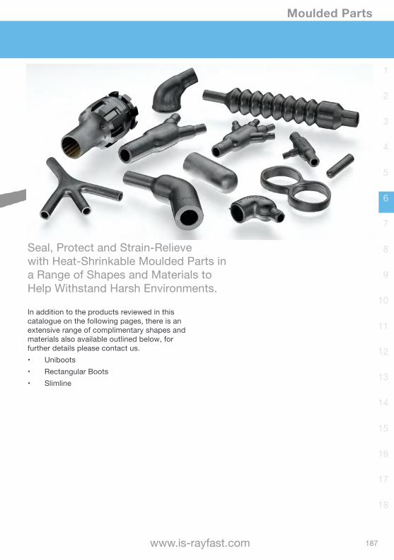
Seal, Protect and Strain-Relieve with Heat-Shrinkable Moulded Parts in a Range of Shapes and Materials to Help Withstand Harsh Environments.
In addition to the products reviewed in this catalogue on the following pages, there is an extensive range of complimentary shapes and materials also available outlined below, for further details please contact us.• Uniboots• Rectangular Boots• Slimline

188
Moulded Parts
[email protected] | +44(0)1793 616700
1
2
3
4
5
6
7
8
9
10
11
12
13
14
15
16
17
18
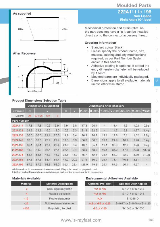
202A111 to 196Non-LippedStraight, boot
Mechanical protection and strain relief. As the part does not have a lip it can be installed directly onto the connector accessory thread.
Ordering Information• Standard colour Black.• Please specify the product name, size,
material, coating and any modifications required, as per Part Numbering System earlier in this section.
• Adhesive lining is optional. If added the entry dimension diameter will be reduced by 1.5mm.
• Moulded parts are individually packaged.• Dimensions apply to all available materials
unless otherwise stated.
H Dia. J Dia.
Tan
P
W
R JOTan
H Dia. J Dia.
As supplied
After Recovery
Product Dimensions Selection TableDimensions as Supplied Dimensions After Recovery
Dimension H J H J P ±10% R ±10% JO ±10% W ±20% Weight
Material 3, 4, 25 12, 100 3, 4, 25 12, 100
Part Number
202A111 16.5 16.5 16.5 11.9 7.9 3.8 25.0 14.0 6.0 1.3 1.0g
202A121 24.3 22.6 24.6 17.8 9.9 5.3 38.0 22.0 9.0 1.5 3.0g
202A132 28.4 26.2 28.4 20.3 14.2 6.6 51.0 28.0 13.0 1.8 3.6g
202A142 31.0 31.0 31.0 25.4 17.8 7.4 67.0 36.0 18.0 1.8 6.4g
202A153 36.1 36.1 36.1 26.2 21.9 8.6 74.0 41.0 16.0 1.8 11.3g
202A163 42.7 42.7 42.7 27.2 27.4 9.4 99.0 63.0 18.0 2.0 18.0g
202A174 51.8 48.3 51.8 48.3 35.3 16.0 130.0 65.0 42.0 3.3 45.0g
202A185 66.0 66.0 66.0 54.1 43.7 19.6 161.3 90.2 47.8 3.81 -
202A196 86.4 86.4 86.4 71.4 57.2 26.9 212.6 113.0 62.2 4.06 -All dimensions in mm unless otherwise stated. Weight is based on polyolefin partInjection and potting ports also available see part number system earlier in this section
Materials AvailableMaterial Material Description
-3 Semi-rigid polyolefin
-4 Flexible polyolefin
-12 Fluoro-elastomer
-25 Fluid resistant elastomer
-100 Polyolefin, Zerohal
Environmental Adhesives AvailableOptional Pre-coat Optional User Applied
/42 or /86 S-1017 or S-1048
/42 or /86 S-1017 or S-1048
N/A S-1255-04
/42 or /86 or /225 S-1017 or S-1048 or S-1125
/86 or /180 S-1048 or S-1030
189
Moulded Parts
www.is-rayfast.com
1
2
3
4
5
6
7
8
9
10
11
12
13
14
15
16
17
18
222A111 to 196Non-Lipped
Right Angle 90º, boot
P
J Dia.
U
JO
W
T
R
H Dia.
J Dia.H Dia.
As supplied
After Recovery
Mechanical protection and strain relief. As the part does not have a lip it can be installed directly onto the connector accessory thread.
Ordering Information• Standard colour Black.• Please specify the product name, size,
material, coating and any modifications required, as per Part Number System earlier in this section.
• Adhesive coating is optional. If added the entry dimension diameter will be reduced by 1.5mm.
• Moulded parts are individually packaged.• Dimensions apply to all available materials
unless otherwise stated.
Product Dimensions Selection TableDimensions as Supplied Dimensions After Recovery
Dimension H J H J P ±10% R ±10% T ±10% U ±10% JO ±10% W ±10% Weight
Material All 3, 4, 25 100 12
Part Number
222A111 17.8 17.8 10.9 9.9 7.9 3.8 17.3 20.1 - 11.4 4.3 1.02 0.9g
222A121 24.9 24.9 16.0 18.0 10.2 5.3 21.3 22.6 - 14.7 5.8 1.27 1.4g
222A132 30.0 30.0 21.1 20.6 14.2 6.4 26.9 26.7 19.1 17.8 7.1 1.52 2.9g
222A142 32.5 32.5 22.9 22.9 17.3 6.9 36.6 30.5 19.1 24.9 10.2 1.78 5.4g
222A152 36.1 36.1 27.4 26.4 21.8 8.4 43.7 35.1 19.1 30.0 12.7 1.78 7.7g
222A163 43.9 43.9 28.4 27.4 27.4 9.4 53.6 43.9 19.1 34.0 17.3 2.03 13.0g
222A174 53.1 53.1 48.3 46.7 33.8 15.0 75.7 52.8 25.4 53.2 32.0 3.30 31.0g
222A185 67.6 67.6 58.4 54.4 44.2 20.3 97.5 66.0 25.4 71.1 40.6 3.81 -
222A196 87.6 87.6 68.8 63.0 55.4 23.4 128.0 79.2 25.4 87.6 56.4 4.57 -All dimensions in mm unless otherwise stated. Weight is based on polyolefin partInjection and potting ports also available see part number system earlier in this section
Materials AvailableMaterial Material Description
-3 Semi-rigid polyolefin
-4 Flexible polyolefin
-12 Fluoro-elastomer
-25 Fluid resistant elastomer
-100 Polyolefin, Zerohal
Environmental Adhesives AvailableOptional Pre-coat Optional User Applied
/42 or /86 S-1017 or S-1048
/42 or /86 S-1017 or S-1048
N/A S-1255-04
/42 or /86 or /225 S-1017 or S-1048 or S-1125
/86 or /180 S-1048 or S-1030
190
Moulded Parts
[email protected] | +44(0)1793 616700
1
2
3
4
5
6
7
8
9
10
11
12
13
14
15
16
17
18
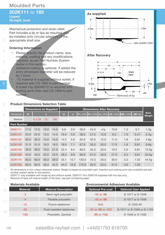
202K111 to 185LippedStraight, boot
JW
PY
JO
Tan
HW
UX
R
Slighttaper
H Dia. J Dia.
H Dia. J Dia. Mechanical protection and strain relief. Part includes a lip or lips as required, can be installed onto circular adaptors of the appropriate shell size.
Ordering Information• Please specify the product name, size,
material, coating and any modifications required, as per Part Number System earlier in this section.
• Adhesive coating is optional. If added the entry dimension diameter will be reduced by 1.5mm.
• -12 material is supplied without eyelet, if required add CS-1863 to part number
• If eyelet clip (000W212) is required with potting ports then add CS-1858 to part number
As supplied
After Recovery
Product Dimensions Selection TableDimensions as Supplied Dimensions After Recovery
Nom. WeightDimension H J H J P ±10% R ±10% U ±10% JO ±10% HW ±10% JW min
Material 3, 4, 25 12 100
Part Number
202K111 17.0 17.0 13.0 14.0 6.9 3.0 39.0 24.0 n/a 10.8 1.3 0.7 1.3g
202K121 24.0 24.0 13.0 14.0 10.4 5.6 38.0 21.0 12.0 8.5 1.9 0.41 2.4g
202K132 30.0 30.0 14.0 15.0 14.2 5.9 55.0 32.0 12.0 11.5 1.8 0.81 4.8g
202K142 31.0 31.0 16.0 18.0 18.0 7.1 67.0 35.0 20.0 17.0 1.8 0.81 9.9g
202K153 36.0 36.0 19.0 21.0 22.4 8.4 80.0 42.0 20.0 19.5 2.0 0.81 12.0g
202K163 43.0 43.0 22.0 25.0 28.2 9.9 99.0 61.0 20.0 21.0 2.2 0.81 20.0g
202K174 60.0 60.0 35.0 39.0 35.1 15.7 130.0 72.0 20.0 39.0 3.3 1.02 44.5g
202K185 66.0 66.0 38.0 42.0 44.5 16.8 170.0 90.0 20.0 51.5 3.8 1.63 -All dimensions in mm unless otherwise stated. Weight is based on polyolefin part. Injection and potting ports also available see part number system earlier in this section. 202K111 only available with single lip and without eyelet. 202K121 thru 202K153 supplied with two lips only.Removal of lip(s) will reduce length of the boot, see part numbering page.
Materials AvailableMaterial Material Description
-3 Semi-rigid polyolefin
-4 Flexible polyolefin
-12 Fluoro-elastomer
-25 Fluid resistant elastomer
-100 Polyolefin, Zerohal
Environmental Adhesives AvailableOptional Pre-coat Optional User Applied
/42 or /86 S-1017 or S-1048
/42 or /86 S-1017 or S-1048
N/A S-1255-04
/42 or /86 or /225 S-1017 or S-1048 or S-1125
/86 or /180 S-1048 or S-1030
see eyelet note
Removal of lip

191
Moulded Parts
www.is-rayfast.com
1
2
3
4
5
6
7
8
9
10
11
12
13
14
15
16
17
18
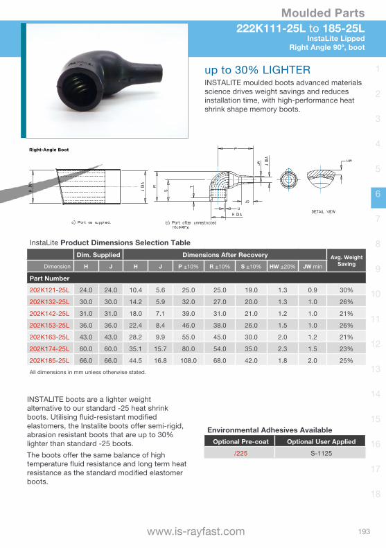
202K121-25L to 185-25LInstaLite Lipped
Straight, boot
InstaLite Product Dimensions Selection TableDim. Supplied Dimensions After Recovery Avg. Weight
SavingDimension H J H J P ±10% R ±10% HW ±20% JW min
Part Number
202K121-25L 24.0 24.0 10.4 5.6 38.0 21.0 1.3 0.9 20%
202K132-25L 30.0 30.0 14.2 5.9 55.0 32.0 1.3 1.0 20%
202K142-25L 31.0 31.0 18.0 7.1 67.0 35.0 1.2 1.0 20%
202K153-25L 36.0 36.0 22.4 8.4 80.0 42.0 1.5 1.0 23%
202K163-25L 43.0 43.0 28.2 9.9 99.0 61.0 2.0 1.2 28%
202K174-25L 60.0 60.0 35.1 15.7 130.0 72.0 2.3 1.5 22%
202K185-25L 66.0 66.0 44.5 16.8 170.0 90.0 1.8 2.0 21%All dimensions in mm unless otherwise stated.
up to 28% LIGHTERINSTALITE moulded boots advanced materials science drives weight savings and reduces installation time, with high-performance heat shrink shape memory boots.
Environmental Adhesives AvailableOptional Pre-coat Optional User Applied
/225 S-1125
INSTALITE boots are a lighter weight alternative to our standard -25 heat shrink boots. Utilising fluid-resistant modified elastomers, the Instalite boots offer semi-rigid, abrasion resistant boots that are up to 28% lighter than standard -25 boots.The boots offer the same balance of high temperature fluid resistance and long term heat resistance as the standard modified elastomer boots.
Instalite Molded Boots

192
Moulded Parts
[email protected] | +44(0)1793 616700
1
2
3
4
5
6
7
8
9
10
11
12
13
14
15
16
17
18
P
Y
JO
J Dia.
JW
RX
H HW
taper
J Dia.H Dia.
222K121 to 185Lipped Right Angle 90º, boot
P
Y
JO
J Dia.
JW
RX
H HW
taper
J Dia.H Dia.
As supplied
After Recovery
Mechanical protection and strain relief. Part includes a lip or lips as required, can be installed onto circular adaptors of the appropriate shell size.
Ordering Information• Please specify the product name, size,
material, coating and any modifications required, as per Part Number System earlier in this section.
• Adhesive coating is optional. If added the entry dimension diameter will be reduced by 1.5mm.
• Dimensions apply to all available materials unless otherwise stated.
• If eyelet clip (000W212) is required with part then add CS-1858 to part number.
Product Dimensions Selection TableDimensions as Supplied Dimensions After Recovery
Dimension H J H J P ±10% R ±10% JO ±10% HW ±10% JW ±10% Weight
Material 3, 4, 12, 25 100 3, 4, 25 12, 100
Part Number
222K121 24.0 24.0 24.0 14.0 10.4 5.6 25.0 25.0 8.5 1.3 0.5 1.7g
222K132 30.0 30.0 30.0 15.0 14.2 5.9 32.0 27.0 8.5 1.5 0.8 3.4g
222K142 31.0 31.0 31.0 18.0 18.0 7.1 39.0 31.0 15.0 1.8 1.0 5.8g
222K152 36.0 36.0 36.0 21.0 22.4 8.4 46.0 38.0 16.0 1.8 1.0 9.0g
222K163 43.0 43.0 43.0 25.0 28.2 9.9 55.0 45.0 17.5 2.0 1.0 14.2g
222K174 60.0 52.0 60.0 39.0 35.1 15.7 80.0 54.0 32.0 3.3 1.8 36.7g
222K185 66.0 66.0 66.0 42.0 44.5 16.8 108.0 68.0 48.0 3.8 2.0 -
All dimension in mm unless otherwise stated. Weight is based on polyolefin partInjection and potting ports also available see part number system earlier in this section
Materials AvailableMaterial Material Description
-3 Semi-rigid polyolefin
-4 Flexible polyolefin
-12 Fluoro-elastomer
-25 Fluid resistant elastomer
-100 Polyolefin, Zerohal
Environmental Adhesives AvailableOptional Pre-coat Optional User Applied
/42 or /86 S-1017 or S-1048
/42 or /86 S-1017 or S-1048
N/A S-1255-04
/42 or /86 or /225 S-1017 or S-1048 or S-1125
/86 or /180 S-1048 or S-1030
193
Moulded Parts
www.is-rayfast.com
1
2
3
4
5
6
7
8
9
10
11
12
13
14
15
16
17
18
Instalite Molded Boots
up to 30% LIGHTERINSTALITE moulded boots advanced materials science drives weight savings and reduces installation time, with high-performance heat shrink shape memory boots.
INSTALITE boots are a lighter weight alternative to our standard -25 heat shrink boots. Utilising fluid-resistant modified elastomers, the Instalite boots offer semi-rigid, abrasion resistant boots that are up to 30% lighter than standard -25 boots.The boots offer the same balance of high temperature fluid resistance and long term heat resistance as the standard modified elastomer boots.
InstaLite Product Dimensions Selection TableDim. Supplied Dimensions After Recovery Avg. Weight
SavingDimension H J H J P ±10% R ±10% S ±10% HW ±20% JW min
Part Number
202K121-25L 24.0 24.0 10.4 5.6 25.0 25.0 19.0 1.3 0.9 30%
202K132-25L 30.0 30.0 14.2 5.9 32.0 27.0 20.0 1.3 1.0 26%
202K142-25L 31.0 31.0 18.0 7.1 39.0 31.0 21.0 1.2 1.0 21%
202K153-25L 36.0 36.0 22.4 8.4 46.0 38.0 26.0 1.5 1.0 26%
202K163-25L 43.0 43.0 28.2 9.9 55.0 45.0 30.0 2.0 1.2 21%
202K174-25L 60.0 60.0 35.1 15.7 80.0 54.0 35.0 2.3 1.5 23%
202K185-25L 66.0 66.0 44.5 16.8 108.0 68.0 42.0 1.8 2.0 25%All dimensions in mm unless otherwise stated.
Environmental Adhesives AvailableOptional Pre-coat Optional User Applied
/225 S-1125
222K111-25L to 185-25LInstaLite Lipped
Right Angle 90º, boot
194
Moulded Parts
[email protected] | +44(0)1793 616700
1
2
3
4
5
6
7
8
9
10
11
12
13
14
15
16
17
18
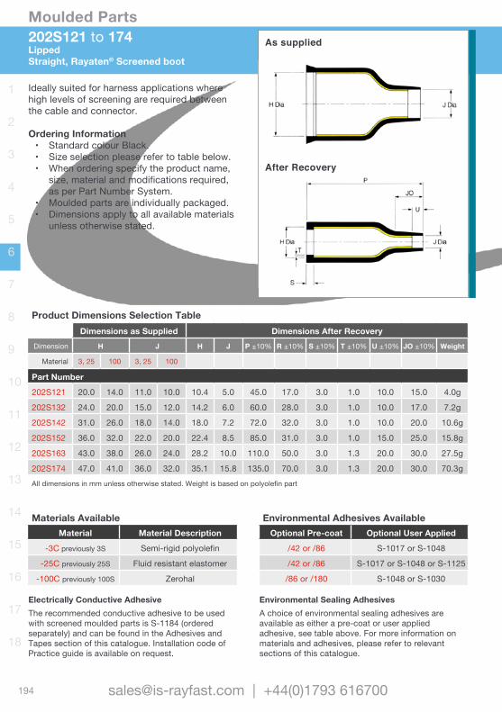
202S121 to 174Lipped Straight, Rayaten® Screened boot
As supplied
After Recovery
Ideally suited for harness applications where high levels of screening are required between the cable and connector.
Ordering Information• Standard colour Black.• Size selection please refer to table below.• When ordering specify the product name,
size, material and modifications required, as per Part Number System.
• Moulded parts are individually packaged.• Dimensions apply to all available materials
unless otherwise stated.
Product Dimensions Selection TableDimensions as Supplied Dimensions After Recovery
Dimension H J H J P ±10% R ±10% S ±10% T ±10% U ±10% JO ±10% Weight
Material 3, 25 100 3, 25 100
Part Number
202S121 20.0 14.0 11.0 10.0 10.4 5.0 45.0 17.0 3.0 1.0 10.0 15.0 4.0g
202S132 24.0 20.0 15.0 12.0 14.2 6.0 60.0 28.0 3.0 1.0 10.0 17.0 7.2g
202S142 31.0 26.0 18.0 14.0 18.0 7.2 72.0 32.0 3.0 1.0 10.0 20.0 10.6g
202S152 36.0 32.0 22.0 20.0 22.4 8.5 85.0 31.0 3.0 1.0 15.0 25.0 15.8g
202S163 43.0 38.0 26.0 24.0 28.2 10.0 110.0 50.0 3.0 1.3 20.0 30.0 27.5g
202S174 47.0 41.0 36.0 32.0 35.1 15.8 135.0 70.0 3.0 1.3 20.0 30.0 70.3gAll dimensions in mm unless otherwise stated. Weight is based on polyolefin part
Materials AvailableMaterial Material Description
-3C previously 3S Semi-rigid polyolefin
-25C previously 25S Fluid resistant elastomer
-100C previously 100S Zerohal
Electrically Conductive AdhesiveThe recommended conductive adhesive to be used with screened moulded parts is S-1184 (ordered separately) and can be found in the Adhesives and Tapes section of this catalogue. Installation code of Practice guide is available on request.
Environmental Adhesives AvailableOptional Pre-coat Optional User Applied
/42 or /86 S-1017 or S-1048
/42 or /86 S-1017 or S-1048 or S-1125
/86 or /180 S-1048 or S-1030
Environmental Sealing AdhesivesA choice of environmental sealing adhesives are available as either a pre-coat or user applied adhesive, see table above. For more information on materials and adhesives, please refer to relevant sections of this catalogue.
195
Moulded Parts
www.is-rayfast.com
1
2
3
4
5
6
7
8
9
10
11
12
13
14
15
16
17
18
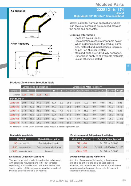
222S121 to 174Lipped
Right Angle 90º, Rayaten® Screened boot
As supplied
After Recovery
Ideally suited for harness applications where high levels of screening are required between the cable and connector.
Ordering Information• Standard colour Black.• Size selection please refer to table below.• When ordering specify the product name,
size, material and modifications required, as per Part Number System.
• Moulded parts are individually packaged.• Dimensions apply to all available materials
unless otherwise stated.
Product Dimensions Selection TableDimensions as Supplied Dimensions After Recovery
Dimension H J H J P ±10% R ±10% S ±10% T ±10% U ±10% JO ±10% Weight
Material 3, 25 100 3, 25 100
Part Number
222S121 20.0 14.0 11.0 10.0 10.4 5.0 30.0 25.0 19.0 3.0 10.0 15.0 4.0g
222S132 24.0 20.0 15.0 12.0 14.2 6.0 38.0 28.0 20.0 3.0 10.0 17.0 4.7g
222S142 31.0 26.0 18.0 14.0 18.0 7.2 42.0 31.0 21.0 3.0 10.0 18.0 9.2g
222S152 36.0 32.0 22.0 20.0 22.4 8.5 51.0 38.0 26.0 3.0 12.0 20.0 15.1g
222S163 43.0 38.0 26.0 24.0 28.2 10.0 67.0 45.0 30.0 3.0 20.0 28.0 27.6g
222S174 47.0 41.0 36.0 32.0 35.1 15.8 80.0 54.0 36.0 3.0 20.0 31.0 41.0gAll dimensions in mm unless otherwise stated. Weight is based on polyolefin part
Materials AvailableMaterial Material Description
-3C previously 3S Semi-rigid polyolefin
-25C previously 25S Fluid resistant elastomer
-100C previously 100S Zerohal
Electrically Conductive AdhesiveThe recommended conductive adhesive to be used with screened moulded parts is S-1184 (ordered separately) and can be found in the Adhesives and Tapes section of this catalogue. Installation code of Practice guide is available on request.
Environmental Adhesives AvailableOptional Pre-coat Optional User Applied
/42 or /86 S-1017 or S-1048
/42 or /86 S-1017 or S-1048 or S-1125
/86 or /180 S-1048 or S-1030
Environmental Sealing AdhesivesA choice of environmental sealing adhesives are available as either a pre-coat or user applied adhesive, see table above. For more information on materials and adhesives, please refer to relevant sections of this catalogue.
196
Moulded Parts
[email protected] | +44(0)1793 616700
1
2
3
4
5
6
7
8
9
10
11
12
13
14
15
16
17
18
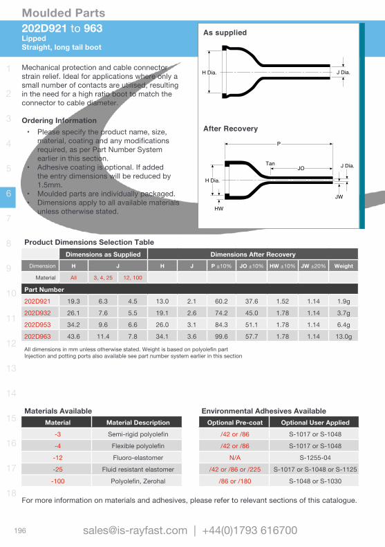
202D921 to 963LippedStraight, long tail boot
H Dia. J Dia.
P
H Dia.
J Dia.
JW
TanJO
HW
As supplied
After Recovery
Mechanical protection and cable connector strain relief. Ideal for applications where only a small number of contacts are utilised, resulting in the need for a high ratio boot to match the connector to cable diameter.
Ordering Information• Please specify the product name, size,
material, coating and any modifications required, as per Part Number System earlier in this section.
• Adhesive coating is optional. If added the entry dimensions will be reduced by 1.5mm.
• Moulded parts are individually packaged.• Dimensions apply to all available materials
unless otherwise stated.
Product Dimensions Selection TableDimensions as Supplied Dimensions After Recovery
Dimension H J H J P ±10% JO ±10% HW ±10% JW ±20% Weight
Material All 3, 4, 25 12, 100
Part Number
202D921 19.3 6.3 4.5 13.0 2.1 60.2 37.6 1.52 1.14 1.9g
202D932 26.1 7.6 5.5 19.1 2.6 74.2 45.0 1.78 1.14 3.7g
202D953 34.2 9.6 6.6 26.0 3.1 84.3 51.1 1.78 1.14 6.4g
202D963 43.6 11.4 7.8 34.1 3.6 99.6 57.7 1.78 1.14 13.0g
All dimensions in mm unless otherwise stated. Weight is based on polyolefin partInjection and potting ports also available see part number system earlier in this section
Materials AvailableMaterial Material Description
-3 Semi-rigid polyolefin
-4 Flexible polyolefin
-12 Fluoro-elastomer
-25 Fluid resistant elastomer
-100 Polyolefin, Zerohal
Environmental Adhesives AvailableOptional Pre-coat Optional User Applied
/42 or /86 S-1017 or S-1048
/42 or /86 S-1017 or S-1048
N/A S-1255-04
/42 or /86 or /225 S-1017 or S-1048 or S-1125
/86 or /180 S-1048 or S-1030
For more information on materials and adhesives, please refer to relevant sections of this catalogue.
197
Moulded Parts
www.is-rayfast.com
1
2
3
4
5
6
7
8
9
10
11
12
13
14
15
16
17
18
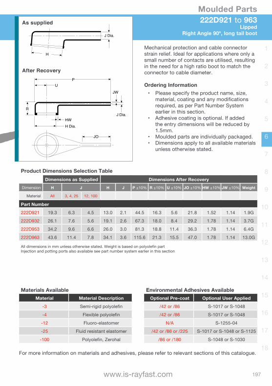
222D921 to 963Lipped
Right Angle 90º, long tail boot
R
JW
P
J Dia. HWH Dia.
U
JO
H
J Dia.
As supplied
After Recovery
Product Dimensions Selection TableDimensions as Supplied Dimensions After Recovery
Dimension H J H J P ±10% R ±10% U ±10% JO ±10% HW ±10% JW ±10% Weight
Material All 3, 4, 25 12, 100
Part Number
222D921 19.3 6.3 4.5 13.0 2.1 44.5 16.3 5.6 21.8 1.52 1.14 1.9G
222D932 26.1 7.6 5.6 19.1 2.6 67.3 18.0 8.4 29.2 1.78 1.14 3.7G
222D953 34.2 9.6 6.6 26.0 3.0 81.3 18.8 11.4 36.3 1.78 1.14 6.4G
222D963 43.6 11.4 7.8 34.1 3.6 115.6 21.3 15.5 47.0 1.78 1.14 13.0G
All dimensions in mm unless otherwise stated. Weight is based on polyolefin partInjection and potting ports also available see part number system earlier in this section
Mechanical protection and cable connector strain relief. Ideal for applications where only a small number of contacts are utilised, resulting in the need for a high ratio boot to match the connector to cable diameter.
Ordering Information• Please specify the product name, size,
material, coating and any modifications required, as per Part Number System earlier in this section.
• Adhesive coating is optional. If added the entry dimensions will be reduced by 1.5mm.
• Moulded parts are individually packaged.• Dimensions apply to all available materials
unless otherwise stated.
Materials AvailableMaterial Material Description
-3 Semi-rigid polyolefin
-4 Flexible polyolefin
-12 Fluoro-elastomer
-25 Fluid resistant elastomer
-100 Polyolefin, Zerohal
Environmental Adhesives AvailableOptional Pre-coat Optional User Applied
/42 or /86 S-1017 or S-1048
/42 or /86 S-1017 or S-1048
N/A S-1255-04
/42 or /86 or /225 S-1017 or S-1048 or S-1125
/86 or /180 S-1048 or S-1030
For more information on materials and adhesives, please refer to relevant sections of this catalogue.

198
Moulded Parts
[email protected] | +44(0)1793 616700
1
2
3
4
5
6
7
8
9
10
11
12
13
14
15
16
17
18
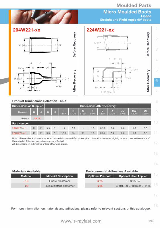
Micro Moulded BootsLippedStraight and Right Angle 90º boots
Product Dimensions Selection TableDimensions as Supplied Dimensions After Recovery
Dimension H J H J P±10%
R±10%
S±10%
T±20%
JO±20%
JW±20%
HW±20%
Material 25,12*
Part Number202A111-xx-G07 17 17 7.9 2.2 25 14 3.0 1.0 6.0 1.7 1.0
222A111-xx-G07 18 18 7.9 2.2 17 20 15.5 1.7 5.0 1.7 1.0
Note * Please check dimensions for -12 material as may differ, as supplied dimensions may be slightly reduced due to the nature of the material. After recovery sizes are not affected.All dimensions in millimetres unless otherwise stated.
202A111-xx-G07
Afte
r Rec
over
yB
efor
e R
ecov
ery
Afte
r Rec
over
yB
efor
e R
ecov
ery222A111-xx-G07
Materials AvailableMaterial Material Description
-12 Fluoro-elastomer
-25 Fluid resistant elastomer
Environmental Adhesives AvailableOptional Pre-coat Optional User Applied
/225 S-1255-04
/225 S-1017 or S-1048 or S-1125
For more information on materials and adhesives, please refer to relevant sections of this catalogue.
199
Moulded Parts
www.is-rayfast.com
1
2
3
4
5
6
7
8
9
10
11
12
13
14
15
16
17
18
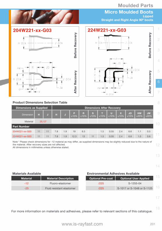
Product Dimensions Selection TableDimensions as Supplied Dimensions After Recovery
Dimension H J H J P±10%
R±10%
S±10%
T±20%
JO±20%
JW±20%
HW±20%
Material 25,12*
Part Number202A111-xx-G07 17 17 7.9 2.2 25 14 3.0 1.0 6.0 1.7 1.0
222A111-xx-G07 18 18 7.9 2.2 17 20 15.5 1.7 5.0 1.7 1.0
Note * Please check dimensions for -12 material as may differ, as supplied dimensions may be slightly reduced due to the nature of the material. After recovery sizes are not affected.All dimensions in millimetres unless otherwise stated.
Micro Moulded BootsLipped
Straight and Right Angle 90º boots
224W221-** Micro Moulded Boots
As supplied
After recovery
204W221-xx
Afte
r Rec
over
yB
efor
e R
ecov
ery
224W221-xx
Afte
r Rec
over
yB
efor
e R
ecov
ery
Product Dimensions Selection TableDimensions as Supplied Dimensions After Recovery
Dimension H J H J P±10%
R±10%
S±10%
T±10%
U±10%
X±10%
JO±10%
HW±20%
JW±20%
Material 25,12*
Part Number204W221-xx 11 11 9.3 2.1 19 6.5 - 1.5 0.55 2.4 6.6 1.0 0.5
224W221-xx 11 11 9.3 2.1 12.3 13 11 1.5 0.55 2.4 6.6 1.0 0.5
Note * Please check dimensions for -12 material as may differ, as supplied dimensions may be slightly reduced due to the nature of the material. After recovery sizes are not affected.All dimensions in millimetres unless otherwise stated.
Materials AvailableMaterial Material Description
-12 Fluoro-elastomer
-25 Fluid resistant elastomer
Environmental Adhesives AvailableOptional Pre-coat Optional User Applied
/225 S-1255-04
/225 S-1017 or S-1048 or S-1125
For more information on materials and adhesives, please refer to relevant sections of this catalogue.
200
Moulded Parts
[email protected] | +44(0)1793 616700
1
2
3
4
5
6
7
8
9
10
11
12
13
14
15
16
17
18
Micro Moulded BootsLipped Straight and Right Angle 90º boots
Afte
r Rec
over
yB
efor
e R
ecov
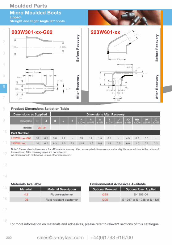
ery203W301-xx-G02
Afte
r Rec
over
yB
efor
e R
ecov
ery
223W601-xx
Product Dimensions Selection TableDimensions as Supplied Dimensions After Recovery
Dimension H J H J K P ±10%
R±10%
S±10%
T±10%
U±10%
JO±10%
HW±20%
JW±20%
X±20%
Material 25, 12*
Part Number203W301-xx-G02 10 6.0 5.8 2.2 - 19 11 1.5 0.5 - 4.5 0.8 0.5 -
223W601-xx 10 6.0 6.3 2.0 7.4 12.5 11.5 9.8 1.2 0.5 6.0 1.0 0.6 3.2
Note * Please check dimensions for -12 material as may differ, as supplied dimensions may be slightly reduced due to the nature of the material. After recovery sizes are not affected.All dimensions in millimetres unless otherwise stated.
Materials AvailableMaterial Material Description
-12 Fluoro-elastomer
-25 Fluid resistant elastomer
Environmental Adhesives AvailableOptional Pre-coat Optional User Applied
/225 S-1255-04
/225 S-1017 or S-1048 or S-1125
Afte
r Rec
over
yB
efor
e R
ecov
ery
For more information on materials and adhesives, please refer to relevant sections of this catalogue.
201
Moulded Parts
www.is-rayfast.com
1
2
3
4
5
6
7
8
9
10
11
12
13
14
15
16
17
18
Product Dimensions Selection TableDimensions as Supplied Dimensions After Recovery
Dimension H J H J K P ±10%
R±10%
S±10%
T±10%
U±10%
JO±10%
HW±20%
JW±20%
X±20%
Material 25, 12*
Part Number203W301-xx-G02 10 6.0 5.8 2.2 - 19 11 1.5 0.5 - 4.5 0.8 0.5 -
223W601-xx 10 6.0 6.3 2.0 7.4 12.5 11.5 9.8 1.2 0.5 6.0 1.0 0.6 3.2
Note * Please check dimensions for -12 material as may differ, as supplied dimensions may be slightly reduced due to the nature of the material. After recovery sizes are not affected.All dimensions in millimetres unless otherwise stated.
Micro Moulded BootsLipped
Straight and Right Angle 90º boots
204W221-xx-G03
Afte
r Rec
over
yB
efor
e R
ecov
ery
224W221-xx-G03
Afte
r Rec
over
yB
efor
e R
ecov
ery
Product Dimensions Selection TableDimensions as Supplied Dimensions After Recovery
Dimension H J H J P±10%
R±10%
S±10%
T±10%
U±10%
X±10%
JO±10%
HW±20%
JW±20%
Material 25,12*
Part Number204W221-xx-G03 11 11 7.8 1.9 19 6.5 1.5 0.55 2.4 6.6 1.1 0.5
224W221-xx-G03 11 11 7.8 1.9 12.3 13 11 1.5 0.55 2.4 6.6 1.0 0.6
Note * Please check dimensions for -12 material as may differ, as supplied dimensions may be slightly reduced due to the nature of the material. After recovery sizes are not affected.All dimensions in millimetres unless otherwise stated.
Materials AvailableMaterial Material Description
-12 Fluoro-elastomer
-25 Fluid resistant elastomer
Environmental Adhesives AvailableOptional Pre-coat Optional User Applied
/225 S-1255-04
/225 S-1017 or S-1048 or S-1125
For more information on materials and adhesives, please refer to relevant sections of this catalogue.
202
Moulded Parts
[email protected] | +44(0)1793 616700
1
2
3
4
5
6
7
8
9
10
11
12
13
14
15
16
17
18
Micro Moulded BootsLippedStraight and Right Angle 90º boots
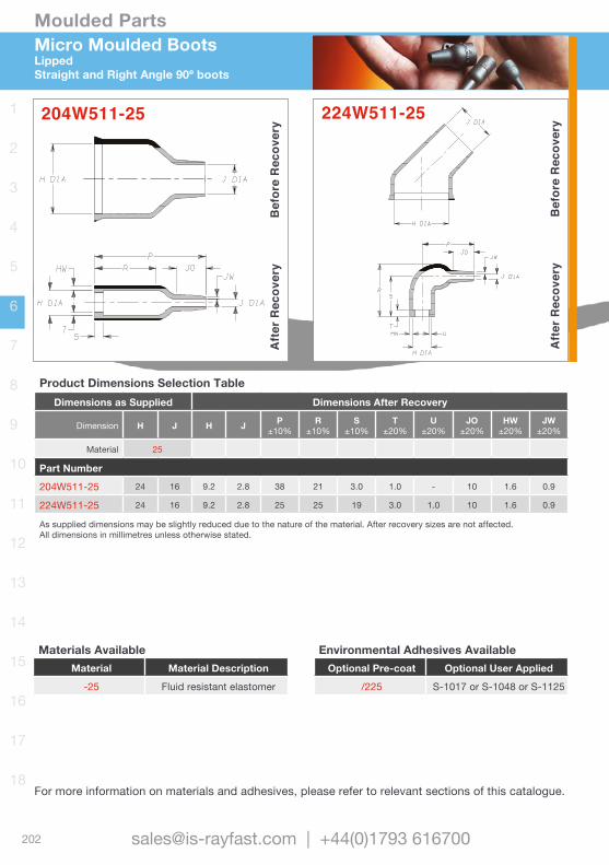
204W511-25
Afte
r Rec
over
yB
efor
e R
ecov
ery
Afte
r Rec
over
yB
efor
e R
ecov
ery224W511-25
Product Dimensions Selection TableDimensions as Supplied Dimensions After Recovery
Dimension H J H J P±10%
R±10%
S±10%
T±20%
U±20%
JO±20%
HW±20%
JW±20%
Material 25
Part Number
204W511-25 24 16 9.2 2.8 38 21 3.0 1.0 - 10 1.6 0.9
224W511-25 24 16 9.2 2.8 25 25 19 3.0 1.0 10 1.6 0.9
As supplied dimensions may be slightly reduced due to the nature of the material. After recovery sizes are not affected.All dimensions in millimetres unless otherwise stated.
Materials AvailableMaterial Material Description
-25 Fluid resistant elastomer
Environmental Adhesives AvailableOptional Pre-coat Optional User Applied
/225 S-1017 or S-1048 or S-1125
For more information on materials and adhesives, please refer to relevant sections of this catalogue.
203
Moulded Parts
www.is-rayfast.com
1
2
3
4
5
6
7
8
9
10
11
12
13
14
15
16
17
18
Micro Moulded BootsLipped
Straight and Right Angle 90º boots
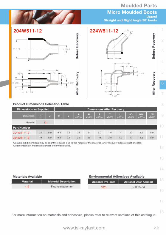
204W511-12
Afte
r Rec
over
yB
efor
e R
ecov
ery
224W511-12
Afte
r Rec
over
yB
efor
e R
ecov
ery
Product Dimensions Selection TableDimensions as Supplied Dimensions After Recovery
Dimension H J H J P±10%
R±10%
S±10%
T±20%
U±20%
JO±20%
HW±20%
JW±20%
Material 12
Part Number
204W511-12 22 8.0 9.3 2.8 38 21 3.0 1.0 - 10 1.6 0.9
224W511-12 19 8.0 9.3 2.8 25 25 19 3.0 1.0 10 1.6 0.9
As supplied dimensions may be slightly reduced due to the nature of the material. After recovery sizes are not affected.All dimensions in millimetres unless otherwise stated.
Materials AvailableMaterial Material Description
-12 Fluoro-elastomer
Environmental Adhesives AvailableOptional Pre-coat Optional User Applied
/225 S-1255-04
For more information on materials and adhesives, please refer to relevant sections of this catalogue.

204
Moulded Parts
[email protected] | +44(0)1793 616700
1
2
3
4
5
6
7
8
9
10
11
12
13
14
15
16
17
18
301A011 to 048Transitions‘T’ Transition, heat shrink boots
H Dia.
J Dia. K Dia.
S W
T
P
As supplied
After Recovery
Used for mechanical protection and cable strain relief. Ideal for cable harness applications where cable branches and breakouts are required.
Ordering Information• Standard colour Black.• Size selection please refer to table below.• Packaged individually• Please specify the product name, size,
material, coating and any modifications required, as per Part Number System earlier in this section.
• Adhesive coating is optional. If added the entry dimensions will be reduced by 1.5mm.
Product Dimensions Selection TableDimensions as Supplied Dimensions After Recovery
Dimension JNom. H, K H, J, K P
±10%S
±10%T
±10%W
±30% Weight
Part Number
301A011 12.0 6.6 3.6 29.7 15.1 - 1.0 0.9g
301A022 24.0 13.2 6.9 58.7 29.5 17.5 1.5 4.1g
301A034 48.0 26.9 13.5 120.1 60.2 35.6 2.3 31.3g
301A048 100.0 55.6 30.2 246.4 123.2 70.9 3.0 253.1g
All dimensions are in mm unless otherwise stated. Weight is based on polyolefin partOptional ‘Injection’ (S) and ‘Vent’ (T) ports indicated above, see part number system earlier in this section.
Materials AvailableMaterial Material Description
-3 Semi-rigid polyolefin
-4 Flexible polyolefin
-12 Fluoro-elastomer
-25 Fluid resistant elastomer
-100 Polyolefin, Zerohal
Environmental Adhesives AvailableOptional Pre-coat Optional User Applied
/42 or /86 S-1017 or S-1048
/42 or /86 S-1017 or S-1048
N/A S-1255-04
/42 or /86 or /225 S-1017 or S-1048 or S-1125
/86 or /180 S-1048 or S-1030
For more information on materials and adhesives, please refer to relevant sections of this catalogue.

205
Moulded Parts
www.is-rayfast.com
1
2
3
4
5
6
7
8
9
10
11
12
13
14
15
16
17
18
322A112 to 158Transitions
‘T’ Transition, heat shrink boots
K Dia.
H Dia. J Dia.
W
T
P
KW
HW
J Dia.
K Dia.
H Dia.
As supplied
After Recovery
Product Dimensions Selection TableDimensions as Supplied Dimensions After Recovery
Dimension H, J K H, J K P±10%
T±10%
U±10%
HW & JW±20%
KW±20% Weight
Part Number
322A112 13.2 6.6 6.9 3.6 49.3 19.6 19.6 1.52 1.02 2.7g
322A123 26.9 6.6 12.7 3.6 92.5 31.8 39.6 2.54 1.02 15.0g
322A134 26.9 13.2 13.7 6.1 144.8 50.8 50.8 2.54 1.52 20.9g
322A148 55.6 13.2 26.9 6.9 184.9 63.5 63.5 4.57 1.52 115g
322A158 55.6 26.9 26.9 13.7 203.5 66.0 66.0 4.57 2.54 164g
All dimensions in mm unless otherwise stated. Weight is based on polyolefin partOptional ‘Injection’ (S) and ‘Vent’ (T) ports indicated above, see part number system earlier in this section.
Used for mechanical protection and cable strain relief. Ideal for cable harness applications where cable branches and breakouts are required.
Ordering Information• Standard colour Black.• Size selection please refer to table below.• Packaged individually• Please specify the product name, size,
material, coating and any modifications required, as per Part Number System earlier in this section.
• Adhesive coating is optional. If added the entry dimensions will be reduced by 1.5mm.
Materials AvailableMaterial Material Description
-3 Semi-rigid polyolefin
-4 Flexible polyolefin
-12 Fluoro-elastomer
-25 Fluid resistant elastomer
-100 Polyolefin, Zerohal
Environmental Adhesives AvailableOptional Pre-coat Optional User Applied
/42 or /86 S-1017 or S-1048
/42 or /86 S-1017 or S-1048
N/A S-1255-04
/42 or /86 or /225 S-1017 or S-1048 or S-1125
/86 or /180 S-1048 or S-1030
For more information on materials and adhesives, please refer to relevant sections of this catalogue.
206
Moulded Parts
[email protected] | +44(0)1793 616700
1
2
3
4
5
6
7
8
9
10
11
12
13
14
15
16
17
18
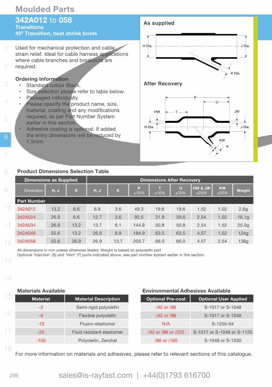
342A012 to 058Transitions45º Transition, heat shrink boots
JW T
PU
HW
KW
H Dia. J Dia.
K
H Dia. J Dia.
K Dia.
As supplied
After Recovery
Used for mechanical protection and cable strain relief. Ideal for cable harness applications where cable branches and breakouts are required.
Ordering Information• Standard colour Black.• Size selection please refer to table below.• Packaged individually• Please specify the product name, size,
material, coating and any modifications required, as per Part Number System earlier in this section.
• Adhesive coating is optional. If added the entry dimensions will be reduced by 1.5mm.
Product Dimensions Selection TableDimensions as Supplied Dimensions After Recovery
Dimension H, J K H, J K P±10%
T±10%
U±10%
HW & JW±20%
KW±20% Weight
Part Number342A012 13.2 6.6 6.9 3.6 49.3 19.6 19.6 1.52 1.02 2.6g342A024 26.9 6.6 12.7 3.6 92.5 31.8 39.6 2.54 1.02 16.1g342A034 26.9 13.2 13.7 6.1 144.8 50.8 50.8 2.54 1.52 25.0g342A048 55.6 13.2 26.9 6.9 184.9 63.5 63.5 4.57 1.52 124g342A058 55.6 26.9 26.9 13.7 203.7 66.0 66.0 4.57 2.54 138g
All dimensions in mm unless otherwise stated. Weight is based on polyolefin partOptional ‘Injection’ (S) and ‘Vent’ (T) ports indicated above, see part number system earlier in this section.
For more information on materials and adhesives, please refer to relevant sections of this catalogue.
Materials AvailableMaterial Material Description
-3 Semi-rigid polyolefin
-4 Flexible polyolefin
-12 Fluoro-elastomer
-25 Fluid resistant elastomer
-100 Polyolefin, Zerohal
Environmental Adhesives AvailableOptional Pre-coat Optional User Applied
/42 or /86 S-1017 or S-1048
/42 or /86 S-1017 or S-1048
N/A S-1255-04
/42 or /86 or /225 S-1017 or S-1048 or S-1125
/86 or /180 S-1048 or S-1030
207
Moulded Parts
www.is-rayfast.com
1
2
3
4
5
6
7
8
9
10
11
12
13
14
15
16
17
18
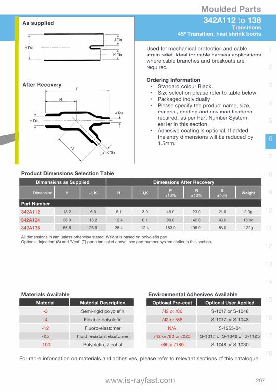
342A112 to 138Transitions
45º Transition, heat shrink boots
As supplied
After Recovery
Product Dimensions Selection TableDimensions as Supplied Dimensions After Recovery
Dimension H J, K H J,K P±10%
R±10%
S±10% Weight
Part Number342A112 13.2 6.6 6.1 3.0 45.0 23.0 21.0 2.3g
342A124 26.9 13.2 12.4 6.1 90.0 42.0 43.0 15.9g
342A138 55.6 26.9 25.4 12.4 183.0 96.0 86.0 122g
All dimensions in mm unless otherwise stated. Weight is based on polyolefin partOptional ‘Injection’ (S) and ‘Vent’ (T) ports indicated above, see part number system earlier in this section.
Used for mechanical protection and cable strain relief. Ideal for cable harness applications where cable branches and breakouts are required.
Ordering Information• Standard colour Black.• Size selection please refer to table below.• Packaged individually• Please specify the product name, size,
material, coating and any modifications required, as per Part Number System earlier in this section.
• Adhesive coating is optional. If added the entry dimensions will be reduced by 1.5mm.
For more information on materials and adhesives, please refer to relevant sections of this catalogue.
Materials AvailableMaterial Material Description
-3 Semi-rigid polyolefin
-4 Flexible polyolefin
-12 Fluoro-elastomer
-25 Fluid resistant elastomer
-100 Polyolefin, Zerohal
Environmental Adhesives AvailableOptional Pre-coat Optional User Applied
/42 or /86 S-1017 or S-1048
/42 or /86 S-1017 or S-1048
N/A S-1255-04
/42 or /86 or /225 S-1017 or S-1048 or S-1125
/86 or /180 S-1048 or S-1030

208
Moulded Parts
[email protected] | +44(0)1793 616700
1
2
3
4
5
6
7
8
9
10
11
12
13
14
15
16
17
18
362A014 to 114Transitions30º Transition, heat shrink boots
JW
KW
PS THW
H Dia. J Dia.
K Dia.
H Dia.
J Dia.
K
As supplied
After Recovery
Used for mechanical protection and cable strain relief. Ideal for cable harness applications where cable branches and breakouts are required.
Ordering Information• Standard colour Black.• Size selection please refer to table below.• Packaged individually• Please specify the product name, size,
material, coating and any modifications required, as per Part Number System earlier in this section.
• Adhesive coating is optional. If added the entry dimensions will be reduced by 1.5mm.
Product Dimensions Selection TableDimensions as Supplied Dimensions After Recovery
Dimension H, J K H, J K P±10%
S±10%
T±10%
HW & JW±20%
KW±20% Weight
Part Number
362A014 30.5 20.3 15.7 10.7 82.6 31.8 21.1 2.54 1.78 20.4g
362A024 35.6 15.2 18.3 8.6 63.5 19.1 22.4 2.54 1.52 13.3g
362A114 35.6 10.2 18.8 5.3 61.0 19.1 21.3 2.79 1.52 13.2gAll dimensions in mm unless otherwise stated. Weight is based on polyolefin partOptional ‘Injection’ (S) and ‘Vent’ (T) ports indicated above, see part number system earlier in this section.
For more information on materials and adhesives, please refer to relevant sections of this catalogue.
Materials AvailableMaterial Material Description
-3 Semi-rigid polyolefin
-4 Flexible polyolefin
-12 Fluoro-elastomer
-25 Fluid resistant elastomer
-100 Polyolefin, Zerohal
Environmental Adhesives AvailableOptional Pre-coat Optional User Applied
/42 or /86 S-1017 or S-1048
/42 or /86 S-1017 or S-1048
N/A S-1255-04
/42 or /86 or /225 S-1017 or S-1048 or S-1125
/86 or /180 S-1048 or S-1030
209
Moulded Parts
www.is-rayfast.com
1
2
3
4
5
6
7
8
9
10
11
12
13
14
15
16
17
18
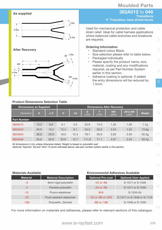
382A012 to 046Transitions
‘Y’ Transition, heat shrink boots
H Dia.
J Dia.
K Dia.
HW T
KW
JW
S
J Dia.
K Dia.
H Dia.
As supplied
After Recovery
Product Dimensions Selection TableDimensions as Supplied Dimensions After Recovery
Dimension H J, K H J,K S±10%
T±10%
HW±20%
JW & KW±20% Weight
Part Number
382A012 13.2 6.6 6.1 3.3 23.9 15.5 1.52 1.02 1.7g
382A023 26.9 13.2 12.4 6.1 53.3 33.0 2.54 1.52 13.6g
382A034 38.6 26.9 18.0 12.4 78.7 55.9 3.05 2.54 55.5g
382A046 55.6 26.9 25.9 12.7 111.8 71.1 4.57 2.54 93.4gAll dimensions in mm unless otherwise stated. Weight is based on polyolefin partOptional ‘Injection’ (S) and ‘Vent’ (T) ports indicated above, see part number system earlier in this section.
Used for mechanical protection and cable strain relief. Ideal for cable harness applications where balanced cable branches and breakouts are required.
Ordering Information• Standard colour Black.• Size selection please refer to table below.• Packaged individually• Please specify the product name, size,
material, coating and any modifications required, as per Part Number System earlier in this section.
• Adhesive coating is optional. If added the entry dimensions will be reduced by 1.5mm.
For more information on materials and adhesives, please refer to relevant sections of this catalogue.
Materials AvailableMaterial Material Description
-3 Semi-rigid polyolefin
-4 Flexible polyolefin
-12 Fluoro-elastomer
-25 Fluid resistant elastomer
-100 Polyolefin, Zerohal
Environmental Adhesives AvailableOptional Pre-coat Optional User Applied
/42 or /86 S-1017 or S-1048
/42 or /86 S-1017 or S-1048
N/A S-1255-04
/42 or /86 or /225 S-1017 or S-1048 or S-1125
/86 or /180 S-1048 or S-1030
210
Moulded Parts
[email protected] | +44(0)1793 616700
1
2
3
4
5
6
7
8
9
10
11
12
13
14
15
16
17
18
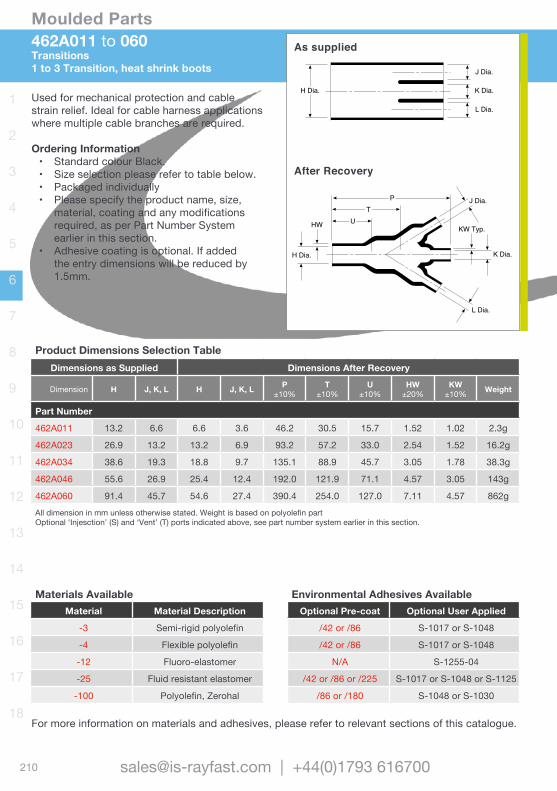
462A011 to 060Transitions1 to 3 Transition, heat shrink boots
KW Typ.
P
UT
HW
H Dia.
J Dia.
K Dia.
L Dia.
H Dia.
J Dia.
K Dia.
L Dia.
As supplied
After Recovery
Used for mechanical protection and cable strain relief. Ideal for cable harness applications where multiple cable branches are required.
Ordering Information• Standard colour Black.• Size selection please refer to table below.• Packaged individually• Please specify the product name, size,
material, coating and any modifications required, as per Part Number System earlier in this section.
• Adhesive coating is optional. If added the entry dimensions will be reduced by 1.5mm.
Product Dimensions Selection TableDimensions as Supplied Dimensions After Recovery
Dimension H J, K, L H J, K, L P±10%
T±10%
U±10%
HW±20%
KW±10% Weight
Part Number
462A011 13.2 6.6 6.6 3.6 46.2 30.5 15.7 1.52 1.02 2.3g
462A023 26.9 13.2 13.2 6.9 93.2 57.2 33.0 2.54 1.52 16.2g
462A034 38.6 19.3 18.8 9.7 135.1 88.9 45.7 3.05 1.78 38.3g
462A046 55.6 26.9 25.4 12.4 192.0 121.9 71.1 4.57 3.05 143g
462A060 91.4 45.7 54.6 27.4 390.4 254.0 127.0 7.11 4.57 862gAll dimension in mm unless otherwise stated. Weight is based on polyolefin partOptional ‘Injesction’ (S) and ‘Vent’ (T) ports indicated above, see part number system earlier in this section.
For more information on materials and adhesives, please refer to relevant sections of this catalogue.
Materials AvailableMaterial Material Description
-3 Semi-rigid polyolefin
-4 Flexible polyolefin
-12 Fluoro-elastomer
-25 Fluid resistant elastomer
-100 Polyolefin, Zerohal
Environmental Adhesives AvailableOptional Pre-coat Optional User Applied
/42 or /86 S-1017 or S-1048
/42 or /86 S-1017 or S-1048
N/A S-1255-04
/42 or /86 or /225 S-1017 or S-1048 or S-1125
/86 or /180 S-1048 or S-1030

211
Moulded Parts
www.is-rayfast.com
1
2
3
4
5
6
7
8
9
10
11
12
13
14
15
16
17
18
562A011 to 067Transitions
1 to 4 Transition, heat shrink boots
H Dia.
K Dia.J Dia.
N Dia.L Dia.
HW U
T
W
J Dia.
P
K Dia.
L Dia.
H Dia.
N Dia.
As supplied
After Recovery
Used for mechanical protection and cable strain relief. Ideal for cable harness applications where multiple cable branches are required.
Ordering Information• Standard colour Black.• Size selection please refer to table below.• Packaged individually• Please specify the product name, size,
material, coating and any modifications required, as per Part Number System earlier in this section.
• Adhesive coating is optional. If added the entry dimensions will be reduced by 1.5mm.
Product Dimensions Selection TableDimensions as Supplied Dimensions After Recovery
Dimension H J, K, L, N H J, K, L, N P±10%
T±10%
U±10%
HW±20%
W±20% Weight
Part Number562A011 13.2 6.6 6.9 3.4 24.1 43.9 18.0 1.52 1.02 3.6g562A022 19.3 9.4 9.7 5.3 35.6 43.2 23.1 1.78 1.02 6.2g562A032 19.3 13.2 9.7 6.9 49.3 50.5 25.4 1.78 1.52 13.6g562A043 26.9 13.2 13.0 6.9 49.3 65.8 33.5 2.54 1.52 18.6g562A054 38.6 19.3 18.5 9.7 71.9 95.3 46.5 3.05 1.78 54.4g562A067 55.6 26.9 26.7 13.0 101.6 135.1 65.5 4.57 2.54 150gAll dimensions in mm unless otherwise stated. Weight is based on polyolefin partOptional ‘Injection’ (S) and ‘Vent’ (T) ports indicated above, see part number system earlier in this section.
For more information on materials and adhesives, please refer to relevant sections of this catalogue.
Materials AvailableMaterial Material Description
-3 Semi-rigid polyolefin
-4 Flexible polyolefin
-12 Fluoro-elastomer
-25 Fluid resistant elastomer
-100 Polyolefin, Zerohal
Environmental Adhesives AvailableOptional Pre-coat Optional User Applied
/42 or /86 S-1017 or S-1048
/42 or /86 S-1017 or S-1048
N/A S-1255-04
/42 or /86 or /225 S-1017 or S-1048 or S-1125
/86 or /180 S-1048 or S-1030

212
Moulded Parts
[email protected] | +44(0)1793 616700
1
2
3
4
5
6
7
8
9
10
11
12
13
14
15
16
17
18
PD Caps PolyolefinEncapsulant lined, semi-rigid
Specifications & Approvals• UL E85381 600v, 125ºC
Part Number Example; PD-CAP-1/4-0 6.35mm inside diameter, Black end cap.Ordering InformationStandard colours: 0=BlackSize selection: The largest size that will recover snugly over the component(s).
Inexpensive way to encapsulate crimped electrical connections. Encapsulant lining melts and flows to fill surface irregularities of the substrate. These vibration proof caps are used to insulate and terminate dead-end electrical cables, fixtures, connectors and other electrical components.
Features & Benefits• Rapid and simple installation• Splash and moisture resistant
Operating Temperature • From -55ºC to +110ºC
Installation• Minimum shrink temperature +125ºC• Minimum full recovery +135ºC
Length Supplied Inside Diameter Wall ThicknessPart NumberNominal
Overall Minimum
Open BarrelMaximumSupplied
MaximumRecovered
Nominal Recovered
25.4 12.7 3.18 0.58 1.22 PD-CAP-1/8-0
25.4 15.2 4.75 1.52 1.57 PD-CAP-3/16-0
28.4 15.2 6.35 2.03 1.98 PD-CAP-1/4-0
31.8 18.3 9.53 2.29 2.08 PD-CAP-3/8-0
38.1 21.6 12.7 2.29 2.54 PD-CAP-1/2-0
Wall thickness will be less if tubing recovery is restricted during shrinkage.All dimensions in millimetres unless otherwise stated.
As Supplied Fully Recovered
3:1shrink
RoHScompliant
213
Moulded Parts
www.is-rayfast.com
1
2
3
4
5
6
7
8
9
10
11
12
13
14
15
16
17
18
Length Supplied Inside Diameter Wall ThicknessPart NumberNominal
Overall Minimum
Open BarrelMaximumSupplied
MaximumRecovered
Nominal Recovered
25.4 12.7 3.18 0.58 1.22 PD-CAP-1/8-0
25.4 15.2 4.75 1.52 1.57 PD-CAP-3/16-0
28.4 15.2 6.35 2.03 1.98 PD-CAP-1/4-0
31.8 18.3 9.53 2.29 2.08 PD-CAP-3/8-0
38.1 21.6 12.7 2.29 2.54 PD-CAP-1/2-0
Wall thickness will be less if tubing recovery is restricted during shrinkage.All dimensions in millimetres unless otherwise stated.
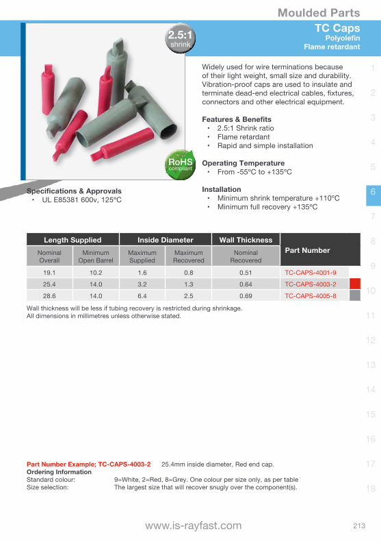
TC Caps Polyolefin
Flame retardant
Widely used for wire terminations because of their light weight, small size and durability. Vibration-proof caps are used to insulate and terminate dead-end electrical cables, fixtures, connectors and other electrical equipment.
Features & Benefits• 2.5:1 Shrink ratio• Flame retardant• Rapid and simple installation
Operating Temperature • From -55ºC to +135ºC
Installation• Minimum shrink temperature +110ºC• Minimum full recovery +135ºC
Specifications & Approvals • UL E85381 600v, 125ºC
Part Number Example; TC-CAPS-4003-2 25.4mm inside diameter, Red end cap.Ordering InformationStandard colour: 9=White, 2=Red, 8=Grey. One colour per size only, as per tableSize selection: The largest size that will recover snugly over the component(s).
Length Supplied Inside Diameter Wall ThicknessPart NumberNominal
Overall Minimum
Open BarrelMaximumSupplied
MaximumRecovered
Nominal Recovered
19.1 10.2 1.6 0.8 0.51 TC-CAPS-4001-9
25.4 14.0 3.2 1.3 0.64 TC-CAPS-4003-2
28.6 14.0 6.4 2.5 0.69 TC-CAPS-4005-8
Wall thickness will be less if tubing recovery is restricted during shrinkage.All dimensions in millimetres unless otherwise stated.
2.5:1shrink
RoHScompliant
214
Moulded Parts
[email protected] | +44(0)1793 616700
1
2
3
4
5
6
7
8
9
10
11
12
13
14
15
16
17
18
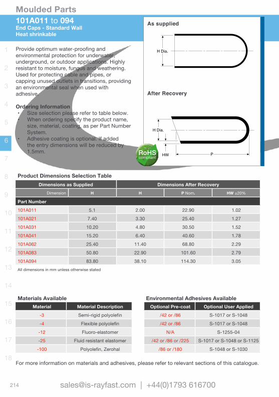
101A011 to 094End Caps - Standard WallHeat shrinkable
HW P
H Dia.
H Dia.
As supplied
After Recovery
Provide optimum water-proofing and environmental protection for underwater, underground, or outdoor applications. Highly resistant to moisture, fungus and weathering. Used for protecting cable and pipes, or capping unused outlets in transitions, providing an environmental seal when used with adhesive.
Ordering Information• Size selection please refer to table below.• When ordering specify the product name,
size, material, coating, as per Part Number System.
• Adhesive coating is optional. If added the entry dimensions will be reduced by 1.5mm.
Product Dimensions Selection TableDimensions as Supplied Dimensions After Recovery
Dimension H H P Nom. HW ±20%
Part Number
101A011 5.1 2.00 22.90 1.02
101A021 7.40 3.30 25.40 1.27
101A031 10.20 4.80 30.50 1.52
101A041 15.20 6.40 40.60 1.78
101A062 25.40 11.40 68.80 2.29
101A083 50.80 22.90 101.60 2.79
101A094 83.80 38.10 114.30 3.05All dimensions in mm unless otherwise stated
For more information on materials and adhesives, please refer to relevant sections of this catalogue.
Materials AvailableMaterial Material Description
-3 Semi-rigid polyolefin
-4 Flexible polyolefin
-12 Fluoro-elastomer
-25 Fluid resistant elastomer
-100 Polyolefin, Zerohal
Environmental Adhesives AvailableOptional Pre-coat Optional User Applied
/42 or /86 S-1017 or S-1048
/42 or /86 S-1017 or S-1048
N/A S-1255-04
/42 or /86 or /225 S-1017 or S-1048 or S-1125
/86 or /180 S-1048 or S-1030
RoHScompliant
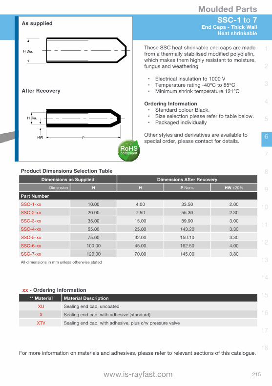
215
Moulded Parts
www.is-rayfast.com
1
2
3
4
5
6
7
8
9
10
11
12
13
14
15
16
17
18
SSC-1 to 7End Caps - Thick Wall
Heat shrinkable
H Dia.
HW
H Dia.
P
These SSC heat shrinkable end caps are made from a thermally stabilised modified polyolefin, which makes them highly resistant to moisture, fungus and weathering
• Electrical insulation to 1000 V• Temperature rating -40ºC to 85ºC• Minimum shrink temperature 121ºC
Ordering Information• Standard colour Black.• Size selection please refer to table below.• Packaged individually
Other styles and derivatives are available to special order, please contact for details.
As supplied
After Recovery
Product Dimensions Selection TableDimensions as Supplied Dimensions After Recovery
Dimension H H P Nom. HW ±20%
Part Number
SSC-1-xx 10.00 4.00 33.50 2.00
SSC-2-xx 20.00 7.50 55.30 2.30
SSC-3-xx 35.00 15.00 89.90 3.00
SSC-4-xx 55.00 25.00 143.20 3.30
SSC-5-xx 75.00 32.00 150.10 3.30
SSC-6-xx 100.00 45.00 162.50 4.00
SSC-7-xx 120.00 70.00 145.00 3.80All dimensions in mm unless otherwise stated
xx - Ordering Information** Material Material Description
XU Sealing end cap, uncoated
X Sealing end cap, with adhesive (standard)
XTV Sealing end cap, with adhesive, plus c/w pressure valve
For more information on materials and adhesives, please refer to relevant sections of this catalogue.
RoHScompliant
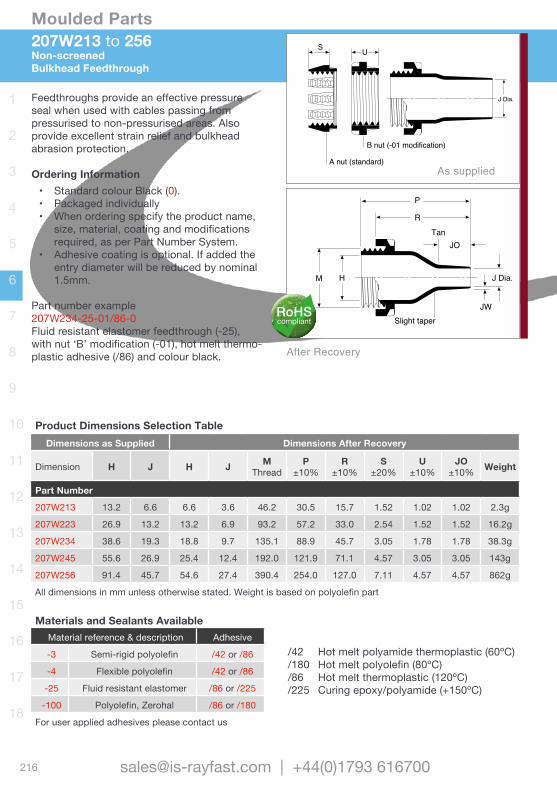
216
Moulded Parts
[email protected] | +44(0)1793 616700
1
2
3
4
5
6
7
8
9
10
11
12
13
14
15
16
17
18
207W213 to 256Non-screenedBulkhead Feedthrough
Feedthroughs provide an effective pressure seal when used with cables passing from pressurised to non-pressurised areas. Also provide excellent strain relief and bulkhead abrasion protection.
Ordering Information• Standard colour Black (0).• Packaged individually• When ordering specify the product name,
size, material, coating and modifications required, as per Part Number System.
• Adhesive coating is optional. If added the entry diameter will be reduced by nominal 1.5mm.
Part number example207W234-25-01/86-0Fluid resistant elastomer feedthrough (-25), withnut‘B’modification(-01),hotmeltthermo-plastic adhesive (/86) and colour black.
Product Dimensions Selection TableDimensions as Supplied Dimensions After Recovery
Dimension H J H J MThread
P±10%
R±10%
S±20%
U±10%
JO±10% Weight
Part Number
207W213 13.2 6.6 6.6 3.6 46.2 30.5 15.7 1.52 1.02 1.02 2.3g
207W223 26.9 13.2 13.2 6.9 93.2 57.2 33.0 2.54 1.52 1.52 16.2g
207W234 38.6 19.3 18.8 9.7 135.1 88.9 45.7 3.05 1.78 1.78 38.3g
207W245 55.6 26.9 25.4 12.4 192.0 121.9 71.1 4.57 3.05 3.05 143g
207W256 91.4 45.7 54.6 27.4 390.4 254.0 127.0 7.11 4.57 4.57 862g
All dimensions in mm unless otherwise stated. Weight is based on polyolefin part
Materials and Sealants AvailableMaterial reference & description Adhesive
-3 Semi-rigid polyolefin /42 or /86
-4 Flexible polyolefin /42 or /86
-25 Fluid resistant elastomer /86 or /225
-100 Polyolefin, Zerohal /86 or /180
For user applied adhesives please contact us
J Dia.
S U
B nut (-01 modification)
A nut (standard)
J Dia.
Slight taper JW
H M
JOTan
P
R
J Dia.
S U
B nut (-01 modification)
A nut (standard)
J Dia.
Slight taper JW
H M
JOTan
P
R
/42 Hot melt polyamide thermoplastic (60ºC)/180 Hot melt polyolefin (80ºC) /86 Hot melt thermoplastic (120ºC)/225 Curing epoxy/polyamide (+150ºC)
After Recovery
As supplied
RoHScompliant
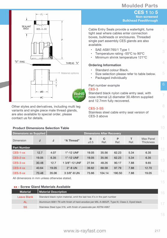
217
Moulded Parts
www.is-rayfast.com
1
2
3
4
5
6
7
8
9
10
11
12
13
14
15
16
17
18
Product Dimensions Selection TableDimensions as Supplied Dimensions After Recovery
Dimension H J H J MThread
P±10%
R±10%
S±20%
U±10%
JO±10% Weight
Part Number
207W213 13.2 6.6 6.6 3.6 46.2 30.5 15.7 1.52 1.02 1.02 2.3g
207W223 26.9 13.2 13.2 6.9 93.2 57.2 33.0 2.54 1.52 1.52 16.2g
207W234 38.6 19.3 18.8 9.7 135.1 88.9 45.7 3.05 1.78 1.78 38.3g
207W245 55.6 26.9 25.4 12.4 192.0 121.9 71.1 4.57 3.05 3.05 143g
207W256 91.4 45.7 54.6 27.4 390.4 254.0 127.0 7.11 4.57 4.57 862g
All dimensions in mm unless otherwise stated. Weight is based on polyolefin part
CES 1 to 5Non-screened
Bulkhead Feedthrough
Cable Entry Seals provide a watertight, fume tight seal where cables enter connection boxes, bulkheads or enclosures. Threaded single part assembly CES glands are also available.• SAE-AS81765/1 Type 1• Temperature rating -55ºC to 90ºC• Minimum shrink temperature 121ºC
Ordering Information• Standard colour Black.• Size selection please refer to table below.• Packaged individually
Part number exampleCES-3Standard black nylon cable entry seal, with nose internal (J) diameter 30.48mm supplied and 12.7mm fully recovered.
CES-3-SSStainless steel cable entry seal version of CES-3 above
Product Dimensions Selection TableDimensions as Supplied Dimensions After Recovery
Dimension J J “A Thread” B±0.5
CRef.
PRef.
TRef.
Max Panel Thickness
Part Number
CES-1-xx 12.7 4.07 1”-12 UNF 19.05 35.56 62.23 5.34 6.35
CES-2-xx 19.05 6.35 1”-12 UNF 19.05 35.56 62.23 5.34 6.35
CES-3-xx 30.48 12.7 1 3/8”-12 UNF 27.94 48.26 90.17 7.88 9.65
CES-4-xx 40.64 19.05 2”-8 UN 39.62 68.58 97.79 7.88 12.70
CES-5-xx 70.48 35.06 3 3/8”-8 UN 73.66 104.14 190.50 7.88 19.05
All dimensions in mm unless otherwise stated.
xx - Screw Gland Materials AvailableMaterial Material Description
Leave Blank Standard black nylon material, omit the last two X’s in the part number
AL Aluminium 6061-T6 with finish of hard anodize per MIL-A-8652F, Type III, Class 2, Dyed black
SS Stainless Steel type 316, with finish of passivate per ASTM-A967
Other styles and derivatives, including multi leg variants and single piece male thread glands, are also available to special order, please contact us for details.
Material options
RoHScompliant
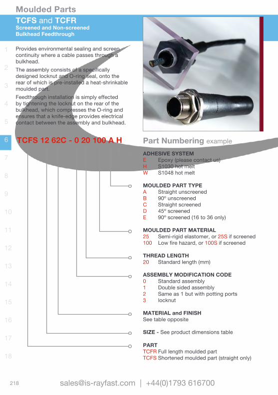
218
Moulded Parts
[email protected] | +44(0)1793 616700
1
2
3
4
5
6
7
8
9
10
11
12
13
14
15
16
17
18
TCFS and TCFRScreened and Non-screenedBulkhead Feedthrough
Provides environmental sealing and screen continuity where a cable passes through a bulkhead. The assembly consists of a specifically designed locknut and O-ring seal, onto the rear of which is pre-installed a heat-shrinkable moulded part. Feedthrough installation is simply effected by tightening the locknut on the rear of the bulkhead, which compresses the O-ring and ensures that a knife-edge provides electrical contact between the assembly and bulkhead.
TCFS 12 62C - 0 20 100 A HADHESIVE SYSTEME Epoxy (please contact us)H S1030 hot meltW S1048 hot melt
MOULDED PART TYPEA Straight unscreenedB 90º unscreenedC Straight screenedD 45º screenedE 90º screened (16 to 36 only)
MOULDED PART MATERIAL25 Semi-rigid elastomer, or 25S if screened100 Low fire hazard, or 100S if screened
THREAD LENGTH20 Standard length (mm)
ASSEMBLY MODIFICATION CODE0 Standard assembly1 Double sided assembly2 Same as 1 but with potting ports3 locknut
MATERIAL and FINISH See table opposite
SIZE - See product dimensions table
PARTTCFR Full length moulded partTCFS Shortened moulded part (straight only)
Part Numbering example
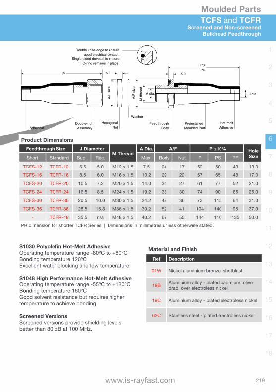
219
Moulded Parts
www.is-rayfast.com
1
2
3
4
5
6
7
8
9
10
11
12
13
14
15
16
17
18
TCFS and TCFRScreened and Non-screened
Bulkhead Feedthrough
O-ring remains in place.
Adhesive Assembly Nut
A/F
size
A/F
size
Body Moulded Part Adhesive
Washer
5.0 5.0
PS
A dia. J dia.
M th
read
PRP
Product DimensionsFeedthrough Size J Diameter
M ThreadA Dia. A/F P ±10% Hole
SizeShort Standard Sup. Rec. Max. Body Nut P PS PR
TCFS-12 TCFR-12 6.5 5.0 M12 x 1.5 7.5 24 17 52 50 43 13.0
TCFS-16 TCFR-16 8.5 6.0 M16 x 1.5 10.2 29 22 57 65 48 17.0
TCFS-20 TCFR-20 10.5 7.2 M20 x 1.5 14.0 34 27 61 77 52 21.0
TCFS-24 TCFR-24 16.5 8.5 M24 x 1.5 19.2 38 30 74 90 65 25.0
TCFS-30 TCFR-30 20.5 10.0 M30 x 1.5 24.2 48 36 73 115 64 31.0
TCFS-36 TCFR-36 28.5 15.8 M36 x 1.5 30.2 52 41 104 140 95 37.0
- TCFR-48 35.5 n/a M48 x 1.5 40.2 67 55 144 110 135 50.0
PR dimension for shorter TCFR Series | Dimensions in millimetres unless otherwise stated.
S1030 Polyolefin Hot-Melt AdhesiveOperating temperature range -80ºC to +80ºCBonding temperature 120ºCExcellent water blocking and low temperature
S1048 High Performance Hot-Melt AdhesiveOperating temperature range -55ºC to +120ºCBonding temperature 160ºCGood solvent resistance but requires higher temperature to achieve bonding
Screened VersionsScreened versions provide shielding levels better than 80 dB at 100 MHz.
Material and Finish
Ref Description
01W Nickel aluminium bronze, shotblast
19B Aluminium alloy - plated cadmium, olive drab, over electroless nickel
19C Aluminium alloy - plated electroless nickel
62C Stainless steel - plated electroless nickel
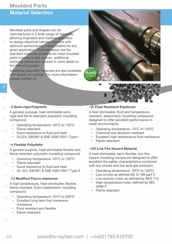
220
Moulded Parts
[email protected] | +44(0)1793 616700
1
2
3
4
5
6
7
8
9
10
11
12
13
14
15
16
17
18
Material Selection
-3 Semi-rigid PolyolefinA general purpose, heat-shrinkable semi-rigid and flame retardant polyolefin moulding compound.• Operating temperature -55ºC to 135ºC• Flame retardant• Good resistance to fluid and heat• UL224, E85381 & SAE-AS81765/1 Type I
-4 Flexible PolyolefinA general purpose, heat-shrinkable flexible and flame retardant polyolefin moulding compound.• Operating temperature -55ºC to 135ºC• Flame retardant• Good resistance to fluid and heat• UL 224, E85381 & SAE-AS81765/1 Type II
-12 Modified Fluoro-elastomerA high temperature, heat-shrinkable, flexible, flame-retarded, fluoro-elastomeric moulding compound.• Operating temperature -55ºC to 200ºC• Excellent long term fuel immersion
resistance• Fluid resistant and flexible• Flame retardant
-25 Fluid Resistant ElastomerA heat-shrinkable, fluid and temperature resistant, elastomeric moulding compound, designed to offer excellent performance in harsh environments. • Operating temperature -75ºC to 150ºC• Chemical and abrasion resistant• Excellent high temperature fluid resistance• Flame retardant
-100 Low Fire Hazard MaterialA heat-shrinkable, semi-flexible, low-fire hazard moulding compound designed to offer excellent fire safety characteristics combined with low smoke and low acid gas emission.• Operating temperature -30ºC to 105ºC• Low smoke as defined BS G 198 part 5• Low-toxicity index as defined by NES 713• High-temperature index defined by ISO
4589-3• Flame retardant
Moulded parts and shapes can be manufactured in a wide range of materials, allowing engineers and material specifiers to design electrical harness systems with optimum performance characteristics for any given application. Outlined below are the standard materials available for most moulded parts covered in this section, additional technical details are covered in more detail on the following pages.Additional specialist materials are also available with details on request. For more information please contact us.
RoHScompliant
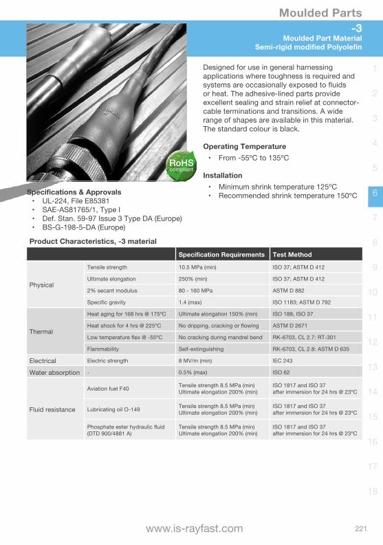
221
Moulded Parts
www.is-rayfast.com
1
2
3
4
5
6
7
8
9
10
11
12
13
14
15
16
17
18
Designed for use in general harnessing applications where toughness is required and systems are occasionally exposed to fluids or heat. The adhesive-lined parts provide excellent sealing and strain relief at connector-cable terminations and transitions. A wide range of shapes are available in this material. The standard colour is black.
Operating Temperature• From -55ºC to 135ºC
Installation• Minimum shrink temperature 125ºC• Recommended shrink temperature 150ºCSpecifications & Approvals
• UL-224, File E85381• SAE-AS81765/1, Type I• Def. Stan. 59-97 Issue 3 Type DA (Europe)• BS-G-198-5-DA (Europe)
Product Characteristics, -3 materialSpecification Requirements Test Method
Physical
Tensile strength 10.5 MPa (min) ISO 37; ASTM D 412
Ultimate elongation 250% (min) ISO 37; ASTM D 412
2% secant modulus 80 - 160 MPa ASTM D 882
Specific gravity 1.4 (max) ISO 1183; ASTM D 792
Thermal
Heat aging for 168 hrs @ 175ºC Ultimate elongation 150% (min) ISO 188, ISO 37
Heat shock for 4 hrs @ 225ºC No dripping, cracking or flowing ASTM D 2671
Low temperature flex @ -55ºC No cracking during mandrel bend RK-6703, CL 2.7: RT-301
Flammability Self-extinguishing RK-6703, CL 2.8: ASTM D 635
Electrical Electric strength 8 MV/m (min) IEC 243
Water absorption - 0.5% (max) ISO 62
Fluid resistance
Aviation fuel F40 Tensile strength 8.5 MPa (min)Ultimate elongation 200% (min)
ISO 1817 and ISO 37after immersion for 24 hrs @ 23ºC
Lubricating oil O-149 Tensile strength 8.5 MPa (min)Ultimate elongation 200% (min)
ISO 1817 and ISO 37after immersion for 24 hrs @ 23ºC
Phosphate ester hydraulic fluid(DTD 900/4881 A)
Tensile strength 8.5 MPa (min)Ultimate elongation 200% (min)
ISO 1817 and ISO 37after immersion for 24 hrs @ 23ºC
-3 Moulded Part Material
Semi-rigid modified Polyolefin
RoHScompliant

222
Moulded Parts
[email protected] | +44(0)1793 616700
1
2
3
4
5
6
7
8
9
10
11
12
13
14
15
16
17
18
Designed for use in general harnessing applications where toughness is required and systems are occasionally exposed to fluids or heat. The adhesive-lined parts provide excellent sealing and strain relief at connector-cable terminations and transitions. A wide range of shapes are available in this material. The standard colour is black.
Operating Temperature• From -55ºC to 135ºC
Installation• Minimum shrink temperature 105ºC• Recommended shrink temperature 150ºC Specifications & Approvals
• UL-224, File E85381• SAE-AS81765/1, Type II• SAE-AS85049/ 140, 141, 142
Product Characteristics, -4 materialSpecification Requirements Test Method
Physical
Tensile strength 1800 psi (min) ASTM D 412
Ultimate elongation 400% (min) ASTM D 412
Specific gravity 1.3 (max) ASTM D 792
Thermal
Heat aging for 168 hrs @ 175ºC Ultimate elongation 300% (min) RT 1304 Sec 4.3.3
Heat shock for 4 hrs @ 225ºC No dripping, cracking or flowing RT 1304 Sec 4.3.3
Low temperature flex @ -55ºC No cracking during mandrel bend RT 1304 Sec 4.3.3
Flammability Average flame time: 120 s (max) ASTM D 635
Electrical Dielectric strength 350 V/mil (min) ASTM D 149
Water absorption - 0.3% (max) ASTM D 570
Fluid resistance JP-4 fuel, aviation gasoline, water, hydraulic fluid
Tensile strength 8.5 MPa psi (min)Ultimate elongation 200% (min) RT-1304 Sec 4.3.3
-4Moulded Part MaterialFlexible Polyolefin
RoHScompliant
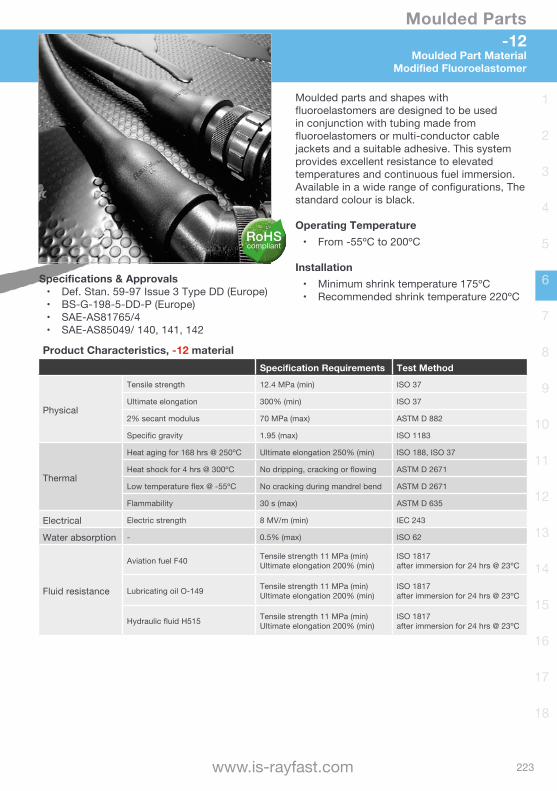
223
Moulded Parts
www.is-rayfast.com
1
2
3
4
5
6
7
8
9
10
11
12
13
14
15
16
17
18
Moulded parts and shapes with fluoroelastomers are designed to be used in conjunction with tubing made from fluoroelastomers or multi-conductor cable jackets and a suitable adhesive. This system provides excellent resistance to elevated temperatures and continuous fuel immersion. Available in a wide range of configurations, The standard colour is black.
Operating Temperature• From -55ºC to 200ºC
Installation• Minimum shrink temperature 175ºC• Recommended shrink temperature 220ºC
Specifications & Approvals• Def. Stan. 59-97 Issue 3 Type DD (Europe)• BS-G-198-5-DD-P (Europe)• SAE-AS81765/4• SAE-AS85049/ 140, 141, 142
Product Characteristics, -12 materialSpecification Requirements Test Method
Physical
Tensile strength 12.4 MPa (min) ISO 37
Ultimate elongation 300% (min) ISO 37
2% secant modulus 70 MPa (max) ASTM D 882
Specific gravity 1.95 (max) ISO 1183
Thermal
Heat aging for 168 hrs @ 250ºC Ultimate elongation 250% (min) ISO 188, ISO 37
Heat shock for 4 hrs @ 300ºC No dripping, cracking or flowing ASTM D 2671
Low temperature flex @ -55ºC No cracking during mandrel bend ASTM D 2671
Flammability 30 s (max) ASTM D 635
Electrical Electric strength 8 MV/m (min) IEC 243
Water absorption - 0.5% (max) ISO 62
Fluid resistance
Aviation fuel F40 Tensile strength 11 MPa (min)Ultimate elongation 200% (min)
ISO 1817 after immersion for 24 hrs @ 23ºC
Lubricating oil O-149 Tensile strength 11 MPa (min)Ultimate elongation 200% (min)
ISO 1817 after immersion for 24 hrs @ 23ºC
Hydraulic fluid H515 Tensile strength 11 MPa (min)Ultimate elongation 200% (min)
ISO 1817after immersion for 24 hrs @ 23ºC
-12 Moulded Part Material
Modified Fluoroelastomer
RoHScompliant
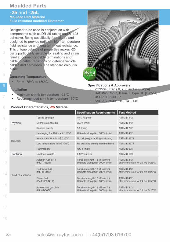
224
Moulded Parts
[email protected] | +44(0)1793 616700
1
2
3
4
5
6
7
8
9
10
11
12
13
14
15
16
17
18
Designed to be used in conjunction with components such as DR-25 tubing and S1125 adhesive. Being specifically formulated and designed to provide optimum high-temperature fluid resistance and long term heat resistance. This unique balance of properties makes -25 parts particularly suitable for sealing and strain relief at connector-cable terminations and cable to cable transitions on defence vehicle cables and harnesses. The standard colour is black.
Operating Temperature• From -75ºC to 150ºC
Installation• Minimum shrink temperature 135ºC• Recommended shrink temperature 150ºC
Specifications & Approvals• VG95343 Parts 6, 7, 8 and 9 (Europe)• Def Stan 59-97, Issue 3, Type DE (Europe)• BSG-198-5-DE-P• SAE-AS85049/ 140, 141, 142
-25 and -25LMoulded Part MaterialFluid resistant modified Elastomer
Product Characteristics, -25 MaterialSpecification Requirements Test Method
Physical
Tensile strength 15 MPa (min) ASTM D 412
Ultimate elongation 350% (min) ASTM D 412
Specific gravity 1.5 (max) ASTM D 792
Thermal
Heat aging for 168 hrs @ 150ºC Ultimate elongation 300% (min) ASTM D 412
Heat shock for 4 hrs @ 225ºC No dripping, cracking or flowing ASTM D 2671
Low temperature flex @ -70ºC No cracking during mandrel bend ASTM D 2671
Flammability 120 s (max) ASTM D 635
Electrical Electric strength 8 MV/m (min) ASTM D 149
Fluid resistance
Aviation fuel JP-4(MIL-T-5624)
Tensile strength 12 MPa (min)Ultimate elongation 300% (min)
ASTM D 412after immersion for 24 hrs @ 25ºC
Hydraulic fluid(MIL-H-6083)
Tensile strength 12 MPa (min)Ultimate elongation 300% (min)
ASTM D 412after immersion for 24 hrs @ 25ºC
Diesel fuel(VV-F-800 No.2)
Tensile strength 12 MPa (min)Ultimate elongation 300% (min)
ASTM D 412after immersion for 24 hrs @ 50ºC
Automotive gasoline(MIL-G-3056)
Tensile strength 12 MPa (min)Ultimate elongation 300% (min)
ASTM D 412after immersion for 24 hrs @ 25ºC
RoHScompliant
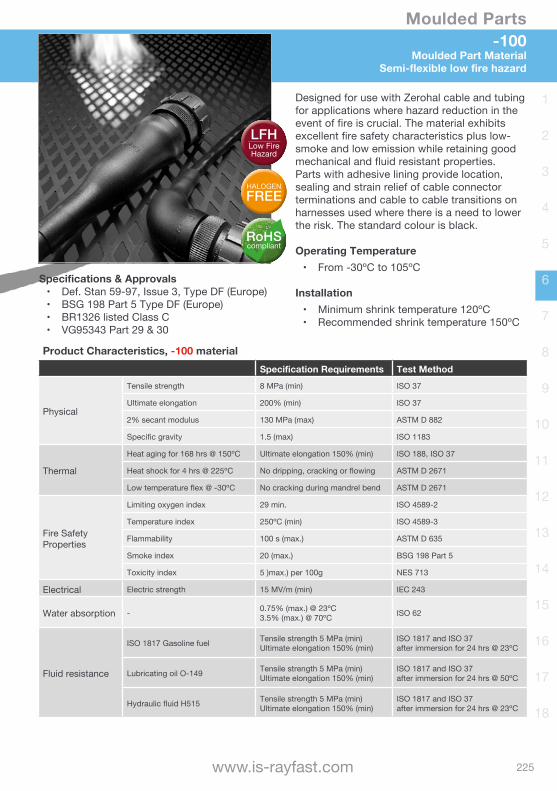
225
Moulded Parts
www.is-rayfast.com
1
2
3
4
5
6
7
8
9
10
11
12
13
14
15
16
17
18
Designed for use with Zerohal cable and tubing for applications where hazard reduction in the event of fire is crucial. The material exhibits excellent fire safety characteristics plus low-smoke and low emission while retaining good mechanical and fluid resistant properties. Parts with adhesive lining provide location, sealing and strain relief of cable connector terminations and cable to cable transitions on harnesses used where there is a need to lower the risk. The standard colour is black.
Operating Temperature• From -30ºC to 105ºC
Installation• Minimum shrink temperature 120ºC• Recommended shrink temperature 150ºC
Specifications & Approvals• Def. Stan 59-97, Issue 3, Type DF (Europe)• BSG 198 Part 5 Type DF (Europe)• BR1326 listed Class C• VG95343 Part 29 & 30
-100 Moulded Part Material
Semi-flexible low fire hazard
Product Characteristics, -100 materialSpecification Requirements Test Method
Physical
Tensile strength 8 MPa (min) ISO 37
Ultimate elongation 200% (min) ISO 37
2% secant modulus 130 MPa (max) ASTM D 882
Specific gravity 1.5 (max) ISO 1183
Thermal
Heat aging for 168 hrs @ 150ºC Ultimate elongation 150% (min) ISO 188, ISO 37
Heat shock for 4 hrs @ 225ºC No dripping, cracking or flowing ASTM D 2671
Low temperature flex @ -30ºC No cracking during mandrel bend ASTM D 2671
Fire Safety Properties
Limiting oxygen index 29 min. ISO 4589-2
Temperature index 250ºC (min) ISO 4589-3
Flammability 100 s (max.) ASTM D 635
Smoke index 20 (max.) BSG 198 Part 5
Toxicity index 5 )max.) per 100g NES 713
Electrical Electric strength 15 MV/m (min) IEC 243
Water absorption - 0.75% (max.) @ 23ºC3.5% (max.) @ 70ºC ISO 62
Fluid resistance
ISO 1817 Gasoline fuel Tensile strength 5 MPa (min)Ultimate elongation 150% (min)
ISO 1817 and ISO 37after immersion for 24 hrs @ 23ºC
Lubricating oil O-149 Tensile strength 5 MPa (min)Ultimate elongation 150% (min)
ISO 1817 and ISO 37after immersion for 24 hrs @ 50ºC
Hydraulic fluid H515 Tensile strength 5 MPa (min)Ultimate elongation 150% (min)
ISO 1817 and ISO 37after immersion for 24 hrs @ 23ºC
RoHScompliant
HALOGENFREE
LFHLow Fire Hazard

Wire and Cable Heat-shrink Tubing
Non-shrink TubingBraided SleevingScreening Braids
Moulded Parts Terminals and Splices
Wire and Cable MarkersAccessoriesConnectorsBackshells
Bonding LeadsMetal Braids
Relays and Contactors Switches and Grips
Adhesives and TapesApplication EquipmentAdded Value Services

228
Terminals and Splices
[email protected] | +44(0)1793 616700
1
2
3
4
5
6
7
8
9
10
11
12
13
14
15
16
17
18
Repeatable and Consistent Quality, Inspect-ability, Convenience and Speed. Lower Installed CostsTermination devices offer an inexpensive, single step, easy to use method of producing high quality wire splicing, solder crimp and sealing in one operation, strain relieving and coaxial shield terminations. A large range of products are available, providing solutions for commercial to harsh environment applications, through to the high performance demands of the Aerospace and Motorsport markets.
Wire to Wire SplicingIncluding single piece solder splice to crimp and heat shrink sleeve.
Terminals and DisconnectsDuraSeal® devices are simple and quick to install using a crimp tool and a heat source.
Wire Terminations to Pins, Posts and TabsOne step solutions for wire connections to pins, posts, tabs and mass wire terminations.
Braid / Shield TerminationScreen grounding terminators offer sealed, insulated and encapsulated solder connection.
Coaxial Cable terminationsCoaxial cable terminators for coaxial cable applications, including printed circuit boards.
Cable to Cable Splicing KitsSolderShield® wire splicing and shield continuity solutions in a heat-shrinkable insulation sleeve.
Shielded Connector ContactsSolderTact® controlled soldering contacts help speed installation and reduce installed costs.
Databus ComponentsMIL-STD-1553B for multiplexing needs.
INTRODUCTION
Wire to Wire
Terminals
Pin Post Tab
Shielded Termination + Splice
Contacts
Coaxial
PCB Coax

229
Terminals and Splices
www.is-rayfast.com
1
2
3
4
5
6
7
8
9
10
11
12
13
14
15
16
17
18
SELECTION GUIDE Reference chart page 230
Wire to Wire Splicing Overview page 231CWT, B-155, D-1744 Series Single piece solder splice page 232SGRS Series Self fixing solder end page 238D-406 Series DuraSeal® Heat shrinkable, crimp splice page 239D-436 Series MiniSeal® Heat shrinkable, crimp splice page 240D-436-Cold Series MiniSeal® Cold applied, crimp splice page 242D200 Series MiniSeal® Heat shrinkable, crimp splice 200ºC page 243
Terminals & Disconnects DuraSeal® and SolderGrip® page 245B-106 DuraSeal® Heat shrinkable, crimp terminals page 246SGRT SolderGrip® Self fixing, solder ring terminal page 250
Pin, Post & Tabs Termination SolderSleeve® page 251CWT, B155, D-1XX Series Heat shrinkable, solder pin, post & tab page 252
Shield Termination SolderSleeve® page 254CWT and S03 Series Commercial applications page 257B-150/1 and B-155 Series Harsh environment applications, B-155 is RoHS page 258ST18 and ST63 Series NAS 1747 approved page 259S01 and S02 Series M83519 Qualified, Thermo-chromic page 260S063 SAE-AS83519 Approved page 261S096 and S0175 Series, SAE-AS83519 Approved, High Temp, RoHS page 261S200, B023 Series SAE-AS83519 Approved, High Temp, RoHS page 262
Coaxial Cable Termination SolderSleeve® Coax Terminators page 263CWT, B-155 Series two part, 125ºC page 265B-02X, B-04X Series one part, 150ºC page 266D-181 Series two part, 150ºC page 267D-184 Series two part, 125ºC page 267D-607 & B-046 Series One piece PCB Terminators page 268
Shielded & Coaxial Splices SolderShield® Coax Splice page 270D-150 and B-202 Series Heat shrinkable, crimp splice with solder shield page 272
Shielded Contacts SolderTacts® Controlled Solder Contacts page 274D600 Series MIL-DTL-26482, page 275D600 Series MIL-DTL-28748 page 276D600 Series MIL-DTL-38999 page 277D600 Series Sub-miniature page 279
Databus Components MIL-STD-1553B D500 Series In-Line Micro-couplers page 280 Cables MIL-AS27500 page 281
CONTENTS

230
Terminals and Splices
[email protected] | +44(0)1793 616700
1
2
3
4
5
6
7
8
9
10
11
12
13
14
15
16
17
18
Application Type
ConductorMax
Temp. Product Description Part SeriesSo
lder
Crim
p
Coi
l
Wire to Wire Splicing
125ºC SolderSleeve wire splices CWT-9000 125ºC RoHS SolderSleeve wire splices B-155150ºC SolderSleeve wire splices D-1744 125ºC SolderGrip closed end connector SGRS 125ºC DuraSeal crimp splices D-406 155ºC MiniSeal crimp splices D-436 200ºC MiniSeal crimp splices D-200
Terminal Disconnects
125ºC DuraSeal crimp terminals & disconnects B-106 150ºC SolderGrip terminals SGRT
Pin, Post & Tab125ºC SolderSleeve wire terminators CWT 125ºC RoHS SolderSleeve wire terminators B-155150ºC SolderSleeve wire terminators D-129, D-141
Shield Termination
125ºC
SolderSleeve shield terminators CWT SolderSleeve shield terminators B-15x
RoHS SolderSleeve shield terminators B-155 NAS1747 SolderSleeve shield terminators ST18
150ºCNAS1747 SolderSleeve shield terminators ST63
SAE-AS83519 SolderSleeve shield terminators SO63M83519, SolderSleeve shield terminators S01, S02 & SO3
175ºCSolderSleeve shield terminators S096
SolderSleeve shield terminators - Bi-alloy SO175200ºC SolderSleeve shield terminators S200260ºC SolderSleeve shield terminators B-023
Coax Cable Termination
125ºCSolderSleeve coaxial cable terminators CWT
RoHS, SolderSleeve coaxial cable terminators B-155
150ºCSolderSleeve coaxial cable terminators B-02x & B-04xSolderSleeve coaxial cable terminators D-181SolderSleeve coaxial PCB terminators D-607 & B-046
Cable to Cable Splicing 150ºC
SolderShield cable splices - Multi-conductor D-150SolderShield cable splices - Coaxial D-150, B-202
Connector Contacts 150ºC
SolderTact for MIL-DTL-26482 D-602SolderTact for MIL-DTL-28748 D-602, D-610
SolderTact for MIL-DTL-38999 Series I, III, IV D-602, D-610SolderTact for MIL-DTL-38999 Series II D-602
SolderTact for Sub-miniature D-602Databus 200ºC Databus micro-couplers - MIL-STD-1553B D-500
Selection GuideOverview
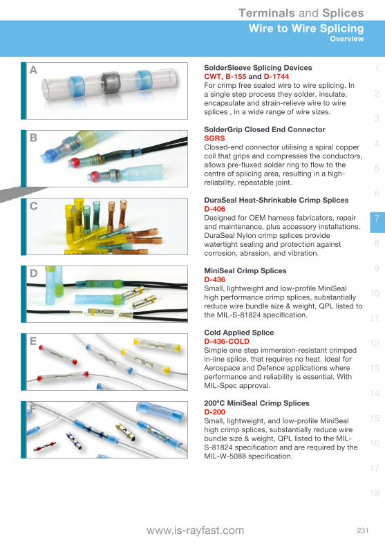
231
Terminals and Splices
www.is-rayfast.com
1
2
3
4
5
6
7
8
9
10
11
12
13
14
15
16
17
18
SolderSleeve Splicing DevicesCWT, B-155 and D-1744For crimp free sealed wire to wire splicing. In a single step process they solder, insulate, encapsulate and strain-relieve wire to wire splices , in a wide range of wire sizes.
SolderGrip Closed End ConnectorSGRSClosed-end connector utilising a spiral copper coil that grips and compresses the conductors, allows pre-fluxed solder ring to flow to the centre of splicing area, resulting in a high-reliability, repeatable joint.
DuraSeal Heat-Shrinkable Crimp Splices D-406Designed for OEM harness fabricators, repair and maintenance, plus accessory installations. DuraSeal Nylon crimp splices provide watertight sealing and protection against corrosion, abrasion, and vibration.
MiniSeal Crimp SplicesD-436Small, lightweight and low-profile MiniSeal high performance crimp splices, substantially reduce wire bundle size & weight, QPL listed to the MIL-S-81824 specification.
Cold Applied Splice D-436-COLDSimple one step immersion-resistant crimped in-line splice, that requires no heat. Ideal for Aerospace and Defence applications where performance and reliability is essential. With MIL-Spec approval.
200ºC MiniSeal Crimp SplicesD-200Small, lightweight, and low-profile MiniSeal high crimp splices, substantially reduce wire bundle size & weight, QPL listed to the MIL-S-81824 specification and are required by the MIL-W-5088 specification.
Wire to Wire SplicingOverview
A
A
B
C
D
E
F
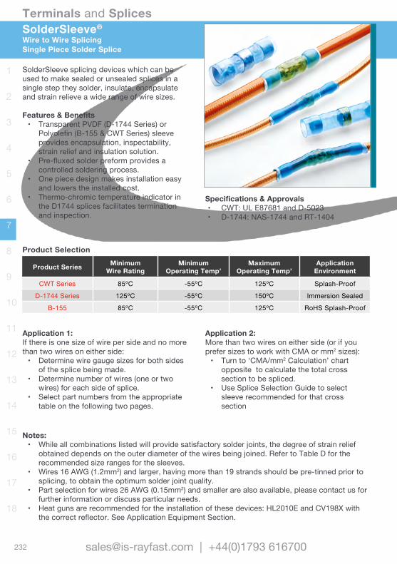
232
Terminals and Splices
[email protected] | +44(0)1793 616700
1
2
3
4
5
6
7
8
9
10
11
12
13
14
15
16
17
18
SolderSleeve splicing devices which can be used to make sealed or unsealed splices in a single step they solder, insulate, encapsulate and strain relieve a wide range of wire sizes.
Features & Benefits• Transparent PVDF (D-1744 Series) or
Polyolefin (B-155 & CWT Series) sleeve provides encapsulation, inspectability, strain relief and insulation solution.
• Pre-fluxed solder preform provides a controlled soldering process.
• One piece design makes installation easy and lowers the installed cost.
• Thermo-chromic temperature indicator in the D1744 splices facilitates termination and inspection.
Product Selection
Product Series MinimumWire Rating
Minimum Operating Temp’
Maximum Operating Temp’
ApplicationEnvironment
CWT Series 85ºC -55ºC 125ºC Splash-Proof
D-1744 Series 125ºC -55ºC 150ºC Immersion Sealed
B-155 85ºC -55ºC 125ºC RoHS Splash-Proof
SolderSleeve®
Wire to Wire SplicingSingle Piece Solder Splice
Specifications & Approvals• CWT: UL E87681 and D-5023• D-1744: NAS-1744 and RT-1404
Notes: • While all combinations listed will provide satisfactory solder joints, the degree of strain relief
obtained depends on the outer diameter of the wires being joined. Refer to Table D for the recommended size ranges for the sleeves.
• Wires 16 AWG (1.2mm2) and larger, having more than 19 strands should be pre-tinned prior to splicing, to obtain the optimum solder joint quality.
• Part selection for wires 26 AWG (0.15mm2) and smaller are also available, please contact us for further information or discuss particular needs.
• Heat guns are recommended for the installation of these devices: HL2010E and CV198X with the correct reflector. See Application Equipment Section.
Application 1: If there is one size of wire per side and no more than two wires on either side:• Determine wire gauge sizes for both sides
of the splice being made.• Determine number of wires (one or two
wires) for each side of splice.• Select part numbers from the appropriate
table on the following two pages.
Application 2: More than two wires on either side (or if you prefer sizes to work with CMA or mm2 sizes):• Turn to ‘CMA/mm2 Calculation’ chart
opposite to calculate the total cross section to be spliced.
• Use Splice Selection Guide to select sleeve recommended for that cross section
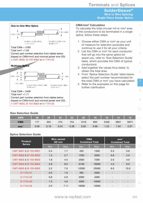
233
Terminals and Splices
www.is-rayfast.com
1
2
3
4
5
6
7
8
9
10
11
12
13
14
15
16
17
18
CMA/mm2 CalculationTo calculate the total circular mil or mm2 area of the conductors to be terminated in a single splice, follow these steps:
1 Choose either CMA or mm2 as your unit of measure for selection purposes and continue to use it for all your criteria.
2 List the CMA or mm2 for each conductor that will go into the same splice (to assist you, refer to ‘Size Selection Guide’ table, which provides the CMA of typical conductors).
3 Add together the values thus listed, to obtain the total area.
4 From ‘Splice Selection Guide’ table below, select the part number recommended for the total CMA or mm2 you have calculated.
5 Refer to the examples on this page for further clarification
One-to-One Wire Splice
Total CMA = 3180Total mm2 =1.59Correct part number selection from tables below (based on CMA/mm2 and nominal jacket wire OD) .= CWT-9002, B-155-9002 or D-1744-02
Multiwire Splice
Total CMA = 3408Total mm2 =1.71Correct part number selection from tables below (based on CMA/mm2 and nominal jacket wire OD) .= CWT-9003, B-155-9003 or D-1744-03
Splice Selection Guide
ProductSeries
Wire JacketOD mm
CMACombined Total
mm2
Combined Total
Min. Max. Min. Max. Min. Max.
CWT-9001 & B-155-9001 0.4 1.7 450 1500 0.3 0.8
CWT-9002 & B-155-9002 1.3 2.7 1250 3500 0.8 2.0
CWT-9003 & B-155-9003 1.8 4.5 2500 7200 2.0 4.0
CWT-9004 & B-155-9004 2.8 6.0 6100 19000 4.0 6.0
CWT-9005 & B-155-9005 3.2 7.0 12000 25000 6.0 10.0
D-1744-01 0.5 1.9 350 2000 - -
D-1744-02 0.8 2.8 2000 4000 - -
D-1744-03 1.3 4.6 4000 10000 - -
D-1744-04 2.0 7.11 10000 13000 - -
Size Selection GuideAWG 28 26 24 22 20 18 16 14 12
CMA 177 304 475 754 1216 900 2426 3831 5874
mm2 0.09 0.16 0.24 0.38 0.62 0.96 1.23 1.94 2.97
SolderSleeve®
Wire to Wire SplicingSingle Piece Solder Splice
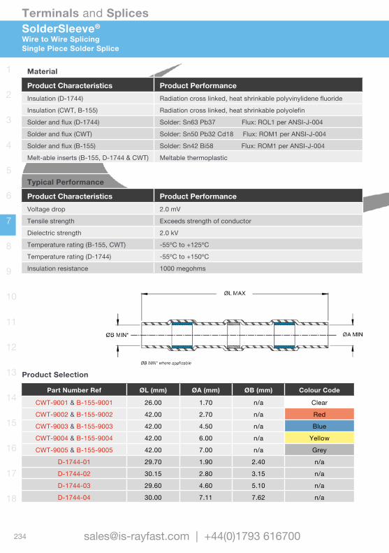
234
Terminals and Splices
[email protected] | +44(0)1793 616700
1
2
3
4
5
6
7
8
9
10
11
12
13
14
15
16
17
18
SolderSleeve®
Wire to Wire SplicingSingle Piece Solder Splice
Material
Product Characteristics Product PerformanceInsulation (D-1744) Radiation cross linked, heat shrinkable polyvinylidene fluoride
Insulation (CWT, B-155) Radiation cross linked, heat shrinkable polyolefin
Solder and flux (D-1744) Solder: Sn63 Pb37 Flux: ROL1 per ANSI-J-004
Solder and flux (CWT) Solder: Sn50 Pb32 Cd18 Flux: ROM1 per ANSI-J-004
Solder and flux (B-155) Solder: Sn42 Bi58 Flux: ROM1 per ANSI-J-004
Melt-able inserts (B-155, D-1744 & CWT) Meltable thermoplastic
Typical Performance
Product Characteristics Product PerformanceVoltage drop 2.0 mV
Tensile strength Exceeds strength of conductor
Dielectric strength 2.0 kV
Temperature rating (B-155, CWT) -55ºC to +125ºC
Temperature rating (D-1744) -55ºC to +150ºC
Insulation resistance 1000 megohms
Product Selection
Part Number Ref ØL (mm) ØA (mm) ØB (mm) Colour Code
CWT-9001 & B-155-9001 26.00 1.70 n/a Clear
CWT-9002 & B-155-9002 42.00 2.70 n/a Red
CWT-9003 & B-155-9003 42.00 4.50 n/a Blue
CWT-9004 & B-155-9004 42.00 6.00 n/a Yellow
CWT-9005 & B-155-9005 42.00 7.00 n/a Grey
D-1744-01 29.70 1.90 2.40 n/a
D-1744-02 30.15 2.80 3.15 n/a
D-1744-03 29.60 4.60 5.10 n/a
D-1744-04 30.00 7.11 7.62 n/a
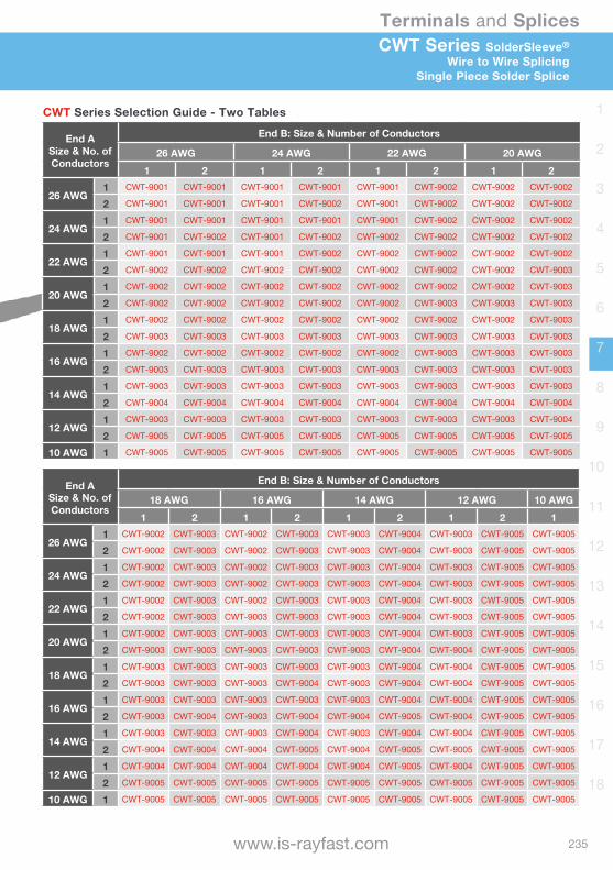
235
Terminals and Splices
www.is-rayfast.com
1
2
3
4
5
6
7
8
9
10
11
12
13
14
15
16
17
18
CWT Series SolderSleeve®
Wire to Wire SplicingSingle Piece Solder Splice
CWT Series Selection Guide - Two Tables
End A Size & No. of Conductors
End B: Size & Number of Conductors
26 AWG 24 AWG 22 AWG 20 AWG1 2 1 2 1 2 1 2
26 AWG1 CWT-9001 CWT-9001 CWT-9001 CWT-9001 CWT-9001 CWT-9002 CWT-9002 CWT-9002
2 CWT-9001 CWT-9001 CWT-9001 CWT-9002 CWT-9001 CWT-9002 CWT-9002 CWT-9002
24 AWG1 CWT-9001 CWT-9001 CWT-9001 CWT-9001 CWT-9001 CWT-9002 CWT-9002 CWT-9002
2 CWT-9001 CWT-9002 CWT-9001 CWT-9002 CWT-9002 CWT-9002 CWT-9002 CWT-9002
22 AWG1 CWT-9001 CWT-9001 CWT-9001 CWT-9002 CWT-9002 CWT-9002 CWT-9002 CWT-9002
2 CWT-9002 CWT-9002 CWT-9002 CWT-9002 CWT-9002 CWT-9002 CWT-9002 CWT-9003
20 AWG1 CWT-9002 CWT-9002 CWT-9002 CWT-9002 CWT-9002 CWT-9002 CWT-9002 CWT-9003
2 CWT-9002 CWT-9002 CWT-9002 CWT-9002 CWT-9002 CWT-9003 CWT-9003 CWT-9003
18 AWG1 CWT-9002 CWT-9002 CWT-9002 CWT-9002 CWT-9002 CWT-9002 CWT-9002 CWT-9003
2 CWT-9003 CWT-9003 CWT-9003 CWT-9003 CWT-9003 CWT-9003 CWT-9003 CWT-9003
16 AWG1 CWT-9002 CWT-9002 CWT-9002 CWT-9002 CWT-9002 CWT-9003 CWT-9003 CWT-9003
2 CWT-9003 CWT-9003 CWT-9003 CWT-9003 CWT-9003 CWT-9003 CWT-9003 CWT-9003
14 AWG1 CWT-9003 CWT-9003 CWT-9003 CWT-9003 CWT-9003 CWT-9003 CWT-9003 CWT-9003
2 CWT-9004 CWT-9004 CWT-9004 CWT-9004 CWT-9004 CWT-9004 CWT-9004 CWT-9004
12 AWG1 CWT-9003 CWT-9003 CWT-9003 CWT-9003 CWT-9003 CWT-9003 CWT-9003 CWT-9004
2 CWT-9005 CWT-9005 CWT-9005 CWT-9005 CWT-9005 CWT-9005 CWT-9005 CWT-9005
10 AWG 1 CWT-9005 CWT-9005 CWT-9005 CWT-9005 CWT-9005 CWT-9005 CWT-9005 CWT-9005
End A Size & No. of Conductors
End B: Size & Number of Conductors
18 AWG 16 AWG 14 AWG 12 AWG 10 AWG1 2 1 2 1 2 1 2 1
26 AWG1 CWT-9002 CWT-9003 CWT-9002 CWT-9003 CWT-9003 CWT-9004 CWT-9003 CWT-9005 CWT-9005
2 CWT-9002 CWT-9003 CWT-9002 CWT-9003 CWT-9003 CWT-9004 CWT-9003 CWT-9005 CWT-9005
24 AWG1 CWT-9002 CWT-9003 CWT-9002 CWT-9003 CWT-9003 CWT-9004 CWT-9003 CWT-9005 CWT-9005
2 CWT-9002 CWT-9003 CWT-9002 CWT-9003 CWT-9003 CWT-9004 CWT-9003 CWT-9005 CWT-9005
22 AWG1 CWT-9002 CWT-9003 CWT-9002 CWT-9003 CWT-9003 CWT-9004 CWT-9003 CWT-9005 CWT-9005
2 CWT-9002 CWT-9003 CWT-9003 CWT-9003 CWT-9003 CWT-9004 CWT-9003 CWT-9005 CWT-9005
20 AWG1 CWT-9002 CWT-9003 CWT-9003 CWT-9003 CWT-9003 CWT-9004 CWT-9003 CWT-9005 CWT-9005
2 CWT-9003 CWT-9003 CWT-9003 CWT-9003 CWT-9003 CWT-9004 CWT-9004 CWT-9005 CWT-9005
18 AWG1 CWT-9003 CWT-9003 CWT-9003 CWT-9003 CWT-9003 CWT-9004 CWT-9004 CWT-9005 CWT-9005
2 CWT-9003 CWT-9003 CWT-9003 CWT-9004 CWT-9003 CWT-9004 CWT-9004 CWT-9005 CWT-9005
16 AWG1 CWT-9003 CWT-9003 CWT-9003 CWT-9003 CWT-9003 CWT-9004 CWT-9004 CWT-9005 CWT-9005
2 CWT-9003 CWT-9004 CWT-9003 CWT-9004 CWT-9004 CWT-9005 CWT-9004 CWT-9005 CWT-9005
14 AWG1 CWT-9003 CWT-9003 CWT-9003 CWT-9004 CWT-9003 CWT-9004 CWT-9004 CWT-9005 CWT-9005
2 CWT-9004 CWT-9004 CWT-9004 CWT-9005 CWT-9004 CWT-9005 CWT-9005 CWT-9005 CWT-9005
12 AWG1 CWT-9004 CWT-9004 CWT-9004 CWT-9004 CWT-9004 CWT-9005 CWT-9004 CWT-9005 CWT-9005
2 CWT-9005 CWT-9005 CWT-9005 CWT-9005 CWT-9005 CWT-9005 CWT-9005 CWT-9005 CWT-9005
10 AWG 1 CWT-9005 CWT-9005 CWT-9005 CWT-9005 CWT-9005 CWT-9005 CWT-9005 CWT-9005 CWT-9005
Typical Performance
Product Characteristics Product PerformanceVoltage drop 2.0 mV
Tensile strength Exceeds strength of conductor
Dielectric strength 2.0 kV
Temperature rating (B-155, CWT) -55ºC to +125ºC
Temperature rating (D-1744) -55ºC to +150ºC
Insulation resistance 1000 megohms

236
Terminals and Splices
[email protected] | +44(0)1793 616700
1
2
3
4
5
6
7
8
9
10
11
12
13
14
15
16
17
18
B-155 Series SolderSleeve®
RoHS Wire to Wire SplicingSingle Piece Solder Splice
B-155 Series Selection Guide
End A Size & No. of Conductors
End B: Size & Number of Conductors
26 AWG 24 AWG 22 AWG 20 AWG
1 2 1 2 1 2 1 2
26 AWG1 B-155-9001 B-155-9001 B-155-9001 B-155-9001 B-155-9001 B-155-9002 B-155-9002 B-155-9002
2 B-155-9001 B-155-9001 B-155-9001 B-155-9002 B-155-9001 B-155-9002 B-155-9002 B-155-9002
24 AWG1 B-155-9001 B-155-9001 B-155-9001 B-155-9001 B-155-9001 B-155-9002 B-155-9002 B-155-9002
2 B-155-9001 B-155-9002 B-155-9001 B-155-9002 B-155-9002 B-155-9002 B-155-9002 B-155-9002
22 AWG1 B-155-9001 B-155-9001 B-155-9001 B-155-9002 B-155-9002 B-155-9002 B-155-9002 B-155-9002
2 B-155-9002 B-155-9002 B-155-9002 B-155-9002 B-155-9002 B-155-9002 B-155-9002 B-155-9003
20 AWG1 B-155-9002 B-155-9002 B-155-9002 B-155-9002 B-155-9002 B-155-9002 B-155-9002 B-155-9003
2 B-155-9002 B-155-9002 B-155-9002 B-155-9002 B-155-9002 B-155-9003 B-155-9003 B-155-9003
18 AWG1 B-155-9002 B-155-9002 B-155-9002 B-155-9002 B-155-9002 B-155-9002 B-155-9002 B-155-9003
2 B-155-9003 B-155-9003 B-155-9003 B-155-9003 B-155-9003 B-155-9003 B-155-9003 B-155-9003
16 AWG1 B-155-9002 B-155-9002 B-155-9002 B-155-9002 B-155-9002 B-155-9003 B-155-9003 B-155-9003
2 B-155-9003 B-155-9003 B-155-9003 B-155-9003 B-155-9003 B-155-9003 B-155-9003 B-155-9003
14 AWG1 B-155-9003 B-155-9003 B-155-9003 B-155-9003 B-155-9003 B-155-9003 B-155-9003 B-155-9003
2 B-155-9004 B-155-9004 B-155-9004 B-155-9004 B-155-9004 B-155-9004 B-155-9004 B-155-9004
12 AWG1 B-155-9003 B-155-9003 B-155-9003 B-155-9003 B-155-9003 B-155-9003 B-155-9003 B-155-9004
2 B-155-9005 B-155-9005 B-155-9005 B-155-9005 B-155-9005 B-155-9005 B-155-9005 B-155-9005
10 AWG 1 B-155-9005 B-155-9005 B-155-9005 B-155-9005 B-155-9005 B-155-9005 B-155-9005 B-155-9005
End A Size & No. of Conductors
End B: Size & Number of Conductors
18 AWG 16 AWG 14 AWG 12 AWG 10 AWG
1 2 1 2 1 2 1 2 1
26 AWG1 B-155-9002 B-155-9003 B-155-9002 B-155-9003 B-155-9003 B-155-9004 B-155-9003 B-155-9005 B-155-9005
2 B-155-9002 B-155-9003 B-155-9002 B-155-9003 B-155-9003 B-155-9004 B-155-9003 B-155-9005 B-155-9005
24 AWG1 B-155-9002 B-155-9003 B-155-9002 B-155-9003 B-155-9003 B-155-9004 B-155-9003 B-155-9005 B-155-9005
2 B-155-9002 B-155-9003 B-155-9002 B-155-9003 B-155-9003 B-155-9004 B-155-9003 B-155-9005 B-155-9005
22 AWG1 B-155-9002 B-155-9003 B-155-9002 B-155-9003 B-155-9003 B-155-9004 B-155-9003 B-155-9005 B-155-9005
2 B-155-9002 B-155-9003 B-155-9002 B-155-9003 B-155-9003 B-155-9004 B-155-9003 B-155-9005 B-155-9005
20 AWG1 B-155-9002 B-155-9003 B-155-9003 B-155-9003 B-155-9003 B-155-9004 B-155-9003 B-155-9005 B-155-9005
2 B-155-9003 B-155-9003 B-155-9003 B-155-9003 B-155-9003 B-155-9004 B-155-9004 B-155-9005 B-155-9005
18 AWG1 B-155-9003 B-155-9003 B-155-9003 B-155-9003 B-155-9003 B-155-9004 B-155-9004 B-155-9005 B-155-9005
2 B-155-9003 B-155-9003 B-155-9003 B-155-9004 B-155-9003 B-155-9004 B-155-9004 B-155-9005 B-155-9005
16 AWG1 B-155-9003 B-155-9003 B-155-9003 B-155-9003 B-155-9003 B-155-9004 B-155-9004 B-155-9005 B-155-9005
2 B-155-9003 B-155-9003 B-155-9003 B-155-9004 B-155-9004 B-155-9005 B-155-9004 B-155-9005 B-155-9005
14 AWG1 B-155-9003 B-155-9003 B-155-9003 B-155-9004 B-155-9003 B-155-9005 B-155-9004 B-155-9005 B-155-9005
2 B-155-9004 B-155-9004 B-155-9004 B-155-9005 B-155-9004 B-155-9005 B-155-9005 B-155-9005 B-155-9005
12 AWG1 B-155-9004 B-155-9004 B-155-9004 B-155-9004 B-155-9004 B-155-9005 B-155-9004 B-155-9005 B-155-9005
2 B-155-9005 B-155-9005 B-155-9005 B-155-9005 B-155-9005 B-155-9005 B-155-9005 B-155-9005 B-155-9005
10 AWG 1 B-155-9005 B-155-9005 B-155-9005 B-155-9005 B-155-9005 B-155-9005 B-155-9005 B-155-9005 B-155-9005
RoHScompliant
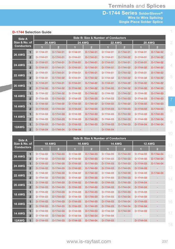
237
Terminals and Splices
www.is-rayfast.com
1
2
3
4
5
6
7
8
9
10
11
12
13
14
15
16
17
18
D-1744 Series SolderSleeve®
Wire to Wire SplicingSingle Piece Solder Splice
D-1744 Selection Guide
Side A Size & No. of Conductors
Side B: Size & Number of Conductors26 AWG 24 AWG 22 AWG 20 AWG
1 2 1 2 1 2 1 2
26 AWG1 D-1744-01 D-1744-01 D-1744-01 D-1744-01 D-1744-01 D-1744-01 D-1744-01 D-1744-02
2 D-1744-01 D-1744-01 D-1744-01 D-1744-01 D-1744-01 D-1744-02 D-1744-01 D-1744-02
24 AWG1 D-1744-01 D-1744-01 D-1744-01 D-1744-01 D-1744-01 D-1744-01 D-1744-01 D-1744-02
2 D-1744-01 D-1744-01 D-1744-01 D-1744-01 D-1744-01 D-1744-02 D-1744-02 D-1744-02
22 AWG1 D-1744-01 D-1744-01 D-1744-01 D-1744-01 D-1744-01 D-1744-02 D-1744-01 D-1744-02
2 D-1744-01 D-1744-02 D-1744-01 D-1744-02 D-1744-02 D-1744-02 D-1744-02 D-1744-02
20 AWG1 D-1744-01 D-1744-01 D-1744-01 D-1744-02 D-1744-01 D-1744-02 D-1744-02 D-1744-02
2 D-1744-02 D-1744-02 D-1744-02 D-1744-02 D-1744-02 D-1744-02 D-1744-02 D-1744-03
18 AWG1 D-1744-02 D-1744-02 D-1744-02 D-1744-02 D-1744-02 D-1744-02 D-1744-02 D-1744-03
2 D-1744-03 D-1744-03 D-1744-03 D-1744-03 D-1744-03 D-1744-03 D-1744-03 D-1744-03
16 AWG1 D-1744-02 D-1744-02 D-1744-02 D-1744-02 D-1744-02 D-1744-02 D-1744-02 D-1744-03
2 D-1744-03 D-1744-03 D-1744-03 D-1744-03 D-1744-03 D-1744-03 D-1744-03 D-1744-03
14 AWG1 D-1744-03 D-1744-03 D-1744-03 D-1744-03 D-1744-03 D-1744-03 D-1744-03 D-1744-03
2 D-1744-03 D-1744-03 D-1744-03 D-1744-03 D-1744-03 D-1744-03 D-1744-03 D-1744-04
12AWG1 D-1744-03 D-1744-03 D-1744-03 D-1744-03 D-1744-03 D-1744-03 D-1744-04 D-1744-04
2 D-1744-04 D-1744-04 D-1744-04 - D-1744-04 - - -
Side A Size & No. of Conductors
Side B: Size & Number of Conductors
18 AWG 16 AWG 14 AWG 12 AWG
1 2 1 2 1 2 1 2
26 AWG1 D-1744-02 D-1744-03 D-1744-02 D-1744-03 D-1744-03 D-1744-03 D-1744-03 D-1744-04
2 D-1744-02 D-1744-03 D-1744-02 D-1744-03 D-1744-03 D-1744-03 D-1744-03 D-1744-04
24 AWG1 D-1744-02 D-1744-03 D-1744-02 D-1744-03 D-1744-03 D-1744-03 D-1744-03 D-1744-04
2 D-1744-02 D-1744-03 D-1744-02 D-1744-03 D-1744-03 D-1744-03 D-1744-03 -
22 AWG1 D-1744-02 D-1744-03 D-1744-02 D-1744-03 D-1744-03 D-1744-03 D-1744-03 D-1744-04
2 D-1744-02 D-1744-03 D-1744-02 D-1744-03 D-1744-03 D-1744-03 D-1744-03 -
20 AWG1 D-1744-02 D-1744-03 D-1744-02 D-1744-03 D-1744-03 D-1744-03 D-1744-04 -
2 D-1744-03 D-1744-03 D-1744-03 D-1744-03 D-1744-03 D-1744-04 D-1744-04 -
18 AWG1 D-1744-02 D-1744-03 D-1744-03 D-1744-03 D-1744-03 D-1744-03 D-1744-03 -
2 D-1744-03 D-1744-03 D-1744-03 D-1744-03 D-1744-03 D-1744-04 D-1744-03 -
16 AWG1 D-1744-03 D-1744-03 D-1744-03 D-1744-03 D-1744-03 D-1744-04 D-1744-03 -
2 D-1744-03 D-1744-03 D-1744-03 D-1744-03 D-1744-03 D-1744-04 D-1744-04 -
14 AWG1 D-1744-03 D-1744-03 D-1744-03 D-1744-03 D-1744-03 D-1744-04 D-1744-03 -
2 D-1744-03 D-1744-04 D-1744-04 D-1744-04 D-1744-04 - - -
12AWG 1 D-1744-03 D-1744-03 D-1744-03 D-1744-04 D-1744-03 - D-1744-04 -

238
Terminals and Splices
[email protected] | +44(0)1793 616700
1
2
3
4
5
6
7
8
9
10
11
12
13
14
15
16
17
18
Features & Benefits• PVDF insulation sleeve provides
encapsulation, inspectability & strain relief.• Spiral copper coil grips and compresses
the conductors for the optimum solder connection.
• Pre-fluxed solder preform provides a controlled soldering process.
• The SGRS series has an adhesive insert to provide immersion sealing performance.
• One piece design.• Accommodates a wide variety of
conductor types, quantities and sizes.• Colour coded for easy identification.
Solder & Flux Characteristics• Sn60 Pb40 with ROM 1flux per
ANSI-J-STD-004
Part Number Wire Range mm2 (CMA)
Max. CurrentRating Length Colour Code
SGRS-1 0.7 - 2.4 (1400 - 4800) 17 Amps 34.8mm Green
SGRS-2 2.0 - 4.0 (4000 - 8000) 28 Amps 34.2mm Red
SGRS-3 3.5 - 8.0 (7000 - 16000) 56 Amps 42.0mm Blue
SGRS-4 7.5 - 12.0 (15000 - 24000) 84 Amps 41.5mm Yellow
SGRS Closed End ConnectorSolderGrip®
Self Fixing Solder End
Specifications & Approvals• UL CUL E87681• RB-109
Notes: • To calculate mm2 or CMA refer to page earlier in this section• Heat guns are recommended for the installation of these devices: HL2010E and CV198X with the correct
reflector added. See Application Equipment Section.
Product Characteristics Product PerformanceVoltage drop <2.0mV
Tensile strength Exceeds strength of individual conductors
Dielectric strength 2.0kV
Temperature rating -55ºC to +125ºC
Insulation resistance after immersion 100 megaohms
Insulation performance 300 mbar (for specific combinations refer to RB-109)
Voltage rating 600V
This product is also available as ‘Ring Terminals’, please see SGRT later in this section.
L
Sealing insert
ØA
B
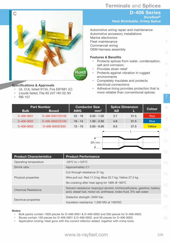
239
Terminals and Splices
www.is-rayfast.com
1
2
3
4
5
6
7
8
9
10
11
12
13
14
15
16
17
18
D-406 SeriesDuraSeal®
Heat Shrinkable, Crimp Splice
Automotive wiring repair and maintenanceAutomotive accessory installationsMarine electronicsFleet maintenanceCommercial wiringOEM Harness assembly
Features & Benefits• Protects splices from water, condensation,
salt and corrosion.• Provides strain relief• Protects against vibration in rugged
environments• Completely insulates and protects
electrical connections• Adhesive lining provides protection that is
more reliable than conventional splices.
Specifications & Approvals• UL CUL listed 9134, Fire E87681 (C)• Lloyds listed, File 65 247 HH 02-93• RB-107
Part NumberBulk Boxed
Conductor SizeAWG mm2
Splice DimensionAØ L Colour
D-406-0001 D-406-0001CS100 22 - 18 0.50 - 1.00 3.7 31.5 Red
D-406-0002 D-406-0002CS100 16 - 14 1.50 - 2.50 4.6 31.5 Blue
D-406-0003 D-406-0003CS50 12 - 10 3.00 - 6.00 6.5 37.5 Yellow
Notes: • Bulk packs contain 1000 pieces for D-406-0001 & D-406-0002 and 500 pieces for D-406-0003.• Boxes contain 100 pieces for D-406-0001 & D-406-0002, and 50 pieces for D-406-0003.• Application tooling: Heat guns with the correct reflector added, together with crimp tools.
Product Characteristics Product PerformanceOperating temperature -55ºC to +125ºC
Shrink ratio Approximately 2:1
Physical properties
Cut through resistance 31 kg
Wire pull out Red 11.3 kg; Blue 22.7 kg; Yellow 27.2 kg
No cracking after heat aging for 168h @ 160ºC
Chemical Resistance Solvent resistance: Isopropyl alcohol, trichloroethylene, gasoline, battery acid, diesel fuel, motor oil, antifreeze, brake fluid, 5% salt water
Electrical propertiesDielectric strength: 2500 Vac
Insulationresistance:1,000MΩat100VDC
ØA min.
L
C
RoHScompliant
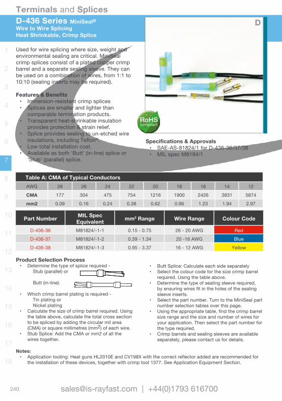
240
Terminals and Splices
[email protected] | +44(0)1793 616700
1
2
3
4
5
6
7
8
9
10
11
12
13
14
15
16
17
18
D-436 Series MiniSeal®Wire to Wire SplicingHeat Shrinkable, Crimp Splice
Used for wire splicing where size, weight and environmental sealing are critical. MiniSeal crimp splices consist of a plated copper crimp barrel and a separate sealing sleeve. They can be used on a combination of wires, from 1:1 to 10:10 (sealing inserts may be required).
Features & Benefits• Immersion-resistant crimp splices• Splices are smaller and lighter than
comparable termination products.• Transparent heat-shrinkable insulation
provides protection & strain relief.• Splice provides sealing to un-etched wire
insulations, including Teflon®.• Low total installation cost.• Available as both ‘Butt’ (in-line) splice or
‘Stub’ (parallel) splice.
Specifications & Approvals• SAE-AS-81824/1 for D-436-36/37/38• MIL spec M8184/1
Notes: • Application tooling: Heat guns HL2010E and CV198X with the correct reflector added are recommended for
the installation of these devices, together with crimp tool 1377. See Application Equipment Section.
Part Number MIL SpecEquivalent mm2 Range Wire Range Colour Code
D-436-36 M81824/-1-1 0.15 - 0.75 26 - 20 AWG Red
D-436-37 M81824/-1-2 0.39 - 1.34 20 -16 AWG Blue
D-436-38 M81824/-1-3 0.95 - 3.37 16 - 12 AWG Yellow
Table A: CMA of Typical ConductorsAWG 28 26 24 22 20 18 16 14 12
CMA 177 304 475 754 1216 1900 2426 3831 5874
mm2 0.09 0.16 0.24 0.38 0.62 0.96 1.23 1.94 2.97
• Butt Splice: Calculate each side separately• Select the colour code for the size crimp barrel
required. Using the table above.• Determine the type of sealing sleeve required,
by ensuring wires fit in the holes of the sealing sleeve inserts.
• Select the part number. Turn to the MiniSeal part number selection tables over this page.
• Using the appropriate table, find the crimp barrel size range and the size and number of wires for your application. Then select the part number for the type required.
• Crimp barrels and sealing sleeves are available separately, please contact us for details.
Product Selection Process• Determine the type of splice required -
Stub (parallel) or
Butt (in-line).
• Which crimp barrel plating is required - Tin plating or Nickel plating• Calculate the size of crimp barrel required. Using
the table above, calculate the total cross section to be spliced by adding the circular mil area (CMA) or square millimetres (mm2) of each wire.
• Stub Splice: Add the CMA or mm2 of all the wires together.
D
RoHScompliant

241
Terminals and Splices
www.is-rayfast.com
1
2
3
4
5
6
7
8
9
10
11
12
13
14
15
16
17
18
Part Number MIL SpecEquivalent mm2 Range Wire Range Colour Code
D-436-36 M81824/-1-1 0.15 - 0.75 26 - 20 AWG Red
D-436-37 M81824/-1-2 0.39 - 1.34 20 -16 AWG Blue
D-436-38 M81824/-1-3 0.95 - 3.37 16 - 12 AWG Yellow
D-436 SeriesMiniSeal®
Heat Shrinkable, Crimp Splice
Product Characteristics Product PerformanceInsulation Radiation crosslinked, heat-shrinkable polyvinylidene fluoride
Operating temperature -55ºC to +150ºC
Dielectric strength 2500 V Max
Insulation resistance after immersion 5000 Mega-ohms
Voltage drop 6.9 mV @ 4.5A vs 8.1 mV for an equal length of wire
Physical properties Tensile strength exceeds strength of spliced wire
Notes: • The correct crimp tool AD-1377, must be used for proper installation of these devices.• Heat guns are recommended for the installation of these devices: HL2010E and CV198X with the correct
reflector added. See Application Equipment Section.
STUB (parallel) Splice - Selection Guide
Part Number Colour Crimp BarrelSize Range
Internal Ø Dimensions
End 1 End 2
Tin Plated Nickel Plated CMA mm2 Sealing Insert
Max. No. Wires
Sealing Insert mm
Max. No. Wires
D-436-0128 D-436-0119 Red 304-1510 0.15-0.75 2.16 2 1.01 2D-436-58 D-436-75 Blue 1058-2680 0.39-1.34 4.56 2 2.28 2D-436-59 D-436-76 Yellow 2375-6755 0.95-3.37 4.56 2 2.28 2D-436-60 D-436-77 Blue 1058-2680 0.39-1.34 2.03 10* 6.35 2D-436-61 D-436-78 Yellow 2375-6755 0.95-3.37 2.03 10* 6.35 2
* Denotes max 2 wires per hole of insert
BUTT (in-line) Splice - Selection Guide
Part Number Colour Crimp BarrelSize Range
Internal Dimensions
End 1 End 2
Tin Plated Nickel Plated CMA mm2 Sealing Insert mm
Max. No. Wires
Sealing Insert mm
Max. No. Wires
D-436-36 D-436-82 Red 304-1510 0.15-0.75 2.16 Ø 2 2.16 Ø 2D-436-37 D-436-83 Blue 1058-2680 0.39-1.34 2.79 Ø 2 2.79 Ø 2D-436-38 D-436-84 Yellow 2375-6755 0.95-3.37 4.32 Ø 2 4.32 Ø 2
D-436-0110 D-436-85 Red 304-1510 0.15-0.75 2.36 Ø 6* 4.06 Ø 2D-436-52 D-436-86 Blue 1058-2680 0.39-1.34 2.36 Ø 6* 4.06 Ø 2D-436-53 D-436-87 Yellow 2375-6755 0.95-3.37 2.36 Ø 6* 4.06 Ø 2
D-436-0115 D-436-88 Red 304-1510 0.15-0.75 2.36 Ø 6* 2.36 Ø 6*D-436-42 D-436-89 Blue 1058-2680 0.39-1.34 2.36 Ø 6* 2.36 Ø 6*D-436-43 D-436-90 Yellow 2375-6755 0.95-3.37 2.36 Ø 6* 2.36 Ø 6*
* Denotes max 2 wires per hole of insert
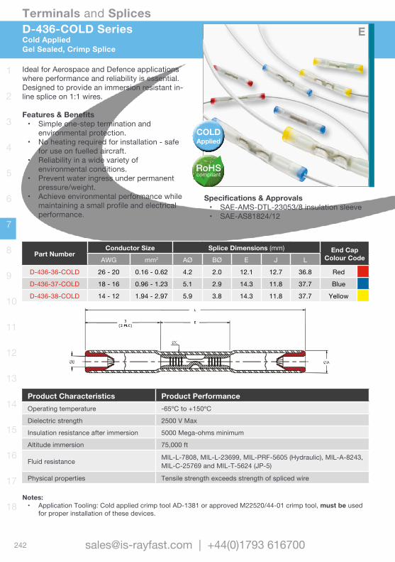
242
Terminals and Splices
[email protected] | +44(0)1793 616700
1
2
3
4
5
6
7
8
9
10
11
12
13
14
15
16
17
18
Ideal for Aerospace and Defence applications where performance and reliability is essential. Designed to provide an immersion resistant in-line splice on 1:1 wires.
Features & Benefits• Simple one-step termination and
environmental protection.• No heating required for installation - safe
for use on fuelled aircraft.• Reliability in a wide variety of
environmental conditions.• Prevent water ingress under permanent
pressure/weight.• Achieve environmental performance while
maintaining a small profile and electrical performance.
D-436-COLD SeriesCold AppliedGel Sealed, Crimp Splice
Specifications & Approvals• SAE-AMS-DTL-23053/8 insulation sleeve• SAE-AS81824/12
Notes: • Application Tooling: Cold applied crimp tool AD-1381 or approved M22520/44-01 crimp tool, must be used
for proper installation of these devices.
Product Characteristics Product PerformanceOperating temperature -65ºC to +150ºC
Dielectric strength 2500 V Max
Insulation resistance after immersion 5000 Mega-ohms minimum
Altitude immersion 75,000 ft
Fluid resistance MIL-L-7808, MIL-L-23699, MIL-PRF-5605 (Hydraulic), MIL-A-8243, MIL-C-25769 and MIL-T-5624 (JP-5)
Physical properties Tensile strength exceeds strength of spliced wire
Part NumberConductor Size Splice Dimensions (mm) End Cap
Colour CodeAWG mm2 AØ BØ E J L
D-436-36-COLD 26 - 20 0.16 - 0.62 4.2 2.0 12.1 12.7 36.8 Red
D-436-37-COLD 18 - 16 0.96 - 1.23 5.1 2.9 14.3 11.8 37.7 Blue
D-436-38-COLD 14 - 12 1.94 - 2.97 5.9 3.8 14.3 11.8 37.7 Yellow
E
COLDApplied
RoHScompliant

243
Terminals and Splices
www.is-rayfast.com
1
2
3
4
5
6
7
8
9
10
11
12
13
14
15
16
17
18
D-200 Series200ºC MiniSeal®
Heat Shrinkable, Crimp Splice
Immersion resistant in-line nickel plated sealed crimp splices for 200ºC applications. Developed for the growing needs of high temperature applications in the aerospace and defence industry. Provides a small and light, environmental-resistant splice, while meeting SAE-AS81824/1Provides immersion resistant in-line splice on 1:1 wires for 26 AWG to 12AWG; nickel-plated conductors.
Features & Benefits• Immersion-resistant crimp splices• Small size and lightweight• Provides sealing to unetched wire
insulations.• No need to stagger wire splices.
Specifications & Approvals• SAE-AS-81824/1 (modified for 200ºC
applications with heat ageing and thermal shock test temperature of 200ºC).
Part Number MIL Spec Equivalent
Conductor Size Insulation Sleeve ID Ø ColourCodeAWG mm2 Supplied Recovered
D-200-82 AS81824/1-1 26 - 20 0.16 - 0.62 2.16 0.64 Red
D-200-83 AS81824/1-2 20 - 16 0.62 - 1.23 2.79 0.64 Blue
D-200-84 AS81824/1-3 16 - 12 1.23 - 2.97 4.32 0.64 Yellow
Notes: • The correct crimp tool AD-1377, must be used for proper installation of these devices.• Heat guns are recommended for the installation of these devices: HL2010E and CV198X with the correct
reflector added. See Application Equipment Section.
Product Characteristics Product PerformanceInsulation Radiation crosslinked, heat-shrinkable modified fluoropolymerOperating temperature -55ºC to +200ºCDielectric strength 2500 V MaxInsulation resistance after immersion 5000 Mega-ohmsVoltage drop 6.9 mV @ 4.5A vs 8.1 mV for an equal length of wirePhysical properties Tensile strength exceeds strength of spliced wire
ID
27.94±1.27
24.13 MIN
COLOR CODE
C
D x 2
ØB ØA
WIRE STOP
E MAX
MARKING ID
COLOR CODE
(SEE NOTE ON PAGE 2)
Product Characteristics Product PerformanceOperating temperature -65ºC to +150ºC
Dielectric strength 2500 V Max
Insulation resistance after immersion 5000 Mega-ohms minimum
Altitude immersion 75,000 ft
Fluid resistance MIL-L-7808, MIL-L-23699, MIL-PRF-5605 (Hydraulic), MIL-A-8243, MIL-C-25769 and MIL-T-5624 (JP-5)
Physical properties Tensile strength exceeds strength of spliced wire
Part NumberConductor Size Splice Dimensions (mm) End Cap
Colour CodeAWG mm2 AØ BØ E J L
D-436-36-COLD 26 - 20 0.16 - 0.62 4.2 2.0 12.1 12.7 36.8 Red
D-436-37-COLD 18 - 16 0.96 - 1.23 5.1 2.9 14.3 11.8 37.7 Blue
D-436-38-COLD 14 - 12 1.94 - 2.97 5.9 3.8 14.3 11.8 37.7 Yellow
F
RoHScompliant

244
Terminals and Splices
[email protected] | +44(0)1793 616700
1
2
3
4
5
6
7
8
9
10
11
12
13
14
15
16
17
18

245
Terminals and Splices
www.is-rayfast.com
1
2
3
4
5
6
7
8
9
10
11
12
13
14
15
16
17
18
Terminals and Disconnects
DuraSeal Heat Shrinkable Nylon CrimpsB-106 SeriesDuraSeal terminals and disconnects protect against water, condensation, salt and corrosion. Their tough, heat-shrinkable nylon tubing resists abrasion and cut-through damage, provides strain relief and protects against vibration damage. DuraSeal products are simple and quick to install using a crimp tool and a heat source. They accommodate a wide range of wire sizes and are colour coded for easy identification, yet are transparent for visual inspection of the finished splice.
SolderGrip Heat Shrinkable Twist-onSGRTSolderGrip terminals and disconnects utilise a spiral copper coil that grips and compresses the conductors and allows a pre-fluxed solder ring to flow to the centre of the splicing area, resulting in a highly reliable, repeatable joint.SolderGrip terminals use a durable polyvinylidene fluoride heat-shrinkable tubing that protects the electrical joint and provides insulation and strain relief. • The SolderGrip technology is a reliable
and repeatable means of terminating conductors time after time.
• Can terminate a variety of conductor types (solid and stranded) and platings.
• Multiple conductors can be successfully terminated in a single splice.
Twist-on Soldergrip
DuraSeal Crimps
RoHScompliant
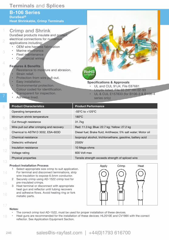
246
Terminals and Splices
[email protected] | +44(0)1793 616700
1
2
3
4
5
6
7
8
9
10
11
12
13
14
15
16
17
18
Crimp and ShrinkDuraSeal products insulate and protect electrical connections for numerous applications including;• OEM wire harness fabrication• Marine electronics• Fleet maintenance• Commercial wiring
Features & Benefits• Resistance to moisture and abrasion.• Strain relief.• Protection from wire pull-out.• Easy installation.• Environmental protection.• Colour coded for identification.• Transparent for inspection.• Adhesive lined.
B-106 SeriesDuraSeal®Heat Shrinkable, Crimp Terminals
Specifications & Approvals• UL and CUL 91J4, File E87681• Lloyds listed, File 65 247 HH 02-93• UL & CUL E157833 (for B106-3 & B106-4
series only)
Product Characteristics Product Performance
Operating temperature -55ºC to +125ºC
Minimum shrink temperature 180ºC
Cut through resistance 31.7kg
Wire pull out after crimping and recovery Red: 11.3 kg; Blue: 22.7 kg; Yellow: 27.2 kg
Chemical to ASTM D 3032, ESA-603D Diesel fuel; Brake fluid; Antifreeze; 5% salt water; Motor oil
Chemical resistance Isopropyl alcohol, trichloroethane, gasoline, battery acid
Dielectric withstand 2500V
Insulation resistance 10 Mega-ohms
Voltage rating 600 Volt max
Physical properties Tensile strength exceeds strength of spliced wire
Notes: • The correct crimp tool AD-1522, must be used for proper installation of these devices.• Heat guns are recommended for the installation of these devices: HL2010E and CV198X with the correct
reflector. See Application Equipment Section.
Product Installation Process1 Select appropriate size crimp to suit application.
For terminal and disconnect terminations, strip wire insulation to expose 6.5mm conductor.
2 Securely crimp using AD-1522 crimp tool for pre-insulated crimps.
3 Heat terminal or disconnect with appropriate heat gun and reflector until tubing recovers and adhesive flows. Avoid heating ring or fork metallic parts.
Crimp HeatApply
RoHScompliant
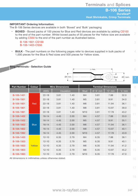
247
Terminals and Splices
www.is-rayfast.com
1
2
3
4
5
6
7
8
9
10
11
12
13
14
15
16
17
18
B-106 SeriesDuraSeal®
Heat Shrinkable, Crimp Terminals
IMPORTANT Ordering Information: The B-106 Series devices are available in both ‘Boxed’ and ‘Bulk’ packaging• BOXED - Boxed packs of 100 pieces for Blue and Red devices are available by adding CS100
to the end of the part number. Whilst boxed packs of 50 pieces for the Yellow size are available by adding CS50 to the end of the part number as illustrated below.
B-106-1601-CS100 B-106-1403-CS50
• BULK - The part numbers on the following pages refer to devices supplied in bulk packs of 1,000 pieces for the Blue & Red sizes and 500 pieces for Yellow sizes.
Ring Terminals - Selection Guide
Part Number Colour Wire Dimensions Terminal Dimensions
AWG Insulation Stud Ø ‘A’ mm ‘C’ mm ‘L’ mm
B-106-1401
Red
22-18 3.81 1.40 M4 3.81 7.88 32.0
B-106-1501 22-18 3.81 1.40 M5 3.81 9.91 34.0
B-106-1601 22-18 3.81 1.40 M6 3.81 11.94 36.1
B-106-1801 22-18 3.81 1.40 M8 3.81 13.97 39.0
B-106-1991 22-18 3.81 1.40 M10 3.81 17.78 43.2
B-106-1402
Blue
16-14 4.45 2.00 M4 4.57 7.88 33.0
B-106-1502 16-14 4.45 2.00 M5 4.57 9.91 35.1
B-106-1602 16-14 4.45 2.00 M6 4.57 11.94 36.1
B-106-1802 16-14 4.45 2.00 M8 4.57 13.97 40.1
B-106-1992 16-14 4.45 2.00 M10 4.57 17.78 43.9
B-106-1403
Yellow
12-10 6.35 2.79 M4 6.35 7.88 38.1
B-106-1503 12-10 6.35 2.79 M5 6.35 9.91 40.1
B-106-1603 12-10 6.35 2.79 M6 6.35 11.94 41.2
B-106-1803 12-10 6.35 2.79 M8 6.35 13.97 45.2
B-106-1993 12-10 6.35 2.79 M10 6.35 17.78 47.0
All dimensions in millimetres unless otherwise stated.
ØA min.
L max.
Stud ØC nom.
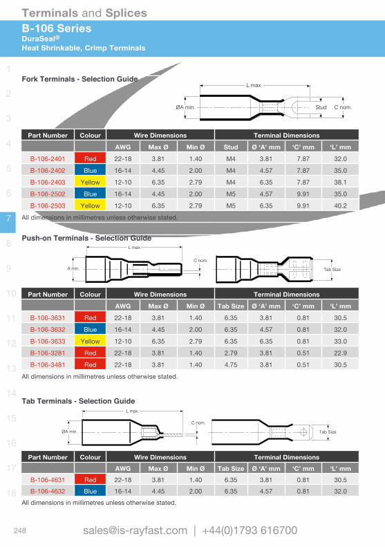
248
Terminals and Splices
[email protected] | +44(0)1793 616700
1
2
3
4
5
6
7
8
9
10
11
12
13
14
15
16
17
18
L max.
ØA min.
C nom.
Tab Size
Tab Size
C nom.
L max.
A min.
ØA min.
L max.
Stud C nom.
Fork Terminals - Selection Guide
Part Number Colour Wire Dimensions Terminal Dimensions
AWG Max Ø Min Ø Stud Ø ‘A’ mm ‘C’ mm ‘L’ mm
B-106-2401 Red 22-18 3.81 1.40 M4 3.81 7.87 32.0
B-106-2402 Blue 16-14 4.45 2.00 M4 4.57 7.87 35.0
B-106-2403 Yellow 12-10 6.35 2.79 M4 6.35 7.87 38.1
B-106-2502 Blue 16-14 4.45 2.00 M5 4.57 9.91 35.0
B-106-2503 Yellow 12-10 6.35 2.79 M5 6.35 9.91 40.2
All dimensions in millimetres unless otherwise stated.
Push-on Terminals - Selection Guide
Part Number Colour Wire Dimensions Terminal Dimensions
AWG Max Ø Min Ø Tab Size Ø ‘A’ mm ‘C’ mm ‘L’ mm
B-106-3631 Red 22-18 3.81 1.40 6.35 3.81 0.81 30.5
B-106-3632 Blue 16-14 4.45 2.00 6.35 4.57 0.81 32.0
B-106-3633 Yellow 12-10 6.35 2.79 6.35 6.35 0.81 33.0
B-106-3281 Red 22-18 3.81 1.40 2.79 3.81 0.51 22.9
B-106-3481 Red 22-18 3.81 1.40 4.75 3.81 0.51 30.5
All dimensions in millimetres unless otherwise stated.
Tab Terminals - Selection Guide
Part Number Colour Wire Dimensions Terminal DimensionsAWG Max Ø Min Ø Tab Size Ø ‘A’ mm ‘C’ mm ‘L’ mm
B-106-4631 Red 22-18 3.81 1.40 6.35 3.81 0.81 30.5B-106-4632 Blue 16-14 4.45 2.00 6.35 4.57 0.81 32.0
All dimensions in millimetres unless otherwise stated.
B-106 SeriesDuraSeal®Heat Shrinkable, Crimp Terminals

249
Terminals and Splices
www.is-rayfast.com
1
2
3
4
5
6
7
8
9
10
11
12
13
14
15
16
17
18
ØA min.
Pin Ø
L max.
ØA min. Bullet Ø
ØA min. ØB ØC min.
L max.
L max.
ØA min. Bullet Ø
ØA min. ØB ØC min.
L max.
L max.
Pin Terminals - Selection Guide
Part Number Colour Wire Dimensions Terminal Dimensions
AWG Max Ø Min Ø Pin Ø Ø ‘A’ mm - ‘L’ mm
B-106-6201 Red 22-18 3.81 1.40 2.00 3.81 - 31.0
All dimensions in millimetres unless otherwise stated.
Bullet Terminals (Male) - Selection Guide
Part Number Colour Wire Dimensions Terminal Dimensions
AWG Max Ø Min Ø Bullet Ø ‘A’ mm - ‘L’ mm
B-106-7401 Red 22-18 3.81 1.40 3.81 3.81 - 33.5
B-106-7502 Blue 16-14 4.45 2.00 5.08 4.57 - 34.5
All dimensions in millimetres unless otherwise stated.
Bullet Terminals (Female) - Selection Guide
Part Number Colour Wire Dimensions Terminal DimensionsAWG Max Ø Min Ø Bullet Ø ‘A’ mm ‘C’ mm ‘L’ mm
B-106-8401 Red 22-18 3.81 1.40 3.81 3.81 5.59 30.5B-106-8502 Blue 16-14 4.45 2.00 5.08 4.57 6.10 32.5
All dimensions in millimetres unless otherwise stated.
B-106 SeriesDuraSeal®
Heat Shrinkable, Crimp Terminals
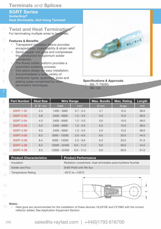
250
Terminals and Splices
[email protected] | +44(0)1793 616700
1
2
3
4
5
6
7
8
9
10
11
12
13
14
15
16
17
18
Twist and Heat Termination For terminating multiple wires to terminals.
Features & Benefits• Transparent insulation sleeve provides
encapsulation, inspectability & strain relief.• Spiral copper coil grips and compresses
the conductors for optimum solder connection.
• Pre-fluxed solder preform provides a controlled soldering process.
• One piece design for easy installation.• Accommodates a wide variety of
conductor types, quantities, sizes and plating types unmatched by other termination techniques.
SGRT SeriesSolderGrip®
Heat Shrinkable, Self-fixing Terminal
Specifications & Approvals• MIL-T-7928G• RB-120
Part Number Stud Size Wire Range Max. Bundle Max. Rating LengthØ ‘B’ mm CMA mm2 Ø mm Amps mm
SGRT-1-02 2.4 1400 - 5000 0.7 - 2.5 4.1 12.5 38.0
SGRT-2-03 3.8 2400 - 6000 1.2 - 3.0 5.0 15.0 38.0
SGRT-2-04 4.3 2400 - 6000 1.2 - 3.0 5.0 15.0 38.0
SGRT-2-05 5.5 2400 - 6000 1.2 - 3.0 5.0 15.0 38.0
SGRT-2-06 6.5 2400 - 6000 1.2 - 3.0 5.0 15.0 38.0
SGRT-3-06 6.5 5000 - 13200 2.5 - 6.6 6.5 33.0 44.5
SGRT-3-08 8.4 5000 - 13200 2.5 - 6.6 6.5 33.0 51.0
SGRT-4-06 6.5 12000 - 22400 6.0 - 11.2 9.0 56.0 44.5
SGRT-4-08 8.5 12000 - 22400 6.0 - 11.2 9.0 56.0 51.0
Product Characteristics Product PerformanceInsulation Radiation crosslinked, heat-shrinkable polyvinylidene fluoride
Solder and Flux Sn60 Pb40 with RA flux
Temperature Rating -55ºC to +150ºC
Notes: • Heat guns are recommended for the installation of these devices: HL2010E and CV198X with the correct
reflector added. See Application Equipment Section.
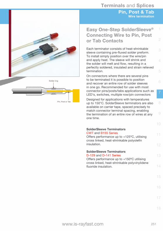
251
Terminals and Splices
www.is-rayfast.com
1
2
3
4
5
6
7
8
9
10
11
12
13
14
15
16
17
18
Easy One-Step SolderSleeve® Connecting Wire to Pin, Post or Tab ContactsEach terminator consists of heat-shrinkable sleeve containing pre-fluxed solder preform. To install simply position over the wire/pin and apply heat. The sleeve will shrink and the solder will melt and flow, resulting in a perfectly soldered, insulated and strain relieved termination. On connectors where there are several pins to be terminated it is possible to position and recover an entire row of solder sleeves in one go. Recommended for use with most connector pins/posts/tabs applications such as LED’s, switches, multiple row/pin connectorsDesigned for applications with temperatures up to 150°C. SolderSleeve terminators are also available on carrier tape, spaced precisely to match connector terminal spacing, enabling the termination of an entire row of wires at any one time.
SolderSleeve Terminators CWT and B155 SeriesOffers performance up to +125ºC, utilising cross linked, heat-shrinkable polyolefin insulation.
SolderSleeve Terminators D-129 and D-141 SeriesOffers performance up to +150ºC utilising cross linked, heat-shrinkable polyvinylidene fluoride insulation.
Pin, Post & TabWire termination
Pin, Post or Tab
Solder ring

252
Terminals and Splices
[email protected] | +44(0)1793 616700
1
2
3
4
5
6
7
8
9
10
11
12
13
14
15
16
17
18
Used for discrete terminating of wires to component terminals, such as motor tabs, connector pins or switch terminals.
Features & Benefits• Transparent insulation sleeve provides
encapsulation, strain relief and insulation with inspectability.
• Pre-fluxed solder preform provides controlled soldering process.
• One-piece design provides easy installation and low installed cost.
• A tape carrier option provides convenience and ease of installation.
• UL and CUL recognised.
CWT / B155 / D1xx SeriesSolderSleeve®
Wire Termination to Pin, Post & Tabs
Specifications & Approvals• UL and CUL E87681• D-5023 and RT-1404• B-155 series RoHS compliant
Material
Insulation for D-129 and D-141 Radiation crosslinked, heat-shrinkable polyvinylidene fluorideInsulation for CWT and B155 Series Radiation crosslinked, heat-shrinkable polyolefinSolder and flux for D-129 and D-141 Sn63 Pb37 Flux: ROM 1 per ANSI-J-004 [RMA flux]Solder and flux for B155 Sn42Bi58 Flux: ROM 1 per ANSI-J-004 [RA flux]Solder and flux for CWT-1500 Series Sn50 Pb32 Cd18 Flux: ROM 1 per ANSI-J-004 [RA flux]
Typical Performance
Temperature rating for CWT / B155 Series -55ºC to +125ºCTemperature rating for D-129 and D-141 -55ºC to +150ºCVoltage drop 2.0 mVTensile strength Exceeds strength of conductorDielectric strength 2.0 kVInsulation resistance 1000 M ohms
Notes: • Heat guns are recommended for the installation of these devices: HL2010E and CV198X with the correct
reflector added. See Application Equipment Section.
Pin, Post or Tab
Solder ring
Onl
y B1
55-1
50X
RoH
S co
mpl
iant
RoHScompliant
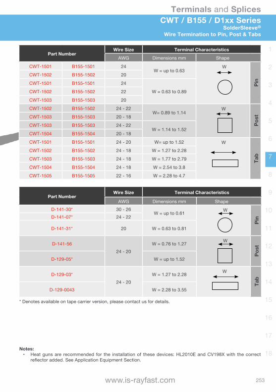
253
Terminals and Splices
www.is-rayfast.com
1
2
3
4
5
6
7
8
9
10
11
12
13
14
15
16
17
18
CWT / B155 / D1xx SeriesSolderSleeve®
Wire Termination to Pin, Post & Tabs
Part NumberWire Size Terminal Characteristics
AWG Dimensions mm Shape
CWT-1501 B155-1501 24W = up to 0.63
W
Pin
CWT-1502 B155-1502 20
CWT-1501 B155-1501 24
W = 0.63 to 0.89CWT-1502 B155-1502 22
CWT-1503 B155-1503 20
CWT-1502 B155-1502 24 - 22W= 0.89 to 1.14
W
PostCWT-1503 B155-1503 20 - 18
CWT-1503 B155-1503 24 - 22W = 1.14 to 1.52
CWT-1504 B155-1504 20 - 18
CWT-1501 B155-1501 24 - 20 W= up to 1.52 W
Tab
CWT-1502 B155-1502 24 - 18 W = 1.27 to 2.28
CWT-1503 B155-1503 24 - 18 W = 1.77 to 2.79
CWT-1504 B155-1504 24 - 18 W = 2.54 to 3.8
CWT-1505 B155-1505 22 - 16 W = 2.28 to 4.7
Part NumberWire Size Terminal Characteristics
AWG Dimensions mm ShapeD-141-30* 30 - 26
W = up to 0.61 W
PinD-141-07* 24 - 22
D-141-31* 20 W = 0.63 to 0.81
D-141-5624 - 20
W = 0.76 to 1.27 W
Post
D-129-05* W = up to 1.52
D-129-03*24 - 20
W = 1.27 to 2.28 W
Tab
D-129-0043 W = 2.28 to 3.55
* Denotes available on tape carrier version, please contact us for details.
Notes: • Heat guns are recommended for the installation of these devices: HL2010E and CV198X with the correct
reflector added. See Application Equipment Section.
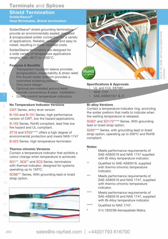
254
Terminals and Splices
[email protected] | +44(0)1793 616700
1
2
3
4
5
6
7
8
9
10
11
12
13
14
15
16
17
18
Shield TerminationSolderSleeve®
Heat Shrinkable, Shield termination
No Temperature Indicator VersionsCWT Series, entry level versionB-150 and B-151 Series, high performance version of CWT, low fire hazard applications.B-155 Series, RoHS compliant, lead free low fire hazard and UL compliant.ST18 and ST63***** offers a high degree of environmental protection and meets NAS-1747B-023 Series, high temperature terminator.
Thermo-chromic VersionsContain a temperature indicator that exhibits a colour change when temperature is achieved.SO1**, SO2** and SO3 Series, terminators with thermal indicator, designed for systems operating up to 150ºC. SO96*** Series, With grounding lead or braid strap option.
Specifications & Approvals• UL and CUL E87681 • NAS 1747 • SAE-AS83519/1 & /2
Bi-alloy VersionsContain a temperature indicator ring, encircling the solder preform that melts to indicate when the wetting temperature is released.SO63* and SO175****# Series, With grounding lead or braid strap option.S200**** Series, with grounding lead or braid strap option, operating up to 200ºC and RoHS compliant.
Notes:* Meets performance requirements of
SAE-AS83519 and NAS 1747 supplied with Bi Alloy temperature indicator.
** Qualified to SAE-AS83519, supplied with thermo-chromic temperature indicator.
*** Meets performance requirements of SAE-AS83519 and NAS 1747, supplied with thermo-chromic temperature indicator.
**** Meets performance requirements of SAE-AS83519 and NAS 1747, supplied with Bi-Alloy temperature indicator.
***** Qualified to NAS 1747.# 514.1920/99 Aerospatiale Matra.
SolderSleeve® shield grounding terminators provide an environmentally sealed, insulated & encapsulated solder connection for a variety of applications. Reliable, versatile and easy to install, resulting in lower installed costs. SolderSleeve terminators are designed for a wide variety of temperature applications ranging from -65°C to +200°C.
Features & Benefits• Transparent insulation sleeve provides
encapsulation, inspectability & strain relief.• Pre-fluxed solder preform provides a
controlled soldering process.• One piece design.• Optional pre-installed ground leads
provide convenience & ease installation.• Quality control temperature indicators.
Onl
y B-
155,
SO
96, S
O17
5 an
d S2
00X
RoH
S co
mpl
iantRoHS
compliant

255
Terminals and Splices
www.is-rayfast.com
1
2
3
4
5
6
7
8
9
10
11
12
13
14
15
16
17
18
Shield TerminationSolderSleeve®
Heat Shrinkable, Shield Termination
Product Series Selection GuideProductSeries
SystemOperating Temp.
CableRating
Pre-installed Lead
Temperature Indicator Application Environment
Min Max. Min. Optional Type
CWT -55ºC 125ºC 85ºC Yes None Commercial grade splash proof
B-150 -55ºC 125ºC 85ºC No None Marine/RMT grade, low fire hazard
B-151 -55ºC 125ºC 85ºC Yes None Marine/RMT grade, low fire hazard
B-155 -55ºC 125ºC 85ºC Yes None RoHS compliant version of CWT
ST18 -55ºC 125ºC 105ºC No None Defence grade NAS approved
ST63 -55ºC 150ºC 125ºC Yes None Defence grade NAS approved
SO63 -55ºC 150ºC 125ºC Yes & Braid Bi-Alloy Defence grade, immersion sealing
SO1 -55ºC 150ºC 125ºC No Thermo-chromic Mil-Spec, immersion sealing
SO2 -55ºC 150ºC 125ºC Yes Thermo-chromic Mil-Spec, immersion sealing
SO3 -55ºC 150ºC 125ºC Braid Thermo-chromic Immersion sealing
SO96 -55ºC 175ºC 150ºC Yes & Braid Thermo-chromic Defence grade, immersion sealing
SO175 -55ºC 175ºC 175ºC Yes & Braid Bi-Alloy Defence grade, immersion sealing
S200 -55ºC 200ºC 150ºC Yes & Braid Bi-Alloy Defence grade, immersion sealing
B-023 -65ºC 260ºC 175ºC No None Defence grade
Product Characteristics Selection GuideProduct Range Characteristic
Insulation S200 Heat-shrinkable, modified fluoropolymer
SO & ST Series Heat-shrinkable, polyvinylidene fluoride
B-150, B-151, CWT Heat-shrinkable, polyolefin
BO23 Heat-shrinkable TFESolder and Flux SO63, ST63, SO1/2/3 Solder: Sn63 Pb37 Flux: ROL 1
S200, SO96, SO175 Solder: Sn96 Ag4 Flux: ROM 1
B-155 Solder: Sn42 Bi58 Flux: ROM 1
CWT, B-15X, ST18 Solder: Sn50 Pb32 Cd18 Flux: ROM 1
BO23 Solder: Pb93 Sn5 Ag2 Flux: ROM 1 Ground Lead B-155, CWT XL polyethylene
B-150, B-151 Zerohal (100G)
S200 Series MIL-C-22759/91 or /87
SO, SO175 Series MIL-W-22759/32 or /41
Typical PerformanceVoltage drop 2.5 mV
Tensile strength Exceeds strength of ground lead
Dielectric strength 1.0 kV immersed
Insulation resistance 1000 Mega-ohms
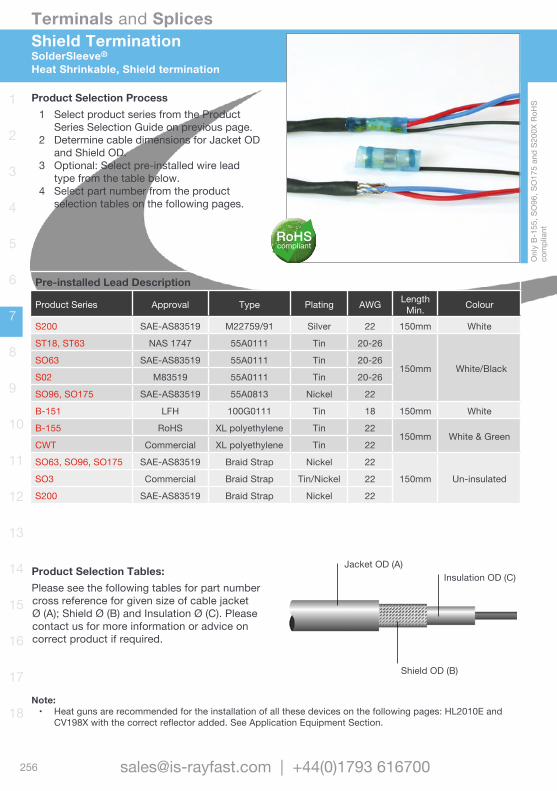
256
Terminals and Splices
[email protected] | +44(0)1793 616700
1
2
3
4
5
6
7
8
9
10
11
12
13
14
15
16
17
18
Shield TerminationSolderSleeve®
Heat Shrinkable, Shield termination
Product Selection Process1 Select product series from the Product
Series Selection Guide on previous page.2 Determine cable dimensions for Jacket OD
and Shield OD.3 Optional: Select pre-installed wire lead
type from the table below.4 Select part number from the product
selection tables on the following pages.
Jacket OD (A)Insulation OD (C)
Shield OD (B)
Pre-installed Lead Description
Product Series Approval Type Plating AWG LengthMin. Colour
S200 SAE-AS83519 M22759/91 Silver 22 150mm White
ST18, ST63 NAS 1747 55A0111 Tin 20-26
150mm White/BlackSO63 SAE-AS83519 55A0111 Tin 20-26
S02 M83519 55A0111 Tin 20-26
SO96, SO175 SAE-AS83519 55A0813 Nickel 22
B-151 LFH 100G0111 Tin 18 150mm White
B-155 RoHS XL polyethylene Tin 22150mm White & Green
CWT Commercial XL polyethylene Tin 22
SO63, SO96, SO175 SAE-AS83519 Braid Strap Nickel 22
150mm Un-insulatedSO3 Commercial Braid Strap Tin/Nickel 22
S200 SAE-AS83519 Braid Strap Nickel 22
Note: • Heat guns are recommended for the installation of all these devices on the following pages: HL2010E and
CV198X with the correct reflector added. See Application Equipment Section.
Product Selection Tables:Please see the following tables for part number cross reference for given size of cable jacket Ø (A); Shield Ø (B) and Insulation Ø (C). Please contact us for more information or advice on correct product if required.
Onl
y B-
155,
SO
96, S
O17
5 an
d S2
00X
RoH
S co
mpl
iantRoHS
compliant
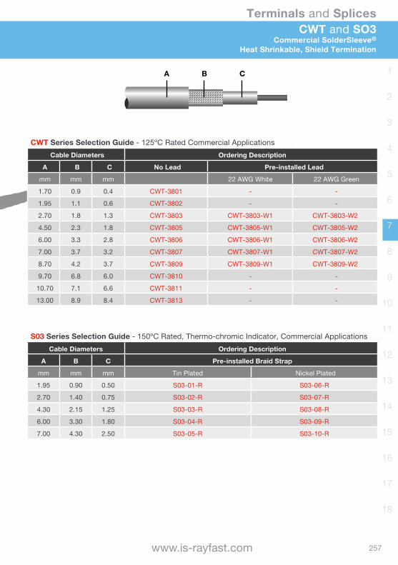
257
Terminals and Splices
www.is-rayfast.com
1
2
3
4
5
6
7
8
9
10
11
12
13
14
15
16
17
18
CWT and SO3Commercial SolderSleeve®
Heat Shrinkable, Shield Termination
A B C
CWT Series Selection Guide - 125ºC Rated Commercial ApplicationsCable Diameters Ordering Description
A B C No Lead Pre-installed Lead
mm mm mm 22 AWG White 22 AWG Green
1.70 0.9 0.4 CWT-3801 - -
1.95 1.1 0.6 CWT-3802 - -
2.70 1.8 1.3 CWT-3803 CWT-3803-W1 CWT-3803-W2
4.50 2.3 1.8 CWT-3805 CWT-3805-W1 CWT-3805-W2
6.00 3.3 2.8 CWT-3806 CWT-3806-W1 CWT-3806-W2
7.00 3.7 3.2 CWT-3807 CWT-3807-W1 CWT-3807-W2
8.70 4.2 3.7 CWT-3809 CWT-3809-W1 CWT-3809-W2
9.70 6.8 6.0 CWT-3810 - -
10.70 7.1 6.6 CWT-3811 - -
13.00 8.9 8.4 CWT-3813 - -
S03 Series Selection Guide - 150ºC Rated, Thermo-chromic Indicator, Commercial ApplicationsCable Diameters Ordering Description
A B C Pre-installed Braid Strap
mm mm mm Tin Plated Nickel Plated
1.95 0.90 0.50 S03-01-R S03-06-R
2.70 1.40 0.75 S03-02-R S03-07-R
4.30 2.15 1.25 S03-03-R S03-08-R
6.00 3.30 1.80 S03-04-R S03-09-R
7.00 4.30 2.50 S03-05-R S03-10-R

258
Terminals and Splices
[email protected] | +44(0)1793 616700
1
2
3
4
5
6
7
8
9
10
11
12
13
14
15
16
17
18
A B C
B-155 and B-15XShield Termination SolderSleeve®
Heat Shrinkable, Shield termination
B-155 Series - 125ºC RatedCable Diameters Ordering Description
A B C No Lead Pre-installed Lead
mm mm mm 22 AWG Green 22 AWG White
1.70 0.9 0.4 B-155-3801 - -
1.95 1.1 0.6 B-155-3802 - -
2.50 1.50 1.0 B-155-03 B-155-03-35-22-5 B-155-03-35-22-9
4.30 2.00 1.5 B-155-05 B-155-05-35-22-5 B-155-05-35-22-9
6.00 3.30 2.8 B-155-06 B-155-06-35-22-5 B-155-06-35-22-9
6.40 3.30 2.8 B-155-07 B-155-07-35-22-5 B-155-07-35-22-9
8.70 4.50 4.0 B-155-09 B-155-09-35-22-5 B-155-09-35-22-9
10.00 7.50 4.0 B-155-11 B-155-11-35-22-5 B-155-11-35-22-9
13.00 7.00 6.5 B-155-13 B-155-13-35-22-5 B-155-13-35-22-9
B-15X Series - 125ºC Rated Low Fire HazardCable Diameters Ordering Description
A B C No Lead Pre-installed Lead
mm mm mm 18 AWG White
3.0 1.5 1.0 B-150-03 -
4.8 2.0 1.5 B-150-05 B-151-05
7.3 3.3 2.8 B-150-07 B-151-07
11.5 4.5 4.0 B-150-11 B-151-11
15.1 7.0 6.5 B-150-13 B-151-13
18.0 9.0 8.0 B-150-17 B-151-17
23.5 12.0 11.0 B-150-23 -
34.0 19.0 17.0 B-150-33 -
RoHScompliant
LFHLow Fire Hazard
LFHLow Fire Hazard

259
Terminals and Splices
www.is-rayfast.com
1
2
3
4
5
6
7
8
9
10
11
12
13
14
15
16
17
18
ST18 and ST63NAS 1747 SolderSleeve®
Heat Shrinkable, Shield Termination
ST18 Series - 125ºC Rated, NAS 1747 ApprovedCable Diameters Ordering Description
A B C No Lead Pre-installed Lead (White/Black)
mm mm mm 20 AWG 22 AWG 24 AWG 26 AWG
2.65 0.90 0.5 ST18-1-00 ST18-1-55-20-90 ST18-1-55-22-90 ST18-1-55-24-90 ST18-1-55-26-90
3.65 1.40 0.75 ST18-2-00 ST18-2-55-20-90 ST18-2-55-22-90 ST18-2-55-24-90 ST18-2-55-26-90
5.08 2.15 1.25 ST18-3-00 ST18-3-55-20-90 ST18-3-55-22-90 ST18-3-55-24-90 ST18-3-55-26-90
6.45 3.30 1.80 ST18-4-00 ST18-4-55-20-90 ST18-4-55-22-90 ST18-4-55-24-90 ST18-4-55-26-90
7.60 4.30 2.50 ST18-5-00 ST18-5-55-20-90 ST18-5-55-22-90 ST18-5-55-24-90 ST18-5-55-26-90
ST63 Series - 150ºC Rated NAS 1747 ApprovedCable Diameters Ordering Description
A B C No Lead Pre-installed Lead (White/Black)
mm mm mm 20 AWG 22 AWG 24 AWG 26 AWG
2.65 0.90 0.5 ST63-1-00 ST63-1-55-20-90 ST63-1-55-22-90 ST63-1-55-24-90 ST63-1-55-26-90
3.65 1.40 0.75 ST63-2-00 ST63-2-55-20-90 ST63-2-55-22-90 ST63-2-55-24-90 ST63-2-55-26-90
5.08 2.15 1.25 ST63-3-00 ST63-3-55-20-90 ST63-3-55-22-90 ST63-3-55-24-90 ST63-3-55-26-90
6.45 3.30 1.80 ST63-4-00 ST63-4-55-20-90 ST63-4-55-22-90 ST63-4-55-24-90 ST63-4-55-26-90
7.60 4.30 2.50 ST63-5-00 ST63-5-55-20-90 ST63-5-55-22-90 ST63-5-55-24-90 ST63-5-55-26-90
A B C
B-15X Series - 125ºC Rated Low Fire HazardCable Diameters Ordering Description
A B C No Lead Pre-installed Lead
mm mm mm 18 AWG White
3.0 1.5 1.0 B-150-03 -
4.8 2.0 1.5 B-150-05 B-151-05
7.3 3.3 2.8 B-150-07 B-151-07
11.5 4.5 4.0 B-150-11 B-151-11
15.1 7.0 6.5 B-150-13 B-151-13
18.0 9.0 8.0 B-150-17 B-151-17
23.5 12.0 11.0 B-150-23 -
34.0 19.0 17.0 B-150-33 -
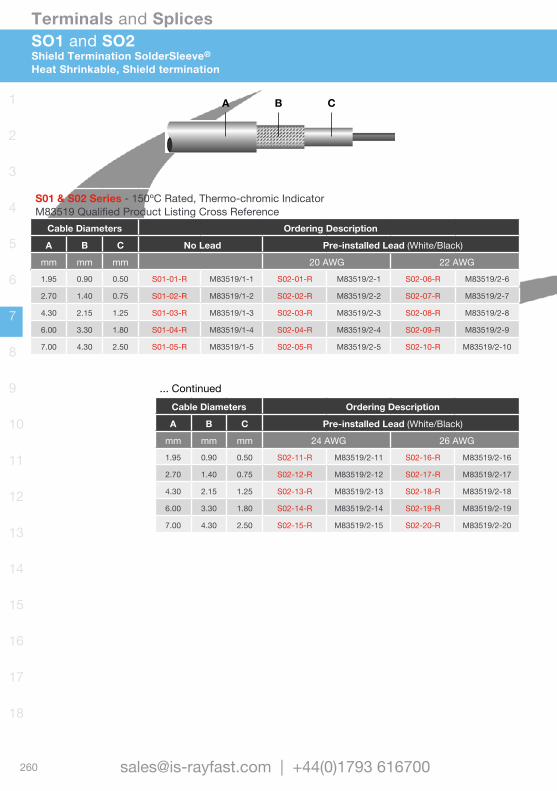
260
Terminals and Splices
[email protected] | +44(0)1793 616700
1
2
3
4
5
6
7
8
9
10
11
12
13
14
15
16
17
18
A B C
SO1 and SO2Shield Termination SolderSleeve®
Heat Shrinkable, Shield termination
S01 & S02 Series - 150ºC Rated, Thermo-chromic Indicator M83519 Qualified Product Listing Cross Reference
Cable Diameters Ordering Description
A B C No Lead Pre-installed Lead (White/Black)
mm mm mm 20 AWG 22 AWG1.95 0.90 0.50 S01-01-R M83519/1-1 S02-01-R M83519/2-1 S02-06-R M83519/2-6
2.70 1.40 0.75 S01-02-R M83519/1-2 S02-02-R M83519/2-2 S02-07-R M83519/2-7
4.30 2.15 1.25 S01-03-R M83519/1-3 S02-03-R M83519/2-3 S02-08-R M83519/2-8
6.00 3.30 1.80 S01-04-R M83519/1-4 S02-04-R M83519/2-4 S02-09-R M83519/2-9
7.00 4.30 2.50 S01-05-R M83519/1-5 S02-05-R M83519/2-5 S02-10-R M83519/2-10
... ContinuedCable Diameters Ordering Description
A B C Pre-installed Lead (White/Black)
mm mm mm 24 AWG 26 AWG1.95 0.90 0.50 S02-11-R M83519/2-11 S02-16-R M83519/2-16
2.70 1.40 0.75 S02-12-R M83519/2-12 S02-17-R M83519/2-17
4.30 2.15 1.25 S02-13-R M83519/2-13 S02-18-R M83519/2-18
6.00 3.30 1.80 S02-14-R M83519/2-14 S02-19-R M83519/2-19
7.00 4.30 2.50 S02-15-R M83519/2-15 S02-20-R M83519/2-20
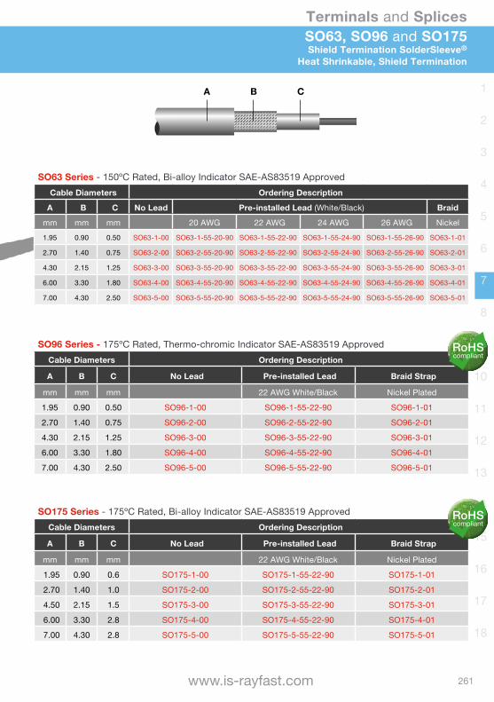
261
Terminals and Splices
www.is-rayfast.com
1
2
3
4
5
6
7
8
9
10
11
12
13
14
15
16
17
18
SO63, SO96 and SO175Shield Termination SolderSleeve®
Heat Shrinkable, Shield Termination
A B C
SO96 Series - 175ºC Rated, Thermo-chromic Indicator SAE-AS83519 ApprovedCable Diameters Ordering Description
A B C No Lead Pre-installed Lead Braid Strap
mm mm mm 22 AWG White/Black Nickel Plated
1.95 0.90 0.50 SO96-1-00 SO96-1-55-22-90 SO96-1-01
2.70 1.40 0.75 SO96-2-00 SO96-2-55-22-90 SO96-2-01
4.30 2.15 1.25 SO96-3-00 SO96-3-55-22-90 SO96-3-01
6.00 3.30 1.80 SO96-4-00 SO96-4-55-22-90 SO96-4-01
7.00 4.30 2.50 SO96-5-00 SO96-5-55-22-90 SO96-5-01
SO175 Series - 175ºC Rated, Bi-alloy Indicator SAE-AS83519 ApprovedCable Diameters Ordering Description
A B C No Lead Pre-installed Lead Braid Strap
mm mm mm 22 AWG White/Black Nickel Plated
1.95 0.90 0.6 SO175-1-00 SO175-1-55-22-90 SO175-1-01
2.70 1.40 1.0 SO175-2-00 SO175-2-55-22-90 SO175-2-01
4.50 2.15 1.5 SO175-3-00 SO175-3-55-22-90 SO175-3-01
6.00 3.30 2.8 SO175-4-00 SO175-4-55-22-90 SO175-4-01
7.00 4.30 2.8 SO175-5-00 SO175-5-55-22-90 SO175-5-01
SO63 Series - 150ºC Rated, Bi-alloy Indicator SAE-AS83519 ApprovedCable Diameters Ordering Description
A B C No Lead Pre-installed Lead (White/Black) Braid
mm mm mm 20 AWG 22 AWG 24 AWG 26 AWG Nickel1.95 0.90 0.50 SO63-1-00 SO63-1-55-20-90 SO63-1-55-22-90 SO63-1-55-24-90 SO63-1-55-26-90 SO63-1-01
2.70 1.40 0.75 SO63-2-00 SO63-2-55-20-90 SO63-2-55-22-90 SO63-2-55-24-90 SO63-2-55-26-90 SO63-2-01
4.30 2.15 1.25 SO63-3-00 SO63-3-55-20-90 SO63-3-55-22-90 SO63-3-55-24-90 SO63-3-55-26-90 SO63-3-01
6.00 3.30 1.80 SO63-4-00 SO63-4-55-20-90 SO63-4-55-22-90 SO63-4-55-24-90 SO63-4-55-26-90 SO63-4-01
7.00 4.30 2.50 SO63-5-00 SO63-5-55-20-90 SO63-5-55-22-90 SO63-5-55-24-90 SO63-5-55-26-90 SO63-5-01
RoHScompliant
RoHScompliant
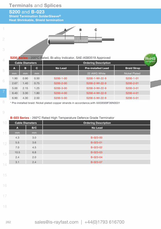
262
Terminals and Splices
[email protected] | +44(0)1793 616700
1
2
3
4
5
6
7
8
9
10
11
12
13
14
15
16
17
18
S200 and B-023Shield Termination SolderSleeve®
Heat Shrinkable, Shield termination
A B C
S200 Series - 200ºC Rated, Bi-alloy Indicator, SAE-AS83519 Approved Cable Diameters Ordering Description
A B C No Lead Pre-installed Lead Braid Strap
mm mm mm 22 AWG White Nickel Plated
1.90 0.90 0.50 S200-1-00 S200-1-WI-22-9 S200-1-01
2.67 1.40 0.75 S200-2-00 S200-2-WI-22-9 S200-2-01
5.00 2.15 1.25 S200-3-00 S200-3-WI-22-9 S200-3-01
6.40 3.30 1.80 S200-4-00 S200-4-WI-22-9 S200-4-01
6.90 4.30 2.50 S200-5-00 S200-5-WI-22-9 S200-5-01
* Pre-installed braid: Nickel plated copper strands in accordance,with AA59569F36N0031
B-023 Series - 260ºC Rated High Temperature Defence Grade TerminatorCable Diameters Ordering Description
A B/C No Lead
mm mm
4.3 3.0 B-023-00
5.5 3.6 B-023-01
7.0 4.5 B-023-02
10.5 6.8 B-023-03
2.4 2.0 B-023-04
3.1 2.4 B-023-07
RoHScompliant

263
Terminals and Splices
www.is-rayfast.com
1
2
3
4
5
6
7
8
9
10
11
12
13
14
15
16
17
18
Coaxial Cable TerminationSolderSleeve®
SolderSleeve coaxial cable terminators allow reliable, easy terminations in a variety of coaxial cable applications, including printed circuit boards. The insulating and strain-relieving capabilities of SolderSleeve terminators provide the ideal solution to centre-conductor breakage problems. Designed for applications with temperatures up to 150ºC.
• Transparent polyvinylidene fluoride or polyolefin insulation sleeve provides encapsulation, strain relief (eliminates centre conductor breakage) and insulation.
• Pre-fluxed solder pre-form provides a controlled soldering process.
• One-piece design provides easy installation and lower installed costs.
• Pre-installed termination leads provide convenience and ease of installation.
SolderSleeve Coaxial Terminators B-155 and CWT Series Maximum operating temperature 125ºC, for use on cables rated (min) 85ºC. Please note that the B-155 series terminator is RoHS compliant.B-02X/B-04X Series Maximum operating temperature 150ºC, for use on cables rated (min) 125ºC.D-181 Series Maximum operating temperature 150ºC, for use on cables rated (min) 125ºC.D-184 Series Maximum operating temperature 150ºC, for use on cables rated (min) 85ºC.
One-Piece PCB Terminators D-607 Series Matched impedance up to 2.3 GHz, metal body.B-046 Series Effective transmission up to 100 MHz, pin to ground.
One-Piece PCB Terminators
Coaxial Terminators
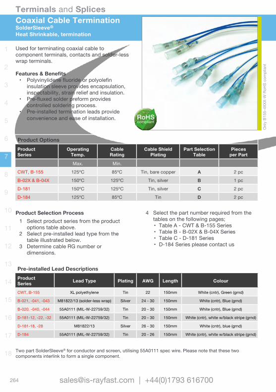
264
Terminals and Splices
[email protected] | +44(0)1793 616700
1
2
3
4
5
6
7
8
9
10
11
12
13
14
15
16
17
18
Used for terminating coaxial cable to component terminals, contacts and solder-less wrap terminals.
Features & Benefits• Polyvinylidene fluoride or polyolefin
insulation sleeve provides encapsulation, inspectability, strain relief and insulation.
• Pre-fluxed solder preform provides controlled soldering process.
• Pre-installed termination leads provide convenience and ease of installation.
Coaxial Cable TerminationSolderSleeve®
Heat Shrinkable, termination
Product OptionsProductSeries
OperatingTemp.
Cable Rating
Cable Shield Plating
Part Selection Table
Piecesper Part
Max. Min.
CWT, B-155 125ºC 85ºC Tin, bare copper A 2 pc
B-02X & B-04X 150ºC 125ºC Tin, silver B 1 pc
D-181 150ºC 125ºC Tin, silver C 2 pc
D-184 125ºC 85ºC Tin D 2 pc
Pre-installed Lead DescriptionsProduct Series Lead Type Plating AWG Length Colour
CWT, B-155 XL polyethylene Tin 22 150mm White (cntr), Green (grnd)
B-021, -041, -043 M81822/13 (solder-less wrap) Silver 24 - 30 150mm White (cntr), Blue (grnd)
B-020. -040, -044 55A0111 (MIL-W-22759/32) Tin 20 - 30 150mm White (cntr), Blue (grnd)
D-181-12, -22, -32 55A0111 (MIL-W-22759/32) Tin 20 - 30 150mm White (cntr), white w/black stripe (grnd)
D-181-18, -28 M81822/13 Silver 26 - 30 150mm White (cntr), blue (grnd)
D-184 55A0111 (MIL-W-22759/32) Tin 20 - 26 150mm White (cntr), white w/black stripe (grnd)
Product Selection Process1 Select product series from the product
options table above.2 Select pre-installed lead type from the
table illustrated below.3 Determine cable RG number or
dimensions.
4 Select the part number required from the tables on the following pages;• Table A - CWT & B-155 Series• Table B - B-02X & B-04X Series• Table C - D-181 Series• D-184 Series please contact us
Two part SolderSleeve® for conductor and screen, utilising 55A0111 spec wire. Please note that these two components interlink to form a single component.
Onl
y B1
55-4
XXX-
W R
oHS
com
plia
nt
RoHScompliant
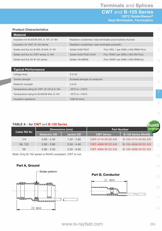
265
Terminals and Splices
www.is-rayfast.com
1
2
3
4
5
6
7
8
9
10
11
12
13
14
15
16
17
18
CWT and B-155 Series125ºC SolderSleeve®
Heat Shrinkable, Termination
Product CharacteristicsMaterialInsulation for B-02X/B-04X, D-181, D-184 Radiation crosslinked, heat-shrinkable polyvinylidene fluoride
Insulation for CWT, B-155 Series Radiation crosslinked, heat-shrinkable polyolefin
Solder and flux for B-02X, B-04X, D-181 Solder Sn63 Pb37 Flux: ROL 1 per ANSI-J-004 (RMA Flux)
Solder and flux for CWT series, D-184 Solder Sn50 Pb32 Cd18 Flux: ROM1 per ANSI-J-004 (RA Flux)
Solder and flux for B-155 series Solder: Sn42Bi58 Flux: ROM1 per ANSI-J-004 (RA(Flux)
Typical PerformanceVoltage drop 2.0 mV
Tensile strength Exceeds strength of conductor
Dielectric strength 2.0 kV
Temperature rating for CWT, B-155 & D-184 -55ºC to +125ºC
Temperature rating for B-02X/B-04X, D-181 -55ºC to +150ºC
Insulation resistance 1000 M ohms
TABLE A - for CWT and B-155 Series
Cable RG NoDimensions (mm) Part Number
Dielectric OD Jacket OD CWT Series B-155 Series (RoHS)
174 0.80 - 2.30 1.30 - 2.80 CWT-4174-W122-5/9 B-155-4174-W122-5/9
58, 122 2.00 - 2.80 2.50 - 4.40 CWT-4058-W122-5/9 B-155-4058-W122-5/9
59 2.80 - 3.30 3.20 - 6.00 CWT-4059-W122-5/9 B-155-4059-W122-5/9
Note: Only B-155 series is RoHS compliant, CWT is not.
Part A, Ground
Part B, Conductor
Solder preform
Part A, Ground
Part B, Conductor
Solder preform
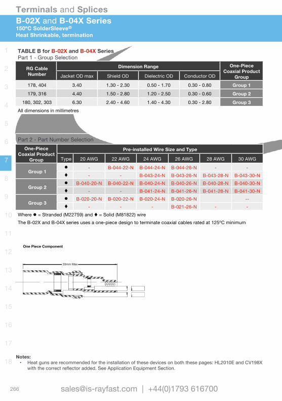
266
Terminals and Splices
[email protected] | +44(0)1793 616700
1
2
3
4
5
6
7
8
9
10
11
12
13
14
15
16
17
18
B-02X and B-04X Series150ºC SolderSleeve®
Heat Shrinkable, termination
TABLE B for B-02X and B-04X SeriesPart 1 - Group Selection
RG CableNumber
Dimension Range One-Piece Coaxial Product
GroupJacket OD max Shield OD Dielectric OD Conductor OD
178, 404 3.40 1.30 - 2.30 0.50 - 1.70 0.30 - 0.80 Group 1
179, 316 4.40 1.50 - 2.80 1.20 - 2.50 0.30 - 0.60 Group 2
180, 302, 303 6.30 2.40 - 4.60 1.40 - 4.30 0.30 - 2.80 Group 3All dimensions in millimetres
Part 2 - Part Number SelectionOne-Piece
Coaxial Product Group
Pre-installed Wire Size and Type
Type 20 AWG 22 AWG 24 AWG 26 AWG 28 AWG 30 AWG
Group 1l - B-044-22-N B-044-24-N B-044-26-N - -t - - B-043-24-N B-043-26-N B-043-28-N B-043-30-N
Group 2l B-040-20-N B-040-22-N B-040-24-N B-040-26-N B-040-28-N B-040-30-Nt - - B-041-24-N B-041-26-N B-041-28-N B-041-30-N
Group 3l B-020-20-N B-020-22-N B-020-24-N B-020-26-N --t - - - B-021-26-N - -
Where l = Stranded (M22759) and t = Solid (M81822) wireThe B-02X and B-04X series uses a one-piece design to terminate coaxial cables rated at 125ºC minimum
33mm Max
One Piece Component
Notes: • Heat guns are recommended for the installation of these devices on both these pages: HL2010E and CV198X
with the correct reflector added. See Application Equipment Section.

267
Terminals and Splices
www.is-rayfast.com
1
2
3
4
5
6
7
8
9
10
11
12
13
14
15
16
17
18
D-181 and D-184 Series150ºC and 125ºC SolderSleeve® Two Part
Heat Shrinkable, termination
TABLE C for D-181 SeriesPart Number Selection
Part NumberMin. Dimensions (mm) Max. Dim. (mm)
AWG A B C D E F L1 L2D-181-1220-90/9 20
3.70 3.20 2.70 2.40 0.71 2.30 17.00 21.50
D-181-1222-90/9 22D-181-1224-90/9 24D-181-1226-90/9 26D-181-1226-6/9 26D-181-1230-6/9 30
D-181-2220-90/9 20
4.50 4.00 3.45 2.90 1.10 3.00 17.00 22.70
D-181-2222-90/9 22D-181-2224-90/9 24D-181-2226-90/9 26D-181-2226-6/9 26D-181-2230-6/9 30
D-181-3220-90/9 20
5.20 4.70 4.45 3.95 1.30 4.00 17.00 21.50
D-181-3222-90/9 22D-181-3224-90/9 24D-181-3226-90/9 26D-181-3226-6/9 26D-181-3230-6/9 30
TABLE D for D-184 SeriesD-184-1220-90/9 20
3.70 3.20 2.70 2.40 0.71 2.30 17.00 21.50D-184-1222-90/9 22D-184-1224-90/9 24D-184-1226-90/9 26D-184-2220-90/9 20
4.50 4.00 3.45 2.90 1.10 3.00 17.00 22.70D-184-2222-90/9 22D-184-2224-90/9 24D-184-2226-90/9 26
Part B, Conductor
Solder preform
Part A, Ground
Solder preform
Please note that these two components interlink to form a single component.
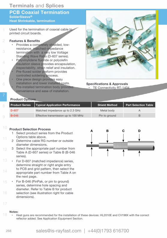
268
Terminals and Splices
[email protected] | +44(0)1793 616700
1
2
3
4
5
6
7
8
9
10
11
12
13
14
15
16
17
18
A B C D
Used for the termination of coaxial cable to printed circuit boards.
Features & Benefits• Provides a completely shielded, low-
resistance, matched-impedance termination with a very low Voltage Standing Wave Ratio (D-607 series).
• Polyvinylidene fluoride or polyolefin insulation sleeve provides encapsulation, inspectability, strain relief and insulation.
• Pre-fluxed solder preform provides controlled soldering process.
• One piece design provides easy installation and lower installed costs.
• Pre-installed termination body provides convenience and ease of installation.
PCB Coaxial TerminationSolderSleeve®
Heat Shrinkable, termination
Product OptionsProduct Series Typical Application Performance Shield Method Part Selection Table
D-607 Matched impedance up to 2.3 GHz Metal body A
B-046 Effective transmission up to 100 MHz Pin to ground B
Specifications & Approvals• TE Connectivity RT-1404
Product Selection Process1 Select product series from the Product
Options table above.2 Determine cable RG number or outside
diameter dimensions.3 Select the appropriate part number from
Table A (D-607 series) or Table B (B-046 series).
• For D-607 (matched impedance) series, determine straight or right angle entry to PCB and grid pattern, then select the appropriate part number from Table A on the next page.
• For B-046 (PinPak, or pin to ground) series, determine hole spacing and diameter. Refer to Table B for product selection (see illustration right for cable dimensions).
Notes: • Heat guns are recommended for the installation of these devices: HL2010E and CV198X with the correct
reflector added. See Application Equipment Section.
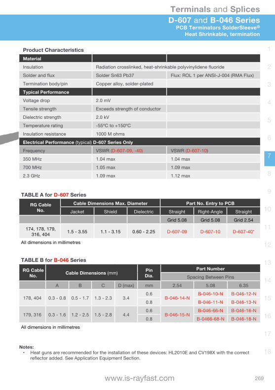
269
Terminals and Splices
www.is-rayfast.com
1
2
3
4
5
6
7
8
9
10
11
12
13
14
15
16
17
18
D-607 and B-046 SeriesPCB Terminators SolderSleeve®
Heat Shrinkable, termination
Product CharacteristicsMaterial
Insulation Radiation crosslinked, heat-shrinkable polyvinylidene fluoride
Solder and flux Solder Sn63 Pb37 Flux: ROL 1 per ANSI-J-004 (RMA Flux)
Termination body/pin Copper alloy, solder-plated
Typical Performance
Voltage drop 2.0 mV
Tensile strength Exceeds strength of conductor
Dielectric strength 2.0 kV
Temperature rating -55ºC to +150ºC
Insulation resistance 1000 M ohms
Electrical Performance (typical) D-607 Series Only
Frequency VSWR (D-607-09, -40) VSWR (D-607-10)
350 MHz 1.04 max 1.04 max
700 MHz 1.05 max 1.09 max
2.3 GHz 1.09 max 1.12 max
TABLE A for D-607 Series
RG CableNo.
Cable Dimensions Max. Diameter Part No. Entry to PCB
Jacket Shield Dielectric Straight Right-Angle Straight
Grid 5.08 Grid 5.08 Grid 2.54
174, 178, 179, 316, 404 1.5 - 3.55 1.1 - 3.15 0.60 - 2.25 D-607-09 D-607-10 D-607-40*
All dimensions in millimetres
TABLE B for B-046 Series
RG CableNo. Cable Dimensions (mm) Pin
Dia.Part Number
Spacing Between Pins
A B C D (max) mm 2.54 5.08 6.35
178, 404 0.3 - 0.8 0.5 - 1.7 1.3 - 2.3 3.40.6
B-046-14-NB-046-10-N B-046-12-N
0.8 B-046-11-N B-046-13-N
179, 316 0.3 - 1.6 1.2 - 2.5 1.5 - 2.8 4.40.6
B-046-15-NB-046-66-N B-046-16-N
0.8 B-0466-68-N B-046-18-N
All dimensions in millimetres
Notes: • Heat guns are recommended for the installation of these devices: HL2010E and CV198X with the correct
reflector added. See Application Equipment Section.
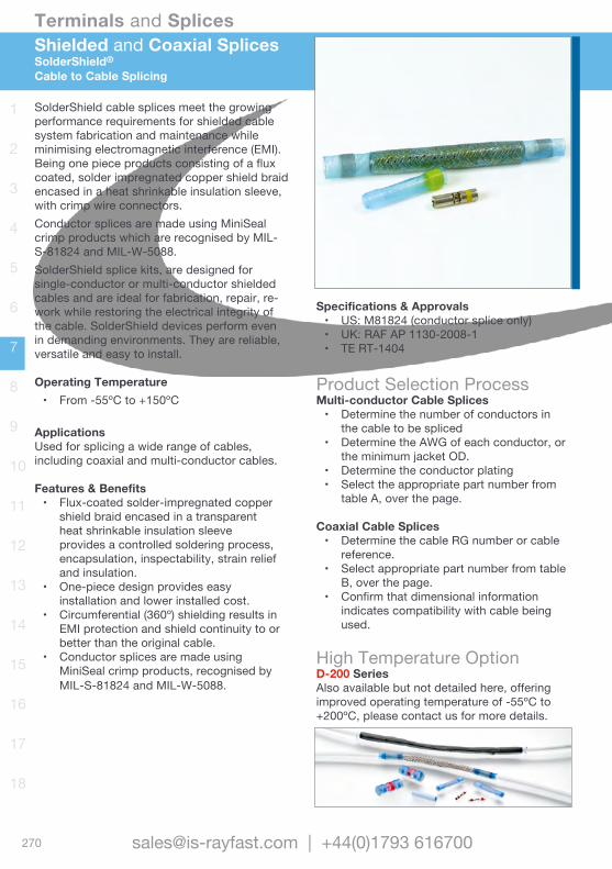
270
Terminals and Splices
[email protected] | +44(0)1793 616700
1
2
3
4
5
6
7
8
9
10
11
12
13
14
15
16
17
18
SolderShield cable splices meet the growing performance requirements for shielded cable system fabrication and maintenance while minimising electromagnetic interference (EMI). Being one piece products consisting of a flux coated, solder impregnated copper shield braid encased in a heat shrinkable insulation sleeve, with crimp wire connectors.Conductor splices are made using MiniSeal crimp products which are recognised by MIL-S-81824 and MIL-W-5088.SolderShield splice kits, are designed for single-conductor or multi-conductor shielded cables and are ideal for fabrication, repair, re-work while restoring the electrical integrity of the cable. SolderShield devices perform even in demanding environments. They are reliable, versatile and easy to install.
Operating Temperature • From -55ºC to +150ºC
ApplicationsUsed for splicing a wide range of cables, including coaxial and multi-conductor cables.
Features & Benefits• Flux-coated solder-impregnated copper
shield braid encased in a transparent heat shrinkable insulation sleeve provides a controlled soldering process, encapsulation, inspectability, strain relief and insulation.
• One-piece design provides easy installation and lower installed cost.
• Circumferential (360º) shielding results in EMI protection and shield continuity to or better than the original cable.
• Conductor splices are made using MiniSeal crimp products, recognised by MIL-S-81824 and MIL-W-5088.
Shielded and Coaxial SplicesSolderShield®
Cable to Cable Splicing
Specifications & Approvals• US: M81824 (conductor splice only)• UK: RAF AP 1130-2008-1• TE RT-1404
Product Selection ProcessMulti-conductor Cable Splices• Determine the number of conductors in
the cable to be spliced• Determine the AWG of each conductor, or
the minimum jacket OD.• Determine the conductor plating• Select the appropriate part number from
table A, over the page.
Coaxial Cable Splices• Determine the cable RG number or cable
reference.• Select appropriate part number from table
B, over the page.• Confirm that dimensional information
indicates compatibility with cable being used.
High Temperature OptionD-200 SeriesAlso available but not detailed here, offering improved operating temperature of -55ºC to +200ºC, please contact us for more details.
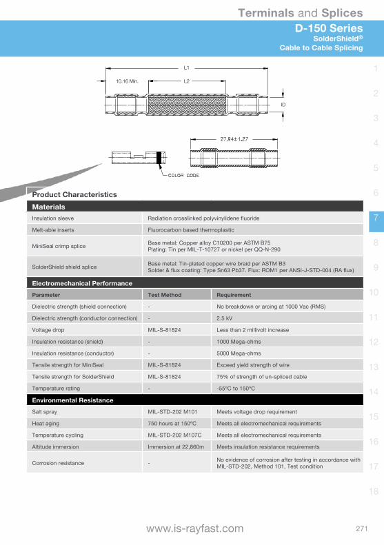
271
Terminals and Splices
www.is-rayfast.com
1
2
3
4
5
6
7
8
9
10
11
12
13
14
15
16
17
18
D-150 SeriesSolderShield®
Cable to Cable Splicing
Product CharacteristicsMaterialsInsulation sleeve Radiation crosslinked polyvinylidene fluoride
Melt-able inserts Fluorocarbon based thermoplastic
MiniSeal crimp splice Base metal: Copper alloy C10200 per ASTM B75Plating: Tin per MIL-T-10727 or nickel per QQ-N-290
SolderShield shield splice Base metal: Tin-plated copper wire braid per ASTM B3Solder & flux coating: Type Sn63 Pb37. Flux: ROM1 per ANSI-J-STD-004 (RA flux)
Electromechanical PerformanceParameter Test Method Requirement
Dielectric strength (shield connection) - No breakdown or arcing at 1000 Vac (RMS)
Dielectric strength (conductor connection) - 2.5 kV
Voltage drop MIL-S-81824 Less than 2 millivolt increase
Insulation resistance (shield) - 1000 Mega-ohms
Insulation resistance (conductor) - 5000 Mega-ohms
Tensile strength for MiniSeal MIL-S-81824 Exceed yield strength of wire
Tensile strength for SolderShield MIL-S-81824 75% of strength of un-spliced cable
Temperature rating - -55ºC to 150ºC
Environmental ResistanceSalt spray MIL-STD-202 M101 Meets voltage drop requirement
Heat aging 750 hours at 150ºC Meets all electromechanical requirements
Temperature cycling MIL-STD-202 M107C Meets all electromechanical requirements
Altitude immersion Immersion at 22,860m Meets insulation resistance requirements
Corrosion resistance - No evidence of corrosion after testing in accordance with MIL-STD-202, Method 101, Test condition
10.16 Min. L2
ID
L1
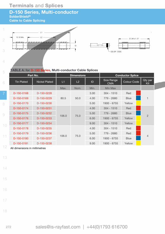
272
Terminals and Splices
[email protected] | +44(0)1793 616700
1
2
3
4
5
6
7
8
9
10
11
12
13
14
15
16
17
18
D-150 Series, Multi-conductorSolderShield®
Cable to Cable Splicing
TABLE A: for D-150 Series, Multi-conductor Cable SplicesPart No. Dimensions Conductor Splice
Tin Plated Nickel Plated L1 L2 ID Size RangeCMA Colour Code Qty per
KitMax. Nom. Min. Min Max
D-150-0168 D-150-0228
80.5 50.0
3.00 304 - 1510 Red
1D-150-0169 D-150-0229 4.00 779 - 2680 Blue
D-150-0170 D-150-0230 5.00 1900 - 6755 Yellow
D-150-0174 D-150-0231
106.0 75.0
4.00 304 - 1510 Red
2D-150-0175 D-150-0232 5.00 779 - 2680 Blue
D-150-0176 D-150-0233 6.00 1900 - 6755 Yellow
D-150-0177 D-150-0234 9.00 304 - 1510 Yellow
D-150-0178 D-150-0235
106.0 75.0
4.00 304 - 1510 Red
4D-150-0179 D-150-0236 5.00 779 - 2680 Red
D-150-0180 D-150-0237 6.00 1900 - 6755 Blue
D-150-0181 D-150-0238 9.00 1900 - 6755 YellowAll dimensions in millimetres
10.16 Min. L2
ID
L1
10.16 Min. L2
ID
L1
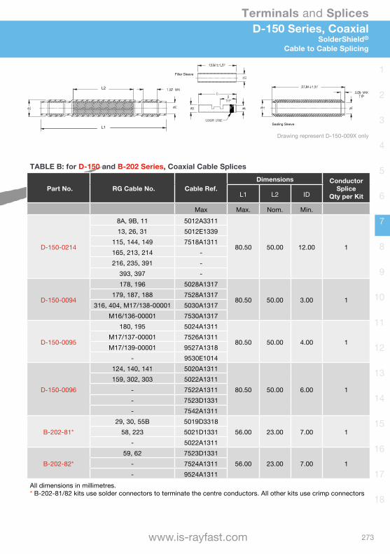
273
Terminals and Splices
www.is-rayfast.com
1
2
3
4
5
6
7
8
9
10
11
12
13
14
15
16
17
18
D-150 Series, CoaxialSolderShield®
Cable to Cable Splicing
TABLE B: for D-150 and B-202 Series, Coaxial Cable Splices
Part No. RG Cable No. Cable Ref.Dimensions Conductor
SpliceQty per KitL1 L2 ID
Max Max. Nom. Min.
D-150-0214
8A, 9B, 11 5012A3311
80.50 50.00 12.00 1
13, 26, 31 5012E1339115, 144, 149 7518A1311165, 213, 214 -216, 235, 391 -
393, 397 -
D-150-0094
178, 196 5028A1317
80.50 50.00 3.00 1179, 187, 188 7528A1317
316, 404, M17/138-00001 5030A1317M16/136-00001 7530A1317
D-150-0095
180, 195 5024A1311
80.50 50.00 4.00 1M17/137-00001 7526A1311M17/139-00001 9527A1318
- 9530E1014
D-150-0096
124, 140, 141 5020A1311
80.50 50.00 6.00 1159, 302, 303 5022A1311
- 7522A1311- 7523D1331- 7542A1311
B-202-81*29, 30, 55B 5019D3318
56.00 23.00 7.00 158, 223 5021D1331- 5022A1311
B-202-82*59, 62 7523D1331
56.00 23.00 7.00 1- 7524A1311- 9524A1311
All dimensions in millimetres.* B-202-81/82 kits use solder connectors to terminate the centre conductors. All other kits use crimp connectors
TABLE A: for D-150 Series, Multi-conductor Cable SplicesPart No. Dimensions Conductor Splice
Tin Plated Nickel Plated L1 L2 ID Size RangeCMA Colour Code Qty per
KitMax. Nom. Min. Min Max
D-150-0168 D-150-0228
80.5 50.0
3.00 304 - 1510 Red
1D-150-0169 D-150-0229 4.00 779 - 2680 Blue
D-150-0170 D-150-0230 5.00 1900 - 6755 Yellow
D-150-0174 D-150-0231
106.0 75.0
4.00 304 - 1510 Red
2D-150-0175 D-150-0232 5.00 779 - 2680 Blue
D-150-0176 D-150-0233 6.00 1900 - 6755 Yellow
D-150-0177 D-150-0234 9.00 304 - 1510 Yellow
D-150-0178 D-150-0235
106.0 75.0
4.00 304 - 1510 Red
4D-150-0179 D-150-0236 5.00 779 - 2680 Red
D-150-0180 D-150-0237 6.00 1900 - 6755 Blue
D-150-0181 D-150-0238 9.00 1900 - 6755 YellowAll dimensions in millimetres
L2
L1
Filler Sleeve
Sealing Sleeve
Drawing represent D-150-009X only

274
Terminals and Splices
[email protected] | +44(0)1793 616700
1
2
3
4
5
6
7
8
9
10
11
12
13
14
15
16
17
18
1 2 3 4
8765
One-piece controlled soldering SolderTacts are designed to facilitate faster and more reliable terminations. SolderTacts eliminate the variables associated with crimping, accelerates production while reducing handling and installed costs.
Features & Benefits• One-piece contact design with integrated
soldering technology• Controlled re-flow soldering process yields
reliable consistent terminations• 360º shielding reduces crosstalk and
improves signal transmission.• Contact fits multiple cable sizes.• Compatible with a variety of commercial
and military connectors.• 150ºC temperature rating.
Shielded Connector ContactsSolderTacts®
Controlled Solder Contacts
Specifications & Approvals• TE D-6002
1. Outer SolderSleeveHeat shrinkable insulating sleeve. Cable inserts easily, with no spacers or other parts required.
2. Inner SolderSleeveTermination is a heat shrinkable sleeve with a precisely pre-fluxed solder preform conforming to QQ-S-571
3. ConnectorThe precision outer body meets electrical engagement and contact retention requirements of individual connector systems.
4. Inner Heat shrinkIn the terminated signal lead, the inner heat shrink tubing forms tightly around the termination to insulate and strain relieve the connection.
5. Outer Solder Pre-formContains precise amounts of solder and flux conforming to QQ-S-571.
6. Inner Pin and SocketContacts are permanently fixed within the assembly to provide proper setback and concentrically.
7. DielectricThe dielectric between inner and outer contacts provides concentricity, electrical integrity, precise mating dimensions and closed entry at the inner socket.
8. InspectionThe shield termination can be inspected through the viewing port.

275
Terminals and Splices
www.is-rayfast.com
1
2
3
4
5
6
7
8
9
10
11
12
13
14
15
16
17
18
Shielded Connector ContactsMIL-DTL-26482 Series SolderTacts®
Controlled Solder Contacts
Notes: • Heat guns are recommended for the installation of these devices: HL2010E and CV198X with the correct
reflector added. See Application Equipment Section.
MIL-DTL-26482 Series ContactsPart Number Size Wire (AWG) Polarity Cable Type Military Specification
D-602-16* 12 24-32 Socket Coaxial MIS-20067/5-001
D-602-17* 12 24-32 Pin Coaxial MIS-20067/5-001
D-602-46 16 24-30 Pin Coaxial -
D-602-47 16 26-32 Socket Coaxial -
D-602-56 16 24-30 Pin Twin Pair -
D-602-57 16 24-30 Socket Twin Pair -
* These SolderTacts contacts are on qualified parts list for indicated specification.
Tooling Selection Guide for MIL-DTL-26482 ContactsPart Numbers Eng Standard Adaptor Insertion Tool Removal Tool
D-602-46/47 ES61137 AT-1319-17 AD-1525 AD-1526
D-602-56/57 ES61138 - (M81969/17-04) (M81969/19-08)
D-602-16/17 ES61161 - - -
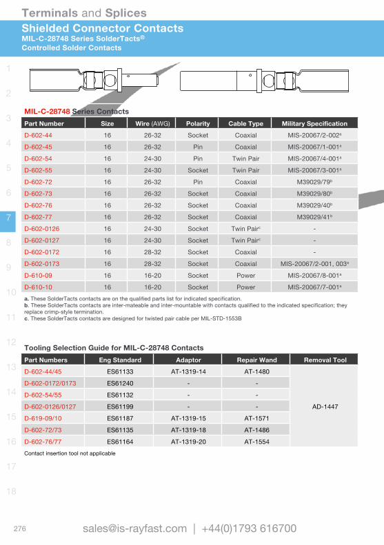
276
Terminals and Splices
[email protected] | +44(0)1793 616700
1
2
3
4
5
6
7
8
9
10
11
12
13
14
15
16
17
18
Shielded Connector ContactsMIL-C-28748 Series SolderTacts®
Controlled Solder Contacts
MIL-C-28748 Series ContactsPart Number Size Wire (AWG) Polarity Cable Type Military Specification
D-602-44 16 26-32 Socket Coaxial MIS-20067/2-002a
D-602-45 16 26-32 Pin Coaxial MIS-20067/1-001a
D-602-54 16 24-30 Pin Twin Pair MIS-20067/4-001a
D-602-55 16 24-30 Socket Twin Pair MIS-20067/3-001a
D-602-72 16 26-32 Pin Coaxial M39029/79b
D-602-73 16 26-32 Socket Coaxial M39029/80b
D-602-76 16 26-32 Socket Coaxial M39029/40b
D-602-77 16 26-32 Socket Coaxial M39029/41b
D-602-0126 16 24-30 Socket Twin Pairc -
D-602-0127 16 24-30 Socket Twin Pairc -
D-602-0172 16 28-32 Socket Coaxial -
D-602-0173 16 28-32 Socket Coaxial MIS-20067/2-001, 003a
D-610-09 16 16-20 Socket Power MIS-20067/8-001a
D-610-10 16 16-20 Socket Power MIS-20067/7-001a
a. These SolderTacts contacts are on the qualified parts list for indicated specification.b. These SolderTacts contacts are inter-mateable and inter-mountable with contacts qualified to the indicated specification; they replace crimp-style termination.c. These SolderTacts contacts are designed for twisted pair cable per MIL-STD-1553B
Tooling Selection Guide for MIL-C-28748 ContactsPart Numbers Eng Standard Adaptor Repair Wand Removal Tool
D-602-44/45 ES61133 AT-1319-14 AT-1480
AD-1447
D-602-0172/0173 ES61240 - -
D-602-54/55 ES61132 - -
D-602-0126/0127 ES61199 - -
D-619-09/10 ES61187 AT-1319-15 AT-1571
D-602-72/73 ES61135 AT-1319-18 AT-1486
D-602-76/77 ES61164 AT-1319-20 AT-1554Contact insertion tool not applicable
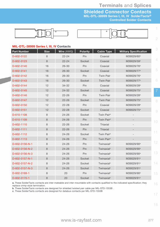
277
Terminals and Splices
www.is-rayfast.com
1
2
3
4
5
6
7
8
9
10
11
12
13
14
15
16
17
18
Shielded Connector ContactsMIL-DTL-38999 Series I, III, IV SolderTacts®
Controlled Solder Contacts
MIL-DTL-38999 Series I, III, IV ContactsPart Number Size Wire (AWG) Polarity Cable Type Military Specification
D-602-0122 8 22-24 Pin Coaxial M39029/60a
D-602-0123 8 22-24 Socket Coaxial M39029/59a
D-602-0140 16 26-30 Pin Coaxial M39029/76a
D-602-0141 16 26-30 Socket Coaxial M39029/77a
D-602-0142 16 26-30 Pin Twin Pair M39029/76a
D-602-0143 16 26-30 Socket Twin Pair M39029/77a
D-602-0144 12 34-32 Pin Coaxial M39029/28a
D-602-0145 12 24-32 Socket Coaxial M39029/75a
D-602-0146 12 22-26 Pin Twin Pair M39029/28a
D-602-0147 12 22-26 Socket Twin Pair M39029/75a
D-602-0150 12 22-28 Pin Coaxial M39029/28a
D-602-0151 12 22-28 Socket Coaxial M39029/75a
D-610-1108 8 24-26 Socket Twin Pairb -
D-610-1109 8 24-26 Pin Twin Pairb -
D-602-1110 8 22-26 Socket Triaxial -
D-602-1111 8 22-26 Pin Triaxial -
D-602-1112 8 24-26 Socket Twin Pairb -
D-602-1113 8 24-26 Pin Twin Pairb -
D-602-0156-N-1 8 24-26 Pin Twinaxialc M39029/90a
D-602-0156-N-2 8 24-26 Pin Twinaxialc M39029/90a
D-602-0156-N-3 8 24-26 Pin Twinaxialc M39029/90a
D-602-0157-N-1 8 24-26 Socket Twinaxialc M39029/91a
D-602-0157-N-2 8 24-26 Socket Twinaxialc M39029/91a
D-602-0157-N-3 8 24-26 Socket Twinaxialc M39029/91a
D-602-0169-1 8 20 Pin Twinaxialc M39029/90a
D-602-0170-1 8 20 Socket Twinaxialc M39029/91a
a. These SolderTacts contacts are inter-mateable and inter-mountable with contacts qualified to the indicated specification; they replace crimp-style termination.b. These SolderTacts contacts are designed for shielded twisted pair cable per MIL-STD-1553B .c. These SolderTacts contacts are designed for databus contacts per MIL-STD-1553B
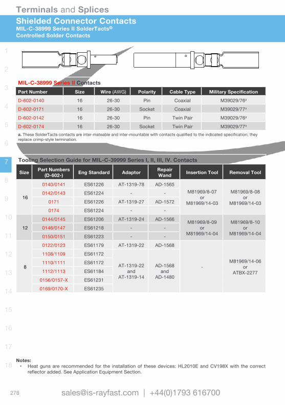
278
Terminals and Splices
[email protected] | +44(0)1793 616700
1
2
3
4
5
6
7
8
9
10
11
12
13
14
15
16
17
18
Shielded Connector ContactsMIL-C-38999 Series II SolderTacts®
Controlled Solder Contacts
MIL-C-38999 Series II ContactsPart Number Size Wire (AWG) Polarity Cable Type Military Specification
D-602-0140 16 26-30 Pin Coaxial M39029/76a
D-602-0171 16 26-30 Socket Coaxial M39029/77a
D-602-0142 16 26-30 Pin Twin Pair M39029/76a
D-602-0174 16 26-30 Socket Twin Pair M39029/77a
a. These SolderTacts contacts are inter-mateable and inter-mountable with contacts qualified to the indicated specification; they replace crimp-style termination.
Tooling Selection Guide for MIL-C-39999 Series I, II, III, IV. Contacts
Size Part Numbers(D-602-) Eng Standard Adaptor Repair
Wand Insertion Tool Removal Tool
16
0140/0141 ES61226 AT-1319-78 AD-1565M81969/8-07
orM81969/14-03
M81969/8-08or
M81969/14-03
0142/0143 ES61224 - -
0171 ES61226 AT-1319-27 AD-1572
0174 ES61224 - -
12
0144/0145 ES61206 AT-1319-24 AD-1566 M81969/8-09or
M81969/14-04
M81969/8-10or
M81969/14-040146/0147 ES61218 - -
0150/0151 ES61223 - -
8
0122/0123 ES61179 AT-1319-22 AD-1568
-M81969/14-06
orATBX-2277
1108/1109 ES61172
AT-1319-22 and
AT-1319-14
AD-1568and
AD-1480
1110/1111 ES61172
1112/1113 ES61184
0156/0157-X ES61231
0169/0170-X ES61235
Notes: • Heat guns are recommended for the installation of these devices: HL2010E and CV198X with the correct
reflector added. See Application Equipment Section.
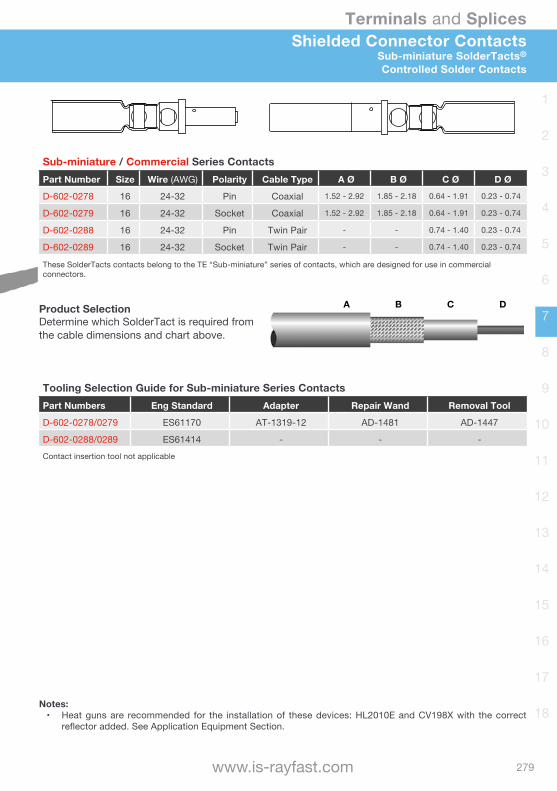
279
Terminals and Splices
www.is-rayfast.com
1
2
3
4
5
6
7
8
9
10
11
12
13
14
15
16
17
18
A B C D
Sub-miniature / Commercial Series ContactsPart Number Size Wire (AWG) Polarity Cable Type A Ø B Ø C Ø D Ø
D-602-0278 16 24-32 Pin Coaxial 1.52 - 2.92 1.85 - 2.18 0.64 - 1.91 0.23 - 0.74
D-602-0279 16 24-32 Socket Coaxial 1.52 - 2.92 1.85 - 2.18 0.64 - 1.91 0.23 - 0.74
D-602-0288 16 24-32 Pin Twin Pair - - 0.74 - 1.40 0.23 - 0.74
D-602-0289 16 24-32 Socket Twin Pair - - 0.74 - 1.40 0.23 - 0.74
These SolderTacts contacts belong to the TE “Sub-miniature” series of contacts, which are designed for use in commercial connectors.
Shielded Connector ContactsSub-miniature SolderTacts®
Controlled Solder Contacts
Product SelectionDetermine which SolderTact is required fromthe cable dimensions and chart above.
Tooling Selection Guide for Sub-miniature Series ContactsPart Numbers Eng Standard Adapter Repair Wand Removal Tool
D-602-0278/0279 ES61170 AT-1319-12 AD-1481 AD-1447
D-602-0288/0289 ES61414 - - -Contact insertion tool not applicable
Notes: • Heat guns are recommended for the installation of these devices: HL2010E and CV198X with the correct
reflector added. See Application Equipment Section.
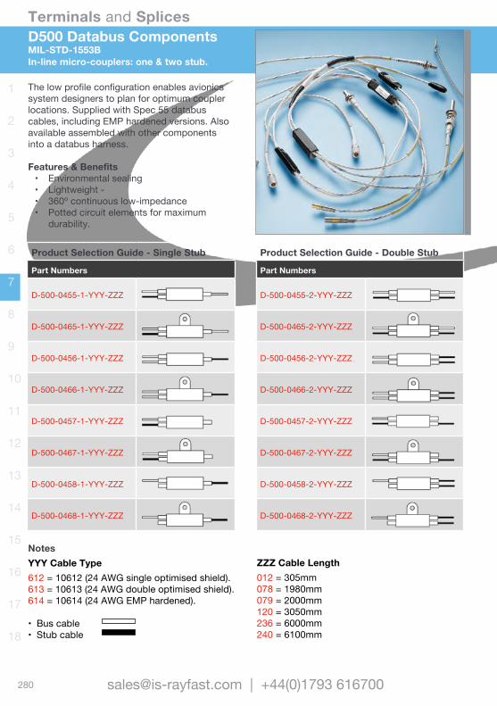
280
Terminals and Splices
[email protected] | +44(0)1793 616700
1
2
3
4
5
6
7
8
9
10
11
12
13
14
15
16
17
18
D500 Databus ComponentsMIL-STD-1553BIn-line micro-couplers: one & two stub.
The low profile configuration enables avionics system designers to plan for optimum coupler locations. Supplied with Spec 55 databus cables, including EMP hardened versions. Also available assembled with other components into a databus harness.
Features & Benefits• Environmental sealing• Lightweight -• 360º continuous low-impedance • Potted circuit elements for maximum
durability.
Product Selection Guide - Single Stub
Part Numbers
D-500-0455-1-YYY-ZZZ
D-500-0465-1-YYY-ZZZ
D-500-0456-1-YYY-ZZZ
D-500-0466-1-YYY-ZZZ
D-500-0457-1-YYY-ZZZ
D-500-0467-1-YYY-ZZZ
D-500-0458-1-YYY-ZZZ
D-500-0468-1-YYY-ZZZ
Product Selection Guide - Double Stub
Part Numbers
D-500-0455-2-YYY-ZZZ
D-500-0465-2-YYY-ZZZ
D-500-0456-2-YYY-ZZZ
D-500-0466-2-YYY-ZZZ
D-500-0457-2-YYY-ZZZ
D-500-0467-2-YYY-ZZZ
D-500-0458-2-YYY-ZZZ
D-500-0468-2-YYY-ZZZ
NotesYYY Cable Type612 = 10612 (24 AWG single optimised shield).613 = 10613 (24 AWG double optimised shield).614 = 10614 (24 AWG EMP hardened).
• Bus cable• Stub cable
ZZZ Cable Length012 = 305mm078 = 1980mm079 = 2000mm120 = 3050mm236 = 6000mm240 = 6100mm
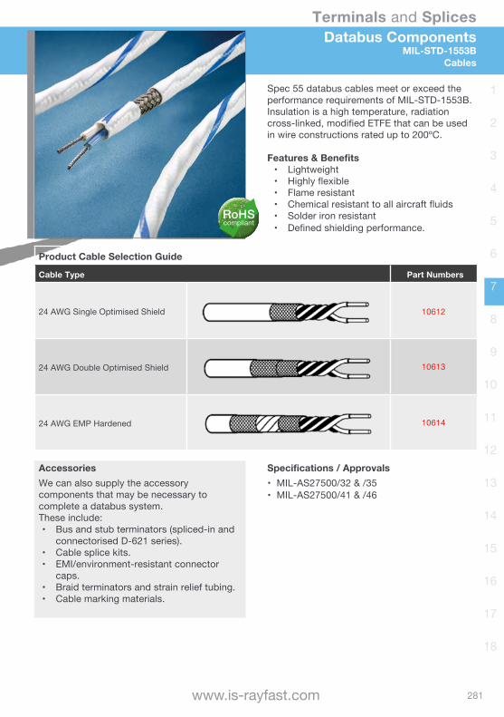
281
Terminals and Splices
www.is-rayfast.com
1
2
3
4
5
6
7
8
9
10
11
12
13
14
15
16
17
18
Databus ComponentsMIL-STD-1553B
Cables
Spec 55 databus cables meet or exceed the performance requirements of MIL-STD-1553B. Insulation is a high temperature, radiation cross-linked, modified ETFE that can be used in wire constructions rated up to 200ºC.
Features & Benefits• Lightweight• Highly flexible• Flame resistant• Chemical resistant to all aircraft fluids• Solder iron resistant• Defined shielding performance.
Product Cable Selection Guide
Cable Type Part Numbers
24 AWG Single Optimised Shield 10612
24 AWG Double Optimised Shield 10613
24 AWG EMP Hardened 10614
Specifications / Approvals• MIL-AS27500/32 & /35• MIL-AS27500/41 & /46
AccessoriesWe can also supply the accessory components that may be necessary to complete a databus system. These include:• Bus and stub terminators (spliced-in and
connectorised D-621 series).• Cable splice kits.• EMI/environment-resistant connector
caps.• Braid terminators and strain relief tubing.• Cable marking materials.
RoHScompliant

Wire and Cable Heat-shrink Tubing
Non-shrink TubingBraided SleevingScreening Braids
Moulded Parts Terminals and Splices
Wire and Cable MarkersAccessoriesConnectorsBackshells
Bonding LeadsMetal Braids
Relays and Contactors Switches and Grips
Adhesives and TapesApplication EquipmentAdded Value Services
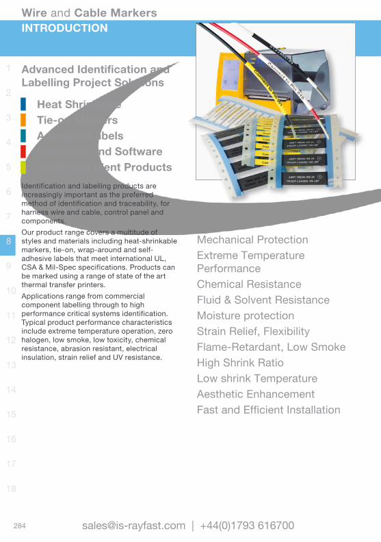
Wire and Cable Markers
284 [email protected] | +44(0)1793 616700
1
2
3
4
5
6
7
8
9
10
11
12
13
14
15
16
17
18
Advanced Identification and Labelling Project Solutions
Heat Shrinkable Tie-on Markers Adhesive Labels Hardware and Software Additional Ident ProductsIdentification and labelling products are increasingly important as the preferred method of identification and traceability, for harness wire and cable, control panel and components.Our product range covers a multitude of styles and materials including heat-shrinkable markers, tie-on, wrap-around and self-adhesive labels that meet international UL, CSA & Mil-Spec specifications. Products can be marked using a range of state of the art thermal transfer printers.Applications range from commercial component labelling through to high performance critical systems identification. Typical product performance characteristics include extreme temperature operation, zero halogen, low smoke, low toxicity, chemical resistance, abrasion resistant, electrical insulation, strain relief and UV resistance.
INTRODUCTION
Mechanical ProtectionExtreme Temperature PerformanceChemical ResistanceFluid & Solvent ResistanceMoisture protectionStrain Relief, FlexibilityFlame-Retardant, Low SmokeHigh Shrink RatioLow shrink TemperatureAesthetic EnhancementFast and Efficient Installation

Wire and Cable Markers
285www.is-rayfast.com
1
2
3
4
5
6
7
8
9
10
11
12
13
14
15
16
17
18
Heat Shrinkable Markers Selection Guide and Overview page 286TMS-SCE Military Grade page 288HT-SCE High Temp, Low Out gassing page 289HX-SCE Low Fire Hazard page 290D-SCE Fluid resistant page 291ZHD-SCE LFH and Fluid resistant page 292UV-SCE UV resistant page 293RPS Commercial Grade page 294TMS-CCUV UV Protection Sleeve page 295
Tie-on Markers Selection Guide page 296CM-SCE-TP Military Grade page 297HLX125 Low Fire Hazard page 298PM316 Stainless Steel page 299
Adhesive Labels Selection Guide page 300SBPlus Self Laminating page 301PVF Self laminating page 302MP Metalised Polyester page 303MV Tamper Evident Metalised Polyester page 304WP White Polyester page 305TTP Continuous Polyester page 306RMK-A4 Epoxy Coated page 307
Hardware and SoftwareWinTotal Software page 308T200 Ident Printer page 310TE3112 Printer page 311RIBBON Thermal Transfer Ribbons page 312
Additional Ident Products Universal Payoff and Push-On Markers page 314 Pre-Print Service page 315
CONTENTS
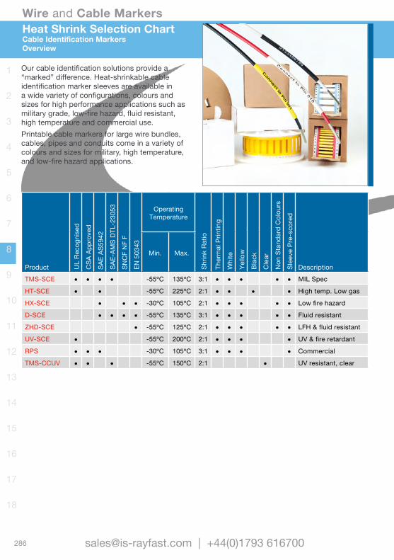
Wire and Cable Markers
286 [email protected] | +44(0)1793 616700
1
2
3
4
5
6
7
8
9
10
11
12
13
14
15
16
17
18
Heat Shrink Selection ChartCable Identification MarkersOverview
Product UL
Reco
gnis
ed
CSA
App
rove
d
SAE
AS59
42
SAE-
AMS
DTL-
2305
3
SNC
F N
F F
EN 5
0343
Operating Temperature
Shrin
k Ra
tio
Ther
mal
Prin
ting
Whi
te
Yello
w
Blac
k
Cle
ar
Non
Sta
ndar
d C
olou
rs
Slee
ve P
re-s
core
d
Description
Min. Max.
TMS-SCE • • • • -55ºC 135ºC 3:1 • • • • • MIL Spec
HT-SCE • • -55ºC 225ºC 2:1 • • • • High temp. Low gas
HX-SCE • • • -30ºC 105ºC 2:1 • • • • • Low fire hazard
D-SCE • • • • -55ºC 135ºC 3:1 • • • • • Fluid resistant
ZHD-SCE • -55ºC 125ºC 2:1 • • • • • LFH & fluid resistant
UV-SCE • -55ºC 200ºC 2:1 • • • • UV & fire retardant
RPS • • • -30ºC 105ºC 3:1 • • • • Commercial
TMS-CCUV • • • -55ºC 150ºC 2:1 • UV resistant, clear
Our cable identification solutions provide a “marked” difference. Heat-shrinkable cable identification marker sleeves are available in a wide variety of configurations, colours and sizes for high performance applications such as military grade, low-fire hazard, fluid resistant, high temperature and commercial use.Printable cable markers for large wire bundles, cables, pipes and conduits come in a variety of colours and sizes for military, high temperature, and low-fire hazard applications.

Wire and Cable Markers
287www.is-rayfast.com
1
2
3
4
5
6
7
8
9
10
11
12
13
14
15
16
17
18
Available on the range of heat shrinkable identification sleeves, in four standard lengths of 50mm, 25mm, 16mm and 12.5mm. Our in-house ability to score sleeves means we can offer a fast order turnaround.
• S1 Scored sleeve for 2 x 25mm sleeves• S2 Scored sleeve for 3 x 16mm sleeves• S3 Scored sleeve for 4 x 12.5mm sleeves
For non-standard lengths please contact us.Minimum order quantity is based on the pack size of the particular heat shrinkable sleeve.
Perforated score line is made to produce multiple markers from each sleeve. For part numbering add S1, S2 or S3 to end of the individual part number. Illustration shows nominal actual size of a 3.2mm Ø marker, using an 11 point Arial font.
Un-scored sleeve
S1 Perforated sleeve for 2 x sleeves
S2 Perforated sleeve for 3 x sleeves
S3 Perforated sleeve for 4 x sleeves
The above represents the standard choices, other options and variants are available, please contact us for information.
Pre-Scoring OptionsHeat Shrinkable Cable Markers
Overview
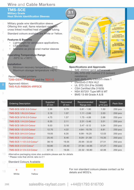
Wire and Cable Markers
288 [email protected] | +44(0)1793 616700
1
2
3
4
5
6
7
8
9
10
11
12
13
14
15
16
17
18
TMS-SCEMilitary GradeHeat Shrink Identification Sleeves
Military grade wire identification sleeve. Offering thin wall, flame retardant radiation cross linked modified heat shrinkable tubing.Standard colours available are White or Yellow.
Features & Benefits• Lightweight for aerospace applications.• CSA certified• Available as pre-scored marker sleeves
Operating Temperature Range• -55ºC to +135ºC
Installation• Minimum recovery temperature +85ºC• Maximum storage temperature +40ºC
Recommended printers: T200-IDENT-PRINTER and the TE3112.Approved ribbon:TMS-RJS-RIBBON-4RPSCE
Ordering Description SuppliedØ mm
RecoveredØ mm
Recommended Range mm
Weightg/10 pcs Pack Size
TMS-SCE-3/32-2.0-Colour 2.36 0.79 0.81 - 1.90 1.50 250 pcs
TMS-SCE-1/8-2.0-Colour 3.18 1.07 1.11 - 2.66 2.03 250 pcs
TMS-SCE-3/16-2.0-Colour 4.75 1.57 1.75 - 4.06 2.68 250 pcs
TMS-SCE-1/4-2.0-Colour 6.35 2.11 2.31 - 5.46 3.51 250 pcs
TMS-SCE-3/8-2.0-Colour 9.53 3.18 3.47 - 8.12 5.04 250 pcs
TMS-SCE-1/2-2.0-Colour 12.70 4.22 4.64 - 10.79 6.81 250 pcs
TMS-SCE-3/4-2.0-Colour 19.05 6.35 6.99 - 16.25 12.03 250 pcs
TMS-SCE-1-2.0-Colour 25.40 8.46 9.29 - 21.59 15.35 250 pcs
TMS-SCE-1-1/2-2.0-Colour* 38.10 19.05 20.95 - 33.02 27.51 250 pcs
TMS-SCE-2-2.0-Colour* 50.80 25.40 27.94 - 44.95 47.27 250 pcs
TMS-SCE-2-1/4-2.0-Colour 57.15 19.05 22.32 - 50.80 42.06 250 pcs
Alternative packaging sizes also available please ask for details * Please note that shrink ratio is 2:1
Specifications and Approvals• SAE AS5942 (print adherence)• MIL-STD-202 method 215 (solvent
resistance)• SAE-AMS-DTL-23053/5 class 1• EN45545-2 R24 HL2• UL STD 224 (File 35586)• CSA Certified (file 31929)• NSA 937201 Type MR & MT• BMS 13-69 Grade A & B
3:1shrink
Standard Colours Available
9 4
White Yellow
For non standard colours please contact us for details and MOQ’s.
RoHScompliant

Wire and Cable Markers
289www.is-rayfast.com
1
2
3
4
5
6
7
8
9
10
11
12
13
14
15
16
17
18
HT-SCEHigh Temperature and Low Out-gassing
Heat Shrink Identification Sleeves
High temperature low out-gassing heat shrinkable wire identification sleeves. Designed for use in high temperature applications or where extreme resistance to fuels, lubricants and cleaning solvents is required.
Features & Benefits• High continuous operating temperature.• Extreme fluid resistance.• Low vacuum out-gassing.• Available as pre-scored marker sleeves
Operating Temperature Range• -55ºC to +225ºC
Installation• Minimum recovery temperature +200ºC• Maximum storage temperature +40ºC
Recommended printers: T200-IDENT-PRINTER and the TE3112.Approved ribbon:TMS-RJS-RIBBON-4HTIf black tubing TMS-RJS-RIBBON-WHT-4HT
Ordering Description SuppliedØ mm
RecoveredØ mm
Recommended Range mm Pack Size
HT-SCE-3/32-2.0-Colour 2.36 0.79 0.81 - 1.90 250 pcsHT-SCE-1/8-2.0-Colour 3.17 1.57 1.75 - 2.66 250 pcsHT-SCE-3/16-2.0-Colour 4.74 2.36 2.54 - 4.06 250 pcsHT-SCE-1/4-2.0-Colour 6.35 3.18 3.40 - 6.00 250 pcsHT-SCE-3/8-2.0-Colour 9.52 4.74 5.30 - 8.10 250 pcsHT-SCE-1/2-2.0-Colour 12.70 6.35 6.60 - 11.40 250 pcsHT-SCE-3/4-2.0-Colour 19.05 9.53 9.90 - 15.30 250 pcsHT-SCE-1-2.0-Colour 25.40 12.70 13.30 - 23.00 250 pcsHT-SCE-1-1/2-2.0-Colour 38.10 19.05 20.95 - 34.00 250 pcs
Alternative packaging sizes also available please ask for details.
Specifications and Approvals• SAE AS5942 (print adherence)• MIL-STD-202G method 215 (solvent
resistance)• UL-224 VW-1 rated• Low out-gassing 1% max TML, 0.1% max
VCM• NSA 937201 Type MK & ML• BMS 13-69 Grade C & D
2:1shrink
Standard Colours Available
9 0
White Black
For non standard colours please contact us for details and MOQ’s.
RoHScompliant

Wire and Cable Markers
290 [email protected] | +44(0)1793 616700
1
2
3
4
5
6
7
8
9
10
11
12
13
14
15
16
17
18
HX-SCELow Fire HazardHeat Shrink Identification Sleeves
Ideal for applications where limited fire hazard characteristics are necessary. The zero halogen material coupled with low smoke and low toxic fume emissions make the product ideal for use in enclosed spaces such as mass transit, marine and industrial installations.
Features & Benefits• Meets international rail LFH standards.• High performance print quality.• Available as pre-scored marker sleeves.
Operating Temperature Range• -55ºC to +105ºC
Installation• Minimum recovery temperature +120ºC• Maximum storage temperature +40ºC
Recommended printers: T200-IDENT-PRINTER and the TE3112.Approved ribbon:1966-RIBBON
Ordering Description SuppliedØ mm
RecoveredØ mm
Recommended Range mm Pack Size
HX-SCE-2.4-50-Colour 2.36 1.19 1.27 - 1.90 250 pcs
HX-SCE-3.2-50-Colour 3.17 1.58 1.77 - 2.66 250 pcs
HX-SCE-4.8-50-Colour 4.74 2.36 2.54- 4.06 250 pcs
HX-SCE-6.4-50-Colour 6.35 3.18 3.81 - 5.46 250 pcs
HX-SCE-9.5-50-Colour 9.52 4.75 5.59 - 8.12 250 pcs
HX-SCE-12.7-50-Colour 12.70 6.35 6.99- 10.79 250 pcs
HX-SCE-19-50-Colour 19.05 9.53 10.16 - 16.25 250 pcs
HX-SCE-25.4-50-Colour 25.40 12.70 14.29 - 21.59 250 pcs
HX-SCE-38.1-50-Colour 38.10 19.05 20.95 - 33.02 250 pcs
Alternative packaging sizes also available please ask for details
Specifications and Approvals• SAE AS5942 (print adherence)• MIL-STD-202G method 215 (solvent
resistance)• EN45545-2 R22/R23/R24 HL3• LUL 1-085 A3 (Fire Safety Performance)• NF F 16-101 (Class 1A)• BS 6853 Cat 1A• EN 50343 H (Diesel immersion removed)
2:1shrink
Standard Colours Available
9 4
White Yellow
For non standard colours please contact us for details and MOQ’s.
RoHScompliant
HALOGENFREE
LFHLow Fire Hazard

Wire and Cable Markers
291www.is-rayfast.com
1
2
3
4
5
6
7
8
9
10
11
12
13
14
15
16
17
18
D-SCEFluid Resistant
Heat Shrink Identification Sleeves
Suitable for applications where exposure to organic fluids, especially oils, is required. Designed to operate in these conditions at elevated temperatures for extended periods, making them ideal for rail and construction industries.
Features & Benefits• Resistance to organic fluids, common
fuels, lubricants and solvents.• Available as pre-scored marker sleeves.
Operating Temperature Range• -75ºC to +135ºC
Installation• Minimum recovery temperature +135ºC• Maximum storage temperature +40ºC
Recommended printers: T200-IDENT-PRINTER and the TE3112.Approved ribbon:1966-RIBBON
Ordering Description SuppliedØ mm
RecoveredØ mm
Recommended Range mm Pack Size
D-SCE-2.4-50-Colour 2.36 0.79 0.81 - 1.90 250 pcs
D-SCE-3.2-50-Colour 3.17 1.07 1.11 - 2.66 250 pcs
D-SCE-4.8-50-Colour 4.74 1.57 1.75 - 4.06 250 pcs
D-SCE-6.4-50-Colour 6.35 2.11 2.31- 5.46 250 pcs
D-SCE-9.5-50-Colour 9.52 3.18 3.47 - 8.12 250 pcs
D-SCE-12-50-Colour 12.70 4.22 4.64 - 10.79 250 pcs
D-SCE-18-50-Colour 19.05 6.35 6.99 - 16.25 250 pcs
D-SCE-25-50-Colour 25.40 8.46 9.29 - 12.59 250 pcs
D-SCE-38-50-Colour* 38.10 19.05 20.95 - 33.02 250 pcs
Alternative packaging sizes also available please ask for details * Please note that shrink ratio is 2:1
Specifications and Approvals• AMS AS5942 4.1 (print adherence)• MIL-STD-202G method 215 (solvent
resistance)• SAE AMS DTL 23053/6 Class 1• EN50343 appendix H• SNCF NF F 00608 (cat. A & H)
3:1shrink
Standard Colours Available
9 4
White Yellow
For non standard colours please contact us for details and MOQ’s.
RoHScompliant

Wire and Cable Markers
292 [email protected] | +44(0)1793 616700
1
2
3
4
5
6
7
8
9
10
11
12
13
14
15
16
17
18
ZHD-SCEHalogen Free and Fluid ResistanceHeat Shrink Identification Sleeves
Manufactured using a specially developed radiation cross-linked, zero halogen material. Designed specifically to bridge the gap for installations where the highest performance is demanded from an identification sleeve.
Features & Benefits• Meets international rail LFH standards• No Halogens, Sulphur and Nitrogen• Non-flame propagating• High performance print quality.• Available as pre-scored marker sleeves.
Operating Temperature Range• -55ºC to +135ºC
Installation• Minimum recovery temperature +120ºC• Maximum storage temperature +40ºC
Recommended printers: T200-IDENT-PRINTER and the TE3112.Approved ribbon:1966-RIBBON
Ordering Description SuppliedØ mm
RecoveredØ mm
Recommended Range mm Pack Size
ZHD-SCE-2.4-50-Colour 2.4 1.19 1.27 - 1.90 250 pcs
ZHD-SCE-3.2-50-Colour 3.2 1.58 1.77 - 2.66 250 pcs
ZHD-SCE-4.8-50-Colour 4.8 2.36 2.54- 4.06 250 pcs
ZHD-SCE-6.4-50-Colour 6.4 3.18 3.81 - 5.46 250 pcs
ZHD-SCE-9.5-50-Colour 9.5 4.75 5.59 - 8.12 250 pcs
ZHD-SCE-12.7-50-Colour 12.7 6.35 6.99- 10.79 250 pcs
ZHD-SCE-19-50-Colour 19.0 9.53 10.16 - 16.25 250 pcs
ZHD-SCE-25.4-50-Colour 25.4 12.70 14.29 - 21.59 250 pcs
ZHD-SCE-38.1-50-Colour 38.1 19.05 20.95 - 33.02 250 pcs
Alternative packaging sizes also available please ask for details
Specifications and Approvals• SAE AS5942 (print adherence)• MIL-STD-202G method 215 (solvent
resistance)• EN45545-2 R22 HL2• BS 6853 Cat II• EN 50343 (Appendix H)
2:1shrink
Standard Colours Available
9 4
White Yellow
For non standard colours please contact us for details and MOQ’s.
RoHScompliant
HALOGENFREE
LFHLow Fire Hazard
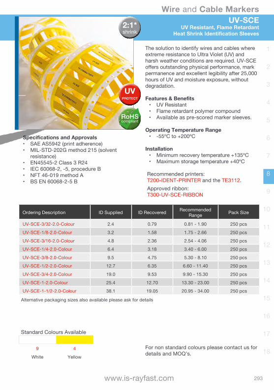
Wire and Cable Markers
293www.is-rayfast.com
1
2
3
4
5
6
7
8
9
10
11
12
13
14
15
16
17
18
UV-SCEUV Resistant, Flame Retardant
Heat Shrink Identification Sleeves
The solution to identify wires and cables where extreme resistance to Ultra Violet (UV) and harsh weather conditions are required. UV-SCE offers outstanding physical performance, mark permanence and excellent legibility after 25,000 hours of UV and moisture exposure, without degradation.
Features & Benefits• UV Resistant• Flame retardant polymer compound• Available as pre-scored marker sleeves.
Operating Temperature Range• -55ºC to +200ºC
Installation• Minimum recovery temperature +135ºC• Maximum storage temperature +40ºC
Recommended printers: T200-IDENT-PRINTER and the TE3112.Approved ribbon:T300-UV-SCE-RIBBON
Ordering Description ID Supplied ID Recovered Recommended Range Pack Size
UV-SCE-3/32-2.0-Colour 2.4 0.79 0.81 - 1.90 250 pcs
UV-SCE-1/8-2.0-Colour 3.2 1.58 1.75 - 2.66 250 pcs
UV-SCE-3/16-2.0-Colour 4.8 2.36 2.54 - 4.06 250 pcs
UV-SCE-1/4-2.0-Colour 6.4 3.18 3.40 - 6.00 250 pcs
UV-SCE-3/8-2.0-Colour 9.5 4.75 5.30 - 8.10 250 pcs
UV-SCE-1/2-2.0-Colour 12.7 6.35 6.60 - 11.40 250 pcs
UV-SCE-3/4-2.0-Colour 19.0 9.53 9.90 - 15.30 250 pcs
UV-SCE-1-2.0-Colour 25.4 12.70 13.30 - 23.00 250 pcs
UV-SCE-1-1/2-2.0-Colour 38.1 19.05 20.95 - 34.00 250 pcs
Alternative packaging sizes also available please ask for details
Specifications and Approvals• SAE AS5942 (print adherence)• MIL-STD-202G method 215 (solvent
resistance)• EN45545-2 Class 3 R24• IEC 60068-2, -5, procedure B• NFT 46-019 method A• BS EN 60068-2-5 B
2:1*shrink
UVPROTECT
Standard Colours Available
9 4
White Yellow
For non standard colours please contact us for details and MOQ’s.
RoHScompliant
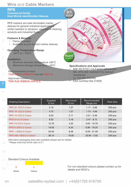
Wire and Cable Markers
294 [email protected] | +44(0)1793 616700
1
2
3
4
5
6
7
8
9
10
11
12
13
14
15
16
17
18
RPSCommercial GradeHeat Shrink Identification Sleeves
RPS markers are heat-shrinkable marker sleeves for general industrial applications, whilst resistant to abrasion, aggressive cleaning solvents and industrial fluids.
Features & Benefits• Flame retardant• Available as pre-scored marker sleeves.
Operating Temperature Range• -30ºC to +105ºC
Installation• Minimum recovery temperature +85ºC• Maximum storage temperature +40ºC
Recommended printers: T200-IDENT-PRINTER and the TE3112.Approved ribbon:TMS-RJS-RIBBON-4RPSCE
Ordering Description SuppliedØ mm
RecoveredØ mm
Recommended Range mm Pack Size
RPS-22-18/2.0-Colour 3.18 1.07 1.17 - 2.66 250 pcs
RPS-18-12/2.0-Colour 4.75 1.57 1.75 - 4.06 250 pcs
RPS-16-10/2.0-Colour 6.35 2.11 2.31 - 5.46 250 pcs
RPS-8-4/2.0-Colour 9.53 3.18 3.47 - 8.12 250 pcs
RPS-10-2/2.0-Colour 12.70 4.22 4.64 - 10.79 250 pcs
RPS-6-250/2.0-Colour 19.05 6.35 6.99 - 16.25 250 pcs
RPS-1-400/2.0-Colour 25.40 8.46 9.29 - 21.59 250 pcs
RPS-400-1000/2.0-Colour* 38.10 19.05 20.95 - 3.02 250 pcs
Alternative packaging sizes also available please ask for details * Please note that shrink ratio is 2:1
Specifications and Approvals• SAE AS 81531 4.6.2 (print adherence)• MIL-STD-202 method 215J (solvent
resistance)• UL 224 (file E35586)• CSA Certified (file 31929)
3:1shrink
Standard Colours Available
9 4
White Yellow
For non standard colours please contact us for details and MOQ’s.
RoHScompliant
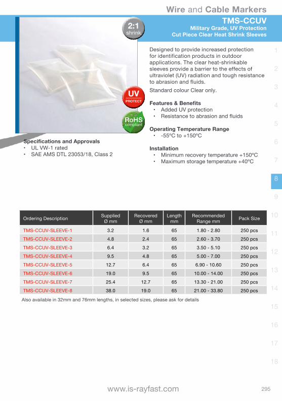
Wire and Cable Markers
295www.is-rayfast.com
1
2
3
4
5
6
7
8
9
10
11
12
13
14
15
16
17
18
TMS-CCUVMilitary Grade, UV Protection
Cut Piece Clear Heat Shrink Sleeves
Designed to provide increased protection for identification products in outdoor applications. The clear heat-shrinkable sleeves provide a barrier to the effects of ultraviolet (UV) radiation and tough resistance to abrasion and fluids.Standard colour Clear only.
Features & Benefits• Added UV protection• Resistance to abrasion and fluids
Operating Temperature Range• -55ºC to +150ºC
Installation• Minimum recovery temperature +150ºC• Maximum storage temperature +40ºC
Ordering Description SuppliedØ mm
RecoveredØ mm
Lengthmm
Recommended Range mm Pack Size
TMS-CCUV-SLEEVE-1 3.2 1.6 65 1.80 - 2.80 250 pcs
TMS-CCUV-SLEEVE-2 4.8 2.4 65 2.60 - 3.70 250 pcs
TMS-CCUV-SLEEVE-3 6.4 3.2 65 3.50 - 5.10 250 pcs
TMS-CCUV-SLEEVE-4 9.5 4.8 65 5.00 - 7.00 250 pcs
TMS-CCUV-SLEEVE-5 12.7 6.4 65 6.90 - 10.60 250 pcs
TMS-CCUV-SLEEVE-6 19.0 9.5 65 10.00 - 14.00 250 pcs
TMS-CCUV-SLEEVE-7 25.4 12.7 65 13.30 - 21.00 250 pcs
TMS-CCUV-SLEEVE-8 38.0 19.0 65 21.00 - 33.80 250 pcs
Also available in 32mm and 76mm lengths, in selected sizes, please ask for details
Specifications and Approvals• UL VW-1 rated• SAE AMS DTL 23053/18, Class 2
2:1shrink
UVPROTECT
RoHScompliant

Wire and Cable Markers
296 [email protected] | +44(0)1793 616700
1
2
3
4
5
6
7
8
9
10
11
12
13
14
15
16
17
18
Tie-On Selection ChartCable Identification MarkersOverview
Tie-On Cable markers are flat, non-adhesive labels that can be used to identify large cables and wire bundles in particularly aggressive environment.
Product
SAE
AS 8
1531
SAE-
AMS
DTL-
2305
3
EN45
545-
2
OperatingTemperature
Size(mm)
Ther
mal
Prin
t StandardColours
Non
Sta
ndar
d C
olou
rs.
Description
Met
al
Whi
te
Yello
wCM-SCE-TP • • -55ºC to +135ºC 10.4 and 51.5 • • • • Polyolefin
HLX125 • • -40ºC to +105ºC 80 x 12.5 • • • • Zero halogen
PM316 -80ºC to +500ºC 95 x 12 n/a • Stainless Steel
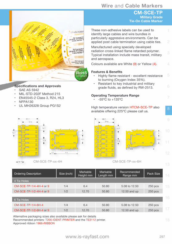
Wire and Cable Markers
297www.is-rayfast.com
1
2
3
4
5
6
7
8
9
10
11
12
13
14
15
16
17
18
CM-SCE-TPMilitary Grade
Tie-On Cable Marker
These non-adhesive labels can be used to identify large cables and wire bundles in particularly aggressive environments. Can be applied post cable termination using cable ties. Manufactured using specially developed radiation cross-linked flame retarded polymer. Typical installation include mass transit, military and aerospace.Colours available are White (9) or Yellow (4).
Features & Benefits• Highly flame resistant - excellent resistance
to burning (Oxygen Index 35%).• Resistant to key industrial and military
grade fluids, as defined by RW-2513.
Operating Temperature Range• -55ºC to +135ºC
High temperature version HTCM-SCE-TP also available offering 225ºC please call us.
Ordering Description Size (inch) Markable Height mm
Markable Length mm
Recommended Range mm Pack Size
4 Tie Holes
CM-SCE-TP-1/4-4H-4 or 9 1/4 6.4 50.80 5.08 to 12.50 250 pcs
CM-SCE-TP-1/2-4H-4 or 9 1/2 12.70 50.80 12.50 and up 250 pcs
6 Tie Holes
CM-SCE-TP-1/4-6H-4 1/4 6.4 50.80 5.08 to 12.50 250 pcs
CM-SCE-TP-1/2-6H-4 or 9 1/2 12.70 50.80 12.50 and up 250 pcs
Alternative packaging sizes also available please ask for details Recommended printers: T200-IDENT-PRINTER and the TE3112 printer. Approved ribbon 1966-RIBBON
Specifications and Approvals• SAE AS 5942• MIL-STD-202F Method 215• EN45545-2 Class 3, R24, HL3• NFPA130• UL MH26328 Group PG1S2
CM-SCE-TP-xx-4H CM-SCE-TP-xx-6H
RoHScompliant

Wire and Cable Markers
298 [email protected] | +44(0)1793 616700
1
2
3
4
5
6
7
8
9
10
11
12
13
14
15
16
17
18
HLX125-NELHalogen free, Low Fire hazardTie-On Cable Marker
Low Fire Hazard, UV stabilised, cross-linked polyolefin Cable Markers, assembled in a Narrow Edge Leading ‘NEL’ format. Consisting of a continuous strip formed into punched tie on Cable Markers. Cable Markers have perforated edges for easy removal Markers are printed by a computer-based system and are attached using cable ties. Ideal for applications where low fire hazard characteristics (low smoke, low toxicity and low flammability) are critical.Standard colours available are White or Yellow.
Features & Benefits• Recommended for use where combustion
of products may endanger personnel or delicate electronics.
• Two formats available.• Ideal for pre or post termination assembly.
Operating Temperature Range• -40ºC to +105ºC
Ordering Description MarkerDimensions mm
PrintableArea mm
No. MarkersAcross Pack Size
HLX125-Colour-4NEL60S 80.0 x 12.5 60.0 x 10.5 4 200 pcs per roll
HLX125-Colour-2NEL60S 80.0 x 12.5 60.0 x 10.5 2 200 pcs per roll
Recommended printers: T200-IDENT-PRINTER and the TE3112 printer. Approved ribbon 1966-RIBBON
Specifications and Approvals• SAE AS5942• MIL-STD-202 Method 215 • London Underground 1-085 A3• EN45545-2 R22/R23/R24 HL3• BS 6853 Vehicle cat 1a• NF F 16-101 Class A1
RoHScompliant
HALOGENFREE
LFHLow Fire Hazard
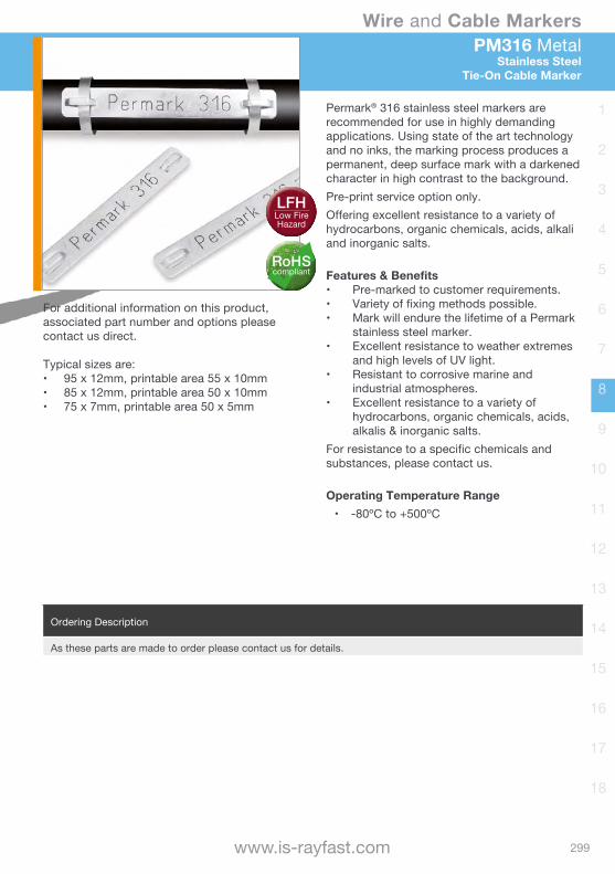
Wire and Cable Markers
299www.is-rayfast.com
1
2
3
4
5
6
7
8
9
10
11
12
13
14
15
16
17
18
PM316 MetalStainless Steel
Tie-On Cable Marker
Permark® 316 stainless steel markers are recommended for use in highly demanding applications. Using state of the art technology and no inks, the marking process produces a permanent, deep surface mark with a darkened character in high contrast to the background. Pre-print service option only.Offering excellent resistance to a variety of hydrocarbons, organic chemicals, acids, alkali and inorganic salts.
Features & Benefits• Pre-marked to customer requirements.• Variety of fixing methods possible.• Mark will endure the lifetime of a Permark
stainless steel marker.• Excellent resistance to weather extremes
and high levels of UV light.• Resistant to corrosive marine and
industrial atmospheres.• Excellent resistance to a variety of
hydrocarbons, organic chemicals, acids, alkalis & inorganic salts.
For resistance to a specific chemicals and substances, please contact us.
Operating Temperature Range• -80ºC to +500ºC
Ordering Description
As these parts are made to order please contact us for details.
For additional information on this product, associated part number and options please contact us direct.
Typical sizes are:• 95 x 12mm, printable area 55 x 10mm• 85 x 12mm, printable area 50 x 10mm• 75 x 7mm, printable area 50 x 5mm
RoHScompliant
LFHLow Fire Hazard
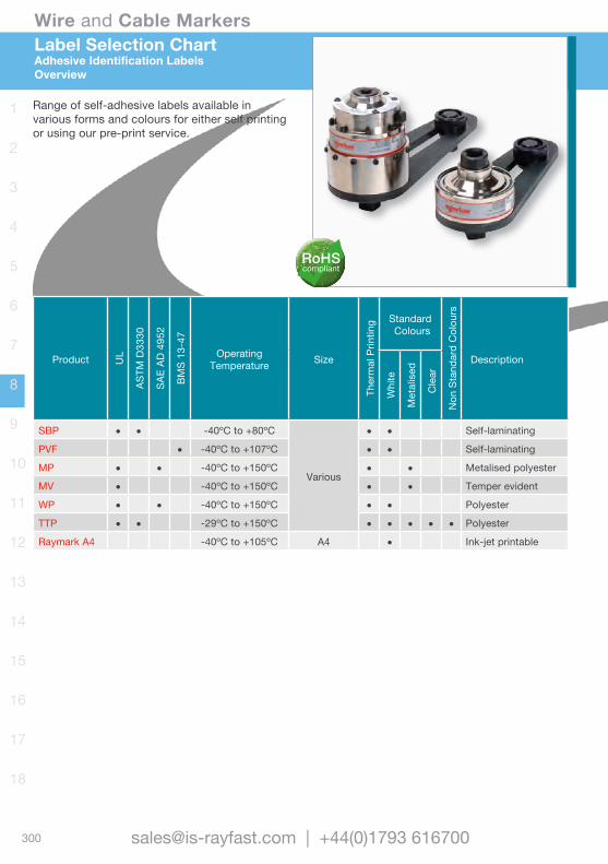
Wire and Cable Markers
300 [email protected] | +44(0)1793 616700
1
2
3
4
5
6
7
8
9
10
11
12
13
14
15
16
17
18
Product UL
ASTM
D33
30
SAE
AD 4
952
BMS
13-4
7
Operating Temperature Size
Ther
mal
Prin
ting Standard
Colours
Non
Sta
ndar
d C
olou
rs
Description
Whi
te
Met
alis
ed
Cle
arSBP • • -40ºC to +80ºC
Various
• • Self-laminating
PVF • -40ºC to +107ºC • • Self-laminating
MP • • -40ºC to +150ºC • • Metalised polyester
MV • -40ºC to +150ºC • • Temper evident
WP • • -40ºC to +150ºC • • Polyester
TTP • • -29ºC to +150ºC • • • • • Polyester
Raymark A4 -40ºC to +105ºC A4 • Ink-jet printable
Label Selection ChartAdhesive Identification LabelsOverview
Range of self-adhesive labels available in various forms and colours for either self printing or using our pre-print service.
RoHScompliant

Wire and Cable Markers
301www.is-rayfast.com
1
2
3
4
5
6
7
8
9
10
11
12
13
14
15
16
17
18
Product UL
ASTM
D33
30
SAE
AD 4
952
BMS
13-4
7
Operating Temperature Size
Ther
mal
Prin
ting Standard
Colours
Non
Sta
ndar
d C
olou
rs
Description
Whi
te
Met
alis
ed
Cle
ar
SBP • • -40ºC to +80ºC
Various
• • Self-laminating
PVF • -40ºC to +107ºC • • Self-laminating
MP • • -40ºC to +150ºC • • Metalised polyester
MV • -40ºC to +150ºC • • Temper evident
WP • • -40ºC to +150ºC • • Polyester
TTP • • -29ºC to +150ºC • • • • • Polyester
Raymark A4 -40ºC to +105ºC A4 • Ink-jet printable
SBPlusSelf-laminating Labels
Thermal Transfer Printable
Clear vinyl film with a permanent acrylic based adhesive, suppled with a white thermal transfer printable area, which is over-laminated upon application with the clear portion of the label. Can also be ‘flagged’ around a wire rather than wrapped. This self-laminating feature protects the printed area from exposure to oil, solvents, water and abrasion.Printable area is equal to the width of the label and the printable height as identified in the table below.Standard colour is White with a clear tail.
Features & Benefits• Strong adhesive, prevents lift off and seals.• Base material allows the printing to remain
clear after lamination.• Designed to withstand exposure to oil,
solvents and water.
Operating Temperature Range• -40ºC to +110ºC
Ordering DescriptionLabel Size mm Printable
Height mmMax. Cable
OD mmNo. Labels
Across Pack SizeHeight Width
SBP050100WE10 25.4 12.7 8.5 5.1 5 10,000
SBP050143WE10 36.5 12.7 12.7 7.6 5 10,000
SBP075094WE10 23.9 19.1 9.5 7.6 4 10,000
SBP080150WE10 38.1 20.3 12.7 7.6 4 10,000
SBP100143WE5 36.5 25.4 12.7 7.6 3 5,000
SBP100225WE5 57.2 25.4 19.1 12.2 3 5,000
SBP100375WE2.5 95.3 25.4 25.4 22.4 3 2,500
SBP100594WE1 151.0 25.4 38.1 35.6 3 1,000
SBP100743WE1 188.9 25.4 38.1 35.6 3 1,000
SBP190319WE2.5 81.0 48.3 19.1 12.2 2 2,500
SBP190594WE1 151.0 48.3 38.1 35.6 2 1,000
SBP200143WE2.5 6.5 50.8 12.7 7.6 2 2,500
SBP200225WE2.5 57.2 50.8 19.1 12.2 2 2,500
SBP200375WE2.5 95.3 50.8 25.4 22.4 2 2,500
SBP200743WE 188.9 50.8 38.1 48.3 2 11,000
Recommended printers T200-IDENT-PRINTER and the TE3112 printer.Approved ribbon TMS-RJS-RIBBON-4RPSCE
Specifications and Approvals• ASTM D3330• ASTM 3611• MIL-STD-202 Method 215• UL969 PGJ12 MH17292
RoHScompliant
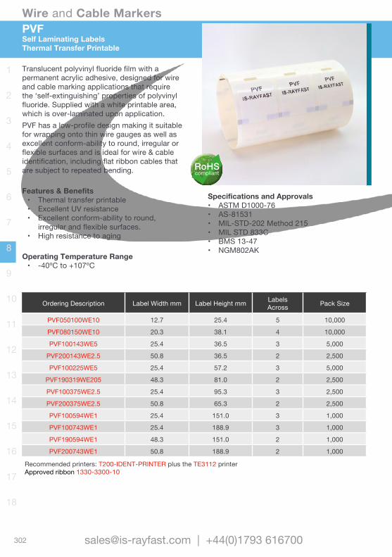
Wire and Cable Markers
302 [email protected] | +44(0)1793 616700
1
2
3
4
5
6
7
8
9
10
11
12
13
14
15
16
17
18
PVFSelf Laminating LabelsThermal Transfer Printable
Translucent polyvinyl fluoride film with a permanent acrylic adhesive, designed for wire and cable marking applications that require the ‘self-extinguishing’ properties of polyvinyl fluoride. Supplied with a white printable area, which is over-laminated upon application. PVF has a low-profile design making it suitable for wrapping onto thin wire gauges as well as excellent conform-ability to round, irregular or flexible surfaces and is ideal for wire & cable identification, including flat ribbon cables that are subject to repeated bending.
Features & Benefits• Thermal transfer printable• Excellent UV resistance• Excellent conform-ability to round,
irregular and flexible surfaces.• High resistance to aging
Operating Temperature Range• -40ºC to +107ºC
Specifications and Approvals• ASTM D1000-76• AS-81531• MIL-STD-202 Method 215• MIL STD 833C• BMS 13-47• NGM802AK
Ordering Description Label Width mm Label Height mm LabelsAcross Pack Size
PVF050100WE10 12.7 25.4 5 10,000
PVF080150WE10 20.3 38.1 4 10,000
PVF100143WE5 25.4 36.5 3 5,000
PVF200143WE2.5 50.8 36.5 2 2,500
PVF100225WE5 25.4 57.2 3 5,000
PVF190319WE205 48.3 81.0 2 2,500
PVF100375WE2.5 25.4 95.3 3 2,500
PVF200375WE2.5 50.8 65.3 2 2,500
PVF100594WE1 25.4 151.0 3 1,000
PVF100743WE1 25.4 188.9 3 1,000
PVF190594WE1 48.3 151.0 2 1,000
PVF200743WE1 50.8 188.9 2 1,000
Recommended printers: T200-IDENT-PRINTER plus the TE3112 printerApproved ribbon 1330-3300-10
RoHScompliant

Wire and Cable Markers
303www.is-rayfast.com
1
2
3
4
5
6
7
8
9
10
11
12
13
14
15
16
17
18
MP is a thermal transfer printable metalised polyester film with permanent acrylic adhesive, designed for rating plates and other applications that require a metal look, such as nameplates, equipment labels, detailed product information labels and serial number plates. MP is UL Listed and CSA certified. Standard colour is Silver, metalised polyester
Features & Benefits• Thermal transfer printable• Several die-cut sizes available• Metalised appearance• UL listed and CSA certified• Ideal for rating plate applications
Operating Temperature Range• -40ºC to +150ºC
The table below only represents a selection of MP label products available, for a complete list or more detailed information please contact us for details.
MPMetalised Polyester Labels
Thermal Transfer Printing
Ordering Description Label Width mm Label Height mm LabelsAcross Pack Size
MP-080080-10-8A 8.0 8.0 8 10,000
MP-095080-25-8A 9.5 8.0 5 25,000
MP-127111-10-8A 12.7 11.1 5 10,000
MP-165102-10-8A 16.5 10.2 5 10,000
MP-191114-18-8A 19.1 11.4 3 15,000
MP-254045-10-8A 25.4 4.6 3 10,000
MP-254127-10-8A 25.4 12.7 3 10,000
MP-445102-5-8A 44.5 10.2 1 5,000
MP-762508-2.5-8A 76.2 50.8 1 2,500
Recommended printers: T200-IDENT-PRINTER plus the TE3112 printerApproved ribbon 1330-0607-10
Specifications and Approvals• ASTM AS 4952• MIL-STD-202 Method 215• FTM-1• UL969 PGJ12 MH17292• UL969 PGJ18 MH17292 (Canadian)
RoHScompliant
Ordering Description Label Width mm Label Height mm LabelsAcross Pack Size
PVF050100WE10 12.7 25.4 5 10,000
PVF080150WE10 20.3 38.1 4 10,000
PVF100143WE5 25.4 36.5 3 5,000
PVF200143WE2.5 50.8 36.5 2 2,500
PVF100225WE5 25.4 57.2 3 5,000
PVF190319WE205 48.3 81.0 2 2,500
PVF100375WE2.5 25.4 95.3 3 2,500
PVF200375WE2.5 50.8 65.3 2 2,500
PVF100594WE1 25.4 151.0 3 1,000
PVF100743WE1 25.4 188.9 3 1,000
PVF190594WE1 48.3 151.0 2 1,000
PVF200743WE1 50.8 188.9 2 1,000
Recommended printers: T200-IDENT-PRINTER plus the TE3112 printerApproved ribbon 1330-3300-10
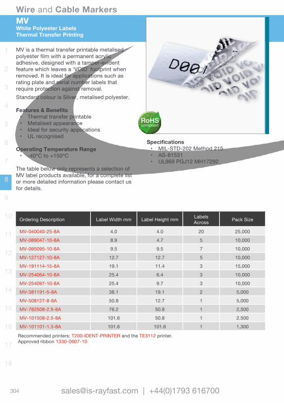
Wire and Cable Markers
304 [email protected] | +44(0)1793 616700
1
2
3
4
5
6
7
8
9
10
11
12
13
14
15
16
17
18
Ordering Description Label Width mm Label Height mm LabelsAcross Pack Size
MV-040040-25-8A 4.0 4.0 20 25,000
MV-089047-10-8A 8.9 4.7 5 10,000
MV-095095-10-8A 9.5 9.5 7 10,000
MV-127127-10-8A 12.7 12.7 5 10,000
MV-191114-15-8A 19.1 11.4 3 15,000
MV-254064-10-8A 25.4 6.4 3 10,000
MV-254097-10-8A 25.4 9.7 3 10,000
MV-381191-5-8A 38.1 19.1 2 5,000
MV-508127-8-8A 50.8 12.7 1 5,000
MV-762508-2.5-8A 76.2 50.8 1 2,500
MV-101508-2.5-8A 101.6 50.8 1 2.500
MV-101101-1.3-8A 101.6 101.6 1 1,300
Recommended printers: T200-IDENT-PRINTER and the TE3112 printer.Approved ribbon 1330-0607-10
MV is a thermal transfer printable metalised polyester film with a permanent acrylic adhesive, designed with a tamper-evident feature which leaves a ‘VOID’ footprint when removed. It is ideal for applications such as rating plate and serial number labels that require protection against removal.Standard colour is Silver, metalised polyester.
Features & Benefits• Thermal transfer printable• Metalised appearance• Ideal for security applications• UL recognised
Operating Temperature Range• -40ºC to +150ºC
The table below only represents a selection of MV label products available, for a complete list or more detailed information please contact us for details.
Specifications• MIL-STD-202 Method 215• AS-81531• UL969 PGJ12 MH17292
MVWhite Polyester LabelsThermal Transfer Printing
RoHScompliant
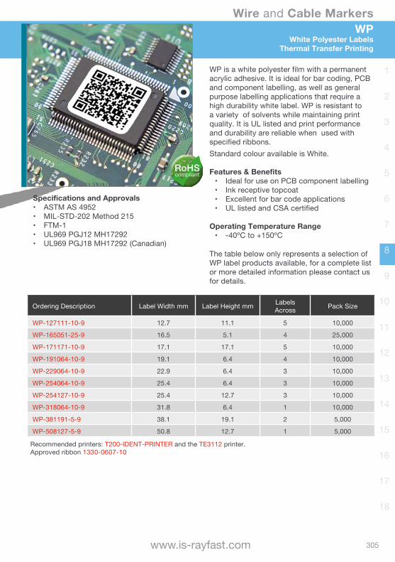
Wire and Cable Markers
305www.is-rayfast.com
1
2
3
4
5
6
7
8
9
10
11
12
13
14
15
16
17
18
WPWhite Polyester Labels
Thermal Transfer Printing
WP is a white polyester film with a permanent acrylic adhesive. It is ideal for bar coding, PCB and component labelling, as well as general purpose labelling applications that require a high durability white label. WP is resistant to a variety of solvents while maintaining print quality. It is UL listed and print performance and durability are reliable when used with specified ribbons.Standard colour available is White.
Features & Benefits• Ideal for use on PCB component labelling• Ink receptive topcoat• Excellent for bar code applications• UL listed and CSA certified
Operating Temperature Range• -40ºC to +150ºC
The table below only represents a selection of WP label products available, for a complete list or more detailed information please contact us for details.
Ordering Description Label Width mm Label Height mm LabelsAcross Pack Size
WP-127111-10-9 12.7 11.1 5 10,000
WP-165051-25-9 16.5 5.1 4 25,000
WP-171171-10-9 17.1 17.1 5 10,000
WP-191064-10-9 19.1 6.4 4 10,000
WP-229064-10-9 22.9 6.4 3 10,000
WP-254064-10-9 25.4 6.4 3 10,000
WP-254127-10-9 25.4 12.7 3 10,000
WP-318064-10-9 31.8 6.4 1 10,000
WP-381191-5-9 38.1 19.1 2 5,000
WP-508127-5-9 50.8 12.7 1 5,000
Recommended printers: T200-IDENT-PRINTER and the TE3112 printer.Approved ribbon 1330-0607-10
Specifications and Approvals• ASTM AS 4952• MIL-STD-202 Method 215• FTM-1• UL969 PGJ12 MH17292• UL969 PGJ18 MH17292 (Canadian)
RoHScompliant

Wire and Cable Markers
306 [email protected] | +44(0)1793 616700
1
2
3
4
5
6
7
8
9
10
11
12
13
14
15
16
17
18
This highly durable system offers the features of ‘Silk Screened’ labels, only without the cost, time and inflexibility involved. The product utilises high performance polyester with permanent adhesive, suitable for panel labels, fascias and decals.
Features & Benefits• Effective alternative solution for expensive
silk-screen printing• Continuous format• Several widths and colours available• Interior and exterior aircraft use
including flight entertainment and deck instrumentation.
Operating Temperature Range• Clear from -40ºC to +125ºC• Other from -29ºC to +150ºC
Ordering Description Label Width mm Roll Length m Qty per Pack
Standard adhesive version
TTP200-Colour-10 50.8 30.48m (100ft) Continuous Roll
TTP300-Colour-10 73.2 30.48m (100ft) Continuous Roll
TTP400-Colour-10 101.6 30.48m (100ft) Continuous Roll
TTP600-Colour-10 152.4 30.48m (100ft) Continuous Roll
High tack adhesive version
TTPA200-Colour-10 50.8 30.48m (100ft) Continuous Roll
TTPA300-Colour-10 73.2 30.48m (100ft) Continuous Roll
TTPA400-Colour-10 101.6 30.48m (100ft) Continuous Roll
TTPA600-Colour-10 152.4 30.48m (100ft) Continuous Roll
Ordering Information: Standard colours: CL = Clear, WE = White and MP = MetalisedNon-Standard: RD = Red, GN = Green, BE = Blue; OE = Orange, BK = Black and YW = YellowRecommended printers: T200-IDENT-PRINTER and the TE3112 printer. Approved ribbon 1330-0607-10
Specifications and Approvals• A-A-59485• GAT100BB• UL MH17292 Group PGJI2 (polywhite)
TTPContinuous Polyester for DecalsThermal Transfer Printable
RoHScompliant

Wire and Cable Markers
307www.is-rayfast.com
1
2
3
4
5
6
7
8
9
10
11
12
13
14
15
16
17
18
Raymark RMK A4Epoxy Coated Labels
Computer Printable
Raymark is a computer printer label stock with outstanding fluid and abrasion resistance, for ink-jet printers. When heat-cured after printing, the heat reactive epoxy surface “locks-in” the printed image. Typical applications are rating plate labels, wiring diagrams, component identification and wraparound markers.Standard colour available is White
Features & Benefits• Outstanding adhesion to many surfaces• Outstanding fluid and abrasion resistance.• Low fire hazard properties• Indoor use only
Operating Temperature Range• Wire marking -40ºC to +85ºC• Panel marking -40ºC to +105ºC
Ordering Description Label Height mm Label Width mm No. Labels / reel Pack Size
RMK-9x25-A4 9 25 132 labels 50 Sheets
RMK-18x35-A4 18 35 48 labels 50 Sheets
RMK-18x50-A4 18 50 36 labels 50 Sheets
RMK-25x50-A4 25 50 27 labels 50 Sheets
RMK-25x75-A4 25 75 18 labels 50 Sheets
RMK-35x75-A4 35 75 12 labels 50 Sheets
RMK-25x100-A4 25 100 10 labels 50 Sheets
RMK-50x100-A4 50 100 5 labels 50 Sheets
RMK-75x150-A4 75 150 3 labels 50 Sheets
RMK-UNCUT-A4 A4 A4 1 label 50 Sheets
A standard pack contains 50 sheets in environmentally sealed package, if opened the labels should be stored at a temperature no greater than +25ºC @ ,80% humidity and used within 6 months. An un-opened pack can be stored at a temperature no greater then +35ºC and has a recommended shelf life of 12 months. For full product performance characteristics, refer to product data sheets TH-93269 (UK) and H54584 (USA).Recommended printers: New Raymark ink jet printer EPSON WF-5190DW. Also refer to the TE 411-121005 (ribbon/ink matrix)
Specifications and Approvals• MIL-M-81531 (mark permanence)• MIL-STD-202F Method 215 (solvent
resistance)
Wire and Cable Markers
308 [email protected] | +44(0)1793 616700
1
2
3
4
5
6
7
8
9
10
11
12
13
14
15
16
17
18
WinTotal Software SolutionDesign and Print
WinTotal is a label/marker design package that makes wire marker printing simple in an industrial environment. Running in the familiar Windows environment, WinTotal v6 has 2,500 standard TE Connectivity (TE) Identification products pre-installed. This makes the creation and printing of Identification sleeves or labels a quick and simple task. Using the advanced editor, it is also possible to create complex layouts that relate to active data fields, giving a true WYSIWYG representation.WinTotal v6 now fully supports Unicode. This allows for multilingual text to be printed using any or all of the languages required. If a character has a Unicode equivalent, then WinTotal v6 will display and print that character, if it can be written into a Microsoft application, it can be copied into WinTotal v6.
Key Features & Benefits• Multi-lingual user interface.• Pre-loaded WYSIWYG templates.• Graphical user interface with WYSIWYG
display• Clipart gallery with commonly used
symbols, on V6 and above only.• Incremental alpha and numeric fields.• Accepts and prints data in any language -
UniCode data support (V6 only).• Multiple Label Design Objects: Text, lines,
boxes, circles and images.• Double sided marker printing complete
with WYSIWYG display.• Extensive Barcode and 2D barcode
support.• Advanced label design elements & tools:
Text boxes, rich text formatting, variable font size.
• Image files supported (JPG, WMF, BMP).• Multiple Printers/Printing: Full MAPP
(Multiple Application Port Printing). Able to drive multiple printers simultaneously with automatic selection.
System Requirements
Computer IBM Compatible PC
Processor 1 GHz or higher
RAM 1GB
Screen Resolution 1024 x 768 pixels
Disk Space Required 100MB of free disk space
Ordering Information
USB key with licence, once inserted. WINTOTAL-6-DONGLE
*RAM requirement is less for earlier Windows operating systems please contact for details
Basic Functionalities• Toolbar design, ‘Keypad’ buttons, ‘Zoom
In/Out’.• ‘Selected Product’ list box• Simplified user interface configurable for
both basic and advanced users• Single file data format: One file now
replaces multiple files used in older versions.
• ‘System Setup’ screen with simplified printer selection: ‘Advanced Printer Setup’ function shows all settings in one location.

Wire and Cable Markers
309www.is-rayfast.com
1
2
3
4
5
6
7
8
9
10
11
12
13
14
15
16
17
18
Data Management• Import data from ASCII or XMT files or
from a Windows database• ‘Database printing’ function for printing
data without importing into WinTotal software
• ‘Preview’ option to review the import configuration without importing.
Templates• ‘Rotation’ option when creating products• File format supporting importing and
exporting of ‘User Defined Layouts’.
Supported LanguagesDutch, English, French, German, Italian, Japanese, Korean, Norwegian, Portuguese (Brazil), Russian, Simplified Chinese, Spanish and Turkish.
NoteThe WinTotal software package is available to suit a Windows® environment and is constantly being developed in line with operating system updates and technology improvements, please enquire for latest release levels.
WinTotal Software Solution
Design and Print
Please note that the WINTOTAL-6-DONGLE acts as an authorisation key, the software can be downloaded as a free trial from the TE.com website which this key activates for unrestricted use.

Wire and Cable Markers
310 [email protected] | +44(0)1793 616700
1
2
3
4
5
6
7
8
9
10
11
12
13
14
15
16
17
18
T200-IDENT-PRINTERThermal Transfer Printer
Get the most out of your cable identification and labelling. The T200 Ident printer brings together a complete solution for your compact range of thermal transfer printing needs. The increased accuracy and the added flexibility of a movable Media sensor extends the variety of products approved for this printer, while reducing the number of misprints. The T200 is also available as a package with the WINTOTAL Software
Features & Benefits• Light-weight at 4kg and small footprint• Automatic calibration• Simple ribbon and media loading
procedure• Superior print positioning accuracy• Touch Screen• Full DHCP and LAN connection
Compact Size• D322mm x H189mm x W253m
Electrical• 100 to 240 V | 50/60 Hz | FPC
Operating Conditions• 5ºC to 40ºC• 25 to 85% non-condensing RH
Printing Method• 300 dpi Thermal Transfer
Printing Speed• 30, 40, 50, 75, 100 & 125 mm/s
(recommended 50 mm/s).
Product Properties• Print width max: 105.7mm• Label width 4mm to 105.7mm• Label height: 5mm to 1,000mm
Approvals & Declarations• CE, FCC Class A, CB, CCC, UL, GOST
Interfaces• USB 2.0 (full speed)• LAN 10/100 Base (Ethernet)
Ordering Information
Standard printer T200-IDENT-PRINTER
... with Wintotal T200-IDENT-SWARE-PRINTER
Spare Parts and Accessories
Print head T200-PRINTHEAD
Drive roller T200-DR4-DRIVEROLLER
Cutter T200-CUTTER
Perforator T200-PERFORATOR
Universal Payoff UNIVERSAL-PAYOFF
For additional information please give us a call
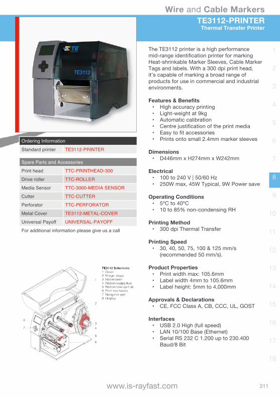
Wire and Cable Markers
311www.is-rayfast.com
1
2
3
4
5
6
7
8
9
10
11
12
13
14
15
16
17
18
TE3112-PRINTERThermal Transfer Printer
The TE3112 printer is a high performance mid-range identification printer for marking Heat-shrinkable Marker Sleeves, Cable Marker Tags and labels. With a 300 dpi print head, it’s capable of marking a broad range of products for use in commercial and industrial environments.
Features & Benefits• High accuracy printing• Light-weight at 9kg• Automatic calibration• Centre justification of the print media• Easy to fit accessories• Prints onto small 2.4mm marker sleeves
Dimensions• D446mm x H274mm x W242mm
Electrical• 100 to 240 V | 50/60 Hz• 250W max, 45W Typical, 9W Power save
Operating Conditions• 5ºC to 40ºC• 10 to 85% non-condensing RH
Printing Method• 300 dpi Thermal Transfer
Printing Speed• 30, 40, 50, 75, 100 & 125 mm/s
(recommended 50 mm/s).
Product Properties• Print width max: 105.6mm• Label width 4mm to 105.6mm• Label height: 5mm to 4,000mm
Approvals & Declarations• CE, FCC Class A, CB, CCC, UL, GOST
Interfaces• USB 2.0 High (full speed)• LAN 10/100 Base (Ethernet)• Serial RS 232 C 1.200 up to 230.400
Baud/8 Bit
Ordering Information
Standard printer TE3112-PRINTER
Spare Parts and Accessories
Print head TTC-PRINTHEAD-300
Drive roller TTC-ROLLER
Media Sensor TTC-3000-MEDIA SENSOR
Cutter TTC-CUTTER
Perforator TTC-PERFORATOR
Metal Cover TE3112-METAL-COVER
Universal Payoff UNIVERSAL-PAYOFF
For additional information please give us a call
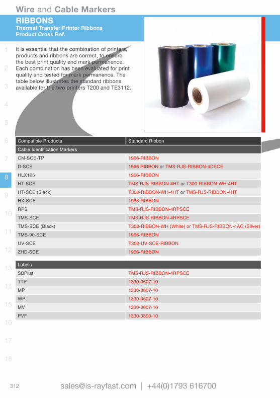
Wire and Cable Markers
312 [email protected] | +44(0)1793 616700
1
2
3
4
5
6
7
8
9
10
11
12
13
14
15
16
17
18
Compatible Products Standard Ribbon
Cable Identification Markers
CM-SCE-TP 1966-RIBBON
D-SCE 1966 RIBBON or TMS-RJS-RIBBON-4DSCE
HLX125 1966-RIBBON
HT-SCE TMS-RJS-RIBBON-4HT or T300-RIBBON-WH-4HT
HT-SCE (Black) T300-RIBBON-WH-4HT or TMS-RJS-RIBBON-4HT
HX-SCE 1966-RIBBON
RPS TMS-RJS-RIBBON-4RPSCE
TMS-SCE TMS-RJS-RIBBON-4RPSCE
TMS-SCE (Black) T300-RIBBON-WH (White) or TMS-RJS-RIBBON-4AG (Silver)
TMS-90-SCE 1966-RIBBON
UV-SCE T300-UV-SCE-RIBBON
ZHD-SCE 1966-RIBBON
Labels
SBPlus TMS-RJS-RIBBON-4RPSCE
TTP 1330-0607-10
MP 1330-0607-10
WP 1330-0607-10
MV 1330-0607-10
PVF 1330-3300-10
RIBBONSThermal Transfer Printer RibbonsProduct Cross Ref.
It is essential that the combination of printers, products and ribbons are correct, to ensure the best print quality and mark permanence. Each combination has been evaluated for print quality and tested for mark permanence. The table below illustrates the standard ribbons available for the two printers T200 and TE3112.

Wire and Cable Markers
313www.is-rayfast.com
1
2
3
4
5
6
7
8
9
10
11
12
13
14
15
16
17
18
RIBBONSThermal Transfer Printer Ribbons
Product Description
1966-RIBBONUltra-high performance black thermal transfer ribbon that produces the ultimate in print performance.Ink type: ResinFEATURES AND BENEFITS• Ideal for use in environments where
marker may come into contact with abrasion, solvent or chemical attack
TMS RJS-RIBBON-4DSCEHigh performance black thermal transfer ribbon, for use on D-SCE heat shrinkable sleeves.Ink type: WaxFEATURES AND BENEFITS• TMS RJS-RIBBON-4DSCE printed
legends have high resistance to fluids, especially diesel.
TMS RJS-RIBBON-4RPSCEHigh durability commercial grade black thermal transfer ribbon, for use with TMS-SCE and RPS heat shrinkable sleeves and SBPlus labels.Ink type: Wax/ResinFEATURES AND BENEFITS• TMS RJS-RIBBON-4RPSCE printed
legends have high resistance to abrasion, solvents and chemicals
TMS RJS-RIBBON-4HTHigh temperature black thermal transfer ribbon, for use with HT-SCE heat shrinkable sleeves.Ink type: ResinFEATURES AND BENEFITS• TMS RJS-RIBBON-4HT printed legends
have excellent resistance to high temperatures.
T300-RIBBON-WH-4HTA white resin based thermal transfer ribbon, for use on HT-SCE product range.Ink type: ResinFEATURES AND BENEFITS• T300-RIBBON-WH-4HT printed legends
have high resistance to abrasion, solvents and chemicals.
1330-0607-10High durability black resin thermal transfer printable ribbon, ideal for use on pressure sensitive labels.Ink type: ResinFEATURES AND BENEFITS• Excellent resistance to abrasion and
chemicals.
1330-3300-10High durability black resin thermal transfer printable ribbon, ideal for use on pressure sensitive labels.Ink type: ResinFEATURES AND BENEFITS• Excellent resistance to chemicals.
T300-UV-SCE-RIBBONHigh performance resin based thermal transfer ribbon, for use on UV-SCE product range.Ink type: ResinFEATURES AND BENEFITS• T300-UV-SCE-RIBBON printed legends
have high resistance to abrasion, solvents and chemicals.
• T300-UV-SCE-RIBBON has excellent UV resistance properties.

Wire and Cable Markers
314 [email protected] | +44(0)1793 616700
1
2
3
4
5
6
7
8
9
10
11
12
13
14
15
16
17
18
Additional Ident’ Products Printer Universal Payoff andPush-On Markers
EC9926-000 Universal PayoffThe Universal Payoff is a free standing bench top, or wall mounted stand. Designed to dispense all TE Connectivity identification marker sleeves, cable markers and labels.
Key Features and Benefits• Free standing bench top.• Wall mountable for space saving.• Robust, all metal stand.• Maximum outside roll diameter 400mm• Size 300 (D) x 232 (H) x 200 (W) mm• Weight 2.23kg.
TE Part Number: EC9926-000
Pre-Printed Push-On MarkersA range of cold applied push-on markers are also available for wire and cable marking, including...
• KTMS-501 heat shrinkable bandolier• Z-Type Marker• K-Type Marker• STD-Type Marker
Please contact us for additional information.
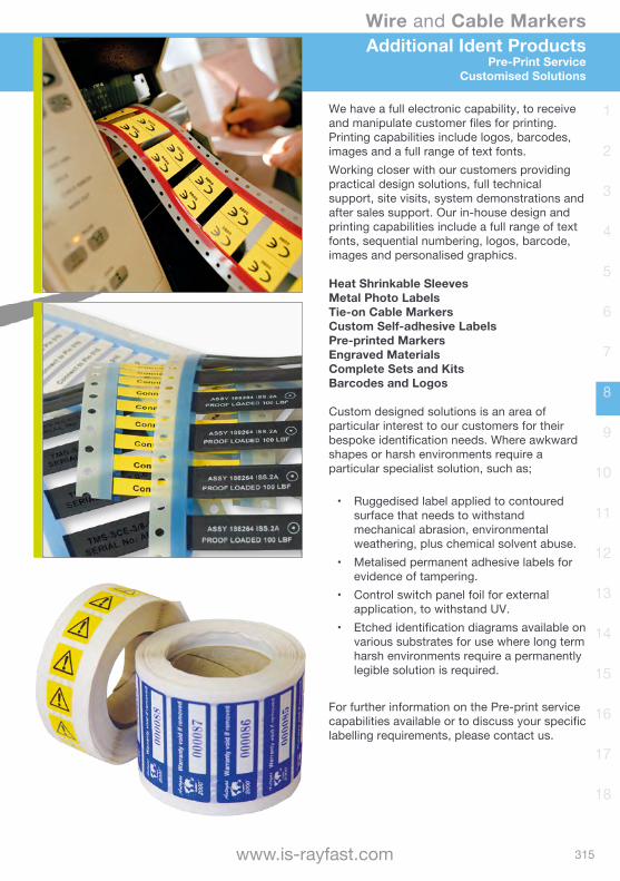
Wire and Cable Markers
315www.is-rayfast.com
1
2
3
4
5
6
7
8
9
10
11
12
13
14
15
16
17
18
Additional Ident ProductsPre-Print Service
Customised Solutions
We have a full electronic capability, to receive and manipulate customer files for printing. Printing capabilities include logos, barcodes, images and a full range of text fonts.Working closer with our customers providing practical design solutions, full technical support, site visits, system demonstrations and after sales support. Our in-house design and printing capabilities include a full range of text fonts, sequential numbering, logos, barcode, images and personalised graphics.
Heat Shrinkable SleevesMetal Photo LabelsTie-on Cable MarkersCustom Self-adhesive LabelsPre-printed MarkersEngraved MaterialsComplete Sets and KitsBarcodes and Logos
Custom designed solutions is an area of particular interest to our customers for their bespoke identification needs. Where awkward shapes or harsh environments require a particular specialist solution, such as;
• Ruggedised label applied to contoured surface that needs to withstand mechanical abrasion, environmental weathering, plus chemical solvent abuse.
• Metalised permanent adhesive labels for evidence of tampering.
• Control switch panel foil for external application, to withstand UV.
• Etched identification diagrams available on various substrates for use where long term harsh environments require a permanently legible solution is required.
For further information on the Pre-print service capabilities available or to discuss your specific labelling requirements, please contact us.

Wire and Cable Heat-shrink Tubing
Non-shrink TubingBraided SleevingScreening Braids
Moulded Parts Terminals and Splices
Wire and Cable MarkersAccessories
ConnectorsBackshells
Bonding LeadsMetal Braids
Relays and Contactors Switches and Grips
Adhesives and TapesApplication EquipmentAdded Value Services

Accessories
318 [email protected] | +44(0)1793 616700
1
2
3
4
5
6
7
8
9
10
11
12
13
14
15
16
17
18
Everything to Manage, Bundle and Route your WiringWe offer a vast range of cable management accessories, from a select range of manufacturers. Products include: Cable Glands and Feedthroughs, to Cable Ties and Clips, Lacing Tapes and Cords.With access to a considerable portfolio of cable management products, a solution can be sourced and matched to your specific requirements.
• Comprehensive solutions• World class quality and reliability• Innovative products and tools• Unmatched Technical support
Cable TiesA wide range of cable tie products are available from Nylon to Stainless Steel, used extensively across a broad range of industries and environments to secure and aesthetically enhance wire and cable systems.
Protective Binding and EdgingFor managing wire and cable runs through bulkheads utilising high performance materials for demanding applications and environments.
Lacing Tapes and CordsLacing tapes and cords are commonly used to secure cable bundles, typically in the Aerospace industry. Available in a wide range of specifications, colours and sizes to meet specific customer requirements.
Specialist InterestThe range of products portrayed on the following pages represents just the most common types that we supply, for more specialist or alternative solutions please contact us.
INTRODUCTION

Accessories
319www.is-rayfast.com
1
2
3
4
5
6
7
8
9
10
11
12
13
14
15
16
17
18
CONTENTS
Plastic Cable Ties Material Characteristics and Selection Chart page 320PLT Series Pan-Ty® Standard profile page 322BT Series Dome-Top® Low profile, metal barb page 324CBR Series Contour-Ty® Parallel entry, outside teeth page 326MS3367 MIL Specification cross reference page 328Cable Tie Variations page 330Cable Tie Mounts page 331Harnessing Board Accessories page 332Approvals page 333 Metal Cable Ties MLT Series Pan-Ty® Standard profile page 334MLTFC and MLTC Series Dome-Top® Low profile, metal barb page 336AS23190 MIL Specification Cross reference page 337
Protective Binding and EdgingSpring-Fast® M2529/2 High performance edge protection page 338GEPR Silicone rubber edging page 339RAYRIM® and TPEM Performance heat shrinkable edge protection page 340GTB PTFE spiral binding page 341
Lacing Tape, Cords and Yarns Overview and General Information page 342 Specifying information page 344CID-A-A-52080 to 52084 Braided Lacing Tape page 345MIL-T-713 Nylon twisted cord page 346MIL-C-572 Nomex® Overbraiding yarn page 347
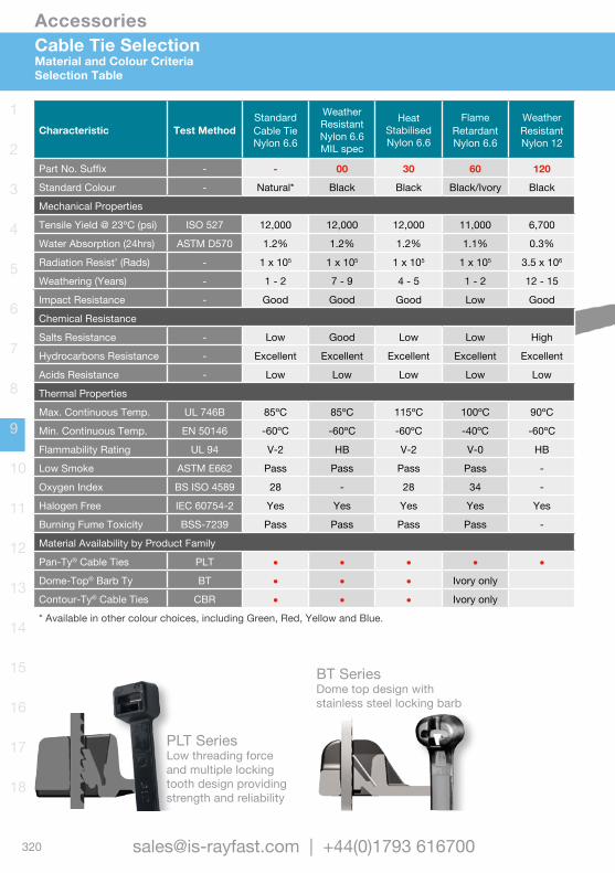
Accessories
320 [email protected] | +44(0)1793 616700
1
2
3
4
5
6
7
8
9
10
11
12
13
14
15
16
17
18
Cable Tie SelectionMaterial and Colour CriteriaSelection Table
Characteristic Test MethodStandard Cable TieNylon 6.6
Weather ResistantNylon 6.6MIL spec
Heat StabilisedNylon 6.6
Flame RetardantNylon 6.6
Weather ResistantNylon 12
Part No. Suffix - - 00 30 60 120
Standard Colour - Natural* Black Black Black/Ivory Black
Mechanical Properties
Tensile Yield @ 23ºC (psi) ISO 527 12,000 12,000 12,000 11,000 6,700
Water Absorption (24hrs) ASTM D570 1.2% 1.2% 1.2% 1.1% 0.3%
Radiation Resist’ (Rads) - 1 x 10⁵ 1 x 10⁵ 1 x 10⁵ 1 x 10⁵ 3.5 x 10⁶
Weathering (Years) - 1 - 2 7 - 9 4 - 5 1 - 2 12 - 15
Impact Resistance - Good Good Good Low Good
Chemical Resistance
Salts Resistance - Low Good Low Low High
Hydrocarbons Resistance - Excellent Excellent Excellent Excellent Excellent
Acids Resistance - Low Low Low Low Low
Thermal Properties
Max. Continuous Temp. UL 746B 85ºC 85ºC 115ºC 100ºC 90ºC
Min. Continuous Temp. EN 50146 -60ºC -60ºC -60ºC -40ºC -60ºC
Flammability Rating UL 94 V-2 HB V-2 V-0 HB
Low Smoke ASTM E662 Pass Pass Pass Pass -
Oxygen Index BS ISO 4589 28 - 28 34 -
Halogen Free IEC 60754-2 Yes Yes Yes Yes Yes
Burning Fume Toxicity BSS-7239 Pass Pass Pass Pass -
Material Availability by Product Family
Pan-Ty® Cable Ties PLT • • • • •Dome-Top® Barb Ty BT • • • Ivory only
Contour-Ty® Cable Ties CBR • • • Ivory only
* Available in other colour choices, including Green, Red, Yellow and Blue.
PLT SeriesLow threading force and multiple locking tooth design providing strength and reliability
BT SeriesDome top design with stainless steel locking barb
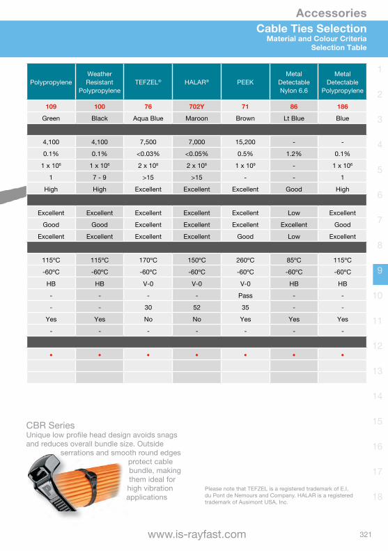
Accessories
321www.is-rayfast.com
1
2
3
4
5
6
7
8
9
10
11
12
13
14
15
16
17
18
Cable Ties SelectionMaterial and Colour Criteria
Selection Table
PolypropyleneWeather Resistant
PolypropyleneTEFZEL® HALAR® PEEK
Metal Detectable Nylon 6.6
MetalDetectable
Polypropylene
109 100 76 702Y 71 86 186
Green Black Aqua Blue Maroon Brown Lt Blue Blue
4,100 4,100 7,500 7,000 15,200 - -
0.1% 0.1% <0.03% <0.05% 0.5% 1.2% 0.1%
1 x 10⁶ 1 x 10⁶ 2 x 10⁸ 2 x 10⁸ 1 x 10⁹ - 1 x 10⁶
1 7 - 9 >15 >15 - - 1
High High Excellent Excellent Excellent Good High
Excellent Excellent Excellent Excellent Excellent Low Excellent
Good Good Excellent Excellent Excellent Excellent Good
Excellent Excellent Excellent Excellent Good Low Excellent
115ºC 115ºC 170ºC 150ºC 260ºC 85ºC 115ºC
-60ºC -60ºC -60ºC -60ºC -60ºC -60ºC -60ºC
HB HB V-0 V-0 V-0 HB HB
- - - - Pass - -
- - 30 52 35 - -
Yes Yes No No Yes Yes Yes
- - - - - - -
• • • • • • •
Characteristic Test MethodStandard Cable TieNylon 6.6
Weather ResistantNylon 6.6MIL spec
Heat StabilisedNylon 6.6
Flame RetardantNylon 6.6
Weather ResistantNylon 12
Part No. Suffix - - 00 30 60 120
Standard Colour - Natural* Black Black Black/Ivory Black
Mechanical Properties
Tensile Yield @ 23ºC (psi) ISO 527 12,000 12,000 12,000 11,000 6,700
Water Absorption (24hrs) ASTM D570 1.2% 1.2% 1.2% 1.1% 0.3%
Radiation Resist’ (Rads) - 1 x 10⁵ 1 x 10⁵ 1 x 10⁵ 1 x 10⁵ 3.5 x 10⁶
Weathering (Years) - 1 - 2 7 - 9 4 - 5 1 - 2 12 - 15
Impact Resistance - Good Good Good Low Good
Chemical Resistance
Salts Resistance - Low Good Low Low High
Hydrocarbons Resistance - Excellent Excellent Excellent Excellent Excellent
Acids Resistance - Low Low Low Low Low
Thermal Properties
Max. Continuous Temp. UL 746B 85ºC 85ºC 115ºC 100ºC 90ºC
Min. Continuous Temp. EN 50146 -60ºC -60ºC -60ºC -40ºC -60ºC
Flammability Rating UL 94 V-2 HB V-2 V-0 HB
Low Smoke ASTM E662 Pass Pass Pass Pass -
Oxygen Index BS ISO 4589 28 - 28 34 -
Halogen Free IEC 60754-2 Yes Yes Yes Yes Yes
Burning Fume Toxicity BSS-7239 Pass Pass Pass Pass -
Material Availability by Product Family
Pan-Ty® Cable Ties PLT • • • • •Dome-Top® Barb Ty BT • • • Ivory only
Contour-Ty® Cable Ties CBR • • • Ivory only
* Available in other colour choices, including Green, Red, Yellow and Blue.
CBR SeriesUnique low profile head design avoids snags and reduces overall bundle size. Outside
serrations and smooth round edges protect cable bundle, making them ideal for high vibration applications
Please note that TEFZEL is a registered trademark of E.I. du Pont de Nemours and Company. HALAR is a registered trademark of Ausimont USA, Inc.

Accessories
322 [email protected] | +44(0)1793 616700
1
2
3
4
5
6
7
8
9
10
11
12
13
14
15
16
17
18
1. Sizing SelectionPart Number Length mm Width mm Thick mm Max Bundle Ø Min. Tensile
Sub-Miniature Cross Section Ties
PLT.6SM-C-Colour 71 1.8 0.8 15mm 36N
Miniature Cross Section Ties
PLT.7M-C-Colour 79 2.3 0.8 17mm 80N
PLT1M-C-Colour 99 2.5 1.1 22mm 80N
PLT1.5M-C-Colour 142 2.5 1.1 32mm 80N
PLT2M-C-Colour 203 2.5 1.1 51mm 80N
Intermediate Cross Section Ties
PLT1.5I-C-Colour 142 3.6 1.1 35mm 178N
PLT2I-C-Colour 203 3.6 1.1 51mm 178N
PLT2.5I-C-Colour 246 3.7 1.3 64mm 178N
PLT3I-C-Colour 290 3.7 1.3 76mm 178N
PLT4I-C-Colour 368 3.7 1.3 102mm 178N
Standard Cross Section Ties
PLT1S-C-Colour 122 4.8 1.3 25mm 222N
PLT1.5S-C-Colour 157 4.8 1.3 38mm 222N
PLT2S-C-Colour 188 4.8 1.3 48mm 222N
PLT2.5S-C-Colour 249 4.8 1.3 64mm 222N
PLT3S-C-Colour 292 4.8 1.3 76mm 222N
PLT4S-C-Colour 368 4.8 1.3 102mm 222N
PLT4.5S-C-Colour 394 4.8 1.3 114mm 222N
PLT5S-C-Colour 445 4.8 1.3 127mm 222N
For applicable hand held application tooling please refer to that section of the catalogue.
PLT SeriesPan-Ty® Locking Nylon Cable TiesNylon Locking Barb
These cable ties can be used in countless applications wherever you need to bundle wire, cable, or hoses. Available in standard (Natural) and weather resistant (Black) Nylon, with other colours and materials available to special order. Low threading force and multiple locking tooth design providing strength and reliability.Conforms to testing requirements of Aerospace standard SAE-A23190A and the dimensional requirements of Aerospace standard SAE-AS33671, see listing later in this section.EN45545-2 approved material denoted by # see table 2 on opposite page.
RoHScompliant
HALOGENFREE
LFHLow Fire Hazard
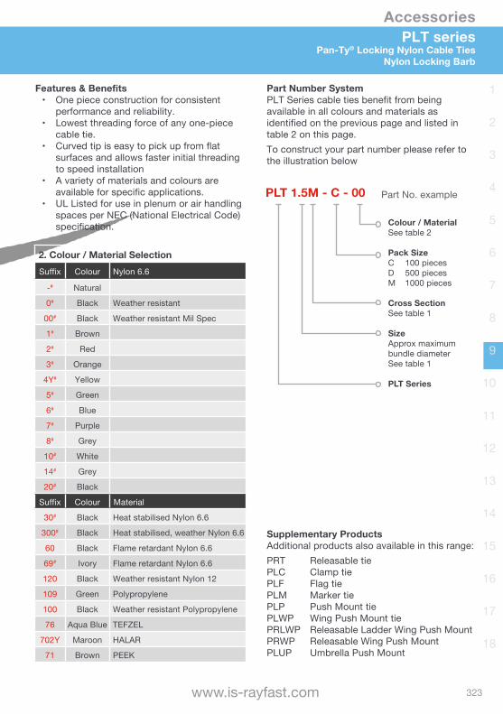
Accessories
323www.is-rayfast.com
1
2
3
4
5
6
7
8
9
10
11
12
13
14
15
16
17
18
PLT seriesPan-Ty® Locking Nylon Cable Ties
Nylon Locking Barb
Part Number SystemPLT Series cable ties benefit from being available in all colours and materials as identified on the previous page and listed in table 2 on this page. To construct your part number please refer to the illustration below
Supplementary ProductsAdditional products also available in this range:PRT Releasable tiePLC Clamp tiePLF Flag tiePLM Marker tiePLP Push Mount tiePLWP Wing Push Mount tiePRLWP Releasable Ladder Wing Push MountPRWP Releasable Wing Push MountPLUP Umbrella Push Mount
PLT 1.5M - C - 00
Colour / MaterialSee table 2
Pack SizeC 100 piecesD 500 piecesM 1000 pieces
Cross SectionSee table 1
Size Approx maximum bundle diameterSee table 1
PLT Series
Part No. example
Features & Benefits• One piece construction for consistent
performance and reliability.• Lowest threading force of any one-piece
cable tie.• Curved tip is easy to pick up from flat
surfaces and allows faster initial threading to speed installation
• A variety of materials and colours are available for specific applications.
• UL Listed for use in plenum or air handling spaces per NEC (National Electrical Code) specification.
2. Colour / Material SelectionSuffix Colour Nylon 6.6
-# Natural
0# Black Weather resistant
00# Black Weather resistant Mil Spec
1# Brown
2# Red
3# Orange
4Y# Yellow
5# Green
6# Blue
7# Purple
8# Grey
10# White
14# Grey
20# Black
Suffix Colour Material
30# Black Heat stabilised Nylon 6.6
300# Black Heat stabilised, weather Nylon 6.6
60 Black Flame retardant Nylon 6.6
69# Ivory Flame retardant Nylon 6.6
120 Black Weather resistant Nylon 12
109 Green Polypropylene
100 Black Weather resistant Polypropylene
76 Aqua Blue TEFZEL
702Y Maroon HALAR
71 Brown PEEK
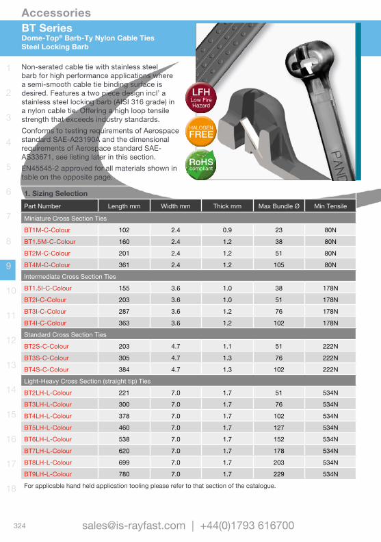
Accessories
324 [email protected] | +44(0)1793 616700
1
2
3
4
5
6
7
8
9
10
11
12
13
14
15
16
17
18
1. Sizing SelectionPart Number Length mm Width mm Thick mm Max Bundle Ø Min Tensile
Miniature Cross Section Ties
BT1M-C-Colour 102 2.4 0.9 23 80N
BT1.5M-C-Colour 160 2.4 1.2 38 80N
BT2M-C-Colour 201 2.4 1.2 51 80N
BT4M-C-Colour 361 2.4 1.2 105 80N
Intermediate Cross Section Ties
BT1.5I-C-Colour 155 3.6 1.0 38 178N
BT2I-C-Colour 203 3.6 1.0 51 178N
BT3I-C-Colour 287 3.6 1.2 76 178N
BT4I-C-Colour 363 3.6 1.2 102 178N
Standard Cross Section Ties
BT2S-C-Colour 203 4.7 1.1 51 222N
BT3S-C-Colour 305 4.7 1.3 76 222N
BT4S-C-Colour 384 4.7 1.3 102 222N
Light-Heavy Cross Section (straight tip) Ties
BT2LH-L-Colour 221 7.0 1.7 51 534N
BT3LH-L-Colour 300 7.0 1.7 76 534N
BT4LH-L-Colour 378 7.0 1.7 102 534N
BT5LH-L-Colour 460 7.0 1.7 127 534N
BT6LH-L-Colour 538 7.0 1.7 152 534N
BT7LH-L-Colour 620 7.0 1.7 178 534N
BT8LH-L-Colour 699 7.0 1.7 203 534N
BT9LH-L-Colour 780 7.0 1.7 229 534N
For applicable hand held application tooling please refer to that section of the catalogue.
BT Series Dome-Top® Barb-Ty Nylon Cable TiesSteel Locking Barb
Non-serated cable tie with stainless steel barb for high performance applications where a semi-smooth cable tie binding surface is desired. Features a two piece design incl’ a stainless steel locking barb (AISI 316 grade) in a nylon cable tie. Offering a high loop tensile strength that exceeds industry standards.Conforms to testing requirements of Aerospace standard SAE-A23190A and the dimensional requirements of Aerospace standard SAE-AS33671, see listing later in this section.EN45545-2 approved for all materials shown in table on the opposite page.
RoHScompliant
HALOGENFREE
LFHLow Fire Hazard
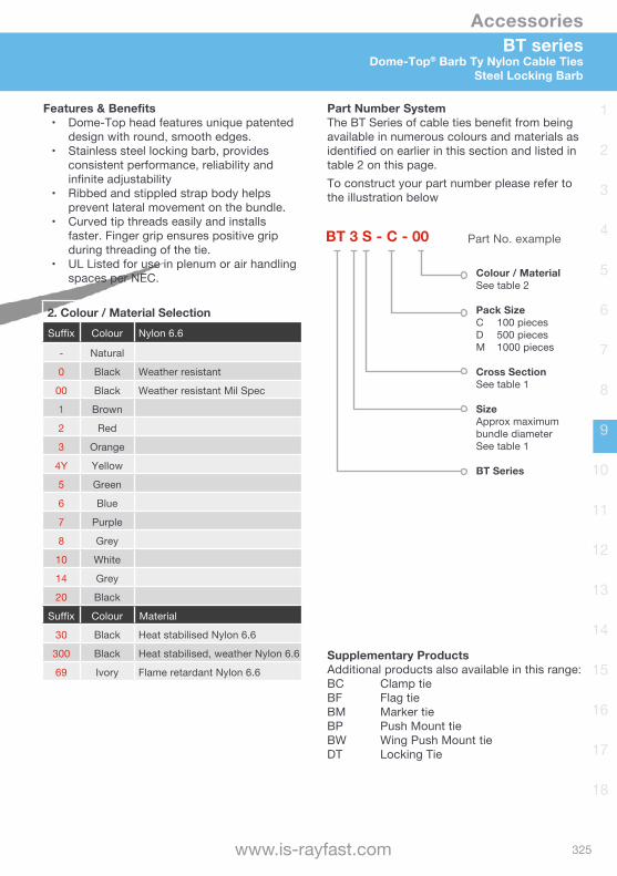
Accessories
325www.is-rayfast.com
1
2
3
4
5
6
7
8
9
10
11
12
13
14
15
16
17
18
BT seriesDome-Top® Barb Ty Nylon Cable Ties
Steel Locking Barb
Features & Benefits• Dome-Top head features unique patented
design with round, smooth edges.• Stainless steel locking barb, provides
consistent performance, reliability and infinite adjustability
• Ribbed and stippled strap body helps prevent lateral movement on the bundle.
• Curved tip threads easily and installs faster. Finger grip ensures positive grip during threading of the tie.
• UL Listed for use in plenum or air handling spaces per NEC.
Part Number SystemThe BT Series of cable ties benefit from being available in numerous colours and materials as identified on earlier in this section and listed in table 2 on this page. To construct your part number please refer to the illustration below
Supplementary ProductsAdditional products also available in this range:BC Clamp tieBF Flag tieBM Marker tieBP Push Mount tieBW Wing Push Mount tieDT Locking Tie
BT 3 S - C - 00
Colour / MaterialSee table 2
Pack SizeC 100 piecesD 500 piecesM 1000 pieces
Cross SectionSee table 1
Size Approx maximum bundle diameterSee table 1
BT Series
Part No. example
2. Colour / Material SelectionSuffix Colour Nylon 6.6
- Natural
0 Black Weather resistant
00 Black Weather resistant Mil Spec
1 Brown
2 Red
3 Orange
4Y Yellow
5 Green
6 Blue
7 Purple
8 Grey
10 White
14 Grey
20 Black
Suffix Colour Material
30 Black Heat stabilised Nylon 6.6
300 Black Heat stabilised, weather Nylon 6.6
69 Ivory Flame retardant Nylon 6.6
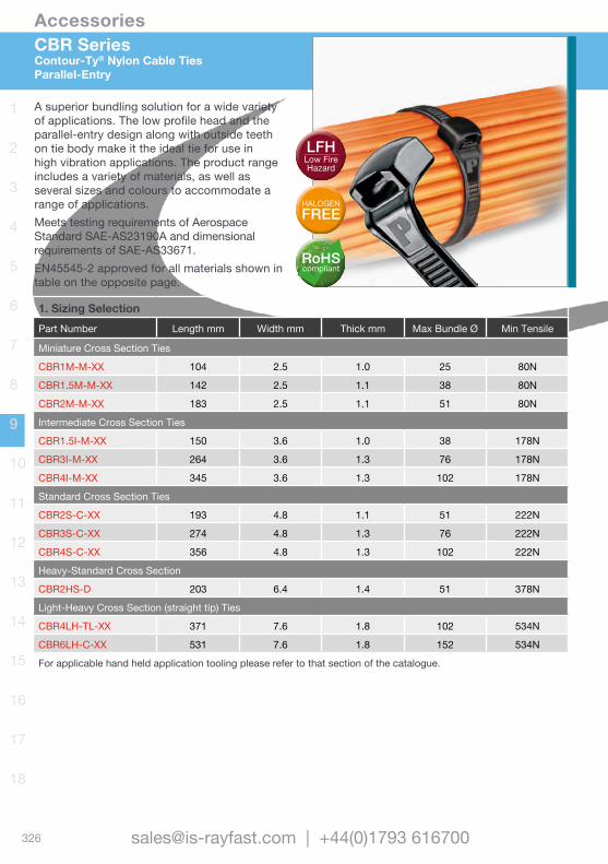
Accessories
326 [email protected] | +44(0)1793 616700
1
2
3
4
5
6
7
8
9
10
11
12
13
14
15
16
17
18
CBR Series Contour-Ty® Nylon Cable TiesParallel-Entry
1. Sizing SelectionPart Number Length mm Width mm Thick mm Max Bundle Ø Min Tensile
Miniature Cross Section Ties
CBR1M-M-XX 104 2.5 1.0 25 80N
CBR1.5M-M-XX 142 2.5 1.1 38 80N
CBR2M-M-XX 183 2.5 1.1 51 80N
Intermediate Cross Section Ties
CBR1.5I-M-XX 150 3.6 1.0 38 178N
CBR3I-M-XX 264 3.6 1.3 76 178N
CBR4I-M-XX 345 3.6 1.3 102 178N
Standard Cross Section Ties
CBR2S-C-XX 193 4.8 1.1 51 222N
CBR3S-C-XX 274 4.8 1.3 76 222N
CBR4S-C-XX 356 4.8 1.3 102 222N
Heavy-Standard Cross Section
CBR2HS-D 203 6.4 1.4 51 378N
Light-Heavy Cross Section (straight tip) Ties
CBR4LH-TL-XX 371 7.6 1.8 102 534N
CBR6LH-C-XX 531 7.6 1.8 152 534N
For applicable hand held application tooling please refer to that section of the catalogue.
A superior bundling solution for a wide variety of applications. The low profile head and the parallel-entry design along with outside teeth on tie body make it the ideal tie for use in high vibration applications. The product range includes a variety of materials, as well as several sizes and colours to accommodate a range of applications. Meets testing requirements of Aerospace Standard SAE-AS23190A and dimensional requirements of SAE-AS33671.EN45545-2 approved for all materials shown in table on the opposite page.
RoHScompliant
HALOGENFREE
LFHLow Fire Hazard
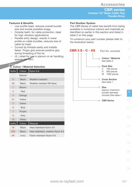
Accessories
327www.is-rayfast.com
1
2
3
4
5
6
7
8
9
10
11
12
13
14
15
16
17
18
CBR series Contour-Ty® Nylon Cable Ties
Parallel-Entry
2. Colour / Material SelectionSuffix Colour Nylon 6.6
- Natural
0 Black Weather resistant
00 Black Weather resistant Mil Spec
1 Brown
2 Red
3 Orange
4Y Yellow
5 Green
6 Blue
7 Purple
8 Grey
10 White
Suffix Colour Material
30 Black Heat stabilised Nylon 6.6
300 Black Heat stabilised, weather Nylon 6.6
69 Ivory Flame retardant Nylon 6.6
Features & Benefits• Low profile head, reduces overall bundle
size and avoids possible snags.• Outside teeth, for cable protection, ideal
for high vibration applications.• Parallel entry design, results in lower
profile on cable bundles, reduces size of cable tie head.
• Curved tip threads easily and installs faster. Finger grip ensures positive grip during threading of the tie.
• UL Listed for use in plenum or air handling spaces per NEC.
Part Number SystemThe CBR Series of cable ties benefit from being available in numerous colours and materials as identified on earlier in this section and listed in table 2 on this page. To construct your part number please refer to the illustration below
CBR 3 S - C - XX
Colour / MaterialSee table 2
Pack SizeC 100 piecesD 500 piecesM 1000 pieces
Cross SectionSee table 1
Size Approx maximum bundle diameter (inches) See table 1
CBR Series
Part No. example
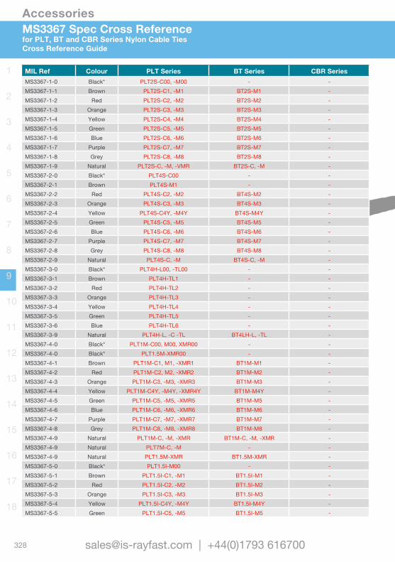
Accessories
328 [email protected] | +44(0)1793 616700
1
2
3
4
5
6
7
8
9
10
11
12
13
14
15
16
17
18
MS3367 Spec Cross Referencefor PLT, BT and CBR Series Nylon Cable TiesCross Reference Guide
MIL Ref Colour PLT Series BT Series CBR SeriesMS3367-1-0 Black* PLT2S-C00, -M00 - -MS3367-1-1 Brown PLT2S-C1, -M1 BT2S-M1 -MS3367-1-2 Red PLT2S-C2, -M2 BT2S-M2 -MS3367-1-3 Orange PLT2S-C3, -M3 BT2S-M3 -MS3367-1-4 Yellow PLT2S-C4, -M4 BT2S-M4 -MS3367-1-5 Green PLT2S-C5, -M5 BT2S-M5 -MS3367-1-6 Blue PLT2S-C6, -M6 BT2S-M6 -MS3367-1-7 Purple PLT2S-C7, -M7 BT2S-M7 -MS3367-1-8 Grey PLT2S-C8, -M8 BT2S-M8 -MS3367-1-9 Natural PLT2S-C, -M, -VMR BT2S-C, -M -MS3367-2-0 Black* PLT4S-C00 - -MS3367-2-1 Brown PLT4S-M1 - -MS3367-2-2 Red PLT4S-C2, -M2 BT4S-M2 -MS3367-2-3 Orange PLT4S-C3, -M3 BT4S-M3 -MS3367-2-4 Yellow PLT4S-C4Y, -M4Y BT4S-M4Y -MS3367-2-5 Green PLT4S-C5, -M5 BT4S-M5 -MS3367-2-6 Blue PLT4S-C6, -M6 BT4S-M6 -MS3367-2-7 Purple PLT4S-C7, -M7 BT4S-M7 -MS3367-2-8 Grey PLT4S-C8, -M8 BT4S-M8 -MS3367-2-9 Natural PLT4S-C, -M BT4S-C, -M -MS3367-3-0 Black* PLT4H-L00, -TL00 - -MS3367-3-1 Brown PLT4H-TL1 - -MS3367-3-2 Red PLT4H-TL2 - -MS3367-3-3 Orange PLT4H-TL3 - -MS3367-3-4 Yellow PLT4H-TL4 - -MS3367-3-5 Green PLT4H-TL5 - -MS3367-3-6 Blue PLT4H-TL6 - -MS3367-3-9 Natural PLT4H-L, -C -TL BT4LH-L, -TL -MS3367-4-0 Black* PLT1M-C00, M00, XMR00 - -MS3367-4-0 Black* PLT1.5M-XMR00 - -MS3367-4-1 Brown PLT1M-C1, M1, -XMR1 BT1M-M1 -MS3367-4-2 Red PLT1M-C2, M2, -XMR2 BT1M-M2 -MS3367-4-3 Orange PLT1M-C3, -M3, -XMR3 BT1M-M3 -MS3367-4-4 Yellow PLT1M-C4Y, -M4Y, -XMR4Y BT1M-M4Y -MS3367-4-5 Green PLT1M-C5, -M5, -XMR5 BT1M-M5 -MS3367-4-6 Blue PLT1M-C6, -M6, -XMR6 BT1M-M6 -MS3367-4-7 Purple PLT1M-C7, -M7, -XMR7 BT1M-M7 -MS3367-4-8 Grey PLT1M-C8, -M8, -XMR8 BT1M-M8 -MS3367-4-9 Natural PLT1M-C, -M, -XMR BT1M-C, -M, -XMR -MS3367-4-9 Natural PLT7M-C, -M - -MS3367-4-9 Natural PLT1.5M-XMR BT1.5M-XMR -MS3367-5-0 Black* PLT1.5I-M00 - -MS3367-5-1 Brown PLT1.5I-C1, -M1 BT1.5I-M1 -MS3367-5-2 Red PLT1.5I-C2, -M2 BT1.5I-M2 -MS3367-5-3 Orange PLT1.5I-C3, -M3 BT1.5I-M3 -MS3367-5-4 Yellow PLT1.5I-C4Y, -M4Y BT1.5I-M4Y -MS3367-5-5 Green PLT1.5I-C5, -M5 BT1.5I-M5 -
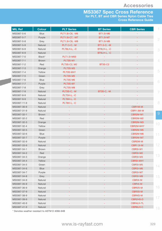
Accessories
329www.is-rayfast.com
1
2
3
4
5
6
7
8
9
10
11
12
13
14
15
16
17
18
MS3367 Spec Cross Referencefor PLT, BT and CBR Series Nylon Cable Ties
Cross Reference Guide
MIL Ref Colour PLT Series BT Series CBR SeriesMS3367-5-6 Blue PLT1.5I-C6, -M6 BT1.5I-M6 -MS3367-5-7 Purple PLT1.5I-C7, -M7 BT1.5I-M7 -MS3367-5-8 Grey PLT1.5I-C8, -M8 BT1.5I-M8 -MS3367-5-9 Natural PLT1.5-C, -M BT1.5-C, -M -MS3367-6-9 Natural PLT8LH-L, -C BT8LH-L, -C -MS3367-6-9 Natural - BT9LH-L, -C -MS3367-7-0 Black* PLT1.5I-M00 - -MS3367-7-1 Brown PLT3S-M1 - -MS3367-7-2 Red PLT3S-C2, M2 BT3S-C2 -MS3367-7-3 Orange PLT3S-M3 - -MS3367-7-4 Yellow PLT3S-M4Y - -MS3367-7-5 Green PLT3S-M5 - -MS3367-7-6 Blue PLT3S-M6 - -MS3367-7-7 Purple PLT3S-M7 - -MS3367-7-8 Grey PLT3S-M8 - -MS3367-7-9 Natural PLT3S-C, -M BT3S-C, -M -MS3367-8-9 Natural PLT5H-L, -C - -MS3367-9-9 Natural PLT6H-L, -C - -MS3367-11-9 Natural PLT8H-L, -C - -MS3367-30-9 Natural - - CBR1M-MMS3367-31-9 Natural - - CBR1.5M-MMS3367-32-1 Brown - - CBR2M-M1MS3367-32-2 Red - - CBR2M-M2MS3367-32-3 Orange - - CBR2M-M3MS3367-32-4 Yellow - - CBR2M-M4YMS3367-32-5 Green - - CBR2M-M5MS3367-32-6 Blue - - CBR2M-M6MS3367-32-7 Purple - - CBR2M-M7MS3367-32-9 Natural - - CBR2M-MMS3367-33-9 Natural - - CBR1.5I-MMS3367-34-1 Brown - - CBR3I-M1MS3367-34-2 Red - - CBR3I-M2MS3367-34-3 Orange - - CBR3I-M3MS3367-34-4 Yellow - - CBR3I-M4YMS3367-34-5 Green - - CBR3I-M5MS3367-34-6 Blue - - CBR3I-M6MS3367-34-7 Purple - - CBR3I-M7MS3367-34-8 Grey - - CBR3I-M8MS3367-34-9 Natural - - CBR3I-MMS3367-35-9 Natural - - CBR4I-MMS3367-36-9 Natural - - CBR2S-MMS3367-37-9 Natural - - CBR3S-MMS3367-38-9 Natural - - CBR4S-MMS3367-39-9 Natural - - CBR2HS-DMS3367-40-9 Natural - - CBR4LH-TLMS3367-41-9 Natural - - CBR6LH-C* Denotes weather resistant to ASTM D 4066-94B

Accessories
330 [email protected] | +44(0)1793 616700
1
2
3
4
5
6
7
8
9
10
11
12
13
14
15
16
17
18
Cable Tie Design VariationsComplementary Product OptionsProduct Overview
Clamp TiesAllows for bundling before or after screwing clamp in place. Used to secure a cable bundle to another surface such as a control panel, communication rack, wall or ceiling.
Wing Push Mount TiesAttached bundles to flat panels, with the wings providing constant tension for a stable, secure and rattle free installation. Single piece moulding for performance and reliability.
Push Mount TiesCable ties, mount and fastener in a single part, used to attach bundles to another surface such as a flat panel. Wingless design allows tie to be used in confined spaces.
Marker and Flag TiesIdeal for fastening and identifying bundles at the same time, with a one piece construction for consistent performance and reliability. Various designs available.
Stud Mounted TiesIntegrated mount pushes onto a threaded stud and tie wraps around bundle. Tie can be removed from the stud by turning counterclockwise. Also available as Mid-mount style and Releasable style.
Our range of Nylon cable ties are approved to various application standards, illustrating the quality and commitment to supply a quality product that is fit for purpose in the markets that we serve:
• UL Listed, E56854 and MH29590• CE EN 50146• Det Norske Veritas E-6405• VG 95 387 - 100MS 3367F• MIL QPL-AS23190-2
For full details please contact us.
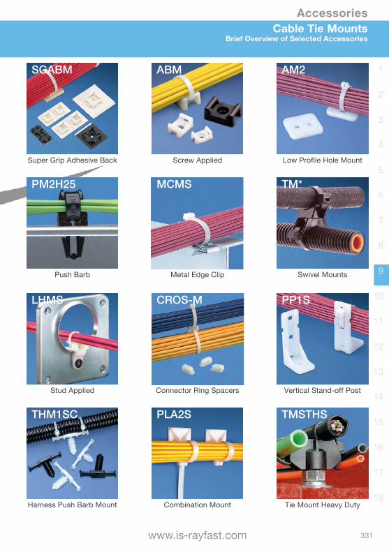
Accessories
331www.is-rayfast.com
1
2
3
4
5
6
7
8
9
10
11
12
13
14
15
16
17
18
Super Grip Adhesive Back Screw Applied Low Profile Hole Mount
Push Barb Metal Edge Clip Swivel Mounts
Stud Applied Connector Ring Spacers Vertical Stand-off Post
Harness Push Barb Mount Combination Mount Tie Mount Heavy Duty
Cable Tie MountsBrief Overview of Selected Accessories
SGABM ABM AM2
PM2H25 MCMS TM*
LHMS CROS-M PP1S
THM1SC PLA2S TMSTHS
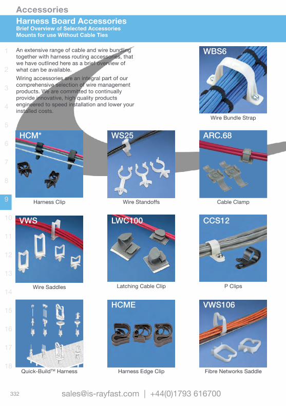
Accessories
332 [email protected] | +44(0)1793 616700
1
2
3
4
5
6
7
8
9
10
11
12
13
14
15
16
17
18
Wire Bundle Strap
Wire Standoffs Cable ClampHarness Clip
Latching Cable Clip P ClipsWire Saddles
Harness Edge Clip Fibre Networks SaddleQuick-BuildTM Harness
Harness Board AccessoriesBrief Overview of Selected Accessories Mounts for use Without Cable Ties
An extensive range of cable and wire bundling together with harness routing accessories, that we have outlined here as a brief overview of what can be available.Wiring accessories are an integral part of our comprehensive selection of wire management products. We are committed to continually provide innovative, high quality products engineered to speed installation and lower your installed costs.
WBS6
HCM* WS25 ARC.68
VWS LWC100 CCS12
HCME VWS106
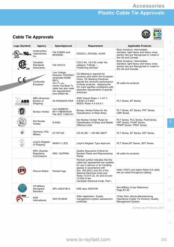
Accessories
333www.is-rayfast.com
1
2
3
4
5
6
7
8
9
10
11
12
13
14
15
16
17
18
Plastic Cable Tie Approvals
Cable Tie Approvals
Logo (Symbol) Agency Spec/Approval Requirement Applicable Products
Underwriters Laboratories,Inc.
File E56854 and MH29590 ZODZ(7), ZODZ(8), ALKW
Most miniature, intermediate,standard, light-heavy and heavy crosssection ties are Recognized or Listed in the US and Canada
Canadian StandardsAssociation
File 031212C22.2 No. 18.5-02 under the category “Fittings –Positioning Devices”
Most miniature, intermediate,standard, light-heavy and heavy crosssection ties are Recognized or Listed in the US and Canada
Conformity European
Low Voltage Directive 73/23/EEC (amended 93/68/EEC). Pan-Ty and Dome-Top Barb Ty cable ties also meet the requirements from EN50146
CE Marking is required for products sold within the European Union. CE Marking Directives specify the minimum performance of these products. Applying the CE mark signifies compliance with essential requirements of specific directives.
All cable tie products
ABS (American Bureau ofShipping)
05-HS463235-PDA2005 Vessel Rules 1-1-4/7.7, 4-8/421.9.3 2001MODU Rules 4-3-3/5.9.1
PLT Series, BT Series
Bureau VeritasCert 05968/C0 BV1178B/BVN/04File ACE 14/601/01
Bureau Veritas Rules for the Classification of Steel Ships
PLT Series, BT Series, PRT Series,CBR Series
Det Norske Veritas E-6405
Det Norske Veritas’ Rules for Classification of Ships and Mobile Offshore Units
PLT Series, PLC Series, PLM Series, PRT Series, PLWP Series, PRWP Series, PRST Series
Germany (VG) Military K17/97165 VG 95 387 – 100 MS 3367F PLT Series, BT Series, SST Series
Lloyd’s Register of Shipping 89/60111 (E3) Lloyd’s Register Type Approval PLT Series,BT Series, SST Series
NRC (Nuclear RegulatoryCommission)
NRC 10CFR50Quality Assurance Criteria for Nuclear Plants and Reprocessing Plants
All cable tie products
Plenum-Rated Panduit logo
Panduit symbol indicates that the cable ties represented are suitable for use in plenum or air handlingspaces in accordance with Sec. 300.22(C) and (D) of the National Electrical Code andRules 12-010 (3), (4) and (5) and 12-020 of theCanadian Electrical Code, Part I.
Halar (702Y) and select Nylon 6.6 cable ties as noted throughout catalog
US MilitaryAerospace Standard
QPL-AS23190-2 SAE spec AS23190 See Military Cross ReferencePage B1.95
AQA International ISO/TS16949
AQA registration. Quality management system assessment certificate
Tinley Park, Illinois Manufacturing Operations (Cable Tie Division) Quality Management System.
Correct as of February 2017
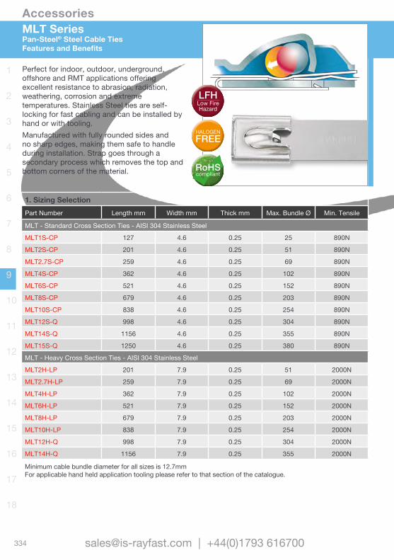
Accessories
334 [email protected] | +44(0)1793 616700
1
2
3
4
5
6
7
8
9
10
11
12
13
14
15
16
17
18
1. Sizing SelectionPart Number Length mm Width mm Thick mm Max. Bundle Ø Min. Tensile
MLT - Standard Cross Section Ties - AISI 304 Stainless Steel
MLT1S-CP 127 4.6 0.25 25 890N
MLT2S-CP 201 4.6 0.25 51 890N
MLT2.7S-CP 259 4.6 0.25 69 890N
MLT4S-CP 362 4.6 0.25 102 890N
MLT6S-CP 521 4.6 0.25 152 890N
MLT8S-CP 679 4.6 0.25 203 890N
MLT10S-CP 838 4.6 0.25 254 890N
MLT12S-Q 998 4.6 0.25 304 890N
MLT14S-Q 1156 4.6 0.25 355 890N
MLT15S-Q 1250 4.6 0.25 380 890N
MLT - Heavy Cross Section Ties - AISI 304 Stainless Steel
MLT2H-LP 201 7.9 0.25 51 2000N
MLT2.7H-LP 259 7.9 0.25 69 2000N
MLT4H-LP 362 7.9 0.25 102 2000N
MLT6H-LP 521 7.9 0.25 152 2000N
MLT8H-LP 679 7.9 0.25 203 2000N
MLT10H-LP 838 7.9 0.25 254 2000N
MLT12H-Q 998 7.9 0.25 304 2000N
MLT14H-Q 1156 7.9 0.25 355 2000N
Minimum cable bundle diameter for all sizes is 12.7mmFor applicable hand held application tooling please refer to that section of the catalogue.
MLT SeriesPan-Steel® Steel Cable TiesFeatures and Benefits
Perfect for indoor, outdoor, underground, offshore and RMT applications offering excellent resistance to abrasion, radiation, weathering, corrosion and extreme temperatures. Stainless Steel ties are self-locking for fast cabling and can be installed by hand or with tooling. Manufactured with fully rounded sides and no sharp edges, making them safe to handle during installation. Strap goes through a secondary process which removes the top and bottom corners of the material. RoHS
compliant
HALOGENFREE
LFHLow Fire Hazard
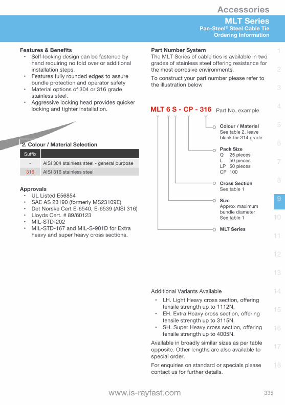
Accessories
335www.is-rayfast.com
1
2
3
4
5
6
7
8
9
10
11
12
13
14
15
16
17
18
MLT SeriesPan-Steel® Steel Cable Tie
Ordering Information
Additional Variants Available• LH. Light Heavy cross section, offering
tensile strength up to 1112N.• EH. Extra Heavy cross section, offering
tensile strength up to 3115N.• SH. Super Heavy cross section, offering
tensile strength up to 4005N.Available in broadly similar sizes as per table opposite. Other lengths are also available to special order.For enquiries on standard or specials please contact us for further details.
Approvals• UL Listed E56854• SAE AS 23190 (formerly MS23109E)• Det Norske Cert E-6540, E-6539 (AISI 316)• Lloyds Cert. # 89/60123• MIL-STD-202• MIL-STD-167 and MIL-S-901D for Extra
heavy and super heavy cross sections.
Features & Benefits• Self-locking design can be fastened by
hand requiring no fold over or additional installation steps.
• Features fully rounded edges to assure bundle protection and operator safety
• Material options of 304 or 316 grade stainless steel.
• Aggressive locking head provides quicker locking and tighter installation.
Part Number SystemThe MLT Series of cable ties is available in two grades of stainless steel offering resistance for the most corrosive environments. To construct your part number please refer to the illustration below
MLT 6 S - CP - 316
Colour / MaterialSee table 2, leave blank for 314 grade.
Pack SizeQ 25 piecesL 50 piecesLP 50 piecesCP 100
Cross SectionSee table 1
Size Approx maximum bundle diameterSee table 1
MLT Series
Part No. example
2. Colour / Material SelectionSuffix
- AISI 304 stainless steel - general purpose
316 AISI 316 stainless steel
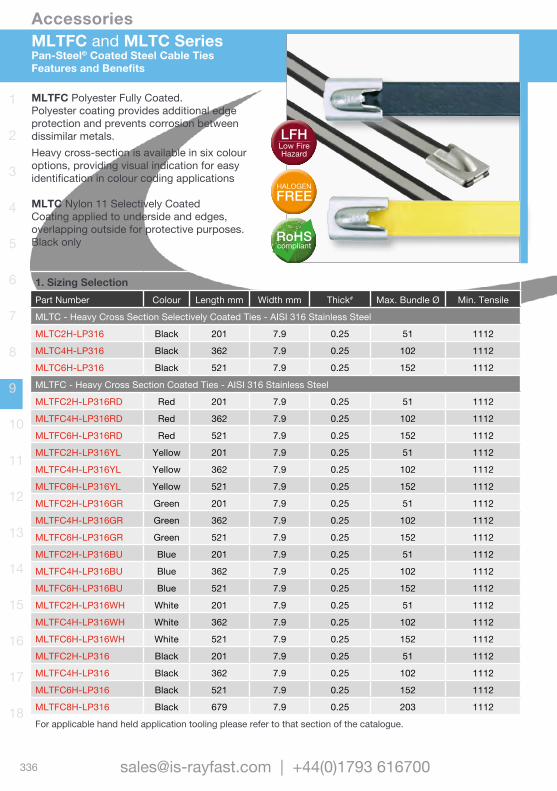
Accessories
336 [email protected] | +44(0)1793 616700
1
2
3
4
5
6
7
8
9
10
11
12
13
14
15
16
17
18
MLTFC and MLTC SeriesPan-Steel® Coated Steel Cable TiesFeatures and Benefits
1. Sizing SelectionPart Number Colour Length mm Width mm Thick# Max. Bundle Ø Min. Tensile
MLTC - Heavy Cross Section Selectively Coated Ties - AISI 316 Stainless Steel
MLTC2H-LP316 Black 201 7.9 0.25 51 1112
MLTC4H-LP316 Black 362 7.9 0.25 102 1112
MLTC6H-LP316 Black 521 7.9 0.25 152 1112
MLTFC - Heavy Cross Section Coated Ties - AISI 316 Stainless Steel
MLTFC2H-LP316RD Red 201 7.9 0.25 51 1112
MLTFC4H-LP316RD Red 362 7.9 0.25 102 1112
MLTFC6H-LP316RD Red 521 7.9 0.25 152 1112
MLTFC2H-LP316YL Yellow 201 7.9 0.25 51 1112
MLTFC4H-LP316YL Yellow 362 7.9 0.25 102 1112
MLTFC6H-LP316YL Yellow 521 7.9 0.25 152 1112
MLTFC2H-LP316GR Green 201 7.9 0.25 51 1112
MLTFC4H-LP316GR Green 362 7.9 0.25 102 1112
MLTFC6H-LP316GR Green 521 7.9 0.25 152 1112
MLTFC2H-LP316BU Blue 201 7.9 0.25 51 1112
MLTFC4H-LP316BU Blue 362 7.9 0.25 102 1112
MLTFC6H-LP316BU Blue 521 7.9 0.25 152 1112
MLTFC2H-LP316WH White 201 7.9 0.25 51 1112
MLTFC4H-LP316WH White 362 7.9 0.25 102 1112
MLTFC6H-LP316WH White 521 7.9 0.25 152 1112
MLTFC2H-LP316 Black 201 7.9 0.25 51 1112
MLTFC4H-LP316 Black 362 7.9 0.25 102 1112
MLTFC6H-LP316 Black 521 7.9 0.25 152 1112
MLTFC8H-LP316 Black 679 7.9 0.25 203 1112
For applicable hand held application tooling please refer to that section of the catalogue.
MLTFC Polyester Fully Coated. Polyester coating provides additional edge protection and prevents corrosion between dissimilar metals.Heavy cross-section is available in six colour options, providing visual indication for easy identification in colour coding applications
MLTC Nylon 11 Selectively CoatedCoating applied to underside and edges, overlapping outside for protective purposes.Black only RoHS
compliant
HALOGENFREE
LFHLow Fire Hazard
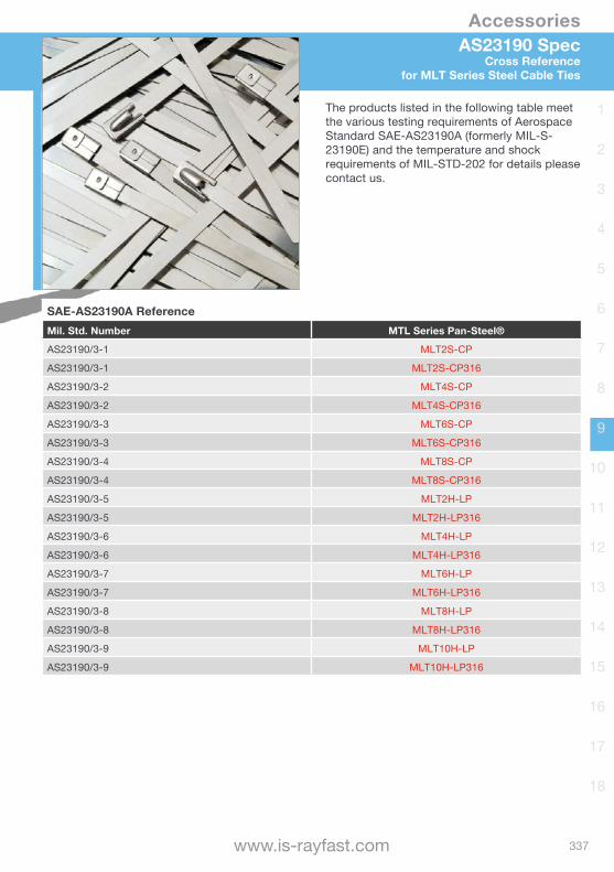
Accessories
337www.is-rayfast.com
1
2
3
4
5
6
7
8
9
10
11
12
13
14
15
16
17
18
AS23190 SpecCross Reference
for MLT Series Steel Cable Ties
The products listed in the following table meet the various testing requirements of Aerospace Standard SAE-AS23190A (formerly MIL-S-23190E) and the temperature and shock requirements of MIL-STD-202 for details please contact us.
SAE-AS23190A ReferenceMil. Std. Number MTL Series Pan-Steel®
AS23190/3-1 MLT2S-CP
AS23190/3-1 MLT2S-CP316
AS23190/3-2 MLT4S-CP
AS23190/3-2 MLT4S-CP316
AS23190/3-3 MLT6S-CP
AS23190/3-3 MLT6S-CP316
AS23190/3-4 MLT8S-CP
AS23190/3-4 MLT8S-CP316
AS23190/3-5 MLT2H-LP
AS23190/3-5 MLT2H-LP316
AS23190/3-6 MLT4H-LP
AS23190/3-6 MLT4H-LP316
AS23190/3-7 MLT6H-LP
AS23190/3-7 MLT6H-LP316
AS23190/3-8 MLT8H-LP
AS23190/3-8 MLT8H-LP316
AS23190/3-9 MLT10H-LP
AS23190/3-9 MLT10H-LP316
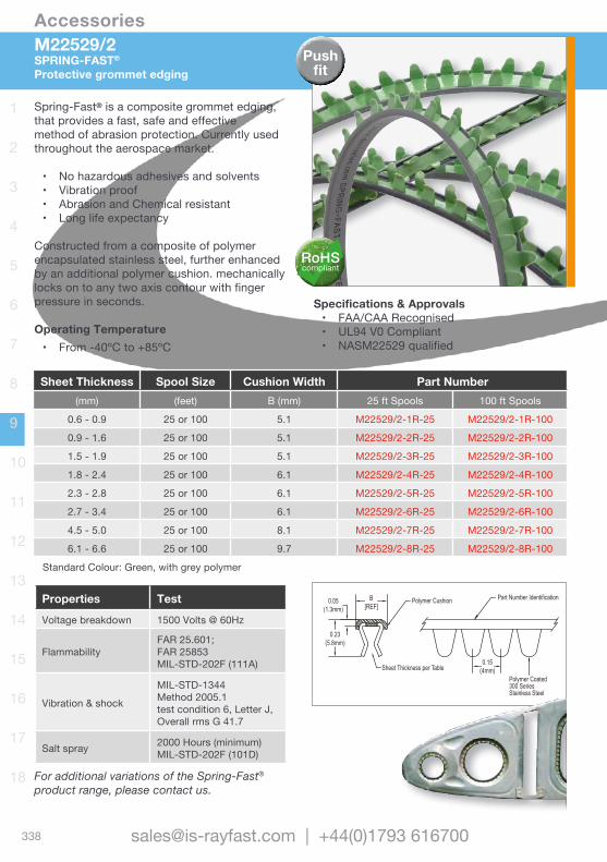
Accessories
338 [email protected] | +44(0)1793 616700
1
2
3
4
5
6
7
8
9
10
11
12
13
14
15
16
17
18
Properties Test
Voltage breakdown 1500 Volts @ 60Hz
FlammabilityFAR 25.601; FAR 25853MIL-STD-202F (111A)
Vibration & shock
MIL-STD-1344 Method 2005.1test condition 6, Letter J, Overall rms G 41.7
Salt spray 2000 Hours (minimum) MIL-STD-202F (101D)
Sheet Thickness Spool Size Cushion Width Part Number(mm) (feet) B (mm) 25 ft Spools 100 ft Spools
0.6 - 0.9 25 or 100 5.1 M22529/2-1R-25 M22529/2-1R-100
0.9 - 1.6 25 or 100 5.1 M22529/2-2R-25 M22529/2-2R-100
1.5 - 1.9 25 or 100 5.1 M22529/2-3R-25 M22529/2-3R-100
1.8 - 2.4 25 or 100 6.1 M22529/2-4R-25 M22529/2-4R-100
2.3 - 2.8 25 or 100 6.1 M22529/2-5R-25 M22529/2-5R-100
2.7 - 3.4 25 or 100 6.1 M22529/2-6R-25 M22529/2-6R-100
4.5 - 5.0 25 or 100 8.1 M22529/2-7R-25 M22529/2-7R-100
6.1 - 6.6 25 or 100 9.7 M22529/2-8R-25 M22529/2-8R-100
Standard Colour: Green, with grey polymer
0.15(4mm)
Part Number IdentificationB
[REF]
0.20 (5mm)0.02
(0.5mm)
Polymer Coated300 SeriesStainless Steel
Sheet Thickness per Table
B[REF]
Polymer Cushion0.05(1.3mm)
0.23(5.8mm)
0.15(4mm)
Part Number Identification
Polymer Coated300 SeriesStainless Steel
Sheet Thickness per Table
M22529/2SPRING-FAST®
Protective grommet edging
Spring-Fast® is a composite grommet edging, that provides a fast, safe and effective method of abrasion protection. Currently used throughout the aerospace market.
• No hazardous adhesives and solvents • Vibration proof• Abrasion and Chemical resistant• Long life expectancy
Constructed from a composite of polymer encapsulated stainless steel, further enhanced by an additional polymer cushion. mechanically locks on to any two axis contour with finger pressure in seconds.
Operating Temperature • From -40ºC to +85ºC
Specifications & Approvals• FAA/CAA Recognised• UL94 V0 Compliant• NASM22529 qualified
For additional variations of the Spring-Fast® product range, please contact us.
RoHScompliant
Push fit
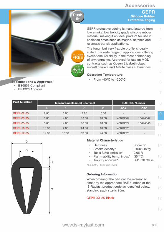
Accessories
339www.is-rayfast.com
1
2
3
4
5
6
7
8
9
10
11
12
13
14
15
16
17
18
GEPRSilicone Rubber
Protective edging
GEPR protective edging is manufactured from low smoke, low toxicity grade silicone rubber material, making it an ideal product for use in enclosed areas such as marine, defence and rail/mass transit applications.The tough but very flexible profile is ideally suited to a wide range of applications, offering exceptional reliability in the most demanding of environments. Approved for use on MOD contracts such as Queen Elizabeth class aircraft carriers and Astute class submarines.
Operating Temperature • From -40ºC to +200ºC
Push fit
Part Number Measurements (mm) - nominal BAE Ref. Number
A B C D ACA CPC
GEPR-02-25 2.00 3.00 9.00 6.00 - -
GEPR-03-25 3.00 4.00 13.00 10.66 40073362 15424647
GEPR-05-25 5.00 4.00 16.00 10.66 40073524 15424648
GEPR-10-25 10.00 7.00 24.00 16.00 40073525 -
GEPR-12-25 12.00 10.00 32.00 24.00 40073526 -
Material Characteristics• Hardness Shore 60• Smoke density * 0.0049 m2/g• Toxic fume emission* 0.05 R• Flammability temp. index* 354ºC• Toxicity approval* BR1326 Class
*BS6853 test method
Specifications & Approvals• BS6853 Compliant• BR1326 Approval
Ordering InformationWhen ordering, the part can be referenced either by the appropriate BAE number, or the IS-Rayfast product code as identified below, standard pack size is 25m.
GEPR-XX-25-Black
RoHScompliant
HALOGENFREE
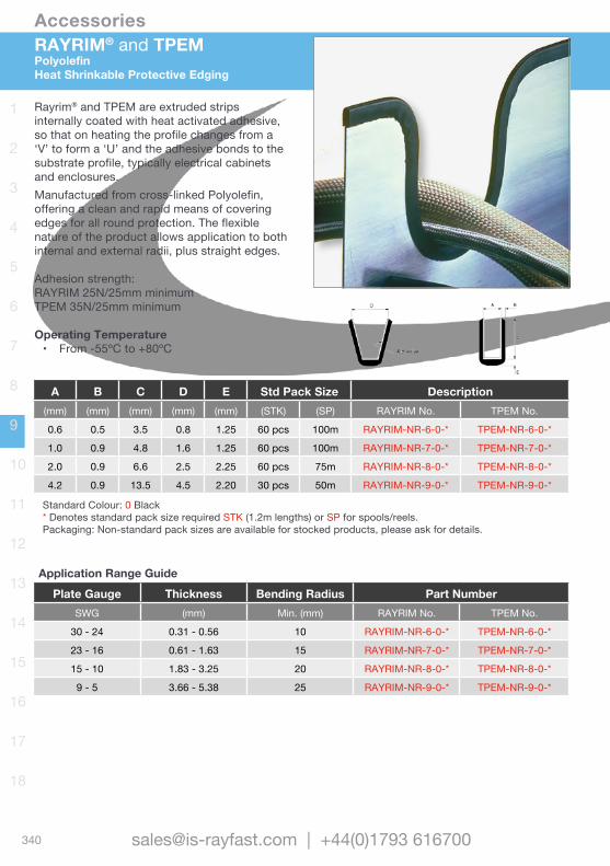
Accessories
340 [email protected] | +44(0)1793 616700
1
2
3
4
5
6
7
8
9
10
11
12
13
14
15
16
17
18
RAYRIM® and TPEMPolyolefinHeat Shrinkable Protective Edging
Rayrim® and TPEM are extruded strips internally coated with heat activated adhesive, so that on heating the profile changes from a ‘V’ to form a ‘U’ and the adhesive bonds to the substrate profile, typically electrical cabinets and enclosures. Manufactured from cross-linked Polyolefin, offering a clean and rapid means of covering edges for all round protection. The flexible nature of the product allows application to both internal and external radii, plus straight edges.
Adhesion strength: RAYRIM 25N/25mm minimumTPEM 35N/25mm minimum
Operating Temperature • From -55ºC to +80ºC
A B C D E Std Pack Size Description(mm) (mm) (mm) (mm) (mm) (STK) (SP) RAYRIM No. TPEM No.
0.6 0.5 3.5 0.8 1.25 60 pcs 100m RAYRIM-NR-6-0-* TPEM-NR-6-0-*
1.0 0.9 4.8 1.6 1.25 60 pcs 100m RAYRIM-NR-7-0-* TPEM-NR-7-0-*
2.0 0.9 6.6 2.5 2.25 60 pcs 75m RAYRIM-NR-8-0-* TPEM-NR-8-0-*
4.2 0.9 13.5 4.5 2.20 30 pcs 50m RAYRIM-NR-9-0-* TPEM-NR-9-0-*
Standard Colour: 0 Black* Denotes standard pack size required STK (1.2m lengths) or SP for spools/reels.Packaging: Non-standard pack sizes are available for stocked products, please ask for details.
Application Range GuidePlate Gauge Thickness Bending Radius Part Number
SWG (mm) Min. (mm) RAYRIM No. TPEM No.
30 - 24 0.31 - 0.56 10 RAYRIM-NR-6-0-* TPEM-NR-6-0-*
23 - 16 0.61 - 1.63 15 RAYRIM-NR-7-0-* TPEM-NR-7-0-*
15 - 10 1.83 - 3.25 20 RAYRIM-NR-8-0-* TPEM-NR-8-0-*
9 - 5 3.66 - 5.38 25 RAYRIM-NR-9-0-* TPEM-NR-9-0-*
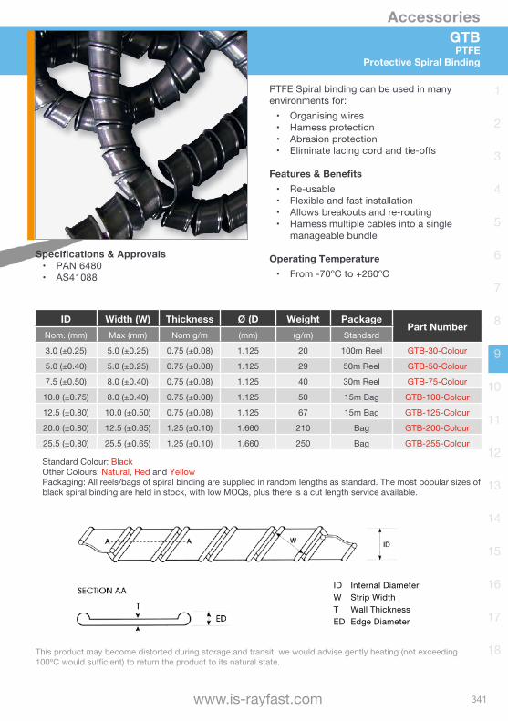
Accessories
341www.is-rayfast.com
1
2
3
4
5
6
7
8
9
10
11
12
13
14
15
16
17
18
GTBPTFE
Protective Spiral Binding
PTFE Spiral binding can be used in many environments for:
• Organising wires • Harness protection• Abrasion protection• Eliminate lacing cord and tie-offs
Features & Benefits • Re-usable• Flexible and fast installation• Allows breakouts and re-routing • Harness multiple cables into a single
manageable bundle
Operating Temperature • From -70ºC to +260ºC
ID Internal DiameterW Strip WidthT Wall ThicknessED Edge Diameter
Specifications & Approvals• PAN 6480• AS41088
ID Width (W) Thickness Ø (D Weight PackagePart Number
Nom. (mm) Max (mm) Nom g/m (mm) (g/m) Standard
3.0 (±0.25) 5.0 (±0.25) 0.75 (±0.08) 1.125 20 100m Reel GTB-30-Colour
5.0 (±0.40) 5.0 (±0.25) 0.75 (±0.08) 1.125 29 50m Reel GTB-50-Colour
7.5 (±0.50) 8.0 (±0.40) 0.75 (±0.08) 1.125 40 30m Reel GTB-75-Colour
10.0 (±0.75) 8.0 (±0.40) 0.75 (±0.08) 1.125 50 15m Bag GTB-100-Colour
12.5 (±0.80) 10.0 (±0.50) 0.75 (±0.08) 1.125 67 15m Bag GTB-125-Colour
20.0 (±0.80) 12.5 (±0.65) 1.25 (±0.10) 1.660 210 Bag GTB-200-Colour
25.5 (±0.80) 25.5 (±0.65) 1.25 (±0.10) 1.660 250 Bag GTB-255-Colour
Standard Colour: BlackOther Colours: Natural, Red and YellowPackaging: All reels/bags of spiral binding are supplied in random lengths as standard. The most popular sizes of black spiral binding are held in stock, with low MOQs, plus there is a cut length service available.
This product may become distorted during storage and transit, we would advise gently heating (not exceeding 100ºC would sufficient) to return the product to its natural state.
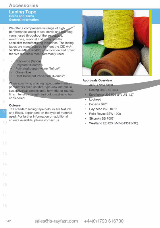
Accessories
342 [email protected] | +44(0)1793 616700
1
2
3
4
5
6
7
8
9
10
11
12
13
14
15
16
17
18
We offer a comprehensive range of high performance lacing tapes, cords and braiding yarns, used throughout the aerospace, electronics, medical and many smaller specialist manufacturing industries. The lacing tapes are manufactured to meet the CID A-A-52080-4 (MIL-T-43435) specification and cover the five materials most commonly used:
• Polyamide (Nylon)• Polyester (Dacron®)• Polytetrafluoroethylene (Teflon®)• Glass-fibre• Heat Resistant Polyamide (Nomex®)
When specifying a lacing tape, performance parameters such as fibre type (raw materials), size (physical dimensions), form (flat or round), finish, tensile strength and colours should be considered.
ColoursThe standard lacing tape colours are Natural and Black, dependent on the type of material used. For further information on additional colours available, please contact us.
Approvals Overview• Airbus NSA 8420• Boeing BMS-13-54D• Eurofighter J96.502 and JN1127• Locheed• Panavia 6481• Raytheon 268-10-11• Rolls Royce ESW 1900• Sikorsky SS 7057• Westland EE 423 (M-T43435T5-3C)
Lacing TapeCords and YarnsGeneral Information
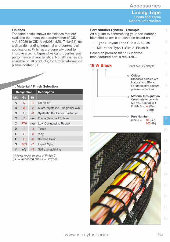
Accessories
343www.is-rayfast.com
1
2
3
4
5
6
7
8
9
10
11
12
13
14
15
16
17
18
Lacing TapeCords and Yarns
General Information
1. Material / Finish SelectionDesignation Description
MIL Gu Br
A U -1 No Finish
B W -2 Micro-crystaline, Fungicidal Wax
C H -3 Synthetic Rubber or Elastomer
C Z n/a Flame Retarded Rubber
C PTH n/a Low Out-gassing Rubber
D T -4 Teflon
E R -5 Vinyl
F S -6 Silicone Resin
G B/G -7 Liquid Nylon
# n/a -8 Self extinguishing
# Meets requirements of Finish C(Gu = Gudebrod and Br = Breyden)
FinishesThe table below shows the finishes that are available that meet the requirements of CID-A-A-52080 to CID-A-A52084 (MIL-T-43435), as well as demanding industrial and commercial applications. Finishes are generally used to improve a lacing tapes physical properties and performance characteristics. Not all finishes are available on all products, for further information please contact us.
Part Number System - ExampleAs a guide to constructing your part number identified below is an example based on...
• Type I - Nylon Tape CID-A-A-52080• MIL ref for Type 1, Size 3, Finish B
Based on premise that a Gudebrod manufactured part is required...
18 W Black
ColourStandard colours are Natural and Black. For additional colours please contact us
Material DesignationCross reference with Mil ref...See table 1Finish B = W (Gu) -2 (Br)
Part NumberSize 3 = 18 (Gu) 103 (Br)
Part No. example
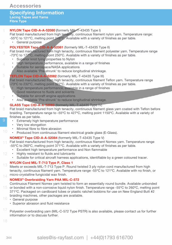
Accessories
344 [email protected] | +44(0)1793 616700
1
2
3
4
5
6
7
8
9
10
11
12
13
14
15
16
17
18
Specifying InformationLacing Tapes and YarnsFibre Type
NYLON Tape CID-A-A-52080 (formerly MIL-T-43435 Type I)Flat braid manufactured from high tenacity, continuous filament nylon yarn. Temperature range: -55ºC to 121ºC, melting point 248ºC. Available with a variety of finishes as per table.
• General purposePOLYESTER Tape CID-A-A-52081 (formerly MIL-T-43435 Type II)Flat braid manufactured from high tenacity, continuous filament polyester yarn. Temperature range -73ºC to 177ºC, melting point 250ºC. Available with a variety of finishes as per table.
• Superior knot tying properties to Nylon• High temperature performance, available in a range of finishes• Suitable for aerospace/NASA applications• Also available ‘Pre-shrunk’ to reduce longitudinal shrinkage.
TEFLON Tape CID-A-A-52082 (formerly MIL-T-43435 Type III)Flat braid manufactured from high tenacity, continuous filament Teflon yarn. Temperature range -73ºC to 232ºC, melting point 327ºC. Available with a variety of finishes as per table.
• High temperature performance, available in a range of finishes• Good resistance to fluids and solvents• Suitable for aircraft engine applications• Also available ‘Pre-shrunk’ to reduce longitudinal shrinkage.
GLASS Tape CID-A-A-52083 (formerly MIL-T-43435 Type IV)Flat braid manufactured from high tenacity, continuous filament glass yarn coated with Teflon before braiding. Temperature range to -55ºC to 427ºC, melting point 1150ºC. Available with a variety of finishes as per table.
• Extremely high temperature performance• Very low elongation• Minimal fibre to fibre abrasion• Produced from continuous filament electrical grade glass (E-Glass).
NOMEX® Tape CID-A-A-52084 (formerly MIL-T-43435 Type V)Flat braid manufactured from high tenacity, continuous filament Nomex yarn. Temperature range -55ºC to 260ºC, melting point 371ºC. Available with a variety of finishes as per table.
• Excellent high temperature performance and Non flammable• Highly resistant to fluids and lubricants• Suitable for critical aircraft harness applications, identifiable by a green coloured tracer.
NYLON Cord MIL-T-713 Type P, Class 1Meets or exceeds MIL-T-713 Type P. Round twisted 3 ply nylon cord manufactured from high tenacity, continuous filament yarn. Temperature range -55ºC to 121ºC. Available with no finish, or micro-crystalline fungicidal wax finish. NOMEX® Overbraiding Yarn PAA MIL-C-572 Continuous Filament Nomex yarn twisted to form an essentially round bundle. Available unbonded or bonded with a non-corrosive liquid nylon finish. Temperature range -55ºC to 260ºC, melting point 371ºC. Packaged on cardboard tubes or plastic ratchet bobbins for use on New England Butt #2 braiding machines, other packages are available.• General purpose• Superior abrasion and fluid resistance
Polyester overbraiding yarn (MIL-C-572 Type PSTR) is also available, please contact us for further information or to discuss further.
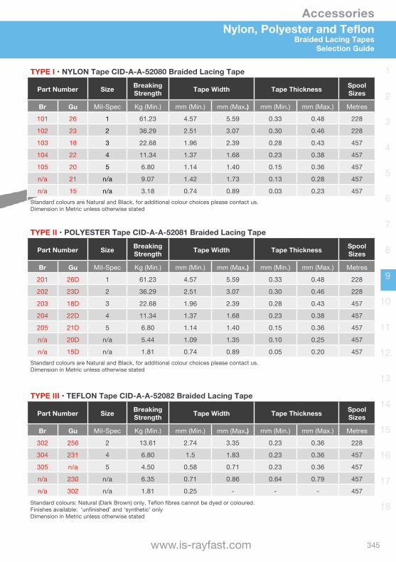
Accessories
345www.is-rayfast.com
1
2
3
4
5
6
7
8
9
10
11
12
13
14
15
16
17
18
Nylon, Polyester and TeflonBraided Lacing Tapes
Selection Guide
TYPE I •NYLON Tape CID-A-A-52080 Braided Lacing Tape
Part Number Size Breaking Strength Tape Width Tape Thickness Spool
Sizes
Br Gu Mil-Spec Kg (Min.) mm (Min.) mm (Max.) mm (Min.) mm (Max.) Metres
101 26 1 61.23 4.57 5.59 0.33 0.48 228
102 23 2 36.29 2.51 3.07 0.30 0.46 228
103 18 3 22.68 1.96 2.39 0.28 0.43 457
104 22 4 11.34 1.37 1.68 0.23 0.38 457
105 20 5 6.80 1.14 1.40 0.15 0.36 457
n/a 21 n/a 9.07 1.42 1.73 0.13 0.28 457
n/a 15 n/a 3.18 0.74 0.89 0.03 0.23 457Standard colours are Natural and Black, for additional colour choices please contact us.Dimension in Metric unless otherwise stated
TYPE II •POLYESTER Tape CID-A-A-52081 Braided Lacing Tape
Part Number Size Breaking Strength Tape Width Tape Thickness Spool
Sizes
Br Gu Mil-Spec Kg (Min.) mm (Min.) mm (Max.) mm (Min.) mm (Max.) Metres
201 26D 1 61.23 4.57 5.59 0.33 0.48 228
202 23D 2 36.29 2.51 3.07 0.30 0.46 228
203 18D 3 22.68 1.96 2.39 0.28 0.43 457
204 22D 4 11.34 1.37 1.68 0.23 0.38 457
205 21D 5 6.80 1.14 1.40 0.15 0.36 457
n/a 20D n/a 5.44 1.09 1.35 0.10 0.25 457
n/a 15D n/a 1.81 0.74 0.89 0.05 0.20 457Standard colours are Natural and Black, for additional colour choices please contact us.Dimension in Metric unless otherwise stated
TYPE III •TEFLON Tape CID-A-A-52082 Braided Lacing Tape
Part Number Size Breaking Strength Tape Width Tape Thickness Spool
Sizes
Br Gu Mil-Spec Kg (Min.) mm (Min.) mm (Max.) mm (Min.) mm (Max.) Metres
302 256 2 13.61 2.74 3.35 0.23 0.36 228
304 231 4 6.80 1.5 1.83 0.23 0.36 457
305 n/a 5 4.50 0.58 0.71 0.23 0.36 457
n/a 230 n/a 6.35 0.71 0.86 0.64 0.79 457
n/a 302 n/a 1.81 0.25 - - - 457Standard colours: Natural (Dark Brown) only, Teflon fibres cannot be dyed or coloured.Finishes available: ‘unfinished’ and ‘synthetic’ onlyDimension in Metric unless otherwise stated
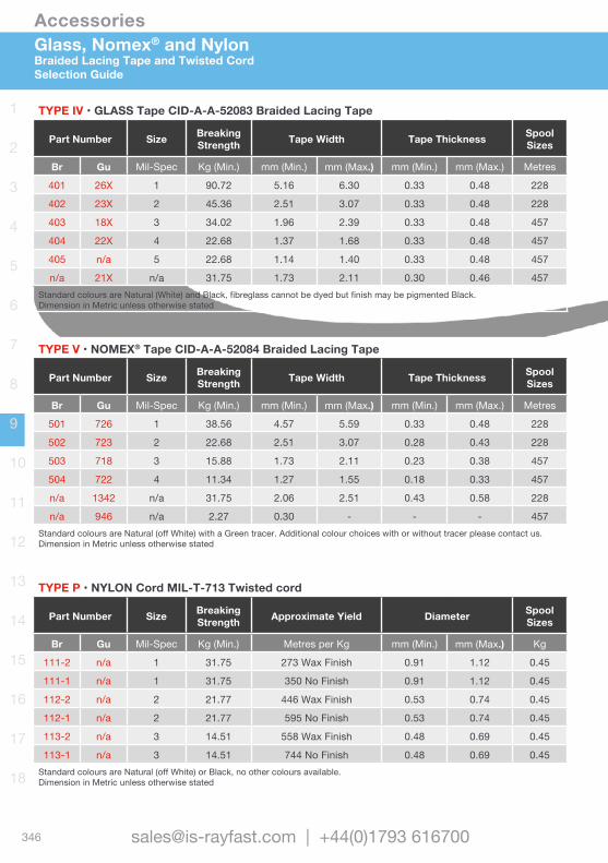
Accessories
346 [email protected] | +44(0)1793 616700
1
2
3
4
5
6
7
8
9
10
11
12
13
14
15
16
17
18
Glass, Nomex® and NylonBraided Lacing Tape and Twisted CordSelection Guide
TYPE IV •GLASS Tape CID-A-A-52083 Braided Lacing Tape
Part Number Size Breaking Strength Tape Width Tape Thickness Spool
Sizes
Br Gu Mil-Spec Kg (Min.) mm (Min.) mm (Max.) mm (Min.) mm (Max.) Metres
401 26X 1 90.72 5.16 6.30 0.33 0.48 228
402 23X 2 45.36 2.51 3.07 0.33 0.48 228
403 18X 3 34.02 1.96 2.39 0.33 0.48 457
404 22X 4 22.68 1.37 1.68 0.33 0.48 457
405 n/a 5 22.68 1.14 1.40 0.33 0.48 457
n/a 21X n/a 31.75 1.73 2.11 0.30 0.46 457Standard colours are Natural (White) and Black, fibreglass cannot be dyed but finish may be pigmented Black.Dimension in Metric unless otherwise stated
TYPE V •NOMEX® Tape CID-A-A-52084 Braided Lacing Tape
Part Number Size Breaking Strength Tape Width Tape Thickness Spool
Sizes
Br Gu Mil-Spec Kg (Min.) mm (Min.) mm (Max.) mm (Min.) mm (Max.) Metres
501 726 1 38.56 4.57 5.59 0.33 0.48 228
502 723 2 22.68 2.51 3.07 0.28 0.43 228
503 718 3 15.88 1.73 2.11 0.23 0.38 457
504 722 4 11.34 1.27 1.55 0.18 0.33 457
n/a 1342 n/a 31.75 2.06 2.51 0.43 0.58 228
n/a 946 n/a 2.27 0.30 - - - 457Standard colours are Natural (off White) with a Green tracer. Additional colour choices with or without tracer please contact us.Dimension in Metric unless otherwise stated
TYPE P •NYLON Cord MIL-T-713 Twisted cord
Part Number Size Breaking Strength Approximate Yield Diameter Spool
Sizes
Br Gu Mil-Spec Kg (Min.) Metres per Kg mm (Min.) mm (Max.) Kg
111-2 n/a 1 31.75 273 Wax Finish 0.91 1.12 0.45
111-1 n/a 1 31.75 350 No Finish 0.91 1.12 0.45
112-2 n/a 2 21.77 446 Wax Finish 0.53 0.74 0.45
112-1 n/a 2 21.77 595 No Finish 0.53 0.74 0.45
113-2 n/a 3 14.51 558 Wax Finish 0.48 0.69 0.45
113-1 n/a 3 14.51 744 No Finish 0.48 0.69 0.45Standard colours are Natural (off White) or Black, no other colours available.Dimension in Metric unless otherwise stated
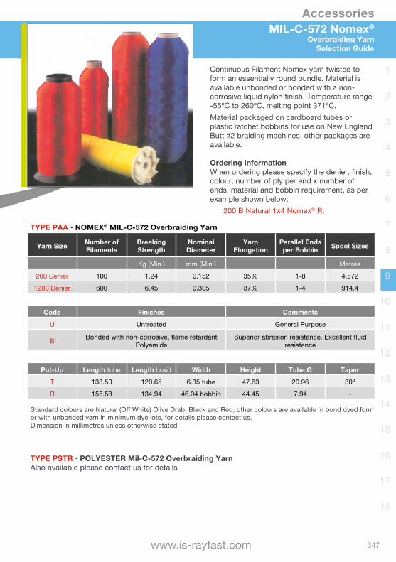
Accessories
347www.is-rayfast.com
1
2
3
4
5
6
7
8
9
10
11
12
13
14
15
16
17
18
MIL-C-572 Nomex®
Overbraiding YarnSelection Guide
TYPE PAA •NOMEX® MIL-C-572 Overbraiding Yarn
Yarn Size Number of Filaments
Breaking Strength
Nominal Diameter
Yarn Elongation
Parallel Ends per Bobbin Spool Sizes
Kg (Min.) mm (Min.) Metres
200 Denier 100 1.24 0.152 35% 1-8 4,572
1200 Denier 600 6.45 0.305 37% 1-4 914.4
Code Finishes Comments
U Untreated General Purpose
B Bonded with non-corrosive, flame retardant Polyamide
Superior abrasion resistance. Excellent fluid resistance
Put-Up Length tube Length braid Width Height Tube Ø Taper
T 133.50 120.65 6.35 tube 47.63 20.96 30º
R 155.58 134.94 46.04 bobbin 44.45 7.94 -
Standard colours are Natural (Off White) Olive Drab, Black and Red, other colours are available in bond dyed form or with unbonded yarn in minimum dye lots, for details please contact us.Dimension in millimetres unless otherwise stated
TYPE PSTR •POLYESTERMil-C-572OverbraidingYarnAlso available please contact us for details
Continuous Filament Nomex yarn twisted to form an essentially round bundle. Material is available unbonded or bonded with a non-corrosive liquid nylon finish. Temperature range -55ºC to 260ºC, melting point 371ºC. Material packaged on cardboard tubes or plastic ratchet bobbins for use on New England Butt #2 braiding machines, other packages are available.
Ordering InformationWhen ordering please specify the denier, finish, colour, number of ply per end x number of ends, material and bobbin requirement, as per example shown below; 200 B Natural 1x4 Nomex® R.


Wire and Cable Heat-shrink Tubing
Non-shrink TubingBraided SleevingScreening Braids
Moulded Parts Terminals and Splices
Wire and Cable MarkersAccessoriesConnectorsBackshells
Bonding LeadsMetal Braids
Relays and Contactors Switches and Grips
Adhesives and TapesApplication EquipmentAdded Value Services

Backshells
362 [email protected] | +44(0)1793 616700
1
2
3
4
5
6
7
8
9
10
11
12
13
14
15
16
17
18
INTRODUCTION
Circular Backshells For all your wire and cable screen connection requirements, we have the solutions through our partners, offering an extensive range of circular connector backshells, available in various materials and plating specifications.Backshells, or connector adaptors if you prefer, offer high performance sealing and strain relief in demanding applications. We offer a wide range for applications in many industries including Aerospace, Defence, Marine and Mass Transit.These backshells are available in many configurations to match applications, are easy to install and offer high reliability.
Let us Help youFor your connector adaptors or backshell assemblies, please contact us with the following information where applicable.
• Backshell type.• Connector part number or specification.• Connector required or the manufacturer.• Connector shell size.• Connector material and plating (this may
be in the part number).• Wire bundle diameter and cable jacket
diameter.• Entry size.• Angle of backshell, or range required.• Type of cable screen (e.g. size and number
of strands, single or double layer).
Connector Backshell Heat shrinkable Moulded Boot (if used)
Cable Screen (if applicable)Memory Ring
or other screen clamp method

Backshells
363www.is-rayfast.com
1
2
3
4
5
6
7
8
9
10
11
12
13
14
15
16
17
18
Introduction Selecting material and plating page 364 Determining the entry size page 366
Screened Backshells Overview and selection guide page 367Braided Tail Pre-terminated with screening braid tail page 368Tinel-Lock® Memory ring page 370Band Band strap clamp page 372Roll Spring Constant force roll spring clamp page 374Hexashield® Individual screen clamp page 376KTKK Pre-installed with heat shrink boot page 378
Non-Screened Backshells Overview and selection guide page 380Solid Solid page 381Spin Spin coupling page 382Spin-Lock® Variable angle Spin-Lock® page 383
Connector Accessories Protective/Dust Caps page 384
CONTENTS
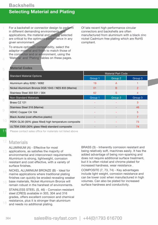
Backshells
364 [email protected] | +44(0)1793 616700
1
2
3
4
5
6
7
8
9
10
11
12
13
14
15
16
17
18
Selecting Material and Plating
For a backshell or connector design to perform in different demanding environments and applications, the material and plating selected are critical to the optimum performance in any given environment.To ensure optimum compatibility, select the adaptor material and finish to match those of the connector and or environment, using the ‘Material’ and ‘Plating’ tables on these pages.
Of late recent high performance circular connectors and backshells are often manufactured from aluminium with a black zinc nickel Cadmium free plating which are RoHS compliant.
Material Codes
Standard Material OptionsMaterial Part Code
Group 1 Group 2 Group 3
Aluminium alloy 6262 / 6082 19 A 1
Nickel Aluminium Bronze DGS 1043 / NES 833 (Marine) 01 B 2
Stainless Steel 303 S31 / 304 62 S 4
Non-Standard Materials Group 1 Group 2 Group 3
Brass CZ 121 - - 3
Stainless Steel 316 (Marine) - - 46
HDHC Copper CA 104 - - 5
Black Acetal (cost effective plastic) - - 7
PEEK GL30 (30% glass filled) high temperature composite - - 73
ULTEM 2300 (30% glass filled) standard composite - - 74Please contact sales office for materials not listed above
MaterialsALUMINIUM (A) - Effective for most applications, as satisfies the majority of environmental and interconnect requirements. Aluminium is strong, lightweight, corrosion resistant and cost effective, with a variety of surface finishes.NICKEL ALUMINIUM BRONZE (B) - Ideal for marine applications where traditional plating finishes can quickly be eroded revealing weaker base materials, Nickel Aluminium Bronze will remain robust in the harshest of environments. STAINLESS STEEL (S, 46) - Corrosion resistant steel (CRES) available in 303, 304 and 316 grades, offers excellent corrosion and chemical resistance, plus it is stronger than aluminium and needs no additional plating.
BRASS (3) - Inherently corrosion resistant and being relatively soft, machines easily. It has the added advantage of being non-sparking and does not require additional surface treatment, but it is often nickel and chrome plated for increased hardness, wear resistance .COMPOSITE (7, 73, 74) - Key advantages include light weight, corrosion resistance and can be lower cost when manufactured in high volumes. Can also be plated for increased surface hardness and conductivity.

Backshells
365www.is-rayfast.com
1
2
3
4
5
6
7
8
9
10
11
12
13
14
15
16
17
18
Material Codes
Standard Material OptionsMaterial Part Code
Group 1 Group 2 Group 3
Aluminium alloy 6262 / 6082 19 A 1
Nickel Aluminium Bronze DGS 1043 / NES 833 (Marine) 01 B 2
Stainless Steel 303 S31 / 304 62 S 4
Non-Standard Materials Group 1 Group 2 Group 3
Brass CZ 121 - - 3
Stainless Steel 316 (Marine) - - 46
HDHC Copper CA 104 - - 5
Black Acetal (cost effective plastic) - - 7
PEEK GL30 (30% glass filled) high temperature composite - - 73
ULTEM 2300 (30% glass filled) standard composite - - 74Please contact sales office for materials not listed above
Plating Codes
Standard Plating Options Colour RoHSPlating Part Code
Group A Group B
Cadmium, per SAE AMS-QQ-P-416, Type II, Class 3. Over electroless nickel Olive Drab No B B
Electroless nickel, per SAE AMS-C-26074, Class 4, Grade B. Silver Yes C C
Anodised hard per MIL-A-8625, Type III, Class 2 Black Yes G D
Anodised, sulphuric, MIL-A-8625, Type II, Class 2 Black Yes - G
Passivated, per SAE AMS-QQ-P-35 or MIL-S-5002 (stainless steel only). - Yes J J
Zinc Cobalt over Electroless Nickel Olive Drab Yes U ZB
Unplated Shot Blast (glass bead), for non reflective finish - Yes W Z
Zinc Nickel passivate over electroless Nickel, ASTM B841 class 1 Black Yes Z ZN
Non-Standard Plating Material Colour RoHS Group A Group B
Anodise Blue to DEF 03-25 Blue Yes - AB
Anodise Red to DEF 03-25 Red Yes - AR
Electroless Nickel, high Phosphor, BS EN ISO 4527:2003 Silver Yes - CHP
Bright electroless Nickel to MIL-C-26047D, class 4, grade C Silver Yes - F
Hard anodise Grey Grey Yes - HA
Iridite conversion of Alocrom 1200, clear/iridescent (aluminium only) - Yes -
Nickel/PTFE Black Yes - TN
Unplated clean finish not shot blasted - Yes - U
Silver plate 5 microns to DEF 03-9 - Yes - V
PlatingCADMIUM (B) - The historical standard finish for military and industrial connectors and backshells, offering excellent salt spray corrosion resistance.ELECTROLESS NICKEL (C) - Commonly used on industrial and high temperature applications, where a non-reflective finish and high corrosion resistance is not essential. HARD ANODISED (G) - Used where the need for surface hardness and abrasion resistance is the main criteria. The build up for hard coat anodising is much thicker than your standard anodising.
PASSIVATED (J) - Removes surface contaminants and produces a surface condition which is resistant to corrosive action. Provides a higher degree of corrosion resistance with finished parts retaining the dimension they had prior to treatment.ZINC COBALT (U) - Offers enhanced corrosion resistance compared to traditional zinc plating of the same thickness. By electroplating zinc and cobalt to the particular metal, the end result is a uniform ductility. SHOT BLAST (W) - For a non reflective finish.BLACK ZINC NICKEL (Z) - The latest RoHS compliant solution to environmental plating of connectors and backshells, offering high levels of compatibility with other plating materials.
Selecting Material and Plating

Backshells
366 [email protected] | +44(0)1793 616700
1
2
3
4
5
6
7
8
9
10
11
12
13
14
15
16
17
18
Determine Entry Size
Determining the Entry SizeOnce you have the wire bundle size, use the chart below to select entry size. Chart shows the minimum entry sizes for cables from 3 to 38 mm in diameter. In other words, the white spaces on the chart represent all of the cable outside diameters each entry size will fit.
Follow these steps:• Find the cable diameter on the chart.• Please note the lowest entry size that will
fit the cable diameter.
If the adaptor is shielded or has a Tinel-Lock ring, there are additional considerations, which are noted below.
For further information or assistance on selecting the correct entry size or constructing your required adaptor part number, please contact us.
3 4 5 6 7 8 9 10 11 12 13 14 15 16 17 18 19 20 21 22 23 24 25 26 27 28 29 30 31 32 33 34 35 36 37 38
04
05
06
07
08
10
12
14
16
18
20
22
24
Entry
size
Braided Tail BackshellsThe extreme flexibility of the braid on these backshells accommodates a large range of cable diameters. It is therefore recommended that the standard entry size for any given adaptor part number be specified as indicated on the relevant data sheet. Non standard entry sizes are available to special order. Use the selection chart above to ensure that the standard entry size will pass over the jacketed cable diameter.
Memory Ring BackshellsThe cable braid must be opened up to fit onto the outside diameter of the adaptor entry. For optimum performance, select the smallest entry size that will pass over the jacketed cable diameter. Repair of the connector will be easier using the boot and shield rollback if a slightly larger than minimum entry size is used. The selection chart above shows the minimum entry sizes for cable diameters in the range of 3 mm to 38 mm. This will ensure that the jacketed cable passes through the adaptor. Ensure the braid will open sufficiently to fit the entry size selected and to ensure that the braid and boot can be rolled back.
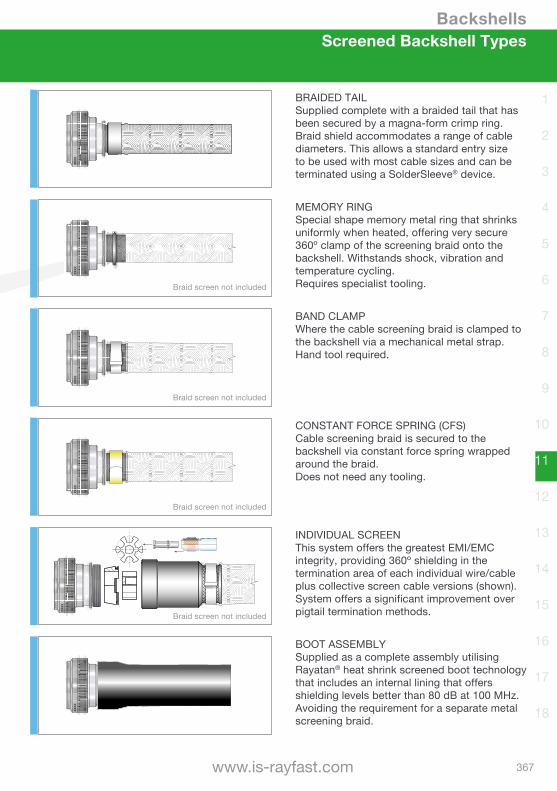
Backshells
367www.is-rayfast.com
1
2
3
4
5
6
7
8
9
10
11
12
13
14
15
16
17
18
Screened Backshell Types
XXXX
XXXX
BAND CLAMPWhere the cable screening braid is clamped to the backshell via a mechanical metal strap.Hand tool required.
CONSTANT FORCE SPRING (CFS)Cable screening braid is secured to the backshell via constant force spring wrapped around the braid. Does not need any tooling.
MEMORY RINGSpecial shape memory metal ring that shrinks uniformly when heated, offering very secure 360º clamp of the screening braid onto the backshell. Withstands shock, vibration and temperature cycling. Requires specialist tooling.
BRAIDED TAILSupplied complete with a braided tail that has been secured by a magna-form crimp ring. Braid shield accommodates a range of cable diameters. This allows a standard entry size to be used with most cable sizes and can be terminated using a SolderSleeve® device.
INDIVIDUAL SCREENThis system offers the greatest EMI/EMC integrity, providing 360º shielding in the termination area of each individual wire/cable plus collective screen cable versions (shown). System offers a significant improvement over pigtail termination methods.
BOOT ASSEMBLYSupplied as a complete assembly utilising Rayatan® heat shrink screened boot technology that includes an internal lining that offers shielding levels better than 80 dB at 100 MHz. Avoiding the requirement for a separate metal screening braid.
XXXX
Braid screen not included
XXXX
Braid screen not included
XXXX
Braid screen not included
XXXX
Braid screen not included
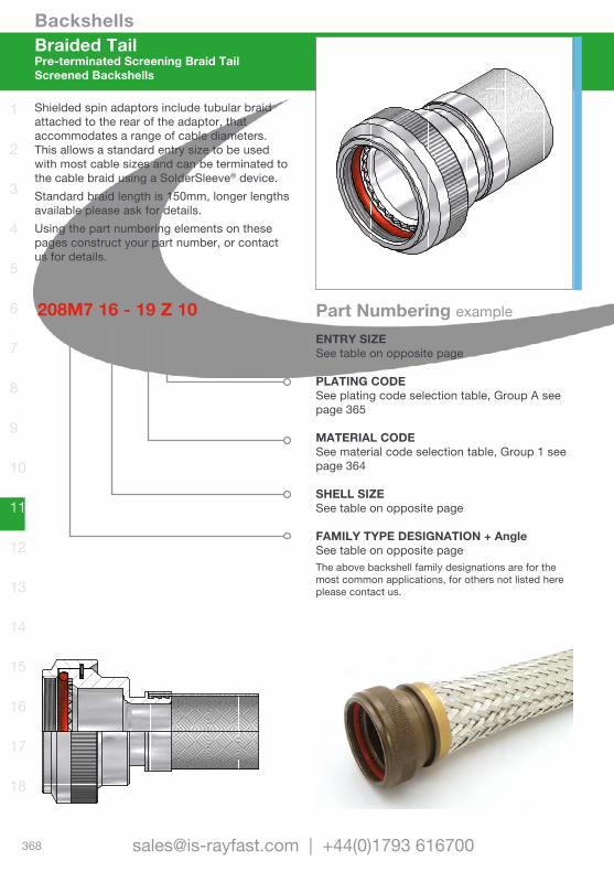
Backshells
368 [email protected] | +44(0)1793 616700
1
2
3
4
5
6
7
8
9
10
11
12
13
14
15
16
17
18
ENTRY SIZESee table on opposite page
PLATING CODESee plating code selection table, Group A see page 365
MATERIAL CODESee material code selection table, Group 1 see page 364
SHELL SIZESee table on opposite page
FAMILY TYPE DESIGNATION + AngleSee table on opposite pageThe above backshell family designations are for the most common applications, for others not listed here please contact us.
Braided TailPre-terminated Screening Braid TailScreened Backshells
Shielded spin adaptors include tubular braid attached to the rear of the adaptor, that accommodates a range of cable diameters. This allows a standard entry size to be used with most cable sizes and can be terminated to the cable braid using a SolderSleeve® device. Standard braid length is 150mm, longer lengths available please ask for details.Using the part numbering elements on these pages construct your part number, or contact us for details.
208M7 16 - 19 Z 10 Part Numbering example

Backshells
369www.is-rayfast.com
1
2
3
4
5
6
7
8
9
10
11
12
13
14
15
16
17
18
Shell Size Selection TablePart No. Ind. Ref. Mil. Ref. Max Entry Size
08 9 A 04
10 11 B 07
12 13 C 09
14 15 D 10
16 17 E 12
18 19 F 14
20 21 G 16
22 23 H 18
24 25 J 20
208M* - Entry Size Dimensions Table
Entry Size Internal Dia
03 4.77 mm
04 6.35 mm
05 7.92 mm
06 9.52 mm
07 11.12 mm
08 12.70 mm
09 14.27 mm
10 15.87 mm
11 17.47 mm
12 19.05 mm
13 20.62 mm
14 22.23 mm
15 23.82 mm
16 25.40 mm
17 26.98 mm
18 28.60 mm
20 31.80 mm
21 33.34 mm
22 35.00 mm
24 38.10 mm
28 44.45 mm
Selection tables shown here are for general indicative purposes only, as they represent the MIL-C-38999 Series III & IV family of ‘Braided tail’ backshells only. For other family type backshells dimensions and characteristics please contact us for details.The entry size range shown above indicates the most common combinations only, for further options please contact us.
Braided TailPre-terminated Screening Braid Tail
Screened Backshells
Family Type Designation
MIL-C-5015 (MS3100)218M7 Straight backshell family218M8 45º backshell family218M9 90º backshell family
MIL-C-26482 Series I206M0 Straight backshell family206M1 45º backshell family206M2 90º backshell family
MIL-C-38999 Series III & IV.208M7 Straight backshell family208M8 45º backshell family208M9 90º backshell family
MIL-C-38999 Series I & II.204M0 Straight backshell family204M1 45º backshell family204M2 90º backshell family
MIL-C-26482 Series II and MIL-C-5015 (MS3400)203M0 Straight backshell family203M1 45º backshell family203M2 90º backshell family
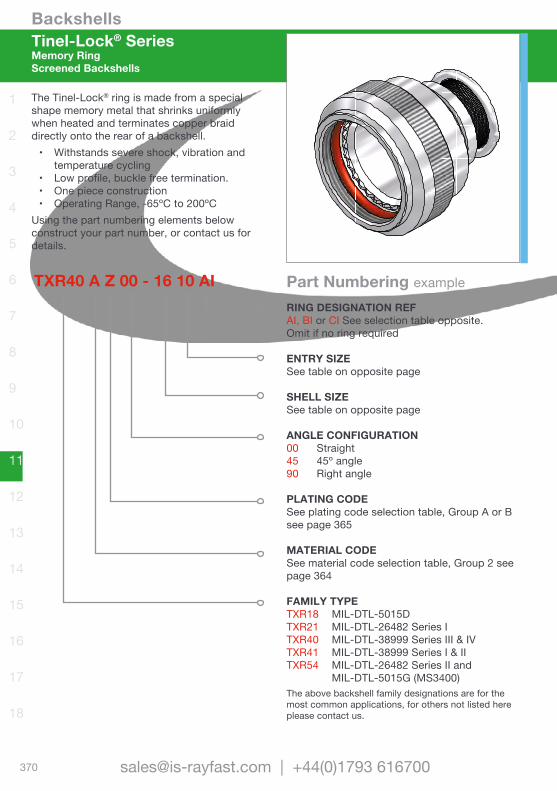
Backshells
370 [email protected] | +44(0)1793 616700
1
2
3
4
5
6
7
8
9
10
11
12
13
14
15
16
17
18
Tinel-Lock® SeriesMemory RingScreened Backshells
The Tinel-Lock® ring is made from a special shape memory metal that shrinks uniformly when heated and terminates copper braid directly onto the rear of a backshell.• Withstands severe shock, vibration and
temperature cycling• Low profile, buckle free termination.• One piece construction• Operating Range, -65ºC to 200ºC
Using the part numbering elements below construct your part number, or contact us for details.
TXR40 A Z 00 - 16 10 AIRING DESIGNATION REFAI, BI or CI See selection table opposite.Omit if no ring required
ENTRY SIZESee table on opposite page
SHELL SIZESee table on opposite page
ANGLE CONFIGURATION00 Straight45 45º angle90 Right angle
PLATING CODESee plating code selection table, Group A or B see page 365
MATERIAL CODESee material code selection table, Group 2 see page 364
FAMILY TYPETXR18 MIL-DTL-5015DTXR21 MIL-DTL-26482 Series ITXR40 MIL-DTL-38999 Series III & IVTXR41 MIL-DTL-38999 Series I & IITXR54 MIL-DTL-26482 Series II and MIL-DTL-5015G (MS3400)The above backshell family designations are for the most common applications, for others not listed here please contact us.
Part Numbering example
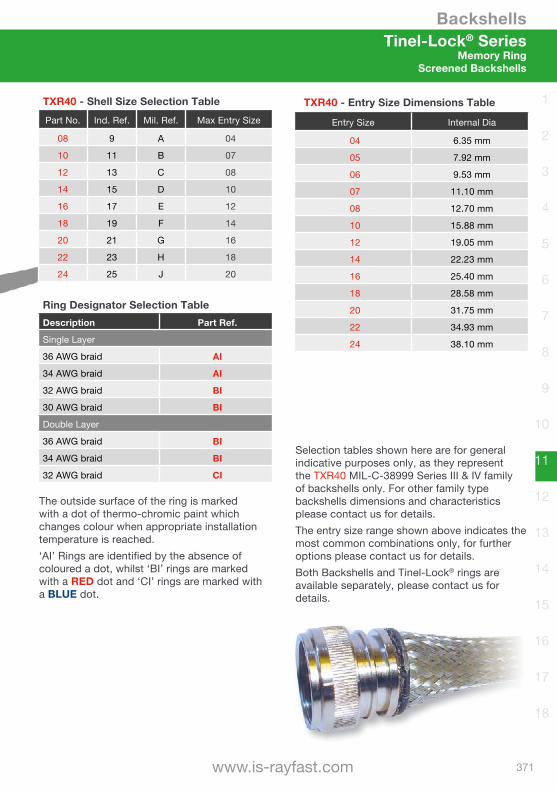
Backshells
371www.is-rayfast.com
1
2
3
4
5
6
7
8
9
10
11
12
13
14
15
16
17
18
TXR40 - Shell Size Selection TablePart No. Ind. Ref. Mil. Ref. Max Entry Size
08 9 A 04
10 11 B 07
12 13 C 08
14 15 D 10
16 17 E 12
18 19 F 14
20 21 G 16
22 23 H 18
24 25 J 20
Selection tables shown here are for general indicative purposes only, as they represent the TXR40 MIL-C-38999 Series III & IV family of backshells only. For other family type backshells dimensions and characteristics please contact us for details.The entry size range shown above indicates the most common combinations only, for further options please contact us for details.Both Backshells and Tinel-Lock® rings are available separately, please contact us for details.
Ring Designator Selection TableDescription Part Ref.
Single Layer
36 AWG braid AI
34 AWG braid AI
32 AWG braid BI
30 AWG braid BI
Double Layer
36 AWG braid BI
34 AWG braid BI
32 AWG braid CI
Tinel-Lock® SeriesMemory Ring
Screened Backshells
The outside surface of the ring is marked with a dot of thermo-chromic paint which changes colour when appropriate installation temperature is reached.‘AI’ Rings are identified by the absence of coloured a dot, whilst ‘BI’ rings are marked with a RED dot and ‘CI’ rings are marked with a BLUE dot.
TXR40 - Entry Size Dimensions Table
Entry Size Internal Dia
04 6.35 mm
05 7.92 mm
06 9.53 mm
07 11.10 mm
08 12.70 mm
10 15.88 mm
12 19.05 mm
14 22.23 mm
16 25.40 mm
18 28.58 mm
20 31.75 mm
22 34.93 mm
24 38.10 mm

Backshells
372 [email protected] | +44(0)1793 616700
1
2
3
4
5
6
7
8
9
10
11
12
13
14
15
16
17
18
Band Strap SeriesBand ClampScreened Backshells
Band Strap adaptors feature a corrosion-resistant steel band to terminate the cable screen. The resulting 360º overall termination creates an effective electrical connection, providing screen continuity between braid and adaptor. The terminated cable can then be protected and sealed using a heat-shrinkable moulded part, providing strain relief to the cable.Using the part numbering elements below construct your part number, or contact us for details.
BND40 A Z 00 - 16 12 VBAND CODEV One step standard band (straight)U Two step band, contact us for more info
ENTRY SIZESee table on opposite page
SHELL SIZESee table on opposite page
ANGLE CONFIGURATION00 Straight45 45º angle90º Right angle
PLATING CODESee plating code selection table, Group A or B see page 365
MATERIAL CODESee material code selection table, Group 2 see page 364
FAMILY TYPEBND18 MIL-DTL-5015 (MS3100)BND21 MIL-DTL-26482 Series IBND40 MIL-DTL-38999 Series III & IVBND41 MIL-DTL-38999 Series I & IIBND54 MIL-DTL-26482 Series II and MIL-DTL-5015 (MS3400)The above backshell family designations are for the most common applications, for others not listed here please contact us.
Part Numbering example
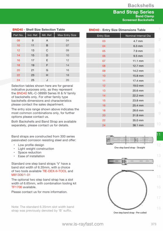
Backshells
373www.is-rayfast.com
1
2
3
4
5
6
7
8
9
10
11
12
13
14
15
16
17
18
BND40 - Shell Size Selection TablePart No. Ind. Ref. Mil. Ref. Max Entry Size
08 9 A 04
10 11 B 07
12 13 C 09
14 15 D 10
16 17 E 12
18 19 F 14
20 21 G 16
22 23 H 18
24 25 J 20
Band Strap SeriesBand Clamp
Screened Backshells
Band straps are constructed from 300 series passivated corrosion resisting steel and offer:• Low profile design• Light weight construction• Space reduction• Ease of installation
Standard one step band straps ‘V’ have a band slot width of 6.35mm, with a choice of two tools available TIE-DEX-II-TOOL and M81306/1-01 The optional two step band strap has a slot width of 6.65mm, with combination tooling kit TF1700 available.Please contact us for more information.
Note: The standard 6.35mm slot width band strap was previously denoted by ‘B’ suffix.
BND40 - Entry Size Dimensions Table
Entry Size Nominal Internal Dia
03 4.7 mm
04 6.3 mm
05 7.9 mm
06 9.5 mm
07 11.1 mm
08 12.7 mm
09 14.2 mm
10 15.8 mm
11 17.4 mm
12 19.0 mm
13 20.6 mm
14 22.2 mm
15 23.8 mm
16 25.4 mm
18 28.6 mm
20 31.8 mm
22 35.0 mm
24 38.1 mm
Selection tables shown here are for general indicative purposes only, as they represent the BND40 MIL-C-38999 Series III & IV family of backshells only. For other family type backshells dimensions and characteristics please contact the sales department.The entry size range shown above indicates the most common combinations only, for further options please contact us.Both Backshells and Band Strap are available separately, please contact us for details.
One step band strap - Pre-coiled
One step band strap - Straight Two step band strap - Straight
Two step band strap - Pre-coiled
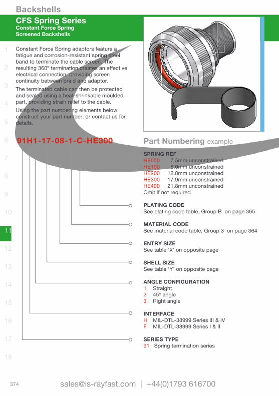
Backshells
374 [email protected] | +44(0)1793 616700
1
2
3
4
5
6
7
8
9
10
11
12
13
14
15
16
17
18
CFS Spring SeriesConstant Force SpringScreened Backshells
Constant Force Spring adaptors feature a fatigue and corrosion-resistant spring steel band to terminate the cable screen. The resulting 360º termination creates an effective electrical connection, providing screen continuity between braid and adaptor. The terminated cable can then be protected and sealed using a heat-shrinkable moulded part, providing strain relief to the cable.Using the part numbering elements below construct your part number, or contact us for details.
91H1-17-08-1-C-HE300SPRING REFHE050 7.5mm unconstrainedHE100 8.0mm unconstrainedHE200 12.8mm unconstrainedHE300 17.9mm unconstrainedHE400 21.8mm unconstrainedOmit if not required
PLATING CODESee plating code table, Group B on page 365
MATERIAL CODESee material code table, Group 3 on page 364
ENTRY SIZESee table ‘X’ on opposite page
SHELL SIZESee table ‘Y’ on opposite page
ANGLE CONFIGURATION1 Straight2 45º angle3 Right angle
INTERFACEH MIL-DTL-38999 Series III & IVF MIL-DTL-38999 Series I & II
SERIES TYPE91 Spring termination series
Part Numbering example
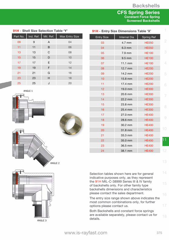
Backshells
375www.is-rayfast.com
1
2
3
4
5
6
7
8
9
10
11
12
13
14
15
16
17
18
91H - Shell Size Selection Table ‘Y’Part No. Ind. Ref. Mil. Ref. Max Entry Size
09 9 A 04
11 11 B 06
13 13 C 08
15 15 D 10
17 17 E 12
19 19 F 14
21 21 G 16
23 23 H 18
25 25 J 20
91H - Entry Size Dimensions Table ‘X’
Entry Size Internal Dia Spring Ref
03 4.7 mm HE050
04 6.3 mm HE050
05 7.9 mm HE100
06 9.5 mm HE100
07 11.1 mm HE100
08 12.7 mm HE200
09 14.2 mm HE200
10 15.8 mm HE200
11 17.4 mm HE200
12 19.0 mm HE300
13 20.6 mm HE300
14 22.2 mm HE300
15 23.8 mm HE300
16 25.4 mm HE300
17 27.0 mm HE400
18 28.6 mm HE400
19 30.2 mm HE400
20 31.8 mm HE400
21 33.3 mm HE400
22 35.0 mm HE400
23 36.5 mm HE400
24 38.1 mm HE400
Selection tables shown here are for general indicative purposes only, as they represent the 91H MIL-C-38999 Series III & IV family of backshells only. For other family type backshells dimensions and characteristics please contact the sales department.The entry size range shown above indicates the most common combinations only, for further options please contact us.Both Backshells and constant force springs are available separately, please contact us for details.
CFS Spring SeriesConstant Force Spring
Screened Backshells
ANGLE 2
ANGLE 3
CONSTANT FORCE SPRING (TABLE 3)
9,50
± 0
,20J
XX
XX
ANGLE 1

Backshells
376 [email protected] | +44(0)1793 616700
1
2
3
4
5
6
7
8
9
10
11
12
13
14
15
16
17
18
Hexashield® SeriesIndividual ScreensScreened Backshells
Superior EMC/EMI Shielding PerformanceHexashield is designed to provide optimum EMC protection solutions for both commercial and military applications, representing a significant improvement over pigtail termination methods. Providing 360º EMC shielding on the termination area of each individual cable, Hexashield backshells provide outstanding shielding effectiveness. Using the part numbering elements below, construct your part number, or contact us for details.
HEX40 - A C 00 - 17 - A6 - 3BACK NUT TYPESee illustration opposite
FERRULESNumber of ferrules to be fitted. These need to be ordered separately, see info opposite
SHELL SIZESee table on opposite page
ANGLE CONFIGURATION00 Straight45 45º angle90º Right angle
PLATING CODEB Cadmium platedC Electroless Nickel
MATERIAL CODEA Aluminium alloy
FAMILY TYPEHEX18 MIL-DTL-5015 (MS3100)HEX21 MIL-DTL-26482 Series IHEX40 MIL-DTL-38999 Series III & IVHEX41 MIL-DTL-38999 Series I & IIHEX54 MIL-DTL-26482 Series II and MIL-DTL-5015 (MS3400)The above backshell family designations are for the most common applications, for others not listed here please contact us.
Part Numbering example
XXXX
Additional Options AvailableThe options below are additional references in the part number, for details please contact us.• Long body (item 4)• Swept body (items 6 and 8)
360º Shielding Each Cable
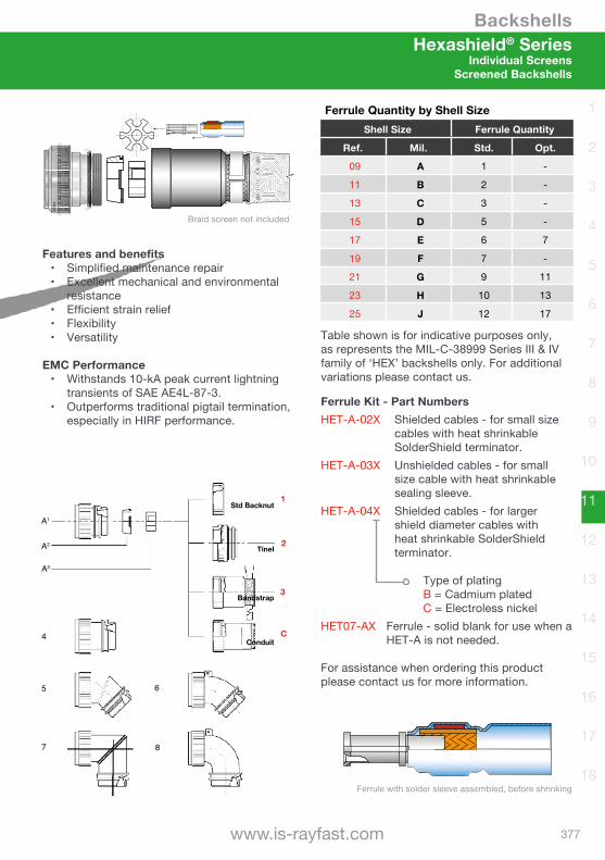
Backshells
377www.is-rayfast.com
1
2
3
4
5
6
7
8
9
10
11
12
13
14
15
16
17
18
1
2
3
C
A1
A2
A3
4
5 6
7 8
Std Backnut
Tinel
Bandstrap
Conduit
Features and benefits• Simplified maintenance repair• Excellent mechanical and environmental
resistance• Efficient strain relief• Flexibility• Versatility
EMC Performance• Withstands 10-kA peak current lightning
transients of SAE AE4L-87-3.• Outperforms traditional pigtail termination,
especially in HIRF performance.
XXXX
Braid screen not included
Ferrule Quantity by Shell SizeShell Size Ferrule Quantity
Ref. Mil. Std. Opt.
09 A 1 -
11 B 2 -
13 C 3 -
15 D 5 -
17 E 6 7
19 F 7 -
21 G 9 11
23 H 10 13
25 J 12 17
Table shown is for indicative purposes only, as represents the MIL-C-38999 Series III & IV family of ‘HEX’ backshells only. For additional variations please contact us.
Ferrule Kit - Part NumbersHET-A-02X Shielded cables - for small size
cables with heat shrinkable SolderShield terminator.
HET-A-03X Unshielded cables - for small size cable with heat shrinkable sealing sleeve.
HET-A-04X Shielded cables - for larger shield diameter cables with heat shrinkable SolderShield terminator.
Type of platingB = Cadmium platedC = Electroless nickel
HET07-AX Ferrule - solid blank for use when a HET-A is not needed.
For assistance when ordering this product please contact us for more information.
Hexashield® SeriesIndividual Screens
Screened Backshells
Ferrule with solder sleeve assembled, before shrinking
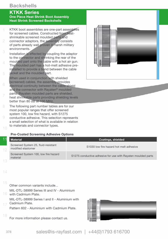
Backshells
378 [email protected] | +44(0)1793 616700
1
2
3
4
5
6
7
8
9
10
11
12
13
14
15
16
17
18
KTKK SeriesOne Piece Heat Shrink Boot AssemblyHeat Shrink Screened Backshells
XXXX
KTKK boot assemblies are one-part assemblies for screened cables. Constructed from heat-shrinkable screened moulded parts and connector adaptors, the assembly consists of parts already well proven in harsh military environments.Installation is effected by coupling the adaptor to the connector and shrinking the rear of the moulded part onto the cable with a hot air gun. The moulded part has a hot-melt adhesive pre-installed to provide a bond between the cable jacket and the moulded part.When used in conjunction with shielded (screened) cables, the assembly provides electrical continuity between the cable shield and the connector with Rayaten® moulded parts. Rayaten moulded parts are shielded, heat shrinkable parts providing shielding levels better than 80 dB at 100 MHz.The following part number tables are for our most popular ranges that offer screened system 100, low fire hazard, with S1275 conductive adhesive. This selection represents a small selection of what is available in relation to materials and connector types.
Other common variants include...MIL-DTL-38999 Series III and IV - Aluminium with Cadmium Plate.MIL-DTL-38999 Series I and II - Aluminium with Cadmium Plate.Pattern 602 - Aluminium with Cadmium Plate.
For more information please contact us.
Pre-Coated Screening Adhesive OptionsMaterial Coatings, shielded
Screened System 25, fluid-resistant modified elastomer S1030 low fire hazard hot melt adhesive
Screened System 100, low fire hazard material S1275 conductive adhesive for use with Rayaten moulded parts
XXXX

Backshells
379www.is-rayfast.com
1
2
3
4
5
6
7
8
9
10
11
12
13
14
15
16
17
18
KTKK SeriesOne Piece Heat Shrink Boot Assembly
Heat Shrink Screened Backshells
MIL-DTL-38999 Series III & IV Connectors - Nickel Aluminium Bronze
Shell Size
Straight Assemblies 45º Assemblies 90º Assemblies
Part Number Cable Range Part Number Cable Range Part Number Cable Range
08 KTKK 2610 5.0 - 7.0 KTKK 3130 5.0 - 7.0 - -
10 KTKK 2611 6.0 - 9.0 KTKK 3131 6.0 - 9.0 KTKK 2621 6.0 - 9.0
12 KTKK 2612 7.2 - 11.0 KTKK 3132 7.2 - 11.0 KTKK 2622 7.2 - 11.0
14 KTKK 2613 7.2 - 11.0 KTKK 3133 7.2 - 11.0 KTKK 2623 7.2 - 11.0
16 KTKK 2614 8.5 - 17.0 KTKK 3134 8.5 - 17.0 KTKK 2624 8.5 - 17.0
18 KTKK 2615 8.5 - 17.0 KTKK 3135 8.5 - 17.0 KTKK 2625 8.5 - 17.0
20 KTKK 2616 10.0 - 21.0 KTKK 3136 10.0 - 21.0 KTKK 2626 10.0 - 21.0
22 KTKK 2617 10.0 - 21.0 KTKK 3137 10.0 - 21.0 KTKK 2627 10.0 - 21.0
24 KTKK 2618 15.8 - 29.0 KTKK 3138 15.8 - 29.0 KTKK 2628 15.8 - 29.0
RoHScompliant
Pattern 105 Connectors - Aluminium with Cadmium Plate
Shell Size
Straight Assemblies 45º Assemblies 90º Assemblies
Part Number Cable Range Part Number Cable Range Part Number Cable Range
08 KTKK 0465 5.0 - 7.0 KTKK 0603 5.0 - 7.0 - -
10 KTKK 0466 6.0 - 9.0 KTKK 0604 6.0 - 9.0 KTKK 1251 6.0 - 9.0
12 KTKK 0467 7.2 - 11.0 KTKK 0605 7.2 - 11.0 KTKK 1252 7.2 - 11.0
14 KTKK 0468 7.2 - 11.0 KTKK 0606 7.2 - 11.0 KTKK 1253 7.2 - 11.0
16 KTKK 0469 8.5 - 17.0 KTKK 0607 8.5 - 17.0 KTKK 1254 8.5 - 17.0
18 KTKK 0470 8.5 - 17.0 KTKK 0608 8.5 - 17.0 KTKK 1255 8.5 - 17.0
20 KTKK 0471 10.0 - 21.0 KTKK 0609 10.0 - 21.0 KTKK 1256 10.0 - 21.0
22 KTKK 0472 10.0 - 21.0 KTKK 0610 10.0 - 21.0 KTKK 1257 10.0 - 21.0
24 KTKK 0473 15.8 - 29.0 KTKK 0611 15.8 - 29.0 KTKK 1258 15.8 - 29.0
Pattern 608 Connectors - Nickel Aluminium Bronze
Shell Size
Straight Assemblies 45º Assemblies 90º Assemblies
Part Number Cable Range Part Number Cable Range Part Number Cable Range
08 KTKK 0444 5.0 - 7.0 KTKK 0580 5.0 - 7.0 - -
10 KTKK 0445 6.0 - 9.0 KTKK 0581 6.0 - 9.0 KTKK 1021 6.0 - 9.0
12 KTKK 0446 7.2 - 11.0 KTKK 0582 7.2 - 11.0 KTKK 1022 7.2 - 11.0
14 KTKK 0447 7.2 - 11.0 KTKK 0583 7.2 - 11.0 KTKK 1023 7.2 - 11.0
16 KTKK 0448 8.5 - 17.0 KTKK 0584 8.5 - 17.0 KTKK 1024 8.5 - 17.0
18 KTKK 0449 8.5 - 17.0 KTKK 0585 8.5 - 17.0 KTKK 1025 8.5 - 17.0
20 KTKK 0450 10.0 - 21.0 KTKK 0586 10.0 - 21.0 KTKK 1026 10.0 - 21.0
22 KTKK 0451 10.0 - 21.0 KTKK 0587 10.0 - 21.0 KTKK 1027 10.0 - 21.0
24 KTKK 0452 15.8 - 29.0 KTKK 0588 15.8 - 29.0 KTKK 1028 15.8 - 29.0
RoHScompliant
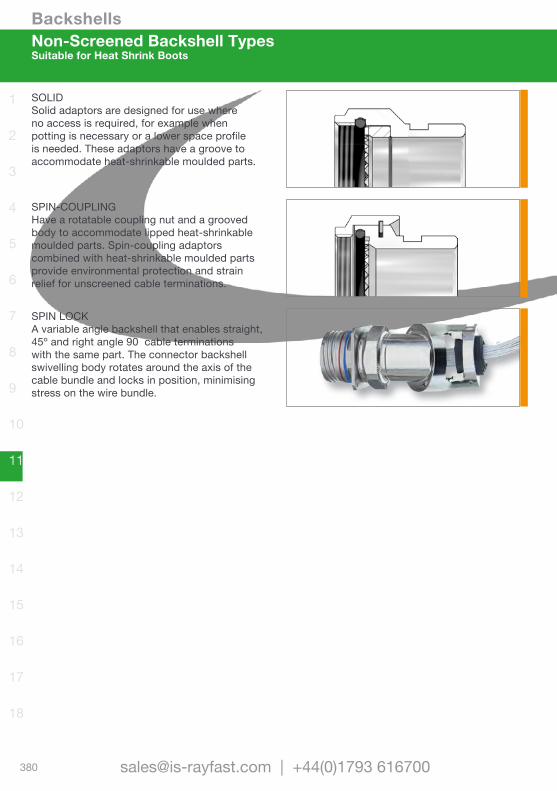
Backshells
380 [email protected] | +44(0)1793 616700
1
2
3
4
5
6
7
8
9
10
11
12
13
14
15
16
17
18
Non-Screened Backshell TypesSuitable for Heat Shrink Boots
SOLIDSolid adaptors are designed for use where no access is required, for example when potting is necessary or a lower space profile is needed. These adaptors have a groove to accommodate heat-shrinkable moulded parts.
SPIN-COUPLINGHave a rotatable coupling nut and a grooved body to accommodate lipped heat-shrinkable moulded parts. Spin-coupling adaptors combined with heat-shrinkable moulded parts provide environmental protection and strain relief for unscreened cable terminations.
SPIN LOCKA variable angle backshell that enables straight, 45º and right angle 90 cable terminations with the same part. The connector backshell swivelling body rotates around the axis of the cable bundle and locks in position, minimising stress on the wire bundle.
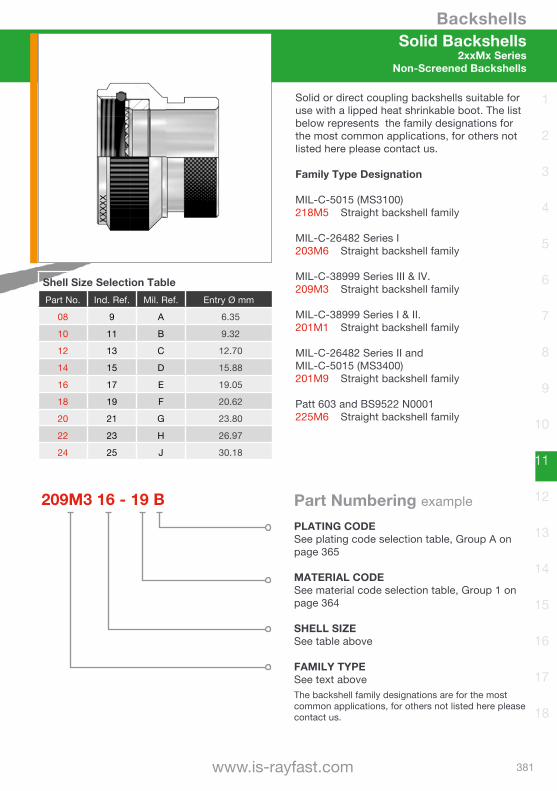
Backshells
381www.is-rayfast.com
1
2
3
4
5
6
7
8
9
10
11
12
13
14
15
16
17
18
209M3 16 - 19 BPLATING CODESee plating code selection table, Group A on page 365
MATERIAL CODESee material code selection table, Group 1 on page 364
SHELL SIZESee table above
FAMILY TYPE See text aboveThe backshell family designations are for the most common applications, for others not listed here please contact us.
Part Numbering example
Shell Size Selection TablePart No. Ind. Ref. Mil. Ref. Entry Ø mm
08 9 A 6.35
10 11 B 9.32
12 13 C 12.70
14 15 D 15.88
16 17 E 19.05
18 19 F 20.62
20 21 G 23.80
22 23 H 26.97
24 25 J 30.18
Solid or direct coupling backshells suitable for use with a lipped heat shrinkable boot. The list below represents the family designations for the most common applications, for others not listed here please contact us.
Family Type Designation
MIL-C-5015 (MS3100)218M5 Straight backshell family
MIL-C-26482 Series I203M6 Straight backshell family
MIL-C-38999 Series III & IV.209M3 Straight backshell family
MIL-C-38999 Series I & II.201M1 Straight backshell family
MIL-C-26482 Series II and MIL-C-5015 (MS3400)201M9 Straight backshell family
Patt 603 and BS9522 N0001225M6 Straight backshell family
Solid Backshells2xxMx Series
Non-Screened Backshells
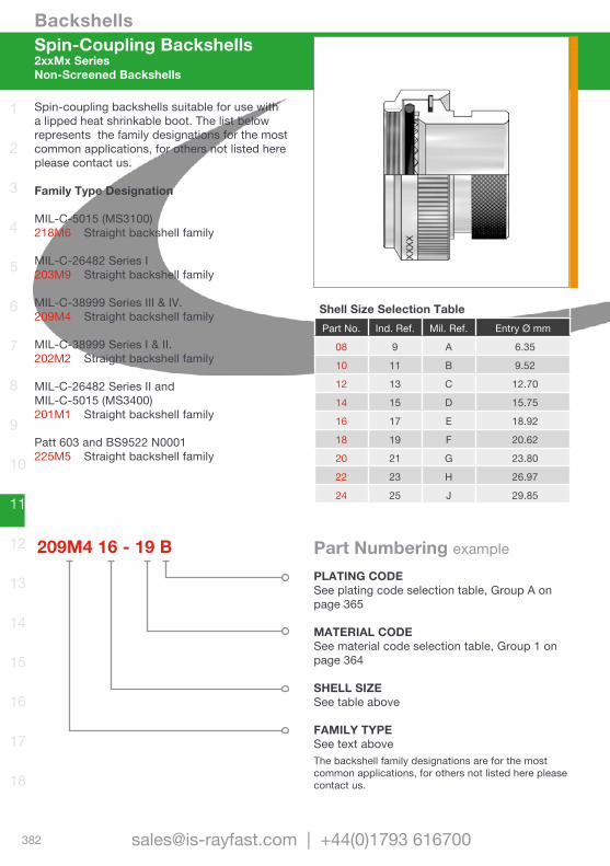
Backshells
382 [email protected] | +44(0)1793 616700
1
2
3
4
5
6
7
8
9
10
11
12
13
14
15
16
17
18
Shell Size Selection TablePart No. Ind. Ref. Mil. Ref. Entry Ø mm
08 9 A 6.35
10 11 B 9.52
12 13 C 12.70
14 15 D 15.75
16 17 E 18.92
18 19 F 20.62
20 21 G 23.80
22 23 H 26.97
24 25 J 29.85
Spin-coupling backshells suitable for use with a lipped heat shrinkable boot. The list below represents the family designations for the most common applications, for others not listed here please contact us.
Family Type Designation
MIL-C-5015 (MS3100)218M6 Straight backshell family
MIL-C-26482 Series I203M9 Straight backshell family
MIL-C-38999 Series III & IV.209M4 Straight backshell family
MIL-C-38999 Series I & II.202M2 Straight backshell family
MIL-C-26482 Series II and MIL-C-5015 (MS3400)201M1 Straight backshell family
Patt 603 and BS9522 N0001225M5 Straight backshell family
Spin-Coupling Backshells2xxMx SeriesNon-Screened Backshells
209M4 16 - 19 BPLATING CODESee plating code selection table, Group A on page 365
MATERIAL CODESee material code selection table, Group 1 on page 364
SHELL SIZESee table above
FAMILY TYPE See text aboveThe backshell family designations are for the most common applications, for others not listed here please contact us.
Part Numbering example
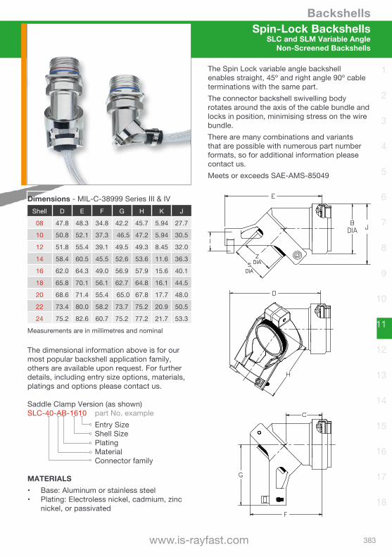
Backshells
383www.is-rayfast.com
1
2
3
4
5
6
7
8
9
10
11
12
13
14
15
16
17
18
Spin-Lock BackshellsSLC and SLM Variable Angle
Non-Screened Backshells
The Spin Lock variable angle backshell enables straight, 45º and right angle 90º cable terminations with the same part.The connector backshell swivelling body rotates around the axis of the cable bundle and locks in position, minimising stress on the wire bundle.There are many combinations and variants that are possible with numerous part number formats, so for additional information please contact us.Meets or exceeds SAE-AMS-85049
Dimensions - MIL-C-38999 Series III & IVShell D E F G H K J
08 47.8 48.3 34.8 42.2 45.7 5.94 27.7
10 50.8 52.1 37.3 46.5 47.2 5.94 30.5
12 51.8 55.4 39.1 49.5 49.3 8.45 32.0
14 58.4 60.5 45.5 52.6 53.6 11.6 36.3
16 62.0 64.3 49.0 56.9 57.9 15.6 40.1
18 65.8 70.1 56.1 62.7 64.8 16.1 44.5
20 68.6 71.4 55.4 65.0 67.8 17.7 48.0
22 73.4 80.0 58.2 73.7 75.2 20.9 50.5
24 75.2 82.6 60.7 75.2 77.2 21.7 53.3
Measurements are in millimetres and nominal
The dimensional information above is for our most popular backshell application family, others are available upon request. For further details, including entry size options, materials, platings and options please contact us.
Saddle Clamp Version (as shown)SLC-40-AB-1610 part No. example Entry Size Shell Size Plating Material Connector family
MATERIALS• Base: Aluminum or stainless steel• Plating: Electroless nickel, cadmium, zinc
nickel, or passivated
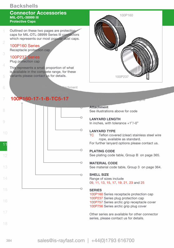
Backshells
384 [email protected] | +44(0)1793 616700
1
2
3
4
5
6
7
8
9
10
11
12
13
14
15
16
17
18
Connector AccessoriesMIL-DTL-38999 IIIProtective Caps
Outlined on these two pages are protection caps for MIL-DTL-38999 Series III connectors which represents our most popular dust caps.
100P160 SeriesReceptacle protection cap
100P237 SeriesPlug protection cap
This represents a small proportion of what is available in the complete range, for these variants please contact us for details.
100P160-17-1-B-TC5-17AttachmentSee illustrations above for code
LANYARD LENGTHIn inches, with tolerance +1”/-0”
LANYARD TYPETC Teflon covered (clear) stainless steel wire
rope, available as standard.For further lanyard options please contact us.
PLATING CODE See plating code table, Group B on page 365.
MATERIAL CODE See material code table, Group 3 on page 364.
SHELL SIZE Range of sizes include09, 11, 13, 15, 17, 19, 21, 23 and 25
SERIES 100P160 Series receptacle protection cap100P237 Series plug protection cap100P757 Series arctic grip receptacle cover100P756 Series arctic grip plug cover
Other series are available for other connector series, please contact us for details.
Part Numbering example
}Omit for no attachment
100P160
100P237
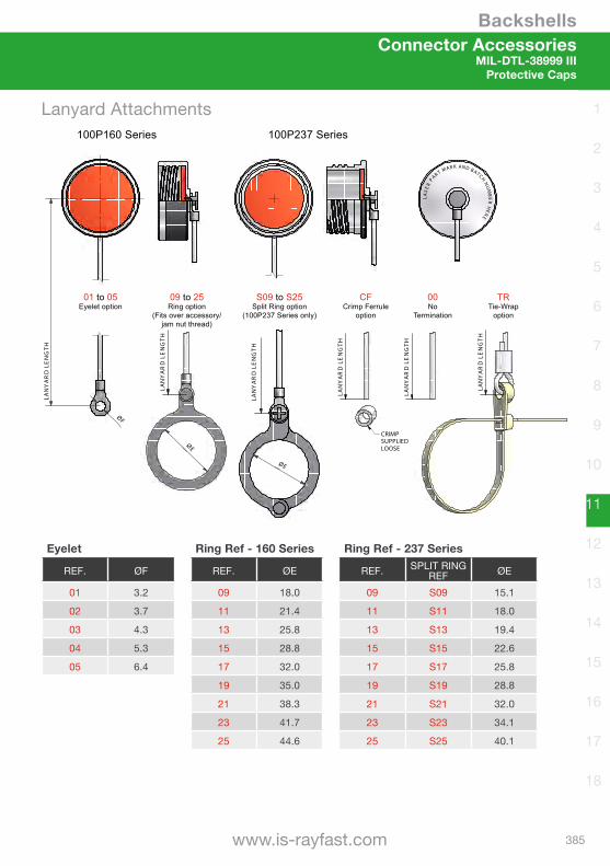
Backshells
385www.is-rayfast.com
1
2
3
4
5
6
7
8
9
10
11
12
13
14
15
16
17
18
Connector AccessoriesMIL-DTL-38999 III
Protective Caps
LASER
PAR
T MAR K AND BATCH NUMBER
HERE
ØF
LAN
YA
RD
LE
NG
TH
LAN
YA
RD
LE
NG
TH
LAN
YA
RD
LE
NG
TH
LAN
YA
RD
LE
NG
TH
CRIMPSUPPLIEDLOOSE
LAN
YA
RD
LE
NG
TH
ØE
100P160 Series 100P237 Series
LAN
YA
RD
LE
NG
TH
01 to 05Eyelet option
09 to 25Ring option
(Fits over accessory/jam nut thread)
S09 to S25Split Ring option
(100P237 Series only)
CFCrimp Ferrule
option
00No
Termination
TRTie-Wrap
option
ØE
Lanyard Attachments
Eyelet
REF. ØF
01 3.2
02 3.7
03 4.3
04 5.3
05 6.4
Ring Ref - 160 Series
REF. ØE
09 18.0
11 21.4
13 25.8
15 28.8
17 32.0
19 35.0
21 38.3
23 41.7
25 44.6
Ring Ref - 237 Series
REF. SPLIT RING REF ØE
09 S09 15.1
11 S11 18.0
13 S13 19.4
15 S15 22.6
17 S17 25.8
19 S19 28.8
21 S21 32.0
23 S23 34.1
25 S25 40.1

Backshells
386 [email protected] | +44(0)1793 616700
1
2
3
4
5
6
7
8
9
10
11
12
13
14
15
16
17
18
LASE
R MARK/BATCH NO. HER
E
Self Closing Dust Caps
Elastomer Dust Caps
Anti Tamper Dust Caps
Connector AccessoriesVariants and SpecialsProtective Caps
Our caps provide a reliable and durable solution to the protection of connectors whilst in transit or being handled in a wide range of environments. Flexible enough to fit a variety of different sized connectors, they can also be colour coded to greatly increase the ease of identifying corresponding connectors/connection points.• Eliminate the potential for damaging other
equipment while the cap is not attached to the connector
• Fit to a variety of different connector specifications
• Provide reliable protection while connectors are being transported and handled
• Flexible enough fit different size connectors
• Can be colour coded to identify different connectors and connection points
• Available in Fluorosilicone, Silicone and Neoprene, dependent on application environment, temperature and fluid resistance requirements.
Universal - 100P3188 MIL-DTL-5015 - RCR1 MIL-DTL-26482 - RCR8 VG95234 - RCRQ
Used on data ports of equipment containing sensitive and confidential data. The design allows the outer shell of the cap to spin without uncoupling until it is locked in position with a small key, allowing it to be removed.MIL-DTL-38999 Series III - PRC433TL Other shell sizes and connector series available.
Ensures the protective cap is not removed or lost from equipment, with strong machined construction.38999 Series III derived square flange receptacle. Other shell sizes and connector series available.MIL-DTL-38999 Series III - PC4SCC

Backshells
387www.is-rayfast.com
1
2
3
4
5
6
7
8
9
10
11
12
13
14
15
16
17
18
As part of our commitment to offering complete harnessing component solutions we can also supply a vast range of accessories such as those illustrated here. Components are sourced from leading edge companies with industry approvals.• Many parts machined from solid material
for reliable strength and performance• Compatible with Mil-Spec dimensions and
performance• Wide choice of lanyard options available• Gasket material options available
Please contact us for more information.
LASE
R PA
RT MARK AND BATCH NUMBER HER
E
Connector AccessoriesMIL-DTL Part Numbering Reference
Protective Caps
MIL-DTL-26482 Series IIPRC3181 series standard receptacle coverPPC3180 series standard plug cover
MIL-DTL-38999 Series IPRC27502 series standard receptacle coverPPC27501 series standard plug cover
MIL-DTL-38999 Seres IIPRC27511 series standard receptacle coverPPC27510 series standard plug cover
MIL-DTL-38999 Seres IIISee pages 384-385
MIL-DTL-38999 Series IV100P608 series standard receptacle cover100P609 series standard plug cover
MIL-DTL-5015H100P1240 series standard receptacle cover100P1167 series standard plug cover
MIL-DTL-5015D100P820S series standard receptacle cover100P1136S series arctic grip receptacle cover100P738 series standard plug cover
MIL-DTL-83723 Series III P83723/60 series standard receptacle coverP83723/59 series standard plug cover
VG96912PRC96912 series standard receptacle coverPPC96912 series standard plug cover
MIL-PRF-39012 BNC/TNC RF CoaxPJCBNC series standard receptacle coverPJCTNC series standard receptacle coverPPCBNC series standard plug coverPPCTNC series standard plug cover