Scientific - UiTM Institutional Repository
21
Volume 3 No. 2 Dec 2006 Institute of Research, Development and Commercialisation ISSN 1675-7009 JOURNAL Scientific RESEARCH
-
Upload
khangminh22 -
Category
Documents
-
view
4 -
download
0
Transcript of Scientific - UiTM Institutional Repository

Volume 3 No. 2
Dec 2006
Institute of Research, Development and Commercialisation
ISSN 1675-7009
JOURNAL
ScientificRESEARCH

SCIENTIFIC RESEARCH JOURNAL
Chief Editor Prof. Dr. Zaiki Awang,
Universiti Teknologi MARA, Malaysia
Managing Editor Assoc. Prof. Dr. Razidah Ismail,
Universiti Teknologi MARA, Malaysia
Editorial Advisory and Review Board Prof. Dr. Ir. Wahyu Kuntjoro, Universiti Teknologi MARA, Malaysia
Assoc. Prof. Dr. Salmiah Kasolang, Universiti Teknologi MARA, Malaysia Assoc. Prof. Ir. Dr. Muhammad Azmi Ayub, Universiti Teknologi MARA, Malaysia
Prof. Dr. Ichsan Setya Putra, Bandung Institue of Technology, Indonesia Prof. Dr. Mohd. Nasir Taib, Universiti Teknologi MARA, Malaysia
Prof. Dr. Ir. Shah Rizam Mohd. Shah Baki, Universiti Teknologi MARA, Malaysia Prof. Dr. Titik Khawa Abd. Rahman, Universiti Teknologi MARA, Malaysia
Prof. Dr. Luciano Boglione, University of Massachusetts Lowell, USA Prof. Dr. K. Ito, Chiba University, Japan
Prof. Dr. Azni Zain Ahmed, Universiti Teknologi MARA, Malaysia Prof. Ir. Dr. Ideris Zakaria, Universiti Malaysia Pahang, Malaysia
Prof. Dr. Abd. Aziz Dato’ Abd. Samad, Universiti Tun Hussein Onn, Malaysia Prof. Sr. Ir. Dr. Suhaimi Abd. Talib, Universiti Teknologi MARA, Malaysia
Assoc. Prof. Ir. Dr. Kartini Kamaruddin, Universiti Teknologi MARA, Malaysia Assoc. Prof. Dr. Hamidah Mohd. Saman, Universiti Teknologi MARA, Malaysia
Dr. Robert Michael Savory, Universiti Teknologi MARA, Malaysia Assoc. Prof. Dr. Mohd Hanapiah Abidin, Universiti Teknologi MARA, Malaysia
Copyright © 2006 Universiti Teknologi MARA, 40450 Shah Alam, Selangor, Malaysia. All rights reserved. No part of this publication may be reproduced, stored in a retrieval system or transmitted in any form or by any means; electronics, mechanical, photocopying, recording or otherwise; without prior permission in writing from the Publisher. Scientific Research Journal is jointly published by Institute of Research, Development and Commercialisation (IRDC) and University Publication Centre (UPENA), Universiti Teknologi MARA, 40450 Shah Alam, Selangor, Malaysia. The views and opinion expressed therein are those of the individual authors and the publication of these statements in the Scientific Research Journal do not imply endorsement by the publisher or the editorial staff. Copyright is vested in Universiti Teknologi MARA. Written permission is required to reproduce any part of this publication.

SCIENTIFIC RESEARCH JOURNAL
Vol. 3 No. 2 December 2006 ISSN 1675-7009
1. Development of an Automated Bi-axial Solar Photovoltaic
Tracking System Ahmad Maliki Omar Muhamad Rizuan Yahir Sulaiman Shaari Abdul Rahman Omar
1
2. Bending and Bonding Properties of Sandwiched Polymer Concrete Composites Hamidah Mohd Saman Azmi Ibrahim Yakub Md. Taib Mohd. Faizal Md. Ja’afar
13
3. Ergonomics Analysis of Muscles Activity of Workers in a Metal Stamping Industry Md Fuad Bahari Abdul Rahman Omar Darius Gnanaraj Solomon Nor Hayati Saad Isa Halim
31
4.
Optimisation of Calcium Silicate and Sand Cement Bricks in Masonary Bearing Walls Kartini Kamaruddin Siti Hawa Hamzah
45

5.
Exfiltration from Sewers: Effects of Different Type of Leakage Mohd Ashaari Ab Wahab Suhaimi Abdul Talib Bahardin Baharom Mat Som Marwi
61

Bending and Bonding Properties ofSandwiched Polymer Concrete
Composites
Hamidah Mohd Saman1,3, Azmi Ibrahim1, Yakub Md. Taib2 &Mohd. Faizal Md. Ja’afar1
Institute for Infrastructure Engineering andSustainable Management (IIESM)
1Faculty of Civil EngineeringUniversiti Teknologi MARA (UiTM), Malaysia
2Faculty of Mechanical EngineeringUniversiti Teknologi MARA (UiTM), Malaysia
3Email: [email protected]
ABSTRACT
It is foreseen that the properties of Polymer Concrete (PC) can be furtherenhanced if the PC is bonded to or sandwiched between Glass Fibre ReinforcedPlastic (GFRP) laminates, later termed as PC-GFRP system. In the presentinvestigation, the performance of PC-GFRP was assessed in terms of its bendingstrength and bonding strength between PC and GFRP. Panels of PC size 500mm × 500 mm × 20 mm were prepared. The panels then were cut into specimensof appropriate geometry and dimensions required for the tests. Four (4) differentresin contents and different percentages of aggregate of different particle sizedistributions were employed in preparing the PC-GFRP specimens. A batch ofPC specimens was layered with a Glass Fibre Reinforced Plastic (GFRP)laminate on one side (SSL) and the other batch PC specimens were sandwichedwith two GFRP laminates (DSL). The PC-GFRP specimens were tested theirbending strength under three-point load test and bonding strength betweenPC as a core material and glued GFRP laminate(s). The results showed that anincrease in the resin content increases the bending strength of the PC regardlessof the aggregate grading. The results also revealed that the PC specimens withwell-graded aggregate recorded the highest bending strength, with coarsergrading resulted in further increase. The bending strength of the PC-GFRP
13
Scientific Research Journal
ISSN 1675-7009© 2006 Universiti Teknologi MARA (UiTM), Malaysia.
Vol. 3 No. 2, 13-29, 2006

14
Scientific Research Journal
system improved significantly when the PC was externally reinforced with aGFRP laminate (SSL) but did not improve further when another layer of GFRPlaminate was applied (DSL). The bonding strength between PC and GFRP wasfound to be increased as the resin content increases and the GFRP laminatebonded better to the PC as a core material if made of the overall aggregate size.
Keywords: Polymer concrete (PC), Glass Fibre Reinforced Plastic (GFRP),PC-GFRP system, sandwiched and layered PC
Introduction
Composite materials such as Fibre Reinforced Polymer (FRP) offermultitudes of benefits such as high specific strength, high corrosionresistance, high fatigue resistance and superior in mechanical properties[1, 2]. However, its high cost to date has hindered its use and concretebased materials are still the most economic option for civil engineeringapplications. Concrete, on the other hand requires modification to enhanceits properties to improve mainly its tensile and flexural strengths, and assuch Polymer Concrete (PC) has been introduced [3, 4]. Nevertheless,PC is still far away to compete that of FRP in terms of its mechanicalproperties. Therefore, an innovative and cost-effective way by assemblingtogether PC and FRP materials to take benefit from the best mechanicalproperties of the both materials have been explored in the present study.
PC is made by modifying ordinary cement mortar with polymer ormonomers and therefore no water is used. PC was given several namessuch as plastic concrete, organomineral concrete, Duroplast, Dezamentand Plexilite [5], resin concrete [6, 7]. Studies on the maximization of theproperties of PC by varying the materials and the formulation have alsobeen conducted by Vipulanandan and Merbakia, [8]; Vipulanandan andEliza, [9]; Alzaydi et al. [4]; Junjian and Vipulanandan [10]. Polyesters,vinyl ester or epoxy resins have been used for the purpose, with polyesterresin, the most common due to low price and corrosion resistance [9].Silica sand, gravel, or fly ash has been used as aggregates or filler in PC.Catalyst or hardeners are added to the resin prior to mixing and casting.Sand with particle sizes between 0.84 mm and 0.59 mm was used infracture studies [8].
To be innovative, PCs characterized by its high flexural strength ascompared to that of conventional cement concrete can be further enhancedby externally reinforcing them with composite materials such as FRP.Studies have shown that the flexural strength of the reinforced beam of

15
Bending and Bonding Properties
normal concrete would be enhanced when bonded externally with FibreReinforced Polymer (FRP) [11, 12]. Hence, this present research is aimedat further enhancing the mechanical properties of PCs by applying laminateof GFRP to PCs to produce a cheaper alternative advanced material.Sandwiching of less strong PC materials with composite materials ofhigher strength can improve the strength of the resulting composites overthat of the PC core alone while reducing the cost of using in total thecomposite materials alone.
In establishing this unique combination of the two materials, theimprovement in the bending strength of the total system and the bondingstrength between the two materials due would become a major concern.Therefore, in the present investigation, bending strength of the series ofPC made of different resin content and aggregate grading and bondingstrength of PC-GFRP specimens were looked into.
Experimental Set Up and Sample Preparation
Materials for PC
Four (4) main ingredients to produce PC are polymer resin, catalyst,sand and filler. A commercial unsaturated polyester resin, Polymal820WPT/820PT was used as a resin and methyl ethyl keton peroxide[MEKP] as a catalyst. Mining sand and granite coarse aggregate wereused as aggregate and Haichen Talc Powder as filler to fill the gapsbetween coarser particles. Water was not used for the preparation ofPC panels.
Preparation of Core PC Specimen for Bending Strength Test
For bending strength test, a series of four (4) polymer concrete (PC)specimens of four different ratios of sand, resin and talcum powder (filler)namely 85:10:5, 80:15:5, 75:20:5 and 70:25:5 (by weight) of the total weightdesignated Mix A, B, C and D, respectively were cast. The four (4)ranges of resin: aggregate ratio selected represents the high side of resincontent which was more than enough to coat the filler to the ratio of justenough to coat the filler.
For each serial, three different particle size distributions of aggregateswere used and designated Type I, II and III. Type I grading contained80 % medium-size-distribution of aggregates with sizes ranging from3.35 mm to 2.0 mm and 20 % fine-size-distribution of aggregates with

16
Scientific Research Journal
sizes ranging from 1.18 mm to 600 mm of mining sand. For Type II, itwas 50 % crushed gravel aggregate with aggregate sizes ranging from5.0 mm to 8.0 mm and 50 % well-graded mining sand. Type III was100 % as-received mining sand. Plain polymer (with no aggregate andfiller) was also cast as a control specimen.
Resin and talcum powder were mixed homogeneously. After the mixwas homogeneous, aggregate was added and stirred manually until allmaterials mixed properly. Subsequently, 1 % of hardener (catalyst) MEKPfrom the weight of resin was added. The 1 % hardener was found toharden the PC specimens within 5 to 6 hours.
Then, the PC mixture was poured into the mould made of steel withdimension of 500 mm × 500 mm × 20 mm for bending strength test and500 mm × 500 mm × 25 mm for bonding strength test. The mould wascoated with wax prior to pouring to ensure that the specimens were notglued to the mould. The top surface of moulded specimens was coveredusing the mould steel cover. After that, the moulded specimen was clampedand pressed with a minimum amount of pressure to get rid the air bubbles.The moulded specimen was demoulded after 24 hours casting and thedemoulded PC specimens were left exposed to the air in the laboratoryat room temperature for about a week. The panels then were cut usingelectric cutter into specimens of appropriate geometry and dimensionsrequired for the tests. For bending strength test, the specimen size was220 mm × 20 mm × 20 mm. For bonding strength test, the size specimenrequired is 140 mm × 25 mm × 25 mm.
Bonding and Sandwiching of PCs with GFRPs
GFRP laminate made of three (3) plies of glass fibres, namely choppedstrand mat (CSM) and woven roving (WR) were supplied by a localcompany with an average thickness of 3 mm. For bending strength, thelaminates were cut and glued to the core PCs on one side and termedas singly-sided lined PC (SSL) and both sides, doubly-sided lined PC(DSL).
Testing for Bending and Bonding Strengths
The bending strength was conducted in accordance with ASTM D 790(96a). The test was conducted on ten (10) identical specimens forreplications. In the bending strength test, the SSL specimens werepositioned with the GFRP layer carrying the largest tensile bending stress

17
Bending and Bonding Properties
as shown in Figure 1, and the DSL specimen as in Figure 2.The bending strength can be calculated using the bending strength
formulation as follows:
σbend
= 3Pl / 2bd 2 (1)
where
σbend
is the bending tensile strength (N/mm2)P is the maximum load applied to the specimen until failure (N)l is the support span (mm)b is the width of the specimen tested (mm)d is the depth of specimen tested (mm)
For bonding strength test method as described by Gower [23] wasadopted. The schematic set-up for bonding strength test is as shown inFigure 3. The bonding strength can be calculated using the bonding strengthformulation as follows:
τbond
= P/2al (2)
where
τbond
is the bonding strength (N/mm2)P is the maximum load applied to the specimen until failure (N)l is the bond length (mm)a is the width of the specimen tested (mm)
Core PC
Support A Support B
Load, P (N)
Transducer
20mm
170 mm 25 mm 25 mm
GFRP Sheet
Figure 1: SSL Specimen under a Symmetrical Three-point Bending

18
Scientific Research Journal
Results and Discussion
The bending strength of PC, SSL and DSL specimens for the four (4)series of PC specimens and the bonding strength of SSL and DSLspecimens are presented in the subsequent sections.
Bending Strength
Table 1 and Figure 4 present the results of the bending strength of PCsmade of four (4) mix formulations using three (3) different aggregategrading. The average of ten (10) results of the bending strength for corePC, SSL and DSL are also presented in a tabular form and shown inTables 2 and 3.
Figure 3: Schematic Diagram of Core PC Specimen Bonded with GFRPLaminates for Bonding Strength Test
Figure 2: DSL Specimen under a Symmetrical Three-point Bending
Core PC
Support A Support B
Load, P (N)
Transducer
20mm
170 mm 25 mm 25 mm
GFRP Sheets
Support A Support B
Load, P (N)
Core PC
GFRP @ 140mm x 25mm x 3mm
GFRP @ 200mm x 25mm x 3mm
170 mm

19
Bending and Bonding Properties
Table 1 and Figure 4 summarise the bending strength of the PCspecimens made of four (4) different formulations for all the three (3)types of aggregate grading. Each formulation comprised 10 %, 15 %,20 % and 25 % of resin content from the total weight of a PC. The resultsindicate not only increasing in bending strength with the amount of resin,but also with the introduction of higher content of coarser aggregates.
Table 1: Average Bending Strength of Polymer Concrete (PC) SpecimensMade of Different Resin Content and Aggregate Grading
Average Bending Strength (N/mm2)
Aggregate Grading (%) Mix Proportion
A (85:10:5) B (80:15:5) C (75:20:5) D (70:25:5)
Type I(80 % medium size: 10.5 18.3 26.9 38.0
20 % fine size)Type II
(50 % overall mining sand: 12.4 21.2 27.8 57.050 % crushed gravel
aggregate)Type III
(100 % overall mining sand) 15.3 24.7 30.0 60.4
Figure 4: Bending Strength of PCs of Four (4) Different Mix Proportionswith Respect to Different Aggregate Grading
0
10
20
30
40
50
60
70
Mix A (85:10:5) Mix B (80:15:5) Mix C (75:20:5) Mix D (70:25:5)
Mix Proportion
Bend
ing S
treng
th (N
/mm
2)
Type IType IIType III

20
Scientific Research Journal
Including coarser particle size of aggregates, for example, gravel size of5 mm was shown to lead to an increase in the bending strength of thePCs over those of medium and finer size of aggregates.
The average bending strength tested on ten (10) replicate of plainpolymer (with no aggregate and filler) specimens was found to be 37.6N/mm2 and it is higher than those of PC specimens made of resin contentup to 20 % of the total weight. PC specimens made of 25 % polymer(resin) and 75 % aggregate/filler (Mix D) attained the highest bendingstrength, recording a value close to twice that the plain polymer itself.Any further increase in the bending strength would not be expected byincreasing the resin content to more than 25 % as the bending strength ofthe resulting PCs would approach that of a plain polymer of 37.6 N/mm2.The strength of an individual aggregate might be higher than the polymeritself but the aggregate would need sufficient polymer to bind themtogether for an effective stress transfer between them as a compositematerial. PCs with only 10 % resin content (Mix A) were found to beonly sufficient to coat but not bind the aggregates. In the case of Mix Dwith a 25 % resin content, an excess resin was observed and this wouldact as an external reinforcement to the PC specimens, thus, leading to ahigher load carrying capacity if positioned at the extreme tensile regionduring the application of transverse loading.
The optimum content of resin in PC could be varied depending onthe grades of resin, types of resin, curing methods, agitation mechanismsand particle size distributions of aggregates. Previous research by Dennard[11] found that PC made of 12 % polyester resin recorded the highestbending strength, a finding later confirmed by Blaga and Beaudoin [12]and Victor et al. [13]. They also found that as the aggregate particle sizebecame finer, the resin content required increased by 30% due to higherspecific surface area in order to maintain the strength. It is for this reasonthat a much coarser aggregate was attempted in the present investigation.Vipulanandan and Eliza [9] claimed that the strength of PC was almostunchanged with increasing polymer content up to 20 % and anotherresearch work by Mikhailov et al. [14] recommended that the optimumcontent of resin ranged from 5 to 30 % of the total weight of PC. Ribeiroet al. [15] concluded that the use of 20 % epoxy resin content increasedthe bending strength of PCs compared to that using polyester resin of thesame amount. However, since PCs made of polyester resin are almostfive (5) times cheaper than those of epoxy while the bending strength ofthe former is only 17 % smaller than the latter, the use of polyester resincould still be the best option.

21
Bending and Bonding Properties
An analysis of variance (ANOVA) was performed to determine therelationship between the increase in the resin content and the bendingstrength. The Pearson correlation reveals a strong linear relationship betweenthe percentage of the resin content and the bending strength of 0.81.
Table 2 and Figure 5 show the average bending strength of PC andSSL specimens. Applying the PCs on one side with a GFRP laminateacting as an external reinforcement, it improves significantly of theresulting composites. An increase of up to 600 % is reported, with thesmallest increase being about 68 %.
Sandwiching of core materials with higher strength and stiffness skinmaterials can increase the strength of the whole system as the stresscarried by the core material can be transferred to the sandwiching material
Table 2: Average Bending Strength of PCs Lined on OneSide with GFRP Laminate (SSL)
Average bending strength (N/mm2)
Aggregate PC SSL
Grading Mix Proportion Mix ProportionDesign A B C D A B C D
(85:10:5) (80:15:5) (75:20:5)(70:25:5) (85:10:5) (80:15:5)(75:20:5) (70:25:5)
Type I 10.5 18.3 26.9 38.0 73.1 78.1 88.8 92.6Type II 12.4 21.2 27.8 56.7 67.0 70.1 82.7 99.8Type III 15.3 24.7 30.0 60.5 74.0 78.5 92.3 101.7
Figure 5: Bending Strength of PCs and SSL Specimens of Different MixFormulations with Respect to Different Aggregate Grading
��������
��������
��������
������������������������
������������������������
����������������������������
������������
������������
������������
��������������������������������
����������������������������
��������������������������������
0
20
40
60
80
100
120
Type I Type II Type II Type I Type II Type II
PC PC-SSL
Bend
ing
Stre
ngth
(N/m
m2 )
�������� A (85:10:5)
B (80:15:5)����C (75:20:5)D (70:25:5)

22
Scientific Research Journal
via interfacial shear [1, 16, 17]. GFRP plates have been used to strengthenconcrete beams and they have been shown to improve the strength ofthe concrete beams as the GFRP plates carried a portion of the tensileforce which decreased the stress in the embedded steel reinforcement[1, 18]. A statistical analysis by the Pearson correlation indicated a strongrelationship between the bending strength of PCs and those subsequentto sandwiching. Table 3 shows the average bending strength of PCs offour (4) different mix formulations and those PCs sandwiched betweenGFRP sheets (DSL).
Table 3: Average Bending Strength of PCs Lined on BothSides with GFRP Laminates (DSL)
Average bending strength (N/mm2)
Aggregate PC DSL
Grading Mix Proportion Mix ProportionDesign A B C D A B C D
(85:10:5) (80:15:5) (75:20:5)(70:25:5) (85:10:5) (80:15:5)(75:20:5) (70:25:5)
Type I 10.45 18.34 26.88 37.98 46.45 57.79 61.89 63.06Type II 12.37 21.16 27.75 56.74 60.61 65.03 70.10 82.69Type III 15.33 24.67 30.02 60.49 70.05 76.53 85.49 92.48
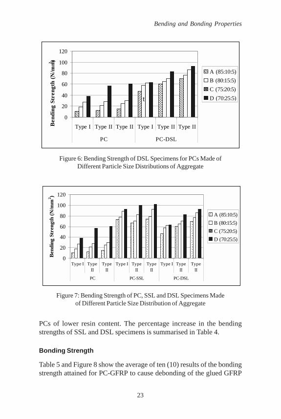
It is shown that sandwiching the PC core specimens with GFRPlaminate, did increase the bending strength of DSL from those of PCs.However, there is no additional advantage of DSL over those of SSL.Another GFRP laminate that positioned far away from the tension zonewould not contribute much to the strength of the total system underbending. Additional GFRP laminate if positioned opposite to the extremetensile region during the application of transverse loading will not bebenefited to increase the bending strength of the PC-GFRP system. Figure9 highlights the slightly lower bending strength of DSL specimens thanthose of SSL specimens, a phenomenon that would be attributed to theworkmanship of laboratory-prepared lined and sandwiched PCs.
The improvement in the bending strength of the lined PCs istremendous and those PCs with a lower content of resin benefited themost from the lining arrangement. This could be due to the presence ofexcess resin in those PCs of higher resin content that could have actedas an external reinforcement to the PC specimens so that bonding aGFRP laminate to their soffits resulted in a smaller increase than those
23
Bending and Bonding Properties
PCs of lower resin content. The percentage increase in the bendingstrengths of SSL and DSL specimens is summarised in Table 4.
Bonding Strength
Table 5 and Figure 8 show the average of ten (10) results of the bondingstrength attained for PC-GFRP to cause debonding of the glued GFRP
Figure 7: Bending Strength of PC, SSL and DSL Specimens Madeof Different Particle Size Distribution of Aggregate
Figure 6: Bending Strength of DSL Specimens for PCs Made ofDifferent Particle Size Distributions of Aggregate
��������
����������
��������
��������������������
������������������������������
������������������������
������������
���������������
������������
������������������������
������������������������
�����������������������������������
0
20
40
60
80
100
120
Type I Type II Type II Type I Type II Type II
PC PC-DSL
Ben
ding
Str
engt
h (N
/mm2 ) ����
����A (85:10:5)B (80:15:5)����C (75:20:5)D (70:25:5)t
������
������
������
����������������������������
������������������������
����������������������������
���������������
������������������
������������������
���������
���������
���������
������������������������
���������������������
������������������������
������������������
������������������
���������������������0
20
40
60
80
100
120
Type I TypeII
TypeII
Type I TypeII
TypeII
Type I TypeII
TypeII
PC PC-SSL PC-DSL
Ben
ding
Str
engt
h (N
/mm
2 )
���A (85:10:5)B (80:15:5)���C (75:20:5)D (70:25:5)

24
Scientific Research Journal
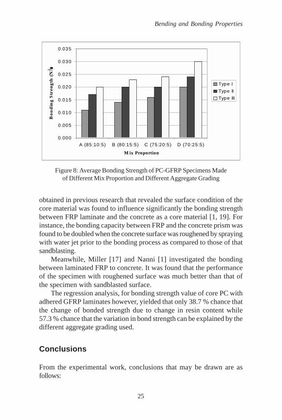
laminates from core PC specimens. It indicates that the bonding strengthincreases with increasing of resin content and it is appeared the PCspecimens made of 100 % overall size of sand can be bonded better withGFRP laminate(s) than those made of mixture of different portion ofsand size. The bonding strength was improved by about 30.0 % ascompared to those made of Type I.
The smooth surface of the PC specimens made of higher content ofresin was found not to compromise the bonding strength between GFRPlaminate and the PC as a core material in fact give the highest bondingstrength among those of tested. This assumption arose from the findings
Table 5: Average Bonding Strength between PC-GFRP Specimens
Average Bending Strength (N/mm2)
Aggregate Grading (%) Mix Proportion
A (85:10:5) B (80:15:5) C (75:20:5) D (70:25:5)
Type I(80 % medium size: 0.011 0.014 0.016 0.020
20 % fine size)Type II
(50 % overall mining sand: 0.017 0.020 0.020 0.02450 % crushed gravel
aggregate)Type III
(100 % overall 0.020 0.023 0.024 0.030mining sand)
Table 4: Percentage of Increase in Bending Strength of CorePC to SSL and DSL Specimens
Percentage Increase (%)
Mix proportion
Aggregate A B C DGrading (85:10:5) (80:15:5) (75:20:5) (70:25:5)
Core PC to Type I 599.14 325.79 230.17 143.76PC-SSL Type II 441.88 231.29 197.95 75.80
Type III 382.58 218.04 207.33 68.04
Core PC to Type I 344.50 215.10 130.25 66.03PC-DSL Type I 389.98 207.33 152.61 45.73
Type III 357.95 210.21 184.78 52.88
25
Bending and Bonding Properties
obtained in previous research that revealed the surface condition of thecore material was found to influence significantly the bonding strengthbetween FRP laminate and the concrete as a core material [1, 19]. Forinstance, the bonding capacity between FRP and the concrete prism wasfound to be doubled when the concrete surface was roughened by sprayingwith water jet prior to the bonding process as compared to those of thatsandblasting.
Meanwhile, Miller [17] and Nanni [1] investigated the bondingbetween laminated FRP to concrete. It was found that the performanceof the specimen with roughened surface was much better than that ofthe specimen with sandblasted surface.
The regression analysis, for bonding strength value of core PC withadhered GFRP laminates however, yielded that only 38.7 % chance thatthe change of bonded strength due to change in resin content while57.3 % chance that the variation in bond strength can be explained by thedifferent aggregate grading used.
Conclusions
From the experimental work, conclusions that may be drawn are asfollows:
Figure 8: Average Bonding Strength of PC-GFRP Specimens Madeof Different Mix Proportion and Different Aggregate Grading
0.000
0.005
0.010
0.015
0.020
0.025
0.030
0.035
A (85:10:5) B (80:15:5) C (75:20:5) D (70:25:5)
M ix Proportion
Bon
din
g S
tren
gth
(N/m2 )
Type IType IIType III
26
Scientific Research Journal
1. PCs with 25 % resin content could be the most cost-effective ingiving the bending strength.
2. Using coarser particle size distribution of aggregates would result inPCs of higher bending strength, particularly when well-gradedaggregate is used.
3. Applying a GFRP sheet to the extreme tension fibre of a PC wouldenhance the ability of the resulting SSL to carry higher loads, withthe increase being more pronounced for PCs of lower resin content.
4. Sandwiching PCs with GFRP sheets does not result in furtherenhancement of the load-carrying capacity of the composites.
5. The different grading of aggregate used in preparing PC couldinfluence the bonding strength between PC and the GFRP laminate/(s).
Acknowledgements
The authors would like to acknowledge the Institute of Research,Development and Commercialisation (IRDC), Universiti TeknologiMARA (UiTM) for providing financial assistance throughout thecompletion of the project. Appreciation is also conveyed to the TLHIndustries Sdn. Bhd. for supplying the GFRP laminates.
References
[1] Nanni, A. 1999. Composite: Coming on Strong. Journal of ConcreteConstruction, 44, pp. 120.
[2] Machida, A. 1993. State of the art report on continuous fibrereinforcing materials. Society of Civil Engineering (JSCE), Tokyo.
[3] Ohama, Y. 1973. Mix proportion and properties of polyesterresin concrete. Polymer in Concrete. International Symposium ACICommittee 548, Publication SP-40, American Concrete Institute,New Jersey, pp. 283-294.
[4] Al Zaydi, A. A., Shihata, S. A. and Alp, T. 1990. The compressivestrength of a new ureaforaldehyde-based polymer concrete.Journal of Materials Science, 25, 6, pp. 2851-2856.

27
Bending and Bonding Properties
[5] Holloway, L. 1993. Polymer composites for civil and structuralengineering. Composite Structures Research Unit, University ofSurrey.
[6] L’Hermite, R. and Jejcic, D. 1963. Resin concrete. RILEM Bulletin(18). The International Union of Testing and Research Laboratoriesfor Materials and Structures, Paris, pp. 87-92.
[7] Kukacka, L. E. and Ramano, A. J.1972. Polymer in concrete.International Symposium ACI Committee 548, Publication SP-40,American Concrete Institute, New Jersey, pp. 15-27.
[8] Vipulanandan, C. and Merbakia, S. 1990. Enhancing themechanical and fracture properties of polyester polymerconcrete. University of Houston, Houston, pp. 411.
[9] Vipulanandan and Eliza. 1990. Performance of epoxy and polyesterpolymer concrete. ACI Materials Journal, 87, May – June.
[10] Junjian, C. and Vipulanandan, C. 1998. Behaviour of carbon fibrepolymer concrete. Retrieved 20/4/2004from http://cigmat.cive.uh.edu/content/conf_exhib/00 poster/1.htm.
[11] Khalifa Ahmed and Antonio. 2002. Rehabilitation of rectangularsimply supported RC beams with shear deficiencies using CFRPcomposites. Elsevier. Construction and Building Materials, 16,pp. 135-146.
[12] Ashour, A. F., El-Refaie, S. A. and Garrity S. W. 2004. Flexuralstrengthening of RC continuous beams using CFRP laminates.Cement and Concrete Composites, Elsevier. 26, pp. 765-775.
[13] Dennard, J. E. 1972. Resin concrete – A literature review. USArmy Engineer Waterway Experiment Station Concrete Laboratory.
[14] Blaga, A. and Beaudoin, J. J. 1985. Polymer modified concrete.Canadian Building Digest 241. Division of Building Research.National Research Council Canada, Ottawa.
28
Scientific Research Journal
[15] Victor, Y., Garas and Vipulanandan, C. 2003. Review of polymerconcrete properties. Centre for Innovative Grouting Materialsand Technology (CIGMAT), Department of Civil Engineering andEnvironmental Engineering, University of Houston.
[16] Mikhailov and Paturoev, V. V. and Kreis, R. 1992. Polymer concreteand their structural uses. A. A. Balkema, Rotterdam andBrookfield, Germany, pp 1-11.
[17] Ribeiro, M. C. S., Tavares, C. M. L., Figueiredo, M., Ferreira, A. J.M. and Fernandes, A. A. 2002. Bending characteristics of resinconcretes. Journal of Material Research, 6(2), pp. 247-254.
[18] Iyer, S. I. and Sen, R. 1991. Advanced composite materials incivil engineering structures. American Society of Civil Engineering,New York, pp. 977.
[19] Miller, B and Nanni, A. 2001. Bond between CFRP sheets andconcrete. Proceeding ASCE, 5th Material Congress, Cincinnati,pp. 240-247.
[20] Chajes, M. J., Frinch, W. W. Jr., Januszka, T. F. and Thompson T.F. 1996. Bond and force transfer of composite material plates bondedto concrete. ACI Structural Journal, American Concrete Institute,93, 2, pp. 295-303.
[21] ASTM D790-96a. Test method for flexural properties ofunreinforced and reinforced plastics and electrical insulatingmaterial.
[22] Ohama, Y. 1979. Introduction to polymer-modified concrete andmortars. Handbook of Polymer Modified Concrete and Mortars:Properties and Process Technology, Koriyama Japan, pp. 1-8.
[23] Scheibe, M. and Rostasy, F. S. 1995. Stress-rupture of AFRPsubjected to alkaline solutions and elevated temperature-experiments. Non-Metallic (FRP) reinforcement for concrete

29
Bending and Bonding Properties
structures. Proceeding of the Second International RILEMSymposium (FRPRCS-2).
[24] Gower, M. R. L. and Sims, G. D. 1999. Determining the skin-to-core bond strength of sandwich construction. http://midas.npl.co.uk/midas/content/mn044.html. (10 /5/ 2005)