
Scientific Report 2008 - Forschungszentrum Jülich
264
Institut für Festkörperforschung Scientific Report 2008 Institut für Festkörperforschung Institute of Solid State Research Member of Helmholtz Association
-
Upload
khangminh22 -
Category
Documents
-
view
3 -
download
0
Transcript of Scientific Report 2008 - Forschungszentrum Jülich

Institut für Festkörperforschung
Scientific Report 2008
Institut für FestkörperforschungInstitute of Solid State Research
Mem
ber
of H
elm
holtz
Ass
ocia
tion
2
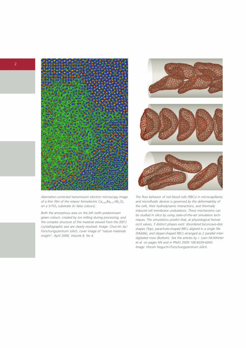
Aberration-corrected transmission electron microscopy imageof a thin film of the relaxor ferroelectric Ca0.28 Ba0.72 Nb2 O6
on a SrTiO3 substrate (in false colours).
Both the amorphous area on the left (with predominantgreen colour), created by ion milling during processing, andthe complex structure of the material viewed from the [001]crystallographic axis are clearly resolved. Image: Chun-lin Jia /Forschungszentrum Jülich, cover image of "nature materialsinsight", April 2008, Volume 8, No 4.
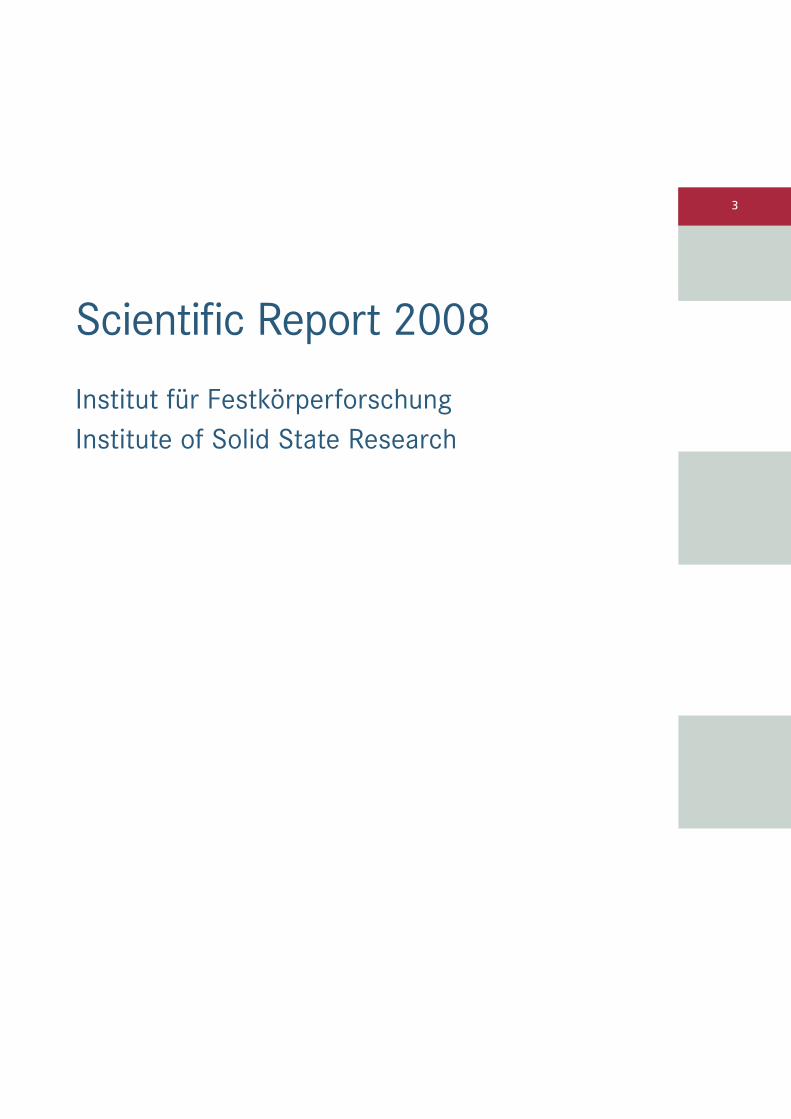
The flow behavior of red blood cells (RBCs) in microcapillariesand microfluidic devices is governed by the deformability ofthe cells, their hydrodynamic interactions, and thermallyinduced cell membrane undulations. These mechanisms canbe studied in silico by using state-of-the-art simulation tech-niques. The simulations predict that, at physiological hemat-ocrit values, 3 distinct phases exist: disordered biconcave-diskshapes (Top), parachute-shaped RBCs aligned in a single file(Middle), and slipper-shaped RBCs arranged as 2 parallel inter-digitated rows (Bottom). See the articles by J. Liam McWhirteret al. on pages NN and in PNAS 2009 106:6039-6043. Image: Hiroshi Noguchi / Forschungszentrum Jülich.
3
Scientific Report 2008
Institut für FestkörperforschungInstitute of Solid State Research

Contents • IFF Scientific Report 2008
4
Directors of the Institute of Solid State Research (IFF) from left:
Prof. Dr. Jan K. G. Dhont (IFF-7: Soft Condensed Matter)Prof. Dr. Knut Urban (IFF-8: Microstructure ResearchProf. Dr. Heiner Müller-Krumbhaar (IFF-3: Theory of Structure Formation)Prof. Dr. Dieter Richter (IFF-5: Neutron Scattering)Prof. Dr. Thomas Brückel (IFF-4: Scattering Methods)Prof. Dr. Stefan Blügel (IFF-1: Quantum Theory of Materials)Prof. Dr. Rainer Waser (IFF-6: Electronic Materials)Prof. Dr. Claus M. Schneider (IFF-9: Electronic Properties)Prof. Dr. Gerhard Gompper (IFF-2: Theoretical Soft-Matter and Biophysics)

5
Contents
IFF Scientific Report 2008 • Contents
Foreword page 8
Snapshots 2008 page 10
Honours page 18
Institute of Solid State Research – Institut für Festkörperforschung (IFF) page 20
Higher level education page 34
HGF research programme Condensed matter physics page 40
Research reportsMetalation/demetalation strategies for magnetic molecules page 42
Antiferroelectric charge order in LuFe2O4 page 44
Volume dependence of TCurie in diluted magnetic semiconductors page 46
Magnetic domain structure of Heusler/MgO/Heusler trilayer systems page 48
Anisotropy and exchange interactions in a gradient nanocrystalline multilayer page 50
Magnetic coupling across highly oriented oxidic interfaces: Fe3O4/NiO page 52
Domino behavior in nanowires page 54
Deep view into the twisted magnetization state in a Fe/Si multilayer page 56
Magnetization dynamics induced by ultra-short optical pulses page 58
Ultrafast dynamics of a magnetic antivortex page 60
Magnetic ordering in FeAs-based superconducting compounds page 62
Phonon dynamics in parent and superconducting FeAs compounds page 64
Low energy nuclear spin excitations in Nd-based compounds page 66
Tuning the frustration of Li2VOSiO4 exchange couplings with high pressure page 68
Kondo proximity effect: How does a metal penetrate into a mott insulator? page 70
On the mechanism for orbital-ordering in KCuF3 page 72
Mott phase of repulsively interacting fermions in a 3D optical lattice page 74
Nanoscale phase transitions in phase change materials: What's new? page 76
Multisite Coulomb correlations: cluster dynamical mean field theory page 78
Transport through quantum dots – a new electron-pair tunneling resonance page 80
Band mapping in higher-energy X-ray photoemission page 82
A linear scaling algorithm for density functional calculations page 84
Optimized tomographic reconstruction applied to electric currents in fuel cells page 86
Nuclear inelastic scattering by 121Sb and 125Te in thermoelectric materials page 88
A stable molecular water oxidation catalyst for artificial photosynthesis page 90
6
Contents • IFF Scientific Report 2008
Magnetic memory effect in the complex metallic alloy T-Al-Mn-Pd page 92
Al-Cr and ternary alloy systems of Al and Cr with Mn, Fe, Ni and Cu page 94
Complex intermetallic phases in the Al-Pd-Ru and Al-Pd-Ir alloy systems page 96
Atomic structure of the interfaces in the SrTiO3/Si(001) system page 98
High-resolution TEM studies of inorganic nanotubes and fullerenes page 100
Reconstruction of the projected crystal potential in high-resolution TEM page 102
Quantification of the information limit of transmission electron microscopes page 104
Leak-rate of seals: comparison of theory with experiment page 106
Theory of dendritic growth in the presence of lattice strain page 108
Crack growth by surface diffusion in viscoelastic media page 110
Polymerization study of 1-octene by a pyridylamidohafnium catalyst page 112
Comparing MD-simulations and neutron scattering experiments of polymer melts page 114
Chain dynamics and viscoelastic properties of poly(ethylene oxide) page 116
Unexpected power-law stress relaxation of entangled ring polymers page 118
A neutron scattering study of asphaltene aggregates in crude oil page 120
A-B diblock copolymer in a three component A/B/A-B polymer blend page 122
Twist grain boundaries in cubic surfactant phases page 124
Synthesis of silica rods, wires and bundles using filamentous fd virus as template page 126
Phase behaviour and kinetics of rod-like viruses under shear page 128
Attractive colloidal rods in shear flow page 130
Dynamic response of block copolymer wormlike micelles to shear flow page 132
Dynamics in colloidal suspensions: from neutral to charged particles page 134
Diffusion in a fluid membrane with a flexible cortical cytoskeleton page 136
Membrane fluctuations determine the short-time movements of cells page 138
Clustering and alignment of red blood cells in microcapillaries page 140
Cooperation of sperm in two dimensions: synchronization and aggregation
through hydrodynamic interactions page 142
Protein domain motions observed in space and time by NSE page 144
Electrostatics of DNA and DNA-protein interactions page 146
Hydrodynamic interactions in polyelectrolyte electrophoresis page 148
Condensation in the zero-range process with random interaction page 150
Soret effect: experiments and simulations page 152
Orientational ordering in solid C60 fullerene-cubane page 154
HGF research programme Information technology with nanoelectronic systems page 156
Research reportsA crossbar memory with resistively switching Pt/MSQ/Ag nanocells page 158
Surface states and origin of the Fermi level pinning on non-polar GaN (1100) surfaces page 160
Strain in SrTiO3 layers embedded in a scandate/titanate multilayer system page 162
Controlling the magnetization direction in molecules via their oxidation state page 164
Spin-transfer torque and anisotropy in Fe/Ag/Fe spin-torque oscillators page 166
Topologically protected surface states: Sb(111) vs. Bi(111) page 168
First-principles calculations on spin injection in Fe/Si(001) page 170
Predicting formation of long chains in break junctions page 172
Peapod synthesis on substrates page 174
Liquid identification by Hilbert spectroscopy page 176
Epitaxial thick film SQUIDs with large voltage swing at 77 K page 178
Separation of bulk and interface contributions to the electroforming of epitaxia
Fe-doped SrTiO3 thin films page 180
Liquid injection ALD of ferroelectric oxide and noble metal thin films page 182

7
IFF Scientific Report 2008 • Contents
Atomic-scale study of domain walls in ferroelectric PbZr0.2Ti0.8O3 films page 184
A mechanism for bipolar resistive switching in a Pt/TiO2/Pt cell page 186
Resistive switching in Sr1-0.05La0.05TiO3 page 188
Field emission resonances at tip/ mercaptoalkylferrocene/Au interfaces page 190
HGF research programme Large-scale facilities for research with photons, neutrons and ions page 192
Research reportsThe first year of operation of the backscattering spectrometer SPHERES page 194
DNS: diffuse neutron scattering with polarization analysis page 196
Aspherical neutron lenses for the SANS diffractometers KWS-1 and KWS-2 page 198
Developments and status of the J-NSE in Munich page 200
MARIA: Status of the new reflectometer of JCNS at the FRM II page 202
BIODIFF: single crystal diffractometer for biological macromolecules page 204
TOPAS: a new thermal time-of-flight spectrometer with polarization analysis page 206
POWTEX: the new high-intensity time-of-flight neutron diffractometer page 208
IN12: the cold neutron three-axis spectrometer at the ILL page 210
NSE at SNS: installation approaches completion page 212
Jülich neutron scattering instruments for the new Chinese research reactor page 214
Appendix page 216
Publications page 218
Ph.D. theses page 234
Diploma theses page 236
Conferences and schools page 237
Kolloquia page 238
Organizational chart page 239
Personnel page 240
Scientific advisory board page 241
Scientists page 242
Graduate students page 247
Technical staff page 249
Administrative staff and secretaries page 252
Scientists on leave page 253
Guest scientists page 255
Scientists teaching at universities page 262
Imprint page 263
Foreword
8
Foreword • IFF Scientific Report 2008
The annual report 2008 is intended toinform the international scientific commu-nity, including our scientific advisory boardand the Helmholtz Association (Helmholtz-Gemeinschaft, HGF) about the researchactivities of the IFF during the past year.We have attempted to present a typicalcross section through the research conductedat the IFF, within the Helmholtz researchprogrammes “Condensed Matter Physics”,“Information Technology with Nanoelec-tronic Systems”, and “Large-scale Facilitiesfor Research with Photons, Neutrons, andIons”.
The IFF is engaged in investigating a multi-tude of condensed matter phenomenawith special emphasis on studies of funda-mental physical mechanisms, the develop-ment and improvement of experimentaland theoretical concepts and methods, aswell as the elucidation and exploitation of new material properties in complex sys-tems. The Helmholtz research programmesfollow this main aim in addition to exploitthe full scale of analytical and numericalmethods to disentangle interrelationsbetween structural, electronic, magnetic,and dynamic properties of condensed mat-ter together with describing underlyingphysical mechanisms on a microscopic andatomistic level.
In the area of nanoelectronics, the advance-ments today are driven by a unique inter-play of scientific and technological issues.As a consequence, strong fundamentalresearch in solid-state physics must be com-bined with leading edge fabrication andcharacterization techniques. Recognizingthis situation, the Forschungszentrum Jülichand the RWTH Aachen University havejoined forces and embarked on a long-termplan for the strategic development of theresearch environment in the field of nano-electronics and information technology byfounding the JARA section “Fundamentalsof Future Information Technology” (JARA-FIT) in 2007.
As a further pivotal step within this concept,we initiated the formation of a centralresearch infrastructure platform, which wenamed the Peter Grünberg Centre, honour-ing the Nobel Prize in Physics 2007. In itsfirst stage, the Peter Grünberg Centre willcomprise the planned Helmholtz Nano-electronics Facility as well as the Synchro-tron Radiation Laboratory. Future units inthe fields of scanning probe spectroscopy,or ultrafast processes, as well as a centrefor advanced technologies on the campusof the RWTH Aachen University are envi-sioned.
The Ernst Ruska-Centre for Microscopy andSpectroscopy with Electrons (ER-C) has beenestablished as a national user facility hous-ing several of the world's most advancedtransmission electron microscopes (TEM)and tools fo nanocharacterization. It isoperated conjointly by the IFF at theForschungszentrum Jülich and the GfE atthe RWTH Aachen University. During 2008,the PICO project was secured by funds ofNorth-Rhine Westphalia, the RWTH Aachen,and the Deutsche Forschungsgemeinschaft(German Research Foundation). The PICOproject aims at a new generation of anultrahigh resolution TEM (PICO-UHT)equipped with a spectroscopy research tool(PICO-SRT) and features spherically andchromatically aberration corrected electronoptics.
The Jülich Centre for Neutron Science (JCNS)operates instruments at some of the leadingneutron sources worldwide: the Forschungs-reaktor München FRM II in Garching, Germany, the Institute Laue-Langevin ILL in Grenoble, France, and the SpallationNeutron Source SNS in Oak Ridge, USA.Under a common scientific objective anduser programme, JCNS offers users state-of-the-art instruments at the neutronsource best suited to the respective appli-cation. Beamtime at JCNS is allocatedthrough an international peer-review panel on the basis of scientific merit only.
9
IFF Scientific Report 2008 • Foreword
In the period 2007/2008, more than 200external proposals for external beam timewith a request for 1,288 beam days werereceived. 75 proposals by users were allo-cated 350 beam days at the instruments of JCNS at FRM II, corresponding to 63 %external use. At FRM II, four instrumentswere in full user operation in 2008: thespin-echo spectrometer NSE, the smallangle camera KWS-2, the backscatteringspectrometer SPHERES and the diffuse neutron scattering instrument DNS. Sevenfurther instruments are in construction.
The Forschungszentrum Jülich hosts andoperates one of the most powerful super-computers in the world. This opens newscientific opportunities for the three theoryinstitutes. The development of the simula-tion sciences on such computers is one ofthe key challenges the Forschungszentrumaddresses. This task is one of the missionsof the newly inaugurated departmentInstitute for Advanced Simulation (IAS). The foundation of this department isembedded in the JARA section “SimulationSciences” (JARA-SIM) and is supplementedby the German Research School for Simula-tion Sciences (GRS). The theory institutes of the IFF have founded working groups in the IAS and contribute to the newly certified master’s course in simulation sciences offered by GRS.
The quality of the research at the IFF iswidely appreciated and respected by thescientific community as reflected by thenumerous awards, for example, the GrandCross with Star of the Order of Merit ofthe Federal Republic of Germany to ourNobel laureate, Prof. Dr. Peter Grünberg, in addition to honorary doctorates fromthe University in Cologne, the Tohoku Uni-versity (Japan), and the Gebze Institute ofTechnology (Turkey). Together with Dr.Maxmilian Haider, Heidelberg, and Prof.Dr. Harald Rose, Darmstadt, Prof. Dr. KnutUrban (Institute of Microstructure Research)was awarded the Honda Prize 2008 for the
development of aberration correction fortransmission electron microscopes. Prof.Dr. Shigemasa Suga (Institute of Electron-ic Properties) received the HumboldtResearch Prize from the Alexander vonHumboldt Foundation. Dr. Martina Müller(Institute of Electronic Properties) wonthe Günter Leibfried Prize awarded byForschungszentrum Jülich for communi-cating science successfully. The IFF wasalso particularly successful in establishingyoung investigator groups. Dr. M. Angst(Complex Ordering Phenomena in Multi-functional Oxides), Dr. M. Lezaic (Compu-tational Nanoferronics Laboratory), andDr. Y. Mokrousov (Topological Nano-electronics) have started their activities in 2008. This success is complemented byappointments to young scientists whohave been working at the IFF in recentyears and now left to start scientificcareers on their own. Dr. A. Rüdiger (Insti-tute of Electronic Materials) accepted anappointment as a full professor for nanol-electronics/nanophotonics at the InstitutNational de la Recherche Scientifique of Québec University (Canada), Dr. H.Noguchi (Institute of Theory of Soft Mat-ter and Biophysics) was appointed associ-ate professor at the Institute for SolidState Physics (ISSP) by the University ofTokyo (Japan), and Dr. A. Schindlmayr(Institute of Quantum Theory of Materi-als) accepted an appointment as profes-sor (W2) in Theoretical Physics at the Uni-versity of Paderborn.
I hope you will enjoy reading the reportand learning about our activities.
Prof. Dr. Rainer WaserManaging Director of IFF in 2009Director of IFF-6 “Electronic Materials”May 2009

The IFF-2008 • IFF Scientific Report 2008
Snapshots 2008
10
Peter Grünberg awarded order of Merit of the Federal Republic of Germany by German President Köhler
8 April: The German President, Horst Köhler (right), awards the Nobel Laureate Prof. Dr. Peter Grünberg (left) from the Jülich Institute of Solid State Research (IFF) with the Cross of the Order of Merit of the Federal Republic of Germany. By presenting this award, the President pays tribute to outstanding achievements in both basic and application-oriented cutting-edgeresearch. The physicist enabled and improved technological developments, without which ourevery-day life would no longer be conceivable. The ceremony was held at the President's officialresidence, Schloss Bellevue in Berlin.
© Presse- und Informationsamt der Bundesregierung / REGIERUNGonline / Sandra Steins

11
IFF Scientific Report 2008 • The IFF-2008
19 February: GMR exhibit on the road in the "NanoTruck"
An exhibit on the GMR effect – theeffect which earned the IFF physicistProf. Dr. Peter Grünberg the Nobel Prizefor Physics 2007 – is on display in amobile nanotechnology exhibition sup-ported by the German Federal Ministryof Education and Research (BMBF). Theso-called "NanoTruck" visits events inschools, universities and research insti-tutions among other things.
"The exhibition aims to explain the scientific, social and economic signifi-cance of nanotechnology and to stimu-late the dialogue between the sciencecommunity and the general public",said Grünberg. He is delighted that hiswork is contributing to this process. The Nobel Laureate was also involved in designing the exhibit.
22 February: Fastest civil supercomputer in the world
An official ceremony in Jülich markedthe inauguration of the fastest civilsupercomputer in the world. The go-ahead was given by Prime Minister Jürgen Rüttgers together with StateSecretary Thomas Rachel. The computer,known as JUGENE, performs around 167 trillion mathematical calculationsper second and is Europe's fastestsupercomputer. It held second place in the global TOP500 ranking list pub-lished in February 2008.
Computer simulations are a key tech-nology for science and they have esta-blished themselves on an equal footingwith theoretical and experimentalresearch. The supercomputer has provenitself to be a flexible and powerful toolwhen complex problems have to besolved. Researchers from IFF, for exam-ple, use supercomputers to unravel themysteries of high-temperature super-conductivity.
A GMR exhibit tours Germany on board the "NanoTruck" .
Photo: Flad & Flad Communication GmbH
At the time of its inauguration, the Jülich IBM BlueGene supercomputer, known as JUGENE, was thefastest civil supercomputer in the world.
1212
The IFF – 2008 • IFF Scientific Report 2008
3 – 14 March: 39th IFF Spring School with 220 participants
220 students and young scientists from25 countries attended the 39th interna-tional IFF spring school in Jülich. Underthe motto "Soft Matter – From Syntheticto Biological Materials", they gained acomprehensive overview of the interdis-ciplinary research area of "soft matter"at the interface of physics, chemistry,biology and the life sciences.
The spring school covered a range of top-ics from the theoretical and experimentalbasis of soft matter to state-of-the-artinvestigation methods and examples ofindustrial application such as in cosmetics.Experts from For-schungszentrum Jülichand other European research institutionsand industrial companies such as BASF SEor Unilever AG gave classes concerningtopics such as computer simulations,research with the aid of light and particlescattering, and the synthesis of complexmaterials in theory and practice.
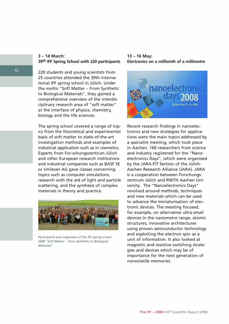
13 – 16 May: Electronics on a millionth of a millimetre
Recent research findings in nanoelec-tronics and new strategies for applica-tions were the main topics addressed bya specialist meeting, which took placein Aachen. 160 researchers from scienceand industry registered for the "Nano-electronics Days", which were organisedby the JARA-FIT Section of the Jülich-Aachen Research Alliance (JARA). JARAis a cooperation between Forschungs-zentrum Jülich and RWTH Aachen Uni-versity. The "Nanoelectronics Days"revolved around methods, techniquesand new materials which can be used to advance the miniaturisation of elec-tronic devices. The meeting focused, for example, on alternative ultra-smalldevices in the nanometre range, atomicstructures, innovative architecturesusing proven semiconductor technologyand exploiting the electron spin as aunit of information. It also looked atmagnetic and resistive switching strate-gies and devices which may be ofimportance for the next generation ofnonvolatile memories.
Participants and organisers of the IFF spring school2008 "Soft Matter – From Synthetic to Biological Materials".
9 – 13 June:Why do particles migrate in temperaturegradients?
At the invitation of IFF, 80 internationalscientists met at the "8th InternationalMeeting on Thermodiffusion" in Bonn.Thermodiffusion is a physical processthat plays a major role in many tech-nical fields. Two examples are the analy-sis of dispersions such as wall paint andthe characterisation of oil deposits.Although this effect was observed forthe first time 150 years ago, we still donot fully understand it. The aim of thescientists is to improve technical appli-cations in the long run through animproved understanding of basic physi-cal fluid properties
13
IFF Scientific Report 2008 • The IFF – 2008
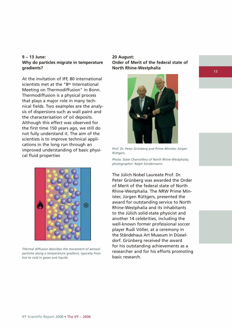
20 August: Order of Merit of the federal state ofNorth Rhine-Westphalia
Prof. Dr. Peter Grünberg and Prime Minister JürgenRüttgers.
Photo: State Chancellery of North Rhine-Westphalia;photographer: Ralph Sondermann.
Thermal diffusion describes the movement of aerosolparticles along a temperature gradient, typically fromhot to cold in gases and liquids.
The Jülich Nobel Laureate Prof. Dr. Peter Grünberg was awarded the Orderof Merit of the federal state of NorthRhine-Westphalia. The NRW Prime Min-ister, Jürgen Rüttgers, presented theaward for outstanding service to NorthRhine-Westphalia and its inhabitants to the Jülich solid-state physicist andanother 14 celebrities, including thewell-known former professional soccerplayer Rudi Völler, at a ceremony in the Ständehaus Art Museum in Düssel-dorf. Grünberg received the award for his outstanding achievements as aresearcher and for his efforts promotingbasic research.
14
The IFF – 2008 • IFF Scientific Report 2008
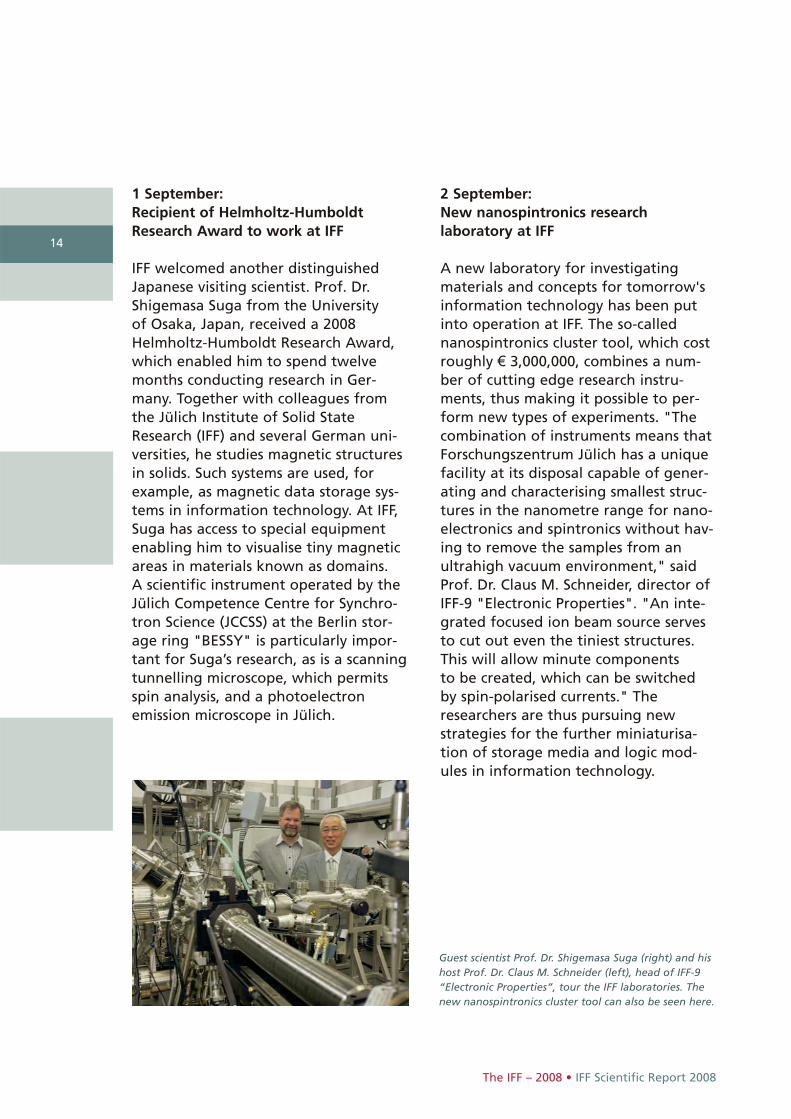
Guest scientist Prof. Dr. Shigemasa Suga (right) and hishost Prof. Dr. Claus M. Schneider (left), head of IFF-9“Electronic Properties”, tour the IFF laboratories. Thenew nanospintronics cluster tool can also be seen here.
2 September: New nanospintronics research laboratory at IFF
A new laboratory for investigatingmaterials and concepts for tomorrow'sinformation technology has been putinto operation at IFF. The so-callednanospintronics cluster tool, which costroughly € 3,000,000, combines a num-ber of cutting edge research instru-ments, thus making it possible to per-form new types of experiments. "Thecombination of instruments means thatForschungszentrum Jülich has a uniquefacility at its disposal capable of gener-ating and characterising smallest struc-tures in the nanometre range for nano-electronics and spintronics without hav-ing to remove the samples from anultrahigh vacuum environment," saidProf. Dr. Claus M. Schneider, director of IFF-9 "Electronic Properties". "An inte-grated focused ion beam source servesto cut out even the tiniest structures.This will allow minute components to be created, which can be switchedby spin-polarised currents." Theresearchers are thus pursuing newstrategies for the further miniaturisa-tion of storage media and logic mod-ules in information technology.
1 September: Recipient of Helmholtz-HumboldtResearch Award to work at IFF
IFF welcomed another distinguishedJapanese visiting scientist. Prof. Dr.Shigemasa Suga from the University of Osaka, Japan, received a 2008 Helmholtz-Humboldt Research Award,which enabled him to spend twelvemonths conducting research in Ger-many. Together with colleagues fromthe Jülich Institute of Solid StateResearch (IFF) and several German uni-versities, he studies magnetic structuresin solids. Such systems are used, forexample, as magnetic data storage sys-tems in information technology. At IFF,Suga has access to special equipmentenabling him to visualise tiny magneticareas in materials known as domains. A scientific instrument operated by theJülich Competence Centre for Synchro-tron Science (JCCSS) at the Berlin stor-age ring "BESSY" is particularly impor-tant for Suga’s research, as is a scanning tunnelling microscope, which permitsspin analysis, and a photoelectron emission microscope in Jülich.
15
8 September: PhD students communicate science successfully
Science fiction and sandwiches with aspin – these were some of the topics of this year's Günter Leibfried Prize. The first prize of € 3,000 went to thephysicist Martina Müller, formerly IFF-9 (Electronic Properties). In a livelypresentation, she described how themain memories in computers will beable to do with magnetism in thefuture. One of two second prizes, worth € 1,500 went to Samir Lounis from IFF-1(Quantum Theory of Materials). In hislecture, the physicist referred to the science fiction movie "I, Robot" andshowed that constructions previouslybelieved to be impossible were indeedconceivable when nanoelectronics iscombined with quantum mechanics.The Günter Leibfried Prize – namedafter the former IFF director who diedin 1977 – is awarded annually to PhDstudents at Forschungszentrum Jülichwho succeed in presenting the resultsof their PhD thesis in a lively and gener-ally intelligible manner.
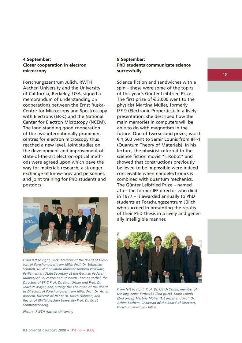
From left to right, back: Member of the Board of Direc-tors of Forschungszentrum Jülich Prof. Dr. SebastianSchmidt, NRW Innovation Minister Andreas Pinkwart,Parliamentary State Secretary at the German FederalMinistry of Education and Research Thomas Rachel, theDirectors of ER-C Prof. Dr. Knut Urban und Prof. Dr.Joachim Mayer, and, sitting: the Chairman of the Boardof Directors of Forschungszentrum Jülich Prof. Dr. AchimBachem, Director of NCEM Dr. Ulrich Dahmen, and Rector of RWTH Aachen University Prof. Dr. ErnstSchmachtenberg.
Picture: RWTH Aachen University
From left to right: Prof. Dr. Ulrich Samm, member of the jury, Anna Strózecka (2nd prize), Samir Lounis (2nd prize), Martina Müller (1st prize) and Prof. Dr.Achim Bachem, Chairman of the Board of Directors,Forschungszentrum Jülich.
IFF Scientific Report 2008 • The IFF – 2008
4 September: Closer cooperation in electronmicroscopy
Forschungszentrum Jülich, RWTHAachen University and the University of California, Berkeley, USA, signed amemorandum of understanding oncooperations between the Ernst Ruska-Centre for Microscopy and Spectroscopywith Electrons (ER-C) and the NationalCenter for Electron Microscopy (NCEM). The long-standing good cooperation of the two internationally prominentcentres for electron microscopy thusreached a new level. Joint studies onthe development and improvement ofstate-of-the-art electron-optical meth-ods were agreed upon which pave theway for materials research, a strongerexchange of know-how and personnel,and joint training for PhD students andpostdocs.

16
The IFF – 2008 • IFF Scientific Report 2008
22 October: Rudolf Diesel Medal for Peter Grünberg
Nobel Laureate Prof. Dr. Peter Grünbergfrom IFF was awarded the Rudolf Diesel Medal by the German Institutefor Inventions (Deutsches Institut fürErfindungswesen; DIE). The physicistreceived the award, which is namedafter the inventor of the diesel engine,for his discovery of giant magnetoresis-tance. The prize for pioneers and inven-tors in the field of technology and sciences was also awarded to the 2007Nobel Laureate for Chemistry Prof. Dr.Gerhard Ertl and several successfulentrepreneurs during an official eventin the hall of honour of the GermanMuseum (Deutsches Museum) inMunich.
2 October: Japanese Honda Prize goes to Knut Urban
The Japanese Honda Foundation jointlyawarded the Honda Prize 2008, beingworth around € 70,000, to a group ofthree German researchers. Prof. Dr.Knut Urban, director of the Ernst Ruska-Centre for Microscopy and Spectroscopywith Electrons (ER-C) and head of IFF-8“Microstructure Research”, was amongthem. The Honda Foundation payedtribute to Dr. Maximilian Haider, Heidel-berg, Prof. Dr. Harald Rose, Darmstadtand Prof. Dr. Knut Urban for the devel-opment of aberration correction fortransmission electron microscopes,which made it possible to study materialswith spatial resolution on a picometrelevel.
Laureates and DIE board members at the Rudolf Diesel Medal ceremony (from left to right):
Dr. Aloys Wobben, Prof. Dr. Gerhard Ertl, Prof. Dr. Peter Grünberg, Dr. Klaus E. Tschira, DIE board member Prof.Dr. Viktor Dulger, Dipl.-Ing. Heinz Leiber, GerhardSturm, DIE board member Prof. Dr. Norbert Haugg,Dietmar Hopp, Dipl.-Ing. Hans A. Härle
Photo: obs/Deutsches Institut für Erfindungswesen
Prof. Dr. Knut Urban
17
IFF Scientific Report 2008 • The IFF – 2008
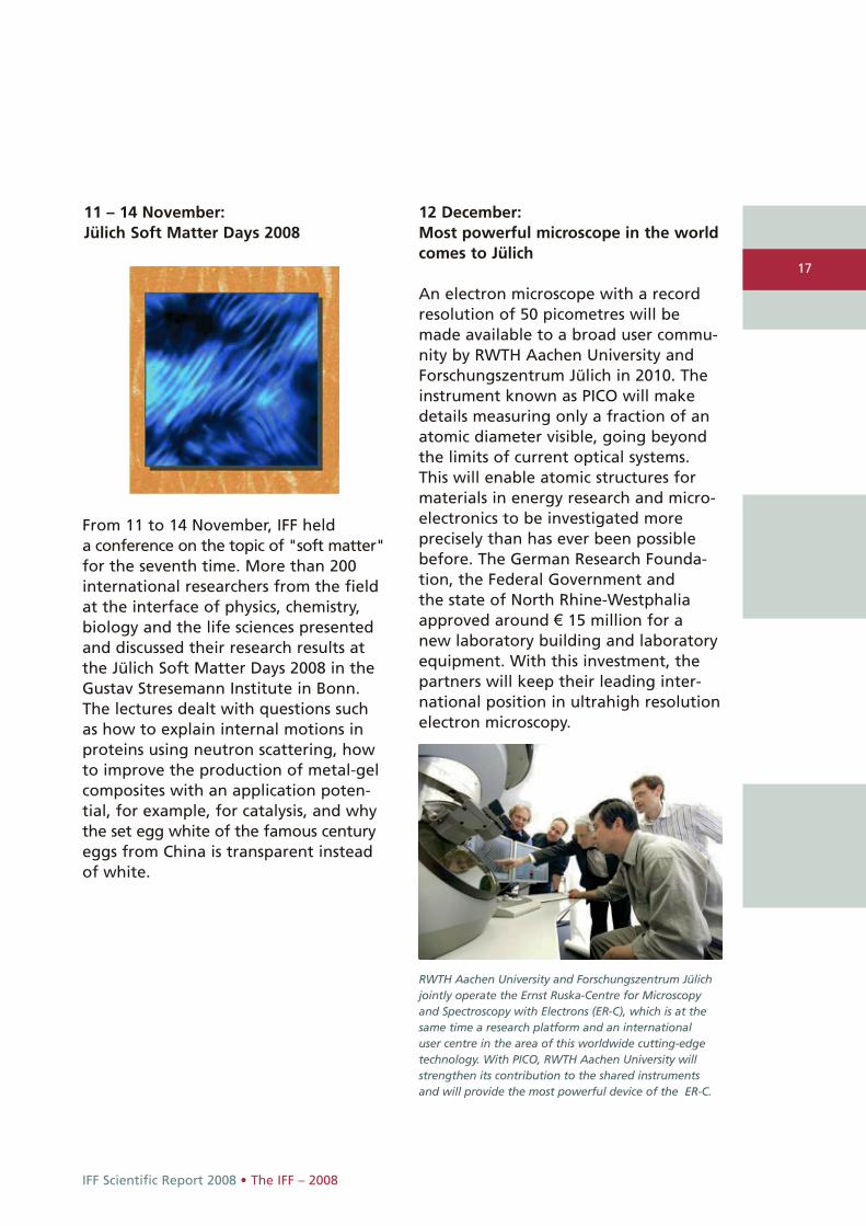
11 – 14 November: Jülich Soft Matter Days 2008
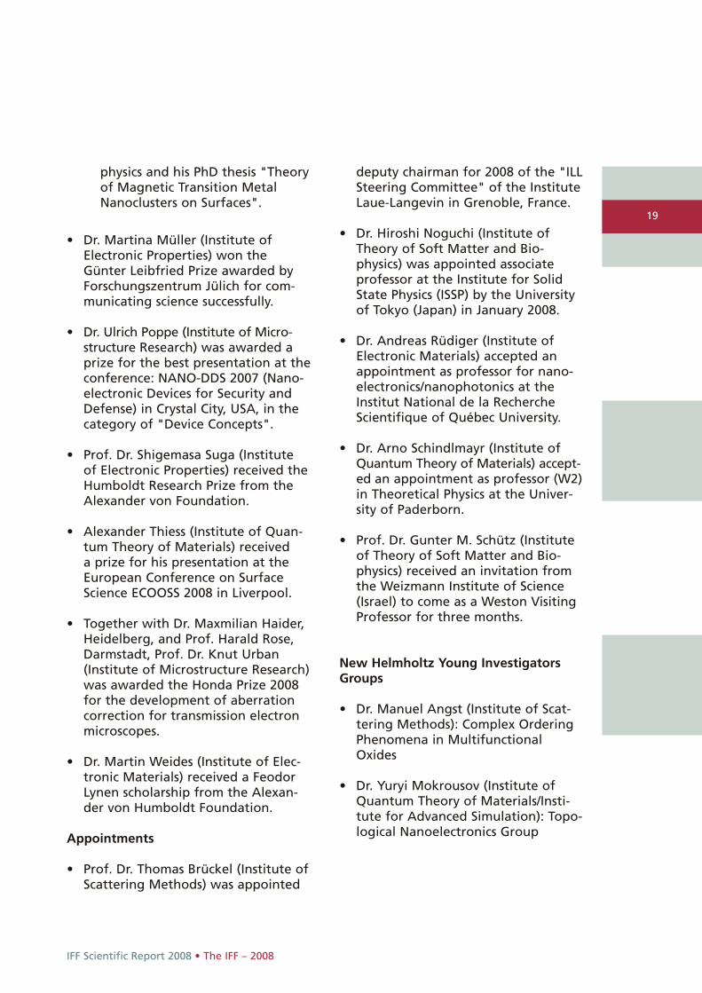
RWTH Aachen University and Forschungszentrum Jülichjointly operate the Ernst Ruska-Centre for Microscopyand Spectroscopy with Electrons (ER-C), which is at thesame time a research platform and an international user centre in the area of this worldwide cutting-edgetechnology. With PICO, RWTH Aachen University willstrengthen its contribution to the shared instrumentsand will provide the most powerful device of the ER-C.
From 11 to 14 November, IFF held a conference on the topic of "soft matter"for the seventh time. More than 200international researchers from the fieldat the interface of physics, chemistry,biology and the life sciences presentedand discussed their research results atthe Jülich Soft Matter Days 2008 in theGustav Stresemann Institute in Bonn.The lectures dealt with questions suchas how to explain internal motions inproteins using neutron scattering, howto improve the production of metal-gelcomposites with an application poten-tial, for example, for catalysis, and whythe set egg white of the famous centuryeggs from China is transparent insteadof white.
12 December: Most powerful microscope in the worldcomes to Jülich
An electron microscope with a recordresolution of 50 picometres will bemade available to a broad user commu-nity by RWTH Aachen University andForschungszentrum Jülich in 2010. Theinstrument known as PICO will makedetails measuring only a fraction of anatomic diameter visible, going beyondthe limits of current optical systems.This will enable atomic structures formaterials in energy research and micro-electronics to be investigated more precisely than has ever been possiblebefore. The German Research Founda-tion, the Federal Government and the state of North Rhine-Westphaliaapproved around € 15 million for a new laboratory building and laboratoryequipment. With this investment, thepartners will keep their leading inter-national position in ultrahigh resolutionelectron microscopy.

18
The IFF – 2008 • IFF Scientific Report 2008
Honours
Awards, honours, scholarships
• Dr. Bo Persson (Institute of QuantumTheory of Materials) received anaward for one of the best publicationsof the year 2007 in the specialist jour-nal "Journal of Physics: CondensedMatter".
• Sebastian Gliga (Institute of ElectronicProperties) received a prize for thebest presentation at the "Joint European Magnetics Symposia (JEMS)2008" conference in Dublin, Ireland.
• Dr. Evgeny Gorelov (Institute of Theo-ry of Structure Formation) received aprize together with an internationalteam in a competition organised bythe Russian Corporation of Nano-technologies (RUSNANO) and the Intel Corporation for a project in the category of “Supercomputers for Nanotechnololgy and the Nano-industry”.
• Prof. Dr. Peter Grünberg (Institute of Electronic Properties)o was awarded an honorary doctor-
ate by the Mathematics and Science Faculty of the University in Cologne on 16 April. Afterwardshe was awarded the universitymedal. Moreover, he was made anhonorary member of the alumninetwork "Köln Alumni e.V.".
o was awarded the Grand Crosswith Star of the Order of Meritof the Federal Republic of Ger-many on 8 April 2008.
o was elected regular member ofthe North Rhine-WestphalianAcademy of Sciences on 10 April2008.
o was awarded an honorary doc-torate on 24 April by the Facultyof Natural Sciences and Techno-
logy II (Physics and MechatronicsEngineering) at Saarland Uni-versity.
o was granted freedom of thecity of Jülich on 25 April.
o was awarded an honorary doctorate by the Tohoku Uni-versity, Sendai, Japan.
o was granted freedom of the city of Lauterbach on 18August.
o was awarded the Order ofMerit of the federal state ofNorth Rhine-Westphalia on 20August for outstanding serviceto North Rhine-Westphalia andits people.
o was awarded the Rudolf DieselMedal by the German Institutefor Inventions (Deutschen Insti-tuts für Erfindungswesen) on 22 October.
o was awarded an honorary doc-torate from the Gebze Instituteof Technology in Turkey inNovember.
o was awarded the Minerva Prizeof Jülich’s Museum Associationon 3 December.
• Dr. Samir Lounis (Institute of Quan-tum Theory of Materials) o was awarded the "ThyssenKrupp
Electrical Steel PhD DissertationPrize 2008 for the best PhD dissertation of 2006/07 in the fieldof magnetism" in Berlin.
o ranked second in the GünterLeibfried Prize competition forcommunicating science successfully.
o was awarded the Friedrich Wil-helm Prize 2008 by RWTH AachenUniversity for his excellent PhD in
19
IFF Scientific Report 2008 • The IFF – 2008
physics and his PhD thesis "Theoryof Magnetic Transition MetalNanoclusters on Surfaces".
• Dr. Martina Müller (Institute of Electronic Properties) won the Günter Leibfried Prize awarded byForschungszentrum Jülich for com-municating science successfully.
• Dr. Ulrich Poppe (Institute of Micro-structure Research) was awarded aprize for the best presentation at theconference: NANO-DDS 2007 (Nano-electronic Devices for Security andDefense) in Crystal City, USA, in thecategory of "Device Concepts".
• Prof. Dr. Shigemasa Suga (Institute of Electronic Properties) received theHumboldt Research Prize from theAlexander von Foundation.
• Alexander Thiess (Institute of Quan-tum Theory of Materials) received a prize for his presentation at theEuropean Conference on Surface Science ECOOSS 2008 in Liverpool.
• Together with Dr. Maxmilian Haider,Heidelberg, and Prof. Harald Rose,Darmstadt, Prof. Dr. Knut Urban(Institute of Microstructure Research)was awarded the Honda Prize 2008for the development of aberrationcorrection for transmission electronmicroscopes.
• Dr. Martin Weides (Institute of Elec-tronic Materials) received a FeodorLynen scholarship from the Alexan-der von Humboldt Foundation.
Appointments
• Prof. Dr. Thomas Brückel (Institute ofScattering Methods) was appointed
deputy chairman for 2008 of the "ILLSteering Committee" of the InstituteLaue-Langevin in Grenoble, France.
• Dr. Hiroshi Noguchi (Institute of Theory of Soft Matter and Bio-physics) was appointed associate professor at the Institute for SolidState Physics (ISSP) by the Universityof Tokyo (Japan) in January 2008.
• Dr. Andreas Rüdiger (Institute ofElectronic Materials) accepted anappointment as professor for nano-electronics/nanophotonics at theInstitut National de la Recherche Scientifique of Québec University.
• Dr. Arno Schindlmayr (Institute ofQuantum Theory of Materials) accept-ed an appointment as professor (W2)in Theoretical Physics at the Univer-sity of Paderborn.
• Prof. Dr. Gunter M. Schütz (Instituteof Theory of Soft Matter and Bio-physics) received an invitation fromthe Weizmann Institute of Science(Israel) to come as a Weston VisitingProfessor for three months.
New Helmholtz Young InvestigatorsGroups
• Dr. Manuel Angst (Institute of Scat-tering Methods): Complex OrderingPhenomena in MultifunctionalOxides
• Dr. Yuryi Mokrousov (Institute ofQuantum Theory of Materials/Insti-tute for Advanced Simulation): Topo-logical Nanoelectronics Group
20
The IFF • IFF Scientific Report 2008
20
spintransport
crackpropa- gation
diffusion
magne-tism
phenomena
numericalmethods
methods
phasetransition
alloys
materials
nano-particles membranes
glasses
polymers
colloids
semi-conductors
polarcrystals
thin films
corrosion
super-conductivity
conductivity
structureformation
neutronscattering
X-rayspectro-
scopy
lightscattering
electronmicroscopy
scanningtunnellingmicroscopy SQUID
micro- scopyelectron
spectro- scopy
IFF
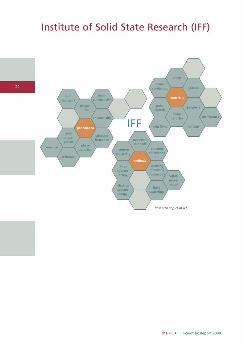
Research topics at IFF
Institute of Solid State Research (IFF)

21
IFF Scientific Report 2008 • The IFF
Founded in 1969, the scientific reputa-tion of the Institute of Solid StateResearch (Institut für Festkörper-forschung – IFF) still owes much to theconception of its founders that new dis-coveries are made at the boundaries ofdisciplines. This is as true today as it wasforty years ago. In this spirit, the IFF haspioneered new research fields such asspintronics and set trends towardsmulti- and cross-disciplinary activities inboth fundamental research as well astechnological innovations.
Today, the IFF is engaged in investigat-ing a multitude of condensed matterphenomena with special emphasis onthree prime objectives:
• studies of fundamental physical mechanisms and phenomena of condensed matter,
• the development and improvement of experimental and theoretical analysis methods, as well as
• the elucidation and utilization of new material properties in complex systems.
The corresponding research pro-grammes follow the main theme toexploit the full scale of analytical andnumerical methods to elucidate interre-lations between structural, electronic,and magnetic properties of the solidstate together with describing underly-ing physical mechanisms. Researchefforts are directed at obtaining amicroscopic and atomistic understand-ing of phenomena based on fundamen-tal interaction mechanisms.
Research at the IFF rests firmly on quan-tum mechanics and statistical physics.On a microscopic scale, they describethe interaction of electrons and atomicbuilding blocks and determine howthese entities respond to external influ-ences. Particular strengths encompassthe theory of electronic structures, clus-ters and polymer physics, biophysics,micromechanics of lattice imperfections,the dynamics of structure formationand phase transitions, materials andphenomena of magneto- and nanoelec-tronics, spintronics, spin dynamics,strongly correlated electron systems, aswell as the instrumentation of electron,neutron, and synchrotron sources andtheir application to the study of con-densed matter.
The experimental portfolio togetherwith an acknowledged expertiseenables the IFF to tackle complex prob-lems in close cooperation with scientistsand industry worldwide. Special state-of-the-art laboratories exist for thin filmdeposition and growth of bulk crystalsas well as for the preparation of softmatter materials. In addition to stan-dard methods for materials characteri-zation, highly specialized techniquesranging from superconducting micros-copy and spinpolarized microscopies to femtosecond laser spectroscopy areavailable at the IFF and are being con-stantly improved in performance.
With the Ernst Ruska-Centre for Microsc-opy and Spectroscopy with Electrons(ER-C) the IFF operates a national userfacility housing several of the world'smost advanced electron microscopes
Jülich-Aachen Research Alliance (JARA).JARA-FIT is the center of excellence fornanoelectronics research in the Jülich-Aachen region and is jointly operatedby the Forschungszentrum Jülich andthe RWTH Aachen University. It providesan excellent basis for future develop-ments of nanoelectronics and informa-tion technology. To identify technologydrivers the research areas cover quan-tum-electronics, magneto-electronics,ferro-electric and molecular nanostruc-tures as well as Terahertz-electronicsand bioelectronic signal processing.
The IFF is partner of more than onehundred universities and research insti-tutions from all around the world. Lastbut not least, the IFF has a long tradi-tion in the teaching and training of stu-dents, not only through the approxi-mately 30 IFF staff scientists steadily giv-ing lectures at universities, but in partic-ular through the annual IFF SpringSchools, Neutron Laboratory Courses,and the Nanoelectronic Days.
Actually representing a department, theIFF currently comprises six experimentaland three theoretical divisions as well as joint service facilities, which, however,cannot be regarded separately. The divi-sions present themselves on the follow-ing pages.
22
The IFF • IFF Scientific Report 2008
22 and tools for nanocharacterization. In-house research programmes covertopical issues in condensed matterphysics and – as a matter of course –future developments of subångströmand sub-electronvolt microscopy.
Within the framework of the Jülich Synchrotron Radiation Laboratory (JSRL) a broad variety of spectroscopy,microscopy, and scattering experimentsat various synchrotron radiation facili-ties are designed and realized. The SRLis part of the recently founded PeterGrünberg Centre and provides expertisefor the development of new beamlinesand experimental concepts and, thus,acts as a valuable partner for synchro-tron radiation laboratories throughoutthe world.
The Jülich Centre for Neutron Science(JCNS) operates advanced neutron scat-tering instruments at the worldwidemost modern and highest flux neutronsources. As a complement to localresearch opportunities, instruments aredesigned and operated at externalnational and international neutronsources, such as the FRM II in Munich or the neutron spallation source in OakRidge, USA.
The international networking of the IFF is a main pillar of its success; theinstitute initiated two EU Networks of Excellence (NoE), and co-founded the section “Fundamentals of FutureInformation Technology (FIT)” of the

23
IFF Scientific Report 2008 • The IFF
Being an institute of the Forschungs-zentrum Jülich – itself belonging to the Helmholtz Association of GermanResearch Centres (HGF) – the IFF pro-vides key contributions to the strategicmission of the Helmholtz Associationwithin three research programmes:
• Condensed Matter (pages 40 – 155),
• Large-Scale Facilities for Research with Photons, Neutrons, and Ions(pages 192 – 215),
• Information Technology with Nanoelectronic Systems (pages 198 – 219).
As a matter of fact, much of the successof the IFF rests upon the inventivenessand initiative of its more than 300 staffmembers. The IFF supports independentresearch by encouraging the responsi-bility of individual scientists – a philo-sophy that contributes greatly to thestimulating atmosphere in the depart-ment. In order to sustain this level onthe long run, special encouragement isgiven to young scientists.
The casual observer may be struck bythe wide range of topics and extensivenetworking at the IFF, whose strength is to link complex issues together withits scientific and industrial partners. In the sixties, Germany seemed to beabout to miss the boat in solid-stateresearch. The success of the IFF demon-strates, how a leading global positionmay be achieved by a sound and clear-sighted research strategy, which is ableto identify and address new develop-ments and challenges at an early stage,and pursue them on a long-term timescale.
Read more:Institute of Solid State Research:www.fz-juelich.de/iff/e_iff/
Forschungszentrum Jülich: www.fz-juelich.de
Ernst Ruska-Centre: www.er-c.org
Jülich Synchrotron Radiation Laboratory:www.fz-juelich.de/iff/d_iee_jsrl/
Jülich Centre for Neutron Science:www.jcns.info/
Jülich-Aachen Research Alliance:www.jara-excellence.de
Helmholtz Association:www.helmholtz.de/en/
24
The IFF • IFF Scientific Report 2008
24
Department IFF
comprising the Institutes
IFF-1: Quantum Theory of Materials Prof. Dr. Stefan BlügelIFF-2: Theoretical Soft-Matter and Biophysics Prof. Dr. Gerhard GompperIFF-3: Theory of Structure Formation Prof. Dr. Heiner Müller-KrumbhaarIFF-4: Scattering Methods Prof. Dr. Thomas BrückelIFF-5: Neutron Scattering Prof. Dr. Dieter RichterIFF-6: Electronic Materials Prof. Dr. Rainer WaserIFF-7: Soft Condensed Matter Prof. Dr. Jan K. G. DhontIFF-8: Microstructure Research Prof. Dr. Knut UrbanIFF-9: Electronic Properties Prof. Dr. Claus M. Schneider

25
IFF Scientific Report 2008 • The IFF
IFF-1: Quantum Theory of Materials
A major focus at “Quantum-Theory ofMaterials“ is the analysis and computa-tion of structural, electronic, magnetic,transport and chemical properties andprocesses in molecules and solids, interms of both basic research and practi-cal applications. The goal is to achieve a microscopic understanding of suchcomplex phenomena.
Our research covers key areas of con-densed matter theory, computationalmaterials science, nanoelectronics andsupercomputing. We explore the elec-tronic and structural properties of sys-tems from large organic (including bio-logical) molecules, low-dimensionalmagnets, and magnetic multilayers, tocomplex solids. We consider transportproperties across interfaces and mole-cules as relevant for spintronics andmolecular electronics. We investigatethe electronic excitations, and dynami-cal properties of atomic and molecularclusters, solids, and solid surfaces, aswell as the quasiparticle behaviour ofsemiconductors, oxides and transitionmetals that results from electronic correlations. We analyze the physics of strongly correlated materials such
as transition-metal oxides and molecu-lar crystals paying particular attentionto complex ordering phenomena. Otherareas include nanoscale tribology,including friction, plastic deformation,adhesion, and brittle fracture, as well as nonlinear processes in the atmos-phere and agrosphere.
A major asset of our institute is thecompetence in developing conceptualand computational methods based ondensity functional theory, moleculardynamics simulations, and QuantumMonte Carlo methods.
26
The IFF • IFF Scientific Report 2008
26
IFF-2: Theoretical Soft-Matter and Biophysics
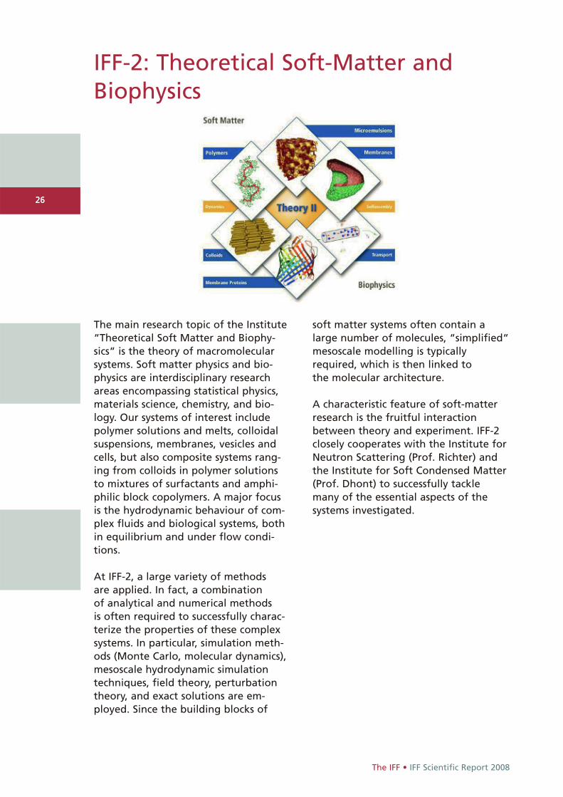
The main research topic of the Institute“Theoretical Soft Matter and Biophy-sics“ is the theory of macromolecularsystems. Soft matter physics and bio-physics are interdisciplinary researchareas encompassing statistical physics,materials science, chemistry, and bio-logy. Our systems of interest includepolymer solutions and melts, colloidalsuspensions, membranes, vesicles andcells, but also composite systems rang-ing from colloids in polymer solutionsto mixtures of surfactants and amphi-philic block copolymers. A major focusis the hydrodynamic behaviour of com-plex fluids and biological systems, bothin equilibrium and under flow condi-tions.
At IFF-2, a large variety of methods are applied. In fact, a combination of analytical and numerical methods is often required to successfully charac-terize the properties of these complex systems. In particular, simulation meth-ods (Monte Carlo, molecular dynamics),mesoscale hydrodynamic simulationtechniques, field theory, perturbationtheory, and exact solutions are em-ployed. Since the building blocks of
soft matter systems often contain alarge number of molecules, “simplified“mesoscale modelling is typicallyrequired, which is then linked to the molecular architecture.
A characteristic feature of soft-matterresearch is the fruitful interactionbetween theory and experiment. IFF-2closely cooperates with the Institute forNeutron Scattering (Prof. Richter) andthe Institute for Soft Condensed Matter(Prof. Dhont) to successfully tacklemany of the essential aspects of the systems investigated.
27
IFF Scientific Report 2008 • The IFF
The research of the Institute “Theory of Structure Formation“ is concernedwith the mechanisms of the formationof structures and their consequences incondensed matter. The investigationsstart from electronic properties whichdefine the shortest length and timescales, but they also encompass themacroscopic consequences. The analyti-cal and numerical studies are in manyways closely connected to experimentalresearch performed in other groups ofthe IFF, but also to activities in otherJülich institutes. The institute contribu-tes mainly to the research programmes“Condensed Matter Physics“ and “Infor-mation Technology with NanoelectronicSystems“ of the Research Centre.
Central points of interest for theresearch at IFF-3 are in the field of electronic structure of solids, in particular effects of strong electroniccorrelations. A specific interest concernsmaterials relevant for Information tech-nology. A second mainstream is formedby cooperative phenomena in con-densed matter. Questions here aim atthe dynamics of structure and patternformation and the statistical mechanics
IFF-3: Theory of Structure Formation
of order and disorder processes. Specificactivities concern the effect of long-range interactions like elastic effects insolids, friction and fracture phenomena,or hydrodynamic interactions in solid-liquid systems.
The research of IFF-3 employs all analyt-ical and numerical techniques applica-ble to many-body problems of equilibri-um and non-equilibrium phenomena in condensed matter. In addition, thedevelopment of new methodologicalconcepts and numerical procedures ispart of our research interest. The devel-opment of parallel programme codesadapted to massively parallel computershas received special attention in recentyears.

28
The IFF • IFF Scientific Report 2008
28
At the Institute for Scattering Methods,we focus on the investigation of struc-tural and magnetic order, fluctuationsand excitations in complex or nanos-tructured magnetic systems and highlycorrelated electron systems. Ourresearch is directed at obtaining amicroscopic atomic understandingbased on fundamental interactionmechanisms and relating this micro-scopic information to macroscopic phys-ical properties and functionalities.
The systems studied have a high poten-tial for applications in future informa-tion technologies. In the field of nano-magnetism and Spintronics they rangefrom magnetic molecules, via magneticnanoparticles and magnetic thin filmsystems to laterally patterned superlat-tices. Among the correlated electronsystems, we focus on transition metaloxides and -chalcogenides with unusualproperties, such as colossal magnetore-sistance or multiferroicity. Transitionmetal oxide superlattices, also laterallypatterned, combine the aspects of cor-related electron systems and nanomag-netism. Thermoelectric materials arebeing explored in the form of bulk andnanostructures.
Our emphasis lies in the application ofmost advanced synchrotron X-ray andneutron scattering methods. We placegreat emphasis on the complementaryuse of these two probes. Some of ourefforts are devoted to dedicated samplepreparation, from the synthesis ofnanoparticles via physical thin film dep-osition techniques to single crystalgrowth. For sample characterisation,several ancillary techniques such asmagnetometry, specific heat, conductiv-ity etc. are being used to complementthe scattering methods.
A significant part of our activity isdevoted to the development of novelscattering techniques and the construc-tion and continuous improvement ofinstruments at large scale neutron andsynchrotron radiation facilities. Ourstrength lays in polarization analysistechniques. The Institute for ScatteringMethods is partner in the Jülich Centrefor Neutron Science JCNS, which oper-ates instruments at some of the leadingfacilities: the research reactor FRM II inGarching, the Institute Laue-LangevinILL in Grenoble, France and the Spalla-tion Neutron Source SNS in Oak-Ridge,USA. Moreover, we contribute to theoperation of a sector at the AdvancedPhoton Source APS (Argonne, USA).
IFF-4: Scattering Methods
29
IFF Scientific Report 2008 • The IFF
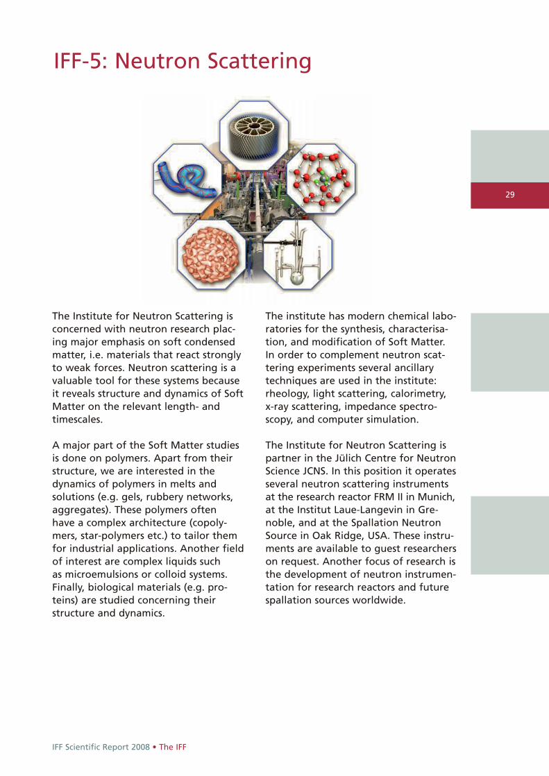
The Institute for Neutron Scattering isconcerned with neutron research plac-ing major emphasis on soft condensedmatter, i.e. materials that react stronglyto weak forces. Neutron scattering is avaluable tool for these systems becauseit reveals structure and dynamics of SoftMatter on the relevant length- andtimescales.
A major part of the Soft Matter studiesis done on polymers. Apart from theirstructure, we are interested in thedynamics of polymers in melts and solutions (e.g. gels, rubbery networks,aggregates). These polymers often have a complex architecture (copoly-mers, star-polymers etc.) to tailor themfor industrial applications. Another fieldof interest are complex liquids such as microemulsions or colloid systems.Finally, biological materials (e.g. pro-teins) are studied concerning theirstructure and dynamics.
IFF-5: Neutron Scattering
The institute has modern chemical labo-ratories for the synthesis, characterisa-tion, and modification of Soft Matter.In order to complement neutron scat-tering experiments several ancillarytechniques are used in the institute:rheology, light scattering, calorimetry,x-ray scattering, impedance spectro-scopy, and computer simulation.
The Institute for Neutron Scattering ispartner in the Jülich Centre for NeutronScience JCNS. In this position it operatesseveral neutron scattering instrumentsat the research reactor FRM II in Munich,at the Institut Laue-Langevin in Gre-noble, and at the Spallation NeutronSource in Oak Ridge, USA. These instru-ments are available to guest researcherson request. Another focus of research isthe development of neutron instrumen-tation for research reactors and futurespallation sources worldwide.

30
The IFF • IFF Scientific Report 2008
30
IFF-6: Electronic Materials
Progress in information technology andrelated fields such as energy storageand sensors originates to a large extentfrom novel electronic phenomena infunctional materials as well as advancesin the processing technology of thesematerials.
In this sense, at the Institute “ElectronicMaterials” we focus on the physics and chemistry of electronic oxides andelectronically active organic molecules,which are promising for potential mem-ory, logic, and sensor functions. Ourresearch aims at the fundamental under-standing of functional effects based on nano-scale electron transfer, electro-chemical redox processes, space chargeformation, electron/ion conduction inreduced dimensions, as well as ferro-and piezoelectricity, and at the elucida-tion of their potential for future deviceapplication. For this purpose, our insti-tute provides a broad spectrum of facili-ties reaching from atomically controlledfilm deposition methods for heteroepi-taxial oxide thin films, molecular self-assembly routes, and dedicated integra-tion technologies. In addition, our insti-tutes are equipped with tools for the
characterisation of processes, structures,and electronic properties with atomicresolution. Circuit design is utilized forthe development of hybrid and inte-grated circuits which comprise newelectronic functions as well as advancedmeasurement systems. This is comple-mented by numerical simulation andmodelling methods which aim at thetheoretical explanation of the electronicphenomena and materials under studyas well as the corresponding devices.
31
IFF Scientific Report 2008 • The IFF
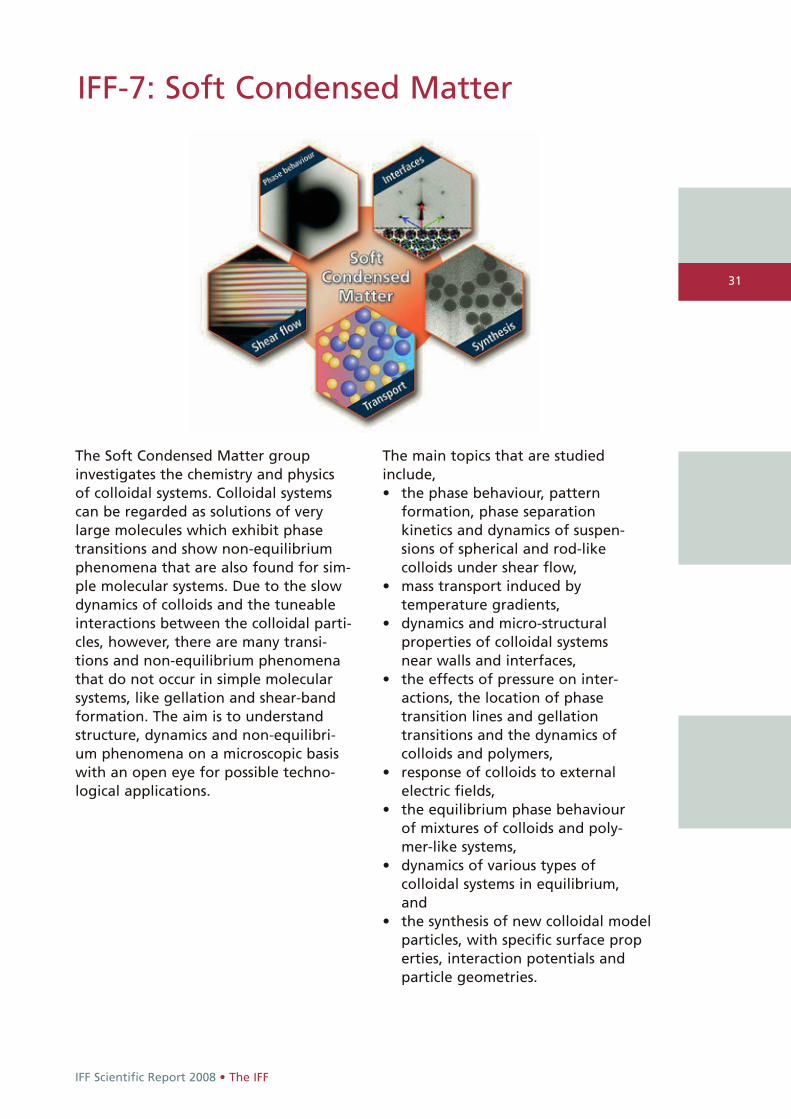
The Soft Condensed Matter groupinvestigates the chemistry and physicsof colloidal systems. Colloidal systemscan be regarded as solutions of verylarge molecules which exhibit phasetransitions and show non-equilibriumphenomena that are also found for sim-ple molecular systems. Due to the slowdynamics of colloids and the tuneableinteractions between the colloidal parti-cles, however, there are many transi-tions and non-equilibrium phenomenathat do not occur in simple molecularsystems, like gellation and shear-bandformation. The aim is to understandstructure, dynamics and non-equilibri-um phenomena on a microscopic basiswith an open eye for possible techno-logical applications.
IFF-7: Soft Condensed Matter
The main topics that are studiedinclude, • the phase behaviour, pattern
formation, phase separation kinetics and dynamics of suspen-sions of spherical and rod-like colloids under shear flow,
• mass transport induced by temperature gradients,
• dynamics and micro-structural properties of colloidal systems near walls and interfaces,
• the effects of pressure on inter-actions, the location of phase transition lines and gellation transitions and the dynamics of colloids and polymers,
• response of colloids to external electric fields,
• the equilibrium phase behaviour of mixtures of colloids and poly-mer-like systems,
• dynamics of various types of colloidal systems in equilibrium, and
• the synthesis of new colloidal model particles, with specific surface properties, interaction potentials and particle geometries.
32
The IFF • IFF Scientific Report 2008
32
IFF-8: Microstructure Research
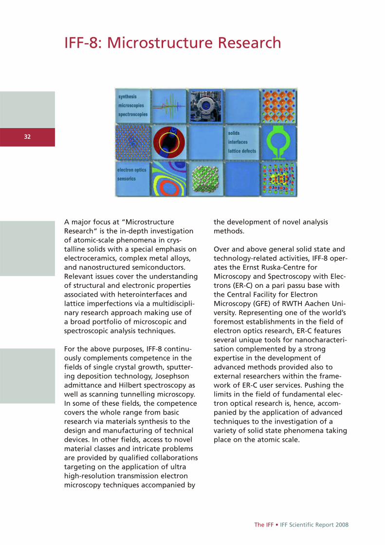
A major focus at “MicrostructureResearch“ is the in-depth investigationof atomic-scale phenomena in crys-talline solids with a special emphasis onelectroceramics, complex metal alloys,and nanostructured semiconductors.Relevant issues cover the understandingof structural and electronic propertiesassociated with heterointerfaces andlattice imperfections via a multidiscipli-nary research approach making use of a broad portfolio of microscopic andspectroscopic analysis techniques.
For the above purposes, IFF-8 continu-ously complements competence in thefields of single crystal growth, sputter-ing deposition technology, Josephsonadmittance and Hilbert spectroscopy aswell as scanning tunnelling microscopy.In some of these fields, the competencecovers the whole range from basicresearch via materials synthesis to thedesign and manufacturing of technicaldevices. In other fields, access to novelmaterial classes and intricate problemsare provided by qualified collaborationstargeting on the application of ultrahigh-resolution transmission electronmicroscopy techniques accompanied by
the development of novel analysismethods.
Over and above general solid state andtechnology-related activities, IFF-8 oper-ates the Ernst Ruska-Centre forMicroscopy and Spectroscopy with Elec-trons (ER-C) on a pari passu base withthe Central Facility for ElectronMicroscopy (GFE) of RWTH Aachen Uni-versity. Representing one of the world’sforemost establishments in the field ofelectron optics research, ER-C featuresseveral unique tools for nanocharacteri-sation complemented by a strongexpertise in the development ofadvanced methods provided also toexternal researchers within the frame-work of ER-C user services. Pushing thelimits in the field of fundamental elec-tron optical research is, hence, accom-panied by the application of advancedtechniques to the investigation of avariety of solid state phenomena takingplace on the atomic scale.
33
IFF Scientific Report 2008 • The IFF
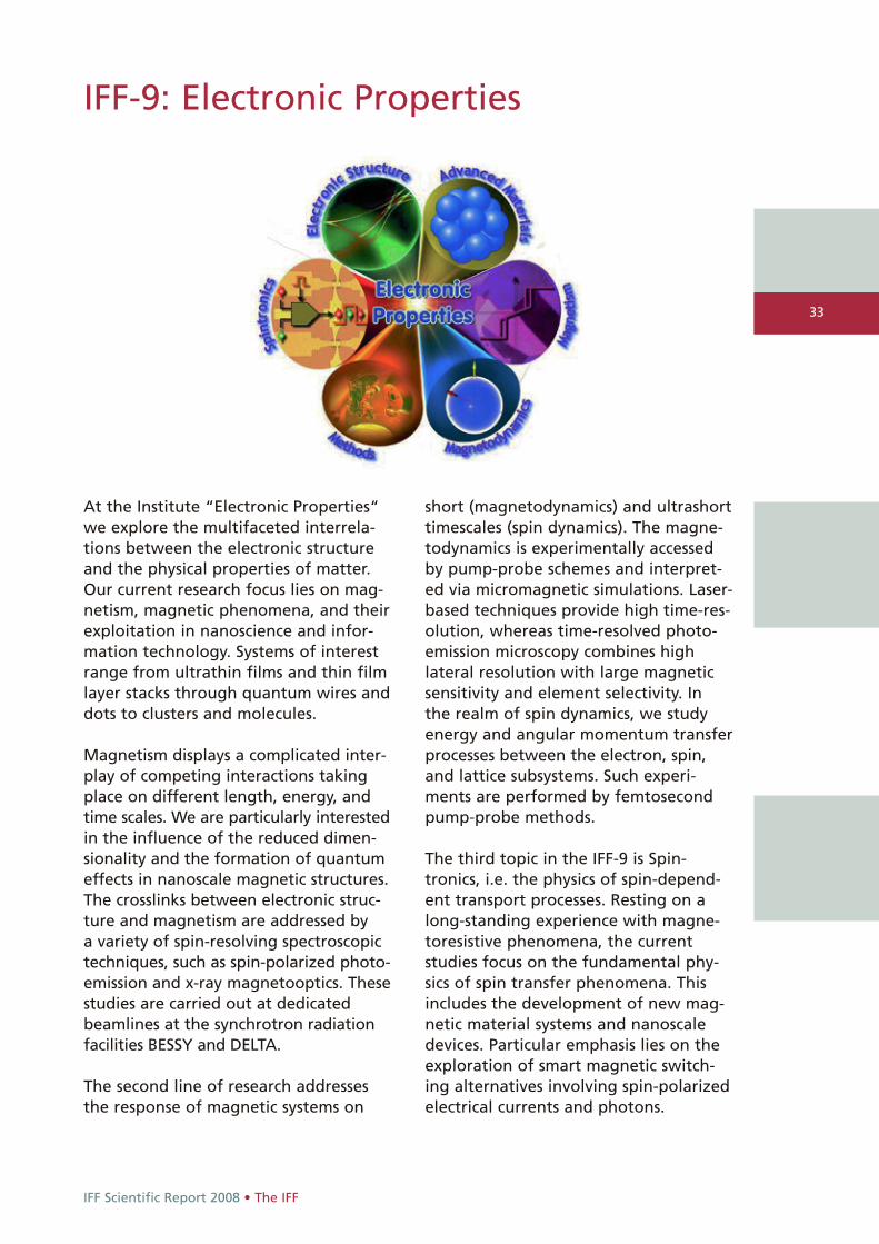
At the Institute “Electronic Properties“we explore the multifaceted interrela-tions between the electronic structureand the physical properties of matter.Our current research focus lies on mag-netism, magnetic phenomena, and theirexploitation in nanoscience and infor-mation technology. Systems of interestrange from ultrathin films and thin filmlayer stacks through quantum wires anddots to clusters and molecules.
Magnetism displays a complicated inter-play of competing interactions takingplace on different length, energy, andtime scales. We are particularly interestedin the influence of the reduced dimen-sionality and the formation of quantumeffects in nanoscale magnetic structures.The crosslinks between electronic struc-ture and magnetism are addressed by a variety of spin-resolving spectroscopictechniques, such as spin-polarized photo-emission and x-ray magnetooptics. Thesestudies are carried out at dedicatedbeamlines at the synchrotron radiationfacilities BESSY and DELTA.
The second line of research addressesthe response of magnetic systems on
IFF-9: Electronic Properties
short (magnetodynamics) and ultrashorttimescales (spin dynamics). The magne-todynamics is experimentally accessedby pump-probe schemes and interpret-ed via micromagnetic simulations. Laser-based techniques provide high time-res-olution, whereas time-resolved photo-emission microscopy combines highlateral resolution with large magneticsensitivity and element selectivity. In the realm of spin dynamics, we studyenergy and angular momentum transferprocesses between the electron, spin,and lattice subsystems. Such experi-ments are performed by femtosecondpump-probe methods.
The third topic in the IFF-9 is Spin-tronics, i.e. the physics of spin-depend-ent transport processes. Resting on along-standing experience with magne-toresistive phenomena, the currentstudies focus on the fundamental phy-sics of spin transfer phenomena. Thisincludes the development of new mag-netic material systems and nanoscaledevices. Particular emphasis lies on theexploration of smart magnetic switch-ing alternatives involving spin-polarizedelectrical currents and photons.

Higher level education • IFF Scientific Report 2008
34
With a reception at the Forschungszentrum's Faculty Club, the German Research School for Simulation Sciences welcomed its first doctoral researchers on 29 April, 2008. The eight successful candidates from Aachen and Jülichwho hold diplomas in engineering, physics, or mathematics, have been chosen by a selection committee from astrong field of excellent nominees.
Higher level education

35
IFF Scientific Report 2008 • Higher level education
German Research School for Simulation Sciences (GRS)
The German Research School for SimulationSciences (GRS) is a joint venture of RWTHAachen University and Forschungszentrum Jülich. It combines, for the first time in Germany, the resources of a large federalresearch centre and a leading university in a research school which, formed as its own legal entity, may act autonomously in research and education. In its academic activity, GRS isclosely connected with the RWTH; academicdegrees are degrees of the RWTH. In itsresearch activity, GRS takes advantage of the scientific environment, in particular the supercomputer facilities of theForschungszentrum Jülich. There are close connections between GRS and all researchgroups in the field of simulation methods inAachen and Jülich within the Jülich-AachenResearch Alliance JARA. The seat of the company is Jülich.
FUNDING: The funding is provided in equal parts by the BMBF (federal government), MIWFT (stategovernment), HGF, RWTH and ForschungszentrumJülich, initially for a period of five years.
BUILDINGS: In both Aachen and Jülich, separatebuildings for the GRS including office space areunder construction. The completion of the buildingsis planned for summer 2009. The officialinauguration of the buildings will take place onSeptember 6 within the event Tag der Neugier inJülich. Currently, interior furnishings of the building(furniture, information and media technology) arebeing prepared.
PERSONNEL: On 29 April 2008, the GRS welcomed its first eight doctoral candidates. A highly-competitive selection procedure involvingexperts from Aachen and Jülich ensuresoutstanding quality of the candidates, in accordancewith the aim of GRS to strive for excellence. An international initiative by GRS to attract further postgraduates is in preparation. The process to fillthe four planned W3 professorships at GRS is underway; their research areas are: AppliedSupercomputing in Engineering, ParallelProgramming, Computational Biophysics andComputational Materials Science.
MASTER PROGRAM: The GRS Master program Simulation Sciences started in the winter semester2008/09 with special ministerial authorization. In parallel, the accreditation process with agency ASIIN was undertaken. A local auditing by the experts of the ASIIN took place on 19 November2008 in Aachen and Jülich. After examination bythe expert committees of ASIIN, the Master program has been formally accredited since end of March 2009.
COOPERATIONS: Future cooperations with foreign partners such as Ter@tec (France) are currentlyunder consideration.
Read more: www.grs-sim.de
Higher level education• IFF Scientific Report 2008
36
International Helmholtz ResearchSchool of Biophysics and Soft Matter
The International Helmholtz Research School of
Biophysics and Soft Matter (IHRS BioSoft) pro-
vides intensive training in biophysics and soft
matter. It also offers a comprehensive framework
of experimental and theoretical techniques that
will enable PhD students to gain a deeper under-
standing of the structure, dynamics, and function
of complex systems.
In recent years, life science research has undergonea fundamental transition. It has become evident thateven the simplest molecular machines display an as-tounding complexity, leaving alone networks of genesand proteins in a living cell. Thus, there is an ur-gent need for a more quantitative, theory-oriented ap-proach. Soft matter research has, in parallel, madegreat progress in understanding the structure of com-plex multi-component macromolecular systems, theirnon-equilibrium behaviour and their response to ex-ternal fields. A particular focus is laid upon unravelingthe physics of biologically relevant systems. Thus,there is an urgent need for an interdisciplinary grad-uate education.
The IHRS BioSoft is located at Forschungszen-trum Jülich, run in cooperation with the universitiesin Cologne and Düsseldorf and caesar Bonn, andfunded by the Helmholtz Association. Its ultimategoal is to advance the integration and exchange be-tween physics, chemistry, and biology in researchand education. Students benefit not only from lec-tures, seminars, and lab courses given by experts inthe field, but also from courses in transferable skills.Furthermore, they experience the environment pro-vided by a large, multidisciplinary research centre.
The research school accepts fellows for three-yearPhD projects and is open to highly qualified and mo-tivated applicants from all countries. The fellow PhD
students will be based in one of the groups that arepart of the IHRS, but also participate in interdisci-plinary courses. Other students are welcome to joinmost of these courses as long as there are freeplaces. The lectures of the school usually attract anumber of extra participants that choose the topicsselectively according to their needs.
In 2007, two-semester introductory lecture courses,’Introduction to Statistical Physics’ taught by Prof.Dhont and Prof. Gompper and ’Molecules of Life -Introduction to the Chemistry and Biology of Cells’with various lecturers from within the IHRS BioSoft(Prof. Schurr, Prof. Merkel, Prof. Kaupp, Prof. Sei-del, Prof. Richter, Prof. Büldt, Prof. Willbold, Dr.Enderlein, and Prof. Offenhäusser) were offered tothe students. Both courses equip the students fortheir research projects with important basic knowl-edge: from a physics point of view, entropy and statis-tical physics have a large influence on the behaviourof the systems that are usually mesoscopic. The bi-ological lectures covered systems from amino acidsto the structure and dynamics of entire cells as wellas methods such as X-ray crystallography, fluores-cence spectroscopy, electrophysiology, and opticalmicroscopy.
In 2007 and 2008, the students learned about theimportant tool of ’Computer Simulations in Physicsand Biology’ by a two-semester advanced-seminarcourse that covered various, independent talks ondifferent topics: Monte Carlo and Molecular Dynam-ics Simulations, Polyelectrolytes, Solid State NMR,Evolution of Bacterial Genomic Networks, Meso-scopic Hydrodynamics, Colloids, Proteins, Protein-Ligand Binding, Protein Structure Prediction, andMembrane Proteins. Most of the speakers were fromForschungszentrum Jülich and daily work with themethods and systems they presented: G. A. Vliegen-thart, R. G. Winkler, H. Heise, M. Stoldt, M. Lercher,M. Ripoll, G. Naegele, A. Baumgärtner, M. Zacharias(IU Bremen), J. Granzin, and W. B. Fischer (NYMU,Taiwan).
Very recently, students were offered the one-semester introductory lecture course on ’Cell Biology’by Prof. Müller and Prof. Baumann that included labdemonstrations, and the advanced lecture courseson ’Complex Fluids’ by Prof. Strey (Cologne) and’Rheology’ by Prof. Vermant (Leuven).
Complementary laboratory courses provide the stu-
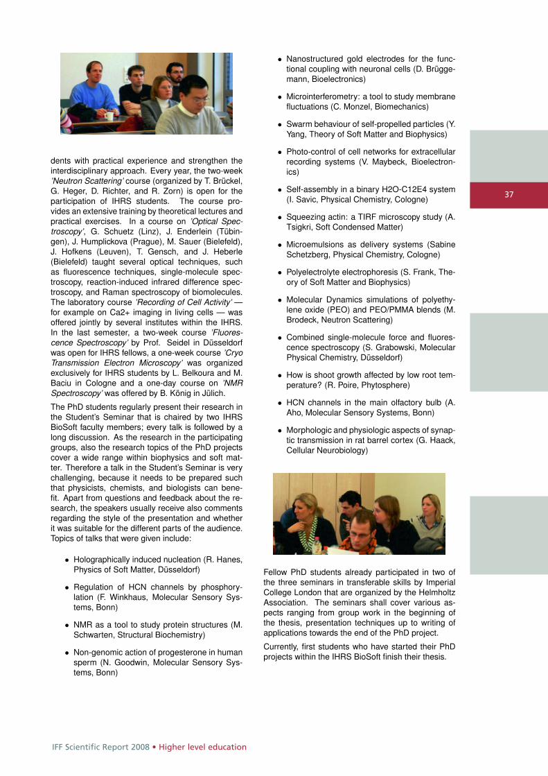
IFF Scientific Report 2008 • Higher level education
37
dents with practical experience and strengthen theinterdisciplinary approach. Every year, the two-week’Neutron Scattering’ course (organized by T. Brückel,G. Heger, D. Richter, and R. Zorn) is open for theparticipation of IHRS students. The course pro-vides an extensive training by theoretical lectures andpractical exercises. In a course on ’Optical Spec-troscopy’, G. Schuetz (Linz), J. Enderlein (Tübin-gen), J. Humplickova (Prague), M. Sauer (Bielefeld),J. Hofkens (Leuven), T. Gensch, and J. Heberle(Bielefeld) taught several optical techniques, suchas fluorescence techniques, single-molecule spec-troscopy, reaction-induced infrared difference spec-troscopy, and Raman spectroscopy of biomolecules.The laboratory course ’Recording of Cell Activity’ —for example on Ca2+ imaging in living cells — wasoffered jointly by several institutes within the IHRS.In the last semester, a two-week course ’Fluores-cence Spectroscopy’ by Prof. Seidel in Düsseldorfwas open for IHRS fellows, a one-week course ’CryoTransmission Electron Microscopy’ was organizedexclusively for IHRS students by L. Belkoura and M.Baciu in Cologne and a one-day course on ’NMRSpectroscopy’ was offered by B. König in Jülich.
The PhD students regularly present their research inthe Student’s Seminar that is chaired by two IHRSBioSoft faculty members; every talk is followed by along discussion. As the research in the participatinggroups, also the research topics of the PhD projectscover a wide range within biophysics and soft mat-ter. Therefore a talk in the Student’s Seminar is verychallenging, because it needs to be prepared suchthat physicists, chemists, and biologists can bene-fit. Apart from questions and feedback about the re-search, the speakers usually receive also commentsregarding the style of the presentation and whetherit was suitable for the different parts of the audience.Topics of talks that were given include:
• Holographically induced nucleation (R. Hanes,Physics of Soft Matter, Düsseldorf)
• Regulation of HCN channels by phosphory-lation (F. Winkhaus, Molecular Sensory Sys-tems, Bonn)
• NMR as a tool to study protein structures (M.Schwarten, Structural Biochemistry)
• Non-genomic action of progesterone in humansperm (N. Goodwin, Molecular Sensory Sys-tems, Bonn)
• Nanostructured gold electrodes for the func-tional coupling with neuronal cells (D. Brügge-mann, Bioelectronics)
• Microinterferometry: a tool to study membranefluctuations (C. Monzel, Biomechanics)
• Swarm behaviour of self-propelled particles (Y.Yang, Theory of Soft Matter and Biophysics)
• Photo-control of cell networks for extracellularrecording systems (V. Maybeck, Bioelectron-ics)
• Self-assembly in a binary H2O-C12E4 system(I. Savic, Physical Chemistry, Cologne)
• Squeezing actin: a TIRF microscopy study (A.Tsigkri, Soft Condensed Matter)
• Microemulsions as delivery systems (SabineSchetzberg, Physical Chemistry, Cologne)
• Polyelectrolyte electrophoresis (S. Frank, The-ory of Soft Matter and Biophysics)
• Molecular Dynamics simulations of polyethy-lene oxide (PEO) and PEO/PMMA blends (M.Brodeck, Neutron Scattering)
• Combined single-molecule force and fluores-cence spectroscopy (S. Grabowski, MolecularPhysical Chemistry, Düsseldorf)
• How is shoot growth affected by low root tem-perature? (R. Poire, Phytosphere)
• HCN channels in the main olfactory bulb (A.Aho, Molecular Sensory Systems, Bonn)
• Morphologic and physiologic aspects of synap-tic transmission in rat barrel cortex (G. Haack,Cellular Neurobiology)
Fellow PhD students already participated in two ofthe three seminars in transferable skills by ImperialCollege London that are organized by the HelmholtzAssociation. The seminars shall cover various as-pects ranging from group work in the beginning ofthe thesis, presentation techniques up to writing ofapplications towards the end of the PhD project.
Currently, first students who have started their PhDprojects within the IHRS BioSoft finish their thesis.
Higher level education • IFF Scientific Report 2008
38
39th IFF Spring School: Soft Matter – From Synthetic to Biological Materials
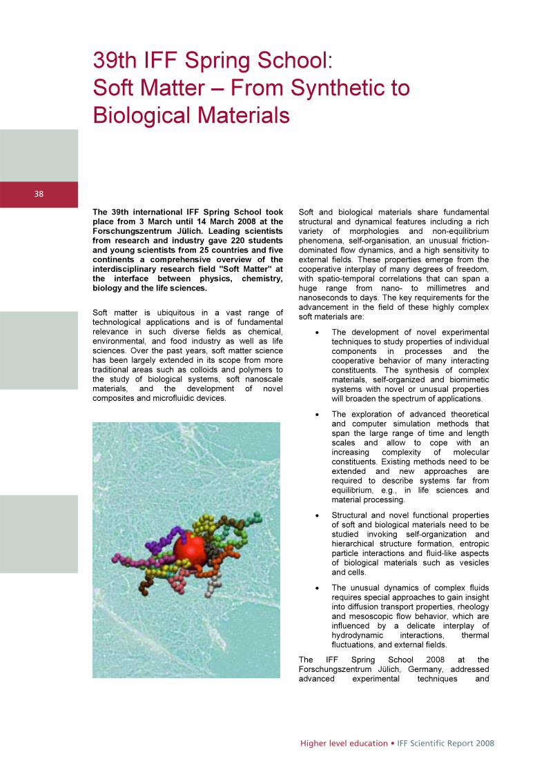
The 39th international IFF Spring School tookplace from 3 March until 14 March 2008 at theForschungszentrum Jülich. Leading scientistsfrom research and industry gave 220 studentsand young scientists from 25 countries and fivecontinents a comprehensive overview of the interdisciplinary research field "Soft Matter" atthe interface between physics, chemistry,biology and the life sciences.
Soft matter is ubiquitous in a vast range oftechnological applications and is of fundamentalrelevance in such diverse fields as chemical, environmental, and food industry as well as life sciences. Over the past years, soft matter science has been largely extended in its scope from moretraditional areas such as colloids and polymers to the study of biological systems, soft nanoscalematerials, and the development of novelcomposites and microfluidic devices.
Soft and biological materials share fundamentalstructural and dynamical features including a richvariety of morphologies and non-equilibriumphenomena, self-organisation, an unusual friction-dominated flow dynamics, and a high sensitivity toexternal fields. These properties emerge from thecooperative interplay of many degrees of freedom, with spatio-temporal correlations that can span ahuge range from nano- to millimetres andnanoseconds to days. The key requirements for theadvancement in the field of these highly complex soft materials are:
� The development of novel experimentaltechniques to study properties of individualcomponents in processes and the cooperative behavior of many interactingconstituents. The synthesis of complex materials, self-organized and biomimeticsystems with novel or unusual properties will broaden the spectrum of applications.
� The exploration of advanced theoreticaland computer simulation methods thatspan the large range of time and lengthscales and allow to cope with an increasing complexity of molecular constituents. Existing methods need to beextended and new approaches arerequired to describe systems far from equilibrium, e.g., in life sciences andmaterial processing.
� Structural and novel functional properties of soft and biological materials need to bestudied invoking self-organization and hierarchical structure formation, entropicparticle interactions and fluid-like aspectsof biological materials such as vesiclesand cells.
� The unusual dynamics of complex fluidsrequires special approaches to gain insightinto diffusion transport properties, rheology and mesoscopic flow behavior, which areinfluenced by a delicate interplay of hydrodynamic interactions, thermalfluctuations, and external fields.
The IFF Spring School 2008 at the Forschungszentrum Jülich, Germany, addressedadvanced experimental techniques and

IFF Scientific Report 2008 • Higher level education
39
applications, and theoretical and computersimulation methods on an undergraduate andgraduate student level. Introductory lecturesprovided the basis of important experimental andtheoretical tools. More advanced lectures explainedpractical aspects of various methods and lead theparticipants from basic methods to the frontiers of current research.
The lectures covered the following topics:
� Scattering Techniques
� Single Molecule Techniques
� Equilibrium- and Non-equilibrium Statistical Physics
� Microfluidics
� Computer Simulations
� Synthesis
� Self-Organisation
� Flow Properties and Rheology
� Biomechanics
� Macromolecules and Colloids
� Membranes and Interfaces
� Biomimetic Systems
� Glasses and Gels
The school offered about 50 hours of lectures plus discussions, as well as the opportunity to participatein practical courses and visits to the participating institutes at the Forschungszentrum Jülich.
The local media coverage included newspapers, radio and television.

Condensed matter physics • IFF Scientific Report 2008
40
With its methods and models, physics forms the basis of the modern world – from industry and business to medicineand biology. Material samples are tested using neutron radiation, the mechanisms of the brain are investigated withthe spin of a proton and individual cells are scrutinized using laser light. The main field of research is the physics ofcondensed matter, or the interaction between atoms in clusters, whether it be silicon in semiconductors or carbon inpolymers and cell membranes or metallic alloys for high-temperature engineering. Well-devised microscopic modelsmake the targeted search for innovative materials possible.
40

41
HGF research programme
Condensed matter physics
IFF Scientific Report 2008 • Condensed matter physics
Research in condensed matter is con-cerned with the complex interplay ofthe myriads of atoms in a solid or a liq-uid. Research in this field can thus beunderstood as the exploration of the„third infinity“, being on equal footingwith the exploration of the very smallscales of elementary particle physics andthe very large scales of astrophysics. The conceptual framework of quantumphysics and statistical physics forms the basis for our understanding of con-densed matter. The cooperation of theelectrons and atoms within a many-body system is responsible for the dif-ferent properties of the substances anddetermines why they are solid, fluid orgaseous, soft or hard, transparent oropaque, magnetic, metallic or evensuperconducting. Extreme length andtime scales give rise to the characteristiccomplexity of condensed matter, rang-ing from subatomic sizes up to macro-scopic measures, from electronic reac-tion times in the femtosecond range up to geological periods.
Our activities focus, in particular, onmulti-scale phenomena in solid stateand liquid phases and are organized in three topics: • Electronic and Magnetic Phenomena, • From Matter to Materials, and • Soft Matter and Biophysics.
The studies in the first topic encompasselectronic and magnetic quantum statesand their properties. This includes prob-lems in highly-correlated materials,superconductivity, magnetism in lowdimensions and on short time scales. The second topic deals with phase tran-sitions and transport processes, glass-like states, and complex metallic alloys,and finally structure formation and self-organization. In the third topic, struc-ture formation and self-organization,mesoscopic dynamics and driven sys-tems, as well as biology-inspired physicsare addressed.
The spectrum of the materials investi-gated covers a wide range from metals,semiconductors and ceramics, throughmacromolecular systems up to biologicalsystems and cells. For this purpose, abroad portfolio of theoretical and exper-imental techniques is utilized, which areconstantly improved and progressed.The experimental emphasis lies on neu-tron scattering, synchrotron-radiationmethods and ultrahigh resolution elec-tron microscopy, whereas the theoreticaltreatments range from quantum theoryto statistical physics and involve bothanalytical and numerical procedures.
Condensed matter physics • IFF Scientific Report 2008
4242
Metalation/demetalation strategies formagnetic moleculesB. Botar1, P. Kögerler1,2
1 IFF-9: Electronic Properties2 Institute of Inorganic Chemistry, RWTH Aachen University
Chemical control of the magnetic properties of
discrete (quasi-zerodimensional) and networked
molecular magnets and networks implies the
need for synthesis strategies that enable fine-
tuning of the number and connectivity of spin
centers in such molecules. Magnetically func-
tionalized polyoxometalates are of particular in-
terest in this context, as these systems com-
bine structurally versatile and robust metal oxide-
based fragments with a large variety and num-
ber of spin centers (3d and 4f ions). We devel-
oped a number of methods to control the number
and connectivity of these spin centers for a fam-
ily of polyoxotungstate clusters. The employed
approach also allows the realization of unprece-
dented and highly anisotropic metal coordination
geometries, in turn resulting in local magnetic
anisotropy.
Polyoxometalates, i.e. the nanometer-sized conden-sation products of the early transition metal oxoan-ions in their high oxidation states, constitute a classof molecular metal oxide compounds that exhibitunmatched structural and chemical versatility. Asthese high-nuclearity cluster anions can be func-tionalized by a wide range of heterometal centersthat can be integrated into the parental polyoxometa-late (POM) structures, these systems represent idealarchetypes for highly tuneable molecular magnets.[1]Moreover, the high structural and redox stability com-mon to polyoxometalates also allows depositing in-tact molecules onto surfaces as well as generatingmixed-valent magnetic systems.However, access to these systems is currently lim-ited by a lack of understanding of the reaction mech-anisms underlying the self-organized formation ofsuch magnetically functionalized polyoxometalates.We target to systematically elucidate these mecha-nisms and focused on the solution chemistry of poly-oxotungstate {γ-M2-W12E} Keggin complexes (M =Mn(II), Cu(II), and Fe(III); E = Si(IV), Ge(IV),. . . ). Thischoice is motivated by the solubility of these clus-ters not only in H2O but also in organic solvents andby an interesting solvent-induced stereochemistry onthe dinuclear M2 unit in γ-Fe2 complexes with impli-cations for their electronic and magnetic properties:an “in-pocket” isomer (with the two Fe centers linkedby two hydroxo bridges) observed in organic sol-vents and an “out-of-pocket” isomer (with the two Fe
centers linked by one hydroxo bridge and no longerbound to the central SiO4 unit) present in aqueoussolution, where these units oligomerize to e.g. forma trimer,
[(Fe2(OH)3(H2O)2)3(γ−SiW10O36)3]15− (1)
[2]. In the presence of acetate, an extensively usedbuffer component for aqueous solutions and also aversatile bridging ligand, a C2v-symmetric acetate-bridged γ-di-iron(III) dimer,
[(Fe(OH)(OAc))4(γ−SiW10O36)2]12− (2)
was found to form for a buffer concentration of 0.5 MCH3COOH/CH3COOK.[3] Probing the extent of lig-and functionalization of γ-di-iron(III) complexes, weidentified a higher buffer concentration (1 M), but oth-erwise identical synthetic conditions, to be crucial forthe formation not of (2), but of an unusual, open-shelldiiron(III) derivative,
[(β−SiFe2W10O37(OH))(γ−SiW10O36)]13− (3)
[4]. The structure of (3)(Fig. 1) reveals an asym-metric clam-shell-like arrangement of {γ-SiW10} and{γ-SiW10Fe2} Keggin units connected by two Fe-O-W bridges acting as a ‘hinge’. (3) also representsthe first example of a polyoxometalate incorporatingtwo different Baker-Figgis (rotational) isomers. Theγ-Keggin unit in (3) incorporates two proximal ferriccenters connected by a hydroxo ligand. As a result ofthe unusual connectivity of the two isomerically dis-tinct units in (3), the ferric centers have no terminalligands and adopt distorted octahedral FeO6 coordi-nation environments with Fe-O bond lengths of 1.93–2.21 Å and cis-O-Fe-O bond angles of 77.6–99.2◦.The structure of (3) is stabilized by an 8-coordinateK+ cation located at the clam-shell opening createdby the two polyanion subunits. The formation of (3)
yielded several surprising findings:
• The facile incorporation of acetate ligandsinto the di-iron-POM framework observed in a0.5 M CH3COOH/CH3COOK buffer is not ob-served at higher acetate concentrations.
• Instead of the expected structures based on“out-of-pocket” {γ-SiW10Fe2} units, 1 M buffersolutions afford the formation of a lower-nuclearity Fe-POM.
One plausible explanation for this pronounced buffer
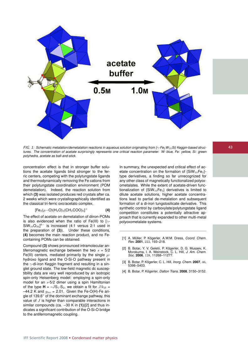
IFF Scientific Report 2008 • Condensed matter physics
43FIG. 1: Schematic metalation/demetalation reactions in aqueous solution originating from {γ-Fe2W10Si} Keggin-based struc-tures. The concentration of acetate surprisingly represents one critical reaction parameter. W: blue, Fe: yellow, Si: greenpolyhedra, acetate as ball-and-stick.
concentration effect is that in stronger buffer solu-tions the acetate ligands bind stronger to the fer-ric centers, competing with the polytungstate ligandsand thermodynamically removing the Fe cations fromtheir polytungstate coordination environment (POMdemetalation). Indeed, the reaction solution fromwhich (3) was isolated produces red crystals after ca.2 weeks which were crystallographically identified asthe classical tri-ferric oxo/acetato complex,
[Fe3(μ−O)(H2O)3(CH3COO)6]+ (4)
The effect of acetate on demetalation of diiron-POMsis also evidenced when the ratio of Fe(III) to [γ-SiW10O36]8− is increased (4:1 versus 2:1 used inthe preparation of (3)). Under these conditions,(4) becomes the main reaction product, and no Fe-containing POMs can be obtained.
Compound (3) shows pronounced intramolecular an-tiferromagnetic exchange between the two s = 5/2Fe(III) centers, mediated primarily by the single μ-hydroxo ligand and the O-Si-O pathway present inthe γ-di-iron Keggin fragment and resulting in a sin-glet ground state. The low-field magnetic dc suscep-tibility data are very well reproduced by an isotropicspin-only Heisenberg model: employing a spin-onlymodel for an s-5/2 dimer using a spin Hamiltonianof the type H = –JS1·S2, we obtain a fit for J /kB =–44.2 K and giso = 2.01. Given the Fe-O(H)-Fe an-gle of 139.6◦ of the dominant exchange pathway, thisvalue of J is higher than comparable interactions insimilar compounds (ca. –30 K in (1))[2] and thus in-dicates a significant contribution of the O-Si-O bridgeto the antiferromagnetic coupling.
In summary, the unexpected and critical effect of ac-etate concentration on the formation of {SiW10Fe2}-type derivatives, a finding so far unrecognized forany other class of magnetically functionalized polyox-ometalates. While the extent of acetate-driven func-tionalization of {SiW10Fe2} derivatives is limited todilute acetate solutions, higher acetate concentra-tions lead to partial de-metalation and subsequentformation of a di-iron tungstosilicate derivative. Thissynthetic control by carboxylate/polytungstate ligandcompetition constitutes a potentially attractive ap-proach that is currently expanded to other multi-metalpolyoxometalate systems.
[1] A. Müller, P. Kögerler, A.W.M. Dress, Coord. Chem.Rev. 2001, 222, 193–218.
[2] B. Botar, Y. V. Geletii, P. Kögerler, D. G. Musaev, K.Morokuma, I. A. Weinstock, C. L. Hill, J. Am. Chem.Soc. 2006, 128, 11268–11277.
[3] B. Botar, P. Kögerler, C. L. Hill, Inorg. Chem. 2007, 46,5398–5403.
[4] B. Botar, P. Kögerler, Dalton Trans. 2008, 3150–3152.
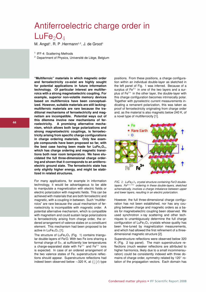
Condensed matter physics • IFF Scientific Report 2008
4444
Antiferroelectric charge order inLuFe2O4M. Angst1, R. P .Hermann1,2, J. de Groot1
1 IFF-4: Scattering Methods2 Department of Physics, Université de Liège, Belgium
“Multiferroic” materials in which magnetic order
and ferroelectricity co-exist are highly sought
for potential applications in future information
technology. Of particular interest are multifer-
roics with a strong magnetoelectric coupling. For
example, superior non-volatile memory devices
based on multiferroics have been conceptual-
ized. However, suitable materials are still lacking:
multiferroic materials are rare because the tra-
ditional mechanisms of ferroelectricity and mag-
netism are incompatible. Potential ways out of
this dilemma involve new mechanisms of fer-
roelectricity. A promising alternative mecha-
nism, which allows both large polarizations and
strong magnetoelectric couplings, is ferroelec-
tricity arising from specific charge configurations
in charge ordering materials. Only few exam-
ple compounds have been proposed so far, with
the best case having been made for LuFe2O4,
which has charge ordering and magnetic transi-
tions both near room temperature. We have elu-
cidated the full three-dimensional charge order-
ing and shown that it corresponds to an antiferro-
electric ground state. The ferroelectric state has
only slightly higher energy, and might be stabi-
lized in related structures.
For many applications, for example in informationtechnology, it would be advantageous to be ableto manipulate a magnetization with electric fields orelectric polarization with magnetic fields. This can beachieved with materials that are both ferroelectric andmagnetic, with a coupling in between. Such “multifer-roics” are rare because the usual mechanism of fer-roelectricity is incompatible with magnetic order. Apotential alternative mechanism, which is compatiblewith magnetism and could sustain large polarizationsis ferroelectricity arising from charge order, the or-dered arrangement of valence states on a constituentelement. This mechanism had been proposed to beactive in LuFe2O4 [1].The structure of LuFe2O4 (Fig. 1) contains triangu-lar double-layers of Fe/O. With two Fe ions sharing aformal charge of 5+, at sufficiently low temperaturesa charge-separated state with Fe2+ and Fe3+ ionsis expected. In case of an ordered arrangement ofthe two valence states of Fe, superstructure reflec-tions should appear. Superstructure reflections hadindeed been observed below ∼320 K, at ( 1
313�) type
positions. From these positions, a charge configura-tion within an individual double-layer as sketched inthe left panel of Fig. 1 was inferred. Because of asurplus of Fe2+ in one of the two layers and a sur-plus of Fe3+ in the other layer, the double-layer withthis charge configuration becomes intrinsically polar.Together with pyroelectric current measurements in-dicating a remanent polarization, this was taken asproof of ferroelectricity originating from charge orderand, as the material is also magnetic below 240 K, ofa novel type of multiferroicity [1].
FIG. 1: LuFe2O4 crystal structure containing Fe/O double-layers. Fe2+/3+ ordering in these double-layers, sketchedschematically, involves a charge imbalance between upperand lower layers, resulting in an electric polarization.
However, the full three-dimensional charge configu-ration has not been established, nor has any cou-pling between charge and magnetic orders as a ba-sis for magnetoelectric coupling been observed. Weused synchrotron x-ray scattering and other tech-niques to unambiguously determine the full chargeconfiguration of LuFe2O4 crystals whose quality hasbeen fine-tuned by magnetization measurements,and which had allowed the first refinement of a three-dimensional magnetic structure [2].Superstructure reflections were observed below 320K (Fig. 2 top panel). The main superstructure re-flections (much weaker reflections are attributed tohigher harmonics, likely due to a small incommensu-ration) could be consistently indexed with three do-mains of charge order, symmetry related by 120◦ ro-tation of the propagation vectors. Each domain has
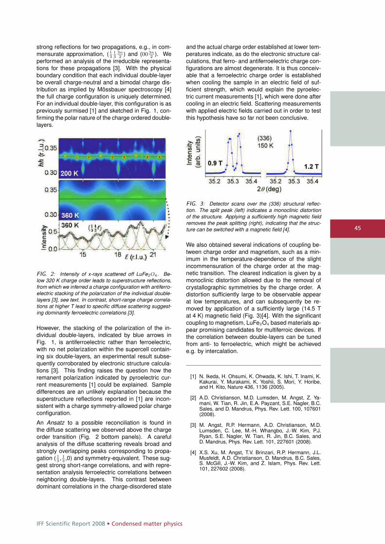
IFF Scientific Report 2008 • Condensed matter physics
45
strong reflections for two propagations, e.g., in com-mensurate approximation, ( 1
313
3n2
) and (00 3n2
). Weperformed an analysis of the irreducible representa-tions for these propagations [3]. With the physicalboundary condition that each individual double-layerbe overall charge-neutral and a bimodal charge dis-tribution as implied by Mössbauer spectroscopy [4]the full charge configuration is uniquely determined.For an individual double-layer, this configuration is aspreviously surmised [1] and sketched in Fig. 1, con-firming the polar nature of the charge ordered double-layers.
FIG. 2: Intensity of x-rays scattered off LuFe2O4. Be-low 320 K charge order leads to superstructure reflections,from which we inferred a charge configuration with antiferro-electric stacking of the polarization of the individual double-layers [3], see text. In contrast, short-range charge correla-tions at higher T lead to specific diffuse scattering suggest-ing dominantly ferroelectric correlations [3].
However, the stacking of the polarization of the in-dividual double-layers, indicated by blue arrows inFig. 1, is antiferroelectric rather than ferroelectric,with no net polarization within the supercell contain-ing six double-layers, an experimental result subse-quently corroborated by electronic structure calcula-tions [3]. This finding raises the question how theremanent polarization indicated by pyroelectric cur-rent measurements [1] could be explained. Sampledifferences are an unlikely explanation because thesuperstructure reflections reported in [1] are incon-sistent with a charge symmetry-allowed polar chargeconfiguration.
An Ansatz to a possible reconciliation is found inthe diffuse scattering we observed above the chargeorder transition (Fig. 2 bottom panels). A carefulanalysis of the diffuse scattering reveals broad andstrongly overlapping peaks corresponding to propa-gation ( 1
3, 13,0) and symmetry-equivalent. These sug-
gest strong short-range correlations, and with repre-sentation analysis ferroelectric correlations betweenneighboring double-layers. This contrast betweendominant correlations in the charge-disordered state
and the actual charge order established at lower tem-peratures indicate, as do the electronic structure cal-culations, that ferro- and antiferroelectric charge con-figurations are almost degenerate. It is thus conceiv-able that a ferroelectric charge order is establishedwhen cooling the sample in an electric field of suf-ficient strength, which would explain the pyroelec-tric current measurements [1], which were done aftercooling in an electric field. Scattering measurementswith applied electric fields carried out in order to testthis hypothesis have so far not been conclusive.
FIG. 3: Detector scans over the (336) structural reflec-tion. The split peak (left) indicates a monoclinic distortionof the structure. Applying a sufficiently high magnetic fieldremoves the peak splitting (right), indicating that the struc-ture can be switched with a magnetic field [4].
We also obtained several indications of coupling be-tween charge order and magnetism, such as a min-imum in the temperature-dependence of the slightincommensuration of the charge order at the mag-netic transition. The clearest indication is given by amonoclinic distortion allowed due to the removal ofcrystallographic symmetries by the charge order. Adistortion sufficiently large to be observable appearat low temperatures, and can subsequently be re-moved by application of a sufficiently large (14.5 Tat 4 K) magnetic field (Fig. 3)[4]. With the significantcoupling to magnetism, LuFe2O4 based materials ap-pear promising candidates for multiferroic devices. Ifthe correlation between double-layers can be tunedfrom anti- to ferroelectric, which might be achievede.g. by intercalation.
[1] N. Ikeda, H. Ohsumi, K. Ohwada, K. Ishi, T. Inami, K.Kakurai, Y. Murakami, K. Yoshii, S. Mori, Y. Horibe,and H. Kito, Nature 436, 1136 (2005).
[2] A.D. Christianson, M.D. Lumsden, M. Angst, Z. Ya-mani, W. Tian, R. Jin, E.A. Payzant, S.E. Nagler, B.C.Sales, and D. Mandrus, Phys. Rev. Lett. 100, 107601(2008).
[3] M. Angst, R.P. Hermann, A.D. Christianson, M.D.Lumsden, C. Lee, M.-H. Whangbo, J.-W. Kim, P.J.Ryan, S.E. Nagler, W. Tian, R. Jin, B.C. Sales, andD. Mandrus, Phys. Rev. Lett. 101, 227601 (2008).
[4] X.S. Xu, M. Angst, T.V. Brinzari, R.P. Hermann, J.L.Musfeldt, A.D. Christianson, D. Mandrus, B.C. Sales,S. McGill, J.-W. Kim, and Z. Islam, Phys. Rev. Lett.101, 227602 (2008).
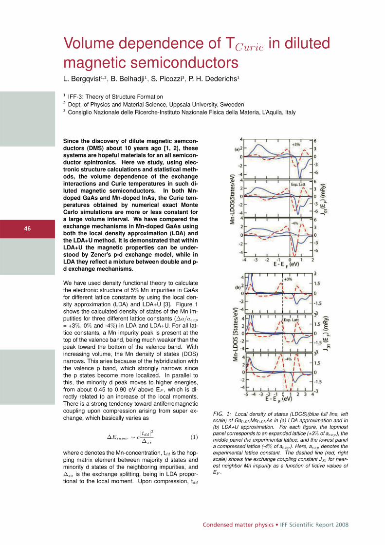
Condensed matter physics • IFF Scientific Report 2008
4646
Volume dependence of TCurie in dilutedmagnetic semiconductorsL. Bergqvist1,2, B. Belhadji1, S. Picozzi3, P. H. Dederichs1
1 IFF-3: Theory of Structure Formation2 Dept. of Physics and Material Science, Uppsala University, Sweeden3 Consiglio Nazionale delle Ricerche-Instituto Nazionale Fisica della Materia, L’Aquila, Italy
Since the discovery of dilute magnetic semcon-ductors (DMS) about 10 years ago [1, 2], thesesystems are hopeful materials for an all semicon-ductor spintronics. Here we study, using elec-tronic structure calculations and statistical meth-ods, the volume dependence of the exchangeinteractions and Curie temperatures in such di-luted magnetic semiconductors. In both Mn-doped GaAs and Mn-doped InAs, the Curie tem-peratures obtained by numerical exact MonteCarlo simulations are more or less constant fora large volume interval. We have compared theexchange mechanisms in Mn-doped GaAs usingboth the local density approximation (LDA) andthe LDA+U method. It is demonstrated that withinLDA+U the magnetic properties can be under-stood by Zener’s p-d exchange model, while inLDA they reflect a mixture between double and p-d exchange mechanisms.
We have used density functional theory to calculatethe electronic structure of 5% Mn impurities in GaAsfor different lattice constants by using the local den-sity approximation (LDA) and LDA+U [3]. Figure 1shows the calculated density of states of the Mn im-putities for three different lattice constants (Δa/aexp
= +3%, 0% and -4%) in LDA and LDA+U. For all lat-tice constants, a Mn impurity peak is present at thetop of the valence band, being much weaker than thepeak toward the bottom of the valence band. Withincreasing volume, the Mn density of states (DOS)narrows. This aries because of the hybridization withthe valence p band, which strongly narrows sincethe p states become more localized. In parallel tothis, the minority d peak moves to higher energies,from about 0.45 to 0.90 eV above EF , which is di-rectly related to an increase of the local moments.There is a strong tendency toward antiferromagneticcoupling upon compression arising from super ex-change, which basically varies as
ΔEsuper ∼ c|tdd|2Δxs
(1)
where c denotes the Mn-concentration, tdd is the hop-ping matrix element between majority d states andminority d states of the neighboring impurities, andΔxs is the exchange splitting, being in LDA propor-tional to the local moment. Upon compression, tdd
FIG. 1: Local density of states (LDOS)(blue full line, leftscale) of Ga0.95Mn0.05As in (a) LDA approximation and in(b) LDA+U approximation. For each figure, the topmostpanel corresponds to an expanded lattice (+3% of aexp), themiddle panel the experimental lattice, and the lowest panela compressed lattice (-4% of aexp). Here, aexp denotes theexperimental lattice constant. The dashed line (red, rightscale) shows the exchange coupling constant J01 for near-est neighbor Mn impurity as a function of fictive values ofEF .
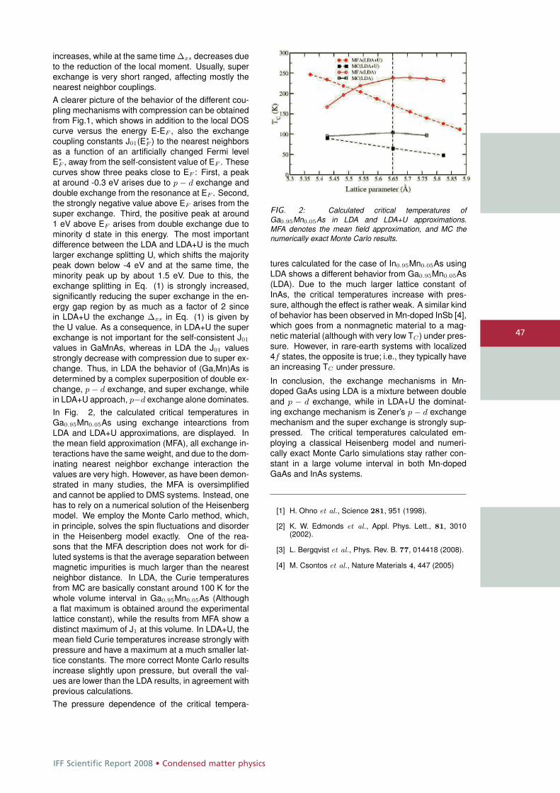
IFF Scientific Report 2008 • Condensed matter physics
47
increases, while at the same time Δxs decreases dueto the reduction of the local moment. Usually, superexchange is very short ranged, affecting mostly thenearest neighbor couplings.A clearer picture of the behavior of the different cou-pling mechanisms with compression can be obtainedfrom Fig.1, which shows in addition to the local DOScurve versus the energy E-EF , also the exchangecoupling constants J01(E∗
F ) to the nearest neighborsas a function of an artificially changed Fermi levelE∗
F , away from the self-consistent value of EF . Thesecurves show three peaks close to EF : First, a peakat around -0.3 eV arises due to p − d exchange anddouble exchange from the resonance at EF . Second,the strongly negative value above EF arises from thesuper exchange. Third, the positive peak at around1 eV above EF arises from double exchange due tominority d state in this energy. The most importantdifference between the LDA and LDA+U is the muchlarger exchange splitting U, which shifts the majoritypeak down below -4 eV and at the same time, theminority peak up by about 1.5 eV. Due to this, theexchange splitting in Eq. (1) is strongly increased,significantly reducing the super exchange in the en-ergy gap region by as much as a factor of 2 sincein LDA+U the exchange Δxs in Eq. (1) is given bythe U value. As a consequence, in LDA+U the superexchange is not important for the self-consistent J01
values in GaMnAs, whereas in LDA the J01 valuesstrongly decrease with compression due to super ex-change. Thus, in LDA the behavior of (Ga,Mn)As isdetermined by a complex superposition of double ex-change, p − d exchange, and super exchange, whilein LDA+U approach, p−d exchange alone dominates.In Fig. 2, the calculated critical temperatures inGa0.95Mn0.05As using exchange intearctions fromLDA and LDA+U approximations, are displayed. Inthe mean field approximation (MFA), all exchange in-teractions have the same weight, and due to the dom-inating nearest neighbor exchange interaction thevalues are very high. However, as have been demon-strated in many studies, the MFA is oversimplifiedand cannot be applied to DMS systems. Instead, onehas to rely on a numerical solution of the Heisenbergmodel. We employ the Monte Carlo method, which,in principle, solves the spin fluctuations and disorderin the Heisenberg model exactly. One of the rea-sons that the MFA description does not work for di-luted systems is that the average separation betweenmagnetic impurities is much larger than the nearestneighbor distance. In LDA, the Curie temperaturesfrom MC are basically constant around 100 K for thewhole volume interval in Ga0.95Mn0.05As (Althougha flat maximum is obtained around the experimentallattice constant), while the results from MFA show adistinct maximum of J1 at this volume. In LDA+U, themean field Curie temperatures increase strongly withpressure and have a maximum at a much smaller lat-tice constants. The more correct Monte Carlo resultsincrease slightly upon pressure, but overall the val-ues are lower than the LDA results, in agreement withprevious calculations.The pressure dependence of the critical tempera-
FIG. 2: Calculated critical temperatures ofGa0.95Mn0.05As in LDA and LDA+U approximations.MFA denotes the mean field approximation, and MC thenumerically exact Monte Carlo results.
tures calculated for the case of In0.95Mn0.05As usingLDA shows a different behavior from Ga0.95Mn0.05As(LDA). Due to the much larger lattice constant ofInAs, the critical temperatures increase with pres-sure, although the effect is rather weak. A similar kindof behavior has been observed in Mn-doped InSb [4],which goes from a nonmagnetic material to a mag-netic material (although with very low TC ) under pres-sure. However, in rare-earth systems with localized4f states, the opposite is true; i.e., they typically havean increasing TC under pressure.
In conclusion, the exchange mechanisms in Mn-doped GaAs using LDA is a mixture between doubleand p − d exchange, while in LDA+U the dominat-ing exchange mechanism is Zener’s p − d exchangemechanism and the super exchange is strongly sup-pressed. The critical temperatures calculated em-ploying a classical Heisenberg model and numeri-cally exact Monte Carlo simulations stay rather con-stant in a large volume interval in both Mn-dopedGaAs and InAs systems.
[1] H. Ohno et al., Science 281, 951 (1998).
[2] K. W. Edmonds et al., Appl. Phys. Lett., 81, 3010(2002).
[3] L. Bergqvist et al., Phys. Rev. B. 77, 014418 (2008).
[4] M. Csontos et al., Nature Materials 4, 447 (2005)
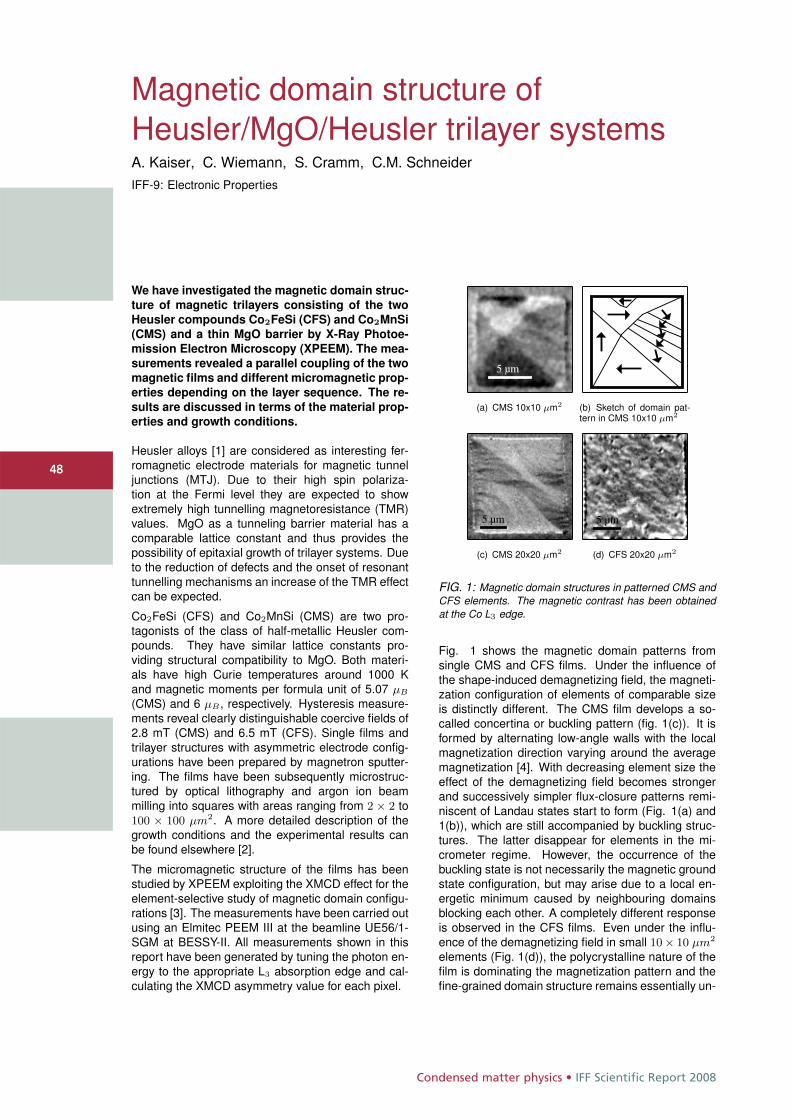
Condensed matter physics • IFF Scientific Report 2008
4848
Magnetic domain structure ofHeusler/MgO/Heusler trilayer systemsA. Kaiser, C. Wiemann, S. Cramm, C.M. SchneiderIFF-9: Electronic Properties
We have investigated the magnetic domain struc-
ture of magnetic trilayers consisting of the two
Heusler compounds Co2FeSi (CFS) and Co2MnSi
(CMS) and a thin MgO barrier by X-Ray Photoe-
mission Electron Microscopy (XPEEM). The mea-
surements revealed a parallel coupling of the two
magnetic films and different micromagnetic prop-
erties depending on the layer sequence. The re-
sults are discussed in terms of the material prop-
erties and growth conditions.
Heusler alloys [1] are considered as interesting fer-romagnetic electrode materials for magnetic tunneljunctions (MTJ). Due to their high spin polariza-tion at the Fermi level they are expected to showextremely high tunnelling magnetoresistance (TMR)values. MgO as a tunneling barrier material has acomparable lattice constant and thus provides thepossibility of epitaxial growth of trilayer systems. Dueto the reduction of defects and the onset of resonanttunnelling mechanisms an increase of the TMR effectcan be expected.
Co2FeSi (CFS) and Co2MnSi (CMS) are two pro-tagonists of the class of half-metallic Heusler com-pounds. They have similar lattice constants pro-viding structural compatibility to MgO. Both materi-als have high Curie temperatures around 1000 Kand magnetic moments per formula unit of 5.07 μB
(CMS) and 6 μB , respectively. Hysteresis measure-ments reveal clearly distinguishable coercive fields of2.8 mT (CMS) and 6.5 mT (CFS). Single films andtrilayer structures with asymmetric electrode config-urations have been prepared by magnetron sputter-ing. The films have been subsequently microstruc-tured by optical lithography and argon ion beammilling into squares with areas ranging from 2 × 2 to100 × 100 μm2. A more detailed description of thegrowth conditions and the experimental results canbe found elsewhere [2].
The micromagnetic structure of the films has beenstudied by XPEEM exploiting the XMCD effect for theelement-selective study of magnetic domain configu-rations [3]. The measurements have been carried outusing an Elmitec PEEM III at the beamline UE56/1-SGM at BESSY-II. All measurements shown in thisreport have been generated by tuning the photon en-ergy to the appropriate L3 absorption edge and cal-culating the XMCD asymmetry value for each pixel.
5 μm
(a) CMS 10x10 μm2 (b) Sketch of domain pat-tern in CMS 10x10 μm2
5 μm
(c) CMS 20x20 μm2
5 μm
(d) CFS 20x20 μm2
FIG. 1: Magnetic domain structures in patterned CMS andCFS elements. The magnetic contrast has been obtainedat the Co L3 edge.
Fig. 1 shows the magnetic domain patterns fromsingle CMS and CFS films. Under the influence ofthe shape-induced demagnetizing field, the magneti-zation configuration of elements of comparable sizeis distinctly different. The CMS film develops a so-called concertina or buckling pattern (fig. 1(c)). It isformed by alternating low-angle walls with the localmagnetization direction varying around the averagemagnetization [4]. With decreasing element size theeffect of the demagnetizing field becomes strongerand successively simpler flux-closure patterns remi-niscent of Landau states start to form (Fig. 1(a) and1(b)), which are still accompanied by buckling struc-tures. The latter disappear for elements in the mi-crometer regime. However, the occurrence of thebuckling state is not necessarily the magnetic groundstate configuration, but may arise due to a local en-ergetic minimum caused by neighbouring domainsblocking each other. A completely different responseis observed in the CFS films. Even under the influ-ence of the demagnetizing field in small 10× 10 μm2
elements (Fig. 1(d)), the polycrystalline nature of thefilm is dominating the magnetization pattern and thefine-grained domain structure remains essentially un-
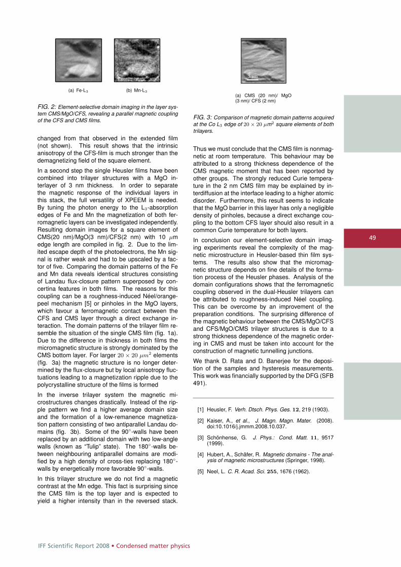
IFF Scientific Report 2008 • Condensed matter physics
49
(a) Fe-L3 (b) Mn-L3
FIG. 2: Element-selective domain imaging in the layer sys-tem CMS/MgO/CFS, revealing a parallel magnetic couplingof the CFS and CMS films.
changed from that observed in the extended film(not shown). This result shows that the intrinsicanisotropy of the CFS-film is much stronger than thedemagnetizing field of the square element.
In a second step the single Heusler films have beencombined into trilayer structures with a MgO in-terlayer of 3 nm thickness. In order to separatethe magnetic response of the individual layers inthis stack, the full versatility of XPEEM is needed.By tuning the photon energy to the L3-absorptionedges of Fe and Mn the magnetization of both fer-romagnetic layers can be investigated independently.Resulting domain images for a square element ofCMS(20 nm)/MgO(3 nm)/CFS(2 nm) with 10 μmedge length are compiled in fig. 2. Due to the lim-ited escape depth of the photoelectrons, the Mn sig-nal is rather weak and had to be upscaled by a fac-tor of five. Comparing the domain patterns of the Feand Mn data reveals identical structures consistingof Landau flux-closure pattern superposed by con-certina features in both films. The reasons for thiscoupling can be a roughness-induced Néel/orange-peel mechanism [5] or pinholes in the MgO layers,which favour a ferromagnetic contact between theCFS and CMS layer through a direct exchange in-teraction. The domain patterns of the trilayer film re-semble the situation of the single CMS film (fig. 1a).Due to the difference in thickness in both films themicromagnetic structure is strongly dominated by theCMS bottom layer. For larger 20 × 20 μm2 elements(fig. 3a) the magnetic structure is no longer deter-mined by the flux-closure but by local anisotropy fluc-tuations leading to a magnetization ripple due to thepolycrystalline structure of the films is formed
In the inverse trilayer system the magnetic mi-crostructures changes drastically. Instead of the rip-ple pattern we find a higher average domain sizeand the formation of a low-remanence magnetiza-tion pattern consisting of two antiparallel Landau do-mains (fig. 3b). Some of the 90◦-walls have beenreplaced by an additional domain with two low-anglewalls (known as “Tulip” state). The 180◦-walls be-tween neighbouring antiparallel domains are modi-fied by a high density of cross-ties replacing 180◦-walls by energetically more favorable 90◦-walls.
In this trilayer structure we do not find a magneticcontrast at the Mn edge. This fact is surprising sincethe CMS film is the top layer and is expected toyield a higher intensity than in the reversed stack.
5 μm
(a) CMS (20 nm)/ MgO(3 nm)/ CFS (2 nm)
FIG. 3: Comparison of magnetic domain patterns acquiredat the Co L3 edge of 20 × 20 μm2 square elements of bothtrilayers.
Thus we must conclude that the CMS film is nonmag-netic at room temperature. This behaviour may beattributed to a strong thickness dependence of theCMS magnetic moment that has been reported byother groups. The strongly reduced Curie tempera-ture in the 2 nm CMS film may be explained by in-terdiffusion at the interface leading to a higher atomicdisorder. Furthermore, this result seems to indicatethat the MgO barrier in this layer has only a negligibledensity of pinholes, because a direct exchange cou-pling to the bottom CFS layer should also result in acommon Curie temperature for both layers.
In conclusion our element-selective domain imag-ing experiments reveal the complexity of the mag-netic microstructure in Heusler-based thin film sys-tems. The results also show that the micromag-netic structure depends on fine details of the forma-tion process of the Heusler phases. Analysis of thedomain configurations shows that the ferromagneticcoupling observed in the dual-Heusler trilayers canbe attributed to roughness-induced Néel coupling.This can be overcome by an improvement of thepreparation conditions. The surprising difference ofthe magnetic behaviour between the CMS/MgO/CFSand CFS/MgO/CMS trilayer structures is due to astrong thickness dependence of the magnetic order-ing in CMS and must be taken into account for theconstruction of magnetic tunnelling junctions.
We thank D. Rata and D. Banerjee for the deposi-tion of the samples and hysteresis measurements.This work was financially supported by the DFG (SFB491).
[1] Heusler, F. Verh. Dtsch. Phys. Ges. 12, 219 (1903).
[2] Kaiser, A., et al., J. Magn. Magn. Mater. (2008).doi:10.1016/j.jmmm.2008.10.037.
[3] Schönhense, G. J. Phys.: Cond. Matt. 11, 9517(1999).
[4] Hubert, A., Schäfer, R. Magnetic domains - The anal-ysis of magnetic microstructures (Springer, 1998).
[5] Neel, L. C. R. Acad. Sci. 255, 1676 (1962).
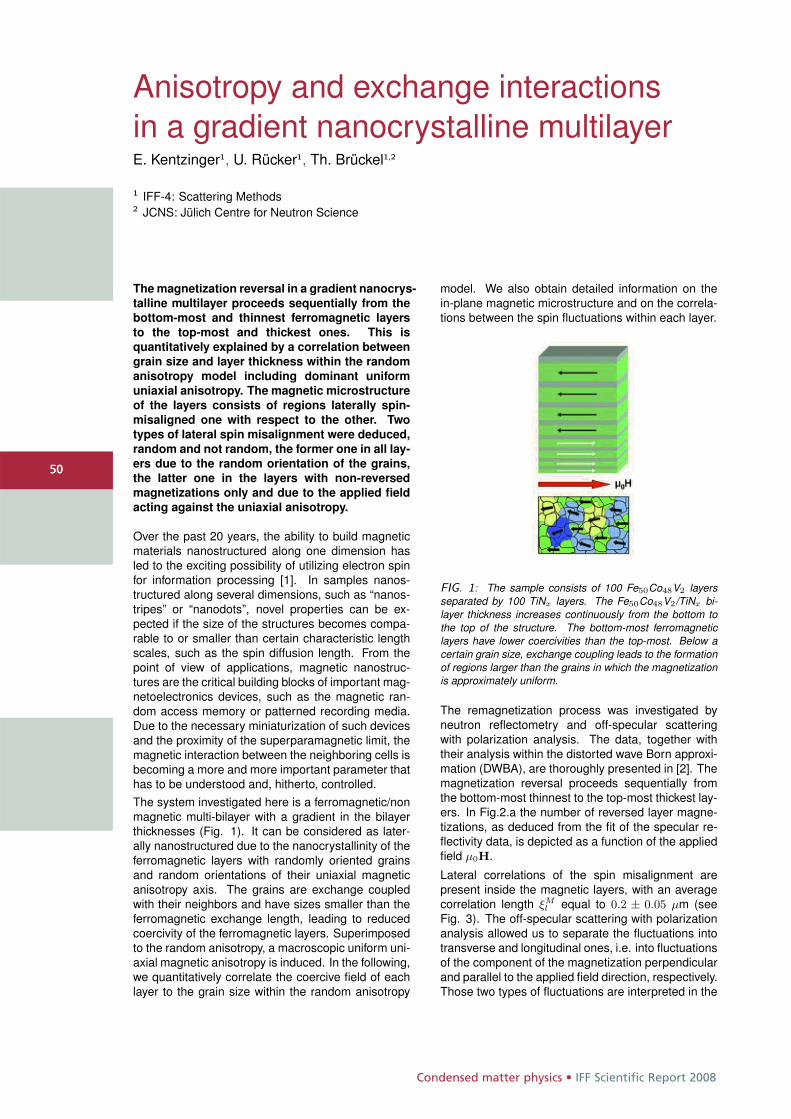
Condensed matter physics • IFF Scientific Report 2008
5050
Anisotropy and exchange interactionsin a gradient nanocrystalline multilayerE. Kentzinger1, U. Rücker1, Th. Brückel1,2
1 IFF-4: Scattering Methods2 JCNS: Jülich Centre for Neutron Science
The magnetization reversal in a gradient nanocrys-
talline multilayer proceeds sequentially from the
bottom-most and thinnest ferromagnetic layers
to the top-most and thickest ones. This is
quantitatively explained by a correlation between
grain size and layer thickness within the random
anisotropy model including dominant uniform
uniaxial anisotropy. The magnetic microstructure
of the layers consists of regions laterally spin-
misaligned one with respect to the other. Two
types of lateral spin misalignment were deduced,
random and not random, the former one in all lay-
ers due to the random orientation of the grains,
the latter one in the layers with non-reversed
magnetizations only and due to the applied field
acting against the uniaxial anisotropy.
Over the past 20 years, the ability to build magneticmaterials nanostructured along one dimension hasled to the exciting possibility of utilizing electron spinfor information processing [1]. In samples nanos-tructured along several dimensions, such as “nanos-tripes” or “nanodots”, novel properties can be ex-pected if the size of the structures becomes compa-rable to or smaller than certain characteristic lengthscales, such as the spin diffusion length. From thepoint of view of applications, magnetic nanostruc-tures are the critical building blocks of important mag-netoelectronics devices, such as the magnetic ran-dom access memory or patterned recording media.Due to the necessary miniaturization of such devicesand the proximity of the superparamagnetic limit, themagnetic interaction between the neighboring cells isbecoming a more and more important parameter thathas to be understood and, hitherto, controlled.The system investigated here is a ferromagnetic/nonmagnetic multi-bilayer with a gradient in the bilayerthicknesses (Fig. 1). It can be considered as later-ally nanostructured due to the nanocrystallinity of theferromagnetic layers with randomly oriented grainsand random orientations of their uniaxial magneticanisotropy axis. The grains are exchange coupledwith their neighbors and have sizes smaller than theferromagnetic exchange length, leading to reducedcoercivity of the ferromagnetic layers. Superimposedto the random anisotropy, a macroscopic uniform uni-axial magnetic anisotropy is induced. In the following,we quantitatively correlate the coercive field of eachlayer to the grain size within the random anisotropy
model. We also obtain detailed information on thein-plane magnetic microstructure and on the correla-tions between the spin fluctuations within each layer.
FIG. 1: The sample consists of 100 Fe50Co48V2 layersseparated by 100 TiNx layers. The Fe50Co48V2/TiNx bi-layer thickness increases continuously from the bottom tothe top of the structure. The bottom-most ferromagneticlayers have lower coercivities than the top-most. Below acertain grain size, exchange coupling leads to the formationof regions larger than the grains in which the magnetizationis approximately uniform.
The remagnetization process was investigated byneutron reflectometry and off-specular scatteringwith polarization analysis. The data, together withtheir analysis within the distorted wave Born approxi-mation (DWBA), are thoroughly presented in [2]. Themagnetization reversal proceeds sequentially fromthe bottom-most thinnest to the top-most thickest lay-ers. In Fig.2.a the number of reversed layer magne-tizations, as deduced from the fit of the specular re-flectivity data, is depicted as a function of the appliedfield μ0H.
Lateral correlations of the spin misalignment arepresent inside the magnetic layers, with an averagecorrelation length ξM
l equal to 0.2 ± 0.05 μm (seeFig. 3). The off-specular scattering with polarizationanalysis allowed us to separate the fluctuations intotransverse and longitudinal ones, i.e. into fluctuationsof the component of the magnetization perpendicularand parallel to the applied field direction, respectively.Those two types of fluctuations are interpreted in the
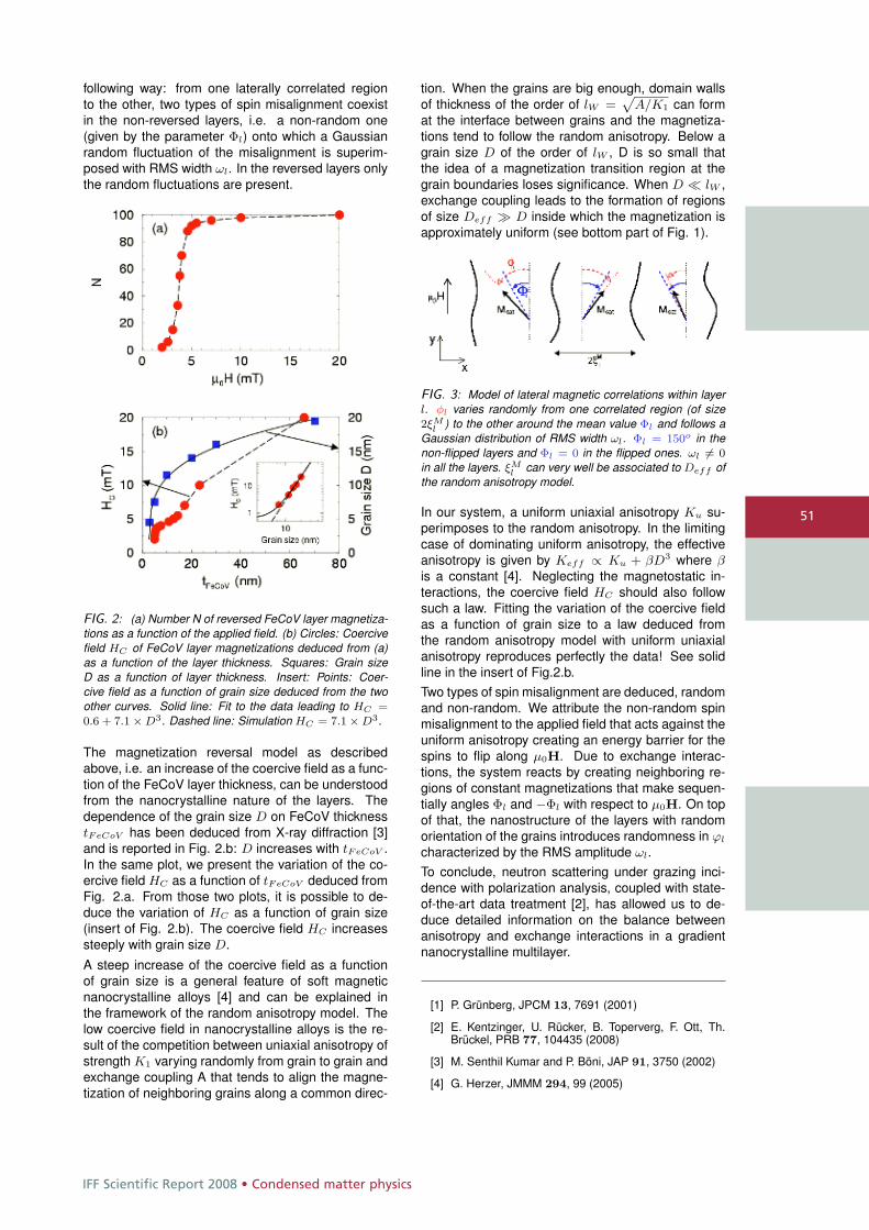
IFF Scientific Report 2008 • Condensed matter physics
51
following way: from one laterally correlated regionto the other, two types of spin misalignment coexistin the non-reversed layers, i.e. a non-random one(given by the parameter Φl) onto which a Gaussianrandom fluctuation of the misalignment is superim-posed with RMS width ωl. In the reversed layers onlythe random fluctuations are present.
FIG. 2: (a) Number N of reversed FeCoV layer magnetiza-tions as a function of the applied field. (b) Circles: Coercivefield HC of FeCoV layer magnetizations deduced from (a)as a function of the layer thickness. Squares: Grain sizeD as a function of layer thickness. Insert: Points: Coer-cive field as a function of grain size deduced from the twoother curves. Solid line: Fit to the data leading to HC =0.6 + 7.1 × D3. Dashed line: Simulation HC = 7.1 × D3.
The magnetization reversal model as describedabove, i.e. an increase of the coercive field as a func-tion of the FeCoV layer thickness, can be understoodfrom the nanocrystalline nature of the layers. Thedependence of the grain size D on FeCoV thicknesstFeCoV has been deduced from X-ray diffraction [3]and is reported in Fig. 2.b: D increases with tFeCoV .In the same plot, we present the variation of the co-ercive field HC as a function of tFeCoV deduced fromFig. 2.a. From those two plots, it is possible to de-duce the variation of HC as a function of grain size(insert of Fig. 2.b). The coercive field HC increasessteeply with grain size D.
A steep increase of the coercive field as a functionof grain size is a general feature of soft magneticnanocrystalline alloys [4] and can be explained inthe framework of the random anisotropy model. Thelow coercive field in nanocrystalline alloys is the re-sult of the competition between uniaxial anisotropy ofstrength K1 varying randomly from grain to grain andexchange coupling A that tends to align the magne-tization of neighboring grains along a common direc-
tion. When the grains are big enough, domain wallsof thickness of the order of lW =
pA/K1 can form
at the interface between grains and the magnetiza-tions tend to follow the random anisotropy. Below agrain size D of the order of lW , D is so small thatthe idea of a magnetization transition region at thegrain boundaries loses significance. When D � lW ,exchange coupling leads to the formation of regionsof size Deff � D inside which the magnetization isapproximately uniform (see bottom part of Fig. 1).
FIG. 3: Model of lateral magnetic correlations within layerl. φl varies randomly from one correlated region (of size2ξM
l ) to the other around the mean value Φl and follows aGaussian distribution of RMS width ωl. Φl = 150o in thenon-flipped layers and Φl = 0 in the flipped ones. ωl �= 0
in all the layers. ξMl can very well be associated to Deff of
the random anisotropy model.
In our system, a uniform uniaxial anisotropy Ku su-perimposes to the random anisotropy. In the limitingcase of dominating uniform anisotropy, the effectiveanisotropy is given by Keff ∝ Ku + βD3 where βis a constant [4]. Neglecting the magnetostatic in-teractions, the coercive field HC should also followsuch a law. Fitting the variation of the coercive fieldas a function of grain size to a law deduced fromthe random anisotropy model with uniform uniaxialanisotropy reproduces perfectly the data! See solidline in the insert of Fig.2.b.Two types of spin misalignment are deduced, randomand non-random. We attribute the non-random spinmisalignment to the applied field that acts against theuniform anisotropy creating an energy barrier for thespins to flip along μ0H. Due to exchange interac-tions, the system reacts by creating neighboring re-gions of constant magnetizations that make sequen-tially angles Φl and −Φl with respect to μ0H. On topof that, the nanostructure of the layers with randomorientation of the grains introduces randomness in ϕl
characterized by the RMS amplitude ωl.To conclude, neutron scattering under grazing inci-dence with polarization analysis, coupled with state-of-the-art data treatment [2], has allowed us to de-duce detailed information on the balance betweenanisotropy and exchange interactions in a gradientnanocrystalline multilayer.
[1] P. Grünberg, JPCM 13, 7691 (2001)
[2] E. Kentzinger, U. Rücker, B. Toperverg, F. Ott, Th.Brückel, PRB 77, 104435 (2008)
[3] M. Senthil Kumar and P. Böni, JAP 91, 3750 (2002)
[4] G. Herzer, JMMM 294, 99 (2005)
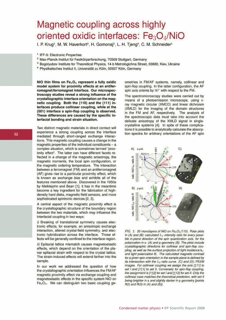
Condensed matter physics • IFF Scientific Report 2008
5252
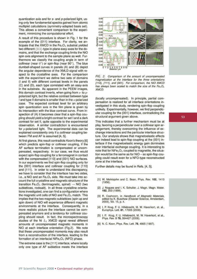
IFF Scientific Report 2008 • Condensed matter physics
53
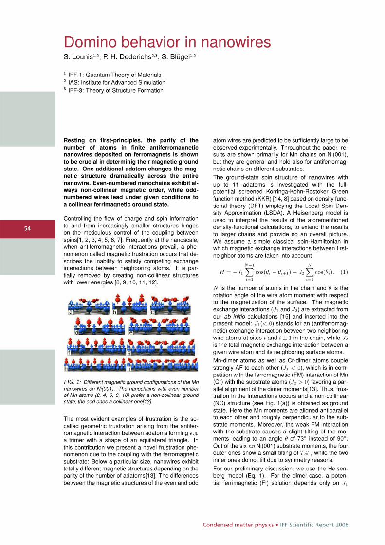
Condensed matter physics • IFF Scientific Report 2008
5454
Domino behavior in nanowiresS. Lounis1,2, P. H. Dederichs2,3, S. Blügel1,2
1 IFF-1: Quantum Theory of Materials2 IAS: Institute for Advanced Simulation3 IFF-3: Theory of Structure Formation
Resting on first-principles, the parity of thenumber of atoms in finite antiferromagneticnanowires deposited on ferromagnets is shownto be crucial in determinig their magnetic groundstate. One additional adatom changes the mag-netic structure dramatically across the entirenanowire. Even-numbered nanochains exhibit al-ways non-collinear magnetic order, while odd-numbered wires lead under given conditions toa collinear ferrimagnetic ground state.
Controlling the flow of charge and spin informationto and from increasingly smaller structures hingeson the meticulous control of the coupling betweenspins[1, 2, 3, 4, 5, 6, 7]. Frequently at the nanoscale,when antiferromagnetic interactions prevail, a phe-nomenon called magnetic frustration occurs that de-scribes the inability to satisfy competing exchangeinteractions between neighboring atoms. It is par-tially removed by creating non-collinear structureswith lower energies [8, 9, 10, 11, 12].
FIG. 1: Different magnetic ground configurations of the Mnnanowires on Ni(001). The nanochains with even numberof Mn atoms (2, 4, 6, 8, 10) prefer a non-collinear groundstate, the odd ones a collinear one[13].
The most evident examples of frustration is the so-called geometric frustration arising from the antifer-romagnetic interaction between adatoms forming e.g.a trimer with a shape of an equilateral triangle. Inthis contribution we present a novel frustration phe-nomenon due to the coupling with the ferromagneticsubstrate: Below a particular size, nanowires exhibittotally different magnetic structures depending on theparity of the number of adatoms[13]. The differencesbetween the magnetic structures of the even and odd
atom wires are predicted to be sufficiently large to beobserved experimentally. Throughout the paper, re-sults are shown primarily for Mn chains on Ni(001),but they are general and hold also for antiferromag-netic chains on different substrates.The ground-state spin structure of nanowires withup to 11 adatoms is investigated with the full-potential screened Korringa-Kohn-Rostoker Greenfunction method (KKR) [14, 8] based on density func-tional theory (DFT) employing the Local Spin Den-sity Approximation (LSDA). A Heisenberg model isused to interpret the results of the aforementioneddensity-functional calculations, to extend the resultsto larger chains and provide so an overall picture.We assume a simple classical spin-Hamiltonian inwhich magnetic exchange interactions between first-neighbor atoms are taken into account
H = −J1
N−1X
i=1
cos(θi − θi+1) − J2
NX
i=1
cos(θi). (1)
N is the number of atoms in the chain and θ is therotation angle of the wire atom moment with respectto the magnetization of the surface. The magneticexchange interactions (J1 and J2) are extracted fromour ab initio calculations [15] and inserted into thepresent model: J1(< 0) stands for an (antiferromag-netic) exchange interaction between two neighboringwire atoms at sites i and i ± 1 in the chain, while J2
is the total magnetic exchange interaction between agiven wire atom and its neighboring surface atoms.Mn-dimer atoms as well as Cr-dimer atoms couplestrongly AF to each other (J1 < 0), which is in com-petition with the ferromagnetic (FM) interaction of Mn(Cr) with the substrate atoms (J2 > 0) favoring a par-allel alignment of the dimer moments[13]. Thus, frus-tration in the interactions occurs and a non-collinear(NC) structure (see Fig. 1(a)) is obtained as groundstate. Here the Mn moments are aligned antiparallelto each other and roughly perpendicular to the sub-strate moments. Moreover, the weak FM interactionwith the substrate causes a slight tilting of the mo-ments leading to an angle θ of 73◦ instead of 90◦.Out of the six nn Ni(001) substrate moments, the fourouter ones show a small tilting of 7.4◦, while the twoinner ones do not tilt due to symmetry reasons.For our preliminary discussion, we use the Heisen-berg model (Eq. 1). For the dimer-case, a poten-tial ferrimagnetic (FI) solution depends only on J1
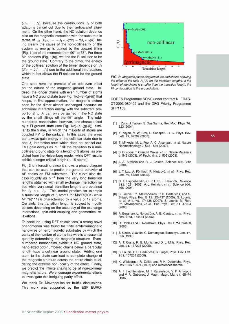
IFF Scientific Report 2008 • Condensed matter physics
55
(EFI = J1), because the contributions J2 of bothadatoms cancel out due to their antiparallel align-ment. On the other hand, the NC solution dependsalso on the magnetic interaction with the substrate interms of J2 (ENC = −J1 cos(2θ) − 2J2 cos(θ)) be-ing clearly the cause of the non-collinearity of thesystem as energy is gained by the upward tilting(Fig. 1(a)) of the moments from 90◦ to 73◦. For threeMn adatoms (Fig. 1(b)), we find the FI solution to bethe ground state. Contrary to the dimer, the energyof the collinear solution of the trimer depends on J2
(EFI = 2J1 − J2) due to the additional third adatom,which in fact allows the FI solution to be the groundstate.
One sees here the premise of an odd-even effecton the nature of the magnetic ground state. In-deed, the longer chains with even number of atomshave a NC ground state (see Fig. 1(c)-(e)-(g)-(i)) thatkeeps, in first approximation, the magnetic pictureseen for the dimer almost unchanged because anadditional interaction energy with the substrate pro-portional to J2 can only be gained in the NC stateby the small tiltings off the 90o angle. The odd-numbered nanochains, however, are characterizedby a FI ground state (see Fig. 1(c)-(e)-(g)-(i)), simi-lar to the trimer, in which the majority of atoms arecoupled FM to the surface. In this case, the wirescan always gain energy in the collinear state due toone J2 interaction term which does not cancel out.This gain decays as N−1 till the transition to a non-collinear ground state for a length of 9 atoms, as pre-dicted from the Heisenberg model, while DFT resultsexhibit a longer critical length (∼ 16 atoms).
Fig. 2 is interesting since it shows a phase diagramthat can be used to predict the general behavior ofAF chains on FM substrates. The curve also de-cays roughly as N−1 from the very long transitionlengths obtained with small exchange interaction ra-tios while very small transition lengths are obtainedfor J2 >> J1. This model predicts for examplea transition length of 5 atoms for Mn/Fe(001) whileMn/Ni(111) is characterized by a value of 17 atoms.Certainly, this transition length is subject to modifi-cations depending on the accuracy of the exchangeinteractions, spin-orbit coupling and geometrical re-laxations.
To conclude, using DFT calculations, a strong novelphenomenon was found for finite antiferromagneticnanowires on ferromagnetic substrates by which theparity of the number of atoms in a wire is an essentialquantity determining the magnetic structure. Even-numbered nanochains exhibit a NC ground state,nano-sized odd-numbered chains below a particularlength have a collinear ground state. Adding oneatom to the chain can lead to complete change ofthe magnetic structure across the entire chain eluci-dating the extreme non-locality of the effect. Finally,we predict the infinite chains to be of non-collinearmagnetic nature. We encourage experimental effortsto investigate this intriguing parity effect.
We thank Dr. Mavropoulos for fruitful discussions.This work was supported by the ESF EURO-
FIG. 2: Magnetic phase diagram of the odd chains showingthe effect of the ratio J2/J1 on the transition lengths. If thelength of the chains is smaller than the transition length, theFI configuration is the ground state.
CORES Programme SONS under contract N. ERAS-CT-2003-980409 and the DFG Priority ProgrammeSPP1153.
[1] I. Zutic, J. Fabian, S. Das Sarma, Rev. Mod. Phys. 76,323 (2004).
[2] Y. Yayon, V. W. Brar, L. Senapati, et al. Phys. Rev.Lett. 99, 67202 (2007).
[3] T. Mirkovic, M. L. Foo, A. C. Arsenault, et al. NatureNanotechnology 2, 565 - 569 (2007).
[4] S. Rusponi, T. Cren, N. Weiss, et al. Nature Materials2, 546 (2003); W. Kuch, ibid. 2, 505 (2003).
[5] J. A. Stroscio and R. J. Celotta, Science 306, 242(2004).
[6] J. T. Lau, A. Föhlisch, R. Nietubyc, et al. Phys. Rev.Lett. 89, 57201 (2002).
[7] C. F. Hirjibehendin, C. P. Lutz, J. Heinrich, Science312, 1021 (2006); A. J. Heinrich, et al. Science 306,466 (2004).
[8] S. Lounis, Ph. Mavropoulos, P. H. Dederichs, and S.Blügel, Phys. Rev. B 72, 224437 (2005); S. Lounis,et al. ibid. 75, 174436 (2007); S. Lounis, M. Reif,Ph. Mavropoulos, et al. Eur. Phys. Lett. 81, 47004(2008).
[9] A. Bergman, L. Nordström, A. B. Klautau, et al. Phys.Rev. B 73, 174434 (2006).
[10] R. Robles and L. Nordström, Phys. Rev. B 74 094403(2006).
[11] S. Uzdin, V. Uzdin, C. Demangeat, Europhys. Lett. 47,556 (1999).
[12] A. T. Costa, R. B. Muniz, and D. L. Mills, Phys. Rev.Lett. 94, 137203 (2005).
[13] S. Lounis, P. H. Dederichs, S. Blügel, Phys. Rev. Lett.101, 107204 (2008).
[14] K. Wildberger, R. Zeller, and P. H. Dederichs, Phys.Rev. B 55 10074 (1997) and references therein.
[15] A. I. Liechtenstein, M. I. Katsnelson, V. P. Antropovand V. A. Gubanov, J. Magn. Magn. Mat 67, 65–74(1987).
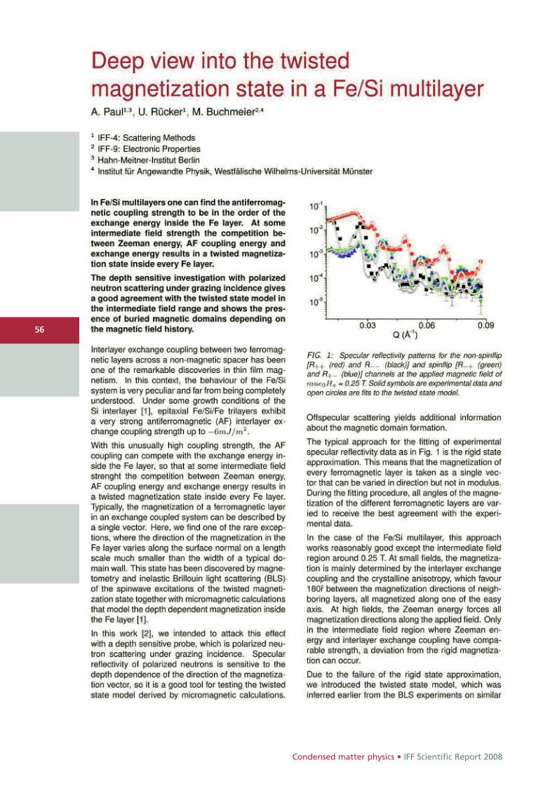
Condensed matter physics • IFF Scientific Report 2008
5656
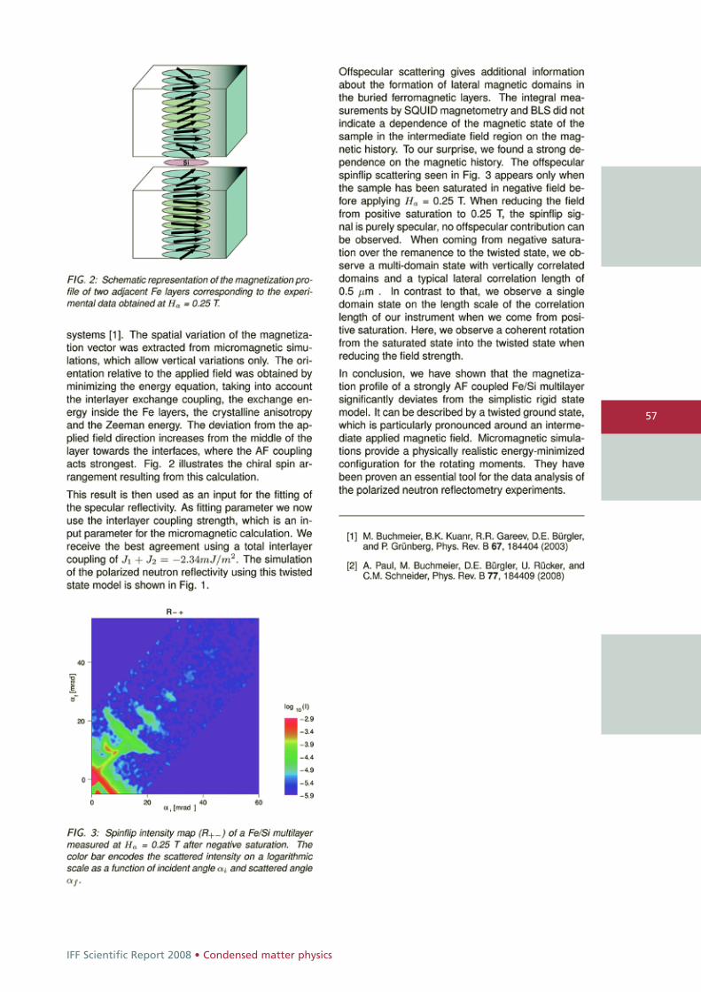
IFF Scientific Report 2008 • Condensed matter physics
57
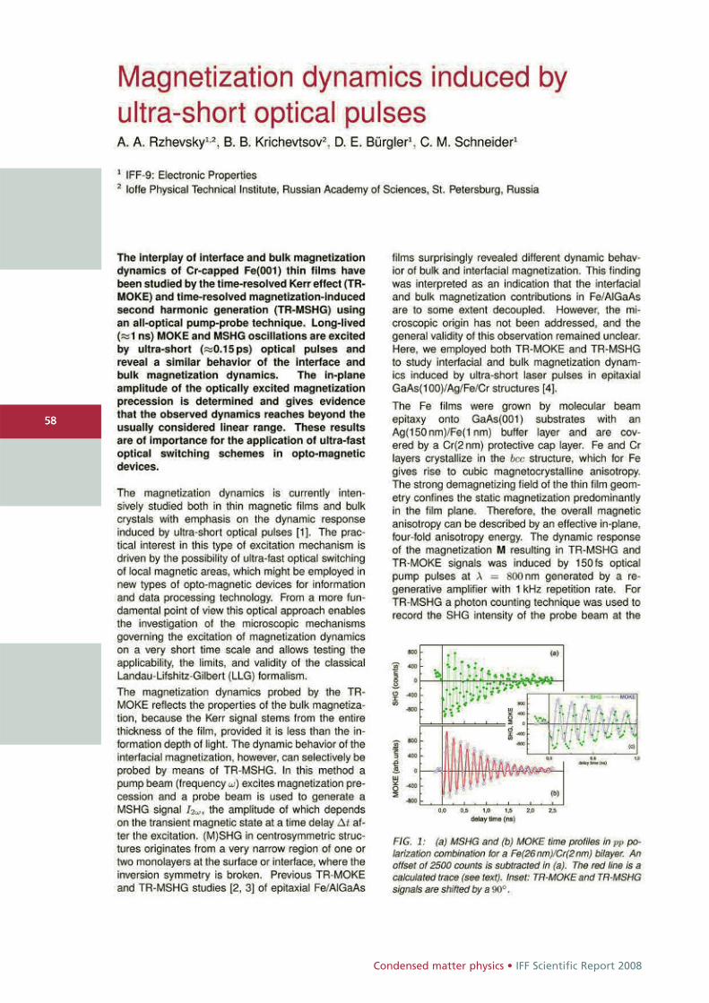
Condensed matter physics • IFF Scientific Report 2008
5858
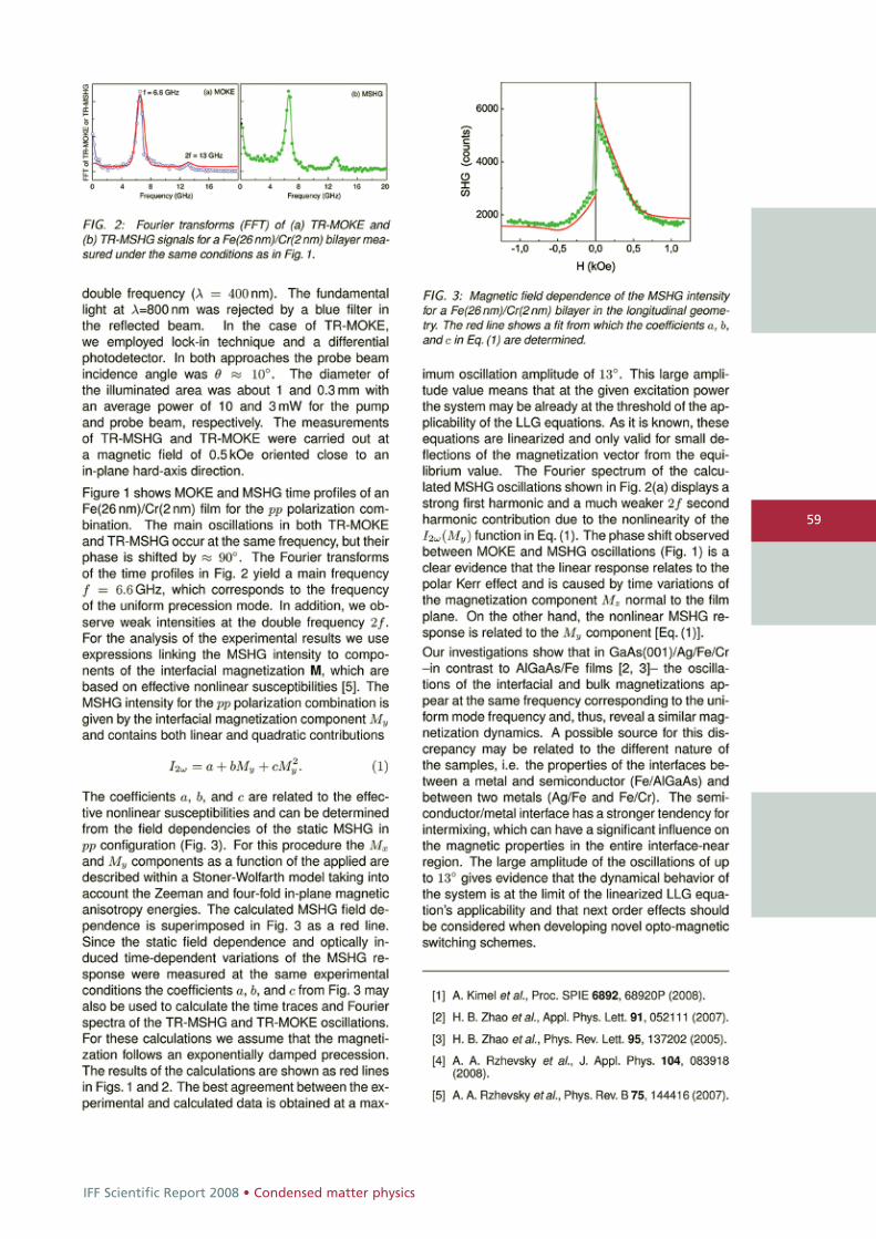
IFF Scientific Report 2008 • Condensed matter physics
59
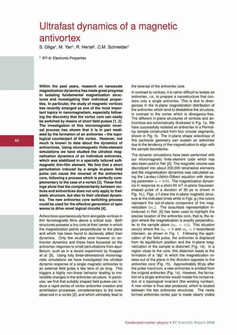
Condensed matter physics • IFF Scientific Report 2008
6060
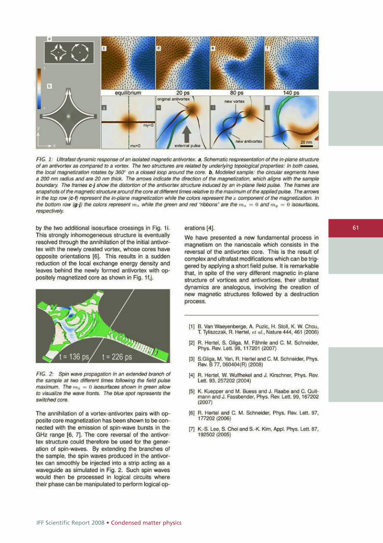
IFF Scientific Report 2008 • Condensed matter physics
61
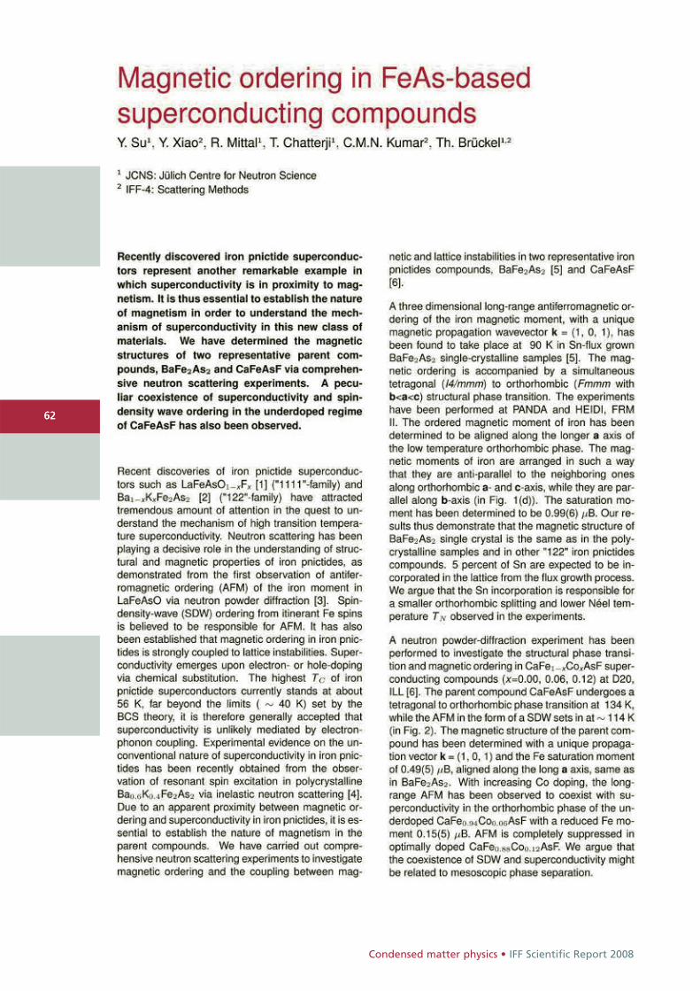
Condensed matter physics • IFF Scientific Report 2008
6262
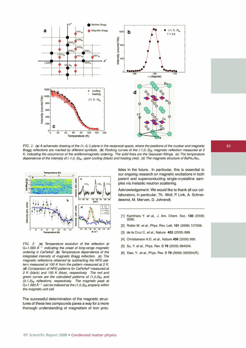
IFF Scientific Report 2008 • Condensed matter physics
63
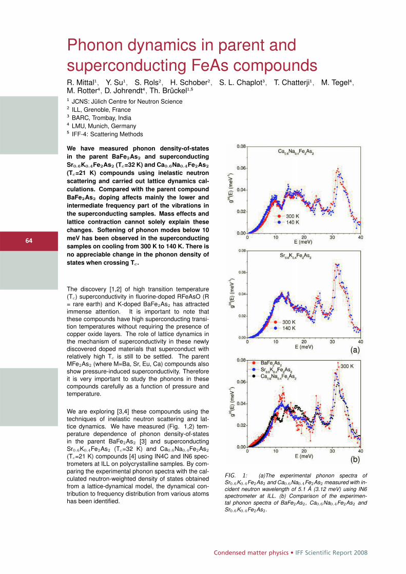
Condensed matter physics • IFF Scientific Report 2008
6464
Phonon dynamics in parent andsuperconducting FeAs compoundsR. Mittal1, Y. Su1, S. Rols2, H. Schober2, S. L. Chaplot3, T. Chatterji1, M. Tegel4,M. Rotter4, D. Johrendt4, Th. Brückel1,5
1 JCNS: Jülich Centre for Neutron Science2 ILL, Grenoble, France3 BARC, Trombay, India4 LMU, Munich, Germany5 IFF-4: Scattering Methods
We have measured phonon density-of-states
in the parent BaFe2As2 and superconducting
Sr0.6K0.4Fe2As2 (Tc=32 K) and Ca0.6Na0.4Fe2As2
(Tc=21 K) compounds using inelastic neutron
scattering and carried out lattice dynamics cal-
culations. Compared with the parent compound
BaFe2As2 doping affects mainly the lower and
intermediate frequency part of the vibrations in
the superconducting samples. Mass effects and
lattice contraction cannot solely explain these
changes. Softening of phonon modes below 10
meV has been observed in the superconducting
samples on cooling from 300 K to 140 K. There is
no appreciable change in the phonon density of
states when crossing Tc .
The discovery [1,2] of high transition temperature(Tc) superconductivity in fluorine-doped RFeAsO (R= rare earth) and K-doped BaFe2As2 has attractedimmense attention. It is important to note thatthese compounds have high superconducting transi-tion temperatures without requiring the presence ofcopper oxide layers. The role of lattice dynamics inthe mechanism of superconductivity in these newlydiscovered doped materials that superconduct withrelatively high Tc is still to be settled. The parentMFe2As2 (where M=Ba, Sr, Eu, Ca) compounds alsoshow pressure-induced superconductivity. Thereforeit is very important to study the phonons in thesecompounds carefully as a function of pressure andtemperature.
We are exploring [3,4] these compounds using thetechniques of inelastic neutron scattering and lat-tice dynamics. We have measured (Fig. 1,2) tem-perature dependence of phonon density-of-statesin the parent BaFe2As2 [3] and superconductingSr0.6K0.4Fe2As2 (Tc=32 K) and Ca0.6Na0.4Fe2As2
(Tc=21 K) compounds [4] using IN4C and IN6 spec-trometers at ILL on polycrystalline samples. By com-paring the experimental phonon spectra with the cal-culated neutron-weighted density of states obtainedfrom a lattice-dynamical model, the dynamical con-tribution to frequency distribution from various atomshas been identified.
FIG. 1: (a)The experimental phonon spectra ofSr0.6K0.4Fe2As2 and Ca0.6Na0.4Fe2As2 measured with in-cident neutron wavelength of 5.1 Å (3.12 meV) using IN6spectrometer at ILL. (b) Comparison of the experimen-tal phonon spectra of BaFe2As2, Ca0.6Na0.4Fe2As2 andSr0.6K0.4Fe2As2.
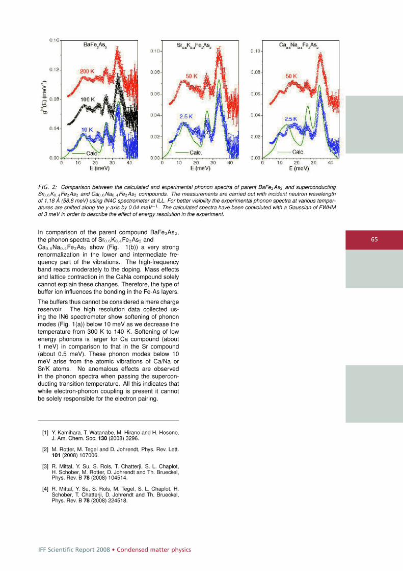
IFF Scientific Report 2008 • Condensed matter physics
65
FIG. 2: Comparison between the calculated and experimental phonon spectra of parent BaFe2As2 and superconductingSr0.6K0.4Fe2As2 and Ca0.6Na0.4Fe2As2 compounds. The measurements are carried out with incident neutron wavelengthof 1.18 Å (58.8 meV) using IN4C spectrometer at ILL. For better visibility the experimental phonon spectra at various temper-atures are shifted along the y-axis by 0.04 meV−1. The calculated spectra have been convoluted with a Gaussian of FWHMof 3 meV in order to describe the effect of energy resolution in the experiment.
In comparison of the parent compound BaFe2As2,the phonon spectra of Sr0.6K0.4Fe2As2 andCa0.6Na0.4Fe2As2 show (Fig. 1(b)) a very strongrenormalization in the lower and intermediate fre-quency part of the vibrations. The high-frequencyband reacts moderately to the doping. Mass effectsand lattice contraction in the CaNa compound solelycannot explain these changes. Therefore, the type ofbuffer ion influences the bonding in the Fe-As layers.
The buffers thus cannot be considered a mere chargereservoir. The high resolution data collected us-ing the IN6 spectrometer show softening of phononmodes (Fig. 1(a)) below 10 meV as we decrease thetemperature from 300 K to 140 K. Softening of lowenergy phonons is larger for Ca compound (about1 meV) in comparison to that in the Sr compound(about 0.5 meV). These phonon modes below 10meV arise from the atomic vibrations of Ca/Na orSr/K atoms. No anomalous effects are observedin the phonon spectra when passing the supercon-ducting transition temperature. All this indicates thatwhile electron-phonon coupling is present it cannotbe solely responsible for the electron pairing.
[1] Y. Kamihara, T. Watanabe, M. Hirano and H. Hosono,J. Am. Chem. Soc. 130 (2008) 3296.
[2] M. Rotter, M. Tegel and D. Johrendt, Phys. Rev. Lett.101 (2008) 107006.
[3] R. Mittal, Y. Su, S. Rols, T. Chatterji, S. L. Chaplot,H. Schober, M. Rotter, D. Johrendt and Th. Brueckel,Phys. Rev. B 78 (2008) 104514.
[4] R. Mittal, Y. Su, S. Rols, M. Tegel, S. L. Chaplot, H.Schober, T. Chatterji, D. Johrendt and Th. Brueckel,Phys. Rev. B 78 (2008) 224518.
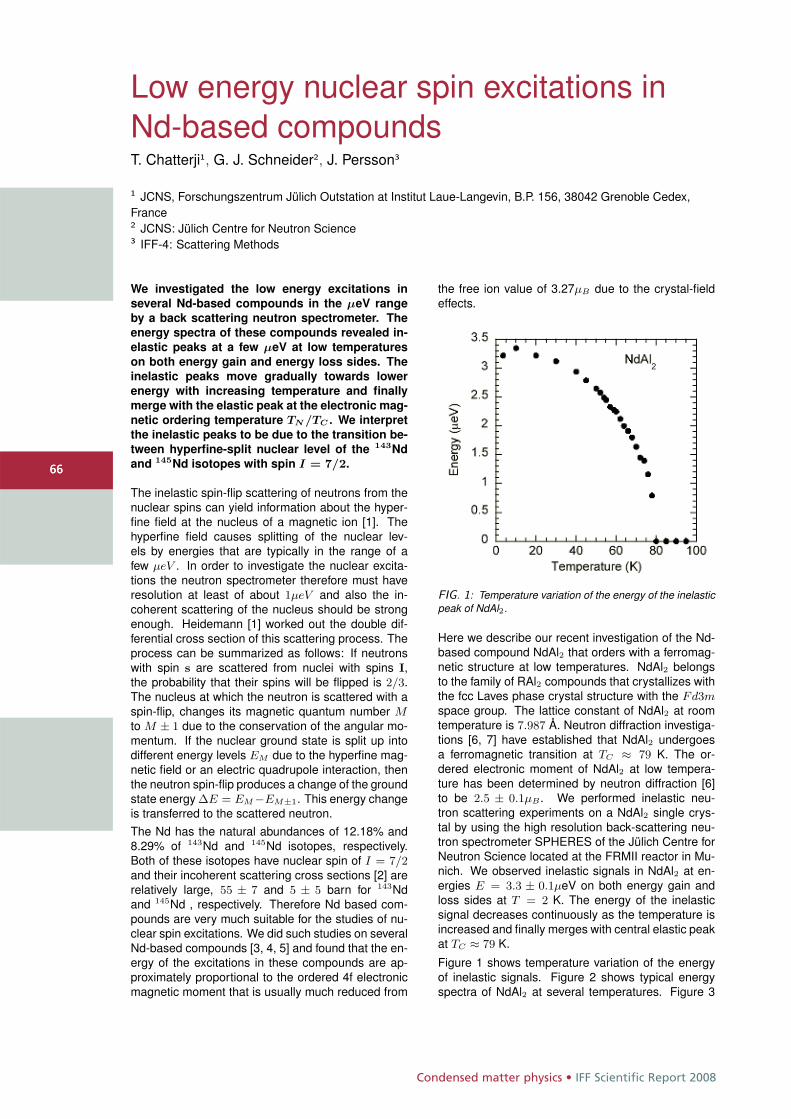
Condensed matter physics • IFF Scientific Report 2008
6666
Low energy nuclear spin excitations inNd-based compoundsT. Chatterji1, G. J. Schneider2, J. Persson3
1 JCNS, Forschungszentrum Jülich Outstation at Institut Laue-Langevin, B.P. 156, 38042 Grenoble Cedex,France2 JCNS: Jülich Centre for Neutron Science3 IFF-4: Scattering Methods
We investigated the low energy excitations in
several Nd-based compounds in the μeV range
by a back scattering neutron spectrometer. The
energy spectra of these compounds revealed in-
elastic peaks at a few μeV at low temperatures
on both energy gain and energy loss sides. The
inelastic peaks move gradually towards lower
energy with increasing temperature and finally
merge with the elastic peak at the electronic mag-
netic ordering temperature TN /TC . We interpret
the inelastic peaks to be due to the transition be-
tween hyperfine-split nuclear level of the 143Nd
and 145Nd isotopes with spin I = 7/2.
The inelastic spin-flip scattering of neutrons from thenuclear spins can yield information about the hyper-fine field at the nucleus of a magnetic ion [1]. Thehyperfine field causes splitting of the nuclear lev-els by energies that are typically in the range of afew μeV . In order to investigate the nuclear excita-tions the neutron spectrometer therefore must haveresolution at least of about 1μeV and also the in-coherent scattering of the nucleus should be strongenough. Heidemann [1] worked out the double dif-ferential cross section of this scattering process. Theprocess can be summarized as follows: If neutronswith spin s are scattered from nuclei with spins I,the probability that their spins will be flipped is 2/3.The nucleus at which the neutron is scattered with aspin-flip, changes its magnetic quantum number Mto M ± 1 due to the conservation of the angular mo-mentum. If the nuclear ground state is split up intodifferent energy levels EM due to the hyperfine mag-netic field or an electric quadrupole interaction, thenthe neutron spin-flip produces a change of the groundstate energy ΔE = EM−EM±1. This energy changeis transferred to the scattered neutron.The Nd has the natural abundances of 12.18% and8.29% of 143Nd and 145Nd isotopes, respectively.Both of these isotopes have nuclear spin of I = 7/2and their incoherent scattering cross sections [2] arerelatively large, 55 ± 7 and 5 ± 5 barn for 143Ndand 145Nd , respectively. Therefore Nd based com-pounds are very much suitable for the studies of nu-clear spin excitations. We did such studies on severalNd-based compounds [3, 4, 5] and found that the en-ergy of the excitations in these compounds are ap-proximately proportional to the ordered 4f electronicmagnetic moment that is usually much reduced from
the free ion value of 3.27μB due to the crystal-fieldeffects.
FIG. 1: Temperature variation of the energy of the inelasticpeak of NdAl2.
Here we describe our recent investigation of the Nd-based compound NdAl2 that orders with a ferromag-netic structure at low temperatures. NdAl2 belongsto the family of RAl2 compounds that crystallizes withthe fcc Laves phase crystal structure with the Fd3mspace group. The lattice constant of NdAl2 at roomtemperature is 7.987 Å. Neutron diffraction investiga-tions [6, 7] have established that NdAl2 undergoesa ferromagnetic transition at TC ≈ 79 K. The or-dered electronic moment of NdAl2 at low tempera-ture has been determined by neutron diffraction [6]to be 2.5 ± 0.1μB . We performed inelastic neu-tron scattering experiments on a NdAl2 single crys-tal by using the high resolution back-scattering neu-tron spectrometer SPHERES of the Jülich Centre forNeutron Science located at the FRMII reactor in Mu-nich. We observed inelastic signals in NdAl2 at en-ergies E = 3.3 ± 0.1μeV on both energy gain andloss sides at T = 2 K. The energy of the inelasticsignal decreases continuously as the temperature isincreased and finally merges with central elastic peakat TC ≈ 79 K.
Figure 1 shows temperature variation of the energyof inelastic signals. Figure 2 shows typical energyspectra of NdAl2 at several temperatures. Figure 3
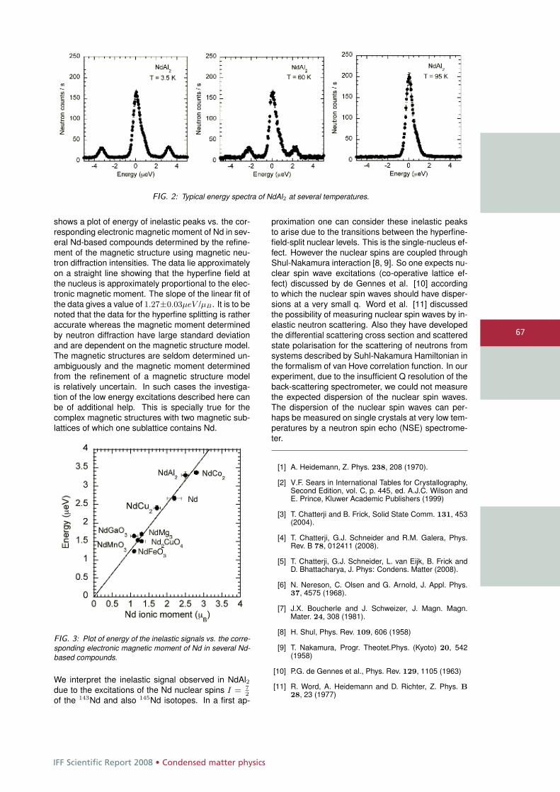
IFF Scientific Report 2008 • Condensed matter physics
67
FIG. 2: Typical energy spectra of NdAl2 at several temperatures.
shows a plot of energy of inelastic peaks vs. the cor-responding electronic magnetic moment of Nd in sev-eral Nd-based compounds determined by the refine-ment of the magnetic structure using magnetic neu-tron diffraction intensities. The data lie approximatelyon a straight line showing that the hyperfine field atthe nucleus is approximately proportional to the elec-tronic magnetic moment. The slope of the linear fit ofthe data gives a value of 1.27±0.03μeV /μB . It is to benoted that the data for the hyperfine splitting is ratheraccurate whereas the magnetic moment determinedby neutron diffraction have large standard deviationand are dependent on the magnetic structure model.The magnetic structures are seldom determined un-ambiguously and the magnetic moment determinedfrom the refinement of a magnetic structure modelis relatively uncertain. In such cases the investiga-tion of the low energy excitations described here canbe of additional help. This is specially true for thecomplex magnetic structures with two magnetic sub-lattices of which one sublattice contains Nd.
FIG. 3: Plot of energy of the inelastic signals vs. the corre-sponding electronic magnetic moment of Nd in several Nd-based compounds.
We interpret the inelastic signal observed in NdAl2due to the excitations of the Nd nuclear spins I = 7
2
of the 143Nd and also 145Nd isotopes. In a first ap-
proximation one can consider these inelastic peaksto arise due to the transitions between the hyperfine-field-split nuclear levels. This is the single-nucleus ef-fect. However the nuclear spins are coupled throughShul-Nakamura interaction [8, 9]. So one expects nu-clear spin wave excitations (co-operative lattice ef-fect) discussed by de Gennes et al. [10] accordingto which the nuclear spin waves should have disper-sions at a very small q. Word et al. [11] discussedthe possibility of measuring nuclear spin waves by in-elastic neutron scattering. Also they have developedthe differential scattering cross section and scatteredstate polarisation for the scattering of neutrons fromsystems described by Suhl-Nakamura Hamiltonian inthe formalism of van Hove correlation function. In ourexperiment, due to the insufficient Q resolution of theback-scattering spectrometer, we could not measurethe expected dispersion of the nuclear spin waves.The dispersion of the nuclear spin waves can per-haps be measured on single crystals at very low tem-peratures by a neutron spin echo (NSE) spectrome-ter.
[1] A. Heidemann, Z. Phys. 238, 208 (1970).
[2] V.F. Sears in International Tables for Crystallography,Second Edition, vol. C, p. 445, ed. A.J.C. Wilson andE. Prince, Kluwer Academic Publishers (1999)
[3] T. Chatterji and B. Frick, Solid State Comm. 131, 453(2004).
[4] T. Chatterji, G.J. Schneider and R.M. Galera, Phys.Rev. B 78, 012411 (2008).
[5] T. Chatterji, G.J. Schneider, L. van Eijk, B. Frick andD. Bhattacharya, J. Phys: Condens. Matter (2008).
[6] N. Nereson, C. Olsen and G. Arnold, J. Appl. Phys.37, 4575 (1968).
[7] J.X. Boucherle and J. Schweizer, J. Magn. Magn.Mater. 24, 308 (1981).
[8] H. Shul, Phys. Rev. 109, 606 (1958)
[9] T. Nakamura, Progr. Theotet.Phys. (Kyoto) 20, 542(1958)
[10] P.G. de Gennes et al., Phys. Rev. 129, 1105 (1963)
[11] R. Word, A. Heidemann and D. Richter, Z. Phys. B28, 23 (1977)
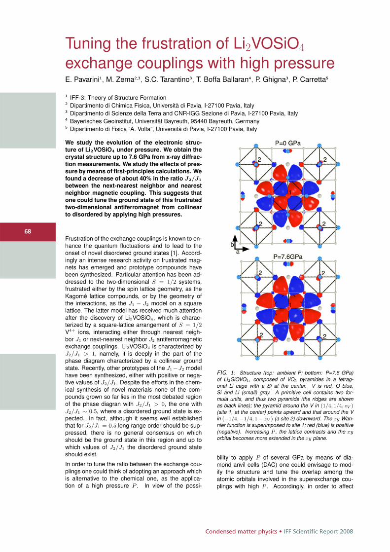
Condensed matter physics • IFF Scientific Report 2008
6868
Tuning the frustration of Li2VOSiO4
exchange couplings with high pressureE. Pavarini1, M. Zema2,3, S.C. Tarantino3, T. Boffa Ballaran4, P. Ghigna3, P. Carretta5
1 IFF-3: Theory of Structure Formation2 Dipartimento di Chimica Fisica, Università di Pavia, I-27100 Pavia, Italy3 Dipartimento di Scienze della Terra and CNR-IGG Sezione di Pavia, I-27100 Pavia, Italy4 Bayerisches Geoinstitut, Universität Bayreuth, 95440 Bayreuth, Germany5 Dipartimento di Fisica “A. Volta”, Università di Pavia, I-27100 Pavia, Italy
We study the evolution of the electronic struc-
ture of Li2VOSiO4 under pressure. We obtain the
crystal structure up to 7.6 GPa from x-ray diffrac-
tion measurements. We study the effects of pres-
sure by means of first-principles calculations. We
found a decrease of about 40% in the ratio J2/J1
between the next-nearest neighbor and nearest
neighbor magnetic coupling. This suggests that
one could tune the ground state of this frustrated
two-dimensional antiferromagnet from collinear
to disordered by applying high pressures.
Frustration of the exchange couplings is known to en-hance the quantum fluctuations and to lead to theonset of novel disordered ground states [1]. Accord-ingly an intense research activity on frustrated mag-nets has emerged and prototype compounds havebeen synthesized. Particular attention has been ad-dressed to the two-dimensional S = 1/2 systems,frustrated either by the spin lattice geometry, as theKagomé lattice compounds, or by the geometry ofthe interactions, as the J1 − J2 model on a squarelattice. The latter model has received much attentionafter the discovery of Li2VOSiO4, which is charac-terized by a square-lattice arrangement of S = 1/2V4+ ions, interacting either through nearest neigh-bor J1 or next-nearest neighbor J2 antiferromagneticexchange couplings. Li2VOSiO4 is characterized byJ2/J1 > 1, namely, it is deeply in the part of thephase diagram characterized by a collinear groundstate. Recently, other prototypes of the J1−J2 modelhave been synthesized, either with positive or nega-tive values of J2/J1. Despite the efforts in the chem-ical synthesis of novel materials none of the com-pounds grown so far lies in the most debated regionof the phase diagran with J2/J1 > 0, the one withJ2/J1 ∼ 0.5, where a disordered ground state is ex-pected. In fact, although it seems well establishedthat for J2/J1 = 0.5 long range order should be sup-pressed, there is no general consensus on whichshould be the ground state in this region and up towhich values of J2/J1 the disordered ground stateshould exist.
In order to tune the ratio between the exchange cou-plings one could think of adopting an approach whichis alternative to the chemical one, as the applica-tion of a high pressure P . In view of the possi-
FIG. 1: Structure (top: ambient P; bottom: P=7.6 GPa)of Li2SiOVO4, composed of VO5 pyramides in a tetrag-onal Li cage with a Si at the center. V is red, O blue,Si and Li (small) gray. A primitive cell contains two for-mula units, and thus two pyramids (the ridges are shownas black lines); the pyramid around the V in (1/4, 1/4, zV )(site 1, at the center) points upward and that around the Vin (−1/4,−1/4, 1 − zV ) (a site 2) downward. The xy Wan-nier function is superimposed to site 1; red (blue) is positive(negative). Increasing P , the lattice contracts and the xy
orbital becomes more extended in the xy plane.
bility to apply P of several GPa by means of dia-mond anvil cells (DAC) one could envisage to mod-ify the structure and tune the overlap among theatomic orbitals involved in the superexchange cou-plings with high P . Accordingly, in order to affect
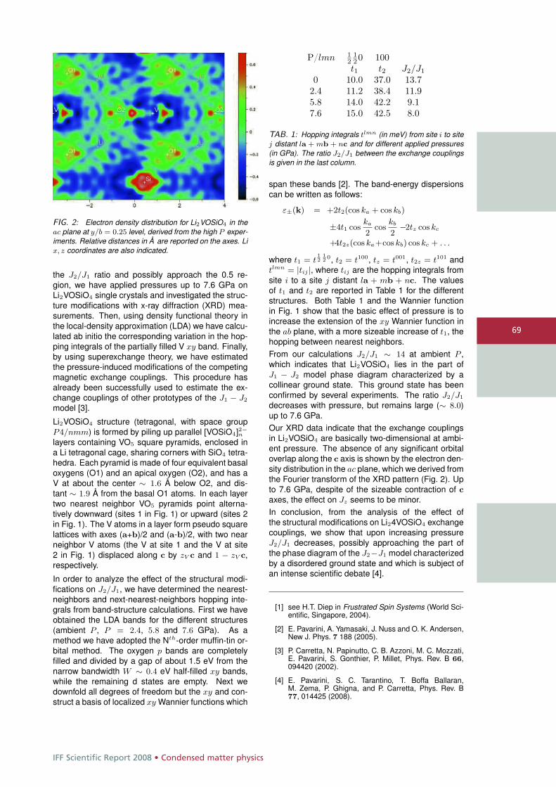
IFF Scientific Report 2008 • Condensed matter physics
69
FIG. 2: Electron density distribution for Li2VOSiO4 in theac plane at y/b = 0.25 level, derived from the high P exper-iments. Relative distances in Å are reported on the axes. Lix, z coordinates are also indicated.
the J2/J1 ratio and possibly approach the 0.5 re-gion, we have applied pressures up to 7.6 GPa onLi2VOSiO4 single crystals and investigated the struc-ture modifications with x-ray diffraction (XRD) mea-surements. Then, using density functional theory inthe local-density approximation (LDA) we have calcu-lated ab initio the corresponding variation in the hop-ping integrals of the partially filled V xy band. Finally,by using superexchange theory, we have estimatedthe pressure-induced modifications of the competingmagnetic exchange couplings. This procedure hasalready been successfully used to estimate the ex-change couplings of other prototypes of the J1 − J2
model [3].
Li2VOSiO4 structure (tetragonal, with space groupP4/nmm) is formed by piling up parallel [VOSiO4]2−n
layers containing VO5 square pyramids, enclosed ina Li tetragonal cage, sharing corners with SiO4 tetra-hedra. Each pyramid is made of four equivalent basaloxygens (O1) and an apical oxygen (O2), and has aV at about the center ∼ 1.6 Å below O2, and dis-tant ∼ 1.9 Å from the basal O1 atoms. In each layertwo nearest neighbor VO5 pyramids point alterna-tively downward (sites 1 in Fig. 1) or upward (sites 2in Fig. 1). The V atoms in a layer form pseudo squarelattices with axes (a+b)/2 and (a-b)/2, with two nearneighbor V atoms (the V at site 1 and the V at site2 in Fig. 1) displaced along c by zV c and 1 − zV c,respectively.
In order to analyze the effect of the structural modi-fications on J2/J1, we have determined the nearest-neighbors and next-nearest-neighbors hopping inte-grals from band-structure calculations. First we haveobtained the LDA bands for the different structures(ambient P , P = 2.4, 5.8 and 7.6 GPa). As amethod we have adopted the Nth-order muffin-tin or-bital method. The oxygen p bands are completelyfilled and divided by a gap of about 1.5 eV from thenarrow bandwidth W ∼ 0.4 eV half-filled xy bands,while the remaining d states are empty. Next wedownfold all degrees of freedom but the xy and con-struct a basis of localized xy Wannier functions which
P/lmn 12
120 100t1 t2 J2/J1
0 10.0 37.0 13.72.4 11.2 38.4 11.95.8 14.0 42.2 9.17.6 15.0 42.5 8.0
TAB. 1: Hopping integrals tlmn (in meV) from site i to sitej distant la + mb + nc and for different applied pressures(in GPa). The ratio J2/J1 between the exchange couplingsis given in the last column.
span these bands [2]. The band-energy dispersionscan be written as follows:
ε±(k) = +2t2(cos ka + cos kb)
±4t1 coska
2cos
kb
2−2tz cos kc
+4t2z(cos ka+cos kb) cos kc + . . .
where t1 = t12
12 0, t2 = t100, tz = t001, t2z = t101 and
tlmn = |tij |, where tij are the hopping integrals fromsite i to a site j distant la + mb + nc. The valuesof t1 and t2 are reported in Table 1 for the differentstructures. Both Table 1 and the Wannier functionin Fig. 1 show that the basic effect of pressure is toincrease the extension of the xy Wannier function inthe ab plane, with a more sizeable increase of t1, thehopping between nearest neighbors.From our calculations J2/J1 ∼ 14 at ambient P ,which indicates that Li2VOSiO4 lies in the part ofJ1 − J2 model phase diagram characterized by acollinear ground state. This ground state has beenconfirmed by several experiments. The ratio J2/J1
decreases with pressure, but remains large (∼ 8.0)up to 7.6 GPa.Our XRD data indicate that the exchange couplingsin Li2VOSiO4 are basically two-dimensional at ambi-ent pressure. The absence of any significant orbitaloverlap along the c axis is shown by the electron den-sity distribution in the ac plane, which we derived fromthe Fourier transform of the XRD pattern (Fig. 2). Upto 7.6 GPa, despite of the sizeable contraction of caxes, the effect on Jz seems to be minor.In conclusion, from the analysis of the effect ofthe structural modifications on Li24VOSiO4 exchangecouplings, we show that upon increasing pressureJ2/J1 decreases, possibly approaching the part ofthe phase diagram of the J2−J1 model characterizedby a disordered ground state and which is subject ofan intense scientific debate [4].
[1] see H.T. Diep in Frustrated Spin Systems (World Sci-entific, Singapore, 2004).
[2] E. Pavarini, A. Yamasaki, J. Nuss and O. K. Andersen,New J. Phys. 7 188 (2005).
[3] P. Carretta, N. Papinutto, C. B. Azzoni, M. C. Mozzati,E. Pavarini, S. Gonthier, P. Millet, Phys. Rev. B 66,094420 (2002).
[4] E. Pavarini, S. C. Tarantino, T. Boffa Ballaran,M. Zema, P. Ghigna, and P. Carretta, Phys. Rev. B77, 014425 (2008).
Condensed matter physics • IFF Scientific Report 2008
7070
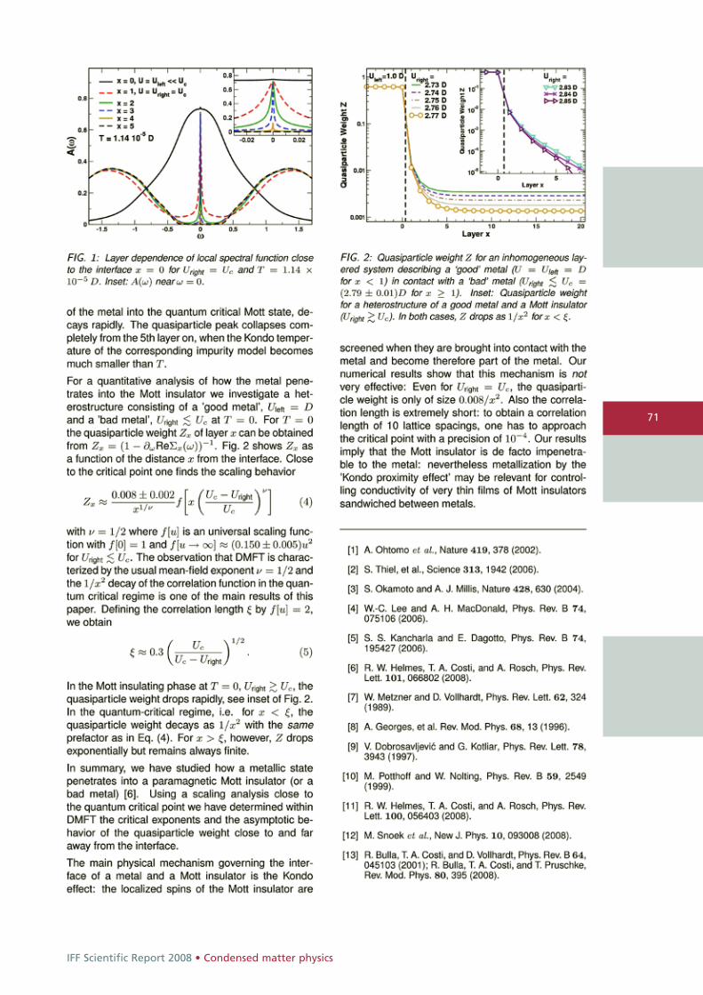
IFF Scientific Report 2008 • Condensed matter physics
71
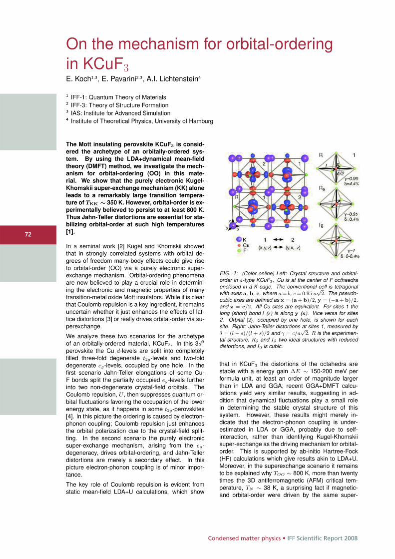
Condensed matter physics • IFF Scientific Report 2008
7272
On the mechanism for orbital-orderingin KCuF3E. Koch1,3, E. Pavarini2,3, A.I. Lichtenstein4
1 IFF-1: Quantum Theory of Materials2 IFF-3: Theory of Structure Formation3 IAS: Institute for Advanced Simulation4 Institute of Theoretical Physics, University of Hamburg
The Mott insulating perovskite KCuF3 is consid-
ered the archetype of an orbitally-ordered sys-
tem. By using the LDA+dynamical mean-field
theory (DMFT) method, we investigate the mech-
anism for orbital-ordering (OO) in this mate-
rial. We show that the purely electronic Kugel-
Khomskii super-exchange mechanism (KK) alone
leads to a remarkably large transition tempera-
ture of TKK ∼ 350 K. However, orbital-order is ex-
perimentally believed to persist to at least 800 K.
Thus Jahn-Teller distortions are essential for sta-
bilizing orbital-order at such high temperatures
[1].
In a seminal work [2] Kugel and Khomskii showedthat in strongly correlated systems with orbital de-grees of freedom many-body effects could give riseto orbital-order (OO) via a purely electronic super-exchange mechanism. Orbital-ordering phenomenaare now believed to play a crucial role in determin-ing the electronic and magnetic properties of manytransition-metal oxide Mott insulators. While it is clearthat Coulomb repulsion is a key ingredient, it remainsuncertain whether it just enhances the effects of lat-tice distortions [3] or really drives orbital-order via su-perexchange.
We analyze these two scenarios for the archetypeof an orbitally-ordered material, KCuF3. In this 3d9
perovskite the Cu d-levels are split into completelyfilled three-fold degenerate t2g-levels and two-folddegenerate eg-levels, occupied by one hole. In thefirst scenario Jahn-Teller elongations of some Cu-F bonds split the partially occupied eg-levels furtherinto two non-degenerate crystal-field orbitals. TheCoulomb repulsion, U , then suppresses quantum or-bital fluctuations favoring the occupation of the lowerenergy state, as it happens in some t2g-perovskites[4]. In this picture the ordering is caused by electron-phonon coupling; Coulomb repulsion just enhancesthe orbital polarization due to the crystal-field split-ting. In the second scenario the purely electronicsuper-exchange mechanism, arising from the eg-degeneracy, drives orbital-ordering, and Jahn-Tellerdistortions are merely a secondary effect. In thispicture electron-phonon coupling is of minor impor-tance.
The key role of Coulomb repulsion is evident fromstatic mean-field LDA+U calculations, which show
FIG. 1: (Color online) Left: Crystal structure and orbital-order in a-type KCuF3. Cu is at the center of F octhaedraenclosed in a K cage. The conventional cell is tetragonalwith axes a, b, c, where a = b, c = 0.95 a
√2. The pseudo-
cubic axes are defined as x = (a + b)/2, y = (−a + b)/2,and z = c/2. All Cu sites are equivalent. For sites 1 thelong (short) bond l (s) is along y (x). Vice versa for sites2. Orbital |2〉, occupied by one hole, is shown for eachsite. Right: Jahn-Teller distortions at sites 1, measured byδ = (l − s)/(l + s)/2 and γ = c/a
√2. R is the experimen-
tal structure, Rδ and Iδ two ideal structures with reduceddistortions, and I0 is cubic.
that in KCuF3 the distortions of the octahedra arestable with a energy gain ΔE ∼ 150-200 meV performula unit, at least an order of magnitude largerthan in LDA and GGA; recent GGA+DMFT calcu-lations yield very similar results, suggesting in ad-dition that dynamical fluctuations play a small rolein determining the stable crystal structure of thissystem. However, these results might merely in-dicate that the electron-phonon coupling is under-estimated in LDA or GGA, probably due to self-interaction, rather than identifying Kugel-Khomskiisuper-exchange as the driving mechanism for orbital-order. This is supported by ab-initio Hartree-Fock(HF) calculations which give results akin to LDA+U.Moreover, in the superexchange scenario it remainsto be explained why TOO ∼ 800 K, more than twentytimes the 3D antiferromagnetic (AFM) critical tem-perature, TN ∼ 38 K, a surprising fact if magnetic-and orbital-order were driven by the same super-
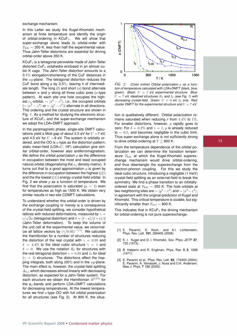
IFF Scientific Report 2008 • Condensed matter physics
73
exchange mechanism.
In this Letter we study the Kugel-Khomskii mech-anism at finite temperature and identify the originof orbital-ordering in KCuF3. We will show thatsuper-exchange alone leads to orbital-order withTKK ∼ 350 K, less than half the experimental value.Thus Jahn-Teller distortions are essential for drivingorbital-order above 350 K.
KCuF3 is a tetragonal perovskite made of Jahn-Tellerdistorted CuF6 octahedra enclosed in an almost cu-bic K cage. The Jahn-Teller distortion amounts to a3.1% elongation/shortening of the CuF distances inthe xy-plane. The tetragonal distortion reduces theCuF bond along z by 2.5%, leaving it of intermedi-ate length. The long (l) and short (s) bond alternatebetween x and y along all three cubic axes (a-typepattern). At each site one hole occupies the high-est eg-orbital, ∼ |s2 − z2〉, i.e., the occupied orbitals(∼ |x2 − z2〉 or ∼ |y2 − z2〉) alternate in all directions.This ordering and the crystal structure are shown inFig. 1. As a method for studying the electronic struc-ture of KCuF3 and the super-exchange mechanismwe adopt the LDA+DMFT approach.
In the paramagnetic phase, single-site DMFT calcu-lations yield a Mott gap of about 2.5 eV for U =7 eV,and 4.5 eV for U =9 eV. The system is orbitally or-dered, and the OO is a-type as the distortion pattern;static mean-field (LDA+U , HF) calculation give sim-ilar orbital-order, however also antiferromagnetism.We define the orbital polarization p as the differencein occupation between the most and least occupiednatural orbital (diagonalizing the eg density-matrix). Itturns out that to a good approximation p is given bythe difference in occupation between the highest (|2〉)and the the lowest (|1〉) energy crystal-field orbital. InFig. 2 we show p as a function of temperature. Wefind that the polarization is saturated (p ∼ 1) evenfor temperatures as high as 1500 K. We obtain verysimilar results in two-site CDMFT calculations.
To understand whether this orbital-order is driven bythe exchange coupling or merely is a consequenceof the crystal-field splitting, we consider hypotheticallattices with reduced deformations, measured by γ =c/√
2a (tetragonal distortion) and δ = (l−s)/(l+s)/2(Jahn-Teller deformation). To keep the volume ofthe unit cell at the experimental value, we renormal-ize all lattice vectors by (γ/0.95)−1/3. We calculatethe Hamiltonian for a number of structures reducingthe distortion of the real crystal with γ = 0.95 andδ = 4.4% to the ideal cubic structure γ = 1 andδ = 0. We use the notation Rδ for structures withthe real tetragonal distortion γ = 0.95 and Iδ for ideal(γ = 1) structures. The distortions affect the hop-ping integrals, both along (001) and in the xy-plane.The main effect is, however, the crystal-field splittingΔ2,1 which decreases almost linearly with decreasingdistortion, as expected for a Jahn-Teller system. Foreach structure we obtain the Hamiltonian HLDA forthe eg-bands and perform LDA+DMFT calculationsfor decreasing temperatures. At the lowest tempera-tures we find a-type OO with full orbital polarizationfor all structures (see Fig. 2). At 800 K, the situa-
FIG. 2: (Color online) Orbital polarization p as a func-tion of temperature calculated with LDA+DMFT (black, blue,green). Black: U = 7 eV, experimental structure. Blue:U = 7 eV, idealized structures Rδ and Iδ (see Fig. 1) withdecreasing crystal-field. Green: U = 9 eV, I0 only. Red:cluster DMFT for the experimental structure and U = 7 eV.
tion is qualitatively different. Orbital polarization re-mains saturated when reducing δ from 4.4% to 1%.For smaller distortions, however, p rapidly goes tozero: For δ = 0.2% and γ = 1, p is already reducedto ∼ 0.5, and becomes negligible in the cubic limit.Thus super-exchange alone is not sufficiently strongto drive orbital-ordering at T � 800 K.
From the temperature dependence of the orbital po-larization we can determine the transition temper-ature TKK at which the Kugel-Khomskii superex-change mechanism would drive orbital-ordering,and thus disentangle the superexchange from theelectron-phonon coupling. For this we study theideal cubic structure, introducing a negligible (1 meV)crystal-field splitting as an external-field to break thesymmetry. We find a phase transition to an orbitally-ordered state at TKK ∼ 350 K. The hole orbitals attwo neighboring sites are ∼ |y2−z2〉 and ∼ |x2−z2〉,in agreement with the original prediction of Kugel andKhomskii. This critical temperature is sizable, but sig-nificantly smaller than TOO ∼ 800 K.
This indicates that in KCuF3 the driving mechanismfor orbital-ordering is not pure superexchange.
[1] E. Pavarini, E. Koch, and A.I. Lichtenstein,Phys. Rev. Lett. 101, 266405 (2008).
[2] K. I. Kugel and D. I. Khomskii, Sov. Phys.-JETP 37,725 (1973).
[3] B. Halperin and R. Englman, Phys. Rev. B 3, 1698(1971).
[4] E. Pavarini et al., Phys. Rev. Lett. 92, 176403 (2004);E. Pavarini, A. Yamasaki, J. Nuss and O.K. Andersen,New J. Phys. 7 188 (2005).
Condensed matter physics • IFF Scientific Report 2008
7474
Mott phase of repulsively interactingfermions in a 3D optical latticeU. Schneider1, L. Hackermüller1, S. Will1, Th. Best1, I. Bloch1, T. A. Costi2, R. W. Helmes3,D. Rasch3, A. Rosch3
1 Institute of Physics, Johannes Gutenberg-University, 55099 Mainz, Germany2 IFF-3: Theory of Structure Formation3 Institute for Theoretical Physics, University of Cologne, 50937 Cologne, Germany
The fermionic Hubbard model plays a fundamen-
tal role in the description of strongly correlated
materials. We have realized this Hamiltonian us-
ing a repulsively interacting spin mixture of ul-
tracold 40K atoms in a 3D optical lattice. Direct
measurement of the compressibility of the quan-
tum gas in the optical lattice and comparison with
ab initio dynamical mean field theory calculations
demonstrates the emergence of an incompress-
ible Mott insulating phase for strong interactions.
Interacting fermions in periodic potentials lie at theheart of modern condensed matter physics, present-ing some of the most challenging problems to quan-tum many-body theory. A prominent example is high-Tc superconductivity in cuprate compounds [1] andthe recently discovered iron-arsenic alloys [2]. In or-der to capture the essential physics of such systems,the fermionic Hubbard Hamiltonian [3] has been in-troduced as a fundamental model describing inter-acting electrons in a periodic potential [1]. In a realsolid, however, the effects of interest are typicallycomplicated by e.g. multiple bands and orbital de-grees of freedom, impurities and the long-range na-ture of Coulomb interactions which becomes espe-cially relevant close to a metal to insulator transition.It is therefore crucial to probe this fundamental modelHamiltonian in a controllable and clean experimen-tal setting. Ultracold atoms in optical lattices providesuch a defect-free system [4, 5], in which the relevantparameters can be independently controlled, allow-ing quantitative comparisons of the experiment withmodern quantum many-body theories.
In this work [6], we directly probe the compressibil-ity of the many-body system by monitoring the in-trapdensity distribution of the fermionic atoms for increas-ing harmonic confinements. This allows us to distin-guish compressible metallic phases from globally in-compressible states and reveals the strong influenceof interactions on the density distribution. For repul-sive interactions, we find the cloud size to be signifi-cantly larger than in the non-interacting case, indicat-ing the resistance of the system to compression. Forstrong repulsion, the system evolves from a metal-lic state into a Mott insulating state and eventually aband insulator as the compression increases.
The experimentally results are compared to numeri-cal calculations using Dynamical Mean Field Theory
(DMFT) [7, 8, 9, 10]. DMFT is a central method ofsolid state theory and is widely used to obtain ab-initio descriptions of strongly correlated materials [8].This comparison of DMFT predictions with experi-ments on ultracold fermions in optical lattices consti-tutes the first parameter-free experimental test of thevalidity of DMFT in a three-dimensional system.
Restricting to the lowest energy band of a simple cu-bic 3D optical lattice, the fermionic quantum gas mix-ture can be modeled via the Hubbard-Hamiltonian [3]together with an additional term describing the poten-tial energy due to the underlying harmonic potential:
H = − JX
〈i,j〉,σc†i,σ cj,σ + U
X
i
ni,↓ni,↑
+ Vt
X
i
(i2x + i2y + γ2i2z) (ni,↓ + ni,↑) .
Here, i = (ix, iy, iz), denote lattice sites, σ ∈ {↓, ↑}the two different spin states, J the tunneling matrixelement and U the effective on-site interaction. Thestrength of the harmonic confinement Vt is conve-niently parameterized by Et = Vt(γNσ/(4π/3))2/3
with Nσ the number of atoms of spin σ and γ theaspect ratio of the trap.
The experiments used an equal mixture of fermionic40K atoms in the two hyperfine states |F, mF 〉 =| 92,− 9
2〉 ≡↓ and | 9
2,− 7
2〉 ≡↑. Using evaporative cool-
ing, we reach temperatures of T/TF = 0.15(3) with1.5 − 2.5 × 10⁵ potassium atoms. A Feshbach res-onance located at 202.1 G [11] is used to tune thescattering length between the two spin states andthereby control the on-site interaction U .
An in-situ image of the cloud is subsequently takenalong the short axis of the trap using phase-contrastimaging [12]. As the latter is non-destructive, it allowsus to also measure the quasi-momentum distributionof the atoms in the same experimental run using aband-mapping technique [13, 14, 15].
All experimental data are compared to numerical cal-culations, in which the DMFT equations are solvedfor a wide range of temperatures and chemical po-tentials using a numerical renormalization group ap-proach [16, 17]. As shown in [18, 9], the trapped sys-tem can be approximated to very high accuracy bythe uniform system through a local density approx-imation (LDA) even close to the boundary betweenmetal and insulator.
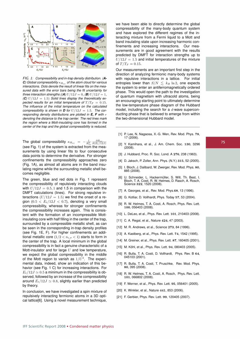
IFF Scientific Report 2008 • Condensed matter physics
75
FIG. 1: Compressibility and in-trap density distribution. (A-C) Global compressibility κRsc of the atom cloud for variousinteractions. Dots denote the result of linear fits on the mea-sured data with the error bars being the fit uncertainty forthree interaction strengths ((A) U/12J = 0, (B) U/12J = 1,(C) U/12J = 1.5) Solid lines display the theoretically ex-pected results for an initial temperature of T/TF = 0.15.The influence of the initial temperature on the calculatedcompressibility is shown in D for U/12J = 1.5. The cor-responding density distributions are plotted in E, F with r
denoting the distance to the trap center. The red lines markthe region where a Mott-insulating core has formed in thecenter of the trap and the global compressibility is reduced.
The global compressibility κRsc = − 1R3
sc
∂Rsc∂(Et/12J)
(see Fig. 1) of the system is extracted from the mea-surements by using linear fits to four consecutivedata points to determine the derivative. For strongerconfinements the compressibility approaches zero(Fig. 1A), as almost all atoms are in the band insu-lating regime while the surrounding metallic shell be-comes negligible.
The green, blue and red dots in Fig. 1 representthe compressibility of repulsively interacting cloudswith U/12J = 0.5, 1 and 1.5 in comparison with theDMFT calculations (lines). For strong repulsive in-teractions (U/12J = 1.5) we find the onset of a re-gion (0.5 < Et/12J < 0.7), denoting a very smallcompressibility, whereas for stronger confinementsthe compressibility increases again. This is consis-tent with the formation of an incompressible Mott-insulating core with half filling in the center of the trap,surrounded by a compressible metallic shell, as canbe seen in the corresponding in-trap density profiles(see Fig. 1E, F). For higher confinements an addi-tional metallic core (1/2 < ni,σ < 1) starts to form inthe center of the trap. A local minimum in the globalcompressibility is in fact a genuine characteristic of aMott-insulator and for large U and low temperature,we expect the global compressibility in the middleof the Mott region to vanish as 1/U2. The experi-mental data, indeed, show an indication of this be-havior (see Fig. 1 C) for increasing interactions. ForEt/12J � 0.5 a minimum in the compressibility is ob-served, followed by an increase of the compressibilityaround Et/12J � 0.8, slightly earlier than predictedby theory.
In conclusion, we have investigated a spin mixture ofrepulsively interacting fermionic atoms in a 3D opti-cal lattice[6]. Using a novel measurement technique,
we have been able to directly determine the globalcompressibility of the many-body quantum systemand have explored the different regimes of the in-teracting mixture from a Fermi liquid to a Mott andband insulating state upon increasing harmonic con-finements and increasing interactions. Our mea-surements are in good agreement with the resultspredicted by DMFT for interaction strengths up toU/12J = 1.5 and initial temperatures of the mixtureof T/TF = 0.15.
Our measurements are an important first step in thedirection of analyzing fermionic many-body systemswith repulsive interactions in a lattice. For initialentropies lower than S/N � kB ln 2, one expectsthe system to enter an antiferromagnetically orderedphase. This would open the path to the investigationof quantum magnetism with ultracold atoms, beingan encouraging starting point to ultimately determinethe low-temperature phase diagram of the Hubbardmodel, including the search for a d-wave supercon-ducting phase that is believed to emerge from withinthe two-dimensional Hubbard model.
[1] P. Lee, N. Nagaosa, X.-G. Wen, Rev. Mod. Phys. 78,17 (2006).
[2] Y. Kamihara, et al., J. Am. Chem. Soc. 130, 3296(2008).
[3] J. Hubbard, Proc. R. Soc. Lond. A 276, 238 (1963).
[4] D. Jaksch, P. Zoller, Ann. Phys. (N.Y.) 315, 52 (2005).
[5] I. Bloch, J. Dalibard, W. Zwerger, Rev. Mod. Phys. 80,885 (2008).
[6] U. Schneider, L. Hackermüller, S. Will, Th. Best, I.Bloch, T. A. Costi, R. W. Helmes, D. Rasch, A. Rosch,Science 322, 1520 (2008).
[7] A. Georges, et al., Rev. Mod. Phys.68, 13 (1996).
[8] G. Kotliar, D. Vollhardt, Phys. Today 57, 53 (2004).
[9] R. W. Helmes, T. A. Costi, A. Rosch, Phys. Rev. Lett.100, 056403 (2008).
[10] L. DeLeo, et al., Phys. Rev. Lett. 101, 210403 (2008).
[11] C. A. Regal, et al., Nature 424, 47 (2003).
[12] M. R. Andrews, et al., Science 273, 84 (1996).
[13] A. Kastberg, et al., Phys. Rev. Lett. 74, 1542 (1995).
[14] M. Greiner, et al., Phys. Rev. Lett. 87, 160405 (2001).
[15] M. Köhl, et al., Phys. Rev. Lett. 94, 080403 (2005).
[16] R. Bulla, T. A. Costi, D. Vollhardt, Phys. Rev. B 64,045103 (2001).
[17] R. Bulla, T. A. Costi, T. Pruschke, Rev. Mod. Phys.80, 395 (2008).
[18] R. W. Helmes, T. A. Costi, A. Rosch, Phys. Rev. Lett.101, 066802 (2008).
[19] F. Werner, et al., Phys. Rev. Lett. 95, 056401 (2005).
[20] K. Winkler, et al., Nature 441, 853 (2006).
[21] F. Gerbier, Phys. Rev. Lett. 99, 120405 (2007).
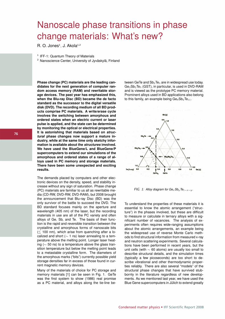
Condensed matter physics • IFF Scientific Report 2008
7676
Nanoscale phase transitions in phasechange materials: What’s new?R. O. Jones1, J. Akola1,2
1 IFF-1: Quantum Theory of Materials2 Nanoscience Center, University of Jyväskylä, Finland
Phase change (PC) materials are the leading can-
didates for the next generation of computer ran-
dom access memory (RAM) and rewritable stor-
age devices. The past year has emphasized this,
when the Blu-ray Disc (BD) became the de facto
standard as the successor to the digital versatile
disk (DVD). The recording medium of all BD prod-
ucts comprise PC materials. A write/erase cycle
involves the switching between amorphous and
ordered states when an electric current or laser
pulse is applied, and the state can be determined
by monitoring the optical or electrical properties.
It is astonishing that materials based on struc-tural phase changes now support a mature in-
dustry, while at the same time only sketchy infor-
mation is available about the structures involved.
We have used the BlueGene/L and BlueGene/P
supercomputers to extend our simulations of the
amorphous and ordered states of a range of al-
loys used in PC memory and storage materials.
There have been some unexpected and exciting
results.
The demands placed by computers and other elec-tronic devices on the density, speed, and stability in-crease without any sign of saturation. Phase change(PC) materials are familiar to us all as rewritable me-dia (CD-RW, DVD-RW, DVD-RAM), but 2008 broughtthe announcement that Blu-ray Disc (BD) was theonly survivor of the battle to succeed the DVD. TheBD standard focuses mainly on the aperture andwavelength (405 nm) of the laser, but the recordingmaterials in use are all of the PC variety and oftenalloys of Ge, Sb, and Te. The basis of their func-tion is the rapid and reversible transition between thecrystalline and amorphous forms of nanoscale bits(� 100 nm), which arise from quenching after a lo-calized and short (∼ 1 ns) laser annealing to a tem-perature above the melting point. Longer laser heat-ing (∼ 50 ns) to a temperature above the glass tran-sition temperature but below the melting point leadsto a metastable crystalline form. The diameters ofthe amorphous marks (“bits”) currently possible yieldstorage densities far in excess of those found in cur-rent magnetic memory devices.Many of the materials of choice for PC storage andmemory materials [1] can be seen in Fig. 1. GeTewas the first system to show (1986) real promiseas a PC material, and alloys along the tie-line be-
tween GeTe and Sb2Te3 are in widespread use today.Ge2Sb2Te5 (GST), in particular, is used in DVD-RAMand is viewed as the prototype PC memory material.Prominent alloys used in BD applications also belongto this family, an example being Ge8Sb2Te11.
FIG. 1: Alloy diagram for GexSbyTe1−x−y .
To understand the properties of these materials it isessential to know the atomic arrangement (“struc-ture”) in the phases involved, but these are difficultto measure or calculate in ternary alloys with a sig-nificant number of vacancies. The analysis of ex-periments often requires wide-ranging assumptionsabout the atomic arrangements, an example beingthe widespread use of reverse Monte Carlo meth-ods to find structural information from measured x-rayand neutron scattering experiments. Several calcula-tions have been performed in recent years, but theunit cells (with ∼ 60 atoms) are usually too small todescribe structural details, and the simulation times(typically a few picoseconds) are too short to de-scribe vibrational and other thermodynamic proper-ties reliably. There are also several “models” of thestructural phase changes that have survived stub-bornly in the literature regardless of new develop-ments. As we mentioned last year, we have used theBlue Gene supercomputers in Jülich to extend greatly
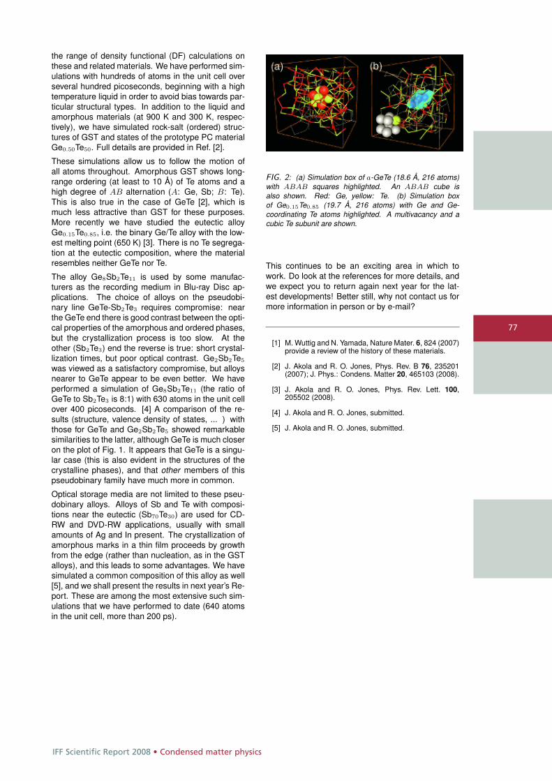
IFF Scientific Report 2008 • Condensed matter physics
77
the range of density functional (DF) calculations onthese and related materials. We have performed sim-ulations with hundreds of atoms in the unit cell overseveral hundred picoseconds, beginning with a hightemperature liquid in order to avoid bias towards par-ticular structural types. In addition to the liquid andamorphous materials (at 900 K and 300 K, respec-tively), we have simulated rock-salt (ordered) struc-tures of GST and states of the prototype PC materialGe0.50Te50. Full details are provided in Ref. [2].
These simulations allow us to follow the motion ofall atoms throughout. Amorphous GST shows long-range ordering (at least to 10 Å) of Te atoms and ahigh degree of AB alternation (A: Ge, Sb; B: Te).This is also true in the case of GeTe [2], which ismuch less attractive than GST for these purposes.More recently we have studied the eutectic alloyGe0.15Te0.85, i.e. the binary Ge/Te alloy with the low-est melting point (650 K) [3]. There is no Te segrega-tion at the eutectic composition, where the materialresembles neither GeTe nor Te.
The alloy Ge8Sb2Te11 is used by some manufac-turers as the recording medium in Blu-ray Disc ap-plications. The choice of alloys on the pseudobi-nary line GeTe-Sb2Te3 requires compromise: nearthe GeTe end there is good contrast between the opti-cal properties of the amorphous and ordered phases,but the crystallization process is too slow. At theother (Sb2Te3) end the reverse is true: short crystal-lization times, but poor optical contrast. Ge2Sb2Te5
was viewed as a satisfactory compromise, but alloysnearer to GeTe appear to be even better. We haveperformed a simulation of Ge8Sb2Te11 (the ratio ofGeTe to Sb2Te3 is 8:1) with 630 atoms in the unit cellover 400 picoseconds. [4] A comparison of the re-sults (structure, valence density of states, ... ) withthose for GeTe and Ge2Sb2Te5 showed remarkablesimilarities to the latter, although GeTe is much closeron the plot of Fig. 1. It appears that GeTe is a singu-lar case (this is also evident in the structures of thecrystalline phases), and that other members of thispseudobinary family have much more in common.
Optical storage media are not limited to these pseu-dobinary alloys. Alloys of Sb and Te with composi-tions near the eutectic (Sb70Te30) are used for CD-RW and DVD-RW applications, usually with smallamounts of Ag and In present. The crystallization ofamorphous marks in a thin film proceeds by growthfrom the edge (rather than nucleation, as in the GSTalloys), and this leads to some advantages. We havesimulated a common composition of this alloy as well[5], and we shall present the results in next year’s Re-port. These are among the most extensive such sim-ulations that we have performed to date (640 atomsin the unit cell, more than 200 ps).
FIG. 2: (a) Simulation box of a-GeTe (18.6 Å, 216 atoms)with ABAB squares highlighted. An ABAB cube isalso shown. Red: Ge, yellow: Te. (b) Simulation boxof Ge0.15Te0.85 (19.7 Å, 216 atoms) with Ge and Ge-coordinating Te atoms highlighted. A multivacancy and acubic Te subunit are shown.
This continues to be an exciting area in which towork. Do look at the references for more details, andwe expect you to return again next year for the lat-est developments! Better still, why not contact us formore information in person or by e-mail?
[1] M. Wuttig and N. Yamada, Nature Mater. 6, 824 (2007)provide a review of the history of these materials.
[2] J. Akola and R. O. Jones, Phys. Rev. B 76, 235201(2007); J. Phys.: Condens. Matter 20, 465103 (2008).
[3] J. Akola and R. O. Jones, Phys. Rev. Lett. 100,205502 (2008).
[4] J. Akola and R. O. Jones, submitted.
[5] J. Akola and R. O. Jones, submitted.
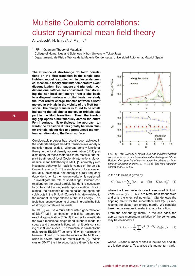
Condensed matter physics • IFF Scientific Report 2008
7878
Multisite Coulomb correlations:cluster dynamical mean field theoryA. Liebsch1, H. Ishida2, J. Merino3
1 IFF-1: Quantum Theory of Materials2 College of Humanities and Sciences, Nihon University, Tokyo,Japan3 Departamento de Física Teórica de la Materia Condensada, Universidad Autónoma, Madrid, Spain
The influence of short-range Coulomb correla-
tions on the Mott transition in the single-band
Hubbard model is studied within cluster dynami-
cal mean field theory and finite-temperature exact
diagonalization. Both square and triangular two-
dimensional lattices are considered. Transform-
ing the non-local self-energy from a site basis
to a diagonal molecular orbital basis, we study
the inter-orbital charge transfer between cluster
molecular orbitals in the vicinity of the Mott tran-
sition. The charge transfer is found to be small,
indicating that all cluster molecular orbitals take
part in the Mott transition. Thus, the insulat-
ing gap opens simultaneously across the entire
Fermi surface. Nevertheless, the approach to-
wards the transition differs greatly between clus-
ter orbitals, giving rise to a pronounced momen-
tum variation along the Fermi surface.
Considerable progress has recently been achieved inthe understanding of the Mott transition in a variety oftransition metal oxides. Whereas density functionaltheory in the local density approximation (LDA) pre-dicts many of these materials to be metallic, the ex-plicit treatment of local Coulomb interactions via dy-namical mean field theory (DMFT) [1] correctly yieldsinsulating behavior for realistic values of the on-siteCoulomb energy U . In the single-site or local versionof DMFT, the complex self-energy is purely frequencydependent, i.e., its momentum variation is neglected.To investigate the role of short-range Coulomb cor-relations on the quasi-particle bands it is necessaryto go beyond the single-site approximation. For in-stance, the existence of the so-called hot spots andcold spots in the Brillouin Zone is intimately related tothe momentum dependence of the self-energy. Thistopic has recently become of great interest in the fieldof strongly correlated materials.
In Ref. [2] we use a multi-site ‘cluster’ generalizationof DMFT [3] in combination with finite temperatureexact diagonalization (ED) [4] in order to investigatethe two-dimensional single band Hubbard model forsquare and triangular lattices, with unit cells consist-ing of 2, 3, and 4 sites. The formalism is similar to themulti-orbital ED/DMFT scheme [5] which has recentlybeen employed to discuss the nature of the Mott tran-sition in several transition metal oxides [6]. Withincluster DMFT the interacting lattice Green’s function
FIG. 1: Top: Density of states ρ(ω) and molecular orbitalcomponents ρm(ω) for three-site cluster of triangular lattice.Bottom: Occupancies of cluster molecular orbitals as func-tions of Coulomb energy U (T = 0.02). The Mott transitionoccurs near Uc ≈ 9.5.
in the site basis is given by
Gij(iωn) =X
k
(iωn + μ − t(k) − Σ(iωn))−1ij (1)
where the k sum extends over the reduced BrillouinZone, ωn = (2n + 1)πT are Matsubara frequenciesand μ is the chemical potential. t(k) denotes thehopping matrix for the superlattice and Σ(iωn) rep-resents the cluster self-energy matrix. We considerhere the paramagnetic metal insulator transition.
From the self-energy matrix in the site basis theapproximate momentum variation of the self-energymay be obtained via
Σ(k, iωn) ≈ 1
nc
X
ij
eik·(Ri−Rj)Σij(iωn) (2)
where nc is the number of sites in the unit cell and Ri
are lattice vectors. To analyze this momentum varia-
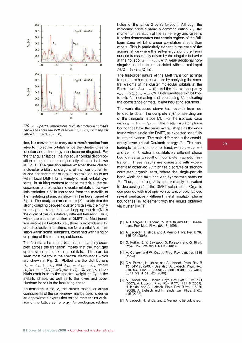
IFF Scientific Report 2008 • Condensed matter physics
79
FIG. 2: Spectral distributions of cluster molecular orbitalsbelow and above the Mott transition (Uc ≈ 9.5) for triangularlattice (T = 0.02, EF = 0).
tion, it is convenient to carry out a transformation fromsites to molecular orbitals since the cluster Green’sfunction and self-energy then become diagonal. Forthe triangular lattice, the molecular orbital decompo-sition of the non-interacting density of states is shownin Fig. 1. The question arises whether these clustermolecular orbitals undergo a similar correlation in-duced enhancement of orbital polarization as foundwithin local DMFT for a variety of multi-orbital sys-tems. In striking contrast to these materials, the oc-cupancies of the cluster molecular orbitals show verylittle variation if U is increased from the metallic tothe insulating phase, as shown in the lower panel ofFig. 1. The analysis carried out in [2] reveals that thestrong coupling between cluster orbitals via the highlynon-diagonal single-electron hopping matrix t(k) isthe origin of this qualitatively different behavior. Thus,within the cluster extension of DMFT the Mott transi-tion involves all orbitals, i.e., there is no evidence fororbital-selective transitions, nor for a partial Mott tran-sition within some subbands, combined with filling oremptying of the remaining subbands.
The fact that all cluster orbitals remain partially occu-pied across the transition implies that the Mott gapopens simultaneously in all orbitals. This can beseen most clearly in the spectral distributions whichare shown in Fig. 2. Plotted are the distributionsA1 = A11 + 2A12 and A2,3 = A11 − A12, whereAij(ω) = −(1/π) Im Gij(ω + iδ). Evidently, all or-bitals contribute to the spectral weight at EF in themetallic phase, as well as to the lower and upperHubbard bands in the insulating phase.
As indicated in Eq. 2, the cluster molecular orbitalcomponents of the self-energy may be used to derivean approximate expression for the momentum varia-tion of the lattice self-energy. An anologous relation
holds for the lattice Green’s function. Although themolecular orbitals share a common critical Uc, themomentum variation of the self-energy and Green’sfunction demonstrates that certain regions of the Bril-louin Zone exhibit stronger correlation effects thanothers. This is particularly evident in the case of thesquare lattice where the self-energy along the Fermisurface is essentially driven by the singular behaviorat the hot spot X = (π, 0), with weak additional non-singular contributions associated with the cold spotM/2 = (π/2, π/2) [2].
The first-order nature of the Mott transition at finitetemperature has been verified by analyzing the spec-tral weights of the cluster molecular orbitals at theFermi level, Am(ω = 0), and the double occupancydocc =
Pm〈nm↑nm↓〉/3. Both quantities exhibit hys-
teresis for increasing and decreasing U , indicatingthe coexistence of metallic and insulating solutions.
The work discussed above has recently been ex-tended to obtain the complete T/U phase diagramof the triangular lattice [7]. For the isotropic casewith t12 = t13 = t23 = t the metal insulator phaseboundaries have the same overall shape as the onesfound within single-site DMFT, as expected for a fullyfrustrated system. The main difference is the consid-erably lower critical Coulomb energy Uc. The non-isotropic lattice, on the other hand, with t13 = t23 = t
and t12 < t, exhibits qualitatively different phaseboundaries as a result of incomplete magnetic frus-tration. These results are consistent with experi-mentally observed T/P phase diagrams of stronglycorrelated organic salts, where the single-particleband width can be tuned with hydrostratic pressureP . Thus, increasing P is approximately equivalentto decreasing U in the DMFT calculation. Organiccompounds with isotropic versus anisotropic latticesreveal qualitatively different metal insulator phaseboundaries, in agreement with the results obtainedvia cluster DMFT.
[1] A. Georges, G. Kotliar, W. Krauth and M.J. Rozen-berg, Rev. Mod. Phys. 68, 13 (1996).
[2] A. Liebsch, H. Ishida, and J. Merino, Phys. Rev. B 78,165123 (2008).
[3] G. Kotliar, S. Y. Savrasov, G. Palsson, and G. Biroli,Phys. Rev. Lett. 87, 186401 (2001).
[4] M. Caffarel and W. Krauth, Phys. Rev. Lett. 72, 1545(1994).
[5] C.A. Perroni, H. Ishida, and A. Liebsch, Phys. Rev. B75, 045125 (2007). See also: A. Liebsch, Phys. Rev.Lett. 95, 116402 (2005); A. Liebsch and T.A. Costi,Eur. Phys. J. 51, 523 (2006).
[6] A. Liebsch and H. Ishida, Phys. Rev. Lett. 98, 216404(2007), A. Liebsch, Phys. Rev. B 77, 115115 (2008),H. Ishida, and A. Liebsch, Phys. Rev. B 77, 115350(2008), A. Liebsch and H. Ishida, Eur. Phys. J. 61,405 (2008).
[7] A. Liebsch, H. Ishida, and J. Merino, to be published.
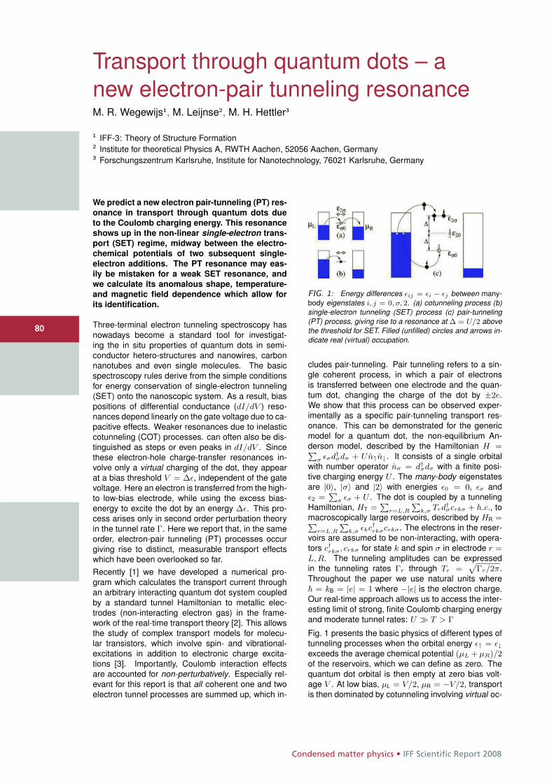
Condensed matter physics • IFF Scientific Report 2008
8080
Transport through quantum dots – anew electron-pair tunneling resonanceM. R. Wegewijs1, M. Leijnse2, M. H. Hettler3
1 IFF-3: Theory of Structure Formation2 Institute for theoretical Physics A, RWTH Aachen, 52056 Aachen, Germany3 Forschungszentrum Karlsruhe, Institute for Nanotechnology, 76021 Karlsruhe, Germany
We predict a new electron pair-tunneling (PT) res-
onance in transport through quantum dots due
to the Coulomb charging energy. This resonance
shows up in the non-linear single-electron trans-
port (SET) regime, midway between the electro-
chemical potentials of two subsequent single-
electron additions. The PT resonance may eas-
ily be mistaken for a weak SET resonance, and
we calculate its anomalous shape, temperature-
and magnetic field dependence which allow for
its identification.
Three-terminal electron tunneling spectroscopy hasnowadays become a standard tool for investigat-ing the in situ properties of quantum dots in semi-conductor hetero-structures and nanowires, carbonnanotubes and even single molecules. The basicspectroscopy rules derive from the simple conditionsfor energy conservation of single-electron tunneling(SET) onto the nanoscopic system. As a result, biaspositions of differential conductance (dI/dV ) reso-nances depend linearly on the gate voltage due to ca-pacitive effects. Weaker resonances due to inelasticcotunneling (COT) processes. can often also be dis-tinguished as steps or even peaks in dI/dV . Sincethese electron-hole charge-transfer resonances in-volve only a virtual charging of the dot, they appearat a bias threshold V = Δε, independent of the gatevoltage. Here an electron is transferred from the high-to low-bias electrode, while using the excess bias-energy to excite the dot by an energy Δε. This pro-cess arises only in second order perturbation theoryin the tunnel rate Γ. Here we report that, in the sameorder, electron-pair tunneling (PT) processes occurgiving rise to distinct, measurable transport effectswhich have been overlooked so far.Recently [1] we have developed a numerical pro-gram which calculates the transport current throughan arbitrary interacting quantum dot system coupledby a standard tunnel Hamiltonian to metallic elec-trodes (non-interacting electron gas) in the frame-work of the real-time transport theory [2]. This allowsthe study of complex transport models for molecu-lar transistors, which involve spin- and vibrational-excitations in addition to electronic charge excita-tions [3]. Importantly, Coulomb interaction effectsare accounted for non-perturbatively. Especially rel-evant for this report is that all coherent one and twoelectron tunnel processes are summed up, which in-
FIG. 1: Energy differences εij = εi − εj between many-body eigenstates i, j = 0, σ, 2. (a) cotunneling process (b)single-electron tunneling (SET) process (c) pair-tunneling(PT) process, giving rise to a resonance at Δ = U/2 abovethe threshold for SET. Filled (unfilled) circles and arrows in-dicate real (virtual) occupation.
cludes pair-tunneling. Pair tunneling refers to a sin-gle coherent process, in which a pair of electronsis transferred between one electrode and the quan-tum dot, changing the charge of the dot by ±2e.We show that this process can be observed exper-imentally as a specific pair-tunneling transport res-onance. This can be demonstrated for the genericmodel for a quantum dot, the non-equilibrium An-derson model, described by the Hamiltonian H =P
σ εσd†σdσ + Un↑n↓. It consists of a single orbital
with number operator nσ = d†σdσ with a finite posi-
tive charging energy U . The many-body eigenstatesare |0〉, |σ〉 and |2〉 with energies ε0 = 0, εσ andε2 =
Pσ εσ + U . The dot is coupled by a tunneling
Hamiltonian, HT =P
r=L,R
Pk,σ Trd
†σcrkσ + h.c., to
macroscopically large reservoirs, described by HR =Pr=L,R
Pk,σ εkc†rkσcrkσ. The electrons in the reser-
voirs are assumed to be non-interacting, with opera-tors c†rkσ, crkσ for state k and spin σ in electrode r =L, R. The tunneling amplitudes can be expressedin the tunneling rates Γr through Tr =
pΓr/2π.
Throughout the paper we use natural units where� = kB = |e| = 1 where −|e| is the electron charge.Our real-time approach allows us to access the inter-esting limit of strong, finite Coulomb charging energyand moderate tunnel rates: U � T > Γ
Fig. 1 presents the basic physics of different types oftunneling processes when the orbital energy ε↑ = ε↓exceeds the average chemical potential (μL + μR)/2of the reservoirs, which we can define as zero. Thequantum dot orbital is then empty at zero bias volt-age V . At low bias, μL = V/2, μR = −V/2, transportis then dominated by cotunneling involving virtual oc-
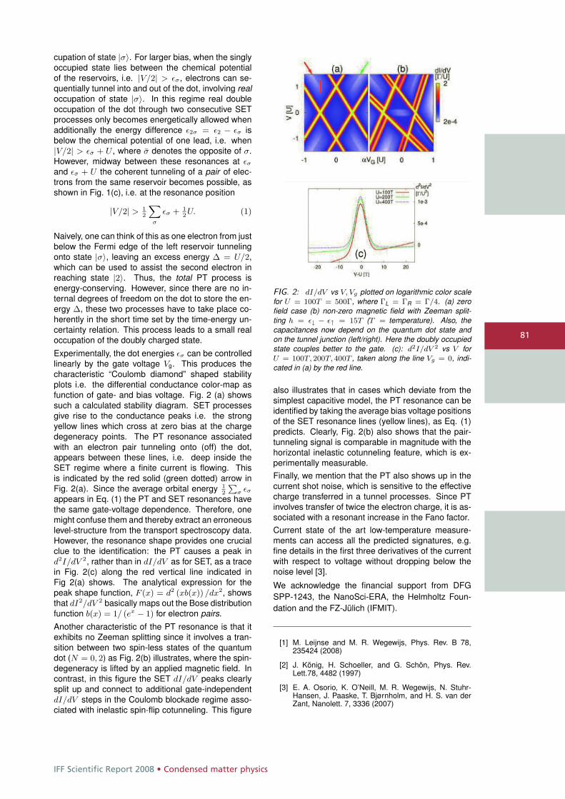
IFF Scientific Report 2008 • Condensed matter physics
81
cupation of state |σ〉. For larger bias, when the singlyoccupied state lies between the chemical potentialof the reservoirs, i.e. |V/2| > εσ, electrons can se-quentially tunnel into and out of the dot, involving realoccupation of state |σ〉. In this regime real doubleoccupation of the dot through two consecutive SETprocesses only becomes energetically allowed whenadditionally the energy difference ε2σ = ε2 − εσ isbelow the chemical potential of one lead, i.e. when|V/2| > εσ + U , where σ denotes the opposite of σ.However, midway between these resonances at εσ
and εσ + U the coherent tunneling of a pair of elec-trons from the same reservoir becomes possible, asshown in Fig. 1(c), i.e. at the resonance position
|V/2| > 12
X
σ
εσ + 12U. (1)
Naively, one can think of this as one electron from justbelow the Fermi edge of the left reservoir tunnelingonto state |σ〉, leaving an excess energy Δ = U/2,which can be used to assist the second electron inreaching state |2〉. Thus, the total PT process isenergy-conserving. However, since there are no in-ternal degrees of freedom on the dot to store the en-ergy Δ, these two processes have to take place co-herently in the short time set by the time-energy un-certainty relation. This process leads to a small realoccupation of the doubly charged state.Experimentally, the dot energies εσ can be controlledlinearly by the gate voltage Vg. This produces thecharacteristic “Coulomb diamond” shaped stabilityplots i.e. the differential conductance color-map asfunction of gate- and bias voltage. Fig. 2 (a) showssuch a calculated stability diagram. SET processesgive rise to the conductance peaks i.e. the strongyellow lines which cross at zero bias at the chargedegeneracy points. The PT resonance associatedwith an electron pair tunneling onto (off) the dot,appears between these lines, i.e. deep inside theSET regime where a finite current is flowing. Thisis indicated by the red solid (green dotted) arrow inFig. 2(a). Since the average orbital energy 1
2
Pσ εσ
appears in Eq. (1) the PT and SET resonances havethe same gate-voltage dependence. Therefore, onemight confuse them and thereby extract an erroneouslevel-structure from the transport spectroscopy data.However, the resonance shape provides one crucialclue to the identification: the PT causes a peak ind2I/dV 2, rather than in dI/dV as for SET, as a tracein Fig. 2(c) along the red vertical line indicated inFig 2(a) shows. The analytical expression for thepeak shape function, F (x) = d2 (xb(x)) /dx2, showsthat dI2/dV 2 basically maps out the Bose distributionfunction b(x) = 1/ (ex − 1) for electron pairs.Another characteristic of the PT resonance is that itexhibits no Zeeman splitting since it involves a tran-sition between two spin-less states of the quantumdot (N = 0, 2) as Fig. 2(b) illustrates, where the spin-degeneracy is lifted by an applied magnetic field. Incontrast, in this figure the SET dI/dV peaks clearlysplit up and connect to additional gate-independentdI/dV steps in the Coulomb blockade regime asso-ciated with inelastic spin-flip cotunneling. This figure
FIG. 2: dI/dV vs V, Vg plotted on logarithmic color scalefor U = 100T = 500Γ, where ΓL = ΓR = Γ/4. (a) zerofield case (b) non-zero magnetic field with Zeeman split-ting h = ε↓ − ε↑ = 15T (T = temperature). Also, thecapacitances now depend on the quantum dot state andon the tunnel junction (left/right). Here the doubly occupiedstate couples better to the gate. (c): d2I/dV 2 vs V forU = 100T, 200T, 400T , taken along the line Vg = 0, indi-cated in (a) by the red line.
also illustrates that in cases which deviate from thesimplest capacitive model, the PT resonance can beidentified by taking the average bias voltage positionsof the SET resonance lines (yellow lines), as Eq. (1)predicts. Clearly, Fig. 2(b) also shows that the pair-tunneling signal is comparable in magnitude with thehorizontal inelastic cotunneling feature, which is ex-perimentally measurable.Finally, we mention that the PT also shows up in thecurrent shot noise, which is sensitive to the effectivecharge transferred in a tunnel processes. Since PTinvolves transfer of twice the electron charge, it is as-sociated with a resonant increase in the Fano factor.Current state of the art low-temperature measure-ments can access all the predicted signatures, e.g.fine details in the first three derivatives of the currentwith respect to voltage without dropping below thenoise level [3].
We acknowledge the financial support from DFGSPP-1243, the NanoSci-ERA, the Helmholtz Foun-dation and the FZ-Jülich (IFMIT).
[1] M. Leijnse and M. R. Wegewijs, Phys. Rev. B 78,235424 (2008)
[2] J. König, H. Schoeller, and G. Schön, Phys. Rev.Lett.78, 4482 (1997)
[3] E. A. Osorio, K. O’Neill, M. R. Wegewijs, N. Stuhr-Hansen, J. Paaske, T. Bjørnholm, and H. S. van derZant, Nanolett. 7, 3336 (2007)
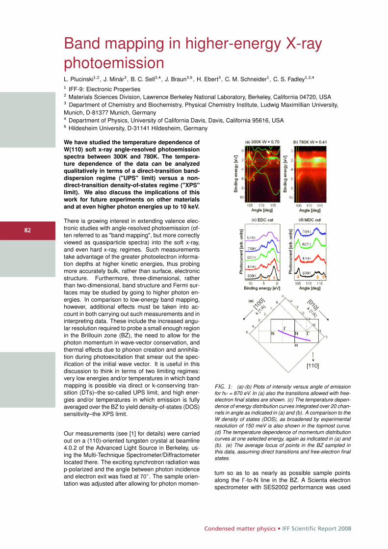
Condensed matter physics • IFF Scientific Report 2008
8282
Band mapping in higher-energy X-rayphotoemissionL. Plucinski1,2, J. Minár3, B. C. Sell2,4, J. Braun3,5, H. Ebert3, C. M. Schneider1, C. S. Fadley1,2,4
1 IFF-9: Electronic Properties2 Materials Sciences Division, Lawrence Berkeley National Laboratory, Berkeley, California 04720, USA3 Department of Chemistry and Biochemistry, Physical Chemistry Institute, Ludwig Maximillian University,Munich, D-81377 Munich, Germany4 Department of Physics, University of California Davis, Davis, California 95616, USA5 Hildesheim University, D-31141 Hildesheim, Germany
We have studied the temperature dependence of
W(110) soft x-ray angle-resolved photoemission
spectra between 300K and 780K. The tempera-
ture dependence of the data can be analyzed
qualitatively in terms of a direct-transition band-
dispersion regime ("UPS" limit) versus a non-
direct-transition density-of-states regime ("XPS"
limit). We also discuss the implications of this
work for future experiments on other materials
and at even higher photon energies up to 10 keV.
There is growing interest in extending valence elec-tronic studies with angle-resolved photoemission (of-ten referred to as "band mapping", but more correctlyviewed as quasiparticle spectra) into the soft x-ray,and even hard x-ray, regimes. Such measurementstake advantage of the greater photoelectron informa-tion depths at higher kinetic energies, thus probingmore accurately bulk, rather than surface, electronicstructure. Furthermore, three-dimensional, ratherthan two-dimensional, band structure and Fermi sur-faces may be studied by going to higher photon en-ergies. In comparison to low-energy band mapping,however, additional effects must be taken into ac-count in both carrying out such measurements and ininterpreting data. These include the increased angu-lar resolution required to probe a small enough regionin the Brillouin zone (BZ), the need to allow for thephoton momentum in wave-vector conservation, andthermal effects due to phonon creation and annihila-tion during photoexcitation that smear out the spec-ification of the initial wave vector. It is useful in thisdiscussion to think in terms of two limiting regimes:very low energies and/or temperatures in which bandmapping is possible via direct or k-conserving tran-sition (DTs)–the so-called UPS limit, and high ener-gies and/or temperatures in which emission is fullyaveraged over the BZ to yield density-of-states (DOS)sensitivity–the XPS limit.
Our measurements (see [1] for details) were carriedout on a (110)-oriented tungsten crystal at beamline4.0.2 of the Advanced Light Source in Berkeley, us-ing the Multi-Technique Spectrometer/Diffractometerlocated there. The exciting synchrotron radiation wasp-polarized and the angle between photon incidenceand electron exit was fixed at 70◦. The sample orien-tation was adjusted after allowing for photon momen-
FIG. 1: (a)-(b) Plots of intensity versus angle of emissionfor hν = 870 eV. In (a) also the transitions allowed with free-electron final states are shown. (c) The temperature depen-dence of energy distribution curves integrated over 20 chan-nels in angle as indicated in (a) and (b). A comparison to theW density of states (DOS), as broadened by experimentalresolution of 150 meV is also shown in the topmost curve.(d) The temperature dependence of momentum distributioncurves at one selected energy, again as indicated in (a) and(b). (e) The average locus of points in the BZ sampled inthis data, assuming direct transitions and free-electron finalstates.
tum so as to as nearly as possible sample pointsalong the Γ-to-N line in the BZ. A Scienta electronspectrometer with SES2002 performance was used
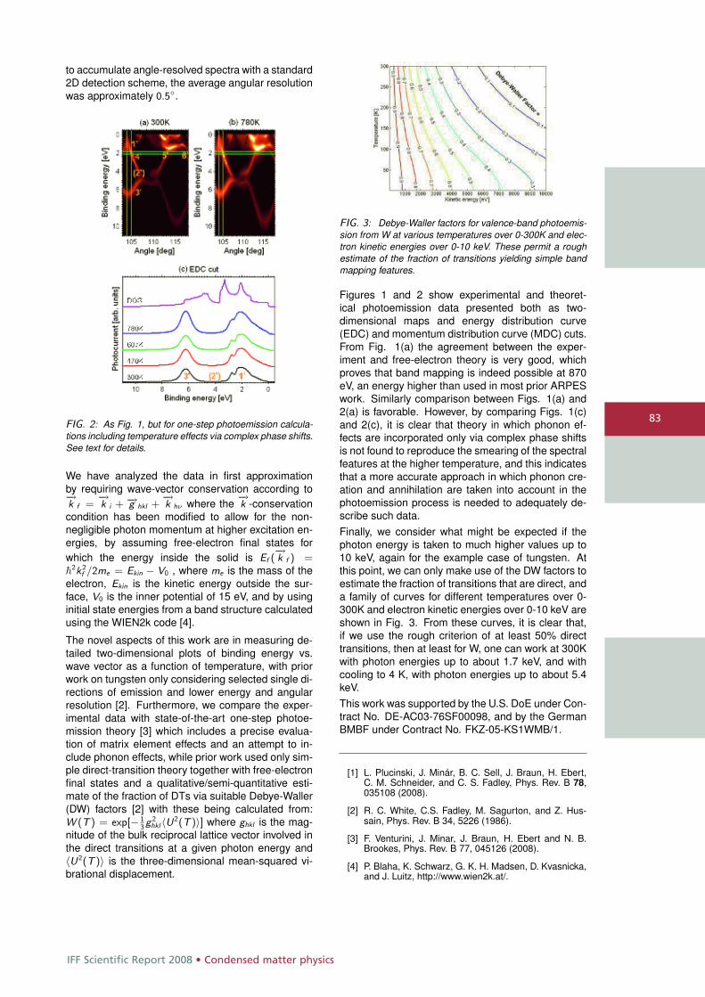
IFF Scientific Report 2008 • Condensed matter physics
83
to accumulate angle-resolved spectra with a standard2D detection scheme, the average angular resolutionwas approximately 0.5◦.
FIG. 2: As Fig. 1, but for one-step photoemission calcula-tions including temperature effects via complex phase shifts.See text for details.
We have analyzed the data in first approximationby requiring wave-vector conservation according to−→k f =
−→k i + −→g hkl +
−→k hν where the
−→k -conservation
condition has been modified to allow for the non-negligible photon momentum at higher excitation en-ergies, by assuming free-electron final states forwhich the energy inside the solid is Ef (
−→k f ) =
�2k2
f /2me = Ekin − V0 , where me is the mass of theelectron, Ekin is the kinetic energy outside the sur-face, V0 is the inner potential of 15 eV, and by usinginitial state energies from a band structure calculatedusing the WIEN2k code [4].
The novel aspects of this work are in measuring de-tailed two-dimensional plots of binding energy vs.wave vector as a function of temperature, with priorwork on tungsten only considering selected single di-rections of emission and lower energy and angularresolution [2]. Furthermore, we compare the exper-imental data with state-of-the-art one-step photoe-mission theory [3] which includes a precise evalua-tion of matrix element effects and an attempt to in-clude phonon effects, while prior work used only sim-ple direct-transition theory together with free-electronfinal states and a qualitative/semi-quantitative esti-mate of the fraction of DTs via suitable Debye-Waller(DW) factors [2] with these being calculated from:W (T ) = exp[− 1
3g 2
hkl〈U2(T )〉] where ghkl is the mag-nitude of the bulk reciprocal lattice vector involved inthe direct transitions at a given photon energy and〈U2(T )〉 is the three-dimensional mean-squared vi-brational displacement.
FIG. 3: Debye-Waller factors for valence-band photoemis-sion from W at various temperatures over 0-300K and elec-tron kinetic energies over 0-10 keV. These permit a roughestimate of the fraction of transitions yielding simple bandmapping features.
Figures 1 and 2 show experimental and theoret-ical photoemission data presented both as two-dimensional maps and energy distribution curve(EDC) and momentum distribution curve (MDC) cuts.From Fig. 1(a) the agreement between the exper-iment and free-electron theory is very good, whichproves that band mapping is indeed possible at 870eV, an energy higher than used in most prior ARPESwork. Similarly comparison between Figs. 1(a) and2(a) is favorable. However, by comparing Figs. 1(c)and 2(c), it is clear that theory in which phonon ef-fects are incorporated only via complex phase shiftsis not found to reproduce the smearing of the spectralfeatures at the higher temperature, and this indicatesthat a more accurate approach in which phonon cre-ation and annihilation are taken into account in thephotoemission process is needed to adequately de-scribe such data.Finally, we consider what might be expected if thephoton energy is taken to much higher values up to10 keV, again for the example case of tungsten. Atthis point, we can only make use of the DW factors toestimate the fraction of transitions that are direct, anda family of curves for different temperatures over 0-300K and electron kinetic energies over 0-10 keV areshown in Fig. 3. From these curves, it is clear that,if we use the rough criterion of at least 50% directtransitions, then at least for W, one can work at 300Kwith photon energies up to about 1.7 keV, and withcooling to 4 K, with photon energies up to about 5.4keV.This work was supported by the U.S. DoE under Con-tract No. DE-AC03-76SF00098, and by the GermanBMBF under Contract No. FKZ-05-KS1WMB/1.
[1] L. Plucinski, J. Minár, B. C. Sell, J. Braun, H. Ebert,C. M. Schneider, and C. S. Fadley, Phys. Rev. B 78,035108 (2008).
[2] R. C. White, C.S. Fadley, M. Sagurton, and Z. Hus-sain, Phys. Rev. B 34, 5226 (1986).
[3] F. Venturini, J. Minar, J. Braun, H. Ebert and N. B.Brookes, Phys. Rev. B 77, 045126 (2008).
[4] P. Blaha, K. Schwarz, G. K. H. Madsen, D. Kvasnicka,and J. Luitz, http://www.wien2k.at/.
Condensed matter physics • IFF Scientific Report 2008
8484
A linear scaling algorithm for densityfunctional calculationsR. Zeller1,2
1 IFF-3: Theory of Structure Formation2 IAS: Institute for Advanced Simulation
The work in standard density functional calcu-
lations increases cubically with the number of
atoms in the system. Several linear scaling tech-
niques, which trade accuracy for speed, have ap-
peared in recent years, but their applicability and
accuracy for metallic systems remains rather un-
clear. In the last two years we have developed a
new algorithm with linear scaling behaviour and
investigated its suitability in model calculations
for large metallic supercells with up to 131072
atoms. Our algorithm is based on the tight-
binding Korringa-Kohn-Rostoker Green function
method and utilizes an exponential decay of the
Green function matrix elements, iterative solu-
tion techniques and a spatial truncation of the
Green function in the sense of Kohn’s principle
of nearsightedness of electronic matter.
In the last decades density functional theory hasemerged as a powerful tool for the quantum me-chanical description of chemical and physical prop-erties of materials. Density functional theory treatsthe many-electron problem by single-particle equa-tions using the electron density instead of the many-electron wavefunction as the basic quantity. Althoughthis represents an obvious simplification, calculationsfor systems with many atoms still represent a seriouscomputational challenge. The main bottleneck is thatthe computing time increases with the third power ofthe number of atoms in the system. Systems witha few hundred atoms can be treated routinely today,but larger systems with thousands of atoms requireenormous computer resources. In recent years con-siderable effort has been spent to reduce the com-putational work by exploiting the short range of thedensity matrix which decays exponentially in semi-conducting and insulating materials and several lin-ear scaling techniques have been developed whichtreat large systems with satisfactory accuracy.
The problem for metallic systems is that the den-sity matrix decays only algebraically. In principle,this does not exclude to apply the concept of near-sightedness of electronic matter, a term phrased byNobel Prize winner Walter Kohn. Nearsightednessmeans that in systems without long range electricfields (and for fixed chemical potential) the densitychange at a point in space is negligibly affected, if the
electronic potential is changed sufficiently far awayfrom this point. For metallic systems this property isused in locally self-consistent approaches based onthe Korringa-Kohn-Rostoker (KKR) and local muffin-tin orbital (LMTO) methods. Each atomic cell and itslocal surrounding are treated as independent subsys-tems with naturally linear scaling effort. The densitiesof the subsystems are then patched together. A dis-advantage of these approaches is that it is difficult toassess and expensive to improve the accuracy sincethe work scales with third power of the number ofatoms in the local interaction zone. This disadvan-tage is avoided in our new KKR algorithm, which ex-ploits not only the nearsightedness, but also the useof sparse matrices and iterative solution techniquesas it is done in most other linear scaling techniques.
In the last two years we have implemented the com-bined use of sparse matrices, iterative solutions andnearsightedness into our existing KKR Green func-tion programs which we have developed over theyears at the IFF to study defects, surfaces and bulksystems. In the KKR Green function method [1]space is divided into nonoverlapping cells aroundthe atomic sites. For each cell a single-site problemis solved using an angular momentum expansion ofdensity, potential and wavefunctions. From the sitedependent quantities the Green function of the sys-tem is then obtained by multiple scattering theory,which computationally requires to invert the KKR ma-trix M(E) at a set of energy mesh points Ei usedto obtain the electron density by energy integration.The computational effort is determined by the ma-trix dimension N(lmax + 1)2 where N is the numberof atoms in the system and lmax the highest angu-lar momentum used, usually lmax = 3 is sufficient.The standard KKR matrix with its free space Greenfunction matrix elements is a dense matrix which re-quires O(N3) computing effort for inversion. Here thetight-binding (TB) KKR method [1] which is based ona repulsive reference system with exponentially de-caying Green function matrix elements is much bettersuited. Setting exponentially small elements to zeromakes the TB-KKR matrix sparse and reduces thecomputational effort from O(N3) to O(N2).
One difficulty for the iterative determination ofM−1(E) is that iterations cannot converge at or nearenergies E, where the Green function has singular-ities. Such singularities appear on the real energy
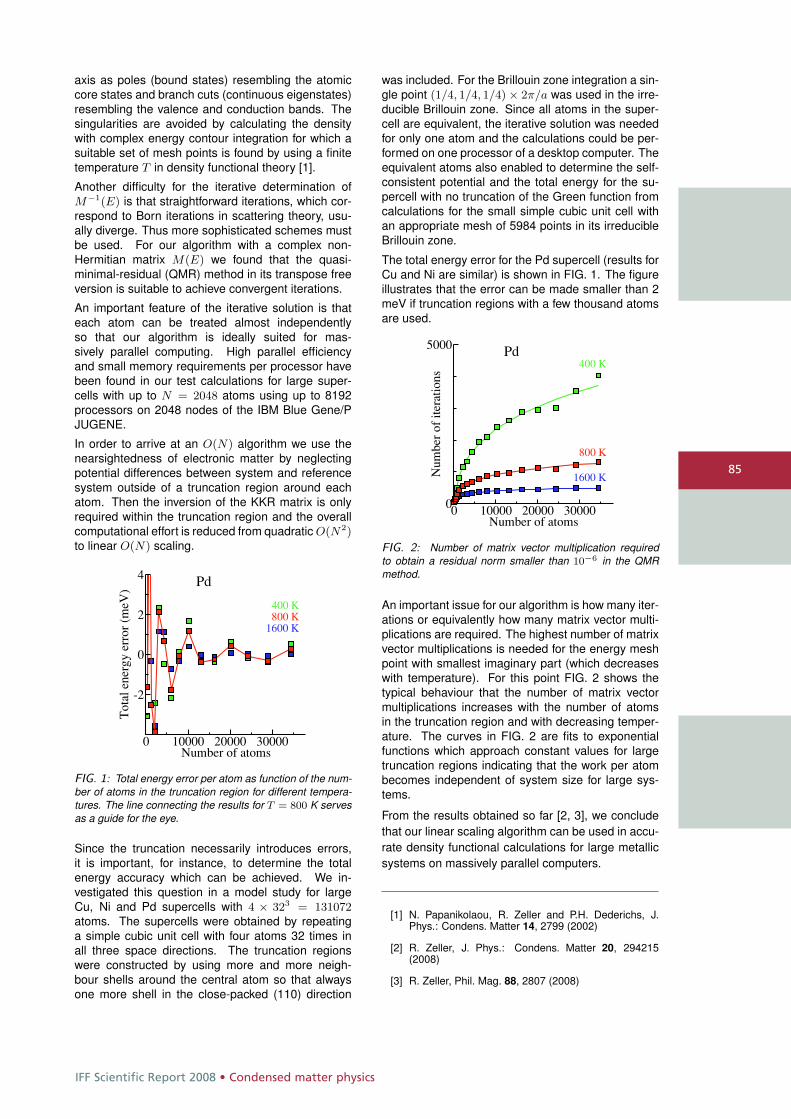
IFF Scientific Report 2008 • Condensed matter physics
85
axis as poles (bound states) resembling the atomiccore states and branch cuts (continuous eigenstates)resembling the valence and conduction bands. Thesingularities are avoided by calculating the densitywith complex energy contour integration for which asuitable set of mesh points is found by using a finitetemperature T in density functional theory [1].
Another difficulty for the iterative determination ofM−1(E) is that straightforward iterations, which cor-respond to Born iterations in scattering theory, usu-ally diverge. Thus more sophisticated schemes mustbe used. For our algorithm with a complex non-Hermitian matrix M(E) we found that the quasi-minimal-residual (QMR) method in its transpose freeversion is suitable to achieve convergent iterations.
An important feature of the iterative solution is thateach atom can be treated almost independentlyso that our algorithm is ideally suited for mas-sively parallel computing. High parallel efficiencyand small memory requirements per processor havebeen found in our test calculations for large super-cells with up to N = 2048 atoms using up to 8192processors on 2048 nodes of the IBM Blue Gene/PJUGENE.
In order to arrive at an O(N) algorithm we use thenearsightedness of electronic matter by neglectingpotential differences between system and referencesystem outside of a truncation region around eachatom. Then the inversion of the KKR matrix is onlyrequired within the truncation region and the overallcomputational effort is reduced from quadratic O(N2)to linear O(N) scaling.
0 10000 20000 30000Number of atoms
-2
0
2
4
Tot
al e
nerg
y er
ror
(meV
)
Pd
400 K800 K
1600 K
FIG. 1: Total energy error per atom as function of the num-ber of atoms in the truncation region for different tempera-tures. The line connecting the results for T = 800 K servesas a guide for the eye.
Since the truncation necessarily introduces errors,it is important, for instance, to determine the totalenergy accuracy which can be achieved. We in-vestigated this question in a model study for largeCu, Ni and Pd supercells with 4 × 323 = 131072atoms. The supercells were obtained by repeatinga simple cubic unit cell with four atoms 32 times inall three space directions. The truncation regionswere constructed by using more and more neigh-bour shells around the central atom so that alwaysone more shell in the close-packed (110) direction
was included. For the Brillouin zone integration a sin-gle point (1/4, 1/4, 1/4) × 2π/a was used in the irre-ducible Brillouin zone. Since all atoms in the super-cell are equivalent, the iterative solution was neededfor only one atom and the calculations could be per-formed on one processor of a desktop computer. Theequivalent atoms also enabled to determine the self-consistent potential and the total energy for the su-percell with no truncation of the Green function fromcalculations for the small simple cubic unit cell withan appropriate mesh of 5984 points in its irreducibleBrillouin zone.
The total energy error for the Pd supercell (results forCu and Ni are similar) is shown in FIG. 1. The figureillustrates that the error can be made smaller than 2meV if truncation regions with a few thousand atomsare used.
0 10000 20000 30000Number of atoms
0
5000
Num
ber
of it
erat
ions
Pd400 K
800 K
1600 K
FIG. 2: Number of matrix vector multiplication requiredto obtain a residual norm smaller than 10−6 in the QMRmethod.
An important issue for our algorithm is how many iter-ations or equivalently how many matrix vector multi-plications are required. The highest number of matrixvector multiplications is needed for the energy meshpoint with smallest imaginary part (which decreaseswith temperature). For this point FIG. 2 shows thetypical behaviour that the number of matrix vectormultiplications increases with the number of atomsin the truncation region and with decreasing temper-ature. The curves in FIG. 2 are fits to exponentialfunctions which approach constant values for largetruncation regions indicating that the work per atombecomes independent of system size for large sys-tems.
From the results obtained so far [2, 3], we concludethat our linear scaling algorithm can be used in accu-rate density functional calculations for large metallicsystems on massively parallel computers.
[1] N. Papanikolaou, R. Zeller and P.H. Dederichs, J.Phys.: Condens. Matter 14, 2799 (2002)
[2] R. Zeller, J. Phys.: Condens. Matter 20, 294215(2008)
[3] R. Zeller, Phil. Mag. 88, 2807 (2008)
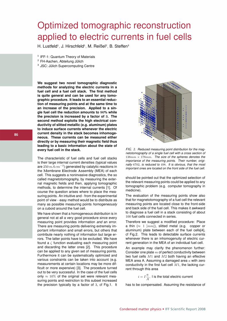
Condensed matter physics • IFF Scientific Report 2008
8686
Optimized tomographic reconstructionapplied to electric currents in fuel cellsH. Lustfeld1, J. Hirschfeld1, M. Reißel2, B. Steffen3
1 IFF-1: Quantum Theory of Materials2 FH-Aachen, Abteilung Jülich3 JSC: Jülich Supercomputing Centre
We suggest two novel tomographic diagnostic
methods for analyzing the electric currents in a
fuel cell and a fuel cell stack. The first method
is quite general and can be used for any tomo-
graphic procedure. It leads to an essential reduc-
tion of measuring points and at the same time to
an increase of the precision. Applied to a sin-
gle fuel cell the reduction amounts to 90% while
the precision is increased by a factor of 3. The
second method exploits the high electrical con-
ductivity of slitted metallic (e.g. aluminum) plates
to induce surface currents whenever the electric
current density in the stack becomes inhomoge-
neous. These currents can be measured either
directly or by measuring their magnetic field thus
leading to a basic information about the state of
every fuel cell in the stack.
The characteristic of fuel cells and fuel cell stacksis their large internal current densities (typical valuesare 250 mA cm−2) generated by catalytic reactions inthe Membrane Electrode Assembly (MEA) of eachcell. This suggests a noninvasive diagnostics, the socalled magnetotomography, by measuring the exter-nal magnetic fields and then, applying tomographicmethods, to determine the internal currents [1]. Ofcourse the question arises where to place the mea-suring points. An intuitive and - from the experimentalpoint of view - easy method would be to distribute asmany as possible measuring points homogeneouslyon a cuboid around the fuel cell.We have shown that a homogeneous distribution is ingeneral not at all a very good procedure since everymeasuring point provides information and an error.There are measuring points delivering extremely im-portant information and small errors, but others thatcontribute nearly nothing of information but large er-rors. The latter points have to be excluded. We havefound a ζ function evaluating each measuring pointand discarding the latter ones [2]. This procedurecan be applied to any given set of measuring points.Furthermore it can be systematically optimized andvarious constraints can be taken into account (e.g.measurements at certain locations may be more dif-ficult or more expensive) [3]. The procedure turnedout to be very successful. In the case of the fuel cellsonly ≈ 10% of the original set were relevant mea-suring points and restriction to this subset increasedthe precision typically by a factor of 3, cf Fig.1. It
FIG. 1: Reduced measuring point distribution for the mag-netotomography of a single fuel cell with a cross section of138mm × 178mm. The size of the spheres denotes theimportance of the measuring points. Their number, origi-nally 6702, is reduced to 498. It is obvious, that the mostimportant ones are located on the front side of the fuel cell.
should be pointed out that the optimized selection ofthe relevant measuring points could be applied to anytomographic problem (e.g. computer tomography inmedicine).
The evaluation of the measuring points show alsothat for magnetotomography of a fuel cell the relevantmeasuring points are located close to the front-sideand back side of the fuel cell. This makes it awkwardto diagnose a fuel cell in a stack consisting of about100 fuel cells connected in series.
Therefore we suggest a modified procedure: Placea thin (≈ 1 [mm]), slitted metal (e.g. copper oraluminum) plate between each of the fuel cells[4],cf Fig.2. This leads to detectable surface currentswhenever there is an inhomogenuity of electric cur-rent generation in the MEA of an individual fuel cell.
An example may clarify the phenomenon further:Consider one plate m of perfect conductivity betweentwo fuel cells M1 and M2 both having an effectiveMEA area A. Assuming a damaged area a with zeroconductivity in the first fuel cell M1, the lacking cur-rent through this area
i = Ia
A, I is the total electric current
has to be compensated. Assuming the resistance of
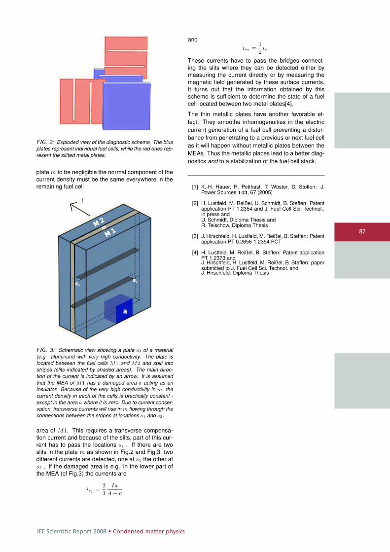
IFF Scientific Report 2008 • Condensed matter physics
87
FIG. 2: Exploded view of the diagnostic scheme. The blueplates represent individual fuel cells, while the red ones rep-resent the slitted metal plates.
plate m to be negligible the normal component of thecurrent density must be the same everywhere in theremaining fuel cell
FIG. 3: Schematic view showing a plate m of a material(e.g. aluminum) with very high conductivity. The plate islocated between the fuel cells M1 and M2 and split intostripes (slits indicated by shaded areas). The main direc-tion of the current is indicated by an arrow. It is assumedthat the MEA of M1 has a damaged area a acting as aninsulator. Because of the very high conductivity in m, thecurrent density in each of the cells is practically constant -except in the area a where it is zero. Due to current conser-vation, transverse currents will rise in m flowing through theconnections between the stripes at locations s1 and s2.
area of M1. This requires a transverse compensa-tion current and because of the slits, part of this cur-rent has to pass the locations si . If there are twoslits in the plate m as shown in Fig.2 and Fig.3, twodifferent currents are detected, one at s1 the other ats2 . If the damaged area is e.g. in the lower part ofthe MEA (cf Fig.3) the currents are
is1 =2
3
Ia
A − a
andis2 =
1
2is1
These currents have to pass the bridges connect-ing the slits where they can be detected either bymeasuring the current directly or by measuring themagnetic field generated by these surface currents.It turns out that the information obtained by thisscheme is sufficient to determine the state of a fuelcell located between two metal plates[4].
The thin metallic plates have another favorable ef-fect: They smoothe inhomogenuities in the electriccurrent generation of a fuel cell preventing a distur-bance from penetrating to a previous or next fuel cellas it will happen without metallic plates between theMEAs. Thus the metallic places lead to a better diag-nostics and to a stabilization of the fuel cell stack.
[1] K.-H. Hauer, R. Potthast, T. Wüster, D. Stolten: J.Power Sources 143, 67 (2005)
[2] H. Lustfeld, M. Reißel, U. Schmidt, B. Steffen: Patentapplication PT 1.2354 and J. Fuel Cell Sci. Technol.,in press andU. Schmidt, Diploma Thesis andR. Telschow, Diploma Thesis
[3] J. Hirschfeld, H. Lustfeld, M. Reißel, B. Steffen: Patentapplication PT 0.2656-1.2354 PCT
[4] H. Lustfeld, M. Reißel, B. Steffen: Patent applicationPT 1.2373 andJ. Hirschfeld, H. Lustfeld, M. Reißel, B. Steffen: papersubmitted to J. Fuel Cell Sci. Technol. andJ. Hirschfeld: Diploma Thesis
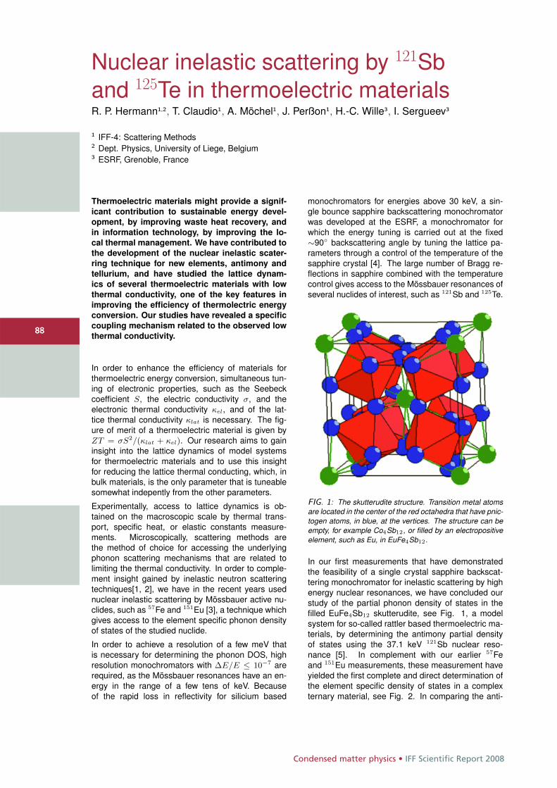
Condensed matter physics • IFF Scientific Report 2008
8888
Nuclear inelastic scattering by 121Sband 125Te in thermoelectric materialsR. P. Hermann1,2, T. Claudio1, A. Möchel1, J. Perßon1, H.-C. Wille3, I. Sergueev3
1 IFF-4: Scattering Methods2 Dept. Physics, University of Liege, Belgium3 ESRF, Grenoble, France
Thermoelectric materials might provide a signif-
icant contribution to sustainable energy devel-
opment, by improving waste heat recovery, and
in information technology, by improving the lo-
cal thermal management. We have contributed to
the development of the nuclear inelastic scater-
ring technique for new elements, antimony and
tellurium, and have studied the lattice dynam-
ics of several thermoelectric materials with low
thermal conductivity, one of the key features in
improving the efficiency of thermolectric energy
conversion. Our studies have revealed a specific
coupling mechanism related to the observed low
thermal conductivity.
In order to enhance the efficiency of materials forthermoelectric energy conversion, simultaneous tun-ing of electronic properties, such as the Seebeckcoefficient S, the electric conductivity σ, and theelectronic thermal conductivity κel, and of the lat-tice thermal conductivity κlat is necessary. The fig-ure of merit of a thermoelectric material is given byZT = σS2/(κlat + κel). Our research aims to gaininsight into the lattice dynamics of model systemsfor thermoelectric materials and to use this insightfor reducing the lattice thermal conducting, which, inbulk materials, is the only parameter that is tuneablesomewhat indepently from the other parameters.
Experimentally, access to lattice dynamics is ob-tained on the macroscopic scale by thermal trans-port, specific heat, or elastic constants measure-ments. Microscopically, scattering methods arethe method of choice for accessing the underlyingphonon scattering mechanisms that are related tolimiting the thermal conductivity. In order to comple-ment insight gained by inelastic neutron scatteringtechniques[1, 2], we have in the recent years usednuclear inelastic scattering by Mössbauer active nu-clides, such as 57Fe and 151Eu [3], a technique whichgives access to the element specific phonon densityof states of the studied nuclide.
In order to achieve a resolution of a few meV thatis necessary for determining the phonon DOS, highresolution monochromators with ΔE/E ≤ 10−7 arerequired, as the Mössbauer resonances have an en-ergy in the range of a few tens of keV. Becauseof the rapid loss in reflectivity for silicium based
monochromators for energies above 30 keV, a sin-gle bounce sapphire backscattering monochromatorwas developed at the ESRF, a monochromator forwhich the energy tuning is carried out at the fixed∼90◦ backscattering angle by tuning the lattice pa-rameters through a control of the temperature of thesapphire crystal [4]. The large number of Bragg re-flections in sapphire combined with the temperaturecontrol gives access to the Mössbauer resonances ofseveral nuclides of interest, such as 121Sb and 125Te.
FIG. 1: The skutterudite structure. Transition metal atomsare located in the center of the red octahedra that have pnic-togen atoms, in blue, at the vertices. The structure can beempty, for example Co4Sb12, or filled by an electropositiveelement, such as Eu, in EuFe4Sb12.
In our first measurements that have demonstratedthe feasibility of a single crystal sapphire backscat-tering monochromator for inelastic scattering by highenergy nuclear resonances, we have concluded ourstudy of the partial phonon density of states in thefilled EuFe4Sb12 skutterudite, see Fig. 1, a modelsystem for so-called rattler based thermoelectric ma-terials, by determining the antimony partial densityof states using the 37.1 keV 121Sb nuclear reso-nance [5]. In complement with our earlier 57Feand 151Eu measurements, these measurement haveyielded the first complete and direct determination ofthe element specific density of states in a complexternary material, see Fig. 2. In comparing the anti-
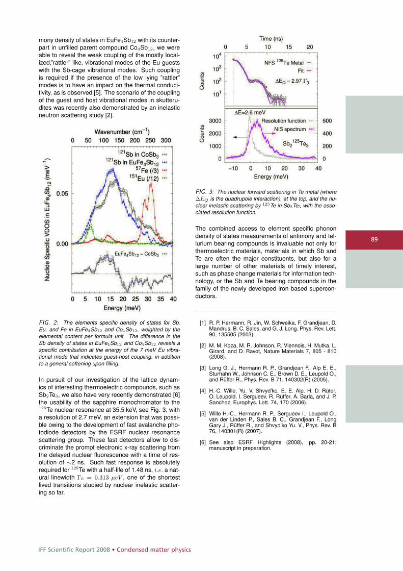
IFF Scientific Report 2008 • Condensed matter physics
89
mony density of states in EuFe4Sb12 with its counter-part in unfilled parent compound Co4Sb12, we wereable to reveal the weak coupling of the mostly local-ized,”rattler” like, vibrational modes of the Eu guestswith the Sb-cage vibrational modes. Such couplingis required if the presence of the low lying ”rattler”modes is to have an impact on the thermal conduci-tivity, as is observed [5]. The scenario of the couplingof the guest and host vibrational modes in skutteru-dites was recently also demonstrated by an inelasticneutron scattering study [2].
FIG. 2: The elements specific density of states for Sb,Eu, and Fe in EuFe4Sb12 and Co4Sb12, weighted by theelemental content per formula unit. The difference in theSb density of states in EuFe4Sb12 and Co4Sb12 reveals aspecific contribution at the energy of the 7 meV Eu vibra-tional mode that indicates guest-host coupling, in additionto a general softening upon filling.
In pursuit of our investigation of the lattice dynam-ics of interesting thermoelectric compounds, such asSb2Te3, we also have very recently demonstrated [6]the usability of the sapphire monochromator to the125Te nuclear resonance at 35.5 keV, see Fig. 3, witha resolution of 2.7 meV, an extension that was possi-ble owing to the development of fast avalanche pho-todiode detectors by the ESRF nuclear resonancescattering group. These fast detectors allow to dis-criminate the prompt electronic x-ray scattering fromthe delayed nuclear fluorescence with a time of res-olution of ∼2 ns. Such fast response is absolutelyrequired for 125Te with a half-life of 1.48 ns, i.e. a nat-ural linewidth Γ0 = 0.313 μeV , one of the shortestlived transitions studied by nuclear inelastic scatter-ing so far.
FIG. 3: The nuclear forward scattering in Te metal (whereΔEQ is the quadrupole interaction), at the top, and the nu-clear inelastic scattering by 125Te in Sb2Te3 with the asso-ciated resolution function.
The combined access to element specific phonondensity of states measurements of antimony and tel-lurium bearing compounds is invaluable not only forthermoelectric materials, materials in which Sb andTe are often the major constituents, but also for alarge number of other materials of timely interest,such as phase change materials for information tech-nology, or the Sb and Te bearing compounds in thefamily of the newly developed iron based supercon-ductors.
[1] R. P. Hermann, R. Jin, W. Schweika, F. Grandjean, D.Mandrus, B. C. Sales, and G. J. Long, Phys. Rev. Lett.90, 135505 (2003).
[2] M. M. Koza, M. R. Johnson, R. Viennois, H. Mutka, L.Girard, and D. Ravot, Nature Materials 7, 805 - 810(2008).
[3] Long G. J., Hermann R. P., Grandjean F., Alp E. E.,Sturhahn W., Johnson C. E., Brown D. E., Leupold O.,and Rüffer R., Phys. Rev. B 71, 140302(R) (2005).
[4] H.-C. Wille, Yu. V. Shvyd’ko, E. E. Alp, H. D. Rüter,O. Leupold, I. Sergueev, R. Rüffer, A. Barla, and J. P.Sanchez, Europhys. Lett. 74, 170 (2006).
[5] Wille H.-C., Hermann R. P., Sergueev I., Leupold O.,van der Linden P., Sales B. C., Grandjean F., LongGary J., Rüffer R., and Shvyd’ko Yu. V., Phys. Rev. B76, 140301(R) (2007).
[6] See also ESRF Highlights (2008), pp. 20-21;manuscript in preparation.
Condensed matter physics • IFF Scientific Report 2008
9090
A stable molecular water oxidationcatalyst for artificial photosynthesisB. Botar1, P. Kögerler1,2
1 IFF-9: Electronic Properties2 Institute of Inorganic Chemistry, RWTH Aachen University
The oxidation of water represents a key reac-
tion in many proposed artificial photosynthesis
systems that aim to convert sunlight energy into
the splitting and formation of chemical bonds.
However, catalysts are required to eliminate ki-
netic obstacles inherent to this elementary reac-
tion. While numerous relevant molecular cata-
lysts were tested in the past decades, all systems
suffer from oxidative degradation of their organic
constituents during the course of the catalyzed
reaction. We now identified an all-inorganic that
retains its high efficiency at ambient temperature
under turnover conditions.
The design of viable and well-defined molecularcatalysts for water oxidation, in part inspired bythe Mn4Ca-centered water oxidation-oxygen evolv-ing center (OEC) in photosystem II, is being pur-sued for three decades and centers on transitionmetal coordination complexes such as the classic[(bpy)2(H2O)RuORu(H2O)(bpy)2]4+ system.[1] De-spite ongoing research, however, stable and rapidmolecular and homogeneous catalysts for the ele-mentary reaction (2 H2O → O2 + 4 H+ + 4 e−) thatexhibit long-term stability have yet to be achieved:Homogenous catalytic oxidation studies suggest thatlikely intermediates in H2O oxidation would de-grade all organic ligands, a point consistent withthe findings in the molecular H2O oxidation cata-lysts reported to date.[2] Thus, the need to de-velop highly active and stable H2O oxidation cata-lysts remains of considerable importance. Based onthe reported Ru2 catalysts for H2O oxidation, doc-umented polyoxometalate complexes with multinu-clear d-electron-containing centers capable of ac-cepting several electrons needed for H2O oxidation,and the report of electrocatalytic O2 evolution bythe complex [WZnRu2(OH)(H2O)(ZnW9O34)2]11−,[3]we developed a tetraruthenium(IV) polyoxotungstatecomplex, isolated as
Rb8K2[ {Ru4O4(OH)2(H2O)4}(γ−Si W10O36)2 ] ·25 H2O , (1)
an oxidatively and hydrolytically stable complex thataddresses some of the core challenges – it cat-alyzes the rapid oxidation of H2O to O2, does so inaqueous solution, and is quite stable under turnoverconditions.[4]
The X-ray crystal structure of (1) reveals the
same “out-of-pocket” d-metal coordination polyhedraobserved in water-soluble γ-di-iron(III) derivatives;namely, the Ru centers are corner-sharing and notligated to the central SiO4 unit. The two “out-of-pocket” {γ-SiW10Ru2} monomeric units are rotatedby 90˚ around the vertical C2 axis relative to one an-other defining overall D2d symmetry for the polyan-ion (Fig. 1). The staggered structure facilitates in-corporation of a [Ru4(μ-O)4(μ-OH)2(H2O)4]4+ corein which the four Ru centers span a slightly distortedtetrahedron with Ru-Ru distances of 3.47-3.66 Å. Theadjacent Ru centers within each {γ-SiW10Ru2} unitare bridged by hydroxo ligands, while oxo ligandsbridge the Ru centers of different monomeric units.The presence of μ-oxo Ru-O-Ru bridges is consistentwith other structural reports on dimeric Ru-containingpolyoxometalates. Several lines of evidence – mag-netic properties, bond valence sums, electrochemicalproperties – indicate that during the synthesis of (1),the Ru(III) reactant is oxidized by O2 to give a Ru(IV)4complex.
In preparation for catalytic studies, several tech-niques were used to further characterize oxida-tion states and potentials of the ruthenium cen-ters and the protonation states of the [Ru4(μ-O)4(μ-OH)2(H2O)4]4+ core. Repeated acid-base titration inboth directions monitored both by pH and the UV-visible spectra indicate that (1) has 2 pKa valuesin the pH range 3.5-4.5 and these titrations are re-versible. Cyclic voltammograms (CVs) of aqueoussolutions of (1) are pH dependent. At pH 1.0, twooxidation peaks at ca. 940 and at 1050 mV are ob-served in a scan from the rest potential (800 mV)to positive potentials and corresponding reductionpeaks at ca. 750 and 965 mV are observed onthe reverse scan. The currents at 950-1050 mV areseveral-fold higher in the presence of less than 1 mMof (1), consistent with electrocatalytic H2O oxidationat these unusually low potentials, which motivated usto evaluate (1) as a catalyst for homogeneous H2Ooxidation in aqueous solution.
The test reaction for H2O oxidation was the well-studied model reaction: 4 [Ru(bipy)3]3+ + 2 H2O →4 [Ru(bipy)3]2+ + O2 + 4 H+ (employing the Ru(III)bipyridine complex as a chemical oxidation agent). ACV of [Ru(bipy)3]2+ at pH 7.0 shows reversible be-havior (Ea = 1100, Ec = 940 mV, and Ia/Ic ∼1),and this potential is higher than both the most pos-
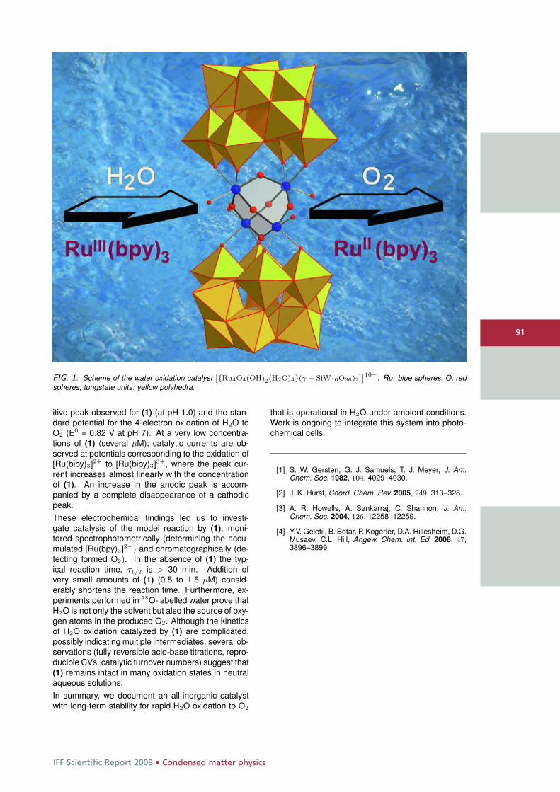
IFF Scientific Report 2008 • Condensed matter physics
91
FIG. 1: Scheme of the water oxidation catalystˆ{Ru4O4(OH)2(H2O)4}(γ − SiW10O36)2]
˜10−. Ru: blue spheres, O: redspheres, tungstate units: yellow polyhedra.
itive peak observed for (1) (at pH 1.0) and the stan-dard potential for the 4-electron oxidation of H2O toO2 (E0 = 0.82 V at pH 7). At a very low concentra-tions of (1) (several μM), catalytic currents are ob-served at potentials corresponding to the oxidation of[Ru(bipy)3]2+ to [Ru(bipy)3]3+, where the peak cur-rent increases almost linearly with the concentrationof (1). An increase in the anodic peak is accom-panied by a complete disappearance of a cathodicpeak.These electrochemical findings led us to investi-gate catalysis of the model reaction by (1), moni-tored spectrophotometrically (determining the accu-mulated [Ru(bpy)3]2+) and chromatographically (de-tecting formed O2). In the absence of (1) the typ-ical reaction time, τ1/2 is > 30 min. Addition ofvery small amounts of (1) (0.5 to 1.5 μM) consid-erably shortens the reaction time. Furthermore, ex-periments performed in 18O-labelled water prove thatH2O is not only the solvent but also the source of oxy-gen atoms in the produced O2. Although the kineticsof H2O oxidation catalyzed by (1) are complicated,possibly indicating multiple intermediates, several ob-servations (fully reversible acid-base titrations, repro-ducible CVs, catalytic turnover numbers) suggest that(1) remains intact in many oxidation states in neutralaqueous solutions.In summary, we document an all-inorganic catalystwith long-term stability for rapid H2O oxidation to O2
that is operational in H2O under ambient conditions.Work is ongoing to integrate this system into photo-chemical cells.
[1] S. W. Gersten, G. J. Samuels, T. J. Meyer, J. Am.Chem. Soc. 1982, 104, 4029–4030.
[2] J. K. Hurst, Coord. Chem. Rev. 2005, 249, 313–328.
[3] A. R. Howells, A. Sankarraj, C. Shannon, J. Am.Chem. Soc. 2004, 126, 12258–12259.
[4] Y.V. Geletii, B. Botar, P. Kögerler, D.A. Hillesheim, D.G.Musaev, C.L. Hill, Angew. Chem. Int. Ed. 2008, 47,3896–3899.
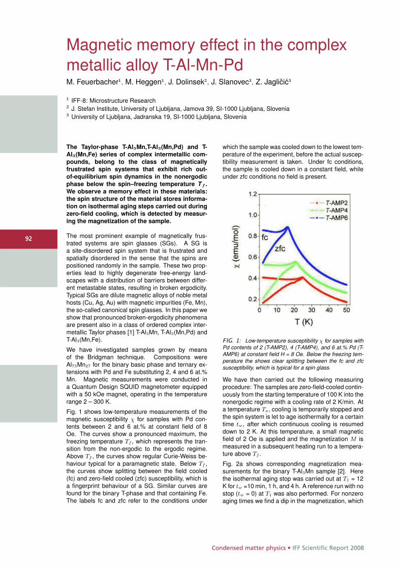
Condensed matter physics • IFF Scientific Report 2008
9292
Magnetic memory effect in the complexmetallic alloy T-Al-Mn-PdM. Feuerbacher1, M. Heggen1, J. Dolinsek2, J. Slanovec3, Z. Jaglicic3
1 IFF-8: Microstructure Research2 J. Stefan Institute, University of Ljubljana, Jamova 39, SI-1000 Ljubljana, Slovenia3 University of Ljubljana, Jadranska 19, SI-1000 Ljubljana, Slovenia
The Taylor-phase T-Al3Mn,T-Al3(Mn,Pd) and T-
Al3(Mn,Fe) series of complex intermetallic com-
pounds, belong to the class of magnetically
frustrated spin systems that exhibit rich out-
of-equilibrium spin dynamics in the nonergodic
phase below the spin–freezing temperature T f .
We observe a memory effect in these materials:
the spin structure of the material stores informa-
tion on isothermal aging steps carried out during
zero-field cooling, which is detected by measur-
ing the magnetization of the sample.
The most prominent example of magnetically frus-trated systems are spin glasses (SGs). A SG isa site-disordered spin system that is frustrated andspatially disordered in the sense that the spins arepositioned randomly in the sample. These two prop-erties lead to highly degenerate free-energy land-scapes with a distribution of barriers between differ-ent metastable states, resulting in broken ergodicity.Typical SGs are dilute magnetic alloys of noble metalhosts (Cu, Ag, Au) with magnetic impurities (Fe, Mn),the so-called canonical spin glasses. In this paper weshow that pronounced broken-ergodicity phenomenaare present also in a class of ordered complex inter-metallic Taylor phases [1] T-Al3Mn, T-Al3(Mn,Pd) andT-Al3(Mn,Fe).
We have investigated samples grown by meansof the Bridgman technique. Compositions wereAl73Mn27 for the binary basic phase and ternary ex-tensions with Pd and Fe substituting 2, 4 and 6 at.%Mn. Magnetic measurements were conducted ina Quantum Design SQUID magnetometer equippedwith a 50 kOe magnet, operating in the temperaturerange 2 – 300 K.
Fig. 1 shows low-temperature measurements of themagnetic susceptibility χ for samples with Pd con-tents between 2 and 6 at.% at constant field of 8Oe. The curves show a pronounced maximum, thefreezing temperature Tf , which represents the tran-sition from the non-ergodic to the ergodic regime.Above Tf , the curves show regular Curie-Weiss be-haviour typical for a paramagnetic state. Below Tf ,the curves show splitting between the field cooled(fc) and zero-field cooled (zfc) susceptibility, which isa fingerprint behaviour of a SG. Similar curves arefound for the binary T-phase and that containing Fe.The labels fc and zfc refer to the conditions under
which the sample was cooled down to the lowest tem-perature of the experiment, before the actual suscep-tibility measurement is taken. Under fc conditions,the sample is cooled down in a constant field, whileunder zfc conditions no field is present.
FIG. 1: Low-temperature susceptibility χ for samples withPd contents of 2 (T-AMP2), 4 (T-AMP4), and 6 at.% Pd (T-AMP6) at constant field H = 8 Oe. Below the freezing tem-perature the shows clear splitting between the fc and zfcsusceptibility, which is typical for a spin glass.
We have then carried out the following measuringprocedure: The samples are zero-field-cooled contin-uously from the starting temperature of 100 K into thenonergodic regime with a cooling rate of 2 K/min. Ata temperature Ta, cooling is temporarily stopped andthe spin system is let to age isothermally for a certaintime tw, after which continuous cooling is resumeddown to 2 K. At this temperature, a small magneticfield of 2 Oe is applied and the magnetization M ismeasured in a subsequent heating run to a tempera-ture above Tf .
Fig. 2a shows corresponding magnetization mea-surements for the binary T-Al3Mn sample [2]. Herethe isothermal aging stop was carried out at T1 = 12K for tw =10 min, 1 h, and 4 h. A reference run with nostop (tw = 0) at T1 was also performed. For nonzeroaging times we find a dip in the magnetization, which
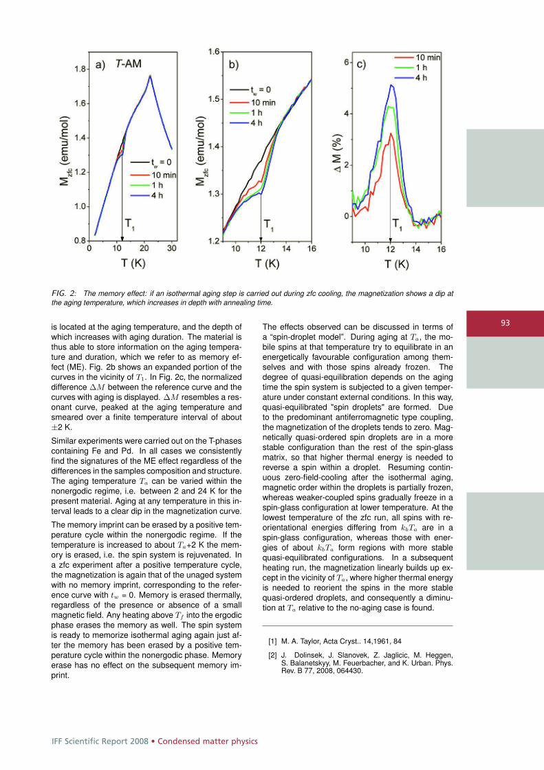
IFF Scientific Report 2008 • Condensed matter physics
93
FIG. 2: The memory effect: if an isothermal aging step is carried out during zfc cooling, the magnetization shows a dip atthe aging temperature, which increases in depth with annealing time.
is located at the aging temperature, and the depth ofwhich increases with aging duration. The material isthus able to store information on the aging tempera-ture and duration, which we refer to as memory ef-fect (ME). Fig. 2b shows an expanded portion of thecurves in the vicinity of T1. In Fig. 2c, the normalizeddifference ΔM between the reference curve and thecurves with aging is displayed. ΔM resembles a res-onant curve, peaked at the aging temperature andsmeared over a finite temperature interval of about±2 K.
Similar experiments were carried out on the T-phasescontaining Fe and Pd. In all cases we consistentlyfind the signatures of the ME effect regardless of thedifferences in the samples composition and structure.The aging temperature Ta can be varied within thenonergodic regime, i.e. between 2 and 24 K for thepresent material. Aging at any temperature in this in-terval leads to a clear dip in the magnetization curve.
The memory imprint can be erased by a positive tem-perature cycle within the nonergodic regime. If thetemperature is increased to about Ta+2 K the mem-ory is erased, i.e. the spin system is rejuvenated. Ina zfc experiment after a positive temperature cycle,the magnetization is again that of the unaged systemwith no memory imprint, corresponding to the refer-ence curve with tw = 0. Memory is erased thermally,regardless of the presence or absence of a smallmagnetic field. Any heating above Tf into the ergodicphase erases the memory as well. The spin systemis ready to memorize isothermal aging again just af-ter the memory has been erased by a positive tem-perature cycle within the nonergodic phase. Memoryerase has no effect on the subsequent memory im-print.
The effects observed can be discussed in terms ofa “spin-droplet model”. During aging at Ta, the mo-bile spins at that temperature try to equilibrate in anenergetically favourable configuration among them-selves and with those spins already frozen. Thedegree of quasi-equilibration depends on the agingtime the spin system is subjected to a given temper-ature under constant external conditions. In this way,quasi-equilibrated "spin droplets" are formed. Dueto the predominant antiferromagnetic type coupling,the magnetization of the droplets tends to zero. Mag-netically quasi-ordered spin droplets are in a morestable configuration than the rest of the spin-glassmatrix, so that higher thermal energy is needed toreverse a spin within a droplet. Resuming contin-uous zero-field-cooling after the isothermal aging,magnetic order within the droplets is partially frozen,whereas weaker-coupled spins gradually freeze in aspin-glass configuration at lower temperature. At thelowest temperature of the zfc run, all spins with re-orientational energies differing from kbTa are in aspin-glass configuration, whereas those with ener-gies of about kbTa form regions with more stablequasi-equilibrated configurations. In a subsequentheating run, the magnetization linearly builds up ex-cept in the vicinity of Ta, where higher thermal energyis needed to reorient the spins in the more stablequasi-ordered droplets, and consequently a diminu-tion at Ta relative to the no-aging case is found.
[1] M. A. Taylor, Acta Cryst.. 14,1961, 84
[2] J. Dolinsek, J. Slanovek, Z. Jaglicic, M. Heggen,S. Balanetskyy, M. Feuerbacher, and K. Urban. Phys.Rev. B 77, 2008, 064430.
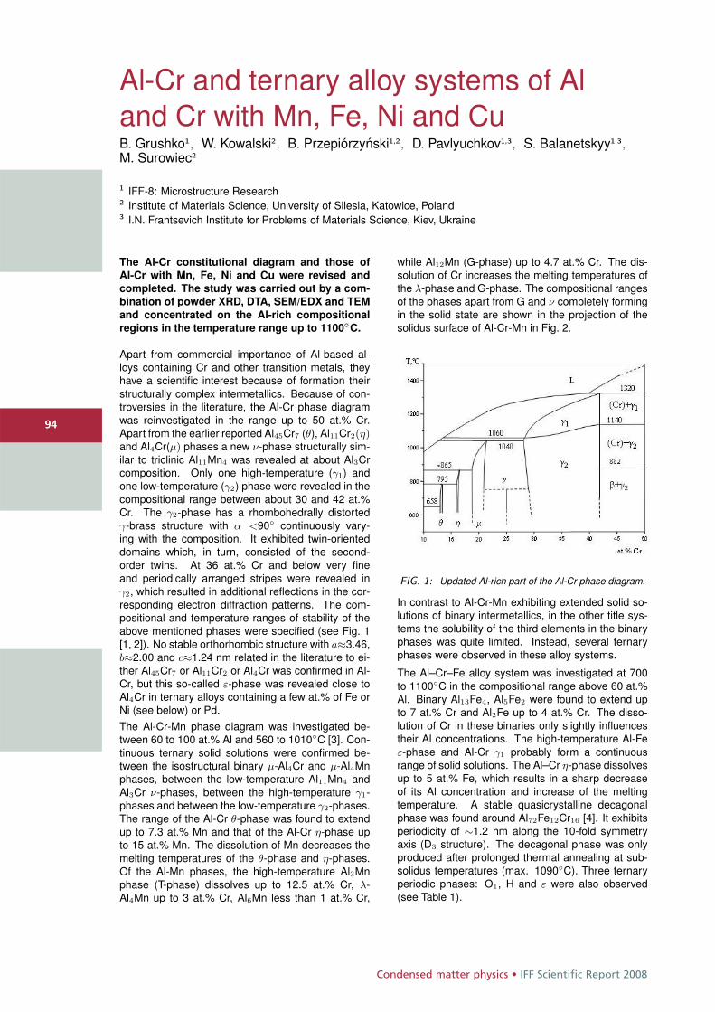
Condensed matter physics • IFF Scientific Report 2008
9494
Al-Cr and ternary alloy systems of Aland Cr with Mn, Fe, Ni and CuB. Grushko1, W. Kowalski2, B. Przepiórzynski1,2, D. Pavlyuchkov1,3, S. Balanetskyy1,3,M. Surowiec2
1 IFF-8: Microstructure Research2 Institute of Materials Science, University of Silesia, Katowice, Poland3 I.N. Frantsevich Institute for Problems of Materials Science, Kiev, Ukraine
The Al-Cr constitutional diagram and those of
Al-Cr with Mn, Fe, Ni and Cu were revised and
completed. The study was carried out by a com-
bination of powder XRD, DTA, SEM/EDX and TEM
and concentrated on the Al-rich compositional
regions in the temperature range up to 1100◦C.
Apart from commercial importance of Al-based al-loys containing Cr and other transition metals, theyhave a scientific interest because of formation theirstructurally complex intermetallics. Because of con-troversies in the literature, the Al-Cr phase diagramwas reinvestigated in the range up to 50 at.% Cr.Apart from the earlier reported Al45Cr7 (θ), Al11Cr2(η)and Al4Cr(μ) phases a new ν-phase structurally sim-ilar to triclinic Al11Mn4 was revealed at about Al3Crcomposition. Only one high-temperature (γ1) andone low-temperature (γ2) phase were revealed in thecompositional range between about 30 and 42 at.%Cr. The γ2-phase has a rhombohedrally distortedγ-brass structure with α <90◦ continuously vary-ing with the composition. It exhibited twin-orienteddomains which, in turn, consisted of the second-order twins. At 36 at.% Cr and below very fineand periodically arranged stripes were revealed inγ2, which resulted in additional reflections in the cor-responding electron diffraction patterns. The com-positional and temperature ranges of stability of theabove mentioned phases were specified (see Fig. 1[1, 2]). No stable orthorhombic structure with a≈3.46,b≈2.00 and c≈1.24 nm related in the literature to ei-ther Al45Cr7 or Al11Cr2 or Al4Cr was confirmed in Al-Cr, but this so-called ε-phase was revealed close toAl4Cr in ternary alloys containing a few at.% of Fe orNi (see below) or Pd.The Al-Cr-Mn phase diagram was investigated be-tween 60 to 100 at.% Al and 560 to 1010◦C [3]. Con-tinuous ternary solid solutions were confirmed be-tween the isostructural binary μ-Al4Cr and μ-Al4Mnphases, between the low-temperature Al11Mn4 andAl3Cr ν-phases, between the high-temperature γ1-phases and between the low-temperature γ2-phases.The range of the Al-Cr θ-phase was found to extendup to 7.3 at.% Mn and that of the Al-Cr η-phase upto 15 at.% Mn. The dissolution of Mn decreases themelting temperatures of the θ-phase and η-phases.Of the Al-Mn phases, the high-temperature Al3Mnphase (T-phase) dissolves up to 12.5 at.% Cr, λ-Al4Mn up to 3 at.% Cr, Al6Mn less than 1 at.% Cr,
while Al12Mn (G-phase) up to 4.7 at.% Cr. The dis-solution of Cr increases the melting temperatures ofthe λ-phase and G-phase. The compositional rangesof the phases apart from G and ν completely formingin the solid state are shown in the projection of thesolidus surface of Al-Cr-Mn in Fig. 2.
FIG. 1: Updated Al-rich part of the Al-Cr phase diagram.
In contrast to Al-Cr-Mn exhibiting extended solid so-lutions of binary intermetallics, in the other title sys-tems the solubility of the third elements in the binaryphases was quite limited. Instead, several ternaryphases were observed in these alloy systems.
The Al–Cr–Fe alloy system was investigated at 700to 1100◦C in the compositional range above 60 at.%Al. Binary Al13Fe4, Al5Fe2 were found to extend upto 7 at.% Cr and Al2Fe up to 4 at.% Cr. The disso-lution of Cr in these binaries only slightly influencestheir Al concentrations. The high-temperature Al-Feε-phase and Al-Cr γ1 probably form a continuousrange of solid solutions. The Al–Cr η-phase dissolvesup to 5 at.% Fe, which results in a sharp decreaseof its Al concentration and increase of the meltingtemperature. A stable quasicrystalline decagonalphase was found around Al72Fe12Cr16 [4]. It exhibitsperiodicity of ∼1.2 nm along the 10-fold symmetryaxis (D3 structure). The decagonal phase was onlyproduced after prolonged thermal annealing at sub-solidus temperatures (max. 1090◦C). Three ternaryperiodic phases: O1, H and ε were also observed(see Table 1).
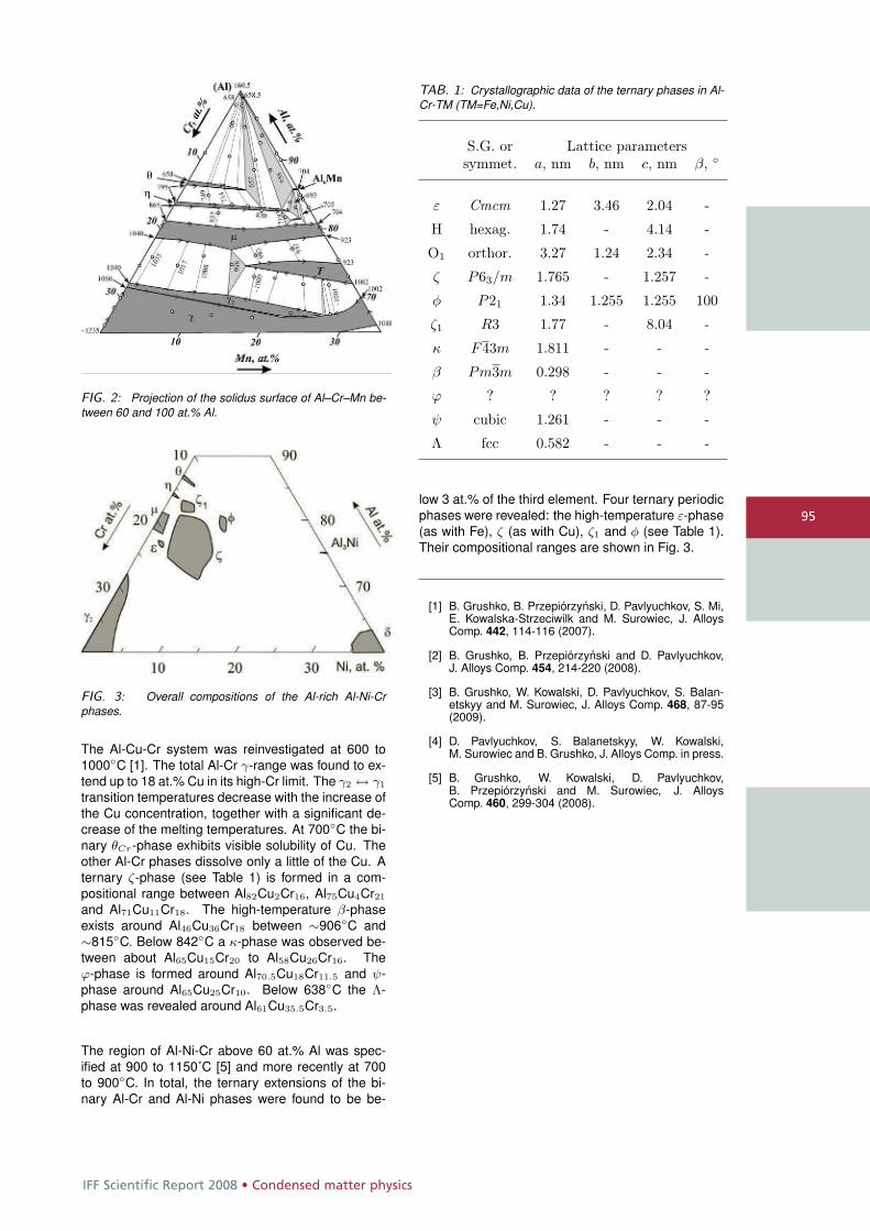
IFF Scientific Report 2008 • Condensed matter physics
95
FIG. 2: Projection of the solidus surface of Al–Cr–Mn be-tween 60 and 100 at.% Al.
FIG. 3: Overall compositions of the Al-rich Al-Ni-Crphases.
The Al-Cu-Cr system was reinvestigated at 600 to1000◦C [1]. The total Al-Cr γ-range was found to ex-tend up to 18 at.% Cu in its high-Cr limit. The γ2 ↔ γ1
transition temperatures decrease with the increase ofthe Cu concentration, together with a significant de-crease of the melting temperatures. At 700◦C the bi-nary θCr-phase exhibits visible solubility of Cu. Theother Al-Cr phases dissolve only a little of the Cu. Aternary ζ-phase (see Table 1) is formed in a com-positional range between Al82Cu2Cr16, Al75Cu4Cr21and Al71Cu11Cr18. The high-temperature β-phaseexists around Al46Cu36Cr18 between ∼906◦C and∼815◦C. Below 842◦C a κ-phase was observed be-tween about Al65Cu15Cr20 to Al58Cu26Cr16. Theϕ-phase is formed around Al70.5Cu18Cr11.5 and ψ-phase around Al65Cu25Cr10. Below 638◦C the Λ-phase was revealed around Al61Cu35.5Cr3.5.
The region of Al-Ni-Cr above 60 at.% Al was spec-ified at 900 to 1150˚C [5] and more recently at 700to 900◦C. In total, the ternary extensions of the bi-nary Al-Cr and Al-Ni phases were found to be be-
TAB. 1: Crystallographic data of the ternary phases in Al-Cr-TM (TM=Fe,Ni,Cu).
S.G. or Lattice parameterssymmet. a, nm b, nm c, nm β, ◦
ε Cmcm 1.27 3.46 2.04 -
H hexag. 1.74 - 4.14 -
O1 orthor. 3.27 1.24 2.34 -
ζ P63/m 1.765 - 1.257 -
φ P21 1.34 1.255 1.255 100
ζ1 R3 1.77 - 8.04 -
κ F43m 1.811 - - -
β Pm3m 0.298 - - -
ϕ ? ? ? ? ?
ψ cubic 1.261 - - -
Λ fcc 0.582 - - -
low 3 at.% of the third element. Four ternary periodicphases were revealed: the high-temperature ε-phase(as with Fe), ζ (as with Cu), ζ1 and φ (see Table 1).Their compositional ranges are shown in Fig. 3.
[1] B. Grushko, B. Przepiórzynski, D. Pavlyuchkov, S. Mi,E. Kowalska-Strzeciwilk and M. Surowiec, J. AlloysComp. 442, 114-116 (2007).
[2] B. Grushko, B. Przepiórzynski and D. Pavlyuchkov,J. Alloys Comp. 454, 214-220 (2008).
[3] B. Grushko, W. Kowalski, D. Pavlyuchkov, S. Balan-etskyy and M. Surowiec, J. Alloys Comp. 468, 87-95(2009).
[4] D. Pavlyuchkov, S. Balanetskyy, W. Kowalski,M. Surowiec and B. Grushko, J. Alloys Comp. in press.
[5] B. Grushko, W. Kowalski, D. Pavlyuchkov,B. Przepiórzynski and M. Surowiec, J. AlloysComp. 460, 299-304 (2008).
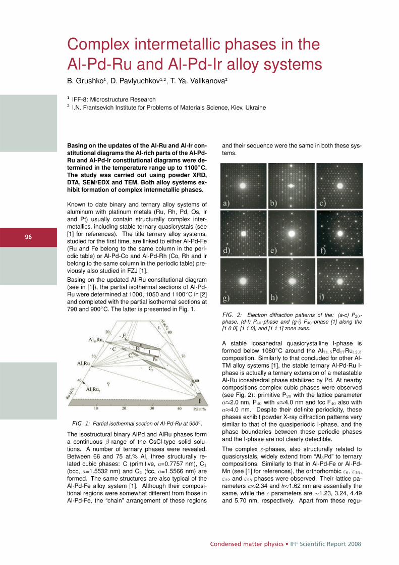
Condensed matter physics • IFF Scientific Report 2008
9696
Complex intermetallic phases in theAl-Pd-Ru and Al-Pd-Ir alloy systemsB. Grushko1, D. Pavlyuchkov1,2, T. Ya. Velikanova2
1 IFF-8: Microstructure Research2 I.N. Frantsevich Institute for Problems of Materials Science, Kiev, Ukraine
Basing on the updates of the Al-Ru and Al-Ir con-
stitutional diagrams the Al-rich parts of the Al-Pd-
Ru and Al-Pd-Ir constitutional diagrams were de-
termined in the temperature range up to 1100◦C.
The study was carried out using powder XRD,
DTA, SEM/EDX and TEM. Both alloy systems ex-
hibit formation of complex intermetallic phases.
Known to date binary and ternary alloy systems ofaluminum with platinum metals (Ru, Rh, Pd, Os, Irand Pt) usually contain structurally complex inter-metallics, including stable ternary quasicrystals (see[1] for references). The title ternary alloy systems,studied for the first time, are linked to either Al-Pd-Fe(Ru and Fe belong to the same column in the peri-odic table) or Al-Pd-Co and Al-Pd-Rh (Co, Rh and Irbelong to the same column in the periodic table) pre-viously also studied in FZJ [1].Basing on the updated Al-Ru constitutional diagram(see in [1]), the partial isothermal sections of Al-Pd-Ru were determined at 1000, 1050 and 1100◦C in [2]and completed with the partial isothermal sections at790 and 900◦C. The latter is presented in Fig. 1.
FIG. 1: Partial isothermal section of Al-Pd-Ru at 900◦.
The isostructural binary AlPd and AlRu phases forma continuous β-range of the CsCl-type solid solu-tions. A number of ternary phases were revealed.Between 66 and 75 at.% Al, three structurally re-lated cubic phases: C (primitive, a=0.7757 nm), C1
(bcc, a=1.5532 nm) and C2 (fcc, a=1.5566 nm) areformed. The same structures are also typical of theAl-Pd-Fe alloy system [1]. Although their composi-tional regions were somewhat different from those inAl-Pd-Fe, the “chain” arrangement of these regions
and their sequence were the same in both these sys-tems.
FIG. 2: Electron diffraction patterns of the: (a-c) P20-phase, (d-f) P40-phase and (g-i) F40-phase [1] along the[1 0 0], [1 1 0], and [1 1 1] zone axes.
A stable icosahedral quasicrystalline I-phase isformed below 1080◦C around the Al71.5Pd17Ru12.5
composition. Similarly to that concluded for other Al-TM alloy systems [1], the stable ternary Al-Pd-Ru I-phase is actually a ternary extension of a metastableAl-Ru icosahedral phase stabilized by Pd. At nearbycompositions complex cubic phases were observed(see Fig. 2): primitive P20 with the lattice parametera≈2.0 nm, P40 with a≈4.0 nm and fcc F40 also witha≈4.0 nm. Despite their definite periodicity, thesephases exhibit powder X-ray diffraction patterns verysimilar to that of the quasiperiodic I-phase, and thephase boundaries between these periodic phasesand the I-phase are not clearly detectible.
The complex ε-phases, also structurally related toquasicrystals, widely extend from “Al3Pd” to ternarycompositions. Similarly to that in Al-Pd-Fe or Al-Pd-Mn (see [1] for references), the orthorhombic ε6, ε16,ε22 and ε28 phases were observed. Their lattice pa-rameters a≈2.34 and b≈1.62 nm are essentially thesame, while the c parameters are ∼1.23, 3.24, 4.49and 5.70 nm, respectively. Apart from these regu-
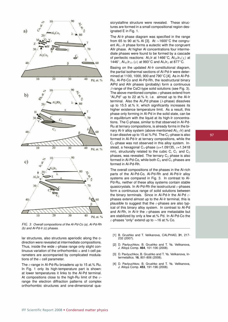
IFF Scientific Report 2008 • Condensed matter physics
97
FIG. 3: Overall compositions of the Al-Pd-Co (a), Al-Pd-Rh(b) and Al-Pd-Ir (c) phases.
lar structures, also structures aperiodic along the c-direction were revealed at intermediate compositions.Thus, inside the wide ε-phase range only slight con-tinuous variation of the orthorhombic a and b cell pa-rameters are accompanied by complicated modula-tions of the c cell parameter.
The ε-range in Al-Pd-Ru broadens up to 15 at.% Ru.In Fig. 1 only its high-temperature part is shown:at lower temperatures it links to the Al-Pd terminal.At compositions close to the high-Ru limit of the ε-range the electron diffraction patterns of complexorthorhombic structures and one-dimensional qua-
sicrystalline structure were revealed. These struc-tures are formed in a small compositional region des-ignated E in Fig. 1.
The Al-Ir phase diagram was specified in the rangefrom 65 to 90 at.% Al [3]. At ∼1600◦C the congru-ent Al2.7Ir phase forms a eutectic with the congruentAlIr phase. At higher Al concentrations four interme-diate phases were found to be formed by a cascadeof peritectic reactions: Al3Ir at 1466◦C, Al28Ir9(χ) at1446◦, Al45Ir13 (φ) at 993◦C and Al9Ir2 at 877◦C.
Basing on the updated Al-Ir constitutional diagram,the partial isothermal sections of Al-Pd-Ir were deter-mined at 1100, 1000, 900 and 790◦C [4]. As in Al-Pd-Ru, Al-Pd-Co and Al-Pd-Rh, the isostructural binaryAlPd and AlIr phases (probably) form a continuousβ-range of the CsCl-type solid solutions (see Fig. 3).The above-mentioned complex ε-phases extend from“Al3Pd” up to 22 at.% Ir, i.e. almost up to the Al-Irterminal. Also the Al4Pd phase (λ-phase) dissolvesup to 15.5 at.% Ir, which significantly increases itshigher existence temperature limit. As a result, thisphase only forming in Al-Pd in the solid state, can bein equilibrium with the liquid at its high-Ir concentra-tions. The C-phase, similar to that observed in Al-Pd-Ru at ternary compositions, is already forms in the bi-nary Al-Ir alloy system (above-mentioned Al2,7Ir) andit can dissolve up to 15 at.% Pd. The C2-phase is alsoformed in Al-Pd-Ir at ternary compositions, while theC1-phase was not observed in this alloy system. In-stead, a hexagonal C3-phase (a=1.09135, c=1.3418nm), structurally related to the cubic C, C1 and C2
phases, was revealed. The ternary C2 phase is alsoformed in Al-Pd-Co, while both C2 and C3 phases areformed in Al-Pd-Rh.
The overall compositions of the phases in the Al-richparts of the Al-Pd-Co, Al-Pd-Rh and Al-Pd-Ir alloysystems are compared in Fig. 3. In contrast to Al-Pd-Ru, neither of these alloy systems contain stablequasicrystals. In Al-Pd-Rh the isostructural ε-phasesform a continuous range of solid solutions betweenthe binary terminals. Since in Al-Pd-Ir the Al-Pd ε-phases extend almost up to the Al-Ir terminal, this isplausible to suggest that the ε-phases are also typ-ical of this binary alloy system. In contrast to Al-Pdand Al-Rh, in Al-Ir the ε-phases are metastable butare stabilized by only a few at.% Pd. In Al-Pd-Co theε-phases “only” extend up to ∼16 at.% Co.
[1] B. Grushko and T. Velikanova, CALPHAD, 31, 217-232 (2007).
[2] D. Pavlyuchkov, B. Grushko and T. Ya. Velikanova,J. Alloys Comp. 464, 101-106 (2008).
[3] D. Pavlyuchkov, B. Grushko and T. Ya. Velikanova, In-termetallics. 16, 801-806 (2008).
[4] D. Pavlyuchkov, B. Grushko and T. Ya. Velikanova,J. Alloys Comp. 453, 191-196 (2008).
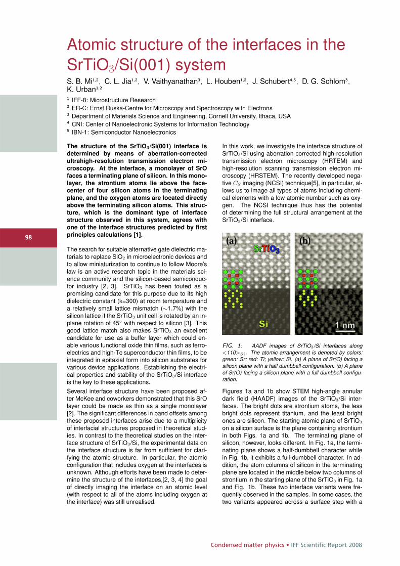
Condensed matter physics • IFF Scientific Report 2008
9898
Atomic structure of the interfaces in theSrTiO3/Si(001) systemS. B. Mi1,2, C. L. Jia1,2, V. Vaithyanathan3, L. Houben1,2, J. Schubert4,5, D. G. Schlom3,K. Urban1,2
1 IFF-8: Microstructure Research2 ER-C: Ernst Ruska-Centre for Microscopy and Spectroscopy with Electrons3 Department of Materials Science and Engineering, Cornell University, Ithaca, USA4 CNI: Center of Nanoelectronic Systems for Information Technology5 IBN-1: Semiconductor Nanoelectronics
The structure of the SrTiO3/Si(001) interface is
determined by means of aberration-corrected
ultrahigh-resolution transmission electron mi-
croscopy. At the interface, a monolayer of SrO
faces a terminating plane of silicon. In this mono-
layer, the strontium atoms lie above the face-
center of four silicon atoms in the terminating
plane, and the oxygen atoms are located directly
above the terminating silicon atoms. This struc-
ture, which is the dominant type of interface
structure observed in this system, agrees with
one of the interface structures predicted by first
principles calculations [1].
The search for suitable alternative gate dielectric ma-terials to replace SiO2 in microelectronic devices andto allow miniaturization to continue to follow Moore’slaw is an active research topic in the materials sci-ence community and the silicon-based semiconduc-tor industry [2, 3]. SrTiO3 has been touted as apromising candidate for this purpose due to its highdielectric constant (k=300) at room temperature anda relatively small lattice mismatch (∼1.7%) with thesilicon lattice if the SrTiO3 unit cell is rotated by an in-plane rotation of 45◦ with respect to silicon [3]. Thisgood lattice match also makes SrTiO3 an excellentcandidate for use as a buffer layer which could en-able various functional oxide thin films, such as ferro-electrics and high-Tc superconductor thin films, to beintegrated in epitaxial form into silicon substrates forvarious device applications. Establishing the electri-cal properties and stability of the SrTiO3/Si interfaceis the key to these applications.Several interface structure have been proposed af-ter McKee and coworkers demonstrated that this SrOlayer could be made as thin as a single monolayer[2]. The significant differences in band offsets amongthese proposed interfaces arise due to a multiplicityof interfacial structures proposed in theoretical stud-ies. In contrast to the theoretical studies on the inter-face structure of SrTiO3/Si, the experimental data onthe interface structure is far from sufficient for clari-fying the atomic structure. In particular, the atomicconfiguration that includes oxygen at the interfaces isunknown. Although efforts have been made to deter-mine the structure of the interfaces,[2, 3, 4] the goalof directly imaging the interface on an atomic level(with respect to all of the atoms including oxygen atthe interface) was still unrealised.
In this work, we investigate the interface structure ofSrTiO3/Si using aberration-corrected high-resolutiontransmission electron microscopy (HRTEM) andhigh-resolution scanning transmission electron mi-croscopy (HRSTEM). The recently developed nega-tive CS imaging (NCSI) technique[5], in particular, al-lows us to image all types of atoms including chemi-cal elements with a low atomic number such as oxy-gen. The NCSI technique thus has the potentialof determining the full structural arrangement at theSrTiO3/Si interface.
FIG. 1: AADF images of SrTiO3/Si interfaces along<110>Si. The atomic arrangement is denoted by colors:green: Sr; red: Ti; yellow: Si. (a) A plane of Sr(O) facing asilicon plane with a half dumbbell configuration. (b) A planeof Sr(O) facing a silicon plane with a full dumbbell configu-ration.
Figures 1a and 1b show STEM high-angle annulardark field (HAADF) images of the SrTiO3/Si inter-faces. The bright dots are strontium atoms, the lessbright dots represent titanium, and the least brightones are silicon. The starting atomic plane of SrTiO3
on a silicon surface is the plane containing strontiumin both Figs. 1a and 1b. The terminating plane ofsilicon, however, looks different. In Fig. 1a, the termi-nating plane shows a half-dumbbell character whilein Fig. 1b, it exhibits a full-dumbbell character. In ad-dition, the atom columns of silicon in the terminatingplane are located in the middle below two columns ofstrontium in the starting plane of the SrTiO3 in Fig. 1aand Fig. 1b. These two interface variants were fre-quently observed in the samples. In some cases, thetwo variants appeared across a surface step with a
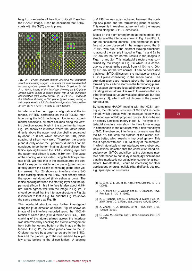
IFF Scientific Report 2008 • Condensed matter physics
99
height of one quarter of the silicon unit cell. Based onthe HAADF image, it can be concluded that SrTiO3
starts with the Sr(O) atomic plane.
FIG. 2: Phase contrast images showing the interfacialstructure including oxygen. The atom columns are denotedby color symbols: green: Sr; red: Ti; blue: O: yellow: Si. (a)A <110>Si image of the interface showing an SrO plane(green arrow) facing a silicon plane with a half dumbbellconfiguration (thin yellow arrow). (b) A <110>Si image ofthe interface showing a SrO plane (green arrow) facing asilicon plane with a full dumbbell configuration (thick yellowarrow). (c) A <100>Si image of the interface.
In order to solve the oxygen configuration at the in-terface, HRTEM performed on the SrTiO3/Si inter-face using the NCSI technique. Under our experi-mental conditions, all atom columns along the view-ing direction appear bright in the experimental image.Fig. 2a shows an interface where the lattice planedirectly above the uppermost dumbbell is separatedby about 0.138 nm, which matches the (004) planespacing of silicon very well. Therefore, the atomicplane directly above the uppermost dumbbell can beconcluded to be the terminating plane of silicon. Thelattice spacing between the SrTiO3 starting layer andthe uppermost silicon is about 0.194 nm. The valueof the spacing was calibrated using the lattice param-eter of Si. We note that in the interface area the con-trast for oxygen is visible in the plane (green arrow)directly above the silicon terminating plane (thin yel-low arrow). Fig. 2b shows an interface where SrOis the starting plane of the SrTiO3 film directly abovethe uppermost dumbbell (thick yellow arrows). Thelattice spacing between the starting layer and the up-permost silicon in this interface is also about 0.194nm, which agrees well with the image in Fig. 2a. Itshould be noted that the interface structure in Fig. 2ais identical to that in Fig. 1a, and that Fig. 2b showsthe same structure as Fig. 1b.
This interfacial structure was further investigatedalong the [100] direction of silicon. Fig. 2c shows animage of the interface recorded along the [100] di-rection of silicon (the [110] direction of SrTiO3). Thestacking of the atomic planes across the interfacewas determined by checking the atomic arrangementfrom both the top and bottom of the image of the in-terface. In Fig. 2c, the lattice planes down to the Sr-O plane marked by a green arrow are in the SrTiO3
film and the planes up to the one marked by a yel-low arrow belong to the silicon lattice. A spacing
of 0.196 nm was again obtained between the start-ing SrO plane and the terminating plane of silicon.This result is in excellent agreement with the imagesviewed along the <110> directions.
Based on the atom arrangement at the interface, thestructures of the interfaces shown in Fig. 1 and Fig. 2,can be considered identical. The difference in inter-face structure observed in the images along the Si<110> was due to the different viewing directions:rotating of the sample imaged in Figs. 1a and 2a by90◦ around the film normal results in the images inFigs. 1b and 2b. This interfacial structure was con-firmed by the image in Fig. 2c which is a conse-quence of rotating the sample from <110> to <100>by 45◦ around the film normal. It can be concludedthat in our SrTiO3/Si system, the interface consists ofa Sr-O plane connecting to the silicon plane. Thestrontium atoms are located above the face-centerformed by four silicon atoms in the terminating plane.The oxygen atoms are located directly above the ter-minating silicon atoms. It is worth to mention that an-other interfacial structure was also observed but lessfrequently [1], which will not discuss in the presentcontribution.
By combining HAADF imaging with the NCSI tech-nique, the interfacial structure of SrTiO3/Si is deter-mined, which agrees with the interface model with afull monolayer of SrO proposed by calculations basedon density functional theory in ref. 4. This type of in-terfacial structure was shown to have lower energyin comparison to the structure with a half monolayerof SrO. The observed interfacial structure shows thatthe SrTiO3 film wets the surface of the silicon sub-strate better, which results in improved epitaxy. Thisresult agrees with our HRTEM study of the samples,in which atomically sharp interfaces were observed.Calculations indicated that the conduction band off-set between SrTiO3 and silicon at the dominant inter-face determined by our study is small[4] which meansthat this interface is not suitable for conventional tran-sistors. Nonetheless, it could be interesting for otherapplications where a negligible band offset is desired,e.g. spin injection structures.
[1] S. B. Mi, C. L. Jia, et al., Appl. Phys. Lett. 93, 101913(2008).
[2] R. A. McKee, F. J. Walker, and M. F. Chisholm, Phys.Rev. Lett. 81, 3014 (1998).
[3] K. J. Hubbard, and D. G. Schlom, J. Mater. Res. 11,2757 (1996). C. J. Först, et al., Nature 427, 53 (2004).
[4] X. Zhang, A. A. Demkov, et al., Phys. Rev. B 68,125323 (2003).
[5] C. L. Jia, M. Lentzen, and K. Urban, Science 299, 870(2003).
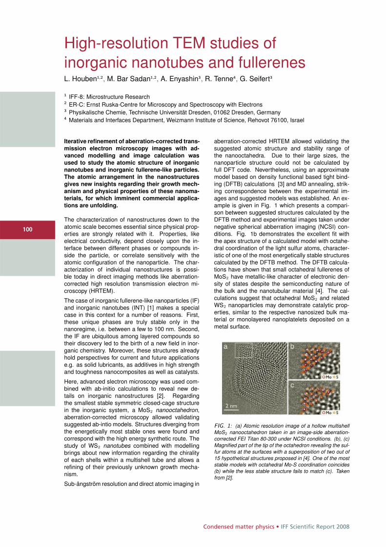
Condensed matter physics • IFF Scientific Report 2008
100100
High-resolution TEM studies ofinorganic nanotubes and fullerenesL. Houben1,2, M. Bar Sadan1,2, A. Enyashin3, R. Tenne4, G. Seifert3
1 IFF-8: Microstructure Research2 ER-C: Ernst Ruska-Centre for Microscopy and Spectroscopy with Electrons3 Physikalische Chemie, Technische Universität Dresden, 01062 Dresden, Germany4 Materials and Interfaces Department, Weizmann Institute of Science, Rehovot 76100, Israel
Iterative refinement of aberration-corrected trans-
mission electron microscopy images with ad-
vanced modelling and image calculation was
used to study the atomic structure of inorganic
nanotubes and inorganic fullerene-like particles.
The atomic arrangement in the nanostructures
gives new insights regarding their growth mech-
anism and physical properties of these nanoma-
terials, for which imminent commercial applica-
tions are unfolding.
The characterization of nanostructures down to theatomic scale becomes essential since physical prop-erties are strongly related with it. Properties, likeelectrical conductivity, depend closely upon the in-terface between different phases or compounds in-side the particle, or correlate sensitively with theatomic configuration of the nanoparticle. The char-acterization of individual nanostructures is possi-ble today in direct imaging methods like aberration-corrected high resolution transmission electron mi-croscopy (HRTEM).
The case of inorganic fullerene-like nanoparticles (IF)and inorganic nanotubes (INT) [1] makes a specialcase in this context for a number of reasons. First,these unique phases are truly stable only in thenanoregime, i.e. between a few to 100 nm. Second,the IF are ubiquitous among layered compounds sotheir discovery led to the birth of a new field in inor-ganic chemistry. Moreover, these structures alreadyhold perspectives for current and future applicationse.g. as solid lubricants, as additives in high strengthand toughness nanocomposites as well as catalysts.
Here, advanced slectron microscopy was used com-bined with ab-initio calculations to reveal new de-tails on inorganic nanostructures [2]. Regardingthe smallest stable symmetric closed-cage structurein the inorganic system, a MoS2 nanooctahedron,aberration-corrected microscopy allowed validatingsuggested ab-intio models. Structures diverging fromthe energetically most stable ones were found andcorrespond with the high energy synthetic route. Thestudy of WS2 nanotubes combined with modellingbrings about new information regarding the chiralityof each shells within a multishell tube and allows arefining of their previously unknown growth mecha-nism.
Sub-ångström resolution and direct atomic imaging in
aberration-corrected HRTEM allowed validating thesuggested atomic structure and stability range ofthe nanooctahedra. Due to their large sizes, thenanoparticle structure could not be calculated byfull DFT code. Nevertheless, using an approximatemodel based on density functional based tight bind-ing (DFTB) calculations [3] and MD annealing, strik-ing correspondence between the experimental im-ages and suggested models was established. An ex-ample is given in Fig. 1 which presents a compari-son between suggested structures calculated by theDFTB method and experimental images taken undernegative spherical abberration imaging (NCSI) con-ditions. Fig. 1b demonstrates the excellent fit withthe apex structure of a calculated model with octahe-dral coordination of the light sulfur atoms, character-istic of one of the most energetically stable structurescalculated by the DFTB method. The DFTB calcula-tions have shown that small octahedral fullerenes ofMoS2 have metallic-like character of electronic den-sity of states despite the semiconducting nature ofthe bulk and the nanotubular material [4]. The cal-culations suggest that octahedral MoS2 and relatedWS2 nanoparticles may demonstrate catalytic prop-erties, similar to the respective nanosized bulk ma-terial or monolayered nanoplatelets deposited on ametal surface.
FIG. 1: (a) Atomic resolution image of a hollow multishellMoS2 nanooctahedron taken in an image-side aberration-corrected FEI Titan 80-300 under NCSI conditions. (b), (c)Magnified part of the tip of the octahedron revealing the sul-fur atoms at the surfaces with a superposition of two out of15 hypothetical structures proposed in [4]. One of the moststable models with octahedral Mo-S coordination coincides(b) while the less stable structure fails to match (c). Takenfrom [2].
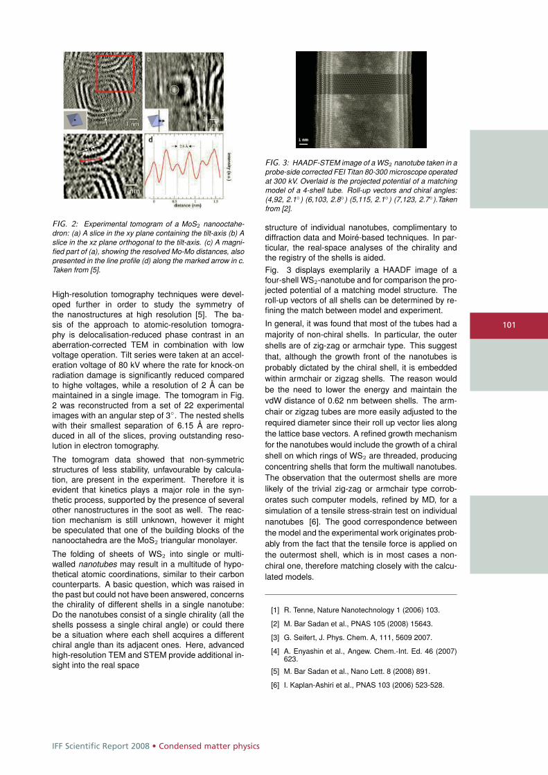
IFF Scientific Report 2008 • Condensed matter physics
101
FIG. 2: Experimental tomogram of a MoS2 nanooctahe-dron: (a) A slice in the xy plane containing the tilt-axis (b) Aslice in the xz plane orthogonal to the tilt-axis. (c) A magni-fied part of (a), showing the resolved Mo-Mo distances, alsopresented in the line profile (d) along the marked arrow in c.Taken from [5].
High-resolution tomography techniques were devel-oped further in order to study the symmetry ofthe nanostructures at high resolution [5]. The ba-sis of the approach to atomic-resolution tomogra-phy is delocalisation-reduced phase contrast in anaberration-corrected TEM in combination with lowvoltage operation. Tilt series were taken at an accel-eration voltage of 80 kV where the rate for knock-onradiation damage is significantly reduced comparedto highe voltages, while a resolution of 2 Å can bemaintained in a single image. The tomogram in Fig.2 was reconstructed from a set of 22 experimentalimages with an angular step of 3◦. The nested shellswith their smallest separation of 6.15 Å are repro-duced in all of the slices, proving outstanding reso-lution in electron tomography.
The tomogram data showed that non-symmetricstructures of less stability, unfavourable by calcula-tion, are present in the experiment. Therefore it isevident that kinetics plays a major role in the syn-thetic process, supported by the presence of severalother nanostructures in the soot as well. The reac-tion mechanism is still unknown, however it mightbe speculated that one of the building blocks of thenanooctahedra are the MoS2 triangular monolayer.
The folding of sheets of WS2 into single or multi-walled nanotubes may result in a multitude of hypo-thetical atomic coordinations, similar to their carboncounterparts. A basic question, which was raised inthe past but could not have been answered, concernsthe chirality of different shells in a single nanotube:Do the nanotubes consist of a single chirality (all theshells possess a single chiral angle) or could therebe a situation where each shell acquires a differentchiral angle than its adjacent ones. Here, advancedhigh-resolution TEM and STEM provide additional in-sight into the real space
FIG. 3: HAADF-STEM image of a WS2 nanotube taken in aprobe-side corrected FEI Titan 80-300 microscope operatedat 300 kV. Overlaid is the projected potential of a matchingmodel of a 4-shell tube. Roll-up vectors and chiral angles:(4,92, 2.1◦) (6,103, 2.8◦) (5,115, 2.1◦) (7,123, 2.7◦).Takenfrom [2].
structure of individual nanotubes, complimentary todiffraction data and Moiré-based techniques. In par-ticular, the real-space analyses of the chirality andthe registry of the shells is aided.Fig. 3 displays exemplarily a HAADF image of afour-shell WS2-nanotube and for comparison the pro-jected potential of a matching model structure. Theroll-up vectors of all shells can be determined by re-fining the match between model and experiment.
In general, it was found that most of the tubes had amajority of non-chiral shells. In particular, the outershells are of zig-zag or armchair type. This suggestthat, although the growth front of the nanotubes isprobably dictated by the chiral shell, it is embeddedwithin armchair or zigzag shells. The reason wouldbe the need to lower the energy and maintain thevdW distance of 0.62 nm between shells. The arm-chair or zigzag tubes are more easily adjusted to therequired diameter since their roll up vector lies alongthe lattice base vectors. A refined growth mechanismfor the nanotubes would include the growth of a chiralshell on which rings of WS2 are threaded, producingconcentring shells that form the multiwall nanotubes.The observation that the outermost shells are morelikely of the trivial zig-zag or armchair type corrob-orates such computer models, refined by MD, for asimulation of a tensile stress-strain test on individualnanotubes [6]. The good correspondence betweenthe model and the experimental work originates prob-ably from the fact that the tensile force is applied onthe outermost shell, which is in most cases a non-chiral one, therefore matching closely with the calcu-lated models.
[1] R. Tenne, Nature Nanotechnology 1 (2006) 103.
[2] M. Bar Sadan et al., PNAS 105 (2008) 15643.
[3] G. Seifert, J. Phys. Chem. A, 111, 5609 2007.
[4] A. Enyashin et al., Angew. Chem.-Int. Ed. 46 (2007)623.
[5] M. Bar Sadan et al., Nano Lett. 8 (2008) 891.
[6] I. Kaplan-Ashiri et al., PNAS 103 (2006) 523-528.
Condensed matter physics • IFF Scientific Report 2008
102102
Reconstruction of the projected crystalpotential in high-resolution TEMM. Lentzen1,2, K. Urban1,2
1 IFF-8: Microstructure Research2 ER-C: Ernst Ruska-Centre for Microscopy and Spectroscopy with Electrons
The projected electrostatic crystal potential is
reconstructed from a high-resolution exit wave
function, which can be measured using wave
function reconstruction techniques in transmis-
sion electron microscopy. Projected-potential
reconstruction is achieved by maximum likeli-
hood refinement from a model potential within
the framework of electron chanelling. This
work extends the maximum likelihood refine-
ment to the case of electron scattering includ-
ing phenomenological absorption, which is im-
portant in high-resolution transmission electron
microscopy already for crystal thicknesses of a
few nanometres. A simulation study assuming
a YBCO crystal of several nanometres in thick-
ness demonstrates a successful refinement for
all atom columns, comprising a wide range of
scattering power.
In high-resolution transmission electron microscopyinformation on the object under investigation can bederived from recorded image intensities or, by meansof wave function reconstruction [1, 2, 3], from exitwave functions. Two processes, however, severelyhamper the direct interpretation of image intensitiesor exit wave functions with respect to the object struc-ture: 1. Dynamical electron scattering along atomiccolumns of a crystalline material leads in general toa non-linear relation between the atomic scatteringpower and the local modulation of the exit wave func-tion. 2. Lens aberrations of the electron microscopeimpose phase changes on the wave function passingfrom the object plane to image plane and induce anunwanted contrast delocalisation [4].The interpretation of reconstructed exit wave func-tions with respect to the object structure can bestrongly improved by simulating the effects of dy-namical electron diffraction using test object struc-tures [5]. The simulation of microscopic imaging [5]can help in a similar way in the interpretation of ex-perimentally recorded image intensities by injectingknowledge of imaging parameters, in particular lensaberration parameters. It is, however, highly desir-able to find ways for the structure interpretation inhigh-resolution electron microscopy which do not relyon simulations of dynamical electron scattering andmicroscopic imaging with a possibly excessive num-ber of test object structures.
The reconstruction of the projected crystal potentialfrom an exit wave function is one of the ways to avoidtedious simulations, and it is the logical extensionof already successfully implemented exit wave func-tion reconstruction methods. The two reconstructionsteps combined would lead from the recorded imageintensities over the reconstructed exit wave functionto the reconstructed projected crystal potential, andthis measurement of the potential would allow a di-rect structure interpretation.
In the past decades few attempts have been madeto solve the potential reconstruction problem for thecase of thick objects including the effects of dynam-ical diffraction. In a first attempt by Gribelyuk [6]an estimate at the projected potential U(�r) was it-eratively refined using forward multislice iterations [7]and evaluations of the difference between the sim-ulated and the reconstructed exit plane wave func-tions, ψsim(�r) and ψexp(�r). In the second attemptby Beeching and Spargo [8] the same scheme wasapplied using reverse multislice iterations and com-paring the respective entrance plane wave functions.Both attempts fail already at small specimen thick-ness, mostly due to improper use of the weak phaseobject approximation for the first estimate and for thecorrection steps.
The attempt by Lentzen and Urban [9] successfullysolved the potential refinement problem within theleast-squares formalism by implementing a searchfor the projected potential along the gradient of thefigure of merit, S2 =
R |ψsim(�r) − ψexp(�r)|2 d�r, withrespect to the potential. Together with use of thechannelling model of electron diffraction [10, 11] asuccessful reconstruction of the crystal potential wasachieved for non-periodic objects over a wide thick-ness range.
In this work the former treatment of Lentzen and Ur-ban [9] has been extended to include phenomenolog-ical absorption, which turned out to be important al-ready for thin objects of few nanometres in thickness.Accuracy and stability of the refinement algorithm aregreatly improved by a new formulation for the gra-dient of S2 with respect to the potential. If ψe(�r, t
′)denotes the difference of ψexp(�r) and ψsim(�r) be-ing back-propagated through the object from the exitplane t to a plane t′ inside the crystal, and if ψs(�r, t
′)denotes the entrance plane wave being propagatedthrough the object from the entrance plane 0 to the

IFF Scientific Report 2008 • Condensed matter physics
103
same plane t′ inside the crystal, then
δU(�r) =1
πλt2Im
j(1 − iκ)
Z t
0
ψ∗s (�r, t′)ψe(�r, t
′) dt′ff
denotes the correction of the projected potential foreach iteration step, with t the object thickness, λthe electron wavelength, and κ the phenomenolog-ical absorption parameter ranging from 0 to around0.2.
Simulation studies assuming an YBa2Cu3O7 crystalof several nanometres in thickness show that the useof the new gradient formulation improves the con-vergence of the refinement algorithm considerably incomparison to the use of the gradient presented in [9]for the case of absorption being present. The recon-struction algorithm is successful even at larger ob-ject thickness, where the exit wave function exhibitsstrongly differing modulations in amplitude and phaseat the Y and Ba atom columns of strong scatteringpower, the Cu-O atom columns of medium scatteringpower, and the O atom columns of weak scatteringpower.
[1] H. Lichte, Ultramicroscopy 20 (1986) 293
[2] W. Coene, G. Janssen, M. Op de Beeck and D. VanDyck, Phys. Rev. Lett. 69 (1992) 3743
[3] A. Thust, W.M.J. Coene, M. Op de Beeck and D. VanDyck, Ultramicroscopy 64 (1996) 211
[4] W. Coene and A.J.E.M. Jansen, Scan. Microsc.Suppl. 6 (1992) 379
[5] P.A. Stadelmann, Ultramicroscopy 21 (1987) 131
[6] M.A. Gribelyuk, Acta Cryst. A47 (1991) 715
[7] J.M. Cowley and A.F. Moodie, Acta Cryst. 10 (1957)609
[8] M.J. Beeching and A.E.C. Spargo, Ultramicroscopy 52(1993) 243
[9] M. Lentzen and K. Urban, Acta Cryst. A56 (2000) 235
[10] K. Kambe, G. Lehmpfuhl and F. Fujimoto, Z. Natur-forsch. A29 (1974) 1034
[11] F. Fujimoto, Phys. Status Solidi A45 (1978) 99
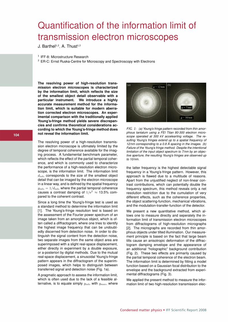
Condensed matter physics • IFF Scientific Report 2008
104104
Quantification of the information limit oftransmission electron microscopesJ. Barthel1,2, A. Thust1,2
1 IFF-8: Microstructure Research2 ER-C: Ernst Ruska-Centre for Microscopy and Spectroscopy with Electrons
The resolving power of high-resolution trans-
mission electron microscopes is characterized
by the information limit, which reflects the size
of the smallest object detail observable with a
particular instrument. We introduce a highly
accurate measurement method for the informa-
tion limit, which is suitable for modern aberra-
tion corrected electron microscopes. An exper-
imental comparison with the traditionally applied
Young’s-fringe method yields severe discrepan-
cies and confirms theoretical considerations ac-
cording to which the Young’s-fringe method does
not reveal the information limit.
The resolving power of a high-resolution transmis-sion electron microscope is ultimately limited by thedegree of temporal coherence available for the imag-ing process. A fundamental benchmark parameter,which reflects the effect of the partial temporal coher-ence, and which is commonly used to characterizethe performance of a high-resolution electron micro-scope, is the information limit. The information limitdinfo corresponds to the size of the smallest objectdetail that can be imaged by the electron microscopein a linear way, and is defined by the spatial frequencyginfo = 1/dinfo where the partial temporal coherencecauses a contrast damping of 1/e2 ≈ 13.5% com-pared to the coherent contrast.
Since a long time the Young’s-fringe test is used asa standard method to determine the information limit[1]. The Young’s-fringe resolution test is based onthe assessment of the Fourier power spectrum of animage taken from an amorphous object, which is of-ten called a diffractogram, where one tries to identifythe highest image frequency that can be undoubt-edly discerned from detection noise. In order to dis-tinguish the signal content from the detection noise,two separate images from the same object area aresuperimposed with a slight real-space displacement,either directly in experiment by a double exposure,or a-posteriori by digital methods. Due to the mutualreal-space displacement, a sinusoidal Young’s-fringepattern appears in the diffractogram of the superim-posed images, which helps to distinguish betweentransferred signal and detection noise (Fig. 1a).
A pragmatic approach to assess the information limit,which is often used due to the lack of a feasible al-ternative, is to equate simply ginfo with gmax, where
FIG. 1: (a) Young’s fringe pattern recorded from thin amor-phous tantalum using a FEI Titan 80-300 electron micro-scope operated at 300 kV accelearting voltage. The re-sulting Young’s fringes extend up to a spatial frequency of12/nm corresponding to a 0.8 Å spacing in the images. (b)Failure of the Young’s fringe method. Despite the intentionallimitation of the input object spectrum to 7/nm by an objec-tive aperture, the resulting Young’s fringes are observed upto 10/nm.
the latter frequency is the highest detectable signalfrequency in a Young’s-fringe pattern. However, thisapproach is flawed due to a multitude of reasons.Apart from the unjustified neglect of non-linear con-trast contributions, which can potentially double thefrequency spectrum, this method reveals only a netresolution restriction due to the cumulation of verydifferent effects, such as the coherence properties,the object scattering-function, mechanical vibrations,and the modulation-transfer-function of the detector.
We present a new quantitative method, which al-lows one to measure directly and seperately the in-formation limit of transmission electron microscopesfrom diffractograms of high-resolution micrographs[2]. The micrographs are recorded from thin amor-phous objects under tilted illumination. Our measure-ment principle is based on the fact that large beamtilts cause an anisotropic deformation of the diffrac-togram damping envelope and the appearance ofan additional “holographic” background contribution(Fig. 2). These two effects are primarily caused bythe partial temporal coherence of the electron beam.The information limit is determined by fitting a modelfunction based on a Gaussian focal distribution to theenvelope and the background extracted from experi-mental diffractograms (Fig. 3).
We applied the present method to measure the infor-mation limit of two high-resolution transmission elec-
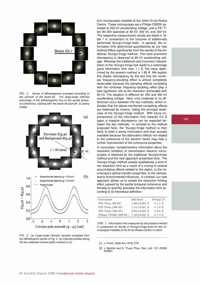
IFF Scientific Report 2008 • Condensed matter physics
105
FIG. 2: Series of diffractograms arranged according tothe azimuth of the beam-tilt. The large-scale intensityanisotropy of the diffractograms due to the partial tempo-ral coherence, rotating with the beam-tilt azimuth, is clearlyvisible.
FIG. 3: (a) Large-scale intensity variation extracted fromthe diffractogram series of Fig. 2. (b) Intensity profiles alongthe two selected circular paths marked in (a).
tron microscopes installed at the Jülich Ernst RuskaCentre. These microscopes are a Philips CM200 op-erated at 200 kV accelerating voltage, and a FEI Ti-tan 80-300 operated at 80 kV, 200 kV, and 300 kV.The respective measurement results are listed in Ta-ble 1 in comparison to the outcome of additionallyperformed Young’s-fringe tests. In general, the in-formation limit determined quantitatively by our newmethod differs significantly from the results of the tra-ditional Young’s-fringe method. The most prominentdiscrepancy is observed at 80 kV accelerating volt-age: Whereas the traditional (and incorrect) interpre-tation of the Young’s-fringe test leads to a seeminglygood information limit near 1.1 Å, the value deter-mined by the present method is 1.89 Å. We explainthis drastic discrepancy by the fact that the nonlin-ear frequency-doubling effect is almost completelyobservable because the damping effects competingwith the nonlinear frequency-doubling effect play aless significant role at the resolution achievable with80 kV. The situation is different for 200 and 300 kVaccelerating voltage. Here, only moderate to no dif-ferences occur between the two methods, which in-dicates that the above-mentioned competing effectsare balanced by chance, hiding the principal weak-ness of the Young’s-fringe method. With future im-provements of the information limit towards 0.5 Åagain a massive discrepancy can be expected be-tween the two methods. In contrast to the methodproposed here, the Young’s-fringe method is thenlikely to yield a worse information limit than actuallyavailable because the attenuation effects not relatedto the coherence of the electron beam may hide afurther improvement of the coherence properties.In conclusion, complementary information about theresolution limitation of transmission electron micro-scopes is obtained by the traditional Young’s-fringemethod and the new approach presented here. TheYoung’s-fringe method reveals qualitatively a kind ofnet resolution limit as a result of a mixing of severalaccumulating effects related to the object, to the mi-croscope’s optical transfer properties, to the camera,and to environmental influences. In contrast, our newapproach allows us to isolate the resolution limitingeffect caused by the partial temporal coherence andthereby to quantify precisely the information limit ac-cording to its theoretical definition.
Instrument Info-limit Young’s fr.FEI Titan (80 kV) 1.89(±0.09) Å ≈ 1.1 ÅFEI Titan (200 kV) 1.11(±0.01) Å ≈ 1.0 ÅFEI Titan (300 kV) 0.83(±0.02) Å ≈ 0.8 ÅPhilips CM200 (200 kV) 1.10(±0.02) Å ≈ 1.3 Å
TAB. 1: Information limit measured by the present methodin comparison to results of Young’s-fringe tests for two mi-croscopes installed at the Ernst Ruska-Centre in Jülich.
[1] J. Frank, Optik 44 (1976) 379.
[2] J. Barthel and A. Thust, Phys. Rev. Lett. 101 (2008)200801.
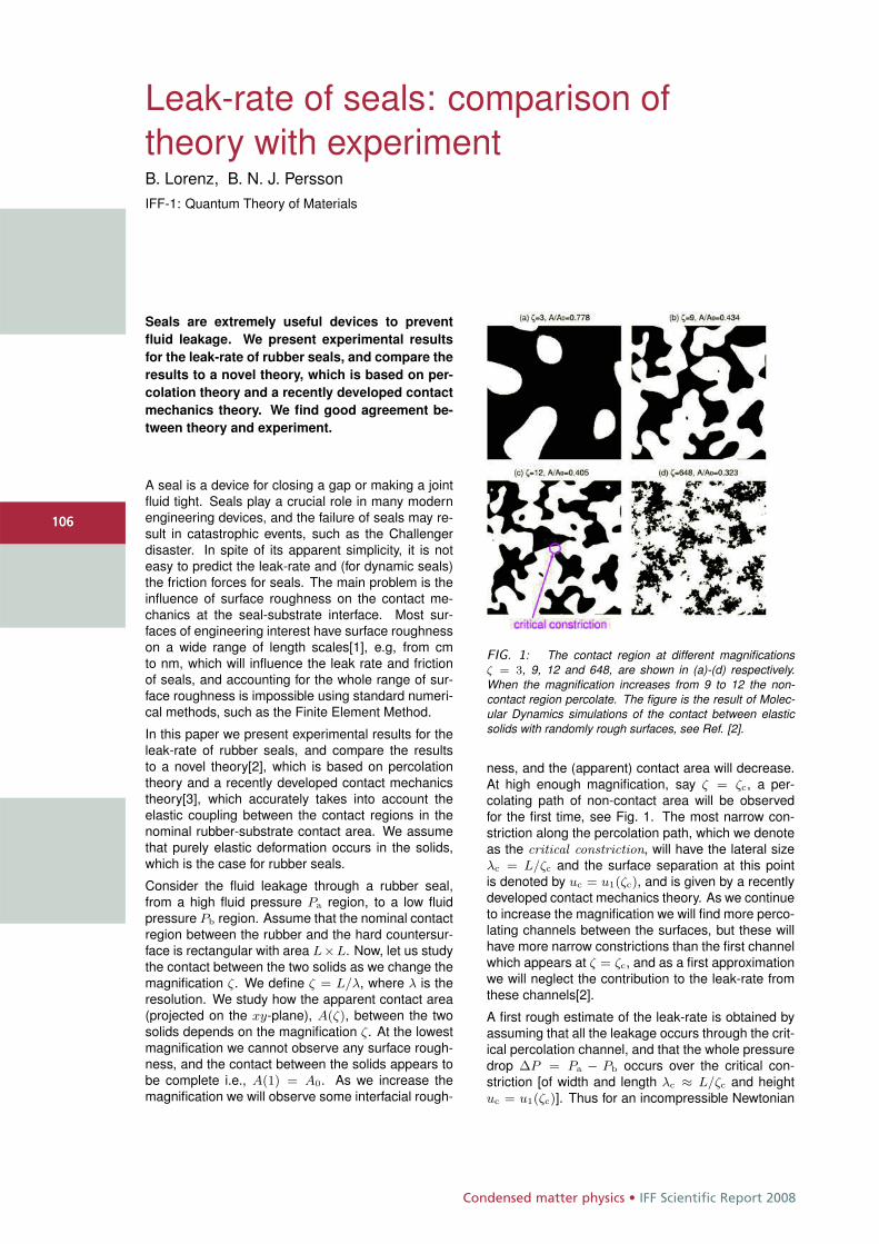
Condensed matter physics • IFF Scientific Report 2008
106
Leak-rate of seals: comparison oftheory with experimentB. Lorenz, B. N. J. PerssonIFF-1: Quantum Theory of Materials
Seals are extremely useful devices to preventfluid leakage. We present experimental resultsfor the leak-rate of rubber seals, and compare theresults to a novel theory, which is based on per-colation theory and a recently developed contactmechanics theory. We find good agreement be-tween theory and experiment.
A seal is a device for closing a gap or making a jointfluid tight. Seals play a crucial role in many modernengineering devices, and the failure of seals may re-sult in catastrophic events, such as the Challengerdisaster. In spite of its apparent simplicity, it is noteasy to predict the leak-rate and (for dynamic seals)the friction forces for seals. The main problem is theinfluence of surface roughness on the contact me-chanics at the seal-substrate interface. Most sur-faces of engineering interest have surface roughnesson a wide range of length scales[1], e.g, from cmto nm, which will influence the leak rate and frictionof seals, and accounting for the whole range of sur-face roughness is impossible using standard numeri-cal methods, such as the Finite Element Method.
In this paper we present experimental results for theleak-rate of rubber seals, and compare the resultsto a novel theory[2], which is based on percolationtheory and a recently developed contact mechanicstheory[3], which accurately takes into account theelastic coupling between the contact regions in thenominal rubber-substrate contact area. We assumethat purely elastic deformation occurs in the solids,which is the case for rubber seals.
Consider the fluid leakage through a rubber seal,from a high fluid pressure Pa region, to a low fluidpressure Pb region. Assume that the nominal contactregion between the rubber and the hard countersur-face is rectangular with area L×L. Now, let us studythe contact between the two solids as we change themagnification ζ. We define ζ = L/λ, where λ is theresolution. We study how the apparent contact area(projected on the xy-plane), A(ζ), between the twosolids depends on the magnification ζ. At the lowestmagnification we cannot observe any surface rough-ness, and the contact between the solids appears tobe complete i.e., A(1) = A0. As we increase themagnification we will observe some interfacial rough-
FIG. 1: The contact region at different magnificationsζ = 3, 9, 12 and 648, are shown in (a)-(d) respectively.When the magnification increases from 9 to 12 the non-contact region percolate. The figure is the result of Molec-ular Dynamics simulations of the contact between elasticsolids with randomly rough surfaces, see Ref. [2].
ness, and the (apparent) contact area will decrease.At high enough magnification, say ζ = ζc, a per-colating path of non-contact area will be observedfor the first time, see Fig. 1. The most narrow con-striction along the percolation path, which we denoteas the critical constriction, will have the lateral sizeλc = L/ζc and the surface separation at this pointis denoted by uc = u1(ζc), and is given by a recentlydeveloped contact mechanics theory. As we continueto increase the magnification we will find more perco-lating channels between the surfaces, but these willhave more narrow constrictions than the first channelwhich appears at ζ = ζc, and as a first approximationwe will neglect the contribution to the leak-rate fromthese channels[2].
A first rough estimate of the leak-rate is obtained byassuming that all the leakage occurs through the crit-ical percolation channel, and that the whole pressuredrop ΔP = Pa − Pb occurs over the critical con-striction [of width and length λc ≈ L/ζc and heightuc = u1(ζc)]. Thus for an incompressible Newtonian
106
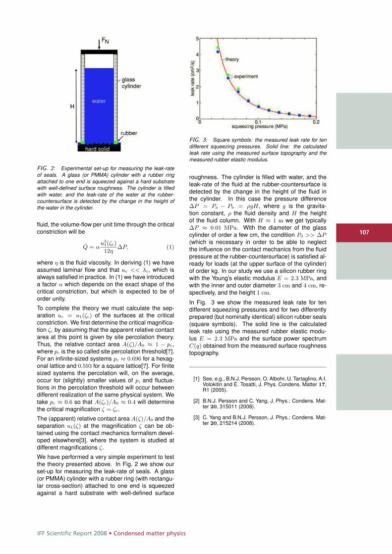
IFF Scientific Report 2008 • Condensed matter physics
107
FIG. 2: Experimental set-up for measuring the leak-rateof seals. A glass (or PMMA) cylinder with a rubber ringattached to one end is squeezed against a hard substratewith well-defined surface roughness. The cylinder is filledwith water, and the leak-rate of the water at the rubber-countersurface is detected by the change in the height ofthe water in the cylinder.
fluid, the volume-flow per unit time through the criticalconstriction will be
Q = αu3
1(ζc)
12ηΔP, (1)
where η is the fluid viscosity. In deriving (1) we haveassumed laminar flow and that uc << λc, which isalways satisfied in practice. In (1) we have introduceda factor α which depends on the exact shape of thecritical constriction, but which is expected to be oforder unity.
To complete the theory we must calculate the sep-aration uc = u1(ζc) of the surfaces at the criticalconstriction. We first determine the critical magnifica-tion ζc by assuming that the apparent relative contactarea at this point is given by site percolation theory.Thus, the relative contact area A(ζ)/A0 ≈ 1 − pc,where pc is the so called site percolation threshold[?].For an infinite-sized systems pc ≈ 0.696 for a hexag-onal lattice and 0.593 for a square lattice[?]. For finitesized systems the percolation will, on the average,occur for (slightly) smaller values of p, and fluctua-tions in the percolation threshold will occur betweendifferent realization of the same physical system. Wetake pc ≈ 0.6 so that A(ζc)/A0 ≈ 0.4 will determinethe critical magnification ζ = ζc.
The (apparent) relative contact area A(ζ)/A0 and theseparation u1(ζ) at the magnification ζ can be ob-tained using the contact mechanics formalism devel-oped elsewhere[3], where the system is studied atdifferent magnifications ζ.
We have performed a very simple experiment to testthe theory presented above. In Fig. 2 we show ourset-up for measuring the leak-rate of seals. A glass(or PMMA) cylinder with a rubber ring (with rectangu-lar cross-section) attached to one end is squeezedagainst a hard substrate with well-defined surface
FIG. 3: Square symbols: the measured leak rate for tendifferent squeezing pressures. Solid line: the calculatedleak rate using the measured surface topography and themeasured rubber elastic modulus.
roughness. The cylinder is filled with water, and theleak-rate of the fluid at the rubber-countersurface isdetected by the change in the height of the fluid inthe cylinder. In this case the pressure differenceΔP = Pa − Pb = ρgH, where g is the gravita-tion constant, ρ the fluid density and H the heightof the fluid column. With H ≈ 1 m we get typicallyΔP ≈ 0.01 MPa. With the diameter of the glasscylinder of order a few cm, the condition P0 >> ΔP(which is necessary in order to be able to neglectthe influence on the contact mechanics from the fluidpressure at the rubber-countersurface) is satisfied al-ready for loads (at the upper surface of the cylinder)of order kg. In our study we use a silicon rubber ringwith the Young’s elastic modulus E = 2.3 MPa, andwith the inner and outer diameter 3 cm and 4 cm, re-spectively, and the height 1 cm.
In Fig. 3 we show the measured leak rate for tendifferent squeezing pressures and for two differentlyprepared (but nominally identical) silicon rubber seals(square symbols). The solid line is the calculatedleak rate using the measured rubber elastic modu-lus E = 2.3 MPa and the surface power spectrumC(q) obtained from the measured surface roughnesstopography.
[1] See, e.g., B.N.J. Persson, O. Albohr, U. Tartaglino, A.I.Volokitin and E. Tosatti, J. Phys. Condens. Matter 17,R1 (2005).
[2] B.N.J. Persson and C. Yang, J. Phys.: Condens. Mat-ter 20, 315011 (2008).
[3] C. Yang and B.N.J. Persson, J. Phys.: Condens. Mat-ter 20, 215214 (2008).
107
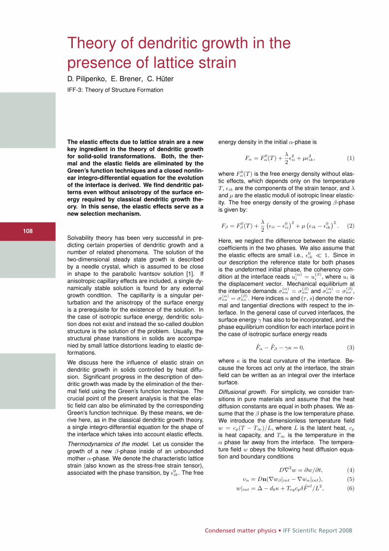
Condensed matter physics • IFF Scientific Report 2008
108108
Theory of dendritic growth in thepresence of lattice strainD. Pilipenko, E. Brener, C. HüterIFF-3: Theory of Structure Formation
The elastic effects due to lattice strain are a new
key ingredient in the theory of dendritic growth
for solid-solid transformations. Both, the ther-
mal and the elastic fields are eliminated by the
Green’s function techniques and a closed nonlin-
ear integro-differential equation for the evolution
of the interface is derived. We find dendritic pat-
terns even without anisotropy of the surface en-
ergy required by classical dendritic growth the-
ory. In this sense, the elastic effects serve as a
new selection mechanism.
Solvability theory has been very successful in pre-dicting certain properties of dendritic growth and anumber of related phenomena. The solution of thetwo-dimensional steady state growth is describedby a needle crystal, which is assumed to be closein shape to the parabolic Ivantsov solution [1]. Ifanisotropic capillary effects are included, a single dy-namically stable solution is found for any externalgrowth condition. The capillarity is a singular per-turbation and the anisotropy of the surface energyis a prerequisite for the existence of the solution. Inthe case of isotropic surface energy, dendritic solu-tion does not exist and instead the so-called doublonstructure is the solution of the problem. Usually, thestructural phase transitions in solids are accompa-nied by small lattice distortions leading to elastic de-formations.
We discuss here the influence of elastic strain ondendritic growth in solids controlled by heat diffu-sion. Significant progress in the description of den-dritic growth was made by the elimination of the ther-mal field using the Green’s function technique. Thecrucial point of the present analysis is that the elas-tic field can also be eliminated by the correspondingGreen’s function technique. By these means, we de-rive here, as in the classical dendritic growth theory,a single integro-differential equation for the shape ofthe interface which takes into account elastic effects.
Thermodynamics of the model. Let us consider thegrowth of a new β-phase inside of an unboundedmother α-phase. We denote the characteristic latticestrain (also known as the stress-free strain tensor),associated with the phase transition, by ε0ik. The free
energy density in the initial α-phase is
Fα = F 0α(T ) +
λ
2ε2ii + με2ik, (1)
where F 0α(T ) is the free energy density without elas-
tic effects, which depends only on the temperatureT , εik are the components of the strain tensor, and λand μ are the elastic moduli of isotropic linear elastic-ity. The free energy density of the growing β-phaseis given by:
Fβ = F 0β (T ) +
λ
2
`εii − ε0ii
´2+ μ
`εik − ε0ik
´2. (2)
Here, we neglect the difference between the elasticcoefficients in the two phases. We also assume thatthe elastic effects are small i.e., ε0ik � 1. Since inour description the reference state for both phasesis the undeformed initial phase, the coherency con-dition at the interface reads u
(α)i = u
(β)i , where ui is
the displacement vector. Mechanical equilibrium atthe interface demands σ
(α)nn = σ
(β)nn and σ
(α)nτ = σ
(β)nτ ,
σ(α)ns = σ
(β)ns . Here indices n and (τ , s) denote the nor-
mal and tangential directions with respect to the in-terface. In the general case of curved interfaces, thesurface energy γ has also to be incorporated, and thephase equilibrium condition for each interface point inthe case of isotropic surface energy reads
Fα − Fβ − γκ = 0, (3)
where κ is the local curvature of the interface. Be-cause the forces act only at the interface, the strainfield can be written as an integral over the interfacesurface.
Diffusional growth. For simplicity, we consider tran-sitions in pure materials and assume that the heatdiffusion constants are equal in both phases. We as-sume that the β phase is the low temperature phase.We introduce the dimensionless temperature fieldw = cp(T − T∞)/L, where L is the latent heat, cp
is heat capacity, and T∞ is the temperature in theα phase far away from the interface. The tempera-ture field w obeys the following heat diffusion equa-tion and boundary conditions
D∇2w = ∂w/∂t, (4)υn = Dn(∇wβ |int −∇wα|int), (5)
w|int = Δ − d0κ + TeqcpδF el/L2, (6)
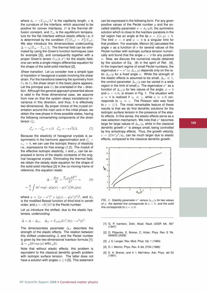
IFF Scientific Report 2008 • Condensed matter physics
109109
where d0 = γTeqcp/L2 is the capillarity length, κ isthe curvature of the interface, which assumed to bepositive for convex interfaces, D is the thermal dif-fusion constant, and Teq is the equilibrium tempera-ture for the flat interface without elastic effects i.e, itis determined by the condition F 0
α(Teq) = F 0β (Teq).
We also introduce the dimensionless undercoolingΔ = cp(Teq − T∞)/L. The thermal field can be elim-inated by using the Green’s function techniques (seefor example [3]), and consequently together with aproper Green’s tensor Gik(r, r′) for the elastic field,one can write a single integro-differential equation forthe shape of the solid-solid interface [2].
Shear transition. Let us consider now a simple typeof transition in hexagonal crystals involving the shearstrain. For the transitions lowering the symmetry fromC6 to C2 the shear strain in the basic plane appears.Let the principal axis C6 be orientated in the z direc-tion. Although the general approach presented aboveis valid in the three dimensional case, we assumefrom now on that the system obeys translational in-variance in this direction, and thus, it is effectivelytwo-dimensional. By proper choice of the crystal ori-entation around the main axis in the initial phase, weobtain the new phase in three possible states, havingthe following nonvanishing components of the straintensor ε0ik:
ε0xx = −ε0yy = ε/2 ε0xy = −ε√
3/2, (7)
Because the elasticity of hexagonal crystals is ax-isymmetric in the harmonic approximation and ε0iz =εiz = 0, we can use the isotropic theory of elasticityi.e., expressions for free energy (1,2). The moduli ofthe effective isotropic elasticity, λ and μ, can be ex-pressed in terms of the elastic constants of the orig-inal hexagonal crystal. Eliminating the thermal field,we obtain the steady state equation for the shape ofthe solid-solid interface [2] In the co-moving frame ofreference, this equation reads:
Δ − d0κ
R+
TeqcpδF el
L2= (8)
=p
π
Zdx′ exp[−p(y(x) − y(x′))]K0(pη),
where η = [(x − x′)2 + (y(x) − y(x′))2]12 , and K0
is the modified Bessel function of third kind in zerothorder, and p = υR/2D is the Peclet number.
Let us introduce the shifted, due to the elastic hys-teresis, undercooling:
Δ = Δ − Δel, Δel = TeqcpEε2/8(1 − ν2)L2.
The dimensionless parameter Δel describes thestrength of the elastic effects. The relation betweenthis shifted undercooling Δ and the Peclet numberis given by the two-dimensional Ivantsov formula [1]:Δ =
√pπ exp (p) erfc(
√p).
Note that without elastic effects, this problem isequivalent to the classical dendritic growth problemwith isotropic surface tension. The latter does nothave a solution with angles φ ≥ 0 [5]. This statement
can be expressed in the following form. For any givenpositive values of the Peclet number p and the so-called stability parameter σ = d0/pR, the symmetricsolution which is close to the Ivantsov parabola in thetail region has an angle at the tip φ = f(σ, p) < 0.The limit σ = 0 and φ = 0 is a singular limit forthat problem. For example, Meiron [4] calculated theangle φ as a function of σ for several values of thePeclet number with isotropic surface tension numeri-cally and found that the angle φ < 0 for any positiveσ. Now, we discuss the numerical results obtainedby the solution of Eq. (8) in the spirit of Ref. [4].In the important regime of small Peclet numbers, theeigenvalue σ = σ∗(φ, Δel, p) depends only on the ra-tio Δel/p for a fixed angle φ. While the strength ofthe elastic effects is assumed to be small, Δel � 1,the control parameter Δel/p can be varied in a wideregion in the limit of small p. The eigenvalue σ∗ as afunction of Δel/p for two values of the angle, φ = 0and φ = π/6, is shown in Fig. 1. The situation withφ ≈ 0 is realized if γb � γ, while φ ≈ π/6 cor-responds to γb ≈ γ. The Poisson ratio was fixedto ν = 1/3. The most remarkable feature of theseresults is that we do find dendritic solutions for theisotropic surface tension in the presence of the elas-tic effects. In this sense, the elastic effects serve as anew selection mechanism. We note that σ∗ becomeslarge for large values of Δel/p, while in the classicaldendritic growth σ∗ is always small, being controlledby tiny anisotropy effects. Thus, the growth velocity,υ = 2Dσ∗p2/d0, can be much larger due to elasticeffects, compared to the classical dendritic growth.
FIG. 1: Stability parameter σ∗ versus Δel/p for two valuesof φ: the dashed line corresponds to φ = 0, and the solidline corresponds to φ = π/6.
[1] G. P. Ivantsov, Dokl. Akad. Nauk USSR 58, 567(1947)
[2] D. Pilipenko, E. Brener, C. Hüter, Phys. Rev. E 78,060603 (2008)
[3] J. S. Langer, Rev. Mod. Phys. 52, 1 (1980)
[4] D. I. Meiron, Phys. Rev. A 33, 2704 (1986)
[5] E. A. Brener, and V. I. Mel’nikov, Adv. Phys. 40 53(1991)
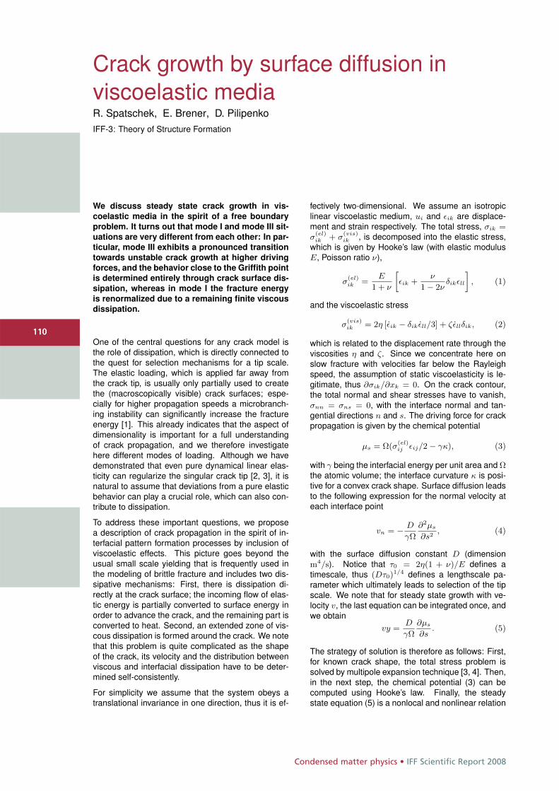
Condensed matter physics • IFF Scientific Report 2008
110110
Crack growth by surface diffusion inviscoelastic mediaR. Spatschek, E. Brener, D. PilipenkoIFF-3: Theory of Structure Formation
We discuss steady state crack growth in vis-coelastic media in the spirit of a free boundaryproblem. It turns out that mode I and mode III sit-uations are very different from each other: In par-ticular, mode III exhibits a pronounced transitiontowards unstable crack growth at higher drivingforces, and the behavior close to the Griffith pointis determined entirely through crack surface dis-sipation, whereas in mode I the fracture energyis renormalized due to a remaining finite viscousdissipation.
One of the central questions for any crack model isthe role of dissipation, which is directly connected tothe quest for selection mechanisms for a tip scale.The elastic loading, which is applied far away fromthe crack tip, is usually only partially used to createthe (macroscopically visible) crack surfaces; espe-cially for higher propagation speeds a microbranch-ing instability can significantly increase the fractureenergy [1]. This already indicates that the aspect ofdimensionality is important for a full understandingof crack propagation, and we therefore investigatehere different modes of loading. Although we havedemonstrated that even pure dynamical linear elas-ticity can regularize the singular crack tip [2, 3], it isnatural to assume that deviations from a pure elasticbehavior can play a crucial role, which can also con-tribute to dissipation.
To address these important questions, we proposea description of crack propagation in the spirit of in-terfacial pattern formation processes by inclusion ofviscoelastic effects. This picture goes beyond theusual small scale yielding that is frequently used inthe modeling of brittle fracture and includes two dis-sipative mechanisms: First, there is dissipation di-rectly at the crack surface; the incoming flow of elas-tic energy is partially converted to surface energy inorder to advance the crack, and the remaining part isconverted to heat. Second, an extended zone of vis-cous dissipation is formed around the crack. We notethat this problem is quite complicated as the shapeof the crack, its velocity and the distribution betweenviscous and interfacial dissipation have to be deter-mined self-consistently.
For simplicity we assume that the system obeys atranslational invariance in one direction, thus it is ef-
fectively two-dimensional. We assume an isotropiclinear viscoelastic medium, ui and εik are displace-ment and strain respectively. The total stress, σik =σ
(el)ik + σ
(vis)ik , is decomposed into the elastic stress,
which is given by Hooke’s law (with elastic modulusE, Poisson ratio ν),
σ(el)ik =
E
1 + ν
»εik +
ν
1 − 2νδikεll
–, (1)
and the viscoelastic stress
σ(vis)ik = 2η [εik − δik εll/3] + ζεllδik, (2)
which is related to the displacement rate through theviscosities η and ζ. Since we concentrate here onslow fracture with velocities far below the Rayleighspeed, the assumption of static viscoelasticity is le-gitimate, thus ∂σik/∂xk = 0. On the crack contour,the total normal and shear stresses have to vanish,σnn = σns = 0, with the interface normal and tan-gential directions n and s. The driving force for crackpropagation is given by the chemical potential
μs = Ω(σ(el)ij εij/2 − γκ), (3)
with γ being the interfacial energy per unit area and Ωthe atomic volume; the interface curvature κ is posi-tive for a convex crack shape. Surface diffusion leadsto the following expression for the normal velocity ateach interface point
vn = − D
γΩ
∂2μs
∂s2, (4)
with the surface diffusion constant D (dimensionm4/s). Notice that τ0 = 2η(1 + ν)/E defines atimescale, thus (Dτ0)
1/4 defines a lengthscale pa-rameter which ultimately leads to selection of the tipscale. We note that for steady state growth with ve-locity v, the last equation can be integrated once, andwe obtain
vy =D
γΩ
∂μs
∂s. (5)
The strategy of solution is therefore as follows: First,for known crack shape, the total stress problem issolved by multipole expansion technique [3, 4]. Then,in the next step, the chemical potential (3) can becomputed using Hooke’s law. Finally, the steadystate equation (5) is a nonlocal and nonlinear relation
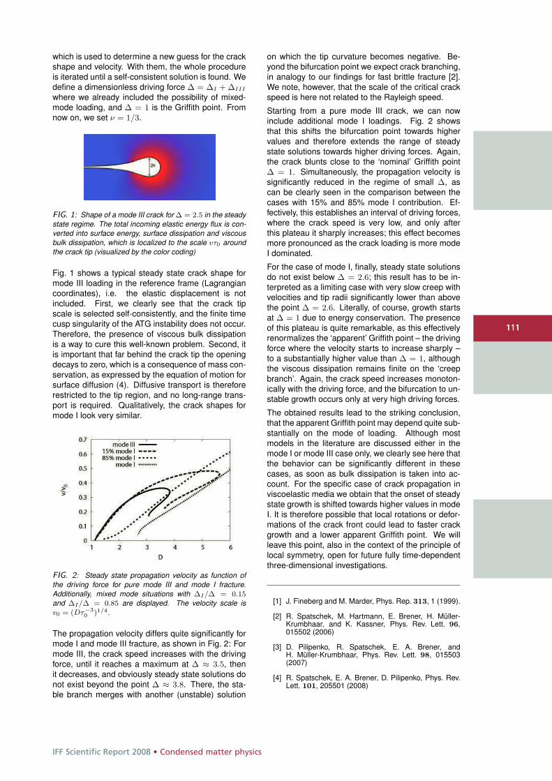
IFF Scientific Report 2008 • Condensed matter physics
111111
which is used to determine a new guess for the crackshape and velocity. With them, the whole procedureis iterated until a self-consistent solution is found. Wedefine a dimensionless driving force Δ = ΔI + ΔIII
where we already included the possibility of mixed-mode loading, and Δ = 1 is the Griffith point. Fromnow on, we set ν = 1/3.
FIG. 1: Shape of a mode III crack for Δ = 2.5 in the steadystate regime. The total incoming elastic energy flux is con-verted into surface energy, surface dissipation and viscousbulk dissipation, which is localized to the scale vτ0 aroundthe crack tip (visualized by the color coding)
Fig. 1 shows a typical steady state crack shape formode III loading in the reference frame (Lagrangiancoordinates), i.e. the elastic displacement is notincluded. First, we clearly see that the crack tipscale is selected self-consistently, and the finite timecusp singularity of the ATG instability does not occur.Therefore, the presence of viscous bulk dissipationis a way to cure this well-known problem. Second, itis important that far behind the crack tip the openingdecays to zero, which is a consequence of mass con-servation, as expressed by the equation of motion forsurface diffusion (4). Diffusive transport is thereforerestricted to the tip region, and no long-range trans-port is required. Qualitatively, the crack shapes formode I look very similar.
FIG. 2: Steady state propagation velocity as function ofthe driving force for pure mode III and mode I fracture.Additionally, mixed mode situations with ΔI/Δ = 0.15
and ΔI/Δ = 0.85 are displayed. The velocity scale isv0 = (Dτ−3
0 )1/4.
The propagation velocity differs quite significantly formode I and mode III fracture, as shown in Fig. 2: Formode III, the crack speed increases with the drivingforce, until it reaches a maximum at Δ ≈ 3.5, thenit decreases, and obviously steady state solutions donot exist beyond the point Δ ≈ 3.8. There, the sta-ble branch merges with another (unstable) solution
on which the tip curvature becomes negative. Be-yond the bifurcation point we expect crack branching,in analogy to our findings for fast brittle fracture [2].We note, however, that the scale of the critical crackspeed is here not related to the Rayleigh speed.
Starting from a pure mode III crack, we can nowinclude additional mode I loadings. Fig. 2 showsthat this shifts the bifurcation point towards highervalues and therefore extends the range of steadystate solutions towards higher driving forces. Again,the crack blunts close to the ‘nominal’ Griffith pointΔ = 1. Simultaneously, the propagation velocity issignificantly reduced in the regime of small Δ, ascan be clearly seen in the comparison between thecases with 15% and 85% mode I contribution. Ef-fectively, this establishes an interval of driving forces,where the crack speed is very low, and only afterthis plateau it sharply increases; this effect becomesmore pronounced as the crack loading is more modeI dominated.
For the case of mode I, finally, steady state solutionsdo not exist below Δ = 2.6; this result has to be in-terpreted as a limiting case with very slow creep withvelocities and tip radii significantly lower than abovethe point Δ = 2.6. Literally, of course, growth startsat Δ = 1 due to energy conservation. The presenceof this plateau is quite remarkable, as this effectivelyrenormalizes the ‘apparent’ Griffith point – the drivingforce where the velocity starts to increase sharply –to a substantially higher value than Δ = 1, althoughthe viscous dissipation remains finite on the ‘creepbranch’. Again, the crack speed increases monoton-ically with the driving force, and the bifurcation to un-stable growth occurs only at very high driving forces.
The obtained results lead to the striking conclusion,that the apparent Griffith point may depend quite sub-stantially on the mode of loading. Although mostmodels in the literature are discussed either in themode I or mode III case only, we clearly see here thatthe behavior can be significantly different in thesecases, as soon as bulk dissipation is taken into ac-count. For the specific case of crack propagation inviscoelastic media we obtain that the onset of steadystate growth is shifted towards higher values in modeI. It is therefore possible that local rotations or defor-mations of the crack front could lead to faster crackgrowth and a lower apparent Griffith point. We willleave this point, also in the context of the principle oflocal symmetry, open for future fully time-dependentthree-dimensional investigations.
[1] J. Fineberg and M. Marder, Phys. Rep. 313, 1 (1999).
[2] R. Spatschek, M. Hartmann, E. Brener, H. Müller-Krumbhaar, and K. Kassner, Phys. Rev. Lett. 96,015502 (2006)
[3] D. Pilipenko, R. Spatschek, E. A. Brener, andH. Müller-Krumbhaar, Phys. Rev. Lett. 98, 015503(2007)
[4] R. Spatschek, E. A. Brener, D. Pilipenko, Phys. Rev.Lett. 101, 205501 (2008)
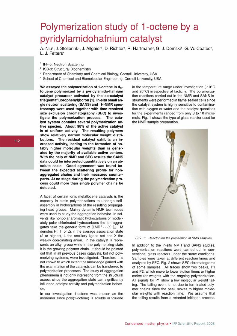
Condensed matter physics • IFF Scientific Report 2008
112
Polymerization study of 1-octene by apyridylamidohafnium catalystA. Niu1, J. Stellbrink1, J. Allgaier1, D. Richter1, R. Hartmann2, G. J. Domski3, G. W. Coates3,L. J. Fetters4
1 IFF-5: Neutron Scattering2 ISB-3: Structural Biochemistry3 Department of Chemistry and Chemical Biology, Cornell University, USA4 School of Chemical and Biomolecular Engineering, Cornell University, USA
We assayed the polymerization of 1-octene in d8-
toluene polymerized by a pyridylamido-hafnium
catalyst precursor activated by the co-catalyst
tris(pentafluorophenyl)boron [1]. In-situ small an-
gle neutron scattering (SANS) and 1H-NMR spec-
troscopy were used together with time resolved
size exclusion chromatography (SEC) to inves-
tigate the polymerization process. The cata-
lyst system contains several polymerization ac-
tive species. About 98% of the active catalyst
is of uniform activity. The resulting polymers
show relatively narrow molecular weight distri-
butions. The residual catalyst exhibits an in-
creased activity, leading to the formation of no-
tably higher molecular weights than is gener-
ated by the majority of available active centers.
With the help of NMR and SEC results the SANS
data could be interpreted quantitatively on an ab-
solute scale. Good agreement was found be-
tween the expected scattering profile for non-
aggregated chains and their measured counter-
parts. At no stage during the polymerization pro-
cess could more than single polymer chains be
detected.
A facet of certain ionic metallocene catalysts is thecapacity in olefin polymerizations to undergo self-assembly in hydrocarbons of the resulting propagat-ing head groups. Mainly dynamic NMR techniqueswere used to study the aggregation behavior. In sol-vents like nonpolar aromatic hydrocarbons or moder-ately polar chlorinated hydrocarbons the ion aggre-gates take the generic form of [LMR+- - -X−]n. Mdenotes Hf, Ti or Zr, n the average association state(2 or higher), L the ancillary ligand set and X theweakly coordinating anion. In the catalyst R repre-sents an alkyl group while in the polymerizing stateit is the growing polymer chain. It should be pointedout that in all previous cases catalysts, but not poly-merizing systems, were investigated. Therefore it isnot known to which extent the knowledge gained withthe examination of the catalysts can be transferred topolymerization processes. The study of aggregationphenomena is not only interesting from the structuralaspect since the aggregation state can significantlyinfluence catalyst activity and polymerization behav-ior.In our investigation 1-octene was chosen as themonomer since poly(1-octene) is soluble in toluene
in the temperature range under investigation (-10◦Cand 20◦C) irrespective of tacticity. The polymeriza-tion reactions carried out in the NMR and SANS in-struments were performed in flame sealed cells sincethe catalyst system is highly sensitive to contamina-tion with oxygen or water and the catalyst quantitiesfor the experiments ranged from only 3 to 10 micro-mols. Fig. 1 shows the type of glass reactor used forthe NMR sample preparation.
FIG. 1: Reactor fort the preparation of NMR samples.
In addition to the in-situ NMR and SANS studies,polymerization reactions were carried out in con-ventional glass reactors under the same conditions.Samples were taken at different reaction times andanalyzed by SEC. Fig. 2 shows SEC chromatogramsof some samples. All traces show two peaks, P1and P2, which move to lower elution times or highermolecular weights with the ongoing polymerization.All signals for P1 show a low molecular weight tail-ing. The tailing event is not due to terminated poly-mer chains since the peak moves to higher molec-ular weights with reaction time. We assume thatthe tailing results from a retarded initiation process.
112
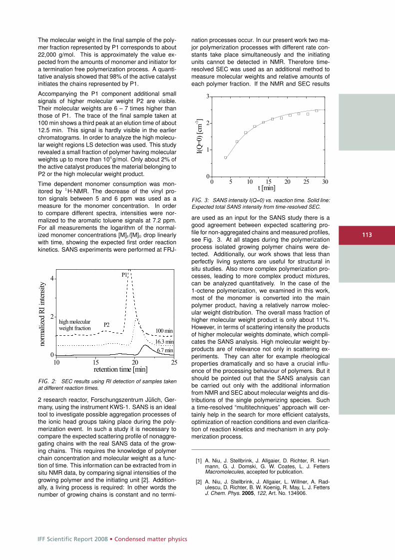
IFF Scientific Report 2008 • Condensed matter physics
113
The molecular weight in the final sample of the poly-mer fraction represented by P1 corresponds to about22,000 g/mol. This is approximately the value ex-pected from the amounts of monomer and initiator fora termination free polymerization process. A quanti-tative analysis showed that 98% of the active catalystinitiates the chains represented by P1.
Accompanying the P1 component additional smallsignals of higher molecular weight P2 are visible.Their molecular weights are 6 – 7 times higher thanthose of P1. The trace of the final sample taken at100 min shows a third peak at an elution time of about12.5 min. This signal is hardly visible in the earlierchromatograms. In order to analyze the high molecu-lar weight regions LS detection was used. This studyrevealed a small fraction of polymer having molecularweights up to more than 106g/mol. Only about 2% ofthe active catalyst produces the material belonging toP2 or the high molecular weight product.
Time dependent monomer consumption was mon-itored by 1H-NMR. The decrease of the vinyl pro-ton signals between 5 and 6 ppm was used as ameasure for the monomer concentration. In orderto compare different spectra, intensities were nor-malized to the aromatic toluene signals at 7.2 ppm.For all measurements the logarithm of the normal-ized monomer concentrations [M]t/[M]0 drop linearlywith time, showing the expected first order reactionkinetics. SANS experiments were performed at FRJ-
FIG. 2: SEC results using RI detection of samples takenat different reaction times.
2 research reactor, Forschungszentrum Jülich, Ger-many, using the instrument KWS-1. SANS is an idealtool to investigate possible aggregation processes ofthe ionic head groups taking place during the poly-merization event. In such a study it is necessary tocompare the expected scattering profile of nonaggre-gating chains with the real SANS data of the grow-ing chains. This requires the knowledge of polymerchain concentration and molecular weight as a func-tion of time. This information can be extracted from insitu NMR data, by comparing signal intensities of thegrowing polymer and the initiating unit [2]. Addition-ally, a living process is required: In other words thenumber of growing chains is constant and no termi-
nation processes occur. In our present work two ma-jor polymerization processes with different rate con-stants take place simultaneously and the initiatingunits cannot be detected in NMR. Therefore time-resolved SEC was used as an additional method tomeasure molecular weights and relative amounts ofeach polymer fraction. If the NMR and SEC results
FIG. 3: SANS intensity I(Q=0) vs. reaction time. Solid line:Expected total SANS intensity from time-resolved SEC.
are used as an input for the SANS study there is agood agreement between expected scattering pro-file for non-aggregated chains and measured profiles,see Fig. 3. At all stages during the polymerizationprocess isolated growing polymer chains were de-tected. Additionally, our work shows that less thanperfectly living systems are useful for structural insitu studies. Also more complex polymerization pro-cesses, leading to more complex product mixtures,can be analyzed quantitatively. In the case of the1-octene polymerization, we examined in this work,most of the monomer is converted into the mainpolymer product, having a relatively narrow molec-ular weight distribution. The overall mass fraction ofhigher molecular weight product is only about 11%.However, in terms of scattering intensity the productsof higher molecular weights dominate, which compli-cates the SANS analysis. High molecular weight by-products are of relevance not only in scattering ex-periments. They can alter for example rheologicalproperties dramatically and so have a crucial influ-ence of the processing behaviour of polymers. But itshould be pointed out that the SANS analysis canbe carried out only with the additional informationfrom NMR and SEC about molecular weights and dis-tributions of the single polymerizing species. Sucha time-resolved “multitechniques” approach will cer-tainly help in the search for more efficient catalysts,optimization of reaction conditions and even clarifica-tion of reaction kinetics and mechanism in any poly-merization process.
[1] A. Niu, J. Stellbrink, J. Allgaier, D. Richter, R. Hart-mann, G. J. Domski, G. W. Coates, L. J. FettersMacromolecules, accepted for publication.
[2] A. Niu, J. Stellbrink, J. Allgaier, L. Willner, A. Rad-ulescu, D. Richter, B. W. Koenig, R. May, L. J. FettersJ. Chem. Phys. 2005, 122, Art. No. 134906.
113
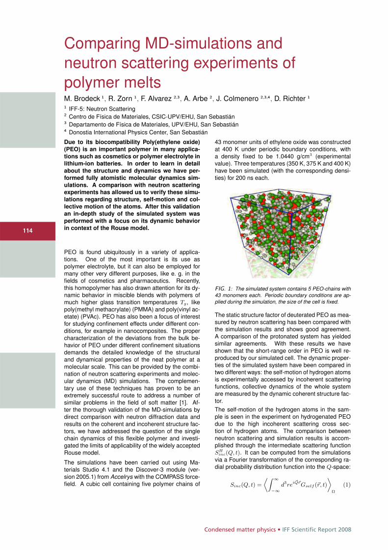
Condensed matter physics • IFF Scientific Report 2008
114
Comparing MD-simulations andneutron scattering experiments ofpolymer meltsM. Brodeck 1, R. Zorn 1, F. Alvarez 2,3, A. Arbe 2, J. Colmenero 2,3,4, D. Richter 1
1 IFF-5: Neutron Scattering2 Centro de Física de Materiales, CSIC-UPV/EHU, San Sebastián3 Departamento de Física de Materiales, UPV/EHU, San Sebastián4 Donostia International Physics Center, San Sebastián
Due to its biocompatibility Poly(ethylene oxide)(PEO) is an important polymer in many applica-tions such as cosmetics or polymer electrolyte inlithium-ion batteries. In order to learn in detailabout the structure and dynamics we have per-formed fully atomistic molecular dynamics sim-ulations. A comparison with neutron scatteringexperiments has allowed us to verify these simu-lations regarding structure, self-motion and col-lective motion of the atoms. After this validationan in-depth study of the simulated system wasperformed with a focus on its dynamic behaviorin context of the Rouse model.
PEO is found ubiquitously in a variety of applica-tions. One of the most important is its use aspolymer electrolyte, but it can also be employed formany other very different purposes, like e. g. in thefields of cosmetics and pharmaceutics. Recently,this homopolymer has also drawn attention for its dy-namic behavior in miscible blends with polymers ofmuch higher glass transition temperatures Tg, likepoly(methyl methacrylate) (PMMA) and poly(vinyl ac-etate) (PVAc). PEO has also been a focus of interestfor studying confinement effects under different con-ditions, for example in nanocomposites. The propercharacterization of the deviations from the bulk be-havior of PEO under different confinement situationsdemands the detailed knowledge of the structuraland dynamical properties of the neat polymer at amolecular scale. This can be provided by the combi-nation of neutron scattering experiments and molec-ular dynamics (MD) simulations. The complemen-tary use of these techniques has proven to be anextremely successful route to address a number ofsimilar problems in the field of soft matter [1]. Af-ter the thorough validation of the MD-simulations bydirect comparison with neutron diffraction data andresults on the coherent and incoherent structure fac-tors, we have addressed the question of the singlechain dynamics of this flexible polymer and investi-gated the limits of applicability of the widely acceptedRouse model.
The simulations have been carried out using Ma-terials Studio 4.1 and the Discover-3 module (ver-sion 2005.1) from Accelrys with the COMPASS force-field. A cubic cell containing five polymer chains of
43 monomer units of ethylene oxide was constructedat 400 K under periodic boundary conditions, witha density fixed to be 1.0440 g/cm3 (experimentalvalue). Three temperatures (350 K, 375 K and 400 K)have been simulated (with the corresponding densi-ties) for 200 ns each.
FIG. 1: The simulated system contains 5 PEO-chains with43 monomers each. Periodic boundary conditions are ap-plied during the simulation, the size of the cell is fixed.
The static structure factor of deuterated PEO as mea-sured by neutron scattering has been compared withthe simulation results and shows good agreement.A comparison of the protonated system has yieldedsimilar agreements. With these results we haveshown that the short-range order in PEO is well re-produced by our simulated cell. The dynamic proper-ties of the simulated system have been compared intwo different ways: the self-motion of hydrogen atomsis experimentally accessed by incoherent scatteringfunctions, collective dynamics of the whole systemare measured by the dynamic coherent structure fac-tor.The self-motion of the hydrogen atoms in the sam-ple is seen in the experiment on hydrogenated PEOdue to the high incoherent scattering cross sec-tion of hydrogen atoms. The comparison betweenneutron scattering and simulation results is accom-plished through the intermediate scattering functionSH
inc(Q, t). It can be computed from the simulationsvia a Fourier transformation of the corresponding ra-dial probability distribution function into the Q-space:
Sinc(Q, t) =
fiZ ∞
−∞d3rei �Q�rGself (�r, t)
flΩ
(1)
114
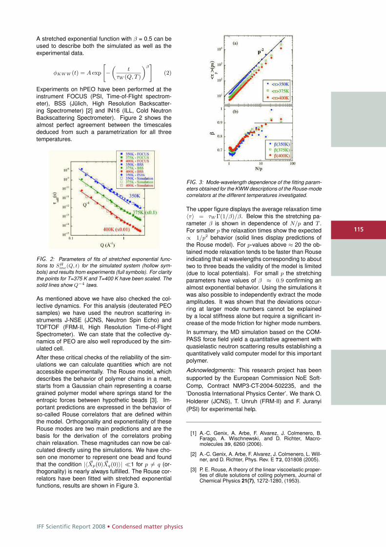
IFF Scientific Report 2008 • Condensed matter physics
115
A stretched exponential function with β = 0.5 can beused to describe both the simulated as well as theexperimental data.
φKWW (t) = A exp
"−
„t
τW (Q, T )
«β#
(2)
Experiments on hPEO have been performed at theinstrument FOCUS (PSI, Time-of-Flight spectrom-eter), BSS (Jülich, High Resolution Backscatter-ing Spectrometer) [2] and IN16 (ILL, Cold NeutronBackscattering Spectrometer). Figure 2 shows thealmost perfect agreement between the timescalesdeduced from such a parametrization for all threetemperatures.
FIG. 2: Parameters of fits of stretched exponential func-tions to SH
inc(Q, t) for the simulated system (hollow sym-bols) and results from experiments (full symbols). For claritythe points for T=375 K and T=400 K have been scaled. Thesolid lines show Q−4 laws.
As mentioned above we have also checked the col-lective dynamics. For this analysis (deuterated PEOsamples) we have used the neutron scattering in-struments J-NSE (JCNS, Neutron Spin Echo) andTOFTOF (FRM-II, High Resolution Time-of-FlightSpectrometer). We can state that the collective dy-namics of PEO are also well reproduced by the sim-ulated cell.After these critical checks of the reliability of the sim-ulations we can calculate quantities which are notaccessible experimentally. The Rouse model, whichdescribes the behavior of polymer chains in a melt,starts from a Gaussian chain representing a coarsegrained polymer model where springs stand for theentropic forces between hypothetic beads [3]. Im-portant predictions are expressed in the behavior ofso-called Rouse correlators that are defined withinthe model. Orthogonality and exponentiality of theseRouse modes are two main predictions and are thebasis for the derivation of the correlators probingchain relaxation. These magnitudes can now be cal-culated directly using the simulations. We have cho-sen one monomer to represent one bead and foundthat the condition |〈 �Xp(0) �Xq(0)〉| �1 for p �= q (or-thogonality) is nearly always fulfilled. The Rouse cor-relators have been fitted with stretched exponentialfunctions, results are shown in Figure 3.
FIG. 3: Mode-wavelength dependence of the fitting param-eters obtained for the KWW descriptions of the Rouse-modecorrelators at the different temperatures investigated.
The upper figure displays the average relaxation time〈τ〉 = τW Γ(1/β)/β. Below this the stretching pa-rameter β is shown in dependence of N/p and T .For smaller p the relaxation times show the expected∝ 1/p2 behavior (solid lines display predictions ofthe Rouse model). For p-values above ≈ 20 the ob-tained mode relaxation tends to be faster than Rouseindicating that at wavelengths corresponding to abouttwo to three beads the validity of the model is limited(due to local potentials). For small p the stretchingparameters have values of β ≈ 0.9 confirming analmost exponential behavior. Using the simulations itwas also possible to independently extract the modeamplitudes. It was shown that the deviations occur-ring at larger mode numbers cannot be explainedby a local stiffness alone but require a significant in-crease of the mode friction for higher mode numbers.In summary, the MD simulation based on the COM-PASS force field yield a quantitative agreement withquasielastic neutron scattering results establishing aquantitatively valid computer model for this importantpolymer.
Acknowledgments: This research project has beensupported by the European Commission NoE Soft-Comp, Contract NMP3-CT-2004-502235, and the’Donostia International Physics Center’. We thank O.Holderer (JCNS), T. Unruh (FRM-II) and F. Juranyi(PSI) for experimental help.
[1] A.-C. Genix, A. Arbe, F. Alvarez, J. Colmenero, B.Farago, A. Wischnewski, and D. Richter, Macro-molecules 39, 6260 (2006).
[2] A.-C. Genix, A. Arbe, F. Alvarez, J. Colmenero, L. Will-ner, and D. Richter, Phys. Rev. E 72, 031808 (2005).
[3] P. E. Rouse, A theory of the linear viscoelastic proper-ties of dilute solutions of coiling polymers, Journal ofChemical Physics 21(7), 1272-1280, (1953).
115
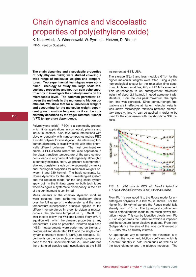
Condensed matter physics • IFF Scientific Report 2008
116116
Chain dynamics and viscoelasticproperties of poly(ethylene oxide)K. Niedzwiedz, A. Wischnewski, W. Pyckhout-Hintzen, D. RichterIFF-5: Neutron Scattering
The chain dynamics and viscoelastic properties
of poly(ethylene oxide) were studied covering a
wide range of molecular weights and tempera-
tures. Two experimental techniques were com-
bined: rheology to study the large scale vis-
coelastic properties and neutron spin echo spec-
troscopy to investigate the chain dynamics on the
microscopic level. The common parameter be-
tween the methods is the monomeric friction co-
efficient. We show that for all molecular weights
and accounting for the molecular weight depen-
dent glass transition temperature it can be con-
sistently described by the Vogel-Tamman-Fulcher
(VFT) temperature dependence.
Poly(ethylene oxide) (PEO) is a commodity productwhich finds applications in cosmetical, plastics andindustrial sectors. Also, favourable interactions withclays or generally with nanocomposites makes PEOa model polymer for investigation. An interesting fun-damental property is its ability to mix with other chem-ically different polymers. The most prominent ex-ample is PEO/PMMA where the wide separation inthe glass transition temperature of the pure compo-nents leads to a dynamical heterogeneity although itis perfectly miscible. Here, we present a comprehen-sive and consistent study on the segmental dynamicsand rheological properties for molecular weights be-tween 1 and 930 kg/mol. The basic concepts, i.e.Rouse dynamics for the short un-entangled systemand the reptation model for the long chain systemapply both in the limiting cases for both techniqueswhereas again a systematic discrepancy in the sizeof the confinement is confirmed.Measurements of the complex dynamic moduluswere obtained from isothermal oscillatory shearover the full range of the rheometer and the time-temperature-superposition principle applied to thedifferent temperatures in order to obtain a master-curve at the reference temperature T0 = 348K. Theshift factors follow the Williams-Landel-Ferry (WLF)equation with which the dynamic properties at anytemperature T can be predicted. Neutron Spin echo(NSE) measurements were performed on blends ofprotonated and deuterated PEO and the single chaindynamic structure factor S(q,t)/S(q,0) obtained. Ex-periments on the low molecular weight sample weredone at the NSE spectrometer at FZJ, Jülich whereasthe entangled species was investigated at the NSE
instrument at NIST, USA.
The storage G’(ω ) and loss modulus G"(ω) for thehigher molecular weights were fitted using a phe-nomenological ansatz for the relaxation time spec-trum. A plateau modulus, G0
N = 1.28 MPa emerged.This corresponds to an entanglement molecularweight of about 2.1 kg/mol, in good agreement withliterature. From the loss peak maximum, the repta-tion time was extracted. Since contour-length fluc-tuations are in-effective at higher molecular weights,well-known microscopic relations between elemen-tary times τe and τd can be applied in order to beused for the comparison with the short-time NSE re-sults.
FIG. 1: NSE data for PEO with Mw=2.1 kg/mol atT=413K.Solid lines show the fit with the Rouse model.
From Fig 1 a very good fit to the Rouse model for un-entangled polymers to a low Mw is shown. For thehigher Mw 80 kg/mol sample the Rouse model failsalready from t=10 ns. The topological confinementdue to entanglements leads to the much slower rep-tation motion. This can be identified clearly from Fig2. For longer times the further relaxation is impededand the structure factor displays plateaus. From theirQ-dependence the size of the tube confinement ofdt ∼ 50A may be directly inferred.
An appropriate way to compare the dynamics is tofocus on the monomeric friction coefficient which isa central quantity in both techniques as well as onthe tube diameter and the plateau modulus. The
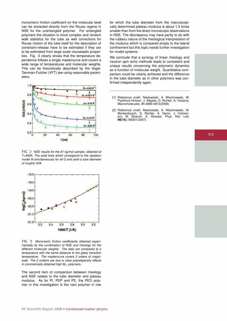
IFF Scientific Report 2008 • Condensed matter physics
117117
monomeric friction coefficient on the molecular levelcan be extracted directly from the Rouse regime inNSE for the unentangled polymer. For entangledpolymers the situation is more complex and randomwalk statistics for the tube as well corrections forRouse motion of the tube itself for the description ofconstraint-release have to be estimated if they areto be estimated from large scale viscoelastic proper-ties. Fig. 3 clearly shows that the temperature de-pendence follows a single mastercurve and covers awide range of temperatures and molecular weights.This can be theoretically described by the Vogel-Tamman-Fulcher (VFT) law using reasonable param-eters.
FIG. 2: NSE results for the 81 kg/mol sample, obtained atT=400K. The solid lines which correspond to the reptationmodel fit simultaneously for all Q and yield a tube diameterof roughly 50A.
FIG. 3: Monomeric friction coefficients obtained experi-mentally by the combination of NSE and rheology for thedifferent molecular weights. The data are compared at atemperature with the same distance to the glass transitiontemperature. The mastercurve covers 2 orders of magni-tude. The 2 outliers are due to clear polydispersity effectsin commercially obtained high Mw polymers.
The second item of comparison between rheologyand NSE relates to the tube diameter and plateaumodulus. As for PI, PEP and PE, the PEO poly-mer in this investigation is the next polymer in row
for which the tube diameter from the macroscopi-cally determined plateau modulus is about 1.5 timessmaller than from the direct microscopic observationsin NSE. The discrepancy may have partly to do withthe rubbery nature of the rheological interpretation ofthe modulus which is compared simply to the lateralconfinement but this topic needs further investigationfor model systems.
We conclude that a synergy of linear rheology andneutron spin echo methods leads to consistent andunique results concerning the polymeric dynamicsas a function of molecular weight. Quantitative com-parison could be clearly achieved and the differencein the tube diameter as in other polymers was con-firmed independently again.
[1] Reference oneK. Niedzwiedz, A. Wischnewski, W.Pyckhout-Hintzen, J. Allgaier, D. Richter, A. Faraone,Macromolecules, 41,4866-4872(2008).
[2] Reference oneK. Niedzwiedz, A. Wischnewski, M.Monkenbusch, D. Richter, A. Genix, J. Colmen-ero, M. Strauch, E. Straube, Phys. Rev. Lett,98(16),168301(2007).
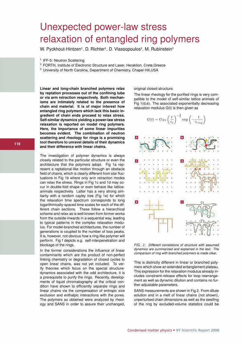
Condensed matter physics • IFF Scientific Report 2008
118118
Unexpected power-law stressrelaxation of entangled ring polymersW. Pyckhout-Hintzen1, D. Richter1, D. Vlassopoulos2, M. Rubinstein3
1 IFF-5: Neutron Scattering2 FORTH, Institute of Electronic Structure and Laser, Heraklion, Crete,Greece3 University of North Carolina, Department of Chemistry, Chapel Hill,USA
Linear and long-chain branched polymers relax
by reptation processes out of the confining tube
or via arm retraction respectively. Both mechan-
isms are intimately related to the presence of
chain end material. It is of major interest how
entangled ring polymers which lack this basic in-
gredient of chain ends proceed to relax stress.
Self-similar dynamics yielding a power-law stress
relaxation is reported on model ring polymers.
Here, the importance of some linear impurities
becomes evident. The combination of neutron
scattering and rheology for rings is a promising
tool therefore to unravel details of their dynamics
and their difference with linear chains.
The investigation of polymer dynamics is alwaysclosely related to the particular structure or even thearchitecture that the polymers adopt. Fig 1a rep-resent a reptational-like motion through an obstaclefield of chains, which is clearly different from star fluc-tuations in Fig 1b where only arm retraction modescan relax the stress. Rings in Fig 1c and 1d may oc-cur in double-fold shape or even behave like lattice-animals respectively. Latter has a very strong sim-ilarity with a random cayley tree (Fig 1e) for whichthe relaxation time spectrum corresponds to longlogarithmically-spaced time scales for each of the dif-ferent chain sections. These follow a hierarchicalscheme and relax as is well known from former worksfrom the outside-inwards in a sequential way, leadingto typical patterns in the complex relaxation modu-lus. For model-branched architectures, the number ofgenerations is coupled to the number of loss peaks.It is, however, not obvious how a ring-like polymer willperform. Fig f depicts e.g. self-interpenetration andblockage of the rings.In the former considerations the influence of linearcontaminants which are the product of non-perfectlinking chemistry or degradation of closed cycles toopen linear chains, was not yet included. To ver-ify theories which focus on the special structure-dynamics associated with the odd architecture, it isa prerequisite to purify the rings. Recently, develop-ments of liquid chromatography at the critical con-dition have shown to efficiently separate rings andlinear chains via the compensation of entropic sizeexclusion and enthalpic interactions with the pores.The polymers so obtained were analyzed by rheol-ogy and SANS in order to assure their unchanged,
original closed structure.
The linear rheology for the purified rings is very com-patible to the model of self-similar lattice animals ofFig 1(d,e). The associated exponentially decreasingrelaxation modulus G(t) is then given as
G(t) = GN0
„t
τe
«− 25
exp
„− t
τring
«
FIG. 1: Different correlations of structure with assumeddynamics are summarized and explained in the text. Thecomparison of ring with branched polymers is made clear.
This is distinctly different in linear or branched poly-mers which show an extended entanglement plateau.This expression for the relaxation modulus already in-cludes constraint-release effects for loop rearrange-ment as well as dynamic dilution and contains no fur-ther adjustable parameters.
SANS measurements are shown in Fig 2. From dilutesolution and in a melt of linear chains (not shown),unperturbed chain dimensions as well as the swellingof the ring by excluded-volume statistics could be
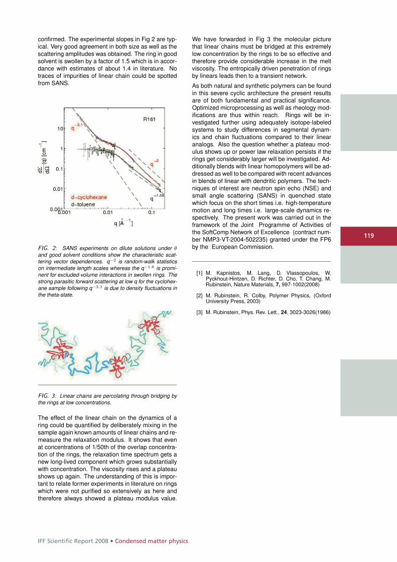
IFF Scientific Report 2008 • Condensed matter physics
119119
confirmed. The experimental slopes in Fig 2 are typ-ical. Very good agreement in both size as well as thescattering amplitudes was obtained. The ring in goodsolvent is swollen by a factor of 1.5 which is in accor-dance with estimates of about 1.4 in literature. Notraces of impurities of linear chain could be spottedfrom SANS.
FIG. 2: SANS experiments on dilute solutions under θ
and good solvent conditions show the characteristic scat-tering vector dependences. q−2 is random-walk statisticson intermediate length scales whereas the q−1.6 is promi-nent for excluded-volume interactions in swollen rings. Thestrong parasitic forward scattering at low q for the cyclohex-ane sample following q−3.1 is due to density fluctuations inthe theta-state.
FIG. 3: Linear chains are percolating through bridging bythe rings at low concentrations.
The effect of the linear chain on the dynamics of aring could be quantified by deliberately mixing in thesample again known amounts of linear chains and re-measure the relaxation modulus. It shows that evenat concentrations of 1/50th of the overlap concentra-tion of the rings, the relaxation time spectrum gets anew long-lived component which grows substantiallywith concentration. The viscosity rises and a plateaushows up again. The understanding of this is impor-tant to relate former experiments in literature on ringswhich were not purified so extensively as here andtherefore always showed a plateau modulus value.
We have forwarded in Fig 3 the molecular picturethat linear chains must be bridged at this extremelylow concentration by the rings to be so effective andtherefore provide considerable increase in the meltviscosity. The entropically driven penetration of ringsby linears leads then to a transient network.
As both natural and synthetic polymers can be foundin this severe cyclic architecture the present resultsare of both fundamental and practical significance.Optimized microprocessing as well as rheology mod-ifications are thus within reach. Rings will be in-vestigated further using adequately isotope-labeledsystems to study differences in segmental dynam-ics and chain fluctuations compared to their linearanalogs. Also the question whether a plateau mod-ulus shows up or power law relaxation persists if therings get considerably larger will be investigated. Ad-ditionally blends with linear homopolymers will be ad-dressed as well to be compared with recent advancesin blends of linear with dendritic polymers. The tech-niques of interest are neutron spin echo (NSE) andsmall angle scattering (SANS) in quenched statewhich focus on the short times i.e. high-temperaturemotion and long times i.e. large-scale dynamics re-spectively. The present work was carried out in theframework of the Joint Programme of Activities ofthe SoftComp Network of Excellence (contract num-ber NMP3-VT-2004-502235) granted under the FP6by the European Commission.
[1] M. Kapnistos, M. Lang, D. Vlassopoulos, W.Pyckhout-Hintzen, D. Richter, D. Cho, T. Chang, M.Rubinstein, Nature Materials, 7, 997-1002(2008)
[2] M. Rubinstein, R. Colby, Polymer Physics, (OxfordUniversity Press, 2003)
[3] M. Rubinstein, Phys. Rev. Lett., 24, 3023-3026(1986)
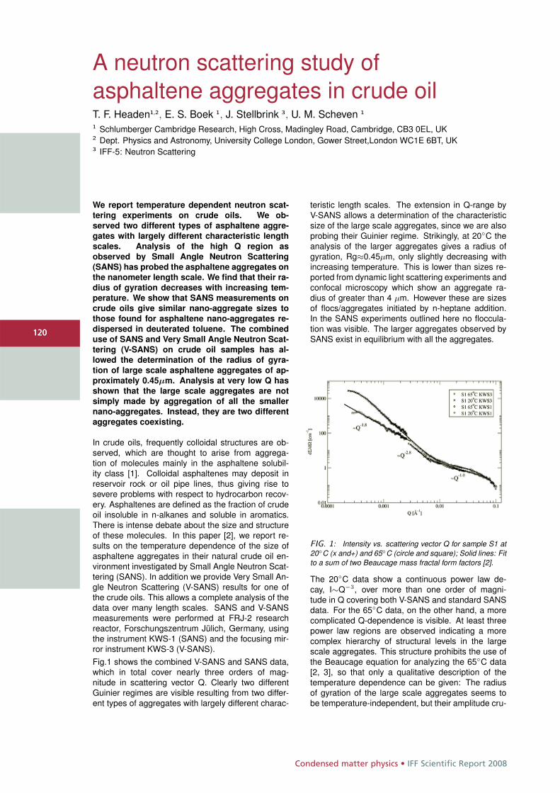
Condensed matter physics • IFF Scientific Report 2008
120
A neutron scattering study ofasphaltene aggregates in crude oilT. F. Headen1,2, E. S. Boek 1, J. Stellbrink 3, U. M. Scheven 1
1 Schlumberger Cambridge Research, High Cross, Madingley Road, Cambridge, CB3 0EL, UK2 Dept. Physics and Astronomy, University College London, Gower Street,London WC1E 6BT, UK3 IFF-5: Neutron Scattering
We report temperature dependent neutron scat-
tering experiments on crude oils. We ob-
served two different types of asphaltene aggre-
gates with largely different characteristic length
scales. Analysis of the high Q region as
observed by Small Angle Neutron Scattering
(SANS) has probed the asphaltene aggregates on
the nanometer length scale. We find that their ra-
dius of gyration decreases with increasing tem-
perature. We show that SANS measurements on
crude oils give similar nano-aggregate sizes to
those found for asphaltene nano-aggregates re-
dispersed in deuterated toluene. The combined
use of SANS and Very Small Angle Neutron Scat-
tering (V-SANS) on crude oil samples has al-
lowed the determination of the radius of gyra-
tion of large scale asphaltene aggregates of ap-
proximately 0.45μm. Analysis at very low Q has
shown that the large scale aggregates are not
simply made by aggregation of all the smaller
nano-aggregates. Instead, they are two different
aggregates coexisting.
In crude oils, frequently colloidal structures are ob-served, which are thought to arise from aggrega-tion of molecules mainly in the asphaltene solubil-ity class [1]. Colloidal asphaltenes may deposit inreservoir rock or oil pipe lines, thus giving rise tosevere problems with respect to hydrocarbon recov-ery. Asphaltenes are defined as the fraction of crudeoil insoluble in n-alkanes and soluble in aromatics.There is intense debate about the size and structureof these molecules. In this paper [2], we report re-sults on the temperature dependence of the size ofasphaltene aggregates in their natural crude oil en-vironment investigated by Small Angle Neutron Scat-tering (SANS). In addition we provide Very Small An-gle Neutron Scattering (V-SANS) results for one ofthe crude oils. This allows a complete analysis of thedata over many length scales. SANS and V-SANSmeasurements were performed at FRJ-2 researchreactor, Forschungszentrum Jülich, Germany, usingthe instrument KWS-1 (SANS) and the focusing mir-ror instrument KWS-3 (V-SANS).Fig.1 shows the combined V-SANS and SANS data,which in total cover nearly three orders of mag-nitude in scattering vector Q. Clearly two differentGuinier regimes are visible resulting from two differ-ent types of aggregates with largely different charac-
teristic length scales. The extension in Q-range byV-SANS allows a determination of the characteristicsize of the large scale aggregates, since we are alsoprobing their Guinier regime. Strikingly, at 20◦C theanalysis of the larger aggregates gives a radius ofgyration, Rg≈0.45μm, only slightly decreasing withincreasing temperature. This is lower than sizes re-ported from dynamic light scattering experiments andconfocal microscopy which show an aggregate ra-dius of greater than 4 μm. However these are sizesof flocs/aggregates initiated by n-heptane addition.In the SANS experiments outlined here no floccula-tion was visible. The larger aggregates observed bySANS exist in equilibrium with all the aggregates.
FIG. 1: Intensity vs. scattering vector Q for sample S1 at20◦C (x and+) and 65◦C (circle and square); Solid lines: Fitto a sum of two Beaucage mass fractal form factors [2].
The 20◦C data show a continuous power law de-cay, I∼Q−3, over more than one order of magni-tude in Q covering both V-SANS and standard SANSdata. For the 65◦C data, on the other hand, a morecomplicated Q-dependence is visible. At least threepower law regions are observed indicating a morecomplex hierarchy of structural levels in the largescale aggregates. This structure prohibits the use ofthe Beaucage equation for analyzing the 65◦C data[2, 3], so that only a qualitative description of thetemperature dependence can be given: The radiusof gyration of the large scale aggregates seems tobe temperature-independent, but their amplitude cru-
120
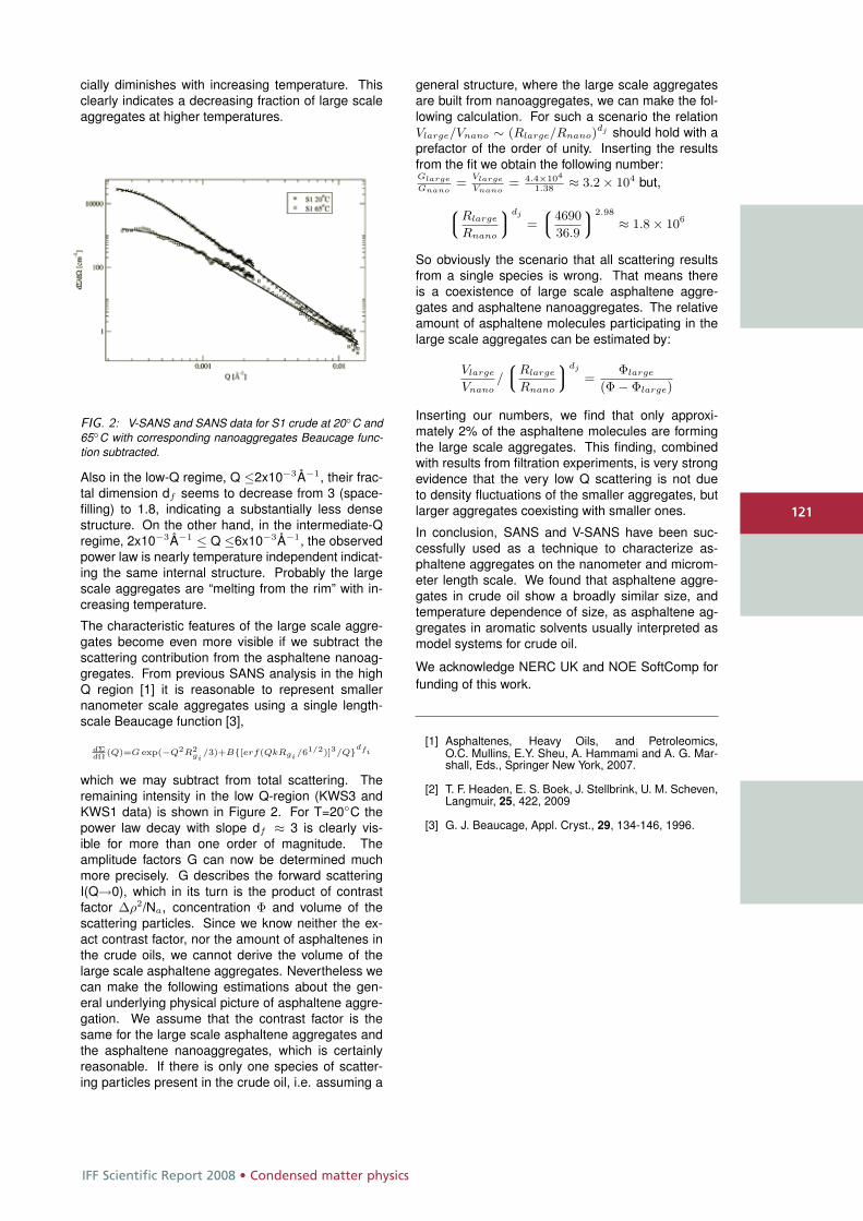
IFF Scientific Report 2008 • Condensed matter physics
121
cially diminishes with increasing temperature. Thisclearly indicates a decreasing fraction of large scaleaggregates at higher temperatures.
FIG. 2: V-SANS and SANS data for S1 crude at 20◦C and65◦C with corresponding nanoaggregates Beaucage func-tion subtracted.
Also in the low-Q regime, Q ≤2x10⁻³Å−1, their frac-tal dimension df seems to decrease from 3 (space-filling) to 1.8, indicating a substantially less densestructure. On the other hand, in the intermediate-Qregime, 2x10⁻³Å−1 ≤ Q ≤6x10⁻³Å−1, the observedpower law is nearly temperature independent indicat-ing the same internal structure. Probably the largescale aggregates are “melting from the rim” with in-creasing temperature.
The characteristic features of the large scale aggre-gates become even more visible if we subtract thescattering contribution from the asphaltene nanoag-gregates. From previous SANS analysis in the highQ region [1] it is reasonable to represent smallernanometer scale aggregates using a single length-scale Beaucage function [3],
dΣdΩ (Q)=G exp(−Q2R2
gi/3)+B{[erf(QkRgi
/61/2)]3/Q}dfi
which we may subtract from total scattering. Theremaining intensity in the low Q-region (KWS3 andKWS1 data) is shown in Figure 2. For T=20◦C thepower law decay with slope df ≈ 3 is clearly vis-ible for more than one order of magnitude. Theamplitude factors G can now be determined muchmore precisely. G describes the forward scatteringI(Q→0), which in its turn is the product of contrastfactor Δρ2/Na, concentration Φ and volume of thescattering particles. Since we know neither the ex-act contrast factor, nor the amount of asphaltenes inthe crude oils, we cannot derive the volume of thelarge scale asphaltene aggregates. Nevertheless wecan make the following estimations about the gen-eral underlying physical picture of asphaltene aggre-gation. We assume that the contrast factor is thesame for the large scale asphaltene aggregates andthe asphaltene nanoaggregates, which is certainlyreasonable. If there is only one species of scatter-ing particles present in the crude oil, i.e. assuming a
general structure, where the large scale aggregatesare built from nanoaggregates, we can make the fol-lowing calculation. For such a scenario the relationVlarge/Vnano ∼ (Rlarge/Rnano)
dj should hold with aprefactor of the order of unity. Inserting the resultsfrom the fit we obtain the following number:Glarge
Gnano=
Vlarge
Vnano= 4.4×10⁴
1.38≈ 3.2 × 10⁴ but,
8>:
Rlarge
Rnano
9>;
dj
=
8>:
4690
36.9
9>;
2.98
≈ 1.8 × 10⁶
So obviously the scenario that all scattering resultsfrom a single species is wrong. That means thereis a coexistence of large scale asphaltene aggre-gates and asphaltene nanoaggregates. The relativeamount of asphaltene molecules participating in thelarge scale aggregates can be estimated by:
Vlarge
Vnano/
8>:
Rlarge
Rnano
9>;
dj
=Φlarge
(Φ − Φlarge)
Inserting our numbers, we find that only approxi-mately 2% of the asphaltene molecules are formingthe large scale aggregates. This finding, combinedwith results from filtration experiments, is very strongevidence that the very low Q scattering is not dueto density fluctuations of the smaller aggregates, butlarger aggregates coexisting with smaller ones.
In conclusion, SANS and V-SANS have been suc-cessfully used as a technique to characterize as-phaltene aggregates on the nanometer and microm-eter length scale. We found that asphaltene aggre-gates in crude oil show a broadly similar size, andtemperature dependence of size, as asphaltene ag-gregates in aromatic solvents usually interpreted asmodel systems for crude oil.
We acknowledge NERC UK and NOE SoftComp forfunding of this work.
[1] Asphaltenes, Heavy Oils, and Petroleomics,O.C. Mullins, E.Y. Sheu, A. Hammami and A. G. Mar-shall, Eds., Springer New York, 2007.
[2] T. F. Headen, E. S. Boek, J. Stellbrink, U. M. Scheven,Langmuir, 25, 422, 2009
[3] G. J. Beaucage, Appl. Cryst., 29, 134-146, 1996.
121
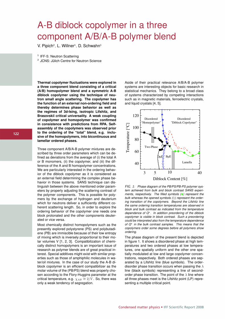
Condensed matter physics • IFF Scientific Report 2008
122
A-B diblock copolymer in a threecomponent A/B/A-B polymer blendV. Pipich2, L. Willner1, D. Schwahn1
1 IFF-5: Neutron Scattering2 JCNS: Jülich Centre for Neutron Science
Thermal copolymer fluctuations were explored in
a three component blend consisting of a critical
(A/B) homopolymer blend and a symmetric A-B
diblock copolymer using the technique of neu-
tron small angle scattering. The copolymer has
the function of an external non-ordering field and
thereby determines phase behavior as well as
the regimes of 3d-Ising, isotropic Lifshitz, and
Brasovskiî critical universality. A weak coupling
of copolymer and homopolymer was confirmed
in consistence with predictions from RPA. Self-
assembly of the copolymers was observed prior
to the ordering of the “total” blend, e.g. inclu-
sive of the homopolymers, into bicontinuous and
lamellar ordered phases.
Three component A/B/A-B polymer mixtures are de-scribed by three order parameters which can be de-fined as deviations from the average of (i) the total Aor B monomers, (ii) the copolymer, and (iii) the dif-ference of the A and B homopolymer concentrations.We are particularly interested in the ordering behav-ior of the diblock copolymer as it is considered asan external field determining the complex phase be-havior in those systems. SANS technique can dis-tinguish between the above mentioned order param-eters by properly adjusting the scattering contrast ofthe polymer components. This is possible for poly-mers by the exchange of hydrogen and deuteriumwhich for neutrons deliver a sufficiently different co-herent scattering length. So, in order to explore theordering behavior of the copolymer one needs oneblock protonated and the other components deuter-ated or vice versa.Most chemically distinct homopolymers such as thepresently explored polystyrene (PS) and polybutadi-ene (PB) are immiscible because of their low entropyof mixing which is inversely proportional to their mo-lar volumes V [1, 2, 3]. Compatibilization of chemi-cally distinct homopolymers is an important issue ofresearch as polymer blends are of great practical in-terest. Special additives might exist with similar prop-erties such as those of amphiphilic molecules in wa-ter/oil mixtures. In the case of our study the A-B di-block copolymer is an efficient compatibilizer as themolar volume of the (PB/PS) blend was properly cho-sen according to the Flory-Huggins parameter at thecritical temperature, e.g. χAB
∼= 2/V . So, there wasonly a weak tendency of segregation.
Aside of their practical relevance A/B/A-B polymersystems are interesting objects for basic research instatistical mechanics. They belong to a broad classof systems characterized by competing interactionssuch as in magnetic materials, ferroelectric crystals,and liquid crystals [4, 5].
10
40
60
80
100
120
53
Disordered"Homopolymer"
Disordered"Diblock Copolymer"
Lamella
DmE BmE
Two-Phase
Tem
pera
ture
[°C
]
Diblock Content [%]
40
FIG. 1: Phase diagram of the PB/PS/PB-PS polymer sys-tem achieved from bulk and block contrast SANS experi-ments, respectively. The filled symbols (�) represent thebulk whereas the opened symbols (♦) represent the order-ing transition of the copolymers. Beyond the Lifshitz linethe same ordering transition temperatures are observed inblock and bulk contrast as indicated from the temperaturedependence of Q∗. In addition preordering of the diblockcopolymer is visible in block contrast. Such a preorderingcould be interpreted also from the temperature dependenceof Q∗ in the bulk contrast samples. This means that thecopolymers order some degrees before all polymers showordering.
The phase diagram of the present blend is depictedin figure 1. It shows a disordered phase at high tem-peratures and two ordered phases at low tempera-tures, one spatially uniform and the other one spa-tially modulated at low and large copolymer concen-trations, respectively. Both ordered phases are sep-arated by a Lifshitz line (blue symbols). The order-disorder phase transition occurs when passing the λline (black symbols) representing a line of second-order phase transition. The point of the λ line whereall three phases meet is the Lifshitz point (LP) repre-senting a multiple critical point.
122
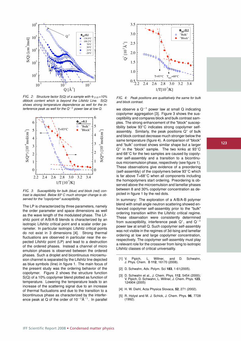
IFF Scientific Report 2008 • Condensed matter physics
123
10-3 10-2 10-1
102
103
104
105
106
FFFFDB
=0.1
139.9°C100.2°C
70°C50°C21°C
-20°C
S(Q
)[c
m3 /m
ol]
Q [Å-1]
Q-3
FIG. 2: Structure factor S(Q) of a sample with ΦDB=10%diblock content which is beyond the Lifshitz Line. S(Q)shows strong temperature dependence as well for the in-terference peak as well for the Q−3 power law at low Q.
2.2 2.4 2.6 2.8 3.0 3.2 3.4
0
1
2
3
4
5
6
0
1
2
3
4
5
6
S(Q
*)[1
0-4m
ol/c
m3 ]
1/T [10-3/K]
FFFFDB
=0.1
"Bulk""Block"
S(Q
*)[1
0-3m
ol/c
m3 ]T=93°C
FIG. 3: Susceptibility for bulk (blue) and block (red) con-trast is depicted. Below 93◦C much stronger change is ob-served for the "copolymer" susceptibility.
The LP is characterized by three parameters, namelythe order parameter and space dimensions as wellas the wave length of the modulated phase. The Lif-shitz point of A/B/A-B blends is characterized by anisotropic Lifshitz critical point and a scalar order pa-rameter. In particular isotropic Lifshitz critical pointsdo not exist in 3 dimensions [4]. Strong thermalfluctuations are observed in particular near the ex-pected Lifshitz point (LP) and lead to a destructionof the ordered phases. Instead a channel of microemulsion phases is observed between the orderedphases. Such a droplet and bicontinuous microemu-sion channel is separated by the Lifshitz line depictedas blue symbols (line) in figure 1. The main focus ofthe present study was the ordering behavior of thecopolymer. Figure 2 shows the structure functionS(Q) of a 10% copolymer blend plotted as function oftemperature. Lowering the temperature leads to anincrease of the scattering signal due to an increaseof thermal fluctuations and due to the transition to abicontinuous phase as characterized by the interfer-ence peak at Q of the order of 10−2Å−1. In parallel
2.2 2.4 2.6 2.8 3.0 3.2 3.40.5
1.0
1.5
2.0
2.5
3.0
3.5
T=93°C TBmE
=68°C
FFFFDB
=0.1
"Bulk""Block"
Q*
[10-2
Å-1]
1/T[10-3/K]
FIG. 4: Peak positions are qualitatively the same for bulkand block contrast.
we observe a Q−3 power law at small Q indicatingcopolymer aggregation [3]. Figure 3 shows the sus-ceptibility and compares block and bulk contrast sam-ples. The strong enhancement of the "block" suscep-tibility below 93◦C indicates strong copolymer self-assembly. Similarly, the peak positions Q∗ of bulkand block contrast decrease much stronger below thesame temperature (figure 4). A comparison of “block”and “bulk” contrast shows similar shape but a largerQ∗ in the “block” sample. The two kinks at 93◦Cand 68◦C for the two samples are caused by copoly-mer self-assembly and a transition to a bicontinu-ous microemulsion phase, respectively (see figure 1).These observations give evidence of a preordering(self-assembly) of the copolymers below 93◦C whichis far above T=68◦C when all components includingthe homopolymers start ordering. Preordering is ob-served above the microemulsion and lamellar phasesbetween 8 and 30% copolymer concentration as de-picted in figure 1 by the red dots.
In summary: The exploration of a A/B/A-B polymerblend with small angle neutron scattering showed en-hanced copolymer self-assembly prior to the "bulk"ordering transition within the Lifshitz critical regime.These observation were consistently determinedfrom susceptibility, interference peak Q∗, and Q−3
power law at small Q. Such copolymer self-assemblywas not visible in the regimes of 3d-Ising and lamellarordering at low and large copolymer concentration,respectively. The copolymer self-assembly must playa relevant role for the crossover from Ising to isotropicLifshitz classes of critical universality.
[1] V. Pipich, L. Willner, and D. Schwahn,J. Phys. Chem. B 112, 16170 (2008).
[2] D. Schwahn, Adv. Polym. Sci 183, 1-61(2005).
[3] D. Schwahn et al., J. Chem. Phys. 112, 5454 (2000);V. Pipich, D. Schwahn, L. Willner, J. Chem. Phys. 123,124904 (2005)
[4] H. W. Diehl, Acta Physica Slovaca, 52, 271 (2002).
[5] R. Holyst and M. J. Schick, J. Chem. Phys. 96, 7728(1992).
123
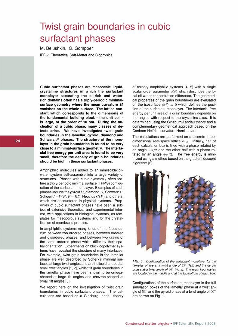
Condensed matter physics • IFF Scientific Report 2008
124
Twist grain boundaries in cubicsurfactant phasesM. Belushkin, G. GompperIFF-2: Theoretical Soft-Matter and Biophysics
Cubic surfactant phases are mesoscale liquid-
crystalline structures in which the surfactant
monolayer separating the oil-rich and water-
rich domains often has a triply-periodic minimal-
surface geometry where the mean curvature Hvanishes on the whole surface. The lattice con-
stant which corresponds to the dimensions of
the fundamental building block - the unit cell -
is large, of the order of 10 nm. During the nu-
cleation of a cubic phase, many classes of de-
fects arise. We have investigated twist grain
boundaries in the lamellar, gyroid, diamond and
Schwarz P phases. The structure of the mono-
layer in the grain boundaries is found to be very
close to a minimal-surface geometry. The interfa-
cial free energy per unit area is found to be very
small, therefore the density of grain boundaries
should be high in these surfactant phases.
Amphiphilic molecules added to an immiscible oil-water system self-assemble into a large variety ofstructures. Phases with cubic symmetry often fea-ture a triply-periodic minimal surface (TPMS) configu-ration of the surfactant monolayer. Examples of suchphases include the gyroid G, diamond D, Schwarz P ,Schoen I −WP , F −RD, Neovius C(P ) and others,which are encountered in physical systems. Prop-erties of cubic surfactant phases have been a sub-ject of extensive theoretical and experimental inter-est, with applications in biological systems, as tem-plates for mesoporous systems and for the crystal-lization of membrane proteins.
In amphiphilic systems many kinds of interfaces oc-cur: between two ordered phases, between orderedand disordered phases, and between two grains ofthe same ordered phase which differ by their spa-tial orientation. Experiments on block copolymer sys-tems have revealed the structure of many interfaces.For example, twist grain boundaries in the lamellarphase are well described by Scherk’s minimal sur-faces at large twist angles and are helicoid-shaped atsmall twist angles [1, 2], whilst tilt grain boundaries inthe lamellar phase have been shown to be omega-shaped at large tilt angles and chevron-shaped atsmall tilt angles [3].
We report here on the investigation of twist grainboundaries in cubic surfactant phases. The cal-culations are based on a Ginzburg-Landau theory
of ternary amphiphilic systems [4, 5] with a singlescalar order parameter φ(�r) which describes the lo-cal oil-water concentration difference. The geometri-cal properties of the grain boundaries are evaluatedon the isosurface φ(�r) ≡ 0 which defines the posi-tion of the surfactant monolayer. The interfacial freeenergy per unit area of a grain boundary depends onthe angles with respect to the crystalline axes. It isdetermined using the Ginzburg-Landau theory and acomplementary geometrical approach based on theCanham-Helfrich curvature Hamiltonian.
The calculations are performed on a discrete three-dimensional real-space lattice φijk. Initially, half ofeach calculation box is filled with a phase rotated byan angle −α/2 and the other half with a phase ro-tated by an angle +α/2. The free energy is mini-mized using a method based on the gradient descentalgorithm [6].
FIG. 1: Configuration of the surfactant monolayer for thelamellar phase at a twist angle of 53o (left) and the gyroidphase at a twist angle of 90o (right). The grain boundariesare located in the middle and at the top/bottom of each box.
Configurations of the surfactant monolayer in the fullsimulation boxes of the lamellar phase at a twist an-gle of 53o and the gyroid phase at a twist angle of 90o
are shown on Fig. 1.
124
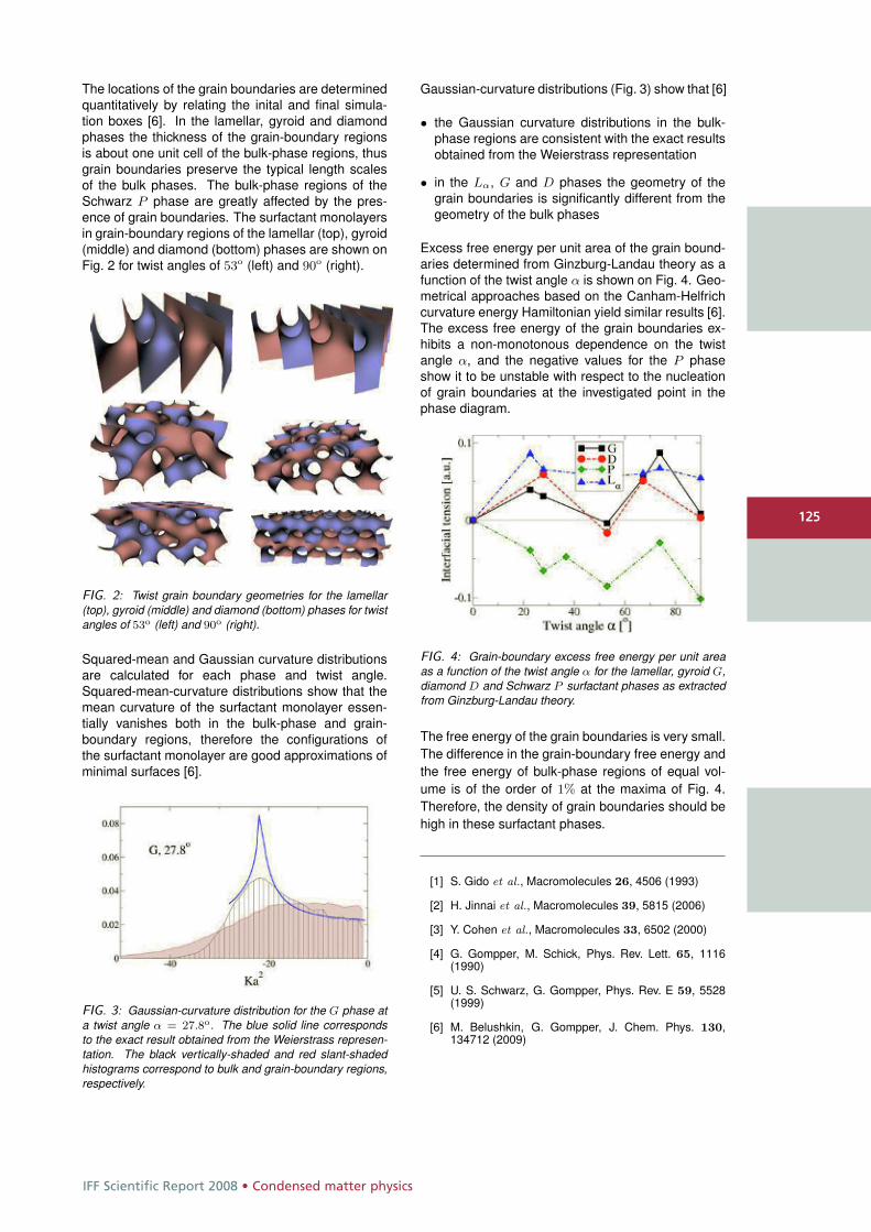
IFF Scientific Report 2008 • Condensed matter physics
125
The locations of the grain boundaries are determinedquantitatively by relating the inital and final simula-tion boxes [6]. In the lamellar, gyroid and diamondphases the thickness of the grain-boundary regionsis about one unit cell of the bulk-phase regions, thusgrain boundaries preserve the typical length scalesof the bulk phases. The bulk-phase regions of theSchwarz P phase are greatly affected by the pres-ence of grain boundaries. The surfactant monolayersin grain-boundary regions of the lamellar (top), gyroid(middle) and diamond (bottom) phases are shown onFig. 2 for twist angles of 53o (left) and 90o (right).
FIG. 2: Twist grain boundary geometries for the lamellar(top), gyroid (middle) and diamond (bottom) phases for twistangles of 53o (left) and 90o (right).
Squared-mean and Gaussian curvature distributionsare calculated for each phase and twist angle.Squared-mean-curvature distributions show that themean curvature of the surfactant monolayer essen-tially vanishes both in the bulk-phase and grain-boundary regions, therefore the configurations ofthe surfactant monolayer are good approximations ofminimal surfaces [6].
FIG. 3: Gaussian-curvature distribution for the G phase ata twist angle α = 27.8o. The blue solid line correspondsto the exact result obtained from the Weierstrass represen-tation. The black vertically-shaded and red slant-shadedhistograms correspond to bulk and grain-boundary regions,respectively.
Gaussian-curvature distributions (Fig. 3) show that [6]
• the Gaussian curvature distributions in the bulk-phase regions are consistent with the exact resultsobtained from the Weierstrass representation
• in the Lα, G and D phases the geometry of thegrain boundaries is significantly different from thegeometry of the bulk phases
Excess free energy per unit area of the grain bound-aries determined from Ginzburg-Landau theory as afunction of the twist angle α is shown on Fig. 4. Geo-metrical approaches based on the Canham-Helfrichcurvature energy Hamiltonian yield similar results [6].The excess free energy of the grain boundaries ex-hibits a non-monotonous dependence on the twistangle α, and the negative values for the P phaseshow it to be unstable with respect to the nucleationof grain boundaries at the investigated point in thephase diagram.
FIG. 4: Grain-boundary excess free energy per unit areaas a function of the twist angle α for the lamellar, gyroid G,diamond D and Schwarz P surfactant phases as extractedfrom Ginzburg-Landau theory.
The free energy of the grain boundaries is very small.The difference in the grain-boundary free energy andthe free energy of bulk-phase regions of equal vol-ume is of the order of 1% at the maxima of Fig. 4.Therefore, the density of grain boundaries should behigh in these surfactant phases.
[1] S. Gido et al., Macromolecules 26, 4506 (1993)
[2] H. Jinnai et al., Macromolecules 39, 5815 (2006)
[3] Y. Cohen et al., Macromolecules 33, 6502 (2000)
[4] G. Gompper, M. Schick, Phys. Rev. Lett. 65, 1116(1990)
[5] U. S. Schwarz, G. Gompper, Phys. Rev. E 59, 5528(1999)
[6] M. Belushkin, G. Gompper, J. Chem. Phys. 130,134712 (2009)
125
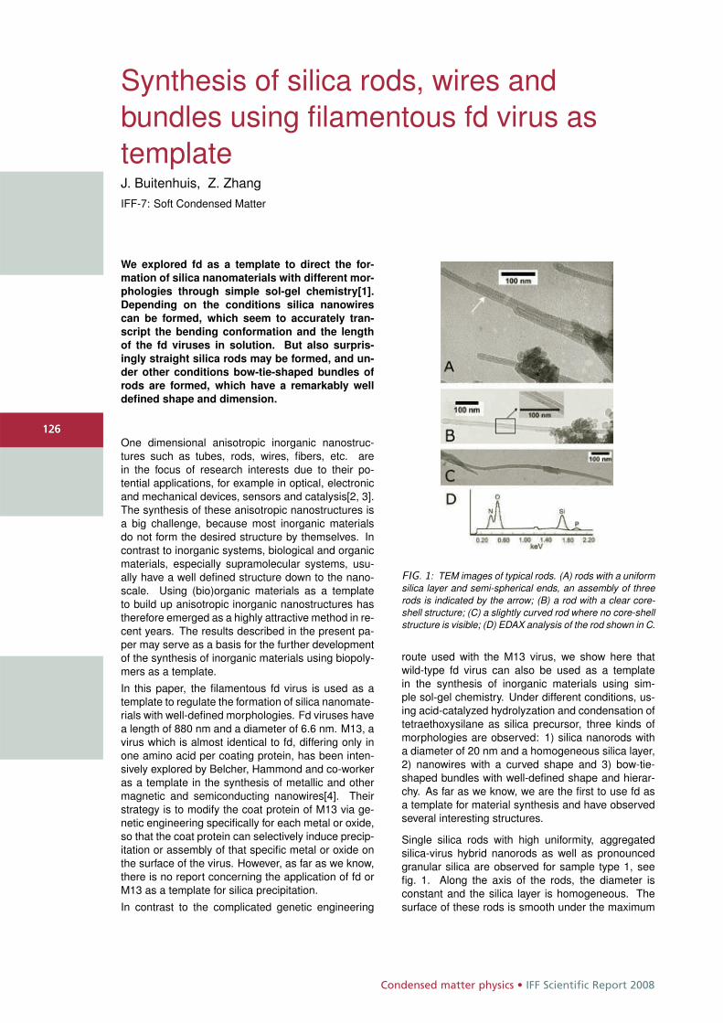
Condensed matter physics • IFF Scientific Report 2008
126
Synthesis of silica rods, wires andbundles using filamentous fd virus astemplateJ. Buitenhuis, Z. ZhangIFF-7: Soft Condensed Matter
We explored fd as a template to direct the for-mation of silica nanomaterials with different mor-phologies through simple sol-gel chemistry[1].Depending on the conditions silica nanowirescan be formed, which seem to accurately tran-script the bending conformation and the lengthof the fd viruses in solution. But also surpris-ingly straight silica rods may be formed, and un-der other conditions bow-tie-shaped bundles ofrods are formed, which have a remarkably welldefined shape and dimension.
One dimensional anisotropic inorganic nanostruc-tures such as tubes, rods, wires, fibers, etc. arein the focus of research interests due to their po-tential applications, for example in optical, electronicand mechanical devices, sensors and catalysis[2, 3].The synthesis of these anisotropic nanostructures isa big challenge, because most inorganic materialsdo not form the desired structure by themselves. Incontrast to inorganic systems, biological and organicmaterials, especially supramolecular systems, usu-ally have a well defined structure down to the nano-scale. Using (bio)organic materials as a templateto build up anisotropic inorganic nanostructures hastherefore emerged as a highly attractive method in re-cent years. The results described in the present pa-per may serve as a basis for the further developmentof the synthesis of inorganic materials using biopoly-mers as a template.In this paper, the filamentous fd virus is used as atemplate to regulate the formation of silica nanomate-rials with well-defined morphologies. Fd viruses havea length of 880 nm and a diameter of 6.6 nm. M13, avirus which is almost identical to fd, differing only inone amino acid per coating protein, has been inten-sively explored by Belcher, Hammond and co-workeras a template in the synthesis of metallic and othermagnetic and semiconducting nanowires[4]. Theirstrategy is to modify the coat protein of M13 via ge-netic engineering specifically for each metal or oxide,so that the coat protein can selectively induce precip-itation or assembly of that specific metal or oxide onthe surface of the virus. However, as far as we know,there is no report concerning the application of fd orM13 as a template for silica precipitation.In contrast to the complicated genetic engineering
FIG. 1: TEM images of typical rods. (A) rods with a uniformsilica layer and semi-spherical ends, an assembly of threerods is indicated by the arrow; (B) a rod with a clear core-shell structure; (C) a slightly curved rod where no core-shellstructure is visible; (D) EDAX analysis of the rod shown in C.
route used with the M13 virus, we show here thatwild-type fd virus can also be used as a templatein the synthesis of inorganic materials using sim-ple sol-gel chemistry. Under different conditions, us-ing acid-catalyzed hydrolyzation and condensation oftetraethoxysilane as silica precursor, three kinds ofmorphologies are observed: 1) silica nanorods witha diameter of 20 nm and a homogeneous silica layer,2) nanowires with a curved shape and 3) bow-tie-shaped bundles with well-defined shape and hierar-chy. As far as we know, we are the first to use fd asa template for material synthesis and have observedseveral interesting structures.
Single silica rods with high uniformity, aggregatedsilica-virus hybrid nanorods as well as pronouncedgranular silica are observed for sample type 1, seefig. 1. Along the axis of the rods, the diameter isconstant and the silica layer is homogeneous. Thesurface of these rods is smooth under the maximum
126
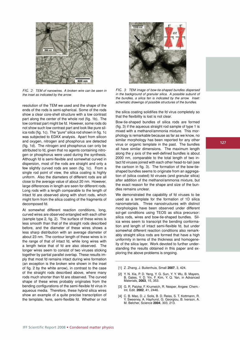
IFF Scientific Report 2008 • Condensed matter physics
127
FIG. 2: TEM of nanowires. A broken wire can be seen inthe inset as indicated by the arrow.
resolution of the TEM we used and the shape of theends of the rods is semi-spherical. Some of the rodsshow a clear core-shell structure with a low contrastpart along the center of the whole rod (fig. 1b). Thelow contrast part might be fd. However, some rods donot show such low contrast part and look like pure sil-ica rods (fig. 1c). The "pure" silica rod shown in fig. 1cwas subjected to EDAX analysis. Apart from siliconand oxygen, nitrogen and phosphorus are detected(fig. 1d). The nitrogen and phosphorus can only beattributed to fd, given that no agents containing nitro-gen or phosphorus were used during the synthesis.Although fd is semi-flexible and somewhat curved indispersion, most of the rods are straight and only afew slightly curved rods are seen (fig. 1c). From asingle rod point of view, the silica coating is highlyuniform. Also the diameters of different rods are allclose to the average value of about 20 nm. However,large differences in length are seen for different rods.Long rods with a length comparable to the length ofintact fd are observed along with short rods, whichmight form from the silica coating of the fragments ofdecomposed fd.
At somewhat different reaction conditions, long,curved wires are observed entangled with each other(sample type 2, fig. 2). The surface of these wires isless smooth than that of the straight rods describedbefore, and the diameter of these wires shows aless sharp distribution with an average diameter ofabout 23 nm. The contour length of these wires is inthe range of that of intact fd, while long wires witha length twice that of fd are also observed. Thelonger wires seem to consist of two viruses stickingtogether by partial parallel overlap. These results im-ply that most fd remains intact during wire formation(an exception is the broken wire shown in the insetof fig. 2 by the white arrow), in contrast to the caseof the straight rods described above, where manyrods much shorter than fd are observed. The curvedshape of these wires probably originates from thebending configurations of the semi-flexible fd virus inaqueous media. Therefore, these hybrid silica wiresshow an example of a quite precise transcription ofthe template, here, semi-flexible fd. Whether or not
FIG. 3: TEM image of bow-tie-shaped bundles dispersedin the background of granular silica. A possible subunit ofthe bundles, a silica fan is indicated by the arrow. Inset:schematic drawings of possible structures of the bundles.
the silica coating solidifies the fd virus completely sothat the flexibility is lost is not clear.Bow-tie-shaped bundles of silica rods are formed(fig. 3) if the aqueous straight rod sample of type 1 ismixed with a methanol/ammonia mixture. This mor-phology is remarkable because as far as we know, nosimilar morphology has been reported for any othervirus or organic template in the past. The bundlesall have similar dimensions. The maximum lengthalong the y axis of the well-defined bundles is about2000 nm, comparable to the total length of two in-tact fd viruses joined with each other head-to-tail (seethe cartoon in fig. 3). The formation of the bow-tie-shaped bundles seems to originate from an aggrega-tion of (silica coated) fd viruses (and granular silica)after addition of the methanol/ammonia mixture, butthe exact reason for the shape and size of the bun-dles remains unclear.We demonstrated the capability of fd viruses to beused as a template for the formation of 1D silicananomaterials. Three nanostructures with distinctmorphologies have been observed under differentsol-gel conditions using TEOS as silica precursor:silica rods, wires and bow-tie-shaped bundles. Sil-ica wires seem to transcript the bending conforma-tion and length of intact semi-flexible fd, but undersomewhat different reaction conditions also remark-ably straight silica rods are formed that have a highuniformity in terms of the thickness and homogene-ity of the silica layer. Work devoted to further under-standing the results obtained in this paper and ex-ploring the above problems is ongoing.
[1] Z. Zhang, J. Buitenhuis, Small 2007, 3, 424.
[2] Y. N. Xia, P. D. Yang, Y. G. Sun, Y. Y. Wu, B. Mayers,B. Gates, Y. D. Yin, F. Kim, Y. Q. Yan, in AdvancedMaterials, 2003, 15, 353.
[3] G. R. Patzke, F. Krumeich, R. Nesper, Angew. Chem.-Int. Edit. 2002, 41, 2446.
[4] C. B. Mao, D. J. Solis, B. D. Reiss, S. T. Kottmann, R.Y. Sweeney, A. Hayhurst, G. Georgiou, B. Iverson, A.M. Belcher, Science 2004, 303, 213.
127
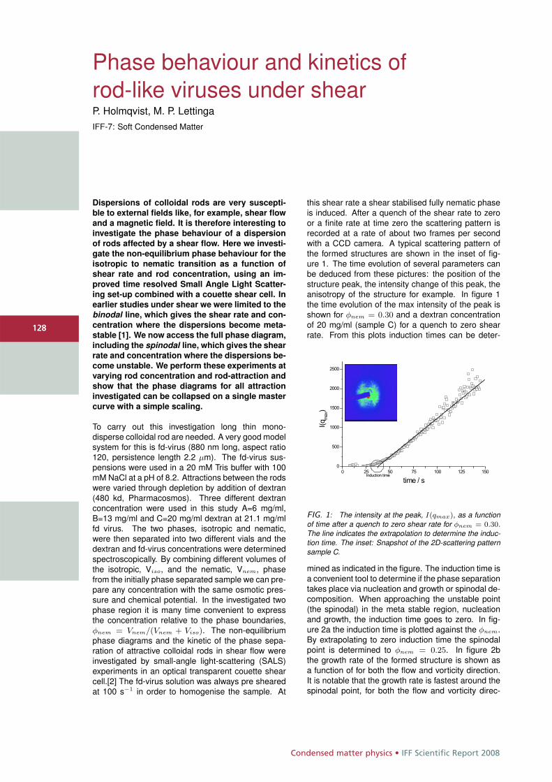
Condensed matter physics • IFF Scientific Report 2008
128
Phase behaviour and kinetics ofrod-like viruses under shearP. Holmqvist, M. P. LettingaIFF-7: Soft Condensed Matter
Dispersions of colloidal rods are very suscepti-ble to external fields like, for example, shear flowand a magnetic field. It is therefore interesting toinvestigate the phase behaviour of a dispersionof rods affected by a shear flow. Here we investi-gate the non-equilibrium phase behaviour for theisotropic to nematic transition as a function ofshear rate and rod concentration, using an im-proved time resolved Small Angle Light Scatter-ing set-up combined with a couette shear cell. Inearlier studies under shear we were limited to thebinodal line, which gives the shear rate and con-centration where the dispersions become meta-stable [1]. We now access the full phase diagram,including the spinodal line, which gives the shearrate and concentration where the dispersions be-come unstable. We perform these experiments atvarying rod concentration and rod-attraction andshow that the phase diagrams for all attractioninvestigated can be collapsed on a single mastercurve with a simple scaling.
To carry out this investigation long thin mono-disperse colloidal rod are needed. A very good modelsystem for this is fd-virus (880 nm long, aspect ratio120, persistence length 2.2 μm). The fd-virus sus-pensions were used in a 20 mM Tris buffer with 100mM NaCl at a pH of 8.2. Attractions between the rodswere varied through depletion by addition of dextran(480 kd, Pharmacosmos). Three different dextranconcentration were used in this study A=6 mg/ml,B=13 mg/ml and C=20 mg/ml dextran at 21.1 mg/mlfd virus. The two phases, isotropic and nematic,were then separated into two different vials and thedextran and fd-virus concentrations were determinedspectroscopically. By combining different volumes ofthe isotropic, Viso, and the nematic, Vnem, phasefrom the initially phase separated sample we can pre-pare any concentration with the same osmotic pres-sure and chemical potential. In the investigated twophase region it is many time convenient to expressthe concentration relative to the phase boundaries,φnem = Vnem/(Vnem + Viso). The non-equilibriumphase diagrams and the kinetic of the phase sepa-ration of attractive colloidal rods in shear flow wereinvestigated by small-angle light-scattering (SALS)experiments in an optical transparent couette shearcell.[2] The fd-virus solution was always pre shearedat 100 s−1 in order to homogenise the sample. At
this shear rate a shear stabilised fully nematic phaseis induced. After a quench of the shear rate to zeroor a finite rate at time zero the scattering pattern isrecorded at a rate of about two frames per secondwith a CCD camera. A typical scattering pattern ofthe formed structures are shown in the inset of fig-ure 1. The time evolution of several parameters canbe deduced from these pictures: the position of thestructure peak, the intensity change of this peak, theanisotropy of the structure for example. In figure 1the time evolution of the max intensity of the peak isshown for φnem = 0.30 and a dextran concentrationof 20 mg/ml (sample C) for a quench to zero shearrate. From this plots induction times can be deter-
FIG. 1: The intensity at the peak, I(qmax), as a functionof time after a quench to zero shear rate for φnem = 0.30.The line indicates the extrapolation to determine the induc-tion time. The inset: Snapshot of the 2D-scattering patternsample C.
mined as indicated in the figure. The induction time isa convenient tool to determine if the phase separationtakes place via nucleation and growth or spinodal de-composition. When approaching the unstable point(the spinodal) in the meta stable region, nucleationand growth, the induction time goes to zero. In fig-ure 2a the induction time is plotted against the φnem.By extrapolating to zero induction time the spinodalpoint is determined to φnem = 0.25. In figure 2bthe growth rate of the formed structure is shown asa function of for both the flow and vorticity direction.It is notable that the growth rate is fastest around thespinodal point, for both the flow and vorticity direc-
128
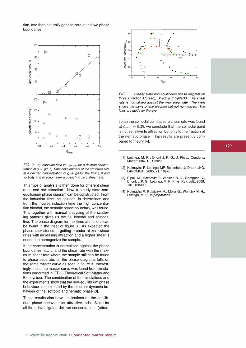
IFF Scientific Report 2008 • Condensed matter physics
129
tion, and then naturally goes to zero at the two phaseboundaries.
FIG. 2: a) induction time vs. φnem for a dextran concen-tration of g 20 g/l. b) Time development of the structure sizeat a dextran concentration of g 20 g/l for the flow (�) andvorticity (©) direction after a quench to zero shear rate.
This type of analysis is then done for different shearrates and rod attraction. Now a steady state non-equilibrium phase diagram can be constructed. Fromthe induction time the spinodal is determined andfrom the inverse induction time the high concentra-tion binodal, the nematic phase boundary, was found.This together with manual analysing of the scatter-ing patterns gives us the full binodal and spinodalline. The phase diagram for the three attractions canbe found in the inset of figure 3. As expected thephase coexistence is getting broader at zero shearrates with increasing attraction and a higher shear isneeded to homogenize the sample.
If the concentration is normalized against the phaseboundaries, φnem, and the shear rate with the maxi-mum shear rate where the sample still can be foundto phase separate, all the phase diagrams falls onthe same master curve as seen in figure 3. Interest-ingly, the same master curve was found from simula-tions performed in IFF-2 (Theoretical Soft-Matter andBiophysics). The combination of the simulations andthe experiments show that the non-equilibrium phasebehaviour is dominated by the different dynamic be-haviour of the isotropic and nematic phase [3].
These results also have implications on the equilib-rium phase behaviour for attractive rods. Since forall three investigated dextran concentrations (attrac-
FIG. 3: Steady state non-equilibrium phase diagram forthree attraction A(green), B(red) and C(black). The shearrate is normalized against the max shear rate. The insetshows the same phase diagram but not normalized. Thelines are guide for the eye.
tions) the spinodal point at zero shear rate was foundat φnem = 0.25, we conclude that the spinodal pointis not sensitive to attraction but only to the fraction ofthe nematic phase. This results are presently com-pared to theory [4].
[1] Lettinga, M. P. , Dhont J. K. G., J. Phys.: Condens.Matter 2004, 16, S3929.
[2] Holmqvist P, Lettinga MP, Buitenhuis J, Dhont JKG,LANGMUIR, 2005, 21, 10976
[3] Ripoll, M., Holmqvist P., Winkler, R. G., Gompper, G.,Dhont, J. K. G., Lettinga, M. P., Phys. Rev. Lett., 2008,101, 168302
[4] Holmqvist P., Ratajczyk M., Meier G., Wensink H. H.,Lettinga, M. P., In preparation
129

Condensed matter physics • IFF Scientific Report 2008
130
Attractive colloidal rods in shear flowM. Ripoll, R. G. Winkler, G. GompperIFF-2: Theoretical Soft-Matter and Biophysics
Suspensions of rod-like colloids show in equi-
librium an isotropic-nematic coexistence region,
which depends on the strength of an attractive in-
teraction between the rods. By means of hydro-
dynamic simulations, we study the behavior of
this system in shear flow for various interaction
strengths. The shear flow induces alignment in
the initially isotropic phase which generates ad-
ditional free volume around each rod and causes
the densification of the isotropic phase at the ex-
pense of an erosion of the initially nematic phase.
Furthermore, the nematic phase exhibits a collec-
tive rotational motion. The density difference be-
tween these two regions at different shear rates,
allows us to determine the binodal line of the
phase diagram. The results are in good agree-
ment with experimental observations.
Phase transitions occurring in soft matter systemsare significantly affected by flow. Both the nature andlocation of the phase transition lines are changed dueto the applied flow. The challenge is to find the pa-rameters that determine the non-equilibrium steadystates under flow conditions. Colloidal-rod suspen-sions constitute a particularly interesting system tostudy the effect of flow on their phase behavior, sincerod orientation is strongly coupled to the shear field.Rods in the isotropic (I) phase align with the flow andbecome paranematic (P). This suggests that the tran-sition to the nematic (N) phase, where rods have ori-entational order, is facilitated by shear. On the otherhand, rods in the nematic phase undergo a collectivetumbling motion in the presence of shear flow. Thequestion that then arises is how these two effects willaffect I-N detailed understanding of the flow behaviorof a model system of attractive colloidal rods is usefulfor industrial applications where shear alignment ofelongated objects, such as carbon nanotubes, worm-like micelles, and polymers, play a role.
The non-equilibrium phase diagrams of attractive col-loidal rods in shear flow have been investigated bymesoscale hydrodynamic simulations and comparedto small-angle light-scattering (SALS) and rheologyexperiments [1, 2]. Earlier rheology experiments [3]have studied the non-equilibrium binodal of fd-virusdispersions under shear flow conditions for a single,
FIG. 1: Snapshots of the simulation box with ε = 3.5, (a) atequilibrium, and (b) in a tumbling event at γ = 0.003. Col-ors in (a) and (b) are coding the rod orientation: horizontalis red, vertical is green and perpendicular to plane of viewis blue. Red arrows in (b) denote flow direction. (c) Timeevolution of the normalized density φ/φ0, and (d) of the ori-entational order parameter Sx, along the gradient direction.
fixed strength of attraction. This study showed thatthe P-N transition changes on applying flow. Thesimulations allow for a microscopic understanding ofthe behavior of coexisting phases and their interfaceunder shear, including the possible role of collectivetumbling motion of rods. The attractive rod-rod inter-actions are systematically varied, which affects thephase behavior, interfacial properties of coexistingphases as well as the tumbling behavior.
Molecular dynamic simulations of rod-like colloids ofaspect ratio 20 with attractive interactions (Lennard-Jones potential with a minimum of ε, in units ofthe thermal energy kBT ), are combined with amesoscopic description of the solvent known asmultiparticle-collision dynamics (MPC). This hybridapproach has been shown to account for long-range
130
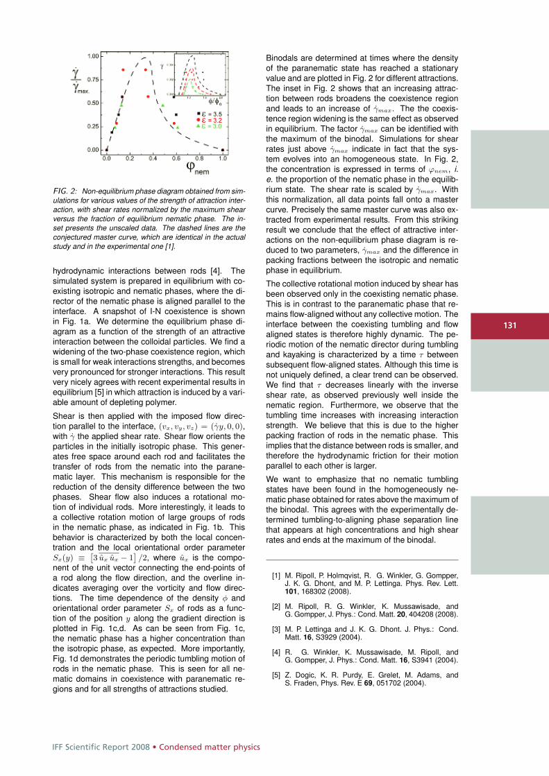
IFF Scientific Report 2008 • Condensed matter physics
131
FIG. 2: Non-equilibrium phase diagram obtained from sim-ulations for various values of the strength of attraction inter-action, with shear rates normalized by the maximum shearversus the fraction of equilibrium nematic phase. The in-set presents the unscaled data. The dashed lines are theconjectured master curve, which are identical in the actualstudy and in the experimental one [1].
hydrodynamic interactions between rods [4]. Thesimulated system is prepared in equilibrium with co-existing isotropic and nematic phases, where the di-rector of the nematic phase is aligned parallel to theinterface. A snapshot of I-N coexistence is shownin Fig. 1a. We determine the equilibrium phase di-agram as a function of the strength of an attractiveinteraction between the colloidal particles. We find awidening of the two-phase coexistence region, whichis small for weak interactions strengths, and becomesvery pronounced for stronger interactions. This resultvery nicely agrees with recent experimental results inequilibrium [5] in which attraction is induced by a vari-able amount of depleting polymer.
Shear is then applied with the imposed flow direc-tion parallel to the interface, (vx, vy, vz) = (γy, 0, 0),with γ the applied shear rate. Shear flow orients theparticles in the initially isotropic phase. This gener-ates free space around each rod and facilitates thetransfer of rods from the nematic into the parane-matic layer. This mechanism is responsible for thereduction of the density difference between the twophases. Shear flow also induces a rotational mo-tion of individual rods. More interestingly, it leads toa collective rotation motion of large groups of rodsin the nematic phase, as indicated in Fig. 1b. Thisbehavior is characterized by both the local concen-tration and the local orientational order parameterSx(y) ≡ ˆ
3 ux ux − 1˜/2, where ux is the compo-
nent of the unit vector connecting the end-points ofa rod along the flow direction, and the overline in-dicates averaging over the vorticity and flow direc-tions. The time dependence of the density φ andorientational order parameter Sx of rods as a func-tion of the position y along the gradient direction isplotted in Fig. 1c,d. As can be seen from Fig. 1c,the nematic phase has a higher concentration thanthe isotropic phase, as expected. More importantly,Fig. 1d demonstrates the periodic tumbling motion ofrods in the nematic phase. This is seen for all ne-matic domains in coexistence with paranematic re-gions and for all strengths of attractions studied.
Binodals are determined at times where the densityof the paranematic state has reached a stationaryvalue and are plotted in Fig. 2 for different attractions.The inset in Fig. 2 shows that an increasing attrac-tion between rods broadens the coexistence regionand leads to an increase of γmax. The the coexis-tence region widening is the same effect as observedin equilibrium. The factor γmax can be identified withthe maximum of the binodal. Simulations for shearrates just above γmax indicate in fact that the sys-tem evolves into an homogeneous state. In Fig. 2,the concentration is expressed in terms of ϕnem, i.e. the proportion of the nematic phase in the equilib-rium state. The shear rate is scaled by γmax. Withthis normalization, all data points fall onto a mastercurve. Precisely the same master curve was also ex-tracted from experimental results. From this strikingresult we conclude that the effect of attractive inter-actions on the non-equilibrium phase diagram is re-duced to two parameters, γmax and the difference inpacking fractions between the isotropic and nematicphase in equilibrium.
The collective rotational motion induced by shear hasbeen observed only in the coexisting nematic phase.This is in contrast to the paranematic phase that re-mains flow-aligned without any collective motion. Theinterface between the coexisting tumbling and flowaligned states is therefore highly dynamic. The pe-riodic motion of the nematic director during tumblingand kayaking is characterized by a time τ betweensubsequent flow-aligned states. Although this time isnot uniquely defined, a clear trend can be observed.We find that τ decreases linearly with the inverseshear rate, as observed previously well inside thenematic region. Furthermore, we observe that thetumbling time increases with increasing interactionstrength. We believe that this is due to the higherpacking fraction of rods in the nematic phase. Thisimplies that the distance between rods is smaller, andtherefore the hydrodynamic friction for their motionparallel to each other is larger.
We want to emphasize that no nematic tumblingstates have been found in the homogeneously ne-matic phase obtained for rates above the maximum ofthe binodal. This agrees with the experimentally de-termined tumbling-to-aligning phase separation linethat appears at high concentrations and high shearrates and ends at the maximum of the binodal.
[1] M. Ripoll, P. Holmqvist, R. G. Winkler, G. Gompper,J. K. G. Dhont, and M. P. Lettinga. Phys. Rev. Lett.101, 168302 (2008).
[2] M. Ripoll, R. G. Winkler, K. Mussawisade, andG. Gompper, J. Phys.: Cond. Matt. 20, 404208 (2008).
[3] M. P. Lettinga and J. K. G. Dhont. J. Phys.: Cond.Matt. 16, S3929 (2004).
[4] R. G. Winkler, K. Mussawisade, M. Ripoll, andG. Gompper, J. Phys.: Cond. Matt. 16, S3941 (2004).
[5] Z. Dogic, K. R. Purdy, E. Grelet, M. Adams, andS. Fraden, Phys. Rev. E 69, 051702 (2004).
131
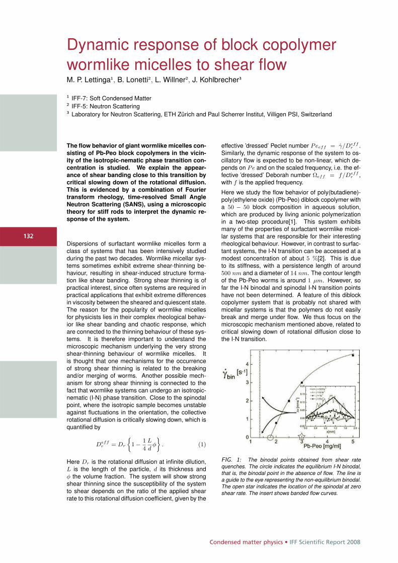
Condensed matter physics • IFF Scientific Report 2008
132
Dynamic response of block copolymerwormlike micelles to shear flowM. P. Lettinga1, B. Lonetti2, L. Willner2, J. Kohlbrecher3
1 IFF-7: Soft Condensed Matter2 IFF-5: Neutron Scattering3 Laboratory for Neutron Scattering, ETH Zürich and Paul Scherrer Institut, Villigen PSI, Switzerland
The flow behavior of giant wormlike micelles con-
sisting of Pb-Peo block copolymers in the vicin-
ity of the isotropic-nematic phase transition con-
centration is studied. We explain the appear-
ance of shear banding close to this transition by
critical slowing down of the rotational diffusion.
This is evidenced by a combination of Fourier
transform rheology, time-resolved Small Angle
Neutron Scattering (SANS), using a microscopic
theory for stiff rods to interpret the dynamic re-
sponse of the system.
Dispersions of surfactant wormlike micelles form aclass of systems that has been intensively studiedduring the past two decades. Wormlike micellar sys-tems sometimes exhibit extreme shear-thinning be-haviour, resulting in shear-induced structure forma-tion like shear banding. Strong shear thinning is ofpractical interest, since often systems are required inpractical applications that exhibit extreme differencesin viscosity between the sheared and quiescent state.The reason for the popularity of wormlike micellesfor physicists lies in their complex rheological behav-ior like shear banding and chaotic response, whichare connected to the thinning behaviour of these sys-tems. It is therefore important to understand themicroscopic mechanism underlying the very strongshear-thinning behaviour of wormlike micelles. Itis thought that one mechanisms for the occurrenceof strong shear thinning is related to the breakingand/or merging of worms. Another possible mech-anism for strong shear thinning is connected to thefact that wormlike systems can undergo an isotropic-nematic (I-N) phase transition. Close to the spinodalpoint, where the isotropic sample becomes unstableagainst fluctuations in the orientation, the collectiverotational diffusion is critically slowing down, which isquantified by
Deffr = Dr
j1 − 1
4
L
dφ
ff. (1)
Here Dr is the rotational diffusion at infinite dilution,L is the length of the particle, d its thickness andφ the volume fraction. The system will show strongshear thinning since the susceptibility of the systemto shear depends on the ratio of the applied shearrate to this rotational diffusion coefficient, given by the
effective ’dressed’ Peclet number Peeff = γ/Deffr .
Similarly, the dynamic response of the system to os-cillatory flow is expected to be non-linear, which de-pends on Pe and on the scaled frequency, i.e. the ef-fective ’dressed’ Deborah number Ωeff = f/Deff
r ,with f is the applied frequency.
Here we study the flow behavior of poly(butadiene)-poly(ethylene oxide) (Pb-Peo) diblock copolymer witha 50 − 50 block composition in aqueous solution,which are produced by living anionic polymerizationin a two-step procedure[1]. This system exhibitsmany of the properties of surfactant wormlike micel-lar systems that are responsible for their interestingrheological behaviour. However, in contrast to surfac-tant systems, the I-N transition can be accessed at amodest concentration of about 5 %[2]. This is dueto its stiffness, with a persistence length of around500 nm and a diameter of 14 nm. The contour lengthof the Pb-Peo worms is around 1 μm. However, sofar the I-N binodal and spinodal I-N transition pointshave not been determined. A feature of this diblockcopolymer system that is probably not shared withmicellar systems is that the polymers do not easilybreak and merge under flow. We thus focus on themicroscopic mechanism mentioned above, related tocritical slowing down of rotational diffusion close tothe I-N transition.
FIG. 1: The binodal points obtained from shear ratequenches. The circle indicates the equilibrium I-N binodal,that is, the binodal point in the absence of flow. The line isa guide to the eye representing the non-equilibrium binodal.The open star indicates the location of the spinodal at zeroshear rate. The insert shows banded flow curves.
132
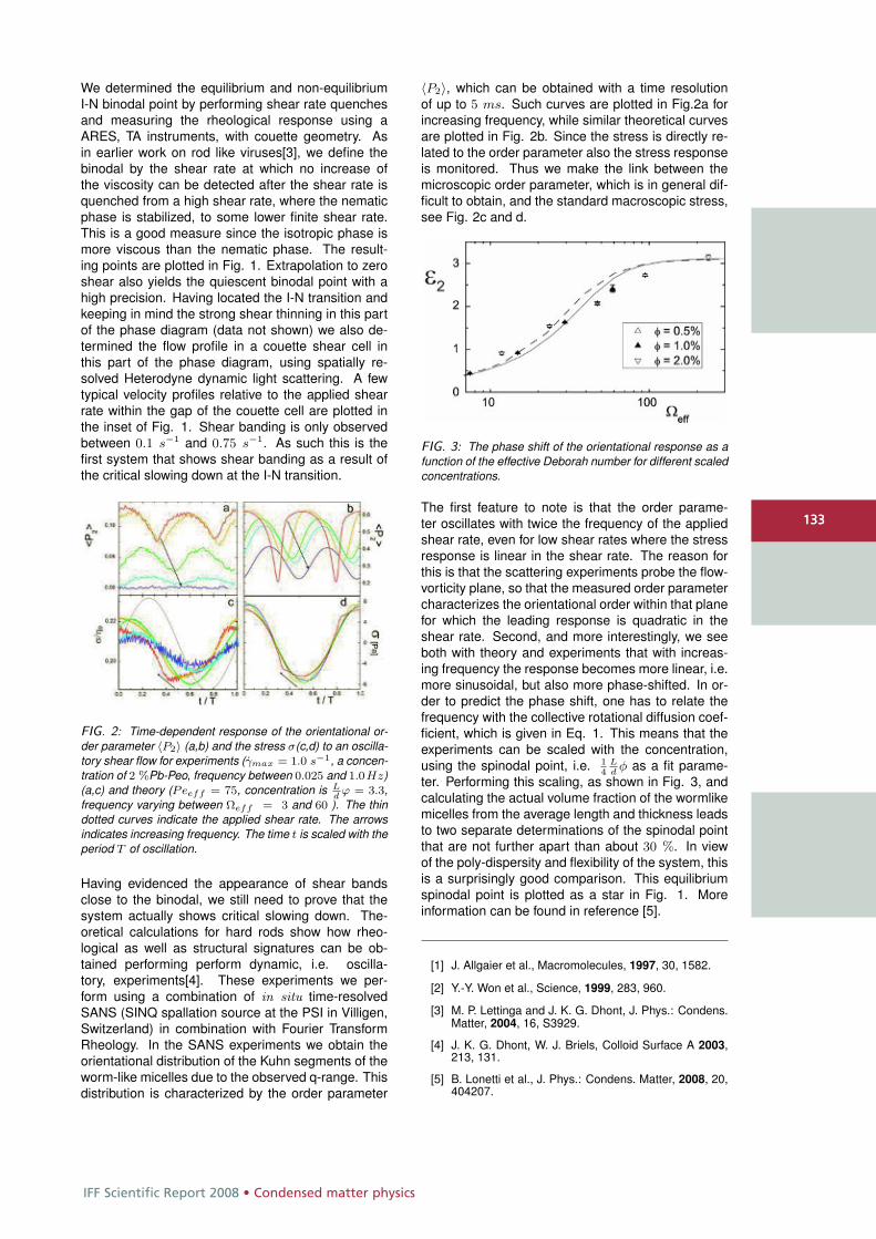
IFF Scientific Report 2008 • Condensed matter physics
133
We determined the equilibrium and non-equilibriumI-N binodal point by performing shear rate quenchesand measuring the rheological response using aARES, TA instruments, with couette geometry. Asin earlier work on rod like viruses[3], we define thebinodal by the shear rate at which no increase ofthe viscosity can be detected after the shear rate isquenched from a high shear rate, where the nematicphase is stabilized, to some lower finite shear rate.This is a good measure since the isotropic phase ismore viscous than the nematic phase. The result-ing points are plotted in Fig. 1. Extrapolation to zeroshear also yields the quiescent binodal point with ahigh precision. Having located the I-N transition andkeeping in mind the strong shear thinning in this partof the phase diagram (data not shown) we also de-termined the flow profile in a couette shear cell inthis part of the phase diagram, using spatially re-solved Heterodyne dynamic light scattering. A fewtypical velocity profiles relative to the applied shearrate within the gap of the couette cell are plotted inthe inset of Fig. 1. Shear banding is only observedbetween 0.1 s−1 and 0.75 s−1. As such this is thefirst system that shows shear banding as a result ofthe critical slowing down at the I-N transition.
FIG. 2: Time-dependent response of the orientational or-der parameter 〈P2〉 (a,b) and the stress σ(c,d) to an oscilla-tory shear flow for experiments (γmax = 1.0 s−1, a concen-tration of 2 %Pb-Peo, frequency between 0.025 and 1.0Hz)(a,c) and theory (Peeff = 75, concentration is L
dϕ = 3.3,
frequency varying between Ωeff = 3 and 60 ). The thindotted curves indicate the applied shear rate. The arrowsindicates increasing frequency. The time t is scaled with theperiod T of oscillation.
Having evidenced the appearance of shear bandsclose to the binodal, we still need to prove that thesystem actually shows critical slowing down. The-oretical calculations for hard rods show how rheo-logical as well as structural signatures can be ob-tained performing perform dynamic, i.e. oscilla-tory, experiments[4]. These experiments we per-form using a combination of in situ time-resolvedSANS (SINQ spallation source at the PSI in Villigen,Switzerland) in combination with Fourier TransformRheology. In the SANS experiments we obtain theorientational distribution of the Kuhn segments of theworm-like micelles due to the observed q-range. Thisdistribution is characterized by the order parameter
〈P2〉, which can be obtained with a time resolutionof up to 5 ms. Such curves are plotted in Fig.2a forincreasing frequency, while similar theoretical curvesare plotted in Fig. 2b. Since the stress is directly re-lated to the order parameter also the stress responseis monitored. Thus we make the link between themicroscopic order parameter, which is in general dif-ficult to obtain, and the standard macroscopic stress,see Fig. 2c and d.
FIG. 3: The phase shift of the orientational response as afunction of the effective Deborah number for different scaledconcentrations.
The first feature to note is that the order parame-ter oscillates with twice the frequency of the appliedshear rate, even for low shear rates where the stressresponse is linear in the shear rate. The reason forthis is that the scattering experiments probe the flow-vorticity plane, so that the measured order parametercharacterizes the orientational order within that planefor which the leading response is quadratic in theshear rate. Second, and more interestingly, we seeboth with theory and experiments that with increas-ing frequency the response becomes more linear, i.e.more sinusoidal, but also more phase-shifted. In or-der to predict the phase shift, one has to relate thefrequency with the collective rotational diffusion coef-ficient, which is given in Eq. 1. This means that theexperiments can be scaled with the concentration,using the spinodal point, i.e. 1
4Ldφ as a fit parame-
ter. Performing this scaling, as shown in Fig. 3, andcalculating the actual volume fraction of the wormlikemicelles from the average length and thickness leadsto two separate determinations of the spinodal pointthat are not further apart than about 30 %. In viewof the poly-dispersity and flexibility of the system, thisis a surprisingly good comparison. This equilibriumspinodal point is plotted as a star in Fig. 1. Moreinformation can be found in reference [5].
[1] J. Allgaier et al., Macromolecules, 1997, 30, 1582.
[2] Y.-Y. Won et al., Science, 1999, 283, 960.
[3] M. P. Lettinga and J. K. G. Dhont, J. Phys.: Condens.Matter, 2004, 16, S3929.
[4] J. K. G. Dhont, W. J. Briels, Colloid Surface A 2003,213, 131.
[5] B. Lonetti et al., J. Phys.: Condens. Matter, 2008, 20,404207.
133
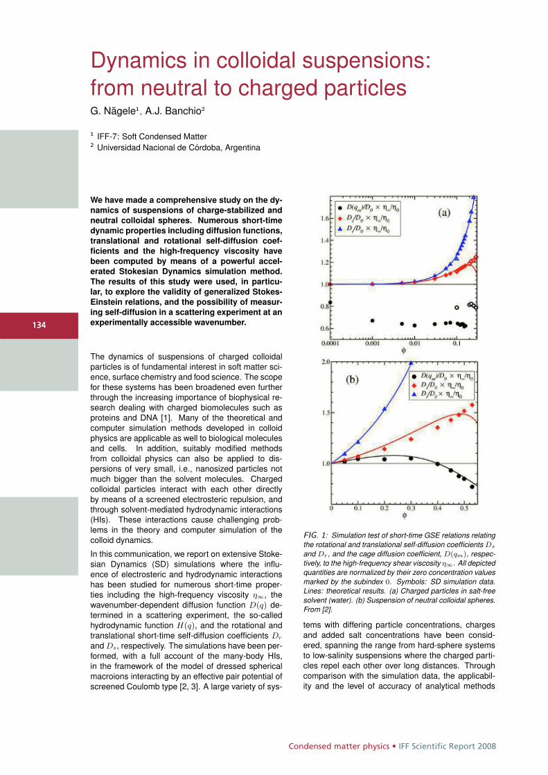
Condensed matter physics • IFF Scientific Report 2008
134
Dynamics in colloidal suspensions:from neutral to charged particlesG. Nägele1, A.J. Banchio2
1 IFF-7: Soft Condensed Matter2 Universidad Nacional de Córdoba, Argentina
We have made a comprehensive study on the dy-
namics of suspensions of charge-stabilized and
neutral colloidal spheres. Numerous short-time
dynamic properties including diffusion functions,
translational and rotational self-diffusion coef-
ficients and the high-frequency viscosity have
been computed by means of a powerful accel-
erated Stokesian Dynamics simulation method.
The results of this study were used, in particu-
lar, to explore the validity of generalized Stokes-
Einstein relations, and the possibility of measur-
ing self-diffusion in a scattering experiment at an
experimentally accessible wavenumber.
The dynamics of suspensions of charged colloidalparticles is of fundamental interest in soft matter sci-ence, surface chemistry and food science. The scopefor these systems has been broadened even furtherthrough the increasing importance of biophysical re-search dealing with charged biomolecules such asproteins and DNA [1]. Many of the theoretical andcomputer simulation methods developed in colloidphysics are applicable as well to biological moleculesand cells. In addition, suitably modified methodsfrom colloidal physics can also be applied to dis-persions of very small, i.e., nanosized particles notmuch bigger than the solvent molecules. Chargedcolloidal particles interact with each other directlyby means of a screened electrosteric repulsion, andthrough solvent-mediated hydrodynamic interactions(HIs). These interactions cause challenging prob-lems in the theory and computer simulation of thecolloid dynamics.
In this communication, we report on extensive Stoke-sian Dynamics (SD) simulations where the influ-ence of electrosteric and hydrodynamic interactionshas been studied for numerous short-time proper-ties including the high-frequency viscosity η∞, thewavenumber-dependent diffusion function D(q) de-termined in a scattering experiment, the so-calledhydrodynamic function H(q), and the rotational andtranslational short-time self-diffusion coefficients Dr
and Ds, respectively. The simulations have been per-formed, with a full account of the many-body HIs,in the framework of the model of dressed sphericalmacroions interacting by an effective pair potential ofscreened Coulomb type [2, 3]. A large variety of sys-
FIG. 1: Simulation test of short-time GSE relations relatingthe rotational and translational self-diffusion coefficients Ds
and Dr , and the cage diffusion coefficient, D(qm), respec-tively, to the high-frequency shear viscosity η∞. All depictedquantities are normalized by their zero concentration valuesmarked by the subindex 0. Symbols: SD simulation data.Lines: theoretical results. (a) Charged particles in salt-freesolvent (water). (b) Suspension of neutral colloidal spheres.From [2].
tems with differing particle concentrations, chargesand added salt concentrations have been consid-ered, spanning the range from hard-sphere systemsto low-salinity suspensions where the charged parti-cles repel each other over long distances. Throughcomparison with the simulation data, the applicabil-ity and the level of accuracy of analytical methods
134
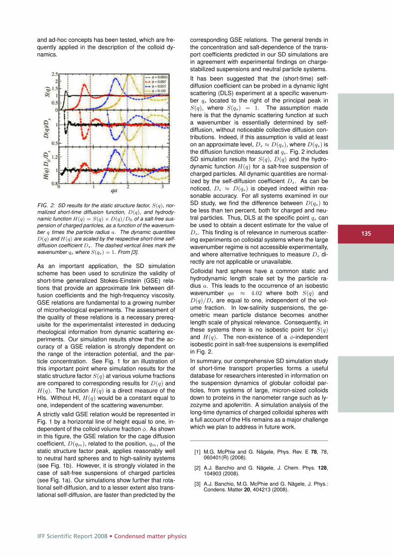
IFF Scientific Report 2008 • Condensed matter physics
135
and ad-hoc concepts has been tested, which are fre-quently applied in the description of the colloid dy-namics.
FIG. 2: SD results for the static structure factor, S(q), nor-malized short-time diffusion function, D(q), and hydrody-namic function H(q) = S(q) × D(q)/D0 of a salt-free sus-pension of charged particles, as a function of the wavenum-ber q times the particle radius a. The dynamic quantitiesD(q) and H(q) are scaled by the respective short-time self-diffusion coefficient Ds. The dashed vertical lines mark thewavenumber qs where S(qs) = 1. From [3].
As an important application, the SD simulationscheme has been used to scrutinize the validity ofshort-time generalized Stokes-Einstein (GSE) rela-tions that provide an approximate link between dif-fusion coefficients and the high-frequency viscosity.GSE relations are fundamental to a growing numberof microrheological experiments. The assessment ofthe quality of these relations is a necessary prereq-uisite for the experimentalist interested in deducingrheological information from dynamic scattering ex-periments. Our simulation results show that the ac-curacy of a GSE relation is strongly dependent onthe range of the interaction potential, and the par-ticle concentration. See Fig. 1 for an illustration ofthis important point where simulation results for thestatic structure factor S(q) at various volume fractionsare compared to corresponding results for D(q) andH(q). The function H(q) is a direct measure of theHIs. Without HI, H(q) would be a constant equal toone, independent of the scattering wavenumber.A strictly valid GSE relation would be represented inFig. 1 by a horizontal line of height equal to one, in-dependent of the colloid volume fraction φ. As shownin this figure, the GSE relation for the cage diffusioncoefficient, D(qm), related to the position, qm, of thestatic structure factor peak, applies reasonably wellto neutral hard spheres and to high-salinity systems(see Fig. 1b). However, it is strongly violated in thecase of salt-free suspensions of charged particles(see Fig. 1a). Our simulations show further that rota-tional self-diffusion, and to a lesser extent also trans-lational self-diffusion, are faster than predicted by the
corresponding GSE relations. The general trends inthe concentration and salt-dependence of the trans-port coefficients predicted in our SD simulations arein agreement with experimental findings on charge-stabilized suspensions and neutral particle systems.
It has been suggested that the (short-time) self-diffusion coefficient can be probed in a dynamic lightscattering (DLS) experiment at a specific wavenum-ber qs located to the right of the principal peak inS(q), where S(qs) = 1. The assumption madehere is that the dynamic scattering function at sucha wavenumber is essentially determined by self-diffusion, without noticeable collective diffusion con-tributions. Indeed, if this assumption is valid at leaston an approximate level, Ds ≈ D(qs), where D(qs) isthe diffusion function measured at qs. Fig. 2 includesSD simulation results for S(q), D(q) and the hydro-dynamic function H(q) for a salt-free suspension ofcharged particles. All dynamic quantities are normal-ized by the self-diffusion coefficient Ds. As can benoticed, Ds ≈ D(qs) is obeyed indeed within rea-sonable accuracy. For all systems examined in ourSD study, we find the difference between D(qs) tobe less than ten percent, both for charged and neu-tral particles. Thus, DLS at the specific point qs canbe used to obtain a decent estimate for the value ofDs. This finding is of relevance in numerous scatter-ing experiments on colloidal systems where the largewavenumber regime is not accessible experimentally,and where alternative techniques to measure Ds di-rectly are not applicable or unavailable.
Colloidal hard spheres have a common static andhydrodynamic length scale set by the particle ra-dius a. This leads to the occurrence of an isobesticwavenumber qa ≈ 4.02 where both S(q) andD(q)/Ds are equal to one, independent of the vol-ume fraction. In low-salinity suspensions, the ge-ometric mean particle distance becomes anotherlength scale of physical relevance. Consequently, inthese systems there is no isobestic point for S(q)and H(q). The non-existence of a φ-independentisobestic point in salt-free suspensions is exemplifiedin Fig. 2.
In summary, our comprehensive SD simulation studyof short-time transport properties forms a usefuldatabase for researchers interested in information onthe suspension dynamics of globular colloidal par-ticles, from systems of large, micron-sized colloidsdown to proteins in the nanometer range such as ly-zozyme and apoferritin. A simulation analysis of thelong-time dynamics of charged colloidal spheres witha full account of the HIs remains as a major challengewhich we plan to address in future work.
[1] M.G. McPhie and G. Nägele, Phys. Rev. E 78, 78,060401(R) (2008).
[2] A.J. Banchio and G. Nägele, J. Chem. Phys. 128,104903 (2008).
[3] A.J. Banchio, M.G. McPhie and G. Nägele, J. Phys.:Condens. Matter 20, 404213 (2008).
135
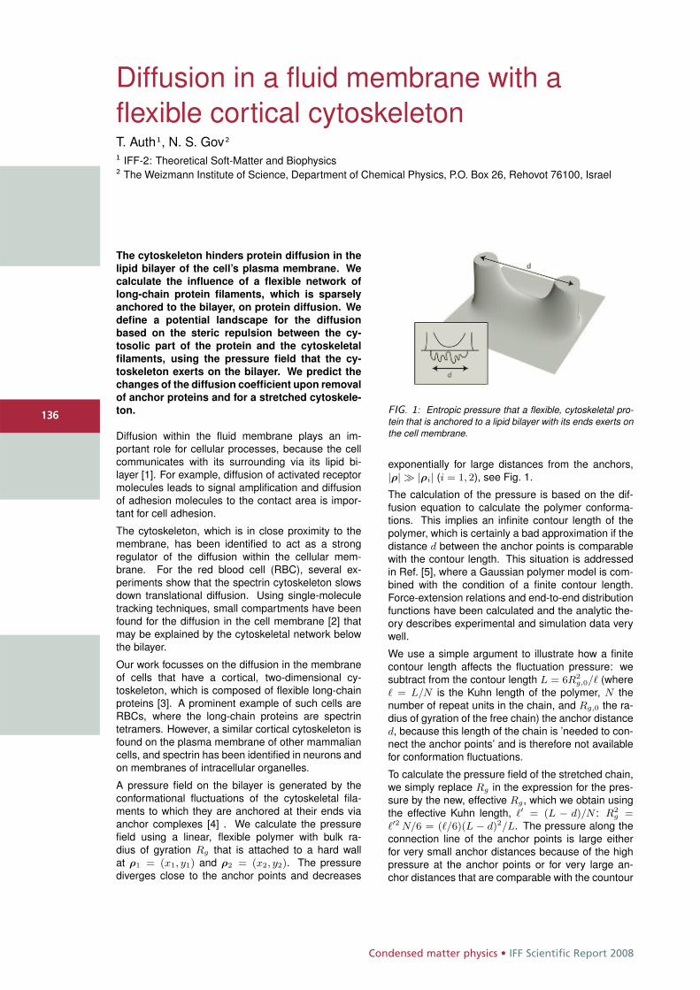
Condensed matter physics • IFF Scientific Report 2008
136
Diffusion in a fluid membrane with aflexible cortical cytoskeletonT. Auth1, N. S. Gov2
1 IFF-2: Theoretical Soft-Matter and Biophysics2 The Weizmann Institute of Science, Department of Chemical Physics, P.O. Box 26, Rehovot 76100, Israel
The cytoskeleton hinders protein diffusion in the
lipid bilayer of the cell’s plasma membrane. We
calculate the influence of a flexible network of
long-chain protein filaments, which is sparsely
anchored to the bilayer, on protein diffusion. We
define a potential landscape for the diffusion
based on the steric repulsion between the cy-
tosolic part of the protein and the cytoskeletal
filaments, using the pressure field that the cy-
toskeleton exerts on the bilayer. We predict the
changes of the diffusion coefficient upon removal
of anchor proteins and for a stretched cytoskele-
ton.
Diffusion within the fluid membrane plays an im-portant role for cellular processes, because the cellcommunicates with its surrounding via its lipid bi-layer [1]. For example, diffusion of activated receptormolecules leads to signal amplification and diffusionof adhesion molecules to the contact area is impor-tant for cell adhesion.
The cytoskeleton, which is in close proximity to themembrane, has been identified to act as a strongregulator of the diffusion within the cellular mem-brane. For the red blood cell (RBC), several ex-periments show that the spectrin cytoskeleton slowsdown translational diffusion. Using single-moleculetracking techniques, small compartments have beenfound for the diffusion in the cell membrane [2] thatmay be explained by the cytoskeletal network belowthe bilayer.
Our work focusses on the diffusion in the membraneof cells that have a cortical, two-dimensional cy-toskeleton, which is composed of flexible long-chainproteins [3]. A prominent example of such cells areRBCs, where the long-chain proteins are spectrintetramers. However, a similar cortical cytoskeleton isfound on the plasma membrane of other mammaliancells, and spectrin has been identified in neurons andon membranes of intracellular organelles.
A pressure field on the bilayer is generated by theconformational fluctuations of the cytoskeletal fila-ments to which they are anchored at their ends viaanchor complexes [4] . We calculate the pressurefield using a linear, flexible polymer with bulk ra-dius of gyration Rg that is attached to a hard wallat ρ1 = (x1, y1) and ρ2 = (x2, y2). The pressurediverges close to the anchor points and decreases
FIG. 1: Entropic pressure that a flexible, cytoskeletal pro-tein that is anchored to a lipid bilayer with its ends exerts onthe cell membrane.
exponentially for large distances from the anchors,|ρ| � |ρi| (i = 1, 2), see Fig. 1.
The calculation of the pressure is based on the dif-fusion equation to calculate the polymer conforma-tions. This implies an infinite contour length of thepolymer, which is certainly a bad approximation if thedistance d between the anchor points is comparablewith the contour length. This situation is addressedin Ref. [5], where a Gaussian polymer model is com-bined with the condition of a finite contour length.Force-extension relations and end-to-end distributionfunctions have been calculated and the analytic the-ory describes experimental and simulation data verywell.
We use a simple argument to illustrate how a finitecontour length affects the fluctuation pressure: wesubtract from the contour length L = 6R2
g,0/� (where� = L/N is the Kuhn length of the polymer, N thenumber of repeat units in the chain, and Rg,0 the ra-dius of gyration of the free chain) the anchor distanced, because this length of the chain is ’needed to con-nect the anchor points’ and is therefore not availablefor conformation fluctuations.
To calculate the pressure field of the stretched chain,we simply replace Rg in the expression for the pres-sure by the new, effective Rg, which we obtain usingthe effective Kuhn length, �′ = (L − d)/N : R2
g =�′2 N/6 = (�/6)(L − d)2/L. The pressure along theconnection line of the anchor points is large eitherfor very small anchor distances because of the highpressure at the anchor points or for very large an-chor distances that are comparable with the countour
136
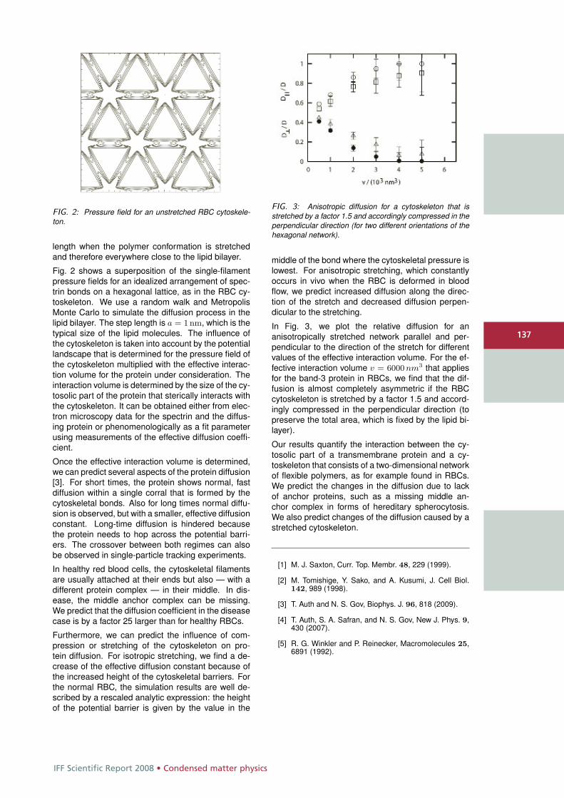
IFF Scientific Report 2008 • Condensed matter physics
137
FIG. 2: Pressure field for an unstretched RBC cytoskele-ton.
length when the polymer conformation is stretchedand therefore everywhere close to the lipid bilayer.
Fig. 2 shows a superposition of the single-filamentpressure fields for an idealized arrangement of spec-trin bonds on a hexagonal lattice, as in the RBC cy-toskeleton. We use a random walk and MetropolisMonte Carlo to simulate the diffusion process in thelipid bilayer. The step length is a = 1 nm, which is thetypical size of the lipid molecules. The influence ofthe cytoskeleton is taken into account by the potentiallandscape that is determined for the pressure field ofthe cytoskeleton multiplied with the effective interac-tion volume for the protein under consideration. Theinteraction volume is determined by the size of the cy-tosolic part of the protein that sterically interacts withthe cytoskeleton. It can be obtained either from elec-tron microscopy data for the spectrin and the diffus-ing protein or phenomenologically as a fit parameterusing measurements of the effective diffusion coeffi-cient.
Once the effective interaction volume is determined,we can predict several aspects of the protein diffusion[3]. For short times, the protein shows normal, fastdiffusion within a single corral that is formed by thecytoskeletal bonds. Also for long times normal diffu-sion is observed, but with a smaller, effective diffusionconstant. Long-time diffusion is hindered becausethe protein needs to hop across the potential barri-ers. The crossover between both regimes can alsobe observed in single-particle tracking experiments.
In healthy red blood cells, the cytoskeletal filamentsare usually attached at their ends but also — with adifferent protein complex — in their middle. In dis-ease, the middle anchor complex can be missing.We predict that the diffusion coefficient in the diseasecase is by a factor 25 larger than for healthy RBCs.
Furthermore, we can predict the influence of com-pression or stretching of the cytoskeleton on pro-tein diffusion. For isotropic stretching, we find a de-crease of the effective diffusion constant because ofthe increased height of the cytoskeletal barriers. Forthe normal RBC, the simulation results are well de-scribed by a rescaled analytic expression: the heightof the potential barrier is given by the value in the
FIG. 3: Anisotropic diffusion for a cytoskeleton that isstretched by a factor 1.5 and accordingly compressed in theperpendicular direction (for two different orientations of thehexagonal network).
middle of the bond where the cytoskeletal pressure islowest. For anisotropic stretching, which constantlyoccurs in vivo when the RBC is deformed in bloodflow, we predict increased diffusion along the direc-tion of the stretch and decreased diffusion perpen-dicular to the stretching.
In Fig. 3, we plot the relative diffusion for ananisotropically stretched network parallel and per-pendicular to the direction of the stretch for differentvalues of the effective interaction volume. For the ef-fective interaction volume v = 6000 nm3 that appliesfor the band-3 protein in RBCs, we find that the dif-fusion is almost completely asymmetric if the RBCcytoskeleton is stretched by a factor 1.5 and accord-ingly compressed in the perpendicular direction (topreserve the total area, which is fixed by the lipid bi-layer).
Our results quantify the interaction between the cy-tosolic part of a transmembrane protein and a cy-toskeleton that consists of a two-dimensional networkof flexible polymers, as for example found in RBCs.We predict the changes in the diffusion due to lackof anchor proteins, such as a missing middle an-chor complex in forms of hereditary spherocytosis.We also predict changes of the diffusion caused by astretched cytoskeleton.
[1] M. J. Saxton, Curr. Top. Membr. 48, 229 (1999).
[2] M. Tomishige, Y. Sako, and A. Kusumi, J. Cell Biol.142, 989 (1998).
[3] T. Auth and N. S. Gov, Biophys. J. 96, 818 (2009).
[4] T. Auth, S. A. Safran, and N. S. Gov, New J. Phys. 9,430 (2007).
[5] R. G. Winkler and P. Reinecker, Macromolecules 25,6891 (1992).
137
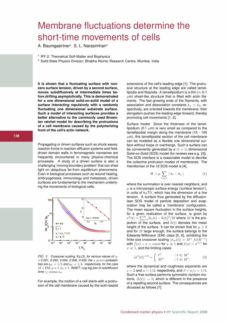
Condensed matter physics • IFF Scientific Report 2008
138
Membrane fluctuations determine theshort-time movements of cellsA. Baumgaertner1, S. L. Narasimhan2
1 IFF-2: Theoretical Soft-Matter and Biophysics2 Solid State Physics Division, Bhabha Atomic Research Centre, Mumbai, India
It is shown that a fluctuating surface with non-
zero surface tension, driven by a second surface,
moves subdiffusively at intermediate times be-
fore drifting asymptotically. This is demonstrated
for a one dimensional solid-on-solid model of a
surface interacting repulsively with a randomly
fluctuating one dimensional substrate surface.
Such a model of interacting surfaces provides a
better alternative to the commonly used Brown-
ian ratchet model for describing the protrusions
of a cell membrane caused by the polymerizing
front of the cell’s actin network.
Propagating or driven surfaces such as shock waves,reaction fronts in reaction-diffusion systems and field-driven domain walls in ferromagnetic nanowires arefrequently encountered in many physico-chemicalprocesses. A study of a driven surface is also achallenging ’moving boundary problem’ that can shedlight on ubiquitous far-from equilibrium phenomena.Even in biological processes such as wound healing,embryogenesis, immunology and metastasis, drivensurfaces are fundamental to the mechanism underly-ing the movements of biological cells.
FIG. 1: Crossover scaling, Eq.(3), for various values of tF= 0.001, 0.002, 0.004, 0.008, 0.032; the a priori probabili-ties are pF = 1/2 and qF = 1/4. respectively, for the caseM = 512, μ = 1, h0 = 1. INSET: Log-log plot of subdiffusiontime τf versus φa.
For example, the motion of a cell starts with a protru-sion of the cell membrane caused by the actin-based
extensions of the cell’s leading edge [1]. The protru-sive structure at the leading edge are called lamel-lipodia and filopodia. A lamellipodium is a thin (≈ 0.1μm) sheet-like structure that is filled with actin fila-ments. The fast growing ends of the filaments, withassociation and dissociation constants ka > kd, re-spectively, are oriented towards the membrane; theirelongation pushes the leading edge forward, therebypromoting cell movements [1, 2].
Surface model: Since the thickness of the lamel-lipodium (0.1 μm) is very small as compared to thelamellipodial margin along the membrane (10 - 100μm), this lamellipodial section of the cell membranecan be modeled as a flexible one dimensional sur-face without loops or overhangs. Such a surface canbe conveniently generated by a (1 + 1)-dimensionalSolid-on-Solid (SOS) model (for reviews see e.g. [3]).The SOS interface is a reasonable model to decribethe collective protrusion modes of membranes. TheHamiltonian of the 1d SOS model is [4],
H = μX
<ij>
| hi − hj | (1)
where the summation is over nearest neighbors, andμ is a microscopic surface energy (’surface tension’),in units of kBT/�, which has the dimension of a linetension. A surface thus generated by the diffusion-less SOS model of particle deposition and evap-oration may be called a ’membrane’ configuration.The mean square fluctuation in the surface heights,for a given realization of the surface, is given byσ2(t) =
PMj=1[hj(t) − h(t)]2/M where M is the pro-
jection of the surface, and h(t) denotes the meanheight of the surface. It can be shown that for μ > 0and for M large enough, the surface belongs to theEdwards-Wilkinson (EW) class [5, 6], exhibiting thefinite size crossover scaling 〈σm(t)〉 = Mα f(tM−z)with f(x) ∼ x = const for x � 1 and f(x) ∼ xα/z forx � 1, and the limiting cases
〈σ2(t)〉1/2 ∼j
tβ : t � Mz
Mα : t � Mz.(2)
where the dynamical and roughness exponents arez = 2 and α = 1/2, respectively, and β = α/z = 1/4.Such a free surface performs symmetric random mo-tions, 〈h(t)〉 → 0, which is different in the presenceof a repelling second surface. The consequences aredicussed as follows [7].
138
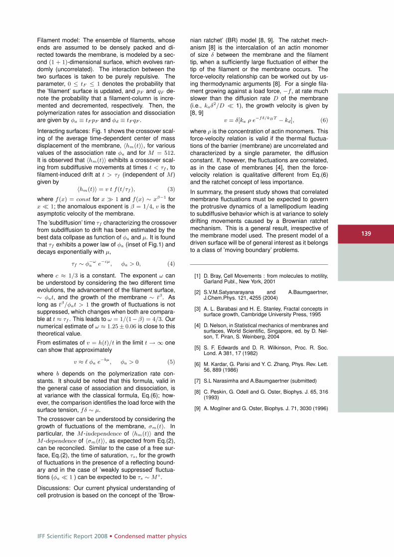
IFF Scientific Report 2008 • Condensed matter physics
139
Filament model: The ensemble of filaments, whoseends are assumed to be densely packed and di-rected towards the membrane, is modeled by a sec-ond (1 + 1)-dimensional surface, which evolves ran-domly (uncorrelated). The interaction between thetwo surfaces is taken to be purely repulsive. Theparameter, 0 ≤ tF ≤ 1 denotes the probability thatthe ’filament’ surface is updated, and pF and qF de-note the probability that a filament-column is incre-mented and decremented, respectively. Then, thepolymerization rates for association and dissociationare given by φa ≡ tF pF and φd ≡ tF qF .
Interacting surfaces: Fig. 1 shows the crossover scal-ing of the average time-dependent center of massdisplacement of the membrane, 〈hm(t)〉, for variousvalues of the association rate φa and for M = 512.It is observed that 〈hm(t)〉 exhibits a crossover scal-ing from subdiffusive movements at times t < τf , tofilament-induced drift at t > τf (independent of M )given by
〈hm(t)〉 = v t f(t/τf ), (3)
where f(x) = const for x � 1 and f(x) ∼ xβ−1 forx � 1; the anomalous exponent is β = 1/4, v is theasymptotic velocity of the membrane.The ’subdiffusion’ time τf characterizing the crossoverfrom subdiffusion to drift has been estimated by thebest data collpase as function of φa and μ. It is foundthat τf exhibits a power law of φa (inset of Fig.1) anddecays exponentially with μ,
τf ∼ φ−ωa e−cμ, φa > 0, (4)
where c ≈ 1/3 is a constant. The exponent ω canbe understood by considering the two different timeevolutions, the advancement of the filament surface,∼ φat, and the growth of the membrane ∼ tβ . Aslong as tβ/φat > 1 the growth of fluctuations is notsuppressed, which changes when both are compara-ble at t ≈ τf . This leads to ω = 1/(1−β) = 4/3. Ournumerical estimate of ω ≈ 1.25 ± 0.06 is close to thistheoretical value.From estimates of v = h(t)/t in the limit t → ∞ onecan show that approximately
v ≈ � φa e−bμ, φa > 0 (5)
where b depends on the polymerization rate con-stants. It should be noted that this formula, valid inthe general case of association and dissociation, isat variance with the classical formula, Eq.(6); how-ever, the comparison identifies the load force with thesurface tension, fδ ∼ μ.The crossover can be understood by considering thegrowth of fluctuations of the membrane, σm(t). Inparticular, the M -independence of 〈hm(t)〉 and theM -dependence of 〈σm(t)〉, as expected from Eq.(2),can be reconciled. Similar to the case of a free sur-face, Eq.(2), the time of saturation, τs, for the growthof fluctuations in the presence of a reflecting bound-ary and in the case of ’weakly suppressed’ fluctua-tions (φa � 1 ) can be expected to be τs ∼ Mz.
Discussions: Our current physical understanding ofcell protrusion is based on the concept of the ’Brow-
nian ratchet’ (BR) model [8, 9]. The ratchet mech-anism [8] is the intercalation of an actin monomerof size δ between the membrane and the filamenttip, when a sufficiently large fluctuation of either thetip of the filament or the membrane occurs. Theforce-velocity relationship can be worked out by us-ing thermodynamic arguments [8]. For a single fila-ment growing against a load force, −f , at rate muchslower than the diffusion rate D of the membrane(i.e., kaδ2/D � 1), the growth velocity is given by[8, 9]
v = δ[ka ρ e−fδ/kBT − kd], (6)
where ρ is the concentration of actin monomers. Thisforce-velocity relation is valid if the thermal fluctua-tions of the barrier (membrane) are uncorrelated andcharacterized by a single parameter, the diffusionconstant. If, however, the fluctuations are correlated,as in the case of membranes [4], then the force-velocity relation is qualitative different from Eq.(6)and the ratchet concept of less importance.
In summary, the present study shows that correlatedmembrane fluctuations must be expected to governthe protrusive dynamics of a lamellipodium leadingto subdiffusive behavior which is at variance to solelydrifting movements caused by a Brownian ratchetmechanism. This is a general result, irrespective ofthe membrane model used. The present model of adriven surface will be of general interest as it belongsto a class of ’moving boundary’ problems.
[1] D. Bray, Cell Movements : from molecules to motility,Garland Publ., New York, 2001
[2] S.V.M.Satyanarayana and A.Baumgaertner,J.Chem.Phys. 121, 4255 (2004)
[3] A. L. Barabasi and H. E. Stanley, Fractal concepts insurface growth, Cambridge University Press, 1995
[4] D. Nelson, in Statistical mechanics of membranes andsurfaces, World Scientific, Singapore, ed. by D. Nel-son, T. Piran, S. Weinberg, 2004
[5] S. F. Edwards and D. R. Wilkinson, Proc. R. Soc.Lond. A 381, 17 (1982)
[6] M. Kardar, G. Parisi and Y. C. Zhang, Phys. Rev. Lett.56, 889 (1986)
[7] S.L Narasimha and A.Baumgaertner (submitted)
[8] C. Peskin, G. Odell and G. Oster, Biophys. J. 65, 316(1993)
[9] A. Mogilner and G. Oster, Biophys. J. 71, 3030 (1996)
139
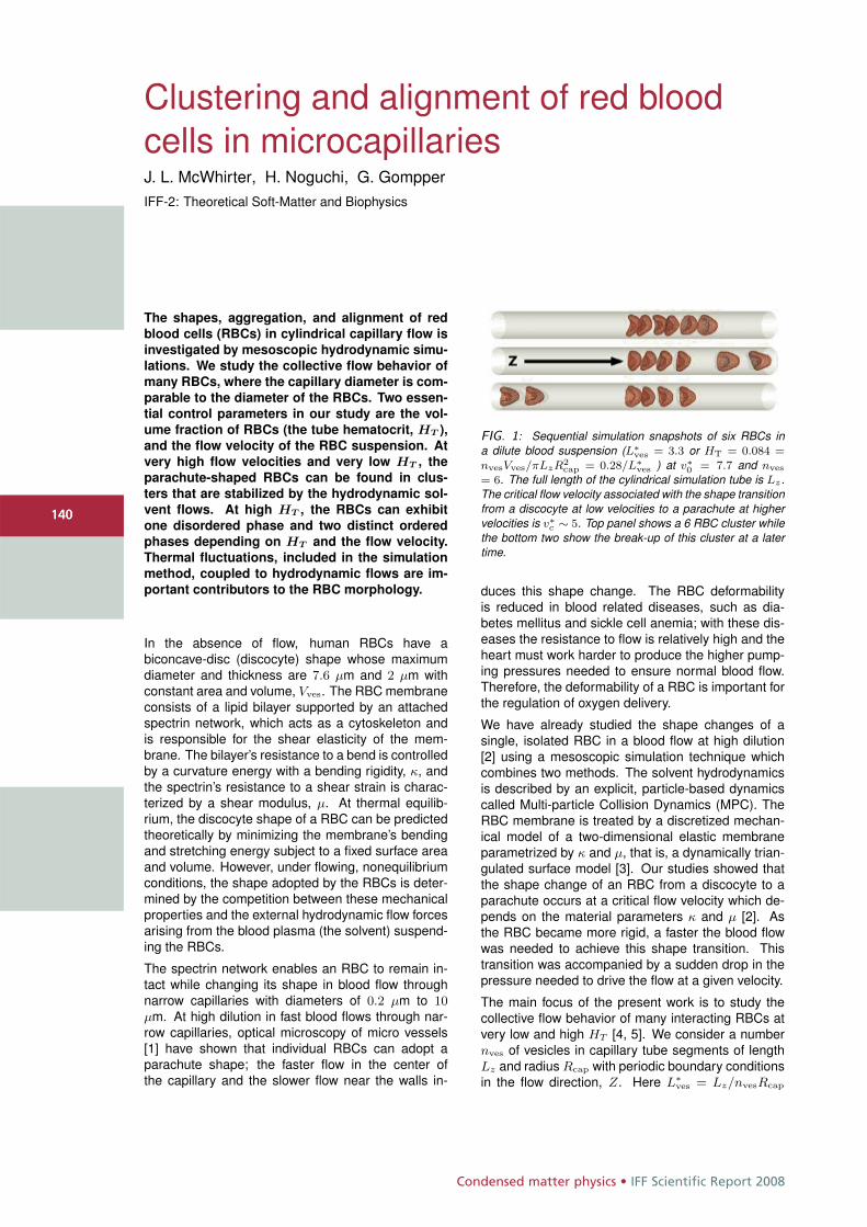
Condensed matter physics • IFF Scientific Report 2008
140
Clustering and alignment of red bloodcells in microcapillariesJ. L. McWhirter, H. Noguchi, G. GompperIFF-2: Theoretical Soft-Matter and Biophysics
The shapes, aggregation, and alignment of red
blood cells (RBCs) in cylindrical capillary flow is
investigated by mesoscopic hydrodynamic simu-
lations. We study the collective flow behavior of
many RBCs, where the capillary diameter is com-
parable to the diameter of the RBCs. Two essen-
tial control parameters in our study are the vol-
ume fraction of RBCs (the tube hematocrit, HT ),
and the flow velocity of the RBC suspension. At
very high flow velocities and very low HT , the
parachute-shaped RBCs can be found in clus-
ters that are stabilized by the hydrodynamic sol-
vent flows. At high HT , the RBCs can exhibit
one disordered phase and two distinct ordered
phases depending on HT and the flow velocity.
Thermal fluctuations, included in the simulation
method, coupled to hydrodynamic flows are im-
portant contributors to the RBC morphology.
In the absence of flow, human RBCs have abiconcave-disc (discocyte) shape whose maximumdiameter and thickness are 7.6 μm and 2 μm withconstant area and volume, Vves. The RBC membraneconsists of a lipid bilayer supported by an attachedspectrin network, which acts as a cytoskeleton andis responsible for the shear elasticity of the mem-brane. The bilayer’s resistance to a bend is controlledby a curvature energy with a bending rigidity, κ, andthe spectrin’s resistance to a shear strain is charac-terized by a shear modulus, μ. At thermal equilib-rium, the discocyte shape of a RBC can be predictedtheoretically by minimizing the membrane’s bendingand stretching energy subject to a fixed surface areaand volume. However, under flowing, nonequilibriumconditions, the shape adopted by the RBCs is deter-mined by the competition between these mechanicalproperties and the external hydrodynamic flow forcesarising from the blood plasma (the solvent) suspend-ing the RBCs.
The spectrin network enables an RBC to remain in-tact while changing its shape in blood flow throughnarrow capillaries with diameters of 0.2 μm to 10μm. At high dilution in fast blood flows through nar-row capillaries, optical microscopy of micro vessels[1] have shown that individual RBCs can adopt aparachute shape; the faster flow in the center ofthe capillary and the slower flow near the walls in-
FIG. 1: Sequential simulation snapshots of six RBCs ina dilute blood suspension (L∗
ves = 3.3 or HT = 0.084 =nvesVves/πLzR2
cap = 0.28/L∗ves ) at v∗
0 = 7.7 and nves
= 6. The full length of the cylindrical simulation tube is Lz .The critical flow velocity associated with the shape transitionfrom a discocyte at low velocities to a parachute at highervelocities is v∗
c ∼ 5. Top panel shows a 6 RBC cluster whilethe bottom two show the break-up of this cluster at a latertime.
duces this shape change. The RBC deformabilityis reduced in blood related diseases, such as dia-betes mellitus and sickle cell anemia; with these dis-eases the resistance to flow is relatively high and theheart must work harder to produce the higher pump-ing pressures needed to ensure normal blood flow.Therefore, the deformability of a RBC is important forthe regulation of oxygen delivery.
We have already studied the shape changes of asingle, isolated RBC in a blood flow at high dilution[2] using a mesoscopic simulation technique whichcombines two methods. The solvent hydrodynamicsis described by an explicit, particle-based dynamicscalled Multi-particle Collision Dynamics (MPC). TheRBC membrane is treated by a discretized mechan-ical model of a two-dimensional elastic membraneparametrized by κ and μ, that is, a dynamically trian-gulated surface model [3]. Our studies showed thatthe shape change of an RBC from a discocyte to aparachute occurs at a critical flow velocity which de-pends on the material parameters κ and μ [2]. Asthe RBC became more rigid, a faster the blood flowwas needed to achieve this shape transition. Thistransition was accompanied by a sudden drop in thepressure needed to drive the flow at a given velocity.
The main focus of the present work is to study thecollective flow behavior of many interacting RBCs atvery low and high HT [4, 5]. We consider a numbernves of vesicles in capillary tube segments of lengthLz and radius Rcap with periodic boundary conditionsin the flow direction, Z. Here L∗
ves = Lz/nvesRcap
140
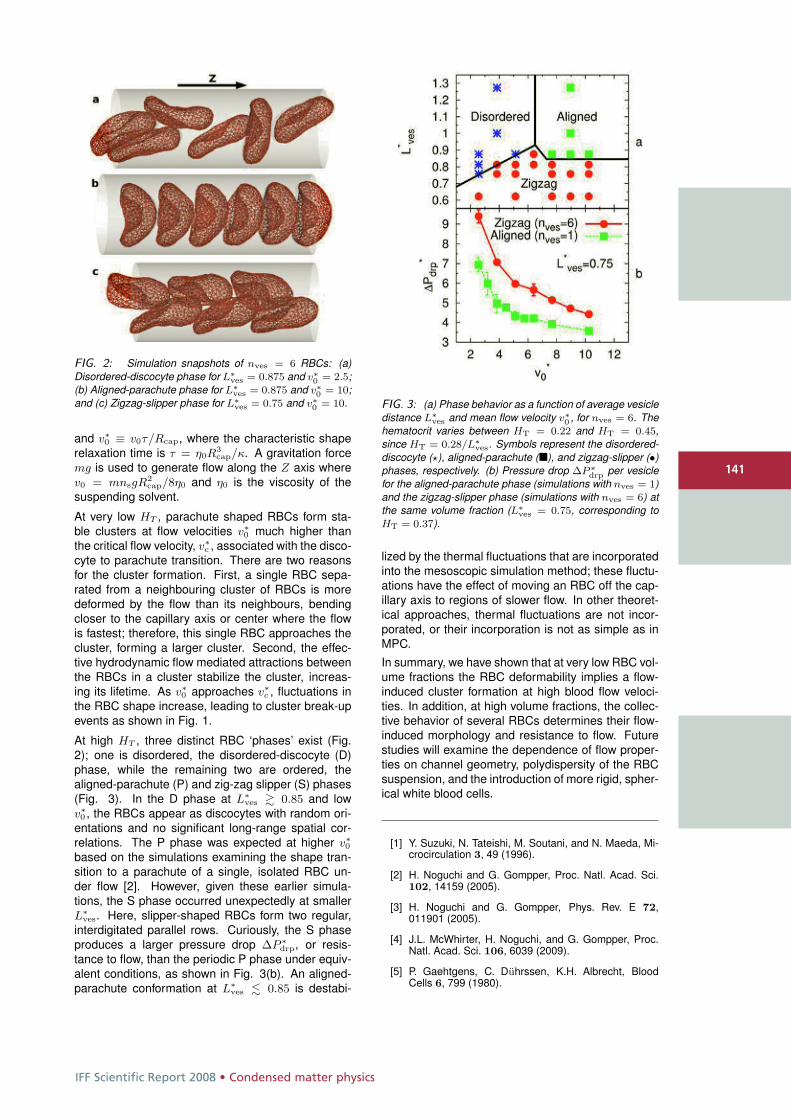
IFF Scientific Report 2008 • Condensed matter physics
141
FIG. 2: Simulation snapshots of nves = 6 RBCs: (a)Disordered-discocyte phase for L∗
ves = 0.875 and v∗0 = 2.5;
(b) Aligned-parachute phase for L∗ves = 0.875 and v∗
0 = 10;and (c) Zigzag-slipper phase for L∗
ves = 0.75 and v∗0 = 10.
and v∗0 ≡ v0τ/Rcap, where the characteristic shape
relaxation time is τ = η0R3cap/κ. A gravitation force
mg is used to generate flow along the Z axis wherev0 = mnsgR2
cap/8η0 and η0 is the viscosity of thesuspending solvent.
At very low HT , parachute shaped RBCs form sta-ble clusters at flow velocities v∗
0 much higher thanthe critical flow velocity, v∗
c , associated with the disco-cyte to parachute transition. There are two reasonsfor the cluster formation. First, a single RBC sepa-rated from a neighbouring cluster of RBCs is moredeformed by the flow than its neighbours, bendingcloser to the capillary axis or center where the flowis fastest; therefore, this single RBC approaches thecluster, forming a larger cluster. Second, the effec-tive hydrodynamic flow mediated attractions betweenthe RBCs in a cluster stabilize the cluster, increas-ing its lifetime. As v∗
0 approaches v∗c , fluctuations in
the RBC shape increase, leading to cluster break-upevents as shown in Fig. 1.
At high HT , three distinct RBC ‘phases’ exist (Fig.2); one is disordered, the disordered-discocyte (D)phase, while the remaining two are ordered, thealigned-parachute (P) and zig-zag slipper (S) phases(Fig. 3). In the D phase at L∗
ves � 0.85 and lowv∗0 , the RBCs appear as discocytes with random ori-
entations and no significant long-range spatial cor-relations. The P phase was expected at higher v∗
0
based on the simulations examining the shape tran-sition to a parachute of a single, isolated RBC un-der flow [2]. However, given these earlier simula-tions, the S phase occurred unexpectedly at smallerL∗
ves. Here, slipper-shaped RBCs form two regular,interdigitated parallel rows. Curiously, the S phaseproduces a larger pressure drop ΔP ∗
drp, or resis-tance to flow, than the periodic P phase under equiv-alent conditions, as shown in Fig. 3(b). An aligned-parachute conformation at L∗
ves � 0.85 is destabi-
FIG. 3: (a) Phase behavior as a function of average vesicledistance L∗
ves and mean flow velocity v∗0 , for nves = 6. The
hematocrit varies between HT = 0.22 and HT = 0.45,since HT = 0.28/L∗
ves. Symbols represent the disordered-discocyte (�), aligned-parachute (�), and zigzag-slipper (•)phases, respectively. (b) Pressure drop ΔP ∗
drp per vesiclefor the aligned-parachute phase (simulations with nves = 1)and the zigzag-slipper phase (simulations with nves = 6) atthe same volume fraction (L∗
ves = 0.75, corresponding toHT = 0.37).
lized by the thermal fluctuations that are incorporatedinto the mesoscopic simulation method; these fluctu-ations have the effect of moving an RBC off the cap-illary axis to regions of slower flow. In other theoret-ical approaches, thermal fluctuations are not incor-porated, or their incorporation is not as simple as inMPC.
In summary, we have shown that at very low RBC vol-ume fractions the RBC deformability implies a flow-induced cluster formation at high blood flow veloci-ties. In addition, at high volume fractions, the collec-tive behavior of several RBCs determines their flow-induced morphology and resistance to flow. Futurestudies will examine the dependence of flow proper-ties on channel geometry, polydispersity of the RBCsuspension, and the introduction of more rigid, spher-ical white blood cells.
[1] Y. Suzuki, N. Tateishi, M. Soutani, and N. Maeda, Mi-crocirculation 3, 49 (1996).
[2] H. Noguchi and G. Gompper, Proc. Natl. Acad. Sci.102, 14159 (2005).
[3] H. Noguchi and G. Gompper, Phys. Rev. E 72,011901 (2005).
[4] J.L. McWhirter, H. Noguchi, and G. Gompper, Proc.Natl. Acad. Sci. 106, 6039 (2009).
[5] P. Gaehtgens, C. Duhrssen, K.H. Albrecht, BloodCells 6, 799 (1980).
141
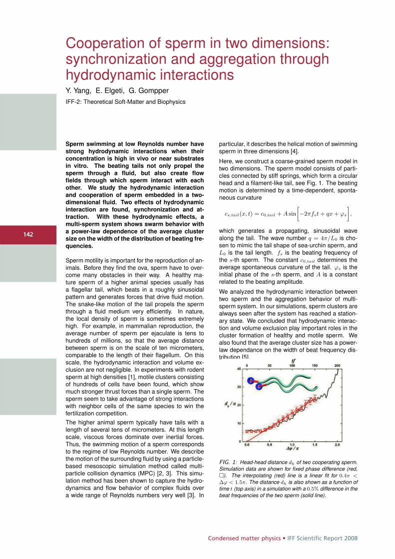
Condensed matter physics • IFF Scientific Report 2008
142
Cooperation of sperm in two dimensions:synchronization and aggregation throughhydrodynamic interactionsY. Yang, E. Elgeti, G. GompperIFF-2: Theoretical Soft-Matter and Biophysics
Sperm swimming at low Reynolds number have
strong hydrodynamic interactions when their
concentration is high in vivo or near substrates
in vitro. The beating tails not only propel the
sperm through a fluid, but also create flow
fields through which sperm interact with each
other. We study the hydrodynamic interaction
and cooperation of sperm embedded in a two-
dimensional fluid. Two effects of hydrodynamic
interaction are found, synchronization and at-
traction. With these hydrodynamic effects, a
multi-sperm system shows swarm behavior with
a power-law dependence of the average cluster
size on the width of the distribution of beating fre-
quencies.
Sperm motility is important for the reproduction of an-imals. Before they find the ova, sperm have to over-come many obstacles in their way. A healthy ma-ture sperm of a higher animal species usually hasa flagellar tail, which beats in a roughly sinusoidalpattern and generates forces that drive fluid motion.The snake-like motion of the tail propels the spermthrough a fluid medium very efficiently. In nature,the local density of sperm is sometimes extremelyhigh. For example, in mammalian reproduction, theaverage number of sperm per ejaculate is tens tohundreds of millions, so that the average distancebetween sperm is on the scale of ten micrometers,comparable to the length of their flagellum. On thisscale, the hydrodynamic interaction and volume ex-clusion are not negligible. In experiments with rodentsperm at high densities [1], motile clusters consistingof hundreds of cells have been found, which showmuch stronger thrust forces than a single sperm. Thesperm seem to take advantage of strong interactionswith neighbor cells of the same species to win thefertilization competition.The higher animal sperm typically have tails with alength of several tens of micrometers. At this lengthscale, viscous forces dominate over inertial forces.Thus, the swimming motion of a sperm correspondsto the regime of low Reynolds number. We describethe motion of the surrounding fluid by using a particle-based mesoscopic simulation method called multi-particle collision dynamics (MPC) [2, 3]. This simu-lation method has been shown to capture the hydro-dynamics and flow behavior of complex fluids overa wide range of Reynolds numbers very well [3]. In
particular, it describes the helical motion of swimmingsperm in three dimensions [4].
Here, we construct a coarse-grained sperm model intwo dimensions. The sperm model consists of parti-cles connected by stiff springs, which form a circularhead and a filament-like tail, see Fig. 1. The beatingmotion is determined by a time-dependent, sponta-neous curvature
cs,tail(x, t) = c0,tail + A sin
»−2πfst + qx + ϕs
–,
which generates a propagating, sinusoidal wavealong the tail. The wave number q = 4π/L0 is cho-sen to mimic the tail shape of sea-urchin sperm, andL0 is the tail length. fs is the beating frequency ofthe s-th sperm. The constant c0,tail determines theaverage spontaneous curvature of the tail. ϕs is theinitial phase of the s-th sperm, and A is a constantrelated to the beating amplitude.
We analyzed the hydrodynamic interaction betweentwo sperm and the aggregation behavior of multi-sperm system. In our simulations, sperm clusters arealways seen after the system has reached a station-ary state. We concluded that hydrodynamic interac-tion and volume exclusion play important roles in thecluster formation of healthy and motile sperm. Wealso found that the average cluster size has a power-law dependance on the width of beat frequency dis-tribution [5].
FIG. 1: Head-head distance dh of two cooperating sperm.Simulation data are shown for fixed phase difference (red,�). The interpolating (red) line is a linear fit for 0.4π <
Δϕ < 1.5π. The distance dh is also shown as a function oftime t (top axis) in a simulation with a 0.5% difference in thebeat frequencies of the two sperm (solid line).
142
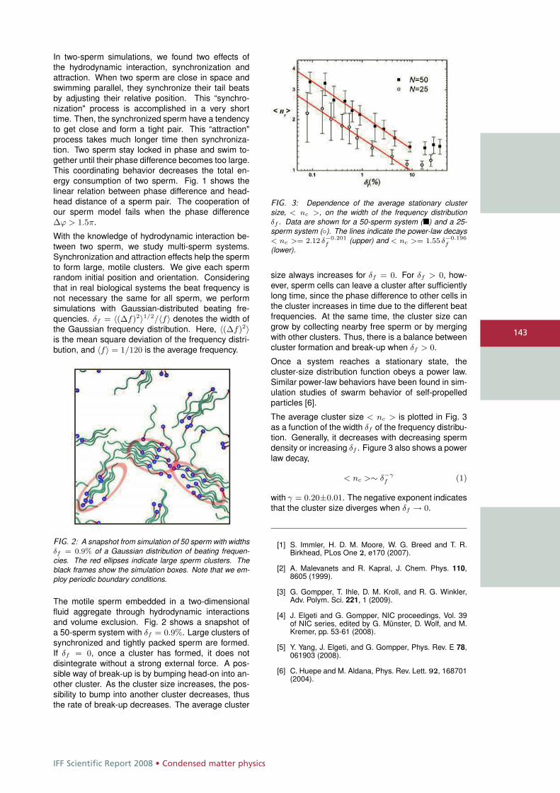
IFF Scientific Report 2008 • Condensed matter physics
143
In two-sperm simulations, we found two effects ofthe hydrodynamic interaction, synchronization andattraction. When two sperm are close in space andswimming parallel, they synchronize their tail beatsby adjusting their relative position. This “synchro-nization" process is accomplished in a very shorttime. Then, the synchronized sperm have a tendencyto get close and form a tight pair. This “attraction"process takes much longer time then synchroniza-tion. Two sperm stay locked in phase and swim to-gether until their phase difference becomes too large.This coordinating behavior decreases the total en-ergy consumption of two sperm. Fig. 1 shows thelinear relation between phase difference and head-head distance of a sperm pair. The cooperation ofour sperm model fails when the phase differenceΔϕ > 1.5π.
With the knowledge of hydrodynamic interaction be-tween two sperm, we study multi-sperm systems.Synchronization and attraction effects help the spermto form large, motile clusters. We give each spermrandom initial position and orientation. Consideringthat in real biological systems the beat frequency isnot necessary the same for all sperm, we performsimulations with Gaussian-distributed beating fre-quencies. δf = 〈(Δf)2〉1/2/〈f〉 denotes the width ofthe Gaussian frequency distribution. Here, 〈(Δf)2〉is the mean square deviation of the frequency distri-bution, and 〈f〉 = 1/120 is the average frequency.
FIG. 2: A snapshot from simulation of 50 sperm with widthsδf = 0.9% of a Gaussian distribution of beating frequen-cies. The red ellipses indicate large sperm clusters. Theblack frames show the simulation boxes. Note that we em-ploy periodic boundary conditions.
The motile sperm embedded in a two-dimensionalfluid aggregate through hydrodynamic interactionsand volume exclusion. Fig. 2 shows a snapshot ofa 50-sperm system with δf = 0.9%. Large clusters ofsynchronized and tightly packed sperm are formed.If δf = 0, once a cluster has formed, it does notdisintegrate without a strong external force. A pos-sible way of break-up is by bumping head-on into an-other cluster. As the cluster size increases, the pos-sibility to bump into another cluster decreases, thusthe rate of break-up decreases. The average cluster
FIG. 3: Dependence of the average stationary clustersize, < nc >, on the width of the frequency distributionδf . Data are shown for a 50-sperm system (�) and a 25-sperm system (◦). The lines indicate the power-law decays< nc >= 2.12 δ−0.201
f (upper) and < nc >= 1.55 δ−0.196f
(lower).
size always increases for δf = 0. For δf > 0, how-ever, sperm cells can leave a cluster after sufficientlylong time, since the phase difference to other cells inthe cluster increases in time due to the different beatfrequencies. At the same time, the cluster size cangrow by collecting nearby free sperm or by mergingwith other clusters. Thus, there is a balance betweencluster formation and break-up when δf > 0.
Once a system reaches a stationary state, thecluster-size distribution function obeys a power law.Similar power-law behaviors have been found in sim-ulation studies of swarm behavior of self-propelledparticles [6].
The average cluster size < nc > is plotted in Fig. 3as a function of the width δf of the frequency distribu-tion. Generally, it decreases with decreasing spermdensity or increasing δf . Figure 3 also shows a powerlaw decay,
< nc >∼ δ−γf (1)
with γ = 0.20±0.01. The negative exponent indicatesthat the cluster size diverges when δf → 0.
[1] S. Immler, H. D. M. Moore, W. G. Breed and T. R.Birkhead, PLos One 2, e170 (2007).
[2] A. Malevanets and R. Kapral, J. Chem. Phys. 110,8605 (1999).
[3] G. Gompper, T. Ihle, D. M. Kroll, and R. G. Winkler,Adv. Polym. Sci. 221, 1 (2009).
[4] J. Elgeti and G. Gompper, NIC proceedings, Vol. 39of NIC series, edited by G. Münster, D. Wolf, and M.Kremer, pp. 53-61 (2008).
[5] Y. Yang, J. Elgeti, and G. Gompper, Phys. Rev. E 78,061903 (2008).
[6] C. Huepe and M. Aldana, Phys. Rev. Lett. 92, 168701(2004).
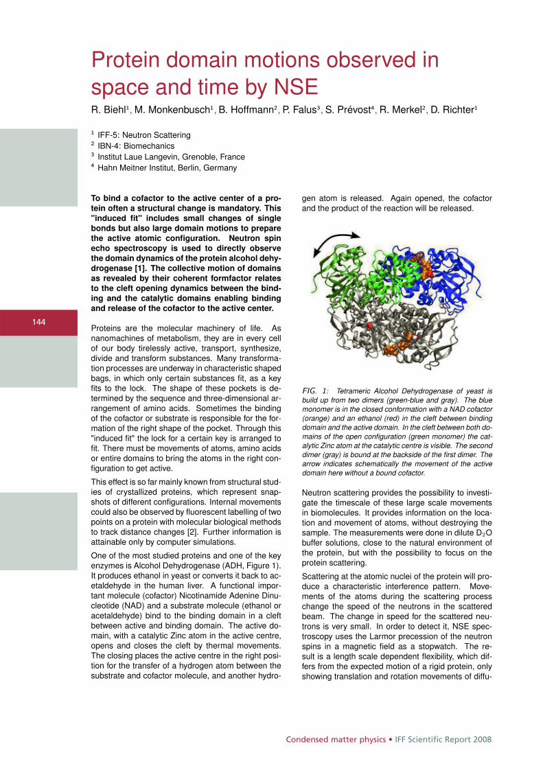
Condensed matter physics • IFF Scientific Report 2008
144
Protein domain motions observed inspace and time by NSER. Biehl1, M. Monkenbusch1, B. Hoffmann2, P. Falus3, S. Prévost4, R. Merkel2, D. Richter1
1 IFF-5: Neutron Scattering2 IBN-4: Biomechanics3 Institut Laue Langevin, Grenoble, France4 Hahn Meitner Institut, Berlin, Germany
To bind a cofactor to the active center of a pro-
tein often a structural change is mandatory. This
"induced fit" includes small changes of single
bonds but also large domain motions to prepare
the active atomic configuration. Neutron spin
echo spectroscopy is used to directly observe
the domain dynamics of the protein alcohol dehy-
drogenase [1]. The collective motion of domains
as revealed by their coherent formfactor relates
to the cleft opening dynamics between the bind-
ing and the catalytic domains enabling binding
and release of the cofactor to the active center.
Proteins are the molecular machinery of life. Asnanomachines of metabolism, they are in every cellof our body tirelessly active, transport, synthesize,divide and transform substances. Many transforma-tion processes are underway in characteristic shapedbags, in which only certain substances fit, as a keyfits to the lock. The shape of these pockets is de-termined by the sequence and three-dimensional ar-rangement of amino acids. Sometimes the bindingof the cofactor or substrate is responsible for the for-mation of the right shape of the pocket. Through this"induced fit" the lock for a certain key is arranged tofit. There must be movements of atoms, amino acidsor entire domains to bring the atoms in the right con-figuration to get active.
This effect is so far mainly known from structural stud-ies of crystallized proteins, which represent snap-shots of different configurations. Internal movementscould also be observed by fluorescent labelling of twopoints on a protein with molecular biological methodsto track distance changes [2]. Further information isattainable only by computer simulations.
One of the most studied proteins and one of the keyenzymes is Alcohol Dehydrogenase (ADH, Figure 1).It produces ethanol in yeast or converts it back to ac-etaldehyde in the human liver. A functional impor-tant molecule (cofactor) Nicotinamide Adenine Dinu-cleotide (NAD) and a substrate molecule (ethanol oracetaldehyde) bind to the binding domain in a cleftbetween active and binding domain. The active do-main, with a catalytic Zinc atom in the active centre,opens and closes the cleft by thermal movements.The closing places the active centre in the right posi-tion for the transfer of a hydrogen atom between thesubstrate and cofactor molecule, and another hydro-
gen atom is released. Again opened, the cofactorand the product of the reaction will be released.
FIG. 1: Tetrameric Alcohol Dehydrogenase of yeast isbuild up from two dimers (green-blue and gray). The bluemonomer is in the closed conformation with a NAD cofactor(orange) and an ethanol (red) in the cleft between bindingdomain and the active domain. In the cleft between both do-mains of the open configuration (green monomer) the cat-alytic Zinc atom at the catalytic centre is visible. The seconddimer (gray) is bound at the backside of the first dimer. Thearrow indicates schematically the movement of the activedomain here without a bound cofactor.
Neutron scattering provides the possibility to investi-gate the timescale of these large scale movementsin biomolecules. It provides information on the loca-tion and movement of atoms, without destroying thesample. The measurements were done in dilute D2Obuffer solutions, close to the natural environment ofthe protein, but with the possibility to focus on theprotein scattering.
Scattering at the atomic nuclei of the protein will pro-duce a characteristic interference pattern. Move-ments of the atoms during the scattering processchange the speed of the neutrons in the scatteredbeam. The change in speed for the scattered neu-trons is very small. In order to detect it, NSE spec-troscopy uses the Larmor precession of the neutronspins in a magnetic field as a stopwatch. The re-sult is a length scale dependent flexibility, which dif-fers from the expected motion of a rigid protein, onlyshowing translation and rotation movements of diffu-
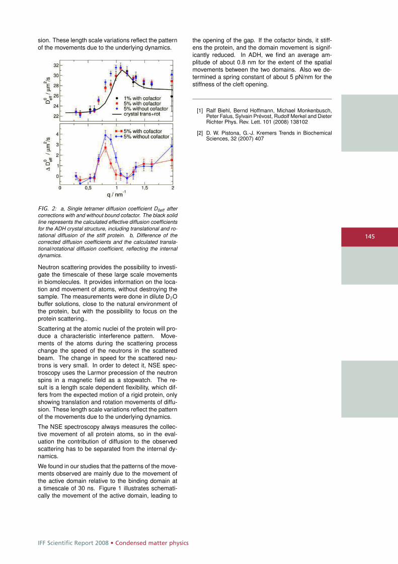
IFF Scientific Report 2008 • Condensed matter physics
145
sion. These length scale variations reflect the patternof the movements due to the underlying dynamics.
FIG. 2: a, Single tetramer diffusion coefficient D0eff aftercorrections with and without bound cofactor. The black solidline represents the calculated effective diffusion coefficientsfor the ADH crystal structure, including translational and ro-tational diffusion of the stiff protein. b, Difference of thecorrected diffusion coefficients and the calculated transla-tional/rotational diffusion coefficient, reflecting the internaldynamics.
Neutron scattering provides the possibility to investi-gate the timescale of these large scale movementsin biomolecules. It provides information on the loca-tion and movement of atoms, without destroying thesample. The measurements were done in dilute D2Obuffer solutions, close to the natural environment ofthe protein, but with the possibility to focus on theprotein scattering..
Scattering at the atomic nuclei of the protein will pro-duce a characteristic interference pattern. Move-ments of the atoms during the scattering processchange the speed of the neutrons in the scatteredbeam. The change in speed for the scattered neu-trons is very small. In order to detect it, NSE spec-troscopy uses the Larmor precession of the neutronspins in a magnetic field as a stopwatch. The re-sult is a length scale dependent flexibility, which dif-fers from the expected motion of a rigid protein, onlyshowing translation and rotation movements of diffu-sion. These length scale variations reflect the patternof the movements due to the underlying dynamics.
The NSE spectroscopy always measures the collec-tive movement of all protein atoms, so in the eval-uation the contribution of diffusion to the observedscattering has to be separated from the internal dy-namics.
We found in our studies that the patterns of the move-ments observed are mainly due to the movement ofthe active domain relative to the binding domain ata timescale of 30 ns. Figure 1 illustrates schemati-cally the movement of the active domain, leading to
the opening of the gap. If the cofactor binds, it stiff-ens the protein, and the domain movement is signif-icantly reduced. In ADH, we find an average am-plitude of about 0.8 nm for the extent of the spatialmovements between the two domains. Also we de-termined a spring constant of about 5 pN/nm for thestiffness of the cleft opening.
[1] Ralf Biehl, Bernd Hoffmann, Michael Monkenbusch,Peter Falus, Sylvain Prévost, Rudolf Merkel and DieterRichter Phys. Rev. Lett. 101 (2008) 138102
[2] D. W. Pistona, G.-J. Kremers Trends in BiochemicalSciences, 32 (2007) 407
Condensed matter physics • IFF Scientific Report 2008
146
Electrostatics of DNA and DNA-proteininteractionsA. G. CherstvyIFF-2: Theoretical Soft-Matter and Biophysics
We present below a short description of some
problems of DNA electrostatics. The biologi-
cal systems considered include DNA cholesteric
phases, DNA-DNA friction in tight DNA plies, tar-
get search on DNA by DNA-sliding proteins, and
structure of DNA protein complexes. We dis-
cuss in particular the electrostatic mechanism of
DNA-protein recognition and analyze the details
of charge distribution on DNA-protein complexes
from the Protein Data Bank structures.
DNA cholesteric phases: Many chiral bio-macromole-cules are highly charged and form a variety of denseliquid-crystalline phases in vivo and in vitro. Thelist includes DNA, f-actin, some polysaccharides andpolypeptides, filamentous viruses (fd, M13). Natureuses the ability of DNA to form chiral phases for pack-aging the genomes of bacteria and viruses and forDNA compactification in sperm of some vertebrates.However, how the DNA molecular chirality manifestsitself through intermolecular interactions in macro-scopic cholesteric properties is still not fully under-stood. For instance, for the DNA twisted phases invitro, the cholesteric pitch is extremely large, 2-4 μm,being dependent however on temperature, the sur-rounding electrolyte, and density of DNA lattice.
We considered DNA-DNA chiral electrostatic inter-actions in dense liquid crystalline DNA phases [1].In particular, we have treated theoretically the condi-tions for existence of DNA cholesterics, the relevantdensities of DNA lattices, the influence of added salts(mono- vs. multivalent), the strength of azimuthalDNA correlations, and calculated the value of DNAcholesteric pitch. Some comparison with recent ex-periments on response of DNA cholesterics to ex-ternal osmotic stresses as well as on boundaries ofDNA cholesteric-isotropic and cholesteric-hexagonalphase transition was presented. The dependenceof the cholesteric pitch on the density of DNA lat-tice obtained was shown be to in agreement with ex-periments. The twist direction of cholesteric phasesin the theory was however right-handed, opposite totypically left-handed phases observed for dense DNAassemblies.
DNA-DNA electrostatic friction: Recent single mole-cule experiments on superhelical DNA plies have re-vealed that in the presence of DNA-binding proteinsthe forces required to shear two DNAs along each
other in the ply are several pN. Without proteins,DNA-DNA friction was detected to be very small, in-dependent on the valence of cations added and num-ber of DNA turns in the ply.We have estimated theoretically the DNA-DNA elec-trostatic frictional forces emerging upon dragging oneDNA over another in a close parallel juxtaposition[2]. For ideally helical DNA duplexes, the electro-static DNA-DNA friction occurs due to correlations inelectrostatic potential variations near the DNA sur-face. The latter originate from intrinsic helicity of DNAnegative phosphate charges and of positive cationsadsorbed in DNA grooves. The length scale of thecharge periodicity along DNA is its pitch of 3.4 nm.These potential barriers produce positive-negativecharge interlocking along the contact of two DNAs.Realistic DNAs are however non-ideal helices. DNAbase pair parameters strongly depend on DNA se-quence, producing quite corrugated quasi-helicalDNA structures. In this case, electrostatic poten-tial barriers become decorrelated after some DNA-DNA interaction length due to accumulation of mis-matches in the DNA structure. This strongly impedesDNA-DNA frictional forces. We calculated the mag-nitude of frictional forces in tight DNA plies that arestrongly stretched by the end forces. We discussedthe possibilities of probing DNA-DNA interactions inconfined DNA superhelical plies as obtained in singlemolecule experiments.Facilitated diffusion of proteins on DNA and DNA-protein electrostatic interactions: Several types ofinteractions occur between DNA and its bindingproteins: hydrogen bonding, electrostatic, van derWaals. Protein structures and domains of DNA re-cognition are extremely diverse. Many DNA-bindingand DNA-sliding proteins are known to find their tar-get sites on DNA with the rates that are much fasterthan allowed by thermal diffusion in 3D solution (e.g.,the lac repressor). Being capable to scan the DNAvery fast, proteins often recognize DNA base pair se-quences with high specificity tolerating only little mis-match. All this complicates the construction of gen-eral theory of DNA-protein interactions. The mech-anisms of protein diffusion in DNA coil (3D vs. 1Ddiffusion) and the peculiarities of DNA-protein recog-nition are also not completely understood.For some protein-DNA complexes, like non-specifi-cally bound lac, electrostatic interactions of protein
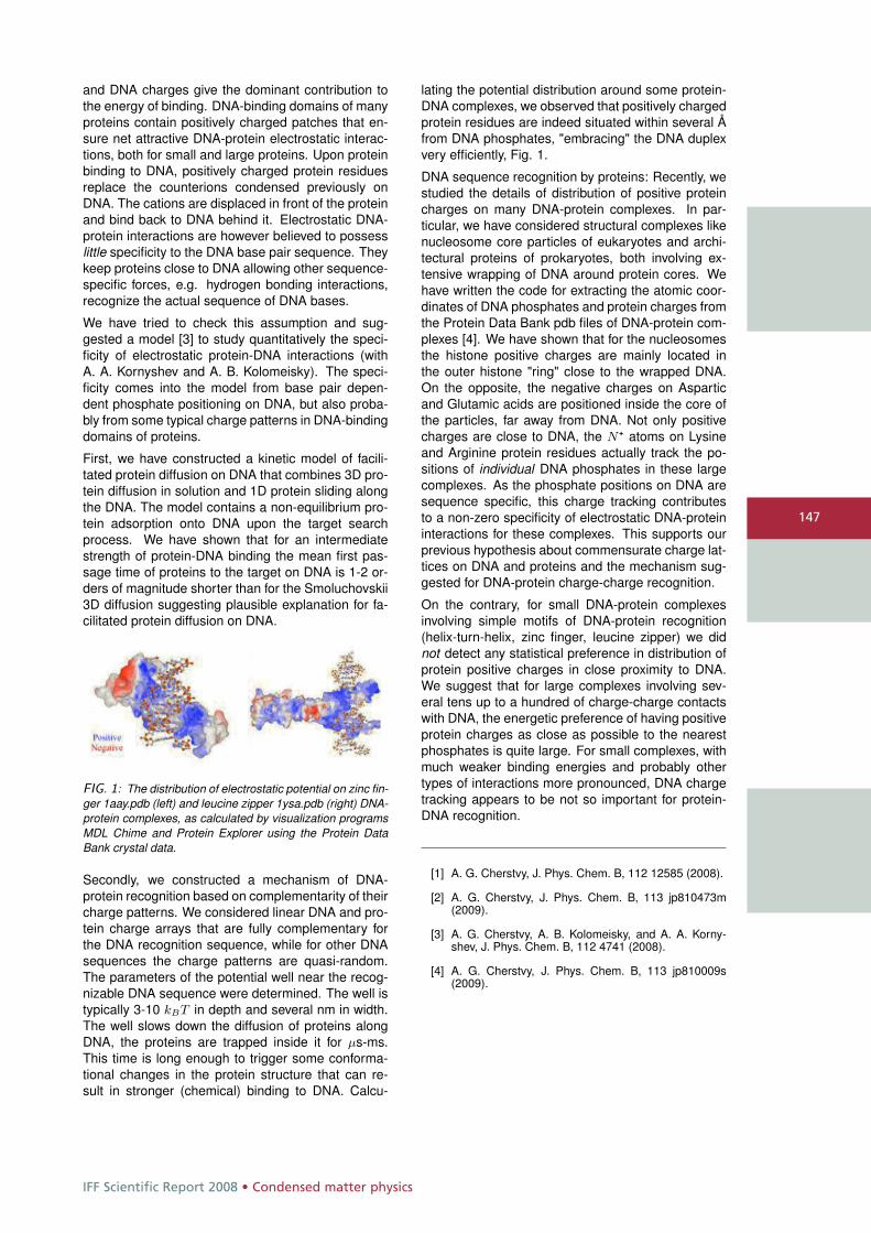
IFF Scientific Report 2008 • Condensed matter physics
147
and DNA charges give the dominant contribution tothe energy of binding. DNA-binding domains of manyproteins contain positively charged patches that en-sure net attractive DNA-protein electrostatic interac-tions, both for small and large proteins. Upon proteinbinding to DNA, positively charged protein residuesreplace the counterions condensed previously onDNA. The cations are displaced in front of the proteinand bind back to DNA behind it. Electrostatic DNA-protein interactions are however believed to possesslittle specificity to the DNA base pair sequence. Theykeep proteins close to DNA allowing other sequence-specific forces, e.g. hydrogen bonding interactions,recognize the actual sequence of DNA bases.
We have tried to check this assumption and sug-gested a model [3] to study quantitatively the speci-ficity of electrostatic protein-DNA interactions (withA. A. Kornyshev and A. B. Kolomeisky). The speci-ficity comes into the model from base pair depen-dent phosphate positioning on DNA, but also proba-bly from some typical charge patterns in DNA-bindingdomains of proteins.
First, we have constructed a kinetic model of facili-tated protein diffusion on DNA that combines 3D pro-tein diffusion in solution and 1D protein sliding alongthe DNA. The model contains a non-equilibrium pro-tein adsorption onto DNA upon the target searchprocess. We have shown that for an intermediatestrength of protein-DNA binding the mean first pas-sage time of proteins to the target on DNA is 1-2 or-ders of magnitude shorter than for the Smoluchovskii3D diffusion suggesting plausible explanation for fa-cilitated protein diffusion on DNA.
FIG. 1: The distribution of electrostatic potential on zinc fin-ger 1aay.pdb (left) and leucine zipper 1ysa.pdb (right) DNA-protein complexes, as calculated by visualization programsMDL Chime and Protein Explorer using the Protein DataBank crystal data.
Secondly, we constructed a mechanism of DNA-protein recognition based on complementarity of theircharge patterns. We considered linear DNA and pro-tein charge arrays that are fully complementary forthe DNA recognition sequence, while for other DNAsequences the charge patterns are quasi-random.The parameters of the potential well near the recog-nizable DNA sequence were determined. The well istypically 3-10 kBT in depth and several nm in width.The well slows down the diffusion of proteins alongDNA, the proteins are trapped inside it for μs-ms.This time is long enough to trigger some conforma-tional changes in the protein structure that can re-sult in stronger (chemical) binding to DNA. Calcu-
lating the potential distribution around some protein-DNA complexes, we observed that positively chargedprotein residues are indeed situated within several Åfrom DNA phosphates, "embracing" the DNA duplexvery efficiently, Fig. 1.
DNA sequence recognition by proteins: Recently, westudied the details of distribution of positive proteincharges on many DNA-protein complexes. In par-ticular, we have considered structural complexes likenucleosome core particles of eukaryotes and archi-tectural proteins of prokaryotes, both involving ex-tensive wrapping of DNA around protein cores. Wehave written the code for extracting the atomic coor-dinates of DNA phosphates and protein charges fromthe Protein Data Bank pdb files of DNA-protein com-plexes [4]. We have shown that for the nucleosomesthe histone positive charges are mainly located inthe outer histone "ring" close to the wrapped DNA.On the opposite, the negative charges on Asparticand Glutamic acids are positioned inside the core ofthe particles, far away from DNA. Not only positivecharges are close to DNA, the N + atoms on Lysineand Arginine protein residues actually track the po-sitions of individual DNA phosphates in these largecomplexes. As the phosphate positions on DNA aresequence specific, this charge tracking contributesto a non-zero specificity of electrostatic DNA-proteininteractions for these complexes. This supports ourprevious hypothesis about commensurate charge lat-tices on DNA and proteins and the mechanism sug-gested for DNA-protein charge-charge recognition.
On the contrary, for small DNA-protein complexesinvolving simple motifs of DNA-protein recognition(helix-turn-helix, zinc finger, leucine zipper) we didnot detect any statistical preference in distribution ofprotein positive charges in close proximity to DNA.We suggest that for large complexes involving sev-eral tens up to a hundred of charge-charge contactswith DNA, the energetic preference of having positiveprotein charges as close as possible to the nearestphosphates is quite large. For small complexes, withmuch weaker binding energies and probably othertypes of interactions more pronounced, DNA chargetracking appears to be not so important for protein-DNA recognition.
[1] A. G. Cherstvy, J. Phys. Chem. B, 112 12585 (2008).
[2] A. G. Cherstvy, J. Phys. Chem. B, 113 jp810473m(2009).
[3] A. G. Cherstvy, A. B. Kolomeisky, and A. A. Korny-shev, J. Phys. Chem. B, 112 4741 (2008).
[4] A. G. Cherstvy, J. Phys. Chem. B, 113 jp810009s(2009).
Condensed matter physics • IFF Scientific Report 2008
148
Hydrodynamic interactions inpolyelectrolyte electrophoresisR. G. Winkler1, S. Frank2
1 IFF-2: Theoretical Soft-Matter and Biophysics2 Institut für Theoretische Physik, Universität Göttingen, 37077 Göttingen
The dynamical and conformational properties of
short polyelectrolytes are studied in salt free so-
lution exposed to an external electric field tak-
ing hydrodynamic interactions into account by
a mesoscale simulation technique. As a func-
tion of polymer length, we find a non-monotonic
electrophoretic mobility, in agreement with exper-
iments, and diffusion coefficients, which are well
described by the expression of rodlike objects.
Both aspects reflect the importance of hydrody-
namic interactions in free polyelectrolyte elec-
trophoresis.
The structural and dynamical properties of poly-electrolyte solutions in an external electric field aregoverned by the interplay of various interactions.The Coulomb interaction among the various charges(monomers, counterions, coions) generates confor-mations which strongly deviate from those of neu-tral polymers and gives rise to particular phenomenasuch as counterion condensation. The applied elec-tric field itself causes a flux of polyions, charges, andpart of the solvent and induces a charge asymme-try, which in turn influences the polyelectrolyte struc-ture and mobility. In addition, hydrodynamic interac-tions are present despite the common assumptionthat hydrodynamic interactions are screened as de-duced from the molecular weight independent poly-electrolyte mobility [1].
Recent experiments on strong polyelectrolytes, e.g.,polystyrenesulfante (PSS), at low or no salt contentsuggest that the mobility of short polyelectrolytes(oligomers) increases initially with increasing molec-ular weight, passes through a maximum and reachesa plateau for long and flexible polymers [1]. Simi-lar results are reported for single-stranded DNA, al-though with a less pronounced maximum [2]. Thisnon-monotonic behavior explicitly reflects the linkageof the various interactions mentioned above.
Full insight into the interplay of the various interac-tions present in free flow electrophoresis is difficult toachieve by analytical theory, particularly due to thenon-equilibrium and non-linear character of the prob-lem. Computer simulations, specifically mesoscalesimulations which take hydrodynamic interactions ad-equately into account, provide the opportunity totackle the challenging problem.
By hybrid mesoscale simulations, which combine
molecular dynamics simulations and the multiparticlecollision dynamics (MPC) algorithm, we determinedthe mobilities and conformational properties of strongpolyelectrolytes in dilute solution at zero salt concen-tration.
The calculation of the conformational properties ofthe considered polyelectrolytes yields a rodlike scal-ing relation for the mean square end-to-end distance,i.e., it is proportional to N2
m, for parameters compara-ble to PSS. This is related to the fact that the amountof condensed counterions (Nc) is very small for shortoligomers and the ratio Nc/Nm increases monotoni-cally with increasing polymer length. This implies thatthe effective charge of the polymer increases slowerthan its length.
Figure 1 displays the polymer length dependence ofthe electrophoretic mobility. We measure μ in unitsof the bare mobility μ0 which we determined from asimulation of a single monomer in the presence ofthe solvent. The interaction strength is comparableto that of PSS. The initial increase of the mobility iscaused by hydrodynamic interactions of a rodlike ob-ject. For such short chains with Nm � 5, counterionsonly very weakly influence the polymer dynamics andthe radius of gyration RG obeys RG � λD, whereλD is the Debye screening length. Thus, μ increaseslogarithmically with the polymer length (μ ∼ ln Nm)due to hydrodynamic interactions. The maximum andthe following decrease is induced by counterion con-densation, which reduces the charge of the polymerand hence the mobility. For even longer chains withRG � λD, electrostatic screening of the Coulomb in-teraction appears and the mobility approaches a con-stant value [1]. As shown in Fig. 1, the simulationdata quantitatively agree with experimental resultsobtained by capillary electrophoresis [1] and NMR[3]. Interestingly, there is no adjustable parameterand the course-grained model captures the essentialphysical aspects of the polyelectrolyte dynamics.
The red bullets in Fig. 1 present simulation re-sults without hydrodynamic interactions. As ex-pected, the lack of hydrodynamic interactions leadsto a decrease of the mobility at short polymers andμ approaches a constant value at large molecularweights. Since the Nernst-Einstein relation μ =DQ/kBT applies in this situation, we can success-fully describe the chain length dependence by μ ∼(Nm − Nc)/(Nm + Nc), where we use the relation
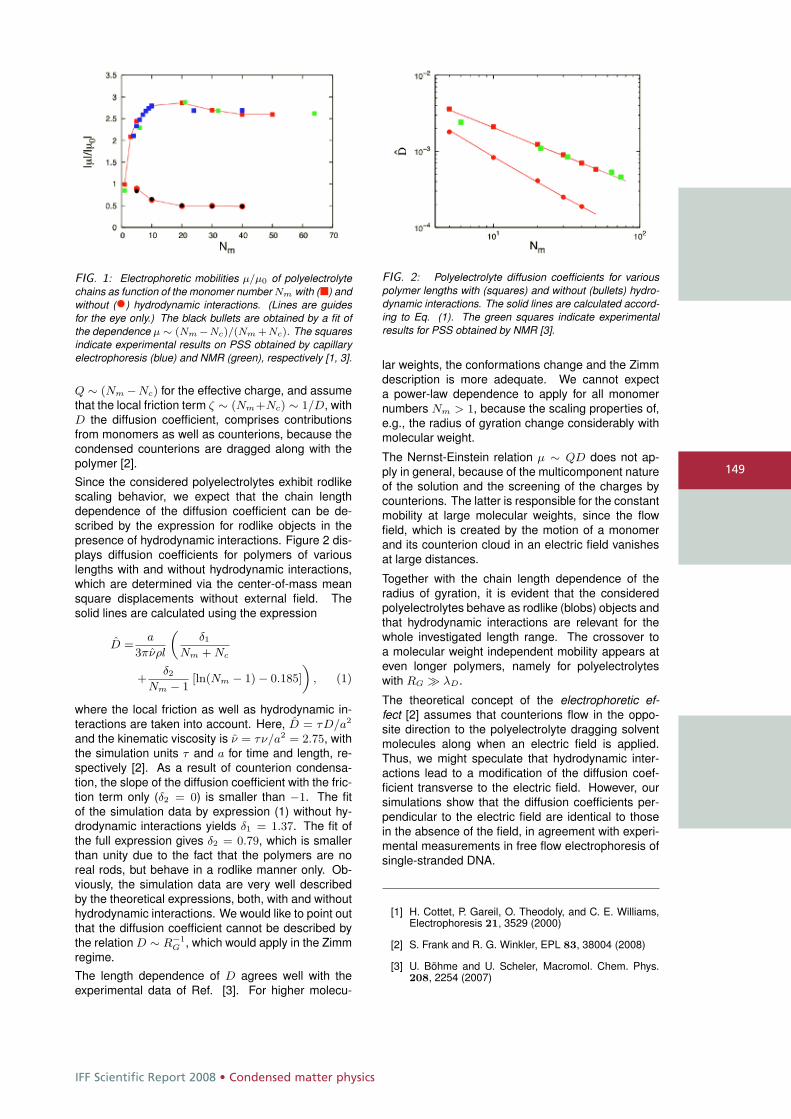
IFF Scientific Report 2008 • Condensed matter physics
149
FIG. 1: Electrophoretic mobilities μ/μ0 of polyelectrolytechains as function of the monomer number Nm with (�) andwithout (•) hydrodynamic interactions. (Lines are guidesfor the eye only.) The black bullets are obtained by a fit ofthe dependence μ ∼ (Nm −Nc)/(Nm +Nc). The squaresindicate experimental results on PSS obtained by capillaryelectrophoresis (blue) and NMR (green), respectively [1, 3].
Q ∼ (Nm −Nc) for the effective charge, and assumethat the local friction term ζ ∼ (Nm+Nc) ∼ 1/D, withD the diffusion coefficient, comprises contributionsfrom monomers as well as counterions, because thecondensed counterions are dragged along with thepolymer [2].
Since the considered polyelectrolytes exhibit rodlikescaling behavior, we expect that the chain lengthdependence of the diffusion coefficient can be de-scribed by the expression for rodlike objects in thepresence of hydrodynamic interactions. Figure 2 dis-plays diffusion coefficients for polymers of variouslengths with and without hydrodynamic interactions,which are determined via the center-of-mass meansquare displacements without external field. Thesolid lines are calculated using the expression
D =a
3πνρl
„δ1
Nm + Nc
+δ2
Nm − 1[ln(Nm − 1) − 0.185]
«, (1)
where the local friction as well as hydrodynamic in-teractions are taken into account. Here, D = τD/a2
and the kinematic viscosity is ν = τν/a2 = 2.75, withthe simulation units τ and a for time and length, re-spectively [2]. As a result of counterion condensa-tion, the slope of the diffusion coefficient with the fric-tion term only (δ2 = 0) is smaller than −1. The fitof the simulation data by expression (1) without hy-drodynamic interactions yields δ1 = 1.37. The fit ofthe full expression gives δ2 = 0.79, which is smallerthan unity due to the fact that the polymers are noreal rods, but behave in a rodlike manner only. Ob-viously, the simulation data are very well describedby the theoretical expressions, both, with and withouthydrodynamic interactions. We would like to point outthat the diffusion coefficient cannot be described bythe relation D ∼ R−1
G , which would apply in the Zimmregime.
The length dependence of D agrees well with theexperimental data of Ref. [3]. For higher molecu-
FIG. 2: Polyelectrolyte diffusion coefficients for variouspolymer lengths with (squares) and without (bullets) hydro-dynamic interactions. The solid lines are calculated accord-ing to Eq. (1). The green squares indicate experimentalresults for PSS obtained by NMR [3].
lar weights, the conformations change and the Zimmdescription is more adequate. We cannot expecta power-law dependence to apply for all monomernumbers Nm > 1, because the scaling properties of,e.g., the radius of gyration change considerably withmolecular weight.
The Nernst-Einstein relation μ ∼ QD does not ap-ply in general, because of the multicomponent natureof the solution and the screening of the charges bycounterions. The latter is responsible for the constantmobility at large molecular weights, since the flowfield, which is created by the motion of a monomerand its counterion cloud in an electric field vanishesat large distances.
Together with the chain length dependence of theradius of gyration, it is evident that the consideredpolyelectrolytes behave as rodlike (blobs) objects andthat hydrodynamic interactions are relevant for thewhole investigated length range. The crossover toa molecular weight independent mobility appears ateven longer polymers, namely for polyelectrolyteswith RG � λD.
The theoretical concept of the electrophoretic ef-fect [2] assumes that counterions flow in the oppo-site direction to the polyelectrolyte dragging solventmolecules along when an electric field is applied.Thus, we might speculate that hydrodynamic inter-actions lead to a modification of the diffusion coef-ficient transverse to the electric field. However, oursimulations show that the diffusion coefficients per-pendicular to the electric field are identical to thosein the absence of the field, in agreement with experi-mental measurements in free flow electrophoresis ofsingle-stranded DNA.
[1] H. Cottet, P. Gareil, O. Theodoly, and C. E. Williams,Electrophoresis 21, 3529 (2000)
[2] S. Frank and R. G. Winkler, EPL 83, 38004 (2008)
[3] U. Böhme and U. Scheler, Macromol. Chem. Phys.208, 2254 (2007)
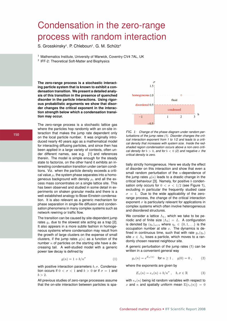
Condensed matter physics • IFF Scientific Report 2008
150
Condensation in the zero-rangeprocess with random interactionS. Grosskinsky1, P. Chleboun1, G. M. Schütz2
1 Mathematics Institute, University of Warwick, Coventry CV4 7AL, UK2 IFF-2: Theoretical Soft-Matter and Biophysics
The zero-range process is a stochastic interact-
ing particle system that is known to exhibit a con-
densation transition. We present a detailed analy-
sis of this transition in the presence of quenched
disorder in the particle interactions. Using rigor-
ous probabilistic arguments we show that disor-
der changes the critical exponent in the interac-
tion strength below which a condensation transi-
tion may occur.
The zero-range process is a stochastic lattice gaswhere the particles hop randomly with an on-site in-teraction that makes the jump rate dependent onlyon the local particle number. It was originally intro-duced nearly 40 years ago as a mathematical modelfor interacting diffusing particles, and since then hasbeen applied in a large variety of contexts, often un-der different names, see e.g. [1] and referencestherein. The model is simple enough for the steadystate to factorize, on the other hand it exhibits an in-teresting condensation transition under certain condi-tions. Viz. when the particle density exceeds a criti-cal value ρc the system phase separates into a homo-geneous background with density ρc and all the ex-cess mass concentrates on a single lattice site. Thishas been observed and studied in some detail in ex-periments on shaken granular media and there is awell-established analogy to Bose-Einstein condensa-tion. It is also relevant as a generic mechanism forphase separation in single-file diffusion and conden-sation phenomena in many complex systems such asnetwork rewiring or traffic flow.
The transition can be caused by site-dependent jumprates gx due to the slowest site acting as a trap [2].It also appears in a more subtle fashion in homoge-neous systems where condensation may result fromthe growth of large clusters on the expense of smallclusters, if the jump rates g(n) as a function of thenumber n of particles on the starting site have a de-creasing tail. A well-studied model with a genericpower law decay is defined by
g(n) = 1 + b/nσ (1)
with positive interaction parameters b, σ. Condensa-tion occurs if 0 < σ < 1 and b > 0 or if σ = 1 andb > 2.
All previous studies of zero-range processes assumethat the on-site interaction between particles is spa-
FIG. 1: Change of the phase diagram under random per-turbations of the jump rates (1). Disorder changes the crit-ical interaction exponent from 1 to 1/2 and leads to a criti-cal density that increases with system size. Inside the red-shaded region condensation occurs above a non-zero criti-cal density for b > 0, and for b < 0 (2) and negative σ thecritical density is zero.
tially strictly homogeneous. Here we study the effectof disorder on this interaction and show that even asmall random perturbation of the n-dependence ofthe jump rates g(n) leads to a drastic change in thecritical behaviour [3]. Namely, for positive b conden-sation only occurs for 0 < σ < 1/2 (see Figure 1),excluding in particular the frequently studied caseσ = 1. Due to the wide applicability of the zero-range process, the change of the critical interactionexponent σ is particularly relevant for applications incomplex systems which often involve heterogeneousand disordered structures.
We consider a lattice ΛL, which we take to be pe-riodic and of finite size |ΛL| = L. A configurationis denoted by (ηx)x∈Λ where ηx ∈ {0, 1, . . .} is theoccupation number at site x. The dynamics is de-fined in continuous time, such that with rate gx(ηx)site x ∈ ΛL loses a particle, which moves to a ran-domly chosen nearest neighbour site.
A generic perturbation of the jump rates (1) can bewritten in a convenient general way
gx(n) = eEx(n) for n ≥ 1 , g(0) = 0 , (2)
where the exponents are given by
Ex(n) = ex(n) + b/nσ , b, σ ∈ R (3)
with ex(n) being iid random variables with respect tox and n and spatially uniform mean E
`ex(n)
´= 0
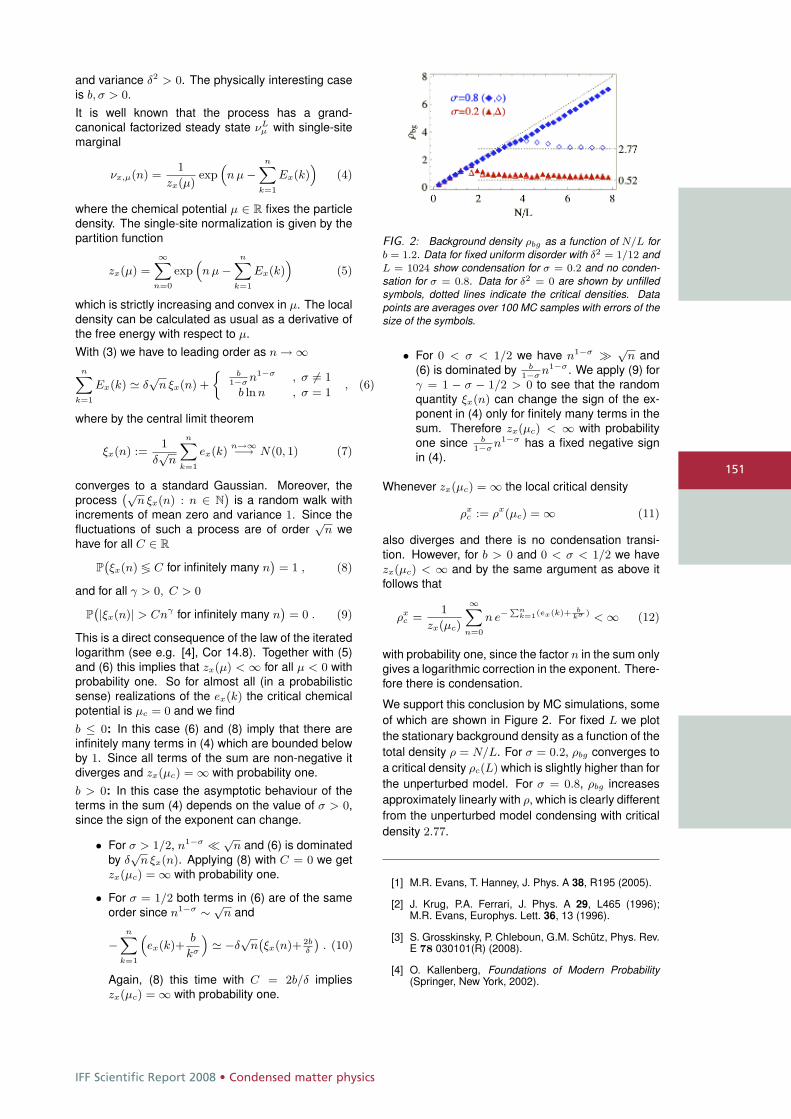
IFF Scientific Report 2008 • Condensed matter physics
151
and variance δ2 > 0. The physically interesting caseis b, σ > 0.It is well known that the process has a grand-canonical factorized steady state νL
μ with single-sitemarginal
νx,μ(n) =1
zx(μ)exp
“n μ −
nXk=1
Ex(k)”
(4)
where the chemical potential μ ∈ R fixes the particledensity. The single-site normalization is given by thepartition function
zx(μ) =
∞Xn=0
exp“n μ −
nXk=1
Ex(k)”
(5)
which is strictly increasing and convex in μ. The localdensity can be calculated as usual as a derivative ofthe free energy with respect to μ.With (3) we have to leading order as n → ∞
nXk=1
Ex(k) � δ√
n ξx(n) +
jb
1−σn1−σ , σ �= 1
b ln n , σ = 1, (6)
where by the central limit theorem
ξx(n) :=1
δ√
n
nXk=1
ex(k)n→∞−→ N(0, 1) (7)
converges to a standard Gaussian. Moreover, theprocess
`√n ξx(n) : n ∈ N
´is a random walk with
increments of mean zero and variance 1. Since thefluctuations of such a process are of order
√n we
have for all C ∈ R
P`ξx(n) ≶ C for infinitely many n
´= 1 , (8)
and for all γ > 0, C > 0
P`|ξx(n)| > Cnγ for infinitely many n
´= 0 . (9)
This is a direct consequence of the law of the iteratedlogarithm (see e.g. [4], Cor 14.8). Together with (5)and (6) this implies that zx(μ) < ∞ for all μ < 0 withprobability one. So for almost all (in a probabilisticsense) realizations of the ex(k) the critical chemicalpotential is μc = 0 and we findb ≤ 0: In this case (6) and (8) imply that there areinfinitely many terms in (4) which are bounded belowby 1. Since all terms of the sum are non-negative itdiverges and zx(μc) = ∞ with probability one.b > 0: In this case the asymptotic behaviour of theterms in the sum (4) depends on the value of σ > 0,since the sign of the exponent can change.
• For σ > 1/2, n1−σ √n and (6) is dominated
by δ√
n ξx(n). Applying (8) with C = 0 we getzx(μc) = ∞ with probability one.
• For σ = 1/2 both terms in (6) are of the sameorder since n1−σ ∼ √
n and
−nX
k=1
“ex(k)+
b
kσ
”� −δ
√n
`ξx(n)+ 2b
δ
´. (10)
Again, (8) this time with C = 2b/δ implieszx(μc) = ∞ with probability one.
FIG. 2: Background density ρbg as a function of N/L forb = 1.2. Data for fixed uniform disorder with δ2 = 1/12 andL = 1024 show condensation for σ = 0.2 and no conden-sation for σ = 0.8. Data for δ2 = 0 are shown by unfilledsymbols, dotted lines indicate the critical densities. Datapoints are averages over 100 MC samples with errors of thesize of the symbols.
• For 0 < σ < 1/2 we have n1−σ � √n and
(6) is dominated by b1−σ
n1−σ. We apply (9) forγ = 1 − σ − 1/2 > 0 to see that the randomquantity ξx(n) can change the sign of the ex-ponent in (4) only for finitely many terms in thesum. Therefore zx(μc) < ∞ with probabilityone since b
1−σn1−σ has a fixed negative sign
in (4).
Whenever zx(μc) = ∞ the local critical density
ρxc := ρx(μc) = ∞ (11)
also diverges and there is no condensation transi-tion. However, for b > 0 and 0 < σ < 1/2 we havezx(μc) < ∞ and by the same argument as above itfollows that
ρxc =
1
zx(μc)
∞Xn=0
n e−Pn
k=1(ex(k)+ bkσ ) < ∞ (12)
with probability one, since the factor n in the sum onlygives a logarithmic correction in the exponent. There-fore there is condensation.
We support this conclusion by MC simulations, someof which are shown in Figure 2. For fixed L we plotthe stationary background density as a function of thetotal density ρ = N/L. For σ = 0.2, ρbg converges toa critical density ρc(L) which is slightly higher than forthe unperturbed model. For σ = 0.8, ρbg increasesapproximately linearly with ρ, which is clearly differentfrom the unperturbed model condensing with criticaldensity 2.77.
[1] M.R. Evans, T. Hanney, J. Phys. A 38, R195 (2005).
[2] J. Krug, P.A. Ferrari, J. Phys. A 29, L465 (1996);M.R. Evans, Europhys. Lett. 36, 13 (1996).
[3] S. Grosskinsky, P. Chleboun, G.M. Schütz, Phys. Rev.E 78 030101(R) (2008).
[4] O. Kallenberg, Foundations of Modern Probability(Springer, New York, 2002).
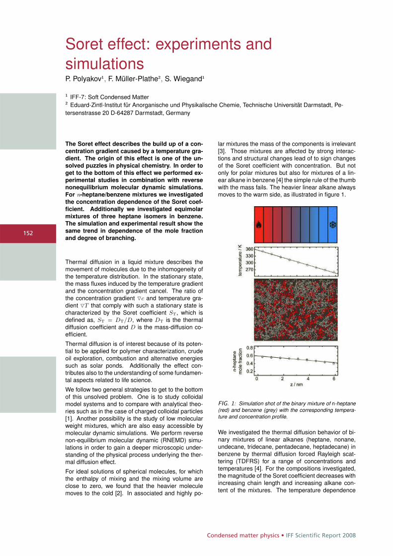
Condensed matter physics • IFF Scientific Report 2008
152
Soret effect: experiments andsimulationsP. Polyakov1, F. Müller-Plathe2, S. Wiegand1
1 IFF-7: Soft Condensed Matter2 Eduard-Zintl-Institut für Anorganische und Physikalische Chemie, Technische Universität Darmstadt, Pe-tersenstrasse 20 D-64287 Darmstadt, Germany
The Soret effect describes the build up of a con-
centration gradient caused by a temperature gra-
dient. The origin of this effect is one of the un-
solved puzzles in physical chemistry. In order to
get to the bottom of this effect we performed ex-
perimental studies in combination with reverse
nonequilibrium molecular dynamic simulations.
For n-heptane/benzene mixtures we investigated
the concentration dependence of the Soret coef-
ficient. Additionally we investigated equimolar
mixtures of three heptane isomers in benzene.
The simulation and experimental result show the
same trend in dependence of the mole fraction
and degree of branching.
Thermal diffusion in a liquid mixture describes themovement of molecules due to the inhomogeneity ofthe temperature distribution. In the stationary state,the mass fluxes induced by the temperature gradientand the concentration gradient cancel. The ratio ofthe concentration gradient �c and temperature gra-dient �T that comply with such a stationary state ischaracterized by the Soret coefficient ST, which isdefined as, ST = DT/D, where DT is the thermaldiffusion coefficient and D is the mass-diffusion co-efficient.
Thermal diffusion is of interest because of its poten-tial to be applied for polymer characterization, crudeoil exploration, combustion and alternative energiessuch as solar ponds. Additionally the effect con-tributes also to the understanding of some fundamen-tal aspects related to life science.
We follow two general strategies to get to the bottomof this unsolved problem. One is to study colloidalmodel systems and to compare with analytical theo-ries such as in the case of charged colloidal particles[1]. Another possibility is the study of low molecularweight mixtures, which are also easy accessible bymolecular dynamic simulations. We perform reversenon-equilibrium molecular dynamic (RNEMD) simu-lations in order to gain a deeper microscopic under-standing of the physical process underlying the ther-mal diffusion effect.
For ideal solutions of spherical molecules, for whichthe enthalpy of mixing and the mixing volume areclose to zero, we found that the heavier moleculemoves to the cold [2]. In associated and highly po-
lar mixtures the mass of the components is irrelevant[3]. Those mixtures are affected by strong interac-tions and structural changes lead of to sign changesof the Soret coefficient with concentration. But notonly for polar mixtures but also for mixtures of a lin-ear alkane in benzene [4] the simple rule of the thumbwith the mass fails. The heavier linear alkane alwaysmoves to the warm side, as illustrated in figure 1.
FIG. 1: Simulation shot of the binary mixture of n-heptane(red) and benzene (grey) with the corresponding tempera-ture and concentration profile.
We investigated the thermal diffusion behavior of bi-nary mixtures of linear alkanes (heptane, nonane,undecane, tridecane, pentadecane, heptadecane) inbenzene by thermal diffusion forced Rayleigh scat-tering (TDFRS) for a range of concentrations andtemperatures [4]. For the compositions investigated,the magnitude of the Soret coefficient decreases withincreasing chain length and increasing alkane con-tent of the mixtures. The temperature dependence
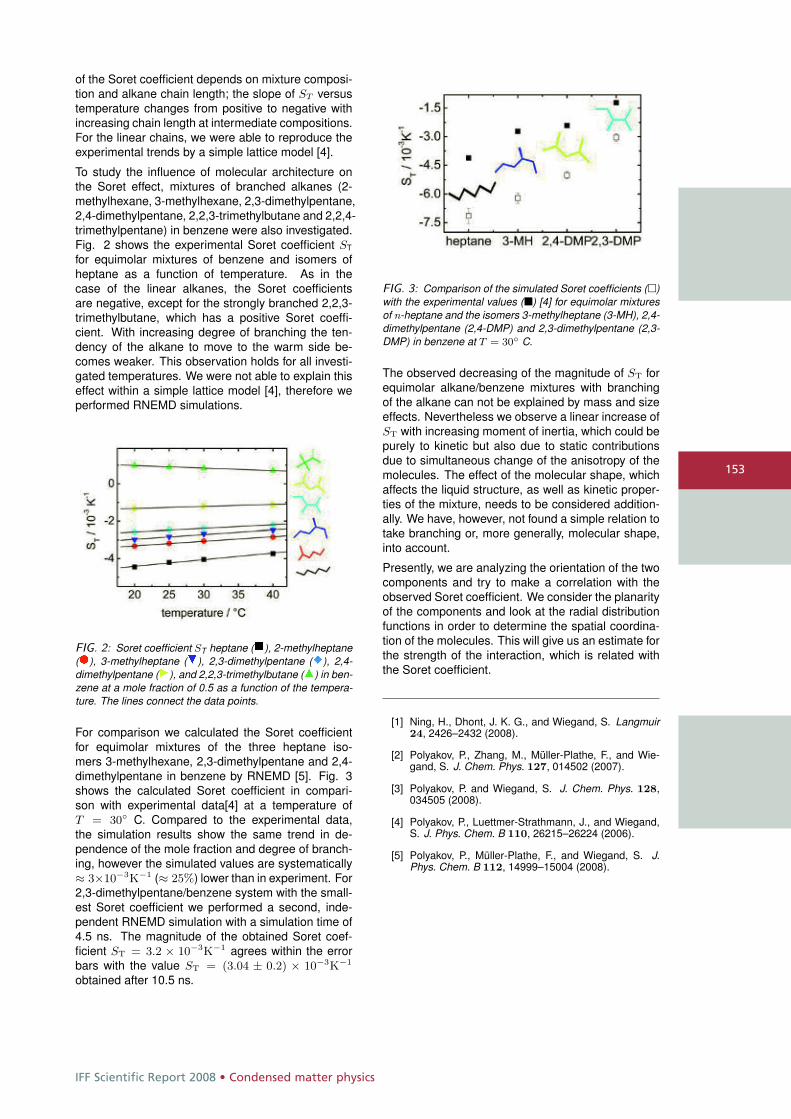
IFF Scientific Report 2008 • Condensed matter physics
153
of the Soret coefficient depends on mixture composi-tion and alkane chain length; the slope of ST versustemperature changes from positive to negative withincreasing chain length at intermediate compositions.For the linear chains, we were able to reproduce theexperimental trends by a simple lattice model [4].
To study the influence of molecular architecture onthe Soret effect, mixtures of branched alkanes (2-methylhexane, 3-methylhexane, 2,3-dimethylpentane,2,4-dimethylpentane, 2,2,3-trimethylbutane and 2,2,4-trimethylpentane) in benzene were also investigated.Fig. 2 shows the experimental Soret coefficient ST
for equimolar mixtures of benzene and isomers ofheptane as a function of temperature. As in thecase of the linear alkanes, the Soret coefficientsare negative, except for the strongly branched 2,2,3-trimethylbutane, which has a positive Soret coeffi-cient. With increasing degree of branching the ten-dency of the alkane to move to the warm side be-comes weaker. This observation holds for all investi-gated temperatures. We were not able to explain thiseffect within a simple lattice model [4], therefore weperformed RNEMD simulations.
FIG. 2: Soret coefficient ST heptane (�), 2-methylheptane(�), 3-methylheptane (�), 2,3-dimethylpentane (�), 2,4-dimethylpentane (�), and 2,2,3-trimethylbutane (�) in ben-zene at a mole fraction of 0.5 as a function of the tempera-ture. The lines connect the data points.
For comparison we calculated the Soret coefficientfor equimolar mixtures of the three heptane iso-mers 3-methylhexane, 2,3-dimethylpentane and 2,4-dimethylpentane in benzene by RNEMD [5]. Fig. 3shows the calculated Soret coefficient in compari-son with experimental data[4] at a temperature ofT = 30◦ C. Compared to the experimental data,the simulation results show the same trend in de-pendence of the mole fraction and degree of branch-ing, however the simulated values are systematically≈ 3×10⁻³K−1 (≈ 25%) lower than in experiment. For2,3-dimethylpentane/benzene system with the small-est Soret coefficient we performed a second, inde-pendent RNEMD simulation with a simulation time of4.5 ns. The magnitude of the obtained Soret coef-ficient ST = 3.2 × 10⁻³K−1 agrees within the errorbars with the value ST = (3.04 ± 0.2) × 10−3K−1
obtained after 10.5 ns.
FIG. 3: Comparison of the simulated Soret coefficients (�)with the experimental values (�) [4] for equimolar mixturesof n-heptane and the isomers 3-methylheptane (3-MH), 2,4-dimethylpentane (2,4-DMP) and 2,3-dimethylpentane (2,3-DMP) in benzene at T = 30◦ C.
The observed decreasing of the magnitude of ST forequimolar alkane/benzene mixtures with branchingof the alkane can not be explained by mass and sizeeffects. Nevertheless we observe a linear increase ofST with increasing moment of inertia, which could bepurely to kinetic but also due to static contributionsdue to simultaneous change of the anisotropy of themolecules. The effect of the molecular shape, whichaffects the liquid structure, as well as kinetic proper-ties of the mixture, needs to be considered addition-ally. We have, however, not found a simple relation totake branching or, more generally, molecular shape,into account.
Presently, we are analyzing the orientation of the twocomponents and try to make a correlation with theobserved Soret coefficient. We consider the planarityof the components and look at the radial distributionfunctions in order to determine the spatial coordina-tion of the molecules. This will give us an estimate forthe strength of the interaction, which is related withthe Soret coefficient.
[1] Ning, H., Dhont, J. K. G., and Wiegand, S. Langmuir24, 2426–2432 (2008).
[2] Polyakov, P., Zhang, M., Müller-Plathe, F., and Wie-gand, S. J. Chem. Phys. 127, 014502 (2007).
[3] Polyakov, P. and Wiegand, S. J. Chem. Phys. 128,034505 (2008).
[4] Polyakov, P., Luettmer-Strathmann, J., and Wiegand,S. J. Phys. Chem. B 110, 26215–26224 (2006).
[5] Polyakov, P., Müller-Plathe, F., and Wiegand, S. J.Phys. Chem. B 112, 14999–15004 (2008).
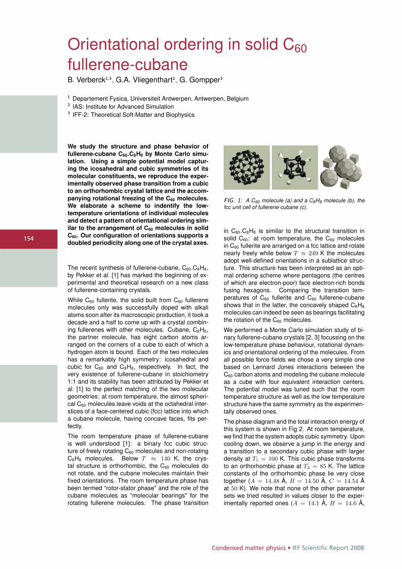
Condensed matter physics • IFF Scientific Report 2008
154
Orientational ordering in solid C60
fullerene-cubaneB. Verberck1,3, G.A. Vliegenthart2, G. Gompper3
1 Departement Fysica, Universiteit Antwerpen, Antwerpen, Belgium2 IAS: Institute for Advanced Simulation3 IFF-2: Theoretical Soft-Matter and Biophysics
We study the structure and phase behavior offullerene-cubane C60.C8H8 by Monte Carlo simu-lation. Using a simple potential model captur-ing the icosahedral and cubic symmetries of itsmolecular constituents, we reproduce the exper-imentally observed phase transition from a cubicto an orthorhombic crystal lattice and the accom-panying rotational freezing of the C60 molecules.We elaborate a scheme to indentify the low-temperature orientations of individual moleculesand detect a pattern of orientational ordering sim-ilar to the arrangement of C60 molecules in solidC60. Our configuration of orientations supports adoubled periodicity along one of the crystal axes.
The recent synthesis of fullerene-cubane, C60.C8H8,by Pekker et al. [1] has marked the beginning of ex-perimental and theoretical research on a new classof fullerene-containing crystals.
While C60 fullerite, the solid built from C60 fullerenemolecules only was successfully doped with alkaliatoms soon after its macroscopic production, it took adecade and a half to come up with a crystal combin-ing fullerenes with other molecules. Cubane, C8H8,the partner molecule, has eight carbon atoms ar-ranged on the corners of a cube to each of which ahydrogen atom is bound. Each of the two moleculeshas a remarkably high symmetry: icosahedral andcubic for C60 and C8H8, respectively. In fact, thevery existence of fullerene-cubane in stoichiometry1:1 and its stability has been attributed by Pekker etal. [1] to the perfect matching of the two moleculargeometries: at room temperature, the almost spheri-cal C60 molecules leave voids at the octahedral inter-stices of a face-centered cubic (fcc) lattice into whicha cubane molecule, having concave faces, fits per-fectly.
The room temperature phase of fullerene-cubaneis well understood [1]: a binary fcc cubic struc-ture of freely rotating C60 molecules and non-rotatingC8H8 molecules. Below T ≈ 140 K, the crys-tal structure is orthorhombic, the C60 molecules donot rotate, and the cubane molecules maintain theirfixed orientations. The room temperature phase hasbeen termed “rotor-stator phase" and the role of thecubane molecules as “molecular bearings" for therotating fullerene molecules. The phase transition
FIG. 1: A C60 molecule (a) and a C8H8 molecule (b), thefcc unit cell of fullerene-cubane (c).
in C60.C8H8 is similar to the structural transition insolid C60: at room temperature, the C60 moleculesin C60 fullerite are arranged on a fcc lattice and rotatenearly freely while below T ≈ 249 K the moleculesadopt well-defined orientations in a sublattice struc-ture. This structure has been interpreted as an opti-mal ordering scheme where pentagons (the centresof which are electron-poor) face electron-rich bondsfusing hexagons. Comparing the transition tem-peratures of C60 fullerite and C60 fullerene-cubaneshows that in the latter, the concavely shaped C8H8
molecules can indeed be seen as bearings facilitatingthe rotation of the C60 molecules.
We performed a Monte Carlo simulation study of bi-nary fullerene-cubane crystals [2, 3] focussing on thelow-temperature phase behaviour, rotational dynam-ics and orientational ordering of the molecules. Fromall possible force fields we chose a very simple onebased on Lennard Jones interactions between theC60 carbon atoms and modeling the cubane moleculeas a cube with four equivalent interaction centers.The potential model was tuned such that the roomtemperature structure as well as the low temperaturestructure have the same symmetry as the experimen-tally observed ones.
The phase diagram and the total interaction energy ofthis system is shown in Fig 2. At room temperature,we find that the system adopts cubic symmetry. Uponcooling down, we observe a jump in the energy anda transition to a secondary cubic phase with largerdensity at T1 = 100 K. This cubic phase transformsto an orthorhombic phase at T2 = 85 K. The latticeconstants of the orthorhombic phase lie very closetogether (A = 14.48 Å, B = 14.50 Å, C = 14.54 Åat 50 K). We note that none of the other parametersets we tried resulted in values closer to the exper-imentally reported ones (A = 14.1 Å, B = 14.6 Å,
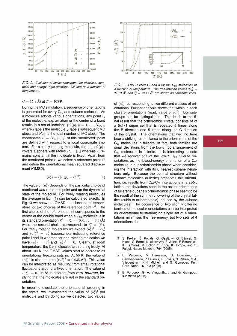
IFF Scientific Report 2008 • Condensed matter physics
155
FIG. 2: Evolution of lattice constants (left abscissa, sym-bols) and energy (right abscissa, full line) as a function oftemperature.
C = 15.3 Å) at T = 105 K.
During the MC simulation, a sequence of orientationsis generated for every C60 and cubane molecule. Asa molecule adopts various orientations, any point �ri
of the molecule, e.g. an atom or the center of a bondresults in a set of locations {�ri(p), p = 1, . . . , NMC},where i labels the molecule, p labels subsequent MCsteps and NMC is the total number of MC steps. Thecoordinates �ri = (xi, yi, zi) of this “monitored" pointare defined with respect to a local coordinate sys-tem. For a freely rotating molecule, the set {�ri(p)}covers a sphere with radius Ri = |�ri| whereas �ri re-mains constant if the molecule is fixed. Apart fromthe monitored point �ri we select a reference point �r0
i
and define the orientational mean squared displace-ment (OMSD),
〈u2i 〉 =
˙|�ri(p) − �r0i |2
¸(1)
The value of 〈u2i 〉 depends on the particular choice of
monitored and reference point and on the dynamicalstate of the molecule. For freely rotating moleculesthe average in Eq. (1) can be calculated exactly. InFig. 3 we show the OMSD as a function of temper-ature for two choices of the reference point �r0
i . Thefirst choice of the reference point corresponds to thecenter of the double bond when a C60 molecule is inits standard orientation �r0
i = �ra = (0, 0, za = 3.48Å)while the second choice corresponds to �r0
i = 〈�ri〉.For freely rotating molecules we expect 〈u2
i 〉I = 2z2a
and 〈u2i 〉II = z2
a (superscripts indicating referencepoint I and II) whereas for non-rotating molecules wehave 〈u2
i 〉I = u2i and 〈u2
i 〉II = 0. Clearly, at roomtemperature, the C60 molecules are rotating freely. Atabout 100 K, the OMSD values start to decrease asorientational freezing sets in. At 50 K, the value of〈u2
i 〉II is close to zero (〈u2i 〉II = 0.035 Å2). This value
can be interpreted as resulting from small rotationalfluctuations around a fixed orientation. The value of〈u2
i 〉I = 0.706 Å2 is different from zero, however, im-plying that the molecules are not in the standard ori-entation.
In order to elucidate the orientational ordering inthe crystal we investigated the value of 〈u2
i 〉I permolecule and by doing so we detected two values
FIG. 3: OMSD values I and II for the C60 molecules asa function of temperature. The free-rotation values 2z2
a =24.22 Å2 and z2
a = 12.11 Å2 are shown as horizontal lines.
of 〈u2i 〉I corresponding to two different classes of ori-
entations. Further analysis shows that within in eachclass of orientations (read: value of 〈u2
i 〉I) four sub-groups can be distinguished. This leads to the fi-nal result that the orthorombic crystal consists of ofa 5x1x1 super cel that is repeated 5 times alongthe B direction and 5 times along the C directionof the crystal. The orientations that we find herebear a striking resemblance to the orientations of theC60 molecules in fullerite, in fact, both families aresmall deviations from the low-T fcc arrangement ofC60 molecules in fullerite. It is interesting to notethat we recover one of the low-T C60 fullerite ori-entations as the lowest-energy orientation of a C60
molecule in our orthorhombic phase when consider-ing the interaction with its 6 nearest cubane neigh-bors only. Because the optimal structure withoutcubane molecules (fullerite) preserves this orienta-tion, i.e. results from C60-C60 interactions in a cubiclattice, the deviations seen in the actual orientationsof fullerene-cubane’s orthorhombic phase seem to bethe result of the symmetry lowering of the crystal lat-tice (cubic-to-orthorhombic) induced by the cubanemolecules. The occurrence of two slightly differingfamilies of molecular orientations can be interpretedas orientational frustration; no single set of 4 orien-tations minimises the free energy, but two sets of 4orientations do.
[1] S. Pekker, É. Kováts, G. Oszlányi, G. Bényei, G.Klupp, G. Bortel, I. Jalsovszky, E. Jakab, F. Borondics,K. Kamarás, M. Bokor, G. Kriza, K. Tompa, and G.Faigel, Nature Mater. 4, 764 (2005).
[2] B. Verberck, V. Heresanu, S. Rouzière, J.Cambedouzou, P. Launois, É. Kováts, S. Pekker, G.A.Vliegenthart, K.H. Michel, and G. Gompper, Full.Carb. Nano. 16, 293 (2008).
[3] B. Verberck, G. A. Vliegenthart, and G. Gompper,submitted (2008).
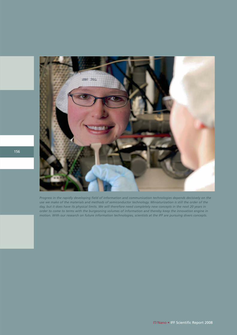
IT/Nano • IFF Scientific Report 2008
156
Progress in the rapidly developing field of information and communication technologies depends decisively on theuse we make of the materials and methods of semiconductor technology. Miniaturization is still the order of theday, but it does have its physical limits. We will therefore need completely new concepts in the next 20 years inorder to come to terms with the burgeoning volumes of information and thereby keep the innovation engine inmotion. With our research on future information technologies, scientists at the IFF are pursuing divers concepts.

IFF Scientific Report 2008 • IT/Nano
HGF research programme
Information technology with nanoelectronic systems
This research programme focuses onmedium-term and long-term tasks innanoelectronics, on emerging far-reach-ing concepts, and on issues of physicsand technology well ahead of the main-stream development. On the eve of the transition from microelectronics tonanoelectronics, the traditional routesof down-scaling along the roadmap will no longer guarantee a long-termsuccess. Exploratory research in the fieldof information technology is entering a new era and is unfolding into newdegrees of freedom. This applies to allthree major fields, information process-ing, information storage, and informa-tion transmission. The major routes ofexploratory research in nanoelectronicsystems to be followed are:
• scalability of device concepts,
• exploration of new material classes and phenomena,
• new concepts beyond conventional CMOS technology, and
• alternative architectures.
Our research towards these generalgoals utilizes three approaches, irre-spective of the specific programme topics. One approach is dedicated tonew electronic materials such as ferro-magnetic and ferroelectric layer struc-tures, group III nitrides, and electroni-cally active organic molecules. Thesematerial classes are studied because of their potential for introducingimproved or completely new functionsonto Si chips and new emerging sub-strates. Another approach is devoted to process technologies for minimumfeature sizes well below 100 nm. Apartfrom using conventional top-down
approaches, which are limited to litho-graphically defined resolutions, we areinvestigating cost-effective bottom-upapproaches, which aim at the genera-tion and assembly of functions fromself-organized inorganic nanostructuresas well as tailored organic molecules atsurfaces. Yet another approach exploresnovel electronic functions as the basisfor new device concepts. These may aimat, for instance, bioelectronic applica-tions, ultra-dense and non-volatile resis-tive memories, spin-controlled devices,Terahertz imaging systems, and self-organized semiconductor nanostruc-tures.
157
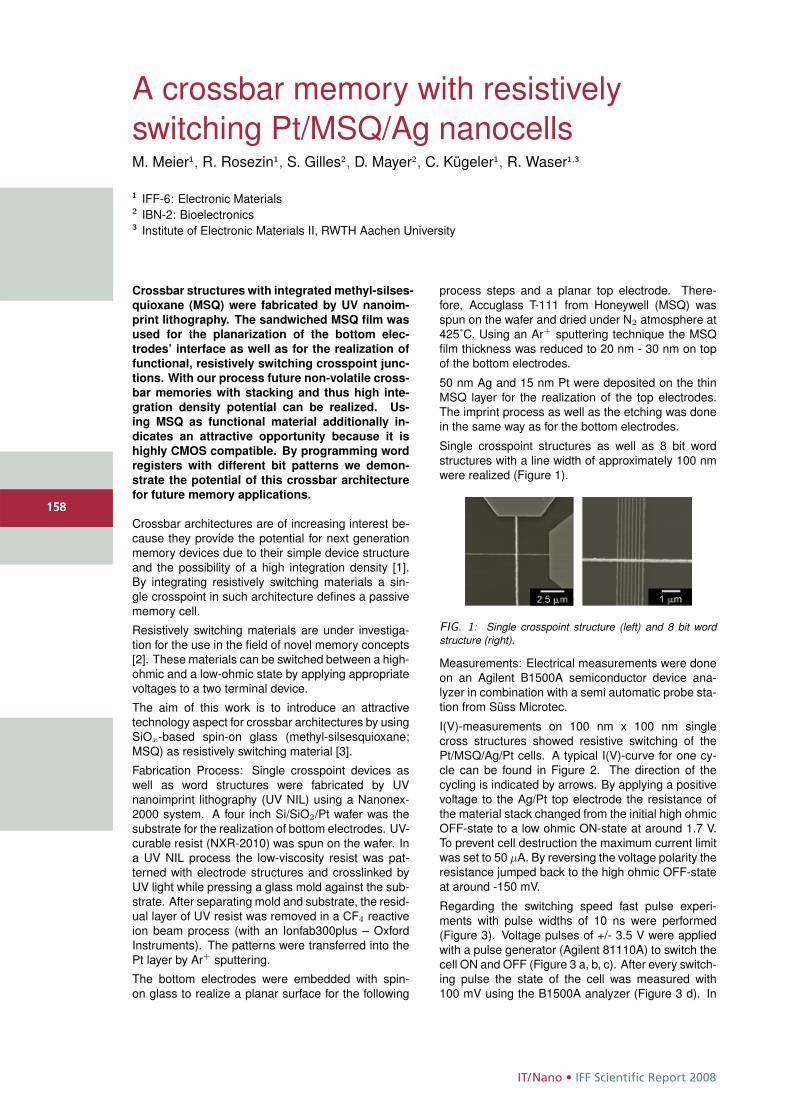
IT/Nano • IFF Scientific Report 2008
158
A crossbar memory with resistivelyswitching Pt/MSQ/Ag nanocellsM. Meier1, R. Rosezin1, S. Gilles2, D. Mayer2, C. Kügeler1, R. Waser1,3
1 IFF-6: Electronic Materials2 IBN-2: Bioelectronics3 Institute of Electronic Materials II, RWTH Aachen University
Crossbar structures with integrated methyl-silses-
quioxane (MSQ) were fabricated by UV nanoim-
print lithography. The sandwiched MSQ film was
used for the planarization of the bottom elec-
trodes’ interface as well as for the realization of
functional, resistively switching crosspoint junc-
tions. With our process future non-volatile cross-
bar memories with stacking and thus high inte-
gration density potential can be realized. Us-
ing MSQ as functional material additionally in-
dicates an attractive opportunity because it is
highly CMOS compatible. By programming word
registers with different bit patterns we demon-
strate the potential of this crossbar architecture
for future memory applications.
Crossbar architectures are of increasing interest be-cause they provide the potential for next generationmemory devices due to their simple device structureand the possibility of a high integration density [1].By integrating resistively switching materials a sin-gle crosspoint in such architecture defines a passivememory cell.
Resistively switching materials are under investiga-tion for the use in the field of novel memory concepts[2]. These materials can be switched between a high-ohmic and a low-ohmic state by applying appropriatevoltages to a two terminal device.
The aim of this work is to introduce an attractivetechnology aspect for crossbar architectures by usingSiOx-based spin-on glass (methyl-silsesquioxane;MSQ) as resistively switching material [3].
Fabrication Process: Single crosspoint devices aswell as word structures were fabricated by UVnanoimprint lithography (UV NIL) using a Nanonex-2000 system. A four inch Si/SiO2/Pt wafer was thesubstrate for the realization of bottom electrodes. UV-curable resist (NXR-2010) was spun on the wafer. Ina UV NIL process the low-viscosity resist was pat-terned with electrode structures and crosslinked byUV light while pressing a glass mold against the sub-strate. After separating mold and substrate, the resid-ual layer of UV resist was removed in a CF4 reactiveion beam process (with an Ionfab300plus – OxfordInstruments). The patterns were transferred into thePt layer by Ar+ sputtering.
The bottom electrodes were embedded with spin-on glass to realize a planar surface for the following
process steps and a planar top electrode. There-fore, Accuglass T-111 from Honeywell (MSQ) wasspun on the wafer and dried under N2 atmosphere at425˚C. Using an Ar+ sputtering technique the MSQfilm thickness was reduced to 20 nm - 30 nm on topof the bottom electrodes.
50 nm Ag and 15 nm Pt were deposited on the thinMSQ layer for the realization of the top electrodes.The imprint process as well as the etching was donein the same way as for the bottom electrodes.
Single crosspoint structures as well as 8 bit wordstructures with a line width of approximately 100 nmwere realized (Figure 1).
FIG. 1: Single crosspoint structure (left) and 8 bit wordstructure (right).
Measurements: Electrical measurements were doneon an Agilent B1500A semiconductor device ana-lyzer in combination with a semi automatic probe sta-tion from Süss Microtec.
I(V)-measurements on 100 nm x 100 nm singlecross structures showed resistive switching of thePt/MSQ/Ag/Pt cells. A typical I(V)-curve for one cy-cle can be found in Figure 2. The direction of thecycling is indicated by arrows. By applying a positivevoltage to the Ag/Pt top electrode the resistance ofthe material stack changed from the initial high ohmicOFF-state to a low ohmic ON-state at around 1.7 V.To prevent cell destruction the maximum current limitwas set to 50 μA. By reversing the voltage polarity theresistance jumped back to the high ohmic OFF-stateat around -150 mV.
Regarding the switching speed fast pulse experi-ments with pulse widths of 10 ns were performed(Figure 3). Voltage pulses of +/- 3.5 V were appliedwith a pulse generator (Agilent 81110A) to switch thecell ON and OFF (Figure 3 a, b, c). After every switch-ing pulse the state of the cell was measured with100 mV using the B1500A analyzer (Figure 3 d). In
158
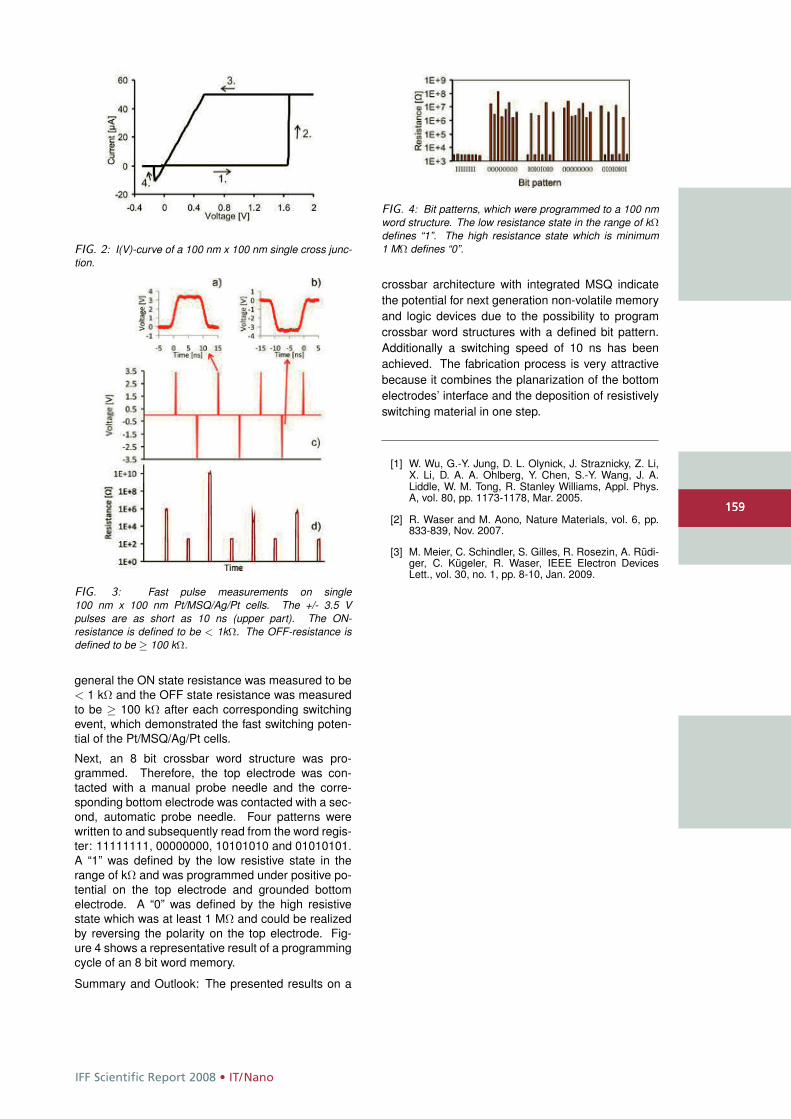
IFF Scientific Report 2008 • IT/Nano
159
FIG. 2: I(V)-curve of a 100 nm x 100 nm single cross junc-tion.
FIG. 3: Fast pulse measurements on single100 nm x 100 nm Pt/MSQ/Ag/Pt cells. The +/- 3.5 Vpulses are as short as 10 ns (upper part). The ON-resistance is defined to be < 1kΩ. The OFF-resistance isdefined to be ≥ 100 kΩ.
general the ON state resistance was measured to be< 1 kΩ and the OFF state resistance was measuredto be ≥ 100 kΩ after each corresponding switchingevent, which demonstrated the fast switching poten-tial of the Pt/MSQ/Ag/Pt cells.
Next, an 8 bit crossbar word structure was pro-grammed. Therefore, the top electrode was con-tacted with a manual probe needle and the corre-sponding bottom electrode was contacted with a sec-ond, automatic probe needle. Four patterns werewritten to and subsequently read from the word regis-ter: 11111111, 00000000, 10101010 and 01010101.A “1” was defined by the low resistive state in therange of kΩ and was programmed under positive po-tential on the top electrode and grounded bottomelectrode. A “0” was defined by the high resistivestate which was at least 1 MΩ and could be realizedby reversing the polarity on the top electrode. Fig-ure 4 shows a representative result of a programmingcycle of an 8 bit word memory.
Summary and Outlook: The presented results on a
FIG. 4: Bit patterns, which were programmed to a 100 nmword structure. The low resistance state in the range of kΩdefines “1”. The high resistance state which is minimum1 MΩ defines “0”.
crossbar architecture with integrated MSQ indicatethe potential for next generation non-volatile memoryand logic devices due to the possibility to programcrossbar word structures with a defined bit pattern.Additionally a switching speed of 10 ns has beenachieved. The fabrication process is very attractivebecause it combines the planarization of the bottomelectrodes’ interface and the deposition of resistivelyswitching material in one step.
[1] W. Wu, G.-Y. Jung, D. L. Olynick, J. Straznicky, Z. Li,X. Li, D. A. A. Ohlberg, Y. Chen, S.-Y. Wang, J. A.Liddle, W. M. Tong, R. Stanley Williams, Appl. Phys.A, vol. 80, pp. 1173-1178, Mar. 2005.
[2] R. Waser and M. Aono, Nature Materials, vol. 6, pp.833-839, Nov. 2007.
[3] M. Meier, C. Schindler, S. Gilles, R. Rosezin, A. Rüdi-ger, C. Kügeler, R. Waser, IEEE Electron DevicesLett., vol. 30, no. 1, pp. 8-10, Jan. 2009.
159
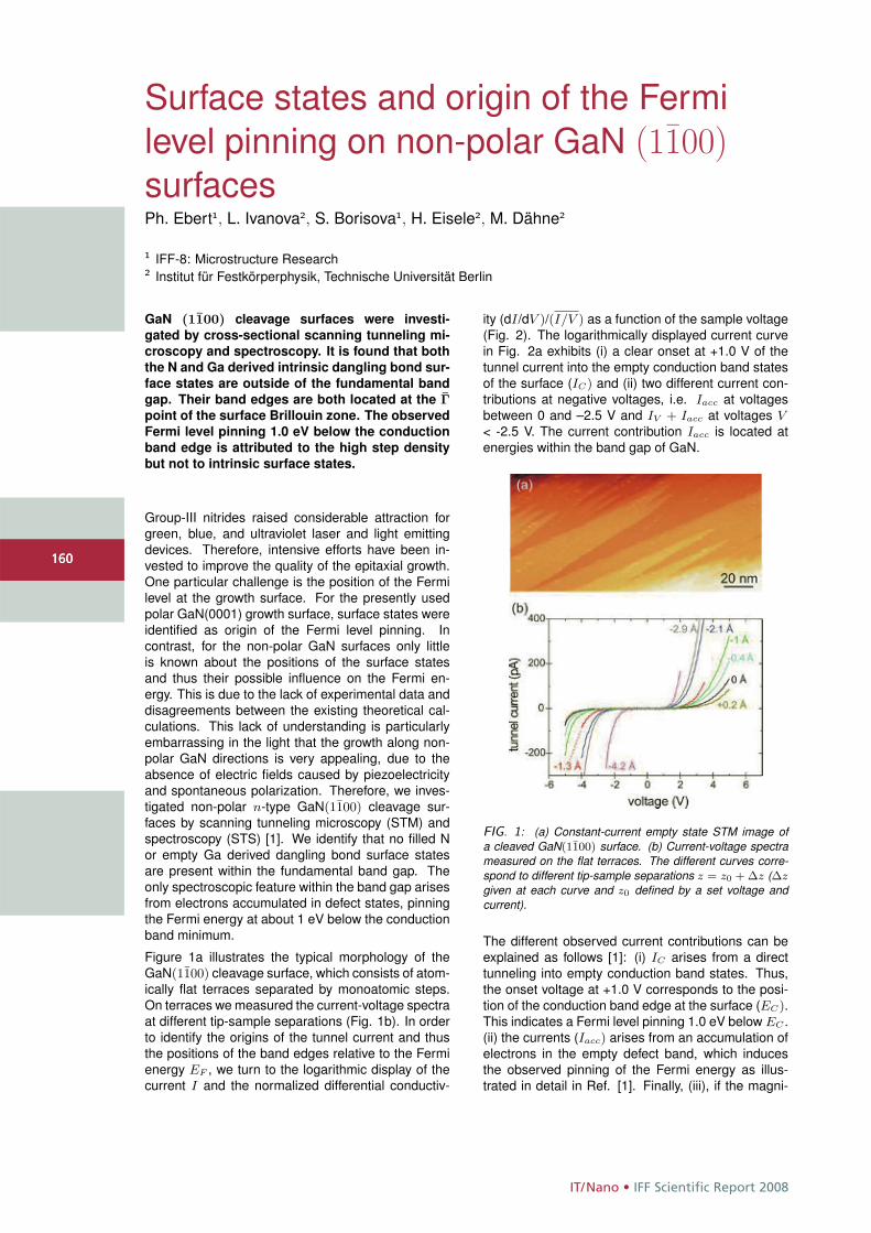
IT/Nano • IFF Scientific Report 2008
160
Surface states and origin of the Fermilevel pinning on non-polar GaN (1100)surfacesPh. Ebert1, L. Ivanova2, S. Borisova1, H. Eisele2, M. Dähne2
1 IFF-8: Microstructure Research2 Institut für Festkörperphysik, Technische Universität Berlin
GaN (1100) cleavage surfaces were investi-
gated by cross-sectional scanning tunneling mi-
croscopy and spectroscopy. It is found that both
the N and Ga derived intrinsic dangling bond sur-
face states are outside of the fundamental band
gap. Their band edges are both located at the Γpoint of the surface Brillouin zone. The observed
Fermi level pinning 1.0 eV below the conduction
band edge is attributed to the high step density
but not to intrinsic surface states.
Group-III nitrides raised considerable attraction forgreen, blue, and ultraviolet laser and light emittingdevices. Therefore, intensive efforts have been in-vested to improve the quality of the epitaxial growth.One particular challenge is the position of the Fermilevel at the growth surface. For the presently usedpolar GaN(0001) growth surface, surface states wereidentified as origin of the Fermi level pinning. Incontrast, for the non-polar GaN surfaces only littleis known about the positions of the surface statesand thus their possible influence on the Fermi en-ergy. This is due to the lack of experimental data anddisagreements between the existing theoretical cal-culations. This lack of understanding is particularlyembarrassing in the light that the growth along non-polar GaN directions is very appealing, due to theabsence of electric fields caused by piezoelectricityand spontaneous polarization. Therefore, we inves-tigated non-polar n-type GaN(1100) cleavage sur-faces by scanning tunneling microscopy (STM) andspectroscopy (STS) [1]. We identify that no filled Nor empty Ga derived dangling bond surface statesare present within the fundamental band gap. Theonly spectroscopic feature within the band gap arisesfrom electrons accumulated in defect states, pinningthe Fermi energy at about 1 eV below the conductionband minimum.
Figure 1a illustrates the typical morphology of theGaN(1100) cleavage surface, which consists of atom-ically flat terraces separated by monoatomic steps.On terraces we measured the current-voltage spectraat different tip-sample separations (Fig. 1b). In orderto identify the origins of the tunnel current and thusthe positions of the band edges relative to the Fermienergy EF , we turn to the logarithmic display of thecurrent I and the normalized differential conductiv-
ity (dI/dV )/(I/V ) as a function of the sample voltage(Fig. 2). The logarithmically displayed current curvein Fig. 2a exhibits (i) a clear onset at +1.0 V of thetunnel current into the empty conduction band statesof the surface (IC) and (ii) two different current con-tributions at negative voltages, i.e. Iacc at voltagesbetween 0 and –2.5 V and IV + Iacc at voltages V< -2.5 V. The current contribution Iacc is located atenergies within the band gap of GaN.
FIG. 1: (a) Constant-current empty state STM image ofa cleaved GaN(1100) surface. (b) Current-voltage spectrameasured on the flat terraces. The different curves corre-spond to different tip-sample separations z = z0 + Δz (Δzgiven at each curve and z0 defined by a set voltage andcurrent).
The different observed current contributions can beexplained as follows [1]: (i) IC arises from a directtunneling into empty conduction band states. Thus,the onset voltage at +1.0 V corresponds to the posi-tion of the conduction band edge at the surface (EC).This indicates a Fermi level pinning 1.0 eV below EC .(ii) the currents (Iacc) arises from an accumulation ofelectrons in the empty defect band, which inducesthe observed pinning of the Fermi energy as illus-trated in detail in Ref. [1]. Finally, (iii), if the magni-
160
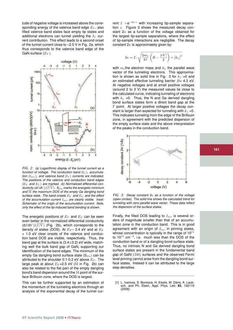
IFF Scientific Report 2008 • IT/Nano
161
tude of negative voltage is increased above the corre-sponding energy of the valence band edge EV , alsofilled valence band states face empty tip states andadditional electrons can tunnel yielding the IV cur-rent contribution. This effect leads to a second onsetof the tunnel current close to –2.5 V in Fig. 2a, whichthus corresponds to the valence band edge of theGaN surface (EV ).
FIG. 2: (a) Logarithmic display of the tunnel current as afunction of voltage. The conduction band (IC), accumula-tion (Iacc), and valence band (IV ) currents are indicated.The positions of the valence and conduction band edges(EV and EC) are marked. (b) Normalized differential con-ductivity (dI/dV )/(I/V ). SGa marks the energetic minimumand M the maximum DOS of the empty Ga dangling bondsurface state. The band onsets EV and EC and the effectof the accumulation current Iacc are clearly visible. Inset:Schematic of the origin of the accumulation current. Note,only the effect of the tip-induced band bending is shown.
The energetic positions of EV and EC can be seeneven better in the normalized differential conductivity(dI/dV )/(I/V ) (Fig. 2b), which corresponds to thedensity of states (DOS). At EF – 2.4 eV and at EF
+ 1.0 eV clear onsets of the valence and conduc-tion band DOS are visible, respectively. Thus, theband gap at the surface is (3.4±0.2) eV wide, match-ing well the bulk band gap of GaN, supporting ouridentification of the band edges. The minimum of theempty Ga dangling bond surface state (SGa) can beattributed to the shoulder 0.1-0.2 eV above EC . Thelarge peak at about EF +2.5 eV (M in Fig. 2b) canalso be related to the flat part of the empty danglingbond’s band dispersion around the M point of the sur-face Brillouin zone, where the DOS is largest.
This can be further supported by an estimation ofthe momentum of the tunneling electrons through ananalysis of the exponential decay of the tunnel cur-
rent I ∼e−2κ·z with increasing tip-sample separa-tion z. Figure 3 shows the measured decay con-stant 2κ as a function of the voltage obtained forthe largest tip-sample separations, where the effectof tip-sample interactions are negligible. The decayconstant 2κ is approximately given by:
2κ = 2 ·s
2me
�2
„B − |eV |
2
«+
˛k||
˛2with methe electron mass and k|| the parallel wavevector of the tunneling electrons. This approxima-tion is shown as solid line in Fig. 3 for k|| =0 andan estimated effective tunneling barrier B= 4.3 eV.At negative voltages and at small positive voltages(around 2 to 3 V) the measured values lie close tothe calculated curve, indicating tunneling of electronswith k|| =0. Thus, the N and Ga derived danglingbond surface states form a direct band gap at theΓ point. At larger positive voltages the decay con-stant is larger than expected for tunneling with k|| =0.This indicates tunneling from the edge of the Brillouinzone, in agreement with the predicted dispersion ofthe empty surface state and the above interpretationof the peaks in the conduction band.
FIG. 3: Decay constant 2κ as a function of the voltage(open circles). The solid line shows the calculated trend fortunneling with zero parallel wave vector. These data reflectthe dispersion of the surface states.
Finally, the filled DOS leading to Iacc is several or-ders of magnitude smaller than that of an accumu-lation zone in the conduction band. This is in goodagreement with an origin of Iacc in pinning states,whose concentration is typically in the range of 1011
to 1013 cm−2, i.e. much less than the DOS of theconduction band or of a dangling bond surface state.Thus, no intrinsic N and Ga derived dangling bondsurface states are present in the fundamental bandgap of GaN(1100) surfaces and the observed Fermilevel pinning cannot arise from the dangling bond sur-face states. Instead it can be attributed to the largestep densities.
[1] L. Ivanova, S. Borisova, H. Eisele, M. Däne, A. Laub-sch, and Ph. Ebert, Appl. Phys. Lett. 93, 192110(2008).
161
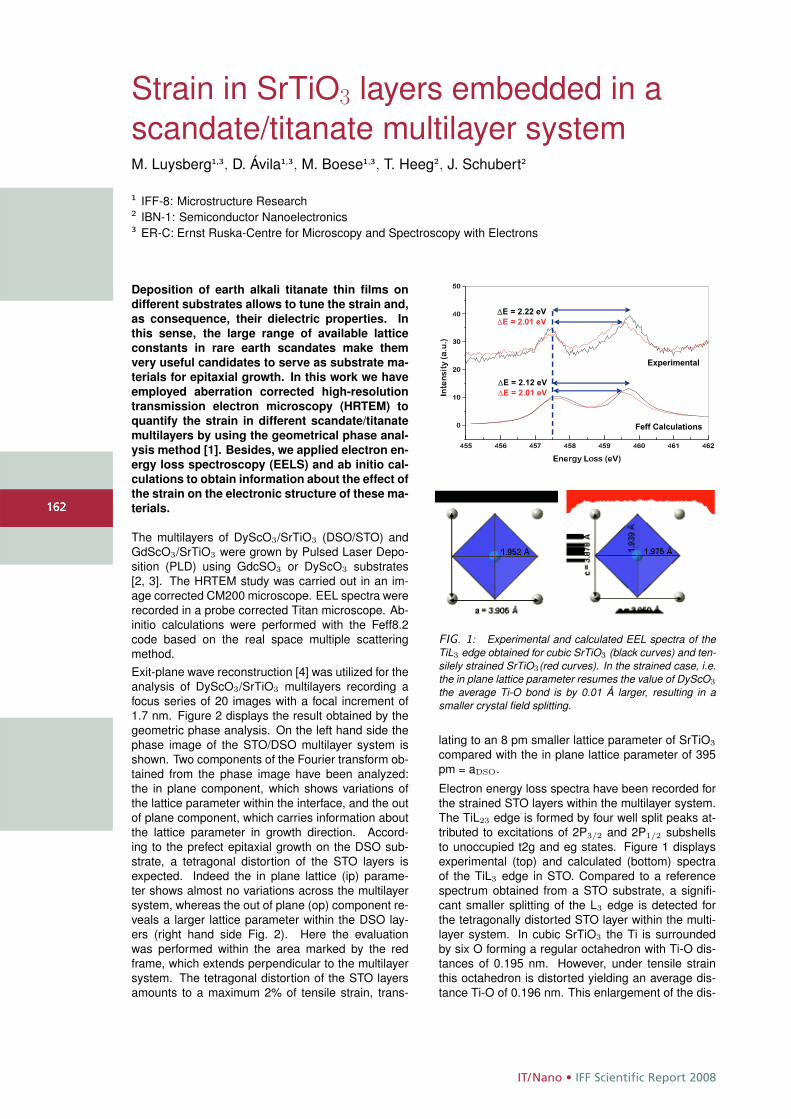
IT/Nano • IFF Scientific Report 2008
162
Strain in SrTiO3 layers embedded in ascandate/titanate multilayer systemM. Luysberg1,3, D. Ávila1,3, M. Boese1,3, T. Heeg2, J. Schubert2
1 IFF-8: Microstructure Research2 IBN-1: Semiconductor Nanoelectronics3 ER-C: Ernst Ruska-Centre for Microscopy and Spectroscopy with Electrons
Deposition of earth alkali titanate thin films on
different substrates allows to tune the strain and,
as consequence, their dielectric properties. In
this sense, the large range of available lattice
constants in rare earth scandates make them
very useful candidates to serve as substrate ma-
terials for epitaxial growth. In this work we have
employed aberration corrected high-resolution
transmission electron microscopy (HRTEM) to
quantify the strain in different scandate/titanate
multilayers by using the geometrical phase anal-
ysis method [1]. Besides, we applied electron en-
ergy loss spectroscopy (EELS) and ab initio cal-
culations to obtain information about the effect of
the strain on the electronic structure of these ma-
terials.
The multilayers of DyScO3/SrTiO3 (DSO/STO) andGdScO3/SrTiO3 were grown by Pulsed Laser Depo-sition (PLD) using GdcSO3 or DyScO3 substrates[2, 3]. The HRTEM study was carried out in an im-age corrected CM200 microscope. EEL spectra wererecorded in a probe corrected Titan microscope. Ab-initio calculations were performed with the Feff8.2code based on the real space multiple scatteringmethod.Exit-plane wave reconstruction [4] was utilized for theanalysis of DyScO3/SrTiO3 multilayers recording afocus series of 20 images with a focal increment of1.7 nm. Figure 2 displays the result obtained by thegeometric phase analysis. On the left hand side thephase image of the STO/DSO multilayer system isshown. Two components of the Fourier transform ob-tained from the phase image have been analyzed:the in plane component, which shows variations ofthe lattice parameter within the interface, and the outof plane component, which carries information aboutthe lattice parameter in growth direction. Accord-ing to the prefect epitaxial growth on the DSO sub-strate, a tetragonal distortion of the STO layers isexpected. Indeed the in plane lattice (ip) parame-ter shows almost no variations across the multilayersystem, whereas the out of plane (op) component re-veals a larger lattice parameter within the DSO lay-ers (right hand side Fig. 2). Here the evaluationwas performed within the area marked by the redframe, which extends perpendicular to the multilayersystem. The tetragonal distortion of the STO layersamounts to a maximum 2% of tensile strain, trans-
455 456 457 458 459 460 461 462
0
10
20
30
40
50
�E = 2.22 eV�E = 2.01 eV
Inte
nsi
ty (
a.u
.)
Energy Loss (eV)
Experimental
�E = 2.12 eV�E = 2.01 eV
Feff Calculations
FIG. 1: Experimental and calculated EEL spectra of theTiL3 edge obtained for cubic SrTiO3 (black curves) and ten-silely strained SrTiO3(red curves). In the strained case, i.e.the in plane lattice parameter resumes the value of DyScO3
the average Ti-O bond is by 0.01 Å larger, resulting in asmaller crystal field splitting.
lating to an 8 pm smaller lattice parameter of SrTiO3
compared with the in plane lattice parameter of 395pm = aDSO.
Electron energy loss spectra have been recorded forthe strained STO layers within the multilayer system.The TiL23 edge is formed by four well split peaks at-tributed to excitations of 2P3/2 and 2P1/2 subshellsto unoccupied t2g and eg states. Figure 1 displaysexperimental (top) and calculated (bottom) spectraof the TiL3 edge in STO. Compared to a referencespectrum obtained from a STO substrate, a signifi-cant smaller splitting of the L3 edge is detected forthe tetragonally distorted STO layer within the multi-layer system. In cubic SrTiO3 the Ti is surroundedby six O forming a regular octahedron with Ti-O dis-tances of 0.195 nm. However, under tensile strainthis octahedron is distorted yielding an average dis-tance Ti-O of 0.196 nm. This enlargement of the dis-
162
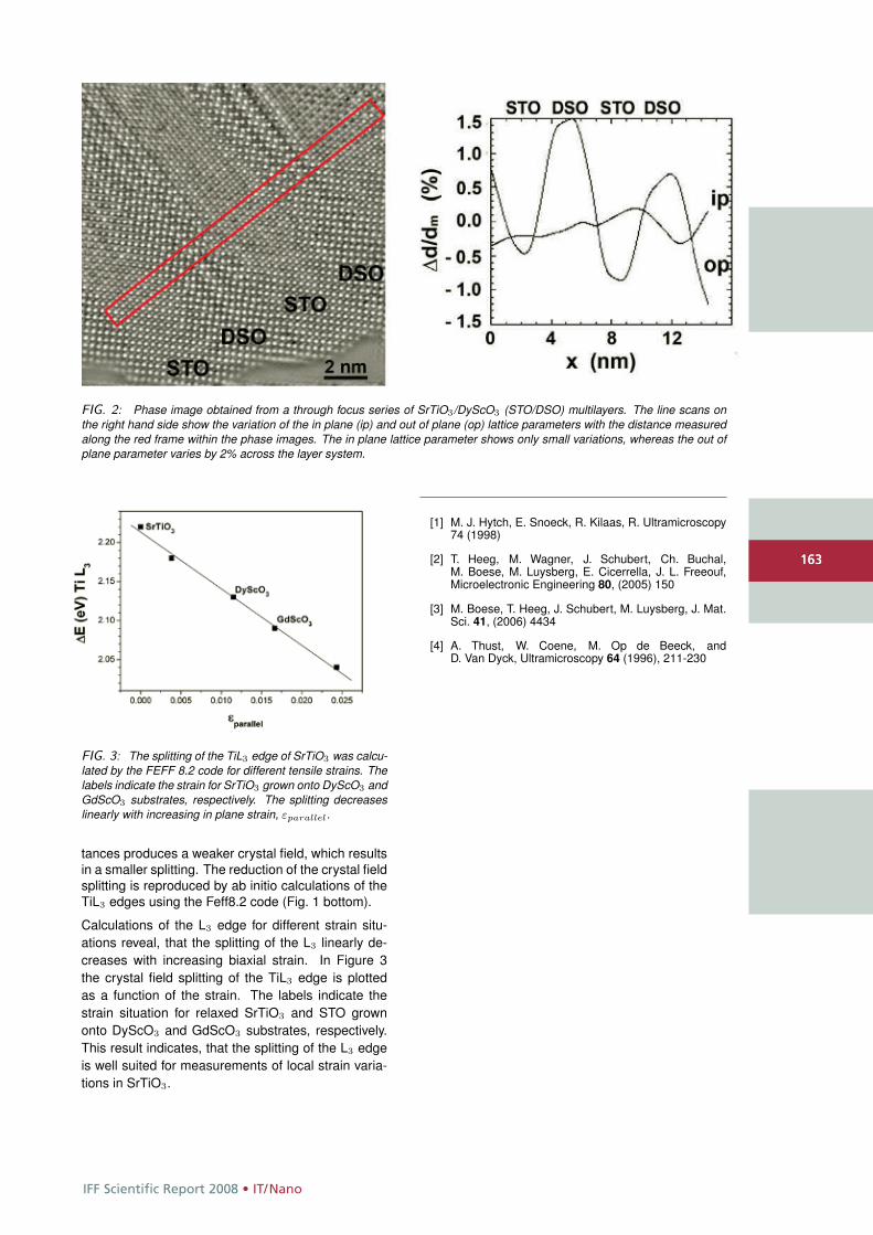
IFF Scientific Report 2008 • IT/Nano
163
FIG. 2: Phase image obtained from a through focus series of SrTiO3/DyScO3 (STO/DSO) multilayers. The line scans onthe right hand side show the variation of the in plane (ip) and out of plane (op) lattice parameters with the distance measuredalong the red frame within the phase images. The in plane lattice parameter shows only small variations, whereas the out ofplane parameter varies by 2% across the layer system.
FIG. 3: The splitting of the TiL3 edge of SrTiO3 was calcu-lated by the FEFF 8.2 code for different tensile strains. Thelabels indicate the strain for SrTiO3 grown onto DyScO3 andGdScO3 substrates, respectively. The splitting decreaseslinearly with increasing in plane strain, εparallel.
tances produces a weaker crystal field, which resultsin a smaller splitting. The reduction of the crystal fieldsplitting is reproduced by ab initio calculations of theTiL3 edges using the Feff8.2 code (Fig. 1 bottom).
Calculations of the L3 edge for different strain situ-ations reveal, that the splitting of the L3 linearly de-creases with increasing biaxial strain. In Figure 3the crystal field splitting of the TiL3 edge is plottedas a function of the strain. The labels indicate thestrain situation for relaxed SrTiO3 and STO grownonto DyScO3 and GdScO3 substrates, respectively.This result indicates, that the splitting of the L3 edgeis well suited for measurements of local strain varia-tions in SrTiO3.
[1] M. J. Hytch, E. Snoeck, R. Kilaas, R. Ultramicroscopy74 (1998)
[2] T. Heeg, M. Wagner, J. Schubert, Ch. Buchal,M. Boese, M. Luysberg, E. Cicerrella, J. L. Freeouf,Microelectronic Engineering 80, (2005) 150
[3] M. Boese, T. Heeg, J. Schubert, M. Luysberg, J. Mat.Sci. 41, (2006) 4434
[4] A. Thust, W. Coene, M. Op de Beeck, andD. Van Dyck, Ultramicroscopy 64 (1996), 211-230
163
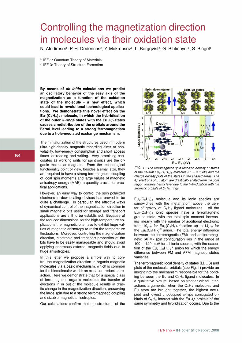
IT/Nano • IFF Scientific Report 2008
164
Controlling the magnetization directionin molecules via their oxidation stateN. Atodiresei1, P. H. Dederichs3, Y. Mokrousov1, L. Bergqvist3, G. Bihlmayer1, S. Blügel1
1 IFF-1: Quantum Theory of Materials3 IFF-3: Theory of Structure Formation
By means of ab initio calculations we predictan oscillatory behavior of the easy axis of themagnetization as a function of the oxidationstate of the molecule - a new effect, whichcould lead to revolutional technological applica-tions. We demonstrate this novel effect on theEu2(C8H8)3 molecule, in which the hybridisationof the outer π-rings states with the Eu 4f -statescauses a redistribution of the orbitals around theFermi level leading to a strong ferromagnetismdue to a hole-mediated exchange mechanism.
The miniaturization of the structures used in modernultra-high-density magnetic recording aims at non-volatility, low-energy consumption and short accesstimes for reading and writing. Very promising can-didates as working units for spintronics are the or-ganic molecular magnets. From the technologicalfunctionality point of view, besides a small size, theyare required to have a strong ferromagnetic couplingof local spin moments and large values of magneticanisotropy energy (MAE), a quantity crucial for prac-tical applications.
However, an easy way to control the spin polarizedelectrons in downscaling devices has proved to bequite a challenge. In particular, the effective waysof dynamical control of the magnetization direction insmall magnetic bits used for storage and transportapplications are still to be established. Because ofthe reduced dimensions, for the high-temperature ap-plications the magnetic bits have to exhibit huge val-ues of magnetic anisotropy to resist the temperaturefluctuations. Moreover, controlling the magnetizationdirection, electronic and transport properties of thebits have to be easily manageable and should avoidapplying enormous external magnetic fields due tohuge anisotropies.
In this letter we propose a simple way to con-trol the magnetization direction in organic magneticmolecules via a basic mechanism, which is commonfor the biomolecular world: an oxidation-reduction re-action. Here we demonstrate that for a special classof ferromagnetic organic molecules the transfer ofelectrons in or out of the molecule results in dras-tic change in the magnetization direction, preservingthe large spin due to a strong ferromagnetic couplingand sizable magnetic anisotropies.
Our calculations confirm that the structures of the
FIG. 1: The ferromagnetic spin-resolved density of statesof the neutral Eu2(C8H8)3 molecule (U = 3.7 eV) and thecharge density plots of the states in the shaded areas. The4f electrons of Eu atom are drastically shifted from the coreregion towards Fermi level due to the hybridization with thearomatic orbitals of C8H8 rings.
Eu2(C8H8)3 molecule and its ionic species aresandwiches with the metal atom above the cen-ter of gravity of C8H8 ligand molecules. All theEu2(C8H8)3 ionic species have a ferromagneticground state, with the total spin moment increas-ing linearly with the number of additional electrons:from 10μB for Eu2(C8H8)+2
3 cation up to 14μB forthe Eu2(C8H8)−2
3 anion. The total energy differencebetween the ferromagnetic (FM) and antiferromag-netic (AFM) spin configuration lies in the range of100 − 120 meV for all ionic species, with the excep-tion of the Eu2(C8H8)−2
3 anion for which the energydifference between FM and AFM magnetic statesvanishes.
The ferromagnetic local density of states (LDOS) andplots of the molecular orbitals (see Fig. 1) provide aninsight into the mechanism responsible for the bond-ing between the Eu and C8H8 ligand molecules. Ina qualitative picture, based on frontier orbital inter-actions arguments, when the C8H8 molecules andEu atom are brought together, the highest occu-pied and lowest unoccupied π-type conjugated or-bitals of C8H8 interact with the Eu 4f -orbitals of thesame symmetry and hybridization occurs. Due to the
164
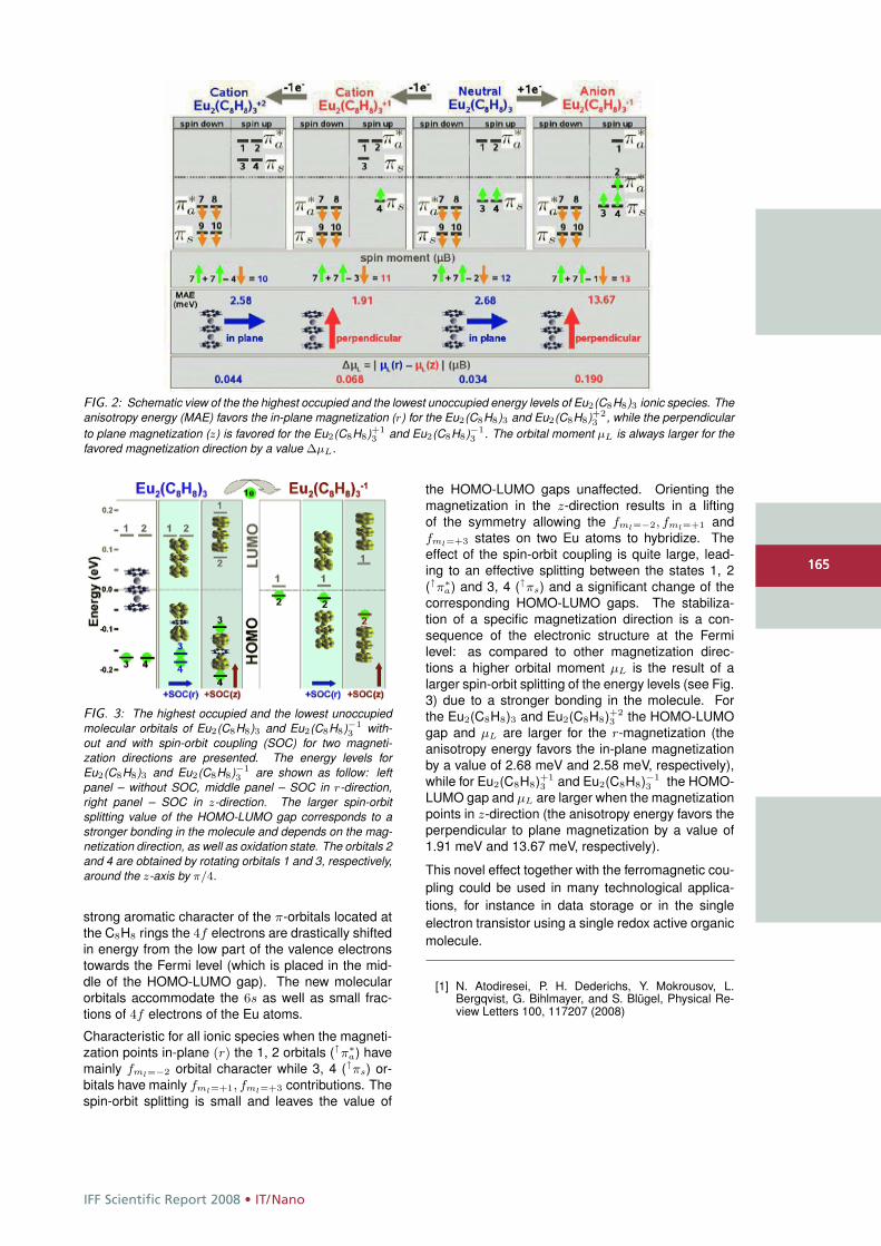
IFF Scientific Report 2008 • IT/Nano
165
FIG. 2: Schematic view of the the highest occupied and the lowest unoccupied energy levels of Eu2(C8H8)3 ionic species. Theanisotropy energy (MAE) favors the in-plane magnetization (r) for the Eu2(C8H8)3 and Eu2(C8H8)+2
3 , while the perpendicularto plane magnetization (z) is favored for the Eu2(C8H8)+1
3 and Eu2(C8H8)−13 . The orbital moment μL is always larger for the
favored magnetization direction by a value ΔμL.
FIG. 3: The highest occupied and the lowest unoccupiedmolecular orbitals of Eu2(C8H8)3 and Eu2(C8H8)−1
3 with-out and with spin-orbit coupling (SOC) for two magneti-zation directions are presented. The energy levels forEu2(C8H8)3 and Eu2(C8H8)−1
3 are shown as follow: leftpanel – without SOC, middle panel – SOC in r-direction,right panel – SOC in z-direction. The larger spin-orbitsplitting value of the HOMO-LUMO gap corresponds to astronger bonding in the molecule and depends on the mag-netization direction, as well as oxidation state. The orbitals 2and 4 are obtained by rotating orbitals 1 and 3, respectively,around the z-axis by π/4.
strong aromatic character of the π-orbitals located atthe C8H8 rings the 4f electrons are drastically shiftedin energy from the low part of the valence electronstowards the Fermi level (which is placed in the mid-dle of the HOMO-LUMO gap). The new molecularorbitals accommodate the 6s as well as small frac-tions of 4f electrons of the Eu atoms.
Characteristic for all ionic species when the magneti-zation points in-plane (r) the 1, 2 orbitals (↑π∗
a) havemainly fml=−2 orbital character while 3, 4 (↑πs) or-bitals have mainly fml=+1, fml=+3 contributions. Thespin-orbit splitting is small and leaves the value of
the HOMO-LUMO gaps unaffected. Orienting themagnetization in the z-direction results in a liftingof the symmetry allowing the fml=−2, fml=+1 andfml=+3 states on two Eu atoms to hybridize. Theeffect of the spin-orbit coupling is quite large, lead-ing to an effective splitting between the states 1, 2(↑π∗
a) and 3, 4 (↑πs) and a significant change of thecorresponding HOMO-LUMO gaps. The stabiliza-tion of a specific magnetization direction is a con-sequence of the electronic structure at the Fermilevel: as compared to other magnetization direc-tions a higher orbital moment μL is the result of alarger spin-orbit splitting of the energy levels (see Fig.3) due to a stronger bonding in the molecule. Forthe Eu2(C8H8)3 and Eu2(C8H8)+2
3 the HOMO-LUMOgap and μL are larger for the r-magnetization (theanisotropy energy favors the in-plane magnetizationby a value of 2.68 meV and 2.58 meV, respectively),while for Eu2(C8H8)+1
3 and Eu2(C8H8)−13 the HOMO-
LUMO gap and μL are larger when the magnetizationpoints in z-direction (the anisotropy energy favors theperpendicular to plane magnetization by a value of1.91 meV and 13.67 meV, respectively).
This novel effect together with the ferromagnetic cou-pling could be used in many technological applica-tions, for instance in data storage or in the singleelectron transistor using a single redox active organicmolecule.
[1] N. Atodiresei, P. H. Dederichs, Y. Mokrousov, L.Bergqvist, G. Bihlmayer, and S. Blügel, Physical Re-view Letters 100, 117207 (2008)
165
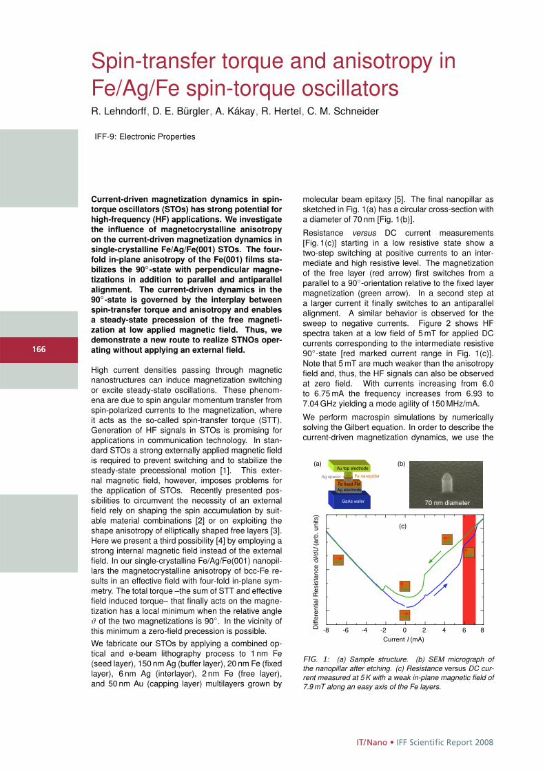
IT/Nano • IFF Scientific Report 2008
166
Spin-transfer torque and anisotropy inFe/Ag/Fe spin-torque oscillatorsR. Lehndorff, D. E. Bürgler, A. Kákay, R. Hertel, C. M. Schneider
IFF-9: Electronic Properties
Current-driven magnetization dynamics in spin-
torque oscillators (STOs) has strong potential for
high-frequency (HF) applications. We investigate
the influence of magnetocrystalline anisotropy
on the current-driven magnetization dynamics in
single-crystalline Fe/Ag/Fe(001) STOs. The four-
fold in-plane anisotropy of the Fe(001) films sta-
bilizes the 90◦-state with perpendicular magne-
tizations in addition to parallel and antiparallel
alignment. The current-driven dynamics in the
90◦-state is governed by the interplay between
spin-transfer torque and anisotropy and enables
a steady-state precession of the free magneti-
zation at low applied magnetic field. Thus, we
demonstrate a new route to realize STNOs oper-
ating without applying an external field.
High current densities passing through magneticnanostructures can induce magnetization switchingor excite steady-state oscillations. These phenom-ena are due to spin angular momentum transfer fromspin-polarized currents to the magnetization, whereit acts as the so-called spin-transfer torque (STT).Generation of HF signals in STOs is promising forapplications in communication technology. In stan-dard STOs a strong externally applied magnetic fieldis required to prevent switching and to stabilize thesteady-state precessional motion [1]. This exter-nal magnetic field, however, imposes problems forthe application of STOs. Recently presented pos-sibilities to circumvent the necessity of an externalfield rely on shaping the spin accumulation by suit-able material combinations [2] or on exploiting theshape anisotropy of elliptically shaped free layers [3].Here we present a third possibility [4] by employing astrong internal magnetic field instead of the externalfield. In our single-crystalline Fe/Ag/Fe(001) nanopil-lars the magnetocrystalline anisotropy of bcc-Fe re-sults in an effective field with four-fold in-plane sym-metry. The total torque –the sum of STT and effectivefield induced torque– that finally acts on the magne-tization has a local minimum when the relative angleϑ of the two magnetizations is 90◦. In the vicinity ofthis minimum a zero-field precession is possible.We fabricate our STOs by applying a combined op-tical and e-beam lithography process to 1 nm Fe(seed layer), 150 nm Ag (buffer layer), 20 nm Fe (fixedlayer), 6 nm Ag (interlayer), 2 nm Fe (free layer),and 50 nm Au (capping layer) multilayers grown by
molecular beam epitaxy [5]. The final nanopillar assketched in Fig. 1(a) has a circular cross-section witha diameter of 70 nm [Fig. 1(b)].
Resistance versus DC current measurements[Fig. 1(c)] starting in a low resistive state show atwo-step switching at positive currents to an inter-mediate and high resistive level. The magnetizationof the free layer (red arrow) first switches from aparallel to a 90◦-orientation relative to the fixed layermagnetization (green arrow). In a second step ata larger current it finally switches to an antiparallelalignment. A similar behavior is observed for thesweep to negative currents. Figure 2 shows HFspectra taken at a low field of 5 mT for applied DCcurrents corresponding to the intermediate resistive90◦-state [red marked current range in Fig. 1(c)].Note that 5 mT are much weaker than the anisotropyfield and, thus, the HF signals can also be observedat zero field. With currents increasing from 6.0to 6.75 mA the frequency increases from 6.93 to7.04 GHz yielding a mode agility of 150 MHz/mA.
We perform macrospin simulations by numericallysolving the Gilbert equation. In order to describe thecurrent-driven magnetization dynamics, we use the
(c)
(a) (b)
-8 -6 -4 -2 0 2 4 6 8Current I (mA)
Diffe
rent
ial R
esist
ance
dI/d
U (a
rb. u
nits)
Fe nanopillarAg spacerAu top electrode
GaAs wafer
Ag electrodeFe fixed FM
70 nm diameter
FIG. 1: (a) Sample structure. (b) SEM micrograph ofthe nanopillar after etching. (c) Resistance versus DC cur-rent measured at 5 K with a weak in-plane magnetic field of7.9 mT along an easy axis of the Fe layers.
166
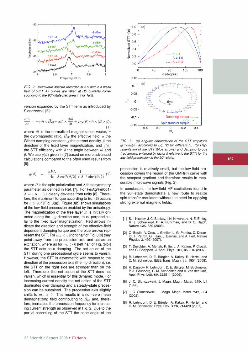
IFF Scientific Report 2008 • IT/Nano
167
6 6.5 7 7.5 8-65
-60
-55
-50Am
plitu
de (d
Bm)
6.0 mA
6.25 mA
6.5 mA
6.75 mA
+3 dBm
+6 dBm
+9 dBm
Frequency (GHz)
FIG. 2: Microwave spectra recorded at 5 K and in a weakfield of 5 mT. All curves are taken at DC currents corre-sponding to the 90◦-state [red area in Fig. 1(c)].
version expanded by the STT term as introduced bySlonczewski [6]:
d�m
dt= −γ �m× �Heff +α�m× d�m
dt+j ·g(ϑ) · �m×(�m×�p),
(1)where �m is the normalized magnetization vector, γthe gyromagnetic ratio, �Heff the effective field, α theGilbert damping constant, j the current density, �p thedirection of the fixed layer magnetization, and g(ϑ)the STT efficiency with ϑ the angle between �m and�p. We use g(ϑ) given in [7] based on more advancedcalculations compared to the often used results from[6]:
g(ϑ) =�PΛ
4e
1
Λ cos2(ϑ/2) + Λ−1 sin2(ϑ/2),(2)
where P is the spin polarization and Λ the asymmetryparameter as defined in Ref. [7]. For Fe/Ag/Fe(001)Λ = 1.6 . . . 3.4 clearly deviates from unity [8]. There-fore, the maximum torque according to Eq. (2) occursfor ϑ > 90◦ [Fig. 3(a)]. Figure 3(b) shows simulationsof the low-field precession enabled by the anisotropy.The magnetization of the free layer �m is initially ori-ented along the +y-direction and, thus, perpendicu-lar to the fixed layer magnetization. Red arrows in-dicate the direction and strength of the effective-fielddependent damping torque and the blue arrows rep-resent the STT. For mx < 0 [right half of Fig. 3(b] theypoint away from the precession axis and act as anexcitation, where as for mx > 0 [left half of Fig. 3(b)]the STT acts as a damping. The net action of theSTT during one precessional cycle seems to vanish.However, the STT is asymmetric with respect to thedirection of the precession axis (the +y-direction), i.e.the STT on the right side are stronger than on theleft. Therefore, the net action of the STT does notvanish, which is essential for this dynamic mode. Forincreasing current density the net action of the STTdominates over damping and a steady-state preces-sion can be sustained. The precession axis slightlyshifts to mz > 0. This results in a non-zero meandemagnetizing field contributing to �Heff and, there-fore, increases the precession frequency for increas-ing current strength as observed in Fig. 2. Due to thepartial cancelling of the STT the cone angle of the
-0.15
-0.1
-0.05
0
0.05
0.1
0.15
-0.4-0.2 0 0.2 0.4m
zmx
time
Damping torquem(t)
Spin transfer torque
0 45 90 135 180ϑ (degree)
Λ = 1Λ = 1.6Λ = 3.4
Nor
mal
ized
STT
τ(ϑ
)
0.0
0.2
0.4
0.6
0.8
1.0 (a)
(b)
FIG. 3: (a) Angular dependence of the STT amplitudeg(ϑ) sin(ϑ) according to Eq. (2) for different Λ. (b) Rep-resentation of the STT (blue arrows) and damping torque(red arrows, enlarged by factor 5 relative to the STT) for thelow-field precession in the 90◦-state.
precession is relatively small, but the low-field pre-cession covers the region of the GMR(ϑ) curve withthe steepest gradient and therefore results in mea-surable microwave signals (Fig. 2).
In conclusion, the low-field HF excitations found inthe 90◦-state demonstrate a new route to realizespin-transfer oscillators without the need for applyingstrong external magnetic fields.
[1] S. I. Kiselev, J. C. Sankey, I. N. Krivorotov, N. E. Emley,R. J. Schoelkopf, R. A. Buhrman, and D. C. Ralph,Nature 425, 380 (2003).
[2] O. Boulle, V. Cros, J. Grollier, L. G. Pereira, C. Deran-lot, F. Petroff, G. Faini, J. Barnas, and A. Fert, NaturePhysics 3, 492 (2007).
[3] T. Devolder, A. Meftah, K. Ito, J. A. Katine, P. Crozat,and C. Chappert, J. Appl. Phys. 101, 063916 (2007).
[4] R. Lehndorff, D. E. Bürgler, A. Kakay, R. Hertel, andC. M. Schneider, IEEE Trans. Magn. 44, 1951 (2008).
[5] H. Dassow, R. Lehndorff, D. E. Bürgler, M. Buchmeier,P. A. Grünberg, C. M. Schneider, and A. van der Hart,Appl. Phys. Lett. 89, 222511 (2006).
[6] J. C. Slonczewski, J. Magn. Magn. Mater. 159, L1(1996).
[7] J. C. Slonczewski, J. Magn. Magn. Mater. 247, 324(2002).
[8] R. Lehndorff, D. E. Bürgler, A. Kakay, R. Hertel, andC. M. Schneider, Phys. Rev. B 76, 214420 (2007).
167
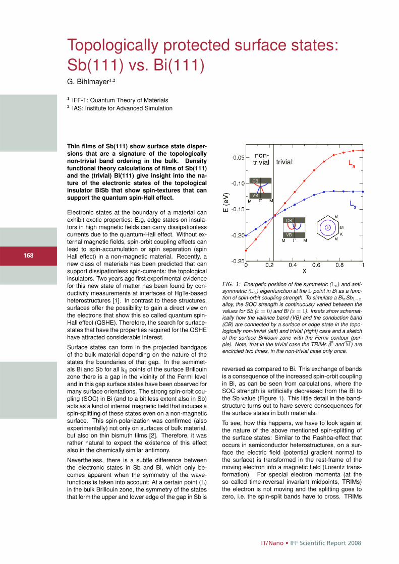
IT/Nano • IFF Scientific Report 2008
168
Topologically protected surface states:Sb(111) vs. Bi(111)G. Bihlmayer1,2
1 IFF-1: Quantum Theory of Materials2 IAS: Institute for Advanced Simulation
Thin films of Sb(111) show surface state disper-
sions that are a signature of the topologically
non-trivial band ordering in the bulk. Density
functional theory calculations of films of Sb(111)
and the (trivial) Bi(111) give insight into the na-
ture of the electronic states of the topological
insulator BiSb that show spin-textures that can
support the quantum spin-Hall effect.
Electronic states at the boundary of a material canexhibit exotic properties: E.g. edge states on insula-tors in high magnetic fields can carry dissipationlesscurrents due to the quantum-Hall effect. Without ex-ternal magnetic fields, spin-orbit coupling effects canlead to spin-accumulation or spin separation (spinHall effect) in a non-magnetic material. Recently, anew class of materials has been predicted that cansupport dissipationless spin-currents: the topologicalinsulators. Two years ago first experimental evidencefor this new state of matter has been found by con-ductivity measurements at interfaces of HgTe-basedheterostructures [1]. In contrast to these structures,surfaces offer the possibility to gain a direct view onthe electrons that show this so called quantum spin-Hall effect (QSHE). Therefore, the search for surface-states that have the properties required for the QSHEhave attracted considerable interest.
Surface states can form in the projected bandgapsof the bulk material depending on the nature of thestates the boundaries of that gap. In the semimet-als Bi and Sb for all k‖ points of the surface Brillouinzone there is a gap in the vicinity of the Fermi leveland in this gap surface states have been observed formany surface orientations. The strong spin-orbit cou-pling (SOC) in Bi (and to a bit less extent also in Sb)acts as a kind of internal magnetic field that induces aspin-splitting of these states even on a non-magneticsurface. This spin-polarization was confirmed (alsoexperimentally) not only on surfaces of bulk material,but also on thin bismuth films [2]. Therefore, it wasrather natural to expect the existence of this effectalso in the chemically similar antimony.
Nevertheless, there is a subtle difference betweenthe electronic states in Sb and Bi, which only be-comes apparent when the symmetry of the wave-functions is taken into account: At a certain point (L)in the bulk Brillouin zone, the symmetry of the statesthat form the upper and lower edge of the gap in Sb is
FIG. 1: Energetic position of the symmetric (Ls) and anti-symmetric (La) eigenfunction at the L point in Bi as a func-tion of spin-orbit coupling strength. To simulate a BixSb1−x
alloy, the SOC strength is continuously varied between thevalues for Sb (x = 0) and Bi (x = 1). Insets show schemat-ically how the valence band (VB) and the conduction band(CB) are connected by a surface or edge state in the topo-logically non-trivial (left) and trivial (right) case and a sketchof the surface Brillouin zone with the Fermi contour (pur-ple). Note, that in the trivial case the TRIMs (Γ and M) areencircled two times, in the non-trivial case only once.
reversed as compared to Bi. This exchange of bandsis a consequence of the increased spin-orbit couplingin Bi, as can be seen from calculations, where theSOC strength is artificially decreased from the Bi tothe Sb value (Figure 1). This little detail in the band-structure turns out to have severe consequences forthe surface states in both materials.
To see, how this happens, we have to look again atthe nature of the above mentioned spin-splitting ofthe surface states: Similar to the Rashba-effect thatoccurs in semiconductor heterostructures, on a sur-face the electric field (potential gradient normal tothe surface) is transformed in the rest-frame of themoving electron into a magnetic field (Lorentz trans-formation). For special electron momenta (at theso called time-reversal invariant midpoints, TRIMs)the electron is not moving and the splitting goes tozero, i.e. the spin-split bands have to cross. TRIMs
168
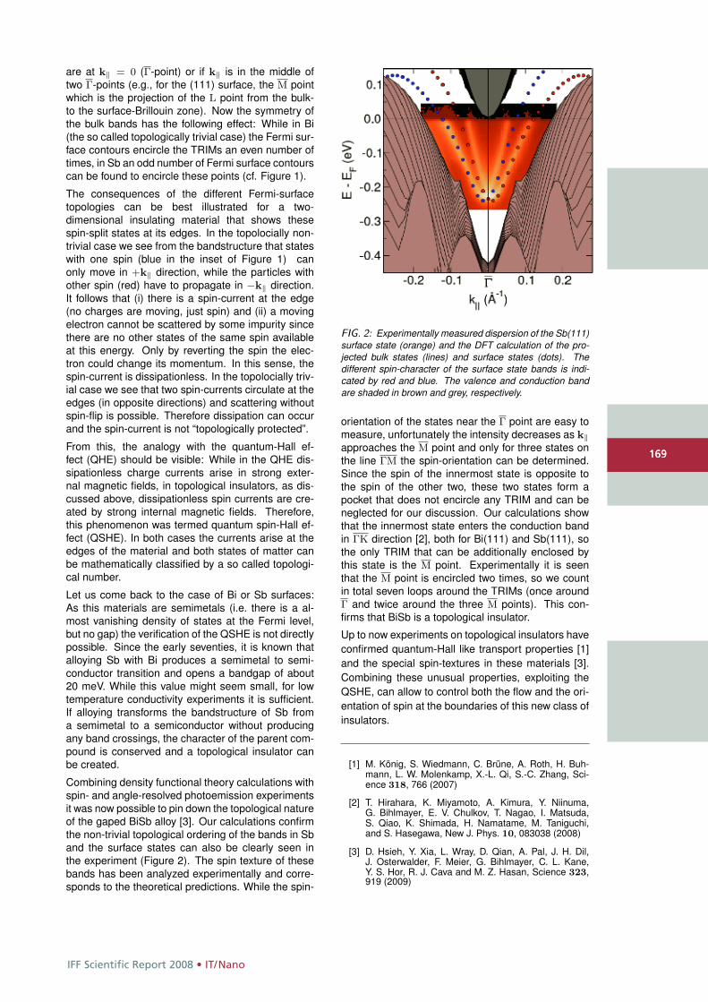
IFF Scientific Report 2008 • IT/Nano
169
are at k‖ = 0 (Γ-point) or if k‖ is in the middle oftwo Γ-points (e.g., for the (111) surface, the M pointwhich is the projection of the L point from the bulk-to the surface-Brillouin zone). Now the symmetry ofthe bulk bands has the following effect: While in Bi(the so called topologically trivial case) the Fermi sur-face contours encircle the TRIMs an even number oftimes, in Sb an odd number of Fermi surface contourscan be found to encircle these points (cf. Figure 1).
The consequences of the different Fermi-surfacetopologies can be best illustrated for a two-dimensional insulating material that shows thesespin-split states at its edges. In the topolocially non-trivial case we see from the bandstructure that stateswith one spin (blue in the inset of Figure 1) canonly move in +k‖ direction, while the particles withother spin (red) have to propagate in −k‖ direction.It follows that (i) there is a spin-current at the edge(no charges are moving, just spin) and (ii) a movingelectron cannot be scattered by some impurity sincethere are no other states of the same spin availableat this energy. Only by reverting the spin the elec-tron could change its momentum. In this sense, thespin-current is dissipationless. In the topolocially triv-ial case we see that two spin-currents circulate at theedges (in opposite directions) and scattering withoutspin-flip is possible. Therefore dissipation can occurand the spin-current is not “topologically protected”.
From this, the analogy with the quantum-Hall ef-fect (QHE) should be visible: While in the QHE dis-sipationless charge currents arise in strong exter-nal magnetic fields, in topological insulators, as dis-cussed above, dissipationless spin currents are cre-ated by strong internal magnetic fields. Therefore,this phenomenon was termed quantum spin-Hall ef-fect (QSHE). In both cases the currents arise at theedges of the material and both states of matter canbe mathematically classified by a so called topologi-cal number.
Let us come back to the case of Bi or Sb surfaces:As this materials are semimetals (i.e. there is a al-most vanishing density of states at the Fermi level,but no gap) the verification of the QSHE is not directlypossible. Since the early seventies, it is known thatalloying Sb with Bi produces a semimetal to semi-conductor transition and opens a bandgap of about20 meV. While this value might seem small, for lowtemperature conductivity experiments it is sufficient.If alloying transforms the bandstructure of Sb froma semimetal to a semiconductor without producingany band crossings, the character of the parent com-pound is conserved and a topological insulator canbe created.
Combining density functional theory calculations withspin- and angle-resolved photoemission experimentsit was now possible to pin down the topological natureof the gaped BiSb alloy [3]. Our calculations confirmthe non-trivial topological ordering of the bands in Sband the surface states can also be clearly seen inthe experiment (Figure 2). The spin texture of thesebands has been analyzed experimentally and corre-sponds to the theoretical predictions. While the spin-
FIG. 2: Experimentally measured dispersion of the Sb(111)surface state (orange) and the DFT calculation of the pro-jected bulk states (lines) and surface states (dots). Thedifferent spin-character of the surface state bands is indi-cated by red and blue. The valence and conduction bandare shaded in brown and grey, respectively.
orientation of the states near the Γ point are easy tomeasure, unfortunately the intensity decreases as k‖approaches the M point and only for three states onthe line ΓM the spin-orientation can be determined.Since the spin of the innermost state is opposite tothe spin of the other two, these two states form apocket that does not encircle any TRIM and can beneglected for our discussion. Our calculations showthat the innermost state enters the conduction bandin ΓK direction [2], both for Bi(111) and Sb(111), sothe only TRIM that can be additionally enclosed bythis state is the M point. Experimentally it is seenthat the M point is encircled two times, so we countin total seven loops around the TRIMs (once aroundΓ and twice around the three M points). This con-firms that BiSb is a topological insulator.
Up to now experiments on topological insulators haveconfirmed quantum-Hall like transport properties [1]and the special spin-textures in these materials [3].Combining these unusual properties, exploiting theQSHE, can allow to control both the flow and the ori-entation of spin at the boundaries of this new class ofinsulators.
[1] M. König, S. Wiedmann, C. Brüne, A. Roth, H. Buh-mann, L. W. Molenkamp, X.-L. Qi, S.-C. Zhang, Sci-ence 318, 766 (2007)
[2] T. Hirahara, K. Miyamoto, A. Kimura, Y. Niinuma,G. Bihlmayer, E. V. Chulkov, T. Nagao, I. Matsuda,S. Qiao, K. Shimada, H. Namatame, M. Taniguchi,and S. Hasegawa, New J. Phys. 10, 083038 (2008)
[3] D. Hsieh, Y. Xia, L. Wray, D. Qian, A. Pal, J. H. Dil,J. Osterwalder, F. Meier, G. Bihlmayer, C. L. Kane,Y. S. Hor, R. J. Cava and M. Z. Hasan, Science 323,919 (2009)
169
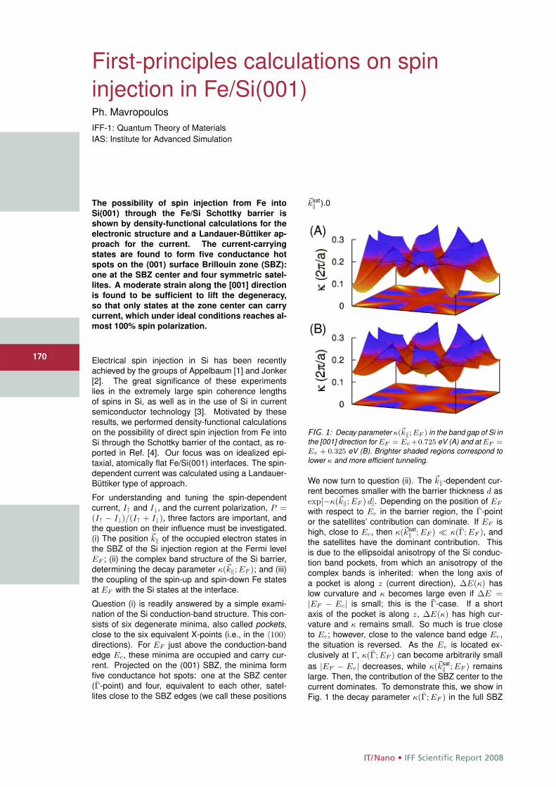
IT/Nano • IFF Scientific Report 2008
170
First-principles calculations on spininjection in Fe/Si(001)Ph. MavropoulosIFF-1: Quantum Theory of MaterialsIAS: Institute for Advanced Simulation
The possibility of spin injection from Fe into
Si(001) through the Fe/Si Schottky barrier is
shown by density-functional calculations for the
electronic structure and a Landauer-Büttiker ap-
proach for the current. The current-carrying
states are found to form five conductance hot
spots on the (001) surface Brillouin zone (SBZ):
one at the SBZ center and four symmetric satel-
lites. A moderate strain along the [001] direction
is found to be sufficient to lift the degeneracy,
so that only states at the zone center can carry
current, which under ideal conditions reaches al-
most 100% spin polarization.
Electrical spin injection in Si has been recentlyachieved by the groups of Appelbaum [1] and Jonker[2]. The great significance of these experimentslies in the extremely large spin coherence lengthsof spins in Si, as well as in the use of Si in currentsemiconductor technology [3]. Motivated by theseresults, we performed density-functional calculationson the possibility of direct spin injection from Fe intoSi through the Schottky barrier of the contact, as re-ported in Ref. [4]. Our focus was on idealized epi-taxial, atomically flat Fe/Si(001) interfaces. The spin-dependent current was calculated using a Landauer-Büttiker type of approach.
For understanding and tuning the spin-dependentcurrent, I↑ and I↓, and the current polarization, P =(I↑ − I↓)/(I↑ + I↓), three factors are important, andthe question on their influence must be investigated.(i) The position �k‖ of the occupied electron states inthe SBZ of the Si injection region at the Fermi levelEF ; (ii) the complex band structure of the Si barrier,determining the decay parameter κ(�k‖; EF ); and (iii)the coupling of the spin-up and spin-down Fe statesat EF with the Si states at the interface.
Question (i) is readily answered by a simple exami-nation of the Si conduction-band structure. This con-sists of six degenerate minima, also called pockets,close to the six equivalent X-points (i.e., in the 〈100〉directions). For EF just above the conduction-bandedge Ec, these minima are occupied and carry cur-rent. Projected on the (001) SBZ, the minima formfive conductance hot spots: one at the SBZ center(Γ-point) and four, equivalent to each other, satel-lites close to the SBZ edges (we call these positions
�ksat‖ ).0
FIG. 1: Decay parameter κ(�k‖; EF ) in the band gap of Si inthe [001] direction for EF = Ev +0.725 eV (A) and at EF =Ev + 0.325 eV (B). Brighter shaded regions correspond tolower κ and more efficient tunneling.
We now turn to question (ii). The �k‖-dependent cur-rent becomes smaller with the barrier thickness d asexp[−κ(�k‖; EF ) d]. Depending on the position of EF
with respect to Ec in the barrier region, the Γ-pointor the satellites’ contribution can dominate. If EF ishigh, close to Ec, then κ(�ksat
‖ ; EF ) � κ(Γ; EF ), andthe satellites have the dominant contribution. Thisis due to the ellipsoidal anisotropy of the Si conduc-tion band pockets, from which an anisotropy of thecomplex bands is inherited: when the long axis ofa pocket is along z (current direction), ΔE(κ) haslow curvature and κ becomes large even if ΔE =|EF − Ec| is small; this is the Γ-case. If a shortaxis of the pocket is along z, ΔE(κ) has high cur-vature and κ remains small. So much is true closeto Ec; however, close to the valence band edge Ev,the situation is reversed. As the Ev is located ex-clusively at Γ, κ(Γ; EF ) can become arbitrarily smallas |EF − Ev| decreases, while κ(�ksat
‖ ; EF ) remainslarge. Then, the contribution of the SBZ center to thecurrent dominates. To demonstrate this, we show inFig. 1 the decay parameter κ(Γ; EF ) in the full SBZ
170
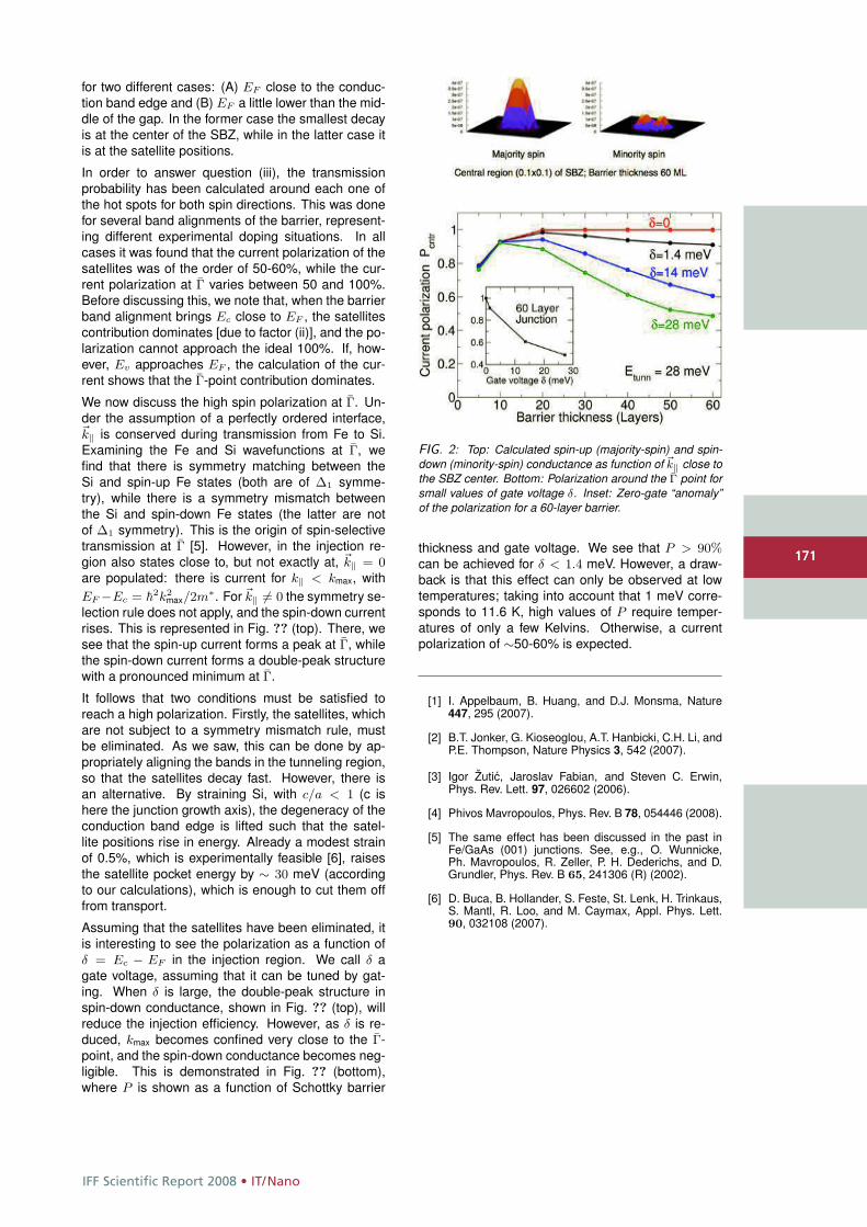
IFF Scientific Report 2008 • IT/Nano
171
for two different cases: (A) EF close to the conduc-tion band edge and (B) EF a little lower than the mid-dle of the gap. In the former case the smallest decayis at the center of the SBZ, while in the latter case itis at the satellite positions.
In order to answer question (iii), the transmissionprobability has been calculated around each one ofthe hot spots for both spin directions. This was donefor several band alignments of the barrier, represent-ing different experimental doping situations. In allcases it was found that the current polarization of thesatellites was of the order of 50-60%, while the cur-rent polarization at Γ varies between 50 and 100%.Before discussing this, we note that, when the barrierband alignment brings Ec close to EF , the satellitescontribution dominates [due to factor (ii)], and the po-larization cannot approach the ideal 100%. If, how-ever, Ev approaches EF , the calculation of the cur-rent shows that the Γ-point contribution dominates.
We now discuss the high spin polarization at Γ. Un-der the assumption of a perfectly ordered interface,�k‖ is conserved during transmission from Fe to Si.Examining the Fe and Si wavefunctions at Γ, wefind that there is symmetry matching between theSi and spin-up Fe states (both are of Δ1 symme-try), while there is a symmetry mismatch betweenthe Si and spin-down Fe states (the latter are notof Δ1 symmetry). This is the origin of spin-selectivetransmission at Γ [5]. However, in the injection re-gion also states close to, but not exactly at, �k‖ = 0are populated: there is current for k‖ < kmax, withEF −Ec = �
2k2max/2m∗. For �k‖ �= 0 the symmetry se-
lection rule does not apply, and the spin-down currentrises. This is represented in Fig. ?? (top). There, wesee that the spin-up current forms a peak at Γ, whilethe spin-down current forms a double-peak structurewith a pronounced minimum at Γ.
It follows that two conditions must be satisfied toreach a high polarization. Firstly, the satellites, whichare not subject to a symmetry mismatch rule, mustbe eliminated. As we saw, this can be done by ap-propriately aligning the bands in the tunneling region,so that the satellites decay fast. However, there isan alternative. By straining Si, with c/a < 1 (c ishere the junction growth axis), the degeneracy of theconduction band edge is lifted such that the satel-lite positions rise in energy. Already a modest strainof 0.5%, which is experimentally feasible [6], raisesthe satellite pocket energy by ∼ 30 meV (accordingto our calculations), which is enough to cut them offfrom transport.
Assuming that the satellites have been eliminated, itis interesting to see the polarization as a function ofδ = Ec − EF in the injection region. We call δ agate voltage, assuming that it can be tuned by gat-ing. When δ is large, the double-peak structure inspin-down conductance, shown in Fig. ?? (top), willreduce the injection efficiency. However, as δ is re-duced, kmax becomes confined very close to the Γ-point, and the spin-down conductance becomes neg-ligible. This is demonstrated in Fig. ?? (bottom),where P is shown as a function of Schottky barrier
FIG. 2: Top: Calculated spin-up (majority-spin) and spin-down (minority-spin) conductance as function of �k‖ close tothe SBZ center. Bottom: Polarization around the Γ point forsmall values of gate voltage δ. Inset: Zero-gate “anomaly”of the polarization for a 60-layer barrier.
thickness and gate voltage. We see that P > 90%can be achieved for δ < 1.4 meV. However, a draw-back is that this effect can only be observed at lowtemperatures; taking into account that 1 meV corre-sponds to 11.6 K, high values of P require temper-atures of only a few Kelvins. Otherwise, a currentpolarization of ∼50-60% is expected.
[1] I. Appelbaum, B. Huang, and D.J. Monsma, Nature447, 295 (2007).
[2] B.T. Jonker, G. Kioseoglou, A.T. Hanbicki, C.H. Li, andP.E. Thompson, Nature Physics 3, 542 (2007).
[3] Igor Žutic, Jaroslav Fabian, and Steven C. Erwin,Phys. Rev. Lett. 97, 026602 (2006).
[4] Phivos Mavropoulos, Phys. Rev. B 78, 054446 (2008).
[5] The same effect has been discussed in the past inFe/GaAs (001) junctions. See, e.g., O. Wunnicke,Ph. Mavropoulos, R. Zeller, P. H. Dederichs, and D.Grundler, Phys. Rev. B 65, 241306 (R) (2002).
[6] D. Buca, B. Hollander, S. Feste, St. Lenk, H. Trinkaus,S. Mantl, R. Loo, and M. Caymax, Appl. Phys. Lett.90, 032108 (2007).
171
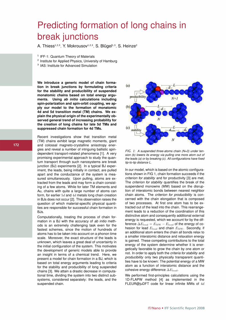
IT/Nano • IFF Scientific Report 2008
172
Predicting formation of long chains inbreak junctionsA. Thiess1,2,3, Y. Mokrousov1,2,3, S. Blügel1,3, S. Heinze2
1 IFF-1: Quantum Theory of Materials2 Institute for Applied Physics, University of Hamburg3 IAS: Institute for Advanced Simulation
We introduce a generic model of chain forma-
tion in break junctions by formulating criteria
for the stability and producibility of suspended
monatomic chains based on total energy argu-
ments. Using ab initio calculations including
spin-polarization and spin-orbit coupling, we ap-
ply our model to the formation of monatomic
4d and 5d transition metal (TM) chains. We ex-
plain the physical origin of the experimentally ob-
served general trend of increasing probability for
the creation of long chains for late 5d TMs and
suppressed chain formation for 4d TMs.
Recent investigations show that transition metal(TM) chains exhibit large magnetic moments, giantand colossal magneto-crystalline anisotropy ener-gies and reveal a number of intriguing ballistic spin-dependent transport-related phenomena [1]. A verypromising experimental approach to study the quan-tum transport through such nanosystems are breakjunction (BJ) experiments [2]. In a typical BJ exper-iment, the leads, being initially in contact, are pulledapart and the conductance of the system is mea-sured simultaneously. Upon pulling, atoms are ex-tracted from the leads and may form a chain consist-ing of a few atoms. While for later TM elements andAu, chains with quite a large number of atoms canform, for earlier 5d and 4d metals long chain creationin BJs does not occur [2]. This observation raises thequestion of which material-specific physical quanti-ties are responsible for successful chain formation inBJs.Computationally, treating the process of chain for-mation in a BJ with the accuracy of ab initio meth-ods is an extremely challenging task even for thefastest schemes, since the motion of hundreds ofatoms has to be taken into account on a phonon timescale. Moreover, the exact structure of the leads isunknown, which leaves a great deal of uncertainty inthe initial configuration of the system. This motivatesthe development of generic models able to providean insight in terms of a chemical trend. Here, wepresent a model for chain formation in a BJ, which isbased on total energy arguments leading to criteriafor the stability and producibility of long suspendedchains [3]. We attain a drastic decrease in computa-tional time, dividing the system into two distinct sub-systems, considered separately: the leads, and thesuspended chain.
FIG. 1: A suspended three-atoms chain (N=3) under ten-sion (b) lowers its energy via pulling one more atom out ofthe leads (a) or by breaking (c). All configurations have fixedtip-to-tip distance L.
In our model, which is based on the atomic configura-tions shown in FIG 1, chain formation succeeds if thecriterion for stability and for productivity [3] are met.The criterion for stability quantifies the break of thesuspendend monowire (MW) based on the disrup-tion of interatomic bonds between nearest neighborchain atoms. The criterion for producibility is con-cerned with the chain elongation that is composedof two processes. At first one atom has to be ex-tracted out of the lead into the chain. This rearrange-ment leads to a reduction of the coordination of thisdistinctive atom and consequently additional externalenergy is requested, which we account for by the dif-ference ΔElead = EMW − Elead of the energy of co-hesion for lead Elead and chain EMW. Secondly, ifan additional atom enters the chain all bonds relax toa smaller interatomic distance and relaxation energyis gained. These competing contributions to the totalenergy of the system determine whether it is ener-getically favorable to grow the chain by one atom ornot. In order to apply both the criteria for stability andproducibility only two physically transparent quanti-ties have to be known: The potential energy of a MWatom as a function of interatomic distance and thecohesive energy difference ΔElead.
We performed first-principles calculations using the1D-FLAPW method [4] as implemented in theFLEUR@juDFT code for linear infinite MWs of 4d
172
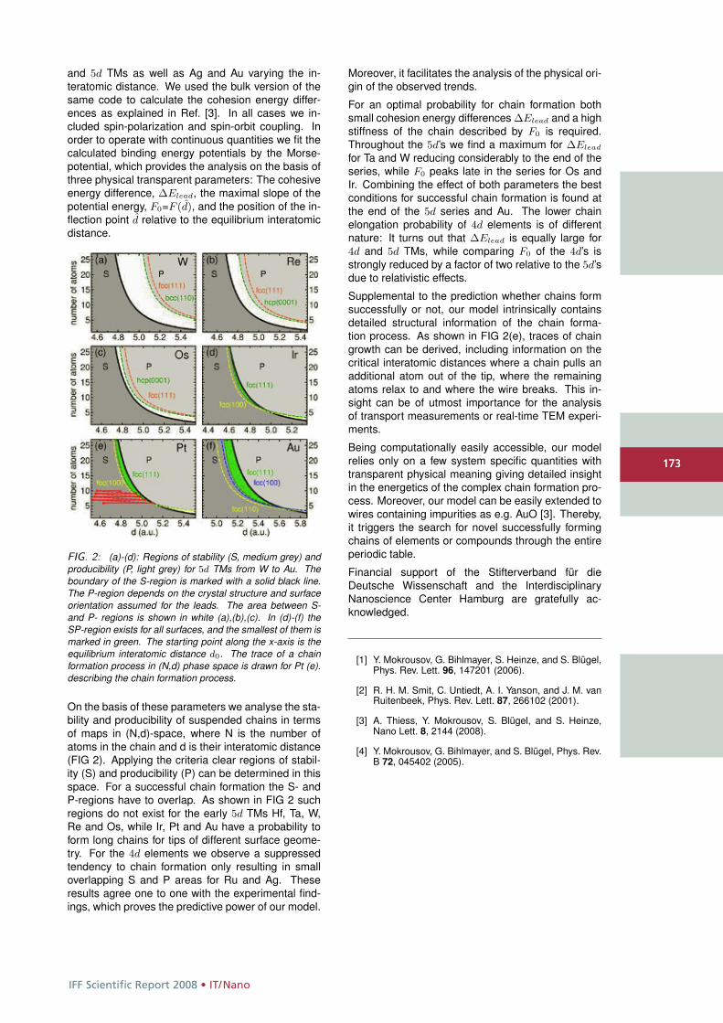
IFF Scientific Report 2008 • IT/Nano
173
and 5d TMs as well as Ag and Au varying the in-teratomic distance. We used the bulk version of thesame code to calculate the cohesion energy differ-ences as explained in Ref. [3]. In all cases we in-cluded spin-polarization and spin-orbit coupling. Inorder to operate with continuous quantities we fit thecalculated binding energy potentials by the Morse-potential, which provides the analysis on the basis ofthree physical transparent parameters: The cohesiveenergy difference, ΔElead, the maximal slope of thepotential energy, F0=F (d), and the position of the in-flection point d relative to the equilibrium interatomicdistance.
FIG. 2: (a)-(d): Regions of stability (S, medium grey) andproducibility (P, light grey) for 5d TMs from W to Au. Theboundary of the S-region is marked with a solid black line.The P-region depends on the crystal structure and surfaceorientation assumed for the leads. The area between S-and P- regions is shown in white (a),(b),(c). In (d)-(f) theSP-region exists for all surfaces, and the smallest of them ismarked in green. The starting point along the x-axis is theequilibrium interatomic distance d0. The trace of a chainformation process in (N,d) phase space is drawn for Pt (e).describing the chain formation process.
On the basis of these parameters we analyse the sta-bility and producibility of suspended chains in termsof maps in (N,d)-space, where N is the number ofatoms in the chain and d is their interatomic distance(FIG 2). Applying the criteria clear regions of stabil-ity (S) and producibility (P) can be determined in thisspace. For a successful chain formation the S- andP-regions have to overlap. As shown in FIG 2 suchregions do not exist for the early 5d TMs Hf, Ta, W,Re and Os, while Ir, Pt and Au have a probability toform long chains for tips of different surface geome-try. For the 4d elements we observe a suppressedtendency to chain formation only resulting in smalloverlapping S and P areas for Ru and Ag. Theseresults agree one to one with the experimental find-ings, which proves the predictive power of our model.
Moreover, it facilitates the analysis of the physical ori-gin of the observed trends.
For an optimal probability for chain formation bothsmall cohesion energy differences ΔElead and a highstiffness of the chain described by F0 is required.Throughout the 5d’s we find a maximum for ΔElead
for Ta and W reducing considerably to the end of theseries, while F0 peaks late in the series for Os andIr. Combining the effect of both parameters the bestconditions for successful chain formation is found atthe end of the 5d series and Au. The lower chainelongation probability of 4d elements is of differentnature: It turns out that ΔElead is equally large for4d and 5d TMs, while comparing F0 of the 4d’s isstrongly reduced by a factor of two relative to the 5d’sdue to relativistic effects.
Supplemental to the prediction whether chains formsuccessfully or not, our model intrinsically containsdetailed structural information of the chain forma-tion process. As shown in FIG 2(e), traces of chaingrowth can be derived, including information on thecritical interatomic distances where a chain pulls anadditional atom out of the tip, where the remainingatoms relax to and where the wire breaks. This in-sight can be of utmost importance for the analysisof transport measurements or real-time TEM experi-ments.
Being computationally easily accessible, our modelrelies only on a few system specific quantities withtransparent physical meaning giving detailed insightin the energetics of the complex chain formation pro-cess. Moreover, our model can be easily extended towires containing impurities as e.g. AuO [3]. Thereby,it triggers the search for novel successfully formingchains of elements or compounds through the entireperiodic table.
Financial support of the Stifterverband für dieDeutsche Wissenschaft and the InterdisciplinaryNanoscience Center Hamburg are gratefully ac-knowledged.
[1] Y. Mokrousov, G. Bihlmayer, S. Heinze, and S. Blügel,Phys. Rev. Lett. 96, 147201 (2006).
[2] R. H. M. Smit, C. Untiedt, A. I. Yanson, and J. M. vanRuitenbeek, Phys. Rev. Lett. 87, 266102 (2001).
[3] A. Thiess, Y. Mokrousov, S. Blügel, and S. Heinze,Nano Lett. 8, 2144 (2008).
[4] Y. Mokrousov, G. Bihlmayer, and S. Blügel, Phys. Rev.B 72, 045402 (2005).
173

IT/Nano • IFF Scientific Report 2008
174
Peapod synthesis on substratesC. Meyer1,2, C. Spudat1,2, L. Houben3,4, C. M. Schneider1,2
1 IFF-9: Electronic Properties2 JARA Fundamentals of Future Information Technologies3 IFF-8: Microstructure Research4 ER-C: Ernst Ruska-Centre for Microscopy and Spectroscopy with Electrons
We present how carbon nanotubes can be grown
and filled with fullerene molecules directly on
a substrate. The resulting peapods are very
clean and thus suitable for the fabrication of
electronic devices. Since oxidation of the nan-
otubes is a crucial step during the peapod syn-
thesis, we investigate the effects in more de-
tail using high resolution transmission electron
microscopy (HRTEM) and Raman spectroscopy.
Two different oxidation methods, heating in air
and acid treatment, are compared.
Carbon nanotubes (CNTs) filled with fullerenemolecules, so-called "peapods", recently have gen-erated a lot of interest as systems for electronic ap-plications. The C60 fullerenes inside the tubes modu-late the local density of states due to hybridization ofthe molecular orbitals with the conduction band andGd@C82 fullerenes inside a semiconducting tube canchange the band gap. These effects allow one tobuild ambipolar CNT field effect transistors and totune the gate-dependent conductance of single elec-tron transistors. Filling with fullerenes can changemechanical properties of CNTs, e.g., softening thevibrational modes, which is interesting for the fabri-cation of nano-electro-mechanical devices.
For electronic applications it is desirable to use CNTssynthesized by chemical vapor deposition (CVD).This method yields CNTs which can be several mi-crometers long and grown on predefined sites on thesubstrate. Therefore, they do not cluster to ropes likeCNTs dispersed on a substrate from solution. Car-bon nanotubes grown with CVD have to be filled di-rectly on the substrate in order to keep these advan-tages for the resulting peapods.
The carbon nanotubes grown by CVD are closed andhave to be opened before they can be filled. This isusually done using oxidation either by heating in air orby acid treatment. For CNTs grown on substrate onlythe former method had been studied [1, 2]. We inves-tigated the influence of both methods on the creationof defects [3]. By doing so, we gained information onhow chemical reactions affect single tubes comparedto powder samples.
The carbon nanotubes were grown with CVD directlyon TEM substrates (DuraSiNTM, Protochips Inc.). Ox-idation by annealing in air was done at 450 ◦C for 20min, oxidation by acid treatment was carried out in 5
molar HNO3 at 100 ◦C for 3 h. The defects and fillingof individual CNTs were studied with high-resolutiontransmission electron microscopy (HRTEM) usingaberration correction.
After oxidation the tubes are filled with amorphouscarbon (see Fig.1). Both methods damage the capsof the CNTs as well as the sidewalls. Annealingthe tube in air seems to have the same effect forindividual tubes as for "bulk" samples. The innerwalls are opened along with the outer walls, as ex-pected (Fig.1a). In contrast, the acid treatment hasa stronger impact on single tubes than on tubes inpowder samples. We could show that the tubes canbe dissolved from inside (Fig.1b). Thus, the carbonresidue inside the CNTs may consist of remnantsfrom destroyed inner walls.
FIG. 1: Oxidation of CVD carbon nanotubes leads to amor-phous carbon residue inside the tubes. Arrows indicate de-fects on the sidewalls. Atoms appear bright in this case dueto the negative spherical aberration imaging used for opti-mized phase contrast. (a) Heating in air usually affects in-ner walls along with the outer walls. (b) Acid treatment candissolve walls from inside-out (bottom arrows).
This residue inside the tube can be removed at leastfor CNTs oxidized by heating in air. High temperatureannealing at 900 ◦C and with a pressure p ≤ 1 · 10−6
174
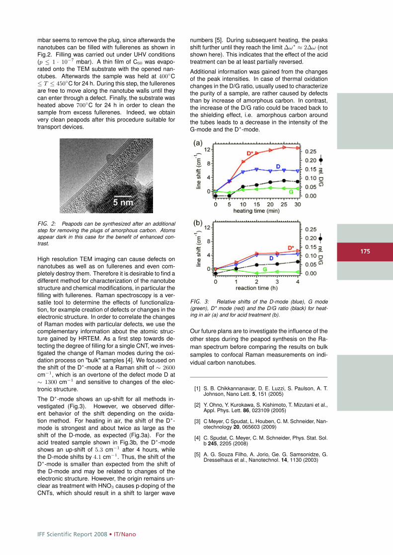
IFF Scientific Report 2008 • IT/Nano
175
mbar seems to remove the plug, since afterwards thenanotubes can be filled with fullerenes as shown inFig.2. Filling was carried out under UHV conditions(p ≤ 1 · 10−7 mbar). A thin film of C60 was evapo-rated onto the TEM substrate with the opened nan-otubes. Afterwards the sample was held at 400◦C≤ T ≤ 450◦C for 24 h. During this step, the fullerenesare free to move along the nanotube walls until theycan enter through a defect. Finally, the substrate washeated above 700◦C for 24 h in order to clean thesample from excess fullerenes. Indeed, we obtainvery clean peapods after this procedure suitable fortransport devices.
FIG. 2: Peapods can be synthesized after an additionalstep for removing the plugs of amorphous carbon. Atomsappear dark in this case for the benefit of enhanced con-trast.
High resolution TEM imaging can cause defects onnanotubes as well as on fullerenes and even com-pletely destroy them. Therefore it is desirable to find adifferent method for characterization of the nanotubestructure and chemical modifications, in particular thefilling with fullerenes. Raman spectroscopy is a ver-satile tool to determine the effects of functionaliza-tion, for example creation of defects or changes in theelectronic structure. In order to correlate the changesof Raman modes with particular defects, we use thecomplementary information about the atomic struc-ture gained by HRTEM. As a first step towards de-tecting the degree of filling for a single CNT, we inves-tigated the change of Raman modes during the oxi-dation process on "bulk" samples [4]. We focused onthe shift of the D∗-mode at a Raman shift of ∼ 2600cm−1, which is an overtone of the defect mode D at∼ 1300 cm−1 and sensitive to changes of the elec-tronic structure.
The D∗-mode shows an up-shift for all methods in-vestigated (Fig.3). However, we observed differ-ent behavior of the shift depending on the oxida-tion method. For heating in air, the shift of the D∗-mode is strongest and about twice as large as theshift of the D-mode, as expected (Fig.3a). For theacid treated sample shown in Fig.3b, the D∗-modeshows an up-shift of 5.3 cm−1 after 4 hours, whilethe D-mode shifts by 4.1 cm−1. Thus, the shift of theD∗-mode is smaller than expected from the shift ofthe D-mode and may be related to changes of theelectronic structure. However, the origin remains un-clear as treatment with HNO3 causes p-doping of theCNTs, which should result in a shift to larger wave
numbers [5]. During subsequent heating, the peaksshift further until they reach the limit Δω∗ ≈ 2Δω (notshown here). This indicates that the effect of the acidtreatment can be at least partially reversed.
Additional information was gained from the changesof the peak intensities. In case of thermal oxidationchanges in the D/G ratio, usually used to characterizethe purity of a sample, are rather caused by defectsthan by increase of amorphous carbon. In contrast,the increase of the D/G ratio could be traced back tothe shielding effect, i.e. amorphous carbon aroundthe tubes leads to a decrease in the intensity of theG-mode and the D∗-mode.
FIG. 3: Relative shifts of the D-mode (blue), G mode(green), D* mode (red) and the D/G ratio (black) for heat-ing in air (a) and for acid treatment (b).
Our future plans are to investigate the influence of theother steps during the peapod synthesis on the Ra-man spectrum before comparing the results on bulksamples to confocal Raman measurements on indi-vidual carbon nanotubes.
[1] S. B. Chikkannanavar, D. E. Luzzi, S. Paulson, A. T.Johnson, Nano Lett. 5, 151 (2005)
[2] Y. Ohno, Y. Kurokawa, S. Kishimoto, T. Mizutani et al.,Appl. Phys. Lett. 86, 023109 (2005)
[3] C Meyer, C Spudat, L. Houben, C. M. Schneider, Nan-otechnology 20, 065603 (2009)
[4] C. Spudat, C. Meyer, C. M. Schneider, Phys. Stat. Sol.b 245, 2205 (2008)
[5] A. G. Souza Filho, A. Jorio, Ge. G. Samsonidze, G.Dresselhaus et al., Nanotechnol. 14, 1130 (2003)
175
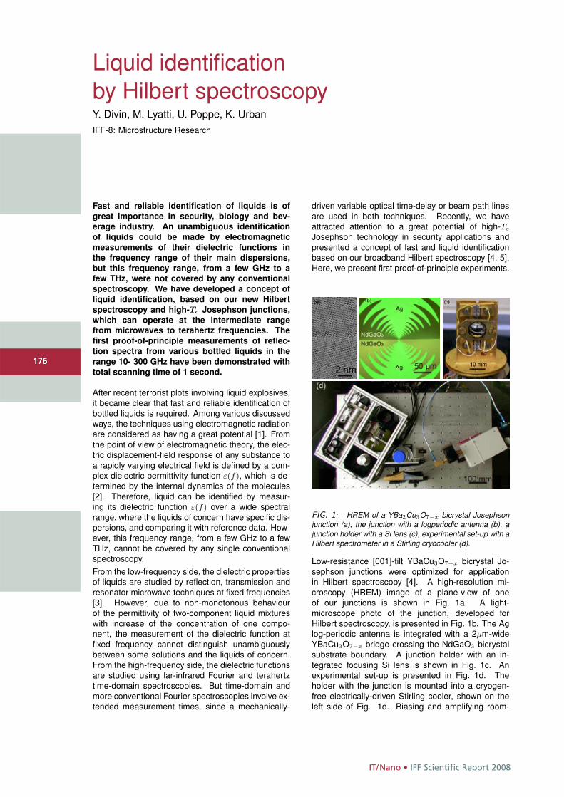
IT/Nano • IFF Scientific Report 2008
176
Liquid identificationby Hilbert spectroscopyY. Divin, M. Lyatti, U. Poppe, K. UrbanIFF-8: Microstructure Research
Fast and reliable identification of liquids is of
great importance in security, biology and bev-
erage industry. An unambiguous identification
of liquids could be made by electromagnetic
measurements of their dielectric functions in
the frequency range of their main dispersions,
but this frequency range, from a few GHz to a
few THz, were not covered by any conventional
spectroscopy. We have developed a concept of
liquid identification, based on our new Hilbert
spectroscopy and high-Tc Josephson junctions,
which can operate at the intermediate range
from microwaves to terahertz frequencies. The
first proof-of-principle measurements of reflec-
tion spectra from various bottled liquids in the
range 10- 300 GHz have been demonstrated with
total scanning time of 1 second.
After recent terrorist plots involving liquid explosives,it became clear that fast and reliable identification ofbottled liquids is required. Among various discussedways, the techniques using electromagnetic radiationare considered as having a great potential [1]. Fromthe point of view of electromagnetic theory, the elec-tric displacement-field response of any substance toa rapidly varying electrical field is defined by a com-plex dielectric permittivity function ε(f), which is de-termined by the internal dynamics of the molecules[2]. Therefore, liquid can be identified by measur-ing its dielectric function ε(f) over a wide spectralrange, where the liquids of concern have specific dis-persions, and comparing it with reference data. How-ever, this frequency range, from a few GHz to a fewTHz, cannot be covered by any single conventionalspectroscopy.From the low-frequency side, the dielectric propertiesof liquids are studied by reflection, transmission andresonator microwave techniques at fixed frequencies[3]. However, due to non-monotonous behaviourof the permittivity of two-component liquid mixtureswith increase of the concentration of one compo-nent, the measurement of the dielectric function atfixed frequency cannot distinguish unambiguouslybetween some solutions and the liquids of concern.From the high-frequency side, the dielectric functionsare studied using far-infrared Fourier and terahertztime-domain spectroscopies. But time-domain andmore conventional Fourier spectroscopies involve ex-tended measurement times, since a mechanically-
driven variable optical time-delay or beam path linesare used in both techniques. Recently, we haveattracted attention to a great potential of high-Tc
Josephson technology in security applications andpresented a concept of fast and liquid identificationbased on our broadband Hilbert spectroscopy [4, 5].Here, we present first proof-of-principle experiments.
FIG. 1: HREM of a YBa2Cu3O7−x bicrystal Josephsonjunction (a), the junction with a logperiodic antenna (b), ajunction holder with a Si lens (c), experimental set-up with aHilbert spectrometer in a Stirling cryocooler (d).
Low-resistance [001]-tilt YBaCu3O7−x bicrystal Jo-sephson junctions were optimized for applicationin Hilbert spectroscopy [4]. A high-resolution mi-croscopy (HREM) image of a plane-view of oneof our junctions is shown in Fig. 1a. A light-microscope photo of the junction, developed forHilbert spectroscopy, is presented in Fig. 1b. The Aglog-periodic antenna is integrated with a 2μm-wideYBaCu3O7−x bridge crossing the NdGaO3 bicrystalsubstrate boundary. A junction holder with an in-tegrated focusing Si lens is shown in Fig. 1c. Anexperimental set-up is presented in Fig. 1d. Theholder with the junction is mounted into a cryogen-free electrically-driven Stirling cooler, shown on theleft side of Fig. 1d. Biasing and amplifying room-
176
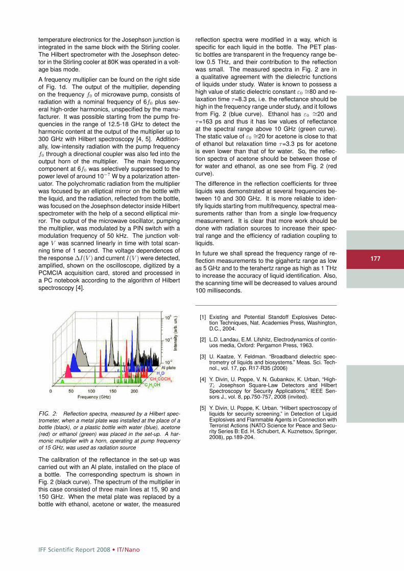
IFF Scientific Report 2008 • IT/Nano
177
temperature electronics for the Josephson junction isintegrated in the same block with the Stirling cooler.The Hilbert spectrometer with the Josephson detec-tor in the Stirling cooler at 80K was operated in a volt-age bias mode.
A frequency multiplier can be found on the right sideof Fig. 1d. The output of the multiplier, dependingon the frequency f0 of microwave pump, consists ofradiation with a nominal frequency of 6f0 plus sev-eral high-order harmonics, unspecified by the manu-facturer. It was possible starting from the pump fre-quencies in the range of 12.5-18 GHz to detect theharmonic content at the output of the multiplier up to300 GHz with Hilbert spectroscopy [4, 5]. Addition-ally, low-intensity radiation with the pump frequencyf0 through a directional coupler was also fed into theoutput horn of the multiplier. The main frequencycomponent at 6f0 was selectively suppressed to thepower level of around 10−7 W by a polarization atten-uator. The polychromatic radiation from the multiplierwas focused by an elliptical mirror on the bottle withthe liquid, and the radiation, reflected from the bottle,was focused on the Josephson detector inside Hilbertspectrometer with the help of a second elliptical mir-ror. The output of the microwave oscillator, pumpingthe multiplier, was modulated by a PIN switch with amodulation frequency of 50 kHz. The junction volt-age V was scanned linearly in time with total scan-ning time of 1 second. The voltage dependences ofthe response ΔI(V ) and current I(V ) were detected,amplified, shown on the oscilloscope, digitized by aPCMCIA acquisition card, stored and processed ina PC notebook according to the algorithm of Hilbertspectroscopy [4].
FIG. 2: Reflection spectra, measured by a Hilbert spec-trometer, when a metal plate was installed at the place of abottle (black), or a plastic bottle with water (blue), acetone(red) or ethanol (green) was placed in the set-up. A har-monic multiplier with a horn, operating at pump frequencyof 15 GHz, was used as radiation source
The calibration of the reflectance in the set-up wascarried out with an Al plate, installed on the place ofa bottle. The corresponding spectrum is shown inFig. 2 (black curve). The spectrum of the multiplier inthis case consisted of three main lines at 15, 90 and150 GHz. When the metal plate was replaced by abottle with ethanol, acetone or water, the measured
reflection spectra were modified in a way, which isspecific for each liquid in the bottle. The PET plas-tic bottles are transparent in the frequency range be-low 0.5 THz, and their contribution to the reflectionwas small. The measured spectra in Fig. 2 are ina qualitative agreement with the dielectric functionsof liquids under study. Water is known to possess ahigh value of static dielectric constant ε0
∼=80 and re-laxation time τ=8.3 ps, i.e. the reflectance should behigh in the frequency range under study, and it followsfrom Fig. 2 (blue curve). Ethanol has ε0
∼=20 andτ=163 ps and thus it has low values of reflectanceat the spectral range above 10 GHz (green curve).The static value of ε0
∼=20 for acetone is close to thatof ethanol but relaxation time τ=3.3 ps for acetoneis even lower than that of for water. So, the reflec-tion spectra of acetone should be between those offor water and ethanol, as one see from Fig. 2 (redcurve).
The difference in the reflection coefficients for threeliquids was demonstrated at several frequencies be-tween 10 and 300 GHz. It is more reliable to iden-tify liquids starting from multifrequency, spectral mea-surements rather than from a single low-frequencymeasurement. It is clear that more work should bedone with radiation sources to increase their spec-tral range and the efficiency of radiation coupling toliquids.
In future we shall spread the frequency range of re-flection measurements to the gigahertz range as lowas 5 GHz and to the terahertz range as high as 1 THzto increase the accuracy of liquid identification. Also,the scanning time will be decreased to values around100 milliseconds.
[1] Existing and Potential Standoff Explosives Detec-tion Techniques, Nat. Academies Press, Washington,D.C., 2004.
[2] L.D. Landau, E.M. Lifshitz, Electrodynamics of contin-uos media, Oxford: Pergamon Press, 1963.
[3] U. Kaatze, Y. Feldman. “Broadband dielectric spec-trometry of liquids and biosystems.” Meas. Sci. Tech-nol., vol. 17, pp. R17-R35 (2006)
[4] Y. Divin, U. Poppe, V. N. Gubankov, K. Urban, “High-Tc Josephson Square-Law Detectors and HilbertSpectroscopy for Security Applications,” IEEE Sen-sors J., vol. 8, pp.750-757, 2008 (invited).
[5] Y. Divin, U. Poppe, K. Urban. “Hilbert spectroscopy ofliquids for security screening.” in Detection of LiquidExplosives and Flammable Agents in Connection withTerrorist Actions (NATO Science for Peace and Secu-rity Series B: Ed. H. Schubert, A. Kuznetsov, Springer,2008), pp.189-204.
177
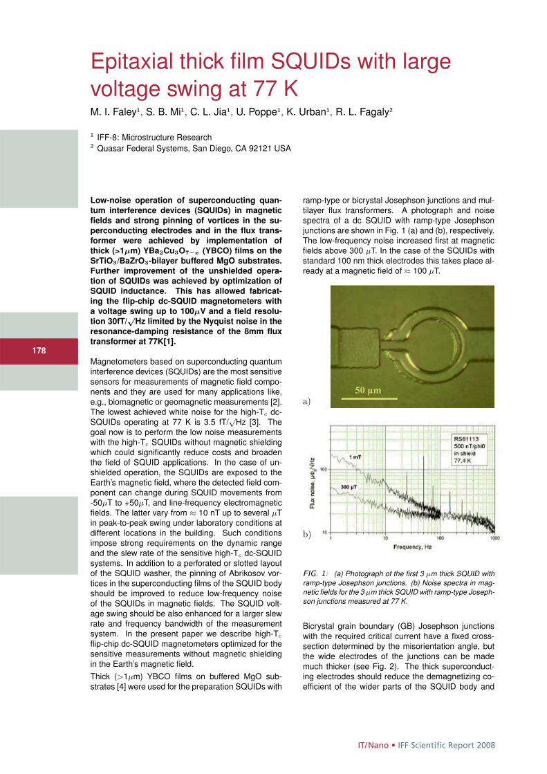
IT/Nano • IFF Scientific Report 2008
178
Epitaxial thick film SQUIDs with largevoltage swing at 77 KM. I. Faley1, S. B. Mi1, C. L. Jia1, U. Poppe1, K. Urban1, R. L. Fagaly2
1 IFF-8: Microstructure Research2 Quasar Federal Systems, San Diego, CA 92121 USA
Low-noise operation of superconducting quan-
tum interference devices (SQUIDs) in magnetic
fields and strong pinning of vortices in the su-
perconducting electrodes and in the flux trans-
former were achieved by implementation of
thick (>1μm) YBa2Cu3O7−x (YBCO) films on the
SrTiO3/BaZrO3-bilayer buffered MgO substrates.
Further improvement of the unshielded opera-
tion of SQUIDs was achieved by optimization of
SQUID inductance. This has allowed fabricat-
ing the flip-chip dc-SQUID magnetometers with
a voltage swing up to 100μV and a field resolu-
tion 30fT/√
Hz limited by the Nyquist noise in the
resonance-damping resistance of the 8mm flux
transformer at 77K[1].
Magnetometers based on superconducting quantuminterference devices (SQUIDs) are the most sensitivesensors for measurements of magnetic field compo-nents and they are used for many applications like,e.g., biomagnetic or geomagnetic measurements [2].The lowest achieved white noise for the high-Tc dc-SQUIDs operating at 77 K is 3.5 fT/
√Hz [3]. The
goal now is to perform the low noise measurementswith the high-Tc SQUIDs without magnetic shieldingwhich could significantly reduce costs and broadenthe field of SQUID applications. In the case of un-shielded operation, the SQUIDs are exposed to theEarth’s magnetic field, where the detected field com-ponent can change during SQUID movements from-50μT to +50μT, and line-frequency electromagneticfields. The latter vary from ≈ 10 nT up to several μTin peak-to-peak swing under laboratory conditions atdifferent locations in the building. Such conditionsimpose strong requirements on the dynamic rangeand the slew rate of the sensitive high-Tc dc-SQUIDsystems. In addition to a perforated or slotted layoutof the SQUID washer, the pinning of Abrikosov vor-tices in the superconducting films of the SQUID bodyshould be improved to reduce low-frequency noiseof the SQUIDs in magnetic fields. The SQUID volt-age swing should be also enhanced for a larger slewrate and frequency bandwidth of the measurementsystem. In the present paper we describe high-Tc
flip-chip dc-SQUID magnetometers optimized for thesensitive measurements without magnetic shieldingin the Earth’s magnetic field.Thick (>1μm) YBCO films on buffered MgO sub-strates [4] were used for the preparation SQUIDs with
ramp-type or bicrystal Josephson junctions and mul-tilayer flux transformers. A photograph and noisespectra of a dc SQUID with ramp-type Josephsonjunctions are shown in Fig. 1 (a) and (b), respectively.The low-frequency noise increased first at magneticfields above 300 μT. In the case of the SQUIDs withstandard 100 nm thick electrodes this takes place al-ready at a magnetic field of ≈ 100 μT.
b)
a)
FIG. 1: (a) Photograph of the first 3 μm thick SQUID withramp-type Josephson junctions. (b) Noise spectra in mag-netic fields for the 3 μm thick SQUID with ramp-type Joseph-son junctions measured at 77 K.
Bicrystal grain boundary (GB) Josephson junctionswith the required critical current have a fixed cross-section determined by the misorientation angle, butthe wide electrodes of the junctions can be mademuch thicker (see Fig. 2). The thick superconduct-ing electrodes should reduce the demagnetizing co-efficient of the wider parts of the SQUID body and
178
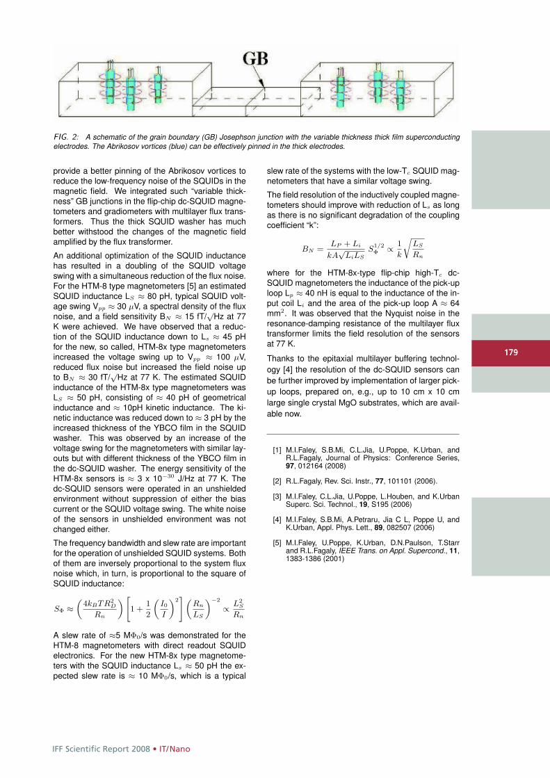
IFF Scientific Report 2008 • IT/Nano
179
FIG. 2: A schematic of the grain boundary (GB) Josephson junction with the variable thickness thick film superconductingelectrodes. The Abrikosov vortices (blue) can be effectively pinned in the thick electrodes.
provide a better pinning of the Abrikosov vortices toreduce the low-frequency noise of the SQUIDs in themagnetic field. We integrated such “variable thick-ness” GB junctions in the flip-chip dc-SQUID magne-tometers and gradiometers with multilayer flux trans-formers. Thus the thick SQUID washer has muchbetter withstood the changes of the magnetic fieldamplified by the flux transformer.
An additional optimization of the SQUID inductancehas resulted in a doubling of the SQUID voltageswing with a simultaneous reduction of the flux noise.For the HTM-8 type magnetometers [5] an estimatedSQUID inductance LS ≈ 80 pH, typical SQUID volt-age swing Vpp ≈ 30 μV, a spectral density of the fluxnoise, and a field sensitivity BN ≈ 15 fT/
√Hz at 77
K were achieved. We have observed that a reduc-tion of the SQUID inductance down to Ls ≈ 45 pHfor the new, so called, HTM-8x type magnetometersincreased the voltage swing up to Vpp ≈ 100 μV,reduced flux noise but increased the field noise upto BN ≈ 30 fT/
√Hz at 77 K. The estimated SQUID
inductance of the HTM-8x type magnetometers wasLS ≈ 50 pH, consisting of ≈ 40 pH of geometricalinductance and ≈ 10pH kinetic inductance. The ki-netic inductance was reduced down to ≈ 3 pH by theincreased thickness of the YBCO film in the SQUIDwasher. This was observed by an increase of thevoltage swing for the magnetometers with similar lay-outs but with different thickness of the YBCO film inthe dc-SQUID washer. The energy sensitivity of theHTM-8x sensors is ≈ 3 x 10⁻³⁰ J/Hz at 77 K. Thedc-SQUID sensors were operated in an unshieldedenvironment without suppression of either the biascurrent or the SQUID voltage swing. The white noiseof the sensors in unshielded environment was notchanged either.
The frequency bandwidth and slew rate are importantfor the operation of unshielded SQUID systems. Bothof them are inversely proportional to the system fluxnoise which, in turn, is proportional to the square ofSQUID inductance:
SΦ ≈„
4kBTR2D
Rn
« "1 +
1
2
„I0
I
«2# „
Rn
LS
«−2
∝ L2S
Rn
A slew rate of ≈5 MΦ0/s was demonstrated for theHTM-8 magnetometers with direct readout SQUIDelectronics. For the new HTM-8x type magnetome-ters with the SQUID inductance Ls ≈ 50 pH the ex-pected slew rate is ≈ 10 MΦ0/s, which is a typical
slew rate of the systems with the low-Tc SQUID mag-netometers that have a similar voltage swing.
The field resolution of the inductively coupled magne-tometers should improve with reduction of Ls as longas there is no significant degradation of the couplingcoefficient “k”:
BN =LP + Li
kA√
LiLS
S1/2Φ ∝ 1
k
rLS
Rn
where for the HTM-8x-type flip-chip high-Tc dc-SQUID magnetometers the inductance of the pick-uploop Lp ≈ 40 nH is equal to the inductance of the in-put coil Li and the area of the pick-up loop A ≈ 64mm2. It was observed that the Nyquist noise in theresonance-damping resistance of the multilayer fluxtransformer limits the field resolution of the sensorsat 77 K.
Thanks to the epitaxial multilayer buffering technol-ogy [4] the resolution of the dc-SQUID sensors canbe further improved by implementation of larger pick-up loops, prepared on, e.g., up to 10 cm x 10 cmlarge single crystal MgO substrates, which are avail-able now.
[1] M.I.Faley, S.B.Mi, C.L.Jia, U.Poppe, K.Urban, andR.L.Fagaly, Journal of Physics: Conference Series,97, 012164 (2008)
[2] R.L.Fagaly, Rev. Sci. Instr., 77, 101101 (2006).
[3] M.I.Faley, C.L.Jia, U.Poppe, L.Houben, and K.UrbanSuperc. Sci. Technol., 19, S195 (2006)
[4] M.I.Faley, S.B.Mi, A.Petraru, Jia C L, Poppe U, andK.Urban, Appl. Phys. Lett., 89, 082507 (2006)
[5] M.I.Faley, U.Poppe, K.Urban, D.N.Paulson, T.Starrand R.L.Fagaly, IEEE Trans. on Appl. Supercond., 11,1383-1386 (2001)
179
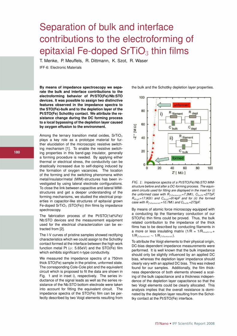
IT/Nano • IFF Scientific Report 2008
180
Separation of bulk and interfacecontributions to the electroforming ofepitaxial Fe-doped SrTiO3 thin filmsT. Menke, P. Meuffels, R. Dittmann, K. Szot, R. WaserIFF-6: Electronic Materials
By means of impedance spectroscopy we sepa-
rate the bulk and interface contributions to the
electroforming behavior of Pt/STO(Fe)/Nb:STO
devices. It was possible to assign two distinctive
features observed in the impedance spectra to
the STO(Fe)-bulk and to the depletion layer of the
Pt/STO(Fe) Schottky contact. We attribute the re-
sistance change during the DC forming process
to a local bypassing of the depletion layer caused
by oxygen effusion to the environment.
Among the ternary transition metal oxides, SrTiO3
plays a key role as a prototype material for fur-ther elucidation of the microscopic resistive switch-ing mechanism [1]. To enable the resistive switch-ing properties in this band-gap insulator, generallya forming procedure is needed. By applying eitherthermal or electrical stress, the conductivity can bedrastically increased due to self-doping induced bythe formation of oxygen vacancies. The locationof the forming and the switching phenomena withinmetal/insulator/metal (MIM)-structures has been in-vestigated by using lateral electrode configurations.To close the link between capacitive and lateral MIM-structures and get a deeper understanding of theforming mechanisms, we studied the electrical prop-erties in capacitor-like structures of epitaxial grownFe-doped SrTiO3 (STO(Fe)) thin films by impedancespectroscopy.
The fabrication process of the Pt/STO(1at%Fe)/Nb:STO devices and the measurement equipmentused for the electrical characterization can be ex-tracted from [2].
The I-V curves of pristine samples showed rectifyingcharacteristics which we could assign to the Schottkycontact formed at the interface between the high workfunction metal Pt (φ: 5.65eV) and the STO(Fe) filmwhich exhibits significant n-type conductivity.
We measured the impedance spectra of a 750nmthick STO(Fe) sample in the pristine, unformed state.The corresponding Cole-Cole plot and the equivalentcircuit which is proposed to fit the data are shown inFig. 1 and in inset i), respectively. The series in-ductance of the signal leads as well as the series re-sistance of the Nb:STO bottom electrode were takeninto account for fitting the equivalent circuit. Theimpedance spectra of the STO(Fe) film can be per-fectly described by two Voigt elements resulting from
the bulk and the Schottky depletion layer properties.
FIG. 1: Impedance spectra of a Pt/STO(Fe)/Nb:STO MIM-structure before and after a DC-forming process. The equiv-alent circuits used for fitting are displayed in the inset for (i)the unformed case with Rfilament=7.3MΩ, Cbulk=277pF,Rdepl=17.9GΩ and Cdepl=914pF and for (ii) the formedcase with Rfilament=10.7MΩ and Cbulk=273pF.
By means of atomic force microscopy equipped witha conducting tip the filamentary conduction of ourSTO(Fe) thin films could be proved. Thus, the bulkrelated contribution to the impedance of the thickfilms has to be described by conducting filaments ina more or less insulating matrix (1/R = 1/Rmatrix+1/Rfilament ∼ 1/Rfilament).
To attribute the Voigt elements to their physical origin,DC-bias dependent impedance measurements wereperformed. It is well known that the bulk impedanceshould only be slightly influenced by an applied DCbias, whereas the depletion layer impedance shouldclearly vary with an applied DC bias. This was indeedfound for our samples. Additionally, the film thick-ness dependence of both elements showed a scal-ing of the bulk capacitance and a thickness indepen-dence of the depletion layer capacitance so that thetwo Voigt elements could be clearly allocated. Thisanalysis implies that the overall resistance is domi-nated by the depletion layer resulting from the Schot-tky contact at the Pt/STO(Fe) interface.
180
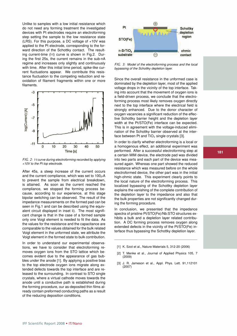
IFF Scientific Report 2008 • IT/Nano
181
Unlike to samples with a low initial resistance whichdo not need any forming treatment the investigateddevices with Pt electrodes require an electroformingstep setting the sample to the low resistance state(LRS). For this purpose, a DC voltage of +10V wasapplied to the Pt electrode, corresponding to the for-ward direction of the Schottky contact. The result-ing current-time (I-t) curve is shown in Fig.2. Dur-ing the first 25s, the current remains in the sub-nAregime and increases only slightly and continuouslywith time. After this initial time period, spike-like cur-rent fluctuations appear. We contribute this resis-tance fluctuation to the competing reduction and re-oxidation of filament fragments within one or morefilaments.
FIG. 2: I-t curve during electroforming recorded by applying+10V to the Pt top electrode.
After 45s, a steep increase of the current occursand the current compliance, which was set to 100μAto prevent the sample from electrical breakdown,is attained. As soon as the current reached thecompliance, we stopped the forming process be-cause, according to our experience, at this stagebipolar switching can be observed. The result of theimpedance measurements on the formed pad can beseen in Fig.1 and can be described using the equiv-alent circuit displayed in inset ii). The most signifi-cant change is that in the case of a formed sampleonly one Voigt element is needed to fit the data. Asthe values for the resistance and the capacitance arecomparable to the values obtained for the bulk relatedVoigt element in the unformed state, we attribute theVoigt element in the formed state to bulk contribution.
In order to understand our experimental observa-tions, we have to consider that electroforming re-moves oxygen ions from the STO lattice which be-comes evident due to the appearance of gas bub-bles under the anode [1]. By applying a positive biasto the top electrode oxygen ions migrate along ex-tended defects towards the top interface and are re-leased to the surrounding. In contrast to STO singlecrystals, where a virtual cathode moves towards theanode until a conductive path is established duringthe forming procedure, our as-deposited thin films al-ready contain preformed conducting paths as a resultof the reducing deposition conditions.
FIG. 3: Model of the electroforming process and the localbypassing of the Schottky depletion layer.
Since the overall resistance in the unformed case isdominated by the depletion layer, most of the appliedvoltage drops in the vicinity of the top interface. Tak-ing into account that the movement of oxygen ions isa field-driven process, we conclude that the electro-forming process most likely removes oxygen directlynext to the top interface where the electrical field isstrongly enhanced. Due to the donor character ofoxygen vacancies a significant reduction of the effec-tive Schottky barrier height and the depletion layerwidth at the Pt/STO(Fe) interface can be expected.This is in agreement with the voltage-induced elimi-nation of the Schottky barrier observed at the inter-face between Pt and TiO2 single crystals [3].
In order to clarify whether electroforming is a local ora homogenous effect, an additional experiment wasperformed. After a successful electroforming step ata certain MIM device, the electrode pad was dividedinto two parts and each part of the device was mea-sured again. Whereas one part showed the reducedresistance which was measured before on the wholeelectroformed device, the other part was in the initialhigh-ohmic state. This experiment clearly points tothe local nature of the electroforming process. Thislocalized bypassing of the Schottky depletion layerexplains the vanishing of the complete contribution ofthe depletion layer to the impedance and also thatthe bulk properties are not significantly changed dur-ing the forming procedure.
In conclusion, we presented that the impedancespectra of pristine Pt/STO(Fe)/Nb:STO structures ex-hibits a bulk and a depletion layer related contribu-tion. A DC forming process removes oxygen alongextended defects in the vicinity of the Pt/STO(Fe) in-terface thus bypassing the Schottky depletion layer.
[1] K. Szot et al., Nature Materials 5, 312-20 (2006)
[2] T. Menke et al., Journal of Applied Physics 105, 7(2009)
[3] J. R. Jameson et al., Appl. Phys. Lett. 91,112101(2007)
181
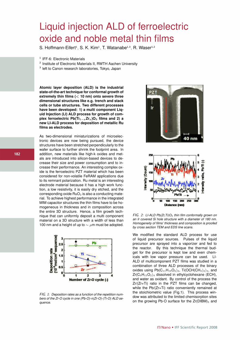
IT/Nano • IFF Scientific Report 2008
182
Liquid injection ALD of ferroelectricoxide and noble metal thin filmsS. Hoffmann-Eifert1, S. K. Kim1, T. Watanabe1,3, R. Waser1,2
1 IFF-6: Electronic Materials2 Institute of Electronic Materials II, RWTH Aachen University3 left to Canon research laboratories, Tokyo, Japan
Atomic layer deposition (ALD) is the industrial
state-of-the-art technique for conformal growth of
extremely thin films (< 10 nm) onto severe three
dimensional structures like e.g. trench and stack
cells or tube structures. Two different processes
have been developed: 1) a multi component Liq-
uid Injection (LI) ALD process for growth of com-
plex ferroelectric Pb(Ti1−xZrx)O3 films and 2) a
new LI-ALD process for deposition of metallic Ru
films as electrodes.
As two-dimensional miniaturizations of microelec-tronic devices are now being pursued, the devicestructures have been stretched perpendicularly to thewafer surface to further shrink the footprint area. Inaddition, new materials like high-k oxides and met-als are introduced into silicon-based devices to de-crease their size and power consumption and to in-crease their performance. An interesting complex ox-ide is the ferroelectric PZT material which has beenconsidered for non-volatile FeRAM applications dueto its remnant polarization. Ru metal is an interestingelectrode material because it has a high work func-tion, a low resistivity, it is easily dry etched, and thecorresponding oxide RuO2 is also a conducting mate-rial. To achieve highest performance in the integratedMIM capacitor structures the thin films have to be ho-mogeneous in thickness and in composition acrossthe entire 3D structure. Hence, a film growth tech-nique that can uniformly deposit a multi componentmaterial on a 3D structure with a width of less than100 nm and a height of up to ∼ μm must be adopted.
FIG. 1: Deposition rates as a function of the repetition num-bers of the Zr-O cycle in one (Pb-O)-n(Zr-O)-(Ti-O) ALD se-quence.
FIG. 2: LI-ALD Pb(Zr,Ti)O3 thin film conformally grown onan Ir covered Si hole structure with a diameter of 180 nm.Homogeneity of films’ thickness and composition is proofedby cross section TEM and EDS line scans.
We modified the standard ALD process for useof liquid precursor sources. Pulses of the liquidprecursor are sprayed into a vaporizer and fed tothe reactor. By this technique the thermal bud-get for the precursor is kept low and even chem-icals with low vapor pressure can be used. LI-ALD of multicomponent PZT films was studied in acombination of three ALD processes of the binaryoxides using Pb(C11H19O2)2, Ti(OCH(CH3)2)4, andZr(C9H15O2)4 dissolved in ethylcyclohexane (ECH),and water as oxidant. By control of the process theZr/(Zr+Ti) ratio in the PZT films can be changed,while the Pb/(Zr+Ti) ratio conveniently remained atthe stoichiometric value (Fig.1). This process win-dow was attributed to the limited chemisorption siteson the growing Pb-O surface for the Zr(DIBM)4 and
182
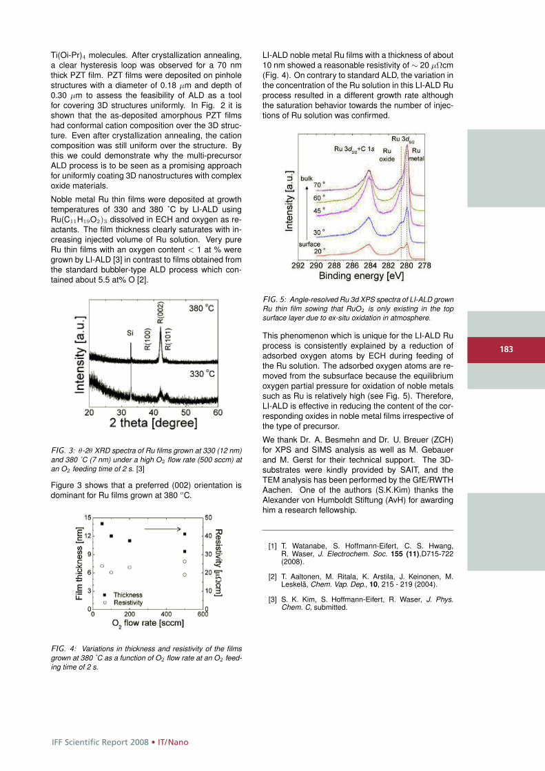
IFF Scientific Report 2008 • IT/Nano
183
Ti(Oi-Pr)4 molecules. After crystallization annealing,a clear hysteresis loop was observed for a 70 nmthick PZT film. PZT films were deposited on pinholestructures with a diameter of 0.18 μm and depth of0.30 μm to assess the feasibility of ALD as a toolfor covering 3D structures uniformly. In Fig. 2 it isshown that the as-deposited amorphous PZT filmshad conformal cation composition over the 3D struc-ture. Even after crystallization annealing, the cationcomposition was still uniform over the structure. Bythis we could demonstrate why the multi-precursorALD process is to be seen as a promising approachfor uniformly coating 3D nanostructures with complexoxide materials.
Noble metal Ru thin films were deposited at growthtemperatures of 330 and 380 ˚C by LI-ALD usingRu(C11H19O2)3 dissolved in ECH and oxygen as re-actants. The film thickness clearly saturates with in-creasing injected volume of Ru solution. Very pureRu thin films with an oxygen content < 1 at % weregrown by LI-ALD [3] in contrast to films obtained fromthe standard bubbler-type ALD process which con-tained about 5.5 at% O [2].
FIG. 3: θ-2θ XRD spectra of Ru films grown at 330 (12 nm)and 380 ˚C (7 nm) under a high O2 flow rate (500 sccm) atan O2 feeding time of 2 s. [3]
Figure 3 shows that a preferred (002) orientation isdominant for Ru films grown at 380 oC.
FIG. 4: Variations in thickness and resistivity of the filmsgrown at 380 ˚C as a function of O2 flow rate at an O2 feed-ing time of 2 s.
LI-ALD noble metal Ru films with a thickness of about10 nm showed a reasonable resistivity of ∼ 20 μΩcm(Fig. 4). On contrary to standard ALD, the variation inthe concentration of the Ru solution in this LI-ALD Ruprocess resulted in a different growth rate althoughthe saturation behavior towards the number of injec-tions of Ru solution was confirmed.
FIG. 5: Angle-resolved Ru 3d XPS spectra of LI-ALD grownRu thin film sowing that RuO2 is only existing in the topsurface layer due to ex-situ oxidation in atmosphere.
This phenomenon which is unique for the LI-ALD Ruprocess is consistently explained by a reduction ofadsorbed oxygen atoms by ECH during feeding ofthe Ru solution. The adsorbed oxygen atoms are re-moved from the subsurface because the equilibriumoxygen partial pressure for oxidation of noble metalssuch as Ru is relatively high (see Fig. 5). Therefore,LI-ALD is effective in reducing the content of the cor-responding oxides in noble metal films irrespective ofthe type of precursor.
We thank Dr. A. Besmehn and Dr. U. Breuer (ZCH)for XPS and SIMS analysis as well as M. Gebauerand M. Gerst for their technical support. The 3D-substrates were kindly provided by SAIT, and theTEM analysis has been performed by the GfE/RWTHAachen. One of the authors (S.K.Kim) thanks theAlexander von Humboldt Stiftung (AvH) for awardinghim a research fellowship.
[1] T. Watanabe, S. Hoffmann-Eifert, C. S. Hwang,R. Waser, J. Electrochem. Soc. 155 (11),D715-722(2008).
[2] T. Aaltonen, M. Ritala, K. Arstila, J. Keinonen, M.Leskelä, Chem. Vap. Dep., 10, 215 - 219 (2004).
[3] S. K. Kim, S. Hoffmann-Eifert, R. Waser, J. Phys.Chem. C, submitted.
183
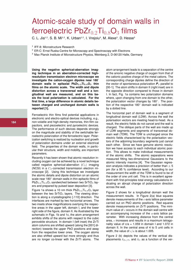
IT/Nano • IFF Scientific Report 2008
184
Atomic-scale study of domain walls inferroelectric PbZr0.2Ti0.8O3 filmsC. L. Jia1,2, S. B. Mi1,2, K. Urban1,2, I. Vrejoiu3, M. Alexe3, D. Hesse3
1 IFF-8: Microstructure Research2 ER-C: Ernst Ruska-Centre for Microscopy and Spectroscopy with Electrons3 Max Planck Institute of Microstructure Physics, Weinberg 2, D-06120 Halle, Germany
Using the negative spherical-aberration imag-
ing technique in an aberration-corrected high-
resolution transmission electron microscope we
investigate the cation-oxygen dipoles near 180˚
domain walls in epitaxial PbZr0.2Ti0.8O3 thin
films on the atomic scale. The width and dipole
distortion across a transversal wall and a lon-
gitudinal wall are measured, and on this ba-
sis the local polarization is calculated. For the
first time, a large difference in atomic details be-
tween charged and uncharged domain walls is
reported [1].
Ferroelectric thin films find potential applications inelectronic and electro-optical devices including, e.g.,non-volatile and high-density memories, thin-film ca-pacitors, and piezoelectric and pyroelectric devices.The performance of such devices depends stronglyon the magnitude and stability of the switchable fer-roelectric polarization of the ferroelectric layer. Polar-ization switching is realized by nucleation and growthof polarization domains under an external electricalfield. The properties of the domain walls, in partic-ular their structure, width and mobility, are importantparameters.Recently it has been shown that atomic resolution in-cluding oxygen can be achieved by a novel techniquecalled negative spherical-aberration (CS) imaging(NCSI) in a CS-corrected transmission electron mi-croscope [2]. Using this technique we investigatethe atomic details and dipole distortion on an atomicscale near 180◦ domain walls in thin epitactic films ofPbZr0.2Ti0.8O3 sandwiched between two SrTiO3 lay-ers and prepared by pulsed laser deposition [3].Figure 1a shows a 10 nm thick PbZr0.2Ti0.8O3 layerbetween the two SrTiO3 layers. The viewing direc-tion is along a crystallographic [-110] direction. Theinterfaces are marked by two horizontal arrows. Thetwo insets show magnifications overlying the respec-tive areas in the upper left, domain I, and the lowerright side of the figure, domain II. As illustrated by theschematic in Figs. 1b and 1c, the atom arrangementexhibits shifts of the atoms with respect to the cubicperovskite structure. In domain I (left inset) the Zr/Tiatom columns are shifted upward (along the [001] di-rection) towards the upper PbO positions and awayfrom the respective lower ones. The oxygen atomsare also shifted upward but more strongly and thusare no longer co-linear with the Zr/Ti atoms. The
atom arrangement leads to a separation of the centreof the anionic negative charge of oxygen from that ofthe cationic positive charge of the metal cations. Thecorresponding charge dipoles define the direction ofthe vector of spontaneous polarization PS parallel to[00-1]. The atom shifts in domain II (right inset) are inthe opposite direction compared to those in domainI. In fact, Fig. 1a contains two polarization domainswhere, upon changing from one domain to the other,the polarization vector changes by 180◦. The posi-tion of the respective 180◦ domain wall is indicatedby a dotted line.
The horizontal part of domain wall is a segment oflongitudinal domain wall (LDW). Across the wall thepolarisation vectors are meeting head-to-head. As aresult, the electric fields do not cancel and the wall ischarged. The oblique parts of the wall are made upof LDW segments and segments of transversal do-main wall (TDW). The TDW is uncharged since theelectric fields characterised by the polarisation vec-tors of the adjoining boundary segments just canceleach other. Since we have genuine atomic resolu-tion we have access to each individual atomic posi-tion. This allows to make individual measurementsof the atomic shifts. The atomic separations weremeasured fitting two-dimensional Gaussians to theatomic intensity maxima [4]. The Gaussian regres-sion analysis indicates a precision of better than ± 5pm (for a 95 % confidence level). According to ourmeasurement the width of the TDW is found to be ofthe order of one unit cell. This is in excellent agree-ment with first-principles total energy calculations in-dicating an abrupt change of polarization directionacross the wall.
Figure 2 shows for a longitudinal domain wall themeasurement results. In Figure 2(a) blue squaresdenote measurements of the c-axis lattice parametercarried out on PbO atomic positions. Red squaresdenote measurements on Zr/Ti positions. The mini-mum value of c occurs in the domain wall centre withan accompanying increase of the a-axis lattice pa-rameter. With increasing distance from the centralarea, c increases and results in a maximum tetrago-nality value of c/a = 1.059 in domain I and 1.072 indomain II. In the central area of 4 to 5 unit cells inwidth, the value of c/a is about 1.005.
Figure 2 (b) depicts the values of the vertical dis-placements δZr/Ti and δO as a function of the ver-
184
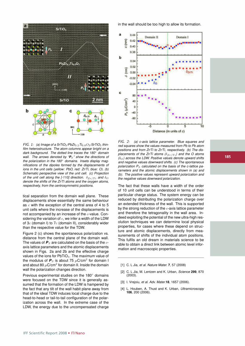
IFF Scientific Report 2008 • IT/Nano
185
FIG. 1: (a) Image of a SrTiO3/PbZr0.2Ti0.8O3/SrTiO3 thin-film heterostructure. The atom columns appear bright on adark background. The dotted line traces the 180◦ domainwall. The arrows denoted by “PS ” show the directions ofthe polarization in the 180◦ domains. Insets display mag-nifications of the dipoles formed by the displacements ofions in the unit cells (yellow: PbO, red: Zr/Ti, blue: O). (b)Schematic perspective view of the unit cell. (c) Projectionof the unit cell along the [-110] direction. δZr/Ti and δO
denote the shifts of the Zr/Ti atoms and the oxygen atoms,respectively, from the centrosymmetric positions.
tical separation from the domain wall plane. Thesedisplacements show essentially the same behaviouras c with the exception of the central area of 4 to 5unit cells where the increase of the displacements isnot accompanied by an increase of the c-value. Con-sidering the variation of c, we infer a width of the LDWof 3c (domain I) to 7c (domain II), considerably widerthan the respective value for the TDW.
Figure 2 (c) shows the spontaneous polarization vs.distance from the central plane of the domain wall.The values of PS are calculated on the basis of the c-axis lattice parameters and the atomic displacementsshown in Figs. 2a and 2b and the effective chargevalues of the ions for PbTiO3. The maximum value ofthe modulus of PS is about 75 μC/cm2 for domain Iand about 80 μC/cm2 for domain II. Inside the domainwall the polarization changes direction.
Previous experimental studies on the 180◦ domainswere focused on the TDW since it is generally as-sumed that the formation of the LDW is hampered bythe fact that any tilt of the wall habit plane away fromthat of the ideal TDW induces local charge due to thehead-to-head or tail-to-tail configuration of the polar-ization across the wall. In the extreme case of theLDW, the energy due to the uncompensated charge
in the wall should be too high to allow its formation.
FIG. 2: (a) c-axis lattice parameter. Blue squares andred squares show the values measured from Pb to Pb atompositions and from Zr/Ti to Zr/Ti, respectively. (b) The dis-placements of the Zr/Ti atoms (δZr/Ti) and the O atoms(δO) across the LDW. Positive values denote upward shiftsand negative values downward shifts. (c) The spontaneouspolarization PS calculated on the basis of the c-lattice pa-rameters and the atomic displacements shown in (a) and(b). The positive values represent upward polarization andthe negative values downward polarization.
The fact that these walls have a width of the orderof 10 unit cells can be understood in terms of theirparticular charge status. The system energy can bereduced by distributing the polarization charge overan extended thickness of the wall. This is supportedby the strong reduction of the c-axis lattice parameterand therefore the tetragonality in the wall area. In-deed exploiting the potential of the new ultra-high res-olution techniques we can determine local physicalproperties, for cases where these depend on struc-ture and atomic displacements, directly from mea-surements of shifts of the individual atom positions.This fulfils an old dream in materials science to beable to obtain a direct link between atomic level infor-mation and macroscopic properties.
[1] C. L Jia, et al. Nature Mater. 7, 57 (2008)
[2] C. L Jia, M. Lentzen and K. Urban, Science 299, 870(2003).
[3] I. Vrejoiu, et al. Adv. Mater.18, 1657 (2006).
[4] L. Houben, A. Thust and K. Urban, Ultramicroscopy106, 200 (2006).
185
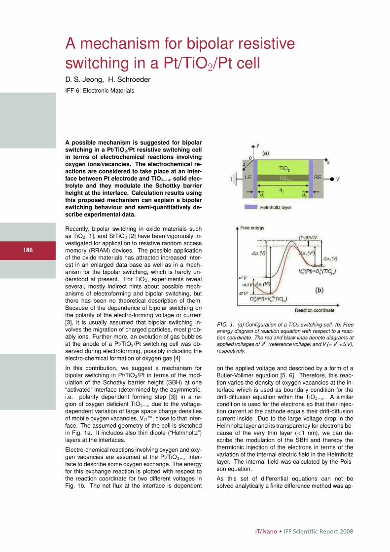
IT/Nano • IFF Scientific Report 2008
186
A mechanism for bipolar resistiveswitching in a Pt/TiO2/Pt cellD. S. Jeong, H. SchroederIFF-6: Electronic Materials
A possible mechanism is suggested for bipolar
switching in a Pt/TiO2/Pt resistive switching cell
in terms of electrochemical reactions involving
oxygen ions/vacancies. The electrochemical re-
actions are considered to take place at an inter-
face between Pt electrode and TiO2−x solid elec-
trolyte and they modulate the Schottky barrier
height at the interface. Calculation results using
this proposed mechanism can explain a bipolar
switching behaviour and semi-quantitatively de-
scribe experimental data.
Recently, bipolar switching in oxide materials suchas TiO2 [1], and SrTiO3 [2] have been vigorously in-vestigated for application to resistive random accessmemory (RRAM) devices. The possible applicationof the oxide materials has attracted increased inter-est in an enlarged data base as well as in a mech-anism for the bipolar switching, which is hardly un-derstood at present. For TiO2, experiments revealseveral, mostly indirect hints about possible mech-anisms of electroforming and bipolar switching, butthere has been no theoretical description of them.Because of the dependence of bipolar switching onthe polarity of the electro-forming voltage or current[3], it is usually assumed that bipolar switching in-volves the migration of charged particles, most prob-ably ions. Further-more, an evolution of gas bubblesat the anode of a Pt/TiO2/Pt switching cell was ob-served during electroforming, possibly indicating theelectro-chemical formation of oxygen gas [4].
In this contribution, we suggest a mechanism forbipolar switching in Pt/TiO2/Pt in terms of the mod-ulation of the Schottky barrier height (SBH) at one“activated” interface (determined by the asymmetric,i.e. polarity dependent forming step [3]) in a re-gion of oxygen deficient TiO2−x due to the voltage-dependent variation of large space charge densitiesof mobile oxygen vacancies, VO**, close to that inter-face. The assumed geometry of the cell is sketchedin Fig. 1a. It includes also thin dipole (“Helmholtz”)layers at the interfaces.
Electro-chemical reactions involving oxygen and oxy-gen vacancies are assumed at the Pt/TiO2−x inter-face to describe some oxygen exchange. The energyfor this exchange reaction is plotted with respect tothe reaction coordinate for two different voltages inFig. 1b. The net flux at the interface is dependent
FIG. 1: (a) Configuration of a TiO2 switching cell. (b) Freeenergy diagram of reaction equation with respect to a reac-tion coordinate. The red and black lines denote diagrams atapplied voltages of V0 (reference voltage) and V (= V0+ΔV),respectively.
on the applied voltage and described by a form of aButler-Vollmer equation [5, 6]. Therefore, this reac-tion varies the density of oxygen vacancies at the in-terface which is used as boundary condition for thedrift-diffusion equation within the TiO2−x. A similarcondition is used for the electrons so that their injec-tion current at the cathode equals their drift-diffusioncurrent inside. Due to the large voltage drop in theHelmholtz layer and its transparency for electrons be-cause of the very thin layer (<1 nm), we can de-scribe the modulation of the SBH and thereby thethermionic injection of the electrons in terms of thevariation of the internal electric field in the Helmholtzlayer. The internal field was calculated by the Pois-son equation.
As this set of differential equations can not besolved analytically a finite difference method was ap-
186
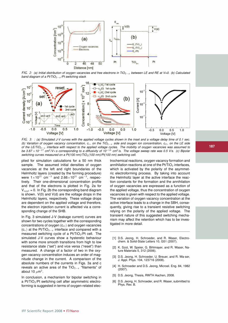
IFF Scientific Report 2008 • IT/Nano
187
FIG. 2: (a) Initial distribution of oxygen vacancies and free electrons in TiO2−x between LE and RE at V=0. (b) Calculatedband diagram of a Pt/TiO2−x/Pt switching stack
FIG. 3: : (a) Simulated J-V curves with the applied voltage cycles shown in the inset and a voltage delay time of 0.1 sec.(b) Variation of oxygen vacancy concentration, cv , on the TiO2−x side and oxygen ion concentration, cO , on the LE sideof the LE/TiO2−x interface with respect to the applied voltage cycles. The mobility of oxygen vacancies was assumed tobe 3.87 ×10⁻¹⁷ cm2/V×s corresponding to a diffusivity of 10−18 cm2/s. The voltage sweep rate was 0.5 V/s. (c) Bipolarswitching curves measured on a Pt(100 nm)/TiO2(100 nm)/Pt(100 nm) switching cell.
plied for simulation calculations for a 50 nm thicksample. The assumed initial densities of oxygenvacancies at the left and right boundaries of theHelmholtz layers (created by the forming procedure)were 1×1021 cm−3 and 2.66×1021 cm−3, respec-tively. Their one-dimensional concentration profileand that of the electrons is plotted in Fig. 2a forVappl = 0. In Fig. 2b the corresponding band diagramis shown. V(0) and V(d) are the voltage drops in theHelmholtz layers, respectively. These voltage dropsare dependent on the applied voltage and therefore,the electron injection current is affected via a corre-sponding change of the SHB.
In Fig. 3 simulated J-V (leakage current) curves areshown for two cycles together with the correspondingconcentrations of oxygen (cO) and oxygen vacancies(cv) at the Pt/TiO2−x interface and compared with ameasured switching cycle of a Pt/TiO2/Pt cell. Thesimulated J-V curves show a hysteretic behaviourwith some more smooth transitions from high to lowresistance state (“set”) and vice versa (“reset”) thanmeasured. A change of a factor of two in the oxy-gen vacancy concentration induces an order of mag-nitude change in the current. A comparison of theabsolute numbers of the currents in Figs. 3a and creveals an active area of the TiO2−x “filaments” ofabout 10 μm2.
In conclusion, a mechanism for bipolar switching ina Pt/TiO2/Pt switching cell after asymmetric electro-forming is suggested in terms of oxygen-related elec-
trochemical reactions, oxygen vacancy formation andannihilation reactions at one of the Pt/TiO2 interfaces,which is activated by the polarity of the asymmet-ric electroforming process. By taking into accountthe Helmholtz layer at the active interface the reac-tion constants for the formation and the annihilationof oxygen vacancies are expressed as a function ofthe applied voltage, thus the concentration of oxygenvacancies is given with respect to the applied voltage.The variation of oxygen vacancy concentration at theactive interface leads to a change in the SBH, conse-quently, giving rise to a transient resistive switchingrelying on the polarity of the applied voltage. Thetransient nature of this suggested switching mecha-nism may affect the retention which has to be inves-tigated in more detail.
[1] D.S. Jeong, H. Schroeder, and R. Waser, Electro-chem. & Solid-State Letters 10, G51 (2007).
[2] K. Szot, W. Speier, G. Bihlmayer, and R. Waser, Na-ture Materials 5, 312 (2006).
[3] D.S. Jeong, H. Schroeder, U. Breuer, and R. Wa-ser,J. Appl. Phys. 104, 123716 (2008).
[4] H. Schroeder and D.S. Jeong, Microel. Eng. 84, 1982(2007).
[5] D.S. Jeong, Thesis, RWTH Aachen, 2008.
[6] D.S. Jeong, H. Schroeder, and R. Waser, submitted toPhys. Rev. B.
187
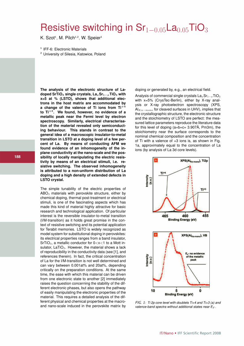
IT/Nano • IFF Scientific Report 2008
188
Resistive switching in Sr1−0.05La0.05TiO3K. Szot1, M. Pilch1,2, W. Speier1
1 IFF-6: Electronic Materials2 University of Silesia, Katowice, Poland
The analysis of the electronic structure of La-
doped SrTiO3 single crystals, LaxSr1−xTiO3 with
x=5 at % (LSTO), shows that additional elec-
trons in the host matrix are accommodated by
a change of the valence of Ti ions from Ti+4
to Ti+3. We found, however, no evidence of a
metallic peak near the Fermi level by electron
spectroscopy. Similarly, electrical characterisa-
tion of the material revealed only semiconduct-
ing behaviour. This stands in contrast to the
general idea of a macroscopic insulator-to-metal
transition in LSTO at a doping level of a few per-
cent of La. By means of conducting AFM we
found evidence of an inhomogeneity of the in-
plane conductivity at the nano-scale and the pos-
sibility of locally manipulating the electric resis-
tivity by means of an electrical stimuli, i.e. re-
sistive switching. The observed inhomogeneity
is attributed to a non-uniform distribution of La
doping and a high density of extended defects in
LSTO crystal.
The simple tunability of the electric properties ofABO3 materials with perovskite structure, either bychemical doping, thermal post-treatment or electricalstimuli, is one of the fascinating aspects which hasmade this kind of material highly attractive for basicresearch and technological application. Of particularinterest is the reversible insulator-to-metal transition(I/M-transition) as it holds great promise in the con-text of resistive switching and its potential applicationfor Terabit memories. LSTO is widely recognized asmodel system for substitutional doping in perovskites:its electrical properties ranges from a band insulator,SrTiO3, a metallic conductor for 0<x<1 to a Mott in-sulator, LaTiO3. However, the material shows a lackof reproducibility in the conductivity data (see [1], andreferences therein). In fact, the critical concentrationof La for the I/M-transition is not well determined andcan vary between 0.001at% and 20at%, dependingcritically on the preparation conditions. At the sametime, the ease with which this material can be drivenfrom one electronic state to another [2] immediatelyraises the question concerning the stability of the dif-ferent electronic phases, but also opens the pathwayof easily manipulating the electronic properties of thematerial. This requires a detailed analysis of the dif-ferent physical and chemical properties at the macro-and nano-scale induced in the perovskite matrix by
doping or generated by, e.g., an electrical field.
Analysis of commercial single crystals LaxSr1−xTiO3
with x=5% (CrysTec-Berlin), either by X-ray anal-ysis or X-ray photoelectron spectroscopy (XPS,AlKα−mono for cleaved surfaces in UHV), implies thatthe crystallographic structure, the electronic structureand the stoichiometry of LSTO are perfect: the mea-sured lattice parameters reproduce the literature datafor this level of doping (a=b=c= 3.907Å, Pm3m), thestoichiometry near the surface corresponds to thenominal chemical composition and the concentrationof Ti with a valence of +3 ions is, as shown in Fig.1a, approximately equal to the concentration of Laions (by analysis of La 3d core levels).
FIG. 1: Ti 2p core level with doublets Ti+4 and Ti+3 (a) andvalence-band spectra without additional states near EF .
188
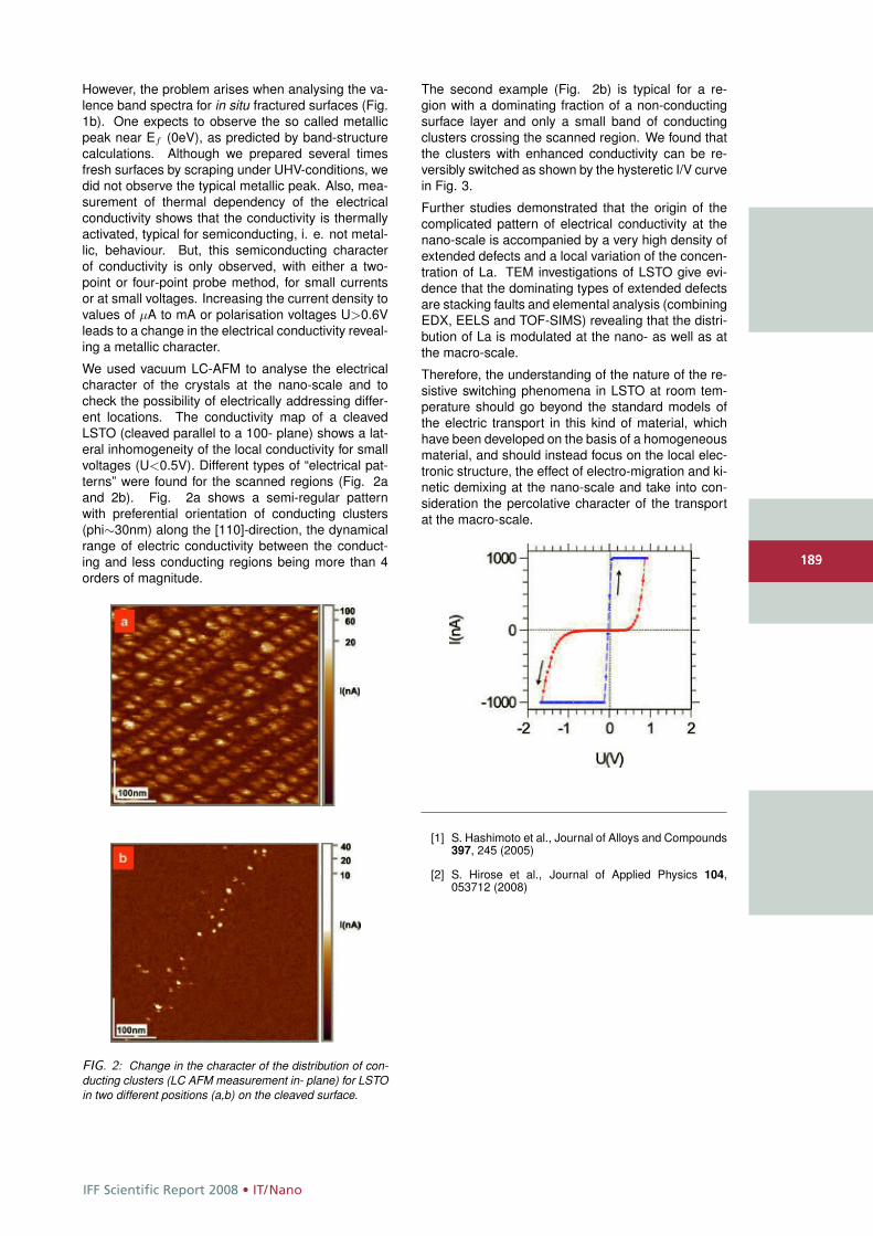
IFF Scientific Report 2008 • IT/Nano
189
However, the problem arises when analysing the va-lence band spectra for in situ fractured surfaces (Fig.1b). One expects to observe the so called metallicpeak near Ef (0eV), as predicted by band-structurecalculations. Although we prepared several timesfresh surfaces by scraping under UHV-conditions, wedid not observe the typical metallic peak. Also, mea-surement of thermal dependency of the electricalconductivity shows that the conductivity is thermallyactivated, typical for semiconducting, i. e. not metal-lic, behaviour. But, this semiconducting characterof conductivity is only observed, with either a two-point or four-point probe method, for small currentsor at small voltages. Increasing the current density tovalues of μA to mA or polarisation voltages U>0.6Vleads to a change in the electrical conductivity reveal-ing a metallic character.
We used vacuum LC-AFM to analyse the electricalcharacter of the crystals at the nano-scale and tocheck the possibility of electrically addressing differ-ent locations. The conductivity map of a cleavedLSTO (cleaved parallel to a 100- plane) shows a lat-eral inhomogeneity of the local conductivity for smallvoltages (U<0.5V). Different types of “electrical pat-terns” were found for the scanned regions (Fig. 2aand 2b). Fig. 2a shows a semi-regular patternwith preferential orientation of conducting clusters(phi∼30nm) along the [110]-direction, the dynamicalrange of electric conductivity between the conduct-ing and less conducting regions being more than 4orders of magnitude.
FIG. 2: Change in the character of the distribution of con-ducting clusters (LC AFM measurement in- plane) for LSTOin two different positions (a,b) on the cleaved surface.
The second example (Fig. 2b) is typical for a re-gion with a dominating fraction of a non-conductingsurface layer and only a small band of conductingclusters crossing the scanned region. We found thatthe clusters with enhanced conductivity can be re-versibly switched as shown by the hysteretic I/V curvein Fig. 3.
Further studies demonstrated that the origin of thecomplicated pattern of electrical conductivity at thenano-scale is accompanied by a very high density ofextended defects and a local variation of the concen-tration of La. TEM investigations of LSTO give evi-dence that the dominating types of extended defectsare stacking faults and elemental analysis (combiningEDX, EELS and TOF-SIMS) revealing that the distri-bution of La is modulated at the nano- as well as atthe macro-scale.
Therefore, the understanding of the nature of the re-sistive switching phenomena in LSTO at room tem-perature should go beyond the standard models ofthe electric transport in this kind of material, whichhave been developed on the basis of a homogeneousmaterial, and should instead focus on the local elec-tronic structure, the effect of electro-migration and ki-netic demixing at the nano-scale and take into con-sideration the percolative character of the transportat the macro-scale.
[1] S. Hashimoto et al., Journal of Alloys and Compounds397, 245 (2005)
[2] S. Hirose et al., Journal of Applied Physics 104,053712 (2008)
189
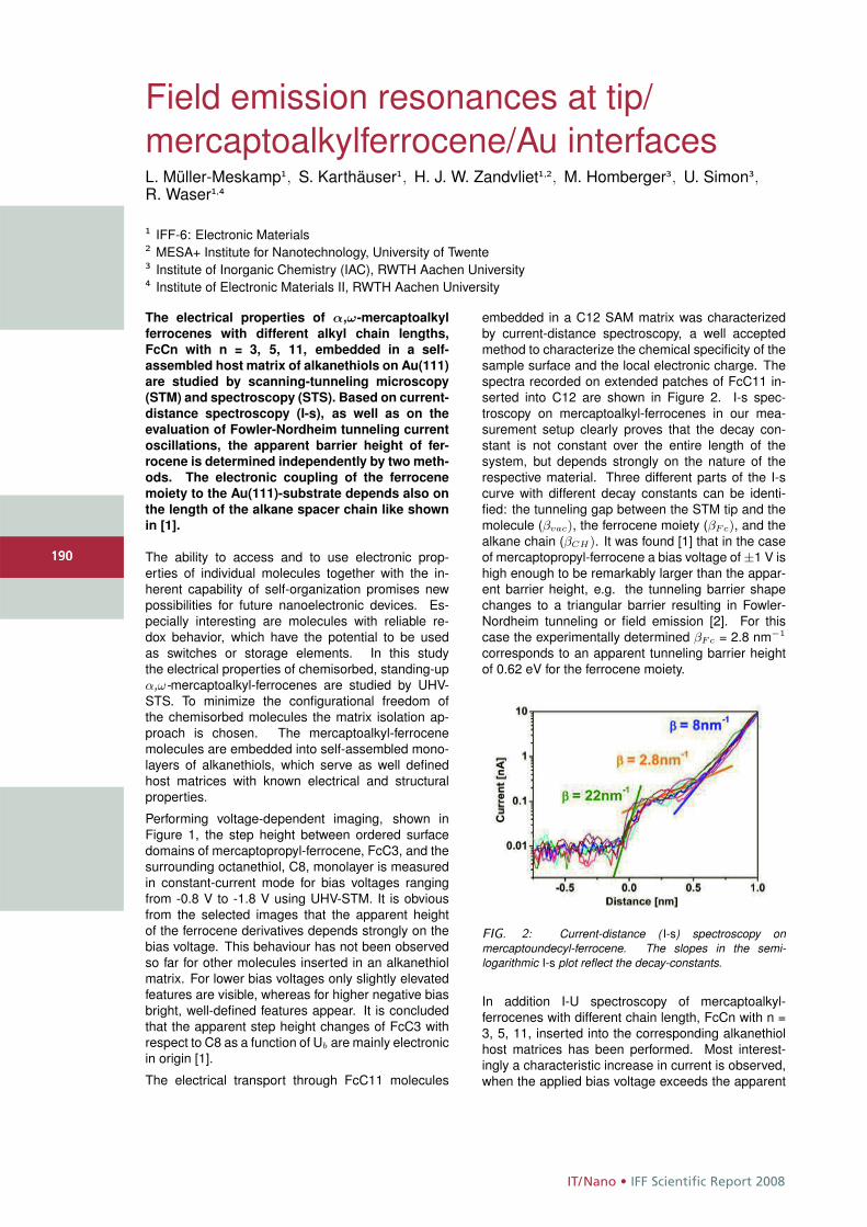
IT/Nano • IFF Scientific Report 2008
190
Field emission resonances at tip/mercaptoalkylferrocene/Au interfacesL. Müller-Meskamp1, S. Karthäuser1, H. J. W. Zandvliet1,2, M. Homberger3, U. Simon3,R. Waser1,4
1 IFF-6: Electronic Materials2 MESA+ Institute for Nanotechnology, University of Twente3 Institute of Inorganic Chemistry (IAC), RWTH Aachen University4 Institute of Electronic Materials II, RWTH Aachen University
The electrical properties of α,ω-mercaptoalkyl
ferrocenes with different alkyl chain lengths,
FcCn with n = 3, 5, 11, embedded in a self-
assembled host matrix of alkanethiols on Au(111)
are studied by scanning-tunneling microscopy
(STM) and spectroscopy (STS). Based on current-
distance spectroscopy (I-s), as well as on the
evaluation of Fowler-Nordheim tunneling current
oscillations, the apparent barrier height of fer-
rocene is determined independently by two meth-
ods. The electronic coupling of the ferrocene
moiety to the Au(111)-substrate depends also on
the length of the alkane spacer chain like shown
in [1].
The ability to access and to use electronic prop-erties of individual molecules together with the in-herent capability of self-organization promises newpossibilities for future nanoelectronic devices. Es-pecially interesting are molecules with reliable re-dox behavior, which have the potential to be usedas switches or storage elements. In this studythe electrical properties of chemisorbed, standing-upα,ω-mercaptoalkyl-ferrocenes are studied by UHV-STS. To minimize the configurational freedom ofthe chemisorbed molecules the matrix isolation ap-proach is chosen. The mercaptoalkyl-ferrocenemolecules are embedded into self-assembled mono-layers of alkanethiols, which serve as well definedhost matrices with known electrical and structuralproperties.
Performing voltage-dependent imaging, shown inFigure 1, the step height between ordered surfacedomains of mercaptopropyl-ferrocene, FcC3, and thesurrounding octanethiol, C8, monolayer is measuredin constant-current mode for bias voltages rangingfrom -0.8 V to -1.8 V using UHV-STM. It is obviousfrom the selected images that the apparent heightof the ferrocene derivatives depends strongly on thebias voltage. This behaviour has not been observedso far for other molecules inserted in an alkanethiolmatrix. For lower bias voltages only slightly elevatedfeatures are visible, whereas for higher negative biasbright, well-defined features appear. It is concludedthat the apparent step height changes of FcC3 withrespect to C8 as a function of Ub are mainly electronicin origin [1].
The electrical transport through FcC11 molecules
embedded in a C12 SAM matrix was characterizedby current-distance spectroscopy, a well acceptedmethod to characterize the chemical specificity of thesample surface and the local electronic charge. Thespectra recorded on extended patches of FcC11 in-serted into C12 are shown in Figure 2. I-s spec-troscopy on mercaptoalkyl-ferrocenes in our mea-surement setup clearly proves that the decay con-stant is not constant over the entire length of thesystem, but depends strongly on the nature of therespective material. Three different parts of the I-scurve with different decay constants can be identi-fied: the tunneling gap between the STM tip and themolecule (βvac), the ferrocene moiety (βFc), and thealkane chain (βCH). It was found [1] that in the caseof mercaptopropyl-ferrocene a bias voltage of ±1 V ishigh enough to be remarkably larger than the appar-ent barrier height, e.g. the tunneling barrier shapechanges to a triangular barrier resulting in Fowler-Nordheim tunneling or field emission [2]. For thiscase the experimentally determined βFc = 2.8 nm−1
corresponds to an apparent tunneling barrier heightof 0.62 eV for the ferrocene moiety.
FIG. 2: Current-distance ( I-s) spectroscopy onmercaptoundecyl-ferrocene. The slopes in the semi-logarithmic I-s plot reflect the decay-constants.
In addition I-U spectroscopy of mercaptoalkyl-ferrocenes with different chain length, FcCn with n =3, 5, 11, inserted into the corresponding alkanethiolhost matrices has been performed. Most interest-ingly a characteristic increase in current is observed,when the applied bias voltage exceeds the apparent
190
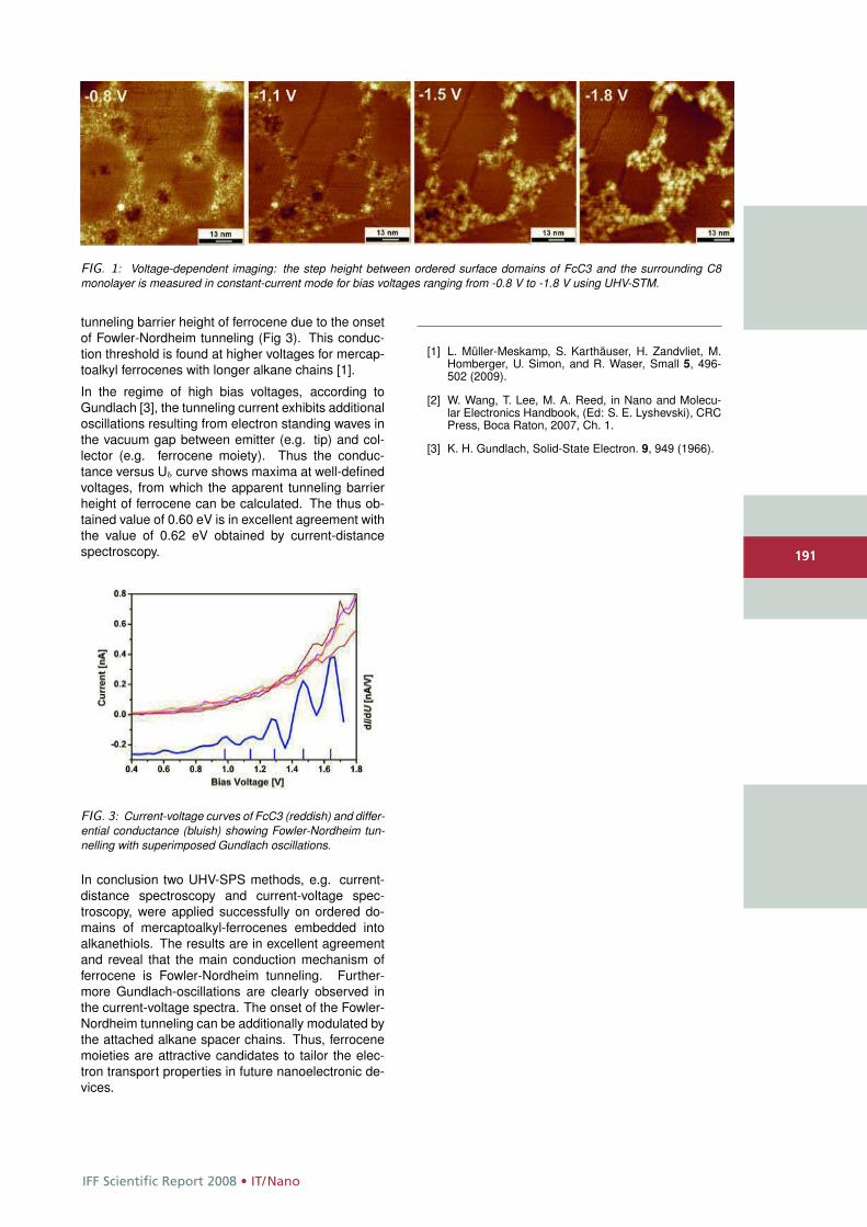
IFF Scientific Report 2008 • IT/Nano
191
FIG. 1: Voltage-dependent imaging: the step height between ordered surface domains of FcC3 and the surrounding C8monolayer is measured in constant-current mode for bias voltages ranging from -0.8 V to -1.8 V using UHV-STM.
tunneling barrier height of ferrocene due to the onsetof Fowler-Nordheim tunneling (Fig 3). This conduc-tion threshold is found at higher voltages for mercap-toalkyl ferrocenes with longer alkane chains [1].
In the regime of high bias voltages, according toGundlach [3], the tunneling current exhibits additionaloscillations resulting from electron standing waves inthe vacuum gap between emitter (e.g. tip) and col-lector (e.g. ferrocene moiety). Thus the conduc-tance versus Ub curve shows maxima at well-definedvoltages, from which the apparent tunneling barrierheight of ferrocene can be calculated. The thus ob-tained value of 0.60 eV is in excellent agreement withthe value of 0.62 eV obtained by current-distancespectroscopy.
FIG. 3: Current-voltage curves of FcC3 (reddish) and differ-ential conductance (bluish) showing Fowler-Nordheim tun-nelling with superimposed Gundlach oscillations.
In conclusion two UHV-SPS methods, e.g. current-distance spectroscopy and current-voltage spec-troscopy, were applied successfully on ordered do-mains of mercaptoalkyl-ferrocenes embedded intoalkanethiols. The results are in excellent agreementand reveal that the main conduction mechanism offerrocene is Fowler-Nordheim tunneling. Further-more Gundlach-oscillations are clearly observed inthe current-voltage spectra. The onset of the Fowler-Nordheim tunneling can be additionally modulated bythe attached alkane spacer chains. Thus, ferrocenemoieties are attractive candidates to tailor the elec-tron transport properties in future nanoelectronic de-vices.
[1] L. Müller-Meskamp, S. Karthäuser, H. Zandvliet, M.Homberger, U. Simon, and R. Waser, Small 5, 496-502 (2009).
[2] W. Wang, T. Lee, M. A. Reed, in Nano and Molecu-lar Electronics Handbook, (Ed: S. E. Lyshevski), CRCPress, Boca Raton, 2007, Ch. 1.
[3] K. H. Gundlach, Solid-State Electron. 9, 949 (1966).
191

Large-scale facilities (PNI) • IFF Scientific Report 2008
192
Neutrons show where atoms are and what atoms do: The Jülich Centre for Neutron Science (JCNS) at the IFF wasfounded in 2006 to operate state-of-the-art neutron scattering instruments at the most modern of highest fluxsources in the world. Here: The Small Angle Neutron Scattering spectrometer KWS 1 at FRM II, Garching.
IFF Scientific Report 2008 • Large-scale facilities (PNI)
193
HGF research programme
Large-scale facilities for research with photons, neutrons and ions
This research programme coordinatesthe activities taking place at the largescale facilities involved in the HGFresearch field Structure of Matter. Thesefacilities offer unique research opportu-nities with photons, neutrons and ionsfor a multitude of science disciplines,ranging from physics, chemistry, biologyand geology to material science, engi-neering science, and environmentalresearch. A particular feature of thisprogramme is the support of externaluser groups, which utilize the majorpart of the available access time. Theseuser groups come mainly from universi-ties, but also from non-universityresearch institutions and industry.
With its excellence in neutron research –manifested in the Jülich Centre for Neu-tron Science (JCNS) – the IFF supplies akey contribution to this research pro-gramme. The strong reputation of theIFF in the German and internationalneutron landscape is closely related to:
• a powerful in-house research in the area of condensed matter focusing particularly on soft matter and magnetism,
• a large user operation in these research areas being extensively supported by IFF experts and
facilities,
• a science-driven programme for the development of new methods and instruments, and
• exploitation of the novel neutron research opportunities provided by pulsed MW spallation sources.
The IFF neutron research is carried out to a large extent at the new state-of-the-art research reactor FRM II inMunich and at the ILL in Grenoble(France), with new opportunities beingcreated at the SNS spallation source inOak Ridge (USA). These activities are a cornerstone of the HGF programme“Condensed Matter Physics” and provide important contributions also to other HGF programmes, such as“Information Technology with Nano-electronic Systems”.
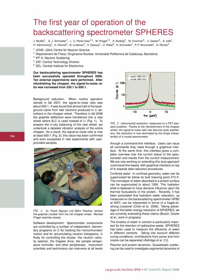
Large-scale facilities (PNI) • IFF Scientific Report 2008
194
The first year of operation of thebackscattering spectrometer SPHERESJ. Wuttke1, G. J. Schneider1, L. C. Pardo Soto1,2, M. Prager†3, A. Budwig4, M. Drochner5, U. Giesen4, A. Ioffe1,H. Kämmerling4, H. Kleines5, B. Lindenau4, V. Ossovyi1, U. Pabst4, H. Schneider1, P. P. Stronciwilk1, D. Richter3
1 JCNS: Jülich Centre for Neutron Science2 Departament de Física i Enginyeria Nuclear, Universitat Politècnica de Catalunya, Barcelona3 IFF-5: Neutron Scattering4 ZAT: Central Technology Division5 ZEL: Central Institute for Electronics
Our backscattering spectrometer SPHERES has
been successfully operated throughout 2008.
Ten external experiments were performed. After
refurbishing the chopper, the signal-to-noise ra-
tio was increased from 330:1 to 600:1.
Background reduction: When routine operationstarted in fall 2007, the signal-to-noise ratio wasabout 300:1. It was found that almost half of the back-ground came from fast neutrons produced in Li ab-sorbers in the chopper wheel. Therefore in fall 2008the graphite deflectors were transferred into a newwheel where B4C is used instead of Li (Fig. 1). Toprepare the in-situ balancing of the new wheel, weundertook a detailed vibration analysis of the entirechopper. As a result, the signal-to-noise ratio is nowat least 600:1 (Fig. 2); this value has been confirmedand even surpassed in real experiments with user-provided samples.
FIG. 1: Vu Thanh Nguyen und Björn Poschen retrievethe graphite crystals from the old chopper wheel. MichaelPrager watches closely.
Software development: Spectrometer componentsare controlled by a number of independent, elemen-tary programs (in C for tracking the monochromatormotion and for accumulating neutron histograms, inRuby for controlling the shutter, the neutron veloc-ity selector, the Doppler drive, the sample temper-ature controller, and other peripherals). Instrumentscientists and technicians can intervene at all levels
FIG. 2: Instrumental resolution, measured on a PET stan-dard scatterer. Thanks to the refurbishment of the chopperwheel, the signal-to-noise ratio has become quite satisfac-tory; the resolution is now dominated by the wings charac-teristic of a crystal spectrometer.
through a command-line interface. Users can issueall commands they need through a graphical inter-face. At the same time, this interface gives a com-plete overview over the current status of the spec-trometer and results from the current measurement.We are now working on extending this dual approach(command-line based, with graphical interface on topof it) towards data reduction procedures.
Confined water: In confined geometry, water can besupercooled far below its bulk freezing point 273 K.The monolayer of water absorbed to a protein surfacecan be supercooled to about 150K. This hydrationshell is believed to have decisive influence upon thethermal fluctuations of the protein. Recently, it hasbeen postulated that hydration water relaxation, asmeasured on the backscattering spectrometer HFBSat NIST, can be interpreted in terms of a fragile-to-strong crossover (Chen et al. 2006). Taking advan-tage of the better energy resolution of SPHERES, weare currently evaluating these claims (Busch, Dosteret al., work in progress)
The kinetics of water in cement is particularly impor-tant for the retention of radioactive waste. SPHEREShas been used to measure the diffusivity of waterin different cements. Taking into account differentcuring conditions, contributions from pores and fromcracks can be separated (Aldridge et al. [1]).
Polymer and protein dynamics: Quasielastic scatter-ing can be used to investigate segmental dynamics of
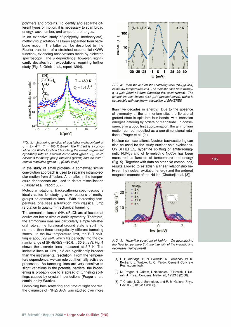
IFF Scientific Report 2008 • Large-scale facilities (PNI)
195
polymers and proteins. To identify and separate dif-ferent types of motion, it is necessary to scan broadenergy, wavenumber, and temperature ranges.In an extensive study of poly(ethyl methacrylate),methyl group rotation has been separated from back-bone motion, The latter can be described by theFourier transform of a stretched exponential (KWWfunction), extending observations made by dielectricspecroscopy. The q dependence, however, signifi-cantly deviates from expectations, requiring furtherstudy (Fig. 3, Génix et al., report 1294).
FIG. 3: Scattering function of poly(ethyl methacrylate) atq = 1.4 Å−1, T = 480 K (blue). The fit (red) is a convo-lution of a KWW function (describing the overall segmentaldynamics) with an effective convolution (green ×), whichaccounts for methyl group rotations (yellow) and the instru-mental resolution (green +) [Génix et al.].
In the study of small proteins, a somewhat similarconvolution approach is used to separate intramolec-ular motion from diffusion. Anomalies in the temper-ature dependence are used to detect miscellisation(Gaspar et al., report 667).Molecular rotations: Backscattering spectroscopy isideally suited for studying slow rotations of methylgroups or ammonium ions. With decreasing tem-perature, one sees a transition from classical jumprerotation to quantum-mechanical tunneling.The ammonium ions in (NH4)2PdCl6 are all located atequivalent lattice sites of cubic symmetry. Therefore,the ammonium ions are particularly simple tetrahe-dral rotors; the librational ground state is split intono more than three energetically different tunnelingstates. In the low-temperature limit, the E–T split-ting is about 29 μeV, which fits perfectly into the dy-namic range of SPHERES (–30.6. . . 30.9 μeV). Fig. 4shows the discrete lines measured at 3.7 K. Theinelastic lines at ±29 μeV are significantly broaderthan the instrumental resolution. From the tempera-ture dependence, we can rule out thermally activatedprocesses. As tunneling lines are very sensitive toslight variations in the potential barriers, the broad-ening is probably due to a spread of tunneling split-tings caused by crystal imperfections (Prager et al.,continued by Wuttke).Combining backscattering and time-of-flight spectra,the dynamics of (NH4)2S2O8 was studied over more
FIG. 4: Inelastic and elastic scattering from (NH4)2PdCl6in the low-temperature limit. The inelastic lines have fwhm=0.84 μeV (read off from Gaussian fits, solid curves). Thecentral line has fwhm= 0.66 μeV (dashed curve), which iscompatible with the known resolution of SPHERES.
than five decades in energy. Due to the absenceof symmetry at the ammonium site, the librationalground state is split into four bands, with transitionenergies differing by orders of magnitude. In conse-quence, in a good first approximation, the ammoniummotion can be modelled as a one-dimensional rota-tional (Prager et al. [2]).
Nuclear spin excitations: Neutron backscattering canalso be used for the study nuclear spin excitations.On SPHERES, hyperfine splitting of antiferromag-netic NdMg3 and of ferroelectric NdCo2 has beenmeasured as function of temperature and energy(Fig. 5). Together with data on other Nd compounds,results allowed to establish a linear relationship be-tween the nuclear excitation energy and the orderedmagnetic moment of the Nd ion (Chatterji et al. [3]).
FIG. 5: Hyperfine spectrum of NdMg3. On approachingthe Néel temperature 6 K, the intensity of the inelastic linedecreases rapidly (inset).
[1] L. P. Aldridge, H. N. Bordallo, K. Fernando, W. K.Bertram, J. Wuttke, L. C. Pardo, Cement ConcreteRes. (submitted).
[2] M. Prager, H. Grimm, I. Natkaniec, D. Nowak, T. Un-ruh, J. Phys.: Condens. Matter 20, 125218 (2008).
[3] T. Chatterji, G. J. Schneider, and R. M. Galera, Phys.Rev. B 78, 012411 (2008).
195
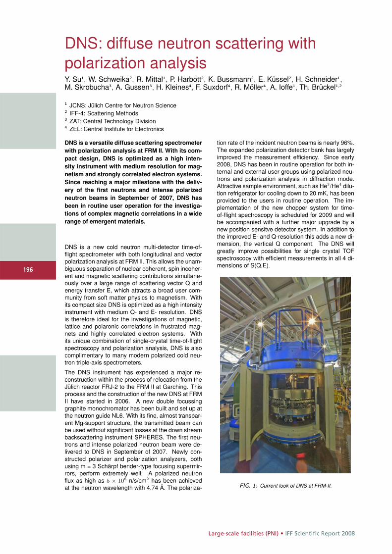
Large-scale facilities (PNI) • IFF Scientific Report 2008
196
DNS: diffuse neutron scattering withpolarization analysisY. Su1, W. Schweika2, R. Mittal1, P. Harbott2, K. Bussmann2, E. Küssel2, H. Schneider1,M. Skrobucha3, A. Gussen3, H. Kleines4, F. Suxdorf4, R. Möller4, A. Ioffe1, Th. Brückel1,2
1 JCNS: Jülich Centre for Neutron Science2 IFF-4: Scattering Methods3 ZAT: Central Technology Division4 ZEL: Central Institute for Electronics
DNS is a versatile diffuse scattering spectrometerwith polarization analysis at FRM II. With its com-pact design, DNS is optimized as a high inten-sity instrument with medium resolution for mag-netism and strongly correlated electron systems.Since reaching a major milestone with the deliv-ery of the first neutrons and intense polarizedneutron beams in September of 2007, DNS hasbeen in routine user operation for the investiga-tions of complex magnetic correlations in a widerange of emergent materials.
DNS is a new cold neutron multi-detector time-of-flight spectrometer with both longitudinal and vectorpolarization analysis at FRM II. This allows the unam-biguous separation of nuclear coherent, spin incoher-ent and magnetic scattering contributions simultane-ously over a large range of scattering vector Q andenergy transfer E, which attracts a broad user com-munity from soft matter physics to magnetism. Withits compact size DNS is optimized as a high intensityinstrument with medium Q- and E- resolution. DNSis therefore ideal for the investigations of magnetic,lattice and polaronic correlations in frustrated mag-nets and highly correlated electron systems. Withits unique combination of single-crystal time-of-flightspectroscopy and polarization analysis, DNS is alsocomplimentary to many modern polarized cold neu-tron triple-axis spectrometers.
The DNS instrument has experienced a major re-construction within the process of relocation from theJülich reactor FRJ-2 to the FRM II at Garching. Thisprocess and the construction of the new DNS at FRMII have started in 2006. A new double focussinggraphite monochromator has been built and set up atthe neutron guide NL6. With its fine, almost transpar-ent Mg-support structure, the transmitted beam canbe used without significant losses at the down streambackscattering instrument SPHERES. The first neu-trons and intense polarized neutron beam were de-livered to DNS in September of 2007. Newly con-structed polarizer and polarization analyzers, bothusing m = 3 Schärpf bender-type focusing supermir-rors, perform extremely well. A polarized neutronflux as high as 5 × 10⁶ n/s/cm2 has been achievedat the neutron wavelength with 4.74 Å. The polariza-
tion rate of the incident neutron beams is nearly 96%.The expanded polarization detector bank has largelyimproved the measurement efficiency. Since early2008, DNS has been in routine operation for both in-ternal and external user groups using polarized neu-trons and polarization analysis in diffraction mode.Attractive sample environment, such as He3/He4 dilu-tion refrigerator for cooling down to 20 mK, has beenprovided to the users in routine operation. The im-plementation of the new chopper system for time-of-flight spectroscopy is scheduled for 2009 and willbe accompanied with a further major upgrade by anew position sensitve detector system. In addition tothe improved E- and Q-resolution this adds a new di-mension, the vertical Q component. The DNS willgreatly improve possibilities for single crystal TOFspectroscopy with efficient measurements in all 4 di-mensions of S(Q,E).
FIG. 1: Current look of DNS at FRM-II.
196
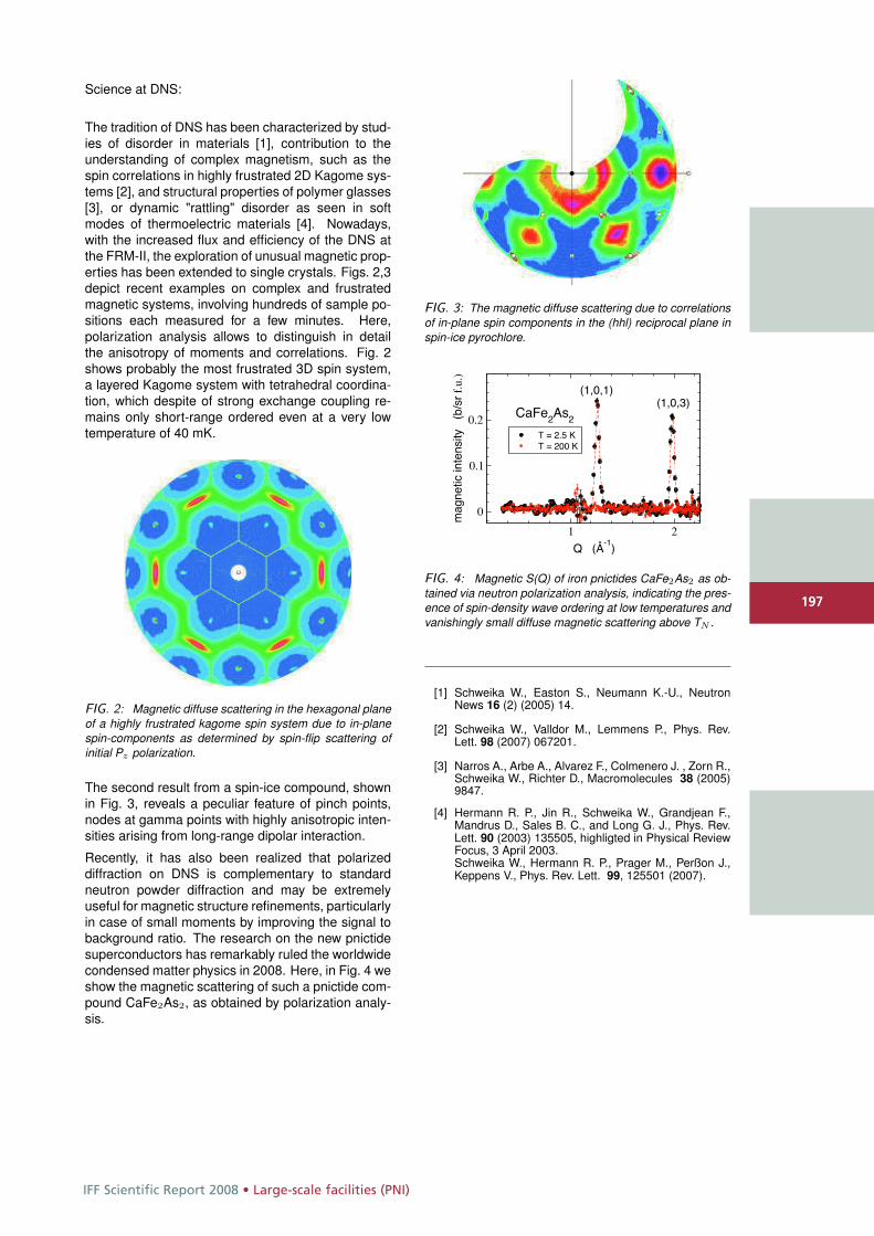
IFF Scientific Report 2008 • Large-scale facilities (PNI)
197
Science at DNS:
The tradition of DNS has been characterized by stud-ies of disorder in materials [1], contribution to theunderstanding of complex magnetism, such as thespin correlations in highly frustrated 2D Kagome sys-tems [2], and structural properties of polymer glasses[3], or dynamic "rattling" disorder as seen in softmodes of thermoelectric materials [4]. Nowadays,with the increased flux and efficiency of the DNS atthe FRM-II, the exploration of unusual magnetic prop-erties has been extended to single crystals. Figs. 2,3depict recent examples on complex and frustratedmagnetic systems, involving hundreds of sample po-sitions each measured for a few minutes. Here,polarization analysis allows to distinguish in detailthe anisotropy of moments and correlations. Fig. 2shows probably the most frustrated 3D spin system,a layered Kagome system with tetrahedral coordina-tion, which despite of strong exchange coupling re-mains only short-range ordered even at a very lowtemperature of 40 mK.
FIG. 2: Magnetic diffuse scattering in the hexagonal planeof a highly frustrated kagome spin system due to in-planespin-components as determined by spin-flip scattering ofinitial Pz polarization.
The second result from a spin-ice compound, shownin Fig. 3, reveals a peculiar feature of pinch points,nodes at gamma points with highly anisotropic inten-sities arising from long-range dipolar interaction.
Recently, it has also been realized that polarizeddiffraction on DNS is complementary to standardneutron powder diffraction and may be extremelyuseful for magnetic structure refinements, particularlyin case of small moments by improving the signal tobackground ratio. The research on the new pnictidesuperconductors has remarkably ruled the worldwidecondensed matter physics in 2008. Here, in Fig. 4 weshow the magnetic scattering of such a pnictide com-pound CaFe2As2, as obtained by polarization analy-sis.
FIG. 3: The magnetic diffuse scattering due to correlationsof in-plane spin components in the (hhl) reciprocal plane inspin-ice pyrochlore.
1 2
Q (Å-1
)
0
0.1
0.2
mag
netic
inte
nsity
(b/s
rf.
u.)
T = 2.5 KT = 200 K
CaFe2As2
(1,0,1)(1,0,3)
FIG. 4: Magnetic S(Q) of iron pnictides CaFe2As2 as ob-tained via neutron polarization analysis, indicating the pres-ence of spin-density wave ordering at low temperatures andvanishingly small diffuse magnetic scattering above TN .
[1] Schweika W., Easton S., Neumann K.-U., NeutronNews 16 (2) (2005) 14.
[2] Schweika W., Valldor M., Lemmens P., Phys. Rev.Lett. 98 (2007) 067201.
[3] Narros A., Arbe A., Alvarez F., Colmenero J. , Zorn R.,Schweika W., Richter D., Macromolecules 38 (2005)9847.
[4] Hermann R. P., Jin R., Schweika W., Grandjean F.,Mandrus D., Sales B. C., and Long G. J., Phys. Rev.Lett. 90 (2003) 135505, highligted in Physical ReviewFocus, 3 April 2003.Schweika W., Hermann R. P., Prager M., Perßon J.,Keppens V., Phys. Rev. Lett. 99, 125501 (2007).
197
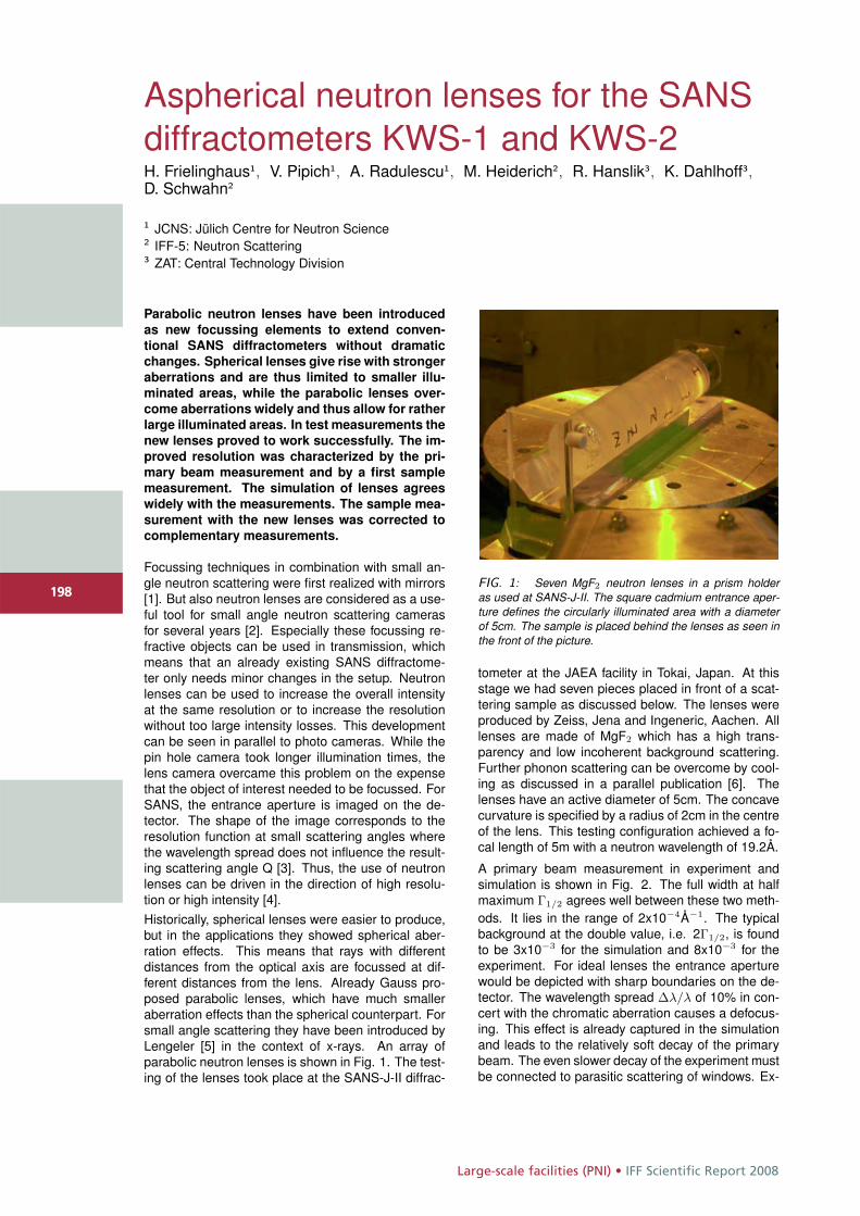
Large-scale facilities (PNI) • IFF Scientific Report 2008
198
Aspherical neutron lenses for the SANSdiffractometers KWS-1 and KWS-2H. Frielinghaus1, V. Pipich1, A. Radulescu1, M. Heiderich2, R. Hanslik3, K. Dahlhoff3,D. Schwahn2
1 JCNS: Jülich Centre for Neutron Science2 IFF-5: Neutron Scattering3 ZAT: Central Technology Division
Parabolic neutron lenses have been introduced
as new focussing elements to extend conven-
tional SANS diffractometers without dramatic
changes. Spherical lenses give rise with stronger
aberrations and are thus limited to smaller illu-
minated areas, while the parabolic lenses over-
come aberrations widely and thus allow for rather
large illuminated areas. In test measurements the
new lenses proved to work successfully. The im-
proved resolution was characterized by the pri-
mary beam measurement and by a first sample
measurement. The simulation of lenses agrees
widely with the measurements. The sample mea-
surement with the new lenses was corrected to
complementary measurements.
Focussing techniques in combination with small an-gle neutron scattering were first realized with mirrors[1]. But also neutron lenses are considered as a use-ful tool for small angle neutron scattering camerasfor several years [2]. Especially these focussing re-fractive objects can be used in transmission, whichmeans that an already existing SANS diffractome-ter only needs minor changes in the setup. Neutronlenses can be used to increase the overall intensityat the same resolution or to increase the resolutionwithout too large intensity losses. This developmentcan be seen in parallel to photo cameras. While thepin hole camera took longer illumination times, thelens camera overcame this problem on the expensethat the object of interest needed to be focussed. ForSANS, the entrance aperture is imaged on the de-tector. The shape of the image corresponds to theresolution function at small scattering angles wherethe wavelength spread does not influence the result-ing scattering angle Q [3]. Thus, the use of neutronlenses can be driven in the direction of high resolu-tion or high intensity [4].Historically, spherical lenses were easier to produce,but in the applications they showed spherical aber-ration effects. This means that rays with differentdistances from the optical axis are focussed at dif-ferent distances from the lens. Already Gauss pro-posed parabolic lenses, which have much smalleraberration effects than the spherical counterpart. Forsmall angle scattering they have been introduced byLengeler [5] in the context of x-rays. An array ofparabolic neutron lenses is shown in Fig. 1. The test-ing of the lenses took place at the SANS-J-II diffrac-
FIG. 1: Seven MgF2 neutron lenses in a prism holderas used at SANS-J-II. The square cadmium entrance aper-ture defines the circularly illuminated area with a diameterof 5cm. The sample is placed behind the lenses as seen inthe front of the picture.
tometer at the JAEA facility in Tokai, Japan. At thisstage we had seven pieces placed in front of a scat-tering sample as discussed below. The lenses wereproduced by Zeiss, Jena and Ingeneric, Aachen. Alllenses are made of MgF2 which has a high trans-parency and low incoherent background scattering.Further phonon scattering can be overcome by cool-ing as discussed in a parallel publication [6]. Thelenses have an active diameter of 5cm. The concavecurvature is specified by a radius of 2cm in the centreof the lens. This testing configuration achieved a fo-cal length of 5m with a neutron wavelength of 19.2Å.
A primary beam measurement in experiment andsimulation is shown in Fig. 2. The full width at halfmaximum Γ1/2 agrees well between these two meth-ods. It lies in the range of 2x10⁻⁴Å−1. The typicalbackground at the double value, i.e. 2Γ1/2, is foundto be 3x10⁻³ for the simulation and 8x10⁻³ for theexperiment. For ideal lenses the entrance aperturewould be depicted with sharp boundaries on the de-tector. The wavelength spread Δλ/λ of 10% in con-cert with the chromatic aberration causes a defocus-ing. This effect is already captured in the simulationand leads to the relatively soft decay of the primarybeam. The even slower decay of the experiment mustbe connected to parasitic scattering of windows. Ex-
198
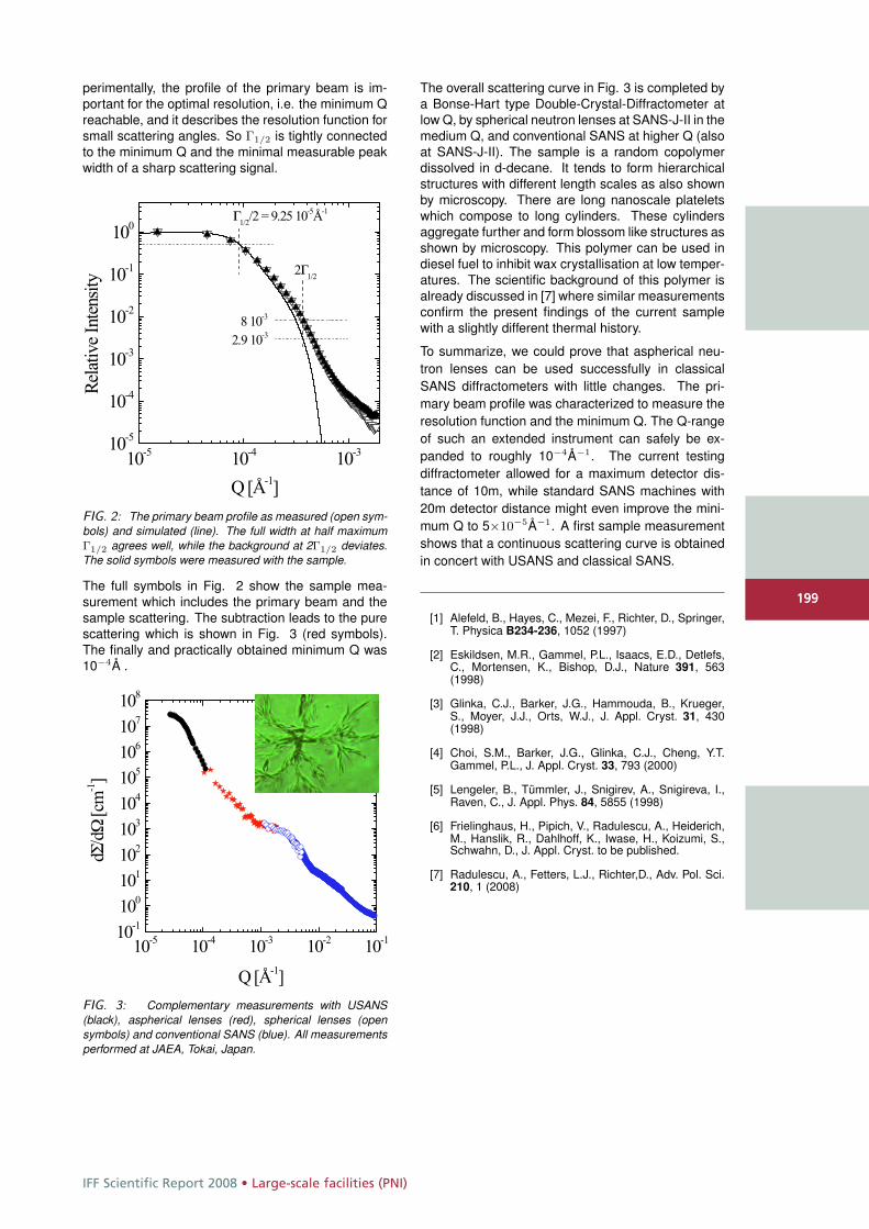
IFF Scientific Report 2008 • Large-scale facilities (PNI)
199
perimentally, the profile of the primary beam is im-portant for the optimal resolution, i.e. the minimum Qreachable, and it describes the resolution function forsmall scattering angles. So Γ1/2 is tightly connectedto the minimum Q and the minimal measurable peakwidth of a sharp scattering signal.
FIG. 2: The primary beam profile as measured (open sym-bols) and simulated (line). The full width at half maximumΓ1/2 agrees well, while the background at 2Γ1/2 deviates.The solid symbols were measured with the sample.
The full symbols in Fig. 2 show the sample mea-surement which includes the primary beam and thesample scattering. The subtraction leads to the purescattering which is shown in Fig. 3 (red symbols).The finally and practically obtained minimum Q was10−4Å .
FIG. 3: Complementary measurements with USANS(black), aspherical lenses (red), spherical lenses (opensymbols) and conventional SANS (blue). All measurementsperformed at JAEA, Tokai, Japan.
The overall scattering curve in Fig. 3 is completed bya Bonse-Hart type Double-Crystal-Diffractometer atlow Q, by spherical neutron lenses at SANS-J-II in themedium Q, and conventional SANS at higher Q (alsoat SANS-J-II). The sample is a random copolymerdissolved in d-decane. It tends to form hierarchicalstructures with different length scales as also shownby microscopy. There are long nanoscale plateletswhich compose to long cylinders. These cylindersaggregate further and form blossom like structures asshown by microscopy. This polymer can be used indiesel fuel to inhibit wax crystallisation at low temper-atures. The scientific background of this polymer isalready discussed in [7] where similar measurementsconfirm the present findings of the current samplewith a slightly different thermal history.
To summarize, we could prove that aspherical neu-tron lenses can be used successfully in classicalSANS diffractometers with little changes. The pri-mary beam profile was characterized to measure theresolution function and the minimum Q. The Q-rangeof such an extended instrument can safely be ex-panded to roughly 10−4Å−1. The current testingdiffractometer allowed for a maximum detector dis-tance of 10m, while standard SANS machines with20m detector distance might even improve the mini-mum Q to 5×10⁻⁵Å−1. A first sample measurementshows that a continuous scattering curve is obtainedin concert with USANS and classical SANS.
[1] Alefeld, B., Hayes, C., Mezei, F., Richter, D., Springer,T. Physica B234-236, 1052 (1997)
[2] Eskildsen, M.R., Gammel, P.L., Isaacs, E.D., Detlefs,C., Mortensen, K., Bishop, D.J., Nature 391, 563(1998)
[3] Glinka, C.J., Barker, J.G., Hammouda, B., Krueger,S., Moyer, J.J., Orts, W.J., J. Appl. Cryst. 31, 430(1998)
[4] Choi, S.M., Barker, J.G., Glinka, C.J., Cheng, Y.T.Gammel, P.L., J. Appl. Cryst. 33, 793 (2000)
[5] Lengeler, B., Tümmler, J., Snigirev, A., Snigireva, I.,Raven, C., J. Appl. Phys. 84, 5855 (1998)
[6] Frielinghaus, H., Pipich, V., Radulescu, A., Heiderich,M., Hanslik, R., Dahlhoff, K., Iwase, H., Koizumi, S.,Schwahn, D., J. Appl. Cryst. to be published.
[7] Radulescu, A., Fetters, L.J., Richter,D., Adv. Pol. Sci.210, 1 (2008)
199
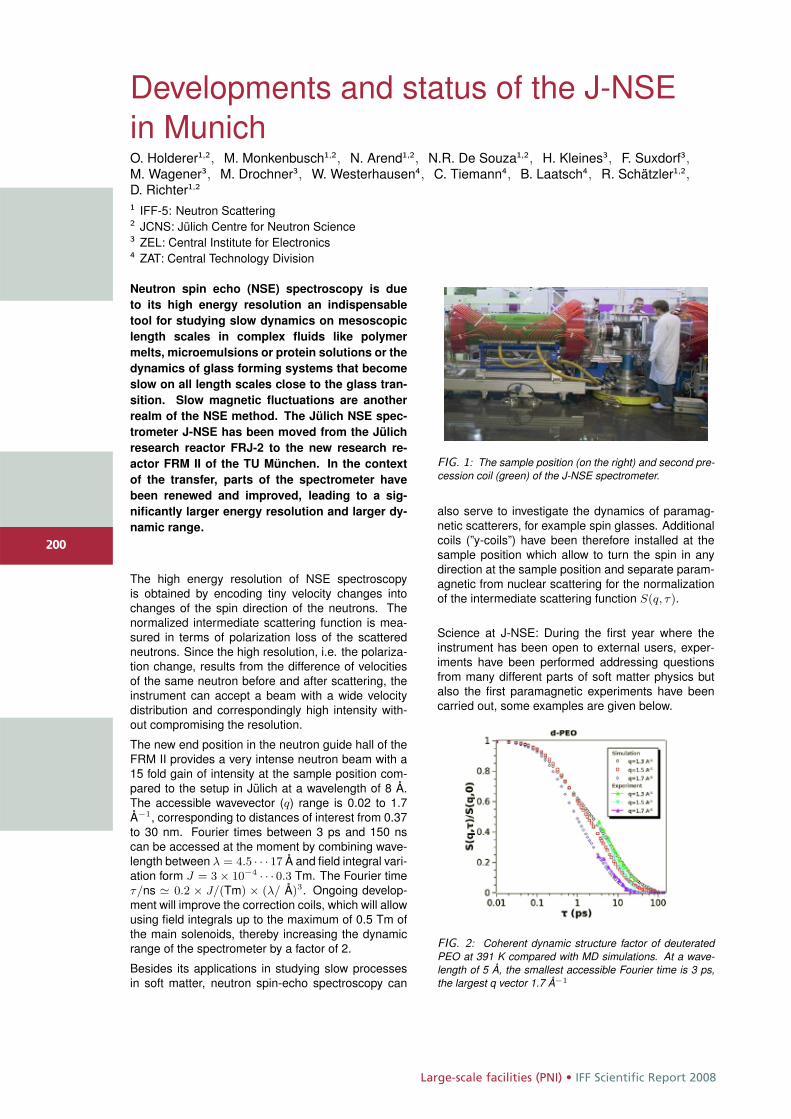
Large-scale facilities (PNI) • IFF Scientific Report 2008
200
Developments and status of the J-NSEin MunichO. Holderer1,2, M. Monkenbusch1,2, N. Arend1,2, N.R. De Souza1,2, H. Kleines3, F. Suxdorf3,M. Wagener3, M. Drochner3, W. Westerhausen4, C. Tiemann4, B. Laatsch4, R. Schätzler1,2,D. Richter1,2
1 IFF-5: Neutron Scattering2 JCNS: Jülich Centre for Neutron Science3 ZEL: Central Institute for Electronics4 ZAT: Central Technology Division
Neutron spin echo (NSE) spectroscopy is due
to its high energy resolution an indispensable
tool for studying slow dynamics on mesoscopic
length scales in complex fluids like polymer
melts, microemulsions or protein solutions or the
dynamics of glass forming systems that become
slow on all length scales close to the glass tran-
sition. Slow magnetic fluctuations are another
realm of the NSE method. The Jülich NSE spec-
trometer J-NSE has been moved from the Jülich
research reactor FRJ-2 to the new research re-
actor FRM II of the TU München. In the context
of the transfer, parts of the spectrometer have
been renewed and improved, leading to a sig-
nificantly larger energy resolution and larger dy-
namic range.
The high energy resolution of NSE spectroscopyis obtained by encoding tiny velocity changes intochanges of the spin direction of the neutrons. Thenormalized intermediate scattering function is mea-sured in terms of polarization loss of the scatteredneutrons. Since the high resolution, i.e. the polariza-tion change, results from the difference of velocitiesof the same neutron before and after scattering, theinstrument can accept a beam with a wide velocitydistribution and correspondingly high intensity with-out compromising the resolution.
The new end position in the neutron guide hall of theFRM II provides a very intense neutron beam with a15 fold gain of intensity at the sample position com-pared to the setup in Jülich at a wavelength of 8 Å.The accessible wavevector (q) range is 0.02 to 1.7Å−1, corresponding to distances of interest from 0.37to 30 nm. Fourier times between 3 ps and 150 nscan be accessed at the moment by combining wave-length between λ = 4.5 · · · 17 Å and field integral vari-ation form J = 3 × 10⁻⁴ · · · 0.3 Tm. The Fourier timeτ/ns � 0.2 × J/(Tm) × (λ/ Å)3. Ongoing develop-ment will improve the correction coils, which will allowusing field integrals up to the maximum of 0.5 Tm ofthe main solenoids, thereby increasing the dynamicrange of the spectrometer by a factor of 2.
Besides its applications in studying slow processesin soft matter, neutron spin-echo spectroscopy can
FIG. 1: The sample position (on the right) and second pre-cession coil (green) of the J-NSE spectrometer.
also serve to investigate the dynamics of paramag-netic scatterers, for example spin glasses. Additionalcoils (”y-coils”) have been therefore installed at thesample position which allow to turn the spin in anydirection at the sample position and separate param-agnetic from nuclear scattering for the normalizationof the intermediate scattering function S(q, τ).
Science at J-NSE: During the first year where theinstrument has been open to external users, exper-iments have been performed addressing questionsfrom many different parts of soft matter physics butalso the first paramagnetic experiments have beencarried out, some examples are given below.
FIG. 2: Coherent dynamic structure factor of deuteratedPEO at 391 K compared with MD simulations. At a wave-length of 5 Å, the smallest accessible Fourier time is 3 ps,the largest q vector 1.7 Å−1
200
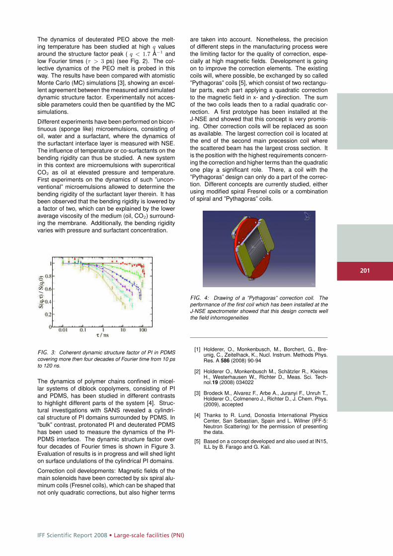
IFF Scientific Report 2008 • Large-scale facilities (PNI)
201
The dynamics of deuterated PEO above the melt-ing temperature has been studied at high q valuesaround the structure factor peak ( q < 1.7 Å−1 andlow Fourier times (τ > 3 ps) (see Fig. 2). The col-lective dynamics of the PEO melt is probed in thisway. The results have been compared with atomisticMonte Carlo (MC) simulations [3], showing an excel-lent agreement between the measured and simulateddynamic structure factor. Experimentally not acces-sible parameters could then be quantified by the MCsimulations.
Different experiments have been performed on bicon-tinuous (sponge like) microemulsions, consisting ofoil, water and a surfactant, where the dynamics ofthe surfactant interface layer is measured with NSE.The influence of temperature or co-surfactants on thebending rigidity can thus be studied. A new systemin this context are microemulsions with supercriticalCO2 as oil at elevated pressure and temperature.First experiments on the dynamics of such ”uncon-ventional” microemulsions allowed to determine thebending rigidity of the surfactant layer therein. It hasbeen observed that the bending rigidity is lowered bya factor of two, which can be explained by the loweraverage viscosity of the medium (oil, CO2) surround-ing the membrane. Additionally, the bending rigidityvaries with pressure and surfactant concentration.
FIG. 3: Coherent dynamic structure factor of PI in PDMScovering more then four decades of Fourier time from 10 psto 120 ns.
The dynamics of polymer chains confined in micel-lar systems of diblock copolymers, consisting of PIand PDMS, has been studied in different contraststo highlight different parts of the system [4]. Struc-tural investigations with SANS revealed a cylindri-cal structure of PI domains surrounded by PDMS. In”bulk” contrast, protonated PI and deuterated PDMShas been used to measure the dynamics of the PI-PDMS interface. The dynamic structure factor overfour decades of Fourier times is shown in Figure 3.Evaluation of results is in progress and will shed lighton surface undulations of the cylindrical PI domains.
Correction coil developments: Magnetic fields of themain solenoids have been corrected by six spiral alu-minum coils (Fresnel coils), which can be shaped thatnot only quadratic corrections, but also higher terms
are taken into account. Nonetheless, the precisionof different steps in the manufacturing process werethe limiting factor for the quality of correction, espe-cially at high magnetic fields. Development is goingon to improve the correction elements. The existingcoils will, where possible, be exchanged by so called”Pythagoras” coils [5], which consist of two rectangu-lar parts, each part applying a quadratic correctionto the magnetic field in x- and y-direction. The sumof the two coils leads then to a radial quadratic cor-rection. A first prototype has been installed at theJ-NSE and showed that this concept is very promis-ing. Other correction coils will be replaced as soonas available. The largest correction coil is located atthe end of the second main precession coil wherethe scattered beam has the largest cross section. Itis the position with the highest requirements concern-ing the correction and higher terms than the quadraticone play a significant role. There, a coil with the”Pythagoras” design can only do a part of the correc-tion. Different concepts are currently studied, eitherusing modified spiral Fresnel coils or a combinationof spiral and ”Pythagoras” coils.
FIG. 4: Drawing of a ”Pythagoras” correction coil. Theperformance of the first coil which has been installed at theJ-NSE spectrometer showed that this design corrects wellthe field inhomogeneities
[1] Holderer, O., Monkenbusch, M., Borchert, G., Bre-unig, C., Zeitelhack, K., Nucl. Instrum. Methods Phys.Res. A 586 (2008) 90-94
[2] Holderer O., Monkenbusch M., Schätzler R., KleinesH., Westerhausen W., Richter D., Meas. Sci. Tech-nol.19 (2008) 034022
[3] Brodeck M., Alvarez F., Arbe A., Juranyi F., Unruh T.,Holderer O., Colmenero J., Richter D., J. Chem. Phys.(2009), accepted
[4] Thanks to R. Lund, Donostia International PhysicsCenter, San Sebastian, Spain and L. Willner (IFF-5:Neutron Scattering) for the permission of presentingthe data.
[5] Based on a concept developed and also used at IN15,ILL by B. Farago and G. Kali.
201
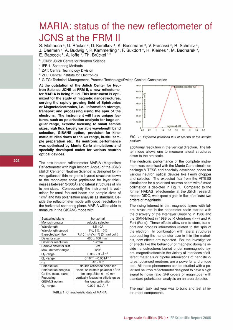
Large-scale facilities (PNI) • IFF Scientific Report 2008
202
MARIA: status of the new reflectometer ofJCNS at the FRM IIS. Mattauch 1, U. Rücker 2, D. Korolkov 1, K. Bussmann 2, V. Fracassi 3, R. Schmitz 3,J. Daemen 3, A. Budwig 3, P. Kämmerling 4, F. Suxdorf 4, H. Kleines 4, M. Bednarek 5,E. Babcock 1, A. Ioffe 1, Th. Brückel 1,2
1 JCNS: Jülich Centre for Neutron Science2 IFF-4: Scattering Methods3 ZAT: Central Technology Division4 ZEL: Central Institute for Electronics5 G-TG: Technical Management, Process Technology/Switch Cabinet Construction
At the outstation of the Jülich Center for Neu-
tron Science JCNS at FRM II, a new reflectome-
ter MARIA is being build. This instrument is opti-
mized for the study of magnetic nanostructures,
serving the rapidly growing field of Spintronics
or Magnetoelectronics, i.e. information storage,
transport and processing using the spin of the
electrons. The instrument will have unique fea-
tures, such as polarisation analysis for large an-
gular range, extreme focusing to small sample
sizes, high flux, largely variable wavelength band
selection, GISANS option, provision for kine-
matic studies down to the μs range, in-situ sam-
ple preparation etc. Its neutronic performance
was optimised by Monte Carlo simulations and
specially developed codes for various neutron
optical devices.
The new neutron reflectometer MARIA (MagnetismReflectometer with high Incident Angle) of the JCNS(Jülich Center of Neutron Science) is designed for in-vestigations of thin magnetic layered structures downto the monolayer scale (optimised for layer thick-nesses between 3-300Å) and lateral structures of nmto μm sizes. Consequently the instrument is opti-mised for small focused beam and sample sizes of1cm2 and has polarisation analysis as standard. Be-side the reflectometer mode with good resolution inthe horizontal scattering plane, MARIA will be able tomeasure in the GISANS mode with
Scattering plane horizontalMonochromator velocity selectorWavelength 4.5-10ÅWavelength spread 1%, 3%, 10%Expected pol. flux 7x10⁷ n/(s*cm2) (3mrad coll.)Detector size 400 x 400 mm2
Detector resolution 1-2mmSample detector dist. 2mMax. detector angle 120◦
Qz-range 0.002 - 3.2Å−1
Qx-range 6·10−5 - 0.001Å−1
αf -10 - 90◦Polarisation double reflection polariserPolarisation analysis Radial solid state polariser / 3HeCollim. (scat. plane) 4m long, Slits: 0 - 40 mmFocussing vertically focussing elliptic guideGISANS option 4m long collimationQy-range 0.002 -0.2 Å−1
TABLE 1: Characteristic data of MARIA.
FIG. 1: Expected polarised flux of MARIA at the sampleposition
additional resolution in the vertical direction. The lat-ter mode allows one to measure lateral structuresdown to the nm scale.
The neutronic performance of the complete instru-ment was optimised with the Monte Carlo simulationpackage VITESS and specially developed codes forvarious neutron optical devices like Fermi chopperand selector. The expected flux from the VITESSsimulations for a polarised neutron beam with 3 mradcollimation is depicted in Fig. 1. Compared to theformer HADAS reflectometer at the Jülich researchreactor DIDO, we expect a gain in flux of at least twoorders of magnitude.
The rising interest in thin magnetic layers with lat-eral structures in the nanometer scale started withthe discovery of the Interlayer Coupling in 1986 andthe GMR-Effect in 1989 by P. Grünberg (IFF) and A.Fert (Paris). These effects allow one to store, trans-port and process information related to the spin ofthe electron. In combination with lateral structuresapproaching the nanometer size in thin film materi-als, new effects are expected. For the investigationof effects like the behaviour of magnetic domains in-side nanostructures buried under nonmagnetic lay-ers, magnetic effects in the vicinity of interfaces of dif-ferent materials or dipolar interactions of nanostruc-tures, polarised neutrons are a powerful and uniquetool. All these phenomena can be studied with a po-larised neutron reflectometer designed to have a highsignal to noise ratio (8-9 orders of magnitude) withstandard polarisation analysis on an area detector.
The main task last year was to build and test all in-strument components.
202
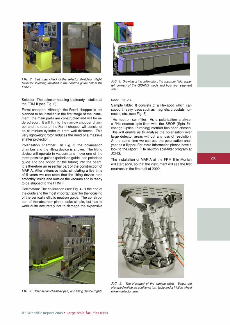
IFF Scientific Report 2008 • Large-scale facilities (PNI)
203
FIG. 2: Left: Last check of the selector shielding. Right:Selector shielding installed in the neutron guide hall at theFRM II.
Selector: The selector housing is already installed atthe FRM II (see Fig. 2).
Fermi chopper: Although the Fermi chopper is notplanned to be installed in the first stage of the instru-ment, the main parts are constructed and will be or-dered soon. It will fit into the narrow chopper cham-ber and the rotor of the Fermi chopper will consist ofan aluminium cylinder of 1mm wall thickness. Thisvery lightweight rotor reduces the need of a massiveshatter protection.
Polarisation chamber: In Fig. 3 the polarisationchamber and the lifting device is shown. The liftingdevice will operate in vacuum and move one of thethree possible guides (polarised guide, non polarisedguide and one option for the future) into the beam.It is therefore an essential part of the construction ofMARIA. After extensive tests, simulating a live timeof 5 years we can state that the lifting device runssmoothly inside and outside the vacuum and is readyto be shipped to the FRM II.
Collimation: The collimation (see Fig. 4) is the end ofthe guide and the most important part for the focusingof the vertically elliptic neutron guide. The construc-tion of the absorber plates looks simple, but has towork quite accurately not to damage the expensive
FIG. 3: Polarisation chamber (left) and lifting device (right).
FIG. 4: Drawing of the collimation, the absorber (inlet upperleft corner) of the GISANS mode and both four segmentslits.
super mirrors.
Sample table: It consists of a Hexapod which cansupport heavy loads such as magnets, cryostats, fur-naces, etc. (see Fig. 5).3He neutron spin-filter: As a polarisation analysera 3He neutron spin-filter with the SEOP (Spin Ex-change Optical Pumping) method has been chosen.This will enable us to analyse the polarisation overlarge detector areas without any loss of resolution.At the same time we can use the polarisation anal-yser as a flipper. For more information please have alook to the report: 3He neutron spin-filter program atJCNS.
The installation of MARIA at the FRM II in Munichwill start soon, so that the instrument will see the firstneutrons in the first half of 2009.
FIG. 5: The Hexapod of the sample table. Below theHexapod will be an additional turn table and a friction wheeldriven detector arm.
203
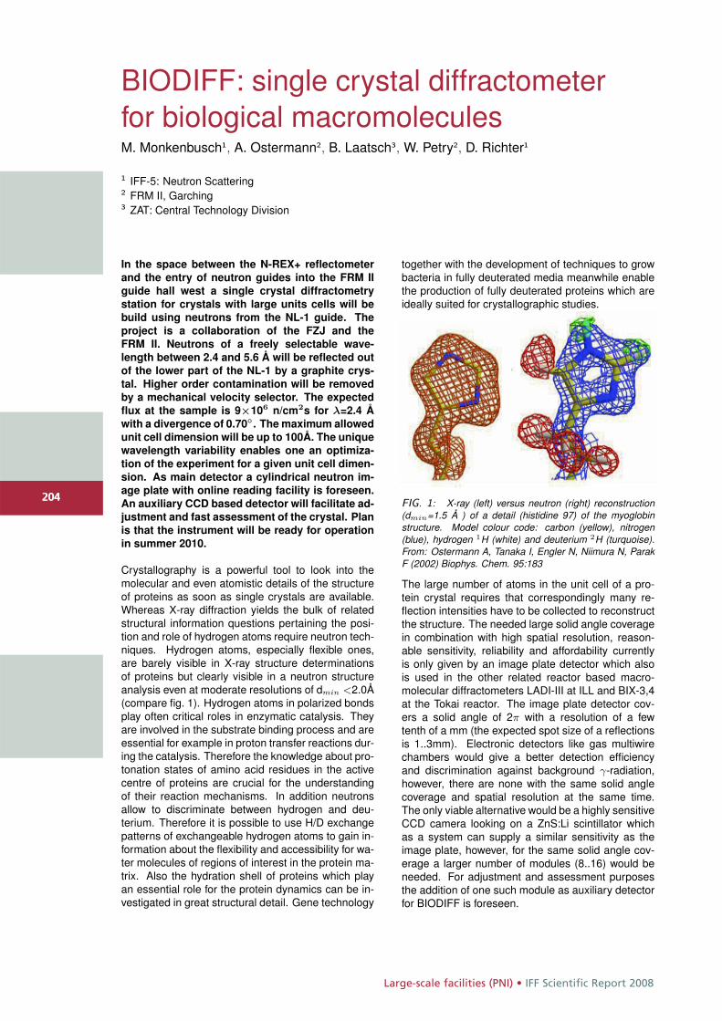
Large-scale facilities (PNI) • IFF Scientific Report 2008
204
BIODIFF: single crystal diffractometerfor biological macromoleculesM. Monkenbusch1, A. Ostermann2, B. Laatsch3, W. Petry2, D. Richter1
1 IFF-5: Neutron Scattering2 FRM II, Garching3 ZAT: Central Technology Division
In the space between the N-REX+ reflectometer
and the entry of neutron guides into the FRM II
guide hall west a single crystal diffractometry
station for crystals with large units cells will be
build using neutrons from the NL-1 guide. The
project is a collaboration of the FZJ and the
FRM II. Neutrons of a freely selectable wave-
length between 2.4 and 5.6 Å will be reflected out
of the lower part of the NL-1 by a graphite crys-
tal. Higher order contamination will be removed
by a mechanical velocity selector. The expected
flux at the sample is 9×10⁶ n/cm2s for λ=2.4 Å
with a divergence of 0.70◦ . The maximum allowed
unit cell dimension will be up to 100Å. The unique
wavelength variability enables one an optimiza-
tion of the experiment for a given unit cell dimen-
sion. As main detector a cylindrical neutron im-
age plate with online reading facility is foreseen.
An auxiliary CCD based detector will facilitate ad-
justment and fast assessment of the crystal. Plan
is that the instrument will be ready for operation
in summer 2010.
Crystallography is a powerful tool to look into themolecular and even atomistic details of the structureof proteins as soon as single crystals are available.Whereas X-ray diffraction yields the bulk of relatedstructural information questions pertaining the posi-tion and role of hydrogen atoms require neutron tech-niques. Hydrogen atoms, especially flexible ones,are barely visible in X-ray structure determinationsof proteins but clearly visible in a neutron structureanalysis even at moderate resolutions of dmin <2.0Å(compare fig. 1). Hydrogen atoms in polarized bondsplay often critical roles in enzymatic catalysis. Theyare involved in the substrate binding process and areessential for example in proton transfer reactions dur-ing the catalysis. Therefore the knowledge about pro-tonation states of amino acid residues in the activecentre of proteins are crucial for the understandingof their reaction mechanisms. In addition neutronsallow to discriminate between hydrogen and deu-terium. Therefore it is possible to use H/D exchangepatterns of exchangeable hydrogen atoms to gain in-formation about the flexibility and accessibility for wa-ter molecules of regions of interest in the protein ma-trix. Also the hydration shell of proteins which playan essential role for the protein dynamics can be in-vestigated in great structural detail. Gene technology
together with the development of techniques to growbacteria in fully deuterated media meanwhile enablethe production of fully deuterated proteins which areideally suited for crystallographic studies.
FIG. 1: X-ray (left) versus neutron (right) reconstruction(dmin=1.5 Å ) of a detail (histidine 97) of the myoglobinstructure. Model colour code: carbon (yellow), nitrogen(blue), hydrogen 1H (white) and deuterium 2H (turquoise).From: Ostermann A, Tanaka I, Engler N, Niimura N, ParakF (2002) Biophys. Chem. 95:183
The large number of atoms in the unit cell of a pro-tein crystal requires that correspondingly many re-flection intensities have to be collected to reconstructthe structure. The needed large solid angle coveragein combination with high spatial resolution, reason-able sensitivity, reliability and affordability currentlyis only given by an image plate detector which alsois used in the other related reactor based macro-molecular diffractometers LADI-III at ILL and BIX-3,4at the Tokai reactor. The image plate detector cov-ers a solid angle of 2π with a resolution of a fewtenth of a mm (the expected spot size of a reflectionsis 1..3mm). Electronic detectors like gas multiwirechambers would give a better detection efficiencyand discrimination against background γ-radiation,however, there are none with the same solid anglecoverage and spatial resolution at the same time.The only viable alternative would be a highly sensitiveCCD camera looking on a ZnS:Li scintillator whichas a system can supply a similar sensitivity as theimage plate, however, for the same solid angle cov-erage a larger number of modules (8..16) would beneeded. For adjustment and assessment purposesthe addition of one such module as auxiliary detectorfor BIODIFF is foreseen.
204
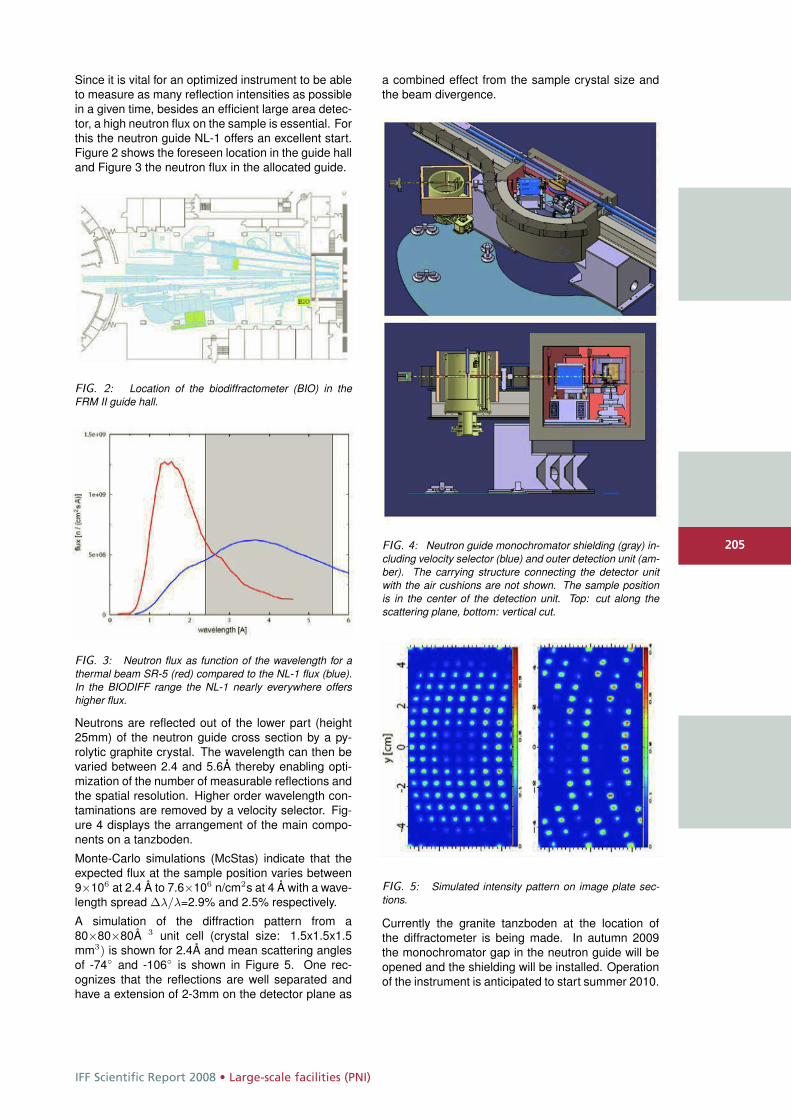
IFF Scientific Report 2008 • Large-scale facilities (PNI)
205
Since it is vital for an optimized instrument to be ableto measure as many reflection intensities as possiblein a given time, besides an efficient large area detec-tor, a high neutron flux on the sample is essential. Forthis the neutron guide NL-1 offers an excellent start.Figure 2 shows the foreseen location in the guide halland Figure 3 the neutron flux in the allocated guide.
FIG. 2: Location of the biodiffractometer (BIO) in theFRM II guide hall.
FIG. 3: Neutron flux as function of the wavelength for athermal beam SR-5 (red) compared to the NL-1 flux (blue).In the BIODIFF range the NL-1 nearly everywhere offershigher flux.
Neutrons are reflected out of the lower part (height25mm) of the neutron guide cross section by a py-rolytic graphite crystal. The wavelength can then bevaried between 2.4 and 5.6Å thereby enabling opti-mization of the number of measurable reflections andthe spatial resolution. Higher order wavelength con-taminations are removed by a velocity selector. Fig-ure 4 displays the arrangement of the main compo-nents on a tanzboden.
Monte-Carlo simulations (McStas) indicate that theexpected flux at the sample position varies between9×106 at 2.4 Å to 7.6×10⁶ n/cm2s at 4 Å with a wave-length spread Δλ/λ=2.9% and 2.5% respectively.
A simulation of the diffraction pattern from a80×80×80Å 3 unit cell (crystal size: 1.5x1.5x1.5mm3) is shown for 2.4Å and mean scattering anglesof -74◦ and -106◦ is shown in Figure 5. One rec-ognizes that the reflections are well separated andhave a extension of 2-3mm on the detector plane as
a combined effect from the sample crystal size andthe beam divergence.
FIG. 4: Neutron guide monochromator shielding (gray) in-cluding velocity selector (blue) and outer detection unit (am-ber). The carrying structure connecting the detector unitwith the air cushions are not shown. The sample positionis in the center of the detection unit. Top: cut along thescattering plane, bottom: vertical cut.
FIG. 5: Simulated intensity pattern on image plate sec-tions.
Currently the granite tanzboden at the location ofthe diffractometer is being made. In autumn 2009the monochromator gap in the neutron guide will beopened and the shielding will be installed. Operationof the instrument is anticipated to start summer 2010.
205
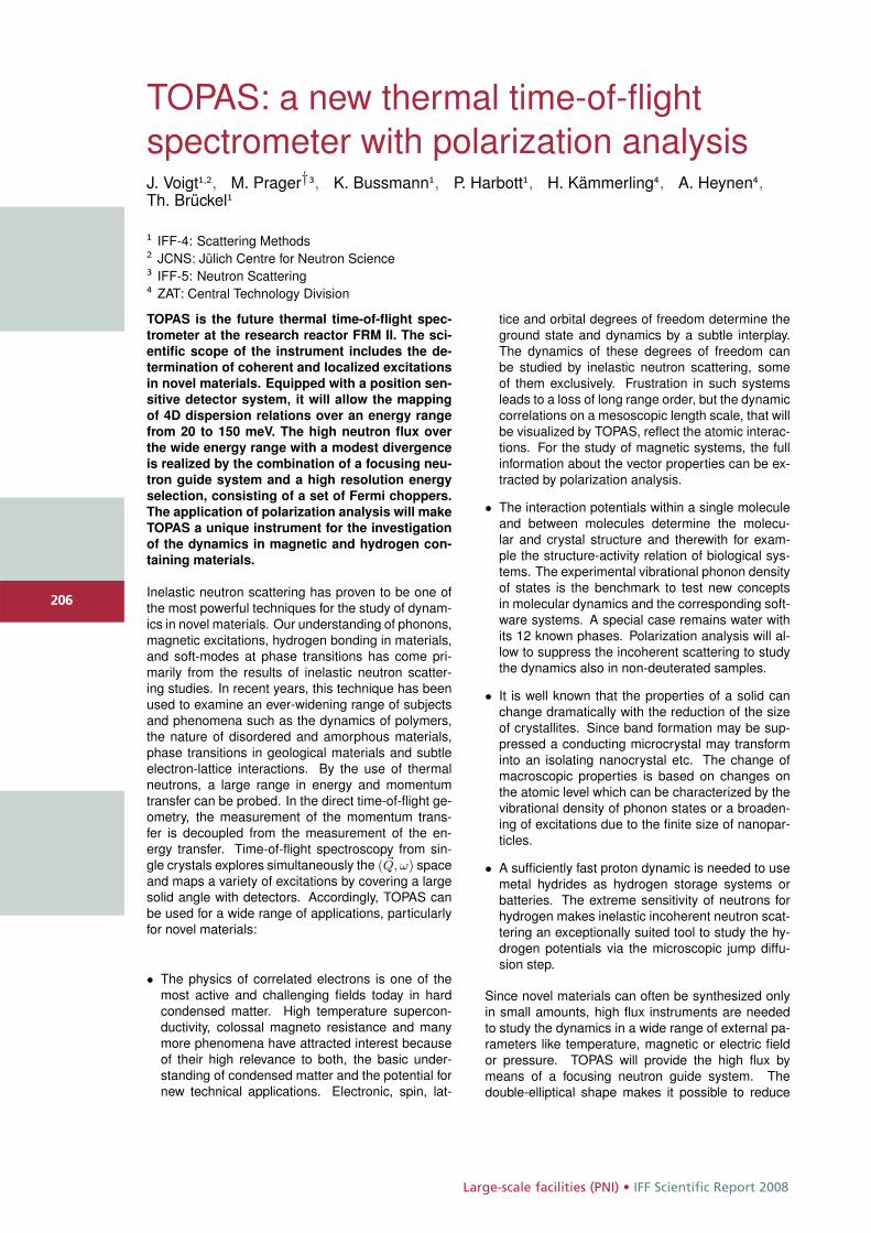
Large-scale facilities (PNI) • IFF Scientific Report 2008
206
TOPAS: a new thermal time-of-flightspectrometer with polarization analysisJ. Voigt1,2, M. Prager†3, K. Bussmann1, P. Harbott1, H. Kämmerling4, A. Heynen4,Th. Brückel1
1 IFF-4: Scattering Methods2 JCNS: Jülich Centre for Neutron Science3 IFF-5: Neutron Scattering4 ZAT: Central Technology Division
TOPAS is the future thermal time-of-flight spec-
trometer at the research reactor FRM II. The sci-
entific scope of the instrument includes the de-
termination of coherent and localized excitations
in novel materials. Equipped with a position sen-
sitive detector system, it will allow the mapping
of 4D dispersion relations over an energy range
from 20 to 150 meV. The high neutron flux over
the wide energy range with a modest divergence
is realized by the combination of a focusing neu-
tron guide system and a high resolution energy
selection, consisting of a set of Fermi choppers.
The application of polarization analysis will make
TOPAS a unique instrument for the investigation
of the dynamics in magnetic and hydrogen con-
taining materials.
Inelastic neutron scattering has proven to be one ofthe most powerful techniques for the study of dynam-ics in novel materials. Our understanding of phonons,magnetic excitations, hydrogen bonding in materials,and soft-modes at phase transitions has come pri-marily from the results of inelastic neutron scatter-ing studies. In recent years, this technique has beenused to examine an ever-widening range of subjectsand phenomena such as the dynamics of polymers,the nature of disordered and amorphous materials,phase transitions in geological materials and subtleelectron-lattice interactions. By the use of thermalneutrons, a large range in energy and momentumtransfer can be probed. In the direct time-of-flight ge-ometry, the measurement of the momentum trans-fer is decoupled from the measurement of the en-ergy transfer. Time-of-flight spectroscopy from sin-gle crystals explores simultaneously the ( �Q, ω) spaceand maps a variety of excitations by covering a largesolid angle with detectors. Accordingly, TOPAS canbe used for a wide range of applications, particularlyfor novel materials:
• The physics of correlated electrons is one of themost active and challenging fields today in hardcondensed matter. High temperature supercon-ductivity, colossal magneto resistance and manymore phenomena have attracted interest becauseof their high relevance to both, the basic under-standing of condensed matter and the potential fornew technical applications. Electronic, spin, lat-
tice and orbital degrees of freedom determine theground state and dynamics by a subtle interplay.The dynamics of these degrees of freedom canbe studied by inelastic neutron scattering, someof them exclusively. Frustration in such systemsleads to a loss of long range order, but the dynamiccorrelations on a mesoscopic length scale, that willbe visualized by TOPAS, reflect the atomic interac-tions. For the study of magnetic systems, the fullinformation about the vector properties can be ex-tracted by polarization analysis.
• The interaction potentials within a single moleculeand between molecules determine the molecu-lar and crystal structure and therewith for exam-ple the structure-activity relation of biological sys-tems. The experimental vibrational phonon densityof states is the benchmark to test new conceptsin molecular dynamics and the corresponding soft-ware systems. A special case remains water withits 12 known phases. Polarization analysis will al-low to suppress the incoherent scattering to studythe dynamics also in non-deuterated samples.
• It is well known that the properties of a solid canchange dramatically with the reduction of the sizeof crystallites. Since band formation may be sup-pressed a conducting microcrystal may transforminto an isolating nanocrystal etc. The change ofmacroscopic properties is based on changes onthe atomic level which can be characterized by thevibrational density of phonon states or a broaden-ing of excitations due to the finite size of nanopar-ticles.
• A sufficiently fast proton dynamic is needed to usemetal hydrides as hydrogen storage systems orbatteries. The extreme sensitivity of neutrons forhydrogen makes inelastic incoherent neutron scat-tering an exceptionally suited tool to study the hy-drogen potentials via the microscopic jump diffu-sion step.
Since novel materials can often be synthesized onlyin small amounts, high flux instruments are neededto study the dynamics in a wide range of external pa-rameters like temperature, magnetic or electric fieldor pressure. TOPAS will provide the high flux bymeans of a focusing neutron guide system. Thedouble-elliptical shape makes it possible to reduce
206
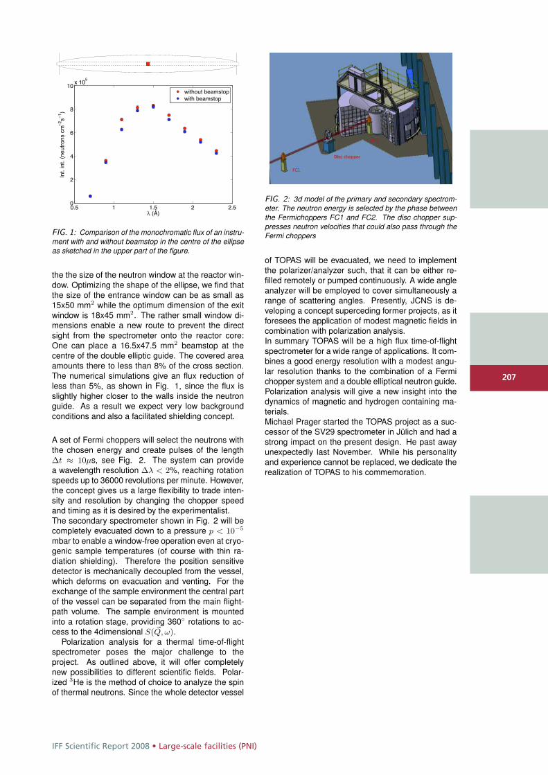
IFF Scientific Report 2008 • Large-scale facilities (PNI)
207
0.5 1 1.5 2 2.50
2
4
6
8
10x 10
5
l (Å)
Int.
int.
(neu
tron
scm
−2 s−
1 )
without beamstopwith beamstop
FIG. 1: Comparison of the monochromatic flux of an instru-ment with and without beamstop in the centre of the ellipseas sketched in the upper part of the figure.
the the size of the neutron window at the reactor win-dow. Optimizing the shape of the ellipse, we find thatthe size of the entrance window can be as small as15x50 mm2 while the optimum dimension of the exitwindow is 18x45 mm2. The rather small window di-mensions enable a new route to prevent the directsight from the spectrometer onto the reactor core:One can place a 16.5x47.5 mm2 beamstop at thecentre of the double elliptic guide. The covered areaamounts there to less than 8% of the cross section.The numerical simulations give an flux reduction ofless than 5%, as shown in Fig. 1, since the flux isslightly higher closer to the walls inside the neutronguide. As a result we expect very low backgroundconditions and also a facilitated shielding concept.
A set of Fermi choppers will select the neutrons withthe chosen energy and create pulses of the lengthΔt ≈ 10μs, see Fig. 2. The system can providea wavelength resolution Δλ < 2%, reaching rotationspeeds up to 36000 revolutions per minute. However,the concept gives us a large flexibility to trade inten-sity and resolution by changing the chopper speedand timing as it is desired by the experimentalist.The secondary spectrometer shown in Fig. 2 will becompletely evacuated down to a pressure p < 10−5
mbar to enable a window-free operation even at cryo-genic sample temperatures (of course with thin ra-diation shielding). Therefore the position sensitivedetector is mechanically decoupled from the vessel,which deforms on evacuation and venting. For theexchange of the sample environment the central partof the vessel can be separated from the main flight-path volume. The sample environment is mountedinto a rotation stage, providing 360◦ rotations to ac-cess to the 4dimensional S( �Q, ω).
Polarization analysis for a thermal time-of-flightspectrometer poses the major challenge to theproject. As outlined above, it will offer completelynew possibilities to different scientific fields. Polar-ized 3He is the method of choice to analyze the spinof thermal neutrons. Since the whole detector vessel
FIG. 2: 3d model of the primary and secondary spectrom-eter. The neutron energy is selected by the phase betweenthe Fermichoppers FC1 and FC2. The disc chopper sup-presses neutron velocities that could also pass through theFermi choppers
of TOPAS will be evacuated, we need to implementthe polarizer/analyzer such, that it can be either re-filled remotely or pumped continuously. A wide angleanalyzer will be employed to cover simultaneously arange of scattering angles. Presently, JCNS is de-veloping a concept superceding former projects, as itforesees the application of modest magnetic fields incombination with polarization analysis.In summary TOPAS will be a high flux time-of-flightspectrometer for a wide range of applications. It com-bines a good energy resolution with a modest angu-lar resolution thanks to the combination of a Fermichopper system and a double elliptical neutron guide.Polarization analysis will give a new insight into thedynamics of magnetic and hydrogen containing ma-terials.Michael Prager started the TOPAS project as a suc-cessor of the SV29 spectrometer in Jülich and had astrong impact on the present design. He past awayunexpectedly last November. While his personalityand experience cannot be replaced, we dedicate therealization of TOPAS to his commemoration.
207
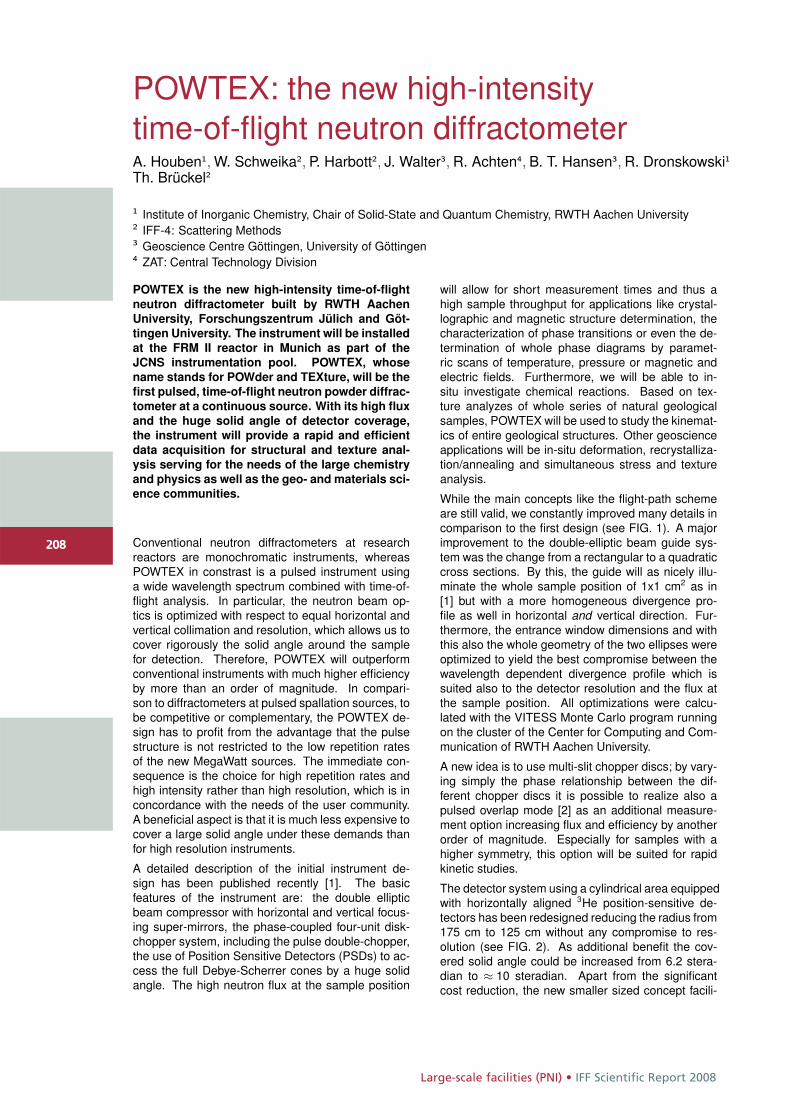
Large-scale facilities (PNI) • IFF Scientific Report 2008
208
POWTEX: the new high-intensitytime-of-flight neutron diffractometerA. Houben1, W. Schweika2, P. Harbott2, J. Walter3, R. Achten4, B. T. Hansen3, R. Dronskowski1Th. Brückel2
1 Institute of Inorganic Chemistry, Chair of Solid-State and Quantum Chemistry, RWTH Aachen University2 IFF-4: Scattering Methods3 Geoscience Centre Göttingen, University of Göttingen4 ZAT: Central Technology Division
POWTEX is the new high-intensity time-of-flight
neutron diffractometer built by RWTH Aachen
University, Forschungszentrum Jülich and Göt-
tingen University. The instrument will be installed
at the FRM II reactor in Munich as part of the
JCNS instrumentation pool. POWTEX, whose
name stands for POWder and TEXture, will be the
first pulsed, time-of-flight neutron powder diffrac-
tometer at a continuous source. With its high flux
and the huge solid angle of detector coverage,
the instrument will provide a rapid and efficient
data acquisition for structural and texture anal-
ysis serving for the needs of the large chemistry
and physics as well as the geo- and materials sci-
ence communities.
Conventional neutron diffractometers at researchreactors are monochromatic instruments, whereasPOWTEX in constrast is a pulsed instrument usinga wide wavelength spectrum combined with time-of-flight analysis. In particular, the neutron beam op-tics is optimized with respect to equal horizontal andvertical collimation and resolution, which allows us tocover rigorously the solid angle around the samplefor detection. Therefore, POWTEX will outperformconventional instruments with much higher efficiencyby more than an order of magnitude. In compari-son to diffractometers at pulsed spallation sources, tobe competitive or complementary, the POWTEX de-sign has to profit from the advantage that the pulsestructure is not restricted to the low repetition ratesof the new MegaWatt sources. The immediate con-sequence is the choice for high repetition rates andhigh intensity rather than high resolution, which is inconcordance with the needs of the user community.A beneficial aspect is that it is much less expensive tocover a large solid angle under these demands thanfor high resolution instruments.
A detailed description of the initial instrument de-sign has been published recently [1]. The basicfeatures of the instrument are: the double ellipticbeam compressor with horizontal and vertical focus-ing super-mirrors, the phase-coupled four-unit disk-chopper system, including the pulse double-chopper,the use of Position Sensitive Detectors (PSDs) to ac-cess the full Debye-Scherrer cones by a huge solidangle. The high neutron flux at the sample position
will allow for short measurement times and thus ahigh sample throughput for applications like crystal-lographic and magnetic structure determination, thecharacterization of phase transitions or even the de-termination of whole phase diagrams by paramet-ric scans of temperature, pressure or magnetic andelectric fields. Furthermore, we will be able to in-situ investigate chemical reactions. Based on tex-ture analyzes of whole series of natural geologicalsamples, POWTEX will be used to study the kinemat-ics of entire geological structures. Other geoscienceapplications will be in-situ deformation, recrystalliza-tion/annealing and simultaneous stress and textureanalysis.
While the main concepts like the flight-path schemeare still valid, we constantly improved many details incomparison to the first design (see FIG. 1). A majorimprovement to the double-elliptic beam guide sys-tem was the change from a rectangular to a quadraticcross sections. By this, the guide will as nicely illu-minate the whole sample position of 1x1 cm2 as in[1] but with a more homogeneous divergence pro-file as well in horizontal and vertical direction. Fur-thermore, the entrance window dimensions and withthis also the whole geometry of the two ellipses wereoptimized to yield the best compromise between thewavelength dependent divergence profile which issuited also to the detector resolution and the flux atthe sample position. All optimizations were calcu-lated with the VITESS Monte Carlo program runningon the cluster of the Center for Computing and Com-munication of RWTH Aachen University.
A new idea is to use multi-slit chopper discs; by vary-ing simply the phase relationship between the dif-ferent chopper discs it is possible to realize also apulsed overlap mode [2] as an additional measure-ment option increasing flux and efficiency by anotherorder of magnitude. Especially for samples with ahigher symmetry, this option will be suited for rapidkinetic studies.
The detector system using a cylindrical area equippedwith horizontally aligned 3He position-sensitive de-tectors has been redesigned reducing the radius from175 cm to 125 cm without any compromise to res-olution (see FIG. 2). As additional benefit the cov-ered solid angle could be increased from 6.2 stera-dian to ≈ 10 steradian. Apart from the significantcost reduction, the new smaller sized concept facili-
208
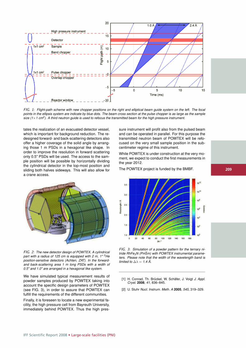
IFF Scientific Report 2008 • Large-scale facilities (PNI)
209
FIG. 1: Flight-path scheme with new chopper positions on the right and elliptical beam guide system on the left. The focalpoints in the ellipsis system are indicate by blue dots. The beam cross section at the pulse chopper is as large as the samplesize (1×1 cm2). A third neutron guide is used to refocus the transmitted beam for the high pressure instrument.
tates the realization of an evacuated detector vessel,which is important for background reduction. The re-designed forward- and back-scattering detectors alsooffer a higher coverage of the solid angle by arrang-ing those 1 m PSDs in a hexagonal like shape. Inorder to improve the resolution in forward scatteringonly 0.5" PSDs will be used. The access to the sam-ple position will be possible by horizontally dividingthe cylindrical detector in the top-most position andsliding both halves sideways. This will also allow fora crane access.
FIG. 2: The new detector design of POWTEX. A cylindricalpart with a radius of 125 cm is equipped with 2 m, 1" 3Heposition-sensitive detectors (Achten, ZAT). In the forward-and back-scattering area 1 m long PSDs with a width of0.5" and 1.0" are arranged in a hexagonal like system.
We have simulated typical measurement results ofpowder samples produced by POWTEX taking intoaccount the specific design parameters of POWTEX(see FIG. 3), in order to assure that POWTEX canfulfill the requirements of the different communities.
Finally, it is foreseen to locate a new experimental fa-cility, the high pressure cell from Bayreuth University,immediately behind POWTEX. Thus the high pres-
sure instrument will profit also from the pulsed beamand can be operated in parallel. For this purpose thetransmitted neutron beam of POWTEX will be refo-cused on the very small sample position in the sub-centimeter regime of this instrument.
While POWTEX is under construction at the very mo-ment, we expect to conduct the first measurements inthe year 2012.
The POWTEX project is funded by the BMBF.
FIG. 3: Simulation of a powder pattern for the ternary ni-tride RhFe3N (Pm3m) with POWTEX instrumental parame-ters. Please note that the width of the wavelength band islimited to Δλ = 1.4 Å.
[1] H. Conrad, Th. Brückel, W. Schäfer, J. Voigt J. Appl.Cryst. 2008, 41, 836–845.
[2] U. Stuhr Nucl. Instrum. Meth. A 2005, 545, 319–329.
209
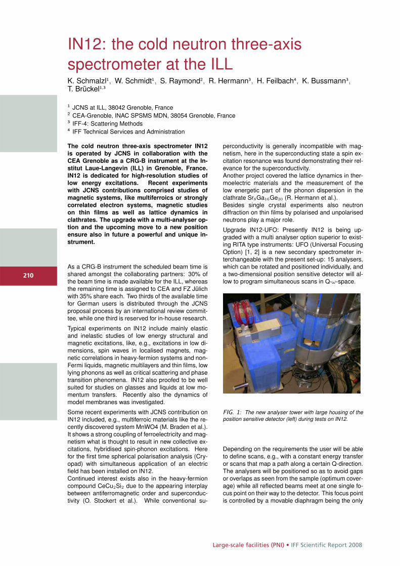
Large-scale facilities (PNI) • IFF Scientific Report 2008
210
IN12: the cold neutron three-axisspectrometer at the ILLK. Schmalzl1, W. Schmidt1, S. Raymond2, R. Hermann3, H. Feilbach4, K. Bussmann3,T. Brückel1,3
1 JCNS at ILL, 38042 Grenoble, France2 CEA-Grenoble, INAC SPSMS MDN, 38054 Grenoble, France3 IFF-4: Scattering Methods4 IFF Technical Services and Administration
The cold neutron three-axis spectrometer IN12
is operated by JCNS in collaboration with the
CEA Grenoble as a CRG-B instrument at the In-
stitut Laue-Langevin (ILL) in Grenoble, France.
IN12 is dedicated for high-resolution studies of
low energy excitations. Recent experiments
with JCNS contributions comprised studies of
magnetic systems, like multiferroics or strongly
correlated electron systems, magnetic studies
on thin films as well as lattice dynamics in
clathrates. The upgrade with a multi-analyser op-
tion and the upcoming move to a new position
ensure also in future a powerful and unique in-
strument.
As a CRG-B instrument the scheduled beam time isshared amongst the collaborating partners: 30% ofthe beam time is made available for the ILL, whereasthe remaining time is assigned to CEA and FZ Jülichwith 35% share each. Two thirds of the available timefor German users is distributed through the JCNSproposal process by an international review commit-tee, while one third is reserved for in-house research.
Typical experiments on IN12 include mainly elasticand inelastic studies of low energy structural andmagnetic excitations, like, e.g., excitations in low di-mensions, spin waves in localised magnets, mag-netic correlations in heavy-fermion systems and non-Fermi liquids, magnetic multilayers and thin films, lowlying phonons as well as critical scattering and phasetransition phenomena. IN12 also proofed to be wellsuited for studies on glasses and liquids at low mo-mentum transfers. Recently also the dynamics ofmodel membranes was investigated.
Some recent experiments with JCNS contribution onIN12 included, e.g., multiferroic materials like the re-cently discovered system MnWO4 (M. Braden et al.).It shows a strong coupling of ferroelectricity and mag-netism what is thought to result in new collective ex-citations, hybridised spin-phonon excitations. Herefor the first time spherical polarisation analysis (Cry-opad) with simultaneous application of an electricfield has been installed on IN12.Continued interest exists also in the heavy-fermioncompound CeCu2Si2 due to the appearing interplaybetween antiferromagnetic order and superconduc-tivity (O. Stockert et al.). While conventional su-
perconductivity is generally incompatible with mag-netism, here in the superconducting state a spin ex-citation resonance was found demonstrating their rel-evance for the superconductivity.Another project covered the lattice dynamics in ther-moelectric materials and the measurement of thelow energetic part of the phonon dispersion in theclathrate Sr8Ga16Ge30 (R. Hermann et al.).Besides single crystal experiments also neutrondiffraction on thin films by polarised and unpolarisedneutrons play a major role.
Upgrade IN12-UFO: Presently IN12 is being up-graded with a multi analyser option superior to exist-ing RITA type instruments: UFO (Universal FocusingOption) [1, 2] is a new secondary spectrometer in-terchangeable with the present set-up: 15 analysers,which can be rotated and positioned individually, anda two-dimensional position sensitive detector will al-low to program simultaneous scans in Q-ω-space.
FIG. 1: The new analyser tower with large housing of theposition sensitive detector (left) during tests on IN12.
Depending on the requirements the user will be ableto define scans, e.g., with a constant energy transferor scans that map a path along a certain Q-direction.The analysers will be positioned so as to avoid gapsor overlaps as seen from the sample (optimum cover-age) while all reflected beams meet at one single fo-cus point on their way to the detector. This focus pointis controlled by a movable diaphragm being the only
210
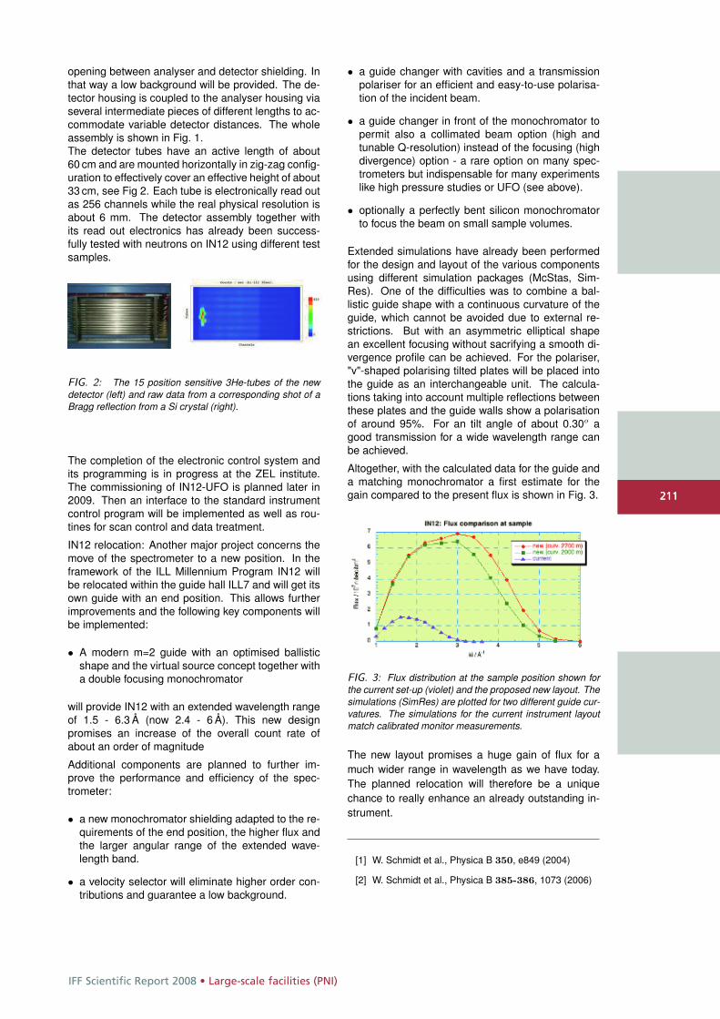
IFF Scientific Report 2008 • Large-scale facilities (PNI)
211
opening between analyser and detector shielding. Inthat way a low background will be provided. The de-tector housing is coupled to the analyser housing viaseveral intermediate pieces of different lengths to ac-commodate variable detector distances. The wholeassembly is shown in Fig. 1.The detector tubes have an active length of about60 cm and are mounted horizontally in zig-zag config-uration to effectively cover an effective height of about33 cm, see Fig 2. Each tube is electronically read outas 256 channels while the real physical resolution isabout 6 mm. The detector assembly together withits read out electronics has already been success-fully tested with neutrons on IN12 using different testsamples.
FIG. 2: The 15 position sensitive 3He-tubes of the newdetector (left) and raw data from a corresponding shot of aBragg reflection from a Si crystal (right).
The completion of the electronic control system andits programming is in progress at the ZEL institute.The commissioning of IN12-UFO is planned later in2009. Then an interface to the standard instrumentcontrol program will be implemented as well as rou-tines for scan control and data treatment.
IN12 relocation: Another major project concerns themove of the spectrometer to a new position. In theframework of the ILL Millennium Program IN12 willbe relocated within the guide hall ILL7 and will get itsown guide with an end position. This allows furtherimprovements and the following key components willbe implemented:
• A modern m=2 guide with an optimised ballisticshape and the virtual source concept together witha double focusing monochromator
will provide IN12 with an extended wavelength rangeof 1.5 - 6.3 Å (now 2.4 - 6 Å). This new designpromises an increase of the overall count rate ofabout an order of magnitude
Additional components are planned to further im-prove the performance and efficiency of the spec-trometer:
• a new monochromator shielding adapted to the re-quirements of the end position, the higher flux andthe larger angular range of the extended wave-length band.
• a velocity selector will eliminate higher order con-tributions and guarantee a low background.
• a guide changer with cavities and a transmissionpolariser for an efficient and easy-to-use polarisa-tion of the incident beam.
• a guide changer in front of the monochromator topermit also a collimated beam option (high andtunable Q-resolution) instead of the focusing (highdivergence) option - a rare option on many spec-trometers but indispensable for many experimentslike high pressure studies or UFO (see above).
• optionally a perfectly bent silicon monochromatorto focus the beam on small sample volumes.
Extended simulations have already been performedfor the design and layout of the various componentsusing different simulation packages (McStas, Sim-Res). One of the difficulties was to combine a bal-listic guide shape with a continuous curvature of theguide, which cannot be avoided due to external re-strictions. But with an asymmetric elliptical shapean excellent focusing without sacrifying a smooth di-vergence profile can be achieved. For the polariser,"v"-shaped polarising tilted plates will be placed intothe guide as an interchangeable unit. The calcula-tions taking into account multiple reflections betweenthese plates and the guide walls show a polarisationof around 95%. For an tilt angle of about 0.30o agood transmission for a wide wavelength range canbe achieved.
Altogether, with the calculated data for the guide anda matching monochromator a first estimate for thegain compared to the present flux is shown in Fig. 3.
FIG. 3: Flux distribution at the sample position shown forthe current set-up (violet) and the proposed new layout. Thesimulations (SimRes) are plotted for two different guide cur-vatures. The simulations for the current instrument layoutmatch calibrated monitor measurements.
The new layout promises a huge gain of flux for amuch wider range in wavelength as we have today.The planned relocation will therefore be a uniquechance to really enhance an already outstanding in-strument.
[1] W. Schmidt et al., Physica B 350, e849 (2004)
[2] W. Schmidt et al., Physica B 385-386, 1073 (2006)
211
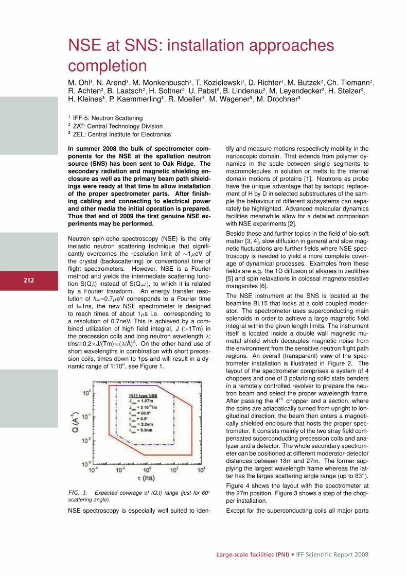
Large-scale facilities (PNI) • IFF Scientific Report 2008
212
NSE at SNS: installation approachescompletionM. Ohl1, N. Arend1, M. Monkenbusch1, T. Kozielewski1, D. Richter1, M. Butzek2, Ch. Tiemann2,R. Achten2, B. Laatsch2, H. Soltner2, U. Pabst2, B. Lindenau2, M. Leyendecker2, H. Stelzer2,H. Kleines3, P. Kaemmerling3, R. Moeller3, M. Wagener3, M. Drochner3
1 IFF-5: Neutron Scattering2 ZAT: Central Technology Division3 ZEL: Central Institute for Electronics
In summer 2008 the bulk of spectrometer com-
ponents for the NSE at the spallation neutron
source (SNS) has been sent to Oak Ridge. The
secondary radiation and magnetic shielding en-
closure as well as the primary beam path shield-
ings were ready at that time to allow installation
of the proper spectrometer parts. After finish-
ing cabling and connecting to electrical power
and other media the initial operation is prepared.
Thus that end of 2009 the first genuine NSE ex-
periments may be performed.
Neutron spin-echo spectroscopy (NSE) is the onlyinelastic neutron scattering technique that signifi-cantly overcomes the resolution limit of ∼1μeV ofthe crystal (backscattering) or conventional time-offlight spectrometers. However, NSE is a Fouriermethod and yields the intermediate scattering func-tion S(Q,t) instead of S(Q,ω), to which it is relatedby a Fourier transform. An energy transfer reso-lution of �ω=0.7μeV corresponds to a Fourier timeof t=1ns, the new NSE spectrometer is designedto reach times of about 1μs i.e. corresponding toa resolution of 0.7neV. This is achieved by a com-bined utilization of high field integral, J (>1Tm) inthe precession coils and long neutron wavelength λ;t/ns∼=0.2×J/(Tm)×(λ/Å)3. On the other hand use ofshort wavelengths in combination with short preces-sion coils, times down to 1ps and will result in a dy-namic range of 1:106, see Figure 1.
FIG. 1: Expected coverage of (Q,t) range (just for 60◦scattering angle).
NSE spectroscopy is especially well suited to iden-
tify and measure motions respectively mobility in thenanoscopic domain. That extends from polymer dy-namics in the scale between single segments tomacromolecules in solution or melts to the internaldomain motions of proteins [1]. Neutrons as probehave the unique advantage that by isotopic replace-ment of H by D in selected substructures of the sam-ple the behaviour of different subsystems can sepa-rately be highlighted. Advanced molecular dynamicsfacilities meanwhile allow for a detailed comparisonwith NSE experiments [2].
Beside these and further topics in the field of bio-softmatter [3, 4], slow diffusion in general and slow mag-netic fluctuations are further fields where NSE spec-troscopy is needed to yield a more complete cover-age of dynamical processes. Examples from thesefields are e.g. the 1D diffusion of alkanes in zeolithes[5] and spin relaxations in colossal magnetoresistivemanganites [6].
The NSE instrument at the SNS is located at thebeamline BL15 that looks at a cold coupled moder-ator. The spectrometer uses superconducting mainsolenoids in order to achieve a large magnetic fieldintegral within the given length limits. The instrumentitself is located inside a double wall magnetic mu-metal shield which decouples magnetic noise fromthe environment from the sensitive neutron flight pathregions. An overall (transparent) view of the spec-trometer installation is illustrated in Figure 2. Thelayout of the spectrometer comprises a system of 4choppers and one of 3 polarizing solid state bendersin a remotely controlled revolver to prepare the neu-tron beam and select the proper wavelength frame.After passing the 4th chopper and a section, wherethe spins are adiabatically turned from upright to lon-gitudinal direction, the beam then enters a magneti-cally shielded enclosure that hosts the proper spec-trometer. It consists mainly of the two stray field com-pensated superconducting precession coils and ana-lyzer and a detector. The whole secondary spectrom-eter can be positioned at different moderator-detectordistances between 18m and 27m. The former sup-plying the largest wavelength frame whereas the lat-ter has the larges scattering angle range (up to 83◦).
Figure 4 shows the layout with the spectrometer atthe 27m position. Figure 3 shows a step of the chop-per installation.
Except for the superconducting coils all major parts
212
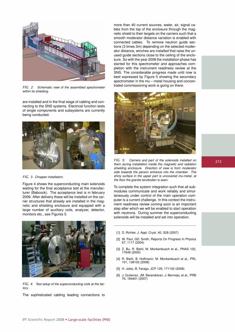
IFF Scientific Report 2008 • Large-scale facilities (PNI)
213
FIG. 2: Schematic view of the assembled spectrometerwithin its shielding.
are installed and in the final stage of cabling and con-necting to the SNS systems. Electrical function testsof single components and subsystems are currentlybeing conducted.
FIG. 3: Chopper installation.
Figure 4 shows the superconducting main solenoidswaiting for the final acceptance test at the manufac-turer (Babcock). The acceptance test is in february2009. After delivery these will be installed on the car-rier structures that already are installed in the mag-netic and shielding enclosure and equipped with alarge number of auxiliary coils, analyzer, detector,monitors etc., see Figures 5.
FIG. 4: Test setup of the superconducting coils at the fac-tory.
The sophisticated cabling leading connections to
more than 40 current sources, water, air, signal ca-bles from the top of the enclosure through the mag-netic shield to their targets on the carriers such that asmooth moderator distance variation is enabled withconnected cables. To remove neutron guide sec-tions (3 times 3m) depending on the selected moder-ator distance, winches are installed that raise the un-used guide sections close to the ceiling of the enclo-sure. So with the year 2008 the installation phase hasstarted for this spectrometer and approaches com-pletion with the instrument readiness review at theSNS. The considerable progress made until now isbest expressed by Figure 5 showing the secondaryspectrometer in the mu – metal housing and concen-trated commissioning work is going on there.
FIG. 5: Carriers and part of the solenoids installed onthem during installation inside the magnetic and radiationshielding enclosure. Direction of view is from moderatorside towards the person entrance into the chamber. Theshiny surface in the upper part is uncovered mu-metal, atthe floor the granite tanzboden is seen.
To complete the system integration such that all sub-modules communicate and work reliably and simul-taneously under control of the main operation com-puter is a current challenge. In this context the instru-ment readiness review coming soon is an importantstep after which we will be enabled to start operationwith neutrons. During summer the superconductingsolenoids will be installed and set into operation.
[1] D. Richter, J. Appl. Cryst. 40, S28 (2007)
[2] W. Paul, GD. Smith, Reports On Progress In Physics67, 1117 (2004)
[3] Z. Bu, R. Biehl, M. Monkenbusch et al., PNAS 102,17646 (2005)
[4] R. Biehl, B. Hoffmann, M. Monkenbusch et al., PRL101, 138102 (2008)
[5] H. Jobic, B. Farago, JCP 129, 171102 (2008)
[6] J. Gutierrez, JM. Barandiaran, J. Bermejo, et al., PRB76, 184401 (2007)
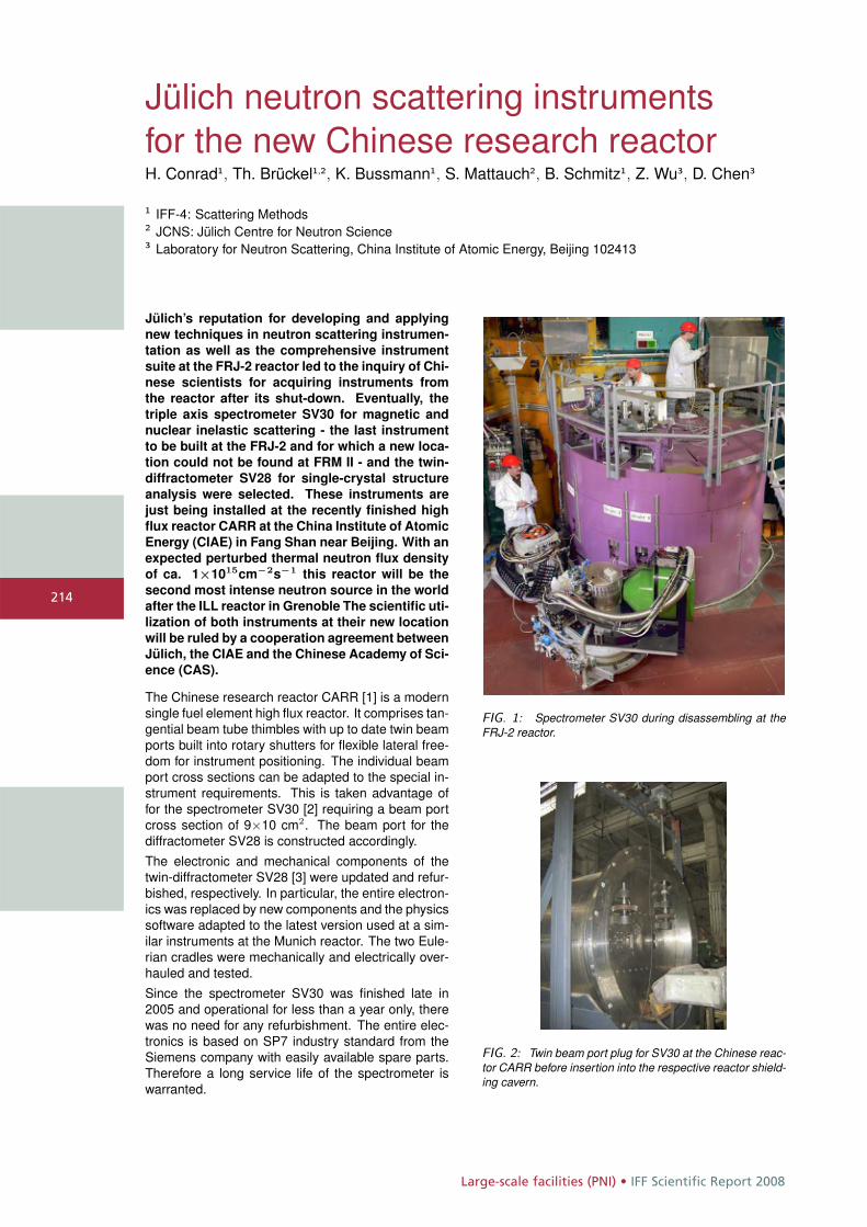
Large-scale facilities (PNI) • IFF Scientific Report 2008
214
Jülich neutron scattering instrumentsfor the new Chinese research reactorH. Conrad1, Th. Brückel1,2, K. Bussmann1, S. Mattauch2, B. Schmitz1, Z. Wu3, D. Chen3
1 IFF-4: Scattering Methods2 JCNS: Jülich Centre for Neutron Science3 Laboratory for Neutron Scattering, China Institute of Atomic Energy, Beijing 102413
Jülich’s reputation for developing and applying
new techniques in neutron scattering instrumen-
tation as well as the comprehensive instrument
suite at the FRJ-2 reactor led to the inquiry of Chi-
nese scientists for acquiring instruments from
the reactor after its shut-down. Eventually, the
triple axis spectrometer SV30 for magnetic and
nuclear inelastic scattering - the last instrument
to be built at the FRJ-2 and for which a new loca-
tion could not be found at FRM II - and the twin-
diffractometer SV28 for single-crystal structure
analysis were selected. These instruments are
just being installed at the recently finished high
flux reactor CARR at the China Institute of Atomic
Energy (CIAE) in Fang Shan near Beijing. With an
expected perturbed thermal neutron flux density
of ca. 1×1015cm−2s−1 this reactor will be the
second most intense neutron source in the world
after the ILL reactor in Grenoble The scientific uti-
lization of both instruments at their new location
will be ruled by a cooperation agreement between
Jülich, the CIAE and the Chinese Academy of Sci-
ence (CAS).
The Chinese research reactor CARR [1] is a modernsingle fuel element high flux reactor. It comprises tan-gential beam tube thimbles with up to date twin beamports built into rotary shutters for flexible lateral free-dom for instrument positioning. The individual beamport cross sections can be adapted to the special in-strument requirements. This is taken advantage offor the spectrometer SV30 [2] requiring a beam portcross section of 9×10 cm2. The beam port for thediffractometer SV28 is constructed accordingly.The electronic and mechanical components of thetwin-diffractometer SV28 [3] were updated and refur-bished, respectively. In particular, the entire electron-ics was replaced by new components and the physicssoftware adapted to the latest version used at a sim-ilar instruments at the Munich reactor. The two Eule-rian cradles were mechanically and electrically over-hauled and tested.Since the spectrometer SV30 was finished late in2005 and operational for less than a year only, therewas no need for any refurbishment. The entire elec-tronics is based on SP7 industry standard from theSiemens company with easily available spare parts.Therefore a long service life of the spectrometer iswarranted.
FIG. 1: Spectrometer SV30 during disassembling at theFRJ-2 reactor.
FIG. 2: Twin beam port plug for SV30 at the Chinese reac-tor CARR before insertion into the respective reactor shield-ing cavern.

IFF Scientific Report 2008 • Large-scale facilities (PNI)
215
FIG. 3: Lifting an 8 t monochromator shielding part intoone of six 20-feet ocean containers inside the service hallof the FRJ-2 reactor.
In order to transfer the instruments to their new lo-cation in China, they had to be dismantled in a qual-ified manner, stored temporarily and then preparedfor shipment. In particular for SV30, the latter had tobe done very cautiously, since about 70 tons of lesssensitive monochromator shielding components hadto go in large ocean shipping containers together withextremely delicate high-tech components like the fo-cusing single crystal monochromators, analyzers anddetectors as well as the many electronic racks.
FIG. 4: Floor plan at the SV30 location inside the CARRreactor hall. The extension of the dance floor (hatched area)is 5.5 m by 5.6 m. The semi-circular area close to thepolygonal reactor shielding outline corresponds to the SV30monochromator shielding contour.
The SV30 instrument’s most important parts, i.e.both the sample table and the analyzer/detectortower move during operation on air cushions across ahigh precision polished surface (the so-called dancefloor) around the instrument’s monochromator shield-ing (cf. Fig. 4). In order to be able to operate SV30accordingly, the Chinese engineers had to provide anequally smooth and absolutely horizontal floor. Sincethere was no experience in China in accomplishingthis task, it was necessary to check the quality of thefloor during the course of manufacturing it. To thisend, a mock-up device resembling the geometry andweight of the analyzer/detector tower (approx. 1.5 t)was built at CARR and successfully tested on the pol-ished granite floor around the SV30 location (Fig. 5).The installation of the instruments is expected to befinished in the second half of 2009.
In order to strengthen the scientific relationship be-tween China and Germany both SV28 and SV30 willbe jointly used by CIAE and FZJ with a share of upto 30% each. CIAE will provide access to the instru-ments for staff members of FZJ and their partners.The rest of the total beam time will be provided freeof charge to users through a proposal system. More-over, both FZJ and CIAE as well as CAS have agreedto cooperate in future developing neutron scatteringtechniques.
FIG. 5: Dance floor (polished granite floor) around themonochromator shielding area at the SV30 location insidethe reactor hall (cf. Fig. 4). The diameter of the mock-updevice base plate is 1 m, the load of 1.5 t not shown. Themock-up device is moved on three air pads of exactly thesame kind as used with the actual SV30 analyzer/detectortower.
[1] CARR: China Advanced Research Reactorhttp://www.ciae.ac.cn
[2] H. Conrad, Th. Brückel, A. Budwig, K. Bussmann, J.Heinen, A. Ioffe, E. Küssel, B. Schmitz, F. Suxdorf andTh. Zeiske. A new thermal triple axis spectrometer atthe research reactor FRJ-2. J. Neutron Res. Vol. 16,No. 1, 2008, 1-8.
[3] Neutron diffractometer SV28 in: Neutron scatteringexperiments at the research reactor in Jülich, Jülich2003; http://www.fz-juelich.de/iff/wns_sv28

Appendix • IFF Scientific Report 2008
216
220 students and young scientists from 25 countries and five continents attended the 39th international IFF SpringSchool "Soft Matter - from Synthetic to Biological Materials". Leading scientists from research and industry gavethem a comprehensive overview of the interdisciplinary research field "Soft Matter" at the interface betweenphysics, chemistry, biology and the life sciences. The unique intensive course organized by the IFF took place fom 3March to 14 March.

IFF Scientific Report 2008 • Appendix
217
Appendix
Publications page 218
Ph.D. theses page 234
Diploma theses page 236
Conferences and schools page 237
Kolloquia page 238
Organizational chart page 239
Personnel page 240
Scientific advisory board page 241
Scientists page 242
Graduate students page 247
Technical staff page 249
Administrative staff and secretaries page 252
Scientists on leave page 253
Guest scientists page 255
Scientists teaching at universities page 262
217

Appendix • IFF Scientific Report 2008
218
Publications
Akola, J.; Jones, R. O.Binary alloys of Ge and Te: order, voids, and the eutectic compositionPhysical Review Letters, 100 (2008), 205502
Akola, J.; Jones, R. O.Structural Patterns in Ge/Sb/Te Phase-change MaterialsNIC Symposium 2008: proceedings/ed.: G. Münster, D. Wolf,M. Kremer. – Jülich, John von Neumann Institute for Computing,2008. – (NIC Series; 39). – 978-3-9810842-5-1. – S. 179 – 186
Allgaier, J.Polymer synthesisSoft Matter: From Synthetic to Biological Materials: Lecturemanuscripts of the 39th Spring School of the Institute of SolidState Research; this spring school was organized by the Instituteof Solid State Research in the Forschungszentrum Jülich onMarch 3 – 14, 2008/ed.: J. K. G. Dhont, G. Gompper, G. Nägele,D. Richter, R. G. Winkler. – Jülich, Forschungszentrum, Zentral-bibliothek, 2008.(Schriften des Forschungszentrums Jülich. Reihe Schlüsseltech-nologien/Key Technologies; 1). – 978-3-89336-517-3. – S. A5.1 –A5.12
Allgaier, J.; Frielinghaus, H.Effects of polymers on the properties of micro emulsionMicroemulsions/ed.: C. Stubenrauch. – Oxford/UK, John Wiley &Sons, 2008. – 1-4051-6782-3. – S. 122 – 145
Andersson, M.; Feuerbacher, M.; Rapp, Ö.Magnetoresistance and Hall Effect of the complex Metal alloyMg2Al3Physical Review B, 78 (2008), 024201
Angst, M.; Hermann, R. P.; Christianson, A. D.;Lumsden, M. D.; Lee, C.; Whangbo, M. H.; Kim, J. W.; Ryna, P. J.; Nagler, S. E.; Tian, W.; Jin, R.;Sales, B. C.; Mandrus, D.Charge order in LuFe2O4: Ant ferroelectric ground state andcoupling to magnetismPhysical Review Letters, 101 (2008), 227601-1-227601-4
Arbe, A.; Genix, A. C.; Colmenero, J.; Richter, D.Anomalous Relaxation of Self Assembled Alkyl-Nanodomains in higher order Poly (n-Alkyl Metacrylates)Soft Matter, 4 (2008) 9, 1792 – 1795
Arrott, A. S.; Hertel, R.Formation and transformation of vortex structures in soft ferromagnetic ellipsoidsJournal of Applied Physics, 103 (2008), 07E739
Atodiresei, N.; Caciuc, V.; Blügel, S.; Hölscher, H.Manipulation of benzene on Cu(110) by dynamic force micros-copy: An ab-initio studyPhysical Review B, 77 (2008), 153408
Atodiresei, N.; Caciuc, V.; Franke, J. H.; Blügel, S.Role of the van der Waals interactions on the bonding mecha-nism of pyridine on Cu(110) and Ag(110) surfaces: A first-principles studyPhysical Review B, 78 (2008), 045411
Atodiresei, N.; Caciuc, V.; Hölscher, H.; Blügel, S.Ab initio modeling of noncontact atomic force microscopy imaging of benzene on Cu(110) surfaceInternational Journal of Quantum Chemistry, 108 (2008) 15,2803 – 2812
Atodiresei, N.; Dederichs, P. H.; Mokrousov, Y.; Bergqvist, L.; Bihlmayer, G.; Blügel, S.Controlling the magnetization direction in molecules via theiroxidation statePhysical Review Letters, 100 (2008), 117207
Auriemma, F.; De Rosa, C.; Ricciardi, R.; Lo Celso, F.; Triolo, R.; Pipich, V.Time-Resolving Analysis of Cryotropic Gelation ofWater/Poly(vinyl alcohol) Solutions via Small-Angle Neutron ScatteringJournal of Physical Chemistry B, 112 (2008) 3, 816 – 823
Auth, T.Statistical Mechanics of MembranesSoft Matter: From Synthetic to Biological Materials: Lecturemanuscripts of the 39th Spring School of the Institute of SolidState Research; this spring school was organized by the Instituteof Solid State Research in the Forschungszentrum Jülich onMarch 3 – 14, 2008/ed.: J. K. G. Dhont, G. Gompper, G. Nägele,D. Richter, R. G. Winkler. - Jülich, Forschungszentrum, Zentral-bibliothek, 2008.– (Schriften des Forschungszentrums Jülich. Reihe Schlüsseltech-nologien/Key Technologies; 1). – 978-3-89336-517-3. – S. C5.1 –C5.34
Balanetskyy, S.; Meisterernst, G.; Heggen, M.; Feuerbacher, M.Reinvestigation of the Al-Mn-Pd alloy system in the T-and R-phasesIntermetallics, 16 (2008), 71 – 87
Balanetskyy, S; Grushko, B.A study of the high-Al part of the Al-Pd-Re phase diagramJ. Alloys Comp. 456, 105 – 112 (2008)
Balanetskyy, S; Grushko, B.A study of the Al-rich part of the Al-Re alloy systemJ. Alloys Comp. 457, 348-356 (2008)
Banchio, A. J.; McPhie, M. G.; Nägele, G.Hydrodynamic and electrokinetic effects on the dynamics of charged colloids and macromoleculesJournal of Physics: Condensed Matter, 20 (2008), 404213-1 –404213-14
Banchio, A. J.; Nägele, G.Short-time transport properties in dense suspensions: From neutral to charge-stabilized colloidal spheresJournal of Chemical Physics, 128 (2008), 104903
Bar-Sadan, M.; Houben, L.; Wolf, S. G.; Enyashin, A.; Seifert, G.; Tenne, R.; Urban, K.Toward Atomic-Scale Bright-Field Electron Tomography for theStudy of Fullerene-Like NanostructuresNano Letters, 8 (2008), 891 – 896
218

IFF Scientific Report 2008 • Appendix
219
Barthel, J.; Thust, A.Quantification of the Information Limit of Transmission ElectronMicroscopesPhysical Review Letters, Vol. 101, 200801 (2008)
Baumgaertner, A.Biological MacromoleculesSoft Matter: From Synthetic to Biological Materials: Lecturemanuscripts of the 39th Spring School of the Institute of SolidState Research; this spring school was organized by the Instituteof Solid State Research in the Forschungszentrum Jülich onMarch 3-14, 2008/ed.: J. K. G. Dhont, G. Gompper, G. Nägele,D. Richter, R. G. Winkler. - Jülich, Forschungszentrum, Zentral-bibliothek, 2008. – (Schriften des Forschungszentrums Jülich.Reihe Schlüsseltechnologien/Key Technologies; 1). – 978-3-89336-517-3. – S. C7.1 – C7-16
Baumgaertner, A.Concepts in Bionanomachines: TranslocatorsJournal of Computational and Theoretical Nanoscience: for allTheoretical and Computational Aspects in Science, Engineering,and Biology, 5 (2008) 9, 1852 – 1890
Biehl, R.; Hoffmann, B.; Monkenbusch, M.; Falus, P.; Préost, S.; Merkel, R.; Richter, D.Direct Observation of Correlated Interdomain Motion in AlcoholDehydrogenasePhysical Review Letters, 101 (2008), 138102-1 – 138102-4
Birczynski, A.; Ylinen, E. E.; Punkkinen, M.; Prager, M.; Szymocha, A. M.; Lalowicz, Z. T.Deuteron NMR relaxation, spectra, and evidence for the order-disorder phase transition in (ND4)2PtCl6Journal of Chemical Physics, 128 (2008), 184510
Blanco, P.; Polyakov, P.; Bou-Ali, M.; Wiegand, S.Thermal diffusion values for some alkane mixtures: A com-parison between thermo-gravitational column and thermal diffusion forced Rayleigh scatteringThermal Nonequilibrium: Lecture Notes of the 8th InternationalMeeting on Thermodiffusion/ed.: S. Wiegand, W. Köhler, J. K. G.Dhont. – Jülich, Forschungszentrum, Zentralbibliothek, 2008.– (Schriften des Forschungszentrums Jülich. Reihe Schlüsseltech-nologien/Key Technologies; 3). – 978-3-89336-523-4. – S. 15 – 22
Blanco, P.; Polyakov, P.; Bou-Ali, M.; Wiegand, S.Thermal diffusion and molecular diffusion values for some alkanemixtures: a comparison between thermogravitational column andthermal diffusion forced Rayleigh scatteringJournal of Physical Chemistry B, 112 (2008) 28, 8340 – 8345
Bodnarchuk, V. I.; Kraan, W. H.; Rekveldt, M. T.; Ioffe, A.Neutron spin turners with a rotating magnetic field: first experimentsMeasurement Science and Technology, 19 (2008), 034012
Bosak, A.; Schmalzl, K.; Krisch, M.; van Beek, W.;Kolobanov, V.Lattice dynamics of beryllium oxide: Inelastic X-ray scatteringand ab initio calculationsPhysical Review B, 77 (2008), 224303-1 – 224303-7
Bóta, A.; Varga, Z.; Goerigk, G.Structural description of the nickel part of a raney-type catalystby using anomalous small-angle X-ray scatteringJournal of Physical Chemistry C, 112 (2008) 12, 4427 – 4429
Brener, E. A.; Temkin, D.Steady-state migration of the liquid film along a grain boundaryduring melting of alloysActa Materialia, 56 (2008), 2290
Brückel, T.A neutron primer: Elastic scattering and the properties of the neutronNeutron Scattering: Lectures of the JCNS Laboratory Courseheld at Forschungszentrum Jülich and the research reactor FRM II of TU Munich; in cooperation with RWTH Aachen andUniversity of Münster/ed.: T. Brückel, G. Heger, D. Richter, R.Zorn. – Jülich, Forschungszentrum, Zentralbibliothek, 2008. –(Schriften des Forschungszentrum Jülich. Reihe Schlüsseltech-nologien/Key Technologies; 5). – 978-3-89336-532-6. – S. 2-1 – 2-31
Brückel, T.Applications of neutron scatteringNeutron Scattering: Lectures of the JCNS Laboratory Courseheld at Forschungszentrum Jülich and the research reactor FRMII of TU Munich; in cooperation with RWTH Aachen and Uni-versity of Münster/ed.: T. Brückel, G. Heger, D. Richter, R. Zorn. –Jülich, Forschungszentrum, Zentralbibliothek, 2008. – (Schriftendes Forschungszentrum Jülich. Reihe Schlüsseltechnologien/KeyTechnologies; 5). – 978-3-89336-532-6. – S. 6-1 – 6-27
Brückel, T.Correlated electrons in complex transition metal oxidesNeutron Scattering: Lectures of the JCNS Laboratory Courseheld at Forschungszentrum Jülich and the research reactor FRMII of TU Munich; in cooperation with RWTH Aachen and Univer-sity of Münster/ed.: T. Brückel, G. Heger, D. Richter, R. Zorn. –Jülich,Forschungszentrum, Zentralbibliothek, 2008. - (Schriften des Forschungszentrum Jülich. Reihe Schlüsseltechnologien/Key Technologies; 5). – 978-3-89336-532-6. – S. 15-1 – 15-20
Brückel, T. (Hrsg.); Heger, G. (Hrsg.); Richter, D. (Hrsg.); Zorn, R. (Hrsg.)Neutron Scattering: Lectures of the JCNS Laboratory Courseheld at Forschungszentrum Jülich and the research reactorFRM II of TU Munich; in cooperation with RWTH Aachen andUniversity of MünsterJülich, Forschungszentrum, Zentralbibliothek, 2008Schriften des Forschungszentrums Jülich. Reihe Schlüsseltech-nologien/Key Technologies; 5
Buchal, C.; Bürgler, D. E.Peter Grünberg – Nobelpreis für Physik 2007Köln, MIC GmbH, 2008
Buitenhuis, J.Colloid SynthesisSoft Matter: From Synthetic to Biological Materials: Lecturemanuscripts of the 39th Spring School of the Institute of SolidState Research; this spring school was organized by the Institu-te of Solid State Research in the Forschungszentrum Jülich onMarch 3-14, 2008/ed.: J. K. G. Dhont, G. Gompper, G. Nägele,D. Richter, R. G. Winkler. - Jülich, Forschungszentrum, Zentral-bibliothek, 2008. – (Schriften des Forschungszentrums Jülich.Reihe Schlüsseltechnologien/Key Technologies; 1). – 978-3-89336-517-3. – S. A6.1 – A6.16
Bulla, R.; Costi, T. A.; Pruschke, T.Numerical renormalization group method for quantum impuritysystemsReviews of Modern Physics, 80 (2008), 395
219

Appendix • IFF Scientific Report 2008
220
Buscaglia, M. T.; Buscaglia, V.; Viviani, M.; Dondero, G.; Röhrig, S.; Rüdiger, A.; Nanni, P.Ferroelectric hollow particles obtained by solid-state reaction Nanotechnology, 19 (2008), 225602
Butz, B.; Störmer, H.; Gerthsen, D.; Bockmeyer, M.; Krüger, R.; Ivers-Tiffée, E.; Luysberg, M.Microstructure of Nanocrystalline Yttria-Doped Zirconia thin filmsobtained by sol-gel processingJ. Am. Ceram. Soc, Vol. 91, No. 1-9, 2281-2289 (2008)
Camley, R.E.; McGrath, B. V.; Khivintsev, Y.; Celinski, Z.; Adam, R.; Schneider, C. M.; Grimsditch, M.The effect of cell size in calculating frequencies of magneticmodes using micromagnetics: The special role of the uniformmodePhysical Review B, 78 (2008), 024425
Cannavacciuolo, L.; Winkler, R. G.; Gompper, G.Mesoscale simulations of polymer dynamics in microchannelflowsEurophysics Letters, 83 (2008), 34007-1 - 34007-6
Chatterjee, S.; Barma, M.Shock probes in a one dimensional Katz-Lebowitz-Spohn ModelPhysical Review E, 77 (2008), 061124-1 – 061124-8
Chatterji, T.; Henry, P. F.; Mittal, R.; Chaplot, S. L.Negative thermal expansion of ReO3: Neutron diffraction experiments and dynamical lattice calculationsPhysical Review B, 78 (2008), 134105-1 – 134105-6
Chatterji, T.; Schneider, G. J.; Galera, R. M.Low-energy nuclear spin excitations in NdMg3 and NdCo2Physical Review B, 78 (2008), 012411
Chen, H. Y.; Jia, C. L.; Schubert, J.Microstructure of high-k dielectric LaLu03 films on (001) SrTi03SubstratesThin Solid Films, 517 (2008), 631 – 634
Chen, J.; Jung, P.; Hoffelner, W.; Ullmaier, H.Dislocation loops and bubbles in oxide dispersion strengthenedferritic steel after helium implantation under stressActa Materialia, 56 (2008), 250 – 258
Chen, J.; Jung, P.; Pouchon, M. A.; Rebac, T.; Hoffelner, W.Irradiation creep and precipitation in a ferritic ODS steel underhelium implantationJournal of Nuclear Materials, 373 (2008), 22 – 27
Cherstvy, A. G.DNA Cholesteric Phases: The Role of DNA Molecular Chiralityand DNA-DNA Electrostatic InteractionsJournal of Physical Chemistry B, 112 (2008), 12585 – 12595
Cherstvy, A.; Kolomeisky, A. B.; Kornyshev, A. A.Protein - DNA interactions: Reaching and Recognizing the TargetsJournal of Physical Chemistry B, 112 (2008), 4741 – 4750
Clemens, S.; Dippel, A. C.; Schneller, T.; Waser, R.; Rüdiger, A.; Röhrig, S.Direct electrical characterization of embedded ferroelectric leadtitanate nanoislandsJournal of Applied Physics, 103 (2008), 034113
Conrad, H.; Brückel, T.; Schäfer, W.; Voigt, J.POWTEX – the high-intensity time-of-flight diffractometer atFRM II for structure analysis of polycrystalline materialsJournal of Applied Crystallography, 41 (2008), 836 – 845
Dasgupta, A.; Huang, Y.; Houben, L.; Klein, S.;Finger, F.; Carius, R.; Luysberg, M.Effect of filament and substrate temperatures on the structuraland electrical properties of SiC thin films grown by the HWCVDtechniqueThin Solid Films, Vol. 516, 622-625 (2008)
Dasgupta, A.; Klein, S.; Houben, R.; Carius, R.; Finger, F.; Luysberg, M.Microstructure of highly cristallyne silicon carbide thin filmsgrown by HWCVD techniqueThin Solid Films, Vol. 516, 618-621 (2008)
Datta, S.; Ning, H.; Sottmann, T.; Wiegand, S.Soret effect of nonionic surfactants in water studied by different transient grating setupsThermal Nonequilibrium: Lecture Notes of the 8th InternationalMeeting on Thermodiffusion/ed.: S. Wiegand, W. Köhler, J. K. G.Dhont. - Jülich, Forschungszentrum, Zentralbibliothek, 2008. –(Schriften des Forschungszentrums Jülich. Reihe Schlüsseltech-nologien/Key Technologies; 3). – 978-3-89336-523-4. –S. 147 – 152
Delcea, M.; Krastev, R.; Gutberlet, T.; Pum, D.; Sleytr, U. B.; Toca-Herrera, J. L.Thermal stability, mechanical properties and water content ofbacterial protein layers recrystallized on polyelectrolyte multi-layersSoft Matter, 4 (2008), 1414 – 1421
Dhont, J. K. G.Dynamics of ColloidsSoft Matter: From Synthetic to Biological Materials: Lecturemanuscripts of the 39th Spring School of the Institute of SolidState Research; this spring school was organized by the Insti-tute of Solid State Research in the Forschungszentrum Jülichon March 3 – 14, 2008/ed.: J. K. G. Dhont, G. Gompper,G. Nägele, D. Richter, R. G. Winkler. – Jülich, Forschungs-zentrum, Zentralbibliothek, 2008. – (Schriften des Forschungs-zentrums Jülich. Reihe Schlüsseltechnologien/Key Technologies;1). – 978-3-89336-517-3. – S. B3.1 – B3.40
Dhont, J. K. G.; Briels, W. J.Gradient and vorticity bandingRheologica Acta, 47 (2008), 257 – 281
Dhont, J. K. G.; Briels, W. J.Single-particle thermal diffusion of charged colloids: double-layer theory in a temperature gradientThermal Nonequilibrium: Lecture Notes of the 8th InternationalMeeting on Thermodiffusion/ed.: S. Wiegand, W. Köhler, J. K. G.Dhont. – Jülich, Forschungszentrum, Zentralbibliothek, 2008. –(Schriften des Forschungszentrums Jülich. Reihe Schlüsseltech-nologien/Key Technologies; 3). – 978-3-89336-523-4. –S. 257 – 260
Dhont, J. K. G.; Briels, W. J.Single-particle thermal diffusion of charged colloids: Double-layer theory in a temperature gradientEuropean Physical Journal E, 25 (2008), 61 – 76
220

IFF Scientific Report 2008 • Appendix
221
Dhont, J. K. G.; Gompper, G.Introduction: Soft MatterSoft Matter: From Synthetic to Biological Materials: Lecturemanuscripts of the 39th Spring School of the Institute of SolidState Research; this spring school was organized by the Instituteof Solid State Research in the Forschungszentrum Jülich onMarch 3 – 14, 2008/ed.: J. K. G. Dhont, G. Gompper, G. Nägele,D. Richter, R. G. Winkler. – Jülich, Forschungszentrum, Zentral-bibliothek, 2008. – (Schriften des Forschungszentrums Jülich.Reihe Schlüsseltechnologien/Key Technologies; 1). – 978-3-89336-517-3. – S. I.1 – I.18
Dhont, J. K. G. (Hrsg.); Gompper, G. (Hrsg.);Nägele, G. (Hrsg.); Richter, D. (Hrsg.); Winkler, R. G. (Hrsg.)Soft Matter - From Synthetic to Biological Materials: Lecture Notes of the 39th Spring School 2008; This SpringSchool was organized by the Institute of Solid State Researchin the Research Centre Jülich on 3 – 14 March, 2008Jülich, Forschungszentrum, Zentralbibliothek, 2008Schriften des Forschungszentrums Jülich. Reihe Schlüsseltech-nologien/Key Technologies; 19783893365173
Dietrich, C.; Hertel, R.; Huber, M.; Weiss, D.; Schäfer, R.; Zweck, J.Influence of perpendicular magnetic fields on the domainstructure of Permalloy microsctructures grown on thin membranesPhysical Review B, 77 (2008), 174427
Dil, H.; Meier, F.; Lobo-Checa, J.; Patthey, L.; Bihlmayer, G.; Osterwalder, J.Rashba-Type Spin-Orbit Splitting of Quantum Well States in Ultrathin Pb FilmsPhysical Review Letters, 101 (2008), 266802
Dippel, A. C.; Schneller, T.; Waser, R.Thin films of undoped lead titanate: Morphology and electricalpropertiesIntegrated Ferroelectrics, 98 (2008), 3 – 10
Disch, S.; Cheetham, A. K.; Ruschewitz, U.Formation of unsaturated C3 hydrocarbons by the protolysis of magnesium sesquicarbide with ammonium halidesInorganic Chemistry, 47 (2008), 969 – 973
Divin, Y.; Poppe, U.; Gubankov, V.; Urban, K.High-Tc Josephson Square-Law Detectores and Hilbert Spectroscopy for Security ApplicationsIEEE Sensors Journal, 8 (2008), 750 – 757
Divin, Y., Poppe, U., Gubankov, V., Urban, K.Hilbert spectroscopy of liquids for security screening to bepublished in nato science series: Detection of liquid explosivesand flammable agents in connection with terrorist actionsEd. H. Schubert; A. Kuznetsov, Springer, (2008)
Divin, Y., Poppe, U., Kotelyanskii, I. M., Gubank-ov, V.N., Urban, K.Terahertz spectroscopy based on Josephson high-temperaturesuperconductor junctionsJ. Comm. Techn. Electronics, Vol. 53, No. 10, 1137-1152 (2008)
Divin, Y.; Poppe, U.; Urban, K.Hilbert Spectroscopy of Liquids for Security Screening Detectionof Liquid Explosives and Flammable Agents in Connection withTerrorist ActionsDetection of Liquid Explosives and Flammable Agents in Con-nection with Terrorism/ed.: H. Schubert, A. Kuznetsov. – Sprin-ger, 2008. – (NATO Science for Peace and Security Series). –978-1-4020-8465-2. – S. 189 – 204
Dolinsek, J.; Slavonek, J.; Jaglicic, Z.; Heggen, M.; Balanetskyy, S.; Feuerbacher, M.; Urban, K.Broken ergodicity, memory effect and rejuvenation in Taylor-phase and decagonal Al3Mn, Pd, Fe complex intermetallicsPhysical Review B, 77 (2008), 064430
Dolfen, A.; Koch, E.Realistic description of TTF-TCNQ – a strongly correlated organic metalNIC Symposium 2008/ed.: G. Münster, D. Wolf, M. Kremer. –Jülich, NIC, 2008. – (NIC series; 39). – 978-3-9810843-5-1. –S. 237
Dolfen, A.; Luo, Y. L.; Koch, E.Simulating materials with strong correlations on Blue Gene/LParallel Computing: Architectures, Algorithms and Appli-cations/ed.: C. Bischof, M. Bücker, P. Gibbon, G. Joubert,T. Lippert, B. Mohr, F. Peters. – Amsterdam, IOS Press, 2008. –(Advances in Parallel Computing; 15). – 978-1-58603-796-3. –S. 601
Ehlers, G.; Mamontov, E.; Zamponi, M.; Faraone, A.; Qiu, Y.; Cornelius, A. L.; Booth, C. H.; Kam, K.C.; LeToquin, R.; Cheetham, A. K.; Gardner, J. S.Frustrated spin correlations in diluted spin ice Ho2-x Lax Ti2 O7Journal of Physics: Condensed Matter, 20 (2008), 235206
Elefant, D.; Schäfer, R.; Thomas, J.; Schneider, C. M.Spin-flip and spin-flop magnetic configuration in NiFe/Cu multilayers and related changes in magnetoresistance, magnetization, and domain structuresPhysical Review B, 77 (2008), 014426
Elefant, D.; Schäfer, R.; Thomas, J.; Vinzelberg, H.; Schneider, C. M.Competition of spin-flip and spin-flop dominated processes inmagnetic multilayers: Magnetization reversal, magnetotrans-port, and domain structure in the NiFe/Cu systemPhysical Review B, 77 (2008), 014426
Elgeti, J.; Gompper, G.Hydrodynamics of Active Mesoscopic SystemsNIC Symposium 2008/ed.: G. Münster, D. Wolf, M. Kremer. –Jülich, Forschungszentrum, John von Neumann Institut fürComputing, 2008. – (NIC Series ; 39). – 978-3-9810843-5-1. –S. 53 – 62
Ellerkmann, U.; Schneller, T.; Nauenheim, C.; Böttger, U.; Waser, R.Reduction of film thickness for chemical solution depositedPbZr0.3Ti0.7O3 thin films revealing no size effects and main-taining high remanent polarization and low coercive fieldThin Solid Films, 516 (2008) 15, 4713 – 4719
Faley, M. I.; Mi, S. B.; Jia, C. L.; Poppe, U.; Urban, K.; Fagaly, R. L.Epitaxial thick film high-Tc SQUIDsJournal of Physics: Conference Series, 97 (2008), P. 012164
Ferriani, P.; von Bergmann, K.; Vedmedenko, E. Y.; Heinze, S.; Bode, M.; Heide, M.; Bihlmayer, G.;Blügel, S.; Wiesendanger, R.Atomic-Scale Spin Spiral with a Unique Rotational Sense: Mn Monolayer on W(001)Physical Review Letters, 101 (2008), 027201
Feuerbacher, M.; Balanetskyy, S.; Heggen, M.Novel Metadislocation Variants in Orthorhombic Al-Pd-FeActa Materialia, 56 (2008), 1849
221

Appendix • IFF Scientific Report 2008
222
Galanakis, I.; Özdogan, K.; Sasioglu, E.Ab initio electronic and magnetic properties of half-metallicNiCrSi and NiMnSi Heusler alloys: The role of defects and interfacesJournal of Applied Physics, 104 (2008), 083916
Galanakis, I.; Özdogan, K.; Sasioglu, E.Role of defects and disorder in the half-metallic full-HeuslercompoundsAdvances in Nanoscale Magnetism: Proceedings of the Inter-national Conference on Nanoscale Magnetism/ed.: B. Aktas, F.Mikailov. – Springer, 2008. – (Springer Proceedings in Physics;122). – S. 1 – 19
Galanakis, I.; Özdogan, K.; Sasioglu, E.; Aktas, B.Ferrimagnetism and antiferro-magnetism in half-metallic Heusler alloysPhysica Status Solidi A, 205 (2008), 1036 – 1039
Galanakis, I.; Sasioglu, E.; Özdogan, K.Magnetic phase transition in half-metallic CoMnSb and NiMnSbsemi-Heusler alloys upon Cu doping: First-principles calculationsPhysical Review B, 77 (2008), 214417
Garbrecht, M.; Spieker, E.; Jäger, W.; Tillmann, K.Aberration-corrected HRTEM study of incommensurate misfitlayer compound interfacesInstrumentation and Methods: Proceedings of the 14th EuropeanMicroscopy Congress, held in Aachen, Germany, 1 – 5 September2008; jointly organised by the European Microscopy Society(EMS), the German Society for Electron Microscopy (DGE) and the local microscopists from RWTH Aachen University and theResearch Centre Jülich/ed.: M. Luysberg, K. Tillmann, P. Weirich. –Berlin, Springer, 2008. – (EMC 2008; 1). – 978-3-540-85154-7. –S. 113 – 114
Genix, A. C.; Arbe, A.; Arres-Igor, S.; Colmenero, J.; Richter, D.; Frick, B.; Deen, P.Neutron scattering and dielectric investigation of a dilute blendof poly(ethyleneoxide) in polyethersulfoneJournal of Chemical Physics, 128 (2008), 184901
Gilles, S.; Meier, M.; Prömpers, M.; von Hart, A.; Kügeler, C.; Offenhäusser, A.; Mayer, D.UV nanoimprint lithography with rigid polymer moldsProceedings of the 34th International Conference on Micro &Nano Engineering, September 15 – 19, 2008, Athens, Greece. –2008. – S. 417 – 418
Gliga, S.; Hertel, R.; Schneider, C. M.Flipping magnetic vortex cores on the picosecond time scalePhysica B: Condensed Matter, 403 (2008) 2/3, 334 – 337
Gliga, S.; Hertel, R.; Schneider, C. M.Switching a magnetic antivortex core with ultrafast field pulsesJournal of Applied Physics, 103 (2008), 07B115
Gliga, S.; Yan, M.; Hertel, R.; Schneider, C. M.Ultrafast dynamics of a magnetic antivortex – MicromagneticsimulationsPhysical Review B, 77 (2008), 060404(R)
Gögelein, C.; Nägele, G.; Tuinier, R.; Gibaud, T.; Stradner, A.; Schurtenberger, P.A simple patchy colloid model for the phase behavior of lysozy-me dispersionsJournal of Chemical Physics, 129 (2008), 085102
Gögelein, C.; Tuinier, R.Phase behaviour of a dispersion of charge-stabilised colloidalspheres with added non-adsorbing interacting polymer chainsEuropean Physical Journal E, 27 (2008), 171 – 184
Feuerbacher, M.; Thomas, C.; Roitsch, S.Single-crystal growth of the complex metallic alloy phaseMg32(Al,Zn)49Intermetallics, 16 (2008), 943 – 947
Finken, R.; Lamura, A.; Seifert, U.; Gompper, G.Two-dimensional fluctuating vesicles in linear shear flowEuropean Physical Journal E, 25 (2008), 309 – 321
Fleer, G. J.; Tuinier, R.Analytical phase diagrams for colloids and non-adsorbing polymerAdvances in Colloid and Interface Science, 143 (2008), 1 – 47
Fleer, G. J.; Tuinier, R.Conditions for the existence of a stable colloidal liquidHighlights in Colloid Science/ed.: D. Platikanov, D. Exerowa. –Weinheim, Wiley-VCH, 2008. – S. 119 – 134
Flocke, A.; Noll, T. G.; Kügeler, C.; Nauenheim, C.;Waser, R.A fundamental analysis of nano-crossbars with non-linear switching materials and its impact on TiO2 as a resistive layerProceedings of the 8th IEEE Conference on Nanotechnology. –2008. – S. 319 – 322
Foster, L. J.; Schwahn, D.; Pipich, V.; Holden, P. J.; Richter, D.SANS characterization of polyhydroxyalkanoates and their PEgylated hybrids in solutionBiomacromolecules, 9 (2008), 314 – 320
Frank, C.; Frielinghaus, H.; Allgaier, J.; Richter, D.Hydrophilic Alcohol Ethoxylates as Efficiency booster for MicroemulsionsLangmuir, 24 (2008), 6036
Frank, S.; Winkler, R. G.Polyelectrolyte electrophoresis: Field effects and hydrodynamicinteractionsEurophysics Letters, 83 (2008), 38004
Freimuth, F.; Mokrousov, Y.; Wortmann, D.; Hein-ze, S.; Blügel, S.Maximally localized Wannier functions within the FLAPW formalismPhysical Review B, 78 (2008), 035120
Freysoldt, C.; Eggert, P.; Rinke, P.; Schindlmayr, A.;Scheffler, M.Screening in two dimensions: GW calculations for surfaces andthin films using the repeated-slab approachPhysical Review B, 77 (2008), 235428
Frielinghaus, H.Conformations of polymer chainsSoft Matter: From Synthetic to Biological Materials: Lecturemanuscripts of the 39th Spring School of the Institute of SolidState Research; this spring school was organized by the Instituteof Solid State Research in the Forschungszentrum Jülich onMarch 3-14, 2008/ed.: J. K. G. Dhont, G. Gompper, G. Nägele, D.Richter, R. G. Winkler. – Jülich, Forschungszentrum, Zentral-bibliothek, 2008. – (Schriften des Forschungszentrums Jülich.Reihe Schlüsseltechnologien/Key Technologies; 1). – 978-3-89336-517-3. – S. C1.1 – C1.23
Fu, Q. X.; Mi, S. B.; Wessel, E.; Tietz, F.Microstructure and Electrical Conductivity of Yttrium-SubstitutedSrTiO3: Influence of Starting Composition and Sintering Atmosphere Journal of the European Ceramic Society, 28 (2008), 811 – 820
222

IFF Scientific Report 2008 • Appendix
223
Goerigk, G.Decomposition kinetics in copper-cobalt alloys systems: Applications of small-angle X-ray scatteringNeutrons and Synchrotron Radiation in Engineering Materials Science/ed.: W. Reimers, A.-R. Pyzalla, A. Schreyer, H. Clemens.–Weinheim, Wiley-VCH, 2008. – S. 249 – 256
Goldman, A. I.; Argyriou, D. N.; Ouladdiaf, B.;Chatterji, T.; Kreyssig, A.; Nandi, S.; Ni, N.;Bud'ko, S. L.; Canfield, P. C.; McQueeney, R. J.Lattice and magnetic instabilities in CaFe2As2: A single crystalneutron diffraction studyPhysical Review B, 78 (2008), 100506(R)
Gompper, G.; Dhont, J. K. G.; Richter, D.Editorial: A unified view of soft matter systems?European Physical Journal E, 26 (2008), 1 – 2
Gompper, G.; Noguchi, H.Blood FlowSoft Matter: From Synthetic to Biological Materials: Lecturemanuscripts of the 39th Spring School of the Institute of SolidState Research; this spring school was organized by the Instituteof Solid State Research in the Forschungszentrum Jülich onMarch 3 – 14, 2008/ed.: J. K. G. Dhont, G. Gompper,G. Nägele, D. Richter, R. G. Winkler. - Jülich, Forschungs-zentrum, Zentralbibliothek, 2008. - (Schriften des Forschungs-zentrums Jülich. Reihe Schlüsseltechnologien/Key Technologies;1). – 978-3-89336-517-3. – S. D7.1 – D7.23
Gordan, O. D.; Persson, B. N. J.; Cesa, C. M.;Mayer, D.; Hoffmann, B.; Dieluweit, S.; Merkel, R.On Pattern Transfer in Replica MoldingLangmuir, 24 (2008), 6636 – 6639
Gossuin, Y.; Hocq, A.; Vuong, Q. L.; Disch, S.; Hermann, R. P.; Gillis, P.Physico-chemical and NMR relaxometric characterization ofgadolinium hydroxide and dysprosium oxide nanoparticlesNanotechnology, 19 (2008), 475102-1 – 475102-8
Gray, D. L.; Long, G. J.; Grandjean, F.; Hermann,R. P.; Ibers, J. A.Syntheses, Structure, and a Mössbauer and Magnetic Study ofBa4Fe2I5S4Inorganic Chemistry, 47 (2008) 1, 94 – 100
Grelet, E.; Lettinga, M. P.; Bier, M.; van Roij, R.;van der Schoot, P.Dynamical and structural insights into the smectic phase of rod-like particlesJournal of Physics: Condensed Matter, 20 (2008), 494213
Großkinsky, S.; Schütz, G. M.Discontinuous Condensation Transition and Nonequivalence of Ensembles in a Zero-Range ProcessJournal of Statistical Physics, 132 (2008), 77 – 108
Grosskinsky, S.; Chleboun, P.; Schütz, G. M.Instability of condensation in the zero-range process with random interactionPhysical Review E, 78 (2008) 3, 030101
Grünberg, P.It's the coupling that creates resistance: Spin electronics in layered magnetic structuresAnnalen der Physik, 17 (2008) 1, 17
Grünberg, P.Nobel Lecture: From spin waves to giant magnetoresistance and beyondReviews of Modern Physics, 80 (2008), 1531
Grushko, B.; Balanetskyy, S.A study phase equilibria in the Al-rich part of the Al-Mn alloysystemInt. J. Mater. 99, 1319-1323 (2008)
Grushko, B.; Pavlyuchkov D.X-ray powder diffraction data for Al-Cu-Ir � and C2 phases ofPowder diffraction 23, 356-359 (2008)
Grushko, B.; Przepiórzyñski B.; Pavlyuchkov, D.On the constitution of the high-Al region of the Al-Cr alloysystemJ. Alloys Comp. 453, 191-196
Grushko, B.; Przepiórzyñski B.; Pavlychukov, D.On the constitution of the high-Al region of the Al-Cr alloysystemJ. Alloys Comp. 454, 214-220 (2008)
Grushko, B.; Kowalski, W.; Pavlyuchkov, D.; Przepiórzyñski B.; Surowiec, M.A contribution to the Al-Ni-Cr phase diagramJ. Alloys Comp. 460, 299-304 (2008)
Grushko, B.; Kowalski, W.; Przepiórzyñski B.; Pavlyuchkov, D.Constitution of the high-Al region of Al-Cu-RhJ. Alloys Comp 464, 227-233 (2008)
Grushko, B.; Balanetskyy, S.X-ray powder diffraction data for Al73.5Ni18.5Re8 orthorhombicphasePowder diffraction. 23, 251-254 (2008)
Gugenberger, C.; Spatschek, R.; Kassner, K.Comparison of phase-field models for surface diffusion Physical Review E, 78 (2008), 016703
Guo, X.Nanostructured ionic and mixed conducting oxidesAnnual Review of Nano Research/ed.: C. J. Brinker, G. Cao. – 3(2008). – Singapore, World Scientific Publishing. – S. 495 – 543
Gupta, M.; Gupta, A.; Stahn, J.; Gutberlet, T.Ordering and self-diffusion in FePt alloy filmNew Journal of Physics, 10 (2008), 053031
Halder, S.; Schneller, T.; Waser, R.; Majumber, S. B.Electrical and optical properties of chemical solution depositedbarium hafnate titanate thin films Thin Solid Films, 516 (2008) 15, 4970 – 4976
Harish, R.; Karevski, D.; Schütz, G. M.Molecular traffic control for a cracking reactionJournal of Catalysis, 253 (2008), 191 – 199
Heggen, M.; Engel, M.; Balanetskyy, S.; Trebin, H. R.; Feuerbacher, M.Structural variations in Epsilon-type Al-Pd-(Mn, Fe) complexmetallic alloy phasesPhilosophical Magazine, 88 (2008), 507 – 521
Heggen, M.; Feuerbacher, M.Quasicrystal plasticity in the framework of a constitutive model:Interaction of the microstructural parameters at high strain-ratesPhilosophical Magazine, 88 (2008), 2325
Heggen, M.; Houben, L.; Feuerbacher, M.Metadislocations in the orthorhombic structurally complex alloyAl13Co4Philosophical Magazine, 88 (2008), 2333
223
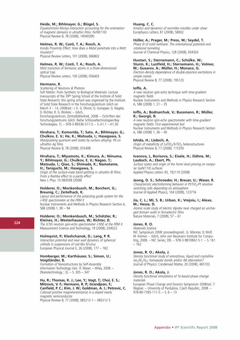
Appendix • IFF Scientific Report 2008
224
Heide, M.; Bihlmayer, G.; Blügel, S.Dzyaloshinskii-Moriya interaction accounting for the orientationof magnetic domains in ultrathin films: Fe/W(110)Physical Review B, 78 (2008), 140403(R)
Helmes, R. W.; Costi, T. A.; Rosch, A.Kondo Proximity Effect: How does a Metal penetrate into a MottInsulator?Physical Review Letters, 101 (2008), 066802
Helmes, R. W.; Costi, T. A.; Rosch, A.Mott transition of fermionic atoms in a three-dimensional optical trapPhysical Review Letters, 100 (2008), 056403
Hermann, R.Scattering of Neutrons & PhotonsSoft Matter: From Synthetic to Biological Materials: Lecturemanuscripts of the 39th Spring School of the Institute of SolidState Research; this spring school was organized by the Instituteof Solid State Research in the Forschungszentrum Jülich onMarch 3 – 14, 2008/ed.: J. K. G. Dhont, G. Gompper, G. Nägele,D. Richter, R. G. Winkler. – Jülich,Forschungszentrum, Zentralbibliothek, 2008. – (Schriften desForschungszentrums Jülich. Reihe Schlüsseltechnologien/KeyTechnologies; 1). – 978-3-89336-517-3. – S. A1.1 – A1.30
Hirahara, T.; Komorida, T.; Sato, A.; Bihlmayer, G.;Chulkov, E. V.; He, K.; Matsuda, I.; Hasegawa, S.Manipulating quantum-well states by surface alloying: Pb onultrathin Ag filmsPhysical Review B, 78 (2008), 035408
Hirahara, T.; Miyamoto, K.; Kimura, A.; Niinuma,Y.; Bihlmayer, G.; Chulkov, E. V.; Nagao, T.; Matsuda, I.; Qiao, S.; Shimada, K.; Namatame, H.; Taniguchi, M.; Hasegawa, S.Origin of the surface-state band-splitting in ultrathin Bi films:From a Rashba effect to a parity effectNew J. Phys. 10 083038 (2008)
Holderer, O.; Monkenbusch, M.; Borchert, G.; Breunig, C.; Zeitelhack, K.Layout and performance of the polarizing guide system for theJ-NSE spectrometer at the FRM IINuclear Instruments and Methods in Physics Research Section A,586 (2008) 1, 90 – 94
Holderer, O.; Monkenbusch, M.; Schätzler, R.; Kleines, H.; Westerhausen, W.; Richter, D.The JCNS neutron spin-echo spectrometer J-NSE at the FRM IIMeasurement Science and Technology, 19 (2008), 034022
Holmqvist, P.; Kleshchanok, D.; Lang, P. R.Interaction potential and near wall dynamics of spherical colloids in suspensions of rod-like fd-virusEuropean Physical Journal E, 26 (2008), 177 – 182
Homberger, M.; Karthäuser, S.; Simon, U.; Voigtländer, B.Formation of Nanostructures by Self-AssemblyInformation Technology I/ed.: R. Waser. – Wiley, 2008. – (Nanotechnology ; 3). – S. 305 – 347
Hu, R.; Thomas, K. J.; Lee, Y.; Vogt, T.; Choi, E. S.; Mitrovic, V. F.; Hermann, R. P.; Grandjean, F.; Canfield, P. C.; Kim, J. W.; Goldman, A. I.; Petrovic, C.Colossal positive magnetoresistance in a doped nearly magnetic semiconductorPhysical Review B, 77 (2008), 085212-1 – 085212-5
Huang, C. C.Kinetics and dynamics of wormlike micelles under shearEurophysics Letters, 81 (2008), 58002
Hüller, A.; Prager, M.; Press, W.; Seydel, T.Phase III of solid methane: The orientational potential androtational tunnelingJournal of Chemical Physics, 128 (2008), 034503
Huotari, S.; Sternemann, C.; Schülke, W.; Sturm, K.; Lustfeld, H.; Sternemann, H.; Volmer,M.; Gusarov, A.; Müller, H.; Monaco, G.Electron-density dependence of double-plasmon excitations insimple metalsPhysical Review B, 77 (2008), 195125
Ioffe, A.A new neutron spin-echo technique with time-gradient magnetic fieldsNuclear Instruments and Methods in Physics Research SectionA, 586 (2008) 1, 31 – 35
Ioffe, A.; Bodnarchuk, V.; Bussmann, R.; Müller,R.; Georgii, R.A new neutron spin-echo spectrometer with time-gradientmagnetic fields: First experimental testNuclear Instruments and Methods in Physics Research SectionA, 586 (2008) 1, 36 – 40
Ishida, H.; Liebsch, A.Origin of metallicity of LaTiO3/SrTiO3 heterostructures Physical Review B, 77 (2008), 115350
Ivanova, L, Borisova, S.; Eisele, H.; Dähne, M.;Laubsch, A.; Ebert, Ph.Surface states and origin of the Fermi level pinning on nonpo-lar GaN(110) surfacesApplied Physics Letters 93, 192110 (2008)
Jeong, D. S.; Schroeder, H.; Breuer, U.; Waser, R.Characteristic electroforming behavior in Pt/TiO2/Pt resistiveswitching cells depending on atmosphereJournal of Applied Physics, 104 (2008), 123716
Jia, C. L.; Mi, S. B.; Urban, K.; Vrejoiu, I.; Alexe,M.; Hesse, D.Atomic-scale study of electric dipoles near charged an unchar-ged domain walls in ferroelectric films Nature Materials, 7 (2008), 57 – 61
Jones, R. O.Materials ScienceNIC Symposium 2008: proceedings/ed.: G. Münster, D. Wolf,M. Kremer. – Jülich, John von Neumann Institute for Compu-ting, 2008. – NIC Series; 39). – 978-3-9810842-5-1. – S. 161– 162
Jones, R. O.; Akola, J.Density functional study of amorphous, liquid and crystallineGe2Sb2Te5: homopolar bonds and/or AB alternation?Journal of Physics: Condensed Matter, 20 (2008), 465103
Jones, R. O.; Akola, J.Density functional simulations of Te-based phase change materialsEuropean Phase Change and Ovonics Symposium 2008/ed.: T.Wagner. – University of Pardubice, Czech Republic, 2008. – 978-80-7395-111-5. – S. 6 – 13
224

IFF Scientific Report 2008 • Appendix
225
Kang, K.; Dhont, J. K. G.Double-layer polarization induced transitions in suspensions ofcolloidal rodsEPL: a Letters Journal Exploring the Frontiers of Physics, 84(2008), 14005
Kang, K.; Lettinga, M. P.; Dhont, J. K. G.Is vorticity-banding due to an elastic instability?Rheologica Acta, 47 (2008), 499 – 508
Kapnistos, M.; Lang, M.; Vlassopoulos, D.; Pyckhout-Hintzen, W.; Richter, D.; Cho, D.;Chang, T.; Rubinstein, M.Unexpected power-law stress relaxation of entangled ring polymersNature Materials, 7 (2008), 997 – 1002
Karatas, Y.; Pyckhout-Hintzen, W.; Zorn, R.; Richter, D.; Wiemhöfer, H. D.SANS Investigation and Conductivity of Pure and Salt-Contai-ning Poly(bismethoxy-phosphazene)Macromolecules, 41 (2008), 2212 – 2218
Katayama-Yoshida, H.; Sato, K.; Fukushima, T.;Toyoda, M.; Kizaki, H.; Dinh, V. A.; Dederichs, P. H.Computational nano-materials design for II-VI compound semiconductor-based spintronics Journal of the Korean Physical Society, 53 (2008), 1 – 12
Kentzinger, E.; Rücker, U.; Toperverg, B.; Ott, F.; Brückel, T.Depth-resolved investigation of the lateral magnetic correlati-ons in a gradient nanocrystalline multilayerPhysical Review B, 77 (2008), 104435-1 – 104435-19
Kimber, S. A. J.; Argyriou, D. N.; Yokaichiya, F.;Habicht, K.; Gerischer, S.; Hansen, T.; Chatterji, T.;Klingeler, R.; Hess, C.; Behr, G.; Kondrat, A.; Büchner, B.Magnetic ordering and negative thermal expansion in PrFeAsOPhysical Review B, 78 (2008), 140503-1 – 140503-4(R)
Kishikawa, Y.; Kita, R.; Kriegs, H.; Wiegand, S.Ludwig-Soret Effect for Aqueous and Non-aqueous Solutionsof PolysaccharideThermal Nonequilibrium: Lecture Notes Thermal Nonequili-brium: Lecture Notes of the 8th International Meeting on Thermodiffusion/ed.: S. Wiegand, W. Köhler, J. K. G. Dhont. –Jülich, Forschungszentrum, Zentralbibliothek, 2008. – (Schriften des Forschungszentrums Jülich. Reihe Schlüssel-technologien/Key Technologies; 3). – 978-3-89336-523-4. – S. 97 – 102
Kleshchanok, D.; Tuinier, R.; Lang, P. R.Direct measurement of polymer-induced forcesJournal of Physics: Condensed Matter, 20 (2008), 073101
Koch, E.; Pavarini, E.Multiple Scales in Solid State PhysicsMultiscale Modeling and Simulation in Science/ed.: B. Engquist,P. Lötstedt, O. Runborg. – Berlin, Springer, 2008. – 978-3-540-88856-7. – S. 295
Koch, E.; Sangiovanni, G.; Gunnarsson, O.Sum-rules and bath-parametrization for quantum cluster theoriesPhysical Review B, 78 (2008), 115102
Kohlstedt, H. H.; Petraru, A.; Szot, K.; Rüdiger,A.; Meuffels, P.; Haselier, H.; Waser, R.; Nagarajan, V.Method to distinguish ferroelectric from nonferroelectric originin case of resistive switching in ferroelectric capacitorsApplied Physics Letters, 92 (2008), 062907
Kolasinska, M.; Krastev, R.; Gutberlet, T.; Warszynski, P.Swelling and Water Uptake of PAH/PSS Polyelectrolyte MultilayersProgress in Colloid and Polymer Science, 134 (2008), 30 – 38
Koroteev, Yu. M.; Bihlmayer, G.; Chulkov, E. V.; Blügel, S.First-principles investigation of structural and electronic properties of ultrathin Bi filmsPhysical Review B, 77 (2008), 045428
Kriegs, H.; Meier, G.; Gapinski, J.; Patkowski, A.The effect of intramolecular relaxations on the damping of longitudinal and transverse phonons in polysiloxanes studiedby Brillouin spectroscopyJournal of Chemical Physics, 128 (2008), 014507
Kronast, F.; Ovsyannikov, R.; Kaiser, A.; Wie-mann, C.; Yang, S. H.; Bürgler, D. E.; Schreiber, R.;Salmassi, F.; Fischer, P.; Dürr, H. A.; Schneider, C.M.; Eberhardt, W.; Fadley, C. S.Depth-resolved soft X-ray photoelectron emission microscopy in nanostructures via standing-wave excited photoemissionApplied Physics Letters, 93 (2008), 243116
Krug, I. P.; Hillebrecht, F. U.; Gomonaj, H.; Haver-kort, M.; Tanaka, A.; Tjeng, L. H.; Fraile-Rodri-guez, A.; Nolting, F.; Schneider, C. M.Impact of interface orientation on the magnetic coupling inhighly ordered systems – A case study on Fe3O4/NiOPhysical Review B, 78 (2008), 064427
Krug, I. P.; Hillebrecht, F. U.; Haverkort, W.;Gomonay, H.; Tanaka, A.; Tjeng, L. H.; Schneider,C. M.Magnetic coupling in highly-ordered NiO/Fe3O4(110): Ultrasharp magnetic interfaces vs. long-range magnetoelasticinteractionsEurophysics Letters, 81 (2008), 17005
Kügeler, C.; Hennings, A.; Böttger, U.; Waser, R.Design and realization of an integrated microwave switchbased on piezoelectric PZT and PLHT thin films Proceedings of the 19th MicroMechanics Workshop, September28-30, Aachen. – 2008. – S. 21 – 24
Kügeler, C.; Hennings, A.; Böttger, U.; Waser, R.An integrated microelecromechanial microwave switch basedon piezoelectric acuation Journal of Electroceramics, (2008)
Kügeler, C.; Rosezin, R.; Schneller, T.; Böttger, U.;Waser, R.Large area piezoelectric actuators using metal foil substrateswith Pb(ZrxTi1-x)O3 thin films Integrated Ferroelectrics, 100 (2008), 254
225

Appendix • IFF Scientific Report 2008
226
Lang, P. R.Particle Wall Interactions and Near-Wall Dynamics of ColloidsSoft Matter: From Synthetic to Biological Materials: Lecturemanuscripts of the 39th Spring School of the Institute of SolidState Research; this spring school was organized by the Instituteof Solid State Research in the Forschungszentrum Jülich onMarch 3 – 14, 2008/ed.: J. K. G. Dhont, G. Gompper,G. Nägele, D. Richter, R. G. Winkler. – Jülich, Forschungszentrum,Zentralbibliothek, 2008. – (Schriften des ForschungszentrumsJülich. Reihe Schlüsseltechnologien/Key Technologies; 1). – 978-3-89336-517-3. – S. C14.1 – C14.16
Lazo, C.; Caciuc, V.; Hölscher, H.; Heinze, S.Role of tip size, orientation, and structural relaxations in firstprinciples studies of magnetic exchange force microscopy andspin polarized scanning tunneling microscopyPhysical Review B, 78 (2008), 214416
Lebedev, D. V.; Filatov, M. V.; Kuklin, A. I.; Islamov, A.K.; Stellbrink, J.; Pantina, R. A.; Denisov, Y. Y.;Toperverg, B. P.; Isaev-Ivanov, V. V.Structural hierarchy of chromatin in chicken erythrocyte nucleibased on small-angle neutron scattering: Fractal nature of thelarge-scale chromatin organizationCrystallography Reports, 53 (2008), 110 – 115
Lehndorff, R.; Bürgler, D. E.; Kakay, A.; Hertel, R.;Schneider, C. M.Spin-Transfer Induced Dynamic Modes in Single-Crystalline Fe-Ag-Fe NanopillarsIEEE Transactions on Magnetics, 44 (2008) 7, 1951 – 1956
Lentzen, M.Contrast transfer and resolution limits for sub-angstrom high-resolution transmission electron microscopyMicroscopy and Microanalysis, 14 (1), 16-26 (2008)
Lettinga, M. P.The Dynamics of Rods in Different PhasesSoft Matter: From Synthetic to Biological Materials: Lecturemanuscripts of the 39th Spring School of the Institute of SolidState Research; this spring school was organized by the Institute ofSolid State Research in the Forschungszentrum Jülich on March3-14, 2008/ed.: J. K. G. Dhont, G. Gompper, G. Nägele, D. Richter,R. G. Winkler. – Jülich, Forschungszentrum, Zentralbibliothek,2008. – (Schriften des Forschungszentrums Jülich. Reihe Schlüs-seltechnologien/Key Technologies; 1). – 978-3-89336-517-3. – S. D4.1 – D4.34
Liebsch, A.Doping-driven Mott transition in La{1-x}SrxTiO3 via simultaneouselectron and hole doping of t2g subbands as predicted byLDA+DMFT calculations Physical Review B, 77 (2008), 115115
Liebsch, A.; Ishida, H.Coulomb correlations do not fill the e'g hole pockets inNa{0.3}CoO2European Physical Journal B, 61 (2008), 405
Liebsch, A.; Ishida, H.; Merino, J.Multisite versus multiorbital Coulomb correlations studied within finite-temperature exact diagonalization dynamical mean-field theory Physical Review B, 78 (2008), 165123
Lonetti, B.; Kohlbrecher, J.; Willner, L.; Dhont, J. K.G.; Lettinga, M. P.Dynamic response of block copolymer wormlike micelles to shearflowJournal of Physics: Condensed Matter, 20 (2008), 404207
Lott, D.; Fenske, J.; Schreyer, A.; Mani, P.; Mankey, G. J.; Klose, F.; Schmidt, W.; Schmalzl,K.; Tartakovskaya, E. V.Antiferromagnetism in a Fe50Pt40Rh10 thin film investigatedusing neutron diffractionPhysical Review B, 78 (2008), 174413-1 – 174413-10
Lounis, S.; Dederichs, P. H.; Blügel, S.Magnetism of Nanowires Driven by Novel Even-Odd EffectsPhysical Review Letters, 101 (2008), 107204
Lounis, S.; Reif, M.; Mavropoulos, P.; Glaser, L.; Dederichs, P. H.; Martins, M.; Bluegel, S.; Wurth, W.Non-collinear magnetism of Cr nanostructures onFe3ML/Cu(001): First principles and experimental investigationsEurophysics Letters, 81 (2008), 47004
Manoshin, S.; Ioffe, A.New modules for the VITESS software package: Time-gradientmagnetic fields and neutron refractive lensesNuclear Instruments and Methods in Physics Research SectionA, 586 (2008) 1, 81 – 85
Mavropoulos, P.Spin injection from Fe into Si(001): Ab initio calculations androle of the Si complex band structurePhysical Review B, 78 (2008), 054446
McGuire, M. A.; Christianson, A. D.; Sefat, A. S.;Sales, B. C.; Lumsden, M. D.; Jin, R.; Payzant, E. A.;Mandrus, D.; Luan, Y.; Keppens, V.; Varadarajan, V.; Brill, J. W.; Hermann, R. P.; Sougrati, M. T.; Grandjean, F.; Long, G.Phase transitions in LaFeAsO: Structural, magnetic, elastic, andtransport properties, heat capacity and Mössbauer spectraPhysical Review B, 78 (2008), 094517-1 – 094517-10
McPhie, M.; Nägele, G.Nonmonotonic density dependence of the diffusion of DNAfragments in low-salt suspensionsPhysical Review E, 78 (2008), 060401(R)
McWhirter, J. L.Phase behavior of a simple dipolar fluid under shear flow in anelectric fieldJournal of Chemical Physics, 128 (2008), 034502
Meier, M.; Gilles, S.; Schindler, C.; Rosezin, R.;Mayer, D.; Rüdiger, A.; Kügeler, C.; Waser, R.Resistively switching Pt/spin-on glass/Ag nanocells for non-volatile memories fabricated with UV nanoimprint lithographyProceedings of the 34th International Conference on Micro &Nano Engineering, September 15-19, 2008, Athens, Greece. –2008. – S. 108
Meier, G.; Kriegs, H.A high pressure cell for dynamic light scattering up to 2 kbarswith conservation of plane of polarizationReview of Scientific Instruments, 79 (2008), 013102
Meier, G.; Vavrin, R.; Kohlbrecher, J.; Buitenhuis,J.; Lettinga, M. P.; Ratajczyk, M.SANS and dynamic light scattering to investigate the viscosityof toluene under high pressure up to 1800 barMeasurement Science and Technology, 19 (2008), 034017
Meier, M.; Nauenheim, C.; Gilles, S.; Mayer, D.; Kügeler, C.; Waser, R.Nanoimprint for future non-volatile memory and logic devicesMicroelectronic Engineering, 85 (2008), 870 – 872
226

IFF Scientific Report 2008 • Appendix
227
Mi, S. B.; Jia, C. L.; Vaithyanathan, V.; Houben, L.; Schubert, J.; Schlom, D. G.; Urban, K.Atomic structure of the interface between SrTi03 thin films andSi(001) substratesApplied Physics Letters, 93 (2008), 101913
Mittal, R.; Su, Y.; Chatterji, T.; Chaplot, S.L.; Schober, H.; Rotter, M.; Johrendt, D.; Brückel, T.Inelastic neutron scattering and lattice-dynamical calculationsof BaFe2As2Physical Review B, 78 (2008), 104514
Mittal, R.; Su, Y.; Rols, S.; Tegel, M.; Chaplot, S. L.; Schober, H.; Chatterji, T.; Johrendt, D.; Brueckel, Th.Phonon dynamics in Sr0.6K0.4Fe2As2 and Ca0.6Na0.4Fe2As2from neutron scattering and lattice-dynamical calculationsPhysical Review B, 78 (2008) 22, 224518-1 – 224518-5
Mofidi, M.; Prakash, B.; Persson, B. N. J.; Albohr, O.Rubber friction on (apparently) smooth lubricated surfacesJournal of Physics: Condensed Matter, 20 (2008) 8, 085223
Molak, A.; Szot, K.; Kania, A.Insulator-metal transition in Mn-doped NaNbO3 induced bychemical and thermal treatmentPhase Transitions, 81 (2008), 977 – 986
Monkenbusch, M.Time-of-flight spectrometers including NSENeutron Scattering: Lectures of the JCNS Laboratory Courseheld at Forschungszentrum Jülich and the research reactor FRMII of TU Munich; In cooperation with RWTH Aachen and Univer-sity of Münster/ed.: T. Brückel, G. Heger, D. Richter, R. Zorn. –Jülich, Forschungszentrum, Zentralbibliothek, 2008. – (Schriftendes Forschungszentrum Jülich. Reihe Schlüsseltechnologien/Key Technologies; 5). – 978-3-89336-532-6. – S. 10.1 – 10.34
Müller-Meskamp, L.; Karthäuser, S.; Waser, R.; Homberger, M.; Simon, U.Striped Phase of Mercaptoalkylferrocenes on Au(111) with aPotential for Nanoscale Surface PatterningLangmuir, 24 (2008), 4577
Münstermann, R.; Dittmann, R.; Szot, K.; Mi, S.; Jia, C. L.; Meuffels, P.; Waser, R.Realization of regular arrays of nanoscale resistive switchingblocks in thin films by Nb-doped STOApplied Physics Letters, 93 (2008), 023110
Nägele, G.Theories of Fluid MicrostructuresSoft Matter: From Synthetic to Biological Materials: Lecturemanuscripts of the 39th Spring School of the Institute of SolidState Research; this spring school was organized by the Instituteof Solid State Research in the Forschungszentrum Jülich onMarch 3 – 14, 2008/ed.: J. K. G. Dhont, G. Gompper,G. Nägele, D. Richter, R. G. Winkler. – Jülich, Forschungs-zentrum, Zentralbibliothek, 2008. – (Schriften des Forschungs-zentrums Jülich. Reihe Schlüsseltechnologien/Key Technologies;1). – 978-3-89336-517-3. – S. B2.1 – B2.47
Narros, A.; Arbe, A.; Alvarez, F.; Colmenero, J.; Richter, D.Atomic motions in the alpha-beta merging regime of 1-4 poly-butadiene: A molecular dynamics simulation studyJournal of Chemical Physics, 128 (2008), 224905
Nauenheim, C.; Kügeler, C.; Rüdiger, A.; Waser, R.; Flocke, A.; Noll, T. G.Nano-crossbar arrays for nonvolatile resistive RAM (RRAM)applications Proceedings of the 8th IEEE Conference on Nanotechnology. –2008. – S. 464 – 467
Niedzwiedz, K.; Wischnewski, A.; Pyckhout-Hintzen, W.; Allgaier, J.; Richter, D.;Faraone, A.Chain Dynamics and Viscoelastic Properties of Poly(ethylene-oxide)Macromolecules, 41 (2008), 4866
Ning, H.; Datta, S.; Sottmann, T.; Wiegand, S.Soret effect of nonionic surfactants in water studied by different transient grating setupsJournal of Physical Chemistry B, 112 (2008), 10927 – 10934
Ning, H.; Dhont, J. K. G.; Wiegand, S.Thermal-Diffusive Behavior of a Dilute Solution of ChargedColloidsLangmuir, 24 (2008), 2426 - 2432
Noguchi, H.; Gompper, G.Transport coefficients of off-lattice mesoscale-hydrodynamicssimulation techniquesPhysical Review E, 78 (2008), 016706-1 – 016706-12
Nygard, K.; Satapathy, D. K.; Bunk, O.; Diaz, A.;Perret, E.; Buitenhuis, J.; Pfeiffer, F.; David, C.; van der Veen, J. F.Structure of confined fluids by X-ray interferometry using diffraction gratingsOptics Express, 16 (2008) 25, 20522 – 20529
Oh, I.; Mattauch, S.; Heger, G.; Lee, C. E.Neutron Diffraction Study of a Rb0.5T10.5H2PO4 Single CrystalJournal of the Physical Society of Japan, Vol.77, No 9 (2008),094602-1- 94602-4
Ott, R. T.; Heggen, M.; Feuerbacher, M.; Park, E. S.;Kim, D. H.; Kramer, M. J.; Besser, M. F.; Sordelet, D. J.Anelastic strain and anisotropy in homogeneoesly deformedCu64.5Zr35.5 metallic glassActa Materialia, 56 (2008), 5575 – 5583
Özdogan, K.; Galanakis, I.; Sasioglu, E.; Aktas, B.Role of the presence of transition-metal atoms at the antisitesin CrAs, CrSe and VAs zinc-blende compoundsJournal of Magnetism and Magnetic Materials, 320 (2008),197 – 203
Özdogan, K.; Sasioglu, E.; Galanakis, I.Engineering the electronic, magnetic, and gap-related proper-ties of the quinternary half-metallic Heusler alloysJournal of Applied Physics, 103 (2008), 023503
Papagiannopoulos, A.; Fernyhough, C. M.; Waigh, T. A.; Radulescu, A.Scattering Study of the Structure of Polystyrene SulfonateComb Polyelectrolytes in SolutionMacromolecular Chemistry and Physics, 209 (2008), 2475 –2486
Patkowski, A.; Gapinski, J.; Fluerasu, A.;Holmqvist, P.; Meier, G.; Lettinga, M. P.; Nägele, G.Structure and dynamics of colloidal suspensions studied bymeans of XPCSActa Physica Polonica A, 114 (2008) 2, 339 – 350
227

Appendix • IFF Scientific Report 2008
228
Paul, A.; Buchmeier, M.; Bürgler, D. E.; Rücker, U.;Schneider, C. M.Twisted magnetization state at the interface of an antiferroma-gnetically coupled Fe/Si multilayer as probed by specular andoff-specular polarized neutron scatteringPhysical Review B, 77 (2008), 184409-1 – 184409-16
Pavarini, E.; Tarantino, S. C.; Boffa Ballaran, T.;Zema, M.; Ghigna, P.; Carretta, P.Effect of high pressure on competing exchange couplings inLi2VOSiO4Physical Review B, 77 (2008), 014425Pavlyuchkov, D.; Grushko, B.; Velikanova, T. Ya.An investigation of the Al-Pd-Ir phase diagram between 50and 100 at.%AlJ. Alloys Comp. 453, 191-196 (2008)
Pavlyuchkov, D.; Grushko, B.; Velikanova, T. Ya.A contribution to the Al-Ir phase diagramIntermetallics. 16, 801-806 (2008)
Pavlyuchkov, D.; Grushko, B.; Velikanova, T. Ya.An investigation of the high-Al part of the Al-Pd-Ru phase diagram at 1000 and 1100°CChem. Met. Alloys. 1, 84-87 (2008)
Pavlyuchkov, D.; Grushko, B.; Velikanova, T. Ya.Al-rich region of Al-Pd-Ru at 1000 to 1100°CJ. Alloys Comp. 464, 101-106 (2008)
Persson, B. N. J.Capillary adhesion between elastic solids with randomly roughsurfacesJournal of Physics: Condensed Matter, 20 (2008) 31, 315007
Persson, B. N. J.Influence of frozen capillary waves on contact mechanicsWear, 264 (2008) 9/10, 746 – 749
Persson, B. N. J.On the elastic energy and stress correlation in the contact between elastic solids with randomly rough surfacesJournal of Physics: Condensed Matter, 20 (2008) 31, 312001
Persson, B. N. J.; Sivebaek, I. M.; Samoilov, V. N.; Zhao, K.; Volokitin, A. I.; Zhang, Z.On the origin of Amonton's friction lawJournal of Physics: Condensed Matter, 20 (2008) 39, 395006
Persson, B. N. J.; Yang, C.Theory of the leak-rate of sealsJournal of Physics: Condensed Matter, 20 (2008) 31, 315011
Pertsev, N. A.; Petraru, A.; Kohlstedt, H.Dynamics of ferroelectric nanodomains in BaTiO3 epitaxial thinfilms via piezoresponse force microscopyNanotechnology, 19 (2008), 375703
Petraru, A.; Kohlstedt, H.; Poppe, U.; Waser, R.;Solbach, A.; Klemradt, U.; Schubert, J.; Zander,W.; Pertsev, N. A.Wedgelike ultrathin epitaxial BaTiO3 films for studies of scalingeffects in ferroelectricsApplied Physics Letters, 93 (2008), 072902
Pfeiffer, J.; Kemmler, M.; Koelle, D.; Kleiner, R.; Goldobin, E.; Weides, M.; Feofanov, K.; Lisenfeld,J.; Ustinov, A. V.Static and dynamic properties of 0, pi, and 0-pi ferromagnetictunnel Josephson junctions Physical Review B, 77 (2008), 214506
Picozzi, S.; Lezaic, M.Ab-initio study of exchange constants and electronic structure in diluted magnetic group-IV SemiconductorsNew Journal of Physics, 10 (2008), 055017
Pilipenko, D.; Brener, E. A.; Hüter, C.Theory of dendritic growth in the presence of lattice strainPhysical Review E, 78 (2008), 060603
Pipich, V.; Balz, M.; Wolf, S. E.; Tremel, W.;Schwahn, D.Nucleation and Growth of CaCO3 Mediated by the Egg-WhiteProtein Ovalbumin: A Time-Resolved in-situ Study Using Small-Angle Neutron ScatteringJournal of the American Chemical Society, 130 (2008) 21,6879 – 6892
Plucinski, L.; Sell, B. C.; Minar, J.; Braun, J.; Ebert,H.; Schneider, C. M.; Fadley, C. S.Band mapping in higher-energy X-ray photoemission: Phononeffects and comparison to one-step theoryPhysical Review B, 78 (2008), 035108
Polyakov, P.; Müller-Plathe, F.; Wiegand, S.Reverse nonequilibrium molecular dynamics calculation of thesoret coefficient in liquid heptane/benzene mixturesJournal of Physical Chemistry B, 112 (2008) 47, 14999 –15004
Polyakov, P.; Wiegand, S.Systematic study of the thermal diffusion in associated mixturesJournal of Chemical Physics, 128 (2008), 034505
Polyakov, P.; Wiegand, S.Study of the thermal diffusion behavior of simple and associated mixturesThermal Nonequilibrium: Lecture Notes Thermal Nonequili-brium: Lecture Notes of the 8th International Meeting on Ther-modiffusion/ed.: S. Wiegand, W. Köhler, J. K. G. Dhont. – Jülich,Forschungszentrum, Zentralbibliothek, 2008. – (Schriften desForschungszentrums Jülich. Reihe Schlüsseltechnologien/KeyTechnologies; 3). – 978-3-89336-523-4. – S. 57 – 61
Popkov, V.; Salerno, M.; Schütz, G. M.Asymmetric simple exclusion process with periodic boundarydriving Physical Review E, 78 (2008) 1, 011122
Prager, M.; Desmedt, A.; Unruh, T.; Allgaier, J.Dynamics and adsorption sites of guest molecules in methylchloride hydrateJournal of Physics: Condensed Matter, 20 (2008), 125219
Prager, M.; Grimm, H.; Natkaniec, I.; Nowak, D.;Unruh, T.The dimensionality of ammonium reorientation in (NH4)2S2O8:the view from neutron spectroscopyJournal of Physics: Condensed Matter, 20 (2008), 125218
Priezzhev, V. B.; Schütz, G. M.Exact solution of the Bernoulli matching model of sequencealignmentJournal of Statistical Mechanics: Theory and Experiment,(2008), P09007
Radulescu, A.; Fetters, L. J.; Richter, D.Polymer driven wax crystal control using partially crystallinepolymeric materialsAdvances in Polymer Science, 210 (2008), 1 – 100
228

IFF Scientific Report 2008 • Appendix
229
Radulescu, A.; Ioffe, A.Neutron guide system for small-angle neutron scatteringinstruments of the Jülich Centre for Neutron Science at theFRM IINuclear Instruments and Methods in Physics Research SectionA, 586 (2008) 1, 55 – 58
Ramzi, A.; Rijcken, C.; Veldhuis, T.; Schwahn, D.; Hennink, W.; van Nostrun, C.Core-Shell Structure of Degradable, Thermosensitive PolymericMicelles studied by Small-Angle Neutron ScatteringJournal of Physical Chemistry B, 112 (2008) 3, 784 – 792
Reckermann, F.; Leijnse, M.; Wegewijs, M. R.; Schoeller, H.Transport signature of pseudo Jahn-Teller dynamics in a single-molecule transistorEurophysics Letters, 83 (2008), 58001
Richter, D.Basic assumptions of quantum mechanics and the born approximation – a brief tutorialNeutron Scattering: Lectures of the JCNS Laboratory Courseheld at Forschungszentrum Jülich and the research reactor FRMII of TU Munich; in cooperation with RWTH Aachen and Uni-versity of Münster/ed.: T. Brückel, G. Heger, D. Richter, R. Zorn. –Jülich, Forschungszentrum, Zentralbibliothek, 2008. – (Schriftendes Forschungszentrum Jülich. Reihe Schlüsseltechnologien/KeyTechnologies; 5). – 978-3-89336-532-6. – S. II-1 – II-32
Richter, D.Dynamics of macromoleculesSoft Matter: From Synthetic to Biological Materials: Lecturemanuscripts of the 39th Spring School of the Institute of SolidState Research; this spring school was organized by the Instituteof Solid State Research in the Forschungszentrum Jülich onMarch 3-14, 2008/ed.: J. K. G. Dhont, G. Gompper, G. Nägele,D. Richter, R. G. Winkler. – Jülich, Forschungszentrum, Zentral-bibliothek, 2008. - (Schriften des Forschungszentrums Jülich.Reihe Schlüsseltechnologien/Key Technologies; 1). – 978-3-89336-517-3. – S. D1.1 – D1.33
Richter, D.Dynamics of macromoleculesNeutron Scattering: Lectures of the JCNS Laboratory Courseheld at Forschungszentrum Jülich and the research reactor FRMII of TU Munich; In cooperation with RWTH Aachen and Univer-sity of Münster/ed.: T. Brückel, G. Heger, D. Richter, R. Zorn. –Jülich, Forschungszentrum, Zentralbibliothek, 2008. – (Schriftendes Forschungszentrum Jülich. Reihe Schlüsseltechnologien/KeyTechnologies; 5). – 978-3-89336-532-6. – S. 14.1 – 14.33
Ripoll, M.Mesoscale HydrodynamicsSoft Matter: From Synthetic to Biological Materials: Lecturemanuscripts of the 39th Spring School of the Institute of SolidState Research; this spring school was organized by the Insti-tute of Solid State Research in the Forschungszentrum Jülichon March 3 – 14, 2008 ed.: J. K. G. Dhont, G. Gompper, G.Nägele, D. Richter, R. G. Winkler. – Jülich, Forschungszentrum,Zentralbibliothek, 2008.-(Schriften des ForschungszentrumsJülich. Reihe Schlüsseltechnologien/Key Technologies; 1). –978-3-89336-517-3. – S. B4.1 – B4.18
Ripoll, M.; Holmqvist, P.; Winkler, R. G.; Gompper, G.; Dhont, J. K. G.; Lettinga, M. P.Attractive Colloidal Rods in Shear FlowPhysical Review Letters, 101 (2008), 168302-1 – 168302-4
Ripoll, M.; Winkler, R. G.; Mussawisade, K.;Gompper, G.Mesoscale hydrodynamics simulations of attractive rod-like colloids in shear flowJournal of Physics: Condensed Matter, 20 (2008), 404209
Roosen, D.; Wegewijs, M. R.; Hofstetter, W.Nonequilibrium Dynamics of Anisotropic Large Spins in theKondo Regime: Time-Dependent Numerical RenormalizationGroup AnalysisPhysical Review Letters, 100 (2008), 087201
Rosenbaum, R.; Balanetskyy, S.; Grushko B.; Przepiórzyñsky B.Very low temperature electronic transport in Al-Pd-Re quasicry-talline alloysJ. Low-temperature Phys. 150, 82-100 (2008)
Rüdiger, A.; Waser, R.Size effects in ferroelectric nanostructuresJournal of Alloys and Compounds, 449 (2008) 1/2, 2 – 6
Rusek, K.; Kruczek, J.; Szot, K.Non-linear properties of BaTiO3 above TcFerroelectrics, 375 (2008), 165
Rzhevsky, A. A.; Krichevtsov, B. B.; Bürgler, D. E.; Schneider, C. M.Interface and bulk magnetization dynamics in biaxial Fe/Cr structures induced by ultrashort optical pulsesJournal of Applied Physics, 104 (2008), 083918
Rzhevsky, A. A.; Krichevtsov, B. B.; Bürgler, D. E.; Schneider, C. M.Domain structure in biaxial Fe/Cr films induced by lateral fluctuations of the magnetic anisotropyPhysical Review B, 77 (2008), 174432
Sacharow, L.; Wiesendanger, R.; Bihlmayer, G.;Blügel, S.; Morgenstern, M.Anisotropic superexchange in one-dimensional Fe-chains onInAs(110)Surface Science, 602 (2008), 3297 – 3302
Saptsov, R. B.On the instability of a homogeneous state of a weakly inter-acting Bose gas under external cooling JETP Letters, 86 (2008), 687 - 691
Sasioglu, E.; Sandratskii, L. M.; Bruno, P.Role of conduction electrons in mediating exchange inter-actions in Mn-based Heusler alloysPhysical Review B, 77 (2008), 064417
Schindler, C.; Szot, K.; Karthäuser, S.; Waser, R.Controlled local filament growth and dissolution in Ag-Ge-SePhysica Status Solidi - Rapid Research Letters, 2 (2008) 3,129 – 131
Schindler, C.; Weides, M.; Kozicki, M. K.; Waser, R.Low current resistive switching in Cu-SiO2 cellsApplied Physics Letters, 92 (2008), 122910
229

Appendix • IFF Scientific Report 2008
230
Schmalzl, K.; Strauch, D.; Hiess, A.; Berger, H.Temperature dependent phonon dispersion in 2H-NbSe2investigated using inelastic neutron scatteringJournal of Physics: Condensed Matter, 20 (2008), 104240-1 –104240-3
Schmidt, H.; Gupta, M.; Gutberlet, T.; Stahn, J.; Bruns, M.How to measure atomic diffusion processes in the sub-nanometer rangeActa Materialia, 56 (2008), 464 – 470
Schneider, G. J.; Kerscher, M.; Göritz, D.Messung der Volumenänderung von Elastomeren bei hohenDehnraten = Measurement of Volume Changes of Elestomeresat High Strain RatesKautschuk Gummi Kunststoffe, 6 (2008) , 317 – 321
Schneider, U.; Hackermueller, L.; Will, S.; Best, Th.;Bloch, I.; Costi, T. A.; Helmes, R. W.; Rasch, D.; Rosch, A.Metallic and Insulating Phases of Repulsively Interacting Fermions in a 3D Optical LatticeScience, 322 (2008), 1520
Schneller, T.; Kohlstedt, H.; Petraru, A.Investigation of the amorphous to crystalline phase transition ofchemical solution deposited Pb(Zr0.3Ti0.7)O3 thin films by soft X-ray absorption and soft X-ray emission spectroscopyJournal of Sol-Gel Science and Technology, 48 (2008),239 – 252
Schober, H.; Farhi, E.; Mezei, F.; Allenspach, P.; Andersen, K.; Bentley, P. M.; Christiansen, P.;Cubitt, B.; Heenan, R. K.; Kulda, J.; Langan, P.; Lefmann, K.; Lieutenant, K.; Monkenbusch, M.;Willendrup, P.; Saroun, J.; Tindesmans, P.; Zsigmond, G.Tailored instrumentation for long-pulse neutron spallation sourcesNuclear Instruments and Methods in Physics Research Section A,589 (2008) 1, 34 – 46
Schubert, J.; Trithaveesak, O.; Zander, W.; Roeckerath, M.; Heeg, T.; Chen, H. Y.; Jia, C. L.;Meuffels, P.; Jia, Y.; Schlom, D. G.Characterization of epitaxial lanthanum lutetium oxide thin filmsprepared by pulsed-laser deposition as an alternative gate dielectricApplied Physics A, 90 (2008), 577 – 579
Schütz, G. M.; Brandaut, M.; Trimper, S.Exact solution of a stochastic susceptible-infectious-recoveredmodelPhysical Review E, 78 (2008), 061132
Schwahn, D.Polymer phase transitionsSoft Matter: From Synthetic to Biological Materials: Lecturemanuscripts of the 39th Spring School of the Institute of SolidState Research; this spring school was organized by the Instituteof Solid State Research in the Forschungszentrum Jülich onMarch 3-14, 2008/ed.: J. K. G. Dhont, G. Gompper, G. Nägele,D. Richter, R. G. Winkler. - Jülich, Forschungszentrum, Zentral-bibliothek, 2008. – (Schriften des Forschungszentrums Jülich.Reihe Schlüsseltechnologien/Key Technologies; 1). - 978-3-89336-517-3. – S. C2.1 – C2.17
Schweika, W.Polarized neutron scatteringNeutron Scattering: Lectures of the JCNS Laboratory Courseheld at Forschungszentrum Jülich and the research reactor FRMII of TU Munich; in cooperation with RWTH Aachen and Univer-sity of Münster/ed.: T. Brückel, G. Heger, D. Richter, R. Zorn. –Jülich, Forschungszentrum, Zentralbibliothek, 2008. – (Schriftendes Forschungszentrum Jülich. Reihe Schlüsseltechnologien/Key Technologies; 5). – 978-3-89336-532-6. – S. 3-1 – 3-23
Scudino, S.; Sperling, S.; Sakaliyshka, M.; Tho-mas, C.; Feuerbacher, M.; Kim, K. B.; Ehrenberg,H.; Eckert, J.Phase transitions in mechanically milled and annealed Beta-Al3Mg2Acta Materialia, 56 (2008), 1136
Seeck, O. H.; Kentzinger, E.Grazing incidence neutron scatteringNeutron Scattering: Lectures of the JCNS Laboratory Courseheld at Forschungszentrum Jülich and the research reactor FRMII of TU Munich; in cooperation with RWTH Aachen and Univer-sity of Münster/ed.: T. Brückel, G. Heger, D. Richter, R. Zorn. –Jülich, Forschungszentrum, Zentralbibliothek, 2008. – (Schriftendes Forschungszentrum Jülich. Reihe Schlüsseltechnologien/KeyTechnologies; 5). – 978-3-89336-532-6. – S. 5-1 – 5-26
Shen, W.; Dittmann, R.; Breuer, U.; Waser, R.Improved endurance behavior of resistive switching in (Ba, Sr)TiO3 thin films with W top electrodeApplied Physics Letters, 93 (2008) 22, 222102-1
Shibuya, K.; Mi, S.; Jia, C. L.; Meuffels, P.; Dittmann, R.Sr2TiO4 layered perovskite thin films grown by pulsed laserdepositionApplied Physics Letters, 92 (2008), 241918
Shiratori, Y.; Magrez, A.; Kato, M.; Kasezawa, K.; Pithan, C.; Waser, R.Pressure-induced phase transitions in micro-, submicro-, and nanocrystalline NaNbO3Journal of Physical Chemistry C, 112 (2008), 9610 – 9616
Sinko, K.; Huesing, N.; Goerigk, G.; Peterlik, H.Nanostructure of gel-derived aluminosilicate materialsLangmuir, 24 (2008) 3, 949 – 956
Sivebaek, I. M.; Samoilov, V. N.; Persson, B. N. J.Frictional properties of confined polymersEuropean Physical Journal E, 27 (2008), 37 – 46
Smilijanic, S.; Smontara, A.; Bilusic, A.; Barisic, N.; Stanic, D.; Lukatela, J.; Dolinsek, J.; Feuerbacher, M.; Grushko, B.Thermal and electrical conductivities in Al-based complexmetallic alloysPhilosophical Magazine, 88 (2008), 2155
Smontara, A.; Smiljaniæ, I.; ABilušiæ, A.;Grushko, B.; Balanetskyy, S.; Jaglièiæ, Z.; Vrtnik,S.; Dolinšek, J.Complex �-phases in the Al-Pd-transition-metal systems:towards a combination of an electrical conductor with a thermal insulatorJ. Alloys Comp. 450, 92-102 (2008)
230
IFF Scientific Report 2008 • Appendix
231
Soni, R.; Meier, M.; Rüdiger, A.; Holländer, B.;Kügeler, C.; Waser, R.Integration of "GexSe1-x" in crossbar arrays for non-volatilememory applicationProceedings of the 34th International Conference on Micro &Nano Engineering, Athen – 2008. – S. 269Athen: 15.09.2008 - 19.09.2008
Soni, R.; Schindler, C.; Weides, M.; Rüdiger, A.; Kügeler, C.; Waser, R.A novel dual-layered electrolyt resistance memory with enhanced retention Proceedings of the 8th IEEE Conference on Nanotechnology. –2008. – S. 764 – 766Sougrati, M. T.; Hermann, R. P.; Grandjean, F.;Long, G. J.; Brück, E.; Tegus, O.; Trung, N. T.;Buschow, K. H. J.A structural, magnetic, and Mössbauer spectral study of themagnetocaloric Mn1.1Fe0.9P1-xGex compoundsJournal of Physics: Condensed Matter, 20 (2008), 475206-1 –475206-9
Spatschek, R.; Brener, E. A.; Pilipenko, D.Crack Growth by Surface Diffusion in Viscoelastic MediaPhysical Review Letters, 101 (2008), 205501
Sprakel, J.; Spruijt, E.; Cohen Stuart, M. A.; Besseling, N. A. M.; Lettinga, M. P.; van der Gucht, J.Shear banding and rheochaos in associative polymer networksSoft Matter, 4 (2008) 8, 1696 – 1705
Spudat, C.; Meyer, C.; Schneider, C. M.Oxidation induced shifts of Raman modes of carbon nanotubesPhysica Status Solidi B, 245 (2008), 2205 – 2208
Stellbrink, J.; Lonetti, B.; Rother, G.; Willner, L.; Richter, D.Shear induced structures of soft colloids: Rheo-SANS experiments on kinetically frozen PEP-PEO diblock copolymermicellesJournal of Physics: Condensed Matter, 20 (2008), 404206
Stelzer, H.; Weissbacher, C.; Soltner, H.; Janssen, F.; Butzek, M.; Kozielewski, T.; Lindenau,B.; Monkenbusch, M.; Ohl, M.Investigation of the temperature rise due to eddy currents inlarge chopper disks operated at polarized neutron beamlinesNuclear Instruments and Methods in Physics Research SectionA, 594 (2008) 2, 228 – 231
Strempfer, J.; Hupfeld, D.; Voigt, J.; Bihlmayer, G.; Goldman, A. I.; Brückel, Th.Resonant magnetic x-ray scattering from terbiumJournal of Physics: Condensed Matter, 20 (2008), 445208-1 –445208-7
Tao, Y. G.; Götze, I. O.; Gompper, G.Multiparticle collision dynamics modeling of viscoelastic fluidsJournal of Chemical Physics, 128 (2008), 144902-1 – 144902-12
Teixeira, S. C. M.; Zaccai, G.; Ankner, J.; Bellissent-Funel, M. C.; Bewley, R.; Blakeley, M. P.;Callow, P.; Coates, L.; Dahint, R.; Dalgliesh, R.;Dencher, N. A.; Forsyth, V. T.; Fragneto, G.; Frick, G.;Gilles, R.; Gutberlet, T.; Haertlein, M.; Hauß, T.; Häußler, W.; Heller, W. T.; Herwig, K.;Holderer, O.; Juranyi, F.; Kampmann, R.; Knott, R.;Krueger, S.; Langan, P.; Lechner, R. E.; Lynn, G.;Majkrzak, C.; May, R. P.; Meilleur, F.; Mo, Y.; Mortensen, K.; Myles, D. A. A.; Natali, F.; Neylon, C.;Niimura, N.; Ollivier, J.; Ostermann, A.; Peters, J.;Pieper, J.; Rühm, A.; Schwahn, D.; Shibata, K.;Soper, A. K.; Strässle, Th.; Suzuki, J.; Tanaka, I.;Tehei, M.; Timmins, P.; Torikai, N.; Unruh, T.; Urban, V.; Vavrin, R.; Weiss, K.New Sources and Instrumentation for Neutrons in BiologyChemical Physics, 345 (2008), 133 – 155
Theis-Bröhl, K.; Westphalen, A.; Zabel, H.; Rücker,U.; McCord, J.; Höink, V.; Schmalhorst, J.; Reiss, G.;Weis, T.; Engel, D.; Ehresmann, A.; Toperverg, B. P.Hyper-domains in exchange bias micro-stripe patternNew Journal of Physics, 10 (2008), 093021-1 – 093021-21
Thiess, A.; Mokrousov, Y.; Blügel, S.; Heinze, S.Theory and Application of Chain Formation in Break JunctionsNano Letters, 8 (2008), 2144 – 2149
Tong, L. N.; Matthes, F.; Müller, M.; Lee, C. G.; Schneider, C. M.Influence of MgO overlayers on the electronic states of Fe(001)thin films grown on GaAs(001)Physical Review B, 77 (2008), 064421
Tuinier, R.DepletionSoft Matter: From Synthetic to Biological Materials: Lecturemanuscripts of the 39th Spring School of the Institute of SolidState Research; this spring school was organized by the Instituteof Solid State Research in the Forschungszentrum Jülich onMarch 3 – 14, 2008/ed.: J. K. G. Dhont, G. Gompper,G. Nägele, D. Richter, R. G. Winkler. – Jülich, Forschungszentrum,Zentralbibliothek, 2008. – (Schriften des ForschungszentrumsJülich. Reihe Schlüsseltechnologien/Key Technologies; 1). – 978-3-89336-517-3. – S. C13.1 – C13.15
Tuinier, R.; Dhont, J. K. G.; Taniguchi, T.; Fan, T. H.Nanoparticle Retardation in Semidilute Polymer SolutionsComplex Systems: 5th International Workshop on ComplexSystems; Sendai, Japan, 25-28 September 2007/ed.: M. Tokuya-ma, I. Oppenheim, H. Nishiyama. – American Institute of Physics,2008. – (AIP Conference Proceedings . Mathematical and Stati-stical Phsyics; 982). – 978-0-7354-0501-1. – S. 326 – 330
Tuinier, R.; Fan, T. H.Scaling of nanoparticle retardation in semi-dilute polymer solutionsSoft Matter, 4 (2008), 254 – 257
Tuinier, R.; Smith, A.; Poon, W. C. K.; Egelhaaf, S.U.; Aarts, D. G. A. L.; Lekkerkerker, H. N. W.; Fleer, G. J.Phase diagram for a mixture of colloids and polymers with equalsizeEPL: a Letters Journal Exploring the Frontiers of Physics,82 (2008), 68002
Ueba, H.; Hayashi, M.; Paulsson, M.; Persson, B. N. J.Adsorbate hopping via vibrational-mode coupling induced byfemtosecond laser pulsesPhysical Review B, 78 (2008) 11, 113408
231

Appendix • IFF Scientific Report 2008
232
Ueba, H.; Persson, B. N. J.Heat transfer between adsorbate and laser-heated hot electronsJournal of Physics: Condensed Matter, 20 (2008) 22, 224016
Ueba, H.; Persson, B. N. J.Heating of adsorbate by vibrational-mode couplingPhysical Review B, 77 (2008) 3, 035413
Urban, K.Studying atomic structures by aberration-corrected trans-mission electron microscopyScience 321, 506-510 (2008)
Urban, K.; Houben, L.; Jia, C. L.; Lentzen, M.; Mi, S. B.; Thust, A.; Tillmann, K.Atomic-Resolution Aberration-Corrected Transmission ElectronMicroscopy in: Advances in Imaging and Electron PhysicsIedited by Peter Hawkes, published by Elsevier Inc. (London,Amsterdam and New York) Vol. 153, Chapter 11, 439-480(2008)
Varga, Z.; Bóta, A.; Goerigk, G.Unbinding Transition in Lipid Multibilayers Induced by Copper(II) IonsJournal of Physical Chemistry B, 112 (2008) 29, 8430 – 8433
Vasenko, A. S.; Golubov, A. A.; Kupriyanov, M. Yu.; Weides, M.Properties of tunnel Josephson junctions with a ferromagneticinterlayerPhysical Review B, 77 (2008), 134507
Verberck, B.; Heresanu, V.; Rouziere, S.; Cambedouzou, J.; Launois, P.; Kovats, E.; Pekker,S.; Vliegenthart, G.; Michel, K. H.; Gompper, G.Fullerene-cubane: X-ray Scattering Experiments and MonteCarlo SimulationsFullerenes Nanotubes and Carbon Nanostructures, 16 (2008),293 – 300
Vliegenhart, G. A.Introduction to Computer SimulationsSoft Matter: From Synthetic to Biological Materials: Lecturemanuscripts of the 39th Spring School of the Institute of SolidState Research; this spring school was organized by the Instituteof Solid State Research in the Forschungszentrum Jülich onMarch 3-14, 2008/ed.: J. K. G. Dhont, G. Gompper, G. Nägele,D. Richter, R. G. Winkler. – Jülich, Forschungszentrum, Zentral-bibliothek, 2008. – (Schriften des Forschungszentrums Jülich.Reihe Schlüsseltechnologien/Key Technologies; 1). – 978-3-89336-517-3. – S. B1.1 – B1.33
Vliegenthart, G.; Gompper, G.Mechanical properties of icosahedral virus capsidsJournal of Computer-Aided Materials Design, 14 (2007),111 – 119
Volokitin, A.; Persson, B. N. J.Theory of the interaction forces and the radiative heat transferbetween moving bodiesPhysical Review B, 78 (2008), 155437
Walter, M.; Akola, J.; Lopez-Acevedo, O.; Jadzinsky, P. D.; Calero, G.; Ackerson, C. J.; Whetten, R. L.; Grönbeck, H.; Häkkinen, H.A unified view of ligand-protected gold clusters as superatomcomplexesProceedings of the National Academy of Sciences of the UnitedStates of America, 105 (2008), 9157 – 9162
Waser, R.Information Technology I1. Auflage; Weinheim, Wiley-VCH, 2008; Nanotechnology; 3;9783527317387
Waser, R. (Hrsg.)Information Technology IIWeinheim, Wiley-VCH, 2008; Nanotechnology; 4;9783527317370
Watanabe, T.; Hoffmann-Eifert, S.; Hwang, C. S.;Waser, R.Growth behavior of atomic-layer-deposited Pb(Zr,Ti)Ox thin filmson planar substrate and three-dimensional hole structuresJournal of the Electrochemical Society, 155 (2008), D715
Weides, M.Magnetic anisotropy in ferromagnetic Josephson junctionsApplied Physics Letters, 93 (2008), 052502
Weides, M.; Goldobin, E.Quantum computation – Principles and solid-state conceptsInformation Technology II/ed.: R. Waser. – Weinheim, Wiley-VCH,2008. – (Nanotechnology ; 4). – Chapter 13, S. 363
Widmer, R.; Maeder, R.; Heggen, M.; Feuerbacher, M.;Groening, O.X-Ray Photoelectron Diffraction on the 6-fold (001)µ-Al4MnApproximant SurfacePhilosophical Magazine, 88 (2008), 2095
Wiegand, S.; Köhler, W.Determination of molecular weights and their distributionsComprehensive analytical chemistry/ed.: J. M. Chalmers, R. Meier. –Elsevier, Amsterdam, 2008. – (Molecular Characterization andAnalysis of Polymers; 53). – Chapter 6, S. 205 – 251
Wiegand, S (Hrsg.); Köhler, W. (Hrsg.); Dhont, J. K.G. (Hrsg.)Thermal Nonequilibrium: Lecture Notes of the 8th International Meeting on Thermodiffusion;This Thermodiffusion Meeting has been organized by the Institu-te of Solid State Research and the University of Bayreuth in Bonn... 9 – 13 June 2008 Jülich, Forschungszentrum, Zentralbibliothek,2008 Schriften des Forschungszentrums Jülich . Reihe Schlüssel-technologien/Key Technologies; 39783893365234
Winkler, R. G.MicrofluidicsSoft Matter: From Synthetic to Biological Materials: Lecturemanuscripts of the 39th Spring School of the Institute of Solid State Research; this spring school was organized by the Institute of Solid State Research in the Forschungszentrum Jülichon March 3 – 14, 2008/ed.: J. K. G. Dhont, G. Gompper,G. Nägele, D. Richter, R. G. Winkler. – Jülich, Forschungszentrum,Zentralbibliothek, 2008. – (Schriften des ForschungszentrumsJülich. Reihe Schlüsseltechnologien/Key Technologies; 1). – 978-3-89336-517-3. – S. D8.1 – D8.35
Xu, X. S.; Angst, M.; Brinzari, T. V.; Hermann, R. P.; Musfeldt, J. L.; Christianson, A. D.; Mandrus, D.; Sales, B. C.; McGill, S.; Kim, J.-W.; Islam, Z.Charge order, dynamics, and magneto-structural transition inmultiferroic LuFe2O4Physical Review Letters, 101 (2008), 227602-1 227602-4
Yaginuma, S.; Nagaoka, K.; Nagao, T.; Bihlmayer,G.; Koroteev, Y. M.; Chulkov, E. V.; Nakayama, T.Electronic Structure of Ultrathin Bismuth Films with A7 andBlack-Phosphorus-like StructuresJournal of the Physical Society of Japan, 77 (2008), 014701
232

IFF Scientific Report 2008 • Appendix
233
Yamauchi, K.; Freimuth, F.; Blügel, S.; Picozzi, S.Magnetically induced ferroelectricity in orthorhombic manganites: Microscopic Origin and chemical trendsPhysical Review B, 78 (2008), 014403
Yan, H.; Frielinghaus, H.; Nykanen, A.; Ruokolainen, J.; Saiani, A.; Miller, A. F.Thermoreversible lysozyme hydrogels: properties and an insightinto the gelation pathwaySoft Matter, 4 (2008) 6, 1313
Yang, C.; Persson, B. N. J.Contact mechanics: contact area and interfacial separationfrom small contact to full contactJournal of Physics: Condensed Matter, 20 (2008) 21, 215214Yang, C.; Tartaglino, U.; Persson, B. N. J.Nanodroplets on rough hydrophilic and hydrophobic surfacesEuropean Physical Journal E, 25 (2008) 2, 139 – 152
Yang, Y.; Elgeti, J.; Gompper, G.Cooperation of Sperm in Two Dimensions: Synchronization,Attraction and Aggregation through Hydrodynamic Interactions Physical Review E, 78 (2008), 061903
Xia, J. H.; Jiang, X.; Jia, C. L.; Dong, C.Hexahedral nanocementites catalizing the growth of carbonnanohelicesAppl. Phys. Lett., Vol. 92, 063121 (2008)
Yu, W.; Houben, L.; Tillmann, K.; Mader, W.Atomic-resolution studies of In2O3-ZnO compounds on aberration-corrected electron microscopesProceedings of the 14th European Microscopy Congress,Aachen (Germany)/ed. J. Mayer ... – 2 (2008). – S. 169 – 170
Zamponi, M.; Wischnewski, A.; Monkenbusch, M.; Willner, L.; Richter, D.; Falus, P.; Farago, B.; Guenza, M.G.Cooperative dynamics in homopolymer melts: a comparision of theoretical predictions with neutron spin echo experimentsJournal of Physical Chemistry B, 112 (2008), 16220 – 16229
Zelenak, V.; Badanicova, M.; Halamova, D.;Cejka, J.; Zukal, A.; Murafa, N.; Goerigk, G.Amine-modified ordered mesoporous silica: Effect of pore sizeon carbon dioxide captureChemical Engineering Journal, 144 (2008) 2, 336 – 342
Zeller, R.Improving the charge density normalization in Korringa-Kohn-Rostoker Green-function calculationsJournal of Physics: Condensed Matter, 20 (2008), 035220
Zeller, R.Linear-scaling total-energy with the tight-binding Korringa-Kohn-Rostoker Green function methodPhilosophical Magazine, 88 (2008), 2807
Zeller, R.Towards a linear-scaling algorithm for electronic structure calculations with the tight-binding Korringa-Kohn-RostokerGreen function methodJournal of Physics: Condensed Matter, 20 (2008), 294215
Zhou, P. H.; Moras, P.; Ferrari, L.; Bihlmayer, G.; Blügel, S.; Carbone, C.One-Dimensional 3d Electronic Bands of Monatomic Cu ChainsPhysical Review Letters, 101 (2008), 036807
Ziebinska, A.; Rytz, D.; Szot, K.Birefringence above Tc in single crystals of barium titanateJournal of Physics: Condensed Matter, 20 (2008), 142202
Zorn, R.Fourier transformNeutron Scattering: Lectures of the JCNS Laboratory Courseheld at Forschungszentrum Jülich and the research reactor FRMII of TU Munich; In cooperation with RWTH Aachen and Univer-sity of Münster/ed.: T. Brückel, G. Heger, D. Richter, R. Zorn. –Jülich, Forschungszentrum, Zentralbibliothek, 2008. – (Schriftendes Forschungszentrum Jülich. Reihe Schlüsseltechnologien/Key Technologies; 5). – 978-3-89336-532-6. – S. I-1 – I-29
Zorn, R.Polyelectrolytes Soft Matter: From Synthetic to Biological Materials: Lecturemanuscripts of the 39th Spring School of the Institute of SolidState Research; this spring school was organized by the Instituteof Solid State Research in the Forschungszentrum Jülich onMarch 3 – 14, 2008/ed.: J. K. G. Dhont, G. Gompper,G. Nägele, D. Richter, R. G. Winkler. – Jülich, Forschungs-zentrum, Zentralbibliothek, 2008. – (Schriften des Forschungs-zentrums Jülich. Reihe Schlüsseltechnologien/Key Technologies;1). – 978-3-89336-517-3. – S. C3.1 – C3.23
Zorn, R.; Mayorova, M.; Richter, D.; Frick, B.Inelastic neutron scattering study of a glass-forming liquid insoft confinementSoft Matter, 4 (2008), 522 – 533
Zorn, R.; Mayorova, M.; Richter, D.; Schönhals,A.; Hartmann, L.; Kremer, F.; Frick, B.Effect of nanoscopic confinement on the microscopic dynamicsof glass-forming liquids and polymers studied by inelastic neutron scatteringAIP Conf. Proc. *982* 79 84 (2008)
Zorn, D.; Richter, D.Correlation functions measured by scattering experimentsNeutron Scattering: Lectures of the JCNS Laboratory Courseheld at Forschungszentrum Jülich and the research reactor FRMII of TU Munich; in cooperation with RWTH Aachen and Univer-sity of Münster/ed.: T. Brückel, G. Heger, D. Richter, R. Zorn. –Jülich, Forschungszentrum, Zentralbibliothek, 2008. – (Schriftendes Forschungszentrum Jülich. Reihe Schlüsseltechnologien/Key Technologies; 5). – 978-3-89336-532-6. – S. 4.1 – 4.24
233

Appendix • IFF Scientific Report 2008
234
Ph.D. theses
Autin, A.; Sager, W. (Copromoter)Precipitation of barium carbonate nanoparticles within water-in-oil microemulsion systems. Relations between particle growth and surfactant environmentNijmegen, Universiteit Nijmegen, 2008Nijmegen, Univ., Diss., 2008
Barthel, J.Ultra-Precise Measurement of Optical Aberrations for Sub-Angström Transmission Electron MicroscopyJülich, Forschungszentrum, Zentralbibliothek, 2008Berichte des Forschungszentrums Jülich; 4274Aachen, RWTH, Diss., 2008
Frank, S.Polyelectrolyte electrophoresis and sedimentation of polymers:A mesoscale simulation studyJülich, Forschungszentrum Jülich, Institut für Festkörper-forschung, 2008Aachen, RWTH, Diss., 2008
Gögelein, C.Phase behaviour of proteins and colloid-polymer mixturesForschungszentrum Jülich GmbH, Zentralbibliothek , 2008Schriften des Forschungszentrums Jülich. Reihe Schlüssel-technologien/Key Technologies; 99783893365555Düsseldorf, Univ., Diss., 2008
Jeong, D. S.Resistive Switching in Pt/Tio2/PtJülich, Forschungszentrum Jülich, Institut für Festkörper-forschung, 2008Aachen, RWTH, Diss., 2008
Korolkov, D.Structural analysis of diblock copolymer nanotemplates usinggrazing incidence scatteringJülich, Forschungszentrum, Zentralbibliothek, 2008Schriften des Forschungszentrums Jülich. Reihe Schlüssel-technologien/Key Technologies; 29783893365227Aachen, RWTH, Diss., 2008
Krug, I. P.Magnetic Proximity Effects in Highly-ordered Transition MetalOxide Heterosystems – A Study by Soft-X-Ray PhotoemissionMicroscopyJülich, Forschungszentrum, Zentralbibliothek, 2008Schriften des Forschungszentrums Jülich . Reihe Information /Information; 2 9783893365210Duisburg, Univ., Diss., 2008
Li, H.Synthesis of CMR manganites and ordering phenomena in complex transition metal oxidesJülich, Forschungszentrum, Zentralbibliothek, 2008Schriften des Forschungszentrums Jülich. Reihe Schlüsseltech-nologien/Key Technologies; 49783893365272Aachen, RWTH, Diss., 2008
Meßlinger, S.Hydrodynamics of Rod-like Colloids and VesiclesJülich, Forschungszentrum Jülich, Institut für Festkörperforschung,2008Köln, Univ., Diss., 2008
Müller-Meskamp, L.Ferrocenes as Potential Building Blocks for Molecular ElectronicsSelf-Assembly and Tunneling SpectroscopyJülich, Forschungszentrum, Zentralbibliothek, 2008Schriften des Forschungszentrums Jülich. Reihe Information / Information; 19783893365098Aachen, RWTH, Diss., 2008
Nandy, B.Theoretical Studies of the Chemotaxis of Biological CellsJülich, Forschungszentrum Jülich, Institut für Festkörperforschung, 2008Duisburg-Essen, Diss., 2008
Plonka, R.Impact of the interface on the paraelectric-to-ferroelectric phasetransition in epitaxial BaSrTiO3 thin film capacitorsJülich, Forschungszentrum, Zentralbibliothek, 2008Berichte des Forschungszentrums Jülich; 4266Aachen, RWTH, Diss., 2007

IFF Scientific Report 2008 • Appendix
235
Polyakov, P.Study of the thermal diffusion behavior of simple binary mixturesJülich, Forschungszentrum Jülich, Institut für Festkörper-forschung, 20089789036527545Twente, Univ., Diss., 2008
Ratajczyk, M.; Lettinga, P. (Copromoter)Behaviour of colloidal dispersions under high pressurePosen, Mieckiewicz University, 2008Posen, Univ., Diss., 2008
Tabatabei, F.Hydrodynamics of colloids in a narrow channel: An analyticaland a simulation study InstitutionMathematisch-naturwissenschaftliche Fakultät der RheinischenFriedrich-Wilhelms-Universität Bonn, Univ., Diss., 2008
Woodford, S.Ultrafast Magnetization DynamicsJülich, Forschungszentrum, Zentralbibliothek, 2008Schriften des Forschungszentrums Jülich. Reihe Schlüsseltech-nologien / Key Technologies ; 69783893365364Aachen, RWTH, Diss., 2008
Yang, C.Role of Surface Roughness in Tribology: From Atomic toMacroscopic ScaleJülich, Forschungszentrum, Zentralbibliothek, 2008Schriften des Forschungszentrums Jülich Reihe Schlüsseltech-nologien / Key Technologies; 79783893365371Berlin, TU, Diss., 2008

Appendix • IFF Scientific Report 2008
236
Diploma theses
Albiez, S.
Herstellung heteroepitaktischer Ferroelektrika und Charakter-
isierung mittels elektromechanischer Rastersondenmikroskopie
Jülich, Forschungszentrum Jülich,
Institut für Festkörperforschung, 2008
Aachen, RWTH, 2008
de Groot, J.
Strukturelle und magnetische Ordnung von multiferroischen
TbMnO3 Untersuchungen in Einkristallen und in Dünnschichten
Jülich, Forschungszentrum Jülich,
Institut für Festkörperforschung, 2008
Aachen, RWTH, 2008
Glavic, A.
Interferenzlithografie zur Erzeugung magnetischer Nanostruk-
turen: Von der lateralen Strukturierung bis zur Untersuchung
der magnetischen Eigenschaften
Jülich, Forschungszentrum Jülich,
Institut für Festkörperforschung, 2008
Aachen, RWTH, 2008
Möchel, A.
Magnetische Struktur und Anregungen von SEMnO3 Multi-
ferroika (SE = Gd, Tb)
Jülich, Forschungszentrum Jülich,
Institut für Festkörperforschung, 2008
Bonn, Univ., 2008
Rosezin, R.
Herstellung und Charakterisierung von Elektrodensystemen für
Nanocrossbar-Architekturen
Jülich, Forschungszentrum Jülich,
Institut für Festkörperforschung, 2008
Aachen, RWTH, 2008
Schumacher, D.
2-Dimensionaler Magnetismus von Eisen-Monolagen in
Palladium
Jülich, Forschungszentrum Jülich,
Institut für Festkörperforschung, 2008
Aachen, RWTH, 2008

IFF Scientific Report 2008 • Appendix
237
Conferences and schools
January 10 – 12 International Workshop on Computational Physics and Materials Science
Progress in Computational Electronic Structure Theory
Gustav-Stresemann-Institut Bonn, Germany
March 3 – 14 39th IFF Spring School
Soft Matter – From Synthetic to Biological Materials
Forschungszentrum Jülich, Germany
May 13 – 16 Nanoelectronics Days
RWTH Aachen University, Germany
June 9 – 13 8th International Meeting on Thermodiffusion
Gustav-Stresemann – Institut Bonn, Germany
August 31 – September 5
Gordon Research Conference Magnetic Nanostructures
Centre Paul Langevin Aussois, France
September 1 – 12 12th Neutron Scattering Labcourse
Forschungszentrum Jülich, Germany
September 24 – 26 Neutron Scattering Workshop on
Biomolecular Dynamics and Protein-Water Interactions
Bildungszentrum Feldafing, Germany
October 9 – 10 NanoFerronics-2008 – International workshop on Nanoferronics
Novel multifunctional metal-oxide tunnel-junctions relevant for future devices
Technologiezentrum Jülich, Germany
October 15 – 17 JCNS Workshop 2008
Modern Trends in Neutron Scattering Instrumentation
Hotel Seeblick, Bernried, Germany
November 12 – 14 Jülich Soft Matter Days 2008
Gustav-Stresemann – Institut Bonn, Germany

Appendix • IFF Scientific Report 2008
238
Kolloquia
February 1 John E. InglesfieldUniversity Cardiff, Great BritainTime-dependent embedding
April 18 Gerald KnellerUniversité d'Orléans, FranceThe Dynamics of Proteins and Liquids – From Brownian to Fractional Brownian Dynamics
April 25 Raffaele RestaUniversity of Trieste, ItalyOrbital magnetization in condensed matter
May 16 Matthias FuchsUniversität Konstanz, GermanyMicro- and Macro-Rheology in dense colloidal dispersions
May 30 Marisol RipollIFF, Forschungszentrum Jülich, GermanyMesoscopic hydrodynamic simulations of soft matter systems in external fields
June 20 Jaroslav FabianUniversität Regensburg, GermanySemiconductor spintronics: from spin coherence to spin transistors
June 27 Jean-Marc TrisconeUniversity of Geneva; SwitzerlandNew Phenomena at Interfaces between Insulating Oxides
July 4 Berend De GrootMax Planck Institute for Biophysical Chemistry, Göttingen, GermanyWater and ion permeation through natural and synthetic membrane channels
July 11 Martin AeschlimannUniversität Kaiserslautern, GermanyTime- and angle-resolved photoemission spectroscopy using a femto-second high-harmonic light-source
September 12 Gerald ManningRutgers University, USATopics in macromolecular electrostatics: effective charges, free energies, and conformational transitions
October 31 Bogdan BotarIFF, Forschungszentrum Jülich, GermanyChemical challenges in solar energy utilization
November 28 Maxim MostovoyUniversity Groningen, The NetherlandsMagnetoelectric coupling in frustrated magnets

IFF Scientific Report 2008 • Appendix
239
Institute of Solid State Research (IFF)
Divisions
Institute of Solid State ResearchManaging Director 2008 Permanent Deputy Managing DirectorProf. Dr. C. M. Schneider D. Schlotmann
IFF-1 Quantum Theory of Materials Prof. Dr. S. Blügel
IFF-2 Theoretical Soft-Matter and Biophysics Prof. Dr. G. Gompper
IFF-3 Theory of Structure Formation Prof. Dr. H. Müller-Krumbhaar
IFF-4 Scattering Methods Prof. Dr. T. Brückel
IFF-5 Neutron Scattering Prof. Dr. D. Richter
Administration D. Schlotmann
Engineering & Design H. Feilbach
Workshop K. Hirtz
Accelerator Group R. Hölzle
Networks & Numerics D. Schlotmann
IFF-6 Electronic Materials Prof. Dr. R. Waser
IFF-7 Soft Condensed Matter Prof. Dr. J. K. G Dhont
IFF-8 Microstructure Research Prof. Dr. K. Urban
IFF-9 Electronic Properties Prof. Dr. C. M. Schneider
Technical Services and Administration
(1 October, 2008)

Appendix • IFF Scientific Report 2008
240
Personnel
Staff members (centrally financial)
• Scientific Staff 186Including those funded externally 46
• Technical Staff 66Including those funded externally 3
Staff members of service-groups 40
Administrations including Secretaries 18
Graduate students 68Including those funded externally 14
Diploma students 31Including those funded externally 7
Trainees 27
Guests Scientists staying for two weeks or longer 186
Invited lectures 127
Scientists on leave 51

IFF Scientific Report 2008 • Appendix
241
Scientific Advisory Board
Joint Scientific Council The joint Scientific Council of the IFF and IBNadvises the Institute and the committees ofResearch Centre Jülich and functions as a super-visory board. The members of the council areleading scientists from research and industry.They are appointed for five years.
Prof. Dr. Georg Bednorz IBM Research GmbH, Rüschlikon (CH)
Prof. Dr. Wim J. BrielsUniversity Twente, AE Enschede (NL)
Dr. Kurt ClausenPaul Scherrer Institut, Villingen (CH)
Dr. Manfred HorstmannAMD Saxony LLC & Co. KG, Dresden (D)
Prof. Dr. Klaus KernMax-Planck-Institut, Stuttgart (D)
Prof. Dr. Jürgen KirschnerMax-Planck-Institut, Halle (D)
Prof. Dr. Beate KlösgenUniversity of Southern Denmark, Odense (DK)
Prof. Dr. Hilbert von LöhneysenForschungszentrum Karlsruhe (D)
Prof. Dr. Werner Press (Chairman)Christian Alberts-Universität Kiel (D)
Prof. Dr. Friederike Schmid Universität Bielefeld (D)
Prof. Dr. Herbert Schöller RWTH Aachen (D)
Prof. Dr. Clivia M. Sotomayor-TorresUniversity College Cork (IRE)
Prof. Dr. Hans-Rainer TrebinUniversität Stuttgart (D)
Prof. Dr. Gero Vogl Universität Wien (A)

Appendix • IFF Scientific Report 2008
242
Scientists
Adam, RomanElectronic Properties
Allgaier, JürgenNeutron Scattering
Angst, Niklaus ManuelScattering Methods
Appavou, Marie-Sousai DeverambanJülich Centre for Neutron Science
Arend, NikolasJülich Centre for Neutron Science
Atodiresei, NicolaeQuantum Theory of Materials
Auth, ThorstenTheoretical Soft-Matter and Biophysics
Babcock, EarlJülich Centre for Neutron Science
Balanetskyy, SergiyMicrostructure Research
Barthel, JuriMicrostructure Research
Baumgarten, LutzElectronic Properties
Baumgärtner, ArturTheoretical Soft-Matter and Biophysics
Bechthold, Paul-SiegfriedElectronic Properties
Belhadji, BrahimTheory of Structure Formation
Belushkin, MaximTheoretical Soft-Matter and Biophysics
Biehl, RalfNeutron Scattering
Bihlmayer, GustavQuantum Theory of Materials
Blügel, StefanQuantum Theory of Materials
Botar, BogdanElectronic Properties
Brener, EfimTheory of Structure Formation
Brückel, Thomas Scattering Methods
Buitenhuis, JohanSoft Condensed Matter
Bürgler, Daniel-EmilElectronic Properties
Busch, PeterJülich Centre for Neutron Science
Caciuc, VasileQuantum Theory of Materials
Carsughi, FlavioNeutron Scattering
Chatterjee, SakuntalaTheoretical Soft-Matter and Biophysics
Chatterjii, ApratimTheoretical Soft-Matter and Biophysics
Chelakkot Govindalayam, RaghunathTheoretical Soft-Matter and Biophysics
Chelaru, Liviu IonutElectronic Properties
Cherstvy, AndreyTheoretical Soft-Matter and Biophysics
Claver-Cabrero, AnaNeutron Scattering
Conrad, HaraldScattering Methods
Costi, TheodoulosTheory of Structure Formation
Cramm, StefanElectronic Properties
Dahbi, LouisaNeutron Scattering
de Souza, Nicolas Raphäel LouisJülich Centre for Neutron Science
Dhont, Jan-KarelSoft Condensed Matter
Dittmann, ReginaElectronic Materials
Divin, YuriMicrostructure Research

IFF Scientific Report 2008 • Appendix
243
Ebert, Philipp-GeorgMicrostructure Research
Elgeti, JensTheoretical Soft-Matter and Biophysics
Faley, MikhailMicrostructure Research
Feuerbacher, MichaelMicrostructure Research
Frank, SandraTheoretical Soft-Matter and Biophysics
Frielinghaus, HenrichJülich Centre for Neutron Science
Frielinghaus, XiuliNeutron Scattering
Goerigk, GünterJülich Centre for Neutron Science
Gögelein, ChristophSoft Condensed Matter
Gompper, GerhardTheoretical Soft-Matter and Biophysics
Gorelov, EvgenyTheory of Structure Formation
Götze, Ingo OliverTheoretical Soft-Matter and Biophysics
Gourdon, OlivierJülich Centre for Neutron Science
Grushko, BenjaminMicrostructure Research
Guo, XinElectronic Materials
Gutberlet, Thomas WernerJülich Centre for Neutron Science
Head, David AndrewTheoretical Soft-Matter and Biophysics
Heggen, MarcMicrostructure Research
Heide, MarcusQuantum Theory of Materials
Heilmann, David BernhardTheory of Structure Formation
Heiß, AlexanderNeutron Scattering
Hermann, RaphaelScattering Methods
Hertel, RiccardoElectronic Properties
Hoffmann-Eifert, SusanneElectronic Materials
Holderer, OlafJülich Centre for Neutron Science
Holmqvist, Jan PeterSoft Condensed Matter
Houben, LotharMicrostructure Research
Huang, Chien-ChengTheoretical Soft-Matter and Biophysics
Hübner, Eike GerhardNeutron Scattering
Inoue, RintaroNeutron Scattering
Ioffe, AlexanderJülich Centre for Neutron Science
Jeong, Doo SeokElectronic Materials
Ji, ShichenTheoretical Soft-Matter and Biophysics
Jia, ChunlinMicrostructure Research
Jiang, RunTheoretical Soft-Matter and Biophysics
Kakay, AttilaElectronic Properties
Kang, Kyong OkSoft Condensed Matter
Karthäuser, SilviaElectronic Materials
Kentzinger, EmmanuelScattering Methods
Kleshchanok, DzinaSoft Condensed Matter
Koch, Erik EduardQuantum Theory of Materials
Kohlstedt, Herbert HermannElectronic Materials
Korolkov, DenisJülich Centre for Neutron Science
Kriegs, Hartmut Oskar KurtSoft Condensed Matter
Krug, Ingo PeterElectronic Properties
Krutyeva, MargaritaNeutron Scattering

Appendix • IFF Scientific Report 2008
244
Kügeler, CarstenElectronic Materials
Kusmin, AndréNeutron Scattering
Landrock, SebastianMicrostructure Research
Lang, Peter RobertSoft Condensed Matter
Lazic, PredragQuantum Theory of Materials
Lehndorff, RonaldElectronic Properties
Lentzen, MarkusMicrostructure Research
Lettinga, Minne PaulSoft Condensed Matter
Lezaic, MarjanaQuantum Theory of Materials
Liebsch, AnsgarQuantum Theory of Materials
Lo Celso, FabrizioNeutron Scattering
Lonetti, BarbaraNeutron Scattering
Lounis, SamirQuantum Theory of Materials
Lustfeld, HansQuantum Theory of Materials
Luysberg, MartinaMicrostructure Research
Lyatti, MatveyMicrostructure Research
Mattauch, Stefan Hans JosefJülich Centre for Neutron Science
Matthes, FrankElectronic Properties
Mayorova, MariaNeutron Scattering
McPhie, Mathieu GordonSoft Condensed Matter
McWhirter, James Liam YatesTheoretical Soft-Matter and Biophysics
Meier, GerhardSoft Condensed Matter
Meßlinger, Reginhard SebastianTheoretical Soft-Matter and Biophysics
Meuffels, PaulElectronic Materials
Meyer, CarolaElectronic Properties
Mi, ShaoboMicrostructure Research
Miao, JunElectronic Materials
Mittal, RanjanJülich Centre for Neutron Science
Monkenbusch, MichaelNeutron Scattering
Müller, MartinaElectronic Properties
Müller-Krumbhaar, HeinerTheory of Structure Formation
Nägele, GerhardSoft Condensed Matter
Niesert, ManfredQuantum Theory of Materials
Ning, HuiSoft Condensed Matter
Niu-Ebert, AizhenNeutron Scattering
Noguchi, HiroshiTheoretical Soft-Matter and Biophysics
Nünighoff, Kay UweScattering Methods
Ohl, MichaelJülich Centre for Neutron Science
Pandian, RamanathaswamyElectronic Materials
Pardo Soto, Luis CarlosJülich Centre for Neutron Science
Pavarini, EvaTheory of Structure Formation
Persson, BoQuantum Theory of Materials
Perßon, JörgScattering Methods
Petraru, Adrian IonElectronic Materials
Pipich, VitaliyJülich Centre for Neutron Science
Pithan, ChristianElectronic Materials

IFF Scientific Report 2008 • Appendix
245
Plucinski, LukaszElectronic Properties
Polyakov, PavelSoft Condensed Matter
Poppe, UlrichMicrostructure Research
Prager, MichaelNeutron Scattering
Pyckhout-Hintzen, WimNeutron Scattering
Qureshi, MohammadElectronic Properties
Radulescu, AurelJülich Centre for Neutron Science
Richter, DieterNeutron Scattering
Ripoll Hernando, Maria SoledadTheoretical Soft-Matter and Biophysics
Rücker, UlrichScattering Methods
Rüdiger, AndreasElectronic Materials
Rushchanskii, KonstantinQuantum Theory of Materials
Sager, WiebkeSoft Condensed Matter
Saha, DebasishNeutron Scattering
Saptsov, RomanTheory of Structure Formation
Schindlmayr, ArnoQuantum Theory of Materials
Schmalzl, Karin ElisabethJülich Centre for Neutron Science
Schmidt, WolfgangJülich Centre for Neutron Science
Schneider, Claus MichaelElectronic Properties
Schneider, Gerald-JohannesJülich Centre for Neutron Science
Schroeder, HerbertElectronic Materials
Schütz, Gunter-MarkusTheoretical Soft-Matter and Biophysics
Schwahn, DietmarNeutron Scattering
Schweika, WernerScattering Methods
Shibuya, KeisukeElectronic Materials
Singh, SunilTheoretical Soft-Matter and Biophysics
Spatschek, Robert Philipp MaximilianTheory of Structure Formation
Staikov, Georgi TzvetanovElectronic Materials
Stellbrink, JörgNeutron Scattering
Stiakakis, Emmanuel IoannisSoft Condensed Matter
Su, YixiJülich Centre for Neutron Science
Swiatek, PiotrElectronic Properties
Szot, KrzysztofElectronic Materials
Tabatabaei, PanahTheoretical Soft-Matter and Biophysics
Thust, AndreasMicrostructure Research
Tillmann, KarstenMicrostructure Research
Tsukamoto, ShigeruQuantum Theory of Materials
Tuinier, RemcoSoft Condensed Matter
Upadhyay, ChandanSoft Condensed Matter
Urban, KnutMicrostructure Research
Vliegenthart, Gerard AdriaanTheoretical Soft-Matter and Biophysics
Voigt, Jörg JakobJülich Centre for Neutron Science
Waser, RainerElectronic Materials
Wegewijs, Maarten RolfTheory of Structure Formation
Weides, Martin PeterElectronic Materials
Weng, RobertElectronic Materials

Appendix • IFF Scientific Report 2008
246
Wiegand, SimoneSoft Condensed Matter
Wiemann, CarstenElectronic Properties
Willner, LutzNeutron Scattering
Winkler, RolandTheoretical Soft-Matter and Biophysics
Wischnewski, AndreasNeutron Scattering
Woodford, Simon RichardQuantum Theory of Materials
Wortmann, DanielQuantum Theory of Materials
Wuttke, JoachimJülich Centre for Neutron Science
Xiao, YinguoScattering Methods
Yan, MingElectronic Properties
Yang, ChunyanQuantum Theory of Materials
Yoon, SonghakElectronic Materials
Zagonel, Luiz FernandoElectronic Properties
Zamponi, MichaelaJülich Centre for Neutron Science
Zeller, RudolfTheory of Structure Formation
Zhang, JingSoft Condensed Matter
Zorn, ReinerNeutron Scattering

IFF Scientific Report 2008 • Appendix
247
Graduate students
Al-Zubi, Ali
Quantum Theory of Materials
Arlt, Bastian
Soft Condensed Matter
Baumeister, Paul Ferdinand
Quantum Theory of Materials
Betzinger, Markus
Quantum Theory of Materials
Brodeck, Martin
Neutron Scattering
Chogondahalli Muniraju, Naveen Kumar
Scattering Methods
Claudio Weber, Tania
Scattering Methods
de Groot, Joost
Scattering Methods
Disch, Sabrina
Scattering Methods
Dolfen, Andreas
Quantum Theory of Materials
Fleck, Michael
Theory of Structure Formation
Frank, Sandra
Theoretical Soft-Matter and Biophysics
Freimuth, Frank
Quantum Theory of Materials
Fu, Zhendong
Scattering Methods
Gerstl, Christine Ilona
Neutron Scattering
Gierlich, Andreas Gottfried
Quantum Theory of Materials
Glavic, Artur Gregor
Scattering Methods
Gliga, Sebastian
Electronic Properties
Gögelein, Christoph
Soft Condensed Matter
Goß, Karin
Electronic Properties
Gugenberger, Clemens Matthias
Theory of Structure Formation
Heers, Swantje
Quantum Theory of Materials
Heidelmann, Markus
Microstructure Research
Heinen, Marco
Soft Condensed Matter
Hüter, Claas
Theory of Structure Formation
July, Christoph
Soft Condensed Matter
Kerscher, Michael
Neutron Scattering
Kowalzik, Peter
Electronic Materials
Lehndorff, Ronald
Electronic Properties
Lennartz, Maria Christina
Electronic Materials
Lipinska-Chwalek, Marta Agata
Microstructure Research
Lorenz, Boris
Quantum Theory of Materials
Lüsebrink, Daniel Alexander
Theoretical Soft-Matter and Biophysics
Manheller, Marcel
Electronic Materials
Marx, Kristian
Theoretical Soft-Matter and Biophysics
Meier, Matthias
Electronic Materials

Appendix • IFF Scientific Report 2008
248
Spudat, Christian
Electronic Properties
Steffens, Lars
Electronic Materials
Thieß, Alexander Reinhold
Quantum Theory of Materials
Tomczyk, Karolina Renata
Soft Condensed Matter
Tranca, Ionut Claudiu
Theory of Structure Formation
Tsigkri, Angeliki
Soft Condensed Matter
Woodford, Simon
Quantum Theory of Materials
Yang, Lin
Electronic Materials
Yang, Chunyan
Quantum Theory of Materials
Yang, Yingzi
Theoretical Soft-Matter and Biophysics
Menke, Tobias
Electronic Materials
Mennig, Martin Julius
Electronic Properties
Meßlinger, Reginhard Sebastian
Theoretical Soft-Matter and Biophysics
Möchel, Anne
Scattering Methods
Münstermann, Ruth
Electronic Materials
Nauenheim, Christian
Electronic Materials
Nusser, Klaus Lothar Josef
Neutron Scattering
Pavlyuchkov, Dmytro
Microstructure Research
Polyakov, Pavel
Soft Condensed Matter
Rahmanizadeh, Kourosh
Theory of Structure Formation
Reckermann, Felix David
Theory of Structure Formation
Röhrig, Sergre
Electronic Materials
Rosezin, Roland Daniel
Electronic Materials
Schindler, Christina
Electronic Materials
Schlipf, Martin Ulrich
Quantum Theory of Materials
Schumacher, Daniel
Scattering Methods
Schützendorf, Patrick Rene
Electronic Materials
Shanmugavadivelu, Gopinath
Soft Condensed Matter
Shen, Wan
Electronic Materials
Sluka, Volker
Electronic Properties
Soni, Rohit
Electronic Materials

IFF Scientific Report 2008 • Appendix
249
Technical staff
Bergs, Wolfgang
Scattering Methods
Bickmann, Konrad
Electronic Properties
Bierfeld, Hermann-Josef
Electronic Materials
Bläsen, Franz
Networks and Numerical Methods
Bongartz, Dieter
Networks and Numerical Methods
Borowski, René Michael
Electronic Materials
Both, Sabrina-Aloisia
Networks and Numerical Methods
Braun, Waldemar
Design/Workshop
Bremen, Arnd
Design/Workshop
Bünten, Ulrich
Neutron Scattering
Bussmann, Klaus Max
Scattering Methods
de Waal, Sylvia-Maria
Soft Condensed Matter
Doghmi, Jaouad
Networks and Numerical Methods
Emmerich, Hans-Matthias
Design/Workshop
Enns, Andreas
Design/Workshop
Erven, Andreas
Jülich Centre for Neutron Science
Esser, Heinz-Peter
Design/Workshop
Feilbach, Herbert
Design/Workshop
Friedrich, Jochen
Electronic Materials
Früh, Stefanie Maria
Design/Workshop
Funk-Kath, Ursula
Networks and Numerical Methods
Gebauer, Manfred
Electronic Materials
Gehlhaar, Reimund Werner
Design/Workshop
Gerst, Marcel
Electronic Materials
Gödel, Marco
Jülich Centre for Neutron Science
Gossen, Frank
Jülich Centre for Neutron Science
Graf, Karl-Heinz
Microstructure Research
Gülak, Fatma
Networks and Numerical Methods
Gurzi, Dennis
Jülich Centre for Neutron Science
Hahn, Christoph
Networks and Numerical Methods
Harbott, Peter
Scattering Methods
Haselier, Johann
Electronic Materials
Heiderich, Manfred
Neutron Scattering
Heinen, Josef
Networks and Numerical Methods
Henkel, Dorothea
Networks and Numerical Methods
Hiller, Peter
Scattering Methods

Appendix • IFF Scientific Report 2008
250
Hintzen, Maria Elisabeth
Neutron Scattering
Hirtz, Kurt
Design/Workshop
Hoffmann, Hans-Jürgen
Soft Condensed Matter
Hölzle, Micha Marc Gerhard
Jülich Centre for Neutron Science
Horriar-Esser, Christel
Scattering Methods
Jansen, Thomas
Electronic Properties
John, Holger
Electronic Materials
Johnen, Karl-Heinz
Design/Workshop
Jungbluth, Heinrich
Scattering Methods
Kinzel, Gernot
Networks and Numerical Methods
Klein, Horst
Scattering Methods
Kluck, Günther
Neutron Scattering
Köhne, Franz-Josef
Electronic Properties
Kohnke, Thomas
Jülich Centre for Neutron Science
Kozielewski, Tadeusz
Jülich Centre for Neutron Science
Küpper, Bernhard
Electronic Properties
Kusche, Harald
Jülich Centre for Neutron Science
Küssel, Eckhard
Scattering Methods
Lauer, Jürgen
Electronic Properties
Leuchtenberg, Anton
Design/Workshop
Lingenbach, Peter Josef
Design/Workshop
Lumma, Nils Friedemann
Design/Workshop
Macht, Kay
Jülich Centre for Neutron Science
Makovicka, Cerstin Renate
Electronic Materials
Makselon, Joanna Maria
Electronic Properties
Matulewski, Anton
Design/Workshop
Meertens, Doris
Microstructure Research
Nebel, Andreas Fabian
Jülich Centre for Neutron Science
Nguyen, Vu-Thanh
Neutron Scattering
Olefs, Bodo-August
Networks and Numerical Methods
Ossovyi, Vladimir
Jülich Centre for Neutron Science
Peters, Alexander
Networks and Numerical Methods
Pfeifer, Heinz
Electronic Properties
Pickartz, Georg
Electronic Materials
Pieper, Werner
Microstructure Research
Pohl, Maria
Design/Workshop
Radermacher, Bert Hubert
Design/Workshop
Rehfisch, Jessica
Design/Workshop
Reisen, Christian
Neutron Scattering
Sachsenhausen, Hans-Rudolf
Design/Workshop
Sausen-Malka, Ulrike
Neutron Scattering
Schätzler, Liane
Networks and Numerical Methods

IFF Scientific Report 2008 • Appendix
251
Schätzler, Reinhardt
Neutron Scattering
Schmidt, Marita
Microstructure Research
Schmitz, Michael
Neutron Scattering
Schmitz, Berthold-Klaus
Scattering Methods
Schneider, Harald Michael
Jülich Centre for Neutron Science
Schnitzler, Helmut-Hubert
Design/Workshop
Schnitzler, Jens-Willi
Design/Workshop
Schnitzler, Norbert
Electronic Properties
Schramm, Franz-Josef
Design/Workshop
Schreiber, Reinert
Electronic Properties
Schumacher, Miriam Helga
Networks and Numerical Methods
Sellinghoff, Karin
Soft Condensed Matter
Speen, Hans-Rolf
Microstructure Research
Starc, Thomas
Neutron Scattering
Stefelmanns, Hans-Peter
Design/Workshop
Stollenwerk, Robert
Neutron Scattering
Stronciwilk, Peter
Jülich Centre for Neutron Science
Sybertz, Wilma
Microstructure Research
Telschow, Roger
Networks and Numerical Methods
Thomas, Carsten
Microstructure Research
Thomas, Rita
Networks and Numerical Methods
Triefenbach, Dieter
Soft Condensed Matter
Vehres, Guido
Neutron Scattering
Wassenhoven, Gabriele-Marie
Microstructure Research
Werges, Fred
Scattering Methods
Westphal, Elmar
Networks and Numerical Methods
Wingerath, Kurt
Networks and Numerical Methods
Würtz, Eva Maria
Microstructure Research

Appendix • IFF Scientific Report 2008
252
Borges, Martina
Neutron Scattering
Garcia y Gonzales, Maria
Electronic Materials
Göcking, Marie-Luise
Soft condensed matter
Gollnick, Jutta
Electronic Properties
Griesen, Johann Engelbert
Administration
Hölzle, Rainer
Accelerator Group
Köppchen, Barbara-Dorothea
Scattering Methods
Michel, Franziska
Jülich Centre for Neutron Science
Mirea, Elena
Administration
Ockenfels, Silke
Administration
Oubenkhir, Saida
Neutron Scattering
Paffen, Helga
Theoretical Soft-Matter and Biophysics
Rische-Radloff, Ingrid
Mictrostructure Research
Schlotmann, Dirk
Administration
Schnitzler, Anna Christine
Neutron Scattering
Sittardt, Hanne
Administration
Snyders, Luise
Theory of Structure Formation
Wassenhoven, Gertrud
Administration
Wenzik, Angela
Administration
Winkler, Ute
Quantum Theory of Materials
Administrative staff and secretaries

IFF Scientific Report 2008 • Appendix
253
Scientists on leave
Appavou, Marie-Sousai Deveram
Jülich Centre for Neutron Science, München,
Germany
Arend, Nikolas
Spallation Neutron Source , Oak Ridge, USA
Atodiresei, Nicolae
Osaka University, Japan
Betzinger, Markus
University Erlangen, Germany
Brodeck, Martin
Donostia International Physical Center, San
Sebastian, Spain
Busch, Peter
Jülich Centre for Neutron Science, München,
Germany
Chatterji, Tapan
Insitut Laue Langevin, Grenoble, France
Deac-Renner, Alina Maria
Spallation Neutron Source , Oak Ridge, USA
Elgeti, Jens
Institute Curie, Paris, France
Erven, Andreas
Jülich Centre for Neutron Science, München,
Germany
Frielinghaus, Henrich
Jülich Centre for Neutron Science, München,
Germany
Frielinghaus, Xiuli
Jülich Centre for Neutron Science, München,
Germany
Gierlich, Andreas-Gottfried
Chiba University, Chiba, Japan
Goerigk, Günter
Jülich Centre for Neutron Science, München,
Germany
Gossen, Frank
Jülich Centre for Neutron Science, München,
Germany
Gutberlet, Thomas Werner
Jülich Centre for Neutron Science, München,
Germany
Heggen, Marc
Harvard University, Cambridge, USA
Hölzle, Micha Marc Gerhard
Jülich Centre for Neutron Science, München,
Germany
Holderer, Olaf
Jülich Centre for Neutron Science, München,
Germany
Ioffe, Alexander
Jülich Centre for Neutron Science, München,
Germany
Korolkov, Denis
Jülich Centre for Neutron Science, München,
Germany
Kozielewski, Tadeusz
Spallation Neutron Source , Oak Ridge, USA
Krug, Ingo-Peter
CEA, Saclay, France
Lässer, Rainer
EFDA CSU, München-Garching, Germany
Lehndorff, Ronald
University of Colorado, Colorado Springs, USA
Lezaic, Marjana
University of California, Santa Barbara, USA
Macht, Kay
Jülich Centre for Neutron Science, München,
Germany
Mattauch, Stefan Hans Josef
Jülich Centre for Neutron Science, München,
Germany
Mittal, Ranjan
Jülich Centre for Neutron Science, München,
Germany

Appendix • IFF Scientific Report 2008
254
Müller, Martina
Francis Bitter Magnet Laboratory,
Massachusetts, USA
Münstermann, Ruth Christine
Hewlett-Packard Quantum Research Laboratory,
Palo Alto, USA
Nebel, Andreas Fabian
Jülich Centre for Neutron Science, München,
Germany
Nusser, Klaus Lothar Josef
Jülich Centre for Neutron Science, München,
Germany
Ohl, Michael
Spallation Neutron Source, Oak Ridge, USA
Ossovyi, Vladimir
Jülich Centre for Neutron Science, München,
Germany
Pipich, Vitaliy
Jülich Centre for Neutron Science, München,
Germany
Radulescu, Aurel
Jülich Centre for Neutron Science, München,
Germany
Rüdiger, Andreas
Institute National de la Recherche Scientifique,
Québec, Canada
Schindlmayr, Arno
University of Paderborn, Germany
Schmalzl, Karin Elisabeth
Institut Laue Langevin, Grenoble, France
Schmidt, Wolfgang
Institut Laue Langevin, Grenoble, France
Schneider, Gerald-Johannes
Jülich Centre for Neutron Science, München,
Germany
Schneider, Harald Michael
Jülich Centre for Neutron Science, München,
Germany
Spatschek, Robert Phillip Maximilian
University of California,
Davis, USA
Ströbl, Michael
Jülich Centre for Neutron Science, München,
Germany
Stronciwilk, Peter
Jülich Centre for Neutron Science, München,
Germany
Su, Yixi
Jülich Centre for Neutron Science, München,
Germany
Swiatec, Piotr
ESF/COST-Büro,
Brüssel, Belgium
Voigt, Jörg Jakob
Jülich Centre for Neutron Science, München,
Germany
Wischnewski, Andreas
Bundesministerium für Bildung
und Forschung,
Bonn, Germany
Wuttke, Joachim
Jülich Centre for Neutron Science, München,
Germany
Zamponi, Michaela
Spallation Neutron Source , Oak Ridge, USA

IFF Scientific Report 2008 • Appendix
255
Guest scientists
Argentina
di Napoli, Dr., SolangeQuantum Theory of MaterialsUniversity of Buenos Aires
Manuel, Dr., Luis O.Quantum Theory of MaterialsNationel University of Rosario
Australia
Foster, Dr., Leslie John RayNeutron ScatteringUniversity of New South Wales, Sydney
Hambe, MichaelElectronic MaterialsUniversity of New South Wales, Sydney
Belgium
Pilipenko, Dr., DenisTheory of Structure FormationUniversite Libre de Bruxelles
Reddy, Naveen KrishnaSoft Condensed MatterKatholieke Universiteit Leuven
Verberck, Dr., BartTheoretical Soft-Matter and Biophysics Universität Antwerpen
Vermant, Prof. Dr., JanSoft Condensed MatterK. V. Leuven
Canada
Arrott, Prof. Dr., Anthony S.Electronic Properties Simon-Fraser-Universität, Vancouver
Marceau, VincentTheoretical Soft-Matter and Biophysics Laval University
Chile
Florez Uribe, Juan ManuelQuantum Theory of MaterialsUniversidad Federico Santa Maria
Vargas, Prof., PatricioQuantum Theory of MaterialsUniversidad Santa Maria
China
Han, XiujunTheory of Structure FormationNorthwestern Polytechnical University, Xian
Jiang, YingMicrostructure ResearchChinese Academy of Sciences Peking
Li, Dr., PeigangElectronic MaterialsZhejiang sci-tech University
Li, YangElectronic MaterialsUniversity of Technology
Na, LeiElectronic Properties Fudan University Shanghai
Xia, JunhaiMicrostructure ResearchDalian University of Technology,Liaoning Province
Zhou, ZhiyayElectronic MaterialsChinese Academy of Sciences Shanghai
Zhou, ZhiyongElectronic MaterialsChinese Academy of Sciences Shanghai
Colombia
Gross, KatherineScattering MethodsUniversidad del Valle

Appendix • IFF Scientific Report 2008
256
Croatia
Lazic, Dr., PredagQuantum Theory of MaterialsRuder Boskovic Institute
Denmark
Sivebak, Dr., IonQuantum Theory of MaterialsTechnical University of Denmark
France
Bécu, Dr., LydianeSoft Condensed MatterPolymeres, Colloides, Interfaces (CNRS), Le Mans
Pouget, Dr., EmilieSoft Condensed MatterCentre de Research Paul Pascal
Slipukhina, IvettaQuantum Theory of MaterialsCEA Grenoble
Zaccai, JosephNeutron ScatteringInstitut de Biologie Structurale, Grenoble
Zhang, ZhenkunSoft Condensed MatterC.R.P.P Avenue Albert Schweitzer, Pessac
Germany
Al-Hada, Dr., MohamedElectronic Properties Technische Universität Berlin
Arunthavarajah, AbiramySoft Condensed MatterFachhochschule Jülich
Beigmohamadi, Dr., MaryamMicrostructure ResearchRWTH Aachen
Böttger, Dr., UlrichElectronic MaterialsRWTH Aachen
Boussinot, Dr., GuillaumeTheory of Structure FormationRWTH Aachen
Bräuhaus, DennisElectronic MaterialsRWTH Aachen
Bückins, Dr., MatthiasMicrostructure ResearchRWTH Aachen
Burkert, AndreasElectronic MaterialsRWTH Aachen
Clemens, SvenElectronic MaterialsRWTH Aachen
Darlinski, GrzegorzElectronic MaterialsRWTH Aachen
Dehoff, CarstenElectronic MaterialsRWTH Aachen
Dippel, Ann-ChristinElectronic MaterialsRWTH Aachen
Egelhaaf, Prof. Dr., Stafan UlrichNeutron ScatteringHeinrich-Heine Universität, Düsseldorf
Evertz, UdoElectronic MaterialsRWTH Aachen
Friedrich, Dr., ChristophQuantum Theory of MaterialsUniversität Paderborn
Ghadimi, Dr. rer. nat., RezaMicrostructure ResearchRWTH Aachen
Gorelov, Dr., EvgenyQuantum Theory of MaterialsUniversität Hamburg
Grychtol, PatrickElectronic Properties Universität Karlsruhe
Hanes, RichardSoft Condensed MatterUniversität Düsseldorf
Heins, MartinaElectronic MaterialsRWTH Aachen
Heinze, Dr., StefanQuantum Theory of MaterialsUniverstät Hamburg
Hennings, Dr. rer. nat., DetlefElectronic MaterialsPhilips Forschungslabor Aachen

IFF Scientific Report 2008 • Appendix
257
Hergesell, Hans-GüntherJCNS GarchingCorrect Power Inst. Ltd.
Hermes, Dr., HelenNeutron ScatteringUniversität Düsseldorf
Herzog, StefanTheory of Structure FormationRWTH Aachen
Hönig, AndreasQuantum Theory of MaterialsStiftung Caesar Bonn
Houben, AndreasScattering MethodsRWTH Aachen
Hüwel, AlbertJCNS GarchingCorrect Power Inst. Ltd.
Jahan, SangidaSoft Condensed MatterFachhochschule Aachen
Jenkins, Dr., MatthewSoft Condensed MatterUniversität Düsseldorf
Jungblut, SwetlanaSoft Condensed MatterJohannes-Gutenberg-Universität Mainz
Kaiser, AlexanderElectronic Properties Universität Duisburg-Essen
Karakatsanis, IoannisElectronic MaterialsRWTH Aachen
Kever, ThorstenElectronic MaterialsRWTH Aachen
Klopstra, BartElectronic MaterialsRWTH Aachen
Kögerler, PaulElectronic Properties RWTH Aachen
Kollamana, JobynsonElectronic Properties RWTH Aachen
Konstantinidis, NikolaosTheory of Structure FormationRWTH Aachen
Linn, EikeElectronic MaterialsRWTH Aachen
Lorenz, BorisQuantum Theory of MaterialsRWTH Aachen
Mayer, Prof. Dr., JoachimMicrostructure ResearchRWTH Aachen
Menzel, StephanElectronic MaterialsRWTH Aachen
Mokrousov, Dr., YuriyQuantum Theory of MaterialsUniversität Hamburg
Morgenstern, Prof., MarkusElectronic MaterialsRWTH Aachen
Nickel, FlorianElectronic Properties Universität Dortmund
Oligschleger, Prof. Dr., ChristinaTheory of Structure FormationFachhochschule Rheinbach
Pohl, DariusMicrostructure ResearchLeibniz-Institut für Festkörper- und Werkstoffforschung
Reichenberg, BerndElectronic MaterialsRWTH Aachen
Reinholt, Dr., AlexanderMicrostructure ResearchRWTH Aachen
Roitsch, Dr., StefanMicrostructure ResearchRWTH Aachen
Röscher, MarkElectronic MaterialsRWTH Aachen
Sasioglu, ErsoyQuantum Theory of MaterialsMax-Planck-Institut Halle
Schindlmayr, Prof. Dr., ArnoQuantum Theory of MaterialsUniversität Paderborn
Schmelzer, SebastianElectronic MaterialsRWTH Aachen

Appendix • IFF Scientific Report 2008
258
Schmitz, ThorstenElectronic MaterialsaisACCT Systems GmbH, Aachen
Schneller, TheodorElectronic MaterialsRWTH Aachen
Simon, Prof., UlrichElectronic MaterialsRWTH Aachen
Solbach, AxelElectronic MaterialsRWTH Aachen
Sologubenko, AllaMicrostructure ResearchRWTH Aachen
Sottmann, Dr. rer. nat., ThomasNeutron ScatteringUniversität zu Köln
Spatschek, Dr., RobertTheory of Structure FormationUniversität Bochum
Sprungmann, DirkElectronic MaterialsRuhr-Universität Bochum
Steinkühler,JCNS GarchingCorrect Power Inst. Ltd.
Straube, Prof., EkkehardNeutron ScatteringMartin-Luther-Univeristät Halle Wittenburg
Strey, Prof. Dr., ReinhardSoft Condensed MatterUniversität zu Köln
Tiedke, StephanElectronic MaterialsRWTH Aachen
Walter, Dr., Jens MartinScattering MethodsUniversität Göttingen
Weirich, ThomasMicrostructure ResearchRWTH Aachen
Weng, RobertElectronic MaterialsRWTH Aachen
Greece
Iatrou, Dr., ErmolaosNeutron ScatteringUniversity of Athens
Loppinet, Dr., BenoitSoft Condensed MatterFORTH Heraklion
Michailidou, Dr., VassilikiSoft Condensed MatterFORTH Institute of Electronic Structure Heraklion
Petekidis, Dr., GeorgeSoft Condensed MatterFORTH Heraklion
Renou, Dr., FredericNeutron ScatteringFORTH Heraklion
Vlassopoulos, Prof. Dr., DimitrisSoft Condensed MatterFORTH Heraklion
Voudouris, PanayiotisSoft Condensed MatterFORTH Institute of Electronic Structure Heraklion
Hungary
Vass, Dr., SzabolcsSoft Condensed MatterKFKI Atomic Energy Res. Institute, Budapest
India
Gupta, SudiptaNeutron ScatteringIndian Institute of Technology
Joshi, RohitNeutron ScatteringIIT Guwahati, Assam
Kamra, AkashdeepElectronic Properties Indian Institute of Technology Kanpur
Murthy, Dr., K.P.N.Theoretical Soft-Matter and BiophysicsUniversity of Hyderabad
Nandy, BidishaTheoretical Soft-Matter and BiophysicsIndian Institute of Technology, Kharagpur

IFF Scientific Report 2008 • Appendix
259
Saha, DabasishNeutron ScatteringIIT Madras
Yadav, Ajay KumarElectronic MaterialsIndian Institute of Technology Kanpur
Iran
Alaei, MojtabaQuantum Theory of MaterialsIsfahan University of Technology
Bamdad, KouroshTheoretical Soft-Matter and Biophysics Tarbiat Modarres University, Tehran
Israel
Bar Sadan, MayaMicrostructure ResearchWeizmann Institute Rehovot
Italy
Botti, Dr., AlbertoNeutron ScatteringUniversita di Roma Tre, Roma
Carbone, Dr., GuiseppeQuantum Theory of MaterialsPolitecnico di Bari, Bai
Lamura, AntonioTheoretical Soft-Matter and Biophysics Instituto Applicazioni Calcolo, CNR, Bari
Perroni, Dr., Antonio CarmineQuantum Theory of MaterialsPhysics Department Napoli
Picozzi, Dr., SilviaQuantum Theory of MaterialsUniversita di L'Aquila
Popkov, VladislavTheoretical Soft-Matter and Biophysics Universität Salerno
Scaraggi, MicheleQuantum Theory of MaterialsPolitecnico di Bari
Tartaglino, Dr., UgoQuantum Theory of MaterialsINFM Democtritos National Simulation Center, Trieste
Japan
Ishida, HiroshiQuantum Theory of MaterialsNihon University, Tokyo
Ishii, Prof., FumiyukiQuantum Theory of MaterialsKanazawa University
Katsu, HayatoElectronic MaterialsMurata Manufacturing Co. LtD
Komura, Dr., ShigeyukiTheoretical Soft-Matter and BiophysicsMetropolitan University Tokio
Noguchi, Dr., HiroshiTheoretical Soft-Matter and BiophysicsUniversity of Tokyo, Kashiwa
Ogura, Dr., MasakoTheory of Structure FormationOsaka University, Osaka
Sato, KazunoriTheory of Structure FormationDepartment of condensed matter physics, Osaka
Shibuya, KesiukeElectronic MaterialsUniversity of Tokyo, Kashiwa
Shishidou, Dr., TatsuyaQuantum Theory of MaterialsHiroshima Science University
Suga, Prof. Dr., S.Electronic Properties Osaka University, Osaka
Yamauchi, KunihikoQuantum Theory of MaterialsUniversität Osaka
Yanagisawa, SusumuQuantum Theory of MaterialsUniversität Osaka
Korea
Jeong, Doo SeokElectronic MaterialsSeoul National Univeristy Shillim-dong, Gwanak-gu
Seong, Dr., KimElectronic MaterialsSeoul National University

Appendix • IFF Scientific Report 2008
260
Yoon, SonghakElectronic MaterialsDepartment of Materials Sci. & Eng., Pohang
Netherlands
Briels, WimSoft Condensed MatterUniversität Twente
Ramanathaswamy, Dr.Electronic MaterialsUniversität Groningen
Zandvliet, Prof. Dr., HaroldElectronic MaterialsUniversity of Twente
Poland
Busiakiewicz, Dr., AdamElectronic MaterialsUniversity of Lodz
Cichocki, Prof. Dr., BogdanSoft Condensed MatterUniversität Warschau
Ekiel-Jezewska, Dr., MariaSoft Condensed MatterPolish Academy of Sciences
Gapinski, Dr., JacekSoft Condensed MatterA Mickiewicz University, Poznan
Kaczkowski, JakubQuantum Theory of MaterialsPolish Academy of Sciences
Klamecka, CamilaSoft Condensed MatterA Mickiewicz University, Poznan
Kowalski, WojciechMicrostructure ResearchUniversity of Silesia, Kaowice
Krok, Dr., FranciszekElectronic MaterialsJagiellonian University
Lipinska-Chwalek, MariaMicrostructure ResearchAGH University of Science
Molak, Dr., AndrzejElectronic MaterialsUniversity of Silesia, Kattowice
Oles, TomaszNeutron ScatteringUniversität Warschau
Patkowski, Prof., AdamSoft Condensed MatterA. Mieckiewicz University, Poznan
Pilch, MichalElectronic MaterialsSchlesische Universität Kattowice
Ratajczyk, Dr., MonikaSoft Condensed MatterA. Mieckiewicz University, Poznan
Rogala, MaciejElectronic MaterialsLodz Universität
Siemiatkowska, AnnaSoft Condensed MatterA Mickiewicz University, Poznan
Romania
Botar, Dr., AlexandruElectronic Properties JIALEX SRL, Cluj-Napoca
Russia
Marchenko, VladimirTheory of Structure FormationRussische Akademie der Wissenschaften, Chernogolovka
Pertsev, Dr., NikolayElectronic MaterialsA.F. Ioffe Physico-Techn. Inst.
Rzhevsky, AlexeyElectronic Properties Ioffe Physical Technical Institute of the Russian, St. Petersburg
Samoilov, Prof. Dr., VladimirQuantum Theory of MaterialsMoscow State University
Volokitin, Prof., AlexanderQuantum Theory of MaterialsDepartment of Physics, Samara
Serbia und Montenegro
Ilic, Dr., MarjiaNeutron ScatteringUniversität Belgrad

IFF Scientific Report 2008 • Appendix
261
Spain
Arbe, Dr., Maria AranzazuNeutron ScatteringUniversität San Sebastian
Avila, Dr., DavidMicrostructure ResearchUniversidad Complutense de Madrid
Banchio, Prof. Dr., AdolfoSoft Condensed MatterUniversidad Nacional de Cordoba
Colmenero, Prof. Dr., JuanNeutron ScatteringUniversität Pais Vasco, San Sebastian
Lund, Dr., ReidarNeutron ScatteringUniversität San Sebastian
Pardo, Dr., SotoJCNS GarchingMinisterio de Education y Ciencia CMECI
Sweden
Bergqvist, Lars, ToreTheory of Structure FormationUniversität Uppsala
Switzerland
Kohlbrecher, Dr., JoachimSoft Condensed MatterPSI Villigen
Vavrin, RonnySoft Condensed MatterETHZ & PSI, Villigen
Taiwan
Lin, Jung-HsingQuantum Theory of MaterialsResearch Center for Applied Science, Taipei
UK
Dammone, OliverSoft Condensed MatterUniversity of Oxford
Reissig, LouisaNeutron ScatteringUniversity of Edinburgh
Ukraine
Kapush, DenysMicrostructure ResearchFrantsevich Institute for Problems of Materials Science
Velikanova, TamaraMicrostructure ResearchNational Academy of Sciences of Ukraine, Kiev
USA
Burkhardt, TheodoreTheoretical Soft-Matter and Biophysics Temple University, Philadelphia
Fadley, Prof. Dr., CharlesElectronic Properties ALS Berkeley
Fetters, Dr., Lewis J.Neutron ScatteringCornell University
Kapadia, RehanElectronic MaterialsUniversity of Texas at Austin
Luettmer-Strathmann, JuttaSoft Condensed MatterUniversity of Akron
McWhirter, Dr., James Liam YatesTheoretical Soft-Matter and BiophysicsUniversity of Thessaly
Zhao, KeQuantum Theory of MaterialsOak Ridge National Laboratory, Tennessee
Zheng, NanQuantum Theory of MaterialsOak Ridge National Laboratory, Tennessee

Appendix • IFF Scientific Report 2008
262
IFF scientists teaching at universities
PD Dr. Artur Baumgärtner
Duisburg
Prof. Dr. Paul-Siegfried Bechthold
Köln
Prof. Dr. Stefan Blügel
Aachen
Prof. Dr. Thomas Brückel
Aachen
PD Dr. Daniel-Emil Bürgler
Köln
Prof. Dr. Jan-Karel Dhont
Düsseldorf
PD Dr. Philipp-Georg Ebert
Aachen
Prof. Dr. Gerhard Gompper
Köln
PD Dr. Raphael Hermann
Liège, Belgium
PD Dr. Riccardo Hertel
Duisburg-Essen
PD Dr. Erik E. Koch
Aachen
PD Dr. Herbert H. Kohlstedt
Köln
PD Dr. Peter R. Lang
Düsseldorf
PD Dr. Hans Lustfeld
Duisburg
Prof. Dr. Heiner Müller-Krumbhaar
Aachen
Prof. Dr. Gerhard Nägele
Düsseldorf
Prof. Dr. Eva Pavarini
Aachen
Prof. Dr. Dieter Richter
Münster
Prof. Dr. Claus M. Schneider
Duisburg-Essen
Prof. Dr. Herbert Schroeder
Aachen
Prof. Dr. Gunter-Markus Schütz
Bonn
PD Dr. Werner Schweika
Aachen
Prof. Dr. Krzysztof Szot
Katowice
Prof. Dr. Knut Urban
Aachen
Prof. Dr. Rainer Waser
Aachen
PD Dr. Simone Wiegand
Köln
Prof. Dr. Roland Winkler
Ulm
PD Dr. Reiner Zorn
Münster

IFF Scientific Report 2007 • Imprint
263
Imprint
Published by: Forschungszentrum Jülich GmbHInstitut für Festkörperforschung (IFF)52425 Jülich, Germany
Phone: +49 2461 61-4465Fax: +49 2461 61-2410
E-mail: [email protected]: www.fz-juelich.de/iff/e_iff
Published in full on the Internet:Persistent Identifier: urn:nbn:de:0001-00462 Resolving URL: www.persistent-identifier.de/?link=610
June 2009
Conception and editorial:Angela WenzikClaus M. Schneider(IFF)
Design and graphics:Graphic Department
Layout research reports:IFF
Pictures:Forschungszentrum Jülich except otherwise noted
Print:Druck & Medienagentur GehlerDüren