SCFM Manual.ai - D-Tools
12
6A-7500 Martin Grove Rd. Woodbridge, ON. Canada L4L 8S9 Phone: (905) 790-8823 E-Mail: [email protected] Web: http://www.logenex.com SCFM Digital cable Modulation Instruction Manual SCM-12 Power Loop Patch Output Level ADJ. Min Max Cable In Output Min Max Min Max Min Max A/V Ratio Adj. ( from Cable provider ) Audio Level Video Level Adj. ( to T.V. ) Channel SCFM A B Adj.
-
Upload
khangminh22 -
Category
Documents
-
view
0 -
download
0
Transcript of SCFM Manual.ai - D-Tools

6A-7500 Martin Grove Rd. Woodbridge, ON. Canada L4L 8S9Phone: (905) 790-8823 E-Mail: [email protected]
Web: http://www.logenex.com
SCFMDigital cable Modulation
Instruction Manual
SCM-12
Power Loop Patch
Output LevelADJ.
Min Max
Cable In Output
Min Max Min Max Min Max
A/V RatioAdj.
( from Cable provider )
Audio Level Video LevelAdj.
( to T.V. )
Channel
SCFM A B
Adj.

Tools that may be Required...
2ndF Z / ENT
V / A C / N
VIDEO AUDIO FREQ
DOUBLE TILT VOLT
1 2 3
4 5 6
7 8 9
0 CLR
SIGNAL LEVEL METER
CHARGE
SLM- 1A
SLM-1AHandheld RF Signal Meter 15dB Drop Amplifier
Pwr RF In
RF Out15dB85-1000MHz
5-65MHz
Two-way Active Drop Amplifier
2ndF Z / ENT
V / A C / N
VIDEO AUDIO FREQ
DOUBLE TILT VOLT
1 2 3
4 5 6
7 8 9
0 CLR
SIGNAL LEVEL METER
CHARGE
SLM- 1A
Cable In from Provider
+5dB = Avg
**If the incoming RF signal from your cable provider is below+5dB, a drop amplifier is required to achieve adequate RF signalstrength.
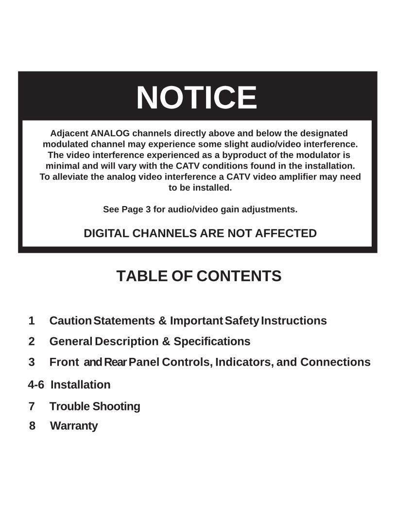
NOTICEAdjacent ANALOG channels directly above and below the designated
modulated channel may experience some slight audio/video interference.The video interference experienced as a byproduct of the modulator is minimal and will vary with the CATV conditions found in the installation.
To alleviate the analog video interference a CATV video amplifier may needto be installed.
See Page 3 for audio/video gain adjustments.
DIGITAL CHANNELS ARE NOT AFFECTED
4-6 Installation
7 Trouble Shooting
TABLE OF CONTENTS
1 Caution Statements & Important Safety Instructions
2 General Description & Specifications
3 Front and Rear Panel Controls, Indicators, and Connections
8 Warranty

Caution Statements
IMPORTANT SAFEGUARDS
Important Safety Instructions
This symbol is intended to alert the user to the presence ofnon-insulated "dangerous voltage" within the product's enclosure,that may be of sufficient magnitude to constitute a risk of electricshock to persons.
This symbol is intended to alert the user to the presence ofimportant operating and maintenance (servicing) instructions in theliterature accompanying the appliance.
TO REDUCE THE RISK OF ELECTRIC SHOCK,DO NOT REMOVE COVER (OR BACK)
NO USER SERVICEABLE PARTS INSIDE.REFER SERVICING
TO QUALIFIED PERSONNEL.
TO REDUCE THE RISK OF FIRE ORELECTRIC SHOCK, DO NOT EXPOSE THISAPPLIANCE TO RAIN OR MOISTURE
CAUTION
CAUTION
TO REDUCE THE RISK OF FIRE OR ELECTRIC SHOCK,DO NOT EXPOSE THIS APPARATUS TO RAIN OR MOISTURE.
WARNING:
POUR PREVENIR LES CHOCS ELECTRIQUES, NE PAS UTILISER CETTEFICHE POLARISEE AVEC UN PROLONGATEUR, UNE PRISE DECOURANT OU UNE AUTRE SORTIE DE COURANT, SAUF SI LES LAMESPEUVENT ETRE INSEREES A FOND SANS EN LAISSER AUCUNE PARTIEA DECOUVERT.
ATTENTION:
Do not attempt to service this product yourself as opening orremoving covers may expose you to dangerous voltage orother hazards. Refer all servicing to qualified servicepersonnel.
"CAUTION" -
1. Read these instructions.2. Keep these instructions.3. Heed all warnings.4. Follow all instructions.5. Do not use this apparatus near water.6. Clean only with a dry cloth.7. Do not block any ventilation openings. Install in accordance with the manufacturer's instructions.8. Do not install near any heat sources such as radiators, heat registers, stoves, or other apparatus (including amplifiers)
that produce heat.9. Do not defeat the safety purpose of the polarized or grounding-type plug. A polarized plug has two blades with one
wider than the other. A grounding type plug has two blades and a third grounding prong. The wide blade or thethird prong are provided for your safety. If the provided plug does not fit into your outlet, consult an electrician forreplacement of the obsolete outlet.
9 a. Mise à la terre ou Polarisation—Cet appareil est équipé avec un cordon d'alimentation à trois fils. Il est a branchersur une prise ayant un connecteur a la terre. Assurez-vous que la connection a la terre ne manque pas.
10. Protect the power cord from being walked on or pinched particularly at plugs, convenience receptacles, and the pointwhere they exit from the apparatus.
11. Only use attachments/accessories specified by the manufacturer.12. Use only with the cart, stand, tripod, bracket, or table specified by the manufacturer, or sold with the apparatus. When
a cart is used, use caution when moving the cart/apparatus combination to avoid injury from tip-over.
13. Unplug the apparatus during lightning storms or when unused for long periods of time.14. Refer all servicing to qualified service personnel. Servicing is required when the apparatus has been damaged in any
way, such as power-supply cord or plug is damaged, liquid has been spilled or objects have fallen into theapparatus, the apparatus has been exposed to rain or moisture, does not operate normally, or has been dropped.
1

Description & Specifications
DESCRIPTION
The Logenex SCFM-59 Video Modulator is a vestigialsideband heterodyne audio/video modulator thatprovides a modulated visual and aural RF carrier outputon the designated channel.The unit is specifically designedto eliminate existing signal on the preset analog channel, as well as the corrosponding digital channel. Consult Logenex Innovations Inc. for custom preset channels. All aeronautical channels are offset positive with a tolerance of ±5 kHz as required by FCC rules. The SCFM-59 is designed to accept video and audio
baseband signals from a satellite receiver, TV camera,video tape recorder, TV demodulator or similarequipment. The heterodyne conversion system, inconjunction with the use of a SAW filter, insures optimumvestigial selectivity for adjacent channel headends.
The modulator accepts standard (sync negative) polarityvideo at a 0.7 -1.5 Vpp level. All level controls arelocated on the front panel for ease of operation.
54 - 552 MHz.
Factory ordered for a single channel:EIA CATV channels 2 to 78 and 95 to 99.
All aeronautical channels offset positivewith a tolerance of ±5 kHz.+5 dBmV, (typically adjustable from +5to +5 dBmV).
75 OHMS, return loss of 14 dB, nominal.Audio Carrier -20 to -12 dB referenced tovideo carrier, adjustable.
Within ±10 kHz of assigned channelfrequency; ±5 kHz on FCCoffset channels.
4.5 MHz, ±5 kHz.-60 dBc minimum, measured at -15 dB A/Vratio and with modulator output level of+55 dBmV.Better than 60 dB.-95 dBc @ ±30 MHz orgreater spacings. (Specified levels arereferenced to the video carrier andmeasured in a 4 MHz bandwidth).
1 Vp-p ±3 dB, manual gain adjust withfront panel control.75 Ohms, return loss of 18 dBminimum.Flat ±2 dB from 30 Hz to 4.2 MHz.60 dB, luminance weighted.Within 50 nSec of 0 nSec L/C delay(complies with FCC rules, 76.605).Less than ±5% (10 to 90% APL).Less than ±5 degrees (10 to 90% APL).
175 mV rms minimum. Manual gainadjustment with front panel control.10K Ohms, unbalanced.75 µSec.(flat by moving internal jumper)40 Hz to 15 kHz, ±1.5 dB, referenced to75 µSec pre-emphasis curve.Within ±5 kHz, 00 C to +500 C.1.5% maximum.-60 dB minimum, referencedto 25 kHz peak deviation.
115 VAC ±10%, 60Hz, 10 Watts.Nominal 120 VAC, 600 Watts, maximum.Nominal 120 VAC 60 Hz,610 Watts, maximum.
00 C to +500 C, ambient.19" W x 1.75" H x 4.0" D.3.6 lbs.Video input, Audio input, RF output, andMonitor output are all type F.
VIDEOInput level for 87.5%
Modulation:
Input Impedance:
Frequency Response:Video S/N:L/C Delay:
Differential Gain:Differential Phase:
AUDIOInput Level for
25 kHz Peak Deviation:
Input Impedance:Pre-emphasis:
Frequency Response:
4.5 MHz Intercarrier Stability:Total Harmonic Distortion:
Hum and Noise:
GENERALModulator Power
Requirement:Auxiliary AC Outlet:
Total AC Power Input:
Operating TemperatureRange:
Size:Weight:
Connectors:
RFModulator Frequency Range:
Channels Available:
FCC FrequencyOffsets:
Output Level:
Output Impedance:A/V Ratio:
Frequency Stability,Visual:
Aural IntercarrierFrequency:
Spurious Outputs:
In-Channel C/N:Broadband Noise:
SPECIFICATIONS
SCM-12
Power Loop Patch
Output LevelADJ.
Min Max
Cable In Output
Min Max Min Max Min Max
A/V RatioAdj.
( from Cable provider )
Audio Level Video LevelAdj.
( to T.V. )
Channel
SCFM A B
2
Adj.
+55 dBmV, (typically adjustable from +43to +55 dBmV).
RF High Output Level:
CATV Throughput Frequency Range: 5 - 1000 MHz.
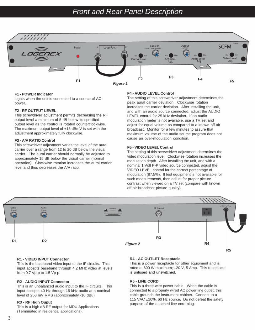
Front and Rear Panel Description
F3 - A/V RATIO ControlThis screwdriver adjustment varies the level of the auralcarrier over a range from 12 to 20 dB below the visualcarrier. The aural carrier should normally be adjusted toapproximately 15 dB below the visual carrier (normaloperation). Clockwise rotation increases the aural carrierlevel and thus decreases the A/V ratio.
F4 - AUDIO LEVEL ControlThe setting of this screwdriver adjustment determines thepeak aural carrier deviation. Clockwise rotationincreases the carrier deviation. After installing the unit,and with an audio source connected, adjust the AUDIOLEVEL control for 25 kHz deviation. If an audiomodulation meter is not available, use a TV set andadjust for equal volume as compared to a known off-airbroadcast. Monitor for a few minutes to assure thatmaximum volume of the audio source program does notcause an over-modulation condition.
F5 - VIDEO LEVEL ControlThe setting of this screwdriver adjustment determines thevideo modulation level. Clockwise rotation increases themodulation depth. After installing the unit, and with anominal 1 Volt P-P video source connected, adjust theVIDEO LEVEL control for the correct percentage ofmodulation (87.5%). If test equipment is not available forsuch measurements, then adjust for proper picturecontrast when viewed on a TV set (compare with knownoff-air broadcast picture quality).
Figure 1
F1 - POWER IndicatorLights when the unit is connected to a source of ACpower.
F2 - RF OUTPUT LEVELThis screwdriver adjustment permits decreasing the RFoutput level a minimum of 5 dB below its specifiedoutput level as the control is rotated counterclockwise.The maximum output level of +15 dBmV is set with theadjustment approximately fully clockwise.
F1 F2 F3 F4 F5
R4 - AC OUTLET ReceptacleThis is a power receptacle for other equipment and israted at 600 W maximum; 120 V, 5 Amp. This receptacleis unfused and unswitched.
R5 - LINE CORDThis is a three-wire power cable. When the cable isconnected to a properly wired AC power line outlet, thiscable grounds the instrument cabinet. Connect to a115 VAC ±10%, 60 Hz source. Do not defeat the safetypurpose of the attached line cord plug.
R1 - VIDEO INPUT ConnectorThis is the baseband video input to the IF circuits. Thisinput accepts baseband through 4.2 MHz video at levelsfrom 0.7 Vp-p to 1.5 Vp-p.
R2 - AUDIO INPUT ConnectorThis is an unbalanced audio input to the IF circuits. Thisinput accepts 40 Hz through 15 kHz audio at a nominallevel of 250 mV RMS (approximately -10 dBu).
SCM-12
Power Loop Patch
Output LevelADJ.
Min Max
Cable In Output
Min Max Min Max Min Max
A/V RatioAdj.
( from Cable provider )
Audio Level Video LevelAdj.
( to T.V. )
Channel
SCFM A B
Adj.
Figure 2R1 R2 R4
R5
Video Input
Audio Input !Warning!
!
600W MAX
120V AC~60Hz 610W
RF Output
3
R3 - RF High OuputThis is a high dB RF output for MDU Applications (Terminated in residential applications).
R3

InstallationCONNECTIONS AND CONTROLSConnections to and from the SCFM are made throughthe front and rear panel. Additional channels can beadded by using additional SCFM modulators.The 'RF Output Level' and 'A/V Ratio' controls are usedto make these adjustments respectively.
WALL MOUNTINGAdequate ventilation is very important. Excessive heatwill shorten component life and modulator performance will be degraded without proper cooling. Therefore when mounting be sure ventilation holes are not covered.
Install Application #1 (Typical Installation with multiple cable services with designated security channel)
Install Application #2 (Installation with digital service without a designated security channel) ** Any SCFM Series Modulators can be used
Install Application #3 (Basic installation, NO digital cable service) ** Any SCFM Series Modulator can be used
Cable Splitter/Distribution Amplifier
Cable Splitter/Distribution Amplifier
Digital Cable Box
Power Loop Patch
Output LevelMin Max
Cable In Output
Min Max Min Max Min Max
A/V Ratio
( from Cable provider )
Audio Level Video Level
( to T.V. )
Channel
SCFM A B
Cable In FromCable Provider
Power Loop Patch
Output LevelMin Max
Cable In Output
Min Max Min Max Min Max
A/V Ratio
( from Cable provider )
Audio Level Video Level
( to T.V. ) SCFM A B
Cable In FromCable Provider
1. Connect cable from cable provider to the input of the 3-Way Splitter, and 1 output from 3-Way Splitter to the “Cable In” located on the front panel of the SCFM.2. Connect the “Cable Out” located on the front panel of the SCFM to your cable distribution device, or directly into your digital cable box.3. Connect digital cable box to television with the designated connectors provided by your cable company.4. Connect the incoming video feed (CCTV camera, TeleDoorBell camera, DVR, or any other video source) to the “Video Input” located on the back panel of the SCFM.5. Power on SCFM and tune to appropriate channel to view CCTV input. 6. If required, tune the level adjustments located on the front panel of the SCFM (see page 4 for details).
1. Connect cable from cable provider to the cable in located on the front of the SCFM.2. Connect the cable out located on the front of the SCFM to your cable distribution device.3. Connect the distributed signal or single incoming feed into a 2-way splitter; one feed connecting into the digtal box, the other directly into the cable input located on the back of the television.4. Connect digital cable box to television with the designated connectors provided by your cable company.5. Connect the video feed (CCTV camera, TeleDoorBell camera, DVR, or any other video source) to the “Video Input” located on the back panel of the SCFM.6. Power on SCFM and tune to appropriate channel. 7. If required, tune the level adjustments located on the front panel of the SCFM.
1. Connect cable from cable provider to the “Cable In” located on the front panel of the SCFM.2. Connect the “Cable Out” located on the front panel of the SCFM to your cable distribution device.3. Connect the distributed signal into the cable input on the television.4. Connect the video feed (CCTV camera, TeleDoorBell camera, or any other video source) to the video input located on the back of the SCFM.6. Power on SCFM and tune to appropriate channel. 7. If required, tune the level adjustments located on the front of the SCFM. 4
+21 dBmV100 ft RG6
+17dBmV+10 dBmV
High Speed Internet Cable Modem
+6dBmV Splitt
er-7
dB
+10 dBmV 6.57 dBmV at TV
Phone Modem
-7-7
-4
From Cable Provider Digital Cable Box
15dB Amplifier

SCM-12
Power Loop Patch
Output LevelADJ.
Min Max
Cable In Output
Min Max Min Max Min Max
A/V RatioAdj.
( from Cable provider )
Audio Level Video LevelAdj.
( to T.V. )
Channel
SCFM A B
Install Application #4 MDU (Multi-Dwelling Unit)
Adj.
SCM-12
Power Loop Patch
Output LevelADJ.
Min Max
Cable In Output
Min Max Min Max Min Max
A/V RatioAdj.
( from Cable provider )
Audio Level Video LevelAdj.
( to T.V. )
Channel
SCFM A B
Adj.
Loop Patch Not Used
Remove Terminator
Screw Terminator on to Loop Patch A
Installation Cont...
Video Input
Audio Input !Warning!
!
600W MAX
120V AC~60Hz 610W
RF Output
Step 1
Step 2
Step 3
Step 4
5
Video Input
Audio Input !Warning!
!
600W MAX
120V AC~60Hz 610W
RF Output
RF Hi Output

MDU Installation Cont... (Multi-Dwelling Unit)
Installation Cont...
Video Input
Audio Input !Warning!
!
600W MAX
120V AC~60Hz 610W
RF Output
Step 5
Single Channel Deletion Filter
Power InserterPower InserterDirectional Coupler
Cable In
Installed By Cable Provider
* Note: Modulated channel signal must be balanced with an adjacent channelTips:
1) Make sure that the customer/tenant has a digital box and it is capable of coverting the modulated analogchannel to a corresponding digital channel.
**(Check the model number of the digital box , ie; Scientific Atlanta Models below 3000 do not have this capability. Digital Boxes with PVR functions must be initialized by the Cable Provider, this can be done remotely.
2) Check that the selected channel for modualtion has a corresponding digital channel. (ie; Channel 59 and Digital 998 show the same program/broadcasting)
Cable Out toAmplifier
6
Installed By Cable Provider

Troubleshooting
7
Problem SolutionProblem SolutionProblem AnswerModulated channel displays a Black Screen onanalog & digital TV’s.
Modulated Analog channel appears but digitalchannel is black
Modulated Analog channel is black but digitalshows regular channel programming.
Modulated channel shows noisey picture, all other channels are normal.
After Modulator installation, analog cable is normalbut digital boxes do not work.
Analog and Digital cable is normal but VOD (Video on Demand) does not upload
Modulator is installed but regular channelprogramming remains.
Modulator is installed, only certain TV’s are showingmodulated channel
1) No incoming video signal2) Adjust Video Level Adj Trimpot
1) Too Low or Too High incoming RF Signal**
1) No incoming video signal2) Digital Box is not compatible
1) Make sure modulator power is present2) Adjust Output Level Adj Trimpot3) Make sure Loop Patch Cable is installed
1) Incoming RF Signal is Too Low or Too High**2) Digital Box is not compatible
1) Too Low or Too High incoming RF Signal**2) Check for poor or RF connectors on all cables3) Any splitters/amplifiers must be bi-directional
** Please refer to Page 2 for tools that may be required for proper modulator installation & troubleshooting
Modulator is installed after main splitter
Specific TV (s) may be fed from another splitter other than the main

WarrantyWarranty
One Year Limited WarrantyLogenex Innovations Inc. warrants to the original purchaser this product shall be free from defects in material orworkmanship for one (1) year from the date of original purchase.
During the warranty period Logenex Innovations Inc. will provide, free of charge, both parts and labor necessary to correct defects in material and workmanship. At its option, Logenex Innovations Inc.may replace a defective unit.
To obtain such a warranty service, the original purchaser must:
(1) Retain invoice or original proof of purchase to establish the start of the warranty period.
(2) Notify Logenex Innovations Inc. or the nearest authorized service facility, as soon as possible after discoveryof a possible defect, of:(a) the model and serial number,(b) the identity of the seller and the approximate date of purchase; and(c) A detailed description of the problem, including details on the electrical connection to associated equipment and thelist of such equipment.
(3) Deliver the product to Logenex Innovations Inc. or the nearest authorized service facility, or ship the same in itsoriginal container or equivalent, fully insured and shipping charges prepaid.
Correct maintenance, repair, and use are important to obtain proper performance from this product. Therefore carefullyread the Instruction Manual. This warranty does not apply to any defect that Logenex Innovations Inc. determines isdue to:
(1) Improper maintenance or repair, including the installation of parts or accessories that do not conform to the qualityand specifications of the original parts.
(2) Misuse, abuse, neglect or improper installation.
(3) Accidental or intentional damage.
All implied warranties, if any, including warranties of merchantability and fitness for a particular purpose, terminate one(1) year from the date of the original purchase.
The foregoing constitutes Logenex Innovations Inc. entire obligation with respect to this product, and the originalpurchaser shall have no other remedy and no claim for incidental or consequential damages, losses or expenses. Somestates/provinces do not allow limitations on how long an implied warranty lasts or do not allow the exclusions or limitationof incidental or consequential damages, so the above limitation and exclusion may not apply to you.
For Service, contact:Logenex Innovations Inc.6A-7500 Martin Grove Rd.
Woodbridge, ON. Canada L4L 8S9Customer Service and Parts Telephone: (905) 790-8823
World Wide Web Site: http://www.logenex.com
8

6A-7500 Martin Grove Rd. Woodbridge, ON. Canada L4L 8S9
Customer Service and Parts Telephone: (905) 790-8823
World Wide Web Site: http://www.logenex.com
May 2009