
BORING - AIT Tools
61
F 1 F 2 F 3 F 14 F 58 F 60 F 61 F 22 F 34 F 38 F 41 F 44 F 46 F 50 F 54 F 57 F 31 Introduction APPLICATIONS Getting started Roughing Finishing Reaming Trouble shooting PRODUCTS Rough boring CoroBore® 820 DuoBore™ Heavy duty Fine boring CoroBore® 825 Fine boring heads 391.37A / 391.37B T-Max U fine boring units Extended offer Rough and fine boring tools Reaming Reamer 830 Extended offer Reaming tools Grade information BORING
-
Upload
khangminh22 -
Category
Documents
-
view
0 -
download
0
Transcript of BORING - AIT Tools

MTG09 Boring_F01-19.indd 2 2009-08-17 11:08:38
F 1
F 2
F 3
F 14
F 58
F 60
F 61
F 22
F 34
F 38
F 41
F 44
F 46
F 50
F 54
F 57
F 31
Introduction
APPLICATIONSGetting started
Roughing
Finishing
Reaming
Trouble shooting
PRODUCTSRough boring
CoroBore® 820
DuoBore™
Heavy duty
Fine boringCoroBore® 825
Fine boring heads 391.37A / 391.37B
T-Max U �ne boring units
Extended offer Rough and �ne boring tools
Reaming Reamer 830
Extended offerReaming tools
Grade information
BORING
MTG09 Boring_F01-19.indd 1 2009-11-25 14:29:59

F 2
A
B
C
D
E
F
G
H
I
Par
ting
and
groo
ving
Gen
eral
tur
ning
Thre
adin
gM
illin
gD
rilli
ngB
orin
gTo
ol h
oldi
ng/
Mac
hine
sM
ater
ials
Info
rmat
ion/
In
dex
Boring – introduction
IntroductionSandvik Coromant offers a comprehensive range of boring tools with the CoroBore family as first choice for most applications.
The CoroBore family offers versatile tools with adjustable diameters that can be configured for different applications. The rough boring tool CoroBore 820 offers increased productivity thanks to the three insert design, while the rigid fine boring tool CoroBore 825 enables machining of holes with close tolerances and high quality surface finishes.
By using damped boring tools (Silent Tools), deeper holes with long overhangs can be machined without devastating vibrations.
The Reamer 830 family with exchangeable heads enables finishing operations with close diameter tolerance and high quality surface finish at high feeds.
Trends Machines and machining methods• Multi-task machining• Reduction in set-up time to maximize income producing
time• Increased productivity with increased material removal
rate• Higher cutting speeds with more wear resistant grades,
CBN and PCD
Components and material• More high-alloy materials entering existing applications• Tighter hole tolerances• More long overhangs• Finishing in hardened material.
MTG09 Boring_F01-19.indd 2 2009-11-25 14:30:01

F 3
A
B
C
D
E
F
G
H
I
P M K N S H
Par
ting
and
groo
ving
Gen
eral
tur
ning
Thre
adin
gM
illin
gD
rilli
ngB
orin
gTo
ol h
oldi
ng/
Mac
hine
sM
ater
ials
Info
rmat
ion/
In
dex
Boring – getting started
Getting started
Boring is defined as a method to enlarge or improve the quality of an existing hole. Sandvik Coromant offers several flexible tool systems available in a wide diameter range for roughing, fine boring and reaming operations.
Roughing – Tools covering a diameter range from 25 to 550 mm. Hole depths up to 6 x coupling diameter. Roughing is primarily focused on metal removal in order to enlarge existing holes made by methods such as pre-machining, casting, forging, flame cutting etc. See page F 14. Fine boring – Tools covering a diameter range from 3 to 981.6 mm. Hole depths up to 6 x coupling diameter. Intended to complete an existing hole to achieve a close hole tolerance, position and high quality surface finish. See page F 22. Reaming – The multi-edge reamer covering a diameter range from 10 to 31.75 mm. This is a highly productive tool for high quality surface finish and close dimensional tolerance. See page F 31.
Milling
A milling cutter with helical or circular interpolation can be used instead of boring tools. The method is less productive when it comes to roughing but can be an alternative when: • machine power is limited and/or no coolant available
• chip breaking/evacuation is difficult to obtain by a boring tool
• an absolutely flat bottom hole is required
• there is limited space in the tool magazine
• the series length is short. Tools to produce various hole diameter.
See Milling, Chapter D.
Internal turning
Boring of rotational symmetrical components is normally carried out in a turning lathe. See General turning, Chapter A.
Boring methods
Choice of method Three different areas may be considered to determine the best method and tooling solution.
1. Hole dimensions and quality 2. Component material, shape and quantity 3. Machine parameters
MTG09 Boring_F01-19.indd 3 2009-11-25 14:30:20

F 4
A
B
C
D
E
F
G
H
I
P M K N S H
Par
ting
and
groo
ving
Gen
eral
tur
ning
Thre
adin
gM
illin
gD
rilli
ngB
orin
gTo
ol h
oldi
ng/
Mac
hine
sM
ater
ials
Info
rmat
ion/
In
dex
1. Start with the hole. Basic parameters are:
• diameter
• depth
• quality (tolerance, surface finish, position and straightness)
Type of operation: Roughing – machining of an existing hole with focus on metal removal
in order to prepare for finishing. Hole tolerances larger or equal to IT9.
Finishing – machining of an existing hole to achieve a close hole tolerance and high quality surface finish. Small cutting depths, generally below 0.5 mm. Hole tolerances between IT6 and IT8.
The quality of the hole affects the type of operation and choice of tool.
Initial considerations
2. The component
After analyzing the hole it is time to look at the component:
• Does the material have good machinability and chip breaking properties?
• Is the component stable or are there thin sections that can cause vibrations?
• Is a tool extension needed to be able to machine the hole?
• Can the component be fixed properly? What stability problems need to be considered?
• Is the component rotation symmetric around the hole i.e. can the hole be ma-chined in a turning lathe?
• Batch size – mass production, which justifies an optimized special tool to maximize productivity, or a single hole machining?
3. The machine
Some important machine considerations:
• Spindle interface
• Stability, power and torque, especially for larger boring tools
• Is spindle speed (rpm) enough for small diameters?
• Tool magazine and tool changer, especially for larger boring tools
• A horizontal spindle and internal coolant supply to improve the chip evacuation.
Roughing Finishing
Boring – getting started
MTG09 Boring_F01-19.indd 4 2009-11-25 14:30:22

F 5
A
B
C
D
E
F
G
H
I
Par
ting
and
groo
ving
Gen
eral
tur
ning
Thre
adin
gM
illin
gD
rilli
ngB
orin
gTo
ol h
oldi
ng/
Mac
hine
sM
ater
ials
Info
rmat
ion/
In
dex
Advantages • Relatively flexible
• Possible to adjust the diameter over a certain range
• High feed rate = high productivity
Disadvantages �• Tools need to be adjusted manually
• Large diameter compared to milling tools requires large torque and space in tool magazine
• Tools with three cutting edges require high machine power
Advantages • Relatively flexible
• Possible to adjust the diameter within a certain range
• Diameter adjustable within microns
Disadvantages �• Tools need to be adjusted manually
• Large diameter compared to milling tools, need more space in tool magazine
Advantages • Very flexible
• Profiling possible with standard tools
Disadvantages • Only one cutting edge
• Limited to components that are possible to set up in a turning lathe
Advantages • Very high feed rate
Disadvantages • Follows the shape and position of the pre-
machined hole
• One tool is limited to one diameter
Advantages • Very flexible
• Chip breaking always obtained
• Can machine a flat bottom on blind holes
• Takes less space in tool magazine
Disadvantages • Longer cycle times
Advantages • Very flexible
• Chip breaking always obtained
• Can machine a flat bottom on blind holes
• Takes less space in tool magazine
Disadvantages •��Requires high quality machines
Internal turning
Reaming
Helical/circular milling
Helical/circular milling
Choice of method – examples
Medium to long series production
Standard option, medium to long series production
Rotation symmetrical components
Long series production
Flexibility, short series production
Flexibility
Rough boring
Fine boring
Boring – getting started
Roughing
Finishing
MTG09 Boring_F01-19.indd 5 2009-11-25 14:30:24

F 6
A
B
C
D
E
F
G
H
I
Par
ting
and
groo
ving
Gen
eral
tur
ning
Thre
adin
gM
illin
gD
rilli
ngB
orin
gTo
ol h
oldi
ng/
Mac
hine
sM
ater
ials
Info
rmat
ion/
In
dex
Boring – getting started
Multi-edge boring Involves two or three cutting edges and is employed for roughing operations of holes, with tolerance IT9 or larger, where metal removal rate is the first priority. Feed rate is obtained by multiplying the feed for each insert by the number of inserts (fn = fz x z).
Basic set-up for most boring applications.
Step boring Performed in roughing by a boring tool having the inserts set at different axial heights and diameters. Employed where large radial depth of cut is required, or to get improved chip control in long chipping materials since the chip width can be divided into several smaller, easily handled chips. The number of tools and tool changes might be reduced when step boring.
The feed rate and produced surface finish is the same as if only one insert is used (fn = fz). Produced hole tolerance is IT9 or larger.
Single-edge boring For roughing and finishing in materials where chip control is demanding, or when machine tool power is limited (fn = fz).
Single-edge boring is used for long chipping material – more space for chips, bottom holes and finishing of holes with tolerance IT9 or larger.
Overview - boring tools for roughing
CoroBore® 820 CoroBore 820 should always be considered as the first choice for rough boring.
It is versatile with slides that can be adjusted in order to cover a certain diameter range with one tool.
Typical applications • Medium to large diameter holes (35–306 mm)
• Maximum productivity
• Triple-edge, step or single-edge boring
• Medium to high power machine tools
DuoBore™ DuoBore is a complement when machine power or stability is limited.
It is versatile with slides that can be adjusted in order to cover a certain diameter range with one tool.
Typical applications • Medium to large diameter holes (25–270 mm)
• Twin-edge, step or single-edge boring
• Low to medium power machine tools
• Deeper holes and long overhangs
Heavy duty boring tools Heavy duty is a complement for large diameter heavy duty rough boring.
It is versatile with slides that can be adjusted in order to cover a certain diameter range with one tool.
Typical applications • Large diameter holes (150–550 mm)
• Applications that require strong inserts
• Twin-edge, step or single-edge boring
• Medium to high power machine tools
Roughing methods
Multi-edge boring Step boring
Single-edge boring
MTG09 Boring_F01-19.indd 6 2009-11-25 14:30:25

F 7
A
B
C
D
E
F
G
H
I
Par
ting
and
groo
ving
Gen
eral
tur
ning
Thre
adin
gM
illin
gD
rilli
ngB
orin
gTo
ol h
oldi
ng/
Mac
hine
sM
ater
ials
Info
rmat
ion/
In
dex
Boring – getting started
Single-edge boring For finishing with small cutting depths when close tolerance (IT6 to IT8) or high quality surface finish is required. The diameter of a fine boring tool can be adjusted within microns with a high precision mechanism. Single-edge boring can be applied with a rough boring tool for finishing of holes with tolerances of IT9 or larger.
Multi-edge reaming A finishing operation performed with a multi-edge reamer provides close tolerances and high quality surface finish at high feeds. Normally used for long series production.
Overview - boring tools for finishing
CoroBore® 825 CoroBore 825 should always be considered as the first choice for fine boring.
The tool can be adjusted radially in order to cover a certain diameter range with one tool. The tool allows precision adjustment in microns in order to achieve close hole tolerances.
Typical applications • Medium to large diameter precision
tolerance holes with high quality surface finish (19–981.6 mm)
• Conventional boring or back boring
• Deeper holes and long overhangs
• External operations
Fine boring head Fine boring head with boring bars for small diameters.
The tool can be adjusted radially in order to cover a certain diameter range with one tool. The tool allows precision adjustment in microns in order to achieve close hole tolerances.
For high speed, use fine boring head 391.37B with adjustable counterweight.
Typical applications • Small to medium diameter precision tolerance
holes with high quality surface finish (3–42 mm)
• High speed machining due to adjustable counterweight
T-Max U fine boring unit Precision tool for mounting in special tools, capable of machining close diameter tolerances.
Typical applications • Engineered solutions
• Minimum diameter of hole 25 mm
Finishing methods
Single-edge boring Multi-edge reaming
Reamer 830 Complement to the high performance drill concept CoroDrill 880 for high precision holes at high feeds.
Typical applications • Precision tool for through holes with high
quality surface finish (10–31.75 mm)
• Long series production
• High feeds
MTG09 Boring_F01-19.indd 7 2009-11-25 14:30:26

F 8
A
B
C
D
E
F
G
H
I
vf = fn x n
vc =π x Dc x n
1000
Par
ting
and
groo
ving
Gen
eral
tur
ning
Thre
adin
gM
illin
gD
rilli
ngB
orin
gTo
ol h
oldi
ng/
Mac
hine
sM
ater
ials
Info
rmat
ion/
In
dex
Boring – getting started
Cutting speed – vc (m/min) The boring tool rotates with a certain number of revolutions (n) per minute, generat-ing a certain diameter (Dc). This gives a specific cutting speed vc measured in m/min at the cutting edge. vc has a direct influence on tool life.
Feed – fn (mm/rev) The axial tool movement is called feed rate (fn) and is measured in mm/revolu-tions. The feed rate is obtained by multiplying the feed per tooth (fz) by the effective number of teeth (number of teeth generating final surface). The feed rate is the key value in determining the quality of the surface being machined and for ensuring that the chip formation is within the scope of the insert geometry.
Penetration rate – vf (mm/min) The penetration rate (vf) means the speed of the axial movement and is strongly related to the productivity.
Metal removal rate – Q (cm³/min) The metal removal rate (Q) means how much material that can be removed in a certain time frame and is strongly related to the productivity for roughing.
Cutting depth – ap (mm) The cutting depth (ap) is the difference between the uncut and the cut hole radius.
Entering angle – kr (º) The cutting edge approach to the workpiece is expressed through the entering angle (kr) as the angle between the main cutting edge and the direction of feed.
Net power – Pc (kW) The net power (Pc) is the power the machine must be able to provide to the cutting edges in order to drive the cutting action. The mechanical and electrical efficiency of the machine must be taken into consideration when selecting cutting data.
Torque – Mc (Nm) The torque (Mc) is the torque value produced by the boring tool during cutting action, which the machine must be able to provide.
Boring definitions
For more information about definitions and formulas, see Information/Index, Chapter I.
MTG09 Boring_F01-19.indd 8 2009-11-25 14:30:26

F 9
A
B
C
D
E
F
G
H
I
Par
ting
and
groo
ving
Gen
eral
tur
ning
Thre
adin
gM
illin
gD
rilli
ngB
orin
gTo
ol h
oldi
ng/
Mac
hine
sM
ater
ials
Info
rmat
ion/
In
dex
Bending stiffness and torque transmission are the most important factors when choosing a tool holder for boring operations. For best stability and hole quality use Coromant Capto coupling, CoroGrip or HydroGrip holding tools.
Coromant Capto coupling is the only modular tooling system designed for all metal cutting operations, including all hole making methods. The same cutting tools and adaptors can be used in different applications and machines. This makes it possible to standardize on one tooling system for the entire work shop.
A small run-out is the most important factor when choosing a holder for reaming operations. Precision chucks suitable for Reamer 830 are HydroGrip and CoroGrip.
• Choose shortest possible adaptor
• Choose strongest possible adaptor
• If reductions are needed, use tapered version if possible
• For long overhangs (>4 x D5m), use damped adaptors
• For long overhangs, ensure rigid clamping with flange contact to spindle if possible
• Maximum recommended run-out for reamers is 5 microns.
See Tool holding/Machines, Chapter G.
Assembled boring tools often have to be built from several items to suit an operation:
• slides or cartridges
• boring adaptors
• reductions
• extensions
• basic holders
It is always vital that recommended torque values are followed for assembly and that a suitable fixture and a good tool pre-setter are used.
Tool holding
Boring – getting started
Assemble a boring tool
MTG09 Boring_F01-19.indd 9 2009-11-25 14:30:27

F 10
A
B
C
D
E
F
G
H
I
P M K
N S H
Par
ting
and
groo
ving
Gen
eral
tur
ning
Thre
adin
gM
illin
gD
rilli
ngB
orin
gTo
ol h
oldi
ng/
Mac
hine
sM
ater
ials
Info
rmat
ion/
In
dex
Boring – getting started
Chip evacuation and tool vibration are important factors that affect the selection of cutting data.
Recommendations for the chosen insert and grade can be followed generally, but with the following exceptions:
• Maximum recommended starting value for cutting speed is 200 m/min for rough boring and 240 m/min for fine boring to ensure proper chip evacuation.
• Recommended starting values for cutting speed for fine boring head 391.37A with steel or carbide bars with inserts are 90-120 m/min (use lower values for long steel bars). Recommended starting value for ground carbide bars is 60 m/min.
• Maximum recommended depth of cut for fine boring is 0.5 mm
• Cutting speed must be reduced when working with long overhangs, see pages F 42 and F 47.
Silent Tools can be used to achieve higher cutting speeds at certain overhangs, see pages F 42 and F 47.
If the tool is adjusted to minimum possible diameter, chip evacuation will be more critical and it might be needed to reduce cutting depth.
Maximum feed at fine boring is limited by desired surface finish. The possibility to influence chip form is therefore limited.
Cutting data
Chip formation and chip evacuation are critical issues in boring operations, especially in blind holes. Inappropriate cutting data can lead to too short/thick chips and excessive cutting forces with deflection and vibration as result. Too long chips (stringy swarf) can accumulate in the hole and cause surface finish deterioration and chip jamming, leading to insert breakdown.
Ideal chips should be in the form of defined commas or spirals that are easily evacuated from the hole. Factors that have an influence on chip breaking are:
• the insert micro and macro geometry
• cutting depth, feed and cutting speed
• material
• nose radius
• entering angle.
Chip control
See General turning, Chapter A for information about turning in different materials, which is also applicable to boring to a very high extent.
Boring different materials
Cutting speed in relation to overhang
MTG09 Boring_F01-19.indd 10 2009-11-25 14:30:28

F 11
A
B
C
D
E
F
G
H
I
fnap vc
Par
ting
and
groo
ving
Gen
eral
tur
ning
Thre
adin
gM
illin
gD
rilli
ngB
orin
gTo
ol h
oldi
ng/
Mac
hine
sM
ater
ials
Info
rmat
ion/
In
dex
Boring – getting started
Effects of cutting speed
Too low •��Built-up edge•��Dulling of edge•��Uneconomical.
Effects of feed rate
Too heavy•��Loss of chip control•��Poor surface finish•��Crater wear/plastic deformation•��High power consumption•��Chip welding•��Chip hammering.
Effects of depth of cut
Too deep•��High power consumption•��Insert breakage•��Increased cutting forces.
Insert tool life Looking at the three main machining parameters, speed, feed, and depth of cut, each has an effect on tool life. The depth of cut has the smallest effect followed by the feed rate. Cutting speed has by far the most effect on the tool life of the insert.
Tool life
Little effect on tool life.
Tool life
Less effect on tool life than vc.
Tool life
Large effect on tool life. Adjust vc for best economy.
Insert nose radius and depth of cutThe radius on the insert is a key factor in boring operations. The selection of nose radius is dependent on depth of cut and feed, and influences the surface finish, chip breaking and insert strength.
At small depths of cut, the resultant cutting force is radial and is trying to push the insert away from the bore surface. When depth of cut is increased, the resultant cutting force is changed to axial force.
• As a general rule of thumb, the depth of cut should be no less than 2/3 of the nose radius. Avoid depths of cut smaller than 1/3 of the nose radius when finishing at small depths of cut.
• The generated surface finish will be directly influenced by the combination of nose radius and feed rate. See General turning, Chapter A, for how to calculate the theoretical surface finish for a conventional insert and a wiper insert.
Too small•��Loss of chip control•��Vibrations•��Excessive heat •��Uneconomical.
Too light•��Stringers•��Rapid flank wear•��Build up edge•��Uneconomical.
Too high•��Rapid flank wear•��Poor finish•��Rapid crater wear•��Plastic deformation.
Large nose radius
• Heavy feed rates
• Large depths of cut
• Strong edge security
• Increased radial cutting forces
Small nose radius
A small nose radius is ideal for small depths of cut and to reduce vibrations. Increased risk for insert breakage.
Wiper insert
Wiper inserts can be used to improve surface finish or increase feed. Note: Wiper inserts are not recommended for unstable conditions and long overhangs.
Rmax
MTG09 Boring_F01-19.indd 11 2009-11-25 14:30:29

F 12
A
B
C
D
E
F
G
H
I
Par
ting
and
groo
ving
Gen
eral
tur
ning
Thre
adin
gM
illin
gD
rilli
ngB
orin
gTo
ol h
oldi
ng/
Mac
hine
sM
ater
ials
Info
rmat
ion/
In
dex
Boring – getting started
Chip evacuation, cooling and lubrication between the tool and the workpiece material, are primary functions of cutting fluid. This affects the hole quality and tool life. Most of Sandvik Coromant's boring tools are designed for internal cutting fluid supply and with nozzles directing the fluid to the cutting zone.
• Use a mixture of 5-8% soluble oil.
• Higher pressure and volume improves chip evacuation.
• Mist cutting fluid or minimal lubrication can be used, especially in aluminium.
• Dry boring can be performed in short-chipping materials, preferably in horizontal or through hole applications. Tool life will be reduced. Compressed air will improve chip evacuation tremendously.
Note: Dry machining is never recommended in the materials stainless steel (ISO M) and HRSA (ISO S).
Use internal cutting fluid to come as close as possible to the cutting edge.
External cutting fluid supply is acceptable in short chipping materials but must continuously be directed to the cutting zone. If not possible, try dry boring.
Cutting fluid
How to achieve good hole quality•� Chip evacuation
Make sure chip breaking and evacuation is satisfactory. Chip jamming affects hole quality and reliability/tool life. Insert geometry and cutting data is crucial. See page F 10.
•��Stability,�tool�set-up Use shortest possible overhang and strongest possible adaptor. Use Silent Tools for overhangs longer than 4 x coupling diameter. See page F 9.
•��Insert�tool�life Check insert wear regularly and establish pre-determined tool life program.
•��Maintenance Change insert-clamping screws regularly, washers and cup springs when needed. Clean the tip seat before changing insert and clean all components before assembly. Use torque wrench and Molycote. See page F 13.
•��Tools Boring tool, insert geometry and grade affect the cutting quality. Wiper inserts improve surface finish but are not recommended for unstable conditions and long overhangs.
•��Cutting�data Use correct cutting data for the insert material and application.
•��Adjustment Make the final diameter adjustment of a fine boring tool while the tool is still mounted in the machine and after a measuring cut.
MTG09 Boring_F01-19.indd 12 2009-11-25 14:30:29

F 13
A
B
C
D
E
F
G
H
I
Par
ting
and
groo
ving
Gen
eral
tur
ning
Thre
adin
gM
illin
gD
rilli
ngB
orin
gTo
ol h
oldi
ng/
Mac
hine
sM
ater
ials
Info
rmat
ion/
In
dex
Boring – getting started
Tool maintenanceCheck the insert seats regularly to ensure that they have not been damaged during machining or handling. Make sure that the insert seats are free from dirt or metal chips from machining.
Replace worn or exhausted screws, washers and cup springs. Ensure to have a torque wrench to obtain correct screw-tightening.
To get the best performance, we recommend to clean all male and female parts and lubricate them with oil at least once a year. Lubricant should be applied when needed to the screw thread as well as the screw head face.
The fine boring mechanism on fine boring tools should be lubricated regularly, see pages F 48 and F 51.
Torque wrenchTo get the best performance out of the boring tools, a torque wrench should be used to get the correct tightening of the assembled boring tool and insert.
Torque that is too high will affect the performance of the tool negatively and cause insert, washer, cup spring and screw breakage.
Torque that is too low will cause slide or insert movement, vibrations and degrade the cutting result. See the Main catalogue to get the correct tightening torque.
Safety precautions – danger pointsChips are very hot with sharp edges and should not be moved by hands. Chips can cause burns to the skin or damage to the eyes.
Be sure that the insert and component is tight and secured in its holder to prevent it coming loose during use. Too much overhang can result in vibration and tool breakage.
Use appropriate safety guards or machine encapsulations to securely collect particles such as chips or cutting elements which may spin off.
Make sure the machine has required torque and power needed for rough boring operations with three cutting edges, large depths of cut or large diameters.
MTG09 Boring_F01-19.indd 13 2009-11-25 14:30:30

F 14
A
B
C
D
E
F
G
H
I
Par
ting
and
groo
ving
Gen
eral
tur
ning
Thre
adin
gM
illin
gD
rilli
ngB
orin
gTo
ol h
oldi
ng/
Mac
hine
sM
ater
ials
Info
rmat
ion/
In
dex
RoughingApplication overview
Choice of tools D 103
How to apply D 113
Milling
Roughing – application overview
Internal turning
Choice of tools A 58
How to apply A 62
MTG09 Boring_F01-19.indd 14 2009-11-25 14:30:37

F 15
A
B
C
D
E
F
G
H
I
Par
ting
and
groo
ving
Gen
eral
tur
ning
Thre
adin
gM
illin
gD
rilli
ngB
orin
gTo
ol h
oldi
ng/
Mac
hine
sM
ater
ials
Info
rmat
ion/
In
dex
Boring
Trouble shooting F 34
Choice of tools F 16
How to apply F 18
Roughing
Roughing – application overview
MTG09 Boring_F01-19.indd 15 2009-11-25 14:30:39

F 16
A
B
C
D
E
F
G
H
I
4 x D5m
IT9
3
T-Max P CoroTurn® 107
84º (75º), 90º, 95º
IT9
2
T-Max P CoroTurn® 107
75º, 84º, 90º
IT9
2
CoroTurn® 107
75º, 90º
IT9
2
CoroTurn® 107
75º, 90º
IT9
2
T-Max P
75º, 90º, 95º
IT9
2
T-Max P CoroTurn® 107
75º, 90º, 95º
4 x D5m 6 x Dc 4 x D5m
35–306 25–270 25–101 99–150 150–300 250–550
CoroBore® 820 DuoBore™
P M KN S H
P M KN S H
P M KN S H
P M KN S H
P M KN S H
P M KN S H
Par
ting
and
groo
ving
Gen
eral
tur
ning
Thre
adin
gM
illin
gD
rilli
ngB
orin
gTo
ol h
oldi
ng/
Mac
hine
sM
ater
ials
Info
rmat
ion/
In
dex
Boring depth
Hole tolerance
Boring range (mm)
Number of cutting edges
Insert types
Power requirement
Entering angle
Material
Medium, high (Low), medium (Low), medium (Low), medium Medium, high Medium, high
See Milling, Chapter D
Heavy duty Milling
600 mm 400 mm
Roughing – choice of tools
Roughing
Choice of tools
Rough boring operations are performed to open up an existing hole to prepare for finishing.
Boring operations are applied to machine holes that have been made through methods such as pre-machining, casting, forging, extrusion, flame cutting etc.
All Sandvik Coromant's rough boring tools can be configured for multi-edge, step and single-edge boring. See page F 6 for selection of methods.
Choice of method
Note: For information about our special tool programme, see Extended offer, page F 57.
MTG09 Boring_F01-19.indd 16 2009-11-25 14:30:46

F 17
A
B
C
D
E
F
G
H
I
Par
ting
and
groo
ving
Gen
eral
tur
ning
Thre
adin
gM
illin
gD
rilli
ngB
orin
gTo
ol h
oldi
ng/
Mac
hine
sM
ater
ials
Info
rmat
ion/
In
dex
Roughing – choice of tools
Insert shapeIn rough boring, it is an advantage to use positive basic shape inserts (CoroTurn 107) as they provides lower cutting forces compared to negative inserts.
In stable conditions, choose negative shape inserts (T-Max P) for better insert economy or tough applications that require strong inserts and improved process security.
Tools with negative shape insertsTools with positive shape inserts
The entering angle of a boring tools affects the direction and magnitude of axial and radial forces. A large entering angle produces a large axial force directed to the spindle, while a small entering angle results in a large radial cutting force and thinner chip thickness.
Choosing entering angle for roughing
95º - For high feeds or improved surface finish with wiper inserts (CoroBore 820) under stable conditions
Recommendations
75°/84° - For interrupted cut, sand inclusions, stack boring etc. but for through holes only
90º - First choice for general operations, step boring and for shoulder operations
Clamping of positive basic shape inserts (CoroTurn 107)
Clamping of negative basic shape inserts (T-Max P)
Positive shaped inserts Negative shaped inserts
Diameter positioning
CoroBore® 820 Diameter range 35–306 mm
DuoBore™ Diameter range 25–270 mm
Heavy duty Diameter range 250–550 mm
DuoBore™ damped Diameter range 25–150 mm
CoroBore® 820 Diameter range 106–306 mm
DuoBore™ Diameter range 69–150 mm
Heavy duty Diameter range 250–550 mm
Heavy duty with Coromant Capto coupling Diameter range 150–300 mm
MTG09 Boring_F01-19.indd 17 2009-11-25 14:30:49

F 18
A
B
C
D
E
F
G
H
I
PMKN
H
H
PMK
-PM / GC4225 -PR / GC4225
-MR / GC2025
-KR / GC3215
-AL / H10
-MM / GC1105
-QM / GC1105
-PR / GC4225
-MR / GC2025
-KR / GC3215
-WM / GC4215
-WM / GC2015
-WM / GC3215
-AL / GC1810
-UM / GC1115
-MM / GC1115
*
*
-WMX / GC4215
-WMX / GC2015
-WMX / GC3215
-MM / GC2025
-KM / GC3215
-AL / H10
-MM / GC1105
-QM / GC1105
-PM / GC4225
-MM / GC2025
- KM / GC3215
S
S
Par
ting
and
groo
ving
Gen
eral
tur
ning
Thre
adin
gM
illin
gD
rilli
ngB
orin
gTo
ol h
oldi
ng/
Mac
hine
sM
ater
ials
Info
rmat
ion/
In
dex
Roughing – choice of tools
How to apply
Large diametersLarge diameter holes require larger torque than small diameter holes. Make sure the machine has sufficient torque value. Large diameter rough boring tools have larger inserts and can therefore take larger depths of cut than small diameter tools. Make sure the machine has the required power.
Weak machinesWhen roughing, make sure the machine has the required power and torque needed for the specific boring application. Feed, number of inserts, hole diameter and depth of cut are main affecting parameters. For more information, see Information/Index, Chapter I.
CoroBore 820 is a highly productive roughing tool with three cutting edges that should be considered first choice for medium to high power machines.
Choose DuoBore for unstable conditions, weak machines or long overhangs. Choose Heavy duty when strong inserts are needed or for large diameter holes.
Deep holes
Damped DuoBore is recommended for use in deep holes or overhangs longer than four times the coupling diameter, see page F 41.
First choice
Geometry and grade recommendations
Positive inserts
Medium Roughing Complementary
T-Max® P, CoroTurn® RC rigid clamping
CoroTurn® 107 screw clamping
* For recommendation on fine boring in ISO H material, see General turning, Chapter A.
Note: Grade recommendations are valid for average conditions.
For recommendations on when alternative grade should be used, see grade information on page F 61.
Negative inserts
MTG09 Boring_F01-19.indd 18 2009-11-25 14:30:50

F 19
A
B
C
D
E
F
G
H
I
Par
ting
and
groo
ving
Gen
eral
tur
ning
Thre
adin
gM
illin
gD
rilli
ngB
orin
gTo
ol h
oldi
ng/
Mac
hine
sM
ater
ials
Info
rmat
ion/
In
dex
Roughing – how to apply
Blind holesWhen machining a blind hole it is very important to secure that proper chip evacuation takes place.
• Correct cutting data is essential to achieve proper chip forming
• Ensure/check that the chips do not jam or wear the inserts
• Coolant pressure and flow should be sufficient to evacuate the chips
• Vertical machines are more critical than horizontal machines for efficient chip evacuation.
Sand inclusions – cast componentsSand inclusions in cast components increase the wear on the inserts.
Recommendations: • Choose a tough grade
• Reduce cutting data
• Choose a strong square negative, basic-shaped insert for improved process security and minimized wear.
Gas burned holesGas burned holes could have local hardened areas that will generate more wear on the inserts.
Recommendations: • Choose a tough grade
• Reduce cutting data
• Choose a strong, square negative basic-shaped insert for improved process security and minimized wear.
Interrupted cutsMachining of interrupted cuts, such as cross holes, set high demands on insert cutting conditions.
Recommendations: • Choose a tough grade
• Choose a strong, square negative basic-shaped insert for improved process security, valid for stable conditions
• Reduce cutting data if there are severe interruptions.
MTG09 Boring_F01-19.indd 19 2009-11-25 14:30:51

F 20
A
B
C
D
E
F
G
H
I ➤
Par
ting
and
groo
ving
Gen
eral
tur
ning
Thre
adin
gM
illin
gD
rilli
ngB
orin
gTo
ol h
oldi
ng/
Mac
hine
sM
ater
ials
Info
rmat
ion/
In
dex
Large depth of cutIf a really large depth of cut is needed, step boring could be considered as a good alternative.
Make sure the machine has the required power and torque.
Off centre holesIf the centre lines of the pre-machined hole and the boring tool are not concentric, the cutting depth could be really large on one side of the hole.
This could typically occur on cast components.
A good solution for these applications is step boring in order to be able to take the large depth of cut. Unsymmetrical cutting forces might bend the tool and cause some small remaining off centre or vibrations, especially when long overhang tool assemblies are used.
Application checklist and hints
• Choose multi-edge boring (triple-edge or twin-edge), step boring or single-edge boring.
• Choose largest possible coupling size.
• Ensure proper chip control. Short chips/hard chips might lead to vibrations and long chips might deteriorate surface finish causing insert breakdown. Horizontal machining and cutting fluid improve chip evacuation in blind holes.
• Select insert geometry and grade: •Startwitharoughinggeometry,unlessasmallcuttingdepthistobe
taken. •Chooseamediumgeometryforsmallercuttingdepthorimprovedchip
breaking.
• Select appropriate entering angle.
Roughing – how to apply
MTG09 Boring_F20-36.indd 20 2009-11-25 14:31:34

F 21
A
B
C
D
E
F
G
H
I
➤
Par
ting
and
groo
ving
Gen
eral
tur
ning
Thre
adin
gM
illin
gD
rilli
ngB
orin
gTo
ol h
oldi
ng/
Mac
hine
sM
ater
ials
Info
rmat
ion/
In
dex
• Select appropriate cutting data and consider overhang. Note: Do not use maximum recommended feed and ap at the same time. Maximum recommended starting speed is 200 m/min to ensure proper chip evacuation.
• A large insert nose radius (re) will improve process security and enable larger feed but might generate vibrations. Nose radius of 0.8 mm is recommended as start radius.
• Positive basic-shape inserts are first choice but negative basic-shape inserts can be used for improved insert economy or process security under stable conditions.
• Insufficient cutting edge engagement can increase vibration through friction during cutting, instead of a clean cutting action.
• Rigid clamping with face contact to spindle improves stability.
• Excessive cutting edge engagement (large depth of cut and/or feed) can increase vibrations.
• Make sure the machine can provide the required torque and power for the specific boring application.
• An insert grade with a higher level of toughness could be considered in some operations to cope with any risks of chip jamming or vibration tendencies.
• Wiper inserts can be used to improve surface finish or increase feed but are not recommended for unstable conditions and long overhangs.
• Make sure to get proper clamping of boring tool and workpiece.
Continued application checklist and hints
• Use cutting fluid to improve chip evacuation, tool life and hole geometry.
• For best performance of CoroBore 820, it is recommended to machine in the higher area of the ap and feed recommendations, especially for longer overhangs. Note: Do not use maximum ap and feed at the same time.
• Multi-edge boring machining enables maximum penetration rate. If a really large depth of cut is needed, it could be more productive to go for step boring since the cycle time can be minimized and fewer tools might be needed.
• Choose the shortest possible overhang. Choose Silent Tools for overhangs longer than 4 times the coupling size.
Roughing – how to apply
MTG09 Boring_F20-36.indd 21 2009-11-25 14:31:35

F 22
A
B
C
D
E
F
G
H
I
Par
ting
and
groo
ving
Gen
eral
tur
ning
Thre
adin
gM
illin
gD
rilli
ngB
orin
gTo
ol h
oldi
ng/
Mac
hine
sM
ater
ials
Info
rmat
ion/
In
dex
Finishing – application overview
FinishingApplication overview
Choice of tools D 103
How to apply D 113
Milling
MTG09 Boring_F20-36.indd 22 2009-11-25 14:31:40

F 23
A
B
C
D
E
F
G
H
I
Par
ting
and
groo
ving
Gen
eral
tur
ning
Thre
adin
gM
illin
gD
rilli
ngB
orin
gTo
ol h
oldi
ng/
Mac
hine
sM
ater
ials
Info
rmat
ion/
In
dex
Finishing – application overview
Boring
Trouble shooting F 34
Choice of tools F 24
How to apply F 26
Fine boring
Choice of tools F 31
How to apply F 32
Reaming
MTG09 Boring_F20-36.indd 23 2009-11-25 14:31:42

F 24
A
B
C
D
E
F
G
H
I
4 x D5m
IT6IT6 IT6 IT6 IT6 IT6 IT6
5 x Dc 6 x Dc 6 x D5m
19–176.63–42 150–324.6 250–581.6 250–981.6 23–176.6 150–324.6
92º90º, 91º, 92º 92º 92º 92º 92º 92º
P M KN S H
P M KN S H
P M KN S H
P M KN S H
P M KN S H
P M KN S H
P M KN S H
4 x D5m
CoroTurn® 107
CoroTurn® 111
Par
ting
and
groo
ving
Gen
eral
tur
ning
Thre
adin
gM
illin
gD
rilli
ngB
orin
gTo
ol h
oldi
ng/
Mac
hine
sM
ater
ials
Info
rmat
ion/
In
dex
CoroBore® 825 – Fine boring tools
CoroBore® 825 – Damped fine boring tools
MillingFine boring head
400 mm 400 mm
See Milling, Chapter D.
Boring depth
Hole tolerance
Boring range (mm)
Entering angle
Material
Fine boring
Fine boring operations are performed to complete an existing hole to achieve a close hole tolerance, correct positioning and high quality surface finish. Machining is carried out with small cutting depths, generally below 0.5 mm.
Fine boring – choice of tools
Choice of tools
See page F 7 for selection of methods.
Choice of method
Note: For information about our special tool programme, see Extended offer, page F 57.
Insert shapeCoroTurn 107 positive basic-shape inserts are the first choice for all fine boring applications since they provide lower cutting forces than negative basic-shape inserts. Large assortment of insert geometries available.
CoroTurn 111 positive basic-shape inserts are an alternative to be used when an extra positive cutting edge is needed.
MTG09 Boring_F20-36.indd 24 2009-11-25 14:31:48
F 25
A
B
C
D
E
F
G
H
I
Par
ting
and
groo
ving
Gen
eral
tur
ning
Thre
adin
gM
illin
gD
rilli
ngB
orin
gTo
ol h
oldi
ng/
Mac
hine
sM
ater
ials
Info
rmat
ion/
In
dex
Fine boring – choice of tools
The entering angle for fine boring should be at least 90 degrees in order to minimize the radial cutting forces and avoid vibrations.
Most of Sandvik Coromant's fine boring tools are equipped with an entering angle of 92 degrees, to enable machining of shoulders and blind holes without engaging the entire cutting edge.
Geometry and grade recommendationsGenerally, inserts for fine boring should have positive top rakes, sharp cutting edges and small nose radii to minimize the radial cutting forces. See page F 47 for CoroBore 825 and page F 50 for Fine boring head 391.37A /37B.
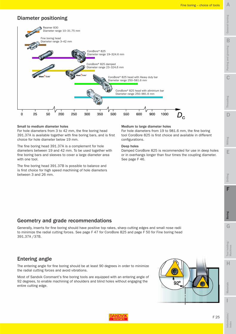
Small to medium diameter holes For hole diameters from 3 to 42 mm, the fine boring head 391.37A is available together with fine boring bars, and is first choice for hole diameter below 19 mm.
The fine boring head 391.37A is a complement for hole diameters between 19 and 42 mm. To be used together with fine boring bars and sleeves to cover a large diameter area with one tool.
The fine boring head 391.37B is possible to balance and is first choice for high speed machining of hole diameters between 3 and 26 mm.
Diameter positioning
Entering angle
Medium to large diameter holes For hole diameters from 19 to 981.6 mm, the fine boring tool CoroBore 825 is first choice and available in different configurations.
Deep holes Damped CoroBore 825 is recommended for use in deep holes or in overhangs longer than four times the coupling diameter. See page F 46.
Reamer 830 Diameter range 10–31.75 mm
Fine boring head Diameter range 3–42 mm
CoroBore® 825 head with aliminium bar Diameter range 250–981.6 mm
CoroBore® 825 Diameter range 19–324.6 mm
CoroBore® 825 head with Heavy duty bar Diameter range 250–581.6 mm
CoroBore® 825 damped Diameter range 23–324,6 mm
MTG09 Boring_F20-36.indd 25 2009-11-25 14:31:49

F 26
A
B
C
D
E
F
G
H
I
Par
ting
and
groo
ving
Gen
eral
tur
ning
Thre
adin
gM
illin
gD
rilli
ngB
orin
gTo
ol h
oldi
ng/
Mac
hine
sM
ater
ials
Info
rmat
ion/
In
dex
Fine boring – how to apply
How to apply
Important considerations for fine boring are:
• stability
• ratio of tool length to coupling size or bar size
• insert geometry
• chip evacuation
• diameter adjustment
• tool deflection.
Cutting forces in single-edge boring operationsWhen the tool is in cut, a tangential and a radial component of the cutting force will attempt to deflect the tool away from the workpiece. The tangential component will try to force the tool downwards and away from the centre line. In doing so, the tool clearance angle will be reduced.
Any radial deflection means that the cutting depth as well as the chip thickness is reduced which can result in vibration tendencies.
Single-edge boring tool deflectionThe size of the tangential and radial components of the cutting force is affected by depth of cut, nose radius and entering angle.
The radial deflection affects the machined hole diameter and the tangential deflection meaning that the insert cutting edge is deflected downwards, away from the centre line.
Use suggested strategy on page F 29 to compensate for radial deflections. Sandvik Coromant´s fine boring tools are equipped with an adjustment mechanism making it possible to adjust the diameter within 2 µm.
Depth of cut (mm)
Deflection (µm)
Tangential deflection
Radial deflection
Balancing• Unbalance, caused by an unsymmetrical tool or large
run-out, generates a force that acts on the boring tool.
• In most applications, the force generated by unbalance, is negligible compared to the cutting forces.
• At high speeds, especially in long overhangs, the unbalance might cause vibrations and will therefore influence the hole quality.
• All Sandvik Coromant´s modular tools are pre-balanced. If fine balancing is required, Sandvik Coromant can recommend and offer balancing of the entire assembled tool (from insert to basic holder).
Contact your Sandvik Coromant representative for more details.
MTG09 Boring_F20-36.indd 26 2009-11-25 14:31:50

F 27
A
B
C
D
E
F
G
H
I
Par
ting
and
groo
ving
Gen
eral
tur
ning
Thre
adin
gM
illin
gD
rilli
ngB
orin
gTo
ol h
oldi
ng/
Mac
hine
sM
ater
ials
Info
rmat
ion/
In
dex
Fine boring – how to apply
Application checklist and hints
• Choose largest possible coupling size or bar diameter.
• Ensure proper chip control. Short/hard chips might lead to vibrations and long chips might deteriorate surface finish or cause insert breakdown.
• Choose shortest possible overhang. Choose Silent Tools for overhangs longer than 4 times the coupling size.
• A large insert nose radius (re) will improve process security and surface finish but might generate vibrations. Nose radii larger than 0.4 is not recommended. Nose radius of 0.2 mm is recommended for fine boring head 391.37 A/B.
• Inserts with thin coatings or uncoated inserts normally provide lower cutting forces compared to thickly coated ones. Especially important when the relationship between tool length/diameter is large. A sharp cutting edge normally improves hole quality through minimized vibration tendency.
• A geometry with an open chip breaker (such as L-K knife-edge) can often be advantageous for boring. First choice for fine boring head 391.37 A/B.
• The geometries L-F and L-WK generate good surface finish but are not recommended for unstable conditions, long overhangs and fine boring head 391.37 A/B.
• The geometry L-F is an advantage if improved chip breaking is needed.
• Insufficient cutting edge engagement can increase vibration through friction during cutting, instead of a clean cutting action.
• Excessive cutting edge engagement (large depth of cut and/or feed) can increase vibrations through tool deflection.
• An insert grade with a higher level of toughness could be considered in some operations to cope with any risks of chip jamming or vibration tendencies.
• When producing close hole tolerance, always ensure that final adjustment is made after measurement of hole diameter while the tool is still in the machine spindle. This compensates for any misalignment between pre-setter and machine tool spindle, radial deflections or insert wear.
• Make sure to get proper clamping of boring tool and workpiece.
• Use cutting fluid to improve chip evacuation, tool life and hole geometry.
• Select appropriate cutting data from insert box. Maximum recommended starting speed for CoroBore 825 is 240 m/min. Maximum cutting depth is 0.5 mm and should not be smaller than 1/3 of nose radius. Starting speed for fine boring head 391.37A is 120 m/min for short steel and carbide bars with inserts, 90 m/min for long steel bars and 60 m/min for solid carbide bars with ground geometry.
MTG09 Boring_F20-36.indd 27 2009-12-09 10:17:26

F 28
A
B
C
D
E
F
G
H
I
Par
ting
and
groo
ving
Gen
eral
tur
ning
Thre
adin
gM
illin
gD
rilli
ngB
orin
gTo
ol h
oldi
ng/
Mac
hine
sM
ater
ials
Info
rmat
ion/
In
dex
Fine boring – how to apply
One full turn of the scale will move the insert 0.25 mm radially. Subsequently the diameter change will be 0.5 mm.
The dial has 50 divisions. Each division represents 0.5/50 = 0.010 mm/diameter.
The vernier has 5 divisions. Each scale division can be divided into 5 parts 0.010/5 = 0.002 mm, making it possible to adjust the diameter by 0.002 mm.
Setting scale for CoroBore® 825 and Fine boring head 391.37A / 391.37B
Example of setting
In this example the blue line on scale disc is reference since it is aligned to a line on the vernier in the start position.
Scale disc turned clockwise until line of scale (red) lines up with second line (green) of vernier. Diameter increased by 0.002 mm.
Scale disc turned clockwise until line of scale (red) lines up with third line (green) of vernier. Diameter increased by 0.004 mm.
Scale disc turned clockwise until line of scale (red) lines up with fourth line (green) of vernier. Diameter increased by 0.006 mm.
Scale disc turned clockwise until line of scale (red) lines up with fifth line (green) of vernier. Diameter increased by 0.008 mm.
Scale disc turned clockwise until line of scale (red) lines up with sixth line (green) of vernier. Diameter increased by 0.010 mm = 1 division of scale.
Adjusted positionStart position
MTG09 Boring_F20-36.indd 28 2009-11-25 14:31:54

F 29
A
B
C
D
E
F
G
H
I
DF
60
Dv
59.2
59.6
0.215
D∆1 = DF - Dv
0.8
59.58
A1 = (D∆1 / 2 / 2)
0.2
0.02
Dc1 = Dv + 2 x A1 DG1 D∆2 = (Dc1 - DG1)
2A2 = A1 +
D∆2
2H6+
1., 2.
3., 4.
5.
6., 7. 60.01
DG2
Dc2
Par
ting
and
groo
ving
Gen
eral
tur
ning
Thre
adin
gM
illin
gD
rilli
ngB
orin
gTo
ol h
oldi
ng/
Mac
hine
sM
ater
ials
Info
rmat
ion/
In
dex
Fine boring – how to apply
How to achieve close hole tolerance with a fine boring tool
Note: For mounting and setting of CoroBore 825 and Fine boring head 391.37A /391.37B, see pages F 48 and F 51.
When fine boring holes with close hole tolerances, possible radial deflection (especially at long overhangs) and misalignments between pre-setter and machine tool spindle must be taken into consideration.
This can be done in several ways, for example: • taking a short measure cut and then adjust the diameter while the tool is still in
the machine spindle
• dividing the cutting depth into two equal parts, see recommended method in example below.
• dividing the cutting depth into three equal parts
1. Deduct diameter of pre-machined hole (Dv) from required diameter (DF) to get the difference (D∆1).
2. Divide the result into two equal parts and divide by two to get the first radial depth of cut (A1).
3. Set the diameter (DC1) to pre-machined diameter (Dv) plus two times the first cut (2 x A1) and bore.
4. Measure received diameter (DG1) and calculate the difference (D∆2) from set diameter (DC1).
5. Calculate the new cutting depth (A2) by compensating for the radial deflection (D∆2/2) and add half of the hole tolerance (H6/2).
6. Increase the diameter (DC2) of the tool with two times the new calculated cutting depth (2 x A2) while the tool is still in the machine and bore.
7. The diameter (DG2) should now be within tolerance.
Example (recommended method)
Required diameter DF = 60 mm Hole tolerance H6 = +0.019/-0 mm (valid for diameter 60 mm) Pre-machined diameter Dv = 59.2 mm
First diameter adjustment
Calculate new cutting depth
Second diameter adjustment Increase diameterWith two times A2
MTG09 Boring_F20-36.indd 29 2009-11-25 14:31:54

F 30
A
B
C
D
E
F
G
H
I
Par
ting
and
groo
ving
Gen
eral
tur
ning
Thre
adin
gM
illin
gD
rilli
ngB
orin
gTo
ol h
oldi
ng/
Mac
hine
sM
ater
ials
Info
rmat
ion/
In
dex
Fine boring – how to apply
External operations can be done with a fine boring tool in order to achieve a close diameter tolerance.• Reverse rotation direction• Reverse head 180 degrees• Consider maximum possible machining length l3 and the outside diameter of the tool
to avoid collision.For external machining, the mass of slide and fine boring head will rotate around the workpiece and cause high centrifugal forces. Therefore, maximum cutting speed for an external application must be calculated with respect to maximum cutting speed for the diameter when the head is rotated 180 degrees which means that the tool is configured for fine boring.
Example: • External diameter to be machined is 80 mm.• Internal diameter that could be machined (with this position of slide and head) would
be 210 mm. Note: Always add 130 mm to the diameter that should be machined to get the diameter to calculate maximum rpm.
• Maximum cutting speed for CoroBore 825 is 1200 m/min (based on internal machining).
• 1200 m/min at diameter 210 mm is equal to 1820 rpm. This means that 1820 rpm is maximum that could be used for this slide and head position.
• For external machining, 1820 rpm corresponds to cutting speed 460 m/min at diameter 80 mm.
Conclusion: • Maximum cutting speed for external machining of 80 mm diameter is 460 m/min.
Back boring is used to enable machining of a hole with a shoulder that can not be reached from the opposite direction. Back boring can also be used to optimize concentricity of a hole with a shoulder since the entire hole is machined from only one position.
Note: Make sure the boring tool will go through the hole with the shoulder and that the front of the boring tool will not collide with the component.
When back boring, the boring tool is configured to go through a hole with minimum diameter of Dc/2 + D21/2.
Tool setting for back boring: • Remove grub screw from top cutting fluid outlet (see page F 48) and attach it into lower cutting
fluid outlet in order to get correct coolant position (for smallest tool sizes, the grub screw can not be attached into the lower cutting fluid outlet)
• Rotate cartridge 180 degrees• Use slide extension if needed• Reverse rotation direction.
Back boring
External operations with a fine boring tool
rpm, max
vc max, internal
vc max, external
rpm, max
MTG09 Boring_F20-36.indd 30 2009-11-25 14:31:55

F 31
A
B
C
D
E
F
G
H
I
H7
10–31.75
Reamer 830
P K
P KPar
ting
and
groo
ving
Gen
eral
tur
ning
Thre
adin
gM
illin
gD
rilli
ngB
orin
gTo
ol h
oldi
ng/
Mac
hine
sM
ater
ials
Info
rmat
ion/
In
dex
Reaming – choice of tools
Reaming
Reaming is a finishing operation performed with a multi-edge tool giving high-precision holes. Very good surface finish and close dimensional tolerance are achieved at high penetration rates and small depths of cut.
Choice of tools
45–106 mmReaming depth
Hole tolerance
Reaming range (mm)
Material
For closer hole tolerance than H7 or diameters outside standard assortment, see our extended offer on page F 60.
Reamer 830 standard version can be used for machining of steel, nodular cast iron (perlitic) and malleable cast iron (perlitic). For other materials, see our extended offer on page F 60.
Reamer 830 is only for through holes. For blind holes, see our extended offer on page F 60.
Note: For information about our special tool programme, see Extended offer, page F 60.
Material to be machined
Reaming diameter and hole quality
Through or blind hole
MTG09 Boring_F20-36.indd 31 2009-11-25 14:32:00

F 32
A
B
C
D
E
F
G
H
I
Par
ting
and
groo
ving
Gen
eral
tur
ning
Thre
adin
gM
illin
gD
rilli
ngB
orin
gTo
ol h
oldi
ng/
Mac
hine
sM
ater
ials
Info
rmat
ion/
In
dex
Reaming – how to apply
Tool holding• A small run-out is the most important factor when choosing tool holder for reaming
operations. Maximum recommended run-out is 5 µm.
• HydroGrip precision chucks should be considered as first choice.
•Chooseshortestpossibletooloverhang.
Position of reamer• Offset of pre-machined hole and reamer should be as small as possible in order to
avoid vibrations.
How to apply
Workpiece set-up• Make sure workpiece is sufficiently clamped.
• For through holes, make sure there is space for the chips to be evacuated.
• When reaming thin walled components make sure clamping force is uniform around the component.
Tool lifeSome parameters that impact the tool life are:
• cutting depth
• speed and feed
• workpiece material
• run-out
• off-set
• coolant
• interrupted cuts
• workpiece clamping
• geometry and grade
• tool length.
5 µm
MTG09 Boring_F20-36.indd 32 2009-11-25 14:32:01

F 33
A
B
C
D
E
F
G
H
I
Par
ting
and
groo
ving
Gen
eral
tur
ning
Thre
adin
gM
illin
gD
rilli
ngB
orin
gTo
ol h
oldi
ng/
Mac
hine
sM
ater
ials
Info
rmat
ion/
In
dex
Interrupted cutsReamer 830 standard version can normally be used to machine: • cross holes smaller than 2 mm in diameter if the diameter of the reamer head is
smaller than 22 mm.
• cross holes smaller than 3 mm in diameter if the diameter of the reamer head is 22 mm or larger.
For other types of interrupted cuts, see our extended offer on page F 60.
Pre-machined hole• Reaming should not be expected to correct any positional or straightness errors of
the pre-machined hole.
• Straightness of a pre-machined hole should be smaller than 0.05 mm.
• Make sure that diameter of pre-machined hole allows for recommended radial depths of cut.
Reaming – how to apply
Cutting fluid• The main tasks of the cutting fluid are to cool the cutting edges in order to
optimize tool life and to push the chips forward.
• Emulsion as cutting fluid normally brings better tool life than oil.
• 4 bar pressure is sufficient.
• Increased pressure of coolant can have positive effect on chip control and chip breaking.
• MQL (minimal quantity lubrication) technique can be used.
Consideration for unused reamers• The sharp cutting edges could cause slight vibrations at hole entry. It will, however,
disappear after a few holes.
Angled or inclined surface• Maximum recommended angle at entrance with Sandvik Coromant's standard reamers is 5 degrees. For larger angle at entrance, see our extended offer on page F 60.
• Minimize the run-out.
MTG09 Boring_F20-36.indd 33 2009-11-25 14:32:01

F 34
A
B
C
D
E
F
G
H
I
Par
ting
and
groo
ving
Gen
eral
tur
ning
Thre
adin
gM
illin
gD
rilli
ngB
orin
gTo
ol h
oldi
ng/
Mac
hine
sM
ater
ials
Info
rmat
ion/
In
dex
Trouble shooting
Cause Solution
Insert wearTo achieve best possible economy regarding tool life, workpiece quality and optimized cutting data, careful observations of the insert edge have to be made. See General turning, Chapter A.
Boring – trouble shooting
Rough boring
Too short, hard • Increase cutting speed• Decrease feed• Change geometry to a more open chip breaker (PR)
Too long • Increase feed• Decrease cutting speed• Change geometry to a more closed chip breaker (PM)
Too high tool length/coupling size ratio
Unstable conditions
Too low feed
Too high feed
Too high speed
Too large cutting depth
Too high cutting force
Too low cutting force
• Use largest possible coupling size• Shorten the assembly if possible• Use damped boring tools (Silent Tools)
• Ensure rigid clamping with face contact to spindle• Use DuoBore• Check workpiece clamping• Check that all units in the tool assembly are
assembled correctly with correct torque• Check machine spindle, clamping, wear etc.
• Increase the feed (especially for CoroBore 820)
• Decrease feed
• Decrease cutting speed
• Apply step boring, see page F 6
• Decrease depth of cut• Use positive inserts• Use smaller nose radius• Wiper insert is not recommended for long overhangs
or unstable conditions
• Increase depth of cut (especially for CoroBore 820)
Limited machine power • Decrease cutting data• Apply step boring, see page F 6
Chip breaking
Tool vibrations
Machine power limitation
MTG09 Boring_F20-36.indd 34 2009-11-25 14:32:02

F 35
A
B
C
D
E
F
G
H
I
Par
ting
and
groo
ving
Gen
eral
tur
ning
Thre
adin
gM
illin
gD
rilli
ngB
orin
gTo
ol h
oldi
ng/
Mac
hine
sM
ater
ials
Info
rmat
ion/
In
dex
Too short, hard • Increase cutting speed• Decrease feed• Change geometry to a more open chip breaker
(L-K, L-WK)
Too long • Increase feed• Decrease cutting speed• Change geometry to a more closed chip breaker
(L-F, PF)
Too high cutting force
Too high tool length/coupling size ratio
Unstable conditions
Too high feed
Too high speed
Friction instead of clean cutting action
• Choose a light-cutting insert (L-K)• Use smaller nose radius• Choose sharp cutting edges with thin coating or
uncoated• Wiper or L-F inserts are not recommended for long
overhangs or unstable conditions• Choose a smaller nose radius•Decreasedepthofcut
• Use largest possible coupling size• Shorten the assembly if possible• Use damped boring tools (Silent Tools)
• Ensure rigid clamping with face contact to spindle• Check workpiece clamping• Check that all units in the tool assembly are
assembled correctly with correct torque• Check machine spindle, clamping, wear etc
• Decrease feed
• Decrease cutting speed
• Increase depth of cut
Tool vibrations
Cause Solution
Boring – trouble shooting
Vibration
Feed marks
Worn insert
Chip scratching surface
• Reduce speed. See above for additional solutions
• Use L-WK or L-F geometry (not for 391.37 A / B, long overhangs or unstable conditions)
• Use larger nose radius• Decrease feed
• Change cutting edge. For how to avoid specific wear patterns, see General turning, Chapter A
• Improve chip breaking
Surface finish
Fine boring
Chip breaking
MTG09 Boring_F20-36.indd 35 2009-11-25 14:32:02

F 36
A
B
C
D
E
F
G
H
I
Par
ting
and
groo
ving
Gen
eral
tur
ning
Thre
adin
gM
illin
gD
rilli
ngB
orin
gTo
ol h
oldi
ng/
Mac
hine
sM
ater
ials
Info
rmat
ion/
In
dex
Boring – trouble shooting
Cause Solutiona) Radial run-out/incorrect rotation axis not parallel
with pre-hole axisb) Position incorrectc) Built-up edged) Increasing vibrations
a) Position incorrect
a) Radial run-out incorrect/rotation axis not parallell with pre-hole axis
b) Position incorrectc) Too much pressure on the reamer during entrance
a) Radial run-out incorrect/rotation axis not parallel with pre-hole axis
b) Position incorrectc) Asymmetrical cutting because of inclined entranced) Too much pressure on the reamere) Number of teeth / arrangement
a) Wear marks on the blades, chippingsb) Machining data incorrect c) Incorrect lead geometryd) Built-up edge
a) Asymmetrical cutting because of inclined entranceb) Radial run-out/angle incorrectc) Position incorrectd) Incorrect lead geometrye) Too much pressure on the reamer during entrance
Hole oversized
Conical hole, oversized at exit
Conical hole, oversized at the entrance
Hole with bad roundness
Bad surface finish
Chatter marks
a) Minimize run-out – use HydroGrip adaptorb) Make sure the reamer is concentric with the
pre-machined holec) Adjust cutting speed, eventually change grade
(extended offer)d) Minimize run-out – use HydroGrip adaptor, increase
cutting speed or feed
a) Make sure the reamer is concentric with the pre-machined hole
a) Minimize run-out - use HydroGrip adaptorb) Make sure the reamer is concentric with the
pre-machined holec) Decrease feed during entrance (normally not needed)
a) Minimize run-out - use HydroGrip adaptorb) Make sure the reamer is concentric with the
pre-machined holec) Minimize run-out - use HydroGrip adaptord) Decrease the feede) Select a reamer from the extended offer
a) Change to a new headb) Adjust cutting speed, eventually coating (extended
offer)c) Change lead geometry (extended offer)d) Adjust cutting speed, eventually change grade
(extended offer)
a) Minimize run-out - use HydroGrip adaptorb) Minimize run-out - use HydroGrip adaptorc) Make sure the reamer is concentric with the pre-
machined holed) Change lead geometry (extended offer) e) Decrease feed during entrance (normally not needed)
Reaming
MTG09 Boring_F20-36.indd 36 2009-11-25 14:32:03
Products – boring
MTG09 Boring_F37-49.indd 37 2009-11-25 14:51:20

F 38
A
B
C
D
E
F
G
H
I
CoroBore® 820
4 x D5m
IT9
35–306
P M KN S H
F 6 F 6 F 6
F 18 F 18 F 19
F 19 F 20 F 20
vc
L1 / D5m
–WM
–PR
1 2 3 4 5 6
Par
ting
and
groo
ving
Gen
eral
tur
ning
Thre
adin
gM
illin
gD
rilli
ngB
orin
gTo
ol h
oldi
ng/
Mac
hine
sM
ater
ials
Info
rmat
ion/
In
dex
Rough boring – CoroBore® 820
Multi-edge boring
Step boring
Single-edge boring
Short, rigid and compact– Maximum stability
Cutting fluid through the tool– Good chip evacuation
Slide assemblies, individually adjustable both axially and radially– Economy– Low inventory
T-Max® P, CoroTurn® RC rigid clamping – For improved economy and process security in stable
conditions
CoroTurn® 107 screw clamping – First choice, wide choice of inserts
Boring depth
Hole tolerance
Material
Boring range (mm) Multi-edge boring Step boring Single-edge boring
Large diameter Weak machines Interrupted cuts
Blind hole Large depth of cut Off centre hole
The cutting speed must be reduced when working with longer overhangs. The chart gives a general trend for how the cutting speed must be reduced at different overhangs and geometries.
Note: The information taken from the chart must only be seen as a general trend for the relationship between the cutting speed and overhang/coupling size ratio.
Cutting speed at different overhangs
Applications
Note: For information about our special tool programme, see Extended offer, page F 57.
MTG09 Boring_F37-49.indd 38 2009-11-25 14:51:28

F 39
A
B
C
D
E
F
G
H
I➤
Par
ting
and
groo
ving
Gen
eral
tur
ning
Thre
adin
gM
illin
gD
rilli
ngB
orin
gTo
ol h
oldi
ng/
Mac
hine
sM
ater
ials
Info
rmat
ion/
In
dex
Rough boring – CoroBore® 820
Clean all support faces before mounting and setting.
For more information about tool maintenance, see page F 13.
Tool maintenance
1. Slide2. Adaptor3. Shim set4. Cover
For information about geometry and grade recommendations, see page F 18.
Geometry and grade recommendations
Requirements: • 1 adaptor• 3 slides
Multi-edge boring
Requirements: • 1 adaptor• 1 slide• 2 cover
Single-edge boring
Requirements: • 1 adaptor• 3 slides• 1 shim set
Step boring
Mount covers on two support faces. Note: Covers have location pins which have to fit into location holes in adaptor. These holes are located in between stop pin and setting pin for two of the support faces.
Place shims on two of three adaptors support faces. Note: Shims have different thickness.
Note: Total depth of cut should be divided into three equal parts for each insert/slide to keep the tool as balanced as possible.
Set all three slides to same diameter and height.
Use only one slide.Set the three slides to different diameters and heights.
Retract setting screws as far as possible by turning them counterclockwise.
Fit slides into adaptor. Stop pin on adaptor must enter slot in slide.
Place cup springs on clamping screws (larger diameter of cup spring facing the slide).
Push slides as far as possible towards the center of the adaptor and tighten the clamping screw finger tight, so that the slides can be easily set without tilting.
Mounting and setting
Mounting of slides
MTG09 Boring_F37-49.indd 39 2009-11-25 14:51:32

F 40
A
B
C
D
E
F
G
H
I
➤
Par
ting
and
groo
ving
Gen
eral
tur
ning
Thre
adin
gM
illin
gD
rilli
ngB
orin
gTo
ol h
oldi
ng/
Mac
hine
sM
ater
ials
Info
rmat
ion/
In
dex
Rough boring – CoroBore® 820
Multi-edge boring Single-edge boringStep boring
Locate slide with the thicker shim.
Tighten clamping screws.
Repeat for slides 2 and 3. Set intermediate diameter on tool pre-setter.
Locate slide with the thinner shim.
Rotate adaptor until largest diameter of the selected slide is found. Lock this position.
Set largest diameter on tool pre-setter.
Locate slide without shim.
Turn setting screw until insert nose radius touches set diameter.
Turn setting screw until insert nose radius touches set diameter.
Tighten clamping screw.
Rotate adaptor until largest diameter of the selected slide is found. Lock this position.
Tighten clamping screw.
Set desired diameter on tool pre-setter. Set desired diameter on tool pre-setter.Set smallest diameter on tool pre-setter.
Mount inserts.
Place adaptor in tool pre-setter.
Rotate adaptor until largest diameter of the selected slide is found.
Lock this position.
Turn setting screw clockwise until insert nose radius reaches set diameter. Note: Setting screw can only be used for setting from smaller to larger diameter.
Tool setting
Setting with vernier caliper
1. Measure diameter of setting pin.
2. Adjust the vernier caliper to required hole radius plus radius of setting pin.
3. Set slides according to instructions above with vernier caliper over setting pin and insert.
Rough setting with the scale on the adaptor
1. Set line on slide to required diameter on adaptor scale. Each division is 2 mm on diameter.
Setting with vernier caliper.
Alternative setting possibilities of CoroBore® 820
Tighten clamping screws to recommended torque, see Main catalogue (can be done outside tool pre-setter if needed).
Check diameter and length of tool in the tool pre-setter. If possible, transfer tool data to machine control system.
Continued mounting and setting
MTG09 Boring_F37-49.indd 40 2009-11-25 14:51:35

F 41
A
B
C
D
E
F
G
H
I
DuoBore™
4 x D5m
IT9 IT9 IT9IT9
6 x Dc4 x D5m
25–150 25–101 99–150148–270
P M KN S H
P M KN S H
P M KN S H
P M KN S H
F 6 F 6 F 6 F 18 F 18
F 19 F 19 F 20 F 20
Par
ting
and
groo
ving
Gen
eral
tur
ning
Thre
adin
gM
illin
gD
rilli
ngB
orin
gTo
ol h
oldi
ng/
Mac
hine
sM
ater
ials
Info
rmat
ion/
In
dex
Rough boring – DuoBore™
Short, rigid and compact – Maximum stability
Cutting fluid through the tool – Good chip evacuation
Slides individually adjustable axially and radially – Versatile – Economical – Reduced assortment
Multi-edge boring
Step boring
Single-edge boring
600–700 mmBoring depth
Hole tolerance
Material
Boring range (mm)
Multi-edge boring Step boring Single-edge boring Large diameter Weak machines
Interrupted cuts Blind hole Large depth of cut
Applications
Off centre hole
T-Max® P, CoroTurn® RC rigid clamping – For improved economy and process security in stable
conditions
CoroTurn® 107 screw clamping – First choice, wide choice of inserts
Note: For information about our special tool programme, see Extended offer, page F 57.
MTG09 Boring_F37-49.indd 41 2009-11-25 14:51:42
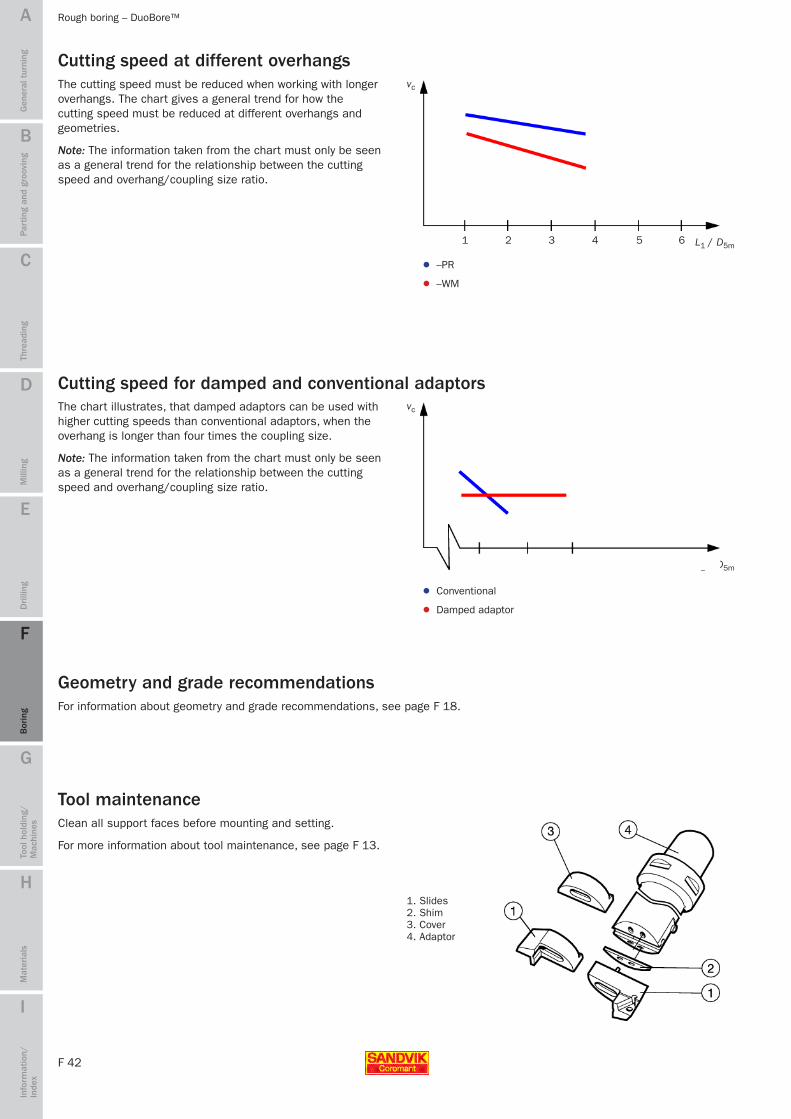
F 42
A
B
C
D
E
F
G
H
I
vc
L1 / D5m
vc
L1 / D5m
–WM
–PR
1 2 3 4 5 6
4 5 6
Par
ting
and
groo
ving
Gen
eral
tur
ning
Thre
adin
gM
illin
gD
rilli
ngB
orin
gTo
ol h
oldi
ng/
Mac
hine
sM
ater
ials
Info
rmat
ion/
In
dex
Rough boring – DuoBore™
Clean all support faces before mounting and setting.
For more information about tool maintenance, see page F 13.
Tool maintenance
1. Slides2. Shim3. Cover4. Adaptor
For information about geometry and grade recommendations, see page F 18.
Geometry and grade recommendations
The chart illustrates, that damped adaptors can be used with higher cutting speeds than conventional adaptors, when the overhang is longer than four times the coupling size.
Note: The information taken from the chart must only be seen as a general trend for the relationship between the cutting speed and overhang/coupling size ratio.
The cutting speed must be reduced when working with longer overhangs. The chart gives a general trend for how the cutting speed must be reduced at different overhangs and geometries.
Note: The information taken from the chart must only be seen as a general trend for the relationship between the cutting speed and overhang/coupling size ratio.
Cutting speed at different overhangs
Cutting speed for damped and conventional adaptors
Damped adaptor
Conventional
MTG09 Boring_F37-49.indd 42 2009-11-25 14:51:43

F 43
A
B
C
D
E
F
G
H
I
Par
ting
and
groo
ving
Gen
eral
tur
ning
Thre
adin
gM
illin
gD
rilli
ngB
orin
gTo
ol h
oldi
ng/
Mac
hine
sM
ater
ials
Info
rmat
ion/
In
dex
Rough boring – DuoBore™
Requirements: • 1 adaptor• 2 slides
Multi-edge boring
Requirements: • 1 adaptor• 1 slide• 1 cover
Single-edge boring
Requirements: • 1 adaptor• 2 slides• 1 shim
Step boring
Mounting of slides
Mount covers on support faces.Note: Covers have location pins which have to fit into location holes in adaptor.
Place shims on one of the two adaptors support faces.Note: Total depth of cut should be divided into two equal parts to keep the tool as balanced as possible.
Tool setting
Set desired diameter on tool pre-setter for smallest diameter.
Repeat for slide 2. Repeat for slide 2 but set desired final diameter on tool pre-setter.
Set desired diameter on tool pre-setter. Set desired diameter on tool pre-setter.
Fit slides to adaptor. Pin on slide must enter slot in adaptor.
Place washers on clamping screws.
Push slides as far as possible towards centre of adaptor. Tighten clamping screw finger tight so that the slides can be easily set without tilting.
Mount inserts.
Place adaptor in tool pre-setter.
Rotate adaptor until largest diameter on selected slide is found.
Lock this position.
Turn setting screws clockwise until insert nose radius reaches set diameter. Note: Setting screws can only be used for setting from smaller to bigger diameter.
Retract setting screws as far as possible by turning them counterclockwise.
Locate slide with shim.
Tighten clamping screws.
Tighten setting screw finger tight.
Mounting and setting
Tighten clamping screws to recommended torque, see Main catalogue (can be done outside tool pre-setter if needed).
Check diameter and length of tool in the tool pre-setter. If possible, transfer tool data to machine control system.
MTG09 Boring_F37-49.indd 43 2009-11-25 14:51:46

F 44
A
B
C
D
E
F
G
H
I
4 x D5m
IT9 IT9
150–300 250–550
P M KN S H
P M KN S H
F 6 F 6 F 6
F 18 F 18 F 19
F 19 F 20 F 20
Par
ting
and
groo
ving
Gen
eral
tur
ning
Thre
adin
gM
illin
gD
rilli
ngB
orin
gTo
ol h
oldi
ng/
Mac
hine
sM
ater
ials
Info
rmat
ion/
In
dex
Rough boring – Heavy duty
Heavy duty
Short, rigid and compact – Maximum stability
Cutting fluid through the tool – Good chip evacuation
Slides individually adjustable axially and radially – Versatile – Economical – Reduced assortment
Multi-edge boring
Step boring
Single-edge boring
400 mmBoring depth
Hole tolerance
Material
Boring range (mm)
Clean all support faces before mounting and setting.
For more information about tool maintenance, see page F 13.
Tool maintenance
1. Cartridge2. Extension slide3. Shim4. Adaptor5. Face mill adaptor
For information about geometry and grade recommendations, see page F 18.
Geometry and grade recommendations
T-Max® P, CoroTurn® RC rigid clamping – For improved economy and process security in stable
conditions
CoroTurn® 107 screw clamping – First choice, wide choice of inserts
Note: For information about our special tool programme, see Extended offer, page F 57.
Multi-edge boring Step boring Single-edge boring
Large diameter Weak machines Interrupted cuts
Blind hole Large depth of cut Off centre hole
Applications
MTG09 Boring_F37-49.indd 44 2009-11-25 14:51:51
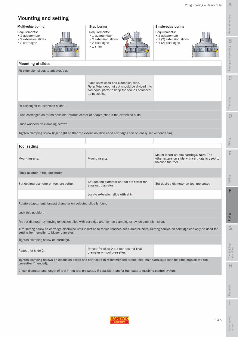
F 45
A
B
C
D
E
F
G
H
I
Par
ting
and
groo
ving
Gen
eral
tur
ning
Thre
adin
gM
illin
gD
rilli
ngB
orin
gTo
ol h
oldi
ng/
Mac
hine
sM
ater
ials
Info
rmat
ion/
In
dex
Rough boring – Heavy duty
Requirements: • 1 adaptor/bar• 2 extension slides• 2 cartridges
Multi-edge boring
Requirements: • 1 adaptor/bar• 1 (2) extension slides• 1 (2) cartridges
Single-edge boring
Requirements: • 1 adaptor/bar• 2 extension slides• 2 cartridges• 1 shim
Step boring
Mounting of slides
Place shim upon one extension slide. Note: Total depth of cut should be divided into two equal parts to keep the tool as balanced as possible.
Fit extension slides to adaptor/bar.
Fit cartridges to extension slides.
Push cartridges as far as possible towards center of adaptor/bar in the extension slide.
Place washers on clamping screws.
Tighten clamping screw finger tight so that the extension slides and cartridges can be easily set without tilting.
Mounting and setting
Set desired diameter on tool pre-setter for smallest diameter.
Mount inserts.
Set desired diameter on tool pre-setter.
Mount insert on one cartridge. Note: The other extension slide with cartridge is used to balance the tool.
Set desired diameter on tool pre-setter.
Mount inserts.
Place adaptor in tool pre-setter.
Rotate adaptor until largest diameter on selected slide is found.
Lock this position.
Pre-set diameter by moving extension slide with cartridge and tighten clamping screw on extension slide.
Locate extension slide with shim.
Turn setting screw on cartridge clockwise until insert nose radius reaches set diameter. Note: Setting screws on cartridge can only be used for setting from smaller to bigger diameter.
Tighten clamping screw on cartridge.
Repeat for slide 2 but set desired final diameter on tool pre-setter.Repeat for slide 2.
Tool setting
Tighten clamping screws on extension slides and cartridges to recommended torque, see Main Catalogue (can be done outside the tool pre-setter if needed).
Check diameter and length of tool in the tool pre-setter. If possible, transfer tool data to machine control system.
MTG09 Boring_F37-49.indd 45 2009-11-25 14:51:54

F 46
A
B
C
D
E
F
G
H
I
CoroBore® 825
4 x D5m
IT6 IT6 IT6 IT6IT6 IT6
4 x D5m 6 x Dc 6 x D5m
19–176.6 150–324.6 23–176.6250–581.6 250–981.6
P M KN S H
P M KN S H
P M KN S H
P M KN S H
P M KN S H
P M KN S H
F 26 F 30 F 30
CoroTurn® 107 TCMT 1103
CoroTurn® 107 TCMT
CoroTurn® 111 TPMT
150–324.6
Par
ting
and
groo
ving
Gen
eral
tur
ning
Thre
adin
gM
illin
gD
rilli
ngB
orin
gTo
ol h
oldi
ng/
Mac
hine
sM
ater
ials
Info
rmat
ion/
In
dex
Fine boring – CoroBore® 825
• Diameter adjustment of 0.002 mm
• Slide extension for increased diameter range and back boring
• Internal cutting fluid
Cartridges for CoroTurn 107 and CoroTurn 111 inserts – wide choice of insert
Cartridge designed for highest stability
400 mm 400 mmBoring depth
Hole tolerance
Material
Boring range (mm)
Conventional fine boring Back boring External operations
Applications
Note: For information about our special tool programme, see Extended offer, page F 57.
MTG09 Boring_F37-49.indd 46 2009-11-25 14:51:58
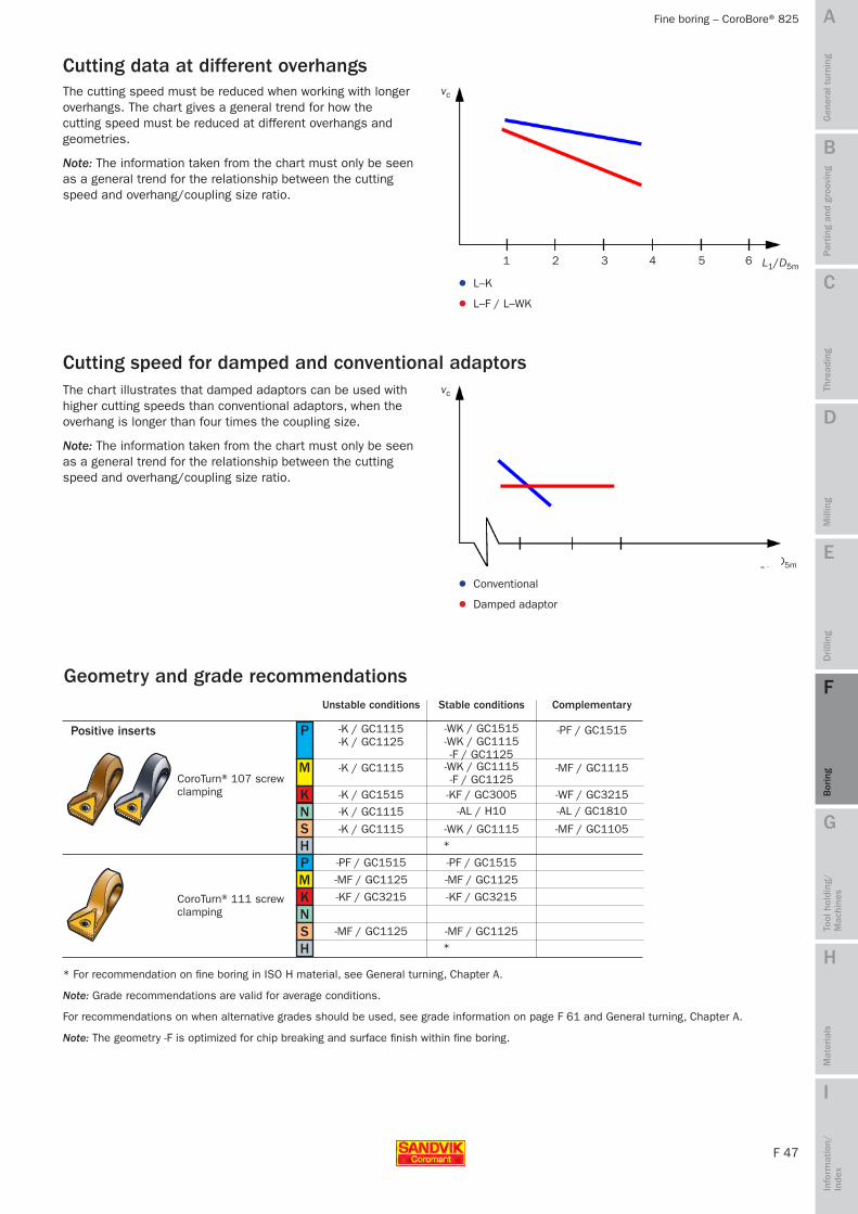
F 47
A
B
C
D
E
F
G
H
I
P
M
KN
H
-K / GC1115 -K / GC1125
-WK / GC1515 -WK / GC1115 -F / GC1125
-WK / GC1115 -F / GC1125
-KF / GC3005-AL / H10
-WK / GC1115*
-PF / GC1515
-MF / GC1115
-WF / GC3215-AL / GC1810
-MF / GC1105
-K / GC1115
-K / GC1515
-K / GC1115
-K / GC1115
PMKNSH
-PF / GC1515
-MF / GC1125
-KF / GC3215
-MF / GC1125
-PF / GC1515
-MF / GC1125
-KF / GC3215
-MF / GC1125
vc
L1 / D5m
vc
L1/D5m
L–K
L–F / L–WK
1 2 3 4 5 6
4 5 6
*
SPar
ting
and
groo
ving
Gen
eral
tur
ning
Thre
adin
gM
illin
gD
rilli
ngB
orin
gTo
ol h
oldi
ng/
Mac
hine
sM
ater
ials
Info
rmat
ion/
In
dex
Fine boring – CoroBore® 825
The cutting speed must be reduced when working with longer overhangs. The chart gives a general trend for how the cutting speed must be reduced at different overhangs and geometries.
Note: The information taken from the chart must only be seen as a general trend for the relationship between the cutting speed and overhang/coupling size ratio.
The chart illustrates that damped adaptors can be used with higher cutting speeds than conventional adaptors, when the overhang is longer than four times the coupling size.
Note: The information taken from the chart must only be seen as a general trend for the relationship between the cutting speed and overhang/coupling size ratio.
Cutting speed for damped and conventional adaptors
Cutting data at different overhangs
Damped adaptor
Conventional
Positive inserts
Unstable conditions Stable conditions Complementary
Geometry and grade recommendations
* For recommendation on fine boring in ISO H material, see General turning, Chapter A.
Note: Grade recommendations are valid for average conditions.
For recommendations on when alternative grades should be used, see grade information on page F 61 and General turning, Chapter A.
Note: The geometry -F is optimized for chip breaking and surface finish within fine boring.
CoroTurn® 107 screw clamping
CoroTurn® 111 screw clamping
MTG09 Boring_F37-49.indd 47 2009-11-25 14:51:58

F 48
A
B
C
D
E
F
G
H
I
Par
ting
and
groo
ving
Gen
eral
tur
ning
Thre
adin
gM
illin
gD
rilli
ngB
orin
gTo
ol h
oldi
ng/
Mac
hine
sM
ater
ials
Info
rmat
ion/
In
dex
Fine boring – CoroBore® 825
Tool maintenanceClean all support faces before mounting and setting.
For more information about tool maintenance, see page F 13.
Lubrication
Lubricating should be done at regular intervals, depending on how frequent the tool is used, at least once a year. Lubrication is done by depressing the spring-loaded ball and adding a few drops of light oil. Due to the centrifugal force, the oil is forced outwards and stops dirt from getting into the adaptor.
Recommended light oil: E.g. Mobil Vactra oil No. 2 BP Olex HLP-D Kluber Isoflex PDP 94
Mounting and settingNote: To achive a close hole tolerance, see page F 29.
Requirement:
• Tool pre-setter
Mounting of cartridge
1. Fit cartridge to cross slide.
2. Tighten cartridge screw to recommended torque, see Main catalogue.
Mounting of cartridge for back boring 1. Remove grub screw from top cutting fluid outlet and attach
it into the lower cutting fluid outlet.2. Mount slide extension when needed.3. Rotate cartridge 180° and fit cartridge to cross slide or
slide extension4. Tighten cartridge screw to recommended torque, see Main
catalogue.
Note: When slide extension is used, the longer screw supplied with the slide extension must be used! Direction of rotation must be reversed when back boring! Check tool length and length of the adaptor. Make sure the boring tool will go through the hole with the shoulder and that the front of the boring tool does not will collide with the component.
Tool setting of diameter 1. Mount insert.2. Set tool pre-setter to required diameter.3. Place tool in tool pre-setter.4. Rotate tool to obtain largest diameter on display.5. Unlock locking screw.6. Retract cartridge by turning dial anti-clockwise to facilitate
setting from smaller to larger diameter.7. Set diameter by turning dial clockwise.8. Tighten locking screw to recommended torque, see Main
catalogue.9. Check diameter and length of tool in the tool pre-setter. If
possible, transfer tool data to machine control system.
BalancingCoroBore 825 is perfectly balanced in the middle of the adjustment range. The balancing values are sufficient for all application areas, when recommended cutting data is used.
If fine balancing is required, Sandvik Coromant can recommend and offer balancing of the entire assembled tool (from insert to basic holder).
absolute inbalancing value
Dc min Dc max
Top cutting fluid outlet
Lower cutting fluid outlet
MTG09 Boring_F37-49.indd 48 2009-11-25 14:51:59

F 49
A
B
C
D
E
F
G
H
I
1 3
2
Par
ting
and
groo
ving
Gen
eral
tur
ning
Thre
adin
gM
illin
gD
rilli
ngB
orin
gTo
ol h
oldi
ng/
Mac
hine
sM
ater
ials
Info
rmat
ion/
In
dex
Fine boring – CoroBore® 825
Warning – avoid damage to the tool! Do not set the diameter without first unlocking the locking screw (1). Make sure that the flat of the ball – not the sphere – is directed towards the cross-slide (2). Do not exceed the diameter setting limits (3).
Mounting of modular shank boring tools 1. Fit o-ring to fine boring head.2. Fit fine boring head to extension slide.3. Tighten the two head screws.4. Fit extension slide on adaptor over cutting fluid outlet
without grub screw.5. Fit counter weight.6. Fit cartridge to cross slide.7. Tighten cartridge screw to recommended torque, see
Main catalogue.
1. Cartridge2. Fine boring head3. Extension slide4. Slide extension5. Adaptor6. Counterweight
Tool setting of diameter 1. Mount insert.2. Set tool pre-setter to required diameter.3. Place tool in tool pre-setter.4. Rotate tool to obtain largest diameter on display.5. Perform rough setting by moving extension slide.6. Tighten extension slide screws.7. Unlock locking screw on fine boring head.8. Retract cartridge by turning dial anti-clockwise to facilitate
setting from smaller to larger diameter.9. Set diameter by turning dial clockwise.10. Tighten locking screw to recommended torque, see Main
catalogue.11. Set counterweight to same scale value as extension slide.12. Tighten counterweight screws to recommended torque,
see Main catalogue.13 Check diameter and length of tool in the tool pre-setter. If
possible, transfer tool data to machine control system.
HintTo optimize balancing of modular shank boring tools, the cartridge position on the fine boring head should be close to middle of the adjustment range for the fine boring head. Set counterweight to the same scale value as the extension slide. Additional fine balancing can be done by moving the balancing screws in the counterweight.
Fine balancing screws
MTG09 Boring_F37-49.indd 49 2009-11-25 14:51:59

F 50
A
B
C
D
E
F
G
H
I
IT6 IT6
3–42 3–26
dmm 12 = 7 000dmm 16 = 5 000dmm 20 = 3 500dmm 25 = 2 500
dmm 12 = 20 000
P M KN S H
P M KN S H
F 26
PMKNSH
-K / GC1515/GC1125
-K / GC1115
-K / GC1515
-K / GC1115
-K / GC1115*
391.37A 391.37B
8–42 9–28 3–11
Par
ting
and
groo
ving
Gen
eral
tur
ning
Thre
adin
gM
illin
gD
rilli
ngB
orin
gTo
ol h
oldi
ng/
Mac
hine
sM
ater
ials
Info
rmat
ion/
In
dex
Fine boring – Fine boring heads 391.37A / 391.37B
Fine boring heads 391.37A / 391.37B
Fine boring head 391.37A Fine boring head 391.37B
≤109 mm ≤60 mmBoring depth
Hole tolerance
Max rpm (rev/min)
Material
Boring range (mm)
• Diameter adjustment of 0.002 mm
• Internal cutting fluid
• Fine boring bars for CoroTurn 107 and CoroTurn 111 inserts
• 391.37B with adjustable counterweight enables high speeds
• Sleeves for flexibility
Conventional fine boring
Applications
Positive inserts
Recommended first choice is the light cutting knife edge geometry (L-K) with nose radius of 0.2 mm.
CoroTurn® 107 screw clamping
Geometry and grade recommendations
Steel bar Carbide bar Solid carbide bar
Note: For information about our special tool programme, see Extended offer, page F 57.
* For recommendations on fine boring in ISO H material, see General turning, Chapter A.
≤88 mm ≤109 mm ≤25 mm
MTG09 Boring_F50-61.indd 50 2009-11-25 15:18:11
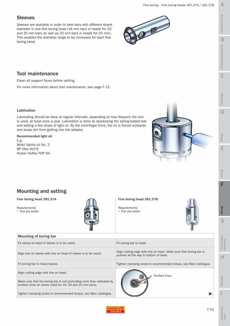
F 51
A
B
C
D
E
F
G
H
I➤
Par
ting
and
groo
ving
Gen
eral
tur
ning
Thre
adin
gM
illin
gD
rilli
ngB
orin
gTo
ol h
oldi
ng/
Mac
hine
sM
ater
ials
Info
rmat
ion/
In
dex
Fine boring – Fine boring heads 391.37A / 391.37B
Lubrication
Lubricating should be done at regular intervals, depending on how frequent the tool is used, at least once a year. Lubrication is done by depressing the spring-loaded ball and adding a few drops of light oil. By the centrifugal force, the oil is forced outwards and stops dirt from getting into the adaptor.
Recommended light oil: E.g. Mobil Vactra oil No. 2 BP Olex HLP-D Kluber Isoflex PDP 94
SleevesSleeves are available in order to take bars with different shank diameter in one fine boring head (16 mm bars in heads for 20 and 25 mm bars as well as 20 mm bars in heads for 25 mm). This enables the diameter range to be increased for each fine boring head.
Clean all support faces before setting.
For more information about tool maintenance, see page F 13.
Tool maintenance
Mounting and setting
Requirements: • Tool pre-setter
Fine boring head 391.37A
Requirements: • Tool pre-setter
Fine boring head 391.37B
Fit sleeve to head (if sleeve is to be used).
Align line on sleeve with line on head (if sleeve is to be used).
Fit boring bar to head/sleeve.
Align cutting edge with line on head.
Make sure that the boring bar is not protruding more than indicated by scribed circle on shank (valid for 16, 20 and 25 mm bars).
Fit boring bar to head.
Align cutting edge with line on head. Make sure that boring bar is pushed all the way to bottom of head.
Tighten clamping screw to recommended torque, see Main catalogue.
Tighten clamping screw to recommended torque, see Main catalogue.
Mounting of boring bar
Scribed lines
MTG09 Boring_F50-61.indd 51 2009-11-25 15:18:11

F 52
A
B
C
D
E
F
G
H
I
➤
1 3
2
Par
ting
and
groo
ving
Gen
eral
tur
ning
Thre
adin
gM
illin
gD
rilli
ngB
orin
gTo
ol h
oldi
ng/
Mac
hine
sM
ater
ials
Info
rmat
ion/
In
dex
Fine boring – Fine boring heads 391.37A / 391.37B
Continued mounting and setting
Fine boring head 391.37A Fine boring head 391.37B
Tool settingMount insert.
Set tool pre-setter to required diameter and place tool in tool pre-setter.
Rotate tool to obtain largest diameter on display and unlock locking screw of setting mechanism.
Retract boring bar by turning dial anti-clockwise to facilitate setting from smaller to larger diameter.
Set diameter by turning dial clockwise.
Tighten locking screw(s) to recommended torque, see Main catalogue.
Check diameter and length of tool in the tool pre-setter. If possible, transfer tool data to machine control system.
Warning – avoid damage to the tool! Do not set the diameter without first unlocking the locking screw (1). Make sure that the flat of the ball – not the sphere – is directed towards the cross-slide (2). Do not exceed the diameter setting limits (3).
1. Unlock locking screw of balance weight setting mechanism.2. Identify selected boring bar.3. Identify selected diameter to be machined.4. Find setting value, see page F 53.5. Turn setting dial until setting value lines up with datum line.6. Lock locking screw.
Example (see red mark in illustration and setting table): Boring bar R429.90-14-040-09-ACDc = 18.1 mmBalance value = 56
Setting of balance weight
Scale for bal-ance setting
Datum line
Minimum clamping lengthBoring bars with shank diameter 16, 20 and 25 mm have a scribed circle indicating minimum clamping length (max overhang). Boring bars with shank diameter 12 mm (have no scribed circle) are to be mounted as deep into the fine boring head as possible. For mounting and setting of fine boring head, see page F 51.
Min. clamping length
Clamping on sleeve
Hole through
Clamping on bar through hole on sleeve.
Set diameter by turning dial clockwise and set balanceweight, see below.
MTG09 Boring_F50-61.indd 52 2009-11-25 15:18:12

F 53
A
B
C
D
E
F
G
H
I
Dc = ø
Dc = ø Dc = ø Dc = ø Dc = ø Dc = ø Dc = ø Dc = ø Dc = ø Dc = ø
3.0 3.2 3.4 3.7 3.9 4.1 4.3 4.6 4.8 5.0 5.2 5.4 5.7 5.9 6.1 6.3 6.6 6.8 7.0 7.2 7.4 7.7 7.9 8.1 8.3 8.6 8.8 9.0
5.0 5.2 5.4 5.7 5.9 6.1 6.3 6.6 6.8 7.0 7.2 7.4 7.7 7.9 8.1 8.3 8.6 8.8 9.0 9.2 9.4 9.7 9.9 10.1 10.3 10.6 10.8 11.0
8.0 8.2 8.5 8.7 8.9 9.2 9.4 9.6 9.8
10.1 10.3 10.5 10.8 11.0 11.2 11.5 11.7 11.9 12.2 12.4 12.6 12.8 13.1 13.3 13.5 13.8 14.0
11.0 11.2 11.4 11.6 11.9 12.1 12.3 12.5 12.7 12.9 13.1 13.4 13.6 13.8 14.0 14.2 14.4 14.6 14.9 15.1 15.3 15.5 15.7 15.9 16.1 16.4 16.6 16.8 17.0
14.0 14.2 14.4 14.6 14.8 15.0 15.2 15.4 15.5 15.7 15.9 16.1 16.3 16.5 16.7 16.9 17.1 17.3 17.5 17.7 17.9 18.1 18.3 18.5 18.6 18.8 19.0 19.2 19.4 19.6 19.8 20.0
17.0 17.2 17.4 17.6 17.8 17.9 18.1 18.3 18.5 18.7 18.9 19.1 19.3 19.4 19.6 19.8 20.0 20.2 20.4 20.6 20.8 20.9 21.1 21.3 21.5 21.7 21.9 22.1 22.3 22.4 22.6 22.8 23.0
20.0 20.2 20.4 20.6 20.8 21.0 21.2 21.4 21.5 21.7 21.9 22.1 22.3 22.5 22.7 22.9 23.1 23.3 23.5 23.7 23.9 24.1 24.3 24.5 24.6 24.8 25.0 25.2 25.4 25.6 25.8 26.0
8.0 8.2 8.5 8.7 8.9 9.2 9.4 9.6 9.8
10.1 10.3 10.5 10.8 11.0 11.2 11.5 11.7 11.9 12.2 12.4 12.6 12.8 13.1 13.3 13.5 13.8 14.0
11.0 11.2 11.4 11.6 11.9 12.1 12.3 12.5 12.7 12.9 13.1 13.4 13.6 13.8 14.0 14.2 14.4 14.6 14.9 15.1 15.3 15.5 15.7 15.9 16.1 16.4 16.6 16.8 17.0
R429.90-03-.. R429.90-05-.. R429.90-08-.. R429.90-11-.. R429.90-14-.. R429.90-17-.. R429.90-20-.. R429U-A08-02.. R429U-A11-03..
8 10 12 14 16 18 20 22 24 26 28 30 32 34 36 38 40 42 44 46 48 50 52 54 56 58 60 62
12 14 16 18 20 22 24 26 28 30 32 34 36 38 40 42 44 46 48 50 52 54 56 58 60 62 64 66
12 14 16 18 20 22 24 26 28 30 32 34 36 38 40 42 44 46 48 50 52 54 56 58 60 62 64
14 16 18 20 22 24 26 28 30 32 34 36 38 40 42 44 46 48 50 52 54 56 58 60 62 64 66 68 70
14 16 18 20 22 24 26 28 30 32 34 36 38 40 42 44 46 48 50 52 54 56 58 60 62 64 66 68 70 72 74 76
12 14 16 18 20 22 24 26 28 30 32 34 36 38 40 42 44 46 48 50 52 54 56 58 60 62 64 66 68 70 72 74 76
18 20 22 24 26 28 30 32 34 36 38 40 42 44 46 48 50 52 54 56 58 60 62 64 66 68 70 72 74 76 78 80
16 18 20 22 24 26 28 30 32 34 36 38 40 42 44 46 48 50 52 54 56 58 60 62 64 66 68
14 16 18 20 22 24 26 28 30 32 34 36 38 40 42 44 46 48 50 52 54 56 58 60 62 64 66 68 70
Dc = ø Dc = ø Dc = ø Dc = ø Dc = ø Dc = ø Dc = ø Dc = ø
14.0 14.2 14.4 14.6 14.8 14.9 15.1 15.3 15.5 15.7 15.9 16.1 16.3 16.4 16.6 16.8 17.0 17.2 17.4 17.6 17.8 17.9 18.1 18.3 18.5 18.7 18.9 19.1 19.3 19.4 19.6 19.8 20.0
17.0 17.2 17.4 17.5 17.7 17.9 18.1 18.3 18.5 18.6 18.8 19.0 19.2 19.4 19.5 19.7 19.9 20.1 20.3 20.5 20.6 20.8 21.0 21.2 21.4 21.5 21.7 21.9 22.1 22.3 22.5 22.6 22.8 23.0
20.0 20.2 20.4 20.5 20.7 20.9 21.1 21.3 21.5 21.6 21.8 22.0 22.2 22.4 22.5 22.7 22.9 23.1 23.3 23.5 23.6 23.8 24.0 24.2 24.4 24.5 24.7 24.9 25.1 25.3 25.5 25.6 25.8 26.0
8.0 8.2 8.4 8.7 8.9 9.1 9.3 9.6 9.8
10.0 10.2 10.4 10.7 10.9 11.1 11.3 11.6 11.8 12.0 12.2 12.4 12.7 12.9 13.1 13.3 13.6 13.8 14.0
11.0 11.2 11.4 11.6 11.8 11.9 12.1 12.3 12.5 12.7 12.9 13.1 13.3 13.4 13.6 13.8 14.0 14.2 14.4 14.6 14.8 14.9 15.1 15.3 15.5 15.7 15.9 16.1 16.3 16.4 16.6 16.8 17.0
14.014.214.314.514.714.815.015.115.315.515.615.815.916.116.316.416.616.816.917.117.217.417.617.717.918.118.218.418.518.718.919.019.219.319.519.719.820.0
17.017.217.317.517.717.818.018.218.318.518.718.819.019.219.319.519.719.820.020.220.320.520.720.821.021.221.321.521.721.822.022.222.322.522.722.823.0
20.020.220.320.520.620.820.921.121.221.421.521.721.822.022.222.322.522.622.822.923.123.223.423.523.723.824.024.224.324.524.624.824.925.125.225.425.525.725.826.0
R429U-A14-04.. R429U-A17-04.. R429U-A20-04.. R429U-A12-08.. R429U-A12-11.. R429U-A12-14.. R429U-A12-17.. R429U-A12-20..
14 16 18 20 22 24 26 28 30 32 34 36 38 40 42 44 46 48 50 52 54 56 58 60 62 64 66 68 70 72 74 76 78
16 18 20 22 24 26 28 30 32 34 36 38 40 42 44 46 48 50 52 54 56 58 60 62 64 66 68 70 72 74 76 78 80 82
14 16 18 20 22 24 26 28 30 32 34 36 38 40 42 44 46 48 50 52 54 56 58 60 62 64 66 68 70 72 74 76 78 80
16 18 20 22 24 26 28 30 32 34 36 38 40 42 44 46 48 50 52 54 56 58 60 62 64 66 68 70
12 14 16 18 2022242628303234363840424446485052545658606264666870727476
1416182022242628303234363840424446485052545658606264666870727476788082848688
20222426283032343638404244464850525456586062646668707274767880828486889092
18202224262830323436384042444648505254565860626466687072747678808284868890929496
Par
ting
and
groo
ving
Gen
eral
tur
ning
Thre
adin
gM
illin
gD
rilli
ngB
orin
gTo
ol h
oldi
ng/
Mac
hine
sM
ater
ials
Info
rmat
ion/
In
dex
Fine boring – Fine boring heads 391.37A / 391.37B
Setting values for high speed fine boring heads with adjustable counterweight
mm mm mm mm mm mm mm mm mm
mm mm mm mm mm mm mm mm
MTG09 Boring_F50-61.indd 53 2009-11-25 15:18:14

F 54
A
B
C
D
E
F
G
H
I
4 x D5m
IT7
P M KN S H
Par
ting
and
groo
ving
Gen
eral
tur
ning
Thre
adin
gM
illin
gD
rilli
ngB
orin
gTo
ol h
oldi
ng/
Mac
hine
sM
ater
ials
Info
rmat
ion/
In
dex
Fine boring – T-Max U fine boring units
T-Max U fine boring units
• Precision fine boring unit for mounting in special tools, capable of machining close tolerances
• Front adjustment
• Self-locking, i.e. no need for unlocking before or locking after setting
• CoroTurn 107 – Screw clamp design
Boring depth
Hole tolerance
Material
Boring range (mm) Min. 25 mm
Note: For information about our special tool programme, see Extended offer, page F 57.
MTG09 Boring_F50-61.indd 54 2009-11-25 15:18:17

F 55
A
B
C
D
E
F
G
H
I
06 16 19 4.6 3.2 11.5 2.8 1.6 9 9.65 ±0.02 M309 20 25 4.6 3.2 15.5 4 1.6 9 12.5 ±0.05 M311 22 30 6.5 4.3 24 5 1.8 13 15.4 ±0.05 M416 32
164619
11.94.6
5.43.2
3311.5
6.32.8
–1.6
169
23 ±0.59.65 ±0.02
M5M306
dT H7 d211) d21
2) d23 h212) h22
2) h231) lTh rhc Th
1) +0.2 -0
2) +0.2 3) ±0.2
x
tan 53°8
Par
ting
and
groo
ving
Gen
eral
tur
ning
Thre
adin
gM
illin
gD
rilli
ngB
orin
gTo
ol h
oldi
ng/
Mac
hine
sM
ater
ials
Info
rmat
ion/
In
dex
Fine boring – T-Max U fine boring units
Setting
• Turn adjusting nut to set bore diameter.
• The nut has a scale where each division is equivalent to 0.01 mm change of radial depth of cut.
• Units have vernier scales on the collar, which facilitates radial adjustments of 0.001 mm. Note: The smallest size is not equipped with vernier.
Note: • When setting a unit, mounted in angular position, the axial position changes equal
to radial movement/tan 53° 8’.
• When designing special tools, calculate the nominal diameter to be machined with the unit set to the centre of the adjustment range, e1. This makes it possible to adjust the nominal bore plus and minus.
• Never unscrew the cartridge further than indicated by the tongue of the setting key for the unit concerned. If the limit is exceeded the unit can not be repaired.
• The dimensions and tolerances in the table below must be adhered to the units to be able to function.
Tool maintenanceClean all support faces before setting.
Mounting dimensions for T-Max U fine boring units
Applies to units with 16 mm cutting edge length.
1. Min. dimension. Can be larger if design allows.
2. Maximum at min. dimension.
Dimensions, mm
Note: Can be mounted in blind holes
MTG09 Boring_F50-61.indd 55 2009-11-25 15:18:17

F 56
A
B
C
D
E
F
G
H
I
A.
B.
C.
D.
E.
Par
ting
and
groo
ving
Gen
eral
tur
ning
Thre
adin
gM
illin
gD
rilli
ngB
orin
gTo
ol h
oldi
ng/
Mac
hine
sM
ater
ials
Info
rmat
ion/
In
dex
Fine boring – T-Max U fine boring units
Cartridge replacement in fine boring unit R/L148CNote: When replacing a cartridge, the mounting fixture 148A-20 must be used. Failure to do this may result in damage to the unit. The mounting fixture takes up the pretension when the cartridge is removed. The same fixture is used for right and left hand units.
1. Clamp the mounting fixture in a vice.
2. Place the fine boring unit in the fixture (fig A) and turn it until the spring loaded plunger fits into the slot in the pilot at the back of the cartridge. Check that it has located by turning the unit around, making sure the plunger follows with it.
3. Fit the fixture nut over the unit.
4. Press the unit in and turn until the fixture pin locates in one of the holes in the sleeve. The correct position is when the arrow on the fixture body is in line with the cutting edge (fig B).
5. Tighten the fixture nut so that play can be felt in the thread of the fine boring unit. This occurs when the adjusting nut becomes easier to turn (fig C).
6. Remove the cartridge by turning the adjusting sleeve clockwise, using the setting key. When the cartridge starts to rotate with the sleeve, unscrew it anti-clockwise. Note: If the fixture nut is loosened in this position a cartridge cannot be mounted and the fine boring unit is destroyed. Make sure that all parts are clean before assembly.
7. Screw in the cartridge by hand (fig D) until the plunger locates in the cartridge slot. The cutting edge should then be in line with the arrow on the fixture body. If the cutting edge lies at 180° relative to this arrow, use the following procedure:
a) Turn the adjusting sleeve with the setting key half a revolution clockwise.
b) Turn the cartridge clockwise by hand to the correct position. Hold the cartridge in this position while turning the adjusting sleeve anti-clockwise with the setting key (fig E). When the cartridge pilot reaches the pilot hole of the bottom of the unit a critical point is reached, as the pilot must locate in the pilot hole without being damaged.
8. Fitting is facilitated by slightly turning the cartridge backwards and forwards, and at the same time gently turning the adjusting sleeve counter-clockwise.
9. Loosen the fixture nut and remove the fine boring unit.
The following procedure should be followed:
MTG09 Boring_F50-61.indd 56 2009-11-25 15:18:18
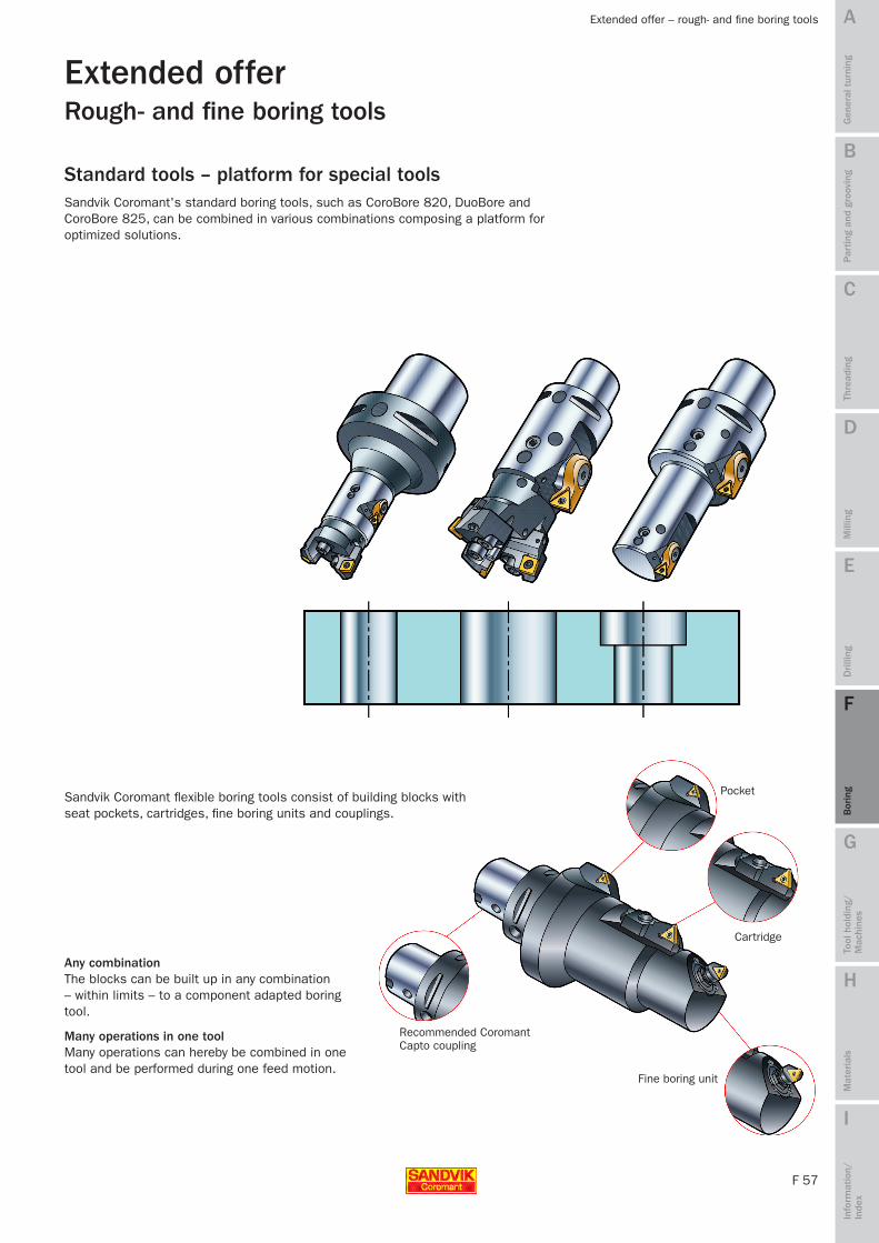
F 57
A
B
C
D
E
F
G
H
I
Par
ting
and
groo
ving
Gen
eral
tur
ning
Thre
adin
gM
illin
gD
rilli
ngB
orin
gTo
ol h
oldi
ng/
Mac
hine
sM
ater
ials
Info
rmat
ion/
In
dex
Extended offer – rough- and fine boring tools
Extended offer
Recommended Coromant Capto coupling
Cartridge
Fine boring unit
Sandvik Coromant flexible boring tools consist of building blocks with seat pockets, cartridges, fine boring units and couplings.
Any combination The blocks can be built up in any combination – within limits – to a component adapted boring tool.
Many operations in one tool Many operations can hereby be combined in one tool and be performed during one feed motion.
Rough- and fine boring tools
Sandvik Coromant's standard boring tools, such as CoroBore 820, DuoBore and CoroBore 825, can be combined in various combinations composing a platform for optimized solutions.
Standard tools – platform for special tools
MTG09 Boring_F50-61.indd 57 2009-11-25 15:18:19
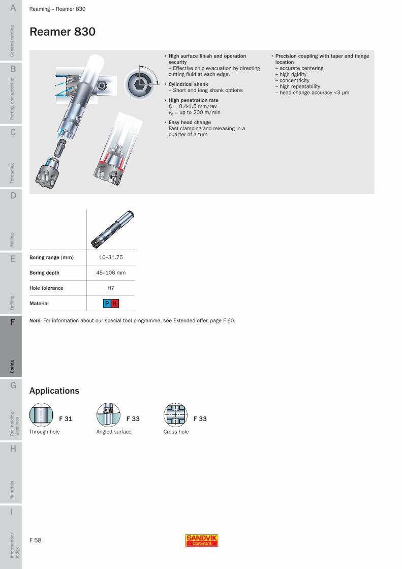
F 58
A
B
C
D
E
F
G
H
I
H7
10–31.75
P K
F 31 F 33F 33
Par
ting
and
groo
ving
Gen
eral
tur
ning
Thre
adin
gM
illin
gD
rilli
ngB
orin
gTo
ol h
oldi
ng/
Mac
hine
sM
ater
ials
Info
rmat
ion/
In
dex
Reaming – Reamer 830
Reamer 830
• High surface finish and operation security – Effective chip evacuation by directing cutting fluid at each edge.
• Cylindrical shank – Short and long shank options
• High penetration rate fn = 0.4-1.5 mm/rev vc = up to 200 m/min
• Easy head change Fast clamping and releasing in a quarter of a turn
• Precision coupling with taper and flange location – accurate centering – high rigidity – concentricity – high repeatability – head change accuracy <3 µm
Boring depth 45–106 mm
Hole tolerance
Material
Boring range (mm)
Through hole Cross holeAngled surface
Applications
Note: For information about our special tool programme, see Extended offer, page F 60.
MTG09 Boring_F50-61.indd 58 2009-11-25 15:18:30

F 59
A
B
C
D
E
F
G
H
I
Par
ting
and
groo
ving
Gen
eral
tur
ning
Thre
adin
gM
illin
gD
rilli
ngB
orin
gTo
ol h
oldi
ng/
Mac
hine
sM
ater
ials
Info
rmat
ion/
In
dex
Reaming – Reamer 830
Tool maintenanceClean all support faces before mounting.
The tool consists of:
• Head
• Retaining knob
• Holder
• Clamp bolt for front clamping.
Releasing
Turn the key anti-clockwise.
Warning! Be sure to securely hold reamer head as it can eject rapidly from shank.
Mounting of head
1. Screw retaining knob with threaded end into reamer head. Note: Left-hand thread.
2. Turn clamp bolt as far as possible anti-clockwise.
3. Align dots on head and holder and insert head completely into holder.
4. Tighten clamp bolt in clockwise direction (direction shown on holder). Face A must not touch stop pin B. Use recom-mended torque, see Main catalogue.
HeadRetaining knob
Clamp bolt Shank
MTG09 Boring_F50-61.indd 59 2009-11-25 15:18:31

F 60
A
B
C
D
E
F
G
H
I
15.80 – 65.00
7.00 – 18.59 45
15.80 – 65.00
7.00 – 18.59 45
15.80 – 65.00
7.00 – 21.29
P M K N S H
Par
ting
and
groo
ving
Gen
eral
tur
ning
Thre
adin
gM
illin
gD
rilli
ngB
orin
gTo
ol h
oldi
ng/
Mac
hine
sM
ater
ials
Info
rmat
ion/
In
dex
Extended offer – reaming tools
Reamers available outside of the standard programmeDiameter range: 7.00 – 65.00 mm
Grades: Tungsten carbide (uncoated and coated)
Cermet (uncoated and coated)
PCD
CBN
Smallest hole tolerance:
Workpiece materials:
IT6 for uncoated and IT7 for coated heads
Examples of holes suitable for Reamer 830 non standard
Through hole Through hole with crossing hole/grooves Yoke
Blind holes Blind holes with crossing holes
Diameter range (mm) Working length (mm)
Front clamping (retention knob)
Axial clamping (double threaded screw)
Head types Clamping systems
Extended offerReaming tools
MTG09 Boring_F50-61.indd 60 2009-11-25 15:18:32

F 61
A
B
C
D
E
F
G
H
I
PMKNSPMKNSH
GC4235 GC4225 GC4215
GC1125/GC4225 GC1515/GC1115 CT5015/GC4215
GC2035 GC2025 GC2015
GC1125 GC1115 GC2015
GC4215 GC3215 GC3210/GC3205*
GC1515/GC3215 GC3005 GC3005
GC1115 H10 GC1810
GC1115 H10 GC1810/CD10
GC1115/H13A GC1105 GC1105
GC1125/H13A GC1115/GC1105 GC1105
P
M
K
N
S
H
** ** **
Par
ting
and
groo
ving
Gen
eral
tur
ning
Thre
adin
gM
illin
gD
rilli
ngB
orin
gTo
ol h
oldi
ng/
Mac
hine
sM
ater
ials
Info
rmat
ion/
In
dex
Grade information
Cutting data recommendations, see Main catalogue.
Boring – grade information
Roughing
Finishing
Application Toughness First choice Wear resistance
General information and guidelines about grades used in boring are given below. For more information about the grades and guidelines about machining in different materials, see General turning, Chapter A.
GC1105• Thin PVD TiAlN-coating with excellent adhesion on a hard,
fine-grained substrate with 6% Co for high hot hardness and good resistance against plastic deformation and flank wear.
• High performance, sharp edges with toughness.• Suitable for finishing stainless steels at high speeds.• Outstanding performance in heat resistant super alloys.
GC1115• Thin PVD-oxide coating with superior adhesion to the sub-
strate, also on sharp edges.• Low to medium speeds and intermittent cuts in heat
resistant super alloys.• Work without problems like uneven flank wear and chipping.• Good resistance against notch wear at short contact times.
GC1515• Thin CVD-coated micro-grain carbide. • Finishing of low carbon- to low alloy steels, and other
“sticky” steel alloys at medium to low cutting speed.• Excellent when surface finish or sharp cutting action is
needed. • Resistance to thermal shocks makes it also suitable for light
intermittent cuts.• Complement for tough boring applications in cast iron.
GC2025• CVD-coated carbide.• Optimized for semi-finishing to roughing of austenitic
stainless and duplex stainless steels at moderate cutting speeds.
• Good resistance to thermal and mechanical shocks. Excellent edge security for interrupted cuts.
GC3005• CVD-coated carbide with a wear resistant coating with very
good adhesion to a hard substrate, capable of withstanding high temperatures.
• Finishing to roughing of nodular iron, high strength malleable iron and “gummy” (alloyed) grey iron.
GC3215• CVD-coated carbide with a smooth, wear resistant coating
on a hard substrate, capable of withstanding demanding interrupted cutting conditions.
• General choice for roughing of all cast irons at low to medium cutting speeds.
GC4225• CVD-coated carbide grade with a thick, wear resistant
coating on a hard and tough gradient substrate.• Finishing to roughing of steel and steel castings.• Can handle continuous as well as interrupted cuts in steel.
H10 (HW)• Uncoated carbide grade with excellent abrasive wear
resistance and edge sharpness.• For rough to finish turning of aluminium alloys.
ISO P = Steel
ISO M = Stainless steel
ISO K = Cast iron
ISO N = Non-ferrous material
ISO S = Heat resistance super alloys
ISO H = Hardened materials
* GC3210 Nodular cast iron, GC3205 Grey cast iron** For recommendation on fine boring in ISO H material, see General turning, Chapter A.
MTG09 Boring_F50-61.indd 61 2009-11-25 15:18:32