WO#130215 Directional Boring Cedar St from N. Sunnyside ...
20
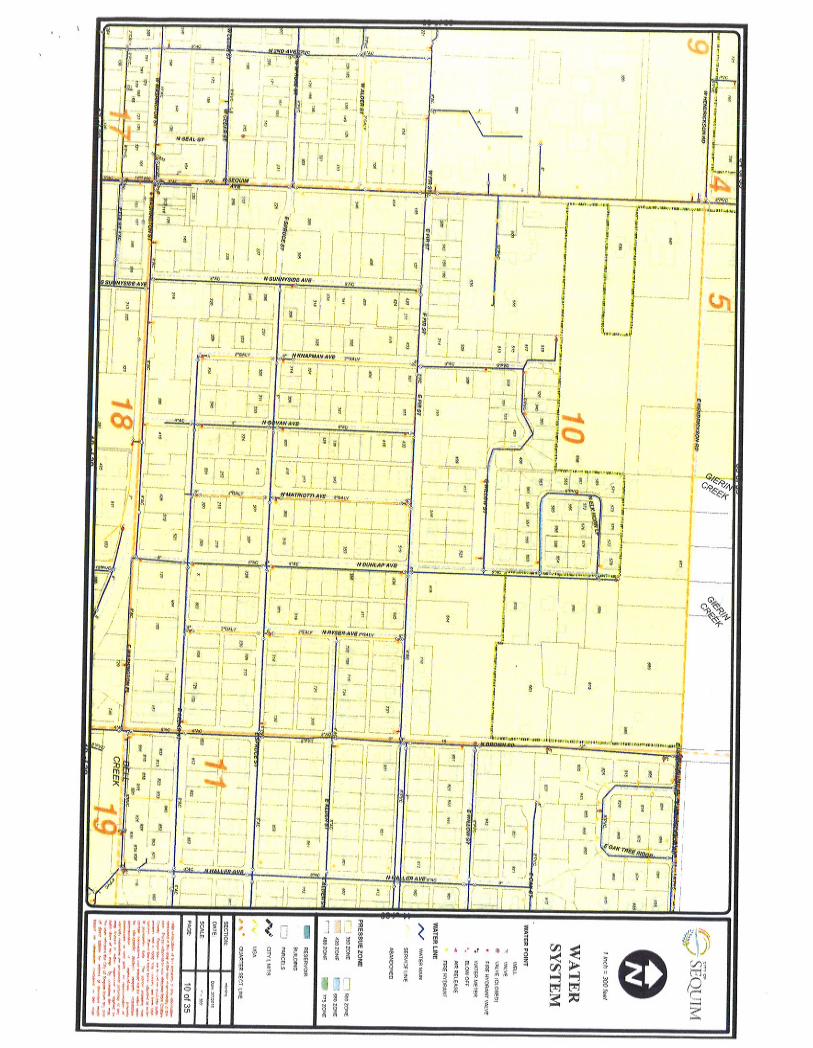
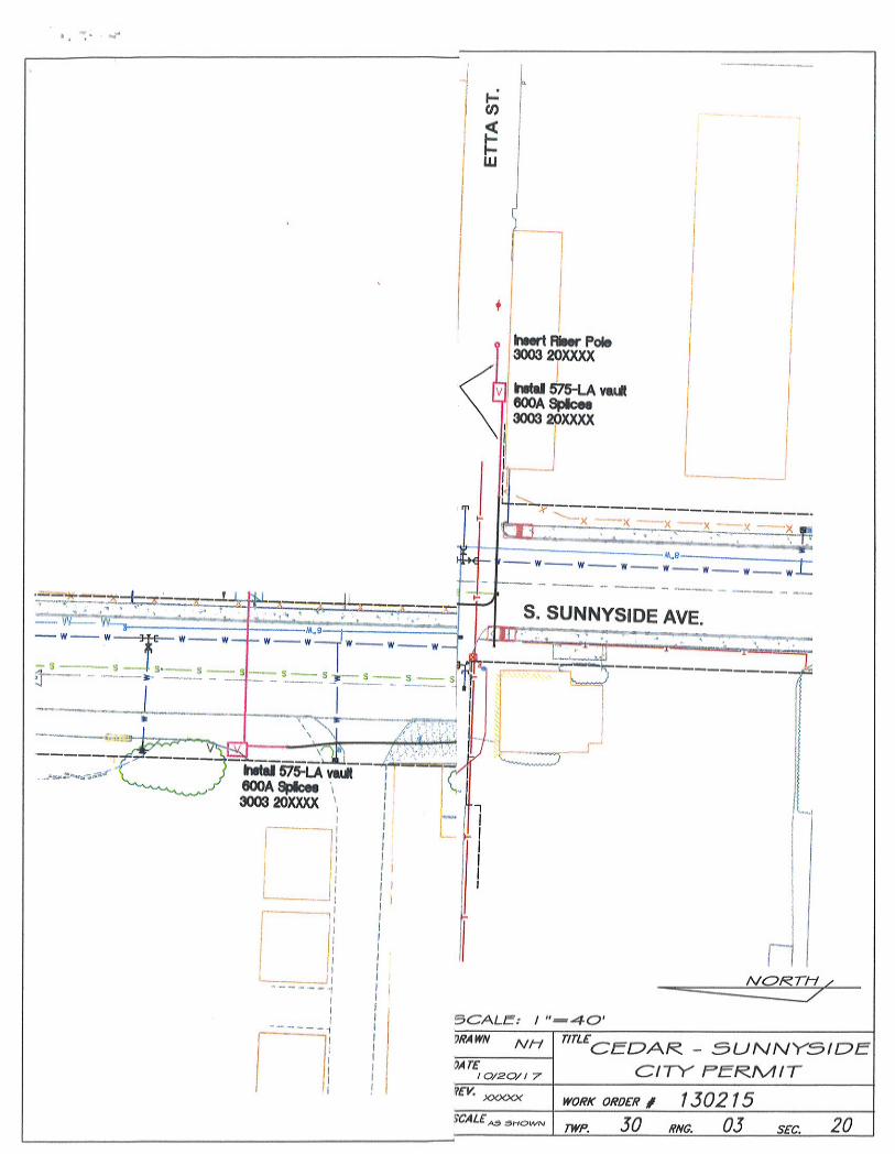
WO#130215 Directional Boring Cedar St from N. Sunnyside Ave to alley before Govan Ave, Sequim You are invited to provide a quote for the following work: GENERAL STATEMENT To supply 6”-schedule 80 (or equivalent) conduit via bore, generally following the route on the attached map. No cable or termination is required. A. LOCATION The work to be performed is between Govan Ave and N. Sunnyside in Sequim WA. See project map for more detail B. SCOPE 1. Install approximately 550’ of 6” conduit for electric conductor. Conduit depth to be between 42” & 60” unless otherwise authorized by PUD inspector. 2. A single, continuous bore the entire length of the project is the preferred alternative. If that is not possible, the bore may be broken up into sections as shown on the project drawing. 3. All other located utilities must be potholed to minimize interruption of other services. Potholes must be backfilled with sand backfill to 4” over the conduit, fill with CDF compacted to 90% and top with Asphalt patch. 4. Contractor to supply all necessary materials and equipment. 5. Restore all affected landscaping, roadways, driveways, and sidewalks to original condition. C. PERMIT & LOCATES Clallam PUD has an approved PUD of Sequim Permit to perform this work, PUD of Sequim Permit #ROW-17-032. D. FLAGGING: Clallam County PUD will provide flaggers for this project. E. TIMELINE Bids must be received back by 8-27-18. Work may commence on award of bid and must be complete by 10-15-18 Access roads may be adjacent to and/or under energized power lines. Maintain a minimum of 10 feet clearance from any person or equipment to the power lines. Bids will be evaluated based on price and completion dates. EXHIBIT C
-
Upload
khangminh22 -
Category
Documents
-
view
4 -
download
0
Transcript of WO#130215 Directional Boring Cedar St from N. Sunnyside ...

WO#130215 Directional Boring
Cedar St from N. Sunnyside Ave to alley before Govan Ave, Sequim
You are invited to provide a quote for the following work:
GENERAL STATEMENT To supply 6”-schedule 80 (or equivalent) conduit via bore, generally following the route on the attached map. No cable or termination is required.
A. LOCATION The work to be performed is between Govan Ave and N. Sunnyside in Sequim WA. See project map for more detail
B. SCOPE 1. Install approximately 550’ of 6” conduit for electric conductor. Conduit depth
to be between 42” & 60” unless otherwise authorized by PUD inspector.2. A single, continuous bore the entire length of the project is the preferred
alternative. If that is not possible, the bore may be broken up into sections asshown on the project drawing.
3. All other located utilities must be potholed to minimize interruption of otherservices. Potholes must be backfilled with sand backfill to 4” over theconduit, fill with CDF compacted to 90% and top with Asphalt patch.
4. Contractor to supply all necessary materials and equipment.5. Restore all affected landscaping, roadways, driveways, and sidewalks to
original condition.C. PERMIT & LOCATES
Clallam PUD has an approved PUD of Sequim Permit to perform this work, PUD of Sequim Permit #ROW-17-032.
D. FLAGGING: Clallam County PUD will provide flaggers for this project.
E. TIMELINE Bids must be received back by 8-27-18.
Work may commence on award of bid and must be complete by 10-15-18 Access roads may be adjacent to and/or under energized power lines. Maintain a minimum of 10 feet clearance from any person or equipment to the power lines.
Bids will be evaluated based on price and completion dates.
EXHIBIT C

HORIZONTAL DIRECTIONAL DRILLING (HDD) STANDARDS
A. GENERAL
1. Scope of Work: The work specified in this section consists of furnishing and installing underground utilities using the HDD method of installation. This work shall include all services, equipment, materials, and labor for the complete and proper installation, testing, restoration of underground utilities and environmental protection and restoration.
2. Quality Assurance: The requirements set forth in this document specify a wide range of procedural precautions necessary to insure that the very basic, essential aspects of a proper directional drilling installation are adequately controlled. Strict adherence shall be required under specifically covered conditions outlined in this document. Adherence to the specifications contained herein, or the PUD’s authorized Representative’s approval on any aspect of any directional drilling operation covered by this specification, shall in no way relieve the Contractor of the ultimate responsibility for the satisfactory completion of the work authorized under the Contract. The HDD Contractor shall be responsible for the repair of all damage to private and/or public property (at no additional expense to PUD). Post construction restoration and/or repair work shall meet all local, state, and federal rules and requirements.
3. Project Schedule and Cooperation: The project schedule shall be established on the basis of working a normal work schedule including five days per week, single shift, and eight hours per day or four days per week, 7:30am-4:30pm.
4. Warranty: The Contractor shall supply to PUD one (1) year unconditional warranty. The warranty shall include materials and installation and shall constitute complete replacement and delivery to the site of materials and installation of same to replace defective materials or defective workmanship with new materials/workmanship conforming to the specifications.
B. PERMITS
1. Permits for all work within the PUD of Sequim shall be obtained and paid for by the PUD. The Contractor shall verify the existence of all permits before commencing any work on the project.
C. SITE PREPARATION
1. Prior to any alterations to the work-site, the Contractor shall photograph or video tape the entire work area. One copy of which shall be given to PUD Representative and one copy to remain with the Contractor for a period of two (2) years following the completion of the project.

2. The Contractor shall coordinate utilities locates with One-Call of Washington State, (800-424-5555 or web site www.call811.com). Once the locate service has field marked all utilities, the Contractor shall field verify each utility (including any service laterals, i.e. water, sewer, cable, gas, electric, phone, etc.) and those within each paved area. Verification may be performed by utilizing Ground Penetrating Radar, hand dig, or vacuum excavation. Prior to initiating drilling, the Contractor shall record on the construction drawings both the horizontal and vertical location of all existing utilities located within the project limits.
3. The work site shall be graded and filled to provide a level working area. No alterations beyond what is required for the Contractor’s operations are to be made. The Contractor shall confine all activities to designated work areas.
4. Following drilling operations, the Contractor shall de-mobilize equipment and restore the work-site to pre-construction condition. All excavations shall be backfilled and compacted to 95% of the original density (at a minimum).
5. Environmental Protection: Contractor shall place silt fence between all drilling operations and any drainage, wetland, waterway or other area designated for such protection by the construction drawings and/or, local, state, and federal regulations. Contractor shall place hay bales, or other approved protection measures, to prevent any off-site discharge of silt and sediments from the project area. Additional environmental protection necessary to contain any hydraulic or drilling fluid spills shall be put in place, including berms, liners, turbidity curtains and other measures. Contractor shall adhere to all applicable environmental regulations including environmental condition stated in local, state, and federal permits. Fuel may not be stored in bulk containers (greater than 25 gallons) within 200 feet of any water-body or wetland.
D. PROTECTION OF PROPERTY AND OBSTRUCTIONS
1. Temporary supports and/or adequate protection and maintenance shall be installed on all underground and surface structures encountered in the progress of the work. The structures that have been disturbed shall be restored upon completion of the work.
2. All underground utilities shall be notified 48 hours prior to beginning construction on an individual project. Any known obstruction shall be shown on the construction drawing (s) provided by the user department for the project. The utmost caution shall be taken during construction operations to avoid damage to existing obstructions (pipe, conduit, utility poles and other structures) whether or not shown on the drawings.
3. PUD shall be responsible for obtaining and the cost associated with all required permits for each project.
E. PERSONNEL QUALIFICATIONS CERTIFICATION
1. Directional Drilling: All personnel shall be fully trained in their respective duties as part of the directional drilling crew and in safety. (Each person must have been fully trained for over 1,000 hours on all facets of directional drilling, including,

but not limited to machine operations, mud mixing, locating and material fusion.) A responsible representative who is thoroughly familiar with the equipment and type of work to be performed, must be in direct charge and control of the operation at all times. In all cases the supervisor must be continually present at the job site during the actual directional drilling operation. The Contractor shall have a sufficient number of competent workers on the job at all times to insure the directional drill is made in a timely and satisfactory manner.
2. Pipe and Fitting Joining: Heat Fusion Joining: Joints between plain end pipes and pipe fittings shall be made by butt fusion when possible. Electro-fusion welding may also be used to complete when the location is not accessible to butt fusion welding equipment. The on-site welder making the joints (butt fusion or electro-fusion) shall have received specific training from the manufacturer of the fittings and/or pipe being welded and shall have written proof of proper training/certification from the associated manufacturers. Only certified welders who have written training certifications from the fitting and/or pipe manufacturer will be allowed to perform this work. That is, to weld a fitting or electrofusion coupling in place, the on-site welder (employee) must be trained and certified by the fitting manufacturer. The fusion work shall be accomplished (welding and cooldown/closing times) in accordance with the fitting and pipe manufacturers’ recommendations, at a minimum. External and internal beads shall not be removed unless approved by PUD.
F. FUSIBLE POLYVINYLCHLORIDE (PVC) PIPE FOR INSTALLATION BY
HDD
1. DELIVERY AND OFF-LOADING a) All pipe shall be bundled or packaged in such a manner as to provide adequate
protection of the ends during transportation to the site. Any pipe damaged in shipment shall be replaced as directed by the owner or engineer.
b) Each pipe shipment should be inspected prior to unloading to see if the load has shifted or otherwise been damaged. Notify owner or engineer immediately if more than immaterial damage is found. Each pipe shipment should be checked for quantity and proper pipe size, color, and type.
c) Pipe should be loaded, off-loaded, and otherwise handled in accordance with AWWA M23, and all of the pipe supplier’s guidelines shall be followed.
d) Off-loading devices such as chains, wire rope, chokers, or other pipe handling implements that may scratch, nick, cut, or gouge the pipe are strictly prohibited.
e) During removal and handling, be sure that the pipe does not strike anything. Significant impact could cause damage, particularly during cold weather.
f) If appropriate unloading equipment is not available, pipe may be unloaded by removing individual pieces. Care should be taken to insure that pipe is not dropped or damaged. Pipe should be carefully lowered, not dropped, from trucks.

2. HANDLING AND STORAGE
a) Any length of pipe showing a crack or which has received a blow that may have caused an incident fracture, even though no such fracture can be seen, shall be marked as rejected and removed at once from the work. Damaged areas, or possible areas of damage may be removed by cutting out and removing the suspected incident fracture area. Limits of the acceptable length of pipe shall be determined by the owner or engineer.
b) Any scratch or gouge greater than 10% of the wall thickness will be considered significant and can be rejected unless determined acceptable by the owner or engineer.
c) Pipe lengths should be stored and placed on level ground. Pipe should be stored at the job site in the unit packaging provided by the manufacturer. Caution should be exercised to avoid compression, damage, or deformation to the ends of the pipe. The interior of the pipe, as well as all end surfaces, should be kept free from dirt and foreign matter.
d) Pipe shall be handled and supported with the use of woven fiber pipe slings or approved equal. Care shall be exercised when handling the pipe to not cut, gouge, scratch or otherwise abrade the piping in any way.
e) If pipe is to be stored for periods of 1 year or longer, the pipe should be shaded or otherwise shielded from direct sunlight. Covering of the pipe which allows for temperature build-up is strictly prohibited. Pipe should be covered with an opaque material while permitting adequate air circulation above and around the pipe as required to prevent excess heat accumulation.
f) Pipe shall be stored and stacked per the pipe supplier’s guidelines.
3. FUSION PROCESS a) Fusible PVC pipe will be handled in a safe and non-destructive manner
before, during, and after the fusion process and in accordance with this specification and pipe supplier’s guidelines.
b) Fusible PVC pipe will be fused by qualified fusion technicians, as documented by the pipe supplier.
c) Each fusion joint shall be recorded and logged by an electronic monitoring device (data logger) connected to the fusion machine.
d) Only appropriately sized and outfitted fusion machines that have been approved by the pipe supplier shall be used for the fusion process. Fusion machines must incorporate the following elements:
e) HEAT PLATE - Heat plates shall be in good condition with no deep gouges or scratches. Plates shall be clean and free of any debris or contamination. Heater controls shall function properly; cord and plug shall be in good condition. The appropriately sized heat plate shall be capable of maintaining a uniform and consistent heat profile and temperature for the size of pipe being fused, per the pipe supplier’s guidelines.
f) CARRIAGE – Carriage shall travel smoothly with no binding at less than 50 psi. Jaws shall be in good condition with proper inserts for the pipe size being fused. Insert pins shall be installed with no interference to carriage travel.

g) GENERAL MACHINE - Overview of machine body shall yield no obvious defects, missing parts, or potential safety issues during fusion.
h) DATA LOGGING DEVICE – An approved data logging device with the current version of the pipe supplier’s recommended and compatible software shall be used. Data logging device operations and maintenance manual shall be with the unit at all times. If fusing for extended periods of time, an independent 110V power source shall be available to extend battery life. i) Other equipment specifically required for the fusion process shall include
the following: i. Pipe rollers shall be used for support of pipe to either side of the
machine ii. A weather protection canopy that allows full machine motion of the
heat plate, fusion assembly and carriage shall be provided for fusion in inclement, extreme temperatures, and /or windy weather, per the pipe supplier’s recommendations.
iii. An infrared (IR) pyrometer for checking pipe and heat plate temperatures.
iv. Fusion machine operations and maintenance manual shall be kept with the fusion machine at all times.
v. Facing blades specifically designed for cutting fusible PVC pipe shall be used.
G. DRILLING OPERATIONS
1. General a) Bore path and alignment are as indicated in the contract documents. The path
of the bore may be modified based on field and equipment conditions. Entry and exit locations and control-point elevations shall be maintained as indicated in the contract documents.
b) Bend radii shown in the contract documents are minimum allowable radii and shall not be reduced.
2. Location and Protection of Underground Utilities a) Correct location of all underground utilities that may impact the HDD
installation is the responsibility of the Contractor, regardless of any locations shown on the drawings or previous surveys completed.
b) Utility location and notification services shall be contacted by the Contractor prior to the start of construction.
c) All existing lines and underground utilities shall be positively identified, including exposing those facilities that are located within an envelope of possible impact of HDD installation as determined for the project specific site conditions. It is the Contractor and HDD system operator’s responsibility to determine this envelope of safe offset from existing utilities. This will include, but is not limited to, soil conditions and layering, utility proximity and material, HDD system and equipment, and foreign subsurface material.
d) Water Main and Non-Water Main Separation Requirements: The minimum separation requirements between water main and a non-water main shall be

shown on the construction drawings or in accordance with the Washington State Department of Environmental Protection requirements.
3. Site Location Preparation a) Work site as indicated on drawings shall be graded or filled to provide a level
working area. No alterations beyond what is required for operations are to be made.
b) Contractor shall confine all activities to designated work areas. 4. Drilling Layout and Tolerances
a) The drill path shall be accurately surveyed with entry and exit areas placed in the appropriate locations within the areas indicated on drawings. If using a magnetic guidance system, drill path will be surveyed for any surface geomagnetic variations or anomalies.
b) Instrumentation shall be provided and maintained at all times that accurately locates the pilot hole, measures drill-string axial and torsional loads and measures drilling fluid discharge rate and pressure.
c) Entry and exit areas shall be drilled so as not to exceed the bending limitations of the pipe as recommended by the pipe supplier.
5. Pilot Hole Bore a) Pilot hole shall be drilled along bore path. In the event that the pilot bore does
deviate from the bore path, it may require contractor to pull-back and re-drill from the location along bore path before the deviation.
b) The Contractor shall limit curvature in any direction to reduce force on the pipe during pull-back. The minimum radius of curvature shall be no less than that specified by the pipe supplier.
6. Reaming a) After successfully completing the pilot hole, the bore hole shall be reamed to a
diameter which meets the requirements of the pipe being installed. b) Multiple reaming passes shall be used at the discretion of the Contractor and
shall conform to this specification. c) In the event of a drilling fluid fracture, returns loss or other loss of drilling
fluid, the Contractor shall be responsible for restoring any damaged property to original condition and cleaning up the area in the vicinity of the damage or loss.
7. Pipe Pull-Back and Insertion a) Pipe shall be fused prior to insertion, if the site and conditions allow, into one
continuous length. b) Contractor shall handle the pipe in a manner that will not over-stress the pipe
prior to insertion. Vertical and horizontal curves shall be limited so that the pipe does not bend past the pipe supplier’s minimum allowable bend radius, buckle, or otherwise become damaged. Damaged portions of the pipe shall be removed and replaced.
c) The pipe entry area shall be graded as needed to provide support for the pipe and to allow free movement into the bore hole.
i. The pipe shall be guided into the bore hole to avoid deformation of, or damage to, the pipe.

ii. The fusible PVC pipe may be continuously or partially supported on rollers or other Owner and Engineer approved friction decreasing implement during joining and insertion, as long as the pipe is not over-stressed or critically abraded prior to, or during installation.
iii. A swivel shall be used between the reaming head and the fusible PVC pipe to minimize torsion stress on the pipe assembly.
d) Buoyancy modification shall be at the sole discretion of the Contractor, and shall not exceed the pipe supplier’s guidelines in regards to maximum pull force or minimum bend radius of the pipe. Damage caused by buoyancy modifications shall be the responsibility of the Contractor.
e) Once pull-back operations have commenced, the operation shall continue without interruption until the pipe is completely pulled through the bore hole.
f) The pipe shall be installed in a manner that does not cause upheaval, settlement, cracking, or movement and distortion of surface features. Any damages caused by the Contractor’s operations shall be corrected by the Contractor
8. Installation Cleanup 1. Following the installation, the project site shall be returned to a condition
equal to or better than the pre-construction condition of the site. All excavations will be backfilled and compacted per the construction documents and jurisdictional standards. All pavement and hardscape shall be repaired per applicable jurisdictional standards, excess materials shall be removed from the site, and disturbed areas shall be re-landscaped. All drilling fluid shall be properly disposed of per these specifications and all applicable jurisdictional laws.
2. Contractor shall verify that all utilities, structures, and surface features in the project area are sound.
H. PIPE ASSEMBLY
1. Pipe shall be welded/fused together in one length, if project site space permits; pipe may be placed on pipe rollers before pulling into bore hole to minimize damage to the pipe. For pipes 16-inch and larger, a re-rounding clamp tool shall be utilized during the electro-fusion process to ensure pipe roundness. For pipe sizes larger than 12-inch, mechanical scrapers (per the fitting manufacturer’s recommendation) shall be utilized during the electro-fusion work. It is critical that all original oxidized pipe surfaces be removed in order for fusion to take place. The scraping process requires that approximately 0.10” of the outer “skin” be removed in order to penetrate the oxidation and contamination barrier.
2. Acceptability of Damaged Pipe: Cuts or gouges that reduce the wall thickness by more than 10% are not acceptable and must be cut out and discarded.
3. Butt Fusion Testing: When requested by a PUD inspector, butt fusion testing will be performed. The test fusion shall be allowed to cool completely, and then fusion test straps shall be cut out. The test strap shall be 12” (min) or 30 times the wall

thickness in length with the fusion in the center and 1” (min) or 1.5 times the wall thickness in width. Bend the test strap until the ends of the strap touch. If the fusion fails at the joint, a new test fusion shall be made, cooled completely and tested
4. Mechanical Joint and Flange Installation: Mechanical joints and flange connections shall be installed in accordance with the Manufacturer’s recommended procedure. Flange faces shall be centered and aligned to each other before assembling and tightened bolts. In no case shall the flange bolts be used to draw the flanges into alignment. Bolts shall be lubricated, and flat washers shall be fitted under the flange nuts. Bolts shall be evenly tightened according to the tightening pattern and torque step recommendations of the Manufacturer. At least 1 hour after initial assembly, flange connections shall be re-tightened following the tightening pattern and torque step recommendations of the Manufacturer. The final tightening torque shall be 100 ft-lbs or less as recommended by the Manufacturer.
I. DIRECTIONAL DRILLING OPERATION
1. Contractor shall provide all material, equipment, and facilities required for directional drilling. Proper alignment and elevation of the bore hole shall be consistently maintained throughout the directional drilling operation. The method used to complete the directional drill shall conform to the requirements of all applicable permits. Copies of all permits shall be supplied to the Contractor by the Owner.
2. The entire drill path shall be accurately surveyed with entry and exit stakes placed in the appropriate locations within the areas indicated on drawings. If Contractor is using a magnetic guidance system, drill path will be surveyed for any surface geo-magnetic variations or anomalies.
3. Contractor shall place silt fence between all drilling operations and any drainage, wellfields, wetland, waterway or other area designated for such protection necessary by documents, state, federal and local regulations. Additional environmental protection necessary to contain any hydraulic or drilling fluid spills shall be put in place, including berms, liners, turbidity curtains and other close space measures. Contractor shall adhere to all applicable environmental regulations. Fuel may not be stored in bulk containers within 200 feet of any water body or wetland.
4. Readings shall be recorded after advancement of each successive drill pipe, (no more than 10’) and the readings plotted on a scaled drawing of 1” = 2’, both vertical and horizontal. Access to all recorded readings and plan and profile information shall be made available to PUD, or its representative, at all times. At no time shall the deflection radius of the drill pipe exceed the deflection limits of the carrier pipe as specified herein.
5. A complete list of all drilling fluid additives and mixtures to be used in the directional operation will be submitted to PUD along with their respective Material Safety Data Sheets. All drilling fluids and loose cuttings shall be contained in pits or holding tanks for recycling or disposal. No fluids shall be

allowed to enter any unapproved areas or natural waterways. Upon completion of the directional drill close space project, the drilling mud and cuttings shall be disposed of by the Contractor at an approved dumpsite.
6. The pilot hole shall be drilled on bore path with no deviations greater than 5% of depth over a length of 100-feet. In the event that pilot does deviate from the bore path more than 5-feet of depth in 100-feet, Contractor will notify PUD and PUD may require Contractor to pull-back and re-drill from the location along bore path before the deviation. In the event that a drilling fluid fracture, inadvertent returns, or returns loss occurs during pilot hole drilling operations, Contractor shall cease drilling, wait at least 30 minutes, inject a quantity of drilling fluid with a viscosity exceeding 120 seconds as measured by a March funnel and wait another 30 minutes. If mud fracture or returns loss continues, Contractor will discuss additional options with the PUD engineer and work will then proceed accordingly.
7. Upon completion of pilot hole phase of the operation, a complete set of “as-built” records shall be submitted in duplicate to the Owner. These records shall include copies of the plan and profile drawing, as well as directional survey reports as recorded during the drilling operation.
8. Upon approval of the pilot hole location the hole opening or enlarging phase of the installation shall begin. The bore hole diameter shall be increased to accommodate the pullback operation of the required size of fusible PVC pipe. The type of hole opener or back reamer to be utilized in this phase shall be determined by the types of subsurface soil conditions that have been encountered during the pilot hole drilling operation. The reamer type shall be at the Contractor’s discretion with the final hole opening being a maximum of 1.5 times larger than the outside diameter of the fusible PVC pipe to be installed in the bore hole
9. The open bore hole may be stabilized by means of bentonite drilling slurry pumped through the inside diameter of the drill rod and through openings in the reamer. The drilling slurry must be in a homogenous / flowable state serving as an agent to carry the loose cuttings to the surface through the annulus of the borehole. The volume of bentonite mud required for each pullback shall be calculated based on soil conditions, largest diameter of the pipe couplings, capacity of the bentonite mud pump, and the speed of pullback as recommended by the bentonite drilling fluid manufacture. The bentonite slurry is to be contained at the exit or entry side of the directional bore in pits or holding tanks. The slurry may be recycled at this time for reuse in the hole opening operation, or shall be hauled by the Contractor to an approved dumpsite for proper disposal.
10. The fusible PVC pipe shall be joined together according to manufacturer’s specifications. The pipe must be inspected and cleaned with a wet cloth prior to each joint assembly so they are free of any dirt or sand. The ends of pipe must be free of any chips, scratches, or scrapes before pipe is assembled. A pulling eye will be attached to the fusible PVC pipe pulling head on the lead stick of pipe which in turn will be attached to a swivel on the end of the drill pipe. Tracer wire confirming to PUD W/WW approved materials manual shall be attached to the pulling eye and the crown of fusible PVC pipe with duct tape @ 24” O.C. and a minimum of two full wraps around the pipe. This will allow for a straight, smooth

pull of the product pipe as it enters and passes through the borehole toward the drill rig and original entrance hole of the directional bore. The product pipe will be elevated to the approximate angle of entry and supported by means of a side boom with roller arm, or similar equipment, to allow for the “free stress: situation as the pipe is pulled into the exit hole toward the drill rig. The product pullback phase of the directional operation shall be carried out in a continuous manner until the pipe reaches the original sentry side of the bore


N. SUNNYSIDE AVE.
155
160
165
170
175
180
185
155
160
165
170
175
180
185
18+00 19+00 20+00 21+00 22+00
16
CIT
Y O
F S
EQ
UIM
2017 W
AT
ER
A
ND
S
EW
ER
IM
PR
OV
EM
EN
TS
PLAN
P
LA
N A
ND
P
RO
FIL
E
5
CONSTRUCTION NOTES:
NOTE:
PROFILE
MA
TC
HL
IN
E S
TA
22+
00, S
EE
S
HE
ET
6
MA
TC
HL
IN
E S
TA
18+
00, S
EE
S
HE
ET
4
RESTORATION LEGEND:
Received 3/7/2017 City of SequimDCD/Public Works
AutoCAD SHX Text
SSMH RIM EL. = 175.70 I.E. = 167.08 18" PVC N I.E. = 167.18 18" PVC S
AutoCAD SHX Text
335 LF 8" C900
AutoCAD SHX Text
(1) FIRE HYDRANT ASSEMBLY
AutoCAD SHX Text
281 LF 8" C900
AutoCAD SHX Text
7
AutoCAD SHX Text
7
AutoCAD SHX Text
7
AutoCAD SHX Text
7
AutoCAD SHX Text
7
AutoCAD SHX Text
7
AutoCAD SHX Text
7
AutoCAD SHX Text
7
AutoCAD SHX Text
2
AutoCAD SHX Text
5
AutoCAD SHX Text
335 LF 8" C900 DR18
AutoCAD SHX Text
281 LF 8" C900 DR18
AutoCAD SHX Text
PLAN SHEETS_SEPA
AutoCAD SHX Text
SHEET:
AutoCAD SHX Text
OF:
AutoCAD SHX Text
DWG:
AutoCAD SHX Text
No.
AutoCAD SHX Text
REVISION
AutoCAD SHX Text
APPD
AutoCAD SHX Text
DATE
AutoCAD SHX Text
SCALE:
AutoCAD SHX Text
DRAWN:
AutoCAD SHX Text
CHECKED:
AutoCAD SHX Text
DATE:
AutoCAD SHX Text
APPROVED:
AutoCAD SHX Text
JOB NO.:
AutoCAD SHX Text
0
AutoCAD SHX Text
1"
AutoCAD SHX Text
2"
AutoCAD SHX Text
701 DEXTER AVENUE NORTH SUITE 200
AutoCAD SHX Text
CONSULTING ENGINEERS
AutoCAD SHX Text
SEATTLE, WASHINGTON 98109 (206) 284-0860
AutoCAD SHX Text
NOTED
AutoCAD SHX Text
TWO INCHES AT FULL SCALE. IF NOT, SCALE ACCORDINGLY
AutoCAD SHX Text
WASHINGTON
AutoCAD SHX Text
CLALLAM COUNTY
AutoCAD SHX Text
15482.00
AutoCAD SHX Text
JUN. 2015
AutoCAD SHX Text
PGM
AutoCAD SHX Text
XXX
AutoCAD SHX Text
N.E.L.
AutoCAD SHX Text
Z:\Water Projects\2015\WTR-056D Water Main Sunnyside - Bell to Fir\5-Plans, Specs & Estimates\CADD\City file - Sunnyside Proj\PLAN SHEETS_SEPA.dwg, 2/28/2017 10:05 AM, MATTHEW KLONTZ, 2/28/2017 10:05 AM, MATTHEW KLONTZ2/28/2017 10:05 AM, MATTHEW KLONTZ, MATTHEW KLONTZMATTHEW KLONTZ
AutoCAD SHX Text
SEPA SUBMITTAL
AutoCAD SHX Text
FEB.
AutoCAD SHX Text
0
AutoCAD SHX Text
SCALE: 1"=20'-0"
AutoCAD SHX Text
1.
AutoCAD SHX Text
ALL PROPERTY LINES SHOWN ARE APPROXIMATE. ALL VALVES SHALL MEET THE MINIMUM REQUIREMENTS OF AWWA C515. ALL WATER SERVICES SHALL BE 3/4" UNLESS OTHERWISE NOTED.
AutoCAD SHX Text
2.
AutoCAD SHX Text
CAUTION: POTENTIAL UTILITY CONFLICT. CONTRACTOR TO FIELD VERIFY (POTHOLE) EXACT LOCATION AND DEPTH OF EXISTING UTILITY. CONTRACTOR SHALL REMOVE AND RETURN HYDRANT TO CITY. INLET SOCKS SHALL BE INSTALLED IN ALL CATCH BASINS. CONTRACTOR SHALL VERIFY DEPTH PRIOR TO CONSTRUCTION OF SEWER MAIN REPLACEMENT. CLOSE EXISTING VALVE, REMOVE AND WASTEHAUL EXISTING VALVE CAN AND FILL WITH CDF. CONNECT NEW WATER SERVICE TO EXISTING METER SETTER AND REPLACE EXISTING METER BOX. INSTALL NEW METER SERVICE PER DETAIL 5 SHEET 14. CONTRACTOR SHALL PLUG EXISTING PIPE WITH GROUT A DEPTH TWICE THE PIPE DIAMETER. CONTRACTOR SHALL FURNISH AND INSTALL NEW MONUMENT PER DETAIL.
AutoCAD SHX Text
1
AutoCAD SHX Text
2
AutoCAD SHX Text
3
AutoCAD SHX Text
5
AutoCAD SHX Text
4
AutoCAD SHX Text
6
AutoCAD SHX Text
7
AutoCAD SHX Text
8
AutoCAD SHX Text
3.
AutoCAD SHX Text
9
AutoCAD SHX Text
0
AutoCAD SHX Text
0
AutoCAD SHX Text
20'
AutoCAD SHX Text
40'
AutoCAD SHX Text
10'
AutoCAD SHX Text
20'
AutoCAD SHX Text
SCALE: HORIZONTAL 1"=20' HORIZONTAL 1"=20' 1"=20' VERTICAL 1"=5'1"=5'
AutoCAD SHX Text
1
AutoCAD SHX Text
-
AutoCAD SHX Text
SCALE: 1"=20' (HORIZ.) 1"=5' (VERT.)
AutoCAD SHX Text
HMA PAVEMENT RESTORATION
AutoCAD SHX Text
PRELIMINARY NOT FOR CONSTRUCTION