Scenario-based requirements analysis techniques for real-time software systems: a comparative...
12
ORIGINAL ARTICLE Hossein Saiedian Prabha Kumarakulasingam Muhammad Anan Scenario-based requirements analysis techniques for real-time software systems: a comparative evaluation Received: 15 February 2003 / Accepted: 13 January 2004 / Published online: 14 April 2004 Ó Springer-Verlag London Limited 2004 Abstract One of the most critical phases of software engineering is requirements elicitation and analysis. Success in a software project is influenced by the quality of requirements and their associated analysis since their outputs contribute to higher level design and verification decisions. Real-time software systems are event driven and contain temporal and resource limitation con- straints. Natural-language-based specification and analysis of such systems are then limited to identifying functional and non-functional elements only. In order to design an architecture, or to be able to test and verify these systems, a comprehensive understanding of dependencies, concurrency, response times, and resource usage are necessary. Scenario-based analysis techniques provide a way to decompose requirements to understand the said attributes of real-time systems. However they are in themselves inadequate for providing support for all real-time attributes. This paper discusses and evalu- ates the suitability of certain scenario-based models in a real-time software environment and then proposes an approach, called timed automata, that constructs a for- malised view of scenarios that generate timed specifica- tions. This approach represents the operational view of scenarios with the support of a formal representation that is needed for real-time systems. Our results indicate that models with notations and semantic support for representing temporal and resource usage of scenario provide a better analysis domain. Keywords Real-time Requirements engineering Scenario-based Time-automata 1 Introduction Requirements analysis paves the way for high-level design, generation of test cases for verification, and supports early architecture reviews. As a result of such analysis, analysts and architects gain a deeper and thorough understanding of the system to be engineered. A popular method of capturing requirements is using a case-based approach [1]. In this method, requirements are defined from the perspective of all actors (users as well as hardware and software) at a hierarchical level. However, these hierarchical use cases can be analysed at different granularity levels by separating these use cases into scenarios thereby providing a deeper understanding of the system being developed. Weidenhaupt et al. [2] showed that scenarios depict specific usage instances between actors and a system. This allows evaluation of individual, composite and interacting scenarios that specify user requirements at a granularity level that details the system’s behaviour. Real-time software systems consist of event driven processes and their requirements can be classified into behavioural requirements and temporal requirements [3]. Behavioural requirements specify the functionality of the system and temporal requirements specify timing constraints of responses from the system to specific events. Since behavioural requirements of a real-time system are descriptions of system functionality, they are easily identified. Temporal requirements, however, may not be read directly from requirements as several inter- acting events may define a single temporal requirement. Thus, expanding the use cases into specific scenarios, and analysing them allows analysts to clearly under- stand the nature of the system to be built. This paper evaluates the suitability of scenario-based requirements analysis for real-time systems. The study H. Saiedian is a member of the Information & Telecommunication Technology Center at the University of Kansas. His research was partially supported by a grant from the National Science Foun- dation (NSF). H. Saiedian (&) P. Kumarakulasingam Electrical Engineering & Computer Science, University of Kansas, Lawrence, KS 66045, USA E-mail: [email protected] M. Anan Sprint Corporation, Overland Park, KS 66211, USA Requirements Eng (2005) 10: 22–33 DOI 10.1007/s00766-004-0192-6
Transcript of Scenario-based requirements analysis techniques for real-time software systems: a comparative...
ORIGINAL ARTICLE
Hossein Saiedian Æ Prabha Kumarakulasingam
Muhammad Anan
Scenario-based requirements analysis techniques for real-timesoftware systems: a comparative evaluation
Received: 15 February 2003 / Accepted: 13 January 2004 / Published online: 14 April 2004� Springer-Verlag London Limited 2004
Abstract One of the most critical phases of softwareengineering is requirements elicitation and analysis.Success in a software project is influenced by the qualityof requirements and their associated analysis since theiroutputs contribute to higher level design and verificationdecisions. Real-time software systems are event drivenand contain temporal and resource limitation con-straints. Natural-language-based specification andanalysis of such systems are then limited to identifyingfunctional and non-functional elements only. In order todesign an architecture, or to be able to test and verifythese systems, a comprehensive understanding ofdependencies, concurrency, response times, and resourceusage are necessary. Scenario-based analysis techniquesprovide a way to decompose requirements to understandthe said attributes of real-time systems. However theyare in themselves inadequate for providing support forall real-time attributes. This paper discusses and evalu-ates the suitability of certain scenario-based models in areal-time software environment and then proposes anapproach, called timed automata, that constructs a for-malised view of scenarios that generate timed specifica-tions. This approach represents the operational view ofscenarios with the support of a formal representationthat is needed for real-time systems. Our results indicatethat models with notations and semantic support forrepresenting temporal and resource usage of scenarioprovide a better analysis domain.
Keywords Real-time Æ Requirements engineering ÆScenario-based Æ Time-automata
1 Introduction
Requirements analysis paves the way for high-leveldesign, generation of test cases for verification, andsupports early architecture reviews. As a result of suchanalysis, analysts and architects gain a deeper andthorough understanding of the system to be engineered.A popular method of capturing requirements is using acase-based approach [1]. In this method, requirementsare defined from the perspective of all actors (users aswell as hardware and software) at a hierarchical level.However, these hierarchical use cases can be analysed atdifferent granularity levels by separating these use casesinto scenarios thereby providing a deeper understandingof the system being developed. Weidenhaupt et al. [2]showed that scenarios depict specific usage instancesbetween actors and a system. This allows evaluationof individual, composite and interacting scenarios thatspecify user requirements at a granularity level thatdetails the system’s behaviour.
Real-time software systems consist of event drivenprocesses and their requirements can be classified intobehavioural requirements and temporal requirements[3]. Behavioural requirements specify the functionalityof the system and temporal requirements specify timingconstraints of responses from the system to specificevents. Since behavioural requirements of a real-timesystem are descriptions of system functionality, they areeasily identified. Temporal requirements, however, maynot be read directly from requirements as several inter-acting events may define a single temporal requirement.Thus, expanding the use cases into specific scenarios,and analysing them allows analysts to clearly under-stand the nature of the system to be built.
This paper evaluates the suitability of scenario-basedrequirements analysis for real-time systems. The study
H. Saiedian is a member of the Information & TelecommunicationTechnology Center at the University of Kansas. His research waspartially supported by a grant from the National Science Foun-dation (NSF).
H. Saiedian (&) Æ P. KumarakulasingamElectrical Engineering & Computer Science,University of Kansas,Lawrence, KS 66045, USAE-mail: [email protected]
M. AnanSprint Corporation, Overland Park,KS 66211, USA
Requirements Eng (2005) 10: 22–33DOI 10.1007/s00766-004-0192-6
applies the methods to an example problem and dis-cusses the implications of the results. Section 2 discussesthe different scenario-based analysis methods used inthis study. Section 3 discusses the case study example. Itdefines the research problem and then applies the chosenscenario-based models. The strengths and weaknesses ofthese methods are discussed and improvements aresuggested where applicable. Section 4lists the contribu-tions of this work and provides suggestions for furtherresearch on this topic.
2 Scenario-based requirements analysis methods
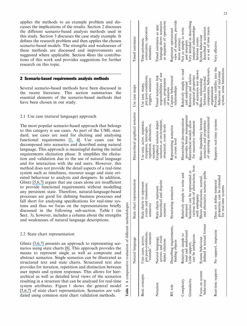
Several scenario-based methods have been discussed inthe recent literature. This section summarises theessential elements of the scenario-based methods thathave been chosen in our study.
2.1 Use case (natural language) approach
The most popular scenario-based approach that belongsto this category is use cases. As part of the UML stan-dard, use cases are used for eliciting and analysingfunctional requirements [1, 4]. Use cases can bedecomposed into scenarios and described using naturallanguage. This approach is meaningful during the initialrequirements elicitation phase. It simplifies the elicita-tion and validation due to the use of natural languageand for interaction with the end users. However, thismethod does not provide the detail aspects of a real-timesystem such as timeliness, resource usage and state ori-ented behaviour to analysts and designers. In addition,Glintz [5,6,7] argues that use cases alone are insufficientto provide functional requirements without modellingany persistent state. Therefore, natural-language-basedprocesses are good for defining business processes andfall short for analysing specifications for real-time sys-tems and thus we focus on the representations brieflydiscussed in the following sub-section. Table 1 (inSect. 3), however, includes a column about the strengthsand weaknesses of natural language descriptions.
2.2 State chart representation
Glintz [5,6,7] presents an approach to representing sce-narios using state charts [8]. This approach provides themeans to represent single as well as composite andabstract scenarios. Single scenarios can be illustrated asstructured text and state charts. Structured text alsoprovides for iteration, repetition and distinction betweenuser inputs and system responses. This allows for hier-archical as well as detailed level views of the scenariosresulting in a structure that can be analysed for real-timesystem attributes. Figure 1 shows the general model[5,6,7] of state chart representation. Scenarios are vali-dated using common state chart validation methods. T
able
1A
comparativeevaluationofdifferentmethodologies
Naturallanguage
State
chart
representation
Hierarchicalgraphicalnotation
Use
case
maps
Tim
edautomata
Basicconcepts
Usescases,actors,
pre/post-conditions,
‘‘extends’’,scenario
State
chartsto
represent
events
andtransitions;
scenarios
Use
case,actor,sequence,
exception,interrupts,
repetition,alternatives,
scenarios
Use
case,maps,
pre/post-conditions,
triggers,scenarios
Tim
e-automata,
constraints,operation
semantics
Notation
Naturallanguage,
arrowsandovals
depictrelations
State
chartsrepresent
hierarchicalanddisjoint
scenarios
Graphicalnotationdepict
scenariosatenvironment,
structural,eventlevels
Visualnotationslink
responsibilitiesofuse
cases,progression
ofscenarios
Tim
edautomata
asspec
languageshowsscenarios
assequence
ofoperations
RErole
Describingrequirem
ents,
findingobjects
Structuringscenarios
Representingscenarios
ateventlevel
Capture
behavioural
relationships
Representoperational
view
ofscenarios;provide
more
accuracy
Complexity
Relativelysimple
toreadandunderstand
Relativelysimple
towrite
and
interpret
Hierarchicaldecomposition
provides
bettermanagem
ent
Relativelysimple
toread
andunderstand
Notso
simple
towrite
andinterpret
Granularity
Littlesupport;
canbeambiguous
Scenarioscanberepresentedat
variouslevelsofabstraction;lives
withambiguity
Hierarchicalmodelsallow
forsuccessiverefinem
ent
Resourceandrelative
temporalproperties
ofscenariosnotshown
Verydetailed
indescribing
temporalrelationships
betweenevents
Focusonsystem
behaviour
System
behaviour
defined
intextualform
at
Showsabstractions,norm
al,
andalternativescenariopaths
Showsdependency
between
scenariosandproprieties
ofoperatingenvironmental
Showsrelationship
betweenfunctional
components,behaviours,
organisation
System
behaviour
described
inscenarios
asasetoftimetraces
Real-timesupport
Nosupport,im
precise
Does
notdefinetemporal
properties;canbeextended
forreal-timesystem
s
Supportsreal-timesystem
sProvides
visibilityinto
the
behaviourofreal-time
system
;somelimitations
Veryeff
ective
23
g p
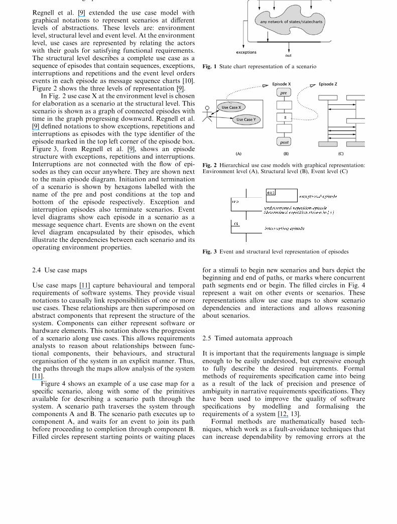
Regnell et al. [9] extended the use case model withgraphical notations to represent scenarios at differentlevels of abstractions. These levels are: environmentlevel, structural level and event level. At the environmentlevel, use cases are represented by relating the actorswith their goals for satisfying functional requirements.The structural level describes a complete use case as asequence of episodes that contain sequences, exceptions,interruptions and repetitions and the event level ordersevents in each episode as message sequence charts [10].Figure 2 shows the three levels of representation [9].
In Fig. 2 use case X at the environment level is chosenfor elaboration as a scenario at the structural level. Thisscenario is shown as a graph of connected episodes withtime in the graph progressing downward. Regnell et al.[9] defined notations to show exceptions, repetitions andinterruptions as episodes with the type identifier of theepisode marked in the top left corner of the episode box.Figure 3, from Regnell et al. [9], shows an episodestructure with exceptions, repetitions and interruptions.Interruptions are not connected with the flow of epi-sodes as they can occur anywhere. They are shown nextto the main episode diagram. Initiation and terminationof a scenario is shown by hexagons labelled with thename of the pre and post conditions at the top andbottom of the episode respectively. Exception andinterruption episodes also terminate scenarios. Eventlevel diagrams show each episode in a scenario as amessage sequence chart. Events are shown on the eventlevel diagram encapsulated by their episodes, whichillustrate the dependencies between each scenario and itsoperating environment properties.
2.4 Use case maps
Use case maps [11] capture behavioural and temporalrequirements of software systems. They provide visualnotations to causally link responsibilities of one or moreuse cases. These relationships are then superimposed onabstract components that represent the structure of thesystem. Components can either represent software orhardware elements. This notation shows the progressionof a scenario along use cases. This allows requirementsanalysts to reason about relationships between func-tional components, their behaviours, and structuralorganisation of the system in an explicit manner. Thus,the paths through the maps allow analysis of the system[11].
Figure 4 shows an example of a use case map for aspecific scenario, along with some of the primitivesavailable for describing a scenario path through thesystem. A scenario path traverses the system throughcomponents A and B. The scenario path executes up tocomponent A, and waits for an event to join its pathbefore proceeding to completion through component B.Filled circles represent starting points or waiting places
for a stimuli to begin new scenarios and bars depict thebeginning and end of paths, or marks where concurrentpath segments end or begin. The filled circles in Fig. 4represent a wait on other events or scenarios. Theserepresentations allow use case maps to show scenariodependencies and interactions and allows reasoningabout scenarios.
2.5 Timed automata approach
It is important that the requirements language is simpleenough to be easily understood, but expressive enoughto fully describe the desired requirements. Formalmethods of requirements specification came into beingas a result of the lack of precision and presence ofambiguity in narrative requirements specifications. Theyhave been used to improve the quality of softwarespecifications by modelling and formalising therequirements of a system [12, 13].
Formal methods are mathematically based tech-niques, which work as a fault-avoidance techniques thatcan increase dependability by removing errors at the
Fig. 1 State chart representation of a scenario
Fig. 2 Hierarchical use case models with graphical representation:Environment level (A), Structural level (B), Event level (C)
Fig. 3 Event and structural level representation of episodes
requirements, specification and design stages of devel-opment. Another main advantage in using this approachis the ability to structure a set of scenarios.
The main motivation for using formal methods isto ensure the quality of the system by adhering to thefollowing attributes:
– Ambiguity: formal methods avoid ambiguity bymaking a requirement subject to only one interpreta-tion.
– Completeness:formal methods achieve completenessby describing all significant requirements of concernto the user, including requirements associated withfunctionality, performance, design constraints, attri-butes, or external interfaces.
– Consistency:formal methods make requirements to beconsistent by avoiding conflicts among requirements.
– Verifiability:formal methods provide a finite and cost-effective process with which a developed softwaresystem can be verified if it meets the requirements.
– Modifiability:formal methods ensure that any changesto the requirements can be made easily, completely,and consistently, while retaining the existing structureand style of the set.
On the other hand, formal methods are not widelyvisible for the following limitations:
– Formal specifications are difficult to read and under-stand
– Formal methods cannot help model all aspects of thereal world
– Correctness proofs are resource-intensive– Development costs increase (for some companies and
projects)– Formal specifications can still have errors
Timed automata Formal methods can be used effec-tively in the specifications of real-time systems but thisadvantage comes at the expense of the readability andeffort to write the scenario. Therefore, for simplicity, thispaper will consider a semi-formal representation calledtimed automata.
All scenarios described earlier were proven useful tosome degree in requirements engineering. The timedautomata approach, as described in Some et al. [14],applies timed automata to scenarios with timing con-strains, which provides an accurate way of consideringuser requirements. It uses timed automata as a targetspecification language. This approach represents theoperational view of scenarios with the support of a semi-
formal representation that is needed for real-time sys-tems. It uses operations semantics, and a mapping be-tween concepts of scenarios, and those of the theory oftimed automata. The major advantage of this approachis its accuracy, simplicity and readability.
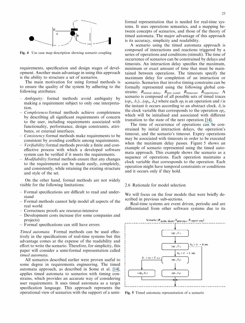
A scenario using the timed automata approach iscomposed of interactions and reactions triggered by aseries of operations and conditions (stimuli). The time ofoccurrence of scenarios can be constrained by delays andtimeouts. An interaction delay specifies the maximum,minimum or exact amount of time that must be main-tained between operations. The timeouts specify themaximum delay for completion of an interaction orscenario. Scenarios that involve timing constrains can beformally represented using the following global con-strains: Rinitial–delay, Rpre–cond, Rtimeout, Rrepetitions. Ascenario is composed of all possible sets of timed traces(op1, d1)...(opn, dn) where each opi is an operation and i isthe instant it occurs according to an abstract clock. di isthe clock variable that corresponds to the operation opi,which will be initialised and associated with differenttransition to the state of the next operation [14].
The time of occurrence of operations can be con-strained by initial interaction delays, the operation’stimeout, and the scenario’s timeout. Expiry operationsmay be associated with timeouts in order to be executedwhen the maximum delay passes. Figure 5 shows anexample of scenario represented using the timed auto-mata approach. This example shows the scenario as asequence of operations. Each operation maintains aclock variable that corresponds to the operation. Eachoperation might have temporal constraints or conditionsand it occurs only if they hold.
2.6 Rationale for model selection
We will focus on the four models that were briefly de-scribed in previous sub-sections.
Real-time systems are event driven, periodic and aredifferentiated from other software systems due to its
Fig. 4 Use case map description showing scenario coupling
Fig. 5 Timed automata representation of a scenario
25
timeliness and throughput characteristics. Also in thesesystems, more than one event could be active at anygiven time providing the notion of concurrency. Inaddition, any requirements analysis technique needs toprovide for an unambiguous and consistent reading ofthe requirements. Another attribute is that theserequirements need to be traceable to hierarchical userrequirements. Therefore the models we have chosen tocompare had to incorporate the concept of events,concurrency, timeliness and abstraction. In addition,techniques that supported visual notations were givenpreference since they were easier to read, analyse andautomate than natural language or mathematical modelbased techniques. The four models we choose to studyprovided powerful visual notations to illustrate andreason about scenarios. These models also supportedreal-time characteristics such as event and time repre-sentation and concurrency. Finally, as discussed above,the concept of abstraction is provided for in all thesemodels thus facilitating the study of these requirementsat different levels of hierarchy.
To summarise, these models were selected because:
– The selected models provide visual notations and areeasier to interpret.
– The selected models support representation of sce-nario interaction facilitating the study of concurrencyin real-time systems.
– The selected models also support real-time charac-teristics such as event and time representation andconcurrency.
– The selected models provide support for abstraction,thus facilitating the study of the requirements at dif-ferent levels of hierarchy.
Evaluation Criteria The chosen models will be evalu-ated based on the following criteria:
– A model’s representational ability of a real-time sys-tems characteristics, such as temporal requirements,concurrency and asynchronous and periodic events.A real-time software system’s essential characteristic isthat all actions performed by the software meet thetime specifications stated by the requirements. Also,real-time software systems contain periodic and asyn-chronous events that influence temporal and functionalspecifications. In order to analyse the requirements, thescenario-based method should provide a mechanism tospecify time and events in scenarios.
– Analysis at different levels of abstraction.It is well known that complex software systems areeasier to analyse and understand when they aredecomposed in a hierarchal manner. It can be said thatreal-time software systems aremore complex since theyhave to fulfil functional as well as many non-functionalrequirements, such as response time and throughput.Hierarchal decomposition allows software architectsand software designers to focus on the analysis at theirlevels of granularity. For example architects will usethe analysis to select suitable architectures, while
design engineers will select design patterns that satisfythe requirements. Therefore the ability to provide amechanism for specifying abstraction in scenario-based analysis methods is important.
– Representational and analytical capabilities to deal withscenario interactions.
Requirements can seldom be represented by individ-ual scenarios. Real-time software systems consist ofmany threads or processes that run concurrently andthese threads and processes synchronise with each otherto accomplish the requested tasks. Then in this instancemany scenarios interact with each other to satisfy arequirement. Therefore a real-time scenario-based anal-ysis technique should provide support for representingmultiple scenarios and interactions among them.
The first criteria was selected as it contained theessential characteristics of a real-time system as describedin next section. The second criteria was selected as itrepresents important requirements engineering charac-teristics. Since an analysis of real-time systems require-ments would contain many scenarios and since real-timesystems exhibit the nature of concurrency it was essentialto study the capability of the techniques to deal withdependencies and interactions between scenarios.
3 Case study: remote temperature sensor (RTS)
In this paper, we discuss four of the scenario-basedanalysis methods previously illustrated on a real-timeindustrial application. This example and the associatedrequirements are chosen to highlight the differences be-tween the four analysis techniques when they are studiedagainst the following real-time attributes:
– Temporal requirements or timeliness of system re-sponses
– Illustration of concurrent requirements– Composition of functional and temporal needs– Resource usage limitations that affect response and/or
concurrency
3.1 Problem definition
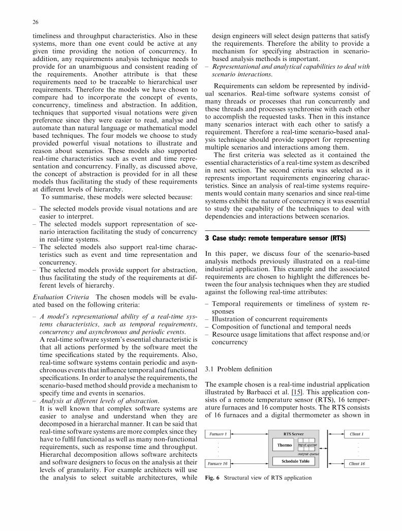
The example chosen is a real-time industrial applicationillustrated by Barbacci et al. [15]. This application con-sists of a remote temperature sensor (RTS), 16 temper-ature furnaces and 16 computer hosts. The RTS consistsof 16 furnaces and a digital thermometer as shown in
Fig. 6 Structural view of RTS application
26
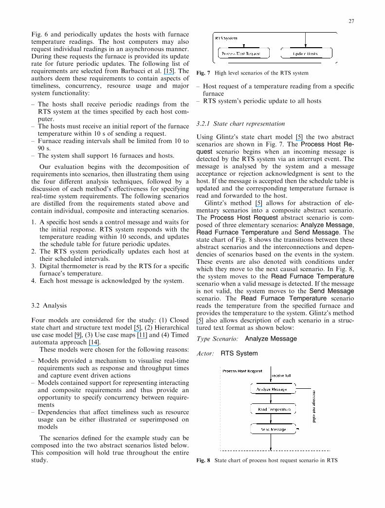
Fig. 6 and periodically updates the hosts with furnacetemperature readings. The host computers may alsorequest individual readings in an asynchronous manner.During these requests the furnace is provided its updaterate for future periodic updates. The following list ofrequirements are selected from Barbacci et al. [15]. Theauthors deem these requirements to contain aspects oftimeliness, concurrency, resource usage and majorsystem functionality:
– The hosts shall receive periodic readings from theRTS system at the times specified by each host com-puter.
– The hosts must receive an initial report of the furnacetemperature within 10 s of sending a request.
– Furnace reading intervals shall be limited from 10 to90 s.
– The system shall support 16 furnaces and hosts.
Our evaluation begins with the decomposition ofrequirements into scenarios, then illustrating them usingthe four different analysis techniques, followed by adiscussion of each method’s effectiveness for specifyingreal-time system requirements. The following scenariosare distilled from the requirements stated above andcontain individual, composite and interacting scenarios.
1. A specific host sends a control message and waits forthe initial response. RTS system responds with thetemperature reading within 10 seconds, and updatesthe schedule table for future periodic updates.
2. The RTS system periodically updates each host attheir scheduled intervals.
3. Digital thermometer is read by the RTS for a specificfurnace’s temperature.
4. Each host message is acknowledged by the system.
3.2 Analysis
Four models are considered for the study: (1) Closedstate chart and structure text model [5], (2) Hierarchicaluse case model [9], (3) Use case maps [11] and (4) Timedautomata approach [14].
These models were chosen for the following reasons:
– Models provided a mechanism to visualise real-timerequirements such as response and throughput timesand capture event driven actions
– Models contained support for representing interactingand composite requirements and thus provide anopportunity to specify concurrency between require-ments
– Dependencies that affect timeliness such as resourceusage can be either illustrated or superimposed onmodels
The scenarios defined for the example study can becomposed into the two abstract scenarios listed below.This composition will hold true throughout the entirestudy.
– Host request of a temperature reading from a specificfurnace
– RTS system’s periodic update to all hosts
3.2.1 State chart representation
Using Glintz’s state chart model [5] the two abstractscenarios are shown in Fig. 7. The Process Host Re-quest scenario begins when an incoming message isdetected by the RTS system via an interrupt event. Themessage is analysed by the system and a messageacceptance or rejection acknowledgment is sent to thehost. If the message is accepted then the schedule table isupdated and the corresponding temperature furnace isread and forwarded to the host.
Glintz’s method [5] allows for abstraction of ele-mentary scenarios into a composite abstract scenario.The Process Host Request abstract scenario is com-posed of three elementary scenarios: Analyze Message,Read Furnace Temperature and Send Message. Thestate chart of Fig. 8 shows the transitions between theseabstract scenarios and the interconnections and depen-dencies of scenarios based on the events in the system.These events are also denoted with conditions underwhich they move to the next causal scenario. In Fig. 8,the system moves to the Read Furnace Temperaturescenario when a valid message is detected. If the messageis not valid, the system moves to the Send Messagescenario. The Read Furnace Temperature scenarioreads the temperature from the specified furnace andprovides the temperature to the system. Glintz’s method[5] also allows description of each scenario in a struc-tured text format as shown below:
Type Scenario: Analyze Message
Actor: RTS System
Fig. 7 High level scenarios of the RTS system
Fig. 8 State chart of process host request scenario in RTS
27
Normal Flow:
1. System: Host message received.
2. System: Start request timeout timer.
3. System: Read message.
4.1. System: Validate message.
4.2. Identify furnace number and update furnaceperiod.
5. Request temperature reading.
6. Send temperature reading to host.
Alternative Flow:
4.1’System System validates message.
– if message is invalid then return error message,terminate; endif.
3’,4’,5’ and 6’ System System sends temperaturereading
– if request timer times-out then send error message,terminate; endif.
In the above instance the state charts were able tospecify the detail functionality of the application usingelementary and composite scenarios. They were also ableto show the dependencies between scenarios. However,the temporal specifications of 10 s for request completionwas missing in the model. One can argue that the struc-ture text description shown above captures this require-ment, illustrated under the alternative flow section. Sincethe timeout can occur in any one of the normal flow stepsit would have to be listed as an alternative for eachnormal flow step. This reduces readability and affects thetemporal analysis of the system.
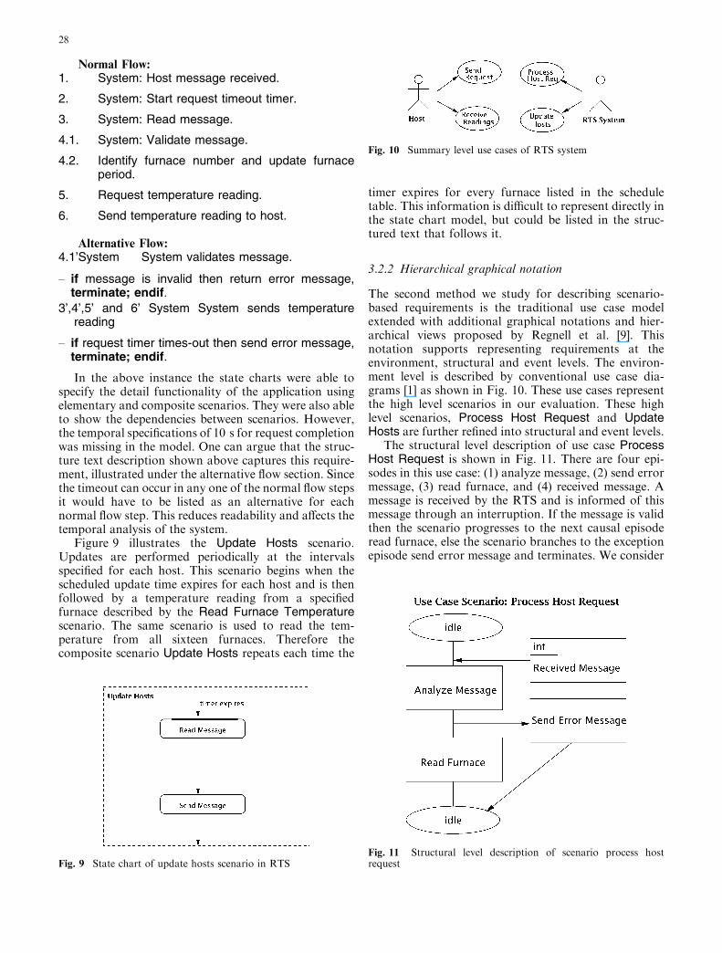
Figure 9 illustrates the Update Hosts scenario.Updates are performed periodically at the intervalsspecified for each host. This scenario begins when thescheduled update time expires for each host and is thenfollowed by a temperature reading from a specifiedfurnace described by the Read Furnace Temperaturescenario. The same scenario is used to read the tem-perature from all sixteen furnaces. Therefore thecomposite scenario Update Hosts repeats each time the
timer expires for every furnace listed in the scheduletable. This information is difficult to represent directly inthe state chart model, but could be listed in the struc-tured text that follows it.
3.2.2 Hierarchical graphical notation
The second method we study for describing scenario-based requirements is the traditional use case modelextended with additional graphical notations and hier-archical views proposed by Regnell et al. [9]. Thisnotation supports representing requirements at theenvironment, structural and event levels. The environ-ment level is described by conventional use case dia-grams [1] as shown in Fig. 10. These use cases representthe high level scenarios in our evaluation. These highlevel scenarios, Process Host Request and UpdateHosts are further refined into structural and event levels.
The structural level description of use case ProcessHost Request is shown in Fig. 11. There are four epi-sodes in this use case: (1) analyze message, (2) send errormessage, (3) read furnace, and (4) received message. Amessage is received by the RTS and is informed of thismessage through an interruption. If the message is validthen the scenario progresses to the next causal episoderead furnace, else the scenario branches to the exceptionepisode send error message and terminates. We consider
Fig. 9 State chart of update hosts scenario in RTS
Fig. 10 Summary level use cases of RTS system
Fig. 11 Structural level description of scenario process hostrequest
28
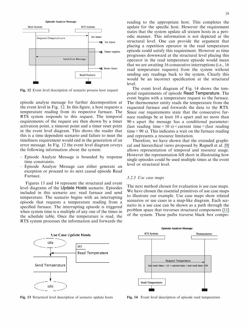
episode analyse message for further decomposition atthe event level in Fig. 12. In this figure, a host requests atemperature reading from its respective furnace. TheRTS system responds to this request. The temporalrequirements of the request are then shown by a timeractivation point, a timeout point and a timer reset pointin the event level diagram. This shows the reader thatthis is a time dependent scenario and failure to meet thetimeliness requirement would end in the generation of anerror message. In Fig. 12 the event level diagram coveysthe following information about the system:
– Episode Analyze Message is bounded by responsetime constraints.
– Episode Analyze Message can either generate anexception or proceed to its next causal episode ReadFurnace.
Figures 13 and 14 represent the structural and eventlevel diagrams of the Update Hosts scenario. Episodesincluded in this scenario are: read furnace and sendtemperature. The scenario begins with an interruptingepisode that requests a temperature reading from aspecified furnace. The interrupting episode is triggeredwhen system time is a multiple of any one of the times inthe schedule table. Once the temperature is read, theRTS system processes the information and forwards the
reading to the appropriate host. This completes theupdate for the specific host. However the requirementstates that the system update all sixteen hosts in a peri-odic manner. This information is not depicted at thestructural level. One can provide the argument thatplacing a repetition operator in the read temperatureepisode could satisfy this requirement. However as timeprogresses downward at the structural level placing thisoperator in the read temperature episode would meanthat we are awaiting 16 consecutive interruptions (i.e., 16read temperature requests) from the system withoutsending any readings back to the system. Clearly thiswould be an incorrect specification at the structurallevel.
The event level diagram of Fig. 14 shows the tem-poral requirements of episode Read Temperature. Theevent begins with a temperature request to the furnace.The thermometer entity reads the temperature from therequested furnace and forwards the data to the RTS.Since our requirements state that the consecutive fur-nace readings be at least 10 s apart and no more than90 s apart the message has a conditional parameter:(last reading time+10 s)<current time<(last readingtime+90 s). This indicates a wait on the furnace readingand represents a resource limitation.
Therefore, we have shown that the extended graphi-cal and hierarchical views proposed by Regnell et al. [9]allows representation of temporal and resource usage.However the representation fell short in illustrating howsingle episodes could be used multiple times at the eventlevel or structural level.
3.2.3 Use case maps
The next method chosen for evaluation is use case maps.We have chosen the essential primitives of use case mapsto illustrate our example. Use case maps show relatedscenarios or use cases in a map-like diagram. Each sce-nario in a use case can be shown as a path through theproblem space that traverses structural components [11]of the system. These paths traverse black box compo-
Fig. 12 Event level description of scenario process host request
Fig. 13 Structural level description of scenario update hosts Fig. 14 Event level description of episode read temperature
29
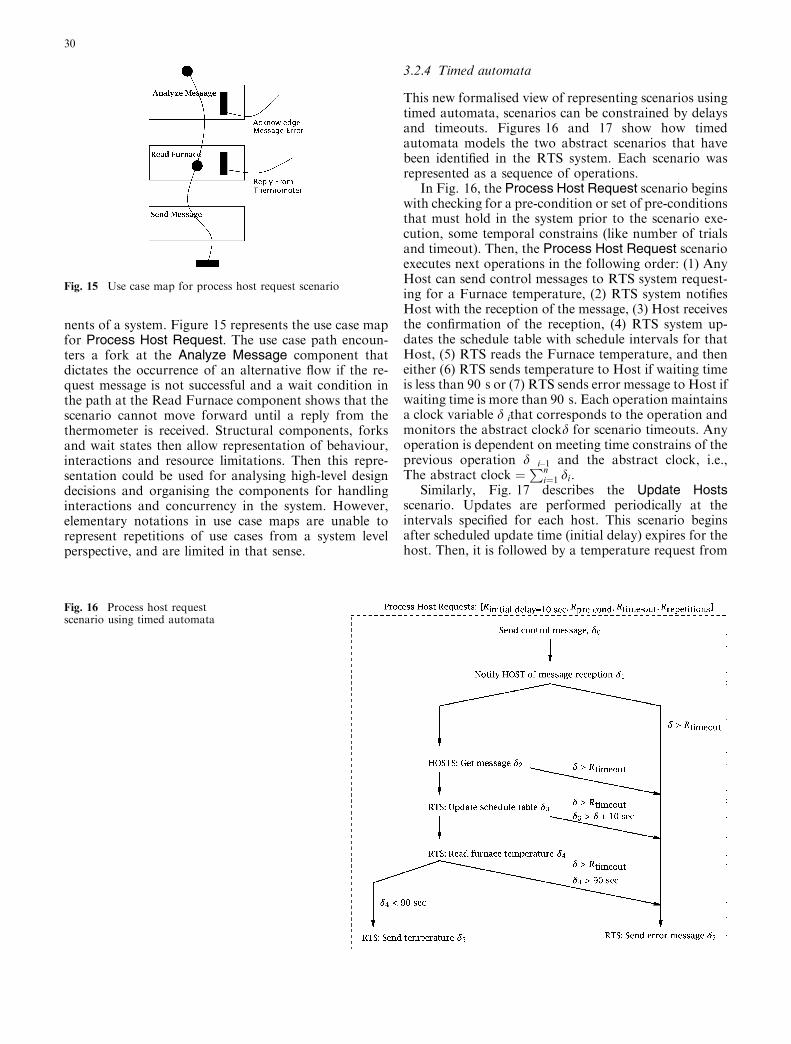
nents of a system. Figure 15 represents the use case mapfor Process Host Request. The use case path encoun-ters a fork at the Analyze Message component thatdictates the occurrence of an alternative flow if the re-quest message is not successful and a wait condition inthe path at the Read Furnace component shows that thescenario cannot move forward until a reply from thethermometer is received. Structural components, forksand wait states then allow representation of behaviour,interactions and resource limitations. Then this repre-sentation could be used for analysing high-level designdecisions and organising the components for handlinginteractions and concurrency in the system. However,elementary notations in use case maps are unable torepresent repetitions of use cases from a system levelperspective, and are limited in that sense.
3.2.4 Timed automata
This new formalised view of representing scenarios usingtimed automata, scenarios can be constrained by delaysand timeouts. Figures 16 and 17 show how timedautomata models the two abstract scenarios that havebeen identified in the RTS system. Each scenario wasrepresented as a sequence of operations.
In Fig. 16, the Process Host Request scenario beginswith checking for a pre-condition or set of pre-conditionsthat must hold in the system prior to the scenario exe-cution, some temporal constrains (like number of trialsand timeout). Then, the Process Host Request scenarioexecutes next operations in the following order: (1) AnyHost can send control messages to RTS system request-ing for a Furnace temperature, (2) RTS system notifiesHost with the reception of the message, (3) Host receivesthe confirmation of the reception, (4) RTS system up-dates the schedule table with schedule intervals for thatHost, (5) RTS reads the Furnace temperature, and theneither (6) RTS sends temperature to Host if waiting timeis less than 90 s or (7) RTS sends error message to Host ifwaiting time is more than 90 s. Each operation maintainsa clock variable d ithat corresponds to the operation andmonitors the abstract clockd for scenario timeouts. Anyoperation is dependent on meeting time constrains of theprevious operation d i–1 and the abstract clock, i.e.,The abstract clock ¼
Pni¼1 di.
Similarly, Fig. 17 describes the Update Hostsscenario. Updates are performed periodically at theintervals specified for each host. This scenario beginsafter scheduled update time (initial delay) expires for thehost. Then, it is followed by a temperature request from
Fig. 15 Use case map for process host request scenario
Fig. 16 Process host requestscenario using timed automata
30
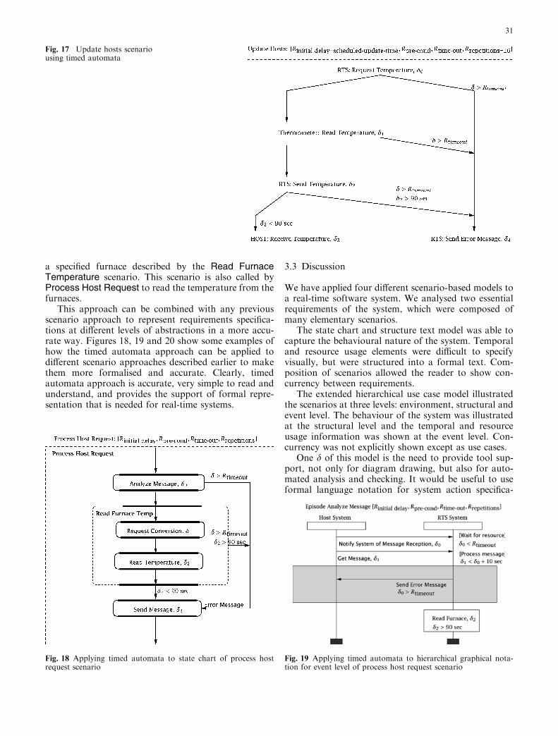
a specified furnace described by the Read FurnaceTemperature scenario. This scenario is also called byProcess Host Request to read the temperature from thefurnaces.
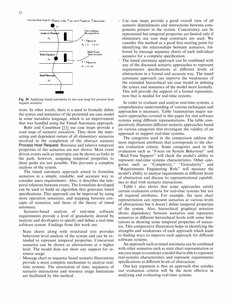
This approach can be combined with any previousscenario approach to represent requirements specifica-tions at different levels of abstractions in a more accu-rate way. Figures 18, 19 and 20 show some examples ofhow the timed automata approach can be applied todifferent scenario approaches described earlier to makethem more formalised and accurate. Clearly, timedautomata approach is accurate, very simple to read andunderstand, and provides the support of formal repre-sentation that is needed for real-time systems.
3.3 Discussion
We have applied four different scenario-based models toa real-time software system. We analysed two essentialrequirements of the system, which were composed ofmany elementary scenarios.
The state chart and structure text model was able tocapture the behavioural nature of the system. Temporaland resource usage elements were difficult to specifyvisually, but were structured into a formal text. Com-position of scenarios allowed the reader to show con-currency between requirements.
The extended hierarchical use case model illustratedthe scenarios at three levels: environment, structural andevent level. The behaviour of the system was illustratedat the structural level and the temporal and resourceusage information was shown at the event level. Con-currency was not explicitly shown except as use cases.
One d of this model is the need to provide tool sup-port, not only for diagram drawing, but also for auto-mated analysis and checking. It would be useful to useformal language notation for system action specifica-
Fig. 17 Update hosts scenariousing timed automata
Fig. 18 Applying timed automata to state chart of process hostrequest scenario
Fig. 19 Applying timed automata to hierarchical graphical nota-tion for event level of process host request scenario
31
tions. In other words, there is a need to formally definethe syntax and semantics of the presented use case modelin some metadata language, which is an improvementthat was handled using the Timed Automata approach.
Buhr and Casselman [11] use case maps provide aroad map of scenario execution. They show the inter-acting and dependent nature of all elementary scenariosinvolved in the completion of the abstract scenarioProcess Host Request. Resource and relative temporalproperties of the scenarios are not shown. Most eventdriven events such as interrupts can be shown as forks inthe path, however, assigning temporal properties tothese paths are not possible. This prevents a completeanalysis of the system.
The timed automata approach aimed to formalisescenarios in a simple, readable, and accurate way toconsider users requirements. Also, it describes the tem-poral relations between events. The formalism developedcan be used to build an algorithm that generates timedspecifications. This approach can be improved by usingmore operation semantics, and mapping between con-cepts of scenarios, and those of the theory of timedautomata.
Scenario-based analysis of real-time softwarerequirements provide a level of granularity desired byanalysts and developers to specify and define a real-timesoftware system. Findings from this work are:
– State charts along with structured text providesbehaviour level analysis of the system and can be ex-tended to represent temporal properties. Concurrentscenarios can be shown as abstractions at a higherlevel. The model does not show any support for re-source usage.
– Message chart or sequence based scenario illustrationsprovide a more complete mechanism to analyse real-time systems. The annotation of time, sequences ofscenario interactions and resource usage limitationsare facilitated by this method.
– Use case maps provide a good overall view of allscenario dependencies and interactions between com-ponents present in the system. Concurrency can berepresented but temporal properties are limited only ifelementary use case map constructs are used. Weconsider this method as a good first starting point foridentifying the relationships between scenarios, fol-lowed by message sequence charts of each individualscenario for a complete specification.
– The timed automata approach can be combined withany of the discussed scenario approaches to representrequirements specifications at different levels ofabstractions in a formal and accurate way. The timedautomata approach can improve the weaknesses ofthe extended hierarchical use case model in definingthe syntax and semantics of the model more formally.This will provide the support of a formal representa-tion that is needed for real-time systems.
In order to evaluate and analyse real-time systems, acomprehensive understanding of various techniques andapproaches is necessary. Table 1summarises major sce-nario approaches covered in this paper for real softwaresystems using different representations. The table com-paratively illustrates different scenario approaches basedon various categories that investigate the validity of anapproach to support real-time systems.
The categories used in the comparison address themost important attributes that corresponds to the cho-sen evaluation criteria. Some categories used in theevaluation such as ‘‘Focus on System Behaviour’’ and‘‘Real-Time Support’’ will check the model’s ability torepresent real-time systems characteristics. Other cate-gories such as ‘‘Complexity,’’ ‘‘Granularity’’ and‘‘Requirements Engineering Role’’ will measure themodel’s ability to analyse requirements at different levelsof abstraction and discuss its representational capabili-ties to deal with scenario interactions.
Table 1 also shows that some approaches satisfycertain evaluation criteria for real-time systems but notall required attributes. For example, the state chartrepresentation can represent scenarios at various levelsof abstractions but it doesn’t define temporal propertiesof the system. Also, hierarchical graphical notationshows dependency between scenarios and representsscenarios at different hierarchical levels with some limi-tations in showing some temporal properties of scenar-ios. This comparative illustration helps in identifying thestrengths and weaknesses of each approach which leadsto finding ways to improve each approach for differentsoftware systems.
An approach such as timed automata can be combinedwith other scenarios such as state chart representation oruse casemaps to construct amodel that is able to representreal-systems characteristics and represent requirementsspecifications at different levels of abstraction.
Our key argument is that an approach that satisfiesour evaluation criteria will be the most effective inanalysing and evaluating real-time systems.
Fig. 20 Applying timed automata to use case map for process hostrequest scenario
32

4 Conclusions
In this paper, we have analysed and evaluated somemethods for analysing scenario-based requirements ofreal-time systems. Real-time systems are characterisedby temporal and resource constraints in addition to userneeds. Our study indicates that the message sequencecharts used by Regnell et al. [9] comes close to depictinga real-time system for complete scenario-based analysiswhen it is combined with the timed automata approach.This new approach will define the syntax and semanticsof the model more formally and provides the supportof a formal representation that is needed for real-timesystems. The use of three different levels in Regnell et al.[9] model allows the analyst to view and reason aboutthe systems responses to the scenarios from differentperspectives thus considering the needs of all stake-holders in a system.
Real-time software systems are characterised by re-sponse times, periodic and asynchronous events andresource constraints. Therefore any real-time require-ments analysis technique should attempt to include thesecharacteristics in their methods. We have discussed foursuch methods above and now provide our recommen-dations.
State chart and message sequence chart illustrationsallow abstraction and thus allows stake holders of thesystem to analyse the system at their level of granu-larity, which enhances understanding of the system.Although state charts are able to represent scenariosand their dependencies to various events there were noprovisions for showing time dependencies of the sce-nario elements. However, when the state chart modelis combined with the timed automata approach, asshown in Fig. 18, time dependencies can be then rep-resented allowing a more thorough and accurateanalysis. Message sequence charts allow the represen-tation of time, events and scenario interactions. How-ever the semantics for representing time are veryelementary and does not provide support for analysingthe temporal properties at the macro level. Extendingthe message sequence charts with the timed automataapproach provided a rich set of semantics and rela-tionships to an abstract clock that could be used forreal-time analysis. Finally, message sequence chartsallowed the manipulation of hardware or system re-sources as shown in Fig. 12 and the state chart methoddid not provide semantics for such notations. There-fore we conclude that extending message sequencecharts with the timed automata approach satisfiesrepresentation and analysis of all real-time character-istics.
Our work was applied to a uni-processor environ-ment and thus was devoid of any true multi-threadedscenarios or concurrent scenarios. Another limitation ofour study is the extent to which use case maps were usedin scenario analysis. It is well known that use case mapsnot only provide the means for scenario or requirements
analysis but also provide the bridge between require-ments analysis and design [11, 16]. Thus use case mapscontain a rich set of notations to annotate interruptservice requests, processes and threads. We have limitedour use of the notations to paths, forks and joins andwait states. Finally this work can be extended to multi-processor based environments to investigate the modelseffectiveness in specifying concurrent scenario-basedsystems. Another interesting application would be to usethe complete use case maps notation for scenario-basedanalysis of real-time systems.
References
1. Jacobson I, Christerson M, Jonsson P, Overgaard, G (1992)Object-oriented software engineering–a use case driven ap-proach. Addison-Wesley, Reading, MA
2. Weidenhaupt K, Pohl K, Jarke M, Haumer P (1998) Scenariosin system development: current practice. IEEESoftw 15(2):34–45
3. Ekelin C, Jonsson J (1996) Real-time system constraints: Wheredo they come from and where do they go? In: Proceedings ofthe International Workshop on Real-Time Constraints, Alex-andria, VA, October 1999, pp 53-57
4. Amyot D, Mussbacher G (2000) On the extension of UMLwith use case maps concepts. In: Proceedings of UML2000,York, UK, October 2000. Lecture notes in computer science,vol 1939. Springer, Berlin Heidelberg New York, pp 16-31
5. Glinz M (2000) Improving the quality of requirements withscenarios. In: Proceedings of the Second World Congress forSoftware Quality (2WCSQ), Yokohama, September 2000, pp55–60
6. Glinz M (2000 Problems and deficiencies of UML as arequirements specification language. Proceedings of the 10thInternational Workshop on Software Specifications and Design(IWSSD-10), San Diego, November 2000, pp 11–22
7. Glinz M (2000) A lightweight approach to consistency of sce-narios and class models. In: Proceedings 4th IEEE Interna-tional Conference on Requirements Engineering. Schaumburg,IL, June 2000, pp 49–58
8. Harel D (1987) StateCharts: a visual formalism for complexsystems. SciComput Program 8:231–274
9. Regnell B, Andersson M, Bergstrand J (1996) A hierarchicaluse case model with graphical representation. In: Proceedingsof ECBS’96, IEEE International Symposium and Workshop onEngineering of Computer-Based Systems, March 1996
10. Message Sequence Chart (MSC) (1993) ITU-T Recommenda-tion Z.120, International Telecommunication Union
11. Buhr R, Casselman R (1996) Use case maps for object-orientedsystems. Prentice Hall
12. Hsia P, Samuel J, Gao J, Kung D (1994) Formal approach toscenario analysis. IEEESoftw 11(2):33-41
13. Leveson N, Heimdhal H, Hildreth H, Reese J (1994)Requirements specifications for process-control systems: les-sons learned and steps to the future. IEEETransSoftwEng20(9):684-706
14. Some S, Dssouli R, Vaucher J (1995) From scenarios to timedautomata: building specifications from users requirements. AsiaPacific Software Engineering Conference, December 1995
15. Barbacci M, Carriere S, Feller P, Klien M, Kazman R, LipsonH, Longstaff T, Weinstock C (1998) Steps in an architecturetradeoff analysis method: quality attribute models and analysis.Technical Report TR-97–029. Software Engineering Institute,Pittsburgh, PA
16. Saiedian H, Dale R (2000) Requirements engineering: makingthe connection between the software developer and customer.Information and Software Technology 42(4):419–428
33