safety - Wieland-electric
122
safety safety Safe System Solutions for Automation Technology Catalog 2016
-
Upload
khangminh22 -
Category
Documents
-
view
0 -
download
0
Transcript of safety - Wieland-electric

safe
ty
safety
safetySafe System Solutions
for Automation Technology
Catalog 2016

2
Company headquarters in Bamberg
Sales Center in Bamberg
STOCKO main plant in Wuppertal
Wieland Electric GmbH is a medium-sized family-run
electrical and electronics company headquartered
in Bamberg. Founded in 1910, Wieland is one of the
pioneers of electrical connection technology.
This family business with its international outlook is
a market leader in pluggable installation technology
for functional buildings, with subsidiaries worldwide
and production lines not only in Bamberg but also
in the Czech Republic and China.
The Wieland Group, which has included STOCKO
Contact GmbH & Co. KG since 1998, is therefore
represented in over 70 countries and employs some
2,200 people.
AT HOME ALL OVER THE WORLD
Building technology
Wind power
Machine building
Lighting technology
Heating, ventilation, air conditioning
Solutions for

3
contacts are green
R D Yaht
27,? ßN
2N
th?
Software/configuration tools• wiemarc, labeling of terminal strips• wieplan, configuration of terminal
strips• revos configurator for connectors• gesis®plan for building installation• podis®plan for configuring the
podis® energy bus system• samos®plan5+, programming tool for
samos®pro compact
Product portfolio• Electronic and electrical engineering
for the control cabinet• Safety technology• Network and field bus systems• Energy bus systems for industry and
buildings• Connectors up to protection type IP 6X• Building automation• PCB terminals and plug connectors• Sensor/actuator cabling
Industries• Machine building• Construction machines & cranes• Buildings and lighting• Logistics• Power engineering• Renewable energy sources• Heating, ventilation and air conditioning
systems
Safety training• Software validation• CSE certified safety engineers• Basics and standards of functional
safety• Modification of old machines and
major changes• Design of safety functions and
calculation with Sistema• Machinery Directive, liability issues
and CE conformity explanations
Business services• Pre-assembly and wiring • Product labeling service• Integrated solutions inside distributors• Customized solutions• On-site project support • Optimization of decentralized,
pluggable installation solutions• Certified machine safety tests
Why Wieland?• Standardized industrial solutions• Customized solutions• Support for your project• Broad product portfolio• Application worldwide due to
international licenses• Group-wide observance of human
rights, including at suppliers• Eco-friendly production

safety
ß @ Y t
safety
4
Overview of safety technologyFrom the sensor pro safety sensors to the safe relay safety relay family and the modular samos®safety modules to the samos®pro safety controllers, Wieland Electric offers the right product for your needs.
Safe signal acquisition
sensor pro
Modular safety modules
samos®
Universal safety relays
safe relay
Compact safety controllers
samos® pro compact
Tested technology
Of course, Wieland Electric offers only thoroughly tested and certified safety technology (i.e., all technical safety products have been approved by recognized testing institutes and meet current regulations and standards).

safetysafety
samos® pro samos® pro compact 8samos® plan 5+ 10SP-COP1 / SP-COP2 12SP-SDIO / SP-SDI 14
1617
samos® 18SA-BM 22SA-IN 23SA-OR-S1 / SA-OR-S2 24
25safe relay 26
28SNO 4083KM 32
SNO 4062K / KM 34
SNO 4063K / KM 36
SNA 4043K / KM / KE, SNA 4044K / KM
38
SNA 4063K / KM, SNA 4064 K / KM
40
SNO 4003K 42SNO 1012K 44SNS 4074K / SNS 4084K 46SVM 4001K 48SNT 4M63K 50SNZ 4052K 52SNZ 1022K 54SNV 4063KL 56
SNV 4063KP 58
SNV 4074SL / SNV 4076SL 60
SNV 4274 SL / SNV 4074ST 62
SNE 1 64SNE 4003K 66SNE 4004K / KV 68SNE 4012K / SNE 4024K 70SNE 4028S 72
sensor pro 74SLC 76SLD 80
84SNH 90SIN 96SMS 100STS 104SMA 108SMI 1001 112
114
116
119
120
5
safe
tyse
nso
r pr
osa
fe re
la
ysa
mos®
pro
sam
os®
ContentsPreface
Programming toolController Module Input / Output Module Gateway Accessories
PrefaceBasic ModuleInput Module Relais Output ModuleGateway
PrefaceOverviewBasic Device Monitoring of emergency stop, safety gates
and light barriersMonitoring of emergency stop, safety gates and light barriersMonitoring of emergency stop, safety gates and light barriersMonitoring of emergency stop, safety gates and light barriersMonitoring of emergency stop, safety gates and light barriersMonitoring of emergency stop + safety gatesMonitoring of emergency stop + safety gatesStandstill monitorStandstill monitorMonitoring of emergency stop + safety gatesTwo-hand relay type IICTwo-hand relay type IIA
Basic Device with time function
Monitoring of emergency stop, safety gates and light barriers, OFF-delayedMonitoring of emergency stop, safety gates and light barriers, ON-delayedMonitoring of emergency stop, safety gates and light barriers, OFF-delayedMonitoring of emergency stop, safety gates and light barriers, OFF-/ON-delayed
Safe Contact Expansion Relay
Contact ExpansionContact ExpansionContact ExpansionContact ExpansionContact Expansion
PrefaceLight curtains / light grids
Safety light curtainSafety light grid Accessories
Emergency stop Emergency stop buttonSafety switch Safety switch with guard locking
Safety switch with separate actuatorTransponder switch Non-contact safety switches Magnetic switch Magnetic safety switchInterface Magnetic switch interface
Complete solutions for machinery and plant engineering Graphic art
Support Software, Training, Hotline
Subsidiaries Addresses worldwide
Glossary Explanation on the overview

safety
EN/IEC 60204-1
EN/IEC 61508
EN/IEC 62061
EN ISO 13849-1
EN/IEC 61511
6
safety
Fit for safety with Wieland
Wieland supports and advises you – from the planning stage right through to start-up – throughout the entire life cycle of a machine or production system. The broad portfolio of safety switching devices covers all important safety functions and fulfills even complex customer requirements.
Important standards for more safety
The safety products from Wieland Electric fulfil a number of international standards and regulations with machine and system safety for various applications playing a major role.
Solutions for many industries
The safety requirements for machine and system control are becoming more demanding in all areas. Wieland Electric offers tailored, innovative solutions ranging from sensors right down to safety control.
Machine building industry
Process industry
Elevator systems
Combustion plants

safety
S1
S2
F1
F2
F1
F2
P2
P2
P2
P2
P1
P1
P1
P1
a
b
c
d
e
S3-4 5-7 8-10 11-13 14-15
4 SIL 2 SIL 2 SIL 2 SIL 3 SIL 3
3 AM SIL 1 SIL 2 SIL 3
2 AM SIL 1 SIL 2
1 AM SIL 1
7
safety
safe
ty
Risk assessment according to EN ISO 13849-1
As the successor standard to EN 954-1, EN ISO 13849-1 is based on the known categories. EN ISO 13849-1 deals with the complete safety functions, including all the devices involved in the their design.EN ISO 13849-1 makes a quantitative assessment of the safety functions. Using the categories as a basis, the so-called Performance Levels (PL) are applied for this purpose.
Low risk
High risk
Performance Level required PLrrStarting point
for the risk assessment
Effects and severity Class K = F + W + P
Death, loss of an eye or an arm
Permanent, loss of fingers
Reversible, medical treatment
Reversible, First Aid
Safety assessment according to EN/IEC 62061
In electrical control technology according to EN/IEC 62061, safety requirements can be divided into so-called Safety Integrity Levels (SIL). The risk assessment takes into account the severity of the injury (S), the frequency and duration of the exposure to the hazard (F), the probability of occurrence of a potentially hazardous incident (W), and the possibility of avoiding or limiting the damage (P). Hence, at the highest protection level SIL 3, the safety function must be maintained at all times.

8
samos® pro
With the highest power in the smallest space, the safety control samos®pro compact sets new standards in the area of machine automation.
Overview of benefits
• 24 safe in- and outputs on 45 mm construc-tion width for space and cost savings
• USB and Ethernet interfaces for remote main-tenance always on board
• Industrial Ethernet protocols integrated
• 512 Mbyte program memory offers space for each project
• 4 A switching power at each output
• Ambient temperature –25 °C to +65 °C
• Modular extendability to up to 172 secure in-/outputs
• Optical display of all in- and outputs in system
• Pluggable connection technology with either screw or push-in terminal blocks
samos®pro compact –The safety control of the next generation

9
sam
os®
pr
o
samos® pro
samos®pro compact is suitable for monitor-ing non-contact safety sensors, Emergency Off buttons, protective door switches and door closures, two-hand controls as well as testable safety light barriers, light curtains and laser scanners.
samos®pro compact – Universal application
samos®pro compact is not only suitable for use in machinery and plant engineering but also, for example, for safety-related control tasks in elevator installations, industrial combustion plants and process technology systems.
Applications in many branches

10
samos® pro
With the new software samos®plan 5+ for the system samos®pro compact, programming is now even easier. With its many practical functions, samos®plan 5+ supports the project developer in generating and validating safety applications, and documenting them in full compliance with the current Machinery Directive.
samos®plan 5+ – The programming tool for samos®pro compact
• Comprehensive library of reliable, certified functions
• Configurable project documentation at the press of a button
• Integrated simulation and logic analysis of the safety functions
• Convenient support for fieldbus and industrial Ethernet integration
• Online diagnosis and remote maintenance for more transparency
Overview of benefits
Function blocks
Sensors

11
sam
os®
pr
o
samos® pro
Logic analysis
Simulation
Report
Logic
Diagnosis
Hardware

ß Y
SP-COP1-A 24 V DC R1.190.1110.0 1
SP-COP1-C 24 V DC R1.190.1120.0 1
12
samos® pro
Applications• Machine building industry• Combustion plants• Elevator systems• SILCL 3 (EN 62061-1)• PL e / Category 4 (EN ISO 13849-1)
Features• 20 safe inputs, 4 safe outputs• USB interface• SD slot for program memory (memory card SP-COP-
CARD can be ordered separately)
SP-COP1 – COMPACT module
Overview of devices | part numbers
Technical data
Type Rated voltage Terminals Remarks Part no. Std. Pack
Screw terminals, pluggable USB-interface
Push-in terminals, pluggable USB-interface
Function Safety control
Function display 24 LED green (in-/outputs)
3 LED green/red/yellow (module status)
Supply circuit
Operating voltage range 16.8 V DC to 30 V DC
Rated power 3.5 W
Electrical isolation supply circuit - control circuit No
Secure input circuit InQuantity/type 20 / digital
Primary voltage range 15 V DC to 30 V DC
Nominal current 2 mA
Secure input circuit Qn
Quantity/type 4 / digital
Nominal output voltage 24 V DC
Output current per output 4 A
Short-circuit protective device Yes
Interfaces
USB Mini interface Yes
Ethernet interface No
Industrial Ethernet protocol No
Program memory External
General data
Protection class as per DIN EN 60529 (housing/terminals) IP20
Air and creepage distances EN 60664-1
Ambient temperature / storage temperature -25 °C – +65 °C / -25 °C – +75 °C
Norms EN 61508, EN 61511, EN 62061, EN ISO 13849-1, EN 50156-1, EN 81-1
Approvals TÜV, cULus

ß Y
SP-COP2-EN-A 24 V DC R1.190.1210.0 1
SP-COP2-EN-C 24 V DC R1.190.1220.0 1
SP-COP2-ENI-A 24 V DC R1.190.1310.0 1
SP-COP2-ENI-C 24 V DC R1.190.1320.0 1
13
samos® pro
sam
os®
pr
o
Applications• Machine building industry• Combustion plants• Elevator systems• SILCL 3 (EN 62061-1)• PL e / Category 4 (EN ISO 13849-1)
Features• 16 inputs, 4 outputs, 4 configurable I/O• USB interface• Ethernet interface• Industrial Ethernet protocol• SD slot for program memory (memory card SP-COP-
CARD can be ordered separately)
SP-COP2 – COMPACT module with ethernet
Overview of devices | part numbers
Technical data
Type Rated voltage Terminals Remarks Part no. Std. Pack
Screw terminals, pluggable USB- / ETH-interface
Push-in terminals, pluggable USB- / ETH-interface
Screw terminals, pluggable USB- / ETH-interface
Push-in terminals, pluggable USB- / ETH-interface
Function Safety control
Function display 24 LED green (in-/outputs)
4 LED green/red/yellow (module status)
Supply circuit
Operating voltage range 16.8 V DC to 30 V DC
Rated power 3.5 W
Electrical isolation supply circuit - control circuit No
Secure input circuit In SP-COP2-EN SP-COP2-ENI
Quantity/type 20 (16) / digital 20 (16) / digital
Primary voltage range 15 V DC to 30 V DC 15 V DC to 30 V DC
Nominal current 2 mA 2 mA
Secure input circuit Qn
Quantity/type 4 (8) / digital 4 (8) / digital
Nominal output voltage 24 V DC 24 V DC
Output current per output 4 A 4 A
Short-circuit protective device Yes Yes
Interfaces
USB Mini interface Yes Yes
Ethernet interface Yes Yes
Industrial Ethernet protocol No Modbus TCP, Profinet, Ethernet IP
Program memory External External
General data
Protection class as per DIN EN 60529 (housing/terminals) IP20
Air and creepage distances EN 60664-1
Ambient temperature / storage temperature -25 °C – +65 °C / -25 °C – +75 °C
Norms EN 61508, EN 61511, EN 62061, EN ISO 13849-1, EN 50156-1, EN 81-1
Approvals TÜV, cULus

SP-SDIO84-P1-K-A 24 V DC R1.190.0030.0 1
SP-SDIO84-P1-K-C 24 V DC R1.190.0040.0 1
TÜV, cULus
ß Y
14
samos® pro
Applications• Machine building industry• Combustion plants• Elevator systems• SILCL 3 (EN 62061-1)• PL e / Category 4 (EN ISO 13849-1)
Features• 8 safe inputs• 4 safe outputs (with/without output test-pulses)• 2 outputs (e.g., test signals)
SP-SDIO – Input- / output module
Overview of devices | part numbers
Technical data
Type Rated voltage Terminals Remarks Part no. Std. Pack
Screw terminals, pluggable with/without output test-pulses
Push-in terminals, pluggable with/without output test-pulses
Function display 13 LEDs, green/red
Power supply circuit
Operating voltage range 16.8 V DC to 30 V DC
Rated consumption 1.8 W
Electrical isolation power supply circuit - control circuit no
Safe input circuit I1 – I8
Quantity / type 8 / digital
Input voltage range 15 V DC to 30 V DC
Rated current 3 mA
Safe output circuits Q1 – Q4
Quantity / type 4 / digital
Output voltage 24 V DC
Output current In per exit 4 A
Output circuits X1, X2
Quantity / type 2 / digital
Output voltage 24 V DC
Output current In per exit 0.5 A
General data
Protection degree according to DIN 60529 (housing / terminals) IP40 / IP20
Creepage distances and clearances EN 60664-1
Ambient temperature / storage temperature -25°C – +65°C / -25°C – +75°C
Standards EN 61508, EN 61511, EN 62061, EN ISO 13849-1, EN 50156-1, EN 81-1
Approvals

TÜV, cULus
SP-SDI8-P1-K-A 24 V DC R1.190.0050.0 1
SP-SDI8-P1-K-C 24 V DC R1.190.0060.0 1
ß Y
15
samos® pro
sam
os®
pr
o
Applications• Machine building industry• Combustion plants• Elevator systems• SILCL 3 (EN 62061-1)• PL e / Category 4 (EN ISO 13849-1)
Features• 8 safe inputs• 8 outputs (e.g., test signals)
SP-SDI – Input module
Type Rated voltage Terminals Part no. Std. pack
Screw terminals, pluggable
Push-in terminals, pluggable
Overview of devices | part numbers
Function display 13 LEDs, green/red
Power supply circuit
Operating voltage range 16.8 V DC to 30 V DC
Rated consumption 1.8 W
Electrical isolation power supply circuit - control circuit no
Safe input circuit I1 – I8
Quantity / type 8 / digital
Input voltage range 15 V DC to 30 V DC
Rated current 3 mA
Output circuits X1, X2
Quantity / type 2 / digital
Output voltage 24 V DC
Output current In per exit 0.5 A
General data
Protection degree according to DIN 60529 (housing / terminals) IP40 / IP20
Creepage distances and clearances EN 60664-1
Ambient temperature / storage temperature -25°C – +65°C / -25°C – +75°C
Standards EN 61508, EN 61511, EN 62061, EN ISO 13849-1, EN 50156-1, EN 81-1
Approvals
Technical data
Note:
Safe relay contacts are expanded using the series SNE contact expansion relay (from Page 64). Types SNE 4024K and SNE 4012K in particular are ideal for contact expansion.

SP-CANopen 24 V DC R1.190.0210.0 1
SP-PROFIBUS-DP 24 V DC R1.190.0190.0 1
SP-EN-ETC 24 V DC R1.190.0160.0 1
Y
16
samos® pro
With the samos® pro gateways, system information can be transferred between the samos® pro safe control and an industrial control, a visualization system or a PC.
Gateway
SP-PROFIBUS-DP
Features• Fieldbus protocol PROFIBUS-DP• Bidirectional communication with PLC• Transfer rate 12 MBaud• Transfer of 50 bytes of data• Simple configuration with samos® plan
SP-EN-ETC
Features• EtherCAT industrial Ethernet protocol• Bidirectional communication • Transfer of 50 bytes of data• Simple configuration with samos® plan
Type Rated voltage Remark Part no. Std. pack
CANopen
PROFIBUS-DP
ETHERCAT
Overview of devices | part numbers
• Direct HMI connection
• Remote diagnosis and programming
• Read and write 50 byte
• Input and output states
• Configuration data
• Process data from the PLC
• Fault data (e.g. fault data of the connected sensor technology)
Application examples:
SP-CANopen
Features• Fieldbus protocol CANopen• Bidirectional communication with PLC• Transfer rate up to 1 MBit/s• Transfer of 50 bytes of data• Simple configuration with samos® plan

SP-COP-CARD1 R1.190.1000.0 1
SP-CABLE-USB1 R1.190.1010.0 1
SP-CABLE-ETH1 R1.190.1020.0 1
SP-COP-STARTER-SET R1.190.1100.0 1
SP-VISUAL-SET R1.190.0280.0 1
SP-COVER R1.190.1040.0 1
SAFETY SCHRAUBKL.SET 99.208.9999.9 1
SAFETY PUSH IN SET 99.209.9999.9 1
WKFN 2,5 E/35 GO-URL 56.703.8755.9 100
APFN 2,5 E/35 07.312.7355.0 10
WKFN 2,5 E/35 GO-URL
SP-CABLE-USB1
SP-COP-CARD1
SP-CABLE-ETH1
SP-VISUAL-SET
SAFETY PUSH IN SET
SAFETY SCHRAUBKL. SET
17
samos® pro
sam
os®
pr
o
Starter set & accessories
samos®pro compact starter set • A safe way to get started
• Contains all required components
• With programming tool samos®plan 5+
• With USB-RS232 converter
Overview of devices | part numbers
You can get the free program-ming tool samos®plan 5+ at www.wieland-electric.com Service / Software
Type Description Part no. Std. pack
Memory-card for SP-COP
USB cable for SP-COP, 1.8 m
Ethernet cable for SP-COP, 2 m
Content: SP-COP2-EN-A, SP-COP-CARD1, SP-PLAN5+, SP-CABLE-USB1, SP-CABLE-ETH1
Visualization set (touch panel 3.5'' color, SP-CABLE4, software driver)
SD card slot cover for SP-COP modules
Screw terminal set with 4 different codings for 5 devices
Push-in terminal set with 4 different codings for 5 devices
fasis - multi-tier block with diodes
End plate
samos®pro accessories • SP-COP-CARD1: Memory-card for SP-COP
• SP-CABLE-USB1: USB cable for SP-COP, 1.8 m
• SP-CABLE-ETH1: Ethernet cable for SP-COP, 2 m
• SP-COP-STARTER-SET: Set including SP-COP2-EN-A, SP-COP-CARD1, SP-PLAN5+, SP-CABLE-USB1, SP-CABLE-ETH1
• Programming software samos®plan 5+
• WKFN 2,5 E/35 GO-URL fasis-multi-tier block with diodes
• SP-FILTER1 output filter, 24 V DC, 680 nF
• SP-FILTER2 output filter, 24 V DC, 2,2 μF
• Screw terminal set with 4 different codings for 5 devices
• Push-in terminal set with 4 different codings for 5 devices

18
samos®
All safety functions are set with a screwdriver without programming
software and can be read at the device.
samos® stands for SAfety MOdular System. The safety system with just a multifunctional, permanently coded basic modules is built on the modular kit principle and grows module by module along with the safety task.
• samos® combines a wide variety of safety sensors which monitor a machine or system for technical safety either individually, in combination or all together.
• samos® replaces special devices with pre-defined, practice-oriented function blocks for monitoring emergency stop, position swit-ches, two-hand buttons and light curtains, for example.
• samos® uses safe logical link functions for simple creation of dependent or independent safety zones.
• samos® offers comprehensive diagnosis by gateways via Profibus-DP, CANopen and DeviceNet or via Industrial Ethernet.
samos® –safety made simple

19
sam
os®
samos®
Example: Single Functions
Emergency stop
Safety door
Controlled stopping
Monitoring BWS type 4
Monitoring BWS type 2 with testing
Testable PDF sensors
Safe position monitoring
Static valve monitoring
Two-hand applications to IIIA and IIIC
4-wire switching mats
Set release delay of output Q4 or
Q3 and Q4
Example: Combination Functions
Example: Special Functions
Jog mode
Setup mode
MUTING and BYPASS
Example: Dual Functions

1 432
1
2
3
4
20
samos®
Basic mastermodule
Inputmodule
Output modulerelay
Gateway
Basic master moduleSafety module with 9 function blocks,8 safe inputs and 4 safe outputs(also suitable for stand-alone operation)
Input moduleExpansion module with 10function blocks and 8 safe inputs
Output module relayExpansion modules with 2 or 4 safe,potential-free relay contacts
GatewayFieldbus or Ethernet gateways for easydiagnosis of the samos® system
Modular design
In its maximum configuration samos® consists of one basic master module and additional modules to expand function blocks, inputs and outputs.
• Up to 12 safe active modules (input modules)
• Up to 4 additional safe passive output module relays
• 1 additional gateway

21
sam
os®
samos®
Intelligently connected modules
The modules are connected to a standard DIN rail and pressed together. Connected on the left of the rail is the Master, the obligatory base module (with coding 1), input modules (coding matches the base module arranged to the left) and relay output modules. All modules in the samos overall system are permanently coded and are always permanently assigned to a simi-larly permanently coded basic module, which eliminates any confusion during service work, for instance.The relay modules are integrated in the function via external wiring. If necessary such system group are made up of basic modules, input modules and relay output modules can be wired together. This allows the implementation of a wide variety of input/output functions withseparate or combined effects.
Functions with added value
The functions of the basic module and the input modules are set either individually or in combination on the front with 10-position rotary switches (e.g. emergency stop and protective door monitoring with controlled shutdown).
The clear and simple userinterface helps to implement safe solutions.
samos® – maximum flexibility
samos® modulesClear handling – maximum flexibility
Additional functions such as automaticreset, startup and re-startup blocking or retriggering of the off-delay are implemented with terminal configuration.

SA-BM-S1-4EKL-A, 5s 24 V DC 1 R1.180.0010.0 1
SA-BM-S1-4EKL-A, 50s 24 V DC 1 R1.180.0020.0 1
SA-BM-S1-4EKL-C, 5s 24 V DC 1 R1.180.0360.0 1
SA-BM-S1-4EKL-C, 50s 24 V DC 1 R1.180.0370.0 1
TÜV, cULus
ß Y
22
samos®
Applications• Machine building industry• Combustion plants• SILCL 3 (EN 62061-1)• PL e / Category 4 (EN ISO 13849-1)
Features• 9 function blocks• 4 inputs for safety sensors• 4 safe semiconductor inputs• Adjustable OFF- delay
SA-BM – Basic module
Overview of devices | part numbers
Technical data
Type Rated voltage Terminals Coding Part no. Std. pack
Screw terminals, pluggable
Screw terminals, pluggable
Push-in terminals, pluggable
Push-in terminals, pluggable
Function display 12 LEDs, green/red
Power supply circuit
Operating voltage range 19.2 V DC to 30 V DC
Rated consumption 1.8 W
Electrical isolation power supply circuit - control circuit no
Safe input circuit I1 – I4
Input voltage range 15 V DC to 30 V DC
Rated current 3 mA
Safe control circuits EN, S1 – S3
Input voltage range 15 V DC to 30 V DC
Rated current 3 mA
Safe output circuits Q1 – Q4
Output voltage 24 V DC
Output current In per exit 2 A
Output circuits X1, X2
Output voltage 24 V DC
Output current In per exit 0.5 A
General technical data
Protection degree according to DIN 60529 (housing / terminals) IP40 / IP20
Creepage distances and clearances EN 60664-1
Ambient temperature / storage temperature -25°C – +55°C / -25°C – +75°C
Standards EN 61508, EN 62061, EN ISO 13849-1, EN 50156-1
Approvals
SA-IN-S1-K-A 24 V DC 1 R1.180.0070.0 1
SA-IN-S1-K-C 24 V DC 1 R1.180.0420.0 1
TÜV, cULus
ß Y
23
sam
os®
samos®
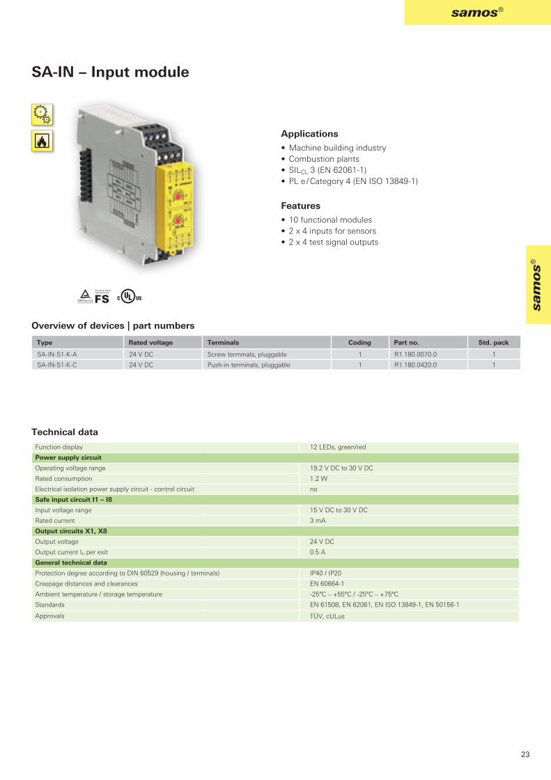
Applications• Machine building industry• Combustion plants• SILCL 3 (EN 62061-1)• PL e / Category 4 (EN ISO 13849-1)
Features• 10 functional modules• 2 x 4 inputs for sensors• 2 x 4 test signal outputs
SA-IN – Input module
Overview of devices | part numbers
Technical data
Type Rated voltage Terminals Coding Part no. Std. pack
Screw terminals, pluggable
Push-in terminals, pluggable
Function display 12 LEDs, green/red
Power supply circuit
Operating voltage range 19.2 V DC to 30 V DC
Rated consumption 1.2 W
Electrical isolation power supply circuit - control circuit no
Safe input circuit I1 – I8
Input voltage range 15 V DC to 30 V DC
Rated current 3 mA
Output circuits X1, X8
Output voltage 24 V DC
Output current In per exit 0.5 A
General technical data
Protection degree according to DIN 60529 (housing / terminals) IP40 / IP20
Creepage distances and clearances EN 60664-1
Ambient temperature / storage temperature -25°C – +55°C / -25°C – +75°C
Standards EN 61508, EN 62061, EN ISO 13849-1, EN 50156-1
Approvals

SA-OR-S1-4RK-A 24 V DC R1.180.0080.0 1
SA-OR-S2-2RK-A 24 V DC R1.180.0320.0 1
SA-OR-S1-4RK-C 24 V DC R1.180.0430.0 1
SA-OR-S2-2RK-C 24 V DC R1.180.0440.0 1
TÜV, cULus
ß Y
24
samos®
Applications• Machine building industry• Combustion plants• SILCL 3 (EN 62061-1)• PL e / Category 4 (EN ISO 13849-1)
Features• Output module SA-OR-S1• 2 x 2 safe enabling with switching up to 230 V AC / 6 A• 2 x outputs 24 V DC / 50 mA• 2 x 1 feedback circuit (NC contact)
• Output module SA-OR-S2• 1 x 2 safe enabling with switching up to 230 V AC / 6 A• 1 x 1 potential-carrying safe output 24 V DC / 50 mA for
signaling or safe logical operation• 1 x 1 feedback circuit (NC contact)
SA-OR – Output module
Overview of devices | part numbers
Function display 3 or 2 LEDs, green
Input circuit B1, B2
Input voltage range 18 V DC to 30 V DC
Electrical isolation power supply circuit – input circuit no
Electrical isolation input circuit - output circuit yes
Electrical isolation power supply circuit - output circuit yes
Rated consumption 2.2 W to 1.1 W
Release delay 30 ms
Output circuits (relays)
Switching voltage 230 V AC
Output current In per exit 6 A
Output circuits (Y14, Y24)
Switching voltage 30 V DC
Output current In per exit 75 mA
General technical data
Protection degree according to DIN 60529 (housing / terminals) IP40 / IP20
Creepage distances and clearances EN 60664-1
Ambient temperature / storage temperature -25°C – +55°C / -25°C – +75°C
Standards EN 61508, EN 62061, EN ISO 13849-1, EN 50156-1
Approvals
Technical data
Type Rated voltage Terminals Part no. Std. pack
Screw terminals, pluggable
Screw terminals, pluggable
Push-in terminals, pluggable
Push-in terminals, pluggable

SA-CANopen-A 24 V DC R1.180.0100.0 1
SA-DeviceNet-A 24 V DC R1.180.0350.0 1
SA-PROFIBUS-DP-A 24 V DC R1.180.0090.0 1
Y
25
sam
os®
samos®
SA-PROFIBUS-DP
Features• Fieldbus protocol PROFIBUS-DP• Communication with PLC• Transfer rate up to 12 MBaud• 4 semi-conductor outputs on board
SA-CANopen
Features• Fieldbus protocol CANopen• Communication with PLC• Transfer rate up to 1 MBit/s• 4 semi-conductor outputs on board
SA-DeviceNet
Features• Fieldbus protocol DeviceNet• Communication with PLC• Transfer rate up to 500 KBit/s• 4 semi-conductor outputs on board
Gateway
With the samos® gateways, system information can be transferred from the configurable samos® safety system to an industrial control or a visualization system, for example
Overview of devices | part numbers
Type Rated voltage Terminals Part no. Std. pack
Screw terminals, pluggable
Screw terminals, pluggable
Screw terminals, pluggable
• Input and Output states
• Configuration data
• Fault data (e.g., configuration faults, faults during operation)
Application examples:

safe relay
SNA, SNO, SNS, SNT, SNZ
SNV
SNE
26
safe relay
safe relay – universal safety relays
The safe relay safety relays offer customized solutions for the safety of man and machine.These devices combine excellent technical performance with efficient use in everyday industrial applications. Compact design, flexible use and flexible connection methods are the decisive advantages of these devices.Depending on the application and the selected device, the safety relays can be used up to PL e / Category 4 ( (EN ISO 13849-1) or SIL 3 (EN 62061).
Versatile application options
• Emergency stop monitoring• Monitoring of protective doors and interlocks• Light curtain monitoring• Two-hand relay• Monitoring of valves and limit value switches• Safe contact expansions
The simple and safeconnection for every situation.
Safety relays

SNA, SNO, SNS, SNT, SNZ
SNV
SNE
27
safe relay
safe
rel
ay
Basic devices with time function
The basic devices of the SNV device families feature a safe internal logic component for the monitoring of the respective safety functions.In addition, these devices offer time-delayed, safe outputs and a corresponding time setting on the device.
Basic devices
Basic devices with time function
Contact expansion relays
Basic devices
The basic devices of the SNA, SNO, SNS, SNT and SNZ device families feature a safeinternal logic component for the monitoring of the respective safety functions.
Contact expansion relays
The contact expansion relays of the SNE device family feature a redundant internal structure and are used for contact multiplication on, for example, basic devices.
Further informations about the screw terminal set and the push-in terminal set see page 17.

SNO 4083KM
SNO 4062K/KM
SNO 4063K/KM
SNA 4043K/KM
SNA 4044K/KM
SNA 4063K/KM
SNA 4064K/KM SNO 4003K SNO 1012K SNS
4074K/4084K SVM 4001K SNT 4M63K SNZ 4052K SNZ 1022K
32 34 36 38 38 40 40 42 44 46 48 50 52 54
0,5 1,5 0,5 0,5
24 24 12 24 24 24 24 24 24 24 24 24 24 24 24
115-23024
115-120 230
24 42-48
115-120 230
24 42-48
115-120 230
2442-48
115-120 230
24 42-48
115-120230
24115-120
23024
24 115-120
230
24 115-120
230
24115-230
28
safe relay
2)
3) 3)
2) 2)
2)
Overview – Basic Devices
1) PLe contact expansion 2) 24 V devices only 3) possible only in isolated cases and according to the risk assessment of the machine functions
Type
Page
Ap
plic
atio
nIn
pu
t C
ircu
its
Sta
rtC
on
tact
sC
har
acte
rist
ics
Rated voltage DC (V)
Rated voltage AC (V)

SNO 4083KM
SNO 4062K/KM
SNO 4063K/KM
SNA 4043K/KM
SNA 4044K/KM
SNA 4063K/KM
SNA 4064K/KM SNO 4003K SNO 1012K SNS
4074K/4084K SVM 4001K SNT 4M63K SNZ 4052K SNZ 1022K
32 34 36 38 38 40 40 42 44 46 48 50 52 54
0,5 1,5 0,5 0,5
24 24 12 24 24 24 24 24 24 24 24 24 24 24 24
115-23024
115-120 230
24 42-48
115-120 230
24 42-48
115-120 230
2442-48
115-120 230
24 42-48
115-120230
24115-120
23024
24 115-120
230
24 115-120
230
24115-230
29
safe relay
safe
rel
ay
1)
1)
1)
For glossary, see cover page 120

SNV 4063KL SNV 4063KP SNV 4074SL SNV 4076SL SNV 4274SL SNV 4074ST SNE 1 SNE 4003K SNE 4004K SNE 4004KV SNE 4012K SNE 4024K SNE 4028S
56 58 60 60 62 62 64 66 68 68 70 70 72
1,0 1,0 1,0 1,0
24 24 24 24 24 24 24 24 24 24 24 24 24
115-230 115-230 115-230 115-230 24 24115-230
30
safe relay
1) 1)
1) 1)
1) applies to undelayed contacts; the following applies to delayed contacts: PL d / category 3 / SILCL 22) depends on the category of the basic device or the safety analysis
Type
Page
Ap
plic
atio
nIn
pu
t C
ircu
its
Sta
rtC
on
tact
sC
har
acte
rist
ics
Rated voltage DC (V)
Rated voltage AC (V)
Overview – Basic Devices with time function

SNV 4063KL SNV 4063KP SNV 4074SL SNV 4076SL SNV 4274SL SNV 4074ST SNE 1 SNE 4003K SNE 4004K SNE 4004KV SNE 4012K SNE 4024K SNE 4028S
56 58 60 60 62 62 64 66 68 68 70 70 72
1,0 1,0 1,0 1,0
24 24 24 24 24 24 24 24 24 24 24 24 24
115-230 115-230 115-230 115-230 24 24115-230
31
safe relay
safe
rel
ay
2) 2) 2) 2) 2)
2) 2) 2) 2) 2)
2) 2)
2) 2)
For glossary, see cover page 120
Contact-Expansion Relais

ß Y t L
SNO 4083KM
32
safe relay
Function After the supply voltage is applied to terminals A1/A2 and the safety inputs are closed, the enabling current paths (NO contacts) are closed and the signal current path (NC contact) is opened automatically or by pressing the reset button (manual monitored start). When the safety inputs are opened/ de-energized the enabling current paths (NO contacts) are opened immediately and the signal current path (NC contact) is closed.
Reduced installation work – The SNO 4083KM requires fewer connection cables, irrespective of whether operation with or without cross monitoring is desired. This saves time and money when it comes to wiring.
• Universal application – The two-channel control of the device is carried out by either an NC/NC or an NC/NO combination of the safety sensor. In the case of two-channel control of the device, a synchronous time is automatically monitored between the two channels.
• SafeStart function – When the device is used with a manual start, the reset input is automatically monitored for a rising and falling signal edge. A manual reset signal is only accepted if the control inputs of the device are activated by the safe transducer (e.g. emergency stop button) during the entire activation procedure.
• Monoflop function – This function is integrated into the device and prevents device interlocking under all circumstances. This is a decisive advantage in applications where very short interruptions of the safety-related signals can occur, or in the case of transducers with bouncing contacts or safe optical sensors (BWS), for example.
• Simple diagnosis – The device features an intelligent display system that shows the user the different operating modes of the device in its different applications. This means, for example, that when the control inputs are closed and manual start has been selected, a reset signal is displayed, which has not yet been given. Fault states in the control (e.g. synchronous time exceeded or a short-circuit in two-channel control) are also signaled to the user via a blinking code.
Applications• Protection of people and machinery• Monitoring of emergency stop applications• Monitoring of safety gates• Monitoring of light barriers• Up to PL e / Categorie 4 (EN ISO 13849-1)• Up to SILCL 3 (EN 62061)
Features• Stop Category 0 according to EN 60204-1• Single-channel or two-channel control• Two-channel control with NC/NC or NC/NO• Manual or automatic start• SafeStart• Cross monitoring • Synchronous time monitoring for two-channel control• 3 enabling current path / 1 signalling current path
SNO 4083KM Monitoring of emergency stop, safety gates and light barriers
Circuit diagram

SNO 4083KM-A 24 V DC R1.188.3580.0 1
SNO 4083KM-A 115-230 V AC R1.188.3590.0 1
SNO 4083KM-C 24 V DC R1.188.3600.0 1
SNO 4083KM-C 115-230 V AC R1.188.3610.0 1
SNO 4083KM-A 24 V DC R1.188.3830.0 1
SNO 4083KM-A 115-230 V AC R1.188.3840.0 1
SNO 4083KM-C 24 V DC R1.188.3850.0 1
SNO 4083KM-C 115-230 V AC R1.188.3860.0 1
TÜV, cULus, CCC, GL
33
safe relay
safe
rel
ay
Overview of devices | part numbers
Technical data
Type Rated voltage Synchr. Time Terminals Part no. Std. pack
1.5 s Screw terminals, pluggable
1.5 s Screw terminals, pluggable
1.5 s Push-in terminals, pluggable
1.5 s Push-in terminals, pluggable
0.5 s Screw terminals, pluggable
0.5 s Screw terminals, pluggable
0.5 s Push-in terminals, pluggable
0.5 s Push-in terminals, pluggable
Function Emergency stop relay
Function display 3 LEDs, green
Power supply circuit
Rated voltage UN A1, A2 24 V DC/ 115-230 V AC
Rated consumption 24 V DC 1.6 W
115-230 V AC 1.8 W / 4.0 VA
Rated frequency 50 - 60 Hz
Operating voltage range UB 0.85 - 1.1 x UN
Electrical isolation supply circuit - control circuit yes (at UN = 115-230 V AC)
Control circuit
Rated output voltage S11/S21 22.5 V DC
Input current / peak current S12, S22 25 mA / 100 mA
S14, S34 3 mA / 5 mA
Response time tA1 / tA2 250 ms
Minimum ON time tM 60 ms
Recovery time tW 120 ms
Release time tR 20 ms
Synchronous time tS 0.5 s / 1.5 s
Permissable test pulse time tTP < 0,8 ms
Max. resistivity, per channel 1) 24 V DC ≤ (5 + (1.176 x UB / UN - 1) x 100) Ω
115-230 V AC ≤ 12 Ω
Output circuit
Enabling paths 13/14, 23/24, 33/34 normally open contact
Signaling paths 41/42 normally closed contact
Contact assignment forcebly guided
Contact type Ag-alloy, gold-plated
Rated switching voltage enabling / signaling path 230 V AC
Max. thermal current Ith enabling / signaling path 6 A / 2 A
Max. total current I² of all current path (Tu = 55 ºC) / (Tu = 65 ºC) 25 A² / 9 A²
Application category (NO) AC-15 Ue 230V, Ie 5 A
DC-13 Ue 24V, Ie 5A
Short-circuit protection (NO), lead fuse / circuit breaker 6 A class gG / melting integral < 100 A²s
Mechanical life 107 switching cycles
General data
Creepage distances and clearances between the circuits EN 60664-1
Protection degree according to EN 60529 (housing / terminals) IP40 / IP20
Ambient temperature / storage temperature -25 ºC - +65 ºC / -25 ºC - + 75 ºC
Wire ranges screw terminals, fine-stranded / solid 1 x 0.2 mm² – 2.5 mm² / 2 x 0.2 mm² – 1.0 mm²
fine-stranded with ferrules 1 x 0.25 mm² – 2.5 mm² / 2 x 0.25 mm² – 1.0 mm²
Permissible torque 0.5 - 0.6 Nm
Wire ranges push-in terminals 1 x 0,25 mm² – 1.5 mm²
Weight 24 V AC/DC device / AC device 0.2 kg
Standards EN ISO 13849-1, EN 62061, EN 81-1, EN 50156-1, EN 61511
Approvals
1) If two-channel devices are installed as single channel, the value is halved.

@ Y t
SNO 4062K /KM
34
safe relay
Function SNO 4062K
The device is a two-channel switching device for emergency stop applications with self-monitoring on each ON-OFF cycle. It complies with EN 60204-1 and is equipped with forcibly guided relays.
Basic function:With supply voltage applied to terminals A1/A2 and the safety inputs closed, pressing the reset button closes the enabling current paths (manual start). When the safety inputs are opened/de-energized the enabling current paths will open.
• Manual start When the safety inputs are closed, a button is used to open reset input S34 (triggering with falling edge) or to close reset input S35 (triggering with rising edge).
• Automatic start Reset input S35 is connected to S33. The device starts with the rising edge of the signal on safety input S12.
SNO 4062KM
The function of this device corresponds to that of the SNO 4062K without synchro check. The device is suitable for connecting to light curtains for Type 4 (EN 61496-1) and connecting to short-circuit forming 4-wire safety mats, switching strips or switching edges (without monitoring resistance).
• Safety mats The device must be operated with two channels and cross monitoring. If there is resistance < 50 Ω / channel and a short circuit between the channels (S11/S12 and S21/S22) the enabling paths open and the SUPPLY LEDs flashes.
• Light curtain for Type 4 (EN 61496-1) The device will be operated with two channels and without cross monitoring, if the light curtain connected to the OSSD detects a shunt fault on its own.
For applications with tactile operating modes (rapid ON-OFF cycles, for example with manual supply) we recommend using SNO 4062KM.
SNO 4062K/KMMonitoring of emergency stop, safety gates and light barriers
Applications• Protection of people and machinery• Monitoring of emergency stop applications• Monitoring of safety gates• Monitoring of light barriers• Up to PL e / Category 4 (EN ISO 13849-1)• Up to SILCL 3 (EN 62061)
Features• Stop Category 0 according to EN 60204-1• Reset button monitoring • Manual or automatic start
Single-channel or two-channel control• Cross monitoring• 2 enabling current paths, 1 signal current path
Circuit diagram

SNO 4062K-A 24 V AC/DC R1.188.0700.2 1
SNO 4062KM-A 24 V AC/DC R1.188.0720.2 1
SNO 4062K-C 24 V AC/DC R1.188.2000.0 1
DGUV, cULus, CCC
35
safe relay
safe
rel
ay
Type Rated voltage Terminals Part no. Std. pack
Screw terminals, pluggable
Screw terminals, pluggable
Push-in terminals, pluggable
Overview of devices | part numbers
Technical dataFunction Emergency stop relay
Function display 3 LEDs, green
Power supply circuit
Rated voltage UN A1, A2 24 V AC/DC
Rated consumption 24 V DC (K / KM) 2.0 W / 2.1 W
Rated frequency 50 - 60 Hz
Operating voltage range UB 0,85 - 1,1 x UN
Electrical isolation supply circuit - control circuit no
Control circuit
Rated output voltage S11, S33/S21 22 V DC
Input current / peak current S12, S31/S22 40 mA / 100 mA
S34, S35 5 mA / 50 mA
Response time tA1 / tA2 40 ms / 500 ms (KM: 40 ms / 80 ms)
Minimum ON time tM 50 ms
Recovery time tW 150 ms
Release time tR 15 ms
Synchronous time tS 200 ms (CH1 → CH2)
Permissable test pulse time tTP < 1ms
Max. resistivity, per channel 1) ≤ (5 + (1.176 x UB / UN - 1) x 100) Ω
Output circuit
Enabling paths 13/14, 23/24 normally open contact
Signaling paths 31/32 normally closed contact
Contact assignment forcebly guided
Contact type Ag-alloy, gold-plated
Rated switching voltage enabling / signaling path 230 V AC
Max. thermal current Ith enabling / signaling path 6 A / 3 A
Max. total current I² of all current path (Tu = 55 ºC) 9 A²
Application category (NO) AC-15 Ue 230 V, Ie 3 A
DC-13 Ue 24 V, Ie 2.5A
Short-circuit protection (NO), lead fuse / circuit breaker 6 A class gG / melting integral < 100 A²s
Mechanical life 107 switching cycles
General data
Creepage distances and clearances between the circuits EN 60664-1
Protection degree according to EN 60529 (housing / terminals) IP40 / IP20
Ambient temperature / storage temperature -25 ºC - +55 ºC / -25 ºC - + 75 ºC
Wire ranges screw terminals, fine-stranded / solid 1 x 0.2 mm² – 2.5 mm² / 2 x 0.2 mm² – 1.0 mm²
fine-stranded with ferrules 1 x 0.25 mm² – 2.5 mm² / 2 x 0.25 mm² – 1.0 mm²
Permissible torque 0.5 - 0.6 Nm
Wire ranges push-in terminals 1 x 0.25 mm² – 1.5 mm²
Weight 24 V AC/DC device / AC device 0.21 kg
Standards EN ISO 13849-1, EN 62061
Approvals
1) If two-channel devices are installed as single channel, the value is halved.

@ Y t
SNO 4063K/KM 24 V AC/DC 115-120 V AC / 230 V AC
36
safe relay
Applications• Protection of people and machinery• Monitoring of emergency stop applications• Monitoring of safety gates• Monitoring of light barriers• Up to PL e / Category 4 (EN ISO 13849-1)• Up to SIL CL 3 (EN 62061)
Features• Stop Category 0 according to EN 60204-1• Manual or automatic start• Cross monitoring• Single-channel or two-channel control• 3 enabling current paths
Function SNO 4063K
The device is a two-channel switching device for emergency stop applications with self-monitoring on each ON-OFF cycle. It complies with EN 60204-1 and is equipped with forcibly guided relays.
After supply voltage has been applied to the A1/A2 terminals and the safety inputs have been closed, pressing the reset button closes the enabling current paths (manual start). When the safety inputs are opened/de-energized the enabling current paths will open.
• Manual start When the safety inputs are closed, a button is used to open reset input S34 (triggering with falling edge) or to close reset input S35 (triggering with rising edge).
• Automatic start Reset input S35 is connected to S33. The device starts with the rising edge of the signal on safety input S12.
SNO 4063KM
The function of this device corresponds to that of the SNO 4063K. The device is suitable for connecting to light curtains for Type 4 (EN 61496-1) and to short-circuit forming 4-wire safety mats, switching strips or switching edges (without monitoring resistance).
• Safety mats The device must be operated with two channels and cross monitoring. If there is resistance < 50 Ω / channel and a short circuit between the channels (S11/S12 and S21/S22) the enabling paths open and the SUPPLY LEDs flash.
• Light curtain for Type 4 (EN 61496-1) The device will be operated with two channels and without cross monitoring, if the light curtain connected to the OSSD detects a shunt fault on its own.
For applications with tactile operating modes (rapid ON-OFF cycles, for example at manual supply) we recommend the use of SNO 4063KM.
SNO 4063K/KMMonitoring of emergency stop, safety gates and light barriers
Circuit diagram

SNO 4063K-A 12 V DC R1.188.1120.0 1
24 V AC/DC R1.188.0990.0 1
115 – 120 V AC R1.188.1000.0 1
230 V AC R1.188.1010.0 1
SNO 4063K-C 24 V AC/DC R1.188.2450.0 1
SNO 4063KM-A 24 V AC/DC R1.188.1280.0 1
DGUV, cULus, CCC
37
safe relay
safe
rel
ay
Overview of devices | part numbers
Technical data
Type Rated voltage Terminals Part no. Std. pack
Screw terminals, pluggable
Screw terminals, pluggable
Screw terminals, pluggable
Screw terminals, pluggable
Push-in terminals, pluggable
Screw terminals, pluggable
Function Emergency stop relay
Function display 3 LEDs, green
Power supply circuit
Rated voltage UN A1, A2 24 V AC/DC, 115-120 V AC, 230 V AC
Rated consumption 24 V DC (K / KM) 2.0 W / 2.1 W
115-120 V AC, 230 V AC 2.4 W / 4.4 VA
Rated frequency 50 - 60 Hz
Operating voltage range UB 0.85 - 1.1 x UN
Electrical isolation supply circuit - control circuit yes (at UN = 115-230 V AC, 230 V AC)
Control circuit
Rated output voltage S11/S21 22 V DC
Input current / peak current S12/S33, S31/S22 40 mA / 100 mA
S34, S35 5 mA / 50 mA
Response time tA1 / tA2 40 ms / 600 ms
Minimum ON time tM 50 ms
Recovery time tW 100 ms
Release time tR 15 ms
Synchronous time tS 200 ms (CH1 → CH2)
Permissable test pulse time tTP < 1ms
Max. resistivity, per channel 1) 24 V AC/DC ≤ (5 + (1.176 x UB / UN - 1) x 100) Ω
115-120 V AC, 230 V AC ≤ (5 + (1.176 x UB / UN - 1) x 100) Ω
Output circuit
Enabling paths 13/14, 23/24, 33/34 normally open contact
Contact assignment forcebly guided
Contact type Ag-alloy, gold-plated
Rated switching voltage enabling path 230 V AC
Max. thermal current Ith enabling path 6 A
Max. total current I² of all current path (Tu = 55 ºC) 9 A²
Application category (NO) AC-15 Ue 230 V, Ie 3 A
DC-13 Ue 24 V, Ie 2.5 A
Short-circuit protection (NO), lead fuse / circuit breaker 6 A class gG / melting integral < 100 A²s
Mechanical life 107 switching cycles
General data
Creepage distances and clearances between the circuits EN 60664-1
Protection degree according to EN 60529 (housing / terminals) IP40 / IP20
Ambient temperature / storage temperature -25 ºC - +55 ºC / -25 ºC - + 75 ºC
Wire ranges screw terminals, fine-stranded / solid 1 x 0.2 mm² – 2.5 mm² / 2 x 0.2 mm² – 1.0 mm²
fine-stranded with ferrules 1 x 0.25 mm² – 2.5 mm² / 2 x 0.25 mm² – 1.0 mm²
Permissible torque 0.5 - 0.6 Nm
Wire ranges push-in terminals 1 x 0.25 mm² – 1-5 mm²
Weight 24 V AC/DC device / AC device 0-21 kg / 0-25 kg
Standards EN ISO 13849-1, EN 62061
Approvals
1) If two-channel devices are installed as single channel, the value is halved.

- ß Y t L
SNA 4044K/KMSNA 4043K/KM SNA 4043KE
38
safe relay
Function Emergency stop and safety gate monitor The safety switching devices of our SNA product line are used to monitor safety sensors (emergency stop buttons, safety gate switches, etc.), feature a large number of safety switching contacts (3 NO contacts/1 NC contact or 4 NO contacts) with a total width of only 22.5 mm at a constant current of up to 8 A. They can be implemented in the extended temperature range up to 65° C.
• Automatic start – Reset input S34 is connected to safety input S11. To monitor external contact blocks (EDM), their NC contacts must be connected in series between S34 and S11.
• Manual start without monitoring – Reset input S34 is connected to safety input S11 via a RESET button. To monitor external contact blocks (EDM), their NC contacts must be connected to the RESET button in series.
• Monitoring of light curtains – The KM device types are especially suitable for the monitoring of very fast tactile switching operations, for example in safety light curtain applications. Very short switch-off procedures of a few milliseconds are detected reliably and lead to the switching off of the internal relays.
SNA 4043K/KM/KE, SNA 4044K/KM Monitoring of emergency stop, safety gates and light barriers
Applications• Protection of people and machinery• Monitoring of emergency stop applications• Monitoring of safety gates• Monitoring of light barriers• Up to PL e / Category 4 (EN ISO 13849-1)• Up to SILCL 3 (EN 62061)
Features• Stop Category 0 according to EN 60204-1• Single-channel or two-channel control• Automatic start• Manual reset without monitoring• Cross monitoring• 3 to 4 enabling current paths
Circuit diagram

SNA 4043K-A 24 V AC/DC R1.188.1810.0 1
SNA 4043K-A 42-48 V AC R1.188.1820.0 1
SNA 4043K-A 115-120 V AC R1.188.1830.0 1
SNA 4043K-A 230 V AC R1.188.1840.0 1
SNA 4043K-C 24 V AC/DC R1.188.1940.0 1
SNA 4043KM-A 24 V AC/DC R1.188.3250.0 1
SNA 4043KM-C 24 V AC/DC R1.188.3400.0 1
SNA 4043KE-A AC/DC 24 V R1.188.3810.0 1
SNA 4043KE-C AC/DC 24 V R1.188.3820.0 1
SNA 4044K-A 24 V AC/DC R1.188.1860.0 1
SNA 4044K-A 42-48 V AC R1.188.1870.0 1
SNA 4044K-A 115-120 V AC R1.188.1880.0 1
SNA 4044K-A 230 V AC R1.188.1890.0 1
SNA 4044K-C 24 V AC/DC R1.188.1960.0 1
SNA 4044KM-A 24 V AC/DC R1.188.1480.0 1
SNA 4044KM-C 24 V AC/DC R1.188.3410.0 1
TÜV, cULus, CCC, GL
39
safe relay
safe
rel
ay
Type Rated voltage Terminals Part no. Std. pack
Screw terminals, pluggable
Screw terminals, pluggable
Screw terminals, pluggable
Screw terminals, pluggable
Push-in terminals, pluggable
Screw terminals, pluggable
Push-in terminals, pluggable
Screw terminals, pluggable
Push-in terminals, pluggable
Screw terminals, pluggable
Screw terminals, pluggable
Screw terminals, pluggable
Screw terminals, pluggable
Push-in terminals, pluggable
Screw terminals, pluggable
Push-in terminals, pluggable
Overview of devices | part numbers
Technical dataFunction Emergency stop relayFunction display 3 LEDs, greenPower supply circuitRated voltage UN A1, A2 24 V AC/DC / 42-48 V AC / 115-120 V AC/ 230 V ACRated consumption 24 V DC / 24 V AC 1.6 W / 2.9 VA
42-48 V AC / 115-120 V AC / 230 V AC 2.3 W / 2.6 VARated frequency 50 - 60 HzOperating voltage range UB 0.85 - 1.1 x UN
Electrical isolation supply circuit - control circuit yes (at UN = 42-48 V AC, 115-230 V AC, 230 V AC)Control circuitRated output voltage S11/S21 24 V DCInput current / peak current S12, S52/S22 | S34 25 mA / 100 mA | 5 mA / 50 mAResponse time tA1 / tA2 350 ms / 350 msMinimum ON time tM 100 msRecovery time tW 750 msRelease time tR 10 msSynchronous time tS noPermissable test pulse time tTP < 1 msMax. resistivity, per channel 1) 24V AC/DC ≤ (5 + (1.176 x UB / UN - 1) x 100) Ω
42-48V AC/ 115-120 V AC, 230 V AC ≤ (5 + (1.176 x UB / UN - 1) x 100) ΩOutput circuit SNA 4043K/KM SNA 4044K/KMEnabling paths 13/14, 23/24, 33/34 13/14, 23/24, 33/34, 43/44 normally open contactSignaling paths 41/42 --- normally closed contactContact assignment forcebly guidedContact type Ag-alloy, gold-platedRated switching voltage enabling / signaling path 230 V ACMax. thermal current Ith enabling / signaling path 8 A / 5 AMax. total current I² of all current path (Tu = 55 ºC) / (Tu = 65 ºC) 25 A² / 9 A²Application category (NO) AC-15 | DC-13 Ue 230 V, Ie 3 A | Ue 24 V, Ie 3 AShort-circuit protection (NO), lead fuse / circuit breaker 6 A class gG / melting integral < 100 A²sMechanical life 107 switching cyclesGeneral dataCreepage distances and clearances between the circuits EN 60664-1Protection degree according to EN 60529 (housing / terminals) IP40 / IP20Ambient temperature / storage temperature -25 ºC - +65 ºC / -25 ºC - + 75 ºCWire ranges screw terminals, fine-stranded / solid 1 x 0.2 mm² – 2.5 mm² / 2 x 0.2 mm² – 1.0 mm²
fine-stranded with ferrules 1 x 0.25 mm² – 2.5 mm² / 2 x 0.25 mm² – 1.0 mm²Permissible torque 0.5 - 0.6 NmWire ranges push-in terminals 1 x 0.25 mm² – 1.5 mm²Weight 24 V AC/DC device / AC device 0.21 kg / 0.25 kgStandards EN ISO 13849-1, EN 62061, EN 81-1, EN 50156-1, EN 61511Approvals
1) If two-channel devices are installed as single channel, the value is halved.

- ß Y t L
SNA 4064K/KMSNA 4063K/KM
40
safe relay
Function After the supply voltage is applied to terminals A1/A2 and the safety inputs are closed, the enabling current paths (NO contacts) are closed and the signal current path (NC contact) is opened by pressing the reset button (manual start with monitoring). When the safety inputs are opened/de-energized, the enabling current paths (NO contacts) are opened immediately.
• Manual start with monitoring – Reset input S34 is connected to safety input S11 via a RESET button. To monitor external contact blocks (EDM), their NC contacts must be connected in series to the RESET button.
• Monitoring of light curtains – The KM device types are especially suitable for the monitoring of very fast tactile switching operations, for example in safety light curtain applications. Very short switch-off procedures of a few milliseconds are detected reliably and lead to the switching off of the internal relays.
SNA 4063K/KM, SNA 4064K/KMMonitoring of emergency stop, safety gates and light barriers
Applications• Monitoring of emergency stop applications• Monitoring of safety gates• Monitoring of light barriers• Up to PL e / Category 4 (EN ISO 13849-1)• Up to SILCL 3 (EN 62061)
Features• Stop Category 0 according to EN 60204-1• Single-channel or two-channel control• Manual reset with monitoring• Cross monitoring• 3 to 4 enabling current paths
Circuit diagram

SNA 4063K-A 24 V AC/DC R1.188.1440.0 1
SNA 4063K-A 42-48 V AC R1.188.1850.0 1
SNA 4063K-A 115-120 V AC R1.188.1450.0 1
SNA 4063K-A 230 V AC R1.188.1460.0 1
SNA 4063K-C 24 V AC/DC R1.188.1950.0 1
SNA 4063KM-A 24 V AC/DC R1.188.3290.0 1
SNA 4063KM-C 24 V AC/DC R1.188.3420.0 1
SNA 4064K-A 24 V AC/DC R1.188.1900.0 1
SNA 4064K-A 42-48 V AC R1.188.1910.0 1
SNA 4064K-A 115-120 V AC R1.188.1920.0 1
SNA 4064K-A 230 V AC R1.188.1930.0 1
SNA 4064K-C 24 V AC/DC R1.188.1970.0 1
SNA 4064KM-A 24 V AC/DC R1.188.3360.0 1
SNA 4064KM-C 24 V AC/DC R1.188.3430.0 1
TÜV, cULus, CCC, GL
41
safe relay
safe
rel
ay
Type Rated voltage Terminals Part no. Std. pack
Screw terminals, pluggable
Screw terminals, pluggable
Screw terminals, pluggable
Screw terminals, pluggable
Push-in terminals, pluggable
Screw terminals, pluggable
Push-in terminals, pluggable
Screw terminals, pluggable
Screw terminals, pluggable
Screw terminals, pluggable
Screw terminals, pluggable
Push-in terminals, pluggable
Screw terminals, pluggable
Push-in terminals, pluggable
Overview of devices | part numbers
Technical dataFunction Emergency stop relayFunction display 3 LEDs, greenPower supply circuitRated voltage UN A1, A2 24 V AC/DC / 42-48 V AC / 115-120 V AC / 230 V ACRated consumption 24V DC / 24 V AC 1.6 W / 2.9 VA
42-48V AC / 115-120V AC / 230 V AC 2.3 W / 2.6 VARated frequency 50 - 60 HzOperating voltage range UB 0.85 - 1.1 x UN
Electrical isolation supply circuit - control circuit yes (at UN = 42-48 V AC, 115-230 V AC, 230 V) ACControl circuitRated output voltage S11/S21 24 V DCInput current / peak current S12, S52/S22 | S34 25 mA / 100 mA | 5 mA / 50 mAResponse time tA1 / tA2 100 ms / ---Minimum ON time tM 100 msRecovery time tW 750 msRelease time tR 10 msSynchronous time tS noPermissable test pulse time tTP < 1 msMax. resistivity, per channel 1) 24V AC/DC ≤ (5 + (1,176 x UB / UN - 1) x 100) Ω
42-48V AC/ 115-120 V AC, 230 V AC ≤ (5 + (1,176 x UB / UN - 1) x 100) ΩOutput circuit SNA 4063K/KM SNA 4064K/KMEnabling paths 13/14, 23/24, 33/34 13/14, 23/24, 33/34, 43/44 normally open contactSignaling paths 41/42 --- normally closed contactContact assignment forcebly guidedContact type Ag-alloy, gold-platedRated switching voltage enabling / signaling path 230 V ACMax. thermal current Ith enabling / signaling path 8 A / 5 AMax. total current I² of all current path (Tu = 55 ºC) / (Tu = 65 ºC) 25 A² / 9 A²Application category (NO) AC-15 | DC-13 Ue 230 V, Ie 3 A | Ue 24 V, Ie 3 AShort-circuit protection (NO), lead fuse / circuit breaker 6 A class gG / melting integral < 100 A²sMechanical life 107 switching cyclesGeneral dataCreepage distances and clearances between the circuits EN 60664-1Protection degree according to EN 60529 (housing / terminals) IP40 / IP20Ambient temperature / storage temperature -25 ºC - +65 ºC / -25 ºC - + 75 ºCWire ranges screw terminals, fine-stranded / solid 1 x 0.2 mm² – 2.5 mm² / 2 x 0.2 mm² – 1.0 mm²
fine-stranded with ferrules 1 x 0.25 mm² – 2.5 mm² / 2 x 0.25 mm² – 1.0 mm²Permissible torque 0-5 - 0-6 NmWire ranges push-in terminals 1 x 0-25 mm² bis 1-5 mm²Weight 24 V AC/DC device / AC device 0-21 kg / 0-25 kgStandards EN ISO 13849-1, EN 62061, EN 81-1, EN 50156-1, EN 61511Approvals
1) If two-channel devices are installed as single channel, the value is halved.
@ Y t
SNO 4003K 24 V AC/DC 115-120 V AC / 230 V AC
42
safe relay
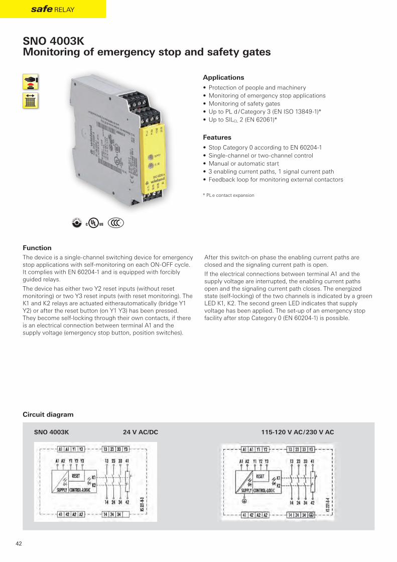
Function The device is a single-channel switching device for emergency stop applications with self-monitoring on each ON-OFF cycle. It complies with EN 60204-1 and is equipped with forcibly guided relays.
The device has either two Y2 reset inputs (without reset monitoring) or two Y3 reset inputs (with reset monitoring). The K1 and K2 relays are actuated eitherautomatically (bridge Y1 Y2) or after the reset button (on Y1 Y3) has been pressed. They become self-locking through their own contacts, if there is an electrical connection between terminal A1 and the supply voltage (emergency stop button, position switches).
After this switch-on phase the enabling current paths are closed and the signaling current path is open.
If the electrical connections between terminal A1 and the supply voltage are interrupted, the enabling current paths open and the signaling current path closes. The energized state (self-locking) of the two channels is indicated by a green LED K1, K2. The second green LED indicates that supply voltage has been applied. The set-up of an emergency stop facility after stop Category 0 (EN 60204-1) is possible.
Applications• Protection of people and machinery• Monitoring of emergency stop applications• Monitoring of safety gates• Up to PL d / Category 3 (EN ISO 13849-1)*• Up to SILCL 2 (EN 62061)*
Features• Stop Category 0 according to EN 60204-1• Single-channel or two-channel control• Manual or automatic start• 3 enabling current paths, 1 signal current path• Feedback loop for monitoring external contactors
* PL e contact expansion
SNO 4003KMonitoring of emergency stop and safety gates
Circuit diagram

SNO 4003K-A 24 V AC/DC R1.188.0500.1 1
115 – 120 V AC R1.188.0900.1 1
230 V AC R1.188.0910.1 1
SNO 4003K-C 24 V AC/DC R1.188.1990.0 1
115 – 120 V AC R1.188.4000.0 1
230 V AC R1.188.4010.0 1
DGUV, cULus, CCC
43
safe relay
safe
rel
ay
Type Rated voltage Terminals Part no. Std. pack
Screw terminals, pluggable
Screw terminals, pluggable
Screw terminals, pluggable
Push-in terminals, pluggable
Push-in terminals, pluggable
Push-in terminals, pluggable
Overview of devices | part numbers
Technical data
Function Emergency stop relay
Function display 2 LEDs, green
Power supply circuit
Rated voltage UN A1, A2 24 V AC/DC / 115-120 V AC / 230 V AC
Rated consumption 24 V DC 1.3 W
115-120 V AC, 230 V AC 2.2 W / 3.9 VA
Rated frequency 50 - 60 Hz
Operating voltage range UB 0.85 - 1.1 x UN
Electrical isolation supply circuit - control circuit yes (at UN = 115-120 V AC, 230 V AC)
Control circuit
Rated output voltage Y1 24 V DC
Input current / peak current Y2, Y3 90 mA / 1500 mA
Response time tA1 / tA2 60 ms
Minimum ON time tM (Manueller Start) 60 ms
Recovery time tW 200 ms
Release time tR 60 ms
Max. resistivity 24V AC/DC ≤ (2.5 + (1.176 x UB / UN - 1) x 50) Ω
115-120 V AC, 230 V AC ≤ (7.5 + (1.176 x UB / UN - 1) x 150) Ω
Output circuit
Enabling paths 13/14, 23/24, 33/34
Signaling paths 41/42 normally closed contact
Contact assignment forcebly guided
Contact type Ag-alloy, gold-plated
Rated switching voltage enabling / signaling path 230 V AC
Max. thermal current Ith enabling / signaling path 8 A / 5 A
Max. total current I² of all current path (Tu = 55 ºC) 9 A²
Application category (NO) AC-15 Ue 230 V, Ie 5 A
DC-13 Ue 24 V, Ie 5A
Short-circuit protection (NO), lead fuse / circuit breaker 6 A class gG / melting integral < 100 A²s
Mechanical life 107 switching cycles
General data
Creepage distances and clearances between the circuits EN 60664-1
Protection degree according to EN 60529 (housing / terminals) IP40 / IP20
Ambient temperature / storage temperature -25 ºC - +55 ºC / -25 ºC - + 75 ºC
Wire ranges screw terminals, fine-stranded / solid 1 x 0.2 mm² – 2.5 mm² / 2 x 0.2 mm² – 1.0 mm²
fine-stranded with ferrules 1 x 0.25 mm² – 2.5 mm² / 2 x 0.25 mm² – 1.0 mm²
Permissible torque 0.5 - 0.6 Nm
Wire ranges push-in terminals 1 x 0.25 mm² – 1.5 mm²
Weight 24 V AC/DC device / AC device 0.20 kg / 0.25 kg
Standards EN ISO 13849-1, EN 62061
Approvals

@ Y t
SNO 1012K
44
safe relay
Function After the operating voltage (L+/L1) is applied via an unactuated emergency stop button or safety gate contact on A1 and A2, the device can be switched on via a Y1/Y2-connected reset button. When the device is on, the internal relays K1 and K2 are energized and the enabling current paths 13/14 and 23/24 are closed. When the emergency stop button or the safety gate contact is actuated, the current supply of the internal relays is interrupted and the enabling current paths are opened.
SNO 1012KMonitoring of emergency stop and safety gates
Applications• Protection of people and machinery• Monitoring of emergency stop applications• Monitoring of safety gates• Up to PL d / Category 3 (EN ISO 13849-1)• Up to SILCL 2 (EN 62061)
Features• Stop Category 0 according to EN 60204-1• Single-channel or two-channel control• Manual or automatic start• 2 enabling current paths• Check of external contactors (EDM)• Compact design
Circuit diagram

SNO 1012K-A 24 V AC/DC R1.188.3740.0 1
SNO 1012K-C 24 V AC/DC R1.188.3750.0 1
DGUV, cULus, CCC
45
safe relay
safe
rel
ay
Overview of devices | part numbers
Technical data
Type Rated voltage Terminals Part no. Std. pack
Screw terminals, pluggable
Push-in terminalss, pluggable
Function Emergency stop relay
Function display 2 LEDs, green
Power supply circuit
Rated voltage UN A1, A2 24 V AC/DC
Rated consumption 24 V DC 1 W / 2 VA
Rated frequency 50 - 60 Hz
Operating voltage range UB 0.85 - 1.1 x UN
Electrical isolation supply circuit - control circuit no
Control circuit
Rated output voltage Y1 24 V DC
Input current / peak current Y2 50 mA / 70 mA
Response time tA1 / tA2 < 20 ms / < 70 ms
Minimum ON time tM 30 ms
Recovery time tW > 200 ms
Release time tR < 70 ms
Max. resistivity ≤ (2.5 + (1.176 x UB / UN - 1) x 50) Ω
Output circuit
Enabling paths 13/14, 23/24 normally open contact
Contact assignment forcebly guided
Contact type Ag-alloy, gold-plated
Rated switching voltage 240 V AC / 50V DC
Max. thermal current Ith enabling path 6 A
Max. total current I² of all current path (Tu = 55 ºC) 72 A² / 9 A²
Application category (NO) AC-15 Ue 230 V, Ie 3 A
DC-13 Ue 24 V, Ie 3 A
Short-circuit protection (NO), lead fuse / circuit breaker 6 A class gG / melting integral < 100 A²s
Mechanical life 10 x 106 switching cycles
General data
Creepage distances and clearances between the circuits EN 60664-1
Protection degree according to EN 60529 (housing / terminals) IP40 / IP20
Ambient temperature / storage temperature -25 ºC - +55 ºC / -25 ºC - + 75 ºC
Wire ranges screw terminals, fine-stranded / solid 1 x 0.2 mm² – 2.5 mm² / 2 x 0.2 mm² – 1.0 mm²
fine-stranded with ferrules 1 x 0.25 mm² – 2.5 mm² / 2 x 0.25 mm² – 1.0 mm²
Permissible torque 0.5 - 0.6 Nm
Wire ranges push-in terminals 2 x 0.25 mm² – 1.5 mm²
Weight 0.12 kg
Standards EN ISO 13849-1, EN 62061
Approvals
ß Y
SNS 4074K / SNS 4084K
46
safe relay
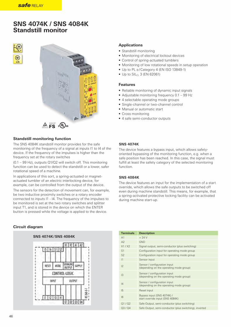
Standstill monitoring functionThe SNS 4084K standstill monitor provides for the safe monitoring of the frequency of a signal at inputs I1 to I4 of the device. If the frequency of the impulses is higher than the frequency set at the rotary switches
(0.1 – 99 Hz), outputs Q1/Q2 will switch off. This monitoring function can be used to detect the standstill or a lower, safer rotational speed of a machine.
In applications of this sort, a spring-actuated or magnet-actuated tumbler of an electric interlocking device, for example, can be controlled from the output of the device.
The sensors for the detection of movement can, for example, be two inductive proximity switches or a rotary encoder connected to inputs I1 - I4. The frequency of the impulses to be monitored is set at the two rotary switches and splitter input T1, and is stored in the device on which the ENTER button is pressed while the voltage is applied to the device.
SNS 4074K
The device features a bypass input, which allows safety-oriented bypassing of the monitoring function, e.g. when a safe position has been reached. In this case, the signal must fulfill at least the safety category of the selected monitoring function.
SNS 4084K
The device features an input for the implementation of a start override, which allows the safe outputs to be switched off even during machine standstill. This means, for example, that a spring-activated protective locking facility can be activated during machine start-up.
Applications• Standstill monitoring• Monitoring of electrical lockout devices• Control of spring-actuated tumblers• Monitoring of low rotational speeds in setup operation• Up to PL e / Category 4 (EN ISO 13849-1)• Up to SILCL 3 (EN 62061)
Features• Reliable monitoring of dynamic input signals• Adjustable monitoring frequency 0.1 – 99 Hz• 4 selectable operating mode groups• Single-channel or two-channel control• Manual or automatic start• Cross monitoring• 4 safe semi-conductor outputs
SNS 4074K / SNS 4084KStandstill monitor
Circuit diagramTerminals Description
A1 + 24 V
A2 GND
X1 / X2 Signal output, semi-conductor (plus switching)
S1 Configuration input for operating mode group
S2 Configuration input for operating mode group
I1 Sensor input
I2 Sensor / configuration input (depending on the operating mode group)
I3 Sensor / configuration input (depending on the operating mode group)
I4 Sensor / configuration input (depending on the operating mode group)
I5 Reset input
I6 Bypass input (SNS 4074K) / start override input (SNS 4084K)
Q1 / Q2 Safe Output, semi-conductor (plus switching)
Q3 / Q4 Safe Output, semi-conductor (plus switching), inverted

SNS 4074K-A R1.188.3640.0 1
SNS 4074K-C R1.188.3650.0 1
SNS 4074K-A R1.188.3620.0 1
SNS 4074K-C R1.188.3630.0 1
SNS 4084K-A R1.188.3480.0 1
SNS 4084K-C R1.188.3490.0 1
SNS 4084K-A R1.188.3660.0 1
SNS 4084K-C R1.188.3670.0 1
TÜV, cULus
47
safe relay
safe
rel
ay
Type Frequency range Terminals Part no. Std. pack
0.5 - 99 Hz Screw terminals, pluggable
0.5 - 99 Hz Push-in terminals, pluggable
0.1 - 9.9 Hz Screw terminals, pluggable
0.1 - 9.9 Hz Push-in terminals, pluggable
0.5 - 99 Hz Screw terminals, pluggable
0.5 - 99 Hz Push-in terminals, pluggable
0.1 - 9.9 Hz Screw terminals, pluggable
0.1 - 9.9 Hz Push-in terminals, pluggable
Overview of devices | part numbers
Function diagram
Technical dataFunction Standstill monitoring
Function display 12 LEDs, green/red
Function mode / adjustment Frequency monitoring / 2 x-position switch
Adjustment range fST 0,1 - 99 Hz / 0,5 - 99 Hz
Power supply circuit
Rated voltage UN A1, A2 24 V DC
Rated consumption 24 V DC 1.8 W
Operating voltage range UB 0.85 - 1.1 x UN
Electrical isolation supply circuit - control circuit no
Control circuit
Rated output voltage 24 V DC
Input current / peak current I1 - I6, S1, S2 3 mA / 3,8 mA
Minimum ON time tM 100 ms (< 5 s)
Release time tR 12 ms + 1.6 / fST
Max. cable length per input 100 m
Output circuit
Enabling paths Q1, Q2, Q3, Q4 Semi-conductor (plus switching), safety-related
Signaling paths X1, X2 Semi-conductor (plus switching), not safety-related
Rated switching voltage enabling path 30 V DC
Max. thermal current Ith enabling path 2 A
Max. total current I² of all current path (Tu = 55 ºC) 4 A
Mechanical life Must be short-circuit proof
General data
Creepage distances and clearances between the circuits EN 60664-1
Protection degree according to EN 60529 (housing / terminals) IP40 / IP20
Ambient temperature / storage temperature -25 ºC - +55 ºC / -25 ºC - + 75 ºC
Wire ranges screw terminals, fine-stranded / solid 1 x 0.2 mm² – 2.5 mm² / 2 x 0.2 mm² – 1.0 mm²
fine-stranded with ferrules 1 x 0.25 mm² – 2.5 mm² / 2 x 0.25 mm² – 1.0 mm²
Permissible torque 0.5 - 0.6 Nm
Wire ranges push-in terminals 1 x 0.25 mm² – 1.5 mm²
Weight 0.16 kg
Standards EN ISO 13849-1, EN 62061
Approvals

ß Y
SVM 4001K
48
safe relay
Function The SVM 4001K device monitors machines, the 3-phase powered drive units of which have no movement detection sensors. When the drives are set in motion or if faults are detected, the standstill monitor relay assumes the rest position.
SVM 4001KStandstill monitor
Application
Applications• Standstill monitoring• Monitoring of electrical lockout devices• Control of spring-actuated tumblers• Monitoring of low rotational speeds in setup operation• Up to PL e / Category 4 (EN ISO 13849-1)• Up to SILCL 3 (EN 62061)
Features• Sensorless monitoring of 1-phase and 3-phase motors• Safe, configurable voltage monitoring• Automatic operation

SVM 4001K-A 24 V DC R1.188.4020.0 1
SVM 4001K-C 24 V DC R1.188.4030.0 1
TÜV, cULus
SVM 4001K
49
safe relay
safe
rel
ay
Circuit diagram
Type Frequency range Terminals Part no. Std. pack
Screw terminals, pluggable
Push-in terminals, pluggable
Overview of devices | part numbers
Technical data
Function Standstill monitoring
Function display 4 LED, green/red
Function mode / adjustment Voltage measurement
Adjustment range 50 - 500 mV
Power supply circuit
Rated voltage UN A1, A2 24 V DC
Rated consumption 24 V DC 1.8 W
Operating voltage range UB 0.85 - 1.1 x UN
Control circuit
Rated output voltage U, V, W 690 V AC3
Response time tA 20 ms
Release time tR 20 ms
Output circuit
Enabling paths 13/14, 23/24 normally open contact
Contact assignment forcebly guided
Contact type Ag-alloy
Rated switching voltage 230 V AC
Max. thermal current Ith 8 A
Application category (NO) AC-15 Ue 230 V, Ie 3 A
DC-13 Ue 24 V, Ie 4 A
Short-circuit protection (NO), lead fuse / circuit breaker 5 A class gG
Mechanical life 20 x 106 switching cycles
General data
Creepage distances and clearances between the circuits EN 60664-1
Protection degree according to EN 60529 (housing / terminals) IP40 / IP20
Ambient temperature / storage temperature -20 ºC - +55 ºC / -40 ºC - + 85 ºC
Wire ranges screw terminals, fine-stranded / solid 1 x 0.2 mm² – 2.5 mm² / 2 x 0.2 mm² – 1.0 mm²
fine-stranded with ferrules 1 x 0.25 mm² – 2.5 mm² / 2 x 0.25 mm² – 1.0 mm²
Permissible torque 0.5 - 0.6 Nm
Wire ranges push-in terminals 1 x 0.25 mm² – 1.5 mm²
Weight 0.180 kg
Standards EN ISO 13849-1, EN 62061
Approvals

@ Y t
SNT 4M63K 24 V DC 115-120 V AC / 230 V AC
50
safe relay
Function The device is a two-channel switching device with self-monitoring on each ON-OFF cycle. It complies with EN 60204-1 and is equipped with forcibly guided relays. It is intended for monitoring connected switching elements on separating safety devices and generating a safety-oriented signal (enable). Depending on the design, separating safety devices may include sliding safety gates, safety gates, housings, covers, sheetings, screens, etc.
Basic functionWith supply voltage applied to terminals A1/A2 and the safety inputs closed, pressing the reset button closes the enabling current paths (manual start). When the safety inputs are opened the enabling paths will open.
• Manual start – When the safety inputs are closed, a button is used to close reset input S34 and open it again (triggering with falling edge) or to close reset input S35 (triggering with rising edge).
• Automatic Start – Reset input S35 is connected to S33/S14. The device starts with the rising edge of the signal on safety input S14.
Applications• Protection of people and machinery• Monitoring of emergency stop applications• Monitoring of safety gates• Up to PL e / Category 4 (EN ISO 13849-1)• Up to SILCL 3 (EN 62061)
Features• Stop Category 0 according to EN 60204-1• Manual or automatic start• Cross monitoring• 3 enabling current paths (NO contact, forcibly guided)• Feedback loop for monitoring external contactors
SNT 4M63KMonitoring of emergency stop and safety gates
Circuit diagram

SNT 4M63K-A 24 V AC/DC R1.188.1050.0 1
115 – 120 V AC R1.188.1060.0 1
230 V AC R1.188.1070.0 1
SNT 4M63K-C 24 V AC/DC R1.188.2390.0 1
DGUV, cULus, CCC
51
safe relay
safe
rel
ay
Type Rated voltage Terminals Part no. Std. pack
Screw terminals, pluggable
Screw terminals, pluggable
Screw terminals, pluggable
Push-in terminals, pluggable
Overview of devices | part numbers
Technical data
Function Emergency stop relay, valve position and safety gate monitoring
Function display 3 LEDs, green
Power supply circuit
Rated voltage UN A1, A2 24 V AC/DC, 115-120 V AC, 230 V AC
Rated consumption 24 V DC 2.0 W
115-120 V AC, 230 V AC 2,6 W / 3.2 VA
Rated frequency 50 - 60 Hz
Operating voltage range UB 0.85 - 1.1 x UN
Electrical isolation supply circuit - control circuit yes (at UN = 115-230 V AC, 230 V AC)
Control circuit
Rated output voltage S13/S23 22 V DC
Input current / peak current S14/S33, S22/S24 40 mA / 100 mA
S34, S35 5 mA / 50 mA
Response time tA1 / tA2 40 ms / 600 ms
Minimum ON time tM 80 ms
Recovery time tW 100 ms
Release time tR 15 ms
Synchronous time tS 200 ms (CH1 → CH2)
Max. resistivity, per channel 1) 24 V AC/DC ≤ (5 + (1.176 x UB / UN - 1) x 100) Ω
115-120 V AC, 230 V AC ≤ (5 + (1.176 x UB / UN - 1) x 100) Ω
Output circuit
Enabling paths 13/14, 23/24, 33/34 normally open contact
Contact assignment forcebly guided
Contact type Ag-alloy, gold-plated
Rated switching voltage enabling path 230 V AC
Max. thermal current Ith enabling path 6 A
Max. total current I² of all current path (Tu = 55 ºC) 9 A²
Application category (NO) AC-15 Ue 230 V, Ie 3 A
DC-13 Ue 24 V, Ie 2.5 A
Short-circuit protection (NO), lead fuse / circuit breaker 6 A class gG / melting integral < 100 A²s
Mechanical life 107 switching cycles
General data
Creepage distances and clearances between the circuits EN 60664-1
Protection degree according to EN 60529 (housing / terminals) IP40 / IP20
Ambient temperature / storage temperature -25 ºC - +55 ºC / -25 ºC - + 75 ºC
Wire ranges screw terminals, fine-stranded / solid 1 x 0.2 mm² – 2.5 mm² / 2 x 0.2 mm² – 1.0 mm²
fine-stranded with ferrules 1 x 0.25 mm² – 2.5 mm² / 2 x 0.25 mm² – 1.0 mm²
Permissible torque 0.5 - 0.6 Nm
Wire ranges push-in terminals 1 x 0.25 mm² – 1-5 mm²
Weight 0-21 kg / 0-25 kg
Standards EN ISO 13849-1, EN 62061
Approvals
1) If two-channel devices are installed as single channel, the value is halved.

@ Y t
SNZ 4052K 24 V DC 115-120 V AC / 230 V AC
52
safe relay
Function The device complies with EN 574 Type III C safety requirements. The safety behavior of the device is designed for applications according to Category 4 (EN 954-1). The device is single-fault safe and self-monitoring. Synchronous activation of both actuators (two-hand momentary contact or safety gate contacts) is monitored. Each of the two actuators is connected to the device with an NO contact and an NC contact. The technical design of the input circuit provides cross connection and ground fault monitoring. The output function is designed with 2 NO contacts as an enabling current path and 1 NC contact as signaling current path (all forcibly guided).
With supply voltage applied to terminals A1/A2 and the feedback loop (terminals Y1/Y2) closed, the enabling current paths are closed by simultaneously activating the actuators (S1+S2). Both actuators must be activated within 0.5 s for the
output contacts to be enabled. If only one of the two actuators is released, the device is immediately de-energized. The enabling current paths open.
The device can be restarted only after both actuators have returned to their initial position (for example when the two-hand momentary contact switches have been released) and the feedback circuit is closed again. The feedback circuit should only be opened again after both actuators are activated. Otherwise the device will remain in the OFF position. The current status of the device is indicated by 3 LEDs: application of the supply voltage with LED SUPPLY, activation of both actuators with LED K1 and additionally with LED K2 in case of synchronous activation.
Applications• Protection of people and machinery• Monitoring of two-hand applications• Monitoring of safety gates• According to EN 574 Type IIIC• Up to PL e / Category 4 (EN ISO 13849-1)• Up to SILCL 3 (EN 62061)
Features• Stop Category 0 according to EN 60204-1• Two-channel actuation; 1 NO contact and
1 NC contact for each channel• Cross monitoring• Monitoring of synchronous activation• 2 enabling current paths, 1 signaling current path
SNZ 4052KTwo-hand relay type IIIC
Circuit diagram

SNZ 4052K-A 24 V AC/DC R1.188.0530.1 1
115 – 120 V AC R1.188.0940.1 1
230 V AC R1.188.0950.1 1
SNZ 4052K-C 24 V AC/DC R1.188.2020.0 1
DGUV, cULus, CCC
53
safe relay
safe
rel
ay
Type Rated voltage Terminals Part no. Std. pack
Screw terminals, pluggable
Screw terminals, pluggable
Screw terminals, pluggable
Push-in terminals, pluggable
Overview of devices | part numbers
Technical data
Function Two-hand control relay
Function display 3 LEDs, green
Power supply circuit
Rated voltage UN A1, A2 24 V AC/DC, 115-120 V AC, 230 V AC
Rated consumption 24 V DC 2.4 W
115-120 V AC, 230 V AC 2.2 W / 3.1 VA
Rated frequency 50 - 60 Hz
Operating voltage range UB 0.85 - 1.1 x UN
Electrical isolation supply circuit - control circuit yes (at UN = 115-230 V AC, 230 V AC)
Control circuit
Rated output voltage Y12/Y14, Y22/Y24, Y1 24 V DC
Input current / peak current Y11, Y21 60 mA / 1000 mA
Y2 < 100 mA
Response time tA1 / tA2 40 ms
Recovery time tW 250 ms
Release time tR 50 ms
Synchronous time tS ≤ 500 ms
Max. resistivity, per channel 24 V AC/DC ≤ (2.5 + (1.176 x UB / UN - 1) x 50) Ω
115-120 V AC, 230 V AC ≤ (2.5 + (1.176 x UB / UN - 1) x 50) Ω
Output circuit
Enabling paths 13/14, 23/24 normally open contact
Signaling paths 31/32 normally closed contact
Contact assignment forcebly guided
Contact type Ag-alloy, gold-plated
Rated switching voltage enabling / signaling path 230 V AC
Max. thermal current Ith enabling / signaling path 6 A / 2 A
Max. total current I² of all current path (Tu = 55 ºC) 9 A²
Application category (NO) AC-15 Ue 230 V, Ie 3 A
DC-13 Ue 24 V, Ie 2.5 A
Short-circuit protection (NO), lead fuse / circuit breaker 6 A class gG / melting integral / < 100 A²s
Mechanical life 107 switching cycles
General data
Creepage distances and clearances between the circuits EN 60664-1
Protection degree according to EN 60529 (housing / terminals) IP40 / IP20
Ambient temperature / storage temperature -25 ºC - +55 ºC / -25 ºC - + 75 ºC
Wire ranges screw terminals, fine-stranded / solid 1 x 0.2 mm² – 2.5 mm² / 2 x 0.2 mm² – 1.0 mm²
fine-stranded with ferrules 1 x 0.25 mm² – 2.5 mm² / 2 x 0.25 mm² – 1.0 mm²
Permissible torque 0.5 - 0.6 Nm
Wire ranges Push-in terminals 1 x 0.25 mm² – 1.5 mm²
Weight 0.20 kg / 0.25 kg
Standards EN ISO 13849-1, EN 62061, EN 574
Approvals

- ß Y t
SNZ 1022K
54
safe relay
Function After the power supply is established at terminals A1/A2 the release current paths are closed when the actuators (S1+S2) are operated at the same time. The two actuators must be operated within 0.5 s to trigger a release. If just one of the two actuators is released, the device is immediately de-energized and the enabling current path is opening.
The device can only be restarted once the two actuators are returned to their initial positions (e.g. the two-hand buttons have been released). The current status of the device is shown by 2 LEDs. The presence of the power supply is indicated with the SUPPLY LED, the operation of the two actuators with the K1 LED, if there is synchronous operation.
Applications• Protection of people and machinery• Monitoring of two-hand applications• Monitoring of safety gates• According to EN 574 Type IIIA• Up to PL c / Category 1 (EN ISO 13849-1)• Up to SILCL 1 (EN 62061)
Features• Stop Category 0 according to EN 60204-1• Two-channel actuation; 1 NO contact and
1 NC contact for each channel• Cross monitoring• Monitoring of synchronous activation• 1 changeover contact
SNZ 1022KTwo-hand relay type IIIA
Circuit diagram

SNZ 1022K-A 24 V AC/DC R1.188.3700.0 1
SNZ 1022K-A 115-230 V AC R1.188.3710.0 1
SNZ 1022K-C 24 V AC/DC R1.188.3720.0 1
SNZ 1022K-C 115-230 V AC R1.188.3730.0 1
TÜV, cULus, CCC
55
safe relay
safe
rel
ay
Type Rated Voltage Synchronous time Terminals Part no. Std. pack
0.5 s Screw terminals, pluggable
0.5 s Screw terminals, pluggable
0.5 s Push-in terminals, pluggable
0.5 s Push-in terminals, pluggable
Overview of devices | part numbers
Technical dataFunction Two-hand control relay
Function display 2 LEDs, green
Power supply circuit
Rated voltage UN A1, A2 24 V AC/DC / 115-230 V AC
Rated consumption AC/DC 24 V 0.7 W / 2.0 VA
AC 115-230 V 3 VA
Rated frequency 50 - 60 Hz
Operating voltage range UB 0.85 - 1.1 x UN
Electrical isolation supply circuit - control circuit yes (at UN = 115-230 V AC)
Control circuit
Rated output voltage T11 24 V DC
Input current / peak current T12 2.5 mA / 3 mA
T13 25 mA / 60 mA
Response time tA1 / tA2 < 20 ms
Recovery time tW > 250 ms
Release time tR < 20 ms
Synchronous time tS ≤ 500 ms
Max. resistivity, per channel (5 + (1.176 × UB / UN – 1) × 100) Ω
Output circuit
Enabling paths 11/12/14 changeover contact
Contact type Ag-alloy, gold-plated
Rated switching voltage 230 V AC
Max. thermal current Ith enabling path 10/12 6 A
Application category (NO) AC-15 Ue 230 V, Ie 3 A
DC-13 Ue 24 V, Ie 2 A
Short-circuit protection (NO), lead fuse / circuit breaker 6 A class gG / melting integral < 100 A²s
Mechanical life 10 x 106 switching cycles
General data
Creepage distances and clearances between the circuits EN 60664-1
Protection degree according to EN 60529 (housing / terminals) IP40 / IP20
Ambient temperature / storage temperature -25 ºC - +55 ºC / -25 ºC - + 75 ºC
Wire ranges screw terminals, fine-stranded / solid 1 x 0.2 mm² – 2.5 mm² / 2 x 0.2 mm² – 1.0 mm²
fine-stranded with ferrules 1 x 0.25 mm² – 2.5 mm² / 2 x 0.25 mm² – 1.0 mm²
Permissible torque 0.5 - 0.6 Nm
Wire ranges push-in terminals 2 x 0.25 mm² – 1.5 mm²
Weight 24 V AC/DC device / AC device 0.1 kg
Standards EN ISO 13849-1, EN 62061, EN 574
Approvals

ß L Y t
SNV 4063KL
56
safe relay
Function With the supply voltage applied to terminals A1/A2 and the emergency set right and left margins in-line button. This controls relays K1 to K4, which become self-locking (when starting via reset button monitoring after the response time). After this switch-on phase the 3 enabling current paths are closed (terminals 13/14, 23/24 and 37/38). Three LEDs display the state of relays K1/K2, K3/K4 and the supply voltage.
If the emergency stop button is activated, the current supplies for relays K1 to K4 are interrupted. The undelayed enabling current paths (terminals 13/14, 23/24) are opened with release time tR1 while the off-delayed enabling current path (terminals 37/38) is opened after the pre-set OFF-delay time tR2. The OFF-delay time can be adjusted infinitely in the range 0.15 to 3 s or 1.5 to 30 s.
With a two-channel control and cross-monitoring wiring of the sensor circuit, additional errors such as short-circuit or ground fault can be detected. An electronic fuse protects the device against damage. After the cause of the malfunction has been removed, the device is operational again after approx. 3 s.
• Reset button monitoring – The device can be started either with the falling edge or with the rising edge (terminals S34 or S35). For emergency stop applications with manual start the button must be connected to terminals S33/S34. The device is enabled only with the falling edge of the reset signal. For starting, the reset button must be pressed and released. For safety gate applications in which an automatic start is performed it is necessary to bridge terminals S33/S35. The device will react at the rising edge of input S12 which is internally connected to S33.
• Monitoring of synchronous time – The use of safety limit switches for single-channel or two-channel circuits in safety gate applications depends on the required safety level. The device provides a monitoring of the synchronous time of two connected safety switches. A synchronous time tS ≈ 0.5 s requires limit switches positioned in such a way that channel 1, terminals S11/S12, closes before channel 2, terminals S21/S22. If channel 2 closes before channel 1, the synchronous time is tS = ∞.
Applications• Protection of people and machinery• Monitoring of emergency stop applications• Monitoring of safety gates• Monitoring of light barriers• Termination of braking operations through OFF-delay time• Control of solenoid-actuated interlocks• Up to PL e / Category 4 (EN ISO 13849-1) for undelayed
contacts• Up to PL d / Category 3 (EN ISO 13849-1) for delayed contacts• Up to SILCL 3 (EN 62061)
Features• Stop category 0/1 according to EN 60204-1• Single-channel or two-channel control• Manual or automatic start• OFF-delay time adjustable in the range 0.15 to 3 s or 1.5 to 30 s• Reset button monitoring, cross monitoring,
monitoring of synchronous time• 3 enabling current paths (2 undelayed, 1 OFF-delayed)
SNV 4063KL – Monitoring of emergency stop, safety gates and light barriers, OFF-delayed
Circuit diagram

SNV 4063KL-A 3 s 24 V DC R1.188.0620.0 1
30 s 24 V DC R1.188.0640.0 1
150 s 24 V DC R1.188.4100.0 1
SNV 4063KL-C 3 s 24 V DC R1.188.2010.0 1
30 s 24 V DC R1.188.3900.0 1
TÜV, GL, cULus, CCC
57
safe relay
safe
rel
ay
Overview of devices | part numbers
Type Time range Rated voltage Terminals Part no. Std. pack
Screw terminals, pluggable
Screw terminals, pluggable
Screw terminals, pluggable
Push-in terminals, pluggable
Push-in terminals, pluggable
Technical data
Function Emergency stop relay for controlled stop
Function display 3 LEDs, green
Function mode / adjustment Time / stepless
Adjustment range 0.15 - 3 s / 1.5 - 30 s / 7.5 - 150 s
Power supply circuit
Rated voltage UN A1, A2 24 V DC
Rated consumption 24 V DC 2.6 W
Operating voltage range UB 0.85 - 1.1 x UN
Electrical isolation supply circuit - control circuit no
Control circuit
Rated output voltage S11, S33/S21 22 V DC
Input current / peak current S12, S31/S22 25 mA / 100 mA
S34, S35 40 mA / 50 mA
Response time tA1 / tA2 30 ms / 700 ms
Minimum ON time tM 200 ms
Recovery time tW 500 ms
Release time tR 25 ms
Release time tR, delayed contacts (tolerance) 0.15 - 3 s / 1.5 - 30 s (±16 %)
Synchronous time tS 500 ms
Permissable test pulse time tTP < 1 ms
Max. resistivity, per channel 1) ≤ (5 + (1.176 x UB / UN - 1) x 100) Ω
Output circuit
Enabling paths 13/14, 23/24 normally open contact
37/38 normally open contact, OFF-delayed
Contact assignment forcebly guided
Contact type Ag-alloy, gold-plated
Rated switching voltage enabling path 230 V AC
Max. thermal current Ith enabling path 6 A
Max. total current I2 of all current path (Tu = 55 ºC) 5 A²
Application category (NO) AC-15 Ue 230 V, Ie 3 A
DC-13 Ue 24 V, Ie 2 A
Short-circuit protection (NO), lead fuse / circuit breaker 6 A Class gG / melting integral < 100 A²s
Mechanical life 107 switching cycles
General data
Creepage distances and clearances between the circuits EN 60664-1
Protection degree according to EN 60529 (housing / terminals) IP40 / IP20
Ambient temperature / storage temperature -25 ºC - +55 ºC / -25 ºC - + 75 ºC
Wire ranges screw terminals, fine-stranded / solid 1 x 0.2 mm² – 2.5 mm² / 2 x 0.2 mm² – 1.0 mm²
fine-stranded with ferrules 1 x 0.25 mm² – 2.5 mm² / 2 x 0.25 mm² – 1.0 mm²
Permissible torque 0.5 - 0.6 Nm
Wire ranges push-in terminals 1 x 0.25 mm² – 1.5 mm²
Weight 0.20 kg
Standards EN ISO 13849-1, EN 62061, EN 50156-1
Approvals
1) If two-channel devices are installed as single channel, the value is halved.

ß L Y t
SNV 4063KP
58
safe relay
SNV 4063KP – Monitoring of emergency stop, safety gates and light barriers, ON-delayed
Function With supply voltage applied to terminals A1/A2, relays K3 and K4 (terminals 37/38) start with the pre-selected ON-delay time. The ON-delay time tA1 can be adjusted infinitely in the range 0.15 to 3 s or 1.5 to 30 s according to the device type. The device is enabled by pressing the reset button. The following operating modes can be selected:
• Manual start – The reset button must be connected to S34 through terminal S33. For starting the relay, the reset button must be pressed. Relays K3 and K4 (terminals 37/38) will switch into the OFF position. With the falling edge of the reset signal, the reset is completed and activates relays K1 and K2, which become self-locking after the response time tA3. After this switch-on phase, the 2 enabling current paths defined for the output are closed (terminals 13/14, 23/24). With the emergency stop command, the power supply to relays K1 and K2 is interrupted. The enabling current paths (terminals 13/14, 23/24) are immediately opened with release time tR, and relays K3 and K4 will start after the pre-set ON-delay time tA1, terminals 37/38. Three LEDs display the state of relays K1/K2, K3/K4 and the supply voltage.
• Automatic start – For monitoring of interlocking installations with locking mechanism or safety gate applications in which on automatic start shall be performed it is necessary to jumper terminals S33/S35. The device will react at the rising edge of input S12 that is internally connected to S33. Relays K3 and K4 (terminals 37/38) will switch into the OFF position. With the rising edge of input S12 the relay K1 is activated and response time tA2 started. When the time has elapsed, the 2 enabling current paths are closed (terminals 13/14, 23/24). With a stop command the power supply to relays K1 and K2 is interrupted. The enabling current paths (terminals 13/14, 23/24) are immediately opened with release time tR, and relays K3 and K4 will start after the pre-set ON-delay time tA1, terminals 37/38.
Applications• Protection of people and machinery• Monitoring of emergency stop applications• Monitoring of safety gates• Monitoring of light barriers• Monitoring of interlocking installation with position
switches and integrated locking• Control of spring-actuated interlocks• Up to PL e / Category 4 (EN ISO 13849-1)• Up to SILCL 3 (EN 62061)
Features• Stop Category 0 according to EN 60204-1• Single-channel or two-channel control• Manual or automatic start• ON-delay time adjustable in the range 0.15 to 3 s or 1.5 to 30 s• Reset button monitoring, cross monitoring• 3 enabling current paths (2 undelayed, 1 ON-delayed)
Circuit diagram

SNV 4063KP-A 3 s 24 V DC R1.188.0660.0 1
30 s 24 V DC R1.188.0680.0 1
TÜV, GL, cULus, CCC
59
safe relay
safe
rel
ay
Type Time range Rated voltage Terminals Part no. Std. pack
Screw terminals, pluggable
Screw terminals, pluggable
Overview of devices | part numbers
Technical data
Function Emergency stop relay for access delay combined with locking mechanism
Function display 3 LEDs, green
Function mode / adjustment Time / stepless
Adjustment range 0.15 - 3 s / 1.5 - 30 s
Power supply circuit
Rated voltage UN A1, A2 24 V DC
Rated consumption 24 V DC 2.6 W
Operating voltage range UB 0.85 - 1.1 x UN
Electrical isolation supply circuit - control circuit no
Control circuit
Rated output voltage S11, S33/S21 22 V DC
Input current / peak current S12, S31/S22 25 mA / 100 mA
S34, S35 40 mA / 50 mA
Response time tA1 / tA2 30 ms / 700 ms
Minimum ON time tM 200 ms
Recovery time tW 500 ms
Release time tR 25 ms
Release time tR, delayed contacts (tolerance) 0.15 - 3 s / 1.5 - 30 s (±16 %)
Synchronous time tS 500 ms
Permissable test pulse time tTP < 1 ms
Max. resistivity, per channel 1) ≤ (5 + (1.176 x UB / UN - 1) x 100) Ω
Output circuit
Enabling paths 13/14, 23/24 normally open contact
37/38 normally open contact, ON-delayed
Contact assignment forcebly guided
Contact type Ag-alloy, gold-plated
Rated switching voltage enabling path 230 V AC
Max. thermal current Ith enabling path 6 A
Max. total current I2 of all current path (Tu = 55 ºC) 5 A²
Application category (NO) AC-15 Ue 230 V, Ie 3 A
DC-13 Ue 24 V, Ie 2 A
Short-circuit protection (NO), lead fuse / circuit breaker 6 A Class gG / melting integral < 100 A²s
Mechanical life 107 switching cycles
General data
Creepage distances and clearances between the circuits EN 60664-1
Protection degree according to EN 60529 (housing / terminals) IP40 / IP20
Ambient temperature / storage temperature -25 ºC - +55 ºC / -25 ºC - + 75 ºC
Wire ranges screw terminals, fine-stranded / solid 1 x 0.2 mm² – 2.5 mm² / 2 x 0.2 mm² – 1.0 mm²
fine-stranded with ferrules 1 x 0.25 mm² – 2.5 mm² / 2 x 0.25 mm² – 1.0 mm²
Permissible torque 0,5 - 0,6 Nm
Wire ranges push-in terminals 1 x 0.25 mm² – 1.5 mm²
Weight 0.20 kg
Standards EN ISO 13849-1, EN 62061, EN 50156-1
Approvals
1) If two-channel devices are installed as single channel, the value is halved.

ß Y t
SNV 4074SL SNV 4076SL
60
safe relay
SNV 4074SL / SNV 4076SL – Monitoring of emergency stop, safety gates and light barriers, OFF-delayed
OFF-delay function After the supply voltage is applied to terminals A1/A2 and the safety inputs are closed, the enabling current paths (NO contacts) are closed automatically or by pressing the reset button (manual start). When the safety inputs are opened/de-energized the enabling current paths (NO contacts are opened immediately or with a delay).
• Automatic start – Reset input S14 is connected to safety
input S12. To monitor external contact blocks (EDM), their NC contacts must be connected in series between S34 and S12.
• Manual start without monitoring – Reset input S14 is connected to safety input S12 via a reset button. To monitor external contact blocks (EDM), their NC contacts must be connected in series to the reset button.
• Manual start with monitoring – Reset input S34 is connected to safety input S11 via a reset button. To monitor external contact blocks (EDM), their NC contacts must be connected in series to the reset button.
Applications• Controlled stop according to Category 1 (EN 60204-1)• Monitoring of emergency stop applications• Monitoring of safety gates• Monitoring of interlocks• Monitoring of light barriers• Up to PL e / Category 4 (EN ISO 13849-1)• Up to SILCL 3 (EN 62061)
Features• Stop Category 0/1 according to EN 60204-1• Time setting in 10 steps• Time ranges 3s, 30s or 300s• Single-channel or two-channel control• Manual or automatic start• SafeStart• Cross monitoring
Circuit diagrams

24 V DC 115 – 230 V ACSNV 4074SL-A 3s 24 V DC 115 – 230 V AC R1.188.2130.0 R1.188.2310.0 1
SNV 4074SL-A 30s 24 V DC 115 – 230 V AC R1.188.2160.0 R1.188.2340.0 1
SNV 4074SL-A 300s 24 V DC 115 – 230 V AC R1.188.2190.0 R1.188.2370.0 1
SNV 4074SL-C 3s 24 V DC 115 – 230 V AC R1.188.2140.0 R1.188.2320.0 1
SNV 4074SL-C 30s 24 V DC 115 – 230 V AC R1.188.2170.0 R1.188.2350.0 1
SNV 4074SL-C 300s 24 V DC 115 – 230 V AC R1.188.2200.0 R1.188.2380.0 1
SNV 4076SL-A 3s 24 V DC 115 – 230 V AC R1.188.2040.0 R1.188.2220.0 1
SNV 4076SL-A 30s 24 V DC 115 – 230 V AC R1.188.2070.0 R1.188.2250.0 1
SNV 4076SL-A 300s 24 V DC 115 – 230 V AC R1.188.2100.0 R1.188.2280.0 1
SNV 4076SL-C 3s 24 V DC 115 – 230 V AC R1.188.2050.0 R1.188.2230.0 1
SNV 4076SL-C 30s 24 V DC 115 – 230 V AC R1.188.2080.0 R1.188.2260.0 1
SNV 4076SL-C 300s 24 V DC 115 – 230 V AC R1.188.2110.0 R1.188.2290.0 1
TÜV, cULus, CCC
61
safe relay
safe
rel
ay
Overview of devices | part numbers
Type Time range Rated voltage Terminals
Part no.Std. pack
Screw terminals, pluggable
Screw terminals, pluggable
Screw terminals, pluggable
Push-in terminals, pluggable
Push-in terminals, pluggable
Push-in terminals, pluggable
Screw terminals, pluggable
Screw terminals, pluggable
Screw terminals, pluggable
Push-in terminals, pluggable
Push-in terminals, pluggable
Push-in terminals, pluggable
Function Emergency stop relayFunction display 5 LEDs, green/redFunction mode / adjustment Time setting in 10 stepsAdjustment range 0.1 - 3 s / 0 - 30 s / 0 - 300 sPower supply circuitRated voltage UN A1, A2 24 V DC / 115-230 V ACRated consumption 24 V DC | 115-230 V AC 2.8 W | 3.2 W / 6,3 VARated frequency 50 - 60 HzOperating voltage range UB 0.85 - 1.1 x UN
Electrical isolation supply circuit - control circuit yes (at UN = AC 115-230 V)Control circuitRated output voltage S11, S13, S33, Y39 / S21 22 V DCInput current / peak current S12, S31/S22, S32 3 mA / 4.5 mA
S14, S34, Y2, Y40 4 mA / 4.5 mAResponse time tA1 / tA2 200 msMinimum ON time tM 100 msRecovery time tW 50 msRelease time tR 20 msRelease time tR, delayed contacts (tolerance) 0.1 / 0.2 / 0.3 / 0.4 / 0,5 / 0.8 / 1 / 1.5 / 2 / 3 s (0,1 % ± 15 ms)
0 / 2 / 4 / 6 / 0.5 / 8 / 10 / 15 / 20 / 30 s (0.1 % ± 15 ms)0 / 20 / 40 / 60 / 80 / 100 / 150 / 200 / 250 / 300 s (0.1 % ± 15 ms)
Permissable test pulse time tTP < 1 msMax. resistivity, per channel 1) 24 V DC | 115-230 V AC < 50 Ω | < 50 ΩOutput circuitEnabling paths 13/14, 23/24, 33/34 normally open contact
57/58, 57/68, 77/78 normally open contact, OFF-delayedSignaling paths 31/32, 41/42 | 75/76, 85/86 normally closed contact | normally closed contact, OFF-delayedContact assignment forcebly guidedContact type Ag-alloy, gold-platedRated switching voltage enabling- / signaling path 230 V ACMax. thermal current Ith enabling- / signaling path 6 A / 2 AMax. total current I2 of all current path (Tu = 55 ºC) 40 A²Application category (NO) AC-15 | DC-13 Ue 230 V, Ie 3 A | Ue 24 V, Ie 3 AShort-circuit protection (NO), lead fuse / circuit breaker 6 A class gG / melting integral < 100 A²sMechanical life 107 switching cyclesGeneral dataCreepage distances and clearances between the circuits EN 60664-1Protection degree according to EN 60529 (housing / terminals) IP40 / IP20Ambient temperature / storage temperature -25 ºC - +55 ºC / -25 ºC - +75 ºCWire ranges screw terminals, fine-stranded / solid 1 x 0.2 mm² – 2.5 mm² / 2 x 0.2 mm² – 1.0 mm²
fine-stranded with ferrules 1 x 0.25 mm² – 2.5 mm² / 2 x 0.25 mm² – 1.0 mm²Permissible torque 0.5 - 0.6 NmWire ranges push-in terminals 1 x 0.25 mm² – 1.5 mm²Weight 0.33 kg / 0.35 kgStandards EN ISO 13849-1, EN 62061, EN 50156-1
Approvals
1) If two-channel devices are installed as single channel, the value is halved.
Technical data

ß Y t
SNV 4274SL SNV 4074ST
62
safe relay
SNV 4274SL / SNV 4074ST – Monitoring of emergency stop, light barriers and safety gates, OFF-delayed/ON-delayed
OFF-delay with retriggering function (SNV 4274SL)After the supply voltage is applied to terminals A1/A2 and the safety inputs are closed, the contacts are switched on immediately, either automatically or by pressing the reset button (manual start). When the safety inputs are opened/de-energized, the contacts are switched off immediately or with a release delay.
The set release delay only expires if the safety inputs are opened longer than the release delay set on the device. If the safety inputs are closed again before the release delay has expired (retriggering), the delayed contacts will remain closed, too.
ON-delay function (SNV 4074ST)After the supply voltage is applied to terminals A1/A2 and the safety inputs are closed, the contacts are switched on immediately or with a response delay, either automatically or by pressing the reset button (manual start). When the safety inputs are opened/de-energized the contacts are switched off immediately.
Applications• Monitoring of limit values in the process industry• Monitoring of emergency stop applications• Monitoring of safety gates• Monitoring of interlocks• Monitoring of light barriers• Up to PL e / Category 4 (EN ISO 13849-1)• Up to SILCL 3 (EN 62061)
Features• Continuously adjustable, analog time setting• Time ranges 3s, 30s or 300s• Retriggering of the time delay possible• Single-channel or two-channel control• Manual or automatic start• SafeStart• Cross monitoring
Circuit diagrams

TÜV, cULus, CCC
24 V DC 115 – 230 V ACSNV 4274SL-A 3s 24 V DC 115 – 230 V AC R1.188.2470.0 R1.188.2650.0 1
SNV 4274SL-A 30s 24 V DC 115 – 230 V AC R1.188.2500.0 R1.188.2680.0 1
SNV 4274SL-A 300s 24 V DC 115 – 230 V AC R1.188.2530.0 R1.188.2710.0 1
SNV 4274SL-C 3s 24 V DC 115 – 230 V AC R1.188.2480.0 R1.188.2660.0 1
SNV 4274SL-C 30s 24 V DC 115 – 230 V AC R1.188.2510.0 R1.188.2690.0 1
SNV 4274SL-C 300s 24 V DC 115 – 230 V AC R1.188.2540.0 R1.188.2720.0 1
SNV 4074ST-A 3s 24 V DC 115 – 230 V AC R1.188.2560.0 R1.188.2740.0 1
SNV 4074ST-A 30s 24 V DC 115 – 230 V AC R1.188.2590.0 R1.188.2770.0 1
SNV 4074ST-A 300s 24 V DC 115 – 230 V AC R1.188.2620.0 R1.188.2800.0 1
SNV 4074ST-C 3s 24 V DC 115 – 230 V AC R1.188.2570.0 R1.188.2750.0 1
SNV 4074ST-C 30s 24 V DC 115 – 230 V AC R1.188.2600.0 R1.188.2780.0 1
SNV 4074ST-C 300s 24 V DC 115 – 230 V AC R1.188.2630.0 R1.188.2810.0 1
63
safe relay
safe
rel
ay
Overview of devices | Part numbers
Function Emergency stop relayFunction display 5 LEDs, green/redFunction mode / adjustment Time / steplessAdjustment range 0.15 - 3 s / 1.5 - 30 s / 15 - 300 sPower supply circuitRated voltage UN A1, A2 24 V DC / 115-230 V ACRated consumption 24 V DC | 115-230 V AC 2.8 W | 3.2 W / 6.3 VARated frequency 50 - 60 HzOperating voltage range UB 0.85 - 1.1 x UN
Electrical isolation supply circuit - control circuit yes (at UN = 115-230 V AC)Control circuitRated output voltage S11, S13, S33, Y39 / S21 22 V DCInput current / peak current S12, S31/S22, S32 3 mA / 4,5 mA
S14, S34, Y2, Y40 4 mA / 4,5 mAResponse time tA1 / tA2 200 msMinimum ON time tM 100 msRecovery time tW 50 msRelease time tR 20 msRelease time tR, delayed contacts (tolerance) 0,15 - 3 s (± 16 % of the setting value)
1,5 - 30 s (± 16 % of the setting value)15 - 300 s (± 16 % of the setting value)
Permissable test pulse time tTP < 1 msMax. resistivity, per channel 1) 24 V DC | 115-230 V AC < 50 Ω | < 50 ΩOutput circuitEnabling paths 13/14, 23/24 normally open contact
57/58, 57/68 normally open contact, time delayedSignaling paths 31/32, 41/42 | 75/76, 85/86 normally closed contact | normally closed contact, time delayedContact assignment forcebly guidedContact type Ag-alloy, gold-platedRated switching voltage enabling- / signaling path 230 V ACMax. thermal current Ith enabling- / signaling path 6 A / 2 AMax. total current I2 of all current path (Tu = 55 ºC) 40 A²Application category (NO) AC-15 | DC-13 Ue 230 V, Ie 3 A | Ue 24 V, Ie 3 AShort-circuit protection (NO), lead fuse / circuit breaker 6 A class gG / melting integral < 100 A²sMechanical life 107 switching cyclesGeneral dataCreepage distances and clearances between the circuits EN 60664-1Protection degree according to EN 60529 (housing / terminals) IP40 / IP20Ambient temperature / storage temperature -25 ºC - +55 ºC / -25 ºC - + 75 ºCWire ranges screw terminals, fine-stranded / solid 1 x 0.2 mm² – 2.5 mm² / 2 x 0.2 mm² – 1.0 mm²
fine-stranded with ferrules 1 x 0.25 mm² – 2.5 mm² / 2 x 0.25 mm² – 1.0 mm²Permissible torque 0.5 - 0.6 NmWire ranges push-in terminals 1 x 0.25 mm² – 1.5 mm²Weight 0,33 kg / 0,35 kgStandards EN ISO 13849-1, EN 62061, EN 50156-1
Approvals
1) If two-channel devices are installed as single channel, the value is halved.
Type Time range Rated voltage Terminals
Part no.Std. pack
Screw terminals, pluggable
Screw terminals, pluggable
Screw terminals, pluggable
Push-in terminals, pluggable
Push-in terminals, pluggable
Push-in terminals, pluggable
Screw terminals, pluggable
Screw terminals, pluggable
Screw terminals, pluggable
Push-in terminals, pluggable
Push-in terminals, pluggable
Push-in terminals, pluggable
Technical data

a
SNE 1
64
safe relay
Applications• Duplication of the enabling current paths of
a basic device• Contact expansion in safety-oriented systems• Up to PL e / Category 4 (EN ISO 13849-1)*• Up to SILCL 3 (EN 62061)*
Features• Stop Category 0 and 1 according to EN 60204-1• Single-channel operation• 2 changeover contacts (positively driven) • Sturdy retaining bracket
* Depends on the category of the basic device or the safety control.
SNE 1Contact expansion
Circuit diagram

SNE 1 24 V DC R1.188.3950.0 1
cURus
SNE 1
65
safe relay
safe
rel
ay
Overview of devices | Part numbers
Circuit diagram
Technical data
Type Rated voltage Terminals Part no. Std. Pack
Screw terminals
Function Emergency stop expansion relay
Function display none
Power supply circuit
Rated voltage UN A1/A2 24 V DC
Rated consumption 0.7 W
Operating voltage range UB 0.63 - 1.25 x UN
Electrical isolation supply circuit - control circuit yes
Control circuit
Input current / peak current A1/A2 ca. 29 mA
Response time tA1 / tA2 12 ms
Release time tR < 20 ms
Output circuit
Enabling paths 11/12/14, 21/22/24 changeover contact
Contact assignment forcebly guided
Contact type Ag-alloy
Rated switching voltage 230 V AC, 24 V DC
Max. thermal current Ith 8 A
Max. total current I2 of all current path (Tu = 55 ºC) 72 A²
Application category (NO) AC-15 Ue 230 V, Ie 2 A
DC-13 Ue 24 V, Ie 3 A
Short-circuit protection (NO), lead fuse / circuit breaker 6 A class gL / melting integral < 100 A²s
Mechanical life 10 x 106 switching cycles
General data
Creepage distances and clearances between the circuits EN 61810-5
Protection degree according to EN 60529 (housing / terminals) IP20 / IP20
Ambient temperature / storage temperature -40 ºC - +70 ºC / -40 ºC - + 70
Wire range fine-stranded / solid 0.25 mm² – 4.0 mm² (AWG 24-12) / 0.25 – 6.0 mm2 (AWG 24-10)
Permissible torque 0.5 Nm
Weight 0.06 kg
Standards EN 50205 (Type B)
Approvals

@ Y t
SNE 4003K
66
safe relay
Function The SNE 4003K is an expansion device for basic devices (such as safety switching devices, light curtains, laser scanners) that are part of the machine’s safety equipment and are used for protecting people, materials and machines.
The device is designed with two channels and redundancy. The enabling current paths are separated from the control circuits and signaling circuits with creepage distances and clearances > 5.5 mm (safe isolation). There is basic insulation to separate the enabling current paths from one another and the control circuits from the signaling current paths. The broad input voltage range of 15 V DC to 30 V DC makes the SNE 4003K ideal for single-channel or two-channel control by semiconductors.
Input voltage to the SNE 4003K is connected via one or two enabling current paths of a basic device. When the input voltage is applied relays K1 and K2 switch into the ON position. After this switch-on phase, enabling current paths 13/14, 23/24, 33/34 are closed and feedback current path Y1/Y2 and signaling current path 41/42 are opened.
This is displayed through two LEDs, K1 and K2, which are assigned to relays K1 and K2. If the enabling current paths of the basic device are opened when the emergency stop button is pressed, relays K1 and K2 on the SNE 4003K switch back into the OFF-position. The enabling current paths open and the feedback current path closes. Feedback current path Y1/Y2 prevents the basic device from switching on again before K1 or K2 releases.
Applications• Duplication of the enabling current paths of a basic device• Contact expansion in safety-oriented systems• Contact expansion for light curtains• Up to PL e / Category 4 (EN ISO 13849-1)*• Up to SILCL 3 (EN 62061)*
Features• Safe isolation according to EN 50178• Single-channel or two-channel operation• 3 enabling current paths (NO contact)• 2 signaling current paths (NC contact)• Wide input voltage range from 15 to 30 V DC• Suitable for semiconductor outputs
* Depends on the category of the basic device or the safety control.
SNE 4003KContact expansion
Circuit diagram

SNE 4003K-A 24 V DC R1.188.1340.0 1
DGUV, cULus, CCC
67
safe relay
safe
rel
ay
Overview of devices | Part numbers
Technical data
Type Rated voltage Terminals Part no. Std. Pack
Screw terminals, pluggable
Function Emergency stop expansion relay
Function display 2 LEDs, green
Power supply circuit
Rated voltage UN B1/B2, B3/B4 24 V DC
Rated consumption 24 V DC 1.2 W
Operating voltage range UB 0.63 - 1.25 x UN
Electrical isolation supply circuit - control circuit no
Control circuit
Input current / peak current B1/B2, B3/B4 50 mA / 500 mA
Response time tA1 / tA2 < 40 ms
Recovery time tW ≤ 40 ms
Release time tR < 20 ms
Permissable test pulse time tTP < 1 ms
Max. resistivity, per channel 1) ≤ (5 + (1.6 x UB / UN - 1) x 100) Ω
Output circuit
Enabling paths 13/14, 23/24, 33/34 normally open contact
Signaling paths 41/42 normally closed contact
Contact assignment forcebly guided
Contact type Ag-alloy, gold-plated
Rated switching voltage enabling- / signaling path 230 V AC
Y1/Y2 230 V AC
Max. thermal current Ith enabling- / signaling path 6 A / 2 A
Y1/Y2 2 A
Max. total current I2 of all current path (Tu = 55 ºC) 9 A²
Application category (NO) AC-15 Ue 230 V, Ie 3 A
DC-13 Ue 24 V, Ie 2,5 A
Short-circuit protection (NO), lead fuse / circuit breaker 6 A class gG / melting integral < 100 A²s
Mechanical life 107 switching cycles
General data
Creepage distances and clearances between the circuits EN 60664-1
Protection degree according to EN 60529 (housing / terminals) IP40 / IP20
Ambient temperature / storage temperature -25 ºC - +55 ºC / -25 ºC - + 75 ºC
Wire ranges screw terminals, fine-stranded / solid 1 x 0.2 mm² – 2.5 mm² / 2 x 0.2 mm² – 1.0 mm²
fine-stranded with ferrules 1 x 0.25 mm² – 2.5 mm² / 2 x 0.25 mm² – 1.0 mm²
Permissible torque 0.5 - 0.6 Nm
Wire ranges push-in terminals 1 x 0.25 mm² – 1.5 mm²
Weight 0,21 kg
Standards EN ISO 13849-1, EN 62061
Approvals
1) If two-channel devices are installed as single channel, the value is halved.

@ Y t
SNE 4004K SNE 4004KV
68
safe relay
Function SNE 4004K
Supply voltage to the SNE devices is routed via an enabling current path of a basic device. When the supply voltage is applied relays K1 and K2 switch into the ON position. After this switch-on phase the four enabling current paths 13/14, 23/24, 33/34, 43/44 (of the SNE 4004K) or 17/18, 27/28, 37/38, 47/48 (of the SNE 4004KV) are closed and the feedback current path Y1/Y2 is open. This is displayed through two LEDs that are assigned to relays K1 and K2.
When the enabling current paths of the basic device are opened through the operation of the emergency stop button, relays K1 and K2 on the SNE 4004K switch back into the OFF-position. The enabling current paths open and the feedback current path closes. Feedback current path Y1/Y2 prevents the basic device from switching on again before K1 or K2 releases.
SNE 4004KV
The functions of this device correspond to those of the SNE 4004K. The SNE 4004KV is available with the following four OFF-delay times tR1: 0.5 s; 1 s; 2 s and 3 s. The device has an OFF-delay time that is enabled through capacitors.
This causes the OFF-delay time tR1 to elapse completely even in case of failure of the power supply (A1/A2). It cannot be reset before it has elapsed. Once the delay time has elapsed, relays K1 and K2 switch into the OFF- position. OFF-delay times of > 0 s correspond to stop category 1.
Applications• Expansion of a basic device’s enabling current paths• Contact expansion in safety equipment• Up to PL d / Category 3 (EN ISO 13849-1)*• Up to SILCL 2 (EN 62061)*
Features• Stop Category 0 and 1 according to EN 60204-1 (see “Function”)• Single-channel or two-channel control• SNE 4004K: 4 enabling current paths, undelayed
(NO contact) 3 signaling curent paths, undelayed (NC contact)
• SNE 4004KV: 4 enabling current paths, OFF-delayed (NO contact) 3 signaling current paths, OFF-delayed (NC contact), Time buffering
* Depends on the category of the basic device or the safety control.
SNE 4004K/KVContact expansion
Circuit diagrams

SNE 4004K-A – 24 V AC/DC R1.188.0590.0 1
SNE 4004K-C – 24 V AC/DC R1.188.1980.0 1
SNE 4004KV-A 24 V DC R1.188.0460.0 1
1 s 24 V DC R1.188.0470.0 1
2 s 24 V DC R1.188.0480.0 1
3 s 24 V DC R1.188.0490.0 1
SNE 4004KV-C 24 V DC R1.188.2410.0 1
1 s 24 V DC R1.188.2420.0 1
2 s 24 V DC R1.188.2430.0 1
3 s 24 V DC R1.188.2440.0 1
DGUV, cULus, CCC
69
safe relay
safe
rel
ay
Overview of devices | part numbers
Technical data
Type Time range Rated voltage Terminals Part no. Std. Pack
Screw terminals, pluggable
Push-in terminals, pluggable
0.5 s Screw terminals, pluggable
Screw terminals, pluggable
Screw terminals, pluggable
Screw terminals, pluggable
0.5 s Push-in terminals, pluggable
Push-in terminals, pluggable
Push-in terminals, pluggable
Push-in terminals, pluggable
Function Emergency stop expansion relay
Function display 2 LEDs, green
Function mode / adjustment Time, fixed
Adjustment range 0,5 s / 1 s / 2 s / 3 s
Power supply circuit
Rated voltage UN A1, A2 24 V DC / 24 V AC/DC
Rated consumption 24 V DC | 24 V AC/DC 1.2 W | 1.7 W / 3.1 VA
Rated frequency 50 - 60 Hz
Operating voltage range UB 0.85 - 1.1 x UN
Electrical isolation supply circuit - control circuit non
Control circuit
Input current / peak current A1, A2 65 mA / 1800 mA
Response time tA1 / tA2 20 ms
Minimum ON time tM 0,15 x tR
Recovery time tW ≤ 200 ms
Release time tR 40 ms
Release time tR, delayed contacts (tolerance) 0.5 s / 1 s / 2 s / 3 s (± 35 %)
Max. resistivity, per channel 1) ≤ (2.5 + (1.176 x UB / UN - 1) x 50) Ω
Output circuit
Enabling paths 13/14, 23/24, 33/34, 43/44 normally open contact
17/17, 27/28, 37/38, 47/48 normally open contact, time delayed
Signaling paths 51/52, 61/62 normally closed contact
55/56, 65/66 normally closed contact, time delayed
Contact assignment forcebly guided
Contact type Ag-alloy, gold-plated
Rated switching voltage enabling / signaling path 230 V AC
Y1/Y2 230 V AC
Max. thermal current Ith enabling / signaling path 6 A / 2 A
Y1/Y2 2 A
Max. total current I2 of all current path (Tu = 55 ºC) 9 A²
Application category (NO) AC-15 | DC-13 Ue 230 V, Ie 5 A | Ue 24 V, Ie 5 A
Short-circuit protection (NO), lead fuse / circuit breaker 6 A class gG / melting integral < 100 A²s
Mechanical life 107 switching cycles
General data
Creepage distances and clearances between the circuits EN 60664-1
Protection degree according to EN 60529 (housing / terminals) IP40 / IP20
Ambient temperature / storage temperature -25 ºC - +55 ºC / -25 ºC - + 75 ºC
Wire ranges screw terminals, fine-stranded / solid 1 x 0.2 mm² – 2.5 mm² / 2 x 0.2 mm² – 1.0 mm²
fine-stranded with ferrules 1 x 0.25 mm² – 2.5 mm² / 2 x 0.25 mm² – 1.0 mm²
Permissible torque 0,5 - 0,6 Nm
Wire ranges push-in terminals 1 x 0.25 mm² –1.5 mm²
Weight 0.20 kg
Standards EN ISO 13849-1, EN 62061
Approvals
1) If two-channel devices are installed as single channel, the value is halved.

- Y t
SNE 4012K SNE 4024K
70
safe relay
Circuit diagrams
Function Once the supply voltage has been applied to terminals B1/A2 (B2/A2), the enabling current paths (NOC) are automatically closed and the signaling current paths (NCC) are opened.
When the supply voltage is ceased, the enabling current paths (NOC) are immediately opened and the signaling current paths (NCC) are immediately closed.
Applications• Expansion of a basic device’s enabling current paths• Contact expansion in safety equipment• Up to PL e / Category 3 (EN ISO 13849-1)*• Up to SILCL 3 (EN 62061)*
Features• Stop Category 0 and 1 according to EN 60204-1 (see “Function”)• Single-channel control• SNE 4012K: 2 enabling current paths (NO contact) • SNE 4024K: 2 x 2 enabling current paths (NO contact)
* Depends on the category of the basic device or the safety control.
SNE 4012K / SNE 4024K Contact expansion
(pending)(pending)

TÜV, cULus, CCC
SNE 4012K-A 24 V DC R1.188.3910.0 1
SNE 4012K-C 24 V DC R1.188.3920.0 1
SNE 4024K-A 24 V DC R1.188.3930.0 1
SNE 4024K-C 24 V DC R1.188.3940.0 1
71
safe relay
safe
rel
ay
Overview of devices | part numbers
Technical data
Type Rated voltage Terminals Part no. Std. Pack
Screw terminals, pluggable
Push-in terminals, pluggable
Screw terminals, pluggable
Push-in terminals, pluggable
Function Emergency stop expansion relay
Function display – SNE 4012K 1 LED, green
Function display – SNE 4024K 2 LED, green
Power supply circuit
Rated voltage UN B1/A2; B2/A2 24 V DC
Rated consumption – SNE 4012K 0.7 W
Rated consumption – SNE 4022K 1.4 W
Operating voltage range UB 0.75 - 1.25 UN
Control circuit
Input current / peak current B1/A2 ca. 30 mA / 110 mA
B2/A2 ca. 30 mA / 110 mA
Response time tA1 / tA2 < 15 ms
Recovery time tW ≤ 30 ms
Release time tR ≤ 15 ms
Max. resistivity, per channel 1) ≤ (5 + (1,333 x UB / UN - 1) x 200) Ω
Output circuit
Enabling paths 13/14, 23/24 normally open contact
33/34, 43/44 normally open contact
Signaling paths Y1/Y2 normally closed contact
Y3/Y4 normally closed contact
Contact assignment forcebly guided
Contact type Ag-alloy
Rated switching voltage 230 V AC, 24 V DC
Max. thermal current Ith enabling / signaling path 6 A
Max. total current I2 of all current path – SNE 4012K (Tu = 55 ºC) 72 A²
Max. total current I2 of all current path – SNE 4024K (Tu = 55 ºC) 2 x 72 A² / 2 x 8 A²
Application category (NO) AC-15 | DC-13 Ue 230 V, Ie 3 A | Ue 24 V, Ie 1 A
Short-circuit protection (NO), lead fuse / circuit breaker 6 A class gL / melting integral < 100 A²s
Mechanical life 10 x 106 switching cycles
General data
Creepage distances and clearances between the circuits EN 60664-1
Protection degree according to EN 60529 (housing / terminals) IP40 / IP20
Ambient temperature / storage temperature -25 ºC - +65 ºC / -25 ºC - + 75 ºC
Wire ranges screw terminals, fine-stranded / solid 1 x 0.2 mm² – 2.5 mm² / 2 x 0.2 mm² – 1.0 mm²
fine-stranded with ferrules 1 x 0.25 mm² – 2.5 mm² / 2 x 0.25 mm² – 1.0 mm²
Permissible torque 0.5 - 0.6 Nm
Wire ranges push-in terminals 1 x 0.25 mm² – 1.5 mm²
Weight 0.180 kg
Standards EN ISO 13849-1, EN 62061, EN81-1, DIN EN 50156-1, EN 61511
Approvals
1) If two-channel devices are installed as single channel, the value is halved.

@ Y t
SNE 4028S
72
safe relay
Function After the supply voltage is applied to terminals A1/ A2 and the safety inputs are closed, the enabling current paths (NO contacts) are closed and the signaling current paths (NC contacts) are opened automatically. When the safety inputs are opened/de-energized the enabling current paths (NO contacts) are opened immediately and the signaling current paths (NC contacts) are closed.
Applications• Duplication of the enabling current paths of a basic device• Contact expansion in safety-oriented systems• Amplification of the output performance of light curtains• Up to PL e / Category 4 (EN ISO 13849-1)*• Up to SILCL 3 (EN 62061)*
Features• Single-channel or two-channel control• Cross monitoring • Safe isolation • 8 enabling current paths, 1 signal current path
* Depends on the category of the basic device or the safety control.
SNE 4028SContact expansion
Circuit diagram
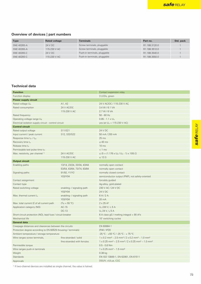
SNE 4028S-A 24 V DC R1.188.3120.0 1
SNE 4028S-A 115-230 V AC R1.188.3510.0 1
SNE 4028S-C 24 V DC R1.188.3540.0 1
SNE 4028S-C 115-230 V AC R1.188.3550.0 1
DGUV, cULus, CCC
73
safe relay
safe
rel
ay
Type Rated voltage Terminals Part no. Std. pack
Screw terminals, pluggable
Screw terminals, pluggable
Push-in terminals, pluggable
Push-in terminals, pluggable
Overview of devices | part numbers
Technical data
Function Contact expansion relay
Function display 3 LEDs, green
Power supply circuit
Rated voltage UN A1, A2 24 V AC/DC / 115-230 V AC
Rated consumption 24 V AC/DC 3.4 W / 6.1 VA
115-230 V AC 2.7 W / 6 VA
Rated frequency 50 - 60 Hz
Operating voltage range UB 0.85 - 1.1 x UN
Electrical isolation supply circuit - control circuit yes (at UN = 115-230 V AC)
Control circuit
Rated output voltage S11/S21 24 V DC
Input current / peak current S12, S32/S22 50 mA / 200 mA
Response time tA1 / tA2 25 ms
Recovery time tw ≤ 40 ms
Release time tR 10 ms
Permissable test pulse time tTP < 1 ms
Max. resistivity, per channel 1) 24 V AC/DC ≤ (5 + (1.176 x UB / UN - 1) x 100) Ω
115-230 V AC ≤ 12 Ω
Output circuit
Enabling paths 13/14, 23/24, 33/34, 43/44 normally open contact
53/54, 63/64, 73/74, 83/84 normally open contact
Signaling paths 91/92, Y1/Y2 normally closed contact
Y03/Y04 semiconductor output (PNP), not safety-oriented
Contact assignment forcebly guided
Contact type Ag-alloy, gold-plated
Rated switching voltage enabling- / signaling path 230 V AC / 24 V DC
Y03/Y04 24 V DC
Max. thermal current Ith enabling- / signaling path 6 A / 2 A
Y03/Y04 20 mA
Max. total current I2 of all current path (Tu = 55 ºC) 2 x 25 A²
Application category (NO) AC-15 Ue 230 V, Ie 5 A
DC-13 Ue 24 V, Ie 5 A
Short-circuit protection (NO), lead fuse / circuit breaker 6 A class gG / melting integral < 90 A²s
Mechanical life 107 switching cycles
General data
Creepage distances and clearances between the circuits EN 60664-1
Protection degree according to EN 60529 (housing / terminals) IP40 / IP20
Ambient temperature / storage temperature -25 ºC - +55 ºC / -25 ºC - + 75 ºC
Wire ranges screw terminals, fine-stranded / solid 1 x 0.2 mm² – 2.5 mm² / 2 x 0.2 mm² – 1.0 mm²
fine-stranded with ferrules 1 x 0.25 mm² – 2.5 mm² / 2 x 0.25 mm² – 1.0 mm²
Permissible torque 0.5 - 0,6 Nm
Wire ranges push-in terminals 1 x 0.25 mm² – 1.5 mm²
Weight 0.38 kg
Standards EN ISO 13849-1, EN 62061, EN 61511
Approvals
1) If two-channel devices are installed as single channel, the value is halved.

74
sensor pro
sensor pro – safe signal acquisition
Safety light curtains SLC SeriesSLC series safety light curtains are ideally suited for implementing optoelectronic protective devices. The SLC series is thereby used to protect operators from dangerous areas or as an access control against unauthorized trespassing.
Safety light grids SLD SeriesThe SLD series safety light grids are optoelectronic personal protective devices for access protection to hazardous areas on machinery and equipment.
The two product families, SLC and SLD, offer an extensive range of items, uncomplicated connection technology and comprehensive additional functions for simple commissioning and fast diagnosis.
SNH SeriesEmergency stop buttons
SLC + SLD SeriesLight curtains + light grids

75
sensor pro
sen
sor p
ro
Emergency stop buttons SNH SeriesThe emergency stop buttons of the SNH series provide for the safety of man and machine and offer users a practical, robust and reliable design.The fast and easy installation of the emergency stop buttons saves time and money, and a long durability as well as reliable functionality is guaranteed through the use of high-quality materials.The emergency stop buttons of the SNH series can be used in a wide range of applications across the various sectors.
Safety switch with guard locking SIN SeriesThe safety switches in the SIN series are used to monitor the position of movable guards and prevent the accidental opening of safety doors or flaps with their integrated guard locking.They are typically used on machines with movements that occur after switching off, where it must be ensured that no person may gain access until the hazardous situation has ended.
STS + SMA SeriesNon-contact safety switches
SNH SeriesEmergency stop buttons
Safety switch with separated actuator SMS SeriesSafety switches in the SMS series are used to monitor movable guards. The safety switches are suitable for the protection of people and processes and are available in three different designs.
Non-contact safety switches STS SeriesThe non-contact safety switches from the STS series feature maximum manipulation protection and are used for monitoring the position of machine parts and the position of doors and switches of isolating protective devices.
Magnetic safety switches SMA SeriesThe sensors of the SMA series are magnetic safety sensors which are used for the contact-less monitoring of protective doors and the detection of safe positions. In addition, they are equipped with integrated manipulation protection and can be used up to IP67.
SIN + SMS SeriesMechanical safety switches

SLC Standard SLC Select
√ √
√ √
√ √
√ √
√
√ √
√
√
[ y
76
sensor pro
Function overview
LED display
Double-scan technology
Range reduction
Selectable transmission channels
7-segment display
Automatic start
Manual start / restart interlock
External device monitoring (EDM)
Functions suitable for every protection task All important contactless safety functions on machines and equipment can be realized by means of the two function versions, Standard and Select, of the SLC series.
Applications• Access protection (finger, hand and arm protection) • Access security (personal protection)• Horizontal zone protection
Features• Safety light curtain AOPD type 4 or type 2 • Beam resolution 14, 20, 30, 40 and 90 mm • Protection field heights 150 – 1800 mm • Extensive accessories
SLC – safety light curtain
With 3-Zone alignment indication
AdvantagesHigher equipment availability • Stable, trouble-free operation with the slender and torsion-
resistant housing
• Parameterization without PC or DIP switch through simple wiring in the control cabinet
• The integrated Double-Scan technology avoids unwanted shutdown even in harsh operating conditions
• Clear diagnostic and status messages in the 7-segment display ensure shorter downtimes
• Cable lengths up to 100 m with unshielded connection cables ensure greater operational flexibility and reduce costs even under difficult EMC conditions
Faster during commissioning, operation and service • The 3-zone alignment indicator reduces assembly time and
justage
• The wide range of SLC products permits optimal and cost-effective design of protective devices
• Easy to connect via standard M12 connection technology
• Fast installation and removal on the machine through a system configuration in the control cabinet
• Selectable transmission channels and range reduction prevent mutual interference
• Simplified planning of safeguards and less type diversity because very SLC safety light curtain from 0 m to the maximum range can be implemented

TÜV, c-CSA-us
77
sensor pro
sen
sor p
ro
Finger, hand and arm protection on machines with the safety light curtain SLC
Technical dataFunction safety light curtain
Function display LED
Power supply circuit
Rated voltage UN 24 V DC
Current consumption (transmitter) 50 mA
Current consumption, no load (receiver/transceiver) 150 mA
Operating voltage range UB 0.8 - 1.2 x UN
Electrical isolation supply circuit - control circuit no
Protection field data Resolution Range / protective field height
14 mm (nur SLC-4) 0 - 6 m / 150 - 1800 mm
20 mm 0 - 15 m / 150 - 1800 mm
30 mm 0 - 10 m / 150 - 1800 mm
40 mm 0 - 20 m / 150 - 1800 mm
90 mm 0 - 20 m / 600 - 1800 mm
Output circuit OSSD
Number 2
Type Transistor outputs PNP
Short-circuit monitoring yes
Switching current (max., per output) 380 mA
Leakage current (max.) 200 µA
Switching voltage, high active (UB - 1V) 18.0 - 27.0 V
Switching voltage, low 0 - 2,5 V
Line resistance / line length < 200 Ω / ≤ 100 m
Response time device-dependent
General data
Creepage distances and clearances between the circuits EN 60664-1
Protection degree according to EN 60529 IP65
Ambient temperature / storage temperature 0 ºC - +55 ºC / -25 ºC - + 70 ºC
Connection M12 (5 pole / 8 pole) device-dependent
Weight 0.3 - 1.95 kg, device-dependent
Standards EN 61496, EN ISO 13849-1, EN 62061
Approvals
SLC – safety light curtain

20 mm 30 mm 40 mm 90 mm
SLC-2TR20-hhhh SLC-2TR30-hhhh SLC-2TR40-hhhh SLC-2TR90-hhhh
0150 R1.512.0150.0 R1.513.0150.0 R1.514.0150.0 -
0225 R1.512.0225.0 R1.513.0225.0 R1.514.0225.0 -
0300 R1.512.0300.0 R1.513.0300.0 R1.514.0300.0 -
0450 R1.512.0450.0 R1.513.0450.0 R1.514.0450.0 -
0600 R1.512.0600.0 R1.513.0600.0 R1.514.0600.0 R1.515.0600.0
0750 R1.512.0750.0 R1.513.0750.0 R1.514.0750.0 R1.515.0750.0
0900 R1.512.0900.0 R1.513.0900.0 R1.514.0900.0 R1.515.0900.0
1050 R1.512.1050.0 R1.513.1050.0 R1.514.1050.0 R1.515.1050.0
1200 R1.512.1200.0 R1.513.1200.0 R1.514.1200.0 R1.515.1200.0
1350 R1.512.1350.0 R1.513.1350.0 R1.514.1350.0 R1.515.1350.0
1500 R1.512.1500.0 R1.513.1500.0 R1.514.1500.0 R1.515.1500.0
1650 R1.512.1650.0 R1.513.1650.0 R1.514.1650.0 R1.515.1650.0
1800 R1.512.1800.0 R1.513.1800.0 R1.514.1800.0 R1.515.1800.0
20 mm 30 mm 40 mm 90 mm
SLC-2ST20-hhhh SLC-2ST30-hhhh SLC-2ST40-hhhh SLC-2ST90-hhhh
0150 R1.522.0150.0 R1.523.0150.0 R1.524.0150.0 -
0225 R1.522.0225.0 R1.523.0225.0 R1.524.0225.0 -
0300 R1.522.0300.0 R1.523.0300.0 R1.524.0300.0 -
0450 R1.522.0450.0 R1.523.0450.0 R1.524.0450.0 -
0600 R1.522.0600.0 R1.523.0600.0 R1.524.0600.0 R1.525.0600.0
0750 R1.522.0750.0 R1.523.0750.0 R1.524.0750.0 R1.525.0750.0
0900 R1.522.0900.0 R1.523.0900.0 R1.524.0900.0 R1.525.0900.0
1050 R1.522.1050.0 R1.523.1050.0 R1.524.1050.0 R1.525.1050.0
1200 R1.522.1200.0 R1.523.1200.0 R1.524.1200.0 R1.525.1200.0
1350 R1.522.1350.0 R1.523.1350.0 R1.524.1350.0 R1.525.1350.0
1500 R1.522.1500.0 R1.523.1500.0 R1.524.1500.0 R1.525.1500.0
1650 R1.522.1650.0 R1.523.1650.0 R1.524.1650.0 R1.525.1650.0
1800 R1.522.1800.0 R1.523.1800.0 R1.524.1800.0 R1.525.1800.0
20 mm 30 mm 40 mm 90 mm
SLC-2SL20-hhhh SLC-2SL30-hhhh SLC-2SL40-hhhh SLC-2SL90-hhhh
0150 R1.532.0150.0 R1.533.0150.0 R1.534.0150.0 -
0225 R1.532.0225.0 R1.533.0225.0 R1.534.0225.0 -
0300 R1.532.0300.0 R1.533.0300.0 R1.534.0300.0 -
0450 R1.532.0450.0 R1.533.0450.0 R1.534.0450.0 -
0600 R1.532.0600.0 R1.533.0600.0 R1.534.0600.0 R1.535.0600.0
0750 R1.532.0750.0 R1.533.0750.0 R1.534.0750.0 R1.535.0750.0
0900 R1.532.0900.0 R1.533.0900.0 R1.534.0900.0 R1.535.0900.0
1050 R1.532.1050.0 R1.533.1050.0 R1.534.1050.0 R1.535.1050.0
1200 R1.532.1200.0 R1.533.1200.0 R1.534.1200.0 R1.535.1200.0
1350 R1.532.1350.0 R1.533.1350.0 R1.534.1350.0 R1.535.1350.0
1500 R1.532.1500.0 R1.533.1500.0 R1.534.1500.0 R1.535.1500.0
1650 R1.532.1650.0 R1.533.1650.0 R1.534.1650.0 R1.535.1650.0
1800 R1.532.1800.0 R1.533.1800.0 R1.534.1800.0 R1.535.1800.0
78
sensor pro
SLC 2 – safety light curtainDevice overview | order numbers Transmitter
Device overview | order numbers Receiver Standard
Device overview | order numbers Receiver Select
Protective field height hhhh [mm]
Protective field height hhhh [mm]
Protective field height hhhh [mm]
Resolution
Type
Resolution
Type
Resolution
Type

14 mm 20 mm 30 mm 40 mm 90 mm
SLC-4TR14-hhhh SLC-4TR20-hhhh SLC-4TR30-hhhh SLC-4TR40-hhhh SLC-4TR90-hhhh
0150 R1.541.0150.0 R1.542.0150.0 R1.543.0150.0 R1.544.0150.0 -
0225 - R1.542.0225.0 R1.543.0225.0 R1.544.0225.0 -
0300 R1.541.0300.0 R1.542.0300.0 R1.543.0300.0 R1.544.0300.0 -
0450 R1.541.0450.0 R1.542.0450.0 R1.543.0450.0 R1.544.0450.0 -
0600 R1.541.0600.0 R1.542.0600.0 R1.543.0600.0 R1.544.0600.0 R1.545.0600.0
0750 R1.541.0750.0 R1.542.0750.0 R1.543.0750.0 R1.544.0750.0 R1.545.0750.0
0900 R1.541.0900.0 R1.542.0900.0 R1.543.0900.0 R1.544.0900.0 R1.545.0900.0
1050 R1.541.1050.0 R1.542.1050.0 R1.543.1050.0 R1.544.1050.0 R1.545.1050.0
1200 R1.541.1200.0 R1.542.1200.0 R1.543.1200.0 R1.544.1200.0 R1.545.1200.0
1350 R1.541.1350.0 R1.542.1350.0 R1.543.1350.0 R1.544.1350.0 R1.545.1350.0
1500 R1.541.1500.0 R1.542.1500.0 R1.543.1500.0 R1.544.1500.0 R1.545.1500.0
1650 R1.541.1650.0 R1.542.1650.0 R1.543.1650.0 R1.544.1650.0 R1.545.1650.0
1800 R1.541.1800.0 R1.542.1800.0 R1.543.1800.0 R1.544.1800.0 R1.545.1800.0
14 mm 20 mm 30 mm 40 mm 90 mm
SLC-4ST14-hhhh SLC-4ST20-hhhh SLC-4ST30-hhhh SLC-4ST40-hhhh SLC-4ST90-hhhh
0150 R1.551.0150.0 R1.552.0150.0 R1.553.0150.0 R1.554.0150.0 -
0225 - R1.552.0225.0 R1.553.0225.0 R1.554.0225.0 -
0300 R1.551.0300.0 R1.552.0300.0 R1.553.0300.0 R1.554.0300.0 -
0450 R1.551.0450.0 R1.552.0450.0 R1.553.0450.0 R1.554.0450.0 -
0600 R1.551.0600.0 R1.552.0600.0 R1.553.0600.0 R1.554.0600.0 R1.555.0600.0
0750 R1.551.0750.0 R1.552.0750.0 R1.553.0750.0 R1.554.0750.0 R1.555.0750.0
0900 R1.551.0900.0 R1.552.0900.0 R1.553.0900.0 R1.554.0900.0 R1.555.0900.0
1050 R1.551.1050.0 R1.552.1050.0 R1.553.1050.0 R1.554.1050.0 R1.555.1050.0
1200 R1.551.1200.0 R1.552.1200.0 R1.553.1200.0 R1.554.1200.0 R1.555.1200.0
1350 R1.551.1350.0 R1.552.1350.0 R1.553.1350.0 R1.554.1350.0 R1.555.1350.0
1500 R1.551.1500.0 R1.552.1500.0 R1.553.1500.0 R1.554.1500.0 R1.555.1500.0
1650 R1.551.1650.0 R1.552.1650.0 R1.553.1650.0 R1.554.1650.0 R1.555.1650.0
1800 R1.551.1800.0 R1.552.1800.0 R1.553.1800.0 R1.554.1800.0 R1.555.1800.0
14 mm 20 mm 30 mm 40 mm 90 mm
SLC-4SL14-hhhh SLC-4SL20-hhhh SLC-4SL30-hhhh SLC-4SL40-hhhh SLC-4SL90-hhhh
0150 R1.561.0150.0 R1.562.0150.0 R1.563.0150.0 R1.564.0150.0 -
0225 - R1.562.0225.0 R1.563.0225.0 R1.564.0225.0 -
0300 R1.561.0300.0 R1.562.0300.0 R1.563.0300.0 R1.564.0300.0 -
0450 R1.561.0450.0 R1.562.0450.0 R1.563.0450.0 R1.564.0450.0 -
0600 R1.561.0600.0 R1.562.0600.0 R1.563.0600.0 R1.564.0600.0 R1.565.0600.0
0750 R1.561.0750.0 R1.562.0750.0 R1.563.0750.0 R1.564.0750.0 R1.565.0750.0
0900 R1.561.0900.0 R1.562.0900.0 R1.563.0900.0 R1.564.0900.0 R1.565.0900.0
1050 R1.561.1050.0 R1.562.1050.0 R1.563.1050.0 R1.564.1050.0 R1.565.1050.0
1200 R1.561.1200.0 R1.562.1200.0 R1.563.1200.0 R1.564.1200.0 R1.565.1200.0
1350 R1.561.1350.0 R1.562.1350.0 R1.563.1350.0 R1.564.1350.0 R1.565.1350.0
1500 R1.561.1500.0 R1.562.1500.0 R1.563.1500.0 R1.564.1500.0 R1.565.1500.0
1650 R1.561.1650.0 R1.562.1650.0 R1.563.1650.0 R1.564.1650.0 R1.565.1650.0
1800 R1.561.1800.0 R1.562.1800.0 R1.563.1800.0 R1.564.1800.0 R1.565.1800.0
79
sensor pro
sen
sor p
ro
SLC 4 – safety light curtainDevice overview | order numbers Transmitter
Device overview | order numbers Receiver Standard
Device overview | order numbers Receiver Select
Protective field height hhhh [mm]
Protective field height hhhh [mm]
Protective field height hhhh [mm]
Resolution
Type
Resolution
Type
Resolution
Type

- [ y
SLD Standard SLD Select SLD Universal Standard
SLD Universal Select
√ √ √ √
√ √ √ √
√ √
√ √
√ √ √ √
√ √
√ √
√ √
80
sensor pro
Function overview
LED display
Multi-scan technology
Range reduction
Laser alignment aid (optional)
Automatic start
Manual start / restart interlock
External device monitoring (EDM)
Transceiver system
AdvantagesFaster during commissioning, operation and service • The integrated laser alignment aid (optional) permits precise
mounting and reduces the startup times of the SLD system
• Robust device columns with spring-loaded base mounting and integrated alignment aid are available for the free-standing implementation
• Muting applications can be easily implemented with samos® or samos® pro
Increased reliability • Robust aluminum housing in IP67
• Operating temperature range -30 °C to 55 °C permits implementation even in the harshest environments
• Multi-beam scanning avoids unwanted shutdown
• Mutual interference is avoided through the adjustable range reduction when implementing multiple systems
• Parameterization without PC or DIP switch through simple wiring in the control cabinet
Personal protection function The SLD safety light grids are especially suitable for the contactless safe guarding of hazardous areas and for personal protection on machines and equipment.
Applications• Access security (personal protection)• Safeguarding of hazardous areas
Features• Safety light grid AOPD type 4 • 2-, 3- and 4-beam resolutions • Also available as an universal system,
i.e. transmitter/receiver in a single unit• High ranges up to 70 m can be implemented • Extensive accessories
SLD – safety light grid
Integrated laser alignment aid

TÜV, c-CSA-us
81
sensor pro
sen
sor p
ro
SLD Standard / SLD SelectThe safety light grid and SLD Standard and SLD Select each consist of a transmitter and a receiver unit and are thus suitable for highest ranges.
• 2-, 3- and 4-beam systems
• Ranges 0.5 - 50 m and 20 - 70 m
SLD Universal – Less cabling expenditureThe safety light grids consist of an integrated SLD universal transmitter/receiver unit and a passive reflector unit without electrical connection.
• 2- and 3-beam systems
• Range 0.5 to 8 m
Technical dataFunction safety light grid
Function display LED
Power supply circuit
Rated voltage UN 24 V DC
Current consumption (transmitter) 50 mA
Current consumption, no load (receiver/transceiver) 150 mA
Operating voltage range UB 0.8 - 1.2 x UN
Electrical isolation supply circuit - control circuit no
Protection field data Beams Range
2 0.5 - 50 m / 20 - 70 m / 0.5 - 8 m
3 0.5 - 50 m / 20 - 70 m / 0.5 - 6 m
4 0.5 - 50 m / 20 - 70 m
Output circuit OSSD
Number 2
Type Transistor outputs PNP
Short-circuit monitoring ja
Switching current (max., per output) 380 mA
Leakage current (max.) 200 µA
Switching voltage, high active (UB - 1V) 18.0 - 27.8 V
Switching voltage, low 0 - 2,5 V
Line resistance / line length < 200 Ω
Response time 25 ms
General data
Creepage distances and clearances between the circuits EN 60664-1
Protection degree according to EN 60529 IP67
Ambient temperature / storage temperature -30 ºC - +55 ºC / -40 ºC - + 75 ºC
Connection M12 (5 pole / 8 pole) device-dependent
Weight 1.4 - 2.2 kg, device-dependent
Standards EN 61496, EN ISO 13849-1, EN 62061
Approvals
Note: For the connection of safety light grids SLD shielded cables are mandatory.
SLD – safety light grid

SLD-4TR2-0-50 R1.641.2050.0 1
SLD-4TR2-0-70 R1.641.2070.0 1
SLD-4TR2-1-50 R1.641.2150.0 1
SLD-4TR2-1-70 R1.641.2170.0 1
SLD-4TR3-0-50 R1.641.3050.0 1
SLD-4TR3-0-70 R1.641.3070.0 1
SLD-4TR3-1-50 R1.641.3150.0 1
SLD-4TR3-1-70 R1.641.3170.0 1
SLD-4TR4-0-50 R1.641.4050.0 1
SLD-4TR4-0-70 R1.641.4070.0 1
SLD-4TR4-1-50 R1.641.4150.0 1
SLD-4TR4-1-70 R1.641.4170.0 1
SLD-4US2-0-00 R1.644.2000.0 1
SLD-4US3-0-00 R1.644.3000.0 1
SLD-4UL2-0-00 R1.645.2000.0 1
SLD-4UL3-0-00 R1.645.3000.0 1
SLD-MIR2-0-08 R1.606.2008.0 1
SLD-MIR3-0-06 R1.606.3006.0 1
SLD-MIR3-0-08 R1.606.3008.0 1
SLD-4SL2-0-50 R1.643.2050.0 1
SLD-4SL2-0-70 R1.643.2070.0 1
SLD-4SL2-1-50 R1.643.2150.0 1
SLD-4SL2-1-70 R1.643.2170.0 1
SLD-4SL3-0-50 R1.643.3050.0 1
SLD-4SL3-0-70 R1.643.3070.0 1
SLD-4SL3-1-50 R1.643.3150.0 1
SLD-4SL3-1-70 R1.643.3170.0 1
SLD-4SL4-0-50 R1.643.4050.0 1
SLD-4SL4-0-70 R1.643.4070.0 1
SLD-4SL4-1-50 R1.643.4150.0 1
SLD-4SL4-1-70 R1.643.4170.0 1
SLD-4ST2-0-50 R1.642.2050.0 1
SLD-4ST2-0-70 R1.642.2070.0 1
SLD-4ST2-1-50 R1.642.2150.0 1
SLD-4ST2-1-70 R1.642.2170.0 1
SLD-4ST3-0-50 R1.642.3050.0 1
SLD-4ST3-0-70 R1.642.3070.0 1
SLD-4ST3-1-50 R1.642.3150.0 1
SLD-4ST3-1-70 R1.642.3170.0 1
SLD-4ST4-0-50 R1.642.4050.0 1
SLD-4ST4-0-70 R1.642.4070.0 1
SLD-4ST4-1-50 R1.642.4150.0 1
SLD-4ST4-1-70 R1.642.4170.0 1
82
sensor pro
SLD – safety light gridsDevice overview | order numbers Transmitter
Device overview | order numbers Universal
Device overview | order numbers Receiver Select
Device overview | order numbers Receiver Standard
Type Actuator Part. no. Std. pack
Transmitter, 2 beams, range 50 m
Transmitter, 2 beams, range 70 m
Transmitter, 2 beams, range 50 m, laser alignment aid
Transmitter, 2 beams, range 70 m, laser alignment aid
Transmitter, 3 beams, range 50 m
Transmitter, 3 beams, range 70 m
Transmitter, 3 beams, range 50 m, laser alignment aid
Transmitter, 3 beams, range 70 m, laser alignment aid
Transmitter, 4 beams, range 50 m
Transmitter, 4 beams, range 70 m
Transmitter, 4 beams, range 50 m, laser alignment aid
Transmitter, 4 beams, range 70 m, laser alignment aid
Type Actuator Part. no. Std. pack
Universal-Standard, 2 beams
Universal-Standard, 3 beams
Universal-Select, 2 beams
Universal-Select, 3 beams
Mirror, 2 beams, range 8 m
Mirror, 3 beams, range 6 m
Mirror, 3 beams, range 8 m
Type Actuator Part. no. Std. pack
Receiver-Select, 2 beams, range 50 m
Receiver-Select, 2 beams, range 70 m
Receiver-Select, 2 beams, range 50 m, laser alignment aid
Receiver-Select, 2 beams, range 70 m, laser alignment aid
Receiver-Select, 3 beams, range 50 m
Receiver-Select, 3 beams, range 70 m
Receiver-Select, 3 beams, range 50 m, laser alignment aid
Receiver-Select, 3 beams, range 70 m, laser alignment aid
Receiver-Select, 4 beams, range 50 m
Receiver-Select, 4 beams, range 70 m
Receiver-Select, 4 beams, range 50 m, laser alignment aid
Receiver-Select, 4 beams, range 70 m, laser alignment aid
Type Actuator Part. no. Std. pack
Receiver-Standard, 2 beams, range 50 m
Receiver-Standard, 2 beams, range 70 m
Receiver-Standard, 2 beams, range 50 m, laser alignment aid
Receiver-Standard, 2 beams, range 70 m, laser alignment aid
Receiver-Standard, 3 beams, range 50 m
Receiver-Standard, 3 beams, range 70 m
Receiver-Standard, 3 beams, range 50 m, laser alignment aid
Receiver-Standard, 3 beams, range 70 m, laser alignment aid
Receiver-Standard, 4 beams, range 50 m
Receiver-Standard, 4 beams, range 70 m
Receiver-Standard, 4 beams, range 50 m, laser alignment aid
Receiver-Standard, 4 beams, range 70 m, laser alignment aid

83
sensor pro
sen
sor p
ro
SLD – Muting functions with samos®pro
SLD safety light grids are ideally suited for monitoring material locks, such as in the packaging industry, in combination with the freely configurable muting function blocks of samos®pro, for example in the packaging industry.
Parallel muting with SLD and SLX-MUTC-SET2P
Safeguarding of a machine with safety light grids

SLX-MO-RO1 R1.591.0006.0 1
SLX-MO-RO-SET1 R1.591.0011.0 1
SLX-MO-RO-SET2 R1.591.0012.0 1
SLX-MO-RO-SET1-S R1.591.0013.0 1
SLX-MO-RO-SET2-S R1.591.0014.0 1
SLX-MO-RO1
SLX-MO-RO-SET1
SLX-MO-RO-SET2
84
sensor pro
Overview of devices | part numbers
Type Description Part no. Std. pack
Rotative bracket 360°, 2 pcs., inkl. 1 pcs. SLC cylinder
Set with SLX-MO-RO-B + SLX-MO-RO-C + screws
Set with 2 x SLX-MO-RO-C + screws
Set with SLX-MO-RO-B, SLX-MO-RO-C + screws + Shockabsorber
Set with 2 x SLX-MO-RO-C + screws + Shockabsorber
Mounting accessories – Series SLC
Mounting accessories – Series SLD
The swivel mount set SLX-MO-RO1 is used for wall mounting of series SLC (360° horizontal adjustment possible).
The swivel mount set SLX-MO-RO-SET1 (SLX-MO-RO-SET1S with shock absorber) is used for wall mounting of Transmitter, Receiver and Transceiver from series SLD (240° horizontal adjustment possible).
The swivel mount set SLX-MO-RO-SET2 (SLX-MO-RO-SET2S with shock absorber) is used for wall mounting of Mirror from series SLD (240° horizontal adjustment possible).

SLX-MO-L R1.591.0004.0 1
SLX-MO-Z R1.591.0005.0 1
SLX-MO-TNUTM6 R1.591.0001.0 1
SLX-MO-TNUTM6M4 R1.591.0002.0 1
SLX-MO-TNUTM6M5 R1.591.0003.0 1
SLX-MO-RO-S R1.591.0007.0 1
SLX-MO-RO270-S R1.591.0008.0 1
SLX-MO-CLIP R1.591.0009.0 1
SLX-MO-CLIP2 R1.591.0010.0 1
SLX-MO-L
SLX-MO-TNUT
SLX-MO-Z
SLX-MO-CLIP
SLX-MO-RO270-S
85
sensor pro
sen
sor p
ro
Overview of devices | part numbers
Type Description Part no. Std. pack
L-Bracket, 2 pcs.
Z-Bracket, 2 pcs.
Set Slot nut with M6-screw thread, 10 pcs.
Set Slot nut with M6- and M4-screw thread, 10 pcs.
Set Slot nut with M6- and M5-screw thread, 10 pcs.
Rotative bracket with Shockabsorber, 70mm lang, 2 pcs.
Rotative bracket with Shockabsorber, 270mm lang, 2 pcs.
Clamp bracket, for Installation in Device column
Set Clamp bracket, for Installation in Device column, 2 pcs.
Mounting accessories – Series SLC / SLD
The SLX-MO-TNUT sets including sliding blocks for mounting of series SLC/SLD.
The SLX-MO-L and SLX-MO-Z sets are used for wall mounting of series SLC/SLD in combination with sliding blocks SLX-MO-TNUT.
The SLX-MO-CLIP is used for fixed mounting of series SLC/SLD in device columns SLX-COL.
The swiveling mounting brackets SLX-MO-RO-S and SLX-MO-RO270-S are used for mounting series SLC/SLD in device columns SLX-COL. These brackets are adjustable and with vibration damping.

SLX-CAB-M12-S0505 R1.600.0505.0 1
SLX-CAB-M12-S0510 R1.600.0510.0 1
SLX-CAB-M12-S0515 R1.600.0515.0 1
SLX-CAB-M12-S0525 R1.600.0525.0 1
SLX-CAB-M12-S0550 R1.600.0550.0 1
SLX-CAB-M12-S0805 R1.600.0805.0 1
SLX-CAB-M12-S0810 R1.600.0810.0 1
SLX-CAB-M12-S0815 R1.600.0815.0 1
SLX-CAB-M12-S0825 R1.600.0825.0 1
SLX-CAB-M12-S0850 R1.600.0850.0 1
SLX-CAB-M12-0505 R1.500.0505.0 1
SLX-CAB-M12-0510 R1.500.0510.0 1
SLX-CAB-M12-0515 R1.500.0515.0 1
SLX-CAB-M12-0525 R1.500.0525.0 1
SLX-CAB-M12-0550 R1.500.0550.0 1
SLX-CAB-M12-0805 R1.500.0805.0 1
SLX-CAB-M12-0810 R1.500.0810.0 1
SLX-CAB-M12-0815 R1.500.0815.0 1
SLX-CAB-M12-0825 R1.500.0825.0 1
SLX-CAB-M12-0850 R1.500.0850.0 1
SLC-PRO-0150 R1.502.0150.0 1
SLC-PRO-0225 R1.502.0225.0 1
SLC-PRO-0300 R1.502.0300.0 1
SLC-PRO-0450 R1.502.0450.0 1
SLC-PRO-0600 R1.502.0600.0 1
SLC-PRO-0750 R1.502.0750.0 1
SLC-PRO-0900 R1.502.0900.0 1
SLC-PRO-1050 R1.502.1050.0 1
SLC-PRO-1200 R1.502.1200.0 1
SLC-PRO-1350 R1.502.1350.0 1
SLC-PRO-1500 R1.502.1500.0 1
SLC-PRO-1650 R1.502.1650.0 1
SLC-PRO-1800 R1.502.1800.0 1
SLC-PRO-FIX2 R1.502.0002.0 1
SLC-PRO-FIX3 R1.502.0003.0 1
SLC-PRO-xxxx
SLX-CAB-M12-xxxxx
86
sensor pro
Overview of devices | part numbers
Type Description Part no. Std. pack
Connection cable M12, 5-pole, Length 5m, shielded
Connection cable M12, 5-pole, Length 10m, shielded
Connection cable M12, 5-pole, Length 15m, shielded
Connection cable M12, 5-pole, Length 25m, shielded
Connection cable M12, 5-pole, Length 50m, shielded
Connection cable M12, 8-pole, Length 5m, shielded
Connection cable M12, 8-pole, Length 10m, shielded
Connection cable M12, 8-pole, Length 15m, shielded
Connection cable M12, 8-pole, Length 25m, shielded
Connection cable M12, 8-pole, Length 50m, shielded
Connection cable M12, 5-pole, Length 5m, unshielded
Connection cable M12, 5-pole, Length 10m, unshielded
Connection cable M12, 5-pole, Length 15m, unshielded
Connection cable M12, 5-pole, Length 25m, unshielded
Connection cable M12, 5-pole, Length 50m, unshielded
Connection cable M12, 8-pole, Length 5m, unshielded
Connection cable M12, 8-pole, Length 10m, unshielded
Connection cable M12, 8-pole, Length 15m, unshielded
Connection cable M12, 8-pole, Length 25m, unshielded
Connection cable M12, 8-pole, Length 50m, unshielded
SLC-Protective glass, Length: 148 mm
SLC-Protective glass, Length: 223 mm
SLC-Protective glass, Length: 298 mm
SLC-Protective glass, Length: 448 mm
SLC-Protective glass, Length: 598 mm
SLC-Protective glass, Length: 748 mm
SLC-Protective glass, Length: 898 mm
SLC-Protective glass, Length: 1048 mm
SLC-Protective glass, Length: 1198 mm
SLC-Protective glass, Length: 1348 mm
SLC-Protective glass, Length: 1498 mm
SLC-Protective glass, Length: 1648 mm
SLC-Protective glass, Length: 1798 mm
Mounting bracket for SLC-Protective glass, 2 pcs.
Mounting bracket for SLC-Protective glass, 3 pcs.
Mounting accessories – Series SLC / SLD
Connection cables SLC/SLDThe connection cables SLX-CAB-M12-xxxxx (shielded and unshielded) are used for the electrical connection of series SLC/SLD by M12-connector (5- or 8-pole). For the connection of safety light grids SLD shielded cables are mandatory.
Protective screen SLCThe protective screens SLC-PRO are used for the protection of the front of series SLC.

SLX-MIR
SLX-COLM
SLD-COLM
SLX-COLM-1000 R1.594.1000.0 1
SLX-COLM-1300 R1.594.1300.0 1
SLX-COLM-1600 R1.594.1600.0 1
SLX-COLM-1900 R1.594.1900.0 1
SLX-MIR-0150 R1.595.0150.0 1
SLX-MIR-0300 R1.595.0300.0 1
SLX-MIR-0450 R1.595.0450.0 1
SLX-MIR-0600 R1.595.0600.0 1
SLX-MIR-0750 R1.595.0750.0 1
SLX-MIR-0900 R1.595.0900.0 1
SLX-MIR-1050 R1.595.1050.0 1
SLX-MIR-1200 R1.595.1200.0 1
SLX-MIR-1350 R1.595.1350.0 1
SLX-MIR-1500 R1.595.1500.0 1
SLX-MIR-1650 R1.595.1650.0 1
SLX-MIR-1800 R1.595.1800.0 1
SLX-MIR-FIX2 R1.595.0002.0 1
SLD-COLM2-0900 R1.604.0900.0 1
SLD-COLM2-1060 R1.604.1060.0 1
SLD-COLM3-1360 R1.604.1363.0 1
SLD-COLM4-1360 R1.604.1364.0 1
SLD-MIR R1.604.0001.0 1
87
sensor pro
sen
sor p
ro
Overview of devices | part numbers
Type Description Part no. Std. pack
Reflector column, persistant 1000 mm
Reflector column, persistant 1300 mm
Reflector column, persistant 1600 mm
Reflector column, persistant 1900 mm
Reflector, length: 210 mm
Reflector, length: 360 mm
Reflector, length: 510 mm
Reflector, length: 660 mm
Reflector, length: 810 mm
Reflector, length: 960 mm
Reflector, length: 1110 mm
Reflector, length: 1260 mm
Reflector, length: 1410 mm
Reflector, length: 1560 mm
Reflector, length: 1710 mm
Reflector, length: 1860 mm
Bracket for SLX-MIR-reflector, 2 pcs.
Reflector column, Reflector distance: 500 mm; Total heigth: 900 mm
Reflector column, Reflector distance: 500 mm; Total heigth: 1060 mm
Reflector column, Reflector distance: 400 mm; Total heigth: 1360 mm
Reflector column, Reflector distance: 300 mm; Total heigth: 1360 mm
Replacement refector for SLD-Reflector columnn
Reflectors and reflector columns – Series SLC /SLD
Reflectors and Reflector columns SLCThe reflectors SLX-MIR are used for the realization of two-side guarding’s in combination with series SLC.
The reflector columns SLX-COLM are used for the realization of two-side guarding’s in combination with free-standing columns SLX-COL and series SLC.
Reflector columns SLDThe reflector columns SLD-COLM are used for the realization of rectangular protective fields in combination with free-standing columns SLX-COL and series SLD.

SLX-COL-0900 R1.593.0900.0 1
SLX-COL-1000 R1.593.1000.0 1
SLX-COL-1300 R1.593.1300.0 1
SLX-COL-1600 R1.593.1600.0 1
SLX-COL-1900 R1.593.1900.0 1
SLX-COL-2500 R1.593.2500.0 1
SLX-COL-BASE R1.593.0001.0 1
SLX-COLP-0900 R1.592.0900.0 1
SLX-COLP-1000 R1.592.1000.0 1
SLX-COLP-1300 R1.592.1300.0 1
SLX-COLP-1600 R1.592.1600.0 1
SLX-COLP-1900 R1.592.1900.0 1
SLX-ACC-LASERCOL R1.596.0003.0 1
SLX-ACC-LASER R1.596.0002.0 1
SLX-ACC-TEST2040 R1.596.2040.0 1
SLX-ACC-TEST1430 R1.596.1430.0 1
SLX-ACC-MKEY R1.596.0001.0 1
SLX-COL
SLX-ACC-LASER SLC-ACC-LASERCOL
SLX-ACC-TEST
88
sensor pro
Overview of devices | part numbers
Type Description Part no. Std. pack
Device column, profile heigth: 820 mm; Total heigth: 900 mm
Device column, profile heigth: 980 mm; Total heigth: 1060 mm
Device column, profile heigth: 1280 mm; Total heigth: 1360 mm
Device column, profile heigth: 1580 mm; Total heigth: 1660 mm
Device column, profile heigth: 1880 mm; Total heigth: 1960 mm
Device column, profile heigth: 2480 mm; Total heigth: 2560 mm
Replacement pedestal for columns with spring elements
2 Protective glasses for SLC-COL-Device column; Length: 820 mm
2 Protective glasses for SLX-COL-Device column; Length: 980 mm
2 Protective glasses for SLX-COLDevice column; Length: 1280 mm
2 Protective glasses for SLX-COL-Device column; Length: 1580 mm
2 Protective glasses for SLX-COL-Device column; Length: 1880 mm
Device columns – Series SLC / SLD
The device columns SLX-COL are used for a free-standing installation of series SLC/SLD.
Overview of devices | part numbers
Type Description Part no. Std. pack
External laser adjustment device, for fixing in Device column
External laser adjustment device
Test bar, 20/40 mm
Test bar, 14/30 mm
Magnet Key for activation of laser adjustment device
Other accessories – Series SLD / SLC
The external laser-alignment device SLX-ACC-LASER (for direct mounting on series SLX/SLD) and SLX-ACC-LASERCOL (for mounting on a device column SLX-COL) are used for the adjustment of the optical system of series SLC/SLD.
The test rods SLX-ACC-TEST are used for functional testing of protective areas realized by series SLC.

SLX-MUTC-SET2P R1.597.0008.0 1
SLX-MUTC-SET4 R1.597.0007.0 1
SLX-MUTC-SET2A R1.597.0005.0 1
SLX-MUTC-SET2B R1.597.0006.0 1
SLX-MUT-SENS20 R1.597.0012.0 1
SLX-MUT-SENS07 R1.597.0013.0 1
SLX-MUT-SENS04 R1.597.0014.0 1
SLX-MUT-REFLEX R1.597.0015.0 1
SLX-MUT-BOX4 R1.597.0020.0 1
SLX-MUT-BOX4-BT R1.597.0019.0 1
SLX-MUT-BOX4-BT-L R1.597.0021.0 1
SLX-MUTC-SET2P
SLX-MUTC-SET2A SLX-MUTC-SET2B
89
sensor pro
sen
sor p
ro
Muting accessories – Series SLC / SLD
The SLX-MUTC-SET2P muting set is required to set-up a 2-sensor parallel muting (cross muting) system, e.g. in combination with the SLX-COL device columns to be ordered separately, or directly onto the SLD safety light grids. The SLX-MUTC-SET4 muting set is used to set-up a 4-sensor sequential muting system, e.g. in combination with the SLX-COL device columns to be ordered separately, or directly onto the SLD safety light grids. The SLX-MUTC-SET2A or SLX-MUTC-SET2B muting sets (see figure below) are used to set-up a 2-sensor sequential muting system, e.g. in combination with the SLX-COL device columns to be ordered separately, or directly onto the SLD safety light grids.
Overview of devices | part numbers
Type Description Part no. Std. pack
SLX-muting-sensor-set (device column) for 2-sensor-parallel-muting, incl. 2 sensor units, 2 reflector units, pre-assembled, distance 8 m, 2 m cable with plug M12
SLX-muting-sensor-set for 4-sensor-sequencial-muting, incl. 4 sensor units, 4 reflector units, pre-assembled, distance 8 m, 2 m cable with plug M12
SLX-muting-sensor-set for 2-sensor-sequencial-muting, incl. 2 sensor units, 2 reflector units, pre-assembled, distance 8 m, 2 m cable with plug M12
SLX-muting-sensor-set for 2-sensor-sequencial-muting, incl. 2 sensor units, 2 reflector units, pre-assembled, distance 8 m, 2 m cable with plug M12
Sensor element, 2 m cable with plug M12
Sensor element, 0.7 m cable with plug M12
Sensor element, 0.4 m cable with plug M12
Reflector
Sensor connector box for 4 muting sensors
Sensor connector box for 4 muting sensors, with mounting plate
Sensor connector box for 4 muting sensors, with L-mounting bracket
Further muting accessories are available on request.

- Y
90
sensor pro
Function Emergency stop buttons of the SNH series are used on or near machines for the protection of persons. They serve the purpose of switching off / stopping machines and systems to avoid or reduce emerging or existing hazards to persons. Emergency stop buttons of the SNH series are also used to avoid damage to the machine or working material.
• Modular design – The emergency stop buttons of the SNH series have a modular design, various actuating elements can be freely combined with the chosen contact design.
• Failure protection – The emergency stop buttons of the SNH series have a special failure protection that auto-matically detects when a contact block is removed from the respective actuating element and then switches off safely.
Applications• Machine and plant manufacturing • Building machinery and transport technology
Features• For applications up to IP69K • Tamper-proof according to EN 418/EN ISO 13850• Modular design • Turn-to-reset• Integrated illumination• Optical indication of the switching state• Up to PL e / Category 4 (EN ISO 13849-1)• Up to SILCL 3 (EN 62061)
SNH – Emergency stop buttons
Cut-out dimensions Dimension diagram

TÜV, cULus
91
sensor pro
sen
sor p
ro
SNH – Emergency stop buttonsTechnical data
Function
According to EN 418/EN ISO 13850 Emergency stop button
Actuator
Housing material Plastic
Protection degree IP 65
Operating ambient temperature -30 – +70 °C (without illumination), -30 – +55 °C (with illumination)
Storage temperature -50 – +85 °C
Switching cycles > 50000
Max. torque 2.5 Nm
Installation diameter 22.3 mm
Contact blocks
Contact type NC contactNC contact with failure protectionNO contact
Contact material AgNi
Switching principle Slow-action contact
Actuating travel 6 mm
Mechanical service life 1 x 10⁷ switching cycles
Electrical service life 1 x 10⁶ switching cycles
Application category AC15 A600: 250 V, 3ADC13 Q600: 24 V, 2A
Protection class II
Rated insulation voltage 600 V
Min. Switching voltage 5 V
Min. Switching current 1 mA
Thermal continuous current lth 16 A
Max. through-type thermistor 20 mΩ
Max. bounce time 20 ms
Min. positive opening travel 3 mm
Operating ambient temperature -30 – +85 °C
Storage temperature -50 – +85 °C
Connection technology Screw connection
Conductor cross-section Max. 2,5 mm2
Standards EN 418 /EN ISO 13850
Approvals

SNH 0200SNH 0500
SNH 0021 SNH 0022 SNH 0023
SNH 0001 SNH 0002 SNH 0003
SNH 0011 SNH 0012 SNH 0013
92
sensor pro
SNH – safe. simple. modular.
SNH 0100SNH 0400 (with illumination)
SNH 0300(up to IP 69K)
SNH – Emergency stop buttons
Contact blocks
Actuating elements

SNH 0044SNH 0043
SNH 0600 SNH 0700 SNH 6001
SNH 0032SNH 0031 SNH 0033
93
sensor pro
sen
sor p
ro
SNH – safe. simple. modular.
SNH – Emergency stop buttons
Housing

SNH 0100
SNH 0400
SNH 0600
SNH 0200
SNH 0700
SNH 0300
SNH 0500
SNH 6001
94
sensor pro
SNH – Emergency stop buttons
Dimension diagram
Actuating elements
Housing

SNH 0001 R1.200.0001.0 1SNH 0002 R1.200.0002.0 1SNH 0003 R1.200.0003.0 1SNH 0011 R1.200.0011.0 1SNH 0012 R1.200.0012.0 1SNH 0013 R1.200.0013.0 1SNH 0021 R1.200.0021.0 1SNH 0022 R1.200.0022.0 1SNH 0023 R1.200.0023.0 1SNH 0031 R1.200.0031.0 1SNH 0032 R1.200.0032.0 1SNH 0033 R1.200.0033.0 1SNH 0043 R1.200.0043.0 1SNH 0044 R1.200.0044.0 1SNH 0200 R1.200.0200.0 1SNH 0300 R1.200.0300.0 1SNH 0100 R1.200.0100.0 1SNH 0400 R1.200.0400.0 1SNH 0500 R1.200.0500.0 1SNH 0600 R1.200.0600.0 1SNH 0700 R1.200.0700.0 1SNH 1101 R1.200.1101.0 1SNH 1102 R1.200.1102.0 1SNH 1111 R1.200.1111.0 1SNH 1112 R1.200.1112.0 1SNH 1121 R1.200.1121.0 1SNH 1122 R1.200.1122.0 1SNH 1131 R1.200.1131.0 1SNH 1132 R1.200.1132.0 1SNH 1143 R1.200.1143.0 1SNH 6001 R1.200.6001.0 1SNH 6010 R1.200.6010.0 10
SNH 0013SNH 0023SNH 0032SNH 0033SNH 0043SNH 0044
SNH 0001SNH 0002SNH 0003SNH 0031SNH 0011SNH 0012SNH 0021SNH 0022
95
sensor pro
sen
sor p
roOverview of devices | part numbers
Type Description Part no. Std. pack
Contact block, 1 NCContact block, 1 NC (failure protection)Contact block, 1 NC (failure protection) / illuminationContact block, 1 NC / 1 NOContact block, 1 NC (failure protection / 1 NO)Contact block, 1 NC (failure protection) / 1 NO / illuminationContact block, 2 NC Contact block, 2 NC (failure protection)Contact block, 2 NC (failure protection) / illuminationContact block, 2 NC / 1 NOContact block, 2 NC (failure protection / 1 NO)Contact block, 2 NC (failure protection) / 1 NO / illuminationContact block, 4 NC (failure protection)Contact block, 3 NC / 1 NO / illuminationActuator (with actuation indication)Actuator IP69 (without actuation indication) Actuator (with actuation indication) Actuator (with actuation indication + illumination)Actuator (with actuation indication + key release)Actuator (with actuation indication + protective collar)Actuator (with actuation indication, protective collar and key release)Emergency stop button (SNH 0100, 1 NC)Emergency stop button (SNH 0100, 1 NC (failure protection))Emergency stop button (SNH 0100, 1 NC / 1 NO)Emergency stop button (SNH 0100, 1 NC (failure protection) / 1 NO)Emergency stop button (SNH 0100, 2 NC)Emergency stop button (SNH 0100, 2 NC (failure protection))Emergency stop button (SNH 0100, 2 NC / 1 NO)Emergency stop button (SNH 0100, 2 NC (failure protection) / 1 NO)Emergency stop button (SNH 0100, 4 NC (failure protection))Housing IP67Emergency stop adhesive plate
SNH – Emergency stop buttons
Contact blocks
Dimension diagram

@ y t
96
sensor pro
FunctionThe mechanical safety switches in the SIN series are suitable for the secure locking (guard locking) of safety doors until a hazardous machine process has ended.
The safety switches have two independent contact blocks which reflect the position of the actuator on the one hand and the position of the guard locking on the other.
The release of the entry or a shutdown of the machine in case of danger is done by evaluating the contact blocks by a suit-able basic device safe relay or through the samos® or samos®pro safety systems.
Applications• Personnel protection on machines with dangerous machine
parts which move after switching off• Locking of a machine or an automatic process when the
guard is open• Position monitoring of guard and guard locking
Features• Suitable for locking devices in accordance with EN 14119• Flexible use with 4 horizontal or 4 vertical actuating
directions• Integrated protection against simple bypassing• Long service life thanks to dust- and water-proof housing
and a broad operating temperature range of up to 70 °C• Locking force 1,500 N
SIN – Safety switch with separated actuator and guard locking
Spring-actuated lockingThe safety switch on the guard is locked automatically when the actuator reaches its end position.
The guard is unlocked by applying a current to the internal electromagnets in the safety switch.
Magnet-actuated lockingThe safety switch on the guard is locked when the actuator reaches its end position by applying a current to the internal electromagnet.
When the current to the internal electromagnet is switched off, the guard locking is released and the guard can be opened.
Versatile installationThanks to the adjustable actuator head and the large selection of actuators, the safety switch can be used to implement guard locking devices for all applications in machine construc-tion.
Universal use through 8 different actuating directions and 5 different actuators:

DEGUV, c-CSA-us, CCC
97
sensor pro
sen
sor p
ro
SIN – Safety switch with separated actuator and guard locking
Technical dataFunction
according EN 14119 Safety switch with separated actuator and guard locking
Power supply circuit
Rated voltage 24 V AC/DC, 110/230 V AC
Continuous output 4.4 VA (SIN 12xx: 8 VA)
Output circuit
Contact load of conv. thermal current Ith 5 A
Application category AC-15: Ue 230V, Ie 2,5 A
Mechanical life 1 x 10⁶ switching cycles (max. 600 switching cyclesh)
Short-circuit protection lead fuse 4 A class gL
Mechanical data
Guard locking force 1500 Nm
Extraction force > 27 Nm
Approach speed max. 0,5 m/s
Dimensions (L x W x H) 170 x 42.5 x 51 mm
Mounting 4 x M5
Cable entry point 3 x M20 x 1,5
General data
Ambient temperature -25 - +70 ºC
Wire ranges push-in terminals 1 x 0.5 -1.5 mm²
Protection degree according to EN 60529 IP 67
Weight 0,35 kg
Standards EN 60947-1, EN 60947-5-1, EN ISO 13849-1, EN 62061
Approvals

SIN 1120 24 V AC/DC R1.310.1120.0 1
SIN 1150 24 V AC/DC R1.310.1150.0 1
SIN 1130 24 V AC/DC R1.310.1130.0 1
SIN 1330 24 V AC/DC R1.310.1330.0 1
SIN 1350 24 V AC/DC R1.310.1350.0 1
SIN 1220 110/230 V AC R1.310.1220.0 1
SIN 1250 110/230 V AC R1.310.1250.0 1
SIN 1230 110/230 V AC R1.310.1230.0 1
SIN 2120 24 V AC/DC R1.310.2120.0 1
SIN 2150 24 V AC/DC R1.310.2150.0 1
SIN 2130 24 V AC/DC R1.310.2130.0 1
SIN 2220 110/230 V AC R1.310.2220.0 1
SIN 2250 110/230 V AC R1.310.2250.0 1
SIN 2230 110/230 V AC R1.310.2230.0 1
SIN 1xxx
SIN 2xxx
98
sensor pro
SIN – Safety switch with separated actuator and guard locking
Dimensions diagramm
Type * Locking principle Contact assignment (actuator + guard locking) Rated voltage Additional features Part. no. Std. pack
Spring-actuated 2NC + 2NC Auxiliary release
Spring-actuated 1NC/1NO + 1NC/1NO Auxiliary release
Spring-actuated 2NC + 1NC/1NO Auxiliary release
Spring-actuated 2NC + 1NC/1NO Auxiliary release, LED
Spring-actuated 1NC/1NO + 1NC/1NO Auxiliary release, LED
Spring-actuated 2NC + 2NC Auxiliary release
Spring-actuated 1NC/1NO + 1NC/1NO Auxiliary release
Spring-actuated 2NC + 1NC/1NO Auxiliary release
Magnet-actuated 2NC + 2NC
Magnet-actuated 1NC/1NO + 1NC/1NO
Magnet-actuated 2NC + 1NC/1NO
Magnet-actuated 2NC + 2NC
Magnet-actuated 1NC/1NO + 1NC/1NO
Magnet-actuated 2NC + 1NC/1NO
* the associated actuator must be ordered separately
Overview of devices | part numbers safety switch
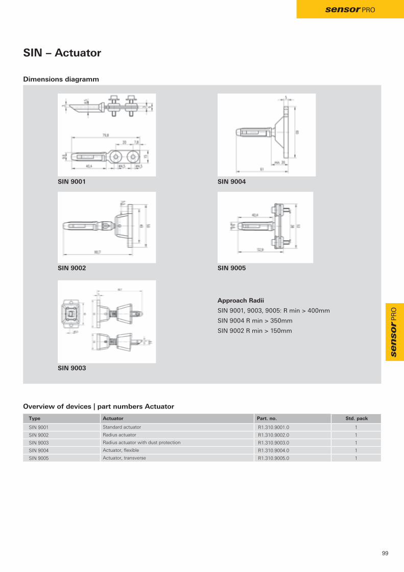
SIN 9001 R1.310.9001.0 1
SIN 9002 R1.310.9002.0 1
SIN 9003 R1.310.9003.0 1
SIN 9004 R1.310.9004.0 1
SIN 9005 R1.310.9005.0 1
SIN 9001 SIN 9004
SIN 9002 SIN 9005
SIN 9003
99
sensor pro
sen
sor p
ro
SIN – Actuator
Dimensions diagramm
Type Actuator Part. no. Std. pack
Standard actuator
Radius actuator
Radius actuator with dust protection
Actuator, flexible
Actuator, transverse
Approach Radii
SIN 9001, 9003, 9005: R min > 400mm
SIN 9004 R min > 350mm
SIN 9002 R min > 150mm
Overview of devices | part numbers Actuator

- b y
SMS 4xxx
SMS 3xxx
100
sensor pro
FunctionThe mechanical safety switches in the SMS 2000, SMS 3000 and SMS 4000 series are suitable for the reliable position monitoring of movable guards (EN 60947-5-3).
If the associated guard on the machine is opened, the hazard-ous machine movement is switched off.
The machine is shut down in a hazardous situation by an analysis of the contacts carried out by a suitable basic device in the safe relay or by one of the samos® or samos®pro safety systems.
Applications• Access protection for operators of machines with
dangerous machine parts which move after switching off• Locking of a machine or an automatic process
when the guard is open• Position monitoring of movable guards in accordance
with EN 60947-5-3
Features• Flexible use with 2 horizontal or 2 vertical actuating
directions• Protection against simple bypassing in accordance with
EN 14119 through multiple coding of the actuator• Long service life thanks to dust- and water-proof housing
and a broad operating temperature range of up to 80 °C.• Increased extraction force up to 30 N• Easy installation with adjustment via slots and final fixing
via round holes
SMS – Safety switch with separated actuator
Simple installation and wiring in each application.

SMS 2xxx / SMS 3xxx
SMS 4xxx
SMS 2xxx
SMS 3xxx / SMS 4xxx
SMS 2xxx
SMS 3xxx
SMS 4xxx
SMS 2xxx
SMS 3xxx
SMS 4xxx
TÜV, UL, c-CSA-us
- b y
SMS 2xxx
101
sensor pro
sen
sor p
ro
Applications• Access protection for operators of machines with
dangerous machine parts which move after switching off• Locking of a machine or an automatic process
when the guard is open• Position monitoring of guard and guard locking
Features• Flexible use with 4 horizontal or 4 vertical actuating
directions• Slim design for installation on profile systems and where
there are difficult space constraints• Protection against simple bypassing in accordance with
EN 1088 through multiple coding of the actuator• Long service life thanks to dust- and water-proof housing
and a broad operating temperature range of up to 80 °C• Increased extraction force up to 50 N
SMS – Safety switch with separated actuator
Technical dataFunction
according EN 14119 Safety switch with separated actuator
Power supply circuit
Max. continuous thermal current Ith 5 A (contact assignment 1 NC or 2 NC/1 NO)
10 A (contact assignment 1 NC/1 NO or 2 NC)
Application category AC-15: 230 V, 1.5 A (contact assignment 1 NC or 2 NC/1 NO)
AC-15: 230 V, 3 A (contact assignment 1 NC/1 NO or 2 NC)
Mechanical life 1 x 10⁶
Short-circuit protection lead fuse 6 A class gL/gG
lead fuse 10 A class gL/gG
Mechanical data
Approach speed ≤ 0,2 m/s
Extraction force 10 N (increased extraction force 50 N)
10 N (increased extraction force 30 N)
Dimensions (L x W x H) 100 x 31 x 30,5 mm
75 x 52 x 33 mm
90 x 52 x 33.5 mm
Mounting 2 x M5
Cable entry point 1 x M20 x 1.5
3 x M16 x 1.5
3 x M20 x 1.5
General data
Ambient temperature -30 - +80 ºC
Wire ranges screw terminals 1 x 0.5 - 1.5 mm²
Protection degree according to EN 60529 IP 65
Weight 0,15 kg
Standards EN 60947-1, EN 60947-5-1, EN ISO 13849-1, EN 62061
Approvals

SMS 3010 10 N R1.320.3010.0 1
SMS 3210 30 N R1.320.3210.0 1
SMS 3110 10 N R1.320.3110.0 1
SMS 4040 10 N R1.320.4040.0 1
SMS 4240 30 N R1.320.4240.0 1
SMS 4140 10 N R1.320.4140.0 1
SMS 4020 10 N R1.320.4020.0 1
SMS 4220 30 N R1.320.4220.0 1
SMS 4120 10 N R1.320.4120.0 1
SMS 4070 10 N R1.320.4070.0 1
SMS 4270 30 N R1.320.4270.0 1
SMS 4170 10 N R1.320.4170.0 1
SMS 2040 10 N R1.320.2040.0 1
SMS 2240 50 N R1.320.2240.0 1
SMS 2020 10 N R1.320.2020.0 1
SMS 2220 50 N R1.320.2220.0 1
SMS 2070 10 N R1.320.2070.0 1
SMS 2270 50 N R1.320.2270.0 1
SMS 4xxx SMS 3xxx SMS 2xxx
102
sensor pro
SMS – Safety switch with separated actuator
Dimensions diagramm
Type Actuator* Contact assignment Extraction force Part no. Std. pack
Standard actuator 1NC
Actuator for increased force 1NC
Radius actuator 1NC
Standard actuator 1NC/1NO
Actuator for increased force 1NC/1NO
Radius actuator 1NC/1NO
Standard actuator 2NC
Actuator for increased force 2NC
Radius actuator 2NC
Standard actuator 2NC/1NO
Actuator for increased force 2NC/1NO
Radius actuator 2NC/1NO
Standard actuator 2 1NC/1NO
Actuator for increased force 1NC/1NO
Standard actuator 2 2NC
Actuator for increased force 2NC
Standard actuator 2 2NC/1NO
Actuator for increased force 2NC/1NO
* The relevant actuator is included in the scope of delivery
Overview of devices | part numbers safety switch

SMS 9001 R1.320.9001.0 1
SMS 9002 R1.320.9002.0 1
SMS 9003 R1.320.9003.0 1
SMS 9004 R1.320.9004.0 1
SMS 9001
SMS 9002
SMS 9003
SMS 9004
SMS 9003
SMS 9002
SMS 9001
SMS 9004
103
sensor pro
sen
sor p
ro
SMS – Actuator
Dimensions diagramm
Type Actuator Part no. Std. pack
Standard actuator
Actuator for increased force
Radius actuator
Standard actuator 2
Overview of devices | part numbers Actuator
(SMS 3xxx / SMS 4xxx included in the scope of delivery)
(SMS 2xxx included in the scope of delivery)

; ySTS 02xx
STS 01xx
M12x1 8-polig
Stecker / connectorAnsicht / view "A"
8
2
6
3 45
71
Stecker / connectorPIN Farbe / colour Funktion / function
1 BN UB2 WH Sicherheitseingang 1 / safety input 13 BU GND4 BK Sicherheitsausgang 1 / safety output 15 GY Diagnoseausgang / diagnostic output6 PK Sicherheitseingang 2 / safety input 27 VT Sicherheitsausgang 2 / safety output 28 OG EDM/Start-Eingang / start input
Inputs
EDM /Start
+1
3Power
Receiver
8
2
64
7
5
-
OSSD
Actuator
Schaltplan / wiring diagramm
A
Pinbelegung und Schaltplan sind für die Serie STS 01xx und STS 02xx identisch
STS 01xx
150 ±10
A STS 02xx
Pinbelegung / pin assignment
150 ±10
1 BN2 WH3 BU4 BK5 GY6 PK7 VT8 OG
104
sensor pro
ConnectorPIN Colour Function
UBSafety input 1GNDSafety output 1Diagnostic outputSafety input 2Safety output 2EDM-start input
Applications• Protection of people or machines• Position monitoring of machine parts• Position monitoring of doors and switches of isolating
protective devices
Features• Individual coding for maximum manipulation protection• Up to PL e / category 4 (EN 13849-1)• Up to SILCL 3 (EN 62061)• Up to 30 sensors can be cascaded• Automatic or manual start• LED and semiconductor output for diagnostics• Switching distance of 8 mm / 10 mm• Protection class IP67 / IP69K
STS – Non-contact safety switches with coding
FunctionThe non-contact safety switches from the STS series are used for monitoring the position of machine parts and the position of doors and switches of isolating protective devices.
The STS series features integrated evaluation and built-in manipulation protection.
In the event of a hazard, access is approved or the machine is shut down, for example, by a device from the safe relay series or the samos® / samos®pro safety system or by the safety switch directly.
Safety switches from the STS series are also able to switch larger loads without wear via safe outputs (OSSDs).
Circuit diagram Pin assignment

STS
STS
GND
L+
105
sensor pro
sen
sor p
ro
STS – Non-contact safety switches with coding
Tailor-made manipulation protectionDifferent applications require different solutions when it comes to existing manipulation protection.
Safety switches from the STS series have 3 different coding variations, which means that they can always offer the right solution.
Coded: The safety switch accepts every STS actuator.
Fully coded: The safety switch only accepts the programmed-in STS actuator.
Unique: The safety switch only accepts STS actuator delivered with it. An STS actuator cannot be programmed in.
Diverse installationThe 5 actuation directions of the STS series and the maximum displacement between the actuator and switch element of 8 mm make installation easy even when the protective device to be monitored has large mechanical tolerances.
The resulting advantage is that it can be used universally on removable, rotatable, or sideways-moving protective devices.
5 different actuation directions for universal use
Application
Serial wiring of 2 safety switches STS with manual start and EDM
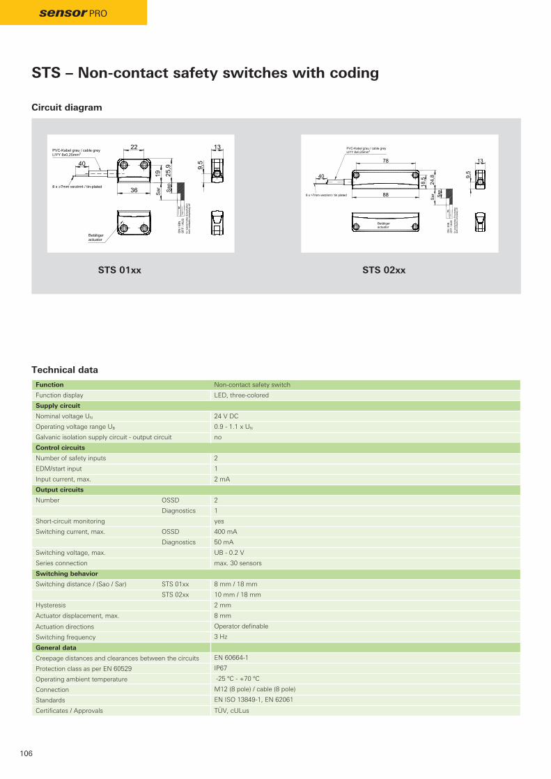
TÜV, cULus
8 x >7mm verzinnt / tin-plated
PVC-Kabel grau / cable greyLIYY 8x0,25mm2
Betätigeractuator
13
9,5
19 25,9
22
36
40
für w
iede
rhol
tes
Eins
chal
ten
both
con
tact
s co
mpl
etel
y of
f
OFF
/ AU
S O
N /
EIN
Sao
Sar
Transponderschalter STS 01xxtransponder switch STS 01xxR1.400.01xxx.0 10W28.09.15 / KOR
Betätigeractuator
9,5
13
18,5 24,8
78
888 x >7mm verzinnt / tin plated
PVC-Kabel grau / cable greyLIYY 8x0,25mm2
40
für w
iede
rhol
tes
Eins
chal
ten
both
con
tact
s co
mpl
etel
y of
f
OFF
/ AU
S O
N /
EIN
Sar Sa
o
Transponderschalter STS 02xxtransponder switch STS 02xxR1.400.02xxx.0 10W28.09.15 / KORSTS 02xxSTS 01xx
106
sensor pro
STS – Non-contact safety switches with coding
Technical dataFunction Non-contact safety switch
Function display LED, three-colored
Supply circuit
Nominal voltage UN 24 V DC
Operating voltage range UB 0.9 - 1.1 x UN
Galvanic isolation supply circuit - output circuit no
Control circuits
Number of safety inputs 2
EDM/start input 1
Input current, max. 2 mA
Output circuits
Number OSSD 2
Diagnostics 1
Short-circuit monitoring yes
Switching current, max. OSSD 400 mA
Diagnostics 50 mA
Switching voltage, max. UB - 0.2 V
Series connection max. 30 sensors
Switching behavior
Switching distance / (Sao / Sar) STS 01xx 8 mm / 18 mm
STS 02xx 10 mm / 18 mm
Hysteresis 2 mm
Actuator displacement, max. 8 mm
Actuation directions Operator definable
Switching frequency 3 Hz
General data
Creepage distances and clearances between the circuits EN 60664-1
Protection class as per EN 60529 IP67
Operating ambient temperature -25 ºC - +70 ºC
Connection M12 (8 pole) / cable (8 pole)
Standards EN ISO 13849-1, EN 62061
Certificates / Approvals
Circuit diagram

STS 0110 R1.400.0110.0 1
STS 0113 R1.400.0113.0 1
STS 0114 R1.400.0114.0 1
STS 0116 R1.400.0116.0 1
STS 0130 R1.400.0130.0 1
STS 0133 R1.400.0133.0 1
STS 0134 R1.400.0134.0 1
STS 0136 R1.400.0136.0 1
STS 0150 R1.400.0150.0 1
STS 0153 R1.400.0153.0 1
STS 0154 R1.400.0154.0 1
STS 0156 R1.400.0156.0 1
STS 0120 R1.400.0120.0 1
STS 0123 R1.400.0123.0 1
STS 0124 R1.400.0124.0 1
STS 0126 R1.400.0126.0 1
STS 0140 R1.400.0140.0 1
STS 0143 R1.400.0143.0 1
STS 0144 R1.400.0144.0 1
STS 0146 R1.400.0146.0 1
STS 0160 R1.400.0160.0 1
STS 0163 R1.400.0163.0 1
STS 0164 R1.400.0164.0 1
STS 0166 R1.400.0166.0 1
STS 0210 R1.400.0210.0 1
STS 0213 R1.400.0213.0 1
STS 0214 R1.400.0214.0 1
STS 0216 R1.400.0216.0 1
STS 0230 R1.400.0230.0 1
STS 0233 R1.400.0233.0 1
STS 0234 R1.400.0234.0 1
STS 0236 R1.400.0236.0 1
STS 0250 R1.400.0250.0 1
STS 0253 R1.400.0253.0 1
STS 0254 R1.400.0254.0 1
STS 0256 R1.400.0256.0 1
STS 0220 R1.400.0220.0 1
STS 0223 R1.400.0223.0 1
STS 0224 R1.400.0224.0 1
STS 0226 R1.400.0226.0 1
STS 0240 R1.400.0240.0 1
STS 0243 R1.400.0243.0 1
STS 0244 R1.400.0244.0 1
STS 0246 R1.400.0246.0 1
STS 0260 R1.400.0260.0 1
STS 0263 R1.400.0263.0 1
STS 0264 R1.400.0264.0 1
STS 0266 R1.400.0266.0 1
STS 3110 R1.400.3110.0 1
STS 3210 R1.400.3210.0 1
107
sensor pro
sen
sor p
ro
Type Description Coding Part no. Std. pack
Switch-set, automatic start, connection M12-8 coded
Switch-set, automatic start, connection cable 3m coded
Switch-set, automatic start, connection cable 5m coded
Switch-set, automatic start, connection cable 10m coded
Switch-set, automatic start, connection M12-8 fully-coded
Switch-set, automatic start, connection cable 3m fully-coded
Switch-set, automatic start, connection cable 5m fully-coded
Switch-set, automatic start, connection cable 10m fully-coded
Switch-set, automatic start, connection M12-8 unique
Switch-set, automatic start, connection cable 3m unique
Switch-set, automatic start, connection cable 5m unique
Switch-set, automatic start, connection cable 10m unique
Switch-set, manual start, connection M12-8 coded
Switch-set, manual start, connection cable 3m coded
Switch-set, manual start, connection cable 5m coded
Switch-set, manual start, connection cable 10m coded
Switch-set, manual start, connection M12-8 fully-coded
Switch-set, manual start, connection cable 3m fully-coded
Switch-set, manual start, connection cable 5m fully-coded
Switch-set, manual start, connection cable 10m fully-coded
Switch-set, manual start, connection M12-8 unique
Switch-set, manual start, connection cable 3m unique
Switch-set, manual start, connection cable 5m unique
Switch-set, manual start, connection cable 10m unique
Actuator for STS 011x, 012x, 013x, 014x
Actuator for STS 021x, 022x, 023x, 024x
Overview of devices | part numbers
STS – Non-contact safety switches with coding
Note: Suitable M12 cables (SLX-CAB) can be selected on P.86

SMA 011x SMA 012x
#
SMA 0113 / SMA 0119 SMA 0123 / SMA 0129
SMA 011x SMA 012xSMA 011x / SMA 012x
SMA 01xx
108
sensor pro
Applications• Machine and plant manufacturing • Packing machines• Wood-processing machines
Features• Block-shaped design• For harsh operating conditions• Tamper proof• Can be used up to PL e / Category 4 (EN ISO 13849-1)• Degree of Protection IP67
SMA – Magnetic safety switches
Dimension diagram
Technical data
Circuit diagram
Set
Dimensions / mm (L x W x H) 36 x 26 x 13 mm
Actuating distance / (Sao / Sar) 8 / 17 mm
Directions of actuation Front - Front / Front - Side / Side - Side
Protection degree IP67
Contact type Reed
Contact assignment NC / NO NO / NO
Switching voltage 48 V DC
Switching current 0.2 A
Maximum cable length 20 m
Contacts are shown in non-operated state(magnet is out of actuating distance Sar)

SMA 021x SMA 022x SMA 023x/024x SMA 061x SMA 062x
#
SMA 0213 / SMA 0219 SMA 0223 / SMA 0229
SMA 021x / SMA 0219 SMA 022x / SMA 0229SMA 021x / SMA 022x / SMA 023x / SMA 024x
SMA 023x
5 GR 6 VIO
Kontrollkontakt (K) / control contact
SMA 023x
SMA 02xxSMA 06xx
109
sensor pro
sen
sor p
ro
Applications• Machine and plant manufacturing • Packing machines• Wood-processing machines
Features• Rectangle-shaped design• For harsh operating conditions• Tamper proof• Can be used up to PL e / Category 4 (EN ISO 13849-1)• Degree of Protection IP67
SMA – Magnetic safety switches
Dimension diagram
Technical data
Circuit diagram
Set
Dimensions / mm (L x W x H) 88 x 25 x 14 mm
Actuating distance / (Sao / Sar) 7 / 17 mm 7 / 18 mm 7 / 22 mm 4 / 16 mm 4 / 17 mm
Directions of actuation Front - Front / Front - Side / Side - Side
Protection degree IP67
Contact type Reed
Contact assignment NC / NO NO / NO NO / NO / NC NC / NO NO / NO
Switching voltage 48 V DC
Switching current 0.2 A
Maximum cable length 20 m
SMA 024x (with LED)
Contacts are shown in non-operated state (magnet is out of actuating distance Sar)

SMA 031x SMA 032x
#
SMA 0313 / SMA 0319 SMA 0323 / SMA 0329
SMA 031x SMA 032xSMA 031x / SMA 032x
SMA 03xx
110
sensor pro
Applications• Machine and plant manufacturing • Packing machines• Wood-processing machines
Features• Round-shaped design• For harsh operating conditions• Tamper proof• Can be used up to PL e / Category 4 (EN ISO 13849-1)• Degree of Protection IP67
SMA – Magnetic safety switches
Dimension diagram
Technical data
Circuit diagram
Set
Dimensions / mm (Ø x L) M30 x 32 mm
Actuating distance / (Sao / Sar) 7 / 20 mm
Directions of actuation Front - Front
Protection degree IP67
Contact type Reed
Contact assignment NC / NO NO / NO
Switching voltage 48 V DC
Switching current 0.2 A
Maximum cable length 20 m
Contacts are shown in non-operated state(magnet is out of actuating distance Sar)

SMA 0113 R1.100.0113.0 1
SMA 0123 R1.100.0123.0 1
SMA 0119 R1.100.0119.0 1
SMA 0129 R1.100.0129.0 1
SMA 0213 R1.100.0213.0 1
SMA 0223 R1.100.0223.0 1
SMA 0224 R1.100.0224.0 1
SMA 0226 R1.100.0226.0 1
SMA 0228 R1.100.0228.0 1
SMA 0233 R1.100.0233.0 1
SMA 0243 R1.100.0243.0 1
SMA 0249 R1.100.0249.0 1
SMA 0219 R1.100.0219.0 1
SMA 0229 R1.100.0229.0 1
SMA 0313 R1.100.0313.0 1
SMA 0323 R1.100.0323.0 1
SMA 0319 R1.100.0319.0 1
SMA 0329 R1.100.0329.0 1
SMA 0613 R1.100.0613.0 1
SMA 0623 R1.100.0623.0 1
SMA 0626 R1.100.0626.0 1
SMA 0619 R1.100.0619.0 1
SMA 0629 R1.100.0629.0 1
SMA 3110 R1.100.3110.0 5
SMA 3120 R1.100.3120.0 5
SMA 3200 R1.100.3200.0 5
SMA 3300 R1.100.3300.0 5
SMA 3600 R1.100.3600.0 5
SMA 4100 R1.100.4100.0 10
SMA 4200 R1.100.4200.0 10
SMA 5004 R1.100.5004.0 1
SMA 5005 R1.100.5005.0 1
SMA 5004 SMA 5005
SMA 4200
SMA 4100
SMA 3110 SMA 3120
SMA 3200SMA 3600
SMA 3300
111
sensor pro
sen
sor p
ro
Accessories for SMA
Overview of devices | part numbers
Overview of devices | part numbers
Type Description Contact Part no. Std. pack
Switch-set with cable 3 m + magnet NC / NO
Switch-set with cable 3 m + magnet NO / NO
Switch-set mit with M8 connection + magnet NC / NO
Switch-set mit with M8 connection + magnet NO / NO
Switch-set with cable 3 m + magnet NC / NO
Switch-set with cable 3 m + magnet NO / NO
Switch-set with cable 5 m + magnet NO / NO
Switch-set with cable 10 m + magnet NO / NO
Switch-set with cable 20 m + magnet NO / NO
Switch-set with cable 3 m + magnet NO / NO / NC
Switch-set with cable 3 m, LED + magnet NO / NO / NC
Switch-set with M12 connection, LED + magnet NO / NO / NC
Switch-set with M8 connection + magnet NC / NO
Switch-set with M8 connection + magnet NO / NO
Switch-set with cable 3 m + magnet NC / NO
Switch-set with cable 3 m + magnet NO / NO
Switch-set with M8 connection + magnet NC / NO
Switch-set with M8 connection + magnet NO / NO
Switch-set with cable 3 m + magnet NC / NO
Switch-set with cable 3 m + magnet NO / NO
Switch-set with cable 10 m + magnet NO / NO
Switch-set with M8 + magnet NC / NO
Switch-set with M8 + magnet NO / NO
Type Description Contact Part no. Std. pack
Magnet (NC / NO) for SMA 011x
Magnet (NO / NO) for SMA 012x
Magnet for SMA 02xx
Magnet for SMA 03xx
Magnet for SMA 06xx
Washer for SMA 01xx
Washer for SMA 02xx / SMA 06xx
Cable, 5 m
Cable, 10 m
Note: Suitable M12 cables (SLX-CAB) can be selected on P.86

Y
K1 S1 K2 S2 K3 S3 K4 S4
A1 A1 A2 A2 1 2 Y8 Y9
11 12 13 14
V+
21 22 23 24
V+
31 32 33 34
V+
41 42 43 44
V+
3 4 Y4 Y3 Y2 Y1Y6 Y5
V+
K1
K2
K3
K4
K4 K3 K2 K1
Power Fault
PTC
PTC
SMI 1001 SMI 1001
112
sensor pro
FunctionThe SMI 1001 connects safety switches / position switches in series. Several safety switches or position switches can be connected to safe relay safety switching devices or to samos® and samos®pro safety systems and evaluated.
The SMI 1001 features status displays for the switching state of the NO circuits of the connected sensors as well as four diagnostics outputs for the display of the switching state of the NO circuits via external LEDs or a control.
Applications• Connecting in series of two-channel sensors with
contact assignment NO/NO up to PL d / Categorie 3 (EN ISO 13849-1)
Features• Control via a maximum of 4 two-channel sensors• Signal output for each sensor• Optical indication of the switching state of each sensor
SMI 1001 – Magnetic switch interface
Circuit diagramDimension diagram

SMI 1001 24 V DC R1.100.4001.0 1
cULus
113
sensor pro
sen
sor p
ro
SMI 1001 – Magnetic switch interface
Application
Type Rated voltage Terminals Part no. Std. pack
Push-in terminals, fixed
Overview of devices | part numbers
Technical data
Function
Function display 1 x LEDs green, 5 x LEDs red
Power supply circuit
Rated voltage 24 V DC
Rated consumption 1.5 W
Control circuit 11 – 44
Max. cable length 30 m
Output circuit signal outputs Y1 – Y6
Contact type NO
Rated switching voltage 24 V DC
Max. switching current 0.5 A
Output circuit 1, 2, 3, 4
Contact type NO
Rated switching voltage 24 V DC
Max. switching current 150 mA
General data
Creepage distances and clearances according to EN 60664-1
Ambient temperature/ storage temperature -25 – +55 ºC / -25 – +70 ºC
Wire ranges fine-stranded/ solid 0.08 – 2.5 mm2
or fine-stranded with ferrules 0.08 – 1 mm2
or fine-stranded with TWIN-ferrule 0.08 – 1.5 mm2
Weight 0.1 kg
Approvals

114
Complete solutions
Flexibility and plug-in ease
Save time and money thanks to flexibility, modular design, and plug-in ease - across all life phases of the machine.
Build your machines in modular fashion with flexiblity – and safely as well!

Wie-Service24
115
Complete solutions
Safety
Make your machine safe - with solutions from Wieland.
Process reliability + communication
Increase process reliability and communicate with your machines worldwide.

116
SISTEMA – safety of machine controls
The SISTEMA software provides developers and testers of safety-related machine controls with comprehensive support when assessing safety within the scope of DIN EN ISO 13849-1. The name SISTEMA comes from the German "SIcherheit von STEuerungen an MAschinen" (safety of machine controls). The tool allows you to reproduce the structure of the safety-related control elements on the basis of the intended architectures and then enables an automated calculation of the reliability values at various levels of detail, including the performance level (PL) attained.
Software
EPLAN – support during configuration
Support of automation projects naturally also includes EPLAN data and macros which can be very easily downloaded from the Wieland homepage at www.wieland-electric.com
Software

117
Training
Wieland Electric offers a range of workshops about the topic of machine safety.The training covers hazard and risk analysis, definition of the necessary safety functions using the SISTEMA tool and support for selecting and implementing the necessary technical safety measures.We provide our safety workshops and product training sessions both as in-house training and as a workshop at our modern Sales Center in Bamberg.
• Risk assessment and risk reduction in accordance with EN 12100
• Definition of technical safety measures• Assessment of safety functions (SISTEMA)• Product training• Training for samos®plan 5+
Simply contact us at +49 951 9324 999 or via e-mail at [email protected]
Training
Sales Center in Bamberg
You can get the free program-ming tool samos®plan 5+ at www.wieland-electric.com Service / Software

www.wieland-electric.com
http://eshop.wieland-electric.com
118
Support
Technical consultation and general information
General information and news:
Visit our e-catalog at
Hotline – one call is all it takes
Industrial Automation – Electromechanical
Hotline +49 951 9324-991 E-Mail [email protected]
Industrial Automation – Electronics
Hotline +49 951 9324-995 E-Mail [email protected]
Safety Technology
Hotline +49 951 9324-999 E-Mail [email protected]
Building and Installation Technology
Hotline +49 951 9324-996 E-Mail [email protected]

contacts are green
www.wieland-electric.com
119Subject to technical modifications! gesis®, RST®, GST®, GST18®, podis®, samos® and saris® are registered trademarks of Wieland Electric GmbH
Our subsidiaries... and the addresses of our sales partner worldwide are available at:
USAWieland Electric Inc.North American Headquarters2889 Brighton RoadOakville, Ontario L6H 6C9Phone +1 905 8298414 Fax +1 905 8298413 www.wielandinc.com
FRANCEWieland Electric SARL.Le Cérame, Hall 647, avenue des GenottesCS 4831395803 Cergy-Pontoise CedexPhone +33 1 30320707Fax +33 1 [email protected] www.wieland-electric.fr
POLANDWieland Electric Sp. Zo.o.Św. Antoniego 862-080 SwadzimPhone +48 61 2225400Fax +48 61 [email protected]
CANADAWieland Electric Inc.North American Headquarters2889 Brighton RoadOakville, Ontario L6H 6C9Phone +1 905 8298414 Fax +1 905 8298413 www.wieland-electric.ca
SPAINWieland Electric S.L.C/ Maria Auxiliadora 2, bajosE-08017 BarcelonaPhone +34 93 2523820Fax +34 93 [email protected]
GREAT BRITAINWieland Electric Ltd.Riverside Business Center, Walnut Tree CloseGB-Guildford /Surrey GU1 4UGPhone +44 1483 531213Fax +44 1483 [email protected]
CHINAWieland Electric TradingUnit 2703 International Soho City 889 Renmin Road, Huang Pu DistrictPRC- Shanghai 200010Phone +86 21 63555833Fax +86 21 63550090info-shanghai@wieland-electric.comwww.wieland-electric.cn
ITALYWieland Electric S.r.l.Via Edison, 209I-20019 Settimo MilanesePhone +39 02 48916357Fax +39 02 [email protected]
DENMARKWieland Electric A/SVallørækken 26DK-4600 KøgePhone +45 70 266635Fax +45 70 [email protected]
SWITZERLANDWieland Electric AGHarzachstrasse 2bCH-8404 WinterthurPhone +41 52 2352100Fax +41 52 [email protected]
JAPANWieland Electric Co, Ltd.Nisso No. 16 Bldg. 7F3-8-8 Shin-Yokohama,Kohoku-kuYokohama 222-0033Phone +81 45 473 5085Fax +81 45 470 [email protected]
GERMANYHeadquarters Wieland Electric GmbH Brennerstraße 10 – 14 96052 Bamberg, GermanyPhone +49 951 9324-0 Fax +49 951 9324-198 [email protected]
BELGIUM & GD LUXEMBOURGATEM-Wieland Electric NVBedrijvenpark De Veert 4B-2830 WillebroekPhone +32 3 8661800Fax +32 3 [email protected]

contacts are green safety
120
Glossary
Single-channel input circuit 1 NC contact or semiconducto
Two-channel input circuit2 NC contacts or semiconductors
Two-channel input circuit, antivalent1 NO / 1 NC contacts or semiconductors
Cross monitoring between two input circuits
Synchro-check between two input circuits
Safe StartStart command is accepted only when the input circuits are closed
Combi-reset Automatic start possible after voltage failure, based on the risk analysis
Automatic Resetafter application of the voltage and/or after safety request
Manual Reset in the case of a rising edge at the reset input
Reset button monitoring in the case of a falling edge at the reset input
Contacts (NO/NC) safe semiconductor outputs
Alarm contacts
Safe changeover contacts
Safe semi conductor outputs
Safe OFF-delay
Safe ON-delay
Monoflopfor rapid tactile applications
Reset of time lapse for OFF-delayed contacts
Expanded diagnostics
Emergency stop monitoring Floating contacts
Protective gate monitoringFloating contacts
Position monitoringMagnetic switch
Safety light grid / -light curtain acc. to EN 61496 BWS Type 4 / Type 2
Two-hand controlaccording to EN 574
Controlled Stopaccording to EN 60204-1 stop category 1
Standstill and motion monitoring
Safety shut-off mat monitoring (4-wire principle, short-circuiting)
Valve position monitoring
Contact expansion
Machine building industry
Elevator systemsin accord. with EN 81-1
Combustion plants according to EN 50156-1
Process technology according to IEC 61511
Finger protection
Hand protection
Arm protection
Access protection
Personal protection

contacts are green
greenhorns
Mission Ausbildung interessant
vielseitigzukunftsorientiert
greenhorns
revos Industriesteckverbinder
Katalog 2015
revo
s In
dust
ries
teck
verb
ind
er
revo
s In
dust
ries
teck
verb
ind
er
0530.x_revos_001_U4.indd 3 04.11.15 10:08
podis®podis®
pod
is®
podis®0830.0 MC 10/14
Dezentrale Automatisierungstechnik
Katalog 2015
IndustrietechnikLösungen für den Schaltschrank•Reihenklemmen
–Schraub-,Zugfeder-oderPushIn-Anschlusstechnik–Leiterquerschnittebis300mm2
–zahlreicheSonderfunktionen–SoftwarelösungenmitSchnittstellenzuCAE-Systemen
•Safety–sichereSignalerfassung–Sicherheitsschaltgeräte–modulareSicherheitsbausteine–kompakteSicherheitssteuerung–applikativeBeratungundSchulungen
•NetzwerktechnikundFeldbussysteme–FernwartungmitVPN-IndustrierouterundVPN-Serviceportal–Industrie-Ethernet-Switches–SPSundI/O-Systeme,Standardund
erweiterteUmgebungsbedingungen•Interface
–Stromversorgungen–Überspannungsschutz–Koppelrelais,Halbleiterschalter–Zeit-,Mess-undÜberwachungsrelais–analogeKoppel-undWandlerbausteine–Übergabebausteine
Lösungen für Feld-Applikationen•DezentraleInstallations-undAutomatisierungstechnik
–Windtower-Installationen–FeldbusanschaltungenundMotorstarterfürAntriebe
•SteckverbinderfürindustrielleAnwendungen–Rechteck-undRundsteckverbinder–GehäuseausAluminiumoderKunststoff–SchutzartbisIP69K–Strombelastbarkeitbis100A–SteckverbinderfürexplosionsgefährdeteBereiche–modulare,applikationsspezifischeTechnik
Leiterplattenklemmen und -steckverbinder–Schraub-oderFederkraftanschlusstechnik–Rastermaße3,5mmbis10,16mm–Reflow-oderSchwallbadlötprozess
Gebäude- und Installationstechnik•Gebäudeinstallationssysteme
–Netz-SteckverbinderIP20/IP65...IP69K–Bus-Steckverbinder–Niedervolt-Steckverbinder–EnergieverteilsystemmitFlachleitungen–Verteiler-Systeme–RaumautomationmitKNX-undFunktechnologie–Installationsreihenklemmen–Überspannungsschutz
Unternehmenszentrale:WielandElectricGmbHBrennerstraße10–14D-96052Bamberg
Vertriebs-Center:WielandElectricGmbHBenzstraße9D-96052Bamberg
Telefon+499519324-0Telefax+499519324-198www.wieland-electric.cominfo@wieland-electric.com
0830.x_podis_Tit_6.5mm.indd Alle Seiten 20.10.14 13:32
gesis®electronicgesis®electronic
gesi
s® elec
tro
nic
gesis®electronic0700.0 MC 09/14
Dezentrale Gebäudeautomation per plug & play
Katalog 2015
IndustrietechnikLösungen für den Schaltschrank•Reihenklemmen
–Schraub-,Zugfeder-oderPushIn-Anschlusstechnik–Leiterquerschnittebis300mm2
–zahlreicheSonderfunktionen–SoftwarelösungenmitSchnittstellenzuCAE-Systemen
•Safety–sichereSignalerfassung–Sicherheitsschaltgeräte–modulareSicherheitsbausteine–kompakteSicherheitssteuerung–applikativeBeratungundSchulungen
•NetzwerktechnikundFeldbussysteme–FernwartungmitVPN-IndustrierouterundVPN-Serviceportal–Industrie-Ethernet-Switches–SPSundI/O-Systeme,Standardund
erweiterteUmgebungsbedingungen•Interface
–Stromversorgungen–Überspannungsschutz–Koppelrelais,Halbleiterschalter–Zeit-,Mess-undÜberwachungsrelais–analogeKoppel-undWandlerbausteine–Übergabebausteine
Lösungen für Feld-Applikationen•DezentraleInstallations-undAutomatisierungstechnik
–Windtower-Installationen–FeldbusanschaltungenundMotorstarterfürAntriebe
•SteckverbinderfürindustrielleAnwendungen–Rechteck-undRundsteckverbinder–GehäuseausAluminiumoderKunststoff–SchutzartbisIP69K–Strombelastbarkeitbis100A–SteckverbinderfürexplosionsgefährdeteBereiche–modulare,applikationsspezifischeTechnik
Leiterplattenklemmen und -steckverbinder–Schraub-oderFederkraftanschlusstechnik–Rastermaße3,5mmbis10,16mm–Reflow-oderSchwallbadlötprozess
Gebäude- und Installationstechnik•Gebäudeinstallationssysteme
–Netz-SteckverbinderIP20/IP65...IP69K–Bus-Steckverbinder–Niedervolt-Steckverbinder–EnergieverteilsystemmitFlachleitungen–Verteiler-Systeme–RaumautomationmitKNX-undFunktechnologie–Installationsreihenklemmen–Überspannungsschutz
Unternehmenszentrale:WielandElectricGmbHBrennerstraße10–14D-96052Bamberg
Vertriebs-Center:WielandElectricGmbHBenzstraße9D-96052Bamberg
Telefon+499519324-0Telefax+499519324-198www.wieland-electric.deinfo@wieland-electric.com
0700.x_Titel+Bund5,5mm.indd Alle Seiten 20.10.14 13:36
RST ®
RST ®
Steckbare Elektroinstallation in höchster Schutzart (IP6X)
Katalog 2016
0690.x_RST_U4-R13-U1_Umschlag.indd 3 29.02.16 13:09
Lift- und AufzugstechnikLösungen für die Elektroinstallation
0416.0_LIFTTECHNIK_1013_CS6.indd 13 30.09.13 13:53
WindkraftElektrotechnische Lösungen für
Windenergieanlagen
0430.x Windkraft_1115_U1_U4.indd 2 12.11.15 10:28
ProduktprogrammLösungen für Industrie-, Gebäude-
und Installationstechnik
0901.x_Produktprogramm_Titel.indd 2 02.11.15 08:59
MaschinenbauIndividuelle Kundenlösungen
selos / fasisselos / fasis
selo
s / fa
sis
selos / fasis0500.0 B 10/14
Reihenklemmen mit Schraub-, Zugfeder- und Push-In-Anschluss
Katalog 2015
IndustrietechnikLösungen für den Schaltschrank
•Reihenklemmen–Schraub-,Zugfeder-oderPushIn-Anschlusstechnik–Leiterquerschnittebis240mm2
–zahlreicheSonderfunktionen–SoftwarelösungenmitSchnittstellenzuCAE-Systemen
•Safety–sichereSignalerfassung–Sicherheitsschaltgeräte–modulareSicherheitsbausteine–kompakteSicherheitssteuerung–applikativeBeratungundSchulungen
•NetzwerktechnikundFeldbussysteme–FernwartungmitVPN-IndustrierouterundVPN-Serviceportal–Industrie-Ethernet-Switches–SPSundI/O-Systeme,Standardund
erweiterteUmgebungsbedingungen•Interface
–Stromversorgungen–Überspannungsschutz–Koppelrelais,Halbleiterschalter–Zeit-,Mess-undÜberwachungsrelais–analogeKoppel-undWandlerbausteine–ÜbergabebausteineLösungen für Feld-Applikationen
•DezentraleInstallations-undAutomatisierungstechnik–Windtower-Installationen–FeldbusanschaltungenundMotorstarterfürAntriebe
•SteckverbinderfürindustrielleAnwendungen–Rechteck-undRundsteckverbinder–GehäuseausAluminiumoderKunststoff–SchutzartbisIP69K–Strombelastbarkeitbis100A–SteckverbinderfürexplosionsgefährdeteBereiche–modulare,applikationsspezifischeTechnikLeiterplattenklemmen und -steckverbinder–Schraub-oderFederkraftanschlusstechnik–Rastermaße3,5mmbis10,16mm–Reflow-oderSchwallbadlötprozess
Gebäude- und Installationstechnik•Gebäudeinstallationssysteme
–Netz-SteckverbinderIP20/IP65...IP69K–Bus-Steckverbinder–Niedervolt-Steckverbinder–EnergieverteilsystemmitFlachleitungen–Verteiler-Systeme–RaumautomationmitKNX-undFunktechnologie–Installationsreihenklemmen–Überspannungsschutz
Unternehmenszentrale:WielandElectricGmbHBrennerstraße10–14D-96052Bamberg
Vertriebs-Center:WielandElectricGmbHBenzstraße9D-96052Bamberg
Telefon+499519324-0Telefax+499519324-198www.wieland-electric.cominfo@wieland-electric.com
0500.x_RKL_Tit_8,5mm.indd Alle Seiten 16.10.14 10:55
Industrietechnik Lösungen für den Schaltschrank •Reihenklemmen –Schraub-,Zugfeder-oderPushIn-Anschlusstechnik –Leiterquerschnittebis240mm2 –zahlreicheSonderfunktionen –SoftwarelösungenmitSchnittstellenzuCAE-Systemen •Safety –sichereSignalerfassung –Sicherheitsschaltgeräte –modulareSicherheitsbausteine –kompakteSicherheitssteuerung –applikativeBeratungundSchulungen •NetzwerktechnikundFeldbussysteme –FernwartungmitVPN-IndustrierouterundVPN-Serviceportal –Industrie-Ethernet-Switches –SPSundI/O-Systeme,Standardund
erweiterteUmgebungsbedingungen • Interface –Stromversorgungen –Überspannungsschutz –Koppelrelais,Halbleiterschalter –Zeit-,Mess-undÜberwachungsrelais –analogeKoppel-undWandlerbausteine –Übergabebausteine Lösungen für Feld-Applikationen •DezentraleInstallations-undAutomatisierungstechnik –Windtower-Installationen –FeldbusanschaltungenundMotorstarterfürAntriebe •SteckverbinderfürindustrielleAnwendungen –Rechteck-undRundsteckverbinder –GehäuseausAluminiumoderKunststoff –SchutzartbisIP68 –Strombelastbarkeitbis100A –SteckverbinderfürexplosionsgefährdeteBereiche –modulare,applikationsspezifischeTechnik Leiterplattenklemmen und -steckverbinder –Schraub-oderFederkraftanschlusstechnik –Rastermaße3,5mmbis10,16mm –Reflow-oderSchwallbadlötprozess
Gebäude- und Installationstechnik •Gebäudeinstallationssysteme –Netz-SteckverbinderIP20/IP65...IP68 –Bus-Steckverbinder –Niedervolt-Steckverbinder –EnergieverteilsystemmitFlachleitungen –Verteiler-Systeme –BussystemeinKNX-,LON-undFunk-Technologie –Installationsreihenklemmen –Überspannungsschutz
UnternehmenszentraleWielandElectricGmbHBrennerstraße10-14D-96052Bamberg
Telefon+499519324-0Telefax+499519324-198
0670.0C03/14
gesis®
Steckbare Elektroinstallation im Innenbereich
Katalog 2014
gesis®gesis®
0670.x_U1_U4_17mm_2014.indd Alle Seiten 13.03.14 15:47
0416.1 Lift Technology Solutions for the electrical installation
0415.1 Machine building Individual customer solutions
Selection of our catalogs
0700.1 gesis® electronic Decentralized building automation with plug & play
0690.1 RST® Pluggable Electrical Installation in highest protection (IP6X)
0500.1 selos / fasis – DIN rail terminal blocks with screw, tension spring and push-in connection
0430.1 Wind power Electro-technical solutions for wind energy systems
0901.1 Product Range Solutions for industrial, building and installation technology
0912.0 Mission Ausbildung
0670.1 gesis® Pluggable electrical installation for indoors
0530.1 revos Industrial Multipole Connectors
0830.1 podis® Decentralized Automation
0950.1 Wieland Image brochure

contacts are green
safe
ty
safety
0860.1 A 06/16
Industrial technologySolutions for the control cabinet• DIN rail terminal blocks
– Screw, tension spring or push-in connection technology– Wire cross sections up to 300 mm2
– Numerous special functions– Software solutions interfacing to CAE systems
• Safety– Safe signal acquisition– Safety switching devices– Modular safety modules– Compact safety controllers– Application consulting and training
• Network engineering and fieldbus systems– Remote maintenance via VPN industrial router and VPN service portal– Industrial Ethernet switches– PLC and I/O systems, standard and
increased environmental conditions• Interface
– Power supply units– Overvoltage protection– Coupling relays, semiconductor switches– Timer relays, measuring and monitoring relays– Analog coupling and converter modules– Passive interfaces
Solutions for field applications• Decentralized installation and automation technology
– Electrical installation for wind tower– Fieldbus interfaces and motor starters
• Connectors for industrial applications– Rectangular and round connectors– Aluminium or plastic housings– Degree of protection up to IP 69K– Current-carrying capacity up to 100 A– Connectors for hazardous areas– Modular, application-specific technology
PC board terminals and connectors– Screw or spring clamp connection technology– Spacings: 3.5 mm to 10.16 mm– Reflow or wave soldering process
Building and installation technology• Building installation systems
– Main power supply connectors IP 20/IP 65 ... IP 69K– Bus connectors– Low-voltage connectors– Power distribution system with flat cables– Distribution systems– Room automation with KNX, EnOcean, SMI and DALI– DIN rail terminal blocks for electrical installations– Overvoltage protection
Headquarters: Wieland Electric GmbH Brennerstraße 10 – 14 96052 Bamberg, Germany
Phone +49 951 9324-0 Fax +49 951 9324-198 [email protected]