
Features and Applications of the Adaptable Flexiband USB3.0 ...
Upload
khangminh22Category
view
0download
0
HAL Id: tel-02469999https://hal.archives-ouvertes.fr/tel-02469999
Submitted on 6 Feb 2020
HAL is a multi-disciplinary open accessarchive for the deposit and dissemination of sci-entific research documents, whether they are pub-lished or not. The documents may come fromteaching and research institutions in France orabroad, or from public or private research centers.
L’archive ouverte pluridisciplinaire HAL, estdestinée au dépôt et à la diffusion de documentsscientifiques de niveau recherche, publiés ou non,émanant des établissements d’enseignement et derecherche français ou étrangers, des laboratoirespublics ou privés.
Runtime testing of dynamically adaptable anddistributed component based Systems
Mariam Lahami
To cite this version:Mariam Lahami. Runtime testing of dynamically adaptable and distributed component based Systems.Computer Science [cs]. Ecole Nationale d’Ingénieurs de Sfax, 2017. English. �tel-02469999�

Ecole Doctorale
Sciences et Technologies
Thèse de DOCTORAT Ingénierie des Systèmes
Informatiques
N° d’ordre: 2017 −156/16
Ministère de l’Enseignement Supérieur,
Et de la Recherche Scientifique
Université de Sfax École Nationale d’Ingénieurs de Sfax
THESE
présenté à
l’Ecole Nationale d’Ingénieurs de Sfax
en vue de l’obtention de
DOCTORAT
Dans la discipline Informatique Ingénierie des systèmes informatiques
par
Mariam LAHAMI
(Mastère Systèmes d'Information et Nouvelles Techno logies )
Runtime Testing of Dynamically Adaptable
and Distributed Component-based Systems
soutenu le 29 Avril 2017, devant le jury composé de :
M. Maher BEN JEMAA (Professeur) Président
M. Mohamed MOSBAH (Professeur) Rapporteur
Mme. Leila JEMNI (Professeur) Rapporteur
M. Kais HADDAR (Maître de conférences) Examinateur
M. Mohamed JMAIEL (Professeur) Directeur de thèse

To the memory of my dad Youssef,
Who gave me the drive and the desire to accomplish this thesis.
“Ya Pa”, I know that your dream was to call me “Doctor”.
Now, we are so close to fulfill our dream !
i

Acknowledgments
It is not an easy task to acknowledge all the people who made this Ph.D. thesis possible with a
few words. However, I will try to do my best to extend my great appreciation to everyone who
helped me scientifically and emotionally throughout this study.
First, I would like to express a deep gratitude to my thesis supervisor Prof. Mohamed Jmaiel
for taking me under his wing and guiding me since the moment I entered the National School of
Engineers of Sfax. I greatly appreciate his patience, motivation, and immense knowledge. His
guidance helped me in all the time of research and writing of this thesis. I feel very privileged
to have worked with an outstanding professor and a superb person like him.
Second, I would like to thank my thesis co-supervisor Dr. Moez Krichen, Associate Professor
at the University of Baha, KSA, as he shared with me his knowledge and his research experience.
Many thanks go to the rest of the jury panel: Prof. Maher Ben Jemaa (Professor at the
University of Sfax, Tunisia), Prof. Kais Haddar (Professor at the University of Sfax, Tunisia),
especially Prof. Mohamed Mosbah (Professor at the University of Bordeaux 1, France) and
Prof. Leila Jemni Ben Ayed (Professor at the University of Manouba, Tunisia) for accepting
the review of my thesis report.
I would also like to convey my sincere and deep gratitude to my family for both believing in
me and suffering with me through this long and arduous process.
A very special thank to my mother Fekria for the unconditional support and understanding
that she has given to me. I am indebted to her more than she knows and I owe to her what I am
today. Everyday and every moment, I thank God for enlightening my life with your presence
“Ya Ma”.
I also owe many thanks and gratitude to my dearest husband Faker for his support and
encouragement. Thank you for sharing my wish to reach the goal of completing this thesis and
for bearing an overworked wife during thirteen years of marriage.
No words could express how much I am indebted to my lovely children Aziz, Youssef and
Khadija who have always stood by me and dealt with all my absence and my stressful times with
simply a smile. Aziz has grown up watching me study and juggle with family and work. I know
that especially the last two years were a burden for you as you stay all day long in the school.
Youssef, thank you for being a constant source of love and tenderness at home. By simply
looking at your eyes, I felt and I will feel the presence of my father by my side, and indirectly
you give me the strength to make this dream a reality. Khadija, the little one, who always tries
ii

to do everything to make her presence felt. You have always told me to stop studying! Mommy’s
Ph.D. studies will be ended soon! I hope that I have been a good mother and that I have not
lost too much during the tenure of this thesis.
Special and profound thanks goes to my sisters Islem, Salma and Yasmin. Your devotion,
unconditional love and support, sense of humor, patience, optimism and advice were more
valuable than you could ever imagine.
Furthermore, I would like to express my sincere thanks to my aunt Soumaya, my uncle Hedi
and also my family-in-law for their support and their prayers.
Distinctive thanks go to my closest friends Raja, Meriam, Afef J., Afef M., Maissa, Faten,
Ines, and Nabiha for their invaluable support and encouragement during the difficult moments
of this thesis. Specially, I owe a debt of gratitude to Afef M. for reading my thesis report and
providing useful suggestions.
Finally, I owe special thanks to all ReDCAD Laboratory members, especially Amina, Imene,
Fatma, Nesrine, Wafa, Rahma, Amal G., Amal G. and Salma for the great environment inside
our lab. We were not only able to support each other by deliberating over our problems and
findings, but also by talking happily about things other than just our papers.
I dedicate this work to you all.
iii

Abstract
This thesis deals with runtime validation of dynamically adaptable and distributed
component-based systems. With the aim of ensuring its correctness after each dynamic adap-
tation, Runtime Testing is adopted as an online validation technique which is carried out in the
final execution environment of a system while it is performing its normal work. In spite of its
ability to detect adaptation faults at runtime, this technique expects additional processing time
and computational resources. Therefore, it is required to design and implement a test framework
that alleviates its cost and burden while increasing its fault-finding capabilities.
Our proposal, called Runtime Testing Framework for Adaptable and Distributed Systems
(RTF4ADS), covers the runtime testing process from the test generation to the test execution
while supporting structural and behavioral adaptations.
The first part of this thesis is devoted to the validation of dynamic structural adaptations.
To this end, RTF4ADS ensures the selection of a minimal set of tests and their distribution
while respecting resource and connectivity constraints of the execution environment. At the
test execution phase, the proposed test system executes runtime tests written in a standardized
test notation based on the Testing and Test Control Notation Language Version 3 (TTCN-
3) standard. It also extends the TTCN-3 test system with a test isolation layer that reduces
the risk of interference between testing processes and business processes in the final execution
environment.
In the second part of this thesis, we focus on handling test suite evolution after dynamic
behavioral adaptations. A selective test generation method from a formal specification based
on timed automata is proposed. Taking the old specification, the evolved one, and the old test
suite as inputs, our approach identifies new tests to be generated, existing tests to rerun, the
existing tests to modify, and the obsolete tests to remove. Finally, our method produces a new
test suite that will be automatically mapped to the TTCN-3 notation.
Through several experiments, we show the efficiency of RTF4ADS in reducing the cost of
runtime testing and we present the tolerated overhead that it introduces in case of dynamic
structural or behavioral adaptations.
iv

Resume
Ce travail de these s’inscrit dans le cadre de la validation d’execution des systemes a base
de composants logiciels distribues et dynamiquement adaptables. Afin de maintenir la surete
de fonctionnement de ces systemes apres chaque adaptation dynamique, nous adoptons le Test
d’execution. Cependant, cette technique se caracterise essentiellement par sa consommation en
termes de ressources et de temps d’execution. D’ou, nous notons le besoin de mettre en place
un Framework de test d’execution capable de reduire son cout et d’augmenter son efficacite a
reveler des fautes d’adaptation.
Notre proposition, dite Runtime Testing Framework for Adaptable and Distributed Systems
(RTF4ADS), assure le test d’execution des la generation jusqu’a l’execution tout en supportant
des adaptations dynamiques a la fois structurelles et comportementales.
La premiere partie de cette these est consacree a la validation des adaptations structurelles.
Pour ce faire, RTF4ADS assure la selection d’un ensemble minimal de tests a distribuer tout
en respectant des contraintes de ressources et de connectivite de l’environnement d’execution.
Durant la phase d’execution, nous avons propose un systeme de test ayant pour role l’execution
des tests rediges selon un standard de test appele Testing and Test Control Notation Language
Version 3 (TTCN-3). De plus, il etend le systeme de test de TTCN-3 par une couche d’isolation
des tests afin d’eviter le risque d’interference entre les processus de test et les processus metiers
dans l’environnement d’execution final.
Dans la deuxieme partie de cette these, nous nous sommes focalises a etudier le test
d’execution lorsque des adaptations comportementales aient lieu. Une methode de generation
selective des tests a partir d’une specification formelle basee sur les automates temporises a ete
definie afin de reduire le cout de la generation de tests. Prenant en entree l’ancienne specification,
la nouvelle obtenue suite a une adaptation dynamique et l’ancienne suite de tests, elle identifie
les nouveaux tests a generer, les tests existants a re-executer, les tests existants a modifier ainsi
que les tests obsoletes a supprimer. Finalement, notre methode produit une nouvelle suite de
tests qui sera automatiquement transformee vers la notation generique du standard TTCN-3.
Des experimentations sont menees afin de montrer l’efficacite de RTF4ADS a reduire le cout
du test d’execution tout en assurant la qualite du systeme evolutif.

Contents
1 Introduction 1
1.1 Research context and motivation . . . . . . . . . . . . . . . . . . . . . . . . . . . 1
1.2 Problem statement . . . . . . . . . . . . . . . . . . . . . . . . . . . . . . . . . . . 2
1.3 Contributions . . . . . . . . . . . . . . . . . . . . . . . . . . . . . . . . . . . . . . 4
1.4 Thesis outline . . . . . . . . . . . . . . . . . . . . . . . . . . . . . . . . . . . . . . 6
I Background and Related Work 8
2 Background Materials 9
2.1 Introduction . . . . . . . . . . . . . . . . . . . . . . . . . . . . . . . . . . . . . . . 9
2.2 Dynamically adaptable systems . . . . . . . . . . . . . . . . . . . . . . . . . . . 9
2.3 Software testing fundamentals . . . . . . . . . . . . . . . . . . . . . . . . . . . . . 13
2.4 Testing dynamically adaptable systems . . . . . . . . . . . . . . . . . . . . . . . . 18
2.5 Summary . . . . . . . . . . . . . . . . . . . . . . . . . . . . . . . . . . . . . . . . 23
3 State Of The Art 24
3.1 Introduction . . . . . . . . . . . . . . . . . . . . . . . . . . . . . . . . . . . . . . . 24
3.2 Related work on regression testing . . . . . . . . . . . . . . . . . . . . . . . . . . 25
3.3 Related work on runtime testing . . . . . . . . . . . . . . . . . . . . . . . . . . . 28
3.4 Summary . . . . . . . . . . . . . . . . . . . . . . . . . . . . . . . . . . . . . . . . 36

II Design of Runtime Testing Approach 37
4 Runtime Testing of Structural Adaptations 38
4.1 Introduction . . . . . . . . . . . . . . . . . . . . . . . . . . . . . . . . . . . . . . . 38
4.2 The Approach in a nutshell . . . . . . . . . . . . . . . . . . . . . . . . . . . . . . 39
4.3 Online dependency analysis . . . . . . . . . . . . . . . . . . . . . . . . . . . . . . 40
4.4 Online test case selection . . . . . . . . . . . . . . . . . . . . . . . . . . . . . . . 43
4.5 Constrained test component placement . . . . . . . . . . . . . . . . . . . . . . . 45
4.6 Test isolation and execution support . . . . . . . . . . . . . . . . . . . . . . . . . 50
4.7 Summary . . . . . . . . . . . . . . . . . . . . . . . . . . . . . . . . . . . . . . . . 56
5 Runtime Testing of Behavioral Adaptations 57
5.1 Introduction . . . . . . . . . . . . . . . . . . . . . . . . . . . . . . . . . . . . . . . 57
5.2 The approach in a nutshell . . . . . . . . . . . . . . . . . . . . . . . . . . . . . . 58
5.3 Prerequisites . . . . . . . . . . . . . . . . . . . . . . . . . . . . . . . . . . . . . . 59
5.4 Differencing between behavioral models . . . . . . . . . . . . . . . . . . . . . . . 65
5.5 Old test suite classification . . . . . . . . . . . . . . . . . . . . . . . . . . . . . . 70
5.6 Test generation and recomputation . . . . . . . . . . . . . . . . . . . . . . . . . 72
5.7 Test case concretization . . . . . . . . . . . . . . . . . . . . . . . . . . . . . . . . 74
5.8 Summary . . . . . . . . . . . . . . . . . . . . . . . . . . . . . . . . . . . . . . . . 79
III Prototype Implementation and Case Studies 80
6 Prototype Implementation 81
6.1 Introduction . . . . . . . . . . . . . . . . . . . . . . . . . . . . . . . . . . . . . . . 81
6.2 RTF4ADS overview . . . . . . . . . . . . . . . . . . . . . . . . . . . . . . . . . . 81
6.3 Test selection and distribution GUI . . . . . . . . . . . . . . . . . . . . . . . . . 82
6.4 Test isolation and execution GUI . . . . . . . . . . . . . . . . . . . . . . . . . . . 88
6.5 Selective Test Generation GUI . . . . . . . . . . . . . . . . . . . . . . . . . . . . 91
6.6 Summary . . . . . . . . . . . . . . . . . . . . . . . . . . . . . . . . . . . . . . . . 94
7 Application of RTF4ADS After Structural Adaptations 95
7.1 Introduction . . . . . . . . . . . . . . . . . . . . . . . . . . . . . . . . . . . . . . . 95
7.2 Case study: Teleservices and Remote Medical Care System . . . . . . . . . . . . 95
7.3 TRMCS test specification . . . . . . . . . . . . . . . . . . . . . . . . . . . . . . . 98
7.4 Checking TRMCS correctness after structural adaptations . . . . . . . . . . . . . 103
vii

7.5 Evaluation and overhead estimation . . . . . . . . . . . . . . . . . . . . . . . . . 106
7.6 Synthesis . . . . . . . . . . . . . . . . . . . . . . . . . . . . . . . . . . . . . . . . 109
7.7 Summary . . . . . . . . . . . . . . . . . . . . . . . . . . . . . . . . . . . . . . . . 110
8 Application of RTF4ADS After Behavioral Adaptations 112
8.1 Introduction . . . . . . . . . . . . . . . . . . . . . . . . . . . . . . . . . . . . . . . 112
8.2 Case study: Toast architecture . . . . . . . . . . . . . . . . . . . . . . . . . . . . 112
8.3 Dynamic Toast evolution . . . . . . . . . . . . . . . . . . . . . . . . . . . . . . . 114
8.4 Applying the selective test generation method after Toast evolution . . . . . . . . 119
8.5 Test distribution and execution . . . . . . . . . . . . . . . . . . . . . . . . . . . . 123
8.6 Evaluation and overhead estimation . . . . . . . . . . . . . . . . . . . . . . . . . 123
8.7 Summary . . . . . . . . . . . . . . . . . . . . . . . . . . . . . . . . . . . . . . . . 126
9 Conclusion 127
9.1 Summary . . . . . . . . . . . . . . . . . . . . . . . . . . . . . . . . . . . . . . . . 127
9.2 Limitations and Future Work . . . . . . . . . . . . . . . . . . . . . . . . . . . . . 128
Author’s Publications 129
Bibliography 132
A Background Material on The TTCN-3 Standard 146
A.1 TTCN-3 core language . . . . . . . . . . . . . . . . . . . . . . . . . . . . . . . . . 146
A.2 TTCN-3 reference architecture . . . . . . . . . . . . . . . . . . . . . . . . . . . . 148
A.3 Distributed testing with TTCN-3 . . . . . . . . . . . . . . . . . . . . . . . . . . . 149
B Dependency Analysis Algorithms 150
B.1 Adding a new component and its connections . . . . . . . . . . . . . . . . . . . . 150
B.2 Deleting an existing component and its connections . . . . . . . . . . . . . . . . . 152
B.3 Replacing a component by another version . . . . . . . . . . . . . . . . . . . . . . 152
B.4 Adding/Deleting a dependency between two components . . . . . . . . . . . . . . 153
B.5 Identification of affected component compositions . . . . . . . . . . . . . . . . . . 154
C Background of the Knapsack Problem 156
C.1 The Knapsack Problem (KP) . . . . . . . . . . . . . . . . . . . . . . . . . . . . . 156
C.2 The Multi-Dimensional Knapsack Problem (MDKP) . . . . . . . . . . . . . . . . 157
C.3 The 0-1 Multiple Knapsack Problem (0-1 MKP) . . . . . . . . . . . . . . . . . . 157
viii

D Test Case Generation Algorithms 158
D.1 Test case generation with satisfying test properties . . . . . . . . . . . . . . . . . 158
D.2 Test case generation with satisfying coverage criteria . . . . . . . . . . . . . . . . 159
ix

List of Figures
2.1 Distributed component-based architecture. . . . . . . . . . . . . . . . . . . . . . . 10
2.2 Basic structural reconfiguration actions. . . . . . . . . . . . . . . . . . . . . . . . 10
2.3 Different kinds of testing [1]. . . . . . . . . . . . . . . . . . . . . . . . . . . . . . 13
2.4 Tester view. . . . . . . . . . . . . . . . . . . . . . . . . . . . . . . . . . . . . . . . 16
2.5 TTCN-3 test configuration [2]. . . . . . . . . . . . . . . . . . . . . . . . . . . . . 17
2.6 Test classification. . . . . . . . . . . . . . . . . . . . . . . . . . . . . . . . . . . . 19
(a) Old test suite. . . . . . . . . . . . . . . . . . . . . . . . . . . . . . . . . . . 19
(b) New test suite in corrective regression testing. . . . . . . . . . . . . . . . . 19
(c) New test suite in progressive regression testing. . . . . . . . . . . . . . . . . 19
2.7 The runtime level in the software life cycle. . . . . . . . . . . . . . . . . . . . . . 19
2.8 A component with a test interface. . . . . . . . . . . . . . . . . . . . . . . . . . . 21
2.9 Illustration of the tagging strategy. . . . . . . . . . . . . . . . . . . . . . . . . . . 21
2.10 Example of the deep clone strategy. . . . . . . . . . . . . . . . . . . . . . . . . . . 22
4.1 Runtime testing process for the validation of structural adaptations. . . . . . . . 39
4.2 Dependency relationship. . . . . . . . . . . . . . . . . . . . . . . . . . . . . . . . 41
4.3 A CDG and its CDM representing direct dependencies. . . . . . . . . . . . . . . 42
4.4 An adjacency matrix representing direct and indirect dependencies produced by
the Roy-Warshall algorithm. . . . . . . . . . . . . . . . . . . . . . . . . . . . . . . 42
4.5 Illustrative example of dependence path computation. . . . . . . . . . . . . . . . 44
4.6 TTCN-3 test configuration for unit and integration testing. . . . . . . . . . . . . 45
(a) Unit test configuration. . . . . . . . . . . . . . . . . . . . . . . . . . . . . . 45
(b) Integration test configuration. . . . . . . . . . . . . . . . . . . . . . . . . . . 45
x

4.7 Illustration of connectivity problems during testing. . . . . . . . . . . . . . . . . 47
4.8 Illustrative example for profit calculation. . . . . . . . . . . . . . . . . . . . . . . 48
4.9 XML schema of the Resource Aware Test Plan. . . . . . . . . . . . . . . . . . . . 50
4.10 Supported layers of TT4RT. . . . . . . . . . . . . . . . . . . . . . . . . . . . . . . 51
4.11 Internal interactions in the TT4RT system. . . . . . . . . . . . . . . . . . . . . . 52
4.12 Test isolation policy. . . . . . . . . . . . . . . . . . . . . . . . . . . . . . . . . . . 54
4.13 The distributed test execution platform. . . . . . . . . . . . . . . . . . . . . . . . 56
5.1 TestGenApp: Selective test case generation approach. . . . . . . . . . . . . . . . 58
5.2 An example of a network of timed automata [3]. . . . . . . . . . . . . . . . . . . 61
5.3 UPPAAL timed automata XML schema. . . . . . . . . . . . . . . . . . . . . . . . 62
5.4 Edge coverage observer presented in both textual and graphical notations. . . . . 64
5.5 An example of initial and evolved models. . . . . . . . . . . . . . . . . . . . . . . 67
(a) The initial model. . . . . . . . . . . . . . . . . . . . . . . . . . . . . . . . . 67
(b) The evolved model. . . . . . . . . . . . . . . . . . . . . . . . . . . . . . . . 67
5.6 Output of the transitionDiff procedure. . . . . . . . . . . . . . . . . . . . . . . . . 67
5.7 Output of the locationDiff procedure. . . . . . . . . . . . . . . . . . . . . . . . . 68
5.8 Output of the model differencing algorithm. . . . . . . . . . . . . . . . . . . . . . 70
6.1 RTF4ADS prototype. . . . . . . . . . . . . . . . . . . . . . . . . . . . . . . . . . 82
6.2 Screenshot of the test selection and distribution GUI. . . . . . . . . . . . . . . . 83
6.3 XML schema of the system dependency graph. . . . . . . . . . . . . . . . . . . . 83
6.4 Online dependency analysis inputs and outputs. . . . . . . . . . . . . . . . . . . . 84
6.5 Online test case selection module inputs and outputs. . . . . . . . . . . . . . . . 84
6.6 XML schema of the test case repository descriptor. . . . . . . . . . . . . . . . . . 84
6.7 Constrained test component placement module inputs and outputs. . . . . . . . . 85
6.8 XML schema of the execution environment descriptor. . . . . . . . . . . . . . . . 85
6.9 Screenshot of the test isolation and execution GUI. . . . . . . . . . . . . . . . . . 88
6.10 TT4RT instance inputs and outputs. . . . . . . . . . . . . . . . . . . . . . . . . . 89
6.11 Screenshot of the selective test generation GUI. . . . . . . . . . . . . . . . . . . . 91
6.12 UPPAAL CO√
ER setup. . . . . . . . . . . . . . . . . . . . . . . . . . . . . . . . 93
7.1 The basic configuration of TRMCS. . . . . . . . . . . . . . . . . . . . . . . . . . 96
7.2 TRMCS bundles running on Felix. . . . . . . . . . . . . . . . . . . . . . . . . . . 97
7.3 The dependency graph of the studied scenario. . . . . . . . . . . . . . . . . . . . 103
7.4 Screenshot of the RATP XML file content. . . . . . . . . . . . . . . . . . . . . . . 104
xi

7.5 An example of interactions between TTCN-3 test components and SUT. . . . . . 105
7.6 The adopted testbed. . . . . . . . . . . . . . . . . . . . . . . . . . . . . . . . . . . 106
7.7 Execution time required by each step in the RTF4ADS framework. . . . . . . . . 107
(a) Execution time of the dependency analysis step. . . . . . . . . . . . . . . . 107
(b) Execution time of the test selection step. . . . . . . . . . . . . . . . . . . . 107
(c) Execution time of the constrained test component placement step. . . . . . 107
(d) Centralized vs distributed runtime tests. . . . . . . . . . . . . . . . . . . . . 107
7.8 Memory usage for one TT4RT instance while varying the number of test cases. . 108
7.9 Memory usage for one TT4RT instance while varying the number of PTCs. . . . 108
7.10 The impact of resource and connectivity awareness on test results. . . . . . . . . 109
7.11 The overhead of the whole runtime testing process while searching for an optimal
solution in step 3. . . . . . . . . . . . . . . . . . . . . . . . . . . . . . . . . . . . . 110
7.12 Assessing the overhead of the whole runtime testing process while searching for a
satisfying solution in step 3. . . . . . . . . . . . . . . . . . . . . . . . . . . . . . . 110
8.1 The initial Toast architecture. . . . . . . . . . . . . . . . . . . . . . . . . . . . . . 113
8.2 Toast behavioral models. . . . . . . . . . . . . . . . . . . . . . . . . . . . . . . . . 114
(a) The initial GPS model. . . . . . . . . . . . . . . . . . . . . . . . . . . . . . 114
(b) The environment model. . . . . . . . . . . . . . . . . . . . . . . . . . . . . . 114
(c) The initial Emergency Monitor model. . . . . . . . . . . . . . . . . . . . . . 114
8.3 The evolved GPS model in Case 1. . . . . . . . . . . . . . . . . . . . . . . . . . . 115
8.4 The evolved GPS model in Case 2. . . . . . . . . . . . . . . . . . . . . . . . . . . 116
8.5 The evolved GPS model in Case 3. . . . . . . . . . . . . . . . . . . . . . . . . . . 116
8.6 The addition of a Back End server to the Toast architecture (Case 4). . . . . . . 117
(a) The new Toast architecture. . . . . . . . . . . . . . . . . . . . . . . . . . . . 117
(b) The new Back End model. . . . . . . . . . . . . . . . . . . . . . . . . . . . 117
(c) The ENV model. . . . . . . . . . . . . . . . . . . . . . . . . . . . . . . . . . 117
8.7 The addition of the Tracking Monitor to the Toast architecture (Case 5). . . . . 118
8.8 The new timed automata of the Tracking Monitor. . . . . . . . . . . . . . . . . . 118
8.9 New templates in Case 6. . . . . . . . . . . . . . . . . . . . . . . . . . . . . . . . 118
(a) The Climate Monitor. . . . . . . . . . . . . . . . . . . . . . . . . . . . . . . 118
(b) The Climate Controller. . . . . . . . . . . . . . . . . . . . . . . . . . . . . . 118
8.10 The GPSdiff model from Case 0 to Case 1. . . . . . . . . . . . . . . . . . . . . . . 119
8.11 The GPSdiff model from Case 2 to Case 3. . . . . . . . . . . . . . . . . . . . . . . 121
8.12 Comparison between TestGenApp and Regenerate All approaches. . . . . . . . . 124
xii

(a) The number of generated traces. . . . . . . . . . . . . . . . . . . . . . . . . 124
(b) Execution time for test evolution. . . . . . . . . . . . . . . . . . . . . . . . 124
8.13 The overhead of the TestGenApp modules. . . . . . . . . . . . . . . . . . . . . . 125
A.1 Core elements in the TTCN-3 module. . . . . . . . . . . . . . . . . . . . . . . . . 147
A.2 TTCN-3 reference architecture. . . . . . . . . . . . . . . . . . . . . . . . . . . . . 148
A.3 Architecture of a distributed TTCN-3 test system. . . . . . . . . . . . . . . . . . 149
xiii

List of Tables
2.1 Limitations of the test isolation strategies. . . . . . . . . . . . . . . . . . . . . . . 22
3.1 Survey of regression testing approaches. . . . . . . . . . . . . . . . . . . . . . . . 28
3.2 Survey of runtime testing approaches. . . . . . . . . . . . . . . . . . . . . . . . . 35
5.1 TTCN-3 transformation rules. . . . . . . . . . . . . . . . . . . . . . . . . . . . . . 76
7.1 Supporting several configurations of the TRMCS application. . . . . . . . . . . . 98
7.2 Supported test scenarios. . . . . . . . . . . . . . . . . . . . . . . . . . . . . . . . 99
7.3 Test scenario 1 (TS-1). . . . . . . . . . . . . . . . . . . . . . . . . . . . . . . . . . 99
7.4 Test scenario 2 (TS-2). . . . . . . . . . . . . . . . . . . . . . . . . . . . . . . . . . 100
7.5 Test scenario 3 (TS-3). . . . . . . . . . . . . . . . . . . . . . . . . . . . . . . . . . 101
7.6 Test scenario 4 (TS-4). . . . . . . . . . . . . . . . . . . . . . . . . . . . . . . . . . 102
7.7 Reusable test cases. . . . . . . . . . . . . . . . . . . . . . . . . . . . . . . . . . . 104
8.1 Several studied Toast evolutions. . . . . . . . . . . . . . . . . . . . . . . . . . . . 115
8.2 Comparison between Regenerate All, Retest All and TestGenApp strategies. . . . 124
xiv

List of Listings
5.1 Customized edge coverage criterion. . . . . . . . . . . . . . . . . . . . . . . . . . 73
5.2 TTCN-3 module structure. . . . . . . . . . . . . . . . . . . . . . . . . . . . . . . 76
5.3 Component and port definitions. . . . . . . . . . . . . . . . . . . . . . . . . . . . 77
5.4 A generated TTCN-3 function for a single test behavior. . . . . . . . . . . . . . . 77
5.5 A generated test case for an abstract test sequence. . . . . . . . . . . . . . . . . . 78
5.6 The generated module control part. . . . . . . . . . . . . . . . . . . . . . . . . . . 78
6.1 Mapping of the MMKP formulation to the Choco-based code. . . . . . . . . . . . 86
6.2 A code snippet of the proposed variable selector heuristic. . . . . . . . . . . . . . 87
6.3 Remote interface of TT4RT instance. . . . . . . . . . . . . . . . . . . . . . . . . . 89
6.4 Test isolation instance based on AOP code. . . . . . . . . . . . . . . . . . . . . . 90
6.5 Test classification code snippet. . . . . . . . . . . . . . . . . . . . . . . . . . . . . 92
7.1 A sample of test case for TS-1. . . . . . . . . . . . . . . . . . . . . . . . . . . . . 99
7.2 A sample of test case for TS-2. . . . . . . . . . . . . . . . . . . . . . . . . . . . . 100
7.3 A sample of test case for TS-3. . . . . . . . . . . . . . . . . . . . . . . . . . . . . 101
7.4 A sample of test case for TS-4. . . . . . . . . . . . . . . . . . . . . . . . . . . . . 102
7.5 The test configuration in TTCN-3 notation. . . . . . . . . . . . . . . . . . . . . . 105
8.1 A snippet TTCN-3 code for testing the new Climate Monitor. . . . . . . . . . . . 122
A.1 TTCN-3 code snippet. . . . . . . . . . . . . . . . . . . . . . . . . . . . . . . . . . 147
xv

List of Algorithms
4.1 Resolution of MMKP problem. . . . . . . . . . . . . . . . . . . . . . . . . . . . . . 50
- Procedure transitionDiff(in list T1, list T2, out list Colored T ). . . . . . . . . . . 66
- Procedure locationDiff(in list L1, list L2, out list Colored L). . . . . . . . . . . . 68
5.1 Model differencing algorithm. . . . . . . . . . . . . . . . . . . . . . . . . . . . . . . 69
5.2 Test classification algorithm. . . . . . . . . . . . . . . . . . . . . . . . . . . . . . . 71
5.3 Test recomputation algorithm. . . . . . . . . . . . . . . . . . . . . . . . . . . . . . 74
B.1 Affected components by the “add Component” action. . . . . . . . . . . . . . . . . 151
B.2 Affected components by the “delete Component” action. . . . . . . . . . . . . . . 152
B.3 Affected components by the “replace Component” action. . . . . . . . . . . . . . . 153
B.4 Affected components by the “add Dependency” (respectively by the “delete De-
pendency”) action. . . . . . . . . . . . . . . . . . . . . . . . . . . . . . . . . . . . . 154
B.5 Affected component compositions by a dynamic change. . . . . . . . . . . . . . . . 155
D.1 A standard reachability analysis algorithm [4]. . . . . . . . . . . . . . . . . . . . . 159
D.2 A breadth-first search exploration algorithm for test case generation [5]. . . . . . . 160
xvi

Glossary
AOP Aspect Oriented Programming
BIT Built-In Test
BPEL Business Process Execution Language
CD Coding/Decoding
CDG Component Dependency Graph
CDM Component Dependency Matrix
CFG Control Flow Graph
CH Component Handling
CPU Central Processing Unit
CSP Constraint Satisfaction Problem
CUT Component Under Test
EFSM Extended Finite State Machine
FSM Finite State Machine
GraphML Graph Markup Language
GUI Graphical User Interface
xvii

IDE Integrated Development Environment
JAR Java ARchive
LTS Labeled Transition System
M@RT Model@runtime
MAPE Monitor-Analyse-Plan-Execute
MBT Model Based Testing
MMKP Multiple Multidimensional Knapsack Problem
MORABIT Mobile Resource-Aware Built-In-Test
MTC Main Test Component
OCL Object Constraint Language
OSGi Open Service Gateway initiative
PA Platform Adapter
PTC Parallel Test Component
QoS Quality of Services
RATP Resouce Aware Test Plan
RTF4ADS Runtime Testing Framework for Adaptable and Distributed Systems
SA System Adapter
SUT System Under Test
TA Timed Automata
TCI TTCN-3 Control Interface
TCP Transmission Control Protocol
TE TTCN-3 Executable
TestGenApp Test Generation Approach
xviii

TM Test Management
TRI TTCN-3 Runtime Interface
TRMCS Teleservices and Remote Medical Care System
TS Test System
TSC Test System Coordinator
TT4RT TTCN-3 Test System for Runtime Testing
TTCN-3 Testing and Test Control Notation Version 3
U2TP UML 2.0 Test Profile
UDP User Datagram Packet
UML Unified Modeling Language
WSDL Web Services Description Language
XML eXtensible Markup Language

CHAPTER 1
Introduction
1.1 Research context and motivation
Nowadays, distributed component-based systems tend to evolve dynamically without stopping
their execution. In general, such evolution is required to provide more dependable systems, to
remove identified deficiencies, or to handle the rapid evolution of user requirements and the
increased variability of the execution context (e.g., mobility of devices hosting components,
Quality of Services (QoS) degradation, node crash, etc.). Known as Dynamically Adaptable and
Distributed Systems, these systems are currently playing an important role in society’s services.
Indeed, the growing demand for such systems is obvious in several application domains such
as crisis management (i.e., helping to identify, assess, and handle a crisis situation like natural
disasters, accidents, etc.) [6], medical monitoring (i.e., offering assistance to patients suffering
from chronic health problems)[7, 8], fleet management (i.e., helping to manage and control vehicle
fleet such as speed management, maintenance, tracking, etc.) [9], etc. This demand is stressed
by the complex, mobile and critical nature of these applications that also need to continue
meeting their functional and non-functional requirements and to support advanced properties
such as context awareness and mobility. To do so, the runtime evolution, commonly referred
to as Dynamic Adaptation, is performed either by dynamically modifying the architecture of
the software system (i.e., structural adaptations) or by modifying its behavior (i.e., behavioral
adaptations).
Nevertheless, dynamic adaptations of component-based systems may generate new risks of
bugs, unpredicted interactions (e.g., connections going down), unintended operation modes and

performance degradation. This may cause system malfunctions and guide its execution to an un-
safe state. For instance, a required functionality may be removed by mistake when a component
leaves the system or an undesired cycle may be introduced in new interactions between com-
ponents. Such unexpected failures can have costly results especially for safety-critical systems
such as patient monitoring systems, fleet management systems, etc. Therefore, guaranteeing
their high quality and their trustworthiness remains a crucial requirement to be considered.
As one of the key methods to get confidence in these evolved systems, software testing cap-
tured researchers’ interest for a long time. It has often been applied to check functional and
non-functional requirements at design stage of the software development life cycle. Its ultimate
goal is to detect the presence of faults (e.g., programming errors, specification mismatches) in the
System Under Test (SUT). In this respect, the literature comprises a myriad of techniques and
methods (i.e., covering test generation, test selection, test execution, etc.) for efficiently testing
several kinds of software systems (e.g., Component-based Systems, Service-based Applications,
Publish/Subscribe Systems, etc.). However, these approaches are not suitable for validating dy-
namically adaptable systems since they are conceived for static systems and they are performed
at the design level.
One of the most promising ways of testing dynamic systems is the use of an emerging tech-
nique, called Runtime Testing. It is defined in [10] as any testing method (i.e., unit testing,
regression testing, conformance testing, etc.) that is carried out in the final execution environ-
ment during the operation time of a system. In spite of its ability to detect faults at runtime and
to provide valuable means of system assurance, runtime testing may impose a relative impact on
the running SUT and on its execution environment. For instance, performing runtime testing
activities requires additional execution time, extra resource consumption, and/or unexpected
changes to the system behavior. Consequently, it is necessary to apply runtime testing carefully
with the purpose of avoiding its undesired side effects.
This thesis addresses the design, the implementation, and the evaluation of a novel approach
that reduces the impact of the runtime testing on both the SUT and its execution environment
while increasing its fault-detection capabilities.
1.2 Problem statement
Similar to any testing method, runtime testing requires additional resources (e.g., memory con-
sumption) and extra processing time to check the correctness of software systems after dynamic
adaptations. Since runtime tests are executed in the final execution environment, such overhead
may have an effect on the running SUT (i.e., performance degradation) and on the execution
2

environment (i.e., burden execution nodes).
Several studies have considered runtime testing in various software domains. In fact, we
distinguish approaches dealing with runtime testing of Java applications [11], ubiquitous soft-
ware systems [12], component-based systems [13, 14, 15], service oriented systems [16, 17, 18],
publish/subscribe systems [19] and autonomic systems [20, 21, 22]. We have noticed that most
of them adopt a centralized test architecture in which a given Test System (TS) communicates
with all parts of the distributed SUT. Such an architecture may considerably load the execution
environment and may intensively consume computational resources. Also, most of the studied
approaches propose platform-dependent test systems tightly coupled with the SUT. They as-
sume that test cases are available (i.e., generally embedded in components under test or stored
in a test repository). Despite the effort to apply an effective runtime testing process, it remains
one of the most challenging validation techniques. Consequently, several problems are fixed and
detailed afterwards.
How to obtain the adequate test cases to execute when the system evolves at runtime?
This question is rarely tackled in the literature. It raises two main challenges while iden-
tifying a subset of test cases to run after the occurrence of dynamic adaptations. In the case
of structural adaptations, system behaviors are preserved and only system architectures are
evolved at runtime. Therefore, tests, usually generated at design time, are still valid. Hence, a
test selection strategy is required with the purpose of identifying a minimal set of test cases to
rerun. The latter must cover affected parts of the system by this dynamic change. In the case
of behavioral adaptations, the old test suite becomes irrelevant because some obsolete behaviors
are omitted from the system, new emergent ones are added and some existing ones are modified.
Regenerating all tests from the evolved behavioral model of the SUT is a costly activity and must
be avoided. Therefore, a selective test case generation method is required with the intention of
avoiding the regeneration of full test suites and reducing the amount of tests to rerun.
How to reduce the burden of execution nodes while executing runtime tests?
As already mentioned, software testing is known by its intense resource consumption. This
fact is emphasized notably when this activity is applied online, in a shared environment with the
SUT, and in a centralized manner. Several risks may happen and undermine SUT quality and
may even cause software and hardware failures such as SUT delays, memory and CPU overload,
node crash, etc. Such risks may impact also the Test System itself, which can produce faulty test
results. As a solution, supporting test distribution over the network may alleviate considerably
the test workload at runtime. Moreover, it is highly demanded to provide a resource-aware and
distributed test system that meets resource availability and fits connectivity constraints in order
3

to have a high confidence in the validity of test results as well as to reduce their associated
burden and cost on the running SUT.
Does runtime testing affect the running system behavior?
Remember that runtime testing is usually applied in the final execution environment while
the SUT is operational. This means that business and test processes are executed concurrently.
As a result, SUT behaviors may be seriously influenced by some test input data. In the worst
case, the obtained side effects are difficult to control or impossible to recover from (e.g., flattening
an airbag due to the test execution, firing a missile while testing a part of a military unit system,
etc.). Therefore, test isolation mechanisms are needed in order to counter the problem of testing
sensitive components (i.e., including some behaviors that cannot be safely tested at runtime)
and to prevent interference between test and business processes.
How to reduce the effort of runtime testing in heterogeneous environments?
Due to the trend towards service-oriented applications and the widespread use of components
off the shelf, software systems are more and more heterogeneous regarding the programming
language of components or regarding the underlying component model such as Fractal [15] and
the Open Service Gateway initiative (OSGi) [17]. For instance, a software system may evolve
dynamically by changing a service implementation (e.g., written in Java language) by another
service implementation (e.g., written in C++ language) while keeping the same behavior. In this
case, existing tests (e.g., written in JUnit1) are not understandable by the new version. Hence,
the generation of new tests for the new version (e.g., written in CppUnit2) is required. For
the purpose of reducing this test development burden and improving the reuse of existing tests,
using a unified and platform-independent notation such as the Testing and Test Control Notation
Language Version (TTCN-3) language for the test specification greatly helps especially when
heterogeneous software components from different providers may join and leave the application
at runtime.
1.3 Contributions
In this thesis, the different problems expressed above are considered in order to find a trade-off
between runtime testing, SUT quality and resource consumption. The main goal to achieve
consists in performing runtime testing activity while reducing its sides effects and its high cost,
either after the occurrence of dynamic structural adaptations or behavioral ones. To that aim,
several contributions are outlined as follows :
1http://junit.org/2http://cppunit.sourceforge.net/doc/cvs/cppunit cookbook.html
4

• The first contribution focuses on selecting and distributing efficiently runtime tests in the
final execution environment without overloading execution nodes when structural adapta-
tions take place. Regarding the test selection perspective, a dependency analysis approach
is used in order to detect affected parts of the system by the dynamic change [23]. Based
on the obtained results, we conceive an algorithm that selects a minimal subset of test
cases to rerun covering the impacted parts of the SUT. Concerning the test distribution
perspective, a novel idea is introduced to efficiently distribute the selected test cases and to
assign their corresponding test components to execution nodes while respecting resource
and connectivity constraints [24]. The Knapsack Problem model is used to formalize this
test component placement problem. A well-known solver in the constraint programming
area, namely Choco [25], is applied to compute either an optimal or a satisfying solution.
• The second contribution consists in designing a standard-based test execution platform,
called TTCN-3 test system for Runtime Testing (TT4RT) [26]. This proposal affords
a platform-independent test system for isolating and executing runtime tests that are
specified in a unified and standardized notation. The choice of TTCN-3 standard [2] as a
test specification language is justified by its platform independence and by its ability to
build dynamic test configurations that evolve when the SUT evolves. The particularity
of TT4RT is that it extends the original TTCN-3 Reference Architecture [27, 28] by a
new test isolation layer capable of reducing interference risks between test and business
processes at runtime. This layer supports different test isolation strategies in order to
handle heterogeneous systems made up of testable components (i.e., components that can
be tested at runtime) and untestable ones (i.e., components that cannot be tested at
runtime) [29].
• The third contribution proposes a Selective Test Generation Approach (TestGenApp)
that produces relevant test cases covering either modified or newly added behaviors at
runtime [30]. By merging model-based testing [1] and selective regression testing [31]
principles, the presented method avoids the regeneration of the full test suite by covering
only the affected parts of the SUT behavioral model. To model the initial SUT behavior
and its evolved version, we employ the UPPAAL Timed Automata formalism [3] due to its
expressiveness and its convenience. Several algorithms are newly conceived to firstly deal
with model differencing and marking difference and similarities between the initial and the
evolved models. Next, a novel test classification algorithm is proposed to select valid tests
from the old test suite and detect either obsolete tests (i.e., tests covering removed items
in the evolved model) or aborted ones (i.e., tests that cannot be animated on the evolved
5

model anymore due to some modified items). Then, the test generation tool UPPAAL
CO√
ER is customized to generate effectively new tests. Based on the Observer Language,
we express a new coverage criteria that is used by the UPPAAL CO√
ER for the efficient
test generation purpose. Also, we propose a test recomputation algorithm that adapts
invalid tests (i.e., obsolete and aborted tests) while avoiding test redundancy. At the end,
the evolved abstract test suite is mapped to the TTCN-3 notation.
• The fourth contribution consists in implementing the Runtime Testing Framework for
Adaptable and Distributed Systems (RTF4ADS) [32]. This Java-based prototype gathers
the achievement of the previous contributions. In addition to that, we demonstrate the
feasibility of our proposal by means of two case studies, one in the healthcare domain and
the other in the fleet management domain. Through several experiments [33], we show
also the efficiency of the proposed framework and the tolerated cost that it introduces in
case of structural and behavioral adaptations.
1.4 Thesis outline
This dissertation is structured in three parts as follows :
• Part I, named Background and Related Work, includes the following two chapters :
Chapter 2 presents the background material related to this thesis. This includes the main
characteristics of dynamically adaptable systems, software testing fundamentals and test lan-
guages. Moreover, two well-known testing techniques usually used to test evolved software
systems are introduced, namely regression testing and runtime testing.
Chapter 3 describes existing approaches in the literature according to two research lines.
The first line deals with approaches relying on regression testing with the aim of testing evolved
systems at design time. The second line introduces approaches that are based on runtime testing
to test evolved systems at runtime. This chapter ends with a synthesis highlighting the main
objectives of this thesis.
• Part II, named Runtime Testing Approach, includes the following two chapters :
Chapter 4 details the approach we propose to handle structural adaptations at runtime.
Our findings in efficiently selecting and distributing test cases is outlined in the first part of this
chapter. In the second part, we focus on presenting our TTCN-3 based test system, especially we
pinpoint the afforded test isolation layer and the distributed test architecture that it is relying
on.
6

Chapter 5 introduces our proposal to handle behavioral adaptations at runtime. In the
beginning, background materials on the UPPAAL model checker, timed automata, and observer
automata are given. Next, a method for selective test case generation is proposed. The evolved
test suite is then mapped to the TTCN-3 notation with the aim of obtaining concrete tests.
• Part III, named Prototype Implementation and Case Studies, includes the following three
chapters:
Chapter 6 presents the prototype implementation of the RTF4ADS framework.
Chapter 7 deals with the application of this framework to validate structural adaptations. A
case study in the healthcare field, called Teleservices and Remote Medical Care System (TRMCS)
is used for this purpose. Also, several experiments are conducted to assess the overhead of the
proposed framework.
Chapter 8 outlines the use of RTF4ADS to support runtime validation of behavioral adap-
tations. A second case study, called Toast architecture, is used in this stage to show the fea-
sibility of our selective test generation method. Several experiments demonstrate the low cost
introduced by this framework compared to typical solutions in the literature.
Finally, Chapter 9 summarizes the contributions and the obtained results of this Ph.D.
work. It also outlines several directions for future research.
7

Part I
Background and Related Work

CHAPTER 2
Background Materials
2.1 Introduction
This chapter is dedicated to present the background material required to understand our con-
tributions in this Ph.D. thesis. In Section 2.2, we start by giving the main characteristics of
adaptable and distributed component-based systems and we discuss the challenges that we face
after the occurrence of dynamic adaptations. Key concepts on software testing is outlined in
Section 2.3. It includes a software testing definition, test kinds, the well-known test implemen-
tation techniques and test architectures. In Section 2.4, some testing techniques commonly used
to validate modifications introduced in software systems are presented, namely regression and
runtime testing. Finally, Section 2.5 concludes this chapter.
2.2 Dynamically adaptable systems
2.2.1 Main characteristics
Dynamically adaptable systems in the sense of this thesis consist of a set of interconnected
software components1 that may leave and join the system at any time during runtime. In
fact, a component is a software module that encapsulates a set of functions or data. Seen as
black-boxes, components offer functionalities that are expressed by clearly defined interfaces.
These interfaces are usually required to connect components for communication and to compose
1Even though the thesis context deals with component-based architectures, it can be easily extended to thecase of service-oriented architectures.

2.2 Dynamically adaptable systems 10
them in order to provide complex functionalities. As highlighted in Figure 2.1, components are
capable of exposing these functionalities as provided interfaces to other components or using
other functionalities from other components by their required interfaces. Due to the increasing
needs of computational resources, these components are distributed among different execution
nodes and they coordinate and synchronize their execution via remote connections.
Component1 Component2
ProvidedInterface1
Node i Node j
Remote
Connection
ProvidedInterface2 Provided
Interface3
RequiredInterface1
Figure 2.1: Distributed component-based architecture.
2.2.2 Dynamic adaptation: kinds and goals
To guarantee their high availability at runtime, dynamically adaptable systems are designed
to accommodate new features even after the design and deployment stages. They need to dy-
namically adapt and evolve at runtime in order to achieve new requirements and avoid failures
without service interrupting. In fact, dynamic adaptation, known also as dynamic reconfigura-
tion, is defined in [34] as the ability to modify and extend a system while it is running.
Several changes, whether structural or behavioral, can be made. For the case of structural
changes, only the system architecture is modified at runtime. Figure 2.2 depicts different kinds
of structural reconfiguration actions, namely, adding or deleting components, adding or deleting
connections and replacing a component by a new version.
C1
C2
C3
SUT
C1
C2
C3
SUT’
C1
C2
C3
SUT’
C1
C2
C4SUT’
C4 C4
�
�
�
(a) Initial SUT
architecture
(b) Adding a new component
and its connections
(c) Deleting a component
and its connections
(d) Replacing a component
by another version
C1’
Figure 2.2: Basic structural reconfiguration actions.
For the case of behavioral changes, the system behavior is modified by changing the imple-
mentation of its components or by changing its interfaces (i.e., adding or deleting interfaces).
Four major purposes of dynamic adaptation are defined in [35] :
Corrective adaptation. It removes the faulty behavior of a running component by re-

2.2 Dynamically adaptable systems 11
placing it with a new version that provides exactly the same functionality. For instance, if a
component misses its specified deadline, it must be replaced with a correct one able to continue
the same tasks of the faulty component.
Extending adaptation. It extends the system by adding either new components or new
functionalities in their implementation to satisfy new emerging requirements.
Perfective adaptation. It aims to improve the system performance even if it runs cor-
rectly. For example, we may replace a component with a new one that has a more optimized
implementation. Moreover, the overhead of a component may be reduced by deploying another
one performing some of its tasks.
Adaptive adaptation. It allows adapting the working system to a new running environ-
ment like a new operating system, a new database or even new hardware components.
In the literature, several research approaches have been proposed to support the establish-
ment of dynamic and distributed systems. They vary according to the underlying component
or service model or according the programming language. We discern approaches dealing with
Fractal [36], OSGi [37], Web services [38], etc.
Without loss of generality, we use in this thesis the OSGi [39] platform as a basis to build
dynamic systems. Within OSGi, components provide and require services. That is, all their
interactions occur via services. Hence, this platform combines service-oriented and component-
oriented concepts to build a service-oriented component model. The latter guarantees the con-
struction of component-based applications that are capable of autonomously adapting at runtime
due to the dynamic availability of services provided by their constituent components.
2.2.3 Challenges
By evolving dynamically the structure or/and the behavior of a distributed component-based
system, several faults2 may arise at runtime. We distinguish:
Functional faults. For instance, a defect at the software level, for example in the new
version of a software component implementation, can lead to an integration fault caused by
interface or data format mismatches with its consumers. Moreover, a defect at the hardware level
(i.e., node overload or crash, node connections going down, etc.) may cause service unavailability
or service shutdown.
Non-functional faults. For instance, migrating a software component from one node to
another can lead to performance degradation and missing deadlines (i.e., timing constraints are
not respected, user requests are delayed, etc.).
2A fault is a physical defect, imperfection or mistake that occurs in hardware or software.

2.2 Dynamically adaptable systems 12
Such faults originally cause errors 3 that can lead to observable failures4 [40]. Moreover, the
failure of one component can trigger the failure of every component which is directly or indirectly
linked to it. Also, all composite components that contain the faulty one may be subject to a
failure. Such series of cascading failures are commonly called in the literature the domino effect
issue [15].
In these situations, it is crucial to investigate ways to validate these systems at runtime
with the aim of avoiding system failures and reaching confidence in their ability to deliver
services in accordance with their specification. Therefore, applying Validation and Verification
(V&V) techniques is highly required to ensure the system quality and trustworthiness after the
occurrence of dynamic adaptations.
In the literature, two recent surveys address this issue [41, 42] and stress the need for the
development of techniques and methods that allow continuous assurance of dynamic software,
especially at service-time. This need comes from the fact that dynamically adaptable sys-
tems may introduce unpredictable behaviors in response to unforeseen context and requirement
changes. Therefore, several V&V techniques can be used with the aim of checking unanticipated
evolutions such as:
Model checking. Based on a formal model and a set of properties expressed in a formal
logic, model checking has been widely used to verify either hardware or software systems satis-
fying desired properties. At runtime, model checking is used either for ensuring the fulfillment
of system requirements or for re-certifying system properties after dynamic adaptations. To
this end, this technique exploits research done in the Models at Run-Time (M@RT) community
[43, 42] in order to have an up-to-date representation of the evolved system. Called in the
literature Model Evolution, the latter is still a challenging issue since it is highly demanded to
preserve coherence between runtime models and the running system [41, 44].
Monitoring and analysis of system executions. Monitoring consists in observing pas-
sively the system ’s executions during its use in the field. To do so, Monitors are required to
collect relevant context information from the execution environment and from the target system.
We can distinguish between assurance monitors that monitor the system itself and adaptation
monitors that monitor the adaptation process [42]. The gathered data are then analyzed with
the aim of detecting inconsistencies introduced after dynamic adaptions.
Software Testing. To address the weakness imposed by the passive nature of monitoring,
software testing was introduced as one of the most promising V&V techniques. It consists in
3An error is a part of the system’s state that may cause a failure.4A failure happens when an error attains the service interface and the delivered service deviates from its
intended behavior.

2.3 Software testing fundamentals 13
stimulating the system with a set of test inputs and comparing the obtained outputs with a
set of expected ones. Providing runtime assurance of dynamically adaptable systems can be
achieved by a new emerging kind of software testing, called Runtime Testing [10]. Its ultimate
goal is to verify that the evolved system still behaves as expected.
The latter technique is adopted in this thesis as one of the most effective V&V techniques.
In the following, basic concepts related to software testing and its variants are deeply discussed.
2.3 Software testing fundamentals
2.3.1 Definition, levels and objectives
One of the most important activities for proper software development is the testing activity. In
fact, it is defined in [45] as the process of validating and ensuring the quality of a System Under
Test, SUT. It is usually performed with the aim of assessing the compliance of a system to its
intended specifications. To accomplish this task, test designers define a test suite composed of a
finite set of test cases. A test case is a sequence of input data and expected outputs in the case
of deterministic reactive systems. It is seen as a tree in the case of non-deterministic reactive
systems. It exercises the SUT and checks whether an erroneous behavior occurs.
Scale of SUT
AccessibilityBlack Box White BoxUnit
Component
Integration
System
Model Based
Testing
Characteristics
being tested
Functional
Black Box White Box
Robustness
Performance
Security
Figure 2.3: Different kinds of testing [1].
As outlined in Figure 2.3, software testing is usually performed at different levels along the
development and maintenance processes :
• Unit testing in which individual units (functions, classes, components, services, etc.) are

2.3 Software testing fundamentals 14
tested in isolation,
• Integration testing in which subsystems formed by integrating individually tested compo-
nents are tested as an entity and
• System testing in which the system formed from tested subsystems is tested as an entity.
It should be pointed out that Component testing and Component integration testing are
adopted in our context. The first one is a sort of unit testing, and the second one is performed
to expose defects in the interfaces and interaction between integrated components.
Testing can be conducted to fulfill a specific objective. It can be used to verify different
properties either functional or non-functional. For instance, test cases can be designed to validate
whether the observed behavior of the tested software conforms to its specifications or not. This
is mostly referred to in the literature as Conformance testing. Non-functional requirements,
such as reliability, performance and security requirements, can be also validated by means of
testing. For instance,
• Performance testing is seen as a testing activity that specifically aims at verifying that
the software meets the specified performance requirements (such as capacity and response
time) [46],
• Security testing is a type of testing activity that intends to check the security properties
of a software (such as confidentiality, integrity and authentication),
• Reliability testing is a testing activity that aims at determining the reliability of a software.
Our main objective in this work consists in using Regression testing for checking dynamically
adaptable systems. This testing activity aims at ensuring that the modified system still behaves
as intended. It is usually applied in static environments at design time. Conversely, we require
to test the modified system at runtime.
2.3.2 Test techniques
It is hard to find a common way for classifying all available test techniques. The one used here is
based on how tests are generated. We distinguish mainly three categories: specification-based,
model-based and code-based techniques.
In specification-based testing, formal SUT specifications (e.g., based on the Z specification
language [47]) or object-oriented specifications (e.g., based on Object-Z notation [48]), are used
for automatic derivation of functional test cases without requiring the knowledge of the internal
structure of the program.

2.3 Software testing fundamentals 15
In Model-Based Testing (MBT), test cases are derived from formal test models like Unified
Modeling Language (UML) diagrams [49, 50] and Finite State Machine (FSM) models [1, 51].
MBT methods have recently gained increased attention because maintaining and adapting test
cases can be facilitated and also automated [1]. Therefore, MBT can be suitably applied in the
context of adaptable systems where test cases have to evolve automatically and efficiently to
follow the system changes.
In code-based testing, several approaches are proposed to extract test cases from the source
code of a program. The obtained test cases allow to find inconsistencies in the control flow or
data flow that may lead to unwanted system behavior. For instance, approaches in combinatorial
testing [52], mutation testing [53], and symbolic execution [54] are seen as code-based test
generation techniques.
2.3.3 Test implementation techniques
In the literature, we identify several test specification and test implementation techniques, in-
cluding the Java Unit5 (JUnit) framework and the TTCN-3 standard [2].
As the name indicates, JUnit is designed for the Java programming language. This framework
is considered more established than various xUnit tools such as CUnit for C programs, NUnit for
.Net applications, etc. It is applied by Java developers in order to test individual methods, classes
or even complex components. JUnit exploits a set of assertion methods useful for writing self-
checking tests. Compared to its old version (version 3), JUnit 4 makes use of annotations which
provide more flexibility and simplicity in specifying unit tests. For instance, some annotations
give information about which methods are going to run before and after test methods. JUnit
is fully integrated in many Integrated Development Environments (IDE) such as Eclipse6. It
supplies a Graphical User Interface (GUI) which simplifies testing and gives valuable information
about executed tests, occurred errors, and reported failures. For instance, a colored bar indicates
the success of the test (i.e., with a green color) or its failure (i.e., with a red color) and a text
field provides information about the reasons of failure.
As for TTCN-3, it is known in the research community as the only internationally stan-
dardized testing language by the European Telecommunications Standards Institute (ETSI). It
is designed to satisfy many testing needs and to be applied to different types of testing, either
combined hardware/software components or pure software components. Similar to a traditional
programming language, TTCN-3 is built upon a well-defined syntax and a modular language
that encapsulates a great number of concepts related to test cases, verdicts, concurrent test
5http://junit.org/6https://eclipse.org/

2.3 Software testing fundamentals 16
behavior and test components.
The strength of TTCN-3 relies on its platform independence. By adopting TTCN-3 as a
test language, testers focus only on the test specification while the complexity of the underlying
platform, e.g., operating system, hardware configuration, is left behind the scenes. They can
work more naturally at the abstract level by hiding technical and implementation details. This
makes the use of TTCN-3 more appropriate in the case of heterogeneous systems and allows it
to address a wide range of applications running in different platforms. In contrast to various
testing and modeling languages, TTCN-3 does not comprise only a test language, but also a test
system architecture for the test execution phase. In fact, this TTCN-3 test system comprises
interacting entities that manage test execution, interpret or execute compiled TTCN-3 code and
establish real communication with the SUT.
Due to all these features (i.e., a standardized, abstract, and platform-independent test lan-
guage), we consider TTCN-3 as a convenient test notation and test execution support for vali-
dating dynamic and distributed systems. For more details about the TTCN-3 language and the
TTCN-3 reference architecture, we refer readers to Appendix A.
2.3.4 Test architectures for distributed systems
A test architecture is composed of a set of test components also called Testers. As described
in [55], the tester is an entity that interacts with the SUT to execute the available test cases
and to observe its response related to this excitation. A test case can be defined as a set of
input values, execution preconditions, execution post-conditions and expected results developed
generally in order to verify the conformance of a system to its requirements.
TesterOutput
Input
SUT
SUT
Verdict
Oracle Test cases
Figure 2.4: Tester view.
As depicted in Figure 2.4, the main role of a tester consists of (1) stimulating the SUT with
input values, (2) comparing the obtained output data with the expected results (also called
oracle) and (3) generating the final verdict. The latter can be pass, fail or inconclusive. A pass
verdict is obtained when the observed results are valid with respect to the expected ones. A

2.3 Software testing fundamentals 17
fail verdict is obtained when at least one of the observed results is invalid with respect to the
expected one. Finally, an inconclusive verdict is obtained when neither a pass or a fail verdict
can be given.
Proposing test architectures for managing distributed systems is carried out in several re-
search works. They offer either centralized [56, 57] or distributed [58, 59, 57] test architectures
for static environments. The centralized architecture presented in [56] consists of a single tester
that communicates with the different ports of the system under test. It considers that the SUT
is distributed among several sites and contains a port in each of its sites. This architecture is
enhanced in [59] by associating a local tester and a local clock to each port. Following the same
principles, [57] proposes two testing architectures. The centralized one is made up of a synchro-
nizer which embeds internal small testers and one global clock. The role of the synchronizer is
to execute test suites on the SUT and to return a verdict about its conformance to its specifi-
cation. The issue of conformance testing was considered in [58], as well. This work proposes a
distributed test architecture consisting of a set of Timed Input-Output Automata each of which
represents the specification of each SUT component and a distributed tester that contains a set
of coordinating testers. Each tester is dedicated to test a single SUT component.
A standardized test architecture has been proposed by TTCN-3 [2]. The afforded test config-
uration is made up of a set of interconnected test components with well-defined communication
ports and an explicit test system interface (see Figure 2.5).
MTC
PTC 2
PTC 1
TTCN-3 Test System
SUT
Real Test System Interface
Abstract Test System Interface
Figure 2.5: TTCN-3 test configuration [2].
Within each configuration, a Main Test Component (MTC) is created. This MTC component
is dedicated to start the test process, create test components called Parallel Test Component
(PTC) if needed and generate the final verdict. This test architecture can be distributed among
different nodes in the network as proposed in [46].

2.4 Testing dynamically adaptable systems 18
2.4 Testing dynamically adaptable systems
Several modifications may be applied to a software system either at design time or at service
time. In the literature, two well-known testing techniques are usually performed to check the
correctness of an evolved software system. Regression tests are executed after the occurrence of
each modification at design time whereas runtime tests are performed at service time. In the
following, these testing techniques are detailed and their main characteristics are highlighted.
2.4.1 Regression testing
Regression testing, as quoted from [60], “attempts to validate modified software and ensure
that no errors are introduced into previously tested code”. This technique guarantees that the
modified program is still working according to its specification and it maintains its level of
reliability. It is commonly applied during the development phase and not at runtime. When the
program code is modified (i.e., behavioral changes), code-based regression testing techniques can
be advocated, as in [61]. In the context of model based testing, such a modification is translated
into the model level and a test generation method is usually applied to regenerate all tests from
the new version of the model. Nevertheless, when we deal with large industrial case studies,
this Regenerate All strategy can be costly. Another possibility is to reuse old tests issued from
the original model, namely Retest All strategy [62]. The latter consists in re-executing all old
tests and generating new tests that cover new added behaviors. However, such a strategy may
reveal faults introduced by executing tests covering deleted behaviors. Therefore, Selective Test
Generation approaches are proposed with the aim of using regression testing techniques in a
cost effective manner [63, 64, 65, 66]. The objective is to avoid the complete regeneration of
tests by selecting a subset of valid tests from the old test suite and generating new tests covering
new behaviors.
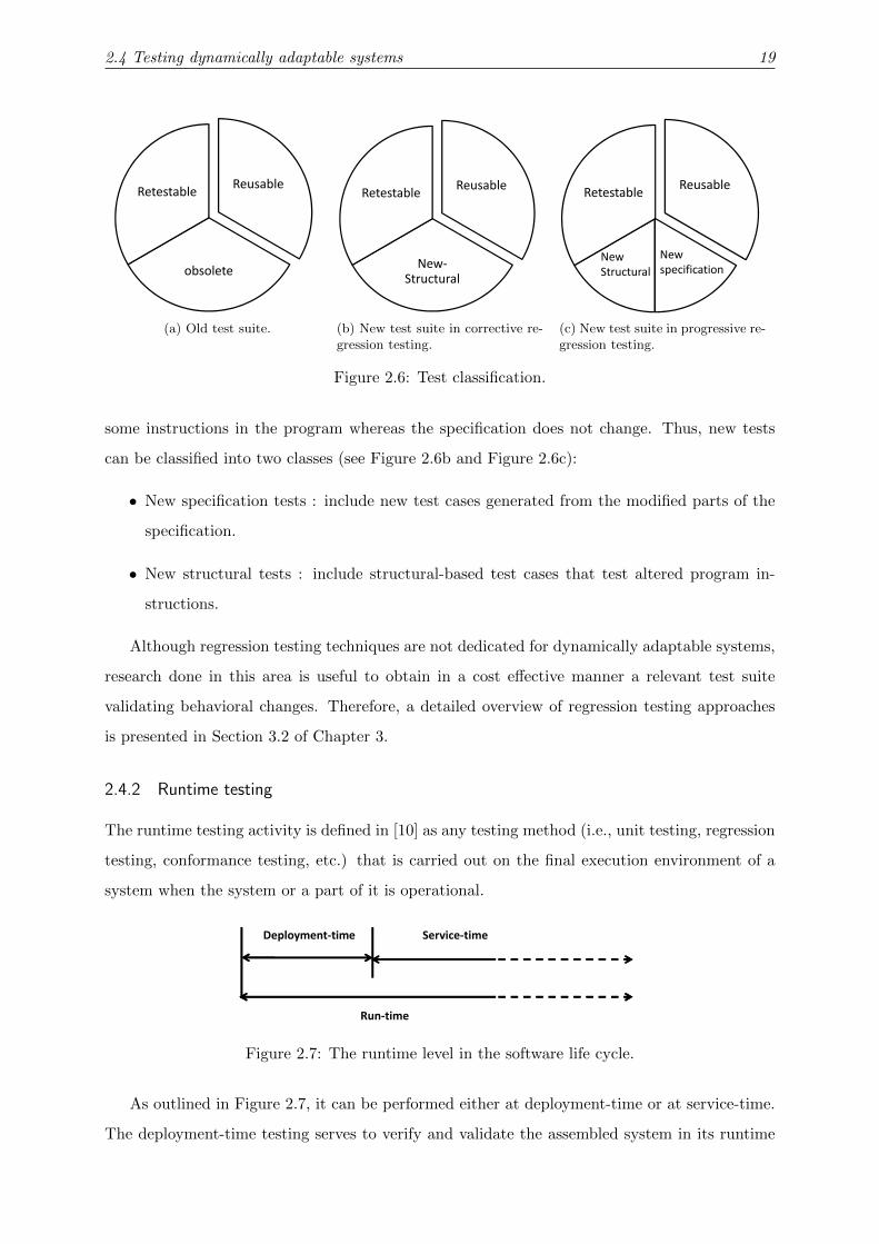
According to Leung et al. [31], old tests can be classified into three kinds of tests (see Figure
2.6a):
• Reusable tests : valid tests that cover the unmodified parts of the SUT.
• Retestable tests : still valid tests that cover modified parts of the SUT.
• Obsolete tests : invalid tests that cover deleted parts of the SUT.
Leung et al. identify two types of regression testing. In the progressive regression testing, the
SUT specification can be modified by reflecting some enhancements or some new requirements
added in the SUT. In the corrective regression testing, only the SUT code is modified by altering
2.4 Testing dynamically adaptable systems 19
ReusableRetestable
obsolete
(a) Old test suite.
ReusableRetestable
New-
Structural
(b) New test suite in corrective re-gression testing.
ReusableRetestable
New
Structural
New
specification
(c) New test suite in progressive re-gression testing.
Figure 2.6: Test classification.
some instructions in the program whereas the specification does not change. Thus, new tests
can be classified into two classes (see Figure 2.6b and Figure 2.6c):
• New specification tests : include new test cases generated from the modified parts of the
specification.
• New structural tests : include structural-based test cases that test altered program in-
structions.
Although regression testing techniques are not dedicated for dynamically adaptable systems,
research done in this area is useful to obtain in a cost effective manner a relevant test suite
validating behavioral changes. Therefore, a detailed overview of regression testing approaches
is presented in Section 3.2 of Chapter 3.
2.4.2 Runtime testing
The runtime testing activity is defined in [10] as any testing method (i.e., unit testing, regression
testing, conformance testing, etc.) that is carried out on the final execution environment of a
system when the system or a part of it is operational.
Run-time
Service-timeDeployment-time
Figure 2.7: The runtime level in the software life cycle.
As outlined in Figure 2.7, it can be performed either at deployment-time or at service-time.
The deployment-time testing serves to verify and validate the assembled system in its runtime

2.4 Testing dynamically adaptable systems 20
environment while it is deployed for the first time. For systems whose architectures remain
constant after their initial installation, there is obviously no need to retest the system when it
has been placed in-service. On the contrary, if the execution environment or the system behavior
or its architecture has changed, service-time testing becomes a necessity to verify and validate
the new system in the new situation.
2.4.3 Runtime testability
According to IEEE std. 610.12 [67], the testability is defined as the degree to which a system
or a component facilitates the performance of tests to determine whether a requirement is met.
Another definition can be rephrased as follows : the testability is an indicator of the effort
needed to test a software.
When we deal with the runtime testability, the definition becomes : the runtime testability is
an indicator of the effort needed to test the running software without affecting its functionalities
or its environment. More concretely, the runtime testability is seen as an important measurement
that characterizes a system under test. In this direction, some approaches, such as [68], have
focused on proposing mathematical methods for its assessment. Furthermore, we notice that
the runtime testability varies according to two main characteristics of the system under test :
Test Sensitivity and Test Isolation.
2.4.3.1 Test sensitivity
It is a component property that indicates whether the component under test can be tested
without unwanted side-effects. In particular, a component is called test sensitive when it includes
some behaviors or operations that cannot be safely tested at runtime. In this case, the component
is called untestable whereas a testable component is characterized by the ability to test its
execution environment and to be tested by it.
2.4.3.2 Test isolation
This solution is applied by test engineers in order to counter the test sensitivity problem and to
prevent test processes from interfering with business processes. Many test isolation techniques
are available to fulfill such aim. The well-known test isolation strategies in the literature are
briefly introduced.
Built-In Test approach. The Built-In Test (BIT) paradigm consists in building testable
components. To do so, components are equipped with a test interface (see Figure 2.8). The
latter provides operations ensuring that the test data and business data are not mixed during
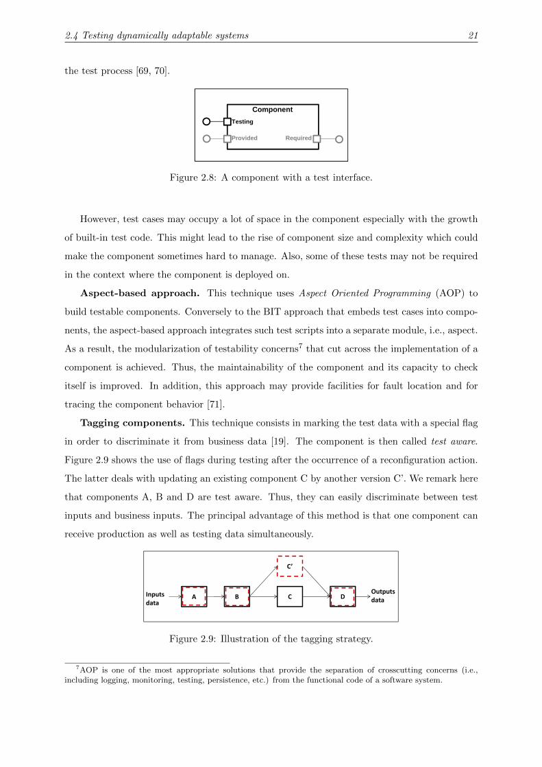
2.4 Testing dynamically adaptable systems 21
the test process [69, 70].
Testing
Provided Required
Component
C
C’
C1
C1’
Deep clone
C’’ C1’’
A B C D
C’
Inputs
data
Outputs
data
Figure 2.8: A component with a test interface.
However, test cases may occupy a lot of space in the component especially with the growth
of built-in test code. This might lead to the rise of component size and complexity which could
make the component sometimes hard to manage. Also, some of these tests may not be required
in the context where the component is deployed on.
Aspect-based approach. This technique uses Aspect Oriented Programming (AOP) to
build testable components. Conversely to the BIT approach that embeds test cases into compo-
nents, the aspect-based approach integrates such test scripts into a separate module, i.e., aspect.
As a result, the modularization of testability concerns7 that cut across the implementation of a
component is achieved. Thus, the maintainability of the component and its capacity to check
itself is improved. In addition, this approach may provide facilities for fault location and for
tracing the component behavior [71].
Tagging components. This technique consists in marking the test data with a special flag
in order to discriminate it from business data [19]. The component is then called test aware.
Figure 2.9 shows the use of flags during testing after the occurrence of a reconfiguration action.
The latter deals with updating an existing component C by another version C’. We remark here
that components A, B and D are test aware. Thus, they can easily discriminate between test
inputs and business inputs. The principal advantage of this method is that one component can
receive production as well as testing data simultaneously.
Testing
Provided Required
Component
C
C’
C1
C1’
Deep clone
C’’ C1’’
A B C D
C’
Inputs
data
Outputs
data
Figure 2.9: Illustration of the tagging strategy.
7AOP is one of the most appropriate solutions that provide the separation of crosscutting concerns (i.e.,including logging, monitoring, testing, persistence, etc.) from the functional code of a software system.

2.4 Testing dynamically adaptable systems 22
Cloning components. This mechanism consists in cloning the component under test before
the start of the test activity. Thus, test processes are performed by the clone while business
processes are performed by the original component. To clone components efficiently, we must
also duplicate their dependencies, known as Deep clone strategy [72] (see Figure 2.10).
Testing
Provided Required
Component
C
C’
C1
C1’
Deep clone
C’’ C1’’
A B C D
C’
Inputs
data
Outputs
data
Figure 2.10: Example of the deep clone strategy.
This option can be very expensive and resource consuming when the number of needed
clones becomes very large. If the physical resources are not limited, cloning components can be
a feasible test isolation solution. Also, this technique can be applied partially for testing only
sensitive components and not for all the system under test.
Blocking components. In case of untestable components, a blocking strategy can be
adopted as a test isolation technique. In fact, it consists in interrupting the activity of component
sources for a lapse of time representing the duration of the test. Thus, all business requests
are interrupted and delayed until the end of the test. Once the test has been achieved, the
component under test resumes its original state. Also, all the source components are unlocked
and the delayed requests are treated.
Synthesis. To sum up, we note that the listed test isolation techniques suffer from some
weaknesses as illustrated in Table 2.1. First of all, the cloning strategy is very costly in terms
of resources especially when the number of needed clones increases. Besides, BIT, tagging
and aspect-based techniques have an additional development burden. Regarding the blocking
option, it may affect the performance of the whole system, especially its responsiveness in case
of real-time systems.
Table 2.1: Limitations of the test isolation strategies.
Mechanisms
Intense resourceconsumption SUT delay
Developmentburden
BIT ×Aspect ×Tagging ×Blocking ×Cloning ×

2.5 Summary 23
2.5 Summary
This chapter addressed the fundamentals related to runtime validation of dynamically adaptable
systems. It was mainly dedicated to give an overview of the most common concepts frequently
used in the field of software testing, especially while testing evolvable systems. In this context,
two well-known techniques, namely regression testing and runtime testing were introduced. The
next chapter surveys the state of art of these two techniques.

CHAPTER 3
State Of The Art
3.1 Introduction
Verification and Validation (V&V) activities aim at getting confidence in software products
throughout their lifecycle. This is achieved by satisfying user needs and by meeting their ex-
pected functionalities. For systems running on stable execution environments and well-known
execution conditions, several V&V methods and tools are applied at design time. However, in
case of dynamically adaptable systems, runtime V&V techniques are highly required for guar-
anteeing the achievement of adaptation goals and fitting the expected quality attributes.
As introduced in Chapter 2, a wide spectrum of V&V techniques already exist in the litera-
ture [41]. Among these techniques, we focus our interest essentially on Software testing. In this
context, two research lines are studied. In the first one, we deal with selective regression testing
as a V&V technique usually applied at design time to ensure the validity of the modified software
systems. In this respect, Section 3.2 outlines research work done mainly on test selection and
test generation issues. In the second research area, we focus on runtime testing as an active
runtime V&V technique. The surveyed approaches in Section 3.3 are studied from different
perspectives such as resource consumption, interference risks, test distribution, test execution
and dynamic test evolution and generation. Finally, Section 3.4 summarizes the chapter and
draws the objectives of this thesis. Parts of this chapter have been published in [33].

3.2 Related work on regression testing 25
3.2 Related work on regression testing
In the literature, many researchers have investigated regression testing techniques to reestablish
confidence in modified software systems. Their research spans a wide variety of topics, namely
test selection, test prioritization, efficient test generation, etc. The existing approaches are
classified into : code-based regression testing [63, 61, 73], model-based regression testing [74, 64,
75, 76, 65, 66] and software architecture-based regression testing [77, 78].
3.2.1 Code-based regression testing approaches
Regenerating all tests, when a program change occurs, may consume inordinate time and re-
sources. Therefore, many researchers handle this issue by proposing selective regression testing
techniques. Commonly, these techniques update the old test suite by maintaining valid tests
and by generating new tests covering only new added behaviors. In this respect, Rothermel et
al. [61] construct control flow graphs from a program and its modified version and then use the
elaborated graphs to select all non obsolete tests from the old test suite. The obtained set of
tests is still valid and covers the changed code.
Similarly, Granja et al. [63] deal with identifying program modifications and selecting at-
tributes required for regression testing. Based on data flow analysis, these authors use the
obtained elements to select retestable tests. In accordance with the metrics defined in Rother-
mel et al. [79], they show that their approach has a good precision (i.e., ignores non relevant
tests), and a high generality (i.e., can be applied even in the case of complex modifications) but
entails further work to reach inclusiveness (i.e., the degree of selecting modification revealing
tests) and efficiency (i.e., the extent to be more economical in terms of space and time require-
ments). Test generation features to produce new tests covering new behaviors are not discussed
in this work.
Regarding the work of [73], it applies a regression test selection and prioritization approach
based on code coverage to a popular Web browser engine. This method analyzes the source
code with the purpose of identifying the modified procedures without using any program repre-
sentations. The obtained results show the efficiency of the proposed implementation to reveal
defects, to reduce the test set and the test time. Nevertheless, this approach is specific to C++
programming language and it is based on C++ specific tools to identify changes made to the
source code. Moreover, it is tightly related to the system under test and cannot be easily applied
to others systems.

3.2 Related work on regression testing 26
3.2.2 Model-based regression testing approaches
Brian et al. [65] introduce a UML-based regression test selection strategy. They support changes
in actions of sequence diagrams and in variables, operations, relationships and classes. Following
these modifications, the proposed approach automatically classifies tests issued from the initial
behavioral models as obsolete, reusable and retestable tests. Identifying parts of the system that
require additional tests to generate has not been tackled by this approach.
Similarly, the work of [66] deals with minimizing the impact of test case evolution by avoiding
the regeneration of full test suites from UML diagrams. In this context, the proposed technique
selects reusable tests, discards obsolete ones and generates only new ones. A point in favor of
this work is the enhancement of the test classification already proposed by Leung et al. [31].
In fact, the authors define a more precise test status based on the model dependence analysis.
Notably, retestable tests are animated on the model and can be classified into re-executed (i.e.,
can be animated on the evolved model and produces the same output), updated (i.e., can be
animated on the evolved model but produces a different output), or failed tests (i.e., cannot be
animated on the evolved model).
Pilskalns et al. [75] present a new technique that reduces the complexity of identifying the
modification impact from various UML diagrams. This proposal is based on an integrated model
called Object Method Directed Acyclic Graph built from class and sequence diagrams as well as
Object Constraint Language (OCL) expressions. The authors consider several design changes
(e.g., the addition of a message in a sequence diagram) which are classified according to whether
they create, modify, or delete elements in the diagram. Also, they assume that when a path in
the graph changes, it may affect one or more test cases. Thus, they define rules to categorize
test cases as obsolete, retestable, and reusable.
Chen et al. [76] propose a safe regression technique relying on Extended Finite State Machine
(EFSM) as a behavioral model and a dependence analysis approach. The latter is used to look for
the effects of three types of Elementary Modifications (EM) of the machine : addition, deletion
and modification of a transition. For this given set of EMs, a regression test suite reduction
method is defined with the aim of capturing essentially the effects of the model on the EMs,
the effects of the EMs on the model, and the side-effects caused by the EMs on the unmodified
parts of the model.
Similar to [76], Korel et al. [80] support only elementary modifications, namely the addition
and the deletion of a transition. In this context, they present two kinds of model-based test
prioritization methods : selective test prioritization and model dependence-based test prioritiza-
tion. In the first case, the authors classify tests into high and low priority sets. A high priority

3.2 Related work on regression testing 27
is assigned to tests that execute modified transitions in the modified model. A low priority is
attributed to tests that do not exercise any modified transition. In the second case, data and
control dependences are applied to identify interactions between added/deleted transitions and
the remaining parts of the model. The obtained information is then used to prioritize high
priority tests.
3.2.3 Software architecture-based regression testing
Initially, Harrold et al. [77] introduced the use of the formal architecture specification instead
of the source code in order to reduce the cost of regression testing and analysis.
This idea has been explored later by Muccini et al. [78]. The authors propose an effective
and well-implemented approach called Software Architecture-based Regression Testing. They
apply regression testing at both code and architecture levels whenever the system implemen-
tation or its architecture evolve. For the first case, they check the conformance of a modified
implementation to a given software architecture. For the second case, they verify the imple-
mentation conformance to the new software architecture. Labeled Transition Systems (LTS) are
used to model software architecture specifications. The authors propose a SAdiff algorithm that
compares the two behavioral models corresponding to the initial architecture and the evolved
one. The main goal of this algorithm is to identify similarities and differences at the model level.
This technique was used later to identify tests to rerun covering the affected paths.
3.2.4 Discussion
Two major questions are identified when several regression testing approaches are studied (see
Table 3.1). The first one is how to select a relevant and a minimal subset of tests from the original
test suite. The second one is how to generate new tests covering only new behaviors. Responding
to these challenging questions requires both test selection and generation capabilities. In this
respect, we notice that some approaches focus only on the test selection activity at the code
level [61, 63] or at the model level [65] whereas the work of [76] deals only with model-based test
generation issue. Addressing both activities as in [64, 66, 75, 78] is highly demanded in order to
reduce their cost especially in terms of number of tests and time required for their execution.
Up to our knowledge, no previous work has dealt with the use of regression testing approaches
at runtime. Therefore, we aim to handle test selection and test generation activities at a higher
abstract level without code source access while the SUT is operational. Consequently, adjusting
regression testing to be applied at runtime requires more effort to obtain a runtime behavioral
model of the target system and to select and derive the adequate test cases to run in the final

3.3 Related work on runtime testing 28
Table 3.1: Survey of regression testing approaches.
ApproachesSupportedtechniques
Behavioralmodels
Supportedchanges
Testingactivities
Rothermel et al. [61] Code-basedControl FlowGraph (CFG)
All types ofprogram changes Test selection
Korel et al. [74, 64] Model-based
Extended FiniteState Machines
(EFSEM)
Addition anddeletion of a
transitionTest generation,
test selection
Granja et al. [63] Code-basedControl FlowGraph (CFG)
Data and controlflow changes Test selection
Muccini et al. [78]SA-based,
Code-basedLabeled Transition
systems (LTS)Topological and
behavioral changesTest selection, test
execution
Pilskalns et al. [75] Model-based
UML (Class andsequence diagrams,OCL expressions)
Addition, deletionand modification
of supporteddiagram elements
Test generation,test selection
Chen et al. [76] Model-based
Extended FiniteState Machines
(EFSEM)
Elementarychanges (addition,
deletion,modification of a
transition) Test generation
Briand et al. [65] Model-based
UML (Class,sequence and use
case diagrams,OCL expressions)
Addition, deletionand modification
of supporteddiagram elements Test selection
Fourneret et al. [66] Model-based
UML (Statechartdiagrams and OCL
constraints)
Changes on dataand controldependences
Test selection, testgeneration
Beszedes et al. [73] Code-based —–Modified
procedures Test selection
execution environment.
3.3 Related work on runtime testing
Recently, there has been a spate of interest in how to use runtime testing to verify and val-
idate dynamically adaptable systems. This technique has been adopted in several software
domains in order to ensure that the target system complies with its functional or non-functional
requirements in spite of predictable and unpredictable evolved user requirements and context
variations. Moreover, we identify several approaches supporting only the runtime testing of
structural adaptations [12, 15, 11, 13, 14, 17]. The work presented in [20] deals only with be-
havioral adaptations. The approaches in [16, 18, 21] take into account both structural and
behavioral adaptations while performing runtime tests.
As discussed in Chapter 2, a trade-off must be made between the confidence gained from
runtime testing and the computational resources used in this kind of testing. To that aim, there
are several arduous challenges that have to be handled while executing runtime tests [41, 81].
Therefore, existent runtime testing approaches are discussed from various perspectives (see Table
3.2). We look for their capabilities to :
• avoid interference risks between test processes and business processes by supporting test

3.3 Related work on runtime testing 29
isolation strategies;
• alleviate the test workload by considering the test distribution over the network;
• provide relevant test suites by handling test selection and evolution at runtime;
• supply loosely coupled test systems by providing platform-independent ones;
• reduce the impact on the final execution environment by supporting test resource aware-
ness.
3.3.1 Supporting test isolation strategies
As stated before, runtime tests are executed while the system under test is operational. In
this case, some component instances are shared between the test configuration and the working
configuration. Consequently, interference risks between test processes and business processes
may happen. This can impact the intended behaviors of the running SUT and lead to other
effects outside the SUT (i.e., its clients, other subsystems), as well. More concretely, we assume
that a component is stimulated by some test input data during its operation. Such test data
may influence its behavior and affect its internal state. For example, it is unsafe to store in a
medical database, monitored sensor values generated by the test execution process. In the worst
case, the obtained side effects are out of control, e.g., delivering an ordered book by an online
book seller or flattening an airbag due to the test execution.
In the literature, we have noticed that several research approaches, such as [10, 18, 21, 15,
14, 17, 19, 20], have a strong tendency to investigate test isolation concept in order to reduce
this interference risk. The majority accommodates the Built-In Test paradigm for this purpose
[10, 15, 19]. Accordingly, test isolation facilities have been already introduced and integrated
into components by software developers. Similarly to this strategy, the approaches introduced
in [18] and [14] deal with putting all the involved components into a testing mode before the
execution of runtime tests. However, these strategies cannot be always adopted, especially due
to the trend towards service-oriented applications and the widespread use of Components Off
The Shelf. In that case, the source code of some components and their testability options are
seldom available.
We have identified some approaches that deal with runtime testing of untestable components.
They afford other test isolation strategies such as Safe Validation with Adaptation [20], which
is equivalent to the blocking strategy already introduced in Chapter 2. Similar to cloning
components, the Replication with Validation strategy has been proposed by [21] as a means of

3.3 Related work on runtime testing 30
test isolation. Furthermore, instantiating services at runtime and using new service instances
for runtime testing purposes is proposed by [17].
Up to our best knowledge, only the Mobile Resource-Aware Built-In-Test (MORABIT)
framework introduced in [12] has addressed the runtime testing of heterogeneous software sys-
tems composed of testable and untestable components. This framework supports two test
isolation strategies : cloning if components under test are untestable and the BIT paradigm
otherwise.
3.3.2 Handling test distribution
The test distribution over the network has been rarely addressed by runtime testing approaches.
Most of the studied works assume that tests are integrated into components under test. Thus,
managing test case assignment to test components and also managing their deployment in exe-
cution nodes has not been required for them. We have identified only two approaches that shed
light on this issue.
In the first study [82, 16], the authors introduce a light-weight framework for adaptive testing
called Multi Agent-based Service Testing in which runtime tests are executed in a coordinated
and distributed environment. This framework encompasses the main test activities including
test generation, test planing and test execution. Notably, the last step defines a coordination
architecture that facilitates mainly test agent deployment and distribution over the execution
nodes and test case assignment to the adequate agents. Unfortunately, this framework suffers
from a dearth of test isolation concerns.
In the second study [11], a distributed in vivo testing approach is introduced. This proposal
defines the notion of Perpetual Testing which suggests the proceeding of software analysis and
testing throughout the entire lifetime of an application : from the design phase until the in-
service phase. In this context, it conducts unit tests while the application is running in the
deployment environment. The main contribution of this work consists in distributing the test
load in order to attenuate the workload and improve the SUT performance by decreasing the
number of tests to run.
Thus, the proposed framework called Invite is characterized by its client-server architecture.
Each application under test encompasses an Invite client. Regarding the Invite server, it runs on
a separate machine and it is in charge of assigning test suites to the Invite clients, coordinating
their execution and managing test results, as well. Under the assumptions that only minor mod-
ifications may happen, the same unit tests applied during the development phase are performed
by the Invite framework at the deployment phase and throughout the entire lifetime of the ap-

3.3 Related work on runtime testing 31
plication. Hence, this framework does not handle the occurrence of behavioral adaptations and
supports only the cloning strategy for test isolation.
3.3.3 Handling test selection and evolution
Under the assumption that some test cases generated during the development phases can be re-
executed when structural adaptations occur, the test selection issue has to be addressed seriously
with the aim of reducing the amount of tests to rerun. One of the potential solutions that tackle
this issue is introduced in [19]. The proposed approach uses dependency analysis to find the
affected components by the change. Regarding the set of affected components, it determines a
subset of test cases to rerun in order to ensure that the affected parts of the system still function
as intended after the occurrence of structural changes.
Executing the same test cases when behavior adaptations occur seems to be meaningless.
These test cases should be updated or even removed and sometimes new ones have to be gener-
ated. For instance, if a dynamic adaptation introduces a new behavior, new test cases should be
generated to cover it. Similarly, if some behaviors are omitted, some test cases may no longer be
applicable, or adequate for testing. Therefore, a dynamic evolution of tests is required in order
to cover all the new requirements with the purpose of validating new behavioral changes.
In the literature, we distinguish the ATLAS framework [15], which affords a test case evo-
lution through an Acceptance Testing Interface. Thus, dynamic addition and removal of test
cases that the component under test may use to check the context it is deployed on are guaran-
teed. This strategy ensures that tests are not built in components permanently and can evolve
when the system under test evolves, too. The major limitation of this approach is the lack of
automated test generation since tests are not generated automatically from components’ models
and specification. Conversely, the authors of [82] and [18] address this last issue. Both methods
regenerate all test cases from new service specifications (Web Services Description Language
(WSDL) for individual services, Business Process Execution Language (BPEL) for composite
services) when dynamic behavioral adaptations occur. However, regenerating all tests can be
costly and is conisdered as an inefficient solution, especially in the case of large scale models.
To overcome these limitations, recent approaches dealing with test case adaptation at runtime
[83, 22] are identified. For instance, Akour et al. [83] propose a model-driven approach for
updating regression tests after dynamic adaptations. Called Test Information Propagation, this
proposal consists in synchronizing component models and test models at runtime. It basically
deals with reductive changes (i.e., removing existing component interfaces or implementations).
Thus, the unit tests associated with the component targeted for removal can be deleted from

3.3 Related work on runtime testing 32
the test suite. Moreover, the integration tests that validate its behaviors with its callees can be
removed, as well. Since the removal of a component may affect its caller components, updating
unit and integration tests used to validate these caller components is also highly demanded.
Nevertheless, additive changes (i.e., adding new component interfaces or implementations) have
not yet been included and dynamic test case generation in this case has not been studied.
In the same context, Fredericks et al. [22] propose an approach called Veritas that adapts
test cases at runtime with the aim of ensuring that the evolved SUT continues its execution safely
and correctly when environmental conditions are adapted. Based on the MAPE-T1 feedback
loop [81], Veritas monitors the execution environment. Then, it identifies relevant test cases for
the current conditions. Next, it executes the test plan and analyzes the results to check the
validity of the executed test cases. In the case of invalid tests, test adaptations are required at
runtime. Nevertheless, this work can only adapt test case parameters at runtime and it is not
intended to dynamically add or remove test cases.
3.3.4 Affording platform independent test systems
The major test systems, that have been surveyed, have been implemented in a tightly coupled
manner to various platforms. In general, this variety relates to the programming language of
components or to the underlying component model such as Fractal [15] and OSGi [17]. We have
distinguished other approaches that have proposed their own research component models like
the one called Dynamic Adaptive System Infrastructure (DAiSI) component model in [14] and
the MORABIT component model in [85]. Another approach presented in [11] affords a Java-
based framework that has been implemented without imposing any restrictions on the design of
the software application. Furthermore, the majority uses the JUnit framework to specify test
cases and also to execute them. Regardless of all the features provided by these test systems,
we have noticed that they are strongly related to the system under test. Their applicability to
other component models might be a complex and tedious task even though some of them affirm
this possibility as [15] does for example.
To handle this complexity, Deussen et al. [86] stress the importance of using the TTCN-
3 standard to build an online validation platform for internet services. Active tests, which are
specified in an abstract and platform-independent notation, are performed to analyze the system
behavior in its current context. However, this work neglects the test isolation issue which is a
fundamental step in order to avoid interference between test and business processes.
It is worthy to note that various test systems are built based on the TTCN-3 standard. We
1Similar to the MAPE-K feedback loop [84] that manages the design and the execution of autonomic systems,MAPE-T provides a support for monitoring, analyzing, planning and executing runtime test adaptations.

3.3 Related work on runtime testing 33
distinguish research for testing protocol-based applications [87, 88], Web applications [46, 89, 90],
Web services [91, 92] and also real-time and embedded systems [93, 94]. All these approaches
benefit from the strengths of the TTCN-3 standard as a platform independent language for
specifying tests even for heterogeneous systems. Nevertheless, they address testing issues at
design time and not at runtime.
3.3.5 Supporting test resource awareness
As discussed before, runtime testing is a resource-consuming activity, which is often performed
concurrently with the system under test in its final execution environment. In fact, computa-
tional resources are used for generating tests if needed, instantiating test components charged
with test execution and finally starting them and evaluating the obtained results. Notably, the
bigger the number of test cases is, the more resources such as CPU load, memory consumption
are used. Hence, we note that the intensive use of these computational resources during the test
execution has an impact not only on the SUT but also on the test system itself. When such a
situation is encountered, the test results can be wrong and can lead to an erroneous evaluation
of the SUT responses.
To the best of our knowledge, this problem has been studied only by Merdes’work [12]. Aim-
ing at adapting the testing behavior to the given resource situation, it provides a resource-aware
infrastructure that keeps track of the current resource states. To do this, a set of resource
monitors are implemented to observe the respective values for processor load, main memory,
battery charge, network bandwidth, etc. According to resource availability, the proposed frame-
work is able to balance in an intelligent manner between testing and the core functionalities of
the components. It provides in a novel way a number of test strategies for resource aware test
management. Among these strategies, we can mention, for example, Threshold Strategy under
which tests are performed only if the amount of used resources does not exceed thresholds.
3.3.6 Discussion
Despite the emergence of runtime testing as a validation technique in many software domains,
this testing activity has to be handled under carefully-controlled conditions. Otherwise, risks of
affecting SUT dependability might happen. Therefore, we have classified the surveyed runtime
testing approaches based on the most relevant features needed to be supported, as outlined
in Table 3.2. First of all, both structural and behavioral adaptations have been studied only
by [16, 18, 21]. Furthermore, we have noticed a quasi-absence of approaches offering platform
independent test systems based on the TTCN-3 standard. Except Deussen et al. [86], most of

3.3 Related work on runtime testing 34
previous studies use a specific test framework like JUnit to define test cases and execute them.
In addition, they support homogenous systems-under test made up of only testable or only
untestable components. Thus, they afford at most one test isolation strategy for reducing inter-
ference risks. We have identified only one work [12] that deals with combining two test isolation
strategies for the testing of testable and untestable components : BIT and cloning. Moreover,
only the latter approach has tackled the issue of resource limitations and time restriction during
runtime testing.
Regarding test evolution and generation at runtime, the existing approaches did not deal
efficiently with this challenging issue. Indeed, we identified works [82, 18] that regenerate all
test cases from the new specifications when dynamic behavioral adaptations occur. The work
of [22] tries to reduce this cost by adapting exiting test cases to the evolved environmental con-
ditions but without generating new tests covering new behaviors or removing obsolete ones. To
partially overcome this limitation, [83] supports only reductive changes (e.g., removing existing
components) and then adapts the test suite by removing obsolete tests and by updating the set
of retestable tests. Thus, we conclude that dynamic test case generation when additive changes
(e.g., adding new components) take place is still an open issue.
In summary, this study on runtime testing approaches reveals a dearth in the provision
of a platform-independent support for test generation and execution which considers resource
limitations and time restriction. To surmount this major lack, our ultimate goal is to conceive
a safe and efficient framework that minimizes the cost of checking a running system after each
dynamic adaptation either structural or behavioral. From the test execution perspective, setting
up a TTCN-3 test system for the distribution, isolation and execution of a minimal set of test
cases identified after the occurrence of structural adaptations is strongly required.

3.3 Related work on runtime testing 35
Tab
le3.
2:S
urv
eyof
runti
me
test
ing
app
roac
hes
.
Approaches
Software
Dom
ain
Adapta
tion
Kin
ds
Test
Levels
Test
Distrib
ution
Test
Isolation
Test
Evolu
tion
Platform
-In
dependentLevel
Test
System
Test
Reso
urce
Awareness
Deu
ssen
etal.
[86]
Inte
rnet
serv
ices
Not
sup
port
ed
Un
itan
din
tegra
tion
test
ing
No
Not
sup
port
edN
oT
TC
N-3
Tes
tS
yst
emN
o
Mer
des
etal.
[12]
Ub
iqu
itou
sS
yst
ems
Str
uct
ura
lU
nit
test
ing
No
BIT
an
dC
lon
ing
Not
state
dM
OR
AB
IT-b
ase
dT
est
Syst
em(J
Un
itte
sts)
Yes
Bai
etal.
[16]
Ser
vic
e-b
ase
dsy
stem
sS
tru
ctu
ral
an
dB
ehavio
ral
Un
itan
din
tegra
tion
test
ing
Yes
Not
state
dY
esA
gen
t-b
ase
dT
est
Syst
emN
o
Gon
zale
zet
al.
[15]
Syst
ems
of
syst
ems
Str
uct
ura
lIn
tegra
tion
test
ing
No
BIT
No
Fra
ctal-
base
dT
est
Syst
em(J
Un
itte
sts)
No
Ram
irez
etal.
[21]
Au
ton
om
ou
ssy
stem
sS
tru
ctu
ral
an
dB
ehavio
ral
Inte
gra
tion
an
dsy
stem
test
ing
No
Rep
lica
tion
wit
hvalid
ati
on
No
Au
ton
om
icC
om
pon
ent-
base
dT
est
Syst
em(J
Un
itte
sts)
No
Hie
lsch
eret
al.
[18]
Ser
vic
e-b
ase
dsy
stem
sS
tru
ctu
ral
an
dB
ehavio
ral
Un
itan
din
tegra
tion
test
ing
No
Tes
tm
od
eY
esN
ot
state
dN
o
Mu
rphy
etal.
[11]
Java-b
ase
dsy
stem
sS
tru
ctu
ral
Un
itte
stin
gY
esC
lon
ing
No
Java-b
ase
dT
est
Syst
em(J
Un
itte
sts)
No
Nie
bu
hr
etal.
[14]
Com
pon
ent-
base
dsy
stem
sS
tru
ctu
ral
Inte
gra
tion
test
ing
No
Tes
tm
od
eN
oD
AiS
I-b
ase
dT
est
Syst
emN
o
Pie
let
al.
[95]
[19]
Com
pon
ent
an
dE
ven
t-b
ase
dsy
stem
sS
tru
ctu
ral
Inte
gra
tion
test
ing
No
Taggin
gor
BIT
Not
state
dP
latf
orm
dep
end
ent
(JU
nit
test
s)N
o
Gre
iler
etal.
[17]
Ser
vic
e-b
ase
dsy
stem
sS
tru
ctu
ral
Inte
gra
tion
test
ing
No
Ser
vic
eIn
stanti
ati
ng
No
OS
Gi-
base
dT
est
Syst
em(J
Un
itte
sts)
No
Kin
get
al.
[20]
Au
ton
om
ou
ssy
stem
sB
ehavio
ral
Inte
gra
tion
an
dsy
stem
test
ing
No
Safe
ad
ap
tati
on
wit
hvalid
ati
on
No
Au
ton
om
icC
om
pon
ent-
base
dT
est
Syst
em(J
Un
itte
sts)
No
Fre
der
icks
etal.
[22]
Au
ton
om
ou
ssy
stem
sS
tru
ctu
ral
an
dB
ehavio
ral
Syst
emte
stin
gN
oN
ot
state
dY
esN
ot
state
dN
o

3.4 Summary 36
From the test generation perspective, proposing a selective test case generation method that
derives test cases efficiently from the affected parts of the SUT behavioral model and selects
relevant tests from the old test suite should be investigated.
3.4 Summary
In this chapter, we discussed the state of art of testing modified systems. Research done in the
area of regression testing as well as runtime testing were analyzed. Based on this study, we
identified several requirements that should be achieved by this thesis.
The next chapter describes in depth our runtime testing approach and how it is able to face
the weakness identified in the literature, notably when structural adaptations take place.

Part II
Design of Runtime Testing Approach

CHAPTER 4
Runtime Testing of Structural Adaptations
4.1 Introduction
Testing at design-time or even at deployment-time usually demonstrates that the System Under
Test, SUT, satisfies its functional and non-functional requirements. However, its applicability
becomes limited and irrelevant when this system is adapted at runtime according to evolving
requirements and environmental conditions that were not explicitly specified at design-time.
For this reason, runtime testing is strongly required to extend assurance from design-time to
runtime.
As stated in Chapter 3, this runtime V&V method is considered resource consuming and
should be applied carefully in the final execution environment of a running system. Therefore,
a trade-off must be made between the confidence gained from applying runtime testing and
the computational resources used for it. To that aim, we introduce in the present chapter our
solution that executes runtime tests while reducing their side-effects and their cost.
In Section 4.2, a brief overview of the overall runtime testing process is given. First of all, the
timing cost is reduced by executing only a minimal subset of test cases that validates the affected
parts of the system by dynamic changes. In this respect, Sections 4.3 and 4.4 introduce the use
of the dependency analysis technique to identify the affected parts of the dynamically adaptable
system and their corresponding test cases. Secondly, Section 4.5 introduces the method we use
to effectively distribute the obtained tests over the network with the aim of alleviating runtime
testing load and not disturbing SUT performance. Thirdly, Section 4.6 presents the standard-
based test execution platform that we have designed for test isolation and execution purposes. It

4.2 The Approach in a nutshell 39
relies on the TTCN-3 standard not only on its test specification language but also on its reference
test architecture [27, 28]. The latter is extended to supply a test isolation layer that reduces
the interference risk between test processes and business processes. Ultimately, this chapter is
concluded in Section 4.7. Parts of this chapter have been published in [26, 29, 24, 32, 96, 33].
4.2 The Approach in a nutshell
The process depicted in Figure 4.1 spans the different steps to fulfill with the aim of executing
runtime tests when structural reconfiguration actions are triggered, as follows :
Structural Reconfiguration action
Start
Online Dependency
Analysis
SUT
Architecture
Executable
Test case
Repository
Affected Components
Constrained Test
Component Placement
Online Test Case
Selection
Minimal Set of test cases Test
Resources
Test
Component
Required
Resources
Test
Sel
ectio
n an
d D
istr
ibut
ion
Test Isolation &
Execution
Verdicts
Pass Verdict
Fail Verdict
Finish
Resource Resource
States of
Execution
nodes
Resource Aware Test Plan
Component Placement
Test
Isol
atio
n an
d E
xecu
tion
Figure 4.1: Runtime testing process for the validation of structural adaptations.
Online Dependency Analysis. In this step, we focus on identifying the affected compo-
nents and compositions by a structural reconfiguration action. To do so, looking for runtime
dependencies between components is required. This information may reduce the test activity
burden through checking only the parts affected by a dynamic change and not the whole system.
In that case, the number of test components to deploy and test cases to rerun is decreased, which
permits a lower test execution time and accordingly the reduction of resource consumption.
Online Test Case Selection. Once the affected parts of the system are identified, we
look for their corresponding test cases that are stored in the Executable Test Case Repository.
We assume in this stage that these test cases have been already written manually or generated
automatically in an abstract format (TTCN-3 language) and compiled to obtain the executable
ones.
Constrained Test Component Placement. For each selected test case, we have at least
one test component to deploy, known in the TTCN-3 standard as the main test component,

4.3 Online dependency analysis 40
MTC. With the purpose of reducing the test burden on the shared execution environment
between the SUT and the TS, these test components have to be assigned to the appropriate
execution node while fitting resource and connectivity constraints. In this step, the placement
solution is generated and saved as a Resource Aware Test Plan (RATP). This plan contains
mainly test cases to execute and the deployment host of each test component to deploy according
to each affected component to validate.
Test Isolation and Execution. The final step in the former process is the test isolation
and execution phase. Before executing the selected tests at runtime, a test isolation layer has to
be set up with the aim of avoiding test interference with the normal behavior of the SUT. Then,
test components are dynamically created and assigned to their appropriate execution nodes.
Afterwards, test cases are started concurrently, test case verdicts are computed and finally the
global verdict is deduced. If a pass verdict is produced then the end of the runtime testing
process is reached. Otherwise, another dynamic reconfiguration action has to be enacted in
order to handle such a failure.
The proposed methods and tools used in the test selection and distribution phase as well as
in the test isolation and execution phase are detailed in the following sections.
4.3 Online dependency analysis
To reduce the time cost and the resource burden of the runtime testing process, the key idea
is to avoid the re-execution of all tests at runtime when structural adaptations occur. Thus,
we use the dependency analysis approach with the aim of determining the parts of the system
impacted by dynamic evolutions and then computing a minimal set of tests to rerun. In fact, the
dependency analysis technique is widely used in various software engineering activities including
testing [97], maintenance and evolution [98, 99]. A definition of this concept is given in the
following. Then, we present the model used to capture direct and indirect dependencies. The
application of this technique on test case selection is also discussed.
4.3.1 Definition
Dependencies between components is defined in [98] as “the reliance of a component on other(s)
to support a specific functionality”. It is also considered as a binary relation between two
components : A and B as illustrated in Figure 4.2.
• Antecedent : a component A is an antecedent to another component B if its data or
functionalities are utilized by B .

4.3 Online dependency analysis 41
AB
AntecedentDependent
Depends on
Figure 4.2: Dependency relationship.
• Dependent : a component B is a dependent on another component A if it utilizes data or
functionalities of A.
Formally, the relation→ called “Depends on” is defined in [100] where B → A means that the
component B depends on the component A. The set of all dependencies in a component-based
system is defined as :
D = {(Ci ,Cj ) : Ci ,Cj ∈ S ∧ Ci → Cj } where S is the set of components in the system.
Accordingly, the current system configuration is a set of components and its dependencies Con =
(S,D).
Dependencies in component-based systems are caused by interacting, cooperating and com-
municating components. Several forms of dependencies are identified in the literature [97]. For
instance, we mention data dependency (i.e., data defined in one component are used in an-
other component), control dependency (i.e., caused by sending a message from one component
to another component), etc. The main dependency form that we support in this thesis is the
interface dependency, which means that a component requires (respectively provides) a service
from (respectively to) another component. With the purpose of managing and analyzing such
dependencies in a good way, the traditional graph theory is used.
4.3.2 Dependency representation
To represent and analyze component dependencies, two formalisms are generally described : a
Component Dependency Graph (CDG) and a Component Dependency Matrix (CDM). These
two concepts are formally defined as follows.
Definition 1 : Component Dependency Graph. A CDG is a directed graph denoted
by G = (S,D) where:
• S is a finite nonempty set of vertices representing system’s components and
• D is a set of edges between two vertices, D ⊆ (S × S). For instance, (a, b) ∈ D means
a → b.
Definition 2 : Component Dependency Matrix. A CDM is defined as a 0-1 Adjacency
Matrix AMn×n , that represents direct dependencies in a component-based system. Figure

4.3 Online dependency analysis 42
4.3 shows an example of dependency graph and its corresponding adjacency matrix. In this
matrix, each component is represented by a column and a row. If a component Ci depends on
a component Cj then dij = 1 otherwise dij = 0. More formally, the values of all elements in
AMn×n = (dij )n×n are defined as follows :
dij =
1 if Ci → Cj
0 otherwise
C1
C2
C3
C4
C5
0 1 0 0 0
0 0 1 1 0
0 0 0 0 1
0 0 0 0 1
0 0 0 0 0
C1 C2 C3 C4 C5
C1
C2
C3
C4
C5
Figure 4.3: A CDG and its CDM representing direct dependencies.
Initially, D represents only direct dependencies between components. In order to gather all
indirect dependencies in the component-based system, the transitive closure of the graph has to
be calculated. Several transitive closure algorithms have been widely studied in the literature
such as the Roy-Warshall algorithm and its modification proposed by Warren [101]. In the worst
case, both algorithms compute the transitive closure on θ(n3) times where n is the number of
vertices of the graph. This complexity has been enhanced in [102] by proposing an algorithm
computing the transitive closure only for cycle-free graphs on better than θ(mn) times where m is
the number of edges of the graph. In our context, we adopt the Roy-Warshall algorithm because
of its sufficiency in computing transitive closure of any graph and its acceptable complexity (see
Figure 4.4).
0 1 1 1 1
0 0 1 1 1
0 0 0 0 1
0 0 0 0 1
0 0 0 0 0
C1 C2 C3 C4 C5
C1
C2
C3
C4
C5
For i=1 to n do
For j=1 to n do
If M[i][j]=1 then
For k=1 to n do
If k<>j then
AM[j][k]:=M[j][k] or M[i][k]
Figure 4.4: An adjacency matrix representing direct and indirect dependencies produced by theRoy-Warshall algorithm.
It is worthy to note that the CDG can be derived from the system’s runtime architecture
even when the source code is not available. To do so, components, their provided and required

4.4 Online test case selection 43
interfaces must be explicitly defined. Such information is considered sufficient to build the CDG.
Systems that require the source code availability in order to detect implicit dependencies cannot
be handled in our context.
4.3.3 Computation of affected components and compositions by dynamic structural changes
Different algorithms for computing affected components with response to the dynamic evolution
of the system are detailed in Appendix B. The obtained set depends on the triggered reconfig-
uration action.
Case 1 : Adding a component and its connections. The set AffectedC By Add con-
tains components that directly or indirectly depend on the new component Cnew and components
that Cnew depends on (see Algorithm B.1).
Case 2 : Deleting a component and its connections. The set AffectedC By Del
comprises components that directly or indirectly depend on the removed component Cremoved
(see Algorithm B.2).
Case 3 : Replacing a component by another version. Replace action can be seen as
a set of adding and deleting actions. Thus, the set AffectedC By Rep = AffectedC By Add ∪
AffectedC By Del (see Algorithm B.3).
Case 4 : Modifying dependencies between two components. The set
AffectedC By AddDep (respectively AffectedC By DelDep) includes components that are di-
rectly or indirectly affected by adding a new dependency (respectively by deleting an old depen-
dency) (see Algorithm B.4).
An affected composition is seen as a dependence path in the CDG that contains at least
one affected component. These dependence paths are derived by traversing the CDG and then
combined to create test execution paths (see Algorithm B.5). Such information can be afterwards
interpreted to select a subset of test cases that cover the identified test execution paths. For the
sake of simplicity, the computation of all affected dependent paths is done under the assumptions
that hierarchical compositions are not supported by our work and also CDG does not contain
cycles. Moreover, we use the term affected composition hereafter instead of affected dependence
path.
4.4 Online test case selection
The main question to be tackled in this section is how to identify a minimal set of test cases
that must be rerun after the occurrence of dynamic changes. This concern has been extensively
studied in the literature. In fact, various regression test selection techniques have been proposed

4.4 Online test case selection 44
with the purpose of identifying a subset of valid test cases from an initial test suite that tests the
affected parts of a program. These techniques usually select regression tests based on data and
control dependency analysis [79]. They indicate that source code access is required in order to
compute such kinds of dependencies. Therefore, they may not be effective in our context as we
adopt interface dependency analysis. Moreover, we suppose that the source code is not available
and only the system architecture description is given (i.e., dependencies between provided and
required interfaces).
Two kinds of tests are considered after the occurrence of dynamic adaptations. On the one
hand, unit tests are executed to validate individual affected components. On the other hand,
integration tests are performed to check interactions and interoperability between components.
In order to facilitate their lookup, a naming convention technique is applied. The latter consists
in including component names as well as dependence paths into test case names. Formally, units
and integration test names are expressed as follows:
• Unit tests : UT = {UTCi} where Ci is a newly added or replaced component.
• Integration tests : IT = {ITPj ,∀Pj ∈ affPaths} where each Pj is a dependence path
in the CDG of length l that covers at least an affected component by the change.
It can be seen as a graph P = (Cp ,Dp), where Cp = {C1,C2, ...Cl} and Dp =
{{C1,C2}, {C2,C3}...{Cl−1,Cl}} with Ci → Ci+1,∀ i ∈ {1..l − 1}.
Let us take an example with four components and a dependency graph that looks like Figure
4.5. Assume that C2 is replaced with a new version. Thus, two dependence paths are identified:
C1 → C2 → C3 and C1 → C2 → C4. As a result, the mapping to integration tests produces:
ITC 1C 2C 3 and ITC 1C 2C 4 have to be rerun.
C1
C2
C4C3
Figure 4.5: Illustrative example of dependence path computation.
Recall that tests are written in the TTCN-3 notation and are executed by TTCN-3 test
components. As depicted in Figure 4.6a, an MTC component is only charged with executing a
unit test. It shares this responsibility with other PTC components when an integration test is
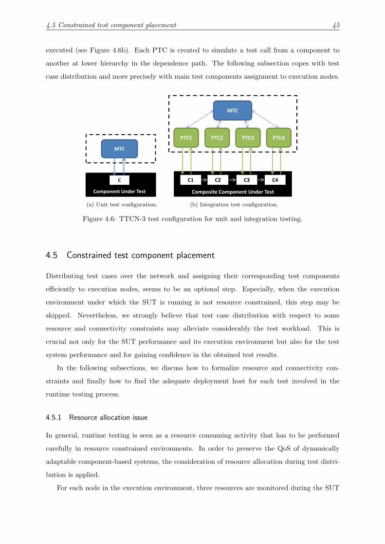
4.5 Constrained test component placement 45
executed (see Figure 4.6b). Each PTC is created to simulate a test call from a component to
another at lower hierarchy in the dependence path. The following subsection copes with test
case distribution and more precisely with main test components assignment to execution nodes.
C1
MTC
PTC1 PTC3PTC2
C3C2 C4
Composite Component Under Test
PTC4
MTC
Component Under Test
C
(a) Unit test configuration.
C1
MTC
PTC1 PTC3PTC2
C3C2 C4
Composite Component Under Test
PTC4
MTC
Component Under Test
C
(b) Integration test configuration.
Figure 4.6: TTCN-3 test configuration for unit and integration testing.
4.5 Constrained test component placement
Distributing test cases over the network and assigning their corresponding test components
efficiently to execution nodes, seems to be an optional step. Especially, when the execution
environment under which the SUT is running is not resource constrained, this step may be
skipped. Nevertheless, we strongly believe that test case distribution with respect to some
resource and connectivity constraints may alleviate considerably the test workload. This is
crucial not only for the SUT performance and its execution environment but also for the test
system performance and for gaining confidence in the obtained test results.
In the following subsections, we discuss how to formalize resource and connectivity con-
straints and finally how to find the adequate deployment host for each test involved in the
runtime testing process.
4.5.1 Resource allocation issue
In general, runtime testing is seen as a resource consuming activity that has to be performed
carefully in resource constrained environments. In order to preserve the QoS of dynamically
adaptable component-based systems, the consideration of resource allocation during test distri-
bution is applied.
For each node in the execution environment, three resources are monitored during the SUT

4.5 Constrained test component placement 46
execution : the available memory, the current CPU load and the battery level. The value
of each resource can be directly captured on each node through the use of internal monitors.
These values are measured after the runtime reconfiguration and before starting the testing
activity. For each test component, we introduce the memory size (i.e., the memory occupation
needed by a test component during its execution), the CPU load and the battery consumption
properties. We suppose that these values are provided by the test manager. It is also worth
noting that some techniques are available in the literature for obtaining the resources required
by test components. For example in [46], the authors propose a preliminary test to learn about
some required resources such as the amount of memory allocated by a test component, the time
needed to execute the test behavior, etc.
Formally, provided resources of m execution nodes are represented through three vectors :
C that contains the CPU load, R that provides the available RAM and B that introduces the
battery level.
C =
c1
c2
...
cm
R =
r1
r2
...
rm
B =
b1
b2
...
bm
The resources required by the n test components are initially computed at the deployment
time after a preliminary test run. Similarly, they are formalized over three vectors : Dc that
contains the required CPU, Dr that introduces the required RAM and Db that contains the
required battery by each test.
Dc =
dc1
dc2
...
dcn
Dr =
dr1
dr2
...
drn
Db =
db1
db2
...
dbn
As the proposed framework is resource aware, checking resource availability during test
distribution is usually performed before starting the runtime testing process. Thus, the overall
resources required by n test components must not exceed the available resources in m nodes. This
rule is formalized through three constraints to fit as outlined in (4.1) where the two dimensional
variable xij can be equal to 1 if the corresponding test component i is assigned to the node j , 0
otherwise.

4.5 Constrained test component placement 47
n∑i=1
xij dci ≤ cj ∀ j ∈ {1, · · · ,m}n∑
i=1xij dri ≤ rj ∀ j ∈ {1, · · · ,m}
n∑i=1
xij dbi ≤ bj ∀ j ∈ {1, · · · ,m}
(4.1)
4.5.2 Connectivity issue
Dynamic environments are characterized by frequent and unpredictable changes in connectivity
caused by firewalls, non-routing networks, node mobility, etc. For this reason, we have to pay
attention when assigning a test component to a host computer by finding at least one route in
the network to communicate with the component under test.
N1 N2
N3 N4
N1 N2
N3 N4
N1 N2
N3 N4
(a) (b) (c)
Figure 4.7: Illustration of connectivity problems during testing.
Such a constraint can be ignored when all nodes are connected together. In this context,
the execution environment is seen as a strongly connected graph in which every pair of nodes
are connected together. As depicted in Figure 4.7 case (a), the node under test1 N1 is colored
in black, thus its corresponding test component can be deployed on any host in the execution
environment. Similarly, in case (b) we can find a path between the black node and any node in
the network. Thus, the test component can find a way to communicate with its corresponding
component under test. However, if there is no such a path between these end-nodes, the testing
process cannot take place. Case (c) outlines a disconnection between the node N4 and the
remaining nodes in the network. Consequently, the corresponding test component cannot be
deployed on N4. The latter is considered as a forbidden node.
More generally, we pinpoint, for each test component, a set of forbidden nodes to discard
during the constrained test component placement step. From a technical perspective, either
Depth-First Search2 or Breadth-First Search3 algorithms can be used to firstly identify connected
execution nodes in the network and secondly to compute a set of forbidden nodes for each test
1The node hosting the component under test2http://en.wikipedia.org/wiki/Depth-first search3http://en.wikipedia.org/wiki/Breadth-first search

4.5 Constrained test component placement 48
component involved in the test process. This connectivity constraint is denoted as follows:
xij = 0 ∀ j ∈ forbiddenNodeSet(i) (4.2)
where the forbiddenNodeSet(i) function returns a set of forbidden nodes for a test component
i .
Finding a satisfying test placement solution is merely achieved by fitting the former con-
straints (4.1) and (4.2). At this stage, the constrained test component placement module is
formalized as a Constraint Satisfaction Problem (CSP)4 [103].
4.5.3 Optimizing the test component placement problem
Looking for an optimal test placement solution consists in identifying the best node to host
the concerned test component in response with two criteria : its distance from the node under
test and its link bandwidth capacity. To do so, we are asked to attribute a profit value pij for
assigning the test component i to a node j . For this aim, a matrix Pn×m is computed as follows:
pij =
0 if j ∈ forbiddenNodeSet(i)
maxP − k × stepp otherwise(4.3)
where maxP is constant, stepp = maxPm , k corresponds to the index of a node j in a Rank
Vector that is computed for each node under test. This vector corresponds to a classification
of the connected nodes according to both criteria : their distance far from the node under test
[24] and their link bandwidth capacities.
Consider an execution environment made up of four nodes (N 1, N 2, N 3, and N 4) as illus-
trated in Figure 4.8.
C1
T1
P11 = maxP
T1
T1
N4
N1
N2 N3
Forbidden
Node for T1
N1
K=
N3 N2
0 1 2100Mbps 150Mbps
150Mbps
Rank Vector
100 50 75 0
Matrix P
maxP=100
Stepp=25
P12 = maxP-1*stepp P13 = maxP-2*stepp
150Mbps
Figure 4.8: Illustrative example for profit calculation.
We look for the best test component placement solution for a test component T1 charged
4A CSP is a problem composed of a finite set of variables each of which has a finite domain of values and a setof constraints. The goal is is to find an assignment of a value for each variable in such a way that the assignmentssatisfy all the constraints.

4.5 Constrained test component placement 49
with testing a component under test C 1 running on an execution node N 1. First of all, the node
N 4 is discarded from the test component placement process because the link with the node under
test N 1 is broken. Second, we compute the Rank Vector for the rest of the connected nodes and
we deduce the matrix profit. We note here that the profit pij is maximal if the test component
T1 is assigned to the node N 1 because assigning a test component to its corresponding node
under test and performing local tests reduces the network communication cost. This profit
decreases with respect to the node index in the Rank Vector. For instance, N 3 is considered a
better target for T1 than N 2 although they have the same distance far from the node under test
because the link bandwidth between N 3 and N 1 is greater than the link bandwidth between
N 2 and N 1.
As a result, the constrained test component placement module generates the best deployment
host for each test component involved in the runtime testing process by maximizing the total
profit value while fitting the former resource and connectivity constraints. Thus, it is formalized
as a variant of the Knapsack Problem, called Multiple Multidimensional Knapsack Problem
(MMKP). In Appendix C, readers can find more in-depth information about knapsack variants.
MMKP =
maximize Z =n∑
i=1
m∑j =1
pij xij (4.4)
subject to (4.1) and (4.2)m∑
j =1xij = 1 ∀ i ∈ {1, · · · ,n} (4.5)
xij ∈ {0, 1} ∀ i ∈ {1, · · · ,n} and ∀ j ∈ {1, · · · ,m}
Constraint (4.4) corresponds to the objective function that maximizes test component profits
while satisfying resource (4.1) and connectivity (4.2) constraints. Constraint (4.5) indicates that
each test component has to be assigned to at most one node.
Algorithm 4.1 displays the main instructions to solve this MMKP problem. First of all,
resource constraints have to be defined (see lines 2-4). Second, forbidden nodes for each test
component are identified and then connectivity constraints are deduced (see lines 5-7). Then,
an objective function is calculated (see line 8) and then maximized (see line 9) to obtain an

4.6 Test isolation and execution support 50
optimal solution.
Algorithm 4.1: Resolution of MMKP problem.
Input: The matrix profit Pn×m ,
The provided resources by m nodes R,C ,B ,
The required resources by n tests Dr ,Dc ,Db .
Output: The two dimensional value x .
1 begin
2 Constraint ram[]=defineResourceConstraint(x ,R,Dr );
3 Constraint cpu[]=defineResourceConstraint(x ,C ,Dc);
4 Constraint bat[]=defineResourceConstraint(x ,B ,Db);
5 Constraint connectivity;
6 for i = 1 to n do
7 connectivity .add(defineConnectivityConstraint(x , forbiddenNodeSet(i)));
8 end
9 Z = defineObjectiveFunction(x ,P);
10 x = maximize(Z , ram, cpu, bat , connectivity);
11 return x ;
12 end
The returned x value is used to produce the RATP file. As depicted in Figure 4.9, it contains
mainly the adequate deployment host for each test case and its associated Main Test Component
involved in the runtime testing process. Further information can be included in this file such
as affected components or compositions as well as their main characteristics (e.g., required and
provided interfaces, testability options, deployment hosts, etc.). It is used next in the test
isolation and execution step. file:///d:/Thèse2/ResourceAwareTestPlan/RATP.xsdPage 1
ProvidedInterfaces
RequiredInterfaces
Default
TestabilityOptions
Name
HostIPAddress
Component
Name
HostIPAddress
Level
TestComponent
TestCase
Name
TestSuite
Kind
SUTTestPlan
Figure 4.9: XML schema of the Resource Aware Test Plan.
4.6 Test isolation and execution support
With the purpose of alleviating the complexity of testing adaptable and distributed systems,
we propose a test system called, TTCN-3 test system for Runtime Testing (TT4RT) [26]. The
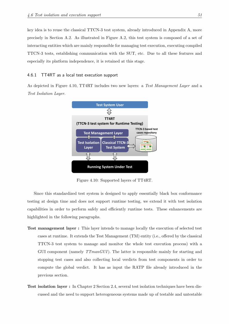
4.6 Test isolation and execution support 51
key idea is to reuse the classical TTCN-3 test system, already introduced in Appendix A, more
precisely in Section A.2. As illustrated in Figure A.2, this test system is composed of a set of
interacting entities which are mainly responsible for managing test execution, executing compiled
TTCN-3 tests, establishing communication with the SUT, etc. Due to all these features and
especially its platform independence, it is retained at this stage.
4.6.1 TT4RT as a local test execution support
As depicted in Figure 4.10, TT4RT includes two new layers: a Test Management Layer and a
Test Isolation Layer.
Test System User
TTCN-3 based test
cases repository
TT4RT
(TTCN-3 test system for Runtime Testing)
Test Management Layer
Classical TTCN-3 Test Isolation
Running System Under Test
Classical TTCN-3
Test System
Test Isolation
Layer
Figure 4.10: Supported layers of TT4RT.
Since this standardized test system is designed to apply essentially black box conformance
testing at design time and does not support runtime testing, we extend it with test isolation
capabilities in order to perform safely and efficiently runtime tests. These enhancements are
highlighted in the following paragraphs.
Test management layer : This layer intends to manage locally the execution of selected test
cases at runtime. It extends the Test Management (TM) entity (i.e., offered by the classical
TTCN-3 test system to manage and monitor the whole test execution process) with a
GUI component (namely TTmanGUI ). The latter is responsible mainly for starting and
stopping test cases and also collecting local verdicts from test components in order to
compute the global verdict. It has as input the RATP file already introduced in the
previous section.
Test isolation layer : In Chapter 2 Section 2.4, several test isolation techniques have been dis-
cussed and the need to support heterogeneous systems made up of testable and untestable

4.6 Test isolation and execution support 52
components has been pointed out, as well. Such techniques aim to reduce the interference
risk between test data and business data when testing is performed at runtime. For this
reason, TT4RT includes a test isolation layer, which is able to choose the most suitable
test isolation technique for each component under test.
4.6.2 Detailed interactions of TT4RT components
As mentioned before, TT4RT relies on the classical TTCN-3 test system. Thus, it reuses all its
constituents, namely Test Management (TM), TTCN-3 Executable (TE), Component Handling
(CH), Coding an Decoding (CD), System Adapter (SA) and Platform Adapter(PA). These
entities are briefly introduced below. For more details, readers can refer to Appendix A. As
depicted in Figure 4.11, a new Generic Test Isolation Component is added to the TTCN-3
reference architecture with the aim of handling test isolation concerns. The next steps define
the different components of TT4RT and their internal interactions:
TCI
Test Management(TM)
Co
din
ga
nd
De
cod
ing
(CD
)TTCN-3 Executable (TE)
Main Test Component
Co
mp
on
en
t
Ha
nd
lin
g(C
H)
Parallel Test
componentTTCN-3 based test
cases repository
1
Resource Aware
Test Plan
2
3
45
6 811
13
12
14
15
16
Local verdict
System Adapter (SA) Platform Adapter (PA)
TRI
cases repository
Generic Test Isolation
Component TT4RT
3 6
7
8
10
11 14
System Under Test (SUT)Component1 Component2
Component3
Test
isolation
Instance
Test
isolation
Instance
9
Figure 4.11: Internal interactions in the TT4RT system.
• When a reconfiguration action is triggered, the RATP file is generated and it is considered
as an input to the TT4RT test system (Step 1).
• The test execution is initiated by the TM entity which is charged with starting and stopping

4.6 Test isolation and execution support 53
runtime tests (Step 2).
• Once the test process is started, the TE entity (i.e., which is responsible of executing the
compiled TTCN-3 code) creates the involved test components and informs the SA entity
(i.e., which is charged with propagating test requests from TE to SUT) with this start up
in order to set up its communication facilities (Step 3).
• Next, TE invokes the CD entity in order to encode the test data from a structured TTCN-3
value into a form that will be accepted by the SUT (Step 4).
• The encoded test data is passed back to the TE entity as a binary string and forwarded
to the SUT via the SA entity (Steps 5-6-7).
• After the test data is sent, a timer can be started (Step 8).
• The Generic Test isolation Component, implementing test isolation facilities, intercepts the
test request, identifies the component under test and its supported test isolation technique
and prepares the test environment (Steps 7-9).
• Different test isolation instances are automatically created to perform test isolation inter-
component invocations (Step 9).
• The SUT response is forwarded to the SA entity through the Generic Test Isolation Com-
ponent. The given response is an encoded value that has to be decoded in order to be
understandable by the TTCN-3 test system (Step 10).
• For this purpose, the SA entity forwards the encoded test data to the TE entity (Step 11).
• The TE entity transmits the encoded response to the CD entity with the intention of
decoding it into a structured TTCN-3 value (Step 12).
• The decoded response is passed back to the TE that stops the running timer and finally
computes a verdict (pass, fail or inconclusive) for the current test case (Steps 13-14-15).
• Finally, a local verdict is computed depending on the obtained verdicts for test cases
executed by the current TT4RT instance (Step 16).
The main behavior of the Generic Test isolation Component and its different instances is
discussed in the following subsection.

4.6 Test isolation and execution support 54
4.6.3 Overview of the Generic Test Isolation Component
To perform a safe runtime testing activity, it is required to set up an adequate test environment
with test isolation capabilities. For this aim, the Generic Test Isolation Component as well as
several test isolation instances required for inter-component invocations are proposed. We make
use of the Aspect Oriented Programming (AOP) capabilities with the purpose of enforcing the
separation of testability concerns from the implementation of the system. The key idea is to
implement an aspect-based test isolation policy that automatically intercepts the test request
and selects the adequate test isolation technique to apply for each component under test or
composite component under test5.
Find the testability option of
the CUT from the RATP file
Add a tag to a the
test request
Block consumer
requests to the
CUT
Look for the BIT
interface of the
corresponding CUT
The corresponding
aspect of the CUT
is intercepted and
Clone the test
sensitive CUT
Initial
BIT-based
Aspect-based
Blocking-based
Cloning-basedTagging-based
Test request at runtime
Redirect the test
request to the BIT
interface
Send the tagged
test request to the
test aware CUT
Send the test
request to the CUT
is intercepted and
test behavior in the
advice part is
executed
Redirect the test
request to the clone
version
End
In case of integration tests
In case of unit tests
Figure 4.12: Test isolation policy.
As outlined in Figure 4.12, the proposed policy is executed while a test request is intercepted
from the System Adapter entity. Five strategies can be applied in response to the testability
degree of a Component Under Test (CUT). On the assumption that the CUT is testable, the
test request can be redirected to one or more test operations provided by its corresponding
test interface or its associated aspect (particularly in the advice part) when the aspect-based
technique is used. If the component under test is test aware, the tagging technique is applied
and the CUT is invoked by tagging the input test data with a flag to discriminate them from
5We note here that the testability capability of each component is required and has to be supplied by systemdesigners.

4.6 Test isolation and execution support 55
business data. If we deal with untestable components, either cloning or blocking techniques can
be performed. For a test sensitive component, a clone is created and the test request is redirected
to it. Regarding the blocking strategy, it consists in interrupting the activity of the component
under test consumers for a lapse of time that corresponds to the test duration. During this
period, all business requests are delayed until the end of the test. Once the test is achieved, the
component under test consumers are unlocked and the delayed requests are treated.
Note that this process is executed only once if a single component is under test. Otherwise,
in the case of a composite component under test, the test isolation instances already introduced
have to be instantiated with the aim of executing safely the test request.
From a technical perspective, each instance is implemented as an aspect (i.e., the unit of
modularity proposed by the AOP paradigm) and it is associated for each provided interface by
the CUT. Within this aspect, a set of execution points, called join points, has to be defined
which correspond in our context to method calls. At each joint point, the test isolation policy
behavior is defined within an advice. Once a test request is intercepted, the advice code is
automatically executed and then the suitable test isolation technique is set.
Thanks to the AOP paradigm, our solution provides more flexibility and allows the dynamic
selection of the most appropriate test isolation technique. Moreover, the defined aspects are
automatically integrated within the functional code to produce a final application which is
safely testable at runtime.
4.6.4 The adopted distributed architecture
As explained before, the TTCN-3 standard offers concepts related to test configurations, test
components, their communicating ports between each other and with the SUT, their execu-
tion and their termination only at an abstract level. Nevertheless, the means to control the
distributed execution of these test components are not explicitly defined in the current specifi-
cation. Regarding this issue, we propose our own test architecture that relies on a Test System
Coordinator (TSC) and several TT4RT instances.
As outlined in Figure 4.13, TSC is mainly charged with distributing selected test cases to re-
run and assigning their corresponding test components to the execution nodes. Several TT4RT
instances are installed within the host computers involved in the final execution environment.
They can be seen as test containers that hold test components (i.e., either MTC or PTC com-
ponents) deployment and execution. Each instance controls the execution of a subset of selected
test cases.
As described in the former workflow, test isolation concerns have to be applied in each

4.7 Summary 56
Test System CoordinatorTest Case
Repository
SUT Execution Environment
Sub-SUT
Sub-SUT
Sub-SUT
TT4RT
TT4RT
TT4RT
Execution
Nodes
Figure 4.13: The distributed test execution platform.
TT4RT instance before the startup of the runtime testing process. During the test execution, test
components are created, connected to the SUT and started in order to detect SUT malfunctions.
When the test execution is done, the test processes are stopped, the communication channels
with SUT are closed and the allocated memory is released. Then, a local verdict is generated
and is sent to TSC with the aim of computing the final global verdict.
4.7 Summary
In this chapter, we applied the runtime testing process to validate component-based systems
after the occurrence of dynamic structural adaptations. For this aim, we proposed a generic
and resource aware test execution platform that covers essentially two phases. The first phase
deals with test selection and distribution concerns. The main issue tackled in this first part is
alleviating test burden, cost and resource consumption. This goal is achieved by reducing the
amount of test cases to rerun and by assigning efficiently their associated test components to
execution nodes while fitting resource and connectivity constraints. The second phase handles
test isolation and execution concerns. Based on the TTCN-3 standard, we proposed a test
system, TT4RT, which performs tests written in a standardized notation. Accordingly, we gained
in terms of using the same notation for all types of tests and using a generic and flexible test
harness. Furthermore, TT4RT afforded a test isolation infrastructure supporting components
with various testability options (i.e., testable, test aware, untestable, etc.).
To illustrate the usefulness of the proposed approach, Chapter 7 introduces the runtime
testing of an OSGi-based application in the context of the healthcare domain. The next chapter
defines the method we propose to validate dynamic behavioral adaptations.

CHAPTER 5
Runtime Testing of Behavioral Adaptations
5.1 Introduction
Running old test suites on dynamic software systems, in which not only the structure evolves
but also the behavior may change, seems to be meaningless. Therefore, it is highly required to
evolve test suites in a cost effective manner as long as the software system is changing to fulfill
new requirements. In this chapter, we address this issue by merging model-based testing and
selective regression testing capabilities. As stated in Chapter 2, MBT is considered as a well-
established technique for generating automatically test cases from formal specifications while
selective regression testing is usually applied to select a subset of valid tests from the existing
test suite. Based on these two techniques, our major aim is to produce a relevant and fault
revealing test suite without full regeneration.
To do so, we propose a Selective Test Generation Approach, called TestGenApp. The latter
is briefly outlined in Section 5.2. It consists of : (1) a model differencing module that detects
similarities and differences between the initial and the evolved behavioral models, expressed on
timed automata, (2) an old test classification module that distinguishes reusable and retestable
tests from the old test suite, discards obsolete ones and detects some tests that cannot be
animated on the evolved behavioral model (called aborted tests), (3) a test recomputation and
generation module that includes facilities to adapt aborted and obsolete tests as well as to
generate new tests covering new behaviors and finally (4) a TTCN-3 transformation module
that derives TTCN-3 test cases from the new abstract test suite.
Before detailing these modules, background materials on timed automata, UPPAAL for-

5.2 The approach in a nutshell 58
malism and observer automata are presented in Section 5.3. Then, we introduce the model
differencing algorithm in Section 5.4. The output of this module is then used in Section 5.5 to
perform an old test classification. Section 5.6 handles the test coverage customization that we
propose in order to generate efficiently new tests. Moreover, it presents the algorithm that we
propose to adapt either aborted or obsolete tests. Once abstract test sequences are obtained,
their mapping to the TTCN-3 notation is discussed in Section 5.7. Finally, this chapter is
concluded in Section 5.8. Several parts of this chapter have been already published in [30].
5.2 The approach in a nutshell
As illustrated in Figure 5.1, our Selective Test Generation Approach is composed of four modules:
BehavioralModel M
Behavioral
Model M’
Model Differencing Module
Test Generation and
Recomputation Module
evolvesOld Test Suite
Mdiff
Old Test Suite Classification
Module
Aborted
&
Obsolete
tests
New Abstract New Abstract
Test Suite
Reusable
tests
Retestable
tests
Adapted
testsNew tests
TTCN-3 Transformation
Module
Concrete TTCN-3 Concrete TTCN-3
Test Suite
Figure 5.1: TestGenApp: Selective test case generation approach.
Model Differencing Module. It is proposed to concisely capture correspondences and
differences between two behavioral models in terms of added, removed or modified locations
and transitions. As a result, it produces a new model called Mdiff that highlights changed and

5.3 Prerequisites 59
unchanged elements.
Old Test Suite Classification Module. It is charged with classifying the old test suite
issued from the original model M into reusable, retestable, aborted and obsolete tests. A test
is reusable if it covers unimpacted parts of the Mdiff model by the change. It is considered
obsolete if it traverses deleted elements. It is retestable if it is still valid and can be animated
on the evolved model otherwise it is called an aborted test.
Test Generation and Recomputation Module. Regarding the test generation issue,
it is based on a model-checking technique which takes as inputs the evolved behavioral model
and coverage criteria encoded as observer automata. It generates essentially new abstract test
sequences covering newly added behaviors. Regarding the test recomputation issue, it adapts
aborted and obsolete tests that fail during their animation on the new behavioral model while
avoiding test redundancy.
TTCN-3 Transformation Module. It is used to transform the abstract test sequences,
obtained in the last step, into the TTCN-3 code. To do so, several rules are defined and then
implemented in order to automate the mapping to TTCN-3. The obtained TTCN-3 test cases
are then compiled and can be executed within our TT4RT test system already described in
Chapter 4.
5.3 Prerequisites
This section gives an overview of the background knowledge involved in our TestGenApp ap-
proach. On the one hand, we present the variant of timed automata that we consider. On
the other hand, the reachability analysis as well as observer automata used for specifying the
coverage criteria are introduced.
5.3.1 UPPAAL Timed Automata
In order to specify the behavioral models of evolved systems, Timed Automata (TA) is chosen for
the reason that it is a widespread formalism usually used for modeling behaviors of critical and
real-time systems. More precisely, we opt for the particular UPPAAL style of timed automata
because UPPAAL is a well-established verification tool. It is made up of a system editor that
allows users to edit easily timed automata, a simulator that visualizes the possible dynamic
execution of a given system and a verifier that is charged with verifying a given model w.r.t. a
formally expressed requirement specification.
Within UPPAAL timed automata, a system is modeled as a network of timed automata,
called processes. A timed automaton, is an extended finite-state machine equipped with a set of

5.3 Prerequisites 60
clock-variables that track the progress of time and that can guard when transitions are allowed.
In the following, we give the syntax definition and semantics for the basic timed automata. For
additional information about the richer UPPAAL language, i.e., with integer variables and the
extensions of urgent channels and committed locations, readers should refer to the UPPAAL
documentation [3].
5.3.1.1 Timed Automata : Definitions
Definition 1 : Timed automaton
Let C be a set of variables called clocks, and Act = I ∪O∪{τ} with I a set of input actions,
O a set of output actions (denoted a? and a!)1, and the non-synchronizing action (denoted τ).
Let G(C) denote the set of guards on clocks being conjunctions of constraints of the form c ./ n,
where c ∈ C, n ∈ IN, and ./∈ {6,≤,=,≥,>}. Moreover, let U(C) denotes the set of updates of
clocks corresponding to sequences of statements of the form c := n.
A timed automaton over (Act, C) is a tuple (L, l0,Act, C, I ,E ), where :
• L is a set of locations, l0 ∈ L is an initial location.
• I : L 7−→ G(C) a function that assigns to each location an invariant.
• E is a set of edges such that E ⊆ L× G(C)×Actτ × U(C)× L
We shall write lg,α,u−−−→ l ′ when 〈l , g , α, u, l ′〉 ∈ E .
Definition 2 : Semantics of TA
Let (L, l0,Act, C, I ,E ) be a timed automaton. The semantics of TA is defined in terms of
a timed transition system over states in the form (l , σ) where l is a location and σ ∈ RC>0 is a
clock valuation satisfying the invariant of l . The initial state (l0, σ0) is a state where l0 is the
initial location of the automaton and σ0 is the initial mapping where ∀ c ∈ C, c = 0. Indeed,
there are two kinds of transitions :
• Delay transitions, (l , σ)d−→ (l , σ + d), in which all clock values of the automaton are
incremented with the amount of the delay, denoted σ + d . In such a case, the automaton
may stay in a location l as long as its invariant remains true.
• Discrete transitions, (l , σ)α−→ (l ′, σ
′), correspond to the execution of edges (l , g , α, u, l ′) for
which the guard g is satisfied by σ. The clock valuation σ′
of the target state is obtained
by modifying σ according to updates u.
1Hereafter, each input action is suffixed with “?”, and each output action is suffixed with “!”. An internalaction has no suffix.

5.3 Prerequisites 61
Definition 3 : A run of TA
A run of timed automaton (L, l0,Act, C, I ,E ) is a sequence of transitions (l0, σ0)d1−→ α1−→
(l1, σ1)d2−→ α2−→ ...
dn−→ αn−−→ (ln , σn), with σi ∈ RC>0, di ∈ R>0 and αi ∈ Act.
Definition 4 : Networks of TA
A network of timed automata, TA1‖...‖TAn over (Act, C) is modeled as a timed transition
system obtained by the parallel composition of n TA over (Act, C). Synchronous communication
between the timed automata is performed by hand-shake synchronization using input and output
actions (e.g., a! and a?).
(a) Lamp (b) User(a) Lamp (b) User
Figure 5.2: An example of a network of timed automata [3].
Figure 5.2 shows a network of timed automata modeling the behavior of a simple lamp and
its user. They communicate using the label press. As outlined in Figure 5.2 (a), the lamp has
three locations : Off, Low, and Bright. Its clock y is used to record time and to detect if the
user was fast (y < 5) or slow (y >= 5) while pressing the button. Indeed, the user model is
shown in Figure 5.2 (b). If the user presses a button slowly, then the lamp is turned on. If the
user presses the button again, the lamp is turned off. However, if the user is fast and rapidly
presses the button twice, the lamp is turned on and becomes bright.
It is worthy to note that a system model is a network of TA. It often consists of a controller
part, specifying the behavior of the system under test, and an environment part specifying the
components surrounding the controller. The controller part might be also a network of timed
automata. Each involved component in the software system is modeled as a timed automaton.
A specific variant of timed automata are required for the controller part [104]. They have
to be Deterministic Input Enabled Output Urgent Timed Automata (DIEOU-TA). For short,
these restrictions mean that: (i) an input or a delay from one semantic state leads only to one
semantic state, (ii) no delay can be done when an input is offered, (iii) if an output is enabled,
no conflicting input, output, or delay is allowed.

5.3 Prerequisites 62
5.3.1.2 UPPAAL timed automata XML schema
It is important to describe the structure of a UPPAAL file as we make use of such a file next in
the model differencing module in order to detect similarities and differences between the initial
and the evolved behavioral models. In this respect, the UPPAAL model-checker saves a SUT
model (i.e., network of timed automata) as an XML file. Its corresponding XML schema is
outlined in Figure 5.3. file:///c:/Mariam/uppaal.xsdPage 1
declaration
name
declaration
name
label
committed
urgent
system
ref
init
id
location
ref
source
ref
target
kind
label
transition
template
nta
Figure 5.3: UPPAAL timed automata XML schema.
As discussed before, a model is made up of several templates < template >. Each template
denotes a single timed automaton. It is characterized by a name, a set of local variables (specified
in the < declaration > element), an initial location < init > identified by the ref attribute,
several locations and transitions. Each location has necessarily an id, a name and may contain
an invariant specified in the element < label >. Also, it can be urgent or committed. A transition
has a more informative structure : a source location and a target location which are identified
by their corresponding id in the ref attribute as well as one or more < label > elements. The
latter can be a guard, an assignment or a synchronization.

5.3 Prerequisites 63
5.3.2 UPPAAL reachability analysis
The UPPAAL model-checker can be used for an offline test generation by model-checking. The
main idea here is to formulate the test case generation problem as a reachability problem. To
do so, UPPAAL performs a reachability analysis of the timed automata network to look for
reachable states. A state is considered reachable if it can be reached from the initial state by
zero or more transitions while a property is satisfied. This can be achieved by adding boolean
auxiliary variables and formulating a property in which a state is reached if all variables are true
[105]. For instance, the edge coverage criterion requires the definition of an auxiliary variable ei
for each edge, initially equal to false. Then, the assignment of ei := true for each edge is also
added to the model. To cover all edges in the model, the reachability property, all ei variables
are evaluated to true, is formulated as e0 == true ∧ e1 == true ∧ · · · en == true, and it must
hold.
As a result, UPPAAL produces a diagnostic trace that satisfies the corresponding reacha-
bility property called also witness trace. Indeed, it supports three options for diagnostic trace
generation:
• any trace leading to a state in which a property holds.
• the shortest trace leading to the goal state with the shortest path (i.e., the minimum
number of transitions).
• the fastest trace leading to the goal state with the shortest execution time delay.
In these three cases, the obtained timed trace has the form
( S0,E0)χ0−→ ( S1,E1)
χ1−→ ( S2,E2) · · · χn−1−−−→ ( Sn ,En)
where Si and Ei are respectively states of the SUT and ENV, χi correspond to the syn-
chronization actions or the time delays. As described in [104], it is possible to obtain a test
sequence which is an alternating sequence of observable actions and delays from the diagnostic
trace. This can be done by simply projecting the trace to the ENV part while removing invisible
transitions, and summing adjacent delay actions.
5.3.3 Observer automata
In this section, observer automata [5], used generally to specify coverage criteria, are introduced.
A coverage criterion consists of a list of items that should be “covered”. An item to be traversed
or visited is called a coverage item. For example, the coverage criterion Edge Coverage requires

5.3 Prerequisites 64
that a test case should visit all the edges of a given timed automaton. Similarly, Location
Coverage consists in looking for a test case covering all the locations of a given automaton.
Thus, an observer is mainly able to observe the execution of a test case and to report the
acceptance when the coverage item is covered by the test case.
Formally, an observer automaton is a quadruple (Q, q0,Qf ,B) where:
• Q is a finite set of observer locations.
• q0 is the initial observer location.
• Qf ⊂ Q is a set of accepting observer locations.
• B is a set of edges, each of the form qb−→ q ′ where b is a predicate based on attributes of
timed automata as locations, edges, variables, etc.
Parametrization of observers is also retained to enable the specification of several coverage
criteria. In this context, a parametrized observer is an observer in which parameters are defined
in locations or edges. Its main advantage is its great flexibility since the same observer can be
used on several timed automata without making any modification on the timed automata or the
observer.
Figure 5.4 outlines a parametrized observer for the coverage criterion “all edges coverage”
that is presented in two notations : graphical and textual. From the graphical perspective, an
observer is composed of locations and edges. Locations are labeled with a name and optional
variables, and edges are labeled with predicates. We distinguish two special types of locations
: the initial location represented by a black filled circle, and the accepting location represented
by a double circle. Moreover, an observer has only one initial location but it can reach several
accepting locations.
edge=E
q0
edgeN (E)
observer edgeObs1 (procid P;) {
node edgeN (edgeid) ;
rule start to edgeN(E) with E := edge (P) ;
accepting edgeN(E);}
Figure 5.4: Edge coverage observer presented in both textual and graphical notations.
From the textual perspective, the observer language is introduced. As shown in Figure 5.4,
the observer, named edgeObs1, takes as argument a set of process instances P. It has an initial
location start and an accepting location edgeN(E) where E is a parameter that ranges over

5.4 Differencing between behavioral models 65
edges. Note that observer parameters are represented with capital letters. They can refer to
edges, locations, variables, etc. In such a case, the observer looks for collecting edges that satisfy
the assignment E:=edge(P). The operation edge(P) returns an edge of the active automaton
if the automaton is a member of the set of processes P. For a complete description of the observer
language, we refer readers to [5].
Using this simple and general mechanism, we are able to specify the most popular coverage
criteria in the literature such as “all edges”, “all locations”, “all-definition use-pairs”2[105].
Moreover, it is possible to tailor existing ones to specific features of a particular SUT.
The next sections deal with the possibility of specifying our own coverage criteria and then
generating the corresponding witness traces covering new behaviors in the context of dynamically
adaptable systems.
5.4 Differencing between behavioral models
Recall that our main objective is to produce efficiently fault revealing tests based on the evolved
behavioral model and the old test suite issued from the original one. Accordingly, it is essential
to identify impacted and unimpacted elements in the new model and then to change the test
suite by generating new tests and adapting not only aborted tests that cannot be animated
on the new model but even obsolete ones. To do so, a model differencing technique should
be applied in order to capture differences and similarities between the original model and the
evolved one. In this context, we have identified in the literature several approaches dealing with
this issue. They have focused essentially on comparing UML diagrams [106] and finite state
models [107, 108].
In this respect, we introduce a novel Differencing Algorithm that concisely captures differ-
ences and similarities between networks of timed automata. In such a case, two main elements
are compared: locations and transitions. Firstly, we apply the code snippet depicted in the
Procedure transitionDiff to differentiate automata at the transition level. Hence, the two
transitions T i in the initial T A and T j in the evolved T A′ are considered similar if the
following conditions are met :
a. T i and T j have the same source and target locations, and
b. they have the same values in the guard, assignment and synchronization fields.
The procedure takes as input two array lists including transitions of two timed automata :
T A and T A′. For each transition in the initial automaton, we firstly check its presence within
2It is a data flow criterion which looks for definition-clear paths from the definition to the use of individualvariables.

5.4 Differencing between behavioral models 66
the evolved one (see line 3). From a technical point of view, this condition is checked by looking
for an equivalent transition in the evolved model having similar source location id and target
location id3. As long as this condition is satisfied, we look for meeting conditions defined above
meaning that they have the same source and target locations (i.e., name, label, committed, and
urgent) and unchanged transition labels (i.e., guard, assignment and synchronization).
Procedure transitionDiff(in list T1, list T2, out list Colored T ).
1 begin
2 foreach transition in list T1 do
3 if (exists(transition, list T2) then
4 if (getSource(transition,T A)==getSource(transition,T A′) and
getTarget(transition,T A)==getTarget(transition,T A′) and
getlabel(transition,T A)==getlabel(transition,T A′) then
5 transition.color=Green;
6 add (transition, list Colored T );
7 else
8 transition.color=Yellow;
9 add (transition, list Colored T );
10 end
11 end
12 end
13 foreach transition in list T2 and not in list T1 do
14 transition.color=Red;
15 add (transition, list Colored T ) ;
16 end
17 end
As a result, the transition is considered unmodified and it is marked in Green (see lines
5-6). If at least one condition is not respected, the transition is considered modified and it is
marked in Yellow (see lines 8-9). New transitions which exist only in the evolved model are
finally marked in Red (see lines 13-16). If a transition in T A does not have an equivalent in the
new timed automaton T A′, then this transition is not copied in the final array list because it is
considered as a removed transition. The output of this procedure is an array list containing all
marked transitions (unmodified, modified and new ones).
Hereafter, we consider a simple example of the initial and the evolved models shown in Figure
5.5 with the aim of illustrating all the given procedures and algorithms. At the beginning,
we apply the Procedure transitionDiff to the above models. As a result, we obtain colored
transitions illustrated within the model in Figure 5.6 in which the new transitions (i.e., T9, T10
3Within UPPAAL, each location is identified by a unique id . We assume here that each transition is identifiedby a couple items : its source id and its target id .

5.4 Differencing between behavioral models 67
L1
L4
L2
L5
T1
T3
T2
T6
T7L3
T5
T4
T8
(a) The initial model.
L1
L4
L2
L5
T1
T3
T2
T6
L3
T5
T4
L6
L7
T10
T11
T9
T8
(b) The evolved model.
Figure 5.5: An example of initial and evolved models.
and T11) are marked in Red, the modified transition T8 (i.e., its target location is changed) is
colored in Yellow and the preserved transitions like T1, T2, T3, T4, T5 and T6 are colored in
Green. Finally, we notice that T7 is removed as depicted in the evolved model (see Figure 5.5b).
L1
L4
L2
L5
T1
T3
T2
T6
L3
T5
T4
L6
L7
T10
T11
T9
T8
Figure 5.6: Output of the transitionDiff procedure.
Following the same logic, we compare locations in both models by applying Procedure lo-
cationDiff. Two locations l i in T A and l j in T A′ are considered similar if the following
conditions are satisfied :
a. l i and l j have the same name and the same identifier,
b. they have the same incoming and outgoing transitions, and
c. they have the same invariant expression.
Whenever these conditions hold as expressed in line 4, the location is copied in list Colored L
and colored in Green (see lines 5-6). The location is marked as changed and colored in Yellow if
at least one of these conditions are not met (see lines 8-9). If an old location has no equivalent
one in the new model, then this location is not copied in the final array list as it is considered
as a removed location. On the contrary, if a location in the new model does not have equivalent
location in the initial model then it has to be added to list Colored L and marked in Red (see

5.4 Differencing between behavioral models 68
lines 13-16).
Procedure locationDiff(in list L1, list L2, out list Colored L).
1 begin
2 foreach location in list L1 do
3 if (exists(location, list L2) then
4 if (getTranIN(location,T A)==getTransIN(location,T A′) and
getTransOUT(location,T A)==getTransOUT(location,T A′) and
getNameID(location,T A)==getNameID(location,T A′) and
getlabel(location,T A)==getlabel(location,T A′) then
5 location.color=Green;
6 add (location, list Colored L);
7 else
8 location.color=Yellow;
9 add (location, list Colored L);
10 end
11 end
12 end
13 foreach location in list L2 not in list L1 do
14 location.color=Red;
15 add (location, list Colored L);
16 end
17 end
The result of applying this procedure to the example already introduced is depicted in Figure
5.7. New locations like L6 and L7 are marked in Red. Locations L1, L2 and L3 are unchanged
and colored in Green. Since the incoming and outgoing transitions are changed, locations L4
and L5 are modified and then colored in Yellow.
L1
L4
L2
L5
T1
T3
T2
T6
L3
T5
T4
L6
L7
T10
T11
T9
T8
Figure 5.7: Output of the locationDiff procedure.
Remember that the SUT is generally modeled by a network of timed automata. Thus, it
is necessary to apply these procedures for each timed automaton in the network. In this con-
text, Algorithm 5.1 is introduced with the purpose of discovering similarities and differences
among each T A (i.e., template with the UPPAAL notation) in the initial and the evolved mod-

5.4 Differencing between behavioral models 69
els. Accordingly, it produces a new model called Mdiff that pinpoints changed and unchanged
elements.
Algorithm 5.1: Model differencing algorithm.
Input: M and M′ : UPPAAL XML files
Output: Mdiff : UPPAAL XML file highlighting changed and unchanged elements.
1 begin
2 foreach template inM′ do
3 get transitions locations(template, list T2, list L2);
4 if exist(template, M) then
5 get transitions locations(template, list T1, list L1);
// Identification of template similarities and differences
6 transitionDiff(list T1, list T2, list Colored T );
7 locationDiff(list L1, list L2, list Colored L);
8 else
// It corresponds to a new template in the new model M′
9 newTemplate(template, list Colored L, list Colored T );
10 end
11 int col=1;
// update the col variable with response to transition and location
status
12 foreach transition in list Colored T do
13 if transition.color==Green and transition.source.color==Green and
transition.target.color== Green then
14 addAssignement(transition, col :=col*1);
15 else if transition.color= Red or transition.source.color==Red or
transition.target.color== Red then
16 addAssignement(transition, col :=col*0);
17 else
18 addAssignement(transition, col=col*2);
19 end
20 end
21 Tempdiff =ColoredTemplate(list Colored L, list Colored T );
22 addTemplate(Tempdiff ,Mdiff );
23 end
24 end
From line 2 to line 7, Procedures transitionDiff and locationDiff are called for each tem-
plate that exists in both models. If the template exists only inM′, all locations and transitions
are considered new and they are marked in Red (see line 9). The colored model includes a new
variable called col initially equal to 1. This variable is updated in response to the performed
modification and it is required for delimiting critical zones in the model (i.e., new and modified
elements). If the target and the source locations as well as the transition labels are marked in

5.5 Old test suite classification 70
Green, the col variable associated with this transition is multiplied by one (i.e., col := col ∗ 1),
see lines 13-14. Similarly, if the transition labels, the source or the target location are colored
in Yellow, the col variable is multiplied by two (i.e., col := col ∗ 2), see line 18. Otherwise, they
are newly added and then colored in Red. Consequently, the col variable is multiplied by zero
(i.e., col := col ∗ 0), see lines 15-16. An illustration of applying the model differencing algorithm
on the running example is given in Figure 5.8.
col=col*1
col=col*2
col=col*2
col=col*0
col=col*0
col=col*2L1
L4
L2
L5
T1
T3
T2
T6
L3
T5
T4
L6
L7
T10
T11
T9
T8
col=col*0
col=col*0
col=col*1
col=col*1
Figure 5.8: Output of the model differencing algorithm.
5.5 Old test suite classification
Inspired from the test classification proposed by Leung et al. [31], we introduce in this section
a new test classification algorithm in which the old test suite generated from the original model
M is analyzed and then partitioned into :
• Reusable test set TRu : valid traces that traverse unimpacted items by the change.
• Retestable test set TRt : valid traces that traverse impacted items by the change.
• Aborted test set TAb : invalid traces that cannot be animated on the new model because
they cannot traverse modified items.
• Obsolete test set TOb : invalid traces that cannot be animated on the new model because
they traverse removed items.
For that aim, each trace in the T R set should be animated on theMdiff model and its covered
items should be identified, as depicted in Algorithm 5.2. Two scenarios are then tackled. On
the one hand, the test animation on the new model is achieved successfully, see line 4. If the
trace traverses unchanged items (locations and transitions marked in Green), it is classified as a
reusable test, see lines 5-6. Otherwise, it is classified as a retestable test (i.e., in case of modified
items, colored in Yellow), see lines 7-8.

5.5 Old test suite classification 71
On the other hand, the test animation on the new model is abandoned, see line 10. If this
abort is due to some removed items which are no longer available in the new model, the trace
is seen as an obsolete test and it should be automatically discarded from the new test suite, see
lines 11-12. Otherwise, this abort can be due to a modified transition which cannot be reached
any more. In such a case, the trace is classified as an aborted test.
Algorithm 5.2: Test classification algorithm.
Input: Old test traces T R and Mdiff .
Output: TRu , TRt , TAb and TOb .
1 begin
2 foreach trace in T R do
3 coveredItemsList= get CoveredItems(trace);
4 if isExercisedPath(coveredItemsList)=true then
// Test animation on the Mdiff succeeds
5 if VerifColor(coveredItemsList)= Green then
6 trace ∈ TRu ;
7 else
8 trace ∈ TRt ;
9 end
10 else
// Test animation on the Mdiff fails
11 if not exist(coveredItemsList, Mdiff ) then
12 trace ∈ TOb ;
13 else
14 trace ∈ TAb
15 end
16 end
17 end
18 end
Consider the example already introduced in Section 5.4. We assume that the old test suite,
issued from the initial model illustrated in Figure 5.5a, is available. For instance, a test covering
transitions T1, T4 and T5 is classified as a reusable test because it covers unimpacted parts of
the model. Moreover, a test covering, for example, transitions T3 and T8 can be classified as
retestable test if it can be animated on the evolved model. Otherwise, it is seen as an aborted
test. Since T7 is removed from the evolved model, the old test covering transitions T2, T7
and T8 is considered obsolete. Finally, we conclude that some new tests have to be generated
especially those that cover critical regions in the new model (i.e., Red locations and transitions).
This issue is tackled in the next section.

5.6 Test generation and recomputation 72
5.6 Test generation and recomputation
Our approach identifies critical regions in the evolved model not only by marking added locations
and transitions in Red but also by detecting old traces that cannot be animated on the new
model. Consequently, the Mdiff is used in this stage to generate new tests and adapt aborted
and obsolete ones in a cost effective manner.
5.6.1 Test generation
To generate new tests covering newly added behaviors, we are based on the findings of Blom
et al. [5], which express coverage criteria by using observer automata with parameters and
formulate the test generation problem as a search exploration problem. Instead of adding aux-
iliary variables to enable the expression of a coverage criterion as a reachability property using
UPPAAL, the superposition of an observer onto timed automata is supported.
Formally, this superposition of an observer (Q, q0,Qf ,B) onto a timed automaton
(L, l0,Act, C, I ,E ) is defined as follows :
• States have the form of 〈(l , σ) | Q〉 where (l , σ) is a state of the timed automaton, and Q
is a set of locations of the observer.
• The initial state is denoted by 〈(l0, σ0) | q0〉 where (l0, σ0) corresponds to the initial state
in the automaton and q0 is the initial location of the observer.
• The computation step is defined as follows : 〈(l , σ) | Q〉; α〈(l ′, σ′) | Q′〉 if (l , σ)α−→ (l ′, σ′)
and Q′ = {q ′ | q b−→ q ′ and q ∈ Q and (l , σ)α−→ (l ′, σ′) |= b}, where b is a predicate on the
observer edge satisfied by the timed automaton transition (l , σ)α−→ (l ′, σ′).
• A state 〈(l , σ) | Q〉 of the superposition covers the coverage item qf ∈ Qf if qf ∈ Q.
Based on this technique, Blom et al. consider the issue of covering a coverage item qf ∈ Q
as the problem of finding a trace having the following form :
tr = 〈(l0, σ0) | q0〉α−→ · · · α
′−→ 〈(l , σ) | Q〉 with qf ∈ Q
They propose an abstract breadth-first search exploration algorithm (see Algorithm D.2 in
Appendix D) that produces the word of the trace tr : w(tr) = α · · ·α′. Note that the obtained
trace covers a maximum number of accepting locations of the observer.
The test generation tool UPPAAL CO√
ER [109] supports the concept of observers and the
test case generation algorithm [110]. This efficient test suite generator is adopted in this thesis

5.6 Test generation and recomputation 73
to realize a selective test generation approach when behavioral adaptations occur. The key idea
is to formulate an observer that monitors only new regions in the evolved model.
Listing 5.1 highlights the use of the formal specification language of observer automata to
express a customized edge coverage criterion. The latter, named Obs, takes two arguments:
process instances having procid as type and a varid variable from the model. In line 2, we
define the location edgeN with the type of its variable. Then, we define the edges and their
associated guards (see line 3). Based on two predefined macros used as guards on edges (i.e.,
edge(procid) and eval(varid)), the proposed observer monitors all different edges E from the
set of processes P while the assignment E :=edge(P) is evaluated to true and the variable col
is evaluated to 0. Finally, the last line indicates that the location edgeN is considered as an
accepting location.
1 observer Obs (procid P;varid col;) {
2 node edgeN (edgeid , varid) ;
3 rule start to edgeN(E, col) with E:=edge(P), eval(col )==0 ;
4 accepting edgeN;
5 }
Listing 5.1: Customized edge coverage criterion.
A test sequence satisfies this coverage criterion if when executed on the model it traverses
at least one new edge where the col variable is updated to zero.
5.6.2 Test recomputation
At this stage, the new test suite NT S contains reusable, retestable and new tests.
NT S = TRu ∪ TRt ∪ TNew
With the aim of enhancing the overall coverage rate and obtaining valid tests covering critical
regions on the evolved model, the Algorithm 5.3, which adapts either aborted or obsolete tests, is
introduced. As mentioned before, the test animation on the evolved model may not be achieved
due to some removed or modified items (i.e., locations or transitions) that cannot be traversed
anymore. The key idea here consists in starting the test recomputation not from the initial state
of the evolved model but from the last reachable state detected during the test animation. To do
so, it takes as inputs the current test suite NT S, the evolved model Mdiff , the valid sub-trace
T R from a given aborted trace (respectively obsolete trace) and the last reached state. Next, it
looks for the adjacency matrix of each timed automaton inMdiff (see line 2). Then, it explores
the state space while generating all sub-paths that start from the given state and reach the

5.7 Test case concretization 74
initial one (see line 3). For each sub-path, an adapted trace is obtained and added to the NT S
test suite while verifying that the test redundancy is avoided (see lines 3-9).
Algorithm 5.3: Test recomputation algorithm.
Input: Mdiff : the evolved model, T R: the valid sub-trace from a given aborted/obsolete
trace, state: the last reached state, NT S: the new test suite.
Output: NT S: the new test suite.
1 begin
2 A= lookForAdjacencyMatrix(Mdiff );
// get all sub-paths that start from the given state and reach the
initial state.
3 ArrayList sub-paths=explore(A,state, init);
4 foreach path in sub-path do
5 adaptedT= T R ∪ path;
6 if VerifRedundancy(adaptedT ,NT S) then
7 NT S ∪ adaptedT ;
8 end
9 end
10 return NT S;
11 end
The greatest added value of this technique is not only the decrease of the test generation cost
but also its ability to create a test suite based on the kind of change (i.e., made up of reusable,
retestable, new and adapted tests).
NT S = TRu ∪ TRt ∪ TNew ∪ TAd
If the obtained test suite is still large, a test prioritization strategy can be adopted. In that case,
a high priority should be attributed to tests that cover critical zones on the evolved model such
as new and adapted tests.
5.7 Test case concretization
Before introducing our proposed transformation rules that we use to derive TTCN-3 test cases
from the abstract test sequences which have been newly generated from UPPAAL CO√
ER, we
give a brief overview of exiting research dealing with this issue.
5.7.1 Related work on transforming abstract tests to TTCN-3 notation
In the last decade, several researchers have paid more attention to automatic test case gen-
eration, more particularly to the concretization and the execution of abstract test suites

5.7 Test case concretization 75
[111, 112, 113, 114, 115, 116]. We can mention, for instance, the approach in [115] which
describes the generation of TTCN-3 test suites specifically for the Session Initiation Protocol
without using formal specifications. The obtained test case generator is included in a commercial
tool developed by Ericsson.
Deriving executable tests from UML 2.0 models was proposed by [114]. Based on a commer-
cial tool4 usually used for interoperability testing of healthcare applications, this work generates
TTCN-3 test behaviors from UML sequence diagrams whereas TTCN-3 test data are generated
from two eHealth standards, namely Health Level 7 which is generally used for data represen-
tation and Integrating Healthcare Entreprise which is used for describing interactions between
medical devices. Similarly, the approach in [112] shows the translation of Message Sequence
Charts elements to the TTCN-3 notation.
Following the same principles of model-driven engineering, [117] proposes an approach that
deals with the model transformation of UML 2.0 Test Profile (U2TP)5 elements into an exe-
cutable test code. Within this work, U2TP is adopted as a modeling language for the test case
specification. Then, the models are transformed to the TTCN-3 language.
To our best knowledge, only the works in [113, 116] handle the derivation of TTCN-3 test
cases from abstract test sequences which are generated from finite state machines. In this con-
text, authors in [113] make use of another variant of UPPAAL called UPPAAL CORA6. Similar
to our approach, they obtain witness traces from extended finite state machines and perform
their derivation to TTCN-3 notation. Also, the approach presented in [116] is close to our
proposal as it deals with a variant of timed automata called Labeled-Ports Timed Input/Out-
put Automata. The latter formalism is used to model the different port behaviors in a given
multi-port system. Then, a test generation algorithm is proposed and the obtained test cases
are transformed into TTCN-3 language.
Since there are no available tools which are able to realize automatically the mapping of
test sequences, generated from formal specifications based on timed automata, to the TTCN-3
notation, we have to develop our own transformation rules as outlined in the following subsection.
5.7.2 Transformation rules from abstract test sequences to TTCN-3
At this stage, we define several rules to derive TTCN-3 test cases from abstract test sequences
(see Table 5.1) [118]. First of all, we assume that for each test suite, a TTCN-3 module should
be generated (R1).
4https://www.seppmed.de/produkte/mbtsuite.html5U2TP is an extension of UML 2.0 with test specific concepts such as test components, test behaviors, etc.6http://people.cs.aau.dk/ adavid/cora/

5.7 Test case concretization 76
Table 5.1: TTCN-3 transformation rules.
Rules Abstract concepts TTCN-3 concepts
R1 a test suite a TTCN-3 module
R2 a single trace a TTCN-3 test case
R3 Time dependent behavior a timer definition
R4a test sequence in the form ofinput! delay output? a TTCN-3 test behavior
R5 each involved TA a PTC component
R6 each channel a template
Recall that within the TTCN-3 standard, the module concept is used as a top-level structure.
As highlighted in Listing 5.2, it is divided into a definition part and a control part. The first part
includes definitions of test data, templates, test components, functions, communication ports,
test cases and so on. The second part is usually used to describe the execution sequence of test
cases7.
1 module MyModuleName {
2 //Module definition part
3 }
4 control{
5 //Module control part
6 }
Listing 5.2: TTCN-3 module structure.
Next, we deal with the generation of the TTCN-3 test configuration which is composed of
several test components with well-defined communication ports and an abstract test system
interface (see Figure 4.6). A test component can be either a Main Test Component (MTC)
or a Parallel Test Component (PTC). Remember that the MTC is charged with creating PTC
components and executing TTCN-3 test cases. To do so, a port must be defined in order to
specify a Point of Control and Observation via which the test component can interact with other
components and with the SUT. To specify time delays, TTCN-3 supports a timer mechanism
(R3). Timers can be declared in component type definitions, the module control part, test
cases, functions and altsteps. The channels declared in the UPPAAL XML file are transformed
into TTCN-3 templates8 (R6).
Listing 5.3 describes the definitions that we generate for several kinds of components. From
line 4 to 13, an MTC component type and a PTC component type are declared. In each
declaration, a port instance is defined. For simplicity reasons, we define a single port type for
7For further details about the TTCN-3 core language, see Appendix A8A TTCN-3 template is a special kind of data structure that declares test data to be sent or received over the
test ports.

5.7 Test case concretization 77
both MTC and PTC components (see lines 1-3). The message keyword declares that the port is
used for message-based communication9. In this context, we assume that several incoming and
outgoing messages are allowed by using the keyword inout all;. However, it should be noted
that the restriction of message direction is supported by the TTCN-3 standard (for instance by
using keywords like in or out). Moreover, an abstract test system interface is defined similarly
to a component definition. It includes a list of all possible communication ports through which
the test system is connected to the SUT (see lines 14-17).
1 type port myPortName message {
2 inout all;
3 }
4 type component MyMTCType
5 {
6 port myPortName mtcPort;
7 timer T; // in case of time-dependent behavior
8 }
9 type component MyPTCType
10 {
11 port myPortName ptcPort;
12 timer T; // in case of time-dependent behavior
13 }
14 type component MySystemType
15 {
16 port myPortName systemPort;
17 }
Listing 5.3: Component and port definitions.
Once the test configuration is generated, we look for the mapping of the abstract test se-
quences to test cases. As stated in Table 5.1, for each test behavior in the form of input! delay
output? 10 a TTCN-3 function is derived (R4). As shown in Listing 5.4, the timer is initialized
with a delay value (see line 2). After emitting the input, the timer is started (see lines 3-4). If
the test component receives the expected output without exceeding the maximum delay, a pass
verdict is produced (see lines 6-8). Otherwise, a fail verdict is obtained (see lines 9-14).
1 function f_tci() runs on MyPTCType {
2 T:=delay;
3 ptcPort.send(inputi)
4 T.start;
5 alt{
6 [] mtcPort.receive(outputi ){
9Note that the procedure-based communications is also allowed by TTCN-3 standard but it is out the scopeof this thesis.
10We write input! and output? (instead of input? and output!) since, with respect to the tester, an input isemitted to the SUT and then an output is received from the SUT.

5.7 Test case concretization 78
7 setverdict (pass);
8 }
9 [] mtcPort.receive {
10 setverdict (fail);stop;
11 }
12 [] T.timeout{
13 setverdict (fail);stop;
14 }
15 }}
Listing 5.4: A generated TTCN-3 function for a single test behavior.
Moreover, for a single trace (i.e., an abstract test sequence), a test case is generated (R2). As
shown in Listing 5.5, its execution is handled by an MTC component which creates the involved
PTC components (see lines 4, 10 and 14). Then, the communication is established between the
PTC ports and the System ports (see lines 6, 11 and 15). Finally, a sequence of calls to the
already generated TTCN-3 functions is performed (see lines 8, 12 and 16).
1 testcase tc_1() runs on MyMTCType system systemType {
2 var MyPTCType ptc1 ,..., ptci ,..., ptcn;
3 // create the PTCs
4 ptc1:= MyPTCType.create("ptc1 ");
5 //map the PTCs to the system port
6 map(ptc1:ptcPort , system:systemPort );
7 //start the PTC’s behavior
8 ptc1.start(f_tc1 ()); ptc1.done;
9 ...
10 ptci:= MyPTCType.create("ptci ");
11 map(ptci:ptcPort , system:systemPort );
12 ptci.start(f_tci ()); ptci.done;
13 ...
14 ptcn:= MyPTCType.create("ptcn ");
15 map(ptcn:ptcPort , system:systemPort );
16 ptc1.start(f_tcn ()); ptcn.done;
17 }
Listing 5.5: A generated test case for an abstract test sequence.
With the aim of executing all generated test cases, the module control part includes the call
of each one as depicted in Listing 5.6.
1 control{
2 execute (tc_1 ());
3 ...
4 execute (tc_n ());
5 }
Listing 5.6: The generated module control part.

5.8 Summary 79
To compile the obtained test cases, the TThree compiler [119] is used. It transforms the
Abstract Test Suite into an Executable Test Suite. Then, our TT4RT test system can be used
for test isolation and execution purposes.
5.8 Summary
The contributions presented in this chapter are many-fold. First, we defined a model differencing
algorithm that highlights similarities and differences between an original behavioral model and
the evolved one, generally obtained after behavioral adaptations. Second, we provided a test
classification algorithm that selects efficiently reusable and retestable tests, identifies aborted
tests and discards obsolete ones. These two steps are responsible for identifying critical regions
in the evolved model that need to be covered by newly generated tests. For this purpose, we
specified our own coverage criteria based on the observer automata language and we used the
well-established tool UPPAAL model-checker and its extension UPPAAL CO√
ER for generating
new tests. Also, a test recomputation algorithm was introduced with the aim of adapting aborted
and obsolete tests. Finally, the mapping of the abstract test sequences to the TTCN-3 notation
was handled.
To demonstrate the feasibility of these contributions, the next chapters are devoted to show
their implementation details and their applications to two case studies.

Part III
Prototype Implementation and Case Studies

CHAPTER 6
Prototype Implementation
6.1 Introduction
The runtime validation approach introduced in Chapter 4 and Chapter 5 helps test engineers
to automate the runtime testing process from the test generation phase until the test execution
and evaluation phase. As discussed before, the main concern of this thesis consists in reducing
the side effects of runtime testing on the running system, on its performance and also on its
execution environment. To demonstrate the achievement of this objective, this chapter deals
with the implementation details of the proposed approach either when structural adaptations
or behavioral adaptations take place. To this end, we provide a Runtime Testing Framework
for Adaptable and Distributed Systems (RTF4ADS) that gathers the different modules already
introduced in Section 4.2 and Section 5.2. Thus, Section 6.2 summarizes from a technical point
of view the different constituents of RTF4ADS. Next, each implemented graphical user interface
is illustrated in Sections 6.3, 6.4 and 6.5. Finally, Section 6.6 summarizes the chapter. Parts of
this chapter have been published in [30, 33].
6.2 RTF4ADS overview
Getting confidence in dynamic and distributed software systems can be reached by using
RTF4ADS as a resource aware and platform independent test support. On the one hand,
resource awareness is achieved by distributing selected tests according to available resources and
connectivity constraints of the final execution nodes. On the other hand, platform indepen-

6.3 Test selection and distribution GUI 82
dence is reached using the TTCN-3 standard. Remember that this test standard provides a
text-based language that inherits the most important programming features and includes some
specific concepts related to the testing domain. Its strength lies essentially in its reference test
architecture that automates test execution and more particularly in its test adaptation layer.
The latter comprises Coding-Decoding entity, Test Adapter entity and Platform Adapter entity
that supply means to adapt the communication and the time handling between the SUT and
the test system in a loosely-coupled manner.Te
st m
anag
emen
t la
yer
Test
pla
nn
ing
la
yer
Graphical User Interfaces
RTF4ADS Core
Local invocation
Test
exe
cuti
on
laye
rTe
st p
lan
nin
g
laye
r
RTF4ADS Core
TT4RT
instance 1
TT4RT
instance i
TT4RT
instance n
Remote invocation
Figure 6.1: RTF4ADS prototype.
As depicted in Figure 6.1, this Java-based framework comprises three layers :
• At the test management layer, Graphical User Interfaces (GUI) are provided to handle
automatically the different phases of the runtime testing process.
• At the test planning layer, the RTF4ADS core includes modules that contribute efficiently
to the test generation, the test selection and the test distribution steps.
• At the test execution layer, several TT4RT instances are deployed and charged with first
applying test isolation mechanisms and second executing runtime tests.
In the following, we introduce each GUI while presenting its corresponding involved modules.
6.3 Test selection and distribution GUI
The GUI component, illustrated in Figure 6.2, is used by the Test System Coordinator1 to plan
the execution of runtime tests in a cost effective manner. It is responsible for analyzing SUT
1Recall that TSC is a test manager charged with starting the runtime testing process after the occurrence ofa dynamic reconfiguration action.

6.3 Test selection and distribution GUI 83
dependencies, selecting test cases to rerun and looking for a test component placement solution
for the involved main test components while fitting resource and connectivity constraints.
Figure 6.2: Screenshot of the test selection and distribution GUI.
The first panel shows the implementation of the online dependency analysis module. It takes
as inputs the performed reconfiguration action and a file that describes the system dependency
graph. The latter is expressed in the Graph Markup Language (GraphML). Indeed, GraphML
notation [120] is an XML-based file format for graphs. It consists of a language core to describe
the structural properties of a graph and a flexible extension mechanism to add application-
specific data. file:///d:/Thèse2/XSD_Files/graphml.xsdPage 1
Label
Data
Id
Name
Node
Id
Source
Target
Edge
GraphGraphml
Figure 6.3: XML schema of the system dependency graph.
Figure 6.3 illustrates the XML schema of the GraphML file which is basically composed of a
GraphML element and a variety of sub-elements such as graph, node and edge. In our context,
nodes represent components and edges represent component dependencies. As illustrated in

6.3 Test selection and distribution GUI 84
Figure 6.4, this module generates the affected parts of the system that have to be validated (i.e.,
single components, composite components).
Dependency
analysis code
SUT SUT
dependency
graph
GraphML file
compositions
Set of affected
components and
compositions
Reconfiguration
action
Figure 6.4: Online dependency analysis inputs and outputs.
The second panel corresponds to the implementation of the test case selection module which
requires two major inputs, as depicted in Figure 6.5.
Test case
selection code
Test Case Test Case
Repository
Descriptor
Set of test cases
to rerun
compositions
Set of affected
components and
compositions
XML file
Figure 6.5: Online test case selection module inputs and outputs.
The first input is the Test Case Repository Descriptor that expresses, for each test stored in
the repository, data like identifiers, names, artifacts, MTC components, required resources, etc.
Its XML schema is outlined in Figure 6.6. The second one is the set of affected components and
compositions obtained from the last step. Remember that the main goal at this stage is to look
for a minimal set of test cases to run following the already defined naming convention between
test names and component/composition names (See Chapter 4 Section 4.4). Untitled5.xsdPage 1
RequiredRAM
RequiredCPU
RequiredBAT
Id
NUT
MTC
Id
Type
Name
TestCase
Id
Artefact
Purpose
TestSuiteRepository
Figure 6.6: XML schema of the test case repository descriptor.
The third panel is used to distribute TTCN-3 tests and their corresponding MTC components
to the execution nodes while respecting already defined resource and connectivity constraints. To
solve such a problem, the outputs generated from the last steps such as single components under
test (respectively composite components under test), their associated unit tests (respectively
integration tests), their main test components and their required resources are given as input
(see Figure 6.7).
The Execution Environment Descriptor that includes the network topology, especially the

6.3 Test selection and distribution GUI 85
Choco-based
code
XML file
Resource AwareTest Plan
Test Case Test Case
Repository
Descriptor
Execution Execution
Environment
DescriptorXML files
Set of test
cases to rerun
Figure 6.7: Constrained test component placement module inputs and outputs.
node and the link characteristics (i.e., identifier, name, device, provided resources, bandwidth,
etc.), is involved in this step, as well. An XML schema of this file is illustrated in Figure 6.8.file:///d:/Thèse2/XSD_Files/env.xsdPage 1
ProvidedRAM
ProvidedCPU
ProvidedBAT
Name
Device
HostIPAddress
NodeNodes
From
To
Bandwidth
Linklinks
Environment
Figure 6.8: XML schema of the execution environment descriptor.
The core of the last module is based on the Choco Java library which is an open source
software offering a problem modeler and a constraint programming solver [25]. Among several
existing solvers like GeCoDe2 and CPLEX3, Choco is selected because it is one of the most
popular within the research community. Also, it offers a reliable and stable open source Java
library widely used in the literature to solve combinatorial optimization problems [121, 122].
Due to all these features, Choco is retained in this thesis to model and to solve the test
placement problem while fitting several resource and connectivity constraints. First, we make
use of the Choco Java library to translate the mathematical representation of the test placement
problem into the Choco-based code. Second, we use it to solve this problem in both modes : in
a satisfaction mode by computing a feasible solution or in an optimization mode by looking for
the optimal solution.
As shown in Listing 6.1, we create a Constraint Programming Model (CPModel) instance
which is one of the basic elements in a Choco program (see line 2). Then, we declare the variables
of the problem, generally unknown. Lines 4-7 show the declaration of the xij variable and its
domain. Moreover, we display in line 9 the declaration of the objective function that maximizes
the profit of test components placement.
2http://www.gecode.org/3http://www-03.ibm.com/software/products/fr/ibmilogcpleoptistud

6.3 Test selection and distribution GUI 86
1 //Model declaration
2 CPModel model = new CPModel ();
3 // Variables declaration
4 IntegerVariable [][] X = new IntegerVariable[n][m];
5 for (int i = 0; i < n; i++) {
6 for (int j = 0; j < m; j++) {
7 X[i][j] = Choco.makeIntVar ("X" + i+j, 0, 1);}}
8 //Objective variable declaration
9 IntegerVariable Z = Choco.makeIntVar ("gain", 1, n*maxp ,Options.V_OBJECTIVE );
10 //Modelling knapsack constraints
11 IntegerVariable [][] XDual = new IntegerVariable[m][n];
12 for (int i = 0; i < m; i++) {
13 for (int j = 0; j < n; j++) {
14 XDual[i][j] = X[j][i];}}
15 Constraint [] cols_ram = new Constraint[m];
16 Constraint [] cols_cpu = new Constraint[m];
17 Constraint [] cols_bat = new Constraint[m];
18 for (int j = 0; j < m; j++) {
19 cols_ram[j] = Choco.leq(Choco.scalar(Dr ,XDual[j]),R[j]);
20 cols_cpu[j] = Choco.leq(Choco.scalar(Dc ,XDual[j]),C[j]);
21 cols_bat[j] = Choco.leq(Choco.scalar(Db ,XDual[j]),B[j]);}
22 model.addConstraints(cols_ram );
23 model.addConstraints(cols_cpu );
24 model.addConstraints(cols_bat );
25 //adding a constraint for each forbidden node, l is the number of forbidden nodes
26 Constraint [] forbiden_nodes = new Constraint[l]; int k=0;
27 for (int i = 0; i < n; i++)
28 for (int j = 0; j < m; j++) {
29 if(P[i][j]==0){
30 forbiden_nodes[k] = Choco.eq(X[i][j],0); k++;}
31 }
32 model.addConstraints(forbiden_nodes );
33 //Objective function
34 IntegerExpressionVariable []exp1=new IntegerExpressionVariable [n];
35 for (int i = 0; i < n; i++)
36 exp1[i]=Choco.scalar(P[i], X[i]);
37 model.addConstraint(Choco.eq(Choco.sum(exp1),Z));
38 //Create the solver
39 Solver s = new CPSolver ();
40 s.read(model);
41 //Variable and value selection heuristics
42 s.setVarIntSelector(new MyFinalVarSelector(s));
43 s.setValIntIterator(new DecreasingDomain ());
44 //Solve the problem
45 s.maximize(s.getVar(Z), false);
Listing 6.1: Mapping of the MMKP formulation to the Choco-based code.

6.3 Test selection and distribution GUI 87
Recall that for each assignment of a test component i to a node j a profit value pij is
computed according to two criteria : the distance of node j from the node under test and the
link bandwidth capacities. In lines 15-24, the resource constraints to be satisfied are expressed
and added to the model. For each forbidden node, the constraint xij = 0 is also defined (see
lines 26-32). Once, the model is designed, we aim next to solve it by building a solver object as
outlined in line 39.
We override the default search strategy4 offered initially by Choco with the aim of improving
the efficiency of the model. To do so, we use a value selector heuristic (see line 43) that it iterates
over decreasing values of every domain variable. In addition, we implement our own variable
selector strategy that selects the next variable to instantiate in a decreasing order of interest
(see line 42).
To show really how this selection strategy is performed, a snippet code of MyFinalVarSelec-
tor.java is highlighted in Listing 6.2.
1 public static IntDomainVar selectNextVar () {
2 IntDomainVar bestVar = null;
3 double bestRate = -Double.MAX_VALUE;
4 for (int n = 0; n < MainTest.n; n++) {
5 for (int k = 0; k < MainTest.m; k++) {
6 IntDomainVar thatVar = MainTest.s.getVar(MainTest.X[n][k]);
7 if (thatVar.isInstantiated ()) {
8 continue;
9 }
10 // Remaining residual capacity of each resource in the node K
11 double remRAMCapa = evalRemainderRAMCapa(k);
12 double remCPUCapa = evalRemainderCPUCapa(k);
13 double remBATCapa = evalRemainderBATCapa(k);
14 // Compute the benefit rate of each test component
15 double thatRate = MainTest.P[n][k]/max(MainTest.Dr.get(n)/ remRAMCapa ,
16 MainTest.Dc.get(n)/remCPUCapa , MainTest.Db.get(n)/ remBATCapa );
17 if (thatRate > bestRate) {
18 bestVar = thatVar;
19 bestRate = thatRate;
20 }
21 }
22 }return bestVar;
23 }
Listing 6.2: A code snippet of the proposed variable selector heuristic.
This class looks for the best variable to instantiate dynamically. A given variable X [n][k ] is
considered bestVar for a given node k if its resource (i.e., CPU, RAM and BAT) consumption is
4The default branching heuristic used by Choco is to choose the variable with current minimum domain sizefirst (i.e., MinDomain(Solver s)) and to take its values in an increasing order (i.e., IncreasingDomain())
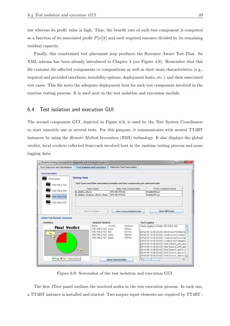
6.4 Test isolation and execution GUI 88
low whereas its profit value is high. Thus, the benefit rate of each test component is computed
as a function of its associated profit P [n][k ] and each required resource divided by its remaining
residual capacity.
Finally, this constrained test placement step produces the Resource Aware Test Plan. Its
XML schema has been already introduced in Chapter 4 (see Figure 4.9). Remember that this
file contains the affected components or compositions as well as their main characteristics (e.g.,
required and provided interfaces, testability options, deployment hosts, etc.) and their associated
test cases. This file nests the adequate deployment host for each test component involved in the
runtime testing process. It is used next in the test isolation and execution module.
6.4 Test isolation and execution GUI
The second component GUI, depicted in Figure 6.9, is used by the Test System Coordinator
to start remotely one or several tests. For this purpose, it communicates with several TT4RT
instances by using the Remote Method Invocation (RMI) technology. It also displays the global
verdict, local verdicts collected from each involved host in the runtime testing process and some
logging data.
Figure 6.9: Screenshot of the test isolation and execution GUI.
The first JTree panel outlines the involved nodes in the test execution process. In each one,
a TT4RT instance is installed and started. Two majors input elements are required by TT4RT :

6.4 Test isolation and execution GUI 89
selected Executable TTCN-3 test cases from the repository as JAR files and the Resource Aware
Test Plan (see Figure 6.10).
Executable TTCN-3
Test cases
.jar files
TT4RT Tool
Resource AwareTest Plan
.XML file
Local
Verdict
.XML file
Figure 6.10: TT4RT instance inputs and outputs.
The centered JTable describes test cases assigned to the selected node as well as their main
characteristics (i.e., test case name, TTCN-3 module name and MTC identifier). Several buttons
are proposed to efficiently manage the test execution. Consequently, we can start a selected
test case, all tests in a selected node or even all tests on their corresponding nodes. In that
case, each TT4RT instance is designed as a remote server object which implements a remote
interface offering three methods as illustrated in Listing 6.3. The method start testCase(...)
starts a single test case from a specified module; the method start testmodule starts all test
cases contained in the specified module and finally the method get FinalVerdict() returns the
local verdict calculated by the TT4RT instance.
1 public interface RemoteTestInterface extends java.rmi.Remote
2 {
3 public void start_testCase( String module , String testcase) throws RemoteException;
4 public void start_testmodule( String module) throws RemoteException;
5 public String get_FinalVerdict () throws RemoteException;
6 }
Listing 6.3: Remote interface of TT4RT instance.
The Generic Test Isolation Component, which represents the test isolation layer in TT4RT,
implements a User Datagram Packet (UDP) port listener function which runs an infinite loop
listening for test data in the form of UDP packets from the UDP test adapter. It can intercept
either local test requests sent by a local test adapter or remote test requests sent by a remote test
adapter. It is worth noticing that in the current implementation of RTF4ADS, not only a UDP
test adapter was implemented but also a Transmission Control Protocol (TCP) test adapter was
encoded. The latter can be easily integrated if required. These two possible implementations
can be used to establish communication through sockets between our TS and any kind of SUT.

6.4 Test isolation and execution GUI 90
This component uses AOP facilities to automate the test isolation of components under test
before the execution of runtime tests. In fact, we associate for each provided interface a test
isolation instance, designed as an AOP advice, which is automatically launched if at least one of
its methods is called by a test component. This test isolation instance is charged with looking
for the testability option of the component under test and then proceeds to the test execution.
To realize such an implementation, we use the most popular and stable AOP language, namely
AspectJ [123]. Indeed, the latter extends the Java language with new features to support the
aspect concepts. Listing 6.2 illustrates an AspectJ-based code of the test isolation instance.
1 public aspect TestIsolationInstance {
2 pointcut asp(String Patient_ID ,String HelpKind , String HelpCenter_Name ):execution
3 (public void HelpCenterAmbulatoryImpl.send_help(String ,String ,String ))
4 && args(Patient_ID ,HelpKind ,HelpCenter_Name );
5 void around(String Patient_ID ,String HelpKind , String HelpCenter_Name)
6 throws InvalidSyntaxException: asp(Patient_ID ,HelpKind ,HelpCenter_Name ){
7 // Test isolation instance is started
8 ReadTestPlanFile tp = new ReadTestPlanFile ("RATP.XML");
9 //Look for the testability option of the invoked component from the RATP file
10 String testOpt = tp.Read_TestOpt_CUT(HelpCenter_Name );
11 // This function returns 0 for BIT, 1 for tagging, 2 for aspect, 3 for blocking and 4 for cloning
12 int opt=testOpt_to_int(testOpt );
13 if(opt ==0){
14 //BIT strategy is applied and the test service is discovered from the registry
15 ...
16 } else if (opt ==1) {
17 //Tagging strategy is applied
18 String id_p_tag=Patient_ID +"#";
19 String help_kind_tag=HelpKind +"#";
20 String helpcenter_name_tag=HelpCenter_Name +"#";
21 proceed (id_p_tag ,help_kind_tag ,helpcenter_name_tag );
22 } else if (opt ==4){
23 // Aspect based strategy is applied
24 ...
25 }else if (opt ==3){
26 // Blocking strategy is applied
27 ...
28 }else if (opt ==2){
29 // Cloning strategy is applied
30 ...
31 }else{
32 //Business behavior is proceeded
33 proceed (Patient_ID ,HelpCenter_Name ,HelpKind );
34 }}}
Listing 6.4: Test isolation instance based on AOP code.

6.5 Selective Test Generation GUI 91
First of all, a pointcut called asp is defined to capture for example the call of the method
send help(String Patient ID, String helpKind, String HelpCenter Name) 5 belonging to the class
HelpCenterAmbulatoryImpl (see lines 2-4). Then, the around advice captures the execution call
and takes the decision to allow the execution of the corresponding method in case of business
request (i.e., the operation will be normally executed by calling the keyword proceed (see line
33)). Otherwise, it prohibits the execution and sets up the appropriate test isolation technique
before performing a test request. To do so, the testability options of each component under test
are obtained from the RATP file (see lines 8-10). Given a test aware component under test,
the input parameters are tagged with a special flag (see lines 18-20), for instance with “#”. In
this case, this component is able to discriminate test data (i.e., tagged with “#”) from business
data. Thus, the method is called with the new tagged parameters by using the keyword proceed
(see line 21).
6.5 Selective Test Generation GUI
The RTF4ADS framework includes a selective test generation GUI to build automatically a new
test suite after the occurrence of behavioral adaptations.
Figure 6.11: Screenshot of the selective test generation GUI.
The new test suite is composed of reusable and retestable tests, selected from the old test
5This scenario belongs to an e-Health application in which an alarm component sends a help request to a helpcenter, e.g., Ambulatory component, in case of emergencies.

6.5 Selective Test Generation GUI 92
suite, new tests generated from the evolved behavioral model by UPPAAL CO√
ER (version
1.4) [109] and some adapted ones obtained by test recomputation. Once the new test suite is
evolved, it is mapped to the TTCN-3 notation.
The first panel illustrated in Figure 6.11 deals with the model differencing step. Indeed, the
initial behavioral model and the evolved one are loaded, and then an Mdiff model highlighting
their similarities and their differences is computed. The next step consists in loading the old
test suite and performing a test classification.
1 // Load the old trace
2 ExtractXMLTraces XMLTR=new ExtractXMLTraces ();
3 Vector <Trace > traces=XMLTR.extract (" OldTraceXML.xml");
4 // Read the SUT and ENV timed automata
5 TA_automata SUTdiff=algo.readModel ("SUT");
6 TA_automata ENVdiff=algo.readModel ("ENV");
7 ArrayList <state > SUTstates=SUTdiff.getStates ();
8 ArrayList <state > ENVstates=ENVdiff.getStates ();
9 for (int i=0;i<traces.size ();i++)
10 {
11 Trace TR=null;
12 state SUT_l0=algo.lookupState(SUTdiff.getInit(), SUTstates );
13 state ENV_l0=algo.lookupState(ENVdiff.getInit(), ENVstates );
14 for (int j=0;j<traces.get(i).sync.size ();j++)
15 {
16 if (algo.IstransitionReached(traces.get(i).sync.get(j), SUT_l0 ,ENV_l0 ))
17 {
18 SymbolicState symb=algo.NextReachedState (...); // Look for the next reached state
19 SUT_l0=symb.getSi ();
20 ENV_l0= symb.getEi ();
21 }else{
22 invalide=true;
23 if (algo.findOldTransition (...) // the transition already exists in the old model
24 TR=new Trace(traces.get(i).sync , "aborted "); break;
25 else
26 TR=new Trace(traces.get(i).sync , "obsolete "); break;}
27 }
28 if (! invalid ){
29 if (algo.VerifColor(traces.get(i).sync , SUTdiff.getTransitions ()))
30 // All the covered items are colored in Green
31 TR=new Trace(traces.get(i).sync , "reusable ");
32 else
33 TR=new Trace(traces.get(i).sync , "retestable ");
34 } OldTestSuite.add(TR);
35 }
Listing 6.5: Test classification code snippet.
Listing 6.5 shows a Java code snippet of the old test classification module. Indeed, the old test

6.5 Selective Test Generation GUI 93
suite is made up of several traces in the XML format (see lines 1-3). Each trace is animated on
the SUT and ENV models. Since a given synchronization action (i.e., traces.get(i).sync.get(j ))
in the old trace cannot be traversed, the test animation is abandoned (see line 21). At line 23,
we check the existence of the corresponding transition in the evolved model. In such a case, the
trace is classified as an aborted trace (see line 24). Otherwise, it is considered obsolete (see line
26). In lines 28-32, we classify valid traces into reusable or retestable traces.
Finally, we compute the new test suite by launching the UPPAAL CO√
ER tool to generate
new tests, in a cost effective manner, by adapting obsolete and aborted tests and by including
resuable and restestable tests.
Test generation tool
UPPAAL CoVer
SUT and ENV
automata
.xml
Observer
automata
Configuration
file
.cfg
Test
sequences
.xml
Query file
.q
automata
.obs
Figure 6.12: UPPAAL CO√
ER setup.
As shown in Figure 6.12, the UPPAAL CO√
ER tool takes mainly as inputs :
• the Mdiff model (.xml), which is composed of a system part (SUT) and an environment
part (ENV),
• the observer (.obs), which expresses the adopted coverage criteria,
• a query file (.q) that is used to specify from which timed automaton or timed automata
of the Mdiff the test suite is generated, and
• a configuration file (.cfg) that is used to format the generated traces to contain desired
information in the XML format.
The last panel is dedicated to perform the mapping of abstract test traces to the TTCN-
notation. Once TTCN-3 test cases are compiled to be executable, test distribution, test isolation
and test execution are performed as in the case of structural adaptations.

6.6 Summary 94
6.6 Summary
The achievement of a well-implemented prototype for runtime testing of dynamic adaptations
was pinpointed in the present chapter. The obtained framework includes the realization of both
approaches proposed to check structural and behavioral adaptations. Implementation details in
terms of input files, output results and used tools required for each module were presented.
In the next chapters, we employ RTF4ADS to check the correctness of two critical case
studies after the occurrence of either dynamic structural or behavioral adaptations. On the one
hand, we illustrate the efficient execution of runtime tests in case of dynamically adapting the
structure of an e-Health case study (see Chapter 7). On the other hand, RTF4ADS is used to
evolve test suites when behavioral adaptations take place in the case of telematic application
(see Chapter 8).

CHAPTER 7
Application of RTF4ADS After Structural Adaptations
7.1 Introduction
This chapter is mainly dedicated to show the relevance of our framework in case of structural
adaptation occurrence. To do so, a remote medical care system is introduced and its implemen-
tation details are highlighted in Section 7.2. In Section 7.3, several test scenarios are specified
for the adopted case study. Their mapping to the TTCN-3 notation is also presented. Section
7.4 shows the applicability of RTF4ADS to check the case study correctness after structural
adaptations. At the end, several experiments have been conducted in Section 7.5 to assess the
overhead introduced by RTF4ADS as well as to show its efficiency to reveal adaption faults. The
last section summarizes this chapter. Parts of this chapter have been published in [32, 96, 33].
7.2 Case study: Teleservices and Remote Medical Care System
7.2.1 General overview
Teleservices and Remote Medical Care Systems (TRMCS) were introduced in the literature for
more than a decade ago [124]. They were designed initially to provide monitoring and assistance
to patients suffering from chronic health problems. Thus, they send emergency signals to the
medical staff (such as doctors, nurses, etc.) to inform them with the critical state of a patient.
Recently, both the architecture and the behaviors of such medical care systems are evolved and
enhanced by more elaborated functionalities (for instance, the acquisition, the analysis and the
storage of biomedical data) and sophisticated technologies [125, 126, 7, 8].

7.2 Case study: Teleservices and Remote Medical Care System 96
New components and features can be installed at runtime during system operation in order
to fulfill new requirements such as adding new health care services, updating the existing ones
in order to support performance improvements, etc. Such adaptability is essential to ensure
that the healthcare system remains within the functional requirements defined by application
designers, and also maintains its performance, security and safety properties.
Device
Nurse PDA
Nurse Bundle
Device
Device
Local Home Server
Device
Remote Server
Report Storer
BundleMedical
Data Base
JDBC
Protocol
TCP/IP
Device
Sensor
Blood Pressure Device
Hospital Computer
Hospital
Bundle
Device
Ambulatory PDA
Ambulatory
Bundle
Local Home Server
Report Builder
Bundle
Analyzer
Bundle
Alarm Bundle
Blood Pressure
Bundle
Heart Rate
Bundle
Device
Doctor PDA
Doctor
Bundle
Figure 7.1: The basic configuration of TRMCS.
Following these directions, we provide our own architecture of the TRMCS application which
is inspired mainly from [126]. Its main architecture is highlighted through a UML deployment
diagram depicted in Figure 7.1. We assume that initially a given patient is suffering from
chronic high blood pressure. Thus, he is equipped with a Blood Pressure Sensor and a Heart
Rate Sensor that measure respectively his arterial blood pressure and his heart-rate beats per
minute. Periodic reports are built and stored in the medical database. They are also accessible
for consultation from the medical staff. The Analyzer component is charged with analyzing the
monitored data in order to detect whether some thresholds are exceeded. In that case, an Alarm
component is invoked with the aim of sending help requests to the medical staff.
7.2.2 TRMCS implementation
The TRMCS is fully implemented as an OSGi application. Developed by OSGi Alliance [39],
the OSGi specification describes how to build service-oriented and loosely coupled systems. This
standardized technology defines a lightweight framework based on Java Runtime Environment
and a set of installed bundles. Bundles are software components, packed in JAR files. A bundle is

7.2 Case study: Teleservices and Remote Medical Care System 97
designed as a minimal deliverable application in OSGi that is composed of cooperating services,
which are discovered after being published in the OSGi service registry. It is capable of either
exporting Java packages and exposing functionalities as services to other bundles or importing
Java packages or services from other bundles [127, 128].
To efficiently manage the bundles’ life cycle, the OSGi framework offers management func-
tionalities that include installing, activating, deactivating, updating, and removing services.
Consequently, it provides dynamic mechanisms for deploying, starting and removing services
at runtime in order to meet, for instance, changing business demands. Furthermore, the OSGi
platform supports various execution environments, networks and technologies [128]. Hence, the
bundles may be deployed on multiple devices such as mobile computing devices, digital TV set
top boxes, game consoles, etc.
Running TRMCS
Bundles
Figure 7.2: TRMCS bundles running on Felix.
Due to these major benefits (i.e., dynamism, extensibility and application interoperability),
OSGi is retained in our context to build TRMCS components. A wide number of implementa-
tions of the OSGi specification exist. The one we are using is Apache Felix1. Figure 7.2 shows
the deployment and the start up of TRMCS bundles on this OSGi container.
7.2.3 TRMCS configurations
For experimental purposes, we vary the TRMCS architecture. Thus, different configurations
of this case study are implemented. The system evolves from one configuration to another by
installing and starting bundles or by stopping and uninstalling them. A brief overview of the
related bundles as well as the main characteristics of each configuration in terms of number
of hosts in the execution environment and number of stored test cases in the repository is
summarized in Table 7.1.
1http://felix.apache.org/site/index.html

7.3 TRMCS test specification 98
Table 7.1: Supporting several configurations of the TRMCS application.
ConfigurationsNumber of
bundlesNumber of
hostsNumber ofStored TCs Bundle names
Conf 1 5 5 9Alarm + Hospital + Doctor + Nurse +Ambulatory
Conf 2 (Basic) 10 7 24 Bundles depicted in Figure 7.1
Conf 3 15 8 48Bundles in Conf 2+ SMS + Call +EmergencyCenter + SensorT + SensorGLS
Conf 4 20 8 58Bundles in Conf 3 + PPS + ECG + GSR +AirS + SPO2
Conf 5 25 13 72
Bundles in Conf 4+ LaboratoryCenter +RadiographyCenter + Different instances ofdoctor bundle
For instance, in Conf 3, TRMCS supports three kinds of help requests: generating call, sms
or alarm signals. Moreover, another help center can be used, Emergency Center. The patient is
also equipped with new sensors to measure the body temperature and the blood glucose level.
Conf 4 includes more medical device sensors such as:
• Patient Positionning Sensor (PPS) that detects the patient body position,
• Electrocardiogram (ECG) sensor that assesses the electrical and muscular heart functions,
• Galvanic Skin Response (GSR) sensor that measures the electrical conductance of the skin,
• Airflow Sensor (AirS) that detects low airflow levels to provide efficient oxygen delivery
for patients and
• Percutaneous arterial oxygen Saturation (SPO2) sensor that measures the blood oxygen
saturation level.
In Conf 5, we extend the TRMCS application by adding bundles like the Laboratory Center,
the Radiography Center and different instances of doctor bundles.
Due to the dynamic nature of the TRMCS application, medical errors and degradation of
QoS parameters can occur. Therefore, runtime testing is required to validate dynamic changes on
the TRMCS application with the aim of early detection of undesirable behaviors. Next, various
test scenarios are specified in the TTCN-3 notation and later performed at runtime for testing
the TRMCS application and checking either its functional or non-functional requirements.
7.3 TRMCS test specification
To show the high expressiveness of the TTCN-3 language in supporting various testing levels
(i.e., unit and/or integration tests) and different testing purposes (i.e., functional tests, load
tests, availability tests, etc.), some test scenarios are studied for the former case study and their

7.3 TRMCS test specification 99
mapping to the TTCN-3 notation is given afterwards. Table 7.2 summarizes tests supported by
the proposed test platform when structural adaptations occur.
Table 7.2: Supported test scenarios.
Test kinds Testing issues
Functional tests Check the compliance of a system or a componentwith its specified behavior by sending stimulus andanalyzing outputs.
Timing tests Check the temporal constraints under which theSUT shall operate.
Availability tests Check the availability of a service after dynamicadaptations.
Load tests Check system responsiveness under normal andheavy load.
Given that the entire test scenarios are too lengthy to describe, four examples are provided
to highlight the most common types of test scenarios. First of all, these scenarios are introduced
in a descriptive way then their mapping to the TTCN-3 code is given.
Guarantee of help service delivery. This scenario can be used to test the situation in
which the analysis of monitored critical events are triggered or threshold conditions are reached
(i.e., when the heart rate exceeds a certain level of tolerance). In this context, emergency signals
are sent to the appropriate medical staff. Table 7.3 provides a concise description of this scenario.
Table 7.3: Test scenario 1 (TS-1).
Test Scenario 1 TS-1
Test objective To ensure that an urgent notification is sent to the medicalstaff when a threshold is exceeded.
Pre-Conditions
a. The appropriate test isolation strategies have to be setup for all the components involved in this test.
b. Test data greater than the threshold is sent to the SUT.
c. No packet loss in the communication network2.
Action Start the test system and inject test data into the SUT.
Post-Conditions A notification should be sent to the involved medical staff.
Mapping of TS-1 to TTCN-3. As depicted in Listing 7.1, a help request is sent to
the Alarm component via an MTC component (see line 4). If the test component receives the
adequate output as mentioned in line 7, a pass verdict is generated (see line 8). Otherwise, a
fail verdict is generated (see line 10).
1 testcase tc_CheckAlarm () runs on mtcType system systemType{
2 map (mtc: mtcPort , system: systemPort );
3 timer localtimer := 15.0;
4 mtcPort.send(msg_to_alarm );
2This pre-condition is proposed with the aim of avoiding inconclusive verdicts.

7.3 TRMCS test specification 100
5 localtimer.start;
6 alt {
7 [] mtcPort.receive(" Service invoked Successfully ")
8 {setverdict (pass , "Test service alarm successfully ");}
9 [] mtcPort.receive
10 {setverdict (fail , "Something else received ");}
11 [] localtimer.timeout
12 { setverdict (fail , "Timeout ");}
13 localtimer.stop ;}}}
Listing 7.1: A sample of test case for TS-1.
Achievement of timing constraints. This scenario is used to check that the Alarm
component must send the help request to the Nurse component in a duration that does not
exceed 15 time units. Table 7.4 provides a concise tabular description of this scenario.
Table 7.4: Test scenario 2 (TS-2).
Test Scenario 2 TS-2
Test objective To ensure that the Alarm component respects its timing con-straints.
Pre-Conditions
a. The appropriate test isolation strategies have to be setup for all the components involved in this test.
b. No packet loss in the communication network.
Action Invoke the Help Service in the Alarm component and measurethe response time.
Post-Conditions The Alarm component should send the emergency requestwhile fitting the predefined timing constraints.
Mapping of TS-2 To TTCN-3. Listing 7.2 depicts an example of testing timing con-
straints.
1 testcase tc_time_Constraint () runs on mtcType system systemType{
2 var float sendTime , receiveTime;
3 map (mtc: mtcPort , system: systemPort );
4 mtcPort.send(msg_ALARM_NURSE)->timestamp sendTime;
5 mtcPort.receive -> timestamp receiveTime;
6 if(receiveTime -sendTime <15)
7 {
8 setverdict (pass , "Time Constraint respected ");}
9 else{
10 setverdict (fail , "Time Constraint not respected ");}}
Listing 7.2: A sample of test case for TS-2.
In this situation, we assume that the Alarm component has to transmit the help request
to the Nurse component in a time lapse that does not exceed 15 time units. Therefore, the

7.3 TRMCS test specification 101
test component sends test data to the concerned component composition (made up of Alarm
and Nurse components) (see line 4). The send time of the message is recorded by means of
the redirection operator − > timestamp [129] and is assigned to the given variable sendTime.
Similarly, the arrival time of the receive message is retrieved and assigned to the receiveTime
variable. As illustrated in lines 6-10, if this deadline is respected, a pass verdict is generated;
otherwise, a fail verdict is computed.
Availability of a component. This scenario serves to check component availability after
the occurrence of dynamic reconfigurations (i.e., adding, updating or migrating components).
For instance, in case of patient mobility in and out of the local server’s range, we have to check
that wearable medical sensors are accessible and can be invoked from components deployed on
the local server (like the Report Builder component, the Analyzer component, etc.). Table 7.5
provides a concise description of this scenario.
Table 7.5: Test scenario 3 (TS-3).
Test Scenario 3 TS-3
Test objective To ensure the availability of the new or modified or mobilecomponent.
Pre-Conditions
a. The appropriate test isolation strategies have to be setup for all the components involved in this test.
b. No packet loss in the communication network.
Action Send a test request to the component under test and check itsavailability.
Post-Conditions The component should receive the test request and send aresponse to the test system.
Mapping of TS-3 to TTCN-3. Listing 7.3 gives an example for testing the availability
of a medical sensor. This kind of test can be applied when a new medical service is added at
runtime to the TRMCS application or when the patient wearing this device is mobile.
1 testcase tc_Availability () runs on mtcType system systemType {
2 map (mtc: mtcPort , system: systemPort );
3 timer localtimer := 15.0;
4 mtcPort.send (msg_to_sensor );
5 localtimer.start;
6 alt {
7 [] mtcPort.receive(" Sensor invoked Successfully ")
8 {setverdict (pass ,"The sensor is available ");}
9 [] mtcPort.receive
10 {setverdict (fail ,"The sensor is not available ");}
11 [] localtimer.timeout
12 { setverdict (fail , "Timeout ");}
13 localtimer.stop;}}}
Listing 7.3: A sample of test case for TS-3.

7.3 TRMCS test specification 102
Concurrent test requests. This scenario is used to simulate the situation in which mul-
tiple users request the service under test at the same time. The dynamic creation of PTCs in
TTCN-3 standard enables our framework to create a number of virtual users that send multiple
test requests concurrently and perform load testing on the SUT. Table 7.6 provides a concise
description of this scenario.
Table 7.6: Test scenario 4 (TS-4).
Test Scenario 4 TS-4
Test objective To ensure that the SUT operates correctly under differentworkloads.
Pre-Conditions
a. The appropriate test isolation strategies have to be setup for all components involved in this test.
b. Fix the number of parallel test components used bythe test system to load the SUT.
c. No packet loss in the communication network.
Action Start the test system and monitor the response time of theSUT under this heavy load.
Post-Conditions SUT performance varies according to the increasing numberof PTCs.
Mapping of TS-4 to TTCN-3. Listing 7.4 gives an example for load testing the Alarm
component.
1 function ptc_time_constraint () runs on ptcType {
2 var integer duration;
3 ptcPort.send (msg_ALARM_NURSE );
4 ptcPort.receive (integer :?) -> value duration;
5 if(duration <15)
6 {setverdict (pass , "Time Constraint respected ");}
7 else
8 {setverdict (fail , "Time Constraint not respected ");}
9 }
10 testcase LoadTest () runs on mtcType system systemType {
11 var ptcType ptcArray[NUMBER_OF_PTCS ];
12 var integer i := 0;
13 for (i := 0; i < NUMBER_OF_PTCS; i := i + 1) {
14 // create the PTCs
15 ptcArray[i] := ptcType.create;
16 map(ptcArray[i]:ptcPort , system:systemPort );
17 ptcArray[i].start(ptc_time_constraint ());
18 ptcArray[i].done;} }
Listing 7.4: A sample of test case for TS-4.
This test case creates an arbitrary number of PTCs components that will execute the test
behavior described from line 1 to line 10. In line 11, we declare an array named ptcArray of

7.4 Checking TRMCS correctness after structural adaptations 103
size equal to the constant NUMBER OF PTCS. Each test component is created, mapped to
the system and then started (see lines 15-17). The aim here is to check that under heavy load
timing constraints under which the Alarm component is running are still respected.
In order to edit and compile the specified tests, we use respectively the TTCN-3 Core Lan-
guage Editor (CL Editor) and the TThree Compiler that are included in the TTworkbench basic
tool3. The generated Jars are stored in the Test Case Repository for further use and can be
dynamically loaded during the runtime test execution to check dynamic changes.
7.4 Checking TRMCS correctness after structural adaptations
At present, we study the evolution of the basic configuration illustrated in Figure 7.1. Indeed, it
comes a moment when this system dynamically evolves to fulfill new requirements. For instance,
the Alarm component is updated with a new version in order to increase SUT responsiveness.
The new version sends the help request to the medical staff in a duration that does not exceed
15 time units instead of 30 time units for the old version. Once this reconfiguration is achieved,
the new component and all the affected parts of the system have to be validated.
To perform efficiently the runtime testing of the studied scenario, we begin with the computa-
tion of the affected components and compositions by this dynamic change. Figure 7.3 illustrates
the system dependencies in this scenario and the affected parts of the system are delimited by
a red square.
Legend:
BP_S: Blood Pressure Sensor
HR_S: Heart Rate Sensor
RB: Report Builder
RS: Report Storer
An: Analyzer
Al: Alarm
Nu: Nurse
Am: Ambulatory
Hp: Hospital
Dr: Doctor
Figure 7.3: The dependency graph of the studied scenario.
In the second step, a subset of test cases covering the impacted parts of the TRCMS appli-
cation is identified. Table 7.7 shows the constituents of the new test suite to run. Recall that
the unit tests are prefixed by “UT” whereas the integration tests are prefixed by “IT”.
Once the test cases are identified, the constrained test component placement module is
called in this stage in order to look for a suitable solution that satisfies predefined resource and
3http://www.testingtech.com/products/ttworkbench.php

7.4 Checking TRMCS correctness after structural adaptations 104
Table 7.7: Reusable test cases.
Selected test cases.
UT Alarm.jar
IT RBuilder SensorBPS.jar
IT RBuilder SensorHRS.jar
IT RBuilder Storer.jar
IT RBuilder Analyzer Alarm Nurse.jar
IT RBuilder Analyzer Alarm Hospital.jar
IT RBuilder Analyzer Alarm Ambulatory.jar
IT RBuilder Analyzer Alarm Doctor.jar
connectivity constraints. For instance, an optimal solution is computed in which four test nodes4
are chosen : the local home server, the hospital computer, the remote server and the nurse PDA.
Then, the selected test cases are distributed over these four nodes. Notice that this solution
may change especially when we vary the node provided resources and the network connectivity.
As mentioned before, affected components as well as their main characteristics (e.g., required
and provided interfaces, testability options, etc.), their associated test components and their
deployment hosts are included in the RATP file. Figure 7.4 shows a screenshot of this file and
describes mainly the new Alarm component and its main features. Especially, it pinpoints the
deployment host where the Alarm unit test case will be run on (i.e., the host having 192.168.2.102
as IP address).
Figure 7.4: Screenshot of the RATP XML file content.
The RATP file is used in the next step that copes with the test isolation and execution.
Indeed, the preparation of the test isolation layer is done in accordance with the testability
options of each component under test. In the current scenario, we have different components
with various testability features. The Report Builder is testable and it is equipped with a test
interface ensuring that the test data and the business data are not mixed during the runtime
testing process. The other components involved in this test process are considered test aware.
4Nodes holding test execution.
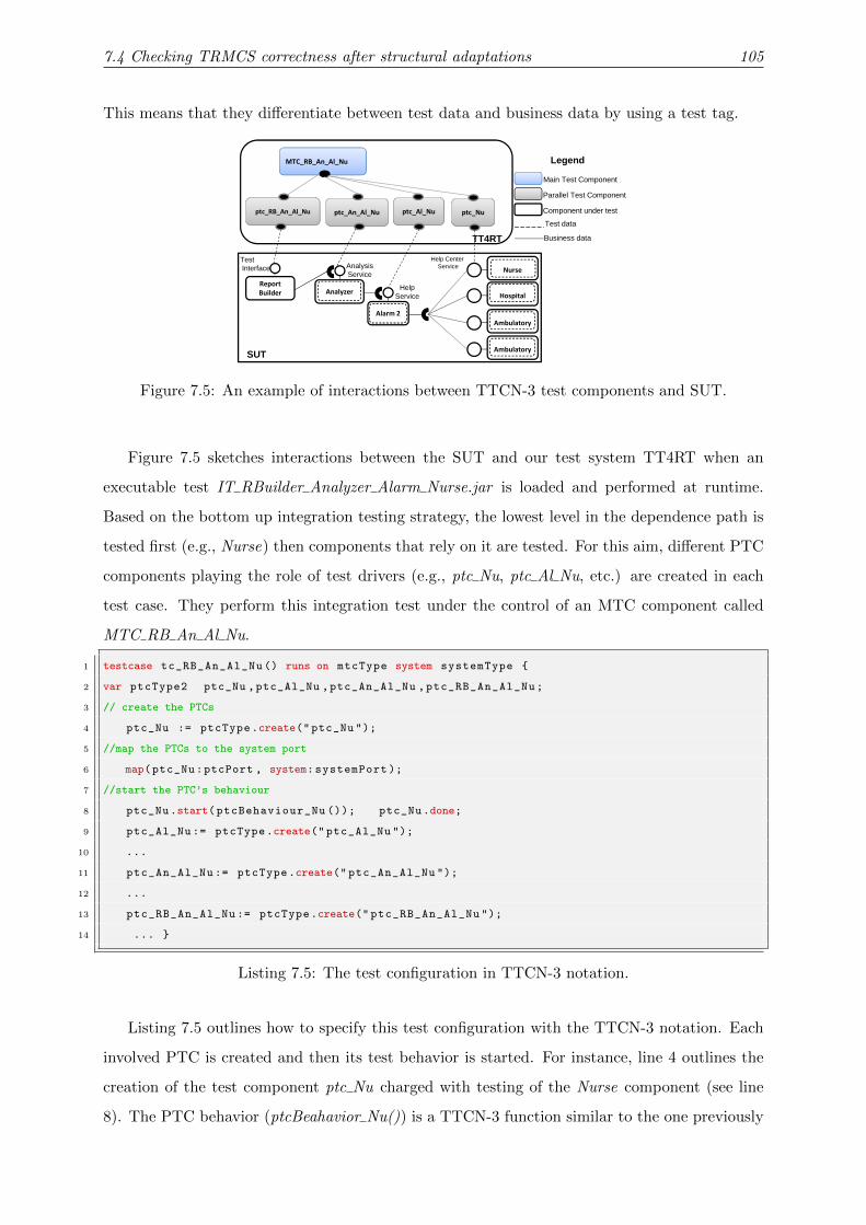
7.4 Checking TRMCS correctness after structural adaptations 105
This means that they differentiate between test data and business data by using a test tag.
ptc_Al_Nu
MTC_RB_An_Al_Nu
ptc_An_Al_Nu
TT4RT Business data
Test data
ptc_RB_An_Al_Nu
Main Test Component
Parallel Test Component
Component under test
Legend
Nurse
Help Center ServiceAnalysis
ServiceReport
TestInterface
ptc_Nu
Alarm 2
HelpService
SUT
AnalyzerReport
Builder Hospital
Ambulatory
Ambulatory
Figure 7.5: An example of interactions between TTCN-3 test components and SUT.
Figure 7.5 sketches interactions between the SUT and our test system TT4RT when an
executable test IT RBuilder Analyzer Alarm Nurse.jar is loaded and performed at runtime.
Based on the bottom up integration testing strategy, the lowest level in the dependence path is
tested first (e.g., Nurse) then components that rely on it are tested. For this aim, different PTC
components playing the role of test drivers (e.g., ptc Nu, ptc Al Nu, etc.) are created in each
test case. They perform this integration test under the control of an MTC component called
MTC RB An Al Nu.
1 testcase tc_RB_An_Al_Nu () runs on mtcType system systemType {
2 var ptcType2 ptc_Nu ,ptc_Al_Nu ,ptc_An_Al_Nu ,ptc_RB_An_Al_Nu;
3 // create the PTCs
4 ptc_Nu := ptcType.create(" ptc_Nu ");
5 //map the PTCs to the system port
6 map(ptc_Nu:ptcPort , system:systemPort );
7 //start the PTC’s behaviour
8 ptc_Nu.start(ptcBehaviour_Nu ()); ptc_Nu.done;
9 ptc_Al_Nu := ptcType.create(" ptc_Al_Nu ");
10 ...
11 ptc_An_Al_Nu := ptcType.create(" ptc_An_Al_Nu ");
12 ...
13 ptc_RB_An_Al_Nu := ptcType.create(" ptc_RB_An_Al_Nu ");
14 ... }
Listing 7.5: The test configuration in TTCN-3 notation.
Listing 7.5 outlines how to specify this test configuration with the TTCN-3 notation. Each
involved PTC is created and then its test behavior is started. For instance, line 4 outlines the
creation of the test component ptc Nu charged with testing of the Nurse component (see line
8). The PTC behavior (ptcBeahavior Nu()) is a TTCN-3 function similar to the one previously

7.5 Evaluation and overhead estimation 106
TT4RT1 TT4RT2
TT4RT3 TT4RT4 RTF4ADS User Interface
Figure 7.6: The adopted testbed.
defined in Listing 7.4.
The use of the TTCN-3 language here ensures the specification of abstract and platform-
independent test suites. Furthermore, adopting TTCN-3 test components for the execution of
these tests allows building a generic test architecture loosely coupled with the system under test.
In this way, the test design is separated from the test implementation and execution.
7.5 Evaluation and overhead estimation
We carried out some experiments to measure the overhead introduced by the use of the
RTF4ADS framework when structural adaptations take place. Thus, the main objective is
to estimate the dependency analysis, the test selection, the constrained test component place-
ment and the test execution overheads and to determine which parameters have a significant
effect on each of them.
Thereby, we deployed our distributed test system as well as the TRMCS application on five
machines: a PC with Intel Core 2 Duo CPU and 2 GO of main memory, another PC with Intel
Core i7 and 8 GB of main memory and three virtual machines having each 2.30 GHz CPU and
512 MB of main memory. Using this experimental setting, we deployed four TT4RT instances
on the involved test nodes identified during the test component placement step. RTF4ADS user
interfaces were deployed on a separate host (see Figure 7.6). Moreover, we have to note that
each experiment was conducted ten times to derive the precise average value of execution time.
As outlined in Figure 7.7, four experiments were conducted to measure the execution time
required by each step in the runtime testing process. The first experiment (see Figure 7.7a) shows
that the execution time needed to compute the affected parts of the system after the occurrence
of a dynamic change increases at the same time as the number of involved components increases.
For instance, whereas the system is made of 25 bundles (Conf 5 ) running together, the time
spent for the dependency analysis does not exceed 70 ms.

7.5 Evaluation and overhead estimation 107
The overhead of test case selection depends mainly on the number of test cases stored in
the repository. In order to estimate the influence of the repository size, we varied the number
of stored tests and we measured the execution time required for the repository exploration. As
depicted in Figure 7.7b, the time required for the test case lookup increases while the number
of stored test cases in the repository increases too.
60
65
70
75
Ex
ecu
tio
n t
ime
(m
s)
50
55
60
conf1 conf2 conf3 conf4 conf5
Ex
ecu
tio
n t
ime
(m
s)
(a) Execution time of the dependency analysis step.
15
20
25
30
Ex
ecu
tio
n T
ime
(m
s)
0
5
10
15
conf1 conf2 conf3 conf4 conf5
Ex
ecu
tio
n T
ime
(m
s)
(b) Execution time of the test selection step.
1500
2000
2500
Ex
ecu
tio
n T
ime
(m
s)
0
500
1000
1500
conf1 conf2 conf3 conf4 conf5
Ex
ecu
tio
n T
ime
(m
s)
Optimal
Realisable
(c) Execution time of the constrained test compo-nent placement step.
0
200
400
600
800
1000
20 40 60 80 100
Ex
ecu
tio
n T
ime
(m
s)
Centralized Test
Distributed Test
20 40 60 80 100
(d) Centralized vs distributed runtime tests.
Figure 7.7: Execution time required by each step in the RTF4ADS framework.
The third experiment was conducted to evaluate the execution time needed for the test
placement phase. Thus, two cases were studied. Two parameters influence the time required for
computing an optimal or a satisfying solution : the number of test components to deploy and
the number of host nodes in the execution environment. As depicted in Figure 7.7c, the first
curve shows the average execution time required by the Choco solver to compute an optimal
solution. The analysis of the results indicates that the average time required for assigning test
components to execution nodes increases with the increase of the number of test components
and nodes. Due to the significant time spent for calculating an optimal solution, this technique
can be adopted when the dynamic changes do not occur frequently. Thus, we have enough time
to validate them.
This amount of time decreases considerably when we look for a satisfying solution as illus-
trated in the second curve. For instance, the time required to find a satisfying solution for 5 test
components in an execution environment made up of 5 nodes (see Conf 1 ) decreases by 20.5%.
Similarly, assigning 21 test components in an execution environment made up of 13 nodes (see

7.5 Evaluation and overhead estimation 108
Conf 5 ) decreases by 53.2%. Thus, we notice that the proposed solver may resolve this NP-hard
problem in a reasonable amount of time while the number of test components and nodes does
not exceed some dozens. Such a solution can be sufficient especially when a very constrained
part of the whole system, in terms of components as well as in terms of execution nodes, are
affected by the modification.
The experiment, outlined in Figure 7.7d, evaluated the overhead of our test execution plat-
form, notably while increasing the number of test cases. Hence, we recorded the execution time
for an example of test by varying the number of test cases from 20 up to 100 (i.e., from 20
up to 100 MTC components). The first curve corresponds to the evolution of the execution
time while one TT4RT instance is deployed (i.e., this is a centralized test). It is evident that
the average time required for performing tests increases with the increase of the number of test
cases. Indeed, the time consumed to create locally 20 test components, to execute tests and to
generate the final verdict is around 300ms while it increases to attain approximately 800ms for
100 tests. The second curve shows a decrease in the execution time after distributing tests over
four TT4RT instances. Such a decrease reaches 32.85% for running 20 tests and attains 47.78%
for running 100 tests.
Moreover, we performed some experiments with and without a TT4RT instance in order to
measure the introduced overhead in each node. For this purpose, we monitored the memory
usage during the test execution based on the JConsole tool. We compared three cases when test
cases are equal to 10, 50 and 100 (see Figure 7.8). In the first case, the memory overhead is
around 4 MB. As expected, when the number of test cases increases, the memory consumption
rises, too, and attains approximately 4.5 MB for running 100 test cases. Similarly, whereas the
PTC components involved in a test case increase significantly in number, the memory consump-
tion rises, too (see Figure 7.9). Therefore, we conclude that minimizing the set of test cases to
re-execute leads to a reduction of the involved test components. Hence, the distribution of the
runtime tests can be seen as a relevant solution for reducing the overhead of runtime tests in
terms of memory usage and execution time .
0
1
2
3
4
5
10 50 100
Memory (MB)
Test cases
TT4RT Memory Usage
SUT Memory Usage
Figure 7.8: Memory usage for one TT4RT in-stance while varying the number of test cases.
0
1
2
3
4
5
10 50 100
Me
mo
ry (
MB
)
Parallel Test Components
TT4RT Memory Usage
SUT Memory Usage
Figure 7.9: Memory usage for one TT4RT in-stance while varying the number of PTCs.

7.6 Synthesis 109
7.6 Synthesis
The different experiments that we carried out show that the runtime testing cost in terms of
execution time and memory consumption increases significantly while the amount of tests to
run or the number of test components to deploy rises. Compared to one of the traditional test
selection strategy, the Retest All strategy [62], which re-executes all available tests, our proposal
seems to be more efficient as it reduces the number of tests to rerun. In addition, the adopted test
selection technique does not require much time to identify the unit and integration tests involved
in the runtime testing process. Even in the worst case, when the whole system is affected by the
dynamic change, we reduce the impact of the runtime testing on the system under test and on
its environment by distributing test cases and their corresponding test components while fitting
the resource and connectivity constraints.
2
4
6
8
10
12
14
16
18
Nu
mb
er o
f te
st c
ase
s
Pass
Fail
Inconc
0
2
Case 1 Case 2 Case 3
Figure 7.10: The impact of resource and connectivity awareness on test results.
The experiment outlined in Figure 7.10 shows the importance of the constraint test compo-
nent placement module and its impact on the final test results. In the following, three cases of
test results are obtained while executing twenty one selected tests as requested in Conf 5.
• In the first case, our test placement module was used to identify the adequate test hosts
and our test system was run to perform the selected tests. The seeded faults were detected
and thus we obtained seventeen Pass and four Fail verdicts.
• In the second case, we assume that the hospital computer is disconnected from the network.
However, this connectivity problem was not taken into consideration during the testing
process. As a result, six test requests were sent from their corresponding test components
without receiving any response. In this situation, neither a Pass nor a Fail verdict can be
assigned and thus six inconclusive verdicts are obtained.
• The third case shows the test results obtained while executing the twenty one tests on

7.7 Summary 110
some overloaded nodes. As in Case 2, the tests results are influenced by the execution
environment state and consequently several verdicts were set to inconclusive. Such test
results were obtained due to the timeout occurrence during the test execution.
To sum up, runtime testing may affect not only the SUT performance and responsiveness
but also the test system itself could be impacted. Thus, resource and connectivity awareness
appears to be a solution in order to have a high confidence in the validity of the test results as
well as to reduce their associated cost.
0
500
1000
1500
2000
2500
conf 1 conf2 conf3 conf4 conf5
Ex
ecu
tio
n T
ime
(ms)
step1 step2 step3 step4
Figure 7.11: The overhead of the whole runtimetesting process while searching for an optimalsolution in step 3.
0
500
1000
1500
conf1 conf2 conf3 conf4 conf5
Ex
ecu
tio
n T
ime
(m
s)
step1 step2 step3 step4
Figure 7.12: Assessing the overhead of the wholeruntime testing process while searching for a sat-isfying solution in step 3.
The experiments presented in Figure 7.11 and Figure 7.12 show that the different overheads
introduced by our runtime testing support are relatively low. In fact, we find out that the sum
of all overheads including the dependency analysis (step 1), the test selection (step 2), the test
placement (step 3) and the test execution (step 4) overheads does not exceed 2.5 seconds in
the worst case (i.e., when we are looking for an optimal solution in step 3). This cost can be
justified by the use of exact methods in the current version of the constrained test component
module. It is obvious that this resolution technique is one of the most costly ways to find the
best solution from all feasible solutions.
As illustrated in Figure 7.12, this cost decreases when we simply look for a feasible solution
of test component placement. In this case, our test framework requires less than 1.5 seconds for
checking Conf 5. With the aim of guaranteeing the scalability of RTF4ADS, we recommend to
make do with generating the satisfying solution as it consumes less time when the numbers of
test components and host nodes increase. We believe that such a solution is sufficient because
it respects both the resource and connectivity constraints of the execution environment.
7.7 Summary
In this chapter, we applied RTF4ADS to execute in a cost effective manner runtime tests after
the occurrence of dynamic structural adaptations. Our contributions were illustrated via the

7.7 Summary 111
TRMCS case study that was implemented using the OSGi platform. Several test scenarios were
presented and were mapped to the TTCN-3 notation in order to demonstrate the expressiveness
of this standard. At the end, several experiments were conducted to estimate the RTF4DAS
overhead. They pointed out the efficiency of the proposed framework and the tolerated cost that
it introduced while varying SUT architecture, execution environment topology and the number
of involved tests.
In the following chapter, we show the application of RTF4ADS to evolve test suites when
dynamic behavioral adaptations take place.

CHAPTER 8
Application of RTF4ADS After Behavioral Adaptations
8.1 Introduction
The present chapter outlines the usefulness of the selective test generation part of RTF4ADS
in case of behavioral adaptation occurrence and how it is able to efficiently evolve test suites.
Therefore, we describe the application of the presented approach on a case study in the telemat-
ics1 and fleet management2 domain, called Toast. The latter is firstly introduced in Section 8.2.
As the dynamic behavior is one of the main hallmarks of this case study, several Toast evolutions
are discussed in Section 8.3 while giving their corresponding behavioral models. Section 8.4 deals
with the application of our selective test generation method in order to evolve efficiently the old
test suite. In Section 8.6, we evaluate the proposed method by assessing its overhead while the
model scale rises and by comparing it to the classical Regenerate All and Retest All approaches.
The last section summarizes the chapter. Parts of this chapter have been published in [30].
8.2 Case study: Toast architecture
The interest in telematics and fleet management systems has witnessed an increase during the
last decade. The first generation of these systems provides simple functionalities such as vehicle
tracking systems. The latters include but they are not limited to the Global Positioning Sys-
tem (GPS) technology integrated with other advanced sensors and the mobile communication
1Telematics is the combination of word telecommunication and informatics. This new technology consists insending, receiving and storing information by using telecommunication devices.
2Fleet management includes a wide range of functions to manage and control vehicles (such as vehicle tracking,vehicle maintenance, speed management, etc.)

8.2 Case study: Toast architecture 113
technology.
Currently, fleet management systems are more and more mature and highly developed. Con-
sequently, they involve sophisticated functions such as the supervision of the use and the main-
tenance of vehicles, the monitoring and the accident investigation capabilities, and so on. More-
over, the flexibility and the dynamic adaptability have become important attributes of a fleet
management system with the aim of adapting its behavior to the changing needs of the industry
and the increasing evolution in the automotive area.
Seeing all these features, a sample case study in this emergent domain is retained to show
the feasibility of our selective test generation approach after the occurrence of behavioral adap-
tations. As introduced in [130], Toast is a typical fleet telematics system used to demonstrate
a wide range of EclipseRT technologies. As an OSGi-based application, it provides means to
manage and to interact with vehicle devices at runtime. Initially, we start with a simple sce-
nario that covers the case of emergency notification. In this situation, the vehicle comprises
three devices : an Airbag, a GPS and a Console. If the airbag deploys, an Emergency Monitor
is notified. The monitor asks the GPS for the vehicle position and speed (see Figure 8.1) and
displays the obtained data on the vehicle console.
Mise à jour 19/04
Emergency Monitor
SUT part
ENV parti?
Airbag+ Console
GPS
IGps
ENV parti?
O!
Figure 8.1: The initial Toast architecture.
In the following, we consider the Airbag and the Console components as a part of the
environment. Our system under test is made up of GPS and Emergency Monitor components.
SUT and ENV parts are modeled by a network of UPPAAL timed automata as shown in
Figure 8.2. At the beginning, timing constraints are not considered and we focus mainly on the
synchronization of input and output signals between the Toast components.
When the Airbag is deployed (via the action deploy), the Emergency Monitor interacts with
the GPS to get the vehicle’s latitude, longitude, heading and speed. Once this information is
obtained, it is displayed on the console with an emergency message (modeled by the action
displayData).
By applying UPPAAL CO√
ER at this stage, we generate the initial test suite which consists

8.3 Dynamic Toast evolution 114
_7 _6 _5 _4
_3_2_1_0
Speed!
getSpeed? Head! getHead?
Long!
getLong?Lat!getLat?
(a) The initial GPS model. (b) The environment model.
(c) The initial Emergency Monitor model.
Figure 8.2: Toast behavioral models.
of :
• a unit test for the GPS component : getLat! Lat? getLong! Long? getHead! Head?
getSpeed! Speed?
• a unit test for the Emergency Monitor component: deploy! getLat? Lat! getLong? Long!
getHead? Head! getSpeed? Speed! displayData?
• an integration test for the composite composition: deploy! displayData?
Throughout this chapter, we turn this basic system into a dynamic and fully functional fleet
management application in order to prove the feasibility of our approach and its efficiency in
reducing the number of generated tests.
8.3 Dynamic Toast evolution
Starting from the basic configuration introduced in the previous section, new components and
features can be installed at run-time during the system execution. For instance, we can add a
new application that tracks the vehicle’s location and periodically reports to the control center.
A support for climate control can be integrated, as well. As illustrated in Table 8.1, six cases of
behavioral adaptations are discussed and deeply studied in the following subsections.
8.3.1 GPS with new behaviors (Case 1)
The initial Toast architecture is maintained whereas GPS behavior is evolved in order to log
other pieces of information like altitude (i.e., vertical distance between the vehicle and the local
surface of the earth), time, passenger status (i.e., with/without passengers). Figure 8.3 outlines

8.3 Dynamic Toast evolution 115
Table 8.1: Several studied Toast evolutions.
Scenarios Evolution description Kind of the evolution SUT templates Locations Transitions
Case 0 Initial Toast configuration ——–GPSEmergency
810
810
Case 1 Updated GPS behavior
Complex (addinglocations andtransitions)
GPSEmergency
1315
1517
Case 2Error support in GPSdata transmission
Complex (addinglocations andtransitions)
GPSEmergency
2729
3638
Case 3Removal some behaviorswithin the GPS
Complex (removinglocations andtransitions)
GPSEmergency
2325
3133
Case 4Addition of the Back EndServer
Complex (adding anew template)
GPSEmergencyBack End
23263
31343
Case 5Addition of the TrackingMonitor
Complex (adding anew template)
GPSEmergencyTrackingBack End
2326116
3134116
Case 6
Addition of the ClimateController and theClimate Monitor
Complex (adding twonew templates)
GPSEmergencyTrackingBack EndClimate MonitorClimate Controller
232611696
3134116129
the updated GPS behaviroal model with new transition labels : getAlt, Alt, getTime, Time,
getStatus and Status. Similarly, the Emergency Monitor behavior evolves too with the aim of
supporting these changes.
Figure 8.3: The evolved GPS model in Case 1.
8.3.2 Error support in GPS data transmission (Case 2)
The evolved GPS behavior, outlined in Figure 8.4, is improved by taking into account errors
during data transmission to the Emergency Monitor. To do so, the evolved version of the GPS
component sends the vehicle information again in case of error occurrence. This modification
introduces new locations and transitions both in the GPS and the Emergency Monitor models.

8.3 Dynamic Toast evolution 116
Figure 8.4: The evolved GPS model in Case 2.
8.3.3 GPS with some removed and modified behaviors (Case 3)
With the aim of illustrating the case of reductive changes, we assume that the GPS component
evolves by removing some behaviors such as passenger status logging. Moreover, instead of
recording the altitude, the GPS logs the Elevation (i.e., vertical distance between the local
surface of the Earth and global sea level.) and hence the old transition labels are replaced by
getElev, Elev and ElevErr as outlined in Figure 8.5.
Figure 8.5: The evolved GPS model in Case 3.
8.3.4 Adding the Back End component (Case 4)
At this stage, the Toast architecture still operates as a stand-alone application. However, it is
required to report emergencies to a remote emergency station in order to notify for example

8.3 Dynamic Toast evolution 117
police and medical services. To do so, the Toast application evolves in order to include a new
component in the server side, called Back End [131]. The latter is a server running entirely on
a separate computer and it is charged with collecting information from the Emergency Monitor
and reporting these emergencies. The obtained architecture is outlined in Figure 8.6a.
Server
SideBack End
Ichannel
Client
Side
GPS
Emergency Monitor
IGps
(a) The new Toast architecture. (b) The new Back Endmodel.
(c) The ENV model.
Figure 8.6: The addition of a Back End server to the Toast architecture (Case 4).
The overall Toast behavior is changed and a new template for the Back End component is
introduced as shown in Figure 8.6b. Regarding the Emergency Monitor behavior, instead of
simply printing the emergency message to the console (via the action displayData), it collects
readings from the GPS and sends it to the Back End (via the action sendData). In turn,
this server component notifies the involved participants (such as fire departments, hospitals,
police office, etc.) to handle possible crisis situations (via the action notify). Note that these
participants are considered as a part of the environment in which the Toast application is
running.
8.3.5 Adding the vehicle tracking feature (Case 5)
In this section, we add a new feature to the Toast application that consists in tracking the
vehicle’s location. Such a scenario is very interesting, especially for car rental agencies, trucking
companies, and even parents of teenagers that are looking for the location of their vehicles.
Indeed, Figure 8.7 highlights the Toast tracking scenario that consists in fetching the vehicle
location by polling the GPS component every two minutes and then reporting the readings to
the Back End server.
The most significant change in this scenario is the new template of the Tracking Monitor
(see Figure 8.8). In this timed automaton, a clock x is defined in order to control the periodic
behavior of this component. In each state, an invariant constraint is added in order to limit the
waiting time and to force the time progress. The Back End component is evolved too in order

8.3 Dynamic Toast evolution 118
Emergency MonitorClient
Side
Server
SideBack End
Ichannel
Tracking Monitor
GPS
IGps
Figure 8.7: The addition of the Tracking Monitor to the Toast architecture (Case 5).
to handle this new interaction with the Tracking Monitor (via the action storeData).
Figure 8.8: The new timed automata of the Tracking Monitor.
8.3.6 Adding the vehicle climate control feature (Case 6)
At this level, the Toast architecture is evolved in order to support the vehicle climate control.
(a) The Climate Monitor. (b) The Climate Controller.
Figure 8.9: New templates in Case 6.
In this scenario, a new component called Climate Controller is deployed on the server side in
order to increase or decrease the temperature in response to the current vehicle temperature. For
that aim, it communicates with a Climate Monitor. The latter collects the inside temperature
and the driver temperature from sensors installed in the vehicle, then the collected data are
reported to the Monitor Controller. The latter commands the monitor to heat or to cool either

8.4 Applying the selective test generation method after Toast evolution 119
the driver’s seat or the vehicle’s inside climate. The behavioral models of these components are
illustrated in Figure 8.9.
8.4 Applying the selective test generation method after Toast evolution
To check the correctness of the evolved Toast application in a cost effective manner, we have to
evolve the test suites by making use of the TestGenApp module. As introduced in Chapter 5, the
first step in this module consists in comparing the initial behavioral model and the evolved one.
As output, it generates an Mdiff model that highlights the similarities and difference between
timed automata. It is worthy to note that several cases of evolution are studied in the following.
For each case, the obtained Mdiff model is automatically exported from the UPPAAL model
checker. For that reason, transition and location colors are not observable.
Let us take the example in which the Toast evolves from Case 0 to Case 1. Here, we focus
on comparing the old GPS model outlined in Figure 8.2a and the evolved one depicted in Figure
8.3. Applying the model differencing step (see Algorithm 5.1, in Chapter 5), transitions labeled
by getTime, Time, getStatus, Status, getAlt and Alt are marked as new transitions and their
corresponding locations are marked as new locations, as well. The obtained GPSdiff model is
highlighted in Figure 8.10.
Figure 8.10: The GPSdiff model from Case 0 to Case 1.
It points out that :
• for each new transition (i.e., colored in Red), the assignment col := col ∗ 0 is added;
• for each unchanged transition (i.e., transition labels as well as their source and target
locations are colored in Green), the assignment col := col ∗ 1 is added;

8.4 Applying the selective test generation method after Toast evolution 120
• for each changed transition (i.e., at least its source location or its target location or its
labels are colored in Yellow), the assignment col := col ∗ 2 is added.
Once the model differencing algorithm is applied to each template in the SUT, we look for
the old test suite classification. As already mentioned, the old test suite, which is issued from
the initial Toast behavioral models, contains three traces. The latter are classified as follows :
• A reusable trace (i.e., covers unimpacted elements in the SUT): deploy! displayData?;
• Two retestable traces (i.e., may cover the impacted elements in the SUT) :
– getLat! Lat? getLong! Long? getHead! Head? getSpeed! Speed?;
– deploy! getLat? Lat! getLong? Long! getHead? Head! getSpeed? Speed! display-
Data?;
Four new traces are generated by the UPPAAL CO√
ER tool while using our proposed
observer automaton that covers edges in which the col variable is evaluated to zero :
New unit tests for the GPS under test are generated :
a. getTime! Time? getStatus! Status?;
b. getLat! Lat? getLong! Long? getAlt! Alt?;
New unit tests for the Emergency Monitor under test are generated :
c. deploy! getTime? Time! getStatus? Status!;
d. deploy! getLat? Lat! getLong? Long! getAlt? Alt!;
Let us study now the evolution from Case 2 to Case 3 while focusing essentially on the
GPS component. Tests issued from the old GPS model already illustrated in Figure 8.4 are the
following :
a. getTime! TimeErr? getTime! Time?;
b. getLat! LatErr? getLat! Lat?;
c. getTime! Time? getStatus! StatusErr? getStatus! Status?;
d. getLat! Lat? getLong! LongErr? getLong! Long?;
e. getLat! Lat? getLong! Long? getAlt! Alt?;
f. getLat! Lat? getLong! Long? getAlt! AltErr? getAlt! Alt?;

8.4 Applying the selective test generation method after Toast evolution 121
g. getLat! Lat? getLong! Long? getHead! HeadErr? getHead! Head?;
h. getLat! Lat? getLong! Long? getHead! Head? getSpeed! SpeedErr? getSpeed! Speed?;
As outlined in Figure 8.11, the output of the model differencing module is given in which
transitions labeled with Status and getStatus are removed. Moreover, several transition labels are
changed since we consider in this case the elevation logging instead of the altitude. Consequently,
the transitions impacted by these changes are marked with the assignment col := col ∗ 2.
Figure 8.11: The GPSdiff model from Case 2 to Case 3.
At this stage, the old test classification module is executed. First, it detects an obsolete test
that covers deleted transitions like getStatus and Status (i.e., TOb = {c}). Then, it identifies
some reusable tests which are still valid and unimpacted by these reductive changes (i.e., TRu =
{a, b, d , g , h}). Moreover, it distinguishes other tests that cannot be animated on the new GPS
model. These tests are classified as aborted (i.e., TAb = {e, f }) and need to be adapted as
follows:
• getLat! Lat? getLong! Long? getElev! Elev?;
• getLat! Lat? getLong! Long? getElev! ElevErr? getElev! Elev?;
Consider now the evolution from Case 3 to Case 4. In this scenario, the template Back
End is newly added to the Toast architecture. Thus, all transitions in the Back End model are
marked as new transitions. Consequently, for each one, the assignment col := col ∗ 0 is added.
It is worthy to note that the GPS component maintains the same behavior illustrated in
Case 3. However, the Emergency Monitor is modified in order to send the measured data to the
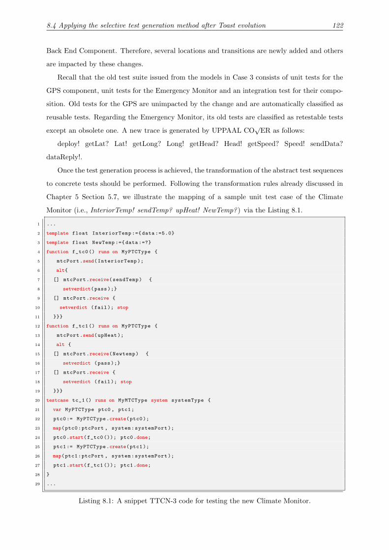
8.4 Applying the selective test generation method after Toast evolution 122
Back End Component. Therefore, several locations and transitions are newly added and others
are impacted by these changes.
Recall that the old test suite issued from the models in Case 3 consists of unit tests for the
GPS component, unit tests for the Emergency Monitor and an integration test for their compo-
sition. Old tests for the GPS are unimpacted by the change and are automatically classified as
reusable tests. Regarding the Emergency Monitor, its old tests are classified as retestable tests
except an obsolete one. A new trace is generated by UPPAAL CO√
ER as follows:
deploy! getLat? Lat! getLong? Long! getHead? Head! getSpeed? Speed! sendData?
dataReply!.
Once the test generation process is achieved, the transformation of the abstract test sequences
to concrete tests should be performed. Following the transformation rules already discussed in
Chapter 5 Section 5.7, we illustrate the mapping of a sample unit test case of the Climate
Monitor (i.e., InteriorTemp! sendTemp? upHeat! NewTemp? ) via the Listing 8.1.
1 ...
2 template float InteriorTemp :={ data :=5.0}
3 template float NewTemp :={ data :=?}
4 function f_tc0() runs on MyPTCType {
5 mtcPort.send(InteriorTemp );
6 alt{
7 [] mtcPort.receive(sendTemp) {
8 setverdict(pass );}
9 [] mtcPort.receive {
10 setverdict (fail); stop
11 }}}
12 function f_tc1() runs on MyPTCType {
13 mtcPort.send(upHeat );
14 alt {
15 [] mtcPort.receive(Newtemp) {
16 setverdict (pass );}
17 [] mtcPort.receive {
18 setverdict (fail); stop
19 }}}
20 testcase tc_1() runs on MyMTCType system systemType {
21 var MyPTCType ptc0 , ptc1;
22 ptc0:= MyPTCType.create(ptc0);
23 map(ptc0:ptcPort , system:systemPort );
24 ptc0.start(f_tc0 ()); ptc0.done;
25 ptc1:= MyPTCType.create(ptc1);
26 map(ptc1:ptcPort , system:systemPort );
27 ptc1.start(f_tc1 ()); ptc1.done;
28 }
29 ...
Listing 8.1: A snippet TTCN-3 code for testing the new Climate Monitor.

8.5 Test distribution and execution 123
It should be noted that the required data structure for the send messages (i.e., actions in the
trace defined with “!”) and the expected one for the receive messages (i.e., actions in the trace
defined with “?”) are declared as a TTCN-3 template. For example, a concrete definition of the
send template InteriorTemp is illustrated in line 2. Another definition of the receive template
NewTemp is given using the matching symbol “?” where the latter may be any float value (see
line 3).
8.5 Test distribution and execution
At this stage, the new abstract test suite is computed after the occurrence of behavioral adap-
tations. In addition, its mapping to the TTCN-3 notation is achieved with the aim of obtaining
concrete tests. Once the latter are compiled by using the TTthree compiler, executable TTCN-3
tests are ultimately produced.
To execute the obtained tests, RTF4ADS is called, more concretely its constraint test place-
ment module as well as its test isolation and execution module. Recall that the first one is
required to distribute the involved tests efficiently over the network while fitting resource and
connectivity constraints. The second one, TT4RT, is used to set up the test isolation layer and
then to perform the test execution.
Since these modules are deeply illustrated in Chapter 7 through the TRMCS case study and
they are also evaluated, we focus in the next section on evaluating and estimating the overhead
of only the TestGenApp module.
8.6 Evaluation and overhead estimation
In this section, we carried out some experiments to measure the overhead introduced by the use
of TestGenApp module when different scenarios of behavioral evolutions take place. Thus, the
main objective is to compute the number of generated traces after each evolution and estimate
the execution time required for the model differencing step, the test classification step and
ultimately for the test generation step with UPPAAL CO√
ER.
Table 8.2 illustrates the studied Toast evolution scenarios and pinpoints the comparison
between our proposal TestGenApp and two well-known regression testing strategies : the Re-
generate All and the Retest All approaches. Recall that the first one consists in generating all
tests from the new evolved model. The second approach deals with re-executing all tests in the
old test suite issued from the old behavioral model and generating new tests that cover only
new added behaviors.

8.6 Evaluation and overhead estimation 124
Table 8.2: Comparison between Regenerate All, Retest All and TestGenApp strategies.
Scenario Case study evolutions Regenerate All Retest All TestGenAppOld New Reusable New Retestable Adapted
1 From Case 0 to Case 1 7 traces 3 4 1 4 2 02 From Case 1 to Case 2 18 traces 7 14 1 14 6 03 From Case 2 to Case 3 14 traces 18 0 1 0 11 44 From Case 3 to Case 4 17 traces 14 2 7 2 7 05 From Case 4 to Case 5 19 traces 17 2 17 2 0 06 From Case 5 to Case 6 28traces 19 9 19 9 0 0
Compared to the Regenerate All technique, our proposal reduces the number of generated
traces as shown in Table 8.2. For instance, the evolution from Case 0 to Case 1 requires the
generation of seven traces with the Regenerate All strategy. The application of TestGenApp
produces the selection of one trace as a reusable test that covers the unimpacted parts of the
model. Moreover, two old traces are classified as retestable tests. Only four traces are newly
generated to cover the newly-added transitions in both the GPS and the Emergency models.
Similarly, instead of generating the full test suite (fourteen traces here) when the Toast
architecture evolves from Case 2 to Case 3, only four traces are adapted in order to cover the
modified transitions in the SUT models. Eleven old traces are still valid and can be re-executed
to prove that these reductive changes have no side effects on the unimpacted parts of the model.
Moreover, one trace is considered as a reusable test.
Concerning the Retest All strategy, we notice that this strategy does not make any analysis
before re-executing tests. Its main limitation consists in re-executing obsolete tests which are
no longer valid. For example, when the Toast evolves from Case 2 to Case 3, four traces from
the old test suite cannot be animated on the new model and then they may cause failure during
test execution. This failure is not caused by a faulty behavior in the system but it is due to the
execution of invalid tests. Consequently, we conclude that selecting valid and relevant tests to
run is highly recommended because it provides a high degree of confidence in the evolved system
without rerunning the overall test suite.
15
20
25
30
Th
e n
um
be
r o
f g
en
era
ted
tra
ces
TestGenApp
0
5
10
1 2 3 4 5 6
Th
e n
um
be
r o
f g
en
era
ted
tra
ces
Toast evolutions
Regenerate All
(a) The number of generated traces.
600
800
1000
1200
1400
Ex
ecu
tio
n t
ime
(m
s)
TestGenApp
0
200
400
1 2 3 4 5 6
Ex
ecu
tio
n t
ime
(m
s)
Toast evolutions
Regenerate All
(b) Execution time for test evolution.
Figure 8.12: Comparison between TestGenApp and Regenerate All approaches.

8.6 Evaluation and overhead estimation 125
Figure 8.12 outlines two experiments that we conducted on a machine with Intel Core i7 and
8 GB of main memory. They show that TestGenApp and Regenerate All approaches depend
highly on the model scale either in terms of generation time or generated traces.
Regarding the number of generated traces after each evolution, we notice that an increase
in the number of involved templates, locations and transitions causes an increase in the test
suite size. As depicted in Figure 8.12a, it is obvious that the TestGenApp produces less traces
than the Regenerate All strategy since it focuses only on covering new behaviors in the evolved
model.
Regarding the generation time, Figure 8.12b shows that this measure follows the model scale,
as well. In case of small systems (e.g., Toast scenarios in Case 1, Case 2 and Case 3), TestGenApp
overhead in terms of test generation time is greater than Regenerate All as it performs several
tasks : model differencing, test classification and test generation (see Figure 8.13). When we
deal with large systems, we notice that the cost of generating the complete test suite is higher
than generating only new behaviors.
400
500
600
700
800
900
Ex
ecu
tio
n t
ime
(m
s)
Test generation
Old test suite
classification
0
100
200
300
1 2 3 4 5 6
Ex
ecu
tio
n t
ime
(m
s)
Toast evolutions
classification
Model differencing
Figure 8.13: The overhead of the TestGenApp modules.
Such experiments show the clear benefits of the TestGenApp especially in case of large scale
models and elementary modifications (i.e., Adding/removing/modifying a location and/or a
transition). It is easier to generate a minimal set of tests from the part of the model impacted
by the dynamic change rather than performing a full regeneration.
Compared to the typical solutions such as Regenerate All and Retest all, TestGenApp gives
an important information about the obtained tests and which parts of the SUT they cover. As
a result, test prioritization can be easily applied in our context and tests covering critical zones
have the priority to be executed first.

8.7 Summary 126
8.7 Summary
This chapter outlined the application of the RTF4ADS framework, more specifically the TestGe-
nApp module, through the dynamic Toast architecture. Several scenarios were studied with the
aim of highlighting the benefits of TestGenApp not only on reducing the number of generated
tests but also on providing a significant status (i.e., reusable, retestable, new and adapted) for
each test in the new test suite. Moreover, the conducted experiments illustrated the merit of
TestGenApp compared to the Retest All as well as the Regenerate All strategies. The next
chapter summarizes the contributions of this thesis, the main results which were obtained, and
outlines areas for future research.

CHAPTER 9
Conclusion
The present chapter concludes firstly this dissertation and summarizes the presented contribu-
tions. Secondly, it discusses some limitations of our work and it proposes some future research
lines to explore.
9.1 Summary
In this thesis, we proposed a runtime testing support that performs platform-independent tests
safely while the SUT is operational in order to check its correctness after dynamic adaptations.
In this respect, we presented several contributions, namely (i.) a dependency analysis approach
for test case selection (ii.) a constrained test component placement method that looks for a
satisfying solution of test component assignment to execution nodes with respect to resource
availability and network connectivity (iii.) a test isolation infrastructure that supports het-
erogeneous components under test in terms of testability options, (iv.) a TTCN-3-based test
system for executing TTCN-3 based tests at runtime (v.) a selective test generation method
that produces relevant test cases covering either modified or newly-added behaviors at runtime
and finally maps the generated abstract test sequences to the TTCN-3 language. The use of
the TTCN-3 standard as a test specification language and as a runtime test execution platform
makes the proposed test system easier to be extended for new systems under test, new com-
ponent models, etc. The RTF4ADS framework, gathering all these provided features was also
introduced.
These contributions were illustrated through two critical and distributed case studies, namely

Conclusion 128
the Teleservices and Remote Medical Care System (TRMCS) and the Toast application. The
first case study was applied to illustrate the applicability of RTF4ADS, more precisely TT4RT
instances for executing safely and efficiently runtime tests in a distributed and resource aware
environment after the occurrence of dynamic structural adaptations. The second case study was
served to empirically validate the feasibility of the selective test generation method, TestGenApp,
when behavioral adaptations take place.
Several experiments were conducted to show the benefits of the RTF4ADS framework and its
components. On the one hand, the experimental results pointed out the efficiency of the proposed
framework and the tolerated cost that it introduced while varying the TRMCS architecture, the
execution environment characteristics (i.e., topology, connectivity, resource availability) and the
number of involved tests. On the other hand, several experiments were carried out to evaluate
our TestGenApp module, and its cost-effective test generation capabilities. For that aim, it was
compared to the classical regression testing techniques namely the Retest All and the Regenerate
All strategies. The results of these experiments indicate that our proposal avoids the re-execution
of obsolete tests, reduces the number newly-generated tests and also provides a significant status
(i.e., reusable, retestable, new and adapted) for each test in the evolved test suite.
9.2 Limitations and Future Work
In spite of the mentioned advantages, this thesis has some limitations which should be addressed.
The remainder of this section outlines some ongoing and future works that will be investigated
in the following order.
9.2.1 Meta-heuristic techniques for the constrained test placement problem
The major problem that we faced while applying RTF4ADS on large-scale environments comes
from the constrained test placement module. Since this module solves the test placement prob-
lem, which is formalized by 0-1 Multiple Knapsack Problem (MKP), by using the Choco solver,
more specifically by an exact approach (i.e., Branch and Bound). This tool requires a long time
to compute an optimal solution fitting the resource and connectivity constraints. Therefore,
we investigate efforts in enhancing the proposed method by using the Tabu Search (TS) meta-
heuristic as a resolution algorithm and performing a parallel exploration of the solution domain.
Due to its notable efficiency in solving large scale size 0-1 MKP, the TS approach may generate
a good approximation of the test placement solution while reducing the execution time and the
memory consumption required for this computation.

Conclusion 129
9.2.2 Extension of the distributed TTCN-3 Test System
The current version of RTF4ADS, more precisely its TT4RT module, focused only on distributing
TTCN-3 test cases. Each one was managed by a Main Test Component (MTC) and may create
several Parallel Test Components in order to execute integration tests. In this case, only MTC
components are involved in the test placement process. To gain more performance and to
alleviate the test workload on the execution environment, it might be interesting to distribute
also PTC Components over the execution nodes. To that aim, we plan to extend TT4RT in
order to avoid the communication overhead introduced by the centralized execution of several
PTCs [88].
9.2.3 Runtime testing of autonomous systems
We dealt in this thesis with dynamically adaptable systems in which dynamic adaptation actions
are done manually by an external adaptation manager. It is highly recommended to enhance our
test framework in order to support autonomous systems which are able to manage themselves
by forming emergent behaviors in response to changing environmental conditions. To do so, we
should include our test system into Monitor-Analyze-Plan-Execute (MAPE-K) loops with the
purpose of automating not only the adaptation process but also the runtime testing process.
In this respect, we plan to adjust RTF4ADS in order to test functional and non-functional
requirements of recent and emergent applications like the smart energy grid [132] and the IoT1-
based eHealth applications [133].
9.2.4 Test generation based on probabilistic model-checking
An emergent research line, which is still in progress, consists in using probabilistic models
during test generation. The key idea here is to apply runtime testing before the occurrence of
dynamic proactive adaptations which consist in making predictions of how the environment or
the system is going to evolve in the near future. To do so, tests have to be generated from
behavioral models that are augmented with probabilities to describe the unpredictable system’s
behavior. Formalisms like Probabilistic Timed Automata (PTAs) can be used to specify the
system behavior. In this context, providing a model-based testing approach that generates
runtime tests from PTAs models while maximizing an utility function should be investigated
[134].
1Internet of Things

Publications
Journal publications
1) Mariam Lahami, Moez Krichen, and Mohamed Jmaiel. Safe and Efficient Runtime
Testing Framework Applied in Dynamic and Distributed Systems, Science of Computer
Programming (SCP), vol. 122, no. C, pp.1-28, 2016.
2) Mariam Lahami, Moez Krichen, and Mohamed Jmaiel. Runtime Testing Approach of
Structural Adaptations for Dynamic and Distributed Systems in the International Journal
of Computer Applications in Technology (IJCAT), vol. 51, no. 4, pp. 259-272, 2015.
3) Mariam Lahami, Moez Krichen, and Mohamed Jmaiel. A distributed Test Architecture
For Adaptable and Distributed Real-Time Systems, dans la Revue Nouvelles Technnologies
d’Information (RNTI), L6 CAL’2011, 2012.
Conference publications
4) Mariam Lahami, Moez Krichen, Hajer Barhoumi and Mohamed Jmaiel. Selective Test
Generation Approach for Testing Dynamic Behavioral Adaptations, in Proceedings of the
27th IFIP International Testing Software and Systems Conference (ICTSS), pp. 224-239,
Sharjah-Dubai, UAE, November 2015. Lecture Notes in Computer science, Springer.
5) Mariam Lahami, Moez Krichen, and Mohamed Jmaiel. Runtime testing framework
for improving quality in dynamic service-based systems, in Proceedings of the second
International Workshop on Quality Assurance for Service-based Applications (QASBA),
in conjunction with ISSTA 2013, July 15-20, Lugano, Switzerland.

Conclusion 131
6) Mariam Lahami and Moez Krichen. Test Isolation Policy for Safe Runtime Validation
of Evolvable Software Systems, in Proceedings of the 22nd IEEE International Confer-
ence on Enabling Technologies: Infrastructure for Collaborative Enterprises (WETICE)
Hammamet, Tunisia, June 2013. IEEE Computer Society.
7) Mariam Lahami, Fairouz Fakhfakh, Moez Krichen, and Mohamed Jmaiel. Towards a
TTCN-3 Test System for Runtime Testing of Adaptable and Distributed Systems, in Pro-
ceedings of the 24th IFIP International Testing Software and Systems Conference (ICTSS),
pp. 71-86, Aalborg, Denmark, November 2012. Lecture Notes in Computer science,
Springer.
8) Mariam Lahami, Moez Krichen, Mariam Bouchakwa and Mohamed Jmaiel. Using
Knapsack Problem Model to Design a Resource Aware Test Architecture for Adaptable
and Distributed systems, in Proceedings of the 24th IFIP International Testing Software
and Systems Conference (ICTSS), pp. 103-118, Aalborg, Denmark, November 2012. Lec-
ture Notes in Computer science, Springer.
Bibliography
[1] M. Utting and B. Legeard, Practical Model-Based Testing: A Tools Approach. Morgan
Kaufmann Publishers Inc., 2006.
[2] ETSI, “Methods for Testing and Specification (MTS), The Testing and Test Control No-
tation version 3, Part 1: TTCN-3 Core Language,” 2005.
[3] G. Behrmann, A. David, and K. G. Larsen, “A Tutorial on UPPAAL,” in Proceeding of
the International School on Formal Methods for the Design of Computer, Communication,
and Software Systems (SFM-RT’04), vol. 3185, 2004, pp. 200–237.
[4] F. Stenh, “Extending a Real-Time Model-Checker to a Test-Case Generation Tool Using
libCoverage,” Master’s thesis, UPPSALA University, 2008.
[5] J. Blom, A. Hessel, B. Jonsson, and P. Pettersson, “Specifying and Generating Test Cases
Using Observer Automata,” in Proceeding of the 5th International Workshop on Formal
Approaches to Software Testing (FATES’05), 2005, pp. 125–139.
[6] J. Kienzle, N. Guelfi, and S. Mustafiz, Transactions on Aspect-Oriented Software De-
velopment VII: A Common Case Study for Aspect-Oriented Modeling. Springer Berlin
Heidelberg, 2010, ch. Crisis Management Systems: A Case Study for Aspect-Oriented
Modeling, pp. 1–22.
[7] I.-Y. Chen and C.-H. Tsai, “Pervasive Digital Monitoring and Transmission of Pre-Care
Patient Biostatics with an OSGi, MOM and SOA Based Remote Health Care System,”
in Proceeding of the 6th Annual IEEE International Conference on Pervasive Computing
and Communications (PerCom’06), 2008, pp. 704–709.

Bibliography 133
[8] U. Varshney, “Pervasive Healthcare and Wireless Health Monitoring,” Mobile Networks
and Applications, vol. 12, no. 2-3, pp. 113–127, 2007.
[9] S. T. S. Thong, C. T. Han, and T. A. Rahman, “Intelligent Fleet Management System with
Concurrent GPS GSM Real-Time Positioning Technology,” in Proceeding of the 7th In-
ternational Conference on Intelligent Transport Systems Telecommunications (ITST’07),
2007, pp. 1–6.
[10] D. Brenner, C. Atkinson, R. Malaka, M. Merdes, B. Paech, and D. Suliman, “Reducing
Verification Effort in Component-based Software Engineering Through Built-In Testing,”
Information Systems Frontiers, vol. 9, no. 2-3, pp. 151–162, 2007.
[11] C. Murphy, G. Kaiser, I. Vo, and M. Chu, “Quality Assurance of Software Applications
Using the In Vivo Testing Approach,” in Proceedings of the 2nd International Conference
on Software Testing Verification and Validation (ICST’09), 2009, pp. 111–120.
[12] M. Merdes, R. Malaka, D. Suliman, B. Paech, D. Brenner, and C. Atkinson, “Ubiquitous
RATs: How Resource-Aware Run-Time Tests Can Improve Ubiquitous Software Systems,”
in Proceedings of the 6th International Workshop on Software Engineering and Middleware
(SEM’06), 2006, pp. 55–62.
[13] E. Piel and A. Gonzalez-Sanchez, “Data-flow Integration Testing Adapted to Runtime
Evolution in Component-Based Systems,” in Proceedings of the ESEC/FSE Workshop on
Software Integration and Evolution@runtime, 2009, pp. 3–10.
[14] D. Niebuhr and A. Rausch, “Guaranteeing Correctness of Component Bindings in Dynamic
Adaptive Systems Based on Runtime Testing,” in Proceedings of the 4th International
Workshop on Services Integration in Pervasive Environments (SIPE’09), 2009, pp. 7–12.
[15] A. Gonzalez-Sanchez, E. Piel, and H.-G. Gross, “Architecture Support for Runtime Inte-
gration and Verification of Component-based Systems of Systems,” in Proceeding of the
Automated Software Engineering - Workshops, (ASE Workshops’08), 2008, pp. 41–48.
[16] X. Bai, D. Xu, G. Dai, W.-T. Tsai, and Y. Chen, “Dynamic Reconfigurable Testing of
Service-Oriented Architecture,” in Proceeding of the 31st Annual International Computer
Software and Applications Conference (COMPSAC’07), 2007, pp. 368–378.
[17] M. Greiler, H.-G. Gross, and A. van Deursen, “Evaluation of Online Testing for Services
– A Case Study,” in Proceeding of the 2nd International Workshop on Principles of Engi-
neering Service-Oriented System, 2010, pp. 36–42.

Bibliography 134
[18] J. Hielscher, R. Kazhamiakin, A. Metzger, and M. Pistore, “A Framework for Proactive
Self-adaptation of Service-Based Applications Based on Online Testing,” in Proceedings
of the 1st European Conference on Towards a Service-Based Internet (ServiceWave’08),
2008, pp. 122–133.
[19] E. Piel, A. Gonzalez-Sanchez, and H.-G. Groß, “Automating Integration Testing of Large-
Scale Publish/Subscribe Systems,” in Principles and Applications of Distributed Event-
Based Systems, 2010, pp. 140–163.
[20] T. M. King, A. A. Allen, R. Cruz, and P. J. Clarke, “Safe Runtime Validation of Behavioral
Adaptations in Autonomic Software,” in Proceedings of the 8th International Conference
on Autonomic and Trusted Computing (ATC’11), 2011, pp. 31–46.
[21] A. E. Ramirez, B. Morales, and T. M. King, “A Self-Testing Autonomic Job Scheduler,”
in Proceedings of the 46th Annual Southeast Regional Conference on XX (ACM-SE’08),
2008, pp. 304–309.
[22] E. M. Fredericks, B. DeVries, and B. H. C. Cheng, “Towards Run-time Adaptation of
Test Cases for Self-adaptive Systems in the Face of Uncertainty,” in Proceedings of the
9th International Symposium on Software Engineering for Adaptive and Self-Managing
Systems (SEAMS’14), 2014, pp. 17–26.
[23] M. Lahami, M. Krichen, and M. Jmaıel, “A distributed Test Architecture For Adaptable
and Distributed Real-Time Systems,” Dans la revue Nouvelles Technologies d’Information
(RNTI), L6 CAL’2011, 2012.
[24] M. Lahami, M. Krichen, M. Bouchakwa, and M. Jmaıel, “Using Knapsack Problem Model
to Design a Resource Aware Test Architecture for Adaptable and Distributed Systems,”
in Proceedings of the 24th IFIP WG 6.1 International Conference Testing Software and
Systems (ICTSS’12), 2012, pp. 103–118.
[25] N. Jussien, G. Rochart, and X. Lorca, “Choco: an Open Source Java Constraint Program-
ming Library,” in Proceeding of the Workshop on Open-Source Software for Integer and
Contraint Programming (OSSICP’08), 2008, pp. 1–10.
[26] M. Lahami, F. Fakhfakh, M. Krichen, and M. Jmaıel, “Towards a TTCN-3 Test System
for Runtime Testing of Adaptable and Distributed Systems,” in Proceedings of the 24th
IFIP WG 6.1 International Conference Testing Software and Systems (ICTSS’12), 2012,
pp. 71–86.

Bibliography 135
[27] ETSI, “Methods for Testing and Specification (MTS), The Testing and Test Control No-
tation version 3, Part 5: TTCN-3 Runtime Interface (TRI),” 2005.
[28] ——, “Methods for Testing and Specification (MTS), The Testing and Test Control No-
tation version 3, Part 6: TTCN-3 Control Interface (TCI),” 2005.
[29] M. Lahami and M. Krichen, “Test Isolation Policy for Safe Runtime Validation of Evolvable
Software Systems,” in Proceedings of the 22nd IEEE International Conference on Enabling
Technologies: Infrastructure for Collaborative Enterprises (WETICE’13), 2013, pp. 377–
382.
[30] M. Lahami, M. Krichen, H. Barhoumi, and M. Jmaıel, “Selective Test Generation Ap-
proach for Testing Dynamic Behavioral Adaptations,” in Proceedings of the 27th IFIP
WG 6.1 International Conference on Testing Software and Systems (ICTSS’15), 2015,
pp. 224–239.
[31] H. Leung and L. White, “Insights into regression testing [software testing],” in Proceedings
of the International Conference on Software Maintenance (ICSM’89), 1989, pp. 60–69.
[32] M. Lahami, M. Krichen, and M. Jmaıel, “Runtime Testing Framework for Improving Qual-
ity in Dynamic Service-based Systems,” in Proceedings of the 2nd International Workshop
on Quality Assurance for Service-based Applications (QASBA’13), in conjunction with
(ISSTA’13), 2013, pp. 17–24.
[33] ——, “Safe and Efficient Runtime Testing Framework Applied in Dynamic and Distributed
Systems,” Science of Computer Programming (SCP), vol. 122, no. C, pp. 1–28, 2016.
[34] J. Kramer and J. Magee, “Dynamic Configuration for Distributed Systems,” IEEE Trans-
actions on Software Engineering (TSE), vol. 11, no. 4, pp. 424–436, 1985.
[35] A. Ketfi, N. Belkhatir, and P. yves Cunin, “Dynamic Updating of Component-Based Appli-
cations,” in Proceeding of the International Conference on Software Engineering Research
and Practice (SERP’02), 2002.
[36] E. Bruneton, T. Coupaye, M. Leclercq, V. Quema, and J.-B. Stefani, “An Open Compo-
nent Model and Its Support in Java,” in Proceeding of the 7th International International
ACM Sigsoft Symposium on Component-Based Software Engineering (CBSE’04), 2004,
pp. 7–22.
[37] T. Chaari and K. Fakhfakh, “Semantic Modeling and Reasoning at Runtime for Au-
tonomous Systems Engineering,” in Proceeding of the 9th International Conference on

Bibliography 136
Ubiquitous Intelligence Computing and Autonomic Trusted Computing (UIC/ATC’12),
2012, pp. 415–422.
[38] E. Mezghani and R. B. Halima, “DRF4SOA: A Dynamic Reconfigurable Framework for
Designing Autonomic Application Based on SOA,” in Proceeding of the 21st IEEE Interna-
tional Conference on Enabling Technologies: Infrastructure for Collaborative Enterprises
(WETICE’12), 2012, pp. 95–97.
[39] OSGi service gateway specification, Release 4 , Open Services Gateway Initiative, 2005.
[40] J. C. Laprie, A. Avizienis, and H. Kopetz, Eds., Dependability: Basic Concepts and Ter-
minology. Springer-Verlag New York, Inc., 1992.
[41] G. Tamura, N. Villegas, H. Muller, J. Sousa, B. Becker, G. Karsai, S. Mankovskii, M. Pezze,
W. Schafer, L. Tahvildari, and K. Wong, “Towards Practical Runtime Verification and
Validation of Self-Adaptive Software Systems,” in Software Engineering for Self-Adaptive
Systems II, 2013, pp. 108–132.
[42] B. Cheng, K. Eder, M. Gogolla, L. Grunske, M. Litoiu, H. Muller, P. Pelliccione, A. Perini,
N. Qureshi, B. Rumpe, D. Schneider, F. Trollmann, and N. Villegas, “Using Models at
Runtime to Address Assurance for Self-Adaptive Systems,” in [email protected], 2014, pp.
101–136.
[43] B. Morin, O. Barais, J.-M. Jezequel, F. Fleurey, and A. Solberg, “Models@Runtime to
Support Dynamic Adaptation,” Computer, vol. 42, no. 10, pp. 44–51, 2009.
[44] P. Inverardi and M. Mori, “Model Checking Requirements at Run-time in Adaptive
Systems,” in Proceedings of the 8th Workshop on Assurances for Self-adaptive Systems
(ASAS’11), 2011, pp. 5–9.
[45] R. Freedman, “Testability of Software Components,” IEEE Transactions on Software En-
gineering, vol. 17, no. 6, pp. 553 –564, 1991.
[46] G. Din, S. Tolea, and I. Schieferdecker, “Distributed Load Tests with TTCN-3,” in Proceed-
ings of the 18th IFIP TC6/WG6.1 International Conference for Testing of Communicating
Systems (TestCom’06), 2006, pp. 177–196.
[47] P. Stocks and D. Carrington, “A Framework for Specification-Based Testing,” IEEE Trans-
actions on Software Engineering (TSE), vol. 22, no. 11, pp. 777–793, 1996.

Bibliography 137
[48] L. Liu, H. Miao, and X. Zhan, “A Framework for Specification-Based Class Testing,”
in Proceeding of the 8th International Conference on Engineering of Complex Computer
Systems (ICECCS’02), 2002, pp. 153–162.
[49] M. Sarma, D. Kundu, and R. Mall, “Automatic Test Case Generation from UML Se-
quence Diagram,” in International Conference on Advanced Computing and Communica-
tions (ADCOM’07), 2007, pp. 60–67.
[50] S. K. Swain and D. P. Mohapatra, “Test Case Generation from Behavioral UML Models,”
International Journal of Computer Applications, vol. 6, no. 8, pp. 5–11, 2010.
[51] A. J. Maalej, M. Krichen, and M. Jmaıel, “Model-Based Conformance Testing of WS-
BPEL Compositions,” in Proceeding of the 4th IEEE International Workshop on Software
Test Automation (STA’12) in conjunction with (COMPSAC ’12), 2012, pp. 452–457.
[52] A. Calvagna and A. Gargantini, “A Logic-based Approach to Combinatorial Testing With
Constraints,” in Proceedings of the 2nd International Conference on Tests and Proofs
(TAP’08), 2008, pp. 66–83.
[53] L. Zhang, T. Xie, L. Zhang, N. Tillmann, J. De Halleux, and H. Mei, “Test Generation
via Dynamic Symbolic Execution for Mutation Testing,” in Procceeding of the 26th IEEE
International Conference on Software Maintenance (ICSM’10), 2010, pp. 1–10.
[54] S. Khurshid, C. S. Pasareanu, and W. Visser, “Generalized Symbolic Execution for Model
Checking and Testing,” in Proceedings of the 9th International Conference on Tools and
Algorithms for the Construction and Analysis of Systems (TACAS’03), 2003, pp. 553–568.
[55] M. Krichen, “A Formal Framework for Conformance Testing of Distributed Real-Time
Systems,” in Proceedings of the 14th International Conference On Principles Of Distributed
Systems, (OPODIS’10), 2010.
[56] A. Khoumsi, “Testing Distributed Real Time Systems Using a Distributed Test Ar-
chitecture,” in Proceeding of the IEEE Symposium on Computers and Communications
(ISCC’01), 2001, pp. 648–654.
[57] S. Siddiquee and A. En-Nouaary, “Two Architectures for Testing Distributed Real-
Time Systems,” in Proceeding of the 2nd Information and Communication Technologies
(ICTTA’06), vol. 2, 2006, pp. 3388–3393.

Bibliography 138
[58] A. Tarhini and H. Fouchal, “Conformance Testing of Real-Time Component Based Sys-
tems,” in Proceeding of the International School and Symposium on Advanced Distributed
Systems (ISSADS’05), 2005, pp. 167–181.
[59] A. Khoumsi, “Testing Distributed Real-Time reactive Systems Using a centralized Test
Architecture,” in Proceeding of the North Atlantic Test Workshop (NATW), 2001, pp.
648–654.
[60] M. J. Harrold, “Testing: a roadmap,” in Proceedings of the 16th IEEE Conference on The
Future of Software Engineering (ICSE’00), 2000, pp. 61–72.
[61] G. Rothermel and M. J. Harrold, “A Safe, Efficient Regression Test Selection Technique,”
ACM Transactions on Software Engineering and Methodology, vol. 6, pp. 173–210, 1997.
[62] T. L. Graves, M. J. Harrold, J.-M. Kim, A. Porter, and G. Rothermel, “An Empirical Study
of Regression Test Selection Techniques,” ACM Transactions on Software Engineering and
Methodology (TOSEM), vol. 10, no. 2, pp. 184–208, 2001.
[63] I. Granja and M. Jino, “Techniques for Regression Testing: Selecting Test Case Sets Tai-
lored to Possibly Modified Functionalities,” in Proceedings of the 3rd European Conference
on Software Maintenance and Reengineering (CSMR’99), 1999, pp. 2–22.
[64] B. Korel, L. Tahat, and B. Vaysburg, “Model Based Regression Test Reduction Using De-
pendence Analysis,” in Proceedings of the 18th IEEE International Conference on Software
Maintenance (ICSM’02), 2002, pp. 214–223.
[65] L. C. Briand, Y. Labiche, and S. He, “Automating Regression Test Selection Based on
UML Designs,” Information & Software Technology, vol. 51, no. 1, pp. 16–30, 2009.
[66] E. Fourneret, F. Bouquet, F. Dadeau, and S. Debricon, “Selective Test Generation Method
for Evolving Critical Systems,” in Proceedings of the 2011 IEEE 4th International Con-
ference on Software Testing, Verification and Validation Workshops (ICSTW’11), 2011,
pp. 125–134.
[67] IEEE, “IEEE Standard Glossary of Software Engineering Terminology,” 1990.
[68] A. Gonzalez, E. Piel, and H.-G. Gross, “A Model for the Measurement of the Runtime
Testability of Component-Based Systems,” in Proceedings of the IEEE International Con-
ference on Software Testing, Verification, and Validation Workshops (ICSTW’09), 2009,
pp. 19–28.

Bibliography 139
[69] Y. Wang, G. King, D. Patel, S. Patel, and A. Dorling, “On Coping With Real-time
Software Dynamic Inconsistency by Built-In Tests,” Annals of Software Engineering, vol. 7,
no. 1-4, pp. 283–296, 1999.
[70] J. Vincent, G. King, P. Lay, and J. Kinghorn, “Principles of Built-In-Test for Run-Time-
Testability in Component-Based Software Systems,” Software Quality Control, vol. 10,
no. 2, pp. 115–133, 2002.
[71] C. Mao, “AOP-based Testability Improvement for Component-based Software,” in Pro-
ceedings of the 31st Annual International Computer Software and Applications Conference
(COMPSAC ’07), 2007, pp. 547–552.
[72] L. Chu, K. Shen, H. Tang, T. Yang, and J. Zhou, “Dependency Isolation for Thread-based
Multi-tier Internet Services,” in Proceeding of the 24th Annual Joint Conference of the
IEEE Computer and Communications Societies (INFOCOM’05), 2005, pp. 796–806.
[73] A. Beszedes, T. Gergely, L. Schrettner, J. Jasz, L. Lango, and T. Gyimothy, “Code
Coverage-Based Regression Test Selection and Prioritization in WebKit,” in Proceeding
of the 28th IEEE International Conference on Software Maintenance (ICSM’12), 2012,
pp. 46–55.
[74] B. Korel and A. M. Al-Yami, “Automated Regression Test Generation,” ACM SIGSOFT
Software Engineering Notes, vol. 23, no. 2, pp. 143–152, 1998.
[75] O. Pilskalns, G. Uyan, and A. Andrews, “Regression Testing UML Designs,” in Proceedings
of the 22nd IEEE International Conference on Software Maintenance (ICSM’06), 2006,
pp. 254–264.
[76] Y. Chen, R. L. Probert, and H. Ural, “Model-based Regression Test Suite Generation Using
Dependence Analysis,” in Proceedings of the 3rd International Workshop on Advances in
Model-based Testing (A-MOST’07), 2007, pp. 54–62.
[77] M. J. Harrold, “Architecture-Based Regression Testing of Evolving Systems,” in Proceeding
of the International Workshop on the Role of Software Architecture in Testing and Analysis
(ROSATEA’98), 1998, pp. 73–77.
[78] H. Muccini, M. S. Dias, and D. J. Richardson, “Software Architecture-Based Regression
Testing,” Journal of Systems and Software, vol. 79, no. 10, pp. 1379–1396, 2006.
[79] G. Rothermel and M. Harrold, “Analyzing Regression Test Selection Techniques,” IEEE
Transactions on Software Engineering, vol. 22, no. 8, pp. 529–551, 1996.

Bibliography 140
[80] B. Korel, L. Tahat, and M. Harman, “Test Prioritization Using System Models,” in Pro-
ceedings of the 21st IEEE International Conference on Software Maintenance(ICSM’05),
2005, pp. 559–568.
[81] E. M. Fredericks, A. J. Ramirez, and B. H. C. Cheng, “Towards Run-time Testing of Dy-
namic Adaptive Systems,” in Proceedings of the 8th International Symposium on Software
Engineering for Adaptive and Self-Managing Systems (SEAMS’13), 2013, pp. 169–174.
[82] X. Bai, G. Dai, D. Xu, and W.-T. Tsai, “A Multi-Agent Based Framework for Collabo-
rative Testing on Web Services,” in Proceedings of the 4th IEEE Workshop on Software
Technologies for Future Embedded and Ubiquitous Systems, and the 2nd International
Workshop on Collaborative Computing, Integration, and Assurance (SEUS-WCCIA’06),
2006, pp. 205–210.
[83] M. Akour, A. Jaidev, and T. M. King, “Towards Change Propagating Test Models in
Autonomic and Adaptive Systems,” in Proceedings of the 18th IEEE International Con-
ference and Workshops on Engineering of Computer-Based Systems (ECBS’11), 2011, pp.
89–96.
[84] J. O. Kephart and D. M. Chess, “The Vision of Autonomic Computing,” Computer, vol. 36,
no. 1, pp. 41–50, 2003.
[85] D. Suliman, B. Paech, L. Borner, C. Atkinson, D. Brenner, M. Merdes, and R. Malaka,
“The MORABIT Approach to Runtime Component Testing,” in Proceedings of the 30th
Annual International Computer Software and Applications Conference (COMPSAC ’06),
2006, pp. 171–176.
[86] P. H. Deussen, G. Din, and I. Schieferdecker, “A TTCN-3 Based Online Test and Validation
Platform for Internet Services,” in Proceedings of the 6th International Symposium on
Autonomous Decentralized Systems (ISADS’03), 2003.
[87] S. Schulz and T. Vassiliou-Gioles, “Implementation of TTCN-3 Test Systems using the
TRI,” in Proceedings of the IFIP 14th International Conference on Testing Communicating
Systems (TestCom’02), 2002, pp. 425–442.
[88] I. Schieferdecker and T. Vassiliou-Gioles, “Realizing Distributed TTCN-3 Test Systems
With TCI,” in Proceedings of the 15th IFIP International Conference on Testing of Com-
municating Systems (TestCom’03), 2003.

Bibliography 141
[89] B. Stepien, L. Peyton, and P. Xiong, “Framework Testing of Web Applications Using
TTCN-3,” International Journal on Software Tools for Technology Transfer (STTT),
vol. 10, no. 4, pp. 371–381, 2008.
[90] Q. L. Ying Li, “Research on Web Application Software Load Test Using Technology of
TTCN-3,” American Journal of Engineering and Technology Research, vol. 11, pp. 3686–
3690, 2011.
[91] I. Schieferdecker, G. Din, and D. Apostolidis, “Distributed Functional and Load Tests for
Web Services,” International Journal on Software Tools for Technology Transfer (STTT),
vol. 7, pp. 351–360, 2005.
[92] C. Rentea, I. Schieferdecker, and V. Cristea, “Ensuring Quality of Web Applications by
Client-side Testing Using TTCN-3,” in Proceeding of the 21th IFIP International Con-
ference on Testing of Communicating Systems joint with 9th International Workshop on
Formal Approaches to Testing of Software (TestCom/Fates’09), 2009.
[93] J. C. Okika, A. P. Ravn, Z. Liu, and L. Siddalingaiah, “Developing a TTCN-3 Test Harness
for Legacy Software,” in Proceedings of the International Workshop on Automation of
Software Test, 2006, pp. 104–110.
[94] D. A. Serbanescu, V. Molovata, G. Din, I. Schieferdecker, and I. Radusch, “Real-Time
Testing with TTCN-3,” in Proceeding of the 20th IFIP International Conference on Testing
of Communicating Systems joint with 8th International Workshop on Formal Approaches
to Testing of Software (TestCom/Fates’08), 2008, pp. 283–301.
[95] E. Piel, A. Gonzalez-Sanchez, and H.-G. Gross, “Built-in Data-Flow Integration Test-
ing in Large-Scale Component-Based Systems,” in Proceedings of the 22nd IFIP WG 6.1
International Conference on Testing Software and Systems (ICTSS’10), 2010, pp. 79–94.
[96] M. Lahami, M. Krichen, and M. Jmaıel, “Runtime Testing Approach of Structural Adap-
tations for Dynamic and Distributed Systems,” International Journal of Computer Appli-
cations in Technology (IJCAT), vol. 51, no. 4, pp. 259–272, 2015.
[97] B. Li, Y. Zhou, Y. Wang, and J. Mo, “Matrix-based Component Dependence Represen-
tation and Its Applications in Software Quality Assurance,” ACM SIGPLAN Notices,
vol. 40, no. 11, pp. 29–36, 2005.

Bibliography 142
[98] S. Alhazbi and A. Jantan, “Dependencies Management in Dynamically Updateable
Component-Based Systems,” Journal of Computer Science, vol. 3, no. 7, pp. 499–505,
2007.
[99] B. Qu, Q. Liu, and Y. Lu, “A Framework for Dynamic Analysis Dependency in
Component-Based System,” in the 2nd International Conference on Computer Engineer-
ing and Technology (ICCET’10), 2010, pp. 250–254.
[100] M. Larsson and I. Crnkovic, “Configuration Management for Component-Based Systems,”
in Proceeding of the 10th International Workshop on Software configuration Management
(SCM’01), 2001.
[101] Y. E. Ioannidis and R. Rantakrishnan, “Efficient Transitive Closure Algorithms,” in Pro-
ceedings of the 14th International Conference on Very Large Databases (VLDB’88), 1988.
[102] B. Jaumard and M. Minoux, “An Efficient Algorithm for The Transitive Closure and a Lin-
ear Worst-case Complexity Result for a Class of Sparse Graphs,” Information Processing
Letters, vol. 22, no. 4, pp. 163–169, 1986.
[103] K. Ghedira and B. Dubuisson, Constraint Satisfaction Problems. John Wiley & Sons,
Inc., 2013, ch. Foundations of CSP, pp. 1–28.
[104] A. Hessel, K. G. Larsen, B. Nielsen, P. Pettersson, and A. Skou, “Time-Optimal Real-Time
Test Case Generation Using UPPAAL,” in Proceeding of the 3rd International Workshop
on Formal Approaches to Testing of Software, (FATES’03), 2003, pp. 114–130.
[105] A. Hessel, K. G. Larsen, M. Mikucionis, B. Nielsen, P. Pettersson, and A. Skou, “Testing
Real-time Systems Using UPPAAL,” in Formal Methods and Testing, 2008, pp. 77–117.
[106] U. Kelter, J. Wehren, and J. Niere, “A Generic Difference Algorithm for UML Models,”
in Proceeding of the Software Engineering 2005, Fachtagung des GI-Fachbereichs Soft-
waretechnik, 2005, pp. 105–116.
[107] H. Muccini, “Using Model Differencing for Architecture-level Regression Testing,” in Pro-
ceeding of the 33rd EUROMICRO Conference on Software Engineering and Advanced Ap-
plications, 2007, pp. 59–66.
[108] K. Bogdanov and N. Walkinshaw, “Computing the Structural Difference between State-
Based Models,” in Proceeding of the 16th Working Conference on Reverse Engineering,
2009, pp. 177–186.
Bibliography 143
[109] A. Hessel and P. Pettersson, “COVER– A Real-Time Test Case Generation Tool,” in
Proceeding of the 7th International Workshop on Formal Approaches to Testing of Software
(FATES’07), 2007.
[110] ——, “A global algorithm for model-based test suite generation,” Electronic Notes in
Theoretical Computer Science, vol. 190, no. 2, pp. 47–59, 2007.
[111] M. Beyer, W. Dulz, and F. Zhen, “Automated TTCN-3 Test Case Generation by Means
of UML Sequence Diagrams and Markov Chains,” in Proceeding of the 12th Asian Test
Symposium (ATS’03), 2003, pp. 102–105.
[112] M. Ebner, “TTCN-3 Test Case Generation from Message Sequence Charts,” in Proceeding
of the Workshop on Integrated-reliability with Telecommunications and UML Languages
(WITUL’04), 2004.
[113] J. P. Ernits, A. Kull, K. Raiend, and J. Vain, “Generating TTCN-3 Test Cases from EFSM
Models of Reactive Software Using Model Checking,” in Informatik 2006 - Informatik fur
Menschen, Band 2, Beitrage der 36. Jahrestagung der Gesellschaft fur Informatik e.V.
(GI), 2.-6, 2006, pp. 241–248.
[114] D. E. Vega, G. Din, and I. Schieferdecker, “Application of TTCN-3 Test Language to Test-
ing Information Systems in eHealth Domain,” in Procceding of the International Confer-
ence on Multimedia Computing and Information Technology (MCIT’10), 2010, pp. 21–24.
[115] N. Katanic, T. Nenadic, S. Desic, and L. Skorin-Kapov, “Automated Generation of TTCN-
3 Test Scripts for SIP-based Calls,” in Proceedings of the 33rd International Conven-
tion on Information and Communication Technology, Electronics and Microelectronics
(MIPRO’10), 2010, pp. 423–427.
[116] X. Zhao and W. Zheng, “Research and Application on MBT and TTCN-3 Based Au-
tomatic Testing Approach,” in Proceeding of the International Conference on Computer
Application and System Modeling (ICCASM’10), vol. 1, 2010, pp. 481–485.
[117] J. Zander, Z. R. Dai, I. Schieferdecker, and G. Din, “From u2tp models to executable tests
with ttcn-3 - an approach to model driven testing -,” in Proceedings of 17th IFIP TC6/WG
6.1 International Conference for Testing Communicating Systems (TestCom’05), 2005, pp.
289–303.
[118] T. V. Axel Rennoch, Claude Desroches and I. Schieferdecker, “TTCN-3 Quick Reference
Card,” 2016.

Bibliography 144
[119] T. Technologies, “TTthree - Compile TTCN-3 modules into test executables,”
http://www.testingtech.com/products/, 2008.
[120] U. Brandes, M. Eiglsperger, I. Herman, M. Himsolt, and M. S. Marshall, “GraphML
Progress Report,” in Proceeding of the International Symposium on Graph Drawing
(GD’01), 2001, p. 501–512.
[121] D. Pizzocaro, S. Chalmers, and A. Preece, “Sensor Assignment In Virtual Environments
Using Constraint Programming,” in Proceedings of the 27th SGAI International Confer-
ence on Innovative Techniques and Applications of Artificial Intelligence (AI’07), 2007,
pp. 333–338.
[122] F. Hermenier, A. Lebre, and J. Menaud, “Cluster-Wide Context Switch of Virtualized
Jobs,” in Proceedings of the 19th ACM International Symposium on High Performance
Distributed Computing, (HPDC’10), 2010, pp. 658–666.
[123] G. Kiczales, E. Hilsdale, J. Hugunin, M. Kersten, J. Palm, and W. G. Griswold, “An
Overview of AspectJ,” in Proceedings of the 15th European Conference on Object-Oriented
Programming (ECOOP’01), 2001, pp. 327–353.
[124] P. Inverardi, C. Mangano, F. Russo, and S. Balsamo, “Performance Evaluation of a Soft-
ware Architecture: a Case Study,” in Proceedings of the 9th International Workshop on
Software Specification and Design, 1998, pp. 116–125.
[125] M. Zouari, C. Diop, and E. Exposito, “Multilevel and Coordinated Self-management in
Autonomic Systems based on Service Bus,” Journal of Universal Computer Science (UCS),
vol. 20, no. 3, pp. 431–460, 2014.
[126] J. Bourcier, “Auto-Home: une plate-forme pour la gestion autonomique d’applications
pervasives,” Ph.D. dissertation, Universite Joseph Fourier, 2008.
[127] T. Gu, H. Pung, and D. Zhang, “Toward an OSGi-based Infrastructure for Context-Aware
Applications,” IEEE Pervasive Computing, vol. 3, no. 4, pp. 66–74, 2004.
[128] D. Tkachenko, N. Kornet, E. Andrievsky, A. Lagunov, D. Kravtsov, and A. Kurbanow,
“Management of IEEE 1394 Video Devices in OSGi Networks,” in Proceeding of the 10th
IEEE International Symposium on Consumer Electronics (ISCE’06), 2006, pp. 1–6.
[129] ETSI, “Methods for Testing and Specification (MTS), The Testing and Test Control No-
tation version 3, TTCN-3 Language Extensions: TTCN-3 Performance and Real Time
Testing,” 2015.

Bibliography 145
[130] J. McAffer, P. VanderLei, and S. Archer, OSGi and Equinox : Creating Highly Modular
Java Systems. Addison-Wesley, 2010.
[131] F. D. Angelis, M. R. D. Berardini, H. Muccini, and A. Polini, “CASSANDRA : An Online
Failure Prediction Strategy for Dynamically Evolving Systems,” in Proceedings of the 16th
International Conference on Formal Engineering Methods (ICFEM’14), 2014, pp. 107–122.
[132] B. Eberhardinger, “Testing Self-organizing, Adaptive Systems,” in Proceedings of the
IEEE International Conference on Self-Adaptive and Self-Organizing Systems Workshops
(SASOW’15), 2015, pp. 140–145.
[133] A. B. Torjusen, H. Abie, E. Paintsil, D. Trcek, and A. Skomedal, “Towards Run-Time
Verification of Adaptive Security for IoT in eHealth,” in Proceedings of the 8th European
Conference on Software Architecture Workshops (ECSAW’14), 2014, pp. 1–8.
[134] G. A. Moreno, J. Camara, D. Garlan, and B. Schmerl, “Proactive Self-adaptation Under
Uncertainty: A Probabilistic Model Checking Approach,” in Proceedings of the 10th Joint
Meeting on Foundations of Software Engineering, 2015, pp. 1–12.
[135] ETSI, “Methods for Testing and Specification (MTS), The Testing and Test Control No-
tation version 3, Part 2: TTCN-3 Tabular presentation Format (TFT),” 2005.
[136] ——, “Methods for Testing and Specification (MTS), The Testing and Test Control No-
tation version 3, Part 3: TTCN-3 Graphical presentation Format (GFT),” 2005.
[137] C. Cotta and J. Troya, “A Hybrid Genetic Algorithm for The 0-1 Multiple Knapsack
Problem,” Artificial Neural Nets and Genetic Algorithms, vol. 3, pp. 251–255, 1998.
[138] P. Pospıchal, J. Schwarz, and J. Jaros, “Parallel Genetic Algorithm Solving 0/1 Knapsack
Problem Running on the GPU,” in Proceeding of the 16th International Conference on
Soft Computing Systems (ICSCS’10), 2010, pp. 64–70.
[139] J. Puchinger, G. R. Raidl, and U. Pferschy, “The Core Concept for the Multidimensional
Knapsack Problem,” in Proceeding of the 6th European Conference on Evolutionary Com-
putation in Combinatorial Optimization (EvoCOP’06), 2006, pp. 195–208.
[140] S. Martello and P. Toth, “Solution of The Zero-One Multiple Knapsack Problem,” Euro-
pean Journal of Operational Research, vol. 4, no. 4, pp. 276 –283, 1980.
[141] K. Jansen, “Parametrized Approximation Scheme for The Multiple Knapsack Prob-
lem,” in Proceedings of the 20th Annual ACM-SIAM Symposium on Discrete Algorithms
(SODA’09), 2009, pp. 665–674.

APPENDIX A
Background Material on The TTCN-3 Standard
TTCN-3 is a test-specification language which is usually used for black-box testing of distributed
or even centralized reactive systems. It supports three different presentation formats, namely:
the textual core language [2], the tabular presentation format [135] and the graphical presen-
tation format [136] for test suite specification. Throughout this thesis, the textual notation is
adopted.
A.1 TTCN-3 core language
This section is devoted to give an insight into TTCN-3 core language [2]. As outlined in Figure
A.1, a module is a top-level unit of TTCN-3. It can be compiled or interpreted, it may include
a single or several test cases, and it can be used as a library by other modules.
Each module comprises a definition part and a control part. The definition part includes
definitions of data types1, constants, test data templates, test components, communication ports,
functions, test cases, etc. From a test configuration perspective, TTCN-3 allows the definition
of several test components with well-defined communication ports and an explicit test system
interface. Each test component is an instance of a component type definition. It can be a Main
Test component (MTC) or Parallel Test Component (PTC). An MTC is the basis of a test case
and is created and started automatically at the beginning of each test case execution. It is
responsible for managing the overall test process. Consequently, it handles the creation and the
startup of PTC components.
1TTCN-3 has a number of pre-defined basic data types (e.g., integer, float, etc.) as well as structured types

Appendices 147
TTCN-3 Module
Data Types
Test Data
Test System
Architecture
Test Behavior
Module Definitions Part
Messages
Signatures
Components
Ports
Altsteps
Functions
Predefined Types
User-defined Types
Constants
Variables
Templates
Declarations
Test Behavior Functions
Test cases
Test Case Executions
Module Control Part
Figure A.1: Core elements in the TTCN-3 module.
Several forms of test behaviors are executed by these components. They can be defined
within functions, altsteps2 and test cases. The control part is considered as “the main function”
of the module. It describes the execution sequence of test cases. It gathers verdicts delivered by
test cases and according to them can decide the next execution steps.
Listing A.1 presents a code snippet of the module definition MyModule, which is saved in a
file calledMyModule.ttcn:
module MyModule{
// Definitions part
import from OtherModule all;
type integer MyPosInt (0 .. infinity );
testcase tc_myFirstCase () runs on MyComponent system MyTsi
{
...
}
// Control part
control
{
execute(tc_myFirstCase (), 10.0); // Maximum execution time 10.0 seconds
execute(tc_mySecondCase ()); //No maximum execution time
}}
Listing A.1: TTCN-3 code snippet.
such as records, sets, unions, enumerated types and arrays.2Altsteps are a special kind of function that allow to structure alternative behavior.

Appendices 148
A.2 TTCN-3 reference architecture
The structure of a TTCN-3 Reference Architecture is depicted in Figure A.2. It is made up of a
set of interacting entities where each one corresponds to a specific functionality involved in the
test system implementation. These entities interact together through two major interfaces: the
TTCN-3 Control Interface (TCI) [28] and the TTCN-3 Runtime Interface (TRI) [27].
Test System User
TRI
TCI
Test Management(TM) Test Logging (TL)
Co
din
ga
nd
De
cod
ing
(CD
)
TTCN-3 Executable (TE)
Main Test Component
Co
mp
on
en
t
Ha
nd
lin
g(C
H)
Parallel Test
Component
System Under Test (SUT)
System Adapter (SA) Platform Adapter (PA)TRI
Figure A.2: TTCN-3 reference architecture.
These core elements in the TTCN-3 runtime environment are briefly described as follows:
The Test Management (TM). It defines the operations to manage tests and administers
the execution parameters and the external constants. The main TM functionality provides
means to start/stop a test case and to monitor the whole test execution process.
The Test Logging (TL). It is responsible for maintaining test logs and presenting them
to the TS user. It provides information about the test execution such as which test components
have been created, started and terminated, which data is sent to the SUT, received from the
SUT, etc.
The TTCN-3 Executable (TE). It interprets or executes the compiled TTCN-3 code.
This component manages different test elements such as control, behavior, component, type,
value and queues, which are the basic constructors for the executable code.
The Coding/Decoding (CD). It encodes and decodes data associated with message-
based or procedure-based communication within the TE. Indeed, to send data to SUT, a coder

Appendices 149
is needed to serialize the data into SUT understandable messages. A decoder is also required to
make the inverse process to transform the SUT message into TS understandable messages.
The Component Handling (CH). It handles the communication between test compo-
nents. The CH API contains operations to create, start, stop parallel test components, to
establish the connection between test components (i.e., connect), to handle the communication
operations (i.e., send, receive, call and reply) and to manage verdicts (i.e., setverdict).
The System Adapter (SA). It mediates between the SUT and the TTCN-3 Executable.
It is in charge of propagating test requests from the TE to the SUT and to notify it of any
received test events from the SUT.
The Platform Adapter (PA). It implements external functions as well as explicit and
implicit timers. The latter are platform-specific elements and have to be implemented outside
the TS.
A.3 Distributed testing with TTCN-3
To alleviate the test workload, a distributed TTCN-3 Test System is proposed by [88]. In fact,
the proposed test system is distributed over several test nodes and various test behaviors can
be performed at the same time. As outlined in Figure A.3, an instance of TE associated with
its own CD, SA and PA is created on each test node. The entities CH, TM and TL supply
the test management, test logging and test component handling between the TEs on each host.
Note that a special TE is required in this distributed test architecture to start a test case and
to calculate its final verdict.
Test Management(TM) Test Logging (TL)
Co
mp
on
en
t
Ha
nd
lin
g(C
H)
System Adapter (SA) Platform Adapter (PA)
Co
din
ga
nd
De
cod
ing
(CD
)
TTCN-3 Executable (TE)
System Adapter (SA) Platform Adapter (PA)
Co
din
ga
nd
De
cod
ing
(CD
)
TTCN-3 Executable (TE)
System Adapter (SA) Platform Adapter (PA)
Co
din
ga
nd
De
cod
ing
(CD
)
TTCN-3 Executable (TE)
Figure A.3: Architecture of a distributed TTCN-3 test system.

APPENDIX B
Dependency Analysis Algorithms
Analyzing component dependencies and computing the affected parts of the SUT after each
dynamic change is introduced. We focus especially on four kinds of structural reconfiguration
actions : adding a new component and its connections, deleting an existing component and
its connections, replacing a component by another version and changing dependencies between
components.
B.1 Adding a new component and its connections
Dynamically adding a new component to the SUT architecture might affect not only its direct
dependents but also indirect ones. As a result, the adjacency matrix has to be modified by
adding new rows and columns representing direct dependencies between the new component and
the old ones. Indirect dependencies are obtained as mentioned before transitively by applying
the Warshall’s algorithm in order to generate an adjacency matrix defining direct and indirect
dependencies. The current system configuration is then modified New Con = (New S ,New D)
with:
• New S=S ∪ Cnew and
• New D=D ∪ {(Cnew ,C ) : Cnew → C} ∪ {(C ,Cnew ) : C → Cnew}

Appendices 151
Algorithm B.1: Affected components by the “add Component” action.
Input: A new component Cnew , the new configuration New Con = (New S ,New D),
and the new adjacency matrix AM.
Output: AffectedC By Add : an array that contains components affected by the “add
Component” action.
1 begin
2 Col : The column index in AM that represents the component Cnew to add;
3 Lig : The row index in AM that represents the component Cnew to add;
4 k = 0 ;
// Find the column and the row number of the Cnew component in the
AM.
5 Col=identify column(Cnew ,AM);
6 Lig=identify row(Cnew ,AM);
// Find components that depend on Cnew.
7 for j = 0 to New Con.New S .size − 1 do
8 if AM[j ][Col ] = 1 then
9 AffectedC By Add [k ] = New Con.New S [j ];
10 k = k + 1;
11 end
12 end
// Find components that Cnew depends on.
13 for j = 0 to New Con.New S .size − 1 do
14 if AM[Lig ][j ] = 1 then
15 AffectedC By Add [k ] = New Con.New S [j ];
16 k = k + 1;
17 end
18 end
19 return AffectedC By Add ;
20 end
Algorithm B.1 defines how to obtain all the affected components by the “add Component”
action. It has as inputs the component to add, the new configuration and the new adjacency
matrix describing direct and indirect dependencies. All components that depend on Cnew and
Cnew depends on are affected by this action. To calculate them, we have to search first in the
adjacency matrix for the non-zero elements in the column corresponding to Cnew (see lines 7-12).
The non-zero elements indicate that the corresponding components depend on Cnew . Second,
we look for the non-zero elements in the row corresponding to Cnew . These elements indicate
that Cnew depends on the corresponding components (see lines 15-18).
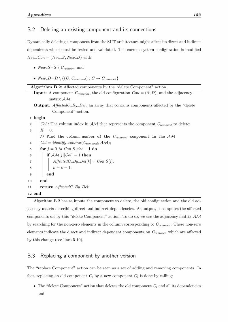
Appendices 152
B.2 Deleting an existing component and its connections
Dynamically deleting a component from the SUT architecture might affect its direct and indirect
dependents which must be tested and validated. The current system configuration is modified
New Con = (New S ,New D) with:
• New S=S \ Cremoved and
• New D=D \ {(C ,Cremoved ) : C → Cremoved}
Algorithm B.2: Affected components by the “delete Component” action.
Input: A component Cremoved , the old configuration Con = (S ,D), and the adjacency
matrix AM.
Output: AffectedC By Del : an array that contains components affected by the “delete
Component” action.
1 begin
2 Col : The column index in AM that represents the component Cremoved to delete;
3 K = 0;
// Find the column number of the Cremoved component in the AM4 Col = identify column(Cremoved ,AM);
5 for j = 0 to Con.S .size − 1 do
6 if AM[j ][Col ] = 1 then
7 AffectedC By Del [k ] = Con.S [j ];
8 k = k + 1;
9 end
10 end
11 return AffectedC By Del ;
12 end
Algorithm B.2 has as inputs the component to delete, the old configuration and the old ad-
jacency matrix describing direct and indirect dependencies. As output, it computes the affected
components set by this “delete Component” action. To do so, we use the adjacency matrix AM
by searching for the non-zero elements in the column corresponding to Cremoved . These non-zero
elements indicate the direct and indirect dependent components on Cremoved which are affected
by this change (see lines 5-10).
B.3 Replacing a component by another version
The “replace Component” action can be seen as a set of adding and removing components. In
fact, replacing an old component Ci by a new component C ′i is done by calling:
• The “delete Component” action that deletes the old component Ci and all its dependencies
and

Appendices 153
• The “add Component” action that adds the new component C ′i and all its dependencies.
Therefore, we use the already defined algorithms as illustrated in Algorithm B.3 to identify
the affected components by the “replace Component” action.
Algorithm B.3: Affected components by the “replace Component” action.
Input: The old component Cold , the new component Cnew ,the old configuration
Con = (S ,D), and the new configuration New Con = (New S ,New D).
Output: AffectedC By Rep: an array that contains components affected by the “replace
Component” action.
1 begin
2 AM: the adjacency matrix;
3 AM= lookForAM(Con);
4 AffectedC By Del = callAlgorithm2(Cold ,Con,AM);
5 AM=lookForAM(New Con);
6 AffectedC By Add = callAlgorithm1(Cnew ,New Con,AM);
7 AffectedC By Rep=AffectedC By Del ∪AffectedC By Add ;
8 return AffectedC By Rep;
9 end
B.4 Adding/Deleting a dependency between two components
When either the “add Dependency” action or the “delete Dependency” is triggered, the adja-
cent matrix AM is modified in order to reflect this change in the dependency structure. Also,
using the Warshall’s algorithm, the matrix is updated in response to the newly added or deleted
dependency. The affected components in both cases are those which depend on the depen-
dent component in the new dependency (respectively in the dependency to remove) and which

Appendices 154
correspond to non-zero elements in the matrix as outlined in Algorithm B.4.
Algorithm B.4: Affected components by the “add Dependency” (respectively by the
“delete Dependency”) action.
Input: The dependent component dependent , the configuration Con = (S ,D), and the
adjacency matrix AM.
Output: AffectedC By AddDep (respectively AffectedC By DelDep): an array that
contains affected components by the “add Dependency” action (respectively by
the “delete Dependency” action).
1 begin
// Find the column number of the dependent component
2 Col = identify column(dependent ,AM);
3 k = 0;
// Find components that depend on dependent component
4 for i = 0 to Con.S .size − 1 do
5 if AM[j ][col ] = 1 then
6 AffectedC By AddDep[k ]=Con.S [j ] (respectively
AffectedC By DelDep = Con.S [j ]);
7 k = k + 1;
8 end
9 return AffectedC By AddDep (respectively AffectedC By DelDep);
10 end
11 end
B.5 Identification of affected component compositions
The Algorithm B.5 illustrates a pseudocode used to identify component compositions affected
by dynamic adaptation actions. In fact, the adjacency matrix AM is updated in response to
the adaptation action. For example, when a new component is instantiated, new rows and
columns representing direct dependencies between the new component and the old ones are
added (line 9). Indirect dependencies are obtained as mentioned before transitively by applying
the Warshall’s algorithm in order to generate another adjacency matrix AM′ defining direct and
indirect dependencies. Afterward, a set of affected components is generated depending on the
executed adaptation action (line 10). A composite component, seen as a dependence path in the
CDG, is affected if it contains at least one affected component. Thus, we derive all dependence

Appendices 155
paths traversing components affected by the adaptation action (line 18).
Algorithm B.5: Affected component compositions by a dynamic change.
Input: The adaptation action adaptAction and the adjacency matrix AMOutput: affPaths: a set of affected component compositions
1 begin
2 if adaptAction= “add Dependency” then
3 new AM = updateAddDep(AM);
4 AM′ = warshall(new AM );
5 AffectC = AffectedC by addDep(AM′,Dependent ,Antecedent);
6 else if adaptAction= “delete Dependency” then
7 new AM = updateDelDep(AM);
8 AM′ = warshall(new AM );
9 AffectC = AffectedC by delDep(AM′,Dependent ,Antecedent);
10 else if adaptAction= “add Component” then
11 new AM = updateAddComp(AM);
12 AM′ = warshall(new AM );
13 AffectC = AffectedC by addComp(AM′,ComptoAdd);
14 else if adaptAction= “delete Component” then
15 new AM = updateDelComp(AM);
16 AM′ = warshall(new AM );
17 AffectC = AffectedC by delComp(AM′,ComptoDel);
18 else
19 new AM = updateRep(AM);
20 AM′ = warshall(new AM );
21 AffectC = AffectedC by replace(AM′,ComptoReplace);
22 end
23 affPaths = findPathforAllAffectedComponent(AffectC ,new AM );
24 return affPaths;
25 end

APPENDIX C
Background of the Knapsack Problem
The Knapsack Problem (KP) is a well-studied, strongly NP-hard combinatorial optimization
problem. It has been used to model different applications for instance in computer science and
financial management. In the literature, we find many variants of this problem [137, 138, 139].
We describe in details the basic one and the two models used in our context.
C.1 The Knapsack Problem (KP)
The most basic form of KP is formulated as follows:
KP =
maximize z =n∑
j =1pj xj
subject ton∑
j =1wj xj ≤W
xj ∈ {0, 1} ∀ j ∈ {1, · · · ,n}
It considers a set of n objects O = o1, . . . , on and a knapsack of capacity W . Each object oj
has an associated profit pj and weight wj . The objective is to find a subset S ⊆ O in such a way
that the weight sum over the objects in S does not exceed the knapsack capacity and yields a
maximum profit.

Appendices 157
C.2 The Multi-Dimensional Knapsack Problem (MDKP)
It is also called the Multiply constrained Knapsack Problem or the m-dimensional knapsack
problem. It can be viewed as a resource allocation model and can be modeled as follows:
MDKP =
maximize z =n∑
j =1pj xj
subject ton∑
j =1wij xj ≤ ci ∀ i ∈ {1, · · · ,m}
xj ∈ {0, 1} ∀ j ∈ {1, · · · ,n}
where a set of n items with profits pj > 0 and m resources with capacities ci > 0 are
given. Each item j consumes an amount wij ≥ 0 from each resource i . The 0-1 decision
variables xj indicate which items are selected. The main purpose is to choose a subset of items
with maximum total profit. the selected items must not exceed the resource capacities. This
is expressed by the knapsack constraints [139]. Obviously, the KP is a special case of the
multidimensional knapsack problem with m = 1.
C.3 The 0-1 Multiple Knapsack Problem (0-1 MKP)
It is the problem of assigning a subset of n items to m distinct knapsacks having different
capacities Wi . It is also referenced as the 0-1 integer programming problem or the 0-1 linear
programming problem [140, 141]. More formally, an MKP is stated as follows:
MKP =
maximize z =m∑
i=1
n∑j =1
pj xij
subject ton∑
j =1wj xij ≤Wi ∀ i ∈ {1, · · · ,m}
m∑i=1
xij ≤ 1 ∀ j ∈ {1, · · · ,n}
xij ∈ {0, 1} ∀ j ∈ {1, · · · ,n} and ∀ i ∈ {1, · · · ,m}
where each item j has a profit pj and a size wj , and each knapsack i has a capacity Wi .
The goal is to find a subset of items of maximum profit in such a way that they have a feasible
packing in the knapsacks. When m = 1, the MKP reduces the 0-1 KP considered in Section
C.1.

APPENDIX D
Test Case Generation Algorithms
Generating test suites by reachability analysis has been widely studied in the literature, e.g.,
[5, 104, 4, 110]. In fact, the proposed algorithms explore the state space of a given model to
find a set of traces that satisfies a given property or follows a given coverage criterion. In what
follows, we introduce test case generation algorithms inspired by reachability analysis used in
the model-checker UPPAAL and its extension UPPAAL CO√
ER, as well.
D.1 Test case generation with satisfying test properties
Algorithm D.1 highlights a standard reachability algorithm that computes on-the-fly state space.
Two data structures WAIT and PASS are used. The first one keeps track of the states waiting
to be examined. The second one stores states already examined. Initially, PASS is empty
and WAIT holds the initial state {(l0, σ0)}. While the WAIT list is not empty, a state (l , σ)
is selected. If the test property is held in the state (l , σ), then the algorithm terminates and
returns true (see lines 6-8). Otherwise, the algorithm looks for the current state in the PASS
list. The state (l , σ) can be ignored if it exits in the PASS list. In the other case, the state is
added to PASS , all its successors are computed and added to WAIT if they are not already in

Appendices 159
the list (see lines 10-16). Then, the while loop starts again.
Algorithm D.1: A standard reachability analysis algorithm [4].
1 begin
2 PASS := ∅ ;
3 WAIT := {(l0, σ0)};4 while WAIT 6= ∅ do
5 select (l , σ) from WAIT ;
6 if testProperty((l , σ)) then
7 return true;
8 end
9 if σ * σ′forall(l , σ′) ∈ PASS then
10 insert(l , σ) in PASS ;
11 forall (l ′, σ′) such that (l , σ) −→ (l ′, σ′) do
12 if σ′ * σ′′ forall (l ′, σ′′) ∈WAIT then
13 insert (l , σ) in WAIT ;
14 end
15 end
16 end
17 end
18 return False;
19 end
D.2 Test case generation with satisfying coverage criteria
Algorithm D.2 has been implemented in the UPPAAL CO√
ER tool with the aim of producing
a trace wmax that covers the maximum number of coverage items MAX . Similar to Algorithm
D.1, the two data structures WAIT and PASS are defined and initialized as follows: the PASS
set is empty and the WAIT set includes the initial extended state {〈(l0, σ0) | {q0}〉,w0} where
w0 is an empty trace. Lines 4 to 14 are repeated until the WAIT set becomes empty. At line
5, a state 〈(l , σ) | Q〉 is taken from WAIT . If it is included in a state 〈(l , σ) | Q′〉 in PASS
then the state 〈(l , σ) | Q〉 does not need to be further explored. Otherwise, all its successors are
generated and they are put on WAIT as shown in lines 11-13.
The global integer variable MAX is initialized with 0 and the variable wmax is set to empty
trace. They are updated whenever an extended state, found in WAIT , covers more items than
the current value of MAX (see lines 6-8). Note that wt denotes the trace w extended with the

Appendices 160
transition t , where 〈(l , σ) | Q〉 t−→ 〈(l ′, σ′) | Q′〉.Algorithm D.2: A breadth-first search exploration algorithm for test case generation [5].
1 begin
2 PASS := ∅; MAX := 0; wmax := w0 ;
3 WAIT := {〈(l0, σ0) | {q0}〉,w0};4 while WAIT 6= ∅ do
5 select (〈(l , σ) | Q〉,w) from WAIT ;
6 if | Qf ∩Q |> MAX then
7 wmax := w , MAX :=| Qf ∩Q | ;
8 end
9 if forall 〈(l , σ) | Q′〉 in PASS: Q * Q′ then
10 add 〈(l , σ) | Q〉 to PASS ;
11 forall 〈(l ′′, σ′′) | Q′′〉 such that 〈(l , σ) | Q〉 t−→ 〈(l ′′, σ′′) | Q′′〉 do
12 add {〈(l ′′, σ′′) | Q′′〉,wt} to WAIT ;
13 end
14 end
15 end
16 return wmax and MAX ;
17 end

Runtime Testing of Dynamically Adaptable and
Distributed Component-based Systems
Mariam LAHAMI
المنظومات البرمجية الموزعة و القابلة للتكيف أصبح ضرورة من أجل المحافظة على سالمتها اختبار : الخالصة
فإن هدفنا وبالتالي .الموارد و تأثيرها على وقت التنفيذ استهالكلكن هذه التقنية تتميز بكثرة . التشغيلية بعد كل تكيف ديناميكي .وقت التشغيل قادر على التقليل من كلفة هذه التقنية و زيادة كفاءتها في الكشف عن أخطاء التكييف اختبار هو تصميم إطار
من .التعديالت الهيكلية والسلوكية بعد مساهمتنا تشمل االختبار وقت التشغيل من الحصول على االختبارات حتى تنفيذهامن ناحية أخرى، . ختبارات وقت التشغيل مع احترام توفر الموارداالموحد الذي ينفذ بأمان وكفاءة اختبار أداةنقترح ناحيةوقد أثبتت التجارب فعالية المنهج المقترح لخفض تكلفة تنفيذ . منهج لتطوير االختبارات القديمة بعد كل تكيف سلوكينقدم
.المنظومةمع ضمان جودة وقت التشغيل ختباراال تطوير االختباراتتنفيذ و TTCN-3 ,معيار ,تكيف ديناميكيال،وقت التشغيل ختباراال : المفاتيح
Résumé : Le test d'exécution des systèmes à base de composants logiciels distribués et
dynamiquement adaptables devient une nécessité afin de maintenir leur sûreté de fonctionnement après chaque adaptation dynamique. Cependant, cette technique se caractérise par sa grande consommation de ressources et de temps d'exécution. D'où, notre objectif consiste à concevoir un Framework de test capable de réduire son coût et d'augmenter son efficacité à révéler des fautes d'adaptation. Notre contribution assure le test d'exécution dès la génération jusqu'à l'exécution tout en supportant des adaptations dynamiques à la fois structurelles et comportementales. D'une part, nous proposons une plateforme standardisée pour l'exécution des tests tout en respectant les contraintes de ressources et de connectivité de l'environnement d'exécution. D'autre part, une méthode de génération sélective des tests a été définie afin d'évoluer la suite de tests après des adaptations comportementales. Des expérimentations ont montré l'efficacité de l'approche proposée à réduire le coût du test d'exécution tout en assurant la qualité du système évolutif.
Mots clés : Test d'exécution, adaptation dynamique, sensibilité aux ressources, TTCN-3,
exécution et évolution des tests
Abstract : Runtime testing of dynamically adaptable and distributed systems is currently
highly demanded to ensure their correctness and trustworthiness. However, this runtime validation technique expects additional processing time and computational resources. Therefore, our objective is to conceive and implement an efficient runtime testing framework that alleviates its cost and burden while increasing its fault-finding capabilities. Our main contribution consists in covering the runtime testing process from the test generation to the test execution while supporting structural and behavioral adaptations. On the one hand, we propose a standardized test execution platform that executes safely and efficiently runtime tests while respecting resource availability and node connectivity. On the other hand, we introduce a selective test generation approach that evolves the old test suite after behavioral adaptations. Through several experiments, we show the efficiency of our proposal and the tolerated overhead that it introduces in case of dynamic structural or behavioral adaptations.
Key-words : Runtime testing, dynamic adaptation, resource awareness, TTCN-3, test
execution and evolution
Copyright © 2022 FDOKUMEN