
Adaptable Software Reuse:
196
Adaptable Software Reuse: Binding Time Aware Modelling Language to Support Variations of Feature Binding Time in Software Product Line Engineering by Armaya’u Zango Umar Supervisor: Dr. Jaejoon Lee Thesis submitted for the degree of Ph.D in Computer Science September 2019
-
Upload
khangminh22 -
Category
Documents
-
view
1 -
download
0
Transcript of Adaptable Software Reuse:

Adaptable Software Reuse:
Binding Time Aware Modelling Language to Support Variations
of Feature Binding Time in Software Product Line Engineering
by
Armaya’u Zango Umar
Supervisor:
Dr. Jaejoon Lee
Thesis submitted for the
degree of Ph.D in Computer Science
September 2019

Acknowledgement
All praises are to Allah whose divine destiny made it possible for me to earn a
Ph.D.. Special thanks to my parents for nurturing me and supporting me with prayers
and unconditional love through thick and thin. May Almighty reward them in abundance.
I most sincerely thank the National Information Technology Development Agency
(NITDA) for providing me with three-year funding. NITDA staff have been very helpful
and responsive to my incessant demands. Thank you NITDA and God bless the federal
republic of Nigeria.
I am ever grateful to my supervisor, Dr. Jaejoon Lee, for being there for me
throughout my Ph.D. journey. Jaejoon has been exceptionally patient, supportive and
provided me with invaluable guides all along. I am also sincerely grateful to panel mem-
bers of my Ph.D. appraisals - Prof. Pete Sawyer, Dr. Geral Kotanya, and Dr. Ioannis
Chatzigeorgiou. Their regular and constructive feedbacks were instrumental to my Ph.D.
success.
I also appreciate the support of my siblings for their prayers and words of encour-
agement. My special regards to my wife, Barira Hamisu, and my two daughters, Maryam
and Asiya for their patience of my absence and my aloofness during the intense period of
my research.
I will also like to appreciate my colleagues at Infolab. These include Mus’ab, Yusuf,
Bruno, Ono, Assyl, Sunday, Juliana to mention but few. It has been a nice feeling being
in their midst as ‘co-travellers’ and knowing fully there were always ready to help.

Abstract
Software product line engineering (SPLE) is a paradigm for developing a family ofsoftware products from the same reusable assets rather than developing individual productsfrom scratch. In many SPLE approaches, a feature is often used as the key abstractionto distinguish between the members of the product family. Thus, the sets of productsin the product line are said to have ’common’ features and differ in ’variable’ features.Consequently, reusable assets are developed with variation points where variant featuresmay be bound for each of the diverse products.
Emerging deployment environments and market segments have been fuelling de-mands for adaptable reusable assets to support additional variations that may be requiredto increase the usage-context of the products of a product line. Similarly, feature bindingtime - when a feature is included in a product and made available for use - may varybetween the products because of uncertain market conditions or diverse deployment en-vironments. Hence, variations of feature binding time should also be supported to coverthe wide-range of usage-contexts.
Through the execution of action research, this thesis has established the following:Language-based implementation techniques, that are specifically proposed to implementvariations in the form of features, have better modularity but are not better than the ex-isting classical technique in terms of modifiability and do not support variations in featurebinding time. Similarly, through a systematic literature review, this thesis has establishedthe following: The different engineering approaches that are proposed to support vari-ations of feature binding time are limited in one of the following ways: a feature mayhave to be represented/implemented multiple time, each for a specific binding time; Thesupport is only to execution context and therefore limited in scope; The support focuseson too fine-grained model elements or too low-level of abstraction at source-codes.
Given the limitations of the existing approaches, this thesis presents binding timeaware modelling language that supports variations of feature binding time by design andimproves the modifiability of reusable assets of a product line.

Declaration
I declare that the work in this thesis is my own work and has not been submitted
either in whole or in part for the award of a higher degree elsewhere. Any sections of the
thesis, which have been published, are clearly identified.
...............................
Armaya’u Zango Umar
i

0.1 List of Acronyms
AOP Aspect Oriented ProgrammingATL Atlas Transformation LanguageDOP Delta Oriented ProgrammingFOP Feature Oriented ProgrammingJEE Java Enterprise EditionMDA Model-Driven ArchitectureMDD Model-Driven DevelopmentM2M Model to ModelM2T Model to textMOF Meta Object FacilityNATO North Atlantic Treaty OrganizationOCL Object Constraint LanguageOMG Object Management GroupOOP Object-Oriented ProgrammingOOSE Object-Oriented Software EngineeringPIM Platform Indipendent ModelPP Pre-processing PSM Platform Specific ModelRV Repetitive ViscosityRBSE Reuse Based Software EngineeringSPLE Software Product Line EngineeringXML eXtensible Markup LanguageXMI Interchangeable eXtensible Markup Language
ii

Contents
0.1 List of Acronyms . . . . . . . . . . . . . . . . . . . . . . . . . . . . . . . . ii
1 Overview . . . . . . . . . . . . . . . . . . . . . . . . . . . . . . . . . . . . . 11.1 Software reuse . . . . . . . . . . . . . . . . . . . . . . . . . . . . . . . . . . 21.2 Domain engineering as a scoped reuse . . . . . . . . . . . . . . . . . . . . . 21.3 Software Product Line Engineering as a form of systematic reuse . . . . . . 31.4 Motivation . . . . . . . . . . . . . . . . . . . . . . . . . . . . . . . . . . . . 31.5 About this thesis . . . . . . . . . . . . . . . . . . . . . . . . . . . . . . . . 5
1.5.1 Research Objectives . . . . . . . . . . . . . . . . . . . . . . . . . . 51.5.2 Research Questions . . . . . . . . . . . . . . . . . . . . . . . . . . . 61.5.3 Contributions . . . . . . . . . . . . . . . . . . . . . . . . . . . . . . 7
1.6 Research methods . . . . . . . . . . . . . . . . . . . . . . . . . . . . . . . . 71.7 Chapter summary . . . . . . . . . . . . . . . . . . . . . . . . . . . . . . . . 9
2 Background . . . . . . . . . . . . . . . . . . . . . . . . . . . . . . . . . . . 102.1 Feature-oriented Software Product Line (SPLE) . . . . . . . . . . . . . . . 102.2 Feature-oriented domain engineering . . . . . . . . . . . . . . . . . . . . . 11
2.2.1 Feature-oriented domain analysis . . . . . . . . . . . . . . . . . . . 122.2.2 Domain analysis example . . . . . . . . . . . . . . . . . . . . . . . . 162.2.3 Domain design . . . . . . . . . . . . . . . . . . . . . . . . . . . . . 212.2.4 Domain design example . . . . . . . . . . . . . . . . . . . . . . . . 232.2.5 Domain Implementation . . . . . . . . . . . . . . . . . . . . . . . . 26
2.3 Feature-oriented application engineering . . . . . . . . . . . . . . . . . . . 302.3.1 Product requirement elicitation . . . . . . . . . . . . . . . . . . . . 312.3.2 Product instantiation . . . . . . . . . . . . . . . . . . . . . . . . . . 322.3.3 Application engineering example . . . . . . . . . . . . . . . . . . . . 33
2.4 Research focus . . . . . . . . . . . . . . . . . . . . . . . . . . . . . . . . . . 352.4.1 Adaptable reusable assets . . . . . . . . . . . . . . . . . . . . . . . 362.4.2 Feature binding . . . . . . . . . . . . . . . . . . . . . . . . . . . . 372.4.3 Feature binding time . . . . . . . . . . . . . . . . . . . . . . . . . . 382.4.4 Variation of feature binding time . . . . . . . . . . . . . . . . . . . 392.4.5 Justifications for managing variations of feature binding time . . . . 40
2.5 Specific research challenges . . . . . . . . . . . . . . . . . . . . . . . . . . . 422.5.1 Research challenge on adaptable reusable assets . . . . . . . . . . . 422.5.2 Research challenge on variations of feature binding time . . . . . . 42
iii

2.6 Chapter summary . . . . . . . . . . . . . . . . . . . . . . . . . . . . . . . . 43
3 Language-based approaches to flexible variations: Action research . . . 443.0.1 Definition of terms . . . . . . . . . . . . . . . . . . . . . . . . . . . 45
3.1 Study settings . . . . . . . . . . . . . . . . . . . . . . . . . . . . . . . . . . 453.1.1 Evaluation criteria: flexibility . . . . . . . . . . . . . . . . . . . . . 453.1.2 Feature modularity and support for multiple binding time . . . . . 463.1.3 The case study: Oracle Berkeley Database Engine (BDE) . . . . . . 473.1.4 Case study exploration . . . . . . . . . . . . . . . . . . . . . . . . . 48
3.2 Study execution . . . . . . . . . . . . . . . . . . . . . . . . . . . . . . . . . 513.2.1 Pre-processing with Antenna tool . . . . . . . . . . . . . . . . . . . 533.2.2 Feature-Oriented Programming (FOP) with Jak language . . . . . . 563.2.3 Aspect Oriented Programming (AOP) with AspectJ . . . . . . . . . 623.2.4 Delta Oriented Programming (DOP) with DeltaJ 1.5 . . . . . . . . 673.2.5 Comparison between the implementation techniques . . . . . . . . . 73
3.3 Custom annotations . . . . . . . . . . . . . . . . . . . . . . . . . . . . . . 753.3.1 Custom annotation definition . . . . . . . . . . . . . . . . . . . . . 753.3.2 Custom annotation application and processing . . . . . . . . . . . . 77
3.4 Comparison with similar action researches . . . . . . . . . . . . . . . . . . 813.5 Chapter Summary and perspective . . . . . . . . . . . . . . . . . . . . . . 82
4 Approaches for supporting variations of feature binding time: A sys-tematic study . . . . . . . . . . . . . . . . . . . . . . . . . . . . . . . . . . 844.1 Introduction . . . . . . . . . . . . . . . . . . . . . . . . . . . . . . . . . . . 85
4.1.1 Review questions . . . . . . . . . . . . . . . . . . . . . . . . . . . . 854.1.2 Review protocol . . . . . . . . . . . . . . . . . . . . . . . . . . . . . 864.1.3 Search terms . . . . . . . . . . . . . . . . . . . . . . . . . . . . . . 864.1.4 Search databases . . . . . . . . . . . . . . . . . . . . . . . . . . . . 864.1.5 Selection strategy . . . . . . . . . . . . . . . . . . . . . . . . . . . 874.1.6 Data extractions . . . . . . . . . . . . . . . . . . . . . . . . . . . . 89
4.2 Overview of the publications . . . . . . . . . . . . . . . . . . . . . . . . . . 894.3 Narrative summary of the proposed approaches . . . . . . . . . . . . . . . 92
4.3.1 Delegation of binding to aspect weaver . . . . . . . . . . . . . . . . 934.3.2 Language extension . . . . . . . . . . . . . . . . . . . . . . . . . . . 984.3.3 Metadata interpretation . . . . . . . . . . . . . . . . . . . . . . . . 1014.3.4 Abstracting the binding time at the model level . . . . . . . . . . . 1034.3.5 Model composition . . . . . . . . . . . . . . . . . . . . . . . . . . . 1054.3.6 Delegation to deployment platform . . . . . . . . . . . . . . . . . . 106
4.4 Summary of the proposed approaches . . . . . . . . . . . . . . . . . . . . . 109
5 Binding time aware modelling language: design and implementation . 1115.0.1 Process overview to supporting variations of feature binding time . 112
5.1 Supporting variations of feature binding time at domain engineering phase 115
iv

5.1.1 Supporting variations of feature binding time at domain analysis . . 1165.1.2 Supporting variations of feature binding time at domain design . . 1175.1.3 Supporting flexible feature binding at the domain implementation . 1205.1.4 PIM to PSM mapping . . . . . . . . . . . . . . . . . . . . . . . . . 129
5.2 Application engineering with feature binding time . . . . . . . . . . . . . . 1315.2.1 Product requirement elicitation . . . . . . . . . . . . . . . . . . . . 1315.2.2 Product design . . . . . . . . . . . . . . . . . . . . . . . . . . . . . 1325.2.3 Consistency checking and PIM to PSM transformation . . . . . . . 1335.2.4 Product instantiation . . . . . . . . . . . . . . . . . . . . . . . . . . 136
5.3 Tool Support . . . . . . . . . . . . . . . . . . . . . . . . . . . . . . . . . . 1365.3.1 PIM implementation and instantiation . . . . . . . . . . . . . . . . 1365.3.2 Consistency checking . . . . . . . . . . . . . . . . . . . . . . . . . . 1375.3.3 PIM to JEE model transformation and code generation . . . . . . . 138
5.4 Evaluation an discussion . . . . . . . . . . . . . . . . . . . . . . . . . . . . 1405.4.1 Performance . . . . . . . . . . . . . . . . . . . . . . . . . . . . . . . 1405.4.2 Modifiability . . . . . . . . . . . . . . . . . . . . . . . . . . . . . . . 142
5.5 Chapter summary . . . . . . . . . . . . . . . . . . . . . . . . . . . . . . . . 143
6 Conclusion . . . . . . . . . . . . . . . . . . . . . . . . . . . . . . . . . . . . 1446.1 Thesis summary . . . . . . . . . . . . . . . . . . . . . . . . . . . . . . . . . 1446.2 Revisiting the Contributions . . . . . . . . . . . . . . . . . . . . . . . . . . 1456.3 Limitations . . . . . . . . . . . . . . . . . . . . . . . . . . . . . . . . . . . 1476.4 Future research directions . . . . . . . . . . . . . . . . . . . . . . . . . . . 1486.5 Closing remarks . . . . . . . . . . . . . . . . . . . . . . . . . . . . . . . . . 149
Bibliography . . . . . . . . . . . . . . . . . . . . . . . . . . . . . . . . . . . . . 150
Appendices . . . . . . . . . . . . . . . . . . . . . . . . . . . . . . . . . . . . . . 163A Platform Indipendent Model with OCL Embedded . . . . . . . . . . . . . . 164B JEE Platform Specific Model in XMI with Ecore Schema . . . . . . . . . . 168C PIM to JEEE transformations . . . . . . . . . . . . . . . . . . . . . . . . . 173D Code generation with Xtend . . . . . . . . . . . . . . . . . . . . . . . . . . 178
List of Figures
1.1 High-level outline of the thesis . . . . . . . . . . . . . . . . . . . . . . . . . 8
v

2.1 Relationship between feature space (top right) on one hand and the deliv-erables of both domain engineering (top left) and application engineering(bottom) on the other hand . . . . . . . . . . . . . . . . . . . . . . . . . . 11
2.2 key engineering activities in feature-oriented SPLE . . . . . . . . . . . . . 132.3 A partial feature model of Automative product line . . . . . . . . . . . . . 142.4 A partial feature model of Education Software Product Line (EduPL), an
enterprise product line for universities . . . . . . . . . . . . . . . . . . . . 172.5 subsystem overview of EduPL(an enterprise product line for universities) . 192.6 A use case model for Account Management subsystem of EduPL . . . . . 202.7 roles for layered components in N-tier architecture pattern . . . . . . . . . 222.8 a domain object model (DOM) for Account Management subsystem . . . . 232.9 Activity diagram showing (a) process flow for account creation and (b)
process flow for account update . . . . . . . . . . . . . . . . . . . . . . . . 242.10 components and connectors PLA model that is derived from the gradual
refinements of DOM. In the figure, dotted outlines represent variable archi-tectural elements . . . . . . . . . . . . . . . . . . . . . . . . . . . . . . . . 25
2.11 use case models (left) in consistent with the feature selections from theconfiguration interface (right) . . . . . . . . . . . . . . . . . . . . . . . . . 34
2.13 Variation of feature binding time between . . . . . . . . . . . . . . . . . . 40
3.1 Selected BDE variations transformed into features. . . . . . . . . . . . . . 473.2 Iterative process for study of features in code assets . . . . . . . . . . . . . 493.3 Union an intersection of feature modules in code-asset . . . . . . . . . . . . 493.4 Research execution steps . . . . . . . . . . . . . . . . . . . . . . . . . . . . 503.5 Part of BDE code-asset before injecting variation. Statistics source-codes
to be decoupled are shaded grey . . . . . . . . . . . . . . . . . . . . . . . . 523.6 Injection of variation to the part of BDE code-asset with pre-processing . . 543.7 UML package representing part of BDE code-asset before injecting variation
with FOP . . . . . . . . . . . . . . . . . . . . . . . . . . . . . . . . . . . . 563.8 Injection of variation with to part of BDE code-asset with FOP . . . . . . 573.9 Containment hierarchies for Base and Statistics in Jak language . . . . . . 593.10 Decoupling of program elements that are exclusive to Statistics in the
DatabaseImpl class with FOP . . . . . . . . . . . . . . . . . . . . . . . . . 593.11 decoupling intersection within a method in FOP . . . . . . . . . . . . . . . 613.12 decoupling intersection within a constructor with FOP . . . . . . . . . . . 613.13 Modularity with FOP . . . . . . . . . . . . . . . . . . . . . . . . . . . . . . 623.14 injection of variation w with AOP . . . . . . . . . . . . . . . . . . . . . . . 633.15 Decoupling of exclusive program elements with AOP . . . . . . . . . . . . 653.16 Decoupling intersection within a method with AOP . . . . . . . . . . . . . 663.17 Decoupling intersection within a constructor with AOP . . . . . . . . . . . 673.18 Modularity with AOP . . . . . . . . . . . . . . . . . . . . . . . . . . . . . 673.19 Delta specifications of Base before variability injection with DOP . . . . . 683.20 Injection of variation with with DOP . . . . . . . . . . . . . . . . . . . . . 69
vi

3.21 Decoupling of exclusive program elements with DOP . . . . . . . . . . . . 703.22 Modularity in DOP . . . . . . . . . . . . . . . . . . . . . . . . . . . . . . . 713.23 Decoupling intersection within a method with DOP . . . . . . . . . . . . . 723.24 Constructor modification with DOP . . . . . . . . . . . . . . . . . . . . . . 723.25 Modularity with DOP . . . . . . . . . . . . . . . . . . . . . . . . . . . . . 733.26 Spread of exclusive and intersection from 11 features . . . . . . . . . . . . 783.27 RV for each of the techniques on exclusive program elements . . . . . . . . 793.28 Example of intersecting features . . . . . . . . . . . . . . . . . . . . . . . . 80
4.1 Paper selection process . . . . . . . . . . . . . . . . . . . . . . . . . . . . . 884.2 Publications by (a) affiliations and (b) paper categories . . . . . . . . . . . 904.3 Publication venues . . . . . . . . . . . . . . . . . . . . . . . . . . . . . . . 904.4 Publication trend . . . . . . . . . . . . . . . . . . . . . . . . . . . . . . . . 914.5 Various research goals of the proposed papers vs research approaches . . . 924.6 Application domains . . . . . . . . . . . . . . . . . . . . . . . . . . . . . . 94
5.1 Overview of supporting variations of feature binding time . . . . . . . . . . 1135.2 Grouping features into units that most be bound together for the correct
function of the product . . . . . . . . . . . . . . . . . . . . . . . . . . . . . 1165.3 Architectural elements (right) organized based on binding unit graph(left) 1185.4 isValidated as fine-grained model element moved to Validation Controller
from Account Controller. . . . . . . . . . . . . . . . . . . . . . . . . . . . . 1185.5 crtlDeleteAccount(user: User) and deleteAccount (user: User) as fine-grained
model elements aggregated into aspectual component of the same bindingunit. . . . . . . . . . . . . . . . . . . . . . . . . . . . . . . . . . . . . . . . 119
5.6 Switching connection mode between components . . . . . . . . . . . . . . . 1215.7 Lifecycle activities for supporting variations of feature binding time in
Model-Drive domain implementation . . . . . . . . . . . . . . . . . . . . . 1225.8 A simplifed view of the platform independent metamodel . . . . . . . . . . 1235.9 Type view of the PIM metamodel . . . . . . . . . . . . . . . . . . . . . . . 1245.10 A simplifed metamodel of Java Enterpriese Edition (JEE) . . . . . . . . . 1275.11 Java Enterpriese Edition (JEE) Invocation metamodel . . . . . . . . . . . . 1285.12 Java Persistence API (JPA) metamodel . . . . . . . . . . . . . . . . . . . . 1285.13 Architecture of Account Management sub-system when Advance child fea-
ture of User Notification is selected. . . . . . . . . . . . . . . . . . . . . . . 1315.14 Instance of PIM representing partial architecture of Account Management
sub-system when Advance child feature of User Notification is selected . . 1325.15 JEE platform specific instance model in which the binding time of Advacnce
(User Notification feature is set to pre-deployment . . . . . . . . . . . . . . 1345.16 JEE platform specific instance model in which the binding time of Advacnce
(User Notification feature is set to pre-deployment . . . . . . . . . . . . . . 1355.17 Components modelled with the eclipse-based plugin for PIM modelling . . 1375.18 OCL implementation . . . . . . . . . . . . . . . . . . . . . . . . . . . . . . 138
vii

5.19 PIM to JEE transformation . . . . . . . . . . . . . . . . . . . . . . . . . . 1395.20 PSM to source code transformation . . . . . . . . . . . . . . . . . . . . . . 1395.21 Comparison between Direct and Platform in synchronous mode . . . . . . 1415.22 Comparison between Direct and Platform in asynchronous mode . . . . . 142
viii

Chapter 1
Overview
Software product line engineering (SPLE) is a paradigm for developing a familyof software products from the same reusable assets rather than developing individualproducts from scratch. The driver of SPLE is pre-planned software reuse and within aspecific problem area known as a domain.
In many SPLE approaches, a feature is often used as the key abstraction to distin-guish between the members of the family. Thus, the sets of products in the product lineare said to have ’common’ features and differ in ’variable’ features. Consequently, reusableassets are developed with variation points where variant features may be bound for eachof the diverse products.
Variations in usage-context, a contextual setting in which the software productfrom a product line is deployed or supplied to, have been fuelling demands for adaptablereusable assets to support additional variations that may be required to increase the usage-context of the product line as a result of expanding markets.
Furthermore, feature binding time - when a feature is included in a product andmade available for use - may vary between the products of a product line because ofthe different usage-contexts. Hence, variations of feature binding time should also besupported to cater for the diverse usage-contexts.
This chapter presents a general overview of the thesis. The chapter begins fromthe background theory of the thesis, which is reuse from the perspective of software en-gineering, and progressed to the focal theory, which is adaptable variations and featurebinding time in software product line engineering. The chapter, also, highlights the re-search motivation; introduces the research challenges; outlines the research objectives;and enumerated the research questions. In addition, the chapter highlights the researchcontributions and presented an overview of the research methods that bound the researchprocesses. Finally, the chapter presents a brief overview of the remaining chapters.

2
1.1 Software reuse
In the late 1960s, the committee on NATO Working Conference coined the term’software crisis’ to describe the lack of successes in developing reliable, large, and complexsoftware[Nau68]. Software projects were either overrunning their budgeted costs, werebeing delivered behind schedule or were not adequately trustworthy. Appalling statis-tics, attributed to the United State General Accounting Office, were widely circulatedas evidence of the ‘software crises’. These statistics were later disputed on the premisethat the prior studies only analysed failed projects and ignored successful ones [Gla94].Nonetheless, conservative results estimated that a typical software project was exceedingits budget with an increase of 33-36% and was being completed with a delay of about 22%behind schedule[VG91].
In response to the ’software crisis’, new ’software engineering’ techniques and meth-ods were developed. In this context, Reuse-Based Software Engineering (RBSE) was con-ceived as an engineering practice to reduce time-to-market, to reduce production costs,and to improve software quality. Intuitively, instead of developing software from scratch,each time, reusing existing artefacts results in speed gain. In addition, the reuse of ex-isting artefacts reduces the efforts required to develop the new software and thus reducesthe production costs. Similarly, the reuse of previously tested and trusted artefacts pro-vides some quality assurance of the new system. Reusable artefacts were increasinglybecoming available in different forms: a program library, an entire product or an abstractconcept [Som11]. As hypothesized, RBSE recorded successes in reducing time-to-marketand improving product quality [AE92, BBM96, FT96, PCH93].
1.2 Domain engineering as a scoped reuse
A pattern began to emerge on factors contributing to the success of software reuse.One of the factors is confining the reuse within a narrow and a special domain[Big98] Adomain is a problem area and knowledge on how to develop software products in thatarea [CE00]. Example of a domain is a mobile telephone software domain and automotivesoftware domain. Successful reuse was reported in a printer firmware domain [Big98] andin the network domain [Nei84]. Software reuse was also demonstrated to be effective indata structure component library [BST+94, CE00].
Consequently, both industry and academia begin to recognize that software reuse ismore effective when it is deliberate rather than speculative; scoped rather than open-ended.This is due to the fact that software products in a specialized domain share substantialcharacteristics and differ in little distinctiveness. Thus, researchers increased focusedon domain engineering as a systematic and planned software reuse paradigm[FPF+98,

3
KKL+98, Nei84]. Reuse within a specialized domain is in contrast to other establishedreuse based practices. For example, even though object-oriented software engineering(OOSE) targets software reuse and has been largely successful[LHKS92], OOSE approachto reuse is speculative. That is, the objective is to produce designs (both abstract andconcrete) that may be reused ’as is’ or modifiable to fit in an unforeseeable software system[BBM96, BD95].
1.3 Software Product Line Engineering as a form of
systematic reuse
In the 1990s, Software Product Line (SPLE) researches emerged as a genre ofsystematic and planned software reuse[ABM00, BFK+99a, GKS+96, KKL+98]. SPLE isintended to address the two phases of reuse-driven software engineering systematically:i) engineering for reuse and ii) engineering with reuse. Engineering for reuse, known asDomain Engineering (DE) in SPLE, is the process for the analysis, design, and implemen-tation of reusable assets. Engineering with reuse, known as Application Engineering (AE)in SPLE, is the process of product-specific analysis, design, and implementation using thereusable assets earlier developed.
Essentially, a domain is analysed, design and implemented in cognisance of commonand variable characteristics of the products in the domain. The common and variablecharacteristics of the domain are often described as product features [GKS+96, KKL+98].Subsequently, reusable assets are developed with pre-defined variation points. Pluggableoptions and variant assets are also developed to fit into the pre-defined variation points.
In order to derive individualised software product from the reusable assets, a validcombination of desired features are selected, a process known as product configuration.In most researches and industrial projects, a product configuration process triggers theselection and activation of specific variants assets for the specific product[ABM00, AK09].
1.4 Motivation
The adaptability of reusable assets is critical to the success of software reuse. Ide-ally, reusable assets should be adaptable with less effort. The following form the basesof this thesis findings on adaptability of reusable assets: a) an exploration of featurecharacteristics, in the source-codes, that have impacts on adding variations; b) investiga-tion of the impact of language-based implementation techniques on the modifiability ofsource-codes to add variations.

4
Modifiable assets are needed to support additional variations that were not plannedbeforehand in order to increase the usage context of SPL as a result of expanding markets.For example, Kastner [KAB07] observed that, in Berkeley Database Engine (BDE) productline[Coo17], features such as Statistics and Transactions were implemented as mandatory.However, such features will have to be made optional to make BDE configurable to otherusage-contexts such as smartcard products because the product cannot afford the footprintof the extraneous feature. Therefore, to increase the usage context of BDE, its source-codes must be modified to make Statistics and Transactions optional. Failure to injectadditional variations may lead to the delivery of product with extraneous source-codes- which is not desirable for lean memory applications and may also cause a problemespecially if the product is to be integrated within other software product[GAO95].
Furthermore, in SPLE where a feature is used as the key design abstraction, featurebinding is a physical inclusion of the feature in a product configuration and making itavailable for use. Consequently, Feature binding time is when the feature is included inthe product configuration and made available for use[ARR+16, CRE08, DFV03, VdH04,LK03, RSAS11]. i.e. when the variable assets are selected and activated for the specificproduct.
Feature binding time for some features may vary between product configurationsbecause of uncertain market conditions or diverse deployment environments. For example,a binding decision of a Power Saving feature of a wireless protocol in a smart devicemay be made in advance if the deployment environment is known beforehand. While abattery-powered device, deployed in the field, certainly requires the Power Saving feature,a device in a residential environment with access to energy would not. However, if thedeployment environment is not known until at deployment time, the binding decision aboutthe same Power Saving feature would have to be delayed. In some cases, the deploymentenvironment may change after initial deployment (e.g. a device may require additionalsecurity settings of a Security feature because of a change in the deployment environment).A wireless protocol supplier that covers the different deployment environments faces achallenge of variations of feature binding time. The supplier cannot simply deploy all thefeatures in a device and leave it to the discretion of a final user to activate the ones neededbecause the device may be overwhelmed, revenues may be lost, and the device may alsomisbehave due to possible feature interaction[AABZ14, AKS+13, KK98]. Had it been therevenue loss is the only concern, the supplier can deploy all the features and provideslicense keys to activate the paid features.
In addition to managing variations of products of a product line, supporting varia-tions of feature binding time is equally important. Without supporting variations of featurebinding time, a product line assets have to go through an ad-hoc adaptation (often throughclone-and-own)– which may affect time-to-market, product quality, and production costs[DRB+13, RK12]. – to support the change of binding times. Conventional approachessuggest narrowing and fixing the scope of a domain in order to have more commonality

5
and less variability or dividing the domain into multiple product lines[LKL02, PBvDL05];the former constraints product line companies from expanding their products and the lat-ter implies that the company has to maintain parallel assets for the different categories ofcustomers which increase maintenance and production costs.
After circa three decades of SPLE researches, new implementation techniques haveemerged to support product line variations. These implementation techniques have differ-ent mechanisms for decoupling of implementation modules in the source codes. However,not much is known about modifiability of source codes these techniques are used to im-plement and update reusable assets.
Similarly, much-needed attention was not adequately given to supporting variationsof feature binding time. Most of the current approaches share one more of the followinglimitations: multiple representations/implementations of the same set of features, eachfor a specific binding time; are interventions targeted at fine-grained model/ programelements; are at low-level of abstraction; are limited in scope [ARR+16, CRE08, WJE+09].
1.5 About this thesis
This thesis focuses on the technological aspects of capturing and implementing vari-ability in terms of products’ features as well as the binding times of those features. Thus,certain processes such as domain scoping, organizational issues, and other managerialframeworks are out of the scope of this thesis.
The overall goal of the thesis is to make contributions that minimize the followingchallenges:
Ch1. The challenge of adapting software product line assets to accommodate emergingvariations that were not planned beforehand. This challenge arises when a newusage context of software product line emerges and the product line company hasreusable assets to enter the market but additional variations have to be injected inthe existing assets.
Ch2. The challenge of managing variations of binding times to cater for different bindingtime requirements for the different categories of customers.
1.5.1 Research Objectives
In order to address the research challenges (Ch1 and Ch2) we set out the followingobjectives:

6
O1. To explore the properties of features, in the code-asset, that affect modifiability ofinjecting additional variations.
O2. To evaluate modifiability of language-based implementation techniques when inject-ing additional variations.
O3. To systematically investigate the current support for a flexible binding time.
O4. To propose and validate an improved approach to support variations of feature bind-ing time and injection of additional variations.
Achieving the first objective (O1) is the first step to addressing the first research challenge(Ch1) and perhaps to triggering of subsequent researches to further understand the chal-lenges and to propose alternatives solutions. Achieving the second objective (O2) has atwo-fold benefit: a) to take a cue on the generally missing support, if any, for addressingthe first (Ch1), and b) to expose the pros and cons of the relatively new language-basedimplementation techniques proposed or adapted to support flexible variations.
We set out the third objective (O3) for two purposes: a) to systematically consoli-date the identification of research gap, and 2) to position our contributions in the contextof the existing body of knowledge in a less partial manner. We set the fourth objective(O4) to simultaneously address Ch1 and Ch2 in a unified approach.
1.5.2 Research Questions
We re-structure the research objective into the following research questions:
RQ1. What are the characteristics of feature in the code-asset that affect the modifiabilityof injecting additional variations?
RQ2. How flexible are the new language-based implementation techniques on the injectionof additional variations?
RQ3. What are the current approaches supporting variations of feature binding time?
RQ4. How can we simultaneously and uniformly improve the support for variations offeature binding time and injection of additional variations?
Answers to the above research questions will determine the extent we achieve theset out objectives.

7
1.5.3 Contributions
C1. We explored the properties of features at the implementation-level and contributedwith the description of the properties that affect the flexibility of reusable assets. Weexperimented with prominent language-based implementation techniques that areproposed or adapted to support flexible variations; we evaluated their modifiabilitywhen injecting of additional variations and contribute with the exposition of theirpros and cons. This contribution is the fulfilment of the first and second researchobjectives (O1 and O2).
C2. We conducted a systematic literature review (SLR) on current approaches proposedto support variations of feature binding time. We contribute to the field by sheddinglights in terms of where the proposed interventions are desirable and where they maybe limited. This contribution is the fulfilment of the third research objective (O3).
C3. We developed binding time aware modelling language, in a model-driven approach, toabstract-away the actual binding mechanisms used at the implementation level and,thus, raised the level of abstraction of binding time management. This contributionis a partial fulfilment of the fourth research objective (O4).
C4. We contribute with toolsets to encode binding time and check consistency at ar-chitecture model level. The toolsets have embedded capability to decide a modelelement, representing an executable artefact, to instantiate based on binding timedecision. This contribution is also a partial fulfilment of the fourth research objective(O4).
1.6 Research methods
Adrion cited by Glass [Gla94] proposed four methods of software engineering re-searches. Two of the proposed methods are a) Empirical method and b) Engineeringmethod. In the Empirical method, researchers do ”propose a model, develop statistical orother methods, apply to case studies, measure and analyse, validate the model, and repeat”.In the Engineering method, researchers do ”observe existing solutions, propose better so-lutions, build or develop measure and analyse, and repeat until no further improvementsare possible”. Observe that each of the above methods consists of a series of researchactivities. To form a research lifecycle, the series of research activities are executed in aparticular order and within a defined research boundary[Fli09].
In this thesis, we executed the research activities in two separate research lifecycles.The second and the third boxes of Fig.1.1, labelled as Research life cycle 1 and Researchlife cycle 2 respectively, highlight the research methods of this thesis. The first researchlife cycle is action research in which an open-source version of Oracle Berkeley Database

8
Figure 1.1: High-level outline of the thesis

9
Engine (BDE) was selected as a case study. Three, distinctive, modern language-basedand one classical tool-based implementation techniques were also selected. We transformedsome of the variations, from the case study, into features using the different techniques tounderstand the properties of a feature that have impacts on adding variations and effectsof the techniques on the modifiability of product line source codes. The details of thelifecycle activities and the results are presented in Chapter three (indicated with the Ch3in the figure).
The second research lifecycle is based on an engineering research method and com-prises the two research activities: (i) A systematic review of the current approaches tomanaging variations of feature binding time the details of which are presented in Chapterfour (Ch4)). (ii) Development and validation of binding time aware architecture modellinglanguage as an improved approach. The details are presented in Chapter five (Ch5).
Also presented in Fig.1.1 are the outlines of the thesis’s chapters. The topmost boxcontains the outline of the current chapter, Chapter one, and that of Chapter two. Chaptertwo elaborates on the concepts introduced in this chapter. Central to these concepts is thefeature-oriented approach to SPLE. Thus, the chapter illustrates the feature-oriented ap-proach to the lifecycle activities of both domain engineering and application engineering.The chapter also elaborates on the concepts of adaptable variations, feature binding timein software product line engineering, and the research challenges associated with both.Chapter three presents the details of the first research lifecycle. Chapter four presentsthe systematic literature review on approaches of supporting variations of binding time.Chapter five presents the detail design and validation of our approach to supporting vari-ations of feature binding time. In Chapter six we present the summary of the thesis,revisit the contributions and discussed limitation and future research directions.
1.7 Chapter summary
This chapter provides a general overview of the thesis. The chapter highlights thebackground theory of the thesis, which is software reuse from the perspective of softwareengineering. The chapter, also, highlights the focal theory of the thesis, which is adaptablevariations and feature binding time in software product line engineering. Further, thechapter highlights the research motivation, the research objectives, and the formulatedresearch questions. Finally, the chapter outlines the research contributions and presentsan overview of the research methods that bound the research processes.

Chapter 2
Background
This chapter explains the background concepts of the feature-oriented softwareproduct line. The chapter discusses the feature-oriented approach to capturing and imple-menting variations in SPLE by illustrating the lifecycle activities of domain engineeringand application engineering with concrete examples. The chapter also explains the con-cept of feature binding time and its possible variations that may arise between differentproducts. Lastly, we elaborate on the research challenges introduced earlier in Chapterone
2.1 Feature-oriented Software Product Line (SPLE)
Throughout the history of software engineering, X-oriented may be used to describean engineering activity if X is the dominant technique, concept or an abstraction usedthroughout the activity.
In feature-oriented SPLE, a feature is used as the key design abstraction to differen-tiate between the products of the same family. The motivation behind feature-orientationis because a feature is recognized by different stakeholders. For example, customers recog-nized a feature as a service or capability of a product that satisfies their need. Requirementengineers can use a feature to describe functions that need to be developed. Developerscan also use a feature to describe a unit of functionality that needs to be designed, de-veloped, tested and maintained. Marketers can use a feature to promote a product topotential customers[LKL02].
As introduced in Chapter one, software product line approach to reuse is by meansof two engineering phases: (i) domain engineering (DE) and, (ii) application engineering(AE). At the domain engineering phase, reusable assets are developed based on the analysisof common and variable characteristics of the products in the domain. At the applicationengineering phase, individual products are developed from the reusable assets.
In feature-oriented approach, the common and variable characteristics of the prod-ucts are expressed in terms of features. Fig.2.1 summarizes the relationship between
10

11
Figure 2.1: Relationship between feature space (top right) on one hand and the deliverablesof both domain engineering (top left) and application engineering (bottom) on the other hand
feature space an the outputs of both domain engineering and the application engineeringactivities. As shown in Fig.2.1, features in the feature space are mapped to the reusableassets (deliverable of the domain engineering activities). Similarly, each product or partialproduct, as the case may be, is derived from the reusable asset based on feature config-urations from the feature space (i.e. valid selection of features). Lastly, product-specificartefact may be fed-back into the reusable assets in the form of feedback.
In the next section, we discuss feature-oriented approach to domain engineeringin more details. We also discuss feature-oriented approach to application engineering inFeature-oriented application engineering section.
2.2 Feature-oriented domain engineering
The term ’domain engineering’ is attributed to neighbour’s work of engineeringreusable assets for a group of similar software products in a particular problem domain asoppose to developing individual products from scratch[Nei84]. Thus, domain engineeringis also known as family engineering as the group of the products can be considered asmembers of the same family. In some approaches [BFK+99b], domain engineering is alsoreferred to as infrastructure construction phase because the activities at the phase are

12
geared toward creating an infrastructure from which individual products in the domaincan be created. Infrastructure usage phase (aka application engineering) is used to describethe phase in which the individual products are created.
Domain engineering in SPLE may have a narrower focus than in traditional do-main engineering due to considerations of current market opportunities of the potentialproducts. For example, smart elderly care product line, with focus on elderly people liv-ing in care homes, may be created from a smart living domain - the generic domain ofinterconnected smart devices. Similarly, a domain in SPLE often combines (part of) sev-eral horizontal technical domains into a single vertical application domain. For example,a banking information system product line is a vertical application domain that com-bines other technical horizontal domains such as database management systems (DBMS),network protocol, and user interface (UI).
The key activity in domain engineering, and which covers all the lifecycles, is ad-vance planning for the commonality and variability (C & V) of the potential products inthe chosen domain. Lifecycle activities at the domain engineering phase include: domainanalysis, domain design, and domain implementation. Fig.2.2 highlights the key engi-neering activities in feature-oriented SPLE. The high-level activities which also constituteother sub-activities are domain analysis, domain design, and domain implementation.
Domain analysis activity is a systematic identification and organization of productfeatures and the outputs from this activity are the analysis models. Domain design activityis the construction of the product line architecture that accommodates the diversities ofthe products in the domain and the outputs are various domain design models. Domainimplementations are the conversion of the product line architecture into executable andthe outputs are the implementation artefacts. The outputs are deposited into repositoryof reusable assets.
We present the details of the sub-activities of the three high-level activities and inthe subsequent sections.
2.2.1 Feature-oriented domain analysis
Kang et al [KCH+90] introduced the idea of eliciting, designing, and implementingthe common and variable characteristics of products in terms of ”product feature”. Theproduct features may be identified from four viewpoints as follows [LKL02]:
• Product capability: A feature from the viewpoint of product capability describesa service provided by the product, a means to operate the product or how theinformation is presented to the product user. It may also be a representation of acertain quality attribute.

13
Figure 2.2: key engineering activities in feature-oriented SPLE
• Product operating environment: A Feature from this viewpoint represents anenvironmental constraint in which the product is deployed or used.
• Domain technology: A Feature from this viewpoint represents a way of imple-menting services or operations that are specific to the domain.
• Implementation technique: Features from the viewpoint of implementation tech-nique are the available implementation decisions.
To analyse a domain, a good starting point is to use a set of exemplar products inthe domain. In some domains, a group of products portfolio, such as basic and advance,can be identified. For example, a manual car without air-condition and sunroof may beconsider a basic while the advance one will have full options (automatic, sunroof, airconditioned, cruise control, etc.).
Beginning from the small set of products, common and variable features shouldbe identified. However, feature identification may not be completed by analysing smallnumber of products in the domain. The followings sources should also be consulted:
• Domain terminologies: In a matured and standard domain, terminologies arealready understood by the domain experts. Examples of domain terminologies arenavigation in avionics domain, method of transfer in banking domain, cumulativegrade point average (CGPA) in the information system of higher institutions oflearning. In an immature domain, domain terminologies need to be clarified andstandardized to have consistent meaning to all stakeholders.

14
Figure 2.3: A partial feature model of Automative product line
• Stakeholders: Stakeholders such as domain expert, end users, product marketers,system designers are potential sources of information about products’ features thatneed to be developed.
• Existing documentation: documentation such as user manual, design documents,and existing laws in the domain are also useful for feature identification.
Domain engineers should create a domain dictionary. The domain engineers shouldalso define, precisely, each of the identified features, and the definitions should be addedto the domain dictionary. Identified features should then be organized in a feature model.We discuss feature modelling in the next section.
2.2.1.1 Feature model
A Feature Model (FM) has been widely used to organize commonality and vari-ability (C &V) information of a product line[MPH+07]. A feature model is a graphicaltree structure in which product features of a product line are organized with their typesand their relationships. Feature type is one of the following broad categories:
• a mandatory type: a feature of this type is a common feature that is manifestedin all the products of a product line.
• a variable type: a feature of this type is either an optional, is part of an alternativegroup (only one feature in the group can be selected) or is part of inclusive ORgroup feature (more than one feature can be selected from the group). Unlike thealternative group, the OR group features are not mutually exclusive and can eithercontain all optional features or at least one of the features must be selected.

15
Fig.2.3 depicts a hypothetical feature model of an automotive product line adaptedfrom Kang et al [KCH+90]. In the feature model, Powertrain and Transmission featuresare mandatory because they must be available in every car. Comfort and Advanced DriverAssistance (ADAS) are optional features because they do not have to be fit in every vehicle.Automatic and Manual are alternative features since the two features cannot co-exist inthe same car. Air Conditioning and Sunroof are OR group features because a car canhave zero or more of the features.
Relationships between features can be hierarchical or horizontal (aka cross-tree con-straints). The major hierarchical relationship is a composed-of relationship. The featureon top of the composed-of hierarchy, the parent feature, represents an abstraction overthe constituent features (children-features) beneath the hierarchy (e.g. Transmission inFig.2.3). Features in a composed-of relationship may also exhibit a generalization/spe-cialization association. In this case, the main feature is the generic feature that representsa suppression of detail differences of the children’s features. Each child feature is a spe-cialization of the generalized feature. For example, in Fig.2.3, Manual and Automatic arespecialization of Transmission feature.
In contrast to the hierarchical relationship, horizontal relationships are usuallypresented separately from the feature model as a series of dependency rules. These arealso called composition rules because the rules are specifications of how features should becomposed. For example, in Fig.2.3, Air Conditioning requires Horsepower >100 representsa composition rule. In other words, a dependency constraint from Air conditioning toHorsepower.
A selection of a valid combination of features is known as as product configuration.For example, the following is a valid configuration of features from Fig.2.3: Horsepower150, Powertrain, Automatic, Air conditioning.
Features organized in the feature model may be validated with a use case model.Beginning from the feature modelling and then the use case modelling is recommendedwhen the domain is familiar and significant expertise exists. In an unfamiliar domain, itmight be more effective to start with use case modelling before feature modelling.
We discuss use case modelling in the next section.
2.2.1.2 Use case model
A use case model describes a software product from the user’s perspective. Infeature-oriented domain analysis, a use case model can be used to support the identificationof variations in the features of a product line. Thus, variant model elements such asactors, systems, and use cases should be identified by exploring user-level semantics of the

16
collective products. Occasionally, the product line has to be explored at a sub-functionlevel to clarify variation.
To validate the identified features using the use case model, the domain engineersshould do the following checks:
• Check if each use case can be mapped to a feature. If not, there may be a featurethat is missing from the feature model.
• Check if all the features are addressed by the use cases. If not, there may be usecases that are missing.
• Check if variations of use cases and variations of features are consistent.
• Check if the use cases are consistent with the semantics of the features defined inthe dictionary.
.
In the next section, we demonstrate an example of domain analysis with the featureand use case models.
2.2.2 Domain analysis example
To present a concrete example of the domain analysis, we introduce EducationSoftware Product Line (EduPL), an enterprise product line for universities initiated bya partner university from a developing country. In that country, in which EduPL wasconceived, a common regulatory body dictates most of the critical operations of the uni-versities. Hence, the product line approach is expected to be beneficial.
We begin with an example of feature modelling of EduPL in the next section.
2.2.2.1 Feature modelling example
Fig.2.4 shows a partial feature model of EduPL. As shown in the figure, we iden-tified the following features as some of the services of the products: User Account, UserNotification, Admission, Registration, and Result Computation. The User Account fea-ture provides services for maintaining an account with the institution’s portal when theproduct is deployed. Since validating the user while creating an account is available onlyfor some products, User Validation is an optional child feature of User Account.

17
Figure 2.4: A partial feature model of Education Software Product Line (EduPL), anenterprise product line for universities
User Notification is a service feature and is decomposed into Basic and Advance.Basic provides display services of status messages on a user’s screen. Advance providesservices for sending messages to a user via email or telephone or both. Hence, Text Messageand Email are modelled as OR group features. Email and SMS are two methods of im-plementing user notification - hence they were identified from implementation technologyperspective.
Admission feature provides services for application into various programmes ofan institution and it is decomposed into three children: (1) Under Graduate - providesservices for admission into under graduate programmes; (2) Graduate - provides servicesfor admission into post-graduate programmes; Sub-degree - provides services for admissioninto sub-degree programmes.
Registration feature provides services for enrolling accepted applicants and therebychanging their status from applicants to students. One of the children features of Registra-tion feature is Module Registration which provides services for students to select modulesand appropriate staff to validate the selections. The registered modules would later beretrieved and assigned marks, after several assessments and semester examination.
Result Computation feature provides service for evaluating students’ academic per-formance based on the marks they score from the registered modules. One of the perfor-mance indicators is cumulative grade point average (CGPA) which is used to determinestudents current standing using aggregate score of all examined modules do date. CGPAScale and Fail Count are some of the children feature of Result Computation and they

18
represent features from domain methods.
Different institutions adopt varying scale for computing CGPA; hence CGPA Scalerepresents an alternative feature group. Fail Count represents how a repeatedly failedmodule would affect student’s CGPA. With the Once child feature of Fail Count, theweight of a failed module is added to the denominator part of computing the averageonly once, no matter how many time a student failed the module, hence less impact onstudent CGPA. With the Continuous count, weight for the repeatedly failed module wouldcontinue to be added to the denominator part of computing the average until the failedmodule is passed in the subsequent attempt, hence negatively affects CGPA of studentswho repeatedly failed modules.
Record Management is a feature identified from the perspective of products oper-ation and represents one of the critical operations in EduPL. The feature is decomposedinto Create, Update and Delete for record creation, record updates and records removaloperations respectively. Delete is an optional child feature of Record Management becausesome institutions have a policy to not remove a stored record. However, that policy maychange with an increasing concern about users’ lack of control on their private data. Forinstance, European General Data Protection Regulation (GDPR) [Uni18] mandated thatdata controllers must remove a private data of their subject within a specified durationupon request.
It may be counter-intuitive as to why Record management is a root feature. Onemay ask why not as a child feature of User Account, Application, and Registration featuressince each of the mentioned features requires records to be managed. However, it isimportant to note that features in a feature model should not be organized as functionaldependencies or call hierarchies; features should be organized so that commonalities andvariabilities can be recognized easily. The functional dependencies should be analysedlater during domain design. Thus, feature that is related to many other features shouldalso be moved to the root.
As with a single product development, sometimes it is useful to decompose theoverall product line into subsystems for further analysis and design. The next paragraphpresents the high-level subsystems of EduPL.
EduPL Subsystem OverviewFig.2.5 presents the package diagram of EduPL subsystems. Note, however, without do-main knowledge it may not be possible to break the product line into subsystems withoutfurther exploration. In Fig.2.5, Account Management subsystem encapsulates User Ac-count, User Notification, and Record Management aspect of the User Account feature. TheAdmission Management subsystem encapsulates Admission feature and its related recordoperations. Admission Management is dependent upon Account Management becausehaving an account is a pre-requisite to starting an application for admission. Similarly,Enrolment Management depends on Account Management and Admission Management.

19
Figure 2.5: subsystem overview of EduPL(an enterprise product line for universities)
Lastly, Results Management depends on Enrolment Management.
in the subsequent illustrations, we focus on the User Account Management subsys-tem for brevity. In the next section, we present an exploration of Account Managementwith use case to validate the identified features from the feature model of Fig.2.4.
2.2.2.2 Use case modelling example
Fig. 2.6. depicts the use case model of the Account Management subsystem.Gomaa et al [Gom05] illustrate a variant model element of a use case model with UMLstereotype. However, to avoid cluttering the model, we represent a variant model elementwith dotted outlines.
In the model of Fig.2.6, the use case Create Account represents an interactionbetween a new user and the system (the software product) to create an account and theuse case is mandatory. While creating an account, the system can optionally validatethe new user. Thus, Validate Account use case optionally extend Create Account usecase. Similarly, Validate Account use case uses Send Notification use case to complete itsrole. Send Notification is an optional use case and represents sending notification via textmessage or email. Display Status is a mandatory use case and it represents basic usernotification. The Update Account is a mandatory use case and corresponds to the updateoperation of an account. Lastly, Delete Account is an optional use case that correspondsto the optional delete operation of an account.

20
Figure 2.6: A use case model for Account Management subsystem of EduPL
Table 2.1: Feature to use case mapping
Feature Use CaseCreate Create AccountValidate User Validate AccountAdvance Notification Send NotificationUpdate Update AccountBasic Notification Display StatusDelete Display Status

21
Table 2.1 presents the mapping from features to use cases. In the table, Create,Update, and Delete features are mapped to Create Account, Update Account, and DeleteAccount use cases respectively. User Validation feature is mapped to Validate Accountuse case, Advance Notification feature is mapped to Send Notification use case. Lastly,Basic Notification is mapped to Display Status use case.
When variations are fully captured and (partially) validated with the use case, wetransition into domain design.
2.2.3 Domain design
Domain design is the activity of crafting the domain architecture, or more specifi-cally, a product line architecture (PLA). Architecture is a ”principle design decision abouta software product” [TMD10]. A PLA, therefore, is an embodiment of ”principal designdecisions” about all potential products of a product line. As with the architecture of asingle software product [Ran98, Kru95], PLA may have several representations and eachof the representations should accommodate diversities of the products.
In feature-oriented domain design, PLA model can be obtained through gradualrefinements of domain objects that should be identified from the products’ features. In therefinement process, we construct other models to understand both the static and dynamicstructure of the domain. We also consider the dominant architectural style of the intendingproducts. In this thesis, we refer to the component and architecture model as the terminalPLA while the various models leading the terminal PLA as intermediary design models.In the subsequent paragraphs, we discuss the refinement process and the required models.We begin with a model that is formed by the objects in the domain.
A domain object model (DOM) represents the domain structure in terms of objectsand their relationships. To design DOM, we identify candidate objects from the featuremodel. Not every feature can be mapped to a domain object though. Some featuresmanifest as operations on domain objects or parameters on a generic object and thereforeare not candidate objects themselves.
After identifying candidate domain objects, we then construct the domain objectmodel by adding the semantic relationship between the objects. A relationship betweenfeatures can also be directly translated into the relationship between objects. The domainobject model should then be refined by exploring detail interaction between the domainobjects.
Interactions between the domain objects must be explored with one or more dy-namic models. The level of detail exploration varies from domain to domain. It may besufficient to explore the flow of execution of operations to identify key components and

22
Figure 2.7: roles for layered components in N-tier architecture pattern
their connections. In that case, the fine-grained details are further explored by developers.In the cases of fluid domains, such as predominantly state-based, details interaction couldbe explored in great detail. So, also, in domains that are highly sensitive to business rulessuch as insurance.
Part of domain design is consideration of architectural pattern and style of theintending software products. An architectural pattern is a generic solution to a reoccurringarchitectural problem that can be adapted to suit many contexts. For example, multi-tier architecture is a pattern to solve the problem of logical separation between data,computation, and control. The architectural style is a class of architecture that is foundrepeatedly in practice and often dictates the topological arrangements of architecturalcomponents. However, the two (architectural style and architectural patterns) are notstrictly different[TMD10]. Generally, patterns and styles facilitate some quality attributessuch as maintainability and ease of evolution. An architectural pattern or style mayhave a significant influence on how domain objects interact and how they are refined intocomponents and connectors. Therefore, we should decide on the architectural pattern orstyle we wish to enforce. For example, when Adopting an N-tier architecture pattern, toseparate data, computation, and control, we may assign roles to layered components asindicated in Fig.2.7.
In Fig.2.7, UI is a component that interacts with user to convey system statusand forward user command/request to Control component. Control is a component thatcoordinates or control steps of operations or other components. Service is a componentthat provides services to other components by performing some computation, process-ing or transformation. The domain objects should then be refined into components andconnectors based on the dynamic exploration and the adopted architectural pattern.

23
Figure 2.8: a domain object model (DOM) for Account Management subsystem
In the next section, we illustrate an example of PLA model that is derived fromthe gradual refinements domain objects.
2.2.4 Domain design example
This section illustrates an example of domain object model and its gradual refine-ments to component and connector architecture model. Along the line, we briefly illustratethe role of architecture style and domain exploration with a dynamic model.
Domain object modelFig.2.8 depicts the domain object model of User Account Management subsystem. The fig-ure shows the following domain objects as identified from the product features: User, Ac-count, Notification, System, Basic (Notification), Text Message (Notification), and Email(Notification). In the same Fig.2.8, the following are the relationships between objects:A User ’manages’ Account ; System ’validates’ User and also ’sends’ Notification to User;User ’receives’ Notification. The ’manages’ relationship is a combination of ’creates’, ’up-dates’ and ’deletes’ relationships that are between the User and the Account objects.In addition, the Generalization/ Specialization relationship between Notification and itschildren features in the feature model of Fig.2.4 are translated into Generalization/ Spe-cialization between Notification object and its sub-types.
Next, we explore the flow of operations between the domain objects using an ac-tivity diagram.
Activity diagramActivity diagram is one of the dynamic models that can be used to explore concise domain

24
Figure 2.9: Activity diagram showing (a) process flow for account creation and (b) processflow for account update
operations by showing the flow of executions from one activity to another. In domain en-gineering, it suffices to explore the domain only at a high-level and not the detail messagestransfer between activities. One of the goals is to identify key operations that must be re-alized by the intending components and connectors. Another goal is to identify variationsof activities between products of a product line.
Fig.2.9 illustrates the key operations in Account Management subsystem with aUML activity diagram. In the figure, unlike in UML, we use dotted outlines to depict avariable activity and the decision branch to depict a variation point. Fig.2.9a shows theflow of activities in the process of account creation while that of Fig.2.9b shows the flow ofactivities in the process of account update. The flow of activities in the process of accountdeletion (not shown in the figure) follows a similar pattern with that of Fig.2.9b.
Subsequently, we refined the domain objects into components and connectors basedon the dynamic flow of the activity diagram of Fig.2.9 and the N-tier architecture patternof Fig.2.7.
Components and connectors PLA modelFig 2.10 depicts component and connector model of the Account Management subsystem.We use UML notations of component and connector but with slight modifications. Weused dotted outlines to represent the variants architectural elements rather than the usualstereotype. However, we retained the usual ball to denote providing connection (providedinterface) and the socket to denote requiring connection (require interface).

25
Figure 2.10: components and connectors PLA model that is derived from the gradualrefinements of DOM. In the figure, dotted outlines represent variable architectural elements
Objects that are playing a system role in the domain object model should be anal-ysed further. If the role is global, the object should be refined into the overall productcontrol component. For example, a component that coordinates the overall operationsof other components in a mobile telephone domain may be refined into Phone Controllercomponent. Similarly, the component coordinating the overall Account Management sub-system may be refined into Account Controller component. However, if the role is local, itshould be refined into a control component that is controlling the local activities. For ex-ample, in the DOM of Fig.2.7, System plays the local role of coordinating user validation,hence we refined it into Validation Controller component to coordinate User Validator,Email, and Text Message service components.
We refined the domain objects, based on the N-tier architecture and the activitydiagram, into two control components, one data component and four service components.The control components areAccount Controller and Validation Controller. The data com-ponent is the DBMS. finally the service components are Account Manager, User Validator,Email, and Text Message (Fig.2.10).
From the top-left to top-right of Fig.2.10, the Account Controller Control com-ponent receives a request to manage an account and forward the same to its requiredconnection to Account Manager service component. In addition, Account Controller op-tionally requires connection to Validation Controller. The top-right component, AccountManager service component, manages the account related records in the persistent storage.Hence, it requires a connection to the DBMS component.
From the middle of Fig.2.10, Validation Controller is connected to the conditional

26
required end of the Account Controller. That is, Validation Controller receives request tovalidate user, from Account Controller, and forward the same to its required connectionto User Validator service component. In addition, the component also required connec-tion to components providing notification services( i.e Email and Text Message servicecomponents). The User Validator component generates token to be sent to the user tobe validated and record the same token in the persistent storage. Hence, it also requiresconnection to DBMS.
Before implementing the domain, further exploration is still needed for the nature ofcommunications between components. Also, internal components implementation shouldbe explored by the developers. Preferably, each implementation details of a componentshould remain local to it and not cross over to other components.
When domain design is completed. The next step is domain implementation. Wediscuss popular approaches to domain implementation in the next section.
2.2.5 Domain Implementation
Domain implementation is the activity of converting the domain design into exe-cutables. The domain may be implemented beforehand as part of the domain engineering,or maybe deferred until a product, from the product line, is requested. In the latter case,the domain is implemented in concurrence with application engineering.
In this section, we discuss the implementation as part of domain engineering. Wealso discuss the domain implementation in concurrence with the application engineeringin Feature-oriented application engineering section.
At the implementation level, a feature manifests as one of the following:
a. one or more major units of implementation (e.g. modules, components, classes )exclusive for the realization of the feature;
b. many fragmented minor units of implementation (e.g. functions, attributes, clauses)scattered in other major units;
c. a combination of (a) and (b).
Kastner et al [KAK08], in an exploratory study, refer to the manifestations offeature in the implementation artefacts as granularity of variations. In summary, a featuremay be traced to many parts of the implementation artefacts and the parts may be coarse-grained or fine-grained implementation units[KAK08]. Conversely, an implementationartefact can (in parts) implement more than one feature.

27
There are different, non-mutually exclusive, techniques to implement the domaindesign. Below are four of the most popular techniques:
Annotative techniquesIn the annotative approach, source-codes fragments for variable features are annotated tobe conditionally compiled. That is, source-codes of variable features are only compiled ifthe feature is included in the product configuration. Consequently, the technique is alsocalled conditional compilation. A simple implementation of a conditional compilation is tohave an additional facility, in the development environment, that pre-processes the source-codes before compilation and comments-out the part of which the corresponding variablefeatures are not in the product configuration. The approach is also called pre-processingbecause the annotated source-codes fragments are pre-processed before compilation.
Listing 2.1 shows an example of annotations (pre-processor directives in this case)that are used to mark features. In the source-codes snippet, the //#ifdef ....//#endif inline 7-9 annotated code fragment of the User Validation feature. If the feature is notincluded in a given product configuration, the annotated source-codes will not be compiled.Likewise //#ifdef ....//#endif in line 11-15 annotated source-codes fragments of Deletefeature. The portion of the annotated source-codes would be commented out if the Deletefeature is not in the product configuration.
Annotative approaches have been heavily criticized for source-codes obfuscation,difficult to understand and maintain the source-codes especially when the #ifdefs areheavily nested[MP02, ZBP+13, LAL+10]. The nesting of #ifdefs is necessary when aparent feature is optional and also some of its child features are optional. It is alsodifficult to reason about individual features because the annotations may span severalplaces in several physical files. Thus, the annotative technique lacks traceability betweena feature and its source-codes implementation. To remedy some of its shortcomings,Kastner et al [KA09] proposed an approach to simulate feature traceability in the pre-processing technique, through assigning of unique background colour to source codes ofthe same feature [KA09]. In the approach, a developer can also view or query programsource codes of a particular feature of interest and thereby improving modularity.
Annotative approaches can be used to implement a feature of any level of granular-ity because the technique is insensitive to the syntax of the target programming language.Pre-processing of annotations has been popular with the developers [LAL+10, HZS+16]and has been in existence even before the emergence of SPLE researches.
Listing 2.1: Examples of pre-processor directives used to implement vari-ations
1 ..............
2 public class AccountController {
3 ........................

28
4 public String createAccount (....){
5 //forward request to Account Manager Service
6 // component to actually create the account
7 #ifdef User Validation
8 //forward request to Validation Controller component
9 #endif
10 }
11 #ifdef Delete
12 public String DeleteAccount (....){
12 //forward request to Account Manager Service
13 // component to actually remove the account
14 }
15 #endif
16 .............
17 }
Compositional techniquesIn the compositional technique, a domain is implemented as combinable implementationunits. Approaches in this class of technique can be language-based or tool-based. Inthe language-based category, the technique depends on programming language support.Various strategies, such as interface-implementation separation, are used to decouple im-plementation units. Example of language-based composition approaches includes compo-nent/service composition, plugin composition, and independent module linking. In thetool-based category, the technique does not depend on programming language supportbut rather a tooling facility that is external to the programming language used. Examplesof a tool based composition approaches are physical file inclusion to the build path andversion control system.
A common limitation of the compositional technique is an inability to separatefine-grained source-codes of a feature. However, In the language-based approaches, con-figuration parameters can be used to tailor coarse-grained components and therefore takingcare of fine-grained variations.
Activation/deactivation techniquesIn the activation/deactivation approach, variable features are simply turned off or ondepending on the product configuration. In this approach, source-codes for all the variantfeatures that may be used have to be compiled and shipped with the product. If a featureis deactivated its various execution paths in the source-codes are sidestepped. That is,feature execution is controlled with conditional statements such as if.. else and switch.Feature activation conditions may be read from an external source and stored as globalvariables and the conditional statements test the values stored in the global variable.Depending on the property of variation point, the global variable may be set once-and-

29
for-all or it may be changeable. A license key, for activating product features, can beregarded as a sophisticated implementation of activation/deactivation technique.
Listing 2.2: Examples of global variables used used to implement variations
1 ..............
2 public class AccountController {
3 static boolean USER_VALIDATION = false;
4 static boolean DELETE= false;
5 ........................
6 public String createAccount (....){
7 //forward request to Account Manager Service
8 // component to actually create the account
9 if (USER_VALIDATION){
10 //forward request to ValidationController component
11 }
12 }
13 if (DELETE)
14 public String DeleteAccount (....){
15 //forward request to Account Manager Service
16 // component to actually remove the account
17 }
18 }
19 .............
20 }
Listing 2.2 depicts an example of the activation/deactivation technique in thesource-codes snippet. In the snippet, the feature activation is controlled using a combina-tion of global variables and conditional statements. In line 3-4 of the listing, USER VALIDATIONand DELETE are Boolean global variables that take the value of true or false. The globalvariables are used in line 9 and 13 to activate part of User Validation and Delete fea-tures respectively. Subsequently, source-codes segments of the corresponding feature areonly executed when the corresponding global variable is set to true (i.e. the feature isactivated).
The activation/deactivation technique can be used to implement a feature at alllevels of granularity at different phases of the product lifecycle. However, the technique isassociated with an over-bloated product because of the variable features must be deliveredeven if they would never be used. Similar to annotative technique, It is also difficult toreason about individual features because several conditional statements may have to beused to activate/deactivate a single feature. In practice, this technique is often used incombination with other techniques such as the compositional approach.

30
Model Driven Development (MDD)Model Driven Development (MDD) is a superset of Model Driven Architecture (MDA)- an Object Management Group (OMG) initiative for raising the level of abstraction ofsoftware development [Fra03]. One of the benefits of MDA is gaining more value from amodel in the sense that implementation artefacts such as executable can be generated fromthe model. Similarly, proven practices such as design patterns, architectural patterns, andarchitectural styles can be codified and enforced in the models. Thus, a model is not onlya design artefacts but also part of implementation artefactss.
Recently, MDD is gaining popularity for the domain implementation and the tech-nique is orthogonal to the many other techniques including the compositional, the annota-tive, and the activation/deactivational approaches. MDD can be used to model combinablecomponents as in compositional technique [VV11]. Model elements can also be filteredin consistent with a product configuration similar to annotative technique[VV11, CA05,WG18, BW14]. Global variables can also be modelled on model-driven components. Con-figuration files may then be generated from the model elements and those values are fedinto conditional statements to activate/deactivate desired features.
Other techniques such as generative [CE00], frame technology[MP02], and language-based [Bat05a, SBB+10] initiatives can also be used for the domain implementation.
We have so far discussed the lifecycle activities of domain engineering phase - thephase to create reusable assets for a family of products. In the next section, we discuss thelifecycle activities of feature-oriented application engineering phase - the phase to createindividual products from the reusable assets produced at the domain engineering phase.
2.3 Feature-oriented application engineering
Application engineering is a phase in which the specific products are derived fromthe reusable assets that were developed earlier at the domain engineering phase. Ideally,application engineering should be less stressful. Some enthusiastic of automated pro-duction of software advocate for eliminating the logical separation between the domainengineering and the application engineering by reducing the later to simple selections offeatures and then ’push-button’ to create the product [Kru06]. In reality, however, the re-quired efforts in application engineering can range from a thorough analysis and completeimplementation of tailored abstract models to the push-button activity.
In the through analysis and complete implementation scenario, an application en-gineer receives high-level requirements of the products; matches the requirements intofeatures; derived, from the reusable assets, abstract models (both analysis and design)that are specific to the product. The terminal architecture model would then have to be

31
implemented entirely. This is the case when the domain is implemented in concurrencewith the application engineering.
Simple feature selections and then ’push-button’ to create a product can be achievedin the case of a specialized and narrow technical domain such as database and networkprotocols. It is also possible in a portfolio of products, such as a microwave oven productline where the features to be selected are limited to those pre-planned (i.e. the productline company is no willing to offer product-specific extensions). Usually, the domain hasbeen implemented with annotative, MDD, or generative techniques. To derive a productin that scenario, an application engineer selects the desired features and then push thebutton to, automatically, generate/assemble implementation artefactss in consistent withthe feature selections. In that case, analysis and design models that are specific to theproduct may also be created through the push-button activity.
Somewhat in the middle of the two extremes is to reuse the analysis and implemen-tation of a similar product already created, rather than to develop the terminal abstractmodel from scratch. Similarly, product-specific extensions may have to be developed.
Recall, also, various techniques can be used as a stand-alone or in combinationto implement the domain. Regardless of the magnitude of the efforts required and thetechniques used, the following activities can be identified as part of application engineeringlifecycles: product requirement elicitation and product instantiation. We explain the twoactivities in the next two sections.
2.3.1 Product requirement elicitation
Product requirement elicitation begins when a customer made initial contact andspecify his requirement. The customer’s requirements should be matched to the pre-planned features. The application engineer should explain, to the customer, each of thevariable features and its implication to the overall product. The application engineershould also guide the customer to resolve the variations by selecting/deselecting optionalfeatures and choosing between the alternatives. If all the requirements match the pre-planned features then no further analysis is required.
If, however, the customer requirements or part of the requirements differ from thepre-planned features, the application engineer should still match the extraneous require-ments with respect to the pre-planned features. Therefore, the requirements should becompared to closely related features and the difference may be modelled either as an ex-tension or alternative to an existing feature. In that case, a new node has to be createdon the feature model; both the analysis and the design models have to be updated toaccommodate the new feature.

32
The extraneous requirements may be modelled as a product-specific extension ifthere is no existing feature to be compared with. In that case, the domain models shouldnot be updated but the feature may still be suggested to similar customers. In some cases,the customer may negotiate with the product line company to hide the specific extensionas it may be the customer’s secret advantage over their competitors [HKM+13].
To complete the product requirement elicitation, the product analysis models suchas the use case model should be derived from the use case model produced from thedomain analysis activity. The customer specific-extensions, if any, have to be reflected inthe use case model of the product. Deriving the use case for the specific product can bedone manually or with the assistance of a tool. In the manual approach, the domain usecase model would be documented but without the model elements that correspond to thedeselected features. In other words, the model elements of the use case model are filteredin consistent with the feature selection. In the tool approach, the use case model could befiltered automatically in consistent with the feature selections.
When requirement elicitation for the specific product is completed, the next activityis product instantiation.
2.3.2 Product instantiation
To instantiate a specific product, specific artefactss realizing all of the product’sfeatures have to be included in the specific configuration. At this stage, all the designmodels, including that of product-specific extensions, must have been completed. Conse-quently, a product can be instantiated through one or more of the following activities:
• Manual tailoring and implementation of an abstract terminal model;
• Automatic derivation of source-codes from the reusable assets;
• Automatic generation of source-codes from the design models.
In the manual tailoring and implementation of the abstract terminal model, inter-mediate models such as the domain object model and the activity diagram are filtered inconsistent with the feature selections and then documented for future references. Simi-larly, the terminal architecture model is filtered in consistent with the feature selections.The filtered terminal model will then have to be fully implemented if no product has beeninstantiated already (i.e. the product is the first to be instantiated from the product line).However, in the case of instantiating the subsequent products, prior source-codes shouldbe reused.
Automatic derivation of source-codes, from the usable assets, is one of the button-push approaches to product instantiation. This is the case when the domain is fully

33
implemented (source-codes exist in its entirety) and in which the feature selections areconnected to the source-codes. Similarly, product-specific extensions, if any, must also havebeen implemented. The design models, both the intermediate and the terminal models (ifthey exist) are filtered in consistent with the feature selection and then documented forfuture references.
In the automatic generation of implementation artefacts from the architecture mod-els, a product is instantiated through the generation of source-codes from the tailored ter-minal model. This is the case when the domain is implemented with MDD or generativetechnique. Intermediate models such as the domain object model and the activity diagramcan either be abstract or concrete and should also be tailored in consistent with the featureselection and then documented for future references. Unlike the automatic derivation fromthe reusable assets, in this approach, source-codes do not exist in its entirety but can begenerated, either fully or partially, from the design model.
It may be possible to select architecture configuration as a part of the product in-stantiation if the quality attributes were not already captured as features. For example, inEduPL, we may have a quality attributed related feature called Users Load with childrenfeatures as <Five Thousand and > Five Thousand as alternative and the choice betweenthe alternatives determines the connection mechanism to be used between architecturalcomponents and whether or not the application and the persistent storage would be dis-tributed on separate servers. In the absence of quality attributes related features from theselectable features, separate selections of architecture configurations are required.
In the next section, we illustrate an example of feature-oriented application engi-neering.
2.3.3 Application engineering example
In this section, we illustrate an example of feature-oriented application engineer-ing using the Account Management subsystem of EduPL. We begin with an example ofrequirements elicitation of a specific product in the next section.
2.3.3.1 Product requirements elicitation example
Assuming management information (MIS) Officer, from a potential customer uni-versity, has established a contact with the EduPL company for a software product andexplained that one of their high-level requirements is to manage accounts of their portalusers. The application engineer should match the requirements of managing accounts ofthe portal users to the features of Account Management subsystem and explain, to the MISofficer, the variable features and their implications. The application engineer should then

34
Figure 2.11: use case models (left) in consistent with the feature selections from theconfiguration interface (right)
help the MIS officer to resolve the variations by selecting/deselecting from the variablefeatures. Variations resolution decisions are usually presented in a configuration interface.Example of a configuration interface is feature configurator depicted at the right hand sideof Fig.2.11a and Fig.2.11b.
After resolving the variations, the application engineer will then has to filter theuse case model, and any other analysis model, in consistent with the selected features. Theleft hand side of Fig.2.11a and Fig.11b shows examples of two instances of use case models.In each of the figures, the variable model elements of the use cases have been filtered inconsistent with the features selected from feature configurator depicted at the right handside of the figure. In the Fig.2.11a, the customer selected none of the variable features.i.e. the customer is happy with the basic features of Account Management subsystem. Onthe other hand, in Fig.2.11b, the customer selected Email and Text Message as variablefeatures. Recall that Email and Text Message are OR children feature of Advance, whichis also a child feature of User Notification. Hence, the Send Notification use case in theuse case model corresponds to the Advance feature in the feature model (refer to Table2.1).

35
The example so far assume that customer requirements match the pre-plannedfeatures of the Account Management subsystem. In reality, that is not always the case.Consider, for example, a case of highly exclusive university where a user has to pay acertain fee to create an account. Such university would require a Payment feature astheir specific extension. The reusable assets of EduPL will have to be updated withthe extension if many other exclusive universities are also likely to require the Paymentfeature.
When the requirements of the specific product are captured and documented, thenext activity is product instantiation. We illustrate an example of product instantiationin the next section.
2.3.3.2 Product instantiation example
Assuming the application engineer wants to instantiate the products based on thefiltered use cases of Fig.11a and Fig.11b. The application engineer should filter the com-ponents and connectors architecture model to be consistent with the use cases and byextension to be consistent with the feature selections. The model will then have to beimplemented.
Fig.2.12a and Fig.2.12b depict components and connectors model corresponding tothe use cases of Fig.11a and Fig.11b respectively. In this example, the implementationof the first product depicted in Fig.2.12a should be reused in the implementation of thesecond product represented by the model in Fig.2.12b.
We have so far discussed the background concepts of feature-oriented softwareproduct line engineering. The focus of the discussion has been on the feature-orientedapproach to capturing and implementing variations. Moving forward, we shall elaborateon the key focus of this thesis. In the next section, we begin with the adaptability ofreusable assets to accommodate emerging variable features.
2.4 Research focus
Recall, in Chapter one, we introduced the adaptability of reusable assets and vari-ations in feature binding time as the focus of this thesis. In this section, we elaborate onboth beginning from the adaptability of reusable assets.

36
2.4.1 Adaptable reusable assets
Usage-context is any contextual setting in which software product is deployed orsupplied to[LK10, HT08]. For example, the Berkeley Database Engine (BDE)[Coo17],introduced in Chapter one, is deployable into many usage-contexts: due to its small foot-print, it suits embedded devices such as smartphones and smart cards; it appeals to mes-saging servers and directory servers applications because of its high concurrency; its fastfront-end cache can as well make it desirable for e-commerce applications. Similarly, someproducts of a product line are supplied to many other product lines. For example, vehicleinfotainment products are often supplied to different car product lines in an automotivedomain. Application domains such as smart home, as discussed in Chapter two, also havewide-range of usage-contexts and multiple chains of product lines[HT08, HMT09].
Variations in usage-contexts, for products of a product line, have been fuellingdemands for adaptable reusable assets. The reusable assets should be flexible to ad-dress variations that may emerge with additional usage-contexts. This is the case whensome mandatory features that were hardcoded to manifest in all the products have to be-come optional in other products[HMT09]. More specifically, product line assets, especiallysource-codes, have to be retrofitted to inject the emerging variations.
Injecting additional variations to existing reusable assets is not the only way toaddress the emerging variations though. The main assets may be cloned and extendedwith the specific variation requirements [SB99]. The clone can be created by either physi-cally copying the original assets to a new location, or by using configuration managementbranches. However, cloning introduces additional maintenance overhead because sometasks, such as testing and bug fixing, need to be performed on each of the duplicatedcopies[DRB+13].
In software engineering literature, changes to inject additional variations may beclassified under adaptive maintenance, which is crucial to software development life-cycle.Adaptive maintenance, of single product development, roughly consumes about 60 percentof total maintenance costs[Gla01]. The maintenance cost of a product line is intuitivelyhigher than that of single product development because of the likelihood to modify theassets is relatively higher in the product line development. In addition, the assets modi-fications in the product line development propagate changes to many parts of the assetsdue to dependencies between features[CCG+16].
In addition to the adaptability of reusable assets to accommodate wide-rangingand emerging variable features, binding time of the features and their possible variationsthat may arise between products is another focal point of this thesis and we elaborate onthat in the next section.

37
2.4.2 Feature binding
Feature binding is a physical inclusion of the feature in the product configurationand making it available for use. Our view of feature binding is consistent with the viewarticulated in the current literature[LK03, Lee, VdH04]. More specifically, and in thisthesis, feature binding means the binding of a feature to a product in contrast to thebinding of a feature to the product execution context. This section explains the two formsof feature bindings.:
Feature binding to a productFeature binding to a product is about a physical inclusion of both the variable structureand the variable behaviour in the product configuration. For example, assuming thefollowing are access control features of a smart home product line: Keypad, Finger Print,and Remote Control. From the variation type point of view, these features belong to ORgroup and each of the three is a specialization of the Access Control feature. Hence, allthe three features can be included and made available to use in a specific smart home.However, even though all the three features can be bound to the smart home product (i.e.included and made available for use), only one of the three features would be executed ata time because they represent different forms of the same thing: access control.
At any given time, a feature in operation is said to be bound to the executioncontext of the product and that is our next explanation.
Feature binding to the execution context of a productFeature binding to execution context is about the product exhibiting the specific variablebehaviour at a given time. For example, the access control handler of the smart homeproduct, in the smart home example, has to be given a reference to one of the three featuresat a time and that is the variable feature in the execution context at that moment. In theimplementation, there are two modes of binding a feature to the execution context of aproduct[CE00]:
i Static feature binding mode: the feature in the current execution context can bedetermined by looking at the static structure of the source code. For example, if areference to the Keypad feature is hard-wired in all the places where access controlis required, the Keypad feature is said to be statically bound.
ii Dynamic feature binding mode: The feature in execution context is not knownuntil at invocation time because one of several variants features may be invokedat execution time[BLL+14, TSCS16]. That is, the feature in the current executioncontext cannot be determined by looking at the static structure of the source codes.For example, if more than one features are included for the access control, any ofthe included features may be used (bound to execution context) to access the smarthome.

38
Distinguishing between the two forms of bindings (binding to product and binding to ex-ecution context) is important to avoid limiting the scope of feature binding to only thebinding to a product execution context. In most cases, a discussion/technique with alimited scope of binding a feature to execution context focuses only on the existence of al-ternative execution path or absence of it (e.g. if..else for the dynamic feature binding modeand absence of if..else for the static feature binding mode). Limiting the scope of featurebinding to execution context may result in one or more of the following consequences:
• Limiting post-deployment variations to only those affecting behaviour (i.e. runtimevariations) of the product and thereby losing sight of features that may need to bebound after product deployment but their binding to execution context is static suchas in software upgrade.
• Taking engineering decisions that complicate upgrading a product with prior-deselectedfeatures. For example, by closing down a variation point using a static reference ofa fixed feature where binding alternative variants may also be possible in the future.
• Impede effective communication between separate groups of researchers or practi-tioners which affects sharing of knowledge, sharing of best practices, making com-parisons between alternative approaches, and advancements of the state-of-the-art.
2.4.3 Feature binding time
Feature binding time is a phase in the product lifecycle in which the feature isincluded and made available for use. In this thesis, we propose to abstract away the actualbinding techniques used. The logic being, for the product line customer, the techniqueused should not matter but rather when the feature is bound. Thus we consider thefollowing binding time as an abstraction over various underlying binding techniques:
Pre-deployment time:A feature is bound to a product before the product is shipped to the customer site. Bindingtechniques that may be used at this phase include pre-processing and product builds. Forexample, when building a special Linux distribution for a firewall router, all features thatare irrelevant to routing and security should be stripped off at this phase. Similarly,features that are needed to optimize routing and security should be bound at this phase.
Deployment time:A feature is bound at installation time at the customer site before the product is put touse. Binding techniques that may be used at this phase include activation/deactivationof features, plugin registration. Configuration interfaces that may be used at this phaseinclude installation wizards and configuration files. For example, binding of a Languagefeature to an operating system product may be decided at this phase.

39
Post-deployment time:A feature is bound when the product is already in operation at the customer site. Forexample, a new device driver of an operating system may be downloaded and bound whena new device is plugged. Field-programmability in embedded domain, where a customerdownloads and activates a new feature is a form of feature binding at post-deploymenttime.
Some features may be required to support multiple binding times for differentcustomers and this requires variations in feature binding times. For example, when aproduct line should support other product lines as customers [HMT09](i.e., a product lineof product lines). We discuss this in the next section.
2.4.4 Variation of feature binding time
In this section, we elaborate on the variation of feature binding time introducedearlier in chapter one.
Traditionally, decisions about the feature binding time are fixed during the analysisand design of product line assets, because binding time is viewed as a property of a varia-tion point [CB13]. However, when a product line targets various categories of customers,there may be a demand for variable binding time for some of the features. In the exampleof a smart home, a decision to bound some features may be made when ordering the smarthome for some customers (if the deployment environment is known). For other customers,the decision may not be made until at a point of installation. In addition, a previouslydeployed smart home may be upgraded with additional features. In this case, the supplierof smart home products is faced with variations of feature binding time.
Another example is EduPL introduced in Feature-oriented domain analysis section.EduPL provides software products to various market segments including universities andEnterprise Resource Planning (ERP) vendors. In this example, consider the following twopartial configurations for two different categories of customers:
(i) A configuration for a customer from a market segment of ERP vendors (Fig.2.12a)who requests the binding of Email at pre-deployment time, but requests the defer-ments of binding decision on Delete and Text Message to the deployment phase toallow their salesman to negotiate with their respective customer over the price of aproduct.
(ii) The second configuration is for a customer university; the customer requests thebinding of the Text Message at the pre-deployment phase (Fig.2.12b), whereas theDelete feature was not included because their current policy prohibits the deletionof stored records. However, they ask the Delete feature to be purchasable at a later

40
(a) Feature binding time decision for an ERPvendor
(b) Feature binding time decision for a customeruniversity an ERP vendor and a university
Figure 2.13: Variation of feature binding time between
time, because they expect to update the policy to allow the deletion of the storedrecord in the near future.
The example of the enterprise software product line also illustrates a variation offeature binding time between the two configurations (i) and (ii): That is, the binding ofDelete is at deployment phase in the configuration (i), but at the post-deployment phasein the configuration (ii); the binding of Text Message is at the deployment phase in theconfiguration (i), but at pre-deployment phase in the configuration (ii).
So far we elaborated on feature binding time and its possible variations betweenproducts of a product line. In the next section, we briefly discuss why variations in featurebinding time need to be managed.
2.4.5 Justifications for managing variations of feature bindingtime
There are several overlapping justifications for the demands of variations of featurebinding time. These are related to agility in responding to customer demands, costsand efforts saving to the product line company, and non-functional requirements of theproducts. This section briefly explains some of these justifications.
Customer request to upgrade already deployed product with prior-deselectedfeaturesThe ability to deliver diverse products means that prior-deselected features may be re-quested later. This may be due to an increase in customer operating capacity or improvefinancial status. Customers may also change their mind and request the forgone alter-native feature. This is because the alternative features may be as a result of alternativedomain rules and the customers of the product line can be at liberty to choose/changebetween the alternative rules. For example, in EduPL the children of the Fail Countfeature represent alternative domain rules of computing CGPA. In this example, one ofthe institutions was using the Continuous alternative feature, later the University senatevoted in favour of Once alternative feature and requested for the changeover. The request

41
that ought to be served with a simple change of binding the alternative feature ended uptriggering the whole application engineering lifecycle activities.
A product line company should be able to serve the request to replace the alter-native or to offer a prior-deselected feature within acceptable costs, efforts, and within areasonable amount of time. managing variations of feature binding time by making thefeature binding flexible would make the product upgrade less time consuming and main-tain product quality because ad-hoc changes to the product are minimised. Minimisingdelay in the product upgrade also benefits customers since they can put the requestedfeature into operation without unnecessary delay.
Diverse usage-contextsA usage-context - a contextual setting in which software product is deployed or suppliedto- is one of the key determinants of feature binding time. As mentioned earlier, Alter-native domain rules often manifest as alternative features and not knowing which of thealternatives domain rules a customer uses means that binding the relevant features wouldhave to be delayed. This case is aggravated if orders come from different suppliers in themiddle of a software supply chain as in the case of EduPL and many consumer electronics[HKM+13]. It is also the case if the products in the product line have diverse deploymentenvironments.
Loss of revenue, security, resource consumptionLoss of revenues, security, and resource consumption are also significant drivers for theflexible binding requirement. Ideally, a product line company should be able to deliverwhat customer has paid for and no more so that the production effort is proportional to therevenue accrued. Recall, from the domain implementation techniques, with the activationoriented technique the whole features may be included in the product and license keys canbe provided to activate the paid features. In that approach, customers only get values inwhat they paid for. However, that does not address resource consumption and securityconcerns.
The ability to deliver both low and high-end products from the same reusable assetsmeans that the source-codes for the selected features have to be totally removed from thelow-end products. Simply deactivating deselected features and making them unavailablewhile their corresponding source-codes remain in the product is unacceptable because theproduct memory would be overwhelmed. Where resource consumption and loss of revenueare not concerns, security can be a concern since the extraneous features may increase thevulnerability for attacks. Thus, managing variations of binding time by making featurebinding flexible would address the revenue, security, and resource consumption concerns.
In the next section, we further elaborate on the specific challenges the thesis aimto address.

42
2.5 Specific research challenges
This section revisits the specific challenges associated with both the adaptability ofreusable assets and the variations of feature binding time. Although these challenges maybe relevant to many application domains, we focus on embedded database and informationsystem domains.
2.5.1 Research challenge on adaptable reusable assets
Over the years, SPLE researchers proposed new language-based implementationtechniques to support flexible variations. Existing languages for advanced separation ofconcerns were also adapted for product line development. The alternative techniquesrepresent different mechanisms for decoupling and synthesis of implementation units inthe code-asset.
The research challenge is to unravel the adaptability of reusable assets when themodern language based implementation techniques are used to implement and updatereusable assets. Existing studies are limited in one or more of the following ways:
• No exploration of feature property in the source-codes that affects the modifiability.
• Limited coverage of the modern-language based implementation techniques andthereby living-out the key techniques that were designed mainly to implement vari-ations.
• No evaluation of modifiability with respect to adding variations
2.5.2 Research challenge on variations of feature binding time
The challenge to support variations of feature binding time stems from the factthat domain implementation techniques and their associated feature binding mechanismseither deliver a fixed target binding time with no option to defer or to advance the bindingtime or deliver flexible binding time but with certain limitations. For example, some ofthe annotative approaches such as a pre-processing technique [HZS+16] can be used toimplement features at all levels of granularity, but features can only be bound beforecompilation. That is, at pre-deployment time. On the other hand, some compositionalapproaches such as plugin architecture [CEM04] can be used to bind features at differentbinding time (through the plugin registration at the different phases) but cannot be usedto implement fine-grained variations [KAK08]. Similarly, although MDD is a flexible

43
implementation technique, current researches [BW09, SE08] are limited to supportingvariations between static and dynamic modes.
Other researches to circumvent the limitations of feature binding techniques tendto follow one of the following ways:
• Employs different sets of techniques for the different binding times[VdH04]
• Flexible composition of fine-grained model slices [WJE+09]
• Implementing each feature with a specific binding time as a separate concern[ARR+16,CRE08].
Most of these approaches do not consider explicit variation points at the archi-tecture level. In addition, they are either too fine-grain or too low-level. Where theapproaches consider variation points at the architecture level, they are limited to thescope of binding a feature to execution context [BW09, SE08].
2.6 Chapter summary
We discussed the background concepts that are related to the feature-oriented ap-proach to capturing and implementing variations in SPLE. We also elaborated on the focusand the research challenges of this thesis: Adaptability of reusable assets to accommodateemerging variations and the associated research challenge; feature binding time and itspossible variations that may arise between different products and the associated researchchallenge.
In the next chapter, Chapter three, we discuss the detail processes and outcomes ofour action research to investigate the flexibility of language-based implementation tech-niques that are proposed to support flexible variations.

Chapter 3
Language-based approaches to flexi-ble variations: Action research
This chapter presents the details of the action research that was executed to inves-tigate the adaptability of reusable assets when adding variations. Part of the investigationis an exploration of the properties of features, in the code-asset, that affect modifiabilitywhen injecting additional variations. In the exploration, we observed that an intersec-tion between program elements of different features negatively affects the modifiability ofcode-assets when injecting additional variations.
In addition to the exploration, we selected and compared the following threelanguage-based implementation techniques: (i) Feature-Oriented Programming (FOP),(ii) Aspect-Oriented Programming (AOP), and (iii) Delta-Oriented Programming (DOP).We compared the techniques relative to Pre-Processing (PP) of annotations (a classicalvariability implementation technique) using modifiability metrics. Furthermore, we dis-cussed the techniques with respect to supports for modularity and multiple binding time.
The results showed that DOP in its current implementation is the steepest in mod-ifiability because it lacks the necessary semantics to support flexibility. AOP is the secondsteepest because of the high number of language constructs that have to be used to un-tangle a feature in the code-assets. FOP has moderate modifiability and the best formof modularity. Overall, none of the language-based implementation techniques is betterthan pre-processing in terms of modifiability. Similarly, language-based implementationtechniques specifically proposed to implement features in SPLE (Feature-Oriented Pro-gramming and Delta-Oriented Programming) have better modularity but do not supportvariations in feature binding time.
The action research fulfills our first and second research objectives (O1 and O2).Hence, the findings provide answers to our first and second research questions (RQ1 andRQ2).
Before we go into the details of the action research, in the next section, we clarifythe meaning of the key terms that appear repeatedly in the chapter.
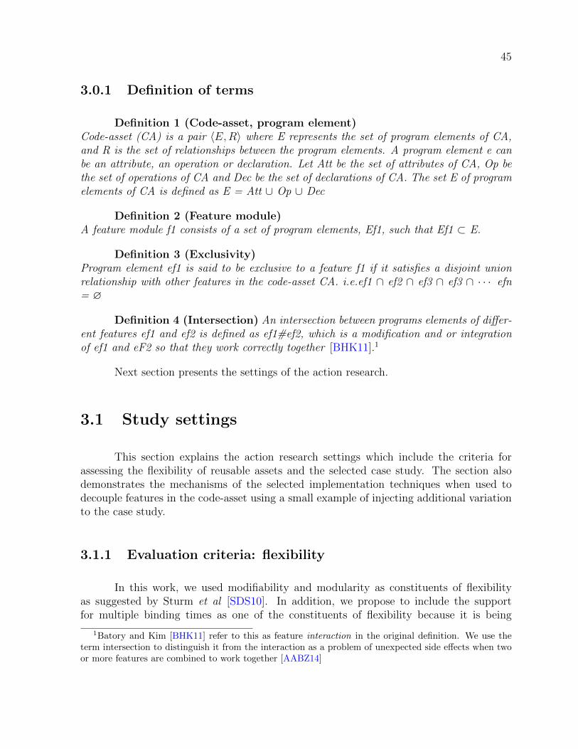
45
3.0.1 Definition of terms
Definition 1 (Code-asset, program element)Code-asset (CA) is a pair 〈E,R〉 where E represents the set of program elements of CA,and R is the set of relationships between the program elements. A program element e canbe an attribute, an operation or declaration. Let Att be the set of attributes of CA, Op bethe set of operations of CA and Dec be the set of declarations of CA. The set E of programelements of CA is defined as E = Att ∪ Op ∪ Dec
Definition 2 (Feature module)A feature module f1 consists of a set of program elements, Ef1, such that Ef1 ⊂ E.
Definition 3 (Exclusivity)Program element ef1 is said to be exclusive to a feature f1 if it satisfies a disjoint unionrelationship with other features in the code-asset CA. i.e.ef1 ∩ ef2 ∩ ef3 ∩ ef3 ∩ · · · efn= ∅
Definition 4 (Intersection) An intersection between programs elements of differ-ent features ef1 and ef2 is defined as ef1#ef2, which is a modification and or integrationof ef1 and eF2 so that they work correctly together [BHK11].1
Next section presents the settings of the action research.
3.1 Study settings
This section explains the action research settings which include the criteria forassessing the flexibility of reusable assets and the selected case study. The section alsodemonstrates the mechanisms of the selected implementation techniques when used todecouple features in the code-asset using a small example of injecting additional variationto the case study.
3.1.1 Evaluation criteria: flexibility
In this work, we used modifiability and modularity as constituents of flexibilityas suggested by Sturm et al [SDS10]. In addition, we propose to include the supportfor multiple binding times as one of the constituents of flexibility because it is being
1Batory and Kim [BHK11] refer to this as feature interaction in the original definition. We use theterm intersection to distinguish it from the interaction as a problem of unexpected side effects when twoor more features are combined to work together [AABZ14]

46
recognized as an important aspect of SPLE [DFV03, VdH04, CRE08, RSAS11]. Thethree constituents of flexibility (modifiability, modularity, and support for multiple bindingtime) are potential indicators to maintainability, time-to-market and production costs. Wefurther elaborate on these constituents of flexibility in the following:
3.1.1.1 Modifiability
Modifiability is the ease of accommodating changes. In this work, we adopted repet-itive viscosity (RV) measure[RKS00] to compare the modifiability of the implementationtechniques. RV is regarded as immediate efforts required to make the changes with thetechnique in observation. The lower the value of viscosity obtained from using a techniqueto modify program elements, the better the technique.
We instantiate the repetitive viscosity with three sub-metrics: #C: number offragments created - this is the case when some fragments should be newly added to injectthe variation (e.g. new delta in DOP or new aspect in AOP). #M: number of programelements moved - these elements are removed from their original location and inserted ata different place (e.g., an attribute declaration is moved to the new fragment created).#V: number of mechanisms added to implement variations - these elements solely belongto a variation mechanism (e.g., #ifdef for the pre-processing technique).
Where it is not possible or it does not make sense to derive the RV interms of#C, #M, and #V, we qualify the RV of each of the techniques as low, moderate or high.For example it does not make sense to quantify RV of intersection within a method an aconstructor and in which the values can be reasonably generalizable due to variations inparameters/signatures, line of codes and scattering of intersections.
3.1.2 Feature modularity and support for multiple binding time
In general, modularity is a desired property of an implementation technique becauseit minimises complexity and enables separation of concerns[BOVH17]. In this work, weconsider modularity from two different perspectives: horizontal and vertical modularity.
The horizontal modularity is used to evaluate whether a technique provides a mech-anism to modularize implementation artefacts at the same level of abstraction with a fea-ture (i.e., decomposing a product line assets into feature modules providing traceabilityfrom an abstract feature in the analysis to feature module in the implementation). Sim-ilarly, the vertical modularity means a sub-hierarchical organization of program elementswithin the feature module.
In addition to modularity, an implementation technique is said to support multiple

47
Figure 3.1: Selected BDE variations transformed into features.
binding times if it can be used to bind a feature at more than one phase of the product’slifecycle.
3.1.3 The case study: Oracle Berkeley Database Engine (BDE)
Oracle Berkeley Database Engine (BDE), Java Edition, is an embedded storageengine designed to support integrations of functionalities and storage requirements ofan application in a single binary installation. It is specific for applications targetingJava Virtual Machine (JVM) and where no separate installation of a database server isrequired. Hence, the BDE runs in the same memory address space with the integratedapplication and thereby eliminating the overhead of process switching. As highlighted inthe Introduction section, BDE products can be embedded in a wide range of applications.
BDE has many features that are extraneous to the requirements of some applica-tions in the domain. For example, features for concurrent access and atomic transactionare not required in an application with single access and simple data requirements. Simi-larly, by default, BDE gathers statistics of almost every operation of the database such astree traversal and memory usage. The implementation of the statistics collection adds asignificant footprint that may become a burden to some applications that do not requirethe collection of statistics. Therefore, those features should be variable and the code-assetshould reflect their variability.
We selected the BDE as a case study because its legacy code-asset requires ad-ditional variations to derive customized products for the different applications and hasbeen used in previous researchers related to flexible variations and binding times[KAB07,ARR+16].
Fig.3.1 depicts the partial feature model of BDE in which 11 features there were

48
Table 3.1: List of 11 variations selected for transformation into features
Feature name explanation
ChecksumFeature for calculating checksum for every database en-try to be written to the log file and using the same forvalidation while reading back the entry.
Delete Feature implementing delete operation of the database.EnvironmentLock
Feature responsible for locking the database to preserveits integrity on concurrent access.
EvictorFeature responsible for maintaining memory consump-tion within certain threshold specified in the databaseconfiguration.
Incompressor Removes delete entries and empty nodes from the tree
IOA variant implementation of database input and outputoperation.
Look aheadcache
Feature for maintaining cache on log files that are line-up for cleaning.
Memory budgetFeature for monitoring overall memory usage of thedatabase.
NIOA variant implementation of database input and outputoperation.
Truncate Feature for deleting the database and creating new one.
StatisticsFeature responsible for gathering statistics about severaloperations of the database.
not variables will have to be made variable to increase its usage-context. All the featureswere identified from previous studies [KAB07, ARR+16] and vary in size of line of codes.We limited our selection to 11 features because the retrofitting of variations into featuresis tediously repetitive. Table 3.1 presents a brief explanation of the selected features.
3.1.4 Case study exploration
To study how features are implemented in the code-asset, we followed an iterativeprocess depicted in Fig.3.2. We started with consulting BDE documentations [Coo17, Tec]to have reasonable domain knowledge. We then checked the features already identifiedfrom the previous studies[ARR+16, KAB07]. We then searched through the code-asset totrace the identified features. With the support of a tool, we marked program elements ofthe traced features with annotations. In the process of marking the BDE code-asset, wemade the following observation: the code-asset of BDE is a union of feature modules andthe program elements in the feature modules intersect with each other. Fig.3.3 depictsthis observation in a Venn diagram.

49
Figure 3.2: Iterative process for study of features in code assets
Figure 3.3: Union an intersection of feature modules in code-asset
In Fig.3.3, each of the feature modules, represented by F1...Fn, internally containsprogram elements (attributes, declarations, and operations) that are only for the contain-ing feature as well as program elements that are shared with other features. We refer tothe program elements that are not shared with any other feature as exclusive elementsto the given feature, and the shared part as an intersection between features. We defineexclusivity and intersection (semi-formally) in definition 3 and definition 4 respectively atDefinition of terms section.
Consequently, injection of additional variations requires decoupling of unions be-tween features in the code-asset: The program elements of the feature to be made variant(both the exclusive and the intersection parts) have to be traced in the code-asset; Boththe exclusive and the intersection parts have to be separated; The separated parts shouldbe added to a product configuration only if the variant feature is selected.

50
Figure 3.4: Research execution steps
We noticed this observation to be true in other implementation techniques. Thefollowing are examples: using various design patterns in OOP[GHJ+95, SSS17], one shouldbe able to encapsulate features to some extent. For example, Keypad, Finger print, Re-mote control as OR group sub-features of Access Control feature in a smart home can beimplemented using Strategy pattern. In that case, a developer implements each feature asa separate strategy for accessing the smart home, and each of the strategies only containsprogram elements exclusive to one of the features. At the point of invocation, however, arequest to access the smart home has to be resolved to one of the concrete strategies, andthat is the point of intersection.
Similarly, when using class inheritance, as a form of polymorphism, to implementan optional feature as a subclass of one of the mandatory classes, the sub-class is theexclusive program element to the optional feature. In that case, intersection points areplaces where references are made to the subclass.
Thus, thinking in terms of exclusiveness and intersection may be beneficial in theevaluation of other implementation techniques. Intuitively, an implementation techniquethat limits the number of intersections may be better for a product line that is not stableand with the tendency of the emergence of new usage-contexts. Of particular note, Factorypattern encapsulates a specific form of intersection- a point to create one of the variantobjects.
Following the observation about the exclusiveness and the intersection, we adopteda reductionism strategy and focus on a small representation of both the exclusivity and theintersection. Reductionism is a scientific approach to understanding complex phenomenaby focusing on a thorough investigation of part of the phenomena in order to understandthe whole[ESSD08]. While the reductionism approach is not normally reported explicitlyin software engineering researches, it has been applied to several software engineeringresearches implicitly [BOVH17, RKS00, MLWR01, DSW14].
Figure 3.4 depicts how the rest of the study was executed. As shown in Fig.3.4,after the exploration of features in the code-asset, the next step (step 1 in Fig.3.4) ofthe study is the injection of additional variation to the small representation with each ofthe selected techniques. In the same step 1, we discussed the flexibility of each of thetechniques using modifiability metrics. We discuss the details activities of step 1 in the

51
next section (Study execution).
In step 2, we compared the three techniques relative to pre-processing of annota-tions. Our hypothesis is that: ’new’ language-based implementation techniques proposedto support flexible variations are also better in modifiability when injecting additional vari-ations than the classical implementation technique.
In step 3, we defined custom annotations based on various categories of exclusive-ness as well as the intersections. We marked program elements of the selected features,from BDE code-asset, with the custom annotation and implemented a custom annotationpre-processor. We collect statistics about the eleven features at compile-time and extrap-olated the results obtained from the small representation (from step 2). We discuss theactivities of step 2 through step 3 in the Custom annotations section.
3.2 Study execution
From SPLE literature, we selected four distinctive variability implementation tech-niques for the study: (i) Pre-processing (PP) of annotations (ii) Aspect-Oriented Pro-gramming (AOP) (iii) Feature-Oriented Programming (FOP) and (iv) Delta-OrientedProgramming (DOP). PP is not a language-based implementation technique but is widelyused in practice[HZS+16, LAL+10] and therefore we used it as a benchmark. AOP aug-ment Object-Oriented Programming (OOP) with mechanisms to separate crosscuttingconcerns. The last two (FOP and DOP) are specifically designed to implement featuremodules in SPLE. These techniques differ in how they can be used to decouple and syn-thesize implementation modules. They also differ in how they deal with the binding timeof features.
The main focus of this chapter is the comparison of language-based implementationtechniques when we have to refactor variations of a legacy code-asset into features. We,therefore, illustrate each of the techniques with a simple case of untangling part of theStatistics features of BDE to change the type of Statistics from mandatory to optional
Note that, the legacy implementation of BDE has no embedded variation mecha-nism. The following sections merely illustrate how the respective techniques might be usedto inject additional variations to the existing code-asset (i.e. to transform some variationsinto features) assuming BDE has been developed with the respective techniques.
Fig.3.5 illustrates the code-asset in which the Statistics is still mandatory. In thefigure, there are four Java classes: Cleaner, LongStat, FileSelector, and DatabaseImpl.Within the classes, the program elements of Statistics are shaded in grey.
In the Cleaner class at the top-left of Fig.3.5, there are two attributes, stats an

52
Figure 3.5: Part of BDE code-asset before injecting variation. Statistics source-codes to bedecoupled are shaded grey

53
nCleanerRuns (line 4-5) that are exclusive to Statistics. In addition, there is an intersectionwithin the class constrcutor (line 9). The entire LongStat class, at the middle-left ofFig.3.5, is exclusive to Statistics. In the FileSelector class, at the bottom-left of Fig.3.5,the method loadStat() (line 7-9) is also exclusive to Statistics.
In the DatabaseImpl class at the right hand side of the Fig.3.5, the attribute, stats(line 7) and the method, getEmptyStat()(line 9-11), and the static inner class StatsAccu-mulator(line 35-36) are exclusive to Statistics . In addition, intersections can be observedwithin the walkDatabaseTree method (line 25-26, line 31-32, and even within its parame-ters on line 20). The method has thirty-seven (37) lines of statements that are not partof the intersection (not shown in Fig.3.5).
The DatabaseImpl class is an interesting one because it has program elements thatare exclusive to Statistics as well intersections. In the subsequent discussions about theimplementation techniques, we use the DatabaseImpl class to illustrate the modifiabilitymetrics when decoupling exclusive elements and intersection within a method. We alsouse the Cleaner class to illustrate the decoupling of an intersection within a constructor.
In each of the techniques, we discuss the case of decoupling the program elementsexclusive to Statistics using the DatabaseImpl class and we present the discussion as(Modifiability Case 1: decoupling of program elements exclusive to a feature). We discussthe intersection of program elements using the walkDatabaseTree method and we presentthe discussion as Modifiability Case 2: decoupling intersection within a method. Lastly, wediscuss the case of decoupling an intersection within a class constructor using the Cleanerclass and present the discussion as Modifiability Case 3: decoupling intersection within aconstructor
We begin with the pre-processing of annotations in the next section.
3.2.1 Pre-processing with Antenna tool
In Chapter two, we illustrated how pre-processing of annotations (pre-processingin short) can be used to implement a domain. To be consistent with the presentation ofother techniques to be discussed in this section, we repeat the pre-processing here withthe example of changing the feature type of Statistics from mandatory to optional.
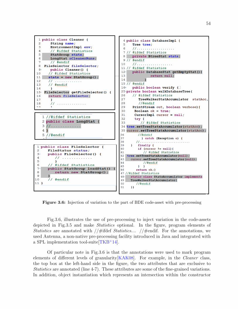
54
Figure 3.6: Injection of variation to the part of BDE code-asset with pre-processing
Fig.3.6, illustrates the use of pre-processing to inject variation in the code-assetsdepicted in Fig.3.5 and make Statistics optional. In the figure, program elements ofStatistics are annotated with //#ifdef Statistics.... //#endif. For the annotations, weused Antenna, a non-native pre-processing facility introduced in Java and integrated witha SPL implementation tool-suite[TKB+14].
Of particular note in Fig.3.6 is that the annotations were used to mark programelements of different levels of granularity[KAK08]. For example, in the Cleaner class,the top box at the left-hand side in the figure, the two attributes that are exclusive toStatistics are annotated (line 4-7). These attributes are some of the fine-grained variations.In addition, object instantiation which represents an intersection within the constructor

55
Table 3.2: Repetitive Viscosity of (Virtual)decoupling of program elements that are exclusiveto the Statistics feature in the DatabaseImpl class with PP
Technique #C #M #V TotalPP 0 0 3 3
Table 3.3: Repetitive Viscosity of (Virtual)decoupling intersections between the base-programand Statistics within the walkDatabaseTree method and within the constructor of the Cleaner
class with the PP technique.
Decoupling scenario RV Remarksintersections within a method low simple annotations are required.intersections within a constructor low simple annotations are required
of the Cleaner class (line 10-13) is also annotated. In contrast, the LongStat class, at themiddle box in the same left-hand side, is annotated in its entirety. It means that the wholeLongStat class is only included in a product configuration when the Statistics feature isselected (The class is exclusive to Statistics and at coarse-grained level). Similarly, inFileSelector class at the bottom box in the left hand side of the Fig.3.6, the method thatis exclusive to Statistics, loadStat(), is entirely annotated (line 6-10).
So far we illustrate how the code-assets can be annotated to introduce variations,next we demonstrate the modifiability metrics when the pre-processing is used to injectvariations. We also briefly discuss modularity and the support for variations in featurebinding time when the technique is used to implement variations.
Modifiability Case 1: decoupling program elements exclusive to featurewith PPTo decouple program elements that are exclusive to Statistics in the DatabaseImpl classwith PP, no #C or #M is required because PP is not sensitive to the semantic of theunderlying programming language. However, #V is required in the form of annotations.In this example, three annotations are required (see lines 7-9, 11-15,and 47-50 in theDatabaseImplclass of Fig.3.6 ). Thus, Table 3.2 represents the modifability of programelements that are exclusive to Statistics and within the DatabaseImpl class.
Modifiability Case 2: decoupling intersection within a method with PPTo decouple the intersections within the walkDatabaseTree method with PP, simple anno-tations are required to virtually decouple the intersections. The annotations required inthis case are three in total (see Fig.3.6). One of the annotations is used to surround theparameter, statsAcc, of the type TreewalketStatsAccumulator (line 26-28 in fig 3.6). Otherannotations are in lines 34-35 and lines 42-43. Thus we rate the PP low in this regard asdepicted in the first row of Table 3.3.

56
Modifiability Case 3: decoupling intersection within a constructor withPPTo decouple the intersection within the constructor of the Cleaner class with PP, singleannotation suffices since the 35 Statistics related attributes (not shown in Fig.3.6) areadjacent to each other as one block of code. Hence, we rate the RV of PP low (see thesecond row of Table 3.3).
Modularity and support for variations in feature binding time in PPAs a classical tool-based technique, PP has no support for modularity. As such, varia-tion mechanisms are scattered in the code-assets with no support for feature traceability[KA09].
With respect to support of flexible binding time, with PP, a feature has to bebound before compilation at pre-deployment time and not at any other binding time.Hence, pre-processing has no support for multiple binding time.
3.2.2 Feature-Oriented Programming (FOP) with Jak language
Figure 3.7: UML package representing part of BDE code-asset before injecting variation withFOP

57
Figure 3.8: Injection of variation with to part of BDE code-asset with FOP
Proponents of Feature-Oriented Programming (FOP) are of the view that a featureis an increment in software functionality. As such, a feature module can be implemented asa refinements to a base-program (a basic implementation of a product line)[SB02, Bat05b,Pre97]. The refinements can be pure addition of new program elements or modification ofexisting ones. The concept of refining the base-program is in line with SPLE approachesin which mandatory features are implemented as monolithic program and variable featuresare implemented as extensions to the mandatory features of the base-program. Terms suchas kernel [Gom05], core-module [SBB+10] are also used to describe the representation ofall mandatory features, with which variable features may extend.
Fig.3.7 depicts a UML package containing program elements, representing the base-program, as in Fig.3.5, and in which the Statistics feature is still mandatory. Thus, thepackage contains the same classes as that of Fig.3.5. In Fig.3.7, the program elementsof Statistics are shaded in grey. The callout shape, placed beneath the LongStat class,illustrates an object instantiation (stats = new StatGroup) within the constructor of theCleaner class.
Fig.3.8 illustrates conceptual injection of variation with FOP. In the figure, thebase-program and the Statistics feature occupy separate packages (illustrated with theUML package diagram and 〈〈feature〉〉 stereotype). On one hand, all the program ele-ments related to Statistics feature are removed from the package of Base (see the left-hand

58
side of Fig.3.8). On the other hand, Statistics, as a variable feature, modifies program el-ements of the Base using a series of refinements (see the right-hand side of Fig.3.8). Therefinements are illustrated with 〈〈refined〉〉 stereotype and include the addition of thefollowing program elements that were removed from the base-program: the method, load-Stats(), in the FileSelector class (the top class in the Statistics package); the attributes(stats and nCleanerRuns) in the Cleaner class; the static inner class StatAccumulator inthe DatabaseImpl class. The refinements also include constructor modification of the sameCleaner class;
Other forms of the refinements is overriding a method which is of two forms: (i)overriding an existing method to introduce the source-codes removed from the originalmethod and (ii) introducing empty method in the base-program and overriding it in thedecoupled feature - this is the case when a hook has to be introduced in the base-programand in which the variant feature extends. For example, in Fig.38, Statistics related source-codes are removed from the walkDatabase method of the DatabaseImpl class of the Base(i.e base-program). Thus, the method is overridden in the DatabaseImpl class of Statisticsto re-introduced the removed source-codes that are relevant only to Statistics. This is thecase of override (i) above. In contrast, setTreeandCursorStat(...) and resetTreeandCur-sorStat(...) methods in the DatabaseImpl of Base were introduced mainly as hooks to beextendend by their counterparts in the same DatabaseImpl of Statistics. This is the caseof ovverride (ii) above.
In summary, Statistics refines Base when the feature is selected but everything inthe Statistics package is not included in the product configuration if the correspondingfeature is not selected.
Jak is a Java language extension designed to reify FOP in the implementation.With the Jak language, each feature module is confined to a separate directory structureknown as containment hierarchy. For example, Fig.3.9a and Fig.3.9b depict the contain-ment hierarchies for Base and the Statistics respectively. The duplicated classes, Cleaner,FileSelector, and DatabaseImpl, in the Statistics containment hierarchy contain only themodifications of the original classes of the Base.
FOP is one of the prominent techniques proposed to implement flexible variationin SPLE[SB02, Pre97, Bat05b]. In this study, we used FeatureIDE[TKB+14], an eclipseplugin that integrated the Jak language compiler and the tools for the synthesis and thetranslation from Jak to Java. From the domain implementation technique perspective,FOP approach is compositional. Thus, the composition of program elements of the selectedfeatures is gradual refinements of the base-program and the composed program elementsare then transformed into target programming language (Java in our example). Next, wediscuss the three cases of modifiability.

59
(a) Containment hierarchy of Base in whichprogram elements of Statistics are removed from the
3 classes
(b) Containment hierarchy of Statistics in which LongStat classis created and other 3 classes refined to form program elements
of Statistics
Figure 3.9: Containment hierarchies for Base and Statistics in Jak language
Table 3.4: Repetitive Viscosity of decoupling of program elements that are exclusive to theStatistics feature in the DatabaseImpl class with FOP.
Technique #C #M #V TotalFOP 1 3 1 5
Figure 3.10: Decoupling of program elements that are exclusive to Statistics in theDatabaseImpl class with FOP
Modifiability Case 1: Decoupling program elements exclusive to featurewith FOPTo decouple program elements that are exclusive to Statistics, in the DatabaseImpl class,with FOP, the class has to be re-created in the Statistics ’ containment hierarchy, which

60
Table 3.5: Repetitive Viscosity of decoupling intersections between the base-program andStatistics within the walkDatabaseTree method and within the constructor of the Cleaner class
with the FOP technique.
Decoupling scenario RV Remarks
intersections within a method moderaterequires the creation of extensionpoints.
intersections within a constructormoderate-
block move operations and simple re-finements
makes #C to be one (1). One (1) #V is required, to refine the DatabaseImpl classin Statistics’ containment hierarchy. The three program elements that are exclusive toStatistics have to be removed from the base-program and moved to the refined class (seeFig.3.10): this makes #M to be three (3). Thus, the total RV of decoupling programelements that are exclusive to Statistics in DatabaseImpl class is five (5) (see Table 3.4).
Modifiability Case 2:decoupling intersection within a method with FOPTo decouple intersection within a method with FOP and when the intersections are neitherat the beginning nor at the end of the method, but in the middle as in the walkDatabaseTreemethod of the DatabaseImpl class (see Fig.3.11a), the points of intersections have to beextracted into empty methods, known as hooks or hotspots [KAB07]. Fig.3.11a shows twohooks created (C1 and C2) and two placeholders for the hooks are also created (C3 andC4).
The C5 in Fig.3.11b denotes the re-creation of the walkDatabaseTree in the newcontainment hierarchy. In addition, the lines of statements that are for Statistics are movedfrom the base-program to the newly created walkDatabaseTree(see M1-M3 in Fig.3.11b).The mechanisms used are the overriding of the walkDatabaseTree method, using the con-struct Super() (V1 in Fig.3.11b) and overriding of the two hook methods (V2 and V3 inFig.3.11b). Thus we rate the RV of FOP for decoupling intersection within a method asmoderate (see the first row of Table 3.5).
Modifiability Case 3: decoupling intersection within a constructor withFOPTo decouple intersection within the constructor of the Cleaner class with FOP, the Cleanerclass has to be re-created, in the Statistics’ containment hierarchy (Fig.3.12), which makesthe #C to be one (1). The program elements that are related to Statistics have to beremoved from the legacy base-program and moved to the new class as one block operation(M1 in Fig.3.12). Only two (2) #Vs are required, in form of modification, to the Cleanerclass itself (V1 in Fig.3.12a) and its constructor(V2 in Fig.3.12). Thus, we rate RV ofFOP moderate -. The minus (-) means that the moderation is closer to low due to thefew number of move and refine operations (see the second row of Table 3.5).

61
(a) re-organized walkDatabaseTree method in whichprogram elements of Statistics are removed in
preparation for refinement with FOP
(b) the walkDatabaseTree method in which theremoved program elements of Statistics are
re-introduced with FOP refinement
Figure 3.11: decoupling intersection within a method in FOP
Figure 3.12: decoupling intersection within a constructor with FOP

62
Figure 3.13: Modularity with FOP
Modularity and support for variations in feature binding time in FOP
FOP support both the horizontal and the vertical modularity as conceptually de-picted in Fig.3.13. In the figure, program elements of each feature are confined to a ded-icated containment hierarchy. As such, the horizontal modularity is strictly enforced(seeFig.3.13). In addition, the typed program elements, donated with letters in Fig.3.13, arealso strictly bounded in separate files. Thus, vertical modularity is also strictly enforced.For example, in Fig.3.13, program element D’ is a refinement of program element D of thebase-program; it is only for feature A and is traced to a separate file under the containmenthierarchy of feature A. Likewise, a separate refinement of program element D, denoted asD”, is only for feature B and is traced to a separate file under the containment hierarchyof feature B [Bat05b].
With respect to support for flexible binding time, FOP supports the two modes offeature binding to executing context: (i) static binding mode and (ii) dynamic bindingmode. With static binding mode, program elements and their refinements are staticallycomposed. With dynamic mode, the mixin inheritance style is used to compose programelements with their refinements. The two different binding modes are supported in Jakwith two separate tools: jampack for the static binding mode and mixin for the dynamicbinding mode. However, from the perspective of feature binding to a product, the vari-ability has to be resolved before compilation at pre-deployment time[Bat05b]. That is,FOP does not support feature binding after compilation at either deployment or post-deployment time.
3.2.3 Aspect Oriented Programming (AOP) with AspectJ
Aspect Oriented Programming (AOP) is a programming paradigm for modulariza-tion of crosscutting concerns. A concern is a specific requirement of a software product.In SPLE, variable features can be implemented as concerns that are separable from thebase-program [CLK08, FCS+08, KAB07, ARR+16]. Thus, the set of mandatory features

63
Figure 3.14: injection of variation w with AOP

64
Table 3.6: Repetitive Viscosity of decoupling of program elements that are exclusive to theStatistics feature in the DatabaseImpl class with FOP.
Technique #C #M #V TotalAOP 1 3 3 7
are implemented as a base-program.
AOP construct, aspect, is used to encapsulate a concern, which may be a featurein SPLE. Aspect extends (advice) the behaviour of a base-program at some points (joinpoints). Similarly, an AOP construct, pointcut, is used to define the specific join pointswhere the aspect extends (advice) in the base-program. In addition, an aspect may in-troduce new program elements or new inheritance hierarchies to program elements in thebase-program using the intertype declaration mechanism.
For AOP, we do not show the structure of program elements, representing the base-program, where the Statistics feature is still mandatory because it is the same with thestructure depicted in Fig.3.8 in the FOP discussion.
Fig.3.14 shows the use of AOP to inject variation and make Statistics optional.In the figure, StatisticsAspect (the grey box at the right-hand side of the figure) injectsadditional attributes (stats and nCleanerRuns) to the Cleaner class and the method,loadStats, to the FileSelector class. Similarly, StatisticsAspect2 at the bottom left of thefigure injects the attribute stats, the method getEmptyStat(), and the static inner classStatAccumulator to the DatabaseImpl class. The injection of attributes and methodsis achieved through the intertype declaration mechanism (represented as the 〈〈ITD〉〉stereotype in Fig.3.14).
Furthermore, StatisticsAspect modifies the construction of the Cleaner object (illus-trated using 〈〈advice〉〉 stereotype) through the joint point captured by the pointcut (illus-trated using 〈〈pointcut〉〉stereotype), exeCleaner. Similarly, the StatisticsAspect2 modifiesthe two empty methods introduced to the DatabaseImpl class hooks using two point cutdeclarations and two around advices. In this work, we use AspectJ [Lad03], one of thepopular Java-based AOP.
When selected, the separated feature (Statistics in this example) is composed withthe base-program using aspect weaving mechanism. The actual weaving may be done atdifferent phases of the product lifecycle. From the feature binding perspective, the AOPapproach is also compositional. The original intention of AOP was not to separate featuresin SPLE. However, there is increasing interest in using AOP to support flexible variationsand binding times [KAB07, ARR+16, CRE08, AM04].

65
Table 3.7: Repetitive Viscosity of decoupling intersections between the base-program andStatistics within the walkDatabaseTree method and within the constructor of the Cleaner class
with the AOP technique.
Decoupling scenario RV Remarks
intersections within a methodmoderate+
requires the creation of extensionpoints and several language constructs.
intersections within a constructormoderate+
aspect has to have several references totargeting type in intertype declaration.
Figure 3.15: Decoupling of exclusive program elements with AOP
Modifiability Case 1: decoupling program elements exclusive to featurewith AOPTo decouple program elements that are exclusive to Statistics, in the DatabaseImpl class,With AOP, a new aspect has to be created which makes #C to be one (1). The threeprogram elements that are exclusive to Statistics have to be removed from the base-program and moved to the new aspect: this makes #M to be three (3) (see Fig.3.15).The new aspect of the Statistics feature injects (through intertype declaration) each ofthe moved program elements to the DatabaseImpl class using the prefix of the class (e.g.DatabaseImpl.stats), which makes #V to be three (3) (see Table 3.6).
Modifiability Case 2: decoupling program intersection within a methodwith AOPTo decouple intersections with a method with AOP and when the intersections are in themiddle of the method, the same extractions of hooks that are required in FOP are alsorequired in AOP. In addition, several language mechanisms have to be used. Fig.3.16 showsthe mechanisms used in AOP: two pointcut declarations (V1 and V2 - not always neededwhen anonymous advices are used); two advices (V5 and V6); movement of programelements related to Statistics from the base-program to the new aspect (M1, M2, andM3); reference to DatabaseImpl (V3 and V4). Further, 6 additional language constructsare required (pointcut, execution, target, within, around and proceed). Thus, similar to

66
Figure 3.16: Decoupling intersection within a method with AOP
FOP, we rate the RV of FOP for decoupling intersection within a method as moderate +.The + sign means that the moderation is tending towards high (see the first row of Table3.7 for the summary).
Modifiability Case 3: decoupling intersection within a constructor withAOPTo decouple intersection within the constructor of the Cleaner class with AOP, a pointcutand advice have to be created in the new aspect. The program elements that are relatedto Statistics have to be removed from the legacy base-program and moved to the Statisticsaspect (M1-M.. in Fig.3.17). The aspect of the Statistics feature uses the reference to theCleaner object severally (V1-V.. in Fig.3,17) in the intertype declaration. Thus, we rateRV of AOP moderate because of the several uses of the reference to the Cleaner class.The plus (+) means that the moderation is closer to high (see the second row of Table 3.7for the summary).
Modularity and support for variations in feature binding time in AOP
AOP supports vertical modularity, the horizontal modularity can be achieved butit is not strictly enforced (depicted as the dotted-triangle in Fig.3.18). For example, apackage system in Java can be used to organize program elements that are exclusive to

67
Figure 3.17: Decoupling intersection within a constructor with AOP
Figure 3.18: Modularity with AOP
feature. Aspects will then have to be used to encapsulate program elements intersectingwith other features.
AOP supports binding of feature to a product at two phases: The first phase,compile-time weaving phase, corresponds to the binding of a feature at pre-deploymenttime. The second phase, load-time weaving phase, roughly corresponds to the binding of afeature at a deployment phase. Similarly, the binding can also be delayed by externalizingthe feature configuration (e.g.using XML file).
3.2.4 Delta Oriented Programming (DOP) with DeltaJ 1.5
Delta Oriented Programming (DOP) is also a language-based implementation tech-nique proposed to support flexible variations[SBB+10]. In DOP, a basic implementationof a software system is known as a core, and features are implemented as deltas to thecore program. We stick with the term base-program for consistency. A delta is a unit ofspecification on how the based-program should be changed. Fig.3.19 depicts delta specifi-cations representing the base-program, as in Fig.3.5 and Fig.3.7, and in which theStatisticsfeature is still mandatory. In the figure, the program elements of Statistics are shaded ingrey.

68
Figure 3.19: Delta specifications of Base before variability injection with DOP

69
Figure 3.20: Injection of variation with with DOP
To inject variation in DOP, a feature implementation is specified in a separatedelta. The left box of the Fig.3.20 depicts specification of Base in DOP, with programelements of Statistics removed. The right box of the Fig.3.20 depicts specification of adelta (changes) to Base in the implementation of Statistics.
Similar to FOP, the composition of program elements of the selected features isgradual modifications of the base-program and the composed program elements are thentransformed into target programming language (Java in this case).
DOP is an emerging variability implementation technique that supports changesto a based-program and the changes are not only additions of program elements but alsothe removal of program elements (positive and negative variability). In this work, we usedDeltaJ [Del17] implemented in Xtext - a language implementation framework [Xte17].

70
Table 3.8: Repetitive Viscosity of decoupling of program elements that are exclusive to theStatistics feature in the DatabaseImpl class with DOP.
Technique #C #M #V TotalDOP 1 3 3 7
Figure 3.21: Decoupling of exclusive program elements with DOP
Modifiability Case 1: decoupling program elements exclusive to featurewith DOPTo decouple program elements that are exclusive to Statistics in the DatabaseImpl classwith DOP, a new delta specification has to be created, which makes the #C to be one (1).The three program elements that are exclusive to Statistics have to be removed from thebase-program and moved to the new delta: this makes #M to be three (3) (see Fig.3.21). Aseparate adds specification is required for each of the three program elements which makes#V to be three (3) (current DOP implementation does not support the addition of a blockof program elements as a single operation). Table 3.8 summarises the RV of decouplingprogram elements that are exclusive to the Statistics feature in the DatabaseImpl class.
Modifiability Case 2: decoupling program intersection within a methodwith DOPDOP has limited language semantics for decoupling intersections within a method. Thetechnique supports wrapping of an existing method only when both the wrapper andthe wrapped methods have the same number of parameters. This is because DOP hasonly two constructs for modifying a method: (i) the modifies keyword to specify thefull signature of the method to be changed and (ii) the original construct to reuse the

71
Figure 3.22: Modularity in DOP
Table 3.9: Repetitive Viscosity of decoupling intersections between the base-program andStatistics within the walkDatabaseTree method and within the constructor of the Cleaner class
with the DOP technique.
Decoupling scenario RV Remarks
intersections within a method high
two separate methods have to be cre-ated one without Statistics in the base-program and one with Statistics in aseparate delta specification.
intersections within a constructor high
two separate constructors have to becreated one without Statistics in thebase-program and one with Statistics ina separate delta specification.

72
(a) Re-specified method without intersectionin DOP
(b) Re-specified method with the intersectionin DOP
Figure 3.23: Decoupling intersection within a method with DOP
Figure 3.24: Constructor modification with DOP
specification of the old method. Consequently, if a method modification involves changinga parameter in DOP, as in our example, two separate methods have to be created: onewithout Statistics (Fig.23a), in the base-program, and one with Statistics (Fig.23b) in aseparate delta specification. Consequently, we rate the repetitive viscosity of decouplingintersections within a method with DOP as high(see the first row of Table 3.9)
3.2.4.1 Modifiability Case 3: decoupling interaction within a constructor withDOP
DOP does not support the direct modification of a constructor, and therefore, twoseparate constructors have to be created: one without Statistics in the base-program, andone with Statistics in a separate delta specification. Again, we rate the RV of DOP highbecause two separate constructors have to be specified(see the second row of Table 3.9).
Modularity and support for variations in feature binding time with DOP

73
Figure 3.25: Modularity with DOP
DOP supports horizontal modularity as each feature can be traced directly to a separatedelta specification. However, there is no hierarchical modularity in the sense that the typeelements are flatly organized in a possibly large file of delta specification. The modularityin DOP is conceptually depicted in Fig.3.25. There is no hierarchical modularity becausethere is no boundary between program elements of different types within the same delta.The lack of hierarchical modularization may be detrimental to maintaining sizable fea-ture specification. For example, when a feature module has more than 10 Kilo Lines ofCode (KLOC), it is difficult to navigate to individual program elements of interest as weexperienced during refactoring of Statistics feature.
On the support of flexible binding time, DOP is similar to PP. That is, featurebinding has to be decided at pre-deployment time before the product code is generatedbut not at any time.
3.2.5 Comparison between the implementation techniques
Table 3.10: Comparison between the 4 techniques on decoupling of exclusive programelements
Technique #C #M #V TotalPP 0 0 3 3FOP 1 3 1 5AOP 1 3 3 7DOP 1 3 3 7
Table 3.10 presents the Repetitive Viscosity of each of the techniques for decouplingthe three program elements that are exclusive to the Statistics in the DatabaseImpl class.In this context, none of the language-based techniques beats PP in terms of modifiability.

74
Table 3.11: Pattern of RV of implementation techniques on program elements exclusive to afeature
TechniqueProgram elementType
RV Total
PPexclusive class single annotation (#V = 1). RV =1
exclusive attributesingle annotation (#V = 1) or becomes partof block annotation (#V = 1/x).
1/x ≤ RV≤ 1
exclusive methodsingle annotation (#V = 1) or becomes partof block annotation (#V = 1/x).
1/x ≤ RV≤ 1
FOPexclusive class move (#M =1) + create (#C=1). RV =2
exclusive attributemove + refined (#M =1, #V =1) or moveonly(#M =1).
1 ≤ RV ≤2
exclusive methodmove + refined (#M =1, #V =1) or moveonly(#M =1).
1 ≤ RV ≤2
AOPexclusive class move (#M =1) + create (#C=1). RV =2
exclusive attributemove + inject + create (#M =1, #V =1,#C=1) or move + inject only (#M =1, #C=1).
2 ≤ RV ≤3
exclusive methodmove + inject + create (#M =1, #V =1,#C=1) or move + inject only (#M =1, #C=1)(#M =1).
2 ≤ RV ≤3
DOPexclusive class move (#M =1) + create (#C=1). RV =2
exclusive attributemove + adds + create (#M =1, #V =1,#C=1) or move + adds only (#M =1, #C=1).
2 ≤ RV ≤3
exclusive methodmove + adds + create (#M =1, #V =1,#C=1) or move + adds only (#M =1, #C=1).
2 ≤ RV ≤3
FOP has moderate modifiability compared to the other techniques while AOP and DOPhave the lowest modifiability index.
Through this analysis, we observe a generic pattern of RV of each of the tech-niques on three types of exclusive program elements (exclusive class, exclusive method,and exclusive attributes). We present this pattern in Table 3.11.
For PP, referring to Table 3.11, the RV for decoupling exclusive class is one (1) (#V= 1). The RV for decoupling exclusive method and exclusive attribute can either be one(1) (#V = 1) or a fraction of one (#V = 1/x). It is one when no two program elementsto be annotated are adjacent in the code-assets (i.e. each of the program elements has tohave a separate annotation) and a fraction of one when program elements to be annotatedare adjacent in the code-assets (i.e. a single annotation covers more than one program

75
elements).
For FOP, the RV for decoupling exclusive class is two (2): one RV for moving theclass from the base program (#M = 1) and one RV for re-creating the class in the targetcontainment hierarchy. The RV for decoupling exclusive method and exclusive attribute inFOP can either be two (2) or one (1). It is two when each of the methods or attributes isin a separate container class - there has to be move operation (#M =1) and the refinementof the container class (#V =1) for each of the program elements. It is one (1) when anelement is only moved but no refinement is required(see Table 3.11).
Still on Table 3.11, the RV for decoupling exclusive class with AOP and DOP istwo (2): one RV for moving the class from the base program (#M = 1) and one RV forre-creating the class, aspect or delta as the case may be. The RV for decoupling exclusivemethod and exclusive attribute in both AOP and DOP can either be three (3) or two (2).It is three when each of the methods or attributes is to be moved into a new aspect ordelta - there has to be move operation (#M =1); intertype declaration in aspect or addsspecification in delta (#V =1); the creation of aspect or delta container (#C=1). It istwo when no new aspect or delta is to be created as a result of the decoupling.
We will return to the RV for decoupling exclusive program elements when we havean idea about the number of exclusive program elements for the Statistics feature inCustom annotation section (next section).
3.3 Custom annotations
In this section, we present the definition and application of custom annotations tomake sense about the results of the repetitive viscosity discussed in the previous section.We defined custom annotations to use as metadata on program elements. We refer tothe annotations as custom to distinguish them from the pre-existing reusable annotations(eg. #ifdef annotations). The custom annotations are used to indicate whether a programelement is exclusive to a given feature or it is shared with one or more features (involved inan intersection). Program elements that may be annotated exclusively to a feature can beclass, method or attribute. The intersection between one or more features can be markedon a class constructor or on a method.
3.3.1 Custom annotation definition
Listing 3.1: List of features marked with custom annotations
1: public enum FeatureSet {

76
2: BASE, STATISTICS, ......
3: }
Listing 3.1 depicts the list of pre-defined features specified as Java enumeratedlist. A program element can be marked as exclusive to one of the features in the list (seethe full list in Table 3.1). We can also mark intersection, on program element, betweentwo or more features in the list. The “BASE” at the beginning of the list represents thebase-program.
Listing 3.2: Types of program elements marked with custom annotations
1: public enum ProgramEType {
2: EXCLUSIVE_CLASS, INTERSECTION_METHOD,..
3: }
Listing 3.2 is also Java enumerated list in which each entry indicates the typeof program element and its relation with the feature being annotated. For example,EXCLUSIVE CLASS indicates that the program element being annotated is a class andis exclusive to a particular feature.
Listing 3.3 depicts the definition of the custom annotation where the attributesare references to the enumerations from listing 3.1 and 3.2: The name attribute in line3 takes one of the predefined features from listing 3.1; The elementType attribute in line4 takes one of the pre-defined types of program elements from listing 3.2; The intersect-ingFeatures attribute in line 5 is an array that takes one or more features defined in listing3.1 as elements. The default value of intersectingFeatures attribute is base-program (i.e.FeatureSet.BASE). That is, a feature intersects with at least the base-program.
Listing 4.3: Specification of the custom annotation
1: ...
2: public @interface Feature {
3: FeatureSet name();
4: ProgramEType elementType ();
5: FeatureSet [] intersectingFeatures ()
6: default {FeatureSet .BASE};
7: String [] descriptions() default {};
}
Listing 3.4 is an example of marking a program element with the custom annotation.In the listing of 3.4, the constructor of Cleaner class is marked as one of the intersectionpoints between Statistics feature and the base-program.

77
Table 3.12: Exclusive and intersections of program elements fro 11 features selected from BDE
Feature nameexclusiveclass
exclusivemethod
exclusiveat-tribute
intersectionin con-structor
intersectioninmethod
Total
Checksum 6 0 16 6 16 44Delete 0 14 18 8 18 48EnvironmentLock
0 2 6 2 2 12
Evictor 4 28 4 0 10 46Incompressor 2 12 8 0 8 30IO 1 0 0 1 0 2Loook aheadcache
1 0 0 0 3 4
Memory budget 2 38 14 2 40 96NIO 1 0 0 1 0 2Statistics 20 70 154 64 2 310Truncate 0 8 0 0 0 8Total 37 172 210 84 99 602
Listing 3.4: Example of marking a program element with the custom an-notation
1: @Feature(name= FeatureSet.STATISTICS,elementType
2: =ProgramEType.INTESECTION_CONSTRUCTOR)
3: public Cleaner( .){..}
3.3.2 Custom annotation application and processing
We marked the eleven (11) features from BDE, summarised in Table 3.1, with thecustom annotations.
We implemented a pre-processor for the custom annotations and collected statisticsabout the annotated code-asset at compile time. We sought to have an idea about thespread of exclusiveness and intersections to make sense of the results of the evaluationsobtained from Study execution section. Table 3.12 presents the spreads of exclusivenessand intersections about the 11 annotated features. Each row in the table represents anentry for a single feature. Note that the exclusive program elements made-up the firstthree columns (i.e. exclusive class, exclusive method, and exclusive attribute).
From Table 3.12, observe that Statistics feature has the highest number of anno-

78
Figure 3.26: Spread of exclusive and intersection from 11 features
tated program elements with a total of 310, constituting about 52% of the total annotatedprogram elements, while IO and NIO jointly have the least number of program elements,having a total of 2 each. This suggests that a feature in the implementation can be bothsmall and large. Fig.3.26 depicts this information graphically.
Referring to the columns of Table 3.12, exclusive attributes constitute the majorpart of the annotated program elements with a total of 210, representing 35% of the totalprogram elements annotated. On the other hand, exclusive classes (being the coarse-grained implementation units in OOP) are 37 in total, constituting only 6% of the totalprogram elements in the 11 features annotated. This means that most parts of the featuresare traced to fine-grained program elements than coarse-grained program elements.
Extrapolating the generic pattern of RV presented in Table 3.11 to the exclusiveprogram elements of the 11 features, we obtain the results of Table 3.13 which are alsodepicted graphically in Fig.3.27a. Recall that the RV of methods and attributes of all thetechniques is not fixed. The RV of these program elements depend on some factors suchas whether or not a block of methods or attributes can be annotated at once with PP. Theother techniques also have their peculiar factors. This explains the use of less-or-equalsign (≤) to reflect on the patterns presented in Table 3.13.
The same general pattern of RV can also be extrapolated to individual features. Forexample, Table 3.14 represents the estimated RV of each of the techniques on programelements exclusive to the Statistics feature and Fig.3.27b depicts the same informationgraphically.
Apart from the extrapolation of exclusiveness, we can also obtain information aboutintersections between various features. This information can be useful in determining theorder of precedence of applying aspects in AOP, for example, or order of refinements andmodifications in FOP and delta respectively.

79
Table 3.13: RV for each of implementation techniques on exclusive program elements of 11features
exclusive classexclusivemethod
exclusive at-tribute
Tota PE 37 172 210RV (PP) 37 ≤ 172 ≤210RV (FOP) 74 ≤ 344 ≤ 420RV (AOP) 74 ≤ 516 ≤ 630RV (DOP) 74 ≤ 516 ≤ 630
Table 3.14: RV for each of the techniques on exclusive program elements of Statistics feature
exclusive classexclusivemethod
exclusive at-tribute
Tota PE 20 70 154RV (PP) 20 ≤ 70 ≤154RV (FOP) 40 ≤ 140 ≤ 308RV (AOP) 40 ≤ 210 ≤ 462RV (DOP) 40 ≤ 210 ≤ 462
(a) RV for each of implementation techniqueson exclusive program elements of 11 features
(b) RV for each of the techniques on exclusiveprogram elements of Statistics feature
Figure 3.27: RV for each of the techniques on exclusive program elements

80
Table 3.15: Intersecting features
Feature IntersectionsDelete Transaction, CleanerEnvironmentalLock
IO, NIO
Evictor IncompressorMemory Budget Transaction, Evictor
StatitisticsTransaction, Evictor, Incompressor,Cleaner, Log, Cache, Checkpointer
Figure 3.28: Example of intersecting features
Table 3.15 shows the summary of intersecting features. Note, some of the inter-secting features in Table 3.15 are not among the 11 selected features but were picked whileannotating the 11 features. Also, note that the intersection is reflexive, i.e. if feature A in-tersects feature B, implies feature B also intersects feature A. Fig.3.28 depicts an exampleof 7 features intersecting the Statistics feature.
Taken the extrapolated results together with the qualitative assessments for the in-tersection within a method and within a constructor, we can estimate the modifiability ofeach of the techniques. We can also conclude that none of the language-based implemen-tations techniques is better than PP in terms of modifiability when injecting additionalvariations. In the same context, the code-asset of DOP is the least modifiable to injectadditional variations. This is because, in addition to being comparable to AOP in mostrespects, it falls short on certain critical language semantics.

81
To conclude the discussion about the action research, in the next section, we com-pare our approach with similar action researches from the literature.
3.4 Comparison with similar action researches
In this section, we present similar action researches from the literature to highlightthe novelty of our approach.
In an exploratory study, Murphy et al [MLWR01] investigated the flexibility ofthree language-based techniques when used to untangle features from a code-asset. Allthe three techniques, Hyper/J[TO], AspectJ[Lad03], and the authors’ own technique, weredesigned for advanced separation of concern. The authors qualitatively characterized theeffect the different techniques had on the structure of the code-asset and also character-ized how to restructure the code-asset to untangle features with each of the techniques.Except for the AspectJ, the other techniques were not reported to be used for productline implementation. In addition, they did not use constituents of flexibility as criteria forthe evaluation and did not consider programming languages specifically designed for theproduct line implementation.
Similarly, previous researchers that analysed features of Berkeley DB [KAB07,ARR+16] focused on the aspect-oriented refactoring of the features and they made nocomparison with any other technique. For example, Chakravarthyet al [CRE08] proposeda combination of design patterns[GHJ+95] and aspect-oriented programming to achievethe flexibility of feature binding time. In their approach, a pattern encapsulates a varia-tion point; variants features are implemented with a separate set of aspects, each set fora specific binding time.
In programmable logic controller domain, Bayrak et al [BOVH17] evaluated flex-ibility and maintainability of three process-oriented programming notations. The threedifferent programming notations are Activity diagram, Statechart diagram, and Sequen-tial function chart. Although they used a wide-range of criteria, including modifiability,none of the programming notations is used for product line implementation.
In summary, we differ with the previous approaches in the following ways: 1) westudied the properties of feature in the source -codes; 2) we covered more implementationtechniques two of which were proposed to implement features in SPLE exclusively ; 3) wecompared the modifiability of the techniques when injecting additional variations.

82
3.5 Chapter Summary and perspective
In this chapter, we explored properties features in the code-asset using BerkeleyDatabase Engine (Java edition), as a case study. In the exploration, we observed that anintersection between program elements of different features is the major property of code-asset that affects the modifiability of injecting additional variations. Another propertyof a feature in a code-asset is exclusivity. That is, certain program elements exist forimplementation of a certain feature exclusively.
The implication of this observation to practice is that, an unstable product line andwith the tendency of emerging usage-contexts, should aim for implementation techniquethat limits the number of intersections between program elements of different features.Similarly, the implication of the observation to research is that, there should be subsequentinvestigations using multiple case studies in different software domains in order to improvethe understanding of our findings.
Also, in this chapter, we report the selection and the evaluation of the flexibilityof implementation techniques when injecting additional variations. Two of the selectedtechniques, FOP and DOP, were specifically designed for product line implementation.
Modifiability of DOP, in its current form, is consistently high because the techniquelacks the necessary language semantics to support flexibility. In addition, although it sup-ports horizontal modularity, program elements are flatly organized in a delta specification(no vertical modularity).
AOP trails DOP on modifiability mainly because of the high number of languageconstructs that have to be used to untangle a feature. Achieving horizontal modularity inAOP depends on the discipline of the developers because the technique does not enforce it.Modifiability of FOP is consistently moderate because few operations are involved whenuntangling a feature from a code-asset. Similarly, FOP has the best form of modularitybecause it supports both horizontal as well as vertical modularity.
Reflecting on our hypothesis, none of the techniques is better than PP in termsof modifiability but the approach has no form of modularity. Note, we are not claimingthat PP is a better technique for product line implementation but hypothesized that,new techniques that are proposed to support flexible variations should also be betterin modifiability when injecting additional variations than the PP - which is a classicalimplementation technique.
Except for FOP, the language-based initiative for flexible variations and bindingtime fall short when it comes to adapting code-asset to add additional variations. Anotherlimitation of language-based approaches is the assumption that the variable features alwaysextend a monolithic base-program. A variable feature may extend (intersect) other variable

83
features, and when only some of the variable features from the intersection are selected,the separation becomes a problem[KAR+09].
The next chapter (Chapter four) presents a systematic review of approaches pro-posed to directly or remotely support variations of feature binding time.

Chapter 4
Approaches for supporting variationsof feature binding time: A systematicstudy
From the results of the action research in the previous chapter (Chapter three),we found that the modern language-based implementation techniques are not better thanthe classical technique in terms of modifiability. Similarly, even the techniques that werespecifically proposed to implement features in SPLE (Feature-Oriented Programming andDelta-Oriented Programming) do not support variations in feature binding time eventhough they have improved modularity.
Given the limitations of the language-based implementation techniques with respectto the adaptability of reusable assets and the support for variations of feature binding time,we expanded our search with a systematic literature review to include approaches thatdirectly or remotely support the variations of feature binding time.
Consequently, we used theories on conducting Systematic Mapping Study (SMS)and Systematic Literature Review (SLR) as guides. From the review, we found that thecurrent support is limited in one of the following ways:
i A feature may have to be implemented more than once, each implementation fora specific binding time. Similarly, where model elements are used to represent afeature, more than one representation may have to be used, each representation fora specific binding time;
ii A product may have to be composed from too fine-grained model slices or source-codes implemented with aspects at a low-level of abstraction. In the former case, themodel slices will have different target transformation depending on the target bindingtime. In the latter case, a separate set of aspects, in aspect-oriented programming,are used to implement a feature and each set is for a specific binding time;
iii Abstracting the two binding modes (static and dynamic) at the model level in model-driven development. The abstraction is limited to supporting only the existence of

85
alternative execution paths for possible binding of any of the variant features atruntime or absence of it to support static binding of only one of the variant features.
In the next section, we introduce the systematic review in relation to our research question.Subsequently, we discuss the review protocols and provide a broad overview and an in-depth narrative summary of the reviewed works. We end the chapter with the highlightsof research gaps that form part of the basis of our research contributions.
4.1 Introduction
Systematic Mapping Study (SMS) is a secondary research aimed at investigatingprimary studies in a specific topic and broadly categorizing and summarizing the findingswith the help of visual charts - otherwise known as maps. The maps highlight differentfacets of interest such as frequencies of publications, trends of publication over time andother information that help to elucidate the overall overview of the research area [K+07,PFMM08]. A Systematic Literature Review (SLR) is also a secondary study. However,a SLR is a step further when compared to the SMS. With SLR, a researcher providesan in-depth analysis and interpretations of the review findings, in addition to the broadoverview. In this thesis, we use both the SMS and the SLR to complement each other assuggested by Petersen et al [PFMM08].
The systematic study fulfills our third research objective (O3). The findings fromthe study are significant for the identification of the research gap, and for the positioningof our contributions in a less partial manner. Equally important, in this chapter, is criticaldiscussions of the pros and cons of the approaches and on what might need to be adjustedto improve them. The discussions can serve as a guide to intending practitioners whowish to select an approach appropriate to their setting. It is also useful to establishedpractitioners who want an objective appraisal to fine-tune their approach.
More specifically, we decompose our third research question (RQ3) into the follow-ing review question:
4.1.1 Review questions
RVQ1. How much researches on variations of binding time are available from 1990 to date?
a. In what software domain?
RVQ2. What approaches do the existing researches proposed to manage variations of bindingtime

86
a. What outcome they seek to achieve?
b. What are the major limitations of the approaches?
In the next section, we discuss the review protocol.
4.1.2 Review protocol
As a scientific approach, both SMS and SLR have to have a prescribed protocolto aid replication of the study. Without the protocol, it would be impossible to replicatethe review. Study replication is encouraged to either consolidate the existing finding orto dispute it. If the results from the repeated study are consistent with the results fromthe earlier study, then the results from the earlier study are validated. If, however, theresults from the repeated study contradict the existing results, another investigation isnecessary to attain a certain level of (no) confidence about the contentious results. Next,we describe our review protocol in line with the review questions.
4.1.3 Search terms
We derived the search terms from the review questions; from preliminary randomsearches into scholarly publications; and from the researcher’s prior exposure to the lit-erature that are relevant to supporting variations of binding time. We grouped similarsearch terms and joined them with logical OR while we joined the groups of dissimilarterms with logical AND to form a search query as follows:
(feature OR variability OR variation*) AND (”binding time*” OR ”configurationtime”) AND (”product line*” OR ”product family” OR ”system family”)
The choice of the search terms in the first group (feature OR variability OR vari-ation*) is to capture papers reporting both feature-oriented and non-feature oriented ap-proaches to supporting variations of feature binding time. Similarly, the search terms inthe second group (”binding time*” OR ”configuration time”) and third group (”productline*” OR ”product family” OR ”system family”) is to reflect the interchangeable termsused in the literature for binding time and product line respectively.
4.1.4 Search databases
We adapted the search query, based on specific database search format, and exe-cuted on the following resources:

87
Table 4.1: Inclusion/exclusion criteria
Inclusion criteria Exclusion criteria- The paper is written in English - The paper is not written in English- The paper is peer-reviewed and pub-lished as article in journals, conferencesor workshops
- The paper is not peer-reviewed
- The paper is published between 1990-2019
- The paper focuses on behaviouralvariations at runtime exclusively (nopre-runtime considerations) or the pa-per focuses on design time variationsexclusively.
- The paper discusses some aspects ofbinding time
- The paper does not discuss bindingtime
• ACM Digital Library;
• IEEE Xplore Digital Library;
• Science Direct
• Scopus
The four databases listed in this section are repositories of research papers from majorworkshops, conferences and journals articles of software engineering in general, and ofsoftware product line engineering in particular. Search through the databases returnedvoluminous research papers, as expected, with the majority of the papers irrelevant tothe review questions. In the next section, we explain how we filtered the most irrelevantpapers.
4.1.5 Selection strategy
We applied the criteria in Table 4.1 for the actual selection. We did the selectionsin three steps. In each step, we applied the inclusion/exclusion criteria. In the firststep, we only read the abstract and sometimes the keywords and then decide whether toinclude or to exclude the paper for another screening in the second step. The first step ismainly meant to reduce the volume of irrelevant papers. In the second step, we applied anadaptive reading strategy [PFMM08](i.e., the scope of reading depends on the clarity ofthe paper’s presentation and, therefore, differs from one paper to another). In the secondstep, a decision is made on whether to include or to exclude a paper mostly based onre-reading the abstract, reading the introduction and reading the conclusion section ofthe paper. However, sometimes we had to read other sections of the paper to make the
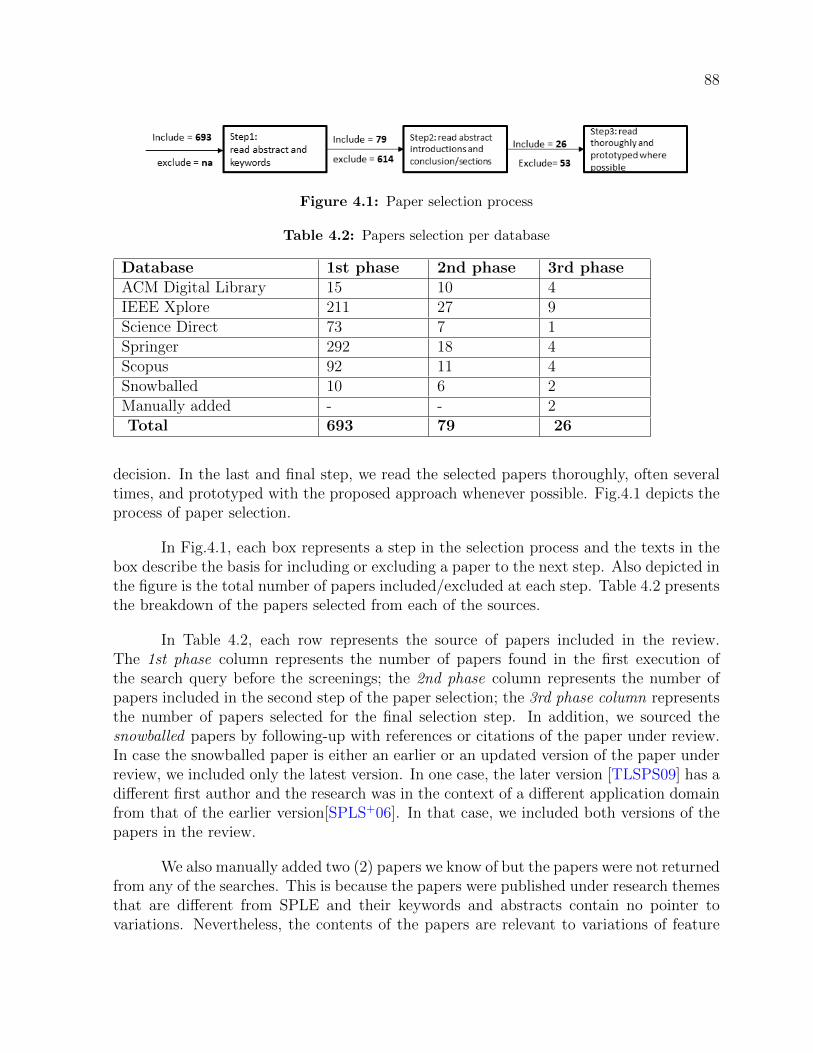
88
Figure 4.1: Paper selection process
Table 4.2: Papers selection per database
Database 1st phase 2nd phase 3rd phaseACM Digital Library 15 10 4IEEE Xplore 211 27 9Science Direct 73 7 1Springer 292 18 4Scopus 92 11 4Snowballed 10 6 2Manually added - - 2Total 693 79 26
decision. In the last and final step, we read the selected papers thoroughly, often severaltimes, and prototyped with the proposed approach whenever possible. Fig.4.1 depicts theprocess of paper selection.
In Fig.4.1, each box represents a step in the selection process and the texts in thebox describe the basis for including or excluding a paper to the next step. Also depicted inthe figure is the total number of papers included/excluded at each step. Table 4.2 presentsthe breakdown of the papers selected from each of the sources.
In Table 4.2, each row represents the source of papers included in the review.The 1st phase column represents the number of papers found in the first execution ofthe search query before the screenings; the 2nd phase column represents the number ofpapers included in the second step of the paper selection; the 3rd phase column representsthe number of papers selected for the final selection step. In addition, we sourced thesnowballed papers by following-up with references or citations of the paper under review.In case the snowballed paper is either an earlier or an updated version of the paper underreview, we included only the latest version. In one case, the later version [TLSPS09] has adifferent first author and the research was in the context of a different application domainfrom that of the earlier version[SPLS+06]. In that case, we included both versions of thepapers in the review.
We also manually added two (2) papers we know of but the papers were not returnedfrom any of the searches. This is because the papers were published under research themesthat are different from SPLE and their keywords and abstracts contain no pointer tovariations. Nevertheless, the contents of the papers are relevant to variations of feature

89
binding time.
4.1.6 Data extractions
We extracted the data fields based on existing review templates and in considerationof the review questions. The following are the fields derived from the review template[PFMM08]: research approach, contributions proposed in the paper; and other auxiliaryfields such as publication venues and publishers. Similarly, we derived the following fieldsfrom the review questions: proposed approaches; software domain in which the approacheswere validated or evaluated; and the goals of the research. In total, we included twenty-six(26) papers for the final review.
We end this section with an attempt to answer the first review question (RVQ1):
We were able to find only twenty-six (26) published papers related to supportingvariations of feature binding time.
4.2 Overview of the publications
Six (6) papers are journals articles, fifteen (15) are conference papers and theremaining five (5) are workshop papers (see Fig.4.2b). The papers appear in twenty-one(21) publication venues (workshops, conferences, and journals). In this context, SoftwareProduct Line Conference (SPLC) attracted the highest number of publications with a totalof five (5) papers; International Workshop on Variability Modelling of Software-IntensiveSystems (VaMoS) and Journal of Science of computer programming has two (2) paperseach. All the other venues have only one (1) paper each (see Fig 4.3).
Based on SCImago Journal Rank (SJR) indicator [GPGBMA10], one of the journalshas reputation for being in the top 25% (first Quartile) of its subject category and theremaining journals are in the top 50%(second Quartile). In the conference category, amongthe 15 papers, 5 were presented at SPLC- the premier conference of SPLE researches; one(1) paper was presented at the top-tier Aspect-Oriented Development conference; four(4) papers were presented at second-tier conference; two (2) papers were presented atthe bottom 50% (third Quartile) conference venues; three (3) papers were presented atthe bottom 25% (fourth Quartile) conference venues. From the five (5) workshop papers,two (2) papers were presented at the VaMoS, the premier workshop for SPLE; 2 werepublished in Springer Lecture Note in Computer Science (LNCS) – a second-tier bookseries for computing; one paper (1) has a reputation of being third tier publication.

90
(a) authors’ affiliation (b) paper categories
Figure 4.2: Publications by (a) affiliations and (b) paper categories
Figure 4.3: Publication venues
The graph in Fig.4.4 shows the publication trends over a period of two decades. Twointeresting revelations from the graph are: 1) SPLE community recognized the challengeof variations of binding time long enough. 2) There are sparse publications despite therecognition of the problem. For example, no paper was published in the year 2000, 2003,2005 and 2010. 2009 is the year with the highest number of published papers (with atotal of 5 papers). 2016 is the year with the second-highest published papers (a total of 4papers).
Using the research categories proposed in[WMMR06], each of the papers reflectsone or more of the research approaches in Table 4.3.
Each of the papers reviewed pursues one or more research goals (horizontal axis ofFig.4.5). Fourteen (14) papers share the goal of supporting flexibility of feature binding

91
Figure 4.4: Publication trend
Table 4.3: Research approaches
Research approach DescriptionExperience report Research describing personal experience of using a par-
ticular technique, often by practitioners in the industry.Evaluation research Researches describing detail investigation of a particular
technique or groups of techniques and reporting the prosand cons.
Philosophical view Researches describing a new conceptual framework ornew way of looking at existing things.
Solution proposal Researches proposing a novel or an incremented solutionto a particular problem.
Validation research Validation research may be a solution proposal researchbut with a detail implementation and demonstrationwith small example (e.g. work done in the lab).

92
Figure 4.5: Various research goals of the proposed papers vs research approaches
and with eight (8) of the papers reflecting the validation research approach (first clus-tered bars in Fig.4.5). Next, six (6) papers share the goal of minimising the footprintof executable and two (2) out of the six papers are experience reports, other two (2)are validation research and the remaining two (2) papers are evaluation research (secondclustered bars in Fig.4.5). Two (2) papers, one (1) validation research paper and one(1) philosophical research paper, share the goal of increasing the execution speed of thesoftware product (third clustered bars in Fig.4.5). Lastly, the research goals of managingcomplexity, increasing scalability and reduction of source-codes redundancy were pursuedby one paper each.
Thus, the following is the summarized answer to RVQ2a:
The researches on variations aimed to influence the following outcomes: flexible bind-ing, minimizing footprint, increasing execution speed, managing complexity, increasingscalability and reducing source code redundancy.
In the next section, we present a narrative summary of the proposed techniques
4.3 Narrative summary of the proposed approaches
This section presents a narrative summary of the proposed approaches in the lit-erature to support variations of feature binding time. Narrative summary is a type ofinterpretive synthesis in qualitative research for aggregating theories[DWAJ+05]. We usednarrative summary here in its simple form to guide the description of approaches proposedto support variations of feature binding time.

93
We derived initial classifications of the approaches from the second step of pa-per selection. After a thorough reading of the papers in the final step, we refined theclassifications with the addition of new approaches and merging of similar ones.
The following is the list of the refined approaches and also a partial answer to thereview question 2 (RVQ2):
• Delegation of binding to aspect weaver
• Programming language extension
• Metadata interpretation
• Model composition
• Delegation of binding to deployment platform
• Abstracting the binding time at model level
Note that the classification is not a hard one as an approach may subsume otherapproaches. For example, some implementations of aspect weaving use metadata inter-pretation and the actual binding may be delegated to a deployment platform. Simi-larly, aspect-oriented implementation is also considered as a form of language extension.Nonetheless, we consider the characteristic of the approach that was primarily utilized inthe research paper in focus. The proposed approaches were used in different applicationdomains as depicted in Fig.4.6.
Fig.4.6 presents a taxonomy of application domains in which the approaches wereeither validated or evaluated. Thus, Fig.4.6 stands as an answer to the review questionRQ1a.
In the subsequent sections, we provide a brief overview of each of the approachesand then followed with a summary of the research contributions of papers in that category.We also assess each of the approaches based on the criteria in Table 4.4.
4.3.1 Delegation of binding to aspect weaver
Aspect Orientation (AO) is an engineering approach for separation of cross-cuttingconcerns - concerns that would normally be scattered across other concerns. Each ofthe separated concerns is implemented as one or more aspects. Aspect weaver is a toolthat intertwines the separated concerns with the rest of other concerns. Depending on theweaver, the intertwining of the separated concern (aspect weaving) can be done at differentphases. Thus, the delegation of the binding decision to aspect weaver is handing over theactual binding to the intertwining process.

94
Table 4.4: Assessment criteria of proposed approaches
Criterion ExplanationBinding phases How the technique support binding at the different
phases and whether or not the technique supports bothinclusion and activation of new artefacts, realizing a fea-ture, or it simply supports activation/deactivation of apre-included artefact.
Granularity Whether the approach supports fine-grained variations(e.g., variation at the level of functions, methods, at-tributes, and clauses) or coarse-grained variations ( e.g.,variation at the level of modules, packages, classes, andfiles) or both.
Level of abstraction The level of detail in which the product line asset to-gether with the variation is expressed. High-level ofabstraction represents less detail representation of thesystem of which further translation is required to ar-rive at low-level details (executable source codes). Onthe other hand, a low-level of abstraction represents amore detail representation of the system and of whichno further translation is required.
Figure 4.6: Application domains

95
A feature in SPLE can also be a separable concern to some extent[KAB07, CLK08,FCS+08]. The fundamental assumption is that, variable features are implemented withaspect-oriented mechanisms to extend a monolithic base-program. Other program elements(interfaces and classes) may be provided to support aspects of a variable feature. Ideally,none of the supporting program elements would be referenced from anywhere in the base-program or in any other feature. To manage variations of feature binding time, the bindingdecision of the variable feature (a feature implemented as aspect) can be made at eitherof the weaving phases supported by the target aspect-based implementation.
4.3.1.1 Existing research contributions
Aspect-oriented related techniques constitute the largest interventions proposed tosupport variations of feature binding time. We begin with three aspect-oriented designidioms proposed to support flexibility of feature binding time. A design idiom is a style ofsolving a specific implementation challenge in a specific environment. Chakravarthy et al[CRE08] proposed the first idiom- Edict. Andrade et al [ARR+16] proposed the other twoidioms: Pointcut redefinition and Layered aspect. All three idioms were evaluated withthe earlier version of AspectJ1 (a Java-based aspect-oriented programming language) butthe evaluations were carried out in different application domains.
Edict idiom: with this idiom, a developer separates source codes of a variablefeature from the base-program and implements the separated source-codes in one or moreaspects. A catalogue of design patterns [GHJ+95] is used to aid the separation. A variablefeature is then implementation as aspect in a two-step process. In the first step, oneor more abstract aspects are implemented with the necessary intertype declarations andpointcuts definitions. The intertype declarations are additional structural codes to supportthe aspect while the pointcut definitions are specifications to capture places in the base-program where the variable feature extends. In the second step, two sets of concreteaspects are implemented: 1) aspects for binding feature to execution context statically,and 2) aspects for binding of a feature to the execution context dynamically. Both setsof concrete aspects are subtypes of their corresponding super abstract aspects. The twosets of aspects differ in the code snippet to enforce either of the two binding modes. Thechoice of the sets of aspects to include in the product configuration depends on the choiceof binding of a feature.
Because of the granularity of variations, using Edict idiom to implement a variablefeature may require several abstract aspects and each having multiple concrete subtypes.Since the multiple concrete subtypes of the same abstract aspect differ only in few codessnippets, most of the same source codes have to be duplicated across the multiple sub-types. Hence, using the Edict idiom can breed too much code duplication. Andrade et
1https://www.eclipse.org/aspectj/

96
al [ARR+16] proposed to minimise the code duplication and we discuss their approach inthe following paragraphs.
Andrade et al, [ARR+16]proposed two design idioms to improve on the utility ofEdict idiom. Specifically, they aimed to minimize the following shortcomings of Edict:code duplication, code tangling, and code size. The two design idioms share the samephilosophy with the Edict: different sets of aspects for the different binding modes. Wepresent the summary of the two idioms in the following paragraphs.
Pointcut redefinition idiom: in this idiom, a developer implements intertypedeclarations and pointcut definitions in the super abstract aspect(s), as in Edict. Unlike inEdict, the super abstract aspect(s) should also contain a complete implementation of thefeature code. In addition, a developer should also implement two separate sets of concreteaspects: 1) an empty concrete subtype for each of the abstract aspect to instantiate thesuper abstract aspect ’as is’. 2) A concrete subtype for each of the abstract aspect andeach concrete aspect overrides all the pointcuts of its super abstract aspect. The onlyreason for the overriding is to link every pointcut with activation condition so that thepointcuts are only advised when the feature is activated (through a configuration fileor similar techniques). A piece of advice, in aspect-oriented programming, is a unit ofimplementation for adding behaviour to the base-program. If a binding time is decidedbefore compilation, a developer includes the abstract aspects as well as the set of emptyconcrete aspects in the product configuration (1 above). Otherwise, a developer includes,in the product configuration, the abstract aspects as well as the set of concrete aspectswith the overridden pointcuts (2 above).
Since the concrete aspects for the early binding are empty, the code duplicationis significantly reduced in comparison to Edict idiom. In addition, the concrete aspectfor the late binding contains only the pointcuts with the additional link to the activationconditions and thus reduces the code duplication of Edict. Andrade et al [ARR+16] furtherproposed to improve this idiom with another idiom as explained in the next paragraph.
Layered aspects idiom: In layered aspects idiom [ARR+16], rather than applyingactivation condition for every pointcuts, as in pointcut redefinition, a single activationcondition is applied to all pointcuts collectively. Technically, the condition is appliedto all pointcuts at once using AspectJ special construct, adviceexcution. However, thepointcuts intercepted with around advices need to be overridden to prevent skipping acode in the base-program when the feature is deactivated.
Similar to the contribution with design idioms, Lee et al [LKKP06, CLK08], pro-posed patterns of aspect-oriented design to implement features and manage their depen-dencies in order to support flexible binding time. Likewise, Vranic et al [VBMD08, MV09,BVD07] proposed patterns for addition and removal of functionality to a web applicationto implement change requests. The approach may be used to control feature bindingby mapping feature implementation patterns to the proposed implementation patterns of

97
change requests.
The approaches discussed so far, under the delegation of binding to aspect weaver,were reported in the context of a static weaver. Static weaver intertwines aspects tophysical artefacts such as source codes and binary and that limits the support of featurebinding at post-deployment time. On the other hand, dynamic weaver modifies a programin execution at runtime and that facilitates feature binding at post-deployment time. Forthe dynamic weaving, the actual binding is often specified as a metadata and interpretedby the deployment platform. To fully support binding time, Tartler et al [TLSPS09,SPLS+06] integrated the two modes of weaving: static weaving and dynamic weaving ina single aspect weaver. However, the integration had to compromise with fine-grainedseparation of concerns. This is similar to the compromise made when AspectJ[Lad03] ( aJava-based aspect-oriented language with static weaving) was merged with AspectWerkz2
(also a Java-based aspect-oriented language but with dynamic weaving) and thereby givingup some dynamic capability of AspectWerkz.
Binding phasesThe approach in [CRE08] and [ARR+16] support binding of feature to a product in twophases: The first phase, compile-time weaving phase, corresponds to the binding of afeature at pre-deployment time. The second phase, load-time weaving phase, roughlycorresponds to the binding of a feature at a deployment phase. Conversely, they do notsupport the inclusion of a new feature at post-deployment time. However, a feature can beincluded at an earlier phase and then supported with activation/deactivation mechanismfor post-deployment binding time decision. In other words, approaches in this categoryhave limited support for feature binding at post-deployment time. In contrast, the ap-proach proposed in [TLSPS09, SPLS+06] provides a technical support to include a featureat post-deployment time albeit at a coarse-grained level.
GranularityUsing the design idioms proposed in [CRE08] and [ARR+16], variations at all levels ofgranularity can be encapsulated as aspect. Generally, an aspect-oriented language witha static weaving provides support for separation of concern at a fine granular level. Onthe other hand, the integrated weaving in [TLSPS09, SPLS+06] does not support theseparation of fine-grained variations.
Level of abstractionAll of the approaches discussed, under Delegation of binding to aspect weaver, supportspecification of product line assets only at low-level of abstraction - at the source codelevel.
DiscussionGenerally, implementing a feature as a separable concern, in terms of aspect of aspect-
2https://www.eclipse.org/aspectj/aj5announce.html

98
oriented programming, requires non-trivial efforts. This is because implementation ofa feature in SPL was not the initial intention of aspect-orientation. Specifically, thepower and utility of aspect is more apparent when applied to separate a homogeneouscross-cutting concern - a single concern that appears uniformly in multiple places in thebase-program (e.g. logging). However, a feature in SPL often manifests as heterogeneouscross-cutting concern at the source code level. In other words, a single feature may affectseveral places in the base-program differently. Consequently, several aspects may have tobe used to effectively separate a single feature of moderate to large size [KAK08].
We notice that the two authors [CRE08] and [ARR+16] aimed at reduction in foot-print. Accordingly, in [CRE08], aspects for the static binding (the aspects to be included ifthe binding decision is decided at pre-deployment time before compilation) are optimisedto make the implementation of deselected feature unreachable and then removed by anoptimisation tool. We recommend that the optimisation should be applied in considera-tion of the overall domain knowledge. For example, it is reasonable to optimise a low-endproduct with memory constraint and which is unsuitable for an upgrade with a priordeselected feature. However, that type of optimisation may have negative consequenceson an optional variation point that may be transformed into an inclusive OR group inthe course of product line evolution in which the additional feature would be bound atpost-deployment time.
Lastly, the notion of binding time in all but in [TLSPS09, SPLS+06] is limited tobinding of a feature to product execution context (i.e. static vs dynamic binding mode)as against binding a feature to a product.
4.3.2 Language extension
Language extension is additions of new constructs or new notations to an existingprogramming language. There are two broad categories of language extensions. Thefirst category is extending a language with additional constructs that are similar to theconstructs of the target language. In this case, a specification with the extension representsthe same level of abstraction with the specification in the target language. The secondcategory is extending a language with constructs or notations that are entirely differentfrom that of a target language. In this case, a specification with the extension representsa different level of abstraction from the specification in the target language. What iscommon among the two categories is that the design specifications with the extendedlanguages are eventually transformed into the target language being extended. The nextsection presents the research contributions in this category.
Existing research contributionsPhilip Consumer Electronics [VO98] developed a purposeful language, Component De-scription Language (CDL), and used it to describe a family architecture of electronics

99
software. CDL is an architecture description language (ADL) with its own constructs.However, the language is compiled to C as the target language. The CDL constructssupport architectural specification at a high level of abstraction than what is possiblewith the C programming language. The configuration information and the binding deci-sions are separated from the component architecture specifications and delegated to theCDL compiler. The compiler evaluates the binding decision expressions and replaces themwith the appropriate constructs for the desired binding in the C language. The collectivetechniques were integrated into a special component model known as Koala.
Similarly, Rosumuller et al [RSAS11] extended C++ programming language tosupport step-wise refinements (SWR)- a development approach promoted in GenVoca[BST+94].GenVoca is an approach to gradually modify program elements such as classes and func-tions. The extension supports implementing a feature as a series of fragmented modifica-tions of C++ classes and functions. A specific product is generated through compositionof the refinements corresponding to the selected features. On one hand, an optimisedproduct is generated from inlined refinements (i.e. static binding of feature to executioncontext). On the other hand, they framed the refinements as decorations, as in the deco-rator pattern[GHJ+95], to support delaying of feature binding to execution context untilat runtime.
Binding phasesWith Koala [VO98], it is possible to generate binding mechanism that facilitates delay ofbinding time up to deployment time. However, there is no explicit support for featurebinding at post-deployment time. Similarly, the approach of Rosumuller et al [RSAS11]is limited to the selection of how a feature would be bound to execution context- staticor dynamic – and the decision has to be made before compilation. The research goalof Rosumuller et al [RSAS11] is to optimise source codes (using function inlining andhardwiring of implementation components), if the binding time of feature can be decidedbefore compilation (i.e. before deployment).
GranularitySince the approach of Rosumuller et al [RSAS11] is a code-level specification, it is appli-cable to both fine-grained and coarse-grained variations. Likewise, not only the approachin Koala [VO98] supports variations at different level of granularities but also they do soin an interesting way. We summarized how Koala supports variation at three levels ofgranularity:
• Component property level: Fine-grained variations (called component internaldiversity in Koala) are represented as variable properties on components and areexposed to configuration interface as diversity interface. When a constant value isassigned to a variable property, Koala compiler completely removed the alternativeclauses (alternative execution paths) in the source codes. As a principle in Koala, avariable property should not have Set and Get operations because one end up with

100
two more functions getX() and SetX() for each property even if the functions willnever be used because the property is set as a constant. With this approach, a prob-lem of bloating component with various alternative execution paths is minimised.
• Component interface level: A component in Koala can have optional required orprovided interface. Koala compiler generates a stub, as in null object pattern[GHJ+95],for each optional provided interface. Similarly, Koala compiler generates Booleanpresence condition to guard each optional required interface.
• Component level: A connection from one component may be rerouted to one of theseveral alternative components using an architectural construct called switch. Theactual rerouting decision can be fixed to one of the several alternatives componentsat configuration time (i.e static binding to execution context) or can be decided atruntime (i.e. dynamic binding to execution context).
Level of abstractionKoala supports product line specification at high-level of abstraction using componentsas building blocks. In contrast, the approach in [RSAS11]supports specification only atlow-level of abstraction.
DiscussionThe Koala component model is one of the earliest approaches (at least in the publicdomain) of product line practice. One of its powers is optimisation techniques incorporatedin the Koala compiler. For example, in component connection rerouting, if the connectionis fixed to one component at compile time, the Koala compiler replaces the connection witha direct function call and the unreachable component is removed from the configuration toreduce footprint. Another example is the removal of alternative clauses when a propertyis assigned constant value in the diversity interface.
The comment on optimisation in the previous section also applies here. However,of note is, application engineers using Koala are also expert in the product they build.
Binding a feature at post-deployment time may be supported in Koala as oneof the configuration decisions. In this case, the decision of feature binding at post-deployment time at CDL level should be replaced with C language constructs supportingfield-programmability.
Overall, the approach in Koala may be valuable if a significant investment canbe made both in tooling and human resources. This is because even the componentcomposition itself is technically-oriented.
The approach proposed in [RSAS11] introduced development processes that maynot be consistent with software engineering practices. The utility of the approach may be

101
supported through a model at a higher level of abstraction to shield engineers using theapproach from the low-level manipulations.
4.3.3 Metadata interpretation
Metadata is a secondary data that describes a primary data. In the context ofSPLE, a metadata is often used to specify product configuration. For example, businessrules such as insurance policy may be stored in a table or as an XML file as a form ofmetadata and different set of rules distinguish one insurance application from the other.Similarly, data about variations as well as their binding times can also be stored as ametadata [SE08]. In this case, products of a product line do not differ only on featuresbut also on feature binding times.
Existing research contributionsYoder et al [YBJ01] advocate that, whenever possible, the semantics of a domain should beabstracted and modelled as a set of ’supertypes’. For example, a domain may be modelledas a state machine consisting of a set of ’State’, ’Transition’, ’Action’ as ’supertypes’.The meta relationships between the ’supertypes’ are explicitly specified. For example,’State’ has one or more ’Transition’ to another ’State’ and each ’Transition’ is triggeredby an ’Action’. Different products in the domain would differ in the concrete ’subtypes’of the ’supertypes’. Thus, a software configuration is the specification of the required’subtypes’ as a metadata. While the authors called this approach ’Adaptive Object Model’,Fowler called it a ’Semantic Model’ style[Fow10]. In this thesis, we go with the ’semanticModel’ as the approach has more to do with the logic of the domain than any specificimplementation technique. We consider this approach in the review because it may beused to support variations of products of a product line. The specification of the metadata,which is comparable to feature selection, is a decision on whether or not to include aspecific ’subtype’ such as an optional ’State’ a system may assume and can be done atthe different phases of binding. Bugerili et al [BMF09] adapted this approach to modelsatellite launcher product line using sensors, actuators, control, etc as the ’supertype’ inthat domain.
Capilla and Bosch [BC12] discussed ideas on how to manage variations of featurebinding time. In a separate work, they mapped the ideas to reconfigurations processes ina power plant control product line [CB16]. Subsequently, and in a more concrete work[CVD16], they illustrated the binding of features to a feature model at a post-deploymenttime. In the implementation, they used a database to store feature with its ’supertype’ asa metadata. a feature can then be added or removed to a feature model by updating thedatabase. The updates are then interpreted and reflected on the feature model using amatching algorithm that compares the root of the new feature to pre-existing ’supertypes’.The root of the new feature may match an existing ’supertype’ and, therefore, a featurecan be added as a child of the ’supertype’. Otherwise, the new feature may have to be

102
added as a new ’supertype’.
Khediri et al [KK15], proposed an approach to modelling database using delta-oriented technique[SBB+10] to specify deltas in data description language (DDL) of Struc-tured Query Language (SQL). Each delta is a specification to change the structure of thedatabase to reflect the binding of a specific feature of a database management system. Al-though this approach is specific to database management domain, we envision the transferof the concept to product line domains that are implementable in scripting languages suchas Hypertext Preprocessor (PHP), Python, Perl.
Binding phasesIn Yoder et al [YBJ01] and [BMF09], all the features are conceptually included in theproduct configuration (although variant of this approach exist). The specifications in themetadata, possibly at the different binding time, are merely for activation/ deactivation ofpre-included features. In the case of the approach in[CVD16], the feature binding is neitherto the execution context nor to the product but the binding is to a feature model. Since afeature model is not executable, we can only imagine that the feature model is supportedwith a repository of implementation components as in [VdH04]. In this case, the updateson the feature model are interpreted to activate or deactivate implementation componentrealizing the features. Therefore, these approaches offer limited support for binding timeeven though they support binding a feature at multiple phases. The approach in[KK15]supports the binding of a feature at all phases, subject to the availability of interpretivesupport at the binding phase.
GranularityIn [YBJ01] and [BMF09], variations are supported only in terms of the semantics of thedomain and therefore limited. In the example of the state machine, although differentproducts may be composed with different states and different transitions, an internal vari-ation within a state, for instance, is not explicitly exposed. There is no enough informationto assess the approach proposed in [CVD16] with respect to the granularity of variations.Delta modelling, as proposed in [KK15], can be used to specify changes of a database interms of field, record, database table or the complete database schema. Hence it supportsboth fine-grained and coarse-grained variations.
Level of abstractionBoth approaches to specifications of product line assets proposed in [YBJ01] and that of[KK15] are at low-level of abstraction. Binding specification proposed in [CVD16] is at thelevel of feature, and a feature can represent both high-level and low-level of abstraction.
DiscussionThe ’semantic model’ approach is only applicable to specific classes of system. Fowler, M.[Fow10] provided guidelines on where the approach may be applicable. A variant of thisapproach is to use the metadata to guide code generation or to implement the ’supertype’and only use the metadata to specify configuration and reconfigurations.

103
The search strategy to locate the appropriate position of the new feature in theexisting feature model proposed in [CVD16] may be resource-intensive. Nonetheless, themajor skeptic about this approach, at least what the concrete implementation demon-strates, is their focus on the feature model exclusively.
4.3.4 Abstracting the binding time at the model level
Abstracting the binding time at a model level is to provide special model propertiesto represent binding time at a model level in model-driven development. This approach issimilar to language extension in the sense that the model and the properties representingthe binding times are ultimately transformed into source-codes of the target programminglanguage.
Existing research contributionsBeuche1, D. and Weiland, J. [BW09] extended Simulink -modelling tool3 with constructsfor modelling variation points and parametrization of the variation points with bindingmodes. Each of the binding modes, represented as a property at the model level, istransformed into an appropriate snippet at source code level using a model to code trans-formation. Similar to this approach, Schmid and Eichelberger [SE08] propose to store thebinding time properties as part of decision-based variability model.
Hartmann et al [HKM+13] proposed an approach to generate a glue componentto adapt binding interfaces of components that might have been developed by differentorganizations. The approach has the potential to support abstracting the binding time andpresenting it at the model level. That is, the glue component may embed a parameterizedbinding time property and the binding time decision can be exposed to a configurationinterface.
The work of Andre Vanda hoek [VdH04] is one of the earliest to address variationsof feature binding time at the architecture level. In his approach, architectural repre-sentation is used as a configuration interface and is mapped to concrete implementationartifacts. Feature binding at pre-deployment time is a selection of architectural elements toform an architectural representation for the desired product; the implementation compo-nents for the architectural representation are then activated. At deployment time, a priorconfigured architecture representation may be updated with additional architectural ele-ments to reflect the binding of additional features. A new architecture representation mayas well be formed if no one exists (i.e., no binding decision was made at pre-deploymenttime). In this case, the architecture representation is translated into calls to concreteimplementation components. At post-deployment time, features are bounded to the prod-uct in operation by comparing a model of the desired architecture representation with
3https://www.mathworks.com/products/simulink.html

104
the model architecture representation of the deployed product. The difference betweenthe two architecture representations is then applied to the existing product through theactivation or deactivation of implementation artifacts.
Binding phasesThe Simulink tool extension [BW09] does not include the support for feature binding atpost-deployment time. On the other hand, the extended support of the model in [SE08]includes properties for generating aspect code to activate or deactivate a feature at post-deployment time and thereby partially supporting feature binding at post-deploymenttime. The glue code generation proposed by Hartmann et al [HKM+13] supports thebinding decision at the code generation time (before deployment) or the binding decisionmay be pass-on to be resolved at deployment time - no support for feature binding atpost-deployment. In Andre Vanda hoek[VdH04], apart from the pre-deployment bindingtime, the architecture model only facilitates activation and deactivation of implementationcomponents at the different binding time.
GranularityBoth the Simulink extension[BW09] and the glue generation approaches[HKM+13] do notexplicitly manage internal component diversity. Hence, they do not support fine-grainedvariations. In contrast, in [SE08], variations are implemented at both fine-grained andcoarse-grained levels as in traditional variability management (e.g. using pre-processing)and then mapped to the decision points at the level of the variability model. In [VdH04],the variations are only explicitly supported at the level of component and interface. How-ever, the approach supports different versions of architectural components and versionsmay differ in fine-grained variations.
Level of AbstractionThe Simulink tool in itself provides model elements (e.g. subsystems, signal routing, andswitch block) for modelling a single system at a high-level of abstraction. Thus, theadditional support for variation and binding time proposed in [BW09] supports modellingproduct line at a high-level of abstraction. Similarly, a glue code generation proposedby Hartmann et al [HKM+13] is to bridge the differences between high-level componentsand hence it is at a high-level of abstraction. The decision-based variability model andthe binding time representation in [SE08] abstracts away the low-level implementationdetails and exposed binding decisions as interactive questions. However, a developer hasto implement the low-level implementation details and mapped them with the variabilitymodel. The approach in [VdH04] supports specification at architecture which is relativelya high-level of abstraction although the architecture has to be manually mapped to low-level implementation details.
DiscussionEmbedded software is the target domain for the glue code generation proposed in [HKM+13].Support for feature binding at post-deployment time in an embedded system is to support

105
field-programmability and which may be represented as a model property at the level ofglue modelling. The scope of the Simulink tool extension proposed in [BW09] is limitedto providing support for binding a feature to the execution context. Consequently, itis difficult to extend the approach to support binding a feature at post-deployment time.Different architectural representations for the different binding time as proposed by VandaHoek [VdH04] may hinder the utility of the approach.
4.3.5 Model composition
Model composition is a process of combining two or more model slices to form asingle model. In SPLE, a model slice represents an implementation of a specific feature,and the composed model represents an implementation of a specific product. A model orother artefacts generated from the model can be composed either at pre or post-deploymenttime.
Existing research contributionsZdun, U. and Strembeck, M. [ZS06] proposed a metamodel for modelling introduction ofadditional structure and interaction of model elements into an existing model (or possiblyan empty model). Although the approach was not meant specifically for modelling varia-tions of feature binding time, it could be adapted to model program elements that wouldbe composed to form a product as a result of feature selection. It can also be used to adda feature to an existing product at the different binding time.
Whittle et al [WJE+09], proposed the use of graph transformation to specify modelslices and to use aspect-oriented techniques to compose the individual slices. Model el-ements for specific concerns (a concern may be a feature) are separated and composedwhen needed. In this approach, a modeller slices models such as UML class, sequence,and state diagrams according to requirements for implementing a specific feature. Themodel slices, for selected features, are then composed to derive a custom model. Eachmodel slice, for the specific feature, is a specification of fine-grained model elements to beadded or to be removed from the base-model or another model slice. For example, a modelslice to implement a feature may be a specification to add ’states’, ’events’, ’transitions’,and ’regions’ to the base state diagram or another model slice. In this approach, featurebinding is a selection of the fine-grained model elements to realize features as a modelslices and using separate target transformation based on binding time requirement: Atpre-deployment, the selected model slices, representing a custom product, is transformedinto source-codes for compilation. At deployment and post-deployment time, the selectedmodel slices are transformed into dynamic script/aspect to adapt the product.
Binding phasesThe assessment of binding phases does not apply to the approach proposed by Zdunand Strembeck [ZS06], because it is an abstract modelling of features with no concrete

106
implementation. The approach proposed by Whittle et al [WJE+09] supports featurebinding at two phases: at pre-deployment time, model slices representing selected featuresare composed and transformed into executable. At post-deployment binding time, modelslices are transformed into AspectWerkz code - an AOP for dynamic weaving.
GranularityBoth the approach in [ZS06] and [WJE+09] support modelling variations at both fine-grained and coarse-grained level.
Level of abstractionIn both [ZS06] and [WJE+09] the models or model fragments, as the case may be, arespecified in terms of low-level model elements.
DiscussionModel composition approach proposed by Whittle et al [WJE+09] is a powerful approachto support feature binding at pre-deployment and post-deployment times. feature bindingat the deployment phase can be supported as well through the generation of a configurationinterface, from the model, to control the inclusion and activation of a variable feature atthe deployment time. The downside of the approach is the focus on fine-grained modelelements which may affect the practical scalability of the technique. Imagine severalfeatures, some of which are of moderate to large size, have to be modelled as slices ofclasses, sequences diagram and so on. The focus on fine-grained model elements alsoimpedes reasoning of the product line at the architecture level.
4.3.6 Delegation to deployment platform
The term software platform, as used in this thesis, may be a middleware thatprovides support services or an architectural framework that is designed to decouple com-ponent interaction. Delegating a feature binding to a deployment platform is to use thesupport of the target environment to decouple dependency between features such thatthey could be bound, unbound and rebound. The actual binding is often managed withdynamic loading/linking with the support of metadata interpretation. A typical exampleof a deployment platform, for Java-based enterprise application, is Java Enterprise Edition(JEE)[Tec]. JEE platform supports light-weight messaging (event-driven, point-to-point,and publish-subscribe) to decouple component interaction.
Although many platforms, including those in real system domain [sm118], facili-tate feature binding, not many pieces of research are available on this class of technique.This may not be unconnected with the fact that existing platforms mainly support singleproduct development, are hard to adapt to product line development and are costly tobe developed from scratch. For example, although JEE supports the decoupling of imple-mentation components, mapping components to features is not straight-forward because

107
of the granularity of variations.
Existing research contributionsGoedicke et al [GPZ02], proposed an architectural framework, ’Central Message Redi-rector’, to support customization of generic components for products of a product line.Specific features of a product are specified as configuration scripts to tailor the genericcomponents to specific product requirements. The framework hides requests and responsesbetween the client and the server components. Both the client and the server componentscan be customized using interpretive script or XML. The ’generic components’ in thisapproach is what the ’supertypes’ is to the ’semantic model’.
Binding phasesFeature binding, in the approach of [GPZ02], is a customisation of the generic componentsto derive a specific product and the customization may be specified at the different bindingphases. However, most or all of the ’generic components’ have to be included in each ofthe products. Hence, the approach supports partial feature binding at multiple phases.
GranularityGeneric component implementations do not normally accommodate fine-grained varia-tions. In the specific case proposed by [GPZ02], lots of configuration parameters have tobe supplied as part of the configuration scripts.
Level of abstractionThe component level specification is relatively a high-level of abstraction.
DiscussionOne limitation of the approach in [GPZ02] is generic component implementation leads toan over-bloated component with many alternative execution paths to accommodate thedifferent usage of the component within possibly many dissimilar products in the productline. Consequently, excessive dynamic scripts have to be used, as part of configurationparameters, to accommodate fine-grained variations within coarse-grained components.Part of the limitations reported by the author is the performance penalty of the approachwhich makes it unsuitable for other domains such as real-time systems.

108
Table
4.5:
Su
mm
ary
ofpro
san
dco
ns
ofth
ep
rop
osed
app
roach
es
Appro
ach
Pro
sC
ons
Dele
gati
on
of
bin
d-
ing
toasp
ect
weaver
-V
aria
tion
atal
lle
vels
ofgr
anula
riti
esca
nb
eim
ple
men
ted
asa
feat
ure
when
ast
atic
wea
ver
isuse
d.
-Supp
orts
pos
t-dep
loym
ent
bin
din
gti
me
when
adynam
icw
eave
ris
use
d.
-Sep
arat
ese
tsof
asp
ects
may
hav
eto
be
use
d,
each
for
asp
ecifi
cbin
din
gti
me.
-L
imit
edsu
pp
ort
offine-
grai
ned
vari
atio
ns
atp
ost-
dep
loym
ent
tim
e.A
feat
ure
will
hav
eto
be
incl
uded
inth
epro
duct
configu
rati
onpri
orto
dep
loym
ent.
-T
he
supp
ort
isat
low
-lev
elof
abst
ract
ion.
Pro
gra
mm
ing
lan-
guage
exte
nsi
on
-Supp
orts
the
two
bin
din
gm
odes
(sta
tic
and
dynam
ic)
-C
omple
xit
yca
nb
ere
duce
dby
intr
oduci
ng
dom
ain
abst
ract
ions
inth
ela
n-
guag
eex
tensi
on.
-N
osu
pp
ort
for
feat
ure
bin
din
gat
pos
t-dep
loym
ent
tim
e.-
Req
uir
esdiff
eren
tex
per
tise
inla
ngu
age
and
tool
des
ign.
Meta
data
inte
rpre
-ta
tion
-D
iffer
ent
pro
duct
s,w
ith
arbit
rary
vari
a-ti
ons
infe
ature
san
dw
orkflow
s,ca
nb
ecr
e-at
ed.
-L
imit
edsu
pp
ort
for
fine-
grai
ned
vari
atio
ns.
-T
he
supp
ort
islim
ited
toso
me
spec
ialize
ddo-
mai
ns.
-L
imit
edsu
pp
ort
for
feat
ure
bin
din
gat
pos
t-dep
loym
ent
tim
e.A
feat
ure
will
hav
eto
be
incl
uded
inth
epro
duct
configu
rati
onpri
orto
de-
plo
ym
ent.
Abst
ract
ing
the
bin
din
gti
me
at
model
level
-Supp
orts
bot
hfine-
grai
ned
and
coar
se-
grai
ned
vari
atio
ns
and
ata
hig
h-l
evel
ofab
-st
ract
ion.
-C
omple
xit
yca
nb
ere
duce
dby
intr
oduci
ng
dom
ain
abst
ract
ions
asm
odel
el-
emen
tsor
pro
per
ties
ofm
odel
elem
ents
.
-C
urr
ent
supp
orts
are
lim
ited
tosu
pp
orti
ng
only
dynam
ican
dst
atic
bin
din
gm
odes
.-
Model
ling
infr
astr
uct
ure
has
tob
ecr
eate
dan
dm
ainta
ined
.
Model
com
posi
tion
-Supp
orts
flex
ible
bin
din
gat
bot
hpre
-dep
loym
ent
and
pos
t-dep
loym
ent
tim
e.-
Supp
orts
bot
hfine-
grai
ned
and
coar
se-
grai
ned
vari
atio
ns.
-C
urr
ent
supp
ort
focu
ses
onto
ofine-
grai
ned
model
elem
ents
,hen
ce,
the
appro
ach
may
not
scal
ein
pra
ctic
ean
dm
ayb
ediffi
cult
tore
ason
abou
tth
ear
chit
ectu
reof
the
pro
duct
.D
ele
gati
on
of
bin
d-
ing
todeplo
ym
ent
pla
tform
-Supp
orts
flex
ible
bin
din
gat
bot
hpre
-dep
loym
ent
and
pos
t-dep
loym
ent
tim
ean
dat
hig
her
leve
lof
abst
ract
ion
-L
imit
edsu
pp
ort
for
fine-
grai
ned
vari
atio
ns.
-E
x-
cess
ive
dynam
icsc
ripts
may
hav
eto
be
use
dto
bin
da
feat
ure
atp
ost-
dep
loym
ent
tim
e.
109
4.4 Summary of the proposed approaches
In this section, we present a summary of the pros and cons of each of the approachesas depicted in Table 4.5. We also present the overall summary in the following paragraphs.
In the category of approaches proposed around the delegation of binding to aspectweaver, in all but two cases, the support of variations of feature binding time stopped atthe deployment time. At post-deployment time, feature binding is limited to activation ordeactivation of the pre-included feature. In the two cases of [TLSPS09] and [SPLS+06],both inclusion and activation of a feature at post-deployment time are supported but onlyat a coarse-grained unit of implementation. Similarly, since the aspect-orientation, asproposed in the approaches, focus on the source-codes level exclusively, all the approachesin this category of approaches are only applicable at low-level of abstraction.
In the category of approaches proposed based on the language extension, nonesupport feature binding at post-deployment time. Similarly, in one of the two proposedapproaches to the language extension [RSAS11], the notion of feature binding is limitedto the scope of binding to the execution context. All the approaches proposed underthe metadata interpretation are only applicable to specific classes of systems (databasemanagement system[KK15], graph[CVD16], and domains whose semantic can be preciselycaptured as a semantic model [YBJ01, BMF09]).
Although the approaches proposed under abstraction of binding time at the modellevel are at high-level of abstraction, only one approach [BW09] explicitly supports vari-ations of feature binding and only in a limited scope of binding to the execution context.In the category of model composition approaches, Whittle et al [WJE+09] supports fea-ture binding at both pre and post-deployment time but only at low-level of abstraction(through the support of flexible composition of fine-grained model elements).
Other papers only discussed the pros and cons of feature binding techniques basedon experience (e.g. [BC12, CB16] .)
Overall, apart from approaches that remotely support variations of feature bindingtime (metadata interpretation and language extension), current support for variationsin feature binding times is through one of the following:
i using separate architectural representations for the different binding time;
ii composition of fine-grained model elements to realize a feature as a model slice,and using separate target transformation based on binding time requirement;
iii implementing separate set of aspects, in aspect-oriented programming, each setfor a specific binding time;

110
iv abstracting the different binding modes at model level.
All the approaches share one or more of the following limitations:multiple representations/implementations (i, ii, iii);composition of too fine-grained model/program elements(ii, iii);low-level of abstraction (iii);limited in scope (iv).
In this thesis, we proposed PLA modeling language, that is aware of binding time,to overcome some of the existing limitations in the following ways:
• To abstract the feature binding to a product, as against feature binding to theexecution context of a product, at a model level, and, thus, increase the scope ofsupport for feature binding.
• To use architectural elements as the dominant representation, as against fine-grainedmodel elements. Hence we raise the level of abstraction of which the binding timeis supported.
• To take binding time requirement into account when transforming architectural el-ements into executable, thereby abolishing the need for multiple implementation-s/representations.
We present the details of our approach in the next chapter (Chapter five).

Chapter 5
Binding time aware modelling language:design and implementation
This chapter discusses the design and implementation of binding time aware mod-elling language as an improved approach to supporting variations of feature binding time.Our approach also contributes to supporting the modifiability of reusable assets.
Recall, from Chapter three, language-based implementation techniques specificallyproposed to implement features in SPLE (Feature-Oriented Programming and Delta-Oriented Programming) might have better modularity but do not support variations infeature binding time. Although Aspect-Oriented Programming, as an adapted language-based approach for product line implementation, has better support for variations of fea-ture binding time, the support is only at a low-level of abstraction.
Also, recall from the systematic study in Chapter four, we classified approaches thatare proposed to support variations of feature binding time into four: 1) using separate ar-chitectural representations for the different binding time; 2) composition of fine-grainedmodel elements to realize a feature as a model slice, and using separate target trans-formation based on binding time requirement; 3)implementing a separate set of aspects,in aspect-oriented programming, each set for the different binding time; 4)abstractingdifferent binding modes at a model level in model-driven Development.
We argue that using different architectural representations, that are separatelymanaged, for the different binding time hinders adoption by practitioners because dif-ferent expertise and different tools are required. This particular approach [VdH04] wasintroduced long-enough but has not been traced to the industry yet.
For the composition of model slices, unless the code-asset would be fully generatedfrom the model - which is hardly the case, except for few specialized domains - we arguethat the approach is too fine-grained and may not scale in practice.
For the aspect weaving category, at a low-level of abstraction, it would have beena normalized practice if only a few features and few products are to be produced fromthe reusable assets. However, if the feature and product spaces of a product line are
111

112
substantially large, implementing every feature with multiple aspect-weaving, based onbinding time requirement, will lead to a combinatorial explosion.
For the abstracting of binding time at the model level, current support is limitedto variations of feature binding to execution context - which is limited in scope.
Given the limitations of the existing approaches, we proposed a binding time awaremodelling language as a new approach to abstract the binding time at the architecturemodel level in model-driven development. The approach is a novel in the sense thatexisting approaches to abstract the binding time at the model level are limited in scope(i.e. restricted to the two modes of feature binding to execution context). We do notclaim, however, that each of the constituents of our techniques is novel. We present anoverview of our approach in the next section.
5.0.1 Process overview to supporting variations of feature bind-ing time
To support variations of feature binding time, we pre-plan for it as we pre-plan forthe variations of features. Thus, we tackle all binding time by design. We also providetool support for the key aspects of the support. Fig.5.1 highlights the main activities ofsupporting variations of feature binding time at both domain engineering and applicationengineering as proposed in this thesis. In the figure, the activities supported by our toolsuite are shaded in grey.
At the top of Fig.5.1, from left to right, the first two outer boxes illustrate the usualhigh-level activities at the domain engineering phase: Domain analysis and domain design.Domain analysis activity, the first outer box, is a systematic identification and organizationof product features. We discussed domain analysis in details in Feature-oriented domainanalysis section of Chapter two. Supporting variations of feature binding time at thedomain analysis level is to analyse, further, the identified features and group them intounits that must be bound together for the correct function of the product (depicted assub-activity beneath use case modelling in the domain analysis box). We elaborate on thegrouping of features into units as the extension of domain analysis in Supporting variationsof feature binding time at domain analysis section.
Domain design activity, the middle outer box at the top of Fig.5.1, is the con-struction of the product line architecture that accommodates diversities of the productsin the domain. We also discussed this in details in Domain design section of Chapter two.However, since a feature manifests as major or minor implementation units, it followsthat, at the design level, a feature may translate into one or more coarse-grained exclu-sive architectural elements(e.g. component or connector). A feature may also translateinto many fine-grained architectural elements (e.g attribute or operation on architectural

113
Figure
5.1:
Ove
rvie
wof
sup
por
tin
gva
riat
ion
sof
feat
ure
bin
din
gti
me

114
component). As discussed in Chapter two, granularities of variations affect how a featureis bound to a product. To support variations of feature binding time at the domain designlevel, we propose, to re-organize the architecture model so that architectural elements ofthe fine-grained variations are attached to coarse-grained elements that are in the samebinding unit. Fine-grained variations may also be aggregated into an aspectual compo-nent. Hence, as illustrated in Fig.5.1, with the arrow from domain analysis to domaindesign, feature binding units (FBUs) should be taken into account when designing prod-uct line architecture. We elaborate on this in Supporting variations of feature binding timeat domain design section.
The right-most outer box at the top of Fig.5.1, at the domain engineering phase,represents model-driven domain implementation which is one of the approaches to im-plement a domain as introduced in Chapter two. We adapted model-driven because ofits flexibility. In our approach, the specific output that comes from domain design andgoes to the model-driven domain implementation is the abstract design of PLA (see thearrow from the Domain design to model-driven Domain Implimentation. As with theOMG recommendation we, specify and implement a platform-independent model(PIM)(the top sub-activity in the model-driven domain implementation box) separate from theplatform-specific model(PSM) (the bottom sub-activity in the model-driven domain im-plementation box). PIM is a model that is independent of platform technology and PSMis a model that is specific to particular platform technology.
To manage variations of feature binding time at the PIM level, we assign bindingtime properties to the model elements. We then define one-way transformation mappingfrom the PIM to PSM. To manage variations of feature binding time at the PSM level,a model element of the PIM is transformed into its corresponding model element of thePSM based on its value of binding time (see details in PIM to PSM mapping section). Atthis stage, the transformation is only implemented but the model elements of the PSMare not instantiated until at application engineering phase. The details of these activitiesare presented in Supporting flexible feature binding at the implementation level section.
So far we have been outlining engineering activities at the domain engineering phase- the top boxes of Fig.5.1. We also present the high-level overview of the engineering activ-ities at the application engineering phase (the bottom boxes of Fig.5.1) in the subsequentparagraphs beginning from product requirement elicitation.
Product requirement elicitation in our approach is depicted at the left bottomof Fig.5.1 and in the application engineering phase. The first activity in requirementelicitation is matching the product requirements to the pre-planned features (the topsub-activity of requirement elicitation). Desired binding time of the variable features arealso determined at this stage (the middle sub-activity of requirement elicitation). Theproduct analysis model may also be derived in our approach (the bottom sub-activity ofthe requirement elicitation).

115
As in the traditional approach, specific product requirement may have to be sub-mitted to the reusable assets as the form of feedback. The derived PLA is then instantiatedwith the desired binding times at the product design phase.
After gathering requirement of the specific product, corresponding abstract PLA,implementing the matched features and the derive analysis model, is then derived fromreusable assets and passed-one to product design activity.
Product design in our approach is depicted in the middlebox of the Applicationengineering phase and constitutes the following sub-activities: instantiation of platformindependent PLA and assigning binding time properties to the model elements (the topsub-activity of Product design in Fig.5.1). Since many model elements may contribute toimplement a single feature their aggregate binding times have to be checked for consistencywith the desired binding time of the feature (middle sub-activity of product design). Bind-ing time consistency should also be checked accross multiple features. Thus, the modelelements are subjected to binding time consistency checking.
If the instantiated PIM elements are well-formed with respect to the binding timerequirement (i.e. they have passed have binding time consistency checking), the elementsare then transformed into elements of another model that is specific to the target plat-form technology (the bottom sub-activity of product design). The product design is thencompleted. The next activity is to generate source-codes from the product-specific PSMmodel.
The last stage in the application engineering is product instantiation (the rightmostouter box at the bottom of Fig.5.1). At this state, a skeletal product is generated from thePSM model of the specific product is generated which will then have to be implementedor to reuse the implementation of the already developed product (the bottom sub-activityof product instantiation at the bottom of Fig.5.1). The key design decisions (architecturalpattern/style and the binding time) are enforced in the skeletal product.
In the next sections, we present the details of our approach to supporting variationsof feature binding time at the domain engineering phase.
5.1 Supporting variations of feature binding time at
domain engineering phase
This section presents details of our approach to supporting variations of featurebinding time at the lifecycle activities of domain engineering. Part of the activities ismodel-driven domain implementation -an approach to implement adaptable infrastructurefor a product line.

116
Figure 5.2: Grouping features into units that most be bound together for the correct functionof the product
5.1.1 Supporting variations of feature binding time at domainanalysis
Recall in the feature-oriented domain analysis section of Chapter two, we discussedthe traditional approach to domain analysis in which product features are systematicallyidentified and organized based on their types and relationship. To support feature bindingtime, domain analysis should be extended with binding unit analysis which is an ideaconceived by Lee and Kang [LK03]. based on the observation that rather than a singlefeature, a group of features is often bound together for meaningful service.
A feature binding unit (FBU) is a set of features that share the same binding time.All the features in the same binding unit must be bound together for the correct behaviourof the product [LK03]. Feature binding unit identification starts with the identification ofa service feature. Each service feature represents a major functionality of the system thatmay be added/removed as a service unit.
To derive feature binding units, a domain designer should identify service features.Beginning from the service feature, the designer should trace the constituents of a bindingunit by traversing the feature model along the feature relationships and its compositionrules (i.e., cross-tree constraints such as require/mutual exclusion). Each binding unitshould be assigned a name, in a capital letter, similar to the name of the major featurein the unit. Fig.5.2 illustrates the derivation of feature binding units from EduPL featuremodel. In the figure, ACCOUNT and VALIDATION are the names assigned to the bind-ing units containing service features User Account and User Validation respectively (seeFig.5.2a). Within a feature binding unit, there may exist optional or alternative featuresthat should be selected based on customer’s needs. These features impose variations onthe component design and, therefore, they have to be identified as separate feature binding

117
units [LK03].
Feature binding units and the relationship between them constitute nodes andedges, respectively, of a binding unit graph. For example, Fig.5.2b depicts a feature bind-ing unit graph with ACCOUNT, VALIDATION, MESSAGE, and DELETE as bindingunits. For the scope of this thesis, a binding relation between binding units can be fixedor variable. A fixed relation denotes non-varying binding relation while a variable relationrepresents a binding relation that may differ from one configuration to another. For exam-ple, in Fig.5.2b, the connection between VALIDATION and MESSAGE is fixed becausethe units must always be bound together, while the connection between ACCOUNT andVALIDATION may vary from one product configuration to other product configuration.
Binding unit graph serves as an input to components and connectors product linearchitecture. In the next section, we discuss the engineering activities of supporting vari-ations of feature binding time at the domain design.
5.1.2 Supporting variations of feature binding time at domaindesign
To support variations of feature binding time at the domain design level, architec-tural elements should be organized based on the feature binding unit graph obtained atthe domain analysis phase. For coarse-grained variations, it is often a straight forwardif the architectural elements have been derived from the gradual refinements of the do-main object model. For example, in the Account Management sub-system of EduPL, UserValidation is an optional feature that may be used to validate an applicant as the initialrealization of the mandatory User Account feature. As such, to organize architecturalelements based on the feature binding unit graph, the variable components, ValidationController and User Validator should be created separate from the Account Controllerand the Account Manager (see Fig.5.3).
For the fine-grained variations, depending on whether the fine-grained model ele-ment is exclusive or is part of an intersection between features, the relevant model elementscan be organized in two ways :
i Moving the model element of the fine-grained variation to a coarse-grained modelelement of the same binding unit. This is the case of a fine-grained model elementthat is exclusive to a feature but falls into a coarse-grained model element of adifferent feature.
ii Aggregation of the model elements of the fine-grained variation into an aspectualcomponent. This is often the case of the points of intersection between features but

118
Figure 5.3: Architectural elements (right) organized based on binding unit graph(left)
Figure 5.4: isValidated as fine-grained model element moved to Validation Controller fromAccount Controller.
can also be the case of a fine-grained model element that is exclusive to a feature asin (i) above.
To illustrate (re-)organizing model elements based on the feature binding unit graphobtained at the domain analysis phase, we have to open some of the coarse-grained com-ponents (see Fig.5.4 and Fig.5.5).
Fig.5.4 depicts the case of variable Boolean attribute, isValidated, which is anelement of a fine-grained model elements exclusive to the User Validation feature and thatcould be on User object in the implementation of Account Controller component in theACCOUNT binding unit but should be move to Validation object in the implementationof Validation Controller component of the VALIDATION binding unit.
Fig.5.5 depicts the case of variable operations, crtlDeleteAccount(user: User) and

119
Figure 5.5: crtlDeleteAccount(user: User) and deleteAccount (user: User) as fine-grainedmodel elements aggregated into aspectual component of the same binding unit.
deleteAccount (user: User) that could have been on Account Controller and AccountManager respectively. These operations should be aggregated and assigned to aspectualcomponent since there is no coarse-grained model element to attach them in the DELETEbinding unit.
Even though architectural elements are re-organized based on the feature bindingunit graphs, relationships from features to architectural elements is in most cases one-to-many. Thus, each individual model element should be assigned variation type and bindingtime corresponding to that of its feature. Consequently, the variation type and bindingtime of a feature should be reflected on the corresponding architectural elements of PLA.At the end of the domain design, abstract PLA should be produced and pass on to domainimplementation.
In the next section, we discuss the engineering activities of supporting variationsof feature binding time at the domain implementation level.

120
5.1.3 Supporting flexible feature binding at the domain imple-mentation
Our concept of supporting variations of feature binding time at the implementationlevel is to switch connection modes between components (SCMBC): The components areconnected directly when the binding time is decided before compilation at pre-deploymenttime (Fig.5.6a). In that case, components should support compile-time and build timecomposition, do not have to follow separation between implementation and interface andmay be followed with a static optimization using a specialized tool. If, however, thebinding time cannot be decided at pre-deployment time, dependencies from mandatorycomponents to variable components are removed. The components are connected dynam-ically, if needed, via a deployment platform(Fig.5.6b). We can think of the deploymentplatform as a concrete mediator of a mediator pattern[GHJ+95].
To realize the concept of switching connection modes between components, modelelements at the PIM level will have to have binding time as properties and should betransformed into model elements of PSM based on the values of the binding time. Con-sequently, the removal of the dependencies between mandatory and variable components,if the binding time of the variable component is later than pre-deployment, is delegatedto model transformation engine as part of MDD process. Specifically, the transformationengine selects target model elements, specific to the deployment platform, based on thebinding time decision. Therefore, the final source-codes of a specific product is generatedwith the binding time decision enforced.
Fig.5.7 depicts the overview of the lifecycle activities to realize the concept ofswitching connection modes between components. The topmost box in the figure repre-sents metamodelling stage which has abstract PLA as input. Ordinarily, metamodelling isthe specification of the abstract PLA. In our approach, metamodelling is extended with aspecification of binding time properties as well as binding time constraints. At the meta-modelling stage (topmost box of Fig.5.7), a metamodel of Platform Independent Model(PIM) is developed. Binding time and binding time constraints are inputs to PIM meta-modelling. PIM is a model that is ’independent’ of specific implementation technology.The metamodel of a Platform Specific Model (PSM) is also developed at the metamodellingstage. PSM is a model that is specific to a particular implementation technology.
The middle box in Fig.5.7 represents the modelling stage which comprises theactivity of instantiating elements of PIM and that of PSM. A modeler does not need toinstantiate the elements of PSM metamodel manually but the PSM model elements areinstantiated using model-to-model (M2M) transformation. The transformation takes intoaccount the binding time properties of PIM model elements when selecting elements to beinstantiated in the target PSM model.
The bottommost box, in Fig.5.7, contains a single activity: code generation. That

121
Figure 5.6: Switching connection mode between components

122
Figure 5.7: Lifecycle activities for supporting variations of feature binding time inModel-Drive domain implementation
is, generating executable and other artifacts from the PSM using model-to-text (M2T)transformation.
The following sections present the details of the MDD processes beginning fromplatform independent metamodelling.
5.1.3.1 Platform independent metamodelling with binding time
Fig.5.3 is a simplified Component and Port view of the metamodel for the proposedmodelling language. From the top right of Fig.5.3, a model of PLA is composed of manyelements of ArchitecturalElement.
To manage variations of feature binding time, the metaclass ArchitecturalElementshas two enumerated properties: BindingTime and ElementType. BindingTime takes oneof five possible values: asset dev, pre-deployment, deployment, post-deployment or un-decided. If an architectural element is assigned binding time properties of asset dev orpre-deployment, then it has to be transformed into PSM elements that have to be in-cluded in the build path for compilation. In other words, other architectural elementscan safely depend on program elements with binding time properties of asset-dev or pre-deployment because their final transformation into source codes has to support the static

123
Figure 5.8: A simplifed view of the platform independent metamodel
connection between components.
If, however, an architectural element is assigned binding time property that is differ-ent from asset dev and pre-deployment (including undecided), then no other architecturalelement should depend on it. The final transformation of dependencies with architecturalelements in this category has to support putting and getting data or control from thedeployment platform (i.e., the dynamic connection between components with no explicitdependencies). The binding time properties of deployment and post-deployment are usedfor generation of configuration interfaces for the deployment and post-deployment bindingrespectively.
ArchitecturalElement also has a Boolean property, isatVP, for checking whether ornot an element is at a variation point. EString and EBoolean represent String and Booleanvalues, respectively, in ECore Language (the language we used to specify the metamodel).Component and Port extend ArchitecturalElement to inherit the BindingTime and Ele-mentType as their properties.
Since at the domain design, the N-Tier architecture pattern have been adoptedand passed on to the domain implementation as part of abstract PLA, Component hassubtypes: Control and Service for modelling different kinds of components. Service is formodelling business logic captured from the analysis of the domain[LKCC00]. Control is for

124
Figure 5.9: Type view of the PIM metamodel
modelling interaction between Service components and what will otherwise be componentcomposition or gluing in non SPLE component-based development.
The metaclass Port is for modelling architectural ports on Component [WM98]. APort is a gateway to a request either coming in or going out of component; encapsulatesInterfaces and their Operations ; can have additional properties such as synchronous orasynchronous. The Port in our model is a logical one; it is transformed into concreteport (or similar logic) in the target chosen platform based on its value of binding time.We introduced a ResourcePort as a subtype of Port for modelling connection to otherresources such as connection to a file or a database.
Still on Fig.5.8, a metaclass Connector is for modelling connection between (com-patible) ports[WM98]. Not shown in the model, to prevent cluttered diagram, is the in-heritance relation from the metaclass Connector, to the metaclass ArchitecturalElement.According to Mehta et al [MMP00], a connector transfers, to other component(s), dataor control or both. Hence, although not shown in Fig.5.8, Component has properties suchas sink which is type of Operation to which the control or the data is passed to; source,which is also a type of Operation passing the data or the control; and datapass which is adata type (see Fig.5.9 for the type view of the PIM metamodel). A connector is definedfrom OutPort to INPort.
For completeness, we present the type view of the PIM in Fig.5.9. In the figure,Type is an abstract super type which has ComplexDataType and SimpleDataType as sub-types. ComplexDataType is a data type that either contains SimpleDataDype as attributes

125
or other ComplexDataType as references; has enumerated property, Durable, which indi-cates whether or not an instance will be stored for the application lifetime (represented asdurable and non-durable respectively). Reference also has enumerated property, Reffer-enceType, representing cardinality of the instances being referenced.
Since each model elements has the variation type and binding time of its feature,assigning arbitrary values to the BindingTime properties of model elements may result inan ill-formed model. In the next section, we discuss how the consistency of binding timecan be maintained on the architectural model.
5.1.3.2 Binding time constraints on PIM metamodel
Consistency constraints, to enforce valid combinations of features, can be specifiedon a feature model using prepositional formula [Bat05a]. Binding time consistency mayalso be added on a features using the same approach of propositional formula, and thenpropagated to architectural elements. However, we choose to add the binding time con-straints on architectural elements to allow independent testing of the architecture modelwithout depending on consistency constraints from the variability model. The Listingsfrom Listing 5.1 through Listing 5.4 are examples of pseudo codes, representing constraintsthat are relevant to the binding time of architectural elements.
Listing 5.1: Restriction of changing binding time on mandatory Architec-turalElement
1: self : ArchitecturalElement
2: invariant btRestriction :
3: if self.elemenType = mandatory
4: self .bindingTime = readOnly
6: end if
Listing 5.1 is a specification to prevent changing the binding time of a mandatoryarchitectural element. A binding time of an architectural element can only be changedwhen the variation type of its corresponding feature is changed from mandatory to variable.
Listing 5.2: Connected ports must have the same binding time
1: self : Connector
2: invariant btRCompatible :
3: self.bindingTime =
4: self.source.bindingTime
5: = self.target.bindingTime

126
Listing 5.2 is a constraint defined on Connector to enforce the same binding time on itssource and target Ports. This, to prevent a situation where the source codes, eventuallygenerated from the model, fail compilation because certain program elements that shouldbe in the build path are not included.
Listing 5.3: OutPort must have reference to Connector
1: self : OutPort
2: invariant btmustHavewire:
3: self.connector != null and
4: self.bindingTime =
5: connector.bindingTime
Listing 5.3 is a constraint defined on OutPort to enforce the presence of a reference toConnector. Since OutPort encapsulates an interface requirement, it must have a referenceto a provided interface. However, the reference can represent a direct static connection orputting data/control to the deployment platform.
Listing 5.4: Port should not have binding time earlier than its owner Com-ponent.
1: self : Port
2: invariant notEalierthanOwner:
3: if self.isVariable() and
4: self.owner.isVariable() then
5: if self.bindingTime =
6: ’product_dev’ then
7: owner.bindingTime <> ’undecided’ and
8: owner.bindingTime <> ’deployment’ and
9: ...
Listing 4.4 is a constraint on Port not to assume binding time earlier than its ownerComponent. If a Port is variable while its owner Component is mandatory, there shouldbe no problem of binding time inconsistency because a binding time of a mandatoryarchitectural element is fixed by default. However, if a Port is variable and its ownercomponent is also variable, binding time consistency will have to be enforced to ensurethat the binding time of the port is not earlier than that of its owner component.
Next section presents the specification of platform-specific model.

127
Figure 5.10: A simplifed metamodel of Java Enterpriese Edition (JEE)
5.1.3.3 Platform specifc (PSM) metamodelling with Java Enterprise Edition(JEE)
We selected Java Enterprise Edition (JEE)[Tec], a platform for developing dis-tributed server-side applications as an example of a specific platform. JEE offers infras-tructure, in the form of Application Programming Interfaces (APIs), to simplify enterprisesystem development. JEE ’container’ manages components and provides commonly usedservices such as multi-threading, resource pooling, and security. Recently, the supportfor light-weight event-driven messaging is one of the services added to the JEE container.As there is no official Unified Modelling Language (UML) profile for the recent version ofJEE, we used a subset of the JEE APIs that are sufficient to illustrate the binding conceptin the PSM metamodel.
Fig.5.10 depicts a simplified Component and Interface view of JEE metamodel.From the top right of Fig.5.10, PLA consists of elements of ArchELement. Componentand Interface extend ArchElement. Component implements 0 or more Interfaces and eachInterface has 1 or more Operations. CDIBean is a subtype of Component used for mod-elling control component that can either be coupled with the user interface (UI) or otherclient components. Scope on CDIBean is specific to a web application lifecycle: a state ofrequest to a web component may last only a single request (request scope), spans acrossmultiple requests for a single user session (session scope), maintains conversation acrossmultiple requests (conversation scope) or lasts for the entire application scope (applicationscope). EJB is for modelling business logic that runs on the application server. Message-Bean is for modelling component that creates and process messages in a loosely coupledand asynchronous manner.
As JEE components have no notion of Port, we introduced InterfaceKind as a prop-

128
Figure 5.11: Java Enterpriese Edition (JEE) Invocation metamodel
Figure 5.12: Java Persistence API (JPA) metamodel
erty of Interface, with three enumerated values: EVENT, PC, and Message. EVENT isfor modelling even driven invocation, PC is for modelling invocation using procedure call,and Message for modelling message processing. The distinguishing properties are propa-gated down to the operations contained within an interface. For example, if InterfaceKind= EVENT, its operations will only support event-driven invocations. Synchronous orasynchronous property may be modelled in a similar manner.
A connection model among JEE components is either through procedure call (re-mote or local) or messaging (event, or message). As such, we model connection as Invo-cation (see Fig.5.11). Invocation has Operation as its source and Reference as its target.SimpleRefence and EventReference are subtypes of Reference. SimpleReference is a refer-ence to an interface upon which an operation will be invoked in the case of a procedurecall. EventReference is a reference to an event that will be fired by the invocation in thecase of event invocation. EVentReference has an additional property, eventdata, whichmay hold data to be emitted when the event is fired.
Again, for completeness, the metamodel of JEE datatype is depicted in Fig.12.This view is compliant with the Java Persistence API (JPA) - an API for persisting dataof Java application into a permanent storage using object-relational mapping technology.

129
Table 5.1: PIM Port to JEE Interface mapping
PIM JEE ConditionINPort Interface, InterfaceKind =
PCbinding time is decided and no laterthan pre-deployment
INPort Interface, InterfaceKind =EVENT
binding time is either undecided orlater than pre-deploymentt
OutPort SimpleReference binding time is decided and no laterthan pre-deployment
OutPort EventReference binding time is either undecided orlater than pre-deployment
A JPA Entity is a data object that is persisted to permanent storage. In our model, weintroduced DataTransfer as a type of an entity that holds data to be transferred betweencomponents(see Fig.5.12).
The full specification of JEE metamodel in XMI can be found in Appendix B.
5.1.4 PIM to PSM mapping
As mention earlier, instances of PSM are not instantiated manually but by model-to-model (M2M) transformation that takes an instance of PIM as input and produces aninstance of PSM as output. Table 5.1 through Table 5.3 present the mapping from PIMmodel elements to JEE model elements. We mapped each model element of PIM to modelelement in PSM in consideration of its binding time property. In general, a mandatoryComponent is not made to depend on a variable Component if the binding time of thevariable Component is later than pre-deployment time. This translates into support forindependent compilation if the binding time is later than product development time.
Table 5.1 presents the mapping from PIM Port to JEE Interface. Each instanceof InPort in PIM is transformed into an instance of Interface in JEE. The IntefaceKindattribute is set to PC if the binding time is decided and its value is not later than pre-deployment (first row in Table 5.1), otherwise, the InterfaceKind is set to EVENT (secondrow in Table 5.1). Similarly, each instance of OutPort in PIM is transformed to an instanceof SimpleReference in JEE if the binding time is decided and its value is not later than pre-deployment (3rd row in Table 5.1), otherwise the instance of the OutPort is transformedinto EventRefence (last row in Table 5.1)
Table 5.2 represents a straight-forward mapping transformation, without any con-dition, from Control in PIM to CDIBean in JEE, Operation in PIM to Operation in JEE,and OperationData in PIM to Parameter in JEE. In addition, an instance of Connectorin PIM is transformed to an instance of PCInvokation in JEE if the binding time is de-
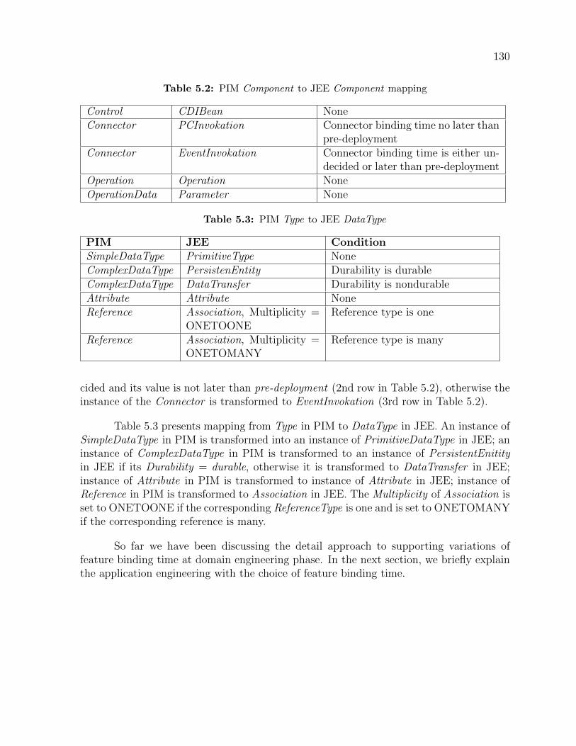
130
Table 5.2: PIM Component to JEE Component mapping
Control CDIBean NoneConnector PCInvokation Connector binding time no later than
pre-deploymentConnector EventInvokation Connector binding time is either un-
decided or later than pre-deploymentOperation Operation NoneOperationData Parameter None
Table 5.3: PIM Type to JEE DataType
PIM JEE ConditionSimpleDataType PrimitiveType NoneComplexDataType PersistenEntity Durability is durableComplexDataType DataTransfer Durability is nondurableAttribute Attribute NoneReference Association, Multiplicity =
ONETOONEReference type is one
Reference Association, Multiplicity =ONETOMANY
Reference type is many
cided and its value is not later than pre-deployment (2nd row in Table 5.2), otherwise theinstance of the Connector is transformed to EventInvokation (3rd row in Table 5.2).
Table 5.3 presents mapping from Type in PIM to DataType in JEE. An instance ofSimpleDataType in PIM is transformed into an instance of PrimitiveDataType in JEE; aninstance of ComplexDataType in PIM is transformed to an instance of PersistentEnitityin JEE if its Durability = durable, otherwise it is transformed to DataTransfer in JEE;instance of Attribute in PIM is transformed to instance of Attribute in JEE; instance ofReference in PIM is transformed to Association in JEE. The Multiplicity of Association isset to ONETOONE if the corresponding ReferenceType is one and is set to ONETOMANYif the corresponding reference is many.
So far we have been discussing the detail approach to supporting variations offeature binding time at domain engineering phase. In the next section, we briefly explainthe application engineering with the choice of feature binding time.
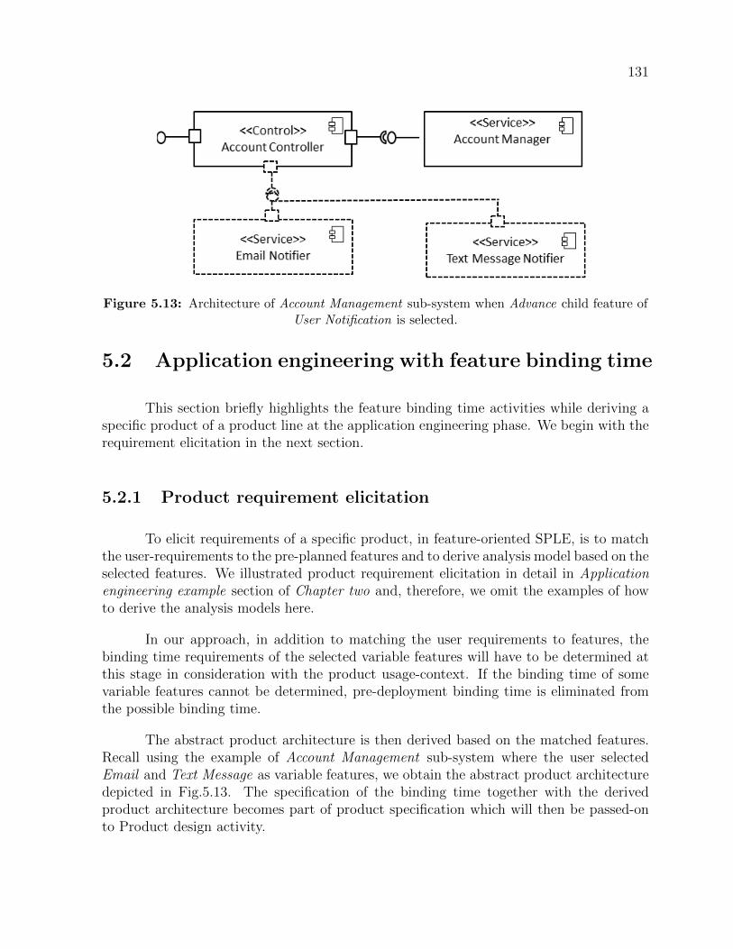
131
Figure 5.13: Architecture of Account Management sub-system when Advance child feature ofUser Notification is selected.
5.2 Application engineering with feature binding time
This section briefly highlights the feature binding time activities while deriving aspecific product of a product line at the application engineering phase. We begin with therequirement elicitation in the next section.
5.2.1 Product requirement elicitation
To elicit requirements of a specific product, in feature-oriented SPLE, is to matchthe user-requirements to the pre-planned features and to derive analysis model based on theselected features. We illustrated product requirement elicitation in detail in Applicationengineering example section of Chapter two and, therefore, we omit the examples of howto derive the analysis models here.
In our approach, in addition to matching the user requirements to features, thebinding time requirements of the selected variable features will have to be determined atthis stage in consideration with the product usage-context. If the binding time of somevariable features cannot be determined, pre-deployment binding time is eliminated fromthe possible binding time.
The abstract product architecture is then derived based on the matched features.Recall using the example of Account Management sub-system where the user selectedEmail and Text Message as variable features, we obtain the abstract product architecturedepicted in Fig.5.13. The specification of the binding time together with the derivedproduct architecture becomes part of product specification which will then be passed-onto Product design activity.

132
Figure 5.14: Instance of PIM representing partial architecture of Account Managementsub-system when Advance child feature of User Notification is selected
5.2.2 Product design
Product design in our approach is comprised of three activities: (i) Instantiation ofthe abstract architecture, derived from the requirement analysis, using the implementedPIM. (ii) Checking binding time consistencies of the instantiated PIM model elements.(iii) Transformation of the well-formed PIM to PSM.
To instantiate the product architecture of Fig.5.13 using the PIM we specified inthe PIM metamodelling section, we obtain the instance of PIM architecture model inFig.5.14. In the figure, each box represents a model element. The text before the colon inthe top compartment of each model element is the name of the model element as assignedby the engineer; the text after the column is the name of PIM class from which the modelelement is instantiated.
In Fig.5.14 the middle model element at the top of the figure, AccountController,represents Account Controller component and its associated model elements at its left andright represent instances of INPort and OutPort respectively. Note that the instance ofthe service component Account Manager is omitted in the figure.
The model element beneath AccountController represents the optional OutPort of

133
the Account Controller and the port is one of the points of intersection between the UserAccount feature and the Advance (User Notification) feature. In this case, no need toremove the optional OutPort because it suffices to remove the dependency between theintersecting features by making the port a gateway to putting and getting data but nottightly coupled connection should the binding time be later than pre-deployment time.Had it been it is an operation or attribute, it may have to be re-align or becomes part ofan aspectual component.
The bottom two model elements and from left to right, TextMessageNotifier andEmailNotifier represent Text Message Notifier and Email Notifier service componentsrespectively and both of which provides the AdVNotification instance of INPort. The Ad-vNotification instance of OutPort, that is on AccountController, is connected to AdvNo-tification INPort, that may be on TextMessageNotifier or EmailNotifier, using AdvNotifi-cationOut2AdvNotificationIN connector. That is, AdvNotificationOut2AdvNotificationINis an instance of Connector that joins Account Controller with either Message Notifier orEmail Notifier or both.
In our approach, the binding time of the variable features will have to be reflectedon the model elements representing the architectural model. As indicated earlier, thisoften means that a binding time of a single feature has to be reflected on many modelelements. For example, all three model elements at the top of the figure are exclusive tothe User Account feature. Thus, binding time property of the User Account feature isreflected on each of the three model elements at the top of the figure.
The instantiated model elements are then subjected to binding time consistencychecking and we discuss this in the next section.
5.2.3 Consistency checking and PIM to PSM transformation
Consistency checking is a check for well-formedness of model elements with respectto binding time. The checking can be in relation to the aggregate binding time of modelelements of a single feature. For example, in the simple example of product architectureof Fig.5.14, we would want to check if none of the mandatory architectural elements, forthe User Account feature, at the top of the figure has been deliberately or accidentallychanged from pre-deployment to something else. The consistency checking can also bein relation to compatibility of binding time of model elements across multiple features.For example, the AdvNotification OutPort and AdvNotification INPort must have bindingtime that is compatible with the AdvNotificationOut2AdvNotificationIN connector.
The transformation of the PIM architecture into its corresponding PSM architec-ture in our approach is a simple push-button. The transformation engines selects modelelement of the PSM based on the value of binding time properties of the PIM element.

134
Figure 5.15: JEE platform specific instance model in which the binding time of Advacnce(User Notification feature is set to pre-deployment
Fig.5.15 depicts Java EE instance model as the target platform-specific model of Fig.5.14platform independent model when the binding time of the Advance(User Notification)feature is set to pre-deployment. In the middle of the figure, the instance of the Sim-pleReference, AdvNot, is the result of transforming AdvNotification instance of OutPort ofthe model in Fig.14; The Kindof = ”PC” property of AdvNotification instance of Interfaceis the result of transforming AdvNotification instance of INPort of the model in Fig.14.Not shown in the figure is the procedure call invocation which is a result of transform-ingAdvNotificationOut2AdvNotificationIN instance of Connector
Similarly, Fig.5.16 depicts Java EE instance model as the target platform-specificmodel of Fig.5.14 platform independent model when the binding time of the Advance(UserNotification) feature is later than pre-deployment or left undecided. In the middle of thefigure, the instance of the EventReference, AccEvent, is the result of transforming AdvNo-tification instance of OutPort of the model in Fig.14; The Kindof = ”Event” property ofAdvNotification instance of Interface is the result of transforming AdvNotification instanceof INPort of the model in Fig.14. Not shown in the figure is the event firing as a result oftransformingAdvNotificationOut2AdvNotificationIN instance of Connector.
At this stage, the PSM should be well-formed and with the binding time decisionsreflected (both the selected binding time and the ones that are left open).

135
Figure 5.16: JEE platform specific instance model in which the binding time of Advacnce(User Notification feature is set to pre-deployment

136
5.2.4 Product instantiation
At the product instantiation stage, the skeletal product is generated from the well-formed platform specific model of the specific product. The key design decisions, includingthe architectural pattern/style and the binding time, are enforced in the skeletal product.The product will then have to be implemented manually or reuse from an existing im-plementation of similar products. The manual implementation may also be incorporatedin the specification of the code generation and preserve against loss in the subsequentre-generation[GHK+15]. Similarly, product-specific extensions that are not fed back tothe reusable asset are also implemented and integrated.
In the generated skeletal product, connection modes between the generated com-ponents depend on the values of the binding time. The components are connected directlywhen the binding time is decided before compilation at pre-deployment time. In that case,components should support compile-time and build time composition, do not have to fol-low separation between implementation and interface and may be followed with a staticoptimization using a specialized tool. If, however, the binding time cannot be decided atpre-deployment time, dependencies from mandatory components to variable componentsare removed. The components are connected dynamically, if needed, via a deploymentplatform.
The process of supporting variations of feature binding time in our approach shouldbe supported with a tool suite. In the next section, we discuss the tooling aspect of ourapproach.
5.3 Tool Support
Supporting variations of feature binding time in model-driven development hassome inherent exigencies that should be supported with tool for greate utility of theapproach. In this section, we highlight the implementation and the utility of toolingaspect of our approach.
5.3.1 PIM implementation and instantiation
We used ECore, a simplified implementation of meta object facility (MOF)[Gro16]of Eclipse Modelling Framework1 project, to implement the metamodel as an Eclipseplugin. Ecore is a metametamodel - a language for creating a metamodel. A light-weightmetamodel can as well be derived from a custom extension of UML metamodel and the
1https://www.eclipse.org/modeling/emf/

137
Figure 5.17: Components modelled with the eclipse-based plugin for PIM modelling
extension is known as UML Profile[LWWC11]. The full specification of the metamodel ofFig.5.8 in Platform independent metamodelling section with binding time can be found inAppendix A. Another approach we could have taken is to specify a grammar and implementa compiler for the binding-time aware modelling language. However, the metamodellingapproach is preferable for interoperability with other tools.
Fig.5.17 is a screenshot of partial PIM architectural elements modelled with the im-plemented metamodel of which the specification is presented in Appendix A. The graphicalinterface is Reflective Ecore Model Diagram Editor which is a plugin from Eclipse Mod-elling Project (EMP) that provides a graphical editor for any EMF model file, using onlythe meta-model such as .ecore and .xsd file. Fig.5.17a, and Fig.5.17b, highlight Account-Controller and TextMessageNotifier intances of Component. The circled parts show someof the components’ properties that include BindingTime and ElementType.
5.3.2 Consistency checking
We implemented the binding time consistency specification as constraints in Ob-ject Constraint Language (OCL)[Gro10] that are embedded in the ECore metamodel. Forexample, the code snippet in Fig.5.18a shows an implementation of a Boolean operationon ArchitecturalElement to check whether an element is variable or not and this operationis inherited by Component, Port and Connector. Lines 17 to 21 in Fig.5.18a show theimplementation of the constraint in listing 1 (a mandatory ArchitecturalElement shouldnot have binding time different from core asset development time). Fig.5.18b shows anexample of the validation error when the constraint in listing 1 is violated. Full specifi-cation of the binding time constraints can be found embedded in the PIM metamodel ofAppendix A.
A successfully validated model is then saved in an exchangeable format(i.e., in

138
Figure 5.18: OCL implementation
XML Metadata Interchange (XMI)) for the next transformation. We illustrate the modelto model transformation in the next section.
5.3.3 PIM to JEE model transformation and code generation
We implemented the model-to-model (M2M) transformation in Atlas Transforma-tion Language (ATL) [JABK08]. Fig.5.19 shows thespecification for transforming INPortin PIM, based on the INPort ’s bindingTime property, to either PC or EVENT Interfacein the target JEE PSM. The full transformation definition can be found in Appendix C.The output of the transformation is JEE model from which we generate the skeletal prod-uct with the key design decisions such as binding time and architectural style enforced.
PSM to source code transformation :We implemented the model-to-text transformation (M2T), aka code generation, in Xtend2.Xtend is a statically-typed programming language optimised for template-based code gen-eration. The transformation from the PSM to code in Java is a straight-forward and isillustrated in Fig.5.20.
2https://www.eclipse.org/xtend/

139
Figure 5.19: PIM to JEE transformation
Figure 5.20: PSM to source code transformation

140
5.4 Evaluation an discussion
In this section, we present the evaluation of our approach with respect to perfor-mance. Also, we discuss the approach with respect to the modifiability of the implemen-tation artefact.
5.4.1 Performance
Recall that we rely on the deployment platform and the removal of dependenciesbetween components to delay the binding if it cannot be decided at pre-deployment time.We can also use the same connection to the deployment platform for the early binding,at pre-deployment time, but we then lose the opportunity to optimise statically and,therefore, compromise performance. In other words, we use the direct static connection toimprove performance when the additional flexibility is not required because the bindingcan be decided before compilation. Consequently, the evaluation is to test how significantis the performance gain for the direct connection.
We set up an experimental environment3 to compare the performance of the twomodes of components connection: i) Direct mode and ii) Platform mode. For the platformmode, we used the JEE event model which supports components communication withoutany compile-time dependency. The test case for the experiment is: ”a user requests tocreate an account and the server responds with a sign-up form. Once the user fills theform and submits, the server creates a record in the database for the user. The server alsogenerates and sends a token to the user, via email and text message, for confirmation”The test case involves the component implementation of the following features: ApplicantAccount (mandatory), Applicant Validation (optional), Message Service (optional), Email(OR-group) and Text Message(OR-group).
In the result tables, the Users column indicates the number of concurrent usersper request and the Ramp up column represents the time interval (in seconds) betweenrequests in the case of multi-user. The two Res. columns specify the average responsetime (delay) of Direct and Platform modes, also in seconds. The Diff. column representsthe difference response time, in seconds, between the two modes. The %Diff. representsthe percentage differences of response time between the two modes. Note that the lowervalues of Res. means less delay- which implies better performance.
Table 5.4 presents the results of the comparison between the Direct mode and thePlatform mode when the components are configured to execute synchronously. Referring
3The components were deployed on Glassfish 4.1, an open-source implementation of the JEE container.A load test was run with Apache JMeter https://jmeter.apache.org/ testing tool on Dell Computer with2.9 GHz Intel R© Core TM i7 and 16GB of RAM.

141
Table 5.4: Response time comparison of Direct and Platform modes for synchronouscomponent implementation
Users Rampup(sec)
Res. (Di-rect)(sec)
Res. (Plat-form (sec)
Diff.(sec) %Diff.
1 na 1.22 1.01 -0.22 -17.4320 20 0.95 3.27 2.32 243.2350 25 4.94 7.44 2.50 50.63100 30 11.33 16.02 4.682 41.31
Figure 5.21: Comparison between Direct and Platform in synchronous mode
to Table 5.4, the response time increases with the increase in the number of users for bothmodes (see Fig.5.21). With a single user (the first row in Table 5.4, the response timewas slightly lower (which means faster response and less delay) for the Platform mode by0.22 seconds (-17.43%) 4. This is because of the components for sending a text messageand email react to the Platform event simultaneously. In all other cases, the responsetime is slightly lower (which means faster and less delay) in the Direct mode because ofthe absence of Platform involvement. Fig.5.21 presents the graph of the result of Table5.4. Overall, the Direct mode offers performance benefit in an execution environment thatrequires synchronous component connection.
Next, we configured asynchronous component connections on all ports at the vari-ation points and this means the components can be executed simultaneously. Table 5.5presents the result with the asynchronous component connections.
It can be observed, from Table 5.5 and Fig.5.22, that the response time remainsfairly stable with the Platform mode, even with the increase of requests, but increasesdrastically from an average of 0.90 sec for one user to an average of 13.04 for 100 users withthe Direct mode. The results show that the Direct mode limits multi-processing capabilityin the asynchronous case. Put in another way, when asynchronous communication betweencomponents is configured, the Platform mode offers more multi-threading capability than
4In this case, we averaged the results of 5 test runs to increase the accuracy of testing.

142
Table 5.5: Response time comparison of Direct and Platform modes for asynchronouscomponent implementation
Users Rampup(sec)
Res. (Di-rect)(sec)
Res. (Plat-form (sec)
Diff.(sec) %Diff.
1 na 0.90 0.38 -0.52 -57.9520 20 1.66 0.36 -1.302 -78.5650 25 6.96 0.40 -6.57 -94.32100 30 13.04 0.35 -12.69 -97.32
Figure 5.22: Comparison between Direct and Platform in asynchronous mode
the Direct mode.
As such, switching to the Direct mode for the early binding offers benefit only whenthe synchronous mode of communication between components is desirable. In contrast, acomplete loose coupling, using the Platform mode offers more flexibility and performancebecause the platform-induced delay is compensated with an optimized multi-threadingcapability. Thus, usage-contexts should also be parametrized and apply the switchingonly where it is needed and go with full flexibility in where it is not needed.
5.4.2 Modifiability
Recall from chapter four (Language-based approaches to flexible variations: Actionresearch), adapting code-asset to inject additional variations using both the language-based implementation techniques and the pre-processing of annotations require makingchanges to several places in the code-asset. In the case of language-based implementationtechniques, often the code-asset has to be re-organized. In contrast, when binding timeaware modelling language is used to implement a product line based on our proposedapproach, the changes will be made at fewer places (at the level of architectural elementsand in the transformation definition). Therefore, our approach may be more modifiablethan language based variability implementation techniques.
143
In addition, the support for variations of feature binding time with language-basedimplementation techniques has been either through several clones of code-asset (in practice[DRB+13]) or through multiple implementations of features as proposed in academic re-searches [CRE08, ARR+16].For example, to support variable feature binding time, Chack-ravathy et al [CRE08] proposed separate implementations of features in aspect-orientedprogramming. In their approach, a single variant feature would have multiple imple-mentations and each of them is the same variant feature with different binding times.Andrade et al [ARR+16] worked along the same line, in direct comparison to the ap-proach in [CRE08], and claimed to have reduced only the code redundancy but retainedthe multiple implementations of a feature.
In contrast to existing approaches, when binding time aware modelling language isused to implement a product line based on our proposed approach, each feature has singlerepresentation at the PIM level, the variations of feature binding time only affects how thePIM is transformed into PSM model elements but no multiple representations of a featureis required. Rather, the mode of component-interaction mechanisms are interchangeablebased on the chosen binding time and this creates fewer modifiability problems than thecase of [CRE08] and [ARR+16]. Our approach could achieve this as we abstract away theactual binding mechanism and manages it at the architecture level.
5.5 Chapter summary
In this chapter, we presented the design and implementation of the binding-awaremodelling language to support variations of feature binding time. To demonstrate the fea-sibility of our approach, we validated the language with a case study of EduPL. However,more works need to be done to enrich the semantics for the metamodels. For example,semantics to aggregate the fine-grained variations into aspectual components should beintegrated into the PIM and PSM metamodels. Other architectural concerns should notonly be supported but should also be verifiable for violations.

Chapter 6
Conclusion
This chapter presents a summary of the previous chapters and puts our contribu-tions in perspective. The chapter also highlights the inherent limitations of the thesis anddiscusses grounds for future works.
6.1 Thesis summary
The Chapter one provided a general overview to set the context of the thesis. Webegan from the background theory of the thesis, which is a reuse from the perspectiveof software engineering, and progressed to the focal theory, which is adaptable variationsand feature binding time in software product line engineering. Also, the chapter high-lighted the research motivation, spelled out the research objectives, and followed with theresearch questions. Finally, the chapter outlined the research contributions and presentedan overview of the research methods that bound the research processes.
Chapter two elaborated on the feature-oriented approach to the lifecycle activities ofboth domain engineering and application engineering. The illustrated, with examples, theconcepts of adaptable variations, feature binding time in software product line engineering,and the research challenges associated with both.
Chapter three presented the details of the action research that was executed toinvestigate the adaptability of reusable assets when adding variations. Part of the in-vestigation is an exploration of the properties of features, in the code-asset, that affectmodifiability when injecting additional variations. In the exploration, we observed thatan intersection between program elements of different features negatively affects the mod-ifiability of code-assets when injecting additional variations.
In addition to the exploration, the chapter reported the selections and comparisonof the following three language-based implementation techniques: (i) Feature-OrientedProgramming (FOP), (ii) Aspect-Oriented Programming (AOP), and (iii) Delta-OrientedProgramming (DOP). We compared the techniques relative to Pre-Processing (PP) ofannotations (a classical variability implementation technique) using modifiability metrics.
144

145
The summary of the comparison is none of the language-based implementation tech-niques is better than pre-processing in terms of modifiability. Similarly, language-basedimplementation techniques specifically proposed to implement features in SPLE (Feature-Oriented Programming and Delta-Oriented Programming) have better modularity but donot support variations in feature binding time.
Chapter four presented a systematic mapping study and systematic literature re-view on the approaches proposed to support variations of feature binding time. The chap-ter presented visual maps of published works, from 1999 through 2016, on the proposedinterventions. In the chapter, we also presented the following six categories of approachesthat emerged from the systematic study:
• Delegation of binding to aspect weaver
• Programming language extension
• Metadata interpretation
• Model composition
• Delegation of binding to deployment platform
• Abstracting the binding time at model level
We also presented a narrative summary of each of the approaches in all the categoriesand qualitative assessments of the proposed interventions through the lenses of bindingphases, granularity, and level of abstraction.
Chapter five presented the detail design and implementation of our proposed binding-time aware modelling language. We validated the modelling language with an example ofan enterprise software product line.
6.2 Revisiting the Contributions
In this section, we highlight the significance of our contributions in the context ofthe existing body of knowledge.
In the literature, there are two categories of actions researches on transformingvariations into features: 1) the exploration of granularity of program elements forming theintersection between separate features [KAK08], and 2) exploration on the structure ofcode-asset and possible transformations that are required to untangle features, using oneor more language-based techniques for advanced separation of concern [MLWR01, KAB07,

146
CRE08, ARR+16, MP02]. The two categories of studies had resulted in new knowledgethat may be used as an initial benchmark for language semantics that should be consid-ered when proposing/improving programming languages for implementing variations asfeatures.
Our first contribution, C1, also emanated from the exploration of properties offeatures in the code-asset as one of the aspects of our action research. However, ourcontribution provides a new perspective (i.e., modifiability to inject additional variations)to the previous studies. Hence, the findings from our action research should also be takeninto consideration when proposing or improving languages for SPL implementation. Forexample, the lack of modifiability when untangling features from the code-asset usingAOP due to the high number of constructs that have to be used or the lack of support formethod and constructor wrapping in DOP should be useful to designers of programminglanguages meant for implementing variations as features.
The second Contribution, C2, stemmed from the systematic study to survey ap-proaches that are proposed to support variations of feature binding time. The study is anew addition to SPLE literature since to the best of our knowledge, no similar study ex-ists. Further, we presented, as a narrative summary, detail insight for each of the surveyedapproaches and highlighted where the proposed intervention is relevant and where it maybe inadequate and in some cases suggested how the approach might be improved. Thenarrative summary complements existing knowledge of variability resolution and bindingtime [KK16, Kre15, SvGB05].
The third and fourth contributions, C3 and C4, are the binding time aware mod-elling language and the toolsets to encode the binding time and to check consistency at thearchitecture model level. We consider our approach as an improvement over the existingapproaches in one of the following ways:
• Abstracting the binding time at the model level in our approach is wider in scope thanthe current approaches because we did not limit the feature binding to only executioncontext as in the existing approaches[BW09, HKM+13]. Hence, our approach maybe more applicable in the cases where practitioners have to deal with the wider scopeof binding that what the current approaches support.
• Modelling the binding time at the architecture level, to circumvent scalability con-cern, as against current approaches where either the binding time is marked on fine-grained model elements [DRO19] or composition of the fine-grained model elementsto realize a feature as a model slice.
• Using the binding time property as a condition for model transformation and therebyeliminating the need for multiple implementations attendant to AOP design idioms[ARR+16,CRE08].

147
Overall, our approach supports variations of feature binding time by design andimproves the modifiability of reusable assets of a product line.
6.3 Limitations
In the action research, the specific cases we considered are by no means generaliza-tion of every single case of exclusivity and intersection. Inherently, the level of modifiabilitydiffers with the level of tangling between program elements of different features. In ad-dition, the study is from a single product line domain. Other product lines may havedifferent structures of code-asset.
Likewise, the evaluated implementation techniques are generally not mutually ex-clusive to each other. AOP, in particular, is used to support other techniques. However,in the evaluation, we reduced the feature union into its atomic constituents to enable thereasoning of individual techniques against these atomic units.
The switching of connection mode between components (SCMBC) in our approachmay not be relevant where a target middleware or platform does not exist. Even if a targetplatform exists, it may not support the delegation of binding as proposed in this thesis.However, many domains, including real-time domain, are increasingly adopting a containertechnology or incorporate a special library that can be adapted for the binding [sm118,ER18]. Likewise, an architectural framework [TMO09] can be developed or adapted tosupport the delegation of binding. Similarly, a light-weight component manager may alsobe used for the same purpose.
In the implementation of the modelling language, we extended Ecore metamod-elling language – an approach that is considered as heavyweight [BGD+15]. A lightweightextension such as UML profiling mechanism might have been easier and could have beenmade reusable to other domains[LWWC11, BGD+15].
The approach we proposed is most appropriate in proactive SPLE [Cle02], wherethe software product line is developed from scratch since a certain degree of freedom isrequired since the support of variations of feature binding time has to be pre-planned.Overall, the proposed approach mainly demonstrated that it is feasible to manage thevariation of feature binding time at a higher level of abstraction in MDD PLA.

148
6.4 Future research directions
In this section, we outline the future works to either consolidate the findings in thisthesis or to extend our approach to supporting variations of feature binding time. Thefollowing some of the grounds for future work:
• One of the immediate extensions to our proposed binding time aware modellinglanguage is to add, to the PIM metamodel, a means to aggregate the fine-grainedvariations into aspectual components.
• The M2M transformation should also be extended to support parameterization inmany fronts (e.g., parameterize ports with synchronicity property, parameterize com-ponent interaction mechanisms) and to check product-wide effects of the instantiatedproperties (e.g., to check possible violation for coordination requirements of paralleltasks).
• From the findings in our systematic study on the interventions to support variationsof feature binding time, AOP related techniques where the dominant interventionsproposed. One of the interventions was the integration of static and dynamic weaverto have the best from the two classes of weavers. Interestingly, the integrationhad to sacrifice the inter-type declaration of fine-grained program elements such asattributes similar to the compromise made when AspectJ and AspectWerkz weaverswere merged. It will be interesting, as future research, to use the two weavers in thesame assets and switch between the two types of weavers depending on the bindingtime requested. Again the switching between the two weavers shall be abstracted atthe model level. In this regard, it will also be interesting to compare the integrationand the switching between the two classes of weavers in terms of efforts and practicalutility.
• It will also be interesting to extend our proposed approach to supporting variationsof feature binding time to cloud-based and micro-service deployment platforms suchas Docker container[And15].
• Since we use only a single domain in our exploration of feature in the code-asset,further investigations are necessary with multiple case studies in different softwaredomains in order to improve the understanding of our findings.
• When the proposed modelling language attained a certain level of maturity, it imper-ative to provide empirical evidence when the approach is directly compared to thecomposition of fine-grained model elements in terms of modifiability and similarlyto compare with the use of aspect idioms in terms of code duplication.

149
6.5 Closing remarks
This thesis has established that modern language-based implementation techniques,including those that are specifically proposed to implement variations in the form of fea-tures, have fallen short in supporting the modifiability of reusable assets and variationsof feature binding time in SPLE. Similarly, the various engineering approaches that areproposed to support variations of feature binding time have also fallen short in terms ofthe scope of their coverage and focus. Given the established limitations of the existingapproaches, this thesis presents binding time aware modelling language that supports vari-ations of feature binding time by design and improves the modifiability of reusable assetsof a product line.

Bibliography
[AABZ14] Sven Apel, Joanne M. Atlee, Luciano Baresi, and Pamela Zave. FeatureInteractions: The Next Generation (Dagstuhl Seminar 14281). DagstuhlReports, 4(7):1–24, 2014.
[ABM00] Colin Atkinson, Joachim Bayer, and Dirk Muthig. Component-based prod-uct line development: the kobra approach. In Software Product Lines,pages 289–309. Springer, 2000.
[AE92] William W. Agresti and William M. Evanco. Projecting software defectsfrom analyzing ada designs. IEEE Transactions on Software Engineering,18(11):988–997, 1992.
[AK09] Sven Apel and Christian Kastner. An overview of feature-oriented softwaredevelopment. Journal of Object Technology, 8(5):49–84, 2009.
[AKS+13] Sven Apel, Sergiy Kolesnikov, Norbert Siegmund, Christian Kastner, andBrady Garvin. Exploring feature interactions in the wild: the new feature-interaction challenge. In Proceedings of the 5th International Workshop onFeature-Oriented Software Development, pages 1–8. ACM, 2013.
[AM04] Michalis Anastasopoulos and Dirk Muthig. An evaluation of aspect-oriented programming as a product line implementation technology. In In-ternational Conference on Software Reuse, pages 141–156. Springer, 2004.
[And15] Charles Anderson. Docker [software engineering]. IEEE Software,32(3):102–c3, 2015.
[ARR+16] Rodrigo Andrade, Marcio Ribeiro, Henrique Rebelo, Paulo Borba, VaidasGasiunas, and Lucas Satabin. Assessing idioms for a flexible feature bind-ing time. The Computer Journal, 59(1):1–32, 2016.
[Bat05a] Don Batory. Feature models, grammars, and propositional formulas. InInternational Conference on Software Product Lines, pages 7–20. Springer,2005.
[Bat05b] Don Batory. A tutorial on feature oriented programming and the ahead toolsuite. In International Summer School on Generative and TransformationalTechniques in Software Engineering, pages 3–35. Springer, 2005.

151
[BBM96] Victor R Basili, Lionel C Briand, and Walcelio L Melo. How reuse in-fluences productivity in object-oriented systems. Communications of theACM, 39(10):104–116, 1996.
[BC12] Jan Bosch and Rafael Capilla. Dynamic variability in software-intensiveembedded system families. Computer, 45(10):28–35, 2012.
[BD95] Jean-Marie Burkhardt and Francoise Detienne. An empirical study of soft-ware reuse by experts in object-oriented design. In Human—ComputerInteraction, pages 133–138. Springer, 1995.
[BFK+99a] Joachim Bayer, Oliver Flege, Peter Knauber, Roland Laqua, Dirk Muthig,Klaus Schmid, Tanya Widen, and Jean-Marc DeBaud. Pulse: A method-ology to develop software product lines. SSR, 99:122–131, 1999.
[BFK+99b] Joachim Bayer, Oliver Flege, Peter Knauber, Roland Laqua, Dirk Muthig,Klaus Schmid, Tanya Widen, and Jean-Marc DeBaud. Pulse: A method-ology to develop software product lines. SSR, 99:122–131, 1999.
[BGD+15] Hugo Bruneliere, Jokin Garcia, Philippe Desfray, Djamel Eddine Khelladi,Regina Hebig, Reda Bendraou, and Jordi Cabot. On lightweight meta-model extension to support modeling tools agility. In European Conferenceon Modelling Foundations and Applications, pages 62–74. Springer, 2015.
[BHK11] Don Batory, Peter Hofner, and Jongwook Kim. Feature interactions, prod-ucts, and composition. In ACM SIGPLAN Notices, volume 47, pages 13–22. ACM, 2011.
[Big98] Ted J Biggerstaff. A perspective of generative reuse. Annals of SoftwareEngineering, 5(1):169, 1998.
[BLL+14] Johannes Burdek, Sascha Lity, Malte Lochau, Markus Berens, UrsulaGoltz, and Andy Schurr. Staged configuration of dynamic software productlines with complex binding time constraints. In Proceedings of the EighthInternational Workshop on Variability Modelling of Software-IntensiveSystems, page 16. ACM, 2014.
[BMF09] Luciana Akemi Burgareli, Selma Shin Shimizu Melnikoff, and MauricioG Vieira Ferreira. A variation mechanism based on adaptive object modelfor software product line of brazilian satellite launcher. In 2009 First IEEEEastern European Conference on the Engineering of Computer Based Sys-tems, pages 24–31. IEEE, 2009.
[BOVH17] Gulden Bayrak, Felix Ocker, and Birgit Vogel-Heuser. Evaluation of se-lected control programming languages for process engineers by means ofcognitive effectiveness and dimensions. Journal of Software Engineeringand Applications, 10(05):457, 2017.

152
[BST+94] Don Batory, Vivek Singhal, Jeff Thomas, Sankar Dasari, Bart Geraci, andMarty Sirkin. The genvoca model of software-system generators. IEEESoftware, 11(5):89–94, 1994.
[BVD07] Michal Bebjak, Valentino Vranic, and Peter Dolog. Evolution of web ap-plications with aspect-oriented design patterns. In AEWSE, 2007.
[BW09] Danilo Beuche and Jens Weiland. Managing flexibility: Modeling binding-times in simulink. In European Conference on Model Driven Architecture-Foundations and Applications, pages 289–300. Springer, 2009.
[BW14] Thomas Buchmann and Bernhard Westfechtel. Mapping feature modelsonto domain models: ensuring consistency of configured domain models.Software and Systems Modeling, 13(4):1495—1527, 2014.
[CA05] Krzysztof Czarnecki and Micha l Antkiewicz. Mapping features to models:A template approach based on superimposed variants. In Internationalconference on generative programming and component engineering, pages422–437. Springer, 2005.
[CB13] Rafael Capilla and Jan Bosch. Binding time and evolution. In Systemsand Software Variability Management, pages 57–73. Springer, 2013.
[CB16] Rafael Capilla and Jan Bosch. Dynamic variability management support-ing operational modes of a power plant product line. In Proceedings ofthe Tenth International Workshop on Variability Modelling of Software-intensive Systems, pages 49–56. ACM, 2016.
[CCG+16] Bruno BP Cafeo, Elder Cirilo, Alessandro Garcia, Francisco Dantas, andJaejoon Lee. Feature dependencies as change propagators: an exploratorystudy of software product lines. Information and Software Technology,69:37–49, 2016.
[CE00] K Czarnecki and U Eisenecker. Generative programming: Methods, tools,and applications., 2000.
[CEM04] Robert Chatley, Susan Eisenbach, and Jeff Magee. Magicbeans: a platformfor deploying plugin components. In International Working Conference onComponent Deployment, pages 97–112. Springer, 2004.
[Cle02] Paul Clements. Being proactive pays off. IEEE Software, 19(4):28, 2002.
[CLK08] Hojin Cho, Kwanwoo Lee, and Kyo C Kang. Feature relation and depen-dency management: An aspect-oriented approach. In 2008 12th Interna-tional Software Product Line Conference, pages 3–11. IEEE, 2008.

153
[Coo17] Oracle Coorporation. Oracle berkeley db java edition — oracle berkeleydb, 2017.
[CRE08] Venkat Chakravarthy, John Regehr, and Eric Eide. Edicts: implementingfeatures with flexible binding times. In Proceedings of the 7th internationalconference on Aspect-oriented software development, pages 108–119. ACM,2008.
[CVD16] Rafael Capilla, Alejandro Valdezate, and Francisco J Dıaz. A runtimevariability mechanism based on supertypes. In 2016 IEEE 1st InternationalWorkshops on Foundations and Applications of Self* Systems (FAS* W),pages 6–11. IEEE, 2016.
[Del17] DeltaJ. a delta oriented programming language with core and delta mod-ules, 2017.
[DFV03] Eelco Dolstra, Gert Florijn, and Eelco Visser. Timeline variability: Thevariability of binding time of variation points, 2003.
[DRB+13] Yael Dubinsky, Julia Rubin, Thorsten Berger, Slawomir Duszynski, Mar-tin Becker, and Krzysztof Czarnecki. An exploratory study of cloning inindustrial software product lines. In 2013 17th European Conference onSoftware Maintenance and Reengineering, pages 25–34. IEEE, 2013.
[DRO19] Udo Kelter Dennis Reuling, Christopher Pietsch and Manuel Ohrndorf.Flexiple - a tool for flexible binding times in annotated modelbased spls.In In Proceedings of 23rd International Systems and Software Product LineConference, Paris, France, 9–13 September, 2019 (SPLC’19), pages 52–67.ACM, 2019.
[DSW14] Ferruccio Damiani, Ina Schaefer, and Tim Winkelmann. Delta-orientedmulti software product lines. In Proceedings of the 18th International Soft-ware Product Line Conference-Volume 1, pages 232–236. ACM, 2014.
[DWAJ+05] Mary Dixon-Woods, Shona Agarwal, David Jones, Bridget Young, andAlex Sutton. Synthesising qualitative and quantitative evidence: a reviewof possible methods. Journal of health services research & policy, 10(1):45–53, 2005.
[ER18] VF Emets and Jan Rogowski. Comparative analysis of event propagationmethods on android platform. In 2018 IEEE 13th International Scientificand Technical Conference on Computer Sciences and Information Tech-nologies (CSIT), volume 1, pages 227–230. IEEE, 2018.
[ESSD08] Steve Easterbrook, Janice Singer, Margaret-Anne Storey, and DanielaDamian. Selecting empirical methods for software engineering research. In

154
Guide to advanced empirical software engineering, pages 285–311. Springer,2008.
[FCS+08] Eduardo Figueiredo, Nelio Cacho, Claudio Sant’Anna, Mario Monteiron,Uira Kulesza, Alessandro Garcia1, Sergio Soares3, Fabiano Ferrari, SafooraKhan, Fernando Castor Filho, and Francisco Dantas. Evolving softwareproduct lines with aspects: An empirical study on design stability. InProceedings of the 30th international conference on Software engineering,pages 261 –270, Leipzig, Germany, 2008. ACM.
[Fli09] Shayne Flint. A conceptual model of software engineering research ap-proaches. In 2009 Australian Software Engineering Conference, pages 229–236. IEEE, 2009.
[Fow10] Martin Fowler. Alternative computational models. In Domain-specificlanguages, pages 113–120. Pearson Education, 2010.
[FPF+98] William Frakes, Ruben Prieto, Christopher Fox, et al. Dare: Domainanalysis and reuse environment. Annals of software engineering, 5(1):125–141, 1998.
[Fra03] David S Frankel. Model driven architecture applying MDA. John Wiley &Sons, 2003.
[FT96] William Frakes and Carol Terry. Software reuse: metrics and models. ACMComputing Surveys (CSUR), 28(2):415–435, 1996.
[GAO95] David Garlan, Robert Allen, and John Ockerbloom. Architectural mis-match: Why reuse is so hard. IEEE software, 12(6):17–26, 1995.
[GHJ+95] Erich Gamma, Richard Helm, Ralph Johnson, John Vlissides, and DesignPatterns. Elements of reusable object-oriented software. Design Patterns.massachusetts: Addison-Wesley Publishing Company, 1995.
[GHK+15] Timo Greifenberg, Katrin Holldobler, Carsten Kolassa, Markus Look, Pe-dram Mir Seyed Nazari, Klaus Muller, Antonio Navarro Perez, DimitriPlotnikov, Dirk Reiss, Alexander Roth, et al. A comparison of mecha-nisms for integrating handwritten and generated code for object-orientedprogramming languages. In 2015 3rd International Conference on Model-Driven Engineering and Software Development (MODELSWARD), pages74–85. IEEE, 2015.
[GKS+96] Hassan Gomaa, Larry Kerschberg, Vijayan Sugumaran, C Bosch,I Tavakoli, and L O’Hara. A knowledge-based software engineering envi-ronment for reusable software requirements and architectures. AutomatedSoftware Engineering, 3(3-4):285–307, 1996.

155
[Gla94] Robert L Glass. The software-research crisis. IEEE Software, 11(6):42–47,1994.
[Gla01] Robert L. Glass. Frequently forgotten fundamental facts about softwareengineering. IEEE SOFTWARE, 18(3):36–44, May/June 2001.
[Gom05] Hassan Gomaa. Designing software product lines with UML. IEEE, 2005.
[GPGBMA10] Borja Gonzalez-Pereira, Vicente P Guerrero-Bote, and Felix Moya-Anegon.A new approach to the metric of journals’ scientific prestige: The sjr indi-cator. Journal of informetrics, 4(3):379–391, 2010.
[GPZ02] Michael Goedicke, Klaus Pohl, and Uwe Zdun. Domain-specific runtimevariability in product line architectures. In International Conference onObject-Oriented Information Systems, pages 384–396. Springer, 2002.
[Gro10] Object Management Group. About the Object Constraint Language Speci-fication Version 2.2. https://www.omg.org/spec/OCL/2.2/About-OCL/,2010.
[Gro16] Object Management Group. About the Meta Object Facility SpecificationVersion 2.5.12. https://www.omg.org/mof/, 2016. Accessed: 2018-04-03.
[HKM+13] Herman Hartmann, Mila Keren, Aart Matsinger, Julia Rubin, Tim Trew,and Tali Yatzkar-Haham. Using mda for integration of heterogeneous com-ponents in software supply chains. Science of Computer Programming,78(12):2313–2330, 2013.
[HMT09] Herman Hartmann, Aart Matsinger, and Tim Trew. Supplier independentfeature modelling. In Proceedings of the 13th International Software Prod-uct Line Conference, pages 191–200, San Francisco, California, USA, 2009.ACM.
[HT08] Herman Hartmann and Tim Trew. Using feature diagrams with contextvariability to model multiple product lines for software supply chains. In2008 12th International Software Product Line Conference, pages 12–21.IEEE, 2008.
[HZS+16] Claus Hunsen, Bo Zhang, Janet Siegmund, Christian Kastner, OlafLeßenich, Martin Becker, and Sven Apel. Preprocessor-based variabil-ity in open-source and industrial software systems: An empirical study.Empirical Software Engineering, 21(2):449–482, 2016.
[JABK08] Frederic Jouault, Freddy Allilaire, Jean Bezivin, and Ivan Kurtev. Atl: Amodel transformation tool. Science of computer programming, 72(1-2):31–39, 2008.
156
[K+07] Staffs Keele et al. Guidelines for performing systematic literature reviewsin software engineering. Technical report, Technical report, Ver. 2.3 EBSETechnical Report. EBSE, 2007.
[KA09] Christian Kastner and Sven Apel. Virtual separation of concerns – a sec-ond chance for preprocessors. Journal of Object Technology, 8(6):59–78,September/October 2009.
[KAB07] Christian Kastner, Sven Apel, and Don Batory. A case study implement-ing features using aspectj. In 11th International Software Product LineConference (SPLC 2007), pages 223–232. IEEE, 2007.
[KAK08] Christian Kastner, Sven Apel, and Martin Kuhlemann. Granularity insoftware product lines. In Proceedings of the 30th international conferenceon Software engineering, pages 311–320. ACM, 2008.
[KAR+09] Christian Kastner, Sven Apel, Marko Rosenmuller, Don Batory, GunterSaake, et al. On the impact of the optional feature problem: Analysis andcase studies. In Proceedings of the 13th International Software ProductLine Conference, pages 181–190. Carnegie Mellon University, 2009.
[KCH+90] Kyo C Kang, Sholom G Cohen, James A Hess, William E Novak, andA Spencer Peterson. Feature-oriented domain analysis (foda) feasibilitystudy. Technical report, Carnegie-Mellon Univ Pittsburgh Pa SoftwareEngineering Inst, 1990.
[KK98] Dirk O Keck and Paul J Kuehn. The feature and service interaction prob-lem in telecommunications systems: A survey. IEEE Transactions on Soft-ware Engineering, 24(10):779–796, 1998.
[KK15] Niloofar Khedri and Ramtin Khosravi. Incremental variability managementin conceptual data models of software product lines. In 2015 Asia-PacificSoftware Engineering Conference (APSEC), pages 222–229. IEEE, 2015.
[KK16] Michael Krisper and Christian Kreiner. Describing binding time in softwaredesign patterns. In Proceedings of the 21st European Conference on PatternLanguages of Programs, page 25. ACM, 2016.
[KKL+98] Kyo C Kang, Sajoong Kim, Jaejoon Lee, Kijoo Kim, Euiseob Shin, andMoonhang Huh. Form: A feature-; oriented reuse method with domain-;specific reference architectures. Annals of Software Engineering, 5(1):143,1998.
[Kre15] Christian Kreiner. A binding time guide to creational patterns. In Proceed-ings of the 18th European Conference on Pattern Languages of Program,page 14. ACM, 2015.

157
[Kru95] Philippe B Kruchten. The 4+ 1 view model of architecture. IEEE software,12(6):42–50, 1995.
[Kru06] Charles W Krueger. New methods in software product line development.In 10th International Software Product Line Conference (SPLC’06), pages95–99. IEEE, 2006.
[Lad03] Ramnivas Laddad. AspectJ in action: practical aspect-oriented program-ming. Dreamtech Press, 2003.
[LAL+10] Jorg Liebig, Sven Apel, Christian Lengauer, Christian Kastner, andMichael Schulze. An analysis of the variability in forty preprocessor-basedsoftware product lines. In Proceedings of the 32nd ACM/IEEE Inter-national Conference on Software Engineering-Volume 1, pages 105–114.ACM, 2010.
[Lee] Kwanwoo Lee. Aspect-oriented patterns for the realization of flexible fea-ture binding. In 1st International Workshop on Model-Driven Approachesin Software Product Line Engineering Goetz Botterweck, Iris Groher, An-dreas Polzer, page 51. Citeseer.
[LHKS92] John A Lewis, Sallie M Henry, Dennis G Kafura, and Robert S Schulman.On the relationship between the object-oriented paradigm and softwarereuse: An empirical investigation. Technical report, Department of Com-puter Science, Virginia Polytechnic Institute & State . . . , 1992.
[LK03] Jaejoon Lee and Kyo C Kang. Feature binding analysis for product linecomponent development. In International Workshop on Software Product-Family Engineering, pages 250–260. Springer, 2003.
[LK10] Kwanwoo Lee and Kyo C Kang. Usage context as key driver for featureselection. In International Conference on Software Product Lines, pages32–46. Springer, 2010.
[LKCC00] Kwanwoo Lee, Kyo C Kang, Wonsuk Chae, and Byoung Wook Choi.Feature-based approach to object-oriented engineering of applications forreuse. Software: Practice and Experience, 30(9):1025–1046, 2000.
[LKKP06] Kwanwoo Lee, Kyo Chul Kang, Minseong Kim, and Sooyong Park. Com-bining feature-oriented analysis and aspect-oriented programming for prod-uct line asset development. In 10th International Software Product LineConference (SPLC’06), pages 10–pp. IEEE, 2006.
[LKL02] Kwanwoo Lee, Kyo C Kang, and Jaejoon Lee. Concepts and guidelinesof feature modeling for product line software engineering. In InternationalConference on Software Reuse, pages 62–77. Springer, 2002.

158
[LWWC11] Philip Langer, Konrad Wieland, Manuel Wimmer, and Jordi Cabot. Fromuml profiles to emf profiles and beyond. In International Conference onModelling Techniques and Tools for Computer Performance Evaluation,pages 52–67. Springer, 2011.
[MLWR01] Gail C. Murphy, Albert Lai, Robert J. Walker, and Martin P. Robillard.Separating features in source code: An exploratory study. In Proceedingsof the 23rd International Conference on Software Engineering(ICSE 2001),pages 275– –284, Toronto, Ontario, Canada, 2001. IEE.
[MMP00] Nikunj R Mehta, Nenad Medvidovic, and Sandeep Phadke. Towards ataxonomy of software connectors. In Proceedings of the 22nd internationalconference on Software engineering, pages 178–187. ACM, 2000.
[MP02] Dirk Muthig and Thomas Patzke. Generic implementation of product linecomponents. In Net. ObjectDays: International Conference on Object-Oriented and Internet-Based Technologies, Concepts, and Applications fora Networked World, pages 313–329. Springer, 2002.
[MPH+07] Andreas Metzger, Klaus Pohl, Patrick Heymans, Pierre-Yves Schobbens,and Germain Saval. Disambiguating the documentation of variability insoftware product lines: A separation of concerns, formalization and au-tomated analysis. In 15th IEEE International Requirements EngineeringConference (RE 2007), pages 243–253. IEEE, 2007.
[MV09] Radoslav Menkyna and Valentino Vranic. Aspect-oriented change realiza-tion based on multi-paradigm design with feature modeling. In IFIP Cen-tral and East European Conference on Software Engineering Techniques,pages 40–53. Springer, 2009.
[Nau68] Peter Naur. Software engineering-report on a conference sponsored by thenato science committee garimisch, germany. http://homepages. cs. ncl. ac.uk/brian. randell/NATO/nato1968. PDF, 1968.
[Nei84] James M Neighbors. The draco approach to constructing softwarefrom reusable components. IEEE Transactions on Software Engineering,(5):564–574, 1984.
[PBvDL05] Klaus Pohl, Gunter Bockle, and Frank J van Der Linden. Software productline engineering: foundations, principles and techniques. Springer Science& Business Media, 2005.
[PCH93] Jeffrey S. Poulin, Joseph M. Caruso, and Debera R. Hancock. The businesscase for software reuse. IBM Systems Journal, 32(4):567–594, 1993.

159
[PFMM08] Kai Petersen, Robert Feldt, Shahid Mujtaba, and Michael Mattsson. Sys-tematic mapping studies in software engineering. In Ease, volume 8, pages68–77, 2008.
[Pre97] Christian Prehofer. Feature-oriented programming: A fresh look at objects.In European Conference on Object-Oriented Programming, pages 419–443.Springer, 1997.
[Ran98] Alexander Ran. Architectural structures and views. In Foundations ofSoftware Engineering: Proceedings of the third international workshop onSoftware architecture, volume 1, pages 117–120, 1998.
[RK12] Baishakhi Ray and Miryung Kim. A case study of cross-system porting inforked projects. In Proceedings of the ACM SIGSOFT 20th InternationalSymposium on the Foundations of Software Engineering, page 53. ACM,2012.
[RKS00] C. R. Roast, B. Khazaei, and J. I. Siddiqi. Formal comparisons of programmodification. In Proceeding 2000 IEEE International Symposium on VisualLanguages, pages 165–171, Seattle, WA, USA, 2000. IEE.
[RSAS11] Marko Rosenmuller, Norbert Siegmund, Sven Apel, and Gunter Saake.Flexible feature binding in software product lines. Automated SoftwareEngineering, 18(2):163–197, 2011.
[SB99] Mikael Svahnberg and Jan Bosch. Evolution in software product lines: Twocases. Journal of Software Maintenance: Research and Practice, 11(6):391–422, 1999.
[SB02] Yannis Smaragdakis and Don Batory. Mixin layers: an object-orientedimplementation technique for refinements and collaboration-based designs.ACM Transactions on Software Engineering and Methodology (TOSEM),11(2):215–255, 2002.
[SBB+10] Ina Schaefer, Lorenzo Bettini, Viviana Bono, Ferruccio Damiani, and NicoTanzarella. Delta-oriented programming of software product lines. In In-ternational Conference on Software Product Lines, pages 77–91. Springer,2010.
[SDS10] Arnon Sturm, Dov Dori, and Onn Shehory. An object-process-based mod-eling language for multiagent systems. IEEE Transactions on Systems,Man, and Cybernetics, Part C (Applications and Reviews),, 40:227–241,March 2010.
[SE08] Klaus Schmid and Holger Eichelberger. Model-based implementation ofmeta-variability constructs: A case study using aspects. VaMoS, 8:63–71,2008.

160
[sm118] SmartSoft : SmartSoft-Robotics. https://sourceforge.net/projects/
smart-robotics/, 2018.
[Som11] Ian Sommerville. Software engineering 9th edition. ISBN-10, 137035152,2011.
[SPLS+06] Wolfgang Schroder-Preikschat, Daniel Lohmann, Fabian Scheler, Wasif Gi-lani, and Olaf Spinczyk. Static and dynamic weaving in system softwarewith aspectc++. In Proceedings of the 39th Annual Hawaii InternationalConference on System Sciences (HICSS’06), volume 9, pages 214a–214a.IEEE, 2006.
[SSS17] Christoph Seidl, Sven Schuster, and Ina Schaefer. Generative softwareproduct line development using variability-aware design patterns. Com-puter Languages, Systems & Structures, 48:89–111, 2017.
[SvGB05] Mikael Svahnberg, Jilles van Gurp, and Jan Bosch. A taxonomy of variabil-ity realization techniques. Software: Practice and Experience, 35(8):705–754, July 2005.
[Tec] Oracle Technology. JavaTM EE at a Glance. https://www.oracle.com/
technetwork/java/javaee/overview/index.html.
[TKB+14] Thomas Thum, Christian Kastner, Fabian Benduhn, Jens Meinicke,Gunter Saake, and Thomas Leich. Featureide: An extensible framework forfeature-oriented software development. Science of Computer Programming,79:70–85, 2014.
[TLSPS09] Reinhard Tartler, Daniel Lohmann, Wolfgang Schroder-Preikschat, andOlaf Spinczyk. Dynamic aspectc++: Generic advice at any time. InSoMeT, pages 165–186. Citeseer, 2009.
[TMD10] Richard N Taylor, Nenad Medvidovic, and Eric Dashofy. Software archi-tecture: foundations, theory, and practice. John Wiley & Sons, 2010.
[TMO09] Richard N Taylor, Nenad Medvidovic, and Peyman Oreizy. Architecturalstyles for runtime software adaptation. In 2009 Joint Working IEEE/IFIPConference on Software Architecture & European Conference on SoftwareArchitecture, pages 171–180. IEEE, 2009.
[TO] Peri Tarr and Harold Ossher. Hyperj user and installation manual. ibmcorporation 2000.
[TSCS16] Nguonly Taing, Thomas Springer, Nicolas Cardozo, and Alexander Schill.A dynamic instance binding mechanism supporting run-time variability ofrole-based software systems. In Companion Proceedings of the 15th Inter-national Conference on Modularity, pages 137–142. ACM, 2016.

161
[Uni18] European Union. The EU General Data Protection Regulation (GDPR).https://eugdpr.org/, 2018.
[VBMD08] Valentino Vranic, Michal Bebjak, Radoslav Menkyna, and Peter Dolog. De-veloping applications with aspect-oriented change realization. In IFIP Cen-tral and East European Conference on Software Engineering Techniques,pages 192–206. Springer, 2008.
[VdH04] Andre Van der Hoek. Design-time product line architectures for any-timevariability. Science of computer programming, 53(3):285–304, 2004.
[VG91] Michiel Van Genuchten. Why is software late? an empirical study ofreasons for delay in software development. IEEE Transactions on softwareengineering, 17(6):582–590, 1991.
[VO98] ROb Van Ommering. Koala, a component model for consumer electronicsproduct software. In International Workshop on Architectural Reasoningfor Embedded Systems, pages 76–86. Springer, 1998.
[VV11] Markus Voelter and Eelco Visser. Product line engineering using domain-specific languages. In 2011 15th International Software Product Line Con-ference, pages 70–79. IEEE, 2011.
[WG18] Bernhard Westfechtel and Sandra Greiner. From single-to multi-variantmodel transformations: Trace-based propagation of variability annota-tions. In Proceedings of the 21th ACM/IEEE International Conferenceon Model Driven Engineering Languages and Systems, pages 46–56. ACM,2018.
[WJE+09] Jon Whittle, Praveen Jayaraman, Ahmed Elkhodary, Ana Moreira, andJoao Araujo. Mata: A unified approach for composing uml aspect mod-els based on graph transformation. In Transactions on Aspect-OrientedSoftware Development VI, pages 191–237. Springer, 2009.
[WM98] Guijun Wang and H Alan MacLean. Architectural components and object-oriented implementations. In A position paper presented at the 1998 In-ternational Workshop on Component-Based Software Engineering, ICSE,1998.
[WMMR06] Roel Wieringa, Neil Maiden, Nancy Mead, and Colette Rolland. Require-ments engineering paper classification and evaluation criteria: a proposaland a discussion. Requirements engineering, 11(1):102–107, 2006.
[Xte17] Xtext. Language engineering for everyone, 2017.

162
[YBJ01] Joseph W Yoder, Federico Balaguer, and Ralph Johnson. Architectureand design of adaptive object-models. ACM Sigplan Notices, 36(12):50–60, 2001.
[ZBP+13] Bo Zhang, Martin Becker, Thomas Patzke, Krzysztof Sierszecki, andJuha Erik Savolainen. Variability evolution and erosion in industrial prod-uct lines: a case study. In Proceedings of the 17th International SoftwareProduct Line Conference, pages 168–177. ACM, 2013.
[ZS06] Uwe Zdun and Mark Strembeck. Modeling composition in dynamic pro-gramming environments with model transformations. In InternationalConference on Software Composition, pages 178–193. Springer, 2006.

Appendices

164
Appendix A Platform Indipendent Model with OCL
Embedded
package PIM : moonlit = ’http://www.moonlit.com/rpim’
{
//product line architecture has many ArchitecturalElements
class PLA
{
property elements : ArchitecturalElement[*|1] { ordered
↪→ composes };
attribute name : String[1];
property datatype : Type[+|1] { composes };
}
//ArchitecturalElement
abstract class ArchitecturalElement
{
//reusable Boolean operation to check whether or not an element
↪→ is mandatory
operation isVariable() : Boolean[1]
{
body: if self.elementType <> ’mandatory’ then true
else false endif;
}
//attributes of ArchitecturalElement
attribute name : String[1];
attribute elementType : String[1];
attribute bindingTime : String[1];
attribute isAtVP : Boolean[1];
//OCL constraint to restric changing binding time of
↪→ mandatory element
invariant btRestriction:
self.elementType = ’mandatory’ implies
self.bindingTime <> ’pre_deployment’ and self.bindingTime <>
’deployment’ and self.bindingTime <> ’post_deployment’
and self.bindingTime <> ’undecided’;
}
enum BindingTime { serializable }
{
literal asset_dev = 1;
literal pre_deployment;
literal deployment;

165
literal post_deployment;
literal undecided;
}
enum ElementType { serializable }
{
literal mandatory = 1;
literal optional;
literal alternative;
literal OR;
}
//Abstract componnent
abstract class Component extends ArchitecturalElement
{
operation notAtPre-Deployment() : Boolean[1]
{
body: inputPorts.incomingConnector.source->forAll(
↪→ bindingTime <> ’’);
}
//ports
property inputPorts : INPort[*|1] { composes };
property outPorts : OutPort[*|1] {composes };
}
//ComplexDataType
class ComplexDataType extends Type
{
property attributes#owner : Attribute[*|1] { composes };
attribute durability : Durability[1];
property references : Reference[*|1] { composes };
}
//Service and Control extend Component
class Service extends Component;
class Control extends Component;
//Operation
class Operation
{
property type : Type[1];
property data#owner : OperationData[1] { composes };
property owner#operations : INPort[1];
attribute name : String[1];
property sourcinTo#passer : Connector[*|1] { };
}
//Port

166
class Port extends ArchitecturalElement
{
property owner : Component[1];
//OCL Constraint prohibing connector have binding time
↪→ earlier than its owner Component
invariant
notEalierthanOwner: if self.isVariable() and self.owner.
↪→ isVariable() then
self.bindingTime = ’pre_deployment’ implies owner.
↪→ bindingTime <> ’undecided’ and owner.
↪→ bindingTime <> ’deployment’ and owner.
↪→ bindingTime <> ’post_deployment’
else
true
endif;
}
class SimpleDataType extends Type;
class OperationData
{
property type : Type[1];
attribute name : String[1];
property owner#data : Operation[1];
}
abstract class Type
{
attribute name : String[1];
}
class Attribute
{
attribute name : String[1];
property type : SimpleDataType[1];
property owner#attributes : ComplexDataType[1];
}
class ResourcePort extends OutPort;
class DataItem
{
attribute name : String[1];
property type : ComplexDataType[1];
property owner : Component[1];
}
enum ReferenceType { serializable }
{
literal one;

167
literal many;
}
enum Durability { serializable }
{
literal durable;
literal nondurable;
}
//Connector
class Connector extends ArchitecturalElement
{
property target#incomingConnector : INPort[1];
property datapass : Type[1];
property sink : Operation[1];
property source#connector : OutPort[1];
property passer#sourcinTo : Operation[1];
//OCL contraint: OutPort must have reference to Connector
invariant
btCompatability: self.bindingTime.toString() = self.source.
↪→ bindingTime.toString() and self.target.bindingTime.
↪→ toString() = self.bindingTime.toString();
}
class Reference
{
attribute name : String[1];
property target : ComplexDataType[1];
attribute referenceType : ReferenceType[1];
}
class INPort extends Port
{
property operations#owner : Operation[*|1] { ordered
↪→ composes };
property incomingConnector#target : Connector[*|1] {
↪→ ordered };
}
class OutPort extends Port
{
property connector#source : Connector[?] { composes };
//OCL constraint: OutPort must have reference to Connector
invariant mustHaveCon: not self.connector.oclIsUndefined()
↪→ and self.connector.bindingTime = self.bindingTime;
}
}

168
Appendix B JEE Platform Specific Model in XMI
with Ecore Schema
<?xml version="1.0" encoding="UTF-8"?>
<ecore:EPackage xmi:version="2.0" xmlns:xmi="http://www.omg.org/XMI" xmlns
↪→ :xsi="http://www.w3.org/2001/XMLSchema-instance"
xmlns:ecore="http://www.eclipse.org/emf/2002/Ecore" name="JEEPSM"
↪→ nsURI="http://www.moonlit.com/rjee" nsPrefix="psm">
<eClassifiers xsi:type="ecore:EClass" name="PLA">
<eStructuralFeatures xsi:type="ecore:EAttribute" name="name"
↪→ lowerBound="1" eType="ecore:EDataType http://www.eclipse.org/emf
↪→ /2002/Ecore#//EString"/>
<eStructuralFeatures xsi:type="ecore:EReference" name="elements"
↪→ lowerBound="1"
upperBound="-1" eType="#//ArchElement" containment="true"/>
<eStructuralFeatures xsi:type="ecore:EReference" name="primitives"
↪→ upperBound="-1"
eType="#//PrimitiveType" containment="true"/>
</eClassifiers>
<eClassifiers xsi:type="ecore:EClass" name="Entity" eSuperTypes="#//
↪→ DataType">
<eStructuralFeatures xsi:type="ecore:EReference" name="associations"
↪→ upperBound="-1"
eType="#//Association" containment="true" eOpposite="#//
↪→ Association/sourceEntity"/>
<eStructuralFeatures xsi:type="ecore:EReference" name="attributes"
↪→ upperBound="-1"
eType="#//Attribute" containment="true" eOpposite="#//Attribute/
↪→ owner"/>
<eStructuralFeatures xsi:type="ecore:EAttribute" name="entityType"
↪→ lowerBound="1"
eType="#//EntityType"/>
</eClassifiers>
<eClassifiers xsi:type="ecore:EClass" name="Association">
<eStructuralFeatures xsi:type="ecore:EReference" name="targetEntity"
↪→ lowerBound="1"
eType="#//Entity"/>
<eStructuralFeatures xsi:type="ecore:EAttribute" name="multiplicity"
↪→ lowerBound="1"
eType="#//Multiplicity"/>
<eStructuralFeatures xsi:type="ecore:EAttribute" name="name"
↪→ lowerBound="1" eType="ecore:EDataType http://www.eclipse.org/emf

169
↪→ /2002/Ecore#//EString"/>
<eStructuralFeatures xsi:type="ecore:EReference" name="sourceEntity"
↪→ lowerBound="1"
eType="#//Entity" eOpposite="#//Entity/associations"/>
</eClassifiers>
<eClassifiers xsi:type="ecore:EEnum" name="Multiplicity">
<eLiterals name="ONETOONE"/>
<eLiterals name="ONETOMANY"/>
</eClassifiers>
<eClassifiers xsi:type="ecore:EClass" name="Component" abstract="true"
↪→ eSuperTypes="#//ArchElement">
<eStructuralFeatures xsi:type="ecore:EReference" name="references"
↪→ upperBound="-1"
eType="#//Reference" containment="true" eOpposite="#//Reference/
↪→ source"/>
<eStructuralFeatures xsi:type="ecore:EReference" name="implements"
↪→ upperBound="-1"
eType="#//Interface" containment="true"/>
</eClassifiers>
<eClassifiers xsi:type="ecore:EClass" name="EJB" eSuperTypes="#//
↪→ Component">
<eStructuralFeatures xsi:type="ecore:EAttribute" name="beanType"
↪→ lowerBound="1"
eType="#//BeanType"/>
</eClassifiers>
<eClassifiers xsi:type="ecore:EEnum" name="BeanType">
<eLiterals name="Stateful"/>
<eLiterals name="Stateless"/>
<eLiterals name="Singleton"/>
</eClassifiers>
<eClassifiers xsi:type="ecore:EClass" name="MessageBean" eSuperTypes
↪→ ="#//Component"/>
<eClassifiers xsi:type="ecore:EClass" name="Operation">
<eStructuralFeatures xsi:type="ecore:EAttribute" name="name"
↪→ lowerBound="1" eType="ecore:EDataType http://www.eclipse.org/emf
↪→ /2002/Ecore#//EString"/>
<eStructuralFeatures xsi:type="ecore:EReference" name="parameters"
↪→ eType="#//Parameter"
containment="true"/>
<eStructuralFeatures xsi:type="ecore:EReference" name="type" eType
↪→ ="#//DataType"/>
<eStructuralFeatures xsi:type="ecore:EReference" name="owner"
↪→ lowerBound="1" eType="#//Interface"

170
eOpposite="#//Interface/operations"/>
<eStructuralFeatures xsi:type="ecore:EReference" name="invokations"
↪→ upperBound="-1"
eType="#//Invocation" containment="true" eOpposite="#//Invocation/
↪→ source"/>
</eClassifiers>
<eClassifiers xsi:type="ecore:EClass" name="SimpleReference" eSuperTypes
↪→ ="#//Reference"/>
<eClassifiers xsi:type="ecore:EClass" name="ArchElement">
<eStructuralFeatures xsi:type="ecore:EAttribute" name="name" eType="
↪→ ecore:EDataType http://www.eclipse.org/emf/2002/Ecore#//EString
↪→ "/>
</eClassifiers>
<eClassifiers xsi:type="ecore:EClass" name="CDIBean" eSuperTypes="#//
↪→ Component">
<eStructuralFeatures xsi:type="ecore:EAttribute" name="scope" eType
↪→ ="#//Scope"/>
</eClassifiers>
<eClassifiers xsi:type="ecore:EEnum" name="Scope">
<eLiterals name="Request"/>
<eLiterals name="Session" literal="Session"/>
<eLiterals name="Application"/>
<eLiterals name="Conversation"/>
</eClassifiers>
<eClassifiers xsi:type="ecore:EClass" name="EventReference" eSuperTypes
↪→ ="#//Reference">
<eStructuralFeatures xsi:type="ecore:EReference" name="eventData"
↪→ lowerBound="1"
eType="#//Entity"/>
</eClassifiers>
<eClassifiers xsi:type="ecore:EClass" name="Attribute">
<eStructuralFeatures xsi:type="ecore:EAttribute" name="name"
↪→ lowerBound="1" eType="ecore:EDataType http://www.eclipse.org/emf
↪→ /2002/Ecore#//EString"/>
<eStructuralFeatures xsi:type="ecore:EReference" name="type"
↪→ lowerBound="1" eType="#//PrimitiveType"/>
<eStructuralFeatures xsi:type="ecore:EReference" name="owner"
↪→ lowerBound="1" eType="#//Entity"
eOpposite="#//Entity/attributes"/>
</eClassifiers>
<eClassifiers xsi:type="ecore:EClass" name="Reference">
<eStructuralFeatures xsi:type="ecore:EAttribute" name="name"
↪→ lowerBound="1" eType="ecore:EDataType http://www.eclipse.org/emf

171
↪→ /2002/Ecore#//EString"
defaultValueLiteral=""/>
<eStructuralFeatures xsi:type="ecore:EReference" name="source" eType
↪→ ="#//Component"
eOpposite="#//Component/references"/>
<eStructuralFeatures xsi:type="ecore:EReference" name="target"
↪→ lowerBound="1"
eType="#//Interface"/>
</eClassifiers>
<eClassifiers xsi:type="ecore:EEnum" name="EntityType">
<eLiterals name="Persistent"/>
<eLiterals name="DataTransfer" value="1"/>
</eClassifiers>
<eClassifiers xsi:type="ecore:EEnum" name="InterfaceKind">
<eLiterals name="PC"/>
<eLiterals name="EVENT"/>
<eLiterals name="Message"/>
</eClassifiers>
<eClassifiers xsi:type="ecore:EClass" name="Parameter">
<eStructuralFeatures xsi:type="ecore:EAttribute" name="name"
↪→ lowerBound="1" eType="ecore:EDataType http://www.eclipse.org/emf
↪→ /2002/Ecore#//EString"/>
<eStructuralFeatures xsi:type="ecore:EReference" name="type"
↪→ lowerBound="1" eType="#//DataType"/>
</eClassifiers>
<eClassifiers xsi:type="ecore:EClass" name="ReourceReference"
↪→ eSuperTypes="#//Reference"/>
<eClassifiers xsi:type="ecore:EClass" name="PrimitiveType" eSuperTypes
↪→ ="#//DataType"/>
<eClassifiers xsi:type="ecore:EClass" name="DataType" abstract="true">
<eAnnotations source="http://www.obeo.fr/dsl/dnc/archetype">
<details key="archetype" value="MomentInterval"/>
</eAnnotations>
<eStructuralFeatures xsi:type="ecore:EAttribute" name="name" eType="
↪→ ecore:EDataType http://www.eclipse.org/emf/2002/Ecore#//EString
↪→ "/>
</eClassifiers>
<eClassifiers xsi:type="ecore:EClass" name="Interface" eSuperTypes="#//
↪→ ArchElement">
<eStructuralFeatures xsi:type="ecore:EReference" name="operations"
↪→ lowerBound="1"
upperBound="-1" eType="#//Operation" containment="true" eOpposite
↪→ ="#//Operation/owner"/>

172
<eStructuralFeatures xsi:type="ecore:EAttribute" name="kindof" eType
↪→ ="#//InterfaceKind"/>
</eClassifiers>
<eClassifiers xsi:type="ecore:EClass" name="PCInvocation" eSuperTypes
↪→ ="#//Invocation">
<eStructuralFeatures xsi:type="ecore:EReference" name="targetOperation
↪→ " lowerBound="1"
eType="#//Operation"/>
</eClassifiers>
<eClassifiers xsi:type="ecore:EClass" name="Invocation">
<eStructuralFeatures xsi:type="ecore:EReference" name="targetRef"
↪→ lowerBound="1"
eType="#//Reference"/>
<eStructuralFeatures xsi:type="ecore:EReference" name="parameter"
↪→ eType="#//DataType"/>
<eStructuralFeatures xsi:type="ecore:EReference" name="source"
↪→ lowerBound="1"
eType="#//Operation" eOpposite="#//Operation/invokations"/>
</eClassifiers>
</ecore:EPackage>

173
Appendix C PIM to JEEE transformations
----sources of the metamodels
--@nsURI PIM = http://www.moonlit.com/rpim
-- @path PIM=/RefinedPIM2JEE/model/PIM.ecore
-- @path JEE=/RefinedPIM2JEE/model/JEEPSM.ecore
module RefinedPIM2JEE;
create OUT : JEE from IN : PIM;
---- Data type mapping
rule SimpleDataType2Primitive {
from
s: PIM!SimpleDataType
to
p: JEE!PrimitiveType (
name <- s.name
)
}
----complex data type to persitent entity
rule ComplexDataType2PersistentEntity {
from
c: PIM!ComplexDataType (
c.durability.toString() = ’durable’
)
to
j: JEE!Entity (
name <- c.name,
entityType <- ’Persistent’,
attributes <- c.attributes,
associations <- c.references
)
}
----complex data type to data transfer object
rule ComplexDataType2DataTransferObject {
from
c: PIM!ComplexDataType (
c.durability.toString() = ’nondurable’
)
to
j: JEE!Entity (
name <- c.name,
entityType <- ’DataTransfer’,

174
attributes <- c.attributes,
associations <- c.references
)
}
rule Attribute2Attribute {
from
a: PIM!Attribute
to
ja: JEE!Attribute (
name <- a.name,
type <- a.type
)
}
rule Reference2OneAssociation {
from
r: PIM!Reference (
r.referenceType.toString() = ’one’
)
to
a: JEE!Association (
name <- r.name,
targetEntity <- r.target,
multiplicity <- ’ONETOONE’
)
}
rule Reference2ManyAssociation {
from
r: PIM!Reference (
r.referenceType.toString() = ’many’
)
to
a: JEE!Association (
name <- r.name,
targetEntity <- r.target,
multiplicity <- ’ONETOMANY’
)
}
----helper operation to determine binding time of port
helper context PIM!INPort def: isPCPort(): Boolean =
if self.bindingTime = ’asset_dev’ or

175
self.bindingTime = ’pre_deployment’ then
true
else
false
endif;
rule Port2Interface {
from pt: PIM!INPort(pt.isPCPort())
to it: JEE!Interface (name <- pt.name, kindof <- ’PC’,
operations <- pt.operations)
}
rule Port2EventInterface {
from pt: PIM!INPort (not pt.isPCPort())
to it: JEE!Interface (name <- pt.name, kindof <- ’EVENT’,
operations <- pt.operations)
}
rule Operation2PCOperation {
from po: PIM!Operation (not po.owner.oclIsTypeOf(PIM!OutPort))
to op: JEE!Operation (name <- po.name, parameters <- po.data,
↪→ invokations <- po.sourcinTo, type <- po.type)
}
rule OperationData2Parameter {
from pi: PIM!OperationData (not pi.owner.owner.oclIsKindOf(PIM!
↪→ OutPort))
to pj:JEE!Parameter(name <- pi.name, type <- pi.type)
}
helper context PIM!Service def: isStateful(): Boolean =
if self.outPorts -> select(r | r.oclIsTypeOf(PIM!ResourcePort)).
↪→ notEmpty() then
true
else
false
endif;
rule Controller2CDIBean {
from
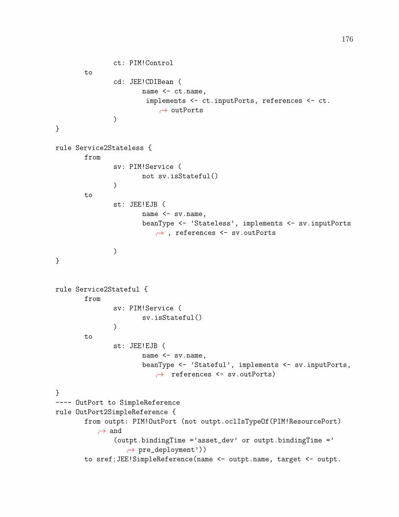
176
ct: PIM!Control
to
cd: JEE!CDIBean (
name <- ct.name,
implements <- ct.inputPorts, references <- ct.
↪→ outPorts
)
}
rule Service2Stateless {
from
sv: PIM!Service (
not sv.isStateful()
)
to
st: JEE!EJB (
name <- sv.name,
beanType <- ’Stateless’, implements <- sv.inputPorts
↪→ , references <- sv.outPorts
)
}
rule Service2Stateful {
from
sv: PIM!Service (
sv.isStateful()
)
to
st: JEE!EJB (
name <- sv.name,
beanType <- ’Stateful’, implements <- sv.inputPorts,
↪→ references <- sv.outPorts)
}
---- OutPort to SimpleReference
rule OutPort2SimpleReference {
from outpt: PIM!OutPort (not outpt.oclIsTypeOf(PIM!ResourcePort)
↪→ and
(outpt.bindingTime =’asset_dev’ or outpt.bindingTime =’
↪→ pre_deployment’))
to sref:JEE!SimpleReference(name <- outpt.name, target <- outpt.

177
↪→ connector.target)
}
----OutPort to event reference
rule OutPortEventReference {
from outpt: PIM!OutPort (not outpt.oclIsTypeOf(PIM!ResourcePort)
↪→ and
(not(outpt.bindingTime =’asset_dev’ or outpt.bindingTime =’
↪→ pre_deployment’)))
to sref:JEE!EventReference(name <- outpt.name, eventData <- outpt.
↪→ connector.datapass)
}
--
----connection to direct invokation
rule Connection2Invoke{
from cn: PIM!Connector (cn.bindingTime = ’asset_dev’ or cn.
↪→ bindingTime =’pre_deployment’)
to iv:JEE!PCInvocation(parameter <- cn.datapass, targetOperation
↪→ <- cn.sink, targetRef <- cn.source)
}
----connection to event invokation
rule Connection2EventInvoke{
from cn: PIM!Connector (not (cn.bindingTime = ’asset_dev’ or cn.
↪→ bindingTime =’pre_deployment’))
to iv:JEE!Invocation(parameter <- cn.datapass, targetRef <- cn.
↪→ source)
}
--

178
Appendix D Code generation with Xtend
package genetaor
import org.eclipse.emf.ecore.EPackage
import org.eclipse.emf.ecore.resource.Resource
import JEEPSM.JEEPSMPackage
import org.eclipse.emf.ecore.xmi.impl.XMIResourceFactoryImpl
import org.eclipse.xtext.generator.JavaIoFileSystemAccess
import JEEPSM.Entity
import org.eclipse.emf.ecore.resource.impl.ResourceSetImpl
import org.eclipse.emf.common.util.URI
import org.eclipse.xtext.resource.impl.ResourceServiceProviderRegistryImpl
import org.eclipse.xtext.parser.IEncodingProvider
import JEEPSM.Attribute
import JEEPSM.Association
//
class EntityGenerator {
JavaIoFileSystemAccess fsa;
//Generator Workflow calls this method and passed file
//of PSM model in xmi
def generateEntity(String file) {
doEMFSetup
val resourceSet = new ResourceSetImpl
val resource = resourceSet.getResource(URI.createURI(file),
↪→ true)
//Iterate through JEE Entities in the passed file
for (e: resource.allContents.toIterable.filter(Entity)){
fsa = new JavaIoFileSystemAccess(new
↪→ ResourceServiceProviderRegistryImpl(),
new IEncodingProvider.Runtime()
)
//set the absolute path for the generated output
fsa.setOutputPath("C:\\Users\\umar_\\OneDrive\\
↪→ Desktop\\Box Sync\\PHD\\dsl\\RefinedPIM2JEE\\
↪→ gen\\entity")
fsa.generateFile(e.name.toFirstUpper+".java", e.
↪→ compileAttributes)
}
}
def compileAttributes(Entity e) {
’’’

179
public class e.name.toFirstUpper{
FOR a: e.attributes
a.compileAttribute
ENDFOR
FOR ass: e.associations
ass.compileAssociation
ENDFOR
}
’’’
}
//generate attributes
def compileAttribute (Attribute a){’’’
private a.type.name a.name;
public a.type.name geta.name.toFirstUpper(){
return a.name;
}
public void seta.name.toFirstUpper(a.type.name a.name.toFirstLower
↪→ ){
}
’’’
}
//generate associations
def compileAssociation (Association ass){’’’
IF ass.multiplicity.literal == ’ONETOONE’
private ass.targetEntity.name ass.targetEntity.name.toFirstLower;
ENDIF
IF ass.multiplicity.literal == ’ONETOMANY’
private java.util.Collection<ass.targetEntity.name> ass.targetEntity.name
↪→ .toFirstLower;
ENDIF
’’’

180
}
def doEMFSetup() {
EPackage$Registry.INSTANCE.put(JEEPSMPackage.eINSTANCE.
↪→ nsURI, JEEPSMPackage.eINSTANCE)
Resource$Factory.Registry.INSTANCE.extensionToFactoryMap.
↪→ put("xmi", new XMIResourceFactoryImpl);
}
}
package genetaor
import org.eclipse.xtext.generator.JavaIoFileSystemAccess
import org.eclipse.emf.ecore.EPackage
import org.eclipse.emf.ecore.resource.Resource
import org.eclipse.emf.ecore.xmi.impl.XMIResourceFactoryImpl
import JEEPSM.JEEPSMPackage
import org.eclipse.emf.ecore.resource.impl.ResourceSetImpl
import org.eclipse.emf.common.util.URI
import org.eclipse.xtext.parser.IEncodingProvider
import JEEPSM.Interface
import org.eclipse.xtext.resource.impl.ResourceServiceProviderRegistryImpl
import JEEPSM.Operation
class BusinessInterfaceGenerator {
JavaIoFileSystemAccess fsa;
//Generator Workflow calls this method and passed file
//of PSM model in xmi
def generate (String file){
doEMFSetup()
val resourceSet = new ResourceSetImpl
val resource = resourceSet.getResource(URI.createURI(file),
↪→ true)
//Iterate through JEE PSM interfaces in the passed file
for (intf : resource.allContents.toIterable.filter(
↪→ Interface)) {
fsa = new JavaIoFileSystemAccess(
new ResourceServiceProviderRegistryImpl(),
new IEncodingProvider.Runtime()
)
//set the absolute path for the generated output

181
fsa.setOutputPath("C:\\Users\\umar_\\OneDrive\\Desktop\\Box Sync\\PHD\\dsl
↪→ \\RefinedPIM2JEE\\gen\\interface")
fsa.generateFile("I"+intf.name + ".java", intf.compileBusInterface)
}
}
//White space preserving template
def compileBusInterface(Interface intf){’’’
public interface Iintf.name{
FOR ops : intf.operations
public IF ops.type != nullops.type.nameELSE voidENDIF ops.name(IF
↪→ ops.parameters != nullops.parameters.type.name ops.parameters.
↪→ nameENDIF);
ops.compilOperation
ENDFOR
}
’’’
}
//this does nothing
def void compilOperation(Operation operation){
}
def doEMFSetup() {
EPackage$Registry.INSTANCE.put(JEEPSMPackage.eINSTANCE.
↪→ nsURI, JEEPSMPackage.eINSTANCE)
Resource$Factory.Registry.INSTANCE.extensionToFactoryMap.
↪→ put("xmi", new XMIResourceFactoryImpl);
}
}
package genetaor
import org.eclipse.xtext.generator.JavaIoFileSystemAccess
import org.eclipse.emf.ecore.EPackage
import JEEPSM.JEEPSMPackage

182
import org.eclipse.emf.ecore.resource.Resource
import org.eclipse.emf.ecore.xmi.impl.XMIResourceFactoryImpl
import org.eclipse.emf.ecore.resource.impl.ResourceSetImpl
import org.eclipse.emf.common.util.URI
import JEEPSM.Component
import org.eclipse.xtext.resource.impl.ResourceServiceProviderRegistryImpl
import org.eclipse.xtext.parser.IEncodingProvider
import JEEPSM.Interface
import JEEPSM.SimpleReference
import JEEPSM.EventReference
import JEEPSM.Operation
import JEEPSM.Invocation
import JEEPSM.PCInvocation
import JEEPSM.InterfaceKind
//component generator
class BusinessComponentGenerator {
JavaIoFileSystemAccess fsa;
//Generator Workflow calls this method and passed file
//of PSM model in xmi
def generateBusinessComponent(String file) {
doEMFSetup
val resourceSet = new ResourceSetImpl
val resource = resourceSet.getResource(URI.createURI(file),
↪→ true)
//Iterate through componenents in the passed file
for (comp : resource.allContents.toIterable.filter(
↪→ Component)) {
fsa = new JavaIoFileSystemAccess(
new ResourceServiceProviderRegistryImpl(),
new IEncodingProvider.Runtime()
)
//set the absolute path for the generated output
fsa.setOutputPath("C:\\Users\\umar_\\OneDrive\\
↪→ Desktop\\Box Sync\\PHD\\dsl\\RefinedPIM2JEE\\
↪→ gen\\session")
fsa.generateFile(comp.name.toFirstUpper + ".java",
↪→ comp.compileComponent)
}
}
def compileComponent(Component comp) {
’’’

183
public class comp.name.toFirstUpper IF comp.
↪→ implements.size !=0 implementsFOR imp: comp.implements Iimp.name
↪→ ENDFOR ENDIF{
FOR r : comp.references
r.compilereference
ENDFOR
IF comp.implements != null
FOR imp: comp.implements imp.
↪→ compiteInterfaceENDFOR
ENDIF
}
’’’
}
def compiteInterface(Interface intf) {
’’’
FOR ops : intf.operations
ops.compilOperation
ENDFOR
’’’
}
//generate operations
def compilOperation(Operation o) {
’’’
public o.type?.name.toFirstUpper ?: ’void’ o.name(o.owner.kindof.
↪→ interfaceType IF o.parameters != null o.parameters.type.name.
↪→ toFirstUpper o.parameters.nameENDIF){
FOR inv : o.invokations
inv.compileInvokation
ENDFOR
IF o.type != null
return null;
ENDIF
}
’’’
}
def String interfaceType(InterfaceKind itf) {

184
if (itf.toString.equals(’EVENT’)) {
’@observes’
} else {
’’
}
}
def dispatch compileInvokation(Invocation invk) {
’’’
invk.targetRef.name.toFirstLower.fire(invk.parameter.name);
’’’
}
def dispatch compileInvokation(PCInvocation pInvk) {
’’’
pInvk.targetRef.name.toFirstLower.pInvk.targetOperation.name(pInvk.
↪→ parameter.name);
’’’
}
def dispatch compilereference(SimpleReference rs) {
’’’
Irs.target.name rs.name.toFirstLower;
’’’
}
def dispatch compilereference(EventReference rs) {
’’’
Event <rs.eventData.name> rs.name.toFirstLower;
’’’
}
def doEMFSetup() {
EPackage$Registry.INSTANCE.put(JEEPSMPackage.eINSTANCE.
↪→ nsURI, JEEPSMPackage.eINSTANCE)
Resource$Factory.Registry.INSTANCE.extensionToFactoryMap.
↪→ put("xmi", new XMIResourceFactoryImpl);

185
}
}
package genetaor
//Generator WorkFlow
class GeneratorWorkFlow {
def static void main (String [] args){
new EntityGenerator().generateEntity("Jee.xmi")
new BusinessInterfaceGenerator().generate("Jee.xmi")
new BusinessComponentGenerator().generateBusinessComponent
↪→ ("Jee.xmi")
}
}