Comprehensive system for systematic case-driven software reuse
12
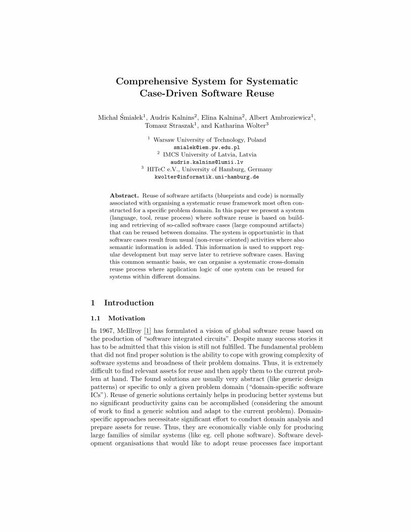
Comprehensive System for Systematic Case-Driven Software Reuse Micha l ´ Smia lek 1 , Audris Kalnins 2 , Elina Kalnina 2 , Albert Ambroziewicz 1 , Tomasz Straszak 1 , and Katharina Wolter 3 1 Warsaw University of Technology, Poland [email protected] 2 IMCS University of Latvia, Latvia [email protected] 3 HITeC e.V., University of Hamburg, Germany [email protected] Abstract. Reuse of software artifacts (blueprints and code) is normally associated with organising a systematic reuse framework most often con- structed for a specific problem domain. In this paper we present a system (language, tool, reuse process) where software reuse is based on build- ing and retrieving of so-called software cases (large compound artifacts) that can be reused between domains. The system is opportunistic in that software cases result from usual (non-reuse oriented) activities where also semantic information is added. This information is used to support reg- ular development but may serve later to retrieve software cases. Having this common semantic basis, we can organise a systematic cross-domain reuse process where application logic of one system can be reused for systems within different domains. 1 Introduction 1.1 Motivation In 1967, McIllroy [1] has formulated a vision of global software reuse based on the production of “software integrated circuits”. Despite many success stories it has to be admitted that this vision is still not fulfilled. The fundamental problem that did not find proper solution is the ability to cope with growing complexity of software systems and broadness of their problem domains. Thus, it is extremely difficult to find relevant assets for reuse and then apply them to the current prob- lem at hand. The found solutions are usually very abstract (like generic design patterns) or specific to only a given problem domain (“domain-specific software ICs”). Reuse of generic solutions certainly helps in producing better systems but no significant productivity gains can be accomplished (considering the amount of work to find a generic solution and adapt to the current problem). Domain- specific approaches necessitate significant effort to conduct domain analysis and prepare assets for reuse. Thus, they are economically viable only for producing large families of similar systems (like eg. cell phone software). Software devel- opment organisations that would like to adopt reuse processes face important
Transcript of Comprehensive system for systematic case-driven software reuse
Comprehensive System for SystematicCase-Driven Software Reuse
Micha l Smia lek1, Audris Kalnins2, Elina Kalnina2, Albert Ambroziewicz1,Tomasz Straszak1, and Katharina Wolter3
1 Warsaw University of Technology, [email protected]
2 IMCS University of Latvia, [email protected]
3 HITeC e.V., University of Hamburg, [email protected]
Abstract. Reuse of software artifacts (blueprints and code) is normallyassociated with organising a systematic reuse framework most often con-structed for a specific problem domain. In this paper we present a system(language, tool, reuse process) where software reuse is based on build-ing and retrieving of so-called software cases (large compound artifacts)that can be reused between domains. The system is opportunistic in thatsoftware cases result from usual (non-reuse oriented) activities where alsosemantic information is added. This information is used to support reg-ular development but may serve later to retrieve software cases. Havingthis common semantic basis, we can organise a systematic cross-domainreuse process where application logic of one system can be reused forsystems within different domains.
1 Introduction
1.1 Motivation
In 1967, McIllroy [1] has formulated a vision of global software reuse based onthe production of “software integrated circuits”. Despite many success stories ithas to be admitted that this vision is still not fulfilled. The fundamental problemthat did not find proper solution is the ability to cope with growing complexity ofsoftware systems and broadness of their problem domains. Thus, it is extremelydifficult to find relevant assets for reuse and then apply them to the current prob-lem at hand. The found solutions are usually very abstract (like generic designpatterns) or specific to only a given problem domain (“domain-specific softwareICs”). Reuse of generic solutions certainly helps in producing better systems butno significant productivity gains can be accomplished (considering the amountof work to find a generic solution and adapt to the current problem). Domain-specific approaches necessitate significant effort to conduct domain analysis andprepare assets for reuse. Thus, they are economically viable only for producinglarge families of similar systems (like eg. cell phone software). Software devel-opment organisations that would like to adopt reuse processes face important
2 M. Smia lek, et. al
barriers (see [2]). These barriers are associated with the complexity of reuse ac-tivities (preparing assets for reuse considering lack of proper tool support) andin resistance of developers and managers to undertake reuse activities “for theuncertain future”.
As identified in a survey by Frakes and Kang [3], practically all approachesto software reuse are based on domain engineering. There, domain engineer-ing is identified with software product lines (see below) and is declared as akey approach and research direction. The survey also stresses the importanceof approaches to reuse pattern-based architectural frameworks with componenttechnologies as technical enablers. Several important research directions havebeen identified: formal specification of architectures for automated constructionof systems; broadening the scope of domains that can participate in the reuseprocess; behavioural contracts for components; reasoning support for componentlibraries; ability to predict variabilities in software assets needed by the re-users.The last research direction has been identified as a key point.
In this paper we present an approach to software reuse that follows most ofthe postulated directions and can be classified as a domain engineering approach.The main difference to the current trend of product lines is that we deliberatelyexclude variability and commonality analysis. Instead of preparing assets forreuse, we promote opportunistic reuse which is often neglected as ad-hoc andunorganised. In our approach we make this opportunistic reuse systematic andorganise it around so-called software cases. Software cases are produced in a sys-tematic process which is compatible with the most typical iterative approaches(either agile or formal). The process starts with writing use cases and is followedby architectural design and coding (repeated over iterations) where traces (de-tailed mappings) between these elements are generated automatically. Throughfollowing of this process, the software cases are prepared for reuse by adding se-mantic information to the requirements specifications. The effort of adding thisinformation is relatively small and can be done even by unskilled people (domainexperts). Reuse of software cases is accomplished by retrieving so-called softwarecase slices. These slices can be extracted by determining similarity of sketcheduse cases for a new system with those stored in a reuse repository. By using thisapproach, a significant reduction of effort can be accomplished which is shownthrough a validation experiment. What is important, this reduction is possibleeven when the new system is built for a new problem domain.
1.2 Related work
Our approach to case-driven reuse is based on use cases as basic indexes to soft-ware cases. Thus, we will relate our work to reuse approaches where requirementsfor the software systems are formulated with use cases. This research directionhas been set in 1997 by introducing Reuse-Driven Software Engineering by Ja-cobson et al. [4]. In this approach, use cases drive both the software developmentand reuse process. Use cases are adorned with specific variability information.This variability analysis is supported with feature analysis as introduced in [5].
Comprehensive System for Systematic Case-Driven Software Reuse 3
Use cases did trace to the other artifacts in the software process like design mod-els and code. In contrast to our work, no tool support for automatic generationof traces existed as use cases were written in natural language.
The direction set in [4] is followed by many software product line approaches.Detailed guidelines for specifying use cases for system families have been givenin [6]. An example notation for use case scenarios, modelling their variabilityand deriving specific scenarios is given in [7]. Another approach in the context ofproduct line testing can be found in [8]. However, no real automation mechanismsfor deriving and mapping design and code from use cases have been developed.A recent paper [9] shows an approach to automatic derivation of scenarios outof use case descriptions adorned with variability information.
In order to automate the transition from use cases to code, we need rigourin specifying use cases. A constrained language approach is introduced in [10]where the essential scenarios are treated as reusable elements of the applicationlogic. This approach does not yet resolve the problem of automation as it simplysuggests manual traceability to design. In [11], the scenarios are traced to codeautomatically through analysing test logs from a testing tool. Thus, scenariosare written in a test scenario language of the test tool. In [12] the approachto use-case based reuse is extended. The presented REUSER system comparesstructural information contained in sequence diagrams associated with use cases.By creating a partial sequence diagram one can find all similar diagrams andassociated use case diagrams. Comparison is based on graph-matching technol-ogy. However, this approach is limited to structural comparison. No indicationon similarity of problem domains is given. On the other hand, [13] uses semanticinformation from the WordNet terminology [14]. With this approach, similarityof problem domains for different use case models can be determined.
2 Scenarios for case-driven software reuse
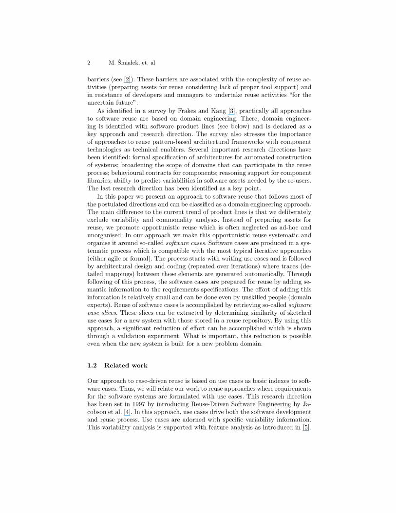
The process of case-driven software reuse (CDSR) is designed to be compatiblewith typical software development methodologies. It assumes iterative develop-ment which is centred around use cases. Figure 1 illustrates the general activitiesof CDSR in the form of a UML activity diagram. It can be noted that for thepurpose of this paper the process is simplified and does not include - for in-stance - testing and deployment. We now describe two typical scenarios wherethe difference is in retrieving legacy use cases (see highlighted action in Fig. 1).
In a basic - non reuse-oriented - scenario, the developers start a new projectby sketching use cases. While writing initial use case descriptions, all the termsused are defined within a domain vocabulary associated with this new softwarecase. Next, they plan for several iterations. Each of the iterations consists indeveloping a set of use cases. For each of the use cases, detailed scenarios arewritten. While writing scenarios, a complete domain vocabulary is constructed.This is done in a tooling environment which assures strict coherence betweenthe vocabulary and the terms used in scenarios’ text. After completing thesedetailed functional requirements, an automatic transformation generates the ar-
4 M. Smia lek, et. al
Fig. 1. Creation, storage and retrieval of software cases
chitectural blueprints of the system. Within this architectural framework, codeis developed. The code for the application logic is taken directly from architec-tural sequence diagrams (interaction model). The code for the business logic iswritten manually for every generated business logic component and interface.This is repeated until the complete system is built. The final action is to store(copy) the created artifacts (requirements, architecture/design and code) with-out modifications to a repository.
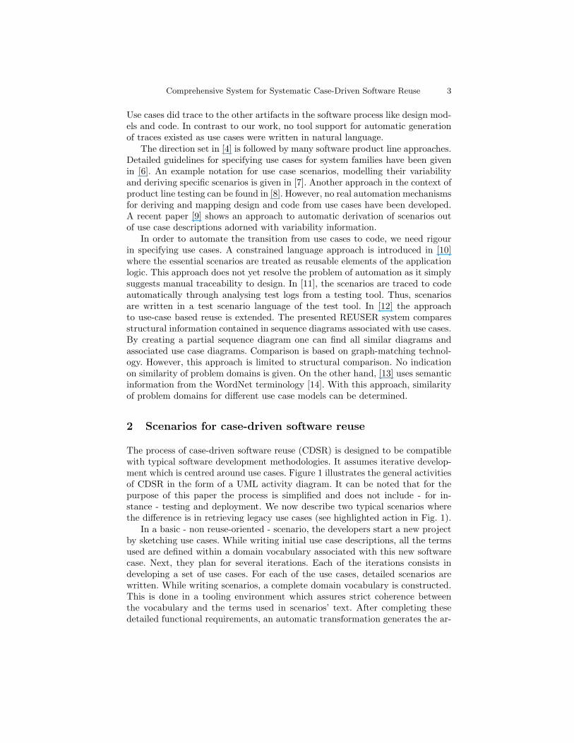
The above scenario is compatible with “normal” software development usingany of the available use case driven iterative methodologies. The main differenceis in giving enough rigour to use cases to be able to perform automatic transfor-mations to architecture. The result of the process is a so-called software casewith its general structure presented in Figure 2. A software case can be definedas a combination of precisely mapped requirements, design (architecture) andcode being the result of a specific project.
The use case model in a software case is structured so that all the terms usedwithin use case descriptions are linked to a vocabulary which is central to allthe use cases. To make the vocabulary comparable to the vocabularies of othersoftware cases, it is linked to a global terminology. Thus, the resulting repositoryof software cases has a semantic backbone common to all the distinct softwarecases (see again Fig. 2).
The global terminology is used within the second scenario which containsthe retrieval activity of Figure 1. In this scenario, after sketching the require-ments (use cases and the related vocabulary), the developers run a query on therepository of past cases. The query tool uses similarity measures that computesemantic (WordNet based) and structural (graph based) distance between thenewly sketched scenarios and the legacy complete scenarios. This is illustratedin Figure 3. When a matching use case is found within one of the stored software
Fig. 2. General structure of a software case repository

Comprehensive System for Systematic Case-Driven Software Reuse 5
Fig. 3. General scheme for use case based retrieval of software artifacts
Fig. 4. RSL model example
cases, all related design and code artifacts can be retrieved. In particular, theretrieval engine shows the mapped interaction diagrams that define the applica-tion logic (user-system interactions) for the given use case and components thatrealise the business logic (data processing algorithms).
After finding relevant use cases, their contents (scenarios, see Fig. 4) togetherwith the vocabularies and associated logic can be merged into the currentlybuilt software case. The rest of the process remains basically very similar tothat without the retrieval step (the process is in fact presented as simplified toperform retrieval only once). Scenarios for other use cases are written and thevocabulary updated. Then, the architectural models are generated. It can benoted that now only some of the business logic components have to be writtenfrom scratch. These components that map from the legacy use cases are alreadywritten and necessitate only some adaptations. In the following sections we willgive more technical details on the major steps of the above two scenarios.
3 Writing semantically rich requirements
The key factor for the above described reuse process to become possible is asemantically rich use case language. We use the Requirements Specification Lan-guage as specified in [15] (see also [16]). The main characteristic of this language
6 M. Smia lek, et. al
is that it offers a detailed syntax for use case scenarios. This syntax is based onwriting simple subject+verb+object(s) sentences, and is presented in Figure 4(see left). Moreover, scenarios written in RSL are composed of hyper-links to avocabulary central for a given software case (see center). As it can be seen in thefigure, the vocabulary is organised around phrases - like seek : for : user - thatconstitute predicates (verbs+objects) of the scenario sentences. Normally, all thesubjects and predicates should be linked to the vocabulary (not all shown on thefigure for clarity). What is important, all the phrases are grouped by the nounswhich gives order to the vocabulary and is used for automatic transformation(see the next section).
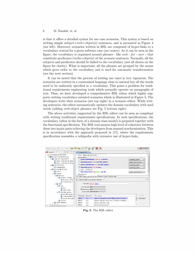
It can be noted that the process of writing use cases is very rigourous. Thescenarios are written in a constrained language close to natural but all the wordsneed to be uniformly specified in a vocabulary. This poses a problem for tradi-tional requirements engineering tools which normally operate on paragraphs oftext. Thus, we have developed a comprehensive RSL editor which highly sup-ports writing vocabulary-oriented scenarios which is illustrated in Figure 5. Thedevelopers write their scenarios (see top right) in a scenario editor. While writ-ing sentences, the editor automatically updates the domain vocabulary with usedwords (adding verb-object phrases; see Fig. 5 bottom right).
The above activities, supported by the RSL editor can be seen as compliantwith writing traditional requirements specifications. In such specifications, thevocabulary (often in the form of a domain class model) is prepared together withthe functional specification. The RSL tool assures high level of coherence betweenthese two major parts relieving the developers from manual synchronisation. Thisis in accordance with the approach proposed in [17], where the requirementsspecification resembles a wikipedia with extensive use of hyper-links.
Fig. 5. The RSL editor
Comprehensive System for Systematic Case-Driven Software Reuse 7
In addition to the above activities which come from general software engi-neering practice, we introduce an extra activity of linking vocabulary entrieswith a global terminology. This is illustrated in Fig. 4 (see right). Each of thewords in the vocabulary (both the verbs and the nouns) has to be assigned to aWordNet element which is used as a global terminology for specifying senses ofwords. This again is highly supported by the RSL editor which offers all availablesenses of a given term (see Fig. 5, very bottom).
The above features of RSL can be used for transforming and mapping usecase scenarios into architectural models and code. RSL was carefully designedto allow for generating very detailed component models with associated detailedapplication logic. Moreover, these generated components can be reused throughcomparing use case scenarios and retrieving traces from these scenarios to com-ponents. This will be explained in the following two sections.
4 Generating and mapping design from requirements
The algorithms for transforming from requirements to design were implementedin the model transformation language MOLA4 [18]. MOLA, as any other suchlanguage assumes that both the source and the target models are written ina meta-model based language. The RSL’s meta-model is specified in [15]. Thetarget models are expressed in UML with its meta-model defined in [19].
The target architectural model conforms to the requirements specificationwritten in RSL by realising use case scenarios in a given logical architecturalframework. Thus, two aspects need to be considered: static structure of thesystem and its dynamics in fulfilling the application logic (ie. use case scenarios).These two aspects are specified at component level for the architectural modeland then refined up to implementation class level. The structure of the generatedarchitecture depends on the chosen architectural style. The architectural styleincludes the definition of the system and model structure, the related set of designpatterns and the general design principles that are applied. The selection of themost appropriate architecture style depends on non-functional requirements forthe system but it is out of scope for this paper.
Here we will give an example of an architectural style conforming to a widerange of typical non-functional constraints. It is based on the most popularlayered approach to architecting contemporary business systems. We assumefour layer design with Presentation, Application Logic, Business Logic and DataAccess layers. Another basic principle used, is component based design at alllayers, with components comunicating through interfaces. In addition, severalpopular design patterns are used. First, the whole design is based on a simplifiedform of the MVC pattern, where no details of the view part are given. For eachdomain element a data transfer object for exchanging data flowing between layersand a data access object encapsulating persistence related operations is built.For the domain elements participating in business logic, corresponding businesslayer objects are created.4 http://mola.mii.lu.lv
8 M. Smia lek, et. al
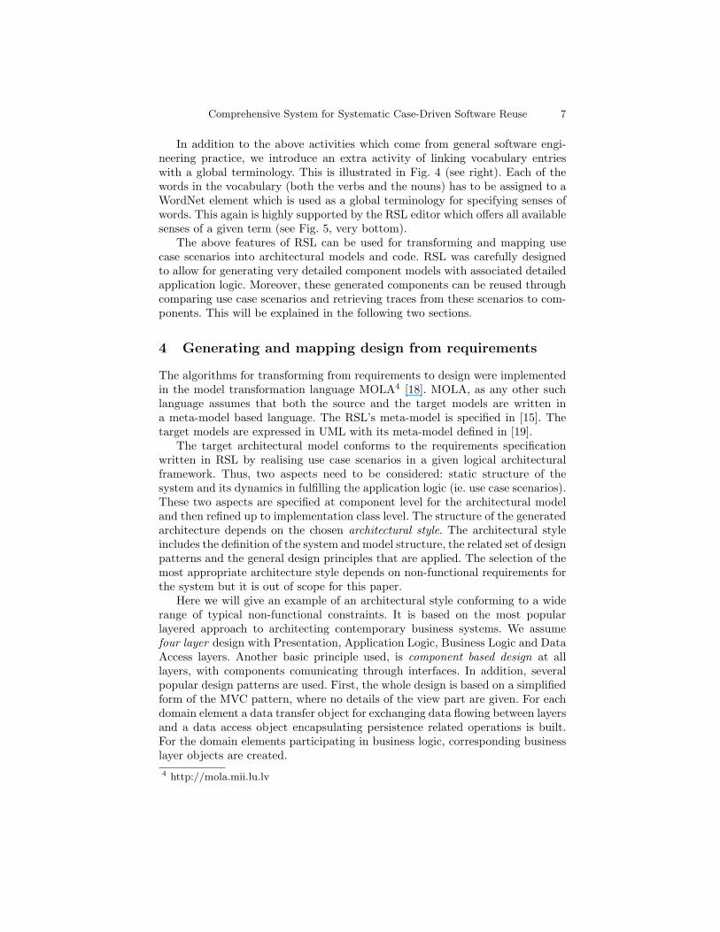
Fig. 6. Transformation of a vocabulary into a component structure
Fig. 7. Transformation of a scenario to a sequence diagram
The above described architectural style provides clear guidelines as to whatelements should be created in the target model of the transformation. Figure6 illustrates the correspondence between requirements and the obtained staticstructure on the example introduced previously (compare with Fig. 3).
The most non-trivial problem is to generate operations for all the interfaces.This can be done only using a thorough analysis of scenario sentences withineach use case. During the analysis corresponding system behaviour is built andoperations to relevant interfaces are added. The generation of messages and thecorresponding operations depend upon the category (actor-to-system, system-to-actor, system-to-system) of the analysed sentence. Figure 7 illustrates theprinciples how the messages (and associated operations) are generated from thesentences and the receiving lifelines selected.
Comprehensive System for Systematic Case-Driven Software Reuse 9
Fig. 8. The retrieval engine with visualisation of software case slices
Fig. 9. Reuse of application logic through reusable transformations
In order to support reuse, mapping links from requirements to architecture(and further to detailed design) are built by transformations. Rich mappinglinks provide the basic prerequisite for traceability and software case slicing asdescribed in the next section.
5 Reusing software cases
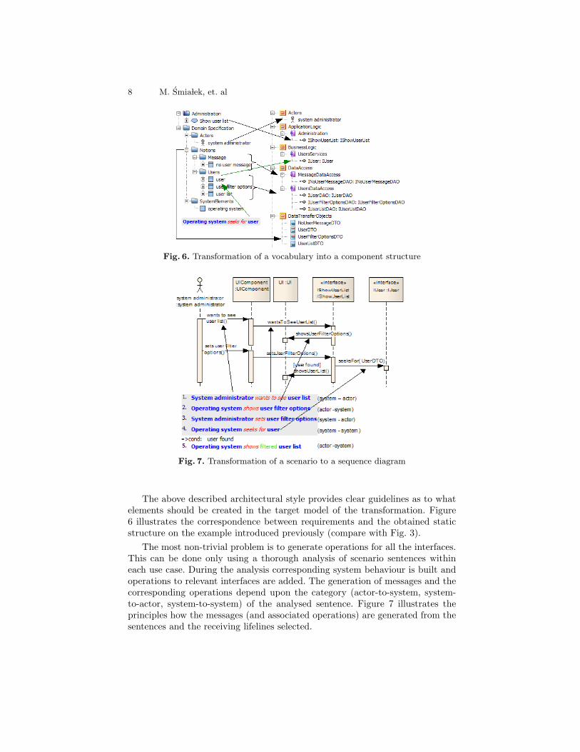
According to the second scenario described in section 2, the newly built use casesshould be compared for similarity with use cases stored in the repository. Theretrieval engine uses the initial sketch as a query. In the following we will use theexample from Fig. 4. The query is based on the use case scenario from “SoftwareCase 2”. With this simple query we result with the engine showing the use casefrom “Software Case 1” as most relevant. This is shown in Figure 8 (bottom).
After determining the similarity we can browse through the found softwarecases and use cases. Moreover, we can determine slices which originate in themost similar use cases. The slice contains all the interfaces and components thatare used within the interaction diagrams associated with the given use cases.This is illustrated in the upper part of Fig. 8.
10 M. Smia lek, et. al
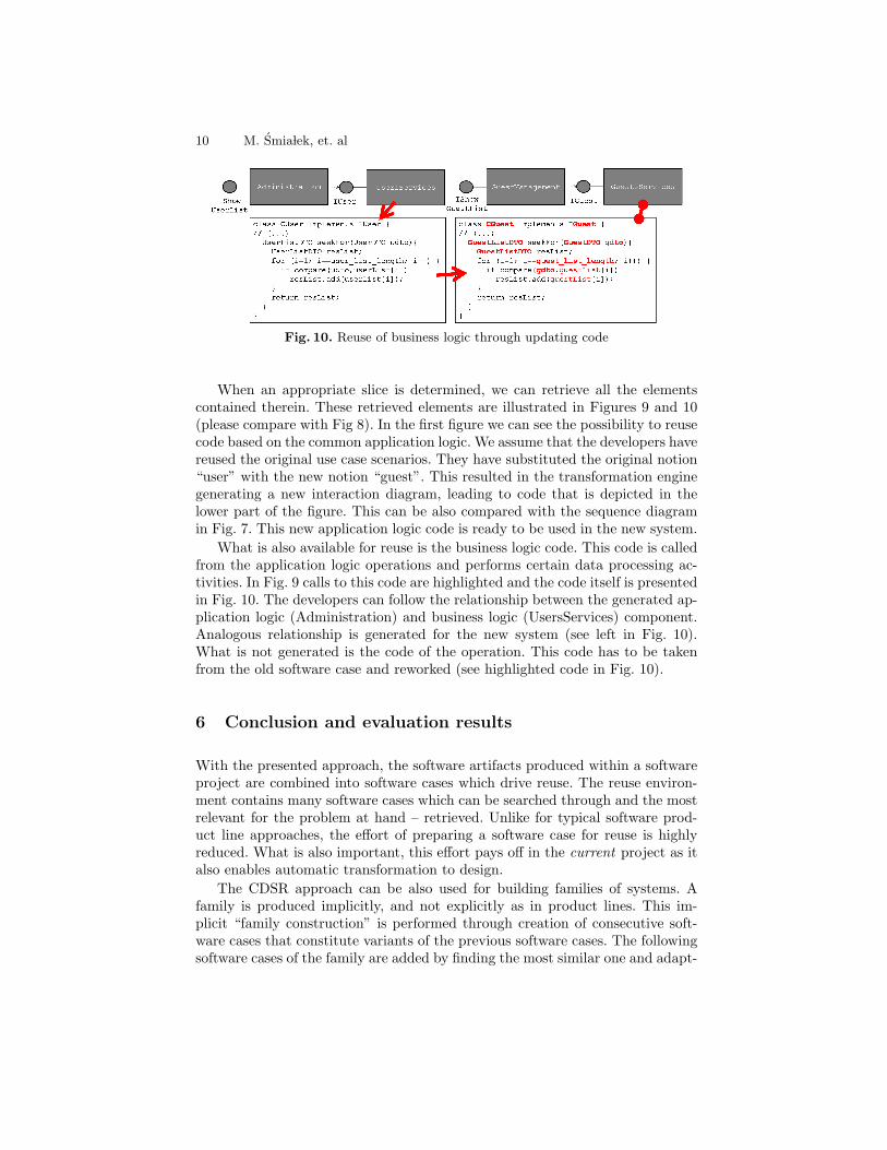
Fig. 10. Reuse of business logic through updating code
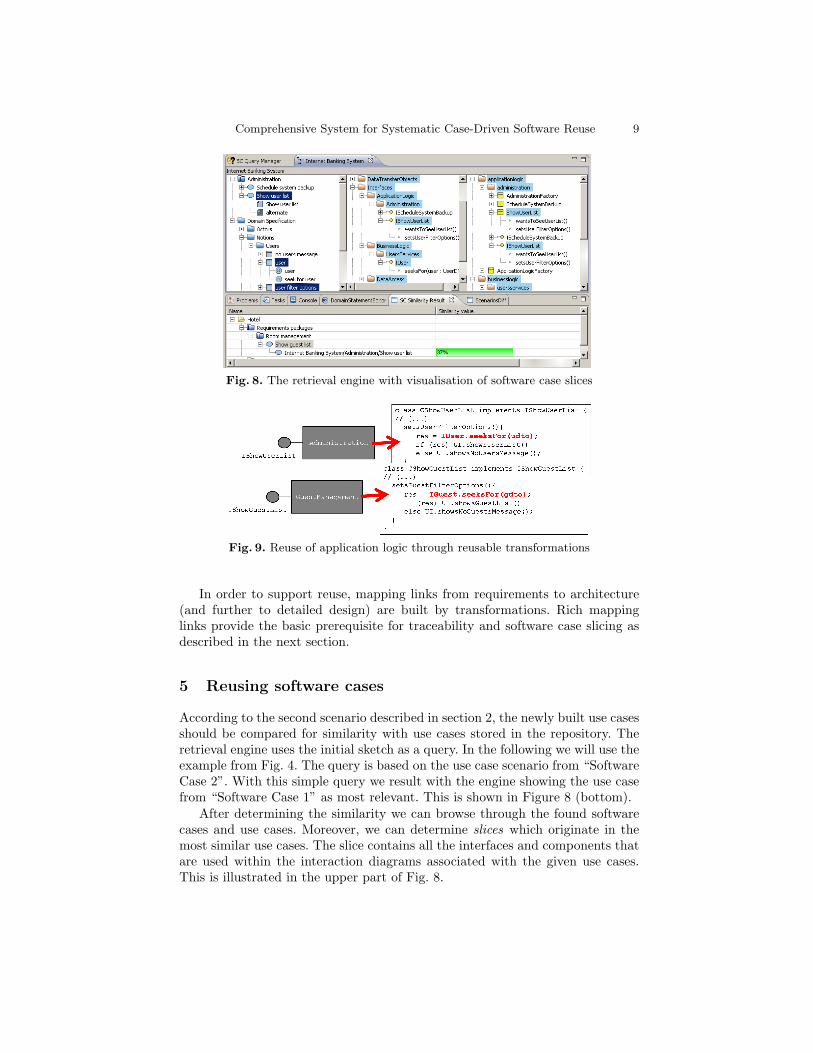
When an appropriate slice is determined, we can retrieve all the elementscontained therein. These retrieved elements are illustrated in Figures 9 and 10(please compare with Fig 8). In the first figure we can see the possibility to reusecode based on the common application logic. We assume that the developers havereused the original use case scenarios. They have substituted the original notion“user” with the new notion “guest”. This resulted in the transformation enginegenerating a new interaction diagram, leading to code that is depicted in thelower part of the figure. This can be also compared with the sequence diagramin Fig. 7. This new application logic code is ready to be used in the new system.
What is also available for reuse is the business logic code. This code is calledfrom the application logic operations and performs certain data processing ac-tivities. In Fig. 9 calls to this code are highlighted and the code itself is presentedin Fig. 10. The developers can follow the relationship between the generated ap-plication logic (Administration) and business logic (UsersServices) component.Analogous relationship is generated for the new system (see left in Fig. 10).What is not generated is the code of the operation. This code has to be takenfrom the old software case and reworked (see highlighted code in Fig. 10).
6 Conclusion and evaluation results
With the presented approach, the software artifacts produced within a softwareproject are combined into software cases which drive reuse. The reuse environ-ment contains many software cases which can be searched through and the mostrelevant for the problem at hand – retrieved. Unlike for typical software prod-uct line approaches, the effort of preparing a software case for reuse is highlyreduced. What is also important, this effort pays off in the current project as italso enables automatic transformation to design.
The CDSR approach can be also used for building families of systems. Afamily is produced implicitly, and not explicitly as in product lines. This im-plicit “family construction” is performed through creation of consecutive soft-ware cases that constitute variants of the previous software cases. The followingsoftware cases of the family are added by finding the most similar one and adapt-
Comprehensive System for Systematic Case-Driven Software Reuse 11
ing it to a slightly different problem at hand. Thus we can call this approach an“opportunistic product line”.
The CDSR system was developed within the ReDSeeDS (www.redseeds.eu)project and consists of the RSL language, a comprehensive tool suite (ReDSeeDSEngine) and the CDSR process description (ReDSeeDS Methodology). In orderto confirm the validity of the CDSR system, these tools were used within acomprehensive validation cycle in the industrial context. The cycle was lead byFraunhofer IESE with the participation of four industrial software developmentteams (see Acknowledgements). One of the teams had experience with a productline. The other teams had previously experienced only ad-hoc reuse. During thecycle, the following experimental validation activities were performed.1. RSL training and case creation and retrieval training (two day tutorials).2. Case creation. More than 20 software cases, with a total of over 300 use cases
were created. The domains ranged from financial systems to rescue systems.3. Case reuse. Four new software cases (over 80 use cases) were created through
retrieving and reusing elements from the old cases. The domains for thesenew systems were significantly different than for the previous ones. Also, fourother existing software cases were extended to create variants. Depending onthe similarity of problem domains, the size of reuse ranged from single usecases and associated design/code to 90% of the whole software cases.
4. Acceptance and usage analysis, using the UTAUT method [20].The qualitative analysis of supplied extensive questionnaires shows very pro-
mising results. The user attitude in four areas (effort expectancy, facilitatingconditions, self efficacy, behavioural intention) is positive. In other four areas(like performance) it is neutral. This means that the users of the system (experi-enced software developers) believe that the approach would reduce their personaleffort and has enough technical support (tools) to be effectively applied in reallife. Moreover, the users show significant intention to use this technology in thefuture. On the other hand, the users do not expect that using the system influ-ence the performance of their work. It has to be noted that the current resultsare obtained for the ReDSeeDS Engine prototype and not for a commercial andmature product. The users have raised several issues which can further improvethe overall acceptance of the system and the CDSR approach. Detailed resultsof this study are available as a ReDSeeDS project report.
The above study showed applicability of CDSR to a broad range of prob-lem domains. It was performed using the transformation algorithm presentedin section 4. Also, other transformation algorithms can be used and are cur-rently developed within ReDSeeDS. These algorithms capture the implicationsstemming from non-functional requirements. Obviously, the limitation of CDSRis that the transition from non-functional requirements to transformation al-gorithms is a manual process depending on experience of the transformationwriters.
Acknowledgments. This work is partially funded by the EU: Requirements-Driven Software Development System (ReDSeeDS) (contract no. IST-2006-33596under 6FP).
12 M. Smia lek, et. al
References
1. McIlroy, M.D.: Mass produced software components. In Naur, P., Randell, B.,Buxton, J.N., eds.: Software engineering concepts and techniques, Proceedings ofNATO Conference on Software Engineering, New York (1969) 88–98
2. Sherif, K., Vinze, A.: Barriers to adoption of software reuse. A qualitative study.Information and Management 41 (2003) 159–175
3. Frakes, W.B., Kang, K.: Software reuse research: status and future. IEEE Trans-actions on Software Engineering 31(7) (2005) 529–536
4. Jacobson, I., Griss, M., Jonsson, P.: Software reuse: architecture process and or-ganization for business success. ACM Press (1997)
5. Griss, M.L., Favaro, J., d’ Alessandro, M.: Integrating feature modeling with theRSEB. In: Proc. 5th International Conference on Software Reuse (1998) 76–85
6. Gomaa, H.: Designing Software Product Lines with UML: From Use Cases toPattern-Based Software Architectures. Addison Wesley (2004)
7. Bertolino, A., Fantechi, A., Gnesi, S., Lami, G.: Product Line Use Cases: Scenario-Based Specification and Testing of Requirements. In: Software Product Lines -Research Issues in Engineering and Management. Springer (2006) 425–445
8. Kamsties, E., Pohl, K., Reis, S., Reuys, A.: Testing variabilities in use case models.Lecture Notes in Computer Science 3014 (2004) 6–18
9. Choi, W.s., Kang, S., Choi, H., Baik, J.: Automated generation of product usecase scenarios in product line development. In: 8th IEEE International Conferenceon Computer and Information Technology, CIT’08. (2008) 760–765
10. Biddle, R., Noble, J., Tempero, E.: Supporting reusable use cases. Lecture Notesin Computer Science 2319 (2002) 210–226
11. Egyed, A., Grunbacher, P.: Supporting software understanding with automated re-quirements traceability. International Journal of Software Engineering and Knowl-edge Engineering 15(5) (2005) 783–810
12. Robinson, W.N., Woo, H.G.: Finding reusable UML sequence diagrams automat-ically. IEEE Software 21(5) (2004) 60–67
13. Blok, M.C., Cybulski, J.L.: Reusing UML specifications in a constrained applica-tion domain. In: Proceedings of 1998 Asia Pacific Software Engineering Conference.(1998) 196–202
14. Fellbaum, C., ed.: WordNet: An Electronic Lexical Database. MIT Press (1998)15. Kaindl, H., Smia lek, M., Svetinovic, D., Ambroziewicz, A., Bojarski, J.,
Nowakowski, W., Straszak, T., Schwarz, H., Bildhauer, D., Brogan, J.P., Mukasa,K.S., Wolter, K., Krebs, T.: Requirements specification language definition. ProjectDeliverable D2.4.1, ReDSeeDS Project (2007) www.redseeds.eu.
16. Smia lek, M., Bojarski, J., Nowakowski, W., Ambroziewicz, A., Straszak, T.: Com-plementary use case scenario representations based on domain vocabularies. Lec-ture Notes in Computer Science 4735 (2007) 544–558
17. Kaindl, H.: Using hypertext for semiformal representation in requirements en-gineering practice. The New Review of Hypermedia and Multimedia 2 (1996)149–173
18. Kalnins, A., Barzdins, J., Celms, E.: Model transformation language MOLA. Lec-ture Notes in Computer Science 3599 (2004) 14–28
19. Object Management Group: Unified Modeling Language: Superstructure, version2.1.1, formal/07-02-05. (2007)
20. Venkatesh, V., Smith, R.H., Morris, M.G., Davis, G.B., Davis, F.D.: User accep-tance of information technology: Toward a unified view. MIS Quarterly 27 (2003)425–478