Runner Series 8 & 16 Zone User's Guide
44
ELECTRONIC ENGINEERING LTD. Runner Series 8 & 16 Zone WIRELESS AND WIRED CONTROL PANEL User’s Guide COVERS: LCD KEYPAD (GREEN/GRAY/BLUE WITH TEXTUAL BUTTONS) & LCD KEYPAD (BLUE WITH SYMBOL BUTTONS) & LED KEYPAD (TEXTUAL & SYMBOL BUTTONS)
-
Upload
khangminh22 -
Category
Documents
-
view
3 -
download
0
Transcript of Runner Series 8 & 16 Zone User's Guide
ELECTRONIC ENGINEERING LTD.
Runner Series
8 & 16 Zone WIRELESS AND WIRED CONTROL PANEL
User’s Guide
COVERS:
LCD KEYPAD (GREEN/GRAY/BLUE WITH TEXTUAL BUTTONS)
&
LCD KEYPAD (BLUE WITH SYMBOL BUTTONS)
&
LED KEYPAD (TEXTUAL & SYMBOL BUTTONS)
Crow Limited Warranty
CROW ELECTRONIC ENGINEERING LTD. (Crow) WARRANTY POLICY CERTIFICATE
This Warranty Certificate is given in favor of the purchaser (hereunder the "Purchaser") purchasing the products directly from Crow or from its authorized distributor.
Crow warrants these products to be free from defects in materials and workmanship under normal use and service for a period of 24 months for control panel and 12 months for modules and accessories that connect to control panel. The 24 month and 12 month periods start from the last day of the week and year whose numbers are printed on the printed circuit board or a label inside these products (hereunder the "Warranty Period").
Subject to the provisions of this Warranty Certificate, during the Warranty Period, Crow undertakes, at its sole discretion and subject to Crow's procedures, as such procedures are from time to time, to repair or replace, free of charge for materials and/or labor, products proved to be defective in materials or workmanship under normal use and service. Repaired products shall be warranted for the remainder of the original Warranty Period.
All transportation costs to and from Crow and in-transit risk of loss or damage related, directly or indirectly, to products returned to Crow for repair or replacement shall be borne solely by the Purchaser.
Crow's warranty under this Warranty Certificate does not cover products that is defective (or shall become defective) due to: (a) alteration of the products (or any part thereof) by anyone other than Crow; (b) accident, abuse, negligence, or improper maintenance; (c) failure caused by a product which Crow did not provide; (d) failure caused by software or hardware which Crow did not provide; (e) use or storage other than in accordance with Crow’s specified operating and storage instructions.
There are no warranties, expressed or implied, of merchantability or fitness of the products for a particular purpose or otherwise, which extend beyond the description on the face hereof.
This limited Warranty Certificate is the Purchaser's sole and exclusive remedy against Crow and Crow's sole and exclusive liability toward the Purchaser in connection with the products, including without limitation - for defects or malfunctions of the products. This Warranty Certificate replaces all other warranties and liabilities, whether oral, written, (non-mandatory) statutory, contractual, in tort or otherwise.
In no case shall Crow be liable to anyone for any consequential or incidental damages (inclusive of loss of profit, and whether occasioned by negligence of the Crow or any third party on its behalf) for breach of this or any other warranty, expressed or implied, or upon any other basis of liability whatsoever. Crow does not represent that these products can not be compromised or circumvented; that these products will prevent any person injury or property loss or damage by burglary, robbery, fire or otherwise; or that these products will in all cases provide adequate warning or protection.
Purchaser understands that a properly installed and maintained product may in some cases reduce the risk of burglary, fire, robbery or other events occurring without providing an alarm, but it is not insurance or a guarantee that such will not occur or that there will be no personal injury or property loss or damage as a result.
Consequently, Crow shall have no liability for any personal injury; property damage or any other loss based on claim that these products failed to give any warning.
If Crow is held liable, whether directly or indirectly, for any loss or damage with regards to its products, regardless of cause or origin, Crow’s maximum liability shall not in any case exceed the purchase price of THE PRODUCT, BEING AN INDIVIDUAL ITEM, that is said to be the cause of such loss or damage, WHICH SHALL BE THE COMPLETE AND EXCLUSIVE REMEDY AGAINST CROW.
Print version 002
(Updated) 29-Mar-2009

i
Contents CROW LIMITED WARRANTY..................................................................................................................... 2
INTRODUCTION ...................................................................................................................................1
THE CROW ALARM CONTROL SYSTEM ........................................................................................................ 1
TYPICAL ALARM SYSTEM CONFIGURATION ................................................................................................... 1
KEYPAD LED TYPE DESCRIPTION........................................................................................................2
FUNCTION KEYS (TEXTUAL LED KEYPAD) ................................................................................................... 2
FUNCTION KEYS (SYMBOL LED KEYPAD) .................................................................................................... 2
ALPHANUMERIC KEYS ............................................................................................................................ 2
AUDIBLE SIGNALS ................................................................................................................................ 3
INDICATORS (LED KEYPAD).................................................................................................................... 3
SUMMARY OF FUNCTIONS (LED KEYPAD).................................................................................................... 3
OPERATING THE LED KEYPAD .............................................................................................................5
HOW TO ARM THE SYSTEM BEFORE EXIT (LED KEYPAD) ................................................................................. 5 Preparing the System for Arming (LED Keypad) ..................................................................................5 Arming the System (LED Keypad) ........................................................................................................5 Quick Arm (When enabled at installation - LED Keypad) .....................................................................5 Disarming the System ...........................................................................................................................5 Stopping and Resetting Alarms.............................................................................................................5
ARMING THE SYSTEM WHILE STAYING HOME (LED KEYPAD)............................................................................ 6 Arming the System in Stay Mode (LED Keypad) ..................................................................................6 Disarming the System ...........................................................................................................................6
HOW TO ARM PARTITIONS...................................................................................................................... 6
HOW TO BYPASS ZONES......................................................................................................................... 6
USING CHIME (IF ENABLED AT INSTALLATION) ............................................................................................. 7
EMERGENCY ALERTS ............................................................................................................................. 7 How to initiate Panic ..............................................................................................................................7 How to initiate Medical Alarm ................................................................................................................7 How to initiate Fire Alarm ......................................................................................................................7
GENERATE THREAT OR DURESS................................................................................................................ 7
HOW TO READ SYSTEM MESSAGES............................................................................................................ 8
HOW TO READ TROUBLE MESSAGES .......................................................................................................... 8
HOW TO DISPLAY EVENTS FROM MEMORY................................................................................................... 8
HOW TO CONTROL OUTPUTS AND DEVICES ................................................................................................. 9
ENTERING THE USER PROGRAM/CLIENT MODE ............................................................................................10
HOW TO CHANGE OR ADD CODES ............................................................................................................10 About Master Code and the User Code (Using LED Keypad) ............................................................10 How to Change the Master Code (Using LED Keypad) ......................................................................10 How to Add or Change the User Code (Using LED Keypad)..............................................................10 How to Delete the User Code (Using LED Keypad)............................................................................11
ADDING/CHANGING TELEPHONE NUMBERS (USING LED KEYPAD).....................................................................11
HOW TO SET TIME AND DATE .................................................................................................................11
HOW TO OPERATE THE ACCESS CONTROL OUTPUT .......................................................................................12
HOW TO START WALK TEST MODE...........................................................................................................12
ii
HOW TO ANSWER AN IN-COMING CALL .....................................................................................................12
HOW TO GENERATE A MANUAL TEST CALL (MONITORED CID ONLY).................................................................12
USING THE REMOTE COMMAND CONTROL ..................................................................................................13
USING LOCAL COMMAND CONTROL ..........................................................................................................14
KEYPAD LCD TYPE DESCRIPTION......................................................................................................15
FUNCTION KEYS (TEXTUAL LCD KEYPAD) ..................................................................................................15
FUNCTION KEYS (SYMBOL LCD KEYPAD) ...................................................................................................15 How to initiate a Panic Alarm ..............................................................................................................16 How to initiate a Medical Alarm...........................................................................................................16 How to initiate a Fire Alarm .................................................................................................................16
ALPHANUMERIC KEYS ...........................................................................................................................16
AUDIBLE SIGNALS ...............................................................................................................................16
INDICATORS (LCD KEYPAD)...................................................................................................................16
SUMMARY OF FUNCTIONS ......................................................................................................................17
HOW TO ARM THE SYSTEM BEFORE EXIT....................................................................................................19 Preparing the System for Arming ........................................................................................................19 Arming the System ..............................................................................................................................19 Quick Arm (When enabled at installation) ...........................................................................................19 Disarming the System .........................................................................................................................19 Stopping and Resetting Alarms...........................................................................................................19
ARMING THE SYSTEM WHILE STAYING HOME ..............................................................................................20 Arming the System in Stay Mode ........................................................................................................20 Disarming the System .........................................................................................................................20
HOW TO ARM PARTITIONS (AREAS) AND HOW THEY WORK .............................................................................20
HOW TO BYPASS ZONES........................................................................................................................21
USING CHIME (IF ENABLED AT INSTALLATION) ............................................................................................21
EMERGENCY ALERTS ............................................................................................................................21 How to initiate a Panic Alarm; .............................................................................................................21 How to initiate a Medical Alarm; ..........................................................................................................21 How to initiate a Fire Alarm .................................................................................................................21
GENERATE THREAT OR DURESS...............................................................................................................22
HOW TO READ SYSTEM MESSAGES...........................................................................................................22
HOW TO READ TROUBLE MESSAGES .........................................................................................................22
HOW TO DISPLAY EVENTS FROM MEMORY..................................................................................................22
HOW TO CONTROL OUTPUTS AND DEVICES ................................................................................................23
ENTERING THE USER PROGRAM/CLIENT MODE (USING LCD KEYPAD)................................................................24
HOW TO CHANGE OR ADD CODES (USING LCD KEYPAD) ...............................................................................24 About Master Code and the User Code ..............................................................................................24 How to Change the Master Code (Using LCD Keypad)......................................................................24 How to Add or Change the User Code (Using LCD Keypad) .............................................................25 How to Delete the User Code (Using LCD Keypad) ...........................................................................25
ADDING/CHANGING TELEPHONE NUMBERS (USING LCD KEYPAD).....................................................................25
HOW TO SET TIME AND DATE .................................................................................................................25
HOW TO OPERATE THE ACCESS CONTROL OUTPUT .......................................................................................26
HOW TO START WALK TEST MODE...........................................................................................................26
HOW TO ANSWER AN IN-COMING CALL .....................................................................................................26
HOW TO GENERATE A MANUAL TEST CALL (MONITORED CID ONLY).................................................................26

iii
USING THE REMOTE COMMAND CONTROL ..................................................................................................27
USING LOCAL COMMAND CONTROL ..........................................................................................................28
ADJUSTING BACKLIGHTING AND BUZZER TONE ............................................................................................29
LCD KEYPAD IN LOCAL EDIT MODE..........................................................................................................30 Accessing Local Edit Mode .................................................................................................................30 Local Edit Mode Direct Program Addresses .......................................................................................30
LCD KEYPAD LOCAL EDIT MODE MENU PROGRAMMING ......................................................................31 Changing the Area Single Character Identifier....................................................................................32 Changing the Zone Names .................................................................................................................33 Changing the Keypad Area Name.......................................................................................................34 Changing the Keypad Name ...............................................................................................................34 Changing the User Names ..................................................................................................................34 Changing the Output Names...............................................................................................................34 Resetting Individual Text to Default or Last Saved Setting.................................................................34 Resetting All Text to Default ................................................................................................................35 Copying Text to another LCD Keypad.................................................................................................35 Exiting Local Edit Program Mode........................................................................................................35
CUSTOMIZATION CHART ...................................................................................................................37
PRODUCT SUPPORT ...........................................................................................................................39
1
Introduction
The Crow Alarm Control System We are really pleased that you chose to protect your premises and possibly even your lives with our RUNNER SERIES from Crow Electronic Engineering Ltd.
The RUNNER SERIES is a highly advanced, multifunction alarm control system, designed to flawlessly manage your security system at home or at business, protects you against burglary and supports the operation of multiple electronic devices.
The RUNNER SERIES has many incredible program options and additional accessories that can enhance the standard features of the panel from simple “Home Automation” to “Radio control” and Voice Prompted Command control”. Please ask your installer to find out more about these powerful features.
You can phone your home to check or change the status of any output using the keys on your phone. Arm or disarm the whole house or just one area, all with your own voice confirming your selections.
Imagine turning on the spa before leaving work so it is hot when you get in the door. The under-floor heating has just automatically switched on using the on board timer and you have just opened the roller-door and disarmed the garage from your cell phone so the white ware repairman can work on your washer.
The controller supports a 16 LED keypad or the more sophisticated LCD (liquid Crystal Display) keypad.
It also has a comprehensive alarm event memory that logs all controller activity with a time and date stamp.
Typical Alarm System Configuration The protected premises can be divided up into 16 zones, as defined by the installation scheme.
The protected area can be grouped into two separate partitions (A and B).
The system enables you in a business environment, to conveniently group separately, the offices from the warehouse area, or in a private residence, the different rooms of the home. For example, living room, bedroom, and maybe the basement and attic.
These groups or zones can react specifically to different types of events and then generating an alarm or activate a device.
The system can be armed in two different modes:
Arm / ( ) – the protected areas are entirely vacated.
Stay / ( ) – people and pets populate the protected areas.
You have access to the keypad's control features, and can change the settings yourself.
The system can be accessed via multiple keypads (each located at a different site). Up to eight keypads can be integrated into the system. Access levels and your access codes are described later on in this guide.

2
KEYPAD LED Type Description
The LED Keypad shows all the information required to operate the system. The User communicates with the alarm system via the keypad. The Keypad displays continuous information about the status of the alarm system, and enables the User to operate the system in different modes, change settings and program Users' access codes.
The keypad also collects and records events to be displayed afterward on request, to overview system activities, and to analyze system performance for diagnostics.
Function Keys (Textual LED Keypad) These keys are used to arm the system, enter commands to alter system settings, or scroll through the history events.
<ARM>, <STAY>, <BYPASS>, <PROGRAM>, <CONTROL>, <MEMORY>, <PANIC>, <ENTER>
Function Keys (Symbol LED Keypad) These keys are used to arm the system, enter commands to alter system settings, or scroll through the history events.
=ARM, =STAY, =BYPASS, =PROGRAM, =CONTROL, =MEMORY, =Panic
=ENTER
Alphanumeric Keys These keys are used to enter codes, Initiate Emergency or used for programming.
3
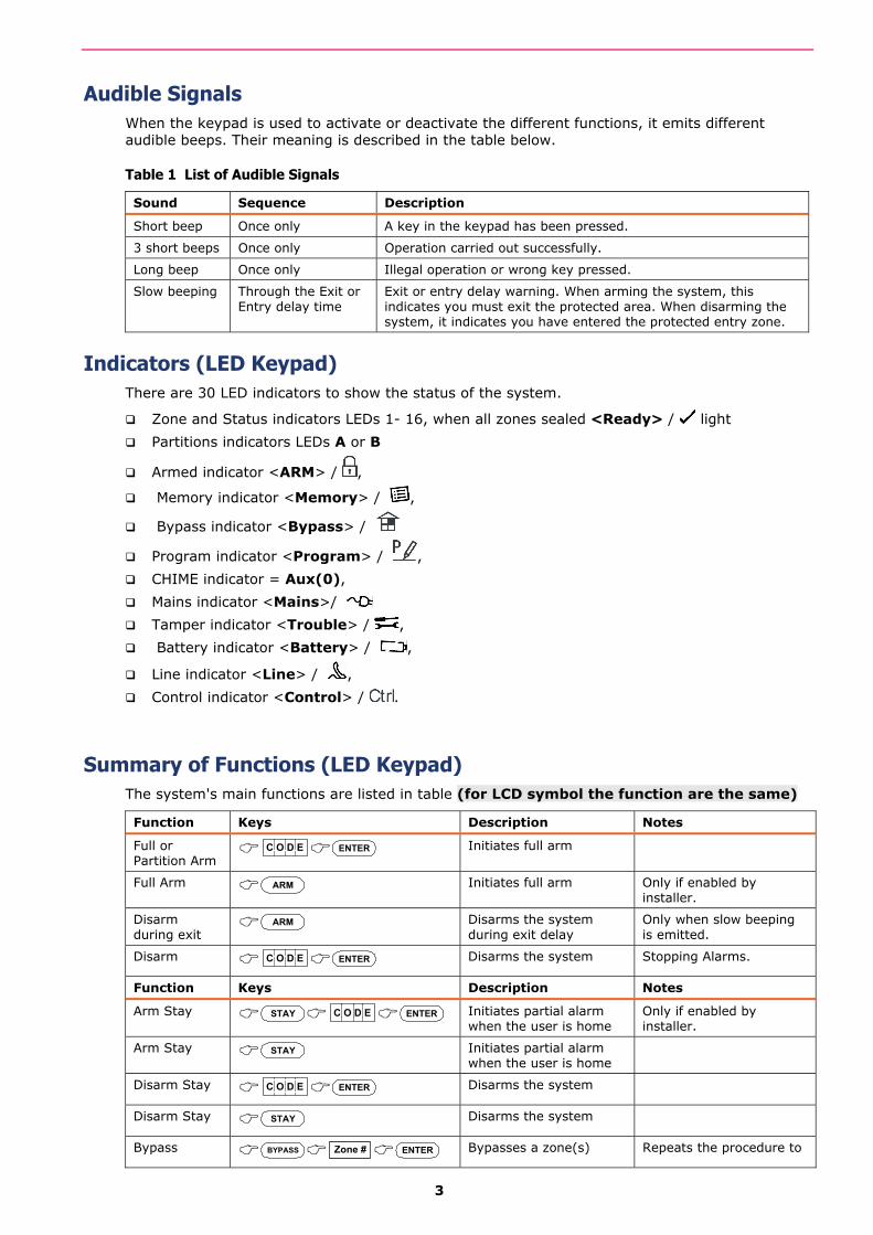
Audible Signals When the keypad is used to activate or deactivate the different functions, it emits different audible beeps. Their meaning is described in the table below.
Table 1 List of Audible Signals
Sound Sequence Description
Short beep Once only A key in the keypad has been pressed.
3 short beeps Once only Operation carried out successfully.
Long beep Once only Illegal operation or wrong key pressed.
Slow beeping Through the Exit or Entry delay time
Exit or entry delay warning. When arming the system, this indicates you must exit the protected area. When disarming the system, it indicates you have entered the protected entry zone.
Indicators (LED Keypad) There are 30 LED indicators to show the status of the system.
Zone and Status indicators LEDs 1- 16, when all zones sealed <Ready> / light
Partitions indicators LEDs A or B
Armed indicator <ARM> / ,
Memory indicator <Memory> / ,
Bypass indicator <Bypass> /
Program indicator <Program> / ,
CHIME indicator = Aux(0),
Mains indicator <Mains>/
Tamper indicator <Trouble> / ,
Battery indicator <Battery> / ,
Line indicator <Line> / ,
Control indicator <Control> / .
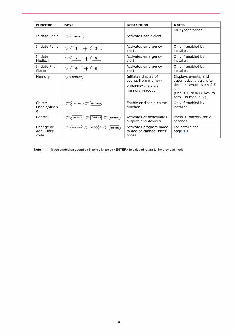
Summary of Functions (LED Keypad) The system's main functions are listed in table (for LCD symbol the function are the same)
Function Keys Description Notes
Full or Partition Arm
C O D E ENTER Initiates full arm
Full Arm ARM Initiates full arm Only if enabled by installer.
Disarm during exit
ARM Disarms the system during exit delay
Only when slow beeping is emitted.
Disarm C O D E ENTER Disarms the system Stopping Alarms.
Function Keys Description Notes
Arm Stay STAY C O D E ENTER Initiates partial alarm when the user is home
Only if enabled by installer.
Arm Stay STAY Initiates partial alarm when the user is home
Disarm Stay C O D E ENTER Disarms the system
Disarm Stay STAY Disarms the system
Bypass BYPASS Zone # ENTER Bypasses a zone(s) Repeats the procedure to
4
Function Keys Description Notes un-bypass zones.
Initiate Panic PANIC Activates panic alert
Initiate Panic 1 + 3 Activates emergency alert
Only if enabled by installer.
Initiate Medical 7 + 9
Activates emergency alert
Only if enabled by installer.
Initiate Fire Alarm 4 + 6
Activates emergency alert
Only if enabled by installer.
Memory MEMORY Initiates display of events from memory.
<ENTER> cancels memory readout
Displays events, and automatically scrolls to the next event every 2.5 sec. (Use <MEMORY> key to scroll up manually).
Chime Enable/disable
CONTROL PROGRAM Enable or disable chime function
Only if enabled by installer
Control CONTROL Device# ENTER Activates or deactivates outputs and devices
Press <Control> for 2 seconds
Change or Add Users' code
PROGRAM M CODE ENTER Activates program mode to add or change Users' codes
For details see page 10
Note: If you started an operation incorrectly, press <ENTER> to exit and return to the previous mode.
5
Operating the LED Keypad
How to Arm the System before Exit (LED Keypad)
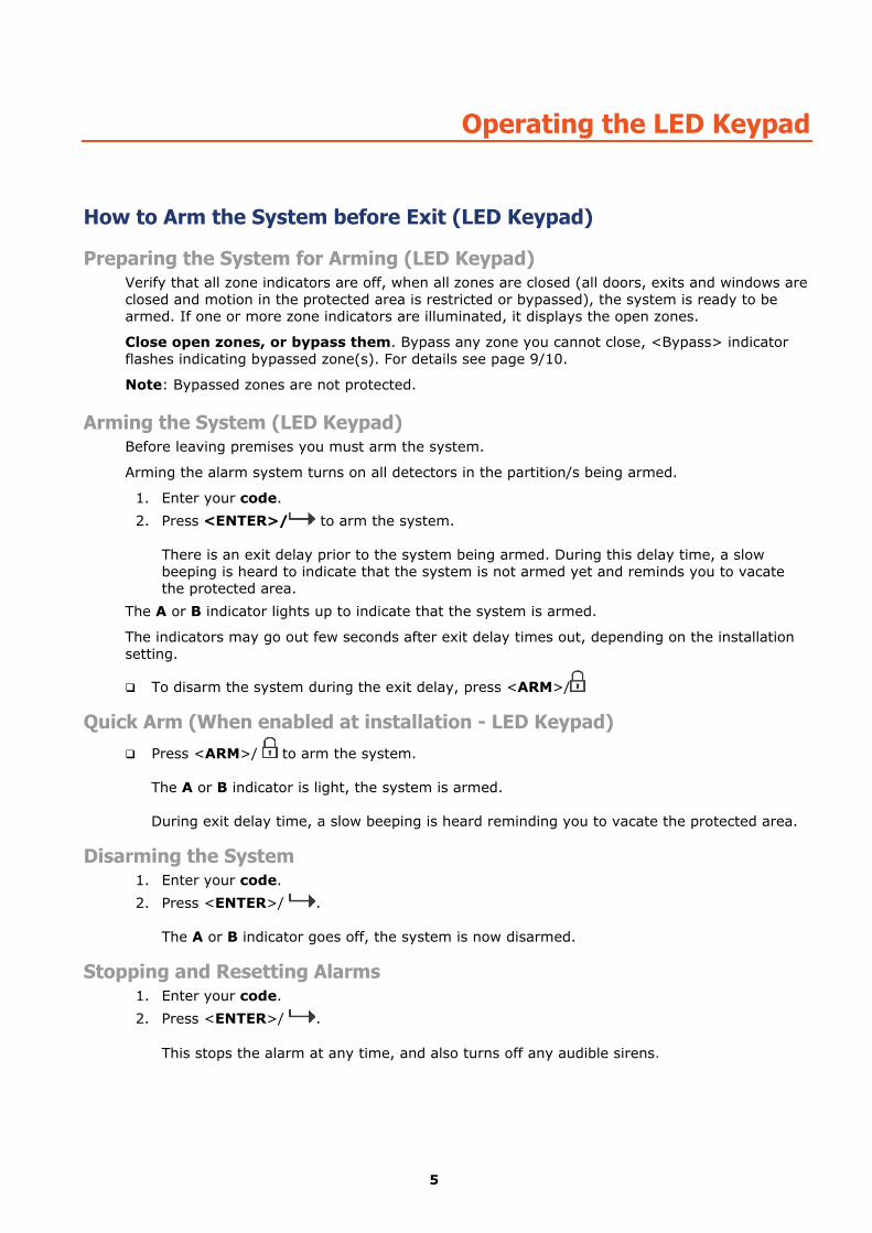
Preparing the System for Arming (LED Keypad) Verify that all zone indicators are off, when all zones are closed (all doors, exits and windows are closed and motion in the protected area is restricted or bypassed), the system is ready to be armed. If one or more zone indicators are illuminated, it displays the open zones.
Close open zones, or bypass them. Bypass any zone you cannot close, <Bypass> indicator flashes indicating bypassed zone(s). For details see page 9/10.
Note: Bypassed zones are not protected.
Arming the System (LED Keypad) Before leaving premises you must arm the system.
Arming the alarm system turns on all detectors in the partition/s being armed.
1. Enter your code.
2. Press <ENTER>/ to arm the system. There is an exit delay prior to the system being armed. During this delay time, a slow beeping is heard to indicate that the system is not armed yet and reminds you to vacate the protected area.
The A or B indicator lights up to indicate that the system is armed.
The indicators may go out few seconds after exit delay times out, depending on the installation setting.
To disarm the system during the exit delay, press <ARM>/
Quick Arm (When enabled at installation - LED Keypad) Press <ARM>/ to arm the system.
The A or B indicator is light, the system is armed. During exit delay time, a slow beeping is heard reminding you to vacate the protected area.
Disarming the System 1. Enter your code.
2. Press <ENTER>/ . The A or B indicator goes off, the system is now disarmed.
Stopping and Resetting Alarms 1. Enter your code.
2. Press <ENTER>/ . This stops the alarm at any time, and also turns off any audible sirens.
6
Arming the System While Staying Home (LED Keypad)
Arming the System in Stay Mode (LED Keypad) This type of arming is used when people are present within the protected area. At nighttime, when the family is about to retire, perimeter zones are protected, but not the interior zones. Consequently, interior movements are ignored by the system.
1. Press <STAY>/ .
2. Enter your code.
3. Press <ENTER>/ . The A or B indicator flashes indicating that the system is now armed in stay mode.
Quick Stay This feature must be enabled at installation time.
Press <STAY>/ to Stay Arm the system. During exit delay you can leave the premises. If you wish to stay, or you don’t want anybody to enter the protected premises, you can cancel the Entry/Exit delay by pressing the <ENTER>/ key. The slow beeping stops and the system will then immediately arm (cancelling the remaining Exit period).
The A or B indicator flashes to indicate that the system is armed in stay mode. The indicators may go out a few seconds after exit delay expired, depending on the installer's setting.
Disarming the System Enter user’s code and press <ENTER>/ , or press <STAY>/ if enabled by installer.
The A or B indicator goes off to indicate that the system is disarmed.
How to Arm Partitions The protected area can be grouped into 3 separate partitions (A or B). The system can be grouped for User‘s convenience to separate, in a business environment, the offices from the warehouse area, or in a private residence, the different rooms of the home, e.g., living room, bedroom, etc.
To arm partition A enter user code for partition A
To arm partition B enter user code for partition B
Note: to arming partition with code see page 10 “How to arm the system before exit”
During exit delay you can leave premises. At the end of the procedure the A or B indicator lights up to indicate that the partition A or/and B or C is armed.
(The indicators may go out after a few seconds, depending on the installer's setting).
To disarm partition, see "Disarming the System".
How to Bypass Zones Bypass any zone that cannot be closed. You can bypass selected zones prior to arming. It is also used to temporarily exclude a faulty zone from service, which requires repair.
To bypass a selected zone, press <BYPASS>/ , the Bypass indicator lights up to indicate that the system is in bypass mode.
7
Enter the zone number (e.g. 01, 05, 12) one or more zones, the zone LED indicators lights up to indicate that the zone is bypassed, following press <ENTER>/ , the Bypass LED flashes to indicate zone(s) bypassed.
While in the Bypass mode it is possible to bypass more than one zone, press <BYPASS>/ , the Bypass indicator lights to indicate that the system is in bypass mode.
Add the zone number (example, 03) one or more zones, the zone LED indicators lights to indicate that the zone is bypassed, then press <ENTER>/ , the Bypass LED flashes to indicate zone(s) bypassed.
To reset bypassed zones, press <BYPASS>/ , enter zone number (example, 07, 13), the zone LED indicators go off to indicate that the zone is no longer bypassed. Press <ENTER>/ .
NOTE: Disarming automatically un-bypasses all zone.
Using Chime (If enabled at Installation) A Chime (Day zone) is a detector that can be part armed while you are at home but working in another part of the building. It can be programmed to operate a buzzer or light to let you know you have a visitor.
To disable the Day (chime) zone, press <CONTROL>/ and <PROGRAM>/ , the Control LED indicator lights up to indicate that Chime is disabled.
To enable Chime mode, you need to press two buttons together: Press <CONTROL>/ and
<PROGRAM>/ Together, the Control LED goes off to indicate that Chime is active.
Emergency Alerts The special function of these three keys is best programmed by your installer to suit your individual needs. Most commonly, these can be used to alert the Alarm Monitoring Company (the system Must be monitored for this to occur. Please see your systems installer).
These Emergencies are “PANIC”, “FIRE”, and “MEDICAL” type alarms. When using the LED keypad, the Panic alarm can be generated by either the single “Panic” button or by the simultaneous operation of two buttons. Pressing two buttons simultaneously generates the Fire and Medical alarms
How to initiate Panic
Press the <PANIC> / key. OR
Press simultaneously keys <1>and <3> / < >and < >.
How to initiate Medical Alarm
Press simultaneously keys <7> and <9> / < > and < >.
How to initiate Fire Alarm
Press simultaneously keys <4> and <6> / < > and < >.
Generate Threat or Duress If you are compelled to disarm the system under threat, you must enter the duress digit before the user’s code to activate the automatic dialer. The duress digit shifts up your usual code by one digit. If your code is 345 and 8 is your duress digit, than entering 8345 modifies your code. The modified duress code disarms the system in a normal way, but at the same time activates the dialer silently to report a “duress event” without arousing suspicion. (For details ask the installer).
8
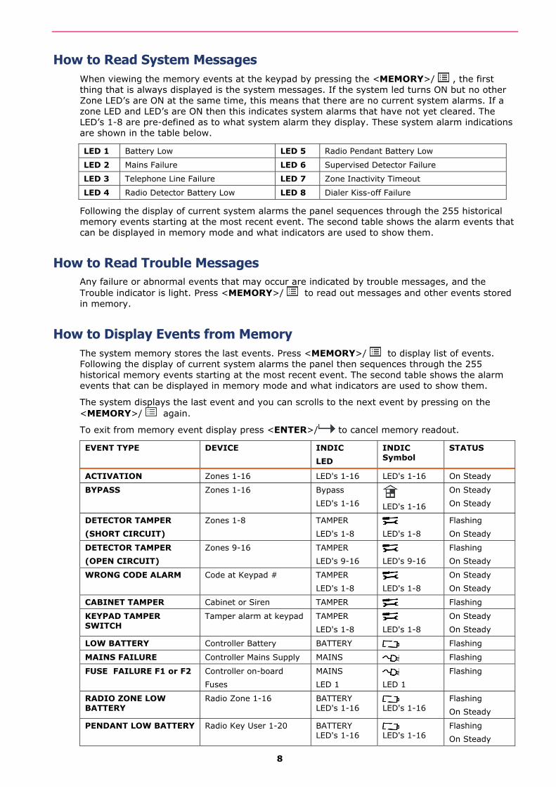
How to Read System Messages When viewing the memory events at the keypad by pressing the <MEMORY>/ , the first thing that is always displayed is the system messages. If the system led turns ON but no other Zone LED’s are ON at the same time, this means that there are no current system alarms. If a zone LED and LED’s are ON then this indicates system alarms that have not yet cleared. The LED’s 1-8 are pre-defined as to what system alarm they display. These system alarm indications are shown in the table below.
LED 1 Battery Low LED 5 Radio Pendant Battery Low
LED 2 Mains Failure LED 6 Supervised Detector Failure
LED 3 Telephone Line Failure LED 7 Zone Inactivity Timeout
LED 4 Radio Detector Battery Low LED 8 Dialer Kiss-off Failure
Following the display of current system alarms the panel sequences through the 255 historical memory events starting at the most recent event. The second table shows the alarm events that can be displayed in memory mode and what indicators are used to show them.
How to Read Trouble Messages Any failure or abnormal events that may occur are indicated by trouble messages, and the Trouble indicator is light. Press <MEMORY>/ to read out messages and other events stored in memory.
How to Display Events from Memory The system memory stores the last events. Press <MEMORY>/ to display list of events. Following the display of current system alarms the panel then sequences through the 255 historical memory events starting at the most recent event. The second table shows the alarm events that can be displayed in memory mode and what indicators are used to show them.
The system displays the last event and you can scrolls to the next event by pressing on the <MEMORY>/ again.
To exit from memory event display press <ENTER>/ to cancel memory readout.
EVENT TYPE DEVICE INDIC
LED
INDIC Symbol
STATUS
ACTIVATION Zones 1-16 LED's 1-16 LED's 1-16 On Steady
BYPASS Zones 1-16 Bypass
LED's 1-16
LED's 1-16
On Steady
On Steady
DETECTOR TAMPER
(SHORT CIRCUIT)
Zones 1-8 TAMPER
LED's 1-8
LED's 1-8
Flashing
On Steady
DETECTOR TAMPER
(OPEN CIRCUIT)
Zones 9-16 TAMPER
LED's 9-16
LED's 9-16
Flashing
On Steady
WRONG CODE ALARM Code at Keypad # TAMPER
LED's 1-8
LED's 1-8
On Steady
On Steady
CABINET TAMPER Cabinet or Siren TAMPER Flashing
KEYPAD TAMPER SWITCH
Tamper alarm at keypad TAMPER
LED's 1-8
LED's 1-8
On Steady
On Steady
LOW BATTERY Controller Battery BATTERY Flashing
MAINS FAILURE Controller Mains Supply MAINS Flashing
FUSE FAILURE F1 or F2 Controller on-board
Fuses
MAINS
LED 1
LED 1
Flashing
RADIO ZONE LOW BATTERY
Radio Zone 1-16 BATTERY LED's 1-16
LED's 1-16
Flashing
On Steady
PENDANT LOW BATTERY Radio Key User 1-20 BATTERY LED's 1-16
LED's 1-16
Flashing
On Steady
9
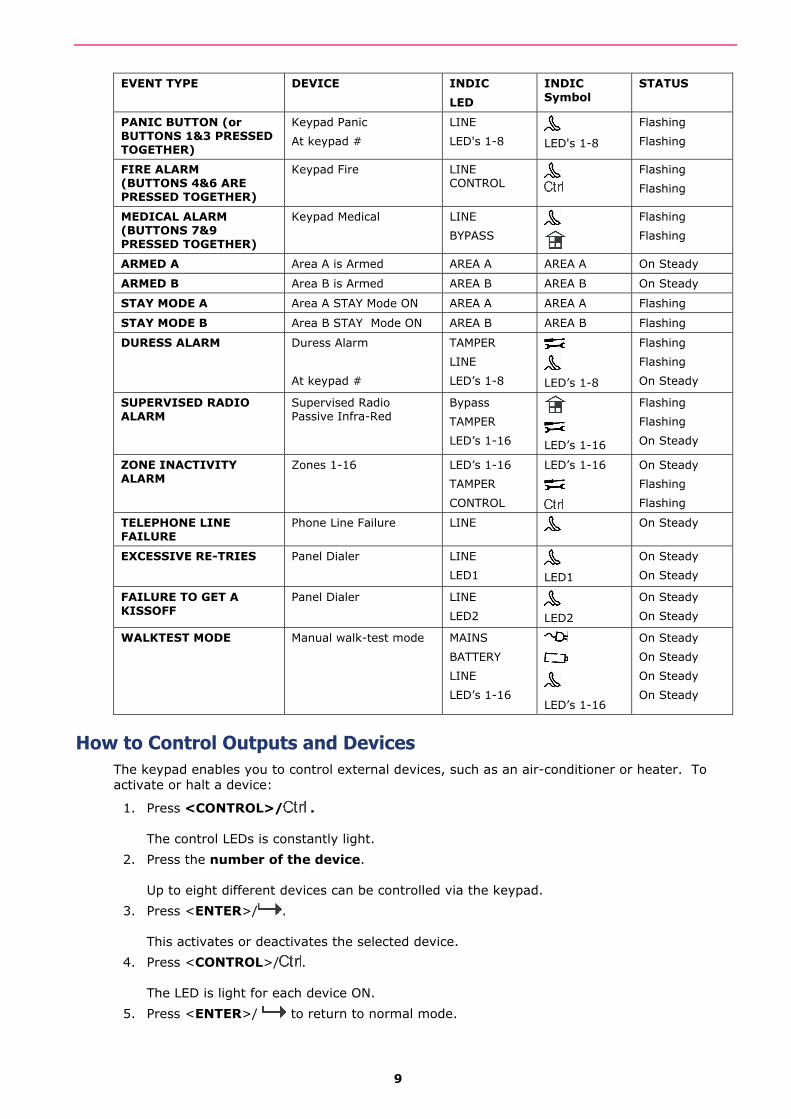
EVENT TYPE DEVICE INDIC
LED
INDIC Symbol
STATUS
PANIC BUTTON (or BUTTONS 1&3 PRESSED TOGETHER)
Keypad Panic
At keypad #
LINE
LED's 1-8
LED's 1-8
Flashing
Flashing
FIRE ALARM (BUTTONS 4&6 ARE PRESSED TOGETHER)
Keypad Fire
LINE CONTROL
Flashing
Flashing
MEDICAL ALARM (BUTTONS 7&9 PRESSED TOGETHER)
Keypad Medical LINE
BYPASS
Flashing
Flashing
ARMED A Area A is Armed AREA A AREA A On Steady
ARMED B Area B is Armed AREA B AREA B On Steady
STAY MODE A Area A STAY Mode ON AREA A AREA A Flashing
STAY MODE B Area B STAY Mode ON AREA B AREA B Flashing
DURESS ALARM Duress Alarm
At keypad #
TAMPER
LINE
LED’s 1-8
LED’s 1-8
Flashing
Flashing
On Steady
SUPERVISED RADIO ALARM
Supervised Radio Passive Infra-Red
Bypass
TAMPER
LED’s 1-16
LED’s 1-16
Flashing
Flashing
On Steady
ZONE INACTIVITY ALARM
Zones 1-16 LED’s 1-16
TAMPER
CONTROL
LED’s 1-16
On Steady
Flashing
Flashing
TELEPHONE LINE FAILURE
Phone Line Failure LINE On Steady
EXCESSIVE RE-TRIES Panel Dialer LINE
LED1
LED1
On Steady
On Steady
FAILURE TO GET A KISSOFF
Panel Dialer LINE
LED2
LED2
On Steady
On Steady
WALKTEST MODE Manual walk-test mode MAINS
BATTERY
LINE
LED’s 1-16
LED’s 1-16
On Steady
On Steady
On Steady
On Steady
How to Control Outputs and Devices The keypad enables you to control external devices, such as an air-conditioner or heater. To activate or halt a device:
1. Press <CONTROL>/ . The control LEDs is constantly light.
2. Press the number of the device. Up to eight different devices can be controlled via the keypad.
3. Press <ENTER>/ . This activates or deactivates the selected device.
4. Press <CONTROL>/ . The LED is light for each device ON.
5. Press <ENTER>/ to return to normal mode.
10
Entering the User Program/Client Mode There are 2 levels of program modes, CLIENT mode and INSTALLER mode. Normally the installer configures the system to give you access to the CLIENT mode so you can add, delete, or change the user codes. To get into CLIENT mode (provided the system is NOT Armed) Press
<PROGRAM>/ enter Master code then press <ENTER>/ . The Program indicator lights up to indicate that the system is in User programming mode.
If you get a single long beep at this point and the Program LED doesn’t turn on, it means your code cannot access Program mode.
How to Exit Program Mode
To exit out of program mode press <PROGRAM>/ and <ENTER>/ . The Program indicator goes off to indicate that the system is not in User programming mode.
How to Change or Add Codes
About Master Code and the User Code (Using LED Keypad) The factory default master code (123) is intended as a preliminary control of the alarm system. After the RUNNER is installed and put into service, the code can be changed to any code known to the Master user (User-1). The Master user can define up to 100 user codes. To limit access rights, the holder of the Master code can ask the installer to define several User profiles.
Access rights are listed below:
User code has Area A and/or B permission
User code can Arm and/or Disarm an area
User code can Stay Arm and/or Stay Disarm an area
User code can change its code
User code can change user’s code
User code can Operate control Functions
User code can change dialer telephone numbers
User code can alter the real time clock
User can answer an incoming call and start up/down load
User can allow access to installer program mode from client mode.
Initiate Walk-test mode.
How to Change the Master Code (Using LED Keypad) NOTE: When changing the Master Code, please Ensure that you remember the new Master Code that you enter. Otherwise, your systems installer will need to come back to reset the code. This may incur a Service (Call Out) Fee.
While in CLIENT mode (see “Entering the user Program/Client Mode” above on page-10), Press
<PROGRAM>/ then 1 <ENTER>/ , and 1 <ENTER>/ again. The current Master Code digits will be flashed back at you one digit at a time. To enter a new Master code, use the numeric keyboard to enter your new Master code then press <ENTER>/ . The new Master Code will flash back at you one digit at a time, followed either by three short beeps to indicate correct entry or one long beep if not accepted. The Master Code can be any combination of 1 to 6 digits. It is recommended to use at least a 4 digits code but a 6 digit code will provide greater security.
To exit user Code Program mode, Press <PROG>/ and <ENTER>/ .
How to Add or Change the User Code (Using LED Keypad) While in CLIENT mode, press <PROGRAM>/ then 1 <ENTER>/ and the User number (2 to 100) to add or change the code, press <ENTER>/ . If there is an existing code already, it is flashed back to you. Use the numeric keyboard to enter the new code. The code can hold
11
any combination of 1 to 6 digits. Entering the new code deletes the old code. Press <ENTER>/ to save your new code, the new code is flashed back to you along with three short beeps.
Repeat the procedure for all users.
Press <PROG>/ and <ENTER>/ to exit Local Program mode.
How to Delete the User Code (Using LED Keypad) In client mode, press <PROGRAM>/ then 1 then <ENTER>/ and the User number (2 to 100) you intend to delete, press <ENTER>/ . The code is flashed back to you. Press
<BYPASS>/ to delete User code.
Press <ENTER>/ to save the change.
Press <PROG>/ and <ENTER>/ exit program mode.
Adding/Changing Telephone Numbers (Using LED Keypad) Your panel accepts up to six phone numbers with a total of 16 digits. Your panel can be programmed to dial all or any of these depending on the event which has occurred. (The six phone numbers are at program address P181E 1-8E).
While in CLIENT mode, key in the following sequence <PROGRAM>/ <, P181E 1E > <ENTER>/ (The address for telephone number 1), the existing number is flashed out at the keypad then enter NEW TELEPHONE # then press <ENTER>/ The new numbers are flashed back to confirm acceptance.
At any time you can enter in the address for the telephone number just to view the currently
programmed value then press the <PROGRAM>/ button to move on to the next address.
For example, P181E 1E= PH # 1, P181E 2E = PH# 2, P181E 6E = PH# 6.
NOTE: On the LED keypad, “0” is indicated by LED “Aux(0)”
How to set Time and Date The alarm system has an internal clock that may be used to automatically Arm or Disarm the alarm or turn Outputs On or off. It is also used to identify when events occurred in memory via the LCD keypad. If you need to change the Time & Date it must be done from the CLIENT mode. To change the Time & Date press
Press <PROGRAM/ <26> <ENTER>/ <2> <ENTER>/ <1-7> <ENTER>/ Where 1-7 = the current day (1=Sun, 2 = Mon to 7 = Sat)
Press <PROGRAM>/ <26> <ENTER>/ <1> <ENTER>/ <HHMM><ENTER>/ Where HH = Hour in 24 Hour Format and MM = Minutes
Press <PROGRAM>/ <26> <ENTER>/ <3> <ENTER>/ <DDMMYY> <ENTER>/ . Where DD =1-31 current date, MM= months 1-12, YY = year 00-99

12
How to Operate the Access Control Output If the alarm system has been set up to allow control of an electric door lock, you can activate the door release function as follows;
Press <CONTROL/ or Press <CONTROL>/ , enter CODE then <ENTER>/ . The Control LED will turn on while the lock is active, and turns off as soon as power is removed from the lock.
The Access Control function can either be a single button operation or restricted to requiring a valid User code entry. Both options are shown above. Please consult your installer as to what option may be programmed.
How to start Walk Test Mode While in CLIENT mode a User with the proper authority can start walk-test mode. This special mode latches the alarm signals from detectors at the keypad initiating the test so that one person can trigger every detector connected to the alarm then return to the keypad to verify operation. On terminating Walk-test mode the test results are put into the memory buffer so they can be viewed at a later time.
To start Walk-test mode while in CLIENT mode press <PROGRAM>/ <200> <ENTER>/ <6> <ENTER>/ and the keypad buzzer beeps at 1-second intervals.
Next trigger every detector connected to the panel then return to the keypad and all of the zones that were triggered are displayed on the keypad.
To terminate Walk-test mode press <ENTER>/ , the keypad stops beeping and automatically exits CLIENT mode.
How to Answer an In-Coming Call From time to time your installer may need to access the alarm from a remote PC to make changes to your programming and for security reasons they may have configured the alarm so that an authorized person on-site is required to make the alarm system answer the in-coming call. This option is only available in CLIENT mode.
If the panel is not configured to answer in-coming calls, the user can force it to answer the call by pressing and holding <CONTROL>/ followed Immediately by <9>and Hold Both buttons for 10 seconds or until you hear three quick beeps. This forces the panel to answer the call immediately. For this function to work, the phone line must be ringing at the time and there must have been at least two rings before pressing the buttons.
Provided the line connected to the alarm was ringing at the time, the panel now answers the call and allows a remote PC connection.
How to Generate a Manual Test Call (Monitored CID Only) From time to time it may be necessary to force the Dialer to report a Manually Generated ‘Test Call’. This is a handy feature for when Test Calls are programmed for Weekly Reporting and the system user (or service technician) would like to confirm that the Dialer is functioning.
If the panel is configured for Contact ID (Back-To-Base Monitored) reporting and test calls are programmed to report, you can force a manual test call by pressing and holding <CONTROL>/
followed Immediately by <0>and Holding Both buttons down until the Line/ Indicator on the keypad turns on.
This operation will cause a Manual Test Call to be Reported to the monitoring company. You can also dial into the panel from a remote site and enter the DTMF Code Number (using the remote telephone (digit) buttons) to force the Runner Panel to hang-up from your call and Immediately Report a Test Call to the Back-To-Base Monitoring Company. This function Must first be programmed (setup) by your systems installer. Please ask your systems installer for details.
13
Using the Remote Command Control Another powerful feature available from your alarm is Command Control. This feature is a remote control facility which allows valid users to access the panel via a standard touch tone telephone and check or changes the Arm/Disarm status of each of the areas, operate each of the eight outputs or turn on an optional Microphone.
The Command Control feature is only available on panels (Runner-8 / 16 & Plus (Compact version)) fitted with a Voice board. The Voice board provides voice prompts to guide you through Command control operations.
Please talk to your installer to find out if all or any of these options are available on your alarm.
To perform any of the Command Control features you must first ring the phone number, which the panel is connected to. The panel may be set up to answer after a specific number of rings or it can be set-up to use a fax defeat option. Either way, when you ring the phone number and the panel answers the call, the first thing you hear over the phone is a two seconds burst of modem tone. After this tone stops you must enter the access code, which is associated with the Command menu option you wish to access. Remember, the code you enter determines which menu option you access. If you miss the pause, the panel repeats the modem tone and then pauses again for 5 seconds looking for your access code. This process is repeated four times before hanging up, if no valid code is received. When entering codes or other information in Command Control the "#" key acts as a "Clear" button.
When you have entered the required 4-digit access code the panel replies with the status message associated with the Command Control function you have accessed. For example, let's say we have a code of “2045” to allow Arming & Disarming of Area A. Once the code “2045” has been received the panel checks the current status of Area A and replies with the pre-programmed voice message relating to that status. For example, if Area A is armed, then the Armed message is sent, if Disarmed then the Disarmed message is sent. If only the DTMF board is fitted, the voice message is substituted with a long beep if Area A is armed and three short beeps if it is disarmed.
Once the status message has informed you of the actual state, you can use the "*" key to toggle the option on & off or Arm and Disarm, e.g. in our example above, code “2045” accesses Area "A" arming or disarming.
Assuming the status message we received was "Area A alarm is Armed" If we press the "*" key, Area "A" is Disarmed and we would receive a status message "Area A alarm is Disarmed" (or whatever message is programmed by the installer).
While you are on-line with the panel you can move between menu options by entering the code of the option you want to control. Assuming there was a code of “4321” programmed to control outputs. After having used code “2045” to control the Arm/Disarm status of Area A we first press the “#” button to reset all previous entries. Then we can enter the digits “43215” (that is “4321” as the code to control outputs and “5” to select output #5). The current status of output #5 is given either by the voice message or the appropriate tone and then the status can be changed with the “*” button on the remote telephone.
NOTE:For output control you must enter the 4 digit code, for example, 4321 followed by the output number you wish to control, in this case 5. At any stage, if you enter in an incorrect code you can press the “ # ” button on the remote telephone to clear all code entries and then start again.
To turn on the optional Microphone (only available if the Voice Board is fitted) you must enter in the appropriate code followed by the “ * ” button. To turn the Microphone off you simply press the “ * ” button again.
To end a Command Control session simply hangs up the phone. The panel is monitoring the line at all times and 15 seconds after the last key press it automatically hangs up the line. This 15-second timer is active during the whole command control process so a period of 15 seconds without a key press causes the panel to hang-up.
14
Using Local Command Control If a command control code for outputs is programmed and the output/s are allowed to be locally controlled from the keypad, then enter the 4 digit code at a keypad then press <ENTER>/ . The zone display then blanks out and the zone LED’s now indicate the output status.
For example, if output 1 is On, zone 1 LED will turn On. To Turn-Off Output-1, Press the digit “1” button at the panel keypad, output 1 can be turned off provided it is allowed to be locally controlled. To leave local command control mode simply press the <ENTER>/ button and the keypad returns to normal operation. This feature works the same way as the function called “Directly Controlling an Output”, only difference that it requires a code to access the function.
15
KEYPAD LCD Type Description
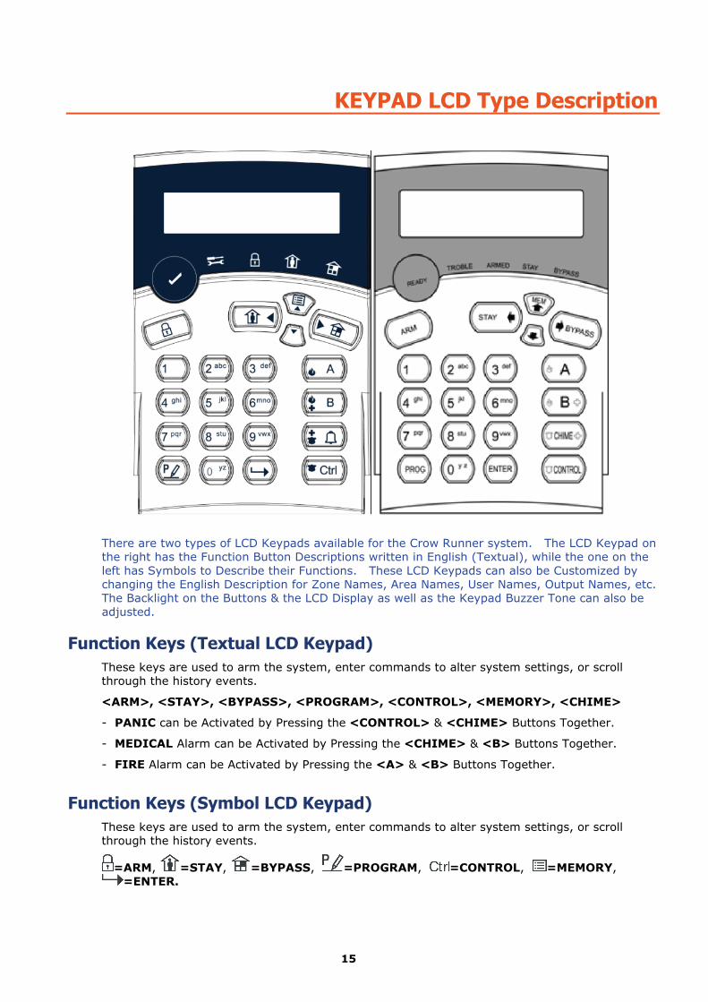
There are two types of LCD Keypads available for the Crow Runner system. The LCD Keypad on the right has the Function Button Descriptions written in English (Textual), while the one on the left has Symbols to Describe their Functions. These LCD Keypads can also be Customized by changing the English Description for Zone Names, Area Names, User Names, Output Names, etc. The Backlight on the Buttons & the LCD Display as well as the Keypad Buzzer Tone can also be adjusted.
Function Keys (Textual LCD Keypad) These keys are used to arm the system, enter commands to alter system settings, or scroll through the history events.
<ARM>, <STAY>, <BYPASS>, <PROGRAM>, <CONTROL>, <MEMORY>, <CHIME>
- PANIC can be Activated by Pressing the <CONTROL> & <CHIME> Buttons Together.
- MEDICAL Alarm can be Activated by Pressing the <CHIME> & <B> Buttons Together.
- FIRE Alarm can be Activated by Pressing the <A> & <B> Buttons Together.
Function Keys (Symbol LCD Keypad) These keys are used to arm the system, enter commands to alter system settings, or scroll through the history events.
=ARM, =STAY, =BYPASS, =PROGRAM, =CONTROL, =MEMORY, =ENTER.
16
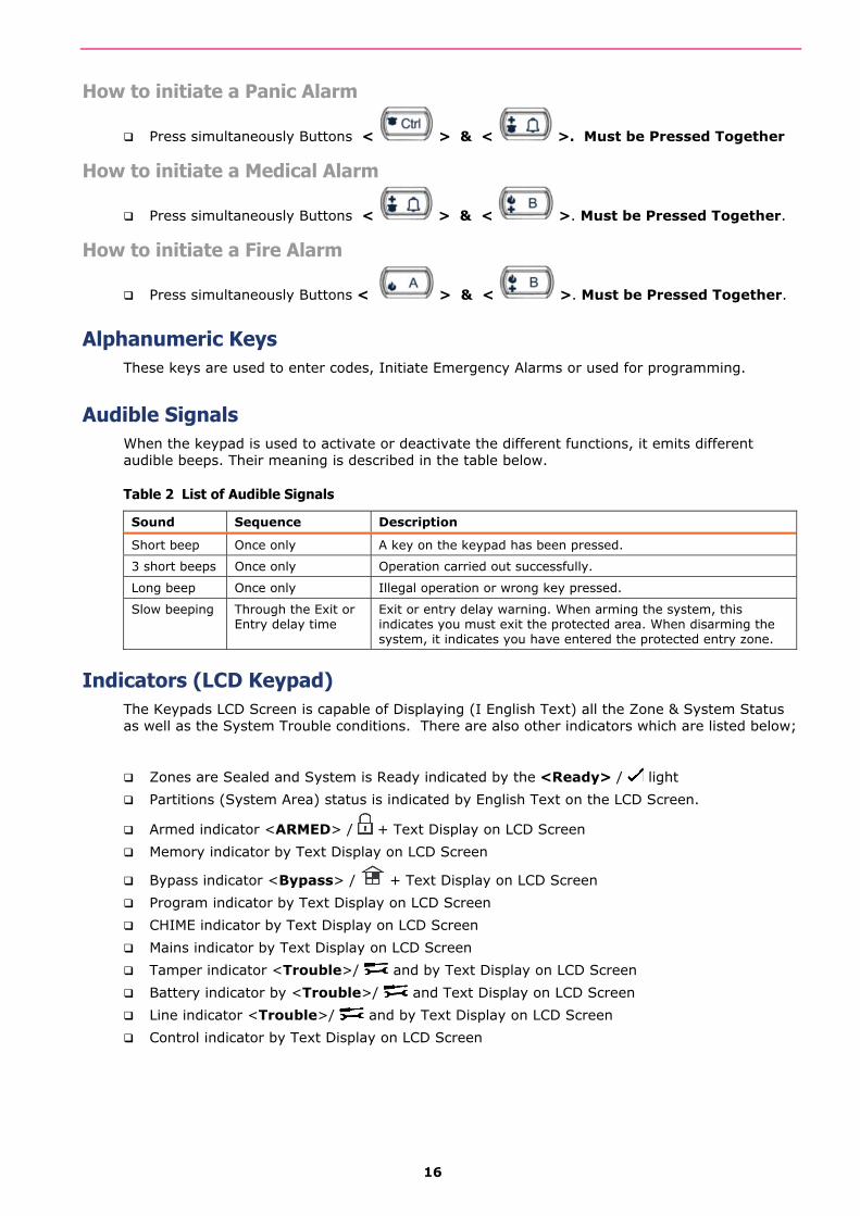
How to initiate a Panic Alarm
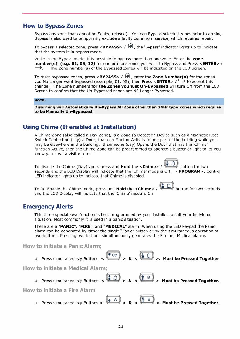
Press simultaneously Buttons < > & < >. Must be Pressed Together
How to initiate a Medical Alarm
Press simultaneously Buttons < > & < >. Must be Pressed Together.
How to initiate a Fire Alarm
Press simultaneously Buttons < > & < >. Must be Pressed Together.
Alphanumeric Keys These keys are used to enter codes, Initiate Emergency Alarms or used for programming.
Audible Signals When the keypad is used to activate or deactivate the different functions, it emits different audible beeps. Their meaning is described in the table below.
Table 2 List of Audible Signals
Sound Sequence Description
Short beep Once only A key on the keypad has been pressed.
3 short beeps Once only Operation carried out successfully.
Long beep Once only Illegal operation or wrong key pressed.
Slow beeping Through the Exit or Entry delay time
Exit or entry delay warning. When arming the system, this indicates you must exit the protected area. When disarming the system, it indicates you have entered the protected entry zone.
Indicators (LCD Keypad) The Keypads LCD Screen is capable of Displaying (I English Text) all the Zone & System Status as well as the System Trouble conditions. There are also other indicators which are listed below;
Zones are Sealed and System is Ready indicated by the <Ready> / light
Partitions (System Area) status is indicated by English Text on the LCD Screen.
Armed indicator <ARMED> / + Text Display on LCD Screen
Memory indicator by Text Display on LCD Screen
Bypass indicator <Bypass> / + Text Display on LCD Screen
Program indicator by Text Display on LCD Screen
CHIME indicator by Text Display on LCD Screen
Mains indicator by Text Display on LCD Screen
Tamper indicator <Trouble>/ and by Text Display on LCD Screen
Battery indicator by <Trouble>/ and Text Display on LCD Screen
Line indicator <Trouble>/ and by Text Display on LCD Screen
Control indicator by Text Display on LCD Screen
17
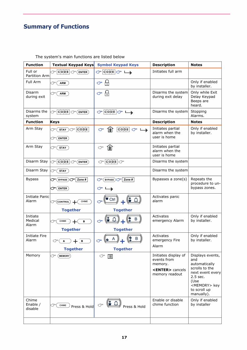
Summary of Functions
The system's main functions are listed below
Function Textual Keypad Keys Symbol Keypad Keys Description Notes
Full or Partition Arm
C O D E ENTER C O D E Initiates full arm
Full Arm ARM Only if enabled
by installer.
Disarm during exit ARM
Disarms the system during exit delay
Only while Exit Delay Keypad Beeps are heard.
Disarms the system
C O D E ENTER C O D E Disarms the system Stopping Alarms.
Function Keys Description Notes
Arm Stay STAY C O D E C O D E
ENTER
Initiates partial alarm when the user is home
Only if enabled by installer.
Arm Stay STAY Initiates partial alarm when the user is home
Disarm Stay C O D E ENTER C O D E Disarms the system
Disarm Stay STAY Disarms the system
Bypass BYPASS Zone # BYPASS Zone #
ENTER
Bypasses a zone(s) Repeats the procedure to un-bypass zones.
Initiate Panic Alarm CONTROL + CONTROL +
Together Together
Activates panic alarm
Initiate Medical Alarm CONTROL + CONTROL +
Together Together
Activates emergency Alarm
Only if enabled by installer.
Initiate Fire Alarm 7 + 9 +
Together Together
Activates emergency Fire
Alarm
Only if enabled by installer.
Memory MEMORY Initiates display of events from memory.
<ENTER> cancels memory readout
Displays events, and automatically scrolls to the next event every 2.5 sec. (Use <MEMORY> key to scroll up manually).
Chime Enable / disable CONTROL Press & Hold Press & Hold
Enable or disable chime function
Only if enabled by installer
CHIME
CHIME
B
B A
CHIME

18
Function Textual Keypad Keys Symbol Keypad Keys Description Notes
Control
CONTROL Device# Device#
ENTER
Activates or deactivates outputs and devices
Press <Control> for 2 seconds
Change or Add Users' code
PROGRAM M CODE M CODE
ENTER
Activates program mode to add or change Users' codes
For details see page-23
Note: If you started an operation incorrectly, press <ENTER>/ to exit and return to the previous mode.
19
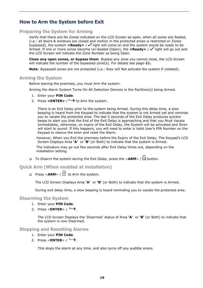
How to Arm the System before Exit
Preparing the System for Arming Verify that there are No Zones indicated on the LCD Screen as open, when all zones are Sealed, (i.e.: all doors & windows are closed and motion in the protected areas is restricted or Zones bypassed), the system <Ready> / light will come on and the system would be ready to be Armed. If one or more zones become Un-Sealed (Open), the <Ready> / light will go out and the LCD Screen will indicate the Zone Number as being Open.
Close any open zones, or bypass them. Bypass any zone you cannot close, the LCD Screen will indicate the number of the bypassed zone(s). For details see page-21.
Note: Bypassed zones are not protected (i.e.: they will Not activate the system if violated).
Arming the System Before leaving the premises, you must Arm the system.
Arming the Alarm System Turns On All Detection Devices in the Partition(s) being Armed.
1. Enter your PIN Code.
2. Press <ENTER> / to Arm the system. There is an Exit Delay prior to the system being Armed. During this delay time, a slow beeping is heard from the Keypad to indicate that the system is not Armed yet and reminds you to vacate the protected area. The last 5 seconds of the Exit Delay produces quicker beeps to alert you that the End of the Exit Delay is approaching and that you Must Vacate Immediately, otherwise, on expiry of the Exit Delay, the System will be activated and Siren will start to sound. If this happens, you will need to enter a Valid User’s PIN Number on the Keypad to silence the siren and reset the Alarm.
However, When you Exit the premises before the Expiry of the Exit Delay, The Keypad’s LCD Screen Displays Area ‘A’ or ‘B’ (or Both) to indicate that the system is Armed.
The indicators may go out few seconds after Exit Delay times out, depending on the installation setting.
To Disarm the system during the Exit Delay, press the <ARM> / button.
Quick Arm (When enabled at installation) Press <ARM> / to Arm the system.
The LCD Screen Displays Area ‘A’ or ‘B’ (or Both) to indicate that the system is Armed. During exit delay time, a slow beeping is heard reminding you to vacate the protected area.
Disarming the System 1. Enter your PIN Code.
2. Press <ENTER> / . The LCD Screen Displays the ‘Disarmed’ status of Area ‘A’ or ‘B’ (or Both) to indicate that the system is now Disarmed.
Stopping and Resetting Alarms 1. Enter your PIN Code.
2. Press <ENTER> / . This stops the alarm at any time, and also turns off any audible sirens.
20
Arming the System While Staying Home
Arming the System in Stay Mode This type of Arming is used when people are present within the protected area. At nighttime, when the family is about to retire, perimeter zones are protected, but not the interior zones. Consequently, interior movements are ignored by the system.
1. Press <STAY> / .
2. Enter your PIN Code.
3. Press <ENTER> / . The LCD Screen Displays the ‘Stay’ mode Armed status of Area ‘A’ or ‘B’ (or Both) to indicate that the system is now Armed in stay mode.
Quick Stay This feature must be enabled at installation time.
Press <STAY> / . to arm the system. During exit delay, you can leave the premises. If you wish to stay, or you don’t want anybody to enter the protected premises, you can cancel the Entry/Exit delay by pressing the <ENTER> / key. The slow beeping stops and the system is then Immediately Armed.
The LCD Screen Displays the ‘Stay’ mode Armed status of Area ‘A’ or ‘B’ (or Both) to indicate that the system is now Armed in stay mode. The LCD Screen may turn off a few seconds after exit delay expired (for Security and Power Saving Purposes), depending on the installer's setting.
Disarming the System Enter your PIN Code and press <ENTER> / , or press <STAY> / , if enabled by installer.
The LCD Screen Displays the ‘Disarmed’ status of Area ‘A’ or ‘B’ (or Both) to indicate that the system is now Disarmed.
How to Arm Partitions (Areas) and how they work The protected area can be grouped into 2 separate partitions (A & B) plus a Common Partition, effectively allowing 3 separate groups of partitions that can be Armed & Disarmed. As the name suggests, the Common partition Must be assigned correctly by the Installer so that it can be Armed or Disarmed allowing the other 2 Separate partitions to function totally independently. An example of this is, a building with 2 apartments with a common Entry or Foyer area. When the owner of the first apartment comes home and Disarms Partition ‘A’, they will be Disarming both their apartment as well as the Common Foyer Area. If the owner of the second apartment comes home, they will Only Disarm their apartment (Partition ‘B’), etc.
To Arm Partition ‘A’, enter the User PIN Code for partition ‘A’.
To Arm Partition ‘B’, enter the User PIN Code for partition ‘B’.
Note: For Arming a Partition with a PIN Code, see page 19 “How to arm the system before exit”
During the Exit Delay, you can leave the premises. At the end of the Exit Delay, the LCD Screen Displays Area ‘A’ or ‘B’ (or Both) to indicate that the system is Armed.
(The LCD Screen may turn off a few seconds after exit delay expired (for Security and Power Saving Purposes), depending on the installer's setting.
To disarm partition, see "Disarming the System" on page 19.
21
How to Bypass Zones Bypass any zone that cannot be Sealed (closed). You can Bypass selected zones prior to arming. Bypass is also used to temporarily exclude a faulty zone from service, which requires repair.
To bypass a selected zone, press <BYPASS> / , the ‘Bypass’ indicator lights up to indicate that the system is in bypass mode.
While in the Bypass mode, it is possible to bypass more than one zone. Enter the zone number(s) (e.g. 01, 05, 12) for one or more zones you wish to Bypass and Press <ENTER> /
. The Zone number(s) of the Bypassed Zones will be indicated on the LCD Screen.
To reset bypassed zones, press <BYPASS> / , enter the Zone Number(s) for the zones you No Longer want bypassed (example, 01, 05), then Press <ENTER> / to accept this change. The Zone numbers for the Zones you just Un-Bypassed will turn Off from the LCD Screen to confirm that the Un-Bypassed zones are N0 Longer Bypassed.
NOTE:
Disarming will Automatically Un-Bypass All Zone other than 24Hr type Zones which require to be Manually Un-Bypassed.
Using Chime (If enabled at Installation) A Chime Zone (also called a Day Zone), is a Zone (a Detection Device such as a Magnetic Reed Switch Contact on (say) a Door) that can Monitor Activity in one part of the building while you may be elsewhere in the building. If someone (say) Opens the Door that has the ‘Chime’ function Active, then the Chime Zone can be programmed to operate a buzzer or light to let you know you have a visitor, etc..
To disable the Chime (Day) zone, press and Hold the <Chime> / button for two seconds and the LCD Display will indicate that the ‘Chime’ mode is Off. <PROGRAM>, Control LED indicator lights up to indicate that Chime is disabled.
To Re-Enable the Chime mode, press and Hold the <Chime> / button for two seconds and the LCD Display will indicate that the ‘Chime’ mode is On.
Emergency Alerts This three special keys function is best programmed by your installer to suit your individual situation. Most commonly it is used in a panic situation.
These are a “PANIC”, “FIRE”, and “MEDICAL” alarm. When using the LED keypad the Panic alarm can be generated by either the single “Panic” button or by the simultaneous operation of two buttons. Pressing two buttons simultaneously generates the Fire and Medical alarms
How to initiate a Panic Alarm;
Press simultaneously Buttons < > & < >. Must be Pressed Together
How to initiate a Medical Alarm;
Press simultaneously Buttons < > & < >. Must be Pressed Together.
How to initiate a Fire Alarm
Press simultaneously Buttons < > & < >. Must be Pressed Together.
22
Generate Threat or Duress If you are compelled to disarm the system under threat, you must enter the duress digit before the user’s code to activate the automatic dialer. The duress digit shifts up your usual code by one digit. If your code is 345 and 8 is your duress digit, than entering 8345 modifies your code. The modified duress code disarms the system in a normal way, but at the same time activates the dialer silently to report a “duress event” without arousing suspicion. (For details ask your installer).
How to Read System Messages When viewing the Memory events at the keypad by pressing the <MEMORY> / button, the first thing that is always displayed is the System Trouble Type Messages (if any). If the System <Trouble>/ indicator light is on or Flashing, then there Is a System related ‘Trouble’ event in the Memory which will be displayed first on the LCD Screen. If nothing is displayed on the LCD Screen under the ‘System’ type Trouble Messages, this means that there are No current System Alarms. If however, the LCD Keypad Screen does alert you of a ‘System’ type Trouble Condition, you should Immediately make yourself familiar with the Type of ‘Trouble’ Condition and Monitor its Progress to ensure that the System’s Integrity is Not Compromised. If Any Type of System ‘Trouble’ condition persists, please contact your System’s Installer and make them aware of the type of ‘Trouble’ the Keypad is Displaying and follow your Installer’s Instructions.
The table below lists the type of ‘Trouble’ Messages the LCD Keypad is likely to display;
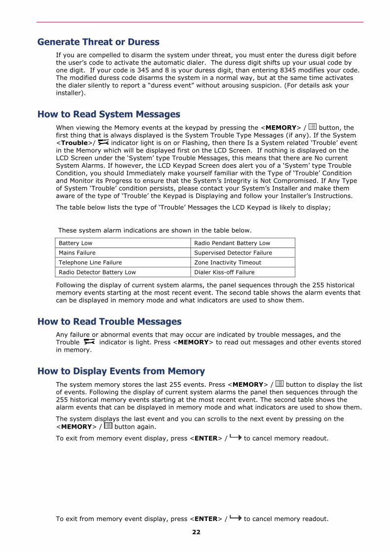
These system alarm indications are shown in the table below.
Battery Low Radio Pendant Battery Low
Mains Failure Supervised Detector Failure
Telephone Line Failure Zone Inactivity Timeout
Radio Detector Battery Low Dialer Kiss-off Failure
Following the display of current system alarms, the panel sequences through the 255 historical memory events starting at the most recent event. The second table shows the alarm events that can be displayed in memory mode and what indicators are used to show them.
How to Read Trouble Messages Any failure or abnormal events that may occur are indicated by trouble messages, and the Trouble indicator is light. Press <MEMORY> to read out messages and other events stored in memory.
How to Display Events from Memory The system memory stores the last 255 events. Press <MEMORY> / button to display the list of events. Following the display of current system alarms the panel then sequences through the 255 historical memory events starting at the most recent event. The second table shows the alarm events that can be displayed in memory mode and what indicators are used to show them.
The system displays the last event and you can scrolls to the next event by pressing on the <MEMORY> / button again.
To exit from memory event display, press <ENTER> / to cancel memory readout.
To exit from memory event display, press <ENTER> / to cancel memory readout.

23
EVENT TYPE DEVICE EVENT TYPE DEVICE
ACTIVATION Zones 1-16 FIRE ALARM (BUTTONS 4&6 ARE PRESSED TOGETHER)
Keypad Fire
BYPASS Zones 1-16 MEDICAL ALARM (BUTTONS 7&9 PRESSED TOGETHER)
Keypad Medical
DETECTOR TAMPER
(SHORT CIRCUIT)
Zones 1-8 ARMED A Area A is Armed
DETECTOR TAMPER
(OPEN CIRCUIT)
Zones 9-16 ARMED B Area B is Armed
WRONG CODE ALARM Code at Keypad # STAY MODE A Area A STAY Mode ON
CABINET TAMPER Cabinet or Siren STAY MODE B Area B STAY Mode ON
KEYPAD TAMPER SWITCH
Tamper alarm at keypad DURESS ALARM Duress Alarm
At keypad #
LOW BATTERY Controller Battery SUPERVISED RADIO ALARM
Supervised Radio Passive Infra-Red
MAINS FAILURE Controller Mains Supply ZONE INACTIVITY ALARM
Zones 1-16
FUSE FAILURE F1 or F2 Controller on-board
Fuses
TELEPHONE LINE FAILURE
Phone Line Failure
RADIO ZONE LOW BATTERY
Radio Zone 1-16 EXCESSIVE RE-TRIES
Panel Dialer
PENDANT LOW BATTERY Radio Key User 1-20 FAILURE TO GET A KISSOFF
Panel Dialer
PANIC BUTTON (or BUTTONS 1&3 PRESSED TOGETHER)
Keypad Panic
At keypad #
WALKTEST MODE Manual walk-test mode
How to Control Outputs and Devices The keypad enables you to control external devices, such as an air-conditioner or heater. These Devices Must First be Interfaced with the Runner System for them to be controlled using the process explained below.
To activate or halt a device:
1. Press <CONTROL> / . The LCD Display Screen will change to the ‘Outputs Control Screen.
2. Press the (Output) number of the device (This is the Output Number where the Device is Connected to inside the Runner Alarm Panel). Up to eight different devices can be controlled via the keypad.
3. Press <ENTER> / . This activates or deactivates the selected device.
4. Press <CONTROL> / . The LED is light for each device ON.
5. Press <ENTER> / to return to normal mode.
24
Entering the User Program/Client Mode (Using LCD Keypad) There are 2 levels of program modes, CLIENT mode and INSTALLER mode. Normally the installer configures the system to give you access to the CLIENT mode so you can add, delete, or change the user codes. To get into CLIENT mode (provided the system is NOT Armed) Press <PROGRAM>/ enter Master code and <ENTER>/ . The LCD Display of the Keypad will show ’Client:’ indicating that the system is in ‘User’ programming mode.
If you get a single long beep at this point and the LCD Display does Not say ‘Client’, this could mean that either your code can Not access Program mode or that you pressed the Wrong Buttons. It’s best to try again in case you had pressed the wrong button when entering your Code into the keypad. Please make sure you are very careful when pressing the keypad buttons. There is No reason to rush.
How to Exit Program Mode
To exit out of program mode press <PROGRAM>/ and <ENTER>/ . The LCD Screen will exit the ‘Client’ Program Mode confirming that the system is No Longer in User programming mode.
How to Change or Add Codes (Using LCD Keypad)
About Master Code and the User Code The factory default master code (123) is intended as a preliminary control of the alarm system. After the RUNNER is installed and put into service, the code can be changed to any code known to the Master user (User-1). The Master user can Add up to 100 user codes and to limit access rights to other users. The Master Code holder can ask the installer to define several User profiles.
Access rights are listed below:
User code has Area A and/or B permission
User code can Arm and/or Disarm an area
User code can Stay Arm and/or Stay Disarm an area
User code can change its code
User code can change user’s code
User code can Operate control Functions
User code can change dialer telephone numbers
User code can alter the real time clock
User can answer an incoming call and start up/down load
User can allow access to installer program mode from client mode.
Initiate Walk-test mode.
How to Change the Master Code (Using LCD Keypad) NOTE: When changing the Master Code, please Ensure that you remember the new Master Code that you enter. Otherwise, you will Not be able to use your system and your systems installer will need to come back to reset the code. This may incur a Service (Call Out) Fee.
While in CLIENT mode (see “Entering the user Program/Client Mode” above on page-23), Press
<PROGRAM>/ then 1 <ENTER>/ and 1 <ENTER>/ again. The current Master Code digits will be displayed on the LCD Screen. To enter a new Master code, use the numeric keypad buttons to enter your new Master code then press <ENTER>/ (At this point, your Old Master Code will No Longer work. You MUST now start using your NEW Master Code). The new Master Code will now be displayed followed either by three short beeps to indicate correct entry or one long beep if not accepted. The Master Code can be any combination of 1 to 6 digits. It is recommended to use at least a 4 digits code but a 6 digit code will provide greater security.
To exit user Code Program mode, Press <PROG>/ and <ENTER>/ .
25
How to Add or Change the User Code (Using LCD Keypad) While in CLIENT mode, press <PROGRAM>/ then 1E and the User number (2 to 100) you want to add or change, then press <ENTER>/ . If there is an existing code already in the system for that user, it will be displayed on the LCD Screen. Use the numeric keypad buttons to enter the new code for that user, then press <ENTER>/ to save your new code. The new code will now be displayed be LCD Screen along with three short beeps. A code can be any combination of 1 to 6 digits. Entering the new code deletes the old code from the system.
Repeat the procedure for all users.
Press <PROG>/ and <ENTER>/ to exit Local Program mode.
How to Delete the User Code (Using LCD Keypad) In client mode, press <PROGRAM>/ then <1> <ENTER>/ and the User number (2 to 100) you intend to delete, press <ENTER>/ . The existing code will be displayed on the LCD Screen. (In this next step, you will need to press Two Buttons TOGETHER), Press <CONTROL>/ and the Digit ‘0’ Together to delete User code.
Press <ENTER>/ to save the change.
Press <PROG>/ and <ENTER>/ to exit program mode.
Adding/Changing Telephone Numbers (Using LCD Keypad) Your panel accepts up to Eight phone numbers with a total of 16 digits each. Your panel can be programmed to dial all or any of these depending on the event which has occurred. (The eight phone numbers are at program address P181E 1-8E).
While in CLIENT mode, key in the following sequence <PROGRAM>/ < P181E 1E > (The address for telephone number 1), the existing number will be displayed on the LCD Screen. Now enter <NEW TELEPHONE #> <ENTER>/ . The new numbers will be displayed on the LCD Screen along with the three confirmation acceptance beeps.
At any time, you can enter in the address for the telephone number just to view the currently
programmed value then press the <PROGRAM>/ button to move on to the next address for the second phone number, etc.
For example, P181E 1E= PH # 1, P181E 2E = PH# 2, P181E 6E = PH# 6.
How to set Time and Date The alarm system has an internal clock that may be used to automatically Arm or Disarm the alarm or turn Outputs On or off. It is also used to identify when events occurred in memory via the LCD keypad. If you need to change the Time & Date it must be done from the CLIENT mode. To change the Time & Date press
Press <PROGRAM>/ <26> <ENTER>/ <2> <ENTER>/ <1-7> <ENTER>/ Where 1-7 = the current day (1=Sun, 2 = Mon to 7 = Sat)
Press <PROGRAM>/ <26> <ENTER>/ <1> <ENTER>/ <HHMM> <ENTER>/ .
Where HH = Hour in 24 Hour Format and MM = Minutes
Press <PROGRAM>/ <26> <ENTER>/ <3> <ENTER>/ <DDMMYY> <ENTER>/ . Where DD =1-31 current date, MM= months 1-12, YY = year 00-99
26
How to Operate the Access Control Output If the alarm system has been set up to allow control of an electric door lock, you can activate the door release function as follows;
Press <CONTROL>/ or Press <CONTROL>/ enter CODE then <ENTER>/ . The LCD Screen will change and say ‘Control’ and the assigned Electric Lock will Operate for the Timed Period set by your Installer. The LCD Screen will show the Digit that represents the Runner Output Number that is assigned to operate the Lock. When the Timer for the Electric Lock Times-Out, the LCD Screen will change back to the Idle (Standard) Screen Status ready to announce any zones that become Open.
The Access Control function can either be a single button operation or restricted to requiring a valid User code entry. Both options are shown above. Please consult your installer as to what option may be programmed.
How to start Walk Test Mode While in CLIENT mode, a User with the proper authority can start walk-test mode. This special mode latches the alarm signals from detectors at the keypad initiating the test so that one person can trigger every detector connected to the alarm then return to the keypad to verify operation. On terminating Walk-test mode, the test results are put into the memory buffer so they can be viewed at a later time.
To start Walk-test mode while in CLIENT mode, press <PROGRAM>/
<200> <ENTER>/ <6> <ENTER>/ and the keypad buzzer beeps at a rate of 2 beeps per second.
Next trigger every detector connected to the panel then return to the keypad and all of the zones that were triggered are displayed on the keypad.
To terminate Walk-test mode press <ENTER>/ , the keypad will stops beeping but the system will still be in Ready mode for another Walk Test Cycle. If you wish to perform another Walk Test, simply press the <Enter>button, otherwise Exit Client Mode by pressing
<PROGRAM>/ <ENTER>/ .
How to Answer an In-Coming Call From time to time your installer may need to access the alarm from a remote PC to make changes to your programming and for security reasons they may have configured the alarm so that an authorized person on-site is required to make the alarm system answer the in-coming call. This option is only available in CLIENT mode.
If the panel is not configured to answer in-coming calls, the user can force it to answer the call by pressing and holding <CONTROL>/ followed Immediately by <9>and Hold Both buttons for 10 seconds or until you hear three quick beeps. This forces the panel to answer the call immediately. For this function to work, the phone line must be ringing at the time and there must have been at least two rings before pressing the buttons.
Provided the line connected to the alarm was ringing at the time, the panel now answers the call and allows a remote PC connection.
How to Generate a Manual Test Call (Monitored CID Only) From time to time it may be necessary to force the Dialer to report a Manually Generated ‘Test Call’. This is a handy feature for when Test Calls are programmed for Weekly Reporting and the system user (or service technician) would like to confirm that the Dialer is functioning.
If the panel is configured for Contact ID (Back-To-Base Monitored) reporting and test calls are programmed to report, you can force a manual test call by pressing and holding <CONTROL>/
button followed Immediately by <0> and Holding Both buttons down until the LCD Display shows ‘Dialler Active’.
This operation will cause a Manual Test Call to be Reported to the monitoring company. You can also dial into the panel from a remote site and enter the DTMF Code Number (using the remote
27
telephone (digit) buttons) to force the Runner Panel to hang-up from your call and Immediately Report a Test Call to the Back-To-Base Monitoring Company. This function Must first be programmed (setup) by your systems installer. Please ask your systems installer for details.
Using the Remote Command Control Another powerful feature available from your alarm is Command Control. This feature is a remote control facility which allows valid users to access the panel via a standard touch tone telephone and check or changes the Arm/Disarm status of each of the areas, operate each of the eight outputs or turn on an optional Microphone.
The Command Control feature is only available on panels (Runner-8 / 16 & Plus (Compact version)) fitted with a Voice board. The Voice board provides voice prompts to guide you through Command control operations.
Please talk to your installer to find out if all or any of these options are available on your alarm.
To perform any of the Command Control features, you must first ring the phone number, which the panel is connected to. The panel may be set up to answer after a specific number of rings or it can be set-up to use a fax defeat option. Either way, when you ring the phone number and the panel answers the call, the first thing you hear over the phone is a two seconds burst of modem tone. After this tone stops you must enter the access code, which is associated with the Command menu option you wish to access. Remember, the code you enter determines which menu option you access. If you miss the pause, the panel repeats the modem tone and then pauses again for 5 seconds looking for your access code. This process is repeated four times before hanging up, if no valid code is received. When entering codes or other information in Command Control the "#" key acts as a "Clear" button.
When you have entered the required 4-digit access code, the panel replies with the status message associated with the Command Control function you have accessed. For example, let's say we have a code of “2045” to allow Arming & Disarming of Area A. Once the code “2045” has been received the panel checks the current status of Area A and replies with the pre-programmed voice message relating to that status. For example, if Area A is armed, then the Armed message is sent, if Disarmed then the Disarmed message is sent. If only the DTMF board is fitted, the voice message is substituted with a long beep if Area A is armed and three short beeps if it is disarmed. Please Note: As at early 2008, the DTMF board is No Longer available. The Voice Board however can be used to perform the Command Control Functions as described above.
Once the status message has informed you of the actual state, you can use the " * " key to toggle the option on & off or Arm and Disarm, e.g. in our example above, code “2045” accesses Area "A" arming or disarming.
Assuming the status message we received was "Area A alarm is Armed" If we press the " * " key, Area "A" is Disarmed and we would receive a status message "Area A alarm is Disarmed" (or whatever message is programmed by the installer).
While you are on-line with the panel, you can move between menu options by entering the code of the option you want to control. Assuming there was a code of “4321” programmed to control outputs. After having used code “2045” to control the Arm/Disarm status of Area A, we first press the “#” button to reset all previous entries. Then we can enter the digits “43215” (that is “4321” as the code to control outputs and “5” to select output #5). The current status of output #5 is given either by the voice message or the appropriate tone and then the status can be changed with the “ * ” button on the remote telephone.
NOTE:For output control you must enter the 4 digit code, for example, 4321 followed by the output number you wish to control, in this case 5. At any stage, if you enter in an incorrect code you can press the “#” button on the remote telephone to clear all code entries and then start again.
To turn on the optional Microphone (only available if the Voice Board is fitted) you must enter in the appropriate code followed by the “ * ” button. To turn the Microphone off you simply press the “ * ” button again.
To end a Command Control session, simply hangs up the phone. The panel is monitoring the line at all times and 15 seconds after the last key press, it automatically hangs up the line. This

28
15-second timer is active during the whole command control process so a period of 15 seconds without a key press causes the panel to hang-up.
Using Local Command Control If a command control code for outputs is programmed and the output/s are allowed to be locally controlled from the keypad, then entering the 4 digit code at a keypad blanks the display and the LCD Screen now indicate the output status. For example, if output 1 is on, the LCD Screen will show the digit-1 to indicate that Output-1 is On. Pressing the “1” button at the panel keypad, output 1 can be turned off provided it is allowed to be locally controlled. To leave local command control mode simply press the <ENTER>/ button and the keypad returns to normal operation. This feature works the same way that “Directly Controlling an Output” works only it requires a code to access the function.
29
Adjusting Backlighting and Buzzer Tone
Adjusting the LCD Keypad Backlighting You can independently adjust the backlight level of the LCD display and the Backlighting of the Keypad Buttons from Completely Off through Maximum Brightness in 16 steps (Levels) of Brightness. The Process used on the LCD keypad to perform this function is;
To increase the backlight Intensity (Level) of the Crow LCD Screen , Press & Hold the
<CONTROL> / . Button followed Immediately by repeatedly pressing on the “STAY”/ Button. This will increase the LCD Screen Backlight level to the maximum.
To Reduce the backlight Intensity (Level) of the Crow LCD Screen , Press & Hold the <CONTROL> / . Button followed Immediately by repeatedly pressing on the
<BYPASS>/ Button. This will Reduce the LCD backlight level to the Minimum (i.e.: The LCD backlight level will Turn OFF).
To increase the backlight Intensity (Level) of the Button’s on the Crow LCD Keypad, Press & Hold the <CONTROL> / . Button followed Immediately by repeatedly pressing on the MEM> / Button. This will increase the Keypad Button Backlight level to the maximum.
To Reduce the backlight Intensity (Level) of the Button’s on the Crow LCD Keypad, Press & Hold the <CONTROL> / . Button followed Immediately by repeatedly pressing on the
<DOWN ARROW> / Button. This will Reduce the Keypad Button Backlight level to the Minimum (i.e.: The Keypad Button Backlight level will Turn OFF).
Adjusting the Keypad Buzzer Tone You can independently adjust the frequency (tone) of the LCD keypad buzzer within a range of 16 steps. By adjusting the frequency, the volume of the tone produced at the buzzer varies as well.
To increase the frequency of the CROW LCD buzzer, Press & Hold the <CONTROL> / .
Button followed Immediately by repeatedly pressing on the “A”/ Button. This will increase the Frequency of the Crow LCD Keypad Buzzer. At some point, the frequency will be so high that we can No Longer Hear the Buzzer (i.e.: The Buzzer will turn Off).
To Reduce the frequency of the CROW LCD buzzer, Press & Hold the <CONTROL> / .
Button followed Immediately by repeatedly pressing on the “B”/ Button. This will Decrease the Frequency of the Crow LCD Keypad Buzzer. At some point, the frequency will be so Low that we can No Longer Hear the Buzzer (i.e.: The Buzzer will turn Off).

30
LCD Keypad in Local Edit Mode The Local Edit Program Mode allows the programming of a customised “System Name” (the name displayed during idle mode at the keypad), Customised “Zone Names” (the text that appears on the keypad when a zone is unsealed), Customised “User Names” (the User name is displayed when viewing arm/disarm events in memory mode), Customised “Area Names” (the Area name is displayed when viewing arm/disarm events in memory mode) and Customised “Output Names” (the Output name is displayed when viewing Output On/Off events in memory mode).
Accessing Local Edit Mode To enter Local Edit Program Mode on a CROW LCD Keypad Press and Hold <CONTROL>/
followed Immediately by Pressing the <ARM>/ and hold both buttons down for 2 seconds.
NOTE:
You must press and Hold Down the “Control” button first and the “Arm” button must be pressed Almost at the Same time as the Control button. If you make a mistake, press the “Enter” button and then repeat the process.
The display now shows “Local Mode kb #” where the # equals the keypad address as previously set (see “LCD keypad address assignment” on page 19 for details). There are two ways to program the keypad in “Local Edit Mode”. You can enter in the program location directly from the list below or you can use the menu function to navigate through all of the program options. The menus are described on the following pages.
Local Edit Mode Direct Program Addresses There are a number of program addresses available to you at this time:
[PROG]-[1]-[ENTER] to; ZONE#1 TEXT (maximum 16 characters)
[PROG]-[16]-[ENTER] ZONE#16 TEXT
[PROG]-[800]-[ENTER] UPDATE EDITABLE TEXT TO ALL LCD KEYPADS
[PROG]-[801]-[ENTER] RETURN ALL EDITABLE TEXT TO DEFAULT
[PROG]-[995]-[ENTER] PANEL TYPE
[PROG]-[996]-[ENTER] KEYPAD ADDRESS NUMBER FROM 1-8 CAN BE SET
[PROG]-[997]-[ENTER] KEYPAD LANGUAGE
[PROG]-[998]-[ENTER] AREA IDENTIFYING CHARACTER (assigning numbers or letters to Areas)
[PROG]-[999]-[ENTER] PANEL NAME DISPLAY (maximum 16 characters)
PROG]-[1001]-[ENTER] to; PROGRAM USER “1” NAME
PROG]-[1100]-[ENTER] PROGRAM USER “100” NAME
[PROG]-[2001]-[ENTER] AREA “A” IDENTIFYING NAME (maximum 16 character Area name)
[PROG]-[2002]-[ENTER] AREA “B” IDENTIFYING NAME (maximum 16 character Area name)
PROG]-[3001]-[ENTER] to; PROGRAM OUTPUT “1” NAME
PROG]-[3008]-[ENTER] PROGRAM OUTPUT “8” NAME
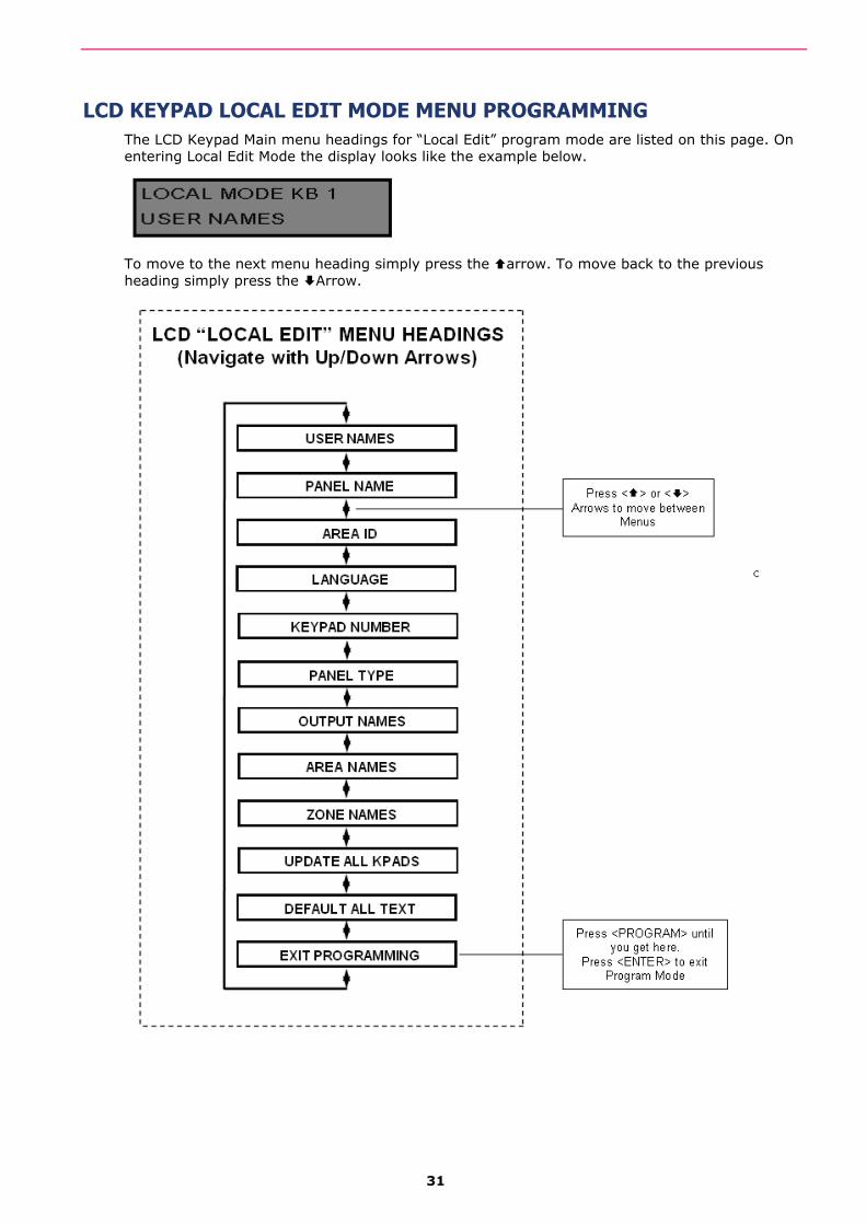
31
LCD KEYPAD LOCAL EDIT MODE MENU PROGRAMMING The LCD Keypad Main menu headings for “Local Edit” program mode are listed on this page. On entering Local Edit Mode the display looks like the example below.
To move to the next menu heading simply press the arrow. To move back to the previous heading simply press the Arrow.
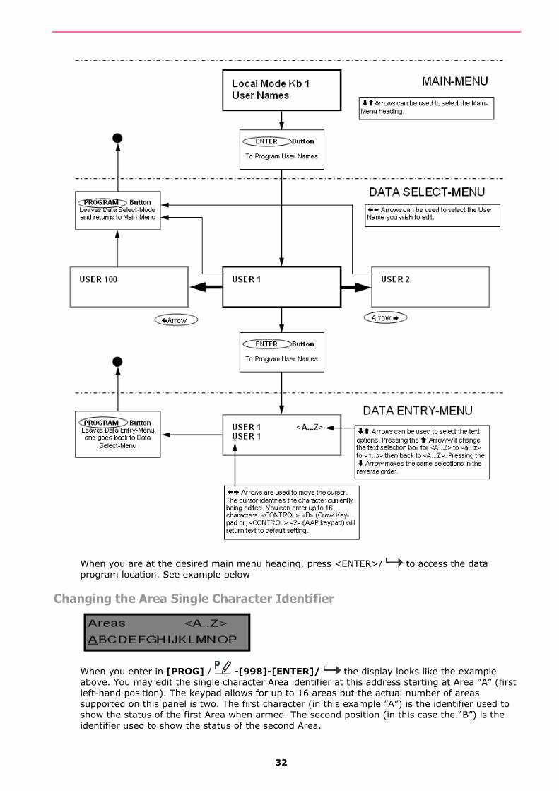
32
When you are at the desired main menu heading, press <ENTER>/ to access the data program location. See example below
Changing the Area Single Character Identifier
When you enter in [PROG] / -[998]-[ENTER]/ the display looks like the example above. You may edit the single character Area identifier at this address starting at Area “A” (first left-hand position). The keypad allows for up to 16 areas but the actual number of areas supported on this panel is two. The first character (in this example ”A”) is the identifier used to show the status of the first Area when armed. The second position (in this case the “B”) is the identifier used to show the status of the second Area.
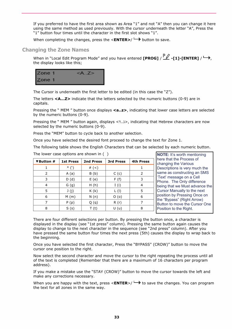
33
If you preferred to have the first area shown as Area “1” and not “A” then you can change it here using the same method as used previously. With the cursor underneath the letter “A”, Press the “1” button four times until the character in the first slot shows “1”.
When completing the changes, press the <ENTER>/ button to save.
Changing the Zone Names When in “Local Edit Program Mode” and you have entered [PROG] / -[1]-[ENTER] / , the display looks like this;
The Cursor is underneath the first letter to be edited (in this case the “Z”).
The letters <A...Z> indicate that the letters selected by the numeric buttons (0-9) are in capitals.
Pressing the “ MEM ” button once displays <a..z>, indicating that lower case letters are selected by the numeric buttons (0-9).
Pressing the “ MEM ” button again, displays <ג..ד>, indicating that Hebrew characters are now selected by the numeric buttons (0-9).
Press the “MEM” button to cycle back to another selection.
Once you have selected the desired font proceed to change the text for Zone 1.
The following table shows the English Characters that can be selected by each numeric button.
The lower case options are shown in ( )
▼Button # 1st Press 2nd Press 3rd Press 4th Press
1 * (‘) # (<) 1
2 A (a) B (b) C (c) 2
3 D (d) E (e) F (f) 3
4 G (g) H (h) I (i) 4
5 J (j) K (k) L (l) 5
6 M (m) N (n) O (o) 6
7 P (p) Q (q) R (r) 7
8 S (s) T (t) U (u) 8
There are four different selections per button. By pressing the button once, a character is displayed in the display (see “1st press” column). Pressing the same button again causes the display to change to the next character in the sequence (see “2nd press” column). After you have pressed the same button four times the next press (5th) causes the display to wrap back to the beginning.
Once you have selected the first character, Press the “BYPASS" (CROW)” button to move the cursor one position to the right.
Now select the second character and move the cursor to the right repeating the process until all of the text is completed (Remember that there are a maximum of 16 characters per program address).
If you make a mistake use the “STAY (CROW)” button to move the cursor towards the left and make any corrections necessary.
When you are happy with the text, press <ENTER>/ to save the changes. You can program the text for all zones in the same way.
NOTE: It’s worth mentioning here that the Process of changing the Various Descriptions is very much the same as constructing an SMS ‘Text’ message on a Cell Phone. The Only difference being that we Must advance the Cursor Manually to the next position by Pressing Once on the “Bypass” (Right Arrow) Button to move the Cursor One Position to the Right.
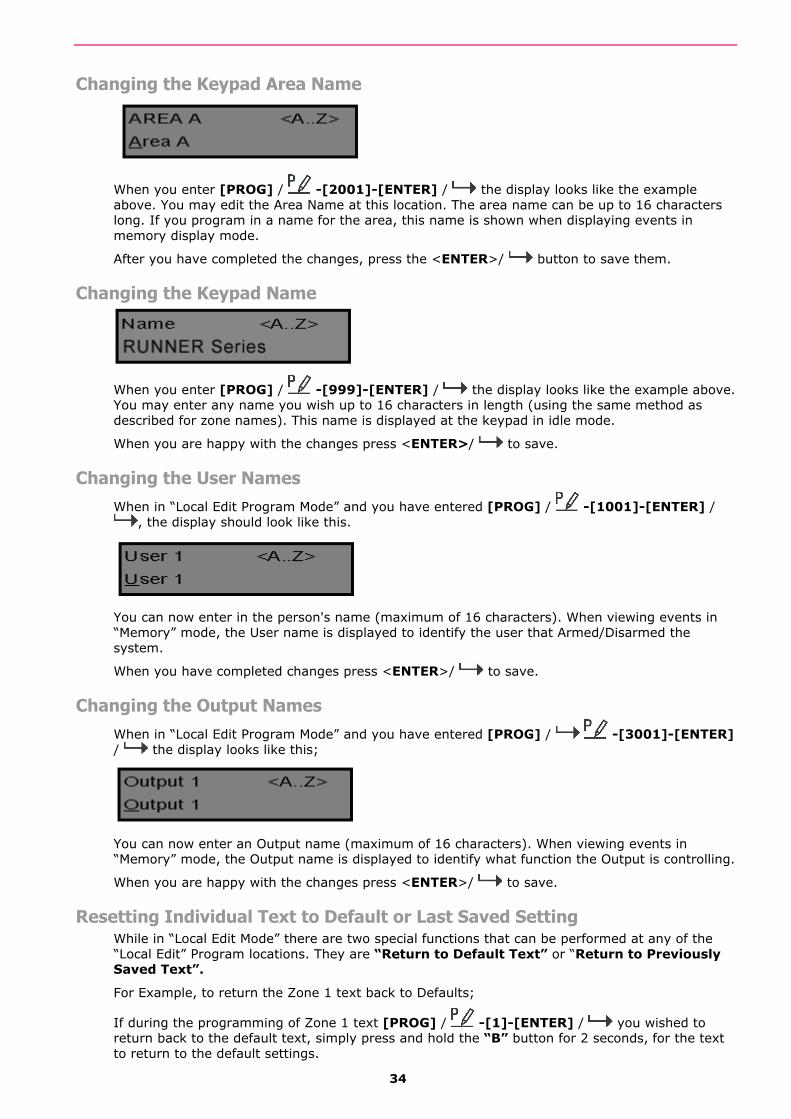
34
Changing the Keypad Area Name
When you enter [PROG] / -[2001]-[ENTER] / the display looks like the example above. You may edit the Area Name at this location. The area name can be up to 16 characters long. If you program in a name for the area, this name is shown when displaying events in memory display mode.
After you have completed the changes, press the <ENTER>/ button to save them.
Changing the Keypad Name
When you enter [PROG] / -[999]-[ENTER] / the display looks like the example above. You may enter any name you wish up to 16 characters in length (using the same method as described for zone names). This name is displayed at the keypad in idle mode.
When you are happy with the changes press <ENTER>/ to save.
Changing the User Names When in “Local Edit Program Mode” and you have entered [PROG] / -[1001]-[ENTER] /
, the display should look like this.
You can now enter in the person's name (maximum of 16 characters). When viewing events in “Memory” mode, the User name is displayed to identify the user that Armed/Disarmed the system.
When you have completed changes press <ENTER>/ to save.
Changing the Output Names When in “Local Edit Program Mode” and you have entered [PROG] / -[3001]-[ENTER] / the display looks like this;
You can now enter an Output name (maximum of 16 characters). When viewing events in “Memory” mode, the Output name is displayed to identify what function the Output is controlling.
When you are happy with the changes press <ENTER>/ to save.
Resetting Individual Text to Default or Last Saved Setting While in “Local Edit Mode” there are two special functions that can be performed at any of the “Local Edit” Program locations. They are “Return to Default Text” or “Return to Previously Saved Text”.
For Example, to return the Zone 1 text back to Defaults;
If during the programming of Zone 1 text [PROG] / -[1]-[ENTER] / you wished to return back to the default text, simply press and hold the “B” button for 2 seconds, for the text to return to the default settings.
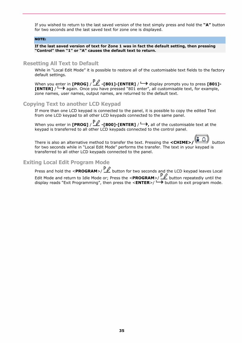
35
If you wished to return to the last saved version of the text simply press and hold the “A” button for two seconds and the last saved text for zone one is displayed.
NOTE:
If the last saved version of text for Zone 1 was in fact the default setting, then pressing “Control” then “1” or “A” causes the default text to return.
Resetting All Text to Default While in “Local Edit Mode” it is possible to restore all of the customisable text fields to the factory default settings.
When you enter in [PROG] / -[801]-[ENTER] / display prompts you to press [801]-[ENTER] / again. Once you have pressed “801 enter”, all customisable text, for example, zone names, user names, output names, are returned to the default text.
Copying Text to another LCD Keypad If more than one LCD keypad is connected to the panel, it is possible to copy the edited Text from one LCD keypad to all other LCD keypads connected to the same panel.
When you enter in [PROG] / -[800]-[ENTER] / , all of the customisable text at the keypad is transferred to all other LCD keypads connected to the control panel.
There is also an alternative method to transfer the text. Pressing the <CHIME>/ button for two seconds while in “Local Edit Mode” performs the transfer. The text in your keypad is transferred to all other LCD keypads connected to the panel.
Exiting Local Edit Program Mode Press and hold the <PROGRAM>/ button for two seconds and the LCD keypad leaves Local
Edit Mode and return to Idle Mode or; Press the <PROGRAM>/ button repeatedly until the display reads “Exit Programming”, then press the <ENTER>/ button to exit program mode.

36
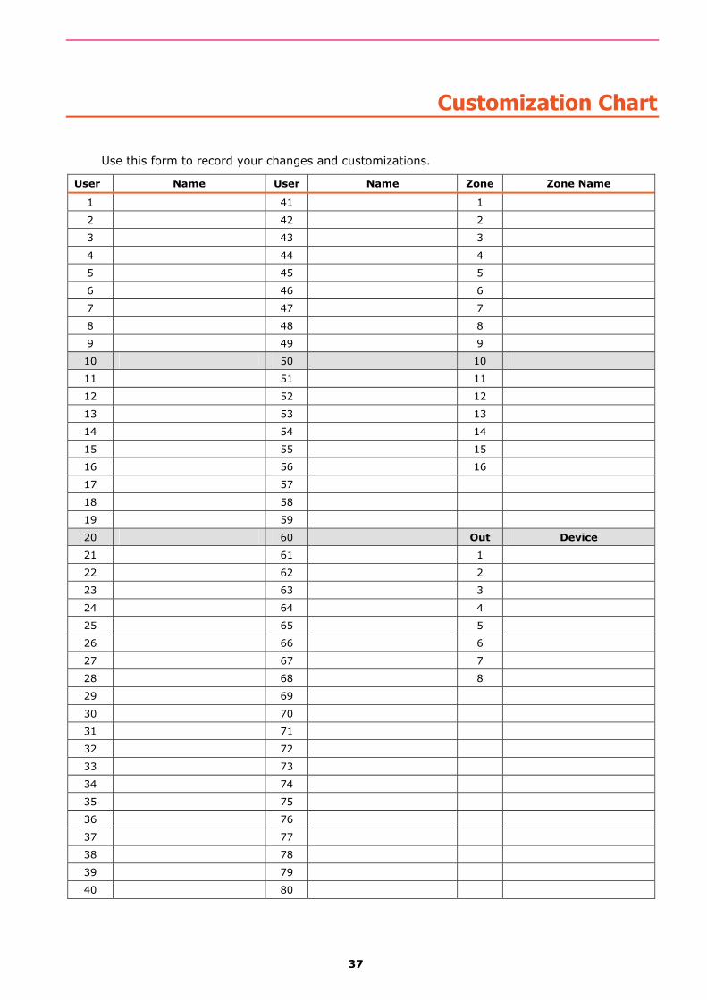
37
Customization Chart
Use this form to record your changes and customizations.
User Name User Name Zone Zone Name
1 41 1
2 42 2
3 43 3
4 44 4
5 45 5
6 46 6
7 47 7
8 48 8
9 49 9
10 50 10
11 51 11
12 52 12
13 53 13
14 54 14
15 55 15
16 56 16
17 57
18 58
19 59
20 60 Out Device
21 61 1
22 62 2
23 63 3
24 64 4
25 65 5
26 66 6
27 67 7
28 68 8
29 69
30 70
31 71
32 72
33 73
34 74
35 75
36 76
37 77
38 78
39 79
40 80

38

39
Product Support
Product Support:
Dear Crow Products User,
Thank you for choosing a Crow Security System. Our products are well known in the industry to be one of the most innovative and flexible systems that will service your requirements for many years to come.
Please contact your Crow Products Installer for any queries you may have regarding you Crow Alarm System. Your Installer is the one who has programmed and configured your system to suit your needs. As a result, any other person (including Crow) would Not know the setup of your system and will Not be able to assist you as well as Your System’s Installer.
If you have purchased a property with a Crow Alarm in it, you can download a User’s Guide for the model of Crow Alarm you have and if you would like to learn more about your system, you can contact one of Crow’s Authorized Distributors and ask them for a name of a Crow Systems Installer in your Area. You can then arrange with that Installer to conduct a service call to check your system as well as to assist you with any questions you may have about your system.
A list of Crow’s Authorized Distributors can be found on the ‘Contact Us’ page of the Crow Australia web site;
www.crowaust.com.au
Sincere Regards,
Crow (Australia) P/L
P/N 7110561 Rev. A G.T.


![[The Stellar Ensemble com] The Kite Runner - Khaled Hosseini](https://static.fdokumen.com/doc/165x107/6345cb7c03a48733920b865d/the-stellar-ensemble-com-the-kite-runner-khaled-hosseini.jpg)