
Rosemount 2130 Level Switch Vibrating Fork | Emerson
74
Reference Manual 00809-0100-4130, Rev EA May 2022 Rosemount ™ 2130 Level Switch Vibrating Fork
-
Upload
khangminh22 -
Category
Documents
-
view
1 -
download
0
Transcript of Rosemount 2130 Level Switch Vibrating Fork | Emerson

Reference Manual00809-0100-4130, Rev EA
May 2022
Rosemount™ 2130 Level Switch
Vibrating Fork

Safety messages
NOTICE
Read this manual before working with the product. For personal and system safety, and for optimum product performance,ensure you thoroughly understand the contents before installing, using, or maintaining this product.
For technical assistance, contacts are listed below:
Customer Central
Technical support, quoting, and order-related questions.
• United States - 1-800-999-9307 (7:00 am to 7:00 pm CST)
• Asia Pacific- 65 777 8211
North American Response Center
Equipment service needs.
• 1-800-654-7768 (24 hours a day — includes Canada)
• Outside of these areas, contact your local Emerson representative.
WARNING
Failure to follow safe installation and servicing guidelines could result in death or serious injury.
Ensure the level switch is installed by qualified personnel and in accordance with applicable code of practice.
Use the level switch only as specified in this manual. Failure to do so may impair the protection provided by the level switch.
The weight of a level switch with a heavy flange and extended fork length may exceed 37 lb. (18 kg). A risk assessment is requiredbefore carrying, lifting, and installing the level switch.
WARNING
Explosions could result in death or serious injury.
Verify the operating atmosphere of the level switch is consistent with the appropriate hazardous locations certifications.
Before connecting a handheld communicator in an explosive atmosphere, ensure the instruments are installed in accordance withintrinsically safe or non-incendive field wiring practices.
In explosion-proof/flameproof and non-incendive installations, do not remove the housing cover when power is applied to thelevel switch.
The housing cover must be fully engaged to meet flameproof/explosion-proof requirements.
WARNING
Electrical shock could cause death or serious injury.
Avoid contact with the leads and terminals. High voltage that may be present on leads can cause electrical shock.
Ensure the power to the level switch is off, and the lines to any other external power source are disconnected or not powered whilewiring the level switch.
Ensure the wiring is suitable for the electrical current and the insulation is suitable for the voltage, temperature, and environment.
WARNING
Process leaks could result in death or serious injury.
Ensure the level switch is handled carefully. If the process seal is damaged, gas might escape from the vessel (tank) or pipe.
2

WARNING
Any substitution of non-recognized parts may jeopardize safety. Repair (e.g. substitution of components) may alsojeopardize safety and is not allowed under any circumstances.
Unauthorized changes to the product are strictly prohibited as they may unintentionally and unpredictably alter performance andjeopardize safety. Unauthorized changes that interfere with the integrity of the welds or flanges, such as making additionalperforations, compromise product integrity and safety. Equipment ratings and certifications are no longer valid on any productsthat have been damaged or modified without the prior written permission of Emerson. Any continued use of product that hasbeen damaged or modified without the written authorization is at the customer’s sole risk and expense.
WARNING
Physical access
Unauthorized personnel may potentially cause significant damage to and/or misconfiguration of end users’ equipment. This couldbe intentional or unintentional and needs to be protected against.
Physical security is an important part of any security program and fundamental to protecting your system. Restrict physical accessby unauthorized personnel to protect end users’ assets. This is true for all systems used within the facility.
CAUTION
The products described in this document are NOT designed for nuclear-qualified applications.
Using non-nuclear qualified products in applications that require nuclear-qualified hardware or products may cause inaccuratereadings.
For information on Rosemount nuclear-qualified products, contact your local Emerson Sales Representative.
CAUTION
Hot surfaces
The flange and process seal may be hot at high process temperatures. Allow to cool before servicing.
3

4

Contents
Chapter 1 Introduction.............................................................................................................. 71.1 Using this manual........................................................................................................................ 7
1.2 Product certifications...................................................................................................................7
1.3 Product recycling/disposal...........................................................................................................7
Chapter 2 Level switch overview................................................................................................ 92.1 Measurement principles.............................................................................................................. 9
2.2 Process characteristics................................................................................................................. 9
2.3 Vessel characteristics...................................................................................................................9
2.4 Application examples.................................................................................................................10
2.5 Components of the level switch................................................................................................. 12
Chapter 3 Mechanical installation............................................................................................ 153.1 Safety messages........................................................................................................................ 15
3.2 Installation considerations......................................................................................................... 16
3.3 Installation procedures.............................................................................................................. 25
Chapter 4 Electrical installation................................................................................................314.1 Safety messages........................................................................................................................ 31
4.2 Prepare the electrical connections............................................................................................. 32
4.3 Connect wiring and power up.................................................................................................... 47
Chapter 5 Operation................................................................................................................ 515.1 Output mode and time delay..................................................................................................... 51
5.2 LED indication status..................................................................................................................52
5.3 Set the operating mode............................................................................................................. 53
Chapter 6 Service and troubleshooting.................................................................................... 556.1 Safety messages........................................................................................................................ 55
6.2 Magnetic test point....................................................................................................................56
6.3 Visual inspection........................................................................................................................57
6.4 Maintenance..............................................................................................................................58
6.5 Troubleshooting........................................................................................................................ 58
6.6 Spare parts................................................................................................................................ 60
6.7 Replacement and calibration of cassettes.................................................................................. 60
6.8 Opening the lid (cover).............................................................................................................. 62
6.9 Service support..........................................................................................................................63
Appendix A Specifications and reference data............................................................................. 65A.1 General......................................................................................................................................65
A.2 Physical specifications............................................................................................................... 65
A.3 Performance specifications........................................................................................................66
Reference Manual Contents00809-0100-4130 May 2022
Rosemount 2130 Level Switch 5

A.4 Electrical specifications..............................................................................................................67
A.5 Functional specifications........................................................................................................... 68
A.6 Environmental specifications.....................................................................................................68
A.7 Dimensional drawings............................................................................................................... 70
Contents Reference ManualMay 2022 00809-0100-4130
6 Reference Manual

1 Introduction
1.1 Using this manualThe sections in this manual provide detailed information on installing, operating, andmaintaining the Rosemount 2130 Level Switch - Vibrating Fork.
The sections are organized as follows:
Level switch overview provides a description of the level switch and its basic principles.
Mechanical installation contains mechanical installation instructions.
Electrical installation contains electrical installation instructions.
Operation contains how to adjust the operation and what the LED indications mean.
Service and troubleshooting provides troubleshooting techniques for the most commonoperating problems.
Specifications and reference data supplies reference and specification data.
1.2 Product certificationsSee the Rosemount 2130 Product Certifications document for detailed information on theexisting approvals and certifications.
1.3 Product recycling/disposalRecycling of equipment and packaging should be taken into consideration and disposed ofin accordance with local and national legislation or regulations.
Related information
Service support
Reference Manual Introduction00809-0100-4130 May 2022
Rosemount 2130 Level Switch 7

Introduction Reference ManualMay 2022 00809-0100-4130
8 Reference Manual

2 Level switch overview
2.1 Measurement principlesUsing the principle of a tuning fork, a piezo-electric crystal oscillates the forks at theirnatural frequency. Changes to the oscillation frequency are continuously monitored byelectronics as it varies depending on the liquid medium in which the forks are immersed.The denser the liquid, the lower the oscillation frequency.
When used as a low-level point alarm, the liquid medium in the vessel (tank) or pipe drainsdown past the fork, causing a change of oscillation frequency that is detected by theelectronics and switches the output state i.e. wet-to-dry.
When the level switch is used as a high-level point alarm, the liquid rises in the vessel(tank) or pipe making contact with the fork and causing the output state to switch i.e. dry-to-wet.
2.2 Process characteristicsEmerson's vibrating fork technology is virtually unaffected by turbulence, foam, solidscontent, coating products, and liquid properties. The natural frequency (1400 Hz) of thefork avoids interference from plant vibration that may cause false switching to a wet state.This allows for minimum intrusion into the tank or pipe using a short fork.
2.3 Vessel characteristicsThe level switch should be mounted using its process connection, and in a horizontal orvertical orientation so that the liquid medium can flow freely in the gap between the forks.
A vessel (tank) or pipe can be almost any shape or type, but check that the processconditions are within the operating limits of the level switch.
Avoid installing near agitators and inlet pipes where the forks are likely to be splashed andcause a false switch to a wet state. False switching events can be minimized by anadjustable time delay on the electronics cassette and allows time for the fork to dry.
Never force the level switch into a vessel (tank) or pipe space. Any contact with theopposite wall, or in-tank objects, could damage the forks and other wetted-process parts.
Extended length versions require supports at regular spaced intervals.
Related information
Required supports for extended fork
Reference Manual Level switch overview00809-0100-4130 May 2022
Rosemount 2130 Level Switch 9

2.4 Application examplesOverfill prevention
Spillage caused by overfilling can be hazardous to people and the environment, resultingin lost product and potentially high clean-up costs. The Rosemount 2130 is an overfillprevention product from Emerson that can be used as one of multiple layers of protection.It has been third party assessed and certified to IEC 61508.
High and low level point alarm
Maximum and minimum level detection in tanks containing different types of liquids areideal applications. It is common practice to have an independent high level alarm switch asa backup to an installed level device in case of primary failure.
Pump control or limit detection
Batch processing tanks often contain stirrers and agitators to ensure mixing and product‘fluidity’. The Rosemount 2130 has a user-selectable time delay, from 0.3 to 30 seconds,that virtually eliminates the risk of false switching from splashing.
Level switch overview Reference ManualMay 2022 00809-0100-4130
10 Reference Manual
Pump protection or empty pipe detection
With the fork projecting only 2 in. (50 mm) (dependent on connection type), theRosemount 2130 can be installed in small diameter pipes. Short forks mean minimumintrusion on the wetside and allow for simple, low cost installation at any angle into pipesor tanks. By selecting the option of direct load switching or relay electronics, theRosemount 2130 is ideal for reliable pump control and can be used to protect againstpumps running dry.
High-temperature applications
The 2130****E version is designed for high temperatures and is suitable for continuousoperation within the process temperature range of –94 to 500 °F (–70 to 260 °C).
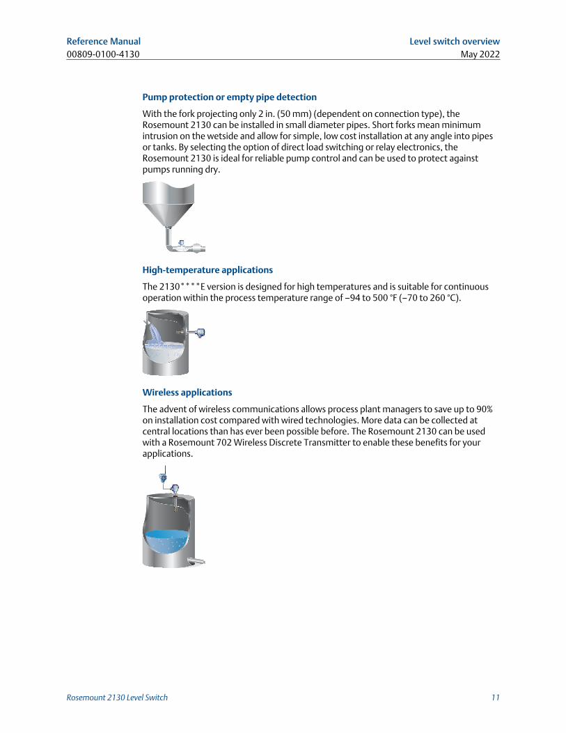
Wireless applications
The advent of wireless communications allows process plant managers to save up to 90%on installation cost compared with wired technologies. More data can be collected atcentral locations than has ever been possible before. The Rosemount 2130 can be usedwith a Rosemount 702 Wireless Discrete Transmitter to enable these benefits for yourapplications.
Reference Manual Level switch overview00809-0100-4130 May 2022
Rosemount 2130 Level Switch 11

Hygienic applications
With the highly polished forks option providing a surface finish (Ra) better than 0.4 μm,the Rosemount 2130 meets the most stringent hygienic requirements used in food andbeverage, and pharmaceutical applications. The Rosemount 2130 is robust enough toeasily withstand CIP (Clean-In- Place) and SIP (Steam-In-Place) cleaning routines.
2.5 Components of the level switchFigure 2-1 shows the components of a Rosemount 2130.
Figure 2-1: Rosemount 2130 Features
C, D
E
A, B
G, H, I
F
J
K
A. Direct Load, DPCO Relay, Fault + Alarm (2 x SPCO) Relays, PLC/PNP, NAMUR, or 8/16 mAelectronics
B. Mode switch, adjustable time delay, and 'heartbeat' LEDC. Housings in aluminum or 316 stainless steelD. Magnetic test pointE. Thermal tube in 316/316L stainless steel (2130****E version only)F. Threaded, flanged, or Tri Clamp process connectionsG. ‘Fast drip’ fork designH. Wetted material in 316/316L stainless steel, Alloy C and Alloy C-276, or ECTFE-coated
316/316L stainless steelI. Short fork length or extensions up to 157.5-in. (4 m)J. Two cable/ conduit entries
K. External ground screw
Level switch overview Reference ManualMay 2022 00809-0100-4130
12 Reference Manual

2.5.1 Short fork technologyUsing short-fork technology, the device can be used in almost all liquid applications.Extensive research has maximized the operational effectiveness of the fork design, makingit suitable for most liquid mediums including coating liquids, aerated liquids, and slurries.
2.5.2 Fork designThe “fast drip” design allows the liquid to be quickly drawn away from the fork tip, makingthe Rosemount 2130 quicker and more responsive in high density or viscous liquidapplications.
Figure 2-2: “Fast drip” forks
2.5.3 Instrument health monitor and continuous self-checkThe Rosemount 2130 continuously performs instrument health diagnostics to self-checkthe condition of the fork and sensor. These diagnostics can detect damage to the forksincluding corrosion, internal or external damage to the forks, and breakages to theinternal wiring.
Detected damage will trigger the 'heartbeat' LED to pulse intermittently, followed by safehandling of the electrical load.
2.5.4 Heartbeat LEDEach electronics cassette of the level switch has a ‘heartbeat’ LED indicating its operationstatus. The LED flashes when the level switch output is ‘off’ and is constantly lit when 'on'.
The LED gives a constant indication that the level switch is functioning correctly (differentflash rates are used to indicate a product malfunction) and gives a local indication of theprocess state.
2.5.5 Mode switch and adjustable output delayA mode switch on the electronics cassette allows the level switch output to be 'on' or 'off'when the forks are wet or dry. Typically is set to 'dry on' (for a low-level point alarm) or 'weton' (for a high-level point alarm). There is also a user-selectable time delay (0.3, 1, 3, 10, or30 seconds) on the electronics cassette to virtually eliminate the risk of false switching inturbulent or splashing applications.
Reference Manual Level switch overview00809-0100-4130 May 2022
Rosemount 2130 Level Switch 13

2.5.6 Magnetic test pointA magnetic test point is located on the side of the housing, allowing a functional test ofthe Rosemount 2130 and a system connected to it. Holding a magnet to the test pointcauses the output to change state.
2.5.7 Electrical connectionsThe terminal blocks extend above the housing and give easy terminal access. Electricalprotections make electrical hook-up safe and easy.
Level switch overview Reference ManualMay 2022 00809-0100-4130
14 Reference Manual

3 Mechanical installation
3.1 Safety messagesInstructions and procedures in this section may require special precautions to ensure thesafety of the personnel performing the operations. Information that potentially raisessafety issues is indicated by a warning symbol ( ). Refer to the following safety messagesbefore performing an operation preceded by this symbol.
WARNING
Failure to follow safe installation and servicing guidelines could result in death orserious injury.
Ensure the level switch is installed by qualified personnel and in accordance withapplicable code of practice.
Use the level switch only as specified in this manual. Failure to do so may impair theprotection provided by the level switch.
The weight of a level switch with a heavy flange and extended fork length may exceed 37lb. (18 kg). A risk assessment is required before carrying, lifting, and installing the levelswitch.
Repair, e.g. substitution of components, etc. may jeopardize safety and is under nocircumstances allowed.
WARNING
Explosions could result in death or serious injury.
Verify the operating atmosphere of the level switch is consistent with the appropriatehazardous locations certifications.
Before connecting a handheld communicator in an explosive atmosphere, ensure theinstruments are installed in accordance with intrinsically safe or non-incendive field wiringpractices.
In explosion-proof/flameproof and non-incendive installations, do not remove the housingcover when power is applied to the level switch.
The housing cover must be fully engaged to meet flameproof/explosion-proofrequirements.
Reference Manual Mechanical installation00809-0100-4130 May 2022
Rosemount 2130 Level Switch 15

WARNING
Electrical shock could cause death or serious injury.
Avoid contact with the leads and terminals. High voltage that may be present on leads cancause electrical shock.
Ensure the power to the level switch is off, and the lines to any other external powersource are disconnected or not powered while wiring the level switch.
Ensure the wiring is suitable for the electrical current and the insulation is suitable for thevoltage, temperature, and environment.
WARNING
Process leaks could result in death or serious injury.
Ensure the level switch is handled carefully. If the process seal is damaged, gas mightescape from the vessel (tank) or pipe.
WARNING
Physical access
Unauthorized personnel may potentially cause significant damage to and/ormisconfiguration of end users’ equipment. This could be intentional or unintentional andneeds to be protected against.
Physical security is an important part of any security program and fundamental toprotecting your system. Restrict physical access by unauthorized personnel to protect endusers’ assets. This is true for all systems used within the facility.
CAUTION
Hot surfaces
The flange and process seal may be hot at high process temperatures. Allow to cool beforeservicing.
3.2 Installation considerationsBefore installing the level switch, review the safety, environmental, application, and pre-installation sections.
3.2.1 Environmental considerationsThe Rosemount 2130 is weatherproof and protected against the ingress of dust, but mustbe protected from flooding. Avoid installing the level switch near heat sources.
Mechanical installation Reference ManualMay 2022 00809-0100-4130
16 Reference Manual

Figure 3-1: Environmental Considerations
OKOK
3.2.2 Application considerationsThe Rosemount 2130 is a wired point-level device for use on open or closed vessels (tanks)and in pipework containing liquid mediums.
For most liquids, including coating, aerated liquids and slurries, the function is virtuallyunaffected by flow, turbulence, bubbles, foam, vibration, solid particles, build-up, orproperties of the liquid medium.
Avoid process medium build-up on the forksAvoid situations where a drying and coating process medium may create an excessivebuild-up or implement preventative maintenance programs to ensure the build-up is notenough to impair performance (see Figure 3-2).
Reference Manual Mechanical installation00809-0100-4130 May 2022
Rosemount 2130 Level Switch 17

Always ensure:
• There is sufficient distance between build-up on the tank wall and the fork.
• There is no risk of ‘bridging’ the level switch forks.Examples of products that can create ‘bridging’ of forks and impair performance aredense paper slurries and bitumen.
Figure 3-2: Avoid Product Build-up
OK
Operating temperature and pressure rangesEnsure the process is operating within the instrument operating temperature and pressureranges.
Liquid density requirements
Minimum standard density is 37.5 lb/ft3 (600 kg/m3).
Minimum density is 31.2 lb/ft3 (500 kg/m3 when ordered with the Low Density Rangeoption.
Liquid viscosity rangeUp to 10000 cP (centiPoise) when operating in the Normal mode.
Up to Up to 1000 cP (centiPoise) when operating in Self-check mode.
Solids content in the liquid mediumAs a guideline, the maximum solid particle diameter in the liquid process medium is 0.2 in.(5 mm). Extra consideration is needed when solid particles are bigger than 0.2 in. (5 mm)and advice should be sought from Emerson.
FoamsIn almost all cases, the Rosemount 2130 is insensitive to foams (i.e. does not see thefoam).
However in rare occasions, some very dense foams may be seen as liquid; known examplesof this are found in ice-cream and orange juice manufacturing.
Mechanical installation Reference ManualMay 2022 00809-0100-4130
18 Reference Manual

Switching pointThe switching point varies with different liquid densities. The switching point (SP) andhysteresis (HY) for water are shown in Figure 3-3.
Figure 3-3: Switching Point in Inches (Millimeters)
SP
HYSP
0.5(13)
0.1(2.5)
0.5(13)
NoteWhen mounted vertically, a low density medium has a switching point closer to theprocess connection. A high density medium has a switching point closer to fork tip.
3.2.3 Pre-installation considerationsMeasurement accuracy is dependent upon the proper installation of the device. Keep inmind the need for easy access, personnel safety, practical field calibration, and a suitableenvironment for the device.
Device identificationTo identify a version of the level switch, see the labels on the housing and on theelectronics cassette inside the housing.
How to handle a level switchHandle the level switch with great care.
The weight of the level switch with a heavy flange and extended fork length may exceed37 lb. (18 kg). A risk assessment is required to be done before carrying, lifting, andinstalling the level switch.
Use both hands to carry the extended length and high temperature versions, and do nothold a level switch by the forks (see Figure 3-4).
Reference Manual Mechanical installation00809-0100-4130 May 2022
Rosemount 2130 Level Switch 19

Figure 3-4: Handling
Make no alterations to the level switchNever make any alterations to the mechanical or electrical features of the level switch.
Figure 3-5: Make No Alterations
Allow adequate space outside tank or pipeMount the level switch so that it is removable and allow easy access to the wiring terminalswhen the top cover is removed. Ensure there is also enough room for fitting cable glandsand cables.
A clearance of 1.2 in. (30 mm) is required for the top cover to be removed.
NoteThe electronics housing cannot be rotated to assist with the cabling.
Covers installationEnsure a proper seal by installing the electronics housing cover so that metal contactsmetal. Always use Emerson's O-rings.
Mounting orientationMount the Rosemount 2130 at any angle that allows the level of the process medium torise, fall, or flow through the fork gap.
Mechanical installation Reference ManualMay 2022 00809-0100-4130
20 Reference Manual

Related information
Correct fork alignment
Insulation
Figure 3-6: Insulation
OK
2130***E
2130***E
2130***M
D
C C
A
A
E
B
B
A. 2.1 in. (55 mm)B. ROCKWOOL® surrounds the Rosemount 2130C. 3.9 in. (100 mm) clearance all aroundD. 5.9 in. (150 mm)E. ROCKWOOL
Pipe installation requirements• The inside pipe diameter (D) must be 1.4 in. (35 mm) or larger.
• Ensure the fork tines intrude at least 0.9 in. (22 mm) into the pipe.
• Keep at least 0.3 in. (7 mm) of clearance between the fork tines and the pipe wall.
Figure 3-7: Pipe Installation
DA B
A. Minimum intrusion 0.9 in. (22 mm)B. Minimum clearance 0.3 in. (7 mm)
Reference Manual Mechanical installation00809-0100-4130 May 2022
Rosemount 2130 Level Switch 21

Other recommendations• Always install in the normally “on” state.
— High-level alarm: recommended Mode setting is Dry = on.
— Low-level alarm: recommended Mode setting is Wet = on.
• Avoid:
— Installing near to liquid entering the tank at the filling-point.
— Heavy splashing on the forks.
Increasing the sensor output delay reduces accidental detection caused by splashing.
• Always ensure:— The overall system is tested during commissioning by using the local magnetic test
point.
— The installation does not create tank crevices around the forks where a liquidmedium may collect. This event can happen with high-viscosity and high-densityliquids.
— The forks do not come into contact with the vessel (tank) or pipe wall, internalfittings, or any other obstructions.
• Extra consideration is needed if the plant vibration is close to the 1400 Hz operatingfrequency of the fork.
Required supports for extended fork
Supporting the extended fork avoids long fork length vibration.
Figure 3-8: Vertical Installation (Standard)
A B
B
A. Maximum 3.28 ft. (1.0 m)B. 3.28 ft. (1.0 m)
Mechanical installation Reference ManualMay 2022 00809-0100-4130
22 Reference Manual

Figure 3-9: Vertical Installation (Marine GL Approved)
AB
B
B
C
A. Maximum 1.3 ft. (0.4 m)B. 2.3 ft. (0.7 m)C. 0.65 ft. (0.2 m)
Figure 3-10: Horizontal Installation (Standard)
A
B B
A. Maximum 3.28 ft. (1.0 m)B. 3.28 ft. (1.0 m)
Reference Manual Mechanical installation00809-0100-4130 May 2022
Rosemount 2130 Level Switch 23

Figure 3-11: Horizontal Installation (Marine GL Approved)
A
BC B B
A. Maximum 1.3 ft. (0.4 m)B. 2.3 ft. (0.7 m)C. 0.65 ft. (0.2 m)
Mechanical installation Reference ManualMay 2022 00809-0100-4130
24 Reference Manual

3.3 Installation procedures
3.3.1 Process connection seals
Figure 3-12: Process Connection Seals
F
B
AC
D
E
A. PTFE tapeB. NPT or BSPT (R) threadC. GasketD. BSPP (G) threadE. Tri ClampF. The Tri Clamp seal is supplied in an accessory kit
3.3.2 Correct fork alignment
Fork alignment in a vessel (tank) installationThe fork is correctly aligned by positioning the groove or notch as indicated (Figure 3-13).
Figure 3-13: Correct Fork Alignment for Vessel (Tank) Installation
OKOK
OK
AB
C
A. Tri Clamp process connections have a circular notchB. Threaded process connections have a grooveC. Flanged process connections have a circular notch
Reference Manual Mechanical installation00809-0100-4130 May 2022
Rosemount 2130 Level Switch 25

Fork alignment in a pipe installationThe fork is correctly aligned by positioning the groove or notch as indicated (Figure 3-14).
Figure 3-14: Correct Fork Alignment for Pipe Installation
OK
OK
AB
AB
A. Tri Clamp process connections have a circular notchB. Threaded process connections have a groove
3.3.3 Mounting the threaded version
Threaded vessel (tank) or pipework connection
Procedure
1. Seal and protect the threads. Use anti-seize paste or PTFE tape according to siteprocedures.
A gasket may be used as a sealant for BSPP (G) threaded connections.
Mechanical installation Reference ManualMay 2022 00809-0100-4130
26 Reference Manual

2. Screw the level switch into the process connection.
NoteTighten using the hexagon nut only.
Figure 3-15: Vertical Installation
A
A. Gasket for BSPP (G) threaded connection
Figure 3-16: Horizontal Installation
A
A. Gasket for BSPP (G) threaded connection
Threaded flange connection
Procedure
1. Place the customer-supplied flange and gasket on the vessel (tank) nozzle.
A
A. Gasket (customer supplied)
Reference Manual Mechanical installation00809-0100-4130 May 2022
Rosemount 2130 Level Switch 27

2. Tighten the bolts and nuts with sufficient torque for the flange and gasket.
3. Seal and protect the threads. Use anti-seize paste or PTFE tape according to siteprocedures.
A gasket may be used as a sealant for BSPP (G) threaded connections.
4. Screw the level switch into the flange thread.
NoteTighten using the hexagon nut only.
A
A. Gasket for BSPP (G) threaded connection
Mechanical installation Reference ManualMay 2022 00809-0100-4130
28 Reference Manual

3.3.4 Mounting the flanged versionProcedure
1. Lower the level switch into the nozzle.
A
A. Gasket (customer supplied)
2. Tighten the bolts and nuts with sufficient torque for the flange and gasket.
Reference Manual Mechanical installation00809-0100-4130 May 2022
Rosemount 2130 Level Switch 29

3.3.5 Mounting the Tri Clamp versionProcedure
1. Lower the level switch into the flange face.
A
A. Seal (supplied with Tri Clamp)
2. Fit the Tri Clamp.
Mechanical installation Reference ManualMay 2022 00809-0100-4130
30 Reference Manual

4 Electrical installation
4.1 Safety messagesInstructions and procedures in this section may require special precautions to ensure thesafety of the personnel performing the operations. Information that potentially raisessafety issues is indicated by a warning symbol ( ). Refer to the following safety messagesbefore performing an operation preceded by this symbol.
WARNING
Failure to follow safe installation and servicing guidelines could result in death orserious injury.
Ensure the level switch is installed by qualified personnel and in accordance withapplicable code of practice.
Use the level switch only as specified in this manual. Failure to do so may impair theprotection provided by the level switch.
The weight of a level switch with a heavy flange and extended fork length may exceed 37lb. (18 kg). A risk assessment is required before carrying, lifting, and installing the levelswitch.
Repair, e.g. substitution of components, etc. may jeopardize safety and is under nocircumstances allowed.
WARNING
Explosions could result in death or serious injury.
Verify the operating atmosphere of the level switch is consistent with the appropriatehazardous locations certifications.
Before connecting a handheld communicator in an explosive atmosphere, ensure theinstruments are installed in accordance with intrinsically safe or non-incendive field wiringpractices.
In explosion-proof/flameproof and non-incendive installations, do not remove the housingcover when power is applied to the level switch.
The housing cover must be fully engaged to meet flameproof/explosion-proofrequirements.
Reference Manual Electrical installation00809-0100-4130 May 2022
Rosemount 2130 Level Switch 31

WARNING
Electrical shock could cause death or serious injury.
Avoid contact with the leads and terminals. High voltage that may be present on leads cancause electrical shock.
Ensure the power to the level switch is off, and the lines to any other external powersource are disconnected or not powered while wiring the level switch.
Ensure the wiring is suitable for the electrical current and the insulation is suitable for thevoltage, temperature, and environment.
WARNING
Process leaks could result in death or serious injury.
Ensure the level switch is handled carefully. If the process seal is damaged, gas mightescape from the vessel (tank) or pipe.
WARNING
Physical access
Unauthorized personnel may potentially cause significant damage to and/ormisconfiguration of end users’ equipment. This could be intentional or unintentional andneeds to be protected against.
Physical security is an important part of any security program and fundamental toprotecting your system. Restrict physical access by unauthorized personnel to protect endusers’ assets. This is true for all systems used within the facility.
CAUTION
Hot surfaces
The flange and process seal may be hot at high process temperatures. Allow to cool beforeservicing.
4.2 Prepare the electrical connections
4.2.1 Cable selectionUse 26–14 AWG (0.13 to 2.5 mm2) AWG wiring. Twisted-pairs and shielded wiring isrecommended for environments with high EMI (electromagnetic interference). Two wirescan be safely connected to each terminal screw.
Electrical installation Reference ManualMay 2022 00809-0100-4130
32 Reference Manual

4.2.2 Cable glands/conduitsFor intrinsically safe, explosion-proof/flameproof, and dust-proof installations, only usecertified cable glands or conduit entry devices. Ordinary location installations can usesuitably rated cable glands or conduit entry devices to maintain the Ingress Protection (IP)rating.
Unused conduit entries must always be sealed with a suitably rated blanking/stoppingplug.
NoteDo not run signal wiring in conduit or open trays with power wiring or near heavy electricalequipment.
4.2.3 Power supplyThe power supply requirements are dependent on the electronics selected.
• Direct load switching electronics: 20 - 60 Vdc or 20 - 264 Vac (50/60 Hz)
• PNP/PLC electronics: 20 - 60 Vdc
• Relay DPCO (Double Pole Changeover) electronics:20 - 60 Vdc or 20 - 264 Vac (50/60 Hz)
• Fault and alarm relays (2 x SPCO) electronics: 20 - 60 Vdc or 20 - 264 Vac (50/60 Hz)
• NAMUR electronics: 8 Vdc
• 8/16 mA electronics: 24 Vdc
4.2.4 Hazardous areasWhen the device is installed in hazardous areas (classified locations), local regulations andthe conditions-of-use specified in applicable certificates must be observed. Review theRosemount 2130 Product Certifications document for information.
4.2.5 Wiring diagrams CAUTION
• Before use, check the cable glands and blanking plugs are suitably rated.
• Isolate supply before connecting the switch or removing the electronics.
• The Protective Earth (PE) terminal must be connected to an external earthingsystem.
NoteWhen replacing a cassette, it is important to re-calibrate.
Reference Manual Electrical installation00809-0100-4130 May 2022
Rosemount 2130 Level Switch 33

Direct load switching cassette
Figure 4-1: Direct Load Switching (2-wire) Cassette (Red Label) – Code L
1 2 3
LN
0V
Fuse 2A(T)R
IL
DPST
+V
R = External load (must be fitted)
N = Neutral
L = Live
NoteA DPST (Double Pole, Single Throw) on/off switch must be fitted for safe disconnection ofthe power supply. Fit the DPST switch as near as possible to the level switch. Keep theDPST switch free of obstructions. Label the DPST switch to indicate it is the supplydisconnection device for the level switch.
NoteThe Rosemount 2130 requires a minimum current to operate (IOFF), which continues toflow when the output is ‘off’. If selecting a relay to wire in series with the Rosemount 2130,ensure the drop-out voltage of the relay is greater than the voltage generated across therelay coil when IOFF flows through it.
Table 4-1: Electrical Parameters
Parameter Value
U 20 - 60 Vdc or 20 - 264 Vac (50/60 Hz)
IOFF < 4 mA
IL 20 - 500 mA
IPK 5 A, 40 ms (inrush)
Electrical installation Reference ManualMay 2022 00809-0100-4130
34 Reference Manual

Table 4-2: Direct Load Functions
Mode: dry on, high level alarm Mode: wet on, low level alarm
1 2
ILR
N0 V
L+ V
F
3
DPST
U12 V
1 2
ILR
N0 V
L+ V
F
3
DPST
< 4 mA
1 2
ILR
N0 V
L+ V
F
3
DPST
U12 V
1 2
ILR
N0 V
L+ V
F
3
DPST
< 4 mA
LED on continuously LED flashes every second LED on continuously LED flashes every second
= Load on
= Load off
Reference Manual Electrical installation00809-0100-4130 May 2022
Rosemount 2130 Level Switch 35

PNP/PLC cassette
Figure 4-2: PNP/PLC (3-wire) Cassette (Yellow Label) – Code P
Wet On Mode
+V
1 2 3 4
O/P 0V
F
F = Fuse 2A(T)
Table 4-3: Electrical Parameters
Parameter Value
U 20 - 60 Vdc
I < 4 mA + IL
I L (OFF) < 100 μA
IL(MAX) 0 - 500 mA
IPK 5 A, 40 ms (inrush)
UOUT(ON) U - 2.5 Vdc (20 °C)
U - 2.75 Vdc (-40 to 80 °C)
Electrical installation Reference ManualMay 2022 00809-0100-4130
36 Reference Manual

Table 4-4: PNP/PLC Cassette Functions
Mode: dry on, high level alarm Mode: wet on, low level alarm
PLC (positive input)
1 2
-I/P
PLC
+
3 4
IL
< 3 VU
1 2
-I/P
PLC
+
3 4
IL
<100 μA
1 2
-I/P
PLC
+
3 4
IL
< 3 VU
1 2
-I/P
PLC
+
3 4
IL
<100 μA
PNP dc
1 2
-+
3 4
R
F
< 3 VU
IL
1 2
-+
3 4
R
FIL
<100 μA
1 2
-+
3 4
R
F
< 3 VU
IL
1 2
-+
3 4
R
FIL
<100 μA
LED
LED on continuously LED flashes every second LED on continuously LED flashes every second
Reference Manual Electrical installation00809-0100-4130 May 2022
Rosemount 2130 Level Switch 37

Relay DPCO cassette (standard version)
Figure 4-3: Relay DPCO Cassette, Standard Version (Green Label) – Code D
NOCNC
REL
AY
LN NOCNC
OPERATION MODEDry On
DryWet
Wet On
DryWet
Dry On Wet OnSeconds Delay
3010
31
0.3 0.3
3010
31
Isolate Supply Before Removing Warning
LN
0V
Fuse 0.5 (T)
DPST
+V
1 2 3 4 5 6 7 8 9
NC C NO NC C NO
NoteA DPST (Double Pole, Single Throw) on/off switch must be fitted for safe disconnection ofthe power supply. Fit the DPST switch as near as possible to the level switch. Keep theDPST switch free of obstructions. Label the DPST switch to indicate it is the supplydisconnection device for the level switch.
Table 4-5: Electrical Parameters
Parameter Value
U 20 - 60 Vdc or 20 - 264 Vac (50/60Hz)
I < 6 mA
Table 4-6: NC, C, and NO Terminals
Parameter Resistive load Inductive load
cos ϕ 1 0.4
L/R 0 ms 7 ms
IMAX 5 A 3.5 A
UMAX ac 250 V 250 V
dc 30 V 30 V
PMAX ac 1250 VA 875 VA
dc 240 W 170 W
Electrical installation Reference ManualMay 2022 00809-0100-4130
38 Reference Manual

Table 4-7: Relay Cassette Functions
Mode: dry on, high level alarm Mode: wet on, low level alarm
NC C NO NC C NO NC C NO NC C NO NC C NO NC C NO NC C NO NC C NO
LED on continuously LED flashes every second LED on continuously LED flashes every second
Reference Manual Electrical installation00809-0100-4130 May 2022
Rosemount 2130 Level Switch 39

Fault and alarm relays (2 x SPCO) cassette
Figure 4-4: Fault and Alarm Relay Outputs Cassette (Light Green Label) – Code D withOption R2264
NC C NO NC C NO
N
Fuse 0.5 (T)
DPST
Live
0V +V
NoteA Double Pole, Single Throw on/off switch must be fitted for safe disconnection of thepower supply. Fit the DPST switch as near as possible to the level switch. Keep the DPSTswitch free of obstructions. Label the DPST switch to indicate it is the supply disconnectiondevice for the level switch.
Table 4-8: Electrical Parameters
Parameter Value
U 20 - 60 Vdc or 20 - 264 Vac (50/60Hz)
I < 6 mA
Table 4-9: NC, C, and NO Terminals
Parameter Resistive load Inductive load
cos ϕ 1 0.4
L/R 0 ms 7 ms
IMAX 5 A 3.5 A
UMAX ac 250 V 250 V
dc 30 V 30 V
PMAX ac 1250 VA 875 VA
dc 240 W 170 W
Electrical installation Reference ManualMay 2022 00809-0100-4130
40 Reference Manual

Table 4-10: Relay Cassette Functions
Mode: dry on, high level alarm Mode: wet on, low level alarm
(No alarm) (No fault) (Alarm) (No fault) (No alarm) (No fault) (Alarm) (No fault)
NC C NO NC C NO NC C NO NC C NO NC C NO NC C NO NC C NO NC C NO
LED on continuously LED flashes every second LED on continuously LED flashes every second
Reference Manual Electrical installation00809-0100-4130 May 2022
Rosemount 2130 Level Switch 41

NAMUR cassette
Figure 4-5: NAMUR Cassette (Light Blue Label) – Code N
A+-
A. A certified intrinsically safe isolating amplifier to IEC 60947-5-6
Note• This cassette is suitable for Intrinsically Safe (IS) applications and requires a certified
isolating barrier. See the Rosemount 2130 Product Certifications document forIntrinsically Safe approvals.
• This electronics cassette is also suitable for non-hazardous (safe) area applications.
• It can only be interchanged with the 8/16 mA cassette.
• Do not exceed 8 Vdc.
Table 4-11: Electrical Parameters
Parameter Value
ION 2.2 - 2.5 mA
IOFF 0.8 - 1.0 mA
IFAULT < 1.0 mA
Electrical installation Reference ManualMay 2022 00809-0100-4130
42 Reference Manual

Table 4-12: NAMUR Cassette Functions
Mode: dry on, high level alarm Mode: wet on, low level alarm
1 2
> 2.2 mA
(-) (+)1 2
< 1.0 mA
(-) (+)1 2
> 2.2 mA
(-) (+)1 2
< 1.0 mA
(-) (+)
LED on continuously LED flashes every second LED on continuously LED flashes every second
Reference Manual Electrical installation00809-0100-4130 May 2022
Rosemount 2130 Level Switch 43

8/16 mA cassette
Figure 4-6: 8/16 mA Cassette (Dark Blue Label) – Code M
1 2 3
A+-
A. A certified intrinsically safe isolating amplifier to IEC 60947-5-6
Note• This cassette is suitable for Intrinsically Safe (IS) applications and requires a certified
isolating barrier. See the Rosemount 2130 Product Certifications document forIntrinsically Safe approvals.
• This electronics cassette is also suitable for non-hazardous (safe) area applications. Inthis case, U = 11 - 36 Vdc.
• It can only be interchanged with a NAMUR cassette.
Table 4-13: Electrical Parameters
Parameter Value
U 24 Vdc Nominal
ION 15 - 17 mA
IOFF 7.5 - 8.5 mA
IFAULT < 3.7 mA
Electrical installation Reference ManualMay 2022 00809-0100-4130
44 Reference Manual

Table 4-14: 8/16 mA Cassette Functions
Mode: dry on, high level alarm Mode: wet on, low level alarm
2(-) (+)
31
> 15 mA
2(-) (+)
31
< 8.5 mA
2(-) (+)
31
> 15 mA
2(-) (+)
31
< 8.5 mA
LED on continuously LED flashes every second LED on continuously LED flashes every second
Reference Manual Electrical installation00809-0100-4130 May 2022
Rosemount 2130 Level Switch 45

Fault condition detection (self-check mode only)When a fault condition is detected in the self-check operating mode, the heartbeat LEDflashes once every half a second and every third flash is missed. The output from the levelswitch will then be as Table 4-15.
Table 4-15: Fault Condition Detection (Self-check Mode Only)
Direct load PLC PNP dc
ILR
N0 V
L+ V
Fuse2A(T)
DPST
< 4 mA
1 2 3
(=Fault)
1 2
-I/P
PLC
+
3 4
IL
< 100 μA
(=Fault)
1 2 3 4
IL
Fuse1A(T)
R
< 100 μA
(+) (-)
(=Fault)
DPCO relay NAMUR 8/16 mA
NC C NO NC C NO
(=Fault)
1 2
< 1.0 mA
(+)(-)
(=Fault)
< 3.7 mA
1 2 3
(+)(-)
(=Fault)
Fault and alarm (2 x SPCO) relays
Alarm relay
NC C NO
(=No alarm)
Fault relay
NC C NO
(=Fault)
= Load on
= Load off
4.2.6 GroundingMake sure grounding is done according to national and local electrical codes. Failure to doso may impair the protection provided by the equipment.
Signal cable shield groundingMake sure the instrument cable shield is:
• Trimmed close and insulated from touching the housing.
Electrical installation Reference ManualMay 2022 00809-0100-4130
46 Reference Manual

• Continuously connected throughout the segment.
• Connected to a good earth ground at the power supply end.
Figure 4-7: Signal Cable Shield Grounding at Power Supply End
B
A
CCD
B
A. Trim shield and insulateB. Minimize distanceC. Trim shieldD. Connect shield back to the power supply ground
Grounding the housingThe most effective grounding method for the metal housing is a direct connection toearth ground with minimal impedance. Housings with NPT conduit entries do not have anearth ground point and must use the fork earth.
Figure 4-8: Ground Screws
A
A. External ground screw
4.3 Connect wiring and power upProcedure
1. Verify the power supply is disconnected.
Reference Manual Electrical installation00809-0100-4130 May 2022
Rosemount 2130 Level Switch 47

2. Remove the field terminals cover.
In an explosion-proof/flameproof installation, do not remove the level switch coverwhen power is applied to the unit. The cover must also not to be removed inextreme environmental conditions.
Versions of the Rosemount 2130 with explosion-proof/flameproof approvals have acover-lock to be undone first.
3. Remove the plastic plugs.
4. Pull cables through the cable gland/conduits.
Cassettes with a single terminal only require one cable.
Identification of thread size and type:¾-in. ANPTM20 x 1.5
M20
5. Connect the cable wires (see Wiring diagrams for other cassettes).
6. Ensure proper grounding.
Electrical installation Reference ManualMay 2022 00809-0100-4130
48 Reference Manual

7. Tighten the cable glands.
Apply PTFE tape or other sealant to the threads.
NoteMake sure to arrange the wiring with a drip loop.
8. Plug and seal the unused conduit connection to avoid moisture and dustaccumulation inside the housing.
Apply PTFE tape or other sealant to the threads.
9. Attach and tighten the cover.
Make sure the cover is fully engaged.
10. Required for explosion-proof/flameproof installations only:
The cover must be fully engaged to comply with explosion-proof requirements.
11. Re-lock the cover.
Reference Manual Electrical installation00809-0100-4130 May 2022
Rosemount 2130 Level Switch 49

12. Connect the power supply.
Electrical installation Reference ManualMay 2022 00809-0100-4130
50 Reference Manual

5 Operation
5.1 Output mode and time delayAll electronics cassettes have a rotating switch for setting the output to be "Dry On" (onwhen the fork is sufficiently dry) or "Wet On" (on when the fork is sufficiently wet).
The electronics uses hysteresis to help prevent constant switching of the output from dry-to-wet and wet-to-dry states due to splashing or intermediate conditions. To furtherprevent false switching, the rotating switch also sets a time delay of up to 30 secondsbefore the output changes.
A small cut-out in the rotating switch indicates the present mode and time delay.
Figure 5-1: Top-down View: Example Cassette Inside Housing
OPERATION MODE
Dry On Mode
Dry
Wet
Wet On Mode
Dry
Wet
Dry On Wet On
Seconds Delay
0.3 0.3
3
30
10
1
3
30
10
1
1 2 3
OUT+ -
4
PLC/PNP
Isolate Supply
Before Removing
A B
A. 'Heartbeat' LEDB. Rotating switch for setting output mode and time delay
The recommended mode for high level alarm installations is the "Dry On" mode (Figure5-2).
Figure 5-2: Typical Settings for High Level Applications
Dry On Wet On
Seconds Delay
0.3 0.3
3
30
10
1
3
30
10
1
A
A. Mode “Dry On” and 1 second time delay
The "Wet On" mode is recommended for low level alarm installations (Figure 5-3).
Reference Manual Operation00809-0100-4130 May 2022
Rosemount 2130 Level Switch 51

Figure 5-3: Typical Settings for Low Level Applications
Dry On Wet On
Seconds Delay
0.3 0.3
30
10
3
30
10
1
3
1
A
A. Mode “Wet On” and 1 second time delay
5.1.1 Set the mode switch and switching time delayProcedure
1. Select “Dry on” or “Wet on” mode.
2. Select 0.3, 1, 3, 10, or 30 seconds for the delay before switching output state.
NoteThere is a five second delay before changes to the mode and time delay becomeactive.
5.2 LED indication statusTable 5-1 shows the different operation statuses and how they are indicated by the LED.
Table 5-1: LED Indications
LED flash rate Switch status
Continuous Output state is on.
1 every ½ second, and everythird flash is missing.
External damage to forks, corroded forks,internal wire damage, or internal sensor damage(self-check mode only).
1 every second Output state is off.
1 every 2 seconds Uncalibrated.
1 every 4 seconds Load fault; load current too high; load shortcircuit.
2 times / second Indication of successful calibration.
3 times / second Internal PCB fault.
Off Problem (e.g. supply).
Operation Reference ManualMay 2022 00809-0100-4130
52 Reference Manual

5.3 Set the operating modeAll versions of the level switch have two operating modes:
• Normal mode (red LED)
• Self-check mode (yellow LED)
Procedure
1. Set the mode switch to 1 s Dry On (or 1 s Wet On).
2. Wait for 10 seconds.
3. Move the mode switch to 30 s Dry On (or 30 s Wet On), and wait for 1 secondbefore moving the mode switch back to 1 s Dry On (or 1 s Wet On). This should becompleted within 3 seconds.
Figure 5-4: Change Operating Mode
Dry On Wet On
Seconds Delay
0.3 0.3
3
30
10
1
3
30
10
1
Dry On Wet On
Seconds Delay
0.3 0.3
3
30
10
1
3
30
10
1
Dry On Wet On
Seconds Delay
0.3 0.3
3
30
10
1
3
30
10
1
A
B
A. 10 secondsB. < 3 seconds
5.3.1 LED indication for operating modesDifferent LED colors indicate the operating mode (Table 5-2).
Table 5-2: LED Indications – Operating Mode
LED color Operating modes Description of mode
Red Normal When the LED is red and flashing, it indicates that theRosemount 2130 may be uncalibrated, successfullycalibrated, has an electrical load problem, or has an internalPCB fault.
Yellow Self-check When the LED is yellow and flashing, it indicates the same asNormal mode, but also indicates there could be externaldamage to forks, corroded forks, or internal sensor damage.
NoteFor SIL 2 compliance, self-check mode must be enabled.
Related information
Rosemount 2130 Safety Manual
Reference Manual Operation00809-0100-4130 May 2022
Rosemount 2130 Level Switch 53

Operation Reference ManualMay 2022 00809-0100-4130
54 Reference Manual

6 Service and troubleshooting
6.1 Safety messagesInstructions and procedures in this section may require special precautions to ensure thesafety of the personnel performing the operations. Information that potentially raisessafety issues is indicated by a warning symbol ( ). Refer to the following safety messagesbefore performing an operation preceded by this symbol.
WARNING
Failure to follow safe installation and servicing guidelines could result in death orserious injury.
Ensure the level switch is installed by qualified personnel and in accordance withapplicable code of practice.
Use the level switch only as specified in this manual. Failure to do so may impair theprotection provided by the level switch.
The weight of a level switch with a heavy flange and extended fork length may exceed 37lb. (18 kg). A risk assessment is required before carrying, lifting, and installing the levelswitch.
Repair, e.g. substitution of components, etc. may jeopardize safety and is under nocircumstances allowed.
WARNING
Explosions could result in death or serious injury.
Verify the operating atmosphere of the level switch is consistent with the appropriatehazardous locations certifications.
Before connecting a handheld communicator in an explosive atmosphere, ensure theinstruments are installed in accordance with intrinsically safe or non-incendive field wiringpractices.
In explosion-proof/flameproof and non-incendive installations, do not remove the housingcover when power is applied to the level switch.
The housing cover must be fully engaged to meet flameproof/explosion-proofrequirements.
Reference Manual Service and troubleshooting00809-0100-4130 May 2022
Rosemount 2130 Level Switch 55

WARNING
Electrical shock could cause death or serious injury.
Avoid contact with the leads and terminals. High voltage that may be present on leads cancause electrical shock.
Ensure the power to the level switch is off, and the lines to any other external powersource are disconnected or not powered while wiring the level switch.
Ensure the wiring is suitable for the electrical current and the insulation is suitable for thevoltage, temperature, and environment.
WARNING
Process leaks could result in death or serious injury.
Ensure the level switch is handled carefully. If the process seal is damaged, gas mightescape from the vessel (tank) or pipe.
WARNING
Physical access
Unauthorized personnel may potentially cause significant damage to and/ormisconfiguration of end users’ equipment. This could be intentional or unintentional andneeds to be protected against.
Physical security is an important part of any security program and fundamental toprotecting your system. Restrict physical access by unauthorized personnel to protect endusers’ assets. This is true for all systems used within the facility.
CAUTION
Hot surfaces
The flange and process seal may be hot at high process temperatures. Allow to cool beforeservicing.
6.2 Magnetic test pointA magnetic test point is marked on the side of the housing to allow a functional test of theRosemount 2130 in the overall system. By touching a magnet to the target, the outputfrom the level switch will change state while the magnet is present.
Service and troubleshooting Reference ManualMay 2022 00809-0100-4130
56 Reference Manual

Figure 6-1: Magnetic Test-point Function
TP TP
TP
S
N
S
N
A
B
B
A
A. Output offB. Output on
6.3 Visual inspectionVisually examine the level switch and do not use if it is damaged. Check:
• The housing cover, cable glands, and blanking plugs are fitted securely.
Figure 6-2: Visual Inspection
OK
Reference Manual Service and troubleshooting00809-0100-4130 May 2022
Rosemount 2130 Level Switch 57

6.4 MaintenanceFigure 6-3: Maintenance
OK
NoteOnly use a soft type brush for cleaning.
6.5 Troubleshooting
6.5.1 Does not switchSymptom or indication
LED is not lit, no power.
Recommended actions
1. Check the power supply.
2. Check the load on direct load switching electronics model.
Symptom or indication
LED is flashing three times per second.
Recommended actions
Contact Emerson to report an internal PCB fault is being indicated.
Symptom or indication
LED is flashing once every two seconds.
Recommended actions
Contact Emerson to report an uncalibrated device is being indicated.
Service and troubleshooting Reference ManualMay 2022 00809-0100-4130
58 Reference Manual

Symptom or indication
LED is flashing once every four seconds.
Recommended actions
Check the electrical installation for a load fault (current is too high or a short-circuit).
Symptom or indication
Visual inspection found fork damage.
Recommended actions
Contact Emerson to report the damage and discuss how to get a replacement.
Symptom or indication
Visual inspection found thick encrustation on the forks.
Recommended actions
Carefully clean the fork.
Symptom or indication
There is always a five second delay after changing the mode or delay.
Recommended actions
This is a normal function when making any changes to the settings.
Related information
LED indication for operating modes
6.5.2 Incorrect switchingSymptom or indication
Dry = On, Wet = On is set incorrectly.
Recommended actions
Set the correct mode on the electronics cassette.
6.5.3 Faulty switchingSymptom or indication
Turbulence.
Recommended actions
Set a longer switching time delay.
Symptom or indication
Excessive electrical noise.
Reference Manual Service and troubleshooting00809-0100-4130 May 2022
Rosemount 2130 Level Switch 59

Recommended actions
Suppress the cause of the interference.
Symptom or indication
Cassette has been fitted from another level switch.
Recommended actions
Fit the factory supplied cassette and then calibrate.
6.6 Spare partsSee the Rosemount 2130 Product Data Sheet for the latest information about spare parts.
6.7 Replacement and calibration of cassettesWhen replacing a damaged or faulty electronics cassette, it is necessary to calibrate thereplacement cassette to the operating frequency of the fork sensor.
6.7.1 Replace the cassettePrerequisites
If this replacement is taking place in a hazardous area, only qualified personnel shouldperform the replacement. All work in hazardous areas must be carried out in accordanceto national and local codes of practice.
On Intrinsically Safe (I.S.) approved versions of the level switch, it is recommended thatreplacement and calibration is performed in a non-hazardous (safe) area.
Note• In I.S. applications, NAMUR cassettes can only be replaced with NAMUR cassettes, and
8/16 mA cassettes can only be replaced by 8/16 mA cassettes.
• Non-I.S. cassettes can be interchanged with other non-I.S. cassettes, but the new labelmust be fitted and the original part number transferred to the new label.
• Before starting the replacement and calibration procedure, ensure that any controlledprocess will not be adversely affected.
Procedure
1. Isolate and disconnect the power to the Rosemount 2130, and insulate the ends ofthe wires as a safety precaution.
There may be more than one power source connected to a relay cassette.
2. Remove the housing cover and disconnect the wires from the cassette.
Make a note of the connections and mode switch position (see Figure 6-4).
Service and troubleshooting Reference ManualMay 2022 00809-0100-4130
60 Reference Manual

Figure 6-4: Mode Switch Setting (Existing Cassette)
This is an example of how the existing cassette may look. Here, the mode switch isset to “Dry On” with a one second delay.
Take note of the actual setting.
SETTING IS: ____________________________________
3. Remove and retain the two fixing screws from the base of the cassette, and thenunplug the cassette.
4. Plug in the replacement cassette, secure it with the two screws.
5. Reconnect the wiring.
6. Set the mode switch to “Wet On” with a one second delay, ready for calibration (seeFigure 6-5).
Figure 6-5: Mode Switch Setting (Replacement Cassette)
7. Reconnect the power supplies to the Rosemount 2130.
6.7.2 Calibrate the replacement cassettePrerequisites
Some of the calibration sequence steps are time-dependent and must be carried outwithin the noted times. The purpose of the time dependency and switching sequence is toprevent an accidental calibration from occurring.
Verify:
• The sensor forks are clean and dry.
• The mode switch is set to “Wet On” with the time delay set to one second.
Procedure
1. Verify the 'heartbeat' LED is flashing at a rate of one flash per second.
Proceed to Step 5 if it is on continuously.
Reference Manual Service and troubleshooting00809-0100-4130 May 2022
Rosemount 2130 Level Switch 61

2. Apply a magnet to the test-point.After a one second delay, the LED will be lit continuously.
3. Within one second, rotate the mode switch two steps clockwise.
The LED will go out within two seconds.
4. Within three seconds, rotate the mode switch two steps counter-clockwise.Proceed to Step 8.After a two second delay, the LED should start flashing twice per second.
5. Apply a magnet to the test-point.After a one second delay, the LED will flash once every second.
6. Within one second, rotate the mode switch two positions clockwise.
The LED will go out within two seconds.
7. Within three seconds, rotate the mode switch two steps counter-clockwise.After a two second delay, the LED should start flashing twice per second.
8. If the LED is flashing twice per second, the calibration has worked correctly.
a) Remove the magnet from the test-point.
b) After a one second delay, the unit will return to normal operation. Proceed toStep 11.
9. If the LED is flashing once per second or it is on continuously, the calibration hasfailed:
a) Remove the magnet from the test-point.
b) Wait ten seconds, and then re-try from Step 2.
10. If the LED is not lit (after the two seconds delay in Step 7):
a) Check the sensor forks are clean and dry.
b) Check if anything is jamming or touching the sensor forks.
c) Contact Customer Support at Emerson if no fault is found.
11. Set the mode switch to the original setting and wait five seconds.
12. Replace the housing cover and check that the system works.
Related information
Magnetic test point
6.8 Opening the lid (cover)Before opening the lid for maintenance reasons observe following items:
• Do not remove the lid while circuits are live.
• No dust deposits or whirlings are present.
• No rain can enter into the housing.
Service and troubleshooting Reference ManualMay 2022 00809-0100-4130
62 Reference Manual

6.9 Service supportTo expedite the return process outside of the United States, contact the nearest Emersonrepresentative.
Within the United States, call the Emerson Instrument and Valve Response Center usingthe 1-800-654-RSMT (7768) toll-free number. This center, available 24 hours a day, willassist you with any needed information or materials.
The center will ask for product model and serial numbers, and will provide a ReturnMaterial Authorization (RMA) number. The center will also ask for the process material towhich the product was last exposed.
CAUTION
Individuals who handle products exposed to a hazardous substance can avoid injury if theyare informed of and understand the hazard. Returned products must include a copy of therequired Safety Data Sheet (SDS) for each substance.
Emerson Instrument and Valve Response Center representatives will explain the additionalinformation and procedures necessary to return goods exposed to hazardous substances.
Reference Manual Service and troubleshooting00809-0100-4130 May 2022
Rosemount 2130 Level Switch 63

Service and troubleshooting Reference ManualMay 2022 00809-0100-4130
64 Reference Manual

A Specifications and reference data
A.1 General
A.1.1 Measuring technologyVibrating fork
A.1.2 ApplicationsPoint level detection in liquid process mediums, including coating liquids, aerated liquids,and slurries. Suitable for horizontal and vertical installation.
A.2 Physical specifications
A.2.1 Material selectionEmerson provides a variety of Rosemount products with various product options andconfigurations, including materials of construction that can be expected to perform well ina wide range of applications. The Rosemount product information presented is intendedas a guide for the purchaser to make an appropriate selection for the application. It is thepurchaser’s sole responsibility to make a careful analysis of all process parameters (such asall chemical components, temperature, pressure, flow rate, abrasives, contaminants,etc.), when specifying product, materials, options, and components for the particularapplication. Emerson is not in a position to evaluate or guarantee the compatibility of theprocess fluid or other process parameters with the product, options, configuration, ormaterials of construction selected.
A.2.2 Housing/EnclosureTable A-1: Housing / Enclosure Specifications
Housing code A-2 A-9 S-2 S-9
Housing material Aluminum Alloy ASTM B85A360.0
316C12 Stainless Steel
Rotational No No No No
Paint Polyurethane Not applicable
LED window None None
Conduit entry M20 ½-in. NPT M20 ¾-in. NPT
Ingress protection IP66/67 to EN60529, NEMA®
4XIP66/67 to EN60529, NEMA 4X
Reference Manual Specifications and reference data00809-0100-4130 May 2022
Rosemount 2130 Level Switch 65

A.2.3 Process wetted connections
ConnectionsThreaded, Tri Clamp, and flanged process connection options.
Materials• 316/316L stainless steel (1.4401/1.4404 dual-certified)
• Alloy C (UNS N10002) and Alloy C-276 (UNS N10276)Available for flanged, and selected threaded process connections (¾-in. and 1-in. BSPT(R), and ¾-in. and 1-in. NPT).
• ECTFE co-polymer coated 316/316L Stainless Steel (1.4401/1.4404 dual certified)Available only for flanged process connections.
• Gasket material for ¾-in. and 1-in. BSPP (G) is non-asbestos BS7531 Grade X carbonfiber with rubber binder.Gaskets are not supplied with flanged process connections.
A.2.4 Customer specified fork lengthTable A-2: Extended Fork Lengths
Process connection Minimum Maximum(1)
¾-in. threaded 3.8 in. (95 mm) 157.5 in. (4000 mm)
1-in. threaded 3.7 in. (94 mm) 157.5 in. (4000 mm)
Flanged 3.5 in. (89 mm) 157.5 in. (4000 mm)
Tri Clamp 4.1 in. (105 mm) 157.5 in. (4000 mm)
(1) The maximum extended length is 157.5 in. (4000 mm), except for ECTFE co-polymer coating andpolished process connection options which have a maximum length of 59.1 in. (1500 mm) and39.4 in. (1000 mm) respectively.
A.3 Performance specifications
A.3.1 Hysteresis (water)0.1 in. (2.5 mm)
A.3.2 Switching point (water)0.5 in. (13 mm) from fork tip if mounted vertically.
0.5 in. (13 mm) from the fork edge if mounted horizontally.
The switching point varies with different liquid densities.
Specifications and reference data Reference ManualMay 2022 00809-0100-4130
66 Reference Manual

A.3.3 Liquid density requirements
Minimum standard density is 37.5 lb/ft3 (600 kg/m3).
Minimum density is 31.2 lb/ft3 (500 kg/m3 when ordered with the Low Density Rangeoption.
A.3.4 Liquid viscosity rangeUp to 10000 cP (centiPoise) when operating in the Normal mode.
Up to Up to 1000 cP (centiPoise) when operating in Self-check mode.
A.3.5 Solids content and coatingThe maximum recommended diameter of solid particles in the liquid is 0.2 in. (5 mm)when used in Normal mode only. Avoid bridging of forks (fork-to-fork).
A.3.6 Operating modesTable A-3: Operating Modes
Fault conditions detected Normal mode Self-check mode
PCB control circuit corruption Yes Yes
External damage to fork No Yes
Internal damage to sensor No Yes
Excessive corrosion No Yes
Over-temperature No Yes
A.4 Electrical specifications
A.4.1 ProtectionsTable A-4: Electrical Protections
Protection Availability on Cassettes
Polarity insensitive Direct Load and Relay electronics
Over-current protection Direct Load and PNP/PLC electronics
Short-circuit protection Direct Load and PNP/PLC electronics
Load-missing protection Direct Load and PNP/PLC electronics
Surge protection (to IEC61326) All electronics
Reference Manual Specifications and reference data00809-0100-4130 May 2022
Rosemount 2130 Level Switch 67

A.4.2 Terminal connection (wire diameter)Minimum 26 AWG, maximum 14 AWG (0.13 to 2.5 mm2). Note national regulations.
A.4.3 Conduit plugs/cable glandsConduit entries for explosion-proof areas are shipped with one Exd plug (loose in bag) andtwo dust caps fitted. Use suitably rated cable glands. Unused conduit entries must besealed with a suitably rated blanking plug. Local codes and regulations must be compliedwith.
A.5 Functional specifications
A.5.1 Switching delayUser-selectable 0.3, 1, 3, 10, 30 seconds delay for dry-to-wet and wet-to-dry switching.
A.5.2 Switching modeUser selectable switching mode (Dry=on or Wet=on).
A.6 Environmental specifications
A.6.1 Maximum operating altitude6562 ft. (2000 m)
A.6.2 Maximum operating pressures
Figure A-1: Process Pressure
1450 (100)
885 (61)2130***E
0 (0)-14.5 (-1.0)
-94(-70)
68(20)
500(260)
32(0)
1450 (100)
1073 (74)2130***M
0 (0)-14.5 (-1.0)
-40(-40)
68(20)
356(180)
32(0)
A A
B B
A. Process pressure, psig (barg)B. Process temperature, °F (°C)
The final rating depends on the type of process connection.
Specifications and reference data Reference ManualMay 2022 00809-0100-4130
68 Reference Manual

Threaded connection
See Figure A-1.
Tri Clamp connection
435 psig (30 barg)
Flanged connection
The maximum operating pressure is the lower of the process pressure (Figure A-1) andflange pressure rating (see Table A-5).
Table A-5: Maximum Flange Pressure Rating
Standard Class/Rating Stainless steel flanges
ASME B16.5 Class 150 275 psig(1)
ASME B16.5 Class 300 720 psig(1)
ASME B16.5 Class 600 1440 psig(1)
EN1092-1 PN 10/16 16 barg(2)
EN1092-1 PN 25/40 40 barg(2)
EN1092-1 PN 63 63 barg(2)
EN1092-1 PN 100 100 barg(2)
(1) At 100 °F (38 °C), the pressure rating decreases with an increasing process temperature.(2) At 122 °F (50 °C), the pressure rating decreases with an increasing process temperature.
A.6.3 Maximum and minimum operating temperaturesSee Figure A-2 for the maximum and minimum operating temperatures.
The ambient temperature for a 8/16 mA cassette is limited to 158 °F (70 °C) in dustapplications.
Figure A-2: Operating Temperature
176 (80)
149 (65) 2130***E 2130***M
32 (0)
-40 (-40)94
(-70)32 (0)
176(80)
500(260)
176 (80)
122 (50)
32 (0)
-40 (-40)-40
(-40)32 (0)
176(80)
356(180)
A A
B B
A. Ambient Temperature, °F (°C)B. Process Temperature, °F (°C)
Reference Manual Specifications and reference data00809-0100-4130 May 2022
Rosemount 2130 Level Switch 69

A.7 Dimensional drawingsSee the Rosemount 2130 web page for all hygienic dimensional drawings.
Figure A-3: ¾- and 1-in. Threaded Mounting (Standard Length)
A A4.7 (120) 4.7 (120)
13.7(348)
B
FG
1.7(44)
DE
C
2.8(70)
2130***E 2130***M
BC
DE
7.1(182)
2.7(69) 1.7
(44)
FG
A. Allow 1.2 (30) clearance to remove coverB. Aluminum or stainless steel housingC. Cable entry M20 x 1.5 or ¾-in. NPTD. 1.6 (40) A/F hexagonE. ¾- or 1-in. threadF. 0.5 (13) switchpoint (when mounted vertically)G. 0.5 (13) switchpoint (when mounted horizontally)
Dimensions are in inches (millimeters).
Specifications and reference data Reference ManualMay 2022 00809-0100-4130
70 Reference Manual

Figure A-4: ¾- and 1-in. Threaded Mounting (Extended Length)
4.7 (120) 4.7 (120)
GH
1.7(44)
2130***E 2130***M
1.7(44)
GH
F
F
B
DE
C
A A
BC
DE
8.0(202)
14.5(368)
I
I
A. Allow 1.2 (30) clearance to remove coverB. Aluminum or stainless steel housingC. Cable entry M20 x 1.5 or ¾-in. NPTD. 1.6 (40) A/F hexagonE. ¾- or 1-in. threadF. Ø1.1 (28) for 1-in. thread; Ø0.9 (23) for ¾-in. threadG. 0.5 (13) switchpoint (when mounted vertically)H. 0.5 (13) switchpoint (when mounted horizontally)
I. Customer specified fork length (see Table A-2)
Dimensions are in inches (millimeters).
Reference Manual Specifications and reference data00809-0100-4130 May 2022
Rosemount 2130 Level Switch 71

Figure A-5: Flange Mounting (Standard Length)
4.7 (120) 4.7 (120)
2130***E 2130***M
EF
1.7(44)
1.7(44)
EF
B
A A
C BC
12.9(328)
4.0(102)
7.3(185)
4.0(102)
D
D
A. Allow 1.2 (30) clearance to remove coverB. Aluminum or stainless steel housingC. Cable entry M20 x 1.5 or ¾-in. NPTD. Ø1.1 (28) for 1½ -in. or larger flange; Ø0.9 (23) for up to 1-in. flange; Ø0.95 (24) for 1-in. coated flangeE. 0.5 (13) switchpoint (when mounted vertically)F. 0.5 (13) switchpoint (when mounted horizontally)
Dimensions are in inches (millimeters).
Specifications and reference data Reference ManualMay 2022 00809-0100-4130
72 Reference Manual

Figure A-6: Flange Mounting (Extended Length)
4.7 (120) 4.7 (120)
2130***E 2130***M
1.7(44)
1.7(44)
E
E
F
F
G
G
BC
BC
A A
12.9(328)
7.3(185)
D
D
A. Allow 1.2 (30) clearance to remove coverB. Aluminum or stainless steel housingC. Cable entry M20 x 1.5 or ¾-in. NPTD. Ø1.1 (28) for 1½ -in. or larger flange; Ø0.9 (23) for up to 1-in. flange; Ø0.95 (24) for 1-in. coated flangeE. 0.5 (13) switchpoint (when mounted vertically)F. 0.5 (13) switchpoint (when mounted horizontally)G. Customer specified fork length (see Table A-2)
Dimensions are in inches (millimeters).
Reference Manual Specifications and reference data00809-0100-4130 May 2022
Rosemount 2130 Level Switch 73

00809-0100-4130Rev. EA
2022
For more information: Emerson.com
©2022 Emerson. All rights reserved.
Emerson Terms and Conditions of Sale are available uponrequest. The Emerson logo is a trademark and service mark ofEmerson Electric Co. Rosemount is a mark of one of theEmerson family of companies. All other marks are the propertyof their respective owners.