The effects of hole locations and hole sizes on damaged behaviour of woven thermoplastic composites
Upload
independentCategory
view
1download
0
Earth and Planetary Science Letters 275 (2008) 233–245
Contents lists available at ScienceDirect
Earth and Planetary Science Letters
j ourna l homepage: www.e lsev ie r.com/ locate /eps l
Rock magnetic identification and geochemical process models of greigite formationin Quaternary marine sediments from the Gulf of Mexico (IODP Hole U1319A)
Yanzhe Fu a,b, Tilo von Dobeneck a,⁎, Christine Franke a,c, David Heslop a, Sabine Kasten d
a Fachbereich Geowissenschaften, Universität Bremen, Klagenfurter Strasse, 28359 Bremen, Germanyb School of Engineering and Sciences, Jacobs University Bremen, Campus Ring 1, 28759 Bremen, Germanyc Laboratoire des Sciences du Climat et de l'Environnement CEA-CNRS-UVSQ, Campus du CNRS, Bât. 12, Avenue de la Terrasse, 91198 Gif-sur-Yvette Cedex, Franced Alfred Wegener Institute for Polar and Marine Research, Marine Geochemistry, Am Handelshafen 12, 27570 Bremerhaven, Germany
⁎ Corresponding author.E-mail address: [email protected] (T. von Do
0012-821X/$ – see front matter © 2008 Published by Edoi:10.1016/j.epsl.2008.07.034
a b s t r a c t
a r t i c l e i n f oArticle history:
A 160 m mostly turbiditic la Received 6 December 2007Received in revised form 17 July 2008Accepted 18 July 2008Available online 1 October 2008Editor: M.L. Delaney
Keywords:marine sedimentsrock magnetismGulf of MexicoIODP Expedition 308greigitepyritediagenesissulfate methane transitionnon-steady state
te Pleistocene sediment sequence (IODP Expedition 308, Hole U1319A) from theBrazos-Trinity intraslope basin system off Texas was investigated with paleo- and rock magnetic methods.Numerous layers depleted in iron oxides and enriched by the ferrimagnetic iron-sulfide mineral greigite(Fe3S4) were detected by diagnostic magnetic properties. From the distribution of these layers, theirstratigraphic context and the present geochemical zonation, we develop two conceptual reaction models ofgreigite formation in non-steady depositional environments. The “sulfidization model” predicts single ortwin greigite layers by incomplete transformation of iron monosulfides with polysulfides around the sulfatemethane transition (SMT). The “oxidation model” explains greigite formation by partial oxidation of ironmonosulfides near the iron redox boundary during periods of downward shifting oxidation fronts. Thestratigraphic record provides evidence that both these greigite formation processes act here at typical depthsof about 12–14 mbsf and 3–4 mbsf. Numerous “fossil” greigite layers most likely preserved by rapid upwardshifts of the redox zonation denote past SMT and sea floor positions characterized by stagnant hemipelagicsedimentation conditions. Six diagenetic stages from a pristine magnetite-dominated to a fully greigite-dominated magnetic mineralogy were differentiated by combination of various hysteresis and remanenceparameters.
© 2008 Published by Elsevier B.V.
1. Introduction
Detrital input, biomineralization, and postdepositional geochem-ical alteration determine the magnetic mineral assemblage of marinesediments. Primary magnetic minerals, essentially iron oxides, carryinformation on sediment source areas, transport pathways anddepositional environments, while secondary magnetic phases suchas iron sulfides indicate diagenetic changes driven by organic carbondegradation and related redoxomorphic reactions.
Greigite (Fe3S4) is a widely distributed meta-stable ferrimagneticiron-sulfide mineral forming authigenically in sulfidic sedimentaryenvironments as precursor to pyrite (Sweeney and Kaplan, 1973;Jørgensen, 1977; Berner, 1984; Schoonen and Barnes, 1991; Wang andMorse,1996;Wilkin and Barnes,1997; Benning et al., 2000). It is foundin organic-rich muds in high-accumulation environments likeestuaries and river fans (Kasten et al., 1998), hemipelagic deposits(Berner, 1984; Horng et al., 1992; Oda and Torii, 2004) and gas hydrate
beneck).
lsevier B.V.
systems (Larrasoaña et al., 2007) and anoxic basins (Lee and Jin, 1995;Sagnotti and Winkler, 1999). The abundance of greigite in aquaticsediments has often been underestimated because of its lowerstability with respect to pyrite (FeS2) (Sweeney and Kaplan, 1973;Jørgensen,1977;Wilkin and Barnes,1997) and its poor detectability bychemical analytics.
A major difference between greigite and pyrite is found in theirmagnetic properties. While pyrite is a weakly paramagnetic mineral,ferrimagnetic greigite has the capability of carrying a stable remanentmagnetization. Its magnetic lattice is similar to that of magnetite, butcoercivity is higher and susceptibility and saturation magnetizationare lower (Hoffmann, 1992; Roberts, 1995). Diagnostic rock magneticmethods can therefore efficiently differentiate these iron mineralspecies (Torii et al., 1996; Rowan and Roberts, 2006).
This study identifies greigite enrichments in the mud-rich hemi-pelagic deposits of Hole U1319A from Brazos-Trinity Basin IV (Gulf ofMexico) visited in 2005 by Integrated Ocean Drilling Program (IODP)Expedition 308 (IODP Expedition Scientists, 2005).We present a simplegreigitediagnostic andvalidate it byestablished rockmagneticmethods.Based on rockmagnetic stratigraphyandporewater geochemistry of theupper 40 mbsf section, we derive two conceptual models of (sub)oxic
234 Y. Fu et al. / Earth and Planetary Science Letters 275 (2008) 233–245
and sulfidic greigite formation based on non-steady state sedimentationand test model predictions against observations.
2. Geological setting and sample material
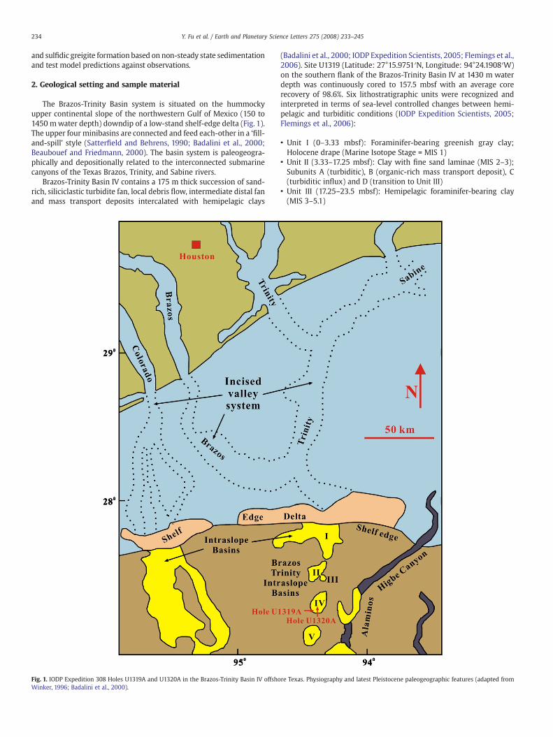
The Brazos-Trinity Basin system is situated on the hummockyupper continental slope of the northwestern Gulf of Mexico (150 to1450 mwater depth) downdip of a low-stand shelf-edge delta (Fig. 1).The upper four minibasins are connected and feed each-other in a ‘fill-and-spill’ style (Satterfield and Behrens, 1990; Badalini et al., 2000;Beaubouef and Friedmann, 2000). The basin system is paleogeogra-phically and depositionally related to the interconnected submarinecanyons of the Texas Brazos, Trinity, and Sabine rivers.
Brazos-Trinity Basin IV contains a 175 m thick succession of sand-rich, siliciclastic turbidite fan, local debris flow, intermediate distal fanand mass transport deposits intercalated with hemipelagic clays
Fig. 1. IODP Expedition 308 Holes U1319A and U1320A in the Brazos-Trinity Basin IV offshoWinker, 1996; Badalini et al., 2000).
(Badalini et al., 2000; IODP Expedition Scientists, 2005; Flemings et al.,2006). Site U1319 (Latitude: 27°15.9751′N, Longitude: 94°24.1908′W)on the southern flank of the Brazos-Trinity Basin IV at 1430 m waterdepth was continuously cored to 157.5 mbsf with an average corerecovery of 98.6%. Six lithostratigraphic units were recognized andinterpreted in terms of sea-level controlled changes between hemi-pelagic and turbiditic conditions (IODP Expedition Scientists, 2005;Flemings et al., 2006):
• Unit I (0–3.33 mbsf): Foraminifer-bearing greenish gray clay;Holocene drape (Marine Isotope Stage = MIS 1)
• Unit II (3.33–17.25 mbsf): Clay with fine sand laminae (MIS 2–3);Subunits A (turbiditic), B (organic-rich mass transport deposit), C(turbiditic influx) and D (transition to Unit III)
• Unit III (17.25–23.5 mbsf): Hemipelagic foraminifer-bearing clay(MIS 3–5.1)
re Texas. Physiography and latest Pleistocene paleogeographic features (adapted from
235Y. Fu et al. / Earth and Planetary Science Letters 275 (2008) 233–245
• Unit IV (23.5–29.5 mbsf): Clay with very fine sand laminae; phase ofdistal turbidites
• Unit V (29.5–31 mbsf): Hemipelagic foraminifer-bearing clay (MIS5.5)
• Unit VI (31–155.8 mbsf): Fine, muddy monotonous organic-rich clay(MIS 6)
The entire drilled succession is thought to be younger than 150 kyrsince the last occurrence (LO) datum of Helicosphaera inversa was notobserved. Near the base of Unit III (hemipelagic drape), a 2 cm thinlayer of volcanic glass sherds was identified as tephra event Y8 byshipboard scientists, which has been associated to the Chocoyoseruption at 84 kyr (Drexler et al., 1980). The chronology in particular ofthe lower Units III–VI is still uncertain. According to a preliminary agemodel based on planktonic foraminifers, nannofossils and magneto-stratigraphy, the sedimentation rates of Units I to V were in the orderof 20 cm/kyr, and of 500 cm/kyr in Unit VI (IODP Expedition Scientists,2005; Flemings et al., 2006).
3. Methods
297 oriented discrete samples were collected onboard RV JOIDESResolution in 6.2 cm3 plastic cubes at equal 0.5 m intervals (0.26 to155.16 mbsf) throughout the entire sequence. These samples weresubject to paleo- and rock magnetic studies at the MagneticsLaboratory of the Marine Geophysics Section, University of Bremen,Germany. Details on standard magnetic parameters and techniquescan be found in Frederichs et al. (1999).
Automated measurements of various remanence parameters wereperformed using a 2G-Enterprises 755R pass-through DC SQUID rockmagnetometer with integrated coils for direct, alternating, and pulsemagnetic fields. AF demagnetization experiments of NRM andAnhysteretic Remanent Magnetization (ARM) imparted at 40 μT directand 100 mT alternating field were done at 5 mT (0–50 mT) and 10 mT(50–100 mT) field increments, in turn κarm is the ratio of the ARM andthe applied direct field. Isothermal Remanent Magnetization (IRM)acquisition curves were measured at 24 fields steps up to 700 mT.
Magnetic hysteresis loops were measured to maximum fields of±300 mT (2 mT increments) on small weighed sub-samples from allspecimens using a Princeton Measurement Corporation 2900 Alternat-ing Gradient Force Magnetometer. Data were processed using theprogram Hystear (von Dobeneck, 1996) to determine hysteresisparameters (Day et al., 1977) including saturation magnetization Ms,saturation remanent magnetization Mrs, coercivity Bc, and coercivityof remanence Bcr. 60 First-order Reversal Curves (FORC, Pike et al.,1999) were measured for selected samples with fields to 1 T andprocessed with FORClab software (Roberts et al., 2000, 2006;Winklhofer and Zimanyi, 2006).
The hysteresis-based Mrs/κ ratio is a measure of magnetic grain-size for remanence bearing particles with higher values for finergrains, equivalent to the SIRM/κ ratio of Thompson and Oldfield(1986). Snowball and Thompson (1990), Roberts and Turner (1993),Reynolds et al. (1994) and Roberts (1995) reported unusually highSIRM/κ values for greigite-bearing samples compared to (titano-)magnetite-bearing samples in the same sequence. The κarm/SIRM ratiois another widely employed grain-size indicator of low-coercivityminerals such as magnetite (Maher, 1988). It is also inverselyproportional to the grain-size, but ignores superparamagnetic (SP)particles and can be used to highlight variations especially within thesub-micron grain-size range. Arguing with the superior stability ofgreigite relative to magnetite ARM, Peters and Thompson (1998)introduced the ARMdem 40 mT/ARM100 mT ratio to discriminate the twominerals.
Greigite diagnostics were also based on a Gyroremanent Magne-tization (GRM) acquired perpendicular to the AF field direction duringNRM and ARM demagnetization (Stephenson, 1980a,b). As shown by
Snowball (1997) and Hu et al. (2002), the high specific GRM values ofgreigite are unique among all known natural magnetic minerals. Nostandardizedmethod for GRM acquisition exists at present. Here, GRMwas determined as the newly forming perpendicular vector compo-nent during a 100 mT AF demagnetization of a previously impartedaxial 100 mT ARM.
4. Results
4.1. Evidence for greigite from NRM demagnetization characteristics
During stepwise AF demagnetization of discrete sample NRM, amoderate ‘Drilling Induced Remanent Magnetization’ (DIRM) compo-nent was generally removed by a 10–30 mT AF after whichCharacteristic Remanent Magnetization (ChRM) directions becameapparent (Fig. 2a). Sample α95 angles (Fisher, 1953) are typically below10°. Except for 9 individual reversed polarity samples, all other 288samples have normal polarities with reasonable ChRM inclinationsaveraging at 49°. The theoretical inclination of a geomagnetic axialdipole field at this site is 45.7°. These results are in agreementwith theassumed late Quaternary age of the sediments, but do not provideenough evidence to associate reversed samples with reversal events ofthe Brunhes chron.
More interestingly for rock magnetism than for paleomagnetism,many samples show an unusual ‘NRM curling-up’ behavior during AFdemagnetization in the field range between 50–70 mT and 100 mT(Fig. 2) due to a remanent magnetization component always formingperpendicular to the last demagnetization direction z. The effect is notinsignificant; it exceeds 10% of the initial NRM intensity in 33 samplesand even 100% in 3 samples. This suggests that the evolvingcomponent cannot be a hard reverse NRM direction but rather alaboratory induced effect indicating the presence of greigite that iscapable of forming a GRM (Snowball, 1997; Hu et al., 2002). Thiscomponent also forms during ARM demagnetization and is indepen-dent of the initial orientation of the sample.
A simplemathematical method is therefore introduced taking profitfromthis unintended laboratoryeffect. As shown in Fig. 2,we canuse theratio of ΔGRM (expressed as difference of Final Value FV and MinimumValue MV) and ΔNRM (expressed as difference of Initial Value IV andMV) to quantify the relative contribution of gyroremanence:
ΔGRMΔNRM
¼ FV−MVð ÞIV−MVð Þ :
This easy to obtain ratio gives a first estimate of the relative greigitevs. magnetite content, but has clear limitations—it is modulated bychanging paleofield intensity and influenced by magnetic grain-size.Applying this formula throughout the section, we find high ΔGRM/ΔNRMvalues at 3.76–13.76mbsf and 24.26–30.26mbsf (Fig. 3a). ‘NRMcurling-up’ is entirely absent in the top (0–3.26 mbsf) and middle(14.03–23.77 mbsf) sections, but persists at a low to intermediatelevels from 33.76 mbsf (Fig. 3b) down to terminal depth.
4.2. Greigite identification by rock magnetic diagnostics
To substantiate the identification of the GRM carrier, severalremanence and hysteresis-based rock magnetic methods indicative ofgreigite were tested. Peters and Thompson (1998) introduced a biplotcombining ARM demagnetization and IRM backfield remagnetizationdata to distinguish greigite from iron oxides (Fig. 3c). The 62 depictedsamples from the upper 40 mbsf section form a curved pathsuggesting a transformation of the magnetic petrology from a primary(titano-)magnetite composition to a secondary assemblage enrichedwith greigite. The ARMdem 40 mT/ARM100 mT ratio seems to be the moreindicative parameter as it combines domain state and coercivitycharacteristics of greigite, but the increasing ΔGRM/ΔNRM parameterdemonstrates the same trend.

Fig. 2. NRM intensities and directions observed during triaxial AF demagnetization of sample U1319A (8.26 mbsf) demonstrating the ‘NRM curling-up’ effect. (a) The normalizedZijderveld diagram shows the demagnetization of a DIRM (0–10mT) and NRM (15–60mT) and the acquisition of a GRM (60–100mT) component perpendicular to themagnetometerz direction. The effect is also obvious in diagrams (b) and (c) depicting total and axial NRM, respectively, against AF intensity.
236 Y. Fu et al. / Earth and Planetary Science Letters 275 (2008) 233–245
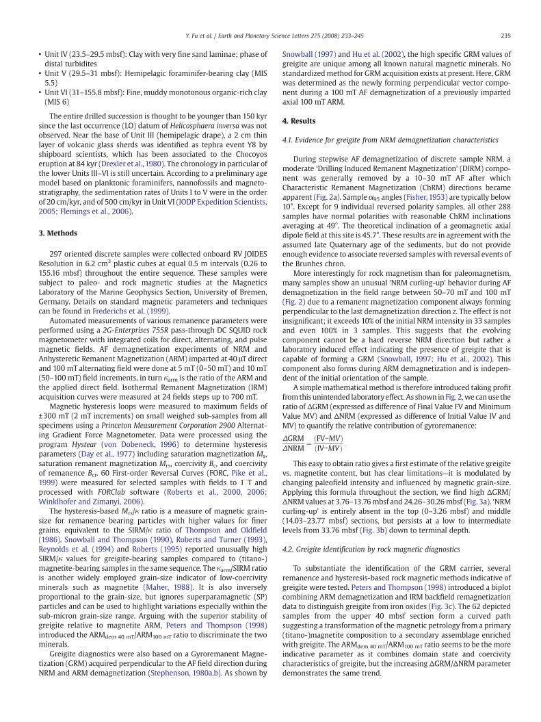
FORC diagrams were determined to further specify domain statesand coercivities of the primary and secondary magnetic phases(Fig. 4). Sample 26.76 mbsf (Fig. 4c) has the highest ΔGRM/ΔNRM andcarries a combination of superparamagnetic (SP, contributing to the“reversible ridge” at Bc=0 mT) and single domain (SD, isolated maxi-mum centered at 57 mT), but apparently no multi-domain (MD, slopetowards Bc=0 mT) properties. The vertical dispersion of the FORC
Fig. 3. ΔGRM/ΔNRM ratio of (a) upper section 0.26–39.76 mbsf and (b) complete IODP HoleGRM, while open, half-solid and solid circles denote increasing greigite content according to(1998) with the 62 discrete samples from (a). Data positions may be slightly shifted as a 0.7 Tthe sample selected for the FORC measurement of Fig. 4. The grey arrow indicates increasin
distribution indicates considerable magnetostatic interaction possi-bly resulting from clustering particles. This concurs with findingsof Roberts et al. (2000), who observed a peak FORC coercivity of SDgreigite clusters at 64 mT with a vertical broadening resulting fromthe magnetostatic interaction. Sample 11.76 mbsf (Fig. 4a) shows abroader maximum shifted to 42 mT indicating a softer greigite phase,with thermal relaxation or more interaction (Rowan and Roberts,
U1319A. Crosses in (a) mark samples that do not contain greigite capable of forming athe proxy defined here. (c) Greigite-specific biplot modified after Peters and ThompsonIRM field was used, while the original test assumes a 1 T SIRM. The star symbol denotesg greigite abundance.
Fig. 4. FORC diagrams depicting the coercivity distributions of four selected samples from IODP Hole U1319A. Sample depths are given in the diagrams. A smoothing factor (SF) of 4was applied.
237Y. Fu et al. / Earth and Planetary Science Letters 275 (2008) 233–245
2006). Sample 17.77 mbsf (Fig. 4b) does not acquire GRM and repre-sents a typical MD/PSD/SDmixture (broad reversible ridgewith bulge)of a soft magnetic mineral saturated at 50 mT, most likely magnetite.Sample 119.86 mbsf (Fig. 4d) has a lesser bulge and coercivities mainlybelow 20 mT typical for PSD/MD mixtures of (titano-)magnetites.Occasional additional SP greigite contributions are possible, butcannot be distinguished in the presence of other magnetically softphases. However, the complete absence of FORC maxima above 60 mTspeaks against the presence of SD pyrrhotite in these samples, whichis known to peak at 70–85 mT (Weaver et al., 2002; Roberts et al.,2006).
Magnetic extracts of two core catcher samples adjacent to greigitelayers were investigated by scanning electron microscopy withcalibrated EDS analytics. In magnetic extracts from these samplesclusters of sub-micron greigite particles (Fe/S ratios of ~0.8) togetherwith coarser detrital titanomagnetite and -hematite particles wereclearly identified (Franke et al., in press).
4.3. Stratigraphic and geochemical context of greigite distribution
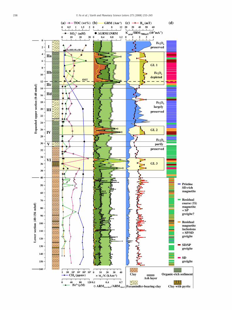
Here we examine the distribution of greigite and magnetite inrelation to the geochemical zonation focussing on the top 40m sectionof Hole U1319A. This upper part shows more pronounced andinterpretable signals than the lower monotonous Unit VI. Accordingto shipboard porewater sulfate andmethane profiles (IODP ExpeditionScientists, 2005; Flemings et al., 2006), the modern sulfate/methanetransition is located at a depth of approximately 12–13 mbsf (Fig. 5a).The linear decrease of sulfate and increase of methane with depthindicate a dynamic equilibrium (Borowski et al.,1996;Niewöhner et al.,1998; Hensen et al., 2003): A diffusive downward flux of sulfate (SO4
2−)and a given upward flux of methane (CH4) control the SMT position,where both react by microbial mediation to form bicarbonate,
hydrogen sulfide and water (Barnes and Goldberg, 1976). Rather thanbeing a “sulfate/methane interface” (SMI) the pore water concentra-tion profiles of sulfate and methane show considerable overlap. Wetherefore prefer the terms “sulfate methane transition” (SMT) or“sulfate methane reaction zone” because they more precisely describethe observed continuum.
Hydrogen sulfide (H2S) data are not available, but wewould expecta typical peak concentration at the SMT (e.g. Kasten et al., 1998;Riedinger et al., 2005). According to pore water Fe2+ data (Fig. 5a), themodern Fe(III)/Fe(II) redox boundary should be located at around 4–5 mbsf. Due to the low resolution and analytical uncertainties of thesedata, this position is not well defined. We presume the boundary at3.3 mbsf since the reductive dissolution of fine-grained magnetite isobserved below this interval (Fig. 5c).
Four rock magnetic parameters for greigite abundance have beencompiled (Fig. 5b): GRM provides a concentration estimate of SDgreigite, while the ratios ΔGRM/ΔNRM, Mrs/κ and ARMdem 40 mT/ARM100 mT quantify the relative abundances of primary magnetiteversus secondary greigite.
From all greigite proxy curves, we can observe three separate zonesof greigite occurrence:
• Greigite layer (GL) 1 (3.5–13.5 mbsf) extends from the Fe(III)/Fe(II)redox boundary, coincident with the upper boundary of the organic-rich clay Unit II, down to the modern SMT position. We can dis-tinguish several greigite maxima between sample positions 3.76 and11.76 mbsf. According to the raisedMrs/κ ratio, greigite dominates inSubunits IIa/IIb, but is absent in Unit I. The ARMdem 40 mT/ARM100 mT
ratio follows the ΔGRM/ΔNRM and GRM curves.• GL 2 (25.5–27.5 mbsf) within organic-rich clay Unit IV is muchnarrower and features two maxima at 25.76 and 26.76 mbsf dis-cerned by all four parameters.
238 Y. Fu et al. / Earth and Planetary Science Letters 275 (2008) 233–245

239Y. Fu et al. / Earth and Planetary Science Letters 275 (2008) 233–245
• GL 3 (34–38 mbsf) embraces a pyrite-rich section (IODP ExpeditionScientists, 2005; Flemings et al., 2006) within clay Unit VI. A verypronounced greigite-related peak at 35.26 mbsf is followed by asmaller peak at 36.76 mbsf.
All three greigite layers coincidewith organically enriched (TOC ~0.8%,Fig. 5a) clays, which were rapidly deposited at low sea-level conditionsand then slowly buried by hemipelagic sediments at higher sea-level.These stagnant situations with lower (TOC ~0.5%) and probably lessreactive organic matter contents could have stabilized the iron redoxboundary and SMT positions.We can therefore assume, that GL 1, 2 and 3correspond to comparable non-steady state geochemical (paleo-)envir-onments, each corresponding to a temporarily stable SMT position.Greigite does not extend much into the organic-rich clay Subunits IIc/IIdsituated below the modern SMT.
In typical marine sediments, the parameters κarm/IRM700 mT and Bcr(Fig. 5c) respond to grain-size variations within magnetite, wherelower κarm/IRM700 mT or coercivity of remanence both indicate coarserparticles. Starting from the sediment subsurface,we observe high κarm/IRM700 mT ratios corresponding to fine magnetite grain-sizes whichdrop steeply between 2 and 4 mbsf. However, the remanence coercivefield Bcr shows an inverse behavior at this point and increases fromcharacteristicmagnetite (30–35mT) to typical greigite values (~50mT)indicating changing magnetic predominance of the two iron minerals.The observed reverse relationship of κarm/IRM700 mT and Bcr impliesthat the granulometric character of κarm/IRM700 mT (like that of Mrs/κ)is being corrupted by the presence of greigite. Low κarm/IRM700 mT
values in GL 1, 2 and 3 do not mirror coarse residual magnetite, butsimply indicate predominant greigite characteristics. A Bcr value of40mT is therefore taken as threshold value todistinguishmagnetite vs.greigite dominance. Bcr is influenced neither by magnetic mineralconcentration nor by ultra-fine SP phases.
Between GL 1 and 2, κarm/IRM700 mT and Bcr values recover nearlyto their pristine values, while the recovery is less complete betweenGL 2 and 3 (Fig. 5c). The primary magnetite content must have beenlargely or at least partly been preserved in these zones. As magnetitedissolution is irreversible, we can conclude, that these greigite-poorintervals have just briefly been exposed to sulfidic conditions. Thereare, however, signs of stronger magnetite dissolution (κarm/IRM700 mT
and Bcr minima) in the contact zones to the greigite layers.The lower part (samples 40.26–155.16mbsf) consists ofmonotonous
fine mud and has been described as a single ‘super’-Unit VI (IODPExpedition Scientists, 2005; Flemings et al., 2006). The only observablestrata are several silt and pyrite-rich layers located in the deeper partbetween 80 and 140 mbsf. It is presently believed that the whole unitwas formed by either one large or several rapidly following masstransport events. While lithology is rather uniform, the rock magneticsignals, in particular greigite proxies (Fig. 5b), show strong variation, butlittle structure throughout the section. Small GRM or Mrs/κ peaksfrequently gather around identified pyrite layers (IODP ExpeditionScientists, 2005; Flemings et al., 2006). Bcr and κarm/IRM700 mT records(Fig. 5c) hint at varying states of magnetite depletion.
5. Discussion
5.1. Geochemical pathways of greigite formation
The occurrence of up to five separate, relatively narrow zones ofgreigite enrichment between the Fe(III)/Fe(II) redox boundary and thesulfate–methane transition zone is difficult to explain from published
Fig. 5. Lithostratigraphyof IODPHoleU1319A (IODPExpedition Scientists, 2005; Flemings et al.,sensitive rock magnetic parameters GRM, ΔGRM/ΔNRM,Mrs/κ and ARMdem 40 mT/ARM100 mT, (magnetic petrology according to the schemederived from Fig. 8 (blue: pristinemagnetite, greenSP greigite, purple: predominant SD and SP greigite, pink: predominant SD greigite. Mark thatsection in sufficient vertical resolution.
theory. Based on previous greigite studies (Berner, 1984; Wang andMorse, 1996; Wilkin and Barnes, 1997; Benning et al., 2000;Larrasoaña et al., 2007), we know that greigite often formsauthigenically under sulfidic environmental conditions as a precursorof pyrite by a series of geochemical reactions which are limited bythree principal factors: (1) availability of dissolved sulfate in thesediment pore water, (2) presence of microbially metabolizableorganic matter or methane utilized by sulfate-reducing bacteria toproduce hydrogen sulfide (HS−), and (3) suitable iron species whichreact with HS− to form iron sulfides such as mackinawite (Fe2+S2−),greigite (Fe2+Fe23+S42−) and pyrite (Fe2+S21−). We explicitly show Fe and Svalances in the formulas to stress the sometimes overlooked fact, thatthe formation of greigite and pyrite from mackinawite involves anoxidation of either Fe or S, and in the case of greigite as precursor ofpyrite, even a full oxidation-reduction cycle of Fe2+. In the zonebetween the Fe(III)/Fe(II) redox boundary and the SMT, all ingredientsfor this reaction chain are principally available. By reduction of ferricminerals like goethite, hematite or magnetite with organic carbon,
4FeOOHþ CH2O þ 7Hþ→4Fe2þðaqÞ þ HCO−3 þ 6H2O ð1Þ
2Fe2O3 þ CH2O þ 7Hþ→4Fe2þðaqÞ þ HCO−3 þ 4H2O ð2Þ
2Fe3O4 þ CH2O þ 11Hþ→6Fe2þðaqÞ þ HCO−3 þ 6H2O; ð3Þ
aqueous Fe2+ is formed which readily reacts with upward diffusinghydrogen sulfide produced by organoclastic sulfate reduction (e.g.Herlihy et al., 1987):
2CH2O þ SO2−4 →2HCO−
3 þ Hþ þ HS− ð4ÞMuch more efficient is anaerobic oxidation of methane (AOM, e.g.
Blair and Aller, 1995):
CH4 þ SO2−4 →HCO−
3 þ H2O þ HS− ð5ÞBerner (1970) and Pyzik and Sommer (1981) describe the forma-
tion of mackinawite as
Fe2þðaqÞ þ HS−→FeSðsÞ þ Hþ ð6Þ
Besides dissimilatory iron reduction (Eqs. (1)–(3)), iron oxides arerapidly reduced in direct reactions with HS− (e.g. Berner,1970; Poultonet al., 2004).
Fe2O3 þ HS− þ 5Hþ→2Fe2þðaqÞ þ S0ðsÞ þ 3H2O ð7ÞFe3O4 þ HS− þ 7Hþ→3Fe2þðaqÞ þ S0ðsÞ þ 4H2O ð8Þ
which lead not only to subsequent precipitation of Fe(II) bound inmonosulfides, but also to formation of dissolved, hence more reactivepolysulfides Sn2− (Rickard and Morse, 2005).
As recently highlighted experimentally by Benning et al. (2000),the subsequent reactions of greigite and pyrite formation remaincontroversial. A reaction of iron monosulfides with sulfur (as poly-sulfide) could yield greigite as an intermediate (Sweeney and Kaplan,1973):
3FeSþ S0→Fe3S4 ð9ÞFe3S4 þ 2S0→3FeS2 ð10Þ
S0 would act as electron acceptor to oxidize twomackinawite Fe(II)in Eq. (9) (fromFe2+S2− to Fe2+Fe23+S42−), while S(II)would be the electrondonor to reduce the greigite Fe(III) back in Eq. (10) (from Fe2+Fe23+S42− toFe2+S21−). It therefore takes twice the elemental sulfur to convertgreigite into pyrite than to form greigite from mackinawite.
2006)with downhole logs of (a) SO42−, CH4, Fe2+ and TOC contents inporewater, (b) greigite-
c) remanent coercive field Bcr and domain state index κarm/IRM700 mT, (d) classification of: diagenetically depletedmagnetite, possiblywith SP greigite, orange: relictmagnetitewiththe upper 0–40 mbsf section is plotted at expanded scale to depict this more structured

240 Y. Fu et al. / Earth and Planetary Science Letters 275 (2008) 233–245
Pyritization of greigite could also proceed via loss of Fe2+ (Furukawaand Barnes, 1995) as
Fe3S4 þ 2Hþ→2FeS2 þ Fe2þ þ H2ðgÞ ð11Þ
although greigite layers seem to remain stable over long periodsof time even in the presence of H+. While some authors (Berner, 1970;Rickard, 1975; Berner, 1984; Kao et al., 2004) assume, that greigiteenrichments are due to ‘arresting’ iron sulfidization half-way, others(Roberts et al., 1969; Luther, 1991; Butler and Rickard, 2000) do notinvoke a greigite intermediate and describe a direct sulfidization ofmonosulfides by the so-called ‘polysulfide pathway’:
FeSþ S0ðsÞ→FeS2 or FeSþ S2−n →FeS2 þ S2−n−1 ð12Þ
Wilkin and Barnes (1997) have taken a different perspective atgreigite as a pyrite precursor by associating its productionwith a moreoxic environment:
6FeS þ 2HS− þ O2 þ 2Hþ→2Fe3S4 þ 2H2O ð13Þ8FeS þ O2 þ 4Hþ→2Fe3S4 þ 2Fe2þ þ 2H2O ð14Þ
A coexistence of free O2 and HS− as in Eq. (13) is unlikely in nature,but a subsequent oxygenation of a formerly sulfidic zone is commonunder changing depositional conditions. This doesn't necessarilyrequire free oxygen, which is confined to the oxic subsurface. FeScan also be fully oxidized back to Fe(III) by nitrate (Schippers andJørgensen, 2002). We propose that nitratemay also induce incompleteiron monosulfide oxidation forming greigite:
4FeS þ NO−3 þ 2Hþ→Fe3S4 þ NO−
2 þ Fe2þ þ H2O ð15ÞGreigite layers resulting from Eqs. (13)–(15) under shallow, suboxic
conditions would have a high preservation potential as long as they donot encounter high HS− concentrations.
Fig. 6. The conceptual “sulfidization model” explains greigite layer formation by incomplemackinawite zone (a) first a single (b) and later a twin greigite layer around a pyrite layerhypothetical oxygen, nitrate, sulfate, methane and hydrogen sulfide profiles, arrows indicateand turbiditic sedimentation.)
5.2. Conceptual non-steady state models of greigite layer formation
In highly dynamic sedimentary environments like the Brazos-Trinity Basin system, non-steady state scenarios andmodels of greigitelayer formation and preservation seem more adequate. Based on thegeochemical reactions outlined above and observations from theprevious section, we propose two different, not necessarily exclusiveprocess models for the formation of greigite layers. Both begin withidentical situations (Figs. 6a and 7a) where an equilibrium redoxzonation has been established after rapid deposition of an organic-richunit. Hydrogen sulfide is formed at the stagnant SMT (Eq. (5)) andabovebydecomposition of organicmatter (Eq. (4)). Below the Fe(III)/Fe(II) redox boundary, free HS− is readily precipitated as mackinawite(Eq. (6)) accumulating over the entire sulfidic zone.
In the firstmodel (Fig. 6),we assume that greigite layers start to formnear the SMTwhere theproductionof freeHS− exceeds the availability ofdissolved Fe2+. This HS− surplus stimulates a sulfidic dissolution ofresidual iron oxides (Eqs. (7) and (8)).With S2− being the electron donorof these reactions, elemental sulfur S0 and polysulfide Sn2− is formed,which reversely reacts with mackinawite to form greigite (Eq. (9)) asstated in Fig. 6b. Once the system is depleted in mackinawite and morepolysulfide is available, the produced greigite is transformed furtherinto pyrite (Eq. (10)). This pyrite layerwillmost likely start forming closeto the SMT where HS− production is highest splitting the formerlysingle greigite layers into an upper and lower layer situated alongboth HS− gradient zones (Fig. 6c). If the SMT position remains stableover an extended time period, all formed greigite will eventually beconsumed and transformed into pyrite. However, the greigite–pyrite–greigite sequence can be conserved, if a massive sedimentation eventshifts the entire geochemical zonation rapidly upwards. The sulfidiza-tion would then cease in the lower part and start at a new higher level(Fig. 6d).
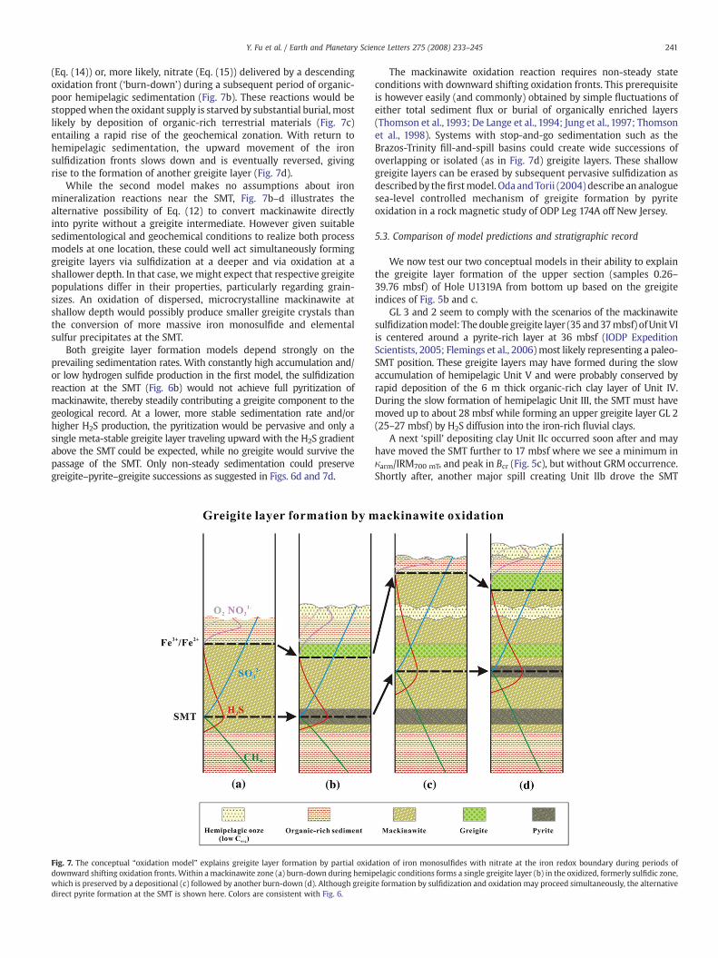
In the second model (Fig. 7), a shallow greigite layer is assumed toform by oxidation of mackinawite with downward diffusing oxygen
te sulfidization of iron monosulfide with polysulfide around a stagnant SMT. Within a(c) are formed and preserved by the next depositional event (d). Colored curves markshifts of iron redox boundary and sulfate–methane transition by alternate hemipelagic
241Y. Fu et al. / Earth and Planetary Science Letters 275 (2008) 233–245
(Eq. (14)) or, more likely, nitrate (Eq. (15)) delivered by a descendingoxidation front (‘burn-down’) during a subsequent period of organic-poor hemipelagic sedimentation (Fig. 7b). These reactions would bestoppedwhen the oxidant supply is starved by substantial burial, mostlikely by deposition of organic-rich terrestrial materials (Fig. 7c)entailing a rapid rise of the geochemical zonation. With return tohemipelagic sedimentation, the upward movement of the ironsulfidization fronts slows down and is eventually reversed, givingrise to the formation of another greigite layer (Fig. 7d).
While the second model makes no assumptions about ironmineralization reactions near the SMT, Fig. 7b–d illustrates thealternative possibility of Eq. (12) to convert mackinawite directlyinto pyrite without a greigite intermediate. However given suitablesedimentological and geochemical conditions to realize both processmodels at one location, these could well act simultaneously forminggreigite layers via sulfidization at a deeper and via oxidation at ashallower depth. In that case, we might expect that respective greigitepopulations differ in their properties, particularly regarding grain-sizes. An oxidation of dispersed, microcrystalline mackinawite atshallow depth would possibly produce smaller greigite crystals thanthe conversion of more massive iron monosulfide and elementalsulfur precipitates at the SMT.
Both greigite layer formation models depend strongly on theprevailing sedimentation rates. With constantly high accumulation and/or low hydrogen sulfide production in the first model, the sulfidizationreaction at the SMT (Fig. 6b) would not achieve full pyritization ofmackinawite, thereby steadily contributing a greigite component to thegeological record. At a lower, more stable sedimentation rate and/orhigher H2S production, the pyritization would be pervasive and only asingle meta-stable greigite layer traveling upward with the H2S gradientabove the SMT could be expected, while no greigite would survive thepassage of the SMT. Only non-steady sedimentation could preservegreigite–pyrite–greigite successions as suggested in Figs. 6d and 7d.
Fig. 7. The conceptual “oxidation model” explains greigite layer formation by partial oxiddownward shifting oxidation fronts. Within a mackinawite zone (a) burn-down during hemipwhich is preserved by a depositional (c) followed by another burn-down (d). Although greigidirect pyrite formation at the SMT is shown here. Colors are consistent with Fig. 6.
The mackinawite oxidation reaction requires non-steady stateconditions with downward shifting oxidation fronts. This prerequisiteis however easily (and commonly) obtained by simple fluctuations ofeither total sediment flux or burial of organically enriched layers(Thomson et al., 1993; De Lange et al., 1994; Jung et al., 1997; Thomsonet al., 1998). Systems with stop-and-go sedimentation such as theBrazos-Trinity fill-and-spill basins could create wide successions ofoverlapping or isolated (as in Fig. 7d) greigite layers. These shallowgreigite layers can be erased by subsequent pervasive sulfidization asdescribedby thefirstmodel. Oda and Torii (2004) describe an analoguesea-level controlled mechanism of greigite formation by pyriteoxidation in a rock magnetic study of ODP Leg 174A off New Jersey.
5.3. Comparison of model predictions and stratigraphic record
We now test our two conceptual models in their ability to explainthe greigite layer formation of the upper section (samples 0.26–39.76 mbsf) of Hole U1319A from bottom up based on the greigiteindices of Fig. 5b and c.
GL 3 and 2 seem to comply with the scenarios of the mackinawitesulfidizationmodel: Thedouble greigite layer (35 and37mbsf) ofUnit VIis centered around a pyrite-rich layer at 36 mbsf (IODP ExpeditionScientists, 2005; Flemings et al., 2006)most likely representing a paleo-SMT position. These greigite layers may have formed during the slowaccumulation of hemipelagic Unit V and were probably conserved byrapid deposition of the 6 m thick organic-rich clay layer of Unit IV.During the slow formation of hemipelagic Unit III, the SMT must havemoved up to about 28 mbsf while forming an upper greigite layer GL 2(25–27 mbsf) by H2S diffusion into the iron-rich fluvial clays.
A next ‘spill’ depositing clay Unit IIc occurred soon after and mayhave moved the SMT further to 17 mbsf where we see a minimum inκarm/IRM700 mT, and peak in Bcr (Fig. 5c), but without GRM occurrence.Shortly after, another major spill creating Unit IIb drove the SMT
ation of iron monosulfides with nitrate at the iron redox boundary during periods ofelagic conditions forms a single greigite layer (b) in the oxidized, formerly sulfidic zone,te formation by sulfidization and oxidation may proceed simultaneously, the alternative

242 Y. Fu et al. / Earth and Planetary Science Letters 275 (2008) 233–245
further up to around 14 mbsf. The partial magnetite preservationbetween 18–22 mbsf and 15–16 mbsf can be explained by a relativelyfast rise of the SMT position leaving little time for reductive diagenesison passage (Garming et al., 2005; Riedinger et al., 2005). Thedeposition of the transitional clay Unit IIa and following hemipelagicsedimentation of Unit I drove the SMT to its present, probably all-timehighest SMT position at 12–13 mbsf. The greigite layer at 12 mbsf cantherefore be regarded as ‘modern analogue’ of GL 2 and 3.
So far, the predictions of the sulfidization model are coherent withthe observed greigite layers. However, this model fails to explain theshallowgreigite enrichments at 4–5mbsf and 7–9mbsf locatedwithina nearly 8 m wide greigite zone (3.5–12 mbsf) coincident with theassumedmodern sulfidic environment.With regard to the low organiccarbon content of Unit I, the linear decline of the sulfate profile downto 12 mbsf and the good preservation of fine-grained magnetite above3 mbsf (Fig. 5c), it seems unlikely, that the SMT had ever been as highas 5–6 mbsf. Instead, the formation of the uppermost greigite peakwithin the top of clay Unit IIa just below the modern Fe redoxboundary is readily explained by our second oxidation model. It isplausible that, after deposition of Unit IIa, oxygen or nitrate diffuseddownwards into its upper part forming greigite by partial mack-inawite oxidation (Eqs. (13)–(15)). Analogously, the greigite peak at8 mbsf may have formed by a similar burn-down into the top of clayUnit IIb.We cannot exclude, that this alternativemechanismmay havealso been involved with deeper greigite layers GL2 and GL3, althoughthe high Holocene sea-level should be more efficient for burn-downthan MIS 3. However, if GL2 and GL3 were formed by mackinawiteoxidation, the question, where the locations and signatures of therespective paleo-SMT positions should have been, would remainunanswered.
Under the given geochemical conditions at this site (mean organiccontent, diffusion lengths, accumulation rates, grain-sizes etc.), itappears that the typical vertical distances from SMT positions to theircorresponding greigite layers are ~1–2 m for the mackinawitesulfidization and ~8–10 m for the mackinawite oxidation process.The 1–2 m distance could be a characteristic offset distance from astagnant SMT, where H2S concentrations are sufficient for greigite, butnot yet for pyrite formation. The 8–10 m length would represent thevertical distance between SMTand Fe(III)/Fe(II) redox boundary undergiven equilibrium conditions.
Our models cannot contribute much to the interpretation of thelower part of the section.
Layers and bands of enhanced greigite and/or pyrite content at 140,(130?), 118, 108, 98–95, 81, 60–56, 47–43 mbsf may represent pastSMT positions corresponding to relatively short stagnant phasesbetween separate mass transport events, each of which accumulatedsome 8–10 m of new sediment. Such ‘quasi-cyclic’ spillover is to beexpected for a system of interconnected micro-basins, where sedi-ment bodies available for mass flows are often similar in size.
5.4. Magnetite depletion and greigite growth stages
In order to identify and categorize the stages of iron-oxidereduction and iron-sulfide formation the multivariate perspective ismore telling than the stratigraphic. To pinpoint the various diageneticstages, concentration-independent coercivity and domain state para-meters (Bcr, Bc, Bcr/Bc, Mrs/Ms, Mrs/κ, κarm/IRM700 mT) have been cross-plotted in many ways. The five most indicative plots are compiled inFig. 8a–e documenting diagenetic changes in magnetic grain-size andmineralogy.
Five stages were distinguished using simple threshold methodsmotivated by data groupings: Iron sulfides were distinguished fromoxides by the boundary value Bcr=40 mT following the method ofPeters and Thompson (1998). Magnetically harder greigite phaseswere subdivided into a softer (orange) (Bcrb45 mT) and two harder(BcrN45 mT) groups of true SD (red) and mixed SD and SP particles
(purple) discriminated by the threshold Bcr/Bc=2. The magneticallysofter iron-oxide group was split into a fine pristine (blue) group and adiagenetically depleted (green) group according to their differing SDmagnetite content (limit κarm/IRM700 mT=0.001 mA−1). The groupingscheme was carried back into the stratigraphic records using color-coded columns (Fig. 5d).
The red group located in the uppermost PSD region of the Day plot(Fig. 8a) occurs only in greigite-rich layers (Fig. 5d). Mrs/Ms values of0.3–0.45 are indicative of interacting SD particles. This phase has thehighest Bcr (43–53 mT) and Bc (23–33 mT) and Mrs/κ up to 40 A/m(Fig. 8b–e). It is therefore identified as primarily SD greigite withsmaller SP or MD contributions.
The adjacent purple group has the same high Bcr (45–53 mT), butplots lower in the Day andMrs/κ plots due to its smaller Bc (12–24mT)and relatively higher Ms and κ values. We follow the argument ofRowan and Roberts (2006) that SD greigite is commonly associatedwith ultra-fine SP greigite at various proportions and explain thisphase as a mixture of SD and SP greigite. This assumption is alsosupported by the greater height of the reversible ridge in therespective FORC diagram. SP particles contribute to induced magne-tizations (Bc, Ms, κ), but leave remanent magnetizations and theirproperties (Bcr, Mrs, SIRM) unchanged, thereby shifting domain stateparameters to seemingly coarser values.
The red and purple clusters define the steep upper branch in theBc vs. Bcr/Bc plot (Fig. 8c), which deflects towards a second lowerbranch with a gentler slope. The orange greigite group has lower Bcr(40–45 mT) and Bc (8–21 mT) than others and connects smoothly tothe lower (titanomagnetite) trend. Only a few of these symbols havean enhanced Mrs/κ indicative of SD greigite. We interpret this phaseas a mixing series of ultra-fine authigenic SP/SD greigite and adiagenetically depleted, detrital SD iron-oxide particles (possiblysmall inclusions protected by silicate matrices or titanohematitelamellae (Pyzik and Sommer, 1981)) together with larger PSD/MDrelict Ti–Fe oxide particles. A respective FORC distribution features avery broad reversible ridge (SP+MD) and an isolated maximumwith a switching field of 40–45 mT characteristic of SD (titano-)magnetite.
The distinct blue group at the left lower branch in Fig. 8c has SD/PSD characteristics (Mrs/Ms 0.15–0.25) and by far the highest κarm/IRM700 mT ratios. Such samples are only found in the top section abovethe recent Fe redox boundary and within a nearly unaltered layerbelow the modern SMT (Fig. 5). Bcr (30–37 mT) and Bc (10–17 mT) aretypical for pristine fine-grained detrital or biogenic magnetite withlittle diagenetic overprint and negligible greigite content.
The green group departs from the blue group into a magneticallycoarser regime (Mrs/Ms 0.5–0.15) with lower Bc (7–15 mT), butsomewhat higher Bcr (32–40 mT). This state prevails in the lower coreand is classified as diagenetically overprinted iron-oxide phase,enriched in corrosion-resistant coarse titanomagnetites and hema-tites (Funk et al., 2003; Dillon and Bleil, 2006). This diagenetic stage isreached after prolonged contact with H2S-bearing pore water and ischaracteristic for both the early mackinawite (possibly with initialgreigite formation) and the late pyrite stage of sulfidic diagenesis(Pyzik and Sommer, 1981).
In consequence, the full reaction pathway from magnetite togreigite should lead from a pristine (blue) state over a reduced (green)stage with beginning sulfidization to initial and mature states ofgreigite formation. Starting as superparamagnetic accessory ironphase of a few nm size in the reduced (green) phase, greigite wouldeventually dominate the magnetic mineralogy (orange) and takegrain-sizes of tens (purple) or even hundreds (red) of nanometers.Frank et al. (2007) describe essentially the same pathway for Dead Seasediments using biplots of magnetic remanence parameters.
A return to the stratigraphic columns of Fig. 5d clarifies, that thisfull diagenesis cycle is not easily observed at 50 cm sampling distance.The geochemical gradients in the upper part are too steep to be

Fig. 8. (a) Day-Plot (Day et al., 1977) and (b–d) biplots of magnetic coercivity and domain state parameters of all 297 samples throughout Hole U1319A. Based on hysteresis criteria, sixdiagenetic stages can be discriminated, ranging from a pristine (blue) over a partially depleted (green) magnetite-dominated magnetic mineralogy with initial to early (orange),advanced (purple) and fully developed (pink) stages of greigite formation (see text for classification criteria). In Fig. 5d, these diagenetic stages are presented in their stratigraphiccontext.
243Y. Fu et al. / Earth and Planetary Science Letters 275 (2008) 233–245
resolved at this resolution and would require much denser coverage.In the lower part, the pristine magnetic mineral assemblage has beenreduced to a relict phase with only spurious greigite layers.
6. Conclusions and summary
Paleo- and rock magnetic investigations of the IODP Hole U1319A,recovered from the small intraslope Brazos-Trinity Basin IV in thenorthwestern Gulf of Mexico, have revealed a complex succession of
greigite enriched layers located within magnetically depleted zones.These ferrimagnetic sub-micron mineral precipitates were firstnoticed by their peculiar NRM characteristics (‘curling-up’ effectduring AF demagnetization due to GRM acquisition) and subsequentlyidentified by remanence- and hysteresis-based greigite diagnostics.There is no indication for the presence of pyrrhotite.
After revising the scope of possible reaction chains involved iniron-oxide reduction and stepwise sulfidization (mackinawite→greigite→pyrite), we propose two different conceptual models for
244 Y. Fu et al. / Earth and Planetary Science Letters 275 (2008) 233–245
greigite layer formation by implementing postulated reactions intosimple non-steady-state sedimentation scenarios:
A) In the sulfidization model, greigite is produced by a (redox)reaction of mackinawite with polysulfide along the HS− gradientzones adjoining a static SMT position. The resulting transientsingle or twin greigite layers are preserved, if copious massdeposits, commonly at sea-level low-stand, rapidly rearrange thegeochemical zonation, starve the diffusive sulfate flux and stop theH2S production at the given depth, thereby inhibiting the ironsulfidization to progress further from greigite to pyrite.
B) The oxidation model assumes that greigite may also be formed bypartial oxidation of iron monosulfide, when free oxygen or nitratediffuse into a formerly sulfidic zone. Downward shifting ofoxidation fronts occurs during periods of low or organic-poorsedimentation, typically at sea-level high-stand. The reactioncould create multiple shallow greigite layers far above the SMT,which may also fossilize under favorable conditions.
We seem capable of explaining the main features of magnetitedepletion and greigite enrichment by applyingour conceptual geochem-ical models to the assumed sediment history of the study site. Themorestructured upper part (0–40 mbsf) of the record bears well-preservedgreigite layers grouped aroundpresent andpast abandoned geochemicalboundaries. The lower part (40–156mbsf) shows an advanced degree ofmagnetite depletion andnumerous thin greigite and/or pyrite layers, butthe signatures are too poorly developed or conserved to be easilyidentifiedwith our models. The rockmagnetic signatures of temporarilystatic and rapidly shifting SMT positions give hints at the rhythm ofsediment spills and their external control by sea-level change.
Using a deterministic multivariate grouping approach based onmagnetic domain state and coercivity, we track the iron-oxide alterationpathway from a pristine magnetic mineral assemblage rich in finemagnetite over an increasingly depleted relict stage consisting pre-dominantly of coarser and Ti-rich particles. During successive sulfidiza-tion, the secondary magnetic mineral greigite grows from an ultra-fine,magnetically instable SP phase into a magnetically dominant SD phase.
Reaction kinetics and diffusion times are essential, but have notbeen regarded in this primarily rock magnetic and stratigraphicapproach. We also lack evidence to decide, to what extent micro-organisms are involved in or responsible for the observed greigiteformation, but consider this a very likely possibility.
Acknowledgements
IODP Expedition 308 (2005) was financed by the U.S. NationalScience Foundation and participating countries. We acknowledge thestrong engagement of the ships crew and the help of all science partymembers in collecting these samples. Yanzhe Fu received support asResearch Student of the International Graduate College “Proxies in EarthHistory” (EUROPROX) and doctorate student of the Jacobs UniversityBremen. Christine Franke has been supported by Deutsche Forschungs-gemeinschaft projectDo705/2. Thiswork contributes to projectC1 of theMARUMCenter for Marine Environmental Sciences.We thank NataschaRiedinger, William P. Gilhooly, Peggy Delaney and three anonymousreviewers for detailed and thoughtful suggestions and comments.
References
Badalini, G., Kneller, B., Winker, C.D., 2000. Architecture and processes in the latePleistocene Trinity-Brazos turbidite system, Gulf of Mexico. In: Weimer, P., Slatt, R.M.,Coleman, J., Rosen, N.C., Nelson, H., Bouma, A.H., Styzen, M.J., Lawrence, D.T. (Eds.),Deep-water Reservoirs of the World, Proceedings of the 20th Annual Research Con-ference. Gulf Coast Section SEPM Foundation, pp. 16–34.
Barnes, R.O., Goldberg, E.D., 1976. Methane production and consumption in anoxicmarine sediments. Geology 4, 297–300.
Beaubouef, R.T., Friedmann, S.J., 2000. High resolution seismic/sequence stratigraphicframework for the evolution of the Pleistocene intra slope basins, western Gulf of
Mexico: depositional models and reservoir analogs. In: Weimer, P., Slatt, R.M.,Coleman, J., Rosen, N.C., Nelson, H., Bouma, A.H., Styzen, M.J., Lawrence, D.T. (Eds.),Deep-water Reservoirs of the World, Proceedings of the 20th Annual ResearchConference. Gulf Coast Section SEPM Foundation, pp. 40–60.
Benning, L.G., Wilkin, R.T., Barnes, H.L., 2000. Reaction pathways in the Fe–S systembelow 100 °C. Chem. Geol. 167, 25–51.
Berner, R.A., 1970. Sedimentary pyrite formation. Am. J. Sci. 268, 1–23.Berner, R.A.,1984. Sedimentary pyrite formation: an update. Geochim. Cosmochim. Acta
48, 605–615.Blair, N.E., Aller, R.C., 1995. Anaerobic methane oxidation on the Amazon shelf. Geochim.
Cosmochim. Acta 59, 3707–3715.Borowski, W.S., Paull, C.K., Ussler, W., 1996. Marine porewater sulfate profiles indicate in
situ methane flux from underlying gas hydrate. Geology 24, 655–658.Butler, I.B., Rickard, D., 2000. Framboidal pyrite formation via the oxidation of iron (II)
monosulfide by hydrogen sulphide. Geochim. Cosmochim. Acta 64, 2665–2672.Day, R., Fuller, M., Schmidt, V.A., 1977. Hysteresis properties of titanomagnetites: grain-
size and compositional dependence. Phys. Earth Planet. Inter. 13, 260–267.De Lange, G.J., Van Os, B., Pruysers, P.A., Middelburg, J.J., Castradori, D., Van Santvoort, P.,
Müller, P.J., Eggenkamp, H., Prahl, F.G., 1994. Possible early diagenetic alteration ofpalaeo proxies. In: Zahn, R., Pedersen, T.F., Kaminski, M.A., Labeyrie, L. (Eds.), CarbonCycling in the Glacial Ocean: Constraints on the Ocean's Role in Global Change.NATO ASI Series, pp. 225–258.
Dillon, M., Bleil, U., 2006. Rock magnetic signatures in diagenetically altered sedimentsfrom the Niger deep-sea fan. J. Geophys. Res 111, B03105. doi:10.1029/2004JB003540.
Drexler, J.W., Rose, W.I., Sparks, R.S.J., Ledbetter, M.T., 1980. The Los Chocoyos ash,Guatemala: a major stratigraphic marker in Middle America and in three oceanbasins. Quat. Res. 13, 327–345.
Fisher, R.A., 1953. Dispersion on a sphere. Proc. R. Soc. Lond. A217, 295–305.Flemings, P.B., Behrmann, J.H., John, C.M., the Expedition 308 Scientists, 2006. Proc.
IODP, 308: College Station TX (IODP Management International, Inc.). doi:10.2204/iodp.proc.308.103.2006.
Frank, U., Nowaczyk, N.R., Negendank, J.F.W., 2007. Rock magnetism of greigite bearingsediments from the Dead Sea, Israel. Geophys. J. Int. 168, 921–934.
Franke, C., Fu, Y., Heslop, D., von Dobeneck, T., (in press). Data report: natural remanentmagnetization of IODP Holes U1319A, U1320A, U1322B, and U1324B and magneticcarrier identification by scanning electron microscopy. IODP Sci. Res. 308. In:Flemings, P.B., Behrmann, J.H., John, C.M., and the Expedition 308 Scientists, Proc.IODP, 308: College Station, TX (Integrated Ocean Drilling Program ManagementInternational, Inc.). doi:10.2204/iodp.proc.308.204.2008
Frederichs, T., Bleil, U., Däumler, K., von Dobeneck, T., Schmidt, A.M., 1999. The magneticview on the marine paleoenvironment: parameters, techniques and potentials ofrock magnetic studies as a key to paleoclimatic and paleoceanographic changes. In:Fischer, G., Wefer, G. (Eds.), Use of Proxies in Paleoceanography: Examples from theSouth Atlantic. Springer-Verlag, Berlin, pp. 575–599.
Funk, J.A., von Dobeneck, T., Reitz, A., 2003. Integrated rock magnetic and geochemicalquantification of redoxomorphic iron mineral diagenesis in Late Quaternarysediments from the Equatorial Atlantic. In: Wefer, G., Mulitza, S., Ratmeyer, V.(Eds.), The South Atlantic in the Late Quaternary: Reconstruction of Material Budgetand Current Systems. Springer, Berlin, pp. 237–260.
Furukawa, Y., Barnes, H.L., 1995. Reactions forming pyrite from precipitated amorphousferrous sulfide. In: Vairavamurthy, M.A., Schoonen, M.A.A. (Eds.), GeochemicalTransformation of Sedimentary Sulfur. ACS Symposium Series, vol. 612, pp.194–205.
Garming, J.F.L., Bleil, U., Riedinger, N., 2005. Alteration of magnetic mineralogy at thesulfate methane transition: analysis of sediments from the Argentine continentalslope. Phys. Earth Planet. Inter. 151, 290–308.
Hensen, C., Zabel, M., Pfeifer, K., Schwenk, T., Kasten, S., Riedinger, N., Schulz, H.D.,Boetius, A., 2003. Control of sulfate pore-water profiles by sedimentary events andthe significance of anaerobic oxidation of methane for the burial of sulfur in marinesediments. Geochim. Cosmochim. Acta 67, 2631–2647.
Herlihy, A.T., Mills, A.L., Hornberger, G.M., Bruckner, A.E., 1987. The importance ofsediment sulfate reduction to the sulfate budget of an impoundment receiving acidmine drainage. Water Resour. Res. 23, 287–292.
Hoffmann, V., 1992. Greigite (Fe3S4) — magnetic properties and first domain obser-vations. Phys. Earth Planet. Inter. 70, 288–301.
Horng, C.-S., Chen, J.-C., Lee, T.-Q., 1992. Variations in magnetic minerals from two Plio-Pleistocene marine-deposited sections, southwestern Taiwan. J. Geol. Soc. China 35,323–335.
Hu, S., Stephenson, A., Apple, E., 2002. A study of gyroremanent magnetization (GRM)and rotational remanent magnetization (RRM) carried by greigite from lake sedi-ments. Geophys. J. Int. 151, 469–474.
IODP Expedition Scientists, 2005. Overpressure and fluid flow processes in thedeepwater Gulf of Mexico: slope stability, seeps, and shallow-water flow. IODPPrel. Rept. 308 (2005). doi:10:2204/iodp.pr.308.
Jørgensen, B.B., 1977. The sulfur cycle of a coastal marine sediment (Limfjorden,Denmark). Limnol. Oceanogr. 22 (5), 814–832.
Jung, M., Ilmberger, J., Mangini, A., Emeis, K.-C., 1997. Why some Mediterraneansapropels survived burn-down (and others did not). Mar. Geol. 141, 51–60.
Kao, S.J., Horng, C.S., Roberts, A.P., Liu, K.K., 2004. Carbon-sulfur–iron relationships insedimentary rocks from southwestern Taiwan: influence of geochemical environ-ment on greigite and pyrrhotite formation. Chem. Geol. 203, 153–168.
Kasten, S., Freudenthal, T., Gingele, F.X., Schulz, H.D., 1998. Simultaneous formation ofiron-rich layers at different redox boundaries in sediments of the Amazon deep-seafan. Geochim. Cosmochim. Acta 62, 2253–2264.
Larrasoaña, J.C., Roberts, A.P., Musgrave, R.J., Gràcia, E., Piñero, E., Vega, M., Martínez-Ruiz, F., 2007. Diagenetic formation of greigite and pyrrhotite in gas hydrate marinesedimentary systems. Earth Planet. Sci. Lett. 261, 350–366.
245Y. Fu et al. / Earth and Planetary Science Letters 275 (2008) 233–245
Lee, C.H., Jin, J.-H., 1995. Authigenic greigite in mud from the continental shelf of theYellow sea, off the southwest Korean Peninsula. Mar. Geol. 128, 11–15.
Luther III, G.W., 1991. Pyrite synthesis via polysulfide compounds. Geochim.Cosmochim. Acta 55, 2839–2849.
Maher, B.A., 1988. Magnetic properties of some synthetic sub-micron magnetites.Geophys. J. 94, 83–96.
Niewöhner, C., Hensen, C., Kasten, S., Zabel, M., Schulz, H.D., 1998. Deep sulphatereduction completely mediated by anaerobic methane oxidation in sediments ofthe upwelling area off Namibia. Geochim. Cosmochim. Acta 62, 455–464.
Oda, H., Torii, M., 2004. Sea-level change and remagnetization of continental shelfsediments off New Jersey (ODP Leg 174A): magnetite and greigite diagenesis.Geophys. J. Int. 156, 443–458.
Peters, C., Thompson, R., 1998. Magnetic identification of selected natural iron oxidesand sulphides. J. Magn. Magn. Mater. 183, 365–374.
Pike, C.R., Roberts, A.P., Verosub, K.L., 1999. Characterizing interactions in fine magneticparticle systems using first order reversal curves. J. Appl. Phys. 85, 6660–6667.
Poulton, S.W., Krom, M.D., Raiswell, R., 2004. A revised scheme for the reactivity of iron(oxyhydr)oxide minerals towards dissolved sulfide. Geochim. Cosmochim. Acta 68,3703–3725.
Pyzik, A.J., Sommer, S.E., 1981. Sedimentary ironmonosulfides: kinetics and mechanismof formation. Geochim. Cosmochim. Acta 45, 687–698.
Reynolds, R.L., Tuttle, M.L., Rice, C.A., Fishman, N.S., Karachewski, J.A., Sherman, D.M.,1994. Magnetization and geochemistry of greigite-bearing Cretaceous strata, NorthSlope Basin, Alaska. Am. J. Sci. 294, 485–528.
Rickard, D.T., 1975. Kinetics and mechanism of pyrite formation at low temperatures.Am. J. Sci. 275, 636–652.
Rickard, D., Morse, J.W., 2005. Acid volatile sulfide (AVS). Mar. Chem. 97, 141–197.Riedinger, N., Pfeifer, K., Kasten, S., Garming, J.F.L., Vogt, C., Hensen, C., 2005. Diagenetic
alteration of magnetic signals by anaerobic oxidation of methane related to achange in sedimentation rate. Geochim. Cosmochim. Acta 69, 4117–4126.
Roberts, A.P., 1995. Magnetic properties of sedimentary greigite (Fe3S4). Earth Planet.Sci. Lett. 134, 227–236.
Roberts, A.P., Turner, G.M., 1993. Diagenetic formation of ferrimagnetic iron sulphideminerals in rapidly deposited marine sediments, South Island, New Zealand. EarthPlanet. Sci. Lett. 115, 257–273.
Roberts, W.M.B., Walker, A.L., Buchanan, A.S., 1969. The chemistry of pyrite formation inaqueous solution and its relation to the depositional environment. Miner. Depos. 4,18–29.
Roberts, A.P., Pike, C.R., Verosub, K.L., 2000. First-order reversal curve diagrams: a newtool for characterizing the magnetic properties of natural samples. J. Geophys. Res.105, 28461–28475.
Roberts, A.P., Liu, Q., Rowan, C.J., Chang, L., Carvallo, C., Torrent, J., Horng, C.-S., 2006.Characterization of hematite (α-Fe2O3), goethite (α-FeOOH), greigite (Fe3S4), andpyrrhotite (Fe7S8) using first-order reversal curve diagrams. J. Geophys. Res. 111,B12S35. doi:10.1029/2006JB004715.
Rowan, C.J., Roberts, A.P., 2006. Magnetite dissolution, diachronous greigite formation,and secondary magnetizations from pyrite oxidation: unravelling complex mag-
netization in Neogene marine sediments from New Zealand. Earth Planet. Sci. Lett.241, 119–137.
Sagnotti, L., Winkler, A., 1999. Rock magnetism and palaeomagnetism of greigite-bearing mudstones in the Italian peninsula. Earth Planet. Sci. Lett. 165, 67–80.
Satterfield, W.M., Behrens, E.W., 1990. A late Quaternary canyon/channel system,northwest Gulf of Mexico continental slope. Mar. Geol. 92, 51–67.
Schippers, A., Jørgensen, B.B., 2002. Biogeochemistry of pyrite and iron sulfide oxidationin marine sediments. Geochim. Cosmochim. Acta 66, 85–92.
Schoonen,M.A.A., Barnes, H.L.,1991. Reactions forming pyrite andmarcasite from solution.II: via FeS precursors below 100 °C. Geochim. Cosmochim. Acta 55, 1505–1514.
Snowball, I.F., 1997. Gyroremanent magnetization and the magnetic properties ofgreigite-bearing clays in southern Sweden. Geophys. J. Int. 129, 624–636.
Snowball, I.F., Thompson, R., 1990. A stable chemical remanence in Holocene sediments.J. Geophys. Res. 95, 4471–4479.
Stephenson, A., 1980a. Gyromagnetism and the remanence acquired by a rotating rockin an alternating magnetic field. Nature 284, 48–49.
Stephenson, A.,1980b. A gyroremanent magnetization in anisotropicmagnetic material.Nature 284, 49–51.
Sweeney, R.E., Kaplan, I.R., 1973. Pyrite framboid formation: laboratory synthesis andmarine sediments. Econ. Geol. 68 (5), 618–634.
Thomson, J., Higgs, N.C., Croudace, I.W., Colley, S., Hydes, D.J., 1993. Redox zonation ofelements at an oxic/post-oxic boundary indeep-sea sediments. Geochim. Cosmochim.Acta 57, 579–595.
Thomson, J., Jarvis, I., Green, D.R.H., Green, D.A., Clayton, T., 1998. Mobility andimmobility of redox-sensitive elements in deep-sea turbidites during shallowburial. Geochim. Cosmochim. Acta 62, 643–656.
Thompson, R., Oldfield, F., 1986. Environmental Magnetism. Allen & Unwin, London.Torii, M., Fukuma, K., Horng, C.-S., Lee, T.-Q.,1996.Magnetic discrimination of pyrrhotite-
and greigite-bearing sediment samples. Geophys. Res. Lett. 23, 1813–1816.von Dobeneck, T., 1996. A systematic analysis of natural magnetic mineral assemblages
based on modelling hysteresis loops with coercivity-related hyperbolic basisfunctions. Geophys. J. Int. 124, 675–694.
Wang, Q.W., Morse, J.W., 1996. Pyrite formation under conditions approximating thosein anoxic sediments. 1: pathway and morphology. Mar. Chem. 52, 99–121.
Weaver, R., Roberts, A.P., Barker, A.J., 2002. A late diagenetic (syn-folding) magnetizationcarried by pyrrhotite: implications for paleomagnetic studies from magnetic ironsulphide-bearing sediments. Earth Planet. Sci. Lett. 200, 371–386.
Wilkin, R.T., Barnes, H.L., 1997. Formation processes of framboidal pyrite. Geochim.Cosmochim. Acta 61, 323–339.
Winker, C.D., 1996. High-resolution seismic stratigraphy of a late Pleistocene sub-marine fan ponded by salt-withdrawal mini-basins on the Gulf of Mexico con-tinental slope. Proceedings of the 28th annual Offshore Technology Conference.OTC, vol. 8024, pp. 619–628.
Winklhofer, M., Zimanyi, G.T., 2006. Extracting the intrinsic switching field distribu-tion in perpendicular media: a comparative analysis. J. Appl. Phys. 99, 08E710.doi:10.1063/1.2176598.
Copyright © 2022 FDOKUMEN