Effect of Biodegradable Hydrophilic and Hydrophobic ... - MDPI

Robust Superhydrophobic Silicon without a Low Surface-EnergyHydrophobic CoatingSasha Hoshian,*,† Ville Jokinen,† Villeseveri Somerkivi,† Arcot R. Lokanathan,‡ and Sami Franssila*,†
†Department of Materials Science and Engineering and ‡Department of Pulp and Paper Technology, Aalto University School ofChemical Technology, 02150 Espoo, Finland
*S Supporting Information
ABSTRACT: Superhydrophobic surfaces without low surface-energy (hydro-phobic) modification such as silanization or (fluoro)polymer coatings arecrucial for water-repellent applications that need to survive under harsh UV orIR exposures and mechanical abrasion. In this work, robust low-hysteresissuperhydrophobic surfaces are demonstrated using a novel hierarchical siliconstructure without a low surface-energy coating. The proposed geometryproduces superhydrophobicity out of silicon that is naturally hydrophilic. Thestructure is composed of collapsed silicon nanowires on top and bottom of T-shaped micropillars. Collapsed silicon nanowires cause superhydrophobicitydue to nanoscale air pockets trapped below them. T-shaped micropillarssignificantly decrease the water contact angle hysteresis because microscale airpockets are trapped between them and can not easily escape. Robustness isstudied under mechanical polishing, high-energy photoexposure, high temper-ature, high-pressure water shower, and different acidic and solvent environments. Mechanical abrasion damages the nanowires ontop of micropillars, but those at the bottom survive. Small increase of hysteresis is seen, but the surface is still superhydrophobicafter abrasion.
KEYWORDS: water-repellent, robust, micro/nanoscale air pockets, hoodoos, etching, nanowire
1. INTRODUCTION
Superhydrophobicity means high contact angle (>150°), lowhysteresis (small difference in advancing and receding contactangles), and easy roll-off (a tilt angle of a few degrees).1−9 It hasbeen a very active research field recently due to its promise in awide field of applications, including solar cells, sensing, self-cleaning, drug delivery, and microfluidic devices.10−21
Superhydrophobicity was inspired by the lotus effect, and itsbasic mechanism includes both the topography and the surfacechemistry. There are two superhydrophobic states defined bycontact angle hysteresis that is a difference between advancingand receding angles. One is a low hysteresis state (rolling stateor “Cassie−Baxter” (CB) state), and the other is a highhysteresis state (sticky state or “Wenzel” state). The CB state isexplained by trapped (hydrophobic) air between the micro-structures. Water droplets remain almost spherical on bothstates, but they will easily roll off from CB surface even by aslight tilting of the surface, while they stick to the surface inWenzel state.Typically roll-off superhydrophobicity is achieved by
separately making the topography single or dual (hierarchical)scale, followed by applying a low surface-energy coating on it.There are some examples of these low surface-energy materialsreported in literature such as perfluorooctyl trichlorosilane(PFOS), 3,3,3-trifluoropropyl trichlorosilane (TFPS), dodecyltrichlorosilane (DTS), octadecyl trichlorosilane (ODTS),
perfluorooctyl trichlorosilane (PFOS), and (fluoro)polymer(CHF3 or C4F8).
17,20,22−28
However, low surface-energy coatings cause problems inmany practical applications due to the degradation of organiccoating caused by mechanical wear, UV radiation, or abrasiveparticles. As an example, UV exposure is common inmicrofluidic devices to switch hydrophilic sites to be super-hydrophilic, while superhydrophobic walls surround them.29
Long-term exposures cause decomposition of coatings onsuperhydrophobic walls and liquid leaks through the walls.Additionally, the conformality of many coatings is not goodenough to cover the nanostructures without changing thetopography. Quite often the limiting factor for the use ofsuperhydrophobic surfaces is the stability of the fluoropolymer,silane, or other coatings.Some oxide nanowires (like zinc oxide), which are produced
by chemical sintering methods, are also reported to besuperhydrophobic without low surface-energy coatings, butthey are not robust in high temperatures and during UVtreatment; in fact they become hydrophilic after some minutesof UV exposure.30−32
Metal-assisted chemical etching (MaCE) is a process tocreate nanostructures of silicon. Many papers report super-
Received: October 31, 2014Accepted: December 18, 2014
Research Article
www.acsami.org
© XXXX American Chemical Society A DOI: 10.1021/am507584jACS Appl. Mater. Interfaces XXXX, XXX, XXX−XXX

hydrophobicity of MaCE nanostructures, but low surface-energy chemical coating was needed to get superhydrophobicsurfaces.23,24,26,33−35 In MaCE, an aqueous solution containinghydrogen fluoride (HF) and an oxidant hydrogen peroxide(H2O2) etches silicon anisotropically when a thin layer of noblemetal (e.g., Ag, Au, Pt) is used as a catalyst.36 Noble metal actsas a cathode that is reduced in the solution and produces holes.These holes diffuse through the noble metal into silicon that isin contact with metal. Silicon is oxidized and dissolved by HF,forming nanopillars or pores.37,38
MaCE silicon structures have also been reported to showsuperhydrophobicity without polymer coatings.22,39 In thesepapers either stability was not studied or it was reported to beinadequate, and low surface-energy coating was usedeventually.33 Turning intrinsically hydrophilic materials tosuperhydrophobic using single scale T-shape structures hasbeen reported by other groups, but robustness was notreported.40,41
Here we report stable superhydrophobicity based oncollapsed bushes of MaCE nanopillars on top and at thebottom of silicon T-shape micropillars (Figure 1). Importantly,a low surface-energy coating is not needed for super-hydrophobicity. The superhydrophobicity is also robust againstUV and IR exposure, chemical exposure, mechanical abrasion,water pressure, and high-temperature annealing. Main noveltyis dual scale micro/nano overhangs with much-improvedrobustness. Micro-overhangs (T-shape micropillars) protect
nano-overhangs (collapsed nanowires on the bottom) duringmechanical abrasion. Also, dual scale micro/nano air pocketstrapped below dual scale overhangs cause reduction ofhysteresis dramatically.
2. EXPERIMENTAL SECTION2.1. Fabrication of T-Shaped Silicon Micropillars (silicon
thick-cap hoodoos). Our fabrication process is shown in Figure 2(a−k). One-side polished p-type silicon wafer was used as substrate.Atomic layer deposition (ALD) of thin-layer aluminum oxide (Al2O3)25 nm ± 1% thick at 300 °C was used as a mask during silicon etching(Figure 2a). Aluminum oxide layer was grown in a Beneq TFS-500reactor using trimethylaluminum (TMA) as a metal precursor andwater as a precursor for oxidation. The pressure in the reactor was 4Torr. Nitrogen was used as a carrier gas and to purge reaction gasesfrom the reactor during each reactin half cycle. 250 ms precursorpulses and 1 s purge pulses (the same for both precursors) were used.To pattern the aluminum oxide layer, 1.5 μm of AZ5214 photoresistwas spin-coated on it (Figure 2b). Hexamethyl disilazane (HMDS)was used to improve the adhesion of photoresist to the substrate. Afterphotolithography, aluminum oxide layer was wet-etched at 50 °C(Figure 2c). Etchant contained 80 wt % phosphoric acid, 5 wt % nitricacid, and the remaining 15 wt % was water. Patterns consisted of 20μm squares with 5 μm spacing. After patterning the Al2O3 layer, siliconwas anisotropically etched using inductively coupled plasma and deepreactive-ion etching (ICP-DRIE, Plasmalab System 100, OxfordInstruments) at −120 °C for 1 min to make the 1 μm thick cap(Figure 2d). All the ICP etching steps were done in 10 mTorrchamber pressure. A mixture of SF6/O2 was used as the anisotropicetching gas, and their flows were set to 40 sccm/6.5 sccm, while the
Figure 1. Side-view schematic of hoodoo structure. (a) Typical structure in literature with thin cap. (b) Our hierarchical structure. (c) SEMmicrograph of nanowires on top of hoodoos.
Figure 2. Schematic of fabrication process. (a) Al2O3 deposition on flat silicon wafer. (b) Photoresist spin-coated on Al2O3. (c) Photolithography topattern Al2O3. (d) Anisotropic silicon etching. (e) Removing the photoresist and depositing TiO2. (f) Anisotropic etching of TiO2 in ICP resultingin protected sidewalls. (g) Isotropic etching of silicon to produce the neck of hoodoos. (h) Anisotropic etching of silicon to increase pillar height. (i)Wet etching of Al2O3. (j) Deposition of noncontinues Ti/Au thin film. (k) Metal-assisted etching of silicon in HF/H2O2 solution.
ACS Applied Materials & Interfaces Research Article
DOI: 10.1021/am507584jACS Appl. Mater. Interfaces XXXX, XXX, XXX−XXX
B
powers of inductively and capacitively coupled power sources were1000 and 2 W, respectively.Then photoresist was removed in acetone, and 25 nm of titanium
oxide (TiO2) was deposited using the same ALD system forpassivation of the surface (Figure 2e). Water and TiCl4 were usedas precursors for ALD of TiO2. 250 ms precursor pulses and 250 mspurge pulses (the same for both precursors) were used. Mixture of SF6and oxygen (40 sccm/6.5 sccm) in ICP reactor was used to etch TiO2(Figure 2f). Next step is isotropic silicon etching, and it was doneusing SF6 80 sccm without oxygen (Figure 2g). We did anotheranisotropic silicon etching step for 8 min to get 8 μm bodies ofmicrohoodoos (Figure 2h). Then the resistive Al2O3 layer was etchedusing the same wet etching as explained (Figure 2i).2.2. Collapsed Silicon Nanowires (nanobushes). Metal-
assisted chemical etching (MaCE) was used to make the nanowireson top and bottom of hoodoos (Figure 2 j,k). We deposited 2 nm ofTi/5 nm of Au on our samples and on a reference sample using e-beam evaporation system (IM-9912 from Instrumentti Mattila Oy).The base pressure was 4 × 10⁻⁷ Torr at room temperature. Depositionrate was 1.2 Å/s for both materials as measured by quartz crystalmicrobalance. A solution of 1:1 HF (50%) and H2O2 (30%) wasprepared for MaCE. We etched the samples for 10 s and then rinsedthem with deionized water for 1 min and dried them immediately withN2 blowing gun. The remaining gold was removed in aqua regia (1:3volume mixture of 69% HNO3 and 37% HCl) for 1 min at roomtemperature and 5 s dipping in solution of 1:1 HF (50%) and H2O2
(30%).2.3. Sample Characterization. Advancing and receding contact
angles were measured using the sessile droplet method (Theta, BiolinScientific, Espoo, Finland). Results are averages of ten measurements.XPS wide-scan spectra were recorded using a Kratos Axis UltraDLD
instrument (Kratos Ltd., Telford, U.K.) equipped with a mono-
chromated aluminum anode (Al Kα 1486 eV) operating at 100 W(12.5 kV and 8 mA) with 160 eV of pass energy. A hybrid lens modewas employed during analysis (electrostatic and magnetic). Spectrawere measured at three areas on each sample, and the value presentedhere corresponding to each sample is the average of threemeasurements. The photoelectron takeoff angle with respect to thenormal to the surface in all measurements is 0°. The measured bindingenergy positions were charge corrected with reference to 285.0 eV,corresponding to the C−C/C−H species. The elemental peaks of thespectra were quantified using CasaXPS software.
A 1500 W infrared lamp (Infrared IC Heater T962) and a UV lamp1300 W with 105 mW/cm2 and 365 nm wavelength (ECE 2000Modular DYMAX) was used for IR and UV exposure. We used a flatsilicon wafer coated with 1H,1H,2H,2H-perfluorododecyltrichlorosi-lane (Sigma-Aldrich) for 2 h in gas phase in room temperature andatmospheric pressure, as reference sample to study the robustness ofsuperhydrophobicity in IR and UV exposure. Heat treatment was doneusing PEO-601 furnace.
Mechanical stability of superhydrophobic samples was tested using apolyester/cellulose Technicloth II wipes (ITW Texwipe, TX 1112) forabrasion with pressure of 3.50 kPa.24 The superhydrophobic surfacewas faced to the wipe paper and moved in one direction for 25 cmwith speed of 60 mm/s in 4 s. Water contact angle and hysteresismeasurements were carried out before and after abrasion test.
3. RESULTS AND DISCUSSION
3.1. Superhydrophobic Silicon Produced by MaCE.Advancing and receding contact angle measurements arecollected in Table 1. It shows MaCE on flat silicon (referencesample) produces superhydrophobicity with 152° water contactangle and hysteresis is 22° although HF-treated flat silicon is
Table 1. Water Contact Angle Measurements
ACS Applied Materials & Interfaces Research Article
DOI: 10.1021/am507584jACS Appl. Mater. Interfaces XXXX, XXX, XXX−XXX
C
hydrophilic before MaCE. Sliding angle for flat silicon samplesafter MaCE is ∼20°.Only 10 s of MaCE is enough to get 1 μm of high silicon
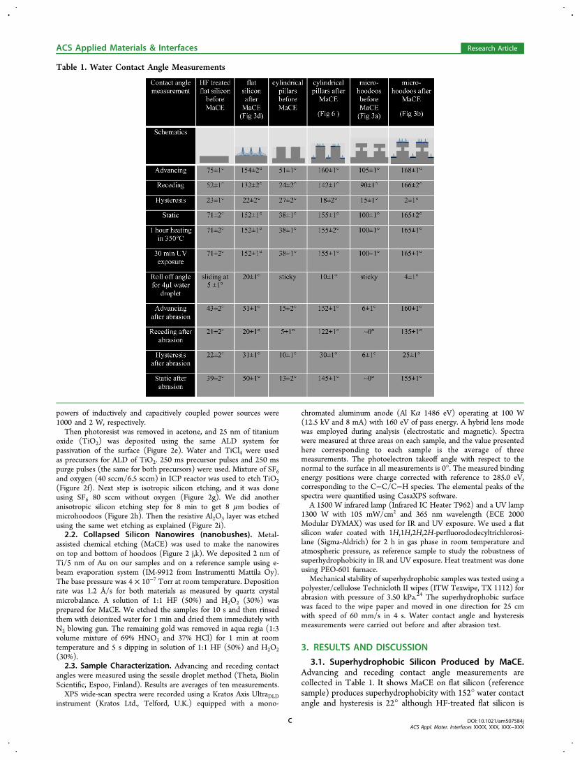
nanowires. We used a thin layer of evaporated gold as a catalyst.Titanium layer improved the adhesion of gold to silicon.Otherwise the gold layer would be peeled off immediatelyduring the MaCE process. The islands of gold act as startingpoint for MaCE etching, resulting in vertical silicon wires. Thekey points are optimizing the noble metal thickness to get alarge number of uniformly sized and uniformly distributed goldnanoislands on the silicon surface. We used 5 nm of Au with 2nm of titanium adhesion layers. Thicker metal layer causes auniform etching due to lack of nanoislands, which is notdesired. Duration of etching is also important because longetching can cause destruction of the nanowires.Collapse of silicon nanowires into nanobushes (Figure 3d)
causes superhydrophobicity without low surface-energy coating.This is due to nanoscale air pockets that are captured and keptunder collapsed nanowires. It is important to notice thataligned nanowires are not robustly superhydrophobic becauseair pockets can escape easily from them and because they needto have final low surface-energy modification to be super-hydrophobic.33
High surface tension of water during the rinsing step afterMaCE causes the nanowires to stick together and to collapse tonanobushes like those reported in ref 42. For robustsuperhydrophobicity, collapsed nanowires are desirable due tore-entrant structures that are necessary for making low contactfraction of solid−liquid, which are the main reason forsuperhydrophobicity without low surface-energy coatings.Although MaCE on flat silicon produces superhydrophobic
surfaces, the hysteresis of 22° is not low enough to result in asmall sliding angle. On the other hand mechanical abrasion can
easily destroy nanowires on the surface, and superhydropho-bicity will be lost.
3.2. MaCE on Top and Bottom of T-shape Pillars. Toimprove the performance of the planar MaCE surface, weadded a second roughness scale with T-shape micropillars toour nanostructures. If cap of T-shape pillars are made out ofthick silicon, then MaCE can be done on top and bottom ofthem (Figure 3a,b).Our T-shape micropillar fabrication technique is based on
sidewall passivation by ALD of TiO2. DRIE is anisotropicprocess that does not etch the thin film on the sidewall, butremoves it from horizontal surfaces. T-shape cap thickness issimply determined by the duration of the first DRIE etch step.MaCE of the thick silicon cap makes the nanowire bushes. Ahighly regular array of T-shape micropillars with 20 μmdiameter, 5 μm pitches, and 25 μm height was demonstrated inthis work (Figure 3). But we are able to tune all the dimensionsof the pillars: height, diameter, and spacing, cap thickness, andnanowire dimensions, too (bigger collapsed silicon nanowiresare demonstrated in Supporting Information, Figure S2).The first critical challenge is to make a thick cap for T-shape
pillars to use it as a substrate in MaCE process. To do so, weneed to consider two main points: (1) use a deposition methodthat is assuring good step coverage of the sidewalls, (2) use amaterial that is resistant in isotropic ICP-DRIE of silicon.Atomic layer deposition of TiO2 is the choice that meets
both requirements. Step coverage of ALD is excellent, and ALDof TiO2 protects the sidewalls of the cap of the T-shape pillarsduring isotropic etching. On the other hand, TiO2 is etchable ina gas mixture of SF6 and O2 (anisotropic silicon etching in ICP-DRIE), while it is resistant to SF6 during isotropic siliconetching. The etch rate of silicon is much higher than etch rateof TiO2 using SF6, so the oxide remains as protection of cap,while silicon is getting etched to form the overhanging
Figure 3. SEM micrograph of hoodoos after DRIE process and (a) before MaCE and (b) after MaCE. Top view high magnification of nanowirebushes (c) on top of a hoodoo after MaCE and (d) on flat silicon after MaCE.
ACS Applied Materials & Interfaces Research Article
DOI: 10.1021/am507584jACS Appl. Mater. Interfaces XXXX, XXX, XXX−XXX
D
structure. Final anisotropic silicon etching step was done toincrease the amount of microscale air pockets to improve therobustness of T-shape pillars.Comparing contact angle measurements (Table 1) of MaCE
on flat silicon and on thick cap T-shape micropillars showshuge reduction of hysteresis (22° to 2°) on hierarchical T-shape structures, which confirms our hypothesis of embeddingmicroscale air pockets between T-shape micropillars. Schematicof microscale air pockets captured between two super-hydrophobic surfaces is illustrated in Figure 4.
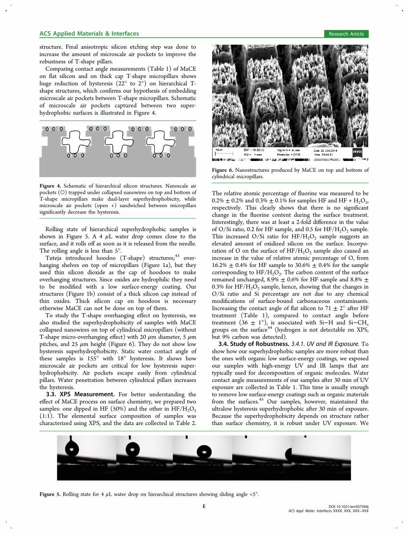
Rolling state of hierarchical superhydrophobic samples isshown in Figure 5. A 4 μL water drop comes close to thesurface, and it rolls off as soon as it is released from the needle.The rolling angle is less than 5°.Tuteja introduced hoodoo (T-shape) structures;43 over-
hanging shelves on top of micropillars (Figure 1a), but theyused thin silicon dioxide as the cap of hoodoos to makeoverhanging structures. Since oxides are hydrophilic they needto be modified with a low surface-energy coating. Ourstructures (Figure 1b) consist of a thick silicon cap instead ofthin oxides. Thick silicon cap on hoodoos is necessaryotherwise MaCE can not be done on top of them.To study the T-shape overhanging effect on hysteresis, we
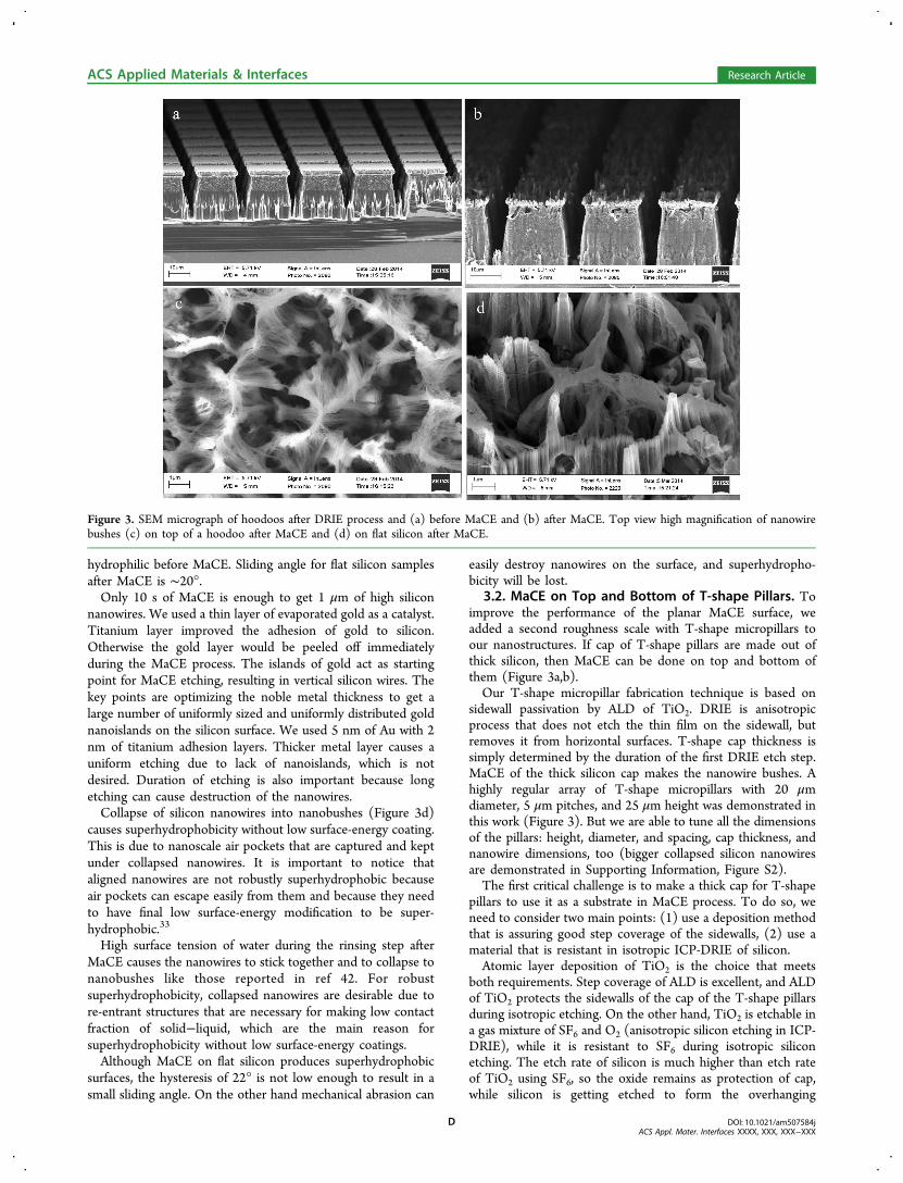
also studied the superhydrophobicity of samples with MaCEcollapsed nanowires on top of cylindrical micropillars (withoutT-shape micro-overhanging effect) with 20 μm diameter, 5 μmpitches, and 25 μm height (Figure 6). They do not show lowhysteresis superhydrophobicity. Static water contact angle ofthese samples is 155° with 18° hysteresis. It shows howmicroscale air pockets are critical for low hysteresis super-hydrophobicity. Air pockets escape easily from cylindricalpillars. Water penetration between cylindrical pillars increasesthe hysteresis.3.3. XPS Measurement. For better understanding the
effect of MaCE process on surface chemistry, we prepared twosamples: one dipped in HF (50%) and the other in HF/H2O2(1:1). The elemental surface composition of samples wascharacterized using XPS, and the data are collected in Table 2.
The relative atomic percentage of fluorine was measured to be0.2% ± 0.2% and 0.3% ± 0.1% for samples HF and HF + H2O2,respectively. This clearly shows that there is no significantchange in the fluorine content during the surface treatment.Interestingly, there was at least a 2-fold difference in the valueof O/Si ratio, 0.2 for HF sample, and 0.5 for HF/H2O2 sample.This increased O/Si ratio for HF/H2O2 sample suggests anelevated amount of oxidized silicon on the surface. Incorpo-ration of O on the surface of HF/H2O2 sample also caused anincrease in the value of relative atomic percentage of O, from16.2% ± 0.4% for HF sample to 30.6% ± 0.4% for the samplecorresponding to HF/H2O2. The carbon content of the surfaceremained unchanged, 8.9% ± 0.6% for HF sample and 8.8% ±0.3% for HF/H2O2 sample, hence, showing that the changes inO/Si ratio and Si percentage are not due to any chemicalmodifications of surface-bound carbonaceous contaminants.Increasing the contact angle of flat silicon to 71 ± 2° after HFtreatment (Table 1), compared to contact angle beforetreatment (36 ± 1°), is associated with Si−H and Si−CHxgroups on the surface44 (hydrogen is not detectable on XPS,but 9% carbon was detected).
3.4. Study of Robustness. 3.4.1. UV and IR Exposure. Toshow how our superhydrophobic samples are more robust thanthe ones with organic low surface-energy coatings, we exposedour samples with high-energy UV and IR lamps that aretypically used for decomposition of organic molecules. Watercontact angle measurements of our samples after 30 min of UVexposure are collected in Table 1. This time is usually enoughto remove low surface-energy coatings such as organic materialsfrom the surfaces.45 Our samples, however, maintained theultralow hysteresis superhydrophobic after 30 min of exposure.Because the superhydrophobicity depends on structure ratherthan surface chemistry, it is robust under UV exposure. We
Figure 4. Schematic of hierarchical silicon structures. Nanoscale airpockets (○) trapped under collapsed nanowires on top and bottom ofT-shape micropillars make dual-layer superhydrophobicity, whilemicroscale air pockets (open +) sandwiched between micropillarssignificantly decrease the hysteresis.
Figure 5. Rolling state for 4 μL water drop on hierarchical structures showing sliding angle <5°.
Figure 6. Nanostructures produced by MaCE on top and bottom ofcylindrical micropillars.
ACS Applied Materials & Interfaces Research Article
DOI: 10.1021/am507584jACS Appl. Mater. Interfaces XXXX, XXX, XXX−XXX
E
used a flat silicon wafer with a low surface-energy coating asreference sample. Water contact angle of reference samplebefore exposure was 125°, and it was reduced to 50° after 30min of exposure due to decomposition of organic moleculesfrom the surface. On the other hand, superhydrophobic TiO2
or ZnO nanowires or nanoparticles become hydrophilic after30 min of UV treatment.30−32
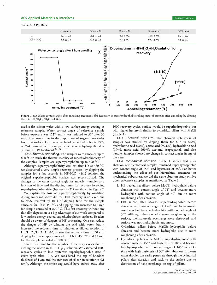
3.4.2. Thermal Annealing. The samples were annealed up to800 °C to study the thermal stability of superhydrophobicity ofthe samples. Samples are superhydrophobic up to 400 °C.Although superhydrophobicity was lost after 1 h at 450 °C,
we discovered a very simple recovery process: by dipping thesamples for a few seconds in HF/H2O2 (1:1) solution theoriginal superhydrophobic surface was reconstructed. Thechanges in the water contact angle for annealed samples as afunction of time and the dipping times for recovery to rollingsuperhydrophobic state (hysteresis <2°) are shown in Figure 7.We explain the loss of superhydrophobicity by oxidation
during annealing above 400 °C. Fast recovery is achieved dueto oxide removal by 10 s of dipping time for the sampleannealed for 1 h in 450 °C, and dipping time increased to 3 minfor sample annealed at 800 °C. This fast recovery without anythin-film deposition is a big advantage of our work compared tolow surface-energy coated superhydrophobic surfaces. Readersshould be aware of dangers of HF processing. One can reducethe danger of HF by diluting the acid with water, but itincreased the recovery time to minutes. A diluted solution ofHF/H2O2/H2O (1:1:10) makes the recovery time to 60 s ofdipping for the sample annealed for 1 h in 450 °C and 15 minfor the sample annealed at 800 °C.There is a limit for the number of recovery cycles due to
etching the silicon in HF + H2O2 solution. We estimated 1000recovery cycles to low hysteresis superhydrophobic state ifevery cycle takes 10 s. We considered the cap of hoodoosthickness of 1 μm and the etch rate of silicon in solution is 0.1nm/s. Although the entire cap would have etched away after
1000 recovery cycles, surface would be superhydrophobic, butwith higher hysteresis similar to cylindrical pillars with MaCE(Table 1).
3.4.3. Chemical Exposure. The chemical robustness ofsamples was studied by dipping them for 6 h in water,hydrofluoric acid (50%), acetic acid (99.8%), hydrochloric acid(37%), nitric acid (69%), acetone, isopropanol, and alsohexane. Samples showed no change in contact angles in any ofthe cases.
3.4.4. Mechanical Abrasion. Table 1 shows that afterabrasion our hierarchical samples remained superhydrophobicwith contact angle of 155° and hysteresis of 25°. For betterunderstanding the effect of our hierarchical structures onmechanical robustness, we did the same abrasion study on fiveother reference samples as mentioned in Table 1.
1. HF-treated flat silicon before MaCE: hydrophilic beforeabrasion with contact angle of 71° and became morehydrophilic with contact angle of 40° due to moreroughening after abrasion.
2. Flat silicon after MaCE: superhydrophobic beforeabrasion with contact angle of 152° due to nanoscaleoverhangs but became hydrophilic with contact angle of50°. Although abrasion adds some roughening to thesurface, the nanoscale overhangs were destroyed, andsurface was not hydrophobic any more.
3. Cylindrical pillars before MaCE: hydrophilic beforeabrasion and became more hydrophilic due to moreroughening after abrasion.
4. Cylindrical pillars after MaCE: superhydrophobic withcontact angle of 155° and hysteresis of 18° and becameless hydrophobic with contact angle of 145° in stickystate with high hysteresis of 30° after abrasion. It meanswater droplet can easily penetrate through the cylindricalpillars after abrasion and stick to the surface due todestruction of nano-overhangs on top of pillars.
Table 2. XPS Data
C atom % O atom % F atom % Si atom % O/Si ratio
HF 8.9 ± 0.6 16.2 ± 0.4 0.2 ± 0.2 74.6 ± 0.8 0.2 ± 0.0HF + H2O2 8.8 ± 0.3 30.6 ± 0.4 0.3 ± 0.1 60.3 ± 0.5 0.5 ± 0.0
Figure 7. (a) Water contact angle after annealing treatment. (b) Recovery to superhydrophobic rolling state of samples after annealing by dippingthem in HF/H2O2/H2O solution.
ACS Applied Materials & Interfaces Research Article
DOI: 10.1021/am507584jACS Appl. Mater. Interfaces XXXX, XXX, XXX−XXX
F
5. Microhoodoos before MaCE: hydrophobic with contactangle of 100° with hysteresis of 15° and becamesuperhydrophilic after abrasion. The hydrophobic stateof microhoodoos before MaCE is specifically due to thetrapped microscale air pockets below them; afterroughening (abrasion) the overhangs are destroyed,and the air pockets can easily escape. Dual scale micro/nano roughening causes the superhydrophilicity ofsilicon.
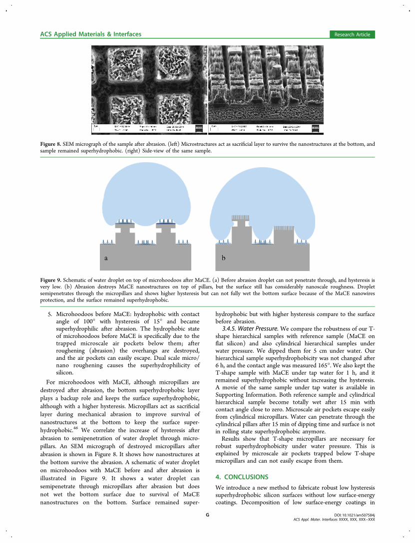
For microhoodoos with MaCE, although micropillars aredestroyed after abrasion, the bottom superhydrophobic layerplays a backup role and keeps the surface superhydrophobic,although with a higher hysteresis. Micropillars act as sacrificiallayer during mechanical abrasion to improve survival ofnanostructures at the bottom to keep the surface super-hydrophobic.46 We correlate the increase of hysteresis afterabrasion to semipenetration of water droplet through micro-pillars. An SEM micrograph of destroyed micropillars afterabrasion is shown in Figure 8. It shows how nanostructures atthe bottom survive the abrasion. A schematic of water dropleton microhoodoos with MaCE before and after abrasion isillustrated in Figure 9. It shows a water droplet cansemipenetrate through micropillars after abrasion but doesnot wet the bottom surface due to survival of MaCEnanostructures on the bottom. Surface remained super-
hydrophobic but with higher hysteresis compare to the surfacebefore abrasion.
3.4.5. Water Pressure. We compare the robustness of our T-shape hierarchical samples with reference sample (MaCE onflat silicon) and also cylindrical hierarchical samples underwater pressure. We dipped them for 5 cm under water. Ourhierarchical sample superhydrophobicity was not changed after6 h, and the contact angle was measured 165°. We also kept theT-shape sample with MaCE under tap water for 1 h, and itremained superhydrophobic without increasing the hysteresis.A movie of the same sample under tap water is available inSupporting Information. Both reference sample and cylindricalhierarchical sample become totally wet after 15 min withcontact angle close to zero. Microscale air pockets escape easilyfrom cylindrical micropillars. Water can penetrate through thecylindrical pillars after 15 min of dipping time and surface is notin rolling state superhydrophobic anymore.Results show that T-shape micropillars are necessary for
robust superhydrophobicity under water pressure. This isexplained by microscale air pockets trapped below T-shapemicropillars and can not easily escape from them.
4. CONCLUSIONS
We introduce a new method to fabricate robust low hysteresissuperhydrophobic silicon surfaces without low surface-energycoatings. Decomposition of low surface-energy coatings in
Figure 8. SEM micrograph of the sample after abrasion. (left) Microstructures act as sacrificial layer to survive the nanostructures at the bottom, andsample remained superhydrophobic. (right) Side-view of the same sample.
Figure 9. Schematic of water droplet on top of microhoodoos after MaCE. (a) Before abrasion droplet can not penetrate through, and hysteresis isvery low. (b) Abrasion destroys MaCE nanostructures on top of pillars, but the surface still has considerably nanoscale roughness. Dropletsemipenetrates through the micropillars and shows higher hysteresis but can not fully wet the bottom surface because of the MaCE nanowiresprotection, and the surface remained superhydrophobic.
ACS Applied Materials & Interfaces Research Article
DOI: 10.1021/am507584jACS Appl. Mater. Interfaces XXXX, XXX, XXX−XXX
G

superhydrophobic surfaces is the main reason for avoiding themin long-term practical applications. Although HF-treated siliconis intrinsically hydrophilic (contact angle 71°), the proposedhierarchical structuring makes silicon superhydrophobic. Weshowed that structuring the surface can be dominant over thechemistry. Because the superhydrophobicity depends onstructure rather than surface chemistry, it is robust under UV,IR, and chemical exposure, water pressure, and thermaltreatments. It is also robust under mechanical abrasion due toexistence of dual-layer structure.About 10% of sunlight is in the UV range, and 95% of that
can penetrate through the atmosphere. This is enough toreduce the robustness of superhydrophobicity based on organiclow surface-energy coatings due to decomposition, over time.Our approach can improve the stability of superhydrophobicmaterials that are used in open environments such as self-cleaning buildings and cloths.Chemically robust superhydrophobic surfaces have many
applications in both research and industry. For example acidicrain causes loss of water-repelling properties of self-cleaningsolar cells because of chemical reactions between organiccoatings and acids.47 Our approach can improve the efficiencyof solar cells that are often located in industrial areas with highconcentration of nitrogen oxide that produce nitric acid inacidic rains.In fact these types of surfaces have a dual approach for their
practical applications. On one hand they are very robust underharsh conditions below 400 °C. On the other hand they can beused in switching applications in higher temperature (>400 °C)environments where they become superhydrophilic.The concept of embedding microscale air pockets in dual-
layer superhydrophobic surfaces can be utilized in marineindustry to reduce biofouling. For example the estimated costsdue to fouling for the U.S. Navy fleet is between $180 M and$260 M per year.48
In future one can think of robust superhydrophobic surfacein higher temperatures without low surface-energy coatings forheat-transfer systems. Recent studies revealed that superbiphilic(combination of superhydrophobic and superhydrophilic)surfaces are the most efficient surfaces for heat-transfersystems.49 Our suggested surfaces have the ability todramatically change the surface energy and can be used forheat-transfer systems involving superbiphilic approaches.
■ ASSOCIATED CONTENT
*S Supporting InformationUnderstanding of nanoscale air pockets trapped belowcollapsed silicon nanowires and also a movie of super-hydrophobic sample under tap water. This material is availablefree of charge via the Internet at http://pubs.acs.org.
■ AUTHOR INFORMATION
Corresponding Authors*E-mail: [email protected]. Phone: 003584603517. (S.H.)*E-mail: [email protected]. (S.F.)
Author ContributionsThe manuscript was written through contributions of allauthors. All authors have given approval to the final version ofthe manuscript.
NotesThe authors declare no competing financial interest.
■ ACKNOWLEDGMENTS
This research was supported by the Academy of Finland(PROWET Project Nos. 263538 and 266820). Waferprocessing took place at Aalto Nanofab cleanroom. Theauthors acknowledge A. S. Syed for his help in silicon etchingprocess.
■ ABBREVIATIONS
ALD, atomic layer depositionMaCE, metal-assisted chemical etchingICP-DRIE, inductively coupled plasma−deep reactive ionetching
■ REFERENCES(1) Crick, C. R.; Parkin, I. P. Preparation and Characterisation ofSuper-Hydrophobic Surfaces. Chem.Eur. J. 2010, 16, 3568−3588.(2) Verho, T.; Bower, C.; Andrew, P.; Franssila, S.; Ikkala, O.; Ras, R.H. A. Mechanically Durable Superhydrophobic Surfaces. Adv. Mater.2011, 23, 673−678.(3) Lafuma, A.; Quere, D. Superhydrophobic States. Nat. Mater.2003, 2, 457−460.(4) Roach, P.; Shirtcliffe, N. J.; Newton, M. I. Progess InSuperhydrophobic Surface Development. Soft Matter 2008, 4, 224−240.(5) Yan, Y. Y.; Gao, N.; Barthlott, W. Mimicking NaturalSuperhydrophobic Surfaces and Grasping The Wetting Process: AReview On Recent Progress In Preparing Superhydrophobic Surfaces.Adv. Colloid Interface Sci. 2011, 169, 80−105.(6) Guo, Z.; Liu, W.; Su, B.-L. Superhydrophobic Surfaces: FromNatural To Biomimetic To Functional. J. Colloid Interface Sci. 2011,353, 335−355.(7) Ma, M.; Hill, R. M. Superhydrophobic Surfaces. Curr. Opin.Colloid Interface Sci. 2006, 11, 193−202.(8) Li, X.-M.; Reinhoudt, D.; Crego-Calama, M. What Do We NeedFor a Superhydrophobic Surface? A Review On The Recent ProgressIn The Preparation Of Superhydrophobic Surfaces. Chem. Soc. Rev.2007, 36, 1350−1368.(9) Tian, Y.; Su, B.; Jiang, L. Interfacial Material System ExhibitingSuperwettability. Adv. Mater. 2014, 26, 6872−6897.(10) Leem, J. W.; Kim, S.; Lee, S. H.; Rogers, J. A.; Kim, E.; Yu, J. S.Efficiency Enhancement of Organic Solar Cells Using HydrophobicAntireflective Inverted Moth-Eye Nanopatterned PDMS Films. Adv.Energy Mater. 2014, 4, 1301315.(11) Smitha, V. S.; Jaimy, K. B.; Shajesh, P.; Jeena, J. K.; Warrier, K.G. UV Curable Hydrophobic Inorganic−Organic Hybrid Coating OnSolar Cell Covers For Photocatalytic Self Cleaning Application. J.Mater. Chem. A 2013, 1, 12641−12649.(12) Park, Y.-B.; Im, H.; Im, M.; Choi, Y.-K. Self-Cleaning Effect OfHighly Water-Repellent Microshell Structures For Solar CellApplications. J. Mater. Chem. 2010, 21, 633−636.(13) Kim, J.-Y.; Choi, K.; Moon, D.-I.; Ahn, J.-H.; Park, T. J.; Lee, S.Y.; Choi, Y.-K. Surface Engineering For Enhancement Of Sensitivity Inan Underlap-FET Biosensor By Control Of Wettability. Biosens.Bioelectron. 2013, 41, 867−870.(14) Anastasiadis, S. H. Development of Functional Polymer Surfaceswith Controlled Wettability. Langmuir 2013, 29, 9277−9290.(15) Yao, X.; Song, Y.; Jiang, L. Applications of Bio-Inspired SpecialWettable Surfaces. Adv. Mater. 2011, 23, 719−734.(16) Azarbayjani, A. F.; Lin, H.; Yap, C. W.; Chan, Y. W.; Chan, S. Y.Surface Tension and Wettability In Transdermal Delivery: A Study OnThe In-Vitro Permeation Of Haloperidol With Cyclodextrin AcrossHuman Epidermis. J. Pharm. Pharmacol. 2010, 62, 770−778.(17) Jokinen, V.; Kostiainen, R.; Sikanen, T. Multiphase DesignerDroplets for Liquid-Liquid Extraction. Adv. Mater. 2012, 24, 6240−6243.
ACS Applied Materials & Interfaces Research Article
DOI: 10.1021/am507584jACS Appl. Mater. Interfaces XXXX, XXX, XXX−XXX
H

(18) Almutairi, Z.; Ren, C. L.; Simon, L. Evaluation ofPolydimethylsiloxane (PDMS) Surface Modification Approaches forMicrofluidic Applications. Colloids Surf., A 2012, 415, 406−412.(19) Feng, X. J.; Jiang, L. Design and Creation of Superwetting/Antiwetting Surfaces. Adv. Mater. 2006, 18, 3063−3078.(20) Jokinen, V.; Sainiemi, L.; Franssila, S. Complex Droplets onChemically Modified Silicon Nanograss. Adv. Mater. 2008, 20, 3453−3456.(21) Sainiemi, L.; Jokinen, V.; Shah, A.; Shpak, M.; Aura, S.; Suvanto,P.; Franssila, S. Non-Reflecting Silicon and Polymer Surfaces byPlasma Etching and Replication. Adv. Mater. 2011, 23, 122−126.(22) Cao, L.; Price, T. P.; Weiss, M.; Gao, D. Super Water- and Oil-Repellent Surfaces on Intrinsically Hydrophilic and Oleophilic PorousSilicon Films. Langmuir 2008, 24, 1640−1643.(23) Xiu, Y.; Zhu, L.; Hess, D. W.; Wong, C. P. Hierarchical SiliconEtched Structures for Controlled Hydrophobicity/Superhydrophobic-ity. Nano Lett. 2007, 7, 3388−3393.(24) Xiu, Y.; Liu, Y.; Hess, D. W.; Wong, C. P. Mechanically RobustSuperhydrophobicity on Hierarchically Structured Si Surfaces. Nano-technology 2010, 21, 155705.(25) Song, Y.; Nair, R. P.; Zou, M.; Wang, Y. SuperhydrophobicSurfaces Produced by Applying a Self-Assembled Monolayer to SiliconMicro/Nano-Textured Surfaces. Nano Res. 2009, 2, 143−150.(26) Hu, H.; Swaminathan, V. V.; Farahani, M. R. Z.; Mensing, G.;Yeom, J.; Shannon, M. A.; Zhu, L. Hierarchically Structured Re-entrantMicrostructures for Superhydrophobic Surfaces with Extremely LowHysteresis. J. Micromech. Microeng. 2014, 24, 095023.(27) Sun, G.; Gao, T.; Zhao, X.; Zhang, H. Fabrication of Micro/Nano Dual-Scale Structures by Improved Deep Reactive Ion Etching.J. Micromech. Microeng. 2010, 20, 075028.(28) Qi, D.; Lu, N.; Xu, H.; Yang, B.; Huang, C.; Xu, M.; Gao, L.;Wang, Z.; Chi, L. Simple Approach to Wafer-Scale Self-CleaningAntireflective Silicon Surfaces. Langmuir 2009, 25, 7769−7772.(29) Zhang, X.; Zhang, J.; Ren, Z.; Zhang, X.; Tian, T.; Wang, Y.;Dong, F.; Yang, B. Photoinduced Cleaning of Water-Soluble Dyes onPatterned Superhydrophilic/Superhydrophobic Substrates. Nanoscale2010, 2, 277−281.(30) Gong, M.; Yang, Z.; Xu, X.; Jasion, D.; Mou, S.; Zhang, H.;Long, Y.; Ren, S. Superhydrophobicity of Hierarchical ZnO NanowireCoatings. J. Mater. Chem. A 2014, 2, 6180−6184.(31) Shaik, U. P.; Kshirsagar, S.; Krishna, M. G.; Tewari, S. P.; DharPurkayastha, D.; Madhurima, V. Growth of Superhydrophobic ZincOxide Nanowire Thin Films. Mater. Lett. 2012, 75, 51−53.(32) Yao, L.; Zheng, M.; Li, C.; Ma, L.; Shen, W. Facile Synthesis ofSuperhydrophobic Surface of ZnO Nanoflakes: Chemical Coating andUV-Induced Wettability Conversion. Nanoscale Res. Lett. 2012, 7, 216.(33) He, Y.; Jiang, C.; Yin, H.; Chen, J.; Yuan, W. SuperhydrophobicSilicon Surfaces with Micro−Nano Hierarchical Structures Via DeepReactive Ion Etching and Galvanic Etching. J. Colloid Interface Sci.2011, 364, 219−229.(34) Xiu, Y.; Zhang, S.; Yelundur, V.; Rohatgi, A.; Hess, D. W.;Wong, C. P. Superhydrophobic and Low Light Reflectivity SiliconSurfaces Fabricated by Hierarchical Etching. Langmuir 2008, 24,10421−10426.(35) Lee, C.; Kim, C.-J. Maximizing the Giant Liquid Slip onSuperhydrophobic Microstructures by Nanostructuring Their Side-walls. Langmuir 2009, 25, 12812−12818.(36) Kim, J.; Kim, Y. H.; Choi, S.-H.; Lee, W. Curved SiliconNanowires with Ribbon-like Cross Sections by Metal-AssistedChemical Etching. ACS Nano 2011, 5, 5242−5248.(37) Hildreth, O. J.; Brown, D.; Wong, C. P. 3D Out-of-PlaneRotational Etching with Pinned Catalysts in Metal-Assisted ChemicalEtching of Silicon. Adv. Funct. Mater. 2011, 21, 3119−3128.(38) Huang, Z.; Geyer, N.; Werner, P.; de Boor, J.; Gosele, U. Metal-Assisted Chemical Etching of Silicon: A Review. Adv. Mater. 2011, 23,285−308.(39) He, Y.; Jiang, C.; Yin, H.; Yuan, W. Tailoring the Wettability ofPatterned Silicon Surfaces with Dual-Scale Pillars: From Hydro-
philicity to Superhydrophobicity. Appl. Surf. Sci. 2011, 257, 7689−7692.(40) Wang, J.; Liu, F.; Chen, H.; Chen, D. SuperhydrophobicBehavior Achieved From Hydrophilic Surfaces. Appl. Phys. Lett. 2009,95, 084104.(41) Liu, T.; Kim, C.-J. Turning a Surface Superrepellent Even toCompletely Wetting Liquids. Science 2014, 346, 1096−1100.(42) Zhang, S.; Wang, X.; Liu, H.; Shen, W. Controllable Light-Induced Conic Structures in Silicon Nanowire Arrays by Metal-Assisted Chemical Etching. Nanotechnology 2014, 25, 025602.(43) Tuteja, A.; Choi, W.; Mabry, J. M.; McKinley, G. H.; Cohen, R.E. Robust Omniphobic Surfaces. Proc. Natl. Acad. Sci. U. S. A. 2008.(44) Grundner, M.; Jacob, H. Investigations on Hydrophilic andHydrophobic Silicon (100) Wafer Surfaces by X-ray Photoelectronand High-Resolution Electron Energy Loss-Spectroscopy. Appl. Phys.A: Solids Surf. 1986, 39, 73−82.(45) Balaur, E.; Macak, J. M.; Taveira, L.; Schmuki, P. Tailoring TheWettability of TiO2 Nanotube Layers. Electrochem. Commun. 2005, 7,1066−1070.(46) Kondrashov, V.; Ruhe, J. Microcones and Nanograss: TowardMechanically Robust Superhydrophobic Surfaces. Langmuir 2014, 30,4342−4350.(47) Fernandez-García, A.; Díaz-Franco, R.; Martinez, L.; Wette, J.Study of the Effect of Acid Atmospheres in Solar Reflectors Durabilityunder Accelerated Aging Conditions. Energy Procedia 2014, 49, 1682−1691.(48) Kirschner, C. M.; Brennan, A. B. Bio-Inspired AntifoulingStrategies. Annu. Rev. Mater. Res. 2012, 42, 211−229.(49) Betz, A. R.; Jenkins, J.; Kim, C.-J.; Attinger, D. Boiling HeatTransfer on Superhydrophilic, Superhydrophobic, and SuperbiphilicSurfaces. Int. J. Heat Mass Transfer 2013, 57, 733−741.
ACS Applied Materials & Interfaces Research Article
DOI: 10.1021/am507584jACS Appl. Mater. Interfaces XXXX, XXX, XXX−XXX
I
Copyright © 2022 FDOKUMEN