Rexcan DS2 manual
45
-
Upload
khangminh22 -
Category
Documents
-
view
5 -
download
0
Transcript of Rexcan DS2 manual


1
1. Precautions for Use A. General Precautions 3
B. Instructions for Storage
C. Precautions in French
4
5
2. Product Information A. Basic Composition 7
B. Product Specifications 9
C. PC Specifications 9
3. Product Installation A. Software Installation 11
B. Hardware Installation 13
C. Confirmation of Hardware Installation 14
4. Using Identica Blue A. Preparations 15
B. Software GUI (Graphic User Interface) 22
C. Calibration 27
D. Model Handling 29

2
User Guide
5. Workflow A. Scanned Teeth Registration 31
B. Selecting Scanning Area 34
C. Setting Depth
D. Inserting Model
E. Additional Scan
F. Manual Alignment
G. Checking Results
35
36
37
39
43

3
1. Precautions for Use
A. General Precautions
A.1. Only qualified persons are allowed to operate this machine.
A.2. The following cautions shall be taken when installing this machine.
A.2.1. Install the machine in a place where the machine will not be adversely affected by water, air
pressure, temperature, high humidity, dust, salt, ion, and other environmental factors.
A.2.2. Pay special attention to external hazards such as slope, vibration, and shock.
A.2.3. Do not install the machine in a chemical storage area or any place where there are gas emissions.
A.2.4. Install the machine in a well-ventilated place.
A.2.5. Take special care about power frequency, voltage, and allowable current (or power consumption).
A.3. Cautions before using this machine
A.3.1. Make sure that every component is correctly connected and fixed.
A.3.2. Make sure that the machine is correctly recognized in Device Manager.
A.3.3. Do not move Identica Blue by applying force to its arm.
A.4. Cautions when using this machine
A.4.1. Do not give shock or vibration to the machine during use.
A.4.2. Do not turn off the power of Identica Blue while using it.
A.4.3. Do not block the vent while using the machine.
A.4.4. If there is smoke or strange smell, immediately turn off the power switch, pull out the power plug
from the outlet, and contact the manufacturer.
A.4.5. If you do not use the machine or you are absent for a long time, remove the power plug from the
outlet. .
A.5. If this machine has any problem, it should be repaired by the manufacturer. User shall not arbitrarily
disassemble or assemble the machine.
A.6. Do not modify this machine under any circumstance.
A.7. Maintenance
A.7.1. If you are using this machine again after not using it for a long time, check if the machine is
installed normally and calibrated properly.
A.7.2. Check if the scan data are normally outputted.
A.7.3. Periodically clean this machine with a dry cloth while taking care not to let water get inside the
machine.
A.7.4. Do not clean this machine with corrosive detergent or antiseptic solution.

4
User Guide
A.7.5. Always turn off the power when checking the inside of this machine.
* Do not aim scan spray toward the scanner. * Do not touch the mirror inside the scanner.
B. Instructions for Storage
B.1. Lightly wipe the surface with a dry cloth while taking care not to let water, liquid, or other foreign substances
contaminate the machine.
B.2. Keep the machine in a safe place so that it will not be damaged due to carelessness.
B.3. Environmental conditions for use
B.3.1. Ambient temperature range: 0 - 35 ˚C
B.3.2. Relative humidity: 20 - 75 %
B.4. Environmental conditions for transport and storage
B.4.1. Ambient temperature range: -5℃ 〜 45℃
B.4.2. Relative humidity: 20% - 80%

5
1. Précautions d’utilisation
A. Généralités
A.1. Ne pas utiliser cet appareil sauf le personnel compétent et expérimenté.
A.2. Précautions à prendre lors d’installation de l’appareil.
A.2.1. Mise en installation doit s’effectuer dans un endroit sec et sans présence d’eau.
A.2.2. Installer l’appareil dans un endroit qui n’est pas affecté par la pression atmosphérique, la
température, l’humidité, l’état d’aération ou par l’air contenant des poussières, du sel et des ions.
A.2.3. Vérifier les facteurs qui peuvent agir sur la sécurité de l’appareil : vibration, choc, inclinaison etc.
A.2.4. Ne pas l’installer dans un local stockant de matières chimiques ou émettant du gaz.
A.2.5. Ne pas l’installer dans un endroit mal aéré.
A.2.6. Attentions aux fréquences électriques, à la tension électrique et au courant admis (ou à la
consommation électrique).
A.3. Précautions à prendre avant l’utilisation.
A.3.1. Vérifier l’état du branchement et des fixations.
A.3.2. Vérifier si l’écran administrateur affiche sans faute l’état de l’appareil.
A.3.3. Lors de manipulation de l’axe « Identica Blue », éviter de forcer.
A.4. Précautions à prendre lors d’utilisation.
A.4.1. Protéger l’appareil du choc ou de la vibration lorsque l’appareil est en marche.
A.4.2. Ne pas éteindre “Identica Blue” lorsque l’appareil est en marche.
A.4.3. Ne pas obstruer le trou d’aération lorsque l’appareil est en marche
A.4.4. En cas de détection de fumée ou d’odeur anormale, éteindre immédiatement l’appareil puis le
débrancher avant de contacter le fabricant.
A.4.5. En cas d’absence humaine ou de non utilisation à long terme, débrancher l’appareil.
A.5. En cas de détection de problèmes, la tâche de l’utilisateur se limite à vérifier l’état de l’appareil. Demander la
réparation auprès du fabricant au lieu de le démanteler/réassembler librement.
A.6. Ne pas transformer l’appareil.
A.7. Entretien/vérification
A.7.1. Lors d’utilisation de l’appareil suite à une longue période de repos, vérifier l’état d’installation et
de calibrage de l’écran.
A.7.2. Vérifier si les données scannées sortent d’une façon normale.
A.7.3. Essuyer l’appareil à intervalle régulière avec un torchon sec pour empêcher l’eau de pénétrer dans
la partie intérieure.

6
User Guide
A.7.4. Ne pas nettoyer l’appareil avec du détergent corrosif ou de la solution désinfectante.
A.7.5. Eteindre impérativement l’appareil lors d’inspection de la partie intérieure.
* Ne pas vaporiser vers la partie intérieure du scanner.
* Ne pas toucher le miroir situé à l’intérieur du scanner.
B. Conditions d’entretien
B.1. Essuyer légèrement la surface de l’appareil avec un torchon sec, tout en prenant précautions pour le protéger
du contact avec substances étrangères tels que l’eau ou autres types de liquide etc.
B.2. Après l’utilisation, conserver l’appareil dans un endroit sûr pour éviter tout dégât causé par l’insouciance.
B.3. Conditions de l’environnement pour l’utilisation
B.3.1. Température ambiante : 0 〜 35 ˚C
B.3.2. Taux d’humidité : 20 〜 75 %
B.4. Conditions de l’environnement pour le transport/stockage
B.4.1. Température ambiante : -5℃ 〜 45℃
B.4.2. Taux d’humidité : 20% 〜 80

7
2. Product Information
A. Basic Composition
A.1. Identica Light scanner
8
User Guide
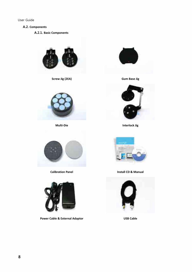
A.2. Components
A.2.1. Basic Components
Screw Jig (2EA) Gum Base Jig
Multi-Die Interlock Jig
Calibration Panel Install CD & Manual
Power Cable & External Adaptor USB Cable

9
Half block Jig (2EA)
Two of half jigs have to be combined with the calibration panel or basic jig for the normal scanning work.
B. Product Specifications
Category Description
Camera resolution 1.3 Mega pixels
Point spacing 0.065 mm
Scan region 80 mmⅹ60 mmⅹ60 mm
Scan principle Phase-shifting optical triangulation, twin camera type
Size 290mm x 290mm x 340mm
Weight 16 kg
light source LED, 50 ANSI-lumens
light color Cyan
connection method USB 3.0 B Type
Power AC 100 ~ 240V, 50~60 Hz
C. PC Specifications
C.1. Minimum Requirements
CPU Intel i5 2.6G or higher / equivalent AMD CPU
RAM 8G or higher
Graphic Card NVIDIA GeForce GTS 450 or higher / equivalent ATI graphic card
O/S Windows 7 64 Bit
C.2. Recommended Requirements
CPU Intel i5 2.6G or higher
RAM 16G or higher
Graphic Card NVIDIA GeForce GTS 450 or higher / equivalent ATI graphic card
O/S Windows 7 64 Bit (32 Bit is not possible )

10
User Guide
C.3. Not compatible USB Controller
C.3.1. The use of Etron / ASMedia / Ti / Via / Fresco FL1000 USB Controller may not be always stable
due to the camera compatibility issue.
C.3.2. If the USB controller in your PC has a higher version than what suggest above, please contact the supplier.

11
3. Product Installation
A. Software Installation
A.1. Insert the Install CD into the PC and run setup.exe.
A.2. Check the license and select “I agree to the…”..
A.3. Specify the installed location (default path recommended)..

12
User Guide
A.4. At last, check the installation information.
A.5. The Identica software and other necessary software programs are automatically installed.
A.6. When the installation is successfully completed, restart the computer.

13
B. Hardware Installation
After installing the software, restart the computer and install the hardware.
※ Caution: You must firmly connect all the cables for Identica Blue to the PC.
(Identica Blue has two cables: USB cable and power cable.)
B.1. Connect the power cable.
B.2. Connect the USB cable.
B.3. Turn on the Identica blue.
Turn on the Power switch at the back of Identica Blue.

14
User Guide
C. Confirmation of Hardware Installation
C.1. Check MEDIT USB Remote NDIS Network Device.
C.2. Check Camera

15
4. How to use Identica Blue
A. Preparation before use
A.1. Checklist before use
A.1.1. Is the scanner connected properly?
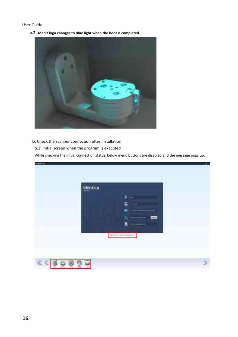
a. Check the boot of the projector
a.1. Medit logo appears when power is turned on.
16
User Guide
a.2. Medit logo changes to Blue light when the boot is completed.
b. Check the scanner connection after installation
b.1. Initial screen when the program is executed
While checking the initial connection status, below menu buttons are disabled and the message pops up.

17
b.2. Proper connection with scanner as program runs
It takes about 30 seconds connecting to the scanner for the first time. Later, It takes about 3~5 seconds
after the initial connection. While connecting, the projector may blink temporarily.
c. The instruction message appears when the scanner is not connected properly. Check the status of
the device according to the instruction message.

18
User Guide
d. “The scanner is now ready to be used.”
<The scanner is connected properly.>
e. “Cannot find the Identica serial port.”
<The computer cannot locate the scanner.>
Check the power button of scanner.
Check the connection of USB cable.

19
f. “Failed to connect the camera.”
<The camera is not connected properly.>
Check the connection of USB cable.
Check the camera’s connection status.
g. “Cannot find the Identica projector”
<The projector is not connected properly.>

20
User Guide
Check the projector’s connection status.
A.1.2. Is there a correct calibration file?
a. You must perform calibration again if the scanner received a strong shock, vibration, etc.
b. You should perform calibration once a month if the scanner has not been moved, shocked, or
vibrated.
A.1.3. Is the object of measurement within the measurement area of scanner?
a. Make sure that the measured model is within the camera area through the camera window in the
tooth model mounting step.
A.1.4. Is the measured model dark or shiny?
a. Identica Blue acquires three-dimensional data with the principle that the camera captures and
analyzes the pattern projected by the projector. However, measurement may be difficult if the
pattern projected on the material of the measured model is not clear.
b. If measurement is difficult, you should apply the spray by referring to Applying Scan Spray below
before measuring.
A.2. Applying Scan Spray
Scan spray is often the same or similar as “Developer Spray” used in the detection of cracks in
metallurgy. It is a matte white, extra fine powder, suspended in a solvent.
You should apply the scan spray if the measured model is dark, glossy like metal, or transparent,
making it difficult to scan.
(Generally, it is not needed to spray on the completely dried model)
A.2.1. Spraying Procedure
a. Spread a sheet of paper with a sufficient size (newspaper, etc.) in a well-ventilated place and put
the object on it.
b. Apply spray with the distance between the object at 30-50cm.
c. For uniform spray to all areas of the object, apply the spray at various angles. Do not spray too
much at once, but in intervals of 1-3 sec.
A.2.2. Cautions for Spray
a. The scan spray has a combustion risk because it contains solvent.
b. Do not use spray in a place where there are sparks.
c. Never inhale spray or apply it to people’s skin or eyes.
A.3. Using Jig
A.3.1. Prepare a clean object and attach it to the jig.
A.3.2. If necessary, apply scan spray before mounting it.
A.3.3. If necessary, attach the object of measurement to the jig with the supplied gum and make sure
that it does not sway.

21
A.3.4. It can only be mounted in one direction because there is a groove at the bottom.
A.3.5. When Identica Blue is mounted, the front of the model must face the user as shown in the
following picture.

22
User Guide
B. Software GUI (Graphic User Interface)
B.1. Start
B.1.1. Basic Status Window
Check the scanner information including dental lab name, date, saving path, scanner connection
state, and last calibration date.
B.1.2. Selection Menu at the Bottom
a. Status
Show the basic status page.
b. Calibration
Calibrate the connected device.
c. Setting
Change the settings of the program.
①
②

23
Dental Lab: Name of the dental lab to be entered in the user information by default
Language: Select a language to use (English, Korean, German, Italian, French, Spanish,
Japanese, and Chinese are available)
Labeling: Choose a teeth numbering method.
Date type: Date display format
Output directory: Folder for saving data
Move to the origin before saving: Move the central coordinates (x, y, z) of scan data to (0,
0, 0) before saving (default coordinates: (0, 0, 200))
Preparation teeth data saving separately: Select whether to save the preparation tooth
and base scan data together or separately.
Use Y axis as scan data orientation: Rotate the central axis of scan data to the Y-axis before
saving.
d. Online Update
When a higher version of the software is released, you can update your software here.

24
User Guide
e. Edit file
Functions that can open STL and edit(Fill-hole/cut) are provided.
The above functions are activated when the file is opened.
1. File edit window: import STL file / Save / Data On/Off on the screen.
①
③
②

25
2. Functions below are the same as existing functions. If the previous button is selected on this page, you can go to the first page
3. Detailed functions
Check box : Remove the unchecked model on the screen. (Not a deleting function)
Indicates the file name
Change the color of the current model being rendered
Remove the current model from the screen (Delete)
Show all : Show all files on the screen in case of many files
Hide all : Off multiple files on the screen. (Not a delete function)
B.2. Scanned Teeth Registration
B.2.1. Auxiliary Window This window plays auxiliary roles when necessary such as camera and user information entry. B.2.2. Main Window
This window plays main roles such as the display of critical information or work information and
tooth selection. B.2.3. Selection Menu at the Bottom
Home, Previous and Next function buttons that are available on the current page are displayed.
You can click one of the icons or select the corresponding number button.
① ②
③

26
User Guide
a. Basic This is the basic tooth model scan process.
b. Multi-Die
Switch to the multi-die mode.
c. Impression
Not supported for Identica Light.
d. Denture
Switch to the Denture mode.
B.3. Additional Scan
B.3.1. Model View Window
This window graphically shows the three-dimensional data acquired from the scanner.
B.3.2. Tooth Information Window
This window shows the basic information about the tooth selected by user.
B.3.3. Process Window
This window shows the steps required for scanning and the current progress.
① ②
③
④
⑤

27
B.3.4. Manual Brightness
The preset brightness (displayed on the screen) can be changed manually according to cases and
circumstances.
B.3.5. Progress Bar
A message and a progress bar are displayed as needed.
C. Calibration
C.1. Panel Mounting
Mount the calibration panel in the scanner as shown in the picture.
C.2. Calibration
In the start step, double click the Calibration icon or select the number 2 button to run the
calibration process.
28
User Guide
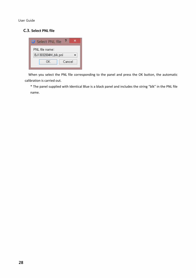
C.3. Select PNL file
When you select the PNL file corresponding to the panel and press the OK button, the automatic
calibration is carried out.
* The panel supplied with Identical Blue is a black panel and includes the string “blk” in the PNL file
name.
29
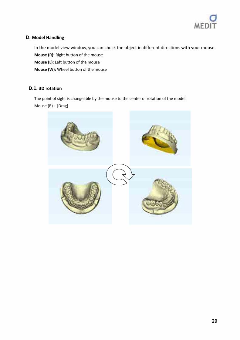
D. Model Handling
In the model view window, you can check the object in different directions with your mouse.
Mouse (R): Right button of the mouse
Mouse (L): Left button of the mouse
Mouse (W): Wheel button of the mouse
D.1. 3D rotation
The point of sight is changeable by the mouse to the center of rotation of the model.
Mouse (R) + [Drag]

30
User Guide
D.2. Pan
The model is moved horizontally from the line of vision.
Mouse (W) + [Drag]
D.3. Zoom in/ Zoom out
Zoom in or out the model in the model view window.
Mouse (W) [Scroll] or Mouse (W) + Mouse (R) + [Drag]
Zoom in Zoom out
Dragging direction

31
5. Workflow
A. Scanned Teeth Registration
A.1. Basic
Select this process when scanning a basic tooth model. The scan process is determined by the selection
of tooth type and options.
A.1.1. Tooth Registration
a. Select a tooth type and options. Then click a tooth to apply them to it.
b. You can clear the selected tooth information by right-clicking your mouse.
c. When you click a tooth and drag the mouse to continuously apply or clear the tooth type.
d. For waxup models, the bridge information is displayed on the screen.
e. When you clear the connection with the right button of your mouse, the waxup models are
measured individually.
A.1.2. Tooth Types and Options

32
User Guide
a. Preparation tooth: An ordinary tooth is prepared and used as preparation tooth.
Waxup: When there is a waxup pattern, it is scanned and used for design.
Gum/Gingiva: The gingiva is separately scanned due to gum work.
Pindex: Teeth that can be separated because of pin work.
b. Implant: Implant case
Waxup: When there is a waxup pattern, it is scanned and used for design.
Gum/Gingiva: The gingiva is separately scanned due to gum work.
Pindex: Teeth that can be separated because of pin work.
Scan Adapter: The scan adapter is scanned to produce a custom abutment, etc.
c. Inlay/Onlay: Inlay or onlay case
Pindex: Teeth that can be separated because of pin work.
d. Natural tooth: Natural tooth with no prosthesis
Pindex: Teeth that can be separated because of pin work.
Proximal tooth: You want to scan the proximal surface separately because it is close to the
preparation tooth (scanned separately as with the preparation tooth).
e. Pontic
Waxup: When there is a waxup pattern, it is scanned and used for design.
Gum/Gingiva: The gingiva is separately scanned due to gum work.
Pindex: Teeth that can be separated because of pin work.
f. Antagonist
Occlusion model: The antagonist tooth is a plaster model.
Bite model: The antagonist tooth is a bite impression.
g. Missing tooth (not repaired)
Pindex: Teeth that can be separated because of pin work.
h. Additional Option
Use of multi-die: when the abutment tooth is scanned, the multi-die should be used to
scan. Scanning the multi-die appropriate for upper/lower/occlusal selection is possible.
Diagnosed Model Scan: The diagnosed model can be scanned for the design work

33
A.2. Use Multi-die
Select this process when scanning individual tooth models using a multi-die. You can set the tooth
type (general, waxup) and labels by the location in the multi-die.
For single simple coping or waxup cases, you can scan multiple teeth in multi-die mode.
A.3. Denture
This process is for the Full-Arch.
B. Selecting Scanning Area

34
User Guide
B.1. Specify Scanning Area
In this step, select a scanning area of the selected tooth by clicking your mouse and adding a circle in
accordance with guidance. You can move or resize the added area. When you select the last tooth,
the image brightness is automatically adjusted.
B.2. Selection Menu at the Bottom
B.2.1. Reset
Reset the area selection.
B.2.2. Axis Initialize
Return the axis to its default position if it was moved arbitrarily while the model was mounted to
or removed from the scanner.
B.2.3. Move to Insert Position & Move to Return Position
Arm is moved to insert position with the first click. Arm is moved to return position with another
click.

35
C. Setting Depth
In this step, select the height of scan area by moving the yellow line up or down. The opaque area
below the yellow line is excluded from the scan area. You can check by rotating the model with the
buttons at the bottom.
36
User Guide
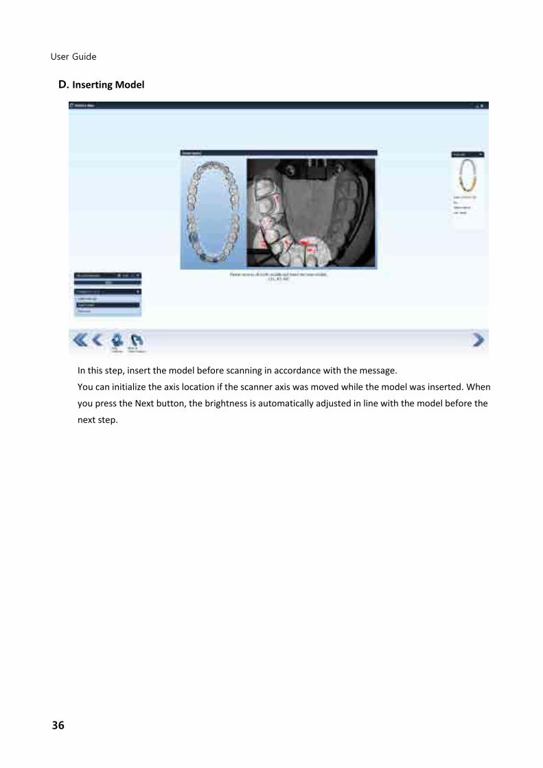
D. Inserting Model
In this step, insert the model before scanning in accordance with the message.
You can initialize the axis location if the scanner axis was moved while the model was inserted. When
you press the Next button, the brightness is automatically adjusted in line with the model before the
next step.

37
E. Additional Scan
E.1. Additional Scan
This step is after automatic scan, and you can perform additional scanning or edit data as needed.
E.2. Selection Menu at the Bottom
E.2.1. Sync View
Decide whether or not to move the axis of the machine when the model view is rotated.
E.2.2. Add Scan
Scan in the current view.
E.2.3. Previous Data
Select previous scan data.
E.2.4. Next Data
Select next scan data.
E.2.5. Delete Data

38
User Guide
Delete the selected scan data.
E.2.6. Rectangular Shape Erase
Select the model in a rectangular shape and delete it.
E.2.7. Free Shape Erase
Select the model in a free polygonal shape and delete it.
E.2.8. Initialize
Restore the data before they were deleted.
E.2.9. Undo
Restore the data to one step before the data deletion.
E.2.10. Redo
Revert to data to its state prior to performing Undo.

39
F. Manual Alignment
In this step, user manually aligns the model.

40
User Guide
F.1. Manual Alignment
You can freely move the models, or align them by specifying one or three points corresponding to
the left and right models.
F.2. Selection Menu at the Bottom
F.2.1. 1 Point Switch on or off 1 point alignment mode.
F.2.2. 3 Point Switch on or off 3 point alignment mode.
F.2.3. Snap to Snap the model to be moved to the reference model.
F.2.4. Initialize Return the model to its original position before movement.
F.2.5. Undo Return the model to one step before movement.
F.2.6. Redo Perform the movement of the returned model again.

41
F.3. Multi-die Manual Alignment
F.3.1. Multi-die Manual Alignment
This step appears when you align tooth models that have been scanned in the multi-die or when
you align the tooth models that have been scanned in the multi-die with the base model. The
model control method is identical to the general manual alignment, but the screen is not divided
to left and right halves for 1 point and 3 point alignments.
42
User Guide
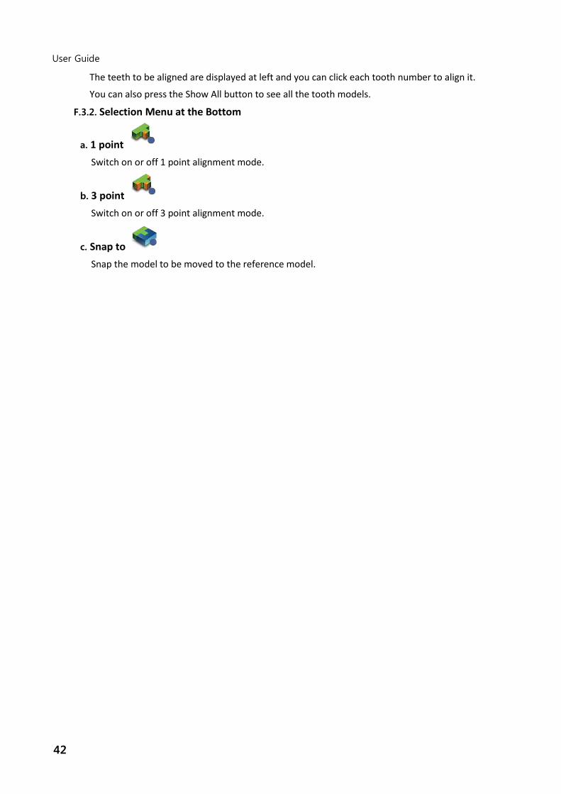
The teeth to be aligned are displayed at left and you can click each tooth number to align it.
You can also press the Show All button to see all the tooth models.
F.3.2. Selection Menu at the Bottom
a. 1 point Switch on or off 1 point alignment mode.
b. 3 point Switch on or off 3 point alignment mode.
c. Snap to Snap the model to be moved to the reference model.

43
G. Checking Results
G.1. Check Final Data
In this step, you check the scanned data for the last time. You can see scan data by group. You can
also delete unwanted data or edit the data with the fill hole feature.
You cannot return to the previous step from here.
G.2. Selection Menu at the Bottom
G.2.1. Rectangular Shape Erase
Select the model in a rectangular shape and delete it.
G.2.2. Free Shape Erase
Select the model in a free polygonal shape and delete it.
G.2.3. Fill hole

44
User Guide
You can manually fill any missing part in the scanned data.
G.2.4. Initialize Return the model to its original position before movement.
G.2.5. Undo Return the model to one step before movement.
G.2.6. Redo Perform the movement of the returned model again.