Rev 1 to Surveillance Test Procedure IC-ST-SI-0005, "Channel ...
23
. . . . . . LO. '' < . > * . 1 Fort Calhoun Station ' Unit No. 1 IC-ST-SI-0005 SURVEILLANCE TEST Title: CHANNEL CALIBRATION OF SAFETY INJECTION TANK SI-6A NITROGEN PRESSURE, LOOP P-2901~ . Setpoint/ Procedure Form Number (FC-68): 38343 Reason for Change: Procedure updates to Section'2, 5 ,- 10, and 11. , t E Contact Person: Kevin Boston s C | 9306230290 930611 T@O PDR ADOCK 05000295 ku }{$ P PDR R1 q ISSUED:- 06-05-92 4:00 pm . . , , . ; .' .. :
-
Upload
khangminh22 -
Category
Documents
-
view
1 -
download
0
Transcript of Rev 1 to Surveillance Test Procedure IC-ST-SI-0005, "Channel ...

. . . . . .
LO.
''<
. >
* .1
Fort Calhoun Station '
Unit No. 1
IC-ST-SI-0005
SURVEILLANCE TEST
Title: CHANNEL CALIBRATION OF SAFETY INJECTIONTANK SI-6A NITROGEN PRESSURE, LOOP P-2901~
.
Setpoint/ ProcedureForm Number (FC-68): 38343
Reason for Change: Procedure updates to Section'2, 5 ,- 10,and 11.
,
t
E
Contact Person: Kevin Boston s
C
|
9306230290 930611 T@OPDR ADOCK 05000295 ku
}{$P PDR
R1 qISSUED:- 06-05-92 4:00 pm
. . , , . ; .' ..:
- - - - . -- .- . .. . .
.
lIC-ST-SI-0005^ #FORT CALHOUN STATION PAGE 1 OF 22,
SURVEILLANCE TEST
CHANNEL CALIBRATION OFSAFETY INJECTION TANK SI-6A
NITROGEN PRESSURE, LOOP P-2901
1
SAFETY RELATED
,
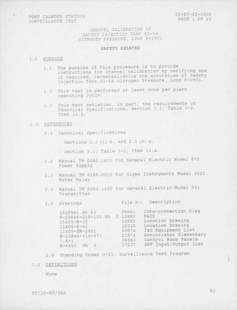
1.0 PURPOSE'
1.1 The purpose of this procedure is to provideinstructions for channel calibration by verifying and,if required, re-establishing the accuracies of SafetyInjection Tank SI-6A Nitrogen Pressure, Loop P-2901.
1.2 This test is performed at least once per plantoperating cycle.
1.3 This test satisfies, in part, the requirements ofTechnical Specifications, Section 3.1, Table 3-2,.
Item 14.b.
2.0 REFERENCES
2.1 Technical Specifications
Sections 2.3 (1) d. and 2.3 (2) g.-
Section 3.1, Table 3-2, Item 14.b.-
2.2 Manual TM G080.1630 for General Electric Model 570Power Supply
2.3 Manual TM S185.0010 for Sigma Instruments Model 9223Meter Relay
2.4 Manual TM G080.1400 for General Electric Model 551Transmitter
2.5 Drawings File No. Description
161F561 Sh 83 09581 Interconnection Diag
E-23866-210-130 Sh 2 10480 P&ID11405-M-15 10583 Location Drawing
11405-E-93 12315 Location Drawing
11405-EM-2901 20574 I&C Equipment List
B-23866-414-431 21574 Annunciator Elementary
7.6-1 36563 Control Room PanelsB-4101 Sh 8 37237 ERF Input / Output List
i
2.6 Standing Order G-23, Surveillance Test ProgramI
3.0 DEFINITIONS
None
f
R1FC/IC-ST/26A

, . - -. - . _ - _~ -. _ _ _. - .
.
IC-ST-SI-0005 *
FORT CALHOUN STATION ,
PAGE 2 OF 22SURVEILLANCE TEST ,
4 .- 0 EOUIPMENT LIST
4.1 Transmitter simulator, Transmation Model 1040 orequivalent
4.2 Digital multimeter (DMM), Fluke Model 8060A orequivalent (3 required)
4.3 Analog volt-ohmmeter (VOM), or equivalent, suitable formonitoring relay contact closure / opening (2 required)
4.4 Pressure source capable of 0 - 300 psig
4.5 Test gauge or equivalent, 0 - 300 psig minimum to0 - 600 psig maximum, with accuracy of at least !1% fullscale
5.0 ?RECAUTIONS AND LIMITATIONS
5.1 A Radiation Work Permit (RWP) shall be issued to coverwork in radiation controlled areas.
,
5.2 All anomalies and deficiencies shall be reportedimmediately to immediate Supervisor, Shift Supervisor,and noted on the Comment Sheet / Chronological Log. Animmediate check shall be made to verify Limiting i
|Conditions for Operation, per Technical Specifications,have not been exceeded.
5.3 An Incident Report shall be initiated, in accordancewith S0-R-4, to report any anomalies or deficiencies.The Incident Report number shall be recorded on theComment Sheet / Chronological Log.
5.4 No maintenance shall be conducted within thisSurveillance Test, other than that specifically
I
directed by this procedure.
5.5 A Maintenance Work Request (MWR) shall be initiated tocorrect any reported deficiency. The MWR number shall y
"be referenced on the Comment Sheet / Chronological Log.
5.6 All steps in this procedure shall be conducted in thesequence written unless otherwise noted.
5.7 If satisfactory results cannot be achieved during theperformance of this procedure, notify immediateSupervisor and proceed as directed.
5.8 If the procedure becomes contaminated or damaged, the'" Lead Technician" or designee shall ensure that alldata, verifications, and other. pertinent information istranscribed to another copy of the procedure, whichwill become the official copy.
R1FC/IC-ST/26A
.- . - . . - - - _. -
_ - .. . - .
.
IC-ST-S2-0005# I FORT CALHOUN STATION*
PAGE 3 OF 22-* - SURVEILLANCE TEST
All initials / signatures shall be those of the person (s).5. 9 actually performing the work. The person completing i
the test shall sign and date the Test Record Package |cover sheet.
5.10 All personnel participating in the performance of thistest shall enter their printed name, signature, andinitials on the Surveillance Test Signature Sheet.
5.11 Critical procedure steps are indicated by thesymbol (S). As each indicated step is completed, itshall be initialed on Sign-Off Sheet in Test RecordPackage.
5.12 The use of N/A (not applicable) in this procedure shallbe in accordance with the requirements listed inStanding Order G-23.
5.13 All applicable "As Found" data must be collected andrecorded before making adjustments to instruments.
5.14 Primary plant process should be considered potentiallycontaminated. If integrity of piping or components isbroken, the opening and the surrounding area must bemonitored and controlled in accordance with RadiationProtection procedures.
5.15 If this test cannot be completed by the end of shift,-
and will not be continued by the next shift, the loopmust be placed in a condition as directed by the ShiftSupervisor. All actions taken for temporarily stoppingand for resuming the test shall be documented in detail(including Form FC-66D, " Independent Verification Sheetfor Prccedure") on the Comment Sheet / Chronological Log.
5.16 Performance of this procedure requires a " LeadTechnician" qualified to Instrument and Control
1
Category 20.
5.17 The following indications and alarms will be erraticduring the conduct of this test:
PIA-2901 - LOOP 1B SI TANK 6A N2 PRESS-
(AI-30A-ESF)
SAFETY INJ TANK PRESS 6A (ERFP2901 --
computer)I
SAFETY INJECTION TANK SI-6A HI-LO PRESS-
(0B-4, Annun A7, Window A-40)
ElFC/IC-ST/26A
,
, _ - ,, . %- r
.
IC-ST-SI-0005*. FORT CALHOUN STATION ,
PAGE 4 OF 22SURVEILLANCE TEST ..
5.18.This loop may be taken out of service in accordatacewith the following Limiting Conditions for-oper'ation(LCOs):
Technical Specifications, Sections 2. 3 (1) d. and-
2. 3 (2) g.
5.19 The System Engineer shall be notified within 24 hoursof the completion of this test, of any marginal,unexpected, or unacceptable results.
5.20 Alternate method for " calling up" ERF computer pointsmay be used. no not " call up" using program names PSD,XYP or SCE.
6.0 INITIAL CONDITIONS
NOTE: Initial conditions need not be performed in numericalsequence.
6.1 Compare procedure revision with revision of MasterProcedure. On Test Record Package cover sheet, enterMaster Procedure revision number, then initial anddate.
1
($) 6.2 A prejob briefing has been conducted prior to the startof this test. ALL personnel involved in theperformance of this test have read AND understand, tothe extent of their involvement, the procedure, andhave completed the Surveillance Test Signature Sheet.
($) 6.3 Verify certification of calibrated test equipment usedfor this test has not expired.
($) 6,4 Form FC-1012, "M&TE Use Log" has been completed foreach piece of. test equipment used-by this procedure.
(S) 6.5 The Shift Supervisor has reviewed Limiting Conditionsfor Operation and concurs that this loop may be removedfrom service. Shift Supervisor initial Sign-Off Sheet.
6.6 The Shift Supervisor has granted approval and releasedequipment necessary to perform this test. The. ShiftSupervisor's cignature, date, and time.must be entered .
on the Test Record Package cover sheet. ||
|
R1FC/IC-ST/26A
u
.
'','# FbRT CALHOUN STATION IC-ST-SI-0005'
PAGE 5-OF 22SURVEILLANCE. TEST
7.0 PROCEDURE
7.1 Calibration of Power Supply PQ-2901
(S) 7.1.1 Lift field lead at AI-30A-ESF, terminal T-47,.and connect a transmitter _ simulator, in serieswith a DMM set for mADC, to terminals T-48 (+)
and T-4 7 (-) . ,
NOTE: Input values are as indicated on the DMM inseries with the transmitter simulator.7.1.2 Adjust the input for 50.0 mADC.
NOTE: Values found out of tolerance must be reportedimmediately to immediate Supervisor per Step 5.2.
7.1.3 Connect a DMM, set for VDC, across power supply(item 273) terminals 1 (+) and 2 (-) , and record"As Found" power supply voltage on DataSheet 1.
7.1.4 Change function of DMM connected to powersupply terminals from VDC to VAC,.and record"As Found" AC ripple on Data Sheet 1.
7.1.5 If "As Found" power supply voltage and ACripple values are in tolerance, and noimprovement in accuracy is warranted, record"As Found" values in "As Left" column on DataSheet 1 and proceed to Step 7.1.9.
NOTE: The immediate Supervisor may direct theTechnician to collect "As Found" loop dataprior to the power supply calibration, thusperforming the procedure out of sequence.
7.1.6 If either "As Found" value is out of tolerance '
or an improvement in accuracy is warranted,notify immediate Supervisor.
7.1.7 If necessary to calibrate power supply, proceedas follows:
NOTE:. A DMM may be used at the test points to-facilitate making adjustments, but all recorded- 5
data must be obtained-from the DMM connected to i
the power supply output terminals.
A. Change function of DMM connected to power j
supply terminals from VAC to VDC. jl
B. Adjust R-215 of power supply for a value asclose as possible to 52.5 VDC, and notepower supply voltage value.
R1FC/IC-ST/26A
- . -
_ _
.
IC-ST-SI-0005, *FORT CALHOUN STATION ,
' PAGE 6 - OF 2 2SURVEILLANCE TEST ,.
7.1.7 C. Change function of DMM connected to powersupply terminals from VDC to VAC, and noteAC ripple value.
D. If power supply cannot be calibrated toin tolerance values, notify.immediate.Supervisor and proceed as directed.
'
7.1.8 If noted power supply voltage and AC ripplevalues are in tolerance, record values in"As Left" column on Data Sheet 1.
7.1.9 Disconnect DMM from power supply (item 273)-terminals 1 and 2.
7.2 Calibration of Meter Relay PIA-2901
(S) 7.2.1 Verify the meter banding is in good conditionand installed over the following ranges. Ifthe meter banding requires repair, notifyimmediate Supervisor and proceed as directed.
)O to 240 psigRed -
Amber - 270 to 300 psig
NOTE: Indicated meter values and relay actuationvalues may be obtained concurrently.
7.2.2 Monitor relay operation by any of the following . |methods: |
Observe SAFETY INJECTION TANK SI-6A HI-LO-
PRESS (CB-4, Annun A7, Window A-4U)
Connect and observe a VOM, set for VDC, for o'-
the contact of the relay being tested:
LOW .AI-30A-ESF, terms T-38 &.T-39HIGH - AI-30A-ESF, terms T-37 & T-40 l
|
NOTE: Input values are as indicated on the DMM in-
series with the transmitter simulator.'
NOTE: Values found out of tolerance mustLbe reported-immediatelyEto immediate Supervisor per' Step 5.2. ,
7.2.3 Using transmitter simulator at'AI-30A-ESF,--
terminals T-48 and T-47, apply inputs-specified' |
on Data Sheet 2 and record "As Found" indicatedvalues.
7.2.4 Increase and decrease input as necessary.andrecord "As Found" setpoint and reset values onData Sheet 2.
R 1'FC/IC-ST/26A
_ _ -
_ _ _ _ - _ _ _
IC-ST-SI-0005*
FORT CALHOUN STATION# --
PAGE 7 OF 22** SURVEILLANCE TEST
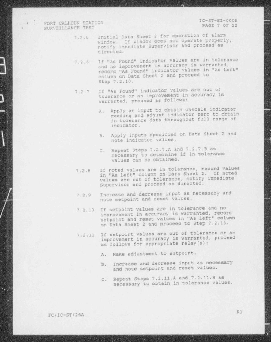
7.2.5 Initial Data Sheet 2 for operation'of alarmwindow. .If window does not operate properly,notify immediate. Supervisor and proceed asdirected.
7.2.6 If "As Found" indicator values are in tolerance-and no improvement in accuracy is warranted,record "As Found" indicator values-in "As.Left"column on Data Sheet 2 and proceed toStep 7.2.10.
7.2.7 If "As Found" indicator values are out oftolerance or an improvement in accuracy iswarranted, proceed as follows:
A. Apply an input to obtain onscale indicatorreading and adjust indicator.zero to obtainin tolerance-data throughout full range of-
indicator.)
B. Apply inputs specified on Data Sheet 2 and. I
note indicator values. _|.I
C. Repeat Steps 7.2.7.A and 7.2.7.B as |'
necessary to determine if in tolerancevalues can be obtained.
| 7.2.8 If noted values are .n tolerance, record values'
i ,
in "As Left" column on Data Sheet 2. If noted-values are out of tolerance, notify-immediate ,
'
Supervisor and proceed as directed.
7.2.9 Increase and decrease input as necessary andnote setpoint and reset values.
7.2.10 If setpoint values e.te in tolerance-and noimprovement in accuracy is warranted, recordsetpoint and reset-values.in "As Left" columnon Data Sheet.2 and proceed to_ Step 7.2.13.
7.2.11 If setpoint values are out of tolerance or animprovement in accuracy is warranted,-proceed-as follows for appropriate relay (s):
A. Make adjustment to satpoint.
B. Increase'and decrease input as necessary~and note setpoint and reset values.
C. Repeat Steps 7.2.ll.A and 7.2.11.B asnecessary to obtain in tolerance values.
R1FC/IC-ST/26A
_ _ - . -___ ____- ___________ - _ _ ___ _ -_-_ -
.
IC-ST-SI-0005,*FORT CALHOUN STATION .
PAGE B OF 22SURVEILLANCE TEST ,.
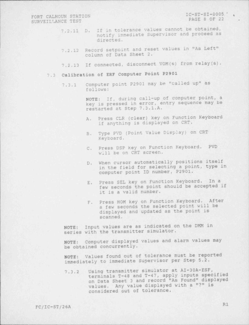
7.2.11 D. If in tolerance values cannot be obtained,notify immediate Supervisor and proceed.asdirected.
7.2.12 Record setpoint and reset values in "As Left"column of Data Sheet 2.
7.2.13 If connected, disconnect VOM(s) from relay (s).
7.3 Calibration of ERF Computer Point P2901
7.3.1 Computer point P2901 may be " called up" asfollows:
NOTE: If, during call-up of computer point, akey is pressed in error, entry sequence may berestarted at Step 7.3.1.A.
A. Press CLR (clear) key cn1 Function Keyboardif anything is displayed on CRT.
B. Type PVD (Point Value Display) on CRTKeyboard.
C. Press DSP key on Function Keyboard. PVD
will be on CRT screen.
D. When cursor automatically positions'itselfin the field for selecting a point, type incomputer point ID number, P2901.
E. Press SEL key on Function Keyboard. In a-few seconds the point should be. accepted ifit is a valid number.
F. Press HOM key on Function Keyboard. Aftera few seconds the selected point will bedisplayed and updated as the point isscanned.
NOTE: Input values are as indicated on the DMM inseries with the transmitter simulator.
..
NOTE: Computer displayed values and. alarm values maybe obtained concurrently.
NOTE:' Values found out of tolerance must be reportedimmediately to immediate Supervisor per Step 5.2.
7.3.2 Using transmitter simulator at AI-30A-ESF,terminals T-48 and T-47, apply' inputs specifiedon Data Sheet 3 and record "As Found" displayed'values. Any_value' displayed with a "?" is
'
considered-out of tolerance.
R1FC/IC-ST/26A

i.
$ FORT CALHOUN STATION IC-ST-SI-0005#-
'' SURVEILLANCE TEST PAGE 9 OF 22
7.3.3 Increase and decrease input signal as necessary-.
and record "As Found"-displayed alarm and reset-values on Data Sheet 3.
7.3.4 If "As Found" displayed and alarm' values are i
in tolerance and no improvement in accuracy iswarranted, record "As Found" values in"As Left" column on Data Sheet 3 and proceed toStep 7.3.6.
7.3.5 If "As Found" values are-out of tolerance or animprovement in accuracy is warranted, notifyimmediate Supervisor and proceed as directed.
'
7.3.6 Press CLR (clear) key on Function _ Keyboard.
($) 7.3.7 Disconnect transmitter simulator and DMM, andreconnect field lead to AI-30A-ESF,terminal T-47.
7.4 Calibration of Transmitter PT-2901
($) 7.4.1 Lift transmitter negative lead and connect DMM,set for mADC, in series with lead and terminalfor monitoring *ransmitter output.
(S) 7.4.2 Close transmitter isolation valve.
(S) 7.4.3 Remove transmitter test tap plug or inputtubing.
~
7.4.4 Connect pressure source and test gauge totransmitter.
NOTE: Input values are as indicated on the test gaugeconnected to the transmitter.
NOTE: Values found out of tolerance must be' reportedimmediately to immediate Supervisor per Step 5.2.
7.4.5 Using pressure source connected to transmitter,apply inputs specified on Data' Sheet 4 andrecord "As Found" transmitter output values.
7.4.6 If "As Found" values are in tolerance and noimprovement in accuracy is warranted, record"As Found" values in "As Left" column on DataSheet 4 and proceed'to Step 7.~4.10. !
R1FC/IC-ST/26A
.
*
IC-ST-SI-0005- .
FORT CALHOUN STATION PAGE.10 OF 22 .*SURVEILLANCE TEST
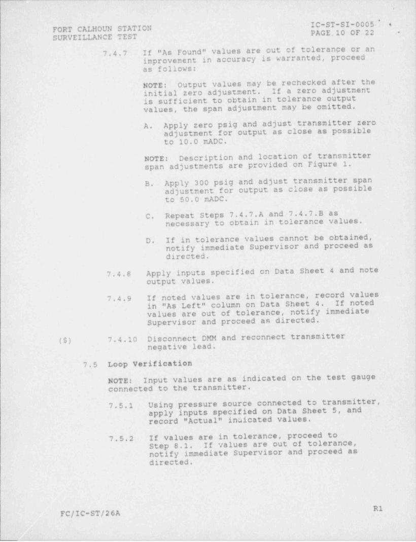
7.4.7 If "As Found" values are out of tolerange or animprovement in accuracy is warranted, proceedas follows:
NOTE: Output values may be rechecked after theinitial zero adjustment. If a zero adjustment-is sufficient to obtain in tolerance output ~values, the span adjustment may be omitted.
A. Apply zero psig and adjust transmitter zeroadjustment for output as close as possibleto 10.0 mADC.
NOTE: Description and location of transmitterspan adjustments are provided on Figure 1.
B. Apply 300 psig and adjust transmitter' spanadjustment for output as close as possibleto 50.0 mADC.
C. Repeat Steps 7.4.7.A and 7.4.7.B asnecessary to obtain in tolerance values.
D. If in tolerance values cannot be obtained,notify immediate Supervisor and proceed asdirected.
7.4.8 Apply inputs specified on Data Sheet 4 and note-output values.
7.4.9 If noted values are in tolerance, record valuesin "As Left" column on Data Sheet 4. If notedvalues are out of tolerance, notify immediateSupervisor and proceed.as directed.
($) 7.4.10 Disconnect DMM and reconnect transmitter|negative lead.
-!-
a
7.5 Loop Verification
NOTE: _ Input values are as indicated on the test gauge -|
connected to the transmitter. {
7.5.1 Using pressure; source connected to transmitter,~
apply inputs specified on Data Sheet 5, and'record " Actual" indicated values.
!7.5.2 If values are in tolerance, proceed to
Step 8.1. If values are out of tolerance,--
notify immediate Supervisor and proceed asdirected.
R1FC/IC-ST/26A
..

.- -.
FbRT CALHOUN STATION IC-ST-SI-0005'#
PAGE 11'OF 22,'SURVEILLANCE TEST
8.0 RESTORATION
8.1 Return transmitter to service as follows:8.1.1 Ensure pressure source connected to. transmitter
is at zero psig.
8.1.2 Disconnect pressure source and test gauge.fromtransmitter.
($) 8.1.3 Reinstall transmitter test tap plug or inputtubing.
($) 8.1.4 Slowly open transmitter isolation valve.
($) 8.1.5 Ensure there is no leakage at all connections,valves, plugs, etc., which were manipulated.If leakage is detected, notify immediateSupervisor and proceed as directed.
,
($) 8.2 Using redundant instrumentation or system condition,|
Verify PIA-2901 reflects current process condition.If indication does not reflect current condition,-notify immediate Supervisor and proceed as dir ected.
8.3 The Shift Supervisor has been notified this channelcalibration is complete and Safety Injection Tank SI-6ANitrogen Pressure, Loop P-2901, is returned to service.The Shift Supervisor's signature, date, and time must,
be entered on the Test Record Package-cover sheet.
($) 8.4 The Surveillance Test Signature Sheet contains theprinted name, signature, and initials of all personswhose signature or initials appears within the TestRecord Package.
8.5 Ensure that the identification number, certificationdate, and calibration due date of test equipment used,are recorded on the appropriate data sheet (s).
9.0 ACCEPTANCE CRITERIA
Acceptance criteria for components, instrument loop,.and/or-i
associated functions are specified on data sheets containedin the Test Record Package.
10.0 TEST RECORD 1
Teet Record Package for Safety Injection Tank SI-6A Nitrogen !
Pressure, Loop P-2901. ]
i,
R1FC/IC-ST/26A*
|;
, _ -_ , ._

- -. - . _ _ _ _ _ _
.
FORT CALHOUN STATION I C-ST-SI-0 0 0 5. * , ,
SURVEILLANCE TEST PAGE;12 OF.22' j..,
11.0 REVIEW'
11.1 The Supervisor-Maintenance is responsible-for ensuring jthe completed Surveillance Test is reviewed in a timely H
manner and forwarded in accordance with.SO-G-23. .| |
11.1.1 -The Supervisor-I&C Field Maintenance mustreview this Surveillance Test.
11.2 The System. Engineer shall be notified within 24 hoursof the completion of this test, of any marginal, ,
unexpected, or unacceptable results.
|,
!
i
!
,
R1-FC/IC-ST/26A.
_ _ - _ - _ _ - . _ - . . _ - . . _ __.-_ _

1
.
IC-ST-SI-0005FdRT CALHOUN STATION*
PAGE 13 OF 22' . SURVEILLANCE TEST
-_.
~ ~ ~ ~ ~ ~ _ __
_ _F1
-,
7, %.
__ H "j _ '.'''. '~Li,'
~ _., _ . - '
, .. / G, ;: 2-.
, g. '?jr-
- ,/'r
../
|
Figure 1 - G.E. MODEL 551 {GE551.WPG}
COARSE SPAN
1. Loosen screw (1).
2. Insert 3/32" hex wrench through hole in (3) and loosenscrew (2).
3. Leaving-wrench in this position, slide both bars alongthe levers (9 & 10) right (to raise span) or left (tolower span).
4. Tighten screw (2) then, while holding upper bar inposition so that flexure wire (4) is vertical, tighten
screw (1).
FINE SPAN|
! 1. Turn magnetic shunt nut (5) in on screw (6) until itstops finger-tight against motor frame-(8)..
2. Loosen set screw (7) about 1/4 turn and turn' nut (5) toreposition shunt screw (6) into (to increase current)or out of (to decrease current) motor frame (8) until |desired output is obtained.
3. Tighten set screw (7). Note that shunt screw (6) doesnot engage with threads in motor frame (8) but is held |
i
inward by magnetic force.
R1FC/IC-ST/26A
L ;
Y -
'
IC-ST-SI-0005- +
FORT CALHOUN .TATION PAGE.14 OF 22 eSURVEILLANCE TEST ,
1
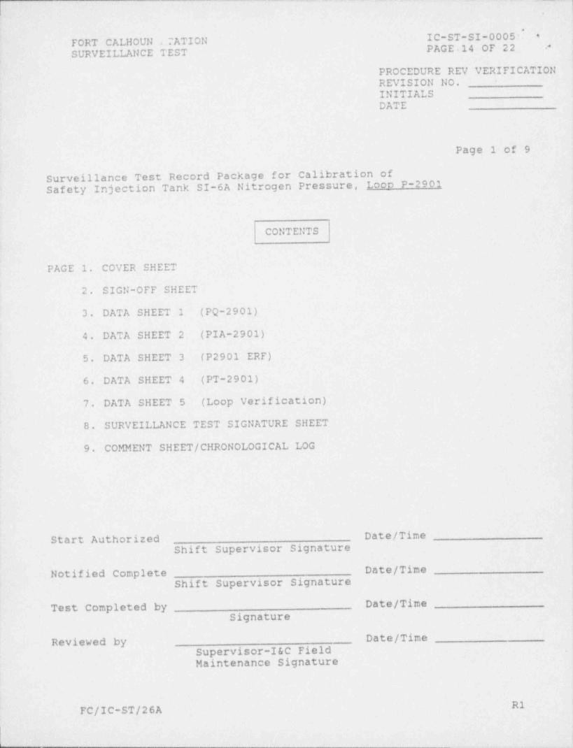
PROCEDURE REV VERIFICATIONREVISION NO. *
INITIALSDATE
Page 1 of 9.
Surveillance Test Record Package for Calibration ofSafety Injection Tank SI-6A Nitrogen. Pressure, Loop P-2901
CONTENTS
PAGE 1. COVER SHEET
2. SIGN-OFF SHEET,
3. DATA SHEET 1 (PQ-2901)
4. DATA SHEET 2 (PIA-2901)
5. DATA SHEET 3 (P2901 ERF)
6. DATA SHEET 4 (PT-2901)
7. DATA SHEET 5 (Loop Verification),
8. SURVEILLANCE TEST SIGNATURE SHEET
9. COMMENT SHEET / CHRONOLOGICAL LOG
,
Start Authorized Date/ TimeShift Supervisor Signature
Notified Complete Date/ Time .
Shift Supervisor Signature |
Test Completed by- Date/ TimeSignature
Reviewed by Date/ TimeSupervisor-I&C Field ,
Maintenance Signature
R1-FC/IC-ST/26A
.. .- --

i1.
IC-ST-SI-0005 lI FORT CALHOUN STATION#PAGE 15 OF 22 I
*- SURVEILLANCE TESTi
Page 2 of 9 q
SIGN-OFF SHEET OF CRITICAL STEPS
STEP NO. DESCRIPTION INITIALS IND VERIF,
6.2 Prejob briefing conducted N/A
6.3 Certification of test equipment current N/A
6.4 Form FC-1012 completed N/A
6.5 LCO review and concurrence (Shft Supv Init) N/A
7.1.1 Field lead lifted, AI-30A-ESF tern T-47
7.2.1 Meter banding verified N/A
7.3.7 Field lead landed, AI-30A-ESF term T-47
7.4.1 Xmtr output lead lifted
7.4.2 Xmtr isolation valve closed N/A
7.4.3 Xmtr test tap plug or tubing removed N/A.
7.4.10 Xmtr output lead landed
8.1.3 Xmtr test tap plug or tubing installed
8.1.4 Xmtr isolation valve opened
8.1.5 Leak check performed N/A
8.2 Device reflects current conditions N/A
8.4 Surv Test Signature Sheet completed N/A
,
j
R1FC/IC-ST/26A
i
- - - , , _

- - _ _ _ _ _ _ _ _ _ - _..
IC-ST-SI-0005.*FORT CALHOUN STATION ,
PAGE 16 OF 22SURVEILLANCE TEST ,
Page 3 of 9DATA SHEET 1
INSTR. TAG NO. PO-2901 LOCATION AI-30A-ESF. Room 77*
DESCRIPTION SI TANK SI-6A NITROGEN PRESSURE, LOOP POWER SUPPLY
MFR. GENERAL ELECTRIC MODEL NO. 570RIPPLE: .Less than 38 mVAC
RANGE N/A TOLERANCE OUTPUT: 14.76% = 2.5 VDC
HEAD CORRECTION N/A SETPOINT N/A
INPUT AI-30A-ESF, Terms T-48 (+) OUTPUT Power supply, Terms 1 (+)
POINT: & T-47 (-) POINT: &2 (-)
INPUT OUTPUT
RANGE APPL'D DESIRED ALLOWED RANGE AS FOUND AS LEFT
% mADC VDC VDC VDC VDC
100 50.0 52.5 50.0 to 55.0J
.
INPUT RIPPLERANGE APPL'D DESIRED ALLOWED RANGE AS FOUND AS LEFT
% mADC mVAC mVAC mVAC mVAC
100 50.0 0.0 <38
TEST EQUIPMENT REMARKS
ID NO. CERT DATE DUE DATE* Rm 77 is-the Main Control Room--(MCR).
I&C TECHNICIAN
DATE CALIBRATED
R1'FC/IC-ST/26A
-
' '' ' '. _ _ _ _ _ _ _ _ . _ _ _ _ _

4
,' FDRT CALHOUN STATION IC-ST-SI-0005PAGE 17 OF 22SURVEILLANCE TEST
Page 4 of 9 '
DATA SHEET 2
INSTR. TAG NO. PIA-2901 LOCATION AI-30A-ESF, Room 77 (MCR)
DESCRIPTION SI TANK SI-6A NITROGEN PRESSURE. METER RELAY
MFR. SIGMA INSTRUMENTS MODEL NO. 9223-20-EINPUT: 10- 50 mADC METER: 12% = 26 PSIG
RANGE OUTPUT: 0- 300 PSIG TOLERANCE RELAY: 2% = 0.8 mADC-LOW: 42.67 mADC DEC '
HEAD CORRECTION N/A SETPOINT HIGH: 45.33 mADC INC
INPUT AI-30A-ESF, Terms T-48 (+) OUTPUT Meter: Indicator scale
POINT: & T-47 (-) POINT: Relay: Alarm or contacts
OUTPUTINPUT
RANGE | APPL'D DESIRED ALLOWED RANGE AS FOUND AS LEFT
PSIG PSIG PSIG PSIG|% mADC
| 0 -6 to 60 10.0*
| 75 69 to 8125 20.0
50 30.0 150 144 to 156
75 40.0 | 225 219 to 231
100 50.0 300 294 to 306
75 40.0 225 219 to 231
50 30.0 150 144 to 156
25 20.0 75 69 to 81 ,
0 10.0 0 -6 to 6
mADC mADC mADCRELAY VALUES f mADC
LOW Setpoint 42.67 41.87 to 43.47_
LOW Reset N/A N/A
HIGH Setpoint 45.33 44.53 to 46.13
HIGH Reset N/A N/A
TEST EQUIPMENT REMARKS ,
IID NO. CERT DATE DUE DATE
SAFETY INJECTION TANK SI-6A HI-LO PRESS I
(CB-4, Annun A7, Window A-4U) actuatedon low and high test signals
initials
|
I&C TECHNICIAN
DATE CALIBRATED
FC/IC-ST/26A
. - - .. .. - - - . . .. . . . _ _ _ _ _ - _ _ _ .
.
FORT CALHOUN. STATION IC-ST-SI-0005.- ,
SURVEILLANCE TEST PAGE 18 OF 22 ,
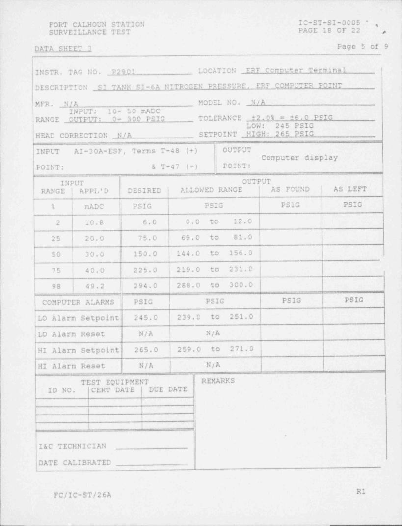
DATA SHEET 3 Page 5 of 9
INSTR. TAG NO. P2901 LOCATION ERF Comeuter Terminal
DESCRIPTION SI TANK SI-6A NITROGEN PRESSURE, ERF COMPUTER POINT
MFR. _LJ / A MODEL NO. N/AINPUT: 10- 50 mADC
RANGE OUTPUT: 0- 300 PSIG TOLERANCE 2.0% = ?6.0 PSIG-LOW: 245 PSIG
HEAD CORRECTION N/A SETPOINT' HIGH: 265 PSIGi
INPUT AI-30A-ESF, Terms T-48 (+) OUTPUTComputer display
POINT: & T-47 (-) POINT *,
INPUT OUTPUTRANGE APPL'D DESIRED | ALLOWED RANGE AS FOUND AS LEFT
% mADC PSIG PSIG PSIG PSIG
f 6.0 0.0 to 12.02 10.8
25 20.0 75.0 69.0 to 81.0
50 30.0 150.0 144.0 to 156.0
75 40.0 225.0 219.0 to 231.0
98 49.2 294.0 288.0 to 300.0
COMPUTER ALARMS PSIG PSIG PSIG PSIG
LO Alarm Setpoint 245.0 239.0 to 251.0
LO Alarm Reset N/A N/A
HI Alarm Setpoint 265.0 259.0 to 271.0
HI Alarm Reset N/A N/A
TEST EQUIPMENT REMARKSID No. CERT DATE DUE DATE
|i.
|I&C TECHNICIAN
DATE CALIBRATED
R1 IFC/IC-ST/26A
.i
-., , . _ , , _ . . - , . - , . , , m,, wi ,,U
.
[ ORT CALHOUN STATION IC-ST-SI-0005'
PAGE 19 OF 22.
SURVEILLANCE TEST,
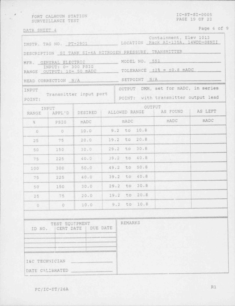
DATA SHEET 4 Page 6 of 9
Containment, Elev 1013
INSTR. TAG NO. PT-2901 LOCATION Rack'AI-135A. 14WDD-08NII
DESCRIPTION SI TANK SI-6A NITROGEN PRESSURE. TRANSMITTER
MFR. GENERAL ELECTRIC MODEL No. 551INPUT: 0- 300 PSIG
RANGE OUTPUT: 10- 50 mADC TOLERANCE 2% = 0.8 mADC
HEAD CORRECTION N/A SETPOINT N/A
INPUT OUTPUT DMM, set for mADC, in seriesTransmitter input port
POINT: POINT: with transmitter output-lead.
INPUT OUTPUT
RANGE APPL'D DESIRED ALLOWED RANGE AS FOUND AS LEFT
% PSIG mADC mADC mADC mADC-
0 0 10.0 9.2 to 10.8,
25 75 20.0 19.2 to 20.8.
50 150 30.0 29.2 to 30.8
75 225 40.0 39.2 to 40.8
100 300 50.0 49.2 to 50.8.
75 225 40.0 39.2 to 40.8
50 150 30.0 29.2 to 30.8 ,
25 75 20.0 19.2 to 20.8
0 0 10.0 9.2 to 10.8
i
TEST EQUIPMENT REMARKSI
ID NO. CERT DATE DUE DATEII
I&C TECHNICIAN|
DATE CALIBRATED-.
R1FC/IC-ST/26A
_ _ _ _ - _ _ _ _ - - _ _ _ _ _ _ _ _ - - _ _
.
FORT CALHOUN STATION IC-ST-SI-0005 s -
SURVEILLANCE TEST PAGE.20 OF 22 -
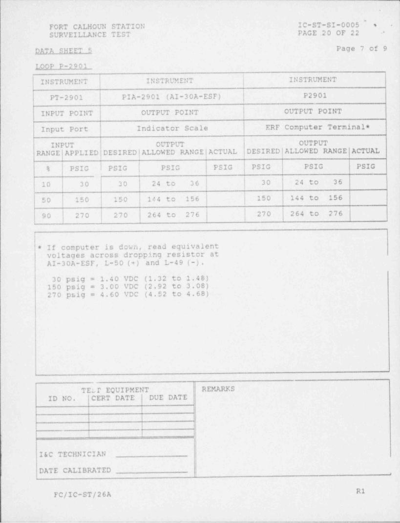
DATA SHEET 5 Page 7 of 9
LOOP P-2901
INSTRUMENT INSTRUMENT INSTRUMENT
PT-2901 PIA-2901 (AI-30A-ESF) P2901
INPUT POINT OUTPUT POINT OUTPUT POINT
Input Port Indicator Scale ERF Computer Terminal *
INPUT OUTPUT OUTPUT
RANGE APPLIED DESIRED |ALLOWEDRANGEACTUAL DESIRED ALLOWED RANGE ACTUAL
% PSIG PSIG PSIG PSIG PSIG PSIG PSIG
10 30 30 24 to 36 30 24 to 36
50 150 150 144 to 156 150 144 to 156
90 270 270 264 to 276 270 264 to 276!
If computer is down, read equivalent*
voltages across dropping resistor atAI-30A-ESF, L- 5 0 ( + ) and L-4 9 (-) . t
30 psig = 1.40 VDC (1.32 to 1.48)150 psig = 3.00 VDC (2.92 to 3.08)270 psig = 4.60 VDC (4.52 to 4.68)
1
TELT EQUIPMENT REMARKSID NO. CERT DATE DUE DATE
.|
|1
I&C TECHNICIAN
DATE CALIBRATED ,
R1FC/IC-ST/26A
I
Y 1
.
* * FORT CALHOUN STATION IC-ST-SI-0005.
* SURVEILLANCE TEST PAGE 21 OF 22
Page 8 of 9,
i
SURVEILLANCE TEST SIGNATURE SHEET
All persons participating in the performance of this test shallenter their printed name, signature, and initials below.
IJAME (PRINT) SIGNATURE INITIALS
,
9
~ en
1
3
i
FC/IC-ST/26A R1
1
- - _ _. _. _ __ . _ . _ - - _ _ . --_-_-.______-_._:__i

.
*,
FORT CALHOUN STATION IC-ST-SI-0005 Is .,
SURVEILLANCE TEST PAGE 22 OF 22 4
, Page 9 of 9
COMMENT SHEET / CHRONOLOGICAL LOG
I1
]
L
i1
1
l
i
M1FC/IC-ST/26A
L