Results of the Guide2 telescope testbed for the SIM Light Astrometric Observatory
10
Results of the Guide-2 telescope testbed for the SIM Light Astrometric Observatory I. Hahn, † M. Weilert, J. Sandhu, X. Wang, R. Smythe, E. Hovland, F. Loya, J. Shields, D. Boussalis, N. Fathpour, B. Kang, A. Ahmed, G. Macala, F. Nicaise, M. Morales, F. Dekens, and R. Goullioud Jet Propulsion Laboratory, California Institute of Technology, Pasadena, CA, USA 91109-1011 ABSTRACT The SIM Lite Astrometric Observatory is to perform narrow angle astrometry to search for Earth-like planets, and global astrometry for a broad astrophysics program, for example, mapping the distribution of dark matter in the Galaxy. The new SIM Lite consists of two Michelson interferometers and one star tracking telescope. The main six-meter baseline science interferometer observes a target star and a set of reference stars. The four-meter baseline interferometer (guide-1) monitors the attitude of the instrument in the direction of a target star. The Guide-2 telescope (G2T) tracks a bright star to monitor the attitude of the instrument in the other two orthogonal directions. A testbed has been built to demonstrate star-tracking capability of the G2T concept using a new interferometric angle metrology system. In the presence of simulated 0.2 arcsecond level of expected spacecraft attitude control system perturbations, the measured star-tracking capability of the G2T testbed system is less than 43 micro-arcsecond during single narrow angle observation. Keywords: SIM, angle metrology, star tracking 1. INTRODUCTION The SIM Lite Astrometric Observatory is to perform narrow angle astrometry to search for Earth-like planets, and global astrometry for a broad astrophysics program.[1] SIM Lite consists of two Michelson interferometers (6 meter baseline science and 4 meter guide) and one star tracking telescope. The basic elements of a stellar interferometer are shown in Figure 1. Light from a distant star is collected at two points separated by baseline B and combined to form interference fringes. This occurs when the internal path length difference (or delay, δ) compensates exactly for the external delay, x. The angle between the interferometer baseline and the star, α, can then be obtained using the relation: (1) SIM Lite is operating in the visible spectrum (450-950 nm). Light from a star is collected by two 30 cm telescopes separated by a 6-meter baseline for the science interferometer. From the two collecting telescopes, the light is propagated by a set of optics to the beam combiner where the two optical wave fronts are re-combined, forming interferences. The peak interference fringe is obtained when the propagation paths through the two arms of the instrument are identical. The internal metrology sensor measures the internal propagation difference between the two arms (also known as internal delay), from the optical corner cube fiducials on the collecting optics to the re-combining optic. When the instrument is tracking the peak of the interference fringe, the external delay is the complement of the internal delay. Therefore, the measurement of the internal delay is an estimate of the external propagation delay. Simultaneously, the external metrology sensor determines the length of the baseline, defined by the two fiducials. SIM Lite simultaneously employs two stellar interferometers (Science, Guide-1) and one telescope (Guide-2) to perform astrometry. Precision astrometry requires knowledge of the baseline orientation to the same order of precision as the † Email: [email protected] Copyright 2010 California Institute of Technology. Government sponsorship acknowledged.
-
Upload
youngstown -
Category
Documents
-
view
1 -
download
0
Transcript of Results of the Guide2 telescope testbed for the SIM Light Astrometric Observatory
Results of the Guide-2 telescope testbed for the SIM Light Astrometric Observatory
I. Hahn,† M. Weilert, J. Sandhu, X. Wang, R. Smythe, E. Hovland, F. Loya, J. Shields, D. Boussalis, N. Fathpour, B. Kang, A. Ahmed, G. Macala, F. Nicaise, M. Morales, F. Dekens, and R. Goullioud
Jet Propulsion Laboratory, California Institute of Technology, Pasadena, CA, USA 91109-1011
ABSTRACT
The SIM Lite Astrometric Observatory is to perform narrow angle astrometry to search for Earth-like planets, and global astrometry for a broad astrophysics program, for example, mapping the distribution of dark matter in the Galaxy. The new SIM Lite consists of two Michelson interferometers and one star tracking telescope. The main six-meter baseline science interferometer observes a target star and a set of reference stars. The four-meter baseline interferometer (guide-1) monitors the attitude of the instrument in the direction of a target star. The Guide-2 telescope (G2T) tracks a bright star to monitor the attitude of the instrument in the other two orthogonal directions. A testbed has been built to demonstrate star-tracking capability of the G2T concept using a new interferometric angle metrology system. In the presence of simulated 0.2 arcsecond level of expected spacecraft attitude control system perturbations, the measured star-tracking capability of the G2T testbed system is less than 43 micro-arcsecond during single narrow angle observation.
Keywords: SIM, angle metrology, star tracking
1. INTRODUCTION
The SIM Lite Astrometric Observatory is to perform narrow angle astrometry to search for Earth-like planets, and global astrometry for a broad astrophysics program.[1] SIM Lite consists of two Michelson interferometers (6 meter baseline science and 4 meter guide) and one star tracking telescope. The basic elements of a stellar interferometer are shown in Figure 1. Light from a distant star is collected at two points separated by baseline B and combined to form interference fringes. This occurs when the internal path length difference (or delay, δ) compensates exactly for the external delay, x. The angle between the interferometer baseline and the star, α, can then be obtained using the relation:
(1)
SIM Lite is operating in the visible spectrum (450-950 nm). Light from a star is collected by two 30 cm telescopes separated by a 6-meter baseline for the science interferometer. From the two collecting telescopes, the light is propagated by a set of optics to the beam combiner where the two optical wave fronts are re-combined, forming interferences. The peak interference fringe is obtained when the propagation paths through the two arms of the instrument are identical. The internal metrology sensor measures the internal propagation difference between the two arms (also known as internal delay), from the optical corner cube fiducials on the collecting optics to the re-combining optic. When the instrument is tracking the peak of the interference fringe, the external delay is the complement of the internal delay. Therefore, the measurement of the internal delay is an estimate of the external propagation delay. Simultaneously, the external metrology sensor determines the length of the baseline, defined by the two fiducials.
SIM Lite simultaneously employs two stellar interferometers (Science, Guide-1) and one telescope (Guide-2) to perform astrometry. Precision astrometry requires knowledge of the baseline orientation to the same order of precision as the
† Email: [email protected] Copyright 2010 California Institute of Technology. Government sponsorship acknowledged.
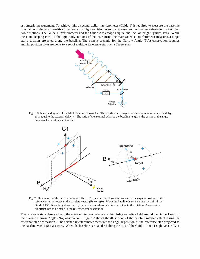
astrometric measurement. To achieve this, a second stellar interferometer (Guide-1) is required to measure the baseline orientation in the most sensitive direction and a high-precision telescope to measure the baseline orientation in the other two directions. The Guide-1 interferometer and the Guide-2 telescope acquire and lock on bright "guide" stars. While these are keeping track of the rigid-body motions of the instrument, the main Science interferometer measures a target star’s position projected along the baseline. The current scenario for the Narrow Angle (NA) observation requires angular position measurements to a set of multiple Reference stars per a Target star.
The reference stars observed with the science interferometer are within 1-degree radius field around the Guide 1 star for the planned Narrow Angle (NA) observation. Figure 2 shows the illustration of the baseline rotation effect during the reference star observation. The science interferometer measures the angular position of the reference star projected to the baseline vector (B): α cos(θ). When the baseline is rotated δθ along the axis of the Guide 1 line-of-sight vector (G1),
Fig. 1. Schematic diagram of the Michelson interferometer. The interference fringe is at maximum value when the delay, δ, is equal to the external delay, x. The ratio of the external delay to the baseline length is the cosine of the angle between the baseline and the star.
Fig. 2. Illustrations of the baseline rotation effect. The science interferometer measures the angular position of the reference star projected to the baseline vector (B): αcos(θ). When the baseline is rotate along the axis of the Guide 1 (G1) line-of-sight vector, δθ, the science interferometer is insensitive to the rotation. A correction, αsin(θ)δθ has to be made to the reference star observation.
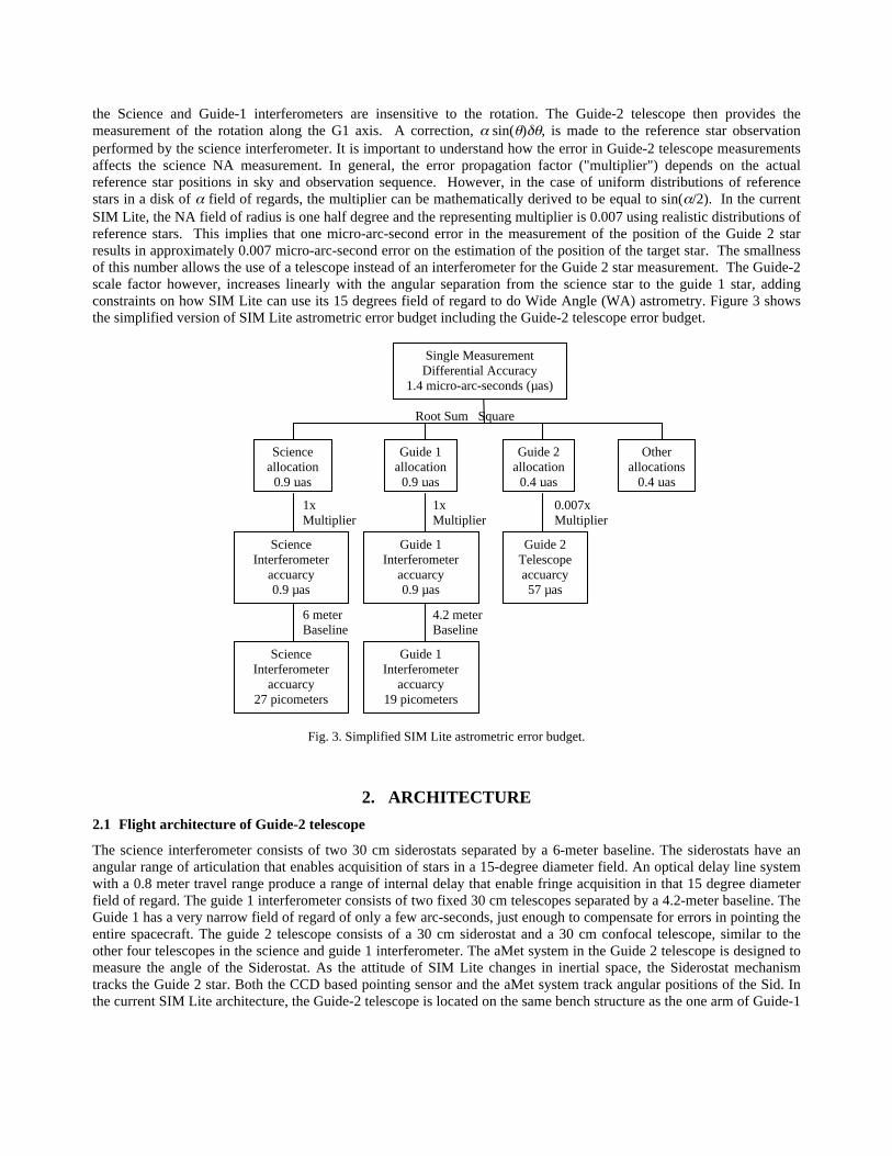
the Science and Guide-1 interferometers are insensitive to the rotation. The Guide-2 telescope then provides the measurement of the rotation along the G1 axis. A correction, α sin(θ)δθ, is made to the reference star observation performed by the science interferometer. It is important to understand how the error in Guide-2 telescope measurements affects the science NA measurement. In general, the error propagation factor ("multiplier") depends on the actual reference star positions in sky and observation sequence. However, in the case of uniform distributions of reference stars in a disk of α field of regards, the multiplier can be mathematically derived to be equal to sin(α/2). In the current SIM Lite, the NA field of radius is one half degree and the representing multiplier is 0.007 using realistic distributions of reference stars. This implies that one micro-arc-second error in the measurement of the position of the Guide 2 star results in approximately 0.007 micro-arc-second error on the estimation of the position of the target star. The smallness of this number allows the use of a telescope instead of an interferometer for the Guide 2 star measurement. The Guide-2 scale factor however, increases linearly with the angular separation from the science star to the guide 1 star, adding constraints on how SIM Lite can use its 15 degrees field of regard to do Wide Angle (WA) astrometry. Figure 3 shows the simplified version of SIM Lite astrometric error budget including the Guide-2 telescope error budget.
Fig. 3. Simplified SIM Lite astrometric error budget.
2. ARCHITECTURE 2.1 Flight architecture of Guide-2 telescope
The science interferometer consists of two 30 cm siderostats separated by a 6-meter baseline. The siderostats have an angular range of articulation that enables acquisition of stars in a 15-degree diameter field. An optical delay line system with a 0.8 meter travel range produce a range of internal delay that enable fringe acquisition in that 15 degree diameter field of regard. The guide 1 interferometer consists of two fixed 30 cm telescopes separated by a 4.2-meter baseline. The Guide 1 has a very narrow field of regard of only a few arc-seconds, just enough to compensate for errors in pointing the entire spacecraft. The guide 2 telescope consists of a 30 cm siderostat and a 30 cm confocal telescope, similar to the other four telescopes in the science and guide 1 interferometer. The aMet system in the Guide 2 telescope is designed to measure the angle of the Siderostat. As the attitude of SIM Lite changes in inertial space, the Siderostat mechanism tracks the Guide 2 star. Both the CCD based pointing sensor and the aMet system track angular positions of the Sid. In the current SIM Lite architecture, the Guide-2 telescope is located on the same bench structure as the one arm of Guide-1
Science Interferometer
accuarcy 0.9 µas
1x Multiplier
1x Multiplier
0.007x Multiplier
Guide 1 Interferometer
accuarcy 0.9 µas
Guide 2 Telescope accuarcy 57 µas
Science Interferometer
accuarcy 27 picometers
6 meter Baseline
4.2 meter Baseline
Guide 1 Interferometer
accuarcy 19 picometers
Root Sum Square
Science allocation
0.9 µas
Guide 1 allocation
0.9 µas
Guide 2 allocation
0.4 µas
Other allocations
0.4 µas
Single Measurement Differential Accuracy
1.4 micro-arc-seconds (µas)
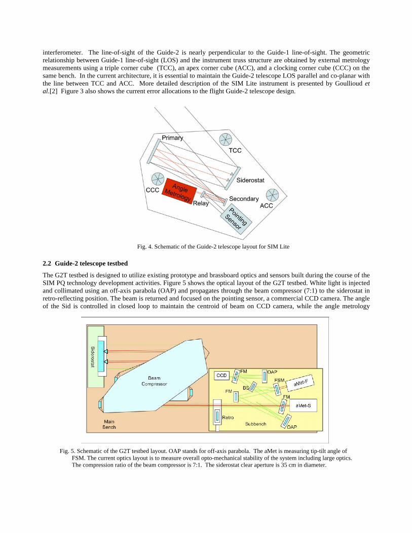
interferometer. The line-of-sight of the Guide-2 is nearly perpendicular to the Guide-1 line-of-sight. The geometric relationship between Guide-1 line-of-sight (LOS) and the instrument truss structure are obtained by external metrology measurements using a triple corner cube (TCC), an apex corner cube (ACC), and a clocking corner cube (CCC) on the same bench. In the current architecture, it is essential to maintain the Guide-2 telescope LOS parallel and co-planar with the line between TCC and ACC. More detailed description of the SIM Lite instrument is presented by Goullioud et al.[2] Figure 3 also shows the current error allocations to the flight Guide-2 telescope design.
2.2 Guide-2 telescope testbed
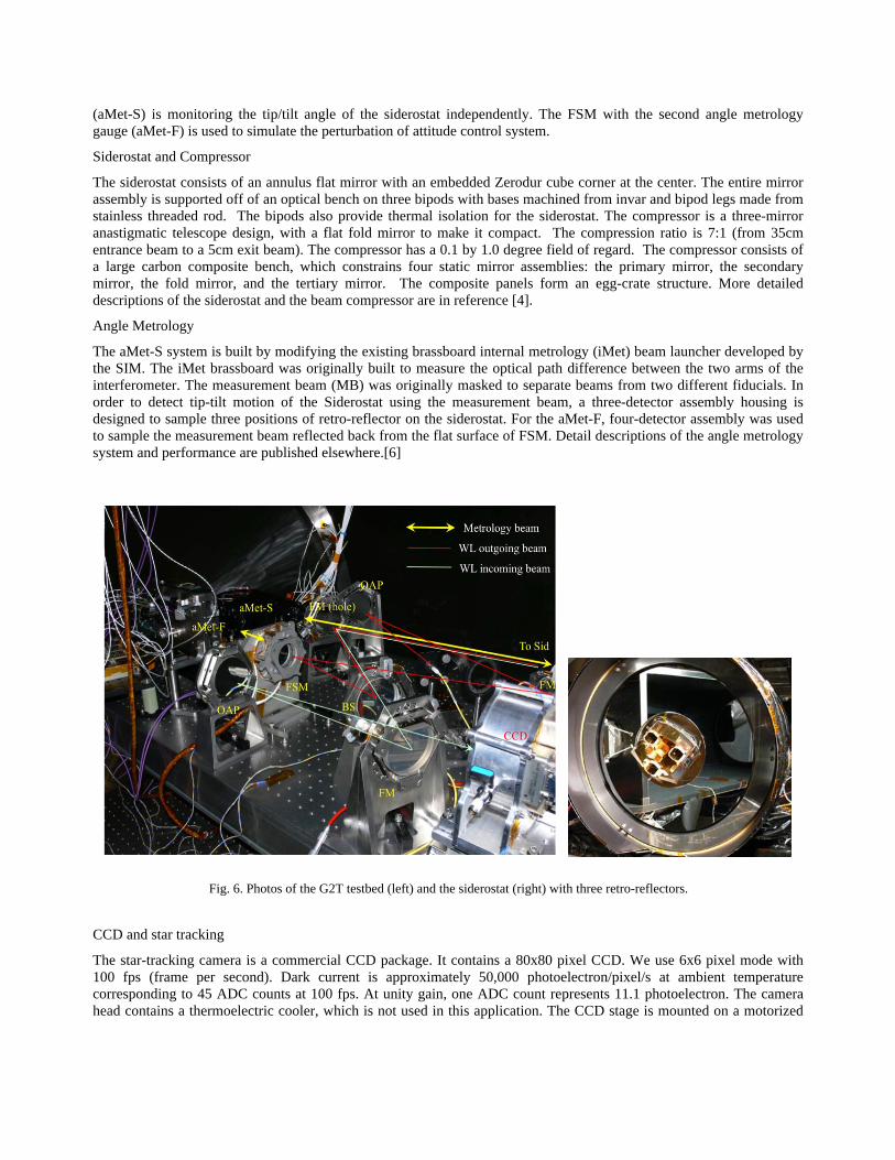
The G2T testbed is designed to utilize existing prototype and brassboard optics and sensors built during the course of the SIM PQ technology development activities. Figure 5 shows the optical layout of the G2T testbed. White light is injected and collimated using an off-axis parabola (OAP) and propagates through the beam compressor (7:1) to the siderostat in retro-reflecting position. The beam is returned and focused on the pointing sensor, a commercial CCD camera. The angle of the Sid is controlled in closed loop to maintain the centroid of beam on CCD camera, while the angle metrology
Fig. 4. Schematic of the Guide-2 telescope layout for SIM Lite
Fig. 5. Schematic of the G2T testbed layout. OAP stands for off-axis parabola. The aMet is measuring tip-tilt angle of
FSM. The current optics layout is to measure overall opto-mechanical stability of the system including large optics. The compression ratio of the beam compressor is 7:1. The siderostat clear aperture is 35 cm in diameter.
(aMet-S) is monitoring the tip/tilt angle of the siderostat independently. The FSM with the second angle metrology gauge (aMet-F) is used to simulate the perturbation of attitude control system.
Siderostat and Compressor
The siderostat consists of an annulus flat mirror with an embedded Zerodur cube corner at the center. The entire mirror assembly is supported off of an optical bench on three bipods with bases machined from invar and bipod legs made from stainless threaded rod. The bipods also provide thermal isolation for the siderostat. The compressor is a three-mirror anastigmatic telescope design, with a flat fold mirror to make it compact. The compression ratio is 7:1 (from 35cm entrance beam to a 5cm exit beam). The compressor has a 0.1 by 1.0 degree field of regard. The compressor consists of a large carbon composite bench, which constrains four static mirror assemblies: the primary mirror, the secondary mirror, the fold mirror, and the tertiary mirror. The composite panels form an egg-crate structure. More detailed descriptions of the siderostat and the beam compressor are in reference [4].
Angle Metrology
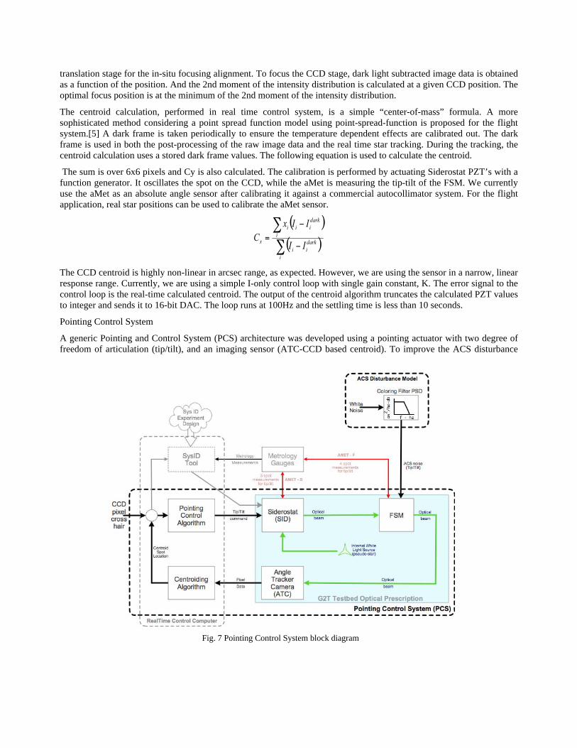
The aMet-S system is built by modifying the existing brassboard internal metrology (iMet) beam launcher developed by the SIM. The iMet brassboard was originally built to measure the optical path difference between the two arms of the interferometer. The measurement beam (MB) was originally masked to separate beams from two different fiducials. In order to detect tip-tilt motion of the Siderostat using the measurement beam, a three-detector assembly housing is designed to sample three positions of retro-reflector on the siderostat. For the aMet-F, four-detector assembly was used to sample the measurement beam reflected back from the flat surface of FSM. Detail descriptions of the angle metrology system and performance are published elsewhere.[6]
CCD and star tracking
The star-tracking camera is a commercial CCD package. It contains a 80x80 pixel CCD. We use 6x6 pixel mode with 100 fps (frame per second). Dark current is approximately 50,000 photoelectron/pixel/s at ambient temperature corresponding to 45 ADC counts at 100 fps. At unity gain, one ADC count represents 11.1 photoelectron. The camera head contains a thermoelectric cooler, which is not used in this application. The CCD stage is mounted on a motorized
Fig. 6. Photos of the G2T testbed (left) and the siderostat (right) with three retro-reflectors.
translation stage for the in-situ focusing alignment. To focus the CCD stage, dark light subtracted image data is obtained as a function of the position. And the 2nd moment of the intensity distribution is calculated at a given CCD position. The optimal focus position is at the minimum of the 2nd moment of the intensity distribution.
The centroid calculation, performed in real time control system, is a simple “center-of-mass” formula. A more sophisticated method considering a point spread function model using point-spread-function is proposed for the flight system.[5] A dark frame is taken periodically to ensure the temperature dependent effects are calibrated out. The dark frame is used in both the post-processing of the raw image data and the real time star tracking. During the tracking, the centroid calculation uses a stored dark frame values. The following equation is used to calculate the centroid.
The sum is over 6x6 pixels and Cy is also calculated. The calibration is performed by actuating Siderostat PZT’s with a function generator. It oscillates the spot on the CCD, while the aMet is measuring the tip-tilt of the FSM. We currently use the aMet as an absolute angle sensor after calibrating it against a commercial autocollimator system. For the flight application, real star positions can be used to calibrate the aMet sensor.
The CCD centroid is highly non-linear in arcsec range, as expected. However, we are using the sensor in a narrow, linear response range. Currently, we are using a simple I-only control loop with single gain constant, K. The error signal to the control loop is the real-time calculated centroid. The output of the centroid algorithm truncates the calculated PZT values to integer and sends it to 16-bit DAC. The loop runs at 100Hz and the settling time is less than 10 seconds.
Pointing Control System
A generic Pointing and Control System (PCS) architecture was developed using a pointing actuator with two degree of freedom of articulation (tip/tilt), and an imaging sensor (ATC-CCD based centroid). To improve the ACS disturbance
Fig. 7 Pointing Control System block diagram
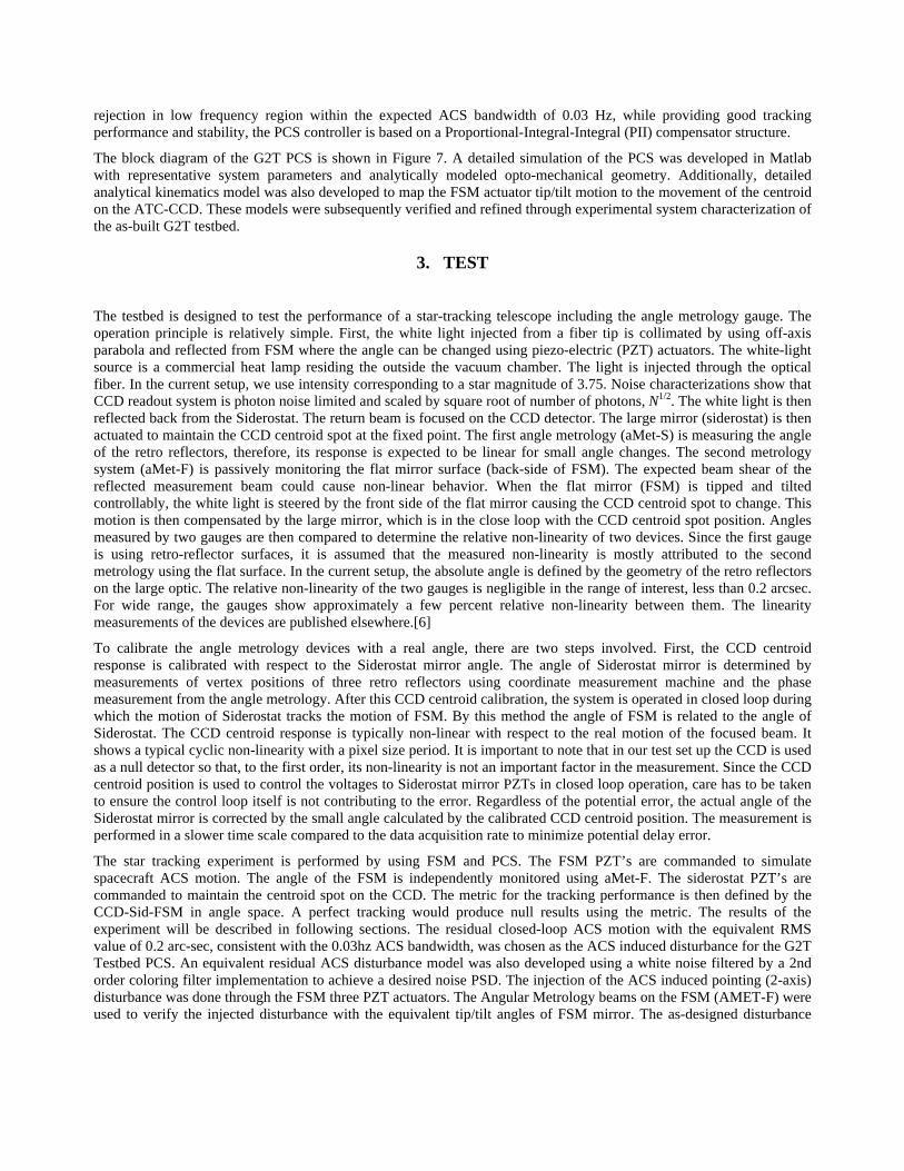
rejection in low frequency region within the expected ACS bandwidth of 0.03 Hz, while providing good tracking performance and stability, the PCS controller is based on a Proportional-Integral-Integral (PII) compensator structure.
The block diagram of the G2T PCS is shown in Figure 7. A detailed simulation of the PCS was developed in Matlab with representative system parameters and analytically modeled opto-mechanical geometry. Additionally, detailed analytical kinematics model was also developed to map the FSM actuator tip/tilt motion to the movement of the centroid on the ATC-CCD. These models were subsequently verified and refined through experimental system characterization of the as-built G2T testbed.
3. TEST
The testbed is designed to test the performance of a star-tracking telescope including the angle metrology gauge. The operation principle is relatively simple. First, the white light injected from a fiber tip is collimated by using off-axis parabola and reflected from FSM where the angle can be changed using piezo-electric (PZT) actuators. The white-light source is a commercial heat lamp residing the outside the vacuum chamber. The light is injected through the optical fiber. In the current setup, we use intensity corresponding to a star magnitude of 3.75. Noise characterizations show that CCD readout system is photon noise limited and scaled by square root of number of photons, N1/2. The white light is then reflected back from the Siderostat. The return beam is focused on the CCD detector. The large mirror (siderostat) is then actuated to maintain the CCD centroid spot at the fixed point. The first angle metrology (aMet-S) is measuring the angle of the retro reflectors, therefore, its response is expected to be linear for small angle changes. The second metrology system (aMet-F) is passively monitoring the flat mirror surface (back-side of FSM). The expected beam shear of the reflected measurement beam could cause non-linear behavior. When the flat mirror (FSM) is tipped and tilted controllably, the white light is steered by the front side of the flat mirror causing the CCD centroid spot to change. This motion is then compensated by the large mirror, which is in the close loop with the CCD centroid spot position. Angles measured by two gauges are then compared to determine the relative non-linearity of two devices. Since the first gauge is using retro-reflector surfaces, it is assumed that the measured non-linearity is mostly attributed to the second metrology using the flat surface. In the current setup, the absolute angle is defined by the geometry of the retro reflectors on the large optic. The relative non-linearity of the two gauges is negligible in the range of interest, less than 0.2 arcsec. For wide range, the gauges show approximately a few percent relative non-linearity between them. The linearity measurements of the devices are published elsewhere.[6]
To calibrate the angle metrology devices with a real angle, there are two steps involved. First, the CCD centroid response is calibrated with respect to the Siderostat mirror angle. The angle of Siderostat mirror is determined by measurements of vertex positions of three retro reflectors using coordinate measurement machine and the phase measurement from the angle metrology. After this CCD centroid calibration, the system is operated in closed loop during which the motion of Siderostat tracks the motion of FSM. By this method the angle of FSM is related to the angle of Siderostat. The CCD centroid response is typically non-linear with respect to the real motion of the focused beam. It shows a typical cyclic non-linearity with a pixel size period. It is important to note that in our test set up the CCD is used as a null detector so that, to the first order, its non-linearity is not an important factor in the measurement. Since the CCD centroid position is used to control the voltages to Siderostat mirror PZTs in closed loop operation, care has to be taken to ensure the control loop itself is not contributing to the error. Regardless of the potential error, the actual angle of the Siderostat mirror is corrected by the small angle calculated by the calibrated CCD centroid position. The measurement is performed in a slower time scale compared to the data acquisition rate to minimize potential delay error.
The star tracking experiment is performed by using FSM and PCS. The FSM PZT’s are commanded to simulate spacecraft ACS motion. The angle of the FSM is independently monitored using aMet-F. The siderostat PZT’s are commanded to maintain the centroid spot on the CCD. The metric for the tracking performance is then defined by the CCD-Sid-FSM in angle space. A perfect tracking would produce null results using the metric. The results of the experiment will be described in following sections. The residual closed-loop ACS motion with the equivalent RMS value of 0.2 arc-sec, consistent with the 0.03hz ACS bandwidth, was chosen as the ACS induced disturbance for the G2T Testbed PCS. An equivalent residual ACS disturbance model was also developed using a white noise filtered by a 2nd order coloring filter implementation to achieve a desired noise PSD. The injection of the ACS induced pointing (2-axis) disturbance was done through the FSM three PZT actuators. The Angular Metrology beams on the FSM (AMET-F) were used to verify the injected disturbance with the equivalent tip/tilt angles of FSM mirror. The as-designed disturbance
angles were converted to three equivalent PZT voltages to drive the FSM, using the inverse of previously identified transformation matrix of three PZT voltages to two rotation angles of the FSM mirror. This transformation was originally identified as part of the characterization testing using AMET-F.
4. NARROW ANGLE ANALYSIS
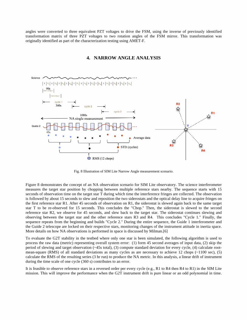
Figure 8 demonstrates the concept of an NA observation scenario for SIM Lite observatory. The science interferometer measures the target star position by chopping between multiple reference stars nearby. The sequence starts with 15 seconds of observation time on the target star T during which time the interference fringes are collected. The observation is followed by about 15 seconds to slew and reposition the two siderostats and the optical delay line to acquire fringes on the first reference star R1. After 45 seconds of observation on R1, the siderostat is slewed again back to the same target star T to be re-observed for 15 seconds. This concludes the "Chop." Then, the siderostat is slewed to the second reference star R2, we observe for 45 seconds, and slew back to the target star. The siderostat continues slewing and observing between the target star and the other reference stars R3 and R4. This concludes "Cycle 1." Finally, the sequence repeats from the beginning and builds "Cycle 2." During the entire sequence, the Guide 1 interferometer and the Guide 2 telescope are locked on their respective stars, monitoring changes of the instrument attitude in inertia space. More details on how NA observations is performed in space is discussed by Milman.[6]
To evaluate the G2T stability in the testbed where only one star is been simulated, the following algorithm is used to process the raw data (metric) representing overall system error: (1) form 45 second averages of input data, (2) skip the period of slewing and target observation (~45s total), (3) compute standard deviation for every cycle, (4) calculate root-mean-square (RMS) of all standard deviations as many cycles as are necessary to achieve 12 chops (~1100 sec), (5) calculate the RMS of the resulting series (3 hr run) to produce the NA metric. In this analysis, a linear drift of instrument during the time scale of one cycle (360 s) contributes to an error.
It is feasible to observe reference stars in a reversed order per every cycle (e.g., R1 to R4 then R4 to R1) in the SIM Lite mission. This will improve the performance when the G2T instrument drift is pure linear or an odd polynomial in time.
Fig. 8 Illustration of SIM Lite Narrow Angle measurement scenario.
When the error is in a quadratic form or even time polynomial, the non-reversed order observation is expected to produce a better result.
5. RESULTS
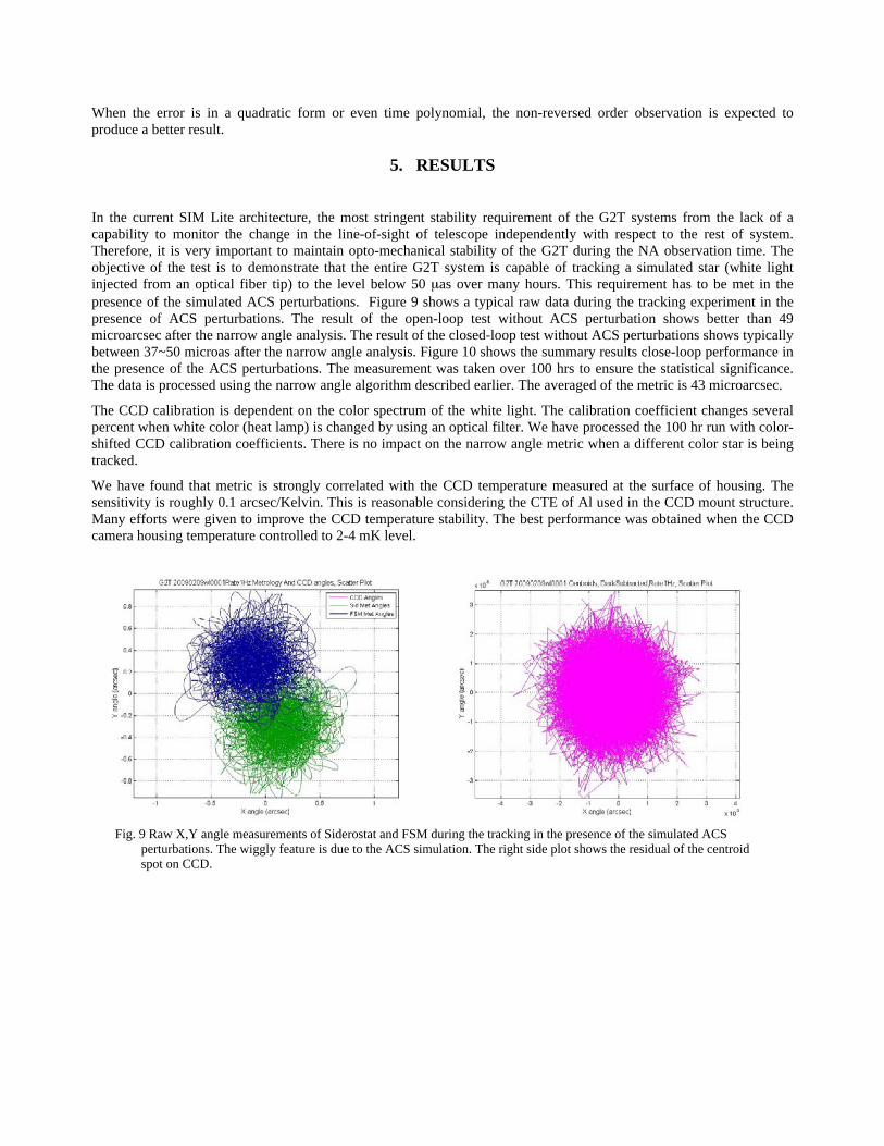
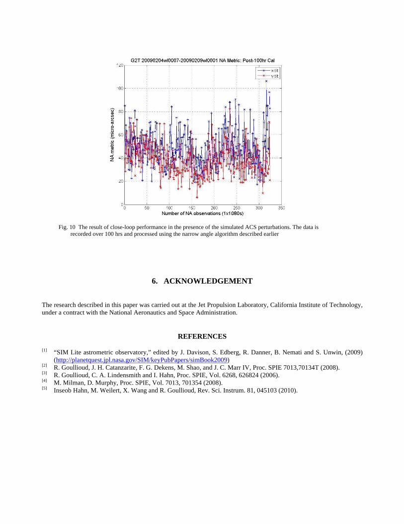
In the current SIM Lite architecture, the most stringent stability requirement of the G2T systems from the lack of a capability to monitor the change in the line-of-sight of telescope independently with respect to the rest of system. Therefore, it is very important to maintain opto-mechanical stability of the G2T during the NA observation time. The objective of the test is to demonstrate that the entire G2T system is capable of tracking a simulated star (white light injected from an optical fiber tip) to the level below 50 µas over many hours. This requirement has to be met in the presence of the simulated ACS perturbations. Figure 9 shows a typical raw data during the tracking experiment in the presence of ACS perturbations. The result of the open-loop test without ACS perturbation shows better than 49 microarcsec after the narrow angle analysis. The result of the closed-loop test without ACS perturbations shows typically between 37~50 microas after the narrow angle analysis. Figure 10 shows the summary results close-loop performance in the presence of the ACS perturbations. The measurement was taken over 100 hrs to ensure the statistical significance. The data is processed using the narrow angle algorithm described earlier. The averaged of the metric is 43 microarcsec.
The CCD calibration is dependent on the color spectrum of the white light. The calibration coefficient changes several percent when white color (heat lamp) is changed by using an optical filter. We have processed the 100 hr run with color-shifted CCD calibration coefficients. There is no impact on the narrow angle metric when a different color star is being tracked.
We have found that metric is strongly correlated with the CCD temperature measured at the surface of housing. The sensitivity is roughly 0.1 arcsec/Kelvin. This is reasonable considering the CTE of Al used in the CCD mount structure. Many efforts were given to improve the CCD temperature stability. The best performance was obtained when the CCD camera housing temperature controlled to 2-4 mK level.
Fig. 9 Raw X,Y angle measurements of Siderostat and FSM during the tracking in the presence of the simulated ACS
perturbations. The wiggly feature is due to the ACS simulation. The right side plot shows the residual of the centroid spot on CCD.
6. ACKNOWLEDGEMENT
The research described in this paper was carried out at the Jet Propulsion Laboratory, California Institute of Technology, under a contract with the National Aeronautics and Space Administration.
REFERENCES
[1] “SIM Lite astrometric observatory,” edited by J. Davison, S. Edberg, R. Danner, B. Nemati and S. Unwin, (2009) (http://planetquest.jpl.nasa.gov/SIM/keyPubPapers/simBook2009)
[2] R. Goullioud, J. H. Catanzarite, F. G. Dekens, M. Shao, and J. C. Marr IV, Proc. SPIE 7013,70134T (2008). [3] R. Goullioud, C. A. Lindensmith and I. Hahn, Proc. SPIE, Vol. 6268, 626824 (2006). [4] M. Milman, D. Murphy, Proc. SPIE, Vol. 7013, 701354 (2008). [5] Inseob Hahn, M. Weilert, X. Wang and R. Goullioud, Rev. Sci. Instrum. 81, 045103 (2010).
Fig. 10 The result of close-loop performance in the presence of the simulated ACS perturbations. The data is
recorded over 100 hrs and processed using the narrow angle algorithm described earlier