RESMI K R-PPT 1
46
FIFTH SEMESTER B Sc PHYSICS Chapter-4 Interference by division of wavefront Resmi. K. R Asst. Professor Dept. Of Physics MESKC
-
Upload
khangminh22 -
Category
Documents
-
view
0 -
download
0
Transcript of RESMI K R-PPT 1

FIFTH SEMESTER B Sc PHYSICS
Chapter-4
Interference by division of wavefront
Resmi. K. R
Asst. Professor
Dept. Of Physics
MESKC

Introduction
• This study is based on the fact, suggested by
Christian Huygens in 1680,that light propagates
in the form of waves.
• The wave theory of light received the first • The wave theory of light received the first
experimental evidence in 1801
• That was interference experiments conducted by
Thomas Young

Wave optics
• According to wave theory light travels in the form of
waves
• The locus of all points which have the same phase
of vibration in a wave is known as a wave front
• According to Huygens Principle, every point on a • According to Huygens Principle, every point on a
wave front behaves as a source of secondary
wavelets.
• Secondary waves spread from these points similar
to light spread from the original point source.
• The new wave front will be the envelop of these
secondary wavelets

Light waves
• Light waves are harmonic electromagnetic waves
• e. m waves consists of periodically varying electric and magnetic fields, oscillating at right angles to each other and also to the direction of propagation of wave.
• Electric field is denoted by E and magnetic field • Electric field is denoted by E and magnetic field by B
• Light waves are usually denoted by E wave, known as light vector or optical vector and the electric field is known as optical field or radiation field or wave field or light field etc.
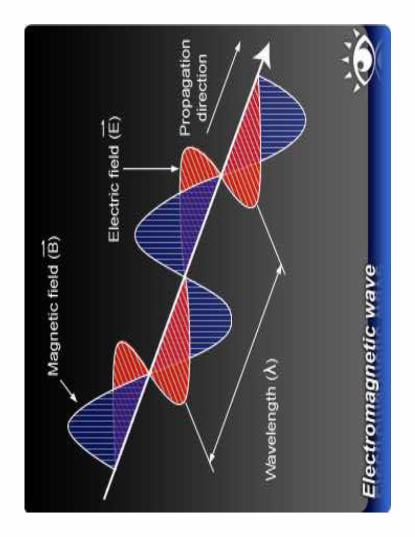


• Velocity of light waves : C=E/B
• Mathematically represented by: E = Eo e[i(kz-ωt)]
• Wave vector : k=2π/λ
• Angular frequency : ω = 2πν • Waves having single definite frequency and
wave length are called monochromatic waves
• Light waves travel slowly in a medium than in
air or vacuum
• If frequencies of two waves are different then
there is phase difference between them.
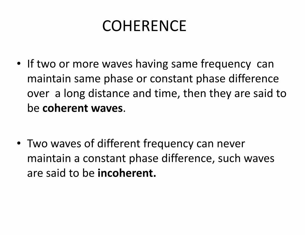
COHERENCE
• If two or more waves having same frequency can
maintain same phase or constant phase difference
over a long distance and time, then they are said to
be coherent waves.
• Two waves of different frequency can never
maintain a constant phase difference, such waves
are said to be incoherent.

Coherent waves : In phase opposite phase

Superposition of waves
• Principle of superposition: when two or more
waves overlap, the resultant displacement at any
point and at any instant may be found by adding
the instantaneous displacements that would be
produced at the point by individual waves if each produced at the point by individual waves if each
were present alone
• In case of electromagnetic waves , the term
displacement refers to the amplitude of electric
field vector.

combined
Superposition of waves
combined
waveform
wave 1
wave 2
Two waves in phase Two waves 180° out

Interference
• Interference is a consequence of superposition of coherent waves
• When two waves superpose, the resultant intensity distribution is called interference intensity distribution is called interference pattern.
• Interference is the phenomenon of redistribution of light energy due to superposition of light waves from two or more coherent sources


• When two or more coherent waves of light are superposed ,the resultant would be brightness in certain regions and darkness in other regions
• They are called bright and dark bands (Maxima and minima)
• These can take the form of straight, circular or any other complex shapes
• Alternate bright and dark fringes are called • Alternate bright and dark fringes are called interference fringes
• Bright bands are formed when constructive interference occur and dark fringes during destructive interference
• The distance between two consecutive bright or dark fringes are called band width or fringe width(β)

• When two waves interfere, if waves are in
phase(constructive interference) then resultant
amplitude:
• AR =A+A = 2A
• IR α (AR )2 = 4A2 =4I
• When two waves interfere, if waves are out of • When two waves interfere, if waves are out of
phase(destructive interference) then resultant
amplitude:
• AR =A-A=0
• IR < 2I

Path difference and Phase difference
A. .p
r1
A.
B.
r2
The path length AP = µ1r1
” BP = µ2r2
Optical path difference= µ2r2 - µ1r1 =∆

• In interference, if the waves arrived at ‘P’ are in phase and if
∆=mλ m=0,1,2,3,4…………………
Then the resultant fringe will be bright fringe (constructive interference)
• If • If
∆=(2m+1)λ/2 m=0,1,2,3,4…………………
Then the resultant fringe will be dark fringe (destructive interference)
� Phase difference=(2π/λ) x path difference

Intensity distribution• Electric field components of two waves arriving at point ‘p’
with time as :
• EA =E1 sin ωt-------------------------------------------------------(1)
• EB =E2 sin(ωt + δ)-------------------------------------------------(2)
• δ = phase difference between them
• ER = EA+EB ----------------------------------------------------------(3)
= E1 sin ωt + E2 sin(ωt + δ) = E1 sin ωt + E2 sin(ωt + δ) = E1 sin ωt + E2 (sinωt cos δ+cosωt sinδ)
= sin ωt(E1 + E2 cos δ) + cos ωt(E2 sinδ)-----------------(4)
Put: E cos φ = (E1 + E2 cos δ) ----------------------------------(5)
E sin φ = (E2 sinδ)-------------------------------------------(6)
E=amplitude of the resultant wave
φ = phase angle

Squiring and adding eq (5) and (6)
(E1 + E2 cos δ)2 + (E2 sinδ)2 = E2 (cos2 φ +sin2 φ)=E2
E12 +E2
2 +2E1E2 cosδ =E2
conclusion:
Square of amplitude of resultant wave is not a Square of amplitude of resultant wave is not a
simple sum of square of amplitudes of superposing
waves. The additional term is called intererence
term.
Intensity of wave is given by square of its amplitude.
I=E2 = E12 +E2
2 +2E1E2 cosδ = Ι1 + Ι2 +2 (Ι1 Ι2) cosδ

• When δ=0, Ι max = Ι1 + Ι2 +2 (Ι1 Ι2) • Ι1=Ι2=Ιο, then Ι max = 4Ιο
• resultant intensity will be more than the sum of
intensities due to two sources
• When δ=180 , cos 180=-1
• Ιmim = Ι1=Ι2 =0• Ιmim = Ι1=Ι2 =0• Αt points between maxima and minima:
• Ι1=Ι2=Ιο
• I= 2Io +2Io cos δ= 2Io (1+cos δ)= 2Io x 2cos2 (δ/2)
• I=4Io cos2 (δ/2 )

Expression for band width or fringe
width
β=λD/d

Interference
• For sound waves and microwaves (as wavelength
is large), interference pattern can be visible as
they maintain a constant phase relation
• But light waves, due to the process of emission • But light waves, due to the process of emission
(light emanating from every point) it is not
possible to observe pattern from independent
source, eventhough interference pattern
takeplace. (As it is difficult to have constant phase
relationship)
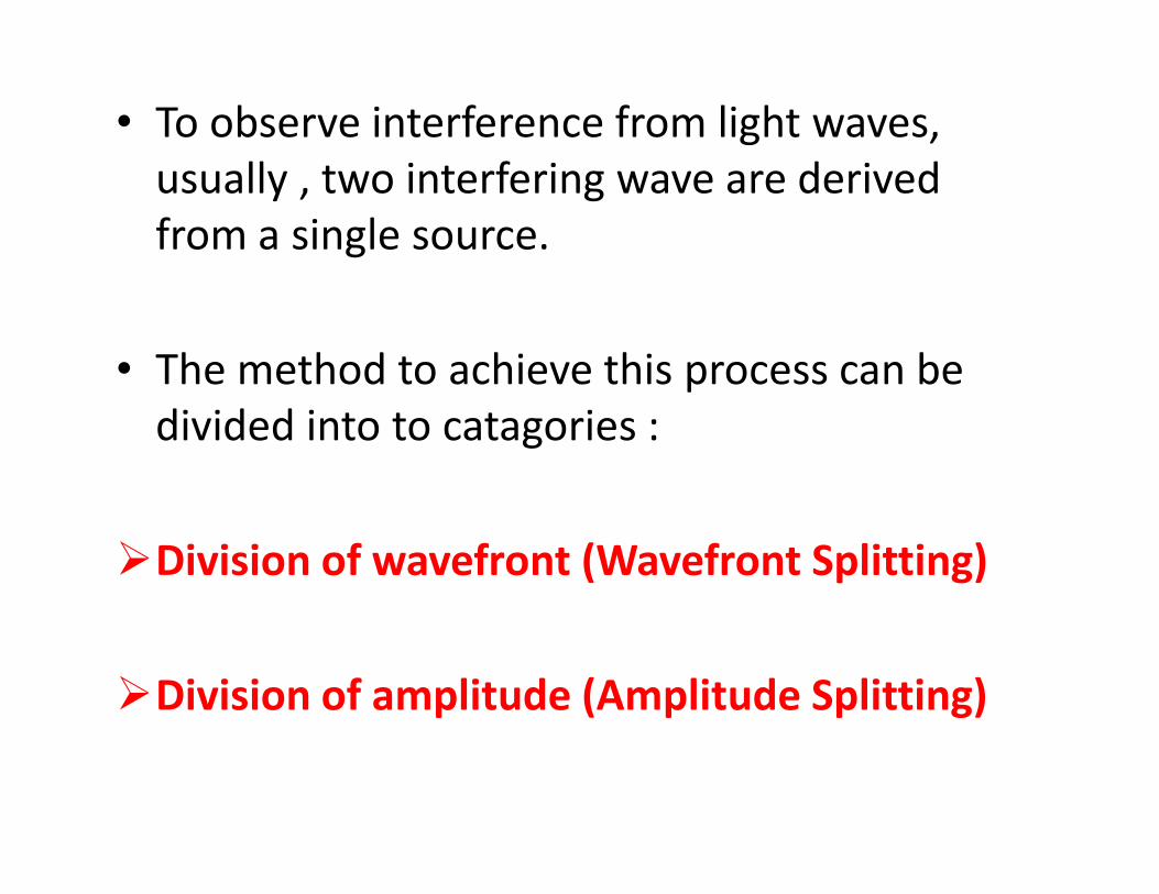
• To observe interference from light waves,
usually , two interfering wave are derived
from a single source.
• The method to achieve this process can be
divided into to catagories :divided into to catagories :
�Division of wavefront (Wavefront Splitting)
�Division of amplitude (Amplitude Splitting)

Division of wavefront
(Wavefront Splitting)
• The beam is allowed to fall on two closely
spaced holes and the beam emanating from
these holes interfere to form interference
pattern called the method of division of pattern called the method of division of
wavefront
• The two parts of the same wavefront travel
through different paths and reunite on a screen
to produce fringe pattern
• Eg: Young’s double slit exp. ,Fresnel’s double
mirror, Fresnel’s biprism etc.

Division of amplitude
(Amplitude Splitting)
• The beam is divided at two or more reflecting
surfaces and reflected beams interfere known as
interference by division of amplitude
• Ie; the amplitude or intensity of a light wave is
divided into two parts (reflected and transmitted divided into two parts (reflected and transmitted
parts) by partial reflection at a surface
• These two parts travel through different paths and
reunite to produce interference patterns
• Eg:- Intereference in thin films (wedge, Newton’s
rings), Interferometers etc use this methods

Interference by division of wavefront

� Fresnel’s two mirror arrangement

• Here light from source ‘S’ falls on two mirrors M1 and M2
• Light reflected from these mirrors, interfere to form interference pattern, as it seems to come from two sources ‘S1’ and ‘S2’
• From figure S,S1 and S2 lie on a circle having centre point ‘M’
• The angle between two mirrors is θ, the angle S1SS2 is • The angle between two mirrors is θ, the angle S1SS2 is also θ
• The angle S1MS2 is 2 θ• S1S2 =2R θ , R is the radius of circle
• 2R θ=d, β=λD/d

Fresnel's Biprism
• Biprism consists of two prisms of very small
refracting angles joined base to base.
• Usually the two side angles are 30’ and the
other angle 179oother angle 179o
C
A
B

S1
SS
S2

• When a ray of light incident on an ordinary prism ,
the ray is bent through an angle called angle of
deviation
• Then the ray emerging out of the prism appears to
have emanated from a source S’ located at a small
distance above the real source.
• Then it is said that prism produced a virtual image • Then it is said that prism produced a virtual image
of the source.
• Then a biprism creates two virtual sources S1 and
S2
• These two virtual sources are images of the same
source S poduced by refraction and are coherent.

Experimental
arrangement • Optical bench
•The biprism is mounted on an optical
bench.
•An optical bench consists of two
horizontal long rods, parallel to each
other and at the same level
•The rods have uprights on which the
optical components are positioned.optical components are positioned.
•A monochromatic light source
illuminates a vertical slit S
•It act as a narrow linear monochromatic
source.
•Biprism is laced in front of the slit with
its refracting edge parallel to the slit.

• Due to refraction from upper and lower portion of
the biprism, light appears to be emanated from two
sources S1 and S2 .
• These sources are coherent and interference • These sources are coherent and interference
pattern can be observed in a region beyond biprism
if a screen is placed

β=λD/d

Determination of wavelength of light • To determine wavelength, the value of β, D and ‘d’ are
to be determined
• (1) . To determine β• The biprism arrangement is mounted on the optical
bench.
• When the fringes are observed in the field of view of the eyepiece, the vertical cross wire is made to coincide
• When the fringes are observed in the field of view of the eyepiece, the vertical cross wire is made to coincide with the centre of one of the bright fringes.
• The position of the eyepiece is read on the scale,x0.
• The micrometer screw of the eyepiece is moved slowly and the number of bright fringed N is noted.
• Then position of Nth fringe is measured as XN.
Then β=XN-X0/N

Determination of ‘d’
A .
S .S .
B .d1
uv

Determination of ‘d’• There are two methods:
• (1) A convex lens of short focal length is placed between the slit and eyepiece without disturbing their positions.
• The lens is moved back and forth near the biprism till a sharp pair of images of the slit is obtained in till a sharp pair of images of the slit is obtained in the field view of the eyepiece.
• The distance between the images is measured.
• Let it be ‘d1’
• If ‘u’ and ‘v’ is the distance of slit and eyepiece from the lens. Then magnification is:
v/u=d1/d

A .
S .S .
B .d2
v u
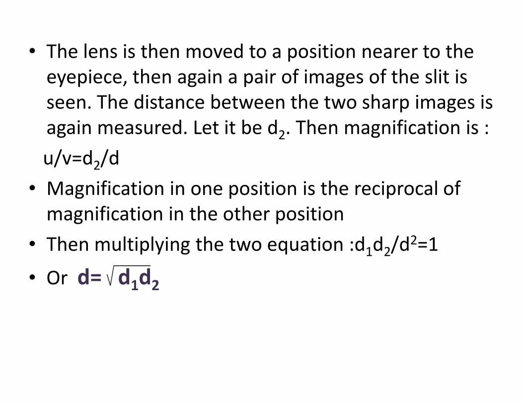
• The lens is then moved to a position nearer to the
eyepiece, then again a pair of images of the slit is
seen. The distance between the two sharp images is
again measured. Let it be d2. Then magnification is :
u/v=d2/d
• Magnification in one position is the reciprocal of
magnification in the other positionmagnification in the other position
• Then multiplying the two equation :d1d2/d2=1
• Or d= d1d2

• (2) The deviation produced in the path of the ray by a thin prism is given by : δ=(µ-1)α
• Where α=is the refracting angle of the prism
• Also δ=θ/2,
• As ‘d’ is very small ,d=aθ
• Hence θ/2=d/2a=(µ-1)α
• d= 2a(µ-1)α

Interference fringes with white light
• In the biprism experiment if slit is illuminated
with white light, the interference pattern
consists of central white fringe franked on its
both sides with few coloured fringes both sides with few coloured fringes

Lateral displacements of fringes

Lateral displacements of fringes
• Biprism experiment can be used to determine the thickness of a given thin sheet of transparent material
• If thin transparent sheet is introduced in the • If thin transparent sheet is introduced in the path of one of the two interfering beams, the fringe system gets displaced towards the beam in whose path the sheet is introduced
• By measuring the amount of displacement , the thickness of the sheet can be determined

�Let S1 and S2 be two virtual sources
�The point O is equidistant from s1 and s2
(s1O=s2O)
�‘t’ be the thickness of the glass plate and ‘µ’ be the refractive index , which is introduced in the path of s1O
�Now S1O and S2O are not equal�Now S1O and S2O are not equal
�Let the central bright fringe shift to ‘P’, from ‘O’
�The light wave from S1 to P travel partly in air and partly in sheet
�The distance in air and the distance in sheet are : (S1P-t) and t respectively

• The optical path is: ∆s1p=(S1p-t)+µt=S1P+(µ-1)t
• :∆S2P=S2P
• At the point ‘P’ the optical path difference is zero as it is the central fringe.
• Then : ∆s1p - ∆s2p = 0 ; ∆s1p = ∆s2p
• ie; S1P+(µ-1)t = S2P
S P- S P= (µ-1)tS2P- S1P= (µ-1)t
Also: S2P- S1P= xd/D
‘x’ is the lateral shift in the central fringe due to the introduction of the thin sheet
(µ-1)t= xd/D
t= xd/D(µ-1)