
Research Article Influence of the Slag Density on the ...
7
Research Article Influence of the Slag Density on the Splashing Process in a Steelmaking Converter Miguel A. Barron, 1 Dulce Y. Medina, 1 Isaias Hilerio, 1 and Gabriel Plascencia 2 1 Departamento de Materiales, Universidad Aut´ onoma Metropolitana Azcapotzalco, Avenida San Pablo 180, Colonia Reynosa-Tamaulipas, 02200 Mexico, DF, Mexico 2 Centro de Investigacion e Innovacion Tecnologica-IPN, Cerrada Cecati S/N, Colonia Santa Catarina, 02250 Mexico, DF, Mexico Correspondence should be addressed to Miguel A. Barron; [email protected] Received 24 October 2013; Accepted 3 January 2014; Published 13 February 2014 Academic Editors: S. Eckert and T. Yue Copyright © 2014 Miguel A. Barron et al. is is an open access article distributed under the Creative Commons Attribution License, which permits unrestricted use, distribution, and reproduction in any medium, provided the original work is properly cited. e way in which slag density influences the slag splashing phenomenon in an oxygen steelmaking converter is numerically analyzed in this work. Several values of the density of the slag are considered, and their effect on the global mass balance and slag average volume fraction on the sidewalls of the converter is studied using isothermal, two-dimensional transient computational fluid dynamics simulations. Diameter of the slag drops is determined from the slag density and the impact velocity of the nitrogen jet. Besides, the effect of the nitrogen jet Mach number on the slag splashing is simulated and discussed. A qualitative comparison between the computer simulations and results from the literature is made. 1. Introduction It is known that the wear of refractory lining in an oxygen steelmaking converter for raw steel manufacturing is a factor which greatly influences the production costs. In the last two decades, slag splashing has emerged as a new technology to extend the lifetime of the converter refractory lining given that this technology reduces the wear associated to thermal and chemical attack by slag and mechanical impact [1, 2]. Aſter the draining of steel, molten slag remaining at the converter bottom is splashed towards the converter sidewalls using a supersonic jet of gaseous nitrogen. Molten slag freezes at the converter walls and forms a protective coating that prevents the wear of the refractory lining. Nitrogen is injected into the converter through a water-cooled vertical lance which has several inclined convergent-divergent nozzles. During the slag splashing process three main stages have been identified in the formation of the slag protective coating: transport of molten slag to the converter walls, adherence of the molten slag to the sidewalls, and freezing and hardening of the slag layer [3]. When the molten slag is transported to the converter sidewalls, two transport mechanisms are present: wash coating and ejection coating [4]. e first one occurs due to the bulk movement of the molten slag to rise above the initial level and the second one due to the ejection of slag droplets which adhere to the vessel sidewalls [5]. In recent years, several experimental studies on the slag splashing phenomenon have been reported. In these studies, physical scale models of the converter are employed, and cold water and air replace molten slag and nitrogen, respectively [4, 6, 7]. In [4] it is reported that large nozzle inclination and lance heights increase the splashing and the main mechanism of splashing changes from ejection to washing as the viscosity of the liquid is increased. In [6] it is reported that the amount of slag splashed is increased as lance is raised, but beyond a critical value of the lance height splashing decreases. In [7] it is shown that when the jet flow rate is increased or the liquid viscosity is decreased, the lower regions of the walls are splashed at a much greater rate. It is also shown that by changing the lance height, more liquid is deposited in the upper regions of the vessel at the expense of lower regions. On the other hand, some numerical studies of gaseous jets impinging on a liquid surface are reported using com- putational fluid dynamics simulations [8–10]. Agreement is reported between numerical and water model results; unfor- tunately, these studies are mainly focused on the jet-surface Hindawi Publishing Corporation ISRN Metallurgy Volume 2014, Article ID 525706, 6 pages http://dx.doi.org/10.1155/2014/525706
-
Upload
khangminh22 -
Category
Documents
-
view
2 -
download
0
Transcript of Research Article Influence of the Slag Density on the ...
Research ArticleInfluence of the Slag Density on the Splashing Process ina Steelmaking Converter
Miguel A Barron1 Dulce Y Medina1 Isaias Hilerio1 and Gabriel Plascencia2
1 Departamento de Materiales Universidad Autonoma Metropolitana Azcapotzalco Avenida San Pablo 180Colonia Reynosa-Tamaulipas 02200 Mexico DF Mexico
2 Centro de Investigacion e Innovacion Tecnologica-IPN Cerrada Cecati SN Colonia Santa Catarina 02250 Mexico DF Mexico
Correspondence should be addressed to Miguel A Barron bmmacorreoazcuammx
Received 24 October 2013 Accepted 3 January 2014 Published 13 February 2014
Academic Editors S Eckert and T Yue
Copyright copy 2014 Miguel A Barron et al This is an open access article distributed under the Creative Commons AttributionLicense which permits unrestricted use distribution and reproduction in any medium provided the original work is properlycited
Theway inwhich slag density influences the slag splashing phenomenon in anoxygen steelmaking converter is numerically analyzedin this work Several values of the density of the slag are considered and their effect on the global mass balance and slag averagevolume fraction on the sidewalls of the converter is studied using isothermal two-dimensional transient computational fluiddynamics simulations Diameter of the slag drops is determined from the slag density and the impact velocity of the nitrogenjet Besides the effect of the nitrogen jet Mach number on the slag splashing is simulated and discussed A qualitative comparisonbetween the computer simulations and results from the literature is made
1 Introduction
It is known that the wear of refractory lining in an oxygensteelmaking converter for raw steel manufacturing is a factorwhich greatly influences the production costs In the last twodecades slag splashing has emerged as a new technology toextend the lifetime of the converter refractory lining giventhat this technology reduces the wear associated to thermaland chemical attack by slag and mechanical impact [1 2]After the draining of steel molten slag remaining at theconverter bottom is splashed towards the converter sidewallsusing a supersonic jet of gaseous nitrogenMolten slag freezesat the converter walls and forms a protective coating thatprevents the wear of the refractory lining Nitrogen is injectedinto the converter through a water-cooled vertical lancewhich has several inclined convergent-divergent nozzles
During the slag splashing process three main stages havebeen identified in the formation of the slag protective coatingtransport of molten slag to the converter walls adherence ofthe molten slag to the sidewalls and freezing and hardeningof the slag layer [3] When the molten slag is transportedto the converter sidewalls two transport mechanisms arepresent wash coating and ejection coating [4] The first one
occurs due to the bulk movement of the molten slag to riseabove the initial level and the second one due to the ejectionof slag droplets which adhere to the vessel sidewalls [5]
In recent years several experimental studies on the slagsplashing phenomenon have been reported In these studiesphysical scale models of the converter are employed and coldwater and air replace molten slag and nitrogen respectively[4 6 7] In [4] it is reported that large nozzle inclination andlance heights increase the splashing and themainmechanismof splashing changes from ejection to washing as the viscosityof the liquid is increased In [6] it is reported that the amountof slag splashed is increased as lance is raised but beyond acritical value of the lance height splashing decreases In [7]it is shown that when the jet flow rate is increased or theliquid viscosity is decreased the lower regions of the wallsare splashed at a much greater rate It is also shown that bychanging the lance height more liquid is deposited in theupper regions of the vessel at the expense of lower regions
On the other hand some numerical studies of gaseousjets impinging on a liquid surface are reported using com-putational fluid dynamics simulations [8ndash10] Agreement isreported between numerical and water model results unfor-tunately these studies are mainly focused on the jet-surface
Hindawi Publishing CorporationISRN MetallurgyVolume 2014 Article ID 525706 6 pageshttpdxdoiorg1011552014525706
2 ISRNMetallurgy
interaction and the prediction of the surface topographyrather than on liquid splashing Recently two studies [11 12]by some of the authors of the present work were reportedon the simulation of the slag splashing phenomenon usingcomputational fluid dynamics considering the dimensions ofactual industrial converters and the influence of propertiesof molten slag Particularly in [12] the influence of the slagviscosity on the slag splashing process was studied and itsconclusions are as follows (i) ejection mechanism becomesdominant as viscosity is decreased (ii) washing mechanismbecomes dominant as viscosity is increased (iii) efficiencyof the slag splashing process is increased as slag viscositydecreases
In this work the influence of the slag density on theslag splashing process is analyzed using computational fluiddynamics simulations Values of the slag density rangingfrom 2000 to 3000 kgmminus3 are considered This range istypical of CaOndashSiO
2
molten slags found in steelmaking [13]Physical dimensions of the converter correspond to an actualindustrial steelmaking converter of 150 metric tons Thevolume fraction of slag in the converter sidewalls is employedfor quantitative evaluation of the slag splashing efficiency Inorder to detect spitting of slag from the converter mouth theglobal mass balance is determined Besides the effect of thenitrogen jet Mach number on the slag splashing is simulatedand discussed Finally a qualitative comparison between thecomputational fluid dynamics simulations and results fromthe literature is made
2 Mathematical Modeling
During the slag splashing process molten slag located inthe converter bottom is splashed to the converter sidewallsby means of a supersonic jet of gaseous nitrogen Themomentum of the nitrogen jet is transferred to the moltenslag which causes the slag to be stirred and ejected by theaction of a standing wave and high shear forces respectively[4] Predominance of one of the coating mechanisms thatis washing or ejection depends on factors such as the jetcharacteristics (velocity exit angle) the operating conditions(lance height molten slag depth) and the slag properties(viscosity density and temperature) Inertial gravitationalviscous and interfacial forces are applied on both phases thatis gaseous nitrogen andmolten slag causing a nonisothermalmultiphase flow To model the complex system here consid-ered equations which govern the fluid flow themass balancethe turbulence and the multiphase flow are required
The flow of an incompressible newtonian fluid is gov-erned by the Navier-Stokes equations which in vector formare expressed as [14]
120588(120597
120597119905+ sdot nabla) = minusnabla119901 + 120583effnabla
2997888119906 + 120588 119892 + 119865 (1)
where 120588 is the fluid density is the velocity vector 119905 is time 119901is pressure 120583eff is the effective fluid viscosity 119892 is the gravityvector and 119865 represents additional forces applied or acting
on the fluid To maintain the mass balance in the system thecontinuity equation [14] must be solved
120597119906119895
120597119909119895
= 0 (2)
where 119906119895
and 119909119895
are the 119895th components of the velocity vectorand the coordinate system respectively
Turbulence was simulated by means of the classical twoequations119870-120576model [15]
120588V119895
120597119870
120597119909119895
=120597
120597119909119895
(120583119905
120590119870
120597119870
120597119909119895
) + 120583119905
120597V119895
120597119909119894
(120597V119894
120597119909119895
+120597V119895
120597119909119894
) minus 120588120576
120588V119895
120597120576
120597119909119895
=120597
120597119909119895
(120583119905
120590120576
120597120576
120597119909119895
) + 1198621
120583119905
120576
119870
120597V119895
120597119909119894
(120597V119894
120597119909119895
+120597V119895
120597119909119894
)
minus 1198622
120576
119870120588120576
(3)
where 119870 is the turbulent kinetic energy 120576 is the dissipationrate and 120583
119905
is the turbulent viscosity Besides 120590119870
= 10120590120576
= 13 1198621
= 144 and 1198622
= 192 The effective viscosityemployed in the Navier-Stokes equations is determined from
120583eff = 1205830 + 120583119905 (4)
where 1205830
is the laminar viscosity The turbulent viscosity iscalculated from
120583119905
=120588119862120583
1198702
120576 (5)
where 119862120583
= 009 and119870 and 120576 are determined from (3)Boundary conditions at the inlet nozzles are determined
as follows for the velocity components 119906119909
= 119880in sin(120572) and119906119910
= 119880in cos(120572) where 119880in is the nominal velocity and 120572is the inlet angle of the nitrogen jet which corresponds tothe exit angle of the nozzles The inlet values of 119870 and 120576 aredetermined from [15 16]
119870in = 0011198802
in
120576in =211987015
in119863
(6)
where 119863 is the diameter of the inlet nozzle At the converterwalls the classical nonslip condition is applied
When droplet breakaway occurs there is a balancebetween the inertial (119865
119894
) interfacial (119865120574
) and gravitationalforces (119865
119892
) [5 17]
119865119894
= 119865120574
+ 119865119892
(7)
The drop diameter (119889) derived from the balance of forcesof (7) is given by [5 17]
119889 =31198802
8119892(1 minus (1 minus
128120574119892
31205881198804)) (8)
where 119880 is the magnitude of the jet velocity at the impactpoint and 120574 is the surface tension
ISRNMetallurgy 3
(a) (b) (c)
(d) (e) (f)
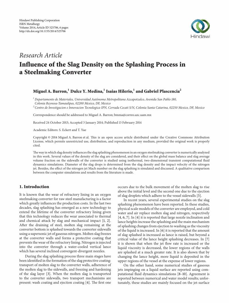
Figure 1 Distribution of phases for several values of the slag density (red is molten slag blue is nitrogen) (a) 2000 (b) 2200 (c) 2400 (d)2600 (e) 2800 and (f) 3000 kgmminus3
The Volume of Fluidmodel is employed here to tackle themultiphase flow This model is based on the assumption thattwo or more phases are not interpenetrating Each 119894th phasehas associated a volume fraction 119881
119894
and in every controlvolume the sum of the volume fractions of all phases is equalto 1 In theVolumeof FluidModel the tracking of the interfacebetween the phases is accomplished by solving the continuityequation for each phase [18]
120597119881119894
120597119905+ sdot nabla119881
119894
= 0 (9)
To better define the slag-nitrogen interface the computa-tional fluid dynamics software (FLUENT) uses an interpola-tion scheme called Geometric Reconstruction Scheme
3 Computer Simulations
Physical dimensions of the considered converter correspondto an actual industrial converter of 150metric tons of capacityand were assumed as follows height 72m diameter 48m
lance diameter 02m number of nozzles 2 diameter of noz-zles 0043m exit angle of nozzles 10 degrees The operatingparameters were set as follows lance height above the initialmolten slag surface 2m velocity of the supersonic nitrogenjet Mach 15 initial molten slag depth 05m Viscosity andsurface tension of slag were assumed to be 05 kgmminus1 sminus1 and04Nmminus1 respectively
To reduce the computational effort an isothermal two-dimensional converter was considered The coupled Navier-Stokes equations the continuity equation the turbulencemodel and the Volume of Fluid Model were numericallysolved using computational fluid dynamics software (FLU-ENT) The Pressure Implicit Splitting Operation algorithmwas employed in the transient simulations for the pressure-velocity coupling given that it maintains stability of thenumerical scheme despite the larger time steps
Transient isothermal two-dimensional computer simu-lations were carried out using a time step of 00001 s anda mesh consisting of 14075 trilateral cells Due to the fastdynamics of the fluid flow the integration time was 2 s in
4 ISRNMetallurgy
10minus4
10minus5
10minus6
10minus7
1800 2000 2200 2400 2600 3000 3200
Dro
p di
amet
er (m
)
2800
Slag density (kg mminus3)
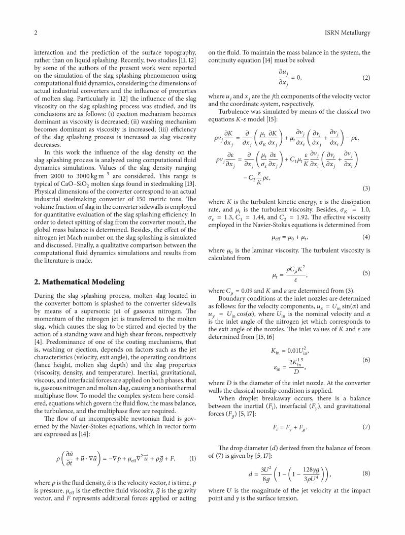
Figure 2 Diameter of the slag drops as a function of the slag densityand the impact velocity 50m sminus1 (circle) and 100m sminus1 (square)
this time the multiphase flow is fully developed Viscosityand surface tension of the molten slag was assumed to be05 kgmminus1 sminus1 and 04Nmminus1 respectively For the analysisthe slag density was varied from 2000 to 3000 kgmminus3 usingintervals of 200 kgmminus3
4 Analysis of Results
Figure 1 depicts the distribution of phases (red phase ismolten slag blue phase is nitrogen) for several values of theslag density using the operating conditions and integrationtime described in Section 3 It is observed that the ejectionheight of the slag drops decreases as the slag density isincreased This is explained by the small forces required bythe less dense slag drops to be broken and ejected comparedwith the relatively big forces required by the denser slag Theejection forces are supplied by themomentumof the nitrogenjet Figure 1(a) shows that for a density of 2000 kgmminus3 theslag reaches the top of the converter and as result of thisspitting of slag from the mouth converter occurs This can becorroborated from a global mass balance A negative valueof the global mass balance indicates that molten slag is beingexpelled from the converter The spitting phenomenon doesnot occur for values of slag density equal or greater than2200 kgmminus3 under the conditions described above
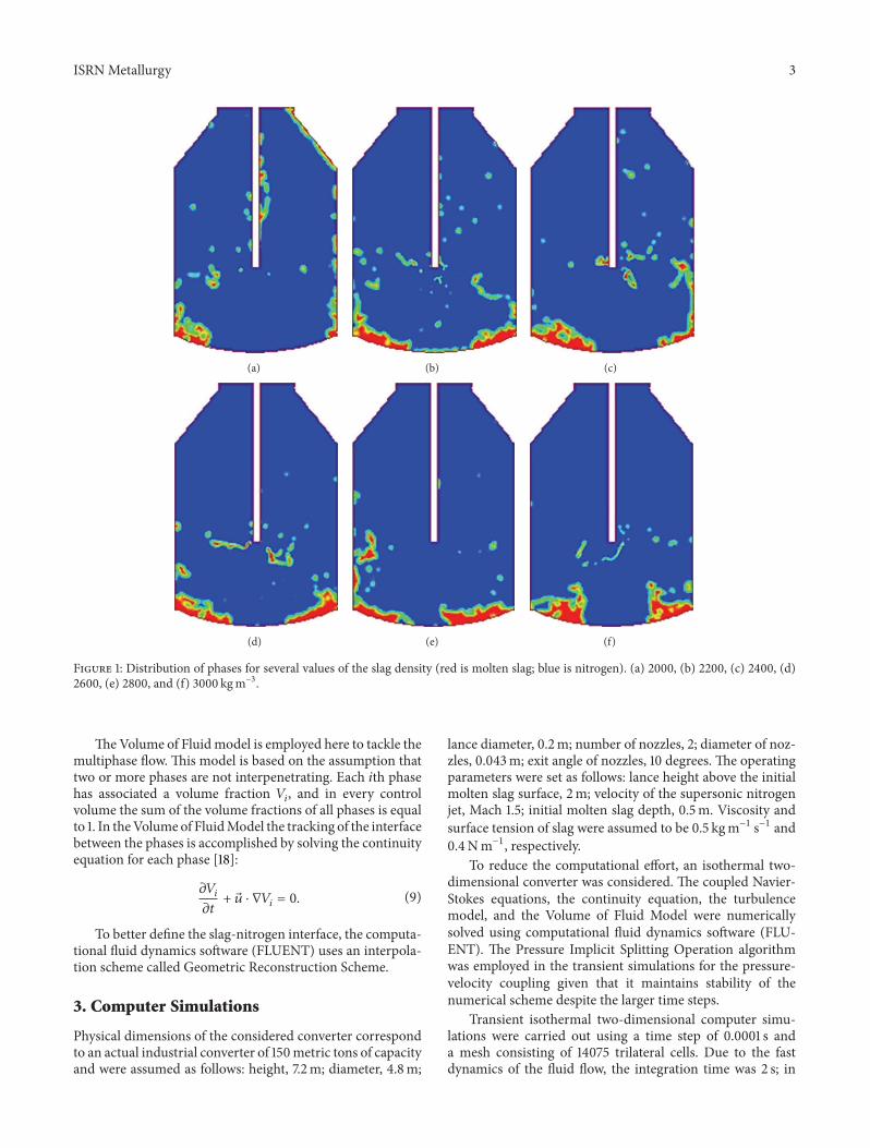
In Figure 2 the diameter of the slag drops as functionof the slag density and the velocity of the jet at the impactsite is shown The drop diameters were obtained using (8)which is strongly nonlinear The velocity of the jet decays asit descends towards the converter bottom and the slag bathis impacted at a subsonic velocity The impact velocity 119880of (8) was approximated from the contours of the velocitymagnitude shown in Figure 3 corresponding to Figure 1(a)During the blowing the depth of the slag bath is reducedand the nitrogen jet covers a longer distance to impact themolten slag Due to this the jet velocity suffers a significantdecay below 200m sminus1 Then two impact velocities wereconsidered 50 and 100m sminus1 It is observed that the dropdiameter decreases in size as density is increased A similarbehavior is observed with respect to the impact velocity
520
500
480460
440
420400380
360
340320
300
280260
240
220
200
140
100
80604020
180
160
120
(ms)
Figure 3 Contours of velocity magnitude corresponding toFigure 1(a)
1800 2000 2200 2400 2600 3000 32002800
04
03
02
01
00
Aver
age v
olum
e fra
ctio
n(d
imen
sionl
ess)
Slag density (kg mminus3)
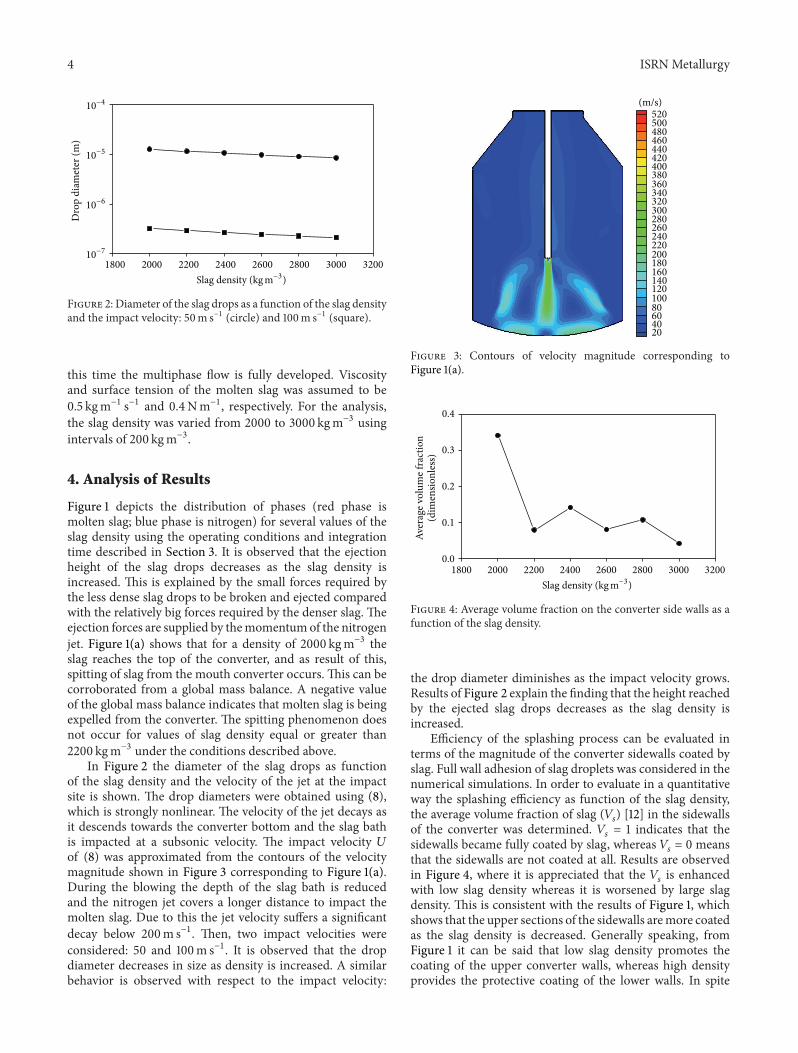
Figure 4 Average volume fraction on the converter side walls as afunction of the slag density
the drop diameter diminishes as the impact velocity growsResults of Figure 2 explain the finding that the height reachedby the ejected slag drops decreases as the slag density isincreased
Efficiency of the splashing process can be evaluated interms of the magnitude of the converter sidewalls coated byslag Full wall adhesion of slag droplets was considered in thenumerical simulations In order to evaluate in a quantitativeway the splashing efficiency as function of the slag densitythe average volume fraction of slag (119881
119904
) [12] in the sidewallsof the converter was determined 119881
119904
= 1 indicates that thesidewalls became fully coated by slag whereas 119881
119904
= 0 meansthat the sidewalls are not coated at all Results are observedin Figure 4 where it is appreciated that the 119881
119904
is enhancedwith low slag density whereas it is worsened by large slagdensity This is consistent with the results of Figure 1 whichshows that the upper sections of the sidewalls aremore coatedas the slag density is decreased Generally speaking fromFigure 1 it can be said that low slag density promotes thecoating of the upper converter walls whereas high densityprovides the protective coating of the lower walls In spite
ISRNMetallurgy 5
(a) (b) (c)
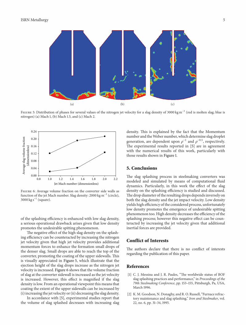
Figure 5 Distribution of phases for several values of the nitrogen jet velocity for a slag density of 3000 kgmminus3 (red is molten slag blue isnitrogen) (a) Mach 1 (b) Mach 15 and (c) Mach 2
024
020
016
012
008
004
000
08 10 12 14 16 18 20 22
Jet Mach number (dimensionless)
Aver
age s
lag
volu
me f
ract
ion
(dim
ensio
nles
s)
Figure 6 Average volume fraction on the converter side walls asfunction of the jet Mach number Slag density 2000 kgmminus3 (circle)3000 kg sminus1 (square)
of the splashing efficiency is enhanced with low slag densitya serious operational drawback arises given that low densitypromotes the undesirable spitting phenomenon
The negative effect of the high slag density on the splash-ing efficiency can be counteracted by increasing the nitrogenjet velocity given that high jet velocity provides additionalmomentum forces to enhance the formation small drops ofthe denser slag Small drops are able to reach the top of theconverter promoting the coating of the upper sidewalls Thisis visually appreciated in Figure 5 which illustrate that theejection height of the slag drops increase as the nitrogen jetvelocity is increased Figure 6 shows that the volume fractionof slag at the converter sidewall is increased as the jet velocityis increased However this effect is magnified if the slagdensity is low From an operational viewpoint this means thatcoating the extent of the upper sidewalls can be increased by(i) increasing the jet velocity or (ii) decreasing the slag density
In accordance with [5] experimental studies report thatthe volume of slag splashed decreases with increasing slag
density This is explained by the fact that the Momentumnumber and theWeber number which determine slag dropletgeneration are dependent upon 120588minus1 and 120588minus05 respectivelyThe experimental results reported in [5] are in agreementwith the numerical results of this work particularly withthose results shown in Figure 1
5 Conclusions
The slag splashing process in steelmaking converters wasmodeled and simulated by means of computational fluiddynamics Particularly in this work the effect of the slagdensity on the splashing efficiency is studied and discussedThedropdiameter of the resulting drops depends inversely onboth the slag density and the jet impact velocity Low densityyields high efficiency of the considered process unfortunatelylow density promotes the emergence of undesirable spittingphenomenon too High density decreases the efficiency of thesplashing process however this negative effect can be coun-teracted by increasing the jet velocity given that additionalinertial forces are provided
Conflict of Interests
The authors declare that there is no conflict of interestsregarding the publication of this paper
References
[1] C J Messina and J R Paules ldquoThe worldwide status of BOFslag splashing practices and performancerdquo in Proceedings of the79th Steelmaking Conference pp 153ndash155 Pittsburgh Pa USAMarch 1996
[2] KMGoodsonNDonaghy andRO Russell ldquoFurnace refrac-tory maintenance and slag splashingrdquo Iron and Steelmaker vol22 no 6 pp 31ndash34 1995
6 ISRNMetallurgy
[3] T R Galiullin E V Protopopov V V Sokolov and A GChernyatevich ldquoGas-jet conditions in the slag coating ofoxygen-converter liningsrdquo Steel in Translation vol 38 no 2 pp97ndash100 2008
[4] K D Peaslee ldquoPhysical modeling of slag splashing in the BOFrdquoIron and Steel Engineer vol 73 no 11 pp 33ndash37 1996
[5] K C Mills Y Su A B Fox Z Li R PThackray and H T TsaildquoA review of slag splashingrdquo ISIJ International vol 45 no 5 pp619ndash633 2005
[6] M J Luomala T M J Fabritius E O Virtanen et al ldquoPhysicalmodel study of selective slag splashing in the BOFrdquo ISIJInternational vol 42 no 11 pp 1219ndash1224 2002
[7] K D Peaslee andW Chen ldquoImportant factors for effective slagsplashingrdquo in Proceedings of the CIM Conference EdmontonCanada 2004
[8] L Salinas and R Fuentes ldquoInteraction between a gaseousvertical jet and a liquid surfacemdasha theoretical and experimentalstudyrdquo in Proceedings of the Copper 99-Cobre 99 InternationalConference Phoenix Ariz USA October 1999
[9] A Nguyen and G Evans ldquoComputational fluid dynamicsmodelling of gas jets impinging onto liquid poolsrdquo AppliedMathematical Modelling vol 30 no 11 pp 1472ndash1484 2006
[10] M Ersson A Tilliander L Jonsson and P Jonsson ldquoA mathe-matical model of an impinging air jet on a water surfacerdquo ISIJInternational vol 48 no 4 pp 377ndash384 2008
[11] M A Barron and I Hilerio ldquoComputer simulation of slagsplashing in a steelmaking converterrdquo in Proceedings of theWorld Congress in Computer Science Computer Engineering andApplied Computing Las Vegas Nev USA 2011
[12] M A Barron D Y Medina and I Hilerio ldquoCFD analysis ofinfluence of slag viscosity on the splashing process in an oxygensteelmaking converterrdquo Modeling and Numerical Simulation ofMaterial Science pp 90ndash93 2013
[13] R J Fruehan The Making Shaping and Treating of SteelSteelmaking and Refining Volume AISE Steel Foundation Pitts-burgh Pa USA 11th edition 1998
[14] R B Bird W E Stewart and E N Lightfoot TransportPhenomena John Wiley amp Sons New York NY USA 2ndedition 2002
[15] B GThomas Q Yuan S Sivaramakrishnan T Shi S P VankaandM B Assar ldquoComparison of four methods to evaluate fluidvelocities in a continuous slab casting moldrdquo ISIJ Internationalvol 41 no 10 pp 1262ndash1271 2001
[16] G Solorio-Dıaz R D Morales J Palafax-Ramos L Garcıa-Demedices and A Ramos-Banderas ldquoAnalysis of fluid flowturbulence in tundishes fed by a swirling ladle shroudrdquo ISIJInternational vol 44 no 6 pp 1024ndash1032 2004
[17] P C Mahapatra S Majumdar R Shrinivas et al ldquoUnderstand-ing slag splashing technology in BOFrdquo SEAISI Quarterly vol 29no 4 pp 54ndash60 2000
[18] C W Hirt and B D Nichols ldquoVolume of fluid (VOF) methodfor the dynamics of free boundariesrdquo Journal of ComputationalPhysics vol 39 no 1 pp 201ndash225 1981
Submit your manuscripts athttpwwwhindawicom
ScientificaHindawi Publishing Corporationhttpwwwhindawicom Volume 2014
CorrosionInternational Journal of
Hindawi Publishing Corporationhttpwwwhindawicom Volume 2014
Polymer ScienceInternational Journal of
Hindawi Publishing Corporationhttpwwwhindawicom Volume 2014
Hindawi Publishing Corporationhttpwwwhindawicom Volume 2014
CeramicsJournal of
Hindawi Publishing Corporationhttpwwwhindawicom Volume 2014
CompositesJournal of
NanoparticlesJournal of
Hindawi Publishing Corporationhttpwwwhindawicom Volume 2014
Hindawi Publishing Corporationhttpwwwhindawicom Volume 2014
International Journal of
Biomaterials
Hindawi Publishing Corporationhttpwwwhindawicom Volume 2014
NanoscienceJournal of
TextilesHindawi Publishing Corporation httpwwwhindawicom Volume 2014
Journal of
NanotechnologyHindawi Publishing Corporationhttpwwwhindawicom Volume 2014
Journal of
CrystallographyJournal of
Hindawi Publishing Corporationhttpwwwhindawicom Volume 2014
The Scientific World JournalHindawi Publishing Corporation httpwwwhindawicom Volume 2014
Hindawi Publishing Corporationhttpwwwhindawicom Volume 2014
CoatingsJournal of
Advances in
Materials Science and EngineeringHindawi Publishing Corporationhttpwwwhindawicom Volume 2014
Smart Materials Research
Hindawi Publishing Corporationhttpwwwhindawicom Volume 2014
Hindawi Publishing Corporationhttpwwwhindawicom Volume 2014
MetallurgyJournal of
Hindawi Publishing Corporationhttpwwwhindawicom Volume 2014
BioMed Research International
MaterialsJournal of
Hindawi Publishing Corporationhttpwwwhindawicom Volume 2014
Nano
materials
Hindawi Publishing Corporationhttpwwwhindawicom Volume 2014
Journal ofNanomaterials
2 ISRNMetallurgy
interaction and the prediction of the surface topographyrather than on liquid splashing Recently two studies [11 12]by some of the authors of the present work were reportedon the simulation of the slag splashing phenomenon usingcomputational fluid dynamics considering the dimensions ofactual industrial converters and the influence of propertiesof molten slag Particularly in [12] the influence of the slagviscosity on the slag splashing process was studied and itsconclusions are as follows (i) ejection mechanism becomesdominant as viscosity is decreased (ii) washing mechanismbecomes dominant as viscosity is increased (iii) efficiencyof the slag splashing process is increased as slag viscositydecreases
In this work the influence of the slag density on theslag splashing process is analyzed using computational fluiddynamics simulations Values of the slag density rangingfrom 2000 to 3000 kgmminus3 are considered This range istypical of CaOndashSiO
2
molten slags found in steelmaking [13]Physical dimensions of the converter correspond to an actualindustrial steelmaking converter of 150 metric tons Thevolume fraction of slag in the converter sidewalls is employedfor quantitative evaluation of the slag splashing efficiency Inorder to detect spitting of slag from the converter mouth theglobal mass balance is determined Besides the effect of thenitrogen jet Mach number on the slag splashing is simulatedand discussed Finally a qualitative comparison between thecomputational fluid dynamics simulations and results fromthe literature is made
2 Mathematical Modeling
During the slag splashing process molten slag located inthe converter bottom is splashed to the converter sidewallsby means of a supersonic jet of gaseous nitrogen Themomentum of the nitrogen jet is transferred to the moltenslag which causes the slag to be stirred and ejected by theaction of a standing wave and high shear forces respectively[4] Predominance of one of the coating mechanisms thatis washing or ejection depends on factors such as the jetcharacteristics (velocity exit angle) the operating conditions(lance height molten slag depth) and the slag properties(viscosity density and temperature) Inertial gravitationalviscous and interfacial forces are applied on both phases thatis gaseous nitrogen andmolten slag causing a nonisothermalmultiphase flow To model the complex system here consid-ered equations which govern the fluid flow themass balancethe turbulence and the multiphase flow are required
The flow of an incompressible newtonian fluid is gov-erned by the Navier-Stokes equations which in vector formare expressed as [14]
120588(120597
120597119905+ sdot nabla) = minusnabla119901 + 120583effnabla
2997888119906 + 120588 119892 + 119865 (1)
where 120588 is the fluid density is the velocity vector 119905 is time 119901is pressure 120583eff is the effective fluid viscosity 119892 is the gravityvector and 119865 represents additional forces applied or acting
on the fluid To maintain the mass balance in the system thecontinuity equation [14] must be solved
120597119906119895
120597119909119895
= 0 (2)
where 119906119895
and 119909119895
are the 119895th components of the velocity vectorand the coordinate system respectively
Turbulence was simulated by means of the classical twoequations119870-120576model [15]
120588V119895
120597119870
120597119909119895
=120597
120597119909119895
(120583119905
120590119870
120597119870
120597119909119895
) + 120583119905
120597V119895
120597119909119894
(120597V119894
120597119909119895
+120597V119895
120597119909119894
) minus 120588120576
120588V119895
120597120576
120597119909119895
=120597
120597119909119895
(120583119905
120590120576
120597120576
120597119909119895
) + 1198621
120583119905
120576
119870
120597V119895
120597119909119894
(120597V119894
120597119909119895
+120597V119895
120597119909119894
)
minus 1198622
120576
119870120588120576
(3)
where 119870 is the turbulent kinetic energy 120576 is the dissipationrate and 120583
119905
is the turbulent viscosity Besides 120590119870
= 10120590120576
= 13 1198621
= 144 and 1198622
= 192 The effective viscosityemployed in the Navier-Stokes equations is determined from
120583eff = 1205830 + 120583119905 (4)
where 1205830
is the laminar viscosity The turbulent viscosity iscalculated from
120583119905
=120588119862120583
1198702
120576 (5)
where 119862120583
= 009 and119870 and 120576 are determined from (3)Boundary conditions at the inlet nozzles are determined
as follows for the velocity components 119906119909
= 119880in sin(120572) and119906119910
= 119880in cos(120572) where 119880in is the nominal velocity and 120572is the inlet angle of the nitrogen jet which corresponds tothe exit angle of the nozzles The inlet values of 119870 and 120576 aredetermined from [15 16]
119870in = 0011198802
in
120576in =211987015
in119863
(6)
where 119863 is the diameter of the inlet nozzle At the converterwalls the classical nonslip condition is applied
When droplet breakaway occurs there is a balancebetween the inertial (119865
119894
) interfacial (119865120574
) and gravitationalforces (119865
119892
) [5 17]
119865119894
= 119865120574
+ 119865119892
(7)
The drop diameter (119889) derived from the balance of forcesof (7) is given by [5 17]
119889 =31198802
8119892(1 minus (1 minus
128120574119892
31205881198804)) (8)
where 119880 is the magnitude of the jet velocity at the impactpoint and 120574 is the surface tension
ISRNMetallurgy 3
(a) (b) (c)
(d) (e) (f)
Figure 1 Distribution of phases for several values of the slag density (red is molten slag blue is nitrogen) (a) 2000 (b) 2200 (c) 2400 (d)2600 (e) 2800 and (f) 3000 kgmminus3
The Volume of Fluidmodel is employed here to tackle themultiphase flow This model is based on the assumption thattwo or more phases are not interpenetrating Each 119894th phasehas associated a volume fraction 119881
119894
and in every controlvolume the sum of the volume fractions of all phases is equalto 1 In theVolumeof FluidModel the tracking of the interfacebetween the phases is accomplished by solving the continuityequation for each phase [18]
120597119881119894
120597119905+ sdot nabla119881
119894
= 0 (9)
To better define the slag-nitrogen interface the computa-tional fluid dynamics software (FLUENT) uses an interpola-tion scheme called Geometric Reconstruction Scheme
3 Computer Simulations
Physical dimensions of the considered converter correspondto an actual industrial converter of 150metric tons of capacityand were assumed as follows height 72m diameter 48m
lance diameter 02m number of nozzles 2 diameter of noz-zles 0043m exit angle of nozzles 10 degrees The operatingparameters were set as follows lance height above the initialmolten slag surface 2m velocity of the supersonic nitrogenjet Mach 15 initial molten slag depth 05m Viscosity andsurface tension of slag were assumed to be 05 kgmminus1 sminus1 and04Nmminus1 respectively
To reduce the computational effort an isothermal two-dimensional converter was considered The coupled Navier-Stokes equations the continuity equation the turbulencemodel and the Volume of Fluid Model were numericallysolved using computational fluid dynamics software (FLU-ENT) The Pressure Implicit Splitting Operation algorithmwas employed in the transient simulations for the pressure-velocity coupling given that it maintains stability of thenumerical scheme despite the larger time steps
Transient isothermal two-dimensional computer simu-lations were carried out using a time step of 00001 s anda mesh consisting of 14075 trilateral cells Due to the fastdynamics of the fluid flow the integration time was 2 s in
4 ISRNMetallurgy
10minus4
10minus5
10minus6
10minus7
1800 2000 2200 2400 2600 3000 3200
Dro
p di
amet
er (m
)
2800
Slag density (kg mminus3)
Figure 2 Diameter of the slag drops as a function of the slag densityand the impact velocity 50m sminus1 (circle) and 100m sminus1 (square)
this time the multiphase flow is fully developed Viscosityand surface tension of the molten slag was assumed to be05 kgmminus1 sminus1 and 04Nmminus1 respectively For the analysisthe slag density was varied from 2000 to 3000 kgmminus3 usingintervals of 200 kgmminus3
4 Analysis of Results
Figure 1 depicts the distribution of phases (red phase ismolten slag blue phase is nitrogen) for several values of theslag density using the operating conditions and integrationtime described in Section 3 It is observed that the ejectionheight of the slag drops decreases as the slag density isincreased This is explained by the small forces required bythe less dense slag drops to be broken and ejected comparedwith the relatively big forces required by the denser slag Theejection forces are supplied by themomentumof the nitrogenjet Figure 1(a) shows that for a density of 2000 kgmminus3 theslag reaches the top of the converter and as result of thisspitting of slag from the mouth converter occurs This can becorroborated from a global mass balance A negative valueof the global mass balance indicates that molten slag is beingexpelled from the converter The spitting phenomenon doesnot occur for values of slag density equal or greater than2200 kgmminus3 under the conditions described above
In Figure 2 the diameter of the slag drops as functionof the slag density and the velocity of the jet at the impactsite is shown The drop diameters were obtained using (8)which is strongly nonlinear The velocity of the jet decays asit descends towards the converter bottom and the slag bathis impacted at a subsonic velocity The impact velocity 119880of (8) was approximated from the contours of the velocitymagnitude shown in Figure 3 corresponding to Figure 1(a)During the blowing the depth of the slag bath is reducedand the nitrogen jet covers a longer distance to impact themolten slag Due to this the jet velocity suffers a significantdecay below 200m sminus1 Then two impact velocities wereconsidered 50 and 100m sminus1 It is observed that the dropdiameter decreases in size as density is increased A similarbehavior is observed with respect to the impact velocity
520
500
480460
440
420400380
360
340320
300
280260
240
220
200
140
100
80604020
180
160
120
(ms)
Figure 3 Contours of velocity magnitude corresponding toFigure 1(a)
1800 2000 2200 2400 2600 3000 32002800
04
03
02
01
00
Aver
age v
olum
e fra
ctio
n(d
imen
sionl
ess)
Slag density (kg mminus3)
Figure 4 Average volume fraction on the converter side walls as afunction of the slag density
the drop diameter diminishes as the impact velocity growsResults of Figure 2 explain the finding that the height reachedby the ejected slag drops decreases as the slag density isincreased
Efficiency of the splashing process can be evaluated interms of the magnitude of the converter sidewalls coated byslag Full wall adhesion of slag droplets was considered in thenumerical simulations In order to evaluate in a quantitativeway the splashing efficiency as function of the slag densitythe average volume fraction of slag (119881
119904
) [12] in the sidewallsof the converter was determined 119881
119904
= 1 indicates that thesidewalls became fully coated by slag whereas 119881
119904
= 0 meansthat the sidewalls are not coated at all Results are observedin Figure 4 where it is appreciated that the 119881
119904
is enhancedwith low slag density whereas it is worsened by large slagdensity This is consistent with the results of Figure 1 whichshows that the upper sections of the sidewalls aremore coatedas the slag density is decreased Generally speaking fromFigure 1 it can be said that low slag density promotes thecoating of the upper converter walls whereas high densityprovides the protective coating of the lower walls In spite
ISRNMetallurgy 5
(a) (b) (c)
Figure 5 Distribution of phases for several values of the nitrogen jet velocity for a slag density of 3000 kgmminus3 (red is molten slag blue isnitrogen) (a) Mach 1 (b) Mach 15 and (c) Mach 2
024
020
016
012
008
004
000
08 10 12 14 16 18 20 22
Jet Mach number (dimensionless)
Aver
age s
lag
volu
me f
ract
ion
(dim
ensio
nles
s)
Figure 6 Average volume fraction on the converter side walls asfunction of the jet Mach number Slag density 2000 kgmminus3 (circle)3000 kg sminus1 (square)
of the splashing efficiency is enhanced with low slag densitya serious operational drawback arises given that low densitypromotes the undesirable spitting phenomenon
The negative effect of the high slag density on the splash-ing efficiency can be counteracted by increasing the nitrogenjet velocity given that high jet velocity provides additionalmomentum forces to enhance the formation small drops ofthe denser slag Small drops are able to reach the top of theconverter promoting the coating of the upper sidewalls Thisis visually appreciated in Figure 5 which illustrate that theejection height of the slag drops increase as the nitrogen jetvelocity is increased Figure 6 shows that the volume fractionof slag at the converter sidewall is increased as the jet velocityis increased However this effect is magnified if the slagdensity is low From an operational viewpoint this means thatcoating the extent of the upper sidewalls can be increased by(i) increasing the jet velocity or (ii) decreasing the slag density
In accordance with [5] experimental studies report thatthe volume of slag splashed decreases with increasing slag
density This is explained by the fact that the Momentumnumber and theWeber number which determine slag dropletgeneration are dependent upon 120588minus1 and 120588minus05 respectivelyThe experimental results reported in [5] are in agreementwith the numerical results of this work particularly withthose results shown in Figure 1
5 Conclusions
The slag splashing process in steelmaking converters wasmodeled and simulated by means of computational fluiddynamics Particularly in this work the effect of the slagdensity on the splashing efficiency is studied and discussedThedropdiameter of the resulting drops depends inversely onboth the slag density and the jet impact velocity Low densityyields high efficiency of the considered process unfortunatelylow density promotes the emergence of undesirable spittingphenomenon too High density decreases the efficiency of thesplashing process however this negative effect can be coun-teracted by increasing the jet velocity given that additionalinertial forces are provided
Conflict of Interests
The authors declare that there is no conflict of interestsregarding the publication of this paper
References
[1] C J Messina and J R Paules ldquoThe worldwide status of BOFslag splashing practices and performancerdquo in Proceedings of the79th Steelmaking Conference pp 153ndash155 Pittsburgh Pa USAMarch 1996
[2] KMGoodsonNDonaghy andRO Russell ldquoFurnace refrac-tory maintenance and slag splashingrdquo Iron and Steelmaker vol22 no 6 pp 31ndash34 1995
6 ISRNMetallurgy
[3] T R Galiullin E V Protopopov V V Sokolov and A GChernyatevich ldquoGas-jet conditions in the slag coating ofoxygen-converter liningsrdquo Steel in Translation vol 38 no 2 pp97ndash100 2008
[4] K D Peaslee ldquoPhysical modeling of slag splashing in the BOFrdquoIron and Steel Engineer vol 73 no 11 pp 33ndash37 1996
[5] K C Mills Y Su A B Fox Z Li R PThackray and H T TsaildquoA review of slag splashingrdquo ISIJ International vol 45 no 5 pp619ndash633 2005
[6] M J Luomala T M J Fabritius E O Virtanen et al ldquoPhysicalmodel study of selective slag splashing in the BOFrdquo ISIJInternational vol 42 no 11 pp 1219ndash1224 2002
[7] K D Peaslee andW Chen ldquoImportant factors for effective slagsplashingrdquo in Proceedings of the CIM Conference EdmontonCanada 2004
[8] L Salinas and R Fuentes ldquoInteraction between a gaseousvertical jet and a liquid surfacemdasha theoretical and experimentalstudyrdquo in Proceedings of the Copper 99-Cobre 99 InternationalConference Phoenix Ariz USA October 1999
[9] A Nguyen and G Evans ldquoComputational fluid dynamicsmodelling of gas jets impinging onto liquid poolsrdquo AppliedMathematical Modelling vol 30 no 11 pp 1472ndash1484 2006
[10] M Ersson A Tilliander L Jonsson and P Jonsson ldquoA mathe-matical model of an impinging air jet on a water surfacerdquo ISIJInternational vol 48 no 4 pp 377ndash384 2008
[11] M A Barron and I Hilerio ldquoComputer simulation of slagsplashing in a steelmaking converterrdquo in Proceedings of theWorld Congress in Computer Science Computer Engineering andApplied Computing Las Vegas Nev USA 2011
[12] M A Barron D Y Medina and I Hilerio ldquoCFD analysis ofinfluence of slag viscosity on the splashing process in an oxygensteelmaking converterrdquo Modeling and Numerical Simulation ofMaterial Science pp 90ndash93 2013
[13] R J Fruehan The Making Shaping and Treating of SteelSteelmaking and Refining Volume AISE Steel Foundation Pitts-burgh Pa USA 11th edition 1998
[14] R B Bird W E Stewart and E N Lightfoot TransportPhenomena John Wiley amp Sons New York NY USA 2ndedition 2002
[15] B GThomas Q Yuan S Sivaramakrishnan T Shi S P VankaandM B Assar ldquoComparison of four methods to evaluate fluidvelocities in a continuous slab casting moldrdquo ISIJ Internationalvol 41 no 10 pp 1262ndash1271 2001
[16] G Solorio-Dıaz R D Morales J Palafax-Ramos L Garcıa-Demedices and A Ramos-Banderas ldquoAnalysis of fluid flowturbulence in tundishes fed by a swirling ladle shroudrdquo ISIJInternational vol 44 no 6 pp 1024ndash1032 2004
[17] P C Mahapatra S Majumdar R Shrinivas et al ldquoUnderstand-ing slag splashing technology in BOFrdquo SEAISI Quarterly vol 29no 4 pp 54ndash60 2000
[18] C W Hirt and B D Nichols ldquoVolume of fluid (VOF) methodfor the dynamics of free boundariesrdquo Journal of ComputationalPhysics vol 39 no 1 pp 201ndash225 1981
Submit your manuscripts athttpwwwhindawicom
ScientificaHindawi Publishing Corporationhttpwwwhindawicom Volume 2014
CorrosionInternational Journal of
Hindawi Publishing Corporationhttpwwwhindawicom Volume 2014
Polymer ScienceInternational Journal of
Hindawi Publishing Corporationhttpwwwhindawicom Volume 2014
Hindawi Publishing Corporationhttpwwwhindawicom Volume 2014
CeramicsJournal of
Hindawi Publishing Corporationhttpwwwhindawicom Volume 2014
CompositesJournal of
NanoparticlesJournal of
Hindawi Publishing Corporationhttpwwwhindawicom Volume 2014
Hindawi Publishing Corporationhttpwwwhindawicom Volume 2014
International Journal of
Biomaterials
Hindawi Publishing Corporationhttpwwwhindawicom Volume 2014
NanoscienceJournal of
TextilesHindawi Publishing Corporation httpwwwhindawicom Volume 2014
Journal of
NanotechnologyHindawi Publishing Corporationhttpwwwhindawicom Volume 2014
Journal of
CrystallographyJournal of
Hindawi Publishing Corporationhttpwwwhindawicom Volume 2014
The Scientific World JournalHindawi Publishing Corporation httpwwwhindawicom Volume 2014
Hindawi Publishing Corporationhttpwwwhindawicom Volume 2014
CoatingsJournal of
Advances in
Materials Science and EngineeringHindawi Publishing Corporationhttpwwwhindawicom Volume 2014
Smart Materials Research
Hindawi Publishing Corporationhttpwwwhindawicom Volume 2014
Hindawi Publishing Corporationhttpwwwhindawicom Volume 2014
MetallurgyJournal of
Hindawi Publishing Corporationhttpwwwhindawicom Volume 2014
BioMed Research International
MaterialsJournal of
Hindawi Publishing Corporationhttpwwwhindawicom Volume 2014
Nano
materials
Hindawi Publishing Corporationhttpwwwhindawicom Volume 2014
Journal ofNanomaterials
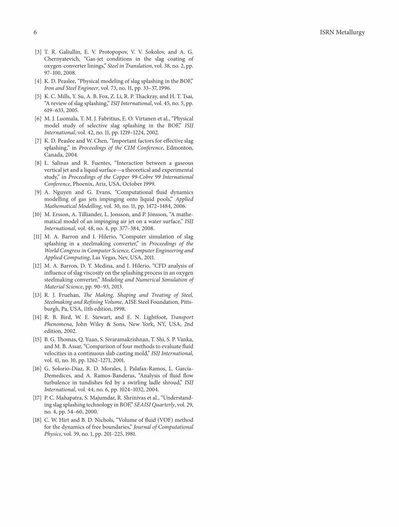