REMOTE I/ O – CHAPTER INDEX TABLES - R. STAHL, INC.
88
50 Home Apr 9, 2020· PK·en-US REMOTE I/O – CHAPTER INDEX TABLES REMOTE I/O – CHAPTER INDEX TABLES ◤ Product Series Page WebCode Remote I/O – Chapter Index Tables Communication & Power Module 51 Discrete Modules 52 Pneumatic Output, Analog Modules 53 Temperature Input Modules 54 Terminals 55 For additional products and information please refer to r-stahl.com
-
Upload
khangminh22 -
Category
Documents
-
view
0 -
download
0
Transcript of REMOTE I/ O – CHAPTER INDEX TABLES - R. STAHL, INC.

50
Home
Apr 9, 2020· PK·en-USREMOTE I/O – CHAPTER INDEX TABLES
REMOTE I/ O – CHAPTER INDEX TABLES
Product Series Page WebCode
Remote I/O – Chapter Index Tables
Communication & Power Module 51
Discrete Modules 52
Pneumatic Output, Analog Modules 53
Temperature Input Modules 54
Terminals 55
For additional products and information please refer to r-stahl.com

Communication & Power Module
51
Home
06 a
Apr 9, 2020· PK·en-US REMOTE I/O – CHAPTER INDEX TABLES
Series 9492 Series 9441, 9444 Series 9490 Series 9440 Series 9496 Series 9442, 9445
Rating Components Protocol Feed Physical Layer
Cl. I,
Div.
1
Zone
1
Cl. I,
Div.
2 / Z
one 2
I/O m
odule
Gatew
ay
Powe
r Sup
ply
Sock
et
Ethe
rnet
IP
Profi
NET
Modb
us T
CP
Redu
ndan
t Mod
bus
TCP
Profi
bus D
P
Modb
us R
TU
100 -
250 V
AC
24 V
DC
FO [o
p is]
RS48
5-IS
RS-4
85
Dual
CAT
5
Ethe
rnet
Proto
col
9441/12-00-00 X X 8 X X Page 739444/12-11 X X X X Page 779492/13-13-41 Socket X X X
Page 73Page 77
9492/13-13-31 Socket X X X9492/13-13-11 Socket X X X9492/13-13-12 Socket X X X9492/12-11-11 Socket X X X9492/12-11-31 Socket X X X9492/12-11-41 Socket X X X9492/12-11-12 Socket X X X
9444/12-11 + 9441/12-00-00 modules need the appropriate 9492/1x socket
Seria
l Pro
tocol
9440/22-01-11-C1243 X 8 X X X X X
Page 60
9440/22-01-21-C1243 X 8 X X X X X9440/22-01-11-C1202 X 8 X X X X X9440/22-01-21-C1202 X 8 X X X X X9490/12-12-AC/DC Socket X X X X9490/11-12 Socket X X X X9490/13-12 Socket X X X X9440/15-01-11-C1198 Socket X 16 X X X X X Page 63
9440/22 modules need a 9490/1 socket
Multi-
proto
col 9442/35-10-00 CPU X 16 X X X Page 66
9445/35-12 PM X X X Page 709496/35-03-00 Socket X X X X X X Page 66
Page 709496/35-04-00 Socket X X X X X X X9442/35-10-00 + 9445/35-12 modules need a 9496/35 socket261232 connector is required for 9445/35
Communication & Power Module
Discrete Modules
52
Home
06 a
Apr 9, 2020· PK·en-USREMOTE I/O – CHAPTER INDEX TABLES
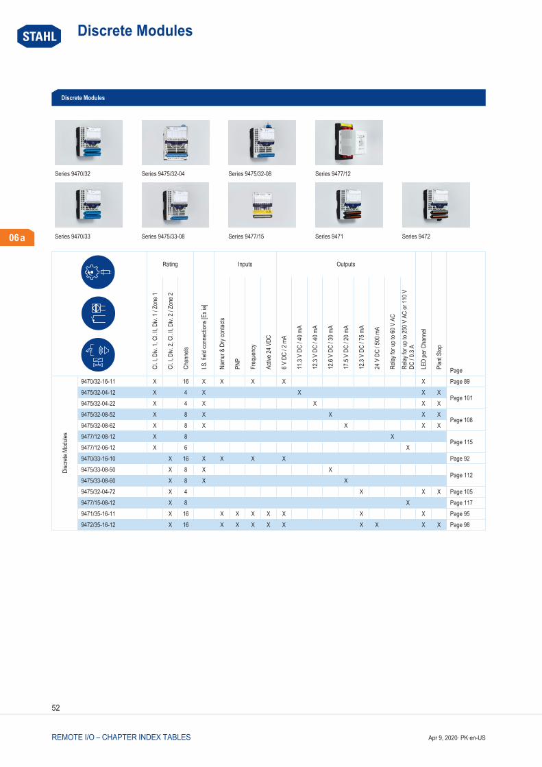
Series 9470/32 Series 9475/32-04 Series 9475/32-08 Series 9477/12
Series 9470/33 Series 9475/33-08 Series 9477/15 Series 9471 Series 9472
Rating
I.S. fi
eld co
nnec
tions
[Ex i
a]
Inputs Outputs
LED
per C
hann
el
Plan
t Stop
PageCl. I,
Div.
1, C
l. II, D
iv. 1
/ Zon
e 1
Cl. I,
Div.
2, C
l. II, D
iv. 2
/ Zon
e 2
Chan
nels
Namu
r & D
ry co
ntacts
PNP
Freq
uenc
y
Activ
e 24 V
DC
6 V D
C / 2
mA
11.3
V DC
/ 40 m
A
12.3
V DC
/ 40 m
A
12.6
V DC
/ 30 m
A
17.5
V DC
/ 20 m
A
12.3
V DC
/ 75 m
A
24 V
DC
/ 500
mA
Relay
for u
p to 6
0 V A
C
Relay
for u
p to 2
50 V
AC
or 11
0 V
DC / 0
.3 A
Disc
rete
Modu
les
9470/32-16-11 X 16 X X X X X Page 899475/32-04-12 X 4 X X X X
Page 1019475/32-04-22 X 4 X X X X9475/32-08-52 X 8 X X X X
Page 1089475/32-08-62 X 8 X X X X9477/12-08-12 X 8 X
Page 1159477/12-06-12 X 6 X9470/33-16-10 X 16 X X X X Page 929475/33-08-50 X 8 X X
Page 1129475/33-08-60 X 8 X X9475/32-04-72 X 4 X X X Page 1059477/15-08-12 X 8 X Page 1179471/35-16-11 X 16 X X X X X X X Page 959472/35-16-12 X 16 X X X X X X X X X Page 98
Discrete Modules

Pneumatic Output, Analog Modules
53
Home
06 a
Apr 9, 2020· PK·en-US REMOTE I/O – CHAPTER INDEX TABLES
Series 9478
Rating Outputs Plant Stop
PageCl. I, Div. 1, Cl. II, Div. 1 / Zone 1 Channels Pneumatic 3/2 way valve. 40-100 psia
Pneumatic Output 9478/22-08-51 X 8 X X Page 120
Pneumatic Output
Series 9468 Series 9469
Rating I.S. field connections [Ex ia]
Inputs Outputs LED per channel
Plant stop
Cl. I,
Div.
1Cl
. II, D
iv. 1
Zone
1
Cl. I,
Div.
2Cl
. II, D
iv. 2
Zone
2
Chan
nels
2-, 3
-, 4-
wire
4 ...
20 m
A
PNP
Activ
e 24 V
DC
2-wi
re 4
... 20
mA
24 V
DC
/ 500
mA
Page
AnalogModules
9468/32-08-11 X 8 X X X X Page 809468/33-08-10 X 8 X X X Page 839469/35-08-12 X 8 X X X X X X Page 86
Analog Modules

Temperature Input Modules
54
Home
06 a
Apr 9, 2020· PK·en-USREMOTE I/O – CHAPTER INDEX TABLES
Series 9482
Rating I.S. field connections
[Ex ia]
Inputs LED per channel
CJC internal / external
Page
Cl. I, Div. 1Cl. II, Div. 1Zone 1
Cl. I, Div. 2Cl. II, Div. 2Zone 2
Channels TC RTD
Temp. Input Modules
9482/32-08-11 X 8 X X X X X Page 122
9482/33-08-11 X 8 X X X X Page 125
Temperature Input Modules

Terminals
55
Home
06 a
Apr 9, 2020· PK·en-US REMOTE I/O – CHAPTER INDEX TABLES
Figure Art. No. Description For use with 162702 Blue terminal block 1...16 screw connections 94xx/32 & 94xx/33
162718 Blue terminal block 17...32 screw connections 9470 and 9482
245090 Black terminal block 1...24 spring connections 9469, 9471, 9472
245091 Black terminal block 25...48 spring connections 9471, 9472
162704 Black terminal block 1...16 spring 9477
220101 Partition between I.S. and non I.S. modules
Terminals

56
Home
Apr 9, 2020· PK·en-USREMOTE I/O
REMOTE I/ O
Product Series Page WebCode
Analog Modules
Analog Universal Module HART for Zone 1 / Cl. I, II, Div. 1 - I.S. 9468/32 80 9468AAnalog Universal Module HART for Zone 2 / Cl. I, Div. 2 9469/35 86 9469AAnalog Universal Module HART for Zone 2 / Cl. I, II, Div. 2 - I.S. 9468/33 83 9468BCPU & Power Modules
CPU & Power Module for Zone 1 / Cl. I, Div. 1 9440/22 60 9440ACPU & Power-Module for Zone 2 / Cl. I, II, Div. 2 9440/15 63 9440BCPU Module for Zone 2 / Cl. I, II, Div. 2 9442/35 66 9442AEthernet CPU Module for Zone 1 / Cl. I, Div. 1 9441/12 73 9441AEthernet Power Module for Zone 1 / Cl. I, II, Div. 1 - I.S. 9444/12 77 9444APower Module for Zone 2 / Cl. I, II, Div. 2 9445/35 70 9445ADigital Input Output Modules
Digital Input Output Module 24 V for Zone 2 / Cl. I, Div. 2 9472/35 98 9472ADigital Input Output Module for Zone 1 / Cl. I, II, Div. 1 - I.S. 9470/32 89 9470CDigital Input Output Module for Zone 2 / Cl. I, II, Div. 2 - I.S. 9470/33 92 9470DDigital Input Output Module NAMUR for Zone 2 / Cl. I, Div. 2 9471/35 95 9471BDigital Output Modules
Digital Output Module 4-Channel Version for Zone 1, Cl. I, II, Div. 1 - I.S. 9475/32-04 101 9475EDigital Output Module 4-Channel Version for Zone 1 / Cl. I, II, Div. 2 - I.S. 9475/32-04-72 105 9475FDigital Output Module 8-Channel Version for Zone 1 / Cl. I, II, Div. 1 - I.S. 9475/32-08 108 9475CDigital Output Module 8-Channel Version for Zone 2 / Cl. I, II, Div. 2 - I.S. 9475/33-08 112 9475DDigital Output Module Relay for Zone 1 / Cl. I, Div. 1 9477/12 115 9477ADigital Output Module Relay for Zone 2 / Cl. I, Div. 2 9477/15 117 9477BDigital Output Module Valve for Zone 1 / Cl. I, Div. 1 9478 120 9478AEnclosures for Fieldstations
IS1+ Remote I/O Standard Enclosure NEC/CEC for Cl. I, Div. I 132 8150OIS1+ Remote I/O Standard Enclosure NEC/CEC for Cl. I, II, Div. 2 and Cl. I, Zone 2 and Zone 2 135 8150N

57
Home
06 b
Apr 9, 2020· PK·en-US REMOTE I/O
Product Series Page WebCode
General
General 59
Overview of Functions IS1+ 58
Overview of the System Components 58
System Components and Accessories
BusRail 9494 129 9494ATemperature Input Modules
Temperature Input Module for Zone 1 / Cl. I, II, Div. 1 - I.S. 9482/32 122 9482ATemperature Input Module for Zone 2 / Cl. I, II, Div. 2 - I.S. 9482/33 125 9482B
For additional products and information please refer to r-stahl.com

Overview of the System Components
58
Home
06 b
Apr 9, 2020· PK·en-USREMOTE I/O
Overview of the System Components
Instal
lation
in Cl
. I, D
iv. 2
/ Zo
ne 2
Instal
lation
in Cl
. I, D
iv. 1
/ Zo
ne 1
RS48
5-IS
100B
ASE-
TX
LWL e
x op i
s
Servi
ceBu
sIS
Wiza
rd
Servi
ceBu
sDT
M
Web
serve
r
COM/
Devic
e/Ga
teway
DTM
HART
supp
ort
Syste
m re
dund
ancy
PROFIBUS DP x x x 1) x x x x x xModbus RTU x x x 1) x x x x x xPROFINET x x x x x x x x 2)
Modbus TCP x x x x x x x x xEtherNet/IPTM x x x x x x x x x 2)
1) when installed in Zone 1 only; in Zone 2: RS4852) in preparation
Overview of Functions IS1+

General
59
Home
06 b
Apr 9, 2020· PK·en-US REMOTE I/O
IS1+ is exceptionally easy: communication and power modules are installed on a DIN rail together with the different input/ output modules. The system’s internal, intrinsically safe power supply and data communication is via the bus rail, which is snapped into the DIN rail. The unique power supply concept which was developed specially for hazardous areas makes planning as easy as for normal industrial I/ O systems. Plug & Play without separate engineering tools.
IS1+ is particularly flexible: it can be used for small and large signal volumes, intrinsically safe and non- safe signals and installation in hazardous areas of Zone 1 and 2 or Division 1 and 2. Intrinsically safe fieldbuses with copper or fibre optic technology and 100 Mbps Ethernet and various redundancy structures combine the field stations with all conventional automation systems. Modern standard technologies such as completely transparent HART transmission and FDT/ DTM are supported throughout.
IS1+ is extremely cost- efficient: modules with up to 16 channels, partly free for parameterization as input or output, ensure a low signal price. Special modules optimised for Zone 2 / Div. 2 installation allow for additional cost reduction. High performance interfaces, e.g. with DTM support, and the integrated diagnostic functions according to NAMUR NE107, allow easy integration of the system into asset management and engineering systems and thus help to significantly reduce costs for operation, troubleshooting and maintenance.
IS1+ is truly universal: the application options are versatile, IS1 can be used effectively in virtually all appli-cations. No matter whether for installation according to IECEx, NEC, CEC or elsewhere in the world, on land, offshore platforms or in shipbuilding - IS1 offers the broadest spectrum of certificates and approvals. A temperature range of -40 to +75 °C is ideal for the most extreme requirements. Add to this, our competence in system solutions with over 30 years of experience for making your solution from universal remote I/ O.
• Inputs and outputs for intrinsically safe (Ex i) and non- intrinsically safe (Ex e/ d/q) field devices
• Communication via PROFIBUS DP, Modbus RTU+TCP, PROFINET and EtherNet/ IPTM
• Hot swap for all modules in Zone 1 and 2, Div. 1 and 2• System redundancy and media redundancy• Option ServiceBus for diagnostics and integration into Asset-
Management systems• DTM technology for full access to all system and HART field device
information• Field enclosures in many versions available, freely configurable

CPU & Power ModuleSeries 9440/22 for Zone 1 / Cl. I, Div. 1
60
Home
06 b
Preferred products – in stock or available at short noticeApr 9, 2020· PK·en-USREMOTE I/O
• Suitable for Ex i V0/ V1 HART PROFIBUS DP, Modbus RTU• Supporting system redundancy and optical rings• CPM in Zone 1 and Cl. I, Div. 1 can be hot swapped• Integration in plant asset management systems via ServiceBus and
FDT/ DTM• Integrated Ex i power supply for up to 8 I/ O modules
Selection Table
Installation Zone 1 / Cl. I, Div. 1
Nominal voltage Vnom Protocols Redundancy Product Type Art. No. Weight lb
24 V DC Modbus RTU full redundancy 9440/ 22- 01- 11- C1202 162221 6.53
Profibus DP V0Profibus DP V1Profibus DP V1 HART
full redundancy 9440/ 22- 01- 11- C1243 162218 6.53
acc. to PNOfull redundancy
9440/ 22- 01- 11- C1455 203585 6.53
120 V / 230 V AC Modbus RTU full redundancy 9440/ 22- 01- 21- C1202 162214 6.53
Profibus DP V0Profibus DP V1Profibus DP V1 HART
full redundancy 9440/ 22- 01- 21- C1243 162211 6.53
acc. to PNOfull redundancy
9440/ 22- 01- 21- C1455 203586 6.53
Please order the 9490 socket (see accessories) separately.
Technical Data
Variant 24 V DC 120 V / 230 V AC
Explosion ProtectionUSA certificate FM FM17US0332X FM17US0332XCAN certificate CSA 1519624 1519624CAN certificate FM FM16CA0134X FM16CA0134X
9440/ 22 series CPU & power modules (CPM) for Zone 1, Cl. I, Div. 1 are used for the intrinsically safe supply of power to up to eight IS1+ I/ O modules and to field circuits. Intrinsically safe RS485- IS with PROFIBUS DP or Modbus RTU is used for communicating with the automation system. These CPMs support system and optical rings and can be replaced while the system is in operation (i.e. hot swapped) in Zone 1/ Division 1.A DTM and process bus or service bus are used for asset management integration.
WebCode 9440AModbus RTU
NEC® 500
CEC Appendix J
Class I Class II Class III
Division 1 2 1 2 1 2
Ex interface
Installation in
CEC Section 18
NEC® 505 NEC® 506
Class I
Zone 0 1 2 20 21 22
Ex interface
Installation in
IECEx / ATEX
Zone 0 1 2 20 21 22
Ex interface
Installation in

CPU & Power ModuleSeries 9440/22 for Zone 1 / Cl. I, Div. 1
61
Home
06 b
Preferred products – in stock or available at short noticeApr 9, 2020· PK·en-US REMOTE I/O
Technical Data
Variant 24 V DC 120 V / 230 V AC
Explosion ProtectionUSA marking FM XP; Class I, Div. 1, Groups A,B,C,D; Class I, Zone 1, IIC
AIS Cl. I,II,III, Div. 1, Groups A,B,C,D,E,F,G; Class I, Zone 1, [AEx ia, ib] IIC; T4 at Ta = 65 °C; See Doc. 9440 6 031 001 1
XP; Class I, Div. 1, Groups A,B,C,D; Class I, Zone 1, IIC AIS Cl. I,II,III, Div. 1, Groups A,B,C,D,E,F,G; Class I, Zone 1, [AEx ia, ib] IIC; T4 at Ta = 65 °C; See Doc. 9440 6 031 001 1
CAN marking CSA Class I, Zone 1, Ex e d ib [ia/ ib] IIC, T4 Class I, Zone 1, Ex e d ib [ia/ ib] IIC, T4CAN marking FM XP; Class I, Div. 1, Groups A,B,C,D; Class I, Zone 1 per
CEC 18- 100 AIS Cl. I,II,III, Div. 1, Groups A,B,C,D,E,F,G; Class I, Zone 1, [Ex ia, ib] IIC; T4 at Ta = 65 °C; See Doc. 9440 6 031 001 1
XP; Class I, Div. 1, Groups A,B,C,D; Class I, Zone 1 per CEC 18- 100 AIS Cl. I,II,III, Div. 1, Groups A,B,C,D,E,F,G; Class I, Zone 1, [Ex ia, ib] IIC; T4 at Ta = 65 °C; See Doc. 9440 6 031 001 1
IECEx gas explosion protection Ex d [ia] [ib] IIC T4 Gb Ex d [ia] [ib] IIC T4 GbCertificates ATEX (DEK), Brazil (ULB), Canada (CSA), Canada (FM), EAC
(STV), IECEx (DEK), Korea (KTL), USA (FM)ATEX (DEK), Brazil (ULB), Canada (CSA), Canada (FM), EAC (STV), IECEx (DEK), Korea (KTL), USA (FM)
Ship approval ABS, CCS, ClassNK, DNV GL, RINA ABS, CCS, ClassNK, DNV GL, RINAElectrical DataTransmission distance/ rate for copper RS485 1200 m at 9.6...93,75 kbit/ s
1000 m at 187.5 kbit/ s400 m at 500 kbit/ s200 m at 1.5 Mbit/ s
1200 m at 9.6...93,75 kbit/ s1000 m at 187.5 kbit/ s400 m at 500 kbit/ s200 m at 1.5 Mbit/ s
Connection Fieldbus RS485 Sub- D socket 9- pole Sub- D socket 9- poleConnection ServiceBus RS485 Sub- D socket 9- pole Sub- D socket 9- poleAuxiliary PowerAuxiliary power voltage range 20 ... 35 V DC 90 ... 253 V ACCurrent consumption (without I/ O modules) 0.21 A at 24 V DC Approx. 25 mA at 230 V AC
Approx. 48 mA at 120 V ACCurrent consumption (with 8 I/ O modules) Approx. 2.5 A at 24 V DC Approx. 0.4 A at 230 V AC
Approx. 0.8 A at 120 V ACPower dissipation (without I/ O modules) 5 W 8.4 WPower dissipation (per I/ O module)
1.4 W 1 W
Ambient ConditionsAmbient temperature °F -4°F ... +149°F -4°F ... +149°F Ambient temperature °C -20°C ... +65°C -20°C ... +65°C Mechanical DataDegree of protection IP (IEC 60529) IP20 connections
IP30 modulesIP20 connectionsIP30 modules
Width inches 3.78 in 3.78 inWidth 96.5 mm 96.5 mmMounting depth inches 6.69 in 6.69 inDepth 170 mm 170 mmLength inches 9.96 in 9.96 inLength 253 mm 253 mm
Accessories–
Figure Description Product Type Art. No. Weight lb
Cable for PROFIBUS DP, RS 485, RS485-ISCable type: BUS 4000- C-PE 2x0,64mm 02YS(St) CY2YColor (sheath): blackApplication area: OutdoorInstallation outdoors and directly in the ground, UV- resistant
O2Y(ST)CY2Y 105444 0.66
Cable for PROFIBUS DP, RS485-ISCable type: 02YS(St) CHSHColor (sheath): blueApplication area: OffshoreHalogen- free, steel wire braid armored cable
02YS(ST)CHSH Profibus 105400 –

CPU & Power ModuleSeries 9440/22 for Zone 1 / Cl. I, Div. 1
62
Home
06 b
Preferred products – in stock or available at short noticeApr 9, 2020· PK·en-USREMOTE I/O
Accessories–
Figure Description Product Type Art. No. Weight lb
Cable for PROFIBUS DP, RS485-ISCable type: BUS 4000- C-PVC 2x0,64mm 02YS(St) CYColor (sheath): blueApplication area: IndoorStandard type for indoor installation
O2Y(ST)CY 105437 –
Series 9490/11 - Socket for CPU and Power ModuleZone 1 connection by means of Ex e terminals24 V DC, 120 / 230 V AC
9490/11-12 162707 1.06
Series 9490/13 - Socket for CPU and Power ModuleZone 1, connection via pig tail24 V DC, 120 / 230 V AC
9490/13-12 162711 1.98
Series 9490/12 - Socket for CPU and Power ModuleDivision 1, connection via conduit24 V DC, 120 / 230 V AC9491/ 00- 13- 70 conduit hub is required and needs to be ordered seperatly
9490/12-12 162715 1.98
SUB-D socket9- pin for connection of the fieldbus or ServiceBus to the CPU & power module Series 9440/ 22 andfieldbus- isolating repeater 9185.Integrated terminator can be switched on or off. For RS 485 IS to PNO standard.
– 162693 0.22
Optical Fieldbus Isolating Repeater, Zone 2 / Div. 2Isolating repeater for installation in Zone 2 / Div. 2For fieldbus via fibre optic intrinsically safe cables “ex op is” into Zone 1 / Div. 1Optical ring possibleExtensive diagnostic function and fault- contactSuitable for Profibus DP up to 1.5 MBit/ sFurther versions and information see data sheet of Series 9186 optical fieldbus- isolating repeater
9186/15-12-11 160624 0.54
Fieldbus Isolating Repeater Series 9185/11Equipment for installation in safe areas or Zone 2/ Div. 2For fieldbuses with RS- 485- IS- interface - Zone 1 / Class I, II, III Division 1 and Class I, II, III Zone 1Suitable for PROFIBUS DP, Modbus, R. STAHL service busRS- 232, RS- 422, RS- 485 interface with the automation systemTransmission rate automatically set with PROFIBUS DPAdjustable transmission rate (1.2 kBit/ s to 1.5 MBit/ s)24 V AC/ DC auxiliary powerFor further information, see data sheet for 9185/ 11
9185/11-35-10s 227598 0.77
Device DTM IS1+ for PROFIBUS DP and Ethernet
DTMParameterization and configuration of the IS1+ systemCommunicating with HART- compatible field devicesSupports all common FDT frame applications (e.g. FieldCare, PactWare™)Condition MonitoringScan function for automatic topology generationDownload at r- stahl.com
– – –
IS1 PCS7 APL field device library
CFCEasy connection of IS1+ modules to the SIEMENS control system PCS7 via PROFIBUS DP.The library contains CFC driver modules created in conformance with PCS7 modules, and documentation in English.HOTLINE support inclusive.Order, processing and support are carried out directly via SIEMENS:[email protected]/ software requirements: SIEMENS PCS7 V7.1 to 8 SP2and IS1+ CPM 9440/…C1455 from V03.45 and GSD from V03.05
– – –
Dimensional drawings on the Internet r- stahl.com

CPU & Power-ModuleSeries 9440/15 for Zone 2 / Cl. I, II, Div. 2
63
Home
06 b
Preferred products – in stock or available at short noticeApr 9, 2020· PK·en-US REMOTE I/O
• Suitable for Modbus RTU• Supporting system redundancy and optical rings• Integration in plant asset management systems via ServiceBus and
FDT/ DTM
Selection Table
Installation Zone 2 / Cl. I, II, Div. 2
Protocols Redundancy Product Type Art. No. Weight lb
Modbus RTU full redundancy 9440/ 15- 01- 11- C1198 162188 1.34
Technical Data
Explosion ProtectionUSA certificate FM FM17US0332XCAN certificate CSA 1519624CAN certificate FM FM16CA0134XUSA marking FM NI; Class I, Div. 2, Groups A,B,C,D; Cl. I, Zone 2, IIC;
ANI; Class I,II,III, Div. 2, Class A,B,C,D,E,F,G; Class I, Zone 2, IIC; T4 at Ta = 65 °C; See Doc. 9440 6 031 002 1
CAN marking CSA Class I, Zone 2, Ex nA [ia/ ib] IIC, T4CAN marking FM NI; Class I, Div. 2, Groups A,B,C,D; Class I, Zone 2 per CEC 18- 150
ANI; Class I,II,III, Div. 2, Groups A,B,C,D,E,F,G; T4 at Ta = 65 °C; See Doc. 9440 6 031 002 1
IECEx gas explosion protection Ex nA [ia, ib Gb] IIC T4 GcCertificates ATEX (PTB), Brazil (ULB), Canada (CSA), Canada (FM), EAC (STV), IECEx (PTB), Korea (KTL), USA (FM)Ship approval ABS, CCS, ClassNK, DNV GL, RINA
9440/ 15 series CPU & power modules (CPM) for Zone 2, Cl. I, II, Div 2 are used for the intrinsically safe supply of power to up to 16 IS1+ I/ O modules and to field circuits. RS485 with Modbus RTU is used for communicating with the automation system. The CPMs support system redundancy and optical rings.A DTM and process bus or service bus are used for asset management integration.
WebCode 9440BModbus RTU
NEC® 500
CEC Appendix J
Class I Class II Class III
Division 1 2 1 2 1 2
Ex interface
Installation in
CEC Section 18
NEC® 505 NEC® 506
Class I
Zone 0 1 2 20 21 22
Ex interface
Installation in
IECEx / ATEX
Zone 0 1 2 20 21 22
Ex interface
Installation in

CPU & Power-ModuleSeries 9440/15 for Zone 2 / Cl. I, II, Div. 2
64
Home
06 b
Preferred products – in stock or available at short noticeApr 9, 2020· PK·en-USREMOTE I/O
Technical Data
Electrical DataTransmission distance/ rate for copper RS485 1200 m at 9.6...93,75 kbit/ s
1000 m at 187.5 kbit/ s400 m at 500 kbit/ s200 m at 1.5 Mbit/ s
Connection Fieldbus RS485 Sub- D socket 9- poleConnection ServiceBus RS485 Sub- D socket 9- poleAuxiliary PowerAuxiliary power voltage range 20 ... 35 V DCCurrent consumption (without I/ O modules) 0.3 A (24 V DC)Current consumption (with 8 I/ O modules) Approx. 2.5 A at 24 V DCCurrent consumption (with 16 I/ O modules)
Approx. 4.9 A at 24 V DC
Power dissipation (without I/ O modules) 7.2 WPower dissipation (per I/ O module)
1 W
Ambient ConditionsAmbient temperature °F -4°F ... +149°F Ambient temperature °C -20°C ... +65°C Mechanical DataDegree of protection IP (IEC 60529) IP20 connections
IP30 modulesWidth inches 3.78 inWidth 96.5 mmMounting depth inches 4.21 inDepth 107 mmLength inches 5.83 inLength 148 mm
Accessories–
Figure Description Product Type Art. No. Weight lb
Cable for PROFIBUS DP, RS 485, RS485-ISCable type: BUS 4000- C-PE 2x0,64mm 02YS(St) CY2YColor (sheath): blackApplication area: OutdoorInstallation outdoors and directly in the ground, UV- resistant
O2Y(ST)CY2Y 105444 0.66
Cable for PROFIBUS DP, RS485Cable type: 02YS(St) CHSHColor (sheath): violetApplication area: OffshoreHalogen- free, steel wire braid armored cable
02YS(ST)CHSH ProfibusDP 209430 –
Cable type: BUS 4000- C-PVC 2x0,64mm 02YS(St) CYColor (sheath): violetApplication area: IndoorStandard type for indoor installation
O2Y(ST)CY 105438 0.66
Sub-D plug + PG interface9- pin for connection of the fieldbus or ServiceBus to the CPU & power module Series 9440/ 15 and fieldbus- isolating repeater 9185.Integrated terminator can be switched on or off. For non- intrinsically safe RS- 485.
– 105715 –
Fieldbus Isolating Repeater Series 9185/12Equipment for installation in safe areas or Zone 2 / Div. 2For fieldbuses with RS- 485 interface. Suitable for PROFIBUS DP, Modbus, R. STAHL service bus.RS- 232, RS- 422, RS- 485 interface with the automation systemTransmission rate automatically set with PROFIBUS DPAdjustable transmission rate (1.2 kbit/ s to 1.5 Mbit/ s)24 V AC/ DC auxiliary powerFor further information, see data sheet for 9185/ 12 series
9185/12-45-10s 227600 0.77

CPU & Power-ModuleSeries 9440/15 for Zone 2 / Cl. I, II, Div. 2
65
Home
06 b
Preferred products – in stock or available at short noticeApr 9, 2020· PK·en-US REMOTE I/O
Accessories–
Figure Description Product Type Art. No. Weight lb
Optical Fieldbus Isolating Repeater, Zone 2 / Div. 2Isolating repeater for installation in Zone 2 / Div. 2For fieldbus via fibre optic intrinsically safe cables “ex op is” into Zone 1 / Div. 1Optical ring possibleExtensive diagnostic function and fault- contactSuitable for Profibus DP up to 1.5 MBit/ sFurther versions and information see data sheet of Series 9186 optical fieldbus- isolating repeater
9186/15-12-11 160624 0.54
Device DTM IS1+ for PROFIBUS DP and Ethernet
DTMParameterization and configuration of the IS1+ systemCommunicating with HART- compatible field devicesSupports all common FDT frame applications (e.g. FieldCare, PactWare™)Condition MonitoringScan function for automatic topology generationDownload at r- stahl.com
– – –
IS1 PCS7 APL field device library
CFCEasy connection of IS1+ modules to the SIEMENS control system PCS7 via PROFIBUS DP.The library contains CFC driver modules created in conformance with PCS7 modules, and documentation in English.HOTLINE support inclusive.Order, processing and support are carried out directly via SIEMENS:[email protected]/ software requirements: SIEMENS PCS7 V7.1 to 8 SP2and IS1+ CPM 9440/…C1455 from V03.45 and GSD from V03.05
– – –
Dimensional drawings on the Internet r- stahl.com

CPU ModuleSeries 9442/35 for Zone 2 / Cl. I, II, Div. 2
66
Home
06 b
Preferred products – in stock or available at short noticeApr 9, 2020· PK·en-USREMOTE I/O
• Support for PROFIBUS DP, PROFINET, Modbus TCP and EtherNet/ IPTM; incl. HART transmission
• RS485 interfaces (max. 12 Mbit/ s) and Ethernet (max. 100 Mbit/ s)• Comprehensive diagnostics based on NE 107• Support of FDT/ DTM and web server for integration in• asset management systems• Enhanced ambient temperature range from -40 °C to +75 °C
Selection Table
Installation Zone 2 / Cl. I, II, Div. 2
Product Type Art. No.9442/ 35- 10- 00 246854
Please order the 9445/ 35 power module and 9496/ 35 base (see accessories) separately.
Technical Data
Explosion ProtectionUSA certificate FM FM17US0332XCAN certificate FM FM16CA0134XUSA marking FM NI; Class I, Div. 2, Groups A,B,C,D;
Class I, Zone 2, AEx ec ia [ia Ga] IIC T4 Gc; Ta = -40°C … +75°C; See Doc. 9442 6 031 002 1
CAN marking FM NI; Class I, Div. 2, Groups A,B,C,D; Class I, Zone 2, Ex ec ia [ia Ga] IIC T4 Gc; Ta = -40°C … +75°C; See Doc. 9442 6 031 002 1
IECEx gas explosion protection Ex ec ia [ia Ga] IIC T4 GcCertificates ATEX (PTB), Canada (FM), EAC (Sertium), IECEx (PTB), USA (FM)Electrical DataConnection RS485 Interface Sub- D plug, 9- pole
The 9442/ 35 CPU module functions as a gateway between the IS1+ Remote I/ O system and the automation system. All supported communication protocols are in the CPU module and can be configured by the user. In addition to the process values, other information such as diagnostics, parameterisation and configuration is transmitted over the CPU module. Communication with the I/ O modules is implemented via the 9496 socket and the 9494 BusRail. Integration in control systems and plant asset management tools is implemented using standards such as GSD, EDS, web servers and FDT/ DTM.
WebCode 9442AModbus TCP
NEC® 500
CEC Appendix J
Class I Class II Class III
Division 1 2 1 2 1 2
Ex interface
Installation in
CEC Section 18
NEC® 505 NEC® 506
Class I
Zone 0 1 2 20 21 22
Ex interface
Installation in
IECEx / ATEX
Zone 0 1 2 20 21 22
Ex interface
Installation in

CPU ModuleSeries 9442/35 for Zone 2 / Cl. I, II, Div. 2
67
Home
Accessories–
Figure Description Product Type Art. No. Weight lb
Series 9496/35 - Socket for CPU & Power ModuleZone 2 / Div. 2simplex, 3 slots for mounting / installing 1 x CPU and 2 x power module or 2 x CPU und 1 x power moduleDimensions: approx. L = 167 mm, W = 96 mm, H = 50.6 mm
9496/35-03-00 246871 0.88
Zone 2 / Div. 2redundant, 4 slots for mounting / installing 2 x CPU and 2 x power moduleDimensions: approx. L = 167 mm, W = 152 mm, H = 50.6 mm
9496/35-04-00 262392 1.32
Fieldbus Isolating Repeater Series 9185/12Equipment for installation in safe areas or Zone 2 / Div. 2For fieldbuses with RS- 485 interface. Suitable for PROFIBUS DP, Modbus, R. STAHL service bus.RS- 232, RS- 422, RS- 485 interface with the automation systemTransmission rate automatically set with PROFIBUS DPAdjustable transmission rate (1.2 kbit/ s to 1.5 Mbit/ s)24 V AC/ DC auxiliary powerFor further information, see data sheet for 9185/ 12 series
9185/12-45-10s 227600 0.77
Optical Fieldbus Isolating Repeater, Zone 2 / Div. 2Isolating repeater for installation in Zone 2 / Div. 2For fieldbus via fibre optic intrinsically safe cables “ex op is” into Zone 1 / Div. 1Optical ring possibleExtensive diagnostic function and fault- contactSuitable for Profibus DP up to 1.5 MBit/ sFurther versions and information see data sheet of Series 9186 optical fieldbus- isolating repeater
9186/15-12-11 160624 0.54
Media converter FX op is / TX SC for Cl. I, Div. 2 and Zone 2Media Converter of 10/ 100 Base- Tx (1 x RJ45 port)to 100 Base- Fx “Ex op is” (1 x FO port SC);Multi mode (up to 4 km range); Webcode: 9721A
9721/13-11-14 220381 0.53
Technical Data
Electrical DataTransmission distance/ rate for copper RS485 1200 m at 9.6...93,75 kbit/ s
1000 m at 187.5 kbit/ s400 m at 500 kbit/ s200 m at 1.5 Mbit/ s100 m at 12 Mbit/ s
Transmission distance/ rate FO RS485 approx. 2000 m at 1,5 Mbit/ sConnection Ethernet Interface 2x RJ45 connectorAuxiliary PowerCurrent consumption max. 0.3 APower supply via socket 9496 a. PM 9445/ 35Power dissipation max. 5 WAmbient ConditionsAmbient temperature °F -40°F ... +149°F (without mounting plate)
-40°F ... +158°F with 3 mm mounting plate sheet steel) -40°F ... +167°F (with 6 mm mounting plate aluminium)
Ambient temperature °C -40°C ... +65°C (without mounting plate) -40°C ... +70°C with 3 mm mounting plate sheet steel) -40°C ... +75°C (with 6 mm mounting plate aluminium)
Storage temperature °F -40°F ... +176°F Storage temperature °C -40°C ... +80°C Mechanical DataDegree of protection IP (IEC 60529) IP30
06 b
Preferred products – in stock or available at short noticeApr 9, 2020· PK·en-US REMOTE I/O

CPU ModuleSeries 9442/35 for Zone 2 / Cl. I, II, Div. 2
68
Home
06 b
Preferred products – in stock or available at short noticeApr 9, 2020· PK·en-USREMOTE I/O
Dimensional Drawings (All Dimensions in mm [inches]) – Subject to Alterations
185 [7 2
8]
.167 [6 5
7]
.
96 [3 78].
152 [5 9
8]
.
183 [7 20].
158 [6 22].
32 [1 2
6]
.
123 [4 8
4]
.
Accessories–
Figure Description Product Type Art. No. Weight lb
Unmanaged Switch FX op is / TX SCUnmanaged Switch FX op is to TX; SC plug connectorFO cable 4 multi mode (MM), 2 RJ45, Installation in Zone 2
9721/13-42-14 243427 1.1
Device DTM IS1+ for PROFIBUS DP and Ethernet
DTMParameterization and configuration of the IS1+ systemCommunicating with HART- compatible field devicesSupports all common FDT frame applications (e.g. FieldCare, PactWare™)Condition MonitoringScan function for automatic topology generationDownload at r- stahl.com
– – –
IS1 PCS7 APL field device library
CFCEasy connection of IS1+ modules to the SIEMENS control system PCS7 via PROFIBUS DP.The library contains CFC driver modules created in conformance with PCS7 modules, and documentation in English.HOTLINE support inclusive.Order, processing and support are carried out directly via SIEMENS:[email protected]/ software requirements: SIEMENS PCS7 V7.1 to 8 SP2and IS1+ CPM 9440/…C1455 from V03.45 and GSD from V03.05
– – –
USB ConverterUSB RS485 converter for installation in Zone 2.Noise insensitive, bidirectional conversion of USB data to RS485 serial data with power supply via USB port.Can be used for various applications, e.g. for missing RS485 interfaces to PCs.For further information, see data sheet for Series 9787 - Webcode 9787A
9787/15-11-11 266011 0.37
USB CableCable type: USB 2 5- pole with shieldingConnector plug: USB type A / USB type ATemperature range: -40 °C ... +85 °CCable colour: blackLength: 2,5 m
– 268119 –

CPU ModuleSeries 9442/35 for Zone 2 / Cl. I, II, Div. 2
69
Home
152 5 98[ ].
185 [7 2
8]
.
167 [6 5
7]
.
152 [5 9
8]
.
06 b
Preferred products – in stock or available at short noticeApr 9, 2020· PK·en-US REMOTE I/O

Power ModuleSeries 9445/35 for Zone 2 / Cl. I, II, Div. 2
70
Home
06 b
Preferred products – in stock or available at short noticeApr 9, 2020· PK·en-USREMOTE I/O
• 24 V DC supply module for IS1+ CPU modules and 16 I/ O modules• Redundancy of the power module with load sharing possible• Integrated polarity reversal protection• Error messages in accordance with NE 107 (overload, excess
temperature, maintenance requirements)• Support of FDT/ DTM and Webserver for integration in asset
management systems• Extended ambient temperature range -40 °C to +75 °C
Selection Table
Installation Zone 2 / Cl. I, II, Div. 2
Auxiliary power nominal voltage Product Type Art. No.24 V DC 9445/ 35- 12 257290
Please order the 9442/ 35 CPU, 9496/ 35 base and 24 V auxiliary power set (see accessories) separately.
Technical Data
Explosion ProtectionUSA certificate FM FM17US0332XCAN certificate FM FM16CA0134XUSA marking FM NI; Class I, Div. 2, Groups A,B,C,D;
Class I, Zone 2, AEx ec [ia Ga, ib Gb] IIC T4 Gc; Ta = -40°C … +75°C; See Doc. 9442 6 031 002 1
CAN marking FM NI; Class I, Div. 2, Groups A,B,C,D; Class I, Zone 2, Ex ec [ia Ga, ib Gb] IIC T4 Gc; Ta = -40°C … +75°C; See Doc. 9442 6 031 002 1
IECEx gas explosion protection Ex ec [ia Ga, ib Gb] IIC T4 GcCertificates ATEX (PTB), Canada (FM), EAC (Sertium), IECEx (PTB), USA (FM)Auxiliary PowerAuxiliary power voltage range 19 ... 32 V DCPolarity reversal protection YesAuxiliary power Connection: 2- pole via a pluggable terminal with a 3 m single core
The 9445/ 35 power module is used for intrinsically safe power supply to the 9442/ 35 CPU and up to 16 I/ O modules. The auxiliary power connection is established using an extendable terminal with unconnected cable end (accessories). Up to two 9445/ 35 power modules can be connected to a 9496/ 35 base to provide a redundant power supply for the 9442/ 35 CPU and the I/ O modules. The 9445/ 35 power module monitors itself and reports notifications to the control system and asset management systems when there is an overload, the ambient temperatures are too high or the end of the service life has been reached
WebCode 9445A
NEC® 500
CEC Appendix J
Class I Class II Class III
Division 1 2 1 2 1 2
Ex interface
Installation in
CEC Section 18
NEC® 505 NEC® 506
Class I
Zone 0 1 2 20 21 22
Ex interface
Installation in
IECEx / ATEX
Zone 0 1 2 20 21 22
Ex interface
Installation in

Power ModuleSeries 9445/35 for Zone 2 / Cl. I, II, Div. 2
71
Home
Dimensional Drawings (All Dimensions in mm [inches]) – Subject to Alterations
126 [4 9
6]
.131 [5 1
6]
.
170 [6 69].
155 [6 10].
32 [1 2
6]
.160 [6 2
9]
. 155 [6 1
0]
.
181 [7 13].
166 [6 54].
167 [6 57].
96 [3 7
8]
.
Accessories–
Figure Description Product Type Art. No. Weight lb
Connection setPower supply set 24 V (3 m) – 261232 0.22
Series 9496/35 - Socket for CPU & Power ModuleZone 2 / Div. 2simplex, 3 slots for mounting / installing 1 x CPU and 2 x power module or 2 x CPU und 1 x power moduleDimensions: approx. L = 167 mm, W = 96 mm, H = 50.6 mm
9496/35-03-00 246871 0.88
Zone 2 / Div. 2redundant, 4 slots for mounting / installing 2 x CPU and 2 x power moduleDimensions: approx. L = 167 mm, W = 152 mm, H = 50.6 mm
9496/35-04-00 262392 1.32
Technical Data
Auxiliary PowerRedundancy Yes (by using two power modules)Ambient ConditionsAmbient temperature °F -40°F ... +149°F (without mounting plate)
-40°F ... +158°F with 3 mm mounting plate sheet steel) -40°F ... +167°F (with 6 mm mounting plate aluminium)
Ambient temperature °C -40°C ... +65°C (without mounting plate) -40°C ... +70°C with 3 mm mounting plate sheet steel) -40°C ... +75°C (with 6 mm mounting plate aluminium)
Storage temperature °F -40°F ... +176°F Storage temperature °C -40°C ... +80°C Mechanical DataDegree of protection IP (IEC 60529) IP30
06 b
Preferred products – in stock or available at short noticeApr 9, 2020· PK·en-US REMOTE I/O

Power ModuleSeries 9445/35 for Zone 2 / Cl. I, II, Div. 2
72
Home
06 b
Preferred products – in stock or available at short noticeApr 9, 2020· PK·en-USREMOTE I/O
181 [7 1
3]
.
166 [6 5
4]
.
160 [6 2
9]
.
155 [6 1
0]
.167 [6 5
7]
.
152 5.9[ 8]

Ethernet CPU Module Series 9441/12 for Zone 1 / Cl. I, Div. 1
73
Home
06 b
Preferred products – in stock or available at short noticeApr 9, 2020· PK·en-US REMOTE I/O
• Suitable for “op is” 100 Mbit/ s Ethernet with PROFINET, Modbus TCP or Ethernet/ IPTM
• Redundant activation with Modbus TCP possible• CPU can be hot swapped in Zone 1 and Cl. I, Div. 1
Selection Table
Installation Zone 1 / Cl. I, Div. 1
Protocols Product Type Art. No. Weight lb
EtherNet/ IPModbus TCPPROFINET
9441/ 12- 00- 00 211045 2.87
Please order the 9444/ 12 power module and 9492/ 12; 9492/ 13 base (see accessories) separately.
Technical Data
Explosion ProtectionUSA certificate FM FM17US0332XCAN certificate FM FM16CA0134XUSA marking FM XP; Class I, Div. 1, Groups A,B,C,D; Class I, Zone 1, IIC
AIS Class I,II,III, Div. 1, Groups A,B,C,D,E,F,G; Class I, Zone 0, [AEx ia] IIC; T4 at Ta = 65 °C; See Doc. 9441 6 031 001 1
CAN marking FM XP; Class I, Div. 1, Groups A,B,C,D; Class I, Zone 1 per CEC 18- 100 AIS Class I,II,III, Div. 1, Groups A,B,C,D,E,F,G; Class I, Zone 0, [Ex ia] IIC; T4 at Ta = 65 °C; See Doc. 9441 6 031 001 1
IECEx gas explosion protection Ex d [ia Ga] [op is T6 Ga] IIC T4 GbIECEx dust explosion protection [Ex ia Da] [Ex op is Da] IIICCertificates ATEX (DEK), Brazil (ULB), Canada (FM), EAC (STV), IECEx (DEK), International (FF), USA (FM)Ship approval ABS, CCS, ClassNK, DNV GL, RINA
The 9441/ 12 series CPU for Zone 1, Cl. I, Div. 1 is used to communicate with the automation system via PROFINET, Modbus TCP or Ethernet/ IPTM. The connection is established by means of an optically inherently safe “op is” fibre optic, which can be connected and disconnected in hazardous areas. IS1+ and connected HART devices are integrated into asset management systems using a DTM.
WebCode 9441AModbus TCP
NEC® 500
CEC Appendix J
Class I Class II Class III
Division 1 2 1 2 1 2
Ex interface
Installation in
CEC Section 18
NEC® 505 NEC® 506
Class I
Zone 0 1 2 20 21 22
Ex interface
Installation in
IECEx / ATEX
Zone 0 1 2 20 21 22
Ex interface
Installation in

Ethernet CPU Module Series 9441/12 for Zone 1 / Cl. I, Div. 1
74
Home
06 b
Preferred products – in stock or available at short noticeApr 9, 2020· PK·en-USREMOTE I/O
Accessories–
Figure Description Product Type Art. No. Weight lb
Device DTM IS1+ for PROFIBUS DP and Ethernet
DTMParameterization and configuration of the IS1+ systemCommunicating with HART- compatible field devicesSupports all common FDT frame applications (e.g. FieldCare, PactWare™)Condition MonitoringScan function for automatic topology generationDownload at r- stahl.com
– – –
Series 9492/13 - Socket for CPU and Power ModuleDivision 1Fieldbus: Modbus TCP, simplex24 V DC
9492/13-13-11 202098 3.09
Division 1Fieldbus: Modbus TCP, redundant24 V DC
9492/13-13-12 202099 6.17
Division 1Fieldbus: PROFINET, simplex24 V DC
9492/13-13-31 208875 3.09
Division 1Fieldbus: EtherNet/ IPTM, simplex24 V DC
9492/13-13-41 208876 3.09
Series 9492/12 - Socket for CPU and Power ModuleZone 1Fieldbus: Modbus TCP, simplex24 V DC
9492/12-11-11 166176 2.43
Zone 1Fieldbus: EtherNet/ IPTM, simplex24 V DC
9492/12-11-41 166322 2.43
Zone 1Fieldbus: PROFINET, simplex24 V DC
9492/12-11-31 166321 2.43
Technical Data
Electrical DataInterface Ethernet Fibre optic cable, 100BASE- FX, Ex op is (IEC 60079- 28)Transmission distance 2000 mTransmission rate max. 100 Mbit/ sEthernet Connection Multimode 62,5/ 125 μm (OM1) and 50/ 125 μm (OM3, OM4), plug LCAuxiliary PowerNominal voltage Vnom 24 V DCCurrent consumption (without I/ O modules) 0.36 A at 24 V DCCurrent consumption (with 8 I/ O modules) Approx. 2.6 A at 24 V DCCurrent consumption (with 16 I/ O modules)
Approx. 4.9 A at 24 V DC
Power dissipation (without I/ O modules) 8.6 WPower dissipation (8 I/ O modules) 14 WAmbient ConditionsAmbient temperature °F -4°F ... +149°F Ambient temperature °C -20°C ... +65°C Mechanical DataDegree of protection IP (IEC 60529) IP30

Ethernet CPU Module Series 9441/12 for Zone 1 / Cl. I, Div. 1
75
Home
Accessories for Div. 1 installation on request
Dimensional Drawings (All Dimensions in mm [inches]) – Subject to Alterations
258 10 1
6[
].
173 [6 8
1]
.
314 [12 36].
36 [1 42].
35 [1 38].
173 [6 8
1]
.129 [5 0
8]
.
314 [12 36].
36 [1 42].
35 [1 38].
Accessories–
Figure Description Product Type Art. No. Weight lb
Series 9492/12 - Socket for CPU and Power ModuleZone 1Fieldbus: Modbus TCP, redundant24 V DC
9492/12-11-12 166324 4.85
Media converter FX op is / TX SC for Cl. I, Div. 2 and Zone 2Media Converter of 10/ 100 Base- Tx (1 x RJ45 port)to 100 Base- Fx “Ex op is” (1 x FO port SC);Multi mode (up to 4 km range); Webcode: 9721A
9721/13-11-14 220381 0.53
Unmanaged Switch FX op is / TX SCUnmanaged Switch FX op is to TX; SC plug connectorFO cable 4 multi mode (MM), 2 RJ45, Installation in Zone 2
9721/13-42-14 243427 1.1
FO patch cablePatch cable for connection of IS1+ Ethernet CPU 9441 with media converter 9721; plug LC / SC; length 3.8 ft / 3 m
– 220911 –
06 b
Preferred products – in stock or available at short noticeApr 9, 2020· PK·en-US REMOTE I/O

Ethernet CPU Module Series 9441/12 for Zone 1 / Cl. I, Div. 1
76
Home
06 b
Preferred products – in stock or available at short noticeApr 9, 2020· PK·en-USREMOTE I/O
173 [6 8
1]
.258 10 1
6[
].
314 [12 36].3 [1 6]2 .2
173 [6 8
1]
.129 [5 0
8]
.
314 [12 36].3 [1 6]2 .2

Ethernet Power ModuleSeries 9444/12 for Zone 1 / Cl. I, II, Div. 1 - I.S.
77
Home
06 b
Preferred products – in stock or available at short noticeApr 9, 2020· PK·en-US REMOTE I/O
• For intrinsically safe IS1+ system supply• For up to eight IS1+ I/ O modules and connected field devices• Power module in Zone 1, Cl. I, II, Div. 1 can be hot swapped
Selection Table
Installation Zone 1 / Cl. I, II, Div. 1
Nominal voltage Vnom Product Type Art. No. Weight lb
24 V DC 9444/ 12- 11 166178 5.31
Please order the 9441/ 12 CPU and 9492/ 12; 9492/ 13 base (see accessories) separately.
Technical Data
Explosion ProtectionUSA certificate FM FM17US0332XCAN certificate FM FM16CA0134XUSA marking FM XP; Class I, Div. 1, Groups A,B,C,D; Class I, Zone 1, IIC
AIS Class I,II,III, Div. 1, Groups A,B,C,D,E,F,G; Class I, Zone 0, [AEx ia] IIC; T4 at Ta = 65 °C; See Doc. 9441 6 031 001 1
CAN marking FM XP; Class I, Div. 1, Groups A,B,C,D; Class I, Zone 1 per CEC 18- 100 AIS Class I,II,III, Div. 1, Groups A,B,C,D,E,F,G; Class I, Zone 0, [Ex ia] IIC; T4 at Ta = 65 °C; See Doc. 9441 6 031 001 1
IECEx gas explosion protection Ex d e [ia Ga] IIC T4 GbIECEx dust explosion protection [Ex ia Da] IIICCertificates ATEX (DEK), Brazil (ULB), Canada (FM), EAC (STV), IECEx (DEK), USA (FM)Ship approval ABS, CCS, ClassNK, DNV GL, RINAAuxiliary PowerCurrent consumption (without I/ O modules) 0.36 A at 24 V DC
The series 9444/ 12 power module supplies up to eight IS1+ I/ O modules, including the connected field circuits, with intrinsically safe energy. A 24 V DC external power supply is required. The power module can be replaced while the system is in operation and without having to disconnect the power supply (i.e. hot swapped).
WebCode 9444A
NEC® 500
CEC Appendix J
Class I Class II Class III
Division 1 2 1 2 1 2
Ex interface
Installation in
CEC Section 18
NEC® 505 NEC® 506
Class I
Zone 0 1 2 20 21 22
Ex interface
Installation in
IECEx / ATEX
Zone 0 1 2 20 21 22
Ex interface
Installation in

Ethernet Power ModuleSeries 9444/12 for Zone 1 / Cl. I, II, Div. 1 - I.S.
78
Home
06 b
Preferred products – in stock or available at short noticeApr 9, 2020· PK·en-USREMOTE I/O
9491/ 00- 13- 70 conduit hub is required and needs to be ordered seperatlyAccessories for Div. 1 installation on request
Accessories–
Figure Description Product Type Art. No. Weight lb
Series 9492/13 - Socket for CPU and Power ModuleDivision 1Fieldbus: Modbus TCP, simplex24 V DC
9492/13-13-11 202098 3.09
Division 1Fieldbus: Modbus TCP, redundant24 V DC
9492/13-13-12 202099 6.17
Division 1Fieldbus: PROFINET, simplex24 V DC
9492/13-13-31 208875 3.09
Division 1Fieldbus: EtherNet/ IPTM, simplex24 V DC
9492/13-13-41 208876 3.09
Series 9492/12 - Socket for CPU and Power ModuleZone 1Fieldbus: Modbus TCP, simplex24 V DC
9492/12-11-11 166176 2.43
Zone 1Fieldbus: PROFINET, simplex24 V DC
9492/12-11-31 166321 2.43
Zone 1Fieldbus: EtherNet/ IPTM, simplex24 V DC
9492/12-11-41 166322 2.43
Zone 1Fieldbus: Modbus TCP, redundant24 V DC
9492/12-11-12 166324 4.85
Technical Data
Auxiliary PowerCurrent consumption (with 8 I/ O modules) Approx. 2.6 A at 24 V DCPower dissipation (without I/ O modules) 8.6 WPower dissipation (8 I/ O modules) 14 WAmbient ConditionsAmbient temperature °F -4°F ... +149°F Ambient temperature °C -20°C ... +65°C Storage temperature °F -40°F ... +158°F Storage temperature °C -40°C ... +70°C Mechanical DataDegree of protection IP (IEC 60529) IP30
Ethernet Power ModuleSeries 9444/12 for Zone 1 / Cl. I, II, Div. 1 - I.S.
79
Home
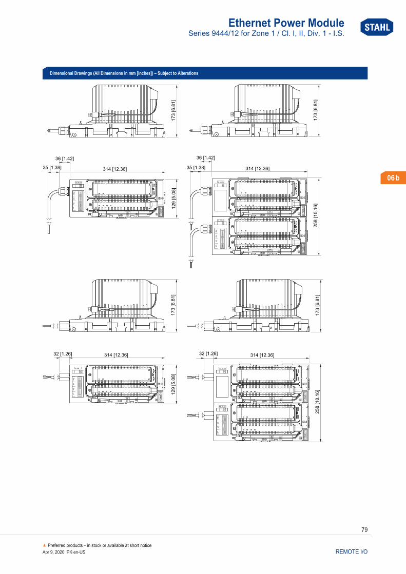
Dimensional Drawings (All Dimensions in mm [inches]) – Subject to Alterations
173 [6 8
1]
.258 10 1
6[
].
314 [12 36].3 [1 6]2 .2
173 [6 8
1]
.129 [5 0
8]
.
314 [12 36].3 [1 6]2 .2
258 10 1
6[
].
173 [6 8
1]
.
314 [12 36].
36 [1 42].
35 [1 38].
173 [6 8
1]
.129 [5 0
8]
.314 [12 36].
36 [1 42].
35 [1 38].
06 b
Preferred products – in stock or available at short noticeApr 9, 2020· PK·en-US REMOTE I/O

Analog Universal Module HARTSeries 9468/32 for Zone 1 / Cl. I, II, Div. 1 - I.S.
80
Home
06 b
Preferred products – in stock or available at short noticeApr 9, 2020· PK·en-USREMOTE I/O
• Eight channels can be used individually as inputs or outputs• Intrinsically safe Ex ia IIC inputs/ outputs with line fault monitoring
and LED error indication for each channel• Module in Zone 1, Cl. I, II, Div. 1 can be hot swapped
Selection Table
Installation Zone 1, Zone 2, Zone 21, Zone 22, Cl. I, II, Div. 1, 2 and in the safe area
Number of channels Product Type Art. No. Weight lb
8 Ex i inputs/ outputs 9468/ 32- 08- 11 210659 0.61
Please order terminals separately - see accessories and spare parts.
Technical Data
Explosion ProtectionUSA certificate FM FM17US0332XCAN certificate FM FM16CA0134XUSA marking FM IS; Class I,II,III, Div. 1, Groups A,B,C,D,E,F,G;
AIS; Class I,II,III, Div. 1, Groups A,B,C,D,E;F,G; Class I, Zone 1, AEx ia [ia] IIC; T4 at Ta = 75 °C; See Doc. 9468 6 031 001 1
CAN marking FM IS; Class I,II,III, Div. 1, Groups A,B,C,D,E,F,G; AIS; Class I,II,III, Div. 1, Groups A,B,C,D,E;F,G; Class I, Zone 1, Ex ia [ia] IIC; T4 at Ta = 75 °C; See Doc. 9468 6 031 001 1
IECEx gas explosion protection Ex ia [ia Ga] IIC T4 GbIECEx dust explosion protection [Ex ia Da] IIICCertificates ATEX (DEK), Brazil (ULB), Canada (FM), EAC (STV), IECEx (DEK), India (PESO), Korea (KTL), Russia (Meteorological certificate),
USA (FM)Ship approval ABS, CCS, ClassNK, DNV GL, RINASafety DataMax. voltage Uo/Voc 24.4 V
The 9468/ 32 series HART Analog Universal Module for Zone 1, Cl. I, II, Div. 1 has eight channels that can be used individually for Ex i operating two-/three- conductor HART transmitters, four- conductor transmitters or control valves/ positioners with 0/ 4 to 20 mA signals. HART communication is bidirectional.All inputs/ outputs are short- circuit proof, galvanically separated from the system and individually monitored to check for line faults.
WebCode 9468A
NEC® 500
CEC Appendix J
Class I Class II Class III
Division 1 2 1 2 1 2
Ex interface
Installation in
CEC Section 18
NEC® 505 NEC® 506
Class I
Zone 0 1 2 20 21 22
Ex interface
Installation in
IECEx / ATEX
Zone 0 1 2 20 21 22
Ex interface
Installation in

Analog Universal Module HARTSeries 9468/32 for Zone 1 / Cl. I, II, Div. 1 - I.S.
81
Home
06 b
Preferred products – in stock or available at short noticeApr 9, 2020· PK·en-US REMOTE I/O
Accessories–
Figure Description Product Type Art. No. Weight lb
Pluggable terminal2.5 mm² with lock, 16- pole, screw connector, blue, for connecting the field signals to I/ O modules, for intrinsically safe field circuitsLabelling: 1 ... 16Attention: An additional terminal is necessary for I/ O module Series 9470 and 9482.Labelling: 17 ... 32
– 162702 0.06
2.5 mm² with lock, 16- pole, spring clamp connection, blue, for connecting the field signals to I/ O modules, for intrinsically safe field circuits, incl. test jacksLabelling: 1 ... 16Attention: An additional terminal is necessary for I/ O module Series 9470 and 9482.Labelling: 17 ... 32
– 162695 0.06
mA-Isolating repeaterThe mA isolating repeaters are used for the connection of 4- wire transmitters to active 2- wire inputs and for the galvanic separation.Input: sink, Ex eOutput: sink, Ex i
9164/13-20-06 224365 0.31
The mA isolating repeaters are used for the connection of 4- wire transmitters to active 2- wire inputs and for the galvanic separation.Input: sink, Ex iOutput: sink, Ex i
9164/13-20-08 224364 0.2
Technical Data
Safety DataMax. current Io (2- conductor) 80 mAMax. current Io (3- conductor) 81.8 mAMax. power Po (2- conductor) 488 mWMax. power Po (3- conductor) 499 mWElectrical DataNumber of channels 8 Ex i inputs/ outputsChannels each with adjustable parameters as input or output
(3- wire, 4- wire transmitters, or active mA- sources occupy 2 channels)Nominal signal 4 ... 20 mA
0 ... 20 mASupply voltage 16 V, at 20 mA for 2- wire transmittersCommunication signal HART protocolConnection Ex i field signals Pluggable, blue terminals, 16- pole, 2.5 mm2, screw- or spring- type versions with lockNotes In order to operate an active 4- wire HART transmitter, a 9164 must be connected between each channel. 9164 is not required when
operating 4- wire transmitter without HART communication.Auxiliary PowerCurrent consumption 220 mA (at 20 mA per channel)Max. power consumption 5.3 W (at 20 mA / channel)Max. power dissipation outputs 3.7 W (at 20 mA. 500 Ω / channel)Max. power dissipation inputs 2.7 W (at 20 mA / channel)InputMax. input resistance 14.1 Ω per channelOutputOutput load resistance max. 750 Ω at 20 mA
700 Ω at 21.8 mAOutput step response (10 … 90 %) 40 msAmbient ConditionsAmbient temperature °F -40°F ... +167°F Observe operating instructionsAmbient temperature °C -40 °C ... +75 °C Observe operating instructionsMechanical DataDegree of protection IP (IEC 60529) IP20

Analog Universal Module HARTSeries 9468/32 for Zone 1 / Cl. I, II, Div. 1 - I.S.
82
Home
06 b
Preferred products – in stock or available at short noticeApr 9, 2020· PK·en-USREMOTE I/O
Dimensional Drawings (All Dimensions in mm [inches]) – Subject to Alterations
68 [2 6
8]
.
63 [2 4
8]
.
128 [5 04].
70 [2 7
6]
.
98 [3 8
6]
.
96.5
0 [3.8
0]
Accessories–
Figure Description Product Type Art. No. Weight lb
Resistor error message suppressionThe resistors are used to suppress error messages for unused I/ O channelsResistance value: 5K6 / 0.5 WSuitable for: AIM 9468; DIOM 9470; DIOM 9471; DIOM 9472; DOM 9475For intrinsically safe circuits (simple apparatus according to EN 60079- 11)
– 244911 –
The resistors are used to suppress error messages for unused I/ O channelsResistance value: 62R / 0.5 WSuitable for: AOM 9468; TIM 9482
– 244912 –
Labelling strips“FB Addr ... Mod No ...” for pluggable terminal, 26 pieces on the sheet – 162788 –
DIN A4 sheetFor the label plate on I/ O modules, 6 labels per sheetPrint IS Wizard, packaging unit = 20 sheets
– 162832 –
Warning sign"Clean modules only with a damp cloth." – 162796 –
PartitionFor mounting between intrinsically safe and non- intrinsically safe connections of the I/ O modules, in order to adhere to the required 50 mm distance
– 220101 0.02

Analog Universal Module HARTSeries 9468/33 for Zone 2 / Cl. I, II, Div. 2 - I.S.
83
Home
06 b
Preferred products – in stock or available at short noticeApr 9, 2020· PK·en-US REMOTE I/O
• Eight channels can be used individually as inputs or outputs• Intrinsically safe Ex ia IIC inputs/ outputs with line fault monitoring• Module in Zone 2, Cl. I, II, Div. 2 can be hot swapped
Selection Table
Installation Zone 2, Zone 22, Cl. I, II, Div. 2 and in the safe area
Number of channels Product Type Art. No. Weight lb
8 Ex i inputs/ outputs 9468/ 33- 08- 10 210660 0.61
Please order terminals separately - see accessories and spare parts.
Technical Data
Explosion ProtectionUSA certificate FM FM17US0332XCAN certificate FM FM16CA0134XUSA marking FM NI, Class I,II,III, Div. 2, Groups A,B,C,D,E,F,G;
AIS, Class I,II,III, Div. 1, Groups A,B,C,D,E,F,G; Class I, Zone 2, AEx nA ia [ia] IIC; T4 at Ta = 75 °C; See Doc. 9468 6 031 002 1
CAN marking FM NI, Class I,II,III, Div. 2, Groups A,B,C,D,E,F,G; AIS, Class I,II,III, Div. 1, Groups A,B,C,D,E,F,G; Class I, Zone 2, Ex nA ia [ia] IIC; T4 at Ta = 75 °C; See Doc. 9468 6 031 002 1
IECEx gas explosion protection Ex nA ia [ia Ga] IIC T4 GcIECEx dust explosion protection [Ex ia Da] IIICCertificates ATEX (DEK), Brazil (ULB), Canada (FM), EAC (STV), IECEx (DEK), India (PESO), Korea (KTL), Russia (Meteorological certificate),
USA (FM)Ship approval ABS, CCS, ClassNK, DNV GL, RINASafety DataMax. voltage Uo/Voc 24.4 V
The 9468/ 33 series HART Analog Universal Module for Zone 2, Cl. I, II, Div. 2 has eight channels that can be used individually for Ex i operating two-/three- conductor HART transmitters, four- conductor transmitters or control valves/ positioners with 0/ 4 to 20 mA signals. HART communication is bidirectional. All inputs/ outputs are short- circuit proof, galvanically separated from the system and individually monitored to check for line faults.
WebCode 9468B
NEC® 500
CEC Appendix J
Class I Class II Class III
Division 1 2 1 2 1 2
Ex interface
Installation in
CEC Section 18
NEC® 505 NEC® 506
Class I
Zone 0 1 2 20 21 22
Ex interface
Installation in
IECEx / ATEX
Zone 0 1 2 20 21 22
Ex interface
Installation in

Analog Universal Module HARTSeries 9468/33 for Zone 2 / Cl. I, II, Div. 2 - I.S.
84
Home
06 b
Preferred products – in stock or available at short noticeApr 9, 2020· PK·en-USREMOTE I/O
Accessories–
Figure Description Product Type Art. No. Weight lb
Pluggable terminal2.5 mm² with lock, 16- pole, screw connector, blue, for connecting the field signals to I/ O modules, for intrinsically safe field circuitsLabelling: 1 ... 16Attention: An additional terminal is necessary for I/ O module Series 9470 and 9482.Labelling: 17 ... 32
– 162702 0.06
2.5 mm² with lock, 16- pole, spring clamp connection, blue, for connecting the field signals to I/ O modules, for intrinsically safe field circuits, incl. test jacksLabelling: 1 ... 16Attention: An additional terminal is necessary for I/ O module Series 9470 and 9482.Labelling: 17 ... 32
– 162695 0.06
mA-Isolating repeaterThe mA isolating repeaters are used for the connection of 4- wire transmitters to active 2- wire inputs and for the galvanic separation.Input: sink, Ex eOutput: sink, Ex i
9164/13-20-06 224365 0.31
The mA isolating repeaters are used for the connection of 4- wire transmitters to active 2- wire inputs and for the galvanic separation.Input: sink, Ex iOutput: sink, Ex i
9164/13-20-08 224364 0.2
Technical Data
Safety DataMax. current Io (2- conductor) 80 mAMax. current Io (3- conductor) 81.8 mAMax. power Po (2- conductor) 488 mWMax. power Po (3- conductor) 499 mWElectrical DataNumber of channels 8 Ex i inputs/ outputsChannels each with adjustable parameters as input or output
(3- wire, 4- wire transmitters, or active mA- sources occupy 2 channels)Nominal signal 4 ... 20 mA
0 ... 20 mASupply voltage 16 V, at 20 mA for 2- wire transmittersCommunication signal HART protocolConnection Ex i field signals Pluggable, blue terminals, 16- pole, 2.5 mm2, screw- or spring- type versions with lockNotes In order to operate an active 4- wire HART transmitter, a 9164 must be connected between each channel. 9164 is not required when
operating 4- wire transmitter without HART communication.Auxiliary PowerCurrent consumption 220 mA (at 20 mA per channel)Max. power consumption 5.3 W (at 20 mA / channel)Max. power dissipation outputs 3.7 W (at 20 mA. 500 Ω / channel)Max. power dissipation inputs 2.7 W (at 20 mA / channel)InputMax. input resistance 14.1 Ω per channelOutputOutput load resistance max. 750 Ω at 20 mA
700 Ω at 21.8 mAOutput step response (10 … 90 %) 40 msAmbient ConditionsAmbient temperature °F -40°F ... +167°F Observe operating instructionsAmbient temperature °C -40 °C ... +75 °C Observe operating instructionsMechanical DataDegree of protection IP (IEC 60529) IP20

Analog Universal Module HARTSeries 9468/33 for Zone 2 / Cl. I, II, Div. 2 - I.S.
85
Home
06 b
Preferred products – in stock or available at short noticeApr 9, 2020· PK·en-US REMOTE I/O
Dimensional Drawings (All Dimensions in mm [inches]) – Subject to Alterations
68 [2 6
8]
.
63 [2 4
8]
.
128 [5 04].
70 [2 7
6]
.
98 [3 8
6]
.
96.5
0 [3.8
0]
Accessories–
Figure Description Product Type Art. No. Weight lb
Resistor error message suppressionThe resistors are used to suppress error messages for unused I/ O channelsResistance value: 5K6 / 0.5 WSuitable for: AIM 9468; DIOM 9470; DIOM 9471; DIOM 9472; DOM 9475For intrinsically safe circuits (simple apparatus according to EN 60079- 11)
– 244911 –
The resistors are used to suppress error messages for unused I/ O channelsResistance value: 62R / 0.5 WSuitable for: AOM 9468; TIM 9482
– 244912 –
Labelling strips“FB Addr ... Mod No ...” for pluggable terminal, 26 pieces on the sheet – 162788 –
DIN A4 sheetFor the label plate on I/ O modules, 6 labels per sheetPrint IS Wizard, packaging unit = 20 sheets
– 162832 –
Warning sign"Clean modules only with a damp cloth." – 162796 –
PartitionFor mounting between intrinsically safe and non- intrinsically safe connections of the I/ O modules, in order to adhere to the required 50 mm distance
– 220101 0.02

Analog Universal Module HARTSeries 9469/35 for Zone 2 / Cl. I, Div. 2
86
Home
06 b
Preferred products – in stock or available at short noticeApr 9, 2020· PK·en-USREMOTE I/O
• Eight channels can be used as analogue inputs or outputs, and 4 of these channels can used as binary inputs or outputs
• Inputs/ outputs with line fault monitoring, an LED fault and status display for each channel and SIL2 shutdown input
• Module in Zone 2, Cl. I, Div. 2 can be replaced during operation (hot swap)
Selection Table
Installation Zone 2, Cl. I, Div. 2 and in the safe area (non-intrinsically safe field circuits)
Number of channels Product Type Art. No. Weight lb
(adjustable parameters in pairs)8 Ex ec/ nA universal input/ output
9469/ 35- 08- 12 230184 0.55
Please order terminal separately - see accessories and spare parts
Technical Data
Explosion ProtectionUSA certificate FM FM17US0332XCAN certificate FM FM16CA0134XUSA marking FM NI; Class I, Div. 2, Groups A,B,C,D;
Class I, Zone 2, AEx ec ic IIC T4 Gc; Ta = -40°C … +75°C See Doc. 9496 6 031 001 1
CAN marking FM NI; Class. I, Div. 2, Groups A,B,C,D; Class I, Zone 2, Ex ec ic IIC T4 Gc; Ta = -40°C … +75°C See Doc. 9496 6 031 001 1
IECEx gas explosion protection Ex ec/ nA ic [ia Ga] IIC T4 GcCertificates ATEX (DEK), Canada (FM), EAC (Sertium), IECEx (DEK), Korea (KTL), SIL (exida), USA (FM)Electrical DataMax. number of 2- conductor analogue inputs/ outputs
8 (channels 0 ... 7)
Max. number of 3/ 4- conductor analogue inputs 4 (channels 4 ... 7)
The HART 9469/ 35 universal module for Zone 2, Cl. I, Div. 2 has 8 channels that are suitable for separately operating 2-/ 3-/4- line HART transmitters, control valves/ position regulators and operating 3- line proximity switches and 24 V / 0.5 A binary output signal can be used.HART communication is bidirectional. All inputs/ outputs are short- circuit proof, galvanically separated from the system and individually monitored to check for line faults.
WebCode 9469A
NEC® 500
CEC Appendix J
Class I Class II Class III
Division 1 2 1 2 1 2
Ex interface
Installation in
CEC Section 18
NEC® 505 NEC® 506
Class I
Zone 0 1 2 20 21 22
Ex interface
Installation in
IECEx / ATEX
Zone 0 1 2 20 21 22
Ex interface
Installation in

Analog Universal Module HARTSeries 9469/35 for Zone 2 / Cl. I, Div. 2
87
Home
06 b
Preferred products – in stock or available at short noticeApr 9, 2020· PK·en-US REMOTE I/O
Accessories–
Figure Description Art. No. Weight lb
Plug-in terminal1.5 mm² with lock, 24- pole, spring clamp connection, blackfor connecting the field signals to I/ O modules, for non- intrinsically safe field circuitsCaution: only for 9469, 9471 and 9472 I/ O modulesLabelling: 1 ... 24
245090 –
1.5 mm² with lock, 24- pole, spring clamp connection, blackfor connecting the field signals to I/ O modules, for non- intrinsically safe field circuitsCaution: only for 9469, 9471 and 9472 I/ O modulesLabelling: 25 ... 48
245091 –
Technical Data
Electrical DataMax. number of 3- conductor PNP inputs 4 (channels 4 ... 7)Max. number of binary outputs 4 (channels 4 ... 7)Analogue digital communication HART protocolDigital communication note up to Version 7.x, only at 4 to 20 mAExternal supply voltage UH (X0) 18 ... 32 V DC (nominal voltage of 24 V)Max. current consumption (X0) 4 x 0.5 A (depends on the total current of the binary outputs)Control input suitability (X0) Disconnection up to SIL 2. low demand (IEC 61508)Control input function (X0) “Plant STOP” to switch off all outputsAuxiliary PowerPower supply connection BusRail types 9494Auxiliary power version Intrinsically safe Ex ia via BusRailCurrent consumption 250 mAMax. power consumption 6 WMax. power dissipation outputs 5.9 WInputAnalogue input signal type 2/ 3/4- conductor transmitterAnalogue input nominal signal 0 ... 20 mA
4 ... 20 mAAnalogue input max. input resistance 200 Ω per channelBinary input signal type 3- conductor PNP initiators
2- conductor 24 V contactsBinary input signal type corresponds to the ext. supply voltage UH (X0)Binary input internal resistance 11 kΩOutputAnalogue output signal type 2- conductor transmitterAnalogue output nominal signal 0 ... 20 mA
4 ... 20 mAAnalogue output max. input resistance 200 Ω per channelAnalogue output max. load resistance 750 Ω at 20 mA
700 Ω at 21.8 mABinary output signal type 2- conductor (24 V / 0.5 A)Binary output supply voltage corresponds to the ext. supply voltage UH - 0.7 V (X0)Binary output current 30 mA … 0.5 A per channel (electronically limited)Binary output connectable loads ohmic
inductivecapacitive
Ambient ConditionsAmbient temperature °F -4°F ... +167°F Ambient temperature °C -40°C ... +75°C Mechanical DataDegree of protection IP (IEC 60529) IP20
Analog Universal Module HARTSeries 9469/35 for Zone 2 / Cl. I, Div. 2
88
Home
06 b
Preferred products – in stock or available at short noticeApr 9, 2020· PK·en-USREMOTE I/O
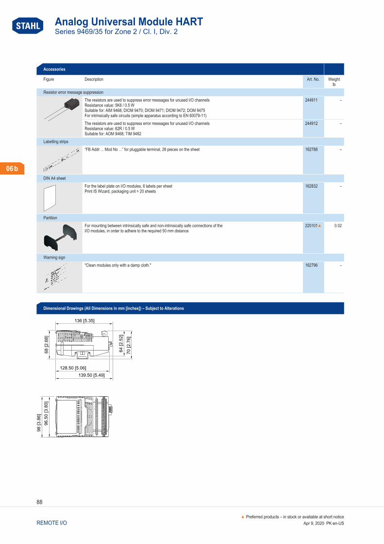
Dimensional Drawings (All Dimensions in mm [inches]) – Subject to Alterations
136 [5 35].
68 [2 6
8]
.
128 50 [5 06]. .
139 50 [5 49]. .
64 [2 5
2]
.
70 [2 7
6]
.
96 5
0 [3 8
0]
..
98 [3 8
6]
.
Accessories–
Figure Description Art. No. Weight lb
Resistor error message suppressionThe resistors are used to suppress error messages for unused I/ O channelsResistance value: 5K6 / 0.5 WSuitable for: AIM 9468; DIOM 9470; DIOM 9471; DIOM 9472; DOM 9475For intrinsically safe circuits (simple apparatus according to EN 60079- 11)
244911 –
The resistors are used to suppress error messages for unused I/ O channelsResistance value: 62R / 0.5 WSuitable for: AOM 9468; TIM 9482
244912 –
Labelling strips“FB Addr ... Mod No ...” for pluggable terminal, 26 pieces on the sheet 162788 –
DIN A4 sheetFor the label plate on I/ O modules, 6 labels per sheetPrint IS Wizard, packaging unit = 20 sheets
162832 –
PartitionFor mounting between intrinsically safe and non- intrinsically safe connections of the I/ O modules, in order to adhere to the required 50 mm distance
220101 0.02
Warning sign"Clean modules only with a damp cloth." 162796 –
Digital Input Output ModuleSeries 9470/32 for Zone 1 / Cl. I, II, Div. 1 - I.S.
89
Home
06 b
Preferred products – in stock or available at short noticeApr 9, 2020· PK·en-US REMOTE I/O
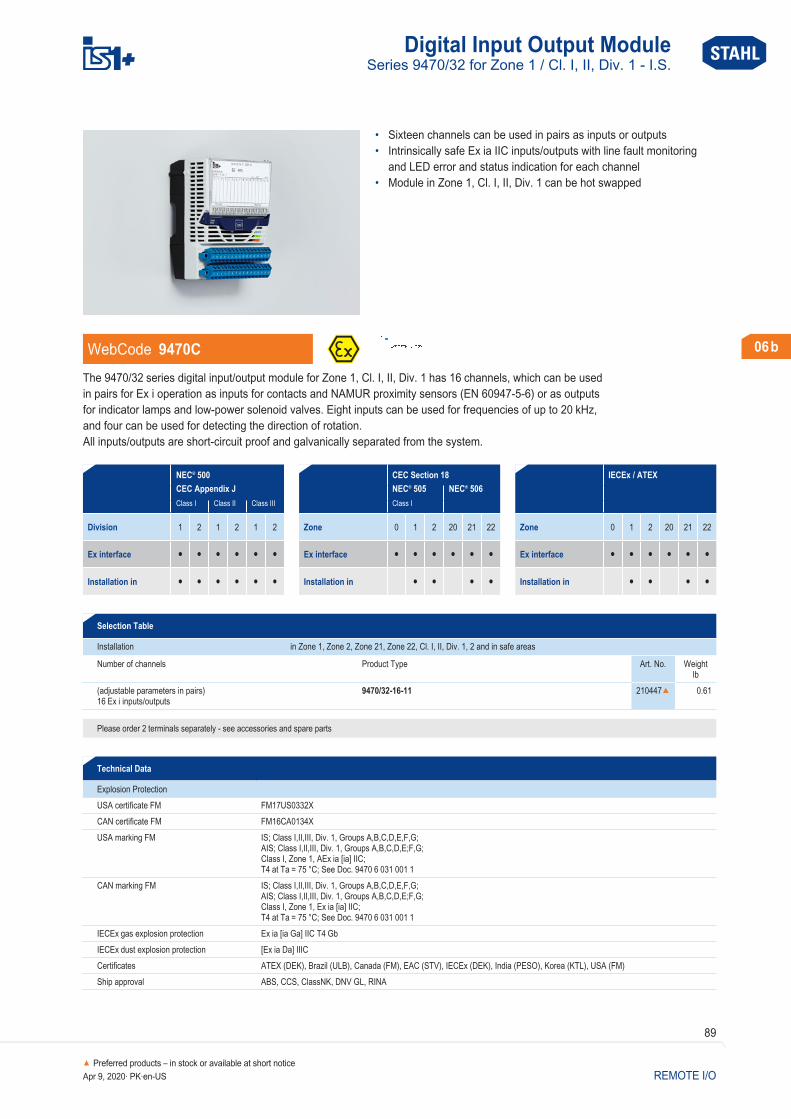
• Sixteen channels can be used in pairs as inputs or outputs• Intrinsically safe Ex ia IIC inputs/ outputs with line fault monitoring
and LED error and status indication for each channel• Module in Zone 1, Cl. I, II, Div. 1 can be hot swapped
Selection Table
Installation in Zone 1, Zone 2, Zone 21, Zone 22, Cl. I, II, Div. 1, 2 and in safe areas
Number of channels Product Type Art. No. Weight lb
(adjustable parameters in pairs)16 Ex i inputs/ outputs
9470/ 32- 16- 11 210447 0.61
Please order 2 terminals separately - see accessories and spare parts
Technical Data
Explosion ProtectionUSA certificate FM FM17US0332XCAN certificate FM FM16CA0134XUSA marking FM IS; Class I,II,III, Div. 1, Groups A,B,C,D,E,F,G;
AIS; Class I,II,III, Div. 1, Groups A,B,C,D,E;F,G; Class I, Zone 1, AEx ia [ia] IIC; T4 at Ta = 75 °C; See Doc. 9470 6 031 001 1
CAN marking FM IS; Class I,II,III, Div. 1, Groups A,B,C,D,E,F,G; AIS; Class I,II,III, Div. 1, Groups A,B,C,D,E;F,G; Class I, Zone 1, Ex ia [ia] IIC; T4 at Ta = 75 °C; See Doc. 9470 6 031 001 1
IECEx gas explosion protection Ex ia [ia Ga] IIC T4 GbIECEx dust explosion protection [Ex ia Da] IIICCertificates ATEX (DEK), Brazil (ULB), Canada (FM), EAC (STV), IECEx (DEK), India (PESO), Korea (KTL), USA (FM)Ship approval ABS, CCS, ClassNK, DNV GL, RINA
The 9470/ 32 series digital input/ output module for Zone 1, Cl. I, II, Div. 1 has 16 channels, which can be used in pairs for Ex i operation as inputs for contacts and NAMUR proximity sensors (EN 60947- 5-6) or as outputs for indicator lamps and low- power solenoid valves. Eight inputs can be used for frequencies of up to 20 kHz, and four can be used for detecting the direction of rotation. All inputs/ outputs are short- circuit proof and galvanically separated from the system.
WebCode 9470C
NEC® 500
CEC Appendix J
Class I Class II Class III
Division 1 2 1 2 1 2
Ex interface
Installation in
CEC Section 18
NEC® 505 NEC® 506
Class I
Zone 0 1 2 20 21 22
Ex interface
Installation in
IECEx / ATEX
Zone 0 1 2 20 21 22
Ex interface
Installation in

Digital Input Output ModuleSeries 9470/32 for Zone 1 / Cl. I, II, Div. 1 - I.S.
90
Home
06 b
Preferred products – in stock or available at short noticeApr 9, 2020· PK·en-USREMOTE I/O
Accessories–
Figure Description Product Type Art. No. Weight lb
Pluggable terminal2.5 mm² with lock, 16- pole, screw connector, blue, for connecting the field signals to I/ O modules, for intrinsically safe field circuitsLabelling: 1 ... 16Attention: An additional terminal is necessary for I/ O module Series 9470 and 9482.Labelling: 17 ... 32
– 162702 0.06
2.5 mm² with lock, 16- pole, screw connector, bluefor connecting the field signals to I/ O modules, for intrinsically safe field circuitsLabelling: 17 ... 32
– 162718 0.06
2.5 mm² with lock, 16- pole, spring clamp connection, blue, for connecting the field signals to I/ O modules, for intrinsically safe field circuits, incl. test jacksLabelling: 1 ... 16Attention: An additional terminal is necessary for I/ O module Series 9470 and 9482.Labelling: 17 ... 32
– 162695 0.06
2.5 mm² with lock, 16- pole, spring clamp connection, bluefor connecting the field signals to I/ O modules, for intrinsically safe field circuits, incl. test jacksLabelling: 17 ... 32
– 162716 0.06
Indicator lampSingle electrical equipment for intrinsically safe circuits according to EN 60079- 11 8010/C1661 228026 0.08
Labelling strips“FB Addr ... Mod No ...” for pluggable terminal, 26 pieces on the sheet – 162788 –
DIN A4 sheetFor the label plate on I/ O modules, 6 labels per sheetPrint IS Wizard, packaging unit = 20 sheets
– 162832 –
Technical Data
Safety DataMax. voltage Uo/Voc 9.8 VMax. current Io (Ex ia) 10.4 mAMax. power Po (Ex ia) 25.5 mWAuxiliary PowerCurrent consumption 120 mAMax. power consumption 2.5 WMax. power dissipation outputs 2.5 WInputSupply voltage 8.2 VFunction Up/ down counter
Frequency with directionSignal input EN 60947 input (NAMUR)Notes IEC 60947-5-6-1999 (NAMUR), 3-conductor PNP proximity switches and active 24 V signals with and without 47 kΩ resistance
connected in parallelOutputOutput rated operation 6 V / 2 mANotes Output characteristic, see data sheet on the Internet r-stahl.com (WebCode 9470C)Ambient ConditionsAmbient temperature °F -40°F ... +167°F Ambient temperature °C -40°C ... +75°C

Digital Input Output ModuleSeries 9470/32 for Zone 1 / Cl. I, II, Div. 1 - I.S.
91
Home
06 b
Preferred products – in stock or available at short noticeApr 9, 2020· PK·en-US REMOTE I/O
Dimensional Drawings (All Dimensions in mm [inches]) – Subject to Alterations
96 5
[3 8
].
.
64
[2 5
2]
.
128 5 [5 06]. .
68
[2.6
8]
70
[2 7
6]
.
98 [3.8
6]
Accessories–
Figure Description Product Type Art. No. Weight lb
PartitionFor mounting between intrinsically safe and non- intrinsically safe connections of the I/ O modules, in order to adhere to the required 50 mm distance
– 220101 0.02
Warning sign"Clean modules only with a damp cloth." – 162796 –
Resistor error message suppressionThe resistors are used to suppress error messages for unused I/ O channelsResistance value: 5K6 / 0.5 WSuitable for: AIM 9468; DIOM 9470; DIOM 9471; DIOM 9472; DOM 9475For intrinsically safe circuits (simple apparatus according to EN 60079- 11)
– 244911 –
Technical Drawings – Subject to Alterations
0
1
2
3
4
5
6
7
8
0 2 4 6 8
U[V
]
I [mA]
9470/3. - Output
Output characteristic

Digital Input Output ModuleSeries 9470/33 for Zone 2 / Cl. I, II, Div. 2 - I.S.
92
Home
06 b
Preferred products – in stock or available at short noticeApr 9, 2020· PK·en-USREMOTE I/O
• Sixteen channels can be used in pairs as inputs or outputs• Intrinsically safe Ex ia IIC inputs/ outputs with line fault monitoring• Module in Zone 2, Cl. I, II, Div. 2 can be hot swapped
Selection Table
Installation in Zone 2, Zone 21, Zone 22, Cl. I, II, Div. 2 and in safe areas
Number of channels Product Type Art. No. Weight lb
16 Ex i inputs/ outputs(adjustable parameters in pairs)
9470/ 33- 16- 10 210448 0.61
Please order 2 terminals separately - see accessories and spare parts
Technical Data
Explosion ProtectionUSA certificate FM FM17US0332XCAN certificate FM FM16CA0134XUSA marking FM NI, Class I,II,III, Div. 2, Groups A,B,C,D,E,F,G;
AIS, Class I,II,III, Div. 1, Groups A,B,C,D,E,F,G; Class I, Zone 2, AEx nA ia [ia] IIC; T4 at Ta = 75 °C; See Doc. 9470 6 031 002 1
CAN marking FM NI, Class I,II,III, Div. 2, Groups A,B,C,D,E,F,G; AIS, Class I,II,III, Div. 1, Groups A,B,C,D,E,F,G; Class I, Zone 2, Ex nA ia [ia] IIC; T4 at Ta = 75 °C; See Doc. 9470 6 031 002 1
IECEx gas explosion protection Ex nA ia [ia Ga] IIC T4 GcIECEx dust explosion protection [Ex ia Da] IIICCertificates ATEX (DEK), Brazil (ULB), Canada (FM), EAC (STV), IECEx (DEK), India (PESO), Korea (KTL), USA (FM)Ship approval ABS, CCS, ClassNK, DNV GL, RINA
The 9470/ 33 series digital input/ output module for Zone 2, Cl. I, II, Div. 2 has 16 channels, which can be used in pairs for Ex i operation as inputs for contacts and NAMUR proximity sensors (EN 60947- 5-6) or as outputs for indicator lamps and low- power solenoid valves. Eight inputs can be used for frequencies of up to 20 kHz, and four can be used for detecting the direction of rotation. All inputs/ outputs are short- circuit proof and galvanically separated from the system.
WebCode 9470D
NEC® 500
CEC Appendix J
Class I Class II Class III
Division 1 2 1 2 1 2
Ex interface
Installation in
CEC Section 18
NEC® 505 NEC® 506
Class I
Zone 0 1 2 20 21 22
Ex interface
Installation in
IECEx / ATEX
Zone 0 1 2 20 21 22
Ex interface
Installation in

Digital Input Output ModuleSeries 9470/33 for Zone 2 / Cl. I, II, Div. 2 - I.S.
93
Home
06 b
Preferred products – in stock or available at short noticeApr 9, 2020· PK·en-US REMOTE I/O
Accessories–
Figure Description Product Type Art. No. Weight lb
Pluggable terminal2.5 mm² with lock, 16- pole, screw connector, blue, for connecting the field signals to I/ O modules, for intrinsically safe field circuitsLabelling: 1 ... 16Attention: An additional terminal is necessary for I/ O module Series 9470 and 9482.Labelling: 17 ... 32
– 162702 0.06
2.5 mm² with lock, 16- pole, screw connector, bluefor connecting the field signals to I/ O modules, for intrinsically safe field circuitsLabelling: 17 ... 32
– 162718 0.06
2.5 mm² with lock, 16- pole, spring clamp connection, blue, for connecting the field signals to I/ O modules, for intrinsically safe field circuits, incl. test jacksLabelling: 1 ... 16Attention: An additional terminal is necessary for I/ O module Series 9470 and 9482.Labelling: 17 ... 32
– 162695 0.06
2.5 mm² with lock, 16- pole, spring clamp connection, bluefor connecting the field signals to I/ O modules, for intrinsically safe field circuits, incl. test jacksLabelling: 17 ... 32
– 162716 0.06
Indicator lampSingle electrical equipment for intrinsically safe circuits according to EN 60079- 11 8010/C1661 228026 0.08
Labelling strips“FB Addr ... Mod No ...” for pluggable terminal, 26 pieces on the sheet – 162788 –
DIN A4 sheetFor the label plate on I/ O modules, 6 labels per sheetPrint IS Wizard, packaging unit = 20 sheets
– 162832 –
Technical Data
Safety DataMax. voltage Uo/Voc 9.8 VMax. current Io (Ex ia) 10.4 mAMax. power Po (Ex ia) 25.5 mWAuxiliary PowerCurrent consumption 120 mAMax. power consumption 2.5 WMax. power dissipation outputs 2.5 WInputSignal input EN 60947 input (NAMUR)Supply voltage 8.2 VFunction Frequency with direction
Up/ down counterOutputOutput rated operation 6 V / 2 mANotes Output characteristic, see data sheet on the Internet r-stahl.com (WebCode 9470D)Ambient ConditionsAmbient temperature °F -40°F ... +167°F Ambient temperature °C -40°C ... +75°C

Digital Input Output ModuleSeries 9470/33 for Zone 2 / Cl. I, II, Div. 2 - I.S.
94
Home
06 b
Preferred products – in stock or available at short noticeApr 9, 2020· PK·en-USREMOTE I/O
Dimensional Drawings (All Dimensions in mm [inches]) – Subject to Alterations
96 5
[3 8
].
.
64
[2 5
2]
.
128 5 [5 06]. .
68
[2.6
8]
70
[2 7
6]
.
98 [3.8
6]
Accessories–
Figure Description Product Type Art. No. Weight lb
PartitionFor mounting between intrinsically safe and non- intrinsically safe connections of the I/ O modules, in order to adhere to the required 50 mm distance
– 220101 0.02
Warning sign"Clean modules only with a damp cloth." – 162796 –
Resistor error message suppressionThe resistors are used to suppress error messages for unused I/ O channelsResistance value: 5K6 / 0.5 WSuitable for: AIM 9468; DIOM 9470; DIOM 9471; DIOM 9472; DOM 9475For intrinsically safe circuits (simple apparatus according to EN 60079- 11)
– 244911 –
Technical Drawings – Subject to Alterations
0
1
2
3
4
5
6
7
8
0 2 4 6 8
U[V
]
I [mA]
9470/3. - Output
Output characteristic

Digital Input Output Module NAMURSeries 9471/35 for Zone 2 / Cl. I, Div. 2
95
Home
06 b
Preferred products – in stock or available at short noticeApr 9, 2020· PK·en-US REMOTE I/O
• Sixteen channels can be used in pairs as inputs or outputs• Inputs/ outputs with line fault monitoring and LED error and status
indication for each channel• Module in Zone 2, Cl. I, Div. 2 can be hot swapped
Selection Table
Installation Zone 2, Cl. I, Div. 2 and safe area
Number of channels Product Type Art. No. Weight lb
(adjustable parameters in pairs)16 Ex ec/ nA inputs/ outputs
9471/ 35- 16- 11 230225 0.61
Please order 2 terminals separately - see accessories and spare parts
Technical Data
Explosion ProtectionUSA certificate FM FM17US0332XCAN certificate FM FM16CA0134XUSA marking FM NI; Class I, Div. 2, Groups A,B,C,D;
Class I, Zone 2, AEx ec ic IIC T4 Gc; Ta = -40°C … +75°C; See Doc. 9471 6 031 001 1
CAN marking FM NI; Class. I, Div. 2, Groups A,B,C,D; Class. I, Zone 2, Ex ec ic IIC T4 Gc; Ta = -40°C … +75°C; See Doc. 9471 6 031 001 1
IECEx gas explosion protection Ex ec/ nA ic [ia Ga] IIC T4 GcCertificates ATEX (DEK), Canada (FM), EAC (Sertium), IECEx (DEK), India (PESO), Korea (KTL), USA (FM)Ship approval DNV GLElectrical DataMax. number of 3- conductor PNP inputs 16 (channels 1... 15)
The 9471/ 35 series digital input/ output module for Zone 2, Cl. I, Div. 2 has 16 channels, which can be used in pairs for operation as inputs for contacts, NAMUR proximity sensors (EN 60947- 5-6) and PNP proximity switches or as outputs for indicator lamps and low- power solenoid valves. Eight inputs can be used for fre-quencies of up to 20 kHz, and four can be used for detecting the direction of rotation. All inputs/ outputs are short- circuit proof and galvanically separated from the system.
WebCode 9471B
NEC® 500
CEC Appendix J
Class I Class II Class III
Division 1 2 1 2 1 2
Ex interface
Installation in
CEC Section 18
NEC® 505 NEC® 506
Class I
Zone 0 1 2 20 21 22
Ex interface
Installation in
IECEx / ATEX
Zone 0 1 2 20 21 22
Ex interface
Installation in

Digital Input Output Module NAMURSeries 9471/35 for Zone 2 / Cl. I, Div. 2
96
Home
06 b
Preferred products – in stock or available at short noticeApr 9, 2020· PK·en-USREMOTE I/O
Accessories–
Figure Description Art. No. Weight lb
Plug-in terminal1.5 mm² with lock, 24- pole, spring clamp connection, blackfor connecting the field signals to I/ O modules, for non- intrinsically safe field circuitsCaution: only for 9469, 9471 and 9472 I/ O modulesLabelling: 1 ... 24
245090 –
1.5 mm² with lock, 24- pole, spring clamp connection, blackfor connecting the field signals to I/ O modules, for non- intrinsically safe field circuitsCaution: only for 9469, 9471 and 9472 I/ O modulesLabelling: 25 ... 48
245091 –
Resistor error message suppressionThe resistors are used to suppress error messages for unused I/ O channelsResistance value: 5K6 / 0.5 WSuitable for: AIM 9468; DIOM 9470; DIOM 9471; DIOM 9472; DOM 9475For intrinsically safe circuits (simple apparatus according to EN 60079- 11)
244911 –
Labelling strips“FB Addr ... Mod No ...” for pluggable terminal, 26 pieces on the sheet 162788 –
DIN A4 sheetFor the label plate on I/ O modules, 6 labels per sheetPrint IS Wizard, packaging unit = 20 sheets
162832 –
PartitionFor mounting between intrinsically safe and non- intrinsically safe connections of the I/ O modules, in order to adhere to the required 50 mm distance
220101 0.02
Technical Data
Auxiliary PowerCurrent consumption 90 mAMax. power consumption 2.2 WPower dissipation max. 0.7 WInputMax. number of frequency inputs 8 (channel 8 ... 15)Notes Max. supply voltage PNP: 24 V externally supplied
IEC 60947-5-6-1999 (NAMUR), 3-conductor PNP proximity switches and active 24 V signals with and without 47 kΩ resistance connected in parallel
OutputBinary output signal type 2- conductor (6 V / 2 mA)Notes Output characteristics, see data sheet online at r-stahl.com (WebCode 9471B)Ambient ConditionsAmbient temperature °F -40°F ... +167°F Ambient temperature °C -40°C ... +75°C Mechanical DataDegree of protection IP (IEC 60529) IP20

Digital Input Output Module NAMURSeries 9471/35 for Zone 2 / Cl. I, Div. 2
97
Home
06 b
Preferred products – in stock or available at short noticeApr 9, 2020· PK·en-US REMOTE I/O
Dimensional Drawings (All Dimensions in mm [inches]) – Subject to Alterations
96 5
[3 8
].
.
64
[2 5
2]
.
128 5 [5 06]. .
68
[2.6
8]
70
[2 7
6]
.
98 [3.8
6]
Accessories–
Figure Description Art. No. Weight lb
Warning sign"Clean modules only with a damp cloth." 162796 –
Technical Drawings – Subject to Alterations
0
1
2
3
4
5
6
7
8
0 2 4 6 8
U[V
]
I [mA]
9471/35 - Output
Output characteristic

Digital Input Output Module 24 VSeries 9472/35 for Zone 2 / Cl. I, Div. 2
98
Home
06 b
Preferred products – in stock or available at short noticeApr 9, 2020· PK·en-USREMOTE I/O
• Sixteen channels can be used in pairs as inputs or outputs (24 V / 0.5 A)
• Inputs/ outputs with line fault monitoring and LED error and status indication for each channel plus SIL 2 shutdown input
• Module in Zone 2, Cl. I, Div. 2 can be hot swapped
Selection Table
Installation Zone 2, Cl. I, Div. 2
Number of channels Product Type Art. No. Weight lb
16 Ex ec/ nA inputs/ outputs(adjustable parameters in pairs)
9472/ 35- 16- 12 230239 0.61
Please order 2 terminals separately - see accessories and spare parts
Technical Data
Explosion ProtectionUSA certificate FM FM17US0332XCAN certificate FM FM16CA0134XUSA marking FM NI; Class I, Div. 2, Groups A,B,C,D;
Class I, Zone 2, AEx ec ic IIC T4 Gc; Ta = -40°C … +75°C; See Doc. 9471 6 031 001 1
CAN marking FM NI; Class I, Div. 2, Groups A,B,C,D; Class I, Zone 2, Ex ec ic IIC T4 Gc; Ta = -40°C … +75°C; See Doc. 9471 6 031 001 1
IECEx gas explosion protection Ex ec/ nA ic [ia Ga] IIC T4 GcCertificates ATEX (DEK), Canada (FM), EAC (Sertium), IECEx (DEK), India (PESO), Korea (KTL), SIL (exida), USA (FM)Electrical DataMax. number of 3- conductor PNP inputs 16 (channels 1... 15)
The 9472/ 35 24 V series digital input/ output module for Zone 2, Cl. I, Div. 2 has 16 channels, which can be used in pairs for operation as inputs for contacts and PNP or NAMUR proximity sensors (EN 60947- 5-6) or as outputs for solenoid valves up to 24 V/ 0.5 A. Eight inputs can be used for frequencies of up to 20 kHz, and four can be used for detecting the direction of rotation. All inputs/ outputs are short- circuit proof and galvanically separated from the system. Additional control input for "System OFF" (IEC61508 / through SIL2)
WebCode 9472A
NEC® 500
CEC Appendix J
Class I Class II Class III
Division 1 2 1 2 1 2
Ex interface
Installation in
CEC Section 18
NEC® 505 NEC® 506
Class I
Zone 0 1 2 20 21 22
Ex interface
Installation in
IECEx / ATEX
Zone 0 1 2 20 21 22
Ex interface
Installation in

Digital Input Output Module 24 VSeries 9472/35 for Zone 2 / Cl. I, Div. 2
99
Home
06 b
Preferred products – in stock or available at short noticeApr 9, 2020· PK·en-US REMOTE I/O
Accessories–
Figure Description Art. No. Weight lb
Plug-in terminal1.5 mm² with lock, 24- pole, spring clamp connection, blackfor connecting the field signals to I/ O modules, for non- intrinsically safe field circuitsCaution: only for 9469, 9471 and 9472 I/ O modulesLabelling: 1 ... 24
245090 –
1.5 mm² with lock, 24- pole, spring clamp connection, blackfor connecting the field signals to I/ O modules, for non- intrinsically safe field circuitsCaution: only for 9469, 9471 and 9472 I/ O modulesLabelling: 25 ... 48
245091 –
Resistor error message suppressionThe resistors are used to suppress error messages for unused I/ O channelsResistance value: 5K6 / 0.5 WSuitable for: AIM 9468; DIOM 9470; DIOM 9471; DIOM 9472; DOM 9475For intrinsically safe circuits (simple apparatus according to EN 60079- 11)
244911 –
Labelling strips“FB Addr ... Mod No ...” for pluggable terminal, 26 pieces on the sheet 162788 –
DIN A4 sheetFor the label plate on I/ O modules, 6 labels per sheetPrint IS Wizard, packaging unit = 20 sheets
162832 –
PartitionFor mounting between intrinsically safe and non- intrinsically safe connections of the I/ O modules, in order to adhere to the required 50 mm distance
220101 0.02
Technical Data
Auxiliary PowerCurrent consumption 90 mAMax. power consumption 2.2 WPower dissipation max. Output: 5.4 W
Input: 1.4 WInputMax. number of frequency inputs 8 (channel 8 ... 15)Notes Max. supply voltage PNP: corresponds to the external supply voltage UH (X0)
External supply voltage UH (X0): 18 ... 32 V DC (nominal voltage 24 V)Max. current consumption (X0): 4 x 0.5 A (depending on the total current of the binary outputs)
IEC 60947-5-6-1999 (NAMUR), 3-conductor PNP proximity switches and active 24 V signals with and without 47 kΩ resistance connected in parallel
OutputSupply voltage binary output Corresponds to the ext. supply voltage UH - 0.7 V (X0)Output current binary output 30 mA ... 0.5 A per channel
(electronically limited)Notes When auxiliary power is not connected: 6 V / 2 mAAmbient ConditionsAmbient temperature °F -40°F ... +167°F Ambient temperature °C -40°C ... +75°C Mechanical DataDegree of protection IP (IEC 60529) IP20

Digital Input Output Module 24 VSeries 9472/35 for Zone 2 / Cl. I, Div. 2
100
Home
06 b
Preferred products – in stock or available at short noticeApr 9, 2020· PK·en-USREMOTE I/O
Dimensional Drawings (All Dimensions in mm [inches]) – Subject to Alterations
96 5
[3 8
].
.
64
[2 5
2]
.
128 5 [5 06]. .
68
[2.6
8]
70
[2 7
6]
.
98 [3.8
6]
139. .495 [5 ]
136 .35[5 ]
Accessories–
Figure Description Art. No. Weight lb
Warning sign"Clean modules only with a damp cloth." 162796 –
Technical Drawings – Subject to Alterations
U[V
]
I [mA]
100 200 300 400 5000
U - 0,7 VH
Connection diagram

Digital Output Module 4-Channel VersionSeries 9475/32-04 for Zone 1, Cl. I, II, Div. 1 - I.S.
101
Home
06 b
Apr 9, 2020· PK·en-US REMOTE I/O
• Four channels for Ex i solenoid valves up to 40 mA• Ex ia outputs with line fault monitoring and LED error and status
indication for each channel plus SIL 2 shutdown input• Modules in Zone 1, Cl. I, II, Div. 1 can be hot swapped
Selection Table
Product variant Digital output module with "Plant STOP"Installation Zone 1, Zone 2, Zone 21, Zone 22, Cl. I, II, Div. 1, 2 and in the safe area
Open- circuit voltage Ua Ex i output rated operation Internal resistance of outputs Product Type Art. No. Weight lb
17.9 V 11.3 V/ 40 mA 170 Ω 9475/ 32- 04- 12 210651 0.61
23.6 V 12.3 V/ 40 mA 287 Ω 9475/ 32- 04- 22 210652 0.61
Please order terminals separately - see accessories and spare parts
Technical Data
Variant 9475/32-04-12 9475/32-04-22
Explosion ProtectionUSA certificate FM FM17US0332X FM17US0332XCAN certificate FM FM16CA0134X FM16CA0134XUSA marking FM IS; Class I,II,III, Div. 1, Groups A,B,C,D,E,F,G;
AIS; Class I,II,III, Div. 1, Groups A,B,C,D,E;F,G; Class I, Zone 1, AEx ia [ia] IIC; T4 at Ta = 75 °C; See Doc. 9475 6 031 001 1
IS; Class I,II,III, Div. 1, Groups A,B,C,D,E,F,G; AIS; Class I,II,III, Div. 1, Groups A,B,C,D,E;F,G; Class I, Zone 1, AEx ia [ia] IIC; T4 at Ta = 75 °C; See Doc. 9475 6 031 001 1
CAN marking FM IS; Class I,II,III, Div. 1, Groups A,B,C,D,E,F,G; AIS; Class I,II,III, Div. 1, Groups A,B,C,D,E;F,G; Class I, Zone 1, Ex ia [ia] IIC; T4 at Ta = 75 °C; See Doc. 9475 6 031 001 1
IS; Class I,II,III, Div. 1, Groups A,B,C,D,E,F,G; AIS; Class I,II,III, Div. 1, Groups A,B,C,D,E;F,G; Class I, Zone 1, Ex ia [ia] IIC; T4 at Ta = 75 °C; See Doc. 9475 6 031 001 1
IECEx gas explosion protection Ex ia [ia Ga] IIC T4 Gb Ex ia [ia Ga] IIC T4 GbIECEx dust explosion protection [Ex ia Da] IIIC [Ex ia Da] IIIC
9475/ 32- 04 series digital output modules for Zone 1, Cl. I, II, Div. 1 have four channels for actuating Ex i solenoid valves or indicator lamps. An additional Ex i control input is suitable for safe shutdown up to SIL 2. All outputs are short- circuit proof, galvanically separated from the system and individually monitored to check for wire breakage/ short- circuiting.
WebCode 9475E
NEC® 500
CEC Appendix J
Class I Class II Class III
Division 1 2 1 2 1 2
Ex interface
Installation in
CEC Section 18
NEC® 505 NEC® 506
Class I
Zone 0 1 2 20 21 22
Ex interface
Installation in
IECEx / ATEX
Zone 0 1 2 20 21 22
Ex interface
Installation in

Digital Output Module 4-Channel VersionSeries 9475/32-04 for Zone 1, Cl. I, II, Div. 1 - I.S.
102
Home
06 b
Apr 9, 2020· PK·en-USREMOTE I/O
Accessories–
Figure Description Product Type Art. No. Weight lb
Pluggable terminal2.5 mm² with lock, 16- pole, screw connector, blue, for connecting the field signals to I/ O modules, for intrinsically safe field circuitsLabelling: 1 ... 16Attention: An additional terminal is necessary for I/ O module Series 9470 and 9482.Labelling: 17 ... 32
– 162702 0.06
2.5 mm² with lock, 16- pole, spring clamp connection, blue, for connecting the field signals to I/ O modules, for intrinsically safe field circuits, incl. test jacksLabelling: 1 ... 16Attention: An additional terminal is necessary for I/ O module Series 9470 and 9482.Labelling: 17 ... 32
– 162695 0.06
Electronic relayThe electronic relay module 9174 is used to switch Ex e loads by using intrinsically safe control signals.Input: Ex iOutput: 48 V / 2 A DC, Ex e
9174/10-14-00 212340 0.24
The electronic relay module 9174 is used to switch Ex e loads by using intrinsically safe control signals.Input: Ex iOutput: 250 V / 1 A DC, Ex e
9174/10-15-00 212431 0.24
LED Indicator lamp Ex iLED indicator lamp for intrinsically safe circuits 8010/ 3- 02, Ex i 8010/3-02 237972 0.08
Technical Data
Variant 9475/32-04-12 9475/32-04-22
Explosion ProtectionCertificates ATEX (DEK), Brazil (ULB), Canada (FM), EAC (STV), IECEx
(DEK), India (PESO), Korea (KTL), SIL (exida), USA (FM)ATEX (DEK), Brazil (ULB), Canada (FM), EAC (STV), IECEx (DEK), India (PESO), Korea (KTL), SIL (exida), USA (FM)
Ship approval ABS, CCS, ClassNK, DNV GL, RINA ABS, CCS, ClassNK, DNV GL, RINASafety DataMax. voltage Uo/Voc 19.7 V 25.7 VMax. current Io (Ex ia) 142 mA 110 mAMax. current Io (Ex ib) 53.8 mA 49.5 mAMax. power Po (Ex ia) 698 mW 708 mWMax. power Po (Ex ib) 617 mW 648 mWElectrical DataNumber of channels 4 Ex i outputs 4 Ex i outputsAuxiliary PowerCurrent consumption 210 mA 240 mAMax. power consumption 5 W 5.8 WMax. power dissipation outputs 4 W 4.5 WInputControl input Ex i control input X3 Ex i control input X3Control input suitability Switch- off up to SIL 2, low demand (IEC61508) Switch- off up to SIL 2, low demand (IEC61508)Control input function "Plant STOP" to switch off all outputs "Plant STOP" to switch off all outputsAmbient ConditionsAmbient temperature °F -40°F ... +167°F -40°F ... +167°F Ambient temperature °C -40°C ... +75°C -40°C ... +75°C Mechanical DataDegree of protection IP (IEC 60529) IP20 IP20

Digital Output Module 4-Channel VersionSeries 9475/32-04 for Zone 1, Cl. I, II, Div. 1 - I.S.
103
Home
06 b
Apr 9, 2020· PK·en-US REMOTE I/O
Accessories–
Figure Description Product Type Art. No. Weight lb
Labelling strips“FB Addr ... Mod No ...” for pluggable terminal, 26 pieces on the sheet – 162788 –
DIN A4 sheetFor the label plate on I/ O modules, 6 labels per sheetPrint IS Wizard, packaging unit = 20 sheets
– 162832 –
PartitionFor mounting between intrinsically safe and non- intrinsically safe connections of the I/ O modules, in order to adhere to the required 50 mm distance
– 220101 0.02
Warning sign"Clean modules only with a damp cloth." – 162796 –
Resistor error message suppressionThe resistors are used to suppress error messages for unused I/ O channelsResistance value: 5K6 / 0.5 WSuitable for: AIM 9468; DIOM 9470; DIOM 9471; DIOM 9472; DOM 9475For intrinsically safe circuits (simple apparatus according to EN 60079- 11)
– 244911 –
Technical Drawings – Subject to Alterations
0
5
10
15
20
25
0 5 10 15 20 25 30 35
U[V
]
I [mA]
40 45
Output characteristic 9475/ 32- 04- 22
0
5
10
15
20
25
0 5 10 15 20 25 30 35
U[V
]
I [mA]
40 45
Output characteristic 9475/ 32- 04- 12

Digital Output Module 4-Channel VersionSeries 9475/32-04 for Zone 1, Cl. I, II, Div. 1 - I.S.
104
Home
06 b
Apr 9, 2020· PK·en-USREMOTE I/O
Dimensional Drawings (All Dimensions in mm [inches]) – Subject to Alterations
6[2
68]
.0
1 [ ]54 6 06.
64 2.5
2[
]
70 2 7
6[
].
98 3 8
6[
].
96.5
0 3.8
0[
]
20 0.7
9[
]
7 0.2
8[
]
1 [5 ]43 .63
1 [5 ]28.50 .06

Digital Output Module 4-Channel VersionSeries 9475/32-04-72 for Zone 1 / Cl. I, II, Div. 2 - I.S.
105
Home
06 b
Apr 9, 2020· PK·en-US REMOTE I/O
• Four channels for Ex i hydraulic and solenoid valves up to 95 mA• Ex ib outputs with line fault monitoring and LED error and status
indication for each channel plus SIL 2 shutdown input• Modules in Zone 1, Cl. I, II, Div. 2 can be hot swapped
Selection Table
Product variant Digital output module with "Plant STOP"Installation Zone 1, Zone 2, Zone 21, Zone 22, Cl. I, II, Div. 2 and in the safe area
Open- circuit voltage Ua Ex i output rated operation Internal resistance of outputs Product Type Art. No. Weight lb
13.8 V 12.3 V/ 75 mA11.7 V/ 95 mA
23.2 Ω 9475/ 32- 04- 72 218063 0.61
Please order terminals separately - see accessories and spare parts
Technical Data
Explosion ProtectionUSA certificate FM FM17US0332XCAN certificate FM FM16CA0134XUSA marking FM IS; Class I,II,III, Div. 2, Groups A,B,C,D,E,F,G;
NIFW; Class I,II,III, Div. 2, Groups A,B,C,D,E;F,G; Class I, Zone 1, AEx ia [ib] IIC; T4 at Ta = 75 °C; See Doc. 9475 6 031 005 1
CAN marking FM IS; Class I,II,III, Div. 2, Groups A,B,C,D,E,F,G; NIFW; Class I,II,III, Div. 2, Groups A,B,C,D,E;F,G; Class I, Zone 1, Ex ia [ib] IIC; T4 at Ta = 75 °C; See Doc. 9475 6 031 005 1
IECEx gas explosion protection Ex ia [ib Gb] IIC T4 GbIECEx dust explosion protection [Ex ib Db] IIICCertificates ATEX (DEK), Brazil (ULB), Canada (FM), EAC (STV), IECEx (DEK), India (PESO), Korea (KTL), SIL (exida), USA (FM)Ship approval ABS, CCS, ClassNK, DNV GL, RINA
9475/ 32- 04- 72 series digital output modules for Zone 1, Cl. I, II, Div. 2 have four channels for actuating Ex i hydraulic and solenoid valves or indicator lamps. An additional Ex i control input is suitable for safe shutdown up to SIL 2. All outputs are short- circuit proof, galvanically separated from the system and individually moni-tored to check for wire breakage/ short- circuiting.
WebCode 9475F
NEC® 500
CEC Appendix J
Class I Class II Class III
Division 1 2 1 2 1 2
Ex interface
Installation in
CEC Section 18
NEC® 505 NEC® 506
Class I
Zone 0 1 2 20 21 22
Ex interface
Installation in
IECEx / ATEX
Zone 0 1 2 20 21 22
Ex interface
Installation in

Digital Output Module 4-Channel VersionSeries 9475/32-04-72 for Zone 1 / Cl. I, II, Div. 2 - I.S.
106
Home
06 b
Apr 9, 2020· PK·en-USREMOTE I/O
Accessories–
Figure Description Product Type Art. No. Weight lb
Pluggable terminal2.5 mm² with lock, 16- pole, screw connector, blue, for connecting the field signals to I/ O modules, for intrinsically safe field circuitsLabelling: 1 ... 16Attention: An additional terminal is necessary for I/ O module Series 9470 and 9482.Labelling: 17 ... 32
– 162702 0.06
2.5 mm² with lock, 16- pole, spring clamp connection, blue, for connecting the field signals to I/ O modules, for intrinsically safe field circuits, incl. test jacksLabelling: 1 ... 16Attention: An additional terminal is necessary for I/ O module Series 9470 and 9482.Labelling: 17 ... 32
– 162695 0.06
Electronic relayThe electronic relay module 9174 is used to switch Ex e loads by using intrinsically safe control signals.Input: Ex iOutput: 48 V / 2 A DC, Ex e
9174/10-14-00 212340 0.24
The electronic relay module 9174 is used to switch Ex e loads by using intrinsically safe control signals.Input: Ex iOutput: 250 V / 1 A DC, Ex e
9174/10-15-00 212431 0.24
LED Indicator lamp Ex iLED indicator lamp for intrinsically safe circuits 8010/ 3- 02, Ex i 8010/3-02 237972 0.08
Labelling strips“FB Addr ... Mod No ...” for pluggable terminal, 26 pieces on the sheet – 162788 –
Technical Data
Safety DataMax. voltage Uo/Voc 15.4 VMax. current Io (Ex ib) 115.4 mAMax. power Po (Ex ib) 1475 mWAuxiliary PowerCurrent consumption 250 mAMax. power consumption 6 WMax. power dissipation outputs 5.8 WInputControl input Ex i control input X3Control input suitability Switch- off up to SIL 2, low demand (IEC61508)Control input function "Plant STOP" to switch off all outputsOutputEx i output rated operation 12.3 V/ 75 mA
11.7 V/ 95 mAAmbient ConditionsAmbient temperature °F -40°F ... +167°F Ambient temperature °C -40°C ... +75°C Mechanical DataDegree of protection IP (IEC 60529) IP20

Digital Output Module 4-Channel VersionSeries 9475/32-04-72 for Zone 1 / Cl. I, II, Div. 2 - I.S.
107
Home
06 b
Apr 9, 2020· PK·en-US REMOTE I/O
Dimensional Drawings (All Dimensions in mm [inches]) – Subject to Alterations
6[2
68]
.0
1 [ ]54 6 06.
64 2.5
2[
]
70 2 7
6[
].
98 3 8
6[
].
96.5
0 3.8
0[
]
20 0.7
9[
]
7 0.2
8[
]
1 [5 ]43 .63
1 [5 ]28.50 .06
Accessories–
Figure Description Product Type Art. No. Weight lb
DIN A4 sheetFor the label plate on I/ O modules, 6 labels per sheetPrint IS Wizard, packaging unit = 20 sheets
– 162832 –
PartitionFor mounting between intrinsically safe and non- intrinsically safe connections of the I/ O modules, in order to adhere to the required 50 mm distance
– 220101 0.02
Warning sign"Clean modules only with a damp cloth." – 162796 –
Technical Drawings – Subject to Alterations
0
3
6
9
12
15
0 10 20 30 40 50 60 70
U[V
]
I [mA]
9475/32-04-72
90 100
2)
1)
80
1) 4 channels2) max. 3 channels
Output characteristic 9475/ 32- 04- 72

Digital Output Module 8-Channel VersionSeries 9475/32-08 for Zone 1 / Cl. I, II, Div. 1 - I.S.
108
Home
06 b
Preferred products – in stock or available at short noticeApr 9, 2020· PK·en-USREMOTE I/O
• Eight channels for Ex i solenoid valves up to 30 mA• Ex ia outputs with line fault monitoring and LED error and status
indication for each channel plus SIL 2 shutdown input• Modules in Zone 1, Cl. I, II, Div. 1 can be hot swapped
Selection Table
Product variant Digital output module with "Plant STOP"Installation Zone 1, Zone 2, Zone 21, Zone 22, Cl. I, II, Div. 1, 2 and in the safe area
Open- circuit voltage Ua Ex i output rated operation Internal resistance of outputs Product Type Art. No. Weight lb
17.5 V 12.6 V/ 30 mA 170 Ω 9475/ 32- 08- 52 210655 0.61
23.5 V 17.5 V/ 20 mA 315 Ω 9475/ 32- 08- 62 210656 0.61
Please order terminals separately - see accessories and spare parts
Technical Data
Variant 9475/32-08-52 9475/32-08-62
Explosion ProtectionUSA certificate FM FM17US0332X FM17US0332XCAN certificate FM FM16CA0134X FM16CA0134XUSA marking FM IS; Class I,II,III, Div. 1, Groups A,B,C,D,E,F,G;
AIS; Class I,II,III, Div. 1, Groups A,B,C,D,E;F,G; Class I, Zone 1, AEx ia [ia] IIC; T4 at Ta = 75 °C; See Doc. 9475 6 031 002 1
IS; Class I,II,III, Div. 1, Groups A,B,C,D,E,F,G; AIS; Class I,II,III, Div. 1, Groups A,B,C,D,E;F,G; Class I, Zone 1, AEx ia [ia] IIC; T4 at Ta = 75 °C; See Doc. 9475 6 031 002 1
CAN marking FM IS; Class I,II,III, Div. 1, Groups A,B,C,D,E,F,G; AIS; Class I,II,III, Div. 1, Groups A,B,C,D,E;F,G; Class I, Zone 1, Ex ia [ia] IIC; T4 at Ta = 75 °C; See Doc. 9475 6 031 002 1
IS; Class I,II,III, Div. 1, Groups A,B,C,D,E,F,G; AIS; Class I,II,III, Div. 1, Groups A,B,C,D,E;F,G; Class I, Zone 1, Ex ia [ia] IIC; T4 at Ta = 75 °C; See Doc. 9475 6 031 002 1
IECEx gas explosion protection Ex ia [ia Ga] IIC T4 Gb Ex ia [ia Ga] IIC T4 GbIECEx dust explosion protection [Ex ia Da] IIIC [Ex ia Da] IIIC
9475/ 32- 08 series digital output modules for Zone 1, Cl. I, II, Div. 1 have eight channels for actuating Ex i solenoid valves or indicator lamps. An additional Ex i control input is suitable for safe shutdown up to SIL 2. All outputs are short- circuit proof, galvanically separated from the system and individually monitored to check for wire breakage/ short- circuiting.
WebCode 9475C
NEC® 500
CEC Appendix J
Class I Class II Class III
Division 1 2 1 2 1 2
Ex interface
Installation in
CEC Section 18
NEC® 505 NEC® 506
Class I
Zone 0 1 2 20 21 22
Ex interface
Installation in
IECEx / ATEX
Zone 0 1 2 20 21 22
Ex interface
Installation in

Digital Output Module 8-Channel VersionSeries 9475/32-08 for Zone 1 / Cl. I, II, Div. 1 - I.S.
109
Home
06 b
Preferred products – in stock or available at short noticeApr 9, 2020· PK·en-US REMOTE I/O
Accessories–
Figure Description Product Type Art. No. Weight lb
Pluggable terminal2.5 mm² with lock, 16- pole, screw connector, blue, for connecting the field signals to I/ O modules, for intrinsically safe field circuitsLabelling: 1 ... 16Attention: An additional terminal is necessary for I/ O module Series 9470 and 9482.Labelling: 17 ... 32
– 162702 0.06
2.5 mm² with lock, 16- pole, spring clamp connection, blue, for connecting the field signals to I/ O modules, for intrinsically safe field circuits, incl. test jacksLabelling: 1 ... 16Attention: An additional terminal is necessary for I/ O module Series 9470 and 9482.Labelling: 17 ... 32
– 162695 0.06
Electronic relayThe electronic relay module 9174 is used to switch Ex e loads by using intrinsically safe control signals.Input: Ex iOutput: 48 V / 2 A DC, Ex e
9174/10-14-00 212340 0.24
LED Indicator lamp Ex iLED indicator lamp for intrinsically safe circuits 8010/ 3- 02, Ex i 8010/3-02 237972 0.08
Technical Data
Variant 9475/32-08-52 9475/32-08-62
Explosion ProtectionCertificates ATEX (DEK), Brazil (ULB), Canada (FM), EAC (STV), IECEx
(DEK), India (PESO), Korea (KTL), SIL (exida), USA (FM)ATEX (DEK), Brazil (ULB), Canada (FM), EAC (STV), IECEx (DEK), India (PESO), Korea (KTL), SIL (exida), USA (FM)
Ship approval ABS, CCS, ClassNK, DNV GL, RINA ABS, CCS, ClassNK, DNV GL, RINASafety DataMax. voltage Uo/Voc 19.4 V 25.7 VMax. current Io (Ex ia) 143 mA 107 mAMax. current Io (Ex ib) 37.8 mA 26.3 mAMax. power Po (Ex ia) 692 mW 688 mWMax. power Po (Ex ib) 506 mW 468 mWElectrical DataNumber of channels 8 Ex i outputs 8 Ex i outputsAuxiliary PowerCurrent consumption 250 mA 240 mAMax. power consumption 6 W 5.8 WMax. power dissipation outputs 4.8 W 4 WInputControl input Ex i control input X3 Ex i control input X3Control input suitability Switch- off up to SIL 2, low demand (IEC61508) Switch- off up to SIL 2, low demand (IEC61508)Control input function "Plant STOP" to switch off all outputs "Plant STOP" to switch off all outputsAmbient ConditionsAmbient temperature °F -40°F ... +167°F -40°F ... +167°F Ambient temperature °C -40°C ... +75°C -40°C ... +75°C Mechanical DataDegree of protection IP (IEC 60529) IP20 IP20

Digital Output Module 8-Channel VersionSeries 9475/32-08 for Zone 1 / Cl. I, II, Div. 1 - I.S.
110
Home
06 b
Preferred products – in stock or available at short noticeApr 9, 2020· PK·en-USREMOTE I/O
Accessories–
Figure Description Product Type Art. No. Weight lb
Labelling strips“FB Addr ... Mod No ...” for pluggable terminal, 26 pieces on the sheet – 162788 –
DIN A4 sheetFor the label plate on I/ O modules, 6 labels per sheetPrint IS Wizard, packaging unit = 20 sheets
– 162832 –
PartitionFor mounting between intrinsically safe and non- intrinsically safe connections of the I/ O modules, in order to adhere to the required 50 mm distance
– 220101 0.02
Warning sign"Clean modules only with a damp cloth." – 162796 –
Resistor error message suppressionThe resistors are used to suppress error messages for unused I/ O channelsResistance value: 5K6 / 0.5 WSuitable for: AIM 9468; DIOM 9470; DIOM 9471; DIOM 9472; DOM 9475For intrinsically safe circuits (simple apparatus according to EN 60079- 11)
– 244911 –
Technical Drawings – Subject to Alterations
0
5
10
15
20
25
0 5 10 15 20 25 30 35
U[V
]
I [mA]
Output characteristic 9475/ 33- 08- 60
0
5
10
15
20
25
0 5 10 15 20 25 30 35
U[V
]
I [mA]
Output characteristic 9475/ 33- 08- 50

Digital Output Module 8-Channel VersionSeries 9475/32-08 for Zone 1 / Cl. I, II, Div. 1 - I.S.
111
Home
06 b
Preferred products – in stock or available at short noticeApr 9, 2020· PK·en-US REMOTE I/O
Dimensional Drawings (All Dimensions in mm [inches]) – Subject to Alterations
6[2
68]
.0
1 [ ]54 6 06.
64 2.5
2[
]
70 2 7
6[
].
98 3 8
6[
].
96.5
0 3.8
0[
]
20 0.7
9[
]
7 0.2
8[
]
1 [5 ]43 .63
1 [5 ]28.50 .06

Digital Output Module 8-Channel VersionSeries 9475/33-08 for Zone 2 / Cl. I, II, Div. 2 - I.S.
112
Home
06 b
Preferred products – in stock or available at short noticeApr 9, 2020· PK·en-USREMOTE I/O
• Eight channels for Ex i solenoid valves up to 30 mA• Ex ia outputs with line fault monitoring• Modules in Zone 2, Cl. I, II, Div. 2 can be hot swapped
Selection Table
Installation Zone 2, Zone 22, Cl. I, II, Div. 2 and in the safe area
Open- circuit voltage Ua Ex i output rated operation Internal resistance of outputs Product Type Art. No. Weight lb
17.5 V 12.6 V/ 30 mA 170 Ω 9475/ 33- 08- 50 210657 0.61
23.5 V 17.5 V/ 20 mA 315 Ω 9475/ 33- 08- 60 210658 0.61
Please order terminals separately - see accessories and spare parts
Technical Data
Variant 9475/33-08-50 9475/33-08-60
Explosion ProtectionUSA certificate FM FM17US0332X FM17US0332XCAN certificate FM FM16CA0134X FM16CA0134XUSA marking FM NI, Class I,II,III, Div. 2, Groups A,B,C,D,E,F,G;
AIS, Class I,II,III, Div. 1, Groups A,B,C,D,E,F,G; Class I, Zone 2, AEx nA ia [ia] IIC; T4 at Ta = 75 °C; See Doc. 9475 6 031 004 1
NI, Class I,II,III, Div. 2, Groups A,B,C,D,E,F,G; AIS, Class I,II,III, Div. 1, Groups A,B,C,D,E,F,G; Class I, Zone 2, AEx nA ia [ia] IIC; T4 at Ta = 75 °C; See Doc. 9475 6 031 004 1
CAN marking FM NI, Class I,II,III, Div. 2, Groups A,B,C,D,E,F,G; AIS, Class I,II,III, Div. 1, Groups A,B,C,D,E,F,G; Class I, Zone 2, Ex nA ia [ia] IIC; T4 at Ta = 75 °C; See Doc. 9475 6 031 004 1
NI, Class I,II,III, Div. 2, Groups A,B,C,D,E,F,G; AIS, Class I,II,III, Div. 1, Groups A,B,C,D,E,F,G; Class I, Zone 2, Ex nA ia [ia] IIC; T4 at Ta = 75 °C; See Doc. 9475 6 031 004 1
IECEx gas explosion protection Ex nA ia [ia Ga] IIC T4 Gc Ex nA ia [ia Ga] IIC T4 GcIECEx dust explosion protection [Ex ia Da] IIIC [Ex ia Da] IIICCertificates ATEX (DEK), Brazil (ULB), Canada (FM), EAC (STV), IECEx
(DEK), India (PESO), Korea (KTL), SIL (exida), USA (FM)ATEX (DEK), Brazil (ULB), Canada (FM), EAC (STV), IECEx (DEK), India (PESO), Korea (KTL), SIL (exida), USA (FM)
Ship approval ABS, CCS, ClassNK, DNV GL, RINA ABS, CCS, ClassNK, DNV GL, RINA
9475/ 33- 08 series digital output modules for Zone 2, Cl. I, II, Div. 2 have eight channels for actuating Ex i solenoid valves or indicator lamps. All outputs are short- circuit proof, galvanically separated from the system and individually monitored to check for wire breakage/ short- circuiting.
WebCode 9475D
NEC® 500
CEC Appendix J
Class I Class II Class III
Division 1 2 1 2 1 2
Ex interface
Installation in
CEC Section 18
NEC® 505 NEC® 506
Class I
Zone 0 1 2 20 21 22
Ex interface
Installation in
IECEx / ATEX
Zone 0 1 2 20 21 22
Ex interface
Installation in

Digital Output Module 8-Channel VersionSeries 9475/33-08 for Zone 2 / Cl. I, II, Div. 2 - I.S.
113
Home
06 b
Preferred products – in stock or available at short noticeApr 9, 2020· PK·en-US REMOTE I/O
Accessories–
Figure Description Product Type Art. No. Weight lb
Pluggable terminal2.5 mm² with lock, 16- pole, screw connector, blue, for connecting the field signals to I/ O modules, for intrinsically safe field circuitsLabelling: 1 ... 16Attention: An additional terminal is necessary for I/ O module Series 9470 and 9482.Labelling: 17 ... 32
– 162702 0.06
2.5 mm² with lock, 16- pole, spring clamp connection, blue, for connecting the field signals to I/ O modules, for intrinsically safe field circuits, incl. test jacksLabelling: 1 ... 16Attention: An additional terminal is necessary for I/ O module Series 9470 and 9482.Labelling: 17 ... 32
– 162695 0.06
Electronic relayThe electronic relay module 9174 is used to switch Ex e loads by using intrinsically safe control signals.Input: Ex iOutput: 48 V / 2 A DC, Ex e
9174/10-14-00 212340 0.24
LED Indicator lamp Ex iLED indicator lamp for intrinsically safe circuits 8010/ 3- 02, Ex i 8010/3-02 237972 0.08
Labelling strips“FB Addr ... Mod No ...” for pluggable terminal, 26 pieces on the sheet – 162788 –
DIN A4 sheetFor the label plate on I/ O modules, 6 labels per sheetPrint IS Wizard, packaging unit = 20 sheets
– 162832 –
Technical Data
Variant 9475/33-08-50 9475/33-08-60
Safety DataMax. voltage Uo/Voc 19.4 V 25.7 VMax. current Io (Ex ia) 143 mA 107 mAMax. current Io (Ex ib) 37.8 mA 26.3 mAMax. power Po (Ex ia) 692 mW 688 mWMax. power Po (Ex ib) 506 mW 468 mWElectrical DataNumber of channels 8 Ex i outputs 8 Ex i outputsAuxiliary PowerCurrent consumption 250 mA 240 mAMax. power consumption 6 W 5.8 WMax. power dissipation outputs 4.8 W 4 WAmbient ConditionsAmbient temperature °F -40°F ... +167°F -40°F ... +167°F Ambient temperature °C -40°C ... +75°C -40°C ... +75°C Mechanical DataDegree of protection IP (IEC 60529) IP20 IP20

Digital Output Module 8-Channel VersionSeries 9475/33-08 for Zone 2 / Cl. I, II, Div. 2 - I.S.
114
Home
06 b
Preferred products – in stock or available at short noticeApr 9, 2020· PK·en-USREMOTE I/O
Dimensional Drawings (All Dimensions in mm [inches]) – Subject to Alterations
6[2
68]
.0
1 [ ]54 6 06.
64 2.5
2[
]
70 2 7
6[
].
98 3 8
6[
].
96.5
0 3.8
0[
]
20 0.7
9[
]
7 0.2
8[
]
1 [5 ]43 .63
1 [5 ]28.50 .06
Accessories–
Figure Description Product Type Art. No. Weight lb
PartitionFor mounting between intrinsically safe and non- intrinsically safe connections of the I/ O modules, in order to adhere to the required 50 mm distance
– 220101 0.02
Warning sign"Clean modules only with a damp cloth." – 162796 –
Resistor error message suppressionThe resistors are used to suppress error messages for unused I/ O channelsResistance value: 5K6 / 0.5 WSuitable for: AIM 9468; DIOM 9470; DIOM 9471; DIOM 9472; DOM 9475For intrinsically safe circuits (simple apparatus according to EN 60079- 11)
– 244911 –
Technical Drawings – Subject to Alterations
0
5
10
15
20
25
0 5 10 15 20 25 30 35
U[V
]
I [mA]
Output characteristic 9475/ 33- 08- 60
0
5
10
15
20
25
0 5 10 15 20 25 30 35
U[V
]
I [mA]
Output characteristic 9475/ 33- 08- 50

Digital Output Module RelaySeries 9477/12 for Zone 1 / Cl. I, Div. 1
115
Home
06 b
Apr 9, 2020· PK·en-US REMOTE I/O
• With up to 8 de- energized relay contacts• Non- I.S. outputs with a high switching capacity up to 100 VA• Module in Zone 1, Cl. I, Div. 1 can be hot swapped
Selection Table
Installation Zone 1 / Cl I, Div. 1
Number of channels Max. switching voltage Max. switching current Product Type Art. No. Weight lb
6 Ex e outputs 250 V AC 2 A 9477/ 12- 06- 12 162630 5.66
8 Ex e outputs 60 V AC 2 A 9477/ 12- 08- 12 162627 5.67
Please order sockets separately - see accessories
Technical Data
Variant 6 Ex e outputs 8 Ex e outputs
Explosion ProtectionUSA certificate FM FM17US0332X FM17US0332XCAN certificate FM FM16CA0134X FM16CA0134XUSA marking FM XP; Class I, Div. 1, Groups A,B,C,D;
Class I, Zone 1, IIC; T4 at Ta = 65 °C; See Doc. 9477 6 031 001 1
XP; Class I, Div. 1, Groups A,B,C,D; Class I, Zone 1, IIC; T4 at Ta = 65 °C; See Doc. 9477 6 031 001 1
CAN marking FM XP; Class I, Div. 1, Groups A,B,C,D; Class I, Zone 1 per CEC 18- 100 T4 at Ta = 65 °C; See Doc. 9477 6 031 001 1
XP; Class I, Div. 1, Groups A,B,C,D; Class I, Zone 1 per CEC 18- 100 T4 at Ta = 65 °C; See Doc. 9477 6 031 001 1
IECEx gas explosion protection Ex d e [ia, ib] IIC T4 Ex d e [ia, ib] IIC T4Certificates ATEX (PTB), Canada (CSA), Canada (FM), EAC (STV), IECEx
(PTB), USA (FM)ATEX (PTB), Canada (CSA), Canada (FM), EAC (STV), IECEx (PTB), USA (FM)
Ship approval ABS, CCS, ClassNK, DNV GL, RINA ABS, CCS, ClassNK, DNV GL, RINA
9477/ 12 series digital output module relays for Zone 1, Cl. I, Div. 1 have six or eight channels for operating non- intrinsically safe solenoid valves with a high switching capacity. Zero- potential relay contacts (normally open contacts) are available as outputs in Ex e or conduit connection technology. Operation in combination with Ex i I/ O modules is permissible.
WebCode 9477A
NEC® 500
CEC Appendix J
Class I Class II Class III
Division 1 2 1 2 1 2
Ex interface
Installation in
CEC Section 18
NEC® 505 NEC® 506
Class I
Zone 0 1 2 20 21 22
Ex interface
Installation in
IECEx / ATEX
Zone 0 1 2 20 21 22
Ex interface
Installation in

Digital Output Module RelaySeries 9477/12 for Zone 1 / Cl. I, Div. 1
116
Home
06 b
Apr 9, 2020· PK·en-USREMOTE I/O
Sockets and accessories for Div. 1 installation on request
Accessories and spare parts on the Internet r- stahl.com
Dimensional Drawings (All Dimensions in mm [inches]) – Subject to Alterations
170 6 7
0[
].
208 8 19[ ].
96 5
0 3 8
0[
].
.
Digital output module relay for Zone 1
170 6 7
0[
].
96 5
0 3 8
0[
].
.
243 9 57[ ].5000 [196.85]
Digital output model relay with base for Division 1
Technical Data
Variant 6 Ex e outputs 8 Ex e outputs
Auxiliary PowerBehaviour during undervoltage All outputs "OFF" All outputs "OFF"Current consumption 200 mA 200 mAMax. power consumption 3.6 W 4.8 WMax. power dissipation outputs 3.6 W 4.8 WOutputContact version NO NOMin. switching voltage 5 V AC / DC 5 V AC / DCMin. switching current 2 mA 2 mAMax. switching voltage 60 V AC 2 A / 100 VA 2 A / 100 VAMax. switching voltage 250 V AC 2 A / 100 WMax. switching voltage 30 V DC 2 A / 60 W 2 A / 60 WMax. switching voltage 110 V DC 0.3 A / 33 WMax. switching voltage 220 V DC 0.12 A / 26 WAmbient ConditionsAmbient temperature °F -4°F ... +149°F -4°F ... +149°F Ambient temperature °C -20°C ... +65°C -20°C ... +65°C Storage temperature °F -40°F ... +158°F -40°F ... +158°F Storage temperature °C -40°C ... +70°C -40°C ... +70°C

Digital Output Module RelaySeries 9477/15 for Zone 2 / Cl. I, Div. 2
117
Home
06 b
Preferred products – in stock or available at short noticeApr 9, 2020· PK·en-US REMOTE I/O
• With 8 zero- potential relay contacts• Ex ec/ nA outputs with a high switching capacity up to 100 VA• Module in Zone 2, Cl. I, Div. 2 can be hot swapped
Selection Table
Installation Zone 2, Zone 22, Cl I, Div. 2
Number of channels Max. switching voltage Max. switching current Product Type Art. No. Weight lb
8 Ex nA outputs 250 V AC 2 A 9477/ 15- 08- 12 168694 0.71
Please order terminal separately - see accessories
Technical Data
Explosion ProtectionUSA certificate FM FM17US0332XCAN certificate FM FM16CA0134XUSA marking FM NI; Class I, Div. 2, Groups A,B,C,D;
Class I, Zone 2, IIC; T4 at Ta = 65 °C; See Doc. 9477 6 031 002 1
CAN marking FM NI; Class I, Div. 2, Groups A,B,C,D; Class I, Zone 2 per CEC 18- 150 T4 at Ta = 65 °C; See Doc. 9477 6 031 002 1
IECEx gas explosion protection Ex nA nC ic [ib Gb] IIC T4 GcCertificates ATEX (PTB), Canada (CSA), Canada (FM), EAC (STV), IECEx (PTB), USA (FM)Ship approval ABS, CCS, ClassNK, DNV GL, RINAAuxiliary PowerBehaviour during undervoltage All outputs "OFF"Current consumption 200 mAMax. power consumption 4.8 W
The 9477/ 15 series digital output module relay for Zone 2, Cl. I, Div. 2 has eight channels for operating non- intrinsically safe solenoid valves with a high switching capacity. Zero- potential relay contacts (normally open contacts) are available as outputs in Ex ec/ nA connection technology. Operation in combination with Ex i I/ O modules is permissible.
WebCode 9477B
NEC® 500
CEC Appendix J
Class I Class II Class III
Division 1 2 1 2 1 2
Ex interface
Installation in
CEC Section 18
NEC® 505 NEC® 506
Class I
Zone 0 1 2 20 21 22
Ex interface
Installation in
IECEx / ATEX
Zone 0 1 2 20 21 22
Ex interface
Installation in

Digital Output Module RelaySeries 9477/15 for Zone 2 / Cl. I, Div. 2
118
Home
06 b
Preferred products – in stock or available at short noticeApr 9, 2020· PK·en-USREMOTE I/O
Accessories–
Figure Description Art. No. Weight lb
Pluggable terminal2.5 mm2 with screw lock, 16- pole, screw connection, black, for connecting the field signals to I/ O modules, for non- intrinsically safe field circuitsVersion with warning signLabelling: 1 ... 16
162704 –
2.5 mm2 with screw lock, 16- pole, spring connection, black, for connecting the field signals to I/ O modules, for non- intrinsically safe field circuits including test jacksVersion with warning signLabelling: 1 ... 16
162706 –
Labelling strips“FB Addr ... Mod No ...” for pluggable terminal, 26 pieces on the sheet 162788 –
DIN A4 sheetFor the label plate on I/ O modules, 6 labels per sheetPrint IS Wizard, packaging unit = 20 sheets
162832 –
PartitionFor mounting between intrinsically safe and non- intrinsically safe connections of the I/ O modules, in order to adhere to the required 50 mm distance
220101 0.02
Technical Data
Auxiliary PowerMax. power dissipation outputs 4.8 WOutputContact version NOMin. switching voltage 5 V AC / DCMin. switching current 2 mAAmbient ConditionsAmbient temperature °F -4°F ... +149°F Ambient temperature °C -20°C ... +65°C Storage temperature °F -40°F ... +158°F Storage temperature °C -40°C ... +70°C

Digital Output Module RelaySeries 9477/15 for Zone 2 / Cl. I, Div. 2
119
Home
06 b
Preferred products – in stock or available at short noticeApr 9, 2020· PK·en-US REMOTE I/O
Dimensional Drawings (All Dimensions in mm [inches]) – Subject to Alterations
96 5
0 3 8
0[
].
.67 2.6
4[
]
128 5.04[ ]

Digital Output Module ValveSeries 9478 for Zone 1 / Cl. I, Div. 1
120
Home
06 b
Preferred products – in stock or available at short noticeApr 9, 2020· PK·en-USREMOTE I/O
• 8 channels for pneumatic valves• Pneumatic outputs with integrated 3/ 2- way valves and SIL 2 shut-
down input• Module in Zone 1, Cl. I, Div. 1 can be hot swapped
Selection Table
Product variant Digital Output Module Valve for Zone 1 / Cl. I, Div. 1
Number of pneumatic valves Pressure range min. Max. pressure range Product Type Art. No. Weight lb
8 x 3/ 2- valves 2.5 bar 7 bar 9478/ 22- 08- 51 203599 2.09
Technical Data
Explosion ProtectionUSA certificate FM FM17US0332XCAN certificate FM FM16CA0134XUSA marking FM IS; Class I,II,III, Div. 1, Groups A,B,C,D,E,F,G;
AIS; Class I,II,III, Div. 1, Groups A,B,C,D,E;F,G; Class I, Zone 1, [AEx ia] IIC; T4 at Ta = 60 °C; See Doc. 9478 6 031 001 1
CAN marking FM IS; Class I,II,III, Div. 1, Groups A,B,C,D,E,F,G; AIS; Class I,II,III, Div. 1, Groups A,B,C,D,E;F,G; Class I, Zone 1, [Ex ia] IIC; T4 at Ta = 60 °C; See Doc. 9478 6 031 001 1
IECEx gas explosion protection Ex ib IIC T4Certificates ATEX (PTB), Brazil (ULB), Canada (FM), EAC (STV), IECEx (PTB), Korea (KTL), SIL (exida), USA (FM)Ship approval CCS, DNV GL, RINAAuxiliary PowerMax. power consumption 5.75 W with activated pilot valvesUndervoltage monitoring All outputs are depressurizedInputControl input suitability Switch- off up to SIL 2, low demand (IEC61508)
The 9478 series digital output module valve for Zone 1, Cl. I, Div. 1 has eight channels for actuating pneu-matic valves. The integrated 3/ 2- way solenoid valves are monitored to check for internal wire breakage and short- circuiting regardless of the drive status. An additional Ex i control input is suitable for safe shutdown up to SIL 2. Operation in combination with Ex i I/ O modules is permissible.
WebCode 9478A
NEC® 500
CEC Appendix J
Class I Class II Class III
Division 1 2 1 2 1 2
Ex interface
Installation in
CEC Section 18
NEC® 505 NEC® 506
Class I
Zone 0 1 2 20 21 22
Ex interface
Installation in
IECEx / ATEX
Zone 0 1 2 20 21 22
Ex interface
Installation in

Digital Output Module ValveSeries 9478 for Zone 1 / Cl. I, Div. 1
121
Home
Technical Data
InputControl input function System OFF, outputs are depressurizedDevice Specific DataPneumatic data media Compressed air oiled
DryNeutral gasses (5 µm filter received)Oil- free
Pneumatic data manual actuation YesPneumatic data switching times Approx. 1000 c.p.m.Pneumatic data Qn value 300 l/ minPneumatic data Qn value note at 20 °C air temperature, 6 bar at the valve inlet and 1 bar of differential pressurePneumatic connections P, R: plug connector Ø 8 mm
Y0 ... Y7: plug connector Ø 6 mmX: standard silencer (included in the delivery and already fitted)
Ambient ConditionsAmbient temperature °F 32°F ... +140°F Ambient temperature °C 0°C ... +60°C Mechanical DataDegree of protection IP (IEC 60529) IP20Enclosure material Polyamide 6GFSealing material FPM, NBRMaterial of valve block PPS, PA
Dimensional Drawings (All Dimensions in mm [inches]) – Subject to Alterations
96 50 [3 80]. .
163 [6 4
2]
.
94 [3 7
0]
.
7 [0 28].
126 [4 96].
20 [0 79].
70 2.7
6[
]
06 b
Preferred products – in stock or available at short noticeApr 9, 2020· PK·en-US REMOTE I/O

Temperature Input ModuleSeries 9482/32 for Zone 1 / Cl. I, II, Div. 1 - I.S.
122
Home
06 b
Preferred products – in stock or available at short noticeApr 9, 2020· PK·en-USREMOTE I/O
• Eight channels for resistance temperature detectors, potentiometers, thermocouples, mV sensors and joysticks
• Intrinsically safe Ex ia inputs with line fault monitoring and LED error indication
• Module in Zone 1, Cl. I, II, Div. 1 can be hot swapped
Selection Table
Installation Zones 1, 2, 21, 22, Div. 1, Cl I, II, Div. 2 and in the safe area
Number of channels Product Type Art. No. Weight lb
8 or 4 Ex i inputs(depends on operating mode)
9482/ 32- 08- 11 217643 0.61
Please order 2 terminals separately - see accessories and spare parts
Technical Data
Explosion ProtectionUSA certificate FM FM17US0332XCAN certificate FM FM16CA0134XUSA marking FM IS; Class I,II,III, Div. 1, Groups A,B,C,D,E,F,G;
AIS; Class I,II,III, Div. 1, Groups A,B,C,D,E;F,G; Class I, Zone 1, AEx ia [ia] IIC; T4 at Ta = 75 °C; See Doc. 9482 6 031 001 1
CAN marking FM IS; Class I,II,III, Div. 1, Groups A,B,C,D,E,F,G; AIS; Class I,II,III, Div. 1, Groups A,B,C,D,E;F,G; Class I, Zone 1, Ex ia [ia] IIC; T4 at Ta = 75 °C; See Doc. 9482 6 031 001 1
IECEx gas explosion protection Ex ia [ia Ga] IIC T4 GbIECEx dust explosion protection [Ex ia Da] IIICCertificates ATEX (DEK), Brazil (ULB), Canada (FM), EAC (STV), IECEx (DEK), India (PESO), Korea (KTL), Russia (Meteorological certificate),
USA (FM)Ship approval ABS, CCS, ClassNK, DNV GL, RINA
The series 9482 temperature input module for Zone 1, Cl. I, II, Div. 1 has eight channels for the Ex i opera-tion of resistance temperature detectors with two-, three- or four- conductor connection and thermocouples. Sensors that comply with DIN, IEC and GOST are supported as well as resistance transmitters up to 10 kΩ and also joysticks for rapid four- channel operation. Earthed thermocouples can be connected. Cold junction compensation can be performed internally or externally.
WebCode 9482A
NEC® 500
CEC Appendix J
Class I Class II Class III
Division 1 2 1 2 1 2
Ex interface
Installation in
CEC Section 18
NEC® 505 NEC® 506
Class I
Zone 0 1 2 20 21 22
Ex interface
Installation in
IECEx / ATEX
Zone 0 1 2 20 21 22
Ex interface
Installation in

Temperature Input ModuleSeries 9482/32 for Zone 1 / Cl. I, II, Div. 1 - I.S.
123
Home
06 b
Preferred products – in stock or available at short noticeApr 9, 2020· PK·en-US REMOTE I/O
Accessories–
Figure Description Product Type Art. No. Weight lb
External reference junction External reference junction for 2 x thermocouple (1 x Pt100 for 2, 3 or 4 wire connection) integrated into the 4- pole. terminal block. Installation takes place on the DIN rail.
9191/VS-04 160675 0.07
Pluggable terminal2.5 mm² with lock, 16- pole, screw connector, blue, for connecting the field signals to I/ O modules, for intrinsically safe field circuitsLabelling: 1 ... 16Attention: An additional terminal is necessary for I/ O module Series 9470 and 9482.Labelling: 17 ... 32
– 162702 0.06
2.5 mm² with lock, 16- pole, screw connector, bluefor connecting the field signals to I/ O modules, for intrinsically safe field circuitsLabelling: 17 ... 32
– 162718 0.06
2.5 mm² with lock, 16- pole, spring clamp connection, blue, for connecting the field signals to I/ O modules, for intrinsically safe field circuits, incl. test jacksLabelling: 1 ... 16Attention: An additional terminal is necessary for I/ O module Series 9470 and 9482.Labelling: 17 ... 32
– 162695 0.06
2.5 mm² with lock, 16- pole, spring clamp connection, bluefor connecting the field signals to I/ O modules, for intrinsically safe field circuits, incl. test jacksLabelling: 17 ... 32
– 162716 0.06
Labelling strips“FB Addr ... Mod No ...” for pluggable terminal, 26 pieces on the sheet – 162788 –
DIN A4 sheetFor the label plate on I/ O modules, 6 labels per sheetPrint IS Wizard, packaging unit = 20 sheets
– 162832 –
Technical Data
Safety DataNotes For proof of intrinsic safety, the safety data must be used in accordance with the combination of connections and
the corresponding sensor.For further information and combination, see operating instructions.
Auxiliary PowerCurrent consumption 42 mAMax. power consumption 1 WMax. power dissipation inputs 1 WInputCompensation of reference junctions Internal (adjustable parameters)
External 3- wire circuitNotes For a breakdown of the sensors see page 128Ambient ConditionsAmbient temperature °F -40°F ... +167°F Ambient temperature °C -40°C ... +75°C Mechanical DataDegree of protection IP (IEC 60529) IP20
Dimensional drawings see serie 9482/ 33 page 125
Connectable sensors see page 128

Temperature Input ModuleSeries 9482/32 for Zone 1 / Cl. I, II, Div. 1 - I.S.
124
Home
06 b
Preferred products – in stock or available at short noticeApr 9, 2020· PK·en-USREMOTE I/O
Accessories–
Figure Description Product Type Art. No. Weight lb
PartitionFor mounting between intrinsically safe and non- intrinsically safe connections of the I/ O modules, in order to adhere to the required 50 mm distance
– 220101 0.02
Warning sign"Clean modules only with a damp cloth." – 162796 –
Resistor error message suppressionThe resistors are used to suppress error messages for unused I/ O channelsResistance value: 62R / 0.5 WSuitable for: AOM 9468; TIM 9482
– 244912 –

Temperature Input ModuleSeries 9482/33 for Zone 2 / Cl. I, II, Div. 2 - I.S.
125
Home
06 b
Preferred products – in stock or available at short noticeApr 9, 2020· PK·en-US REMOTE I/O
• Eight channels for resistance temperature detectors, potentiometers, thermocouples, mV sensors and joysticks
• Intrinsically safe Ex ia inputs with line fault monitoring• Module in Zone 2, Cl. I, II, Div. 2 can be hot swapped
Selection Table
Installation Zones 2, 22, Cl I, II, Div. 2 and in the safe area
Number of channels Product Type Art. No. Weight lb
(depends on operating mode)8 or 4 Ex i inputs
9482/ 33- 08- 10 217644 0.61
Please order 2 terminals separately - see accessories and spare parts
Technical Data
Explosion ProtectionUSA certificate FM FM17US0332XCAN certificate FM FM16CA0134XUSA marking FM IS; Class I,II,III, Div. 1, Groups A,B,C,D,E,F,G;
AIS; Class I,II,III, Div. 1, Groups A,B,C,D,E;F,G; Class I, Zone 2, AEx ia [ia] IIC; T4 at Ta = 75 °C; See Doc. 9482 6 031 002 1
CAN marking FM NI, Class I,II,III, Div. 2, Groups A,B,C,D,E,F,G; AIS, Class I,II,III, Div. 1, Groups A,B,C,D,E,F,G; Class I, Zone 2, Ex nA ia [ia] IIC; T4 at Ta = 75 °C; See Doc. 9482 6 031 002 1
IECEx gas explosion protection Ex nA ia [ia Ga] IIC T4 GbIECEx dust explosion protection [Ex ia Da] IIICCertificates ATEX (DEK), Brazil (ULB), Canada (FM), EAC (STV), IECEx (DEK), India (PESO), Korea (KTL), Russia (Meteorological certificate),
USA (FM)Ship approval ABS, CCS, ClassNK, DNV GL, RINA
The 9482 series temperature input module for Zone 2, Cl. I, II, Div. 2 has eight channels for the Ex i opera-tion of resistance temperature detectors with two-, three- or four- conductor connection and thermocouples. Sensors that comply with DIN, IEC and GOST are supported as well as resistance transmitters up to 10 kΩ and also joysticks for rapid four- channel operation. Earthed thermocouples can be connected. Cold junction compensation can be performed internally or externally.
WebCode 9482B
NEC® 500
CEC Appendix J
Class I Class II Class III
Division 1 2 1 2 1 2
Ex interface
Installation in
CEC Section 18
NEC® 505 NEC® 506
Class I
Zone 0 1 2 20 21 22
Ex interface
Installation in
IECEx / ATEX
Zone 0 1 2 20 21 22
Ex interface
Installation in

Temperature Input ModuleSeries 9482/33 for Zone 2 / Cl. I, II, Div. 2 - I.S.
126
Home
06 b
Preferred products – in stock or available at short noticeApr 9, 2020· PK·en-USREMOTE I/O
Accessories–
Figure Description Product Type Art. No. Weight lb
External reference junction External reference junction for 2 x thermocouple (1 x Pt100 for 2, 3 or 4 wire connection) integrated into the 4- pole. terminal block. Installation takes place on the DIN rail.
9191/VS-04 160675 0.07
Pluggable terminal2.5 mm² with lock, 16- pole, screw connector, blue, for connecting the field signals to I/ O modules, for intrinsically safe field circuitsLabelling: 1 ... 16Attention: An additional terminal is necessary for I/ O module Series 9470 and 9482.Labelling: 17 ... 32
– 162702 0.06
2.5 mm² with lock, 16- pole, screw connector, bluefor connecting the field signals to I/ O modules, for intrinsically safe field circuitsLabelling: 17 ... 32
– 162718 0.06
2.5 mm² with lock, 16- pole, spring clamp connection, blue, for connecting the field signals to I/ O modules, for intrinsically safe field circuits, incl. test jacksLabelling: 1 ... 16Attention: An additional terminal is necessary for I/ O module Series 9470 and 9482.Labelling: 17 ... 32
– 162695 0.06
2.5 mm² with lock, 16- pole, spring clamp connection, bluefor connecting the field signals to I/ O modules, for intrinsically safe field circuits, incl. test jacksLabelling: 17 ... 32
– 162716 0.06
Labelling strips“FB Addr ... Mod No ...” for pluggable terminal, 26 pieces on the sheet – 162788 –
DIN A4 sheetFor the label plate on I/ O modules, 6 labels per sheetPrint IS Wizard, packaging unit = 20 sheets
– 162832 –
Technical Data
Safety DataNotes For proof of intrinsic safety, the safety data must be used in accordance with
the combination of connections and the corresponding sensor.For further information and combination, see operating instructions.
Auxiliary PowerCurrent consumption 42 mAMax. power consumption 1 WMax. power dissipation inputs 1 WInputCompensation of reference junctions Internal (adjustable parameters)
External 3- wire circuitNotes For a breakdown of the sensors see page 128Ambient ConditionsAmbient temperature °F -40°F ... +167°F Ambient temperature °C -40°C ... +75°C Mechanical DataDegree of protection IP (IEC 60529) IP20
Connectable sensors see page 128

Temperature Input ModuleSeries 9482/33 for Zone 2 / Cl. I, II, Div. 2 - I.S.
127
Home
06 b
Preferred products – in stock or available at short noticeApr 9, 2020· PK·en-US REMOTE I/O
Dimensional Drawings (All Dimensions in mm [inches]) – Subject to Alterations
96 5
[3 8
].
.
64
[2 5
2]
.
128 5 [5 06]. .
68
[2.6
8]
70
[2 7
6]
.
98 [3.8
6]
Accessories–
Figure Description Product Type Art. No. Weight lb
PartitionFor mounting between intrinsically safe and non- intrinsically safe connections of the I/ O modules, in order to adhere to the required 50 mm distance
– 220101 0.02
Warning sign"Clean modules only with a damp cloth." – 162796 –
Resistor error message suppressionThe resistors are used to suppress error messages for unused I/ O channelsResistance value: 62R / 0.5 WSuitable for: AOM 9468; TIM 9482
– 244912 –

Temperature Input ModulesSeries 9482/32, 9482/33
128
Home
06 b
Apr 9, 2020· PK·en-USREMOTE I/O
Connectable resistance temperature detectors / resistance transmitters
Type Reference Measuring range (ITS-90)
Medium resolution
Pt100Pt500Pt1000Ni100Ni500Ni1000Pt46Pt50Pt100Cu53M50M100Resistance transmitter (3-wire)Resistance transmitter (3-wire)Resistance transmitter (3-wire)Resistance transmitter (3-wire)Resistance transmitter (3-wire)Joystick (4-wire)
IEC 60751IEC 60751IEC 60751DIN 43760DIN 43760DIN 43760GOST 6651-94GOST 6651-94GOST 6651-94GOST 6651-94GOST 6651-94GOST 6651-94------------
200 ... +850 °C-200 ... +850 °C-200 ... +850 °C-60 ... +180 °C-60 ... +180 °C-60 ... +180 °C-200 ... +1100 °C-200 ... +1100 °C-200 ... +1100 °C-50 ... +180 °C-200 ...+200 °C-200 ...+200 °C0 ... 500 Ω0 ... 2,5 kΩ0 ... 5 kΩ0 ... 10 kΩ-200 ... +850 °C500 ... 10 kΩ
0.1 K0.1 K0.1 K0.1 K0.1 K0.1 K0.15 K0.15 K0.1 K0.1 K0.15 K0.1 K0.02 Ω0.10 Ω0.20 Ω0.4 Ω0.1 K
Connectable thermocouples / mV sensors
Type Reference Measuring range (ITS-90) Medium resolution Medium error of measurement with regard to measuring range
BEJKNRSTLUXKmV
IEC 60584-1IEC 60584-1IEC 60584-1IEC 60584-1IEC 60584-1IEC 60584-1IEC 60584-1IEC 60584-1DIN 43710DIN 43710GOST 8.585--
-400 ... +1800 °C-200 ... +1000 °C-200 ... +1200 °C-200 ... +1370 °C-200 ... +1300 °C-50 ... +1767 °C-50 ... +1767 °C-200 ... +400 °C-200 ... +900 °C-200 ...+600 °C-50 ...+800 °C0 ... +100 mV
0.25 K0.1 K0.1 K0.1 K0.1 K0.2 K0.2 K0.1 K0.1 K0.1 K0.1 K3.6 μV
0.1 %0.013 %0.014 %0.02 %0.02 %0.05 %0.053 %0.042 %0.027 %0.038 %0.02 %0.01 %
Ex i Inputs

BusRailSeries 9494
129
Home
06 b
Preferred products – in stock or available at short noticeApr 9, 2020· PK·en-US REMOTE I/O
• For the internal electrical connection between CPU & power module and 8 I/ O modules for Div. 1, Zone 1 and 16 /IO modules for Div. 2, Zone 2
• Redundant data bus, power bus with high availability• Simple, protected installation in NS35/ 15 DIN rails• Passive component with redundancy and high availability
Selection Table
Product variant Remote I/ O IS1+ BusRail
Figure Version Max. BusRail length Product Type Art. No. Weight lb
For 2 modules, beginning 118 in / 3 m, incl. connection cable 9494/ S1- B2 261798 0.14
For 2 modules, end 118 in / 3 m, incl. connection cable 9494/ S1- E2 261799 0.14
For 4 modules 118 in / 3 m, incl. connection cable 9494/ S1- M4 261800 0.22
Product variant Remote I/ O IS1+ BusRail connecting line
Figure Version Max. BusRail length Product Type Art. No. Weight lb
27.56 in / 70 cm 118 in / 3 m, incl. connection cable 9494/ L1- V7 261795 0.46
43.31 in / 110 cm 118 in / 3 m, incl. connection cable 9494/ L1- V8 261796 0.57
Length in acc. with specific. 118 in / 3 m, incl. connection cable 9494/ L1- V9 162867 0.15
Product variant Remote I/ O IS1+ BusRail end piece
Figure Version Max. BusRail length Product Type Art. No. Weight lb
Beginning – 9494/ A1- B0 261933 0.1
The series 9494 bus rails are used as a backplane bus for the IS1+ remote I/ O system. They include an Ex i power bus boasting high availability, a redundant Ex i data bus and address lines. The bus rails are available for 2 or 4 modules and can be combined for up to 18 slots. The BusRail extension cable can be used to place BusRail segments anywhere in the field enclosure.
WebCode 9494A
NEC® 500
CEC Appendix J
Class I Class II Class III
Division 1 2 1 2 1 2
Ex interface
Installation in
CEC Section 18
NEC® 505 NEC® 506
Class I
Zone 0 1 2 20 21 22
Ex interface
Installation in
IECEx / ATEX
Zone 0 1 2 20 21 22
Ex interface
Installation in

BusRailSeries 9494
130
Home
06 b
Preferred products – in stock or available at short noticeApr 9, 2020· PK·en-USREMOTE I/O
Selection Table
Product variant Remote I/ O IS1+ BusRail
Figure Version Max. BusRail length Product Type Art. No. Weight lb
End – 9494/ A1- E0 261934 0.1
Technical Data
Explosion ProtectionUSA certificate FM FM17US0332XCAN certificate FM FM16CA0134XUSA marking FM IS; Class I,II,III, Div. 1, GP A,B,C,D;
Class I, Zone 1, AEx ia IIC; T4 at Ta = 75°C; See Doc. 9494 6 031 001 1
CAN marking FM IS; Class I,II,III, Div. 1, GP A,B,C,D; Class I, Zone 1, Ex ia IIC; T4 at Ta = 75°C; See Doc. 9494 6 031 001 1
IECEx gas explosion protection Ex ia IIC T4 GbCertificates ATEX (PTB), Canada (FM), EAC (Sertium), IECEx (PTB), Korea (KTL), USA (FM)Electrical DataEngineering note The BusRail is available in lengths for 2 or 4 modules. One end piece each is necessary at the beginning and the end. The end pieces
are available as "BusRail beginning" and "BusRail end" as well as with an integrated connecting line. The connecting line allows for multiple BusRail segments to be set up in one enclosure.
Ambient ConditionsAmbient temperature °F -40°F ... +167°F Ambient temperature °C -40°C ... +75°C
Dimensional Drawings (All Dimensions in mm [inches]) – Subject to Alterations
197 [7 75].
[1 3
8]
.35
15 [0 59].
61 2.4[ 0]
27 1.06[ ]
32 1.26[ ]
68 2.6
8[
]
398 [15 67].
[1 3
8]
.35
15 [0 59].
197 [7 75].
[1 3
8]
.35
15 [0 59].

BusRailSeries 9494
131
Home
06 b
Preferred products – in stock or available at short noticeApr 9, 2020· PK·en-US REMOTE I/O
1100 43 31.[ ] 32 1 26[ ].
68 2 6
8[
].
700 27 60.[ ] 32 1 26[ ].
68 2 6
8[
].

IS1+ Remote I/O Standard Enclosure NEC/CEC for Cl. I, Div. I
132
Home
06 b
Apr 9, 2020· PK·en-USREMOTE I/O
• Ready to install in NEC; CEC Class I, Div. 1• 316SS NEMA 4X enclosures (based on 8150 series)• I/ O modules need to be purchased separately• Ex interface depends on selected I/ O modules
Selection Table
Dimensions (WxHxD) 23.6 in x 23.6 in x 9.1 in / 600 mm x 600 mm x 230 mmProduct Description IS1+ Remote I/ O Standard enclosure NEC/ CEC with shield bar, blue wire duct and communication Gateway
Product variant Built- in unit 1 Built- in unit 2 Product Type Art. No.Ethernet IP for up to 4 I/ O Modules 1 x BusRail for 4 slots
(1 x CPM, 4 x I/ O - modules)1 x Socket simple Ethernet IP 9492/ 13- 13- 41
S- EIP- C1D1- 04 276992
Modbus TCP for up to 4 I/ O Modules 1 x BusRail for 4 slots (1 x CPM, 4 x I/ O - modules)
1 x Socket simple Modbus TCP 9492/ 13- 13- 11
S- TCP- C1D1- 04 276994
ProfiNET for up to 4 I/ O Modules 1 x BusRail for 4 slots (1 x CPM, 4 x I/ O - modules)
1 x Socket simple ProfiNET 9492/ 13- 13- 31
S- PN- C1D1- 04 276993
Dimensions (WxHxD) 29.9 in x 29.9 in x 11.8 in / 760 mm x 760 mm x 300 mmProduct Description IS1+ Remote I/ O Standard enclosure NEC/ CEC with shield bar, blue wire duct and Gateway
Product variant Built- in unit 1 Built- in unit 2 Product Type Art. No.Ethernet IP for up to 8 I/ O Modules 1 x BusRail for 8 slots
(1 x CPM, 8 x I/ O - modules)1 x Socket simple Ethernet IP 9492/ 13- 13- 41
S- EIP- C1D1- 08 276995
Modbus TCP for up to 8 I/ O Modules 1 x BusRail for 8 slots (1 x CPM, 8 x I/ O - modules)
1 x Socket simple Modbus TCP 9492/ 13- 13- 11
S- TCP- C1D1- 08 276997
ProfiNET for up to 8 I/ O Modules 1 x BusRail for 8 slots (1 x CPM, 8 x I/ O - modules)
1 x Socket simple ProfiNET 9492/ 13- 13- 31
S- PN- C1D1- 08 276996
Dimensions (WxHxD) 39.4 in x 47.2 in x 11.8 in / 1000 mm x 1200 mm x 300 mmProduct Description IS1+ Remote I/ O Standard enclosure NEC/ CEC with shield bar, blue wire duct and Gateway
Product variant Built- in unit 1 Built- in unit 2 Product Type Art. No.Ethernet IP for up to 16 I/ O Modules 1 x BusRail for 16 slots
(2 x CPM, 16 x I/ O - modules)2 x Socket simple Ethernet IP 9492/ 13- 13- 41
S- EIP- C1D1- 16 276998
Modbus TCP for up to 16 I/ O Modules 1 x BusRail for 16 slots (2 x CPM, 16 x I/ O - modules)
2 x Socket simple Modbus TCP 9492/ 13- 13- 11
S- TCP- C1D1- 16 277000
ProfiNET for up to 16 I/ O Modules 1 x BusRail for 16 slots (2 x CPM, 16 x I/ O - modules)
2 x Socket simple ProfiNET 9492/ 13- 13- 31
S- PN- C1D1- 16 276999
With the IS1+ standard enclosures for Cl. I, Div. 1, we offer you a variety of prefabricated field enclosures made from stainless steel 316SS. The communication module, power module, bus rails and sockets are included and already installed in the enclosure. Only need to add the I/ O modules and entries to the system.
WebCode 8150O
NEC® 500
CEC Appendix J
Class I Class II Class III
Division 1 2 1 2 1 2
Ex interface
Installation in
CEC Section 18
NEC® 505 NEC® 506
Class I
Zone 0 1 2 20 21 22
Ex interface
Installation in
IECEx / ATEX
Zone 0 1 2 20 21 22
Ex interface
Installation in

IS1+ Remote I/O Standard Enclosure NEC/CEC for Cl. I, Div. I
133
Home
06 b
Apr 9, 2020· PK·en-US REMOTE I/O
Once the IS1+ components (available separately) have been installed, the enclosures can be used in Cl. I, Div. 1.
Standard Solution: Drawings are provided upon request.
Technical Data
Variant S-...-C1D1-04 S-...-C1D1-08 S-...-C1D1-16
Explosion ProtectionUSA certificate FM FM17US0332X FM17US0332X FM17US0332XCAN certificate FM FM16CA0134X FM16CA0134X FM16CA0134XIECEx certificate Gas yes yes yesUSA marking FM Class I, Div. 1 & 2 , Groups A, B, C, D Class I, Div. 1 & 2 , Groups A, B, C, D Class I, Div. 1 & 2 , Groups A, B, C, DCAN marking FM Class I, Div. 1 & 2 , Groups A, B, C, D Class I, Div. 1 & 2 , Groups A, B, C, D Class I, Div. 1 & 2 , Groups A, B, C, DNotes Explosion protection is based on the I/O modules installedElectrical DataGrounding connection version External M8 grounding connection External M8 grounding connection External M8 grounding connectionApplicable IS1+ modules note I/ O modules need to be ordered and
installed separately. I/ O modules require terminal blocks for field wire connection.
I/ O modules need to be ordered and installed separately. I/ O modules require terminal blocks for field wire connection.
I/ O modules need to be ordered and installed separately. I/ O modules require terminal blocks for field wire connection.
Auxiliary PowerAuxiliary power rated operating voltage 24 V DC (20 ... 35 V DC) 24 V DC (20 ... 35 V DC) 24 V DC (20 ... 35 V DC)Device Specific DataCable duct 1 x (3″X4″X21″) 1 x (3″X4″X21″) 1 x (3″X4″X21″)Shield bus yes yes yesFront door 1 x opening upwards
3 x cam lockswith cover support right
1 x opening upwards3 x cam lockswith cover support right
1 x opening upwards3 x cam lockswith cover support right
Ambient ConditionsAmbient temperature °F -4 °F ... +149 °F -4 °F ... +149 °F -4 °F ... +149 °F Ambient temperature °C -20 °C ... +65 °C -20 °C ... +65 °C -20 °C ... +65 °C Mechanical DataDegree of protection (NEC UL 50) NEMA 4X NEMA 4X NEMA 4XDegree of protection (IP) IP65 IP65 IP65Enclosure material Stainless steel, (AISI 316L)
brush finished Stainless steel, (AISI 316L) brush finished
Stainless steel, (AISI 316L) brush finished
Sealing material Silicon foam gasket Silicon foam gasket Silicon foam gasketSilicone- free no no noWall thickness inches 1.5″ 1.5″ 1.5″Wall thickness 38 mm 38 mm 38 mmMounting / InstallationMounting position horizontal horizontal horizontalConnection type screw connection screw connection screw connectionComponentsBuilt- in unit 3 1 x CPU 9441/ 12- 00- 00 1 x CPU 9441/ 12- 00- 00 2 x CPU 9441/ 12- 00- 00Built- in unit 3 note Communication is done via fiber optic
[op is]. Media converter series 9721 needs to be purchased separately.
Communication is done via fiber optic [op is]. Media converter series 9721 needs to be purchased separately.
Communication is done via fiber optic [op is]. Media converter series 9721 needs to be purchased separately.
Built- in unit 4 1 x Power module (9444/ 12- 11) 1 x Power module (9444/ 12- 11) 2 x Power module (9444/ 12- 11)Built- in unit 5 1 x conduit hub 9491/ 00- 13- 70 included in
the enclosure1 x conduit hub 9491/ 00- 13- 70 included in the enclosure
1 x conduit hub 9491/ 00- 13- 70 included in the enclosure
Cable Glands No cable glands included. No cable glands included. No cable glands included.Entry 1 1/ 2″ conduit entry provided 1/ 2″ conduit entry provided 1/ 2″ conduit entry providedCable entry note The entries should be done so that the
enclosure maintains NEMA 4X rating. Contact factory for additional details if necessary.
The entries should be done so that the enclosure maintains NEMA 4X rating. Contact factory for additional details if necessary.
The entries should be done so that the enclosure maintains NEMA 4X rating. Contact factory for additional details if necessary.

IS1+ Remote I/O Standard Enclosure NEC/CEC for Cl. I, Div. I
134
Home
06 b
Apr 9, 2020· PK·en-USREMOTE I/O
Dimensional Drawings (All Dimensions in mm [inches]) – Subject to Alterations
30 1
01.8
1[
]
C
10 [39.37]00
D
AB
1000
47.2
4[
]
S-...-C1D1- 16
76 9.920 2[ ]
C
B
D
A
76
9.9
20 2[
]
300 [11.8
1]
S-...-C1D1- 08
600 23 62.[ ]
C
B
600 23 6
2.
[]
D
A
230 9 0
6[
].
S-...-C1D1- 04

IS1+ Remote I/O Standard Enclosure NEC/CEC for Cl. I, II, Div. 2 and Zone 2
135
Home
06 b
Apr 9, 2020· PK·en-US REMOTE I/O
• Ready to install in NEC; CEC Class I, II, Div. 2 and Zone 2 areas• 316SS NEMA 4X enclosures (based on 8150)• I/ O modules need to be purchase separately• Ex interface depends on selected I/ O modules
Selection Table
Product Description IS1+ Remote I/O Standard enclosure NEC/CEC with shield bar, wire duct and Gateway
Dimensions (WxHxD) Built- in unit 1 Built- in unit 2 Product Type Art. No.23.6 in x 23.6 in x 9.1 in600 mm x 600 mm x 230 mm
1 x BusRail for 8 slots (1 x CPM, 7 x I/ O - modules)
1 x Socket 9496/ 35- 03- 00 S- MP- C1D2- 07 277002
30.9 in x 18.8 in x 9.1 in787 mm x 480 mm x 230 mm
1 x BusRail for 6 slots (1 x CPM, 5 x I/ O - modules)
1 x Socket 9496/ 35- 03- 00 S- MP- C1D2- 05 277001
31.5 in x 39.7 in x 11.8 in800 mm x 1000 mm x 300 mm
1 x BusRail for 12 slots (1 x CPM, 11 x I/ O - modules)
1 x Socket 9496/ 35- 03- 00 S- MP- C1D2- 11 277003
31.5 in x 39.7 in x 11.8 in800 mm x 1000 mm x 300 mm
1 x BusRail for 16 slots (1 x CPM, 15 x I/ O - modules)
1 x Socket 9496/ 35- 03- 00 S- MP- C1D2- 15 277004
Once the IS1+ components (available separately) have been installed, the enclosures can be used in Cl. I, II, Div. 2and Class I, Zone 2 as well as Zone 2.
Standard Solution: Drawings are provided upon request.
Technical Data
Explosion ProtectionUSA certificate FM FM17US0332XCAN certificate FM FM16CA0134XIECEx certificate Gas yesUSA gas explosion protection FM Class I, Div. 2, Groups A, B, C, D; Class I, Zone 2, AEx ... T4 GcUSA marking FM Class I, Div. 2, Groups A, B, C, D; Class I, Zone 2, AEx ... T4 GcCAN marking FM Class I, Div. 2, Groups A, B, C, D; Class I, Zone 2, Ex ... T4 GcNotes Explosion protection is based on the I/O modules installed
With the IS1+ standard enclosures for Cl. I, II, Div. 2 and Zone 2, we offer you a variety of prefabricated field enclosures made from stainless steel 316SS. The communication module, power module, bus rails and sockets are included and already installed in the enclosure. Only need to add the I/ O modules and entries to the system.
WebCode 8150N
NEC® 500
CEC Appendix J
Class I Class II Class III
Division 1 2 1 2 1 2
Ex interface
Installation in
CEC Section 18
NEC® 505 NEC® 506
Class I
Zone 0 1 2 20 21 22
Ex interface
Installation in
IECEx / ATEX
Zone 0 1 2 20 21 22
Ex interface
Installation in

IS1+ Remote I/O Standard Enclosure NEC/CEC for Cl. I, II, Div. 2 and Zone 2
136
Home
06 b
Apr 9, 2020· PK·en-USREMOTE I/O
Technical Data
Electrical DataProtocols Profibus DP
Ethernet IPModbus TCPProfiNet
Grounding connection version External M8 grounding connectionApplicable IS1+ modules note I/ O modules need to be ordered and installed separately. I/ O modules require terminal blocks for field wire connection.Auxiliary PowerAuxiliary power rated operating voltage 24 V DC (20 ... 35 V DC)Device Specific DataCable duct 1 x (3″X4″X21″)Shield bus yesFront door 1 x opening upwards
3 x cam lockswith cover support right
Ambient ConditionsAmbient temperature °F -40 °F ... +167 °F Ambient temperature °C -40 °C ... +75 °C Mechanical DataDegree of protection (NEC UL 50) NEMA 4XDegree of protection (IP) IP65Enclosure material Stainless steel, (AISI 316L)
brush finished Sealing material Silicon foam gasketSilicone- free noWall thickness inches 1.5″Wall thickness 38 mmMounting / InstallationMounting position horizontal / verticalConnection type screw connectionComponentsBuilt- in unit 3 1 x CPU 9442/ 35- 10- 00Built- in unit 4 1 x Power module 9445/ 35- 12 and connector Art. No. 261232Cable Glands No cable glands included.Entry 1 No entries providedCable entry note The entries should be done so that the enclosure maintains NEMA 4X rating. Contact factory for additional details if necessary.Type of terminals 1 2 x UT2.5Type of grounding terminal 1 1 x UT2.5- PE

IS1+ Remote I/O Standard Enclosure NEC/CEC for Cl. I, II, Div. 2 and Zone 2
137
Home
06 b
Apr 9, 2020· PK·en-US REMOTE I/O
Dimensional Drawings (All Dimensions in mm [inches]) – Subject to Alterations
D
A B
C
800 31 50.[ ]
1000 39 3
7.
[]
310 12 2
0.
[]
S- MP- C1D2- 15
D
A B
C
800 31 50.[ ]
1000 39 3
7.
[]
310 12 2
0.
[]
S- MP- C1D2- 11
230 9 0
6[
].
D
C
A B
600 23 6
2.
[]
600 23 62.[ ]
S- MP- C1D2- 07
D C
AB
7[
]87 3
0 9
8.
480 18 90.[ ]230 9 06[ ].
S- MP- C1D2- 05