
RELIANCE 4–FRONT - Boston Scientific
48
PHYSICIAN’S LEAD MANUAL RELIANCE 4–FRONT ™ Pace/Sense and Defibrillation Lead Integrated Bipolar DF4-LLHH and DF4-LLHO Connectors Extendable/Retractable Fixation Single Shock Coil with GORE™ Coating REF 0657, 0692, 0693 Dual Shock Coils with GORE™ Coating REF 0658, 0695, 0696 Single Shock Coil with Silicone In-Fill REF 0652, 0672, 0673 Dual Shock Coils with Silicone In-Fill REF 0653, 0675, 0676
-
Upload
khangminh22 -
Category
Documents
-
view
0 -
download
0
Transcript of RELIANCE 4–FRONT - Boston Scientific

PHYSICIAN’S LEAD MANUAL
RELIANCE 4–FRONT™Pace/Sense and Defibrillation Lead
Integrated Bipolar DF4-LLHH and DF4-LLHO ConnectorsExtendable/Retractable Fixation
Single Shock Coil with GORE™™ CoatingREF 0657, 0692, 0693
Dual Shock Coils with GORE™™ CoatingREF 0658, 0695, 0696
Single Shock Coil with Silicone In-FillREF 0652, 0672, 0673
Dual Shock Coils with Silicone In-FillREF 0653, 0675, 0676


Table of Contents
INFORMATION FOR USE ...................................................................1Device Description ...........................................................................1Related Information ..........................................................................3MR Conditional System Information .....................................................3Indications and Usage.......................................................................4Contraindications .............................................................................4Warnings........................................................................................4Precautions ....................................................................................6Potential Adverse Events................................................................. 11Warranty Information ...................................................................... 12
PRE- IMPLANT INFORMATION ......................................................... 12Surgical Preparation ....................................................................... 13Items Included............................................................................... 13Accessories .................................................................................. 13Vein Pick .................................................................................... 13Radiopaque Suture Sleeve ............................................................ 14Stylets ....................................................................................... 14Lead Cap ................................................................................... 14EZ-4 Connector Tool..................................................................... 15
IMPLANTATION.............................................................................. 15Attaching the Connector Tool to the Lead ............................................ 16Inserting the Stylet ......................................................................... 16Handling the Fixation Helix............................................................... 17Inserting the Lead .......................................................................... 18Positioning Lead in Right Ventricle ..................................................... 21Lead Fixation ................................................................................ 22Checking for Lead Stability............................................................... 24Repositioning the Lead.................................................................... 24Evaluating Lead Performance........................................................... 24Connection to a Pulse Generator....................................................... 27Electrical Performance .................................................................... 28Conversion Testing......................................................................... 28Securing the Lead .......................................................................... 29Tunneling the Lead......................................................................... 32
POSTIMPLANT............................................................................... 33Postimplant Evaluation.................................................................... 33Explantation.................................................................................. 34
SPECIFICATIONS ........................................................................... 35Specifications (Nominal) .................................................................. 35Lead Introducer ............................................................................. 37

Symbols on Packaging.................................................................... 37

The following are trademarks of Boston Scientific or its affiliates: EZ-4, IMAGEREADY,IROX, RELIANCE 4–FRONT.
DUAL COIL models, DF4–LLHH connector, Extendable/Retractable fixation
SINGLE COIL models, DF4–LLHO connector, Extendable/Retractablefixation
1. Distal steroid-eluting pace/sense electrode (cathode)2. Proximal pace/sense coil (anode), distal defibrillating coil3. Proximal defibrillating coil (dual coil models only)4. Suture sleeve5. Terminal pin insertion indicator

1
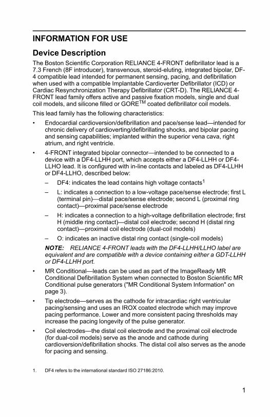
INFORMATION FOR USE
Device DescriptionThe Boston Scientific Corporation RELIANCE 4-FRONT defibrillator lead is a7.3 French (8F introducer), transvenous, steroid-eluting, integrated bipolar, DF-4 compatible lead intended for permanent sensing, pacing, and defibrillationwhen used with a compatible Implantable Cardioverter Defibrillator (ICD) orCardiac Resynchronization Therapy Defibrillator (CRT-D). The RELIANCE 4-FRONT lead family offers active and passive fixation models, single and dualcoil models, and silicone filled or GORETM coated defibrillator coil models.This lead family has the following characteristics:• Endocardial cardioversion/defibrillation and pace/sense lead—intended for
chronic delivery of cardioverting/defibrillating shocks, and bipolar pacingand sensing capabilities; implanted within the superior vena cava, rightatrium, and right ventricle.
• 4-FRONT integrated bipolar connector—intended to be connected to adevice with a DF4-LLHH port, which accepts either a DF4-LLHH or DF4-LLHO lead. It is configured with in-line contacts and labeled as DF4-LLHHor DF4-LLHO, described below:– DF4: indicates the lead contains high voltage contacts1
– L: indicates a connection to a low-voltage pace/sense electrode; first L(terminal pin)—distal pace/sense electrode; second L (proximal ringcontact)—proximal pace/sense electrode
– H: indicates a connection to a high-voltage defibrillation electrode; firstH (middle ring contact)—distal coil electrode; second H (distal ringcontact)—proximal coil electrode (dual-coil models)
– O: indicates an inactive distal ring contact (single-coil models)NOTE: RELIANCE 4-FRONT leads with the DF4-LLHH/LLHO label areequivalent and are compatible with a device containing either a GDT-LLHHor DF4-LLHH port.
• MR Conditional—leads can be used as part of the ImageReady MRConditional Defibrillation System when connected to Boston Scientific MRConditional pulse generators ("MR Conditional System Information" onpage 3).
• Tip electrode—serves as the cathode for intracardiac right ventricularpacing/sensing and uses an IROX coated electrode which may improvepacing performance. Lower and more consistent pacing thresholds mayincrease the pacing longevity of the pulse generator.
• Coil electrodes—the distal coil electrode and the proximal coil electrode(for dual-coil models) serve as the anode and cathode duringcardioversion/defibrillation shocks. The distal coil also serves as the anodefor pacing and sensing.
1. DF4 refers to the international standard ISO 27186:2010.

2
• GORETM expanded polytetrafluoroethylene (ePTFE)-covered coils2 —theePTFE covering prevents tissue ingrowth around and between the coilfilars.
• IROX-coated tip electrode—the tip electrode is coated with IROX (iridiumoxide) to increase the microscopic surface area.
• Steroid-eluting—upon exposure to body fluids, the steroid elutes from thelead to help reduce tissue inflammation response at the distal electrode.The steroid suppresses the inflammatory response believed to causethreshold rises typically associated with implanted pacing electrodes.Lower thresholds are desirable because they can increase pacing safetymargins and reduce pacing energy requirements, potentially increasingpulse generator longevity. The nominal dose and structure of the steroidare listed in the specifications (Table 6 Specifications (Nominal) on page35).
• Radiopaque suture sleeve—the radiopaque suture sleeve is visible underfluoroscopy and is used to secure, immobilize, and protect the lead at thevenous entry site after lead placement. The window feature is designed toaid compression of the sleeve onto the lead during suturing.
• Extendable/Retractable fixation—the extendable/retractable helix designanchors the distal tip electrode to the endocardial surface without supportof trabecular structures, offering various lead placement possibilities forthe tip electrode in the right ventricle. The helix serves as the cathode forendocardial pacing and sensing. The helix is extended and retracted usingan accessory tool.
• Fluoroscopic markers—radiopaque markers near the distal tip can beseen under fluoroscopy. These markers show when the helix is fullyretracted or fully extended.
• Lead body—the isodiametric lead body contains one conductor for pacing/sensing. Dual-coil models have two conductors for defibrillation andsingle-coil models have one conductor for defibrillation. The leadconductors are coated and insulated in separate lumens within the siliconerubber lead body. A second layer of silicone covers the lead body toprovide additional insulation and a uniform body diameter. A layer ofpolyurethane covers the proximal area of the lead body to provideadditional abrasion protection in the implantation pocket. The suturesleeve and terminal boot molding are fabricated from molded siliconerubber.
• Lubricious coating—the lead has a proprietary coating that makes thesurface more lubricious. This reduces both the static and dynamiccoefficients of friction, and makes the lead feel and handle likepolyurethane while providing the reliability of silicone.
• Stylet delivery method—the design consists of an open-lumen conductorcoil to enable lead delivery using a stylet. Refer to the stylet information("Stylets" on page 14).
2. GORE is a trademark of W.L. Gore and Associates.

3
Related InformationInstructions in the lead manual should be used in conjunction with otherresource material, including the applicable pulse generator physician's manualand instructions for use on any implant accessories or tools.For additional reference information, go to www.bostonscientific-elabeling.com.Refer to the ImageReady MR Conditional Defibrillation System MRI TechnicalGuide3 (MRI Technical Guide) for information about MRI scanning.
INTENDED AUDIENCEThis literature is intended for use by professionals trained or experienced indevice implant and/or follow-up procedures.
MR Conditional System InformationThese leads can be used as part of the ImageReady MR ConditionalDefibrillation System when connected to Boston Scientific MR Conditionalpulse generators. Patients with an MR Conditional Defibrillation System maybe eligible to undergo MRI scans if performed when all Conditions of Use, asdefined in the MRI Technical Guide, are met. Components required for MRConditional status include specific models of Boston Scientific pulsegenerators, leads, and accessories; the Programmer/Recorder/Monitor (PRM);and PRM Software Application. For the model numbers of MR Conditionalpulse generators and components, as well as a complete description of theImageReady MR Conditional Defibrillation System, refer to the MRI TechnicalGuide.
Implant-related MRI Conditions of UseThe following subset of the MRI Conditions of Use pertains to implantation, andis included as a guide to ensure implantation of a complete ImageReady MRConditional System. For a full list of Conditions of Use, refer to the MRITechnical Guide. All items on the full list of Conditions of Use must be met inorder for an MRI scan to be considered MR Conditional.• Patient is implanted with the ImageReady MR Conditional Defibrillation
System• No other active or abandoned implanted devices, components, or
accessories present such as lead adaptors, extenders, leads, or pulsegenerators
• Pulse generator implant location restricted to left or right pectoral region• At least six (6) weeks have elapsed since implantation and/or any lead
revision or surgical modification of the MR Conditional DefibrillationSystem
• No evidence of a fractured lead or compromised pulse generator-leadsystem integrity
3. Available at www.bostonscientific-elabeling.com.

4
Indications and UsageThis Boston Scientific lead is indicated for use as follows:• Intended for pacing, rate-sensing, and delivery of cardioversion and
defibrillation shocks when used with a compatible pulse generator
ContraindicationsUse of this Boston Scientific lead is contraindicated for the following patients:• Patients who have a unipolar pacemaker• Patients with a hypersensitivity to a maximum single dose of 1.1 mg
dexamethasone acetate• Patients with mechanical tricuspid heart valves
WARNINGSGeneral• Labeling knowledge. Read this manual thoroughly before implantation to
avoid damage to the pulse generator and/or lead. Such damage can resultin patient injury or death.
• For single patient use only. Do not reuse, reprocess, or resterilize.Reuse, reprocessing, or resterilization may compromise the structuralintegrity of the device and/or lead to device failure which, in turn, mayresult in patient injury, illness, or death. Reuse, reprocessing, orresterilization may also create a risk of contamination of the device and/orcause patient infection or cross-infection, including, but not limited to, thetransmission of infectious disease(s) from one patient to another.Contamination of the device may lead to injury, illness, or death of thepatient.
• Backup defibrillation protection. Always have external defibrillationequipment available during implant and electrophysiologic testing. If notterminated in a timely fashion, an induced ventricular tachyarrhythmia canresult in the patient's death.
• External-source rescue shocks. Do not use any component of the leadsystem to assist in delivery of external-source rescue shocks or extensivetissue damage could occur.
• Resuscitation availability. Ensure that an external defibrillator andmedical personnel skilled in CPR are present during post-implant devicetesting should the patient require external rescue.
• Lead fracture. Lead fracture, dislodgment, abrasion, or an incompleteconnection can cause a periodic or continual loss of pacing or sensing orboth.This could possibly result in arrhythmia nondetection, oversensing of rate,inappropriate delivery of a pulse generator shock, or inadequate delivery ofconverting energy.

5
Handling• Excessive flexing. Although pliable, the lead is not designed to tolerate
excessive flexing, bending, or tension. This could cause structuralweakness, conductor discontinuity, and/or lead dislodgment.
• Do not kink leads. Do not kink, twist, or braid the lead with other leads asdoing so could cause lead insulation abrasion damage or conductordamage.
• Handling the lead without Connector Tool. Use caution handling thelead terminal when the Connector Tool is not present on the lead. Do notdirectly contact the lead terminal with any surgical instruments or electricalconnections such as PSA (alligator) clips, ECG connections, forceps,hemostats, and clamps. This could damage the lead terminal, possiblycompromising the sealing integrity and result in loss of therapy orinappropriate therapy.
• Handling the terminal while tunneling. Do not contact any other portionof the lead terminal, other than the terminal pin, even when the lead cap isin place.
Implant Related• Do not implant in MRI site Zone III. Implant of the system cannot be
performed in an MRI site Zone III (and higher) as defined by the AmericanCollege of Radiology Guidance Document for Safe MR Practices4. Someof the accessories packaged with pulse generators and leads, includingthe torque wrench and stylet wires, are not MR Conditional and should notbe brought into the MRI scanner room, the control room, or the MRI siteZone III or IV areas.
• Electrode placement above midseptum. The safety and efficacy of thetip electrode placement in the right ventricle above midseptum has notbeen clinically established.
• Separate defibrillation electrode. In order to deliver defibrillation therapy,the single-coil models must be implanted with an additional defibrillationelectrode. It is recommended to use the pectorally implanted defibrillatorpulse generator that uses the metallic housing as a defibrillation electrode.
• Use fluoroscopy to verify lead position. Use fluoroscopy to verify thatthe lead tip is directed toward the apex when implanted. Other positionsmay result in lead movement which could affect defibrillation efficacy.
• Only use Connector Tool for electrical connections. For DF4-LLHH orDF4-LLHO leads, only use the Connector Tool for electrical connections topacing system analyzers or similar monitors. Do not attach alligator clipsdirectly to the lead terminal or damage could occur.
• Obtain appropriate electrode position. Take care to obtain appropriateelectrode position. Failure to do so may result in higher defibrillationthresholds or may render the lead unable to defibrillate a patient whosetachyarrhythmia(s) might otherwise be convertible by a pulse generatorsystem.
4. Kanal E, et al., American Journal of Roentgenology 188:1447-74, 2007.

6
• Proper connections.When connecting the lead to the pulse generator, itis very important that proper connections are made. The terminal pin mustbe inserted beyond the setscrew block to enable a proper connection.Visualization of the terminal pin insertion indicator beyond the setscrewblock may be used to confirm that the terminal pin is fully inserted into thepulse generator port. Evaluation of the electrical performance of the leadafter connection to the pulse generator is the final confirmation of fullinsertion. An improper connection could result in loss of therapy orinappropriate therapy.
Post-Implant• Magnetic Resonance Imaging (MRI) exposure. Unless all of the MRI
Conditions of Use (as described in the MRI Technical Guide) are met, MRIscanning of the patient does not meet MR Conditional requirements for theimplanted system, and significant harm to or death of the patient and/ordamage to the implanted system may result.Refer to the MRI Technical Guide for potential adverse events applicablewhen Conditions of Use are met or not met, as well as for a complete list ofMRI-related Warnings and Precautions.
• Diathermy. Do not subject a patient with an implanted pulse generatorand/or lead to diathermy since diathermy may cause fibrillation, burning ofthe myocardium, and irreversible damage to the pulse generator becauseof induced currents.
PRECAUTIONSClinical Considerations• Dexamethasone acetate. It has not been determined whether the
warnings, precautions, or complications usually associated with injectabledexamethasone acetate apply to the use of a low concentration, highlylocalized, controlled-release device. Refer to the Physicians' DeskReference™ 5 for a listing of potentially adverse effects.
Sterilization and Storage• If package is damaged. The blister trays and contents are sterilized with
ethylene oxide gas before final packaging. When the pulse generator and/or lead is received, it is sterile provided the container is intact. If thepackaging is wet, punctured, opened, or otherwise damaged, return thepulse generator and/or lead to Boston Scientific.
• Storage temperature. Store at 25°C (77°F). Excursions are permittedbetween 15°C to 30°C (59°F to 86°F). Transportation spikes are permittedup to 50°C (122°F).
• Use by date. Implant the pulse generator and/or lead before or on theUSE BY date on the package label because this date reflects a validatedshelf life. For example, if the date is January 1, do not implant on or afterJanuary 2.
5. Physicians' Desk Reference is a trademark of Thomson Healthcare Inc.

7
Handling• Do not immerse in fluid. Do not wipe or immerse the tip electrode in fluid.
Such treatment will reduce the amount of steroid available when the leadis implanted.
• Chronic repositioning. Optimum threshold performance might not beachieved if the lead is chronically repositioned because the steroid can bedepleted.
• Protect from surface contamination. The lead uses silicone rubberwhich can attract particulate matter, and therefore, must always beprotected from surface contamination.
• Do not alter or use deformed helix. To promote proper function do notuse a lead with a deformed helix or damaged helix fixation mechanism. Toavoid electrode damage, do not attempt to straighten or realign the helix.Avoid holding or handling the distal tip.
• Lubricants. Do not apply oil-based lubricants to the ePTFE-coveredshocking coils or it may affect electrical performance.
• No mineral oil on lead tip. Mineral oil should never come in contact withthe helix. Mineral oil on the helix may inhibit tissue ingrowth andconduction.
• Ensure suture sleeve position. Ensure the suture sleeve remainsproximal to the venous entry site and near the terminal boot moldingthroughout the procedure until it is time to secure the lead.
Implantation• Evaluate patient for surgery. There may be additional factors regarding
the patient's overall health and medical condition that, while not related todevice function or purpose, could render the patient a poor candidate forimplantation of this system. Cardiac health advocacy groups may havepublished guidelines that may be helpful in conducting this evaluation.
• Lead compatibility. Prior to implantation, confirm the lead-to-pulsegenerator compatibility. Using incompatible leads and pulse generatorscan damage the connector and/or result in potential adverseconsequences, such as undersensing of cardiac activity or failure todeliver necessary therapy.
• Line-powered equipment. Exercise extreme caution if testing leads usingline-powered equipment because leakage current exceeding 10 µA caninduce ventricular fibrillation. Ensure that any line-powered equipment iswithin specifications.
• Do not bend the lead near the lead-header interface. Insert the leadterminal straight into the lead port. Do not bend the lead near the lead-header interface. Improper insertion can cause insulation or connectordamage.
• Vein pick. The vein pick is not intended either for puncturing the vein or fordissecting tissue during a cutdown procedure. Be sure that the vein pickdoes not puncture the insulation of the lead. This could prevent properlead function.

8
• Do not bend lead with stylet in place. Do not bend the lead with a styletin place. Bending the lead could damage the conductor and insulationmaterial.
• Tools applied to distal end. Do not apply tools to the distal end of thelead because lead damage could occur. Avoid holding or handling thedistal tip of the lead.
• Curving the stylet. Do not use a sharp object to curve the distal end of astylet. Do not curve a stylet while it is in the lead. If a curved stylet ispreferred, gently curve a straight stylet before inserting it into the lead toavoid damage to the stylet and lead.
• Connector Tool handling technique. The helix can becomeunintentionally extended if the Connector Tool fixation knob is engaged onthe terminal pin and the lead body is rotated counterclockwise while thefixation knob is held stationary.
• Do not overextend or over-retract the helix. Do not overextend or over-retract the helix. The lead can be damaged if you continue to rotate theterminal pin once the helix is fully extended or retracted.
• Terminal pin maximum number of turns. Do not rotate the terminal pinclockwise or counterclockwise more than the number of turns indicated inthe specifications (Table 6 Specifications (Nominal) on page 35).Continuing to rotate the terminal pin once the helix is fully extended orretracted (as indicated by fluoroscopy) can damage the lead, cause leaddislodgment, tissue trauma, and/or cause acute pacing threshold to rise.
• Ensure helix is retracted. Do not insert a lead into the vein when the helixis extended, as this may cause damage to the tissue and/or lead. Prior toinsertion in the vein, rotate the terminal pin counterclockwise to retract thehelix into the distal lead tip.
• Helix retraction during implant. Do not continue to use the lead if thehelix cannot be retracted during implant. Continuous counterclockwiserotation of the lead body during lead removal is necessary to avoidinadvertent tissue trauma and accidental fixation, and to release theelectrode helix if tissue snagging has occurred.
• Do not implant lead under clavicle.When attempting to implant the leadvia a subclavian puncture, do not introduce the lead under the medial one-third region of the clavicle. Damage or chronic dislodgment to the lead ispossible if the lead is implanted in this manner. If implantation via thesubclavian vein is desired, the lead must enter the subclavian vein nearthe lateral border of the first rib to avoid entrapment by the subclaviusmuscle or ligamentous structures associated with the narrowcostoclavicular region. It has been established in the literature that leadfracture can be caused by lead entrapment in such soft tissue structuresas the subclavius muscle, costocoracoid ligament, or the costoclavicularligament.6
6. Magney JE, et al. Anatomical mechanisms explaining damage to pacemaker leads, defibrillatorleads, and failure of central venous catheters adjacent to the sternoclavicular joint. PACE.1993;16:445–457.

9
• Electrode distance from pacemaker. For patients with bipolar cardiacpacemakers, the lead pace/sense electrode (the tip electrode and distalcoil electrode) should be placed as far as possible from the pacemakerelectrodes to avoid cross-sensing between the defibrillator pulse generatorand the pacemaker.
• Thin RV free wall. If the patient has a thin RV free wall, another fixationsite should be considered.
• Lead dislodgment. Should dislodgment occur, immediate medical care isrequired to resolve the electrode position and minimize endocardialtrauma.
• Prevent dislodgment. To prevent dislodgment, avoid rotating the terminalpin after fixating the lead.
• Compatible delivery tools. Only use compatible delivery tools to deliverthe lead because using incompatible delivery tools may cause leaddamage or patient injury.
• Inaccurate rate counting. R-wave amplitudes of less than therecommended value can cause inaccurate rate counting in the chronicstate, possibly resulting in failure to sense a tachyarrhythmia ormisdiagnosis of a normal rhythm as abnormal. Signal durations thatexceed the programmed refractory period of the pulse generator cancause inaccurate rate sensing which may cause inappropriate behavior.
• Avoid tight stricture.When ligating the vein, avoid stricture that is tootight. A tight stricture might damage the insulation or sever the vein. Avoiddislodging the distal tip during the anchoring procedure.
• Do not suture directly over lead. Do not suture directly over the leadbody, as this may cause structural damage. Use the suture sleeve tosecure the lead proximal to the venous entry site to prevent leadmovement.
• Use caution to remove suture sleeve. Avoid removing or cutting thesuture sleeve from the lead. If removal of the suture sleeve is necessary,use caution as lead damage can occur.
• Use of multiple suture sleeves has not been evaluated. Use of multiplesuture sleeves has not been evaluated and is not recommended.
• Tunnel the lead. Tunnel the lead from the chest area to the pulsegenerator implant site. Do not tunnel the lead from the pulse generatorimplant site to the chest area because this can damage the electrodes orlead body or both by permanently stretching the lead.
• Excessive tension on lead.When tunneling the lead, take precautionsnot to place excessive tension on the lead. This can cause either structuralweakness and/or conductor discontinuity.
• Re-evaluate the lead after tunneling. After tunneling, re-evaluate thelead to verify that no significant change in signals or damage to the leadhas occurred during the tunneling procedure. Reattach the Connector Tooland repeat the steps in Evaluating Lead Performance.

10
Hospital and Medical Environments• Electrocautery. Electrocautery may induce ventricular arrhythmias and/or
fibrillation, and may cause asynchronous pacing, inhibited pacing,inappropriate shocks, and/or a reduction in pulse generator pacing outputpossibly leading to loss of capture.If electrocautery is medically necessary, observe the following to minimizerisk to the lead. Also, refer to pulse generator labeling for deviceprogramming recommendations and additional information aboutminimizing risk to the patient and system.• Avoid direct contact between the electrocautery equipment and the
pulse generator or leads.• Keep the path of the electrical current as far away as possible from the
pulse generator and leads.• If electrocautery is performed on tissue near the device or leads,
monitor pre- and post- measurements for sensing and pacingthresholds and impedances to determine the integrity and stability ofthe system.
• Use short, intermittent, and irregular bursts at the lowest feasibleenergy levels.
• Use a bipolar electrocautery system where possible.• Radio frequency (RF) ablation. RF ablation may induce ventricular
arrhythmias and/or fibrillation, and may cause asynchronous pacing,inhibition of pacing, inappropriate shocks, and/or a reduction in pulsegenerator pacing output possibly leading to loss of capture. RF ablationmay also cause ventricular pacing up to the Maximum Tracking Rate(MTR) and/or changes in pacing thresholds. Additionally, exercise cautionwhen performing any other type of cardiac ablation procedure in patientswith implanted devices.If RF ablation is medically necessary, observe the following to minimizerisk to the lead. Also, refer to pulse generator labeling for deviceprogramming recommendations and additional information aboutminimizing risk to the patient and system.• Avoid direct contact between the ablation catheter and the pulse
generator and leads. RF ablation close to the lead electrode maydamage the lead-tissue interface.
• Keep the path of the electrical current as far away as possible from thepulse generator and leads.
• If RF ablation is performed on tissue near the device or leads, monitorpre- and post-measurements for sensing and pacing thresholds andimpedances to determine the integrity and stability of the system.
• Central line guidewire insertion. Use caution when inserting guidewiresfor placement of other types of central venous catheter systems such asPIC lines or Hickman catheters in locations where pulse generator leadsmay be encountered. Insertion of such guidewires into veins containingleads could result in the leads being damaged or dislodged.

11
Follow-up Testing• Unsuccessful conversion testing. Following an unsuccessful high-
energy shock, miscounting of cardiac rate, delayed detection, ornondetection due to low amplitude VF signals, it may be necessary toreposition the lead.
• Lead performance in chronic state. For some patients, leadperformance at implant may not predict performance in the chronic state.Therefore, it is strongly recommended that post-implant follow-up EPtesting be performed should any change occur in lead performance. Thistesting should include at least one arrhythmia induction/conversion test ofventricular fibrillation.
Potential Adverse EventsBased on the literature and on pulse generator and/or lead implant experience,the following list includes the possible adverse events associated withimplantation of products described in this literature:• Air embolism• Allergic reaction• Arterial damage with subsequent stenosis• Bleeding• Bradycardia• Breakage/failure of the implant instruments• Cardiac perforation• Cardiac tamponade• Chronic nerve damage• Component failure• Conductor coil fracture• Death• Electrolyte imbalance/dehydration• Elevated thresholds• Erosion• Excessive fibrotic tissue growth• Extracardiac stimulation (muscle/nerve stimulation)• Fluid accumulation• Foreign body rejection phenomena• Formation of hematomas or seromas• Heart block• Hemorrhage• Hemothorax• Inability to defibrillate or pace

12
• Inappropriate therapy (e.g., shocks and antitachycardia pacing [ATP]where applicable, pacing)
• Incisional pain• Incomplete lead connection with pulse generator• Infection including endocarditis• Lead dislodgment• Lead fracture• Lead insulation breakage or abrasion• Lead tip deformation and/or breakage• Local tissue reaction• Low amplitude VF signals• Malignancy or skin burn due to fluoroscopic radiation• Myocardial trauma (e.g., irritability, injury, tissue damage)• Myopotential sensing• Oversensing/undersensing• Pericardial rub, effusion• Pneumothorax• Post-shock rhythm disturbances• Pulse generator and/or lead migration• Shunting current during defibrillation with internal or external paddles• Syncope• Tachyarrhythmias, which include acceleration of arrhythmias and early,
recurrent atrial fibrillation• Thrombosis/thromboemboli• Valve damage• Vasovagal response• Venous occlusion• Venous trauma (e.g., perforation, dissection, erosion)For a list of potential adverse events associated with MRI scanning, refer to theImageReady MR Conditional Defibrillation System MRI Technical Guide.
Warranty InformationA limited warranty certificate for the lead is available. For a copy, contactBoston Scientific using the information on the back cover.
PRE- IMPLANT INFORMATIONProper surgical procedures and techniques are the responsibility of the medicalprofessional. The described implant procedures are furnished only for

13
informational purposes. Each physician must apply the information in theseinstructions according to professional medical training and experience.The lead is designed, sold, and intended for use only as indicated.A major consideration choosing this lead family is that it does not require athoracotomy. The physician should weigh its advantages against the patient'sability to withstand additional electrophysiology (EP) testing (arrhythmiainduction and conversion test), and a possible thoracotomy, should the leadsystem prove ineffective.Various factors, such as disease state or drug therapy, may necessitaterepositioning of the defibrillation leads or substitution of one lead system foranother in order to facilitate arrhythmia conversion. In some cases, reliablearrhythmia conversion may not be obtained with any leads at the availabledefibrillation or pulse generator defibrillation energy levels.Bipolar pacemakers may be used with this lead family and pulse generator aslong as the pacemaker and pulse generator do not interact, causing pulsegenerator nondetection or false detection. Refer to the pulse generatorphysician's manual for information about minimizing pacemaker interaction.
Surgical PreparationConsider the following prior to the implantation procedure:• Instrumentation for cardiac monitoring, imaging (fluoroscopy), external
defibrillation, and lead signal measurements must be available duringimplant.
• Always isolate the patient from potentially hazardous leakage currentwhen using electrical instrumentation.
• Sterile duplicates of all implantable items should be available for use ifaccidental damage or contamination occurs.
Items IncludedThe following items are packaged with the lead:
Vein pick
Stylets
Connector Tool
Literature
AccessoriesSeparately packaged lead accessories are available in addition to thosepackaged with the lead.
Vein PickThe vein pick is a disposable plastic device designed to assist with insertioninto a vein during a cutdown procedure.

14
Radiopaque Suture SleeveThe radiopaque suture sleeve is an adjustable, tubular reinforcement that isvisible under fluoroscopy. It is positioned over the outer lead insulation and isdesigned to secure and protect the lead at the venous entry site after leadplacement. Using a suture sleeve reduces the possibility of structural damagecaused by suturing directly over the lead body. To move the suture sleeve,gently pinch and slide it over the lead until it is in the desired position. Thewindow feature is designed to aid compression of the sleeve onto the leadduring suturing.NOTE: A radiopaque suture sleeve is pre-loaded on the lead and is alsoavailable in a slit form as an accessory (Model 6403). The accessory slit suturesleeve is intended to be used as a replacement for the pre-loaded suturesleeve in the event of damage or loss.
CAUTION: Use of multiple suture sleeves has not been evaluated and is notrecommended.
StyletsStylets aid in positioning the lead. Ensure you use the length appropriate to thelead. Stylets of various degrees of stiffness are available depending on implanttechnique and patient anatomy.
Table 1. Stylet stiffness and knob color
Stylet Stiffness a Knob Color
Soft Green
Firm White
a. The stylet stiffness is imprinted on the knob.
Table 2. Stylet length and cap color
Stylet Length (cm) (Imprinted on cap ofthe knob)
Cap Color
59 Yellow
64 Green
70 Black
Lead CapThe lead cap may be used to isolate or cap the lead terminal that is not insertedin the pulse generator. Place a suture around the lead cap groove to secure thelead cap to the lead terminal. Use an appropriate cap for lead.NOTE: The lead cap (Model 7007) is available as an accessory.

15
EZ-4 Connector ToolThe EZ-4 Connector Tool is packaged with the lead and when attached to thelead performs the following functions:• Protects the lead terminal during the implant procedure.• Provides a safe and secure connection between PSA patient cables and
the lead terminal.• Guides the stylet into the lead through the stylet funnel.• Rotates the terminal pin clockwise or counterclockwise to extend or retract
the helix.
[1] Fixation knob (disengaged) [2] Stylet funnel [3] Rotation mark [4] Terminal boot levers [5] Indicatorarrows [6] Anode (+) spring contact [7] Cathode (-) spring contact
Figure 1. Connector Tool
IMPLANTATIONNOTE: Select the appropriate lead length for a given patient. It is important toselect a lead that is long enough to avoid any sharp angles or kinks and toallow for a gentle curve of excess lead in the pocket. Typically, a minimum of 5to 10 cm of excess lead is sufficient to achieve this configuration in the pocket.The suture sleeve should be secured to the lead as close to the vascularaccess site as clinically appropriate as described in "Securing the Lead" onpage 29. Proper placement of the suture sleeve aids in maintaining thisconfiguration in the pocket.NOTE: Refer to the MRI Technical Guide for considerations affecting choiceand implant of leads for use as part of an MR Conditional system.Use ofBoston Scientific MR Conditional pulse generators and leads is required for animplanted system to be considered MR Conditional. Refer to the MRI TechnicalGuide for model numbers of pulse generators, leads, accessories, and othersystem components needed to satisfy the Conditions of Use for MRConditional scanning.NOTE: Other implanted devices or patient conditions may cause a patient tobe ineligible for an MRI scan, independent of the status of the patient’sImageReady MR Conditional System.

16
Attaching the Connector Tool to the LeadFollow the steps below to attach the Connector Tool to the lead.1. Slide the Connector Tool onto the proximal end of the lead (Figure 2 Lead
fully inserted into Connector Tool on page 16).2. While squeezing the EZ-4 Connector Tool wings, push the lead into the
tool until the white boot aligns with the arrows on the tool to ensure thelead is fully inserted.
3. Release the terminal boot levers to secure the Connector Tool to theproximal end of the lead.
[1] Indicator arrows [2] Terminal boot molding [3] Terminal molding
Figure 2. Lead fully inserted into Connector Tool
Inserting the StyletFollow the steps below to insert a stylet.1. Remove any preinserted stylet before inserting a different one.2. Select a stylet according to the function and to the preferred firmness. If
desired, gently curve the stylet with any sterile, smooth-surfacedinstrument (e.g., 10-cc or 12-cc syringe barrel) (Figure 3 Curve the styleton page 17). A gentle curve is less likely to straighten than a sharp bendas the stylet is used.
CAUTION: Do not use a sharp object to curve the distal end of a stylet. Donot curve a stylet while it is in the lead. If a curved stylet is preferred, gentlycurve a straight stylet before inserting it into the lead to avoid damage to thestylet and lead.

17
Figure 3. Curve the stylet
3. Carefully insert the stylet through the funnel of the Connector Tool andterminal pin.
NOTE: To optimize insertion into the lead, do not allow body fluids to come incontact with the stylet.4. Ensure the stylet is fully inserted in the lead prior to inserting the lead into
the vein.CAUTION: Do not bend the lead with a stylet in place. Bending the lead coulddamage the conductor and insulation material.
Handling the Fixation HelixBefore implanting the lead, verify the mechanical functioning of the lead.1. Grasp the Connector Tool and the terminal boot molding. To engage the
fixation knob on the terminal pin, push the fixation knob toward theConnector Tool body to close the gap. Rotate the fixation knob clockwiseto extend the helix or counterclockwise to retract it. Visually observe thehelix extending and retracting (Figure 4 Connector Tool fixation knobengaged on page 17).
Figure 4. Connector Tool fixation knob engaged
NOTE: The expected and maximum number of turns to extend or retractthe helix are provided in the specifications (Table 6 Specifications(Nominal) on page 35). Any curves introduced into the stylet couldincrease the number of turns needed to extend or retract the helix.
18
CAUTION: Do not overextend or over-retract the helix. The lead can bedamaged if you continue to rotate the terminal pin once the helix is fullyextended or retracted.
CAUTION: If the helix cannot be extended or retracted, do not use thelead.CAUTION: To promote proper function do not use a lead with adeformed helix or damaged helix fixation mechanism. To avoid electrodedamage, do not attempt to straighten or realign the helix. Avoid holding orhandling the distal tip.
2. Ensure the helix is retracted into the distal lead tip prior to inserting thelead into the vein.CAUTION: Do not insert a lead into the vein when the helix is extended,as this may cause damage to the tissue and/or lead. Prior to insertion inthe vein, rotate the terminal pin counterclockwise to retract the helix intothe distal lead tip.
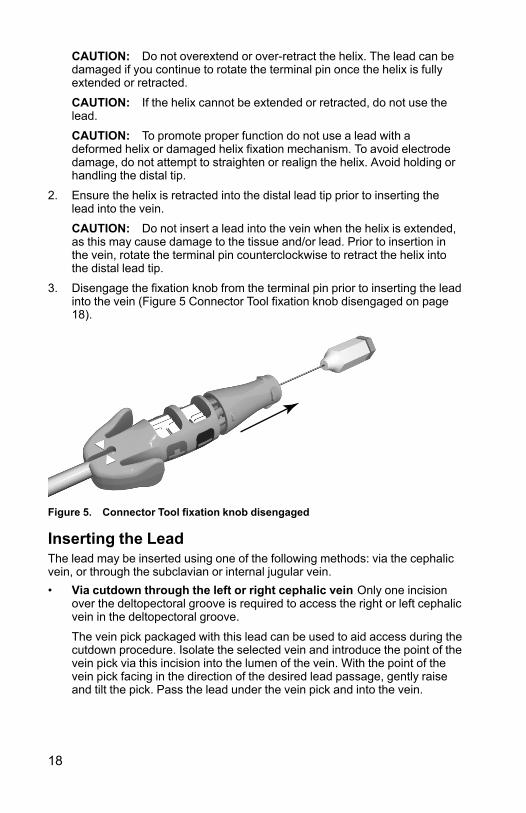
3. Disengage the fixation knob from the terminal pin prior to inserting the leadinto the vein (Figure 5 Connector Tool fixation knob disengaged on page18).
Figure 5. Connector Tool fixation knob disengaged
Inserting the LeadThe lead may be inserted using one of the following methods: via the cephalicvein, or through the subclavian or internal jugular vein.• Via cutdown through the left or right cephalic vein Only one incision
over the deltopectoral groove is required to access the right or left cephalicvein in the deltopectoral groove.
The vein pick packaged with this lead can be used to aid access during thecutdown procedure. Isolate the selected vein and introduce the point of thevein pick via this incision into the lumen of the vein. With the point of thevein pick facing in the direction of the desired lead passage, gently raiseand tilt the pick. Pass the lead under the vein pick and into the vein.

19
CAUTION: The vein pick is not intended either for puncturing the vein orfor dissecting tissue during a cutdown procedure. Be sure that the veinpick does not puncture the insulation of the lead. This could prevent properlead function.
Figure 6. Using the vein pick
• Percutaneously or via cutdown through the subclavian vein Asubclavian introducer set is available for use during percutaneous leadinsertion. Refer to the specifications for the recommended introducer size.
CAUTION: The helix can become unintentionally extended if theConnector Tool fixation knob is engaged on the terminal pin and the leadbody is rotated counterclockwise while the fixation knob is held stationary.
CAUTION: When attempting to implant the lead via a subclavianpuncture, do not introduce the lead under the medial one-third region ofthe clavicle. Damage or chronic dislodgment to the lead is possible if thelead is implanted in this manner. If implantation via the subclavian vein isdesired, the lead must enter the subclavian vein near the lateral border ofthe first rib to avoid entrapment by the subclavius muscle or ligamentousstructures associated with the narrow costoclavicular region. It has beenestablished in the literature that lead fracture can be caused by leadentrapment in such soft tissue structures as the subclavius muscle,costocoracoid ligament, or the costoclavicular ligament.7
Leads placed by percutaneous subclavian venipuncture should enter thesubclavian vein, where it passes over the first rib (rather than moremedially), to avoid entrapment by the subclavius muscle or ligamentousstructures associated with the narrow costoclavicular region.8 It isrecommended to introduce the lead into the subclavian vein near thelateral border of the first rib.The syringe should be positioned directly above and parallel to the axillaryvein to reduce the chance that the needle will contact the axillary orsubclavian arteries or the brachial plexus. Use of fluoroscopy is helpful inlocating the first rib and in guiding the needle.
7. Magney JE, et al. Anatomical mechanisms explaining damage to pacemaker leads, defibrillatorleads, and failure of central venous catheters adjacent to the sternoclavicular joint. PACE.1993;16:445–457.
8. Magney JE, et al. A new approach to percutaneous subclavian venipuncture to avoid leadfracture or central venous catheter occlusion. PACE. 1993;16:2133–2142.

20
The steps below explain how to identify the skin entry point and define thecourse of the needle toward the subclavian vein where it crosses the firstrib.
1. Identify points St (sternal angle) and Cp (coracoid process) (Figure 7Entry point for percutaneous subclavian venipuncture on page 20).
[1] Subclavius muscle [2] Costocoracoid ligament [3] Costoclavicular ligament
Figure 7. Entry point for percutaneous subclavian venipuncture
2. Visually draw a line between St and Cp, and divide the segment intothirds. The needle should pierce the skin at the junction of the middleand lateral thirds, directly above the axillary vein (point Ax).
3. Place an index finger on the clavicle at the junction of the medial andmiddle thirds (point V), beneath which point the subclavian veinshould be located.
4. Press a thumb against the index finger and project 1–2 centimetersbelow the clavicle to shield the subclavius muscle from the needle(when hypertrophy of the pectoralis muscle is apparent, the thumbshould project about 2 centimeters below the clavicle because thesubclavius muscle should be hypertrophied as well) (Figure 8Location of thumb and needle entry on page 21).

21
Figure 8. Location of thumb and needle entry
5. Feel with the thumb the pressure from the passage of the needlethrough the superficial fascia; direct the needle deep into the tissuestoward the subclavian vein and the underlying first rib. Fluoroscopicguidance will reduce the chance that the needle would pass below thefirst rib and into the lung.
Positioning Lead in Right VentricleCorrect functioning of the lead depends on appropriate placement of theelectrodes. Follow the instructions below to position the lead.1. Ensure the helix is retracted.
CAUTION: Do not insert a lead into the vein when the helix is extended, asthis may cause damage to the tissue and/or lead. Prior to insertion in the vein,rotate the terminal pin counterclockwise to retract the helix into the distal leadtip.2. Partially withdraw the stylet during lead positioning to minimize tip
stiffness.
NOTE: A curved stylet may enhance maneuverability.3. Under fluoroscopy and with a stylet in the lead, advance the lead as far as
possible so the tip electrode is in healthy myocardium in the apex of theright ventricle.
WARNING: Use fluoroscopy to verify that the lead tip is directed toward theapex when implanted. Other positions may result in lead movement whichcould affect defibrillation efficacy.WARNING: Take care to obtain appropriate electrode position. Failure to doso may result in higher defibrillation thresholds or may render the lead unableto defibrillate a patient whose tachyarrhythmia(s) might otherwise beconvertible by a pulse generator system.

22
[1] Proximal coil electrode [2] Distal coil electrode
Figure 9. Suggested electrode position within the heart
4. Verify under fluoroscopy that the distal coil electrode is situated in the rightventricle, below the tricuspid valve, and that the proximal coil electrode (indual-coil models) is situated in the superior vena cava and high rightatrium.
CAUTION: For patients with bipolar cardiac pacemakers, the lead pace/sense electrode (the tip electrode and distal coil electrode) should be placed asfar as possible from the pacemaker electrodes to avoid cross-sensing betweenthe defibrillator pulse generator and the pacemaker.5. Ensure sufficient contact between the lead tip and the fixation site.
CAUTION: If the patient has a thin RV free wall, another fixation site shouldbe considered.WARNING: In order to deliver defibrillation therapy, the single-coil modelsmust be implanted with an additional defibrillation electrode. It is recommendedto use the pectorally implanted defibrillator pulse generator that uses themetallic housing as a defibrillation electrode.
Lead FixationThe lead helix is electrically conductive to allow mapping (measuring pacingand sensing thresholds) of potential electrode positions without extending thehelix into the tissue. Mapping prior to lead fixation is recommended as it canreduce the potential need for multiple lead positionings.

23
When data are acceptable and the correct position has been achieved,proceed with lead fixation.NOTE: Maintain the stylet in a partially retracted position when placing thelead in the RV apex or RV free wall to minimize tip stiffness.1. Remove the pacing system analyzer (PSA) alligator clips from the
Connector Tool.2. Apply adequate pressure to the lead body to position the distal electrode
against the desired fixation site.3. Grasp the Connector Tool and the terminal boot molding. Engage the
fixation knob on the terminal pin and maintain alignment of the terminalboot molding with the indicator arrows.
4. Rotate the engaged fixation knob clockwise to extend and affix the distalelectrode helix into the heart wall. Watch or feel the rotation mark to countthe number of turns.
NOTE: Stylet curvature, extended implant time, and repositioning the leadmultiple times may increase the number of turns to extend or retract the helix.
CAUTION: Do not rotate the terminal pin clockwise or counterclockwise morethan the number of turns indicated in the specifications (Table 6 Specifications(Nominal) on page 35). Continuing to rotate the terminal pin once the helix isfully extended or retracted (as indicated by fluoroscopy) can damage the lead,cause lead dislodgment, tissue trauma, and/or cause acute pacing threshold torise.5. View the radiopaque markers under fluoroscopy to identify when the
fixation helix is fully extended. Full extension is achieved when theradiopaque markers are joined and the fixation helix is extended outsidethe distal fluoroscopy markers (Table 3 Fluoroscopic view of helixelectrode on page 23).
Table 3. Fluoroscopic view of helix electrode
Fully Retracted Fully Extended
6. Once the lead is affixed in the desired location, hold the proximal end ofthe lead and Connector Tool, and disengage the fixation knob from theterminal pin.NOTE: Any torque stored within the lead is released by disengaging thefixation knob after helix extension or retraction.

24
Checking for Lead StabilityFollow these steps to check lead stability:1. After fixation, partially withdraw the stylet 20 to 25 cm.
CAUTION: To prevent dislodgment, avoid rotating the terminal pin afterfixating the lead.2. Check the stability of the lead using fluoroscopy. Do not tug on the lead. If
possible, have the patient cough or take several deep breaths.3. When the electrode position is satisfactory, withdraw the stylet beyond the
right atrium.CAUTION: Should dislodgment occur, immediate medical care is required toresolve the electrode position and minimize endocardial trauma.
Repositioning the LeadIf the lead needs repositioning, follow these steps.1. Rotate the terminal pin with the engaged fixation knob counterclockwise to
retract the helix.2. View the radiopaque markers under fluoroscopy to verify that the helix is
retracted and disengaged completely from the heart wall before attemptingto reposition the lead.
CAUTION: Do not rotate the terminal pin clockwise or counterclockwise morethan the number of turns indicated in the specifications (Table 6 Specifications(Nominal) on page 35). Continuing to rotate the terminal pin once the helix isfully extended or retracted (as indicated by fluoroscopy) can damage the lead,cause lead dislodgment, tissue trauma, and/or cause acute pacing threshold torise.CAUTION: Do not continue to use the lead if the helix cannot be retractedduring implant. Continuous counterclockwise rotation of the lead body duringlead removal is necessary to avoid inadvertent tissue trauma and accidentalfixation, and to release the electrode helix if tissue snagging has occurred.3. Reaffix the electrode using the previous procedures for handling,
positioning, and checking for lead stability.
CAUTION: The helix can become unintentionally extended if the ConnectorTool fixation knob is engaged on the terminal pin and the lead body is rotatedcounterclockwise while the fixation knob is held stationary.
Evaluating Lead PerformanceVerify electrical performance of the lead using a pacing system analyzer (PSA)before attaching the lead to the pulse generator.1. Connect the lead to the PSA.
• Attach the PSA cable alligator clips to the Connector Tool cathode (–)spring contact and anode spring contact (+). Use of the ConnectorTool will protect the terminal pin from alligator clip damage andprevent bridging between terminal contacts. Fully engage the alligator

25
clips on the cathode and anode spring contacts to avoid inaccuratebaseline measurements (Figure 10 PSA clips attached to ConnectorTool on page 25).WARNING: For DF4-LLHH or DF4-LLHO leads, only use theConnector Tool for electrical connections to pacing system analyzersor similar monitors. Do not attach alligator clips directly to the leadterminal or damage could occur.
Figure 10. PSA clips attached to Connector Tool
2. Perform the measurements as indicated in the table.Table 4. Recommended threshold and sensing measurements
Signal Type Amplitude Duration PacingThresholda
Impedance
Pacing/Sensing
≥ 5 mV < 100 ms ≤ 1.5 V 300–1200 Ω
Defibrillation ≥ 1 mV < 150 ms NA 20–125 Ω
a. Pulse width setting 0.5 ms.
• Pulse generator measurements may not exactly correlate to the PSAmeasurements due to signal filtering. Baseline measurements shouldfall within the recommended values indicated in the table.
• Lower intrinsic potentials, longer durations, and higher pacingthreshold may indicate lead placement in ischemic or scarred tissue.Because signal quality may deteriorate, reposition the lead ifnecessary to obtain a signal with the largest possible amplitude,shortest duration, and lowest pacing threshold.
• Changes in the defibrillation electrode surface area, such as changingfrom a TRIAD configuration to a single coil configuration, can affectthe impedance measurements. Baseline defibrillation impedancemeasurements should fall within the recommended values indicatedin the table.CAUTION: R-wave amplitudes of less than the recommended valuecan cause inaccurate rate counting in the chronic state, possibly

26
resulting in failure to sense a tachyarrhythmia or misdiagnosis of anormal rhythm as abnormal. Signal durations that exceed theprogrammed refractory period of the pulse generator can causeinaccurate rate sensing which may cause inappropriate behavior.
3. If measurements do not conform to the values in the table, perform thefollowing steps:• Remove the PSA alligator clips from the Connector Tool.• Reinsert the stylet and reposition the lead using the procedures
previously discussed and repeat the lead evaluation process.• If testing results are unsatisfactory, further lead system repositioning
or replacement may be required.Consider the following information:
• Low stimulation threshold readings indicate a desirable safety margin,since stimulation threshold may rise after implantation.
• Initial electrical measurements may deviate from recommendationsbecause of acute cellular trauma. If this occurs, wait approximately 10minutes and repeat testing. Values may be dependent on patient-specific factors such as tissue condition, electrolyte balance, and druginteractions.
• Amplitude and duration measurements are not inclusive of current ofinjury and are taken during the patient's normal baseline rhythm.
• Over-rotation of the terminal pin may increase local tissue trauma andcause temporarily high voltage thresholds.

27
4. Test for diaphragmatic stimulation by pacing the lead at a high voltageoutput, using professional medical judgment to select the output voltage.Adjust the lead configurations and lead position as necessary. PSA testingat higher outputs may also be considered to better characterize stimulationmargins. Testing should be conducted for all lead placements.
5. Once acceptable measurements are obtained, remove the pacing systemanalyzer connections, and remove the stylet.
6. Pinch the terminal boot levers and slide the Connector Tool off of theproximal end of the lead.
7. If additional repositioning and/or PSA measurements are necessary,reattach the Connector Tool, ensuring the lead is fully inserted, and repeatthe evaluation process.
Connection to a Pulse GeneratorConsult the applicable pulse generator physician's manual for moreinstructions for connecting lead terminals to the pulse generator.1. Verify the stylet and any terminal pin accessories are removed prior to
connecting the lead to the pulse generator.2. Grasp the lead body in the labeled area distal to the terminal ring contacts
and fully insert the lead terminal into the pulse generator port until theterminal pin is visible beyond the setscrew block. If the terminal pin isdifficult to insert, verify the setscrew is completely retracted. Visualizationof the terminal pin insertion indicator beyond the setscrew block may beused to confirm that the terminal pin is fully inserted into the pulsegenerator port.
NOTE: If necessary, lubricate the entire lead terminal (area shown in Figure11 DF4 Lead Terminal on page 27) sparingly with sterile water or sterile mineraloil to make insertion easier.
Figure 11. DF4 Lead Terminal
3. Apply gentle traction to the lead by grasping the labeled area of the leadbody to ensure a secure connection.
CAUTION: Insert the lead terminal straight into the lead port. Do not bend thelead near the lead-header interface. Improper insertion can cause insulation orconnector damage.WARNING: When connecting the lead to the pulse generator, it is veryimportant that proper connections are made. The terminal pin must be insertedbeyond the setscrew block to enable a proper connection. Visualization of theterminal pin insertion indicator beyond the setscrew block may be used toconfirm that the terminal pin is fully inserted into the pulse generator port.Evaluation of the electrical performance of the lead after connection to thepulse generator is the final confirmation of full insertion. An improperconnection could result in loss of therapy or inappropriate therapy.

28
NOTE: If the lead terminal will not be connected to a pulse generator at thetime of lead implantation, you must cap the connector before closing the pocketincision. The lead cap is designed specifically for this purpose. Place a suturearound the lead cap to keep it in place.4. Giving consideration to patient anatomy and pulse generator size and
motion, gently coil any excess lead and place adjacent to the pulsegenerator. It is important to place the lead into the pocket in a manner thatminimizes lead tension, twisting, sharp angles, and/or pressure.
Electrical Performance1. Evaluate the lead signals using the pulse generator.2. Place the pulse generator into the implant pocket as indicated in the pulse
generator physician's manual. Also refer to the instructions in this manual("Connection to a Pulse Generator" on page 27).
3. Evaluate the lead signals by viewing the real-time EGM. Consider thefollowing:• The signal from the implanted lead should be continuous and without
artifact, similar to a body-surface ECG.• A discontinuous signal may indicate a lead fracture or an otherwise
damaged lead, or an insulation break that would necessitate leadreplacement.
• Inadequate signals may result either in a failure of the pulse generatorsystem to detect an arrhythmia or in an unnecessary delivery oftherapy.
4. Test for diaphragmatic stimulation by pacing the lead at a high voltageoutput, using professional medical judgment to select the output voltage.Adjust the lead configurations and lead position as necessary. Testingshould be conducted for all lead placements.
Conversion TestingAfter obtaining acceptable signals, use the pulse generator to demonstrateability to reliably convert ventricular fibrillation (VF) and, when appropriate tothe patient, ventricular tachycardias. This testing involves inducing arrhythmiasand shocking the patient with high-voltage pulses delivered from the pulsegenerator, through the defibrillation electrodes of the lead, to the heart.Baseline measurements should fall within the recommended values listed inthe Recommended threshold and sensing measurements table (Table 4Recommended threshold and sensing measurements on page 25).CAUTION: Following an unsuccessful high-energy shock, miscounting ofcardiac rate, delayed detection, or nondetection due to low amplitude VFsignals, it may be necessary to reposition the lead.WARNING: Always have external defibrillation equipment available duringimplant and electrophysiologic testing. If not terminated in a timely fashion, aninduced ventricular tachyarrhythmia can result in the patient's death.

29
Reliable conversion of VF should be demonstrated at an energy level less thanthe maximum energy setting of the pulse generator. Consider the following:• It is recommended that multiple induction conversion tests of VF be
performed to determine conversion reliability and the patient’s defibrillationthreshold (DFT).
• It is a matter of clinical judgment as to what constitutes a demonstration ofreliable conversion. Since the result of any single test is subject tostatistical variation, a one-time conversion of a rhythm disturbance at aparticular energy level does not necessarily predict future conversionenergy levels.
• Refer to the applicable pulse generator physician's manual for conversiontesting guidelines.
• Weigh the probability of reliable conversion in the ambulatory state againstthe availability of the pulse generator energy settings and the patient’sability to tolerate multiple arrhythmia inductions.
• If a patient’s arrhythmia(s) cannot be reliably converted with the lead,supplementary implantation of an alternate lead system will requireadditional conversion testing.WARNING: Do not use any component of the lead system to assist indelivery of external-source rescue shocks or extensive tissue damagecould occur.
• The decision to implant any pulse generator lead system in anyconfiguration should be based on demonstration of adequate safetymargins at the programmed shock energy as determined by DFTandcardioversion energy requirement (CER) testing. Refer to the applicablepulse generator physician’s manual for DFTand CER testingrequirements.
• Clinical study indicates that a programmed safety margin of 9–10 J abovethe patient’s DFT was used in the majority of patients. If a 9–10 J safetymargin cannot be obtained, consider placing an alternative defibrillationlead system.NOTE: If, after prolonged and repeated inductions of VF, a thoracotomyis to be performed, consider performing it at a later date.
Securing the LeadAfter the electrodes are satisfactorily positioned, use the suture sleeve tosecure the lead to achieve permanent hemostasis and lead stabilization.Suture sleeve tie-down techniques can vary with the lead insertion techniqueused. Consider the following warning and precautions while securing the lead.WARNING: Do not kink, twist, or braid the lead with other leads as doing socould cause lead insulation abrasion damage or conductor damage.CAUTION: When ligating the vein, avoid stricture that is too tight. A tightstricture might damage the insulation or sever the vein. Avoid dislodging thedistal tip during the anchoring procedure.

30
CAUTION: Do not suture directly over the lead body, as this may causestructural damage. Use the suture sleeve to secure the lead proximal to thevenous entry site to prevent lead movement.CAUTION: Avoid removing or cutting the suture sleeve from the lead. Ifremoval of the suture sleeve is necessary, use caution as lead damage canoccur.CAUTION: Use of multiple suture sleeves has not been evaluated and is notrecommended.Percutaneous Implant Technique1. Peel back the introducer sheath and slide the suture sleeve deep into the
tissue (Figure 12 Example of suture sleeve, percutaneous implanttechnique on page 30).
Figure 12. Example of suture sleeve, percutaneous implant technique

31
2. Using at least two grooves, ligate the suture sleeve and the lead to thefascia. For additional stability, the sleeve may be secured to the lead firstbefore securing the sleeve to the fascia.
3. Check the suture sleeve after tie-down to demonstrate stability and lack ofslippage by grasping the suture sleeve with fingers and trying to move thelead in either direction.
Venous Cutdown Technique1. Slide the suture sleeve into the vein past the distal groove.2. Ligate the vein around the suture sleeve to obtain hemostasis.3. Using the same groove, secure the lead and vein to the adjacent fascia
(Figure 13 Example of suture sleeve, venous cutdown technique on page31).
Figure 13. Example of suture sleeve, venous cutdown technique

32
4. Use at least two grooves to secure the sleeve to the lead. Secure the leadand suture sleeve to the adjacent fascia.
5. Check the suture sleeve after tie-down to demonstrate stability and lack ofslippage by grasping the suture sleeve with fingers and trying to move thelead in either direction.
Tunneling the LeadFollow these steps if tunneling the lead:1. Allow slack on the lead for strain relief on the lateral side of the suture
sleeve near the venous entry site when securing the leads to body tissue.This will prevent lead dislodgment caused by the weight of the pulsegenerator or upper extremity movement.
Figure 14. Strain relief loop
WARNING: Use caution handling the lead terminal when the Connector Toolis not present on the lead. Do not directly contact the lead terminal with anysurgical instruments or electrical connections such as PSA (alligator) clips,ECG connections, forceps, hemostats, and clamps. This could damage thelead terminal, possibly compromising the sealing integrity and result in loss oftherapy or inappropriate therapy.2. Remove the stylet and Connector Tool.
NOTE: A compatible tunneling tip is recommended for use with this lead if thepulse generator is implanted away from the vein insertion site. Refer to theinstructions for use for the tunneling tip and/or tunneler kit if one is being used.When using a compatible tunneling tip, do not cap the lead.3. Cap the lead terminal if a tunneling tip and/or tunneler kit is not used. Grip
the terminal pin with a hemostat, or equivalent.
WARNING: Do not contact any other portion of the lead terminal, other thanthe terminal pin, even when the lead cap is in place.

33
4. Gently tunnel the lead subcutaneously from the vein insertion site to theimplant pocket.
CAUTION: Tunnel the lead from the chest area to the pulse generatorimplant site. Do not tunnel the lead from the pulse generator implant site to thechest area because this can damage the electrodes or lead body or both bypermanently stretching the lead.CAUTION: When tunneling the lead, take precautions not to place excessivetension on the lead. This can cause either structural weakness and/orconductor discontinuity.CAUTION: After tunneling, re-evaluate the lead to verify that no significantchange in signals or damage to the lead has occurred during the tunnelingprocedure. Reattach the Connector Tool and repeat the steps in EvaluatingLead Performance.
NOTE: If the tunneling procedure must be delayed, cap the lead terminal andform a temporary pocket for the coiled lead. Capping the terminal protects itand prevents body fluids from entering the lumen of the lead.5. Reattach the lead terminals to the pulse generator and evaluate lead
signals with the pulse generator as previously described.• If the measurements are unacceptable, check the electrical
connections. A discontinuous or abnormal signal may indicatedislodgment, a loose connection, or lead damage.
• If necessary, reposition the lead electrodes until acceptable values areobtained. To reposition the lead, carefully withdraw the tunneledportion back to the venous entry site. Release the permanent ligaturesand reposition the lead using procedures previously discussed.
POSTIMPLANT
Postimplant EvaluationPerform follow-up evaluation as recommended in the applicable pulsegenerator physician's manual.CAUTION: For some patients, lead performance at implant may not predictperformance in the chronic state. Therefore, it is strongly recommended thatpost-implant follow-up EP testing be performed should any change occur inlead performance. This testing should include at least one arrhythmiainduction/conversion test of ventricular fibrillation.WARNING: Ensure that an external defibrillator and medical personnelskilled in CPR are present during post-implant device testing should the patientrequire external rescue.NOTE: Chronic repositioning of the lead may be difficult because of bodyfluid or fibrotic tissue intrusion.

34
ExplantationNOTE: Return all explanted pulse generators and leads to Boston Scientific.Examination of explanted pulse generators and leads can provide informationfor continued improvement in system reliability and warranty considerations.
WARNING: Do not reuse, reprocess, or resterilize. Reuse, reprocessing, orresterilization may compromise the structural integrity of the device and/or leadto device failure which, in turn, may result in patient injury, illness, or death.Reuse, reprocessing, or resterilization may also create a risk of contaminationof the device and/or cause patient infection or cross-infection, including, but notlimited to, the transmission of infectious disease(s) from one patient to another.Contamination of the device may lead to injury, illness, or death of the patient.Contact Boston Scientific when any of the following occur:• When a product is removed from service.• In the event of patient death (regardless of cause), along with an autopsy
report, if performed.• For other observation or complications reasons.NOTE: Disposal of explanted pulse generators and/or leads is subject toapplicable laws and regulations. For a Returned Product Kit, contact BostonScientific using the information on the back cover.Consider the following items when explanting and returning the pulse generatorand/or lead:• Interrogate the pulse generator and print a comprehensive report.• Deactivate the pulse generator before explantation.• Disconnect the leads from the pulse generator.• If leads are explanted, attempt to remove them intact, and return them
regardless of condition. Do not remove leads with hemostats or any otherclamping tool that may damage the leads. Resort to tools only if manualmanipulation cannot free the lead.
• Wash, but do not submerge, the pulse generator and leads to removebody fluids and debris using a disinfectant solution. Do not allow fluids toenter the pulse generator's lead ports.
• Use a Boston Scientific Returned Product Kit to properly package thepulse generator and/or lead, and send it to Boston Scientific.

35
SPECIFICATIONS
Specifications (Nominal)Table 5. Model Number and Lead Length
Model Single Coil/DualCoil
ePTFE-coveredcoil(s)
Length
0675 Dual Coil No 59 cm
0676 Dual Coil No 64 cm
0653 Dual Coil No 70 cm
0692 Single Coil Yes 59 cm
0693 Single Coil Yes 64 cm
0657 Single Coil Yes 70 cm
0695 Dual Coil Yes 59 cm
0696 Dual Coil Yes 64 cm
0658 Dual Coil Yes 70 cm
0672 Single Coil No 59 cm
0673 Single Coil No 64 cm
0652 Single Coil No 70 cm
Table 6. Specifications (Nominal)
Characteristic Nominal
Terminal type DF4-LLHH (dual-coil models)DF4-LLHO (single-coil models)
Compatibility Pulse generators with a DF4-LLHHport or GDT-LLHH port, whichaccepts either a DF4-LLHH or DF4-LLHO terminal
Fixation Extendable/retractable helix
Expected number of rotations to fullyextend/retract the helixa
11 turns
Maximum number of rotations allowed toextend/retract the helixa
20 turns
Maximum fixation helix penetration depth 1.9 mm
Electrode:

36
Table 6. Specifications (Nominal) (continued)
Characteristic Nominal
Distal coil surface area 450 mm2
Proximal coil surface area (dual-coilmodels)
660 mm2
Fixation helix surface area 5.7 mm2
Tip to proximal coil electrode length (dual-coil models)
18 cm
Tip to distal coil electrode length 12 mm
Diameter:
Insertion 2.7 mm (8F)
Isodiametric lead body 2.4 mm (7.3F)
Fixation Helix 1.3 mm
Material:
External insulation Silicone rubber
Terminal molding Polyurethane (75D)
Terminal pin and ring contacts MP35N™ b nickel-cobalt alloy
Pace/sense conductor MP35N™ b nickel-cobalt alloy,PTFE covered
Shocking conductor Drawn filled tube cable, ETFEcoated
Tip electrode IROX (iridium oxide) coated Pt-Ir
Distal fitting electrode Titanium
Coil electrode covering (models withePTFE-covered coils)
ePTFE
Coil backfill (models without ePTFE-covered coils)
Silicone
Steroid 0.96 mg dexamethasone acetate
Maximum Lead Conductor Resistance:
From (low voltage) terminal pin to distal tipelectrode
80 Ω
From (low voltage) proximal terminal ringcontact to distal coil electrode
80 Ω

37
Table 6. Specifications (Nominal) (continued)
Characteristic Nominal
From (high voltage) middle terminal ringcontact to distal coil electrode
2.5 Ω
From (high voltage) distal terminal ringcontact to proximal coil electrode (dual coilmodels)
2.5 Ω
a. Use fluoroscopy markers for verification of full extension/retraction of the helix.b. MP35N is a trademark of SPS Technologies, Inc.
Lead IntroducerTable 7. Lead introducer
Recommended lead introducer
Introducer without guide wirea 8F (2.7 mm)
a. When retaining a guide wire, a 2.5F increase in introducer size is recommended.
Symbols on PackagingThe following symbols may be used on packaging and labeling (Table 8Symbols on packaging on page 37):Table 8. Symbols on packaging
Symbol Description
Reference number
Serial number
Use by
Lot number
Date of manufacture
Sterilized using ethylene oxide
Do not resterilize
Do not reuse

38
Table 8. Symbols on packaging (continued)
Symbol Description
Do not use if package is damaged
Consult instructions for use on this website: www.bostonscientific-elabeling.com
CE mark of conformity with the identification of thenotified body authorizing use of the mark
Opening instruction
Authorized Representative in the EuropeanCommunity
Manufacturer
Australian Sponsor Address
MR Conditional


Boston Scientific Corporation4100 Hamline Avenue NorthSt. Paul, MN 55112-5798 USA
Guidant Europe NV/SA; Boston ScientificGreen Square, Lambroekstraat 5D1831 Diegem, Belgium
Boston Scientific (Australia) Pty LtdPO Box 332Botany NSW 1455 AustraliaFree Phone 1 800 676 133Free Fax 1 800 836 666
www.bostonscientific.com
1.800.CARDIAC (227.3422)
+1.651.582.4000
© 2016 Boston Scientific Corporation or its affiliates.
All rights reserved.350065-075 EN Europe 2019-10
Authorized 2012
*350065-075*