ReliaGATE 10-12
88
User manual ReliaGATE 10-12 IoT Edge Gateway TI AM335x, LTE Cat 1 Rev. 0-10 — 27 June 2018 — REGATE-10-12-x6_UserMan_EN_0-10 — ENGLISH Preliminary
-
Upload
khangminh22 -
Category
Documents
-
view
2 -
download
0
Transcript of ReliaGATE 10-12

User manual
ReliaGATE 10-12IoT Edge Gateway TI AM335x, LTE Cat 1
Rev. 0-10 — 27 June 2018 — REGATE-10-12-x6_UserMan_EN_0-10 — ENGLISH
Prelim
inary

TrademarksAll trademarks, registered trademarks, logos, trade names and products names contained in thisdocument are the property of their respective owners.
Intended audience of this documentThis document is intended for system integrators: skilled persons with a thorough knowledge in linkingtogether different computing systems and software applications physically or functionally, to operate as acoordinated whole, in compliance with the applicable regulations.
Revision historyRevision Description Date
0-10 Preliminary release 27 June 2018
© 2018 Eurotech SpA - Via Fratelli Solari 3/A - 33020 AMARO (UD) - Italy
Prelim
inary

ReliaGATE 10-12 User manual Rev. 0-10 Contents
CONTENTSTrademarks 2Intended audience of this document 2Revision history 2
Contents 3
1 Safety instructions 71.1 Safety messages used in this document 7
1.1.1 Safety messages for hazards with a high level of risk 71.1.2 Safety messages for hazards with amedium level of risk 81.1.3 Safety messages for hazards with a low level of risk 8
1.2 Other messages used in this document 81.2.1 Instructions on how to use the product effectively and avoid any damage 8
1.3 How to prevent electrostatic discharge 91.4 How to safely connect power to the product 91.5Wireless safety information 9
2 How to receive technical assistance 112.1 How to ask for technical support 112.2 How to send a product for repair 11
3 Conventions used in this document 133.1 Conventions used for signal names 133.2 Conventions used for signal types 13
4 Getting started 15
5 Product overview 175.1 Product description 175.2 Intended use and not allowed uses of the product 18
5.2.1 Intended use 185.2.2 Not allowed uses 18
5.3 Technical Specifications 195.4 CE marking (only for versions: -x1, -x2, -x4, -x6) 215.5WEEE compliance 215.6 RoHS compliance 215.7 Electromagnetic Compatibility 22
5.7.1 Directive 2014/30/EU (only for version: -x1, ) 225.7.1.1 Modification statement 22
5.7.2 Directive RED 2014/53/EU (only for versions: -x2, -x4, -x6) 225.7.2.1 Modification statement 22
5.7.3 FCC/ISED regulatory notices 225.7.3.1 Modification statement 225.7.3.2 Interference statement 225.7.3.3 RF radiation exposure statement 225.7.3.4 FCC Class B digital device notice 235.7.3.5 Labeling information 23
5.8 Product labels 23
6 Interfaces Overview 256.1 Front side overview 256.2 Rear side overview 26
6.2.1 Service Panel interfaces 27
3 / 88
Prelim
inary

Contents ReliaGATE 10-12 User manual Rev. 0-10
6.3 Right side overview 286.4 Left side overview 296.5 LED indicators overview 30
7 Interfaces in detail 317.1Wi-Fi and Bluetooth (only for versions: -x2, -x5, -x6, -x7) 31
7.1.1Wi-Fi specifications 317.1.2 Bluetooth specifications 317.1.3 BLE specifications 317.1.4Wi-Fi and Bluetooth antennas connectors specifications 32
7.2 Internal cellular (only for versions: -x3, -x4, -x5, -x6, -x7) 337.2.1 Internal cellular modem specifications (according to product versions) 337.2.2 Internal cellular antennas connectors specifications 34
7.3 TheMicroSIM card receptacles 357.3.1 How to insert / remove theMicroSIM card 35
7.3.1.1 If you are using the receptacle on the top side of the circuit board 357.3.1.2 If you are using the receptacle on the bottom side of the circuit board 36
7.4 Digital I/Os 377.4.1 Insulated Digital Inputs 37
7.4.1.1 Electrical specifications 377.4.1.2 Electrical schematics 37
7.4.2 Insulated Digital Outputs 387.4.2.1 Electrical specifications 387.4.2.2 Electrical schematics 38
7.4.3 Digital I/Os connector specifications 387.5 COM ports 0 and 1 39
7.5.1 Note for termination resistors (for RS-485mode only) 397.5.2 Note for fail safe resistors (for RS-485mode only) 39
7.5.2.1 Switches meaning 397.5.3 COM connector specifications 40
7.6 CAN ports 0 and 1 417.6.1 CAN 0/1 connector specifications 41
7.7 Ethernet ETH 0 and 1 427.7.1 Ethernet specifications 427.7.2 ETH 0/1 connectors specifications 42
7.8 Host USB ports 437.8.1 USB 0/1/2 connectors specifications 43
7.9 Expansion Connector 447.9.1 Expansion connector specifications 44
7.10 TTL Serial console 457.10.1 TTL Serial console connector specifications 45
7.11 TheMicroSD card receptacle 467.11.1 How to insert / remove theMicroSD card in the receptacle 46
7.12 RTC (Real Time Clock) 477.12.1 The RTC device "/dev/rtc1" 477.12.2 The RTC backup battery 47
7.12.2.1 Battery Install / Replacement Instructions 477.12.2.2 How to enable / disable the RTC battery 48
7.13Watchdog 487.14 Accelerometer 487.15 The Programmable pushbutton 48
8 How to supply power to the product 498.1 Power supply specifications 49
8.1.1 Power IN connector andmating connector specifications 498.2 How to supply power and turn ON the product 50
4 / 88
Prelim
inary
ReliaGATE 10-12 User manual Rev. 0-10 Contents
8.3 How to turn OFF the product 518.4 How to reduce the power consumption of the product 518.5 How to perform a hardware reset of the product 51
9 The Software 539.1 The Linux OS distribution 539.2 The bootloader procedure 53
9.2.1 How to select theMLO source 539.2.2 How to set up a correct MicroSD card / eMMC card partition 53
10 How to access interfaces under Linux 5510.1 How to drive the GPIOs: the GPIO utility 5510.2 How to determine theOperating System version installed 5610.3Memory and storage devices 5610.4Wi-Fi and Bluetooth 5610.5 ReliaCELL (optional) 5610.6Modems 5710.7 CAN ports 58
10.7.1 How to enable the CAN bus 5V 5810.7.2 How to setup a CAN port 5810.7.3 How to send/receive amessage via a CAN port 58
10.8 COM ports 0 and 1, Console port 5910.8.1 How to set the RS-232/485modes 59
10.8.1.1 How to use the ethsetserial utility to configure the COM ports 5910.8.1.2 How to implement the ioctl in the source code to configure the COM ports 60
10.8.2 How to test a serial port 6210.9 Digital I/Os 6310.10 LED indicators 6310.11 Ignition Sense 6310.12 Ethernet ports 6310.13 How to enable the 3.3V and 5V power supply on expansion connector 6410.14 RTC 6510.15Watchdog 66
10.15.1 How tomanage the watchdog using the C programming language 6610.15.2 How tomanage the watchdog from the command line 6610.15.3 For further information 67
10.16 Accelerometer 6710.17 Internal temperature sensor 6810.18 The Programmable pushbutton 68
11 How to log in the Administration Console 6911.1 The default credentials 6911.2 How to login using the Console port 6911.3 How to login via Secure Shell (SSH) 69
11.3.1 How to login via the eth0 port 7011.3.2 How to login via the eth1 port 70
11.4 How to change your security settings 70
12 How to compile custom software for the ReliaGATE 10-12 7112.1 How to set up the toolchain 7112.2 How to use the toolchain to compile custom software for the ReliaGATE 10-12 71
13 Eurotech Everyware IoT 7313.1 Everyware Software Framework (ESF) 7313.2 The ESFWebUI 7413.3 The ESFWires Application 7513.4 Everyware Cloud (EC) 76
5 / 88
Prelim
inary

Contents ReliaGATE 10-12 User manual Rev. 0-10
13.5 For further information 76
14 Mechanical specifications 7714.1 Product mechanical dimensions 7714.2Mounting Bracket mechanical dimensions 78
15 How to install the product 7915.1 Comply with the safety instructions 7915.2 How to install the product using theMounting Bracket 7915.3 How to replace theMounting Bracket with the DIN Rail Mounting Kit 8015.4 How to replace the DIN Rail Mounting Kit with theMounting Bracket 8115.5 How to install the product on a DIN rail 8215.6 How to remove the product from aDIN rail 8215.7Which screws are used with theMounting Bracket or the DIN Mounting Kit 83
16 How to maintain the product 8516.1 How to prevent electrostatic discharge 8516.2 How to safely remove the power supply 8516.3 How to verify the installation of the product 8516.4 How to clean the product 85
Notes 87
6 / 88
Prelim
inary

ReliaGATE 10-12 User manual Rev. 0-10 1 Safety instructions
1 SAFETY INSTRUCTIONS
IMPORTANT: Read carefully and understand the instructions and warnings contained in thisdocument before installing / using the product. Keep this document for future reference.To lower the risk of personal injury, electric shock, fire or damage to equipment, observe the instructionsand warnings contained in this document.
Failure to comply with the instructions and warnings contained this document, violates the standards ofsafety, design, manufacture, and intended use of the product.
Eurotech assume no liability for any damage caused by failure to observe the instructions and warningscontained this document.
Whenever you have any doubt regarding the correct understanding of this document, contact the EurotechTechnical Support (for more information see "How to receive technical assistance" on page 11).
1.1 Safety messages used in this document
1.1.1 Safety messages for hazards with a high level of riskTo indicate a hazard with a high level of risk which, if not avoided, will result in death or serious injury,the following safety message is used; themessage also contains the safety instructions to follow to avoidany hazard:
DANGER
WARNING
SIGN
TEXT THAT EXPLAINS THE SOURCE OF THE HAZARD(WRITTEN WITH BOLD UPPER-CASE CHARACTERS)Text with the safety instructions to follow to avoid any hazard(written with bold lower-case characters)
Example:
DANGER
HIGH VOLTAGE INSIDE.CONTACT WILL CAUSE ELECTRIC SHOCK OR BURN.Turn OFF and disconnect power before opening the rack.
7 / 88
Prelim
inary

1 Safety instructions ReliaGATE 10-12 User manual Rev. 0-10
1.1.2 Safety messages for hazards with a medium level of riskTo indicate a hazard with amedium level of risk which, if not avoided, could result in death or seriousinjury, the following safety message is used; themessage also contains the safety instructions to followto avoid any hazard:
WARNING
WARNING
SIGN
TEXT THAT EXPLAINS THE SOURCE OF THE HAZARD(WRITTEN WITH BOLD UPPER-CASE CHARACTERS)Text with the safety instructions to follow to avoid any hazard(written with bold lower-case characters)
1.1.3 Safety messages for hazards with a low level of riskTo indicate a hazard with a low level of risk which, if not avoided, could result in minor or moderateinjury, the following safety message is used; themessage also contains the safety instructions to followto avoid any hazard:
CAUTION
WARNING
SIGN
TEXT THAT EXPLAINS THE SOURCE OF THE HAZARD(WRITTEN WITH BOLD UPPER-CASE CHARACTERS)Text with the safety instructions to follow to avoid any hazard(written with bold lower-case characters)
1.2 Other messages used in this document
1.2.1 Instructions on how to use the product effectively and avoid any damageTo indicate:
l Instructions on how to use the product effectivelyl Instructions on how to avoid damaging the product or third-party property (not related to personalinjury),
the followingmessage is used:
NOTICE
SIGNif necessary
Text with the instructions to follow to complete the specific task(written with bold characters).
8 / 88
Prelim
inary

ReliaGATE 10-12 User manual Rev. 0-10 1 Safety instructions
1.3 How to prevent electrostatic dischargeNOTICE
HOW TO PREVENT DAMAGING ELECTROSTATIC-SENSITIVE DEVICESThe symbol on the left is applied on electrostatic-sensitive devices.To prevent damaging electrostatic-sensitive devices:
l Handle the electrostatic-sensitive devices in an ESD Protected Area (EPA)l Observe the appropriate antistatic precautions. For example: use a wriststrap kept in constant contact with bare skin and attached to ground.
1.4 How to safely connect power to the productTo safely connect power to the product:
l Observe all the instructions for safety, installation, and operationl Never operate with wet handsl Use certified power cablesl Make sure the power cables are not damaged before using theml Make sure that the power cables meet the power requirements of the devicesl Position cables with care. Do not position cables in places where they may be trampled orcompressed by objects placed on them
l Make sure that the power-points and plugs are not damaged before using theml Do not overload the power-points and plugsl Use a power supply that meets the requirements stated on the identification label of theproduct. In case of uncertainties about the required power supply, contact the EurotechTechnical Support Team (for more information see "How to receive technical assistance"on page 11).
1.5 Wireless safety informationThe antennas used in the product have to be installed with care in order to avoid any interference with otherelectronic devices and to guarantee aminimum distance from the body (20 cm).
In case of this requirement cannot be satisfied, the system integrator has to assess the final productagainst the SAR regulations.
9 / 88
Prelim
inary

(This page has been intentionally left blank)
Prelim
inary

ReliaGATE 10-12 User manual Rev. 0-10 2 How to receive technical assistance
2 HOW TO RECEIVE TECHNICAL ASSISTANCE
2.1 How to ask for technical supportTo ask for technical support, complete the following steps
1. Go to the Eurotech Global Support Centre: https://support.eurotech.com/2. Submit a support request3. Wait for the reply from the Support Team with the information you required
2.2 How to send a product for repairTo send a product for repair, complete the following steps:
1. Go to the Eurotech Global Support Centre: https://support.eurotech.com/2. Submit an RMA request3. Wait for the reply from the RMA Department. It will contain:
l The RMA numberl The shipping information
4. Pack the product adequately using anti-static material and place it in a sturdy box with enoughpackingmaterial to protect it from shocks and vibrations
5. Ship the product to Eurotech following the information received from the RMA Department.
NOTICE
Any product returned to Eurotech, that is found to be damaged due to inadequate packaging,will not be covered by the warranty.
11 / 88
Prelim
inary

(This page has been intentionally left blank)
Prelim
inary

ReliaGATE 10-12 User manual Rev. 0-10 3 Conventions used in this document
3 CONVENTIONS USED IN THIS DOCUMENT
3.1 Conventions used for signal namesConvention Description
GND Ground
# Active low signal
+ Positive signal; Positive signal in differential pair
- Negative signal; Negative signal in differential pair
3.3 3.3 V signal level
5 5 V signal level
NC NoConnection
Reserved Use is reserved to Eurotech
3.2 Conventions used for signal typesConvention Description
I Signal is an input to the system
O Signal is an output from the system
IO Signalmaybe input or output
P Power andGround
A Analog signal
NC NoConnection
Reserved Use is reserved to Eurotech
13 / 88
Prelim
inary

(This page has been intentionally left blank)
Prelim
inary

ReliaGATE 10-12 User manual Rev. 0-10 4 Getting started
4 GETTING STARTED
To get started with the ReliaGATE 10-12, follow these steps:
1. Know the ReliaGATE 10-12 interfaces.The ReliaGATE 10-12 provides connectivity to several wired and wireless interfaces.For further information, see:
l "Product overview" on page 17l "Technical Specifications" on page 19l "Interfaces Overview" on page 25l "Interfaces in detail" on page 31
2. Supply power to the ReliaGATE 10-12.Supply power to the ReliaGATE 10-12 correctly, respecting all the safety instructions.For further information, see "How to supply power to the product" on page 49
3. Log into the Administration console.The ReliaGATE 10-12 runs a Linux distribution based on a Yocto framework and supports login viaa variety of methods.For further information, see:
l "The Software" on page 53l "How to log in the Administration Console" on page 69l "How to access interfaces under Linux" on page 55
4. Start developing your applications.The ReliaGATE 10-12 supports ESF, which is an inclusive software framework that puts amiddleware layer between the operating system and theOEM application.For detailed instructions, and sample applications for developing device applications using ESF onEurotech platforms, see: http://esf.eurotech.com/docs.
5. Install the ReliaGATE 10-12.The ReliaGATE 10-12 is lightweight, compact, and easy to install.For further information, see:
l "Mechanical specifications" on page 77l "How to install the product" on page 79
6. Maintain the ReliaGATE 10-12.Periodic maintenance of the ReliaGATE 10-12 ensures greater integrity and reliable operation.For further information, see:
l "How tomaintain the product" on page 85
15 / 88
Prelim
inary

(This page has been intentionally left blank)
Prelim
inary

ReliaGATE 10-12 User manual Rev. 0-10 5 Product overview
5 PRODUCT OVERVIEW
5.1 Product descriptionThe ReliaGATE 10-12 is a IoT EdgeGateway that has been designed to deliver LTE connectivity (with 3Gfallback) to industrial and lightly rugged applications.
Based on the TI AM335x Cortex-A8 (Sitara) processor family, with 1GB of RAM, 4GB of eMMC and user-accessible MicroSD and dual Micro-SIM slots, the ReliaGATE 10-12 is a low power gateway suitable fordemanding use cases: it supports a 6 to 36V power supply with transient protection and ignition sense, twoprotected RS-232/RS-485 serial ports, two CAN bus interfaces, three noise and surge protected USBports, and four isolated digital interfaces.
The ReliaGATE 10-12 features a wide range of connectivity capabilities1: it integrates an internal LTE Cat1 cellular modem with dual Micro-SIM support, Wi-Fi, Bluetooth, and two Fast Ethernet ports; an optionalinternal GNSS provides precise geolocation capabilities.
Expansion options include the ReliaCELL 10-20 family, consisting of external, rugged cellular modules forglobal use that are certified by leading carriers. An expansion connector allows adding extra features withsidemodules, such as the ReliaLORA 10-12, a LoRaGateway unit, or the ReliaIO 10-12, which providesanalog input andmore DI/O ports.
For further details visit www.eurotech.com.
Figure 5.1 - Example of ReliaGATE 10-12, front side
1The features availability depends on the product versions
17 / 88
Prelim
inary

5 Product overview ReliaGATE 10-12 User manual Rev. 0-10
5.2 Intended use and not allowed uses of the product
NOTICE
Install this product in a secured location, only accessible to authorized personnel (for examplein a cabinet / technical compartment).
Use
Road transport No
Rail transport No
Residential No
Defence No
Industrial Yes
5.2.1 Intended useThe ReliaGATE 10-12 is a IoT EdgeGateway that has been designed to deliver LTE connectivity (with 3Gfall-back) to industrial and lightly rugged applications.
The ReliaGATE 10-12must:l Be accessible to authorized personnel onlyl Be used with appropriate interconnecting and power cablesl Be used with a power supply that meets the requirements stated on the identification label of theproduct
l Be used indoors only
5.2.2 Not allowed usesDo not use the ReliaGATE 10-12:
l On-board road vehiclesl On-board rail vehiclesl In residential applicationsl In defence applicationsl Outdoorsl In environments with potentially explosive atmospheresl If not installed according to the instructions and warnings contained in this document.
18 / 88
Prelim
inary

ReliaGATE 10-12 User manual Rev. 0-10 5 Product overview
5.3 Technical SpecificationsThe ReliaGATE 10-12 is available in the following product versions: from -x1 to -x7.They have the following specifications:
Specifications Description
-x1 -x2 -x3 -x4 -x5 -x6 -x7
Processor CPU TI AM3352, 1 GHz, 1 Core
Memory RAM 1GB, DDR3
Storage Embedded 4GBeMMC
Other 1xMicroSD slot (user accessible)
I/Ointerfaces
Ethernet 2xFast Ethernet on RJ45 connectors
USB 3xHost 2.0 (noise and surge protected) on Type A connectors
Serial 2xRS-232/485 (Surge protected, RS-485 termination and fail-safe resistors)1xTTL SerialConsole
CAN 2.0B 2xCAN buswith 5V (100mA) Power Out
Digital I/O 2xDigital Input: 36 V, 1 kVOptoinsulated2xDigitalOutput: 40 VAC/DC, 1 kVOptoinsulated, 500mA, 1 kHzMaxSwitching
Expansion Yes, for Side ExpansionModules
Radiointerfaces
InternalCellular
No LTECat 1 (NA)3GFallback
LTECat 1 (EU)2GFallback
LTECat 1 (NA)3GFallback
LTECat 1 (EU)2GFallback
LTECat 1 (JP)
ExternalCellular
OptionalAccessory: ReliaCELL 10-20 (3G/4G)
GNSS FactoryOption: Internal (72 channelsGPS, Galileo, GLONASS, BeiDou)OptionalAccessory: ExternalReliaCELL 10-20 3G
Wi-Fi/BT No 802.11a,b,g,n/BLE 4.2
No 802.11a,b,g,n/BLE 4.2
Antennas(external)
No 2xRP-SMAWi-Fi/BT
2xSMACellular 2xSMACellular, 2xRP-SMAWi-Fi/BT
Other RTC Yes (user accessible backup battery)
Watchdog Yes (external)
TPM FactoryOption
Sensors Temperature (inside the product), Accelerometer
LEDs 1xPower, 1xCellular, 4xProgrammable
Buttons 1xReset, 1xProgrammable
SIM slot No 2xMicro-SIM (user accessible)
Power Input 6 to 36 VDC with transient protection and Ignition Sense
Consumption 2W typical; 15Wmaximum
(Continued on next page)
19 / 88
Prelim
inary

5 Product overview ReliaGATE 10-12 User manual Rev. 0-10
(Continued from previouspage)
Specifications Description
-x1 -x2 -x3 -x4 -x5 -x6 -x7
Environment OperatingTemperature
-30 to +70 °C
StorageTemperature
-40 to +85 °C
Certifications Regulatory FCC,ISED,CE
FCC,ISED
CE FCC,ISED
CE JATE,TELEC
Safety EN 62368-1, UL160950
Environmental RoHS2; REACH
Wi-Fi/BTRadio
No FCC,ISED,CE
FCC,ISED
CE FCC,ISED
CE JATE,TELEC
CellularRadio
No No FCC, ISED,PTCRB(AT&T,Verizon)
CE FCC, ISED,PTCRB(AT&T,Verizon)
CE JATE,TELEC,
NTT DoCoMo
Ingress IP40 (enclosure only, excluding connectors)
MTBF >375.000 h (predictionmethod: IEC 62380@ 25°C GF)
Mechanical Enclosure Material: ABS- Color: Aluminium
Dimensions 139 (L) x 115 (W) x46 (H); mm - AntennasConnectors andMounting Bracket included
Weight 210 g (without mounting kit/bracket)
Operating System Yocto Linux2.3 - Kernel 4.9.57
1UL, NRTL listing Factory Option.
20 / 88
Prelim
inary

ReliaGATE 10-12 User manual Rev. 0-10 5 Product overview
5.4 CE marking (only for versions: -x1, -x2, -x4, -x6)Some versions of the product described in this document are CE marked; for furtherinformation see "Technical Specifications" on page 19.Eurotech is not responsible for the use of this product together with equipment (for example:power supplies, personal computers, etc.) that are not CE marked and not compliant withthe requirements specified in this document.
5.5 WEEE complianceIn compliance with the Directive 2012/19/EU of the European Parliament and of the Councilof 4 July 2012 on waste electrical and electronic equipment (WEEE), the symbol on theright, shown on the product or within its literature, indicates separate collection for electricaland electronic equipment (EEE) that has been placed on themarket after 2005.
The product described in this document, at the end of its life cycle, must be collectedseparately andmanaged in accordance with the provisions of the current Directive on wasteof electrical and electronic equipment.
Because of the substances present in the product, improper disposal can cause damage tohuman health and to the environment.To avoid any possible legal implications, contact your local waste collection body for fullcollect and recycling information.
5.6 RoHS complianceThis product, including all its components and its sub-assemblies, have beenmanufactured in compliancewith the Directive 2011/65/EU of the European Parliament and of the Council of 8 June 2011 on therestriction of the use of certain hazardous substances in electrical and electronic equipment.
21 / 88
Prelim
inary

5 Product overview ReliaGATE 10-12 User manual Rev. 0-10
5.7 Electromagnetic Compatibility
5.7.1 Directive 2014/30/EU (only for version: -x1, )This product meets the requirements of the Directive 2014/30/EU of the European Parliament and of theCouncil of 26 February 2014 on the harmonization of the laws of theMember States relating toelectromagnetic compatibility.
5.7.1.1 Modification statementEurotech has not approved any changes or modifications to this product by the user. Any changes ormodifications could void the user’s authority to operate the product.
5.7.2 Directive RED 2014/53/EU (only for versions: -x2, -x4, -x6)This product meets the requirements of the Directive 2014/53/EU of the European Parliament and of theCouncil of 16 April 2014 on the harmonization of the laws of theMember States relating to themakingavailable on themarket of radio equipment.
5.7.2.1 Modification statementEurotech has not approved any changes or modifications to this product by the user. Any changes ormodifications could void the user’s authority to operate the product.
5.7.3 FCC/ISED regulatory notices
5.7.3.1 Modification statementEurotech has not approved any changes or modifications to this product by the user. Any changes ormodifications could void the user’s authority to operate the product.
Eurotech n’approuve aucunemodification apportée à l’appareil par l’utilisateur, quelle qu’en soit la nature.Tout changement oumodification peuvent annuler le droit d’utilisation de l’appareil par l’utilisateur.
5.7.3.2 Interference statementThis product and its accessories comply with part 15 of FCC rules and Industry Canada licence-exemptRSS standard(s). Operation is subject to the following two conditions: (1) this product may not causeinterference, and (2) this product must accept any interference, including interference that may causeundesired operation of the product.
Le présent appareil est conforme aux CNR d'Industrie Canada applicables aux appareils radio exempts delicence. L'exploitation est autorisée aux deux conditions suivantes : (1) l'appareil ne doit pas produire debrouillage, et (2) l'utilisateur de l'appareil doit accepter tout brouillage radioélectrique subi, même si lebrouillage est susceptible d'en compromettre le fonctionnement.
5.7.3.3 RF radiation exposure statementThis product complies with FCC and ISED radiation exposure limits set forth for an uncontrolledenvironment. The antenna should be installed and operated with minimum distance of 20 cm between theradiator and your body. Antenna gainmust be below:
Cet appareil est conforme aux limites d'exposition aux rayonnements de l’ISED pour un environnementnon contrôlé. L'antenne doit être installé de façon à garder une distanceminimale de 20 centimètres entrela source de rayonnements et votre corps. Gain de l'antenne doit être ci-dessous:
22 / 88
Prelim
inary

ReliaGATE 10-12 User manual Rev. 0-10 5 Product overview
Antenna typesTypes d’antenne
Frequency BandBande de fréquences
Antenna GainGain de l'antenne
Cellular 700MHz850MHz1700MHz1900MHz
6.63 dBi6.63 dBi6.00 dBi9.01 dBi
Wi-Fi / Bluetooth 6 dBi
This transmitter must not be co-located or operating in conjunction with any other antenna or transmitter.
L'émetteur ne doit pas être colocalisé ni fonctionner conjointement avec à autre antenne ou autre émetteur.
5.7.3.4 FCC Class B digital device noticeThis product has been tested and found to comply with the limits for a Class B digital device, pursuant topart 15 of the FCC Rules. These limits are designed to provide reasonable protection against harmfulinterference in a residential installation. This product generates, uses and can radiate radio frequencyenergy and, if not installed and used in accordance with the instructions, may cause harmful interference toradio communications. However, there is no guarantee that interference will not occur in a particularinstallation. If this product does cause harmful interference to radio or television reception, which can bedetermined by turning the product OFF andON, the user is encouraged to try to correct the interference byone or more of the followingmeasures:
l Reorient or relocate the receiving antennal Increase the separation between the product and the receiverl Connect the product into an outlet on a circuit different from that to which the receiver is connectedl Consult the dealer or an experienced radio/TV technician for help
5.7.3.5 Labeling informationFCC ID:UKMMRG1012Contains FCC ID:WS2‐WG7833B0
Contains FCC ID:RI7LE910NAV2ISED: 21442-MRG1012Contains IC: 5131A-LE910NAV2
5.8 Product labelsThe product labels are placed on the underside of the product.
23 / 88
Prelim
inary

(This page has been intentionally left blank)
Prelim
inary
ReliaGATE 10-12 User manual Rev. 0-10 6 Interfaces Overview
6 INTERFACES OVERVIEW
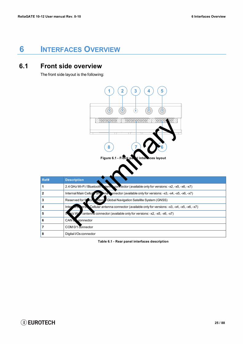
6.1 Front side overviewThe front side layout is the following:
78 6
3 41 2 5
Figure 6.1 - Front panel interfaces layout
Ref# Description
1 2.4 GHzWi-Fi / Bluetooth antenna connector (available only for versions: -x2, -x5, -x6, -x7)
2 InternalMain Cellular antenna connector (available only for versions: -x3, -x4, -x5, -x6, -x7)
3 Reserved for factory optionalGlobalNavigation Satellite System (GNSS)
4 InternalDiversityCellular antenna connector (available only for versions: -x3, -x4, -x5, -x6, -x7)
5 5GHzWi-Fi antenna connector (available only for versions: -x2, -x5, -x6, -x7)
6 CAN 0/1 connector
7 COM0/1 connector
8 Digital I/Os connector
Table 6.1 - Rear panel interfaces description
25 / 88
Prelim
inary

6 Interfaces Overview ReliaGATE 10-12 User manual Rev. 0-10
6.2 Rear side overviewThe rear side layout is the following:
1 2 3 4 65
Figure 6.2 - Rear panel interfaces layout
Ref# Description
1 Ethernet ETH 1 connector
2 Ethernet ETH 0 connector
3 USB0 connector
4 USB1 connector
5 Service Panel
6 Power IN connector
Table 6.2 - Rear panel interfaces description
26 / 88
Prelim
inary

ReliaGATE 10-12 User manual Rev. 0-10 6 Interfaces Overview
6.2.1 Service Panel interfacesThe interfaces available in the Service Panel are the following:
Figure 6.3 - Service Panel interfaces layout
Ref# Description
1 ComboMicroSD +MicroSIM cards receptacle; pull-lever
2 RTC battery connection jumper
3 Boot selection jumper
4 DIP-switch for serial ports configuration
5 Programmable pushbutton
6 TTL Serial console
7 Hardware reset pushbutton
8 RTC user accessible backup battery
9 MicroSIM card receptacle; push-pull
Table 6.3 - Service Panel interfaces description
27 / 88
Prelim
inary

6 Interfaces Overview ReliaGATE 10-12 User manual Rev. 0-10
6.3 Right side overviewThe right side layout is the following:
1
Figure 6.4 - Expansion connector
Ref# Description
1 Expansion Connector.For further details see: "Expansion Connector" on page 44
Table 6.4 - Expansion connector description
28 / 88
Prelim
inary

ReliaGATE 10-12 User manual Rev. 0-10 6 Interfaces Overview
6.4 Left side overviewThe left side layout is the following:
1
Figure 6.5 - Expansion USB connector layout
Ref# Description
1 2.0 Host USB connector.This connector is ready for the connection of optionalUSBaccessories (for example ReliaCELL 10-20)
Table 6.5 - Expansion USB connector description
29 / 88
Prelim
inary

6 Interfaces Overview ReliaGATE 10-12 User manual Rev. 0-10
6.5 LED indicators overviewThe LED indicators are placed on the bottom side of the product. They are the following:
1
6
Figure 6.6 - LED indicators layout
Ref# Use Color
1 USER1 (General purpose) Green
2 USER2 (General purpose) Green
3 USER3 (General purpose) Amber
4 USER4 (General purpose) Amber
5 CELL (Modem activity) (available only for versions: -x3, -x4, -x5, -x6, -x7):l LEDON:ModemONl LED blinking: Modem connected to GSM network
Green
6 POWER:l LEDON: Product powered by the external sourcel LEDOFF: Product not powered by the external source
Blue
Table 6.6 - LED indicators description
30 / 88
Prelim
inary

ReliaGATE 10-12 User manual Rev. 0-10 7 Interfaces in detail
7 INTERFACES IN DETAIL
7.1 Wi-Fi and Bluetooth (only for versions: -x2, -x5, -x6, -x7)The ReliaGATE 10-12 provides the followingWi-Fi / Bluetooth functionality:
l 2.5 GHz Wi-Fi 802.11a,b,g,n / BLE 4.2 BLE Bluetoothl 5GHz Wi-Fi 802.11a,b,g,n
The internal circuitry allows for 2.5 GHz Wi-Fi and Bluetooth coexistence.
TheWi-Fi and Bluetooth antennas connectors are placed on the front side.
7.1.1 Wi-Fi specificationsl Integrated 2.4 and 5GHz Power Amplifier (PA) forWLAN solutionl WLAN Baseband Processor and RF transceiver Supporting IEEE Std 802.11a/b/g/nl WLAN 2.4/5 GHz SISO (20/40MHz channels)l 2.4-GHz MRC Support for Extended Rangel 5GHz Frequencies:
o U-NII-1 Bands 36, 38, 40, 44, 46, 48o U-NII-3 Bands 149,151, 153, 157, 159, 161, 165
l Baseband Processor:o IEEE Std 802.11a/b/g/n data rates and IEEE Std 802.11n data rates with 20 or 40MHz
SISOl Fully calibrated system. Production calibration not requiredl Medium Access Controller (MAC):
o Embedded ARM™Central Processing Unit (CPU)o Hardware-Based Encryption/Decryption using 64-, 128-, and 256-Bit WEP, TKIP or AES
Keyso Supports requirements forWi-Fi Protected Access (WPA andWPA2.0) and IEEE Std
802.11i [includes hardware-accelerated Advanced Encryption Standard (AES)]o Designed to work with IEEE Std 802.1x
l IEEE Std 802.11d,e,h,i,k,r PICS compliantl New advanced co-existence schemewith BT/BLEl 2.4/5 GHz Radio:
o Internal LNA and PAo Supports: IEEE Std 802.11a, 802.11b, 802.11g and 802.11n
l Supports 4 bit SDIO host interface, including high speed (HS) and V3modes
7.1.2 Bluetooth specificationsl Supports Bluetooth 4.2l Includes concurrent operation and built -in coexisting and prioritization handling of Bluetooth, BLE,audio processing andWLAN
l Dedicated Audio processor supporting on chip SBC encoding + A2DP:o Assisted A2DP (A3DP) support - SBC encoding implemented internallyo AssistedWB-Speech (AWBS) support - modified SBC codec implemented internally
7.1.3 BLE specificationsl Fully compliant with BT and BLE dual mode standardl Support for all roles and role-combinations, mandatory as well as optionall Supports up to 10 BLE connectionsl Independent buffering for LE allows having large number of multiple connections without affectingBR/EDR performance
31 / 88
Prelim
inary

7 Interfaces in detail ReliaGATE 10-12 User manual Rev. 0-10
7.1.4 Wi-Fi and Bluetooth antennas connectors specificationsSpecifications are the same for both the following antennas connectors:
l 2.4 GHz Wi-Fi / Bluetoothl 5GHz Wi-Fi
Connector Layout:
12
Connector Specifications:l RP-SMA connectorl Gender: Female
Mating Connector Specifications:l RP-SMA connectorl Gender: Male
Connector Pinout:
Pin # Description
1 Male inner pin contact
2 Female connector body (outer thread)
32 / 88
Prelim
inary

ReliaGATE 10-12 User manual Rev. 0-10 7 Interfaces in detail
7.2 Internal cellular (only for versions: -x3, -x4, -x5, -x6, -x7)The ReliaGATE 10-12 provides the following internal cellular functionality:
Version Functionality
-x3 LTECat 1 (NA) 3GFallback
-x4 LTECat 1 (EU) 2GFallback
-x5 LTECat 1 (NA) 3GFallback
-x6 LTECat 1 (EU) 2GFallback
-x7 LTECat 1 (JP)
The cellular antennas connectors are placed on the front side.
7.2.1 Internal cellular modem specifications (according to product versions)Product features:
l Rx Diversity andMIMODL 2x2l LTE FDD Cat.1, 3GPP release 9 compliantl SIM application Tool Kit 3GPP TS 51.014l Serial port multiplexer 3GPP TS27.010l SMS over IMSl Built in UDP/TCP/FTP/SMTP stack
LTE Data:l Uplink up to 5Mbpsl Downlink up to 10Mbps
Frequencies:l 4G bands (MHz)
o B12/B13(700)o B5(850)o B4(AWS1700)o B2(1900)o B1(2100)o B3(1800)o B7(2600)o B8(900)o B20(800)
l 3G bands (MHz)o B2(1900)o B5(850)
l 2G bands (MHz)o B3(1800)o B7(2600)
33 / 88
Prelim
inary

7 Interfaces in detail ReliaGATE 10-12 User manual Rev. 0-10
7.2.2 Internal cellular antennas connectors specificationsSpecifications are the same for both the following antennas connectors:
l Main Cellularl Diversity Cellular
Connector Layout:
12
Connector Specifications:l SMA connectorl Gender: Female
Mating Connector Specifications:l SMA connectorl Gender: Male
Connector Pinout:
Pin # Description
1 Female inner pin contact
2 Female connector body (outer thread)
34 / 88
Prelim
inary

ReliaGATE 10-12 User manual Rev. 0-10 7 Interfaces in detail
7.3 The MicroSIM card receptaclesThe ReliaGATE 10-12 includes the followingMicroSIM card receptacles in the Service Panel:
1st MicroSIM card receptacle: Integrated in a ComboMicroSD + MicroSIM cards receptacle (pull-lever) on the top side of the circuit board
2nd MicroSIM card receptacle: On the bottom side of the circuit board (push-pull)
NOTICE
TURN THE SIM PIN OFF BEFORE INSERTING THE SIM CARD IN THE RECEPTACLE.THE CELLULAR CONNECTION WILL NOT WORK IF THE SIM PIN IS ON.
7.3.1 How to insert / remove the MicroSIM card
7.3.1.1 If you are using the receptacle on the top side of the circuit boardTo insert theMicroSIM card, push it in the holder with the contacts facing down, and the cut corner facinginwards:
To remove theMicroSIM card, pull the eject lever towards yourself: use a pen tip to simplify the operation:
35 / 88
Prelim
inary

7 Interfaces in detail ReliaGATE 10-12 User manual Rev. 0-10
7.3.1.2 If you are using the receptacle on the bottom side of the circuit boardTo insert theMicroSIM card, push it in the holder with the contacts facing up, and the cut corner facinginwards.
To remove theMicroSIM card, pull it out from the holder: use a pair of tweezers to simplify the operation.
36 / 88
Prelim
inary

ReliaGATE 10-12 User manual Rev. 0-10 7 Interfaces in detail
7.4 Digital I/OsThe ReliaGATE 10-12 provides the following Digital I/Os:
l 2x Digital Input: 36 V, 1 kV Optoinsulatedl 2x Digital Output: 40 V AC/DC, 1 kV Optoinsulated, 500mA, 1 kHz Max Switching
The Digital I/Os connector is available on the front side.
7.4.1 Insulated Digital Inputs
7.4.1.1 Electrical specificationsThe table below shows the electrical specifications of the digital inputs:
Characteristic Value
Logic Zero 0 V ≤ VIN_low ≤ 1 V
Logic One 2 V ≤ VIN_high ≤ 36 V
Input Current <3.5mA
7.4.1.2 Electrical schematicsThe figure below shows the electrical schematics of one digital input:
Digital Input
Cathode
Digital Input
Anode
VCC3
GPIN
37 / 88
Prelim
inary

7 Interfaces in detail ReliaGATE 10-12 User manual Rev. 0-10
7.4.2 Insulated Digital Outputs
7.4.2.1 Electrical specificationsThe table below shows the electrical specifications of the digital outputs:
Characteristic Value
Maximum Voltage 40 V
Maximum Current 500mA
Output ON Resistance Typical: 0.83 OhmMaximum: 2.50Ohm
Maximum switching frequency 1 kHz
7.4.2.2 Electrical schematicsThe illustration below shows the electrical schematics of one digital output:
VCC3
GPOUT
Digital Output
Normally Open
Digital Output
Common
7.4.3 Digital I/Os connector specifications
Connector Layout:
81
Connector Specifications:l Base strip, Headerl Gender: Femalel Type: 8-pin, 3.5mm pitch
Mating Connector Specifications:l Pluggable screw terminal block;l Gender: Malel Type: 8-pin, 3.5mm pitchl Example:Manufacturer: PhoenixContactPart Number: MC 1,5/ 8-STF-3,5 - 1847181(or equivalent)
Connector Pinout:
Pin # Signal Type Description
1 DigitalOUT: 1COM O DigitalOutput 1Common
2 DigitalOUT: 1NO O DigitalOutput 1NormallyOpen
3 DigitalOUT: 2COM O DigitalOutput 2Common
4 DigitalOUT: 2NO O DigitalOutput 2NormallyOpen
5 Digital IN: 1A I Digital Input 1 Anode
6 Digital IN: 1C I Digital Input 1 Cathode
7 Digital IN: 2A I Digital Input 2 Anode
8 Digital IN: 2C I Digital Input 2 Cathode
38 / 88
Prelim
inary

ReliaGATE 10-12 User manual Rev. 0-10 7 Interfaces in detail
7.5 COM ports 0 and 1The ReliaGATE 10-12 provides 2x RS-232/485 COM ports:
l COM 0l COM 1
TheCOM 0/1 connectors are available on the front side.
COM ports specifications:l The COM ports are surge protectedl Each port has 2 pairs of pins (each signal is doubled)l Both COM ports are disabled when the ReliaGATE is initially poweredONl To set the RS-232/485modes see "How to set the RS-232/485modes" on page 59l Maximum supported baud rates are:
o For RS-232mode: up to 450 kbpso For RS-485mode: up to 1.75Mbps
7.5.1 Note for termination resistors (for RS-485 mode only)Each port has 2 pairs of pins (each signal is doubled):
l If the ReliaGATE 10-12 is located at the beginning, or at the end, of a RS-485 chain, spare pair ofpins can be used to connect permanently standard axial resistor 120Ohm, if the application requiresthat
l If the ReliaGATE 10-12 is not at the beginning or at end of the RS-485 chain, two options areavailable:
o Option1: one pair of pins can remain not connectedo Option2: one pair of pins can be used to connect the previous device of the chain, and
the other pair can be used to connect the following device of the chain
7.5.2 Note for fail safe resistors (for RS-485 mode only)You can use the DIP switch available in the Service Panel to insert the RS-485 fail-safe resistors.
7.5.2.1 Switches meaningDefault DIP switch configuration is OFF; this means no resistors inserted.
SW# Signal Description
1 RS232RX_1 / RS485+_1 ON: 4.7 kΩ pull-up resistor inserted
2 RS232TX_1 / RS485-_1 ON: 4.7 kΩ pull-down resistor inserted
3 RS232RX_2 / RS485+_2 ON: 4.7 kΩ pull-up resistor inserted
4 RS232TX_2 / RS485-_2 ON: 4.7 kΩ pull-down resistor inserted
39 / 88
Prelim
inary

7 Interfaces in detail ReliaGATE 10-12 User manual Rev. 0-10
7.5.3 COM connector specifications
Connector Layout:
1 10
Connector Specifications:l Base strip, Headerl Gender: Malel Type: 10-pin, 3.5mm pitch
Mating Connector Specifications:l Pluggable screw terminal block;l Gender: Femalel Type: 10-pin, 3.5mm pitchl Example:Manufacturer: Shenzhen Connection ElectronicsCo., Ltd.Part Number: MC 1,5/10-STF-3,5 - 1847204(or equivalent)
Connector Pinout:
Pin # Signal Type Description
1 COM0: TX/B O COMport 0:l RS-232: Transmit Datal RS-485: B Line
2 COM0: RX/A I COM port 0:l RS-232: Receive Datal RS-485: A Line
3 COM0: GND P Ground
4 COM0: RX/A I COM port 0:l RS-232: Receive Datal RS-485: A Line
5 COM0: TX/B O COMport 0:l RS-232: Transmit Datal RS-485: B Line
6 COM1: TX/B O COMport 1:l RS-232: Transmit Datal RS-485: B Line
7 COM1: RX/A I COM port 1:l RS-232: Receive Datal RS-485: A Line
8 COM1: GND P Ground
9 COM1: RX/A I COM port 1:l RS-232: Receive Datal RS-485: A Line
10 COM1: TX/B O COMport 1:l RS-232: Transmit Datal RS-485: B Line
40 / 88
Prelim
inary

ReliaGATE 10-12 User manual Rev. 0-10 7 Interfaces in detail
7.6 CAN ports 0 and 1The ReliaGATE 10-12 provides 2x CAN (Controller Area Network) ports compliant with the CANSpecification 2.0, Parts A and B:
l CAN 0l CAN 1
TheCAN 0/1 connectors are available on the front side.
Notes about CAN power supply:l The ReliaGATE 10-12 can supply power to the 2 CAN ports: 100mA@ 5V (each port)l CAN power can be enabled / disabled by softwarel The interfaces are surge protected.
7.6.1 CAN 0/1 connector specifications
Connector Layout:
81
Connector Specifications:l Base strip, Headerl Gender: Malel Type: 8-pin, 3.5mm pitch
Mating Connector Specifications:l Pluggable screw terminal block;l Gender: Femalel Type: 8-pin, 3.5mm pitchl Example:Manufacturer: PhoenixContactPart Number: MC 1,5/ 8-STF-3,5 - 1847181(or equivalent)
Connector Pinout:
Pin # Signal Type Description
1 CAN 0: H IO CAN port 0 Positive Data
2 CAN 0: L IO CAN port 0 Negative Data
3 CAN 0: 5V 5 CAN node 05 VOutput power supply
4 CAN 0: GND P Ground
5 CAN 1: H IO CAN port 1 Positive Data
6 CAN 1: L IO CAN port 1 Negative Data
7 CAN 1: 5V 5 CAN node 15 VOutput power supply
8 CAN 1: GND P Ground
41 / 88
Prelim
inary

7 Interfaces in detail ReliaGATE 10-12 User manual Rev. 0-10
7.7 Ethernet ETH 0 and 1The ReliaGATE 10-12 provides 2x 10/100Mbps Ethernet ports for wired network connectivity:
l ETH 0l ETH 1
The ETH 0/1 connectors are available on the rear side.
7.7.1 Ethernet specificationsFeature Description
Network Standard IEEE 802.3u 10/100-BaseTX.IEEE802.3x full-duplex flow control.
Speeds 10/100-BaseTX interfaceswith MAC
Notes The interfacesare noise and surge protected.The RJ-45 connector has integratedmagnetics.
7.7.2 ETH 0/1 connectors specifications
Connector Layout:
1
Connector Specifications:l RJ-45 socketl Gender: Female
Mating Connector Specifications:l RJ-45 plugl Gender: Male
Connector Pinout (pins not listed are not connected):
Pin # Signal Type Description
1 TX+ O Transmit Data +
2 TX- O Transmit Data -
3 RX+ I Receive Data +
6 RX- I Receive Data -
42 / 88
Prelim
inary

ReliaGATE 10-12 User manual Rev. 0-10 7 Interfaces in detail
7.8 Host USB portsThe ReliaGATE 10-12 provides 3x Host 2.0 USB ports (Noise and Surge Protected) for general purposeapplications:
l USB 0 on the front sidel USB 1 on the front sidel USB 2 on the left side. This connector is ready for the connection of optional USB accessories (forexample ReliaCELL 10-20)
7.8.1 USB 0/1/2 connectors specifications
Connector Pinout:
1
Connector Specifications:l USBType-A socketl Gender: Female
Mating Connector Specifications:l USBType-A plugl Gender: Male
Connector Pinout (pins not listed are not connected):
Pin # Signal Type Description
1 VBUS 5 +5V
2 D- IO Negative data
3 D+ IO Positive data
4 DGND P Ground
43 / 88
Prelim
inary
7 Interfaces in detail ReliaGATE 10-12 User manual Rev. 0-10
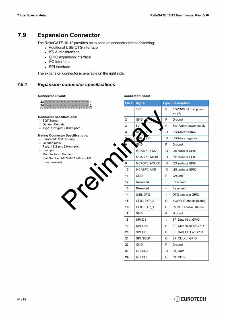
7.9 Expansion ConnectorThe ReliaGATE 10-12 provides an expansion connector for the following:
l Additional USB OTG interfacel I2S Audio interfacel GPIO expansion interfacel I2C interfacel SPI interface
The expansion connector is available on the right side.
7.9.1 Expansion connector specifications
Connector Layout:
1
2
23
24
Connector Specifications:l SQT Socketl Gender: Femalel Type: 12*2-pin; 2.0mm pitch
Mating Connector Specifications:l SamtecMTMMHousingl Gender: Malel Type: 12*2-pin; 2.0mm pitchl Example:Manufacturer: SamtecPart Number: MTMM-112-07-L-D-3(or equivalent)
Connector Pinout:
Pin # Signal Type Description
1 3V3 P 3.3V/100mAmaxpowersupply
2 GND P Ground
3 5V P 5V/1Amaxpower supply
4 USB: EXP+ IO USBdata positive
5 USB: EXP- IO USBdata negative
6 GND P Ground
7 MCASP0: FSX IO I2S audio or GPIO
8 MCASP0: AXR0 IO I2S audio or GPIO
9 MCASP0: ACLKX IO I2S audio or GPIO
10 MCASP0: AXR1 IO I2S audio or GPIO
11 GND P Ground
12 Reserved - Reserved
13 Reserved - Reserved
14 USB: OTG I OTGdetect or GPIO
15 GPIO: EXP_2 O 3.3VOUT enable (status)
16 GPIO: EXP_1 O 5VOUT enable (status)
17 GND P Ground
18 SPI: D1 I SPI Data IN or GPIO
19 SPI: CS0 O SPI Chip select or GPIO
20 SPI: D0 O SPI Data OUT or GPIO
21 SPI: SCLK O SPI Clockor GPIO
22 GND P Ground
23 I2C: SDA IO I2C Data
24 I2C: SCL O I2C Clock
44 / 88
Prelim
inary

ReliaGATE 10-12 User manual Rev. 0-10 7 Interfaces in detail
7.10 TTL Serial consoleThe ReliaGATE 10-12 provides a 3.3 V TTL compatible Serial console port in the Service Panel.
The voltage levels are the following:l Log 1 (Hi): 2.0 to 3.3 Vl Log 0 (Low): 0 to 0.8 V
7.10.1 TTL Serial console connector specifications
Connector Layout:
1
Connector Specifications:l Shrouded headerl Gender: Malel Type: Pitch 1.25mm; 3-pin
Mating Connector Specifications:l Receptacle Housingl Gender: Femalel Type: 3-pin, 1.25mm pitchl Example:Manufacturer: MolexPart Number: 51021-0300(or equivalent)
Connector Pinout:
Pin # Signal Type Description
1 GND P Ground
2 TX O Transmit Data
3 RX I Receive Data
45 / 88
Prelim
inary

7 Interfaces in detail ReliaGATE 10-12 User manual Rev. 0-10
7.11 The MicroSD card receptacleThe ReliaGATE 10-12 includes aMicroSD card receptacle in the Service Panel.
It is integrated in a ComboMicroSD + MicroSIM cards receptacle (pull-lever) on the top side of the circuitboard.
7.11.1 How to insert / remove the MicroSD card in the receptacleTo insert theMicroSD card, push it in the holder with the contacts facing down.
To remove theMicro SD card, pull it out from the holder. Use your little finger or a pair of tweezers tosimplify the operation.
46 / 88
Prelim
inary

ReliaGATE 10-12 User manual Rev. 0-10 7 Interfaces in detail
7.12 RTC (Real Time Clock)The ReliaGATE 10-12 includes the following two RTC (Real Time Clocks) devices:
RTC device Description Use
/dev/rtc0 l Internal (in the CPU SoC) Reserved
/dev/rtc1 l External (I2C-based RTC device)l Default RTC used byLinuxl Accuracy: 25minutesper year (at 25 °C)
Wake up the ReliaGATE10-12 from a deep low powerstate
7.12.1 The RTC device "/dev/rtc1"The RTC device "/dev/rtc1" offers three timestamp registers.
7.12.2 The RTC backup batteryThe ReliaGATE 10-12 includes a BR1225 lithium coin cell RTC battery in the Service Panel.
7.12.2.1 Battery Install / Replacement Instructions
CAUTION
RISK OF EXPLOSION IF BATTERY IS REPLACED BY AN INCORRECT TYPE.REPLACE THE BATTERY WITH THE SAME TYPE.DISPOSE OF USED BATTERIES ACCORDING TO MANUFACTURER'S INSTRUCTIONS.
To install (or replace) a battery, complete the following steps:1. Disconnect the power cable from the product2. Remove the old battery: use a pair of plastic tweezers to pull out the battery. Dispose of it properly3. Insert a new battery with theminus “-” pole facing up.
47 / 88
Prelim
inary

7 Interfaces in detail ReliaGATE 10-12 User manual Rev. 0-10
7.12.2.2 How to enable / disable the RTC battery
The ReliaGATE 10-12 includes an RTC battery jumper in the Service Panel.
You can use the RTC battery jumper to enable / disable the RTC battery (this can be useful for examplewhen the ReliaGATE 10-12 is stored in the warehouse to save RTC battery charge):
l Jumper inserted = Battery connectedl Jumper removed = Battery not connected
7.13 WatchdogThe ReliaGATE 10-12 includes a watchdog / supervisor IC, external to the CPU.
7.14 AccelerometerYour ReliaGATE 10-12 includes a 3-axis +/- 8g accelerometer with 12 bit resolution and a programmableoutput signal which can trigger an interrupt to the CPU (movement detection).
7.15 The Programmable pushbuttonA programmable pushbutton is available in the Service Panel.
The pushbutton is sensed by a Linux daemonwhich executes a shell script every time the button is eitherpushed or released.
48 / 88
Prelim
inary

ReliaGATE 10-12 User manual Rev. 0-10 8 How to supply power to the product
8 HOW TO SUPPLY POWER TO THE PRODUCT
8.1 Power supply specificationsPower supply 6 to 36 VDC with transient protection and Ignition Sense
Power consumption 2W typical; 15Wmaximum
Peak demand <15W
8.1.1 Power IN connector and mating connector specificationsThe power input is protected against: surge, noise, reverse polarity, over-voltage.
NOTICE
The Power IN connector is NOT protected against short circuit.Always include an external fuse to protect the product!
The ReliaGATE 10-12 provides the power supply input port on the rear panel.
Connector Layout:
1 3
Connector Specifications:l Base strip, Headerl Gender: Malel Type: 3-pin, 3.5mm pitch
Mating Connector Specifications:l Pluggable screw terminal blockl Gender: Femalel Type: 3-pin, 3.5mm pitchl Example:Manufacturer: PhoenixContactPart Number: MC 1,5/ 3-STF-3,5 - 1847068(or equivalent)
Connector Pinout:
Pin # Signal Type Description
1 Power IN + P Positive power supply input
2 Power IN - P Negative power supply input
3 KEY P Ignition Sense
49 / 88
Prelim
inary

8 How to supply power to the product ReliaGATE 10-12 User manual Rev. 0-10
8.2 How to supply power and turn ON the product
WARNING
ELECTRIC SHOCK HAZARDFailure to supply power correctly, or failure to follow all operating instructions correctly, maycreate an electric shock hazard, which could result in personal injury or loss of life, and / ordamage to equipment or other property.To avoid injuries:
l Do not perform any connections with wet handsl Check any power cords for damage before using theml Use certified power cables. The power cables must meet the power requirements of thedevices
l Position cables with care. Avoid positioning cables in places where they may betrampled or compressed by objects placed on them
l Take particular care of plugs, power-points and outlets. Avoid overcharging theml Before applying power, thoroughly review all installation, operation, and safetyinstructions
l Before operating any equipment, carefully read any supplied instructionsl Always disconnect power and discharge the circuits before touching theml Only start the product with a power supply that meets the requirements stated on thevoltage label. In case of uncertainties about the required power supply, contact theEurotech Technical Support Team (see the back cover for full contact details) or theelectricity authority.
To supply power to the ReliaGATE 10-12, complete the following steps:1. Set up a DC power source that meets the ReliaGATE 10-12 power requirements2. Always include a T3. 15A 65 Vdc external fuse in the power supply circuit to protect the
ReliaGATE 10-123. Check the input voltage as close as possible to the Power IN connector. This is to compensate for
any cable losses, caused by cable length and other cable characteristics4. Turn ON the DC power source to supply power to Pins 1 and 2. The ReliaGATE 10-12
automatically turns ON and the LED 6 (POWER) turns ON.
1 3
Power IN + Power IN -
Note about the Ignition SenseThe Ignition Sense is a digital input that can be used tomonitor the ignition status.The ReliaGATE 10-12 turns ON independently of the status of the Ignition Sense (for further informationsee "Ignition Sense" on page 63).
50 / 88
Prelim
inary

ReliaGATE 10-12 User manual Rev. 0-10 8 How to supply power to the product
8.3 How to turn OFF the productTo turn the ReliaGATE 10-12OFF follow these steps:
1. Login the Administration console and run the shutdown command. The system turns itself OFF2. Remove power from pins 1 and 2.
8.4 How to reduce the power consumption of the productTo reduce the power consumption of the ReliaGATE 10-12, turn OFF the radio interfaces and disableunnecessary services that contribute to overall system power consumption.
8.5 How to perform a hardware reset of the productTo trigger a hardware reset of the ReliaGATE 10-12 push the reset pushbutton available in the ServicePanel.
51 / 88
Prelim
inary

(This page has been intentionally left blank)
Prelim
inary

ReliaGATE 10-12 User manual Rev. 0-10 9 The Software
9 THE SOFTWARE
9.1 The Linux OS distributionEurotech can provide a Linux operating systems based on Yocto framework (www.yoctoproject.org) aswell as an SDK for application development.
All the documentation for the developer is available from:www.yoctoproject.org/documentation.
9.2 The bootloader procedureThe bootloader procedure is the following:
1. TheMLO file is loaded from either the external MicroSD card or the on-board eMMC memory, andsaved in the on-chip memory to configure the RAMmemory for use
2. The uboot.img file is loaded (from the same device whereMLOwas loaded from), saved in the RAMmemory, and executed
3. The bootloader searches for a valid operating system. The search order is:a. MicroSD cardb. eMMC
4. The bootloader fetches a FIT image which includes the kernel and device tree. The FIT imageincludes image signatures which are verified before boot
9.2.1 How to select the MLO sourceTheMLO file can be loaded from either the external MicroSD card or the on-board eMMC memory,according to the setting of the Boot selection jumper (JP2):
l JP2 inserted = Boot fromMicro-SDl JP2 removed = Boot from eMMC
9.2.2 How to set up a correct MicroSD card / eMMC card partitionFor a valid boot, theMicroSD card and the eMMC memory must be configured with at least these 2partitions:
l 1st partition:o Type: FAT16o Flags: lba, booto Contains the files: MLO and uboot.img
l 2nd partition:o Type: ext4o Contains the operating system, including the Linux kernel FIT image
53 / 88
Prelim
inary

(This page has been intentionally left blank)
Prelim
inary

ReliaGATE 10-12 User manual Rev. 0-10 10 How to access interfaces under Linux
10 HOW TO ACCESS INTERFACES UNDER LINUXInterfaces availability depend on the product version.
NOTICE
If Everyware Software Framework (ESF) is installed, it will manage the network interfaces,cellular modem, Bluetooth adapter and GPIOs.Any changes you make to the Linux configuration files may be overwritten if the related serviceis managed by ESF.Refer to the ESF documentation for further details.
10.1 How to drive the GPIOs: the GPIO utilitySeveral ReliaGATE 10-12 interfaces are controlled by their GPIO. Tomanage these interfaces, you willneed to control the relevant GPIO pin.
To drive aGPIO, use theGPIO utility: gpio_utility.
gpio_utility allows you to:l Read / Write a GPIO statusl Set a GPIO as input or outputl Unexport a GPIO.
TheGPIOs are exported by default at startup.
To read the GPIO status (for example: the status of LED 1), enter the following command:
gpio_utility gpio117
The output is the following:l If LED 1 is ON, then gpio117 = 1l If LED 1 is OFF, then gpio117 = 0
To set the GPIO status (for example: the status of LED 1), enter the following commands:
#turn led ongpio_utility gpio117 1
#turn led offgpio_utility gpio117 0
55 / 88
Prelim
inary

10 How to access interfaces under Linux ReliaGATE 10-12 User manual Rev. 0-10
10.2 How to determine the Operating System version installedTo determine the Operating System version installed, enter the following command:
eurotech_versions
Example output:
eth_name_bsp: xxxeth_vers_bsp: Operating System versioneth_partno_bsp: unknowneth_serial_number: xxxeth_model: xxxeth_partno_epr: unknown
10.3 Memory and storage devicesThe ReliaGATE 10-12 exposes thememory and the storage devices as follows:
l Internal flashmemory: /dev/mmcblk0l MicroSD cardmemory: /dev/mmcblk1
10.4 Wi-Fi and BluetoothThe ReliaGATE 10-12 exposes theWi-Fi and Bluetooth interfaces as follows:
l Wi-Fi interface: wlan0
l Bluetooth interface: hci0
The ReliaGATE 10-12 exposes the power supply of the Bluetooth as follows:l /sys/class/gpio/gpio22/value
Tomanage this GPIO, see "How to drive the GPIOs: the GPIO utility" on the previous page.
NOTES:l Turning the Bluetooth OFF and ON, does not automatically restart the daemonl Wi-Fi power control is handled by the driver and is not user accessible.
10.5 ReliaCELL (optional)The ReliaGATE 10-12 exposes the power supply for the ReliaCELL as follows:
l /sys/class/gpio/gpio73/value
Tomanage this GPIO, see "How to drive the GPIOs: the GPIO utility" on the previous page.
56 / 88
Prelim
inary

ReliaGATE 10-12 User manual Rev. 0-10 10 How to access interfaces under Linux
10.6 ModemsTo set up and control themodem, use the /usr/bin/telit-he910 script (there are sequencing andtiming requirements that must be adhered to in order to effectively control themodem).
To obtain the help of the script, enter the following command:
telit-he910 help
Example output:
Usage: telit-he910 command [command_arg]help - Display this messages.gpio_init - Setup the gpio for the ON_OFF* signal.gpio_toggle - Toggle the ON_OFF* signal to turn modem on or off.turn_off - Turn the modem off.turn_on - Turn the modem on.is_on - Check whether the modem is on. Returns status as both text and in
the exit status.restore_defaults - Set the modem NVM to the product defaults.get_info - Return details about the modem and possibly the SIM.chat at_command - Send AT-command to the modem and print its response.detect_sim - Force detection of the SIM, if inserted.is_sim_present - Check whether the SIM was detected. Returns status as both text
and in the exit status.is_sim_registered - Check whether the SIM is registered to either a home or roaming
network. Returns status as both text and in the exit status
NOTICE
The script above is designed to work for telit-he910 or telit-le910 modems.
57 / 88
Prelim
inary

10 How to access interfaces under Linux ReliaGATE 10-12 User manual Rev. 0-10
10.7 CAN portsThe ReliaGATE 10-12 exposes the CAN ports as follows:
l CAN 0 port: can0
l CAN 1 port: can1
CAN ports are added through the SocketCAN kernel extension.For further information on SocketCAN refer to the Linux kernel documentation:www.kernel.org/doc/Documentation/networking/can.txt
10.7.1 How to enable the CAN bus 5VTo enable can0 5V, enter the following command:
gpio_utility gpio8 1
To enable can1 5V, enter the following command:
gpio_utility gpio9 1
10.7.2 How to setup a CAN portTo setup a CAN port, enter the following commands:
#Set CAN0 to work at 125 kbpsip link set can0 type can bitrate 125000
#Open the connectionip link set up can0
10.7.3 How to send/receive a message via a CAN portExample: Sending/receiving a message via a CAN port (once the CAN port has been setup)
#Send a byte via CAN0cansend can0 255
#Example of received message on can0root@productname...:~# candump can0interface = can0, family = 29, type = 3, proto = 1<0x001> [1] 01<0x001> [1] 02<0x001> [1] 05<0x001> [1] 00<0x001> [1] ff
58 / 88
Prelim
inary

ReliaGATE 10-12 User manual Rev. 0-10 10 How to access interfaces under Linux
10.8 COM ports 0 and 1, Console portThe ReliaGATE 10-12 exposes the COM ports as follows:
l COM port 0: /dev/ttyS4 (available on the front panel)l COM port 1: /dev/ttyS3 (available on the front panel)l Console port /dev/ttyS0 (available in the Service Panel)
You need to configure the serial ports mode before they will work.
10.8.1 How to set the RS-232/485 modesYou can configure the serial port mode in the following ways, A or B:
A. Using the ethsetserial utilityB. Implementing the ioctl in the source code
10.8.1.1 How to use the ethsetserial utility to configure the COM portsTo set COM port 1 to RS-232 mode, enter the following command:
ethsetserial –p ttyO3 –m232
To set COM port 1 to RS-485 mode, enter the following command:
ethsetserial –p ttyO3 –m485
To see all the available options, enter the following command:
ethsetserial –h
59 / 88
Prelim
inary

10 How to access interfaces under Linux ReliaGATE 10-12 User manual Rev. 0-10
10.8.1.2 How to implement the ioctl in the source code to configure the COM ports
To implement the ioctl in the source code, enter the following commands:
/*Ioctl to read */
#define TIOCGRS485 0x542E
/*Ioctl to write */
#define TIOCSRS485 0x542F
Definition of the flags bit
/*FLAGS */
//#define SER_RS485_ENABLED (1 << 0)
/* Logical level for RTS pin when sending *///#define SER_RS485_RTS_ON_SEND (1 << 1)
/* Logical level for RTS pin after sent*///#define SER_RS485_RTS_AFTER_SEND (1 << 2)
//#define SER_RS485_RX_DURING_TX (1 << 4)
/* Inverted logic level for RS485 gpio */#define SER_RS485_INVERT (1 << 5)
/* if enabled serial line drivers must be configured in HiZ*/#define SER_HIZ_ENABLED (1 << 31)
Linux kernel data structure
struct serial_rs485 {
__u32 flags; /* RS485 feature flags */
__u32 delay_rts_before_send; /* Delay before send (milliseconds) */
__u32 delay_rts_after_send; /* Delay after send (milliseconds) */
__u32 padding[5]; /* Memory is cheap, new structs};
60 / 88
Prelim
inary

ReliaGATE 10-12 User manual Rev. 0-10 10 How to access interfaces under Linux
Example: Configuring a serial port in RS-232 modeser_port_name can be either /dev/ttyO3 or /dev/ttyO4.
struct serial_rs485 rs485conf;unsigned int rs_mode_mask=(SER_HIZ_ENABLED|SER_RS485_ENABLED|SER_RS485_INVERT|SER_RS485_RTS_ON_SEND|SER_RS485_RTS_AFTER_SEND);
unsigned int set_flags=0;unsigned int set_flags_mask=rs_mode_mask;
int fd;fd=open(ser_port_name,O_RDWR);if (fd==-1){/* process the error */…}
/* get serial port configuration */if (ioctl (fd, TIOCGRS485, & rs485conf) < 0){/* process the error */…}
rs485conf.flags&=~ set_flags_mask;set_flags&=set_flags_mask;rs485conf.flags|= set_flags;
/*set delay but not used in rs232 mode */rs485conf.delay_rts_after_send=<delay after send in ms>;rs485conf.delay_rts_before_send=<delay before send in ms>;
/* apply changes */if (ioctl (fd, TIOCSRS485, & rs485conf) < 0){/* process the error */…}close(fd);
61 / 88
Prelim
inary

10 How to access interfaces under Linux ReliaGATE 10-12 User manual Rev. 0-10
Example: Configuring a serial port in RS-485 modeser_port_name can be either /dev/ttyO3 or /dev/ttyO4.
struct serial_rs485 rs485conf;unsigned int rs_mode_mask=(SER_HIZ_ENABLED|SER_RS485_ENABLED|SER_RS485_INVERT|SER_RS485_RTS_ON_SEND|SER_RS485_RTS_AFTER_SEND);
unsigned int set_flags=(SER_RS485_INVERT|SER_RS485_ENABLED|SER_RS485_RTS_ON_SEND);unsigned int set_flags_mask=rs_mode_mask;
int fd;fd=open(ser_port_name,O_RDWR);if (fd==-1){/* process the error */…}
/* get serial port configuration */if (ioctl (fd, TIOCGRS485, & rs485conf) < 0){/* process the error */…}
rs485conf.flags&=~ set_flags_mask;set_flags&=set_flags_mask;rs485conf.flags|= set_flags;
/*set delays */rs485conf.delay_rts_after_send=<delay after send in ms>;rs485conf.delay_rts_before_send=<delay before send in ms>;
/* apply changes */if (ioctl (fd, TIOCSRS485, & rs485conf) < 0){/* process the error */…}close(fd);
10.8.2 How to test a serial portTo test the serial port, use the microcom utility:
#connect ttyO3 with a baud rate of 9600microcom /dev/ttyO3 –s 9600
Themicrocom utility:l Allows you to transmit / receive data to / from the serial portl Does not include a local echo (you cannot see the data sent).
62 / 88
Prelim
inary

ReliaGATE 10-12 User manual Rev. 0-10 10 How to access interfaces under Linux
10.9 Digital I/OsThe ReliaGATE 10-12 exposes the Digital I/Os (GPIOs) as follows:
l Digital Input 1: /sys/class/gpio/gpio87/valuel Digital Input 2: /sys/class/gpio/gpio89/valuel Digital Output 1: /sys/class/gpio/gpio26/valuel Digital Output 2: /sys/class/gpio/gpio27/value
Tomanage theseGPIOs, see "How to drive the GPIOs: the GPIO utility" on page 55.
10.10 LED indicatorsThe ReliaGATE 10-12 exposes the LED indicators as follows:
l LED 1 (green): /sys/class/gpio/gpio117/valuel LED 2 (green): /sys/class/gpio/gpio114/valuel LED 3 (amber): /sys/class/gpio/gpio115/valuel LED 4 (amber): /sys/class/gpio/gpio116/valuel LED 5 (green): Reservedl LED 6 (blue): Reserved
Tomanage theseGPIOs, see "How to drive the GPIOs: the GPIO utility" on page 55.
10.11 Ignition SenseThe ReliaGATE 10-12 is provided with a Ignition Sense on the Power supply connector (Pin# 3: KEY).
The Ignition Sense is a digital input that can be used tomonitor the ignition status
To read the Ignition Sense status, enter the following command:
gpio_utility gpio30
The output is the following:l If Pin# 3 is not connected, or connected to GND, then value = 1l If Pin# 3 is connected to Power IN +, then value = 0.
10.12 Ethernet portsThe ReliaGATE 10-12 exposes Ethernet ports as follows:
l Ethernet 0 port: eth0l Ethernet 1 port: eth1
63 / 88
Prelim
inary

10 How to access interfaces under Linux ReliaGATE 10-12 User manual Rev. 0-10
10.13 How to enable the 3.3V and 5V power supply on expansionconnector3.3V and 5V are OFF by default and are controlled driving specific GPIO’s.
To control the 3.3V, enter the following commands:
#turn on 3.3Vgpio_utility gpio71 1
#turn off 3.3Vgpio_utility gpio71 0
To control the 5V, enter the following commands:
#turn on 5Vgpio_utility gpio70 1
#turn off 5Vgpio_utility gpio70 0
NOTICE
While the default kernel DTB allows access to these power control pins, depending on thedevice tree used, control of these power supplies is handled by the kernel and therefore it maynot be possible to control them from user space.
64 / 88
Prelim
inary

ReliaGATE 10-12 User manual Rev. 0-10 10 How to access interfaces under Linux
10.14 RTCThe ReliaGATE 10-12 exposes the RTC as follows:
l RTC: /dev/rtc1
/dev/rtc1 offers three read-only timestamp registers:
Timestamp register What it contains
sys/class/rtc/rtc1/device/timestamp1 Reserved data
sys/class/rtc/rtc1/device/timestamp2 The timestamp that the system last lost power (only if a successfulinitialization hasbeen achieved)
sys/class/rtc/rtc1/device/timestamp3 The timestamp that the system last hasbeen powered(only if a successful initialization hasbeen achieved)
To read a timestamp (for example: timestamp2), enter the following command:
cat /sys/class/rtc/rtc1/device/timestamp2
65 / 88
Prelim
inary

10 How to access interfaces under Linux ReliaGATE 10-12 User manual Rev. 0-10
10.15 WatchdogThe ReliaGATE 10-12 exposes the watchdog as follows:
l Watchdog: /dev/watchdog1
10.15.1 How to manage the watchdog using the C programming languageTo manage the watchdog using the C programming language enter the following commands:
Int interval;Int bootstatus;Long value;
/* display current watchdog value */If (ioctl(fd,WDIOC_GETTIMEOUT,&interval)==0){ // interval contains current timeout in seconds}
/* Check if lasdt boot is caused by watchdog */If (ioctl(fd,WDIOC_GETBOOTSTATUS,&bootstatus)==0){ //bootstatus <> 0 Watchdog //bootstatus = 0 Power-on reset}
/* set the watchdog value (for example: 30 seconds) */value=30;If (ioctl(fd,WDIOC_SETTIMEOUT,&value)==0){ //Watchdog has been set to value content}
/* stop the watchdog */write(fd,”V”,1);
/* feed the watchdog */ioctl(fd,WDIOC_KEEPALIVE,0);
10.15.2 How to manage the watchdog from the command lineTo set the watchdog value (for example: 30 seconds), enter the following command:
wdt_setup –d /dev/watchdog1 –t 30
To start and feed the watchdog, enter the following command:
echo 1 > /dev/watchdog1
To stop the watchdog, enter the following command:
echo V > /dev/watchdog1
66 / 88
Prelim
inary

ReliaGATE 10-12 User manual Rev. 0-10 10 How to access interfaces under Linux
10.15.3 For further informationFor further information on Linux support for watchdog, see:www.kernel.org/doc/Documentation/watchdog/watchdog-api.txt
10.16 AccelerometerThe ReliaGATE 10-12 is provided with an accelerometer sensor.
To print the information from the accelerometer, including an update every time movement isdetected, use the following command:
evtest /dev/input/event0
Example output:
Input driver version is 1.0.1Input device ID: bus 0x18 vendor 0x0 product 0x159 version 0x0Input device name: "ADXL34x accelerometer"Supported events:Event type 0 (Sync)Event type 1 (Key)Event code 330 (Touch)Event type 3 (Absolute)Event code 0 (X)Value 0Min -4096Max 4096Fuzz 3Flat 3Event code 1 (Y)Value -8Min -4096Max 4096Fuzz 3Flat 3Event code 2 (Z)Value -262Min -4096Max 4096Fuzz 3Flat 3Testing ... (interrupt to exit)Event: time 1325419699.822493, type 3 (Absolute), code 2 (Z), value -254Event: time 1325419699.822493, -------------- Report Sync ------------Event: time 1325419699.863461, type 3 (Absolute), code 2 (Z), value -263Event: time 1325419699.863461, -------------- Report Sync ------------Event: time 1325419699.904445, type 3 (Absolute), code 2 (Z), value -265Event: time 1325419699.904445, -------------- Report Sync ------------Event: time 1325419699.945433, type 3 (Absolute), code 2 (Z), value -263Event: time 1325419699.945433, -------------- Report Sync ------------Event: time 1325419700.109388, type 3 (Absolute), code 2 (Z), value -264Event: time 1325419700.109388, -------------- Report Sync ------------Event: time 1325419700.232362, type 3 (Absolute), code 2 (Z), value -263Event: time 1325419700.232362, -------------- Report Sync ------------
67 / 88
Prelim
inary

10 How to access interfaces under Linux ReliaGATE 10-12 User manual Rev. 0-10
10.17 Internal temperature sensorThe ReliaGATE 10-12 is provided with a sensor that measures the temperature inside the product.
To read the internal temperature, enter the following command:
cat /sys/class/hwmon/hwmon0/temp1_input
10.18 The Programmable pushbuttonThe programmable pushbutton is sensed by a Linux daemonwhich executes a shell script every time thebutton is either pushed or released. This script is located at /usr/bin/switch_script.sh and can becustomized according to the needs of the user.
To see the pushbutton status, enter the following command:
gpio_utility gpio74
The output is the following:l If the button is being pushed, then value = 0l If the button is not being pushed, then value = 1.
68 / 88
Prelim
inary

ReliaGATE 10-12 User manual Rev. 0-10 11 How to log in the Administration Console
11 HOW TO LOG IN THE ADMINISTRATION CONSOLEThis section describes how to enter the Administration Console to access the ReliaGATE 10-12 LinuxOperating System.
To login the Administration Console, use one of the followingmethods:l Direct login via Console Portl Remote login via Secure Shell (SSH)
11.1 The default credentialsThe default credentials are the following (case sensitive):
l Username: rootl Password: eurotech
11.2 How to login using the Console portTo log in using the Console port, complete the following steps:
1. Connect the USB-to-Serial cable adapter1 between your development PC and the Consoleconnector of the ReliaGATE 10-12
2. Start a terminal emulator program on your development PC (for example TeraTerm onWindows,Minicom on Linux). Configure the serial port connection for: 115200, 8 bits, 1 stop bit, no parity, andno flow control
3. At the Linux prompt, enter your credentials (see "The default credentials" above).You will obtain a video output like the following:
rootPassword:root@productname...:~#
11.3 How to login via Secure Shell (SSH)The default (out-of-the-box) network configuration of your ReliaGATE 10-12 is as follows:
l eth0o Status: Enabled for LANo Configure: Manually (Static IP)o IP Address: 172.16.0.1o Subnet Mask: 255.255.255.0o DHCP Server Enabled
l eth1o Status: Enabled forWANo Configure: DHCP (DHCP client)
l wlan0o Status: Disabled
1This cable adapter has an end provided with aMale USB connector type A, and the other end provided with a 3-pin,1.25 pitch, female receptacle housing. Contact Eurotech for further information.
69 / 88
Prelim
inary

11 How to log in the Administration Console ReliaGATE 10-12 User manual Rev. 0-10
11.3.1 How to login via the eth0 portReliaGATE 10-12 eth0 port is configured with the static IP address: 172.16.0.1/24.
To log in using eth0, complete the following steps:1. Enter the command ssh [email protected]. At the prompt, enter the password (see "The default credentials" on the previous page).
11.3.2 How to login via the eth1 portReliaGATE 10-12 eth1 port is configured in DHCP client mode.
You have to know its IP address before you can log in, or you have to use a zeroconf implementation.
NOTICE
By default the ReliaGATE 10-12 runs a zeroconf implementation.You can detect the IP address of the unit remotely by running the command: avahi-discover.
Example:1. Run the command: avahi-discover. A dialog box pops-up reporting all the devices on
your network that support this mechanism2. Under "eth0 IPv4" > "local" > "Workstation", you should see your product's hostname
(example: productname_serialnumber). Select it to see its IP address3. Log in your Reliagate using: ssh root@productname_serialnumber.local4. At the prompt, enter the password: (see "The default credentials" on the previous page).
11.4 How to change your security settingsFor security reasons, Eurotech recommends you to change the Linux 'root' password after your initialsetup.
To change your Linux password, complete the following steps:1. Login using the console port2. Run the passwd command and enter a new ‘root’ account password
70 / 88
Prelim
inary

ReliaGATE 10-12 User manual Rev. 0-10 12 How to compile custom software for the ReliaGATE 10-12
12 HOW TO COMPILE CUSTOM SOFTWARE FOR THERELIAGATE 10-12
12.1 How to set up the toolchain1. Make sure you're using the correct toolchain version corresponding to the Yocto image installed on
your gateway.The latest toolchain and Yocto image for your ReliaGATE 10-12 are available here:
https://eurotech.github.io/linux-releases/
2. Download the binary file (x86_64 version tested) on a Virtual/physical machine running Ubuntu(14.04 tested), execute it and select appropriate installation options
3. Once the installation is complete, switch to superuser (sudo su)4. To setup the correct environment variables, run:
source /opt/poky/2.3.2/environment-setup-cortexa8hf-neon-poky-linux-gnueabi
cd /opt/poky/2.3.2/sysroots/cortexa8hf-neon-poky-linux-gnueabi/usr/kernel
make scripts
5. Exit superuser mode
12.2 How to use the toolchain to compile custom software forthe ReliaGATE 10-12
1. Setup the environment variables using:
source /opt/poky/2.3.2/environment-setup-cortexa8hf-neon-poky-linux-gnueabi
2. To directly compile a user-space C source file hello_world.c, use
$CC hello_world.c
3. To compile a kernel module kernel_module.c, configure your Makefile to point to the kerneldirectory and include the .config file in the kernel directory. Here's an example of Makefile:
KBLD := /opt/poky/2.3.2/sysroots/cortexa8hf-neon-poky-linux-gnueabi/usr/kernel -include $(KBLD/.config)obj-m :=kernel_module.oall : modulesmodules clean :$(MAKE) -C $(KBLD) M=$(PWD) $@
71 / 88
Prelim
inary

(This page has been intentionally left blank)
Prelim
inary

ReliaGATE 10-12 User manual Rev. 0-10 13 Eurotech Everyware IoT
13 EUROTECH EVERYWARE IOTEurotech Everyware IoT is a combination of hardware, firmware, operating systems, programmingframeworks, and cloud platforms. It enables you to layer you added-value components on a reliable ready-to-use infrastructure, dramatically accelerating the time tomarket of your IoT projects.
13.1 Everyware Software Framework (ESF)Everyware Software Framework (ESF) Edge Computing Platform is a high-level, multi-platform andflexible application development environment.
ESF is a smart application container that enables remotemanagement of IoT gateways and provides awide range of APIs allowing you to write and deploy your own IoT application.
ESF allows the connection and communication with field devices (close to data sources), thanks toalready tested libraries for field protocol communication, the visual IoT Edge Computing applicationsdevelopment and the connection with leading IoT Cloud Services such as Everyware Cloud (Eurotech IoTIntegration Platform) , Eclipse Kapua, AWS IoT andMicrosoft Azure IoT.
ESF runs on top of the Java Virtual Machine (JVM) and leverages OSGi (a dynamic component system forJava) to simplify the process of writing reusable software building blocks.
ESF APIs offer:l easy access to the underlying hardware including: serial ports, positioning, watchdog, USB,GPIOs, I2C, etc.
l OSGi bundles to simplify themanagement of network configurations, the communication with IoTservers, and the remotemanagement of the gateway.
ESF is based on Kura, the popular Eclipse open source project that was originally contributed to theEclipse community by Eurotech.
73 / 88
Prelim
inary

13 Eurotech Everyware IoT ReliaGATE 10-12 User manual Rev. 0-10
13.2 The ESF Web UIESF provides a web-based user interface: ESF Web UI.The ESFWebUI provides several functionalities such as:
l Monitor the gateway statusl Manage the network configurationl Oversee the installed application(s) and services.
The ESFWebUI is available on port 80 of the gateway IP.
The default user is: adminThe default password is: admin.
The following picture shows an example of the ESFWebUI:
74 / 88
Prelim
inary

ReliaGATE 10-12 User manual Rev. 0-10 13 Eurotech Everyware IoT
13.3 The ESF Wires ApplicationESF provides also a dataflow programmingmodel:Wires.Wires simplifies the development of Edge Computing Applications leveraging reusable configurablecomponents.
In the dataflow programmingmodel, the application logic is expressed as a directed graph (flow) whereeach node can have inputs, outputs and independent processing units.
The processing unit of a node executes independently and does not affect the execution of other nodes.Thus, the nodes are highly reusable and portable.
75 / 88
Prelim
inary

13 Eurotech Everyware IoT ReliaGATE 10-12 User manual Rev. 0-10
13.4 Everyware Cloud (EC)Eurotech’s Everyware™Cloud (EC) is an IoT Integration Platform that simplifies system and datamanagement by connecting distributed devices over secure and reliable cloud services.Everyware Cloud allows you to connect, configure andmanage devices through all the lifecycle, fromdeployment throughmaintenance to retirement.
With EC you can:l Connect any sensor, device or asset to the platform to quickly create new IoT scenariosl Dynamically and remotely create and add new services and functions to your field devicesl Configure the platform to analyze data in real-time and trigger immediate alertsl Leverage a device-specific message-oriented infrastructure for fast and easy creation of reliable,device-independent IoT applications
l IntegrateMVNOConnectivity Platforms to have a single point of management of ConnectedDevices and associated SIM cards
l Enable IoT Analytics through built-in connectors to on-line Dashboards and Analytical Reportsl Enable IoT Business Application Integrations through native REST APIs
13.5 For further informationFor further information and tutorials about ESF and EC, refer to the following links:
Information Available at
ESFWebsite esf.eurotech.com
ESF Download www.eurotech.com/download/en/pb.aspx?pg=ESF(click theDeveloper Environment tab)
EC Integration Platform www.eurotech.com/en/products/software+services/everyware+cloud+m2m+platform
EC Developer’sGuide everywarecloud.eurotech.com/doc/ECDevGuide/
KuraWebsite eclipse.org/kura/
76 / 88
Prelim
inary

ReliaGATE 10-12 User manual Rev. 0-10 14 Mechanical specifications
14 MECHANICAL SPECIFICATIONS
14.1 Product mechanical dimensionsThe product electronics are housed in an ABS enclosure having the following dimensions: 139 (L) x 115(W) x 46 (H); mm - Antennas Connectors andMounting Bracket included.
All dimensions are in millimeters.
5
297 2968
139
90
98
108
115
2
46
77 / 88
Prelim
inary

14 Mechanical specifications ReliaGATE 10-12 User manual Rev. 0-10
14.2 Mounting Bracket mechanical dimensionsThe following figure shows the dimensions of theMounting Bracket installed on the bottom side of theReliaGATE 10-12. All dimensions are in millimeters.
2
11
5
139
29 29
= 55 55 =
M5
68
10
3
55
30
A
8.2
90°
DETAIL BSECTION A-A
B
A
4.2
78 / 88
Prelim
inary

ReliaGATE 10-12 User manual Rev. 0-10 15 How to install the product
15 HOW TO INSTALL THE PRODUCT
15.1 Comply with the safety instructionsAlways comply with the information and instructions contained in the following sections:
l "Safety instructions" on page 7l "Electromagnetic Compatibility" on page 22
15.2 How to install the product using the Mounting BracketTo install the product in place, add all the necessary mounting hardware to safely secure the product inplace according to your installation requirements (for example useM5 screws).
To simplify the installation, the ReliaGATE 10-12 is already provided with aMounting Bracket. For furtherinformation see "Mechanical specifications" on page 77
79 / 88
Prelim
inary

15 How to install the product ReliaGATE 10-12 User manual Rev. 0-10
15.3 How to replace the Mounting Bracket with the DIN RailMounting KitTo replace theMounting Bracket with the DIN Rail Mounting Kit on the product, complete the followingsteps:
1. Remove the 3 screws that hold theMounting Bracket in place2. Remove theMounting Bracket and the 3 spacers (H = 4mm; Ext. diam. = 14mm; Int. diam. = 7mm)3. Place the DIN Rail Mounting Kit4. Fasten the 3 screws removed at Step 1 to hold the DIN Rail Mounting Kit in place
80 / 88
Prelim
inary

ReliaGATE 10-12 User manual Rev. 0-10 15 How to install the product
15.4 How to replace the DIN Rail Mounting Kit with the MountingBracketTo replace the DIN Rail Mounting Kit with theMounting Bracket on the product, complete the followingsteps:
1. Remove the 3 screws that hold the DIN Rail Mounting Kit in place2. Remove the DIN Rail Mounting Kit3. Place the 3 spacers (H = 4mm; Ext. diam. = 14mm; Int. diam. = 7mm) and theMounting Bracket4. Fasten the 3 screws removed at Step 1 to hold theMounting Bracket in place
81 / 88
Prelim
inary

15 How to install the product ReliaGATE 10-12 User manual Rev. 0-10
15.5 How to install the product on a DIN railPrerequisite: Replace theMounting Bracket with the DIN Rail Mounting Kit
To install the product on a horizontal DIN rail, complete the following steps:1. Hook the upper mobile latches of the DIN Rail Mounting Kit on the upper edge of the din rail2. Push the product against the DIN rail. The lower latches of the DIN Rail Mounting Kitr are locked on
the din rail.
15.6 How to remove the product from a DIN railTo remove the product from a horizontal DIN rail, complete the following steps:
1. Push downwards the upper mobile latches of the DIN Rail Mounting Kit. The lower latches arereleased from the DIN rail
2. Pull the product out
82 / 88
Prelim
inary

ReliaGATE 10-12 User manual Rev. 0-10 15 How to install the product
15.7 Which screws are used with the Mounting Bracket or theDIN Mounting KitThe 3 screws that hold in place theMounting Bracket or the DIN mounting kit have the following features:
l Phillips type H cross flat countersunk head screw KA35x12l Fully threadedl Stainless steell Example of Manufacturer and Part Number: Bossard BN 13580 2000997
Reference Value (mm)
ΦDK 7.3
T 1.3
L 12
ΦD 3.5
83 / 88
Prelim
inary

(This page has been intentionally left blank)
Prelim
inary

ReliaGATE 10-12 User manual Rev. 0-10 16 How to maintain the product
16 HOW TO MAINTAIN THE PRODUCT
Periodically inspect the product to verify its integrity and to ensure proper operation.
Before starting the product maintenance, complete the following steps:1. Carefully read and understand the instructions contained in the section "Safety
instructions" on page 72. Prevent electrostatic discharge3. Remove the power supply
16.1 How to prevent electrostatic dischargeNOTICE
HOW TO PREVENT DAMAGING ELECTROSTATIC-SENSITIVE DEVICESThe symbol on the left is applied on electrostatic-sensitive devices.To prevent damaging electrostatic-sensitive devices:
l Handle the electrostatic-sensitive devices in an ESD Protected Area (EPA)l Observe the appropriate antistatic precautions. For example: use a wriststrap kept in constant contact with bare skin and attached to ground.
16.2 How to safely remove the power supplyTo safely remove the power supply from the product, complete the following steps:
1. ALWAYS make sure your hands are dry before performing any cables disconnection2. ALWAYS remove all the power supply sources3. ALWAYS disconnect all the cables4. ALWAYS make sure that all the circuits are discharged
Failure to follow the steps above, may create an electric shock hazard, which could result inpersonal injury or loss of life, and / or damage to equipment or other property
16.3 How to verify the installation of the productTo verify the installation of the product, complete the following steps:
1. Verify that the product is clean and not damaged2. Verify that the LED indicators are visible and not damaged3. Verify that all the screws, bolts, nuts are correctly fastened4. Verify that the product is installed correctly.
16.4 How to clean the productTo clean the product, complete the following steps:
1. Never use detergents, aerosol sprays, solvents or abrasive sponges2. To remove dust from the case of the product, use a dry, lint-free, cloth3. To remove the dirt, use water-based, non-flammable, cleaner products.
85 / 88
Prelim
inary

(This page has been intentionally left blank)
Prelim
inary

ReliaGATE 10-12 User manual Rev. 0-10 Notes
NOTES
87 / 88
Prelim
inary

EUROTECH.COM
HEADQUARTERSVia Fratelli Solari, 3/a33020 Amaro (UD) - ItalyTel: +39 0433.485.411Fax: +39 0433.485.499Email: [email protected]: www.eurotech.com
For your Eurotech local contact refer to:
For the Eurotech Global Support Centre refer to:
For the Eurotech Download Area refer to:
eurotech.com/contacts
support.eurotech.com
eurotech.com/download
All trademarks, registered trademarks, logos, trade names and products names contained in this document are the property of their respective owners.
Prelim
inary