Regional Training Course on Validation
557
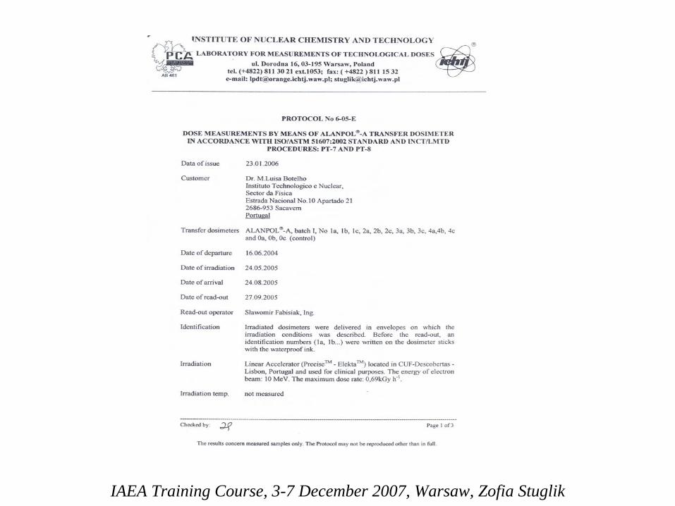
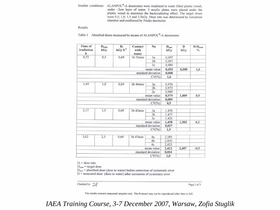
Regional Training Course on Validation and Process Control for Electron Beam Radiation Processing Technical Cooperation Project RER/8/010 “Quality Control Methods and Procedures for Radiation Technology” Warsaw, Poland, 3-8 December 2007 Organizers: International Atomic Energy Agency Institute of Nuclear Chemistry and Technology
-
Upload
khangminh22 -
Category
Documents
-
view
3 -
download
0
Transcript of Regional Training Course on Validation
Regional Training Course on Validation and Process Control
for Electron Beam Radiation Processing
Technical Cooperation Project RER/8/010 “Quality Control Methods and Procedures
for Radiation Technology”
Warsaw, Poland, 3-8 December 2007
Organizers: International Atomic Energy Agency
Institute of Nuclear Chemistry and Technology
Results of first RER/8010 comparison in technological
gamma ray dosimetry
Zofia Stuglik
Institute of Nuclear Chemistry and Technology, Laboratory for Measurement of Technological Doses, Warsaw, Poland
IAEA Training Course, 3-7 December 2007, Warsaw, Poland
Arrangement
of a comparison
• Before IAEA Training Course (April 2006, Warsaw) its participants were invited to bring for meeting some high dose dosimeters for irradiation in reference 60Co gamma field.
• Dosimeters should be a transfer-type. It means, they should not change their dosimetric signals during transportation between laboratories.
• Dose rate at a reference 60Co gamma field (INCT, Warsaw, Poland) has been traceable to a primary standard of absorbed dose maintained by National Physical Laboratory (NPL) Teddington, UK.
IAEA Training Course, 3-7 December 2007, Warsaw, Poland

Arrangement of comparison
• Dosimeters were irradiated during the meeting by a staff of a reference laboratory (LMTD/INCT) and returned to the participants.
• Irradiated dosimeters were analyzed at the participants laboratories according to their own procedures.
• Participants were sent an information about dose values on the Information Sheets to IAEA Officer.
• The reference laboratory sent the protocol of irradiation to IAEA Officer.
• All the data has been treated as strictly confidential.
IAEA Training Course, 3-7 December 2007, Warsaw, Poland
Why
our
laboratory
(Laboratory
for Measurements
of Technological
Doses
operated
in
the
Institute
of
Nuclear
Chemistry
and
Technology) was chosen
as organizer?
To be entitled to organize proficiency testing (PT) or interlaboratory comparisons (ILC) the organizer must demonstrate implementation of quality system according to at least one of the standards:
ISO/IEC 9001 ISO/IEC 17025 ISO/IEC Guide 43-1 ISO/Guide 34
IAEA Training Course, 3-7 December 2007, Warsaw, Poland

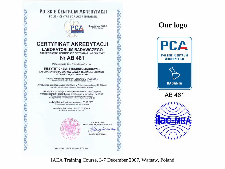
Laboratory for Measurements of Technological Doses Institute of Nuclear Chemistry and Technology
(LMTD/INCT)
fulfil this requirement because it had implemented the quality system concordant with ISO/IEC 17025:2005
standard.
The accreditation number of LMTD is AB 461
IAEA Training Course, 3-7 December 2007, Warsaw, Poland

LMTD/INCTwas accredited
by
Polish Centre for Accreditation
(PCA)
PCA
is a governmental body and cooperates with
European co-operation for Accreditation (EA) and
International Laboratory Accreditation Cooperation (ILAC)
IAEA Training Course, 3-7 December 2007, Warsaw, Poland

On the ground of multilateral agreement signed between PCA and EA, PCA
accreditations are valid not only in Poland but
also in all countries associated with EA and/or ILAC
IAEA Training Course, 3-7 December 2007, Warsaw, Poland
IAEA Training Course, 3-7 December 2007, Warsaw, Poland
Our
logo

holders60Co, Issledovatel
Irradiation
conditions
• Because of different size of participant’s dosimeters two different holders were used.
• An expanded uncertainty of dose rate evaluation in standard polystyrene holder was equal 1,2% (k=1) and in PMMA holder 1,9% (k=1), (k=coverage factor).
• Dosimeters were irradiated at the approximate electron equilibrium conditions at temperature: 22±1°C.
IAEA Training Course, 3-7 December 2007, Warsaw, Poland
The full results were known only to IAEA Officer M.H. de O.Sampa and two persons, chosen by her for data evaluation.
The individual results were known to their owner (the participant) and could be used by for evaluation and improving of his/her dosimetry system.
General information about state of art of high dose dosimetry in the countries participating in RER/8/010 were presented by me at June 2007 on RER/8/010 Meeting at Bran, Rumunia.
IAEA Training Course, 3-7 December 2007, Warsaw, Poland
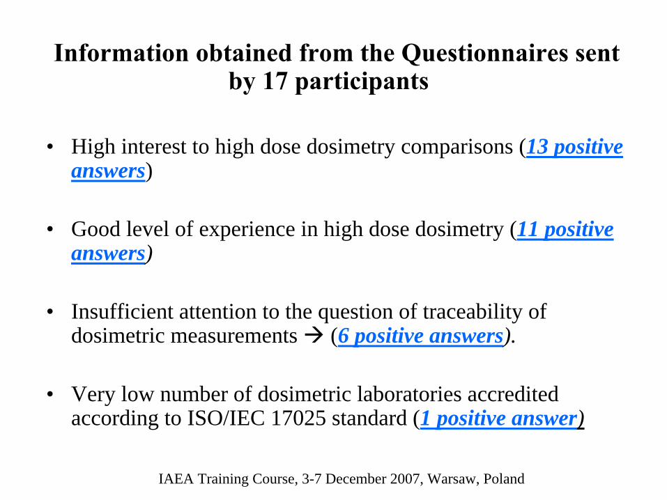
Information
obtained
from
the
Questionnaires sent by 17 participants
• High interest to high dose dosimetry comparisons (13 positive answers)
• Good level of experience in high dose dosimetry (11 positive answers)
• Insufficient attention to the question of traceability of dosimetric measurements (6 positive answers).
• Very low number of dosimetric laboratories accredited according to ISO/IEC 17025 standard (1 positive answer)
IAEA Training Course, 3-7 December 2007, Warsaw, Poland

Dosimetry
systems
used
(2006) in
the
region(according to participants declaration)
6 standard liquid dosimeters: ECB, Fricke, cerric/cerous)
3 TLD 3 films (FWT, other ones) 3 alanine-EPR dosimetry3 semiconductor dosimeters, track dosimeters2 calorimeters2 ionization chambers2 plates (perspex, other ones)
IAEA Training Course, 3-7 December 2007, Warsaw, Poland
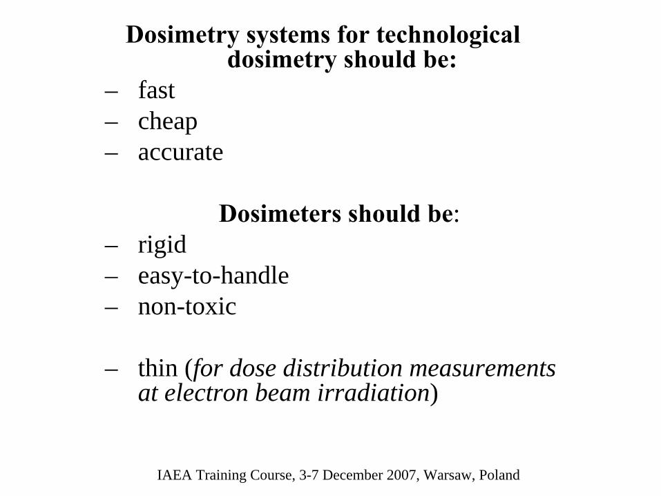
Dosimetry
systems
for technological dosimetry
should
be:
– fast– cheap– accurate
Dosimeters
should
be:– rigid– easy-to-handle– non-toxic
– thin (for dose distribution measurements at electron beam irradiation)
IAEA Training Course, 3-7 December 2007, Warsaw, Poland
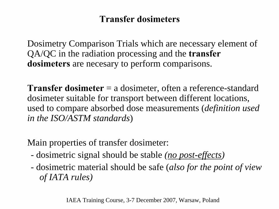
Transfer dosimeters
Dosimetry Comparison Trials which are necessary element of QA/QC in the radiation processing and the transfer dosimeters
are necesary to perform comparisons.
Transfer dosimeter
= a dosimeter, often a reference-standard dosimeter suitable for transport between different locations, used to compare absorbed dose measurements (definition used in the ISO/ASTM standards)
Main properties of transfer dosimeter:- dosimetric signal should be stable (no post-effects)- dosimetric material should be safe (also for the point of view
of IATA rules)
IAEA Training Course, 3-7 December 2007, Warsaw, Poland
Conclusion
• not all actually used dosimetry systems are suitable for technological purposes
• not all countries have dosimeters which can be used as transfer dosimeters
IAEA Training Course, 3-7 December 2007, Warsaw, Poland
IAEA Training Course, 3-7 December 2007, Warsaw, Poland
The problem
Many countries from our region use ECB dosimeters.
These dosimeters have very good dosimetric characteristics.
Their dosimetric properties allow to use them as transfer dosimeters.
Unfortunately, according the IATA rules they can not be sent by air.
IAEA Training Course, 3-7 December 2007, Warsaw, Poland
So, many our actions with ECB dosimeters are non legal.
At the time of 2006 comparison two our participants lost their ECB dosimeters in the airports – ECB dosimeters were recognized by custom officers as „dangerous”.
It can not be sent by fast posts, as DHL.

Dosimeters
used
in
the
Comparison
Trial, Warsaw,
2006
• 3 EPR/alanine• 3 films• 1 plate (PMMA)• 1 ECB
IAEA Training Course, 3-7 December 2007, Warsaw, Poland
IAEA Training Course, 3-7 December 2007, Warsaw, Poland
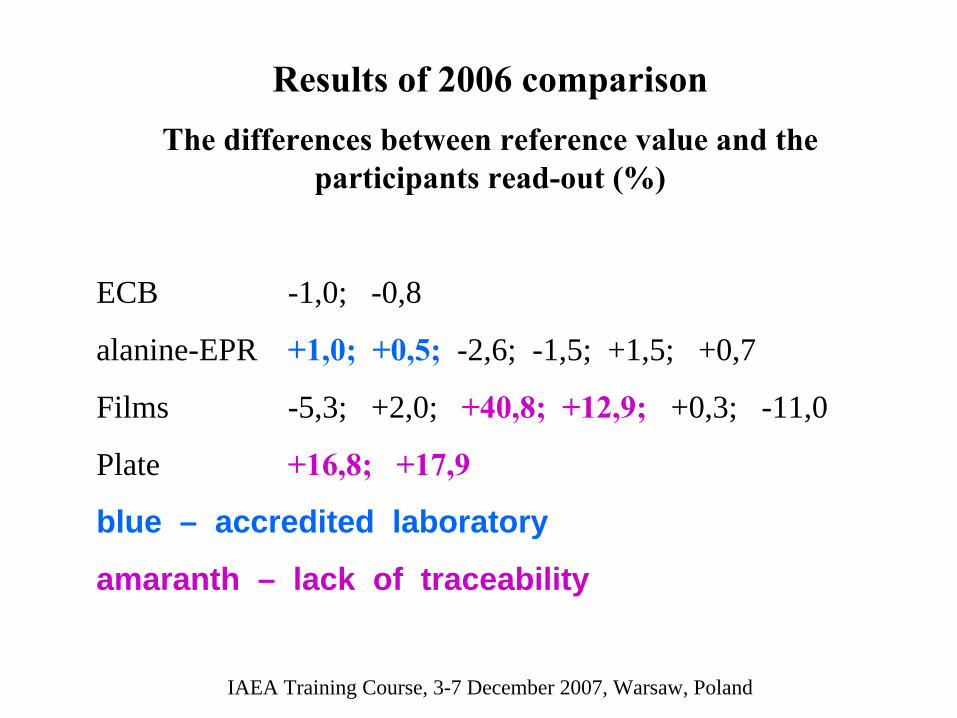
Results
of
2006 comparisonThe
differences
between
reference
value
and
the
participants
read-out
(%)
ECB -1,0; -0,8
alanine-EPR +1,0; +0,5;
-2,6; -1,5; +1,5; +0,7
Films -5,3; +2,0; +40,8; +12,9;
+0,3; -11,0
Plate +16,8; +17,9
blue – accredited laboratory
amaranth – lack of traceability
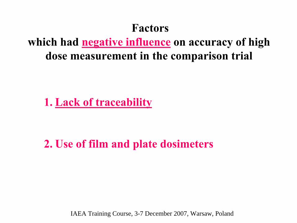
Factors which had negative influence
on accuracy
of
high dose
measurement
in the comparison trial
IAEA Training Course, 3-7 December 2007, Warsaw, Poland
1.
Lack
of
traceability
2.
Use
of
film and
plate
dosimeters
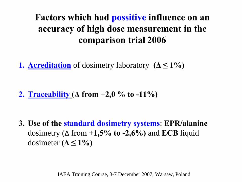
Factors
which had possitive
influence on an accuracy
of
high dose
measurement
in the
comparison trial
2006
IAEA Training Course, 3-7 December 2007, Warsaw, Poland
1.
Acreditation
of dosimetry laboratory (Δ ≤ 1%)
2.
Traceability
(Δ
from
+2,0 % to -11%)
3.
Use
of
the
standard dosimetry
systems: EPR/alanine dosimetry (Δ
from +1,5% to -2,6%)
and ECB liquid
dosimeter (Δ ≤ 1%)
ALANINE-EPR DOSIMETRY SYSTEM. WHY WE LIKE IT?
Zofia
Stuglik
Institute of Nuclear Chemistry and Technology, Laboratory for Measurement of Technological Doses,
Warsaw, Poland
IAEA Training Course, 3-7 December 2007, Warsaw, Zofia Stuglik
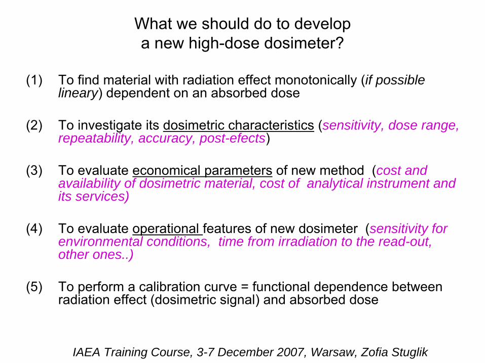
What we should do to developa new high-dose dosimeter?
(1)
To find material
with
radiation effect monotonically (if possible lineary) dependent on an
absorbed
dose
(2)
To investigate its
dosimetric
characteristics
(sensitivity, dose range, repeatability, accuracy, post-efects)
(3)
To evaluate economical parameters
of
new
method
(cost and availability of dosimetric material, cost of analytical instrument and its services)
(4)
To evaluate operational features of
new
dosimeter
(sensitivity for environmental conditions, time from irradiation to the read-out, other ones..)
(5)
To perform a
calibration curve = functional
dependence
between radiation
effect
(dosimetric
signal) and
absorbed
dose
IAEA Training Course, 3-7 December 2007, Warsaw, Zofia Stuglik
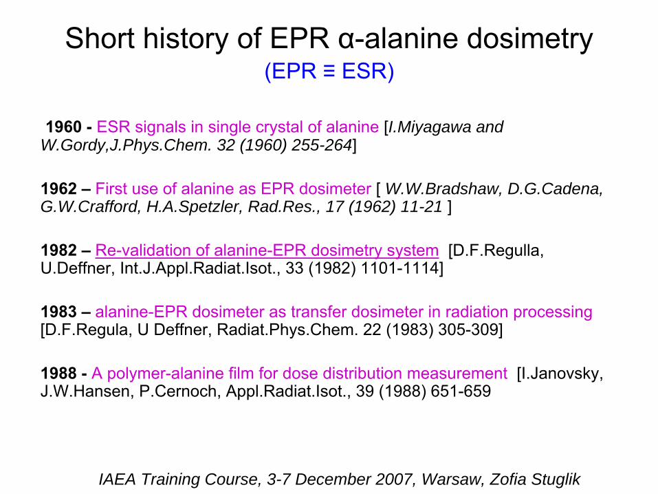
Short
history
of
EPR α-alanine
dosimetry(EPR ≡
ESR)
1960 -
ESR signals
in
single crystal
of
alanine
[I.Miyagawa and W.Gordy,J.Phys.Chem. 32 (1960) 255-264]
1962 –
First
use
of
alanine
as EPR dosimeter
[ W.W.Bradshaw, D.G.Cadena, G.W.Crafford, H.A.Spetzler, Rad.Res., 17 (1962) 11-21 ]
1982 –
Re-validation
of
alanine-EPR
dosimetry
system
[D.F.Regulla, U.Deffner, Int.J.Appl.Radiat.Isot., 33 (1982) 1101-1114]
1983 –
alanine-EPR
dosimeter
as transfer dosimeter
in
radiation
processing [D.F.Regula, U Deffner, Radiat.Phys.Chem. 22 (1983) 305-309]
1988 -
A polymer-alanine
film for dose
distribution
measurement
[I.Janovsky, J.W.Hansen, P.Cernoch, Appl.Radiat.Isot., 39 (1988) 651-659
IAEA Training Course, 3-7 December 2007, Warsaw, Zofia Stuglik
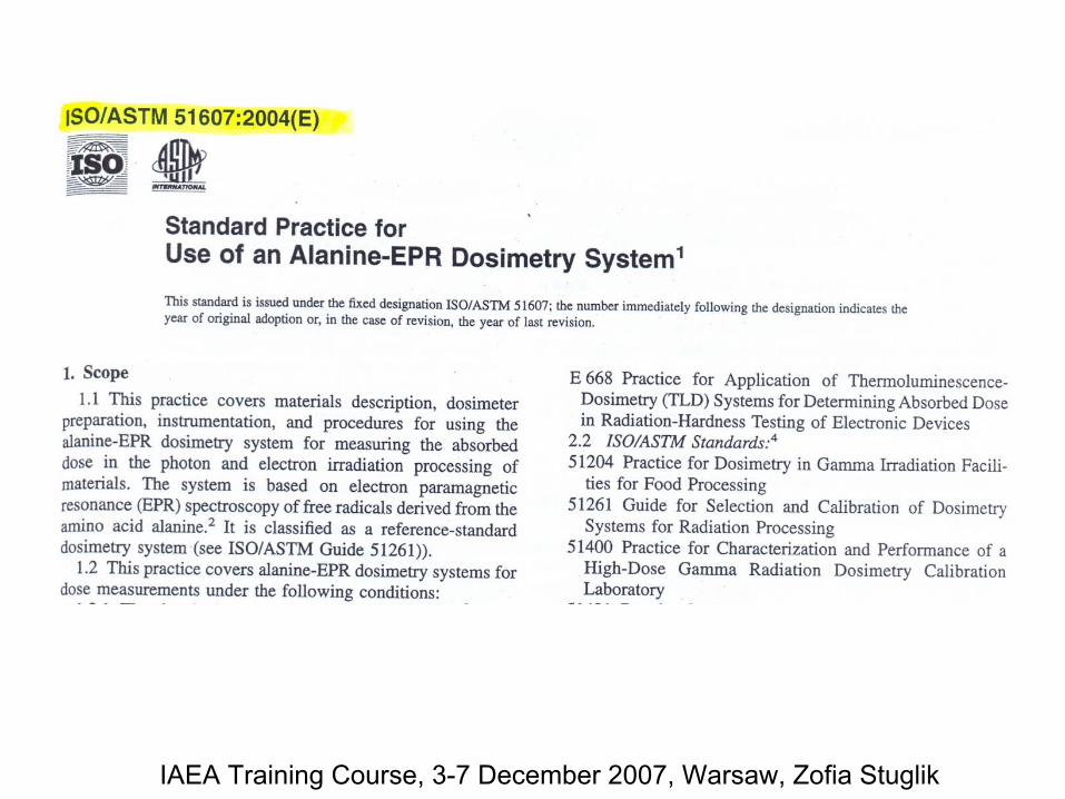
Standard Practicefor Use
of
an
Alanine-EPR
Dosimetry
System
1/ 1994 E 1607 - 94 ASTM1a/ International
Standard ISO 15566:1998(E)
2/ 1996 E 1607 - 96 ASTM
3/ 2002 ISO/ASTM 51607:2002(E)
4/ 2004 ISO/ASTM 51607:2004(E)
IAEA Training Course, 3-7 December 2007, Warsaw, Zofia Stuglik
IAEA Training Course, 3-7 December
2007, Warsaw, Zofia
Stuglik
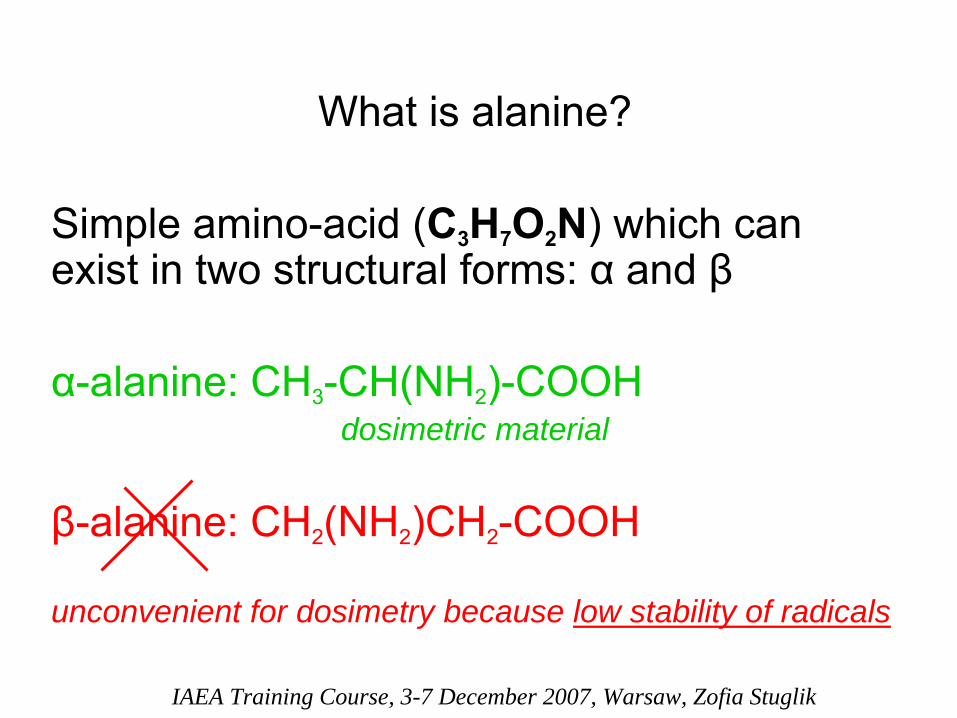
What
is
alanine?
Simple
amino-acid
(C3
H7
O2
N) which
can exist
in
two
structural
forms: α
and
β
α-alanine: CH3
-CH(NH2
)-COOH dosimetric material
β-alanine: CH2
(NH2
)CH2
-COOH
unconvenient for dosimetry because low stability of radicals
IAEA Training Course, 3-7 December 2007, Warsaw, Zofia Stuglik
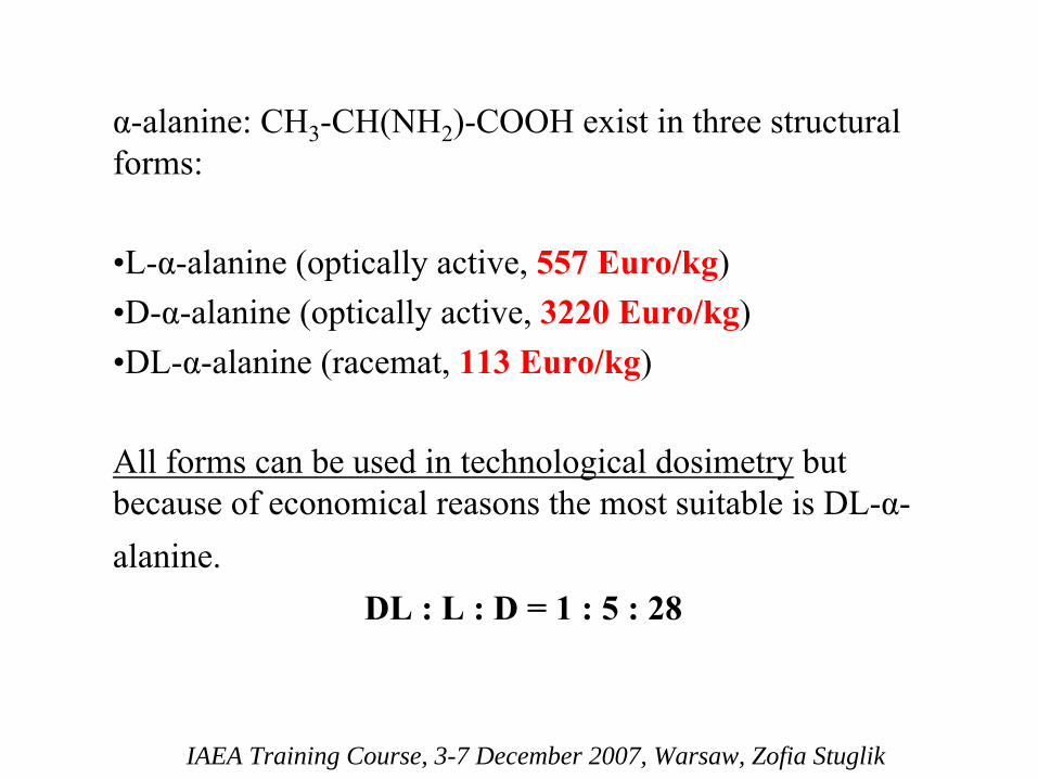
α-alanine: CH3
-CH(NH2
)-COOH exist
in
three
structural forms:
•L-α-alanine
(optically
active, 557 Euro/kg)•D-α-alanine
(optically
active,
3220 Euro/kg)
•DL-α-alanine
(racemat, 113 Euro/kg)
All
forms
can
be used
in
technological
dosimetry
but because
of
economical
reasons
the
most suitable
is
DL-α-
alanine.DL : L : D = 1 : 5 : 28
IAEA Training Course, 3-7 December 2007, Warsaw, Zofia Stuglik

Crystalline
α-alanine
CH3
-CH(NH2
)-COOH
CH3
-CH(NH3+)-COO-
zwitterionvery stable structure, melting point: 314,5 °C
FW 89,06
IAEA Training Course, 3-7 December
2007, Warsaw, Zofia
Stuglik

CH3
-CH(NH3+)-COO-
chemical
bond
energy
(eV)C-H
4,3
N-H
4,0C-O
3,6
C-C 3,5C-N
3,0
The
weakest
bond
is
C-N
and
it
is
broken
during
the radiolysis
giving
the
NH3 (amonium, stable molecule)
and
SAR
radical
IAEA Training Course, 3-7 December 2007, Warsaw, Zofia Stuglik
IAEA Training Course, 3-7 December 2007, Warsaw, Zofia Stuglik
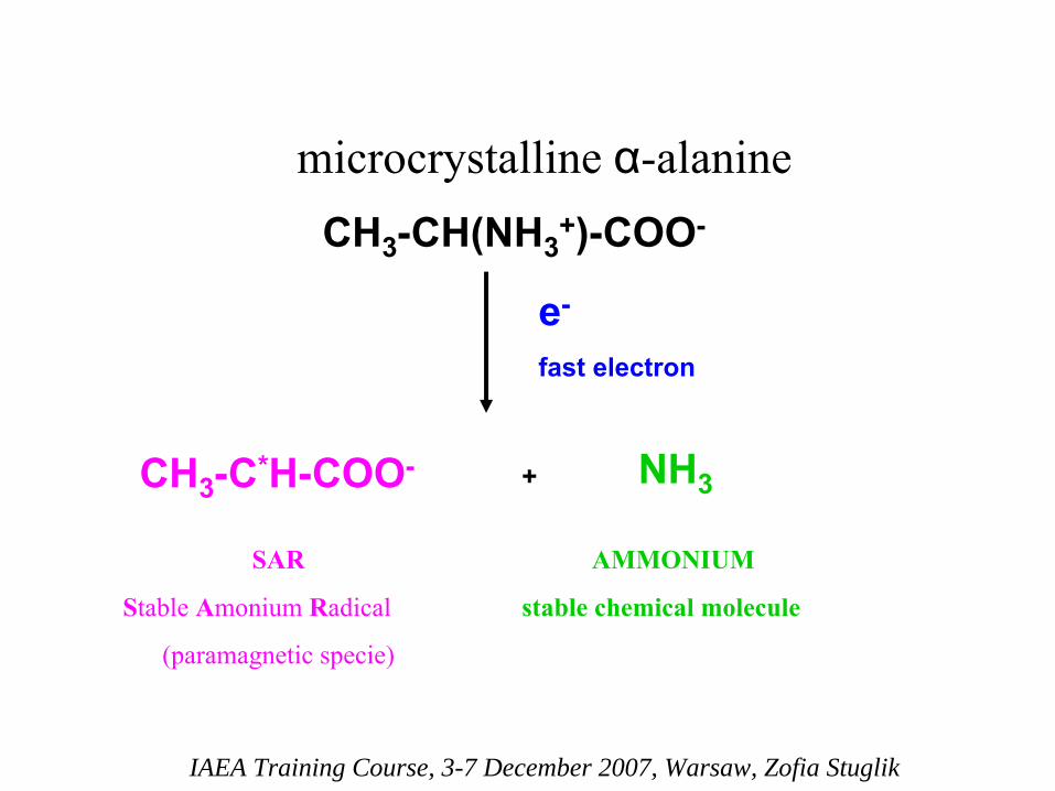
CH3
-CH(NH3+)-COO-
e-
fast
electron
CH3
-C*H-COO- + NH3
SAR
Stable
Amonium
Radical
(paramagnetic
specie)
AMMONIUM
stable
chemical
molecule
microcrystalline
α-alanine

On the base of this very stable (years) SAR radical
generated
in
crystalline
α-
alanine
it
is
established an
alanine-EPR
dosimetry
system.
IAEA Training Course, 3-7 December 2007, Warsaw, Zofia Stuglik

IAEA Training Course, 3-7 December 2007, Warsaw, Zofia Stuglik
Date: 3 .0 6 .1 9 0 7 Time: 1 2 :0 2
Fi l ename: F:\WIDMAE~1 \MORDAL~2 \mor1 .spc
[]3400 3425 3450 3475 3500 3525 3550 3575
- 250
- 200
- 150
- 100
- 50
0
50
100
150
200
*10^ 3]
EPR signal
in
microcrystalline
α-alanine
ΔH dosimetric
signal
magnetic
field [mT]
IAEA Training Course, 3-7 December 2007, Warsaw, Zofia Stuglik
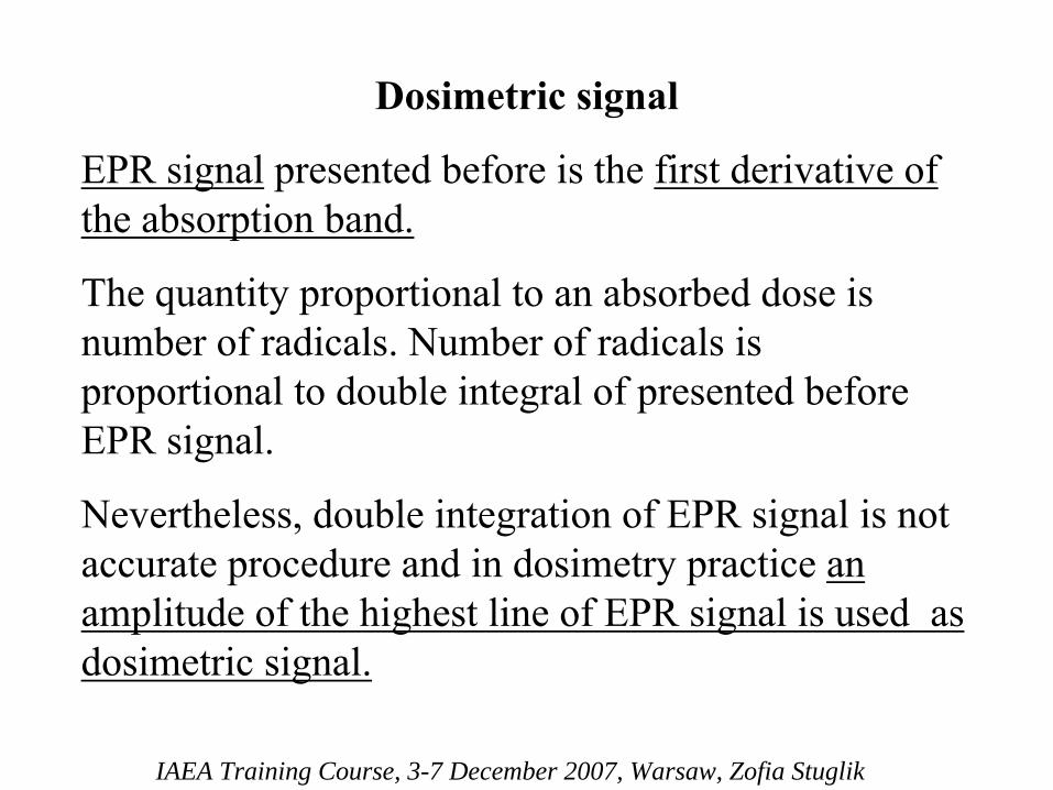
Dosimetric
signal
EPR signal
presented
before
is
the
first
derivative
of the
absorption
band.
The
quantity
proportional
to an
absorbed
dose
is number
of
radicals. Number
of
radicals
is
proportional
to double integral
of
presented
before EPR signal.
Nevertheless, double integration
of
EPR signal
is
not accurate
procedure
and
in
dosimetry
practice
an
amplitude
of
the
highest
line
of
EPR signal
is
used
as dosimetric
signal.

EPR measurementsThe
method
was developed
at
1941 year
by
Zavojskijand
is
connected
with
Zeeman
effect.
IAEA Training Course, 3-7 December 2007, Warsaw, Zofia Stuglik
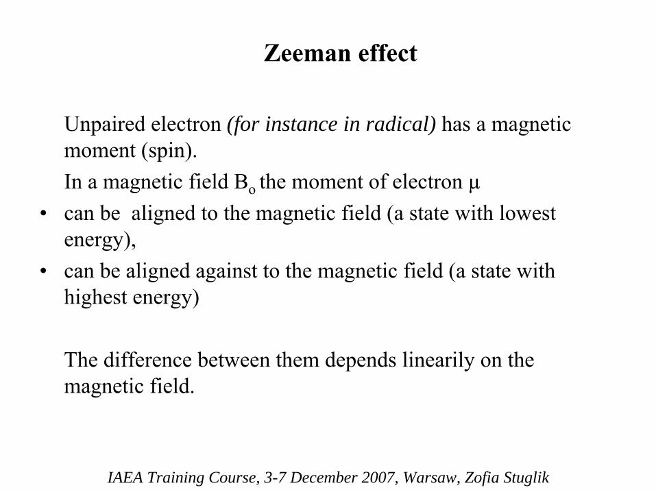
Zeeman
effect
Unpaired
electron
(for instance in radical) has
a magnetic moment (spin).
In a magnetic
field Bo the
moment of
electron
µ•
can
be aligned
to the
magnetic
field (a state
with
lowest
energy),•
can
be aligned
against
to the
magnetic
field (a state
with
highest
energy)
The
difference
between
them
depends
linearily
on the magnetic
field.
IAEA Training Course, 3-7 December 2007, Warsaw, Zofia Stuglik

EPRWhen
we use
not only
magnetic
field but also
microwave
field with
the
frequency
~10 GHz
(X range, λ~3cm) we can observe
an
absorption
of
microwave
energy
by spin
population
with
lower
energy EPR signal generation.
IAEA Training Course, 3-7 December 2007, Warsaw, Zofia Stuglik
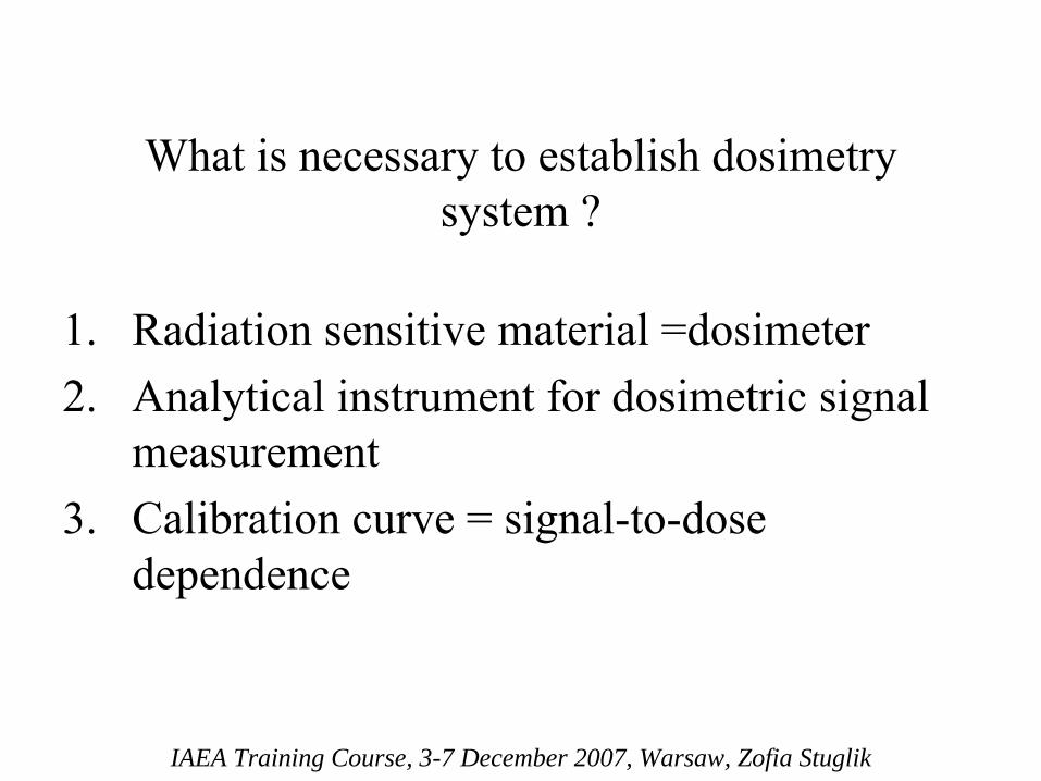
1.
Radiation
sensitive
material
=dosimeter2.
Analytical
instrument for dosimetric
signal
measurement3.
Calibration
curve
= signal-to-dose
dependence
IAEA Training Course, 3-7 December 2007, Warsaw, Zofia Stuglik
What
is
necessary
to establish
dosimetry system ?

Different
kinds
of
alanine-EPR
dosimeters
IAEA Training Course, 3-7 December 2007, Warsaw, Zofia Stuglik

Kodak alanine-EPR
film dosimeter
IAEA Training Course, 3-7 December 2007, Warsaw, Zofia Stuglik
IAEA Training Course, 3-7 December 2007, Warsaw, Zofia Stuglik
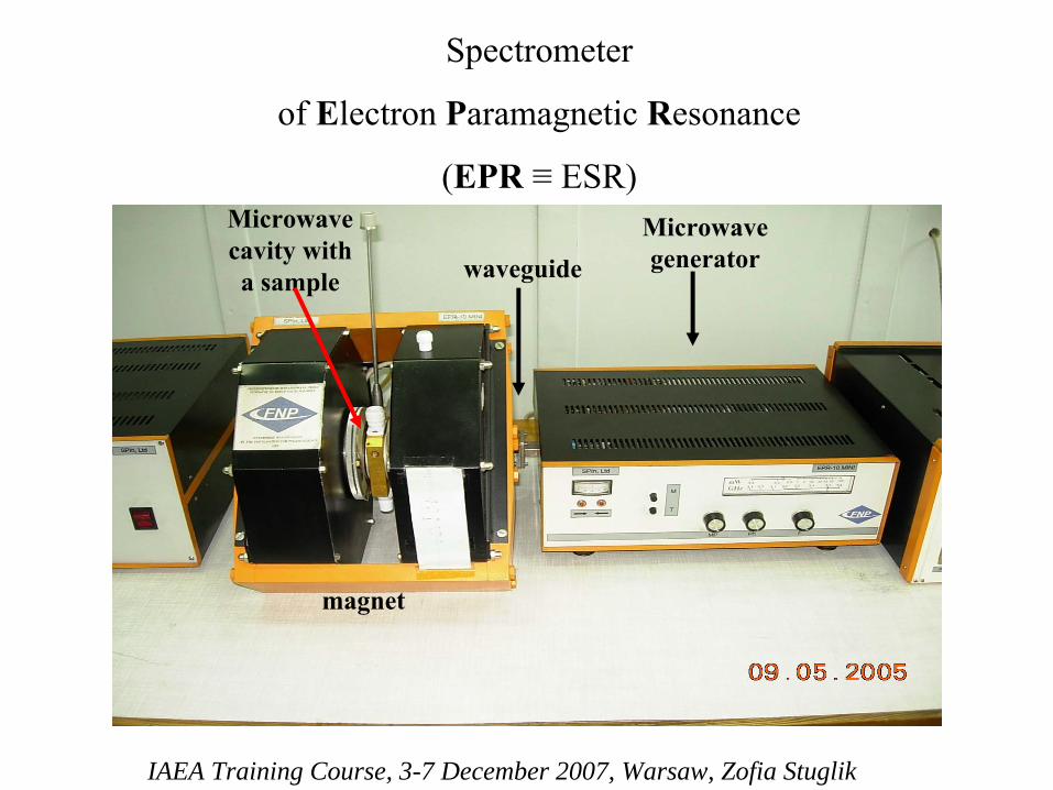
Spectrometer
of
Electron
Paramagnetic
Resonance
(EPR
≡
ESR)
magnet
Microwave cavity with a sample
Microwave generatorwaveguide
IAEA Training Course, 3-7 December 2007, Warsaw, Zofia Stuglik
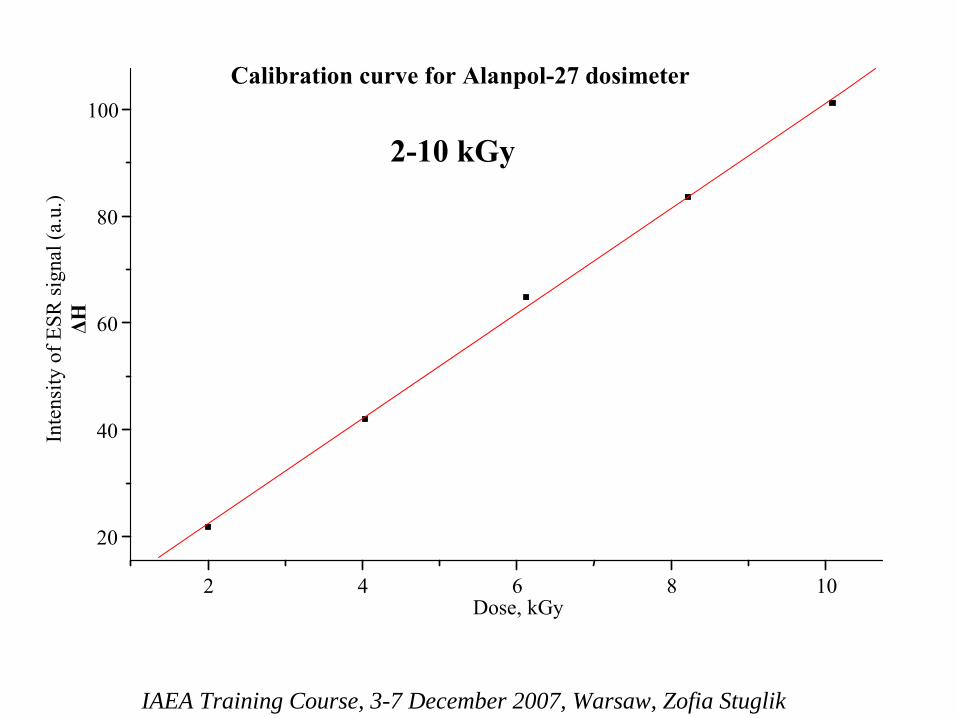
2 4 6 8 10
20
40
60
80
100
Inte
nsity
of E
SR si
gnal
(a.u
.) ΔH
Calibration curve for Alanpol-27 dosimeter
Dose, kGy
2-10 kGy

IAEA Training Course, 3-7 December 2007, Warsaw, Zofia Stuglik
Dozymetr Alanpol 27 - krzywa wzorcowa (zakres: 0,4 - 60kGy)
y = -0,0007x2 + 0,1159x + 0,0267R2 = 0,9997
0,0
0,5
1,0
1,5
2,0
2,5
3,0
3,5
4,0
4,5
5,0
0 10 20 30 40 50 60 70Dawka pochłonięta, kGy
ΔH
, j. u
.
0,4 kGy
–
60 kGy

Advantages
of
alanine-EPR
dosimetry
system
•
dosimetric
signal
is
stable
during
very
long
time
(years)•
wide dose detection range (1Gy -
100 kGy)
•
linear
signal-to-dose
dependence
(≤
10 kGy)•
Dosimetric
signal
is
energy
and
dose
rate independent
(gamma and electron beams)•
accuracy
•
non-destructive and
fast
detection method •
low temperature coefficient of
irradiation
•
different
shapes
of
dosimeters, also
films•
dosimeters
are
not very
expensive
•
easy to handle•
non-toxic
•
chemical composition of
dosimetric
material
is
similar to the chemical
composition
of
organic
matter
•
environmental
conditions•
1expensive 2.
energy and dose
IAEA Training Course, 3-7 December 2007, Warsaw, Zofia Stuglik

Disadvantages
of
alanine-EPR
dosimetry
system
EPR signal
•
Sensitive
to light
(for long
time
illumination)•
Sensitive
to water
and
humidity
EPR spectrometer
•
Expensive•
Market monopolized
by one producer
Small
EPR spectrometers
for dosimetry
(20 000 -
60 000 Euro)
IAEA Training Course, 3-7 December 2007, Warsaw, Zofia Stuglik
IAEA Training Course, 3-7 December 2007, Warsaw, Zofia Stuglik
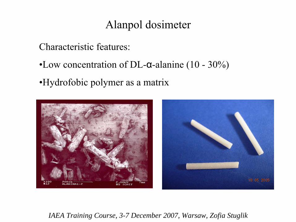
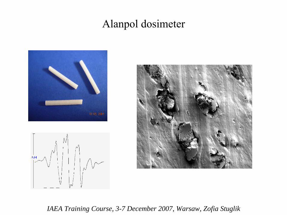
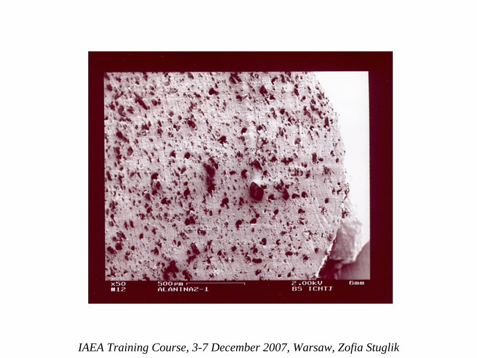
Alanpol
dosimeter
IAEA Training Course, 3-7 December 2007, Warsaw, Zofia Stuglik
Characteristic
features:
•Low
concentration
of
DL-α-alanine
(10 -
30%)
•Hydrofobic
polymer
as a matrix

Alanpol
dosimeter
IAEA Training Course, 3-7 December 2007, Warsaw, Zofia Stuglik
Alanpol
dosimeter
IAEA Training Course, 3-7 December 2007, Warsaw, Zofia Stuglik
IAEA Training Course, 3-7 December 2007, Warsaw, Zofia Stuglik
IAEA Training Course, 3-7 December 2007, Warsaw, Zofia Stuglik
IAEA Training Course, 3-7 December 2007, Warsaw, Zofia Stuglik
IAEA Training Course, 3-7 December 2007, Warsaw, Zofia Stuglik
IAEA Training Course, 3-7 December 2007, Warsaw, Zofia Stuglik
IAEA Training Course, 3-7 December 2007, Warsaw, Zofia Stuglik
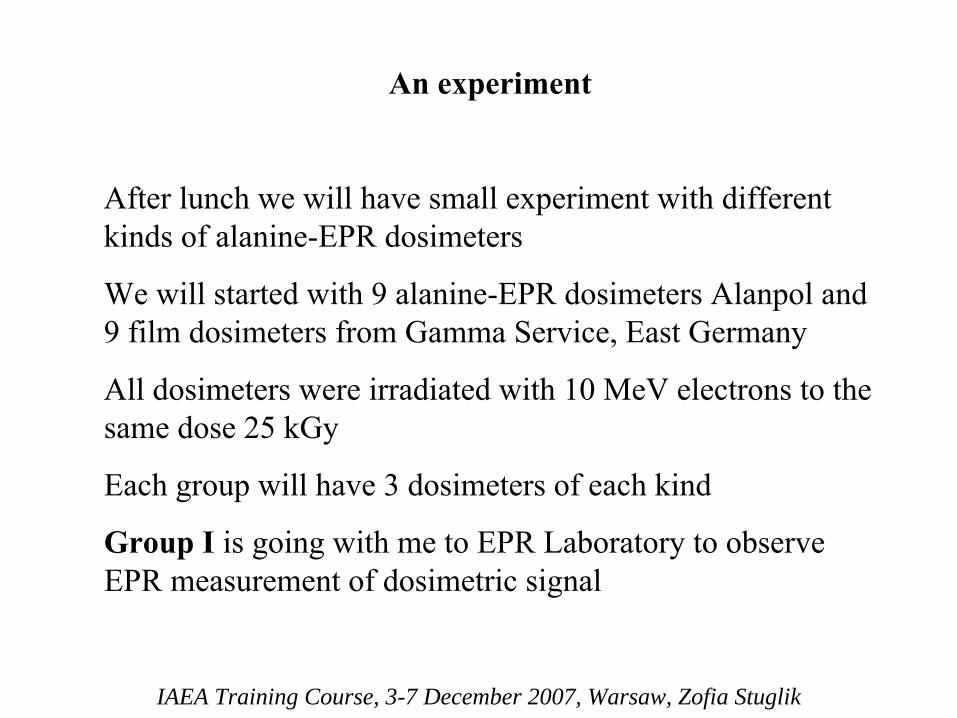
An
experiment
After
lunch we will have
small
experiment
with
different kinds
of
alanine-EPR
dosimeters
We will started
with
9 alanine-EPR
dosimeters
Alanpol
and 9 film dosimeters
from
Gamma Service, East
Germany
All
dosimeters
were
irradiated
with
10 MeV
electrons
to the same dose
25 kGy
Each
group
will have
3 dosimeters
of
each
kind
Group
I
is
going
with
me to EPR Laboratory
to observe EPR measurement
of
dosimetric
signal
IAEA Training Course, 3-7 December 2007, Warsaw, Zofia Stuglik
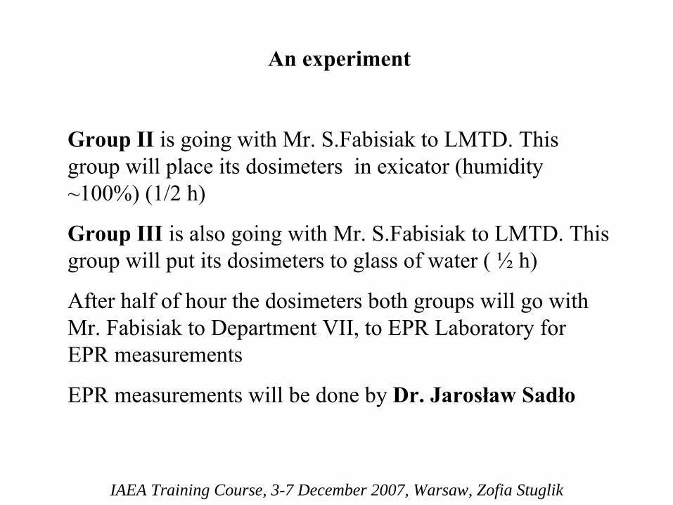
An experiment
Group II
is going with Mr. S.Fabisiak
to LMTD. This group will place its dosimeters in exicator
(humidity
~100%) (1/2 h)
Group III
is also going with Mr. S.Fabisiak
to LMTD. This group will put its dosimeters to glass of water ( ½
h)
After half of hour the dosimeters both groups will go with Mr. Fabisiak
to Department VII, to EPR Laboratory for
EPR measurements
EPR measurements will be done by Dr. Jarosław
Sadło

IAEA Training Course, 3-7 December 2007, Warsaw, Zofia Stuglik
The results of all measurements will be given to the participants today or tomorrow.
You will able
to observe that the sensitivity of different alanine
dosimeters for environmental condition is different
We expected that signal in Alanpol
will be practically the same for all dosimeters.
EPR
signals
in GS films will strongly depend on the storage conditions.
SelectionSelection ofof materialsmaterials ((polymerspolymers) for ) for radiationradiation sterilizationsterilization
GraGrażżyna Przybytniakyna Przybytniak
International Atomic Energy AgencyDecember 3 – 7, 2007
Regional Training Course on Validation and Process Controlfor Electron Beam Radiation Processing

Progress Progress inin radiationradiation processingprocessingSubstantial fraction of cable insulation is crossSubstantial fraction of cable insulation is cross--linked using radiation (flame retardant wirelinked using radiation (flame retardant wires s and and cables cables –– for for safsafeetyty and to reduce the total and to reduce the total weight).weight).Nylons for automobilesNylons for automobiles..RotomoldedRotomolded drums (transportation of hazardous drums (transportation of hazardous chemical wastes).chemical wastes).Application in rubber tires.Application in rubber tires.Radiation vulcanization of rubber latexRadiation vulcanization of rubber latex..Radiation crossRadiation cross--linked linked SiCSiC fiber.fiber.Polymer recycling.Polymer recycling.HydrogelsHydrogels –– wound dressing, soft contact lenses, wound dressing, soft contact lenses, controlledcontrolled––release drug deliveryrelease drug delivery..
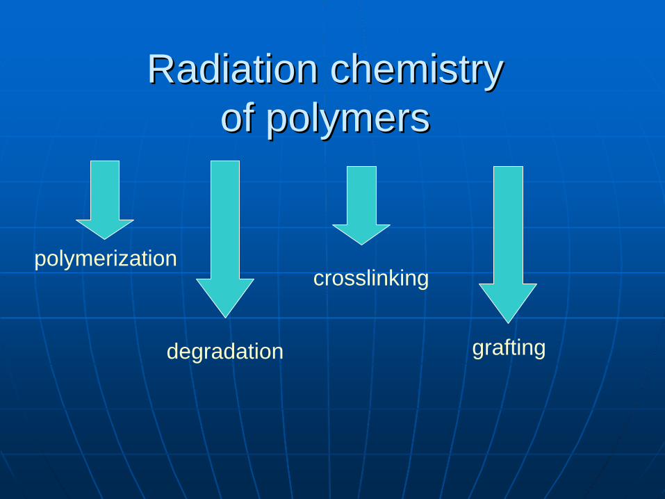
RadiationRadiation chemistrychemistry ofof polymerspolymers
polymerizationcrosslinking
degradation grafting
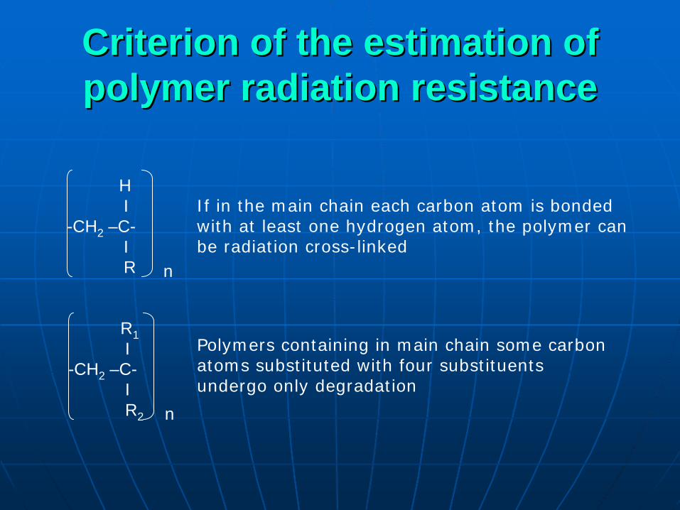
Criterion of the estimation of Criterion of the estimation of polymer radiation resistancepolymer radiation resistance
HI
-CH2 –C-IR n
R1I
-CH2 –C-IR2 n
If in the main chain each carbon atom is bonded with at least one hydrogen atom, the polymer can be radiation cross-linked
Polymers containing in main chain some carbonatoms substituted with four substituentsundergo only degradation
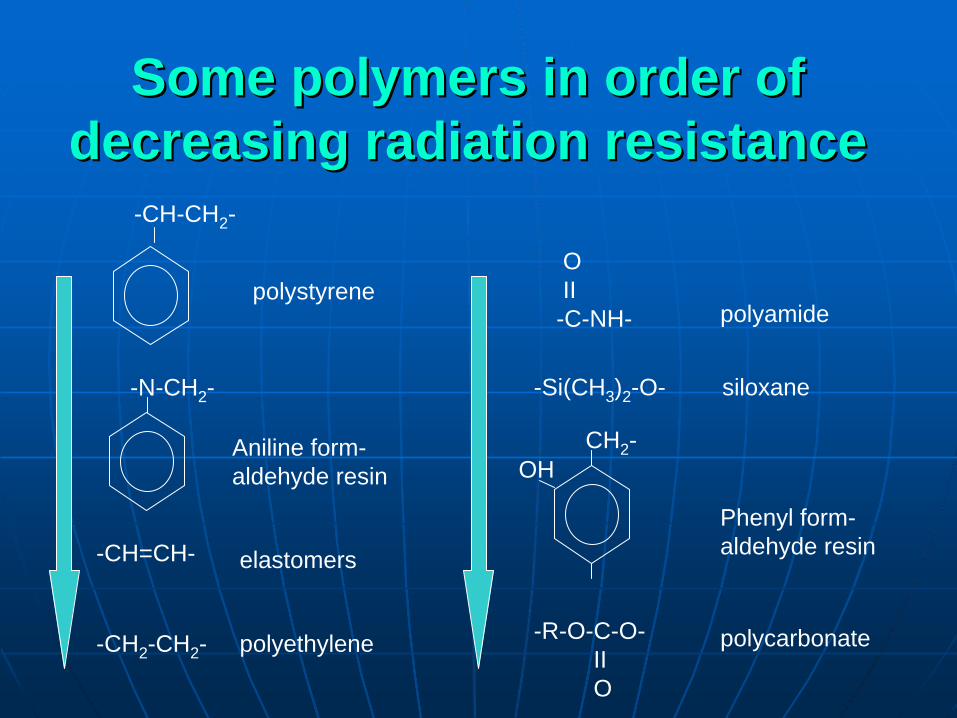
Some polymers in order of Some polymers in order of decreasing radiation resistancedecreasing radiation resistance
-CH-CH2 -
-N-CH2 -
-CH=CH-
-CH2 -CH2 -
OII-C-NH-
-Si(CH3 )2 -O-
CH2 -OH
-R-O-C-O-IIO
polystyrene
Aniline form-aldehyde resin
polyethylene
elastomers
polyamide
siloxane
Phenyl form-aldehyde resin
polycarbonate
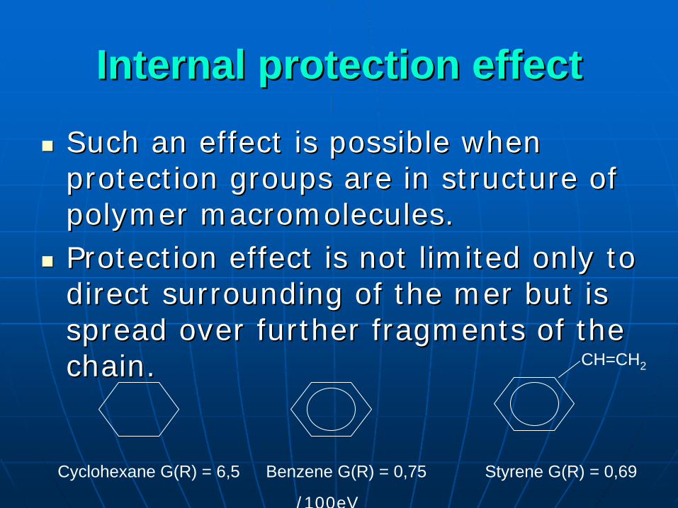
Internal protection effectInternal protection effect
Such an effect is possible when Such an effect is possible when protection groups are in structure of protection groups are in structure of polymer macromolecules.polymer macromolecules.Protection effect is not limited only to Protection effect is not limited only to direct surrounding of the direct surrounding of the mermer but is but is spread over further fragments of the spread over further fragments of the chain.chain.
Cyclohexane G(R) = 6,5 Benzene G(R) = 0,75
CH=CH2
Styrene G(R) = 0,69
/100eV
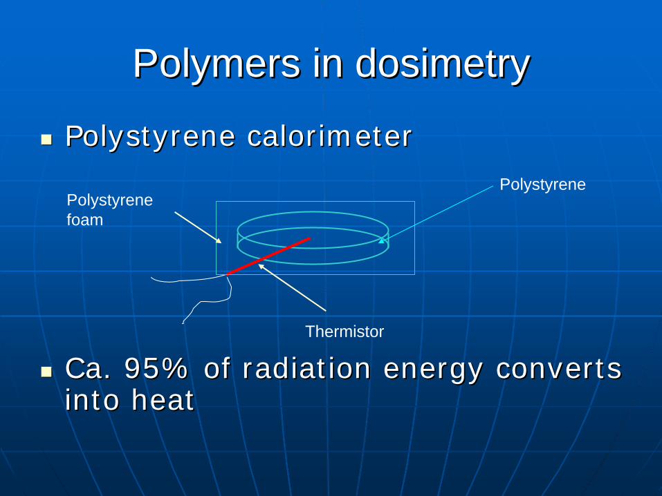
PolymersPolymers inin dosimetrydosimetry
Polystyrene Polystyrene calorcaloriimetmeterer
Ca. 95% of radiation energy converts Ca. 95% of radiation energy converts into heatinto heat
Polystyrene
Thermistor
Polystyrenefoam
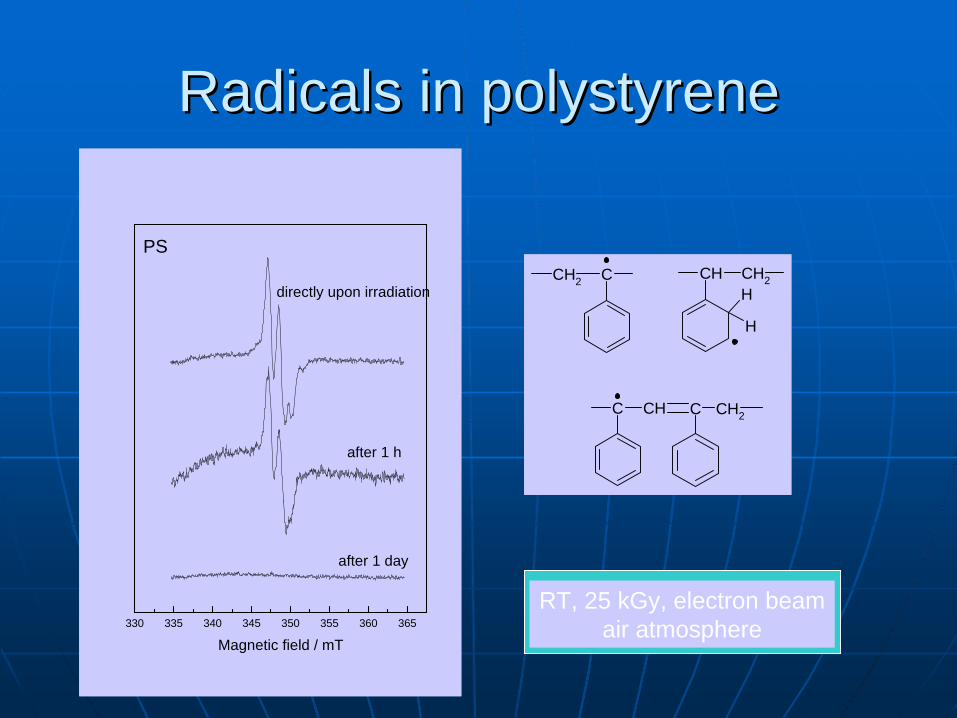
CCH2 CH2CHH
H
C CH C CH2
330 335 340 345 350 355 360 365
after 1 day
after 1 h
directly upon irradiation
PS
Magnetic field / mT
RT, 25 kGy, electron beamair atmosphere
RadicalsRadicals inin polystyrenepolystyrene
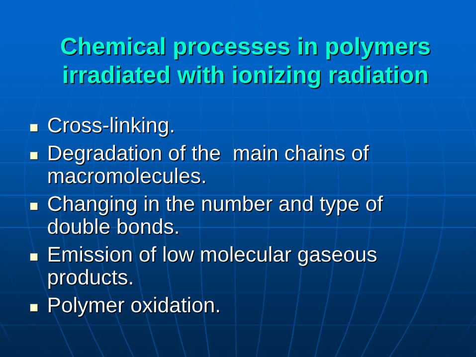
ChemicalChemical processesprocesses inin polymerspolymers irradiatedirradiated withwith ionizing ionizing radiationradiation
CrossCross--linkinglinking..Degradation of the main chains of Degradation of the main chains of macromolecules.macromolecules.Changing in the number and type of Changing in the number and type of double bonds. double bonds. Emission of low molecular gaseous Emission of low molecular gaseous productsproducts..Polymer oxidation.Polymer oxidation.

Heat of polymerizationHeat of polymerization
PolymerPolymer EffectEffect HeatHeat ofof polymerizationpolymerization
PolyethylenePolyethylenePolypropylenePolypropylenePolystyrenePolystyrenePolyisobutylenePolyisobutylenepolymethylmethacrylatepolymethylmethacrylate
CrosslinkCrosslinkCrosslinkCrosslinkCrosslinkCrosslinkChainChain scissionscissionChainChain scissionscission
22 kcal/mol22 kcal/mol16.5 kcal/mol16.5 kcal/mol17 kcal/mol17 kcal/mol13 kcal/mol13 kcal/mol13kcal/mol13kcal/mol
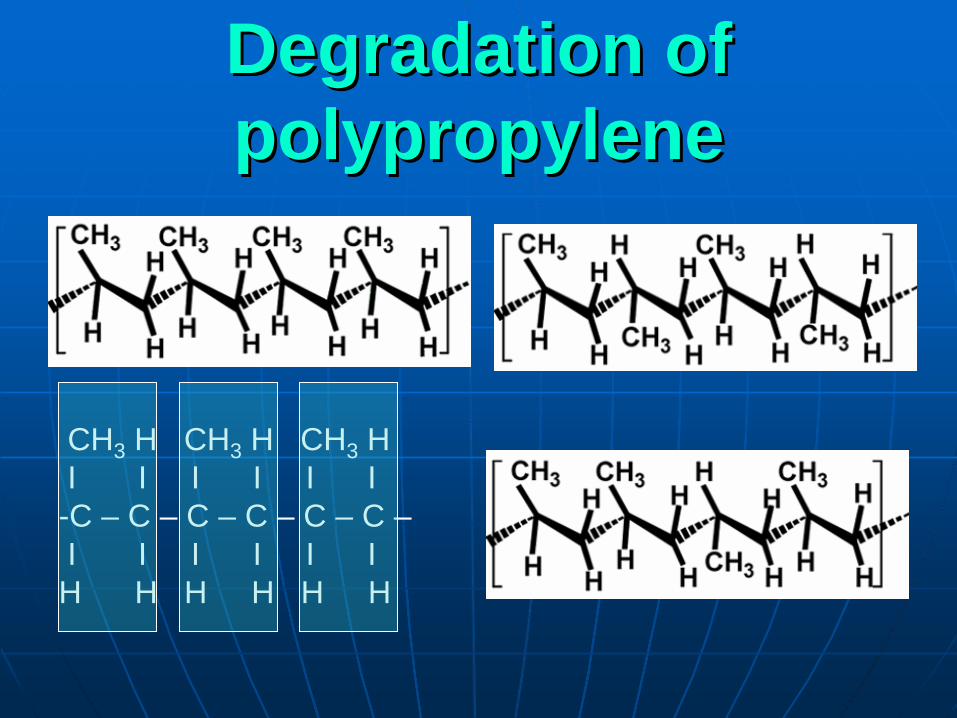
DegradationDegradation ofof polypropylenepolypropylene
CH3 H CH3 H CH3 HI I I I I I-C – C – C – C – C – C –I I I I I IH H H H H H
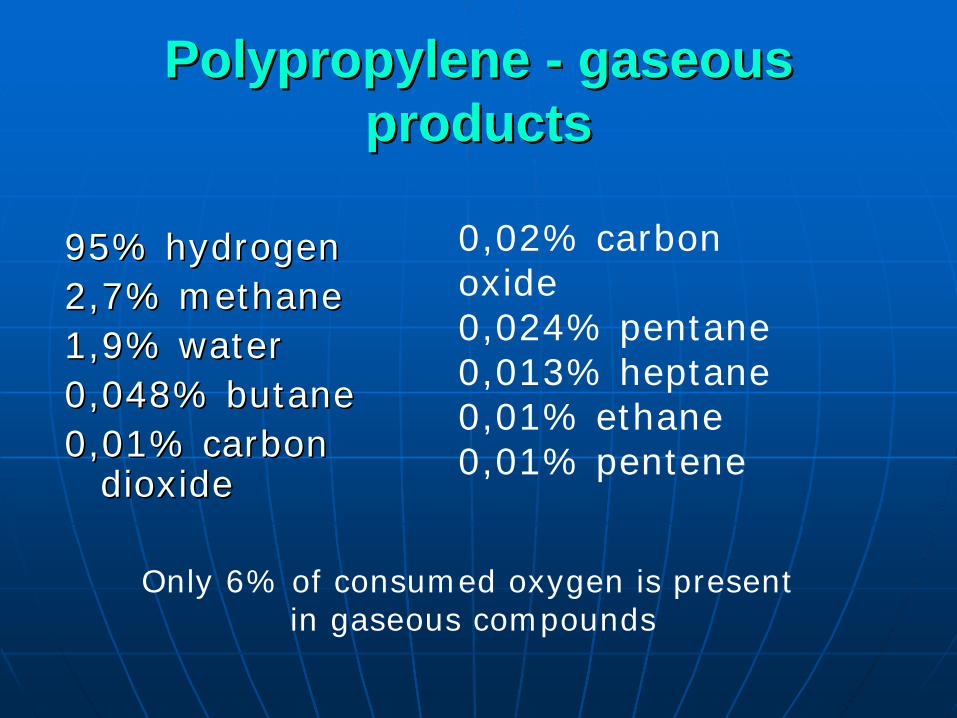
PolypropylenePolypropylene -- gaseous gaseous productsproducts
95% hydrogen95% hydrogen2,7% methane2,7% methane1,9% water1,9% water0,048% butane0,048% butane0,01% carbon 0,01% carbon
dioxidedioxide
0,02% carbon oxide0,024% pentane0,013% heptane0,01% ethane0,01% pentene
Only 6% of consumed oxygen is presentin gaseous compounds

AlkylAlkyl radicalsradicals ofof polypropylenepolypropylene
-CH2 C•(CH3 )CH2 -
-CH2 C•HCH2 --CH(CH3 )C•HCH(CH3 )-
-CH(CH3 )CH2 C•H
-CH(CH3 )CH2 C•(CH3 )
-CH2 CHCH2-I
•CH2
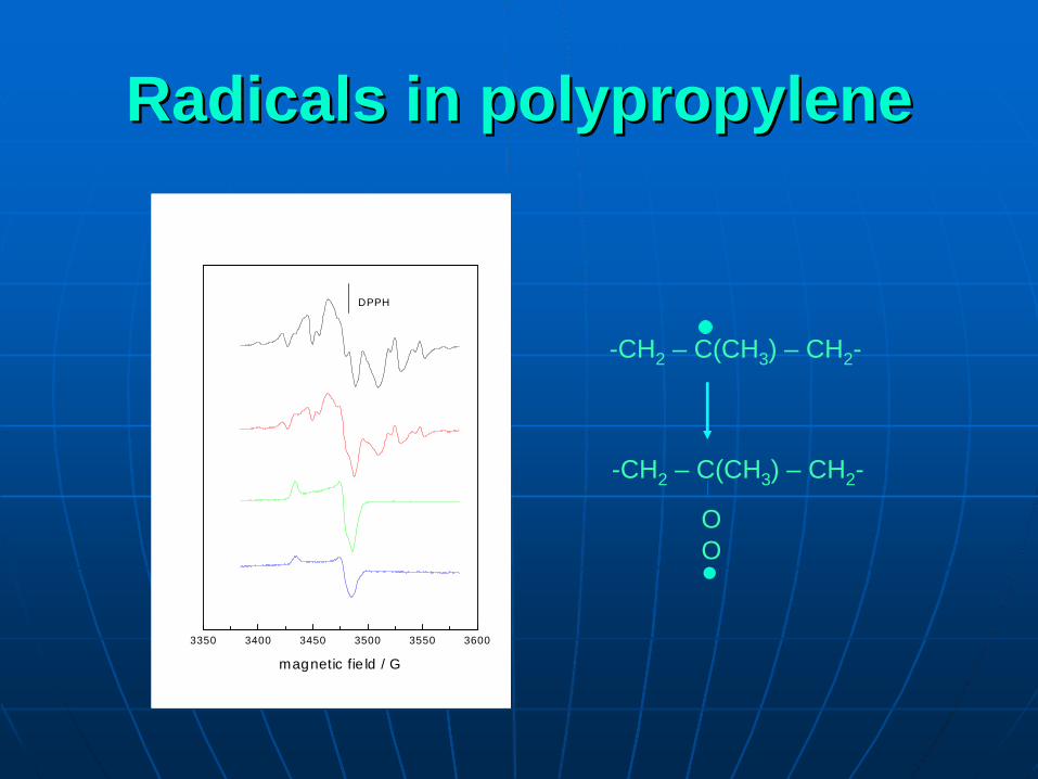
RadicalsRadicals inin polypropylenepolypropylene
3350 3400 3450 3500 3550 3600
DPPH
magnetic fie ld / G
-CH2 – C(CH3 ) – CH2 -
-CH2 – C(CH3 ) – CH2 -
OO

PREFERENCESPREFERENCES
RADICALS BOND DISSOCIATION ENERGY CH3 CH2
•
422 kJ/mol
CH3 CH•
CH3 413(CH3 )3 C•
397CH2 =CHCH2
•
359
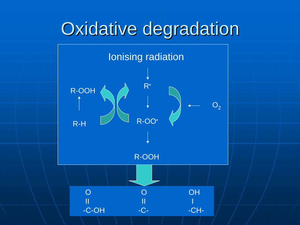
OxidativeOxidative degradationdegradation
R•
Ionising radiation
R-OO•
R-OOH
O2
R-H
R-OOH
O O OHII II I-C-OH -C- -CH-
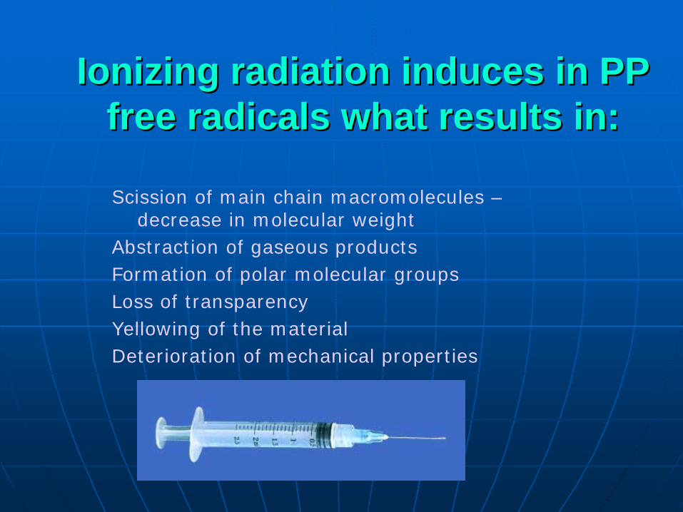
Scission of main chain macromolecules – decrease in molecular weight
Abstraction of gaseous productsFormation of polar molecular groups Loss of transparencyYellowing of the materialDeterioration of mechanical properties
IoniIonizzinging radiation induces in PP radiation induces in PP free radicals what results in:free radicals what results in:
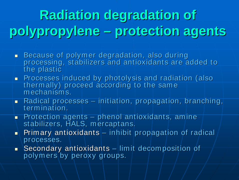
Radiation degradation of Radiation degradation of polypropylene polypropylene –– protection agentsprotection agents
Because of polymer degradation, also during Because of polymer degradation, also during processing, stabilizers and antioxidants are added to processing, stabilizers and antioxidants are added to the plastic the plastic Processes induced by Processes induced by phphotolysisotolysis and radiation (also and radiation (also thermally) proceed according to the same thermally) proceed according to the same mechanisms. mechanisms. Radical processes Radical processes –– initiation, propagation, branching, initiation, propagation, branching, termination. termination. Protection agents Protection agents –– phenol antioxidantsphenol antioxidants,, amine amine stabilizers, HALS, stabilizers, HALS, mercaptansmercaptans..Primary antioxidants Primary antioxidants –– inhibit propagation of radical inhibit propagation of radical processes. processes. Secondary antioxidants Secondary antioxidants –– limit decomposition of limit decomposition of polymers by polymers by peroxyperoxy groups.groups.

Comparison of spin trapping by Comparison of spin trapping by various agentsvarious agents
O
H
O. O
ROO ROO..
OOR
N
H
N
O.O.
R.
N
ORROO.
-ROOR
Piperydinederivatives
Phenol derivatives
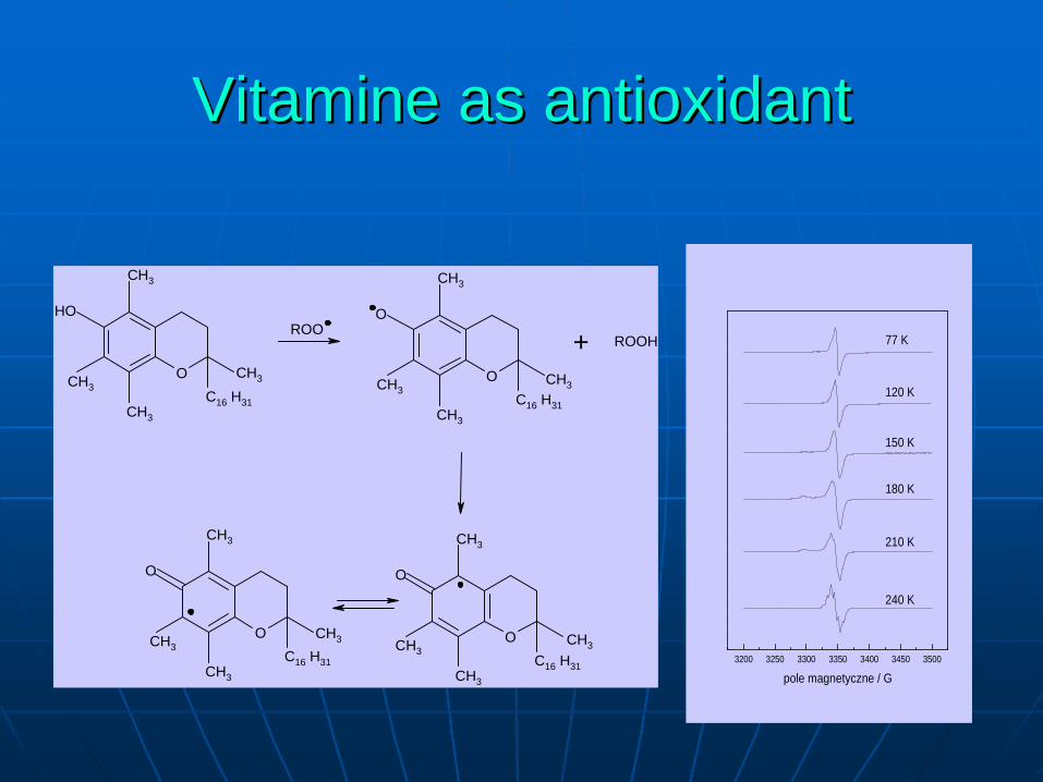
VitamineVitamine as as antioxidantantioxidant
O CH3CH3
CH3
CH3
C16 H31
HOROO
OCH3
CH3
CH3
C16 H31
O
OCH3
CH3
CH3
C16 H31
O
+ ROOH
OCH3
CH3
CH3
C16 H31
O
CH3
CH3 CH33200 3250 3300 3350 3400 3450 3500
240 K
210 K
180 K
150 K
120 K
77 K
pole magnetyczne / G
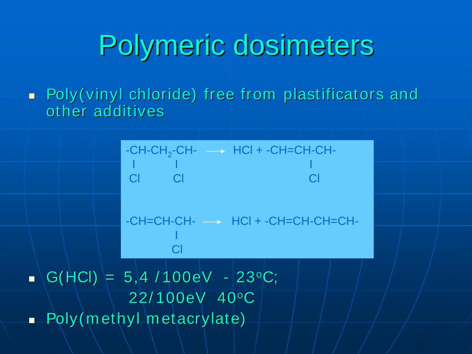
PolymericPolymeric dosimetersdosimetersPoly(vinylPoly(vinyl chloride) free from chloride) free from plastificatorsplastificators and and other other additadditiviveses
G(HClG(HCl) = 5,4 /100eV ) = 5,4 /100eV -- 2323ooC;C;22/100eV 4022/100eV 40ooCC
Poly(methylPoly(methyl metacrylatemetacrylate))
-CH-CH2 -CH- HCl + -CH=CH-CH-I I ICl Cl Cl
-CH=CH-CH- HCl + -CH=CH-CH=CH-ICl
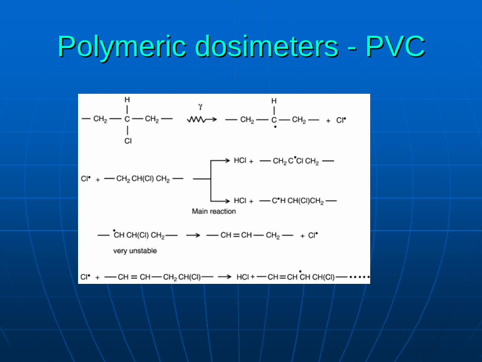
PolymericPolymeric dosimetersdosimeters -- PVCPVC

RadiationRadiation yieldyield ofof hydrogenhydrogen
PolymerPolymer G(HG(H22 ) / ) / μμmol/Jmol/J SupplierSupplier
PP PP freefree fromfrom additivesadditivesPP PP freefree fromfrom additivesadditivesPP PP isotacticisotacticPP PP sydiotacticsydiotacticParafilmParafilm
0.400.400.370.370.260.260.330.330.340.34
F401 (F401 (isotacticisotactic) PKN ORLEN S.A.) PKN ORLEN S.A.MoplenMoplen HP 400H HP 400H BasselBassel PKN ORLEN S.A. PKN ORLEN S.A. AldrichAldrich ChemicalChemical Company Company IncIncAldrichAldrich ChemicalChemical Company Company IncIncPARAFILMPARAFILMRR MM
PEPE
UHMWPEUHMWPE
0.420.420.450.450.460.460.410.410.490.490.460.460.430.430.510.51
MalenMalen FGNX 23DFGNX 23D--022022BorealisBorealis FT 3030FT 3030BorealisBorealis RB 0323RB 0323BorealisBorealis FA 3220FA 3220BorealisBorealis FT 5230FT 5230LupolenLupolen 2012d2012dLitenLiten PL10PL10GURGUR
PSPS 0.0360.036 GPPS GPPS -- OwispolOwispol 525 0001TH525 0001TH PKN PKN
OrlenOrlen

RadiationRadiation crosslinkingcrosslinking
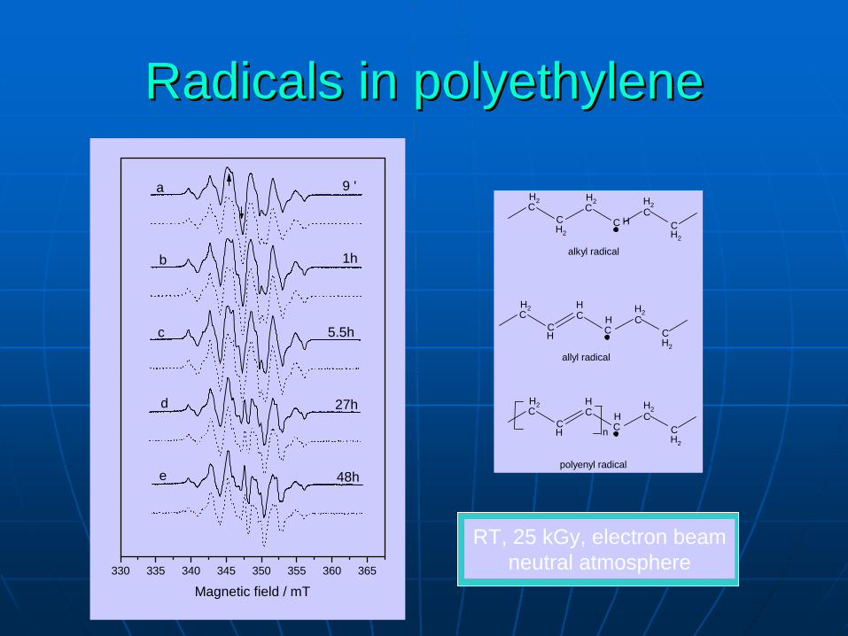
330 335 340 345 350 355 360 365
Magnetic field / mT
9 '
1h
5.5h
27h
48h
a
b
c
d
e
CC
CC
CC
H
H2
H2H2
H2
H2
alkyl radical
CC
CC
CC
H
H2
H2H2
H
H
H
CC
CC
CC
H
H2
H2H2 H
allyl radical
n
polyenyl radical
RT, 25 kGy, electron beamneutral atmosphere
RadicalsRadicals inin polyethylenepolyethylene
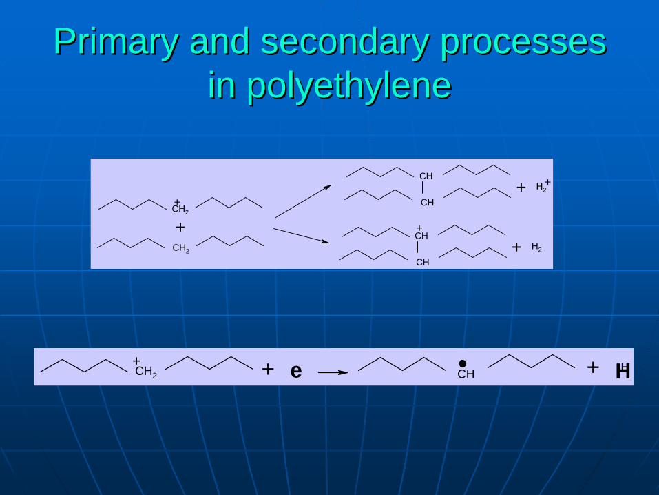
PrimaryPrimary and and secondarysecondary processesprocesses inin polyethylenepolyethylene
CH2
CH2
++
CH
CH
++ H2
CH
CH
+
+ H2
HCH2+
CH+ e + H
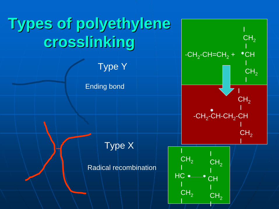
Types of polyethylene Types of polyethylene crosslinkingcrosslinking
Type Y
Type X ICH2I
HCICH2I
ICH2ICHICH2I
Radical recombination
Ending bond
ICH2I
-CH2 -CH=CH2 + CHICH2I
ICH2I
-CH2 -CH-CH2 -CHICH2I

Unsaturated bonds after Unsaturated bonds after irradiationirradiation
-CH=CH2
-CH=CH-
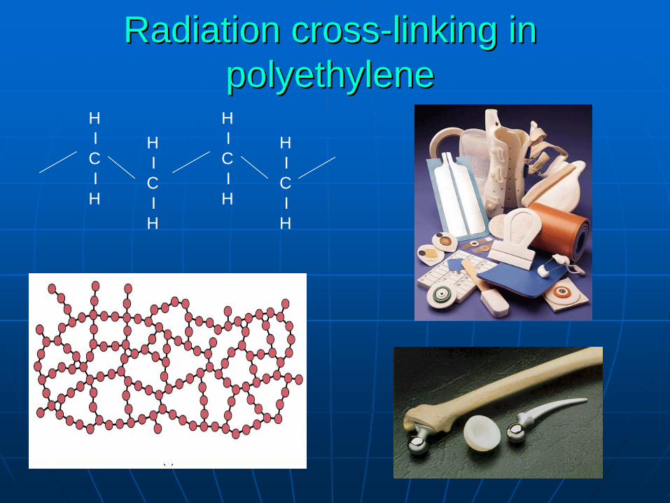
RadiationRadiation crosscross--linkinglinking inin polyethylenepolyethylene
HICIH
HICIH
HICIH
HICIH

Radiation chemistry of amorphous Radiation chemistry of amorphous and crystalline phases of PEand crystalline phases of PE
Alkyl radicals are produced in both Alkyl radicals are produced in both phases.phases.CrossCross--linking is limited to amorphous linking is limited to amorphous phase.phase.Oxidation proceeds only in amorphous Oxidation proceeds only in amorphous phase.phase.Residual radicals in crystalline phase Residual radicals in crystalline phase migrate towards surface between both migrate towards surface between both phases.phases.
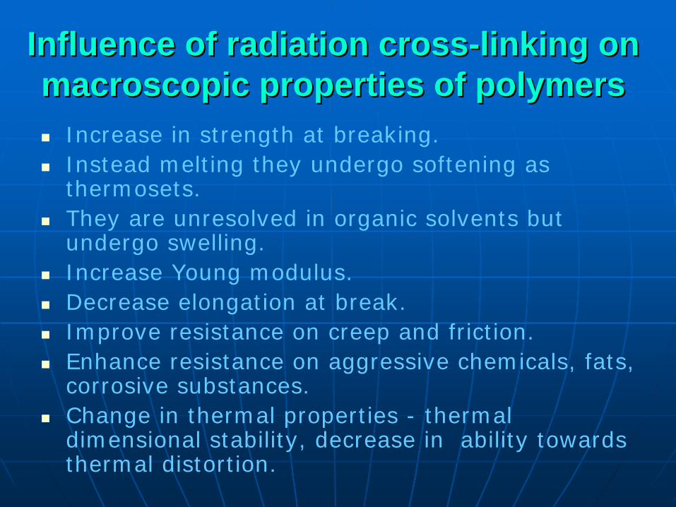
Influence of radiation crossInfluence of radiation cross--linking on linking on macroscopic propertiesmacroscopic properties ofof polymerspolymers
Increase in strength at breaking.Instead melting they undergo softening as thermosets.They are unresolved in organic solvents but undergo swelling.Increase Young modulus.Decrease elongation at break.Improve resistance on creep and friction.Enhance resistance on aggressive chemicals, fats, corrosive substances.Change in thermal properties - thermal dimensional stability, decrease in ability towards thermal distortion.

AgentsAgents influencinginfluencing radiationradiation stabilitystability ofof polymericpolymeric materialsmaterials::
•Less defects in crystalline domains - higher radiation stability
•Chemical changes induced by ionizing radiationcan be divided on two stages. At first stage reactions proceed directly during irradiation, at second stage upon exposure, in post-radiation effects.

AgentsAgents influencinginfluencing radiationradiation stabilitystability ofof polymerspolymers
Significant diffusion of oxygen throughSignificant diffusion of oxygen throughoutoutpolymer facilitates oxidative degradation and polymer facilitates oxidative degradation and enhances enhances radiosensitivityradiosensitivity. Polymers in . Polymers in thethe form form of films and fibres have intensive contact with of films and fibres have intensive contact with oxygen due to large ratio of oxygen due to large ratio of thethe surface to surface to weight.weight.
Fast irradiation with large doses results in Fast irradiation with large doses results in inhibition of oxidation effects (likewise in neutral inhibition of oxidation effects (likewise in neutral gas atmosphere) because of short time of gas atmosphere) because of short time of oxygen diffusion inward material. Therefore oxygen diffusion inward material. Therefore inside of the object polymer preserves initial inside of the object polymer preserves initial properties properties andand even undergoes crosslink.even undergoes crosslink.
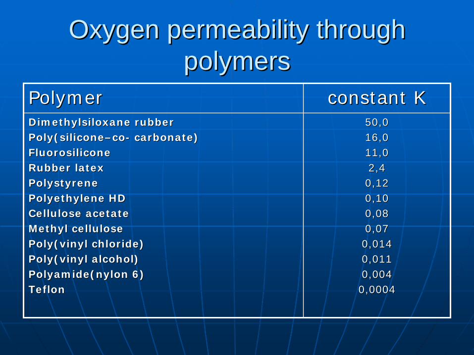
Oxygen permeability through Oxygen permeability through polymerspolymers
PolymerPolymer constantconstant KKDimethylsiloxaneDimethylsiloxane rubberrubberPoly(siliconePoly(silicone––coco-- carbonatecarbonate))FluorosiliconeFluorosiliconeRubberRubber latexlatexPolystyrenePolystyrenePolyethylenePolyethylene HDHDCelluloseCellulose acetateacetateMethylMethyl cellulosecellulosePoly(vinylPoly(vinyl chloridechloride))Poly(vinylPoly(vinyl alcoholalcohol))Polyamide(nylonPolyamide(nylon 6)6)TeflonTeflon
50,050,016,016,011,011,02,42,40,120,120,100,100,080,080,070,070,0140,0140,0110,0110,0040,0040,00040,0004

Polymers applied in radiation Polymers applied in radiation sterilized medical devicessterilized medical devices
•Acrylonitryle/butadiene/styrene (ABS)•Polystyrene•Polystyrene-acryl nitryle•Polyethylene of various density•Polyamide•Polyurethane•Poly(ethylene–vinyl acetate)•Poly(ethylene-acryl)•Polypropylene
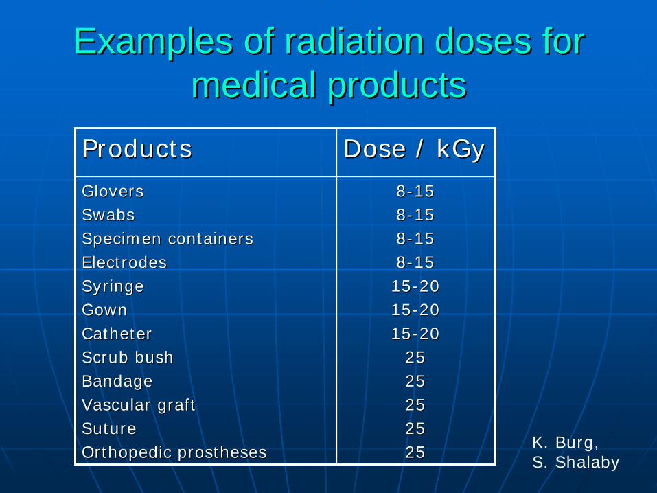
Examples of radiation doses for Examples of radiation doses for medical productsmedical products
ProductsProducts DoseDose / / kGykGy
GloversGloversSwabsSwabsSpecimen containersSpecimen containersElectrodesElectrodesSyringeSyringeGownGownCatheterCatheterScrub bushScrub bushBandageBandageVascular graftVascular graftSutureSutureOrthopedic prosthesesOrthopedic prostheses
88--151588--151588--151588--15151515--20201515--20201515--2020
25252525252525252525 K. Burg,
S. Shalaby

SterilizationSterilization StabilityStability ofof MaterialsMaterials www.eldonjames.comwww.eldonjames.com//framesframes//strilize.htmlstrilize.html
MATERIAL GAMMA RADIATION ETHYLENE OXIDE AUTOCLAVE
Polycarbonate Compatible to 10 M-Rad dose with little loss of physical properties. Will discolor to light yellow- green hue.
Highly compatible with 100% EtO; may stress crack if sterilized in EtO/ CFC mix, due to molding stresses.
Not recommended. May craze or stress crack due to molding stresses.
Radiation Stable Polycarbonate Excellent up to 10 M-Rad dose with little loss of physical properties. Light violet hue turns clear upon sterilization.
Highly compatible. Withstands normal EtO sterilization conditions, but multiple exposures can reduce tensile elongation properties.
Not recommended.
Polypropylene Excellent up to commonly used sterilization doses (approximately 6 M-Rad).
Fair; may stress crack in EtO/CFC mix due to molding stresses.
Poor. Parts may distort due to low heat deflection temperature.
Stainless Steel see additional notes below**
Excellent Excellent Excellent
Nylon and Glass Filled Nylon Physically compatible with commonly used sterilization doses, but may discolor to brownish hue.
Very Good. Some susceptibility to oxidizing agents.
Very Good. Components may swell slightly due to water absorption.
ABS Compatible to 10 M-Rad dose with some loss of impact strength, but increased tensile strength. Some discoloration to slight brownish hue.
Excellent retention of properties for at least 5 sterilization cycles.
Poor. Parts may distort due to low heat deflection temperature.
Polyurethane (Tubing) Excellent. Some discoloration may occur, but reverses over time. No significant effect on physical properties.
Excellent. No noticeable effect on material properties.
Not Recommended. Hydrolysis of polyurethane may create aromatic amine impurities.
Polyethylene (Tubing) Excellent. Tensile strength increases and modulus of elasticity decreases due to cross-linking of polymer.
Excellent Not Recommended. Tubing may distort at common autoclave temperatures.

ExamplesExamples ofof radiationradiation--stablestable materialsmaterials inin sterilizingsterilizing dosedose rangerange
goodgood poorpoorAcrylonitrileAcrylonitrile//butatienebutatiene//styrenestyrenePolystyrenePolystyrenePolystyrenePolystyrene--acrylonitrileacrylonitrilePolyethylenePolyethylenePolyamidesPolyamidesPolysulfonesPolysulfonesPolyimidesPolyimidesPolyurethanePolyurethanepolyphenylenepolyphenylene-- sulfidesulfidePolyestersPolyestersPoly(ethylenePoly(ethylene--vinylvinyl acetateacetate))Poly(ethylenePoly(ethylene--acrylateacrylate))SiliconeSiliconeNatiralNatiral rubberrubber
PolyvinylchloridePolyvinylchloridePolyvinylidenePolyvinylidene chloridechloridePolyvinylPolyvinyl formalformalPolyvinylbutyralPolyvinylbutyralPolycarbonatePolycarbonateStyreneStyrene//AcrylonitrileAcrylonitrile
PolypropylenePolypropyleneFluoropolymersFluoropolymersPolytetrafluoroethylenePolytetrafluoroethylenePolychlorotrifluoroethylenePolychlorotrifluoroethylenePolyvinylPolyvinyl fluoridefluoridePolyvinylidenePolyvinylidene fluoridefluorideEthyleneEthylene-- tetrafluoroethylenetetrafluoroethyleneFluorinatedFluorinated ethyleneethylene-- propylenepropyleneCellulosicsCellulosics ––estersesters celulosecelulosePolyacetalsPolyacetals
ANSI/AAMI/ISO 11137 – 1995Annex A
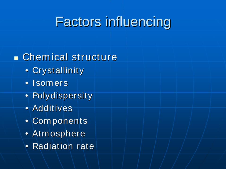
FactorsFactors influencinginfluencing
ChemicalChemical structurestructure•• CrystallinityCrystallinity•• IsomersIsomers•• PolydispersityPolydispersity•• AdditivesAdditives•• ComponentsComponents•• AtmosphereAtmosphere•• RadiationRadiation raterate


30 years
of
PVC dosimetry in
INCT
Zofia
Stuglik
Institute of Nuclear Chemistry and Technology, Laboratory for Measurement of Technological Doses, Warsaw, Poland
IAEA Training Course, 3-7 December 2007, Warsaw, Zofia Stuglik
History1972
Instalation
of linear electron accelerator LAE 13/9
9 kW, 7 ÷
13 MeV, (Jefremov
Institute,
Leningrad, USSR)
two
regimes:straight electron
beam –
for pulse radiolysis
scanned electron
beam –
for technological studies
IAEA Training Course, 3-7 December 2007, Warsaw, Zofia Stuglik
IAEA Training Course, 3-7 December 2007, Warsaw, Zofia Stuglik
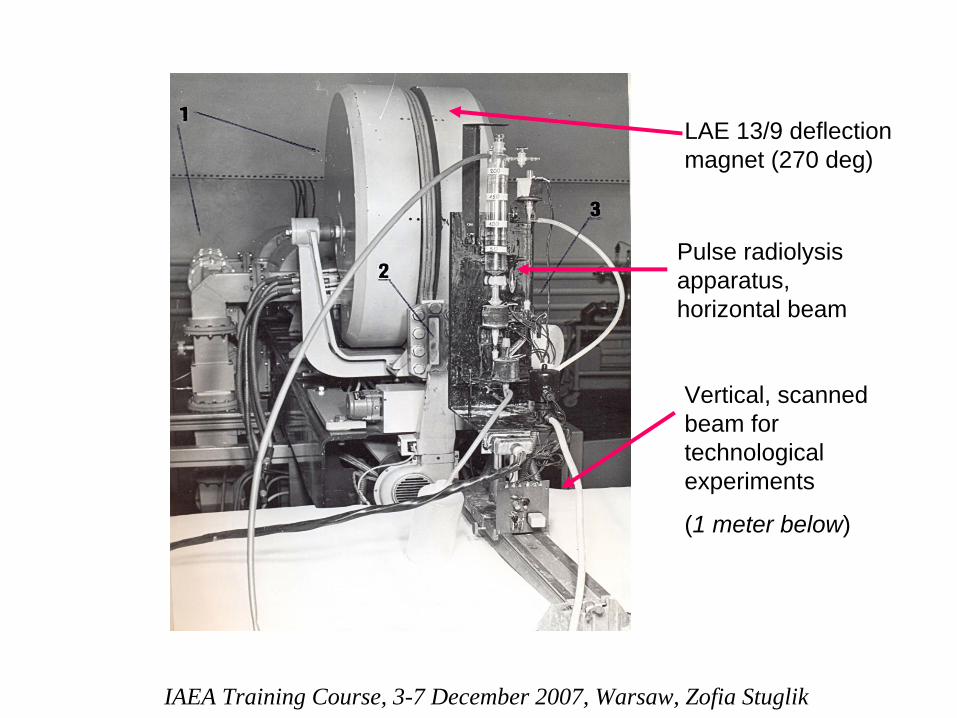
LAE 13/9 deflection magnet (270 deg)
Pulse radiolysis apparatus, horizontal beam
Vertical, scanned beam for technological experiments
(1 meter below)
HistoryResponsible persons for electron beam dosimetry
systems
were:
Dr. Przemysław
Panta
(water and graphite quasi-adiabatic calorimeters)
Dr. Zofia
Bułhak
(film dosimeters)
IAEA Training Course, 3-7 December 2007, Warsaw, Zofia Stuglik
At 60-ties and 70-ties PVC films were intensively investigated by a lot of scientists
(C.Artandi, A.A.Miller, A.Chapiro,
S.Onishi, Y.Nakayama…).
Mrs. Bułhak
joined to this group at the beginning of 70-ties. Dosimetric
applications of PVC films was a subject
of Mrs.
Bułhak
dissertation and because of that they were investigated very carefully.
Some results of these experiments will be presented today
and were compared with the results of the last studies done in Laboratory for Measurement of Technological Doses.
IAEA Training Course, 3-7 December 2007, Warsaw, Zofia Stuglik

IAEA Training Course, 3-7 December 2007, Warsaw, Zofia Stuglik
PVC production, method
I
PVC = polyvinyl
chloride
ethylene + chlorine vinyl chloride
vinyl chloride polyvinyl chloridePCV
catalyst
polymerization
n
dichlorethane
IAEA Training Course, 3-7 December 2007, Warsaw, Zofia Stuglik
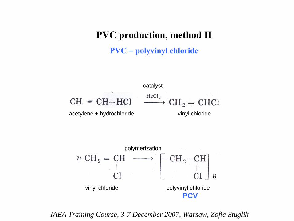
PVC production, method
IIPVC = polyvinyl
chloride
acetylene + hydrochloride vinyl chloride
vinyl chloride polyvinyl chloridePCV
catalyst
polymerization
n

IAEA Training Course, 3-7 December 2007, Warsaw, Zofia Stuglik
How
much of
PVC is
in
the
PVC ?
It
depends……
PVC
hard
(%)
soft (%)
PVC
> 90
40-80
Plasticizer
≤
5
20-60
Stabilizer
0,5 –
0,5 0,5-4
Lubricant ≤5
≤
1
(Fillers)
?
?

IAEA Training Course, 3-7 December 2007, Warsaw, Zofia Stuglik
The PVC film from Kunstoffwerke, Staufen
which has been used in our Institute for electron beam dosimetry
applications was produced for pharmacy.
It may contain some amounts:
• plasticizers (probably phthalates)
• thermal stabilizers (probably Sn
(stannum) compounds)
• lubricants
The main component is
PVC

IAEA Training Course, 3-7 December 2007, Warsaw, Zofia Stuglik
Radiolysis
For the simple chemical system as Fricke dosimeter it is possible to establish exact scheme of radiation reactions, to measure their orders, rate constants and G-values.
For PVC it is impossible.
The system is too complicated. We have some information about radiolytical
processes going in
PVC but we are still far for the full knowledge.

IAEA Training Course, 3-7 December 2007, Warsaw, Zofia Stuglik
What we know?EPR experiments of Ohnishi and Nakayama showed that irradiation of PVC generate 3 types of radicals:
-CH2
C*H-CH2
-
-CHCl-C*H-CHCl-
-CH2
C*Cl-CH2
-
These reactive species initiate chemical reactions leading to more stable structures, for instance -
double bonds systems
C=C.
IAEA Training Course, 3-7 December 2007, Warsaw, Zofia Stuglik
What else we know?
It is known from many years that the main gaseous product of PVC radiolysis is hydrochloride (HCl).
High G-value of HCl
formation (~26) points to the chain reactions involved in its production.
It is also known that HCl
initiate autocatalytic decay of PVC polymer.

IAEA Training Course, 3-7 December 2007, Warsaw, Zofia Stuglik
So, among products of PVC radiolysis there are at least two types of species: radicals
and hydrochloride (HCl)
which will destabilize the PVC polymeric system.
But we want to use PVC as dosimeter. So, we should find factors which will stabilize it.
There are two such factors: •time•temperature
In dosimetry
we have not plenty of time,
so we use temperature.
.

IAEA Training Course, 3-7 December 2007, Warsaw, Zofia Stuglik
At higher temperatures the chemical reactions go faster, the concentration of active species go down and irradiated PVC is going to the more stable state.
Of course, the temperature should be below the softening point
of PVC because very high temperature also lead to
destruction of polymer.
IAEA Training Course, 3-7 December 2007, Warsaw, Zofia Stuglik
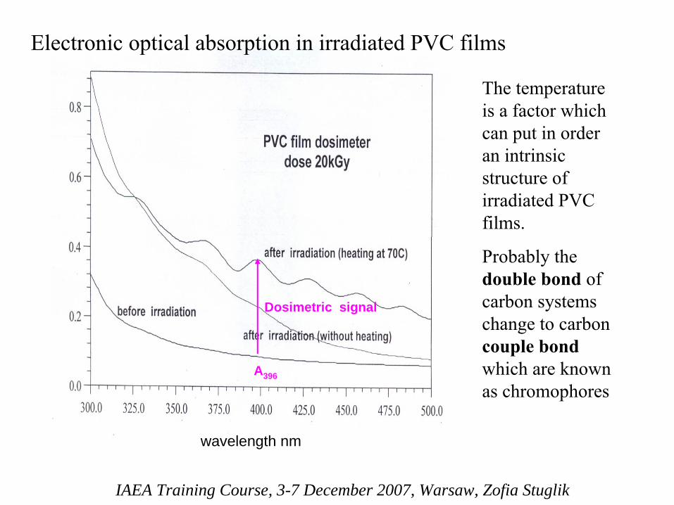
The temperature is
a factor which
can
put in order an
intrinsic
structure of irradiated PVC
films.
Probably
the double bond
of carbon
systems
change
to
carbon couple bond
which
are
known as chromophores
wavelength nm
Dosimetric signal
A396
Electronic
optical
absorption
in
irradiated
PVC films
IAEA Training Course, 3-7 December 2007, Warsaw, Zofia Stuglik
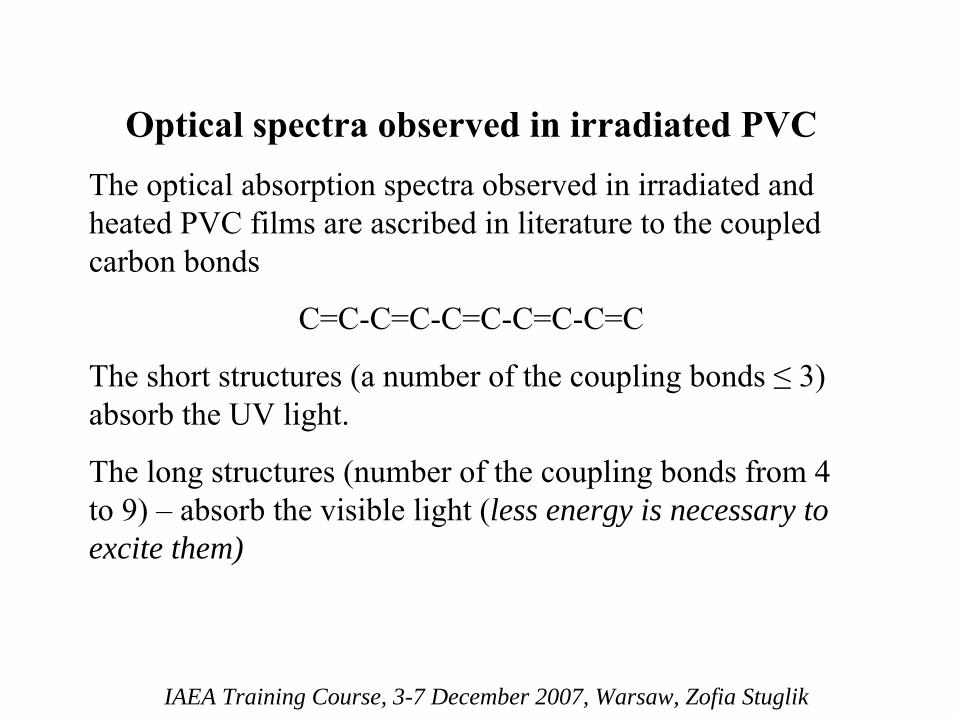
Optical spectra observed in irradiated PVCThe optical absorption spectra observed in irradiated and
heated
PVC films are ascribed in literature to the coupled carbon bonds
C=C-C=C-C=C-C=C-C=C
The short structures (a number of the coupling bonds ≤
3) absorb the UV light.
The long structures (number of the coupling bonds from 4 to 9) –
absorb the visible light (less energy is necessary to
excite them)

IAEA Training Course, 3-7 December 2007, Warsaw, Zofia Stuglik
Now, we are
going
to the
results
obtained
in
our
Institute 30-ty years
ago.
IAEA Training Course, 3-7 December 2007, Warsaw, Zofia Stuglik
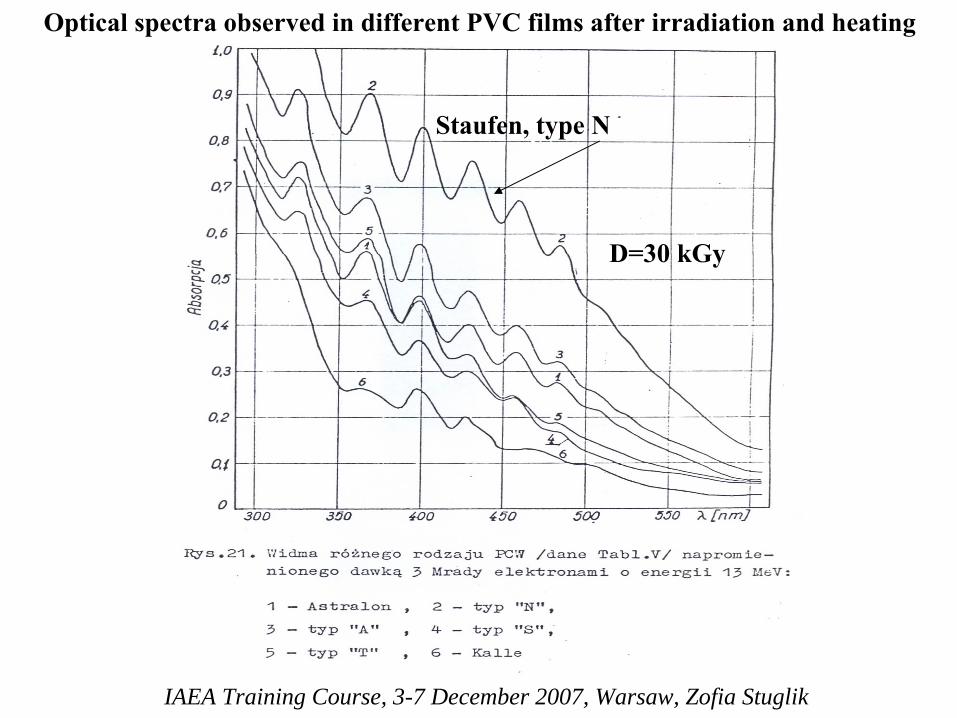
Optical
spectra observed
in
different
PVC films
after
irradiation
and
heating
D=30 kGy
Staufen, type
N
IAEA Training Course, 3-7 December 2007, Warsaw, Zofia Stuglik
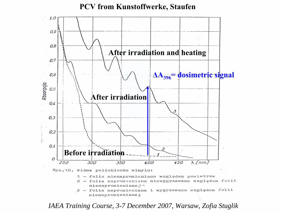
After
irradiation
and
heating
After
irradiation
Before
irradiation
PCV from
Kunstoffwerke, Staufen
ΔA396
= dosimetric
signal
IAEA Training Course, 3-7 December 2007, Warsaw, Zofia Stuglik
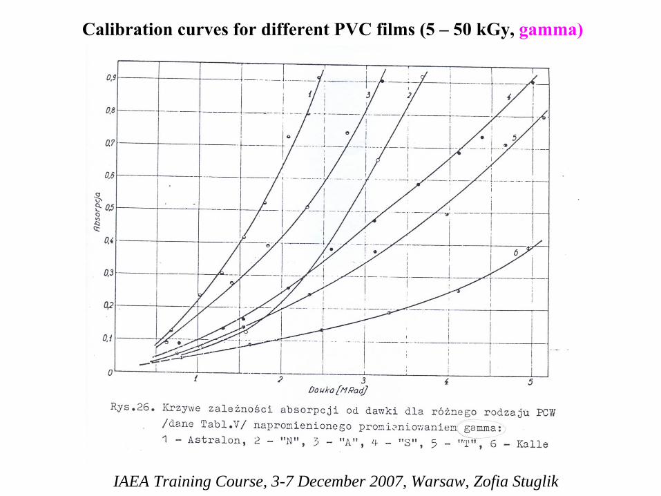
Calibration
curves
for different
PVC films
(5 –
50 kGy, gamma)

IAEA Training Course, 3-7 December 2007, Warsaw, Zofia Stuglik
Calibration
curves
for different
PVC films
(5 –
50 kGy, 10 MeV
electrons)
IAEA Training Course, 3-7 December 2007, Warsaw, Zofia Stuglik
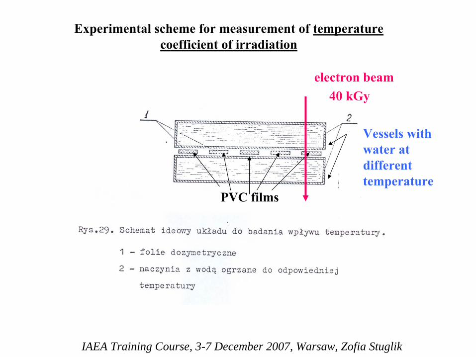
Vessels
with water
at
different temperature
PVC films
Experimental
scheme
for measurement
of
temperature coefficient of irradiation
40 kGyelectron
beam

IAEA Training Course, 3-7 December 2007, Warsaw, Zofia Stuglik
Temperature coefficient of irradiation
k=0,25 % per 1°C [Z.Bułhak]
IAEA Training Course, 3-7 December 2007, Warsaw, Zofia Stuglik
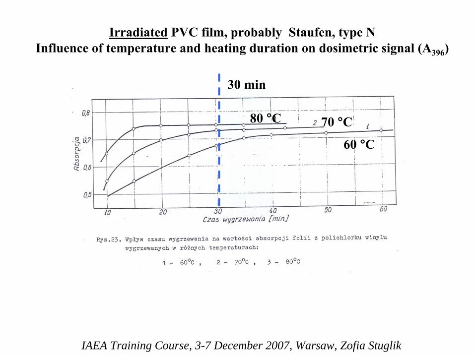
Irradiated
PVC film, probably
Staufen, type
N Influence of
temperature
and
heating
duration
on dosimetric
signal
(A396
)
80 °C
30 min
70 °C
60 °C
IAEA Training Course, 3-7 December 2007, Warsaw, Zofia Stuglik
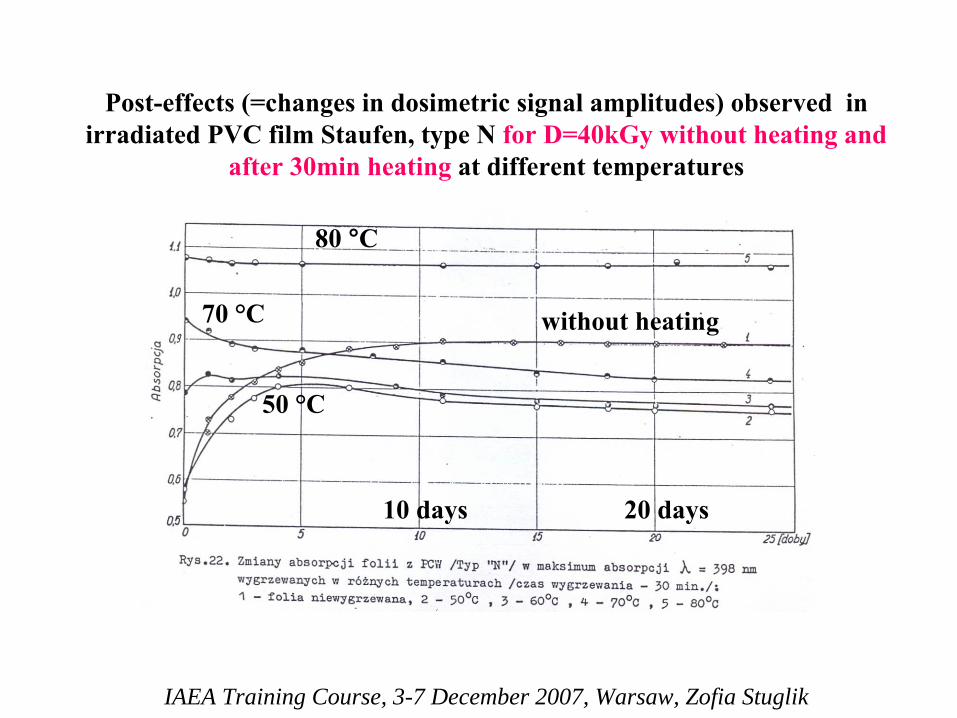
Post-effects
(=changes
in
dosimetric
signal
amplitudes) observed
in irradiated
PVC film Staufen, type
N for D=40kGy without
heating
and
after
30min heating
at
different
temperatures
80 °C
70 °C without
heating
50
°C
10 days 20 days
IAEA Training Course, 3-7 December 2007, Warsaw, Zofia Stuglik
The best stability of dosimetric
signal was obtained for 30min heating at 80°C.
However
So high temperature was near the softening point of PVC film used in this experiment and because of that 70°C was selected for dosimetric
applications.
IAEA Training Course, 3-7 December 2007, Warsaw, Zofia Stuglik
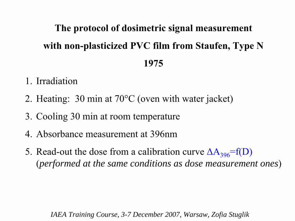
The protocol of dosimetric
signal measurement
with non-plasticized PVC film from Staufen, Type N
1975
1.
Irradiation
2.
Heating: 30 min at 70°C (oven with water jacket)
3.
Cooling 30 min at room temperature
4.
Absorbance measurement at 396nm
5.
Read-out the dose from a calibration curve ΔA396
=f(D) (performed at the same conditions as dose measurement ones)
IAEA Training Course, 3-7 December 2007, Warsaw, Zofia Stuglik
On the base of Dr. Z.Bułhak
work INCT bought some tons of non-plasticized PVC film from Kunststoffwerke, Staufen
and used this film for
dose distribution measurements during more than 30 years.
The same film is used also today.
Two years ago LMTD started the experiments to re- validate dosimetric
characteristics of PVC films
which still are using at INCT Sterilization Plant.
IAEA Training Course, 3-7 December 2007, Warsaw, Zofia Stuglik
Results
•There were observed some differences between sensitivity of different scrolls
of
PVC film.
• No correction for film thickness was necessary.
• CV-values and calibration curves were acceptable.
• Resistance for environmental conditions was excellent.
IAEA Training Course, 3-7 December 2007, Warsaw, Zofia Stuglik
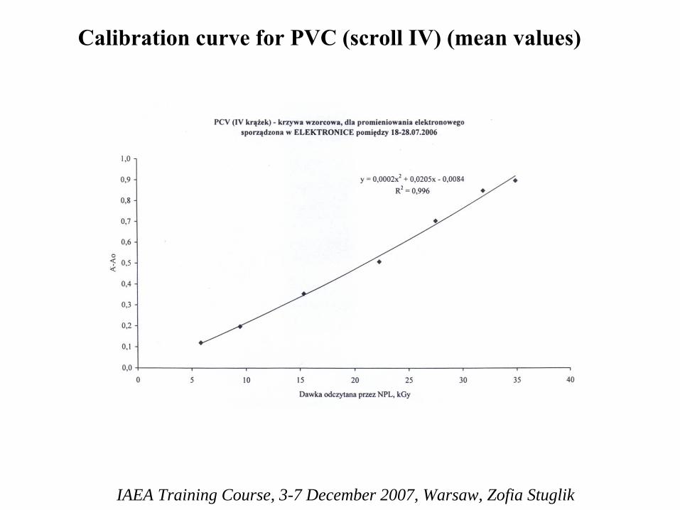
Calibration curve for PVC (scroll IV) (mean values)
IAEA Training Course, 3-7 December 2007, Warsaw, Zofia Stuglik
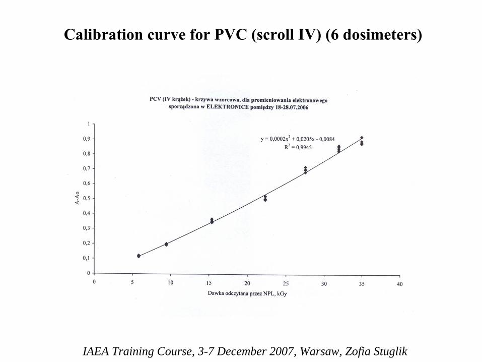
Calibration curve for PVC (scroll IV) (6 dosimeters)
IAEA Training Course, 3-7 December 2007, Warsaw, Zofia Stuglik
The protocol from 1975 is still valid
However, we observed
that
actually
used PVC films are much more sensitive to
any deviation from the
protocol
because
of
strong
post-effects

IAEA Training Course, 3-7 December 2007, Warsaw, Zofia Stuglik
Post-effects
in
PVC films
irradiated
with
gamma and high energy
electrons
to 22 kGy
time, h
gamma
electrons
IAEA Training Course, 3-7 December 2007, Warsaw, Zofia Stuglik
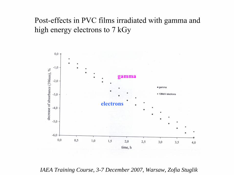
Post-effects
in
PVC films
irradiated
with
gamma and high energy
electrons
to 7 kGy
gamma
electrons

IAEA Training Course, 3-7 December 2007, Warsaw, Zofia Stuglik
[Z.Peimel-Stuglik, S.Fabisiak, Appl.Radiat.Isot., 2007, in
press]
and heating
IAEA Training Course, 3-7 December 2007, Warsaw, Zofia Stuglik
What is a reason of such situation?
There were at least three possibilities:
(a) PVC films changed their properties during 30 years
(b) The films which endured to our time are not type N from Kunststoffwerke, Staufen, chosen for dosimetric
application by Dr. Bułhak
IAEA Training Course, 3-7 December 2007, Warsaw, Zofia Stuglik
(c) The results dealing post-effects and presented in work done at 1975 were obtained for PVC films irradiated to doses ~ 40 kGy.
For such high doses the post-effects in irradiated and heated PVC films are negligible and were omitted.
IAEA Training Course, 3-7 December 2007, Warsaw, Zofia Stuglik
Advantages
of PVC films
• Very low price
• High sensitivity to ionizing radiation
•
High tolerance (nonsensitivity) to environmental conditions (air humidity, liquid water, visible, UV and Cherenkov light)
• Negligible film thickness variations
•
Slow ageing, significant rigidity, availability in large sheets and the possibility of rough visual dose evaluation
•
Cheap and simple analytical instrument for dosimetric
signal measurements
(spectrofotometer
for visible light)
IAEA Training Course, 3-7 December 2007, Warsaw, Zofia Stuglik
Disadvantagesof
PVC films
• Significant and complicated post-effects
• Dependence of the post-effects on dose.
•
Repeatability (CV, % ) on the level 2 –
6% (from batch to batch).
•
Chemical composition of PVC films different that mean chemical composition of organic matter (high content of Cl and some amounts (1-3%) of Ca or Sn). Exact chemical composition of PVC film is known only to its producer.
IAEA Training Course, 3-7 December 2007, Warsaw, Zofia Stuglik
Disadvantagesof
PVC films
• Be careful to use them for low doses (up to 20 kGy)
•
Take attention for technical parameters of oven -
dosimetric signal obtained after heating in oven with ventilation will be
different than after heating in oven with water jacket (for the same dose).
• Each batch should be carefully validated.
•
The protocol of measurement (timing, heating) should be establish and the staff shall follow it.
IAEA Training Course, 3-7 December 2007, Warsaw, Zofia Stuglik
You
can
use
PVC film for high dose electron
beam
dosimetry
if
you
are
very
accurate
and
carefull

IAEA Training Course, 3-7 December 2007, Warsaw, Zofia Stuglik
What will be if you are not very accurate

Practical Aspects of IQ and OQ
Electron Radiation Processing
A. KovácsInstitute of Isotopes
Hungarian Academy of Sciences
Budapest, Hungary
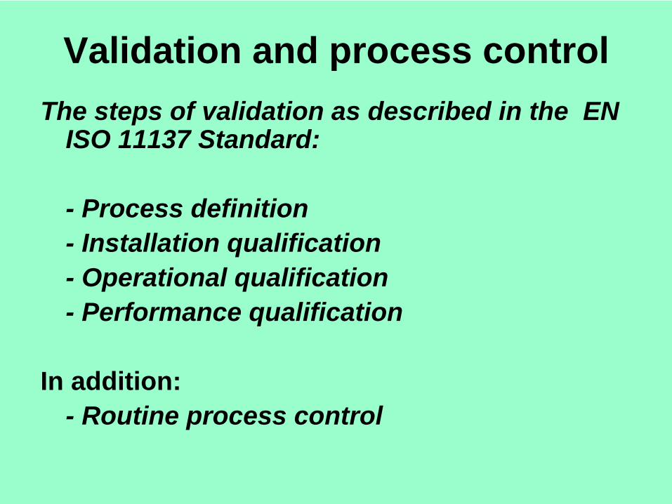
Validation and process controlThe steps of validation as described in the EN
ISO 11137 Standard:
- Process definition- Installation qualification- Operational qualification- Performance qualification
In addition:- Routine process control

Dosimetry procedures - validation
Installation qualification:- to demonstrate that the irradiation facility has been supplied and installed according to its specifications:
To determine beam No specific dosimetric requirements,characteristics by dosimetry; to verify operation within specification;
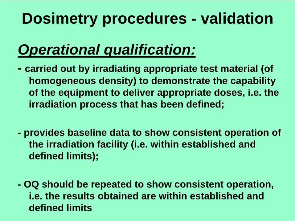
Dosimetry procedures - validation
Operational qualification:- carried out by irradiating appropriate test material (of
homogeneous density) to demonstrate the capability of the equipment to deliver appropriate doses, i.e. the irradiation process that has been defined;
- provides baseline data to show consistent operation of the irradiation facility (i.e. within established and defined limits);
- OQ should be repeated to show consistent operation, i.e. the results obtained are within established and defined limits
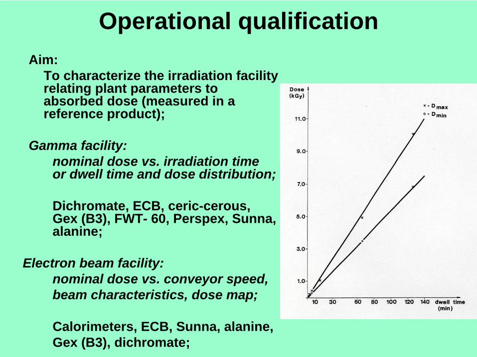
Operational qualificationAim:
To characterize the irradiation facility relating plant parameters to absorbed dose (measured in a reference product);
Gamma facility: nominal dose vs. irradiation time or dwell time and dose distribution;
Dichromate, ECB, ceric-cerous, Gex (B3), FWT- 60, Perspex, Sunna, alanine;
Electron beam facility:nominal dose vs. conveyor speed,beam characteristics, dose map;
Calorimeters, ECB, Sunna, alanine,Gex (B3), dichromate;
Operational Qualification I.
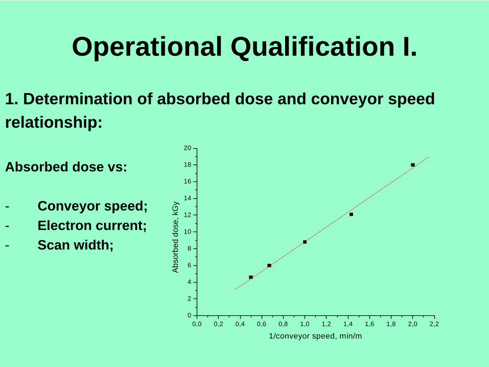
1. Determination of absorbed dose and conveyor speedrelationship:
Absorbed dose vs:
- Conveyor speed;- Electron current;- Scan width;
0,0 0,2 0,4 0,6 0,8 1,0 1,2 1,4 1,6 1,8 2,0 2,20
2
4
6
8
10
12
14
16
18
20
Abs
orbe
d do
se, k
Gy
1/conveyor speed, min/m
Tasks and Tools1. Dosimeters to use:
Calorimeters (PS, graphite);(other possibilities: ECB, Sunna, alanine,etc);
2. Tasks:- To irradiate calorimeters at two conveyor speeds and at two electron current settings (separately);- To establish conveyor speed and electron current vs. absorbed dose relationship;
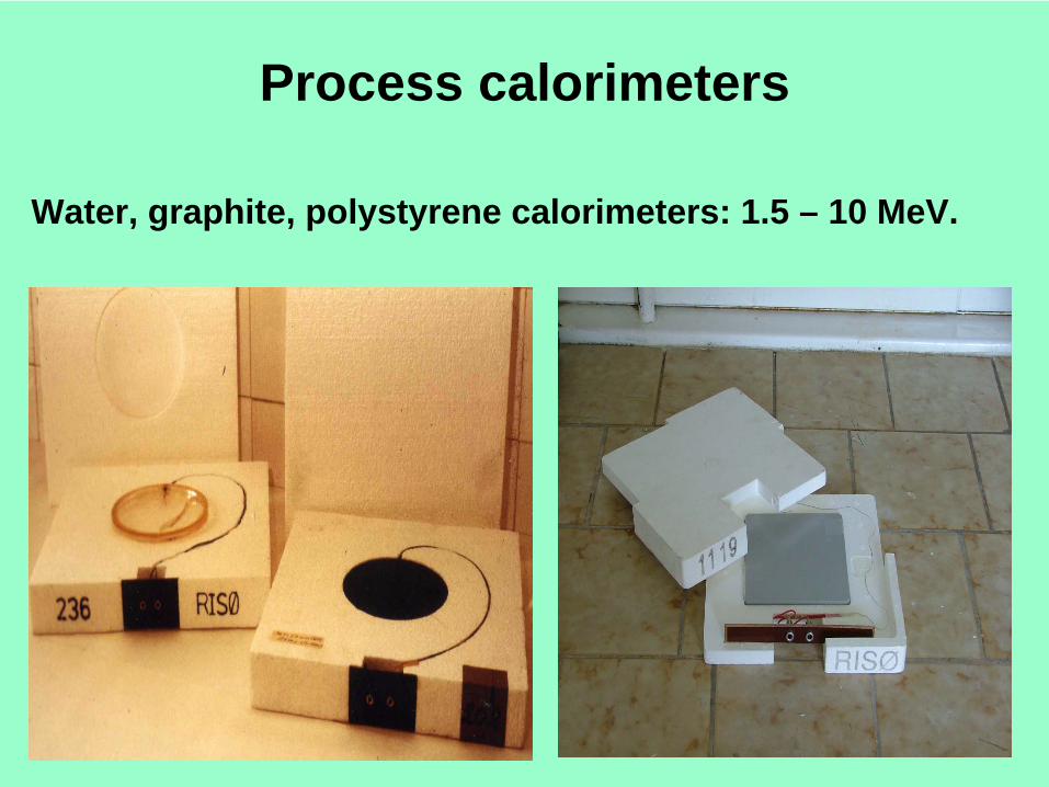
Process calorimeters
Water, graphite, polystyrene calorimeters: 1.5 – 10 MeV.
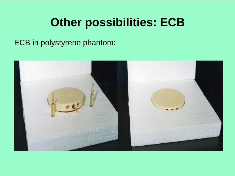
Other possibilities: ECBECB in polystyrene phantom:
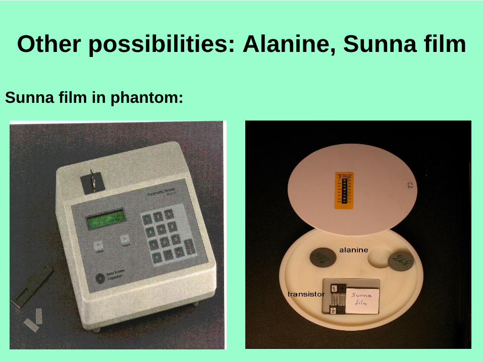
Other possibilities: Alanine, Sunna film
Sunna film in phantom:
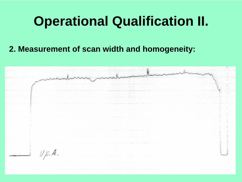
Operational Qualification II.
2. Measurement of scan width and homogeneity:
Tasks and Tools1. Dosimeters to use:
PVC film strip;
(other possibilities: FWT-60, B3, alanine, Sunna, etc);
• Tasks:
- To irradiate PVC films at various scan widths – scanning direction;
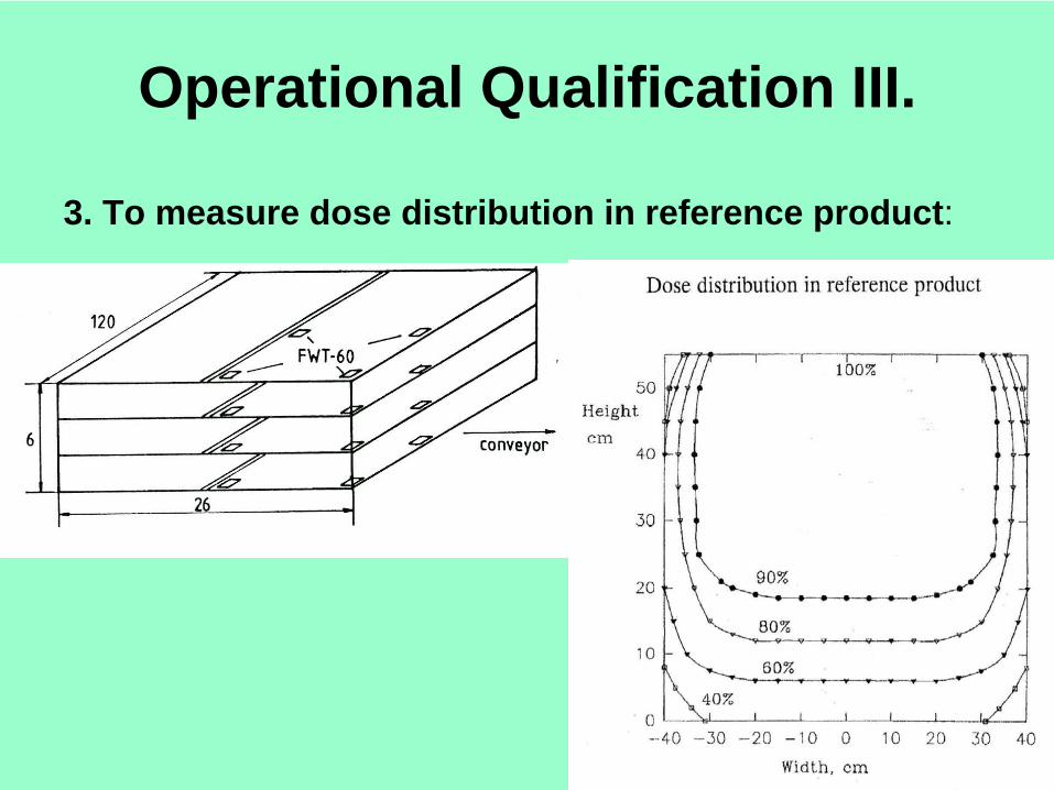
Operational Qualification III.
3. To measure dose distribution in reference product:
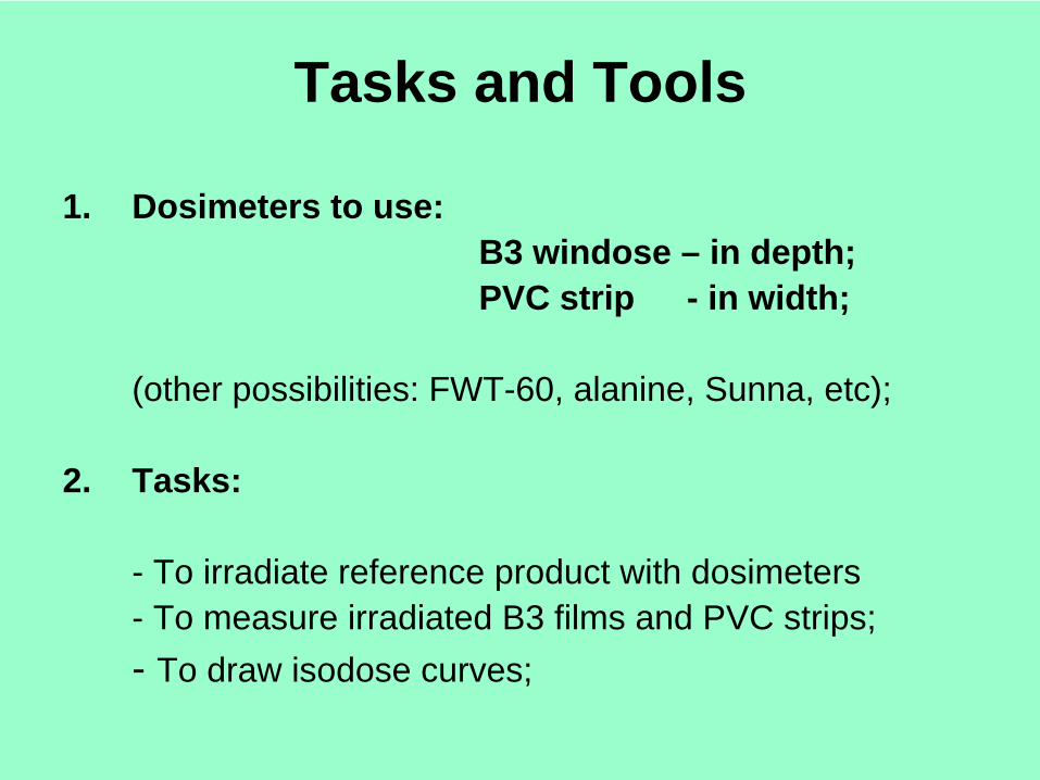
Tasks and Tools
1. Dosimeters to use: B3 windose – in depth;PVC strip - in width;
(other possibilities: FWT-60, alanine, Sunna, etc);
2. Tasks:
- To irradiate reference product with dosimeters- To measure irradiated B3 films and PVC strips;- To draw isodose curves;
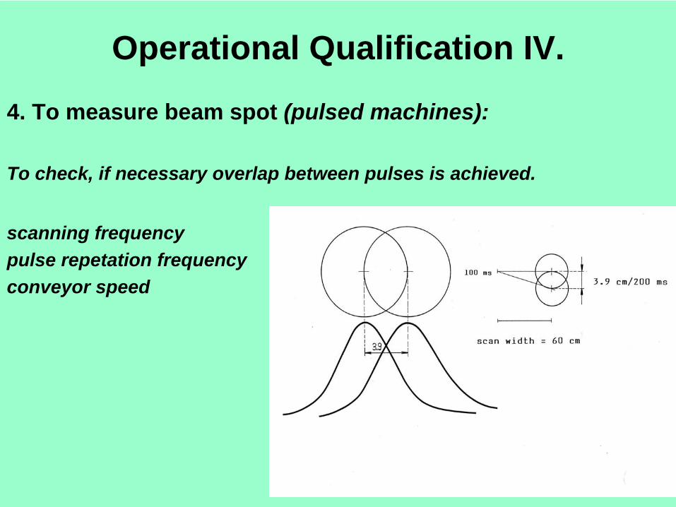
Operational Qualification IV.
4. To measure beam spot (pulsed machines):
To check, if necessary overlap between pulses is achieved.
scanning frequencypulse repetation frequencyconveyor speed

Tasks and Tools
1. Dosimeters to use:PVC and B3 strips;
(other possibilities: CTA, etc).
2. Tasks:
To irradiate PVC and B3 strips on polystyrene sheet under the scanner in „standing” mode.

Operational Qualification V.
5. To measure „process interruption”.
To use PVC strips (in conveyor move direction).
Other possibilities:
CTA film, B3 strip.
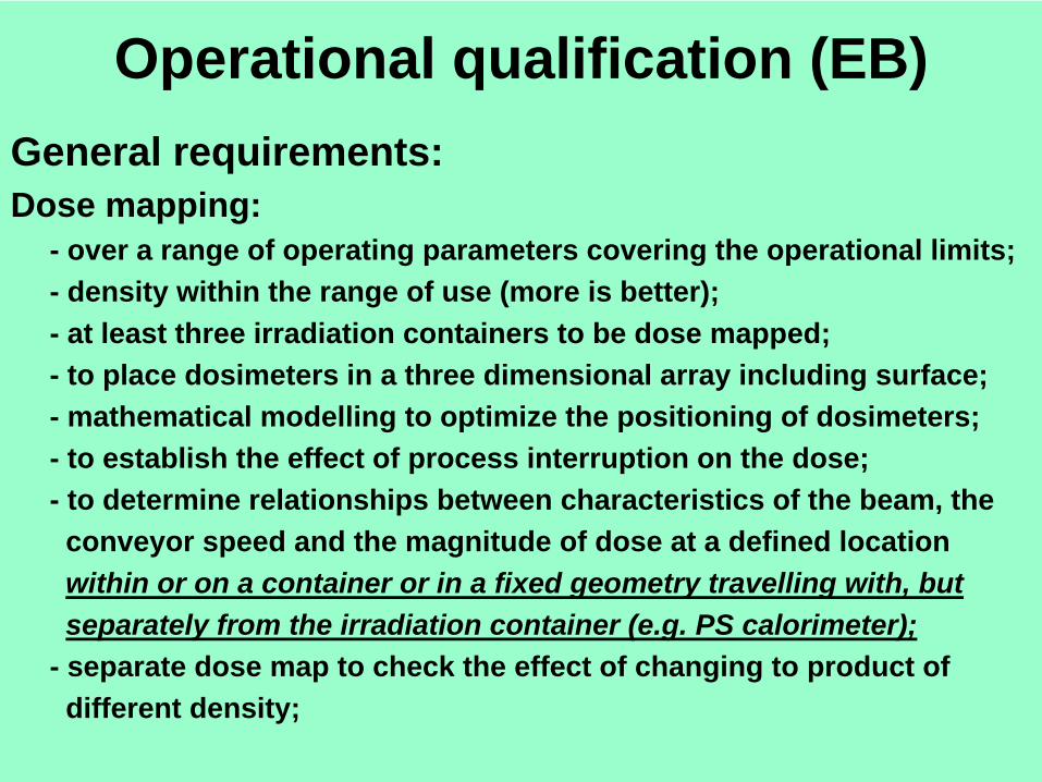
Operational qualification (EB)General requirements:Dose mapping:
- over a range of operating parameters covering the operational limits;- density within the range of use (more is better);- at least three irradiation containers to be dose mapped;- to place dosimeters in a three dimensional array including surface;- mathematical modelling to optimize the positioning of dosimeters;- to establish the effect of process interruption on the dose;- to determine relationships between characteristics of the beam, theconveyor speed and the magnitude of dose at a defined locationwithin or on a container or in a fixed geometry travelling with, butseparately from the irradiation container (e.g. PS calorimeter);
- separate dose map to check the effect of changing to product ofdifferent density;
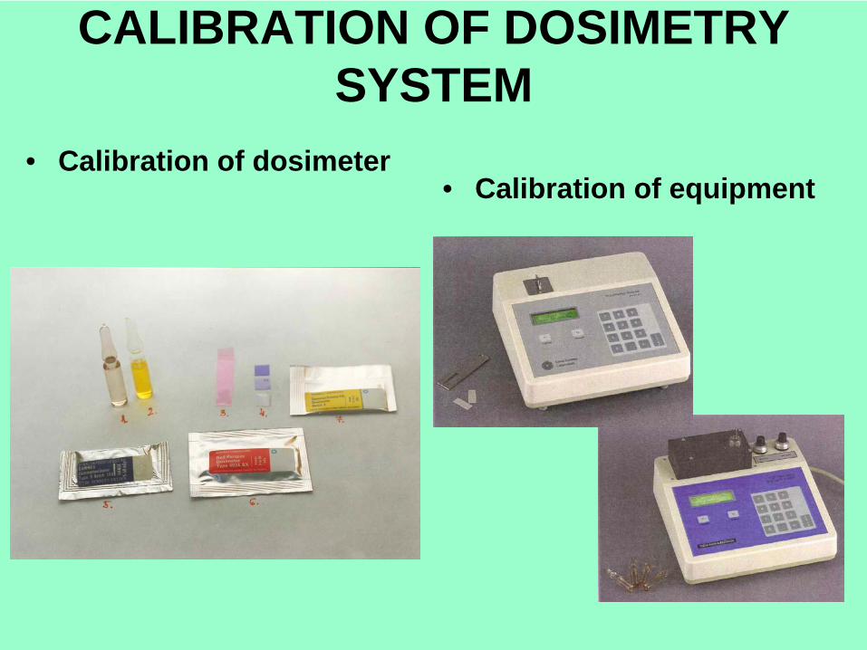
CALIBRATION OF DOSIMETRY SYSTEM
• Calibration of dosimeter• Calibration of equipment
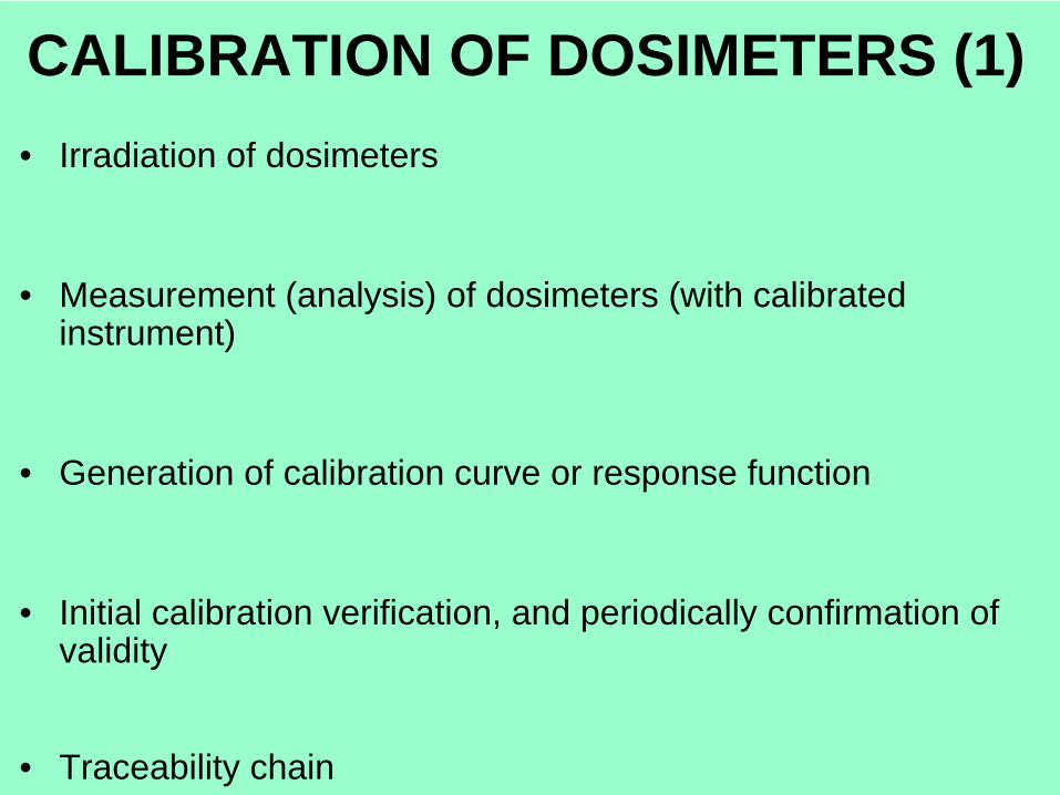
CALIBRATION OF DOSIMETERS (1)• Irradiation of dosimeters
• Measurement (analysis) of dosimeters (with calibrated instrument)
• Generation of calibration curve or response function
• Initial calibration verification, and periodically confirmation of validity
• Traceability chain
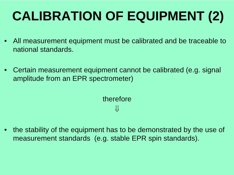
CALIBRATION OF EQUIPMENT (2)
• All measurement equipment must be calibrated and be traceable to national standards.
• Certain measurement equipment cannot be calibrated (e.g. signal amplitude from an EPR spectrometer)
therefore⇓
• the stability of the equipment has to be demonstrated by the use of measurement standards (e.g. stable EPR spin standards).
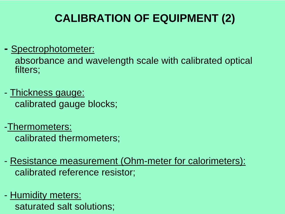
CALIBRATION OF EQUIPMENT (2)
- Spectrophotometer:absorbance and wavelength scale with calibrated optical filters;
- Thickness gauge:calibrated gauge blocks;
-Thermometers:calibrated thermometers;
- Resistance measurement (Ohm-meter for calorimeters):calibrated reference resistor;
- Humidity meters:saturated salt solutions;


THANK YOU FOR YOUR ATTENTION!
Accuracy
Precision

Principles and Practical Aspects of
Performance Qualification
A. Kovács
Institute of IsotopesHungarian Academy of Sciences
Budapest, Hungary
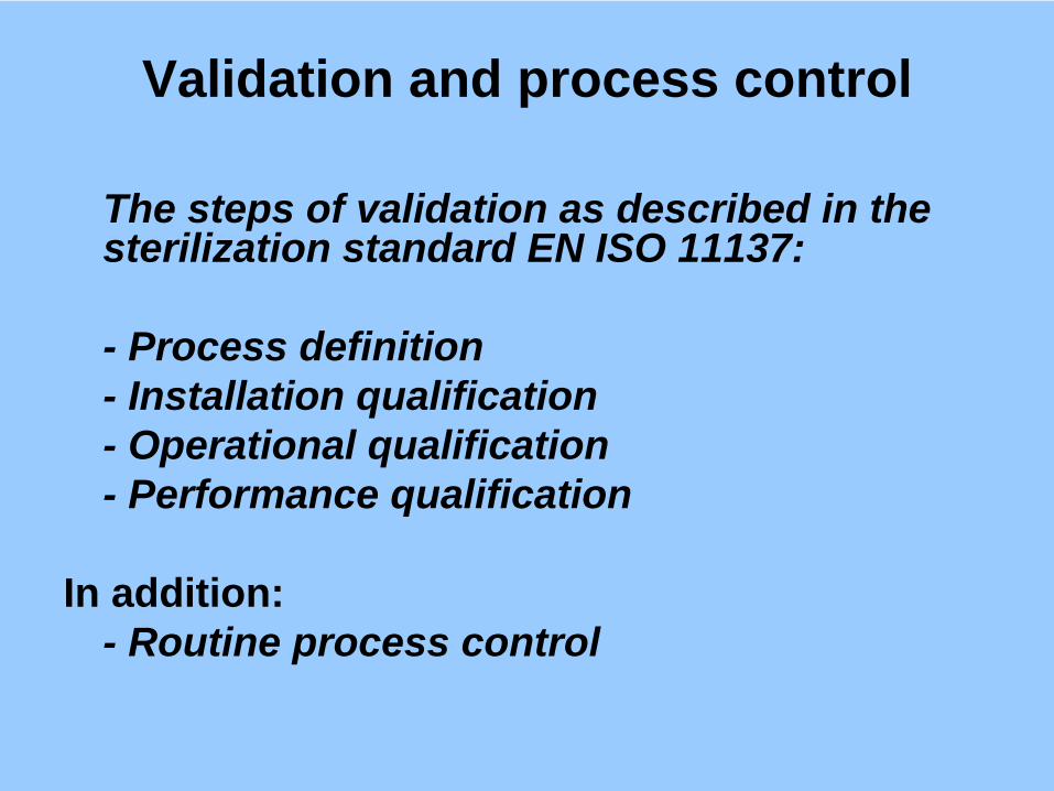
Validation and process control
The steps of validation as described in the sterilization standard EN ISO 11137:
- Process definition- Installation qualification- Operational qualification- Performance qualification
In addition:- Routine process control
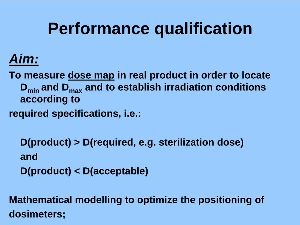
Performance qualification
Aim:To measure dose map in real product in order to locate
Dmin and Dmax and to establish irradiation conditions according to
required specifications, i.e.:
D(product) > D(required, e.g. sterilization dose)and D(product) < D(acceptable)
Mathematical modelling to optimize the positioning ofdosimeters;
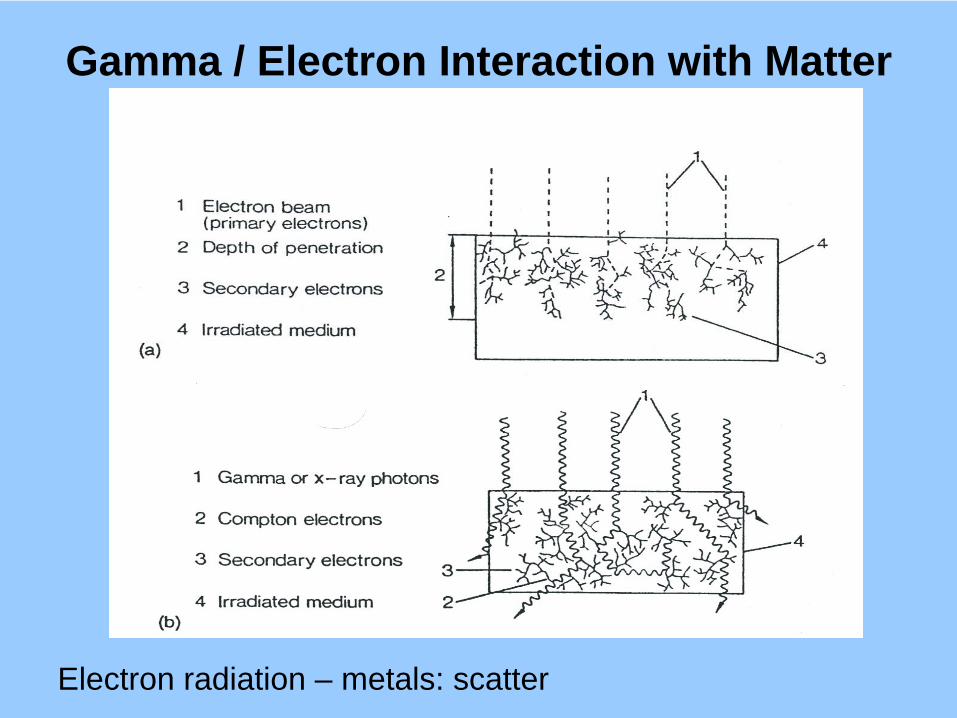
Gamma / Electron Interaction with Matter
Electron radiation – metals: scatter
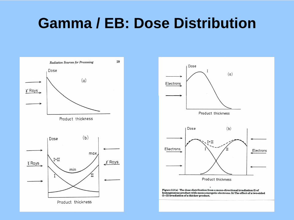
Gamma / EB: Dose Distribution
EB Processing Aspects
Single and double sided irradiation:
• Electron energy (surface sterility; single layer);• Product box dimensions;• Product density;• Product loading pattern;
Education of manufacturer!
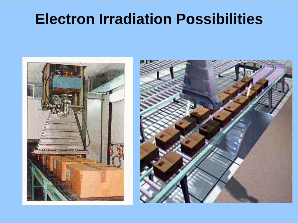
Electron Irradiation Possibilities
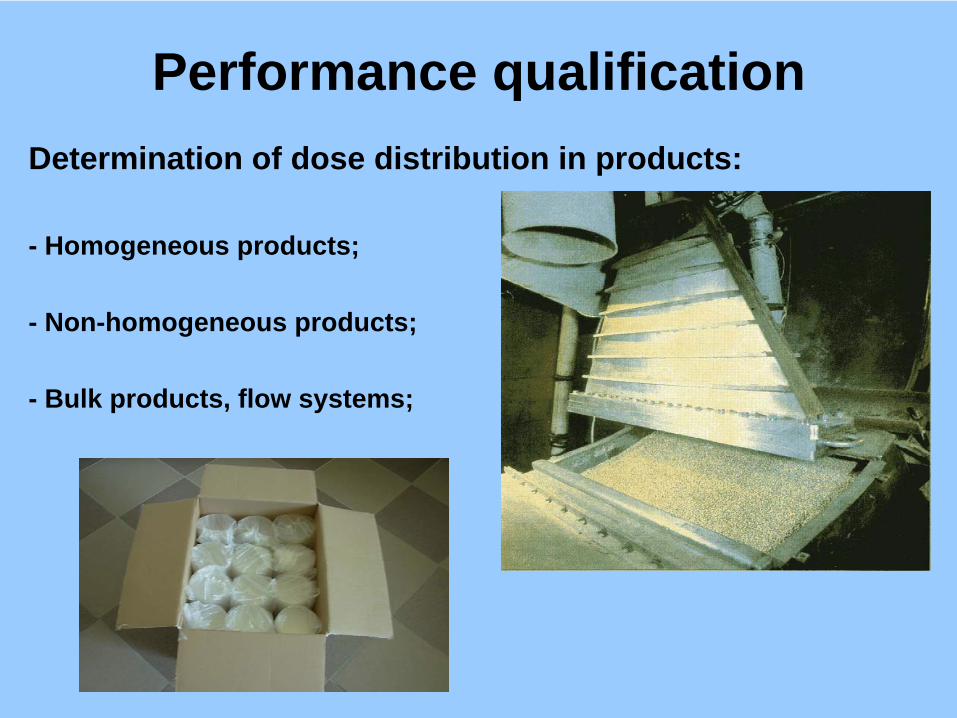
Performance qualificationDetermination of dose distribution in products:
- Homogeneous products;
- Non-homogeneous products;
- Bulk products, flow systems;

Performance qualificationThe role of film dosimeters – resolution!
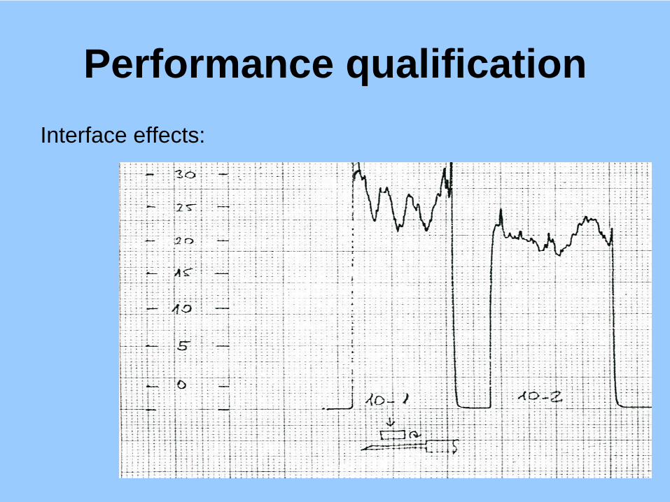
Performance qualificationInterface effects:

X-Ray Machines
X-Ray Dosimetry• Dosimeters applied in gamma processing seems
to be suitable;
• IAEA dosimetry check in Takasaki, Japan:Alanine, ECB, dichromate, ceric-cerous tests;(Anthrax case).
• Gamma and X-ray similarities in interaction with matter;

Electron Accelerator Facilities
Zbigniew Zimek, Sylwester BułkaDepartment of Radiation Chemistry and Technology
Institute of Nuclear Chemistry and Technology
Dorodna 16, 03-195 Warsaw, Poland
Regional Training Course on Validation and Process Control
for Electron Beam Radiation Processing
Technical Cooperation Project RER/8/010
“Quality Control Methods and Procedures for Radiation Technology”Warsaw, Poland, 3 - 8 December 2007

03 - 08 December 2007
Zbigniew ZIMEK, Sylwester BUŁKA,
INCT, Warsaw, POLAND 2
Aspects of progress in development of
industrial accelerators
� Adaptation of accelerators primary built for scientific experiments
� Electron energy and beam power increase in certain accelerator
constructions
� Computer control system managing accelerator start-up, routine
operation and technological process, maintenance (diagnostics)
� Accelerator technology perfection (electrical efficiency, operation
cost)
� Compact and more efficient accelerator constructions
� Reliability improvement according to industrial standards
� Accelerators for MW power levels
� Accelerators tailored for specific use
03 - 08 December 2007
Zbigniew ZIMEK, Sylwester BUŁKA,
INCT, Warsaw, POLAND 3
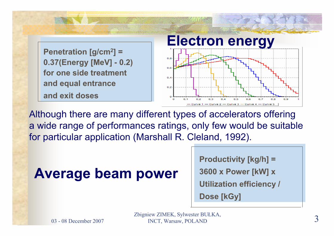
Penetration [g/cm2] =
0.37(Energy [MeV] - 0.2)
for one side treatment
and equal entrance
and exit doses
Productivity [kg/h] =
3600 x Power [kW] x
Utilization efficiency /
Dose [kGy]
Average beam power
Although there are many different types of accelerators offering
a wide range of performances ratings, only few would be suitable
for particular application (Marshall R. Cleland, 1992).
Electron energy

03 - 08 December 2007
Zbigniew ZIMEK, Sylwester BUŁKA,
INCT, Warsaw, POLAND 4
General considerations
� Product to be irradiated dimensions, densities, position
� Vetical or horizontal EB direction
� Operation schedule and seasonal requirements
� Reliability of accelerator
� Control system compatible with facility automation standarts
� Remote accelerator operation and diagnostics
� Accelerator external supply service
� Factory assembling tests
� Warranty conditions and post-warranty service
� Staff training
� Facility qualification

03 - 08 December 2007
Zbigniew ZIMEK, Sylwester BUŁKA,
INCT, Warsaw, POLAND 5
Criterions for accelerator selection
Criterion of selection
Basic accelerator parameters� Electron energy
� Average beam powerAuxiliary accelerator parameters
� Scan characteristics
� Control system compatibility� Accelerator external supply service
Terms of accelerator purchase� Price
� Manufacturer
� Terms of delivery and installation� Warranty conditions
� Exploitation cost
Remarks
The main requirements which
define technological abilities
and facility throughput
The parameters which may
characterize accelerator for
facility design
Economical aspects which define
investments and exploitaton
costs

03 - 08 December 2007
Zbigniew ZIMEK, Sylwester BUŁKA,
INCT, Warsaw, POLAND 6
Accelerator/Facility external supply service
� Safety installations (personnel, radiation, high voltage, fire,
TV surveillance system)
� Electricity consumption, grounding, mains frequency
compatibility
� UPS system or additional power line
� Stand-by conditions (vacuum and temperature regime)
� Water cooling system(s)
� Compressed air or other gases provided
� Air cooling and ozone ventillation

03 - 08 December 2007
Zbigniew ZIMEK, Sylwester BUŁKA,
INCT, Warsaw, POLAND 7
ADVANTAGES
� Proven accelerator technology
� Simplicity of construction
� Long life power components
� High parameters stability
� High beam power
� Narrow energy spread
� Wide range of power adjustment
� Computer supported control system
� Low exploitation cost
� High quality maintenance service

03 - 08 December 2007
Zbigniew ZIMEK, Sylwester BUŁKA,
INCT, Warsaw, POLAND 8
DISADVANTAGES
� Prototype accelerator construction (limited exploitation
experience)
� Parameters on the edge of present limits
� Some power components with limited lifetime (magnetron)
� High electric energy demands
� Poor accelerator availability
� Small company with limited resources
� High total cost
� Difficulties in spare parts availability
03 - 08 December 2007
Zbigniew ZIMEK, Sylwester BUŁKA,
INCT, Warsaw, POLAND 9
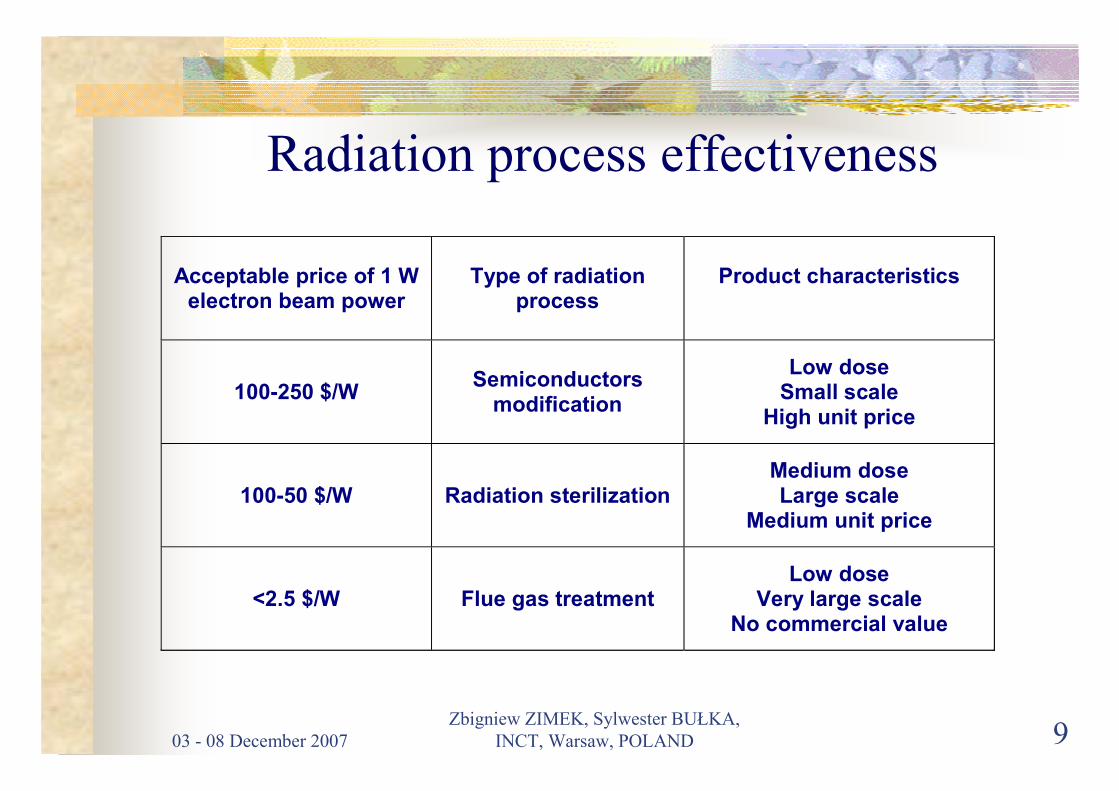
Radiation process effectiveness
Acceptable price of 1 W electron beam power
Type of radiation process
Product characteristics
100-250 $/W Semiconductors
modification
Low dose Small scale
High unit price
100-50 $/W Radiation sterilization Medium dose Large scale
Medium unit price
<2.5 $/W Flue gas treatment Low dose
Very large scale No commercial value
03 - 08 December 2007
Zbigniew ZIMEK, Sylwester BUŁKA,
INCT, Warsaw, POLAND 10
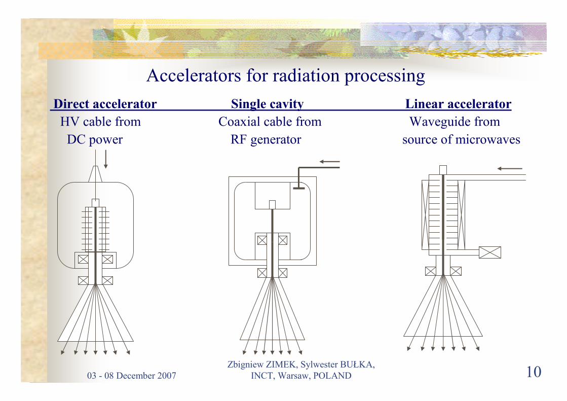
Accelerators for radiation processing
Direct accelerator Single cavity Linear accelerator
HV cable from Coaxial cable from Waveguide from
DC power RF generator source of microwaves
03 - 08 December 2007
Zbigniew ZIMEK, Sylwester BUŁKA,
INCT, Warsaw, POLAND 11
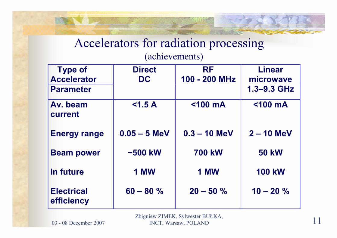
Accelerators for radiation processing(achievements)
Type of Accelerator Parameter
Direct DC
RF 100 - 200 MHz
Linear microwave 1.3–9.3 GHz
Av. beam current Energy range Beam power In future Electrical efficiency
<1.5 A
0.05 – 5 MeV
~500 kW
1 MW
60 – 80 %
<100 mA
0.3 – 10 MeV
700 kW
1 MW
20 – 50 %
<100 mA
2 – 10 MeV
50 kW
100 kW
10 – 20 %

03 - 08 December 2007
Zbigniew ZIMEK, Sylwester BUŁKA,
INCT, Warsaw, POLAND 12
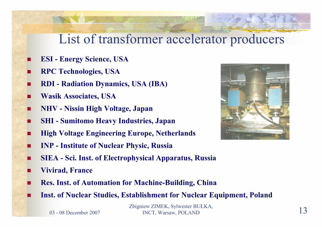
DIRECT ACCELERATORS
transformer type
03 - 08 December 2007
Zbigniew ZIMEK, Sylwester BUŁKA,
INCT, Warsaw, POLAND 13
List of transformer accelerator producers
� ESI - Energy Science, USA
� RPC Technologies, USA
� RDI - Radiation Dynamics, USA (IBA)
� Wasik Associates, USA
� NHV - Nissin High Voltage, Japan
� SHI - Sumitomo Heavy Industries, Japan
� High Voltage Engineering Europe, Netherlands
� INP - Institute of Nuclear Physic, Russia
� SIEA - Sci. Inst. of Electrophysical Apparatus, Russia
� Vivirad, France
� Res. Inst. of Automation for Machine-Building, China
� Inst. of Nuclear Studies, Establishment for Nuclear Equipment, Poland

03 - 08 December 2007
Zbigniew ZIMEK, Sylwester BUŁKA,
INCT, Warsaw, POLAND 14
Capability of D.C. Power Supplyfor transformer accelerators
Accelerator Power line transformer
Cockckroft- Walton
HF Transformer
Dynamitron
Ratings 150-1000kV 10-1000 mA
300-5000 kV 30-1000 mA
500-1000 kV 30 mA
500-5000 kV 1-70 mA
Frequency 50/60 Hz 1-3 kHz 20-50 kHz 50-100 kHz
Insulation Oil/SF6 SF6 SF6 SF6
Efficiency >90 % 70-80 % 85 % 30-60 %
Remarks Low energy High power
High energy High power
Large
High energy Low power Compact
High energy Low eff.

03 - 08 December 2007
Zbigniew ZIMEK, Sylwester BUŁKA,
INCT, Warsaw, POLAND 15
CASCADE ACCELERATOR
EPS-4 type
NISSIN HV, Japan
PARAMETERS:
ENERGY 1-5 MeV
STABILITY ± 2%
BEAM CURRENT 30 mA
STABILITY ± 2%
BEAM POWER 150 kW
SCANNER 1400 mm
HOMOGENEITY <± 5%
03 - 08 December 2007
Zbigniew ZIMEK, Sylwester BUŁKA,
INCT, Warsaw, POLAND 16
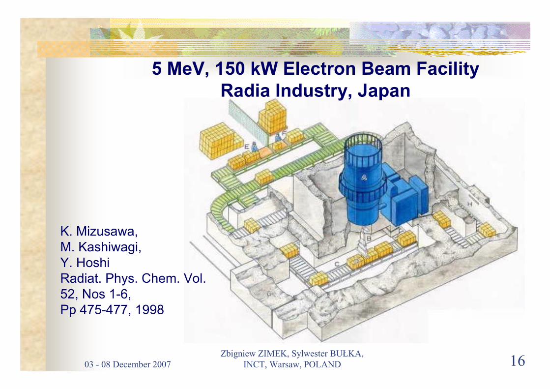
K. Mizusawa,
M. Kashiwagi,
Y. Hoshi
Radiat. Phys. Chem. Vol.
52, Nos 1-6,
Pp 475-477, 1998
5 MeV, 150 kW Electron Beam FacilityRadia Industry, Japan
03 - 08 December 2007
Zbigniew ZIMEK, Sylwester BUŁKA,
INCT, Warsaw, POLAND 17
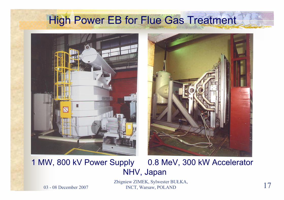
High Power EB for Flue Gas Treatment
1 MW, 800 kV Power Supply 0.8 MeV, 300 kW Accelerator
NHV, Japan

03 - 08 December 2007
Zbigniew ZIMEK, Sylwester BUŁKA,
INCT, Warsaw, POLAND 18
ELV 12 coreless transformer acceleratorElectron energy 1 MeVBeam power 400 kWFrequency 1000 HzOne power supply Three scanners
INP, Russia

03 - 08 December 2007
Zbigniew ZIMEK, Sylwester BUŁKA,
INCT, Warsaw, POLAND 19
SINGLE CAVITY ACCELERATORS
single pass or multi-pass systems
03 - 08 December 2007
Zbigniew ZIMEK, Sylwester BUŁKA,
INCT, Warsaw, POLAND 20
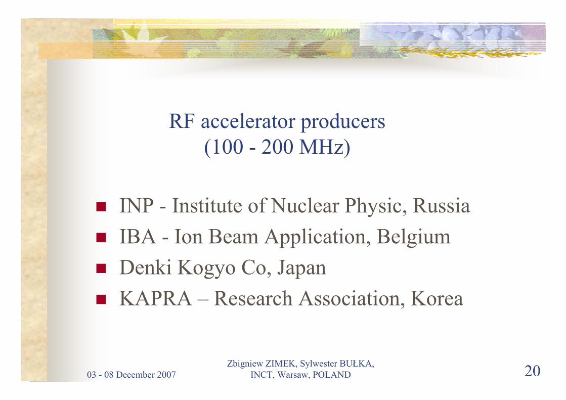
RF accelerator producers
(100 - 200 MHz)
� INP - Institute of Nuclear Physic, Russia
� IBA - Ion Beam Application, Belgium
� Denki Kogyo Co, Japan
� KAPRA – Research Association, Korea
03 - 08 December 2007
Zbigniew ZIMEK, Sylwester BUŁKA,
INCT, Warsaw, POLAND 21
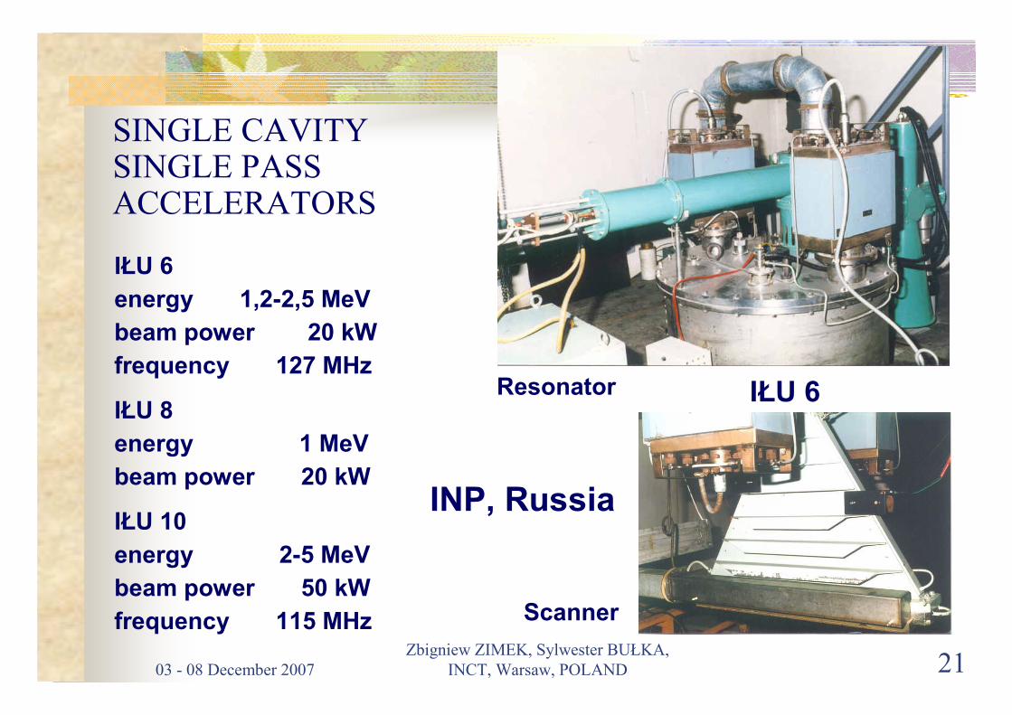
SINGLE CAVITY SINGLE PASSACCELERATORS
IŁU 6
energy 1,2-2,5 MeV
beam power 20 kW
frequency 127 MHz
IŁU 8
energy 1 MeV
beam power 20 kW
IŁU 10
energy 2-5 MeV
beam power 50 kW
frequency 115 MHz Scanner
Resonator IŁU 6
INP, Russia

03 - 08 December 2007
Zbigniew ZIMEK, Sylwester BUŁKA,
INCT, Warsaw, POLAND 22
ILU 12 ELECTRON ACCELERATOR
Electron energy 5 MeVBeam power 300 kWFrequency 176 MHzRF power 450 kW
Auslender V.L. et all.,
EPAC 2002, Paris, France
Accelerating structure
03 - 08 December 2007
Zbigniew ZIMEK, Sylwester BUŁKA,
INCT, Warsaw, POLAND 23
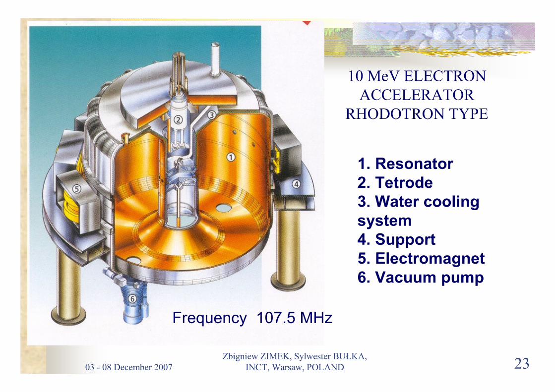
10 MeV ELECTRON
ACCELERATOR
RHODOTRON TYPE
1. Resonator2. Tetrode3. Water cooling system4. Support5. Electromagnet6. Vacuum pump
Frequency 107.5 MHz
03 - 08 December 2007
Zbigniew ZIMEK, Sylwester BUŁKA,
INCT, Warsaw, POLAND 24
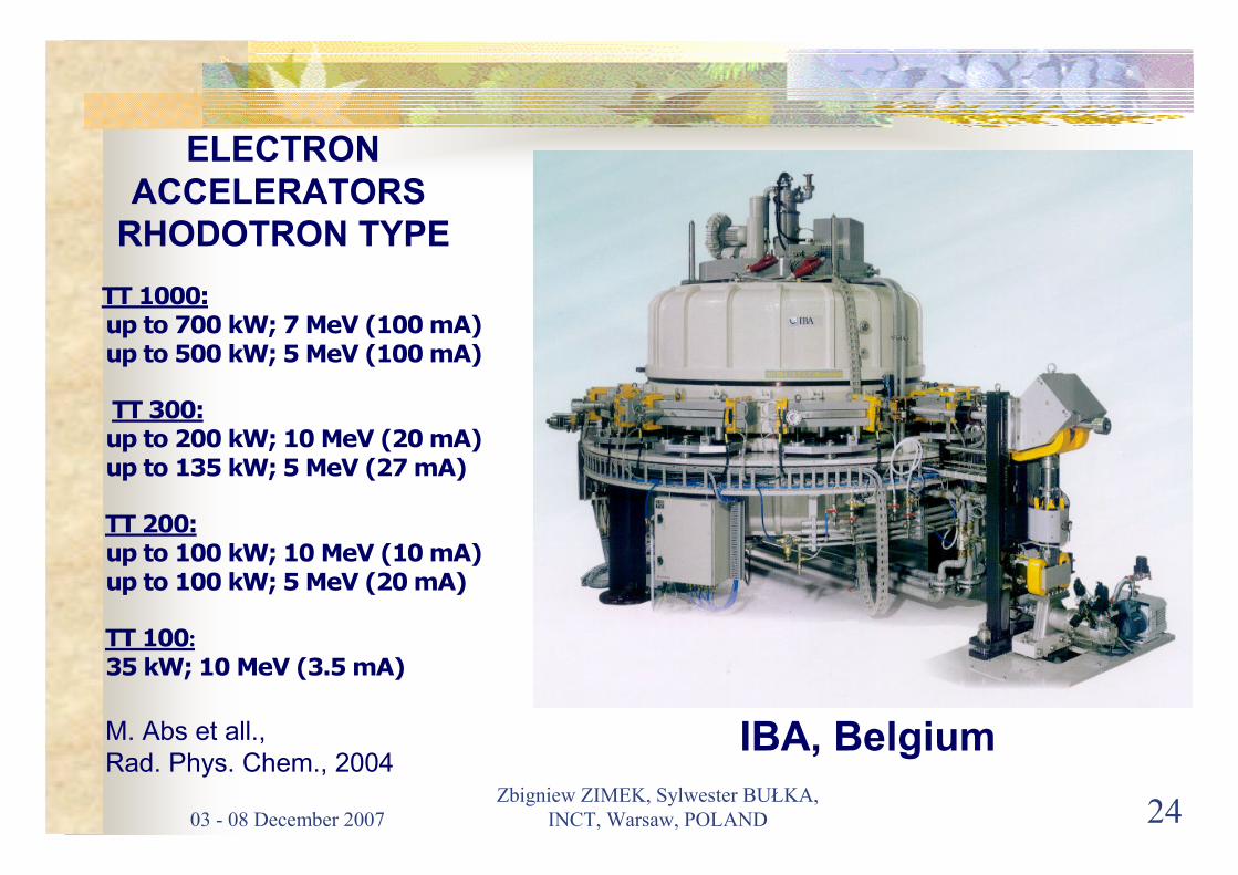
TT 1000:
up to 700 kW; 7 MeV (100 mA)
up to 500 kW; 5 MeV (100 mA)
TT 300:
up to 200 kW; 10 MeV (20 mA)
up to 135 kW; 5 MeV (27 mA)
TT 200:
up to 100 kW; 10 MeV (10 mA)
up to 100 kW; 5 MeV (20 mA)
TT 100:
35 kW; 10 MeV (3.5 mA)
IBA, Belgium
ELECTRON ACCELERATORS
RHODOTRON TYPE
M. Abs et all.,
Rad. Phys. Chem., 2004
03 - 08 December 2007
Zbigniew ZIMEK, Sylwester BUŁKA,
INCT, Warsaw, POLAND 25
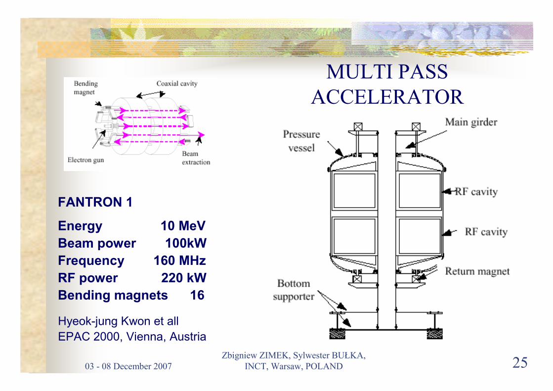
MULTI PASS
ACCELERATOR
FANTRON 1
Energy 10 MeV
Beam power 100kW
Frequency 160 MHz
RF power 220 kW
Bending magnets 16
Hyeok-jung Kwon et all
EPAC 2000, Vienna, Austria

03 - 08 December 2007
Zbigniew ZIMEK, Sylwester BUŁKA,
INCT, Warsaw, POLAND 26
LINEAR ELECTRON
ACCELERATORS
03 - 08 December 2007
Zbigniew ZIMEK, Sylwester BUŁKA,
INCT, Warsaw, POLAND 27
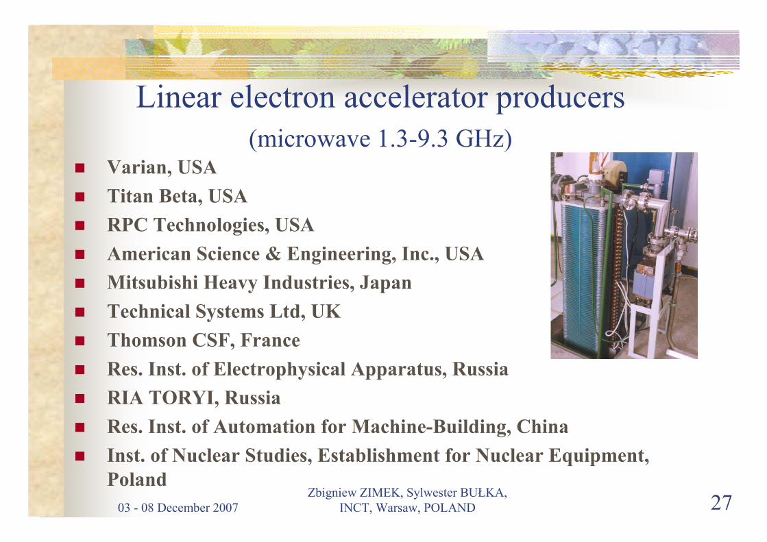
Linear electron accelerator producers
(microwave 1.3-9.3 GHz)� Varian, USA
� Titan Beta, USA
� RPC Technologies, USA
� American Science & Engineering, Inc., USA
� Mitsubishi Heavy Industries, Japan
� Technical Systems Ltd, UK
� Thomson CSF, France
� Res. Inst. of Electrophysical Apparatus, Russia
� RIA TORYI, Russia
� Res. Inst. of Automation for Machine-Building, China
� Inst. of Nuclear Studies, Establishment for Nuclear Equipment,
Poland

03 - 08 December 2007
Zbigniew ZIMEK, Sylwester BUŁKA,
INCT, Warsaw, POLAND 28
Accelerator for medical sterilization
� Electron energy
5 – 12 MeV
� Beam power
10 – 45 kW
P.J. Cracknell
Radiat. Phys. Chem.
46 (1995) 469-472
03 - 08 December 2007
Zbigniew ZIMEK, Sylwester BUŁKA,
INCT, Warsaw, POLAND 29
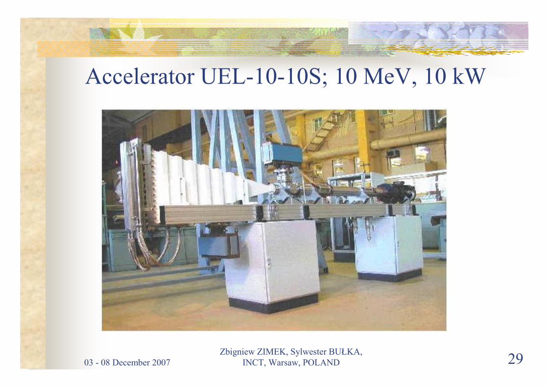
Accelerator UEL-10-10S; 10 MeV, 10 kW
03 - 08 December 2007
Zbigniew ZIMEK, Sylwester BUŁKA,
INCT, Warsaw, POLAND 30
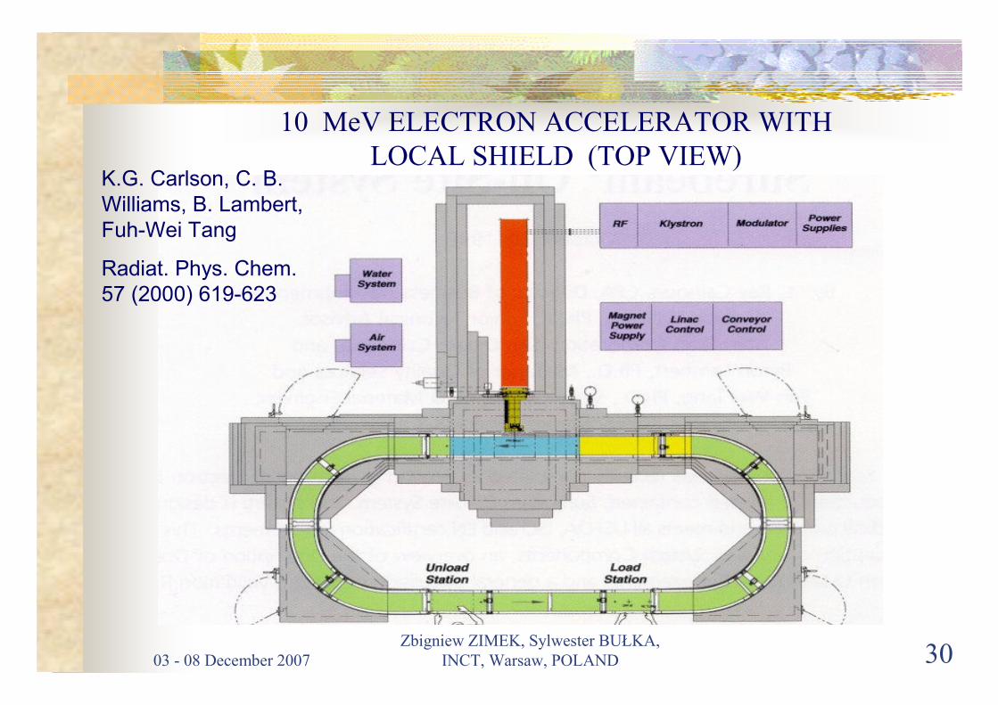
10 MeV ELECTRON ACCELERATOR WITH
LOCAL SHIELD (TOP VIEW)K.G. Carlson, C. B.
Williams, B. Lambert,
Fuh-Wei Tang
Radiat. Phys. Chem.
57 (2000) 619-623
03 - 08 December 2007
Zbigniew ZIMEK, Sylwester BUŁKA,
INCT, Warsaw, POLAND 31
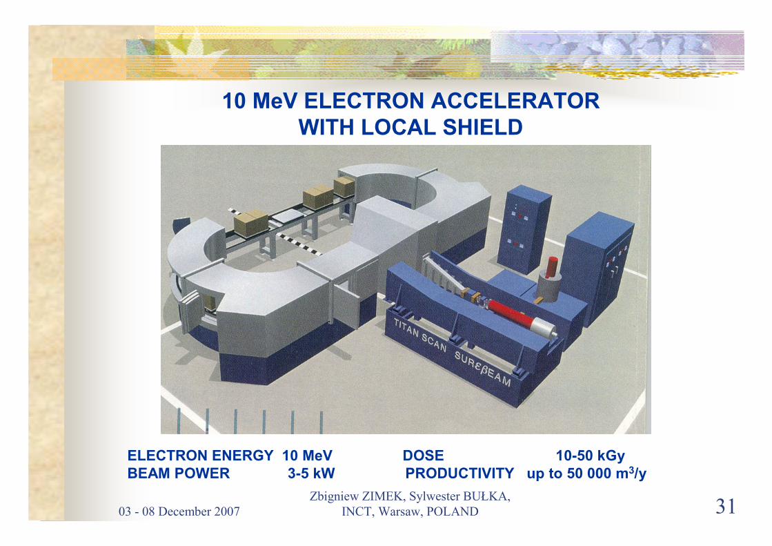
10 MeV ELECTRON ACCELERATOR WITH LOCAL SHIELD
ELECTRON ENERGY 10 MeV DOSE 10-50 kGyBEAM POWER 3-5 kW PRODUCTIVITY up to 50 000 m3/y

03 - 08 December 2007
Zbigniew ZIMEK, Sylwester BUŁKA,
INCT, Warsaw, POLAND 32
COMPACT
ACCELERATOR
MeVAc
Energy 3 MeVBeam power 3 kWScanning 30 to 50 cmHeight 1 mWidth 0,3 m
THOMSON-CSF
LINAC
03 - 08 December 2007
Zbigniew ZIMEK, Sylwester BUŁKA,
INCT, Warsaw, POLAND 33
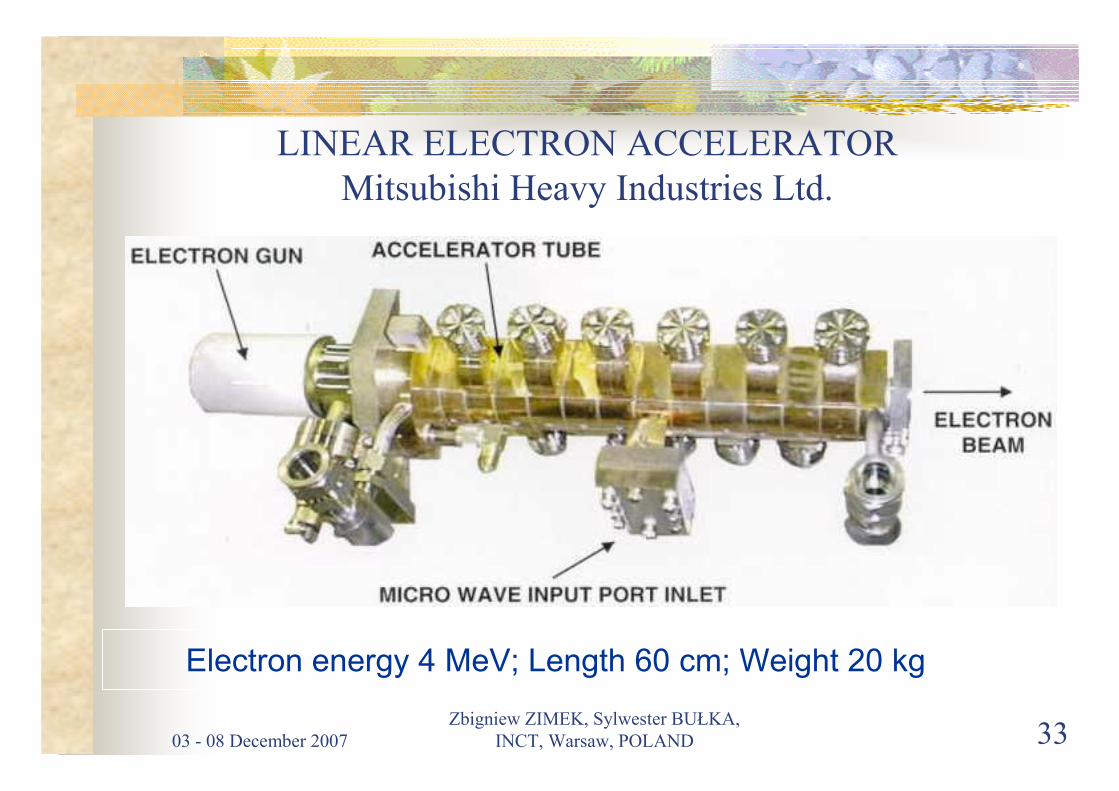
LINEAR ELECTRON ACCELERATOR
Mitsubishi Heavy Industries Ltd.
Electron energy 4 MeV; Length 60 cm; Weight 20 kg
03 - 08 December 2007
Zbigniew ZIMEK, Sylwester BUŁKA,
INCT, Warsaw, POLAND 34
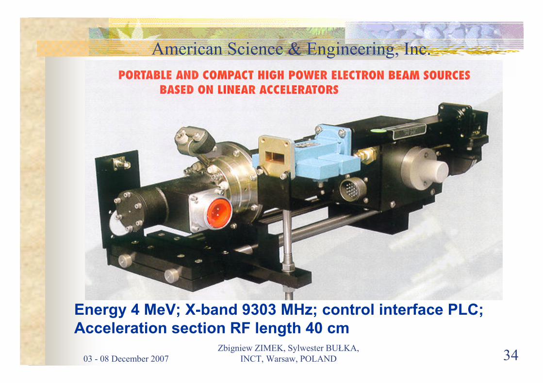
American Science & Engineering, Inc.
Energy 4 MeV; X-band 9303 MHz; control interface PLC;Acceleration section RF length 40 cm

03 - 08 December 2007
Zbigniew ZIMEK, Sylwester BUŁKA,
INCT, Warsaw, POLAND 35
OUTPUT AND BEAM
SCANNING DEVICES
03 - 08 December 2007
Zbigniew ZIMEK, Sylwester BUŁKA,
INCT, Warsaw, POLAND 36
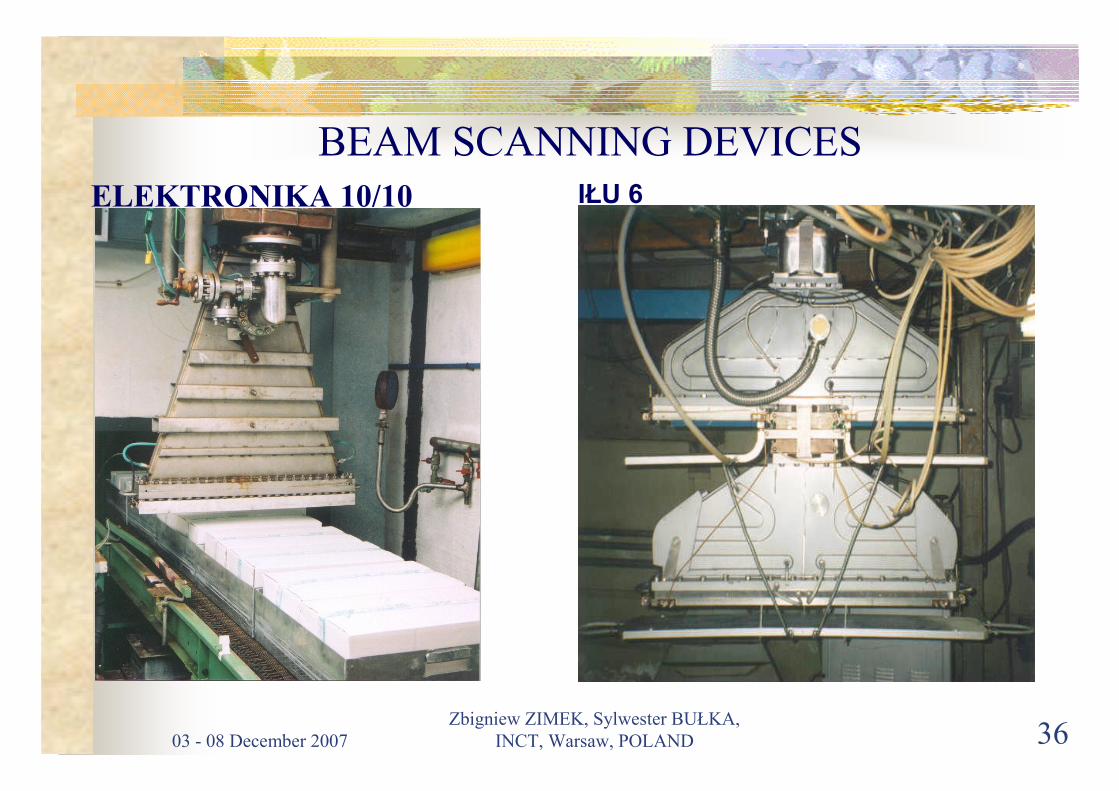
BEAM SCANNING DEVICES
ELEKTRONIKA 10/10 IŁU 6
03 - 08 December 2007
Zbigniew ZIMEK, Sylwester BUŁKA,
INCT, Warsaw, POLAND 37
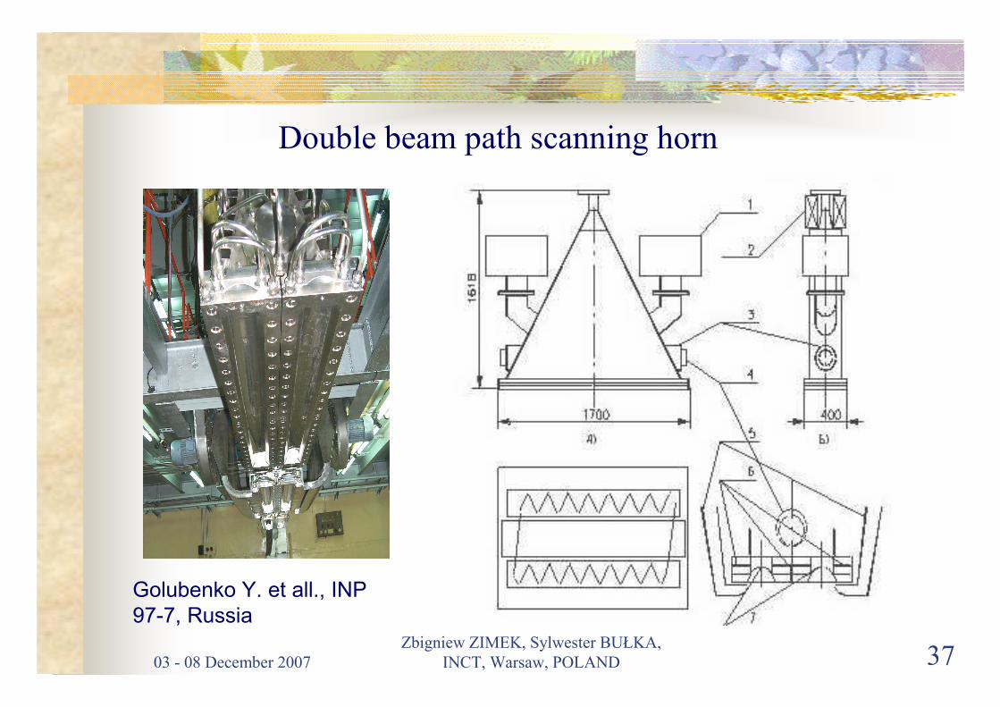
Double beam path scanning horn
Golubenko Y. et all., INP
97-7, Russia
03 - 08 December 2007
Zbigniew ZIMEK, Sylwester BUŁKA,
INCT, Warsaw, POLAND 38
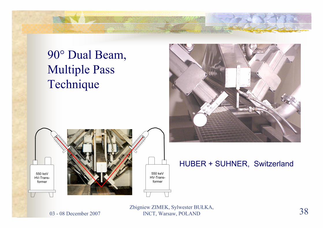
90° Dual Beam,
Multiple Pass
Technique
550 keV
HV-Trans-
former
550 keV
HV-Trans-
former
HUBER + SUHNER, Switzerland
03 - 08 December 2007
Zbigniew ZIMEK, Sylwester BUŁKA,
INCT, Warsaw, POLAND 39
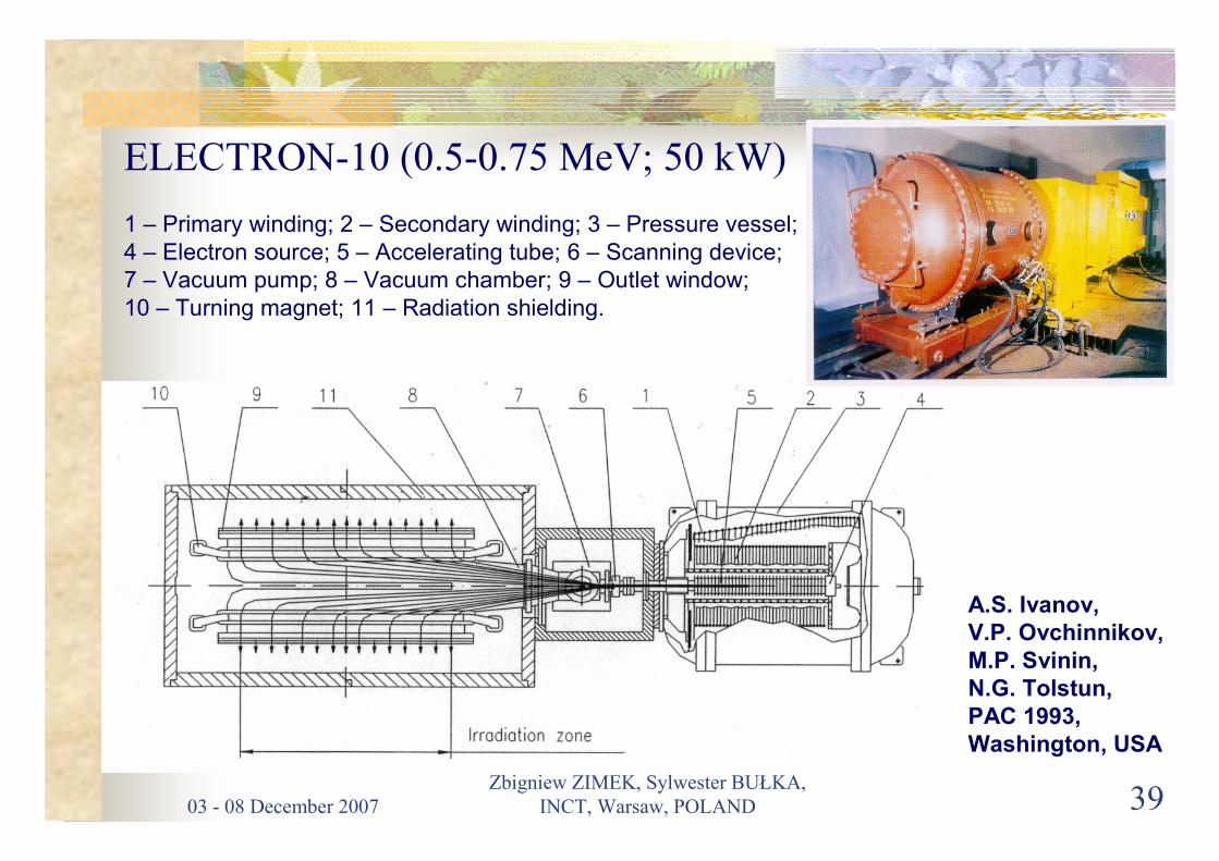
ELECTRON-10 (0.5-0.75 MeV; 50 kW)
1 – Primary winding; 2 – Secondary winding; 3 – Pressure vessel;
4 – Electron source; 5 – Accelerating tube; 6 – Scanning device;
7 – Vacuum pump; 8 – Vacuum chamber; 9 – Outlet window;
10 – Turning magnet; 11 – Radiation shielding.
A.S. Ivanov, V.P. Ovchinnikov,M.P. Svinin, N.G. Tolstun,PAC 1993, Washington, USA
03 - 08 December 2007
Zbigniew ZIMEK, Sylwester BUŁKA,
INCT, Warsaw, POLAND 40
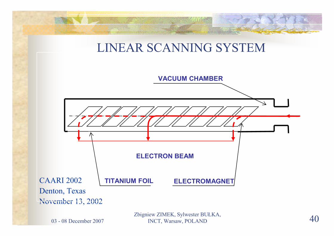
LINEAR SCANNING SYSTEM
CAARI 2002
Denton, Texas
November 13, 2002
VACUUM CHAMBER
ELECTRON BEAM
ELECTROMAGNET TITANIUM FOIL

03 - 08 December 2007
Zbigniew ZIMEK, Sylwester BUŁKA,
INCT, Warsaw, POLAND 41
COMPUTER CONTROL
SYSTEMS
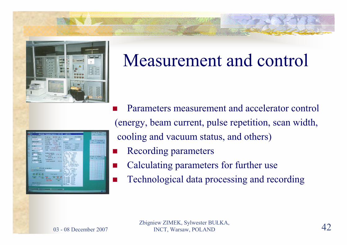
03 - 08 December 2007
Zbigniew ZIMEK, Sylwester BUŁKA,
INCT, Warsaw, POLAND 42
Measurement and control
� Parameters measurement and accelerator control
(energy, beam current, pulse repetition, scan width,
cooling and vacuum status, and others)
� Recording parameters
� Calculating parameters for further use
� Technological data processing and recording

03 - 08 December 2007
Zbigniew ZIMEK, Sylwester BUŁKA,
INCT, Warsaw, POLAND 43
CONTROL ROOM IN INDUSTRIAL FACILITY FOR
FLUE GAS TREATMENT
03 - 08 December 2007
Zbigniew ZIMEK, Sylwester BUŁKA,
INCT, Warsaw, POLAND 44
X-RAY CONVERSION
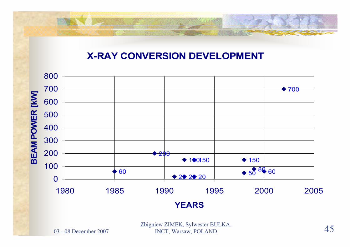
03 - 08 December 2007
Zbigniew ZIMEK, Sylwester BUŁKA,
INCT, Warsaw, POLAND 45
X-RAY CONVERSION DEVELOPMENT
60
200150
5080
700
6020
150 150
20200
100
200
300
400
500
600
700
800
1980 1985 1990 1995 2000 2005
YEARS
BE
AM
PO
WE
R [
kW
]

03 - 08 December 2007
Zbigniew ZIMEK, Sylwester BUŁKA,
INCT, Warsaw, POLAND 46
NFI : Irradiation Room with EB
and X-ray Ports
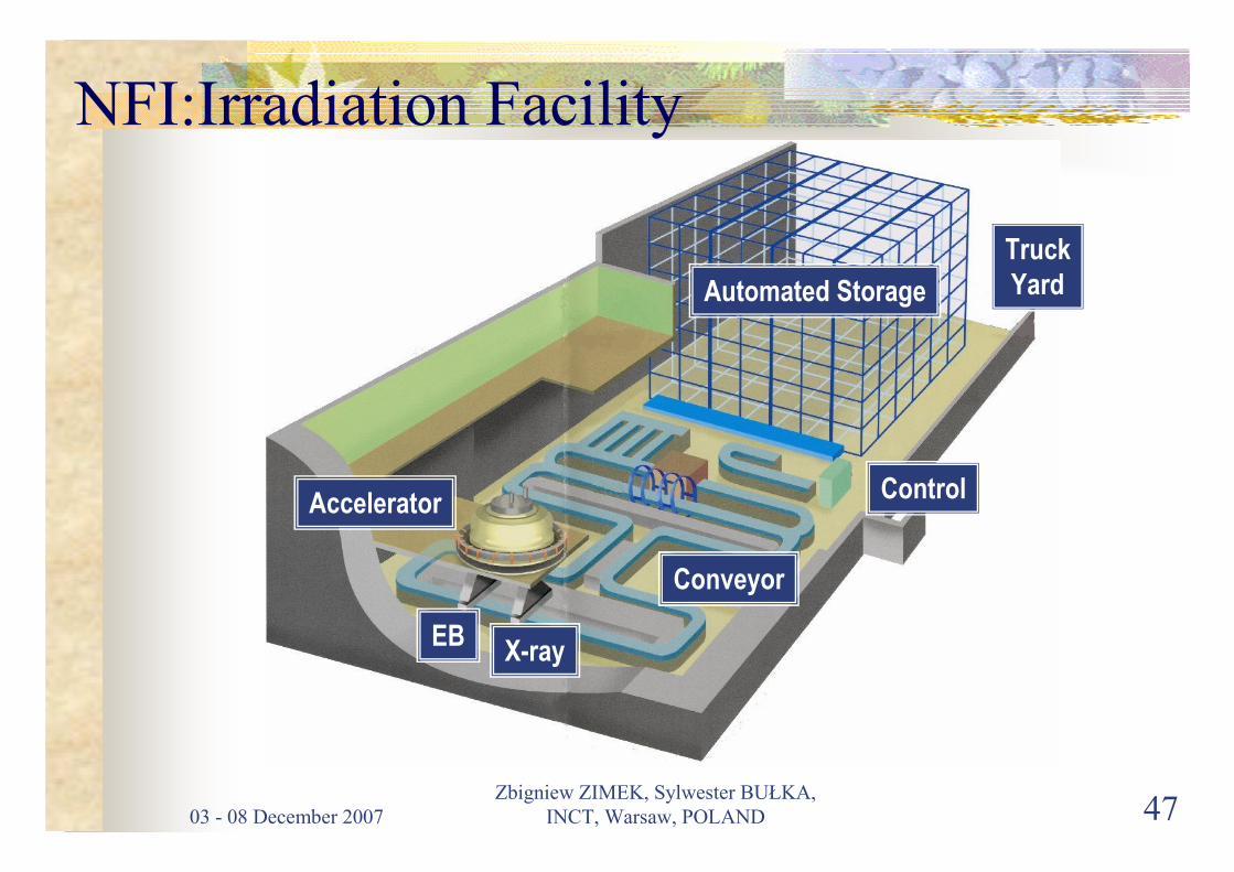
03 - 08 December 2007
Zbigniew ZIMEK, Sylwester BUŁKA,
INCT, Warsaw, POLAND 47
Conveyor
Control
Truck
Yard
X-rayEB
Accelerator
Automated Storage
NFI:Irradiation Facility

03 - 08 December 2007
Zbigniew ZIMEK, Sylwester BUŁKA,
INCT, Warsaw, POLAND 48
Remarks� A meaningful steps can be recognized in the past of accelerator development.
Present stage of accelerator technology perfection includes: cost
effectiveness, reliability, compactness, very low energy and introduction of
MW beam power level,
� Major industrial accelerator producers are located in USA, Russia, Japan
and Belgium. Several other countries including China and Poland are
capable to produce accelerators at limited scale,
� Any practical accelerator construction must be compromise between size,
efficiency and cost,
� The progress in accelerator technology is not a quick process but can be
easily noticed in longer time scale,
� Appropriate accelerator selection should be performed to meet all technical
and economical conditions for successful process implementation,
03 - 08 December 2007
Zbigniew ZIMEK, Sylwester BUŁKA,
INCT, Warsaw, POLAND 49
� Highly trained personnel is not required to run modern accelerators because
of simplicity of their operation under computer support,
� Spare parts and major maintenance service should be available from the
manufacturer of the accelerator during the machine lifetime,
� New accelerators constructions can frequently offer better economic and
technical characteristics but only long time operation can reveal weak points
of certain construction in practical industrial conditions.
03 - 08 December 2007
Zbigniew ZIMEK, Sylwester BUŁKA,
INCT, Warsaw, POLAND 50
THANK YOU FOR ATTENTION...THANK YOU FOR ATTENTION...

Validation and Process Control for EB Radiation Processing 1
Establishment of a sterilization dose
Iwona KaluskaInstitute of Nuclear Technology and Chemistry
Warsaw, Poland
Validation and Process Control for EB Radiation Processing 2
Radiation sterilization processing -
responsibilities
Product manufacturer
Operator of the radiation sterilization facility
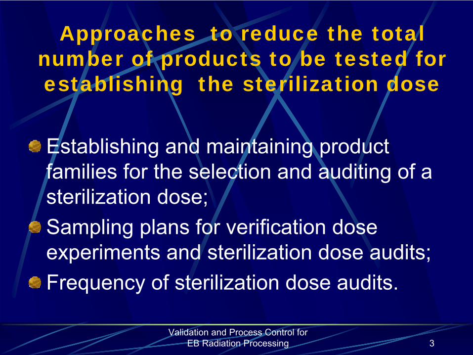
Validation and Process Control for EB Radiation Processing 3
Approaches to reduce the total number of products to be tested for establishing the sterilization dose
Establishing and maintaining product families for the selection and auditing of a sterilization dose;Sampling plans for verification dose experiments and sterilization dose audits;Frequency of sterilization dose audits.

Validation and Process Control for EB Radiation Processing 4
Bioburden
Population
of
viable
microorganisms
on or
in
product
and/or
sterile
barrier
system
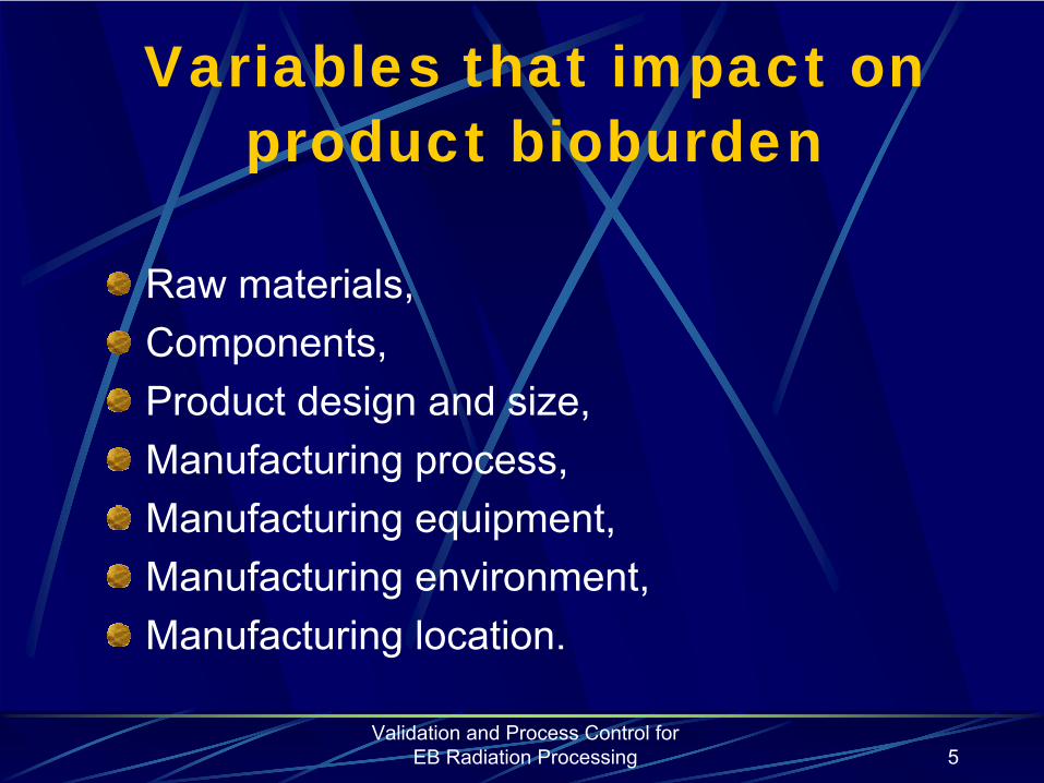
Validation and Process Control for EB Radiation Processing 5
Variables that impact on product bioburden
Raw materials,Components,Product design and size,Manufacturing process,Manufacturing equipment,Manufacturing environment,Manufacturing location.

Validation and Process Control for EB Radiation Processing 6
For product manufactured in different locations, consideration shall be given to the impact on bioburden of:
Geographic and climatic differences between locations,Any differences in the control of the manufacturing processes or environment, andSources of raw materials and processing adjuvants
(e.g.water).
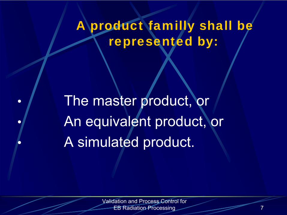
Validation and Process Control for EB Radiation Processing 7
A product familly shall be represented by:
•
The master product, or•
An equivalent product, or
•
A simulated product.
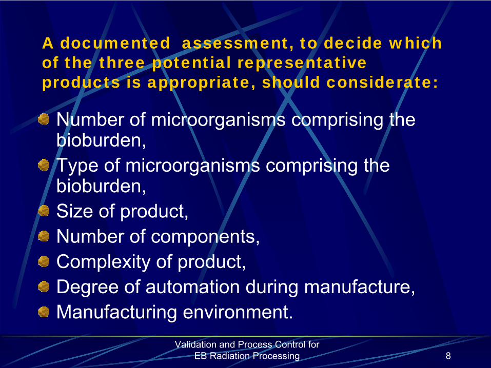
Validation and Process Control for EB Radiation Processing 8
A documented assessment, to decide which of the three potential representative products is appropriate, should considerate:
Number of microorganisms comprising the bioburden,Type of microorganisms comprising the bioburden,Size of product,Number of components,Complexity of product,Degree of automation during manufacture,Manufacturing environment.

Validation and Process Control for EB Radiation Processing 9
Master product
A member of the product family shall only be considered a master product, if assessment indicates that this product requires a sterilization dose that is greater than that of all other product family members. In some situations there may be several products within the product family that could be considered as the master product. In such circumstances any one of these products may be selected as the master product to represent the product family.

Validation and Process Control for EB Radiation Processing 10
Equivalent product
A group of product shall only be considered equivalent if assessment indicates that group members require the same sterilization dose. Selection of the equivalent product shall either be
at random, or according to a planned schedule
to include different
members of the
product family. The
manufacturing volume and availability of product
should be considered in the selection of the equivalent product to represent the product family.

Validation and Process Control for EB Radiation Processing 11
A simulated product may be:
One which is similar to the actual product in terms of materials and size, and subjected to similar manufacturing processes; orA combination of components from products within the product family that would not typically be combined for use.

Validation and Process Control for EB Radiation Processing 12
Maintaining product families
Assessment/Periodic reviews;Modifications to product and/or manufacturing processes;Records.

Validation and Process Control for EB Radiation Processing 13
Selection and testing of product for establishing the sterilization dose
Nature of the productproduct for sterilization may consist of:
an individual health care product within its primary package,a set components presented in a primary package which are assembled at the point of use to form the health care product, together with accessories required to use the assembled product,a number of identical health care products within a primary package,a kit comprising a variety of procedure-related health care products.
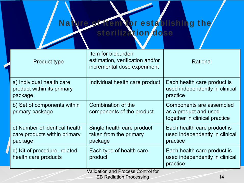
Validation and Process Control for EB Radiation Processing 14
Nature of item for establishing the sterilization dose
Product typeItem for bioburden
estimation, verification and/or incremental dose experiment
Rational
a) Individual health care product within its primary package
Individual health care product Each health care product is used independently in clinical practice
b) Set of components within primary package
Combination of the components of the product
Components are assembled as a product and used together in clinical practice
c) Number of identical health care products within primary package
Single health care product taken from the primary package
Each health care product is used independently in clinical practice
d) Kit of procedure-
related
health care productsEach type of health care product
Each health care product is used independently in clinical practice
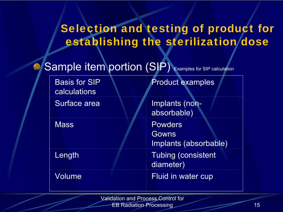
Validation and Process Control for EB Radiation Processing 15
Selection and testing of product for establishing the sterilization dose
Sample
item
portion
(SIP)
Examples for SIP calculation
Basis for SIP calculations
Product examples
Surface area Implants (non- absorbable)
Mass PowdersGownsImplants (absorbable)
Length Tubing (consistent diameter)
Volume Fluid in water cup
Validation and Process Control for EB Radiation Processing 16
Sterilization dose
Minimum absorbed dose required to achieve the specified assurance level
Validation and Process Control for EB Radiation Processing 17
Sterilization dose selection
Selection of sterilization dose using either:Bioburden informationInformation obtained by incremental dosing
Selection of a sterilization dose of a 25 kGy or 15 kGy following
substantiation
of the appropriateness of this dose
Validation and Process Control for EB Radiation Processing 18
If a product-specific sterilization dose is selected, it shall be set by one of the
following methods
a) Methods 1 for multiple and single batches
b) Method 2A
c) Methods 2B
d) A method providing equivalent assurance to that of a), b) or c) above in achieving the specified
requirement for sterility
Validation and Process Control for EB Radiation Processing 19
The sterilization dose shall be substantiated by one of the following methods (1/2)
a)
for product with an average biodurden in the range 0,1 to 1000 inclusive, by
1)
Method VD25max
2)
Method 1, subjected to the derived sterilization dose taking a value equal to or less than 25 kGy,
3)
Method 2, subjected to the derived sterilization dose taking a value equal to or less than 25 kGy,
4)
A method providing equivalent assurance to that of 1), 2), or 3) above in achieving maximally an SAL of 10-6.
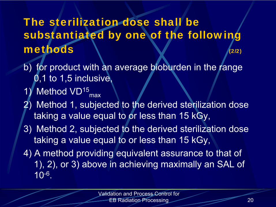
Validation and Process Control for EB Radiation Processing 20
The sterilization dose shall be substantiated by one of the following methods (2/2)
b)
for product with an average
bioburden
in the range 0,1 to 1,5 inclusive,
1)
Method VD15max
2)
Method 1, subjected to the derived sterilization dose taking a value equal to or less than 15
kGy,
3)
Method 2, subjected to the derived sterilization dose taking a value equal to or less than 15 kGy,
4) A method providing equivalent assurance to that of 1), 2), or 3) above in achieving maximally an SAL of 10-6.
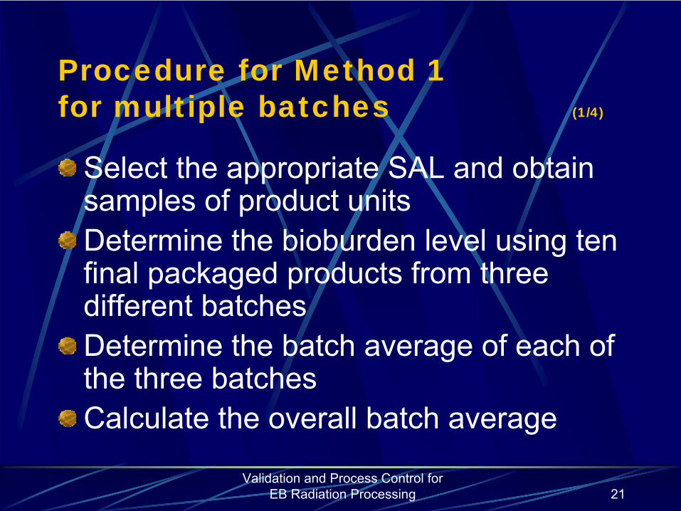
Validation and Process Control for EB Radiation Processing 21
Procedure for Method 1 for multiple batches (1/4)
Select the appropriate SAL and obtain samples of product unitsDetermine the bioburden level using ten final packaged products from three different batchesDetermine the batch average of each of the three batchesCalculate the overall batch average
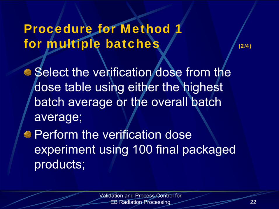
Validation and Process Control for EB Radiation Processing 22
Procedure for Method 1 for multiple batches (2/4)
Select the verification dose from the dose table using either the highest batch average or the overall batch average;Perform the verification dose experiment using 100 final packaged products;

Validation and Process Control for EB Radiation Processing 23
Procedure for Method 1 for multiple batches (3/4)
Sterility test the 100 units (Soybean Casein Digest Broth, incubated at (30±2)°C for 14 days);Acceptability of the experiment
≤ 2 positive sterility tests = acceptable> 2 positive sterility tests = method is not valid, the alternative method should be used (Method 2).

Validation and Process Control for EB Radiation Processing 24
Procedure for Method 1 for multiple batches (4/4)
Establish sterilization dose by finding the closest biodurden number in the dose table equal or greater than the average bioburden and the selected SAL level.
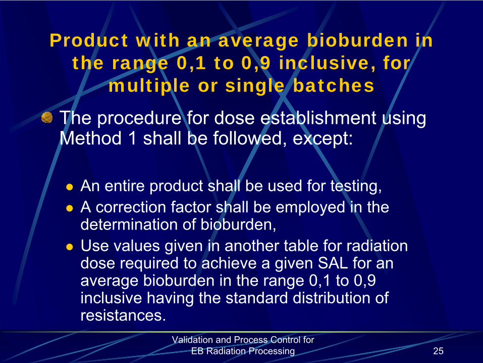
Validation and Process Control for EB Radiation Processing 25
Product with an average bioburden in the range 0,1 to 0,9 inclusive, for
multiple or single batchesThe procedure for dose establishment using Method 1 shall be followed, except:
An entire product shall be used for testing,A correction factor shall be employed in the determination of bioburden,Use values given in another table for radiation dose required to achieve a given SAL for an average bioburden in the range 0,1 to 0,9 inclusive having the standard distribution of resistances.

Validation and Process Control for EB Radiation Processing 26
Method 2
Two procedures are available for validation of Method 2
Method 2A for products with bioburden as would be expected from normal manufacturing processMethod 2B for products with consistent and very low bioburden.
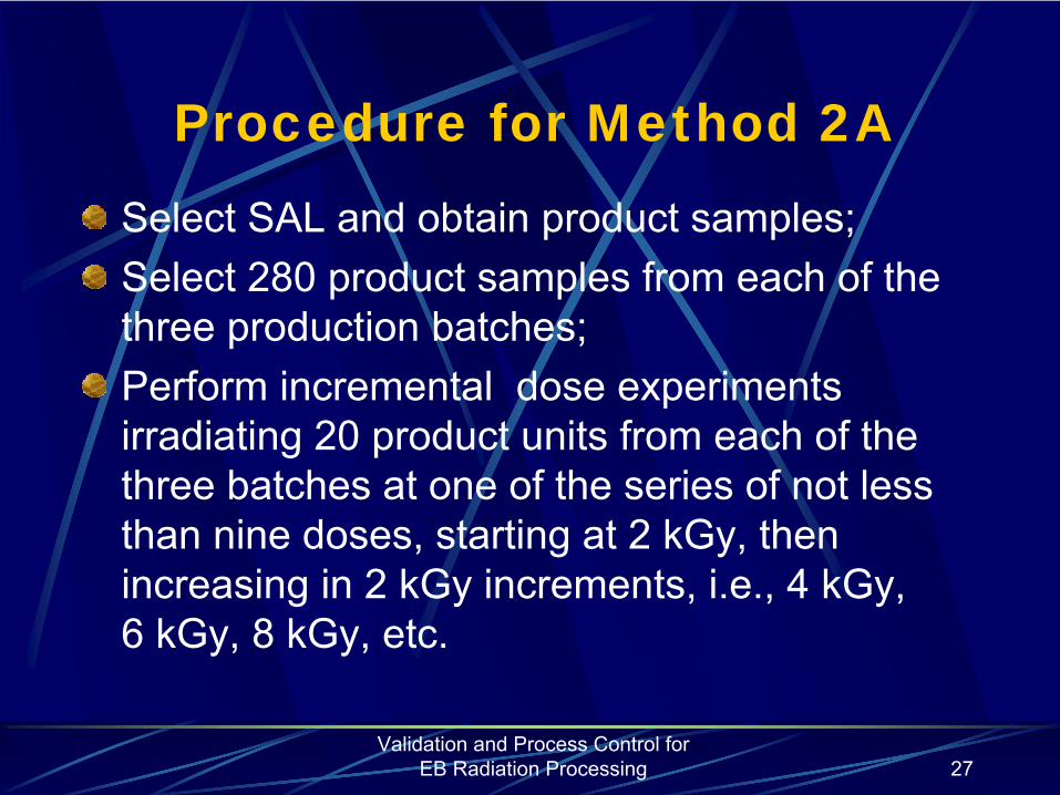
Validation and Process Control for EB Radiation Processing 27
Procedure for Method 2ASelect SAL and obtain product samples;Select 280 product samples from each of the three production batches;Perform incremental dose experiments irradiating 20 product units from each of the three batches at one of the series of not less than nine doses, starting at
2 kGy, then
increasing in
2 kGy increments, i.e., 4 kGy, 6 kGy, 8 kGy, etc.
Validation and Process Control for EB Radiation Processing 28
This dose may vary from the nominal incremental dose by ±
1,0 kGy or ±
10%
whichever is greater.
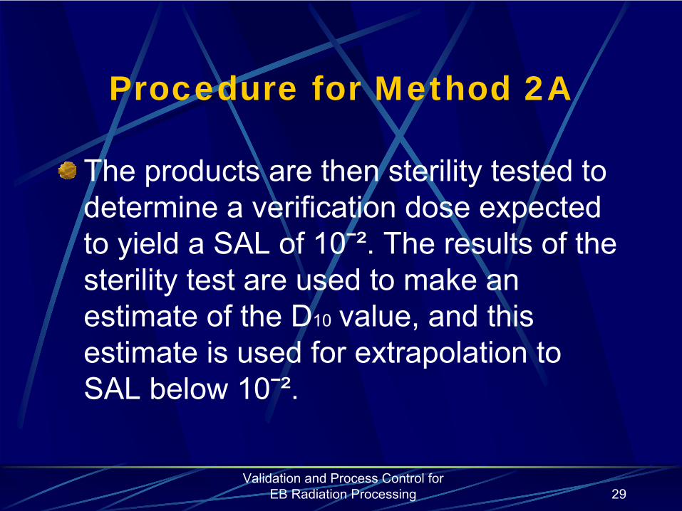
Validation and Process Control for EB Radiation Processing 29
Procedure for Method 2A
The products are then sterility tested to determine a verification dose expected to yield a SAL of 10¯². The results of the sterility test are used to make an estimate of the D10
value, and this
estimate is used for extrapolation to SAL below 10¯².

Validation and Process Control for EB Radiation Processing 30
A kGy and First Fraction Positive (FFP) kGy
For each of the three batches, determined the lowest dose (FFP kGy) where at least one of the twenty tests is negative. Find the median value. Determine A kGy from the table using the number of positive sterility tests at the median FFP kGy dose.
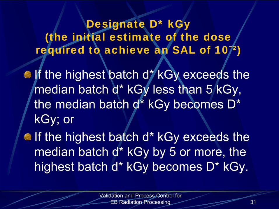
Validation and Process Control for EB Radiation Processing 31
Designate D* kGy (the initial estimate of the dose
required to achieve an SAL of 10¯²)
If the highest batch d* kGy exceeds the median batch d* kGy less than 5 kGy, the median batch d* kGy becomes D* kGy; orIf the highest batch d* kGy exceeds the median batch d* kGy by 5 or more, the highest batch d* kGy becomes D* kGy.

Validation and Process Control for EB Radiation Processing 32
D* kGy
For each of the three batches, determine the d* kGy by either finding the lowest dose of two consecutive doses at which all tests are negative, followed by no more than one further positive test, or by finding the lowest dose at which one positive in twenty tests occurs, immediately preceded and followed by incremental doses at which all tests are negative.
Validation and Process Control for EB Radiation Processing 33
CD* batch
Establish the batch in which the d* kGy equals the D* kGy and designate in the CD* batch.

Validation and Process Control for EB Radiation Processing 34
First No Positives (FNP) kGy
If CD* ≤
2, FNP kGy= DD* kGyIf 10<CD*>2, FNP kGy = DD* +2,0 kGy
•
If 16<CD*>9, FNP kGy = DD* +4,0 kGy•
If CD*>15 D* kGy should be redetermined
DD* kGy, the actual dose delivered

Validation and Process Control for EB Radiation Processing 35
Establish sterilization dose
Determine DS kGy (dose required to inactive 90% of the organism surviving DD* kGy) from FFP kGy and FNP
•
When (FNP-FFP)<
10 kGy, then DS kGy = 2+0,2(FNP-FFP) kGy
•
When (FNP-FFP)≥
10 kGy, then DS kGy = 0,4+(FNP-FFP) kGy
•
EstablishD** kGy = DD*kGy + [log(CD*)] (DS) kGy
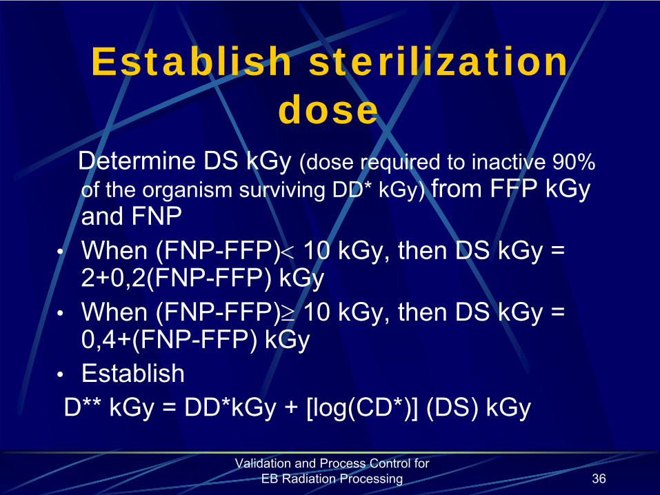
Validation and Process Control for EB Radiation Processing 36
Establish sterilization dose
Determine DS kGy (dose required to inactive 90% of the organism surviving DD* kGy) from FFP kGy and FNP
•
When (FNP-FFP)<
10 kGy, then DS kGy = 2+0,2(FNP-FFP) kGy
•
When (FNP-FFP)≥
10 kGy, then DS kGy = 0,4+(FNP-FFP) kGy
•
EstablishD** kGy = DD*kGy + [log(CD*)] (DS) kGy
Validation and Process Control for EB Radiation Processing 37
Verification dose experiment
Irradiate 100 products from CD* batch at the dose of D* kGy. Designate the delivered dose as DD* kGy.Test the irradiated products at 30°C±2°
for 14 days.

Validation and Process Control for EB Radiation Processing 38
Sterilization dose
Sterilization dose = D**kGy +[-log(SAL) – log(SIP)-2] (DS) kGy
WhereD**
kGy is the estimate of the dose that will provide a 10ֿ²SAL for the test samples
SAL
is the preselected sterility assurance level for the productSIP
is the portion of product unit used for determining D** kGy and DS kGy
DS kGy
is an estimate of the dose required to inactivate 90% of the organisms surviving D** kGy
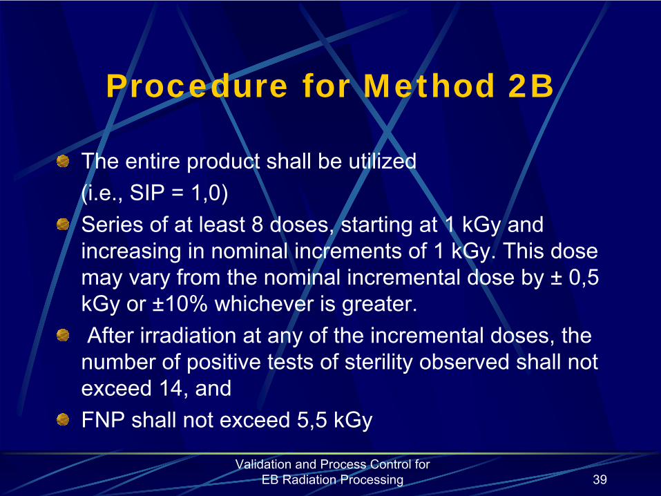
Validation and Process Control for EB Radiation Processing 39
Procedure for Method 2B
The entire product shall be utilized (i.e., SIP = 1,0)Series of at least 8 doses, starting at 1 kGy
and
increasing in nominal increments of 1 kGy. This dose may vary from the nominal incremental dose by ±
0,5
kGy or ±10% whichever is greater.After irradiation at any of the incremental doses, the number of positive tests of sterility observed shall not exceed 14, andFNP shall not exceed 5,5 kGy
Validation and Process Control for EB Radiation Processing 40
Method VDmax
This method is for substantiation of a selected sterilization dose.In carrying out substantiation, the method verifies that
bioburden
present on product prior to sterilization is less resistant to radiation than a microbial population of maximal resistance consistent with the attainment of an SAL of 10-6
at the selected sterilization dose.
Verification is conducted at a SAL of 10-1
with 10 items irradiated in the performance of the verification dose experiment. The dose corresponding to this SAL is characteristic of both the bioburden level and the associated maximal
Validation and Process Control for EB Radiation Processing 41
Method VDmax
The
VDmax methods given in ISO 11137-2 are for selected sterilization doses of 25
kGy
and 15
kGy. The method for 25
kGy
is applicable to product having an average
bioburden
in the range 0,1 to 1000 inclusive, whereas that for 15
kGy
applies to a limited
range of
bioburden
only extending from 0,1 to 1,5.
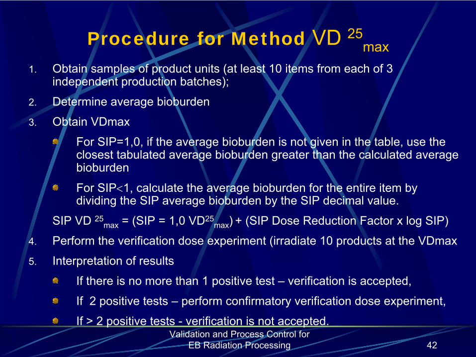
Validation and Process Control for EB Radiation Processing 42
Procedure for Method VD 25max
1.
Obtain samples of product units (at least 10 items from each of 3 independent production batches);
2.
Determine average bioburden
3.
Obtain VDmax
For SIP=1,0, if the average bioburden is not given in the table,
use the closest tabulated average bioburden greater than the calculated average bioburden
For SIP<1, calculate the average bioburden for the entire item by dividing the SIP average bioburden by the SIP decimal value.
SIP VD 25max
= (SIP = 1,0 VD25max
)
+ (SIP Dose Reduction Factor
x log SIP)
4.
Perform the verification dose experiment (irradiate 10 products at the VDmax
5.
Interpretation of results
If there is
no
more than
1 positive test –
verification is accepted,
If 2 positive tests
–
perform confirmatory
verification dose experiment,
If >
2
positive tests
-
verification is not accepted.

Validation and Process Control for EB Radiation Processing 43
Confirmatory verification dose experiment
Select at least 10 product itemsIrradiate the 10 product items at VD 25
max
Subject the irradiated products to test of sterilityInterpretation of results
No positive tests – verification is acceptedIf the are any positive tests -verification is not accepted.
Validation and Process Control for EB Radiation Processing 44
Procedure for Method VD 15max
General
1.
The average bioburden of product shall be determined by applying a correction factor.
2.
An entire product (SIP=1) shall be used

Validation and Process Control for EB Radiation Processing 45
Procedure for Method VD 15max
1.
Obtain samples of product units (at least 10 items from each of 3 independent production batches);
2.
Determine average bioburden
3.
Obtain VDmax
the highest batch average, if
one or more batch averages is equal
to or greater than two times the overall average bioburden, or
the overall average bioburden, if each of the batch averages is
less than two times the overall average bioburden
4.
Perform the verification dose experiment (irradiate 10 products at the VD 15
max
obtained from the table
)
5. Interpretation of results
If there is
no more than
1 positive test –
verification is accepted,
If 2 positive tests
–
perform confirmatory
verification dose experiment,
If >
2
positive tests
-
verification is not accepted.
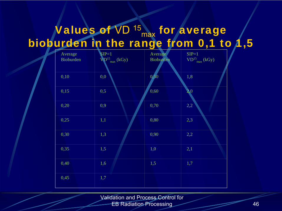
Validation and Process Control for EB Radiation Processing 46
Values of VD 15max
for average bioburden in the range from 0,1 to 1,5
Average Bioburden
SIP=1VD15
max (kGy)Average Bioburden
SIP=1VD15
max (kGy)
0,10 0,0 0,50 1,8
0,15 0,5 0,60 2,0
0,20 0,9 0,70 2,2
0,25 1,1 0,80 2,3
0,30 1,3 0,90 2,2
0,35 1,5 1,0 2,1
0,40 1,6 1,5 1,7
0,45 1,7

Validation and Process Control for EB Radiation Processing 47
Comparison of the Dose Setting Methods
Method 1 Method 2 VDmax
A and B 25 kGyRational Estimate dose
for SAL=10-2, extrapolate to required SAL
Determine dose by incremental dosing, calculate dose required for SAL
Assume 25 kGy produces SAL= 10-6
Production batch size All Medium –Large AllProduction rate Any Frequent AnyBioburden limit 1,000,000 None ≤1000
Method 2A-840Method 2B-780(200 can be returned to inventory)
Samples for testing 130 units 40
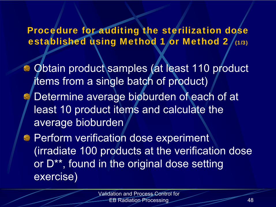
Validation and Process Control for EB Radiation Processing 48
Procedure for auditing the sterilization dose established using Method 1 or Method 2 (1/3)
Obtain product samples (at least 110 product items from a single batch of product)Determine average bioburden of each of at least 10 product items and calculate the average bioburdenPerform verification dose experiment (irradiate 100 products at the verification dose or D**, found in the original dose setting exercise)

Validation and Process Control for EB Radiation Processing 49
Procedure for auditing the sterilization dose established using Method 1 or Method 2 (2/3)
Interpretation of resultsIf there are no more than 2 positives –verification acceptedIf there are 3 ÷ 4 positive tests - augment the sterilization dose; to resume the use of the original sterilization dose, repeat the sterilization dose audit, using a further 100 items and the same verification dose as that used in the original audit.
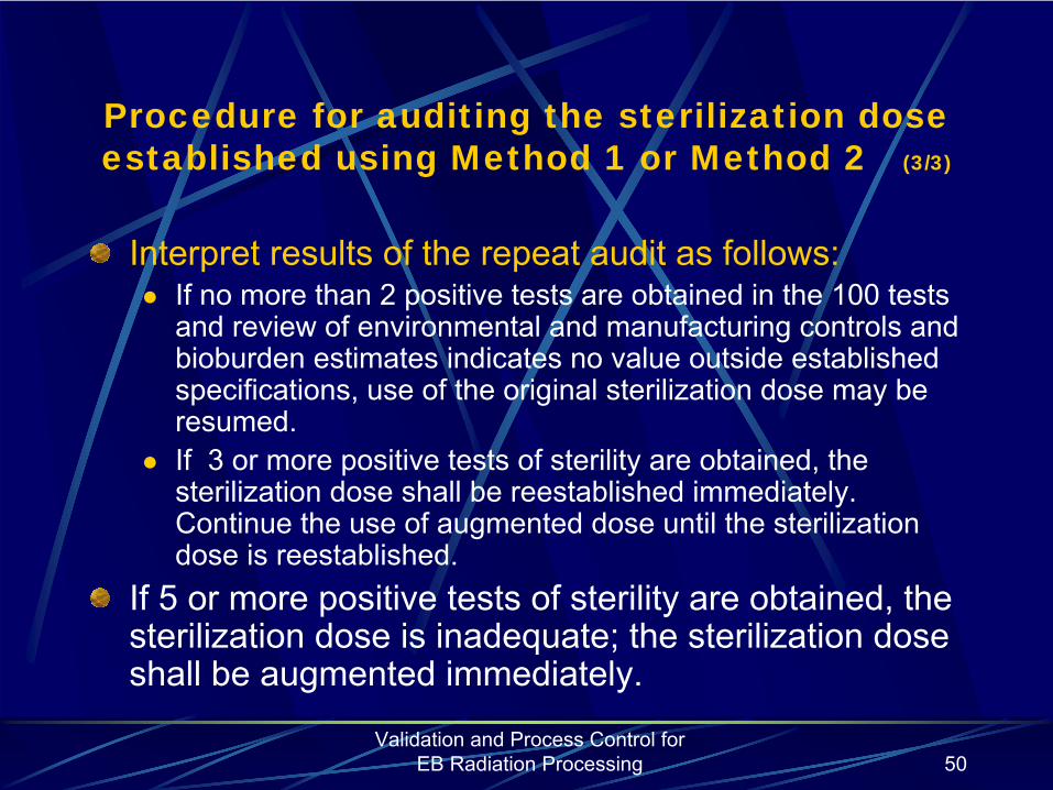
Validation and Process Control for EB Radiation Processing 50
Procedure for auditing the sterilization dose established using Method 1 or Method 2 (3/3)
Interpret results of the repeat audit as follows:If no more than 2 positive tests are obtained in the 100 tests and review of environmental and manufacturing controls and bioburden estimates indicates no value outside established specifications, use of the original sterilization dose may be resumed.If 3 or more positive tests of sterility are obtained, the sterilization dose shall be reestablished immediately. Continue the use of augmented dose until the sterilization dose is reestablished.
If 5 or more positive tests of sterility are obtained, the sterilization dose is inadequate; the sterilization dose shall be augmented immediately.
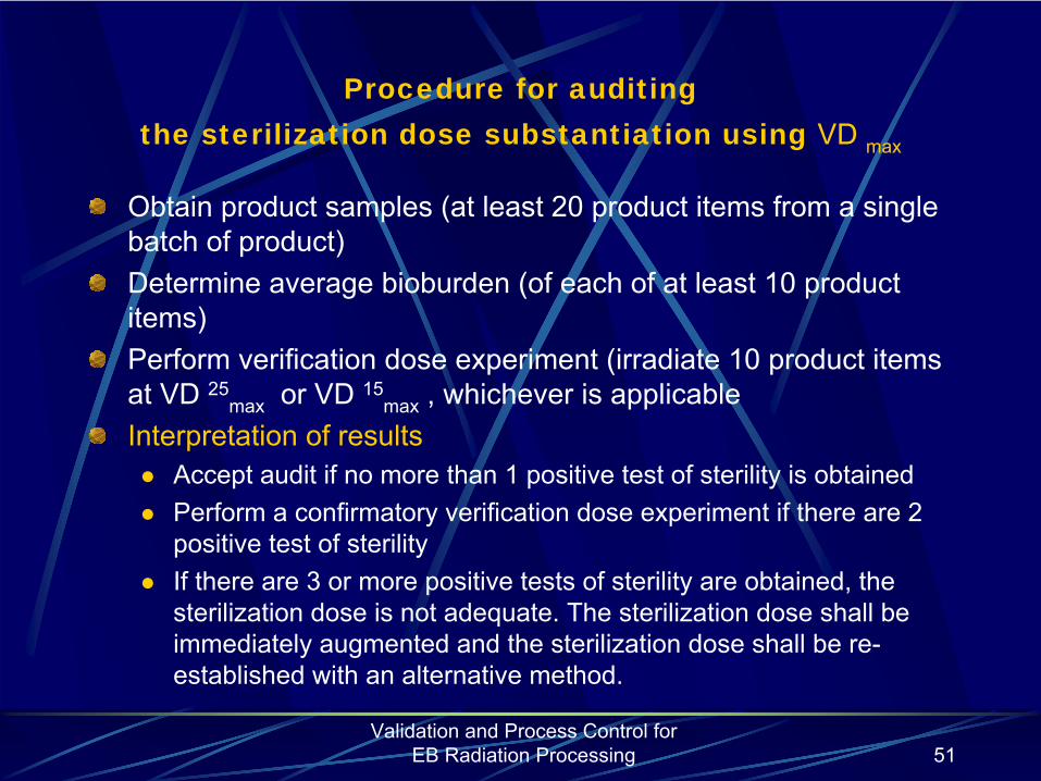
Validation and Process Control for EB Radiation Processing 51
Procedure for auditing the sterilization dose substantiation using VD max
Obtain product samples (at least 20 product items from a single batch of product)Determine average bioburden (of each of at least 10 product items)Perform verification dose experiment (irradiate 10 product items
at VD 25max
or VD 15max
, whichever is applicableInterpretation of results
Accept audit if no more than 1 positive test of sterility is obtainedPerform a confirmatory verification dose experiment if there are 2 positive test of sterilityIf there are 3 or more positive tests of sterility are obtained, the sterilization dose is not adequate. The sterilization dose shall be immediately augmented and the sterilization dose shall be re-established with an alternative method.

Validation and Process Control for EB Radiation Processing 52
Confirmatory sterilization dose audit
Select 10 product itemsIrradiate them at VD 25
max
or VD 15max
, whichever is applicableInterpretation of results
If no positive tests of sterility – sterilization dose has been confirmedIf any positive tests of sterility are obtained- the sterilization dose shall be immediately augmented and re-established.
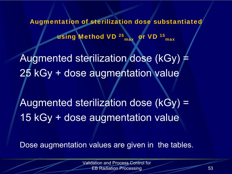
Validation and Process Control for EB Radiation Processing 53
Augmentation of sterilization dose substantiated
using Method VD 25max or VD 15
max
Augmented sterilization dose (kGy) = 25 kGy + dose augmentation value
Augmented sterilization dose (kGy) = 15 kGy + dose augmentation value
Dose augmentation values are given in the tables.
Validation and Process Control for EB Radiation Processing 54
The Role
of
Influence
Factors
on
the
Performance
of
Dosimetric
Systems
A.
Kovács
Institute
of
IsotopesHungarian
Academy
of
Sciences
Budapest, Hungary
Master
Course
on
Nuclear
and
Ionising
Radiation
Technology

Dosimetry
– principles
•
In radiation processing, validation and process control (e.g. sterilization, food irradiation) depend on the measurement of absorbed dose.
•
Determination
of
absorbed
dose
in
product
specific* dosimetry
systems.
•
Accurate, traceable
dose
measurements
provide independent, inexpensive
means
for
quality
control
in
radiation
processing.

Dosimetry
–
applications
and
systems
•
Fields
of
application:
-
installation
qualification;-
operational
qualification;
-
performance
qualification;-
process
control;
•
Dosimetry
provides
documentation
in
the
processes, if
-
the
measurement
is traceable
to
a national
standard,-
the
uncertainty
of
the
system
is known.
•
Applied
systems:-
primary-, secondary-, transfer
standards;
-
routine
systems;

Selection
criteriaQuality
control
has to
be based
on
the
assurance
that
the
process
was
carried
out within
prescribed
dose
limits.
↓
This
requires
proper
use
and
selection
of
dosimetry
system.
↓
Selection
criteria:
-
according
to
the
process
to
be controlled
(i.e. dose
range);
-
according
to
dosimeter
characteristics;
(dose, dose
range, energy, cost, reproducibility, resolution, stability, etc);

Dosimetry
principlesDose measurements are based on various methods:
-
Temperature
increase
(calorimetry)
-
Colour
change
(radiochromic
systems)
-
Free
radical
concentration
(alanine)
-
Conductivity
change
(ECB, aqueous-alanine
solution)
-
Radiation
chemical
oxidation
(Fricke)
-
Radiation
chemical
reduction
(ceric-cerous, dichromate)
-
Crystal
lattice
modification
(semiconductors)
-
Measurement
of
optically
stimulated
luminescence
(Sunna
film)
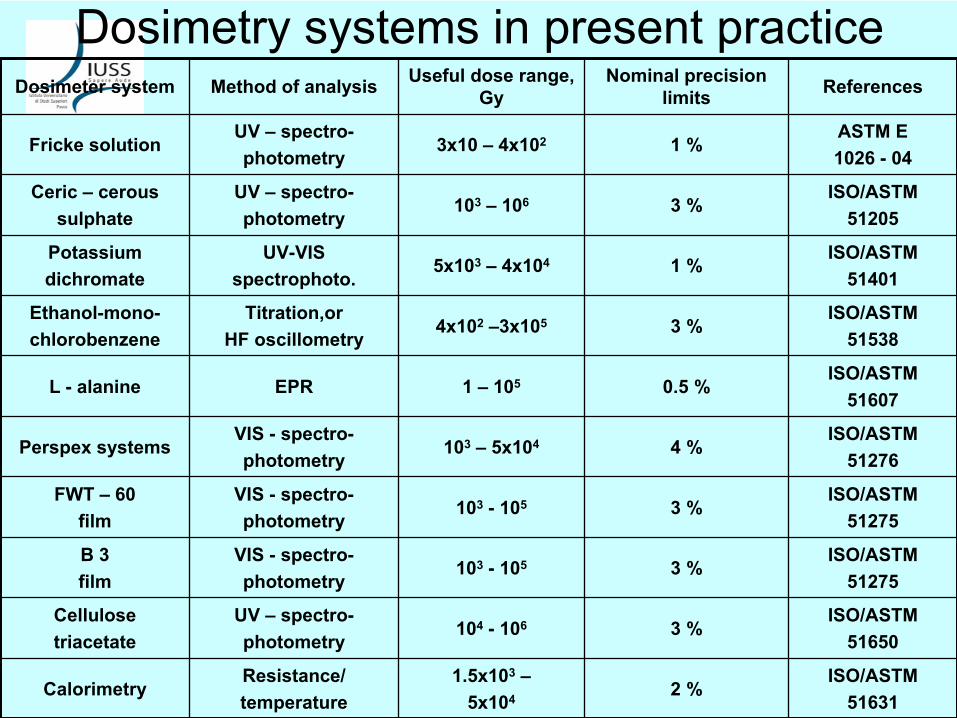
Dosimetry
systems
in
present
practiceDosimeter
system Method
of
analysis Useful
dose
range, Gy
Nominal
precision
limits References
Fricke
solutionUV –
spectro-photometry
3x10 –
4x10² 1 %ASTM E 1026 -
04
Ceric – ceroussulphate
UV –
spectro-photometry
103
– 106 3 %ISO/ASTM
51205
Potassiumdichromate
UV-VISspectrophoto.
5x10³
–
4x10⁴ 1 %ISO/ASTM
51401
Ethanol-mono-chlorobenzene
Titration,orHF oscillometry
4x10²
–3x10⁵ 3 %ISO/ASTM
51538
L -
alanine EPR 1 –
105 0.5 %ISO/ASTM
51607
Perspex
systemsVIS -
spectro-photometry
103
– 5x10⁴ 4 %ISO/ASTM
51276
FWT –
60film
VIS -
spectro-photometry
103
- 105 3 %ISO/ASTM
51275
B 3film
VIS -
spectro-photometry
103
- 105 3 %ISO/ASTM
51275
Cellulosetriacetate
UV –
spectro-photometry
104
- 106 3 %ISO/ASTM
51650
CalorimetryResistance/temperature
1.5x10³
–5x10⁴ 2 %
ISO/ASTM51631
Factors
Affecting
Dosimeter
AccuracyCalibration and practical irradiation conditions are different:
•
Energy
dependence
(gamma, X-ray, electron)
•
Geometrical
factors
(product
type, dose
gradients)
•
Dose-rate effects (EB – gamma)
•
Environmental
effects
(light, temperature, etc)
•
Instrumental
errors
(scattered
light, OD/λ
scale)
•
Storage
conditions
(before
and
after
irradiation)

Characteristics
of
gamma and
electron radiation
•
Gamma
Electron-
high
penetration
-
low/medium
penetration
-
low
dose
rate
-
high
dose
rate-
longer
irradiation
time:
-
short
irradiation
time:
hours/days
seconds/minutes
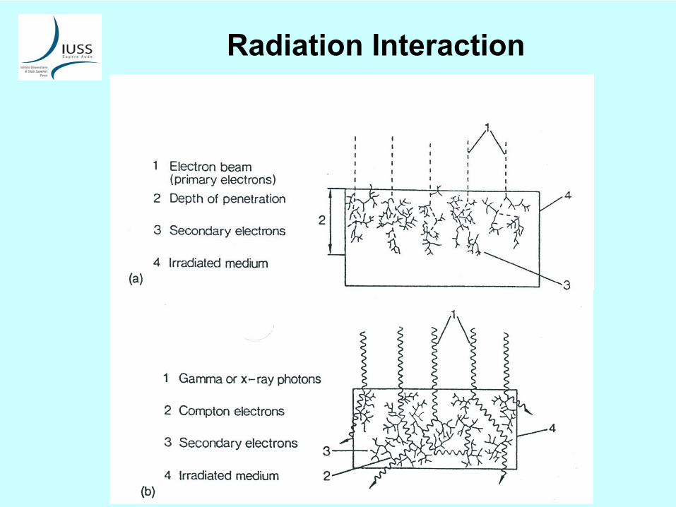
Radiation
Interaction
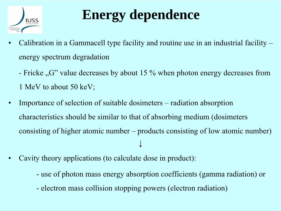
Energy dependence
•
Calibration
in
a Gammacell
type
facility
and
routine
use
in
an
industrial
facility
– energy
spectrum
degradation
-
Fricke
„G”
value
decreases
by
about
15 % when
photon
energy
decreases
from 1 MeV
to
about
50 keV;
•
Importance
of
selection
of
suitable
dosimeters
–
radiation
absorption characteristics
should
be similar
to
that
of
absorbing
medium
(dosimeters
consisting
of
higher
atomic
number
–
products
consisting
of
low
atomic
number)↓
•
Cavity
theory
applications
(to
calculate
dose
in
product):
-
use
of
photon
mass
energy
absorption
coefficients
(gamma radiation) or -
electron
mass
collision
stopping
powers
(electron
radiation)

Geometrical
Factors•
Dose
distributions
in
bulk
products
•
Dose
gradients
within
product
and
dosimeter
•
Homogeneous
vs. inhomogeneous
products
•
Interface
effects
–
use
of
thin
dosimeters
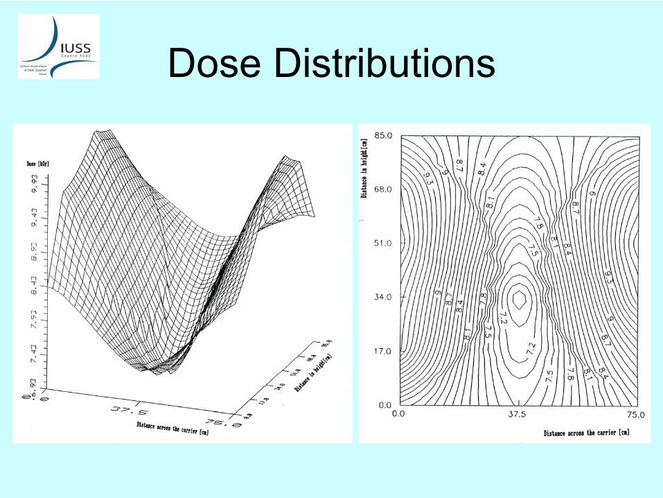
Dose Distributions

Dose Distributions
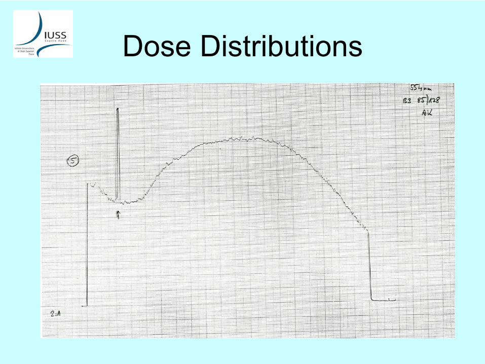
Dose Distributions
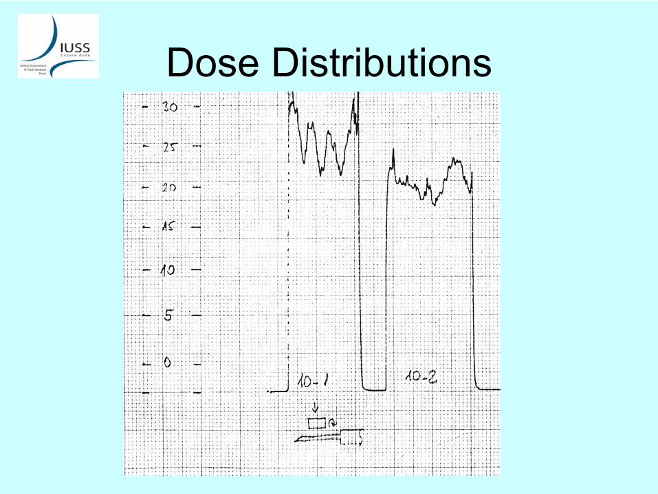
Dose Distributions
Dose
rate
effects•
In
radiation
processing
applications
the
absorbed
dose
rates
may
vary
from
mGy/s up
to
about
109
Gy/s resulting
in
dosimetry
errors
in
the
case of
dose
rate
dependent
dosimeter
response.
•
The reason: radiation-induced
intermediate
species –
ions, radicals
- (formed
in
higher
concentrations
at
higher
dose
rates) interfere
with
the
development
of
the
ultimate
dosimeter
response.
•
In
physical
systems
(ionization
chambers) the
high
dose
rate
effect
is the recombination
of
ions.
•
In
chemical
systems
(solutions) due
to
high
dose
rate
effect
the
radical- radical
reactions
in
the
solvent
compete
with
the
primary
solute
scavenging
reactions
(Fricke
system).
•
Dose
rate
dependence
is usually
coupled
with
other
influences (temperature, oxygen
diffusion), therefore
corrections
are
difficult
(in-plant
calibration).
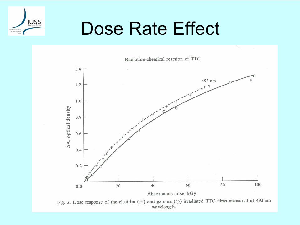
Dose Rate Effect
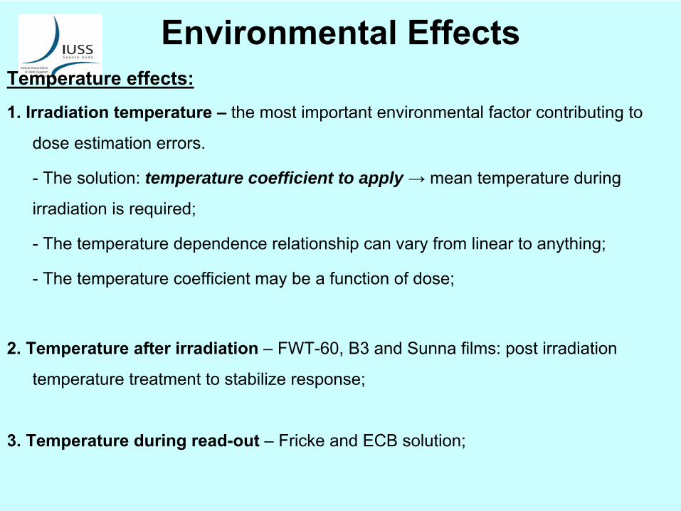
Environmental
EffectsTemperature
effects:
1. Irradiation
temperature
–
the
most important
environmental
factor
contributing
to dose
estimation
errors.
-
The solution:
temperature coefficient to apply → mean
temperature
during irradiation
is required;
-
The temperature
dependence
relationship
can
vary
from
linear
to
anything;
-
The temperature
coefficient
may
be a function
of
dose;
2. Temperature
after
irradiation
–
FWT-60, B3 and
Sunna
films: post
irradiation temperature
treatment
to
stabilize
response;
3. Temperature
during
read-out
–
Fricke
and
ECB solution;

Irradiation Temperature Effects
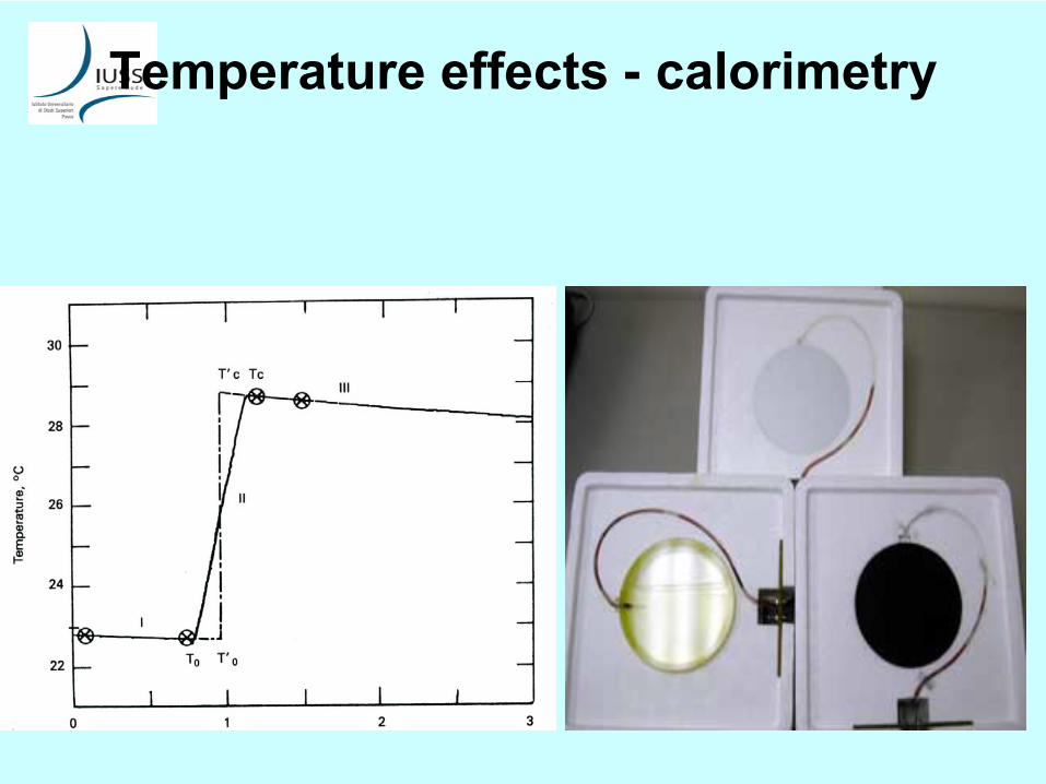
Temperature
effects
-
calorimetry
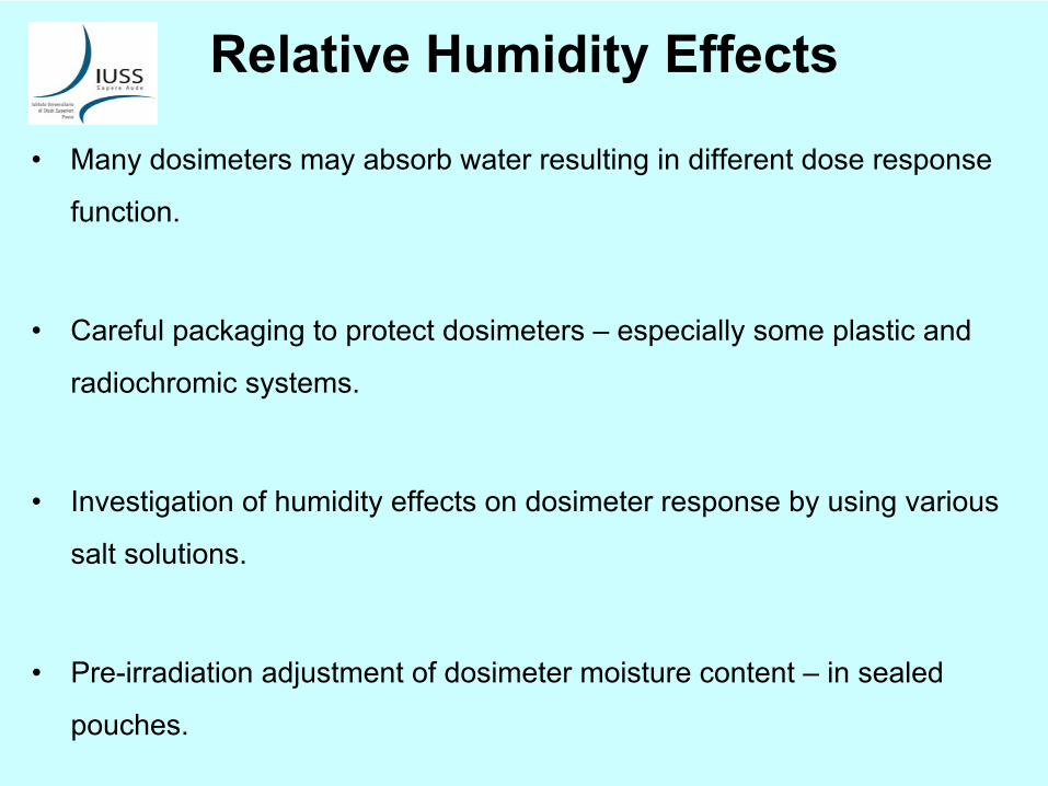
Relative
Humidity
Effects
•
Many
dosimeters
may
absorb
water
resulting
in
different
dose
response function.
•
Careful
packaging
to
protect
dosimeters
–
especially
some
plastic
and radiochromic
systems.
•
Investigation
of
humidity
effects
on
dosimeter
response
by
using
various salt
solutions.
•
Pre-irradiation
adjustment
of
dosimeter
moisture
content
–
in
sealed pouches.
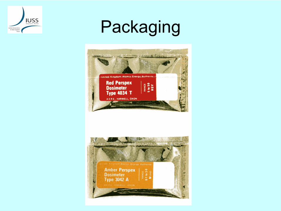
Packaging
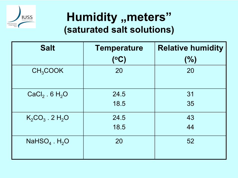
Humidity
„meters” (saturated
salt
solutions)
Salt Temperature(oC)
Relative
humidity(%)
CH3
COOK 20 20
CaCl2
. 6 H2
O 24.518.5
3135
K2
CO3
. 2 H2
O 24.518.5
4344
NaHSO4
. H2
O 20 52
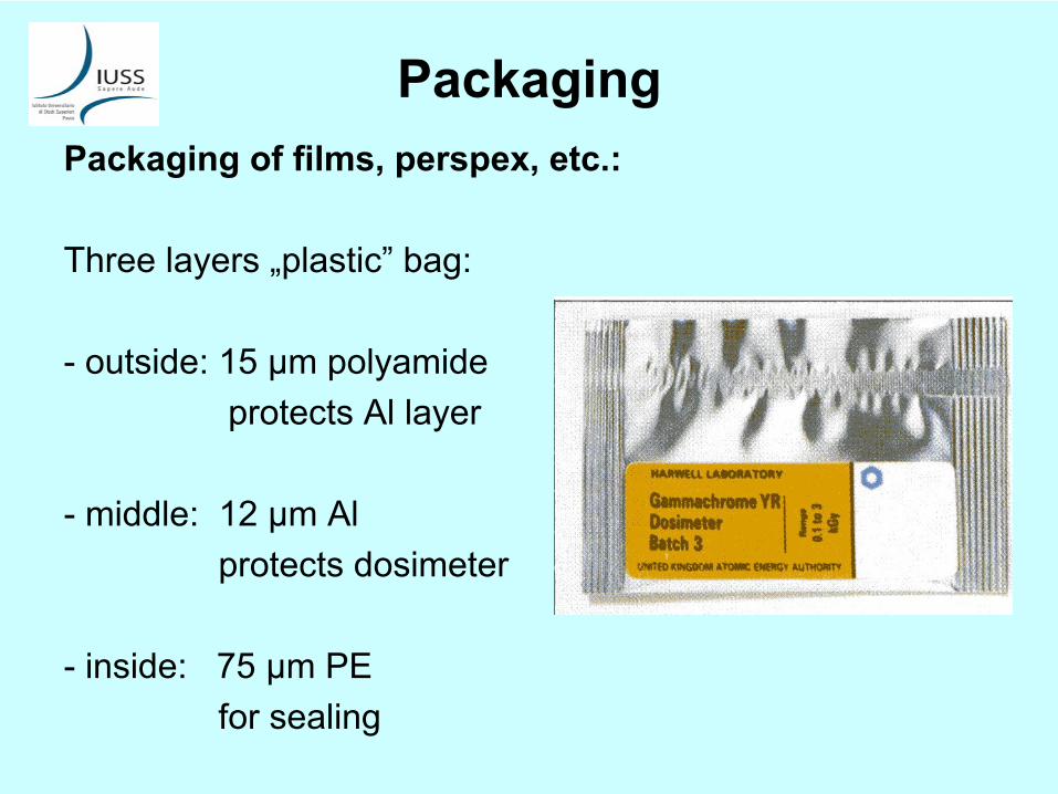
PackagingPackaging
of
films, perspex, etc.:
Three
layers
„plastic”
bag:
-
outside: 15 μm polyamideprotects
Al
layer
-
middle: 12 μm Alprotects
dosimeter
-
inside: 75 μm PEfor
sealing
Effect
of
Oxygen
Content
•
Oxygen
is a reactive
molecule
which
reacts
with
radiation-induced unstable
species and
free
radicals
(radical
scavenger) thus
affecting
the
final
concentration
of
certain
products
used
for
dosimetry, i.e. the
dose response.
•
The role
of
oxygen
in
the
Fricke
system
–
effects
the
dose
range.
•
Oxygen
diffusion
into
plastic
film dosimeters
at
low
dose
rates
–
e.g. in CTA film higher
response
is due
to
more efficient
double
bond
formation
as
a result
of
oxygen
diffusion
during
irradiation.
•
Post
irradiation
effect: oxygen
diffusion
into
dosimeter
material
after irradiation
results
in
fading
of
the
dosimeter
signal.
Light
Effects
•
Many
dosimeters
are
sensitive
to
light
effects
before, during
and
after irradiation
–
sometimes
even
during
read-out.
-
Solutions
(e.g. Fricke, ECB), radiochromic
films
(e.g. FWT-60, B3);
•
To
avoid
it: packaging
and
careful
handling.
•
To
avoid
UV light
during
storage
(solutions, films).
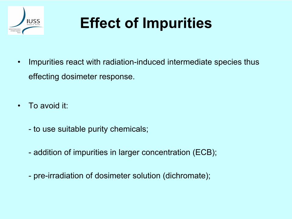
Effect
of
Impurities
•
Impurities
react
with
radiation-induced
intermediate
species thus effecting
dosimeter
response.
•
To
avoid
it:
-
to
use
suitable
purity
chemicals;
-
addition
of
impurities
in
larger
concentration
(ECB);
-
pre-irradiation
of
dosimeter
solution
(dichromate);
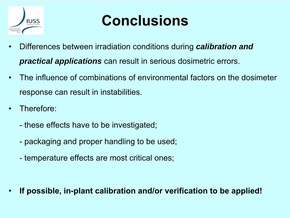
Conclusions•
Differences
between
irradiation
conditions
during
calibration and
practical applications can
result
in
serious
dosimetric
errors.
•
The influence
of
combinations
of
environmental
factors
on
the
dosimeter response
can
result
in
instabilities.
•
Therefore:
-
these
effects
have
to
be investigated;
-
packaging
and
proper
handling
to
be used;
-
temperature
effects
are
most critical
ones;
•
If
possible, in-plant
calibration
and/or
verification
to
be applied!
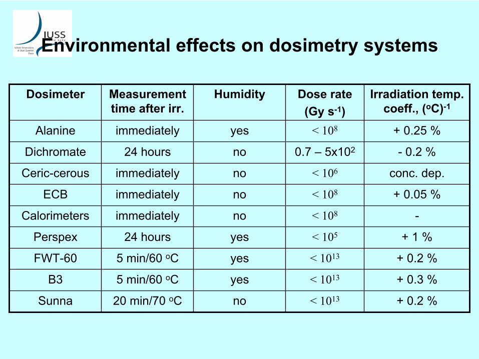
Environmental
effects
on
dosimetry
systems
Dosimeter Measurement time
after
irr.
Humidity Dose
rate(Gy
s-1)
Irradiation
temp. coeff., (oC)-1
Alanine immediately yes < 108 + 0.25 %
Dichromate 24 hours no 0.7 –
5x10² -
0.2 %
Ceric-cerous immediately no < 106 conc. dep.
ECB immediately no < 108 + 0.05 %
Calorimeters immediately no < 108 -
Perspex 24 hours yes < 105 + 1 %
FWT-60 5 min/60 oC yes < 1013 + 0.2 %
B3 5 min/60 oC yes < 1013 + 0.3 %
Sunna 20 min/70 oC no < 1013 + 0.2 %

Thank you for your attention!

ValidationValidation ofof radiationradiation sterilizationsterilization processprocess
Iwona KaluskaInstitute of Nuclear Chemistry and Technology
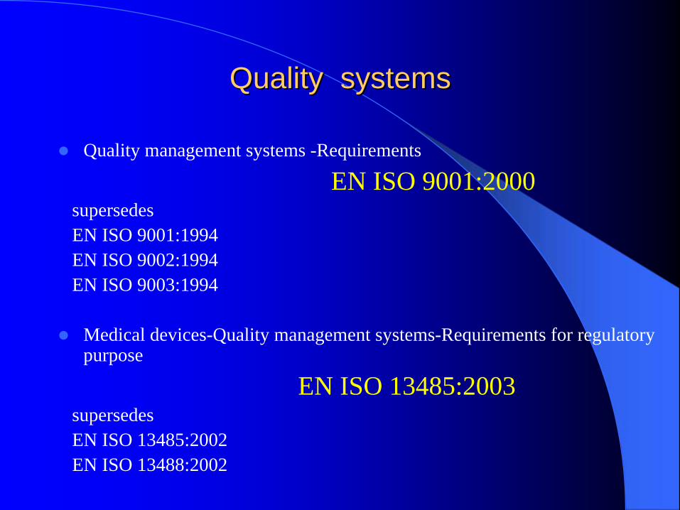
QualityQuality systemssystems
Quality management systems -Requirements
EN ISO 9001:2000supersedes EN ISO 9001:1994EN ISO 9002:1994EN ISO 9003:1994
Medical devices-Quality management systems-Requirements for regulatory purpose
EN ISO 13485:2003supersedesEN ISO 13485:2002 EN ISO 13488:2002
WhyWhy ISO 13 485 ?ISO 13 485 ?
The standards for quality management systems recognize that, for certain processes used in manufacturing, the effectiveness of the process cannot be fully verified by subsequent inspection and testing of the product. Sterilization is an example of such a process. For this reason, sterilization processes are validated for use, the performance of sterilization process is monitored routinely and the equipment is maintained.
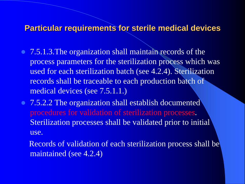
Particular requirements for sterile medical devicesParticular requirements for sterile medical devices
7.5.1.3.The organization shall maintain records of the process parameters for the sterilization process which was used for each sterilization batch (see 4.2.4). Sterilization records shall be traceable to each production batch of medical devices (see 7.5.1.1.)7.5.2.2 The organization shall establish documented procedures for validation of sterilization processes. Sterilization processes shall be validated prior to initial use.Records of validation of each sterilization process shall be maintained (see 4.2.4)
ISO 14937:2000ISO 14937:2000
Sterilization of health care products –General requirements for characterization of a sterilizing agent and the development, validation and routine control of a sterilization process

ValidationValidation
The purpose of validation is to demonstrate that the sterilization process established in process definition can be delivered effectively and reproducibly to the sterilization load. Validation consists of a number of identified stages: installation qualification, operational qualification, and performance qualification.
InstallationInstallation qualificationqualification (IQ)(IQ)
IQ is undertaken to demonstrate that the sterilization equipment and any ancillary items have been supplied and installed in accordance with their specification.

OperationalOperational qualificationqualification (OQ)(OQ)
OQ is carried out either with unloaded equipment or using appropriate test material to demonstrate the capability of the equipment to deliver the sterilization process that bas been defined.
Performance Performance qualificationqualification (PQ)(PQ)
PQ is the stage of validation that uses product to demonstrate that equipment consistently operates in accordance with predetermined criteria and the process yields product that is sterile and meets specified requirements.
ManagementManagement responsibilityresponsibility
The development, validation and routine control of a sterilization process is likely to involve a number of separate parties, each of whom is responsible for certain elements.
In order to illustrate the variety of possible allocations, three sample o scenarios are presented.
Scenario 1 – Health care facilityScenario 2 –Medical device manufacturer using in-house facilitiesScenario 3 – Medical device manufacturer using a sterilization subcontractor.
Medical device manufacturer using Medical device manufacturer using a a sterilization subcontractorsterilization subcontractor
In this scenario, the user of the sterilization process is a manufacturer of single-use medical devices who is using sterilization subcontractor to deliver the sterilization process. Additionally, the medical device manufacturer is using a contract laboratory to undertake defined testing as part of the product release procedures. The parties involved are the medical device manufacturer, the sterilization subcontractor, and the contract laboratory.
The allocation of responsibilities might The allocation of responsibilities might be be as as followsfollows: : (1/ 5)(1/ 5)
Quality management system elements– Each party has its own quality management system.
The limits of responsibility of each party are laid down in formal contracts.
Sterilizing agent characterization– The sterilization subcontractor has licensed the
sterilization process from a separate organization who characterized and developed the sterilization process. The process developer has undertaken the sterilizing agent characterization and made the resultant data available to the sterilization subcontractor and the medical device manufacturer.
The allocation of responsibilities mightThe allocation of responsibilities might be be as as followsfollows: : (2/ 5)(2/ 5)
Process/equipment characterization– The sterilization subcontractor has developed an
equipment specification, including a control system for the equipment, which is capable of being programmed to deliver a predefined process. A sterilizer manufacturer has been contracted to manufacture and install the specified equipment.
Product definition– The medical device manufacturer is responsible for
specification of the product and its manufacture.
The allocation of responsibilities mightThe allocation of responsibilities might be be as as followsfollows: : (3/ 5)(3/ 5)
Process definition– The medical device manufacturer defines a process for the
particular medical device(s) to be sterilized. The medical device manufacturer undertakes the biological safety assessments and product compatibility studies. In this case, these studies are conducted using experimental sterilization equipment.
Validation– The sterilization subcontractor undertakes installation qualification
and operational qualification in accordance with documented procedures. The medical device manufacturer then undertakes performance qualification using the installed sterilization equipment conforming that the equipment is capable of delivering the defined sterilization process. The medical device manufacturer reviews and approves the validation exercise. A contract laboratory might perform microbiological testing in accordance with methods agreed with the medical device manufacturer.
The allocation of responsibilities mightThe allocation of responsibilities might be be as as followsfollows: : (4/ 5)(4/ 5)
Routine control and monitoring– This is carried out by the sterilization subcontractor
laboratory in accordance with documented procedures agreed with the medical device manufacturer.
Product release from sterilization– This is carried out by medical device manufacturer in
accordance with documented procedures, on the basis of records provided by the sterilization subcontractor and the contract laboratory.

The allocation of responsibilities mightThe allocation of responsibilities might be be as as followsfollows: : (5/ 5)(5/ 5)
Maintaining process effectiveness– The sterilization subcontractor carries out
equipment maintenance and calibration in accordance with documented procedures. The medical device manufacturer maintains the quality of product prior to sterilization and takes responsibility for requalification; the sterilization subcontractor carries out any necessary repetition of part or all of installation qualification or operational qualification.
EN ISO 11137 : 2006EN ISO 11137 : 2006
Sterilization of health care products - Radiation
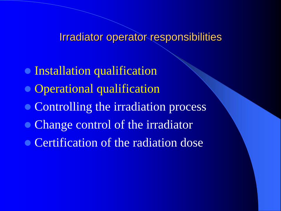
IrradiatorIrradiator operator operator responsibilitiesresponsibilities
Installation qualificationOperational qualificationControlling the irradiation processChange control of the irradiatorCertification of the radiation dose

Primary manufacturer responsibilities
• Establishing the sterilization dose• Developing product families• Establishing the maximum acceptable dose• Performance qualification• Controlling the manufacturing process including the
specifications for products submitted to the irradiator operator, i.e., product density, orientation, dimensions
• Revision of specifications submitted to the irradiator operator
• Change control of the product to include a review of product-related variables that impact processing categories
• Product release

Installation Qualification
Equipment documentation (describing the design
and installation requirements; it should include
drawings and details of all the construction materials,
the dimensions and tolerances of the equipment,
support services and power supplies)
Any modification made to the irradiator installation
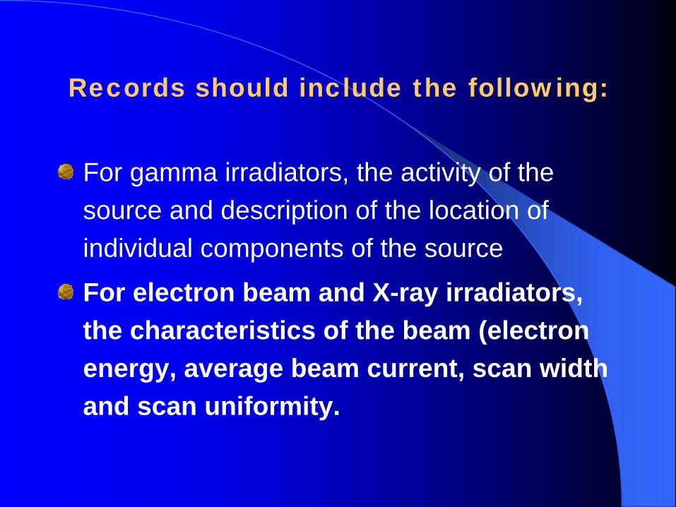
Records should include the following:
For gamma irradiators, the activity of the source and description of the location of individual components of the source
For electron beam and X-ray irradiators, the characteristics of the beam (electron energy, average beam current, scan width and scan uniformity.

Operational qualificationOperational qualification
Equipment calibration (including test
instrumentation used for monitoring,
controlling, indicating or recording)
Irradiator dose mapping
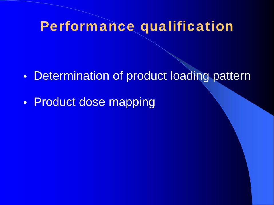
Performance qualification
• Determination of product loading pattern
• Product dose mapping

RisRisøøScanScan, a new software , a new software package package for for analysis of analysis of
radiochromic radiochromic film film dosimetersdosimeters
Jakob HeltJakob Helt--HansenHansenArne MillerArne Miller
High High Dose Reference Dose Reference LaboratoryLaboratoryRisRisøø National National LaboratoryLaboratory

The ideaThe idea……
Replace spectrophoto-meter with scanner and PC.
RisRisøøScanScan is:is:
A software package for image analysis of A software package for image analysis of dosimeter films. dosimeter films. Not only RisNot only Risøø B3 film, but other dosimeter B3 film, but other dosimeter systems using color change can be used.systems using color change can be used.Emphasis on calibration, depth dose curves Emphasis on calibration, depth dose curves and surface dose profiles.and surface dose profiles.Developed at the High Dose Reference Developed at the High Dose Reference Laboratory at RisLaboratory at Risøø National Laboratory.National Laboratory.Using Using LabViewLabView programming language from programming language from National Instruments.National Instruments.
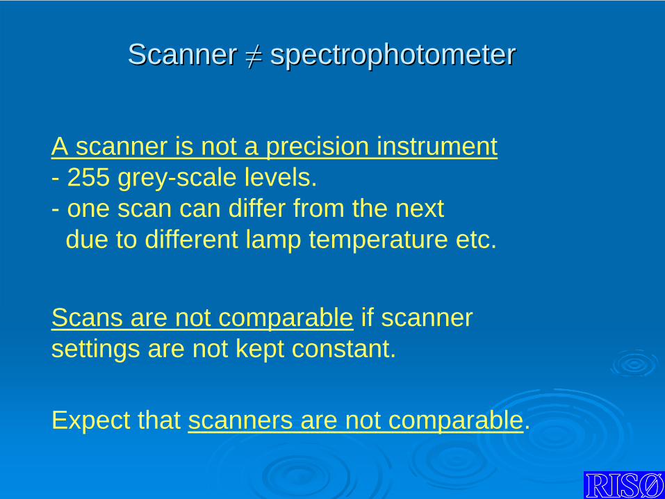
Scanner Scanner ≠≠
spectrophotometerspectrophotometer
A scanner is not a precision instrument- 255 grey-scale levels.- one scan can differ from the nextdue to different lamp temperature etc.
Expect that scanners are not comparable.
Scans are not comparable if scanner settings are not kept constant.

CalibrationCalibration
Ideally one would make a calibration for every Ideally one would make a calibration for every image.image.Calibration for each dosimeter type.Calibration for each dosimeter type.Use reference to link calibration to subsequent Use reference to link calibration to subsequent images.images.
We use laminated B3 film dosimeter irradiated to 12, 25 and 50 kGy.
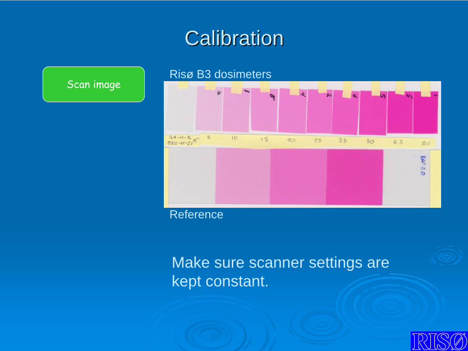
CalibrationCalibration
Scan imageRisø B3 dosimeters
Reference
Make sure scanner settings are kept constant.
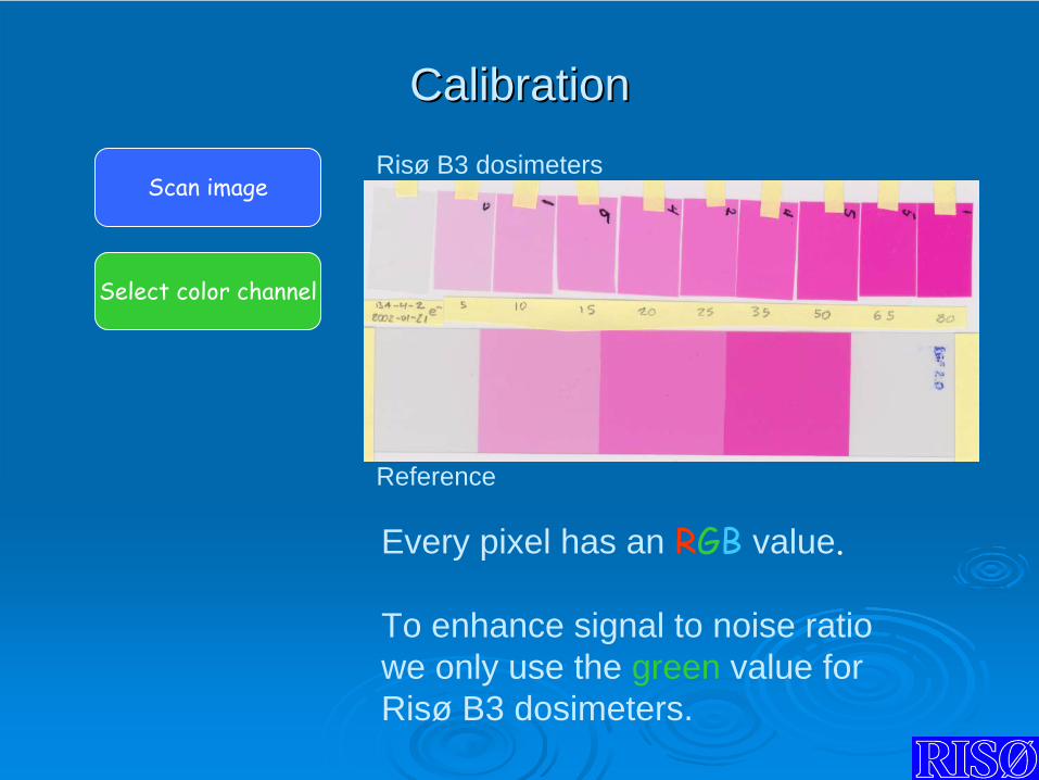
CalibrationCalibration
Scan image
Select color channel
Every pixel has an RGB
value.
To enhance signal to noise ratio we only use the green value for Risø B3 dosimeters.
Risø B3 dosimeters
Reference
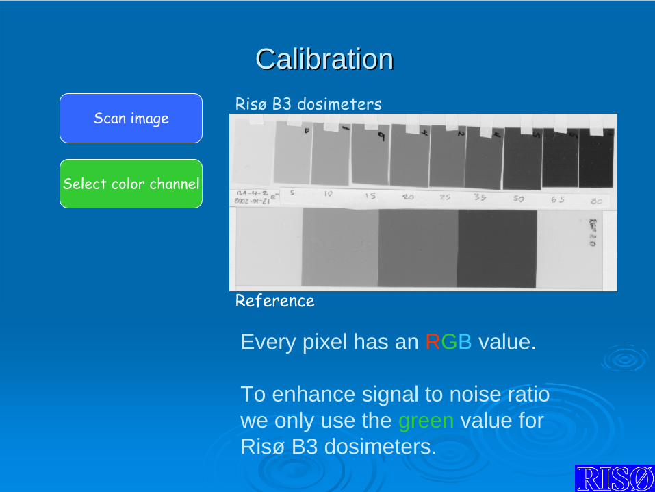
CalibrationCalibration
Scan image
Select color channel
Every pixel has an RGB value.
To enhance signal to noise ratio we only use the green value for Risø B3 dosimeters.
Risø
B3 dosimeters
Reference
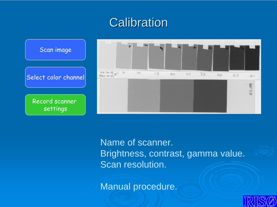
CalibrationCalibration
Scan image
Record scanner settings
Select color channel
Name of scanner.Brightness, contrast, gamma value.Scan resolution.
Manual procedure.

CalibrationCalibration
Scan image
Record scanner settings
Select polynomial fitCheck residuals
Select color channel
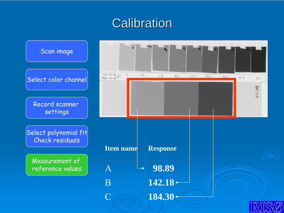
CalibrationCalibration
Scan image
Record scanner settings
Select polynomial fitCheck residuals
Measurement of reference values
Select color channel
Item name Response
A 98.89B 142.18C 184.30
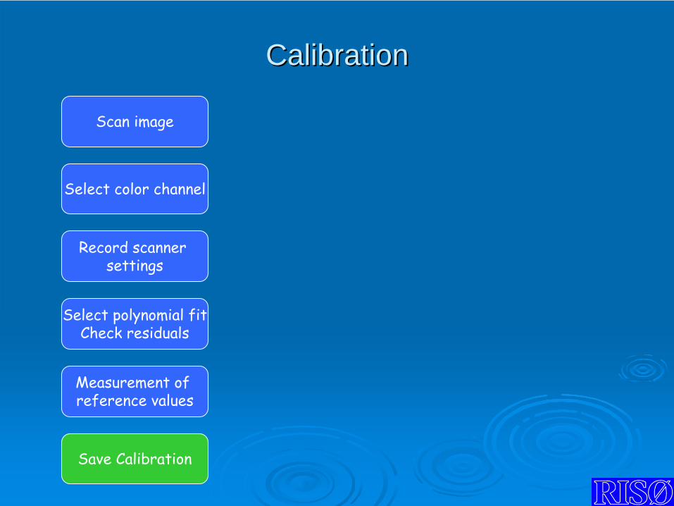
CalibrationCalibration
Scan image
Record scanner settings
Select polynomial fitCheck residuals
Measurement of reference values
Select color channel
Save Calibration
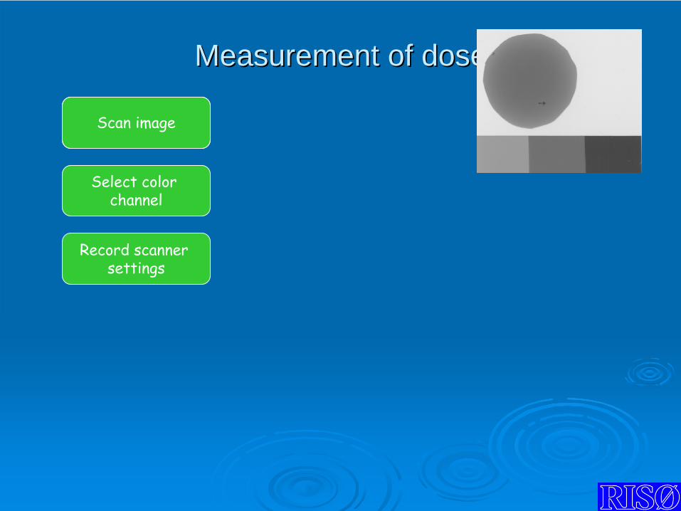
Measurement of Measurement of ddoseose
Scan image
Record scanner settings
Select color channel
Scan image

Measurement ofMeasurement of ddoseose
Scan image
Record scanner settings
Load
calibration
Select color channel
Compare image and calibration settings
Scan image
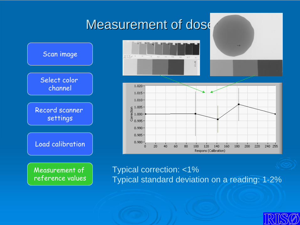
Measurement ofMeasurement of ddoseose
Scan image
Record scanner settings
Load
calibration
Measurement of reference values
Select color channel
Typical correction: <1%Typical standard deviation on a reading: 1-2%
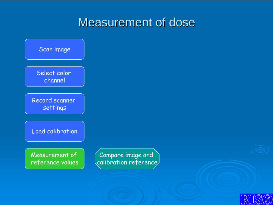
Measurement ofMeasurement of ddoseose
Scan image
Record scanner settings
Load
calibration
Measurement of reference values
Select color channel
Compare image and calibration
reference
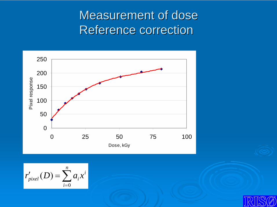
MeasurementMeasurement of doseof dose Reference correctionReference correction
∑=
=′n
i
iipixel xaDr
0
)(
0
50
100
150
200
250
0 25 50 75 100Dose, kGy
Pix
el re
spon
se
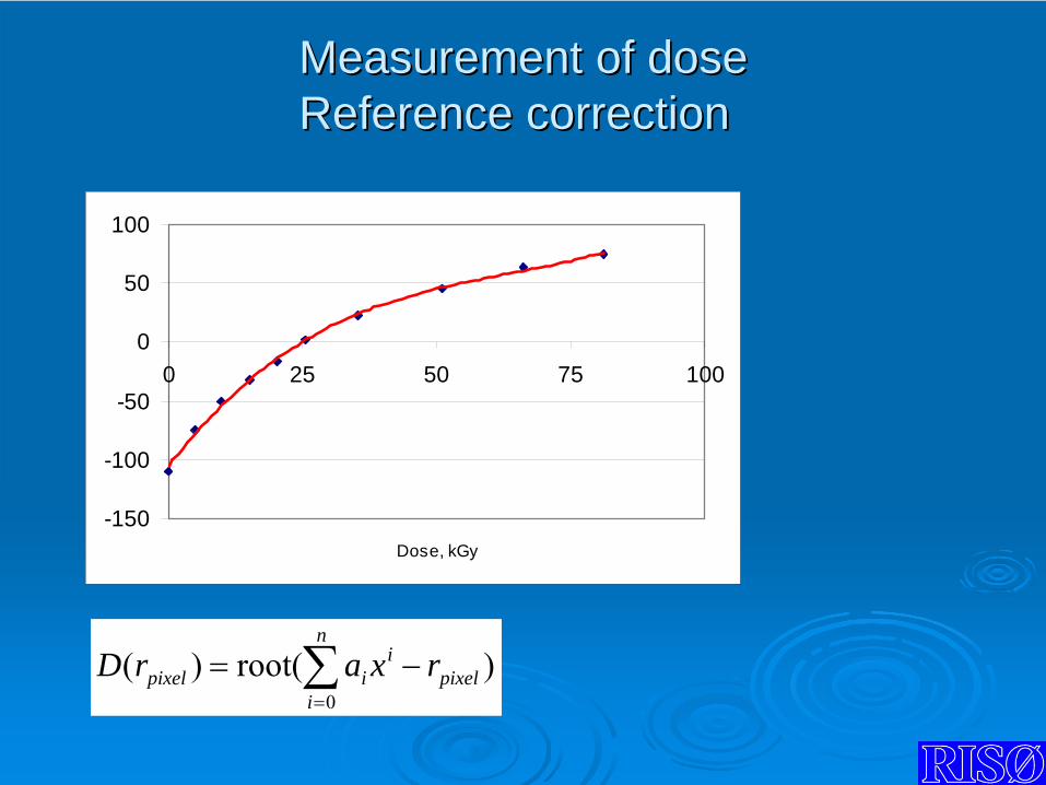
MeasurementMeasurement of doseof dose Reference correctionReference correction
∑=
−=n
ipixel
iipixel rxarD
0
)root()(
-150
-100
-50
0
50
100
0 25 50 75 100
Dose, kGy
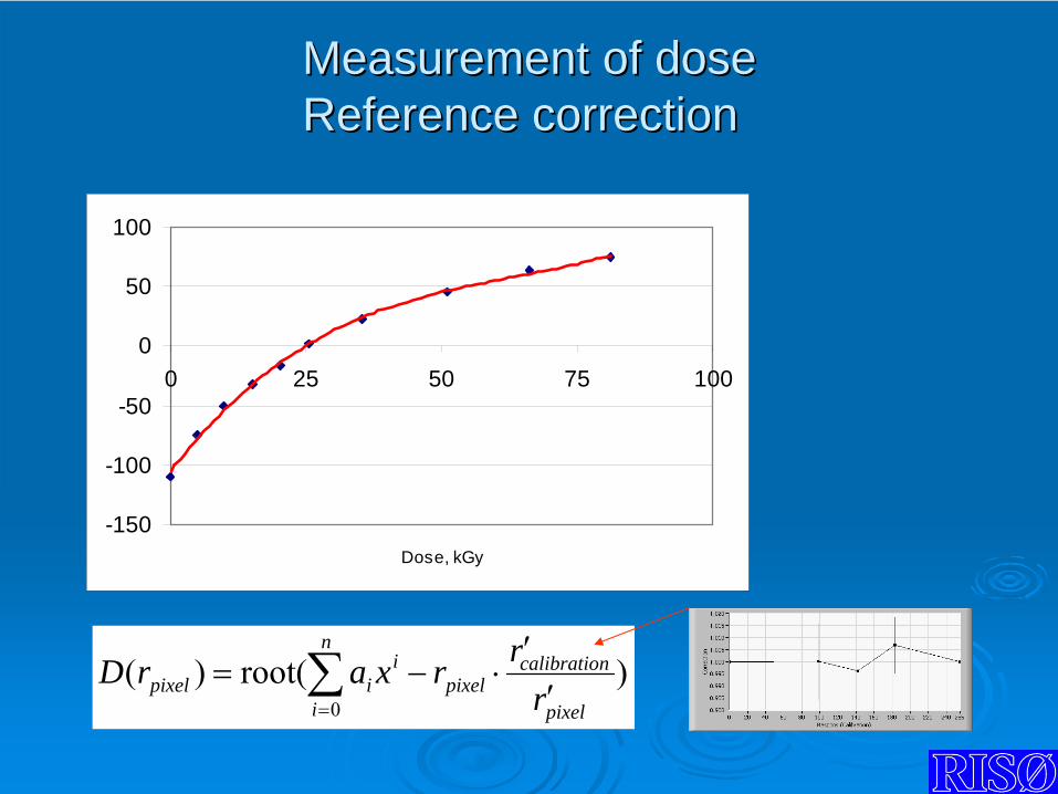
MeasurementMeasurement of doseof dose Reference correctionReference correction
∑= ′
′⋅−=
n
i pixel
ncalibratiopixel
iipixel r
rrxarD0
)root()(
-150
-100
-50
0
50
100
0 25 50 75 100
Dose, kGy
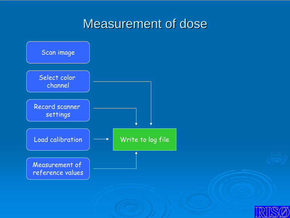
Measurement of Measurement of ddoseose
Scan image
Record scanner settings
Load
calibration
Select color channel
Write to log file
Measurement of reference values
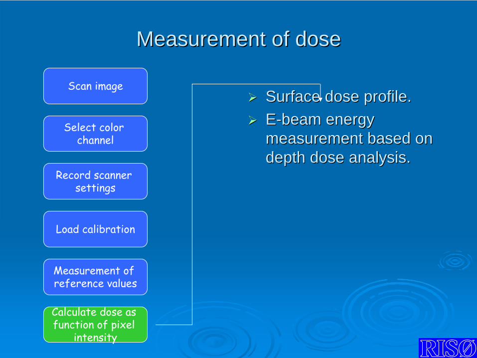
Measurement of Measurement of ddoseose
Surface Surface dose dose profileprofile..EE--beam energy beam energy measurement based on measurement based on depth depth dose dose analysisanalysis..
Scan image
Record scanner settings
Load
calibration
Measurement of reference values
Select color channel
Calculate dose as function of pixel
intensity
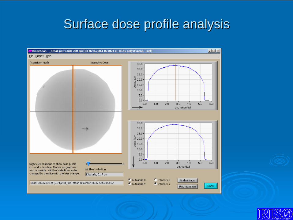
Surface dose profile analysisSurface dose profile analysis
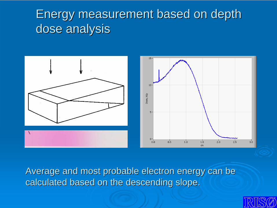
Energy measurement based on Energy measurement based on ddepthepth dose analysisdose analysis
Average and most probable electron energy can beAverage and most probable electron energy can be calculated based on the descending slope.calculated based on the descending slope.

Energy measurement based on Energy measurement based on ddepthepth dose analysisdose analysis
Determination of Determination of offsets: depth & dose.offsets: depth & dose.Calculation of L.R. of Calculation of L.R. of the descending slope.the descending slope.Calculation of RCalculation of R5050, R, Rexexand Eand E5050, , EEexex based on based on user defined user defined equations. equations. (ISO/ASTM).(ISO/ASTM).Manual and Manual and automated procedure.automated procedure.

Energy measurement based onEnergy measurement based on ddepthepth dose analysisdose analysis
Calculation of beam energy: scanner versus photospectromete
Difference in calculated beam energy: <1%

GAFGAF dosimeters and dosimeters and RisoeScanRisoeScan
Use Red and Green color channel
11
DosimetryDosimetryfor for
electron beam electron beam sterilization sterilization
Arne MillerRadiation Research DepartmentRisø National LaboratoryTechnical University of Denmark DK-4000 RoskildeDenmark
22
Absorbed dose:Absorbed dose:
Energy absorbed per unit massEnergy absorbed per unit mass
1 Gray (Gy) = 1 J/kg1 Gray (Gy) = 1 J/kg
Dose range for sterilization: 10 Dose range for sterilization: 10 -- 5500 kGykGy
Dose range for dose setting: 1 Dose range for dose setting: 1 -- 10 kGy10 kGy
Realization by Realization by calorimetrycalorimetry::
dose = dose = ΔΔT*CpT*Cp
related through basic physical properties and related through basic physical properties and definitionsdefinitions
33
Dosimeter systemsDosimeter systems
Response based on physical or chemical changesResponse based on physical or chemical changesin a materialin a material
temperaturetemperaturecolour (UV colour (UV –– VIS VIS –– IR)IR)luminescence (TL luminescence (TL –– OSL)OSL)radical concentration (EPR)radical concentration (EPR)viscosityviscosityelectrical conductivityelectrical conductivityoptical rotationoptical rotation
44
Dosimeter propertiesDosimeter properties
response functionresponse function
temperature effectstemperature effects
humidity effectshumidity effects
dose rate influencedose rate influence
stability before and after stability before and after
irradiationirradiation
55
Examples of dosimeter systems for eExamples of dosimeter systems for e--
beambeam
calorimeterscalorimeters
radiochromicradiochromic film dosimetersfilm dosimeters
alanine / EPRalanine / EPR
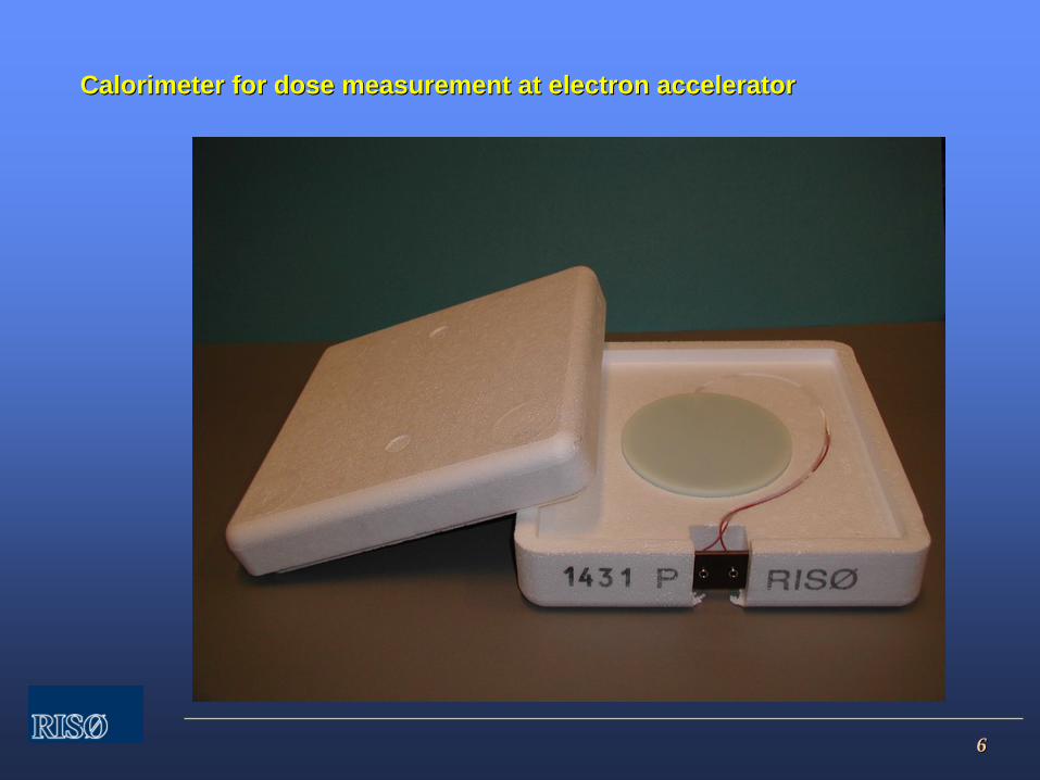
66
Calorimeter for dose measurement at electron acceleratorCalorimeter for dose measurement at electron accelerator
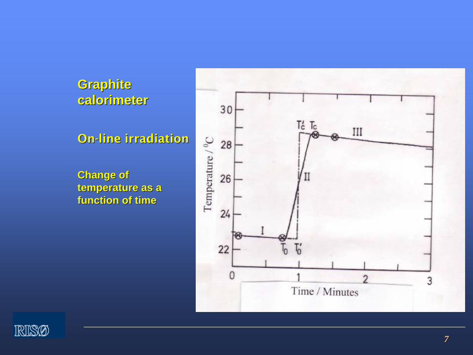
77
Graphite Graphite calorimetercalorimeter
OnOn--line irradiationline irradiation
Change of Change of temperature as a temperature as a function of timefunction of time
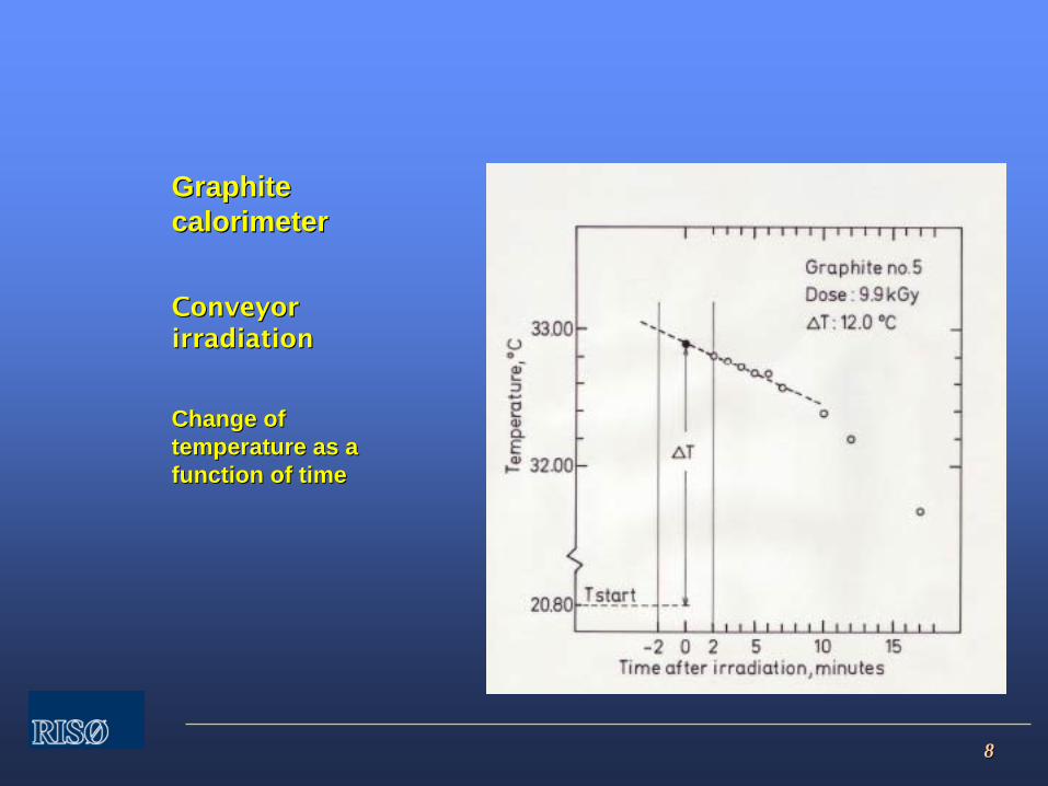
88
Graphite Graphite calorimetercalorimeter
Conveyor Conveyor irradiationirradiation
Change of Change of temperature as a temperature as a function of timefunction of time
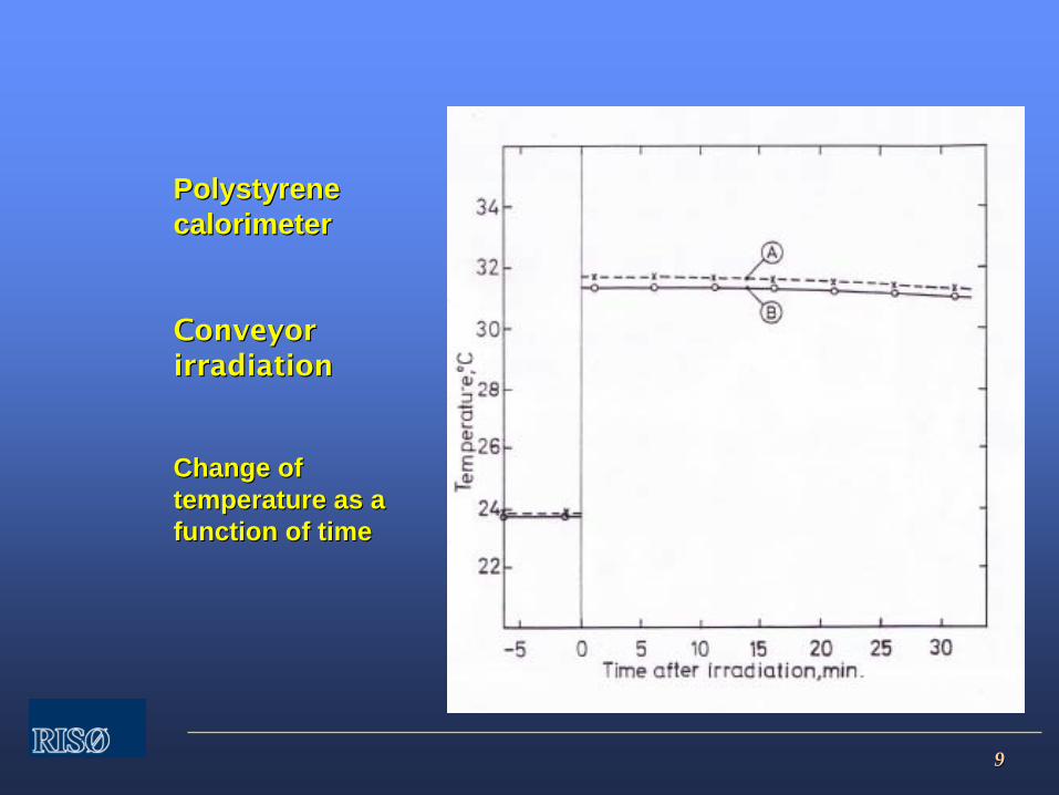
99
Polystyrene Polystyrene calorimetercalorimeter
Conveyor Conveyor irradiationirradiation
Change of Change of temperature as a temperature as a function of timefunction of time

1010
CalorimeterCalorimeter
Measures change in temperatureMeasures change in temperature
Dose range:Dose range:
Graphite 1.5 Graphite 1.5 ––
15 kGy15 kGy
Polystyrene 3 Polystyrene 3 ––
40 kGy40 kGy
Stable signal for 10 minutes (polystyrene)Stable signal for 10 minutes (polystyrene)
Reproducibility less than 1%, 1.s.dReproducibility less than 1%, 1.s.d
Measurement instrument: DGVMMeasurement instrument: DGVM

1111
Change of colourChange of colour
ExampleExample
RisRisøø B3 dosimeterB3 dosimeter
Visible absorption Visible absorption spectrumspectrum
RadiochromicRadiochromic film dosimetersfilm dosimeters
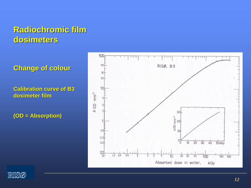
1212
RadiochromicRadiochromic film film dosimetersdosimeters
Change of colourChange of colour
Calibration curve of B3 Calibration curve of B3 dosimeter filmdosimeter film
(OD = Absorption)(OD = Absorption)

1313
RadiochromicRadiochromic film dosimetersfilm dosimeters
Change of colourChange of colour
Response function of Response function of B3 dosimeter filmB3 dosimeter film
Risø B3-06 Gamma UV4
y = 1,2080E-06x3 - 4,3548E-04x2 + 8,0201E-02x + 2,6373E-01R2 = 9,9958E-01
0,0000
1,0000
2,0000
3,0000
4,0000
5,0000
6,0000
0 20 40 60 80 100 120 140
Dose, kGy
A/t
1414
RdiochromicRdiochromic
film dosimetersfilm dosimeters
Measures change absorptionMeasures change absorption
Dose range:Dose range:
RisRisøø
B3B3
3 3 ––
100 kGy100 kGy
GEX WinDose GEX WinDose ––
DoseStix 3DoseStix 3--
100 kGy100 kGy
Far West Technology FWTFar West Technology FWT
1 1 ––
80 kGy80 kGy
CTA 10 CTA 10 ––
300 kGy300 kGy
1515
RdiochromicRdiochromic
film dosimetersfilm dosimeters
Measures change absorptionMeasures change absorption
Response change with time after irradiationResponse change with time after irradiation
RisRisøø
––
GEX GEX ––
FWT stable FWT stable --
almost almost --
after after heating heating
Reproducibility less than 3%, 1.s.dReproducibility less than 3%, 1.s.d
Measurement instrument:Measurement instrument:
Spectrophotometer or ScannerSpectrophotometer or Scanner
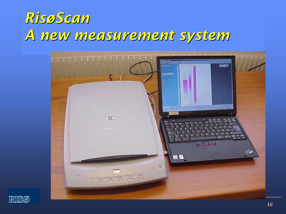
1616
RisRisøøScanScan A new measurement systemA new measurement system

1717
Dose mapping Dose mapping --
RisRisøøScanScan
Dosimeter film
Dose alongX-axis
Dose alongY-axis
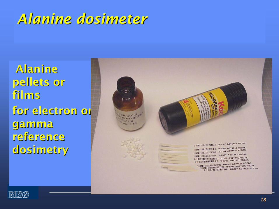
1818
Alanine dosimeterAlanine dosimeter
Alanine Alanine pellets or pellets or filmsfilms
for electron or for electron or gamma gamma reference reference dosimetrydosimetry
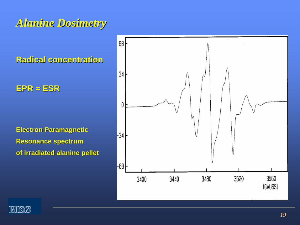
1919
Alanine DosimetryAlanine Dosimetry
Radical concentrationRadical concentration
EPR = ESREPR = ESR
Electron Paramagnetic Electron Paramagnetic
Resonance spectrumResonance spectrum
of irradiated alanine pelletof irradiated alanine pellet
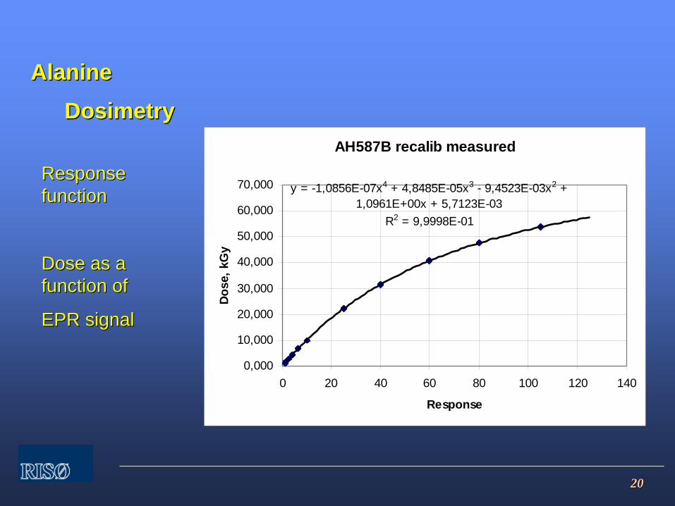
2020
Alanine Alanine
DosimetryDosimetryAH587B recalib measured
y = -1,0856E-07x4 + 4,8485E-05x3 - 9,4523E-03x2 + 1,0961E+00x + 5,7123E-03
R2 = 9,9998E-01
0,000
10,000
20,000
30,000
40,000
50,000
60,000
70,000
0 20 40 60 80 100 120 140
Response
Dos
e, k
Gy
ResponseResponse functionfunction
DoseDose as a as a functionfunction ofof
EPR signalEPR signal
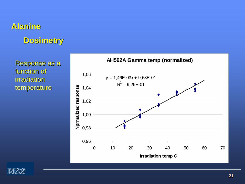
2121
Alanine Alanine
DosimetryDosimetry
ResponseResponse as a as a function of function of irradiation irradiation temperaturetemperature
AH592A Gamma temp (normalized)
y = 1,46E-03x + 9,63E-01R2 = 9,29E-01
0,96
0,98
1,00
1,02
1,04
1,06
0 10 20 30 40 50 60 70
Irradiation temp C
Npr
mal
ized
res
pons
e

2222
Alanine DosimetryAlanine Dosimetry
Measures free radical concentrationMeasures free radical concentration
Pellets or filmsPellets or films
Dose range: 10 Gy Dose range: 10 Gy ––
100 kGy100 kGy
Stable signal for more than one yearStable signal for more than one year
Reproducibility less than 0.5%, 1.s.dReproducibility less than 0.5%, 1.s.d
Measurement instrument:Measurement instrument:
EPR spectrometerEPR spectrometer
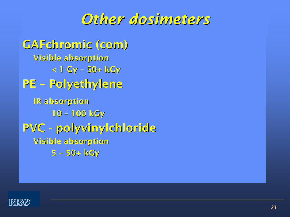
2323
Other dosimetersOther dosimeters
GAFchromic (com)GAFchromic (com)Visible absorptionVisible absorption
< 1 Gy < 1 Gy ––
50+ kGy50+ kGy
PE PE ––
PolyethylenePolyethylene
IR absorptionIR absorption
10 10 ––
100 kGy100 kGy
PVC PVC --
polyvinylchloridepolyvinylchlorideVisible absorptionVisible absorption
5 5 ––
50+ kGy50+ kGy

2424
CalibrationCalibration

2525
CalibrationCalibration
ISO 11137ISO 11137--1, sect 4.3.41, sect 4.3.4
““Dosimetry used in the development, Dosimetry used in the development, validation and routine control of validation and routine control of the sterilization process shall have the sterilization process shall have measurement traceability to measurement traceability to national or international national or international standards and shall have a known standards and shall have a known level of uncertainty.level of uncertainty.””
Can only be obtained through Can only be obtained through calibrationcalibration
2626
CalibrationCalibration
Dosimeters used in radiation processingDosimeters used in radiation processing
must be calibrated.must be calibrated.
MethodMethod::
1.1.
IrradiateIrradiate
dosimetersdosimeters
to to knownknown
dosesdoses
2.2.
MeasureMeasure
responseresponse
3.3.
EstablishEstablish
responseresponse
functionfunction
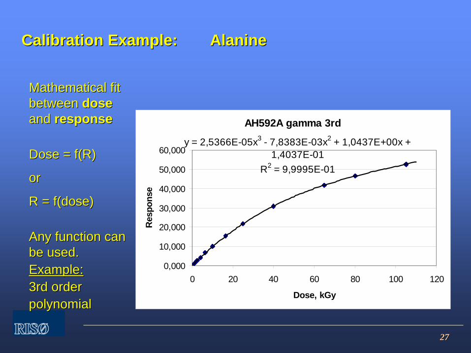
2727
Calibration Example: Calibration Example: AlanineAlanine
MathematicalMathematical fitfit betweenbetween dosedose and and responseresponse
Dose = f(R)Dose = f(R)
oror
R = f(dose)R = f(dose)
AnyAny functionfunction cancan bebe used.used.Example:Example:3rd order3rd orderpolynomialpolynomial
AH592A gamma 3rd
y = 2,5366E-05x3 - 7,8383E-03x2 + 1,0437E+00x + 1,4037E-01
R2 = 9,9995E-01
0,000
10,000
20,000
30,000
40,000
50,000
60,000
0 20 40 60 80 100 120
Dose, kGy
Res
pons
e
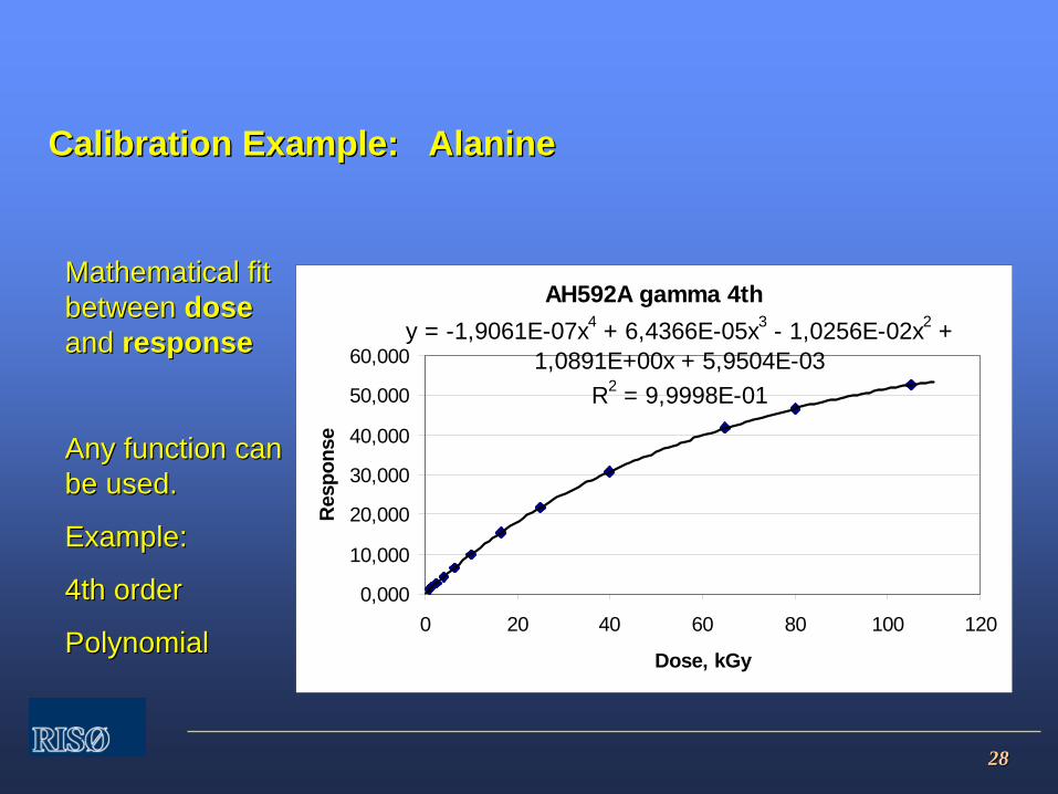
2828
Calibration Example: AlanineCalibration Example: Alanine
MathematicalMathematical fitfit betweenbetween dosedose and and responseresponse
AnyAny functionfunction cancan bebe usedused..
Example:Example:
4th order4th order
PolynomialPolynomial
AH592A gamma 4thy = -1,9061E-07x4 + 6,4366E-05x3 - 1,0256E-02x2 +
1,0891E+00x + 5,9504E-03R2 = 9,9998E-01
0,000
10,000
20,000
30,000
40,000
50,000
60,000
0 20 40 60 80 100 120
Dose, kGy
Res
pons
e

2929
Calibration Example: Calibration Example: AlanineAlanine
SelectionSelection ofof functionfunction basedbased onon evaluationevaluation ofof residualresidual plotplot
This plot This plot contains a contains a function function –– the the residuals are residuals are not randomnot random
AH592 gamma 3rd residual
-12,00-10,00-8,00-6,00-4,00
-2,000,002,004,00
0 20 40 60 80 100 120
Dose, kGy
Res
idua
l, %
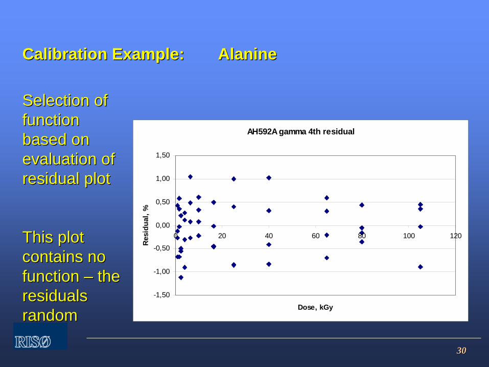
3030
Calibration Example: Calibration Example: AlanineAlanine
SelectionSelection ofof functionfunction basedbased onon evaluationevaluation ofof residualresidual plotplot
This plot This plot contains no contains no function function –– the the residuals residuals randomrandom
AH592A gamma 4th residual
-1,50
-1,00
-0,50
0,00
0,50
1,00
1,50
0 20 40 60 80 100 120
Dose, kGy
Res
idua
l, %

3131
MethodsMethods
ofof
CalibrationCalibration
RecommendedRecommended
methodmethod::
InIn--plant calibrationplant calibration
CalibrateCalibrate
by by irradiationirradiation
at at thethe
facilityfacility wherewhere
thethe
dosimetersdosimeters
areare
usedused..
DoseDose
measuredmeasured
by reference by reference dosimeters.dosimeters.
This method allows environmental This method allows environmental influence factors to neglected influence factors to neglected ––
almost!almost!
3232
MethodsMethods
ofof
CalibrationCalibration
InIn--plant calibrationplant calibration
ImportantImportant
The routine dosimeter and the reference The routine dosimeter and the reference dosimeter must receive the same dose.dosimeter must receive the same dose.
Use phantoms.Use phantoms.
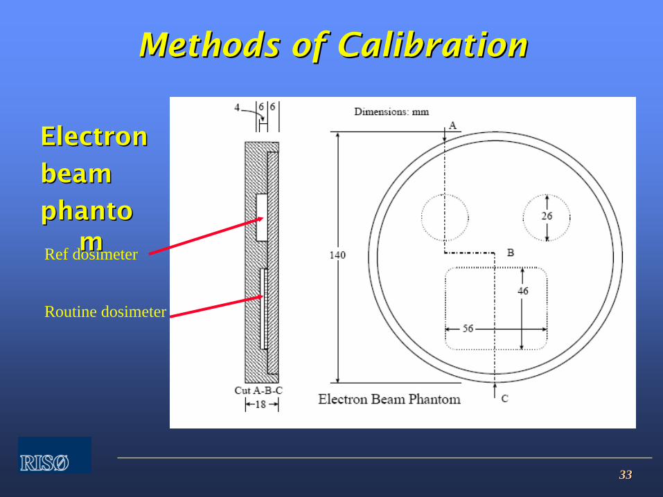
3333
MethodsMethods
ofof
CalibrationCalibration
ElectronElectron
beambeam
phantophanto mmRef dosimeter
Routine dosimeter

3434
MethodsMethods
ofof
CalibrationCalibration
AlternativeAlternative
methodmethod
CalibrateCalibrate
by by irradiationirradiation
at at calibrationcalibration laboratory.laboratory.
When using this method, verification of When using this method, verification of dosimeter response in plant must be dosimeter response in plant must be carried out.carried out.
3535
MethodsMethods
ofof
CalibrationCalibration
RecommendedRecommended
reference:reference:
CIRMCIRM--29 (August 1999)29 (August 1999)
Guidelines for the Calibration of Guidelines for the Calibration of Dosimeters for use in Radiation Dosimeters for use in Radiation ProcessingProcessing
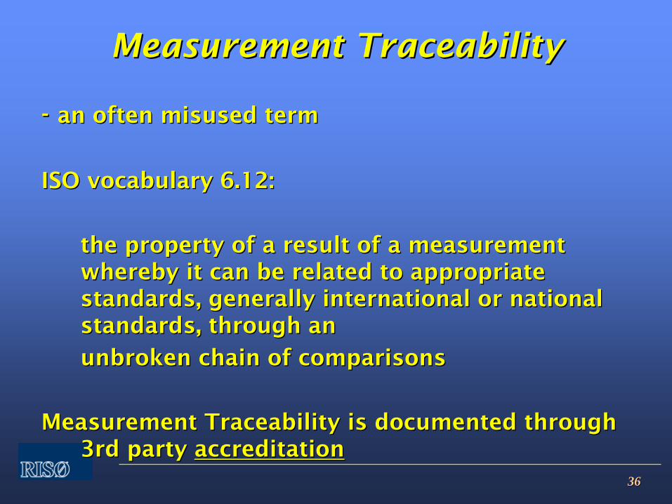
3636
MeasurementMeasurement
TraceabilityTraceability
--
an often misused terman often misused term
ISO vocabulary 6.12:ISO vocabulary 6.12:
the property of a result of a measurement the property of a result of a measurement whereby it can be related to appropriate whereby it can be related to appropriate standards, generally international or national standards, generally international or national standards, through an standards, through an
unbroken chain of comparisonsunbroken chain of comparisons
Measurement Traceability is documented through Measurement Traceability is documented through 3rd party 3rd party accreditationaccreditation
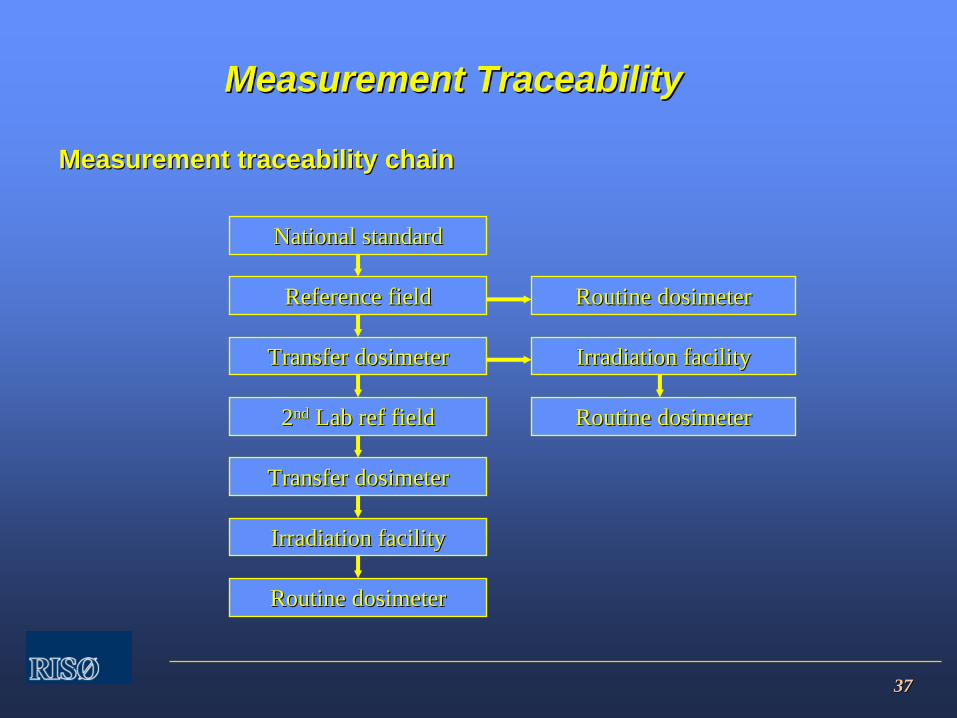
3737
Measurement traceability chainMeasurement traceability chain
MeasurementMeasurement TraceabilityTraceability
National standardNational standard
Reference fieldReference field
Transfer dosimeterTransfer dosimeter
22ndnd Lab ref fieldLab ref field
Transfer dosimeterTransfer dosimeter
Irradiation facilityIrradiation facility
Routine dosimeterRoutine dosimeter
Routine dosimeterRoutine dosimeter
Irradiation facilityIrradiation facility
Routine dosimeterRoutine dosimeter
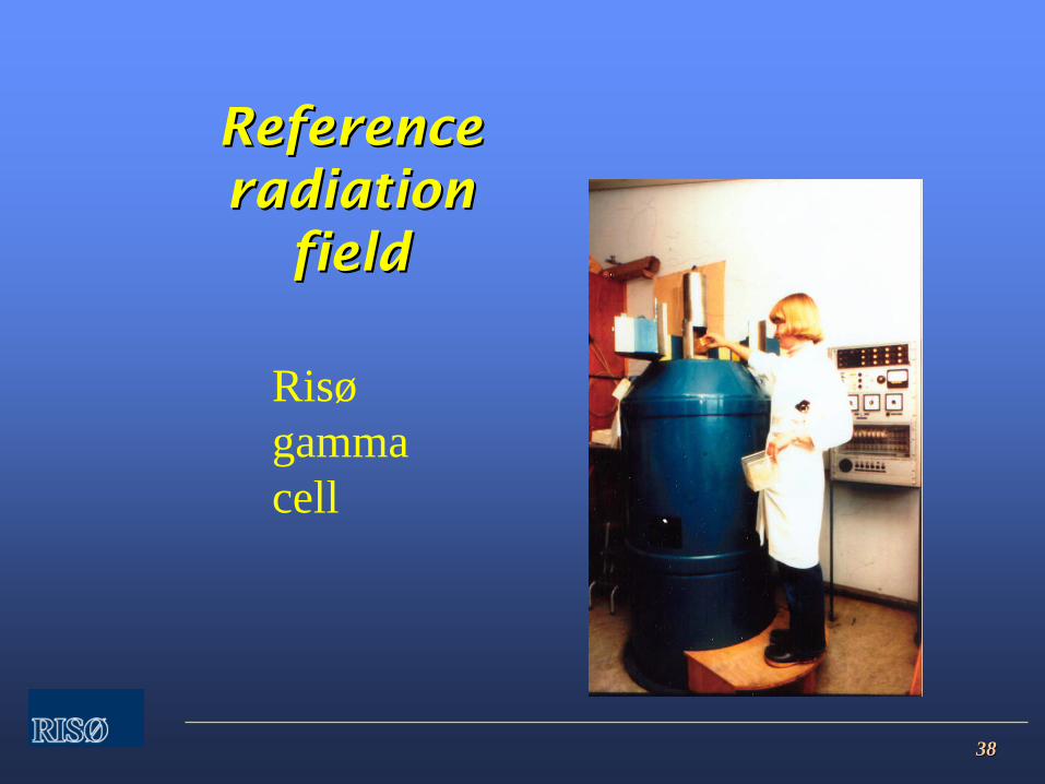
3838
Reference Reference radiation radiation
fieldfield
Risøgammacell
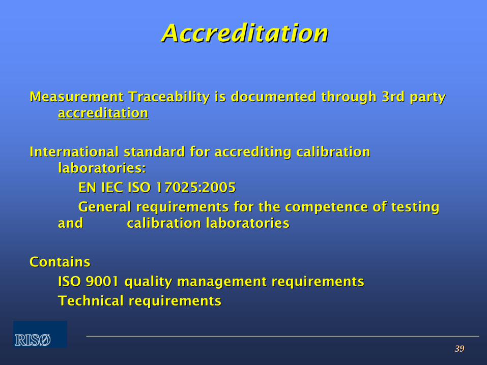
3939
AccreditationAccreditation
Measurement Traceability is documented through 3rd party Measurement Traceability is documented through 3rd party accreditationaccreditation
International standard for accrediting calibration International standard for accrediting calibration laboratories:laboratories:
EN IEC ISO 17025:2005EN IEC ISO 17025:2005
General requirements for the competence of testing General requirements for the competence of testing and and calibration laboratoriescalibration laboratories
ContainsContains
ISO 9001 quality management requirementsISO 9001 quality management requirements
Technical requirementsTechnical requirements

4040
AccreditationAccreditation
AccreditationAccreditation
is granted by national accrediting is granted by national accrediting organizations.organizations.
In Denmark: DANAKIn Denmark: DANAK
The national accreditations must be evaluated by The national accreditations must be evaluated by international organizations. In Europe: European international organizations. In Europe: European organization for Accreditation, EA.organization for Accreditation, EA.
Wider international network based on multinational Wider international network based on multinational recognition agreements.recognition agreements.
4141
AccreditationAccreditation
Why accreditation?Why accreditation?
Customer requirementCustomer requirement
Regulatory requirementsRegulatory requirements
3rd party evaluation strengthens technical competence 3rd party evaluation strengthens technical competence of laboratoryof laboratory
4242
Measurement UncertaintyMeasurement Uncertainty
ReferencesReferences
GUM: Guide to the expression of GUM: Guide to the expression of Uncertainty in Measurement (1993) Uncertainty in Measurement (1993) (ISO)(ISO)
Guide for Estimating Uncertainties in Guide for Estimating Uncertainties in Dosimetry for Radiation ProcessingDosimetry for Radiation Processing
ISO / ASTM 51707ISO / ASTM 51707
4343
MeasurementMeasurement
UncertaintyUncertainty
OneOne
classificationclassification::
RandomRandom::
ObservedObserved
duringduring
measurementmeasurement
NonNon--randomrandom::
Not Not observedobserved
duringduring measurementmeasurement
BothBoth
contributecontribute
to to thethe
measurementmeasurement
uncertaintyuncertainty
4444
MeasurementMeasurement
UncertaintyUncertainty
BIPM classificationBIPM classification::
Type A:Type A:
Uncertainties that are evaluated by applying Uncertainties that are evaluated by applying statistical methods to a series of repeated measurementsstatistical methods to a series of repeated measurements
Type B:Type B: Uncertainties that are evaluated by other means Uncertainties that are evaluated by other means
BothBoth
contributecontribute
to to thethe
measurementmeasurement
uncertaintyuncertainty
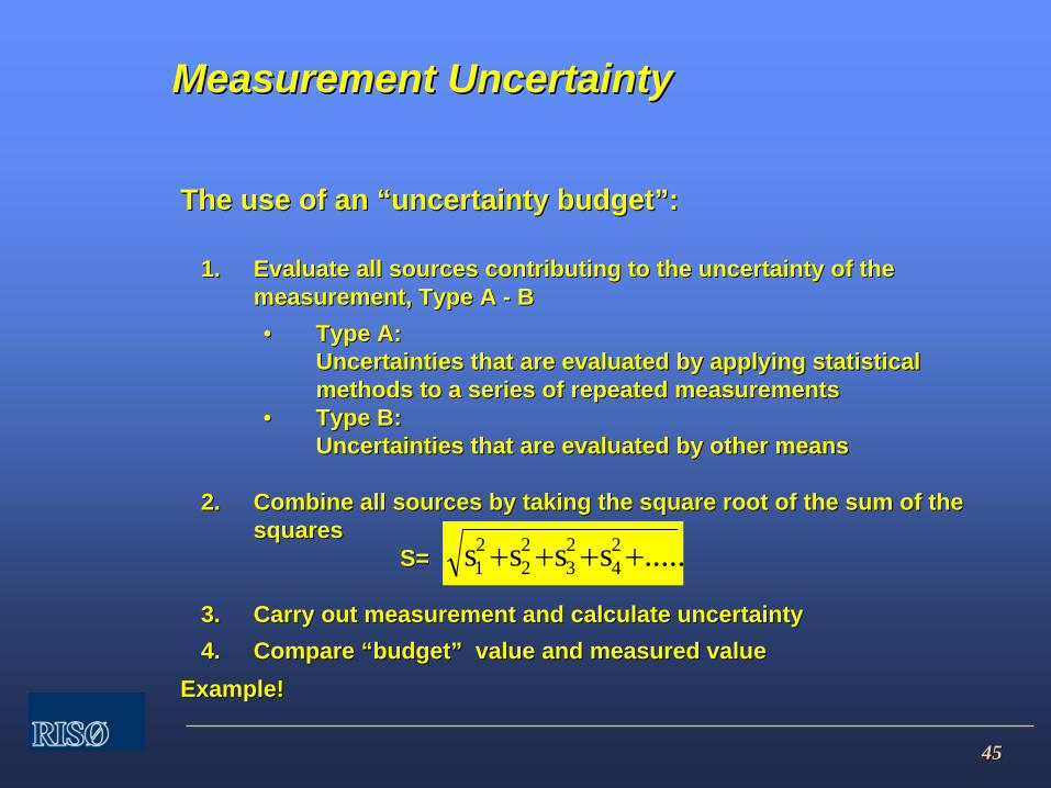
4545
The use of an The use of an ““uncertainty budgetuncertainty budget””::
1.1. Evaluate all sources contributing to the uncertainty of the Evaluate all sources contributing to the uncertainty of the measurement, Type A measurement, Type A -- BB•• Type A:Type A:
Uncertainties that are evaluated by applying statistical Uncertainties that are evaluated by applying statistical methods to a series of repeated measurementsmethods to a series of repeated measurements
•• Type B:Type B:Uncertainties that are evaluated by other meansUncertainties that are evaluated by other means
2.2. Combine all sources by taking the square root of the sum of the Combine all sources by taking the square root of the sum of the squaressquares
S=S=
3.3. Carry out measurement and calculate uncertaintyCarry out measurement and calculate uncertainty4.4. Compare Compare ““budgetbudget”” value and measured value value and measured value
Example!Example!
.....ssss 24
23
22
21 ++++
Measurement UncertaintyMeasurement Uncertainty
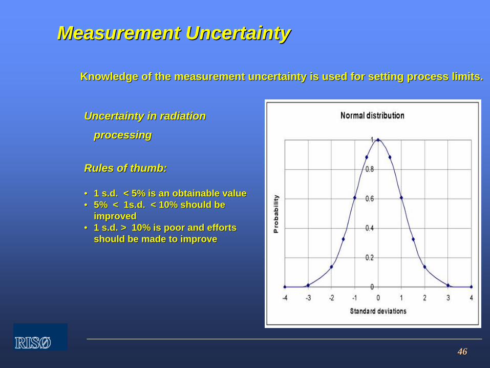
4646
Uncertainty in radiation Uncertainty in radiation
processingprocessing
Rules of thumb:Rules of thumb:
•• 1 s.d. < 5% is an obtainable value1 s.d. < 5% is an obtainable value•• 5% < 1s.d. < 10% should be 5% < 1s.d. < 10% should be
improvedimproved•• 1 s.d. > 10% is poor and efforts 1 s.d. > 10% is poor and efforts
should be made to improveshould be made to improve
Knowledge of the measurement uncertainty is used for setting proKnowledge of the measurement uncertainty is used for setting process limits.cess limits.
Measurement UncertaintyMeasurement Uncertainty
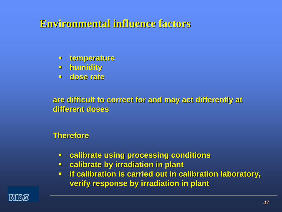
4747
temperaturetemperaturehumidityhumiditydose ratedose rate
are difficult to correct for and may act differently at are difficult to correct for and may act differently at different dosesdifferent doses
ThereforeTherefore
calibrate using processing conditionscalibrate using processing conditionscalibrate by irradiation in plantcalibrate by irradiation in plantif calibration is carried out in calibration laboratory, if calibration is carried out in calibration laboratory, verify response by irradiation in plantverify response by irradiation in plant
Environmental influence factorsEnvironmental influence factors

11
ValidationValidationandand
routine control ofroutine control ofsterilization by irradiationsterilization by irradiation
Arne MillerRisø
National LaboratoryTechnical University of Denmark DK-4000 RoskildeDenmark
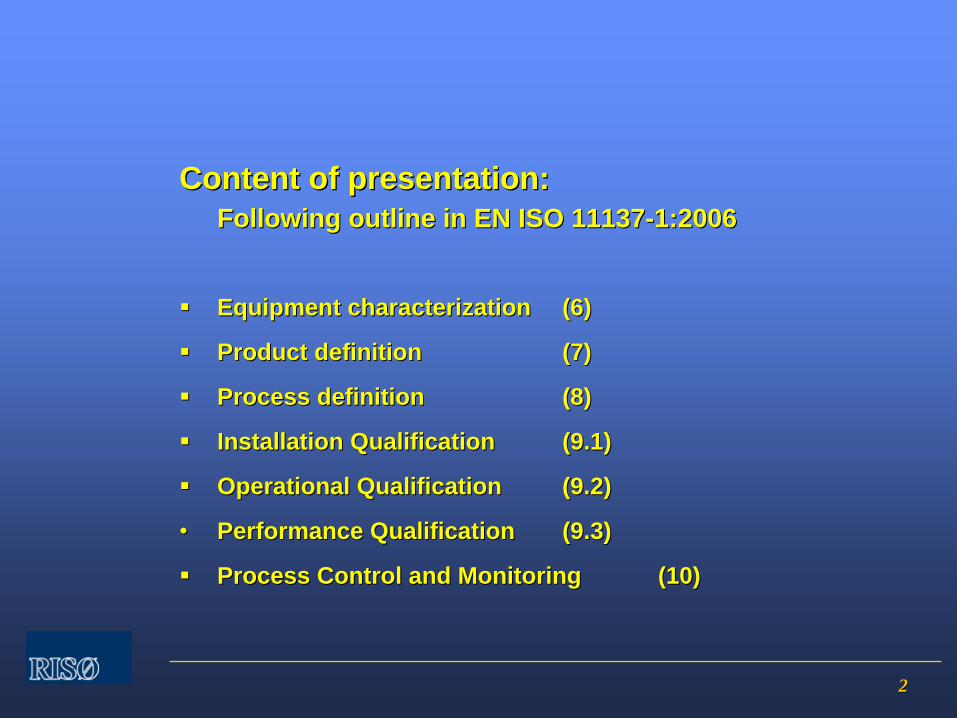
22
Content of presentation:Content of presentation:FollowingFollowing outlineoutline in EN ISO in EN ISO 1113711137--1:20061:2006
Equipment characterizationEquipment characterization (6)(6)
Product definitionProduct definition (7)(7)
ProcessProcess definitiondefinition (8)(8)
InInstallationstallation Qualification Qualification (9.1)(9.1)
Operational Operational QualificationQualification (9.2)(9.2)
••
Performance QualificationPerformance Qualification (9.3)(9.3)
Process Control and MonitoringProcess Control and Monitoring (10)(10)

33
6 Equipment characterization6 Equipment characterization
1. Description of irradiation facility1. Description of irradiation facility
2. Software2. Software
(6.2.2) Software used to control and/or (6.2.2) Software used to control and/or monitor the process shall be prepared in monitor the process shall be prepared in accordance with a quality management accordance with a quality management system that provides documented evidence system that provides documented evidence that the software meets its design intentionthat the software meets its design intention
= = software software validationvalidation
44
7 Product definition7 Product definition
7.17.1
Product to be sterilized, including Product to be sterilized, including packaging materials, shall be specified.packaging materials, shall be specified.

55
8 Process definition8 Process definition
(8.2)(8.2)
Establishing sterilization doseEstablishing sterilization dose
Using dose setting or dose substantiation Using dose setting or dose substantiation methods (11137methods (11137--2).2).
Note:Note:
Product samples shall be irradiated to Product samples shall be irradiated to defined and uniform doses.defined and uniform doses.
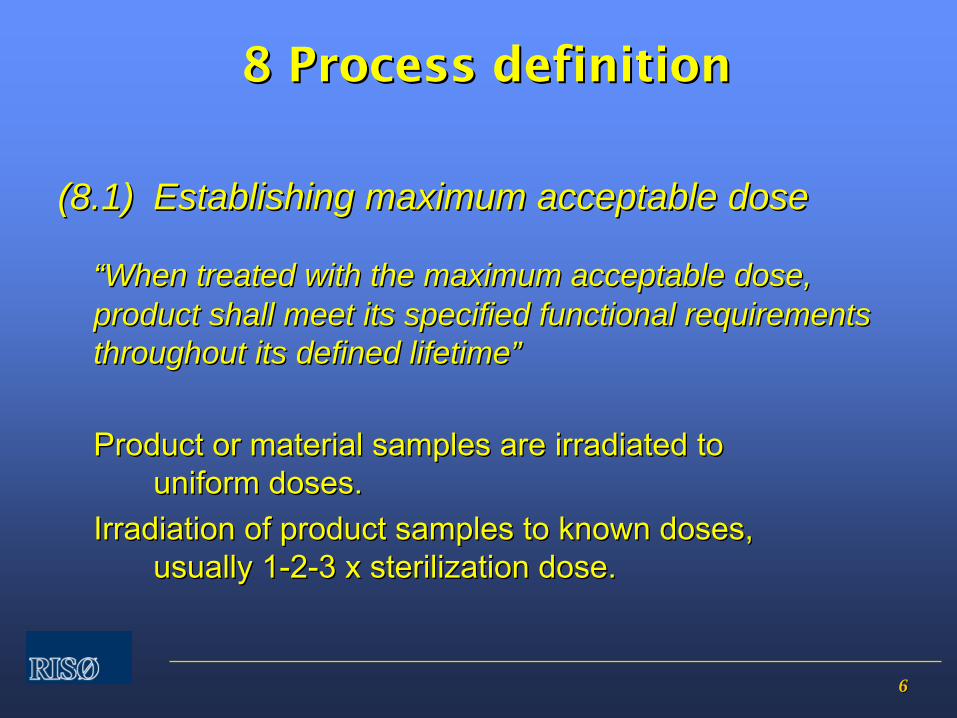
66
8 Process definition8 Process definition
(8.1)(8.1) Establishing maximum acceptable doseEstablishing maximum acceptable dose
““When treated with the maximum acceptable dose, When treated with the maximum acceptable dose, product shall meet its specified functional requirements product shall meet its specified functional requirements throughout its defined lifetimethroughout its defined lifetime””
Product or material samples are irradiated to Product or material samples are irradiated to uniform doses.uniform doses.
Irradiation of product samples to known doses, Irradiation of product samples to known doses, usually 1usually 1--22--3 x sterilization dose.3 x sterilization dose.
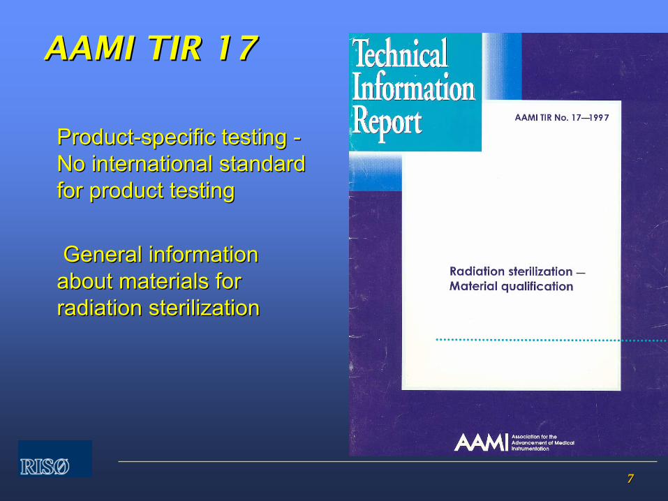
77
ProductProduct--specific testing specific testing -- No international standard No international standard
for product testingfor product testing
General information General information about materials for about materials for radiation sterilizationradiation sterilization
AAMI TIR 17AAMI TIR 17

88
9.1 Installation qualification9.1 Installation qualification
(A.9.1) (A.9.1) --
is carried out to demonstrate that the is carried out to demonstrate that the sterilization equipment and any ancillary sterilization equipment and any ancillary items has been supplied and installed in items has been supplied and installed in accordance with their specification.accordance with their specification.
Whether or not data are Whether or not data are ““in accordance with in accordance with their specificationtheir specification””
depends on agreement depends on agreement
between supplier and userbetween supplier and user
MeasurementsMeasurements
are oftenare often
thethe
same as forsame as forOperationalOperational
QualificationQualification
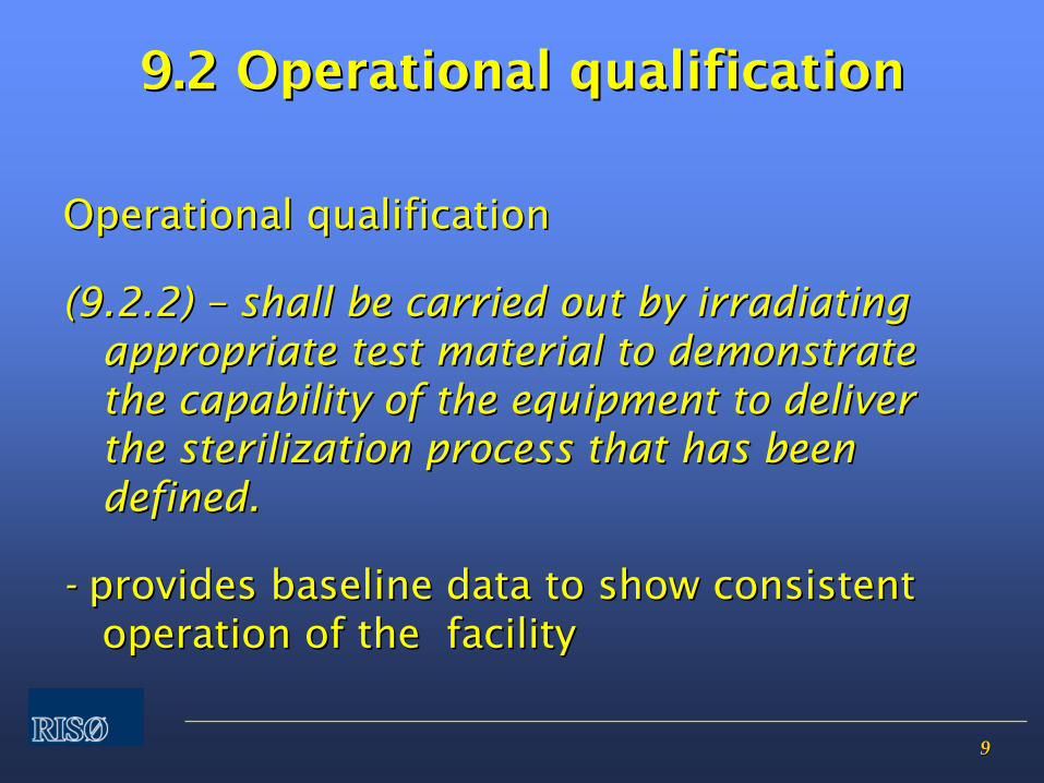
99
9.2 Operational qualification9.2 Operational qualification
Operational qualificationOperational qualification
(9.2.2) (9.2.2) ––
shall be carried out by irradiating shall be carried out by irradiating appropriate test material to demonstrate appropriate test material to demonstrate the capability of the equipment to deliver the capability of the equipment to deliver the sterilization process that has been the sterilization process that has been defined.defined.
--
provides baseline data to show consistent provides baseline data to show consistent operation of the facilityoperation of the facility
1010
Operational qualification Operational qualification
GammaGamma
••
dosedose
distribution in reference distribution in reference product(sproduct(s))
••
dosedose
as as functionfunction
ofof
dwelldwell
timetime••
processprocess
interruptioninterruption
••
mixmix
ofof
productsproducts
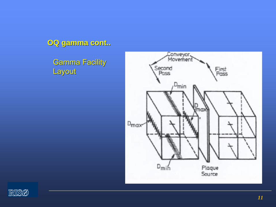
1111
OQ gamma cont..OQ gamma cont..
Gamma FacilityGamma FacilityLayoutLayout
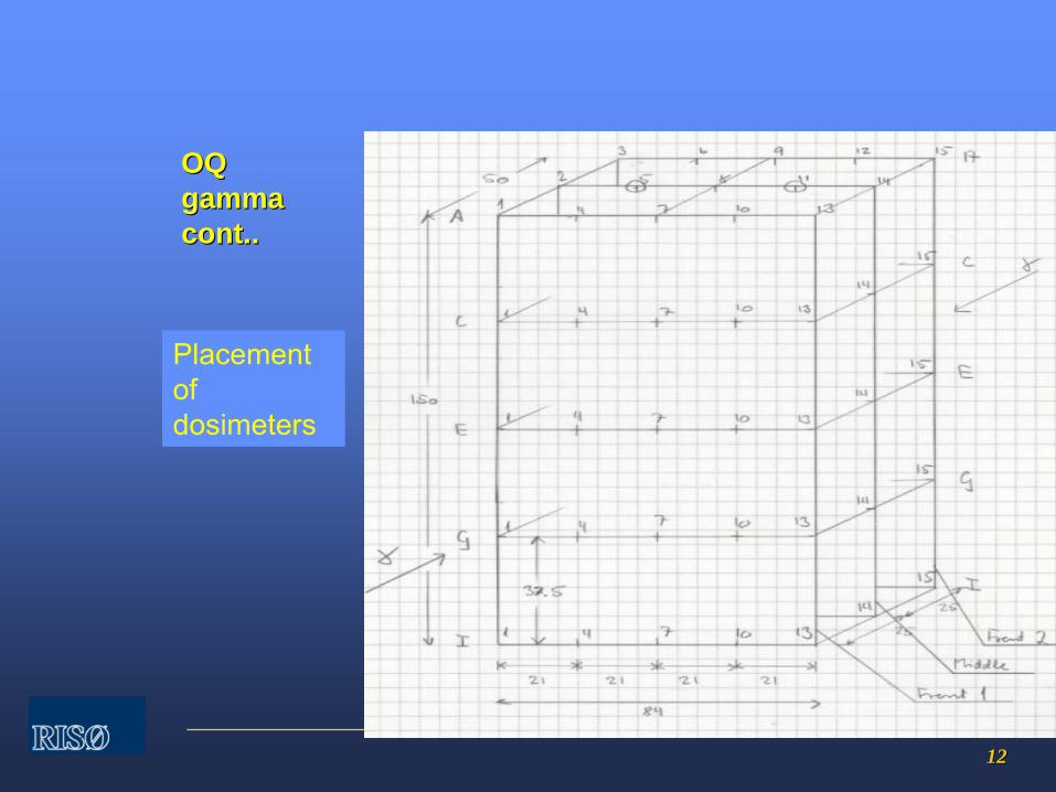
1212
OQ OQ gammagammacont..cont..
Placement of dosimeters
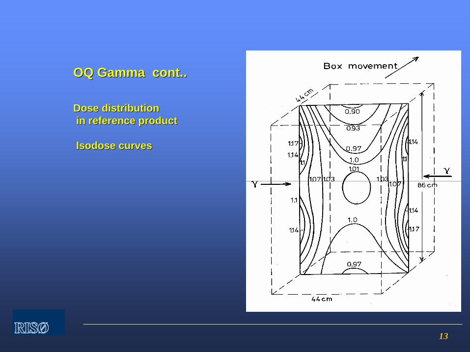
1313
Dose distributionDose distribution in reference productin reference product
IsodoseIsodose curvescurves
OQ Gamma cont..OQ Gamma cont..
1414
Dose maps must be made with fully loaded irradiation Dose maps must be made with fully loaded irradiation chamberchamber
Range of densities of reference product must cover Range of densities of reference product must cover extremes of products to be irradiatedextremes of products to be irradiated
Additional measurement:Additional measurement:
−−
effect of process interruptioneffect of process interruption
Dose mappingDose mapping
OQ gamma cont..OQ gamma cont..

1515
Dose mapping shall be carried out on a sufficient number of Dose mapping shall be carried out on a sufficient number of irradiation containers to allow determination of the irradiation containers to allow determination of the distribution and variability of dose between containersdistribution and variability of dose between containers
Dose mapping must be repeated when significant changes Dose mapping must be repeated when significant changes of the irradiation plant are made, of the irradiation plant are made, e.g. e.g. source changesource change
Dose mappingDose mapping
OQ gamma cont..OQ gamma cont..
1616
Operational qualification Electron Operational qualification Electron beambeam
Measurements to be carried outMeasurements to be carried out
––
dosedose
distribution reference distribution reference productproduct––
scan scan widthwidth
––
energyenergy––
dosedose
as as functionfunction
ofof
speed, speed, currentcurrent, scan , scan
widthwidth––
beambeam
spotspot
––
processprocess
interruptioninterruption

1717
OQ EOQ E--beam cont..beam cont..
Placement of Placement of dosimeters in dosimeters in reference productreference product
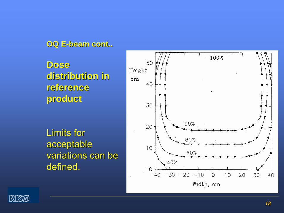
1818
Dose Dose distribution in distribution in reference reference productproduct
Limits for Limits for acceptable acceptable variations can bevariations can bedefineddefined.
OQ EOQ E--beam cont..beam cont..
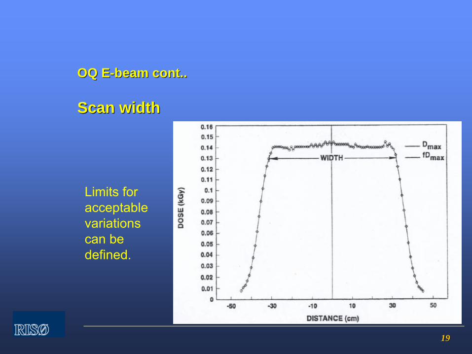
1919
Scan widthScan width
OQ EOQ E--beam cont..beam cont..
Limits for acceptable variations can bedefined.
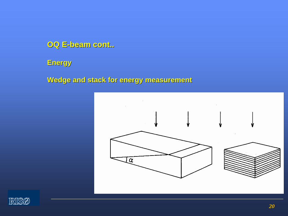
2020
EnergyEnergy
Wedge and stack for energy measurementWedge and stack for energy measurement
OQ EOQ E--beam cont..beam cont..
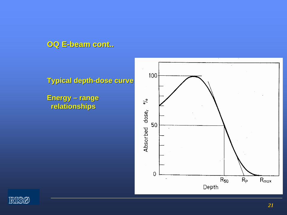
2121
Typical depthTypical depth--dose curvedose curve
EnergyEnergy –– range range relationshipsrelationships
OQ EOQ E--beam cont..beam cont..
2222
Energy Energy –– range relationshipsrange relationships
ISO / ASTM 51649ISO / ASTM 51649
AluminiumAluminium
Most probable energy Most probable energy EEpp
= 5.09 x = 5.09 x RRpp
+ 0.2 (+ 0.2 (MeVMeV))
Average energy EAverage energy Eaa
= 6.2 x R= 6.2 x R5050
Other equations for water and polymersOther equations for water and polymers
OQ EOQ E--beam cont..beam cont..
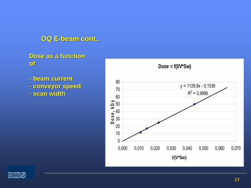
2323
Dose as a function Dose as a function of of
-- beambeam currentcurrent-- conveyor speedconveyor speed-- scan scan widthwidth
OQ EOQ E--beam cont..beam cont..
Dose = f(I/V*Sw)
y = 1129,8x - 0,1538R2 = 0,9996
01020304050607080
0,000 0,010 0,020 0,030 0,040 0,050 0,060 0,070
I/(V*Sw)
Dose
, kG
y

2424
OQ EOQ E--beam cont..beam cont..
Beam spot patternBeam spot pattern

2525
OQ EOQ E--beam cont..beam cont..
Process interruptionProcess interruption
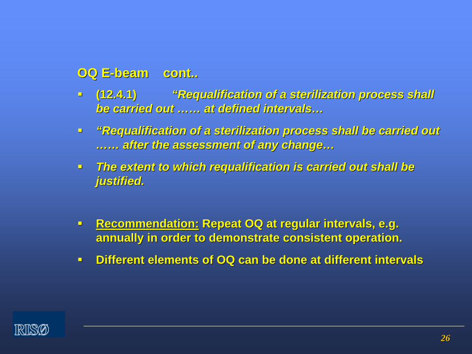
2626
(12.4.1)(12.4.1) ““RequalificationRequalification of a sterilization process shall of a sterilization process shall be carried out be carried out ………… at defined intervalsat defined intervals……
““RequalificationRequalification of a sterilization process shall be carried out of a sterilization process shall be carried out ………… after the assessment of any changeafter the assessment of any change……
The extent to which The extent to which requalificationrequalification is carried out shall be is carried out shall be justified.justified.
Recommendation:Recommendation: Repeat OQ at regular intervals, e.g. Repeat OQ at regular intervals, e.g. annually in order to demonstrate consistent operation.annually in order to demonstrate consistent operation.
Different elements of OQ can be done at different intervalsDifferent elements of OQ can be done at different intervals
OQ EOQ E--beam cont..beam cont..
2727
Performance qualificationPerformance qualification
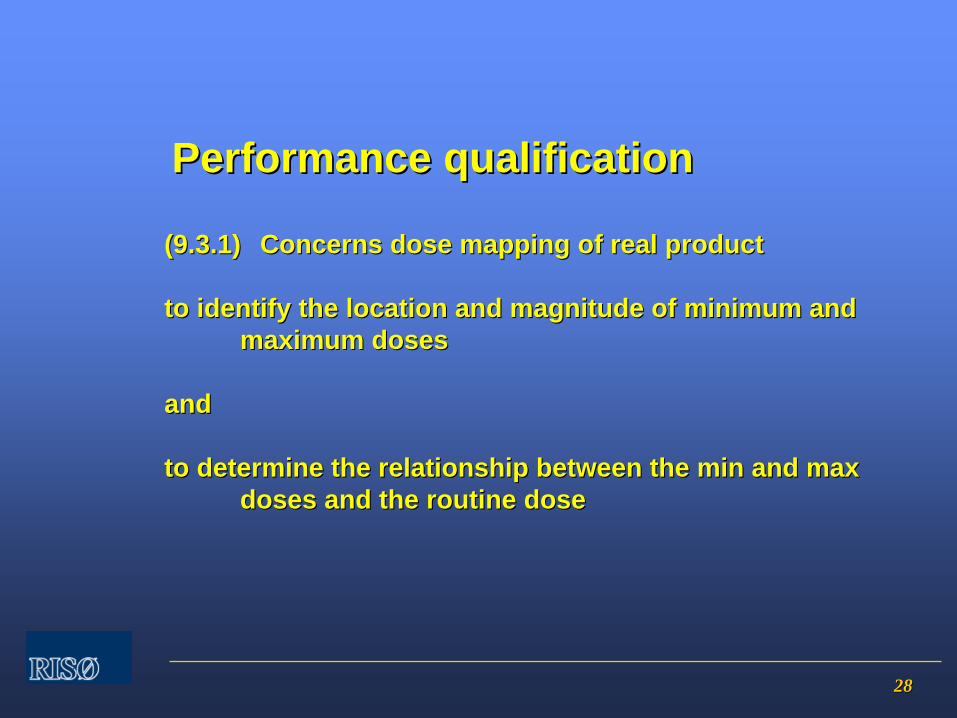
2828
(9.3.1)(9.3.1) Concerns dose mapping of real productConcerns dose mapping of real product
to identify the location and magnitude of minimum and to identify the location and magnitude of minimum and maximum dosesmaximum doses
andand
to determine the relationship between the min and max to determine the relationship between the min and max doses and the routine dosedoses and the routine dose
Performance qualificationPerformance qualification

2929
Purpose of dose mappingPurpose of dose mapping
-- to demonstrate that: to demonstrate that:
••
D (min) D (min) >>
D (Steril) and D (max) D (Steril) and D (max) <<
D (acceptable)D (acceptable)
••
D (min) determined by sterilization requirementsD (min) determined by sterilization requirements
••
D (max) determined by radiationD (max) determined by radiation--induced changes in productinduced changes in product
Performance qualification ..cont..Performance qualification ..cont..

3030
Strategies for dose mappingStrategies for dose mapping-- based on:based on:
OQ measurementsOQ measurementsInhomogeneous product distribution, orientation, voids, interfacInhomogeneous product distribution, orientation, voids, interfaces.es.ExperienceExperience
Processing categoriesProcessing categories
Limitations of dose mappingLimitations of dose mapping
Ability to measure Ability to measure ““the truethe true”” value of D(min) or D(max)value of D(min) or D(max)Location of dosimeterLocation of dosimeterResolution of dosimeter systemResolution of dosimeter system
Performance qualification ..cont..Performance qualification ..cont..

3131
Performance qualification ..cont..Performance qualification ..cont..
Examples from real life Examples from real life ……....
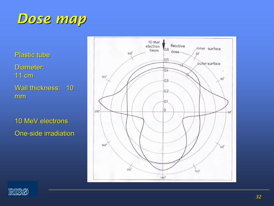
3232
DoseDose
mapmap
Plastic tubePlastic tube
Diameter:Diameter: 11 cm11 cm
WallWall
thicknessthickness: 10 : 10 mmmm
10 10 MeVMeV
electronselectrons
OneOne--sideside
irradiationirradiation
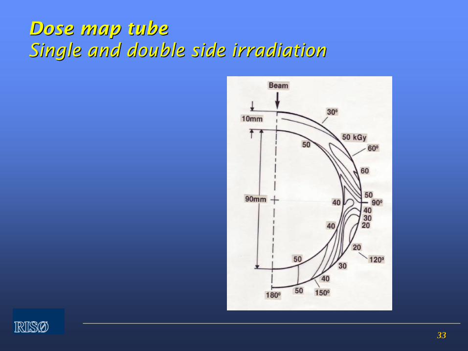
3333
DoseDose
mapmap
tubetube Single and double side Single and double side irradiationirradiation
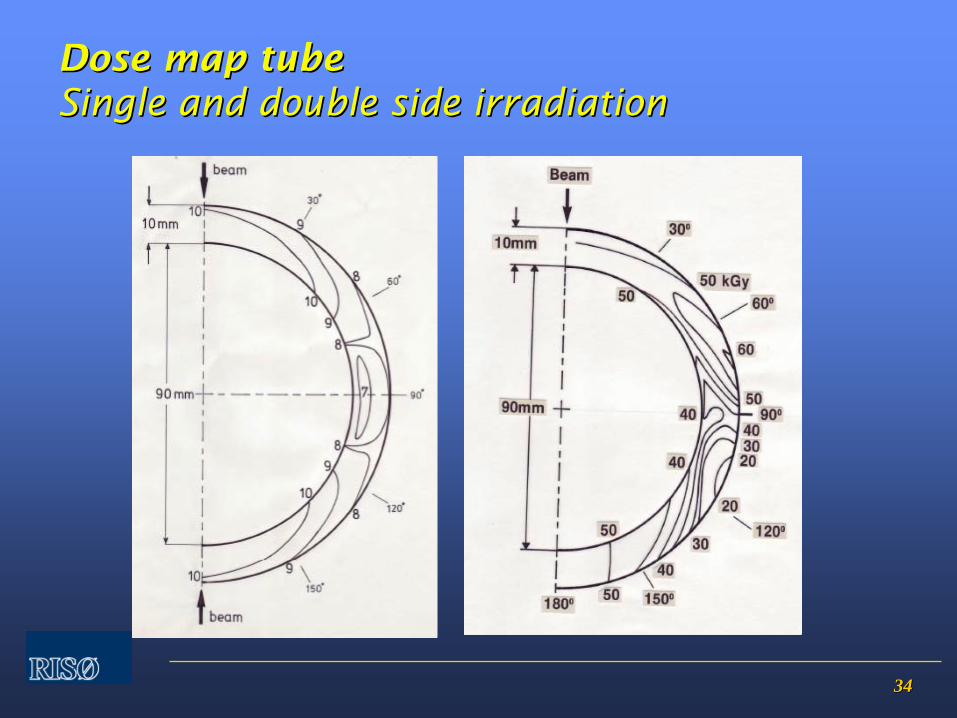
3434
DoseDose
mapmap
tubetube Single and double side Single and double side irradiationirradiation
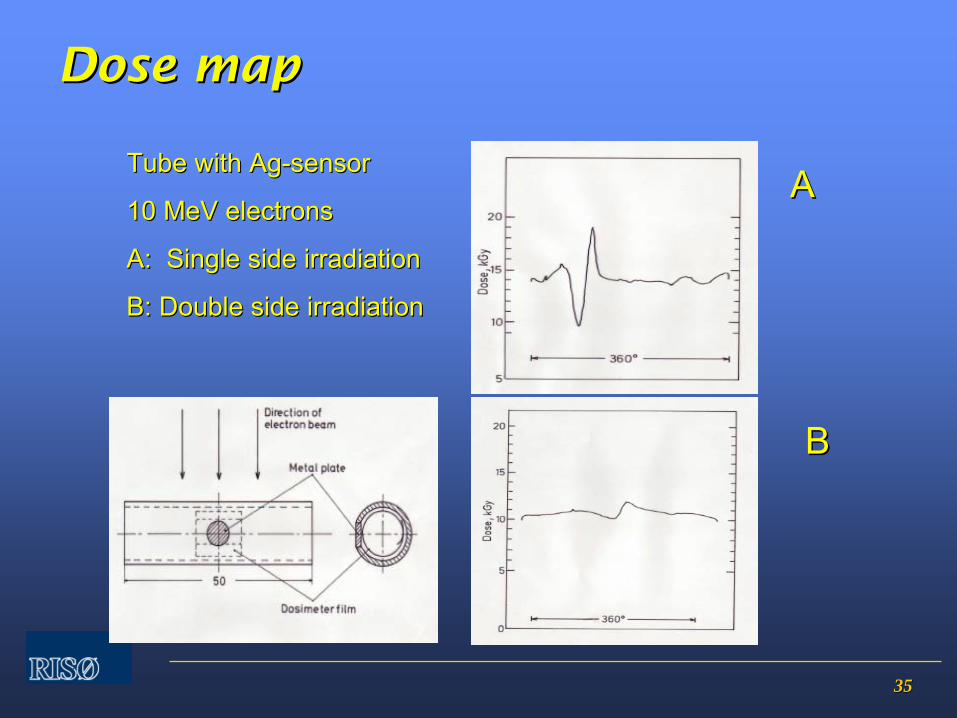
3535
DoseDose
mapmap
Tube Tube withwith
AgAg--sensorsensor
10 10 MeVMeV
electronselectrons
A: Single side A: Single side irradiationirradiation
B: Double side B: Double side irradiationirradiation
AA
BB

3636
DoseDose
mapmap Metal Metal implantimplant, 10 , 10 MeVMeV
electronselectrons, double , double sidedsided
irradiationirradiation RisRisøø
B3, RisB3, Risøø
ScanScan

3737
Measurement UncertaintyMeasurement Uncertainty
(9.3.5) Dose mapping shall be carried out using representative i(9.3.5) Dose mapping shall be carried out using representative irradiation containers rradiation containers sufficient in number to determine the variability of dose betweesufficient in number to determine the variability of dose between containersn containers
Practical approach:Practical approach:
Either dose map in detail 3Either dose map in detail 3--10 containers10 containers
oror−−
dose map in detail one containerdose map in detail one container−−
repeat measurement of D (min) and D (max) in several (e.g. 10) repeat measurement of D (min) and D (max) in several (e.g. 10) containers containers
−−
evaluate measurement uncertainty taking into account all evaluate measurement uncertainty taking into account all uncertainty components.uncertainty components.
Performance qualification ..cont..Performance qualification ..cont..
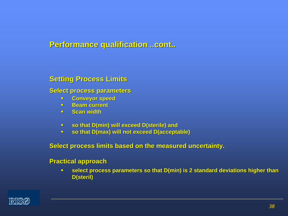
3838
Setting Process LimitsSetting Process LimitsSelect process parametersSelect process parameters
Conveyor speedConveyor speedBeam currentBeam currentScan width Scan width
so that so that D(minD(min) will exceed ) will exceed D(sterileD(sterile) and ) and so that so that D(maxD(max) will not exceed ) will not exceed D(acceptableD(acceptable))
Select process limits based on the measured uncertainty.Select process limits based on the measured uncertainty.
Practical approachPractical approachselect process parameters so that D(min) is 2 standard deviationselect process parameters so that D(min) is 2 standard deviations higher than s higher than D(sterilD(steril))
Performance qualification ..cont..Performance qualification ..cont..
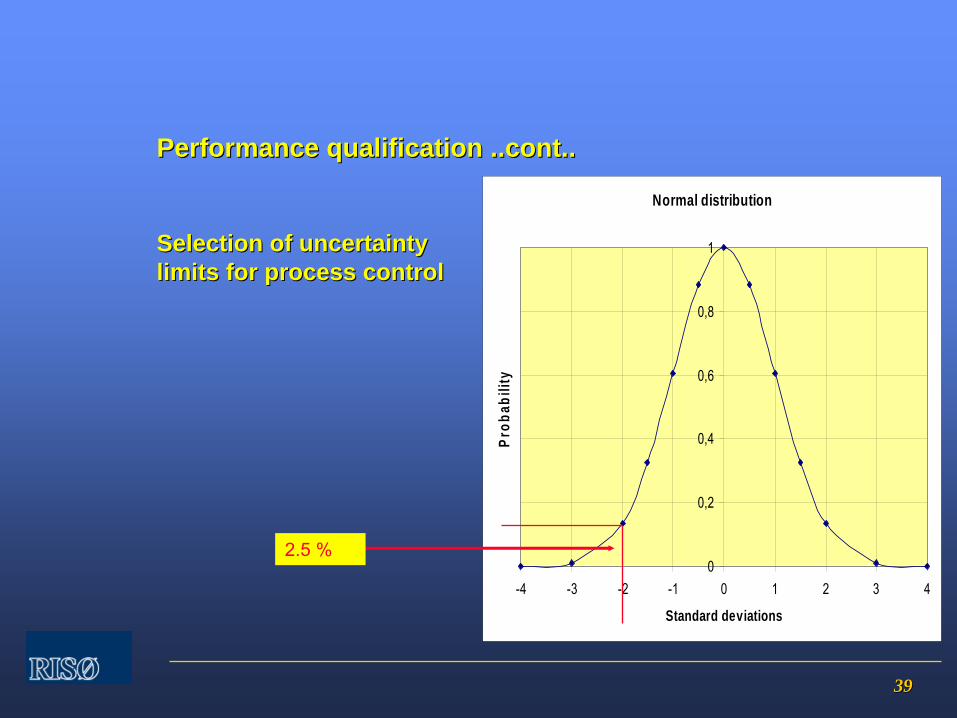
3939
Selection of uncertainty Selection of uncertainty limits for process controllimits for process control
Normal distribution
0
0,2
0,4
0,6
0,8
1
-4 -3 -2 -1 0 1 2 3 4
Standard deviations
Prob
abili
ty
Performance qualification ..cont..Performance qualification ..cont..
2.5 %
4040
Strategies for dose mapping based onStrategies for dose mapping based on
-- information from Operational Qualificationinformation from Operational Qualification
-- inhomogeneous product distribution, orientation, voids, interfainhomogeneous product distribution, orientation, voids, interfacesces
-- experienceexperience
Limitations of dose mappingLimitations of dose mapping
-- ability to detect correctly the locations of min and max dosesability to detect correctly the locations of min and max doses
-- location of dosimeterlocation of dosimeter
-- measurement resolution of dosimetermeasurement resolution of dosimeter
Process categoriesProcess categories
product that can be processed product that can be processed –– irradiated irradiated –– in the same wayin the same way
Performance qualification ..cont..Performance qualification ..cont..
4141
Repeat of Performance QualificationRepeat of Performance Qualification
Only needed if product is changedOnly needed if product is changedor if facility is changedor if facility is changed
review of documentation at defined intervals is review of documentation at defined intervals is recommended, e.g. every 3 yearsrecommended, e.g. every 3 years
Performance qualification ..cont..Performance qualification ..cont..
4242
Routine monitoring and controlRoutine monitoring and control
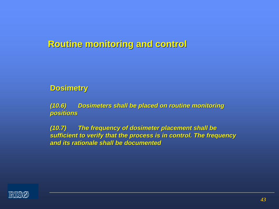
4343
Dosimetry Dosimetry
(10.6)(10.6) Dosimeters shall be placed on routine monitoring Dosimeters shall be placed on routine monitoring positionspositions
(10.7)(10.7) The frequency of dosimeter placement shall be The frequency of dosimeter placement shall be sufficient to verify that the process is in control. The frequensufficient to verify that the process is in control. The frequency cy and its rationale shall be documented and its rationale shall be documented
Routine monitoring and controlRoutine monitoring and control
4444
Monitoring of parametersMonitoring of parameters
ElectronsElectrons
Electron energyElectron energyBeam currentBeam currentScan widthScan widthConveyor speedConveyor speed
Routine monitoring and controlRoutine monitoring and control
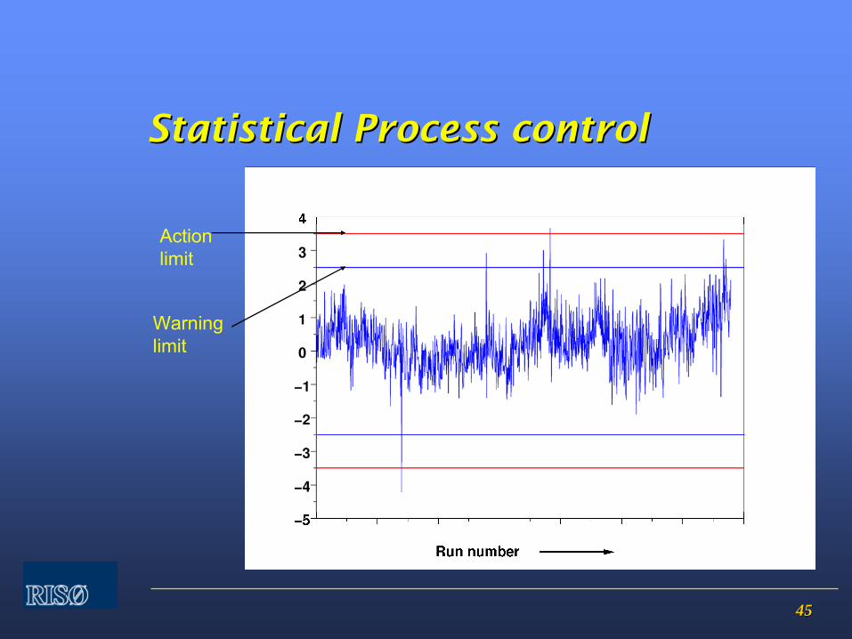
4545
Statistical Process controlStatistical Process control
Action limit
Warning
limit
4646
(11.2)(11.2) Procedures shall define the requirements for Procedures shall define the requirements for designating the sterilization process as conforming, designating the sterilization process as conforming, taking into account the uncertainty of thetaking into account the uncertainty of the measurement system.measurement system.
Product release from sterilizationProduct release from sterilization

4747
Audit issuesAudit issues Installation / operation qualificationInstallation / operation qualification
GammaGamma••
Is dose map detail sufficient?Is dose map detail sufficient?
••
Was a suitable range of densities for reference Was a suitable range of densities for reference products used?products used?
••
Was effect of process interruption Was effect of process interruption demonstrated?demonstrated?
••
Was OQ repeated after latest source reloading?Was OQ repeated after latest source reloading?••
Was consistent plant operation demonstrated?Was consistent plant operation demonstrated?
••
Was dosimeter system calibrated with Was dosimeter system calibrated with traceability?traceability?
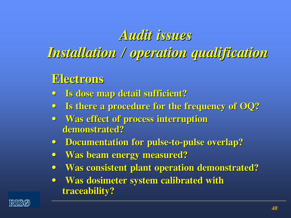
4848
Audit issuesAudit issues Installation / operation qualificationInstallation / operation qualification
ElectronsElectrons••
Is dose map detail sufficient?Is dose map detail sufficient?
••
Is there a procedure for the frequency of OQ?Is there a procedure for the frequency of OQ?••
Was effect of process interruption Was effect of process interruption
demonstrated?demonstrated?••
Documentation for pulseDocumentation for pulse--toto--pulse overlap?pulse overlap?
••
Was beam energy measured?Was beam energy measured?••
Was consistent plant operation demonstrated?Was consistent plant operation demonstrated?
••
Was dosimeter system calibrated with Was dosimeter system calibrated with traceability?traceability?
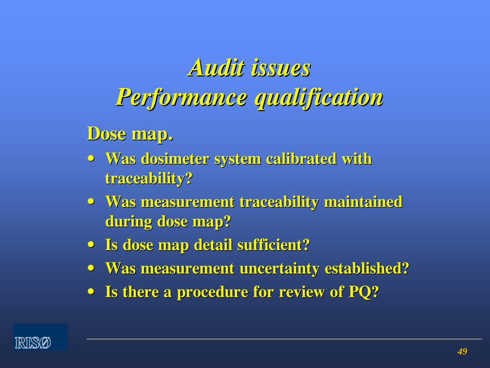
4949
Audit issuesAudit issues Performance qualificationPerformance qualification
Dose map.Dose map.••
Was dosimeter system calibrated with Was dosimeter system calibrated with traceability?traceability?
••
Was measurement traceability maintained Was measurement traceability maintained during dose map?during dose map?
••
Is dose map detail sufficient?Is dose map detail sufficient?••
Was measurement uncertainty established?Was measurement uncertainty established?
••
Is there a procedure for review of PQ? Is there a procedure for review of PQ?
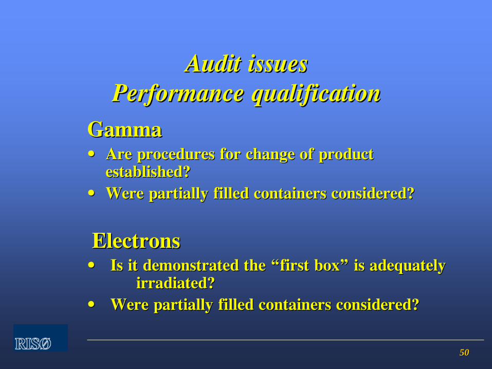
5050
Audit issuesAudit issues Performance qualificationPerformance qualification
GammaGamma••
Are procedures for change of product Are procedures for change of product established?established?
••
Were partially filled containers considered?Were partially filled containers considered?
ElectronsElectrons••
Is it demonstrated the Is it demonstrated the ““first boxfirst box””
is adequately is adequately
irradiated?irradiated?••
Were partially filled containers considered?Were partially filled containers considered?
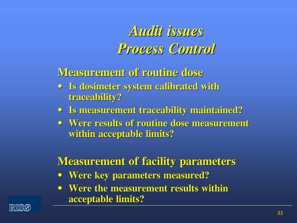
5151
Audit issuesAudit issues Process ControlProcess Control
Measurement of routine doseMeasurement of routine dose••
Is dosimeter system calibrated with Is dosimeter system calibrated with traceability?traceability?
••
Is measurement traceability maintained?Is measurement traceability maintained?••
Were results of routine dose measurement Were results of routine dose measurement within acceptable limits?within acceptable limits?
Measurement of facility parametersMeasurement of facility parameters••
Were key parameters measured?Were key parameters measured?
••
Were the measurement results within Were the measurement results within acceptable limits?acceptable limits?
International Standards for Radiation Sterilization of
Medical Devices
ArnArnee
MillerMillerRisRisøø
National LaboratoryNational Laboratory
Technical University of DenmarkTechnical University of DenmarkDK 4000 DK 4000 RoskildeRoskildeDenmarkDenmark

22
Sterilization of Medical DevicesSterilization of Medical Devices
Medical Device Directive Medical Device Directive 93/42/EEC93/42/EECHas been implemented for CE marking in national legislation Has been implemented for CE marking in national legislation since 1998. since 1998. A new Medical Device Directive was issuedA new Medical Device Directive was issued12 October 2007: 2007/47/EC12 October 2007: 2007/47/EC
It amends the old directive It amends the old directive It must be implemented in national laws by end of 2008It must be implemented in national laws by end of 2008Manufactures must comply by March 2010Manufactures must comply by March 2010
Nothing is changed with respect to sterilizationNothing is changed with respect to sterilization
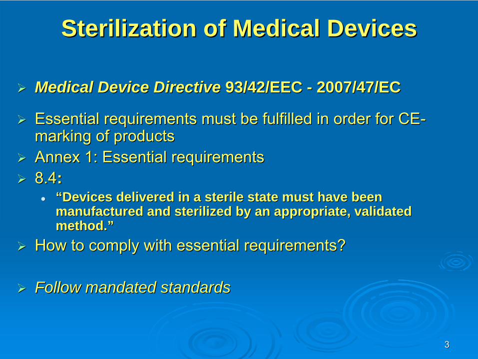
33
Sterilization of Medical DevicesSterilization of Medical Devices
Medical Device Directive Medical Device Directive 93/42/EEC 93/42/EEC -- 2007/47/EC2007/47/EC
Essential requirements must be fulfilled in order for CEEssential requirements must be fulfilled in order for CE--marking of products marking of products Annex 1: Essential requirementsAnnex 1: Essential requirements8.48.4::
““Devices delivered in a sterile state must have been Devices delivered in a sterile state must have been manufactured and sterilized by an appropriate, validated manufactured and sterilized by an appropriate, validated method.method.””
How to comply with essential requirements? How to comply with essential requirements?
Follow mandated standardsFollow mandated standards
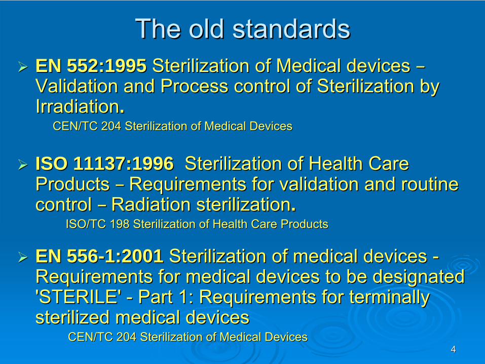
44
The old standardsThe old standardsEN 552:1995EN 552:1995 Sterilization of Medical devices Sterilization of Medical devices ––Validation and Process control of Sterilization by Validation and Process control of Sterilization by IrradiationIrradiation..
CEN/TC 204 Sterilization of Medical DevicesCEN/TC 204 Sterilization of Medical Devices
ISO 11137:1996ISO 11137:1996 Sterilization of Health Care Sterilization of Health Care Products Products –– Requirements for validation and routine Requirements for validation and routine control control –– Radiation sterilizationRadiation sterilization..
ISO/TC 198 Sterilization of Health Care ProductsISO/TC 198 Sterilization of Health Care Products
EN 556EN 556--1:2001 1:2001 Sterilization of medical devices Sterilization of medical devices --Requirements for medical devices to be designated Requirements for medical devices to be designated 'STERILE' 'STERILE' -- Part 1: Requirements for terminally Part 1: Requirements for terminally sterilized medical devicessterilized medical devices
CEN/TC 204 Sterilization of Medical DevicesCEN/TC 204 Sterilization of Medical Devices
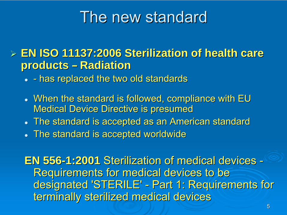
55
The new standardThe new standard
EN ISO 11137:2006 Sterilization of health care EN ISO 11137:2006 Sterilization of health care products products –– RadiationRadiation
-- has replaced the two old standardshas replaced the two old standards
When the standard is followed, compliance with EU When the standard is followed, compliance with EU Medical Device Directive is presumedMedical Device Directive is presumedThe standard is accepted as an American standardThe standard is accepted as an American standardThe standard is accepted worldwideThe standard is accepted worldwide
EN 556EN 556--1:2001 1:2001 Sterilization of medical devices Sterilization of medical devices -- Requirements for medical devices to be Requirements for medical devices to be
designated 'STERILE' designated 'STERILE' --
Part 1: Requirements for Part 1: Requirements for terminally sterilized medical devicesterminally sterilized medical devices
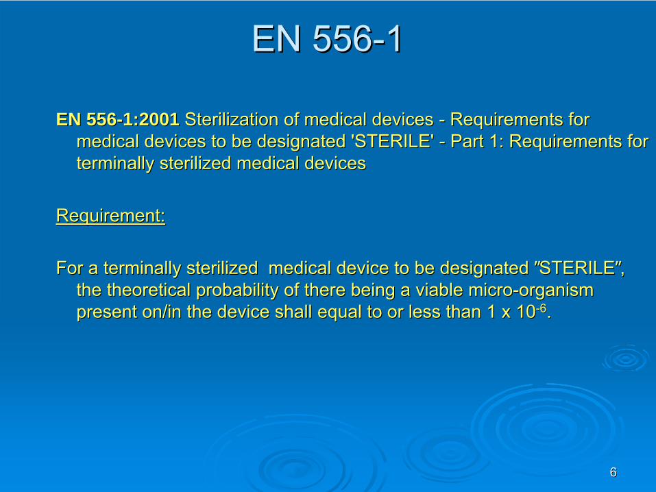
66
EN 556EN 556--11
EN 556EN 556--1:2001 1:2001 Sterilization of medical devices Sterilization of medical devices --
Requirements for Requirements for medical devices to be designated 'STERILE' medical devices to be designated 'STERILE' --
Part 1: Requirements for Part 1: Requirements for
terminally sterilized medical devicesterminally sterilized medical devices
Requirement:Requirement:
For a terminally sterilized medical device to be designated For a terminally sterilized medical device to be designated ””STERILESTERILE””, , the theoretical probability of there being a viable microthe theoretical probability of there being a viable micro--organism organism present on/in the device shall equal to or less than 1 x 10present on/in the device shall equal to or less than 1 x 10--66..
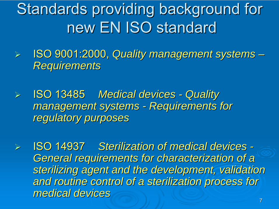
77
Standards providing background for Standards providing background for new EN ISO standardnew EN ISO standard
ISO 9001:2000, ISO 9001:2000, Quality management systems Quality management systems ––RequirementsRequirements
ISO 13485ISO 13485 Medical devices Medical devices -- Quality Quality management systems management systems -- Requirements for Requirements for regulatory purposesregulatory purposes
ISO 14937 ISO 14937 Sterilization of medical devices Sterilization of medical devices --General requirements for characterization of a General requirements for characterization of a sterilizing agent and the development, validation sterilizing agent and the development, validation and routine control of a sterilization process for and routine control of a sterilization process for medical devicesmedical devices

88
Other standards that are incorporated Other standards that are incorporated into the new ISO EN standardsinto the new ISO EN standards
ISO/TR 15843 Product families, ISO/TR 15843 Product families, dose audit frequency and dose dose audit frequency and dose audit sample sizesaudit sample sizes
ISO/TR 15844 Radiation ISO/TR 15844 Radiation sterilization of one batchsterilization of one batch
AAMI TIR 27 VDAAMI TIR 27 VDmaxmaxsubstantiationsubstantiation ofof 25 kGy25 kGy
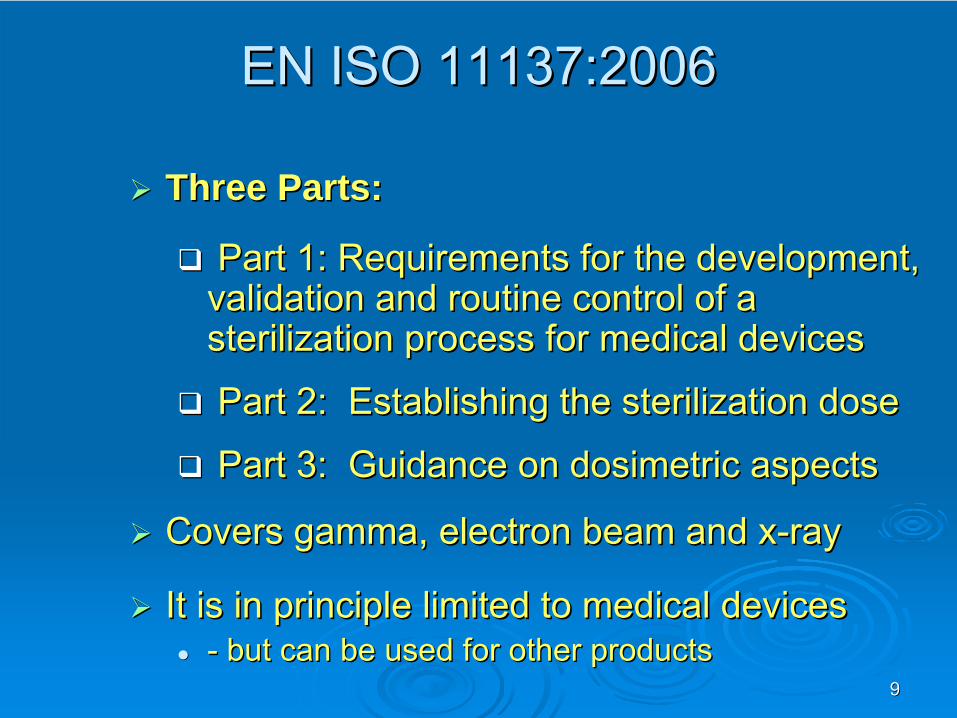
99
EN ISO 11137:2006EN ISO 11137:2006
Three Parts:Three Parts:
Part 1: Part 1: Requirements for the development, Requirements for the development, validation and routine control of a validation and routine control of a sterilization process for medical devicessterilization process for medical devices
Part 2: Establishing the sterilization dose Part 2: Establishing the sterilization dose
Part 3: Guidance on Part 3: Guidance on dosimetricdosimetric aspectsaspects
Covers gamma, electron beam and xCovers gamma, electron beam and x--rayray
It is in principle limited to medical devicesIt is in principle limited to medical devices-- but can be used for other productsbut can be used for other products

1010
EN ISO 11137EN ISO 11137--11
ContentContent1 Scope1 Scope2 References2 References3 Terms and definitions3 Terms and definitions4 Quality management system4 Quality management system5 Sterilizing agent characterization5 Sterilizing agent characterization6 Process and equipment characterization6 Process and equipment characterization7 Product definition7 Product definition8 Process definition8 Process definition9 Validation9 Validation10 Routine monitoring10 Routine monitoring11 Product release11 Product release12 Maintaining process effectiveness12 Maintaining process effectiveness
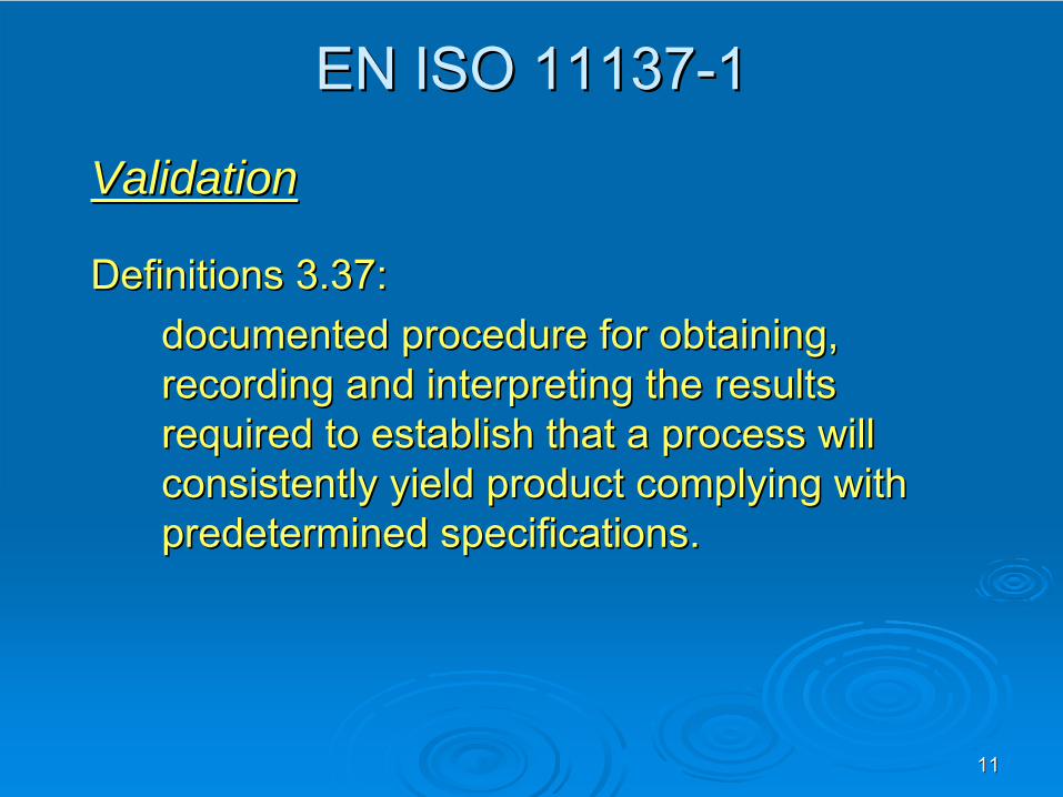
1111
EN ISO 11137EN ISO 11137--11
ValidationValidation
Definitions 3.37: Definitions 3.37: documented procedure for obtaining, documented procedure for obtaining, recording and interpreting the results recording and interpreting the results required to establish that a process will required to establish that a process will consistently yield product complying with consistently yield product complying with predetermined specifications. predetermined specifications.
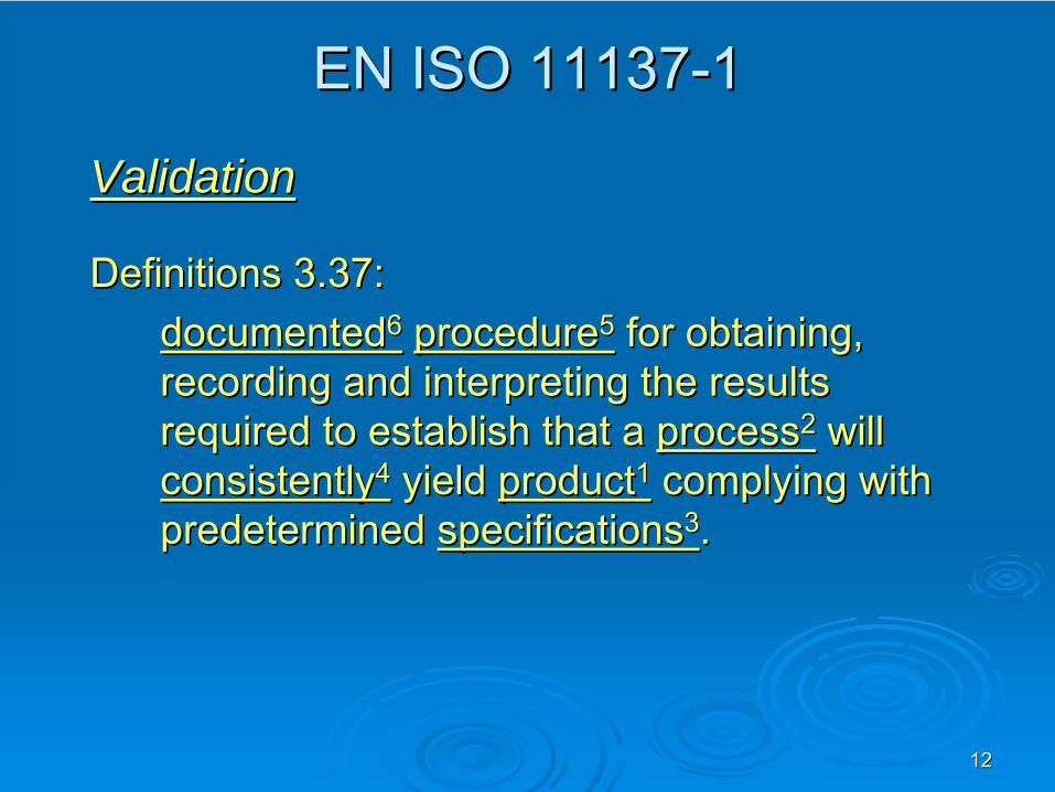
1212
EN ISO 11137EN ISO 11137--11
ValidationValidation
Definitions 3.37: Definitions 3.37: documenteddocumented66
procedureprocedure55
for obtaining, for obtaining,
recording and interpreting the results recording and interpreting the results required to establish that a required to establish that a processprocess22
will will
consistentlyconsistently44
yield yield productproduct11
complying with complying with predetermined predetermined specificationsspecifications33. .
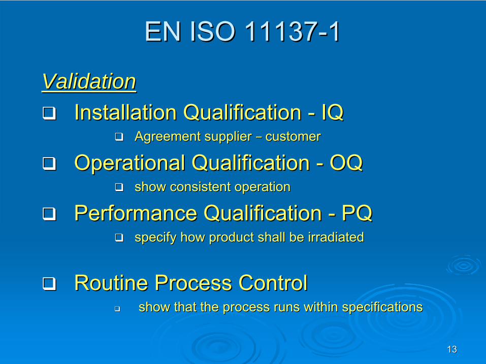
1313
EN ISO 11137EN ISO 11137--11
ValidationValidationInstallation Qualification Installation Qualification -- IQIQ
Agreement supplier Agreement supplier –– customercustomer
Operational Qualification Operational Qualification -- OQOQshow consistent operationshow consistent operation
Performance Qualification Performance Qualification -- PQPQspecify how product shall be irradiatedspecify how product shall be irradiated
Routine Process ControlRoutine Process Controlshow that the process runs within specificationsshow that the process runs within specifications

1414
EN ISO 11137EN ISO 11137--1 Requirements1 Requirements
Documentation is in all steps based on Documentation is in all steps based on ability to measure doseability to measure doseSect. 4.3.4:Sect. 4.3.4:
““Dosimetry used in the development, Dosimetry used in the development, validation and routine control of the validation and routine control of the sterilization process shall have sterilization process shall have measurement traceability to national or measurement traceability to national or international standards and shall have a international standards and shall have a known level of uncertainty.known level of uncertainty.””
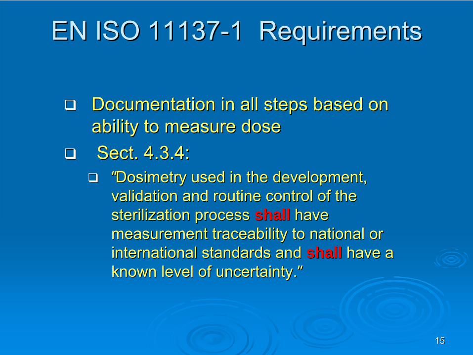
1515
EN ISO 11137EN ISO 11137--1 Requirements1 Requirements
Documentation in all steps based on Documentation in all steps based on ability to measure doseability to measure doseSect. 4.3.4:Sect. 4.3.4:
““Dosimetry used in the development, Dosimetry used in the development, validation and routine control of the validation and routine control of the sterilization process sterilization process shallshall have have measurement traceability to national or measurement traceability to national or international standards and international standards and shallshall have a have a known level of uncertainty.known level of uncertainty.””

1616
ISO 11137ISO 11137--1 Requirements1 Requirements Revision issues 1Revision issues 1
The use of Biological IndicatorsThe use of Biological Indicators••
and Tests and Tests forfor Sterility are not requiredSterility are not required
Sterilizing agent characterizationSterilizing agent characterization•• Radiation energy levels are Radiation energy levels are not restrictednot restricted. .
--
but assessment is but assessment is required required for potentially for potentially induced radioactivity at energy levelsinduced radioactivity at energy levels
higher higher
than 5 than 5 MeVMeV
xx--rays and 10 rays and 10 MeVMeV
electronselectrons
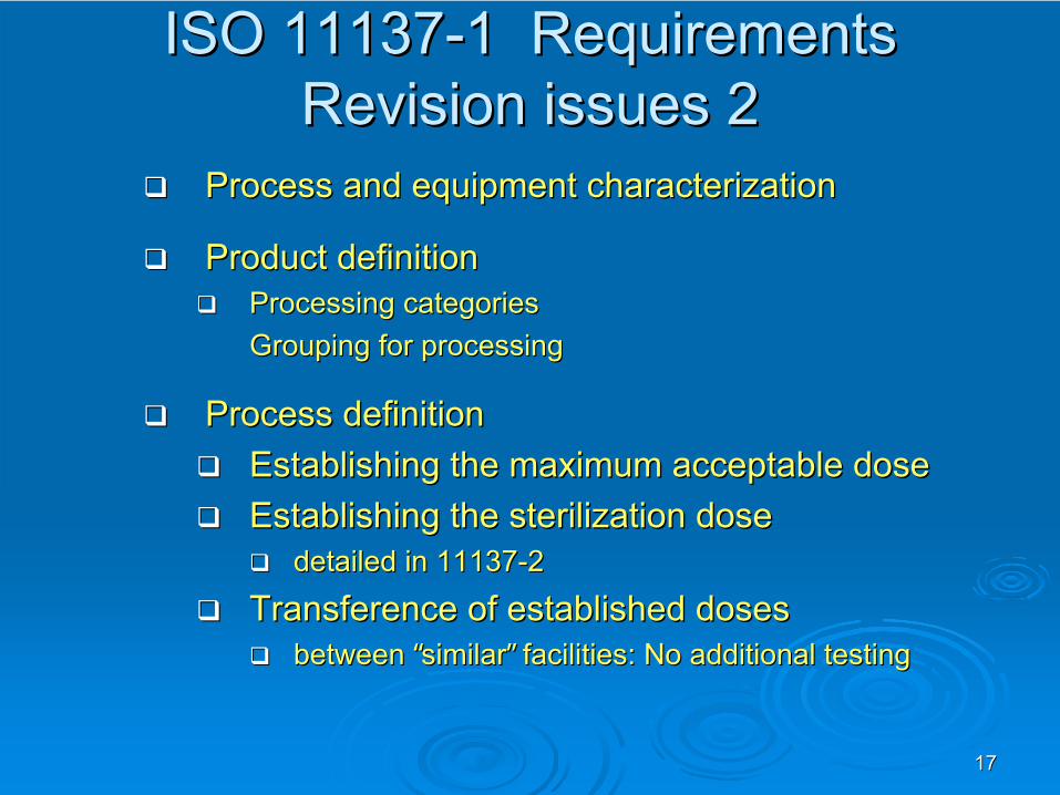
1717
ISO 11137ISO 11137--1 Requirements1 Requirements Revision issues 2Revision issues 2
Process and equipment characterizationProcess and equipment characterization
Product definitionProduct definitionProcessing categoriesProcessing categoriesGrouping for processingGrouping for processing
Process definitionProcess definitionEstablishing the maximum acceptable doseEstablishing the maximum acceptable doseEstablishing the sterilization doseEstablishing the sterilization dose
detailed in 11137detailed in 11137--22
Transference of established dosesTransference of established dosesbetween between ““similarsimilar”” facilities: No additional testingfacilities: No additional testing
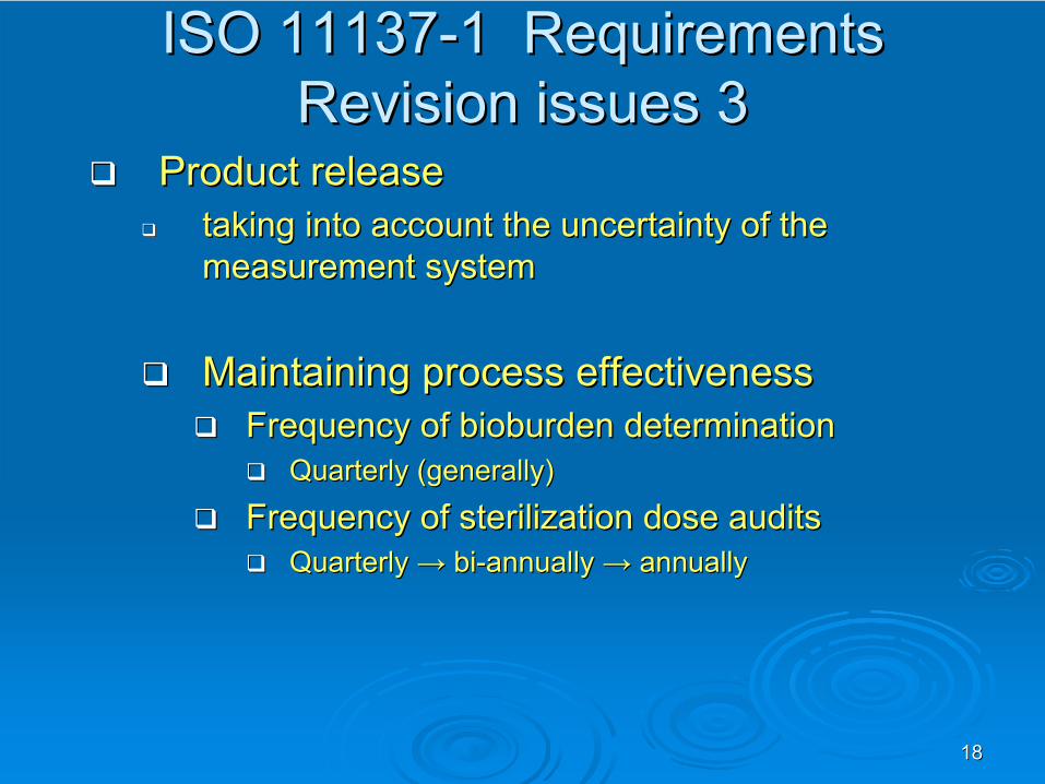
1818
ISO 11137ISO 11137--1 Requirements1 Requirements Revision issues 3Revision issues 3
Product release Product release taking into account the uncertainty of the taking into account the uncertainty of the measurement systemmeasurement system
Maintaining process effectivenessMaintaining process effectivenessFrequency of bioburden determinationFrequency of bioburden determination
Quarterly (generally)Quarterly (generally)
Frequency of sterilization dose auditsFrequency of sterilization dose auditsQuarterly Quarterly →→ bibi--annually annually →→ annuallyannually
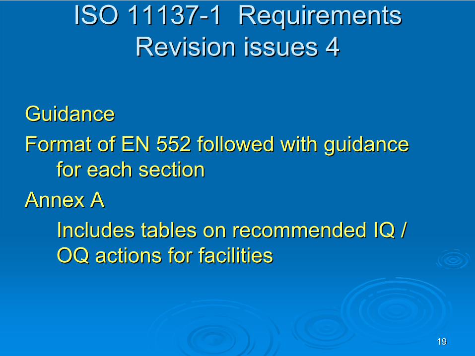
1919
ISO 11137ISO 11137--1 Requirements1 Requirements Revision issues 4Revision issues 4
GuidanceGuidanceFormat of EN 552 followed with guidance Format of EN 552 followed with guidance
for each sectionfor each sectionAnnex AAnnex A
Includes tables on recommended IQ / Includes tables on recommended IQ / OQ actions for facilities OQ actions for facilities
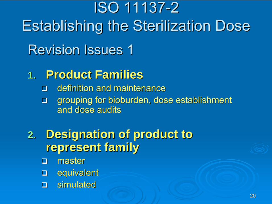
2020
ISO 11137ISO 11137--2 2 Establishing the Sterilization DoseEstablishing the Sterilization DoseRevision Issues 1Revision Issues 1
1.1. Product FamiliesProduct Familiesdefinition and maintenancedefinition and maintenancegrouping for bioburden, dose establishment grouping for bioburden, dose establishment and dose auditsand dose audits
2.2. Designation of product to Designation of product to represent familyrepresent family
master master equivalentequivalentsimulatedsimulated
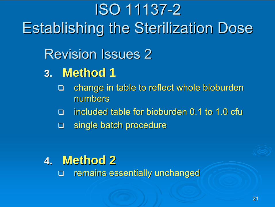
2121
Revision Issues 2Revision Issues 23.3. Method 1 Method 1
change in table to reflect whole bioburden change in table to reflect whole bioburden numbersnumbersincluded table for bioburden 0.1 to 1.0 included table for bioburden 0.1 to 1.0 cfucfusingle batch proceduresingle batch procedure
4.4. Method 2 Method 2 remains essentially unchangedremains essentially unchanged
ISO 11137ISO 11137--2 2 Establishing the Sterilization DoseEstablishing the Sterilization Dose
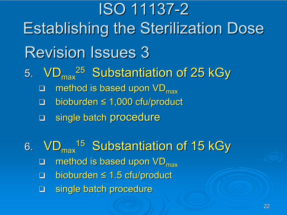
2222
Revision Issues 3Revision Issues 35.5.
VDVDmaxmax
2525
Substantiation of 25 kGySubstantiation of 25 kGymethodmethod is based upon VDis based upon VDmaxmax
bioburden bioburden ≤≤ 1,000 1,000 cfucfu/product/product
single batchsingle batch procedureprocedure
6.6.
VDVDmaxmax
1515
Substantiation of 15 kGySubstantiation of 15 kGymethodmethod is based upon VDis based upon VDmaxmax
bioburden bioburden ≤≤ 1.5 1.5 cfucfu/product/productsingle batch proceduresingle batch procedure
ISO 11137ISO 11137--2 2 Establishing the Sterilization DoseEstablishing the Sterilization Dose
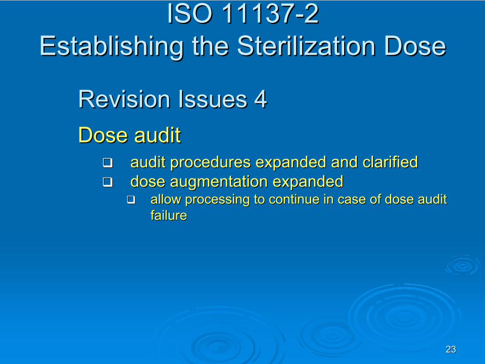
2323
Revision Issues 4Revision Issues 4Dose auditDose audit
audit procedures expanded and clarifiedaudit procedures expanded and clarifieddose augmentation expandeddose augmentation expanded
allow processing to continue in case of dose audit allow processing to continue in case of dose audit failurefailure
ISO 11137ISO 11137--2 2 Establishing the Sterilization DoseEstablishing the Sterilization Dose
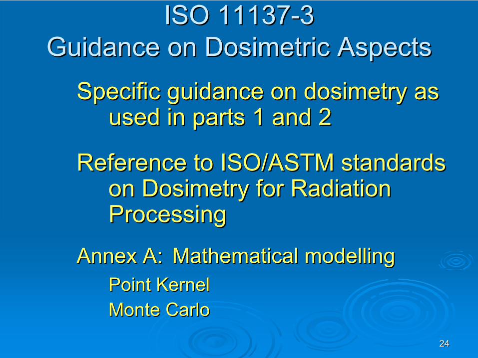
2424
ISO 11137ISO 11137--3 3 Guidance on Guidance on DosimetricDosimetric
AspectsAspects
Specific guidance on dosimetry as Specific guidance on dosimetry as used in parts 1 and 2used in parts 1 and 2
ReferenceReference
to ISO/ASTM standards to ISO/ASTM standards onon
Dosimetry for Radiation Dosimetry for Radiation
ProcessingProcessing
AnnexAnnex
A:A:
MathematicalMathematical
modellingmodellingPoint Point KernelKernelMonteMonte
CarloCarlo
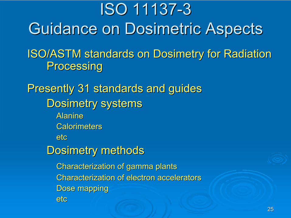
2525
ISO 11137ISO 11137--3 3 Guidance on Guidance on DosimetricDosimetric
AspectsAspectsISO/ASTMISO/ASTM
standards standards onon
Dosimetry for Radiation Dosimetry for Radiation
ProcessingProcessing
Presently 31 standards and guides Presently 31 standards and guides Dosimetry systemsDosimetry systems
AlanineAlanineCalorimetersCalorimetersetcetc
Dosimetry methodsDosimetry methodsCharacterization of gamma plantsCharacterization of gamma plantsCharacterization of electron acceleratorsCharacterization of electron acceleratorsDose mappingDose mappingetcetc

2626
ISO 11137ISO 11137--3 3 Guidance on Guidance on DosimetricDosimetric
AspectsAspectsIssues:Issues:
Dosimeter calibrationDosimeter calibration
Guidance on practical use of dosimetryGuidance on practical use of dosimetry
Application of measurement uncertainties.Application of measurement uncertainties.
Use of statistical evaluation of PQ dose Use of statistical evaluation of PQ dose map data.map data.
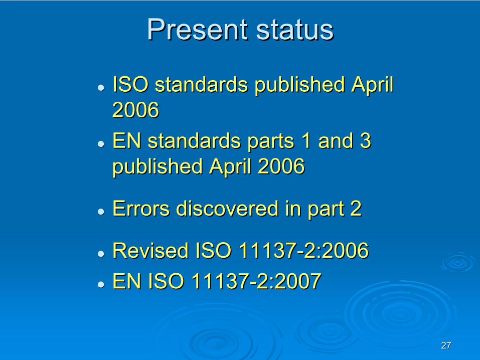
2727
Present statusPresent status
ISO standards published April ISO standards published April 20062006EN standards parts 1 and 3 EN standards parts 1 and 3 published April 2006published April 2006
Errors discovered in part 2Errors discovered in part 2
Revised ISO 11137Revised ISO 11137--2:20062:2006EN ISO 11137EN ISO 11137--2:20072:2007

QA/QC Reflected in ISO 11137
(The Role of Dosimetry in the Validation Process)
András Kovács
Institute of IsotopesHungarian Academy of Sciences
Budapest, Hungary
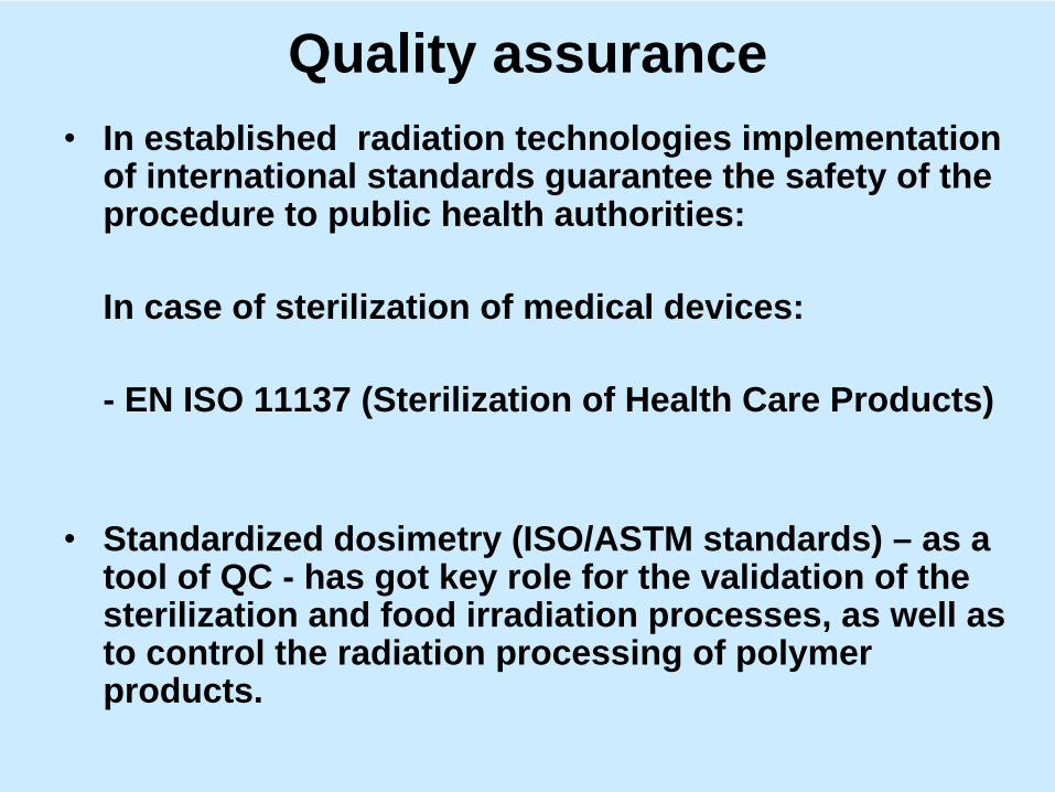
Quality assurance•
In established radiation technologies implementation of international standards guarantee the safety of the procedure to public health authorities:
In case of sterilization of medical devices:
- EN ISO 11137 (Sterilization of Health Care Products)
•
Standardized dosimetry (ISO/ASTM standards) – as a tool of QC - has got key role for the validation of the sterilization and food irradiation processes, as well as to control the radiation processing of polymer products.
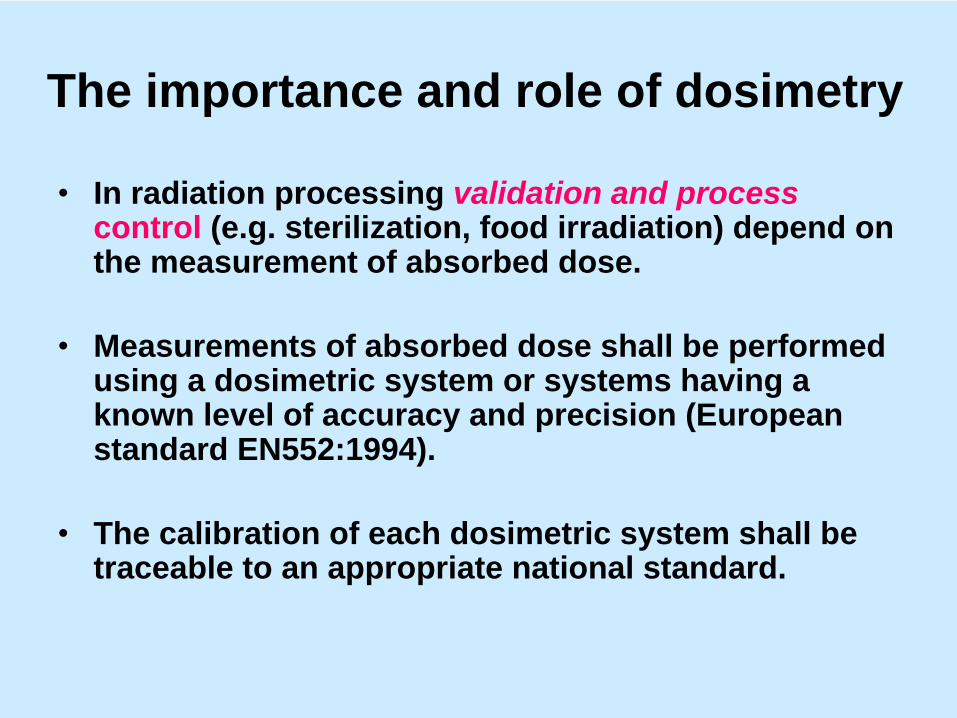
The importance and role of dosimetry
•
In radiation processing validation and process control (e.g. sterilization, food irradiation) depend on the measurement of absorbed dose.
•
Measurements of absorbed dose shall be performed using a dosimetric system or systems having a known level of accuracy and precision (European standard EN552:1994).
•
The calibration of each dosimetric system shall be traceable to an appropriate national standard.
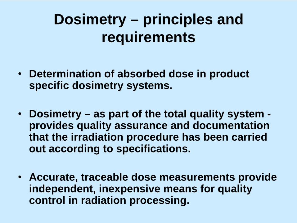
Dosimetry – principles and requirements
•
Determination of absorbed dose in product specific dosimetry systems.
•
Dosimetry – as part of the total quality system - provides quality assurance and documentation that the irradiation procedure has been carried out according to specifications.
•
Accurate, traceable dose measurements provide independent, inexpensive means for quality control in radiation processing.
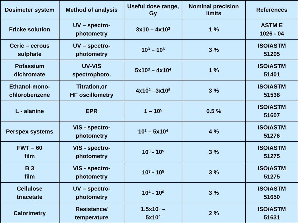
Dosimeter system Method of analysis Useful dose range, Gy
Nominal precision limits References
Fricke solutionUV – spectro-photometry
3x10 – 4x10² 1 %ASTM E 1026 - 04
Ceric – ceroussulphate
UV – spectro-photometry
103 – 106 3 %ISO/ASTM
51205
Potassiumdichromate
UV-VISspectrophoto.
5x10³ – 4x10⁴ 1 %ISO/ASTM
51401
Ethanol-mono-chlorobenzene
Titration,orHF oscillometry
4x10² –3x10⁵ 3 %ISO/ASTM
51538
L - alanine EPR 1 – 105 0.5 %ISO/ASTM
51607
Perspex systemsVIS - spectro-photometry
103 – 5x10⁴ 4 %ISO/ASTM
51276
FWT – 60film
VIS - spectro-photometry
103 - 105 3 %ISO/ASTM
51275
B 3film
VIS - spectro-photometry
103 - 105 3 %ISO/ASTM
51275
Cellulosetriacetate
UV – spectro-photometry
104 - 106 3 %ISO/ASTM
51650
CalorimetryResistance/temperature
1.5x10³ –5x10⁴ 2 %
ISO/ASTM51631

Validation and process control
The steps of validation as described in the EN ISO 11137 Standard:
- Process definition- Installation qualification- Operational qualification- Performance qualification
In addition:- Routine process control
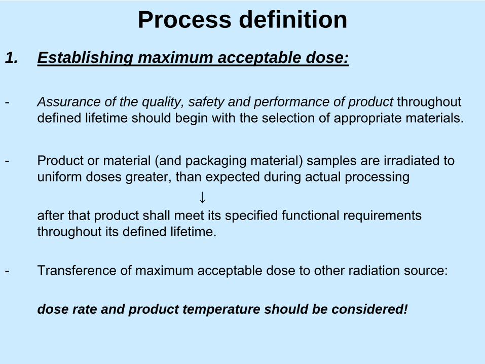
Process definition1. Establishing maximum acceptable dose:
-
Assurance of the quality, safety and performance of product throughout defined
lifetime
should
begin
with
the
selection
of
appropriate
materials.
-
Product
or
material
(and
packaging
material)
samples are irradiated to uniform doses
greater, than
expected
during
actual
processing
↓after
that
product
shall
meet
its
specified
functional
requirements
throughout
its
defined
lifetime.
-
Transference
of
maximum acceptable
dose
to
other
radiation
source:
dose rate and product temperature should be considered!
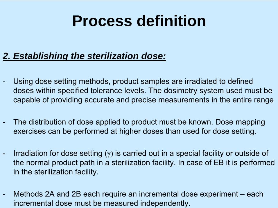
Process definition
2. Establishing the sterilization dose:
-
Using dose setting methods, product samples are irradiated to defined doses
within
specified
tolerance
levels.
The dosimetry
system
used
must be
capable
of
providing
accurate
and
precise
measurements
in
the
entire
range
-
The distribution
of
dose
applied
to
product
must be known. Dose
mapping exercises
can
be
performed
at
higher
doses
than
used
for
dose
setting.
-
Irradiation
for
dose
setting
(γ) is carried
out in
a special
facility
or
outside
of the
normal
product
path
in
a sterilization
facility. In
case
of
EB it
is performed
in
the
sterilization
facility.
-
Methods
2A and
2B each
require
an
incremental
dose
experiment
–
each incremental
dose
must be measured
independently.
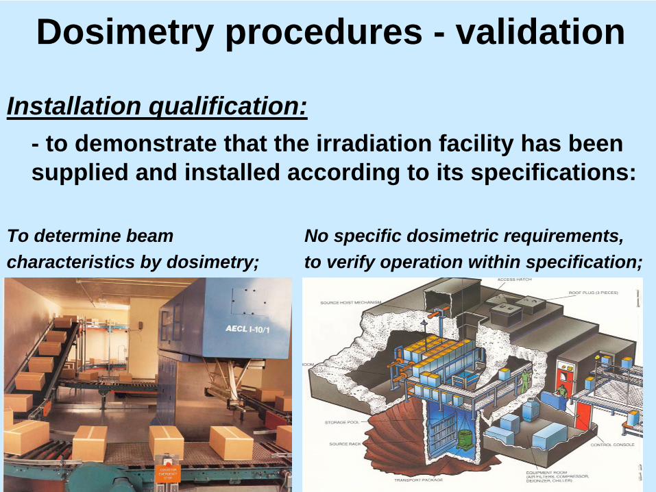
Dosimetry procedures - validation
Installation qualification:- to demonstrate that the irradiation facility has been supplied and installed according to its specifications:
To determine beam No specific dosimetric requirements,characteristics by dosimetry; to verify operation within specification;

Dosimetry procedures - validation
Operational qualification:- carried out by irradiating appropriate test material (of
homogeneous density) to demonstrate the capability of the equipment to deliver appropriate doses, i.e. the irradiation process that has been defined;
- provides baseline data to show consistent operation of the irradiation facility (i.e. within established and defined limits);
- OQ should be repeated to show consistent operation, i.e. the results obtained are within established and defined limits
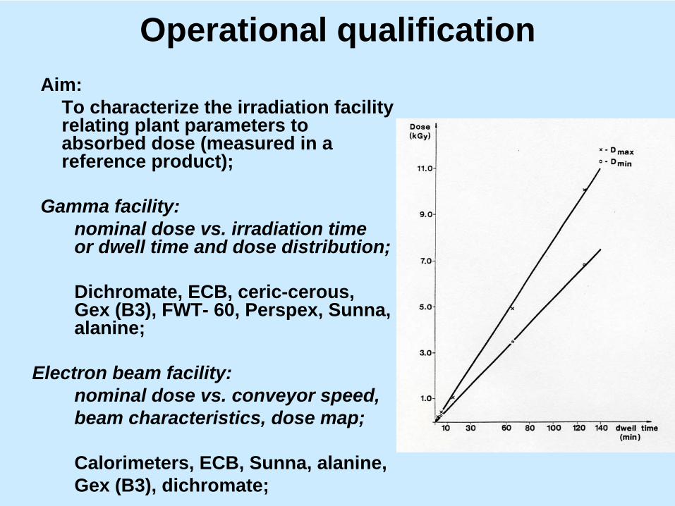
Operational qualificationAim:
To characterize the irradiation facility relating plant parameters to absorbed dose (measured in a reference product);
Gamma facility: nominal dose vs. irradiation time or dwell time and dose distribution;
Dichromate, ECB, ceric-cerous, Gex (B3), FWT- 60, Perspex, Sunna, alanine;
Electron beam facility:nominal dose vs. conveyor speed,beam characteristics, dose map;
Calorimeters, ECB, Sunna, alanine,Gex (B3), dichromate;
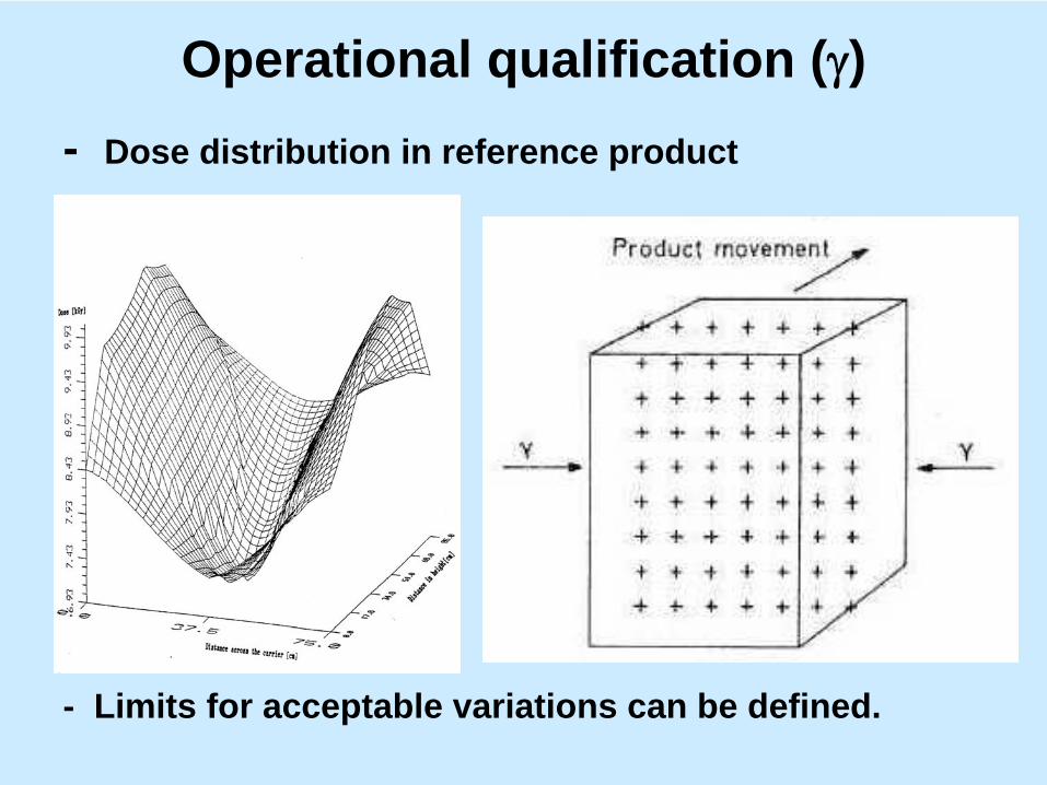
Operational qualification (γ)- Dose distribution in reference product
- Limits for acceptable variations can be defined.
Operational qualification (γ)
General requirements:-
Dose mapping:
- density within the range of use (two densities);- at least three irradiation containers;- for requalification mathematical modelling to optimise the positioning of dosimeters;
- dose mapping data to determine relationshipbetween timer setting and dose at e.g. Dmin location;mathematical models can give approximate values.
- separate dose mapping for assessing theeffect of process interruption;
- to check the effect of changing to product of differentdensity (sequentially processing the two materials);

Operational qualification (EB)•
Dose distribution in reference product:

Operational qualification (EB)
Measurement of electron energy:

Operational qualification (EB)
Measurement of beam spot(pulsed machines):To check, if necessary overlap between pulses is achieved.
scanning frequencypulse repetation frequencyconveyor speed
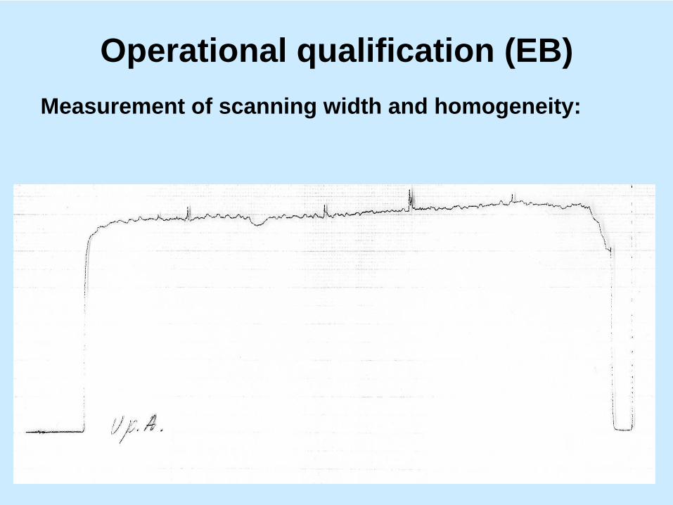
Operational qualification (EB)Measurement of scanning width and homogeneity:

Operational qualification (EB)General requirements:Dose mapping:
- over a range of operating parameters covering the operational limits;- density within the range of use (more is better);- at least three irradiation containers to be dose mapped;- to place dosimeters in a three dimensional array including surface;- mathematical modelling to optimize the positioning of dosimeters;- to establish the effect of process interruption on the dose;- to determine relationships between characteristics of the beam, theconveyor speed and the magnitude of dose at a defined locationwithin or on a container or in a fixed geometry travelling with, butseparately from the irradiation container (e.g. PS calorimeter);
- separate dose map to check the effect of changing to product ofdifferent density;
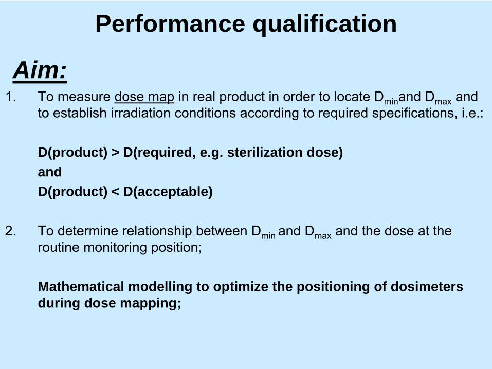
Performance qualification
Aim:1.
To
measure
dose
map
in
real product in
order to locate
Dmin
and
Dmax
and to
establish
irradiation conditions
according
to
required
specifications, i.e.:
D(product) > D(required, e.g. sterilization dose)and D(product) < D(acceptable)
2.
To
determine
relationship
between
Dmin
and
Dmax
and
the
dose
at
the routine
monitoring position;
Mathematical modelling to optimize the positioning of dosimeters during dose mapping;

Process control1. Measurement of process parameters:
To measure dose at the monitoring position to verify that theirradiation process is within established/required limits
⇓knowing the relationship between Dmin , Dmax and Dmonitoring .
Dose measurement frequency: at beginning and end of run (minimum)
2. Control and monitoring of operating parameters.
Controlled parameters:Electron beam facility: Gamma facility:
–
Electron energy - Timer setting–
Beam current - Other type of products present
–
Scanned beam width - Routine dose–
Conveyor speed
–
Routine dose

THANK YOU FOR YOUR ATTENTION

IDEAL DOSIMETRY SYSTEMIDEAL DOSIMETRY SYSTEM
DOSIMETRY SYSTEMS IN CURRENT DOSIMETRY SYSTEMS IN CURRENT USEUSE
A. KOVA. KOVÁÁCSCS
InstituteInstitute
ofof
IsotopesIsotopesHungarianHungarian
AcademyAcademy
ofof
SciencesSciences
HH--1525. Budapest, P.O.B. 77. Hungary1525. Budapest, P.O.B. 77. Hungary
BACKGROUNDBACKGROUND
In radiation processing validation and process control In radiation processing validation and process control (sterilization, food irradiation, etc.) depend on the (sterilization, food irradiation, etc.) depend on the measurement of absorbed dose.measurement of absorbed dose.
Measurements of absorbed dose shall be performed Measurements of absorbed dose shall be performed using a dosimetric system or systems having a known using a dosimetric system or systems having a known level of accuracy and precision (European standard level of accuracy and precision (European standard EN552:1994).EN552:1994).
The calibration of each dosimetric system shall be The calibration of each dosimetric system shall be traceable to an appropriate national standardtraceable to an appropriate national standard..
DosimetryDosimetry –– principlesprinciples
andand requirementsrequirements
DeterminationDetermination ofof absorbedabsorbed dosedose inin productproduct specificspecificdosimetrydosimetry systemssystems –– similaritysimilarity inin radiationradiation absorptionabsorptioncharacteristicscharacteristics..
DosimetryDosimetry –– asas part part ofof thethe totaltotal qualityquality systemsystem -- providesprovidesqualityquality assuranceassurance andand documentationdocumentation thatthat thethe irradiationirradiationprocedureprocedure has has beenbeen carriedcarried out out accordingaccording toto specificationsspecifications..
AccurateAccurate, , traceabletraceable dosedose measurementsmeasurements provideprovideindependentindependent, , inexpensiveinexpensive meansmeans forfor qualityquality controlcontrol ininradiationradiation proessingproessing..

DosimetryDosimetry
––
applicationapplication
andand
systemssystems
FieldsFields ofof applicationapplication::--
installationinstallation
qualificationqualification;;
--
operationaloperational
qualificationqualification;;--
performanceperformance
qualificationqualification;;
--
processprocess
controlcontrol;;
DosimetryDosimetry providesprovides documentationdocumentation inin thethe processesprocesses, , ifif
--
thethe
measurementmeasurement
is is traceabletraceable
toto
a a nationalnational
standard,standard,--
thethe
uncertaintyuncertainty
ofof
thethe
systemsystem
is is knownknown..
AppliedApplied systemssystems::--
primaryprimary--, , secondarysecondary--, , transfertransfer
standardsstandards;;
--
routineroutine
systemssystems;;
DosimetryDosimetry systemssystems
inin radiationradiation processingprocessing
PrimaryPrimary
standard standard systemssystems::
--
DosimeterDosimeter
ofof
thethe
highesthighest
metrologicalmetrological
qualityquality, , establishedestablished
andand
maintainedmaintained
asas
anan
absorbedabsorbed
dosedose
standard standard byby
a a nationalnational
oror
internationalinternational
standardsstandards organizationorganization
forfor
calibrationcalibration
ofof
radiationradiation
environmentsenvironments
((fieldsfields););
--
ApplicationApplication
is is basedbased
onon
measurementmeasurement
ofof
basicbasic physicalphysical
quantitiesquantities;;
--
Most Most commoncommon
systemssystems: : ionizationionization
chamberschambers, , calorimeterscalorimeters;;

DosimetryDosimetry systemssystems
inin radiationradiation processingprocessing
ReferenceReference
standard standard systemssystems::
--
DosimeterDosimeter
ofof
highhigh
metrologicalmetrological
qualityquality
usedused
asas
a standard a standard toto provideprovide
measurementsmeasurements
traceabletraceable
toto
measurementsmeasurements
mademade
byby
primaryprimary
standardstandard
systemssystems;;--
TheseThese
systemssystems
requirerequire
calibrationcalibration
andand
areare
usedused
toto
calibratecalibrate
radiationradiation
environmentsenvironments
andand
routineroutine
dosimetersdosimeters;;--
SolidSolid
phasephase
dosimetrydosimetry
systemssystems
::
alaninealanine
((pelletpellet, , rodrod, film);, film);--
LiquidLiquid
phasephase
dosimetrydosimetry
systemssystems
: :
FrickeFricke
solutionsolution;;potassiumpotassium
dichromatedichromate
solutionsolution;;
ethanolethanol--monochlorobenzenemonochlorobenzene
solutionsolution;;cericceric--cerouscerous
solutionsolution;;
--
CalorimetersCalorimeters;;
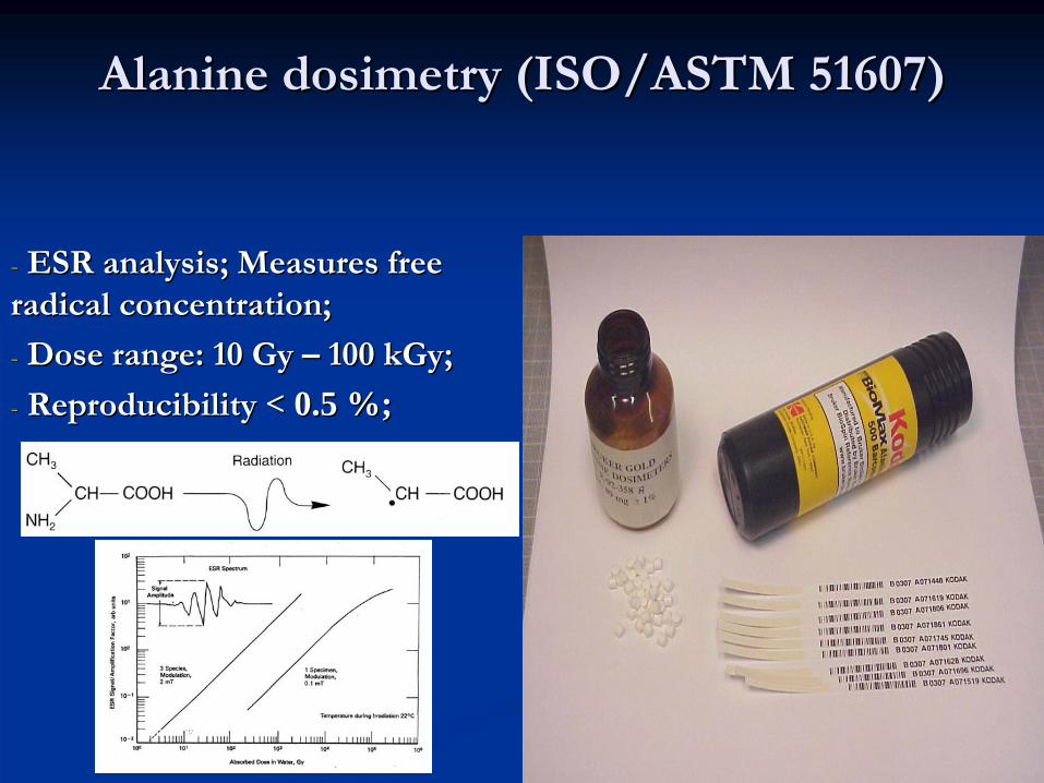
AlanineAlanine
dosimetrydosimetry
(ISO/ASTM 51607)(ISO/ASTM 51607)
--
ESR ESR analysisanalysis; ; MeasuresMeasures
freefree
radicalradical
concentrationconcentration;;
-- DoseDose
rangerange: 10 : 10 GyGy
––
100 100 kGykGy;;
-- ReproducibilityReproducibility
<< 0.5 %;0.5 %;
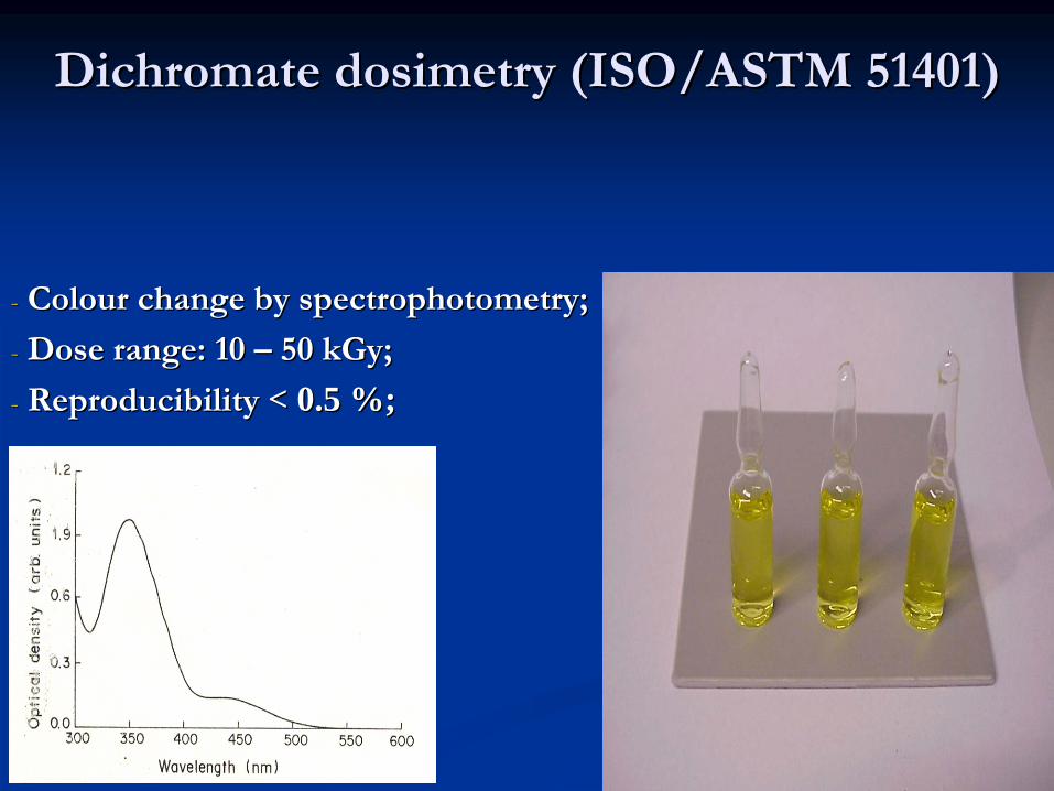
DichromateDichromate
dosimetrydosimetry
(ISO/ASTM 51401)(ISO/ASTM 51401)
-- ColourColour
changechange
byby
spectrophotometryspectrophotometry;;
-- DoseDose
rangerange: 10 : 10 ––
50 50 kGykGy;;
-- ReproducibilityReproducibility
<< 0.5 %;0.5 %;
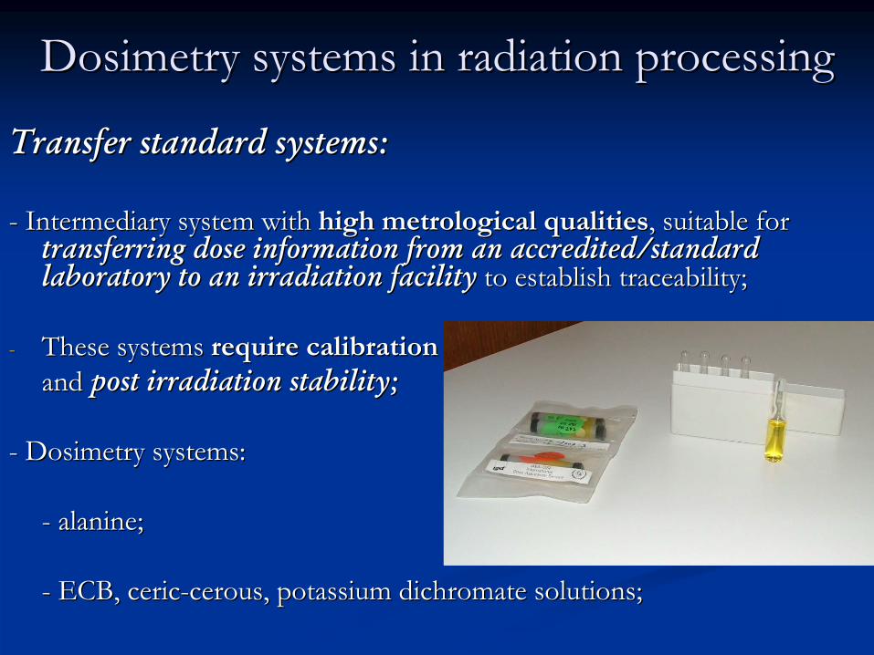
DosimetryDosimetry systemssystems
inin radiationradiation processingprocessing
TransferTransfer
standard standard systemssystems::
--
IntermediaryIntermediary
systemsystem
withwith
highhigh
metrologicalmetrological
qualitiesqualities, , suitablesuitable
forfor transferringtransferring
dosedose
informationinformation
fromfrom
anan
accreditedaccredited/standard /standard
laboratorylaboratory
toto
anan
irradiationirradiation
facilityfacility
toto
establishestablish
traceabilitytraceability;;
--
TheseThese
systemssystems
requirerequire
calibrationcalibration
andand
postpost
irradiationirradiation
stabilitystability;;
--
DosimetryDosimetry
systemssystems::
--
alaninealanine; ;
--
ECB, ECB, cericceric--cerouscerous, , potassiumpotassium
dichromatedichromate
solutionssolutions;;
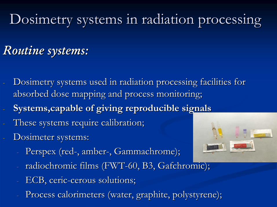
DosimetryDosimetry systemssystems
inin radiationradiation processingprocessing
RoutineRoutine
systemssystems::
--
DosimetryDosimetry
systemssystems
usedused
inin
radiationradiation
processingprocessing
facilitiesfacilities
forfor absorbedabsorbed
dosedose
mappingmapping
andand
processprocess
monitoring;monitoring;
--
SystemsSystems,,capablecapable
ofof
givinggiving
reproduciblereproducible
signalssignals
--
TheseThese
systemssystems
requirerequire
calibrationcalibration;;--
DosimeterDosimeter
systemssystems::
--
PerspexPerspex
((redred--, , amberamber--, , GammachromeGammachrome););--
radiochromicradiochromic
filmsfilms
(FWT(FWT--60, B3, 60, B3, GafchromicGafchromic););
--
ECB, ECB, cericceric--cerouscerous
solutionssolutions;;--
ProcessProcess
calorimeterscalorimeters
((waterwater, , graphitegraphite, , polystyrenepolystyrene););
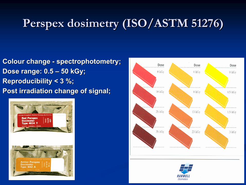
PerspexPerspex
dosimetrydosimetry
(ISO/ASTM 51276)(ISO/ASTM 51276)
ColourColour
changechange
--
spectrophotometryspectrophotometry;;DoseDose
rangerange: 0.5 : 0.5 ––
50 50 kGykGy;;
ReproducibilityReproducibility
<<
3 %;3 %;PostPost
irradiationirradiation
changechange
ofof
signalsignal;;

RadiochromicRadiochromic
dyedye
filmsfilms
(ISO/ASTM 51275) (ISO/ASTM 51275)
ColourColour
changechange
--
spectrophotometryspectrophotometry;;FWTFWT--
6060: : 33
––
1150 50 kGykGy;;
B3: 2 B3: 2 ––
100 100 kGykGy;;GafChromicGafChromic: 1 : 1 GyGy
––
40 40 kGykGy;;
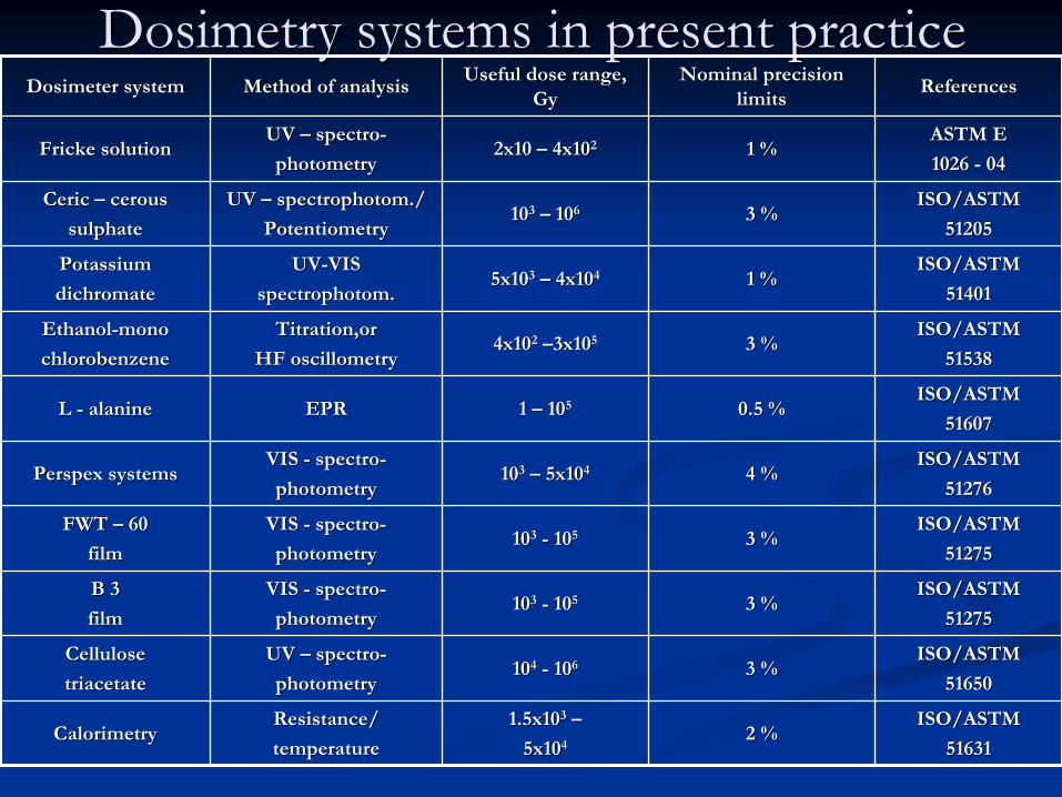
DosimetryDosimetry systemssystems
inin presentpresent practicepractice
DosimeterDosimeter
systemsystem MethodMethod
ofof
analysisanalysisUsefulUseful
dosedose
rangerange, , GyGy
NominalNominal
precisionprecision
limitslimits
ReferencesReferences
FrickeFricke
solutionsolutionUV UV ––
spectrospectro--
photometryphotometry2x10 2x10 ––
4x104x1022 1 %1 %ASTM E ASTM E
1026 1026 --
0404
CericCeric
––
cerouscerous
sulphatesulphate
UV UV ––
spectrophotomspectrophotom././
PotentiometryPotentiometry101033
––
101066 3 %3 %ISO/ASTMISO/ASTM
5120551205
PotassiumPotassium
dichromatedichromate
UVUV--VISVIS
spectrophotomspectrophotom..5x105x1033
––
4x104x1044 1 %1 %ISO/ASTMISO/ASTM
5140151401
EthanolEthanol--monomono
chlorobenzenechlorobenzene
TitrationTitration,,oror
HF HF oscillometryoscillometry4x104x1022
––3x103x1055 3 %3 %ISO/ASTMISO/ASTM
5153851538
L L --
alaninealanine EPREPR 1 1 ––
101055 0.5 %0.5 %ISO/ASTMISO/ASTM
5160751607
PerspexPerspex
systemssystemsVIS VIS --
spectrospectro--
photometryphotometry101033
––
5x105x1044 4 %4 %ISO/ASTMISO/ASTM
5127651276
FWT FWT ––
6060
filmfilm
VIS VIS --
spectrospectro--
photometryphotometry101033
--
101055 3 %3 %ISO/ASTMISO/ASTM
5127551275
B 3B 3
filmfilm
VIS VIS --
spectrospectro--
photometryphotometry101033
--
101055 3 %3 %ISO/ASTMISO/ASTM
5127551275
CelluloseCellulose
triacetatetriacetate
UV UV ––
spectrospectro--
photometryphotometry101044
--
101066 3 %3 %ISO/ASTMISO/ASTM
5165051650
CalorimetryCalorimetryResistanceResistance//
temperaturetemperature
1.5x101.5x1033
––
5x105x10442 %2 %
ISO/ASTMISO/ASTM
5163151631
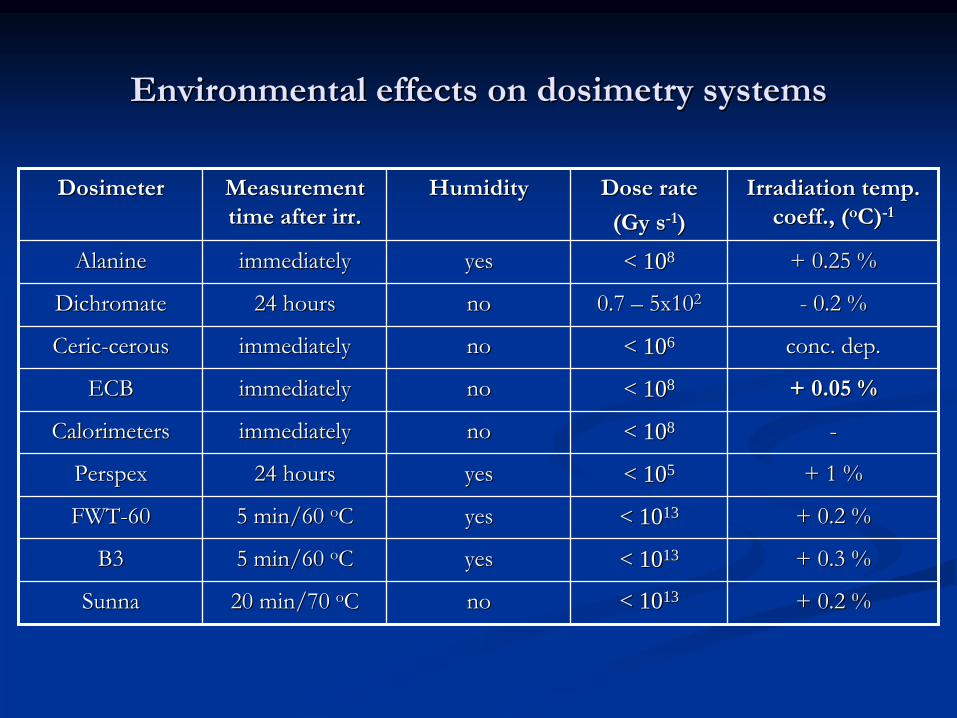
EnvironmentalEnvironmental
effectseffects
onon
dosimetrydosimetry
systemssystems
DosimeterDosimeter MeasurementMeasurement
timetime
afterafter
irrirr..
HumidityHumidity DoseDose
raterate
((GyGy
ss--11))
IrradiationIrradiation
temptemp. .
coeffcoeff., (., (ooCC))--11
AlanineAlanine immediatelyimmediately yesyes << 101088 + 0.25 %+ 0.25 %
DichromateDichromate 24 24 hourshours nono 0.7 0.7 ––
5x105x1022 --
0.2 %0.2 %
CericCeric--cerouscerous immediatelyimmediately nono << 101066 concconc. . depdep..
ECBECB immediatelyimmediately nono << 101088 + 0.05 %+ 0.05 %
CalorimetersCalorimeters immediatelyimmediately nono << 101088 --
PerspexPerspex 24 24 hourshours yesyes << 101055 + 1 %+ 1 %
FWTFWT--6060 5 min/60 5 min/60 ooCC yesyes << 10101313 + 0.2 %+ 0.2 %
B3B3 5 min/60 5 min/60 ooCC yesyes << 10101313 + 0.3 %+ 0.3 %
SunnaSunna 20 min/70 20 min/70 ooCC nono << 10101313 + 0.2 %+ 0.2 %
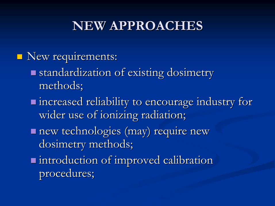
NEW APPROACHESNEW APPROACHES
New New requirementsrequirements::standardizationstandardization ofof existingexisting dosimetrydosimetrymethodsmethods;;increasedincreased reliabilityreliability toto encourageencourage industryindustry forforwiderwider useuse ofof ionizingionizing radiationradiation;;newnew technologiestechnologies ((maymay) ) requirerequire newnewdosimetrydosimetry methodsmethods;;introductionintroduction ofof improvedimproved calibrationcalibrationproceduresprocedures;;

New New approachesapproaches –– novelnovel
dosimetrydosimetry systemssystems
RequirementsRequirements::
New New technologiestechnologies ((environmentalenvironmental processesprocesses, , foodfoodirradiationirradiation atat lowlow temperaturestemperatures, , anthraxanthrax, , pharmaceuticalspharmaceuticals, , XX--rayray technologiestechnologies, , highhigh dosedose controlcontrol););
AchievedAchieved byby::
ImprovementImprovement ofof existingexisting dosimetrydosimetry systemssystems;;IntroductionIntroduction ofof newnew systemssystems;;
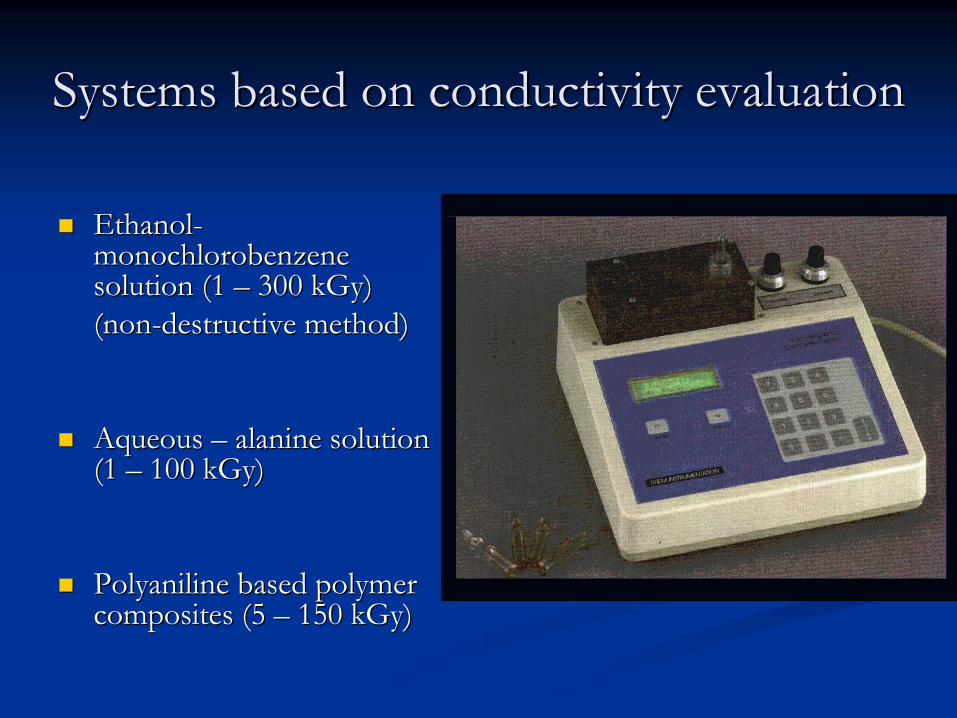
SystemsSystems basedbased
onon conductivityconductivity
evaluationevaluation
EthanolEthanol--monochlorobenzenemonochlorobenzenesolutionsolution (1 (1 –– 300 300 kGykGy))((nonnon--destructivedestructive
methodmethod))
AqueousAqueous –– alaninealanine solutionsolution(1 (1 –– 100 100 kGykGy))
PolyanilinePolyaniline basedbased polymerpolymercompositescomposites (5 (5 –– 150 150 kGykGy))

SystemsSystems basedbased
onon fluorimetryfluorimetry
PrinciplesPrinciples::AbsorbedAbsorbed energyenergy is is emittedemitted asas fluorescentfluorescent lightlight duedue toto opticalopticalexcitationexcitation (OSL (OSL –– opticallyoptically stimulatedstimulated luminescenceluminescence););FluorescenceFluorescence appearsappears micromicro-- oror nanosecondsnanoseconds afterafter excitationexcitation;;
AdvantagesAdvantages::Wide Wide dynamicdynamic rangerange;;HighHigh sensitivitysensitivity;;PassivePassive andand realreal timetime dosimetrydosimetry;;VariableVariable geometriesgeometries;;InexpensiveInexpensive detectorsdetectors;;MultipurposeMultipurpose applicationsapplications ((medicalmedical diagnosticdiagnostic, , radiationradiationprocessingprocessing, , radiationradiation protectionprotection, , spacespace studiesstudies, , etcetc); );

SystemsSystems basedbased
onon fluorimetryfluorimetry
ApplicationApplication possibilitiespossibilities::
RadiationRadiation inducedinduced decaydecay ofoforiginallyoriginally fluorescentfluorescentmoleculesmolecules ((anthraceneanthracene, , fluoresceinfluorescein derivativesderivatives, , etcetc););
AppearanceAppearance ofof radiationradiationinducedinduced fluorescencefluorescence duedue totoformationformation ofof newnewfluorescentfluorescent radiolysisradiolysisproductsproducts ((SunnaSunna film);film);
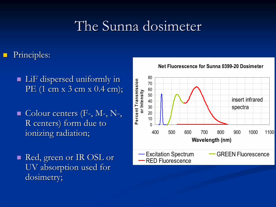
The The SunnaSunna dosimeterdosimeter
PrinciplesPrinciples::
LiFLiF disperseddispersed uniformlyuniformly ininPE (1 cm x 3 cm x 0.4 cm);PE (1 cm x 3 cm x 0.4 cm);
ColourColour centerscenters (F(F--, M, M--, N, N--, , R R centerscenters) ) formform duedue totoionizingionizing radiationradiation;;
RedRed, , greengreen oror IR OSL IR OSL ororUV UV absorptionabsorption usedused forfordosimetrydosimetry;;
Net Fluorescence for Sunna 0399-20 Dosimeter
01020304050607080
400 500 600 700 800 900 1000 1100Wavelength (nm)
Perc
ent T
rans
mis
sion
or In
tens
ity
Excitation Spectrum GREEN FluorescenceRED Fluorescence
insert infraredspectra
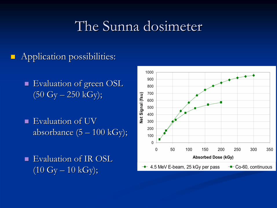
The The SunnaSunna dosimeterdosimeter
ApplicationApplication possibilitiespossibilities::
EvaluationEvaluation ofof greengreen OSL OSL (50 (50 GyGy –– 250 250 kGykGy););
EvaluationEvaluation ofof UV UV absorbanceabsorbance (5 (5 –– 100 100 kGykGy););
EvaluationEvaluation ofof IR OSL IR OSL (10 (10 GyGy –– 10 10 kGykGy););
0
100
200
300
400
500
600
700
800
900
1000
0 50 100 150 200 250 300 350
Absorbed Dose (kGy)
Net S
igna
l (fs
u)
4.5 MeV E-beam, 25 kGy per pass Co-60, continuous

SystemsSystems basedbased
onon opticaloptical
absorptionabsorption ((tetrazoliumtetrazolium
saltssalts))TetrazoliumTetrazolium saltssalts studiedstudied::
CompoundCompound
ProductProduct
λλ
maxmax..
DoseDose
rangerange::
tetrazoliumtetrazolium
violetviolet
(TV)(TV)
525 525 nmnm
0.01 0.01 ––
30 30 kGykGytetrazoliumtetrazolium
redred
(TTC)(TTC)
490 490 nmnm
0.01 0.01 ––
100 100 kGykGy
tetrazoliumtetrazolium
blueblue
(TB)(TB)
520 520 nmnm
0.01 0.01 ––
10 10 kGykGynitronitro
blueblue
tetrazoliumtetrazolium
(NBT) (NBT) 522 522 andand
612 612 nmnm
0.01 0.01 ––
25 25 kGykGy
--
heterocyclicheterocyclic
organicorganic
compoundscompounds, , whichwhich
uponupon
irradiationirradiation
yieldyield
highlyhighly colouredcoloured
waterwater
insolubleinsoluble
formazansformazans
duedue
toto
radiolyticradiolytic
reductionreduction..
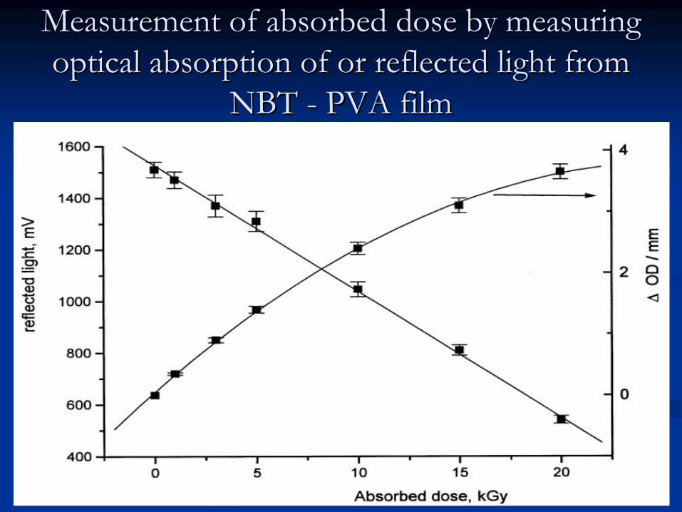
MeasurementMeasurement
ofof
absorbedabsorbed
dosedose
byby
measuringmeasuring opticaloptical
absorptionabsorption
ofof
oror
reflectedreflected
lightlight
fromfrom
NBT NBT --
PVA filmPVA film
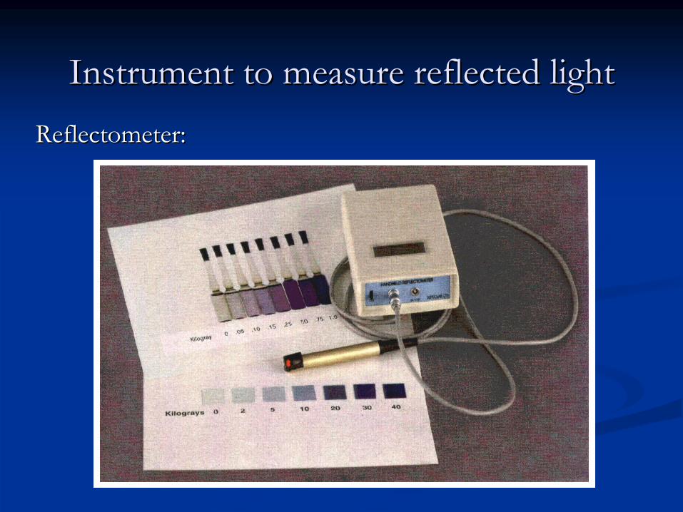
InstrumentInstrument toto measuremeasure
reflectedreflected lightlight
ReflectometerReflectometer::
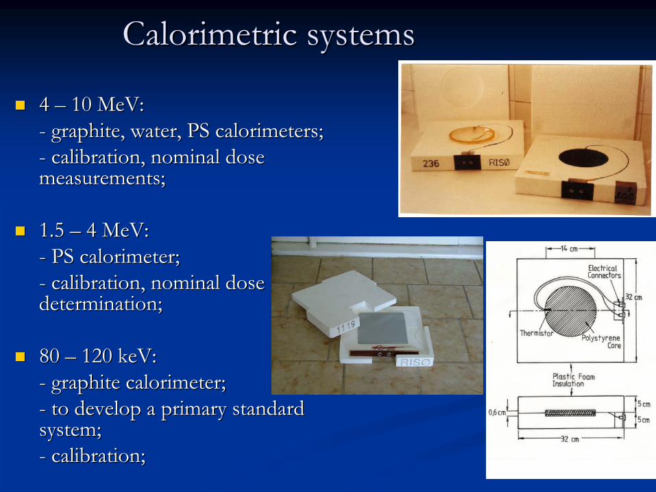
CalorimetricCalorimetric systemssystems
4 4 –– 10 10 MeVMeV: : --
graphitegraphite, , waterwater, PS , PS calorimeterscalorimeters;;
--
calibrationcalibration, , nominalnominal
dosedose measurementsmeasurements;;
1.5 1.5 –– 4 4 MeVMeV::--
PS PS calorimetercalorimeter;;
--
calibrationcalibration, , nominalnominal
dosedose determinationdetermination;;
80 80 –– 120 120 keVkeV::--
graphitegraphite
calorimetercalorimeter;;
--
toto
developdevelop
a a primaryprimary
standard standard systemsystem;;--
calibrationcalibration;;
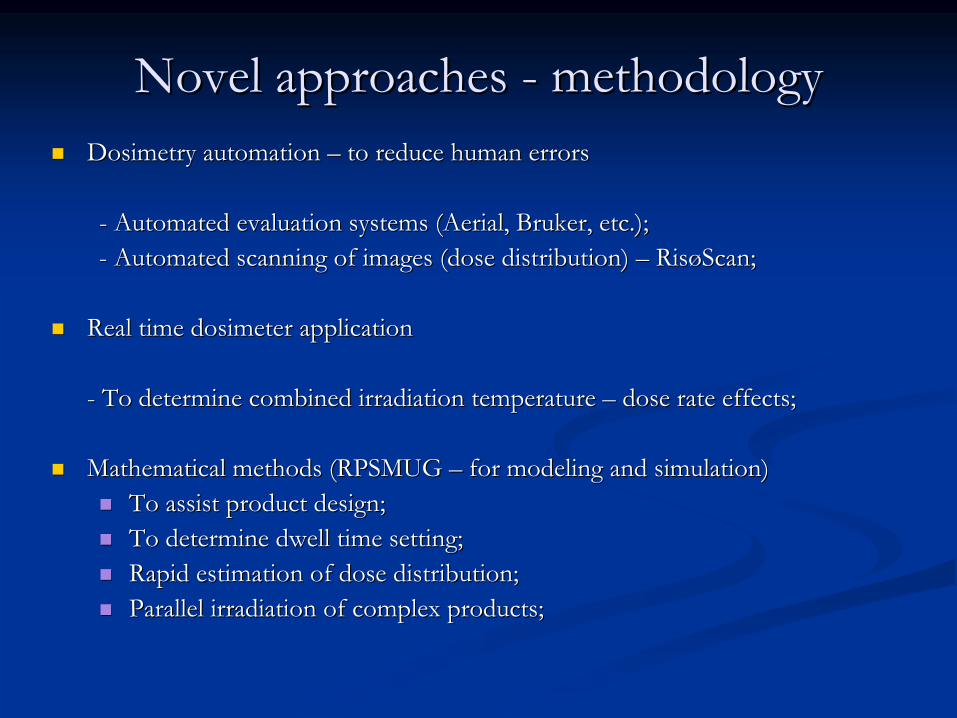
NovelNovel approachesapproaches
-- methodologymethodologyDosimetryDosimetry automationautomation –– toto reducereduce humanhuman errorserrors
--
AutomatedAutomated
evaluationevaluation
systemssystems
((AerialAerial, , BrukerBruker, , etcetc.);.);--
AutomatedAutomated
scanningscanning
ofof
imagesimages
((dosedose
distributiondistribution) ) ––
RisRisøøScanScan;;
RealReal timetime dosimeterdosimeter applicationapplication
--
ToTo
determinedetermine
combinedcombined
irradiationirradiation
temperaturetemperature
––
dosedose
raterate
effectseffects;;
MathematicalMathematical methodsmethods (RPSMUG (RPSMUG –– forfor modelingmodeling andand simulationsimulation))ToTo assistassist productproduct design;design;ToTo determinedetermine dwelldwell timetime settingsetting;;Rapid Rapid estimationestimation ofof dosedose distributiondistribution;;Parallel Parallel irradiationirradiation ofof complexcomplex productsproducts;;
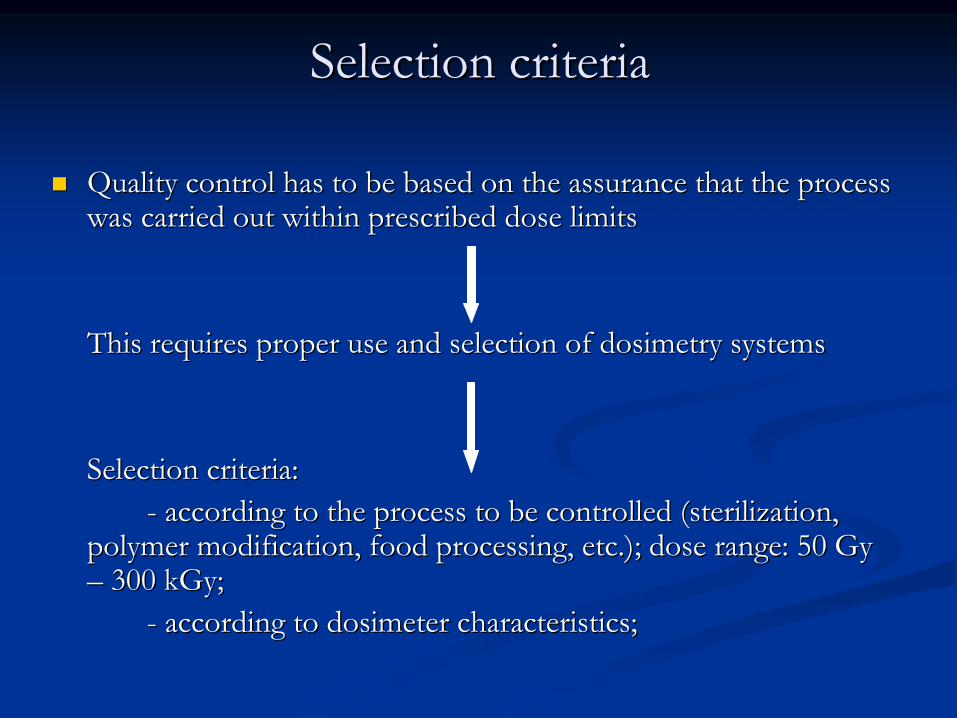
SelectionSelection criteriacriteria
QualityQuality controlcontrol has has toto be be basedbased onon thethe assuranceassurance thatthat thethe processprocesswaswas carriedcarried out out withinwithin prescribedprescribed dosedose limitslimits
ThisThis
requiresrequires
properproper
useuse
andand
selectionselection
ofof
dosimetrydosimetry
systemssystems
SelectionSelection
criteriacriteria::--
accordingaccording
toto
thethe
processprocess
toto
be be controlledcontrolled
((sterilizationsterilization, ,
polymerpolymer
modificationmodification, , foodfood
processingprocessing, , etcetc.); .); dosedose
rangerange: 50 : 50 GyGy ––
300 300 kGykGy;;
--
accordingaccording
toto
dosimeterdosimeter
characteristicscharacteristics;;
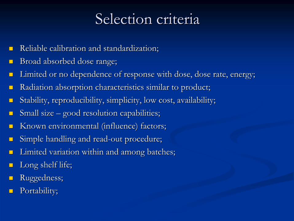
SelectionSelection criteriacriteria
ReliableReliable calibrationcalibration andand standardizationstandardization;;BroadBroad absorbedabsorbed dosedose rangerange;;Limited Limited oror no no dependencedependence ofof responseresponse withwith dosedose, , dosedose raterate, , energyenergy;;RadiationRadiation absorptionabsorption characteristicscharacteristics similarsimilar toto productproduct;;StabilityStability, , reproducibilityreproducibility, , simplicitysimplicity, , lowlow costcost, , availabilityavailability;;SmallSmall sizesize –– goodgood resolutionresolution capabilitiescapabilities;;KnownKnown environmentalenvironmental ((influenceinfluence) ) factorsfactors;;SimpleSimple handlinghandling andand readread--outout procedureprocedure;;Limited Limited variationvariation withinwithin andand amongamong batchesbatches;;LongLong shelfshelf lifelife;;RuggednessRuggedness;;PortabilityPortability;;
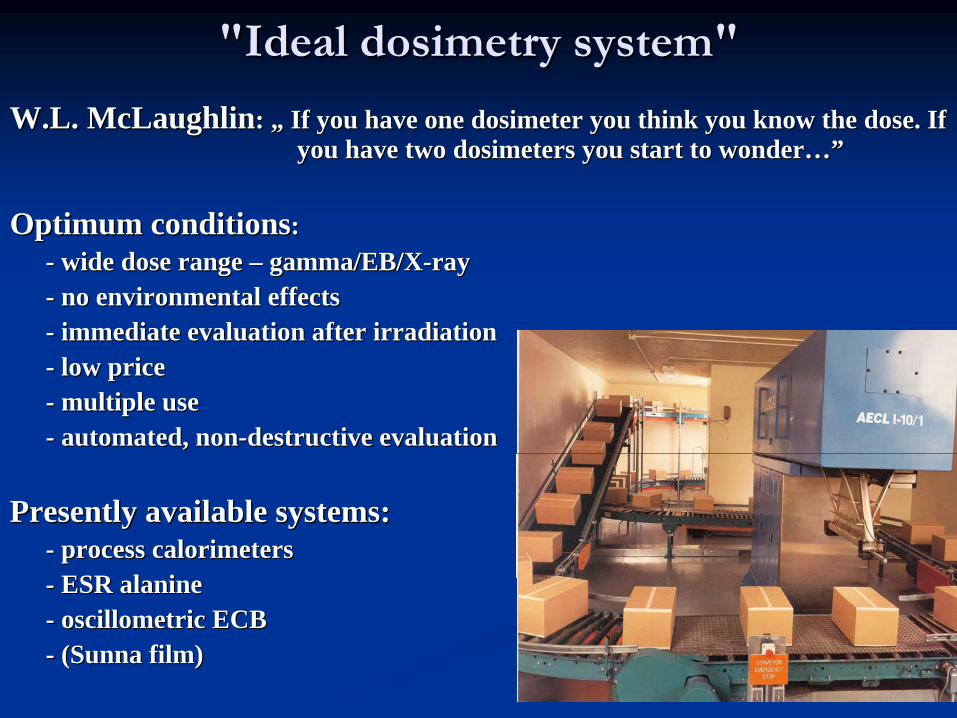
""IdealIdeal
dosimetrydosimetry
systemsystem""
W.L. W.L. McLaughlinMcLaughlin: : „„ IfIf youyou havehave oneone dosimeterdosimeter youyou thinkthink youyou knowknow thethe dosedose. . IfIf youyou havehave twotwo dosimetersdosimeters youyou start start toto wonderwonder…”…”
Optimum Optimum conditionsconditions: : -- widewide dosedose rangerange –– gamma/EB/gamma/EB/XX--rayray-- no no environmentalenvironmental effectseffects-- immediateimmediate evaluationevaluation afterafter irradiationirradiation-- lowlow priceprice-- multiplemultiple useuse-- automatedautomated, , nonnon--destructivedestructive evaluationevaluation
PresentlyPresently availableavailable systemssystems::-- processprocess calorimeterscalorimeters-- ESR ESR alaninealanine-- oscillometricoscillometric ECBECB-- ((SunnaSunna film)film)

FACTORS AFFECTING DOSIMETER FACTORS AFFECTING DOSIMETER ACCURACYACCURACY
1.1.
IrradiationIrradiation
conditionsconditions
areare
differentdifferent
fromfrom
calibrationcalibration
conditionsconditions::
--
temperaturetemperature, , dosedose
raterate, , relativerelative
humidityhumidity, , energyenergy
spectrumspectrum, , irradiationirradiation
geometrygeometry, , etcetc..
2.2.
StorageStorage
conditionsconditions::
--
beforebefore
andand
afterafter
irradiationirradiation
3.3.
InstrumentalInstrumental
errorserrors::
--
absorbanceabsorbance
andand
wavelengthwavelength
scalescale, , scatteredscattered
lightlight, , transfertransfer
ofof calibrationcalibration
curvecurve
fromfrom
oneone
instrumentinstrument
toto
anotheranother
oneone, , etcetc..

Accuracy and PrecisionAccuracy and Precision

AIM OF CALIBRATIONAIM OF CALIBRATION
Determine relationship Determine relationship between response of a between response of a dosimeter and absorbed dosimeter and absorbed dose.dose.
Influence factors:Influence factors:--
dose ratedose rate
--
temperaturetemperature--
timetime
--
humidity, etc. humidity, etc.
Minimize effects of Minimize effects of influence factors by influence factors by optimum calibration optimum calibration conditions.conditions.
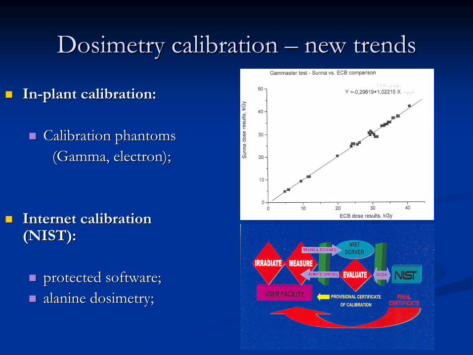
DosimetryDosimetry calibrationcalibration
–– newnew trendstrends
InIn--plantplant calibrationcalibration::
CalibrationCalibration phantomsphantoms(Gamma, (Gamma, electronelectron););
Internet Internet calibrationcalibration(NIST):(NIST):
protectedprotected software;software;alaninealanine dosimetrydosimetry;;
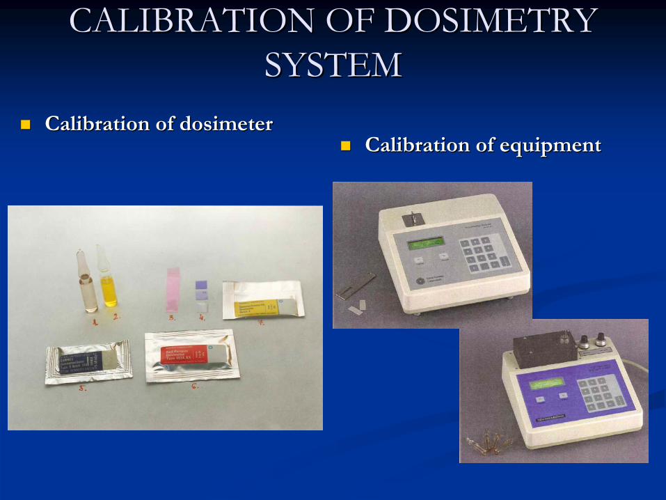
CALIBRATION OF DOSIMETRY CALIBRATION OF DOSIMETRY SYSTEMSYSTEM
Calibration of dosimeterCalibration of dosimeterCalibration of equipmentCalibration of equipment
CALIBRATION OF EQUIPMENT (1)CALIBRATION OF EQUIPMENT (1)
All All measurement equipmentmeasurement equipment must be calibratedmust be calibrated and be traceable to and be traceable to national standards.national standards.
Certain measurement equipment cannot be calibrated (e.g. signal Certain measurement equipment cannot be calibrated (e.g. signal amplitude amplitude from an EPR spectrometer) from an EPR spectrometer)
thereforetherefore⇓⇓
the the stability of the equipment has to be demonstratedstability of the equipment has to be demonstrated by the use of by the use of measurement standards (e.g. stable EPR spin standards).measurement standards (e.g. stable EPR spin standards).
CALIBRATION OF EQUIPMENT (2)CALIBRATION OF EQUIPMENT (2)
--
Spectrophotometer:Spectrophotometer:absorbance and wavelength scale with calibrated optical filters;absorbance and wavelength scale with calibrated optical filters;
--
Thickness gauge:Thickness gauge:calibrated gauge blocks;calibrated gauge blocks;
--Thermometers:Thermometers:calibrated thermometers;calibrated thermometers;
--
Resistance measurement (OhmResistance measurement (Ohm--meter for calorimeters):meter for calorimeters):calibrated reference resistor;calibrated reference resistor;
--
Humidity meters:Humidity meters:saturated salt solutions;saturated salt solutions;
CALIBRATION OF DOSIMETERS (1)CALIBRATION OF DOSIMETERS (1)
Irradiation of dosimetersIrradiation of dosimeters
Measurement Measurement ((analysisanalysis) ) of dosimeters (with calibrated instrument)of dosimeters (with calibrated instrument)
Generation of calibration curve or response functionGeneration of calibration curve or response function
Initial Initial ccalibrationalibration verification, and periodically confirmation of validityverification, and periodically confirmation of validity
TraceabilityTraceability chainchain
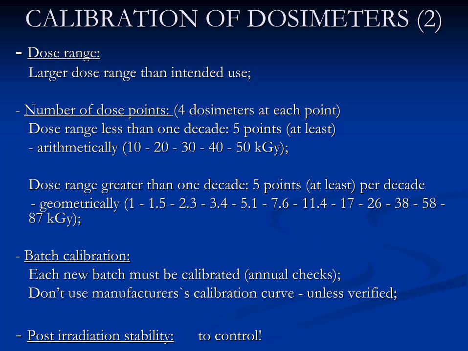
CALIBRATION OF DOSIMETERS (2)CALIBRATION OF DOSIMETERS (2)--
Dose range:Dose range:Larger dose range than intended use;Larger dose range than intended use;
--
Number of dose points: Number of dose points: (4 dosimeters at each point)(4 dosimeters at each point)Dose range less than one decadeDose range less than one decade: : 5 points (at least)5 points (at least)--
arithmetically (10 arithmetically (10 --
20 20 --
30 30 --
40 40 --
50 50 kGykGy););
Dose range greater than one decadeDose range greater than one decade: : 5 points (at least) per decade5 points (at least) per decade--
geometricalgeometricallyly
(1 (1 --
1.5 1.5 --
2.3 2.3 --
3.4 3.4 --
5.1 5.1 --
7.6 7.6 --
11.4 11.4 --
17 17 --
26 26 --
38 38 --
58 58 --
87 kGy);87 kGy);
--
Batch calibration:Batch calibration:Each new batch must be calibrated (annual checks);Each new batch must be calibrated (annual checks);DonDon’’t use manufacturers`s calibration curve t use manufacturers`s calibration curve --
unless verified;unless verified;
--
Post irradiation stability:Post irradiation stability:
to control! to control!

IRRADIATION OF DOSIMETERSIRRADIATION OF DOSIMETERS1. 1. Irradiation at a Irradiation at a calibration calibration facilitfacilityy
Irradiation of dosimeters in the reference radiation field of a Irradiation of dosimeters in the reference radiation field of a calibration laboratory calibration laboratory ((oror
ofof
anan
inin--househouse
calibrationcalibration
facilityfacility) ) followed followed
by by ““calibration verificationcalibration verification””
in the irradiation plant.in the irradiation plant.
a./ advantagesa./ advantages--
easy to obtain full dose range;easy to obtain full dose range;
--
irradiation to accurately known doses under controlled and irradiation to accurately known doses under controlled and documented conditions;documented conditions;
b./ disadvantages:b./ disadvantages:--
different conditions from real use (uncertainties);different conditions from real use (uncertainties);
--
transport of dosimeters (pretransport of dosimeters (pre--
and postand post--irradiation storage irradiation storage effects effects --
uncertainties);uncertainties);
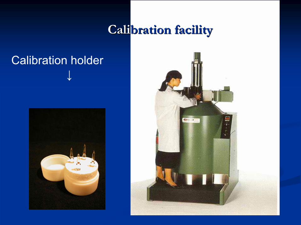
CCalialibrationbration
facilityfacility
Calibration
holder ↓
IRRADIATION OF DOSIMETERSIRRADIATION OF DOSIMETERS22..
Irradiation Irradiation in plantin plant
Routine dosimeters are irradiated together with reference or traRoutine dosimeters are irradiated together with reference or transfer standard nsfer standard dosimeters in dosimeters in ““calibration phantomscalibration phantoms””
in the irradiation plant.in the irradiation plant.
a./ advantages:a./ advantages:--
calibration and production conditions are similarcalibration and production conditions are similar(environmental conditions); (environmental conditions);
b./ disadvantages:b./ disadvantages:--
difficult to obtain full dose range in certain plants;difficult to obtain full dose range in certain plants;
c./ care must be taken:c./ care must be taken:--
to ensure that all dosimeters irradiated together receive the to ensure that all dosimeters irradiated together receive the same same
absorbed doseabsorbed dose
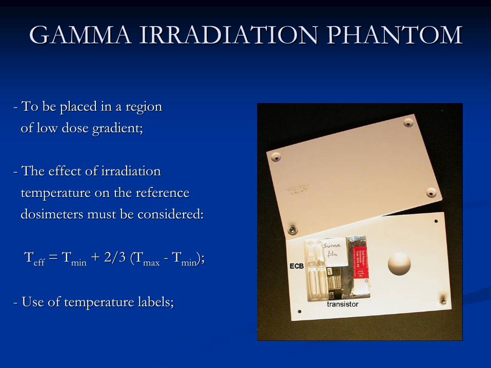
GAMMA IRRADIATION PHANTOMGAMMA IRRADIATION PHANTOM
--
To be placed in a regionTo be placed in a regionof low dose gradient;of low dose gradient;
--
The effect of irradiationThe effect of irradiationtemperature on the referencetemperature on the referencedosimeters must be considered:dosimeters must be considered:
TTeffeff
= = TTminmin
+ 2/3 (+ 2/3 (TTmaxmax
--
TTminmin
););
--
Use of temperature labels;Use of temperature labels;

ELECTRON BEAM PHANTOMELECTRON BEAM PHANTOM--
It is irradiated separately,It is irradiated separately,not in e.g. dummy product;not in e.g. dummy product;
--
Specific location on the depthSpecific location on the depthdose curve should be chosen;dose curve should be chosen;
-
The effective irradiation temperature can be considered:
Teff
= (Tmin
+ Tmax
) / 2;

IMPORTANCE OF TRACEABILITYIMPORTANCE OF TRACEABILITY
The The abilityability
toto
show show thatthat
a a measurementmeasurement
is is consistentconsistent
withwith
thethe
appropriateappropriate
nationalnational
oror
internationalinternational
standardsstandards
throughthrough
anan
unbrokenunbroken
chainchain
ofof
comparisoncomparison
((primaryprimary
standard standard lablab. . →→ secondarysecondary
standard standard lablab. . →→ routineroutine
lablab.).)
((verificationverification
is is neededneeded))
CALIBRATION VERIFICATIONCALIBRATION VERIFICATION
--
Calibration curves prepared for routine dosimeters in a Calibration curves prepared for routine dosimeters in a calibration facility (or incalibration facility (or in--house calibration facility) must be house calibration facility) must be verified for the actual conditions of use in the production verified for the actual conditions of use in the production irradiation facility;irradiation facility;
--
Routine dosimeters have to be irradiated together with Routine dosimeters have to be irradiated together with reference or transfer standard dosimeters to at least three reference or transfer standard dosimeters to at least three different absorbed doses.different absorbed doses.
--
Absorbed dose results originating from the two types of Absorbed dose results originating from the two types of dosimeters must be analyzed with respect to any systematic dosimeters must be analyzed with respect to any systematic trends for potential corrections if neededtrends for potential corrections if needed..
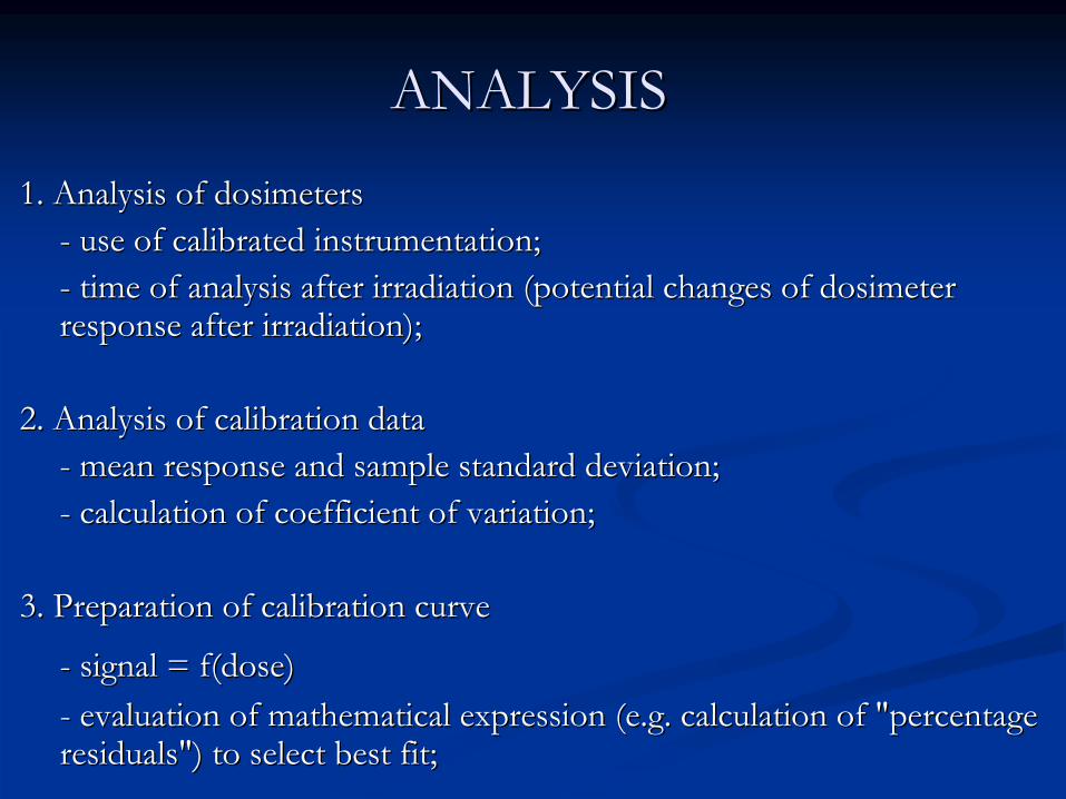
ANALYSISANALYSIS
1. Analysis of dosimeters1. Analysis of dosimeters--
use of calibrated instrumentation;use of calibrated instrumentation;
--
time of analysis after irradiation (potential changes oftime of analysis after irradiation (potential changes of
dosimeter dosimeter responseresponse
after irradiation);after irradiation);
2. Analysis of calibration data2. Analysis of calibration data--
mean response and sample standard deviation;mean response and sample standard deviation;
--
calculation of coefficient of variation;calculation of coefficient of variation;
3. Preparation of calibration curve3. Preparation of calibration curve
--
signal = f(dose)signal = f(dose)--
evaluation of mathematical expression (e.g. calculation of "perevaluation of mathematical expression (e.g. calculation of "percentage centage
residuals")residuals")
toto
selectselect
bestbest
fitfit;;

EXAMINATION OF RESIDUALSEXAMINATION OF RESIDUALSSelectSelect thethe mathematicalmathematical expressionexpression forfor thethe dosedose=f(=f(signalsignal) ) relationshiprelationship((e.ge.g. . lowestlowest
orderorder
polynomialpolynomial););
DetermineDetermine thethe coefficientscoefficients ofof thethe polynomialpolynomial ((useuse individualindividualdosimeterdosimeter pointspoints););
CalculateCalculate thethe dosedose forfor eacheach calibratedcalibrated dosimeterdosimeter;;
CalculateCalculate ""percentagepercentage residualsresiduals""::
((DDcalculatedcalculated
––
DDdelivereddelivered
) / ) / DDdelivereddelivered
x100x100
PlotPlot ""percentagepercentage residualsresiduals"" againstagainst dosedose andand examineexamine datadata forforanyany systematicsystematic trendstrends;;
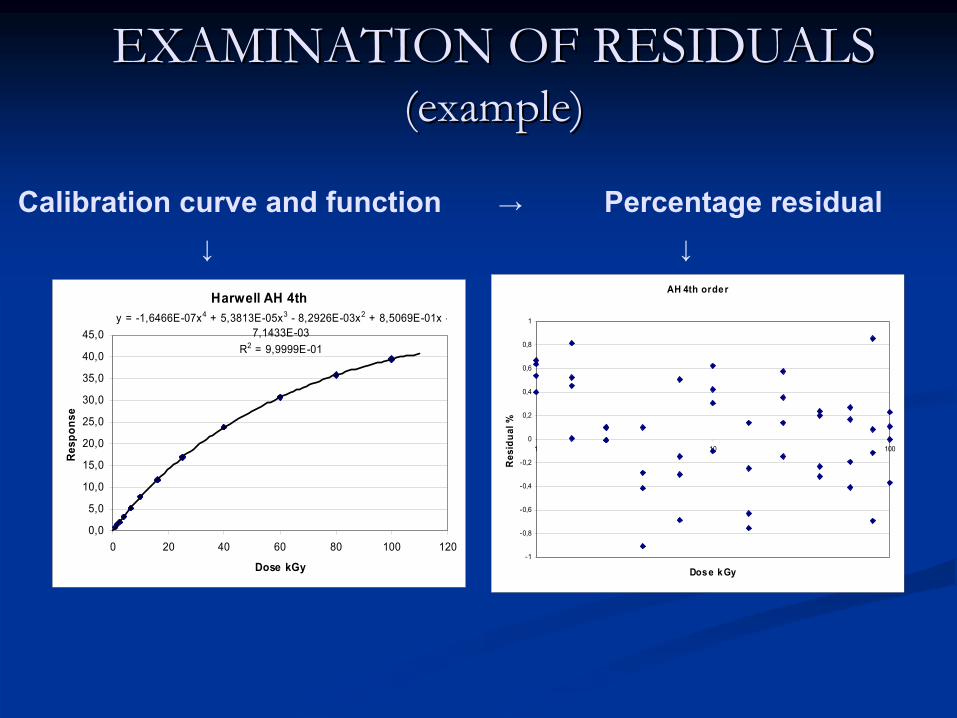
EXAMINATION OF RESIDUALSEXAMINATION OF RESIDUALS ((exampleexample))
Calibration
curve
and
function
→ Percentage
residual
↓ ↓
Harwell AH 4thy = -1,6466E-07x4 + 5,3813E-05x3 - 8,2926E-03x2 + 8,5069E-01x -
7,1433E-03R2 = 9,9999E-01
0,0
5,0
10,0
15,0
20,0
25,0
30,0
35,0
40,0
45,0
0 20 40 60 80 100 120
Dose kGy
Resp
onse
AH 4th order
-1
-0,8
-0,6
-0,4
-0,2
0
0,2
0,4
0,6
0,8
1
1 10 100
Dose kGy
Res
idua
l %

THANK YOU FOR YOUR ATTENTION!THANK YOU FOR YOUR ATTENTION!
Accuracy
Precision