REG-D™ Relay for Voltage Control & Transformer Monitoring
432
User Manual Issue: 2016/07 REG-D™ Relay for Voltage Control & Transformer Monitoring g
-
Upload
khangminh22 -
Category
Documents
-
view
4 -
download
0
Transcript of REG-D™ Relay for Voltage Control & Transformer Monitoring
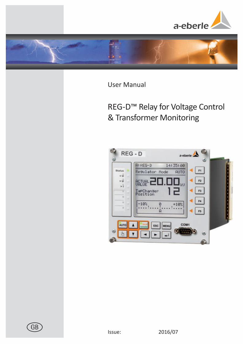
User Manual
Issue: 2016/07
REG-D™ Relay for Voltage Control & Transformer Monitoring
g
NOTICE! Please note that these operating instructions may not always containthe latest information concerning the device. Should you require a more recent version of these instructions or have any questions about the product or how to use it, please contact the REGSys™ Support on: +49 (0)911 628108-101 or via email at [email protected]
A. Eberle GmbH & Co. KG
Frankenstrasse 160
D-90461 Nürnberg
Telefon: +49 (0)911 / 62 81 08 0
Telefax: +49 (0)911 / 62 81 08 96
E-Mail: [email protected]
Internet: www.a-eberle.de
A. Eberle GmbH & Co. KG does not accept any liability for damage or losses of any kind arising from printing errors or changes in this manual.
Furthermore, Firma A. Eberle GmbH & Co. KG will not accept any liability for loss ore damageof any kind resulting from faulty equipment or devices that have been modified by the user.
We take care of it.
2 User Manual REG-D™
Engineers with experience in secondary systems will know that the perfect technical manual has never been written. After much anticipation from our stakeholders especially customers, this first edition of our new REG-D™ manual is released in the knowledge that the feedbackwe will receive from users on its content and form, will help us make later editions more comprehensive and easier to navigate. Consider this 1st edition as preliminary.
3
User manual REG-D™
Contents 1. User guidance ................................................................................................................... 8
1.1 Target group ............................................................................................................................. 8 1.2 Warnings ................................................................................................................................... 8 1.3 Tips ............................................................................................................................................ 8 1.4 Other symbols ........................................................................................................................... 9 1.5 Applicable documentation ........................................................................................................ 9 1.6 Storage ...................................................................................................................................... 9
2. Scope of delivery ............................................................................................................ 10
3. Safety instructions .......................................................................................................... 11
4. Intended use ................................................................................................................... 12
5. Performance features ..................................................................................................... 13
6. Operation/Indicators ...................................................................................................... 14 6.1 Indicators, controls and display .............................................................................................. 14 6.2 Display modes ......................................................................................................................... 19
6.2.1 Regulator................................................................................................................................. 20 6.2.2 Transducer .............................................................................................................................. 22 6.2.3 Recorder ................................................................................................................................. 28 6.2.4 Statistics .................................................................................................................................. 29 6.2.5 ParaGramer ............................................................................................................................. 30 6.2.6 Monitor (software feature TM) .............................................................................................. 31 6.2.7 PQIView................................................................................................................................... 32 6.2.8 Logbook................................................................................................................................... 34
6.3 Status ...................................................................................................................................... 38 6.4 Password protection ............................................................................................................... 45
7. Installation and commissioning ....................................................................................... 47 7.1 Hardware and connection ...................................................................................................... 47
7.1.1 System design and description ............................................................................................... 47 7.1.2 Installation/removal ............................................................................................................... 49
7.1.2.1 Housing/module rack .............................................................................................................. 49 7.1.2.2 REG-D™ plug-in unit ................................................................................................................ 51
7.1.3 Hardware ................................................................................................................................ 53 7.1.3.1 Status contact ......................................................................................................................... 53 7.1.3.2 Current measurement range .................................................................................................. 54 7.1.3.3 DCF input (TimeBus) ............................................................................................................... 55
7.1.4 Connection .............................................................................................................................. 57 7.1.4.1 Grounding ............................................................................................................................... 58 7.1.4.2 Auxiliary voltage ..................................................................................................................... 60 7.1.4.3 Binary signals .......................................................................................................................... 62 7.1.4.4 Analog signals ......................................................................................................................... 63 7.1.4.5 Process .................................................................................................................................... 66 7.1.4.6 E-LAN ....................................................................................................................................... 67 7.1.4.7 COM3 interface ....................................................................................................................... 72
7.2 Setup ....................................................................................................................................... 74

We take care of it.
4
User manual REG-D™
7.2.1 Update bootloader and firmware .......................................................................................... 74 7.2.2 Basic parameter setup ........................................................................................................... 81
7.2.2.1 System .................................................................................................................................... 81 7.2.2.2 Taking measurements ............................................................................................................ 86 7.2.2.3 Tap position ........................................................................................................................... 89 7.2.2.4 Regulation .............................................................................................................................. 93 7.2.2.5 Limit values ............................................................................................................................ 97 7.2.2.6 Input/Output signals .............................................................................................................. 99 7.2.2.7 Background programs .......................................................................................................... 103 7.2.2.8 SCADA system ...................................................................................................................... 103
7.2.3 Parallel operation ................................................................................................................. 105 7.2.4 Current influence ................................................................................................................. 111 7.2.5 Measurement value simulation ........................................................................................... 114 7.2.6 RAM-Backup ......................................................................................................................... 117
8. Parameters, functions and software features ................................................................ 122 8.1 Parameters ........................................................................................................................... 122
8.1.1 System .................................................................................................................................. 122 8.1.1.1 Station ID .............................................................................................................................. 122 8.1.1.2 Station name ........................................................................................................................ 122 8.1.1.3 RS-232 .................................................................................................................................. 122 8.1.1.4 E-LAN .................................................................................................................................... 125
8.1.2 Basic values .......................................................................................................................... 127 8.1.2.1 Permissible setpoint deviation (bandwidth Xwz) ................................................................. 127 8.1.2.2 Time behavior ...................................................................................................................... 131 8.1.2.3 Setpoints 1 - 4 ...................................................................................................................... 141 8.1.2.4 Setpoint index ...................................................................................................................... 144
8.1.3 Limit values .......................................................................................................................... 145 8.1.3.1 General ................................................................................................................................. 145 8.1.3.2 <U undervoltage (G6) ........................................................................................................... 146 8.1.3.3 >U overvoltage (G4) ............................................................................................................. 147 8.1.3.4 Over- and undercurrent limit (>I, <I).................................................................................... 148 8.1.3.5 Inhibit high (G1) ................................................................................................................... 149 8.1.3.6 High speed switching at over-/undervoltage (G2 or G3) ..................................................... 150 8.1.3.7 Inhibit low (G8) .................................................................................................................... 151 8.1.3.8 Three-winding limit >Ub (monitoring non-regulated voltage) ............................................ 152 8.1.3.9 Time delay of limit values .................................................................................................... 154
8.1.4 Current influence ................................................................................................................. 155 8.1.5 Parallel operation ................................................................................................................. 165
8.1.5.1 General ................................................................................................................................. 165 8.1.5.2 Parallel programs ................................................................................................................. 167 8.1.5.3 Parallel parameters .............................................................................................................. 170 8.1.5.4 Detailed explanation of the parallel program "dcos(ϕ)" ..................................................... 177 8.1.5.5 Detailed explanation of the parallel programs "dIsin(ϕ)" and "dIsin(ϕ)[S]" ....................... 178 8.1.5.6 Detailed explanation of the parallel programs “Master-Follower”, “MSI” and “MSI2” ...... 179
8.1.6 Tap changer .......................................................................................................................... 181 8.1.6.1 Maximum TC in operation time (run time of motor drive) ................................................. 181 8.1.6.2 Tap position indication ........................................................................................................ 182
5
User manual REG-D™
8.1.6.3 Tap limiter ............................................................................................................................. 183 8.1.6.4 Tap position 0 longer (6s) debounced .................................................................................. 184
8.1.7 Configuration and functions ................................................................................................. 185 8.1.7.1 Manual / Automatic .............................................................................................................. 185 8.1.7.2 Self-conduct (Manual/Auto remains unchanged after reset) .............................................. 186 8.1.7.3 Current display ...................................................................................................................... 186 8.1.7.4 LCD saver .............................................................................................................................. 186 8.1.7.5 LCD contrast .......................................................................................................................... 187 8.1.7.6 Regulator-Mode Large Display ............................................................................................. 187 8.1.7.7 Language ............................................................................................................................... 187 8.1.7.8 Up/down relay on-time ........................................................................................................ 188 8.1.7.9 Manual locked at E-LAN error ............................................................................................... 188 8.1.7.10 Block high-speed switching ................................................................................................... 188 8.1.7.11 Three-winding activation ...................................................................................................... 189 8.1.7.12 Creeping Net Breakdown ...................................................................................................... 190 8.1.7.13 Limit base .............................................................................................................................. 193 8.1.7.14 Block if <I or >I ...................................................................................................................... 194 8.1.7.15 Rolling Screens ...................................................................................................................... 195 8.1.7.16 Time of RollingScreens .......................................................................................................... 195 8.1.7.17 Setpoint adjustment with ←→ keys ..................................................................................... 196 8.1.7.18 Setpoint adjustment with binary inputs ............................................................................... 196 8.1.7.19 ParaGramer activity .............................................................................................................. 197 8.1.7.20 CT/VT configuration .............................................................................................................. 198 8.1.7.21 Actual value correction of measurement voltage UE............................................................ 202 8.1.7.22 Actual value correction of measurement current IE ............................................................. 202
8.1.8 SCADA system ....................................................................................................................... 203 8.1.9 Time setting .......................................................................................................................... 205
8.2 Inputs and Outputs ............................................................................................................... 207 8.2.1 General ................................................................................................................................. 207 8.2.2 Binary inputs ......................................................................................................................... 208 8.2.3 Relays .................................................................................................................................... 213 8.2.4 LEDs ....................................................................................................................................... 217 8.2.5 Analog inputs and outputs .................................................................................................... 221 8.2.6 I/O extensions (COM3) ......................................................................................................... 224 8.2.7 Operating states and error messages ................................................................................... 227
8.2.7.1 General ................................................................................................................................. 227 8.2.7.2 E-LAN error (ELANErr) ........................................................................................................... 227 8.2.7.3 COM3 error (COM3Err) ......................................................................................................... 227 8.2.7.4 TC in operation signal error (TCErr) ...................................................................................... 228 8.2.7.5 Tap change error (TapErr) ..................................................................................................... 228 8.2.7.6 Tap position indication error ................................................................................................ 228 8.2.7.7 Parallel operation error (ParErr) ........................................................................................... 229 8.2.7.8 ParaGramer input error (PG_INERR) .................................................................................... 229 8.2.7.9 dcos(ϕ) emergency program (dCosEmgy) ............................................................................ 229
8.3 Features (software) ............................................................................................................... 230 8.3.1 General and overview ........................................................................................................... 230 8.3.2 ParaGramer including extensions [protected] ..................................................................... 232
8.3.2.1 Feature ParaGramer [protected] .......................................................................................... 232 8.3.2.2 Feature Crosslink [protected] ............................................................................................... 236

We take care of it.
6
User manual REG-D™
8.3.2.3 Feature Ringlink [protected] ................................................................................................ 238 8.3.2.4 Feature HVLVControl [protected] ........................................................................................ 239 8.3.2.5 Feature PG_SCHEME_1 [protected] .................................................................................... 240 8.3.2.6 Processing of additional switch positions ............................................................................ 240 8.3.2.7 Feature 991101 [protected] ................................................................................................. 241 8.3.2.8 ParaGramer via SCADA system ............................................................................................ 242 8.3.2.9 Overview of ParaGramer input functions ............................................................................ 243
8.3.3 Feature Recorder [protected] .............................................................................................. 244 8.3.4 Feature TM (Transformer Monitoring) [protected] ............................................................. 252 8.3.5 Feature 3winding (three-winding transformer) [protected] ............................................... 253 8.3.6 Feature 3winding Plus (three-winding transformer) [protected] ........................................ 261 8.3.7 Feature PQCtrl [protected] .................................................................................................. 261 8.3.8 Feature 4Setpoints [protected] ........................................................................................... 264 8.3.9 Feature Adapt ...................................................................................................................... 265 8.3.10 Feature Bootload ................................................................................................................. 265 8.3.11 Feature COM2FIX ................................................................................................................. 266 8.3.12 Feature DELTAI ..................................................................................................................... 267 8.3.13 Feature Invers ...................................................................................................................... 268 8.3.14 Feature M2 [protected] ....................................................................................................... 270 8.3.15 Feature MISWAP .................................................................................................................. 272 8.3.16 Feature Qsigned ................................................................................................................... 273 8.3.17 Feature LocalRemote ........................................................................................................... 273 8.3.18 Feature SimMode ................................................................................................................ 274 8.3.19 Feature SR192 [protected] ................................................................................................... 275 8.3.20 Feature SYSCTRL .................................................................................................................. 276 8.3.21 Feature SYSCTRL2 ................................................................................................................ 278 8.3.22 Feature PrimCtrl [protected] ............................................................................................... 280 8.3.23 Feature ULC [protected] ...................................................................................................... 280 8.3.24 Custom features [protected] ............................................................................................... 280
8.4 Background programs and the programming language REG-L ............................................ 281 8.4.1 Programming language REG-L ............................................................................................. 281 8.4.2 Background programs .......................................................................................................... 283
8.4.2.1 Loading H-programs in a device ........................................................................................... 283 8.4.2.2 Reading H-programs from a device ..................................................................................... 286 8.4.2.3 Deleting H-programs ............................................................................................................ 286
9. Configuration and display software WinREG ................................................................. 287 9.1 General ................................................................................................................................. 287 9.2 Installation ........................................................................................................................... 287 9.3 Control Center ...................................................................................................................... 291 9.4 Communication with an A. Eberle device (e.g. REG-D™) ..................................................... 293
9.4.1 Connection settings ............................................................................................................. 293 9.4.2 Other communication parameters ...................................................................................... 297
9.5 Panel .................................................................................................................................... 299 9.6 Terminal ............................................................................................................................... 303 9.7 Service .................................................................................................................................. 305
9.7.1 General ................................................................................................................................. 305 9.7.2 Log/Divers ............................................................................................................................ 306 9.7.3 Statistics ............................................................................................................................... 307
7
User manual REG-D™
9.7.4 Simulation ............................................................................................................................. 308 9.7.5 I/O extnsions (COM3) ........................................................................................................... 310 9.7.6 Summertime Adjustment, UTC ............................................................................................. 311 9.7.7 REG-L ..................................................................................................................................... 312 9.7.8 RAM-Backup ......................................................................................................................... 313
9.8 REGPara ................................................................................................................................ 314 9.9 REGView ................................................................................................................................ 317 9.10 Collector ................................................................................................................................ 322 9.11 WinTM/WinDM .................................................................................................................... 325
10. External components .................................................................................................... 326 10.1 Additional components REGSys™ ......................................................................................... 326
10.1.1 I/O extension modules BIN-D & ANA-D ................................................................................ 326 10.1.2 COM3/MODBUS converter ................................................................................................... 327 10.1.3 Monitoring units ................................................................................................................... 327 10.1.4 Tap position interfaces ......................................................................................................... 328 10.1.5 Local/remote switch REG-LR ................................................................................................. 329 10.1.6 Miscellaneous ....................................................................................................................... 330
10.2 SCADA system ....................................................................................................................... 330
11. Retrofit of analog channels ........................................................................................... 331
12. Maintenance/Cleaning .................................................................................................. 334 12.1 Cleaning instructions ............................................................................................................ 334 12.2 Fuse replacement ................................................................................................................. 335 12.3 Battery replacement ............................................................................................................. 336
13. Standards and laws ....................................................................................................... 343
14. Disposal ........................................................................................................................ 344
15. Product warranty .......................................................................................................... 345
16. Storage ......................................................................................................................... 346
17. Troubleshooting ............................................................................................................ 347 17.1 General ................................................................................................................................. 347 17.2 Measurement ....................................................................................................................... 349 17.3 Process signals (e.g. binary signals) ...................................................................................... 350 17.4 E-LAN ..................................................................................................................................... 352 17.5 Regulation in general ............................................................................................................ 353 17.6 Parallel operation ................................................................................................................. 356 17.7 WinREG ................................................................................................................................. 359 17.8 REGUpdate (update32.exe) .................................................................................................. 360 17.9 SCADA system ....................................................................................................................... 361
18. Abbreviation list ........................................................................................................... 364
19. Symbol list .................................................................................................................... 368
20. Index ............................................................................................................................ 370
21. Appendix ...................................................................................................................... 375
We take care of it.
8
User manual REG-D™
1. User guidance
This user manual contains a summary of the information needed for installation, commissioning and operation. Read the user manual entirely and do not use the product unless you have understood its content.
1.1 Target group The user manual is intended for skilled technicians and trained and certified operating personnel. The contents of this user manual must be accessible to people tasked with the installation and operation of the system.
1.2 Warnings Structure of the warnings Warnings are structured as follows:
SIGNAL WORD! Nature and source of the danger. Consequences if instructions are not obeyed.
Actions to avoid the danger.
Types of warnings Warnings are distinguished by the type of danger they are warning against:
DANGER! Warns of an immediately impending danger that can result in death or serious injuries when not avoided.
WARNING! Warns of a potentially dangerous situation that can result in death or serious injuries when not avoided.
CAUTION! Warns of a potentially dangerous situation that can result in fairly serious or light injuries when not avoided.
NOTICE! Warns of a potentially dangerous situation that results in material or environmental damage when not avoided.
1.3 Tips
Tips on the appropriate use of the device and recommendations.
9
User manual REG-D™
1.4 Other symbols Instructions Structure of the instructions: Instructions for an action.
Indication of an outcome, if necessary. Lists Structure of unnumbered lists: 0 List level 1
– List level 2 Structure of numbered lists: 1) List level 1 2) List level 1
1. List level 2 2. List level 2
1.5 Applicable documentation For the safe and correct use of the installation, observe the additional documentation that is delivered with the system, as well as the relevant standards and laws.
1.6 Storage Store the user manual, including the supplied documentation, readily accessible near the system.
We take care of it.
10
User manual REG-D™
2. Scope of delivery
0 Relay for Voltage Control & Transformer Monitoring REG-D™ 0 Terminal diagram in English* 0 User manual in English 0 Programming and configuration software WinREG* 0 Null-modem cable or USB cable (depending on order feature I)* 0 Removable spare fuse on circuit board 0 Extraction tool (only for REG-D™ as plug-in module)* If the REG-D ™ is installed in a voltage regulation system, the positions marked * are provided only once per system.
11
User manual REG-D™
3. Safety instructions
Follow the operating instructions.
Keep the operating instructions with the device.
Regularly instruct staff in all relevant issues regarding occupational safety, the operating instructions and, in particular, the safety instructions they contain.
Ensure that the device is only operated if in perfect condition. Never use a damaged device (physically damaged or malfunctioning).
Ensure the device is only operated by qualified personnel.
Connect and use the device only as specified.
Operate the device only with the recommended accessories.
Ensure that the device is operated only in its original condition.
Ensure that the device is only operated within the permissible rated data (see technical specifications in the appendix, chapter 21).
Do not install or operate the device in environments where explosive gases, dust or vapours may be present, i.e. that generally do not meet the requirements mentioned in the technical datasheet.
Clean the device only with cleaning products that comply with the manufacturer's specifications.
Use only spare parts and auxiliary materials that have been approved by the manufacturer.
Maintenance and repair of an open REG-D™ Relay for Voltage Control & Transformer Monitoring (plug-in module without housing) must only be carried out by authorised, qualified personnel and must satisfy EMC Directives.
No supply or control voltage should be applied to a disassembled plug-in module, e.g. open (disassembled) REG-D™ Relay for Voltage Control & Transformer Monitoring, as electrical parts carrying dangerously high voltages could be encountered.

We take care of it.
12
User manual REG-D™
4. Intended use
The Relay for Voltage Control & Transformer Monitoring REG-D™ is designed as a permanently installed measuring and regulation unit for controlling on-load tap changers, and is exclusively intended for use in electrical power engineering facilities and installations, where professionals carry out the necessary work. Professionals are defined as people who are familiar with the installation, assembly, commissioning and operation of such products. They have qualifications that meet the requirements of their activities. The Relay for Voltage Control & Transformer Monitoring REG-D™ complies with the laws, rules and standards applicable at the time of delivery, in particular with relevant safety and health requirements. To maintain this condition and ensure safe operation, the operator must follow all the instructions and warnings in the user manual and the technical data must be observed. A. Eberle GmbH & Co. KG accepts no liability for damage resulting from unauthorized or improper modification or use of the product. Improper modifications of the product without consultation with A. Eberle GmbH & Co. KG can lead to personal injury, property damage and malfunctions.
13
User manual REG-D™
5. Performance features
The RegSys™ Relay for Voltage Control & Transformer Monitoring system can be used to perform both simple and complex measurement, control and regulation tasks on tap-changing transformers. To help with these numerous and varied tasks, the REG-D™ Relay for Voltage Control & Transformer Monitoring (basic component) can be used with the monitoring modules PAN-D and PAN-A1/A2, as well as with interface components that have binary and analog inputs and outputs. Telecontrol connection (DNP3, IEC 60870-5-101 / 103/104, IEC 61850, MODBUS, etc.) can be realized via an additional telecontrol board module. The core function of the REG-D™ is the regulator function, in which the actual value and a fixed or load-dependent setpoint value are compared. Depending on the setpoint deviation, the comparison determines the correcting variable for the transformer's tap changer. The regulator's parameters can be fine-tuned to the dynamic time behavior of the grid voltage to obtain a high regulation performance via a low number of switching operations. Moreover, the Relay for Voltage Control & Transformer Monitoring REG-D™ is capable of using other Relays for Voltage Control & Transformer Monitoring in the REGSys™ family, with parallel operation of up to 10 transformers without additional components. There are different methods to choose from for the control of transformers, which can be used on site according to the circumstances. It is worth noting that additional components are not required because the regulators contain all of the functional units required for parallel operation. In addition to the regulator, each REG-D™ comes with the current optional features of transformer monitoring, transducer, recorder, statistics and ParaGramer. The Transducer mode displays all of the relevant measured grid quantities. The Recorder mode records the regulated voltage over time as well as two additional selectable quantities. Tap-change position statistics provide a clear overview of all of the tap changer's switching operations, and the ParaGramer displays a single-line diagram of the transformer unit. The ParaGramer is a valuable tool, when setting up parallel operations for several transformers, because it automatically recognizes transformers that are run in parallel. The REG-D™ regulator can be equipped with a powerful transformer monitoring function in conformity with IEC 60354 or IEC 60076. This function enables the operator to view information regarding hot-spot temperature and the transformer's loss of life at any time. If required, the regulator can even activate up to six cooling levels. The oil temperature can either be recorded directly (as a PT100 signal) or through an mA input. To solve customer-specific requirements, a background program can be loaded into the Relay for Voltage Control & Transformer Monitoring REG-D™. Simple and complex logics can be created, as well as additional custom menus. As an alternative to direct logging, U, I and cos(ϕ) measurements, as well as the tap position, can be fed to the REG-D through a serial connection such as an IEC 61850 client function or an mA signal. Switch positions for use, for example, in ParaGramer can also be made available via GOOSE as an alternative to binary signals wired to the regulator.
We take care of it.
14
User manual REG-D™
6. Operation/Indicators
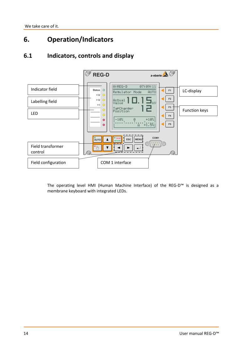
6.1 Indicators, controls and display
The operating level HMI (Human Machine Interface) of the REG-D™ is designed as a membrane keyboard with integrated LEDs.
Indicator field
Labelling field
LED
LC-display
Function keys
Field transformer control
Field configuration COM 1 interface
15
User manual REG-D™
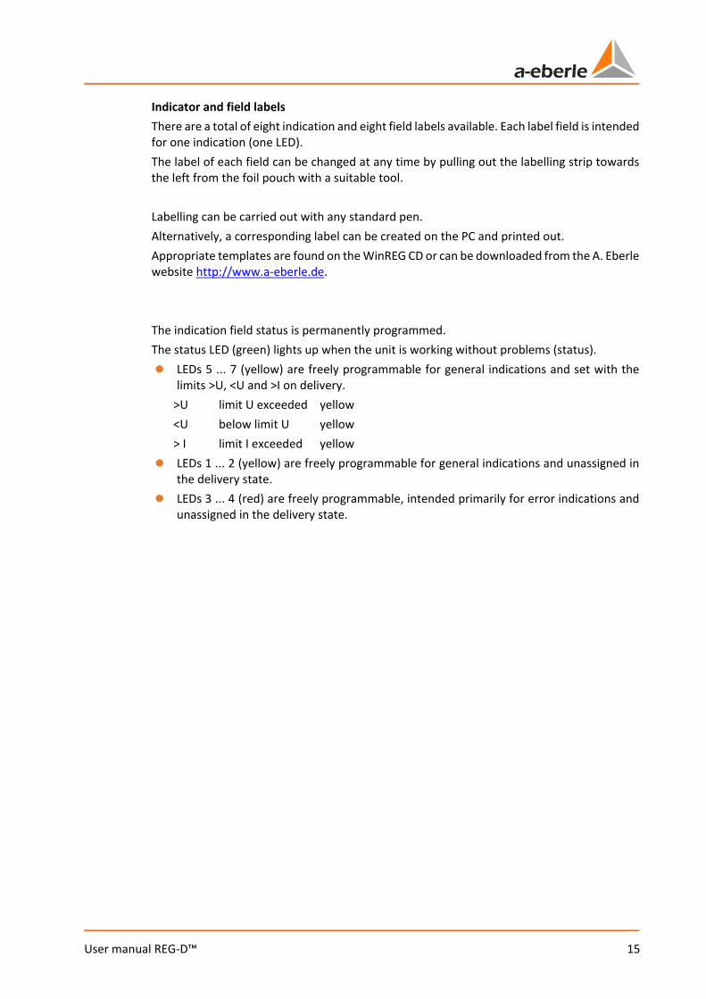
Indicator and field labels There are a total of eight indication and eight field labels available. Each label field is intended for one indication (one LED). The label of each field can be changed at any time by pulling out the labelling strip towards the left from the foil pouch with a suitable tool. Labelling can be carried out with any standard pen. Alternatively, a corresponding label can be created on the PC and printed out. Appropriate templates are found on the WinREG CD or can be downloaded from the A. Eberle website http://www.a-eberle.de. The indication field status is permanently programmed. The status LED (green) lights up when the unit is working without problems (status). 0 LEDs 5 ... 7 (yellow) are freely programmable for general indications and set with the
limits >U, <U and >I on delivery. >U limit U exceeded yellow <U below limit U yellow > I limit I exceeded yellow
0 LEDs 1 ... 2 (yellow) are freely programmable for general indications and unassigned in the delivery state.
0 LEDs 3 ... 4 (red) are freely programmable, intended primarily for error indications and unassigned in the delivery state.
We take care of it.
16
User manual REG-D™
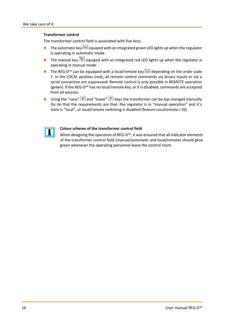
Transformer control The transformer control field is associated with five keys.
0 The automatic key equiped with an integrated green LED lights up when the regulator is operating in automatic mode.
0 The manual key equiped with an integrated red LED lights up when the regulator is operating in manual mode.
0 The REG-D™ can be equipped with a local/remote key depending on the order code Y. In the LOCAL position (red), all remote control commands via binary inputs or via a serial connection are suppressed. Remote control is only possible in REMOTE operation (green). If the REG-D™ has no local/remote key, or it is disabled, commands are accepted from all sources.
0 Using the "raise" and "lower" keys the transformer can be tap-changed manually (to do that the requirements are that: the regulator is in “manual operation” and it´s state is “local”, or local/remote switching is disabled (feature Localremote = 0)).
Colour scheme of the transformer control field When designing the operation of REG-D™, it was ensured that all indicator elements of the transformer control field (manual/automatic and local/remote) should glow green whenever the operating personnel leave the control room.
17
User manual REG-D™
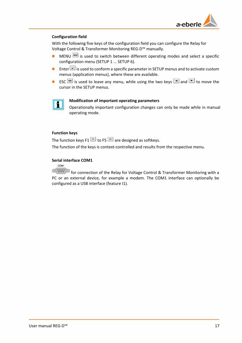
Configuration field With the following five keys of the configuration field you can configure the Relay for Voltage Control & Transformer Monitoring REG-D™ manually.
0 MENU is used to switch between different operating modes and select a specific configuration menu (SETUP 1 ... SETUP 6).
0 Enter is used to conform a specific parameter in SETUP menus and to activate custom menus (application menus), where these are available.
0 ESC is used to leave any menu, while using the two keys and to move the cursor in the SETUP menus.
Modification of important operating parameters Operationally important configuration changes can only be made while in manual operating mode.
Function keys
The function keys F1 to F5 are designed as softkeys. The function of the keys is context-controlled and results from the respective menu. Serial interface COM1
for connection of the Relay for Voltage Control & Transformer Monitoring with a PC or an external device, for example a modem. The COM1 interface can optionally be configured as a USB interface (feature I1).
We take care of it.
18
User manual REG-D™
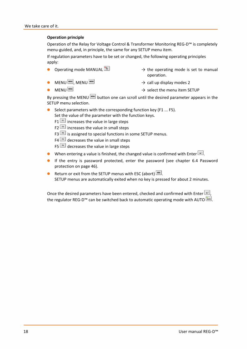
Operation principle Operation of the Relay for Voltage Control & Transformer Monitoring REG-D™ is completely menu-guided, and, in principle, the same for any SETUP menu item. If regulation parameters have to be set or changed, the following operating principles apply:
0 Operating mode MANUAL → the operating mode is set to manual operation.
0 MENU , MENU → call up display modes 2
0 MENU → select the menu item SETUP
By pressing the MENU button one can scroll until the desired parameter appears in the SETUP menu selection. 0 Select parameters with the corresponding function key (F1 ... F5).
Set the value of the parameter with the function keys. F1 increases the value in large steps F2 increases the value in small steps F3 is assigned to special functions in some SETUP menus. F4 decreases the value in small steps F5 decreases the value in large steps
0 When entering a value is finished, the changed value is confirmed with Enter . 0 If the entry is password protected, enter the password (see chapter 6.4 Password
protection on page 46).
0 Return or exit from the SETUP menus with ESC (abort) . SETUP menus are automatically exited when no key is pressed for about 2 minutes.
Once the desired parameters have been entered, checked and confirmed with Enter , the regulator REG-D™ can be switched back to automatic operating mode with AUTO .

19
User manual REG-D™
Lamp test To check functioning of the LEDs on the front panel: press F5. This test is only possible in the display modes Regulator mode and Statistics mode. Reset of fault indications To reset pending fault indications the operating mode must be switched from automatic to manual and then switch back to automatic. Alternatively, the F5 key can be pressed in the display mode Regulator and Statistics. The reset of fault indications is also possible remotely using a background program or a SCADA system.
6.2 Display modes Selection of display modes
After pressing MENU , the display modes of the Relay for Voltage Control & Transformer Monitoring REG-D™ can be selected. The following modes, which are explained in detail in the following chapters, are available: 0 Regulator 0 Transducer mode 0 Recorder 0 Statistics (monitor) 0 ParaGramer 0 PQIView 0 Logbook

We take care of it.
20
User manual REG-D™
6.2.1 Regulator
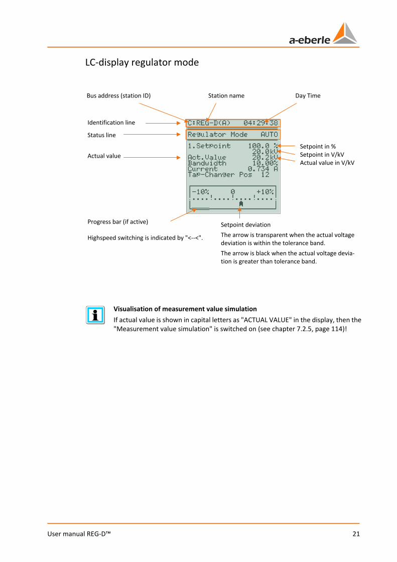
In regulator mode, the setpoint value in V (kV) and in % of nominal voltage, the present actual value, the value of the permissible setpoint deviation (bandwidth) and the current tap position of the tap-changing transformer are displayed. In addition, the current setpoint deviation is visualised aon an analog like gauge with a scale width of ±10% from the setpoint. If the voltage leaves the tolerance band (bandwidth either the positive or the negative direction), the colour of the scale pointer changes from transparent to black (reverse color scheme). If necessary, the actual value of the current for the indication may also be selected. Press the F1 key to switch between the detailed view and the large display. On the large display, the actual measured voltage and tap position are displayed at the top. The graphical display of the actual voltage deviation remains unchanged.
Menu 1
Regulator
21
User manual REG-D™
LC-display regulator mode
Visualisation of measurement value simulation If actual value is shown in capital letters as "ACTUAL VALUE" in the display, then the "Measurement value simulation" is switched on (see chapter 7.2.5, page 114)!
Setpoint in % Setpoint in V/kV Actual value in V/kV
Day Time Station name Bus address (station ID)
Status line
Actual value
Progress bar (if active) Setpoint deviation The arrow is transparent when the actual voltage deviation is within the tolerance band. The arrow is black when the actual voltage devia-tion is greater than tolerance band.
Highspeed switching is indicated by "<--<".
Identification line

We take care of it.
22
User manual REG-D™
6.2.2 Transducer
The above figure shows the transducer basic display available in most cases. Here, voltage, current, power values, cos(ϕ), phase angle, reactive current, frequency and selected nominal current of the current transformer (value in [ ]) are shown. Additionally or alternatively to this indication, depending on features and parameters, it is possible that additional transducer screens are accessible. Scrolling through screens is done in a loopwise manner. On arriving to the last screen, you can either scroll back (left arrow) or return to the first page by scrolling further (right arrow or, alternatively with the F2 key).
Display of reactive current I*sinϕ in the transducer basic display Only the reactive current I*sinϕ of the transformer is shown in the transducer basic display. The component of this current due to the load and the component due to circulating reactive current cannot be seen in this display. To this end, there is an-other transducer screen, which is available after selecting a parallel program.
Menu 1
Transducer Mode
23
User manual REG-D™
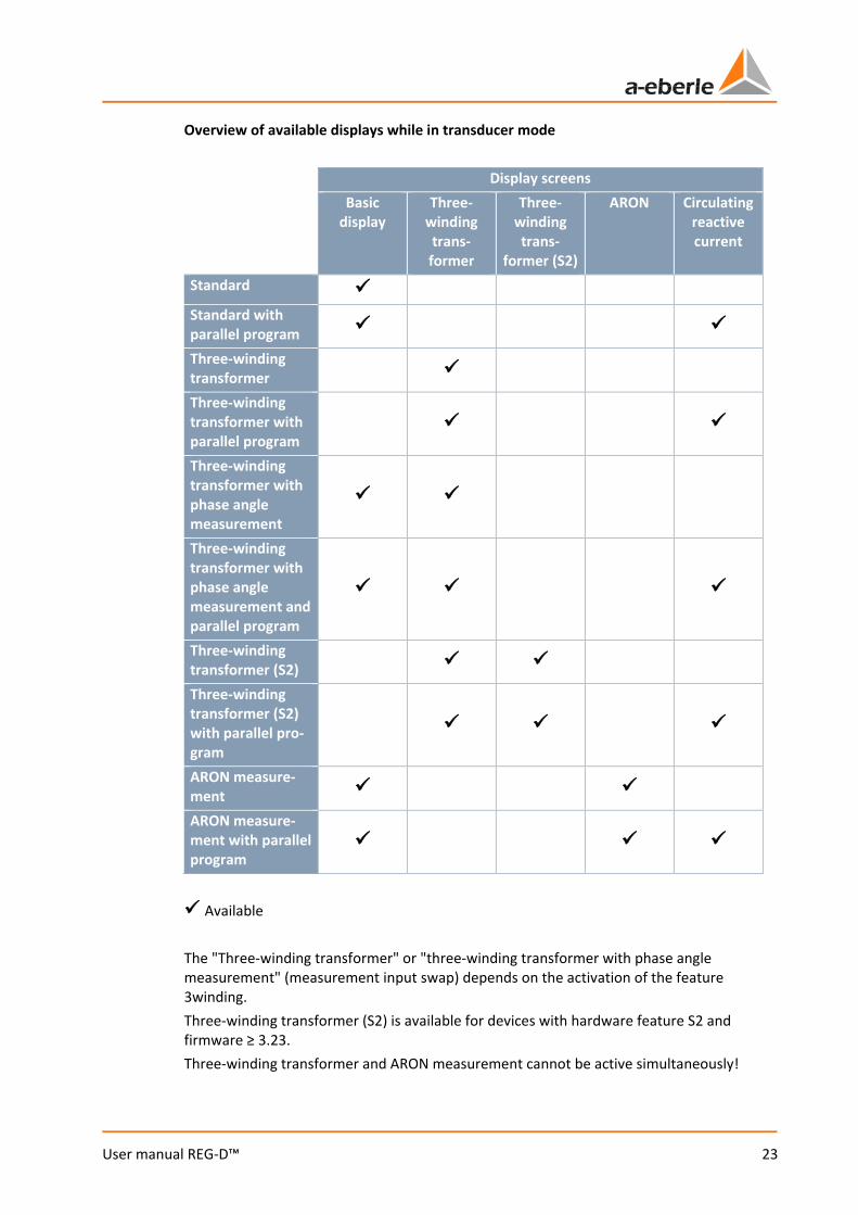
Overview of available displays while in transducer mode
Display screens
Basic display
Three-winding trans-former
Three-winding trans-
former (S2)
ARON Circulating reactive current
Standard Standard with parallel program
Three-winding transformer
Three-winding transformer with parallel program
Three-winding transformer with phase angle measurement
Three-winding transformer with phase angle measurement and parallel program
Three-winding transformer (S2)
Three-winding transformer (S2) with parallel pro-gram
ARON measure-ment
ARON measure-ment with parallel program
Available The "Three-winding transformer" or "three-winding transformer with phase angle measurement" (measurement input swap) depends on the activation of the feature 3winding. Three-winding transformer (S2) is available for devices with hardware feature S2 and firmware ≥ 3.23. Three-winding transformer and ARON measurement cannot be active simultaneously!
We take care of it.
24
User manual REG-D™
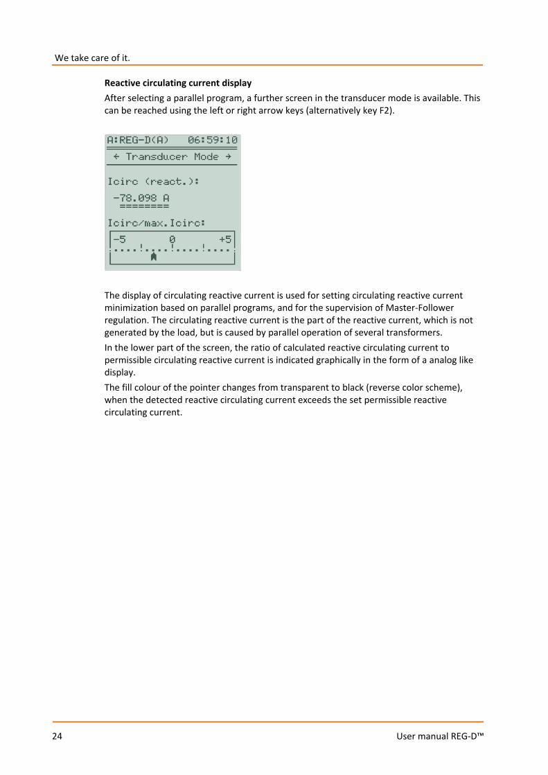
Reactive circulating current display After selecting a parallel program, a further screen in the transducer mode is available. This can be reached using the left or right arrow keys (alternatively key F2).
The display of circulating reactive current is used for setting circulating reactive current minimization based on parallel programs, and for the supervision of Master-Follower regulation. The circulating reactive current is the part of the reactive current, which is not generated by the load, but is caused by parallel operation of several transformers. In the lower part of the screen, the ratio of calculated reactive circulating current to permissible circulating reactive current is indicated graphically in the form of a analog like display. The fill colour of the pointer changes from transparent to black (reverse color scheme), when the detected reactive circulating current exceeds the set permissible reactive circulating current.

25
User manual REG-D™
Display of ARON measurement values (feature M2) If the REG-D™ has the M2 feature and the ARON measurement is enabled (parameter "CT/VT Configuration" = ARON), the regulator provides a transducer mode screen on which the readings of ARON measurements (arbitrarily loaded three-phase grid) are displayed.
Display of power values On comparing power values from the ARON display and the transducer basic display there may be differences. This is because calculation of power values in the basic display is always based on symmetrical loading, whereas the ARON values take asymmetry into account.
We take care of it.
26
User manual REG-D™
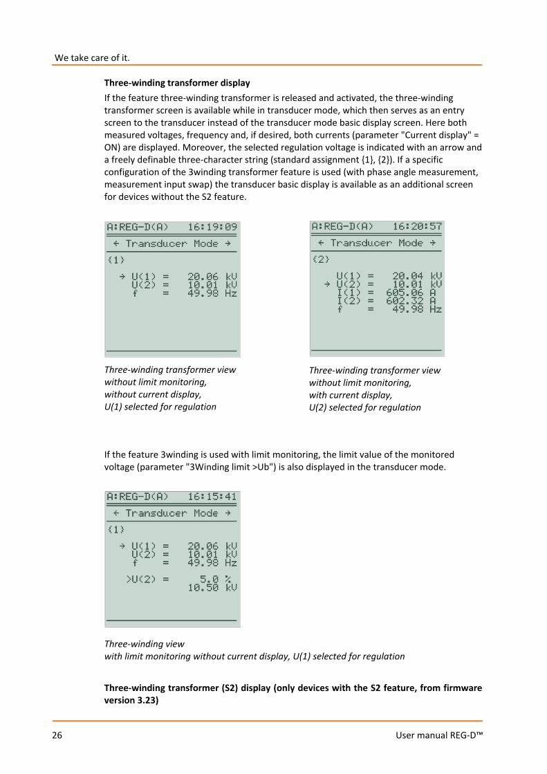
Three-winding transformer display If the feature three-winding transformer is released and activated, the three-winding transformer screen is available while in transducer mode, which then serves as an entry screen to the transducer instead of the transducer mode basic display screen. Here both measured voltages, frequency and, if desired, both currents (parameter "Current display" = ON) are displayed. Moreover, the selected regulation voltage is indicated with an arrow and a freely definable three-character string (standard assignment 1, 2). If a specific configuration of the 3winding transformer feature is used (with phase angle measurement, measurement input swap) the transducer basic display is available as an additional screen for devices without the S2 feature.
If the feature 3winding is used with limit monitoring, the limit value of the monitored voltage (parameter "3Winding limit >Ub") is also displayed in the transducer mode.
Three-winding transformer (S2) display (only devices with the S2 feature, from firmware version 3.23)
Three-winding transformer view without limit monitoring, without current display, U(1) selected for regulation
Three-winding transformer view without limit monitoring, with current display, U(2) selected for regulation
Three-winding view with limit monitoring without current display, U(1) selected for regulation
27
User manual REG-D™
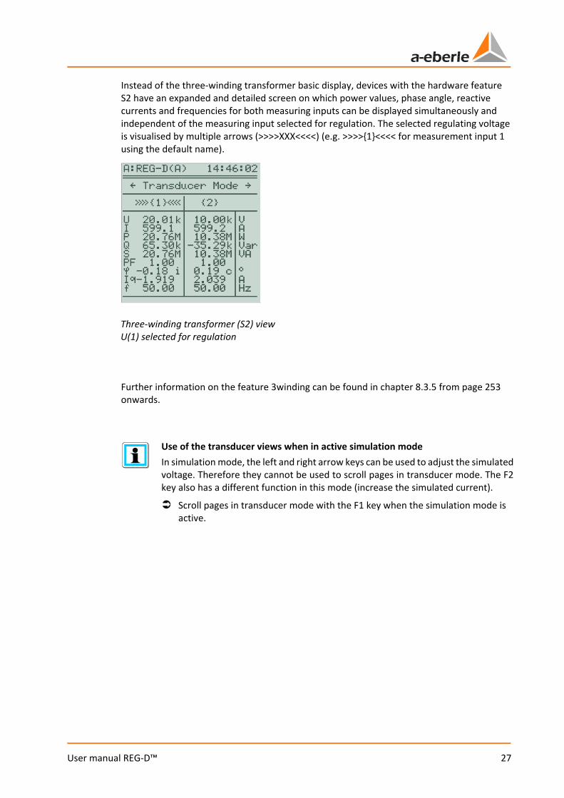
Instead of the three-winding transformer basic display, devices with the hardware feature S2 have an expanded and detailed screen on which power values, phase angle, reactive currents and frequencies for both measuring inputs can be displayed simultaneously and independent of the measuring input selected for regulation. The selected regulating voltage is visualised by multiple arrows (>>>>XXX<<<<) (e.g. >>>>1<<<< for measurement input 1 using the default name).
Further information on the feature 3winding can be found in chapter 8.3.5 from page 253 onwards.
Use of the transducer views when in active simulation mode In simulation mode, the left and right arrow keys can be used to adjust the simulated voltage. Therefore they cannot be used to scroll pages in transducer mode. The F2 key also has a different function in this mode (increase the simulated current).
Scroll pages in transducer mode with the F1 key when the simulation mode is active.
Three-winding transformer (S2) view U(1) selected for regulation
We take care of it.
28
User manual REG-D™
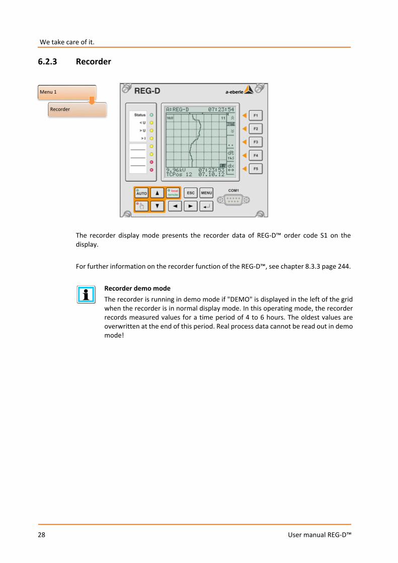
6.2.3 Recorder
The recorder display mode presents the recorder data of REG-D™ order code S1 on the display. For further information on the recorder function of the REG-D™, see chapter 8.3.3 page 244.
Recorder demo mode The recorder is running in demo mode if "DEMO" is displayed in the left of the grid when the recorder is in normal display mode. In this operating mode, the recorder records measured values for a time period of 4 to 6 hours. The oldest values are overwritten at the end of this period. Real process data cannot be read out in demo mode!
Menu 1
Recorder
29
User manual REG-D™
6.2.4 Statistics
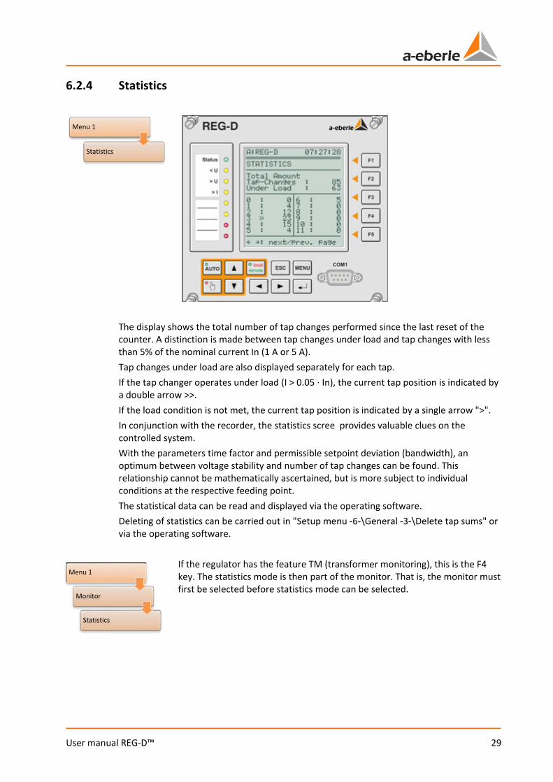
The display shows the total number of tap changes performed since the last reset of the counter. A distinction is made between tap changes under load and tap changes with less than 5% of the nominal current In (1 A or 5 A). Tap changes under load are also displayed separately for each tap. If the tap changer operates under load (I > 0.05 · In), the current tap position is indicated by a double arrow >>. If the load condition is not met, the current tap position is indicated by a single arrow ">". In conjunction with the recorder, the statistics scree provides valuable clues on the controlled system. With the parameters time factor and permissible setpoint deviation (bandwidth), an optimum between voltage stability and number of tap changes can be found. This relationship cannot be mathematically ascertained, but is more subject to individual conditions at the respective feeding point. The statistical data can be read and displayed via the operating software. Deleting of statistics can be carried out in "Setup menu -6-\General -3-\Delete tap sums" or via the operating software.
If the regulator has the feature TM (transformer monitoring), this is the F4 key. The statistics mode is then part of the monitor. That is, the monitor must first be selected before statistics mode can be selected.
Menu 1
Statistics
Menu 1
Monitor
Statistics
We take care of it.
30
User manual REG-D™
6.2.5 ParaGramer
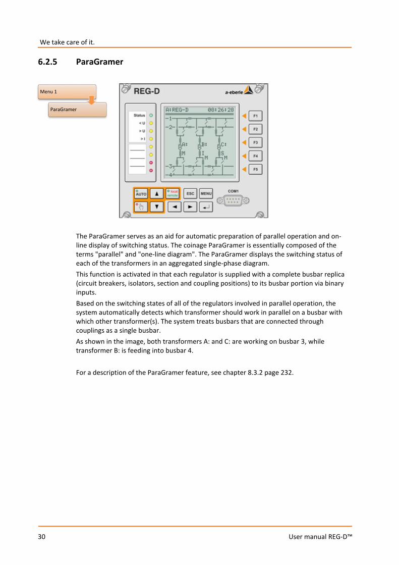
The ParaGramer serves as an aid for automatic preparation of parallel operation and on-line display of switching status. The coinage ParaGramer is essentially composed of the terms "parallel" and "one-line diagram". The ParaGramer displays the switching status of each of the transformers in an aggregated single-phase diagram. This function is activated in that each regulator is supplied with a complete busbar replica (circuit breakers, isolators, section and coupling positions) to its busbar portion via binary inputs. Based on the switching states of all of the regulators involved in parallel operation, the system automatically detects which transformer should work in parallel on a busbar with which other transformer(s). The system treats busbars that are connected through couplings as a single busbar. As shown in the image, both transformers A: and C: are working on busbar 3, while transformer B: is feeding into busbar 4. For a description of the ParaGramer feature, see chapter 8.3.2 page 232.
Menu 1
ParaGramer
31
User manual REG-D™
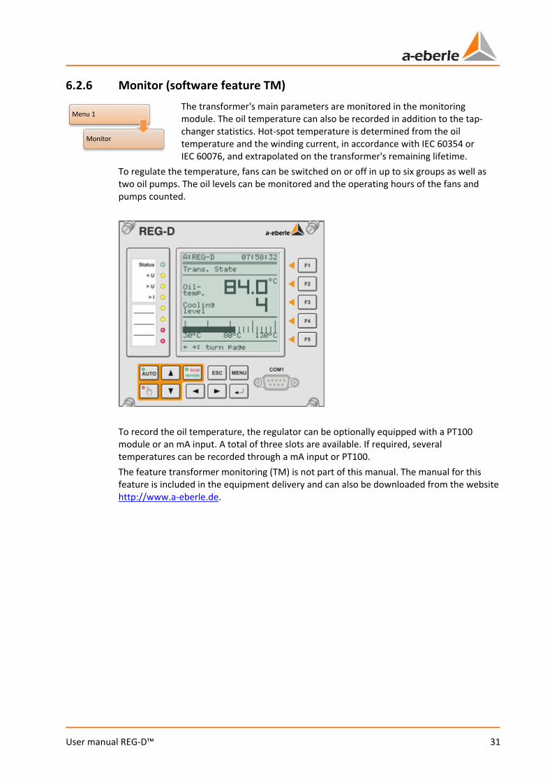
6.2.6 Monitor (software feature TM) The transformer's main parameters are monitored in the monitoring module. The oil temperature can also be recorded in addition to the tap-changer statistics. Hot-spot temperature is determined from the oil temperature and the winding current, in accordance with IEC 60354 or IEC 60076, and extrapolated on the transformer's remaining lifetime.
To regulate the temperature, fans can be switched on or off in up to six groups as well as two oil pumps. The oil levels can be monitored and the operating hours of the fans and pumps counted.
To record the oil temperature, the regulator can be optionally equipped with a PT100 module or an mA input. A total of three slots are available. If required, several temperatures can be recorded through a mA input or PT100. The feature transformer monitoring (TM) is not part of this manual. The manual for this feature is included in the equipment delivery and can also be downloaded from the website http://www.a-eberle.de.
Menu 1
Monitor
We take care of it.
32
User manual REG-D™
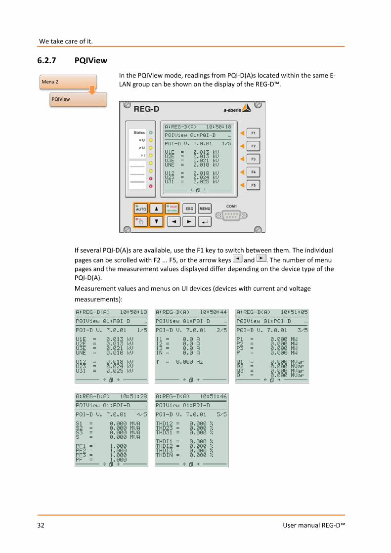
6.2.7 PQIView In the PQIView mode, readings from PQI-D(A)s located within the same E-LAN group can be shown on the display of the REG-D™.
If several PQI-D(A)s are available, use the F1 key to switch between them. The individual pages can be scrolled with F2 ... F5, or the arrow keys and . The number of menu pages and the measurement values displayed differ depending on the device type of the PQI-D(A). Measurement values and menus on UI devices (devices with current and voltage measurements):
Menu 2
PQIView
33
User manual REG-D™
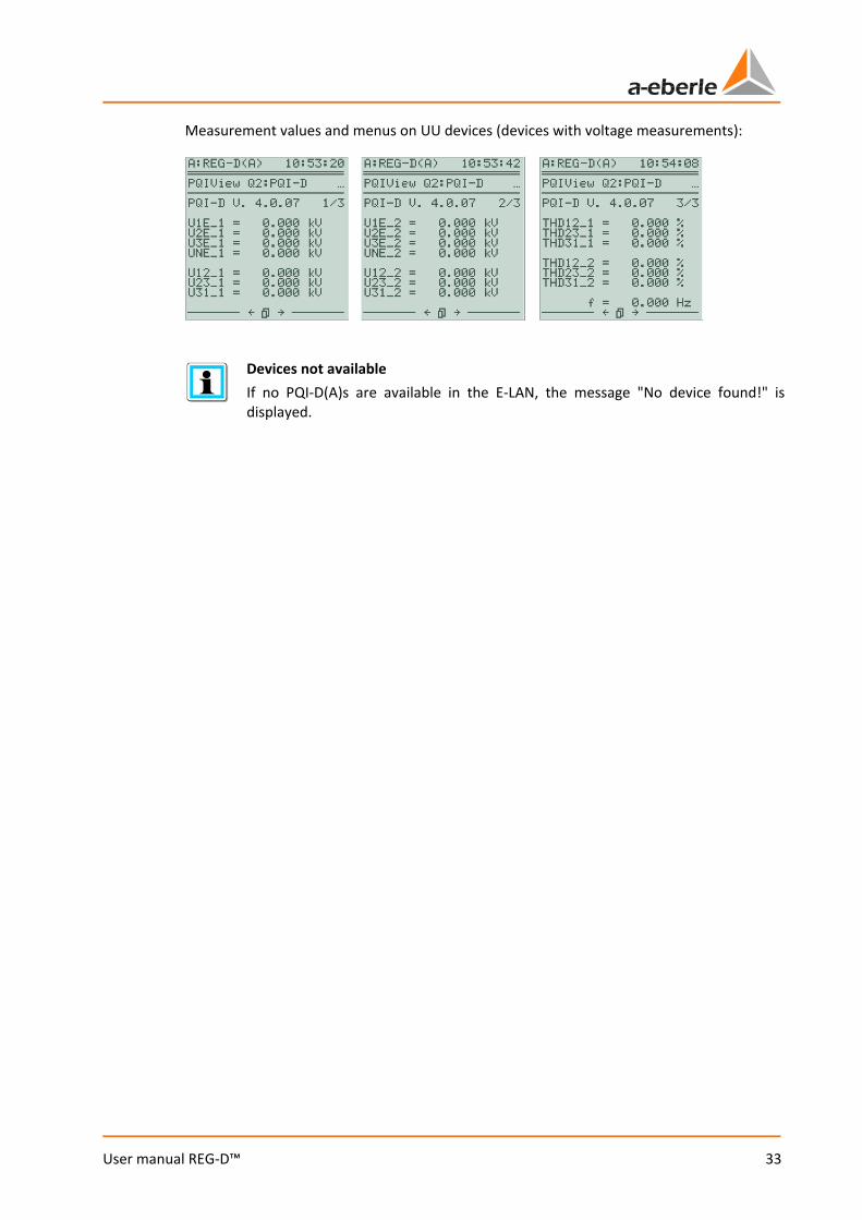
Measurement values and menus on UU devices (devices with voltage measurements):
Devices not available If no PQI-D(A)s are available in the E-LAN, the message "No device found!" is displayed.
We take care of it.
34
User manual REG-D™
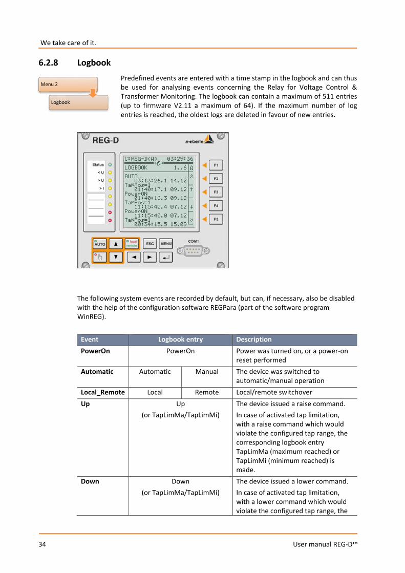
6.2.8 Logbook Predefined events are entered with a time stamp in the logbook and can thus be used for analysing events concerning the Relay for Voltage Control & Transformer Monitoring. The logbook can contain a maximum of 511 entries (up to firmware V2.11 a maximum of 64). If the maximum number of log entries is reached, the oldest logs are deleted in favour of new entries.
The following system events are recorded by default, but can, if necessary, also be disabled with the help of the configuration software REGPara (part of the software program WinREG).
Event Logbook entry Description PowerOn PowerOn Power was turned on, or a power-on
reset performed Automatic Automatic Manual The device was switched to
automatic/manual operation Local_Remote Local Remote Local/remote switchover Up Up
(or TapLimMa/TapLimMi) The device issued a raise command. In case of activated tap limitation, with a raise command which would violate the configured tap range, the corresponding logbook entry TapLimMa (maximum reached) or TapLimMi (minimum reached) is made.
Down Down (or TapLimMa/TapLimMi)
The device issued a lower command. In case of activated tap limitation, with a lower command which would violate the configured tap range, the
Menu 2
Logbook

35
User manual REG-D™
Event Logbook entry Description corresponding logbook entry TapLimMa (maximum reached) or TapLimMi (minimum reached) is made.
Tap TapPos = xx Tap position SP index SP-Index=x Setpoint index (setpoint 1 ... 4
activated) Inhibit high Inh-High:ON Inh-High:OFF inhibit high Inhibit low Inh-Low:ON Inh-Low:OFF inhibit low Fast-Up Fast-Up:ON Fast-Up:OFF Limit for high-speed forward
switching Fast-Down Fast-Dwn:ON Fast-Dwn:OFF Limit for high-speed backward
switching >U >U:ON >U:OFF Overvoltage limit <U <U:ON <U:OFF Undervoltage limit >I >I:ON >I:OFF Overcurrent limit Simulation Simul:ON Simul:OFF Simulation mode
activated/deactivated Grid breakdown
CNB:ON CNB:OFF Creeping Net Breakdown
Hunting Hunting:ON Hunting:OFF Hunting (x taps within a given time) ClearLog LOG cleared Logbook cleared ClrRecorder REC cleared Recorder data cleared ClearStats STAT cleared Statistics data cleared PanelLogin PanelLogin-x User x has logged into the device
(password protection) Status Status:Error Status:OK Status (life contact) ELanErr ELANErr:ON ELANErr:OFF E-LAN error TapErr TapErr:ON TapErr:OFF Tap position error (TapErr) TC-Err TC-Err:ON TC-Err:OFF TC in operation error (TC-Err)

We take care of it.
36
User manual REG-D™
Additionally, the following system events are always logged at the same time. They cannot be disabled via the configuration software REGPara as with the previous system events (part of the software program WinREG).
Event Logbook entry Description RAM restore RAMresto Restoration of RAM by means of an existing RAM-
Backup (possible from bootloader V2.12), see also chapter 7.2.6 from page 117 onwards.
Time restore RTC=RAMt RTC=EEPt RTC=RBUt RTC=2000
After a PowerOn, false time information was detected and the time information was restored as well as possible according to the available source. Time sources: RAMt = time source was RAM (MRAM) EEPT = time source was the EPROM RBUt = time source was the RAM-image in flash 2000 = the time was set to 01.01.2000 0:00:00
Master reset MaRESET The device was completely reset and RAM initialized again.
Moreover, of all relays, binary inputs and LEDs both the rising and falling flank can be separately logged. These logs are disabled by default due to the limited number of recordable events, but can be activated at any time by use of the configuration software REGPara (part of the software program WinREG). In addition to these standard events, which are defined by the firmware, custom messages can be entered into the logbook via a background program. These consist of a freely definable text with a length of up to eight characters (e.g. "Custsp_1"). The content of the logbook can be visualised directly on the screen of the REG-D™, and in the service program WinREG. It is also possible to save log entries to a file for archiving on a PC via the service page. Deleting logbook entries is also possible through the service page of WinREG.
37
User manual REG-D™
Further logbook entries REG-D™ firmware versions from V2.13 to V2.17 by default log incorrectly transmitted E-LAN telegrams in the form: Rnxxxxxx or Lnxxxxxx Where R or L stands for E-LAN-R or E-LAN-L and n is the length of the faulty telegram in bytes. Subsequently, the first three bytes of the telegram are recorded in hexadecimal (e.g. R1AE7H3X). These faulty telegrams are automatically detected and transmitted again or corrected. Therefore, the logbook entries introduced for monitoring purposes are removed again using firmware version 2.18 or greater.
We take care of it.
38
User manual REG-D™
6.3 Status
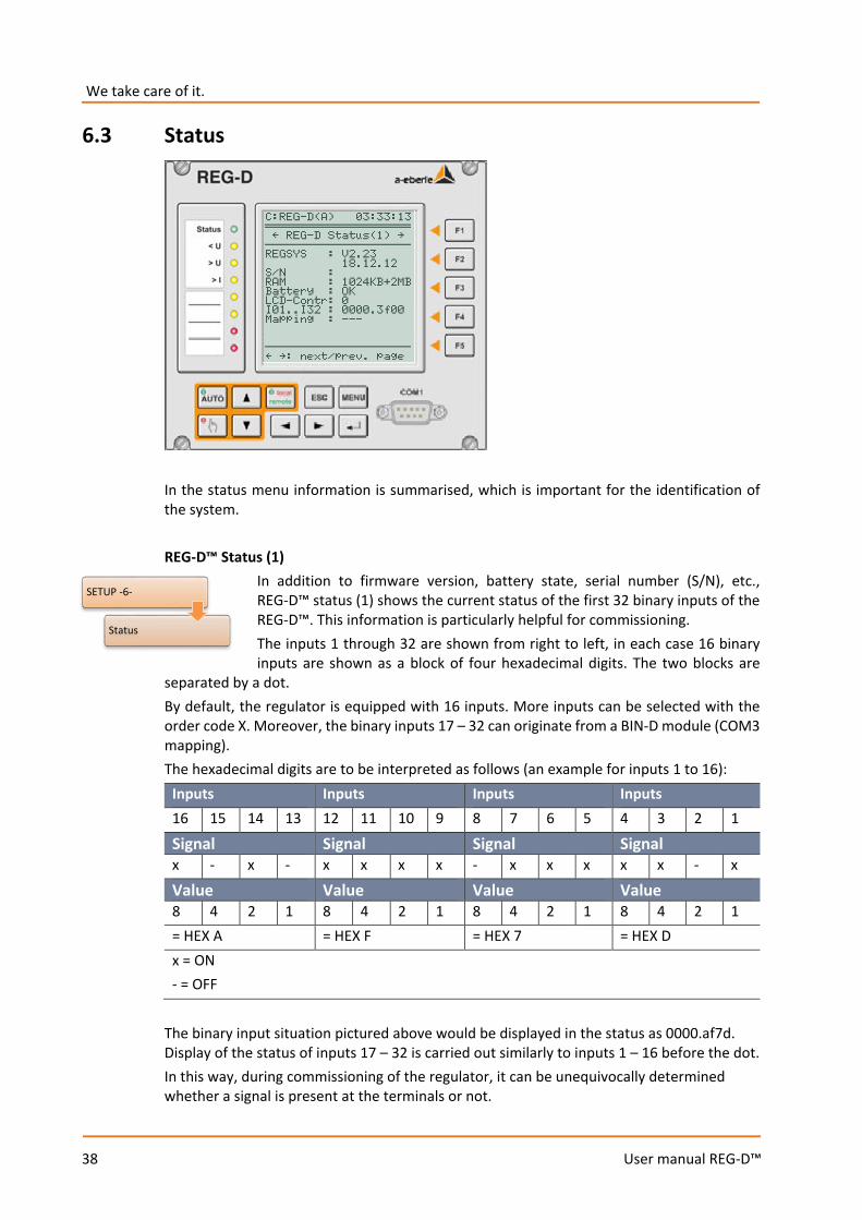
In the status menu information is summarised, which is important for the identification of the system. REG-D™ Status (1)
In addition to firmware version, battery state, serial number (S/N), etc., REG-D™ status (1) shows the current status of the first 32 binary inputs of the REG-D™. This information is particularly helpful for commissioning. The inputs 1 through 32 are shown from right to left, in each case 16 binary inputs are shown as a block of four hexadecimal digits. The two blocks are
separated by a dot. By default, the regulator is equipped with 16 inputs. More inputs can be selected with the order code X. Moreover, the binary inputs 17 – 32 can originate from a BIN-D module (COM3 mapping). The hexadecimal digits are to be interpreted as follows (an example for inputs 1 to 16):
Inputs Inputs Inputs Inputs 16 15 14 13 12 11 10 9 8 7 6 5 4 3 2 1
Signal Signal Signal Signal x - x - x x x x - x x x x x - x
Value Value Value Value 8 4 2 1 8 4 2 1 8 4 2 1 8 4 2 1 = HEX A = HEX F = HEX 7 = HEX D x = ON - = OFF
The binary input situation pictured above would be displayed in the status as 0000.af7d. Display of the status of inputs 17 – 32 is carried out similarly to inputs 1 – 16 before the dot. In this way, during commissioning of the regulator, it can be unequivocally determined whether a signal is present at the terminals or not.
SETUP -6-
Status
39
User manual REG-D™
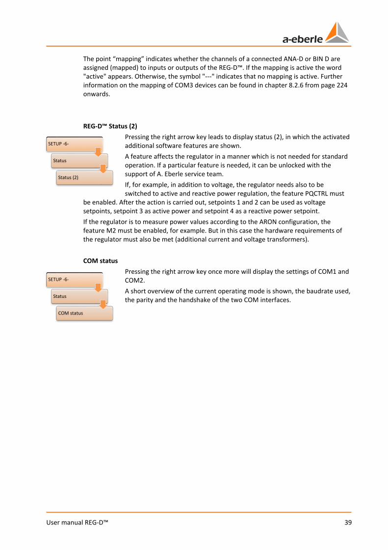
The point “mapping” indicates whether the channels of a connected ANA-D or BIN D are assigned (mapped) to inputs or outputs of the REG-D™. If the mapping is active the word "active" appears. Otherwise, the symbol "---" indicates that no mapping is active. Further information on the mapping of COM3 devices can be found in chapter 8.2.6 from page 224 onwards. REG-D™ Status (2)
Pressing the right arrow key leads to display status (2), in which the activated additional software features are shown. A feature affects the regulator in a manner which is not needed for standard operation. If a particular feature is needed, it can be unlocked with the support of A. Eberle service team. If, for example, in addition to voltage, the regulator needs also to be switched to active and reactive power regulation, the feature PQCTRL must
be enabled. After the action is carried out, setpoints 1 and 2 can be used as voltage setpoints, setpoint 3 as active power and setpoint 4 as a reactive power setpoint. If the regulator is to measure power values according to the ARON configuration, the feature M2 must be enabled, for example. But in this case the hardware requirements of the regulator must also be met (additional current and voltage transformers). COM status
Pressing the right arrow key once more will display the settings of COM1 and COM2. A short overview of the current operating mode is shown, the baudrate used, the parity and the handshake of the two COM interfaces.
SETUP -6-
Status
Status (2)
SETUP -6-
Status
COM status
We take care of it.
40
User manual REG-D™
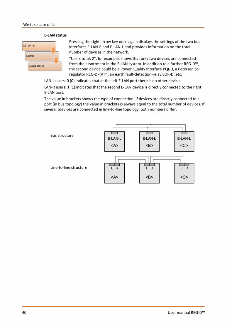
E-LAN status Pressing the right arrow key once again displays the settings of the two bus interfaces E-LAN-R and E-LAN-L and provides information on the total number of devices in the network. "Users total: 2", for example, shows that only two devices are connected from the assortment in the E-LAN system. In addition to a further REG-D™, the second device could be a Power Quality Interface PQI-D, a Petersen coil regulator REG-DP(A)™, an earth fault-detection-relay EOR-D, etc.
LAN-L users: 0 (0) indicates that at the left E-LAN port there is no other device. LAN-R users: 1 (1) indicates that the second E-LAN device is directly connected to the right E-LAN port. The value in brackets shows the type of connection. If devices are directly connected to a port (in bus topology) the value in brackets is always equal to the total number of devices. If several tdevices are connected in line-to-line topology, both numbers differ.
Bus structure
Line-to-line structure
SETUP -6-
Status
ELAN status

41
User manual REG-D™
COM-3 status Here the devices connected to the COM3 bus of the REG-D™ are displayed, such as ANA-Ds and BIN-Ds. The address and the type of available devices can be found in the table at the bottom of the screen. With the F5 key you can scroll to addresses 11 to 15. The F4 key allows access to the monitor settings of the COM3 interface.
Time/date Pressing of the right arrow key once more leads to the time/date status menu. Here are shown the current time, date, the set time zone (here: UTC+1) and the summer time (DST) if used are shown.
If the time of the REG-D™ is synchronised via a DCF signal, the status of the DCF signal is also displayed here. Hereby are displayed the source of the DCF signal (TBUS, COM1, COM2), the time, date, and time zone of the DCF signal and the time of the last adjustment of the REG-D™ time. If the DCF signal fails, the DCF time signal is displayed in brackets and the duration of the dropout is displayed in square brackets instead of the time zone. If there is no DCF signal for more than two minutes, the time/date menu changes back to the view without DCF status.
SETUP -6-
Status
COM-3 status
SETUP -6-
Status
Time/date
We take care of it.
42
User manual REG-D™
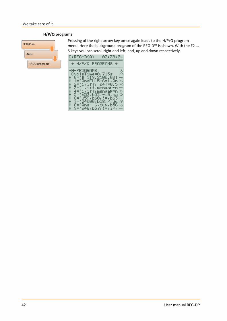
H/P/Q programs Pressing of the right arrow key omce again leads to the H/P/Q program menu. Here the background program of the REG-D™ is shown. With the F2 ... 5 keys you can scroll right and left, and, up and down respectively.
SETUP -6-
Status
H/P/Q programs
43
User manual REG-D™
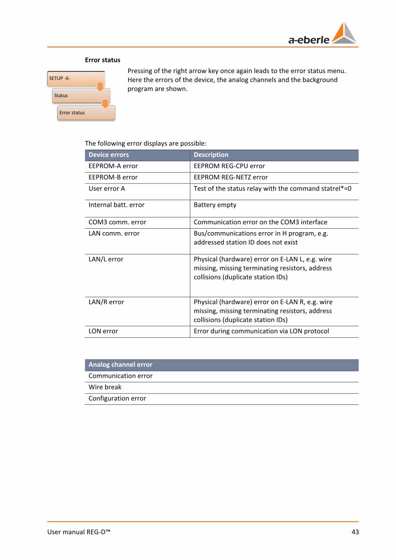
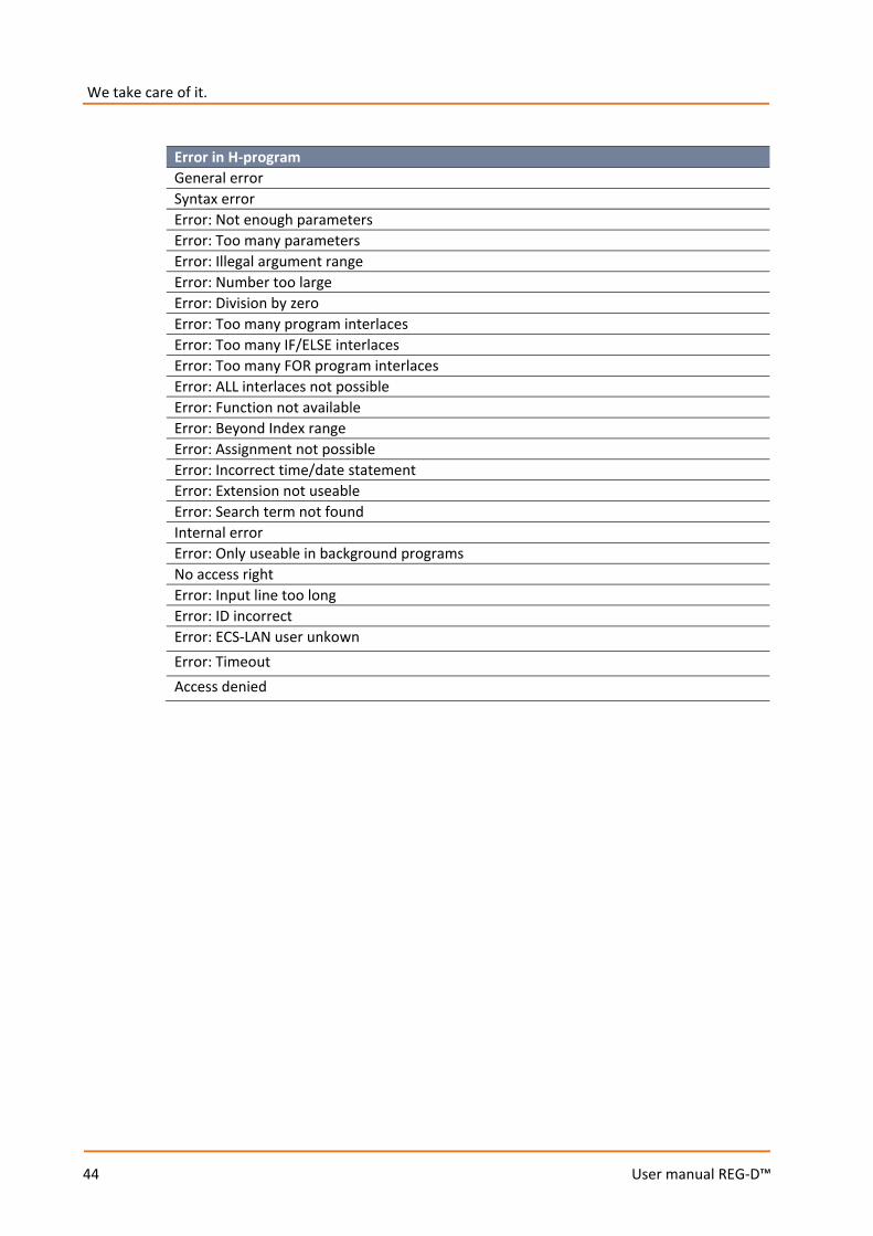
Error status Pressing of the right arrow key once again leads to the error status menu. Here the errors of the device, the analog channels and the background program are shown.
The following error displays are possible: Device errors Description EEPROM-A error EEPROM REG-CPU error EEPROM-B error EEPROM REG-NETZ error User error A Test of the status relay with the command statrel*=0
Internal batt. error Battery empty
COM3 comm. error Communication error on the COM3 interface LAN comm. error Bus/communications error in H program, e.g.
addressed station ID does not exist
LAN/L error Physical (hardware) error on E-LAN L, e.g. wire missing, missing terminating resistors, address collisions (duplicate station IDs)
LAN/R error Physical (hardware) error on E-LAN R, e.g. wire missing, missing terminating resistors, address collisions (duplicate station IDs)
LON error Error during communication via LON protocol
Analog channel error Communication error Wire break Configuration error
SETUP -6-
Status
Error status
We take care of it.
44
User manual REG-D™
Error in H-program General error Syntax error Error: Not enough parameters Error: Too many parameters Error: Illegal argument range Error: Number too large Error: Division by zero Error: Too many program interlaces Error: Too many IF/ELSE interlaces Error: Too many FOR program interlaces Error: ALL interlaces not possible Error: Function not available Error: Beyond Index range Error: Assignment not possible Error: Incorrect time/date statement Error: Extension not useable Error: Search term not found Internal error Error: Only useable in background programs No access right Error: Input line too long Error: ID incorrect Error: ECS-LAN user unkown Error: Timeout Access denied
45
User manual REG-D™
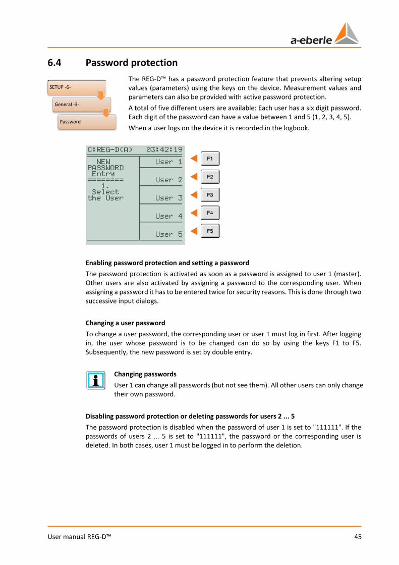
6.4 Password protection The REG-D™ has a password protection feature that prevents altering setup values (parameters) using the keys on the device. Measurement values and parameters can also be provided with active password protection. A total of five different users are available: Each user has a six digit password. Each digit of the password can have a value between 1 and 5 (1, 2, 3, 4, 5). When a user logs on the device it is recorded in the logbook.
Enabling password protection and setting a password The password protection is activated as soon as a password is assigned to user 1 (master). Other users are also activated by assigning a password to the corresponding user. When assigning a password it has to be entered twice for security reasons. This is done through two successive input dialogs. Changing a user password To change a user password, the corresponding user or user 1 must log in first. After logging in, the user whose password is to be changed can do so by using the keys F1 to F5. Subsequently, the new password is set by double entry.
Changing passwords User 1 can change all passwords (but not see them). All other users can only change their own password.
Disabling password protection or deleting passwords for users 2 ... 5 The password protection is disabled when the password of user 1 is set to "111111". If the passwords of users 2 ... 5 is set to "111111", the password or the corresponding user is deleted. In both cases, user 1 must be logged in to perform the deletion.
SETUP -6-
General -3-
Password
We take care of it.
46
User manual REG-D™
Password query (login) A password query is performed automatically as soon as a password-protected parameter adjustment, or a password protection change, is to be performed. After the selection of a user (only users for which a password has already been assigned can be selected) and entering the correct password, the new value of the parameter is set and the system remains open for five minutes. If any inputs occur during this time, the open time is five minutes. This means that throughout this period further parameter modifications can be performed without re-entering the password. If the REG-D™ has no operation performed on for more than five minutes, the system is closed and the user gets logged out automatically. Instant activation of password protection Normally, password protection is first activated five minutes after the last operation of the REG-D™. Pressing the "<" key (left arrow) in the password request menu (SETUP-6-\General -3-\Password) enables password protection immediately.
Deleting the password of user 1 If the password of user 1 is deleted by entering "111111", the entire password protection of the device is disabled. Any existing passwords of users 2 ... 5 are retained. If a password for user 1 is set again, users 2 ... 5 will still be present with their previous passwords.
Forgotten passwords If you have forgotten the password for the REG-D™, it is possible to disable password protection by entering a device-specific code. For this purpose, please contact the A. Eberle REGSys support team ([email protected], +49(0)911/628108-101).
Password protection of COM interfaces The REG-D™ also has the possibility to protect the COM interfaces (COM1 and COM2) with a password. Password protection of COM interfaces can be activated and managed through the service program of WinREG (versions later than 3.9.6). Here there are six users (user 1 (administrator) + users 2 ... 5, + guest) whose permissions can be customized in five stages (no permissions, local read, local read/write, local read/write and E-LAN read, local and E-LAN read/write).

47
User manual REG-D™
7. Installation and commissioning
7.1 Hardware and connection
7.1.1 System design and description The Relay for Voltage Control & Transformer Monitoring REG-D™ is available in many housing options. These range from 30 HP (horizontal pitch) wide plastic housings to 49 HP wide plastic housings up to a 84 HP wide module rack. The housings are available as wall-mounted or panel-mounted housing. For details about the housing options (wire cross sections, cut-outs, etc.) please refer to the technical data in the appendix, chapter 21. The housing/module racks are mostly fitted with custom wiring. That is, to be able to carry out the wiring, you will need the matching current and/or terminal diagrams for the system. These are supplied with the system. If you do not have the circuit diagrams, please contact the A. Eberle REGSys support team ([email protected], +49(0)911/628108-101). The unique identifier of the system is a construction design number number. This number describes the whole system with its hardware and software. The building code number is located on the back or side of the housing/module rack.
Serial number
Construction design number
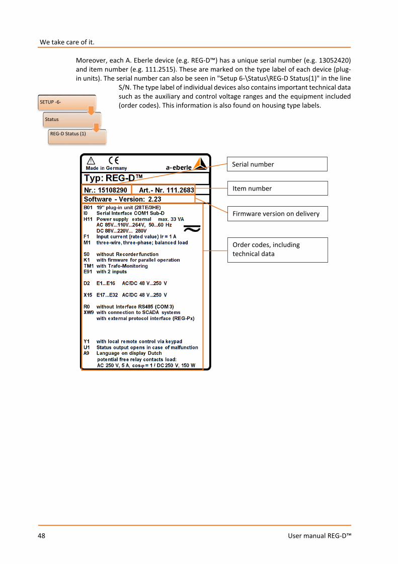
We take care of it.
48
User manual REG-D™
Moreover, each A. Eberle device (e.g. REG-D™) has a unique serial number (e.g. 13052420) and item number (e.g. 111.2515). These are marked on the type label of each device (plug-in units). The serial number can also be seen in "Setup 6-\Status\REG-D Status(1)" in the line
S/N. The type label of individual devices also contains important technical data such as the auxiliary and control voltage ranges and the equipment included (order codes). This information is also found on housing type labels.
Serial number
Item number
Firmware version on delivery
Order codes, including technical data
SETUP -6-
Status
REG-D Status (1)
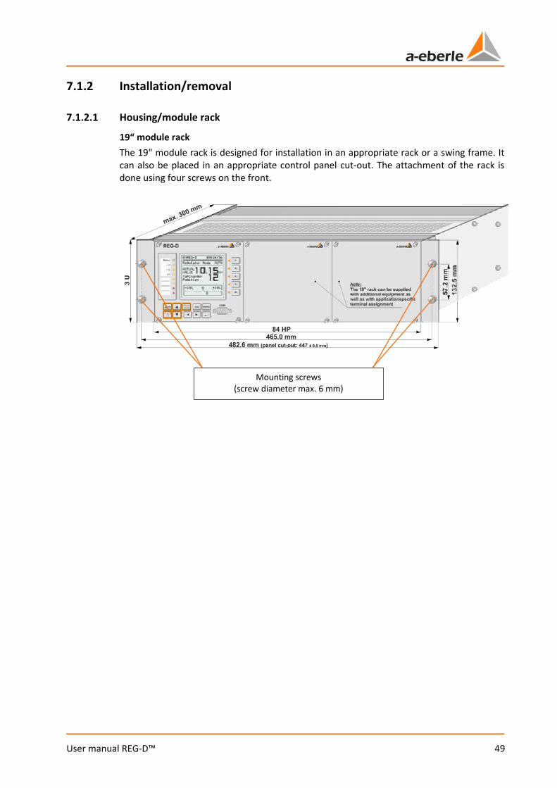
49
User manual REG-D™
7.1.2 Installation/removal
7.1.2.1 Housing/module rack
19“ module rack The 19" module rack is designed for installation in an appropriate rack or a swing frame. It can also be placed in an appropriate control panel cut-out. The attachment of the rack is done using four screws on the front.
Mounting screws (screw diameter max. 6 mm)

We take care of it.
50
User manual REG-D™
Wall-mount housing The wall-mount housing is designed for mounting on a wall or mounting plate. The fixing is done by four screws in the holes provided. Since hole distances depend on the construction of the housing (30 or 49 HP width), obtain the drilling distances from the technical data in the appendix, chapter 21, or the drawings supplied with the system.
Panel mounting housing The panel-mounting housing is intended for mounting in a panel or cabinet door. To this end, the panel must be provided with a correspondingly large cut. Since the hole distances depend on the construction of the housing (30 or 49 HP width), obtain the drilling distances from the technical data in the appendix, chapter 21, or the drawings supplied with the system. Fastening of the housing on the panel is done via four clamping devices, which are mounted on the housing. For this purpose, the housing is first inserted from the front all the way into the cut-out. Subsequently, the holding devices are folded out by turning the corresponding screw. The housing is clamped to the panel by further turning of the screw. The maximum thickness of the panel is 20 mm.
Mounting screws (screw diameter max. 5 mm)
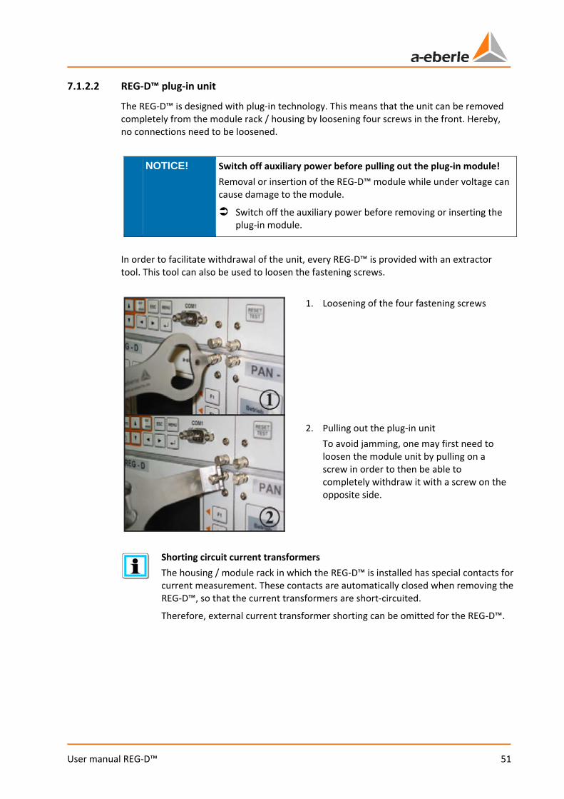
51
User manual REG-D™
7.1.2.2 REG-D™ plug-in unit
The REG-D™ is designed with plug-in technology. This means that the unit can be removed completely from the module rack / housing by loosening four screws in the front. Hereby, no connections need to be loosened.
NOTICE! Switch off auxiliary power before pulling out the plug-in module! Removal or insertion of the REG-D™ module while under voltage can cause damage to the module.
Switch off the auxiliary power before removing or inserting the plug-in module.
In order to facilitate withdrawal of the unit, every REG-D™ is provided with an extractor tool. This tool can also be used to loosen the fastening screws.
1. Loosening of the four fastening screws
2. Pulling out the plug-in unit To avoid jamming, one may first need to loosen the module unit by pulling on a screw in order to then be able to completely withdraw it with a screw on the opposite side.
Shorting circuit current transformers The housing / module rack in which the REG-D™ is installed has special contacts for current measurement. These contacts are automatically closed when removing the REG-D™, so that the current transformers are short-circuited.
Therefore, external current transformer shorting can be omitted for the REG-D™.
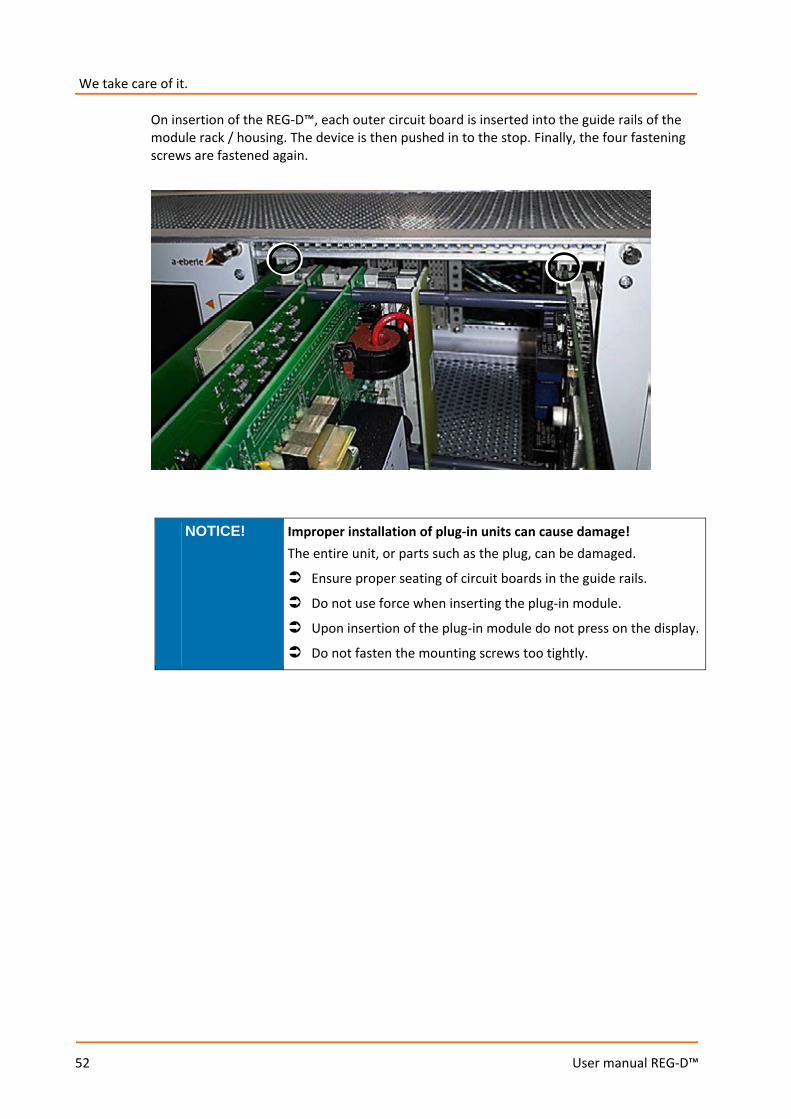
We take care of it.
52
User manual REG-D™
On insertion of the REG-D™, each outer circuit board is inserted into the guide rails of the module rack / housing. The device is then pushed in to the stop. Finally, the four fastening screws are fastened again.
NOTICE! Improper installation of plug-in units can cause damage! The entire unit, or parts such as the plug, can be damaged.
Ensure proper seating of circuit boards in the guide rails.
Do not use force when inserting the plug-in module.
Upon insertion of the plug-in module do not press on the display.
Do not fasten the mounting screws too tightly.
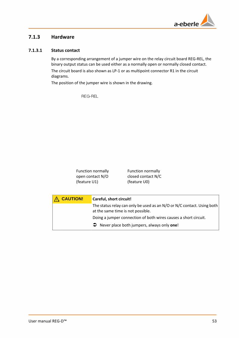
53
User manual REG-D™
7.1.3 Hardware
7.1.3.1 Status contact
By a corresponding arrangement of a jumper wire on the relay circuit board REG-REL, the binary output status can be used either as a normally open or normally closed contact. The circuit board is also shown as LP-1 or as multipoint connector R1 in the circuit diagrams. The position of the jumper wire is shown in the drawing.
CAUTION! Careful, short circuit! The status relay can only be used as an N/O or N/C contact. Using both at the same time is not possible. Doing a jumper connection of both wires causes a short circuit.
Never place both jumpers, always only one!
Function normally closed contact N/C (feature U0)
Function normally open contact N/O (feature U1)
REG-REL
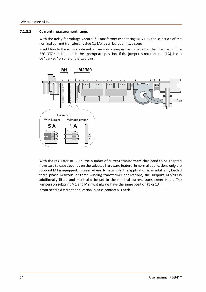
We take care of it.
54
User manual REG-D™
7.1.3.2 Current measurement range
With the Relay for Voltage Control & Transformer Monitoring REG-D™, the selection of the nominal current transducer value (1/5A) is carried out in two steps. In addition to the software-based conversion, a jumper has to be set on the filter card of the REG-NTZ circuit board in the appropriate position. If the jumper is not required (1A), it can be "parked" on one of the two pins.
With the regulator REG-D™, the number of current transformers that need to be adapted from case to case depends on the selected hardware feature. In normal applications only the subprint M1 is equipped. In cases where, for example, the application is an arbitrarily loaded three phase network, or three-winding transformer applications, the subprint M2/M9 is additionally fitted and must also be set to the nominal current transformer value. The jumpers on subprint M1 and M2 must always have the same position (1 or 5A). If you need a different application, please contact A. Eberle.
Assignment With jumper Without jumper
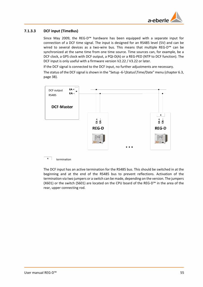
55
User manual REG-D™
7.1.3.3 DCF input (TimeBus)
Since May 2009, the REG-D™ hardware has been equipped with a separate input for connection of a DCF time signal. The input is designed for an RS485 level (5V) and can be wired to several devices as a two-wire bus. This means that multiple REG-D™ can be synchronized at the same time from one time source. Time sources can, for example, be a DCF clock, a GPS clock with DCF output, a PQI-D(A) or a REG-PED (NTP to DCF function). The DCF input is only useful with a firmware version V2.22 / V3.22 or later. If the DCF signal is connected to the DCF input, no further adjustments are necessary. The status of the DCF signal is shown in the "Setup -6-\Status\Time/Date" menu (chapter 6.3, page 38).
The DCF input has an active termination for the RS485 bus. This should be switched in at the beginning and at the end of the RS485 bus to prevent reflections. Activation of the termination via two jumpers or a switch can be made, depending on the version. The jumpers (X601) or the switch (S601) are located on the CPU board of the REG-D™ in the area of the rear, upper connecting rod.
DCF output RS485
termination

We take care of it.
56
User manual REG-D™
Version with jumpers (X601): Plugged jumpers -> termination active Jumpers not plugged -> termination inactive
Version with switch (X601): Switch in position A -> termination active Switch in position B -> termination inactive
A B
57
User manual REG-D™
7.1.4 Connection Almost all housings and module racks are equipped with custom internal wiring. That is, to be able to carry out the wiring of the housings or module racks, you will need the matching wiring diagrams for the system. These are supplied with the system. If you do not have the circuit diagrams, please contact the A. Eberle REGSys support team ([email protected], +49(0)911/628108-101). The wire cross-sections of the different terminal types and tightening torques can be found in the technical data in the appendix, chapter 21.
WARNING! Danger of electric shock!
When you connect, always follow the five safety rules.
Carry out connections according to the applicable regulations and this user manual.
Upon insertion of the plug-in module do not press on the display.
Do not fasten the mounting screws too tightly.
WARNING! Incorrect connection! The device and/or the system can be damaged.
To make connections always use the associated system drawings.
Pay attention to the nominal values of the auxiliary and control voltages.
Ensure that communication interfaces are not subjected to control or auxiliary voltage.
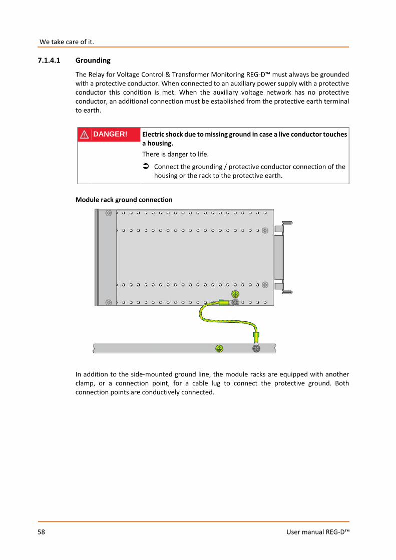
We take care of it.
58
User manual REG-D™
7.1.4.1 Grounding
The Relay for Voltage Control & Transformer Monitoring REG-D™ must always be grounded with a protective conductor. When connected to an auxiliary power supply with a protective conductor this condition is met. When the auxiliary voltage network has no protective conductor, an additional connection must be established from the protective earth terminal to earth.
DANGER! Electric shock due to missing ground in case a live conductor touches a housing. There is danger to life.
Connect the grounding / protective conductor connection of the housing or the rack to the protective earth.
Module rack ground connection
In addition to the side-mounted ground line, the module racks are equipped with another clamp, or a connection point, for a cable lug to connect the protective ground. Both connection points are conductively connected.
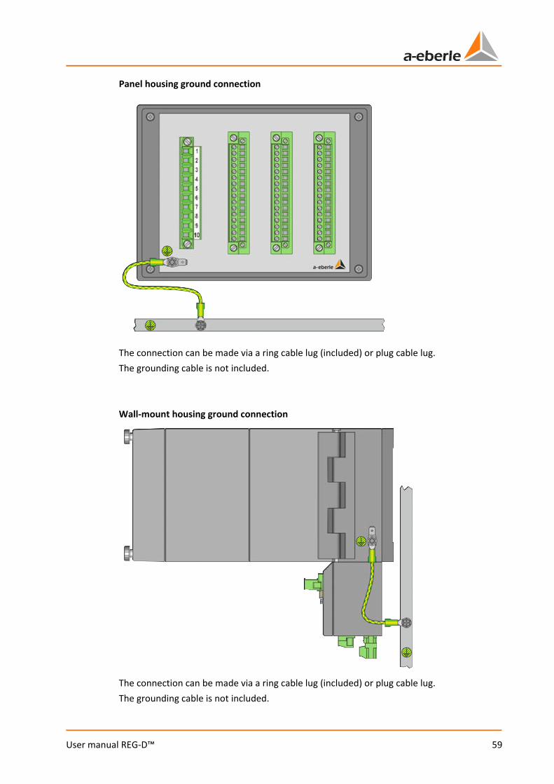
59
User manual REG-D™
Panel housing ground connection
The connection can be made via a ring cable lug (included) or plug cable lug. The grounding cable is not included. Wall-mount housing ground connection
The connection can be made via a ring cable lug (included) or plug cable lug. The grounding cable is not included.
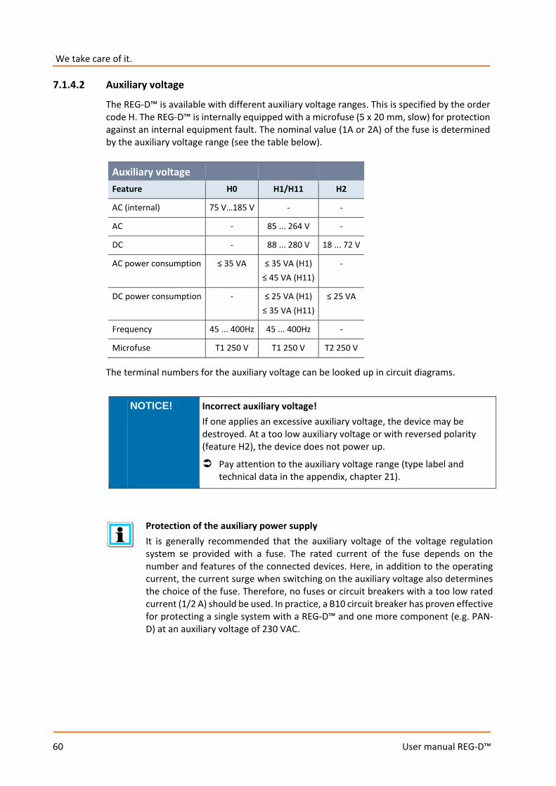
We take care of it.
60
User manual REG-D™
7.1.4.2 Auxiliary voltage
The REG-D™ is available with different auxiliary voltage ranges. This is specified by the order code H. The REG-D™ is internally equipped with a microfuse (5 x 20 mm, slow) for protection against an internal equipment fault. The nominal value (1A or 2A) of the fuse is determined by the auxiliary voltage range (see the table below).
The terminal numbers for the auxiliary voltage can be looked up in circuit diagrams.
NOTICE! Incorrect auxiliary voltage! If one applies an excessive auxiliary voltage, the device may be destroyed. At a too low auxiliary voltage or with reversed polarity (feature H2), the device does not power up.
Pay attention to the auxiliary voltage range (type label and technical data in the appendix, chapter 21).
Protection of the auxiliary power supply It is generally recommended that the auxiliary voltage of the voltage regulation system se provided with a fuse. The rated current of the fuse depends on the number and features of the connected devices. Here, in addition to the operating current, the current surge when switching on the auxiliary voltage also determines the choice of the fuse. Therefore, no fuses or circuit breakers with a too low rated current (1/2 A) should be used. In practice, a B10 circuit breaker has proven effective for protecting a single system with a REG-D™ and one more component (e.g. PAN-D) at an auxiliary voltage of 230 VAC.
Auxiliary voltage Feature H0 H1/H11 H2
AC (internal) 75 V…185 V - -
AC - 85 ... 264 V -
DC - 88 ... 280 V 18 ... 72 V
AC power consumption ≤ 35 VA ≤ 35 VA (H1) ≤ 45 VA (H11)
-
DC power consumption - ≤ 25 VA (H1) ≤ 35 VA (H11)
≤ 25 VA
Frequency 45 ... 400Hz 45 ... 400Hz -
Microfuse T1 250 V T1 250 V T2 250 V
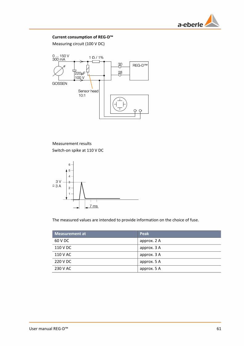
61
User manual REG-D™
Current consumption of REG-D™ Measuring circuit (100 V DC)
Measurement results Switch-on spike at 110 V DC
The measured values are intended to provide information on the choice of fuse.
Measurement at Peak 60 V DC approx. 2 A 110 V DC approx. 3 A 110 V AC approx. 3 A 220 V DC approx. 5 A 230 V AC approx. 5 A

We take care of it.
62
User manual REG-D™
7.1.4.3 Binary signals
Binary inputs A REG-D™ can be fitted internally with up to 32 binary inputs. The input cards are available with different voltage levels. The voltage range of the fitted binary inputs can be found on the circuit diagrams and the type label (order codes D and X). The terminal numbers of the binary inputs can be looked up in the circuit diagrams. The binary inputs of the REG-D™ are potential-free binary inputs. This means that they have to be controlled by an external control voltage.
NOTICE! Incorrect auxiliary voltage! If one applies an excessive auxiliary voltage, the binary inputs may be destroyed. At a too low control voltage no signal is detected at the inputs.
Pay attention to the auxiliary voltage range (type label and technical data in the appendix, chapter 21).
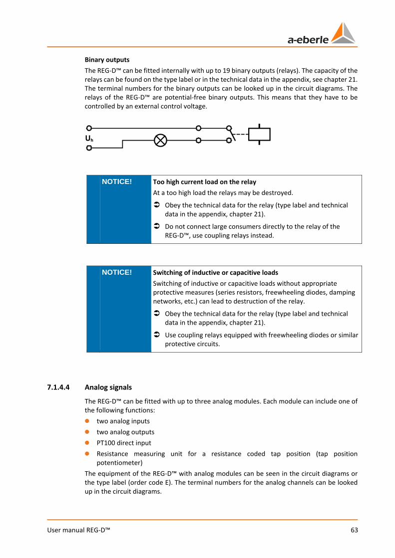
63
User manual REG-D™
Binary outputs The REG-D™ can be fitted internally with up to 19 binary outputs (relays). The capacity of the relays can be found on the type label or in the technical data in the appendix, see chapter 21. The terminal numbers for the binary outputs can be looked up in the circuit diagrams. The relays of the REG-D™ are potential-free binary outputs. This means that they have to be controlled by an external control voltage.
NOTICE! Too high current load on the relay At a too high load the relays may be destroyed.
Obey the technical data for the relay (type label and technical data in the appendix, chapter 21).
Do not connect large consumers directly to the relay of the REG-D™, use coupling relays instead.
NOTICE! Switching of inductive or capacitive loads Switching of inductive or capacitive loads without appropriate protective measures (series resistors, freewheeling diodes, damping networks, etc.) can lead to destruction of the relay.
Obey the technical data for the relay (type label and technical data in the appendix, chapter 21).
Use coupling relays equipped with freewheeling diodes or similar protective circuits.
7.1.4.4 Analog signals
The REG-D™ can be fitted with up to three analog modules. Each module can include one of the following functions: 0 two analog inputs 0 two analog outputs 0 PT100 direct input 0 Resistance measuring unit for a resistance coded tap position (tap position
potentiometer) The equipment of the REG-D™ with analog modules can be seen in the circuit diagrams or the type label (order code E). The terminal numbers for the analog channels can be looked up in the circuit diagrams.
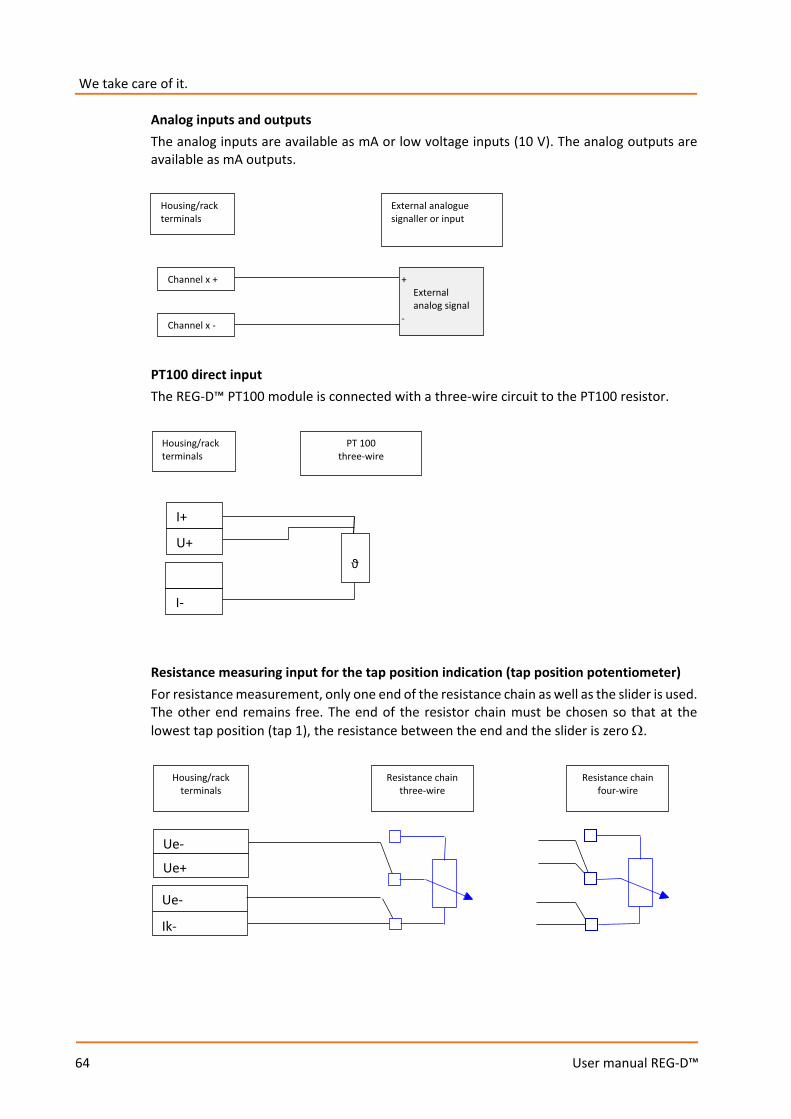
We take care of it.
64
User manual REG-D™
Analog inputs and outputs The analog inputs are available as mA or low voltage inputs (10 V). The analog outputs are available as mA outputs.
PT100 direct input The REG-D™ PT100 module is connected with a three-wire circuit to the PT100 resistor.
Resistance measuring input for the tap position indication (tap position potentiometer) For resistance measurement, only one end of the resistance chain as well as the slider is used. The other end remains free. The end of the resistor chain must be chosen so that at the lowest tap position (tap 1), the resistance between the end and the slider is zero Ω.
External analogue signaller or input
Housing/rack terminals
+ External analog signal -
Channel x -
Channel x +
PT 100 three-wire
Housing/rack terminals
ϑ
U+
I+
I-
Ue+
Ue-
Ik-
Ue-
Housing/rack terminals
Resistance chain three-wire
Resistance chain four-wire
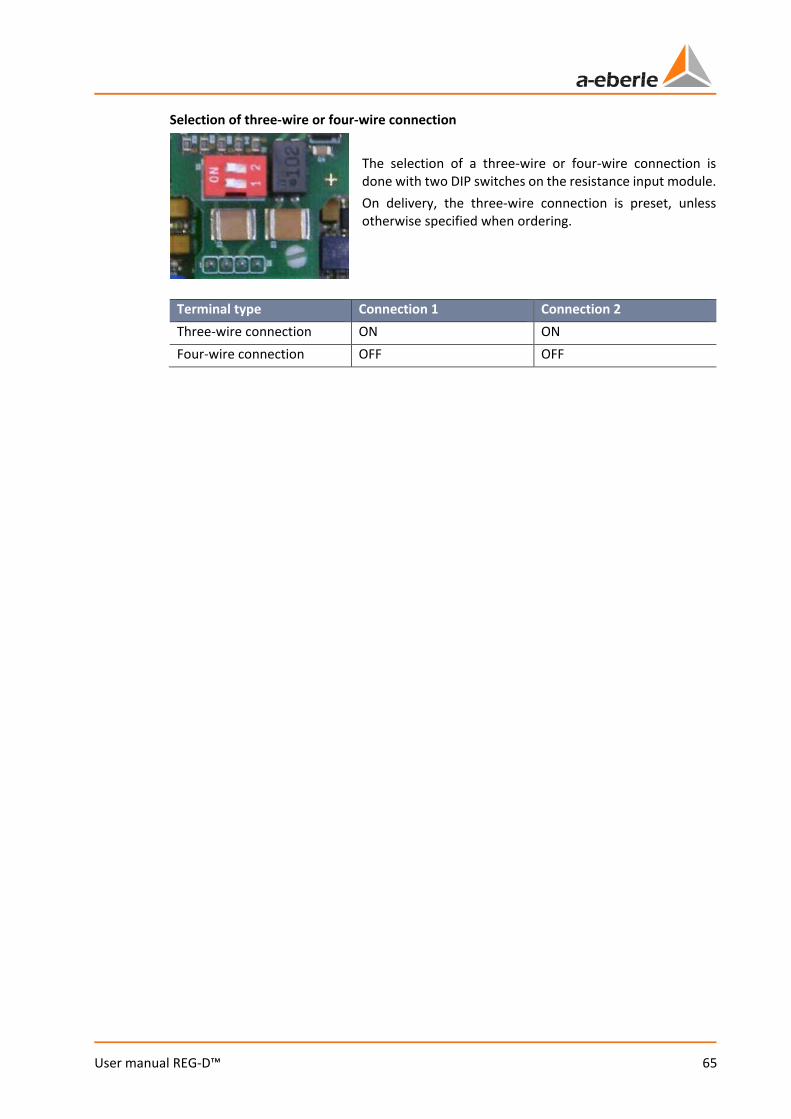
65
User manual REG-D™
Selection of three-wire or four-wire connection The selection of a three-wire or four-wire connection is done with two DIP switches on the resistance input module. On delivery, the three-wire connection is preset, unless otherwise specified when ordering.
Terminal type Connection 1 Connection 2 Three-wire connection ON ON Four-wire connection OFF OFF

We take care of it.
66
User manual REG-D™
7.1.4.5 Process
The connection of the process (transducer, tap changer, etc.) can be done in many different ways. In the following, a simplified diagram of the signals is shown.
Connecting the current and voltage transformers Any star or phase voltage can be supplied for regulating the REG-D™. The current can also be taken from any phase. In order for the phase relationships (phase shift between voltage and current) and thus the power calculation and the load flow direction to be correct, the voltages and currents used have to be set in the VT/CT configuration. In addition, on connecting the transducer ensure that the polarity is correct.
Pay attention to the nominal values of the voltage and current inputs.
Note the A. Eberle definition of power directions (see figure below).
On connecting, note the polarity of the transducer (see figure below).
* Please obey the contact load at R1 and R2
** Free software selection of I and U connectors
*** Optional tap-changer position via mA-signal
MANUAL / HAND AUTOMATIC / AUTO
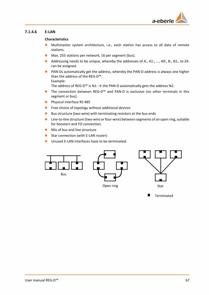
67
User manual REG-D™
7.1.4.6 E-LAN
Characteristics 0 Multimaster system architecture, i.e., each station has access to all data of remote
stations. 0 Max. 255 stations per network, 16 per segment (bus). 0 Addressing needs to be unique, whereby the addresses of A:, A1:, ..., A9:, B:, B1:, to Z4:
can be assigned. 0 PAN-Ds automatically get the address, whereby the PAN-D address is always one higher
than the address of the REG-D™. Example: The address of REG-D™ is N1: → the PAN-D automatically gets the address N2:
0 The connection between REG-D™ and PAN-D is exclusive (no other terminals in this segment or bus).
0 Physical interface RS 485 0 Free choice of topology without additional devices 0 Bus structure (two-wire) with terminating resistors at the bus ends 0 Line-to-line structure (two-wire or four-wire) between segments of an open ring, suitable
for boosters and FO connection. 0 Mix of bus and line structure 0 Star connection (with E-LAN router) 0 Unused E-LAN interfaces have to be terminated.
Bus
Open ring Star
Terminated

We take care of it.
68
User manual REG-D™
Configuration Connection Max. wire length REG-D™ REG-D™ two-wire, direct 400 m REG-D™ REG-D™ REG-D™
two-wire, bus (max. 16 devices)
100 m branch line 10 m
REG-D™ REG-D™ four-wire, direct 1200 m REG-D™ Booster Booster REG-D™ four-wire,
two boosters 4000 m
Recommended cable type: e.g. 2 x 2 x 0.6 … 0.8 mm2, twisted pair The use of non-twisted control lines may also be possible for short distances. This needs to be checked in each case. Use of the E-LAN GND The E-LAN GND terminal is not an earth ground, but a terminal for a potential equalization line, which is connected to all the GND terminals of the connected E-LAN interfaces. The potential equalization line is additionally led to the twisted pair and may be low-resistance grounded at only one point. This is only a functional earth! With a bundled installation with disturbing wires, an additional shield may be required. This may only be low-resistance grounded at one point. Grounding at other points via resistors ≥ 100 Ω is allowed, but unnecessary. Connection examples for E-LAN REG-D™ with PAN-D and other REG-D™
Terminated Not terminated

69
User manual REG-D™
Connection example for E-LAN: 3 x REG-D™ in two-wire bus topology
Connection example for E-LAN: 3 x REG-D™ with two-wire and four-wire point-to-point connection
Terminated
Not terminated
Terminated
Not terminated
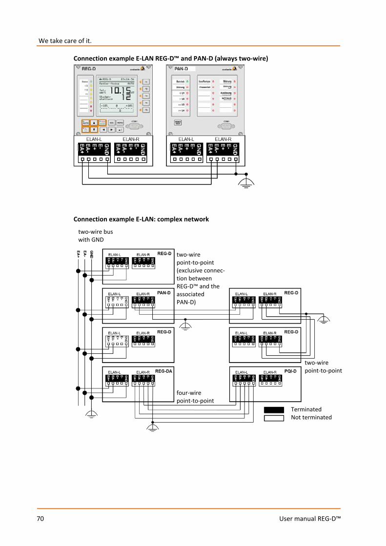
We take care of it.
70
User manual REG-D™
Connection example E-LAN REG-D™ and PAN-D (always two-wire)
Connection example E-LAN: complex network
two-wire bus with GND
two-wire point-to-point (exclusive connec-tion between REG-D™ and the associated PAN-D)
four-wire point-to-point
two-wire point-to-point
Terminated Not terminated
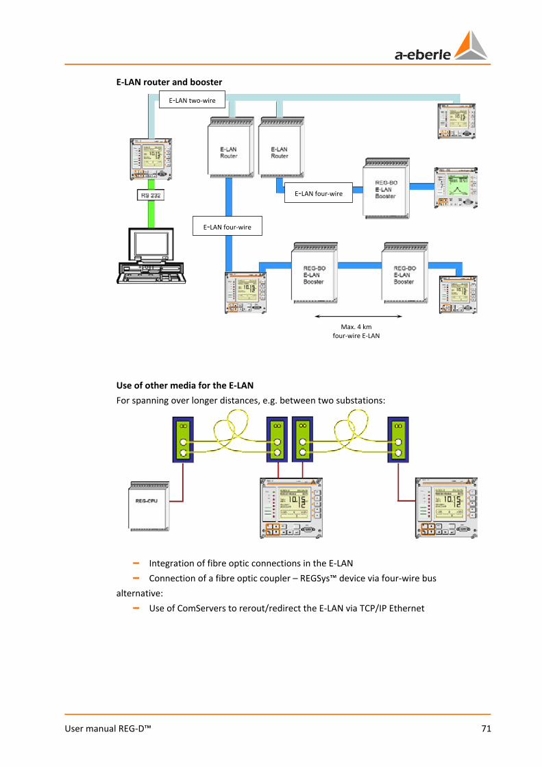
71
User manual REG-D™
E-LAN router and booster
Use of other media for the E-LAN For spanning over longer distances, e.g. between two substations:
– Integration of fibre optic connections in the E-LAN – Connection of a fibre optic coupler – REGSys™ device via four-wire bus
alternative: – Use of ComServers to rerout/redirect the E-LAN via TCP/IP Ethernet
E-LAN two-wire
E-LAN four-wire
E-LAN four-wire
Max. 4 km four-wire E-LAN
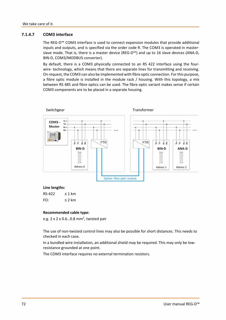
We take care of it.
72
User manual REG-D™
7.1.4.7 COM3 interface
The REG-D™ COM3 interface is used to connect expansion modules that provide additional inputs and outputs, and is specified via the order code R. The COM3 is operated in master-slave mode. That is, there is a master device (REG-D™) and up to 16 slave devices (ANA-D, BIN-D, COM3/MODBUS converter). By default, there is a COM3 physically connected to an RS 422 interface using the four-wire- technology, which means that there are separate lines for transmitting and receiving. On request, the COM3 can also be implemented with fibre optic connection. For this purpose, a fibre optic module is installed in the module rack / housing. With this topology, a mix between RS 485 and fibre optics can be used. The fibre optic variant makes sense if certain COM3 components are to be placed in a separate housing.
Line lengths: RS-422 ≤ 1 km FO: ≤ 2 km Recommended cable type: e.g. 2 x 2 x 0.6…0.8 mm2, twisted pair The use of non-twisted control lines may also be possible for short distances. This needs to checked in each case. In a bundled wire installation, an additional shield may be required. This may only be low-resistance grounded at one point. The COM3 interface requires no external termination resistors.
Switchgear Transformer
Adress 0 Adress 1 Adress 2
Option: fibre optic module
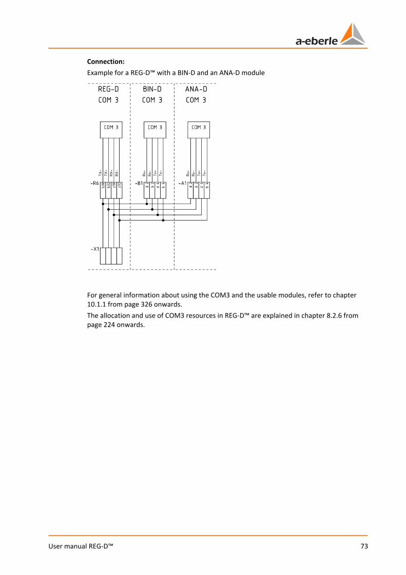
73
User manual REG-D™
Connection: Example for a REG-D™ with a BIN-D and an ANA-D module
For general information about using the COM3 and the usable modules, refer to chapter 10.1.1 from page 326 onwards. The allocation and use of COM3 resources in REG-D™ are explained in chapter 8.2.6 from page 224 onwards.
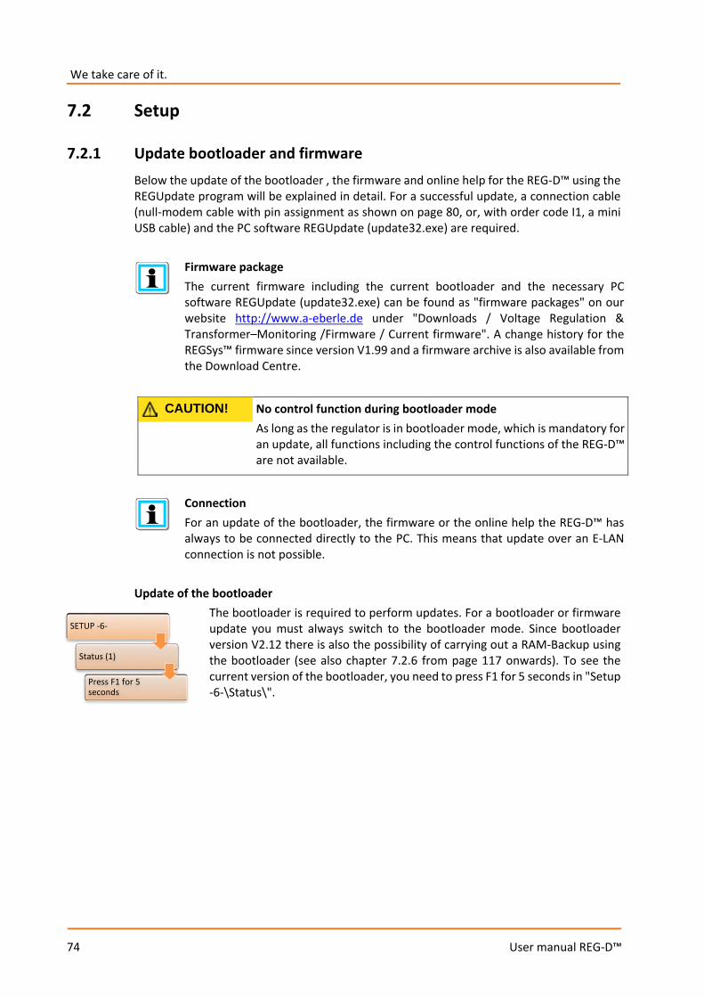
We take care of it.
74
User manual REG-D™
7.2 Setup
7.2.1 Update bootloader and firmware Below the update of the bootloader , the firmware and online help for the REG-D™ using the REGUpdate program will be explained in detail. For a successful update, a connection cable (null-modem cable with pin assignment as shown on page 80, or, with order code I1, a mini USB cable) and the PC software REGUpdate (update32.exe) are required.
Firmware package The current firmware including the current bootloader and the necessary PC software REGUpdate (update32.exe) can be found as "firmware packages" on our website http://www.a-eberle.de under "Downloads / Voltage Regulation & Transformer–Monitoring /Firmware / Current firmware". A change history for the REGSys™ firmware since version V1.99 and a firmware archive is also available from the Download Centre.
CAUTION! No control function during bootloader mode As long as the regulator is in bootloader mode, which is mandatory for an update, all functions including the control functions of the REG-D™ are not available.
Connection For an update of the bootloader, the firmware or the online help the REG-D™ has always to be connected directly to the PC. This means that update over an E-LAN connection is not possible.
Update of the bootloader
The bootloader is required to perform updates. For a bootloader or firmware update you must always switch to the bootloader mode. Since bootloader version V2.12 there is also the possibility of carrying out a RAM-Backup using the bootloader (see also chapter 7.2.6 from page 117 onwards). To see the current version of the bootloader, you need to press F1 for 5 seconds in "Setup -6-\Status\".
SETUP -6-
Status (1)
Press F1 for 5 seconds

75
User manual REG-D™
When is a bootloader update required? It is recommended to update the bootloader only if it is really necessary. For example, if the RAM-Backup functionality needs to be used, a bootloader >= version V2.12 must be loaded, if it is not already present.
NOTICE! Downgrading the bootloader Never perform a downgrade of the bootloader (e.g. V2.12 to V2.10). The regulator can be permanently damaged by doing so.
To update the bootloader the following steps are necessary: 1.) With the null-modem cable connect the regulator via COM1 to a free COM interface on
the PC. If the REG-D™ is equipped with a USB interface instead of a SUB-D socket, connect COM1 to the PC via the USB cable.
2.) Starting the PC software
Use the program REGUpdate (update32.exe) under any of the operating systems Windows 95/98/NT/XP/7 or 8. 2.1 Select language 2.2 Select the appropriate COM interface on your PC 2.3 Select the connected device (here: REG-D™)
3.) Loading the new bootloader In the program REGUpdate under "Update / new Bootloader", select file boot_xxx.mot and click on Open. There is an indication that the bootloader needs to be started via "Setup -6-/Status/" pressing F1 for 5 seconds.
The REG-D™ bootloader has its own interface settings. These are visible after starting the bootloader. The baudrate can be set using the F3 key. The settings for flow control (handshake) and parity cannot be selected.
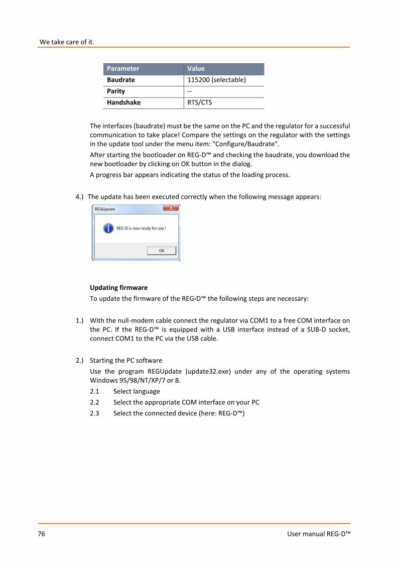
We take care of it.
76
User manual REG-D™
The interfaces (baudrate) must be the same on the PC and the regulator for a successful communication to take place! Compare the settings on the regulator with the settings in the update tool under the menu item: "Configure/Baudrate". After starting the bootloader on REG-D™ and checking the baudrate, you download the new bootloader by clicking on OK button in the dialog. A progress bar appears indicating the status of the loading process.
4.) The update has been executed correctly when the following message appears:
Updating firmware To update the firmware of the REG-D™ the following steps are necessary:
1.) With the null-modem cable connect the regulator via COM1 to a free COM interface on the PC. If the REG-D™ is equipped with a USB interface instead of a SUB-D socket, connect COM1 to the PC via the USB cable.
2.) Starting the PC software Use the program REGUpdate (update32.exe) under any of the operating systems Windows 95/98/NT/XP/7 or 8. 2.1 Select language 2.2 Select the appropriate COM interface on your PC 2.3 Select the connected device (here: REG-D™)
Parameter Value Baudrate 115200 (selectable) Parity -- Handshake RTS/CTS
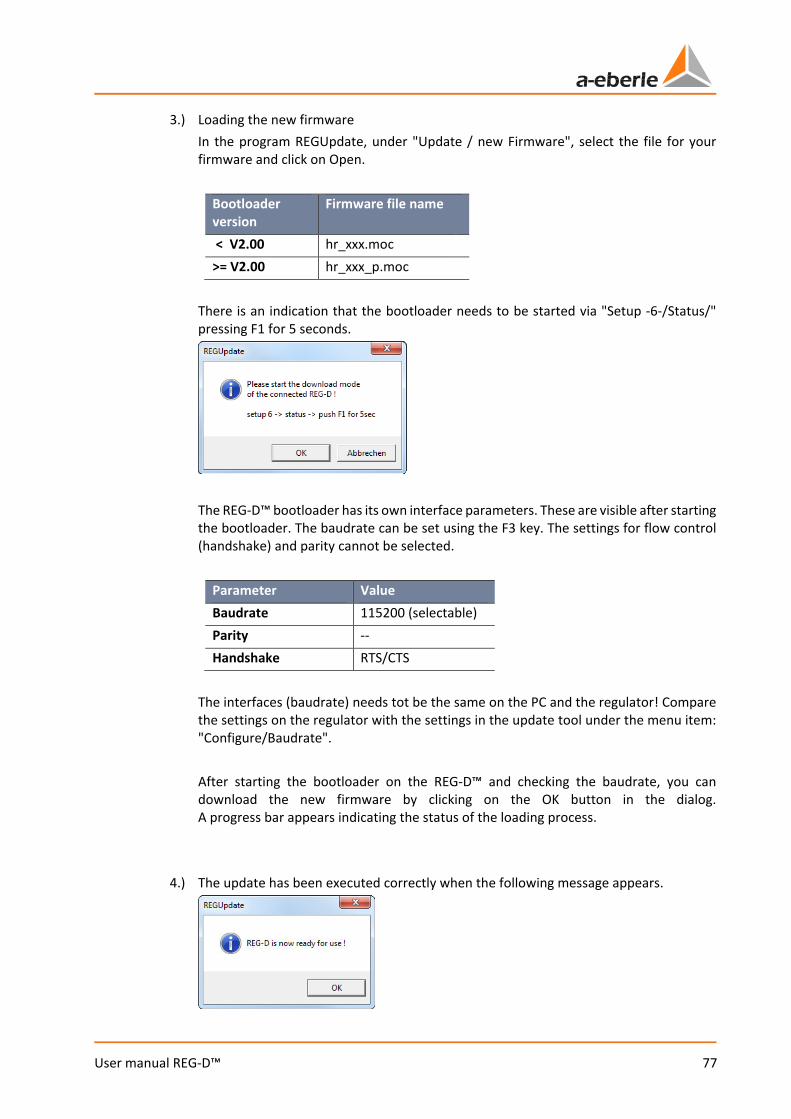
77
User manual REG-D™
3.) Loading the new firmware In the program REGUpdate, under "Update / new Firmware", select the file for your firmware and click on Open.
Bootloader version
Firmware file name
< V2.00 hr_xxx.moc >= V2.00 hr_xxx_p.moc
There is an indication that the bootloader needs to be started via "Setup -6-/Status/" pressing F1 for 5 seconds.
The REG-D™ bootloader has its own interface parameters. These are visible after starting the bootloader. The baudrate can be set using the F3 key. The settings for flow control (handshake) and parity cannot be selected.
Parameter Value Baudrate 115200 (selectable) Parity -- Handshake RTS/CTS
The interfaces (baudrate) needs tot be the same on the PC and the regulator! Compare the settings on the regulator with the settings in the update tool under the menu item: "Configure/Baudrate". After starting the bootloader on the REG-D™ and checking the baudrate, you can download the new firmware by clicking on the OK button in the dialog. A progress bar appears indicating the status of the loading process.
4.) The update has been executed correctly when the following message appears.
We take care of it.
78
User manual REG-D™
Important notes after an upgrade or downgrade of the REG-D™ firmware
1.) After upgrading the firmware of the REG-D™ (e.g. V2.10 V2.20) any pre-existing RAM-
Backup should be replaced by a new RAM-Backup. The reason for this is that new parameters that have been added to a recent firmware do not yet exist in the old RAM-Backup. If a RAM-Backup of a lower firmware version is restored, new parameters are initialized with default values.
2.) After a downgrade of the firmware of REG-D™ (e.g. V2.22 V2.15) it is essential to take
the following steps:
a.) The device must be re-initialized (see "Resetting all parameters via the bootloader" in chapter 7.2.6 RAM-Backup, from page 121 onwards).
b.) An existing RAM-Backup must be performed again (see "Performing RAM-Backup" in
chapter 7.2.6 RAM-Backup, from page 117 onwards), or deleted (see "Deleting an existing backup file" in chapter 7.2.6 RAM-Backup, from page 120 onwards).
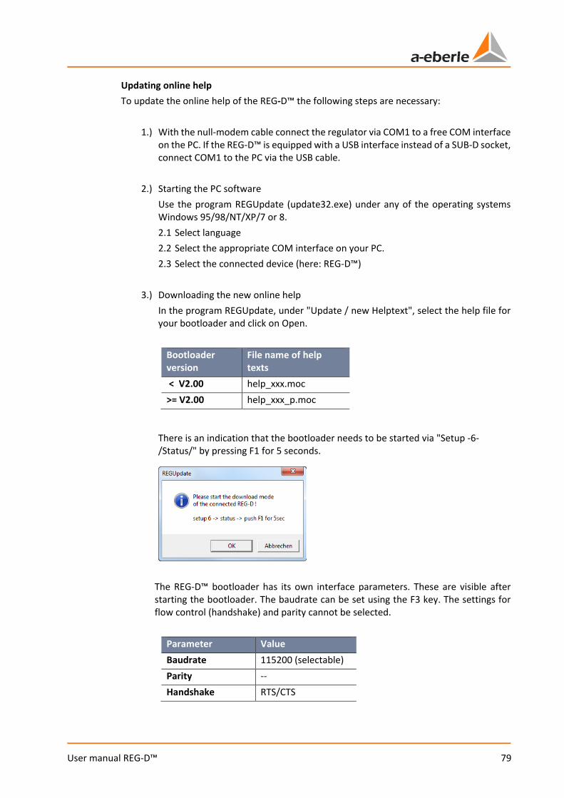
79
User manual REG-D™
Updating online help To update the online help of the REG-D™ the following steps are necessary:
1.) With the null-modem cable connect the regulator via COM1 to a free COM interface on the PC. If the REG-D™ is equipped with a USB interface instead of a SUB-D socket, connect COM1 to the PC via the USB cable.
2.) Starting the PC software
Use the program REGUpdate (update32.exe) under any of the operating systems Windows 95/98/NT/XP/7 or 8. 2.1 Select language 2.2 Select the appropriate COM interface on your PC. 2.3 Select the connected device (here: REG-D™)
3.) Downloading the new online help
In the program REGUpdate, under "Update / new Helptext", select the help file for your bootloader and click on Open.
Bootloader version
File name of help texts
< V2.00 help_xxx.moc >= V2.00 help_xxx_p.moc
There is an indication that the bootloader needs to be started via "Setup -6-/Status/" by pressing F1 for 5 seconds.
The REG-D™ bootloader has its own interface parameters. These are visible after starting the bootloader. The baudrate can be set using the F3 key. The settings for flow control (handshake) and parity cannot be selected.
Parameter Value Baudrate 115200 (selectable) Parity -- Handshake RTS/CTS
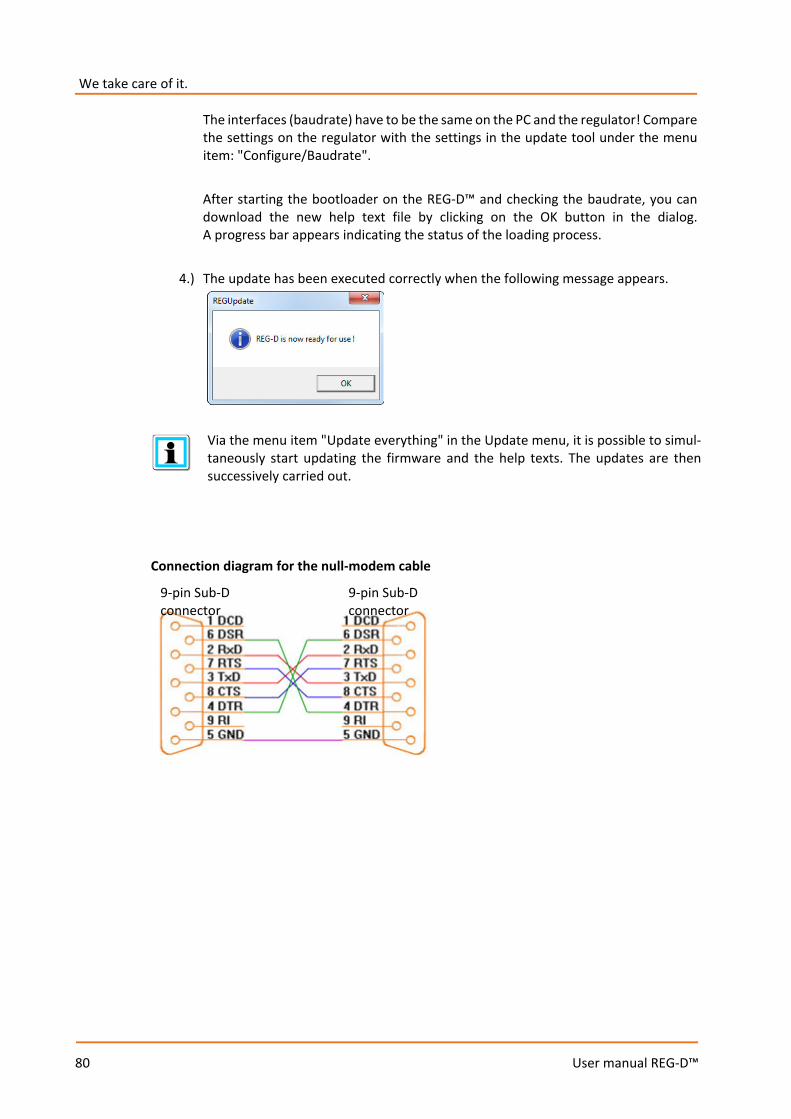
We take care of it.
80
User manual REG-D™
The interfaces (baudrate) have to be the same on the PC and the regulator! Compare the settings on the regulator with the settings in the update tool under the menu item: "Configure/Baudrate". After starting the bootloader on the REG-D™ and checking the baudrate, you can download the new help text file by clicking on the OK button in the dialog. A progress bar appears indicating the status of the loading process.
4.) The update has been executed correctly when the following message appears.
Via the menu item "Update everything" in the Update menu, it is possible to simul-taneously start updating the firmware and the help texts. The updates are then successively carried out.
Connection diagram for the null-modem cable
9-pin Sub-D connector
9-pin Sub-D connector

81
User manual REG-D™
7.2.2 Basic parameter setup
7.2.2.1 System
Menu structure of REG-D™ When powering up, the regulator starts in one of the basic regulator modes.
Repeatedly pressing the MENU key leads to the following submenus:
In addition to the MENU key you can also use the arrow keys and to move within the menu structure. Using the ESC key you move back to the previous screen without saving changes made to date. The ENTER key is used to confirm entries and save changes.
MENU 1 MENU 2 SETUP 1 SETUP 2 SETUP 3 SETUP 4 SETUP 5 SETUP 6

We take care of it.
82
User manual REG-D™
The modes available in MENU 1 and MENU 2 (regulator, transducer mode, recorder, statistics/monitor, PQIView and logbook) each present a basic display mode, accessed via the keys F1 ... F5. When you select one of these modes, the corresponding screen is displayed permanently and can only be changed by changing the selection in MENU 1 or MENU 2 again.
In addition to the available basic display modes, further choices can be made depending on the configuration of the device. After MENU 1 and MENU 2 you arrive at SETUP 1 to SETUP 6, with which the Relay for Voltage Control & Transformer Monitoring REG-D™ can be configured. The various submenus can be selected again with the keys F1 … F5.
F
F

83
User manual REG-D™
Station ID Up to 255 different devices can be addressed in the (E-LAN) bus. However, each device needs to be assigned a unique address (ID). The address range is from A ... A9, B ... B9, ... up to Z4. The ID can always be read in the upper left corner of the panel. The station ID is the part to the left of the colon.
PAN-D If a PAN-D is available, it is automatically assigned the ID of the directly connected REG-D™ plus one. That is, when the REG-D™ gets the identifier A: the PAN-D gets the address A1:. This has to be taken into account on addressing the Relay for Voltage Control & Transformer Monitoring. Please note that a change in the station ID may also involve adaptation of the tele-control system configuration, because the station ID is set in the configuration file used.
NOTICE! Same station ID If several devices are connected via E-LAN and have the same station ID, this can lead to malfunction of the devices.
SETUP -6-
General 2
Station ID

We take care of it.
84
User manual REG-D™
Station name The station name describes the regulator, i.e., the station name, unlike the station ID, is not used for unique identification in the E-LAN. The station name can, for example, be used for allocation to a transformer. The station name is freely selectable and can be up to eight characters long, where spaces are not allowed (but hyphens and underscores are). The station name (e.g. "Trafo12") is displayed together with the terminal ID (e.g. "B:“) in the upper left corner of the regulator, and also in the WinREG device selection dialog (in this example,
"B:Trafo12"), thus making the identification of the device easier. The station name can easily be entered in WinREG, or alternatively through the REG-D™ panel. In this, the F-keys have the following functions:
Select character set; the four arrow keys are used to select the character that needs to be confirmed with Enter
Switch character case
Clipboard Insert character at current position Delete character at current position
COM 1
The COM1 interface is accessible as configuration or programming interface via a SUB-D connector on the front panel. Alternatively, the connection can be made via a mini USB cable (order code I1). By default the COM1 mode is ECL. In this mode, the regulator can be accessed using the software WinREG. BAUDRATE, PARITY and HANDSHAKE must match the settings of the connected end device (e.g. PC) to ensure trouble-free communication. The
following communication parameters are recommended:
SETUP -6-
RS-232
SETUP -6-
General 2
Station Name
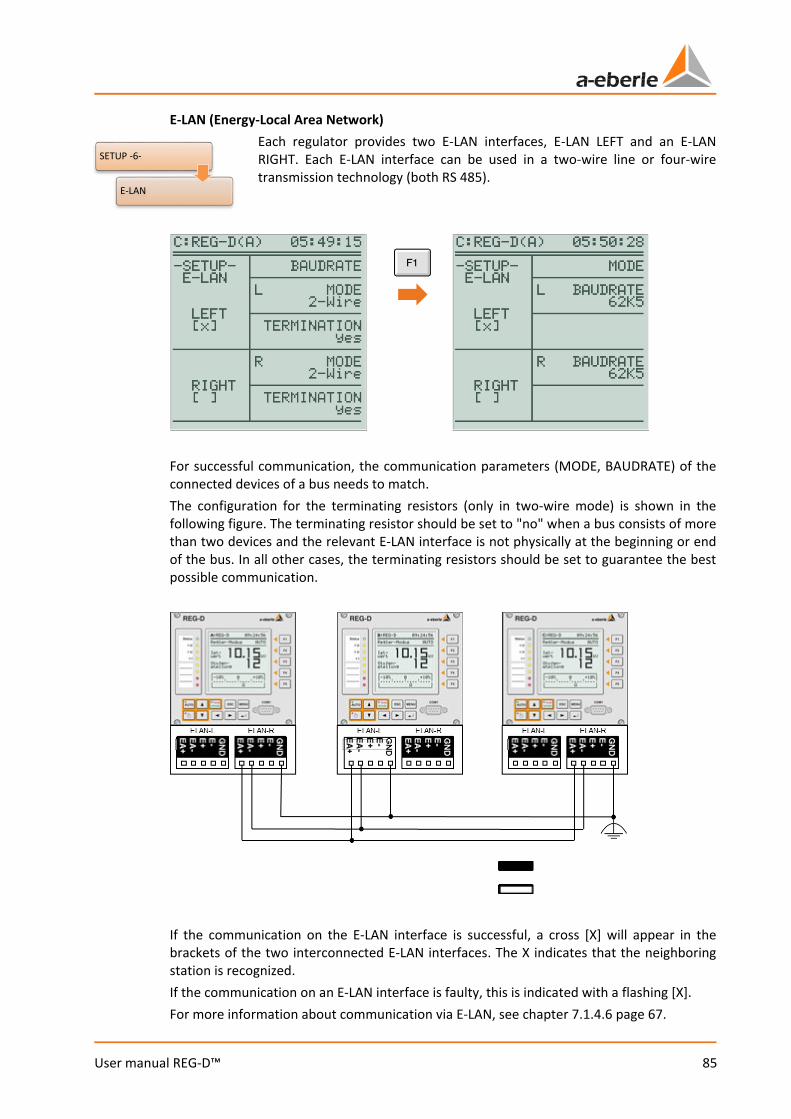
85
User manual REG-D™
E-LAN (Energy-Local Area Network) Each regulator provides two E-LAN interfaces, E-LAN LEFT and an E-LAN RIGHT. Each E-LAN interface can be used in a two-wire line or four-wire transmission technology (both RS 485).
For successful communication, the communication parameters (MODE, BAUDRATE) of the connected devices of a bus needs to match. The configuration for the terminating resistors (only in two-wire mode) is shown in the following figure. The terminating resistor should be set to "no" when a bus consists of more than two devices and the relevant E-LAN interface is not physically at the beginning or end of the bus. In all other cases, the terminating resistors should be set to guarantee the best possible communication.
If the communication on the E-LAN interface is successful, a cross [X] will appear in the brackets of the two interconnected E-LAN interfaces. The X indicates that the neighboring station is recognized. If the communication on an E-LAN interface is faulty, this is indicated with a flashing [X]. For more information about communication via E-LAN, see chapter 7.1.4.6 page 67.
SETUP -6-
E-LAN
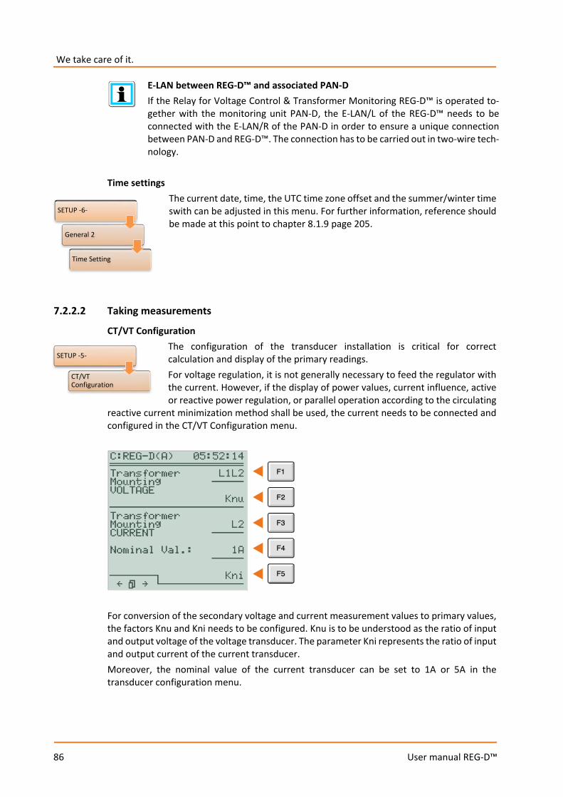
We take care of it.
86
User manual REG-D™
E-LAN between REG-D™ and associated PAN-D If the Relay for Voltage Control & Transformer Monitoring REG-D™ is operated to-gether with the monitoring unit PAN-D, the E-LAN/L of the REG-D™ needs to be connected with the E-LAN/R of the PAN-D in order to ensure a unique connection between PAN-D and REG-D™. The connection has to be carried out in two-wire tech-nology.
Time settings
The current date, time, the UTC time zone offset and the summer/winter time swith can be adjusted in this menu. For further information, reference should be made at this point to chapter 8.1.9 page 205.
7.2.2.2 Taking measurements
CT/VT Configuration The configuration of the transducer installation is critical for correct calculation and display of the primary readings. For voltage regulation, it is not generally necessary to feed the regulator with the current. However, if the display of power values, current influence, active or reactive power regulation, or parallel operation according to the circulating
reactive current minimization method shall be used, the current needs to be connected and configured in the CT/VT Configuration menu.
For conversion of the secondary voltage and current measurement values to primary values, the factors Knu and Kni needs to be configured. Knu is to be understood as the ratio of input and output voltage of the voltage transducer. The parameter Kni represents the ratio of input and output current of the current transducer. Moreover, the nominal value of the current transducer can be set to 1A or 5A in the transducer configuration menu.
SETUP -6-
General 2
Time Setting
SETUP -5-
CT/VT Configuration
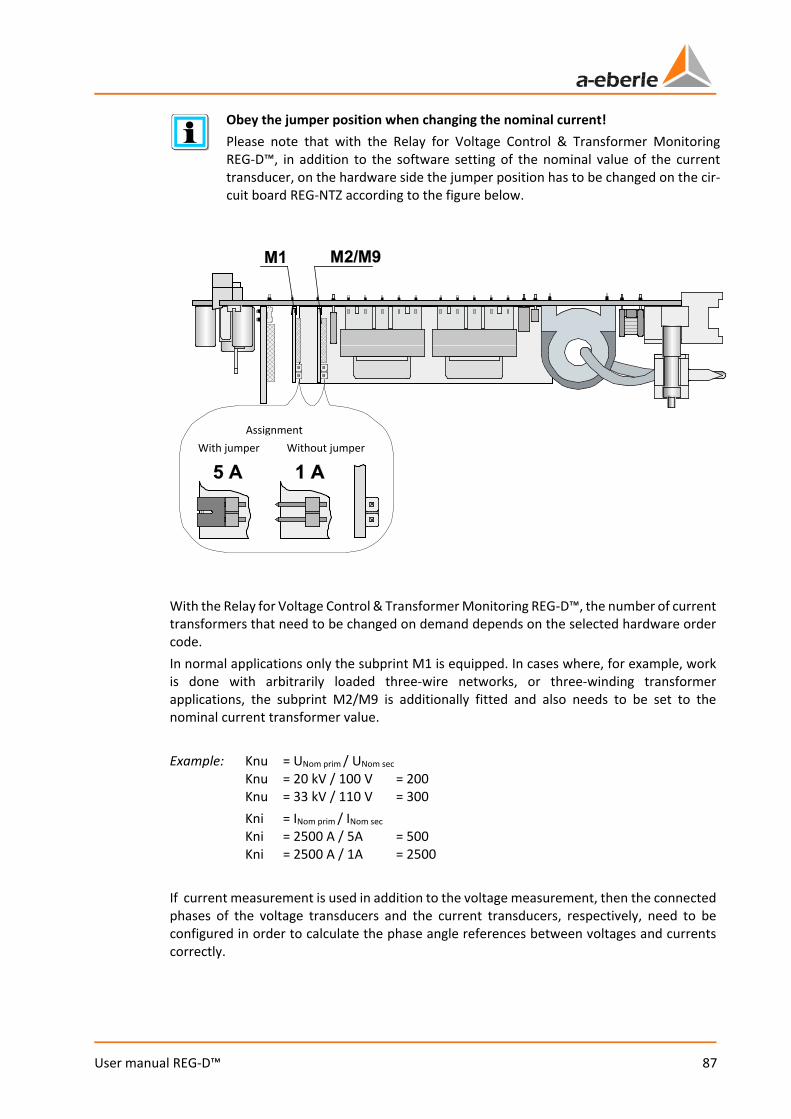
87
User manual REG-D™
Obey the jumper position when changing the nominal current! Please note that with the Relay for Voltage Control & Transformer Monitoring REG-D™, in addition to the software setting of the nominal value of the current transducer, on the hardware side the jumper position has to be changed on the cir-cuit board REG-NTZ according to the figure below.
With the Relay for Voltage Control & Transformer Monitoring REG-D™, the number of current transformers that need to be changed on demand depends on the selected hardware order code. In normal applications only the subprint M1 is equipped. In cases where, for example, work is done with arbitrarily loaded three-wire networks, or three-winding transformer applications, the subprint M2/M9 is additionally fitted and also needs to be set to the nominal current transformer value. Example: Knu = UNom prim / UNom sec Knu = 20 kV / 100 V = 200 Knu = 33 kV / 110 V = 300 Kni = INom prim / INom sec Kni = 2500 A / 5A = 500 Kni = 2500 A / 1A = 2500 If current measurement is used in addition to the voltage measurement, then the connected phases of the voltage transducers and the current transducers, respectively, need to be configured in order to calculate the phase angle references between voltages and currents correctly.
Assignment With jumper Without jumper
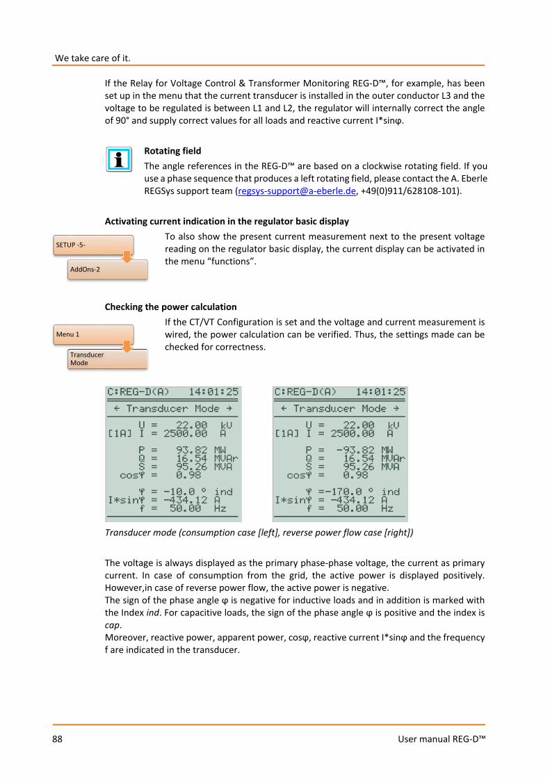
We take care of it.
88
User manual REG-D™
If the Relay for Voltage Control & Transformer Monitoring REG-D™, for example, has been set up in the menu that the current transducer is installed in the outer conductor L3 and the voltage to be regulated is between L1 and L2, the regulator will internally correct the angle of 90° and supply correct values for all loads and reactive current I*sinϕ.
Rotating field The angle references in the REG-D™ are based on a clockwise rotating field. If you use a phase sequence that produces a left rotating field, please contact the A. Eberle REGSys support team ([email protected], +49(0)911/628108-101).
Activating current indication in the regulator basic display
To also show the present current measurement next to the present voltage reading on the regulator basic display, the current display can be activated in the menu “functions”.
Checking the power calculation If the CT/VT Configuration is set and the voltage and current measurement is wired, the power calculation can be verified. Thus, the settings made can be checked for correctness.
Transducer mode (consumption case [left], reverse power flow case [right]) The voltage is always displayed as the primary phase-phase voltage, the current as primary current. In case of consumption from the grid, the active power is displayed positively. However,in case of reverse power flow, the active power is negative. The sign of the phase angle ϕ is negative for inductive loads and in addition is marked with the Index ind. For capacitive loads, the sign of the phase angle ϕ is positive and the index is cap. Moreover, reactive power, apparent power, cosϕ, reactive current I*sinϕ and the frequency f are indicated in the transducer.
Menu 1
Transducer Mode
SETUP -5-
AddOns-2
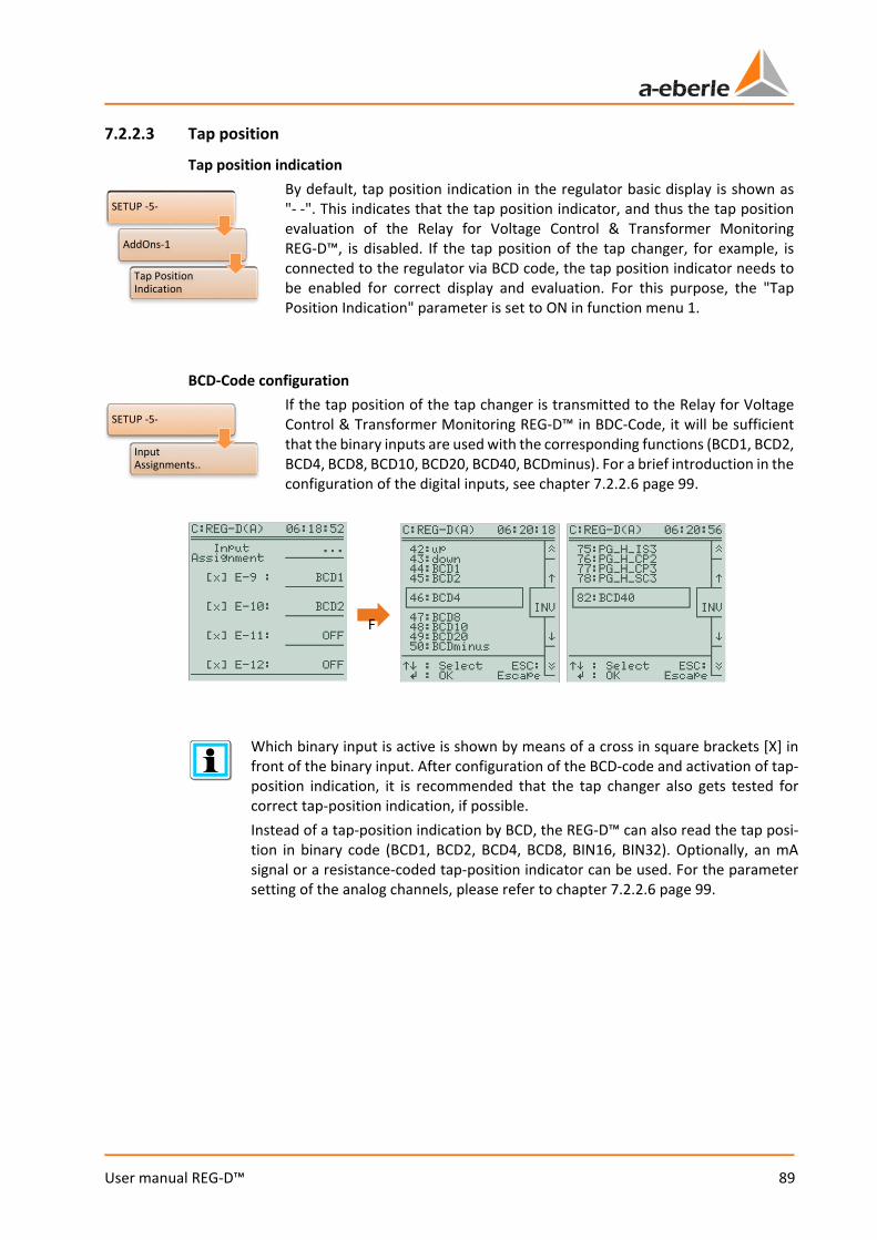
89
User manual REG-D™
7.2.2.3 Tap position
Tap position indication By default, tap position indication in the regulator basic display is shown as "- -". This indicates that the tap position indicator, and thus the tap position evaluation of the Relay for Voltage Control & Transformer Monitoring REG-D™, is disabled. If the tap position of the tap changer, for example, is connected to the regulator via BCD code, the tap position indicator needs to be enabled for correct display and evaluation. For this purpose, the "Tap Position Indication" parameter is set to ON in function menu 1.
BCD-Code configuration
If the tap position of the tap changer is transmitted to the Relay for Voltage Control & Transformer Monitoring REG-D™ in BDC-Code, it will be sufficient that the binary inputs are used with the corresponding functions (BCD1, BCD2, BCD4, BCD8, BCD10, BCD20, BCD40, BCDminus). For a brief introduction in the configuration of the digital inputs, see chapter 7.2.2.6 page 99.
Which binary input is active is shown by means of a cross in square brackets [X] in front of the binary input. After configuration of the BCD-code and activation of tap-position indication, it is recommended that the tap changer also gets tested for correct tap-position indication, if possible. Instead of a tap-position indication by BCD, the REG-D™ can also read the tap posi-tion in binary code (BCD1, BCD2, BCD4, BCD8, BIN16, BIN32). Optionally, an mA signal or a resistance-coded tap-position indicator can be used. For the parameter setting of the analog channels, please refer to chapter 7.2.2.6 page 99.
F
SETUP -5-
AddOns-1
Tap Position Indication
SETUP -5-
Input Assignments..
We take care of it.
90
User manual REG-D™
Configuring the TC in operation signal The TC in operation signal indicates that the tap changer is performing a tap change. As in the BCD-code configuration, the "07:TC.i.Op" function must be assigned to one of the binary inputs, so that the regulator interprets the binary input signal as the TC in operation signal.
TC in operation signal with the monitoring unit PAN-D If the Relay for Voltage Control & Transformer Monitoring REG-D™ is operated to-gether with the monitoring unit PAN-D, the TC in operation signal needs to be connected to the PAN-D. On the REG-D™ there is no need to set a binary input for the TC in operation signal, because the REG-D™ takes over the TC in operation signal (including TC Error) from the PAN-D. If the TC in operation signal is configured on the REG-D™ anyway, it will monitor the TC in operation signal (including TC Error) in addition to the PAN-D.
Maximum TC in operation time and TC Error
The maximum TC in operation time has two different functions, depending on the configuration. The tap changer is monitored using this parameter as long as the TC in operation signal is read on to the Relay for Voltage Control & Transformer Monitoring REG-D™ as a binary signal. This means that as soon as the TC in operation signal is present for longer than the maximum TC in operation time, a TC Error is raised. The TC Error can, for example, be assigned as a
function to a freely programmable relay. The function "14:TC-Err" thereby provides a continuous signal, whereas the function "41:TC-Err+" produces a wiping signal. With this output signal, when required a message can be sent to shut down the motor drive via a relay (emergency stop), or a message placed in the SCADA system. However, if a binary signal for the TC in operation signal is not used, the parameter maximum TC in operation time has the function that, after a successful tap-change command, no further tap commands are issued for a certain time (Maximum TC in operation time). A new tap command is given at the earliest after expiry of the maximum TC in operation time plus two additional seconds. The parameter maximum TC in operation time can be determined by measuring the time it takes the tap changer to complete the tap change starting from the time when the tap-change command is issued. The maximum TC in operation time should be set to a value two or three seconds above the measured time to allow a certain tolerance with respect to ageing of the tap changer.
Maximum TC in operation time with the monitoring unit PAN-D If the Relay for Voltage Control & Transformer Monitoring REG-D™ is operated together with the monitoring unit PAN-D, the maximum TC in operation time has to be configured under "Setup -3-/AddOns-1/Maximum time TC in operation" in the PAN-D.
SETUP -5-
Input Assignments..
SETUP -5-
AddOns-1
Maximum Time TC in Operation
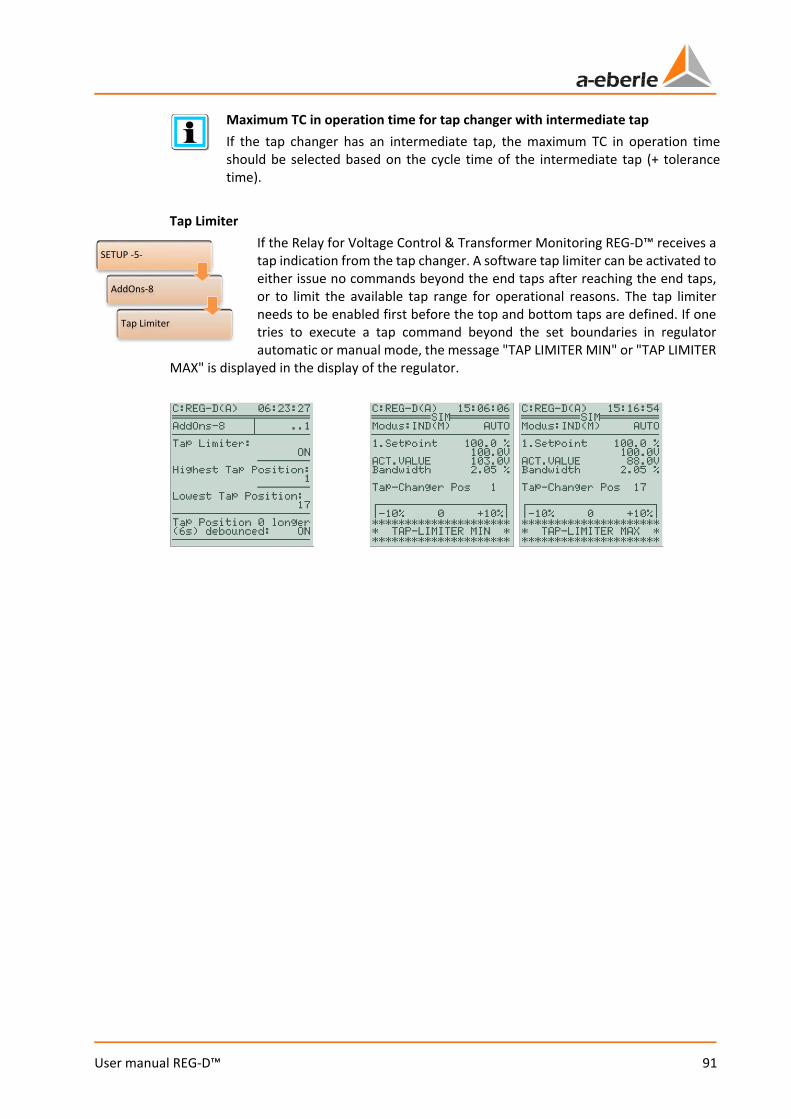
91
User manual REG-D™
Maximum TC in operation time for tap changer with intermediate tap If the tap changer has an intermediate tap, the maximum TC in operation time should be selected based on the cycle time of the intermediate tap (+ tolerance time).
Tap Limiter
If the Relay for Voltage Control & Transformer Monitoring REG-D™ receives a tap indication from the tap changer. A software tap limiter can be activated to either issue no commands beyond the end taps after reaching the end taps, or to limit the available tap range for operational reasons. The tap limiter needs to be enabled first before the top and bottom taps are defined. If one tries to execute a tap command beyond the set boundaries in regulator automatic or manual mode, the message "TAP LIMITER MIN" or "TAP LIMITER
MAX" is displayed in the display of the regulator.
SETUP -5-
AddOns-8
Tap Limiter

We take care of it.
92
User manual REG-D™
Inverse tap changer When reading the following table, it is assumed that the tap changer is fitted to the primary side of the transformer and the voltage measured on the secondary side. The default setting of the Relay for Voltage Control & Transformer Monitoring REG-D™ is as defined above for a non-inverse tap changer. Using the software WinREG (REGPara), the tap changer can be configured for the Relay for Voltage Control & Transformer Monitoring REG-D™ as inverse without swapped relays or inverse with swapped relays.
Tap changer Umax LV
Umin LV
Up tap command Down tap command
Non inverse Largest tap
Smallest tap
Up relay operates, tap position increases, voltage increases
Down relay operates, tap position decreases, voltage decreases
Inverse without swapped relays
Smallest tap
Largest tap
Up relay operates, tap position decreases, voltage increases
Down relay operates, tap position increases, voltage decreases
Inverse with swapped relays
Smallest tap
Largest tap
Down relay operates, tap position decreases, voltage increases
Up relay operates, tap position increases, voltage decreases
The inverse tap changer without swapped relays differs from the non-inverse tap changer from the perspective of the Relay for Voltage Control & Transformer Monitoring REG-D™, in particular with respect to the expected tap position after a tap change. With a "lower" tap-change command, in both cases the "down" relay is energized and the voltage on the low voltage side (LV) decreases. With a non-inverse tap changer, the regulator expects that the tap is reduced by one, with an inverse tap changer, however, the regulator expects that the tap is increased by one. The expected tap change is particularly important for evaluation of the tap-change error "TAPERR", which can be indicated as a SCADA system signal, relay output or LED signal. To prevent false raising of tap-change error "TAPERR", the Relay for Voltage Control & Transformer Monitoring REG-D™ needs to know whether the tap changer is inverse or non-inverse. The inverse tap changer with swapped relays differs from the non-inverse tap changer again from the perspective of the Relay for Voltage Control & Transformer Monitoring REG-D™, in particular with respect to the expected tap change. The expected tap change corresponds to the inverse tap changer without swapped relays. In addition, with the inverse tap changer with swapped relays the "up" and "down" relays are swapped, i.e. on a tap-change lower command the "up" relay operates, and vice versa.
Inverse tap changer As an alternative to setting the inverse tap changer with swapped relays, the setting of inverse tap changer without swapped relays can be used, whereby either the "up" and "down" relay functions need to be swapped, or the wiring for the "up" and "down" relays switched. If the Relay for Voltage Control & Transformer Monitoring REG-D™ is operated to-gether with the monitoring unit PAN-D, using the function "Inverse with swapped relays" is not possible. The parameter "Inverse tap changer" must be set to the same value in the REG-D™ and the PAN-D.
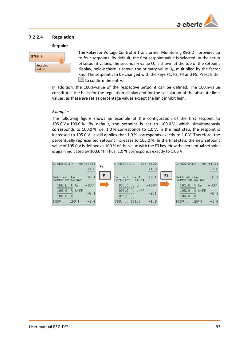
93
User manual REG-D™
7.2.2.4 Regulation
Setpoint The Relay for Voltage Control & Transformer Monitoring REG-D™ provides up to four setpoints. By default, the first setpoint value is selected. In the setup of setpoint values, the secondary value Un is shown at the top of the setpoint display, below there is shown the primary value ULL multiplied by the factor Knu. The setpoint can be changed with the keys F1, F2, F4 and F5. Press Enter
to confirm the entry. In addition, the 100%-value of the respective setpoint can be defined. The 100%-value constitutes the basis for the regulation display and for the calculation of the absolute limit values, as these are set as percentage values except the limit inhibit high. Example: The following figure shows an example of the configuration of the first setpoint to 105.0 V = 100.0 %. By default, the setpoint is set to 100.0 V, which simultaneously corresponds to 100.0 %, i.e. 1.0 % corresponds to 1.0 V. In the next step, the setpoint is increased to 105.0 V. It still applies that 1.0 % corresponds exactly to 1.0 V. Therefore, the percentually represented setpoint increases to 105.0 %. In the final step, the new setpoint value of 105.0 V is defined as 100 % of the value with the F3 key. Now the percentual setpoint is again indicated by 100.0 %. Thus, 1.0 % corresponds exactly to 1.05 V.
5x
SETUP -1-
Setpoint Values..

We take care of it.
94
User manual REG-D™
Changing the setpoint index The active setpoint value is displayed in the regulator's basic display mode. Also, the active setpoint is indicated by an arrow in the menu under Setup. 1. The setpoint index can be changed in the relevant menu with the respective F-key behind the associated setpoint.
Permissible setpoint deviation (Bandwidth Xwz) The adjustment of the permissible setpoint deviation depends on two limits. Firstly, it is necessary to take the voltage tolerance accepted by consumers into account. Secondly, the minimum setpoint deviation is determined by the tap increment of the transformer. The permissible setpoint deviation Xwz is equally applicable in both the
positive and negative directions, i.e., the tolerance band, in which the Relay for Voltage Control & Transformer Monitoring REG-D™ does not perform any automatic regulation, corresponds to twice the permissible setpoint deviation. The minimum voltage bandwidth is therefore calculated using the following formula:
𝑿𝑿𝑿𝑿𝒛𝒛[%] ≥ 𝟎𝟎.𝟔𝟔 ∗ 𝑻𝑻𝑻𝑻𝑻𝑻 𝒊𝒊𝒊𝒊𝒊𝒊𝒊𝒊𝒊𝒊𝒊𝒊𝒊𝒊𝒊𝒊𝒊𝒊[%]
Unstable regulation ("hunting“) If a permissible setpoint deviation (bandwith Xwz) is chosen so tight that the toler-ance band is smaller than the tap increment of the transformer, the regulator, after having left the tolerance band, will move to the other side of the tolerance band with the next tap change. A stable regulation is not possible in a situation that, one speaks about as "hunting". In addition, it should be noted that with decreasing the permissible setpoint deviation, the wear on the tap changer, i.e. the number of tap changes carried out, will generally increase.
Note the limit base! The percentual limit for the permissible setpoint deviation (bandwidth Xwz) depends on the parameter limit base, see chapter 7.2.2.5. Limit values, page 97, or chapter 8.1.7 Configuration and functions, from page 185 onwards.
SETUP -1-
Setpoint values..
Index..
SETUP -1-
Tolerance Band
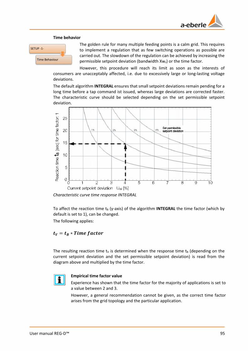
95
User manual REG-D™
Time behavior The golden rule for many multiple feeding points is a calm grid. This requires to implement a regulation that as few switching operations as possible are carried out. The slowdown of the regulation can be achieved by increasing the permissible setpoint deviation (bandwidth Xwz) or the time factor. However, this procedure will reach its limit as soon as the interests of
consumers are unacceptably affected, i.e. due to excessively large or long-lasting voltage deviations. The default algorithm INTEGRAL ensures that small setpoint deviations remain pending for a long time before a tap command ist issued, whereas large deviations are corrected faster. The characteristic curve should be selected depending on the set permissible setpoint deviation.
Characteristic curve time response INTEGRAL To affect the reaction time tB (y-axis) of the algorithm INTEGRAL the time factor (which by default is set to 1), can be changed. The following applies:
𝒊𝒊𝑽𝑽 = 𝒊𝒊𝑩𝑩 ∗ 𝑻𝑻𝒊𝒊𝒊𝒊𝒊𝒊 𝒇𝒇𝑻𝑻𝒊𝒊𝒊𝒊𝒇𝒇𝒊𝒊
The resulting reaction time tV is determined when the response time tB (depending on the current setpoint deviation and the set permissible setpoint deviation) is read from the diagram above and multiplied by the time factor.
Empirical time factor value Experience has shown that the time factor for the majority of applications is set to a value between 2 and 3. However, a general recommendation cannot be given, as the correct time factor arises from the grid topology and the particular application.
SETUP -1-
Time Behaviour
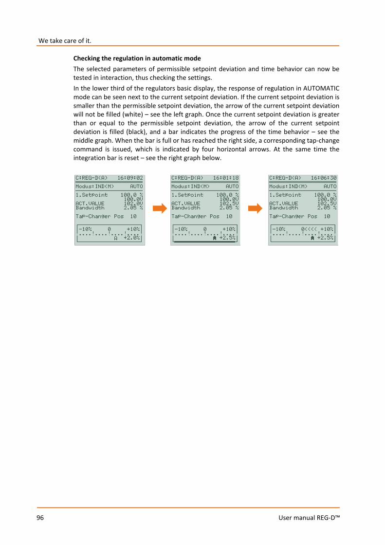
We take care of it.
96
User manual REG-D™
Checking the regulation in automatic mode The selected parameters of permissible setpoint deviation and time behavior can now be tested in interaction, thus checking the settings. In the lower third of the regulators basic display, the response of regulation in AUTOMATIC mode can be seen next to the current setpoint deviation. If the current setpoint deviation is smaller than the permissible setpoint deviation, the arrow of the current setpoint deviation will not be filled (white) – see the left graph. Once the current setpoint deviation is greater than or equal to the permissible setpoint deviation, the arrow of the current setpoint deviation is filled (black), and a bar indicates the progress of the time behavior – see the middle graph. When the bar is full or has reached the right side, a corresponding tap-change command is issued, which is indicated by four horizontal arrows. At the same time the integration bar is reset – see the right graph below.
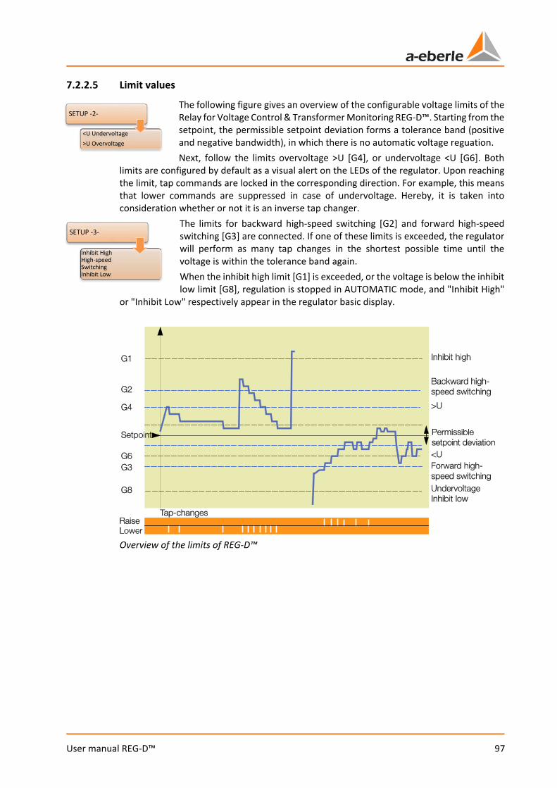
97
User manual REG-D™
7.2.2.5 Limit values
The following figure gives an overview of the configurable voltage limits of the Relay for Voltage Control & Transformer Monitoring REG-D™. Starting from the setpoint, the permissible setpoint deviation forms a tolerance band (positive and negative bandwidth), in which there is no automatic voltage reguation. Next, follow the limits overvoltage >U [G4], or undervoltage <U [G6]. Both
limits are configured by default as a visual alert on the LEDs of the regulator. Upon reaching the limit, tap commands are locked in the corresponding direction. For example, this means that lower commands are suppressed in case of undervoltage. Hereby, it is taken into consideration whether or not it is an inverse tap changer.
The limits for backward high-speed switching [G2] and forward high-speed switching [G3] are connected. If one of these limits is exceeded, the regulator will perform as many tap changes in the shortest possible time until the voltage is within the tolerance band again. When the inhibit high limit [G1] is exceeded, or the voltage is below the inhibit low limit [G8], regulation is stopped in AUTOMATIC mode, and "Inhibit High"
or "Inhibit Low" respectively appear in the regulator basic display.
Overview of the limits of REG-D™
SETUP -2-
<U Undervoltage>U Overvoltage
SETUP -3-
Inhibit HighHigh-speed SwitchingInhibit Low
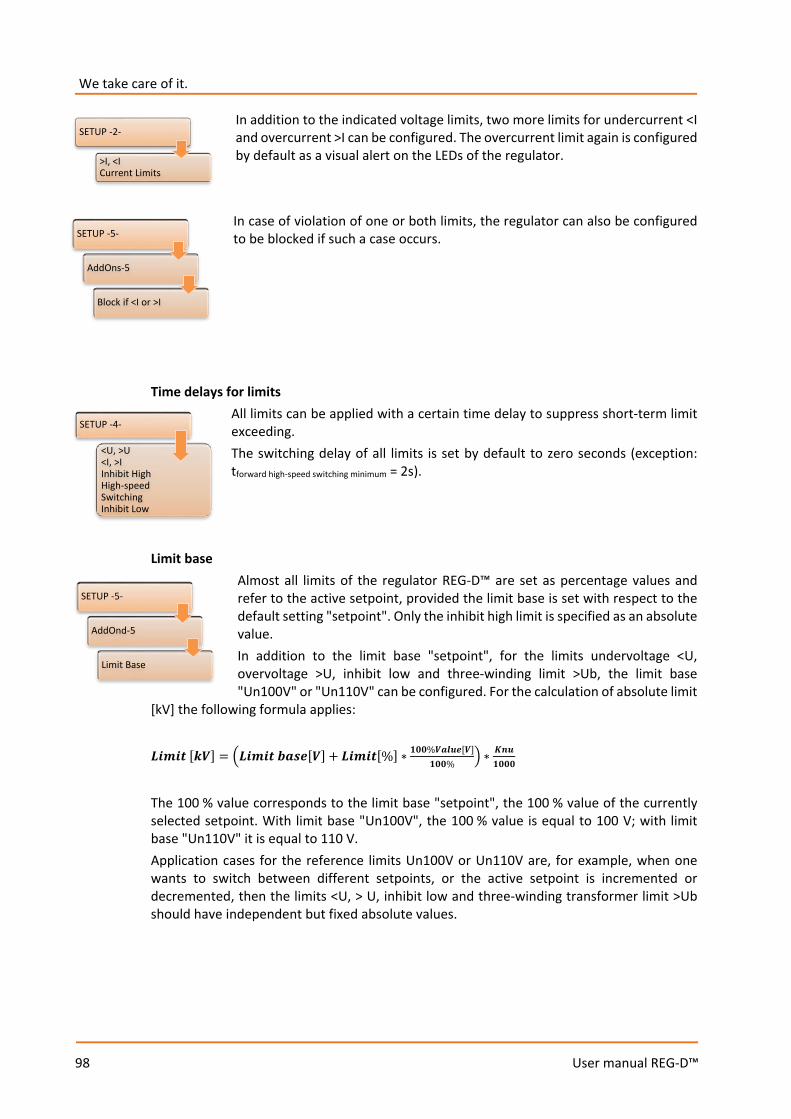
We take care of it.
98
User manual REG-D™
In addition to the indicated voltage limits, two more limits for undercurrent <I and overcurrent >I can be configured. The overcurrent limit again is configured by default as a visual alert on the LEDs of the regulator. In case of violation of one or both limits, the regulator can also be configured to be blocked if such a case occurs.
Time delays for limits
All limits can be applied with a certain time delay to suppress short-term limit exceeding. The switching delay of all limits is set by default to zero seconds (exception: tforward high-speed switching minimum = 2s).
Limit base
Almost all limits of the regulator REG-D™ are set as percentage values and refer to the active setpoint, provided the limit base is set with respect to the default setting "setpoint". Only the inhibit high limit is specified as an absolute value. In addition to the limit base "setpoint", for the limits undervoltage <U, overvoltage >U, inhibit low and three-winding limit >Ub, the limit base "Un100V" or "Un110V" can be configured. For the calculation of absolute limit
[kV] the following formula applies:
𝑳𝑳𝒊𝒊𝒊𝒊𝒊𝒊𝒊𝒊 [𝒌𝒌𝑽𝑽] = 𝑳𝑳𝒊𝒊𝒊𝒊𝒊𝒊𝒊𝒊 𝒃𝒃𝑻𝑻𝒃𝒃𝒊𝒊[𝑽𝑽] + 𝑳𝑳𝒊𝒊𝒊𝒊𝒊𝒊𝒊𝒊[%] ∗ 𝟏𝟏𝟎𝟎𝟎𝟎%𝑽𝑽𝑻𝑻𝑽𝑽𝑽𝑽𝒊𝒊[𝑽𝑽]𝟏𝟏𝟎𝟎𝟎𝟎%
∗ 𝑲𝑲𝒊𝒊𝑽𝑽𝟏𝟏𝟎𝟎𝟎𝟎𝟎𝟎
The 100 % value corresponds to the limit base "setpoint", the 100 % value of the currently selected setpoint. With limit base "Un100V", the 100 % value is equal to 100 V; with limit base "Un110V" it is equal to 110 V. Application cases for the reference limits Un100V or Un110V are, for example, when one wants to switch between different setpoints, or the active setpoint is incremented or decremented, then the limits <U, > U, inhibit low and three-winding transformer limit >Ub should have independent but fixed absolute values.
SETUP -4-
<U, >U<I, >IInhibit HighHigh-speed SwitchingInhibit Low
SETUP -2-
>I, <I Current Limits
SETUP -5-
AddOns-5
Block if <I or >I
SETUP -5-
AddOnd-5
Limit Base
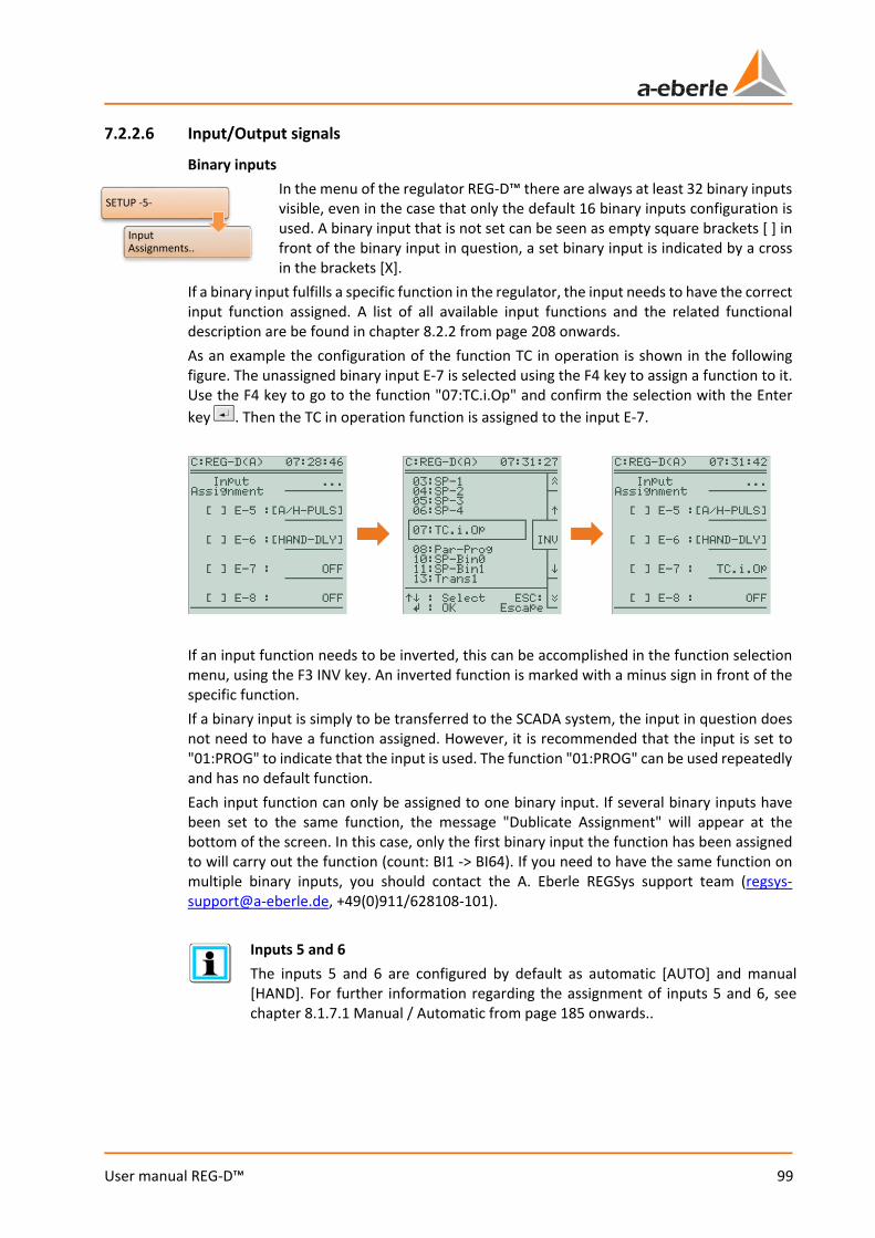
99
User manual REG-D™
7.2.2.6 Input/Output signals
Binary inputs In the menu of the regulator REG-D™ there are always at least 32 binary inputs visible, even in the case that only the default 16 binary inputs configuration is used. A binary input that is not set can be seen as empty square brackets [ ] in front of the binary input in question, a set binary input is indicated by a cross in the brackets [X].
If a binary input fulfills a specific function in the regulator, the input needs to have the correct input function assigned. A list of all available input functions and the related functional description are be found in chapter 8.2.2 from page 208 onwards. As an example the configuration of the function TC in operation is shown in the following figure. The unassigned binary input E-7 is selected using the F4 key to assign a function to it. Use the F4 key to go to the function "07:TC.i.Op" and confirm the selection with the Enter key . Then the TC in operation function is assigned to the input E-7.
If an input function needs to be inverted, this can be accomplished in the function selection menu, using the F3 INV key. An inverted function is marked with a minus sign in front of the specific function. If a binary input is simply to be transferred to the SCADA system, the input in question does not need to have a function assigned. However, it is recommended that the input is set to "01:PROG" to indicate that the input is used. The function "01:PROG" can be used repeatedly and has no default function. Each input function can only be assigned to one binary input. If several binary inputs have been set to the same function, the message "Dublicate Assignment" will appear at the bottom of the screen. In this case, only the first binary input the function has been assigned to will carry out the function (count: BI1 -> BI64). If you need to have the same function on multiple binary inputs, you should contact the A. Eberle REGSys support team ([email protected], +49(0)911/628108-101).
Inputs 5 and 6 The inputs 5 and 6 are configured by default as automatic [AUTO] and manual [HAND]. For further information regarding the assignment of inputs 5 and 6, see chapter 8.1.7.1 Manual / Automatic from page 185 onwards..
SETUP -5-
Input Assignments..

We take care of it.
100
User manual REG-D™
Relays/binary outputs All available freely-programmable relays of the REG-D™ are listed in the relay mapping. This does not include the permanently assigned relays "Manual/Auto" and "Status". The functional assignment of the relays can be performed analogously to the functional assignment of the binary inputs.
A list of all available relay functions with related functional descriptions is given in chapter 8.2.3 from page 213 onwards. LEDs
LED mapping contains all freely-programmable LEDs of the regulator. Only the dedicated status LED is not listed. By default, LED 5 is assigned the undervoltage <U function, LED 6 the overvoltage >U function and LED 7 the overcurrent >I function. The functional assignment of the LEDs can be performed analogously to the functional assignment of the binary inputs.
A list of all available LED functions with related functional descriptions is given in chapter 8.2.4 LEDs, from page 217 onwards.
LED sequence The LEDs are numbered as follows (from top to bottom): Status – 5 – 6 – 7 – 1 – 2 – 3 – 4.
SETUP -5-
Relay Assignments..
SETUP -5-
LED Assignments..

101
User manual REG-D™
Analog channels Each regulator can be equipped with up to three analog modules (each with two analog channels). Therefore, six analog channels are available in the analog menu by default. Analog modules are available as pure input or output modules, as PT100 modules and resistance input modules, which are briefly explained separately below. For recognition purposes, the different types in the analog menu are given analog module IDs, such as "AI" for analog input or "AO" for analog output. For information regarding connection of the various
analog modules, refer to chapter 7.1.4.4 Analog signals, from page 63 onwards. Information for retrofitting analog modules can be found in chapter 11. Retrofit of analog channels, from page 331 onwards.
Input and output modules Analog input (AI) or output modules (AO) each have two channels, which, depending on the module slot, can be found on channels 1&2, 3&4 or 5&6. The individual channel parameters can be accessed using the F key behind the respective channel.
The left graph in the figure shows the first setup page of an analog channel. Under Analog Function a function for an analog channel can be assigned, the same as with the binary inputs, relays and LEDs. A list of all available analog functions with related functional descriptions is given in chapter 8.2.5 from page 221 onwards. Moreover, the unit and the number of decimal places can be configured. Under Parameter Selection, the type of characteristic curve can be set, which is configured on the next setup page 2 (F1 key). A start point and an end point are defined for the standard curve P0P2, where the y-coordinate corresponds to the normalized mA value and the x-coordinate corresponds to the reference value (see the middle graph). In the figure above, the mA range 4-20 mA (P0-Y = 0.2, P2-Y = 1) corresponds to the reference value of 0-120 (P0-X = 0, P2-X = 120). Limit Processing can be set on the third setup page. If for example the mA-output signal should always be at least 4 mA, limit processing needs be set to 02:Low.
Input module AI
Output module AO
PT-100 module TI
Resistance input module RM
SETUP -6-
General 1
Analog..

We take care of it.
102
User manual REG-D™
PT100 module The PT100 module has only one channel available per module (channel 1, 3 or 5) and is indicated as "TI". The second channel of the module (channel 2, 4 or 6) cannot be used and is indicated as "-". If no PT100 sensor is connected, a PT100 module channel indicates a temperature of -42.73°C. Settings such as for the analog inputs or outputs cannot be made in this module as the calibration of each module was done at the factory.
Resistance input module A resistance input module with the indication "RM" on both module channels, shows the tap position on the first module channel (channel 1, 3 or 5), the measured resistance value in Ω on the second module channel (channel 2, 4 or 6). The parameters are set only through the first module channel. If the detected tap value of the resistance module provides the regulator with the tap position of the tap changer, The analog function "70: iTapPos" has to be assigned on the first module channel. On the second setup page, in addition to the minimum and maximum tap positions, the resistance value per tap, as well as a possibly existing offset resistance, can be configured.
Note firmware version! Firmware versions below V2.22 or V3.22 can only evaluate a resistance input mod-ule by means of a background program. For questions regarding this matter, please contact the A. Eberle REGSys support team ([email protected], +49(0)911/628108-101).
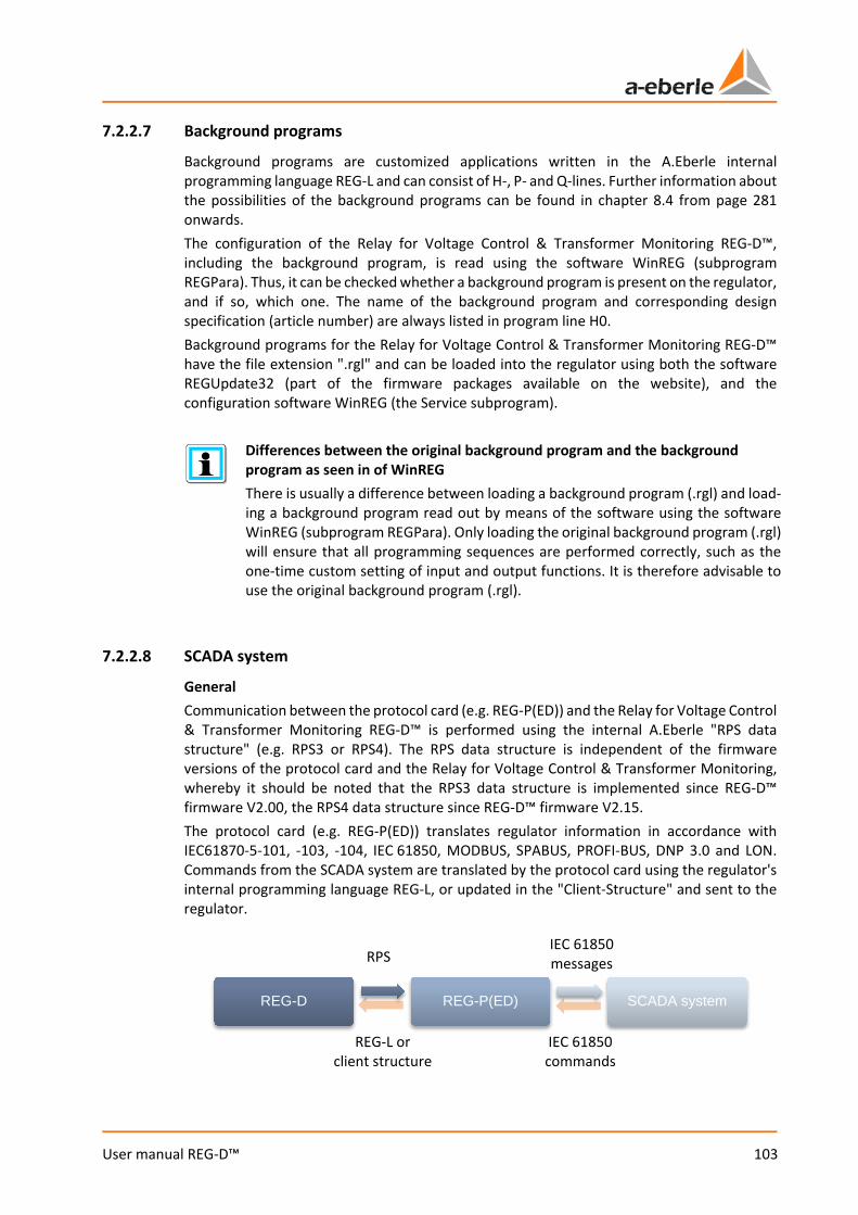
103
User manual REG-D™
7.2.2.7 Background programs
Background programs are customized applications written in the A.Eberle internal programming language REG-L and can consist of H-, P- and Q-lines. Further information about the possibilities of the background programs can be found in chapter 8.4 from page 281 onwards. The configuration of the Relay for Voltage Control & Transformer Monitoring REG-D™, including the background program, is read using the software WinREG (subprogram REGPara). Thus, it can be checked whether a background program is present on the regulator, and if so, which one. The name of the background program and corresponding design specification (article number) are always listed in program line H0. Background programs for the Relay for Voltage Control & Transformer Monitoring REG-D™ have the file extension ".rgl" and can be loaded into the regulator using both the software REGUpdate32 (part of the firmware packages available on the website), and the configuration software WinREG (the Service subprogram).
Differences between the original background program and the background program as seen in of WinREG There is usually a difference between loading a background program (.rgl) and load-ing a background program read out by means of the software using the software WinREG (subprogram REGPara). Only loading the original background program (.rgl) will ensure that all programming sequences are performed correctly, such as the one-time custom setting of input and output functions. It is therefore advisable to use the original background program (.rgl).
7.2.2.8 SCADA system
General Communication between the protocol card (e.g. REG-P(ED)) and the Relay for Voltage Control & Transformer Monitoring REG-D™ is performed using the internal A.Eberle "RPS data structure" (e.g. RPS3 or RPS4). The RPS data structure is independent of the firmware versions of the protocol card and the Relay for Voltage Control & Transformer Monitoring, whereby it should be noted that the RPS3 data structure is implemented since REG-D™ firmware V2.00, the RPS4 data structure since REG-D™ firmware V2.15. The protocol card (e.g. REG-P(ED)) translates regulator information in accordance with IEC61870-5-101, -103, -104, IEC 61850, MODBUS, SPABUS, PROFI-BUS, DNP 3.0 and LON. Commands from the SCADA system are translated by the protocol card using the regulator's internal programming language REG-L, or updated in the "Client-Structure" and sent to the regulator.
RPS IEC 61850 messages
REG-L or client structure
IEC 61850 commands
REG-D REG-P(ED) SCADA system
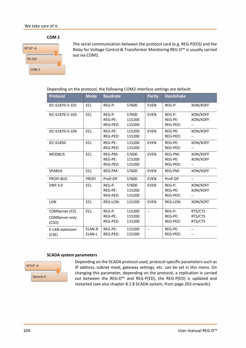
We take care of it.
104
User manual REG-D™
COM 2 The serial communication between the protocol card (e.g. REG-P(ED)) and the Relay for Voltage Control & Transformer Monitoring REG-D™ is usually carried out via COM2.
Depending on the protocol, the following COM2 interface settings are default: Protocol Mode Baudrate Parity Handshake
IEC 61870-5-101 ECL REG-P: 57600 EVEN REG-P: XON/XOFF
IEC 61870-5-103 ECL REG-P: REG-PE: REG-PED:
57600 115200 115200
EVEN REG-P: REG-PE: REG-PED:
XON/XOFF XON/XOFF --
IEC 61870-5-104 ECL REG-PE: REG-PED:
115200 115200
EVEN REG-PE: REG-PED:
XON/XOFF --
IEC 61850 ECL REG-PE: REG-PED:
115200 115200
EVEN REG-PE: REG-PED:
XON/XOFF --
MODBUS ECL REG-PM: REG-PE: REG-PED:
57600 115200 115200
EVEN REG-PM: REG-PE: REG-PED:
XON/XOFF XON/XOFF --
SPABUS ECL REG-PM: 57600 EVEN REG-PM: XON/XOFF
PROFI-BUS PROFI Profi-DP 57600 EVEN Profi-DP -- DNP 3.0 ECL REG-P:
REG-PE: REG-PED:
57600 115200 115200
EVEN REG-P: REG-PE: REG-PED:
XON/XOFF XON/XOFF --
LON ECL REG-LON: 115200 EVEN REG-LON: XON/XOFF
COMServer (CS) COMServer only (CSO)
ECL REG-P: REG-PE: REG-PED:
115200 115200 115200
-- REG-P: REG-PE: REG-PED:
RTS/CTS RTS/CTS RTS/CTS
E-LAN extension (CSE)
ELAN-R ELAN-L
REG-PE: REG-PED:
115200 115200
-- REG-PE: REG-PED:
-- --
SCADA system parameters
Depending on the SCADA protocol used, protocol-specific parameters such as IP address, subnet mask, gateway settings, etc. can be set in this menu. On changing this parameter, depending on the protocol, a replication is carried out between the REG-D™ and REG-P(ED), the REG-P(ED) is updated and restarted (see also chapter 8.1.8 SCADA system, from page 203 onwards).
SETUP -6-
RS-232
COM-2
SETUP -6-
General 4

105
User manual REG-D™
7.2.3 Parallel operation General and conditions All parallel programs are intended to minimize the circulating reactive current of parallel-connected transformers. Which parallel program is useful and can be applied due to conditions on the site is explained in detail in chapter 8.1.5.2 from page 167 onwards. Parallel program-specific parameters are also described in chapter 8.1.5.3 from page 170 onwards. In principle, with all parallel programs (except dcos(ϕ)) an E-LAN communication is required between the participating Relays for Voltage Control & Transformer Monitoring so that relevant data for parallel operation can be exchanged between the regulators involved. Further, for the parallel programs dcos(ϕ), dIsin(ϕ) and dIsin(ϕ)[S], in addition to measurement of the regulation voltage, also a current measurement associated with the regulation voltage is required to be able to determine the phase angle and the circulating reactive current. With the parallel programs Master-Follower, MSI and MSI2 the circulating reactive current can be monitored optionally. However, the determination of the circulating reactive current is not required for these parallel programs, as the circulating reactive current is implicitly minimized by the tap positions (e.g. for identical transformers). Sign conventions To understand the calculation of the circulating reactive current and its influence on the voltage regulation, the following sign conventions should be observed:
Positive sign Negative sign Active Power P Consumption case Reverse power flow case Reactive power Q Inductive reactive power
consumption Capacitive reactive power
consumption Phase angle ϕ Capacitive reactive power
consumption Inductive reactive power
consumption Reactive current I*sinϕ
Capacitive reactive power consumption
Inductive reactive power consumption
Circulating reactive current Icirc
Capacitive reactive power consumption
Inductive reactive power consumption
We take care of it.
106
User manual REG-D™
NOTICE! Wiring and configuration
It needs to be ensured that the voltage and current measurements are correctly configured and wired, so that with active power consumption of the grid (consumption case) the active power P in the transducer has a positive value, and with active power flow feedback of the grid (reverse power flow case), the active power P takes on a negative value in the transducer. In addition, pay attention to the correct wiring of raise and lower relays and correct configuration of the inverse tap changer, so that raise commands always increase the voltage and lower commands always reduce the voltage.
If these conventions are not consistently obeyed, it may result in unequal taps on the tap changer, and thus an increase of the circulating reactive current which may go as far as tripping the transformer.
Choice of parallel program
The corresponding parallel program needs to be selected for all involved Relays for Voltage Control & Transformer Monitoring. The parallel programs MSI and MSI2 are only available with the feature ParaGramer activated.
Group list All regulators operating in parallel are defined in the group list. The group list has to be identical in all participating regulators and may not have any gaps. For the parallel program dcos(ϕ), which is normally used without E-LAN, the group list is only required if an E-LAN between the participating regulators is available and either the ParaGramer is used or a maximum tap difference of the regulators concerned is to be monitored.
Parallel program activation The parallel program activation needs to be set for all regulators that are to participate in the parallel operation. An exception is the Master-Follower parallel program. With ParaGramer, the first regulator in the group list with activated parallel program activation becomes master. Without the use of ParaGramer, one of the regulators in the group list with an enabled parallel program activation becomes master (the one that first defines itself as master, regardless of placement in the group list).
In addition to permanent activation/deactivation of a parallel program, the parameter can also be set to level or pulse so that parallel program activation/deactivation can be done via binary input using the function "08:Par-Prog". If activation/deactivation is carried out by a SCADA system, the parameter will be actively changed with corresponding SCADA commands.
SETUP -1-
Programs..
Parallel program
SETUP -1-
Programs..
Par.Parameter..
Group List
SETUP -5-
AddOns-7
Parallel Prog. Activation
107
User manual REG-D™
ParaGramer activation When using the ParaGramer function, the parameter "ParaGramer activation" always needs to be set to ON. If the feature ParaGramer is enabled, the ParaGramer can be activated. The number of transformers to be placed in ParaGramer is defined using the parameter "ParaGramer activity".
Configuration of ParaGramer The ParaGramer can be used for the display of parallel operation of transformers. Moreover, using the ParaGramer, parallel operation is automatically detected based on switch positions in all parallel programs except for MSI and MSI2. There are various standard switches available to the ParaGramer, which need to be configured in the input assignments in order to be displayed and evaluated by the ParaGramer. For a detailed explanation of
the operation and configuration of ParaGramer, see chapter 8.3.2 from page 232 onwards. An overview of the binary input functions of the ParaGramer is also given in the table of chapter 8.2.2 from page 208 onwards. Specific configuration of the parallel program dcosϕ
The parallel program dcosϕ necessarily requires configuration of the Net-cosϕ, the Permissible Icirc (permissible circulating reactive current), and the Limitation . The parameter Net-cosϕ has to be configured according to the present grid. When the actual cosϕ is equivalent to the parameter Net-cosϕ, the regulator assumes that no circulating reactive current is present in parallel operation, but that the total reactive current is consumed in the grid below. The circulating reactive current is calculated from the difference between Net-cosϕ and the actual measured cosϕ.
The determination of the parameter Permissible Icirc (permissible circulating reactive current) is explained in detail on page 110. The parameter Limitation limits the influence of the parallel program dcosϕ in the regulation of the tap changer. The value of limitation multiplied by the permissible setpoint deviation (bandwidth Xwz) gives the maximum influence of the parallel program dcos(ϕ). Example:
permissible setpoint deviation Xwz: 2.0 % Limitation: 3
→ maximum influence of the parallel program dcos(ϕ) = 3 * ±2.0% = ±6%
Parameters dependent on the parallel program dcos(ϕ) The parameters Permissible Icirc, Limitation and Net-cosϕ of the parallel program dcos(ϕ) are available only when the corresponding parallel program is selected in the previous menu.
SETUP -5-
AddOns-6
PARAGRAMER Activation
SETUP -5-
Input Assignments..
SETUP -1-
Programs..
Par.Parameter..
Permiss. IcircLimitationNet-cosϕ
We take care of it.
108
User manual REG-D™
Specific configuration of parallel programs dIsin(ϕ) and dIsin(ϕ)[S] For the parallel programs dIsin(ϕ) and dIsin(ϕ)[S] the parameter Permissible Icirc is available and can be used for defining the permissible circulating reactive current. The determination of the Permissible Icirc parameter is explained in detail on page 110. The parameter Limitation is set to 20 by default and is not visible in the menu. Moreover, different nominal transformer powers can be configured for the parallel program dIsin(ϕ)[S]. In the parallel program dIsin(ϕ), it is assumed that the nominal transformer powers are the same, therefore the corresponding parameter in this parallel program is dropped.
Parameters dependent on the parallel programs dIsin(ϕ) and dIsin(ϕ)[S] The parameters Permissible Icirc and Limitation of the parallel programs dIsin(ϕ) and dIsin(ϕ)[S] are only available when one of the corresponding parallel programs is selected in the previous menu. The nominal transformer power parameter is only available for the parallel program dIsin(ϕ)[S].
Specific configuration of the parallel programs Master-Follower, MSI and MSI2 In the parallel programs Master-Follower, MSI and MSI2 an excessively high circulating reactive current can be supervised by using the parameter Icirc-Supervision. In contrast to the parallel regulation procedures dcos(ϕ), dIsin(ϕ) and dIsin(ϕ)[S], the circulating reactive current is not directly included in the regulation, but only represents a limit. If the parameter Icirc-Supervision is exceeded, the regulator switches over to manual mode. Example: Two identical transformers are operated in the Master-Follower parallel program. If a cable break occurs at the master regulator with the
currently active signal BCD04, the tap position feedback will change, for example, from tap 14 to tap 10. The master regulator then drags the slave to its supposed tap, thereby resulting in a real tap difference of four taps, which causes a high circulating reactive current. If the parameter Icirc-Supervision is correspondingly configured, retracing of the slave until the Icirc monitoring limit is reached can be interrupted, since the master and slave switch to manual mode.
Parameters dependent on the parallel programs Master-Follower, MSI and MSI2 The parameter Icirc-Supervision of the parallel programs Master-Follower, MSI and MSI2 is only available when one of the corresponding parallel programs is selected in the previous menu.
SETUP -1-
Programs..
Par.Parameter..
Permiss. IcircLimitationTransformer Nominal Power
SETUP -1-
Programs..
Par.Parameter..
Icirc-Superv.
109
User manual REG-D™
In the parallel program MSI, for each Relay for Voltage Control & Transformer Monitoring the status master, slave or independent can be assigned. In addition, in the parallel program MSI2 two separate master-slave groups (master 1&2 and slave 1&2) can be defined. An evaluation of switch position is not provided in these parallel programs in the regulator itself, but can, for example, be supplied externally.
The allocation of master, slave and independent can be done either in ParaGramer itself (the F1 key in ParaGramer), or by means of binary signals, whereby the last positive slope of the selected function is always decisive. The binary input functions available: MSI: 64:MSI_Ma (master) 65:MSI_Sl (slave) 66:MSI_Ind (independent) MSI2: 67:MSI_Ma1 (master 1) 68:MSI_Ma2 (master 2) 69:MSI_Sl1 (slave 1) 70:MSI_Sl2 (slave 2) 66:MSI_Ind (independent) The choice of master, slave or independent can also be adjusted via the SCADA system. Emergency program dcos(ϕ)!! for parallel programs dIsin(ϕ) and dIsin(ϕ)[S]
If there is a failure of the E-LAN connection during active parallel programs dIsin(ϕ) and dIsin(ϕ)[S] in AUTOMATIC mode, the E-LAN error and the emergency program dcos(ϕ)!! are activated after approximately 30 seconds. The parameters Permissible Icirc and Limitation of the regular dcos(ϕ) parallel program are used in the emergency program dcos(ϕ)!!. On the other hand, for the parameter Net-cosϕ, the cosϕ measured at the time of the E-LAN error is used. It is therefore assumed that the circulating reactive current was perfectly
minimized at the time of the failure of the E-LAN bus.
Parameter settings for the parallel emergency program dcos(ϕ)!! In order to be able to adjust the parameters Permissible Icirc and Limitation for the emergency program dcos(ϕ)!! in the Relay for Voltage Control & Transformer Mon-itoring REG-D™, the parallel program dcos(ϕ) needs to be temporarily activated for the configuration. Only in this case the parameters will be visible under Par.Param-eter.
SETUP -5-
Input Assignments..
SETUP -1-
Programs..
Par.Parameter..
Permiss. Icirc Limitation
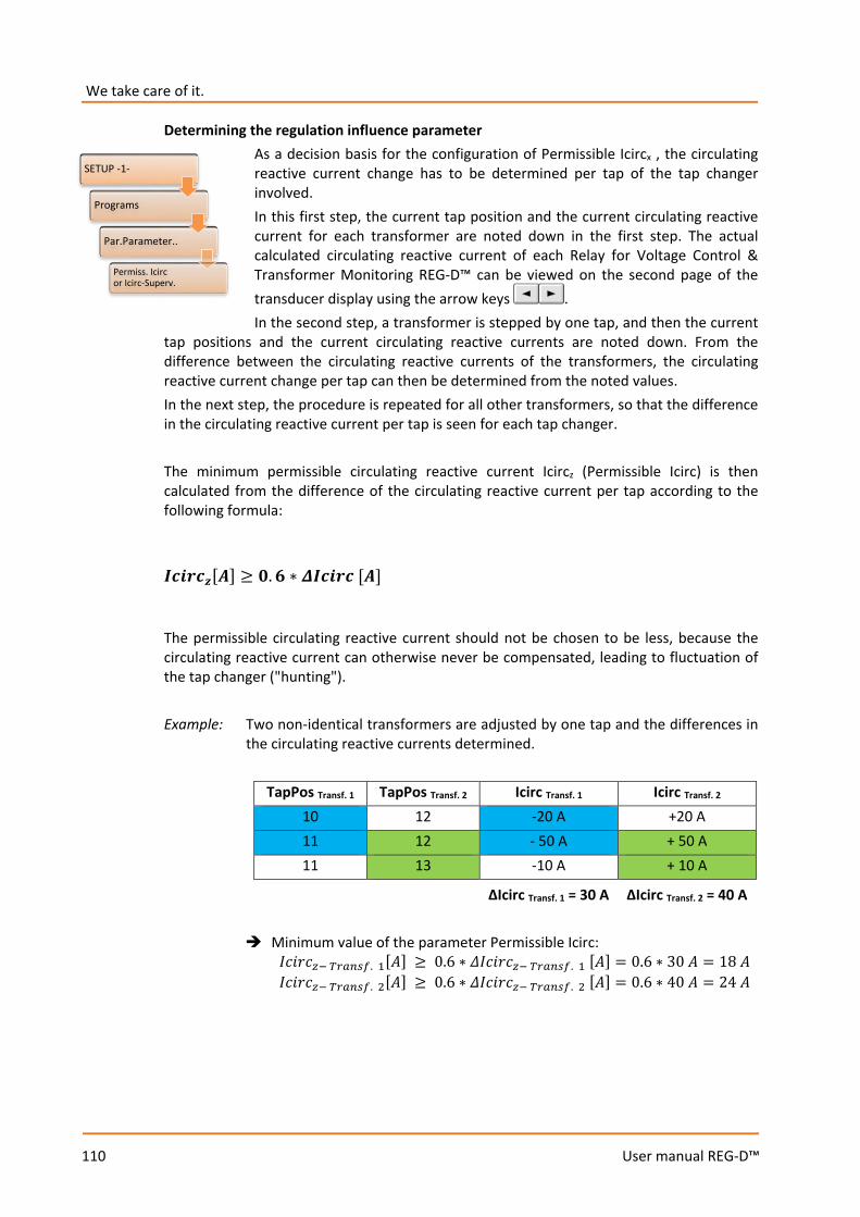
We take care of it.
110
User manual REG-D™
Determining the regulation influence parameter As a decision basis for the configuration of Permissible Icircx , the circulating reactive current change has to be determined per tap of the tap changer involved. In this first step, the current tap position and the current circulating reactive current for each transformer are noted down in the first step. The actual calculated circulating reactive current of each Relay for Voltage Control & Transformer Monitoring REG-D™ can be viewed on the second page of the transducer display using the arrow keys . In the second step, a transformer is stepped by one tap, and then the current
tap positions and the current circulating reactive currents are noted down. From the difference between the circulating reactive currents of the transformers, the circulating reactive current change per tap can then be determined from the noted values. In the next step, the procedure is repeated for all other transformers, so that the difference in the circulating reactive current per tap is seen for each tap changer. The minimum permissible circulating reactive current Icircz (Permissible Icirc) is then calculated from the difference of the circulating reactive current per tap according to the following formula:
𝑰𝑰𝒊𝒊𝒊𝒊𝒊𝒊𝒊𝒊𝒛𝒛[𝑨𝑨] ≥ 𝟎𝟎.𝟔𝟔 ∗ 𝜟𝜟𝑰𝑰𝒊𝒊𝒊𝒊𝒊𝒊𝒊𝒊 [𝑨𝑨]
The permissible circulating reactive current should not be chosen to be less, because the circulating reactive current can otherwise never be compensated, leading to fluctuation of the tap changer ("hunting"). Example: Two non-identical transformers are adjusted by one tap and the differences in
the circulating reactive currents determined.
TapPos Transf. 1 TapPos Transf. 2 Icirc Transf. 1 Icirc Transf. 2 10 12 -20 A +20 A 11 12 - 50 A + 50 A 11 13 -10 A + 10 A
ΔIcirc Transf. 1 = 30 A ΔIcirc Transf. 2 = 40 A
Minimum value of the parameter Permissible Icirc: 𝐼𝐼𝐼𝐼𝐼𝐼𝐼𝐼𝐼𝐼𝑧𝑧− 𝑇𝑇𝑇𝑇𝑇𝑇𝑇𝑇𝑇𝑇𝑇𝑇. 1[𝐴𝐴] ≥ 0.6 ∗ 𝛥𝛥𝐼𝐼𝐼𝐼𝐼𝐼𝐼𝐼𝐼𝐼𝑧𝑧− 𝑇𝑇𝑇𝑇𝑇𝑇𝑇𝑇𝑇𝑇𝑇𝑇. 1 [𝐴𝐴] = 0.6 ∗ 30 𝐴𝐴 = 18 𝐴𝐴 𝐼𝐼𝐼𝐼𝐼𝐼𝐼𝐼𝐼𝐼𝑧𝑧− 𝑇𝑇𝑇𝑇𝑇𝑇𝑇𝑇𝑇𝑇𝑇𝑇. 2[𝐴𝐴] ≥ 0.6 ∗ 𝛥𝛥𝐼𝐼𝐼𝐼𝐼𝐼𝐼𝐼𝐼𝐼𝑧𝑧− 𝑇𝑇𝑇𝑇𝑇𝑇𝑇𝑇𝑇𝑇𝑇𝑇. 2 [𝐴𝐴] = 0.6 ∗ 40 𝐴𝐴 = 24 𝐴𝐴
SETUP -1-
Programs
Par.Parameter..
Permiss. Icirc or Icirc-Superv.
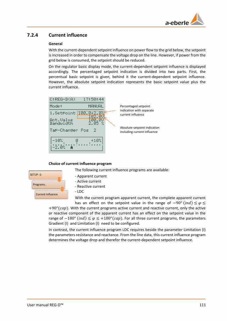
111
User manual REG-D™
7.2.4 Current influence General With the current-dependent setpoint influence on power flow to the grid below, the setpoint is increased in order to compensate the voltage drop on the line. However, if power from the grid below is consumed, the setpoint should be reduced. On the regulator basic display mode, the current-dependent setpoint influence is displayed accordingly. The percentaged setpoint indication is divided into two parts. First, the percentual basic setpoint is given, behind it the current-dependent setpoint influence. However, the absolute setpoint indication represents the basic setpoint value plus the current influence.
Choice of current influence program
The following current influence programs are available: - Apparent current - Active current - Reactive current - LDC With the current program apparent current, the complete apparent current has an effect on the setpoint value in the range of −90° (𝐼𝐼𝑖𝑖𝑖𝑖) ≤ 𝜑𝜑 ≤
+90°(𝐼𝐼𝑐𝑐𝑐𝑐). With the current programs active current and reactive current, only the active or reactive component of the apparent current has an effect on the setpoint value in the range of −180° (𝐼𝐼𝑖𝑖𝑖𝑖) ≤ 𝜑𝜑 ≤ +180°(𝐼𝐼𝑐𝑐𝑐𝑐). For all three current programs, the parameters Gradient (I) and Limitation (I) need to be configured. In contrast, the current influence program LDC requires beside the parameter Limitation (I) the parameters resistance and reactance. From the line data, this current influence program determines the voltage drop and therefor the current-dependent setpoint influence.
Percentaged setpoint indication with separate current influence
Absolute setpoint indication including current influence
SETUP -1-
Programs..
Current Influence
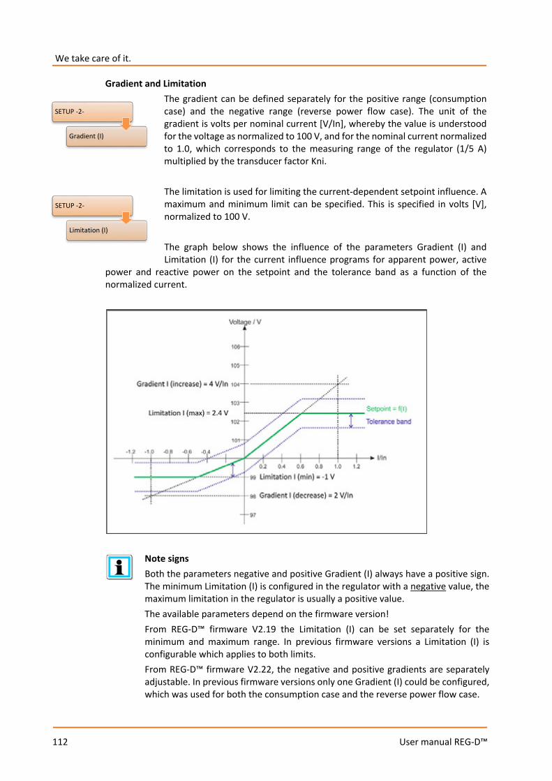
We take care of it.
112
User manual REG-D™
Gradient and Limitation The gradient can be defined separately for the positive range (consumption case) and the negative range (reverse power flow case). The unit of the gradient is volts per nominal current [V/In], whereby the value is understood for the voltage as normalized to 100 V, and for the nominal current normalized to 1.0, which corresponds to the measuring range of the regulator (1/5 A) multiplied by the transducer factor Kni.
The limitation is used for limiting the current-dependent setpoint influence. A maximum and minimum limit can be specified. This is specified in volts [V], normalized to 100 V. The graph below shows the influence of the parameters Gradient (I) and Limitation (I) for the current influence programs for apparent power, active
power and reactive power on the setpoint and the tolerance band as a function of the normalized current.
Note signs Both the parameters negative and positive Gradient (I) always have a positive sign. The minimum Limitation (I) is configured in the regulator with a negative value, the maximum limitation in the regulator is usually a positive value. The available parameters depend on the firmware version! From REG-D™ firmware V2.19 the Limitation (I) can be set separately for the minimum and maximum range. In previous firmware versions a Limitation (I) is configurable which applies to both limits. From REG-D™ firmware V2.22, the negative and positive gradients are separately adjustable. In previous firmware versions only one Gradient (I) could be configured, which was used for both the consumption case and the reverse power flow case.
SETUP -2-
Gradient (I)
SETUP -2-
Limitation (I)
113
User manual REG-D™
Resistance and reactance (LDC procedure) If the current influence program LDC is selected, the menu item LDC Parameter is visible. Here, the resistance (R) and reactance (X) of the compensated line can be specified. From the given values the Relay for Voltage Control & Transformer Monitoring REG-D™ calculates the corresponding setpoint influence based on the current and phase angle.
For more information, see chapter 8.1.4 from page 155 onwards.
SETUP -1-
Programs..
LDC Parameter

We take care of it.
114
User manual REG-D™
7.2.5 Measurement value simulation Activating measurement value simulation
The simulation of measurement values can be used for testing, presentation or commissioning of the Relay for Voltage Control & Transformer Monitoring. To prevent the simulation from being turned on accidentally, some operating steps are required, which should ensure that the work with the simulation can only proceed when it is explicitly wanted.
Three different configurations of measurement value simulation are possible, which will be explained in the following. The value of the feature Simmode can be checked in the status menu (scrolling with the arrow keys and ).
1. Feature Simmode = 0 In this mode, a measurement value simulation is not possible. The feature is not listed in the status menu (2) of the regulator.
2. Feature Simmode = 1 In this mode, a measurement value simulation is only possible in manual mode. On switching from manual mode to automatic mode, the simulation is terminated. Simulation needs to be activated separately in status menu (1) by pressing F5.
3. Feature Simmode = 2 In this mode, a measurement value simulation is possible in both manual and automatic mode. Simulation needs to be activated separately in the status menu (1) by pressing F5.
By default, the simulation mode is activated on delivery of the regulator, ina way that only allows simulation in manual mode (feature Simmode = 1). If a different kind of measurement value simulation is wanted, this can be changed at any time via the terminal program (subprogram of the configuration software WinREG), using the appropriate commands (e.g. "feature Simmode = 2") . If the simulation is active, it can be disabled via the F5 key in the status menu (1). Simulation terminates automatically 15 minutes after the last key press.
DANGER! Real tap changing! In active simulation mode it is to be noted that tap-change commands are issued via the raise or lower relays in real time and the tap changer can really be tapped. In particular, during active simulation in automatic mode (Simmode = 2), this can lead to a significant tap change within a short time and thus violate certain voltage limits, which are not regulated by the Relay for Voltage Control & Transformer Monitoring REG-D™ due to the simulation mode.
SETUP -6-
Status

115
User manual REG-D™
Display of active measured value simulation If simulation is active, the word "SIM" will be visible (from REGSys™ firmware V2.22) in the regulator basic display mode and in the transducer mode. Moreover, in the regulator basic display mode the words "Actual value" are written in capital letters with the active simulation mode ("ACTUAL VALUE"), and in status menu (1) the note "Input Simulation" is shown in the lower left corner.
Measurement value simulation with PAN-D present If the Relay for Voltage Control & Transformer Monitoring REG-D™ is used in conjunction with the monitoring unit PAN-D (connected via E-LAN), in simulation mode it should be noted that the simulated voltage is also transmitted to the PAN-D and that during simulation time the PAN-D sees only the simulated voltage and not the real system voltage.
Setting the simulated voltage, current and phase angle
Simulated voltage can be adjusted in the regulator basic display mode, in the transducer mode and in the recorder mode by using the arrow keys and
. The left arrow key reduces the voltage by 0.5 V, the right arrow key increases the voltage by 0.5 V (voltage data normalized to 100 V).
In the transducer, by using the key the simulated current can be increased by 5% of the nominal current, or by using the key be reduced by 5% of the nominal current.
In the transducer mode, by using the key the simulated phase angle can likewise be increased by 1°, or by using the key be reduced by 1°.
Active simulation mode
Transducer
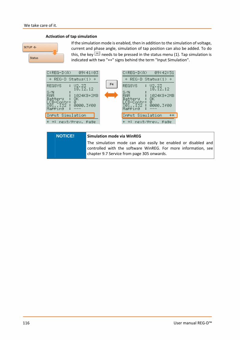
We take care of it.
116
User manual REG-D™
Activation of tap simulation If the simulation mode is enabled, then in addition to the simulation of voltage, current and phase angle, simulation of tap position can also be added. To do this, the key needs to be pressed in the status menu (1). Tap simulation is indicated with two "++" signs behind the term "Input Simulation".
NOTICE! Simulation mode via WinREG The simulation mode can also easily be enabled or disabled and controlled with the software WinREG. For more information, see chapter 9.7 Service from page 305 onwards.
SETUP -6-
Status

117
User manual REG-D™
7.2.6 RAM-Backup General The parameters of the Relay for Voltage Control & Transformer Monitoring REG-D™ are kept in the memory (RAM) by an internal battery, and are thus available unchanged after any interruption of the supply voltage. If the battery life is exhausted, the RAM loses data after any interruption of the supply voltage and the regulator will start with default parameters. To save the parameters independently of the regulator battery, since bootloader firmware version V2.12 it is possible to perform a RAM-Backup of the regulator. Hereby, parameters from the volatile memory (RAM) are secured in the non-volatile memory (flash) of the regulator. If, in addition, a REG-D™ firmware newer than V2.22 is used, the RAM-Backup is automatically restored in the RAM in case of loss of the parameters, and hence the parameters are restored too. In addition to automatic restoration, there is always the option of manually restoring a RAM-Backup regardless of the firmware of the REG-D™.
Data backup It is recommended to carry out a RAM-Backup at the end of commissioning so that the parameters are saved on the spot in case of failure of the internal battery.
REG-D™ devices with MRAM (as of 05/2014 or with the feature S2 as of 09/2013) In REG-D™ Relays for Voltage Control & Transformer Monitoring manufactured since 05/2014 (with feature S2 from 09/2013) a non-volatile RAM (MRAM) is used. In these devices no RAM-Backup is necessary, and for devices with the feature S2 this is not available in the bootloader.
Performing a RAM-Backup
The RAM-Backup can easily be performed from the software WinREG (subprogram Service, see chapter 9.7 Service, from page 305 onwards), but alternatively also carried out directly on the regulator. For a manual RAM-Backup, the bootloader first needs to be started by pressing the key in the status menu for 5 seconds.
WARNING! Control function While the regulator is in bootloader mode, all functions including the control functions of the REG-D™ are inoperative.
SETUP -6-
Status (1)
Bootloader (press F1 for 5s)
RAM BACKUP
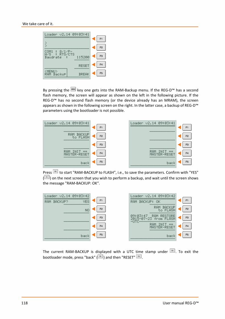
We take care of it.
118
User manual REG-D™
By pressing the key one gets into the RAM-Backup menu. If the REG-D™ has a second flash memory, the screen will appear as shown on the left in the following picture. If the REG-D™ has no second flash memory (or the device already has an MRAM), the screen appears as shown in the following screen on the right. In the latter case, a backup of REG-D™ parameters using the bootloader is not possible.
Press to start "RAM-BACKUP to FLASH", i.e., to save the parameters. Confirm with "YES" ( ) on the next screen that you wish to perform a backup, and wait until the screen shows the message "RAM-BACKUP: OK“.
The current RAM-BACKUP is displayed with a UTC time stamp under . To exit the bootloader mode, press "back" ( ) and then "RESET" .
Loader v2.14 09:03:41 ĢĢĢĢĢĢĢĢĢĢĢĢĢĢĢĢĢĢĢĢĢ > > ĐĐĐĐĐĐĐĐĐĐĐĐĐĐĐĐĐĐĐĐĐ COM1 : 8/1/P- H/S : RTS/CTS Baudrate : 115200 ĐĐĐĐĐĐĐ RESET ĐĐĐĐĐĐĐĐĐĐċ ĐĐĐĐĐĐĐ <MENU> ¦ RAM Backup¦ BREAK ĐĐĐĐĐĐĐĐĐĐ·ĐĐĐĐĐĐĐĐĐĐ
Loader v2.14 09:03:41 ĢĢĢĢĢĢĢĢĢĢĢĢĢĢĢĢĢĢĢĢĢ ĐĐĐĐĐĐĐĐĐĐĐĐ RAM BACKUP to FLASH ĐĐĐĐĐĐĐĐĐĐĐĐ ĐĐĐĐĐĐĐĐĐĐĐĐ RAM INIT == MASTER-RESET ĐĐĐĐĐĐĐĐĐĐĐĐ back ĐĐĐĐĐĐĐĐĐĐĐĐĐĐĐĐĐĐĐĐĐ
Loader v2.14 09:03:41 ĢĢĢĢĢĢĢĢĢĢĢĢĢĢĢĢĢĢĢĢĢ ĐĐĐĐĐĐĐĐĐĐĐĐ ĐĐĐĐĐĐĐĐĐĐĐĐ ĐĐĐĐĐĐĐĐĐĐĐĐ RAM INIT == MASTER-RESET ĐĐĐĐĐĐĐĐĐĐĐĐ back ĐĐĐĐĐĐĐĐĐĐĐĐĐĐĐĐĐĐĐĐĐ
Loader v2.14 09:03:42 ĢĢĢĢĢĢĢĢĢĢĢĢĢĢĢĢĢĢĢĢĢ RAM BACKUP? YES ĐĐĐĐĐĐĐĐĐĐĐĐ NO ĐĐĐĐĐĐĐĐĐĐĐĐ ĐĐĐĐĐĐĐĐĐĐĐĐ ĐĐĐĐĐĐĐĐĐĐĐĐ back ĐĐĐĐĐĐĐĐĐĐĐĐĐĐĐĐĐĐĐĐĐ
Loader v2.14 09:03:42 ĢĢĢĢĢĢĢĢĢĢĢĢĢĢĢĢĢĢĢĢĢ RAM BACKUP: OK ĐĐĐĐĐĐĐĐĐĐĐĐ RAM BACKUP to FLASH ĐĐĐĐĐĐĐĐĐĐĐĐ 09:03:47 RAM RESTORE 2015-07-23 from FLASH -UTCĐĐĐĐĐĐĐĐĐĐĐĐĐĐĐĐĐ RAM INIT == MASTER-RESET ĐĐĐĐĐĐĐĐĐĐĐĐ back ĐĐĐĐĐĐĐĐĐĐĐĐĐĐĐĐĐĐĐĐĐ
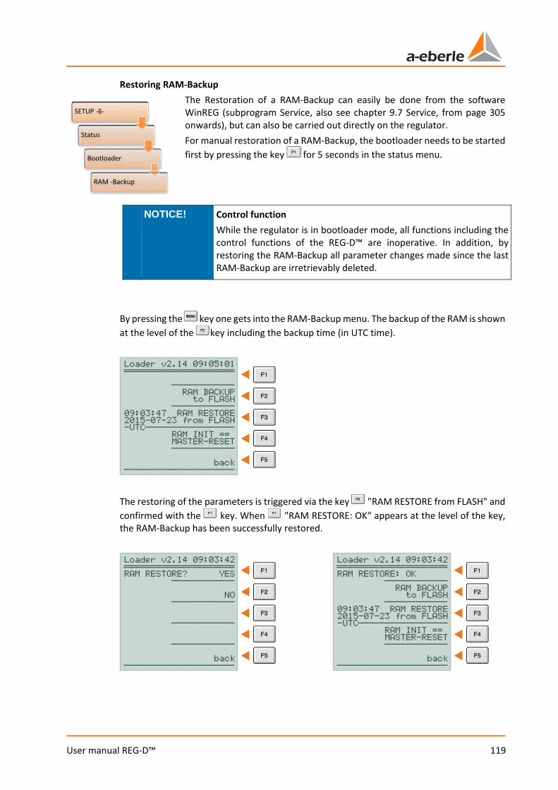
119
User manual REG-D™
Restoring RAM-Backup The Restoration of a RAM-Backup can easily be done from the software WinREG (subprogram Service, also see chapter 9.7 Service, from page 305 onwards), but can also be carried out directly on the regulator. For manual restoration of a RAM-Backup, the bootloader needs to be started first by pressing the key for 5 seconds in the status menu.
NOTICE! Control function While the regulator is in bootloader mode, all functions including the control functions of the REG-D™ are inoperative. In addition, by restoring the RAM-Backup all parameter changes made since the last RAM-Backup are irretrievably deleted.
By pressing the key one gets into the RAM-Backup menu. The backup of the RAM is shown at the level of the key including the backup time (in UTC time).
The restoring of the parameters is triggered via the key "RAM RESTORE from FLASH" and confirmed with the key. When "RAM RESTORE: OK“ appears at the level of the key, the RAM-Backup has been successfully restored.
Loader v2.14 09:05:01 ĢĢĢĢĢĢĢĢĢĢĢĢĢĢĢĢĢĢĢĢĢ ĐĐĐĐĐĐĐĐĐĐĐĐ RAM BACKUP to FLASH ĐĐĐĐĐĐĐĐĐĐĐĐ 09:03:47 RAM RESTORE 2015-07-23 from FLASH -UTCĐĐĐĐĐĐĐĐĐĐĐĐĐĐĐĐĐ RAM INIT == MASTER-RESET ĐĐĐĐĐĐĐĐĐĐĐĐ back ĐĐĐĐĐĐĐĐĐĐĐĐĐĐĐĐĐĐĐĐĐ
Loader v2.14 09:03:42 ĢĢĢĢĢĢĢĢĢĢĢĢĢĢĢĢĢĢĢĢĢ RAM RESTORE? YES ĐĐĐĐĐĐĐĐĐĐĐĐ NO ĐĐĐĐĐĐĐĐĐĐĐĐ ĐĐĐĐĐĐĐĐĐĐĐĐ ĐĐĐĐĐĐĐĐĐĐĐĐ back ĐĐĐĐĐĐĐĐĐĐĐĐĐĐĐĐĐĐĐĐĐ
Loader v2.14 09:03:42 ĢĢĢĢĢĢĢĢĢĢĢĢĢĢĢĢĢĢĢĢĢ RAM RESTORE: OK ĐĐĐĐĐĐĐĐĐĐĐĐ RAM BACKUP to FLASH ĐĐĐĐĐĐĐĐĐĐĐĐ 09:03:47 RAM RESTORE 2015-07-23 from FLASH -UTCĐĐĐĐĐĐĐĐĐĐĐĐĐĐĐĐĐ RAM INIT == MASTER-RESET ĐĐĐĐĐĐĐĐĐĐĐĐ back ĐĐĐĐĐĐĐĐĐĐĐĐĐĐĐĐĐĐĐĐĐ
SETUP -6-
Status
Bootloader
RAM -Backup

We take care of it.
120
User manual REG-D™
The parameters are now fully restored. To exit the bootloader mode, press "back" ( ) and then "RESET" .
Checking the time setting If the restoration of a RAM-Backup is performed due to an empty buffer battery, it will be necessary to check the time setting of the Relay for Voltage Control & Transformer Monitoring REG-D™, and to correct it if necessary.
Deleting an existing backup file If an existing backup file is to be deleted completely and not only overwritten, the following steps needs be taken.
In bootloader mode, switch to the RAM-Backup menu with the key. After a renewed "BACKUP RAM to FLASH" via the key has been triggered, the indicator "BUSY ..." appears in the panel of the regulator. If the RAM-Backup using the key is cancelled, the current RAM-BACKUP is deleted and is then no longer visible.
Loader v2.14 09:03:42 ĢĢĢĢĢĢĢĢĢĢĢĢĢĢĢĢĢĢĢĢĢ ĐĐĐĐĐĐĐĐĐĐĐĐ RAM BACKUP to FLASH ĐĐĐĐĐĐĐĐĐĐĐĐ 09:03:47 RAM RESTORE 2015-07-23 from FLASH -UTCĐĐĐĐĐĐĐĐĐĐĐĐĐĐĐĐĐ RAM INIT == MASTER-RESET ĐĐĐĐĐĐĐĐĐĐĐĐ back ĐĐĐĐĐĐĐĐĐĐĐĐĐĐĐĐĐĐĐĐĐ
Loader v2.14 09:03:42 ĢĢĢĢĢĢĢĢĢĢĢĢĢĢĢĢĢĢĢĢĢ BUSY...... ĐĐĐĐĐĐĐĐĐĐĐĐ Cancel ĐĐĐĐĐĐĐĐĐĐĐĐĐĐĐĐĐĐĐĐĐ
Loader v2.14 09:03:42 ĢĢĢĢĢĢĢĢĢĢĢĢĢĢĢĢĢĢĢĢĢ RAM BACKUP: cancelled ĐĐĐĐĐĐĐĐĐĐĐĐ RAM BACKUP ins FLASH ĐĐĐĐĐĐĐĐĐĐĐĐ ĐĐĐĐĐĐĐĐĐĐĐĐ RAM INIT == MASTER-RESET ĐĐĐĐĐĐĐĐĐĐĐĐ back ĐĐĐĐĐĐĐĐĐĐĐĐĐĐĐĐĐĐĐĐĐ
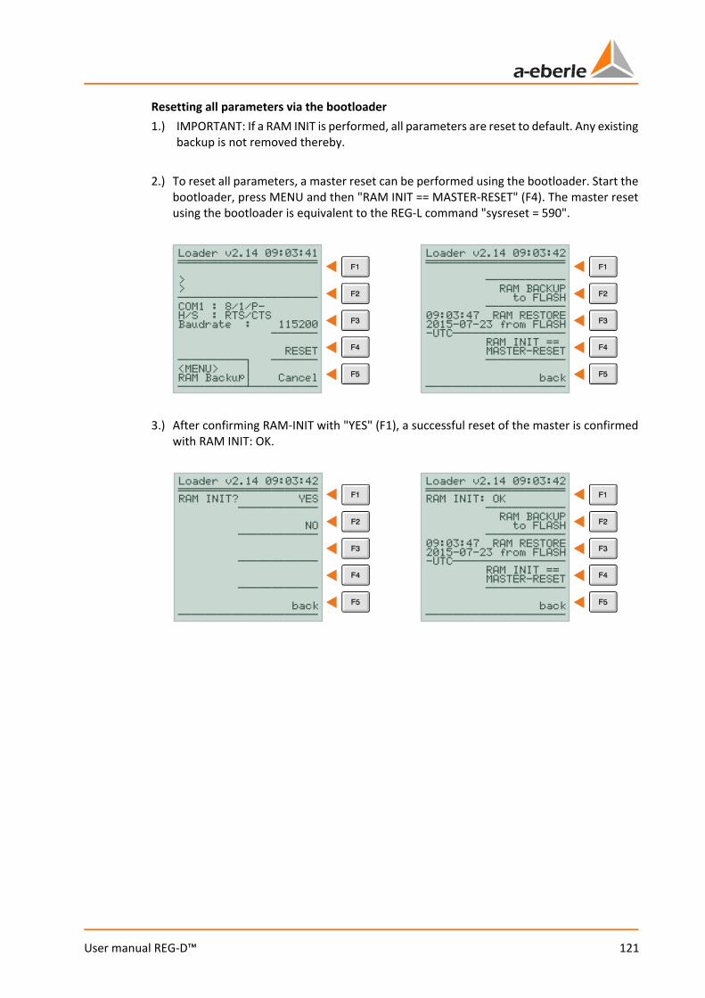
121
User manual REG-D™
Resetting all parameters via the bootloader 1.) IMPORTANT: If a RAM INIT is performed, all parameters are reset to default. Any existing
backup is not removed thereby. 2.) To reset all parameters, a master reset can be performed using the bootloader. Start the
bootloader, press MENU and then "RAM INIT == MASTER-RESET" (F4). The master reset using the bootloader is equivalent to the REG-L command "sysreset = 590".
3.) After confirming RAM-INIT with "YES" (F1), a successful reset of the master is confirmed
with RAM INIT: OK.
Loader v2.14 09:03:41 ĢĢĢĢĢĢĢĢĢĢĢĢĢĢĢĢĢĢĢĢĢ > > ĐĐĐĐĐĐĐĐĐĐĐĐĐĐĐĐĐĐĐĐĐ COM1 : 8/1/P- H/S : RTS/CTS Baudrate : 115200 ĐĐĐĐĐĐĐ RESET ĐĐĐĐĐĐĐĐĐĐċ ĐĐĐĐĐĐĐ <MENU> ¦ RAM Backup¦ Cancel ĐĐĐĐĐĐĐĐĐĐ·ĐĐĐĐĐĐĐĐĐĐ
Loader v2.14 09:03:42 ĢĢĢĢĢĢĢĢĢĢĢĢĢĢĢĢĢĢĢĢĢ ĐĐĐĐĐĐĐĐĐĐĐĐ RAM BACKUP to FLASH ĐĐĐĐĐĐĐĐĐĐĐĐ 09:03:47 RAM RESTORE 2015-07-23 from FLASH -UTCĐĐĐĐĐĐĐĐĐĐĐĐĐĐĐĐĐ RAM INIT == MASTER-RESET ĐĐĐĐĐĐĐĐĐĐĐĐ back ĐĐĐĐĐĐĐĐĐĐĐĐĐĐĐĐĐĐĐĐĐ
Loader v2.14 09:03:42 ĢĢĢĢĢĢĢĢĢĢĢĢĢĢĢĢĢĢĢĢĢ RAM INIT? YES ĐĐĐĐĐĐĐĐĐĐĐĐ NO ĐĐĐĐĐĐĐĐĐĐĐĐ ĐĐĐĐĐĐĐĐĐĐĐĐ ĐĐĐĐĐĐĐĐĐĐĐĐ back ĐĐĐĐĐĐĐĐĐĐĐĐĐĐĐĐĐĐĐĐĐ
Loader v2.14 09:03:42 ĢĢĢĢĢĢĢĢĢĢĢĢĢĢĢĢĢĢĢĢĢ RAM INIT: OK ĐĐĐĐĐĐĐĐĐĐĐĐ RAM BACKUP to FLASH ĐĐĐĐĐĐĐĐĐĐĐĐ 09:03:47 RAM RESTORE 2015-07-23 from FLASH -UTCĐĐĐĐĐĐĐĐĐĐĐĐĐĐĐĐĐ RAM INIT == MASTER-RESET ĐĐĐĐĐĐĐĐĐĐĐĐ back ĐĐĐĐĐĐĐĐĐĐĐĐĐĐĐĐĐĐĐĐĐ
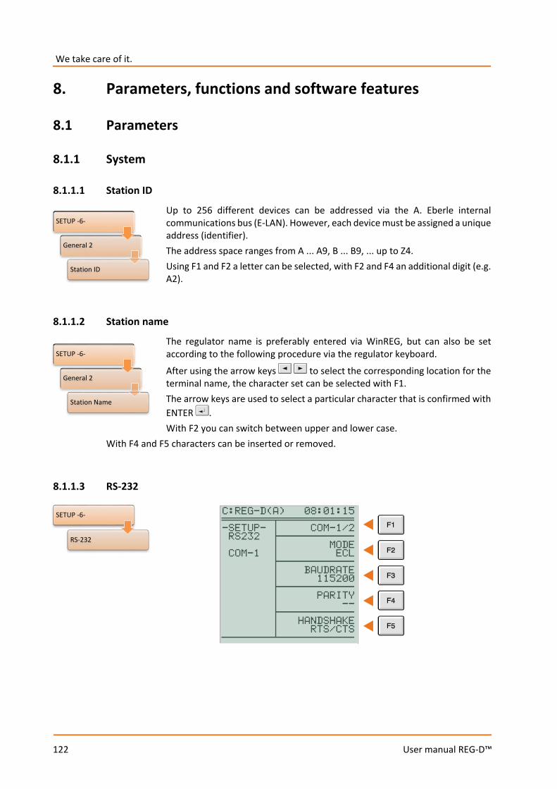
We take care of it.
122
User manual REG-D™
8. Parameters, functions and software features
8.1 Parameters
8.1.1 System
8.1.1.1 Station ID
Up to 256 different devices can be addressed via the A. Eberle internal communications bus (E-LAN). However, each device must be assigned a unique address (identifier). The address space ranges from A ... A9, B ... B9, ... up to Z4. Using F1 and F2 a letter can be selected, with F2 and F4 an additional digit (e.g. A2).
8.1.1.2 Station name
The regulator name is preferably entered via WinREG, but can also be set according to the following procedure via the regulator keyboard.
After using the arrow keys to select the corresponding location for the terminal name, the character set can be selected with F1. The arrow keys are used to select a particular character that is confirmed with ENTER . With F2 you can switch between upper and lower case.
With F4 and F5 characters can be inserted or removed.
8.1.1.3 RS-232
SETUP -6-
General 2
Station ID
SETUP -6-
General 2
Station Name
SETUP -6-
RS-232
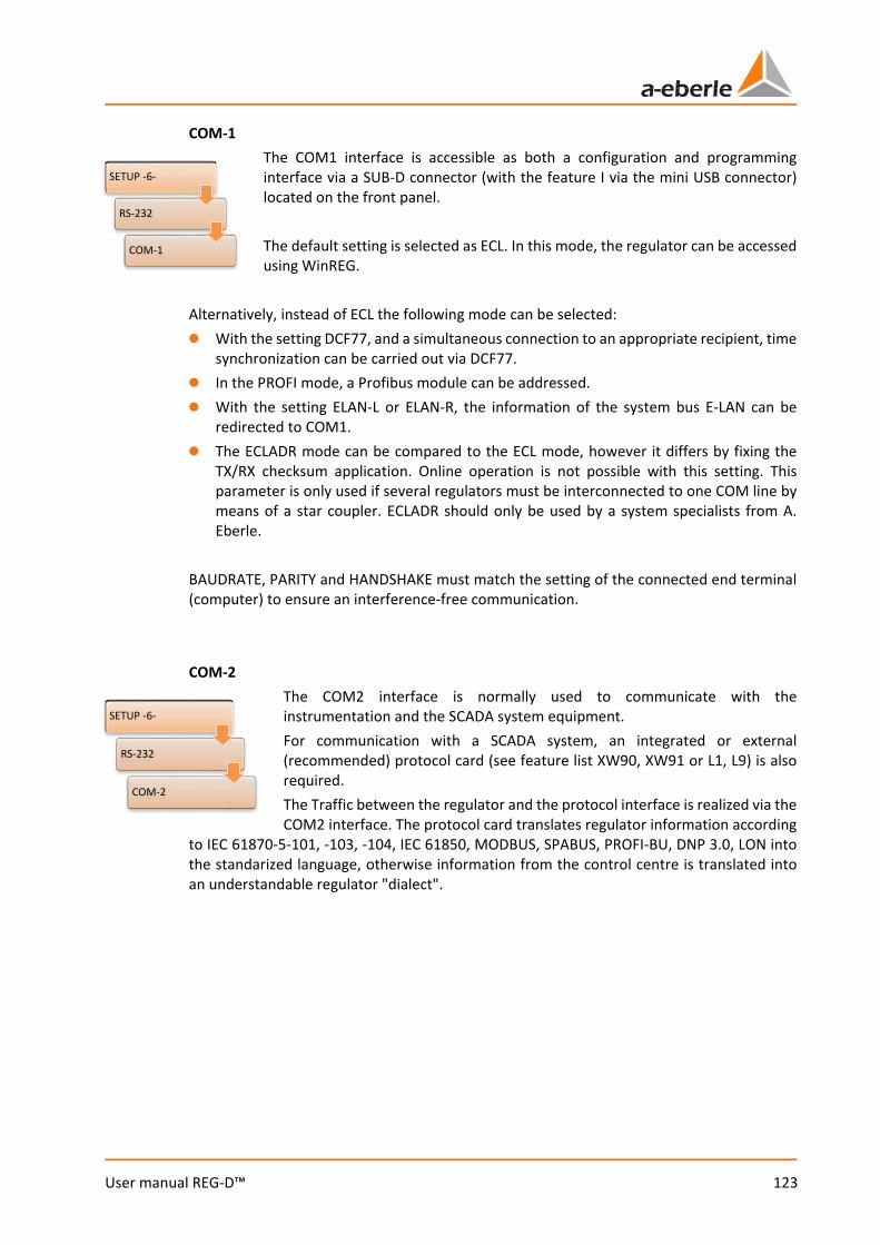
123
User manual REG-D™
COM-1 The COM1 interface is accessible as both a configuration and programming interface via a SUB-D connector (with the feature I via the mini USB connector) located on the front panel. The default setting is selected as ECL. In this mode, the regulator can be accessed using WinREG.
Alternatively, instead of ECL the following mode can be selected: 0 With the setting DCF77, and a simultaneous connection to an appropriate recipient, time
synchronization can be carried out via DCF77. 0 In the PROFI mode, a Profibus module can be addressed. 0 With the setting ELAN-L or ELAN-R, the information of the system bus E-LAN can be
redirected to COM1. 0 The ECLADR mode can be compared to the ECL mode, however it differs by fixing the
TX/RX checksum application. Online operation is not possible with this setting. This parameter is only used if several regulators must be interconnected to one COM line by means of a star coupler. ECLADR should only be used by a system specialists from A. Eberle.
BAUDRATE, PARITY and HANDSHAKE must match the setting of the connected end terminal (computer) to ensure an interference-free communication. COM-2
The COM2 interface is normally used to communicate with the instrumentation and the SCADA system equipment. For communication with a SCADA system, an integrated or external (recommended) protocol card (see feature list XW90, XW91 or L1, L9) is also required. The Traffic between the regulator and the protocol interface is realized via the COM2 interface. The protocol card translates regulator information according
to IEC 61870-5-101, -103, -104, IEC 61850, MODBUS, SPABUS, PROFI-BU, DNP 3.0, LON into the standarized language, otherwise information from the control centre is translated into an understandable regulator "dialect".
SETUP -6-
RS-232
COM-1
SETUP -6-
RS-232
COM-2
We take care of it.
124
User manual REG-D™
The default mode is ECL, which is usually used for communication with the SCADA system. Moreover, the following modes can be set: 0 If time synchronization is to be realized via DCF77, the setting DCF77 must be selected.
In this case, a suitable receiver must be connected to the COM2 interface. 0 The setting ECL+HP opens up the possibility that an output, generated via an H-program,
in addition to COM1, is also issued via COM2. 0 The mode ECLADR can be compared to the mode ECL, however it differs by setting the
TX/RX checksum application. Online operation is not possible with this setting. This parameter is only used if several regulators must be interconnected to one COM line by means of a star coupler. ECLADR should only be used by system specialists from A. Eberle.
0 If E-LAN (ELAN-L, ELAN-R) information is to be redirected to the serial interface to carry out modem transmissions at the E-LAN level, the setting must be ELAN-L or PEP-R. Further detailed descriptions will be omitted at this point, because such connections should in any case be implemented in cooperation with the A. Eberle REGSys support team ([email protected], +49(0)911/628108-101).
0 PROFI is always the right setting for COM2 if a PROFIBUS-DP connection is to be implemented. In this case, an external PROFIBUS-DP module can be controlled via COM2.
0 OFF switches off the interface. BAUDRATE, PARITY and HANDSHAKE must match the setting of the connected end terminal (computer) to ensure interference-free communication.
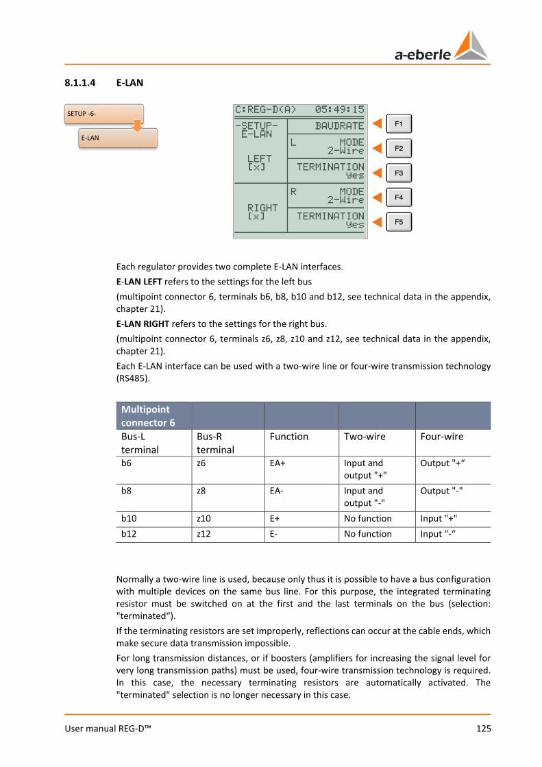
125
User manual REG-D™
8.1.1.4 E-LAN
Each regulator provides two complete E-LAN interfaces. E-LAN LEFT refers to the settings for the left bus (multipoint connector 6, terminals b6, b8, b10 and b12, see technical data in the appendix, chapter 21). E-LAN RIGHT refers to the settings for the right bus. (multipoint connector 6, terminals z6, z8, z10 and z12, see technical data in the appendix, chapter 21). Each E-LAN interface can be used with a two-wire line or four-wire transmission technology (RS485).
Multipoint connector 6
Bus-L terminal
Bus-R terminal
Function Two-wire Four-wire
b6 z6 EA+ Input and output "+"
Output "+“
b8 z8 EA- Input and output "-"
Output "-"
b10 z10 E+ No function Input "+" b12 z12 E- No function Input "-“
Normally a two-wire line is used, because only thus it is possible to have a bus configuration with multiple devices on the same bus line. For this purpose, the integrated terminating resistor must be switched on at the first and the last terminals on the bus (selection: "terminated“). If the terminating resistors are set improperly, reflections can occur at the cable ends, which make secure data transmission impossible. For long transmission distances, or if boosters (amplifiers for increasing the signal level for very long transmission paths) must be used, four-wire transmission technology is required. In this case, the necessary terminating resistors are automatically activated. The "terminated" selection is no longer necessary in this case.
SETUP -6-
E-LAN
We take care of it.
126
User manual REG-D™
If the terminations (only possible with two-wire operation!) and the baud rate are set correctly, and the wiring is done properly, a bracketed [X] will appear in the two mutually connected devices. The [X] signifies that the neighbouring station is recognized. If the connection cannot be made completely or stably, the devices will respond with a flashing [X]. The following causes may be involved: 1. Wiring error; open or wrong connection. 2. Identical station identifiers (each regulator must be assigned a unique address in the
E-LAN group, see chapter 8.1.1.1from page 122 onwards). 3. The baudrate between interconnected regulators is not identical.
Example: The right E-LAN bus terminal of regulator "A:" is connected to the left E-LAN bus terminal of regulator "B:". Then the condition applies that the same baudrate must be set for the right E-LAN of regulator "A:" as the left E-LAN of regulator "B:".
4. Incorrect termination Only the first and last device of a bus segment may be terminated (also see chapter 7.1.4.6 from page 67 onwards). With a four-wire connections this termination occurs automatically.
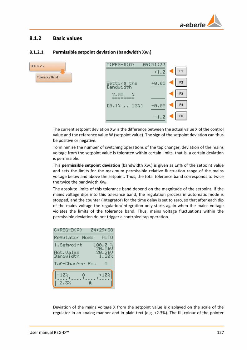
127
User manual REG-D™
8.1.2 Basic values
8.1.2.1 Permissible setpoint deviation (bandwidth Xwz)
The current setpoint deviation Xw is the difference between the actual value X of the control value and the reference value W (setpoint value). The sign of the setpoint deviation can thus be positive or negative. To minimize the number of switching operations of the tap changer, deviation of the mains voltage from the setpoint value is tolerated within certain limits, that is, a certain deviation is permissible. This permissible setpoint deviation (bandwidth Xwz) is given as ±n% of the setpoint value and sets the limits for the maximum permissible relative fluctuation range of the mains voltage below and above the setpoint. Thus, the total tolerance band corresponds to twice the twice the bandwidth Xwz. The absolute limits of this tolerance band depend on the magnitude of the setpoint. If the mains voltage dips into this tolerance band, the regulation process in automatic mode is stopped, and the counter (integrator) for the time delay is set to zero, so that after each dip of the mains voltage the regulation/integration only starts again when the mains voltage violates the limits of the tolerance band. Thus, mains voltage fluctuations within the permissible deviation do not trigger a controled tap operation.
Deviation of the mains voltage X from the setpoint value is displayed on the scale of the regulator in an analog manner and in plain text (e.g. +2.3%). The fill colour of the pointer
SETUP -1-
Tolerance Band
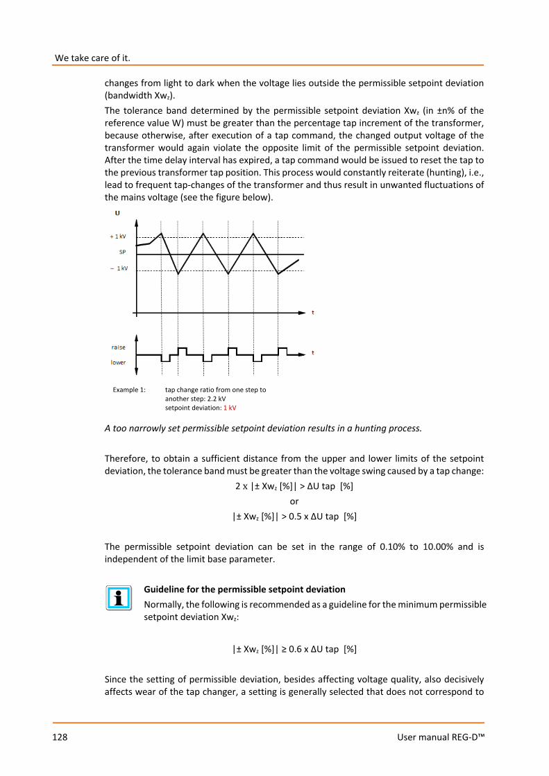
We take care of it.
128
User manual REG-D™
changes from light to dark when the voltage lies outside the permissible setpoint deviation (bandwidth Xwz). The tolerance band determined by the permissible setpoint deviation Xwz (in ±n% of the reference value W) must be greater than the percentage tap increment of the transformer, because otherwise, after execution of a tap command, the changed output voltage of the transformer would again violate the opposite limit of the permissible setpoint deviation. After the time delay interval has expired, a tap command would be issued to reset the tap to the previous transformer tap position. This process would constantly reiterate (hunting), i.e., lead to frequent tap-changes of the transformer and thus result in unwanted fluctuations of the mains voltage (see the figure below).
A too narrowly set permissible setpoint deviation results in a hunting process. Therefore, to obtain a sufficient distance from the upper and lower limits of the setpoint deviation, the tolerance band must be greater than the voltage swing caused by a tap change:
2 x |± Xwz [%]| > ∆U tap [%] or
|± Xwz [%]| > 0.5 x ∆U tap [%] The permissible setpoint deviation can be set in the range of 0.10% to 10.00% and is independent of the limit base parameter.
Guideline for the permissible setpoint deviation Normally, the following is recommended as a guideline for the minimum permissible setpoint deviation Xwz:
|± Xwz [%]| ≥ 0.6 x ∆U tap [%]
Since the setting of permissible deviation, besides affecting voltage quality, also decisively affects wear of the tap changer, a setting is generally selected that does not correspond to
Example 1: tap change ratio from one step to another step: 2.2 kV setpoint deviation: 1 kV
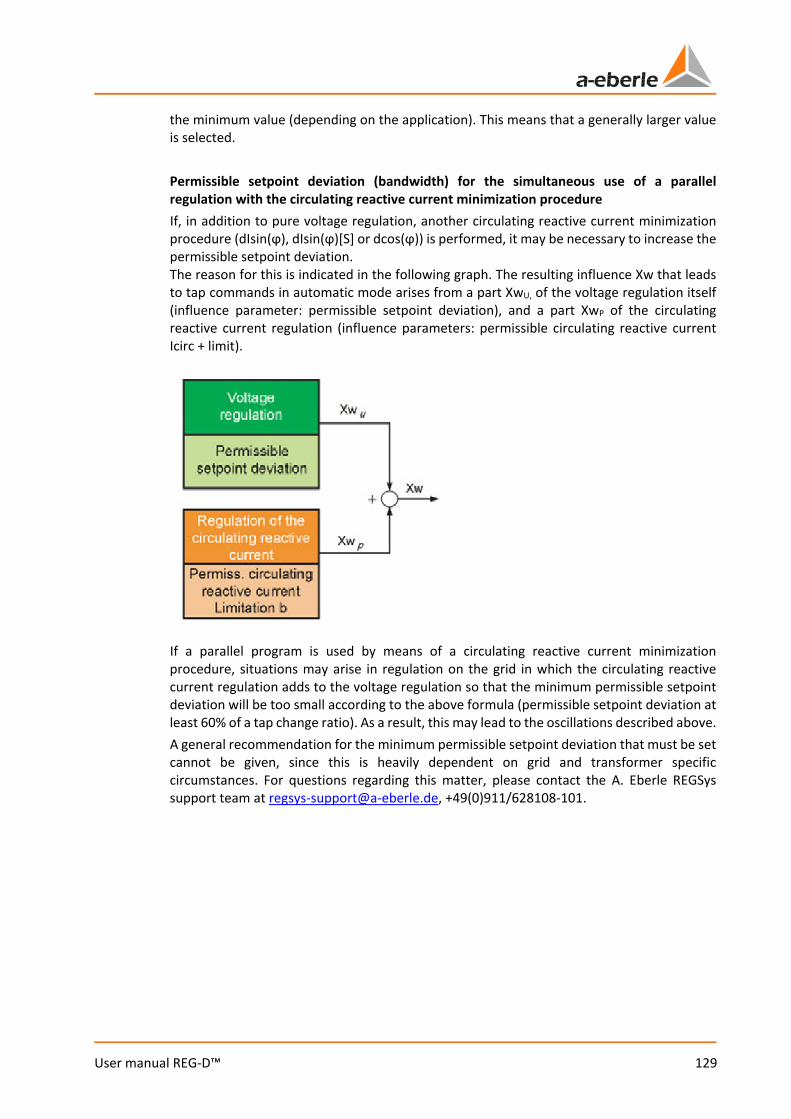
129
User manual REG-D™
the minimum value (depending on the application). This means that a generally larger value is selected. Permissible setpoint deviation (bandwidth) for the simultaneous use of a parallel regulation with the circulating reactive current minimization procedure If, in addition to pure voltage regulation, another circulating reactive current minimization procedure (dIsin(ϕ), dIsin(ϕ)[S] or dcos(ϕ)) is performed, it may be necessary to increase the permissible setpoint deviation. The reason for this is indicated in the following graph. The resulting influence Xw that leads to tap commands in automatic mode arises from a part XwU, of the voltage regulation itself (influence parameter: permissible setpoint deviation), and a part XwP of the circulating reactive current regulation (influence parameters: permissible circulating reactive current Icirc + limit).
If a parallel program is used by means of a circulating reactive current minimization procedure, situations may arise in regulation on the grid in which the circulating reactive current regulation adds to the voltage regulation so that the minimum permissible setpoint deviation will be too small according to the above formula (permissible setpoint deviation at least 60% of a tap change ratio). As a result, this may lead to the oscillations described above. A general recommendation for the minimum permissible setpoint deviation that must be set cannot be given, since this is heavily dependent on grid and transformer specific circumstances. For questions regarding this matter, please contact the A. Eberle REGSys support team at [email protected], +49(0)911/628108-101.
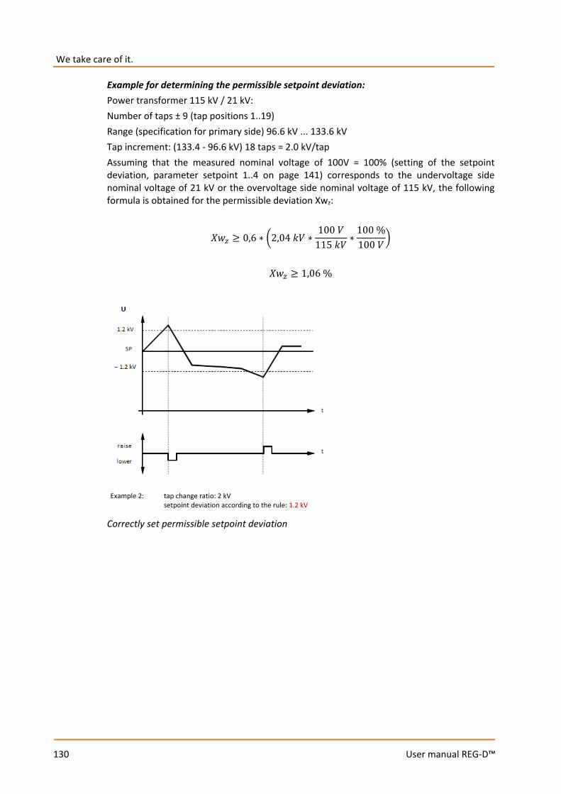
We take care of it.
130
User manual REG-D™
Example for determining the permissible setpoint deviation: Power transformer 115 kV / 21 kV: Number of taps ± 9 (tap positions 1..19) Range (specification for primary side) 96.6 kV ... 133.6 kV Tap increment: (133.4 - 96.6 kV) 18 taps = 2.0 kV/tap Assuming that the measured nominal voltage of 100V = 100% (setting of the setpoint deviation, parameter setpoint 1..4 on page 141) corresponds to the undervoltage side nominal voltage of 21 kV or the overvoltage side nominal voltage of 115 kV, the following formula is obtained for the permissible deviation Xwz:
𝑋𝑋𝑋𝑋𝑧𝑧 ≥ 0,6 ∗ 2,04 𝑘𝑘𝑘𝑘 ∗100 𝑘𝑘
115 𝑘𝑘𝑘𝑘∗
100 %100 𝑘𝑘
𝑋𝑋𝑋𝑋𝑧𝑧 ≥ 1,06 %
Correctly set permissible setpoint deviation
Example 2: tap change ratio: 2 kV setpoint deviation according to the rule: 1.2 kV

131
User manual REG-D™
8.1.2.2 Time behavior
The golden rule for multiple feeding points is a calm network. This requirement leads to a regulation that has as result few switching operations ordered. Reduced regulation can be achieved by increasing the permissible setpoint deviation (Xwz) or the reaction time. However, this procedure will reach its limit as soon as the interests of consumers are unduly prejudiced, i.e., because of excessively large or long-lasting voltage deviations. The REG-D™ reaction time in automatic mode depends, beside the current permissible setpoint deviation, on some parameters, which are explained below. All time based programs have in common that the setpoint deviations are summed up to a specified integral value before the regulator outputs a tap command. Thus, an integration (summation) takes place only when the voltage lies outside the permissible setpoint deviation. The current setpoint deviation is weighted for the summation according to the selected time program (Integral, Fast Integral, LINEAR, CONST). Depending on the chosen time program, the value the integrator sums up depending on either non-linear, linear or stepped on the amount of the current setpoint deviation. The mapping rules of the time programs are selected so that large setpoint deviations (voltage deviations) are compensated more rapidly than small ones. With the time program CONST, this compensation can be actively influenced by the choice of the delay times T1 and T2. This means that it is possible to compensate all deviations by the same time.
SETUP -1-
Time Behaviour

We take care of it.
132
User manual REG-D™
The "filling level" of the integrator is indicated in the regulator basic display through of a quasi-analog display. Once the voltage leaves the tolerance band, the bar starts to run from the left to right. The speed at which the bar runs depends on the current setpoint deviation and the settings for the time behavior. When the bar reaches the right side of the screen, a tap command is issued. If the mains voltage drops into the tolerance band (± Xwz) before reaching the right edge of the screen, the integrator is reset, i.e., no tap command is issued.
Under certain conditions no tap commands are issued on reaching the right screen edge: – The TC in operation signal is active or the maximum TC in operation time has not
expired (if no TC in operation signal is present/detected). – A tap command was issued shortly before (5s lock time). – Tap commands are blocked via REG-L (background program).
Under certain circumstances (for example, overvoltage) it may be necessary to accelerate the reaction time of the regulator. To this end, the "High-speed switching function" (see chapter 8.1.3.6 from page 150 onwards) can be used. Moreover, with small setpoint deviations or oscillations of the voltage about the tolerance band limits, it may be necessary to perform a tap change. To this end, the "Trend memory" function can be used (see trend memory from page 139 onwards).
Progress bar
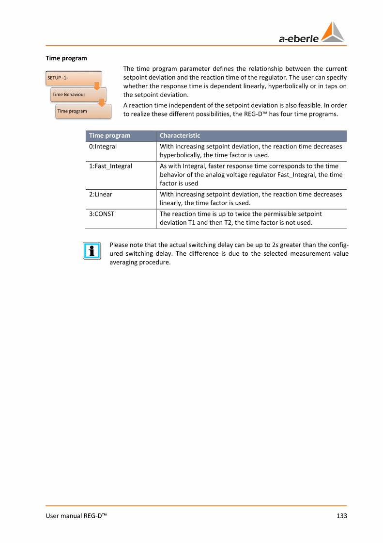
133
User manual REG-D™
Time program The time program parameter defines the relationship between the current setpoint deviation and the reaction time of the regulator. The user can specify whether the response time is dependent linearly, hyperbolically or in taps on the setpoint deviation. A reaction time independent of the setpoint deviation is also feasible. In order to realize these different possibilities, the REG-D™ has four time programs.
Time program Characteristic 0:Integral With increasing setpoint deviation, the reaction time decreases
hyperbolically, the time factor is used. 1:Fast_Integral As with Integral, faster response time corresponds to the time
behavior of the analog voltage regulator Fast_Integral, the time factor is used
2:Linear With increasing setpoint deviation, the reaction time decreases linearly, the time factor is used.
3:CONST The reaction time is up to twice the permissible setpoint deviation T1 and then T2, the time factor is not used.
Please note that the actual switching delay can be up to 2s greater than the config-ured switching delay. The difference is due to the selected measurement value averaging procedure.
SETUP -1-
Time Behaviour
Time program
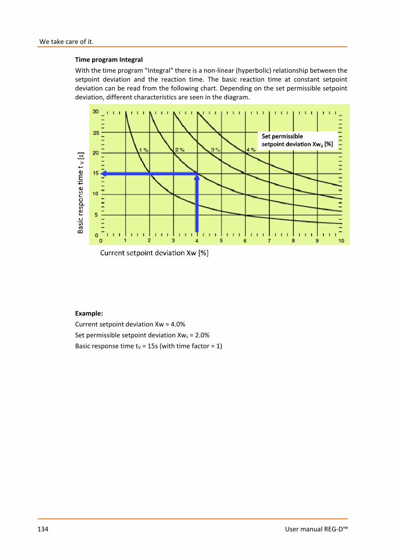
We take care of it.
134
User manual REG-D™
Time program Integral With the time program "Integral" there is a non-linear (hyperbolic) relationship between the setpoint deviation and the reaction time. The basic reaction time at constant setpoint deviation can be read from the following chart. Depending on the set permissible setpoint deviation, different characteristics are seen in the diagram.
Example: Current setpoint deviation Xw = 4.0% Set permissible setpoint deviation Xwz = 2.0% Basic response time tV = 15s (with time factor = 1)
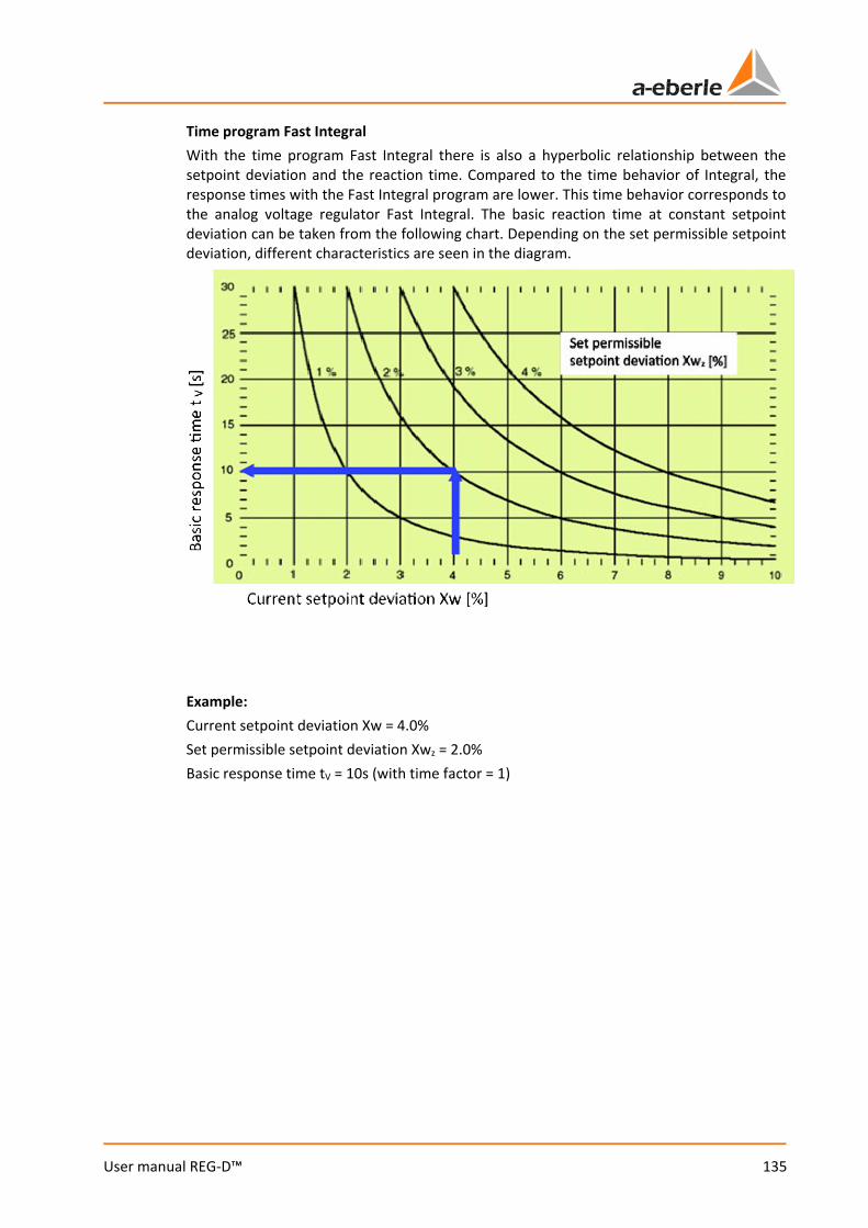
135
User manual REG-D™
Time program Fast Integral With the time program Fast Integral there is also a hyperbolic relationship between the setpoint deviation and the reaction time. Compared to the time behavior of Integral, the response times with the Fast Integral program are lower. This time behavior corresponds to the analog voltage regulator Fast Integral. The basic reaction time at constant setpoint deviation can be taken from the following chart. Depending on the set permissible setpoint deviation, different characteristics are seen in the diagram.
Example: Current setpoint deviation Xw = 4.0% Set permissible setpoint deviation Xwz = 2.0% Basic response time tV = 10s (with time factor = 1)
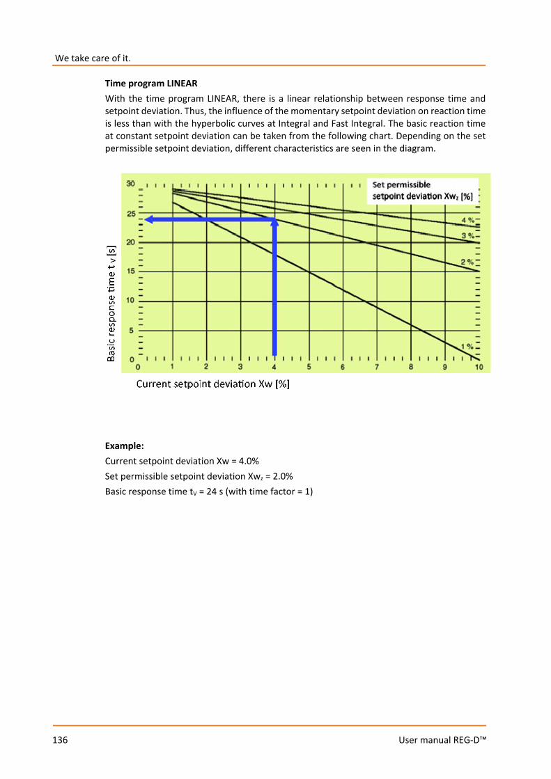
We take care of it.
136
User manual REG-D™
Time program LINEAR With the time program LINEAR, there is a linear relationship between response time and setpoint deviation. Thus, the influence of the momentary setpoint deviation on reaction time is less than with the hyperbolic curves at Integral and Fast Integral. The basic reaction time at constant setpoint deviation can be taken from the following chart. Depending on the set permissible setpoint deviation, different characteristics are seen in the diagram.
Example: Current setpoint deviation Xw = 4.0% Set permissible setpoint deviation Xwz = 2.0% Basic response time tV = 24 s (with time factor = 1)
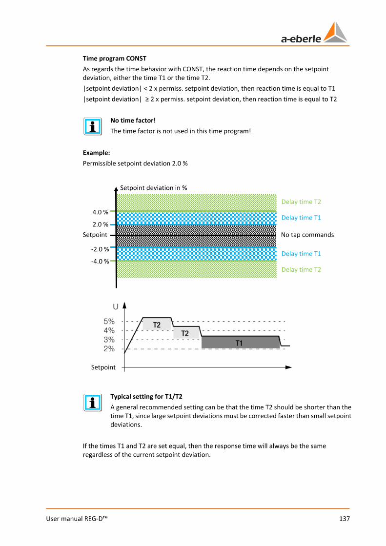
137
User manual REG-D™
Time program CONST As regards the time behavior with CONST, the reaction time depends on the setpoint deviation, either the time T1 or the time T2. |setpoint deviation| < 2 x permiss. setpoint deviation, then reaction time is equal to T1 |setpoint deviation| ≥ 2 x permiss. setpoint deviation, then reaction time is equal to T2
No time factor! The time factor is not used in this time program!
Example: Permissible setpoint deviation 2.0 %
Typical setting for T1/T2 A general recommended setting can be that the time T2 should be shorter than the time T1, since large setpoint deviations must be corrected faster than small setpoint deviations.
If the times T1 and T2 are set equal, then the response time will always be the same regardless of the current setpoint deviation.
Setpoint deviation in %
2.0 %
-2.0 %
4.0 %
-4.0 %
Setpoint No tap commands
Delay time T1
Delay time T2
Delay time T1
Delay time T2
Setpoint
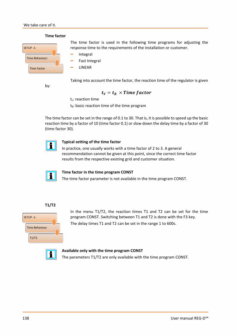
We take care of it.
138
User manual REG-D™
Time factor The time factor is used in the following time programs for adjusting the response time to the requirements of the installation or customer. – Integral – Fast Integral – LINEAR Taking into account the time factor, the reaction time of the regulator is given
by:
𝒊𝒊𝑽𝑽 = 𝒊𝒊𝑩𝑩 × 𝑻𝑻𝒊𝒊𝒊𝒊𝒊𝒊 𝒇𝒇𝑻𝑻𝒊𝒊𝒊𝒊𝒇𝒇𝒊𝒊 tv: reaction time tB: basic reaction time of the time program
The time factor can be set in the range of 0.1 to 30. That is, it is possible to speed up the basic reaction time by a factor of 10 (time factor 0.1) or slow down the delay time by a factor of 30 (time factor 30).
Typical setting of the time factor In practice, one usually works with a time factor of 2 to 3. A general recommendation cannot be given at this point, since the correct time factor results from the respective existing grid and customer situation.
Time factor in the time program CONST The time factor parameter is not available in the time program CONST.
T1/T2
In the menu T1/T2, the reaction times T1 and T2 can be set for the time program CONST. Switching between T1 and T2 is done with the F3 key. The delay times T1 and T2 can be set in the range 1 to 600s.
Available only with the time program CONST The parameters T1/T2 are only available with the time program CONST.
SETUP -1-
Time Behaviour:
Time Factor
SETUP -1-
Time Behaviour
T1/T2
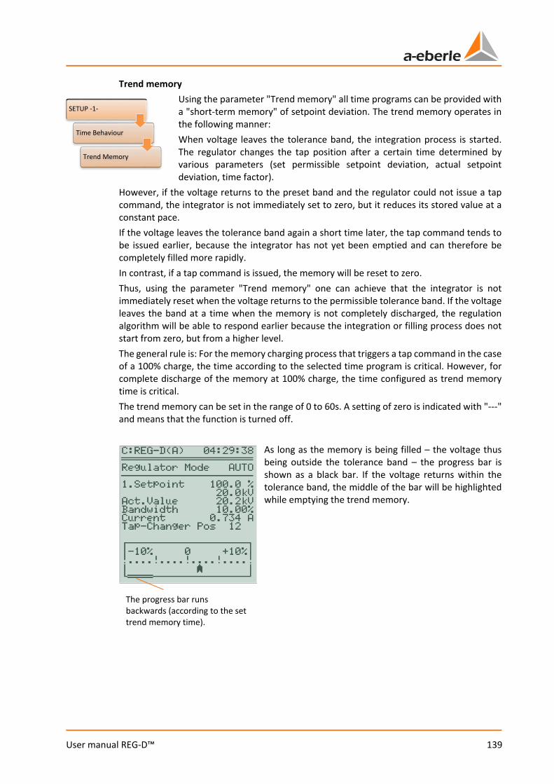
139
User manual REG-D™
Trend memory Using the parameter "Trend memory" all time programs can be provided with a "short-term memory" of setpoint deviation. The trend memory operates in the following manner: When voltage leaves the tolerance band, the integration process is started. The regulator changes the tap position after a certain time determined by various parameters (set permissible setpoint deviation, actual setpoint deviation, time factor).
However, if the voltage returns to the preset band and the regulator could not issue a tap command, the integrator is not immediately set to zero, but it reduces its stored value at a constant pace. If the voltage leaves the tolerance band again a short time later, the tap command tends to be issued earlier, because the integrator has not yet been emptied and can therefore be completely filled more rapidly. In contrast, if a tap command is issued, the memory will be reset to zero. Thus, using the parameter "Trend memory" one can achieve that the integrator is not immediately reset when the voltage returns to the permissible tolerance band. If the voltage leaves the band at a time when the memory is not completely discharged, the regulation algorithm will be able to respond earlier because the integration or filling process does not start from zero, but from a higher level. The general rule is: For the memory charging process that triggers a tap command in the case of a 100% charge, the time according to the selected time program is critical. However, for complete discharge of the memory at 100% charge, the time configured as trend memory time is critical. The trend memory can be set in the range of 0 to 60s. A setting of zero is indicated with "---" and means that the function is turned off.
As long as the memory is being filled – the voltage thus being outside the tolerance band – the progress bar is shown as a black bar. If the voltage returns within the tolerance band, the middle of the bar will be highlighted while emptying the trend memory.
SETUP -1-
Time Behaviour
Trend Memory
The progress bar runs backwards (according to the set trend memory time).

We take care of it.
140
User manual REG-D™
Example: Operation of the trend memory will be explained with an example. Time program: CONST T1: 40 seconds Trend memory: 40 seconds Permissible setpoint deviation: ±1%
The overall status is illustrated by the three graphs above.
Graph 1 shows the curve of voltage over time. At the time T0 the voltage leaves the tolerance band to return to the band after 20 seconds. After another 10 seconds, the voltage again leaves the permissible tolerance band to be returned after another 30 seconds due to a down tap command from the regulator, if the trend memory is used. Without a trend memory, the tap change would be performed only after 40s (see graph 3). Graph 2 describes filling of the trend memory. When the fill level reaches the normalized value 1, the regulator makes a tap change. However, if the curve reaches the x-axis (value 0) the memory is emptied. Graph 3 shows the temporal relations without the trend memory. After 20 seconds the integrator for T1 is set to zero, to be recharged after another 10 seconds, starting from zero charge. Now a total of 40 seconds (T1) are needed to fill the memory to such an extent that a setting process can be initiated. Functioning of the trend memory can best be explained with the aid of graph 2. In order to explain the individual steps better, the diagram is divided into three sections (i ... iii).

141
User manual REG-D™
Section i: The voltage lies outside the voltage band, the integrator for the time T1 is running. If the voltage remained for 40 seconds outside the tolerance band, the regulator would issue a tap command, but since the voltage returns to the tolerance band already within 20 seconds, integration is interrupted at this point. Section ii: The integrator for T1 is half charged (with a total of 50%, or 20 seconds!). Now the discharge starts according to the time setting given for the trend memory (100% => 40 seconds). Section iii: The voltage only remains within the permissible tolerance band for 10 seconds and then again exceeds the allowable voltage range. In this period, the integrator could only be emptied from a fill level of 50% to 25% (25% => 10 seconds). If the voltage remains for 30 seconds outside the band, the regulator will initiate a command process. With the voltage curve selected in the example, the time up to initiation of the control algorithm is shortened from 70 to 60 seconds by use of the trend memory (see graph 3).
8.1.2.3 Setpoints 1 - 4
The setpoints make the reference value for regulating the tap changer (further details regarding reference value W can be found at the end of the chapter). The active setpoint is located in the middle of the tolerance band (setpoint ± permissible setpoint deviation). The REG-D™ has four adjustable setpoints. Generally there are two ways to change a setpoint for regulation. The first is changing the setpoint index. This switches between the four predefined
setpoints without changing the value of the setpoint itself. The second way is to leave the setpoint index, and adjust the value of the setpoint. Thus, modification of the individual setpoint can take place via menu, H program, SCADA system, WinREG, arrow keys (only for setpoint 1) and binary inputs (only setpoint 1). Also a combination of changing the setpoint value and changing the setpoint index is possible. For example, setpoint 2 can be used for regulation while setpoint 1 is adjusted. When adjustment has been completed, setpoint 1 is activated through the set point index.
SETUP -1-
Setpoint Values..
Setpoint Value1-4
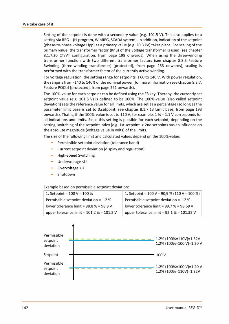
We take care of it.
142
User manual REG-D™
Setting of the setpoint is done with a secondary value (e.g. 101.5 V). This also applies to a setting via REG-L (H-program, WinREG, SCADA system). In addition, indication of the setpoint (phase-to-phase voltage Upp) as a primary value (e.g. 20.3 kV) takes place. For scaling of the primary value, the transformer factor (Knu) of the voltage transformer is used (see chapter 8.1.7.20 CT/VT configuration, from page 198 onwards). When using the three-winding transformer function with two different transformer factors (see chapter 8.3.5 Feature 3winding (three-winding transformer) [protected], from page 253 onwards), scaling is performed with the transformer factor of the currently active winding. For voltage regulation, the setting range for setpoints is 60 to 140 V. With power regulation, the range is from -140 to 140% of the nominal power (for more information see chapter 8.3.7. Feature PQCtrl [protected], from page 261 onwards). The 100%-value for each setpoint can be defined using the F3 key. Thereby, the currently set setpoint value (e.g. 101.5 V) is defined to be 100%. The 100%-value (also called setpoint deviation) sets the reference value for all limits, which are set as a percentage (so long as the parameter limit base is set to 0:setpoint, see chapter 8.1.7.13 Limit base, from page 193 onwards). That is, if the 100%-value is set to 110 V, for example, 1 % = 1.1 V corresponds for all indications and limits. Since this setting is possible for each setpoint, depending on the setting, switching of the setpoint index (e.g. 1st setpoint -> 2nd setpoint) has an influence on the absolute magnitude (voltage value in volts) of the limits. The size of the following limit and calculated values depend on the 100%-value:
– Permissible setpoint deviation (tolerance band) – Current setpoint deviation (display and regulation) – High-Speed Switching – Undervoltage <U – Overvoltage >U – Shutdown
Example based on permissible setpoint deviation:
1. Setpoint = 100 V = 100 % Permissible setpoint deviation = 1.2 % lower tolerance limit = 98.8 % = 98.8 V upper tolerance limit = 101.2 % = 101.2 V
1. Setpoint = 100 V = 90,9 % (110 V = 100 %) Permissible setpoint deviation = 1.2 % lower tolerance limit = 89.7 % = 98.68 V upper tolerance limit = 92.1 % = 101.32 V
Setpoint 100 V
1.2% (100%=100 V)=1.20 V 1.2% (100%=110V)=1.32V
Permissible setpoint deviation
Permissible setpoint deviation
1.2% (100%=110V)=1.32V 1.2% (100%=100 V)=1.20 V

143
User manual REG-D™
With power regulation (P-/Q-regulation) always apply: 100%-value = 100 V for voltage limits 100%-value = nominal power for power limits (e.g. tolerance band)
High-speed switching for setpoint changes By default, high-speed switching is activated after changing the setpoint. This serves to bring the voltage as quickly as possible to the new setpoint. If this behavior is not desired, please contact the A. Eberle REGSys support team ([email protected], +49(0)911/628108-101).
Limited setting range for older devices Depending on the hardware configuration of the REG-D™, adjustment of setpoints can be limited to 80 V to 120 V or -120% to 120% with older devices.
Reference value W The reference value W for the voltage of the tap-changing transformer can be either a fixed value (setpoint) or a variable value (setpoint + variable component). A varia-ble reference value can, for example, consist of a fixed setpoint and the current influence, for example, to regulate a remote network point with variable load and variable primary voltage. In addition to a fixed or variable reference value W, an active parallel program based on the circulating reactive current minimization pro-cedure (dIsin(ϕ), dIsin(ϕ)[S] or dcos(ϕ)) can influence integration of the selected time program, and hence the issue of of setting tap commands. The interaction is illustrated in the following function diagram.

We take care of it.
144
User manual REG-D™
8.1.2.4 Setpoint index
The setpoint used for regulation can be selected via the setpoint index menu. You can choose between the four pre configured setpoint values 1 – 4. In the selection, the secondary and the primary values are shown for each setpoint.
The setpoint index is selected with the keys F2 to F5. The currently active setpoint is marked by an angle bracket ">".
Additional ways to select setpoint index Besides selection via the setpoint index menu, the setpoint index can be switched via binary inputs (see chapter 8.1.7.18 Setpoint adjustment with binary inputs, from page 196 onwards), the arrow keys (see chapter 8.1.7.17 Setpoint adjustment with ←→ keys, from page 196 onwards), the background program, the service module of WinREG and via the SCADA system.
By default, high-speed switching is activated after changing the setpoint This serves to bring the voltage as quickly as possible to the new setpoint. If this behavior is not desired, please contact the A. Eberle REGSys support team ([email protected], +49(0)911/628108-101).
SETUP -1-
Setpoint Values..
Index..
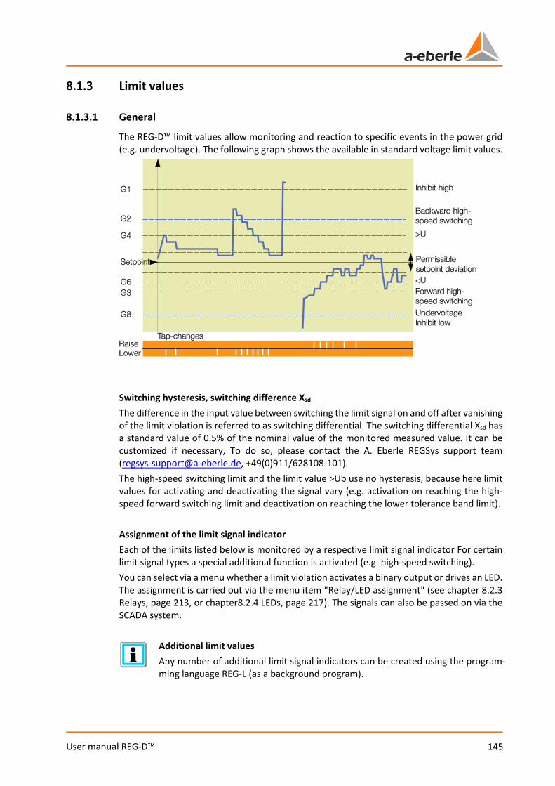
145
User manual REG-D™
8.1.3 Limit values
8.1.3.1 General
The REG-D™ limit values allow monitoring and reaction to specific events in the power grid (e.g. undervoltage). The following graph shows the available in standard voltage limit values.
Switching hysteresis, switching difference Xsd The difference in the input value between switching the limit signal on and off after vanishing of the limit violation is referred to as switching differential. The switching differential Xsd has a standard value of 0.5% of the nominal value of the monitored measured value. It can be customized if necessary, To do so, please contact the A. Eberle REGSys support team ([email protected], +49(0)911/628108-101). The high-speed switching limit and the limit value >Ub use no hysteresis, because here limit values for activating and deactivating the signal vary (e.g. activation on reaching the high-speed forward switching limit and deactivation on reaching the lower tolerance band limit). Assignment of the limit signal indicator Each of the limits listed below is monitored by a respective limit signal indicator For certain limit signal types a special additional function is activated (e.g. high-speed switching). You can select via a menu whether a limit violation activates a binary output or drives an LED. The assignment is carried out via the menu item "Relay/LED assignment" (see chapter 8.2.3 Relays, page 213, or chapter8.2.4 LEDs, page 217). The signals can also be passed on via the SCADA system.
Additional limit values Any number of additional limit signal indicators can be created using the program-ming language REG-L (as a background program).
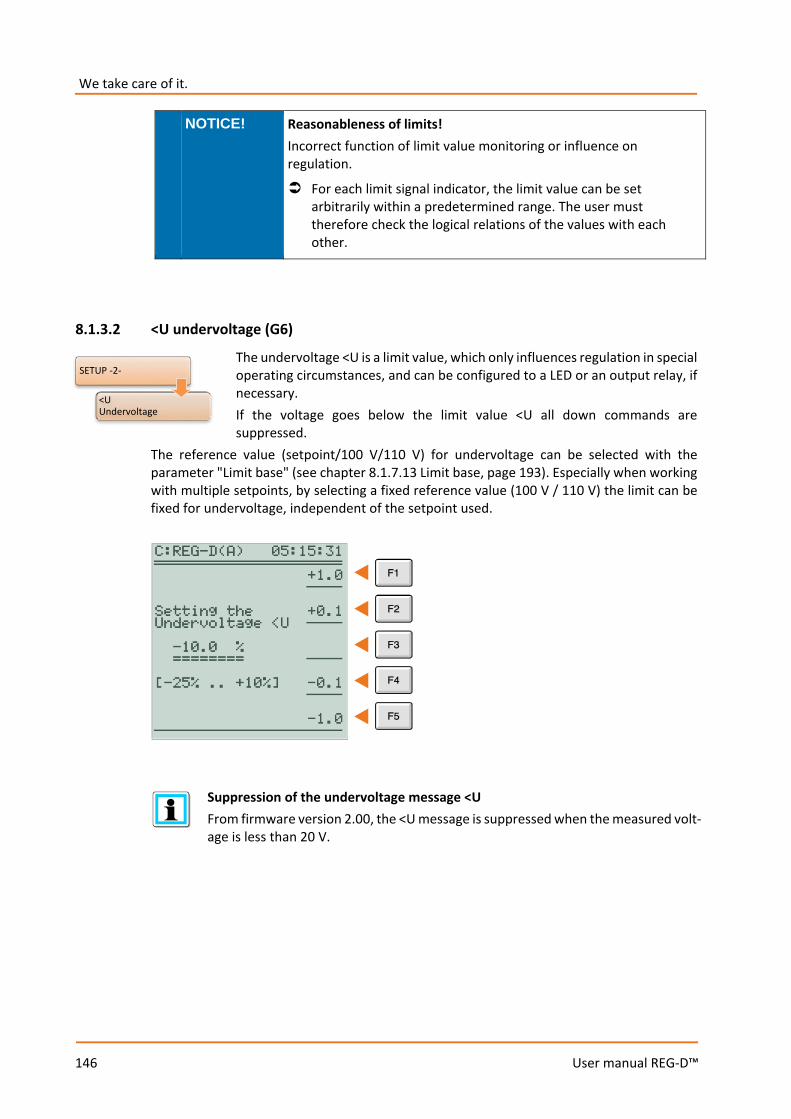
We take care of it.
146
User manual REG-D™
NOTICE! Reasonableness of limits! Incorrect function of limit value monitoring or influence on regulation.
For each limit signal indicator, the limit value can be set arbitrarily within a predetermined range. The user must therefore check the logical relations of the values with each other.
8.1.3.2 <U undervoltage (G6)
The undervoltage <U is a limit value, which only influences regulation in special operating circumstances, and can be configured to a LED or an output relay, if necessary. If the voltage goes below the limit value <U all down commands are suppressed.
The reference value (setpoint/100 V/110 V) for undervoltage can be selected with the parameter "Limit base" (see chapter 8.1.7.13 Limit base, page 193). Especially when working with multiple setpoints, by selecting a fixed reference value (100 V / 110 V) the limit can be fixed for undervoltage, independent of the setpoint used.
Suppression of the undervoltage message <U From firmware version 2.00, the <U message is suppressed when the measured volt-age is less than 20 V.
SETUP -2-
<U Undervoltage
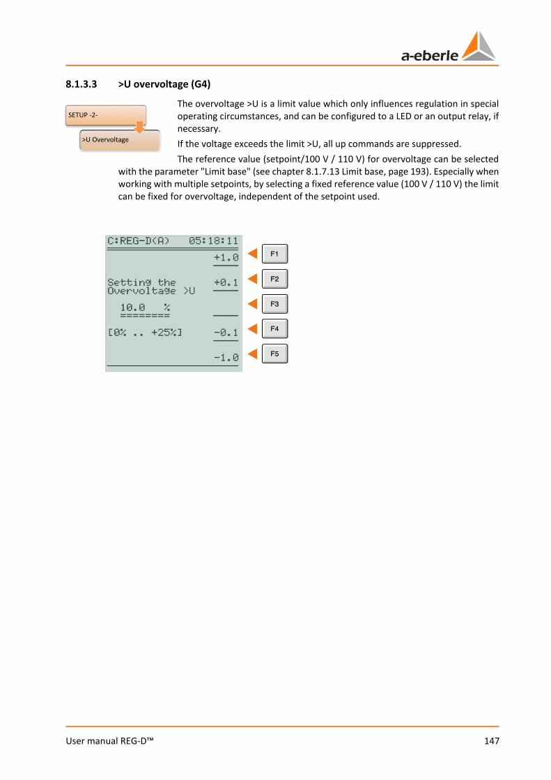
147
User manual REG-D™
8.1.3.3 >U overvoltage (G4)
The overvoltage >U is a limit value which only influences regulation in special operating circumstances, and can be configured to a LED or an output relay, if necessary. If the voltage exceeds the limit >U, all up commands are suppressed. The reference value (setpoint/100 V / 110 V) for overvoltage can be selected
with the parameter "Limit base" (see chapter 8.1.7.13 Limit base, page 193). Especially when working with multiple setpoints, by selecting a fixed reference value (100 V / 110 V) the limit can be fixed for overvoltage, independent of the setpoint used.
SETUP -2-
>U Overvoltage

We take care of it.
148
User manual REG-D™
8.1.3.4 Over- and undercurrent limit (>I, <I)
The limits overcurrent and undercurrent are used to monitor the transformer current. The regulator can be optionally inhibited on exceeding or falling below the corresponding limit (no issuing of tap commands.). However, the Inhibit function is only activated if it has been activated previously with the "Shutdown at <I or >I" parameter (see also chapter 8.1.7.14 Block if <I or >I, page 194).
The selected nominal value (1 A or 5 A) always applies as limit base. The limit signal can be set to a binary output, if needed. The limit violation can also be signalled by a freely programmable LED. Transmission via the SCADA system is also possible.
Change between the setting values for overcurrent (>I) and undercurrent (<I) is done by pressing the F3 key.
WARNING! Overcurrent limit as protection against transient overcurrents, e.g. short circuits! Damage to the tap changer and/or the transformer.
Use the overcurrent limit only for protection of the tap changer against stationary overcurrents, which last more than one second. Due to the measured value averaging procedure, the limit switch is not suitable for short-circuit protection.
SETUP -2-
>I, <I Current Limits
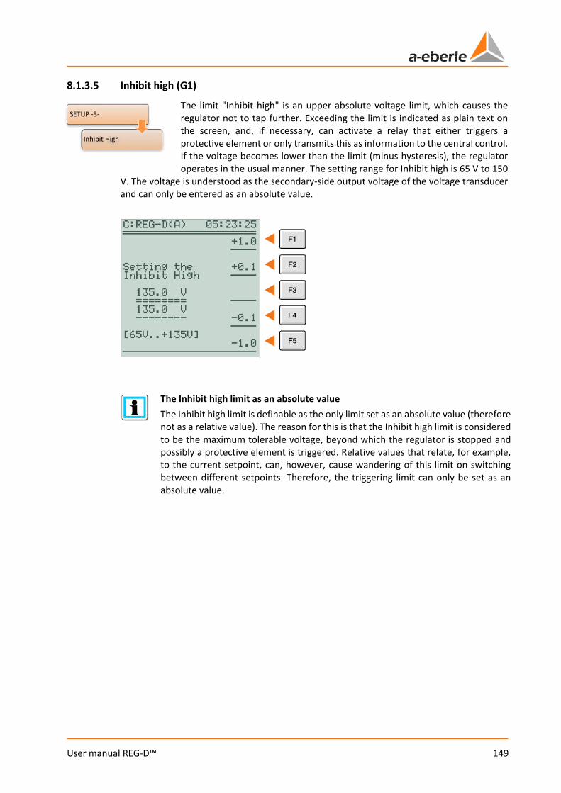
149
User manual REG-D™
8.1.3.5 Inhibit high (G1)
The limit "Inhibit high" is an upper absolute voltage limit, which causes the regulator not to tap further. Exceeding the limit is indicated as plain text on the screen, and, if necessary, can activate a relay that either triggers a protective element or only transmits this as information to the central control. If the voltage becomes lower than the limit (minus hysteresis), the regulator operates in the usual manner. The setting range for Inhibit high is 65 V to 150
V. The voltage is understood as the secondary-side output voltage of the voltage transducer and can only be entered as an absolute value.
The Inhibit high limit as an absolute value The Inhibit high limit is definable as the only limit set as an absolute value (therefore not as a relative value). The reason for this is that the Inhibit high limit is considered to be the maximum tolerable voltage, beyond which the regulator is stopped and possibly a protective element is triggered. Relative values that relate, for example, to the current setpoint, can, however, cause wandering of this limit on switching between different setpoints. Therefore, the triggering limit can only be set as an absolute value.
SETUP -3-
Inhibit High
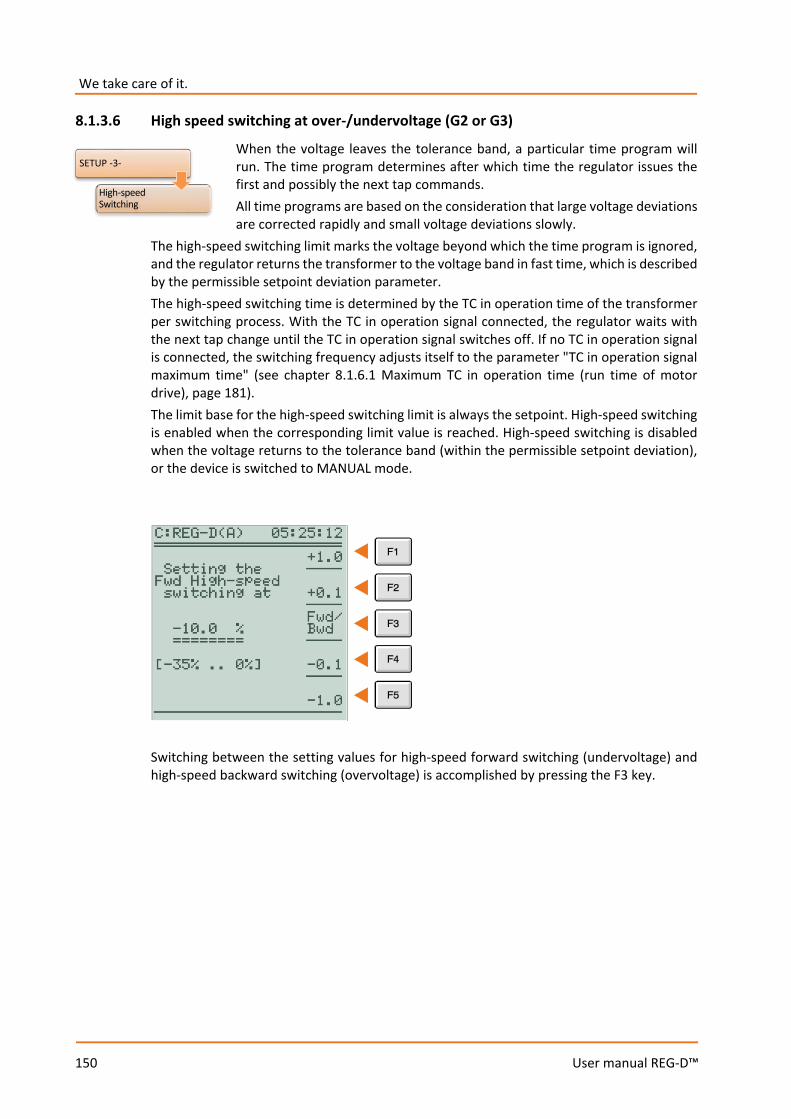
We take care of it.
150
User manual REG-D™
8.1.3.6 High speed switching at over-/undervoltage (G2 or G3)
When the voltage leaves the tolerance band, a particular time program will run. The time program determines after which time the regulator issues the first and possibly the next tap commands. All time programs are based on the consideration that large voltage deviations are corrected rapidly and small voltage deviations slowly.
The high-speed switching limit marks the voltage beyond which the time program is ignored, and the regulator returns the transformer to the voltage band in fast time, which is described by the permissible setpoint deviation parameter. The high-speed switching time is determined by the TC in operation time of the transformer per switching process. With the TC in operation signal connected, the regulator waits with the next tap change until the TC in operation signal switches off. If no TC in operation signal is connected, the switching frequency adjusts itself to the parameter "TC in operation signal maximum time" (see chapter 8.1.6.1 Maximum TC in operation time (run time of motor drive), page 181). The limit base for the high-speed switching limit is always the setpoint. High-speed switching is enabled when the corresponding limit value is reached. High-speed switching is disabled when the voltage returns to the tolerance band (within the permissible setpoint deviation), or the device is switched to MANUAL mode.
Switching between the setting values for high-speed forward switching (undervoltage) and high-speed backward switching (overvoltage) is accomplished by pressing the F3 key.
SETUP -3-
High-speed Switching
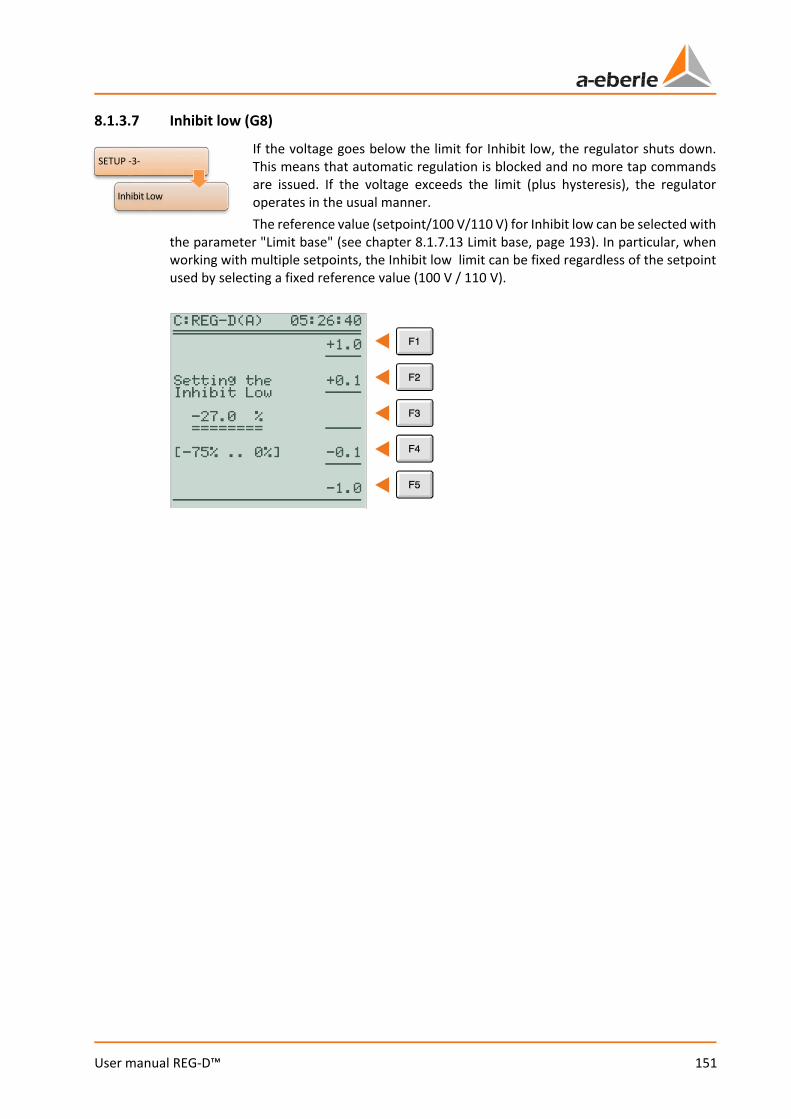
151
User manual REG-D™
8.1.3.7 Inhibit low (G8)
If the voltage goes below the limit for Inhibit low, the regulator shuts down. This means that automatic regulation is blocked and no more tap commands are issued. If the voltage exceeds the limit (plus hysteresis), the regulator operates in the usual manner. The reference value (setpoint/100 V/110 V) for Inhibit low can be selected with
the parameter "Limit base" (see chapter 8.1.7.13 Limit base, page 193). In particular, when working with multiple setpoints, the Inhibit low limit can be fixed regardless of the setpoint used by selecting a fixed reference value (100 V / 110 V).
SETUP -3-
Inhibit Low
We take care of it.
152
User manual REG-D™
8.1.3.8 Three-winding limit >Ub (monitoring non-regulated voltage)
The limit >Ub is used to monitor the non-regulated voltage in an application with a three-winding transformer which has only one tap changer. Here, in general one of the two secondary voltages is selected for regulation. The other voltage can be monitored for exceeding an adjustable limit (>Ub). If the limit is reached, then up commands are blocked.
Reaching the limit can be reported via LED, relay or the SCADA system. Moreover, in the transducer display the limit >Ub is prefixed by two exclamation marks (for example, !! >U(2) = 5.0%). The reference value (setpoint/100 V/110 V) for shutdown can be selected with the parameter "Limit base" (see chapter 8.1.7.13 Limit base, page 193). The limit >Ub is activated when the limit value is reached and deactivated when the monitored voltage reaches a defined limit value as follows, or the device is switched into the manual mode. Evaluation of the limit >Ub occurs only in AUTOMATIC mode. Limit value for deactivation of >Ub: The monitored voltage must be less than the value obtained from adding the reference value (secondary value) to the permissible setpoint deviation (in secondary volts). Example: Three-winding transformer limit >Ub: Three-winding transformer: 110 KV -> 20 kV / 10 kV; transducer factors 20 kV: 200 ± 10 kV: 100 Perm. setpoint deviation 1.5 % Setpoint value 1: 101 V 100%-value: 100 V
(Limit base setpoint -> 100%-value of the active setpoint) (Limit base 100 V -> fix 100 V) (Limit base 110 V -> fix 110 V)
>Ub limit value: 5 % Limit base: setpoint (reference value) The 20 kV level is regulated, the 10 kV level is monitored. Activation >Ub: >Ubactive = reference value + (>Ub limit * 100%-value/100% ) = 101 V + (5% * 100V / 100%) = 106 V -> 10.60 kV The limit> Ub becomes active as soon as the 10 kV level reaches a voltage of 10.6 kV. Deactivation >Ub: >Ubinactive = reference value + (bandwidth * 100%-value/100%) = 101 V + (1.5% * 100V / 100%) = 102.5 V -> 10.25 kV The limit >Ub becomes inactive as soon as the 10 kV level drops below a voltage of 10.25 kV.
SETUP -3-
Dreiwickler Limit >Ub
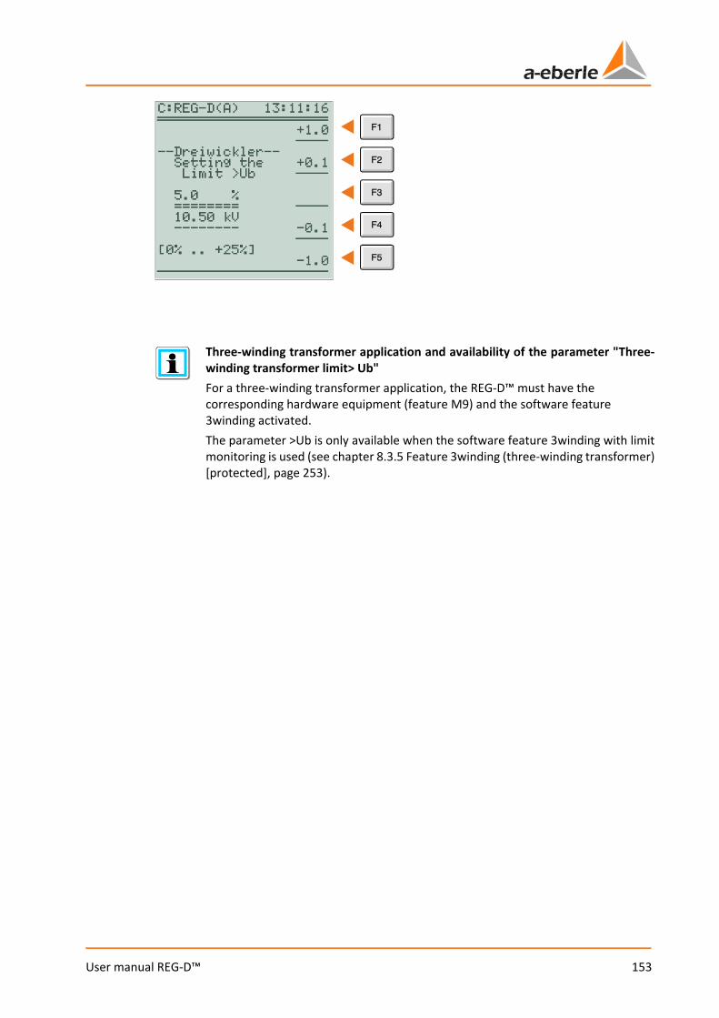
153
User manual REG-D™
Three-winding transformer application and availability of the parameter "Three-winding transformer limit> Ub" For a three-winding transformer application, the REG-D™ must have the corresponding hardware equipment (feature M9) and the software feature 3winding activated. The parameter >Ub is only available when the software feature 3winding with limit monitoring is used (see chapter 8.3.5 Feature 3winding (three-winding transformer) [protected], page 253).
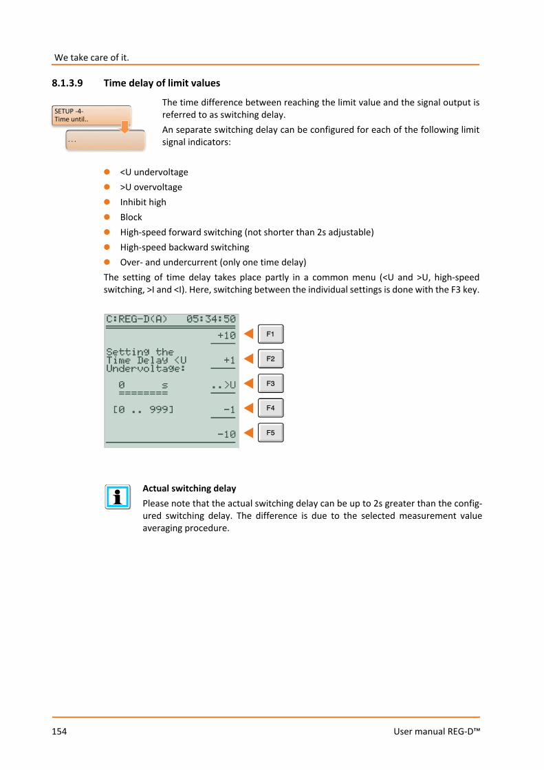
We take care of it.
154
User manual REG-D™
8.1.3.9 Time delay of limit values
The time difference between reaching the limit value and the signal output is referred to as switching delay. An separate switching delay can be configured for each of the following limit signal indicators:
0 <U undervoltage 0 >U overvoltage 0 Inhibit high 0 Block 0 High-speed forward switching (not shorter than 2s adjustable) 0 High-speed backward switching 0 Over- and undercurrent (only one time delay) The setting of time delay takes place partly in a common menu (<U and >U, high-speed switching, >I and <I). Here, switching between the individual settings is done with the F3 key.
Actual switching delay Please note that the actual switching delay can be up to 2s greater than the config-ured switching delay. The difference is due to the selected measurement value averaging procedure.
SETUP -4-Time until..
. . .
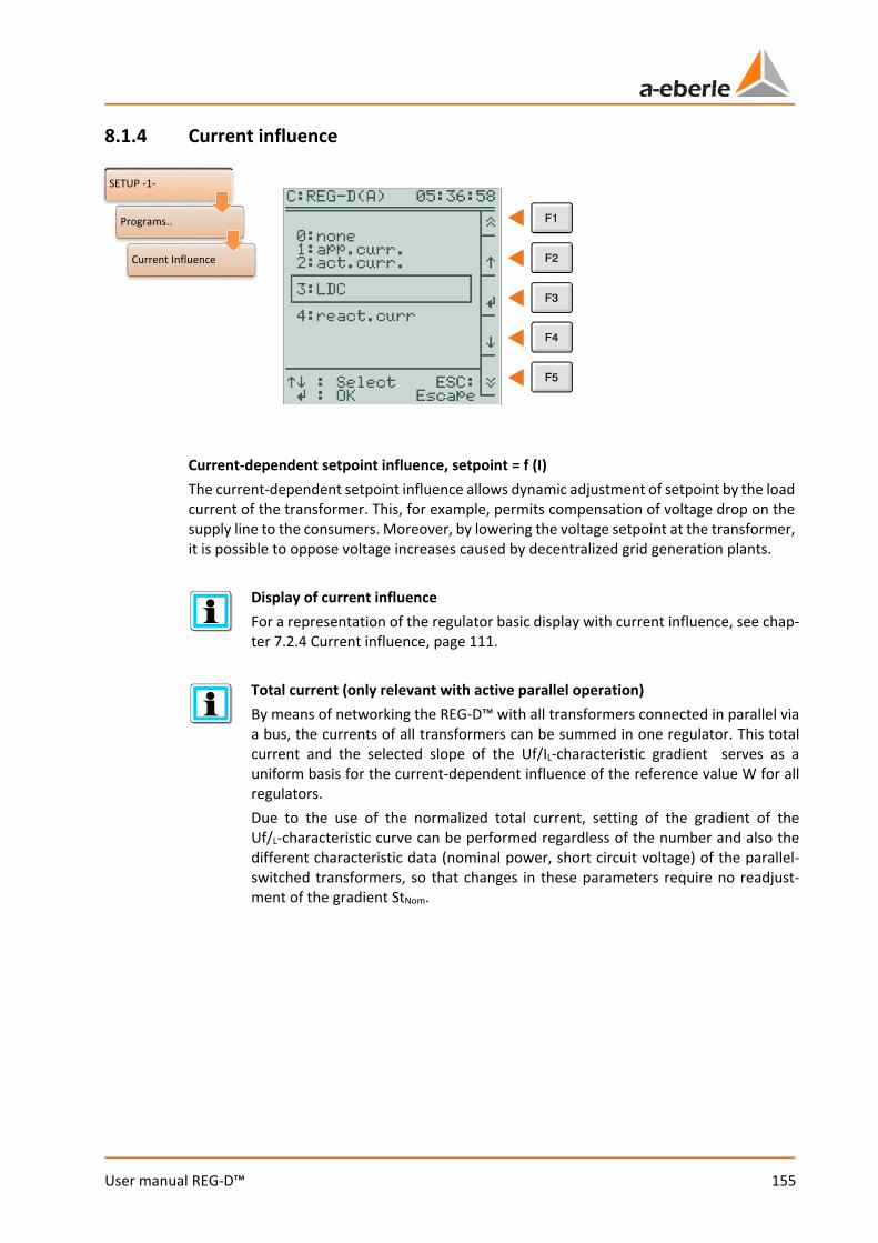
155
User manual REG-D™
8.1.4 Current influence
Current-dependent setpoint influence, setpoint = f (I) The current-dependent setpoint influence allows dynamic adjustment of setpoint by the load current of the transformer. This, for example, permits compensation of voltage drop on the supply line to the consumers. Moreover, by lowering the voltage setpoint at the transformer, it is possible to oppose voltage increases caused by decentralized grid generation plants.
Display of current influence For a representation of the regulator basic display with current influence, see chap-ter 7.2.4 Current influence, page 111.
Total current (only relevant with active parallel operation) By means of networking the REG-D™ with all transformers connected in parallel via a bus, the currents of all transformers can be summed in one regulator. This total current and the selected slope of the Uf/IL-characteristic gradient serves as a uniform basis for the current-dependent influence of the reference value W for all regulators. Due to the use of the normalized total current, setting of the gradient of the Uf/L-characteristic curve can be performed regardless of the number and also the different characteristic data (nominal power, short circuit voltage) of the parallel-switched transformers, so that changes in these parameters require no readjust-ment of the gradient StNom.
SETUP -1-
Programs..
Current Influence

We take care of it.
156
User manual REG-D™
Current programs In general, the following programs for current-dependent influencing of the setpoint are available: 0 Apparent current-dependent setpoint influence
In this program, the apparent current is used to determine the voltage boost. Raising of the setpoint only takes place when the active power is positive. Lowering of the setpoint in case of a reverse power flow does not take place. The current program only uses the parameters "Gradient (I) pos." and "Limitation (I) max."
0 Active current-dependent setpoint influence
This program uses the effective current to determine setpoint change. If a positive active current flows (P > 0, consumption), the setpoint is increased. If a negative active current flows (P < 0, feedback), the setpoint is decreased. The current program will use the parameters "Gradient (I) pos.", "Gradient (I) neg.", "Limitation (I) max." and "Limitation (I) min.".
Setpoint
Apparent current
P > 0 P < 0
Setpoint
Active current
P > 0 P < 0
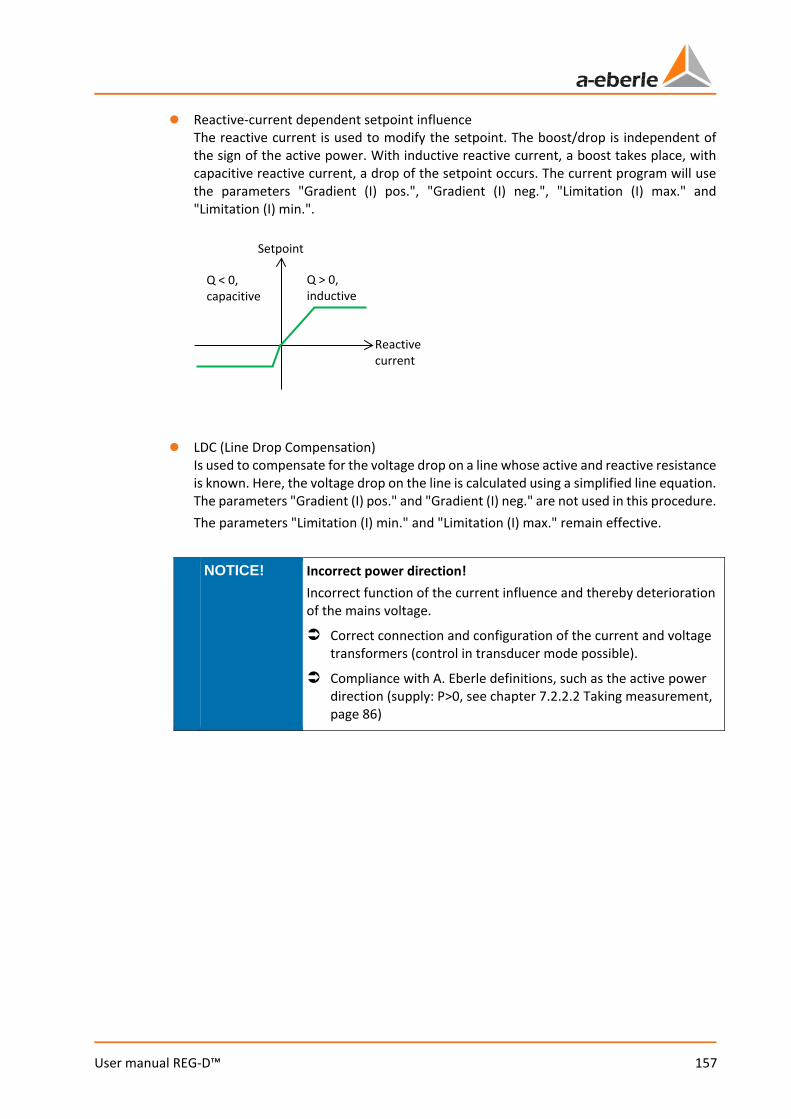
157
User manual REG-D™
0 Reactive-current dependent setpoint influence The reactive current is used to modify the setpoint. The boost/drop is independent of the sign of the active power. With inductive reactive current, a boost takes place, with capacitive reactive current, a drop of the setpoint occurs. The current program will use the parameters "Gradient (I) pos.", "Gradient (I) neg.", "Limitation (I) max." and "Limitation (I) min.".
0 LDC (Line Drop Compensation)
Is used to compensate for the voltage drop on a line whose active and reactive resistance is known. Here, the voltage drop on the line is calculated using a simplified line equation. The parameters "Gradient (I) pos." and "Gradient (I) neg." are not used in this procedure. The parameters "Limitation (I) min." and "Limitation (I) max." remain effective.
NOTICE! Incorrect power direction! Incorrect function of the current influence and thereby deterioration of the mains voltage.
Correct connection and configuration of the current and voltage transformers (control in transducer mode possible).
Compliance with A. Eberle definitions, such as the active power direction (supply: P>0, see chapter 7.2.2.2 Taking measurement, page 86)
Setpoint
Reactive current
Q > 0, inductive
Q < 0, capacitive
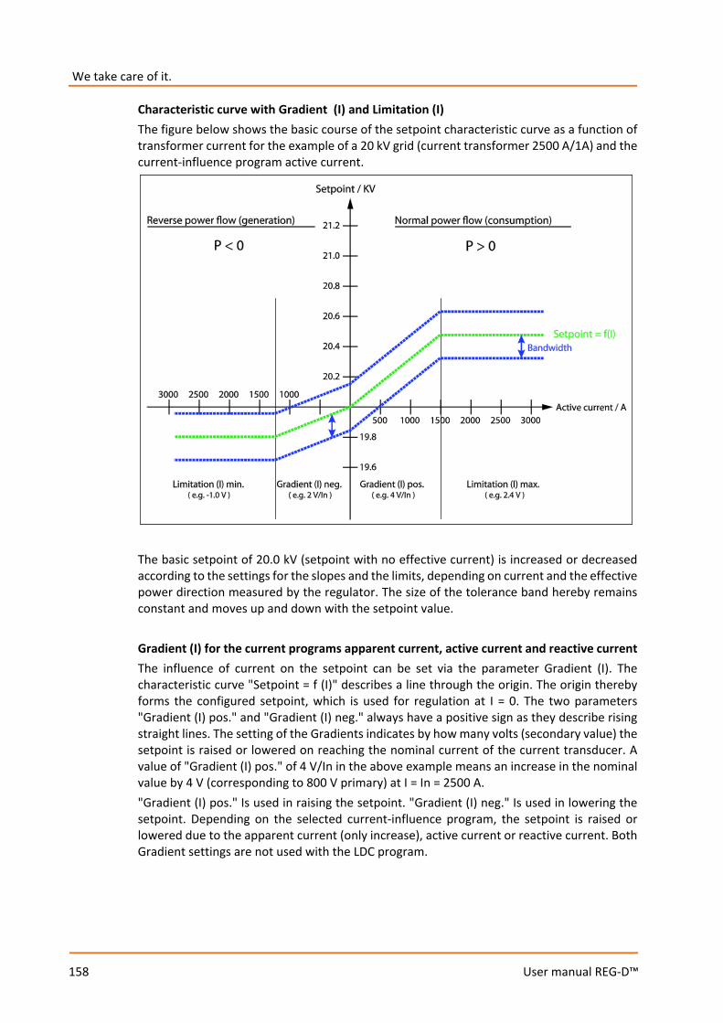
We take care of it.
158
User manual REG-D™
Characteristic curve with Gradient (I) and Limitation (I) The figure below shows the basic course of the setpoint characteristic curve as a function of transformer current for the example of a 20 kV grid (current transformer 2500 A/1A) and the current-influence program active current.
The basic setpoint of 20.0 kV (setpoint with no effective current) is increased or decreased according to the settings for the slopes and the limits, depending on current and the effective power direction measured by the regulator. The size of the tolerance band hereby remains constant and moves up and down with the setpoint value. Gradient (I) for the current programs apparent current, active current and reactive current The influence of current on the setpoint can be set via the parameter Gradient (I). The characteristic curve "Setpoint = f (I)" describes a line through the origin. The origin thereby forms the configured setpoint, which is used for regulation at I = 0. The two parameters "Gradient (I) pos." and "Gradient (I) neg." always have a positive sign as they describe rising straight lines. The setting of the Gradients indicates by how many volts (secondary value) the setpoint is raised or lowered on reaching the nominal current of the current transducer. A value of "Gradient (I) pos." of 4 V/In in the above example means an increase in the nominal value by 4 V (corresponding to 800 V primary) at I = In = 2500 A. "Gradient (I) pos." Is used in raising the setpoint. "Gradient (I) neg." Is used in lowering the setpoint. Depending on the selected current-influence program, the setpoint is raised or lowered due to the apparent current (only increase), active current or reactive current. Both Gradient settings are not used with the LDC program.
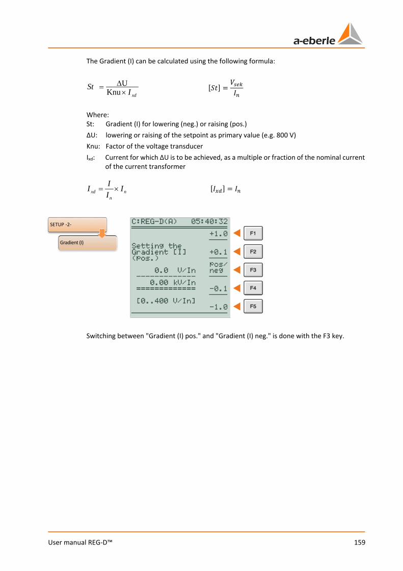
159
User manual REG-D™
The Gradient (I) can be calculated using the following formula:
[𝑆𝑆𝑆𝑆] =𝑘𝑘𝑇𝑇𝑠𝑠𝑠𝑠𝐼𝐼𝑇𝑇
Where: St: Gradient (I) for lowering (neg.) or raising (pos.) ΔU: lowering or raising of the setpoint as primary value (e.g. 800 V) Knu: Factor of the voltage transducer Ixd: Current for which ΔU is to be achieved, as a multiple or fraction of the nominal current
of the current transformer
[𝐼𝐼𝑥𝑥𝑥𝑥] = 𝐼𝐼𝑇𝑇
Switching between "Gradient (I) pos." and "Gradient (I) neg." is done with the F3 key.
xdISt
×∆=
KnuU
nn
xd IIII ×=
SETUP -2-
Gradient (I)

We take care of it.
160
User manual REG-D™
Limitation (I) In order to prevent unwanted high or low setpoints from occurring in modifying the setpoint via current-influence, raising or lowering the setpoint can be restricted via the Limitation (I). After reaching the limitation, the characteristic curve runs horizontally, i.e., the setpoint is no longer being lowered or raised. A value of "Limitation (I) max." of 2.4 V in the above example means limitation of setpoint increase to 2.4 V (corresponding to 20.48 kV primary) at I = In = 1500 A. In general, a negative value or zero is chosen for the parameter "Limitation (I) min.", a positive value for the parameter "Limitation (I) max.". The limitations are active in all current-influence programs.
[𝐵𝐵] = 𝑘𝑘𝑇𝑇𝑠𝑠𝑠𝑠 Where: B: Limitation (I) for lowering (neg.) or raising (pos.) ΔBprim: Limitation (I) for lowering/raising as primary value (e.g. 0.5 kV) Knu factor of the voltage transducer
Switching between "Limitation (I) max." and "Limitation (I) min." is done with the F3 key.
KnuB
B prim∆=
SETUP -2-
Limitation (I)
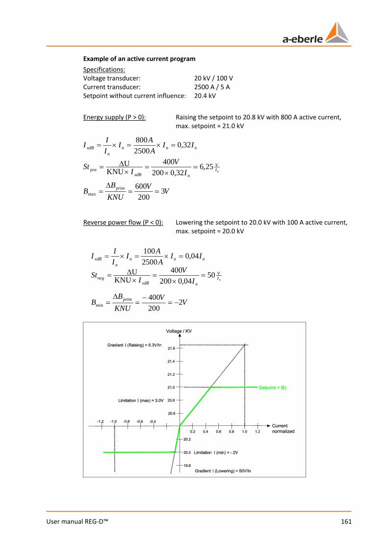
161
User manual REG-D™
Example of an active current program Specifications: Voltage transducer: 20 kV / 100 V Current transducer: 2500 A / 5 A Setpoint without current influence: 20.4 kV Energy supply (P > 0): Raising the setpoint to 20.8 kV with 800 A active current,
max. setpoint = 21.0 kV
Reverse power flow (P < 0): Lowering the setpoint to 20.0 kV with 100 A active current,
max. setpoint = 20.0 kV
VVKNUB
B prim 3200
600max ==
∆=
nIV
nxdBpos I
VISt 25,6
32,0200400
KNUU =
×=
×∆=
nnnn
xdB IIA
AIIII 32,0
2500800
=×=×=
VVKNUB
B prim 2200400
min −=−
=∆
=
nIV
nxdRneg I
VISt 50
04,0200400
KNUU =
×=
×∆=
nnnn
xdR IIA
AIIII 04,0
2500100
=×=×=
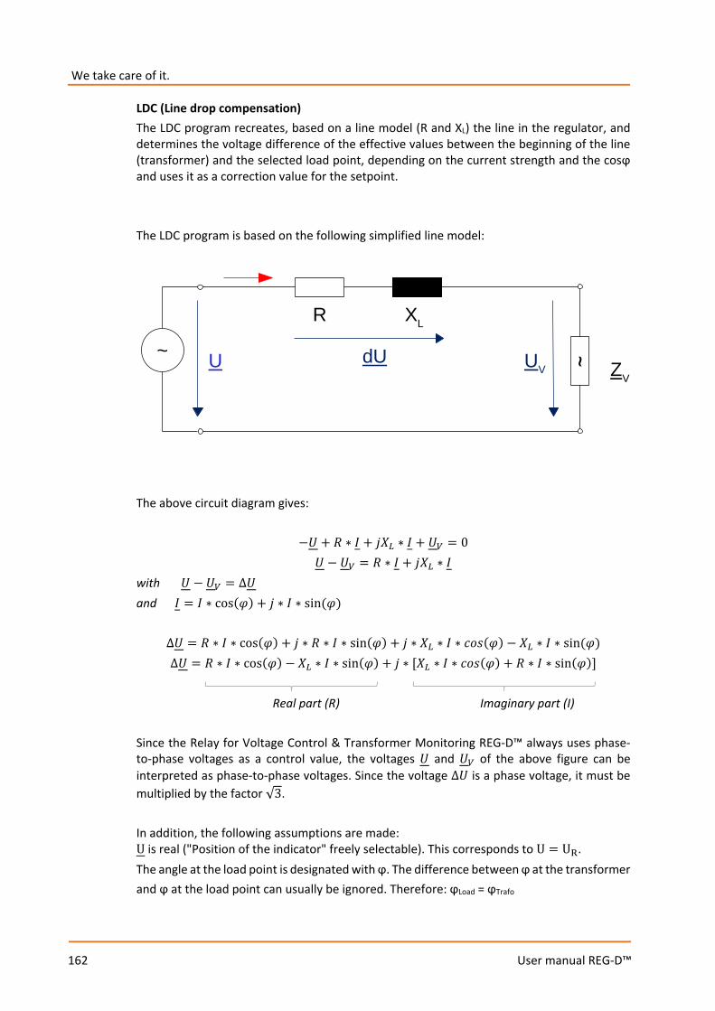
We take care of it.
162
User manual REG-D™
LDC (Line drop compensation) The LDC program recreates, based on a line model (R and XL) the line in the regulator, and determines the voltage difference of the effective values between the beginning of the line (transformer) and the selected load point, depending on the current strength and the cosϕ and uses it as a correction value for the setpoint. The LDC program is based on the following simplified line model:
The above circuit diagram gives:
−𝑈𝑈 + 𝑅𝑅 ∗ 𝐼𝐼 + 𝑗𝑗𝑋𝑋𝐿𝐿 ∗ 𝐼𝐼 + 𝑈𝑈𝑉𝑉 = 0 𝑈𝑈 − 𝑈𝑈𝑉𝑉 = 𝑅𝑅 ∗ 𝐼𝐼 + 𝑗𝑗𝑋𝑋𝐿𝐿 ∗ 𝐼𝐼
with 𝑈𝑈 − 𝑈𝑈𝑉𝑉 = ∆𝑈𝑈 and 𝐼𝐼 = 𝐼𝐼 ∗ cos(𝜑𝜑) + 𝑗𝑗 ∗ 𝐼𝐼 ∗ sin (𝜑𝜑)
∆𝑈𝑈 = 𝑅𝑅 ∗ 𝐼𝐼 ∗ cos(𝜑𝜑) + 𝑗𝑗 ∗ 𝑅𝑅 ∗ 𝐼𝐼 ∗ sin(𝜑𝜑) + 𝑗𝑗 ∗ 𝑋𝑋𝐿𝐿 ∗ 𝐼𝐼 ∗ 𝐼𝐼𝑐𝑐𝑐𝑐(𝜑𝜑) − 𝑋𝑋𝐿𝐿 ∗ 𝐼𝐼 ∗ sin (𝜑𝜑) ∆𝑈𝑈 = 𝑅𝑅 ∗ 𝐼𝐼 ∗ cos(𝜑𝜑) − 𝑋𝑋𝐿𝐿 ∗ 𝐼𝐼 ∗ sin(𝜑𝜑) + 𝑗𝑗 ∗ [𝑋𝑋𝐿𝐿 ∗ 𝐼𝐼 ∗ 𝐼𝐼𝑐𝑐𝑐𝑐(𝜑𝜑) + 𝑅𝑅 ∗ 𝐼𝐼 ∗ sin(𝜑𝜑)]
Real part (R) Imaginary part (I)
Since the Relay for Voltage Control & Transformer Monitoring REG-D™ always uses phase-to-phase voltages as a control value, the voltages 𝑈𝑈 and 𝑈𝑈𝑉𝑉 of the above figure can be interpreted as phase-to-phase voltages. Since the voltage ∆𝑈𝑈 is a phase voltage, it must be multiplied by the factor √3. In addition, the following assumptions are made: U is real ("Position of the indicator" freely selectable). This corresponds to U = UR. The angle at the load point is designated with ϕ. The difference between ϕ at the transformer and ϕ at the load point can usually be ignored. Therefore: ϕLoad = ϕTrafo
U
R X L
~ Z V
U V dU
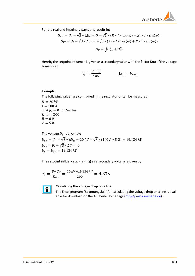
163
User manual REG-D™
For the real and imaginary parts this results in:
𝑈𝑈𝑉𝑉𝑉𝑉 = 𝑈𝑈𝑉𝑉 − √3 ∗ ∆𝑈𝑈𝑉𝑉 = 𝑈𝑈 − √3 ∗ (𝑅𝑅 ∗ 𝐼𝐼 ∗ cos(𝜑𝜑) − 𝑋𝑋𝐿𝐿 ∗ 𝐼𝐼 ∗ sin(𝜑𝜑))
𝑈𝑈𝑉𝑉𝑉𝑉 = 𝑈𝑈𝑉𝑉 − √3 ∗ ∆𝑈𝑈𝑉𝑉 = −√3 ∗ (𝑋𝑋𝐿𝐿 ∗ 𝐼𝐼 ∗ 𝐼𝐼𝑐𝑐𝑐𝑐(𝜑𝜑) + 𝑅𝑅 ∗ 𝐼𝐼 ∗ sin(𝜑𝜑))
𝑈𝑈𝑉𝑉 = 𝑈𝑈𝑉𝑉𝑉𝑉2 + 𝑈𝑈𝑉𝑉𝑉𝑉2
Hereby the setpoint influence is given as a secondary value with the factor Knu of the voltage transducer:
𝑥𝑥𝑖𝑖 = 𝑈𝑈−𝑈𝑈𝑉𝑉𝐾𝐾𝑇𝑇𝐾𝐾
[𝑥𝑥𝑖𝑖] = 𝑘𝑘𝑇𝑇𝑠𝑠𝑠𝑠
Example: The following values are configured in the regulator or can be measured: 𝑈𝑈 = 20 𝑘𝑘𝑘𝑘 𝐼𝐼 = 100 𝐴𝐴 cos(𝜑𝜑) = 0 𝐼𝐼𝑖𝑖𝑖𝑖𝑖𝑖𝐼𝐼𝑆𝑆𝐼𝐼𝑖𝑖𝑖𝑖 𝐾𝐾𝑖𝑖𝑖𝑖 = 200 𝑅𝑅 = 0 Ω 𝑋𝑋 = 5 Ω The voltage 𝑈𝑈𝑉𝑉 is given by:
𝑈𝑈𝑉𝑉𝑉𝑉 = 𝑈𝑈𝑉𝑉 − √3 ∗ ∆𝑈𝑈𝑉𝑉 = 20 𝑘𝑘𝑘𝑘 − √3 ∗ (100 𝐴𝐴 ∗ 5 Ω) = 19,134 𝑘𝑘𝑘𝑘
𝑈𝑈𝑉𝑉𝑉𝑉 = 𝑈𝑈𝑉𝑉 − √3 ∗ ∆𝑈𝑈𝑉𝑉 = 0 𝑈𝑈𝑉𝑉 = 𝑈𝑈𝑉𝑉𝑉𝑉 = 19,134 𝑘𝑘𝑘𝑘 The setpoint influence 𝑥𝑥𝑖𝑖 (raising) as a secondary voltage is given by:
𝑥𝑥𝑖𝑖 = 𝑈𝑈−𝑈𝑈𝑉𝑉𝐾𝐾𝑇𝑇𝐾𝐾
= 20 𝑠𝑠𝑉𝑉−19,134 𝑠𝑠𝑉𝑉200
= 4,33 V
Calculating the voltage drop on a line The Excel program "Spannungsfall" for calculating the voltage drop on a line is avail-able for download on the A. Eberle Homepage (http://www.a-eberle.de).
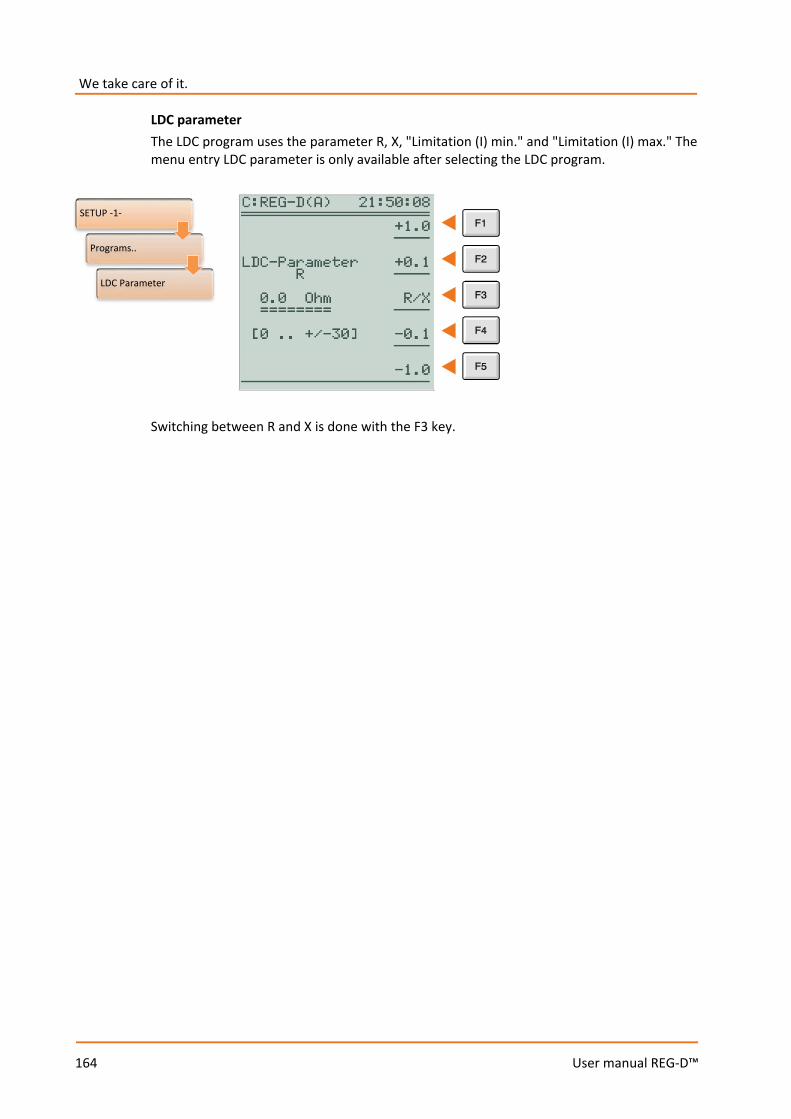
We take care of it.
164
User manual REG-D™
LDC parameter The LDC program uses the parameter R, X, "Limitation (I) min." and "Limitation (I) max." The menu entry LDC parameter is only available after selecting the LDC program.
Switching between R and X is done with the F3 key.
SETUP -1-
Programs..
LDC Parameter
165
User manual REG-D™
8.1.5 Parallel operation
8.1.5.1 General
If parallel coupled transformers do not have the same data (uk, vector group, number of taps, tap change ratio) or identical transformers stand at different taps, within such a parallel circuit there always flows a reactive current independent of the load current, which increases transformer load, reactive circulating current, and must therefore be avoided. With parallel operation on a busbar, the terminal voltage of all transformers – even with different tap positions – is forcibly set to the same value. Therefore the voltage of transformers connected in parallel cannot be a regulation criterion by itself. In order to set parallel transformers on a busbar with different parameters to the required voltage and optimum tap position, voltage regulation must be supplemented by circulating reactive current regulation (parallel program dIsin(ϕ), dIsin(ϕ)[S] or dcos(ϕ)). However, if the transformers are the same, a stable parallel operation can be implemented using the voltage and tap position (parallel programs Master-Follower, MSI or MSI2). A parallel operation of several transformers must always be prepared. As a rule, first the tap positions of the transformers involved in the parallel scheme must be equalized, and the circuit breakers and isolators placed in the appropriate positions. Finally, these switching states must be passed on to the Relay for Voltage Control & Transformer Monitorings involved in the parallel circuit. The Relay for Voltage Control & Transformer Monitoring REG-D™ is also equipped with the so-called ParaGramer, which is independently able to recognize the switching states of the individual transformers, and which groups regulators automatically according to the switching states, so that only the regulators that supply a common busbar work together in parallel. For a detailed description of the ParaGramer function, see chapter 8.3.2 from page 232 onwards.
Total current (only relevant when using current influence, see chapter 8.1.4 page 155) Through networking of all REG-D™ of the parallel coupled transformers via a bus, the currents from all transformers connected in parallel are summed in a regulator for evaluation of the current influence. This total current serves as a uniform basis for the current-dependent influence on the setpoint for all regulators.
We take care of it.
166
User manual REG-D™
Publication "Parallel Regulation of Transformers" A Publication "Parallel Regulation of Transformers" with further information can be found on the A. Eberle Homepage (http://www.a-eberle.de) in the Download Cen-tre under Publications.
CAUTION! Please note that only REG-D™ Relays for Voltage Control & Transformer Monitoring with the same firmware version may be run in parallel operation. Otherwise, malfunctions may appear in the course of this operation. The current firmware version can be queried via the keyboard of the regulator. Please press the Menu key until you reach SETUP 6. You can now select the status page of the regulator with F5. In the first and second line appears the firmware version, for example, V2.23 of 18.12.12 (18 December 2012). In case different versions are currently loaded, please use the possibility to download the required firmware from our homepage (http://www.a-eberle.de) or contact the A. Eberle REGSys support team ([email protected], +49(0)911/628108-101).

167
User manual REG-D™
8.1.5.2 Parallel programs
All parallel programs are intended to minimize the circulating reactive current in parallel-connected transformers. Depending on the characteristics of the parallel working transformers (nominal power, tap size, number of taps) and the information made available to the REG-D™ Relays for Voltage Control & Transformer Monitoring (tap position feedback, E-LAN communication, current measurement), there are several parallel programs to choose from. Using the following table, an initial preselection can be made as to which parallel programs are basically eligible, or what requirements need to be considered for a certain parallel program.
Process Equa
l no
min
al p
ower
Une
qual
no
min
al p
ower
Sam
e ta
p si
ze a
nd
num
ber
Diff
eren
t tap
size
and
nu
mbe
r
Tap
posi
tion
requ
ired
Curr
ent m
easu
rem
ent
requ
ired
E-LA
N c
omm
unic
atio
n re
quire
d dcos(ϕ) yes yes yes yes O yes O
dIsin(ϕ) yes no yes yes O yes yes
dIsin(ϕ)[S] yes yes yes Yes O yes yes
Master-Follower, MSI/MSI2
yes yes yes no yes O yes
O: Optional for monitoring purposes
SETUP -1-
Programs..
Parallel Program

We take care of it.
168
User manual REG-D™
In the following the choices of the parameter parallel program are shown at a glance: Parallel program Description 0:no No parallel operation 1:dIsin(ϕ) Circulating reactive current minimization procedure for
transformers with the same nominal power The regulators exchange the respective calculated power values with each other via the communication bus E-LAN and then calculate the circulating reactive current. The circulating reactive current acts on the command variable W as configured.
2:dIsin(ϕ) Circulating reactive current minimization procedure which does not require E-LAN communication A net-cos(ϕ) must be defined for each regulator. Deviations from this net cos(ϕ) will be interpreted as circulating reactive current and act as configured on the reference variable W.
4:dIsin(ϕ)[S] Circulating reactive current minimization procedure for transformers with the same and different nominal power The parallel program is based on the procedure of dIsin(ϕ). In addition, the nominal transformer power of the associated transformer must be defined in each Relay for Voltage Control & Transformer Monitoring REG-D™ so that this can be properly included in the calculation of circulating reactive current.
6:Master-Follower Master-slave parallel program which works according to the principle of tap equality The parallel program is usually the first choice, so long as it regards parallel operation of transformers, which are identical or have the same tap change ratio. The master and slave(s) are always at the same tap level or have a permanent tap offset (from firmware V2.24 onwards).
7:MSI Master-Slave-Independent parallel program Corresponds to the Master-Follower parallel procedure, only selection of the function (master, slave, independent) is done explicitly for each regulator (only selectable with activated ParaGramer feature).
8:MSI2 Master-Slave-Independent parallel program with two busbars Corresponds to the Master-Follower parallel procedure, only selection of the function (master 1, master 2, slave 1, slave 2, independent) is done explicitly for each regulator (only selectable with activated ParaGramer feature).
169
User manual REG-D™
Emergency program “dcos(ϕ)!!!” in case of an E-LAN communication failure of the parallel programs dIsin(ϕ) and dIsin(ϕ)[S] The dcos(ϕ) parallel program acts as an emergency program in the event of an E-LAN communication failure between the regulators. This is indicated by the text "dcos(ϕ)!!!“ in the basic regulator display. Hereby the last measured cos(ϕ) is ac-cepted as Net-cos(ϕ). This function is only available with the parallel programs dIsin(ϕ) and dIsin(ϕ)[S]. When using the parallel programs Master-Follower, MSI and MSI2, the dcos(ϕ) emergency program is inactive, since current measurement is not absolutely necessary with these programs, and therefore the conditions for the emergency program are not met.
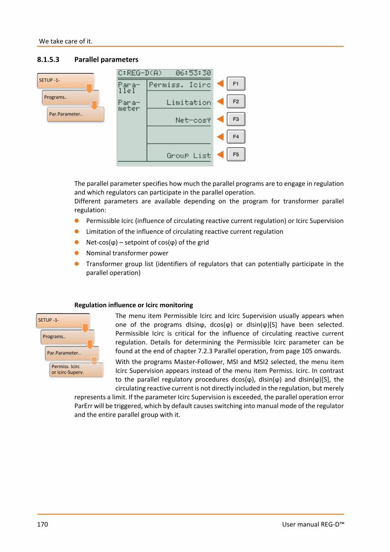
We take care of it.
170
User manual REG-D™
8.1.5.3 Parallel parameters
The parallel parameter specifies how much the parallel programs are to engage in regulation and which regulators can participate in the parallel operation. Different parameters are available depending on the program for transformer parallel regulation: 0 Permissible Icirc (influence of circulating reactive current regulation) or Icirc Supervision 0 Limitation of the influence of circulating reactive current regulation 0 Net-cos(ϕ) – setpoint of cos(ϕ) of the grid 0 Nominal transformer power 0 Transformer group list (identifiers of regulators that can potentially participate in the
parallel operation) Regulation influence or Icirc monitoring
The menu item Permissible Icirc and Icirc Supervision usually appears when one of the programs dIsinϕ, dcos(ϕ) or dIsin(ϕ)[S] have been selected. Permissible Icirc is critical for the influence of circulating reactive current regulation. Details for determining the Permissible Icirc parameter can be found at the end of chapter 7.2.3 Parallel operation, from page 105 onwards. With the programs Master-Follower, MSI and MSI2 selected, the menu item Icirc Supervision appears instead of the menu item Permiss. Icirc. In contrast to the parallel regulatory procedures dcos(ϕ), dIsin(ϕ) and dIsin(ϕ)[S], the circulating reactive current is not directly included in the regulation, but merely
represents a limit. If the parameter Icirc Supervision is exceeded, the parallel operation error ParErr will be triggered, which by default causes switching into manual mode of the regulator and the entire parallel group with it.
SETUP -1-
Programs..
Par.Parameter..
SETUP -1-
Programs..
Par.Parameter..
Permiss. Icirc or Icirc-Superv.
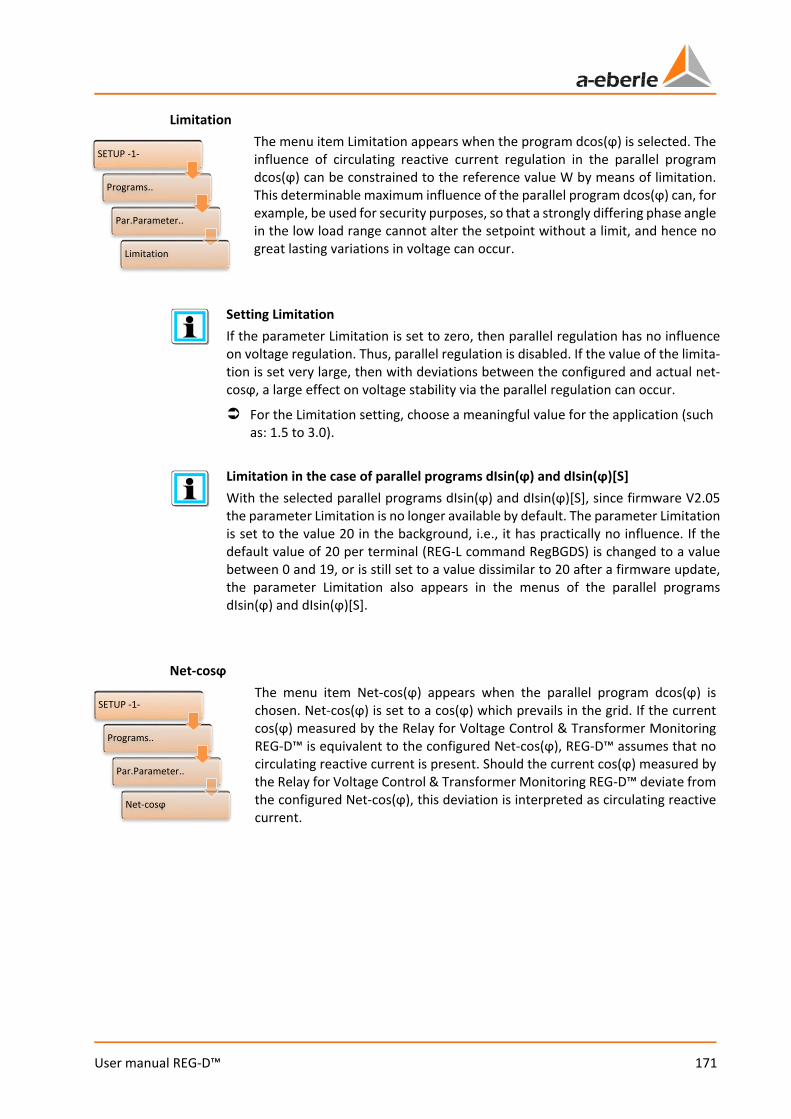
171
User manual REG-D™
Limitation The menu item Limitation appears when the program dcos(ϕ) is selected. The influence of circulating reactive current regulation in the parallel program dcos(ϕ) can be constrained to the reference value W by means of limitation. This determinable maximum influence of the parallel program dcos(ϕ) can, for example, be used for security purposes, so that a strongly differing phase angle in the low load range cannot alter the setpoint without a limit, and hence no great lasting variations in voltage can occur.
Setting Limitation If the parameter Limitation is set to zero, then parallel regulation has no influence on voltage regulation. Thus, parallel regulation is disabled. If the value of the limita-tion is set very large, then with deviations between the configured and actual net-cosϕ, a large effect on voltage stability via the parallel regulation can occur.
For the Limitation setting, choose a meaningful value for the application (such as: 1.5 to 3.0).
Limitation in the case of parallel programs dIsin(ϕ) and dIsin(ϕ)[S] With the selected parallel programs dIsin(ϕ) and dIsin(ϕ)[S], since firmware V2.05 the parameter Limitation is no longer available by default. The parameter Limitation is set to the value 20 in the background, i.e., it has practically no influence. If the default value of 20 per terminal (REG-L command RegBGDS) is changed to a value between 0 and 19, or is still set to a value dissimilar to 20 after a firmware update, the parameter Limitation also appears in the menus of the parallel programs dIsin(ϕ) and dIsin(ϕ)[S].
Net-cosϕ
The menu item Net-cos(ϕ) appears when the parallel program dcos(ϕ) is chosen. Net-cos(ϕ) is set to a cos(ϕ) which prevails in the grid. If the current cos(ϕ) measured by the Relay for Voltage Control & Transformer Monitoring REG-D™ is equivalent to the configured Net-cos(ϕ), REG-D™ assumes that no circulating reactive current is present. Should the current cos(ϕ) measured by the Relay for Voltage Control & Transformer Monitoring REG-D™ deviate from the configured Net-cos(ϕ), this deviation is interpreted as circulating reactive current.
SETUP -1-
Programs..
Par.Parameter..
Net-cosϕ
SETUP -1-
Programs..
Par.Parameter..
Limitation
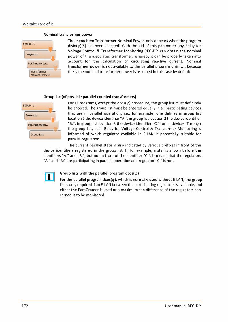
We take care of it.
172
User manual REG-D™
Nominal transformer power The menu item Transformer Nominal Power only appears when the program dIsin(ϕ)[S] has been selected. With the aid of this parameter any Relay for Voltage Control & Transformer Monitoring REG-D™ can obtain the nominal power of the associated transformer, whereby it can be properly taken into account for the calculation of circulating reactive current. Nominal transformer power is not available to the parallel program dIsin(ϕ), because the same nominal transformer power is assumed in this case by default.
Group list (of possible parallel-coupled transformers)
For all programs, except the dcos(ϕ) procedure, the group list must definitely be entered. The group list must be entered equally in all participating devices that are in parallel operation, i.e., for example, one defines in group list location 1 the device identifier "A:", in group list location 2 the device identifier "B:", in group list location 3 the device identifier "C:" for all devices. Through the group list, each Relay for Voltage Control & Transformer Monitoring is informed of which regulator available in E-LAN is potentially suitable for parallel regulation. The current parallel state is also indicated by various prefixes in front of the
device identifiers registered in the group list. If, for example, a star is shown before the identifiers "A:" and "B:", but not in front of the identifier "C:", it means that the regulators "A:" and "B:" are participating in parallel operation and regulator "C:" is not.
Group lists with the parallel program dcos(ϕ) For the parallel program dcos(ϕ), which is normally used without E-LAN, the group list is only required if an E-LAN between the participating regulators is available, and either the ParaGramer is used or a maximum tap difference of the regulators con-cerned is to be monitored.
SETUP -1-
Programs..
Par.Parameter..
TransformerNominal Power
SETUP -1-
Programs..
Par.Parameter..
Group List
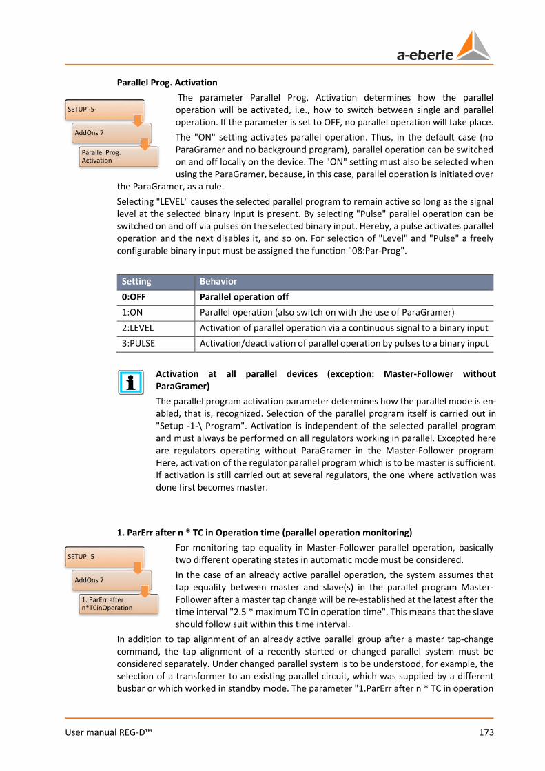
173
User manual REG-D™
Parallel Prog. Activation The parameter Parallel Prog. Activation determines how the parallel operation will be activated, i.e., how to switch between single and parallel operation. If the parameter is set to OFF, no parallel operation will take place. The "ON" setting activates parallel operation. Thus, in the default case (no ParaGramer and no background program), parallel operation can be switched on and off locally on the device. The "ON" setting must also be selected when using the ParaGramer, because, in this case, parallel operation is initiated over
the ParaGramer, as a rule. Selecting "LEVEL" causes the selected parallel program to remain active so long as the signal level at the selected binary input is present. By selecting "Pulse" parallel operation can be switched on and off via pulses on the selected binary input. Hereby, a pulse activates parallel operation and the next disables it, and so on. For selection of "Level" and "Pulse" a freely configurable binary input must be assigned the function "08:Par-Prog".
Setting Behavior 0:OFF Parallel operation off 1:ON Parallel operation (also switch on with the use of ParaGramer) 2:LEVEL Activation of parallel operation via a continuous signal to a binary input 3:PULSE Activation/deactivation of parallel operation by pulses to a binary input
Activation at all parallel devices (exception: Master-Follower without ParaGramer) The parallel program activation parameter determines how the parallel mode is en-abled, that is, recognized. Selection of the parallel program itself is carried out in "Setup -1-\ Program". Activation is independent of the selected parallel program and must always be performed on all regulators working in parallel. Excepted here are regulators operating without ParaGramer in the Master-Follower program. Here, activation of the regulator parallel program which is to be master is sufficient. If activation is still carried out at several regulators, the one where activation was done first becomes master.
1. ParErr after n * TC in Operation time (parallel operation monitoring)
For monitoring tap equality in Master-Follower parallel operation, basically two different operating states in automatic mode must be considered. In the case of an already active parallel operation, the system assumes that tap equality between master and slave(s) in the parallel program Master-Follower after a master tap change will be re-established at the latest after the time interval "2.5 * maximum TC in operation time". This means that the slave should follow suit within this time interval.
In addition to tap alignment of an already active parallel group after a master tap-change command, the tap alignment of a recently started or changed parallel system must be considered separately. Under changed parallel system is to be understood, for example, the selection of a transformer to an existing parallel circuit, which was supplied by a different busbar or which worked in standby mode. The parameter "1.ParErr after n * TC in operation
SETUP -5-
AddOns 7
Parallel Prog. Activation
SETUP -5-
AddOns 7
1. ParErr after n*TCinOperation
We take care of it.
174
User manual REG-D™
time" can be used to determine by how many taps a newly selected transformer may differ from the existing transformers running in parallel, or which tap difference is permissible when restarting a Master-Follower parallel regulation. The following applies to starting parallel operation:
– Activation of parallel operation in automatic mode – Changing the master regulator in automatic mode – Switching from manual to automatic
When you add a transformer to an existing Master-Follower parallel regulation, the transformer will be introduced tapwise as soon as possible to the group already operating in parallel (status: follower) and finally added to it (status: slave). If alignment is not achieved during the preselected time, parallel coupling is stopped and a parallel operation error (ParErr) triggered. In the standard configuration, this leads to switching the regulator to manual mode.
"1 ParErr after n * TC in operation time“ is a time interval, not a maximum tap difference The parameter "1 ParErr after n * TC in operation time" (default value = 4) does not specify the number of taps that the slave/follower can be separated by at the start or selection of the transformer into parallel regulation of the master! In contrast, the parameter indicates a permissible time interval (n * maximum TC in operation time), after which ParErr is triggered due to tap inequality.
Availability of parameters The parameter "1 ParErr after n * TC in operation time" is only available in the reg-ulator menu if one of the parallel programs Master-Follower, MSI or MSI2 is selected.
It is possible to determine the parameter "1 ParErr after n * TC in operation time“ so that a certain number of taps is possible. The following formula is used to determine the parameter "1 ParErr after n * TC in operation time“ on the basis of permissible number of taps which can be followed:
1.𝑃𝑃𝑐𝑐𝐼𝐼𝑃𝑃𝐼𝐼𝐼𝐼 𝑐𝑐𝑎𝑎𝑆𝑆𝑖𝑖𝐼𝐼 𝑖𝑖 ∗ 𝑇𝑇𝑇𝑇 𝐼𝐼𝑖𝑖 𝑐𝑐𝑐𝑐𝑖𝑖𝐼𝐼𝑐𝑐𝑆𝑆𝐼𝐼𝑐𝑐𝑖𝑖 𝑆𝑆𝐼𝐼𝑡𝑡𝑖𝑖 ≥ 𝑇𝑇𝑟𝑟𝑟𝑟𝑟𝑟𝑟𝑟+𝑥𝑥 ×𝑇𝑇𝑟𝑟𝑟𝑟𝑟𝑟𝑟𝑟𝑟𝑟𝑟𝑟𝑟𝑟+(𝑥𝑥−1)×4𝑇𝑇𝑇𝑇𝑟𝑟𝑟𝑟𝑟𝑟𝑟𝑟
− 0,6
where: x : taps that can be followed before a ParErr is issued Trunl: maximum TC in operation time Trunleff: effective run time of the tap changer in seconds
175
User manual REG-D™
Example: The transformer/regulator to be switched in stands in rest position at tap 5. The group operating in parallel is currently working on tap 8 (x = 3), the motor run time between two taps is 7 seconds (TTCinOp_eff = 7s) and the "maximum TC in operation time“ is 8 seconds (TTCinOp = 8s). If, regardless of occuring circulating reactive currents, you wish to switch in a transformer which is at level 5 to the parallel working group, the parameter "1 ParErr after n * TC in operation time " must be set to at least 5 according to the following calculation:
1.𝑃𝑃𝑐𝑐𝐼𝐼𝑃𝑃𝐼𝐼𝐼𝐼 𝑐𝑐𝑎𝑎𝑆𝑆𝑖𝑖𝐼𝐼 𝑖𝑖 ∗ 𝑇𝑇𝑇𝑇 𝐼𝐼𝑖𝑖 𝑐𝑐𝑐𝑐𝑖𝑖𝐼𝐼𝑐𝑐𝑆𝑆𝐼𝐼𝑐𝑐𝑖𝑖 𝑆𝑆𝐼𝐼𝑡𝑡𝑖𝑖 ≥ 8𝑐𝑐 + 3 × 7𝑐𝑐 + (3 − 1) × 4𝑐𝑐
8𝑐𝑐 − 0,6
1.𝑃𝑃𝑐𝑐𝐼𝐼𝑃𝑃𝐼𝐼𝐼𝐼 𝑐𝑐𝑎𝑎𝑆𝑆𝑖𝑖𝐼𝐼 𝑖𝑖 ∗ 𝑇𝑇𝑇𝑇 𝐼𝐼𝑖𝑖 𝑐𝑐𝑐𝑐𝑖𝑖𝐼𝐼𝑐𝑐𝑆𝑆𝐼𝐼𝑐𝑐𝑖𝑖 𝑆𝑆𝐼𝐼𝑡𝑡𝑖𝑖 ≥ 4,025
1.𝑃𝑃𝑐𝑐𝐼𝐼𝑃𝑃𝐼𝐼𝐼𝐼 𝑐𝑐𝑎𝑎𝑆𝑆𝑖𝑖𝐼𝐼 𝑖𝑖 ∗ 𝑇𝑇𝑇𝑇 𝐼𝐼𝑖𝑖 𝑐𝑐𝑐𝑐𝑖𝑖𝐼𝐼𝑐𝑐𝑆𝑆𝐼𝐼𝑐𝑐𝑖𝑖 𝑆𝑆𝐼𝐼𝑡𝑡𝑖𝑖 = 5 The monitoring algorithm of the parallel program thus waits 5 times the "maximum TC in Operation time" (5 x 8 seconds = 40 seconds) for the connected transformer before a parallel error (ParErr) is triggered. During this time, the new terminal can be "pulled" to the tap of the group under normal circumstances. If it does not participate, the error flag ParErr is set and the whole group switched to manual mode.

We take care of it.
176
User manual REG-D™
Permissible Difference of Taps (monitoring parallel operation) The parameter Permissible Difference of Taps is available with the parallel programs dIsin(ϕ), dIsin(ϕ)[S] and dcos(ϕ). The function is only active when an E-LAN connection exists between the regulators. In the Master-Follower program, no tap difference is allowed (except for a fixed tap offset between the regulators – from firmware V2.24), so the parameter is not displayed here. The maximum tap difference parameter indicates how many taps
transformers working in parallel may run separated from each other. If the permissible difference is exceeded, the parallel operation error (ParErr) is triggered. In the standard configuration, this leads to switching the regulator to MANUAL mode. The parameters can be adjusted in the range from 0 to 6. The setting value 0 is shown as "---" and turns off the monitoring. That is, with a setting of 0 no monitoring of the tap difference takes place.
Availability of the parameter This parameter is available with the use of the parallel programs dIsin(ϕ), dIsin(ϕ)[S] and dcos(ϕ). The function is only active when an E-LAN connection exists between the regulators. In the Master-Follower program no tap difference is permitted, so the parameter will not be displayed here.
Manual/automatic balance at Master-Follower start:
The manual/automatic state of a group working according to the Master-Follower principle is always the same. This means that when a regulator is switched to manual mode, all regulators in this group switch to manual mode. Switching to automatic mode can only be done from the master regulator. On connecting a transformer to a parallel group of transformers working on the master-follower principle, matching of the manual/automatic state must take place in case of a manual/automatic state of the group that is different
from the other transformer. For this purpose, via the parameter "Manual/automatic balance at Master-Follower start: " you can define which state is dominant. The setting "MasterPrio" leads to matching the manual/automatic state of the additional transformer with the state of the master regulator of the group. The selection "HandPrio" means that the whole group is switched to MANUAL, if at least one transformer of the new group is set to MANUAL.
Special behavior: different manual/automatic state in a parallel group Manual/automatic matching was introduced in firmware version 2.00. The original behavior (up to firmware V1.99), which allowed a different manual/automatic state between regulators, can be activated again on request. For questions regarding this matter, please contact the A. Eberle REGSys support team ([email protected], +49(0)911/628108-101).
SETUP -5-
AddOns 7
Manu/Auto Balance at M/F Start
SETUP -5-
AddOns 7
Permissible Dif-ference of Taps
177
User manual REG-D™
8.1.5.4 Detailed explanation of the parallel program "dcos(ϕ)"
In the following the calculation of circulating reactive current and the effect of the parameters Permiss. Icirc and Limitation on the parallel program dcos(ϕ) is explained further. The current circulating reactive current is calculated from the configured Net-cos(ϕ) and the actual cos(ϕ). It is assumed that with the Net-cos(ϕ) the circuit reactive current is equal to zero.
𝐼𝐼𝐼𝐼𝐼𝐼𝐼𝐼𝐼𝐼𝑐𝑐𝐾𝐾𝑇𝑇𝑇𝑇𝑠𝑠𝑇𝑇𝑐𝑐 [𝐴𝐴] = 𝐼𝐼𝑐𝑐𝐾𝐾𝑇𝑇𝑇𝑇𝑠𝑠𝑇𝑇𝑐𝑐[𝐴𝐴] ∗ (𝑐𝑐𝐼𝐼𝑖𝑖 (𝜑𝜑) − 𝑐𝑐𝐼𝐼𝑖𝑖(𝜑𝜑𝑇𝑇𝑠𝑠𝑐𝑐−𝑐𝑐𝑐𝑐𝑇𝑇𝑐𝑐)) The ratio of current and permissible circulating reactive current forms the basis for the influence of the parallel program dcos(ϕ) on voltage regulation. The following formula can be used to determine the setpoint influenced by the parallel program dcos(ϕ) (virtual setpoint):
𝑖𝑖𝐼𝐼𝐼𝐼𝑆𝑆𝑖𝑖𝑐𝑐𝑣𝑣 𝑆𝑆𝑃𝑃 [𝑘𝑘] = 𝑆𝑆𝑃𝑃𝑐𝑐𝐾𝐾𝑇𝑇𝑇𝑇. [𝑘𝑘] + 𝑋𝑋𝑋𝑋𝑧𝑧[%] ∗ 𝑉𝑉𝑐𝑐𝑖𝑖𝑇𝑇𝑐𝑐𝑐𝑐𝑟𝑟𝑟𝑟𝑟𝑟𝑟𝑟𝑟𝑟𝑐𝑐[𝐴𝐴]𝑉𝑉𝑐𝑐𝑖𝑖𝑇𝑇𝑐𝑐𝑝𝑝𝑟𝑟𝑟𝑟𝑝𝑝𝑝𝑝𝑝𝑝𝑝𝑝.[𝐴𝐴]
∗ 100%𝑉𝑉𝑇𝑇𝑉𝑉𝐾𝐾𝑠𝑠𝑆𝑆𝑆𝑆 𝑐𝑐𝑟𝑟𝑟𝑟𝑟𝑟. [𝑉𝑉]100%
Example: Current setpoint SPcurrent: 100 V (=100%) Permissible setpoint deviation Xwz: 2.0 % Permissible circulating reactive current Icircpermiss.: 50 A Current circulating reactive current Icirccurrent: -75 A (inductive)
𝑖𝑖𝐼𝐼𝐼𝐼𝑆𝑆𝑖𝑖𝑐𝑐𝑣𝑣 𝑆𝑆𝑃𝑃 [𝑘𝑘] = 100 𝑘𝑘 + 2,0 % ∗ −75 𝐴𝐴50 𝐴𝐴
∗ 100 𝑉𝑉100 %
= 97 𝑘𝑘
→ The setpoint drops virtually to 97 V. Thereby down commands are provoked, which
reduce the inductive circulating reactive current. The ratio of current and permissible circulating reactive current in the above formula can be limited using the parameter Limitation. Thus, the parameter Limitation specifies which maximum influence the parallel program can have on voltage regulation. The maximum and minimum virtual setpoint can be calculated using the following formula:
virt. SPmin/max [V] = SPcurr. [V] ± Xwz[%] ∗ Limitation ∗100%ValueSPcurr. [V]
100%

We take care of it.
178
User manual REG-D™
Example: Current setpoint: 100 V (=100%)
Permissible setpoint deviation Xwz: 2.0 % Limitation: 3
𝑖𝑖𝐼𝐼𝐼𝐼𝑆𝑆. 𝑆𝑆𝑃𝑃𝑚𝑚𝑖𝑖𝑇𝑇/𝑚𝑚𝑇𝑇𝑥𝑥 [𝑘𝑘] = 100 𝑘𝑘 ± 2,0 % ∗ 3 ∗100 𝑘𝑘100 %
= 100 𝑘𝑘 ± 6 𝑘𝑘
→ The setpoint changes maximum ± 6 V due to the influence of the parallel program
dcos(ϕ).
8.1.5.5 Detailed explanation of the parallel programs "dIsin(ϕ)" and "dIsin(ϕ)[S]"
The following describes in detail the effect of the parameters Permiss. Icirc and Transformer Nominal Power on parallel regulation of the parallel programs dIsin(ϕ) and dIsin(ϕ)[S]. The current circulating reactive current is determined based on the number of parallel transformers and the nominal transformer power of regulators participating in parallel operation. With the parallel program dIsin(ϕ)[S], the respective nominal transformer powers are freely programmable; with the parallel program dIsin(ϕ) all nominal transformer powers are assumed to be equal, whereby input of nominal transformer power can be eliminated. Below follows the method for calculating circulating reactive current in two parallel transformers:
𝐼𝐼𝐼𝐼𝐼𝐼𝐼𝐼𝐼𝐼current [𝐴𝐴] = 𝐼𝐼1[𝐴𝐴] ∗ 𝑐𝑐𝐼𝐼𝑖𝑖𝜑𝜑1 −𝑆𝑆𝑁𝑁1
𝑆𝑆𝑁𝑁1 + 𝑆𝑆𝑁𝑁2∗ 𝐼𝐼𝐼𝐼𝐿𝐿𝑐𝑐𝑐𝑐𝑐𝑐 [𝐴𝐴]
𝑋𝑋𝐼𝐼𝑆𝑆ℎ 𝐼𝐼𝐼𝐼𝐿𝐿𝑐𝑐𝑐𝑐𝑐𝑐 [𝐴𝐴] = 𝐼𝐼1[𝐴𝐴] ∗ 𝑐𝑐𝐼𝐼𝑖𝑖 (𝜑𝜑1)− 𝐼𝐼2[𝐴𝐴] ∗ 𝑐𝑐𝐼𝐼𝑖𝑖 (𝜑𝜑2)
where: Icirccurrent: current circulating reactive current SN1: nominal power trafo 1 SN2: nominal power trafo 2 IqLtot: total reactive current without circulating reactive current The ratio of current and permissible circulating reactive current forms the basis for the effect of the parallel programs dIsin(ϕ) and dIsin(ϕ)[S] on voltage regulation. The calculation formula for virtual setpoint corresponds to that of the parallel program dcos(ϕ), see previous chapter 8.1.5.4, from page 177 onwards.
179
User manual REG-D™
8.1.5.6 Detailed explanation of the parallel programs “Master-Follower”, “MSI” and “MSI2”
The parallel programs Master-Follower, MSI and MSI2 do not differ in their parallel procedures, but only in the way the parallel programs are activated. While the Master-Follower procedure can be used with or without ParaGramer, the parallel programs MSI and MSI2 can only be used with ParaGramer. For more information on ParaGramer see chapter 8.3.2 ParaGramer including extensions [protected], from page 232 onwards. For the parallel programs Master-Follower, MSI and MSI2, the circulating reactive current is used for monitoring purposes only, in contrast to the remaining parallel programs. Therefore, the menu item for configuration of permissible circulating reactive current is not designated as "Permiss. Icirc" but "Icirc-Superv.". Calculation of circulating reactive current is carried out according to the calculation of the parallel program dIsin(ϕ), see chapter 8.1.5.5 Detailed explanation of the parallel programs , from page 178 onwards. If the permissible circulating reactive current is exceeded, the regulator switches to manual, and with it the parallel group as well. If the parallel mode is enabled, one of the regulators of the parallel group becomes master and the others slaves. If several masters are possible, that regulator becomes master which occupies the lowest place in the group list. (The exception is Master-Follower without ParaGramer: Here the regulator who first recognized the parallel operation becomes master.) If the manual/automatic states of the new parallel group are different, the resulting manual/automatic state depends on the parameter "Manual/automatic balance at Master-Follower start", see chapter 8.1.5.3 from page 170 onwards. If the parallel group is in manual mode, tap-change commands at the master will lead to tap changes for the entire parallel group. In contrast, tap-change commands at a slave result in no tap changes in the entire parallel group, but only changes in the corresponding slave tap. If the parallel group is in automatic mode, differentiation must be made between whether it is a just launched or modified parallel system (through activation of parallel operation in automatic mode, change of master regulator in automatic mode, switching from manual to automatic mode), or it is an already active parallel coupling. In a just started or modified parallel system, if the slaves are on a different tap than the master, the slaves change into follower mode and tap towards the tap position of the master. If the followers reach the tap position of the master within the predetermined time interval "1 ParErr after n * TC in operation time“ (see chapter 8.1.5.3 from page 173 onwards), they switch into slave mode again. If the tap position of the master is not reached within the time interval "1 ParErr after n * TC in operation time “, the parallel operation error (ParErr) is issued, which leads by default to a change of the parallel group to manual. From the time of reaching tap equality, in automatic mode, the system is already an active parallel coupling. From this point, the slaves are tapped together from the master. It is assumed that the slaves have reached the tap setting of the master after a maximum "2.5 * maximum TC in operation time ". Should this not be the case, the parallel operation error (ParErr) will be issued.
We take care of it.
180
User manual REG-D™
The parameters "Parameter Base Tap Position" and "Sync mode" (firmware V2.24) From firmware V2.24 it is possible to define a tap offset between regulators participating in parallel operation using the parameter "Parameter Base Tap Position". Later, this option is indicated for the parallel programs Master-Follower, MSI and MSI2 by the text "(Including tap offset)". Also new from firmware V2.24 is the so-called "Sync mode". If at the beginning of parallel operation slaves are on a different tap than the master, the slaves and the master switch to sync mode. In this mode, in contrast to previous firmware versions, slaves are not necessarily pulled to the tap of the master (including tap offset), but the current voltage of the master is also taken into account. This means that either one of the slaves or the master is tapped, depending on the current voltage, so that, with optimum maintenance of the setpoint of the master, tap equality is restored (including tap offset).
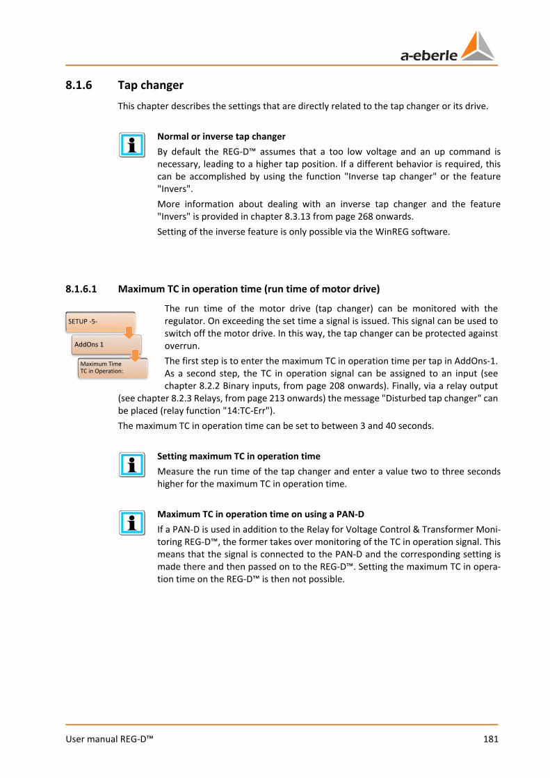
181
User manual REG-D™
8.1.6 Tap changer This chapter describes the settings that are directly related to the tap changer or its drive.
Normal or inverse tap changer By default the REG-D™ assumes that a too low voltage and an up command is necessary, leading to a higher tap position. If a different behavior is required, this can be accomplished by using the function "Inverse tap changer" or the feature "Invers". More information about dealing with an inverse tap changer and the feature "Invers" is provided in chapter 8.3.13 from page 268 onwards. Setting of the inverse feature is only possible via the WinREG software.
8.1.6.1 Maximum TC in operation time (run time of motor drive)
The run time of the motor drive (tap changer) can be monitored with the regulator. On exceeding the set time a signal is issued. This signal can be used to switch off the motor drive. In this way, the tap changer can be protected against overrun. The first step is to enter the maximum TC in operation time per tap in AddOns-1. As a second step, the TC in operation signal can be assigned to an input (see chapter 8.2.2 Binary inputs, from page 208 onwards). Finally, via a relay output
(see chapter 8.2.3 Relays, from page 213 onwards) the message "Disturbed tap changer" can be placed (relay function "14:TC-Err"). The maximum TC in operation time can be set to between 3 and 40 seconds.
Setting maximum TC in operation time Measure the run time of the tap changer and enter a value two to three seconds higher for the maximum TC in operation time.
Maximum TC in operation time on using a PAN-D If a PAN-D is used in addition to the Relay for Voltage Control & Transformer Moni-toring REG-D™, the former takes over monitoring of the TC in operation signal. This means that the signal is connected to the PAN-D and the corresponding setting is made there and then passed on to the REG-D™. Setting the maximum TC in opera-tion time on the REG-D™ is then not possible.
SETUP -5-
AddOns 1
Maximum Time TC in Operation:
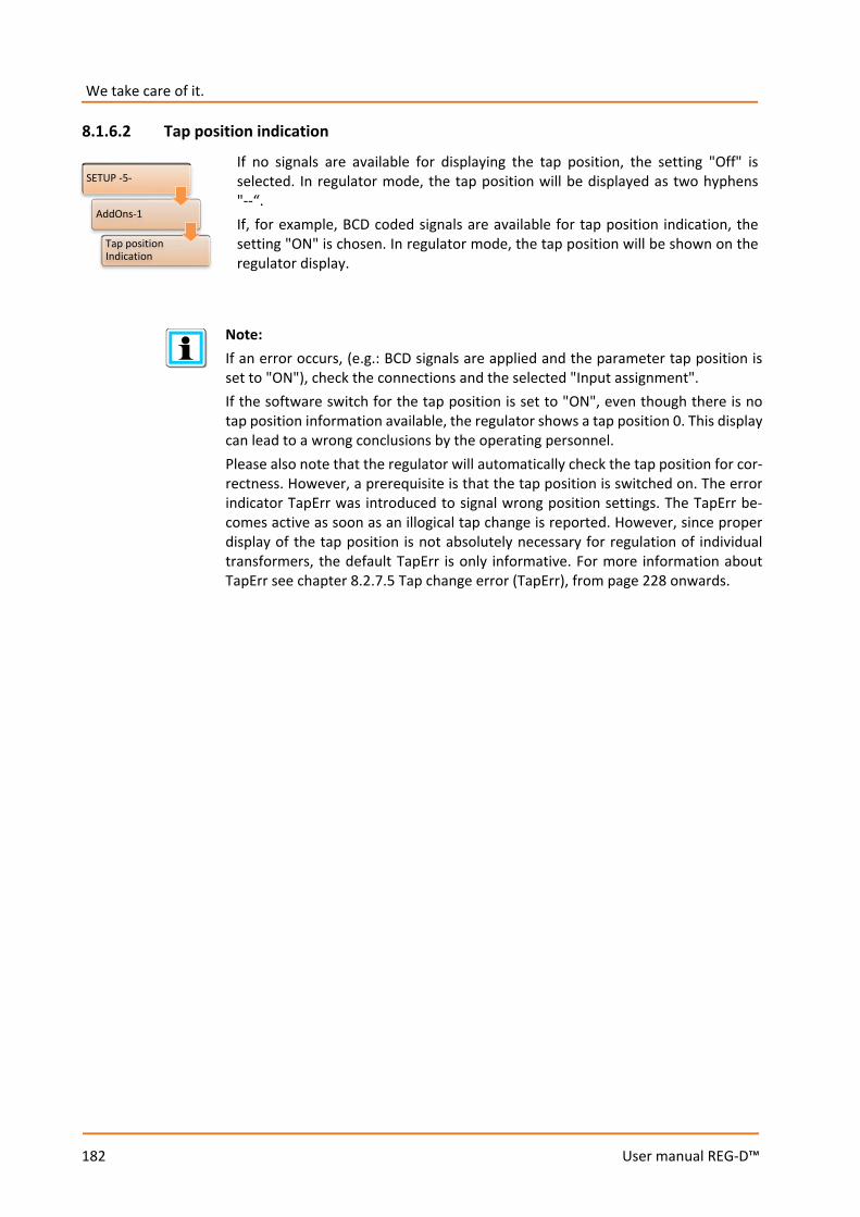
We take care of it.
182
User manual REG-D™
8.1.6.2 Tap position indication
If no signals are available for displaying the tap position, the setting "Off" is selected. In regulator mode, the tap position will be displayed as two hyphens "--“. If, for example, BCD coded signals are available for tap position indication, the setting "ON" is chosen. In regulator mode, the tap position will be shown on the regulator display.
Note: If an error occurs, (e.g.: BCD signals are applied and the parameter tap position is set to "ON"), check the connections and the selected "Input assignment". If the software switch for the tap position is set to "ON", even though there is no tap position information available, the regulator shows a tap position 0. This display can lead to a wrong conclusions by the operating personnel. Please also note that the regulator will automatically check the tap position for cor-rectness. However, a prerequisite is that the tap position is switched on. The error indicator TapErr was introduced to signal wrong position settings. The TapErr be-comes active as soon as an illogical tap change is reported. However, since proper display of the tap position is not absolutely necessary for regulation of individual transformers, the default TapErr is only informative. For more information about TapErr see chapter 8.2.7.5 Tap change error (TapErr), from page 228 onwards.
SETUP -5-
AddOns-1
Tap position Indication

183
User manual REG-D™
8.1.6.3 Tap limiter
With this function the tap range in which the Relay for Voltage Control & Transformer Monitoring can allow the tap changer to operate can be adjusted. In general, the physically available range of the tap changer is to be set (for example, tap 1 to 19). If the upper tap is reached, then up commands are blocked. If the lower tap is reached, then down commands are blocked. With an inverse tap changer (the feature Invers is set on REG-D™), on reaching the lowest tap, up commands are blocked, as are down commands on reaching the highest tap. Blocking of tap commands works in the MANUAL and the automatic modes. If a tap change beyond a tap limit is to be performed, a message appears on the screen that the lowest or highest tap has already been reached.
Setting Behavior OFF Tap limitation off (no blocking of tap commands on reaching the lowest or
highest tap) ON Tap limitation on
Function depends on tap position indication The tap limitation function will only work if the tap parameter "Tap Position Indica-tion" ("Setup -5-/AddOns-1") is set to ON. If the tap position indication is disrupted (indicator 99 on the display), the tap limitation will be inactive. This means that tap changes are possible in both directions.
SETUP -5-
AddOns-8
Tap Limiter
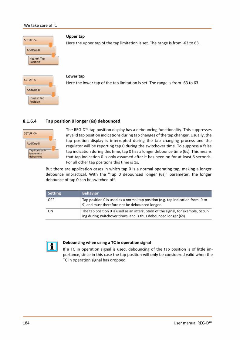
We take care of it.
184
User manual REG-D™
Upper tap Here the upper tap of the tap limitation is set. The range is from -63 to 63. Lower tap Here the lower tap of the tap limitation is set. The range is from -63 to 63.
8.1.6.4 Tap position 0 longer (6s) debounced
The REG-D™ tap position display has a debouncing functionality. This suppresses invalid tap position indications during tap changes of the tap changer. Usually, the tap position display is interrupted during the tap changing process and the regulator will be reporting tap 0 during the switchover time. To suppress a false tap indication during this time, tap 0 has a longer debounce time (6s). This means that tap indication 0 is only assumed after it has been on for at least 6 seconds. For all other tap positions this time is 1s.
But there are application cases in which tap 0 is a normal operating tap, making a longer debounce impractical. With the "Tap 0 debounced longer (6s)" parameter, the longer debounce of tap 0 can be switched off.
Setting Behavior OFF Tap position 0 is used as a normal tap position (e.g. tap indication from -9 to
9) and must therefore not be debounced longer. ON The tap position 0 is used as an interruption of the signal, for example, occur-
ing during switchover times, and is thus debounced longer (6s).
Debouncing when using a TC in operation signal If a TC in operation signal is used, debouncing of the tap position is of little im-portance, since in this case the tap position will only be considered valid when the TC in operation signal has dropped.
SETUP -5-
AddOns-8
Highest Tap Position
SETUP -5-
AddOns-8
Lowest Tap Position
SETUP -5-
AddOns-8
Tap Position 0 longer (6s) debounced
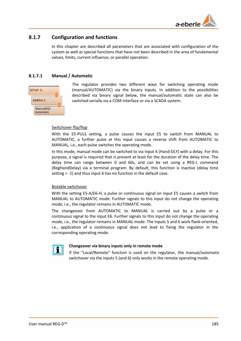
185
User manual REG-D™
8.1.7 Configuration and functions In this chapter are described all parameters that are associated with configuration of the system as well as special functions that have not been described in the area of fundamental values, limits, current influence, or parallel operation.
8.1.7.1 Manual / Automatic
The regulator provides two different ways for switching operating mode (manual/AUTOMATIC) via the binary inputs. In addition to the possibilities described via binary signal below, the manual/automatic state can also be switched serially via a COM interface or via a SCADA system.
Switchover flip/flop With the E5-PULS setting, a pulse causes the input E5 to switch from MANUAL to AUTOMATIC, a further pulse at this input causes a reverse shift from AUTOMATIC to MANUAL, i.e., each pulse switches the operating mode. In this mode, manual mode can be switched to via input 6 (Hand-DLY) with a delay. For this purpose, a signal is required that is present at least for the duration of the delay time. The delay time can range between 0 and 60s, and can be set using a REG-L command (RegHandDelay) via a terminal program. By default, this function is inactive (delay time setting = -1) and thus input 6 has no function in the default case. Bistable switchover With the setting E5-A/E6-H, a pulse or continuous signal on input E5 causes a switch from MANUAL to AUTOMATIC mode. Further signals to this input do not change the operating mode, i.e., the regulator remains in AUTOMATIC mode. The changeover from AUTOMATIC to MANUAL is carried out by a pulse or a continuous signal to the input E6. Further signals to this input do not change the operating mode, i.e., the regulator remains in MANUAL mode. The inputs 5 and 6 work flank-oriented, i.e., application of a continuous signal does not lead to fixing the regulator in the corresponding operating mode.
Changeover via binary inputs only in remote mode If the "Local/Remote" function is used on the regulator, the manual/automatic switchover via the inputs 5 (and 6) only works in the remote operating mode.
SETUP -5-
AddOns-1
Manual(H)/Automatic

We take care of it.
186
User manual REG-D™
Using inputs 5 and 6 not for a manual/automatic switchover and share them with the background program The selection E5 + 6-PROG disables the switchover of the manual/automatic state via inputs 5 (and 6). This allows use of the inputs 5 and 6 in the background program. Remote manual/automatic switchover can then, for example, be effected via a SCADA system (e.g. IEC 61850).
8.1.7.2 Self-conduct (Manual/Auto remains unchanged after reset)
Using the "WITH" setting, the operating mode of the regulator is stored before any failure of the auxiliary voltage, i.e., after restoration of voltage, the regulator is set to AUTOMATIC if it was on AUTOMATIC before the voltage failure, or MANUAL if it was on AUTOMATIC before the voltage failure. Using the "WITHOUT" setting, the operating mode of the regulator is not stored on an auxiliary voltage failure, i.e., after voltage recurrence, the regulator is always set to MANUAL.
8.1.7.3 Current display
With the setting "ON", current is also indicated in the basic regulator display (detail display). In the setting "OFF" , no indication of current is given in the regulator basic display. The setting can be used to suppress the value 0.000 A in the display in the absence of a current connection.
8.1.7.4 LCD saver
If the parameter "ON" is set, the display shuts off one hour after the last keystroke. The backlight switches off about 15 minutes after the last keystroke. The setting "OFF" means that the display always remains on and only the backlight switches off about 15 minutes after the last keystroke.
SETUP -5-
AddOns-1
Self-conduct
SETUP -5-
AddOns-2
Current Display
SETUP -5-
AddOns-2
LCD Saver
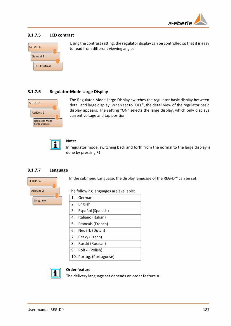
187
User manual REG-D™
8.1.7.5 LCD contrast
Using the contrast setting, the regulator display can be controlled so that it is easy to read from different viewing angles.
8.1.7.6 Regulator-Mode Large Display
The Regulator-Mode Large Display switches the regulator basic display between detail and large display. When set to "OFF", the detail view of the regulator basic display appears. The setting "ON" selects the large display, which only displays current voltage and tap position.
Note: In regulator mode, switching back and forth from the normal to the large display is done by pressing F1.
8.1.7.7 Language
In the submenu Language, the display language of the REG-D™ can be set. The following languages are available:
1. German 2. English 3. Español (Spanish) 4. Italiano (Italian) 5. Francais (French) 6. Nederl. (Dutch) 7. Cesky (Czech) 8. Russki (Russian) 9. Polski (Polish) 10. Portug. (Portuguese)
Order feature The delivery language set depends on order feature A.
SETUP -6-
General 2
LCD Contrast
SETUP -5-
AddOns-2
Regulator-Mode Large Display:
SETUP -5-
AddOns-2
Language
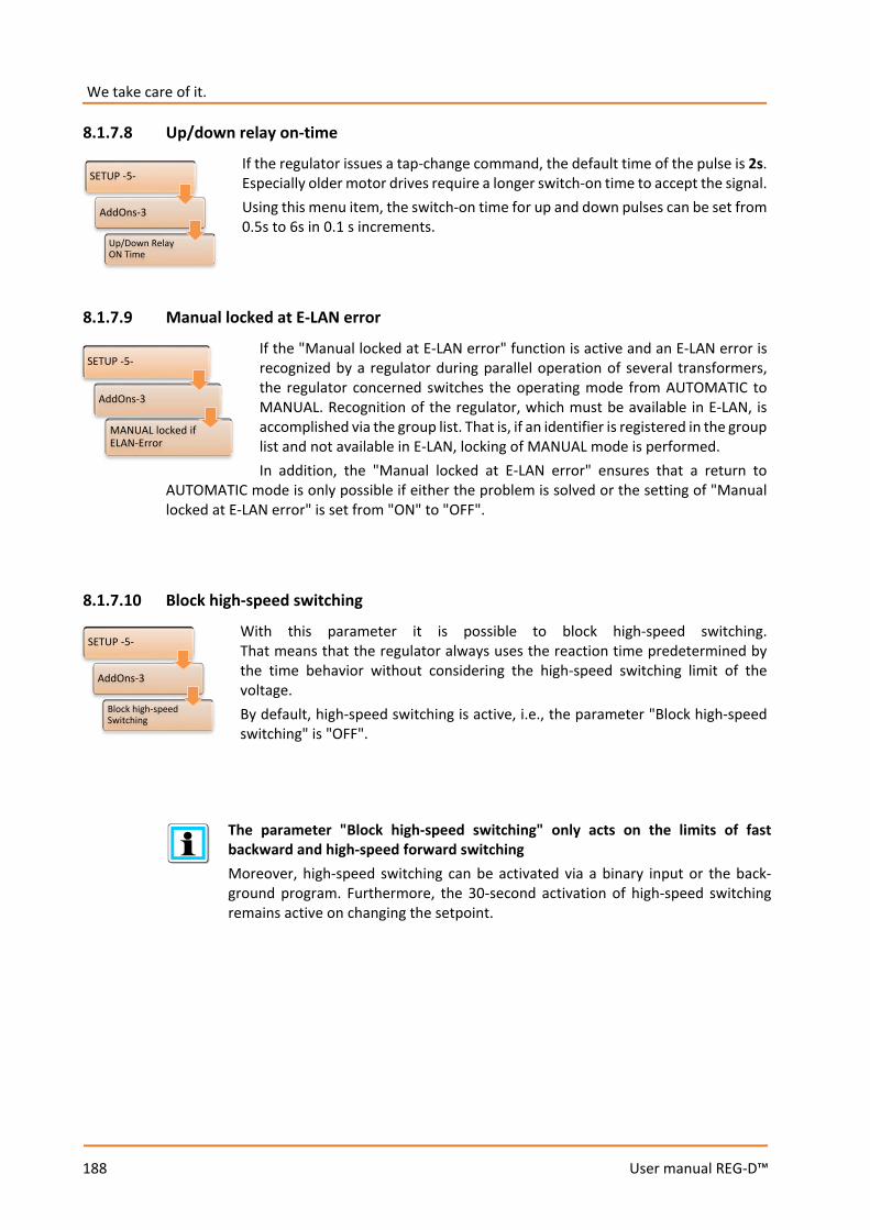
We take care of it.
188
User manual REG-D™
8.1.7.8 Up/down relay on-time
If the regulator issues a tap-change command, the default time of the pulse is 2s. Especially older motor drives require a longer switch-on time to accept the signal. Using this menu item, the switch-on time for up and down pulses can be set from 0.5s to 6s in 0.1 s increments.
8.1.7.9 Manual locked at E-LAN error
If the "Manual locked at E-LAN error" function is active and an E-LAN error is recognized by a regulator during parallel operation of several transformers, the regulator concerned switches the operating mode from AUTOMATIC to MANUAL. Recognition of the regulator, which must be available in E-LAN, is accomplished via the group list. That is, if an identifier is registered in the group list and not available in E-LAN, locking of MANUAL mode is performed. In addition, the "Manual locked at E-LAN error" ensures that a return to
AUTOMATIC mode is only possible if either the problem is solved or the setting of "Manual locked at E-LAN error" is set from "ON" to "OFF".
8.1.7.10 Block high-speed switching
With this parameter it is possible to block high-speed switching. That means that the regulator always uses the reaction time predetermined by the time behavior without considering the high-speed switching limit of the voltage. By default, high-speed switching is active, i.e., the parameter "Block high-speed switching" is "OFF".
The parameter "Block high-speed switching" only acts on the limits of fast backward and high-speed forward switching Moreover, high-speed switching can be activated via a binary input or the back-ground program. Furthermore, the 30-second activation of high-speed switching remains active on changing the setpoint.
SETUP -5-
AddOns-3
Up/Down Relay ON Time
SETUP -5-
AddOns-3
MANUAL locked if ELAN-Error
SETUP -5-
AddOns-3
Block high-speed Switching
189
User manual REG-D™
8.1.7.11 Three-winding activation
With the three-winding transformer activation, use of the three-winding transformer functionality of the REG-D™ can be switched on and off when the REG-D™ has the feature "3winding". If the three-winding function is activated, the voltage to be regulated can be switched via the corresponding binary inputs or via a background program between the measuring inputs 1 and 2. This means that the voltage U1 or U2 can be used for regulation. The respective other voltage can be monitored on a limit. If the three-winding transformer activation is set to
"OFF", this switchover possibility is not available.
Required software and hardware features This parameter is only available when the software feature "3winding" (see chapter 8.3.5 Feature 3winding (three-winding transformer) [protected], from page 253 on-wards) is activated, and REG-D™ has the corresponding hardware feature (M9, see Technical Data in the supplement of chapter 21). Otherwise this menu position is empty.
SETUP -5-
AddOns-3
Dreiwickler Activation
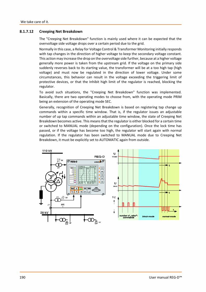
We take care of it.
190
User manual REG-D™
8.1.7.12 Creeping Net Breakdown
The "Creeping Net Breakdown" function is mainly used where it can be expected that the overvoltage side voltage drops over a certain period due to the grid. Normally in this case, a Relay for Voltage Control & Transformer Monitoring initially responds with tap changes in the direction of higher voltage to keep the secondary voltage constant. This action may increase the drop on the overvoltage side further, because at a higher voltage generally more power is taken from the upstream grid. If the voltage on the primary side suddenly reverses back to its starting value, the transformer will be at a too high tap (high voltage) and must now be regulated in the direction of lower voltage. Under some circumstances, this behavior can result in the voltage exceeding the triggering limit of protective devices, or that the Inhibit high limit of the regulator is reached, blocking the regulator. To avoid such situations, the "Creeping Net Breakdown" function was implemented. Basically, there are two operating modes to choose from, with the operating mode PRIM being an extension of the operating mode SEC. Generally, recognition of Creeping Net Breakdown is based on registering tap change up commands within a specific time window. That is, if the regulator issues an adjustable number of up tap commands within an adjustable time window, the state of Creeping Net Breakdown becomes active. This means that the regulator is either blocked for a certain time or switched to MANUAL mode (depending on the configuration). Once the lock time has passed, or if the voltage has become too high, the regulator will start again with normal regulation. If the regulator has been switched to MANUAL mode due to Creeping Net Breakdown, it must be explicitly set to AUTOMATIC again from outside.
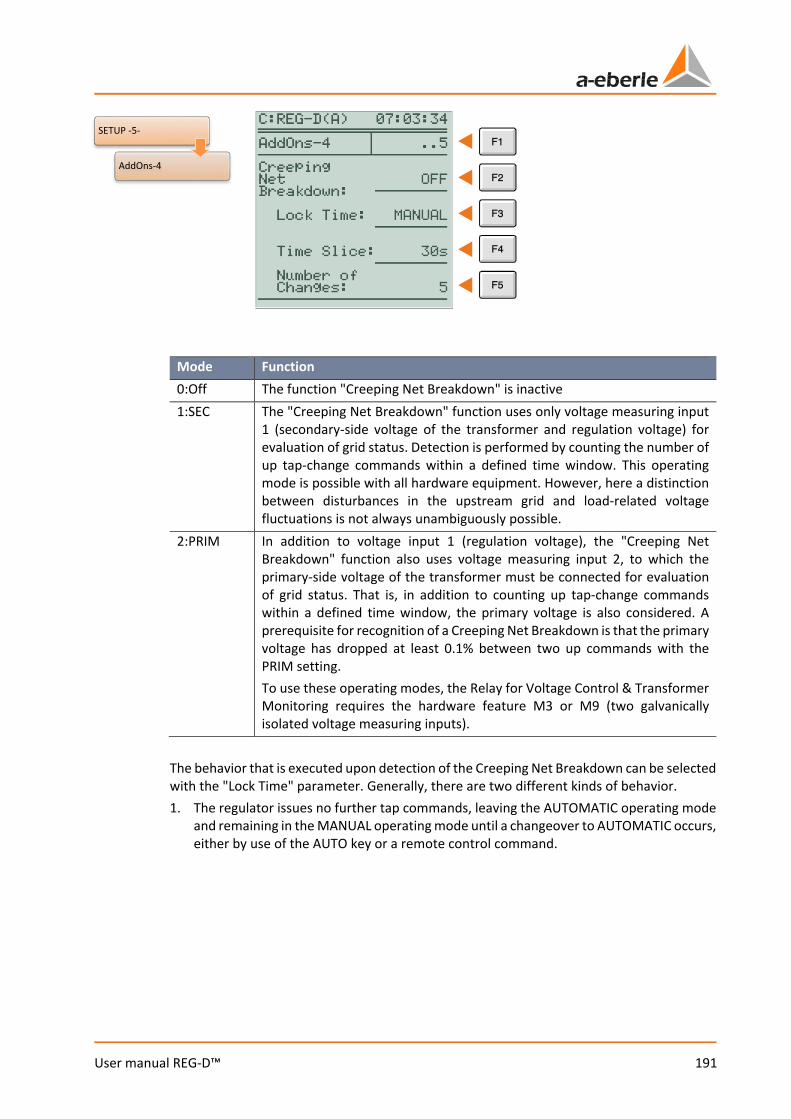
191
User manual REG-D™
Mode Function 0:Off The function "Creeping Net Breakdown" is inactive 1:SEC The "Creeping Net Breakdown" function uses only voltage measuring input
1 (secondary-side voltage of the transformer and regulation voltage) for evaluation of grid status. Detection is performed by counting the number of up tap-change commands within a defined time window. This operating mode is possible with all hardware equipment. However, here a distinction between disturbances in the upstream grid and load-related voltage fluctuations is not always unambiguously possible.
2:PRIM In addition to voltage input 1 (regulation voltage), the "Creeping Net Breakdown" function also uses voltage measuring input 2, to which the primary-side voltage of the transformer must be connected for evaluation of grid status. That is, in addition to counting up tap-change commands within a defined time window, the primary voltage is also considered. A prerequisite for recognition of a Creeping Net Breakdown is that the primary voltage has dropped at least 0.1% between two up commands with the PRIM setting. To use these operating modes, the Relay for Voltage Control & Transformer Monitoring requires the hardware feature M3 or M9 (two galvanically isolated voltage measuring inputs).
The behavior that is executed upon detection of the Creeping Net Breakdown can be selected with the "Lock Time" parameter. Generally, there are two different kinds of behavior. 1. The regulator issues no further tap commands, leaving the AUTOMATIC operating mode
and remaining in the MANUAL operating mode until a changeover to AUTOMATIC occurs, either by use of the AUTO key or a remote control command.
SETUP -5-
AddOns-4
We take care of it.
192
User manual REG-D™
2. For a selectable lock time (1 min ... 20 min) the regulator blocks all other up tap commands. The lock is released automatically when: 0 the selected lock time has expired, or 0 the first down tap command is issued (that is, if the upper limit of the setpoint
deviation is violated). The time window parameter allows you to specify the time period within which the number of tap changes must must occur. The adjustment is possible in the range 15 to 120 seconds in 15s steps. The "Number of Changes" parameter specifies how many time a up tap command must occur within the time window for a Creeping Net Breakdown to be detected. The value range is from 2 to 6. If the state of Creeping Net Breakdown is detected, this is shown via a message (CREEPING NBD) in the lower part of the display. Example: With the settings: mode = PRIM, time window = 60s, number of tap changes = 4 and lock time = 15 min, a Creeping Net Breakdown is detected when the regulator issues an up command four times within 60 seconds and the primary voltage decreases simultaneously. The state of Creeping Net Breakdown is cancelled after 15 minutes or the first down command is issued.
Suppressing the function "High-speed forward switching" (voltage limit) The "Creeping Net Breakdown" function suppresses high-speed forward switching via the voltage limit. High-speed switching via the binary input and by changing the setpoint remains active. During these high-speed switchings no Creeping Net Break-down evaluation is performed.
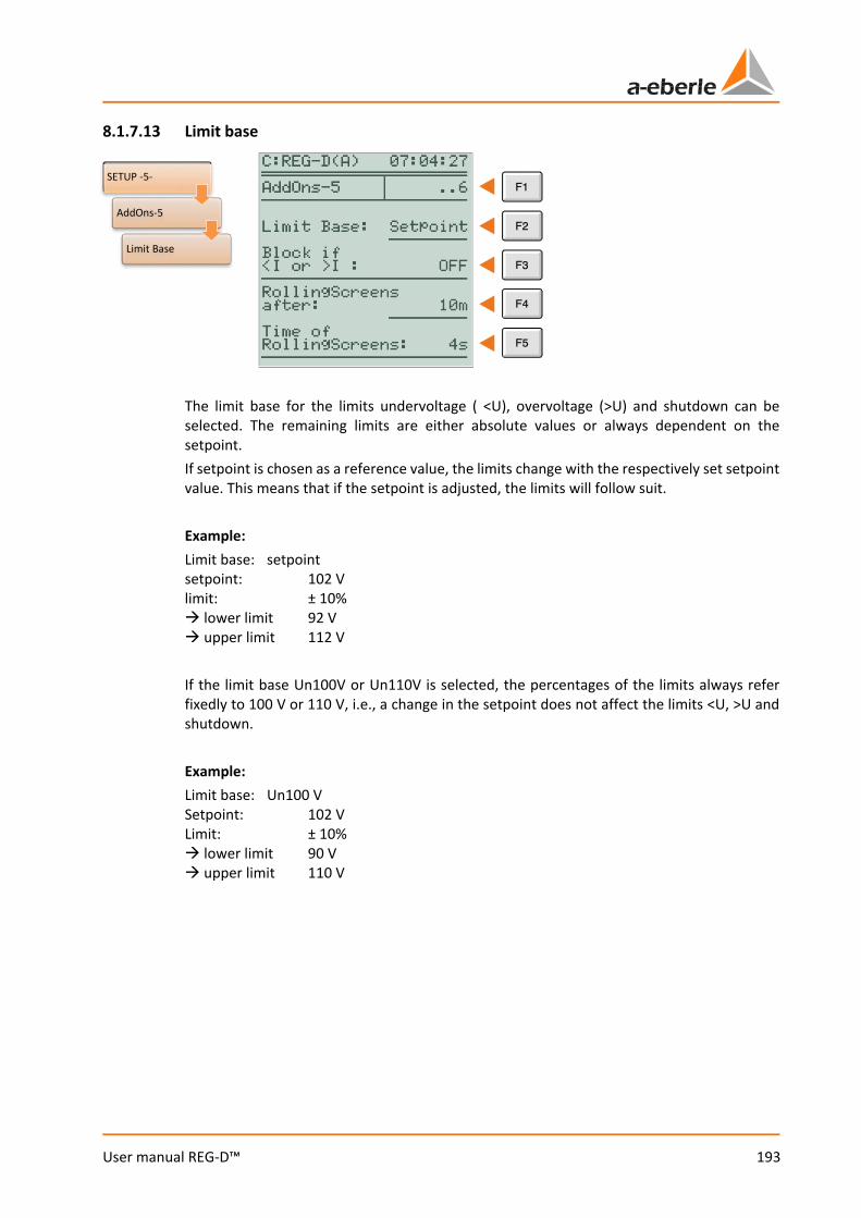
193
User manual REG-D™
8.1.7.13 Limit base
The limit base for the limits undervoltage ( <U), overvoltage (>U) and shutdown can be selected. The remaining limits are either absolute values or always dependent on the setpoint. If setpoint is chosen as a reference value, the limits change with the respectively set setpoint value. This means that if the setpoint is adjusted, the limits will follow suit. Example: Limit base: setpoint setpoint: 102 V limit: ± 10% lower limit 92 V upper limit 112 V If the limit base Un100V or Un110V is selected, the percentages of the limits always refer fixedly to 100 V or 110 V, i.e., a change in the setpoint does not affect the limits <U, >U and shutdown. Example: Limit base: Un100 V Setpoint: 102 V Limit: ± 10% lower limit 90 V upper limit 110 V
SETUP -5-
AddOns-5
Limit Base
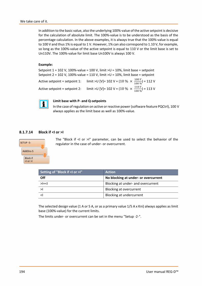
We take care of it.
194
User manual REG-D™
In addition to the basic value, also the underlying 100%-value of the active setpoint is decisive for the calculation of absolute limit. The 100%-value is to be understood as the basis of the percentage calculation. In the above examples, it is always true that the 100%-value is equal to 100 V and thus 1% is equal to 1 V. However, 1% can also correspond to 1.10 V, for example, so long as the 100%-value of the active setpoint is equal to 110 V or the limit base is set to Un110V. The 100%-value for limit base Un100V is always 100 V. Example: Setpoint 1 = 102 V, 100%-value = 100 V, limit >U = 10%, limit base = setpoint Setpoint 2 = 102 V, 100%-value = 110 V, limit >U = 10%, limit base = setpoint
Active setpoint = setpoint 1: limit >U [V]= 102 V + (10 % × 100 𝑉𝑉100 %
) = 112 V
Active setpoint = setpoint 2: limit >U [V]= 102 V + (10 % × 110 𝑉𝑉100 %
) = 113 V
Limit base with P- and Q-setpoints In the case of regulation on active or reactive power (software feature PQCtrl), 100 V always applies as the limit base as well as 100%-value.
8.1.7.14 Block if <I or >I
The "Block if <I or >I" parameter, can be used to select the behavior of the regulator in the case of under- or overcurrent.
Setting of "Block if <I or >I" Action Off No blocking at under- or overcurrent >I+<I Blocking at under- and overcurrent >I Blocking at overcurrent <I Blocking at undercurrent
The selected design value (1 A or 5 A, or as a primary value 1/5 A x Kni) always applies as limit base (100%-value) for the current limits. The limits under- or overcurrent can be set in the menu "Setup -2-".
SETUP -5-
AddOns-5
Block if <I or >I
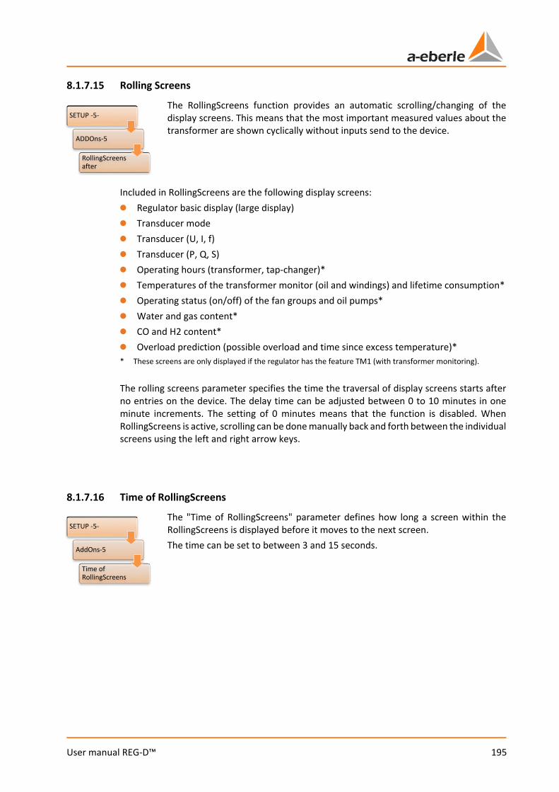
195
User manual REG-D™
8.1.7.15 Rolling Screens
The RollingScreens function provides an automatic scrolling/changing of the display screens. This means that the most important measured values about the transformer are shown cyclically without inputs send to the device.
Included in RollingScreens are the following display screens: 0 Regulator basic display (large display) 0 Transducer mode 0 Transducer (U, I, f) 0 Transducer (P, Q, S) 0 Operating hours (transformer, tap-changer)* 0 Temperatures of the transformer monitor (oil and windings) and lifetime consumption* 0 Operating status (on/off) of the fan groups and oil pumps* 0 Water and gas content* 0 CO and H2 content* 0 Overload prediction (possible overload and time since excess temperature)* * These screens are only displayed if the regulator has the feature TM1 (with transformer monitoring). The rolling screens parameter specifies the time the traversal of display screens starts after no entries on the device. The delay time can be adjusted between 0 to 10 minutes in one minute increments. The setting of 0 minutes means that the function is disabled. When RollingScreens is active, scrolling can be done manually back and forth between the individual screens using the left and right arrow keys.
8.1.7.16 Time of RollingScreens
The "Time of RollingScreens" parameter defines how long a screen within the RollingScreens is displayed before it moves to the next screen. The time can be set to between 3 and 15 seconds.
SETUP -5-
AddOns-5
Time of RollingScreens
SETUP -5-
ADDOns-5
RollingScreens after
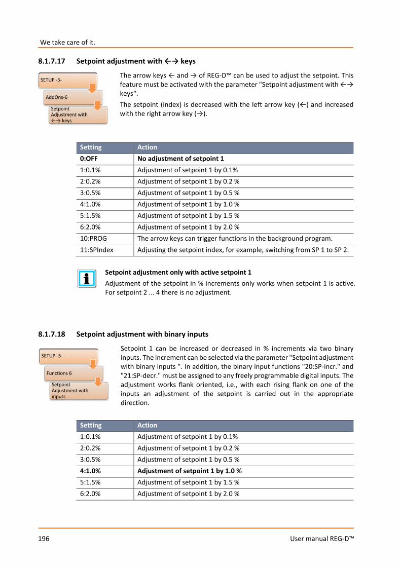
We take care of it.
196
User manual REG-D™
8.1.7.17 Setpoint adjustment with ←→ keys
The arrow keys ← and → of REG-D™ can be used to adjust the setpoint. This feature must be activated with the parameter "Setpoint adjustment with ←→ keys“. The setpoint (index) is decreased with the left arrow key (←) and increased with the right arrow key (→).
Setting Action 0:OFF No adjustment of setpoint 1 1:0.1% Adjustment of setpoint 1 by 0.1% 2:0.2% Adjustment of setpoint 1 by 0.2 % 3:0.5% Adjustment of setpoint 1 by 0.5 % 4:1.0% Adjustment of setpoint 1 by 1.0 % 5:1.5% Adjustment of setpoint 1 by 1.5 % 6:2.0% Adjustment of setpoint 1 by 2.0 % 10:PROG The arrow keys can trigger functions in the background program. 11:SPIndex Adjusting the setpoint index, for example, switching from SP 1 to SP 2.
Setpoint adjustment only with active setpoint 1 Adjustment of the setpoint in % increments only works when setpoint 1 is active. For setpoint 2 ... 4 there is no adjustment.
8.1.7.18 Setpoint adjustment with binary inputs
Setpoint 1 can be increased or decreased in % increments via two binary inputs. The increment can be selected via the parameter "Setpoint adjustment with binary inputs ". In addition, the binary input functions "20:SP-incr." and "21:SP-decr." must be assigned to any freely programmable digital inputs. The adjustment works flank oriented, i.e., with each rising flank on one of the inputs an adjustment of the setpoint is carried out in the appropriate direction.
Setting Action 1:0.1% Adjustment of setpoint 1 by 0.1% 2:0.2% Adjustment of setpoint 1 by 0.2 % 3:0.5% Adjustment of setpoint 1 by 0.5 % 4:1.0% Adjustment of setpoint 1 by 1.0 % 5:1.5% Adjustment of setpoint 1 by 1.5 % 6:2.0% Adjustment of setpoint 1 by 2.0 %
SETUP -5-
AddOns-6
Setpoint Adjustment with ←→ keys
SETUP -5-
Functions 6
Setpoint Adjustment with inputs
197
User manual REG-D™
Setpoint adjustment always active for setpoint 1 Adjustment of setpoint 1 in 1% increments works even if setpoint 1 is not active. For example, if setpoint 2 is used for regulation and commands arrive for adjusting set-point 1 at the binary inputs, the latter are placed in the background. For setpoints 2 ... 4 no adjustment via the binary inputs is possible by default.
8.1.7.19 ParaGramer activity
In the event that a system of several transformers/regulators is to decide autonomously which transformer will run in parallel with which other(s), the ParaGramer must be enabled and the maximum number of parallel operating transformers ("ON-1" to "ON-10") entered.
Software feature ParaGramer required The parameter "ParaGramer activity" is only available when the software feature ParaGramer is enabled. If the feature is not active, the DEMO display of ParaGramer can be activated here. The menu item is then "PARAGRAMER demo activity". For more information on ParaGramer see chapter 8.3.2 ParaGramer including ex-tensions [protected], from page 232 onwards.
SETUP -5-
AddOns-6
PARAGRAMER Activation
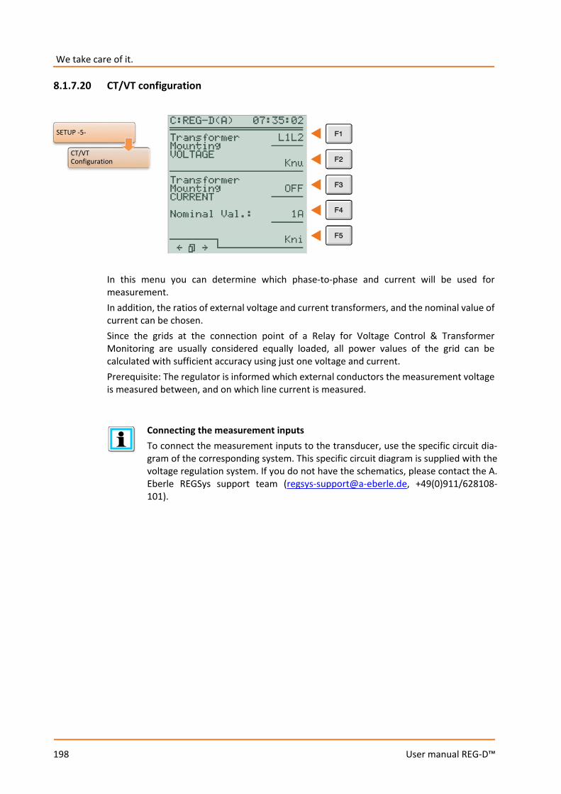
We take care of it.
198
User manual REG-D™
8.1.7.20 CT/VT configuration
In this menu you can determine which phase-to-phase and current will be used for measurement. In addition, the ratios of external voltage and current transformers, and the nominal value of current can be chosen. Since the grids at the connection point of a Relay for Voltage Control & Transformer Monitoring are usually considered equally loaded, all power values of the grid can be calculated with sufficient accuracy using just one voltage and current. Prerequisite: The regulator is informed which external conductors the measurement voltage is measured between, and on which line current is measured.
Connecting the measurement inputs To connect the measurement inputs to the transducer, use the specific circuit dia-gram of the corresponding system. This specific circuit diagram is supplied with the voltage regulation system. If you do not have the schematics, please contact the A. Eberle REGSys support team ([email protected], +49(0)911/628108-101).
SETUP -5-
CT/VT Configuration

199
User manual REG-D™
Transformer Mounting Voltage
To employ the Relay for Voltage Control & Transformer Monitoring REG-D™ in terms of hardware it is not necessary to assign voltage measurement connections to a particular position in the network (e.g. U12). Regardless of which external conductors the voltage is measured between, the regulator determines the correct angular relationship when the actual connection is set in the CT/VT Configuration menu. In case the regulator is connected to an asymmetrically loaded grid and correct measured values for active and reactive power is needed, the regulator can also be operated in an Aron measuring circuit (feature M2). For this purpose, the parameters "Transformer Mounting Voltage" and "Transformer Mounting Current" must each be set to ARON. The connection must be carried out in a correct manner. Please employ the following circuit diagram. With an Aron connection the following applies:
Used to regulate voltage in an Aron measurement Only one delta voltage (U12) is used for regulation even though the regulator measures with an Aron connection.
SETUP -5-
CT/VT Configuration
Transformer Mounting VOLTAGE

We take care of it.
200
User manual REG-D™
Factor of the voltage transformer (Knu) If the primary value of the voltage is to be displayed, the factor Knu for the voltage transformer must be entered. Example: 20 kV / 100 V → Knu = 200 Please note that the scale for the input of the transformer factor can be switched by pressing F3 and thus adapted to the requirements.
Transformer Mounting Current
To use the Relay for Voltage Control & Transformer Monitoring REG-D™, it is not necessary to assign the current measurement terminals a specific location in the grid in terms of hardware (e.g. I1). Regardless of which phase the current is measured in, the regulator determines the correct angular relationship when the actual connection is set in the CT/VT Configuration menu. In case the regulator is connected to an asymmetrically loaded grid and correct measured values for active and reactive power is needed, the regulator can also be operated in an Aron measuring circuit (feature M2). For this purpose, the parameters "Transformer Mounting voltage" and "Transformer Mounting current" must each be set to ARON. The connection must be carried out in a correct manner (see previous point "Transformer Mounting Voltage"). Factor of the current transformer (Kni) If the primary value of the current is to be displayed, the factor Kni for the current transformer must be entered. Example: 1000 A / 1 A → Kni = 1000 Please note that the scale for the input of the transformer factor can be switched by pressing F3 and thus adapted to the requirements.
SETUP -5-
CT/VT Configuration
Transformer Mounting CURRENT
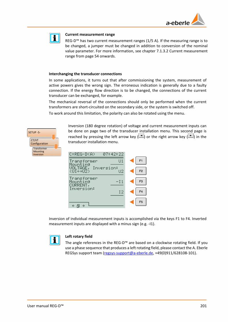
201
User manual REG-D™
Current measurement range REG-D™ has two current measurement ranges (1/5 A). If the measuring range is to be changed, a jumper must be changed in addition to conversion of the nominal value parameter. For more information, see chapter 7.1.3.2 Current measurement range from page 54 onwards.
Interchanging the transducer connections In some applications, it turns out that after commissioning the system, measurement of active powers gives the wrong sign. The erroneous indication is generally due to a faulty connection. If the energy flow direction is to be changed, the connections of the current transducer can be exchanged, for example. The mechanical reversal of the connections should only be performed when the current transformers are short-circuited on the secondary side, or the system is switched off. To work around this limitation, the polarity can also be rotated using the menu.
Inversion (180 degree rotation) of voltage and current measurement inputs can be done on page two of the transducer installation menu. This second page is reached by pressing the left arrow key ( ) or the right arrow key ( ) in the transducer installation menu.
Inversion of individual measurement inputs is accomplished via the keys F1 to F4. Inverted measurement inputs are displayed with a minus sign (e.g. -I1).
Left rotary field The angle references in the REG-D™ are based on a clockwise rotating field. If you use a phase sequence that produces a left rotating field, please contact the A. Eberle REGSys support team ([email protected], +49(0)911/628108-101).
SETUP -5-
CT/VT Configuration
Transformer Mounting Inversion
We take care of it.
202
User manual REG-D™
8.1.7.21 Actual value correction of measurement voltage UE
The actual value correction of voltage serves to compensate voltage drops on the line and for correcting transducer error between the voltage transformer and REG-D™.
8.1.7.22 Actual value correction of measurement current IE
The actual value correction of current is mainly used for correcting transducer error.
Actual value correction not via WinREG Correction values for voltage and current are not transmitted when a parameter file is read with WinREG. Reason: Correction values are only suitable for a very specific installation location and are presumably not transferable to other installation locations.
SETUP -6-
General 3
Actual Value Correction
SETUP -6-
General 3
Actual Value Correction
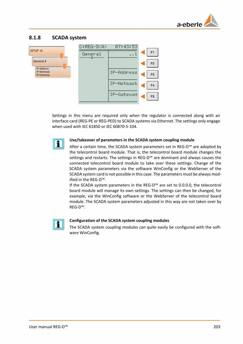
203
User manual REG-D™
8.1.8 SCADA system
Settings in this menu are required only when the regulator is connected along with an interface card (REG-PE or REG-PED) to SCADA systems via Ethernet. The settings only engage when used with IEC 61850 or IEC 60870-5-104.
Use/takeover of parameters in the SCADA system coupling module After a certain time, the SCADA system parameters set in REG-D™ are adopted by the telecontrol board module. That is, the telecontrol board module changes the settings and restarts. The settings in REG-D™ are dominant and always causes the connected telecontrol board module to take over these settings. Change of the SCADA system parameters via the software WinConfig or the WebServer of the SCADA system card is not possible in this case. The parameters must be always mod-ified in the REG-D™. If the SCADA system parameters in the REG-D™ are set to 0.0.0.0, the telecontrol board module will manage its own settings. The settings can then be changed, for example, via the WinConfig software or the WebServer of the telecontrol board module. The SCADA system parameters adjusted in this way are not taken over by REG-D™.
Configuration of the SCADA system coupling modules The SCADA system coupling modules can quite easily be configured with the soft-ware WinConfig.
SETUP -6-
General 4
IP-AddressIP-NetmaskIP-Gateway

We take care of it.
204
User manual REG-D™
IP address and IP subnet mask The IP address is the logical address of a device. It is 32 bits or four bytes long and is written separately for easier readability with dots between the four bytes. A subnet mask is always associated with an IP address, which together with the IP address is a unique identifier of a device within a network. The subnet mask separates physically connected networks into logical networks. Thus, the
subnet mask defines how many bytes or bits define the network part and how many belong to the host part. The larger the network part the smaller the available number of possible hosts/devices in the network. It is recommended to use a class C network with a private IP address (e.g. 192.168.xx), so that up to 254 devices in a network can be addressed (e.g. a transformer station). The associated subnet mask would be 255.255.255.0, so all hosts on the network should have the first three bytes identical (e.g. 192.168.1.) and differ in the last byte (e.g. values between .1 and .254). IP gateway
A gateway is the interface for communication with other networks, including the Internet (public IP address, as opposed to private IP addresses), to connect to the control room. Here, for example, the IP address of a router is given, which includes both the private network of the installation as well as the public network.
SETUP -6-
General 4
IP-Gateway
SETUP -6-
General 4
IP-AddressIP-Netmask

205
User manual REG-D™
8.1.9 Time setting
Time, date, time zone (offset from UTC time) and the rules for daylight saving time can be set in the time menu. Use the F1 and F2 keys to change the values. With the F3 and F4 keys you can switch between the individual values. The F5 key has different functions depending on the selected setting value. If seconds is selected to be set, the F5 key is used to zero the seconds. If a different setting is selected, the F5 key serves as access to the daylight saving time rules. Summer time (DaylightSavingTime): Daylight saving time is activated in the "Time Setting" menu via the DST parameter. If OFF is selected, there is no daylight saving time. The time for summer/winter time changeover can be defined in the menu for the daylight saving time rule definition. By default, the rules for Central Europe (DST from 02:00 the last Sunday in March to 03:00 the last Sunday in October) are set here. The changeover times (date and time) for the selected year are displayed in each case. Rules for daylight saving time change are already available for certain regions and countries. These can be selected using the wizard (F5 key). If the daylight saving time change is required at a time, which is not present in a predefined list, the rules can be freely configured. For this purpose, the keys F1 and F2 are used to modify the value and the F3 and F4 keys to select the value. The DST rules can be set separately for each year. While editing a rule, the individual constituents are generally represented as a number. The meaning of the selected editing number is displayed in plain text in square brackets below the heading "DST rule list". If an invalid rule is defined, the message "Error in Rule!" appears. The DST rule list can be exited with the ESC key.
Time
Date
Time zone
Changing daylight saving time (DST)
Daylight saving time
SETUP -6-
General 2
Time Setting
We take care of it.
206
User manual REG-D™
With the rule definitions the following value ranges for the individual parameters can be selected: Year: 1990 to 2078 Weekday: Monday … Sunday (from), exact date, Monday … Sunday before Day: Last weekday (0), 1. ... 5. weekday, 1 … 31 Month: January … December Hour: -3 days 23h, -2 days 0…23h, -1 day 0…23h, 0…23h, +1 day 0.23h, +2 days 0..2h Minutes: 0, 15, 30, 45 min Example: Daylight saving time begins next Friday after 1 April, at 02:00 and ends on Saturday before the last Sunday in October at 22:00. Start of DST: Friday (5), 1, April(4), 02h, 00min End of DST: Sunday(7), last (0), October(10), 22:00h-1day(98), 00min Once the rules are defined, they can be saved with the ENTER key. Then a menu appears where you can choose whether the rules defined apply only to the selected year, from the selected year to 2078, or for all years.
Simple installation via WinREG Rule setting can also be performed easily via the service program of WinREG (see chapter 9.7 Service, from page 305 onwards).
207
User manual REG-D™
8.2 Inputs and Outputs
8.2.1 General In its default configuration, the REG-D™ provides 16 binary inputs (14 freely configurable), 11 relays (9 freely programmable), 8 LEDs (7 freely programmable) and 3 analog module slots, each with a maximum of two analog channels. The freely configurable inputs and outputs can be explicitly switched off, made available to the background program or assigned a preconfigured function. Configuration of the freely configurable binary inputs, relays, LEDs and analog channels is described in chapter 7.2.2.6 Input/Output signals, from page 99 onwards. This chapter contains a detailed explanation of all available input and output functions, as well as input and output expansion options of the REG-D™ via COM3. In addition to a description of the function, the firmware version of REG-D™ after which the function is available is also given, as well as availability of functions depending on a software feature. For further information, reference is made at this point to chapter 8.3 Features (software) from page 230 onwards.
Status information and control of binary inputs and outputs via a SCADA system In general, the status (on or off) of a binary input or relay can be transferred inde-pendently of the assigned function via a SCADA system. In order to control a relay from a SCADA system, it must have the function 01:PROG.
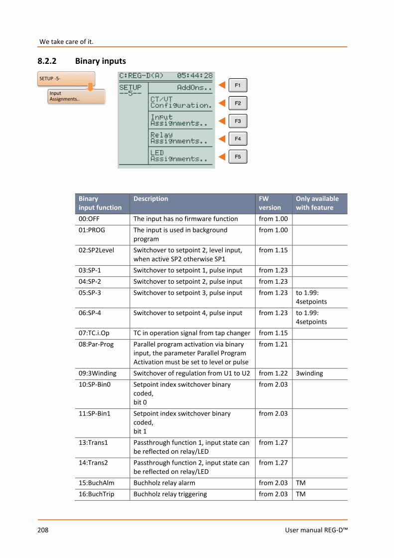
We take care of it.
208
User manual REG-D™
8.2.2 Binary inputs
Binary input function
Description FW version
Only available with feature
00:OFF The input has no firmware function from 1.00 01:PROG The input is used in background
program from 1.00
02:SP2Level Switchover to setpoint 2, level input, when active SP2 otherwise SP1
from 1.15
03:SP-1 Switchover to setpoint 1, pulse input from 1.23 04:SP-2 Switchover to setpoint 2, pulse input from 1.23 05:SP-3 Switchover to setpoint 3, pulse input from 1.23 to 1.99:
4setpoints 06:SP-4 Switchover to setpoint 4, pulse input from 1.23 to 1.99:
4setpoints 07:TC.i.Op TC in operation signal from tap changer from 1.15 08:Par-Prog Parallel program activation via binary
input, the parameter Parallel Program Activation must be set to level or pulse
from 1.21
09:3Winding Switchover of regulation from U1 to U2 from 1.22 3winding 10:SP-Bin0 Setpoint index switchover binary
coded, bit 0
from 2.03
11:SP-Bin1 Setpoint index switchover binary coded, bit 1
from 2.03
13:Trans1 Passthrough function 1, input state can be reflected on relay/LED
from 1.27
14:Trans2 Passthrough function 2, input state can be reflected on relay/LED
from 1.27
15:BuchAlm Buchholz relay alarm from 2.03 TM 16:BuchTrip Buchholz relay triggering from 2.03 TM
SETUP -5-
Input Assignments..
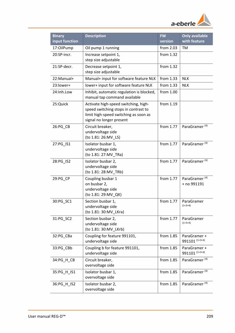
209
User manual REG-D™
Binary input function
Description FW version
Only available with feature
17:OilPump Oil pump 1 running from 2.03 TM 20:SP-incr. Increase setpoint 1,
step size adjustable from 1.32
21:SP-decr. Decrease setpoint 1, step size adjustable
from 1.32
22:Manual+ Manual+ input for software feature NLK from 1.33 NLK 23:lower+ lower+ input for software feature NLK from 1.33 NLK 24:Inh.Low Inhibit, automatic regulation is blocked,
manual tap command available from 1.00
25:Quick Activate high-speed switching, high-speed switching stops in contrast to limit high-speed switching as soon as signal no longer present
from 1.19
26:PG_CB Circuit breaker, undervoltage side (to 1.81: 26:MV_LS)
from 1.77 ParaGramer (4)
27:PG_IS1 Isolator busbar 1, undervoltage side (to 1.81: 27:MV_TRa)
from 1.77 ParaGramer (4)
28:PG_IS2 Isolator busbar 2, undervoltage side (to 1.81: 28:MV_TRb)
from 1.77 ParaGramer (4)
29:PG_CP Coupling busbar 1 on busbar 2, undervoltage side (to 1.81: 29:MV_QK)
from 1.77 ParaGramer (4) + no 991191
30:PG_SC1 Section busbar 1, undervoltage side (to 1.81: 30:MV_LKra)
from 1.77 ParaGramer (1+3+4)
31:PG_SC2 Section busbar 2, undervoltage side (to 1.81: 30:MV_LKrb)
from 1.77 ParaGramer (1+3+4)
32:PG_CBa Coupling for feature 991101, undervoltage side
from 1.85 ParaGramer + 991101 (1+3+4)
33:PG_CBb Coupling b for feature 991101, undervoltage side
from 1.85 ParaGramer + 991101 (1+3+4)
34:PG_H_CB Circuit breaker, overvoltage side
from 1.85 ParaGramer (4)
35:PG_H_IS1 Isolator busbar 1, overvoltage side
from 1.85 ParaGramer (4)
36:PG_H_IS2 Isolator busbar 2, overvoltage side
from 1.85 ParaGramer (4)

We take care of it.
210
User manual REG-D™
Binary input function
Description FW version
Only available with feature
37:PG_H_CP Coupling busbar 1 on busbar 2, overvoltage side
from 1.85 ParaGramer (4) + no 991191
38:PG_H_SC1 Section busbar 1, overvoltage side
from 1.85 ParaGramer (2+3+4)
39:PG_H_SC2 Section busbar 2, overvoltage side
from 1.85 ParaGramer (2+3+4)
40:PG_H_CBa Monitoring signal for feature 991101, overvoltage side
from 1.85 ParaGramer + 991101 (4)
41:PG_H_CBb Monitoring signal for feature 991101, overvoltage side
from 1.85 ParaGramer + 991101 (4)
42:up Issue of an up tap command, only in remote and manual mode
from 1.85
43:down Issue of a down tap command, only in remote and manual mode
from 1.85
44:BCD1 Tap position feedback BCD 1 from 1.85 45:BCD2 Tap position feedback BCD 2 from 1.85 46:BCD4 Tap position feedback BCD 4 from 1.85 47:BCD8 Tap position feedback BCD 8 from 1.85 48:BCD10 Tap position feedback BCD 10 from 1.85 49:BCD20 Tap position feedback BCD 20 from 1.85 50:BCDminus Tap position feedback sign from 1.85 51:BIN16 Binary coded tap position indication
value 16, value 1..8 are covered via the BCD input functions
from 1.85
52:BIN32 Binary coded tap position indication value 32, value 1..8 are covered via the BCD input functions
from 1.85
53:LR_AH Manual/automatic input of additional component REG-LR, 0:Manual 1:Auto
from 1.97
54:LR_STAT Input status of additional component REG-LR, 0:Fault 1:OK
from 1.97
55:PG_C1a Section busbar 1 left from the coupling, undervoltage side
from 1.91 ParaGramer + Crosslink=1/3 (4)
56:PG_C1b Section busbar 1 right from the coupling, undervoltage side
from 1.91 ParaGramer + Crosslink=1/3 (4)
57:PG_C2a Section busbar 2 left from the coupling, undervoltage side
from 1.91 ParaGramer + Crosslink=1/3 (4)
58:PG_C2b Section busbar 2 right from the coupling, undervoltage side
from 1.91 ParaGramer + Crosslink=1/3 (4)
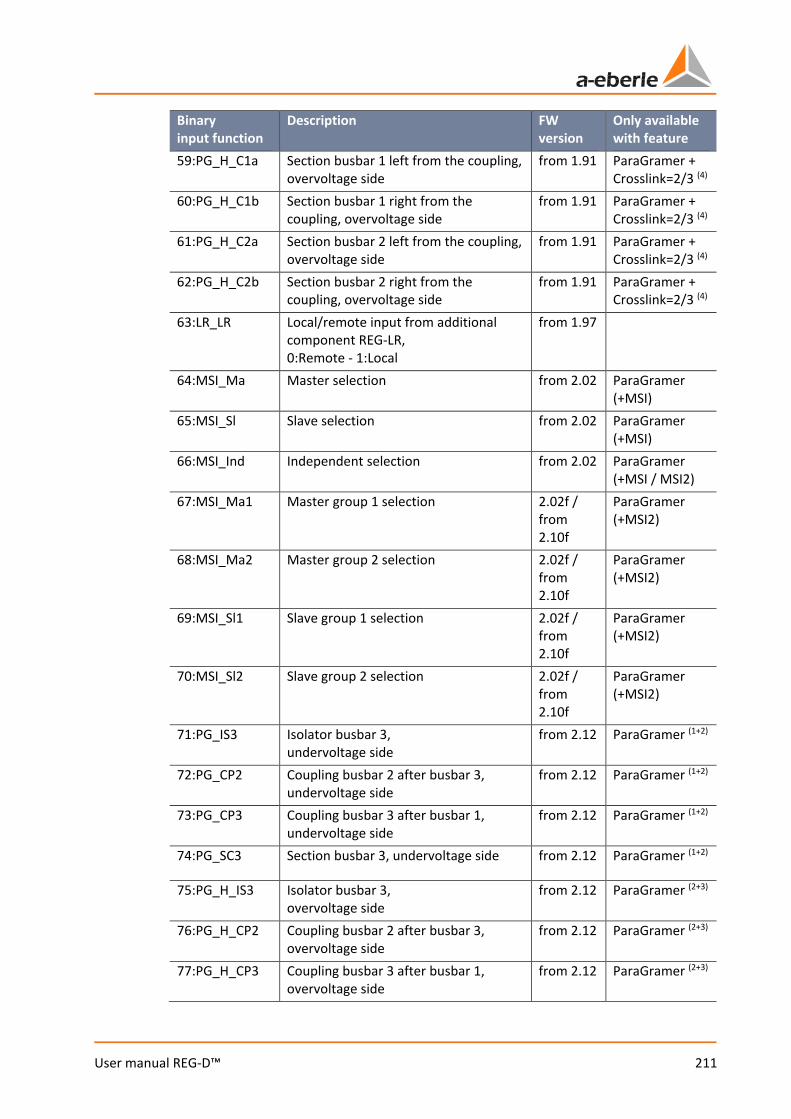
211
User manual REG-D™
Binary input function
Description FW version
Only available with feature
59:PG_H_C1a Section busbar 1 left from the coupling, overvoltage side
from 1.91 ParaGramer + Crosslink=2/3 (4)
60:PG_H_C1b Section busbar 1 right from the coupling, overvoltage side
from 1.91 ParaGramer + Crosslink=2/3 (4)
61:PG_H_C2a Section busbar 2 left from the coupling, overvoltage side
from 1.91 ParaGramer + Crosslink=2/3 (4)
62:PG_H_C2b Section busbar 2 right from the coupling, overvoltage side
from 1.91 ParaGramer + Crosslink=2/3 (4)
63:LR_LR Local/remote input from additional component REG-LR, 0:Remote - 1:Local
from 1.97
64:MSI_Ma Master selection from 2.02 ParaGramer (+MSI)
65:MSI_Sl Slave selection from 2.02 ParaGramer (+MSI)
66:MSI_Ind Independent selection from 2.02 ParaGramer (+MSI / MSI2)
67:MSI_Ma1 Master group 1 selection 2.02f / from 2.10f
ParaGramer (+MSI2)
68:MSI_Ma2 Master group 2 selection 2.02f / from 2.10f
ParaGramer (+MSI2)
69:MSI_Sl1 Slave group 1 selection 2.02f / from 2.10f
ParaGramer (+MSI2)
70:MSI_Sl2 Slave group 2 selection 2.02f / from 2.10f
ParaGramer (+MSI2)
71:PG_IS3 Isolator busbar 3, undervoltage side
from 2.12 ParaGramer (1+2)
72:PG_CP2 Coupling busbar 2 after busbar 3, undervoltage side
from 2.12 ParaGramer (1+2)
73:PG_CP3 Coupling busbar 3 after busbar 1, undervoltage side
from 2.12 ParaGramer (1+2)
74:PG_SC3 Section busbar 3, undervoltage side from 2.12 ParaGramer (1+2)
75:PG_H_IS3 Isolator busbar 3, overvoltage side
from 2.12 ParaGramer (2+3)
76:PG_H_CP2 Coupling busbar 2 after busbar 3, overvoltage side
from 2.12 ParaGramer (2+3)
77:PG_H_CP3 Coupling busbar 3 after busbar 1, overvoltage side
from 2.12 ParaGramer (2+3)
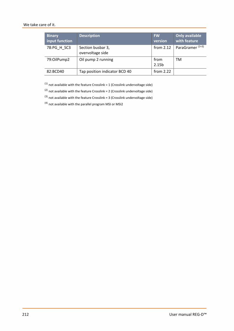
We take care of it.
212
User manual REG-D™
Binary input function
Description FW version
Only available with feature
78:PG_H_SC3 Section busbar 3, overvoltage side
from 2.12 ParaGramer (2+3)
79:OilPump2 Oil pump 2 running from 2.15b
TM
82:BCD40 Tap position indicator BCD 40 from 2.22 (1) not available with the feature Crosslink = 1 (Crosslink undervoltage side) (2) not available with the feature Crosslink = 2 (Crosslink undervoltage side) (3) not available with the feature Crosslink = 3 (Crosslink undervoltage side) (4) not available with the parallel program MSI or MSI2
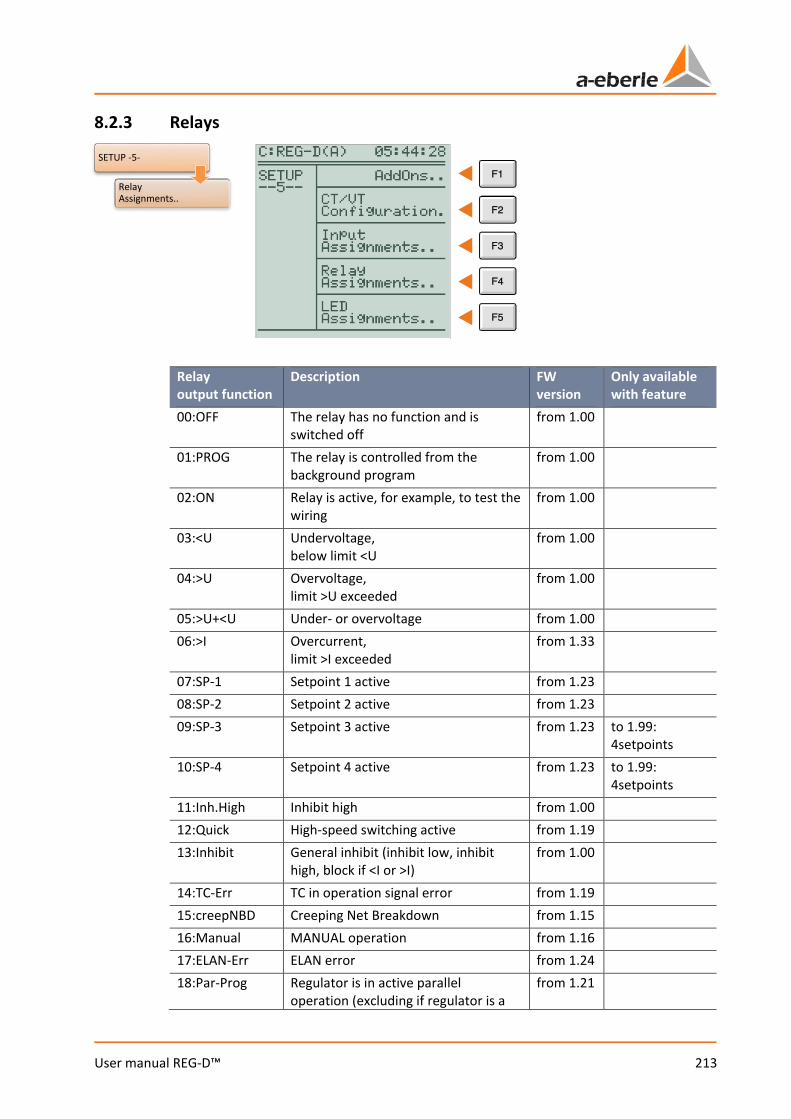
213
User manual REG-D™
8.2.3 Relays
Relay output function
Description FW version
Only available with feature
00:OFF The relay has no function and is switched off
from 1.00
01:PROG The relay is controlled from the background program
from 1.00
02:ON Relay is active, for example, to test the wiring
from 1.00
03:<U Undervoltage, below limit <U
from 1.00
04:>U Overvoltage, limit >U exceeded
from 1.00
05:>U+<U Under- or overvoltage from 1.00 06:>I Overcurrent,
limit >I exceeded from 1.33
07:SP-1 Setpoint 1 active from 1.23 08:SP-2 Setpoint 2 active from 1.23 09:SP-3 Setpoint 3 active from 1.23 to 1.99:
4setpoints 10:SP-4 Setpoint 4 active from 1.23 to 1.99:
4setpoints 11:Inh.High Inhibit high from 1.00 12:Quick High-speed switching active from 1.19 13:Inhibit General inhibit (inhibit low, inhibit
high, block if <I or >I) from 1.00
14:TC-Err TC in operation signal error from 1.19 15:creepNBD Creeping Net Breakdown from 1.15 16:Manual MANUAL operation from 1.16 17:ELAN-Err ELAN error from 1.24 18:Par-Prog Regulator is in active parallel
operation (excluding if regulator is a from 1.21
SETUP -5-
Relay Assignments..
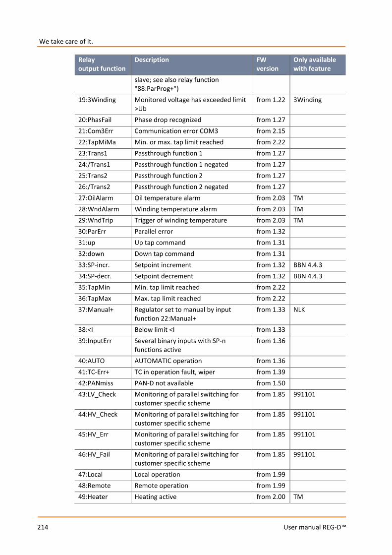
We take care of it.
214
User manual REG-D™
Relay output function
Description FW version
Only available with feature
slave; see also relay function "88:ParProg+")
19:3Winding Monitored voltage has exceeded limit >Ub
from 1.22 3Winding
20:PhasFail Phase drop recognized from 1.27 21:Com3Err Communication error COM3 from 2.15 22:TapMiMa Min. or max. tap limit reached from 2.22 23:Trans1 Passthrough function 1 from 1.27 24:/Trans1 Passthrough function 1 negated from 1.27 25:Trans2 Passthrough function 2 from 1.27 26:/Trans2 Passthrough function 2 negated from 1.27 27:OilAlarm Oil temperature alarm from 2.03 TM 28:WndAlarm Winding temperature alarm from 2.03 TM 29:WndTrip Trigger of winding temperature from 2.03 TM 30:ParErr Parallel error from 1.32 31:up Up tap command from 1.31 32:down Down tap command from 1.31 33:SP-incr. Setpoint increment from 1.32 BBN 4.4.3 34:SP-decr. Setpoint decrement from 1.32 BBN 4.4.3 35:TapMin Min. tap limit reached from 2.22 36:TapMax Max. tap limit reached from 2.22 37:Manual+ Regulator set to manual by input
function 22:Manual+ from 1.33 NLK
38:<I Below limit <I from 1.33 39:InputErr Several binary inputs with SP-n
functions active from 1.36
40:AUTO AUTOMATIC operation from 1.36 41:TC-Err+ TC in operation fault, wiper from 1.39 42:PANmiss PAN-D not available from 1.50 43:LV_Check Monitoring of parallel switching for
customer specific scheme from 1.85 991101
44:HV_Check Monitoring of parallel switching for customer specific scheme
from 1.85 991101
45:HV_Err Monitoring of parallel switching for customer specific scheme
from 1.85 991101
46:HV_Fail Monitoring of parallel switching for customer specific scheme
from 1.85 991101
47:Local Local operation from 1.99 48:Remote Remote operation from 1.99 49:Heater Heating active from 2.00 TM

215
User manual REG-D™
Relay output function
Description FW version
Only available with feature
50:Cooler1 Cooler 1 on from 2.00 TM 51:Cooler2 Cooler 2 on from 2.00 TM 52:Cooler3 Cooler 3 on from 2.00 TM 53:Cooler4 Cooler 4 on from 2.00 TM 54:Cooler5 Cooler 5 on from 2.00 TM 55:Cooler6 Cooler 6 on from 2.00 TM 56:TempTC Overtemperature tap changer from 2.00 TM 57:OillvTC- Tap changer oil level too low from 2.00 TM 58:OillvTC+ Tap changer oil level too high from 2.00 TM 59:OillvTr- Transformer oil level too low from 2.00 TM 60:OillvTr+ Transformer oil level too high from 2.00 TM 61:Water Water limit exceeded from 2.00 TM 62:Gas Gas limit exceeded from 2.00 TM 63:BuchAlm Buchholz alarm from 2.00 TM 64:BuchTrip Buchholz triggering from 2.00 TM 65:COM2Act Communication on COM2 active from 2.00 66:MSI_Ma MSI: Master selected from 2.00 ParaGramer
(+MSI) 67:MSI_Sl MSI: Slave selected from 2.00 ParaGramer
(+MSI) 68:MSI_Ind MSI: Independent selected from 2.00 ParaGramer
(+MSI / MSI2) 69:TAPERR Tap change error from 2.00 70:HvLvDiff Different parallel states between over-
and undervoltage sides from 2.00 HVLVCONTROL
71:T60s/1s Every 60 sec for 1 sec on (second pulse)
from 2.00
72:Inh.Low Inhibit low from 2.00 73:HUNTING Hunting detected (hunting function
can only be configured via REG-L) from 2.00
74:OilPump Actuation of oil pump from 2.00 TM 75:MSI_Ma1 MSI2: Master 1 selected 2.02f /
from 2.10f
ParaGramer (+MSI2)
76:MSI_Ma2 MSI2: Master 2 selected 2.02f / from 2.10f
ParaGramer (+MSI2)
77:MSI_Sl1 MSI2: Slave 1 selected 2.02f / from 2.10f
ParaGramer (+MSI2)
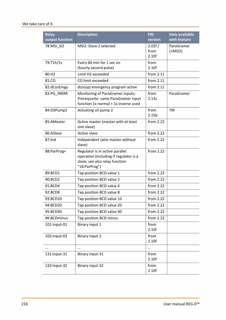
We take care of it.
216
User manual REG-D™
Relay output function
Description FW version
Only available with feature
78:MSI_Sl2 MSI2: Slave 2 selected 2.02f / from 2.10f
ParaGramer (+MSI2)
79:T1h/1s Every 60 min for 1 sec on (hourly second pulse)
from 2.10f
80:H2 Limit H2 exceeded from 2.11 81:CO CO limit exceeded from 2.11 82:dCosEmgy dcos(ϕ) emergency program active from 2.11 83:PG_INERR Monitoring of ParaGramer inputs;
Prerequisite: same ParaGramer input function 1x normal + 1x inverse used
from 2.13c
ParaGramer
84:OilPump2 Actuating oil pump 2 from 2.15b
TM
85:AMaster Active master (master with at least one slave)
from 2.22
86:ASlave Active slave from 2.22 87:Ind Independent (also master without
slave) from 2.22
88:ParProg+ Regulator is in active parallel operation (including if regulator is a slave; see also relay function "18:ParProg")
from 2.22
89:BCD1 Tap position BCD value 1 from 2.22 90:BCD2 Tap position BCD value 2 from 2.22 91:BCD4 Tap position BCD value 4 from 2.22 92:BCD8 Tap position BCD value 8 from 2.22 93:BCD10 Tap position BCD value 10 from 2.22 94:BCD20 Tap position BCD value 20 from 2.22 95:BCD40 Tap position BCD value 40 from 2.22 96:BCDminus Tap position BCD minus from 2.22 101:Input-01 Binary input 1 from
2.10f
102:Input-02 Binary input 2 from 2.10f
... … … 131:Input-31 Binary input 31 from
2.10f
132:Input-32 Binary input 32 from 2.10f
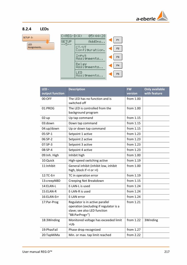
217
User manual REG-D™
8.2.4 LEDs
LED - output function
Description FW version
Only available with feature
00:OFF The LED has no function and is switched off
from 1.00
01:PROG The LED is controlled from the background program
from 1.00
02:up Up tap command from 1.15 03:down Down tap command from 1.15 04:up/down Up or down tap command from 1.15 05:SP-1 Setpoint 1 active from 1.23 06:SP-2 Setpoint 2 active from 1.23 07:SP-3 Setpoint 3 active from 1.23 08:SP-4 Setpoint 4 active from 1.23 09:Inh. High Inhibit high from 1.00 10:Quick High-speed switching active from 1.19 11:Inhibit General inhibit (inhibit low, inhibit
high, block if <I or >I) from 1.00
12:TC-Err TC in operation error from 1.19 13:creepNBD Creeping Net Breakdown from 1.15 14:ELAN-L E-LAN-L is used from 1.24 15:ELAN-R E-LAN-R is used from 1.24 16:ELAN-Err E-LAN error from 1.24 17:Par-Prog Regulator is in active parallel
operation (excluding if regulator is a slave; see also LED function "88:ParProg+")
from 1.21
18:3Winding Monitored voltage has exceeded limit >Ub
from 1.22 3Winding
19:PhasFail Phase drop recognized from 1.27 20:TapMiMa Min. or max. tap limit reached from 2.22
SETUP -5-
LED Assignments..
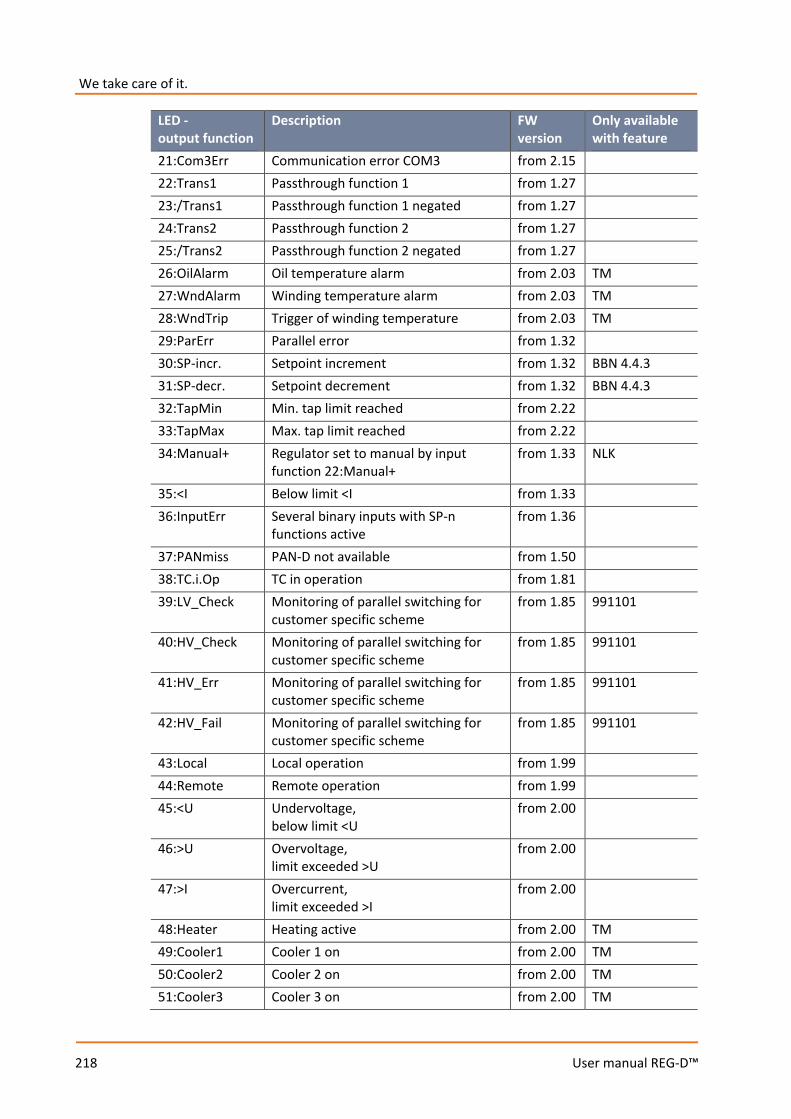
We take care of it.
218
User manual REG-D™
LED - output function
Description FW version
Only available with feature
21:Com3Err Communication error COM3 from 2.15 22:Trans1 Passthrough function 1 from 1.27 23:/Trans1 Passthrough function 1 negated from 1.27 24:Trans2 Passthrough function 2 from 1.27 25:/Trans2 Passthrough function 2 negated from 1.27 26:OilAlarm Oil temperature alarm from 2.03 TM 27:WndAlarm Winding temperature alarm from 2.03 TM 28:WndTrip Trigger of winding temperature from 2.03 TM 29:ParErr Parallel error from 1.32 30:SP-incr. Setpoint increment from 1.32 BBN 4.4.3 31:SP-decr. Setpoint decrement from 1.32 BBN 4.4.3 32:TapMin Min. tap limit reached from 2.22 33:TapMax Max. tap limit reached from 2.22 34:Manual+ Regulator set to manual by input
function 22:Manual+ from 1.33 NLK
35:<I Below limit <I from 1.33 36:InputErr Several binary inputs with SP-n
functions active from 1.36
37:PANmiss PAN-D not available from 1.50 38:TC.i.Op TC in operation from 1.81 39:LV_Check Monitoring of parallel switching for
customer specific scheme from 1.85 991101
40:HV_Check Monitoring of parallel switching for customer specific scheme
from 1.85 991101
41:HV_Err Monitoring of parallel switching for customer specific scheme
from 1.85 991101
42:HV_Fail Monitoring of parallel switching for customer specific scheme
from 1.85 991101
43:Local Local operation from 1.99 44:Remote Remote operation from 1.99 45:<U Undervoltage,
below limit <U from 2.00
46:>U Overvoltage, limit exceeded >U
from 2.00
47:>I Overcurrent, limit exceeded >I
from 2.00
48:Heater Heating active from 2.00 TM 49:Cooler1 Cooler 1 on from 2.00 TM 50:Cooler2 Cooler 2 on from 2.00 TM 51:Cooler3 Cooler 3 on from 2.00 TM
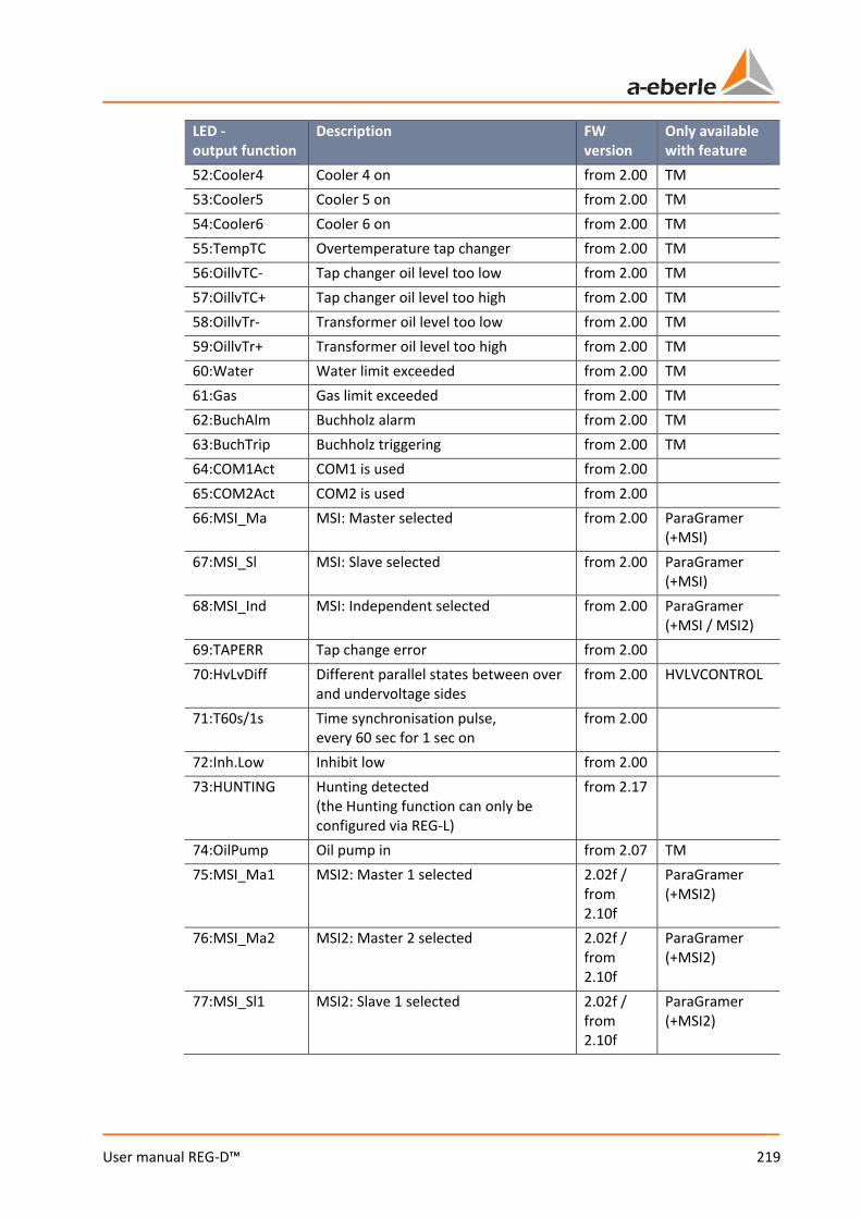
219
User manual REG-D™
LED - output function
Description FW version
Only available with feature
52:Cooler4 Cooler 4 on from 2.00 TM 53:Cooler5 Cooler 5 on from 2.00 TM 54:Cooler6 Cooler 6 on from 2.00 TM 55:TempTC Overtemperature tap changer from 2.00 TM 56:OillvTC- Tap changer oil level too low from 2.00 TM 57:OillvTC+ Tap changer oil level too high from 2.00 TM 58:OillvTr- Transformer oil level too low from 2.00 TM 59:OillvTr+ Transformer oil level too high from 2.00 TM 60:Water Water limit exceeded from 2.00 TM 61:Gas Gas limit exceeded from 2.00 TM 62:BuchAlm Buchholz alarm from 2.00 TM 63:BuchTrip Buchholz triggering from 2.00 TM 64:COM1Act COM1 is used from 2.00 65:COM2Act COM2 is used from 2.00 66:MSI_Ma MSI: Master selected from 2.00 ParaGramer
(+MSI) 67:MSI_Sl MSI: Slave selected from 2.00 ParaGramer
(+MSI) 68:MSI_Ind MSI: Independent selected from 2.00 ParaGramer
(+MSI / MSI2) 69:TAPERR Tap change error from 2.00 70:HvLvDiff Different parallel states between over
and undervoltage sides from 2.00 HVLVCONTROL
71:T60s/1s Time synchronisation pulse, every 60 sec for 1 sec on
from 2.00
72:Inh.Low Inhibit low from 2.00 73:HUNTING Hunting detected
(the Hunting function can only be configured via REG-L)
from 2.17
74:OilPump Oil pump in from 2.07 TM 75:MSI_Ma1 MSI2: Master 1 selected 2.02f /
from 2.10f
ParaGramer (+MSI2)
76:MSI_Ma2 MSI2: Master 2 selected 2.02f / from 2.10f
ParaGramer (+MSI2)
77:MSI_Sl1 MSI2: Slave 1 selected 2.02f / from 2.10f
ParaGramer (+MSI2)

We take care of it.
220
User manual REG-D™
LED - output function
Description FW version
Only available with feature
78:MSI_Sl2 MSI2: Slave 2 selected 2.02f / from 2.10f
ParaGramer (+MSI2)
79:T1h/1s Time synchronisation pulse, every 60 min for 1 sec on
from 2.10f
80:H2 H2 limit exceeded from 2.11 TM 81:CO CO limit exceeded from 2.11 TM 82:dCosEmgy dcos(ϕ) emergency program active from 2.11 83:PG_INERR Monitoring of ParaGramer inputs;
Prerequisite: same ParaGramer input function 1x normal + 1x inverse used
from 2.13c
ParaGramer
84:OilPump2 Oil pump actuated or running from 2.15b
TM
85:AMaster Active master (master with at least one slave)
from 2.22
86:ASlave Active slave from 2.22 87:Ind Independent (also master without
slave) from 2.22
88:ParProg+ Regulator is in active parallel operation (including if regulator is a slave; see also the LED function "17:ParProg")
from 2.22
89:BCD1 Tap position BCD value 1 from 2.22 90:BCD2 Tap position BCD value 2 from 2.22 91:BCD4 Tap position BCD value 4 from 2.22 92:BCD8 Tap position BCD value 8 from 2.22 93:BCD10 Tap position BCD value 10 from 2.22 94:BCD20 Tap position BCD value 20 from 2.22 95:BCD40 Tap position BCD value 40 from 2.22 96:BCDminus Tap position BCD minus from 2.22 101:Input-01 Binary input 1 from
2.10f
102:Input-02 Binary input 2 from 2.10f
... … … 131:Input-31 Binary input 31 from
2.10f
132:Input-32 Binary input 32 from 2.10f
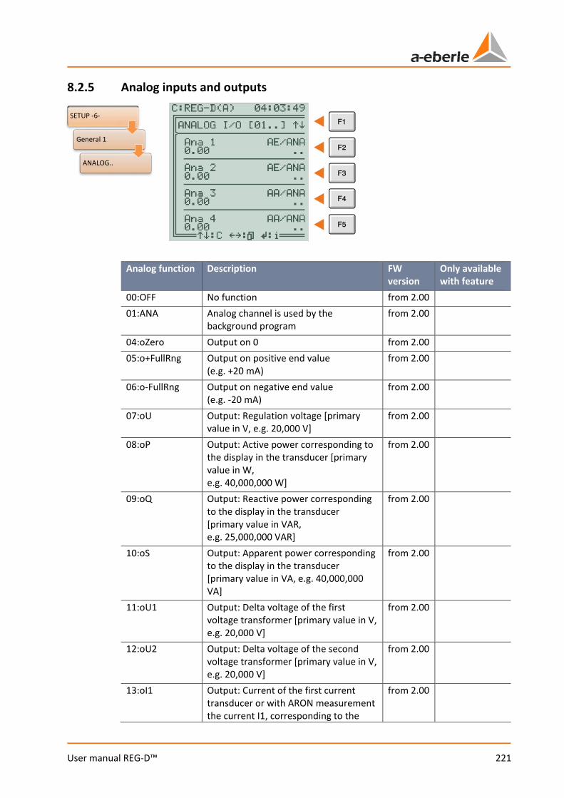
221
User manual REG-D™
8.2.5 Analog inputs and outputs
Analog function Description FW version
Only available with feature
00:OFF No function from 2.00 01:ANA Analog channel is used by the
background program from 2.00
04:oZero Output on 0 from 2.00 05:o+FullRng Output on positive end value
(e.g. +20 mA) from 2.00
06:o-FullRng Output on negative end value (e.g. -20 mA)
from 2.00
07:oU Output: Regulation voltage [primary value in V, e.g. 20,000 V]
from 2.00
08:oP Output: Active power corresponding to the display in the transducer [primary value in W, e.g. 40,000,000 W]
from 2.00
09:oQ Output: Reactive power corresponding to the display in the transducer [primary value in VAR, e.g. 25,000,000 VAR]
from 2.00
10:oS Output: Apparent power corresponding to the display in the transducer [primary value in VA, e.g. 40,000,000 VA]
from 2.00
11:oU1 Output: Delta voltage of the first voltage transformer [primary value in V, e.g. 20,000 V]
from 2.00
12:oU2 Output: Delta voltage of the second voltage transformer [primary value in V, e.g. 20,000 V]
from 2.00
13:oI1 Output: Current of the first current transducer or with ARON measurement the current I1, corresponding to the
from 2.00
SETUP -6-
General 1
ANALOG..
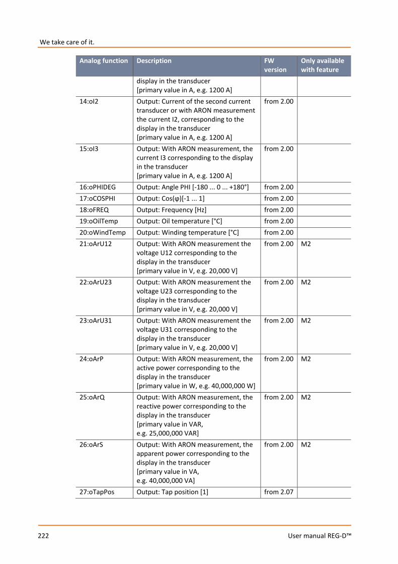
We take care of it.
222
User manual REG-D™
Analog function Description FW version
Only available with feature
display in the transducer [primary value in A, e.g. 1200 A]
14:oI2 Output: Current of the second current transducer or with ARON measurement the current I2, corresponding to the display in the transducer [primary value in A, e.g. 1200 A]
from 2.00
15:oI3 Output: With ARON measurement, the current I3 corresponding to the display in the transducer [primary value in A, e.g. 1200 A]
from 2.00
16:oPHIDEG Output: Angle PHI [-180 ... 0 ... +180°] from 2.00 17:oCOSPHI Output: Cos(ϕ)[-1 ... 1] from 2.00 18:oFREQ Output: Frequency [Hz] from 2.00 19:oOilTemp Output: Oil temperature [°C] from 2.00 20:oWindTemp Output: Winding temperature [°C] from 2.00 21:oArU12 Output: With ARON measurement the
voltage U12 corresponding to the display in the transducer [primary value in V, e.g. 20,000 V]
from 2.00 M2
22:oArU23 Output: With ARON measurement the voltage U23 corresponding to the display in the transducer [primary value in V, e.g. 20,000 V]
from 2.00 M2
23:oArU31 Output: With ARON measurement the voltage U31 corresponding to the display in the transducer [primary value in V, e.g. 20,000 V]
from 2.00 M2
24:oArP Output: With ARON measurement, the active power corresponding to the display in the transducer [primary value in W, e.g. 40,000,000 W]
from 2.00 M2
25:oArQ Output: With ARON measurement, the reactive power corresponding to the display in the transducer [primary value in VAR, e.g. 25,000,000 VAR]
from 2.00 M2
26:oArS Output: With ARON measurement, the apparent power corresponding to the display in the transducer [primary value in VA, e.g. 40,000,000 VA]
from 2.00 M2
27:oTapPos Output: Tap position [1] from 2.07
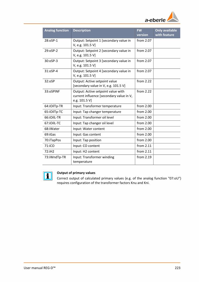
223
User manual REG-D™
Analog function Description FW version
Only available with feature
28:oSP-1 Output: Setpoint 1 [secondary value in V, e.g. 101.5 V]
from 2.07
29:oSP-2 Output: Setpoint 2 [secondary value in V, e.g. 101.5 V]
from 2.07
30:oSP-3 Output: Setpoint 3 [secondary value in V, e.g. 101.5 V]
from 2.07
31:oSP-4 Output: Setpoint 4 [secondary value in V, e.g. 101.5 V]
from 2.07
32:oSP Output: Active setpoint value [secondary value in V, e.g. 101.5 V]
from 2.22
33:oSPINF Output: Active setpoint value with current influence [secondary value in V, e.g. 101.5 V]
from 2.22
64:iOilTp-TR Input: Transformer temperature from 2.00 65:iOilTp-TC Input: Tap changer temperature from 2.00 66:iOilL-TR Input: Transformer oil level from 2.00 67:iOilL-TC Input: Tap changer oil level from 2.00 68:iWater Input: Water content from 2.00 69:iGas Input: Gas content from 2.00 70:iTapPos Input: Tap position from 2.00 71:iCO Input: CO content from 2.11 72:iH2 Input: H2 content from 2.11 73:iWndTp-TR Input: Transformer winding
temperature from 2.19
Output of primary values Correct output of calculated primary values (e.g. of the analog function "07:oU") requires configuration of the transformer factors Knu and Kni.

We take care of it.
224
User manual REG-D™
8.2.6 I/O extensions (COM3) In addition to the standard inputs and outputs of the REG-D™, additional modules (BIN-Ds or ANA-Ds) can be connected to the REG-D™ via the COM3 communication interface to expand the binary and analog inputs and outputs. BIN-Ds make additional binary signals available (binary inputs, relays, LEDs), ANA-Ds provide additional analog signals (milliamp inputs or outputs). For a detailed description of the hardware side, see chapter 7.1.4.7 COM3 interface from page 72 onwards.
Successful detection of connected COM3 modules can be carried out via the REG-D™ status menu. For this, each module must have a unique address. By way of example in the figure above are shown two BIN-Ds with the address 0 (16 binary inputs [BI16]), and the address 1 (8 relays [REL8]), as well as an ANA-D with address 2 (8 analog inputs [AI8]). These input/output expansion modules are respectively shown in the COM3
status of REG-D™.
SETUP -6-
Status
COM-3 STATUS
Adress 0 Adress 1 Adress 2
Option: fibre optic module

225
User manual REG-D™
The COM3 interface has a mechanism for error monitoring. Activation and adjustment can be made in the menu "COM-3 Error Check", which can be reached by pressing the F4 key in the menu "COM3 status".
The following settings are available:
Setting Description OFF
Disable monitoring of the COM3 interface.
ON
Enable monitoring of the COM3 interface.
SET!
The current configuration of COM3 (number, address and type of connected device) are stored as a target state and COM3 monitoring is activated.
Monitoring of the COM3 interface is based on the number, the address and the type of devices connected. If at least one of the three above-mentioned properties of the current COM3 configuration does not match the stored COM3 configuration for monitoring, a COM3-Err is triggered. This means that if, for example, at the time of setting COM3 monitoring, two BIN-Ds (16 binary inputs, address 0, and 8 relays, address 1) and one ANA-D (AI8, address 2) are connected to COM3, COM3-Err is triggered when, for example, only two devices can be reached.
Changes to the COM3 configuration Any change in the number, address or type of devices connected to COM3 triggers an error when COM3 monitoring is enabled. Therefore, after each change of the configuration of COM3, the target state for monitoring must be reset (SET! in the COM-3 Error Check).
We take care of it.
226
User manual REG-D™
COM3 mapping (assignment of the COM3 resources) Apart from the basic detection of BIN-Ds and ANA-Ds, mapping is crucial for asuccessful use. Any physical input or output must be assigned to a logical (software) input or output. That is, the inputs and outputs connected via COM3 are managed and displayed as internal resources by REG-D™. It is specified, for example, that relay 1 of BIN-D with address 0 is associated with relay 11 of the REG-D™. This software-based mapping between I/O expansion cards and the Relay for Voltage Control & Transformer Monitoring REG-D™ can be read out using the configuration software WinREG (subprogram REGPara), or even changed, if required (via the subprogram Service). For more information, see chapter 9.8 REGPara, from page 314 onwards, or chapter 9.7 Service, from page 305 onwards.
General use of COM3 resources Use of devices connected to COM3 resources can generally be done in two ways. If the additional inputs and outputs are connected via COM3 mapping with logical (software) inputs and outputs of the firmware, they can be used or set with prede-fined functions in the menu or via WinREG in the normal way as internal inputs and outputs of REG-D™, or used in the background program. In addition, direct access to the resources of COM3 devices is possible via the back-ground program without COM3 mapping. This type of access is mainly used with older firmware versions (≤ 2.15), which do not support COM3 mapping. If both types of access are mixed, it may cause a malfunction.
Assignment of the 16 binary inputs of a BIN-D to binary inputs 17 to 32 of the REG-D™ using DIL switches Use of a BIN-D with 16 binary inputs, which are to be mapped to the binary inputs 17... 32 of the REG-D™, constitutes an exception to the normal flow. This function can be selected with DIL switch 7 of the BIN-D. The following applies: DIP switch 7 = ON -> no assignment to E17 ... 32 DIP switch 7 = OFF -> assignment to E17 ... 32 A COM3 mapping or a background program is not necessary for this purpose. Com-bination with the normal COM3 mapping is not possible. That is, if more than one BIN-D is to be assigned, total allocation must be carried out via the COM3 mapping mechanism. The DIL switch cannot be used then.
227
User manual REG-D™
8.2.7 Operating states and error messages
8.2.7.1 General
The REG-D™ comes standard with some functions which serve to monitor the communication of the tap-changer drive and the parallel operation. The respective status and fault messages can be reported by relay, LED and the SCADA system. If additional monitoring functions or status messages are necessary, this can be effected via a background program.
Generation of collective messages A collective message of the following signals as well as other standard or customer- and application-specific reports can be generated via the background program. For this purpose, please contact the A. Eberle REGSys support team ([email protected], +49(0)911/628108-101).
8.2.7.2 E-LAN error (ELANErr)
The E-LAN error indicates a communication interruption on the E-LAN interfaces. The E-LAN error applies only if there is active parallel operation between the regulators, or if the ParaGramer is used. The display of the E-LAN error is delayed about 30 seconds by default. The delay time is adjustable. To do so, please contact the A. Eberle REGSys support team ([email protected], +49(0)911/628108-101).
Termination of unused E-LAN interfaces Unused E-LAN interfaces that are configured for double-wire operation must be ter-minated. If that is not the case, false E-LAN errors can be triggered.
8.2.7.3 COM3 error (COM3Err)
The COM3 error indicates a communication interruption to a device (ANA-D, BIN-D) connected to COM3. In order that communication failure of one of the COM3 devices can be recognized, COM3 monitoring must be activated (see chapter 8.2.6 I/O extensions (COM3), from page 224 onwards). The COM3 error is also indicated by blinking of the REG-D™ status LED. As soon as the current configuration of COM3 devices again corresponds to the stored situation, the COM3 error is automatically reset.

We take care of it.
228
User manual REG-D™
8.2.7.4 TC in operation signal error (TCErr)
The TC in operation error is triggered when the TC in operation time detected via the TC in operation signal of the motor drive exceeds the configured maximum TC in operation time. This function is used to monitor the run time of the motor drive and can be used as overrun protection. The output function TC-Err is used to permanently display TC in operation error. The signal is confirmed as soon as the regulator is switched from manual to automatic, one more error-free tap change is performed, or the F5 key is pressed in regulator or transducer mode. If the error cause is not remedied after confirmation (TC in operation signal is still on), the TC in operation error is activated again after the maximum TC in operation time has elapsed. In order to trigger the motor circuit breaker, the wiping relay output function "41:TC-Err+" can also be used.
8.2.7.5 Tap change error (TapErr)
The tap-change error is used to monitor tap feedback after issue of a tap command. The following tap-change errors are monitored: 0 Tap change in the wrong direction (the tap position did not change in the expected
direction after a tap-change command ) 0 Change of tap position by more than one tap, or no change (the tap position did not
change to the previously calculated tap after a tap-change command) The signal is confirmed as soon as the regulator is switched from manual to automatic, or the F5 key is pressed in regulator or transducer mode.
8.2.7.6 Tap position indication error
An error in tap position detection is indicated by the tap position 99. Possible causes for this error are: 0 Invalid BCD code, for example, the binary inputs for eight and four are active
simultaneously. 0 The mA signal for the tap position message lies outside the configured limits (e.g. smaller
than four mA). 0 Too large total resistance or line discontinuity on detecting tap position via resistance
measurement. Once a correct tap feedback is detected, it will be displayed again instead of the 99. Con-firmation is unnecessary. The fault indicator (tap position 99) in most SCADA system connections is displayed at tap zero.
229
User manual REG-D™
8.2.7.7 Parallel operation error (ParErr)
The following situations lead to triggering of a parallel operation error: 0 The occurrence of a tap difference, which cannot be compensated by the follower
(Master-Follower procedure). To reach the tap of the master regulator, the follower regulator has a time window available that is 2.5 times the maximum TC in operation time. Immediately after activation of parallel operation, the time defined by the parameter "1 ParErr after n * TC in operation time“ is available.
0 Exceeding the circulating reactive current limit (Icirc supervision) in Master-Follower parallel operation.
0 Exceeding the set maximum allowable tap difference in the circulating reactive current minimization procedured (dIsin(ϕ) and dIsin(ϕ)[S]).
The parallel operation error is acknowledged as soon as the regulator is switched from manual to automatic, or parallel operation is disabled. By default, appearance of the parallel operation error leads to switching the regulators involved to MANUAL mode.
8.2.7.8 ParaGramer input error (PG_INERR)
The ParaGramer input error is used to monitor switch feedback for the ParaGramer function. It is only applicable if detection of the switch position is double pole. That is, for each switch position, a respective binary signal for "Switch open" and "Switch closed" is being used. The ParaGramer input error becomes active if both binary signals are on or off, i.e., the switch is in fault position or there is a broken cable. The faulty input status is also indicated by rotation of the corresponding switch in the ParaGramer display. As soon as the incorrect position feedback is resolved, the ParaGramer input error is automatically confirmed.
Using the ParaGramer input error The function ParaGramer input error is only available if, for the corresponding switch, both the input function (e.g. "26: PG_CB") and the inverse input function (e.g. "26:-PG_CB") are used on one binary input each.
8.2.7.9 dcos(ϕ) emergency program (dCosEmgy)
The message dcos(ϕ) emergency program becomes active when communication between the parallel operating regulators is interrupted in parallel operation with dIsin(ϕ) or dIsin(ϕ)[S] and the regulator switches to the dcos(ϕ) emergency program. As soon as communication between the regulators is established again, and the devices switch back into the original parallel program after about 10s, the message is automatically deactivated.

We take care of it.
230
User manual REG-D™
8.3 Features (software)
8.3.1 General and overview The software features allow customization of REG-D™ functionality based on the customer's and the installation's requirements. This means that they switch certain functions of the REG-D™ on and off without needing to change firmware. Certain features have password protection (protected feature) since they enable either very specific functions or are chargeable.
Switching features on and off is done via a terminal program (e.g. the terminal of the WinREG software). For questions regarding this matter, please contact the A. Eberle REGSys support team ([email protected], +49(0)911/628108-101). Activated features appear in the REG-D™ menu and the WinREG software.
NOTICE! Switching on and off and changing features may lead to unintended behavior of the device.
Features may be only be adjusted after consultation with the A. Eberle REGSys support team ([email protected], +49(0)911/628108-101).
Overview of all features
Feature Description Dependencies 991101 Customer-specific expansion of the
ParaGramer from FW 1.85
3winding Three-winding transformer functionality, changeover between measurement inputs U1, I1 and U2, I2
Hardware feature M9 from firmware 1.22 to firmware 1.97 "3winding“
4setpoints Four setpoints instead of two (from firmware 2.00 always four SPs)
Up two firmware 1.99
Adapt Adaptation of system messages from firmware 2.09 and 2.02d/f
BBN4.4.3 Custom feature from firmware 1.32 Bootload Enables remote starting of the bootloader from firmware 2.22 COM2FIX Fixing the COM2 interface settings from firmware 2.00 Crosslink Expansion of ParaGramer, crosswise
connection of busbars, cannot be used with a third busbar
from firmware 1.91
DELTAI Parallel program from firmware 1.98 EMHAGEN Custom feature from firmware 1.30 EnBW Custom feature from firmware 1.68
SETUP -6-
Status
REG-D Status (2)
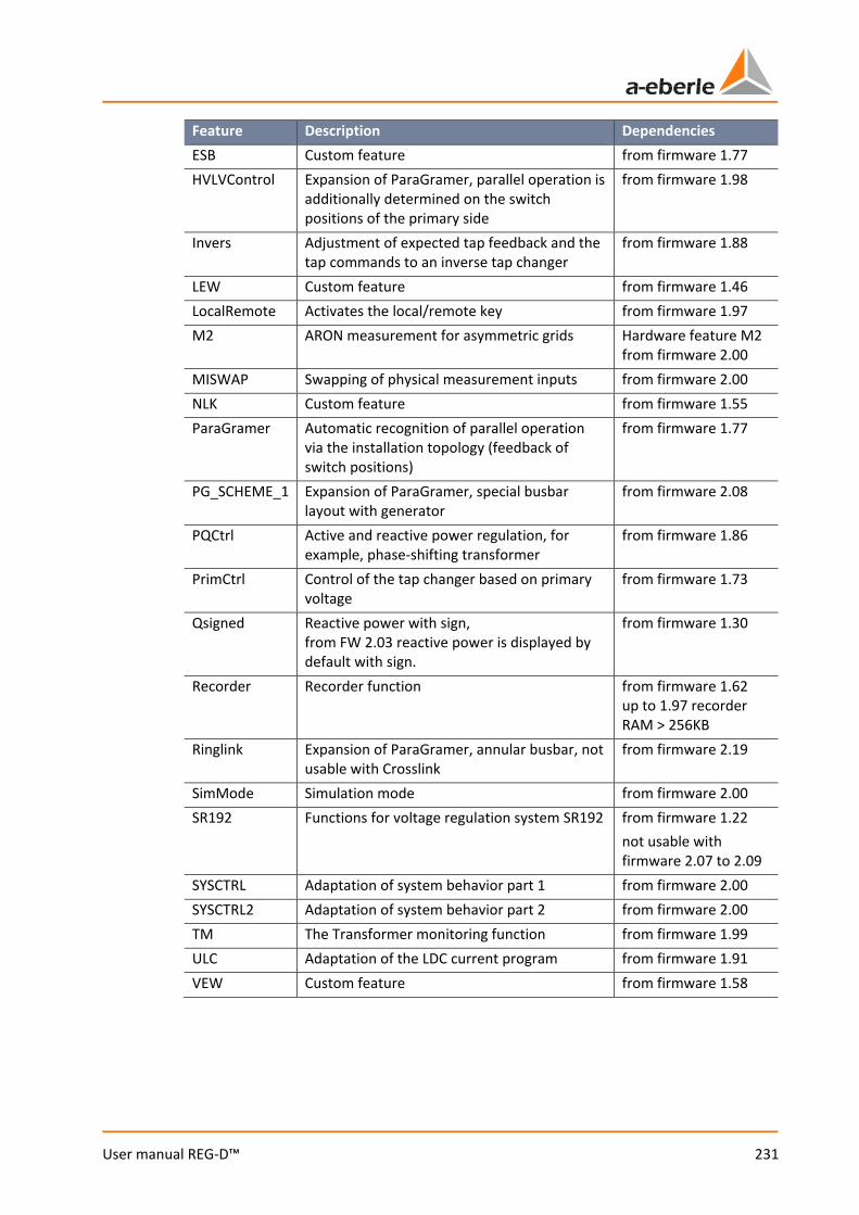
231
User manual REG-D™
Feature Description Dependencies ESB Custom feature from firmware 1.77 HVLVControl Expansion of ParaGramer, parallel operation is
additionally determined on the switch positions of the primary side
from firmware 1.98
Invers Adjustment of expected tap feedback and the tap commands to an inverse tap changer
from firmware 1.88
LEW Custom feature from firmware 1.46 LocalRemote Activates the local/remote key from firmware 1.97 M2 ARON measurement for asymmetric grids Hardware feature M2
from firmware 2.00 MISWAP Swapping of physical measurement inputs from firmware 2.00 NLK Custom feature from firmware 1.55 ParaGramer Automatic recognition of parallel operation
via the installation topology (feedback of switch positions)
from firmware 1.77
PG_SCHEME_1 Expansion of ParaGramer, special busbar layout with generator
from firmware 2.08
PQCtrl Active and reactive power regulation, for example, phase-shifting transformer
from firmware 1.86
PrimCtrl Control of the tap changer based on primary voltage
from firmware 1.73
Qsigned Reactive power with sign, from FW 2.03 reactive power is displayed by default with sign.
from firmware 1.30
Recorder Recorder function from firmware 1.62 up to 1.97 recorder RAM > 256KB
Ringlink Expansion of ParaGramer, annular busbar, not usable with Crosslink
from firmware 2.19
SimMode Simulation mode from firmware 2.00 SR192 Functions for voltage regulation system SR192 from firmware 1.22
not usable with firmware 2.07 to 2.09
SYSCTRL Adaptation of system behavior part 1 from firmware 2.00 SYSCTRL2 Adaptation of system behavior part 2 from firmware 2.00 TM The Transformer monitoring function from firmware 1.99 ULC Adaptation of the LDC current program from firmware 1.91 VEW Custom feature from firmware 1.58
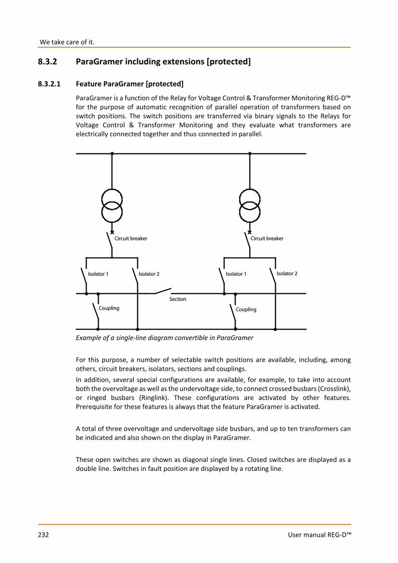
We take care of it.
232
User manual REG-D™
8.3.2 ParaGramer including extensions [protected]
8.3.2.1 Feature ParaGramer [protected]
ParaGramer is a function of the Relay for Voltage Control & Transformer Monitoring REG-D™ for the purpose of automatic recognition of parallel operation of transformers based on switch positions. The switch positions are transferred via binary signals to the Relays for Voltage Control & Transformer Monitoring and they evaluate what transformers are electrically connected together and thus connected in parallel.
Example of a single-line diagram convertible in ParaGramer For this purpose, a number of selectable switch positions are available, including, among others, circuit breakers, isolators, sections and couplings. In addition, several special configurations are available, for example, to take into account both the overvoltage as well as the undervoltage side, to connect crossed busbars (Crosslink), or ringed busbars (Ringlink). These configurations are activated by other features. Prerequisite for these features is always that the feature ParaGramer is activated. A total of three overvoltage and undervoltage side busbars, and up to ten transformers can be indicated and also shown on the display in ParaGramer. These open switches are shown as diagonal single lines. Closed switches are displayed as a double line. Switches in fault position are displayed by a rotating line.
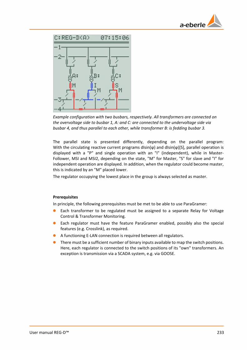
233
User manual REG-D™
Example configuration with two busbars, respectively. All transformers are connected on the overvoltage side to busbar 1, A: and C: are connected to the undervoltage side via busbar 4, and thus parallel to each other, while transformer B: is fedding busbar 3. The parallel state is presented differently, depending on the parallel program: With the circulating reactive current programs dIsin(ϕ) and dIsin(ϕ)[S], parallel operation is displayed with a "P" and single operation with an "I" (independent), while in Master-Follower, MSI and MSI2, depending on the state, "M" for Master, "S" for slave and "I" for independent operation are displayed. In addition, when the regulator could become master, this is indicated by an "M" placed lower. The regulator occupying the lowest place in the group is always selected as master. Prerequisites In principle, the following prerequisites must be met to be able to use ParaGramer: 0 Each transformer to be regulated must be assigned to a separate Relay for Voltage
Control & Transformer Monitoring. 0 Each regulator must have the feature ParaGramer enabled, possibly also the special
features (e.g. Crosslink), as required. 0 A functioning E-LAN connection is required between all regulators. 0 There must be a sufficient number of binary inputs available to map the switch positions.
Here, each regulator is connected to the switch positions of its "own" transformers. An exception is transmission via a SCADA system, e.g. via GOOSE.
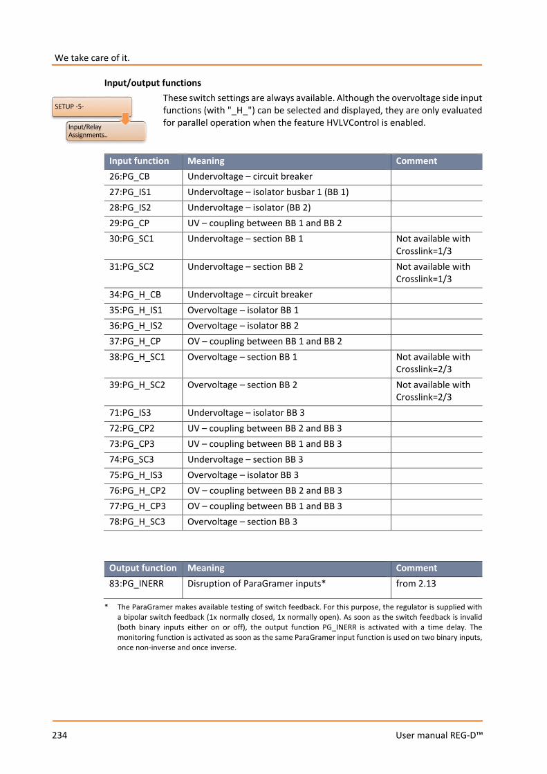
We take care of it.
234
User manual REG-D™
Input/output functions These switch settings are always available. Although the overvoltage side input functions (with "_H_") can be selected and displayed, they are only evaluated for parallel operation when the feature HVLVControl is enabled.
Input function Meaning Comment 26:PG_CB Undervoltage – circuit breaker 27:PG_IS1 Undervoltage – isolator busbar 1 (BB 1) 28:PG_IS2 Undervoltage – isolator (BB 2) 29:PG_CP UV – coupling between BB 1 and BB 2 30:PG_SC1 Undervoltage – section BB 1 Not available with
Crosslink=1/3 31:PG_SC2 Undervoltage – section BB 2 Not available with
Crosslink=1/3 34:PG_H_CB Undervoltage – circuit breaker 35:PG_H_IS1 Overvoltage – isolator BB 1 36:PG_H_IS2 Overvoltage – isolator BB 2 37:PG_H_CP OV – coupling between BB 1 and BB 2 38:PG_H_SC1 Overvoltage – section BB 1 Not available with
Crosslink=2/3 39:PG_H_SC2 Overvoltage – section BB 2 Not available with
Crosslink=2/3 71:PG_IS3 Undervoltage – isolator BB 3 72:PG_CP2 UV – coupling between BB 2 and BB 3 73:PG_CP3 UV – coupling between BB 1 and BB 3 74:PG_SC3 Undervoltage – section BB 3 75:PG_H_IS3 Overvoltage – isolator BB 3 76:PG_H_CP2 OV – coupling between BB 2 and BB 3 77:PG_H_CP3 OV – coupling between BB 1 and BB 3 78:PG_H_SC3 Overvoltage – section BB 3
Output function Meaning Comment 83:PG_INERR Disruption of ParaGramer inputs* from 2.13
* The ParaGramer makes available testing of switch feedback. For this purpose, the regulator is supplied with a bipolar switch feedback (1x normally closed, 1x normally open). As soon as the switch feedback is invalid (both binary inputs either on or off), the output function PG_INERR is activated with a time delay. The monitoring function is activated as soon as the same ParaGramer input function is used on two binary inputs, once non-inverse and once inverse.
SETUP -5-
Input/Relay Assignments..
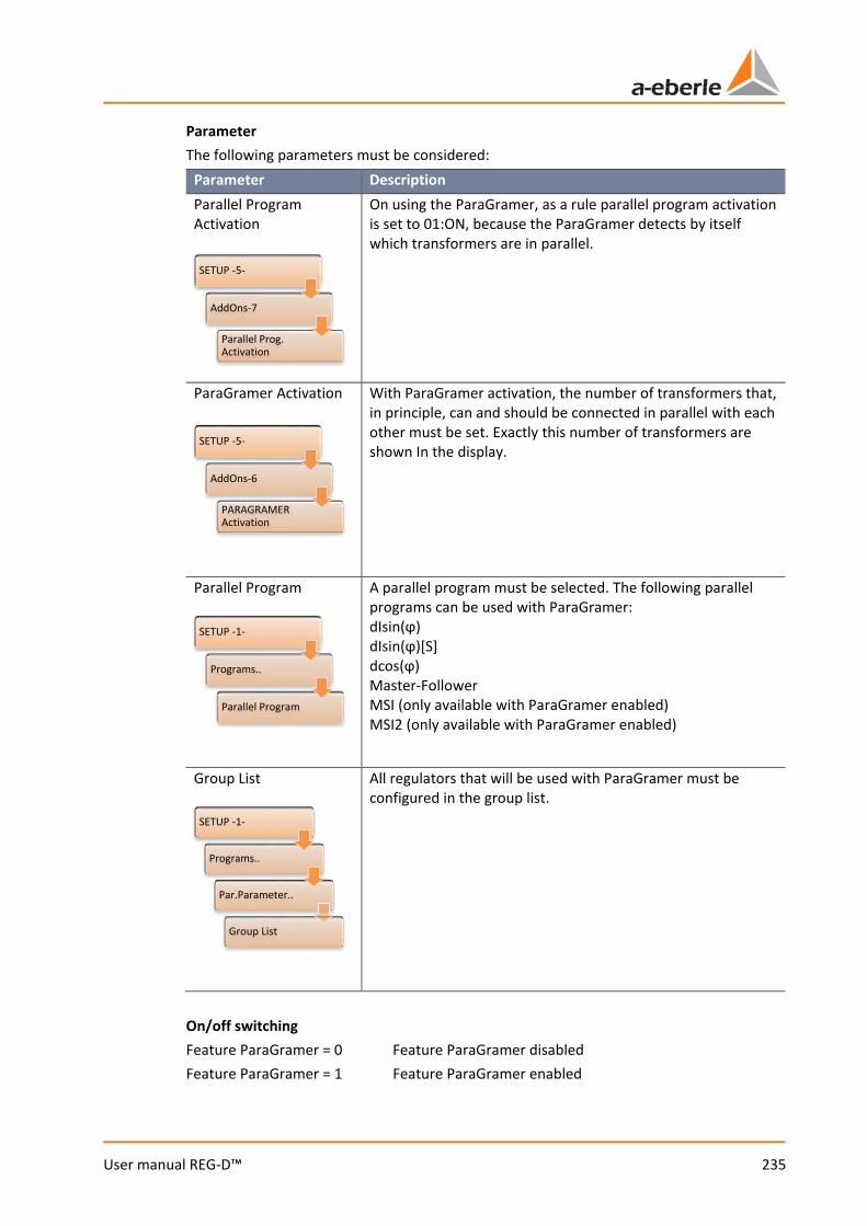
235
User manual REG-D™
Parameter The following parameters must be considered:
Parameter Description Parallel Program Activation
On using the ParaGramer, as a rule parallel program activation is set to 01:ON, because the ParaGramer detects by itself which transformers are in parallel.
ParaGramer Activation
With ParaGramer activation, the number of transformers that, in principle, can and should be connected in parallel with each other must be set. Exactly this number of transformers are shown In the display.
Parallel Program
A parallel program must be selected. The following parallel programs can be used with ParaGramer: dIsin(ϕ) dIsin(ϕ)[S] dcos(ϕ) Master-Follower MSI (only available with ParaGramer enabled) MSI2 (only available with ParaGramer enabled)
Group List
All regulators that will be used with ParaGramer must be configured in the group list.
On/off switching Feature ParaGramer = 0 Feature ParaGramer disabled Feature ParaGramer = 1 Feature ParaGramer enabled
SETUP -5-
AddOns-7
Parallel Prog. Activation
SETUP -5-
AddOns-6
PARAGRAMER Activation
SETUP -1-
Programs..
Parallel Program
SETUP -1-
Programs..
Par.Parameter..
Group List
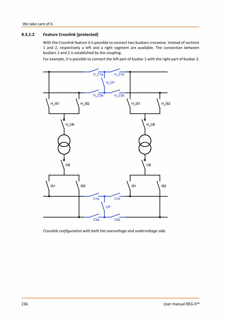
We take care of it.
236
User manual REG-D™
8.3.2.2 Feature Crosslink [protected]
With the Crosslink feature it is possible to connect two busbars crosswise. Instead of sections 1 and 2, respectively a left and a right segment are available. The connection between busbars 1 and 2 is established by the coupling. For example, it is possible to connect the left part of busbar 1 with the right part of busbar 2.
Crosslink configuration with both the overvoltage and undervoltage side.
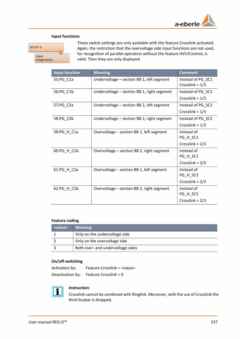
237
User manual REG-D™
Input functions These switch settings are only available with the feature Crosslink activated. Again, the restriction that the overvoltage side input functions are not used, for recognition of parallel operation without the feature HVLVControl, is valid. Then they are only displayed.
Input function Meaning Comment 55:PG_C1a Undervoltage – section BB 1, left segment Instead of PG_SC1
Crosslink = 1/3 56:PG_C1b Undervoltage – section BB 1, right segment Instead of PG_SC1
Crosslink = 1/3 57:PG_C2a Undervoltage – section BB 2, left segment Instead of PG_SC2
Crosslink = 1/3 58:PG_C2b Undervoltage – section BB 2, right segment Instead of PG_SC2
Crosslink = 1/3 59:PG_H_C1a Overvoltage – section BB 1, left segment Instead of
PG_H_SC1 Crosslink = 2/3
60:PG_H_C1b Overvoltage – section BB 2, right segment Instead of PG_H_SC1 Crosslink = 2/3
61:PG_H_C2a Overvoltage – section BB 1, left segment Instead of PG_H_SC2 Crosslink = 2/3
62:PG_H_C2b Overvoltage – section BB 2, right segment Instead of PG_H_SC2 Crosslink = 2/3
Feature coding
<value> Meaning 1 Only on the undervoltage side 2 Only on the overvoltage side 3 Both over- and undervoltage sides
On/off switching Activation by: Feature Crosslink = <value> Deactivation by: Feature Crosslink = 0
Instruction: Crosslink cannot be combined with Ringlink. Moreover, with the use of Crosslink the third busbar is dropped.
SETUP -5-
Input Assignments..
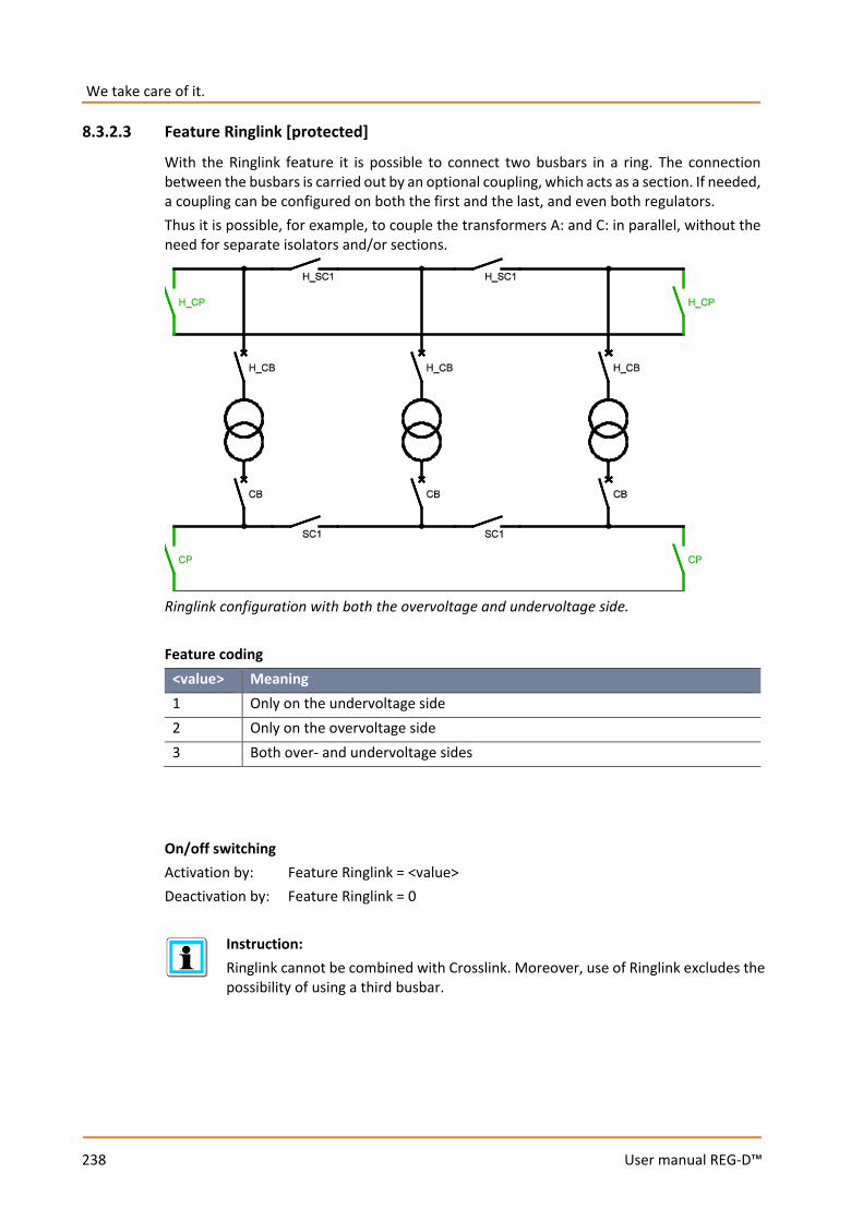
We take care of it.
238
User manual REG-D™
8.3.2.3 Feature Ringlink [protected]
With the Ringlink feature it is possible to connect two busbars in a ring. The connection between the busbars is carried out by an optional coupling, which acts as a section. If needed, a coupling can be configured on both the first and the last, and even both regulators. Thus it is possible, for example, to couple the transformers A: and C: in parallel, without the need for separate isolators and/or sections.
Ringlink configuration with both the overvoltage and undervoltage side. Feature coding
<value> Meaning 1 Only on the undervoltage side 2 Only on the overvoltage side 3 Both over- and undervoltage sides
On/off switching Activation by: Feature Ringlink = <value> Deactivation by: Feature Ringlink = 0
Instruction: Ringlink cannot be combined with Crosslink. Moreover, use of Ringlink excludes the possibility of using a third busbar.
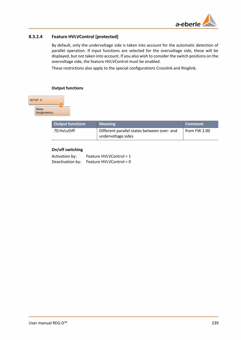
239
User manual REG-D™
8.3.2.4 Feature HVLVControl [protected]
By default, only the undervoltage side is taken into account for the automatic detection of parallel operation. If input functions are selected for the overvoltage side, these will be displayed, but not taken into account. If you also wish to consider the switch positions on the overvoltage side, the feature HVLVControl must be enabled. These restrictions also apply to the special configurations Crosslink and Ringlink. Output functions
Output functions Meaning Comment 70:HvLvDiff Different parallel states between over- and
undervoltage sides from FW 2.00
On/off switching Activation by: Feature HVLVControl = 1 Deactivation by: Feature HVLVControl = 0
SETUP -5-
Relay Assignments..
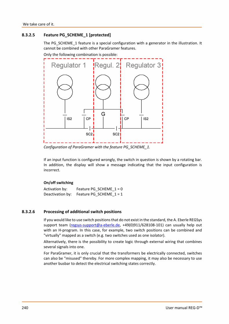
We take care of it.
240
User manual REG-D™
8.3.2.5 Feature PG_SCHEME_1 [protected]
The PG_SCHEME_1 feature is a special configuration with a generator in the illustration. It cannot be combined with other ParaGramer features. Only the following combination is possible:
Configuration of ParaGramer with the feature PG_SCHEME_1. If an input function is configured wrongly, the switch in question is shown by a rotating bar. In addition, the display will show a message indicating that the input configuration is incorrect. On/off switching Activation by: Feature PG_SCHEME_1 = 0 Deactivation by: Feature PG_SCHEME_1 = 1
8.3.2.6 Processing of additional switch positions
If you would like to use switch positions that do not exist in the standard, the A. Eberle REGSys support team ([email protected], +49(0)911/628108-101) can usually help out with an H-program. In this case, for example, two switch positions can be combined and "virtually" mapped as a switch (e.g. two switches used as one isolator). Alternatively, there is the possibility to create logic through external wiring that combines several signals into one. For ParaGramer, it is only crucial that the transformers be electrically connected, switches can also be "misused" thereby. For more complex mapping, it may also be necessary to use another busbar to detect the electrical switching states correctly.
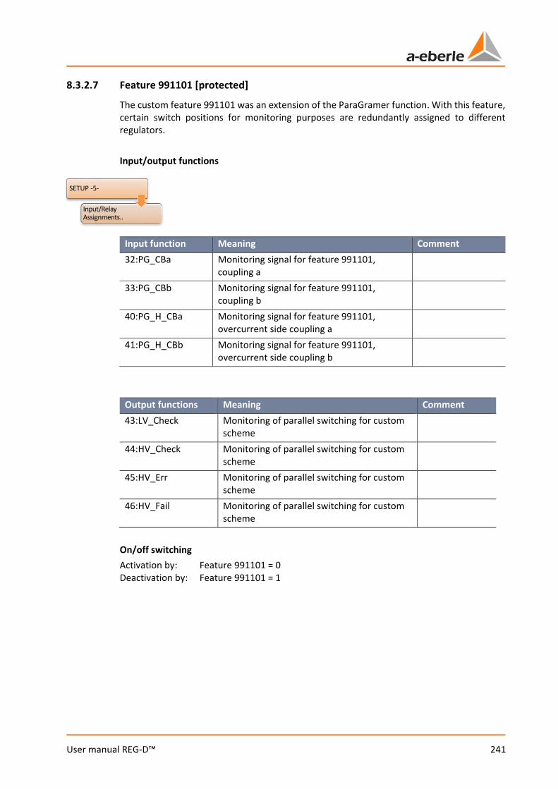
241
User manual REG-D™
8.3.2.7 Feature 991101 [protected]
The custom feature 991101 was an extension of the ParaGramer function. With this feature, certain switch positions for monitoring purposes are redundantly assigned to different regulators. Input/output functions
Input function Meaning Comment 32:PG_CBa Monitoring signal for feature 991101,
coupling a
33:PG_CBb Monitoring signal for feature 991101, coupling b
40:PG_H_CBa Monitoring signal for feature 991101, overcurrent side coupling a
41:PG_H_CBb Monitoring signal for feature 991101, overcurrent side coupling b
Output functions Meaning Comment 43:LV_Check Monitoring of parallel switching for custom
scheme
44:HV_Check Monitoring of parallel switching for custom scheme
45:HV_Err Monitoring of parallel switching for custom scheme
46:HV_Fail Monitoring of parallel switching for custom scheme
On/off switching Activation by: Feature 991101 = 0 Deactivation by: Feature 991101 = 1
SETUP -5-
Input/Relay Assignments..

We take care of it.
242
User manual REG-D™
8.3.2.8 ParaGramer via SCADA system
ParaGramer via IEC-61850 GOOSE light With a GOOSE-capable state of the REG-PE(D) firmware for IEC 61850, it is also possible to transmit all switch positions via GOOSE to the Relay for Voltage Control & Transformer Monitoring. For this purpose, a small addition to the background program is necessary. To have the switch positions received via GOOSE incorporated in ParaGramer, previously the binary inputs 33 ... 64 were used. Since these are not usually available in hardware, they are used as "virtual binary inputs" for GOOSE messages. If hardware already exists for the binary inputs 33 ... 64, use of GOOSE for ParaGramer is either not available or available only to a limited extent. If you are interested in the GOOSE application, please contact the A. Eberle REGSys support team ([email protected], +49(0)911/628108-101). Further applications If you would like a different method of switch position transmission via SCADA system technology, the A. Eberle REGSys support team ([email protected], +49(0)911/628108-101) will be glad to advise you.
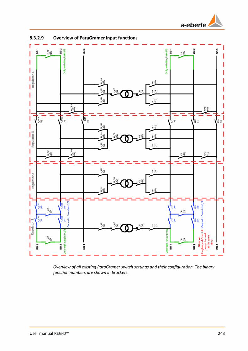
243
User manual REG-D™
8.3.2.9 Overview of ParaGramer input functions
Overview of all existing ParaGramer switch settings and their configuration. The binary function numbers are shown in brackets.
We take care of it.
244
User manual REG-D™
8.3.3 Feature Recorder [protected] With this feature the recorder function will be activated. Without activation the recorder is only available as a demo.
Recorder demo mode! The recorder is running in demo mode if "DEMO" is displayed in the left of the grid when the recorder is in normal display mode. In this operating mode, the recorder records measured values for a time domain of 4 to 6 hours. The oldest values are overwritten at the end of this period. Data cannot be read out in demo mode!
The recorder feature (order feature S1) serves for registration and display of up to three selectable measured values. Besides the measured values, the current tap position*, the setpoint value*, the tolerance band and the manual/automatic state, as well as the time and date are recorded. The time grid for the recording is adjustable. The recorder shows the continuous time course of up to two selectable measured values on the display as a line graph. The current date and time (timestamp) are also recorded. This enables correlated data to be queried by date and time. The average storage time for a channel (e.g. voltage and tap) is about six weeks (recording time < 18.7 days with continuous change of the measured value and the parameter "absolute deviation" = 0). The stored values can be retrieved and displayed via the keyboard or the operating software REGView (see chapter 9.9 REGView, from page 317 onwards, or chapter 9.10 Collector, from page 322 onwards). (*requires recording of voltage (function 01:U) on channel 1)
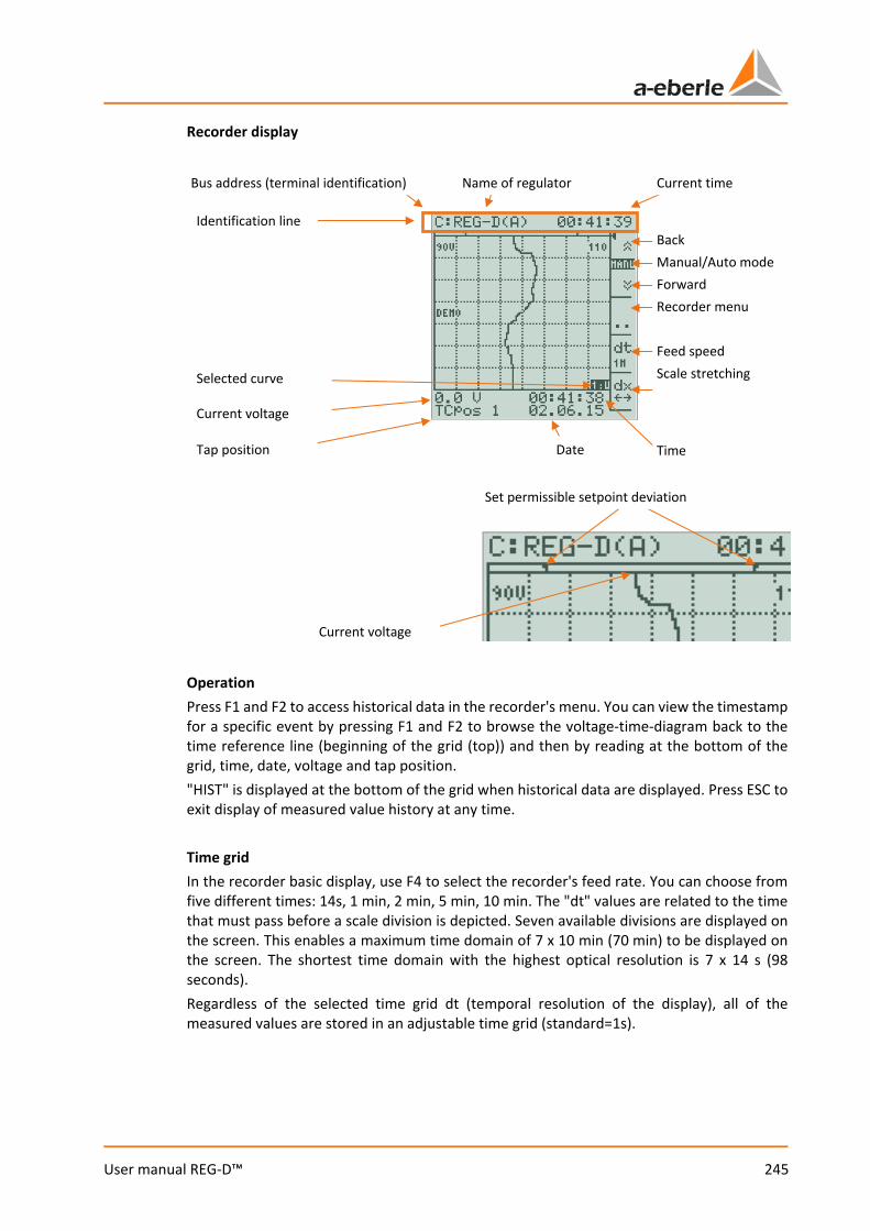
245
User manual REG-D™
Recorder display
Operation Press F1 and F2 to access historical data in the recorder's menu. You can view the timestamp for a specific event by pressing F1 and F2 to browse the voltage-time-diagram back to the time reference line (beginning of the grid (top)) and then by reading at the bottom of the grid, time, date, voltage and tap position. "HIST" is displayed at the bottom of the grid when historical data are displayed. Press ESC to exit display of measured value history at any time. Time grid In the recorder basic display, use F4 to select the recorder's feed rate. You can choose from five different times: 14s, 1 min, 2 min, 5 min, 10 min. The "dt" values are related to the time that must pass before a scale division is depicted. Seven available divisions are displayed on the screen. This enables a maximum time domain of 7 x 10 min (70 min) to be displayed on the screen. The shortest time domain with the highest optical resolution is 7 x 14 s (98 seconds). Regardless of the selected time grid dt (temporal resolution of the display), all of the measured values are stored in an adjustable time grid (standard=1s).
Bus address (terminal identification) Name of regulator Current time
Back Manual/Auto mode Forward Recorder menu Feed speed Scale stretching
Time Date
Current voltage
Tap position
Identification line
Selected curve
Current voltage
Set permissible setpoint deviation
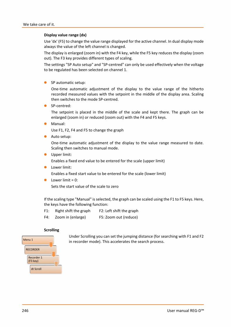
We take care of it.
246
User manual REG-D™
Display value range (dx) Use 'dx' (F5) to change the value range displayed for the active channel. In dual display mode always the value of the left channel is changed. The display is enlarged (zoom in) with the F4 key, while the F5 key reduces the display (zoom out). The F3 key provides different types of scaling. The settings "SP Auto setup" and "SP-centred" can only be used effectively when the voltage to be regulated has been selected on channel 1. 0 SP automatic setup:
One-time automatic adjustment of the display to the value range of the hitherto recorded measured values with the setpoint in the middle of the display area. Scaling then switches to the mode SP-centred.
0 SP-centred: The setpoint is placed in the middle of the scale and kept there. The graph can be enlarged (zoom in) or reduced (zoom out) with the F4 and F5 keys.
0 Manual: Use F1, F2, F4 and F5 to change the graph
0 Auto setup: One-time automatic adjustment of the display to the value range measured to date. Scaling then switches to manual mode.
0 Upper limit: Enables a fixed end value to be entered for the scale (upper limit)
0 Lower limit: Enables a fixed start value to be entered for the scale (lower limit)
0 Lower limit = 0: Sets the start value of the scale to zero
If the scaling type "Manual" is selected, the graph can be scaled using the F1 to F5 keys. Here, the keys have the following function: F1: Right shift the graph F2: Left shift the graph F4: Zoom in (enlarge) F5: Zoom out (reduce) Scrolling
Under Scrolling you can set the jumping distance (for searching with F1 and F2 in recorder mode). This accelerates the search process.
Menu 1
RECORDER
Recorder 1 (F3 key)
dt Scroll
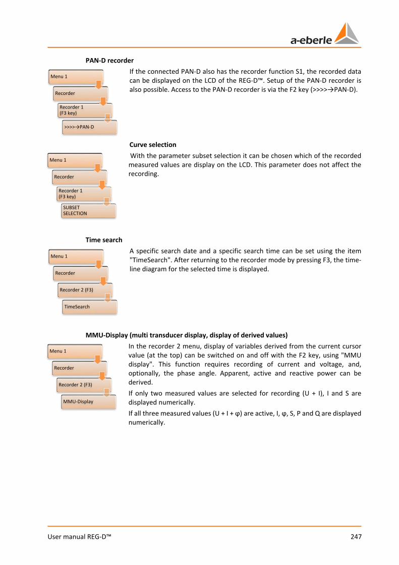
247
User manual REG-D™
PAN-D recorder If the connected PAN-D also has the recorder function S1, the recorded data can be displayed on the LCD of the REG-D™. Setup of the PAN-D recorder is also possible. Access to the PAN-D recorder is via the F2 key (>>>>→PAN-D). Curve selection With the parameter subset selection it can be chosen which of the recorded measured values are display on the LCD. This parameter does not affect the recording.
Time search A specific search date and a specific search time can be set using the item "TimeSearch". After returning to the recorder mode by pressing F3, the time-line diagram for the selected time is displayed.
MMU-Display (multi transducer display, display of derived values) In the recorder 2 menu, display of variables derived from the current cursor value (at the top) can be switched on and off with the F2 key, using "MMU display". This function requires recording of current and voltage, and, optionally, the phase angle. Apparent, active and reactive power can be derived. If only two measured values are selected for recording (U + I), I and S are displayed numerically. If all three measured values (U + I + ϕ) are active, I, ϕ, S, P and Q are displayed numerically.
Menu 1
Recorder
Recorder 1 (F3 key)
>>>>→PAN-D
Menu 1
Recorder
Recorder 1 (F3 key)
SUBSET SELECTION
Menu 1
Recorder
Recorder 2 (F3)
TimeSearch
Menu 1
Recorder
Recorder 2 (F3)
MMU-Display
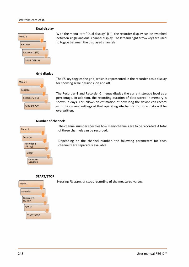
We take care of it.
248
User manual REG-D™
Dual display With the menu item "Dual display" (F4), the recorder display can be switched between single and dual channel display. The left and right arrow keys are used to toggle between the displayed channels.
Grid display The F5 key toggles the grid, which is represented in the recorder basic display for showing scale divisions, on and off. The Recorder-1 and Recorder-2 menus display the current storage level as a percentage. In addition, the recording duration of data stored in memory is shown in days. This allows an estimation of how long the device can record with the current settings at that operating site before historical data will be overwritten.
Number of channels The channel number specifies how many channels are to be recorded. A total of three channels can be recorded. Depending on the channel number, the following parameters for each channel x are separately available.
START/STOP
Pressing F3 starts or stops recording of the measured values.
Menu 1
Recorder
Recorder 2 (F3)
DUAL DISPLAY
Menu 1
Recorder
Recorder 2 (F3)
GRID DISPLAY
Menu 1
Recorder
Recorder 1 (F3 key)
SETUP
CHANNEL NUMBER
Menu 1
Recorder
Recorder 1 (F3 key)
SETUP
START/STOP
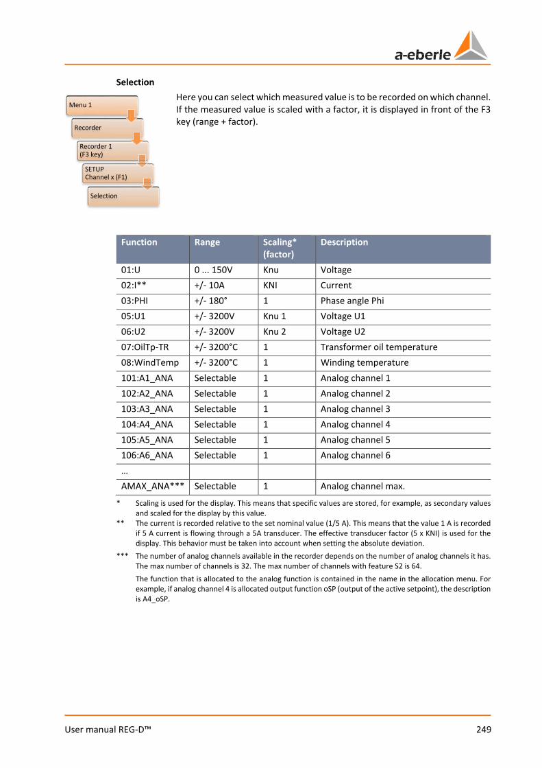
249
User manual REG-D™
Selection Here you can select which measured value is to be recorded on which channel. If the measured value is scaled with a factor, it is displayed in front of the F3 key (range + factor).
Function Range Scaling*
(factor) Description
01:U 0 ... 150V Knu Voltage 02:I** +/- 10A KNI Current 03:PHI +/- 180° 1 Phase angle Phi 05:U1 +/- 3200V Knu 1 Voltage U1 06:U2 +/- 3200V Knu 2 Voltage U2 07:OilTp-TR +/- 3200°C 1 Transformer oil temperature 08:WindTemp +/- 3200°C 1 Winding temperature 101:A1_ANA Selectable 1 Analog channel 1 102:A2_ANA Selectable 1 Analog channel 2 103:A3_ANA Selectable 1 Analog channel 3 104:A4_ANA Selectable 1 Analog channel 4 105:A5_ANA Selectable 1 Analog channel 5 106:A6_ANA Selectable 1 Analog channel 6 … AMAX_ANA*** Selectable 1 Analog channel max.
* Scaling is used for the display. This means that specific values are stored, for example, as secondary values and scaled for the display by this value.
** The current is recorded relative to the set nominal value (1/5 A). This means that the value 1 A is recorded if 5 A current is flowing through a 5A transducer. The effective transducer factor (5 x KNI) is used for the display. This behavior must be taken into account when setting the absolute deviation.
*** The number of analog channels available in the recorder depends on the number of analog channels it has. The max number of channels is 32. The max number of channels with feature S2 is 64.
The function that is allocated to the analog function is contained in the name in the allocation menu. For example, if analog channel 4 is allocated output function oSP (output of the active setpoint), the description is A4_oSP.
Menu 1
Recorder
Recorder 1 (F3 key)
SETUP Channel x (F1)
Selection
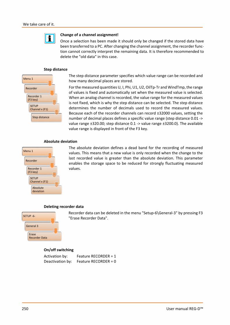
We take care of it.
250
User manual REG-D™
Change of a channel assignment! Once a selection has been made it should only be changed if the stored data have been transferred to a PC. After changing the channel assignment, the recorder func-tion cannot correctly interpret the remaining data. It is therefore recommended to delete the "old data" in this case.
Step distance
The step distance parameter specifies which value range can be recorded and how many decimal places are stored. For the measured quantities U, I, Phi, U1, U2, OilTp-Tr and WindTmp, the range of values is fixed and automatically set when the measured value is selected. When an analog channel is recorded, the value range for the measured values is not fixed, which is why the step distance can be selected. The step distance determines the number of decimals used to record the measured values. Because each of the recorder channels can record ±32000 values, setting the number of decimal places defines a specific value range (step distance 0.01 -> value range ±320.00; step distance 0.1 -> value range ±3200.0). The available value range is displayed in front of the F3 key.
Absolute deviation
The absolute deviation defines a dead band for the recording of measured values. This means that a new value is only recorded when the change to the last recorded value is greater than the absolute deviation. This parameter enables the storage space to be reduced for strongly fluctuating measured values.
Deleting recorder data Recorder data can be deleted in the menu "Setup-6\General-3" by pressing F3 "Erase Recorder Data".
On/off switching Activation by: Feature RECORDER = 1 Deactivation by: Feature RECORDER = 0
Menu 1
Recorder
Recorder 1(F3 key)
SETUP Channel x (F1)
Step distance
Menu 1
Recorder
Recorder 1 (F3 key)
SETUP Channel x (F1)
Absolute deviation
SETUP -6-
General 3
Erase Recorder Data
251
User manual REG-D™
Activation of the recorder feature The feature is not activated when the REG-D™ only has 256KB RAM. The amount of RAM is given in the menu "Setup -6-\Status\REG-D status (1)". After changing the feature, the regulator must be switched off and on again, or the command SYSRESET= 0 (PowerOn reset, switching on/off) must be executed via REG-L.
Recorder mode (feature S2) The recorder mode S2 provides another four recorders, each with 64 channels, in addition to the three channels of recorder S1. The recording interval can be set separately for each. The data can only be configured and displayed with the operating software. Stored values cannot be displayed on the screen of the REG-D™. The S2 recorder is only available at REG-D™ devices with the hardware feature S2.
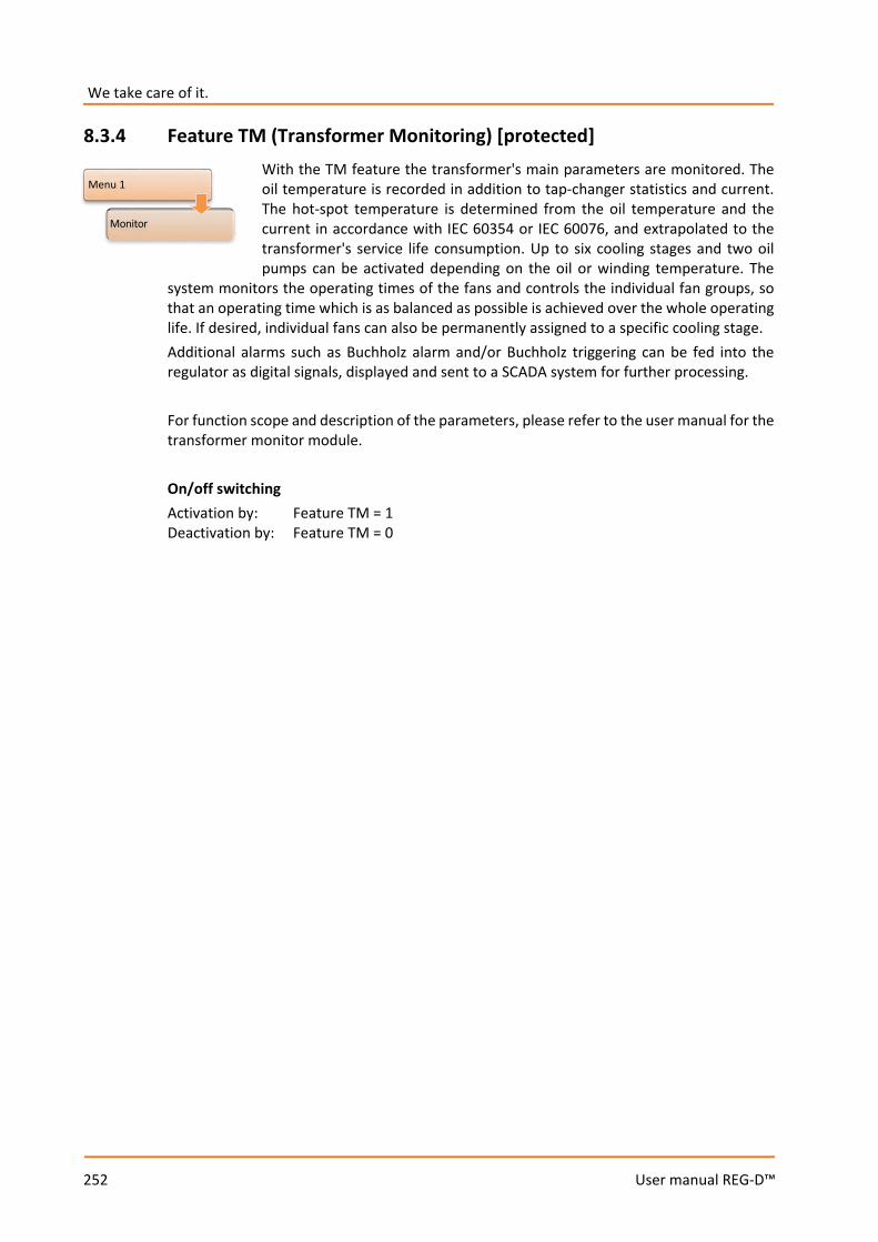
We take care of it.
252
User manual REG-D™
8.3.4 Feature TM (Transformer Monitoring) [protected] With the TM feature the transformer's main parameters are monitored. The oil temperature is recorded in addition to tap-changer statistics and current. The hot-spot temperature is determined from the oil temperature and the current in accordance with IEC 60354 or IEC 60076, and extrapolated to the transformer's service life consumption. Up to six cooling stages and two oil pumps can be activated depending on the oil or winding temperature. The
system monitors the operating times of the fans and controls the individual fan groups, so that an operating time which is as balanced as possible is achieved over the whole operating life. If desired, individual fans can also be permanently assigned to a specific cooling stage. Additional alarms such as Buchholz alarm and/or Buchholz triggering can be fed into the regulator as digital signals, displayed and sent to a SCADA system for further processing. For function scope and description of the parameters, please refer to the user manual for the transformer monitor module. On/off switching Activation by: Feature TM = 1 Deactivation by: Feature TM = 0
Menu 1
Monitor
253
User manual REG-D™
8.3.5 Feature 3winding (three-winding transformer) [protected] Originally, this feature was developed in order to regulate and monitor three-winding transformers. Moreover, it is possible to use the feature for other applications, which require a second voltage (U1, U2) and current measurement (I1, I2). In these cases, the three-winding software feature is usually combined with a background program to implement customer-specific requirements. Properties of the three-winding transformer feature 0 The same or a different configuration of voltage transformers (VTs) which are assigned
to the voltage measuring channels (U1, U2). This means that three-winding transformers with different secondary voltages can be regulated easily. The configuration of current transformers (CTs), which are wired to the current measurement inputs, can also be adjusted separately from one another with the exception of the nominal current of the transducer (1/5 A).
0 Display of both secondary voltages in the transducer display mode. 0 Voltage, current, cosϕ, apparent, active and reactive power can be shown for the
respective active measurement input pair (U1, I1 or U2, I2) in the transducer display mode (with hardware feature S2 simultaneous display of all calculated values is also possible).
0 The voltage to be regulated on can be selected via binary input, SCADA system or using a background program. For example, selection of the voltage to be regulated on depending on the load of both windings can be done with a background program. This means that regulation is carried out on the voltage of the winding with the higher load, and the other winding is still monitored in parallel (standard solution with three-winding transformers, so long as the currents of the windings are measured).
0 The currently regulated busbar or secondary voltage (voltage measuring channel U1 or U2) is indicated on the REG-D™ screen with "1" or "2", which can also be output via a SCADA system or relay output.
0 All parallel programs and current influence algorithms (Z compensation or LDC) can also be used with three-winding applications.
0 Even if only the voltages (U1, U2) are measured, the winding to be controlled can be freely selected. It is also possible to make selection dependent on user-definable voltage limits. For this purpose, a background program is used again.

We take care of it.
254
User manual REG-D™
Regulation of three-winding transformers
Wiring diagram for the regulation of three-winding transformers The voltage to be regulated on can be selected via binary inputs, SCADA system or using a background program. It is possible to supervise the unregulated voltage in parallel to ensure that it remains within certain voltage limits. If a current measurement at the transformer or on the incoming feeder is present, the REG-D™ can automatically select the regulation voltage depending on the load. For this purpose, a background program is used. Generally, it is possible to adapt selection of regulation voltage to each customer request.
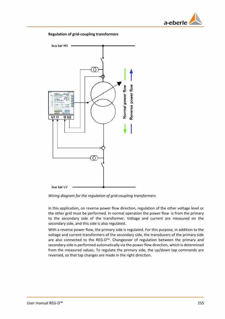
255
User manual REG-D™
Regulation of grid-coupling transformers
Wiring diagram for the regulation of grid-coupling transformers In this application, on reverse power flow direction, regulation of the other voltage level or the other grid must be performed. In normal operation the power flow is from the primary to the secondary side of the transformer. Voltage and current are measured on the secondary side, and this side is also regulated. With a reverse power flow, the primary side is regulated. For this purpose, in addition to the voltage and current transformers of the secondary side, the transducers of the primary side are also connected to the REG-D™. Changeover of regulation between the primary and secondary side is performed automatically via the power flow direction, which is determined from the measured values. To regulate the primary side, the up/down tap commands are reversed, so that tap changes are made in the right direction.
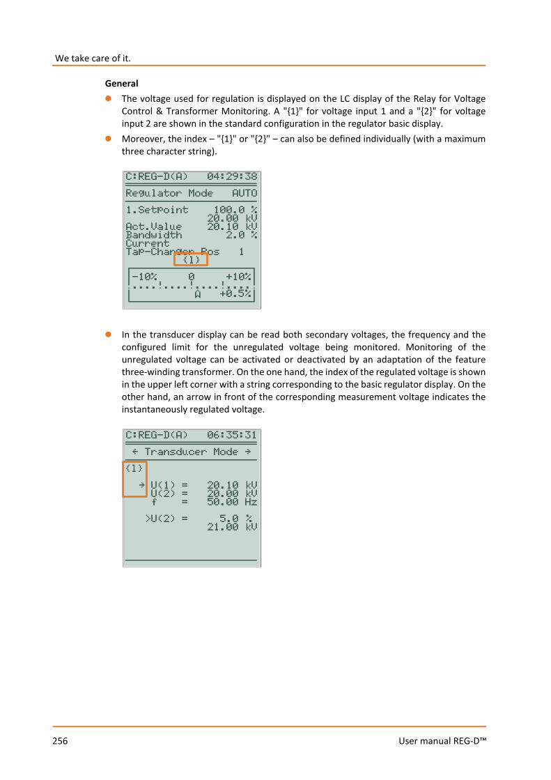
We take care of it.
256
User manual REG-D™
General 0 The voltage used for regulation is displayed on the LC display of the Relay for Voltage
Control & Transformer Monitoring. A "1" for voltage input 1 and a "2" for voltage input 2 are shown in the standard configuration in the regulator basic display.
0 Moreover, the index – "1" or "2" – can also be defined individually (with a maximum three character string).
0 In the transducer display can be read both secondary voltages, the frequency and the
configured limit for the unregulated voltage being monitored. Monitoring of the unregulated voltage can be activated or deactivated by an adaptation of the feature three-winding transformer. On the one hand, the index of the regulated voltage is shown in the upper left corner with a string corresponding to the basic regulator display. On the other hand, an arrow in front of the corresponding measurement voltage indicates the instantaneously regulated voltage.
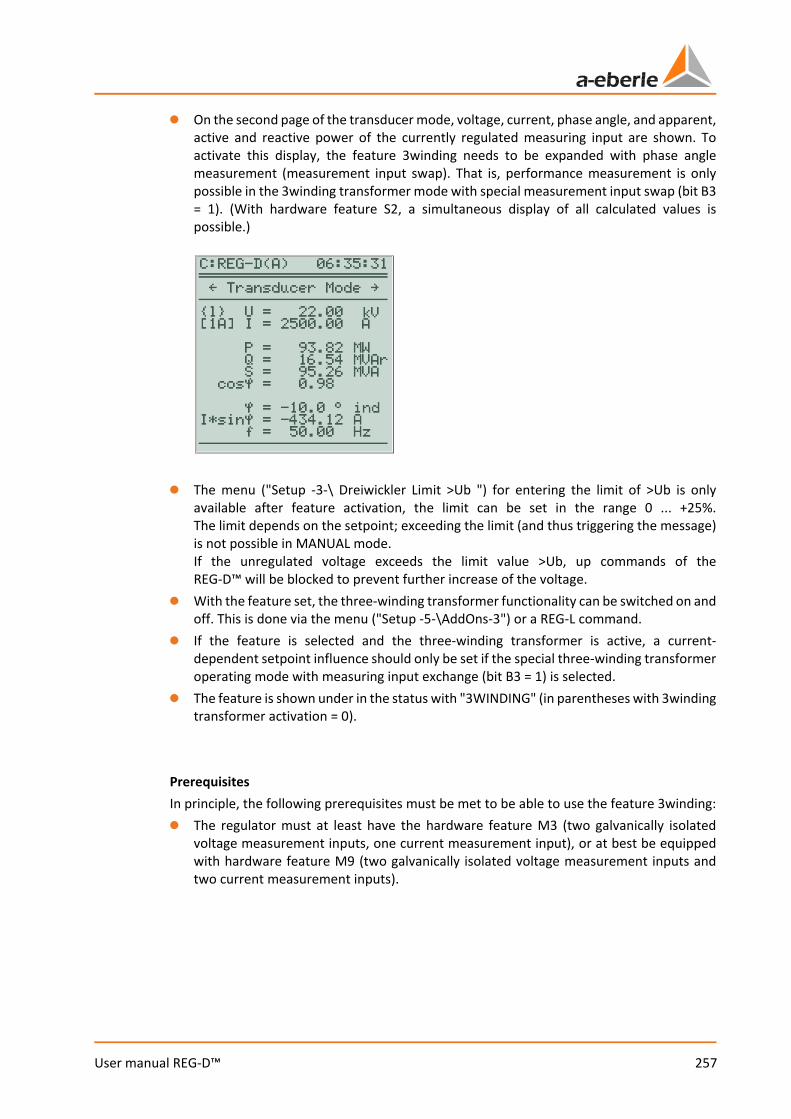
257
User manual REG-D™
0 On the second page of the transducer mode, voltage, current, phase angle, and apparent, active and reactive power of the currently regulated measuring input are shown. To activate this display, the feature 3winding needs to be expanded with phase angle measurement (measurement input swap). That is, performance measurement is only possible in the 3winding transformer mode with special measurement input swap (bit B3 = 1). (With hardware feature S2, a simultaneous display of all calculated values is possible.)
0 The menu ("Setup -3-\ Dreiwickler Limit >Ub ") for entering the limit of >Ub is only
available after feature activation, the limit can be set in the range 0 ... +25%. The limit depends on the setpoint; exceeding the limit (and thus triggering the message) is not possible in MANUAL mode. If the unregulated voltage exceeds the limit value >Ub, up commands of the REG-D™ will be blocked to prevent further increase of the voltage.
0 With the feature set, the three-winding transformer functionality can be switched on and off. This is done via the menu ("Setup -5-\AddOns-3") or a REG-L command.
0 If the feature is selected and the three-winding transformer is active, a current-dependent setpoint influence should only be set if the special three-winding transformer operating mode with measuring input exchange (bit B3 = 1) is selected.
0 The feature is shown under in the status with "3WINDING" (in parentheses with 3winding transformer activation = 0).
Prerequisites In principle, the following prerequisites must be met to be able to use the feature 3winding: 0 The regulator must at least have the hardware feature M3 (two galvanically isolated
voltage measurement inputs, one current measurement input), or at best be equipped with hardware feature M9 (two galvanically isolated voltage measurement inputs and two current measurement inputs).
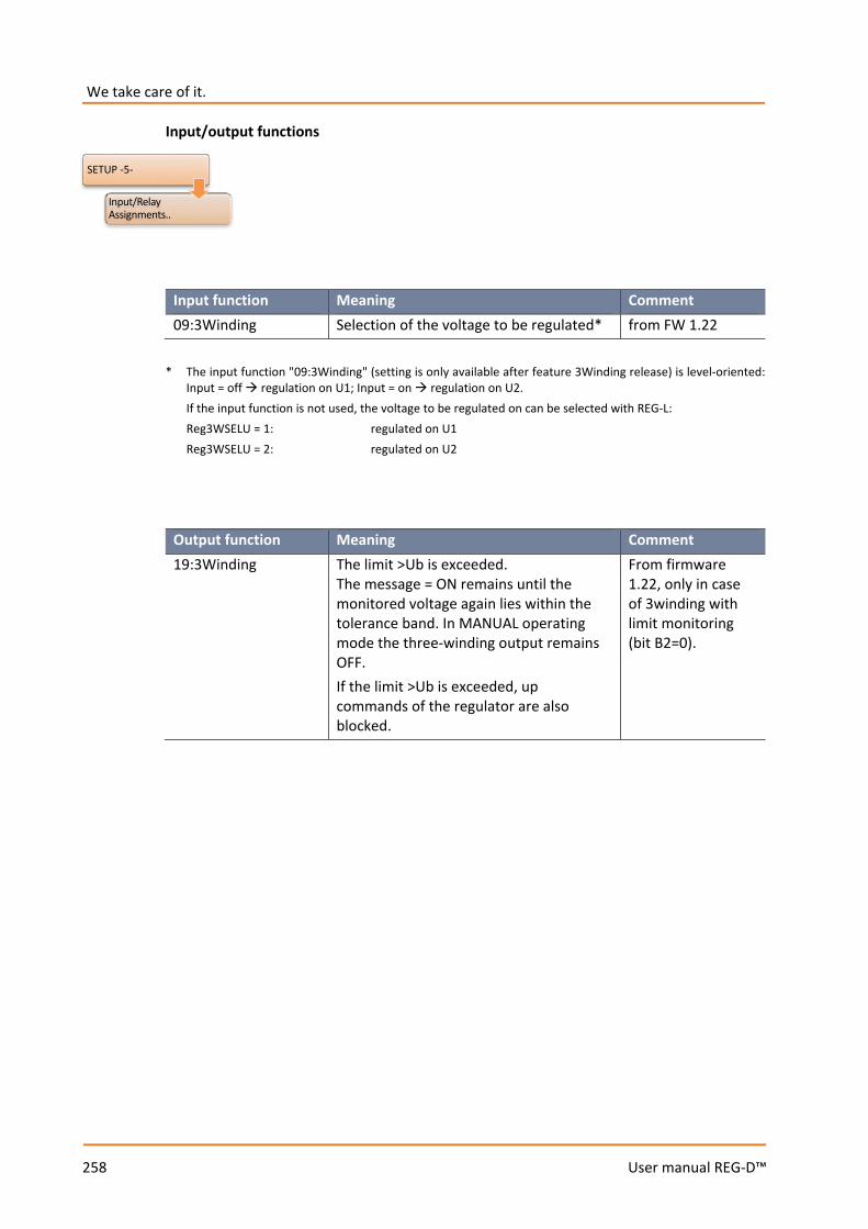
We take care of it.
258
User manual REG-D™
Input/output functions
Input function Meaning Comment 09:3Winding Selection of the voltage to be regulated* from FW 1.22
* The input function "09:3Winding" (setting is only available after feature 3Winding release) is level-oriented:
Input = off regulation on U1; Input = on regulation on U2. If the input function is not used, the voltage to be regulated on can be selected with REG-L: Reg3WSELU = 1: regulated on U1 Reg3WSELU = 2: regulated on U2
Output function Meaning Comment 19:3Winding The limit >Ub is exceeded.
The message = ON remains until the monitored voltage again lies within the tolerance band. In MANUAL operating mode the three-winding output remains OFF. If the limit >Ub is exceeded, up commands of the regulator are also blocked.
From firmware 1.22, only in case of 3winding with limit monitoring (bit B2=0).
SETUP -5-
Input/Relay Assignments..
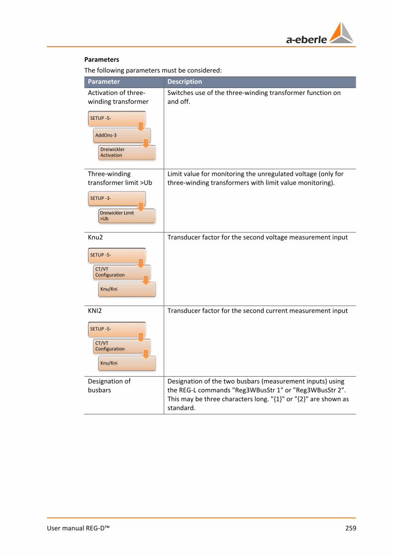
259
User manual REG-D™
Parameters The following parameters must be considered:
Parameter Description Activation of three-winding transformer
Switches use of the three-winding transformer function on and off.
Three-winding transformer limit >Ub
Limit value for monitoring the unregulated voltage (only for three-winding transformers with limit value monitoring).
Knu2 Transducer factor for the second voltage measurement input
KNI2 Transducer factor for the second current measurement input
Designation of busbars
Designation of the two busbars (measurement inputs) using the REG-L commands "Reg3WBusStr 1" or "Reg3WBusStr 2". This may be three characters long. "1" or "2" are shown as standard.
SETUP -5-
CT/VTConfiguration
Knu/Kni
SETUP -5-
CT/VTConfiguration
Knu/Kni
SETUP -5-
AddOns-3
DreiwicklerActivation
SETUP -3-
Dreiwickler Limit >Ub
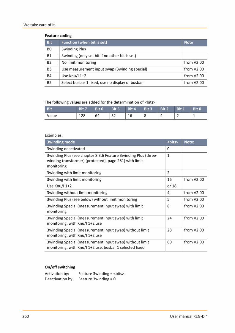
We take care of it.
260
User manual REG-D™
Feature coding Bit Function (when bit is set) Note B0 3winding Plus B1 3winding (only set bit if no other bit is set) B2 No limit monitoring from V2.00 B3 Use measurement input swap (3winding special) from V2.00 B4 Use Knu/I 1+2 from V2.00 B5 Select busbar 1 fixed, use no display of busbar from V2.00
The following values are added for the determination of <bits>:
Bit Bit 7 Bit 6 Bit 5 Bit 4 Bit 3 Bit 2 Bit 1 Bit 0 Value 128 64 32 16 8 4 2 1
Examples:
3winding mode <bits> Note: 3winding deactivated 0 3winding Plus (see chapter 8.3.6 Feature 3winding Plus (three-winding transformer) [protected], page 261) with limit monitoring
1
3winding with limit monitoring 2 3winding with limit monitoring Use Knu/I 1+2
16 or 18
from V2.00
3winding without limit monitoring 4 from V2.00 3winding Plus (see below) without limit monitoring 5 from V2.00 3winding Special (measurement input swap) with limit monitoring
8 from V2.00
3winding Special (measurement input swap) with limit monitoring, with Knu/I 1+2 use
24 from V2.00
3winding Special (measurement input swap) without limit monitoring, with Knu/I 1+2 use
28 from V2.00
3winding Special (measurement input swap) without limit monitoring, with Knu/I 1+2 use, busbar 1 selected fixed
60 from V2.00
On/off switching Activation by: Feature 3winding = <bits> Deactivation by: Feature 3winding = 0
261
User manual REG-D™
8.3.6 Feature 3winding Plus (three-winding transformer) [protected] Tis feature is like the feature 3winding, however with a fixed assignment of the binary input 8 on relay 3. This feature is represented in the status screen with "3winding+" (in brackets with 3winding activation = 0). Note: Up to firmware version V1.97 this feature was called DREIWICKLER. On/off switching Activation by: Feature 3winding = 1 Deactivation by: Feature 3winding = 0
8.3.7 Feature PQCtrl [protected] The feature PQCtrl was developed for regulation of phase shifting transformers, but can also be used for other applications. In case of P/Q regulation, the active and reactive power is controlled rather than the voltage. Properties of the PQCtrl feature 0 The feature PQCtrl can be activated independently of hardware and used with all
REG-D™. Hereby, the date of manufacture of the unit is irrelevant. It may be necessary to update the firmware, depending on the existing firmware version in the original REG-D™ hardware.
0 Four setpoints are available: two voltage setpoints, one active power and one reactive power setpoint.
0 Whether the REG-D™ will operate as a voltage, active power or reactive power regulator, can easily be determined by selecting the appropriate setpoint. For certain applications, selection of setpoints can be limited via a background program.
0 Regulation on P or Q in accordance with the setpoint index SPI: SPI = = 1 : Standard regulation on the voltage RegUN with SP 1. SPI = = 2 : Standard regulation on the voltage RegUN with SP 2. SPI = = 3 : Regulation on P with SP 3 (SP is a power value normalized to 100). The basic regulator display shows the P-value instead of the voltage value. SPI = = 4 : Regulation on Q with SP 4 (SP is a power value normalized to 100). The basic regulator display shows the Q-value instead of the voltage
value. 0 The menus for setting setpoints and indication in the regulator display are adjusted
accordingly. No units can be shown on the large regulator display when using P or Q regulation, because of lack of space (except k for kilo).

We take care of it.
262
User manual REG-D™
Regulator basic display with P setpoint
0 The active and reactive power setpoints can be set in the range from -140% to +140% of
the nominal power. The nominal power is calculated using the following formula:
𝑃𝑃𝑇𝑇 = 𝑄𝑄𝑇𝑇 = √3 × 100𝑘𝑘 × 𝐾𝐾𝑖𝑖𝑖𝑖 × 𝐼𝐼𝑇𝑇 × 𝐾𝐾𝑖𝑖𝐼𝐼
Pr, Qr: Nominal power for setpoint Knu: Transformer factor of the voltage transformer Kni: Transformer factor of the current transformer Ir: Nominal current of the current transformer (1 A or 5 A)
0 All limits of the REG-D™ are also available with the PQCtrl feature. Thereby, the limits
undervoltage <U, overvoltage >U, inhibit low, inhibit high and high-speed switching depend on the measured voltage. As a basis for percentage limits, U-nominal is always used (default: U-nominal=100 V, also when the limit base is set to the setpoint). If the limit base is set to U-nominal = 110 V, the limit base applies in this case not only for the limits undervoltage <U, overvoltage >U and shutdown. The limits overcurrent and undercurrent are derived from the measured current.
0 If a monitoring unit PAN-D is being used in addition to the REG-D™, it will always receive a setpoint of 100 V from REG-D™. This only has an effect if the limit base of the PAN-D is set to setpoint.
0 The key functions of REG-D™ as a Relay for Voltage Control & Transformer Monitoring, such as transducer mode, recorder, statistics unit, transformer monitoring, logbook, and, of course, free programmability via background programs will also remain intact with the feature PQCtrl.
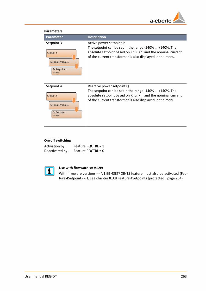
263
User manual REG-D™
Parameters Parameter Description Setpoint 3
Active power setpoint P The setpoint can be set in the range -140% ... +140%. The absolute setpoint based on Knu, Kni and the nominal current of the current transformer is also displayed in the menu.
Setpoint 4
Reactive power setpoint Q The setpoint can be set in the range -140% ... +140%. The absolute setpoint based on Knu, Kni and the nominal current of the current transformer is also displayed in the menu.
On/off switching Activation by: Feature PQCTRL = 1 Deactivated by: Feature PQCTRL = 0
Use with firmware <= V1.99 With firmware versions <= V1.99 4SETPOINTS feature must also be activated (Fea-ture 4Setpoints = 1, see chapter 8.3.8 Feature 4Setpoints [protected], page 264).
SETUP -1-
Setpoint Values..
P- SetpointValue
SETUP -1-
Setpoint Values..
Q- SetpointValue
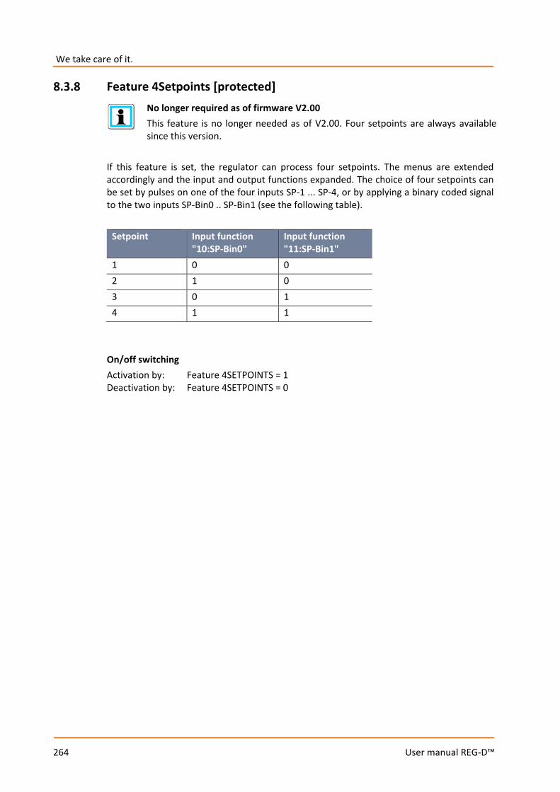
We take care of it.
264
User manual REG-D™
8.3.8 Feature 4Setpoints [protected]
No longer required as of firmware V2.00 This feature is no longer needed as of V2.00. Four setpoints are always available since this version.
If this feature is set, the regulator can process four setpoints. The menus are extended accordingly and the input and output functions expanded. The choice of four setpoints can be set by pulses on one of the four inputs SP-1 ... SP-4, or by applying a binary coded signal to the two inputs SP-Bin0 .. SP-Bin1 (see the following table).
Setpoint Input function "10:SP-Bin0"
Input function "11:SP-Bin1"
1 0 0 2 1 0 3 0 1 4 1 1
On/off switching Activation by: Feature 4SETPOINTS = 1 Deactivation by: Feature 4SETPOINTS = 0
265
User manual REG-D™
8.3.9 Feature Adapt This feature is available as of firmware V2.09 / 17.06.2005, also in V2.02d/f. This feature must be set if one of the following REG-LON versions are used: 0 H1_10U 0 H1_11P On/off switching Activation by: Feature ADAPT = 1 Deactivation by: Feature ADAPT = 0
8.3.10 Feature Bootload
NOTICE! As long as the unit is in bootloader mode, no regulation and other actions may take place. Moreover, no communication via E-LAN or to the SCADA system is possible.
Only activate remote starting of the bootloader when it is absolutely necessary.
If the bootloader is not quit, the unit exits the bootloader automatically after 30 minutes.
The Bootload feature allows remote starting of the bootloader. This means that if the feature is set (= 1), the bootloader can be started via REG-L (e.g. the terminal program or the Service program of WinREG). The feature exists as of firmware V2.22. On/off switching Activation by: Feature Bootload = 1 Deactivation by: Feature Bootload = 0

We take care of it.
266
User manual REG-D™
8.3.11 Feature COM2FIX From firmware version V2.00, with this feature the COM2 interface can be set so that it is no longer adjustable via the panel or REG-L. Coding of the feature
Bit Function with B0 = 1 Function with B0 = 0 B0 1: use B1 ... B7 0: Fixation on current setting B1 0: Mode ECL
1: Mode PROFI always = 1
B2 always = 0 (reserved) 0: SETCOM2 conditionally blocked 1: SETCOM2 completely blocked
B3 0: Baudrate 57600 1: Baudrate 115200
always = 0 (reserved)
B4 always = 0 (reserved) always = 0 (reserved) B5 0: Parity OFF
1: Parity EVEN always = 0 (reserved)
B7 / B6 0/0: Handshake OFF 0/1: Handshake XON/XOFF 1/0: Handshake RTS/CTS 1/1: reserved
always = 0/0 (reserved)
The following values are added for the determination of <bits>:
Bit Bit 7 Bit 6 Bit 5 Bit 4 Bit 3 Bit 2 Bit 1 Bit 0 Value 128 64 32 16 8 4 2 1
Examples: 0 COM2 fixed on current setting: <bits> = 2 0 COM2 fixed on ECL / 57K6 / PE / XON : <bits> = 0b01100001 = 97 0 COM2 fixed on PROFI / 57K6 / PE /H- : <bits> = 0b01100001 = 35 0 COM2 fixed on ECL / 115200 / PE /H- : <bits> = 0b01100001 = 41 On/off switching Activation by: Feature COM2FIX = <bits> Deactivation by: Feature COM2FIX = 0

267
User manual REG-D™
8.3.12 Feature DELTAI With the feature set, the parallel program "3: dI" is available (as of firmware V1.98). Parameters
Parameter Description Permiss. Icirc Permissible circulating current of the parallel program "dI"
Nominal transformer power
Nominal transformer power of the parallel program "dI"
On/off switching Activation by: Feature DELTAI = 1 Deactivation by: Feature DELTAI = 0
Setup -1-
Programs..
Par.Parameter..
Permiss. Icirc
Setup -1-
Programs..
Par.Parameter..
TransformerNominal Power
We take care of it.
268
User manual REG-D™
8.3.13 Feature Invers INVERS without exchanging the higher/lower relay When the feature is activated, on up tap changes the regulator expects a decreasing tap position number, on down tap changes an increasing tap position number. On/off switching Activation by: Feature INVERS = 1 Deactivation by: Feature INVERS = 0 INVERS with exchange of up/down relays When the feature is activated, on up tap changes the regulator expects a decreasing tap position number, versus on down tap changes an increasing tap position number. In addition, an exchange of the relay outputs for up/down tap changes takes place. The relay and LED functions for up or down and the display of tap-change direction in the basic regulator display are also exchanged. This feature variant is available from version V1.88; use with a PAN-D is not possible. On/off switching Activation by: Feature INVERS = 2 Deactivation by: Feature INVERS = 0 More information about the Invers feature and its use can be found in chapter 7.2.2.3 Tap position, page 89.
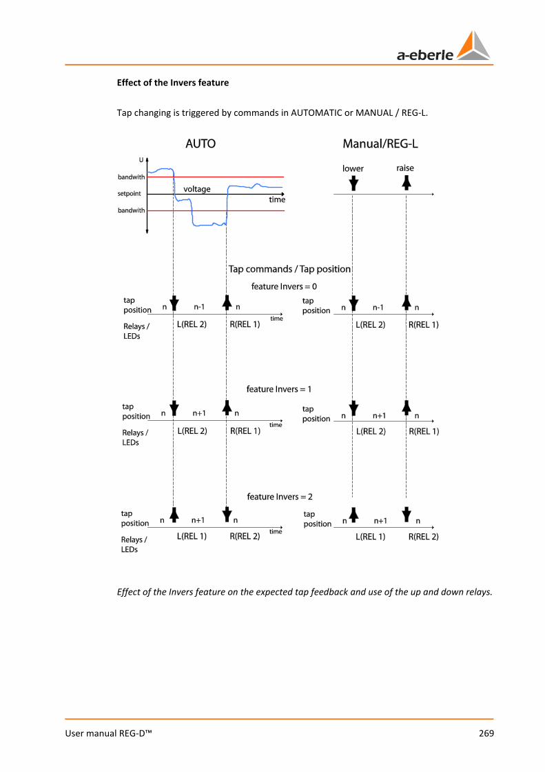
269
User manual REG-D™
Effect of the Invers feature Tap changing is triggered by commands in AUTOMATIC or MANUAL / REG-L.
Effect of the Invers feature on the expected tap feedback and use of the up and down relays.

We take care of it.
270
User manual REG-D™
8.3.14 Feature M2 [protected] The M2 feature, available from firmware V2.00 onwards, allows also for the measurement of an asymmetric grid using an ARON measurement circuit , with the appropriate transducer equipment (hardware feature M2). The following measured values must be connected: the L1, L2 and L3 should be connected to the voltage input transducers U1 and U2, I1 to current input transducer 1 and I3 to current input transducer 2. It is essential to ensure correct polarity or these connections.
Display of ARON readings in transducer mode Parameters
Parameter Description Transducer mounting voltage
For the ARON measurement, the transducer mounting voltage and current must be configured for ARON.
Transducer mounting current
For the ARON measurement, the transducer mounting voltage and current must be configured for ARON.
On/off switching Activation by: Feature M2 = 1 Deactivation by: Feature M2 = 0
SETUP -5-
CT/VTConfiguration
SETUP -5-
CT/VTConfiguration

271
User manual REG-D™
Notes 0 Special case "exchanged current transducer":
Unless I3 is connected to the current input transducer 1, and I1 to the current input transducer 2, the M2 feature must be = 2. If this feature is already activated, assignment can also be done without access enabling / license code (feature M2 = 2).
0 With M2 = 2, the feature MISWAP is deactivated!
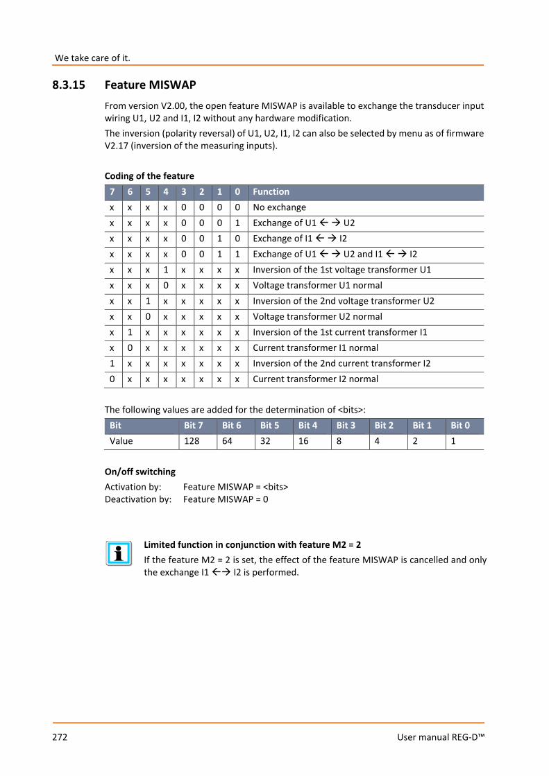
We take care of it.
272
User manual REG-D™
8.3.15 Feature MISWAP From version V2.00, the open feature MISWAP is available to exchange the transducer input wiring U1, U2 and I1, I2 without any hardware modification. The inversion (polarity reversal) of U1, U2, I1, I2 can also be selected by menu as of firmware V2.17 (inversion of the measuring inputs). Coding of the feature
7 6 5 4 3 2 1 0 Function x x x x 0 0 0 0 No exchange x x x x 0 0 0 1 Exchange of U1 U2 x x x x 0 0 1 0 Exchange of I1 I2 x x x x 0 0 1 1 Exchange of U1 U2 and I1 I2 x x x 1 x x x x Inversion of the 1st voltage transformer U1 x x x 0 x x x x Voltage transformer U1 normal x x 1 x x x x x Inversion of the 2nd voltage transformer U2 x x 0 x x x x x Voltage transformer U2 normal x 1 x x x x x x Inversion of the 1st current transformer I1 x 0 x x x x x x Current transformer I1 normal 1 x x x x x x x Inversion of the 2nd current transformer I2 0 x x x x x x x Current transformer I2 normal
The following values are added for the determination of <bits>:
Bit Bit 7 Bit 6 Bit 5 Bit 4 Bit 3 Bit 2 Bit 1 Bit 0 Value 128 64 32 16 8 4 2 1
On/off switching Activation by: Feature MISWAP = <bits> Deactivation by: Feature MISWAP = 0
Limited function in conjunction with feature M2 = 2 If the feature M2 = 2 is set, the effect of the feature MISWAP is cancelled and only the exchange I1 I2 is performed.

273
User manual REG-D™
8.3.16 Feature Qsigned
According to DIN, the reactive power is an unsigned entity: 𝑄𝑄 = 𝑐𝑐2 − 𝑐𝑐2 With the aid of the feature Qsigned, the sign of the reactive power can be activated or deactivated. (The sign always corresponds to the opposite sign of the angle ϕ.)
Firmware <bits>=0 (Default) <bits> = 1 <bits> = 2 V1.30 – V2.02
Q unsigned Q signed -
from V2.03 Q signed Q signed Q unsigned On/off switching Activation by: Feature Qsigned = <bits> Deactivation by: Feature Qsigned = 0
8.3.17 Feature LocalRemote The REG-D™ extended keyboard allows you to switch between local and remote, provided the feature LocalRemote is set accordingly. The input functions "54:LR_STAT" and "53:LR_AH", which, in particular, are employed for using a REG-LR, may not be configured. Switching between local and remote is done with the local/remote key, the selected state being shown with LEDs. The functionality of the local/remote key corresponds to local/remote switching with a binary input. In case of an auxiliary power interruption, the last selected state is maintained. Moreover, with the Reg-L command RegLR_KEY the local/remote state can be changed in addition to a key operation: RegLR_KEY = 0 local RegLR_KEY = 1 remote On/off switching Activation by: Feature LocalRemote = 1 Deactivation by: Feature LocalRemote = 0
Notes 0 If the feature LOCALREMOTE = 2, then you can switch between
Local(0)/Remote(1)/Off(2); Off means that neither local nor remote blocks are applied, the local/remote display is suppressed.
0 If the feature is not activated, the local/remote display is omitted.
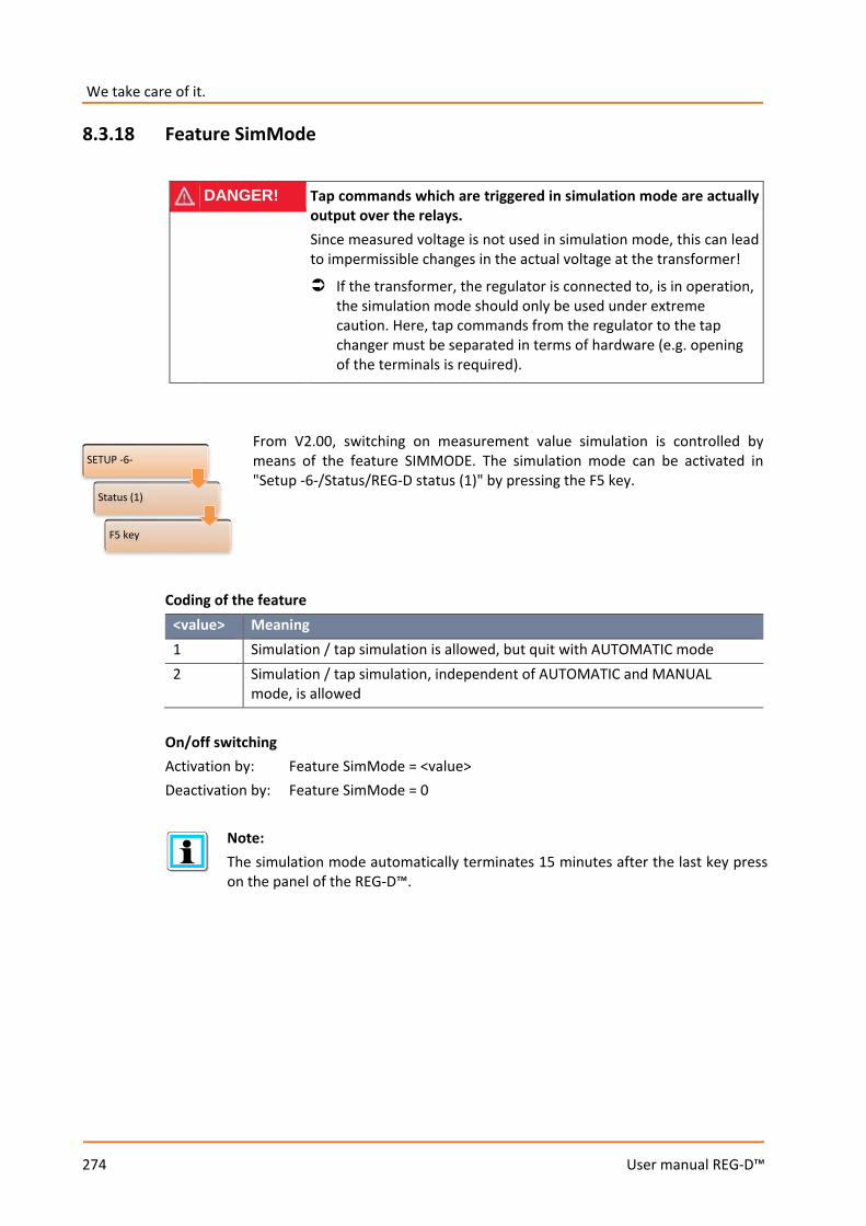
We take care of it.
274
User manual REG-D™
8.3.18 Feature SimMode
DANGER! Tap commands which are triggered in simulation mode are actually output over the relays. Since measured voltage is not used in simulation mode, this can lead to impermissible changes in the actual voltage at the transformer!
If the transformer, the regulator is connected to, is in operation, the simulation mode should only be used under extreme caution. Here, tap commands from the regulator to the tap changer must be separated in terms of hardware (e.g. opening of the terminals is required).
From V2.00, switching on measurement value simulation is controlled by means of the feature SIMMODE. The simulation mode can be activated in "Setup -6-/Status/REG-D status (1)" by pressing the F5 key.
Coding of the feature
<value> Meaning 1 Simulation / tap simulation is allowed, but quit with AUTOMATIC mode 2 Simulation / tap simulation, independent of AUTOMATIC and MANUAL
mode, is allowed On/off switching Activation by: Feature SimMode = <value> Deactivation by: Feature SimMode = 0
Note: The simulation mode automatically terminates 15 minutes after the last key press on the panel of the REG-D™.
SETUP -6-
Status (1)
F5 key
275
User manual REG-D™
8.3.19 Feature SR192 [protected]
NOTICE! This feature may not be activated with REG-D™ firmwares V2.07, V2.08 and V2.09, because in these versions the input BE4 = high-speed switching cannot be used.
Do not activate the feature in the above-mentioned firmware versions. Perform a prior firmware update if activation of the feature is necessary on any relevant device.
This feature controls the assignment of inputs and outputs and switching behavior of the voltage regulation system SR192 (special configuration of REGSys™). BE2 = 1 selects AUTOMATIC operating mode, BE2 = 0 MANUAL operating mode. While the MANUAL operating mode is dominant with BE2 = 0, i.e., no switching to AUTOMATIC mode via the keyboard, with BE2 = 1 the then activated AUTOMATIC operating mode can be freely switched via the keyboard to MANUAL and then back again to AUTOMATIC. As soon as BE2 is active, Trans1 is set and displayed by LED1. With AUTOMATIC mode relay 3 is switched on, with MANUAL mode relay 3 is switched off. On/off switching Activation by: Feature SR192 = 1(2) Deactivation by: Feature SR192 = 0
Specific, non-changeable input and output assignments When the feature is selected, the input assignment for BE2 (Trans1), the output assignment for relay 3 (AUTOMATIC), and the LED assignment for LED 1 (Trans1) cannot be changed. Inputs 5 + 6 for remote adjustment of MANUAL/AUTOMATIC are still active, but their adjustment is subject to the same restrictions as in operation via the keypad (see above). Furthermore, the following applies: Feature SR192 = 1: BE4 is fixed on high-speed switching. Feature SR192 = 2: BE1 is fixed on high-speed switching.
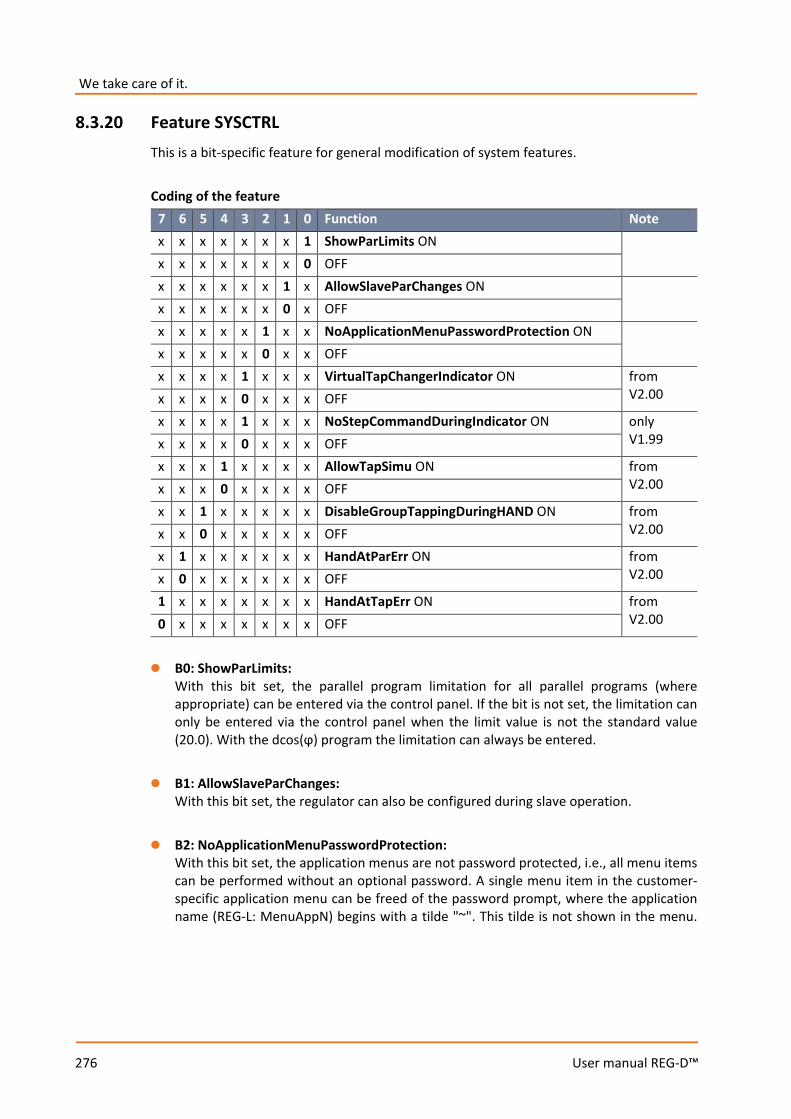
We take care of it.
276
User manual REG-D™
8.3.20 Feature SYSCTRL This is a bit-specific feature for general modification of system features. Coding of the feature
7 6 5 4 3 2 1 0 Function Note x x x x x x x 1 ShowParLimits ON x x x x x x x 0 OFF x x x x x x 1 x AllowSlaveParChanges ON x x x x x x 0 x OFF x x x x x 1 x x NoApplicationMenuPasswordProtection ON x x x x x 0 x x OFF x x x x 1 x x x VirtualTapChangerIndicator ON from
V2.00 x x x x 0 x x x OFF x x x x 1 x x x NoStepCommandDuringIndicator ON only
V1.99 x x x x 0 x x x OFF x x x 1 x x x x AllowTapSimu ON from
V2.00 x x x 0 x x x x OFF x x 1 x x x x x DisableGroupTappingDuringHAND ON from
V2.00 x x 0 x x x x x OFF x 1 x x x x x x HandAtParErr ON from
V2.00 x 0 x x x x x x OFF 1 x x x x x x x HandAtTapErr ON from
V2.00 0 x x x x x x x OFF 0 B0: ShowParLimits:
With this bit set, the parallel program limitation for all parallel programs (where appropriate) can be entered via the control panel. If the bit is not set, the limitation can only be entered via the control panel when the limit value is not the standard value (20.0). With the dcos(ϕ) program the limitation can always be entered.
0 B1: AllowSlaveParChanges:
With this bit set, the regulator can also be configured during slave operation. 0 B2: NoApplicationMenuPasswordProtection:
With this bit set, the application menus are not password protected, i.e., all menu items can be performed without an optional password. A single menu item in the customer-specific application menu can be freed of the password prompt, where the application name (REG-L: MenuAppN) begins with a tilde "~". This tilde is not shown in the menu.
277
User manual REG-D™
0 B3: VirtualTapChangerIndicator (available from REG-D™ V2.00): During the up/down relay switching phase and during TC in operation signal activity, further pending up or down tap commands are generally deleted from V2.00. The bit functionality introduced with V1.99 NoStepCommandDuringIndicator is therefore no longer necessary. But if the regulator or the corresponding PAN-D is not supplied with TC in operation information, the up/down tap command lock will only engage during the up/down relay switching phase. On setting the VirtualTapChangerIndicator bit, the TC in operation signal activity is simulated, so that the tap command lock can engage during the imaginary TC in operation signal activity in this case. The parameter maximum time TC in operation (RegTLaufl) determines the activity duration of the virtual TC in operation, there can be no TC in operation failure in the virtual mode. Note: Connection of a TC in operation on the REG-D™ or the PAN-D lead to deactivation of the virtual TC in operation functionality.
0 B3: NoStepCommandDuringIndicator (only available with REG-D™ V1.99):
New up or down tap commands are erased during the up/down relay switching phase. Once the corresponding relay is de-energized, tap commands are stored and carried out after the cycle time (this depends on the TC in operation time or the actual TC in operation signal activity). If the bit is set, the tap commands are not only deleted during the up/down relay switching phase, but throughout the entire switching phase. Note: As of V2.00, tap commands are generally deleted throughout the switching phase (behavior as with the bit set). Bit 3 is indeed ignored, but should be set to 0.
0 B4 : AllowTapSimu (available from REG-D™ V2.00):
In the AddOns menu, with bit 4 set, tap position can be selected besides 0:OFF and 3:ON and also 4:TapSimu. If "4:TapSimu" is selected, the tap position is non-volatilely simulated (up commands increment, down commands decrement the tap value, change of tap with REG-L command RegTapNV). The INVERS feature is observed, i.e., with the feature set, up commands reduce the tap value. The value range is limited to +/-40. The value from RegTAPNV is debounced like a normal input value at 1s, hence the new tap value will only appear after 1s.
0 B5 : DisableGroupTappingDuringHAND (available from REG-D™ V2.00):
With the bit not set the entire group is tap changed by the master in the manual mode. If the bit is set, tap commands from the master in manual mode are not routed to the group (behavior as in V1.99).
0 B6 : HandAtParErr (available from REG-D™ V2.00):
With this bit set, the regulator switches to MANUAL mode as soon as a parallel error is present.
0 B7 : HandAtParErr (available from REG-D™ V2.00):
With this bit set, the regulator switches to MANUAL mode as soon as a tap error is present.
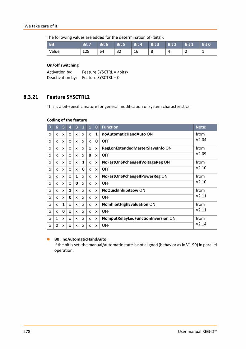
We take care of it.
278
User manual REG-D™
The following values are added for the determination of <bits>: Bit Bit 7 Bit 6 Bit 5 Bit 4 Bit 3 Bit 2 Bit 1 Bit 0 Value 128 64 32 16 8 4 2 1
On/off switching Activation by: Feature SYSCTRL = <bits> Deactivation by: Feature SYSCTRL = 0
8.3.21 Feature SYSCTRL2 This is a bit-specific feature for general modification of system characteristics. Coding of the feature
7 6 5 4 3 2 1 0 Function Note: x x x x x x x 1 noAutomaticHandAuto ON from
V2.04 x x x x x x x 0 OFF x x x x x x 1 x RegLonExtendedMasterSlaveInfo ON from
V2.09 x x x x x x 0 x OFF x x x x x 1 x x NoFastOnSPchangeIfVoltageReg ON from
V2.10 x x x x x 0 x x OFF x x x x 1 x x x NoFastOnSPchangeIfPowerReg ON from
V2.10 x x x x 0 x x x OFF x x x 1 x x x x NoQuickInhibitLow ON from
V2.11 x x x 0 x x x x OFF x x 1 x x x x x NoInhibitHighEvaluation ON from
V2.11 x x 0 x x x x x OFF x 1 x x x x x x NoInputRelayLedFunctionInversion ON from
V2.14 x 0 x x x x x x OFF 0 B0 : noAutomaticHandAuto:
If the bit is set, the manual/automatic state is not aligned (behavior as in V1.99) in parallel operation.

279
User manual REG-D™
0 B1 : RegLonExtendedMasterSlaveInfo (available from REG-D™ V2.09 and V2.02e): If the bit is set, the following data points in the REGLON structure are modified as follows:
Data point B1 = 0 B1 = 1 REGLON.TC_Single_Parallel ParallelProgramActive IsActiveMaster OR
IsSlave REGLON.TC_Master (NOT IsSlave) AND
ParallelProgramActive AND (ParProg = Master or MasterFollower)
IsActiveMaster
0 B2 : NoFastOnSPchangeIfVoltageReg:
Normally (B2 = 0) with voltage regulation and a setpoint change, high-speed switching mode is automatically activated until the voltage value lies wihtin the tolerance band again. If bit B2 is set (B2 = 1), high-speed switching is NOT activated in the case just described.
0 B3 : NoFastOnSPchangeIfPowerReg:
Normally (B3 = 0) with power regulation and a setpoint change (setpoint 3 or 4 + software feature PQCtrl), high-speed switching is automatically activated until the power value again lies within the tolerance band. If bit B3 is set (B3 = 1), high-speed switching is NOT activated.
0 B4 : NoQuickInhibitLow:
If this bit is set (B4 = 1), no quick shutdown detection with undervoltage (U <60 V) is carried out, so the appropriate time delay must pass before shutdown occurs (inhibit low). Processing of the shutdown input or the REG-L shutdown command is not affected by this bit.
0 B5 : NoInhibitHighEvaluation:
If this bit is set (B5 = 1), no triggering request (inhibit high) is evaluated and the menu item disappears (the associated REG-L commands can still be used, but without an effect).
0 B6 : NoInputRelayLedFunctionInversion:
If this bit is set (B6 = 1), input, relay and LED functions cannot be inverted, the related list boxes correspond to the list boxes used up to V2.12 with F3:ENTER instead of F3:INV. Reason: Forcing the behavior up to and including V2.12.
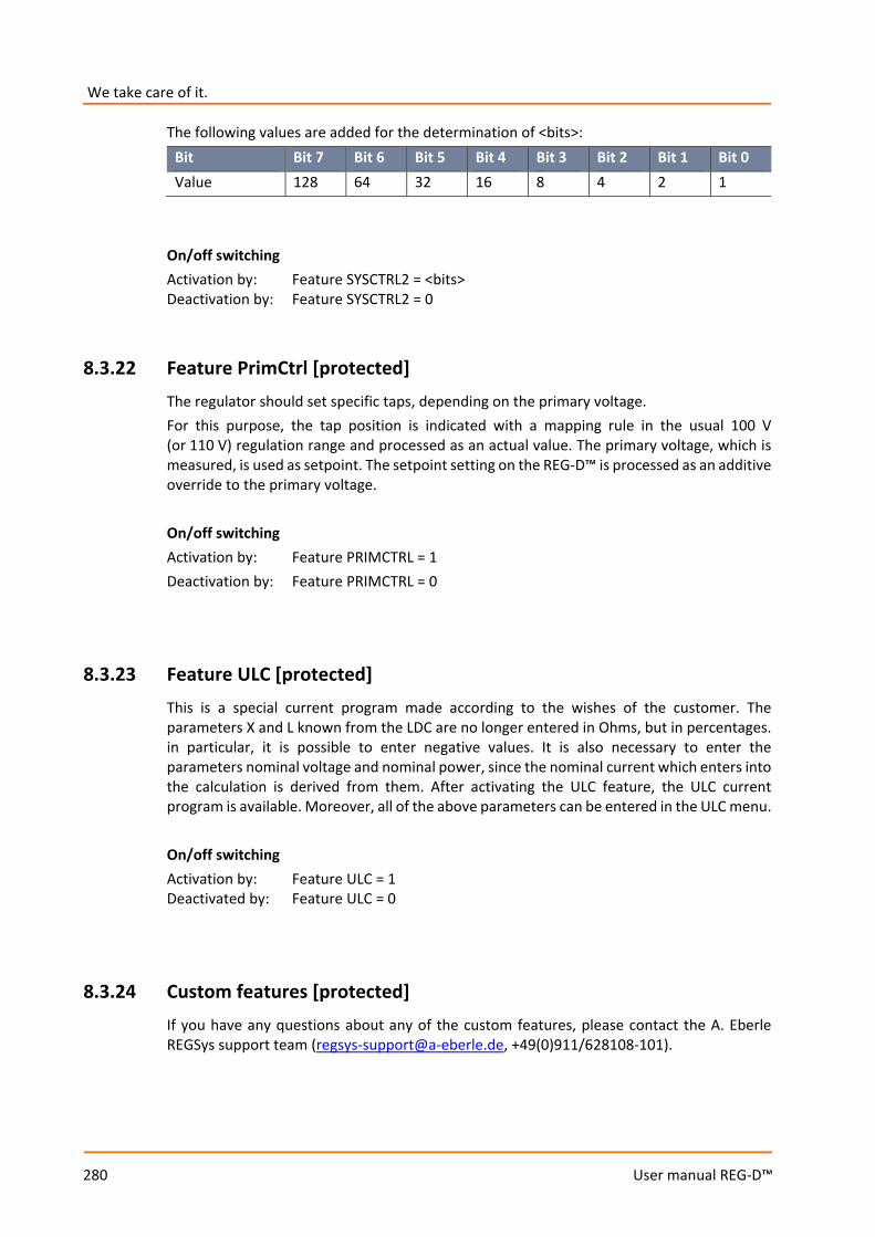
We take care of it.
280
User manual REG-D™
The following values are added for the determination of <bits>: Bit Bit 7 Bit 6 Bit 5 Bit 4 Bit 3 Bit 2 Bit 1 Bit 0 Value 128 64 32 16 8 4 2 1
On/off switching Activation by: Feature SYSCTRL2 = <bits> Deactivation by: Feature SYSCTRL2 = 0
8.3.22 Feature PrimCtrl [protected] The regulator should set specific taps, depending on the primary voltage. For this purpose, the tap position is indicated with a mapping rule in the usual 100 V (or 110 V) regulation range and processed as an actual value. The primary voltage, which is measured, is used as setpoint. The setpoint setting on the REG-D™ is processed as an additive override to the primary voltage. On/off switching Activation by: Feature PRIMCTRL = 1 Deactivation by: Feature PRIMCTRL = 0
8.3.23 Feature ULC [protected] This is a special current program made according to the wishes of the customer. The parameters X and L known from the LDC are no longer entered in Ohms, but in percentages. in particular, it is possible to enter negative values. It is also necessary to enter the parameters nominal voltage and nominal power, since the nominal current which enters into the calculation is derived from them. After activating the ULC feature, the ULC current program is available. Moreover, all of the above parameters can be entered in the ULC menu. On/off switching Activation by: Feature ULC = 1 Deactivated by: Feature ULC = 0
8.3.24 Custom features [protected] If you have any questions about any of the custom features, please contact the A. Eberle REGSys support team ([email protected], +49(0)911/628108-101).

281
User manual REG-D™
8.4 Background programs and the programming language REG-L
8.4.1 Programming language REG-L REG-L is the programming language for all devices of the A. Eberle REGSys™ family: REG-D™, PAN-D, REG-DA, REG-DP, MMU-D, EOR-D, REG-DMA and REG-DM. The language is used: 0 For communication between REGSys™ devices via E-LAN 0 For reading measured values, device states and parameters 0 For configuring REGSys™ devices 0 In H-programs in order to realize customer-specific additional functions 0 For communication with the configuration software WinREG REG-L is an interpreted language, which uses the inverted Polish notation. This type of notation allows a very effective, short notation. There is a general instruction set which is supported by all devices. In addition to the general instruction set each device knows more commands that are specific to the device. Instruction syntax An instruction consists of: <identifier:><instruction><extension> <parameter1> <para.2> ... =<parameter1> <para.2> ... 0 A comma (or ;) separates instructions 0 A space separates parameters 0 Upper/lower case is not distinguished 0 All REG-D™/PAN-D specific instructions begin with the prefix "Reg..."
(e.g. RegAuto, RegREL, ...) 0 further prefixes: "Esp..." for REG-DP; "mmu..." for MMU-D; "Eor..." for EOR-D; 0 Help: Is called with "?" and a terminal designation (e.g. "? analog“ or "? syntax“) 0 With "? book" the entire help text of the REGSys™ device is issued.
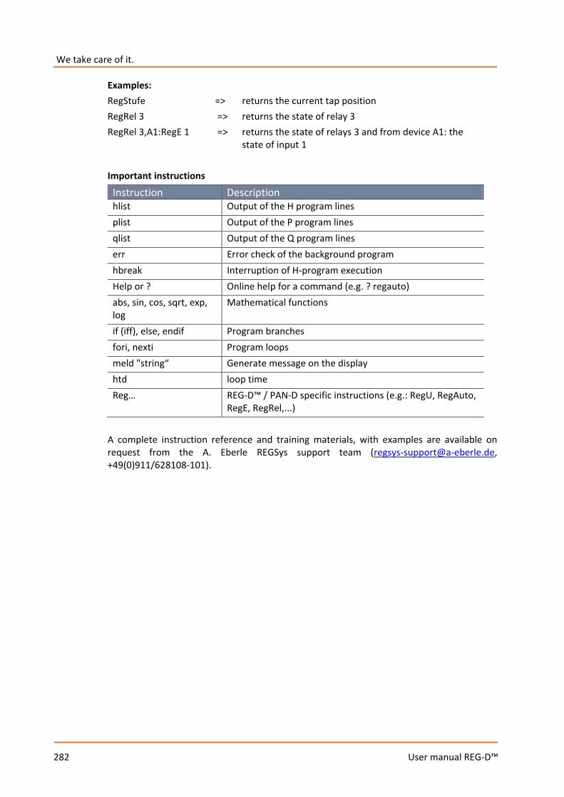
We take care of it.
282
User manual REG-D™
Examples: RegStufe => returns the current tap position RegRel 3 => returns the state of relay 3 RegRel 3,A1:RegE 1 => returns the state of relays 3 and from device A1: the state of input 1 Important instructions
Instruction Description hlist Output of the H program lines plist Output of the P program lines qlist Output of the Q program lines err Error check of the background program hbreak Interruption of H-program execution Help or ? Online help for a command (e.g. ? regauto) abs, sin, cos, sqrt, exp, log
Mathematical functions
if (iff), else, endif Program branches fori, nexti Program loops meld "string“ Generate message on the display htd loop time Reg… REG-D™ / PAN-D specific instructions (e.g.: RegU, RegAuto,
RegE, RegRel,...) A complete instruction reference and training materials, with examples are available on request from the A. Eberle REGSys support team ([email protected], +49(0)911/628108-101).

283
User manual REG-D™
8.4.2 Background programs Background programs (H-programs) consist of program lines, each with a number of REG-L instructions. A background program consists of the following components: 0 H-lines (executed cyclically) 0 P-lines (only executed with an explicit call) 0 Q-lines (only executed with an explicit call) 0 Application menus to enter and display user-specific parameters and values 0 User variables to store and transfer user-specific parameters 0 User-Definable-Menu (UDM) for creating fully customized screens and complement the
background programs. UDMs are only supported by devices with the S2 feature. In general, background programs created by A. Eberle are delivered as ASCII text files. Each background program includes a description of the functions and the resources used in the form of a PDF file or another ASCII text file. The background programs have device-specific file extensions (*.rgl for REG-D™, *.pnl for PAN-D, *.dpl for REG-DP, *.mml for MMU-D, *.eol for EOR-D). That is, a background program for a REG-D™ is, for example, called "REG-L_example_for_UserManual_V01.rgl“. UDM files are also ASCII text files and can be used on devices with the S2 feature, in addition to, or as a substitute for, the classic background program (e.g. *.rgl). They have the file extension *.udm.
8.4.2.1 Loading H-programs in a device
General – Establish a connection between the REG-D™ and the PC. – Set the interface on the regulator under: "Setup -6-\RS232\COM1" or COM2 – The interface (baudrate) used in the program must be set the same as for the
regulator! – Instructions on how to load the background program into the regulator, including
allocation of the serial cable are found in the readme file of the background program. Loading with the software REGUpdate (update32.exe), (classic H-program, no UDM)
– Setting the interface under Configuration – Selection of H-program under Update -> REG-L Download – Sending the H-program (only possible on directly connected devices)
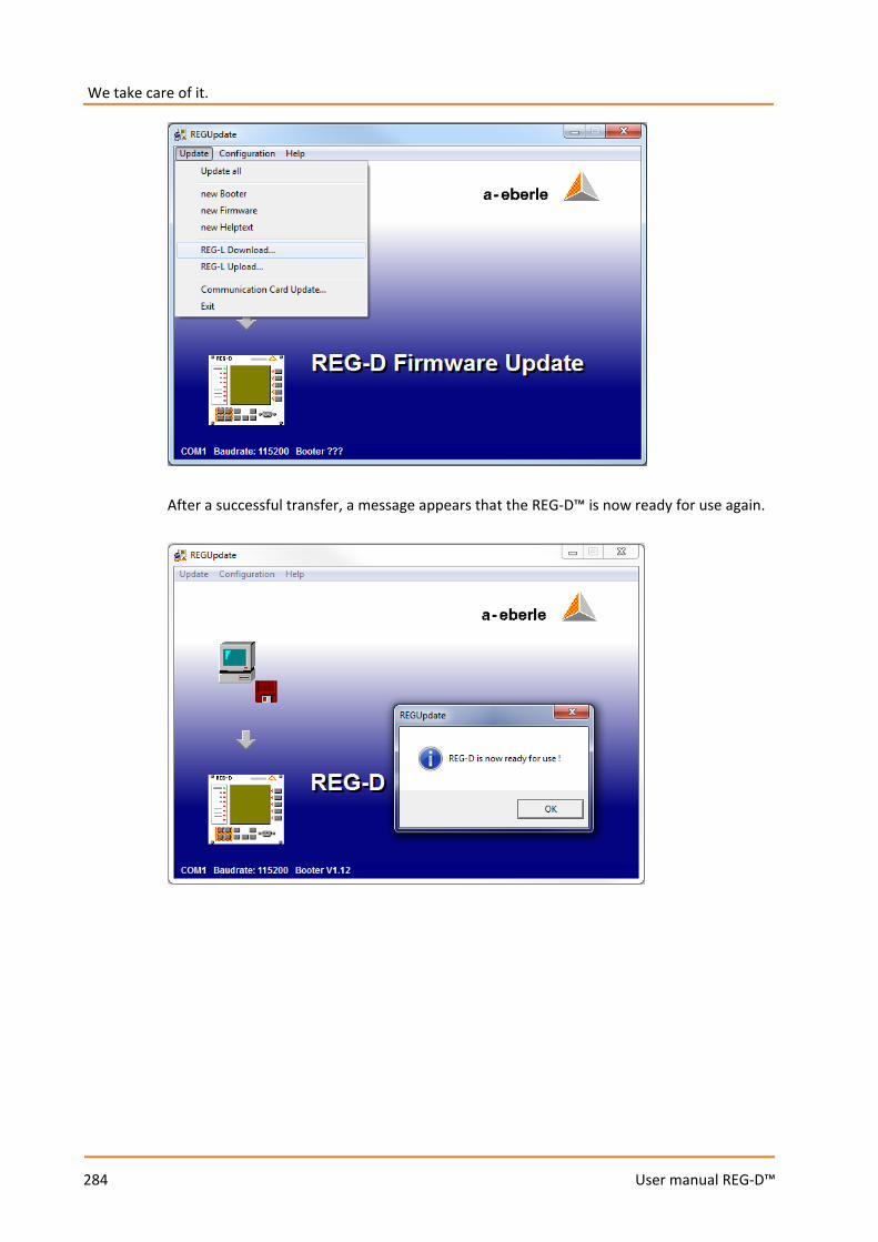
We take care of it.
284
User manual REG-D™
After a successful transfer, a message appears that the REG-D™ is now ready for use again.
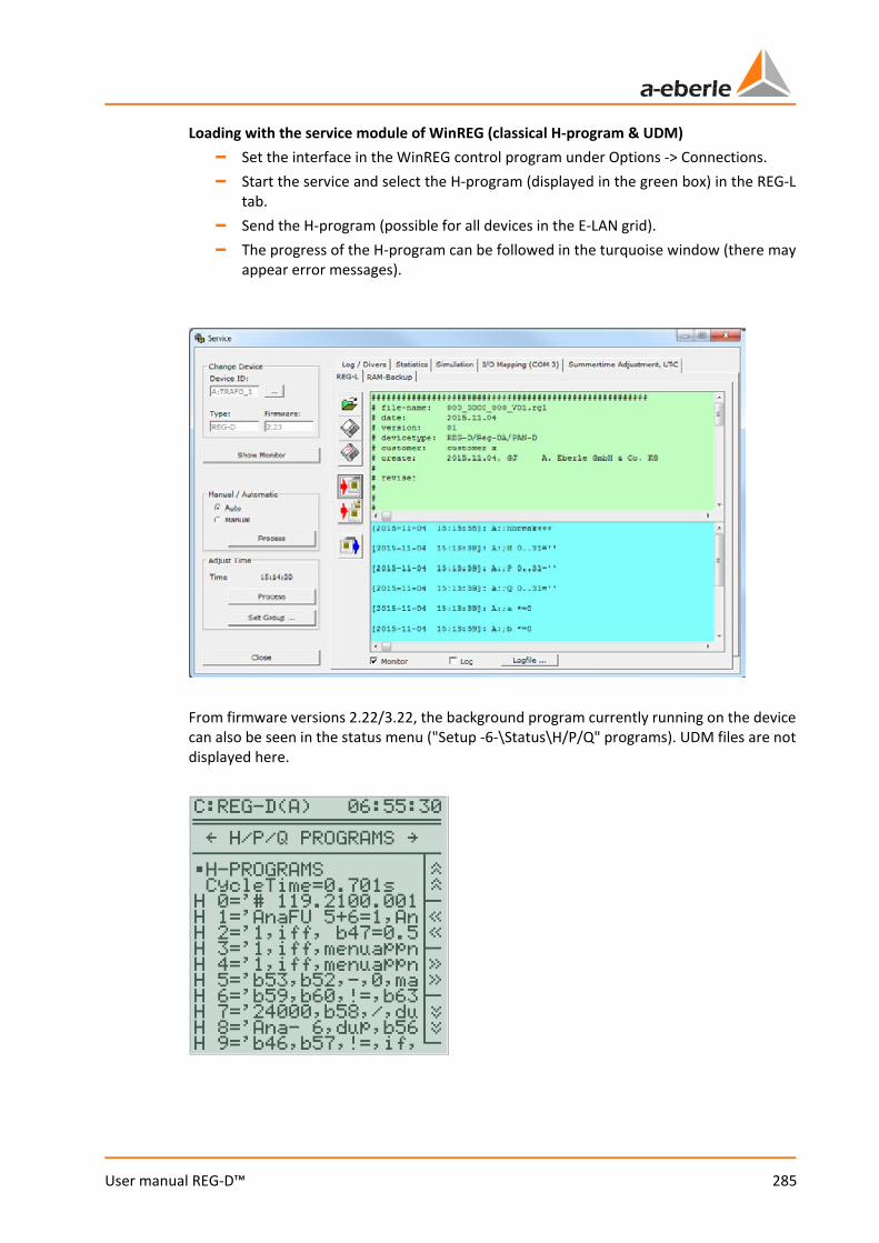
285
User manual REG-D™
Loading with the service module of WinREG (classical H-program & UDM) – Set the interface in the WinREG control program under Options -> Connections. – Start the service and select the H-program (displayed in the green box) in the REG-L
tab. – Send the H-program (possible for all devices in the E-LAN grid). – The progress of the H-program can be followed in the turquoise window (there may
appear error messages).
From firmware versions 2.22/3.22, the background program currently running on the device can also be seen in the status menu ("Setup -6-\Status\H/P/Q" programs). UDM files are not displayed here.

We take care of it.
286
User manual REG-D™
8.4.2.2 Reading H-programs from a device
To read the H-program from the device, the PC software REGUpdate (update32.exe, Update -> REG-L Upload), or the service module of WinREG (REG-L tab) can be used.
The use of the original background program is recommended! The read out background program file no longer contains any comments, and any REG-L commands executed besides the H/P/Q lines during the download cannot be restored! Therefore, it is always advisable to load the original background program (e.g. the *.rgl file).
8.4.2.3 Deleting H-programs
The background program is deleted by loading an empty background program, as well as via a terminal program. For this purpose, please contact the A. Eberle REGSys support team ([email protected], +49(0)911/628108-101).
287
User manual REG-D™
9. Configuration and display software WinREG
9.1 General The WinREG software is used to configure and program the A. Eberle REG-D™ Relay for Voltage Control & Transformer Monitoring. WinREG has a modular structure and consists of several programs for control and configuration of the Relay for Voltage Control & Transformer Monitoring, as well as storage and display of data from it. WinREG is designed so that a plurality of subprograms can access the connected devices (e.g. Panel and Service) at the same time. An exception is the Terminal. If this is in online mode, no access of another WinREG program is possible via this interface. The SCADA system connections of the Relay for Voltage Control & Transformer Monitoring are performed using the SCADA system configuration software WinConfig. Instructions for WinConfig software use are not included in this manual.
WinREG version The following chapters describe WinREG version 3.9 (R6) in detail.
9.2 Installation To run the WinREG software, the minimum hardware and software configuration is:
– A Personal Computer with a Pentium core – 512 MB RAM – 50 MB free disk space – A serial interface or an USB with an USB serial adapter,
or a network card for devices that are connected via TCP/IP – Windows XP, Vista, Windows 7, Windows 8, Windows Server as of 2003 – Microsoft DotNet Framework 3.5
During installation administrator rights are required To install the software you start Windows. Do not insert the installation CD-ROM into the CD drive yet. 1. Run the "Software" program in the control panel folder
("Start/Settings/Control Panel"). 2. An alphabetical list of all installed programs appears. Check first if WinREG is already
listed.
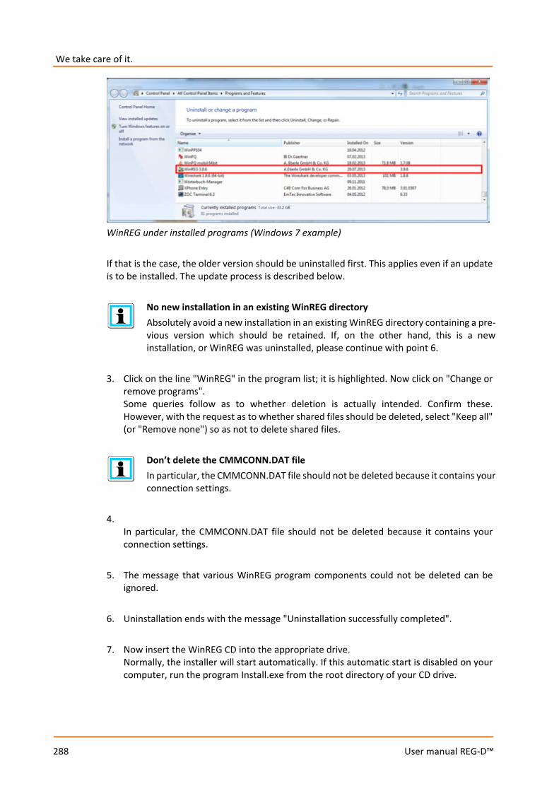
We take care of it.
288
User manual REG-D™
WinREG under installed programs (Windows 7 example)
If that is the case, the older version should be uninstalled first. This applies even if an update is to be installed. The update process is described below.
No new installation in an existing WinREG directory Absolutely avoid a new installation in an existing WinREG directory containing a pre-vious version which should be retained. If, on the other hand, this is a new installation, or WinREG was uninstalled, please continue with point 6.
3. Click on the line "WinREG" in the program list; it is highlighted. Now click on "Change or
remove programs". Some queries follow as to whether deletion is actually intended. Confirm these. However, with the request as to whether shared files should be deleted, select "Keep all" (or "Remove none") so as not to delete shared files.
Don’t delete the CMMCONN.DAT file In particular, the CMMCONN.DAT file should not be deleted because it contains your connection settings.
4.
In particular, the CMMCONN.DAT file should not be deleted because it contains your connection settings.
5. The message that various WinREG program components could not be deleted can be
ignored. 6. Uninstallation ends with the message "Uninstallation successfully completed". 7. Now insert the WinREG CD into the appropriate drive.
Normally, the installer will start automatically. If this automatic start is disabled on your computer, run the program Install.exe from the root directory of your CD drive.

289
User manual REG-D™
REGSys™ installation program 8. The Home screen appears. You can choose the installation language in the left column
and install the programs you need by clicking on the text in the middle column.
Instruction: If you received the WinREG installation via email or by other means (A. Eberle Homepage, USB pendrive), please run setup.exe directly. The other steps are iden-tical to installing WinREG from the CD.
9. The program directory c:\programme\a-eberle\WinREG3 is proposed.
10. All further steps are described by appropriate instructions and queries. 11. When the installation is complete, you will find the WinREG Control Center under
Start/programs.
WinREG Control Center (standard version) The control center program contains the panel, terminal, REGSys configuration (REGPara), service, desktop load and desktop save. The additional modules RegView and Collector (collector/recorder) are optional and included only if they have been ordered. The same applies to WinTM and WinDM. The additional programs RegView, Collector, WinTM and WinDM must be installed separately. If you have installed the additional programs, the respective symbol appears in colour automatically after installing the program.

We take care of it.
290
User manual REG-D™
The panel does not start If, after successful installation, the panel does not start and an error message ap-pears instead, then please check the installation of Microsoft DotNet Framework 3.5 on your PC. You can find a version of the Framework, which can be installed without an Internet connection, on the WinREG CD.
USB drivers for devices with the I1 feature If your REGSysTM device has an interface to COM1 (feature I1) via USB, the desired driver can be installed via the menu item "USB driver for REGSys". If communication with the device takes place via a serial interface (RS232), USB/serial converter, or TCP/IP, installation of the USB driver is not necessary. The driver only works with A. Eberle devices which are equipped with a built-in USB interface. Please use the driver supplied by the manufacturer of the driver for an external USB/serial con-verter.
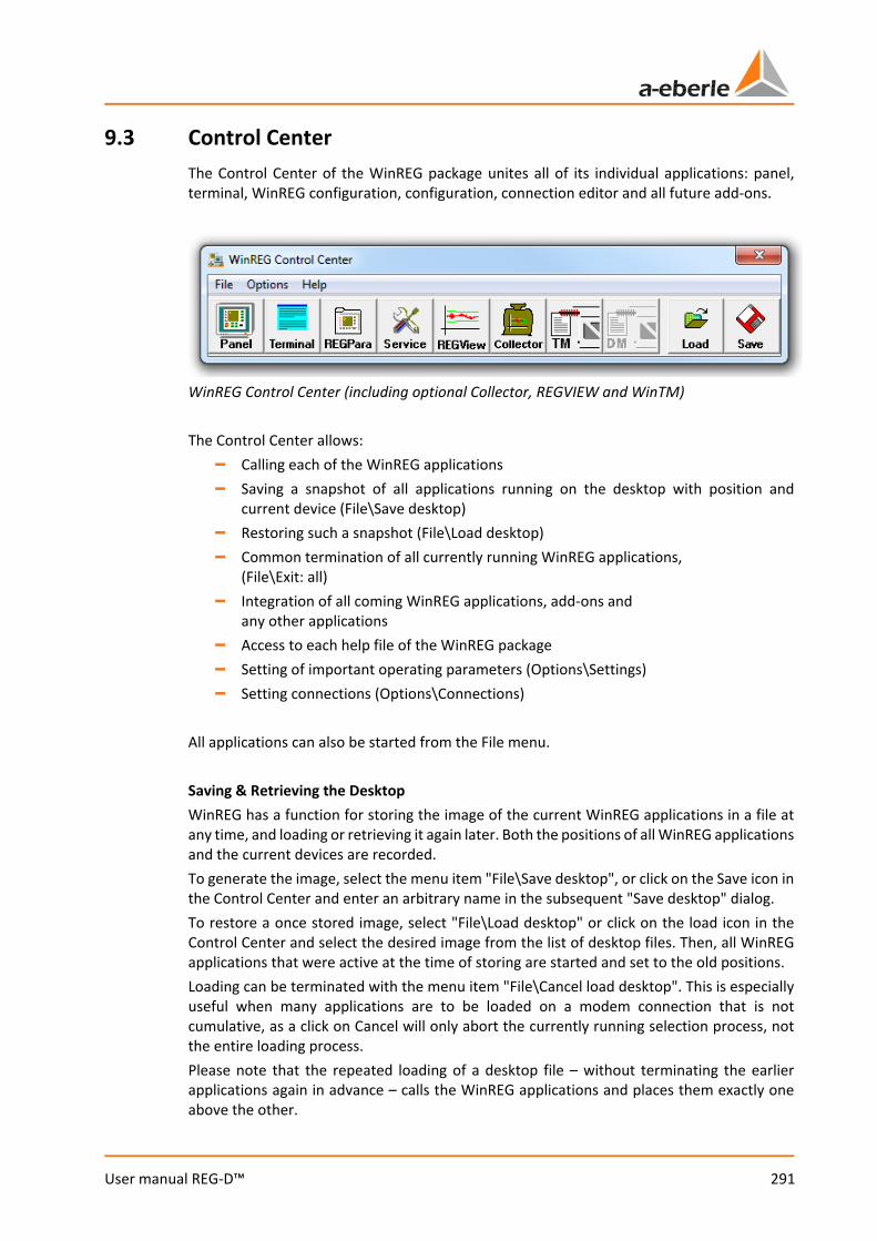
291
User manual REG-D™
9.3 Control Center The Control Center of the WinREG package unites all of its individual applications: panel, terminal, WinREG configuration, configuration, connection editor and all future add-ons.
WinREG Control Center (including optional Collector, REGVIEW and WinTM) The Control Center allows:
– Calling each of the WinREG applications – Saving a snapshot of all applications running on the desktop with position and
current device (File\Save desktop) – Restoring such a snapshot (File\Load desktop) – Common termination of all currently running WinREG applications,
(File\Exit: all) – Integration of all coming WinREG applications, add-ons and
any other applications – Access to each help file of the WinREG package – Setting of important operating parameters (Options\Settings) – Setting connections (Options\Connections)
All applications can also be started from the File menu. Saving & Retrieving the Desktop WinREG has a function for storing the image of the current WinREG applications in a file at any time, and loading or retrieving it again later. Both the positions of all WinREG applications and the current devices are recorded. To generate the image, select the menu item "File\Save desktop", or click on the Save icon in the Control Center and enter an arbitrary name in the subsequent "Save desktop" dialog. To restore a once stored image, select "File\Load desktop" or click on the load icon in the Control Center and select the desired image from the list of desktop files. Then, all WinREG applications that were active at the time of storing are started and set to the old positions. Loading can be terminated with the menu item "File\Cancel load desktop". This is especially useful when many applications are to be loaded on a modem connection that is not cumulative, as a click on Cancel will only abort the currently running selection process, not the entire loading process. Please note that the repeated loading of a desktop file – without terminating the earlier applications again in advance – calls the WinREG applications and places them exactly one above the other.

We take care of it.
292
User manual REG-D™
Setting language The language of WinREG can be set in the "Options\Language" menu or using the F9 key. Backing up and restoring connections WinREG connections can be backed up to a file and restored from a file via the menu items "Options\Save connections" and "Options\Restore connections". Thereby, for example, all connections of an existing WinREG installation can be moved to a new installation on another PC.

293
User manual REG-D™
9.4 Communication with an A. Eberle device (e.g. REG-D™)
9.4.1 Connection settings WinREG's communication connections are set up and managed in the menu "Options\Connections". The default connection is indicated with a white "S" placed in a red ellipse. This connection is opened as soon as a WinREG subprogram starts.
WinREG "Edit Connections" A. Eberle devices which are equipped with a USB interface (feature I1), are automatically detected by WinREG. If a USB device is connected to the PC, the corresponding driver must be installed first. This driver is included on the WinREG CD. If the WinREG connection dialog opens, a connection is automatically created for each connected A. Eberle USB device. This is confirmed by a message. Subsequently, the desired device can now be selected in the connection list. With USB devices, the assigned COM interface is displayed in the phone field. This information is useful when the A. Eberle USB device is to be used with a program that does not support automatic recognition. With the "USB device" button details such as driver version of the connected devices can be displayed.
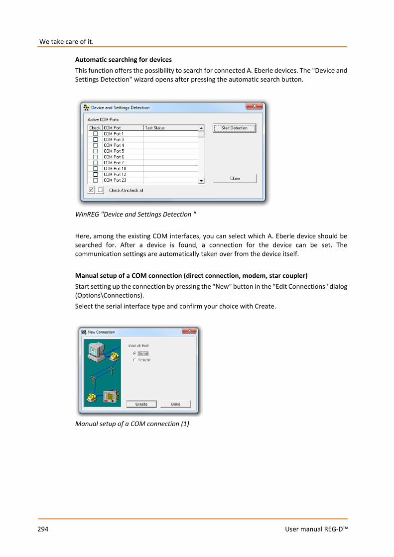
We take care of it.
294
User manual REG-D™
Automatic searching for devices This function offers the possibility to search for connected A. Eberle devices. The "Device and Settings Detection" wizard opens after pressing the automatic search button.
WinREG "Device and Settings Detection " Here, among the existing COM interfaces, you can select which A. Eberle device should be searched for. After a device is found, a connection for the device can be set. The communication settings are automatically taken over from the device itself. Manual setup of a COM connection (direct connection, modem, star coupler) Start setting up the connection by pressing the "New" button in the "Edit Connections" dialog (Options\Connections). Select the serial interface type and confirm your choice with Create.
Manual setup of a COM connection (1)
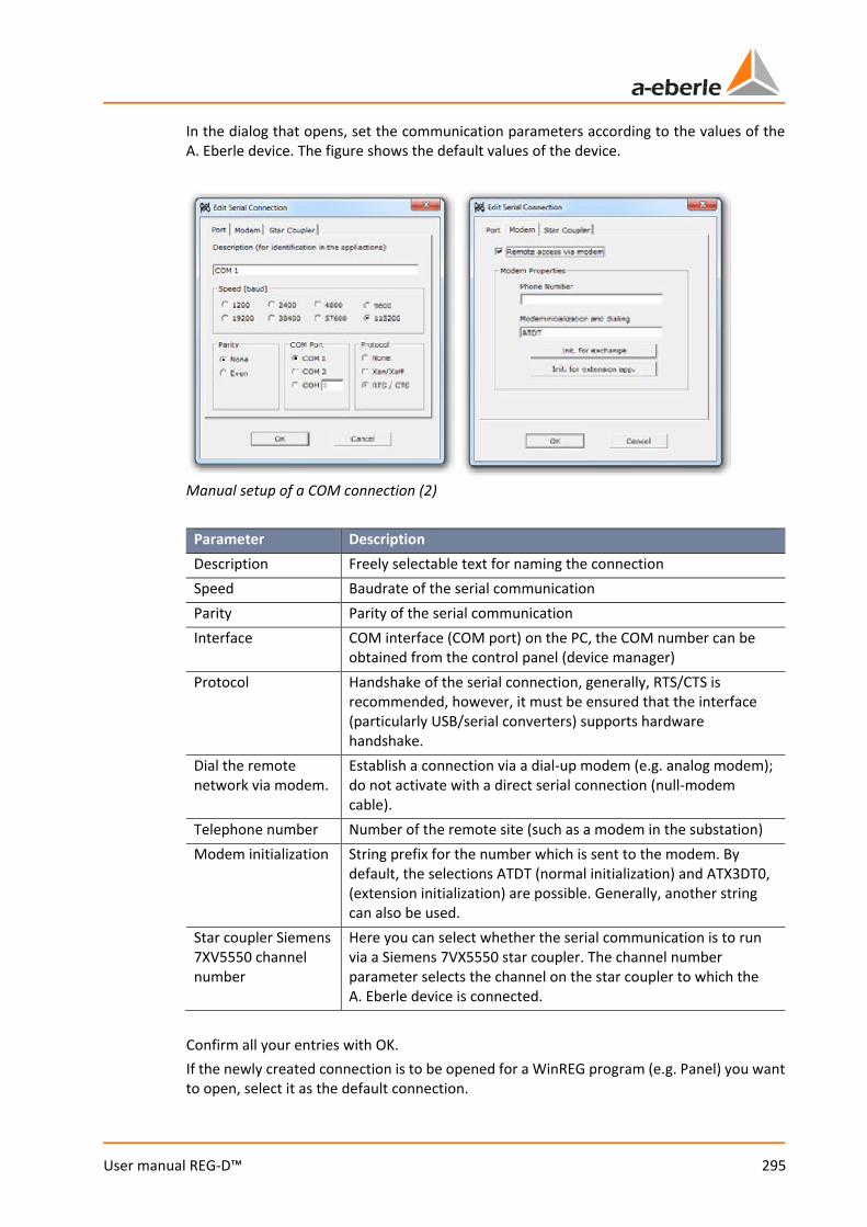
295
User manual REG-D™
In the dialog that opens, set the communication parameters according to the values of the A. Eberle device. The figure shows the default values of the device.
Manual setup of a COM connection (2)
Parameter Description Description Freely selectable text for naming the connection Speed Baudrate of the serial communication Parity Parity of the serial communication Interface COM interface (COM port) on the PC, the COM number can be
obtained from the control panel (device manager) Protocol Handshake of the serial connection, generally, RTS/CTS is
recommended, however, it must be ensured that the interface (particularly USB/serial converters) supports hardware handshake.
Dial the remote network via modem.
Establish a connection via a dial-up modem (e.g. analog modem); do not activate with a direct serial connection (null-modem cable).
Telephone number Number of the remote site (such as a modem in the substation) Modem initialization String prefix for the number which is sent to the modem. By
default, the selections ATDT (normal initialization) and ATX3DT0, (extension initialization) are possible. Generally, another string can also be used.
Star coupler Siemens 7XV5550 channel number
Here you can select whether the serial communication is to run via a Siemens 7VX5550 star coupler. The channel number parameter selects the channel on the star coupler to which the A. Eberle device is connected.
Confirm all your entries with OK. If the newly created connection is to be opened for a WinREG program (e.g. Panel) you want to open, select it as the default connection.
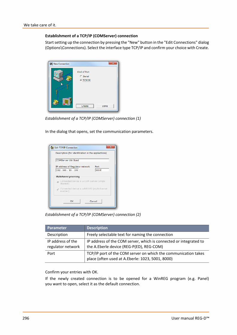
We take care of it.
296
User manual REG-D™
Establishment of a TCP/IP (COMServer) connection Start setting up the connection by pressing the "New" button in the "Edit Connections" dialog (Options\Connections). Select the interface type TCP/IP and confirm your choice with Create.
Establishment of a TCP/IP (COMServer) connection (1) In the dialog that opens, set the communication parameters.
Establishment of a TCP/IP (COMServer) connection (2)
Parameter Description Description Freely selectable text for naming the connection IP address of the regulator network
IP address of the COM server, which is connected or integrated to the A.Eberle device (REG-P(ED), REG-COM)
Port TCP/IP port of the COM server on which the communication takes place (often used at A.Eberle: 1023, 5001, 8000)
Confirm your entries with OK. If the newly created connection is to be opened for a WinREG program (e.g. Panel) you want to open, select it as the default connection.
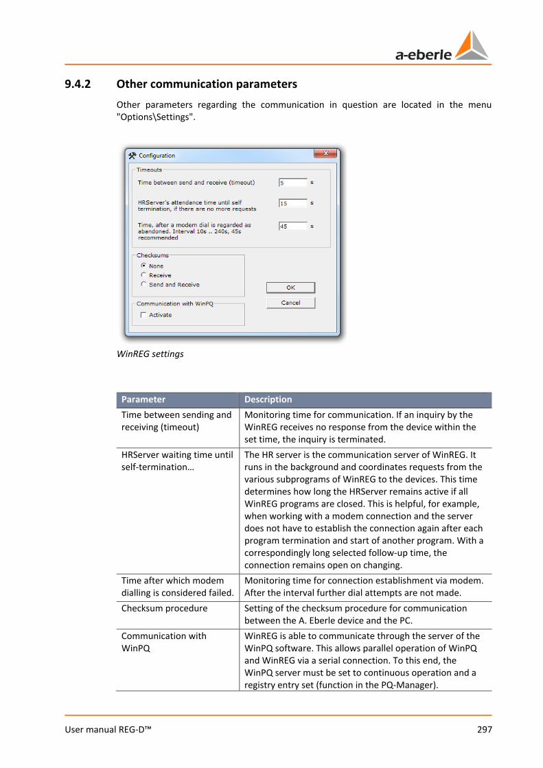
297
User manual REG-D™
9.4.2 Other communication parameters Other parameters regarding the communication in question are located in the menu "Options\Settings".
WinREG settings
Parameter Description Time between sending and receiving (timeout)
Monitoring time for communication. If an inquiry by the WinREG receives no response from the device within the set time, the inquiry is terminated.
HRServer waiting time until self-termination…
The HR server is the communication server of WinREG. It runs in the background and coordinates requests from the various subprograms of WinREG to the devices. This time determines how long the HRServer remains active if all WinREG programs are closed. This is helpful, for example, when working with a modem connection and the server does not have to establish the connection again after each program termination and start of another program. With a correspondingly long selected follow-up time, the connection remains open on changing.
Time after which modem dialling is considered failed.
Monitoring time for connection establishment via modem. After the interval further dial attempts are not made.
Checksum procedure Setting of the checksum procedure for communication between the A. Eberle device and the PC.
Communication with WinPQ
WinREG is able to communicate through the server of the WinPQ software. This allows parallel operation of WinPQ and WinREG via a serial connection. To this end, the WinPQ server must be set to continuous operation and a registry entry set (function in the PQ-Manager).
We take care of it.
298
User manual REG-D™
Parameter Description Caution: If the communication with WinPQ is active, WinREG will try to reach all connections found in WinPQ and WinREG via the PQServer (e.g. COM1, COM3, TCP/IP 192.168.55.199). If the PQServer is not active, WinREG cannot connect.
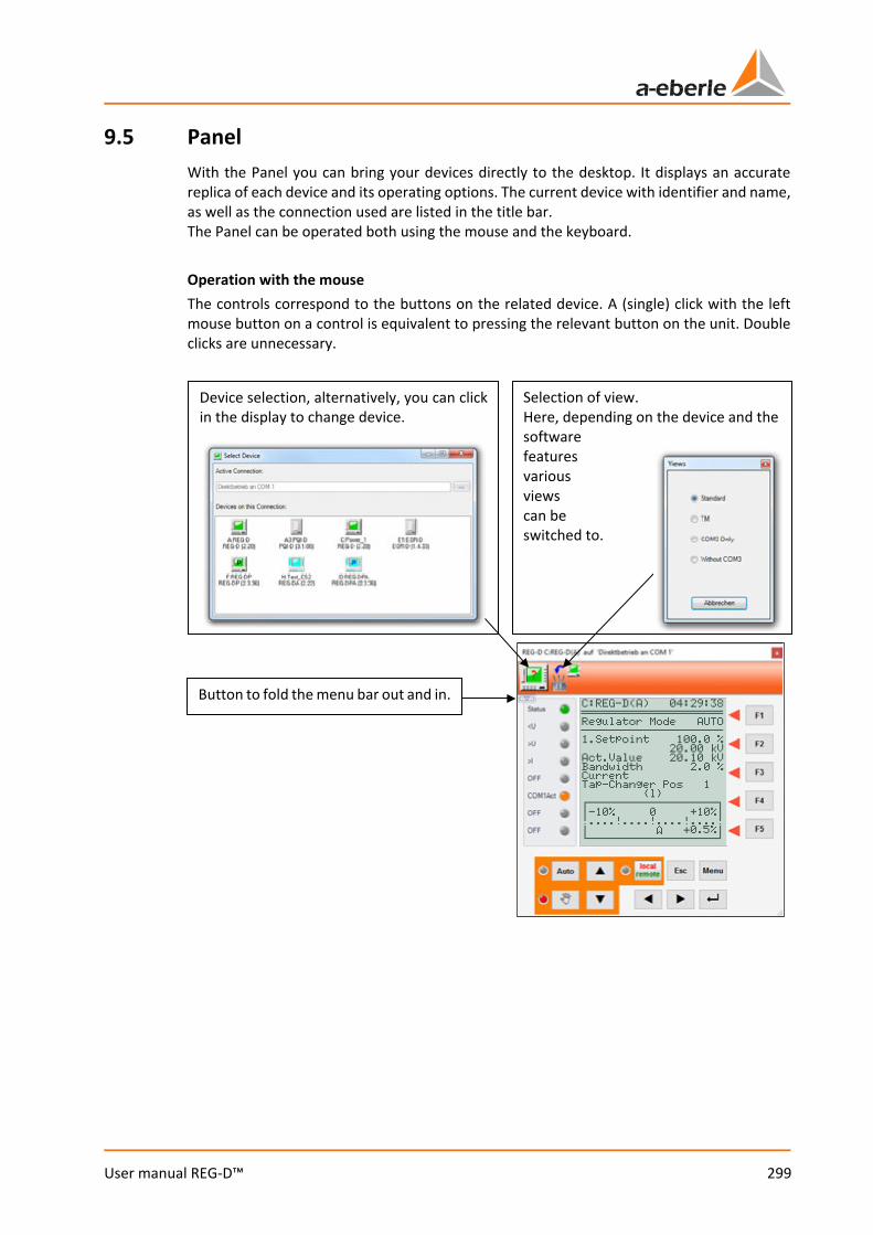
299
User manual REG-D™
9.5 Panel With the Panel you can bring your devices directly to the desktop. It displays an accurate replica of each device and its operating options. The current device with identifier and name, as well as the connection used are listed in the title bar. The Panel can be operated both using the mouse and the keyboard. Operation with the mouse The controls correspond to the buttons on the related device. A (single) click with the left mouse button on a control is equivalent to pressing the relevant button on the unit. Double clicks are unnecessary.
Selection of view. Here, depending on the device and the software features various views can be switched to.
Device selection, alternatively, you can click in the display to change device.
Button to fold the menu bar out and in.
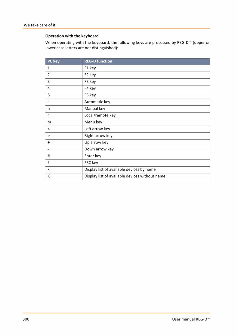
We take care of it.
300
User manual REG-D™
Operation with the keyboard When operating with the keyboard, the following keys are processed by REG-D™ (upper or lower case letters are not distinguished):
PC key REG-D function 1 F1 key 2 F2 key 3 F3 key 4 F4 key 5 F5 key a Automatic key h Manual key r Local/remote key m Menu key < Left arrow key > Right arrow key + Up arrow key - Down arrow key # Enter key ! ESC key k Display list of available devices by name K Display list of available devices without name
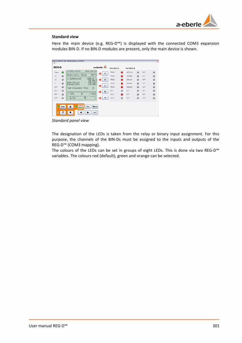
301
User manual REG-D™
Standard view Here the main device (e.g. REG-D™) is displayed with the connected COM3 expansion modules BIN-D. If no BIN-D modules are present, only the main device is shown.
Standard panel view The designation of the LEDs is taken from the relay or binary input assignment. For this purpose, the channels of the BIN-Ds must be assigned to the inputs and outputs of the REG-D™ (COM3 mapping). The colours of the LEDs can be set in groups of eight LEDs. This is done via two REG-D™ variables. The colours red (default), green and orange can be selected.
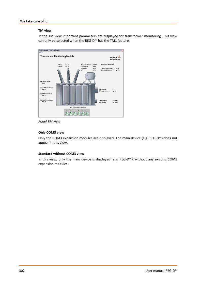
We take care of it.
302
User manual REG-D™
TM view In the TM view important parameters are displayed for transformer monitoring. This view can only be selected when the REG-D™ has the TM1 feature.
Panel TM view Only COM3 view Only the COM3 expansion modules are displayed. The main device (e.g. REG-D™) does not appear in this view. Standard without COM3 view In this view, only the main device is displayed (e.g. REG-D™), without any existing COM3 expansion modules.
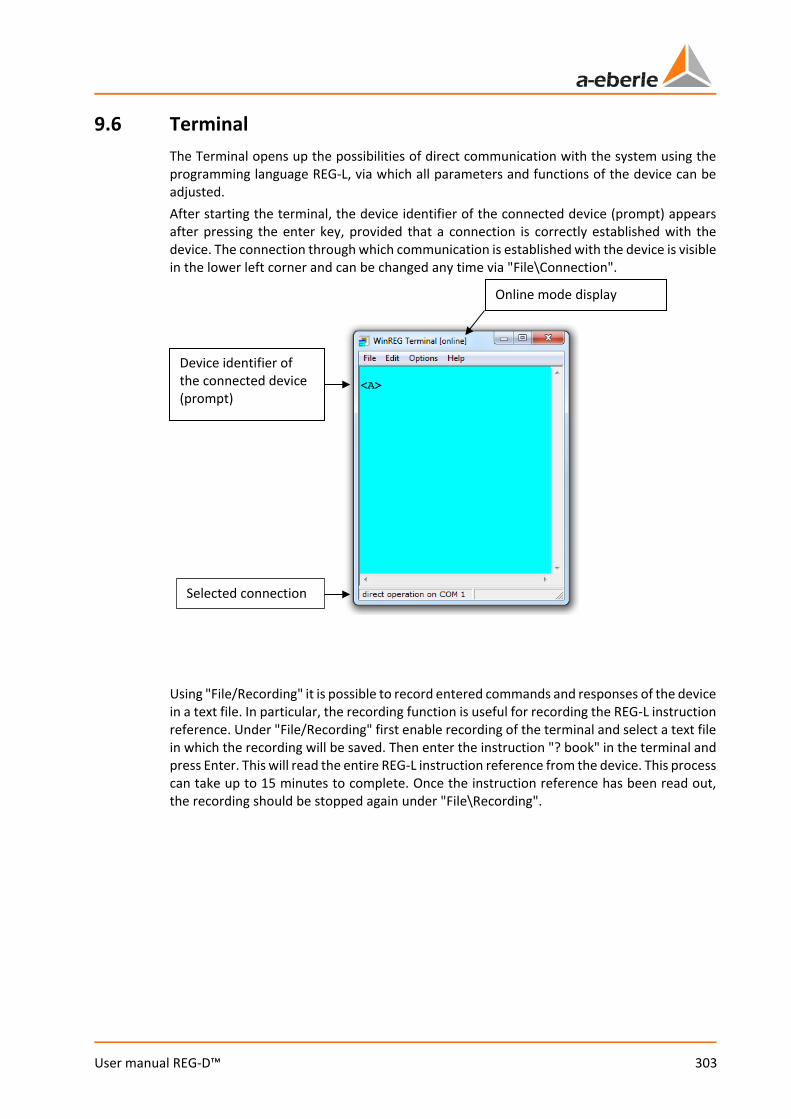
303
User manual REG-D™
9.6 Terminal The Terminal opens up the possibilities of direct communication with the system using the programming language REG-L, via which all parameters and functions of the device can be adjusted. After starting the terminal, the device identifier of the connected device (prompt) appears after pressing the enter key, provided that a connection is correctly established with the device. The connection through which communication is established with the device is visible in the lower left corner and can be changed any time via "File\Connection".
Using "File/Recording" it is possible to record entered commands and responses of the device in a text file. In particular, the recording function is useful for recording the REG-L instruction reference. Under "File/Recording" first enable recording of the terminal and select a text file in which the recording will be saved. Then enter the instruction "? book" in the terminal and press Enter. This will read the entire REG-L instruction reference from the device. This process can take up to 15 minutes to complete. Once the instruction reference has been read out, the recording should be stopped again under "File\Recording".
Device identifier of the connected device (prompt)
Online mode display
Selected connection
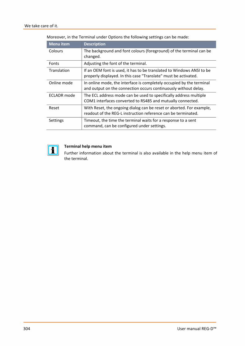
We take care of it.
304
User manual REG-D™
Moreover, in the Terminal under Options the following settings can be made: Menu item Description Colours The background and font colours (foreground) of the terminal can be
changed. Fonts Adjusting the font of the terminal. Translation If an OEM font is used, it has to be translated to Windows ANSI to be
properly displayed. In this case "Translate" must be activated. Online mode In online mode, the interface is completely occupied by the terminal
and output on the connection occurs continuously without delay. ECLADR mode The ECL address mode can be used to specifically address multiple
COM1 interfaces converted to RS485 and mutually connected. Reset With Reset, the ongoing dialog can be reset or aborted. For example,
readout of the REG-L instruction reference can be terminated. Settings Timeout, the time the terminal waits for a response to a sent
command, can be configured under settings.
Terminal help menu item Further information about the terminal is also available in the help menu item of the terminal.
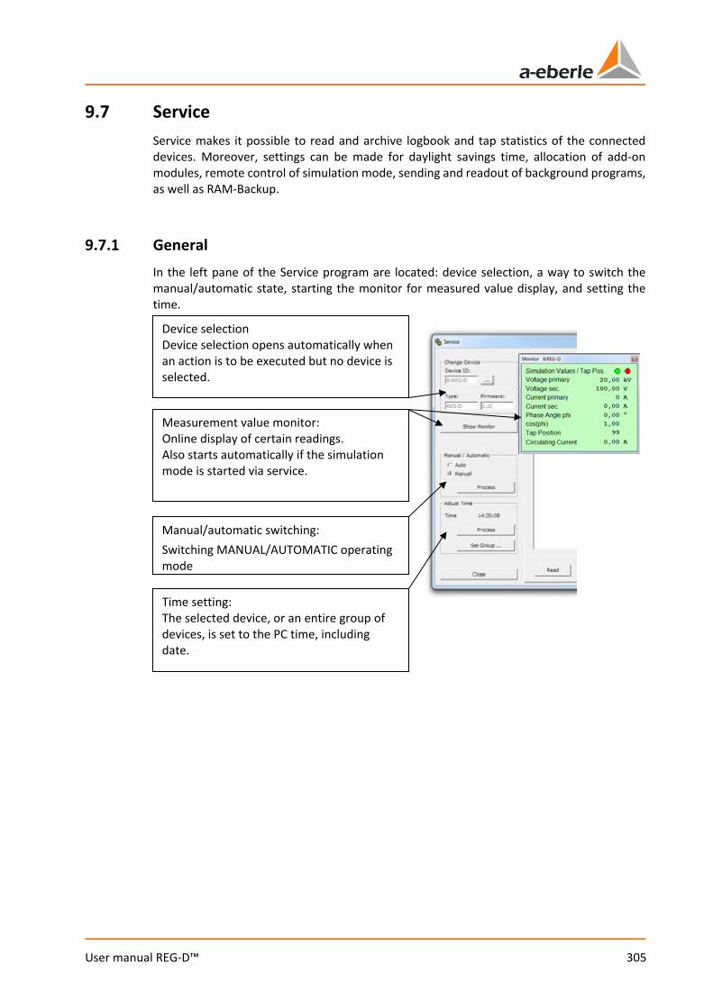
305
User manual REG-D™
9.7 Service Service makes it possible to read and archive logbook and tap statistics of the connected devices. Moreover, settings can be made for daylight savings time, allocation of add-on modules, remote control of simulation mode, sending and readout of background programs, as well as RAM-Backup.
9.7.1 General In the left pane of the Service program are located: device selection, a way to switch the manual/automatic state, starting the monitor for measured value display, and setting the time.
Device selection Device selection opens automatically when an action is to be executed but no device is selected.
Measurement value monitor: Online display of certain readings. Also starts automatically if the simulation mode is started via service.
Time setting: The selected device, or an entire group of devices, is set to the PC time, including date.
Manual/automatic switching: Switching MANUAL/AUTOMATIC operating mode

We take care of it.
306
User manual REG-D™
9.7.2 Log/Divers The logbook of the REG-D™ can be read, archived and deleted via the tab "Log/Divers". Moreover, the setpoint index can be switched here.
Display field for logbook
Reading of the setpoint settings (step 1)
Display of configured setpoints
Selection of setpoint Index (step 2)
Sending of setpoint index selection (step3)
Reading of the logbook from the selected device (step 1)
Copying contents of the logbook to the clipboard
Printing contents of the logbook
Saving contents of the logbook to a file (*.log)
Opening/viewing a logbook file on the PC
Deleting content of the logbook on the device

307
User manual REG-D™
9.7.3 Statistics The statistics of REG-D™ can be read out and displayed with the Statistics function of the Service screen.
Graphical display of tap statistics
Tap sums with and without load
Tabular display of tap statistics
Deletion of device statistics
Printing of statistics
Copying statistics to clipboard: Hereby, both the table as well as the graph are copied.
Reading of the device statistics (step 1)

We take care of it.
308
User manual REG-D™
9.7.4 Simulation
DANGER! Tap commands which are triggered in simulation mode are actually output over the relays. Since measured voltage is not used in simulation mode, this can lead to impermissible changes in the actual voltage at the transformer!
If the transformer the regulator is connected to is in operation, the simulation mode should only be used under extreme caution. Here, tap commands from the regulator to the tap changer must be separated in terms of hardware (e.g. opening of the terminals).
The Simulation tab enables remote control of the REG-D™ simulation mode.
Reading of device state (step 1)
Sending the selection to the device (step 3)
Device state
Activation/deactivation of the simulation modes (step 2)
Simulating measurement values in the device (step 5)
Setting measurement values for the simulation (step 4)

309
User manual REG-D™
Measurement value monitor On starting the simulation, the measurement value monitor starts automatically. Here the simulated measurements can be checked.
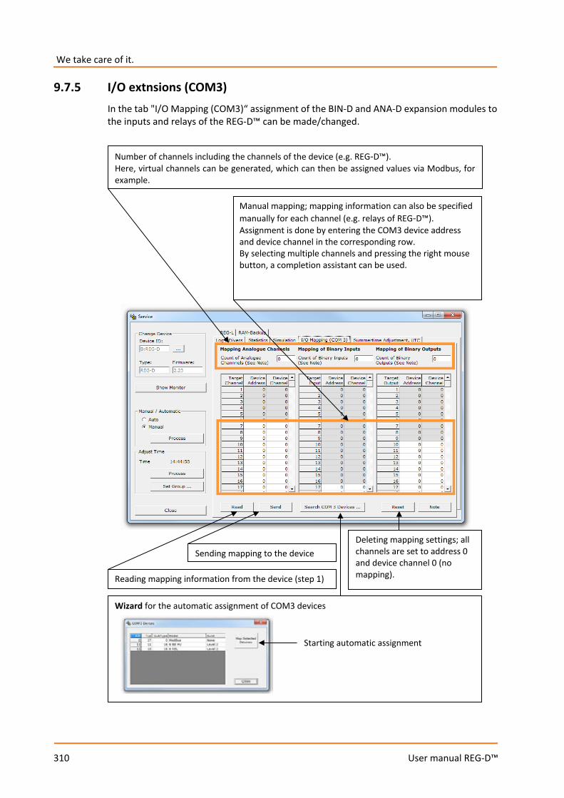
We take care of it.
310
User manual REG-D™
9.7.5 I/O extnsions (COM3) In the tab "I/O Mapping (COM3)“ assignment of the BIN-D and ANA-D expansion modules to the inputs and relays of the REG-D™ can be made/changed.
Wizard for the automatic assignment of COM3 devices
Number of channels including the channels of the device (e.g. REG-D™). Here, virtual channels can be generated, which can then be assigned values via Modbus, for example.
Reading mapping information from the device (step 1)
Sending mapping to the device Deleting mapping settings; all channels are set to address 0 and device channel 0 (no mapping).
Starting automatic assignment
Manual mapping; mapping information can also be specified manually for each channel (e.g. relays of REG-D™). Assignment is done by entering the COM3 device address and device channel in the corresponding row. By selecting multiple channels and pressing the right mouse button, a completion assistant can be used.
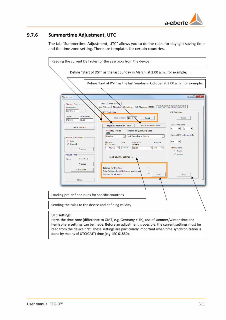
311
User manual REG-D™
9.7.6 Summertime Adjustment, UTC The tab "Summertime Adjustment, UTC" allows you to define rules for daylight saving time and the time zone setting. There are templates for certain countries.
Reading the current DST rules for the year xxxx from the device
Define "End of DST" as the last Sunday in October at 3:00 a.m., for example.
Define "Start of DST“ as the last Sunday in March, at 2:00 a.m., for example.
UTC settings: Here, the time zone (difference to GMT, e.g. Germany = 1h), use of summer/winter time and hemisphere settings can be made. Before an adjustment is possible, the current settings must be read from the device first. These settings are particularly important when time synchronization is done by means of UTC(GMT) time (e.g. IEC 61850).
Loading pre-defined rules for specific countries
Sending the rules to the device and defining validity

We take care of it.
312
User manual REG-D™
9.7.7 REG-L The "REG-L" tab allows you to open, edit, send, read and save REG-L Files (e.g. H-programs).
Only certain parts (markings, lines, etc.) of the REG-L scripts can be sent via the context menu (right click).
Saving a REG-L file under a new name
Sending an opened REG-L script to a device
Sending an opened REG-L script to several devices
Opening a REG-L file
Saving a REG-L file
Reading REG-L from a device
Monitor: Shows what is being sent to the device.
The log function produces a recording of communication to a file. It must be activated prior to sending.
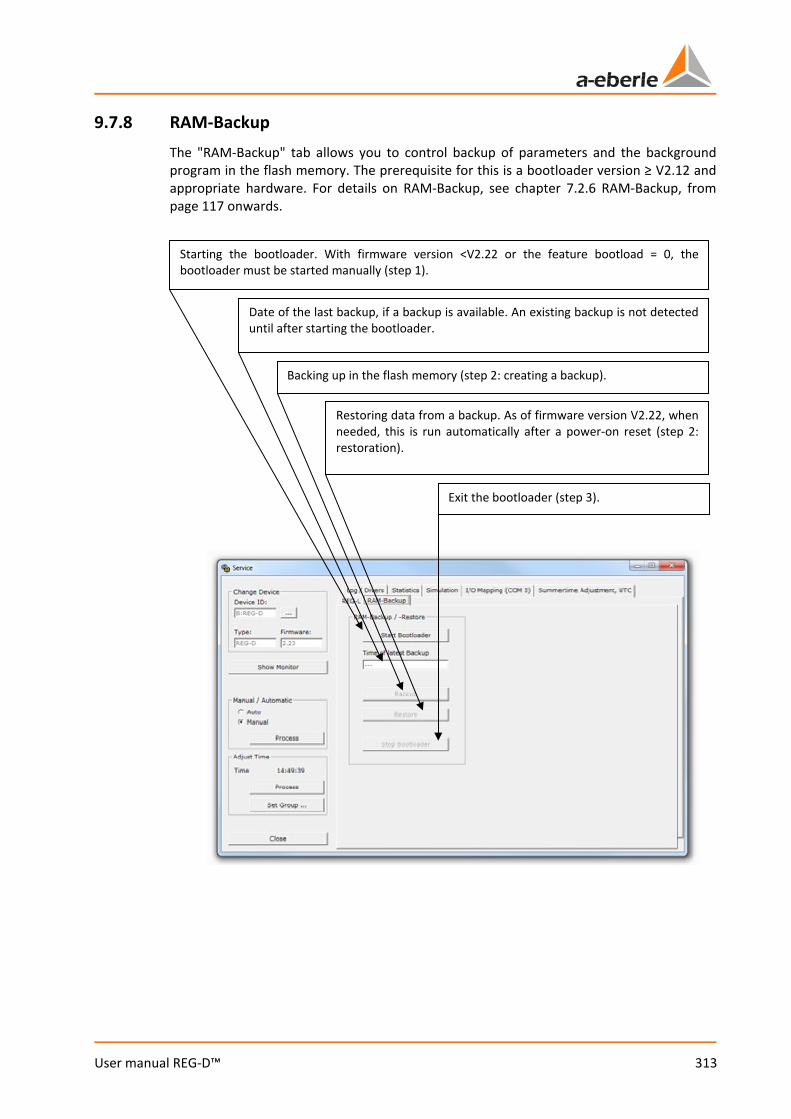
313
User manual REG-D™
9.7.8 RAM-Backup The "RAM-Backup" tab allows you to control backup of parameters and the background program in the flash memory. The prerequisite for this is a bootloader version ≥ V2.12 and appropriate hardware. For details on RAM-Backup, see chapter 7.2.6 RAM-Backup, from page 117 onwards.
Starting the bootloader. With firmware version <V2.22 or the feature bootload = 0, the bootloader must be started manually (step 1).
Restoring data from a backup. As of firmware version V2.22, when needed, this is run automatically after a power-on reset (step 2: restoration).
Exit the bootloader (step 3).
Backing up in the flash memory (step 2: creating a backup).
Date of the last backup, if a backup is available. An existing backup is not detected until after starting the bootloader.
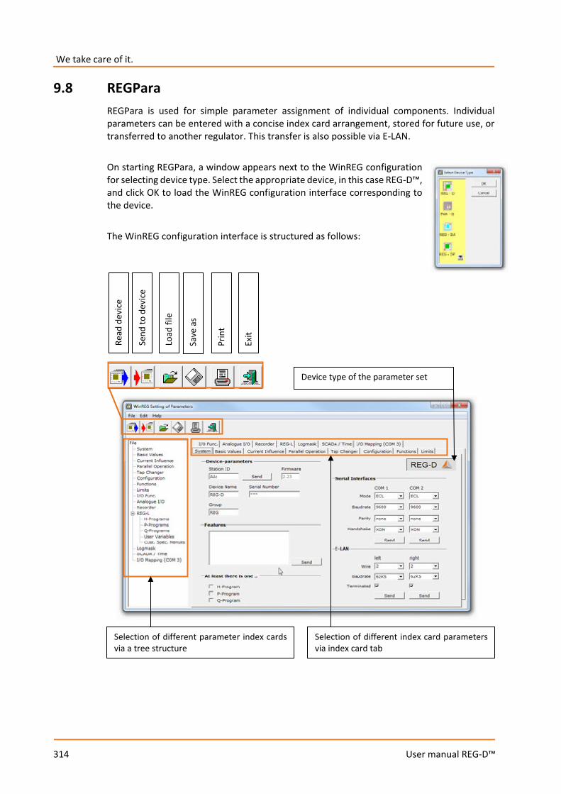
We take care of it.
314
User manual REG-D™
9.8 REGPara REGPara is used for simple parameter assignment of individual components. Individual parameters can be entered with a concise index card arrangement, stored for future use, or transferred to another regulator. This transfer is also possible via E-LAN. On starting REGPara, a window appears next to the WinREG configuration for selecting device type. Select the appropriate device, in this case REG-D™, and click OK to load the WinREG configuration interface corresponding to the device. The WinREG configuration interface is structured as follows:
Device type of the parameter set
Read
dev
ice
Send
to d
evic
e
Selection of different parameter index cards via a tree structure
Load
file
Save
as
Prin
t
Exit
Selection of different index card parameters via index card tab
315
User manual REG-D™
The following actions are available via the File menu (partly also available as shortcuts in the WinREG configuration interface):
Menu item Description Read Device
Starts reading a device. After starting, a dialog opens for selecting the device to be read.
Send to Device
Starts sending the current parameter setting to a device. After starting, a dialog opens for selecting the target device. With the action "Send to device" all parameters are sent that do not need to be sent separately. The relevant parameters that need to be sent individually, are provided with a separate Send button. The following parameters must be sent separately: 0 Identifier 0 Features 0 COM interface settings 0 E-LAN interface settings 0 DST settings 0 COM3 mapping 0 REG-L
Load file
The dialog "Load parameter file" appears to open existing REGSys™ parameter files (*.prm).
Save as …
By clicking on "Save as" an "Additional data" dialog appears first (see also "Edit/Additional data"), where a printout heading and a comment can be entered. With the button "Insert ...", recently used printout headings / comments or templates can be attached. By clicking OK in the "Additional data" dialog, the window "Save parameter file" appears for specifying location and name. By clicking Save, the PRM file is stored as indicated.
Export to XML … Export the configuration in xml format (RSEI). The XML file can be read into the management software of the company IPS.
The Print dialog appears, in which the printer and presentation can be defined. Firstly, font and font size can be set under presentation. Secondly, the order of the parameters can be arranged either as in the configuration of WinREG, i.e., according to the different index cards, or as in the device, i.e., sorted in accordance with setups 1 to 6.
Previous sessions Up to four of the last opened PRM files can be opened using the shortcut.
Exit
Exits the software.
We take care of it.
316
User manual REG-D™
The following actions are also available via the Edit menu: Menu item Description Compare
There are three modes available: The current parameter settings can be compared to a device, or also to an existing parameter file (*.prm). After the comparison, a related dialog appears in which the various parameters are listed with their respective values. H-Programs are not included in the comparison.
Additional Data Here a printout heading and a comment for the current configuration can be entered. With the button "Insert ...", recently used printout headings / comments or templates can be attached. The "Additional data" dialog also appears the first time you save the current configuration, or with Save as.
Change Device Type
Device type, e.g. REG-D™ or PAN-D, can be changed here. Please note that all previously altered parameters may be irretrievably lost with change of device type. If necessary, save the current parameter settings before starting.
Convert
With the convert function, a set of parameters of a REG-D™ can be converted to a set of parameters of a REG-DA and vice versa. This results in changes, in particular, with regard to the available binary inputs/outputs and analog channels. To transfer a parameter set to a device, the device type of the parameter set must match the type of device.
Configuration Using all parameters: In some devices (REG-DP(A)) parameters are subdivided into groups. When the function is activated, all parameters are sent, read or compared without prompting. If it is not checked off, for each read, write, or compare action you will receive a request regarding which groups should be used. By default, the parameter is set. Activate feature sending: This function allows you to send the features of the parameter file to a device. By default, the sending of features is not available. The function is password-protected.
REGPara help menu item Further information about configuration is also available in the configuration help menu item.

317
User manual REG-D™
9.9 REGView
REGView is used to view and analyse recorder data. These can either be accessed directly on the REG-D™ (online), or via data from an archive file of the Collector.
Legend
Selection of interval start date
Selection of interval duration Undo zoom
A zoom step back
Display of recorded data
Adaptation of the respective Y-axis (by clicking on the corresponding point on the Y axis): a: Push axis upwards b: Zoom in c: Zoom out d: Push axis downwards
Shortcut to display charts Data update (online or archive file)
a
b c
d
Characteristic zoom by mouse: XZ: Zoom only enabled on the X axis BZ: Zoom on the X and Y axes enabled
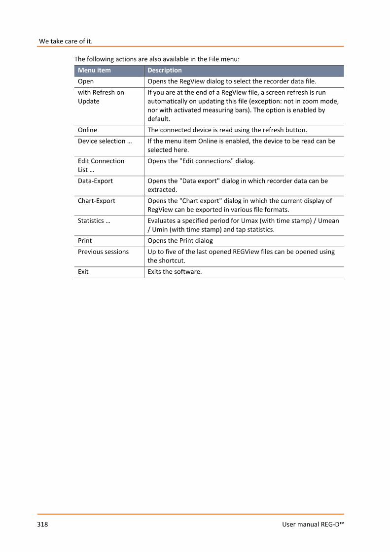
We take care of it.
318
User manual REG-D™
The following actions are also available in the File menu: Menu item Description Open Opens the RegView dialog to select the recorder data file. with Refresh on Update
If you are at the end of a RegView file, a screen refresh is run automatically on updating this file (exception: not in zoom mode, nor with activated measuring bars). The option is enabled by default.
Online The connected device is read using the refresh button. Device selection … If the menu item Online is enabled, the device to be read can be
selected here. Edit Connection List …
Opens the "Edit connections" dialog.
Data-Export Opens the "Data export" dialog in which recorder data can be extracted.
Chart-Export Opens the "Chart export" dialog in which the current display of RegView can be exported in various file formats.
Statistics … Evaluates a specified period for Umax (with time stamp) / Umean / Umin (with time stamp) and tap statistics.
Print Opens the Print dialog Previous sessions Up to five of the last opened REGView files can be opened using
the shortcut. Exit Exits the software.
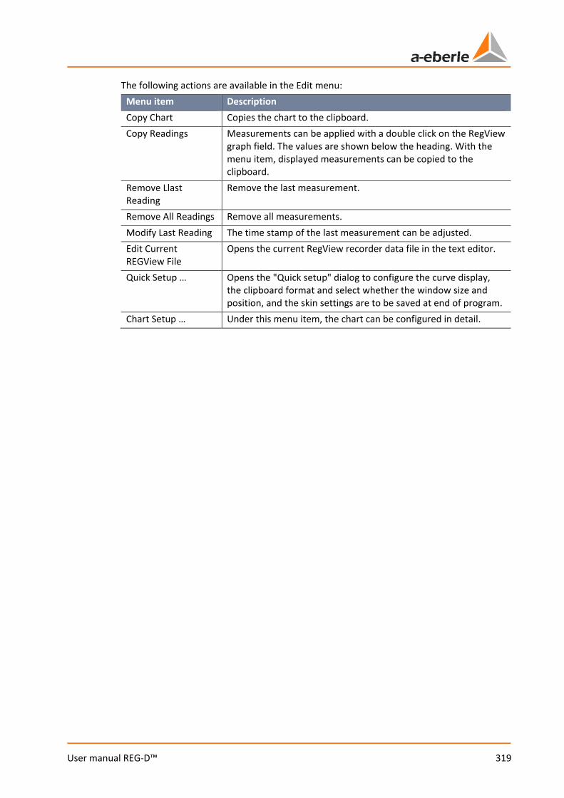
319
User manual REG-D™
The following actions are available in the Edit menu: Menu item Description Copy Chart Copies the chart to the clipboard. Copy Readings Measurements can be applied with a double click on the RegView
graph field. The values are shown below the heading. With the menu item, displayed measurements can be copied to the clipboard.
Remove Llast Reading
Remove the last measurement.
Remove All Readings Remove all measurements. Modify Last Reading The time stamp of the last measurement can be adjusted. Edit Current REGView File
Opens the current RegView recorder data file in the text editor.
Quick Setup … Opens the "Quick setup" dialog to configure the curve display, the clipboard format and select whether the window size and position, and the skin settings are to be saved at end of program.
Chart Setup … Under this menu item, the chart can be configured in detail.
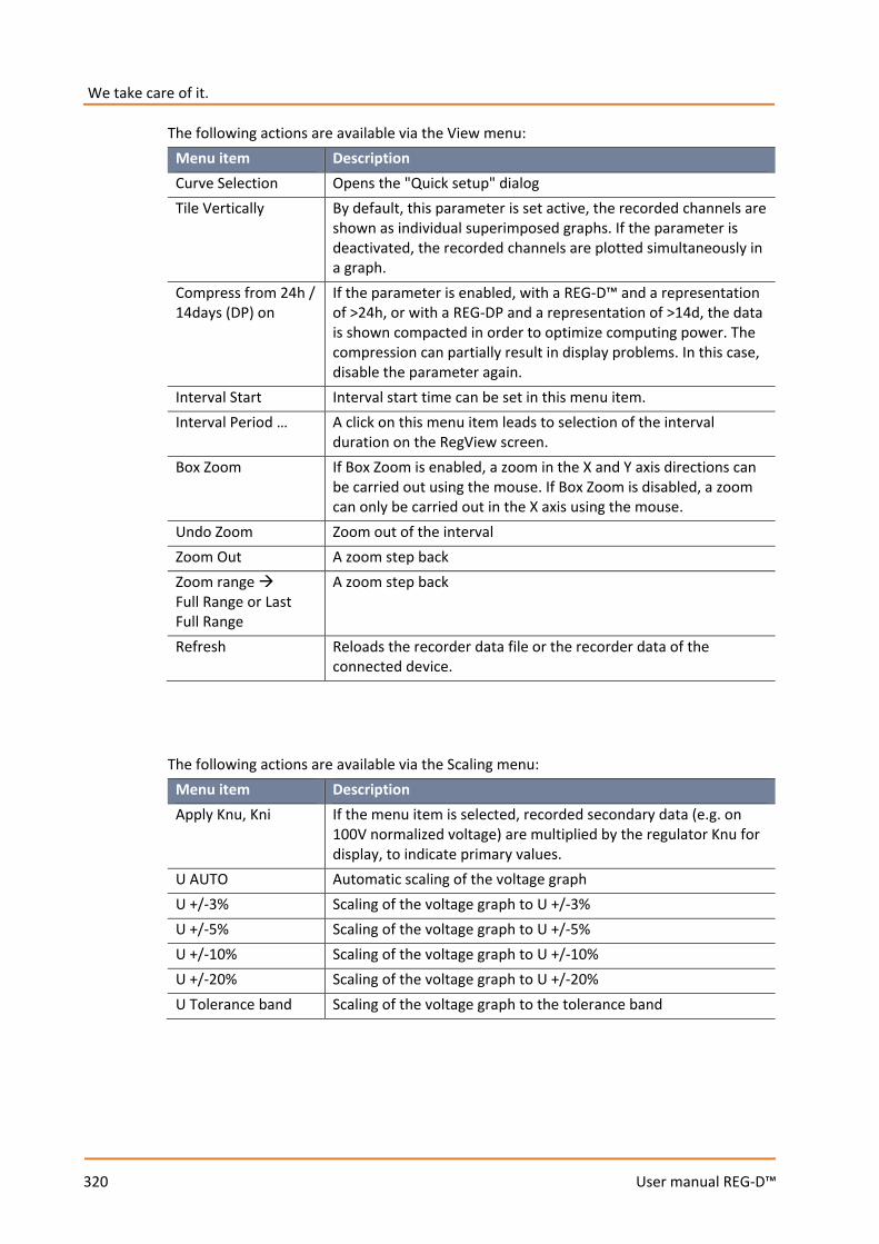
We take care of it.
320
User manual REG-D™
The following actions are available via the View menu: Menu item Description Curve Selection Opens the "Quick setup" dialog Tile Vertically By default, this parameter is set active, the recorded channels are
shown as individual superimposed graphs. If the parameter is deactivated, the recorded channels are plotted simultaneously in a graph.
Compress from 24h / 14days (DP) on
If the parameter is enabled, with a REG-D™ and a representation of >24h, or with a REG-DP and a representation of >14d, the data is shown compacted in order to optimize computing power. The compression can partially result in display problems. In this case, disable the parameter again.
Interval Start Interval start time can be set in this menu item. Interval Period … A click on this menu item leads to selection of the interval
duration on the RegView screen. Box Zoom If Box Zoom is enabled, a zoom in the X and Y axis directions can
be carried out using the mouse. If Box Zoom is disabled, a zoom can only be carried out in the X axis using the mouse.
Undo Zoom Zoom out of the interval Zoom Out A zoom step back Zoom range Full Range or Last Full Range
A zoom step back
Refresh Reloads the recorder data file or the recorder data of the connected device.
The following actions are available via the Scaling menu:
Menu item Description Apply Knu, Kni If the menu item is selected, recorded secondary data (e.g. on
100V normalized voltage) are multiplied by the regulator Knu for display, to indicate primary values.
U AUTO Automatic scaling of the voltage graph U +/-3% Scaling of the voltage graph to U +/-3% U +/-5% Scaling of the voltage graph to U +/-5% U +/-10% Scaling of the voltage graph to U +/-10% U +/-20% Scaling of the voltage graph to U +/-20% U Tolerance band Scaling of the voltage graph to the tolerance band
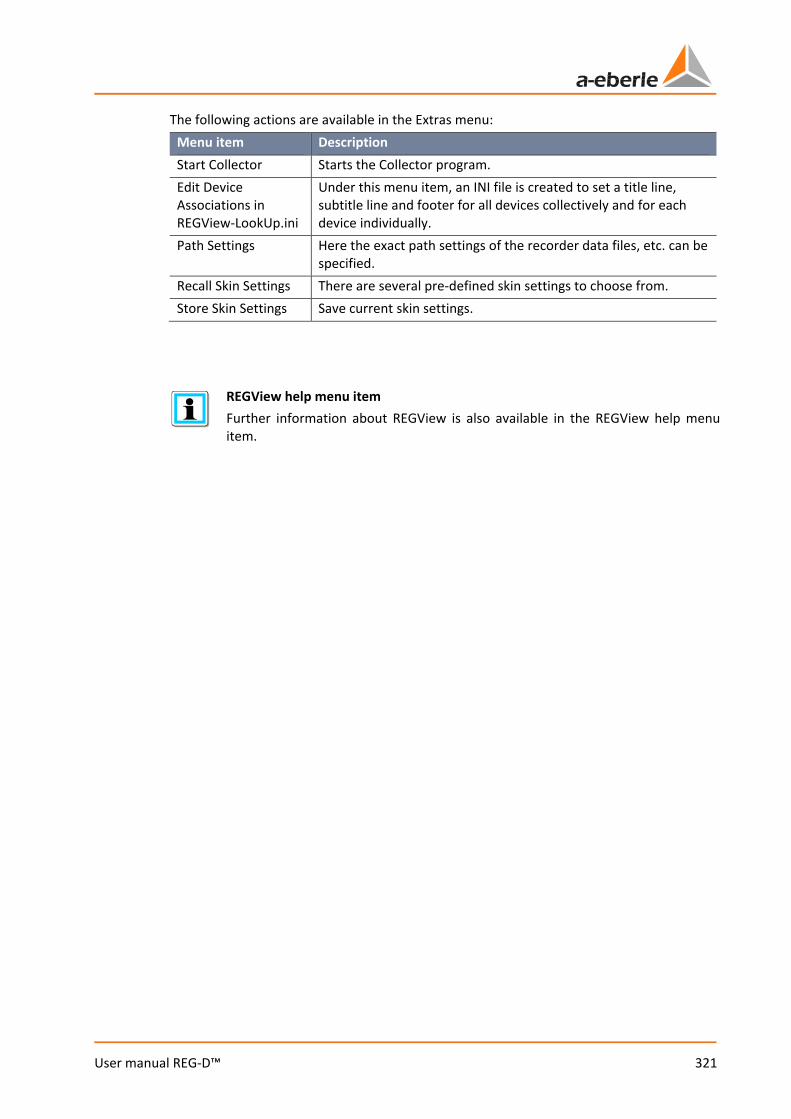
321
User manual REG-D™
The following actions are available in the Extras menu: Menu item Description Start Collector Starts the Collector program. Edit Device Associations in REGView-LookUp.ini
Under this menu item, an INI file is created to set a title line, subtitle line and footer for all devices collectively and for each device individually.
Path Settings Here the exact path settings of the recorder data files, etc. can be specified.
Recall Skin Settings There are several pre-defined skin settings to choose from. Store Skin Settings Save current skin settings.
REGView help menu item Further information about REGView is also available in the REGView help menu item.
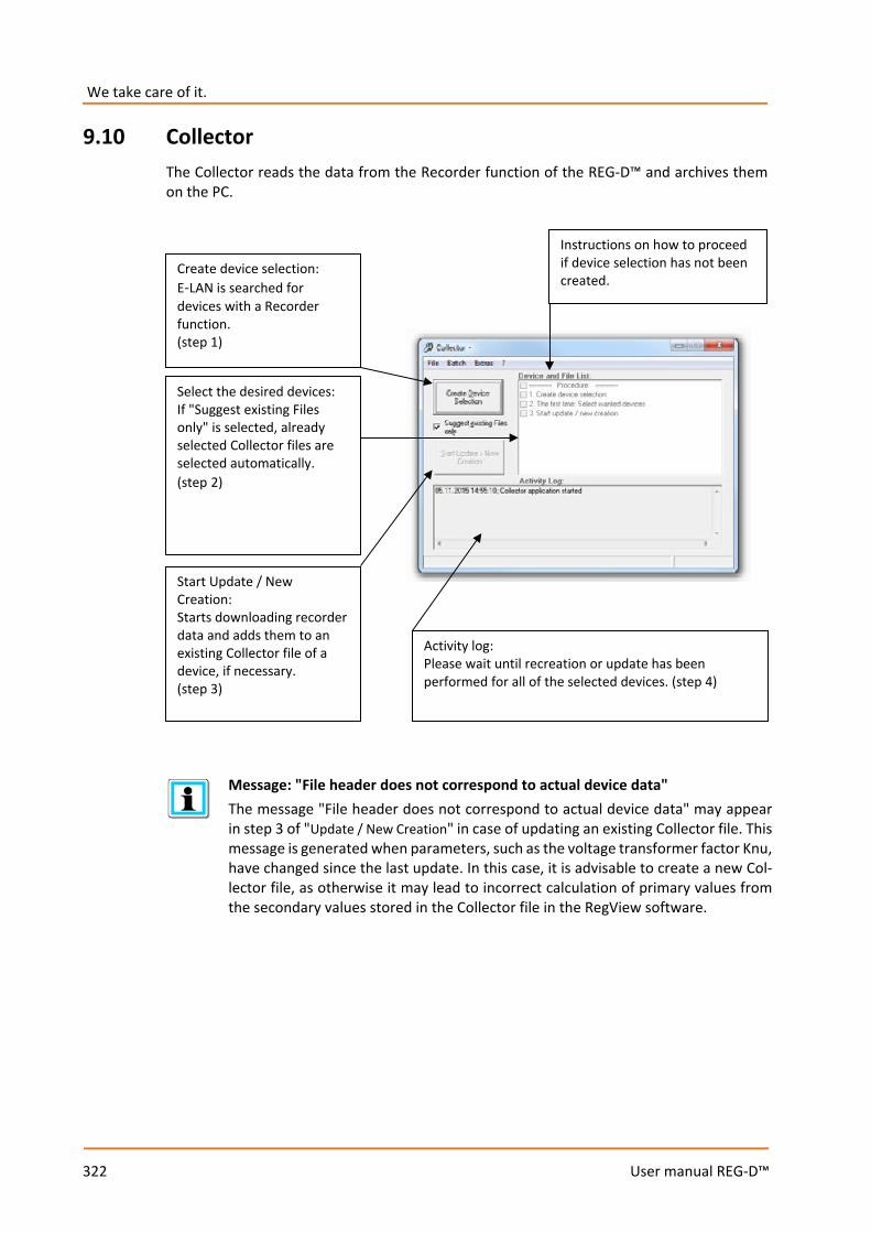
We take care of it.
322
User manual REG-D™
9.10 Collector The Collector reads the data from the Recorder function of the REG-D™ and archives them on the PC.
Message: "File header does not correspond to actual device data" The message "File header does not correspond to actual device data" may appear in step 3 of "Update / New Creation" in case of updating an existing Collector file. This message is generated when parameters, such as the voltage transformer factor Knu, have changed since the last update. In this case, it is advisable to create a new Col-lector file, as otherwise it may lead to incorrect calculation of primary values from the secondary values stored in the Collector file in the RegView software.
Instructions on how to proceed if device selection has not been created.
Create device selection: E-LAN is searched for devices with a Recorder function. (step 1)
Select the desired devices: If "Suggest existing Files only" is selected, already selected Collector files are selected automatically. (step 2)
Start Update / New Creation: Starts downloading recorder data and adds them to an existing Collector file of a device, if necessary. (step 3)
Activity log: Please wait until recreation or update has been performed for all of the selected devices. (step 4)
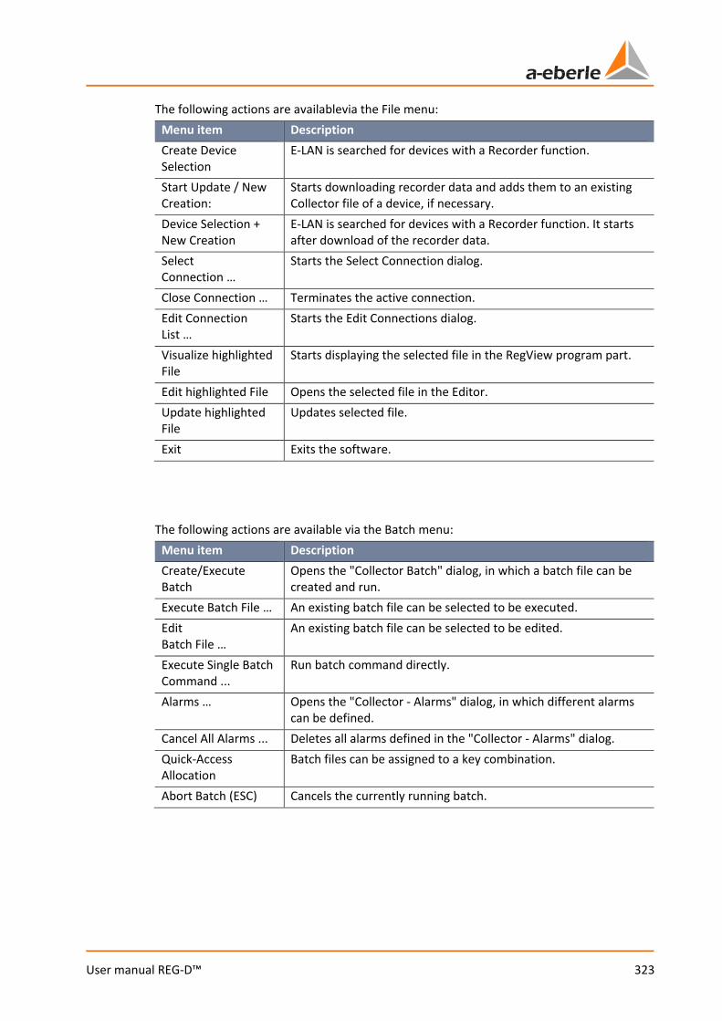
323
User manual REG-D™
The following actions are availablevia the File menu: Menu item Description Create Device Selection
E-LAN is searched for devices with a Recorder function.
Start Update / New Creation:
Starts downloading recorder data and adds them to an existing Collector file of a device, if necessary.
Device Selection + New Creation
E-LAN is searched for devices with a Recorder function. It starts after download of the recorder data.
Select Connection …
Starts the Select Connection dialog.
Close Connection … Terminates the active connection. Edit Connection List …
Starts the Edit Connections dialog.
Visualize highlighted File
Starts displaying the selected file in the RegView program part.
Edit highlighted File Opens the selected file in the Editor. Update highlighted File
Updates selected file.
Exit Exits the software. The following actions are available via the Batch menu:
Menu item Description Create/Execute Batch
Opens the "Collector Batch" dialog, in which a batch file can be created and run.
Execute Batch File … An existing batch file can be selected to be executed. Edit Batch File …
An existing batch file can be selected to be edited.
Execute Single Batch Command ...
Run batch command directly.
Alarms … Opens the "Collector - Alarms" dialog, in which different alarms can be defined.
Cancel All Alarms ... Deletes all alarms defined in the "Collector - Alarms" dialog. Quick-Access Allocation
Batch files can be assigned to a key combination.
Abort Batch (ESC) Cancels the currently running batch.
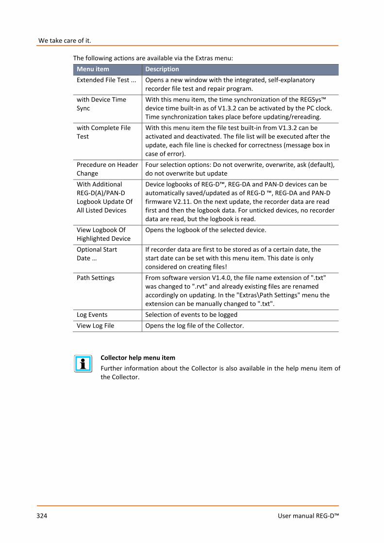
We take care of it.
324
User manual REG-D™
The following actions are available via the Extras menu: Menu item Description Extended File Test ... Opens a new window with the integrated, self-explanatory
recorder file test and repair program. with Device Time Sync
With this menu item, the time synchronization of the REGSys™ device time built-in as of V1.3.2 can be activated by the PC clock. Time synchronization takes place before updating/rereading.
with Complete File Test
With this menu item the file test built-in from V1.3.2 can be activated and deactivated. The file list will be executed after the update, each file line is checked for correctness (message box in case of error).
Precedure on Header Change
Four selection options: Do not overwrite, overwrite, ask (default), do not overwrite but update
With Additional REG-D(A)/PAN-D Logbook Update Of All Listed Devices
Device logbooks of REG-D™, REG-DA and PAN-D devices can be automatically saved/updated as of REG-D ™, REG-DA and PAN-D firmware V2.11. On the next update, the recorder data are read first and then the logbook data. For unticked devices, no recorder data are read, but the logbook is read.
View Logbook Of Highlighted Device
Opens the logbook of the selected device.
Optional Start Date …
If recorder data are first to be stored as of a certain date, the start date can be set with this menu item. This date is only considered on creating files!
Path Settings From software version V1.4.0, the file name extension of ".txt" was changed to ".rvt" and already existing files are renamed accordingly on updating. In the "Extras\Path Settings" menu the extension can be manually changed to ".txt".
Log Events Selection of events to be logged View Log File Opens the log file of the Collector.
Collector help menu item Further information about the Collector is also available in the help menu item of the Collector.
325
User manual REG-D™
9.11 WinTM/WinDM The WinTM module (parameters for the transformer monitoring module) and the WinDM module (parameters for the transformer monitoring device without Relay for Voltage Control & Transformer Monitoring) complete the software package. These modules are not part of this user manual.
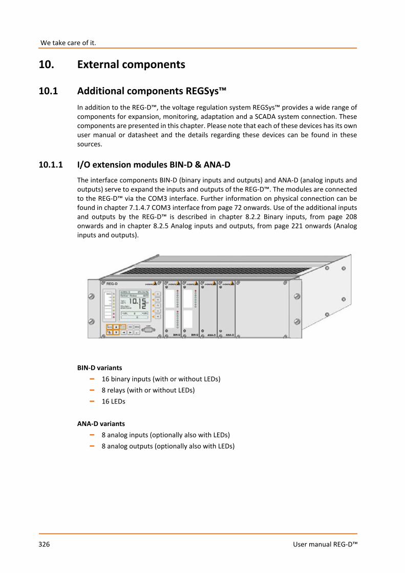
We take care of it.
326
User manual REG-D™
10. External components
10.1 Additional components REGSys™ In addition to the REG-D™, the voltage regulation system REGSys™ provides a wide range of components for expansion, monitoring, adaptation and a SCADA system connection. These components are presented in this chapter. Please note that each of these devices has its own user manual or datasheet and the details regarding these devices can be found in these sources.
10.1.1 I/O extension modules BIN-D & ANA-D The interface components BIN-D (binary inputs and outputs) and ANA-D (analog inputs and outputs) serve to expand the inputs and outputs of the REG-D™. The modules are connected to the REG-D™ via the COM3 interface. Further information on physical connection can be found in chapter 7.1.4.7 COM3 interface from page 72 onwards. Use of the additional inputs and outputs by the REG-D™ is described in chapter 8.2.2 Binary inputs, from page 208 onwards and in chapter 8.2.5 Analog inputs and outputs, from page 221 onwards (Analog inputs and outputs).
BIN-D variants
– 16 binary inputs (with or without LEDs) – 8 relays (with or without LEDs) – 16 LEDs
ANA-D variants
– 8 analog inputs (optionally also with LEDs) – 8 analog outputs (optionally also with LEDs)

327
User manual REG-D™
10.1.2 COM3/MODBUS converter The COM3/MODBUS converter allows connection of MODBUS RTU compatible devices having RS485 interfaces to the COM3 interface of the REGSys™ devices REG-D™, REG-DA and PAN-D. This allows direct access to all the information made available to the device via MODBUS. This data can be processed and stored in the REG-D™ and passed on to the SCADA system.
Schematic representation of COM3/MODBUS communication.
10.1.3 Monitoring units The monitoring units are used to monitor voltage and partly the function of the tap changer and the regulator. They constitute a monitoring unit for the voltage to be regulated that is independent of the Relay for Voltage Control & Transformer Monitoring. If the voltage leaves certain adjustable limits, tap commands are interrupted physically in the corresponding direction and messages are generated. Moreover, PAN-D provides monitoring functions for the motor drive of the tap changer as well as the Relay for Voltage Control & Transformer Monitoring REG-D™. The PAN-D is based on the same platform as the Relay for Voltage Control & Transformer Monitoring REG-D™, and therefore provides the same options as regards configuration, programming and SCADA systems are concerned. Moreover, PAN-D offers the possibility of being configured via the REG-D™. The PAN-A1 is the simplest of the monitoring modules and provides one-step monitoring of regulation voltage (specific limits for overvoltage and undervoltage). The settings are made locally on the device using keys. No configuration software is necessary. In addition to the PAN-A1, the PAN-A2 offers two-stage monitoring of the regulation voltage and is configured using the software "PAN-A2 Control".
COM3 MODBUS
RS 485
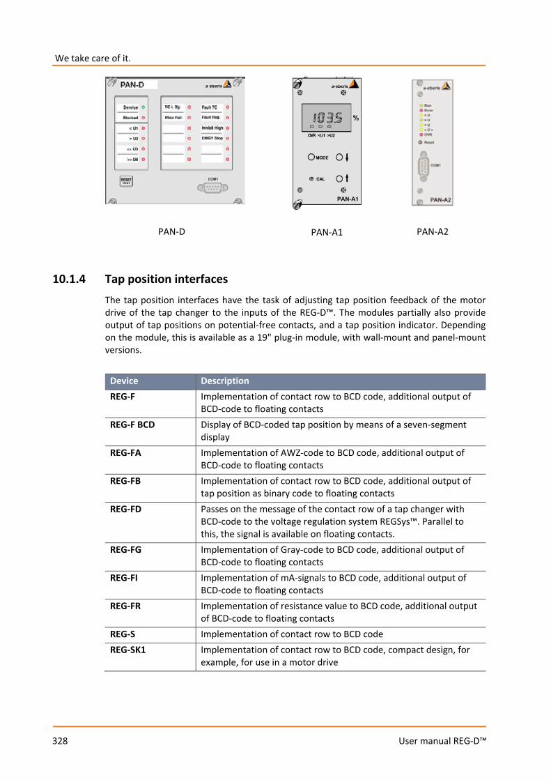
We take care of it.
328
User manual REG-D™
10.1.4 Tap position interfaces The tap position interfaces have the task of adjusting tap position feedback of the motor drive of the tap changer to the inputs of the REG-D™. The modules partially also provide output of tap positions on potential-free contacts, and a tap position indicator. Depending on the module, this is available as a 19" plug-in module, with wall-mount and panel-mount versions.
Device Description REG-F Implementation of contact row to BCD code, additional output of
BCD-code to floating contacts REG-F BCD Display of BCD-coded tap position by means of a seven-segment
display REG-FA Implementation of AWZ-code to BCD code, additional output of
BCD-code to floating contacts REG-FB Implementation of contact row to BCD code, additional output of
tap position as binary code to floating contacts REG-FD Passes on the message of the contact row of a tap changer with
BCD-code to the voltage regulation system REGSys™. Parallel to this, the signal is available on floating contacts.
REG-FG Implementation of Gray-code to BCD code, additional output of BCD-code to floating contacts
REG-FI Implementation of mA-signals to BCD code, additional output of BCD-code to floating contacts
REG-FR Implementation of resistance value to BCD code, additional output of BCD-code to floating contacts
REG-S Implementation of contact row to BCD code REG-SK1 Implementation of contact row to BCD code, compact design, for
example, for use in a motor drive
PAN-D PAN-A1 PAN-A2
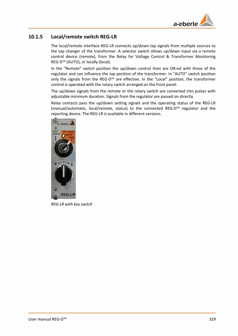
329
User manual REG-D™
10.1.5 Local/remote switch REG-LR The local/remote interface REG-LR connects up/down tap signals from multiple sources to the tap changer of the transformer. A selector switch allows up/down input via a remote control device (remote), from the Relay for Voltage Control & Transformer Monitoring REG-D™ (AUTO), or locally (local). In the "Remote" switch position the up/down control lines are OR-ed with those of the regulator and can influence the tap position of the transformer. In "AUTO" switch position only the signals from the REG-D™ are effective. In the "Local" position, the transformer control is operated with the rotary switch arranged on the front panel. The up/down signals from the remote or the rotary switch are converted into pulses with adjustable minimum duration. Signals from the regulator are passed on directly. Relay contacts pass the up/down setting signals and the operating status of the REG-LR (manual/automatic, local/remote, status) to the connected REG-D™ regulator and the reporting device. The REG-LR is available in different versions.
REG-LR with key switch

We take care of it.
330
User manual REG-D™
10.1.6 Miscellaneous There are other modules that are used to adapt the regulation system to the customer's requirement.
Device Description REG-K The binary interface REG-K extends the hardware resource of the
voltage regulation system REGSysTM by raising the nominal insulation voltage of REG-D™ binary inputs and outputs to 250 VAC. The module REG-K is mainly used in older REG-D™ device applications whose binary inputs and outputs are not directly suitable for 250 VAC. In current devices this module is no longer necessary, in general.
REG-M The module REG-M makes available a possibility of manual intervention in the process, in a selectable manner (with a general switch or key). Applications range from emergency stop keys to manual/automatic and up/down switches.
REG-U/BF The switching interfaces REG-U and REG-BF expand the hardware resource of the digital voltage regulation system REGSysTM. Switches and keys are provided to enable control functions.
10.2 SCADA system The SCADA system connection of the REG-D™ is implemented via a telecontrol board module. This module can be installed internally or externally, depending on the protocol used, the resulting type of coupling module, and customer request. Configuration of the telecontrol board module is carried out with the WinConfig software. For questions regarding the SCADA system please contact the A. Eberle SCADA System Support under +49 (0)911/628108-104 or [email protected].
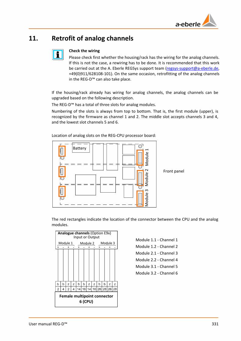
331
User manual REG-D™
11. Retrofit of analog channels
Check the wiring Please check first whether the housing/rack has the wiring for the analog channels. If this is not the case, a rewiring has to be done. It is recommended that this work be carried out at the A. Eberle REGSys support team ([email protected], +49(0)911/628108-101). On the same occasion, retrofitting of the analog channels in the REG-D™ can also take place.
If the housing/rack already has wiring for analog channels, the analog channels can be upgraded based on the following description. The REG-D™ has a total of three slots for analog modules. Numbering of the slots is always from top to bottom. That is, the first module (upper), is recognized by the firmware as channel 1 and 2. The middle slot accepts channels 3 and 4, and the lowest slot channels 5 and 6. Location of analog slots on the REG-CPU processor board:
The red rectangles indicate the location of the connector between the CPU and the analog modules.
Front panel
Battery M
odul
e 1
Mod
ule
2 M
odul
e 3
Female multipoint connector 6 (CPU)
Module 1.1 - Channel 1 Module 1.2 - Channel 2 Module 2.1 - Channel 3 Module 2.2 - Channel 4 Module 3.1 - Channel 5 Module 3.2 - Channel 6
Analogue channels (Option E9x) Input or Output
Module 1 Module 2 Module 3
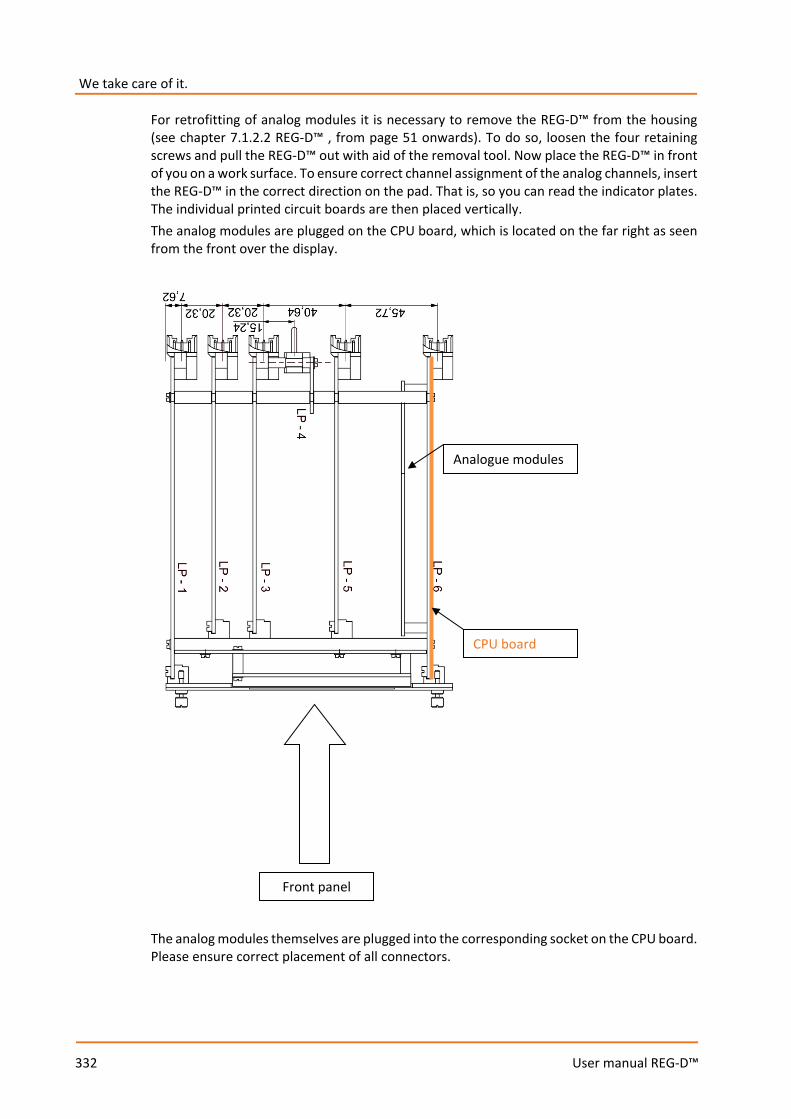
We take care of it.
332
User manual REG-D™
For retrofitting of analog modules it is necessary to remove the REG-D™ from the housing (see chapter 7.1.2.2 REG-D™ , from page 51 onwards). To do so, loosen the four retaining screws and pull the REG-D™ out with aid of the removal tool. Now place the REG-D™ in front of you on a work surface. To ensure correct channel assignment of the analog channels, insert the REG-D™ in the correct direction on the pad. That is, so you can read the indicator plates. The individual printed circuit boards are then placed vertically. The analog modules are plugged on the CPU board, which is located on the far right as seen from the front over the display.
The analog modules themselves are plugged into the corresponding socket on the CPU board. Please ensure correct placement of all connectors.
Front panel
CPU board
Analogue modules
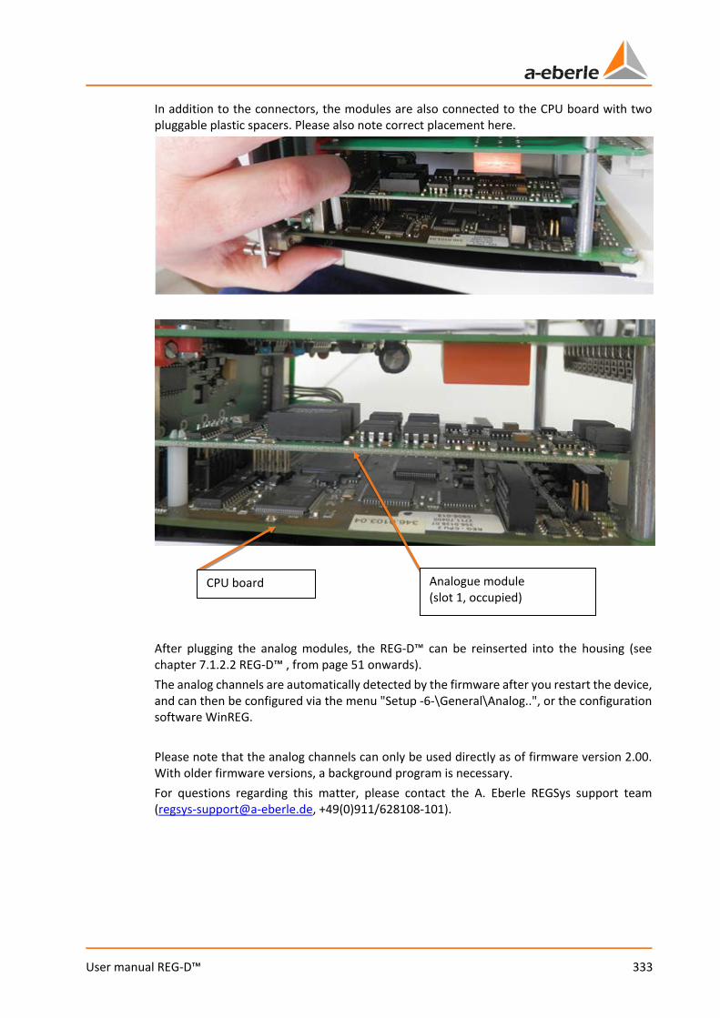
333
User manual REG-D™
In addition to the connectors, the modules are also connected to the CPU board with two pluggable plastic spacers. Please also note correct placement here.
After plugging the analog modules, the REG-D™ can be reinserted into the housing (see chapter 7.1.2.2 REG-D™ , from page 51 onwards). The analog channels are automatically detected by the firmware after you restart the device, and can then be configured via the menu "Setup -6-\General\Analog..", or the configuration software WinREG. Please note that the analog channels can only be used directly as of firmware version 2.00. With older firmware versions, a background program is necessary. For questions regarding this matter, please contact the A. Eberle REGSys support team ([email protected], +49(0)911/628108-101).
CPU board Analogue module (slot 1, occupied)
We take care of it.
334
User manual REG-D™
12. Maintenance/Cleaning
12.1 Cleaning instructions Use a soft, slightly damp and lint-free cloth. Make sure no liquid gets in the housing. Do not use window cleaner, household cleaners, sprays, dissolvent, cleaners that contain alcohol, ammonia solutions or abrasive cleaning agents. If the inside is very dirty due to improper use, it is recommended that the device be returned to the manufacturer. Indeed, if a lot of dust has accumulated on the printed circuit board, this may lead to insulation coordination failure. Dust is generally hygroscopic and can bridge creepage distances. For this reason, if the device has a housing cover, it is recommended that it be operated with this closed.
NOTICE! Do not clean the device with unsuitable products! This can damage the surface of the device and remove markings
Please follow the cleaning instructions above.
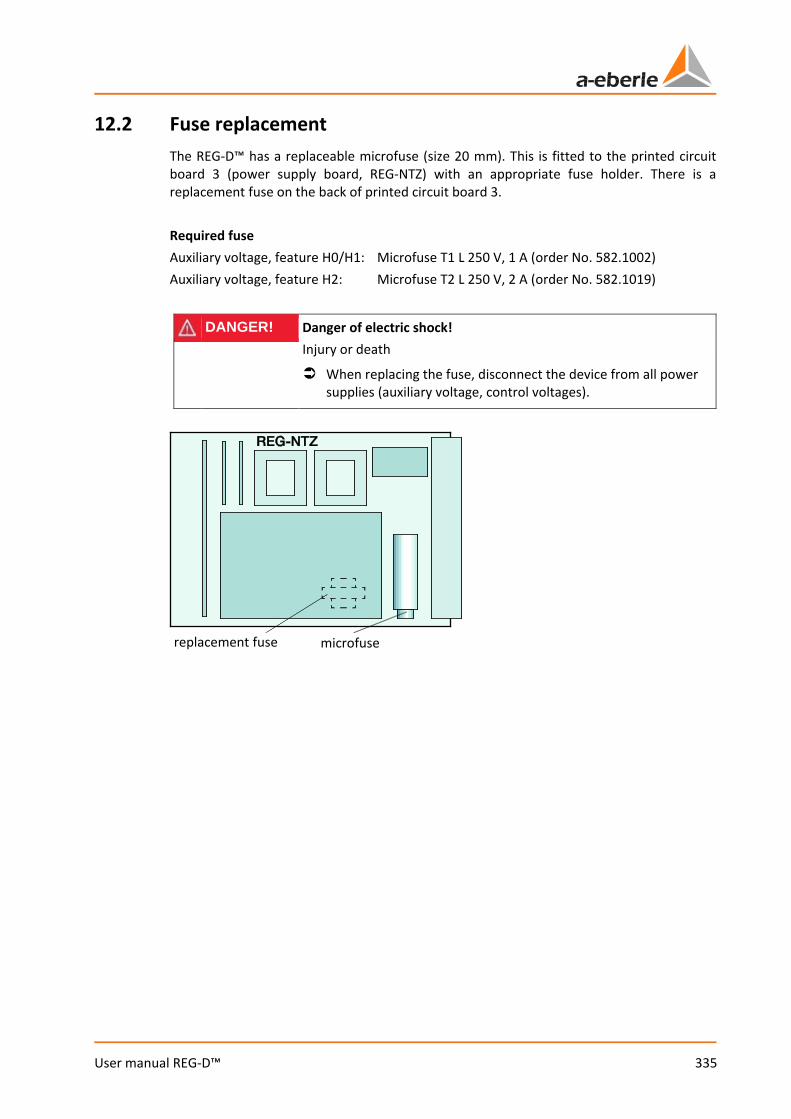
335
User manual REG-D™
12.2 Fuse replacement The REG-D™ has a replaceable microfuse (size 20 mm). This is fitted to the printed circuit board 3 (power supply board, REG-NTZ) with an appropriate fuse holder. There is a replacement fuse on the back of printed circuit board 3. Required fuse Auxiliary voltage, feature H0/H1: Microfuse T1 L 250 V, 1 A (order No. 582.1002) Auxiliary voltage, feature H2: Microfuse T2 L 250 V, 2 A (order No. 582.1019)
DANGER! Danger of electric shock! Injury or death
When replacing the fuse, disconnect the device from all power supplies (auxiliary voltage, control voltages).
replacement fuse microfuse
We take care of it.
336
User manual REG-D™
12.3 Battery replacement In REG-D™ three variants of buffer batteries are used. Depending on the version and year of manufacture of the device, the batteries are used for different purposes (see case in this chapter). If the device is supplied with auxiliary voltage, the battery is not actively used. The battery serves as a back-up, in the event of auxiliary voltage failure. In general, the battery voltage is monitored and an alarm (status relay or status/operation LED) or message (output function for weak batteries with firmware version 2.24/3.24 or later (devices with characteristic S2)) is issued if the battery has low remaining capacity. This means that regular replacement of the battery is not necessary. Battery replacement may also be event-based. The delivery time-frames below are approximate. Due to repairs, for example, old devices can require a new CPU circuit board. Please check the battery type in the device. Regardless of the type of battery incorporated, in the event of a battery failure, the parameters should be saved as soon as possible, and always before the device is separated from the supply voltage. In devices fitted with MRAM, this is not necessary, but it is possible. Further notes on saving and restoring parameters are to be found in chapter 7.2.6 RAM-Backup, from page 117 onwards, or in the document "Backup and restore parameters of REG-D(A) via Bootloader V02.pdf". Alternatively, parameters can be backed up with the WinREG software (see chapter 9.7 Service, page 305).
DANGER! Danger of electric shock! Injury or death
When replacing the battery, disconnect the device from all power supplies (auxiliary voltage, control voltages).
To replace the battery, first remove the plastic protective cover on the CPU board. Loosen the four screws and remove the cover. Once the battery has been changed, put the cover back on.

337
User manual REG-D™
REG-D™ devices with MRAM (devices with the feature S2 from 09/2013, all others from 05/2014) These devices have a button cell battery to buffer the real-time clock. This means that no data are lost when the battery is removed. The time may have to be adjusted when the new battery is installed. Required battery: Lithium button cell 3 V Type CR1632 (order no. 570.0005) Service life: when the REG-D™ is in storage (no auxiliary voltage) > 6 years in duty cycle operation > 50% > 6 years The battery is installed on the outside of the CPU board in a suitable mount. To replace the battery, remove the existing battery from the mount and insert a new one. If you use tools to remove the battery, be careful not to damage the printed circuit board.
NOTICE! Do not use pointed or sharp tools to remove the button cell! Avoid damage to the CPU circuit board
Remove the button cell with your fingers and not with a tool.
If you have to use a tool, do not use a screwdriver or similar pointed or sharp object.
Remove the button cell Insert the button cell
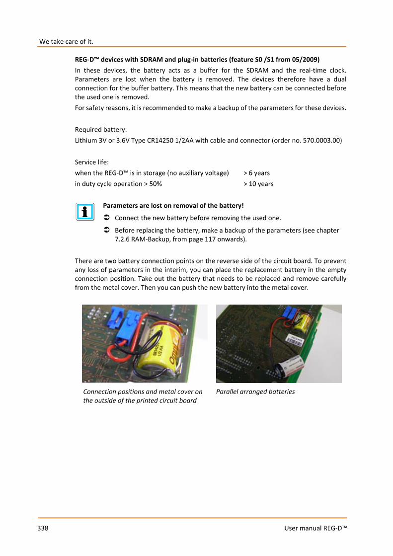
We take care of it.
338
User manual REG-D™
REG-D™ devices with SDRAM and plug-in batteries (feature S0 /S1 from 05/2009) In these devices, the battery acts as a buffer for the SDRAM and the real-time clock. Parameters are lost when the battery is removed. The devices therefore have a dual connection for the buffer battery. This means that the new battery can be connected before the used one is removed. For safety reasons, it is recommended to make a backup of the parameters for these devices. Required battery: Lithium 3V or 3.6V Type CR14250 1/2AA with cable and connector (order no. 570.0003.00) Service life: when the REG-D™ is in storage (no auxiliary voltage) > 6 years in duty cycle operation > 50% > 10 years
Parameters are lost on removal of the battery!
Connect the new battery before removing the used one.
Before replacing the battery, make a backup of the parameters (see chapter 7.2.6 RAM-Backup, from page 117 onwards).
There are two battery connection points on the reverse side of the circuit board. To prevent any loss of parameters in the interim, you can place the replacement battery in the empty connection position. Take out the battery that needs to be replaced and remove carefully from the metal cover. Then you can push the new battery into the metal cover.
Connection positions and metal cover on the outside of the printed circuit board
Parallel arranged batteries
339
User manual REG-D™
REG-D™ devices with SDRAM and soldering battery (feature S0/S1 before 05/2009 and feature S2 before 09/2013) In these devices, the battery acts as a buffer for the SDRAM and the real-time clock. Parameters are lost when the battery is removed. Therefore, before replacing the battery in these devices, a backup of the parameters must be made.
Parameters are lost on removal of the battery!
Connect the new battery before removing the used one.
Before replacing the battery, make a backup of the parameters (see chapter 7.2.6 RAM-Backup, from page 117 onwards).
Required battery: Lithium 3V or 3.6V Type CR14250 1/2AA with soldering lugs (order no. 570.0001) Service life: when the REG-D™ is in storage (no auxiliary voltage) > 6 years in duty cycle operation > 50% > 10 years
NOTICE! Mechanical/thermal damage to the CPU circuit board! Destruction of the conductor paths and/or the soldering pads
It is recommended to have the battery changed in the factory.
If the battery has to be replaced on-site, this must only be done by trained and qualified personnel, and in compliance with EMC Directives.
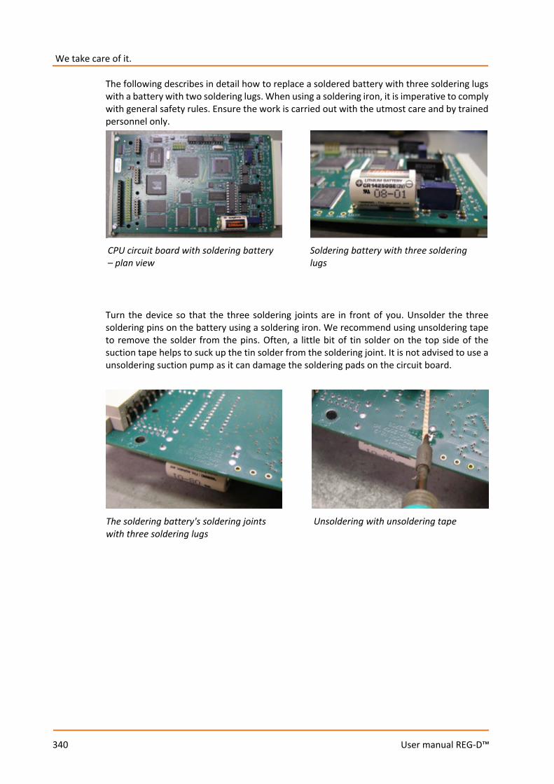
We take care of it.
340
User manual REG-D™
The following describes in detail how to replace a soldered battery with three soldering lugs with a battery with two soldering lugs. When using a soldering iron, it is imperative to comply with general safety rules. Ensure the work is carried out with the utmost care and by trained personnel only.
Turn the device so that the three soldering joints are in front of you. Unsolder the three soldering pins on the battery using a soldering iron. We recommend using unsoldering tape to remove the solder from the pins. Often, a little bit of tin solder on the top side of the suction tape helps to suck up the tin solder from the soldering joint. It is not advised to use a unsoldering suction pump as it can damage the soldering pads on the circuit board.
Soldering battery with three soldering lugs
CPU circuit board with soldering battery – plan view
The soldering battery's soldering joints with three soldering lugs
Unsoldering with unsoldering tape
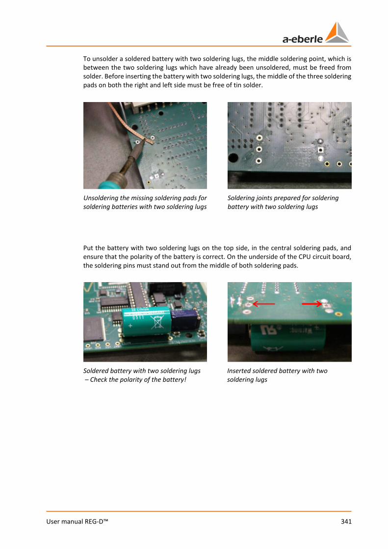
341
User manual REG-D™
To unsolder a soldered battery with two soldering lugs, the middle soldering point, which is between the two soldering lugs which have already been unsoldered, must be freed from solder. Before inserting the battery with two soldering lugs, the middle of the three soldering pads on both the right and left side must be free of tin solder.
Put the battery with two soldering lugs on the top side, in the central soldering pads, and ensure that the polarity of the battery is correct. On the underside of the CPU circuit board, the soldering pins must stand out from the middle of both soldering pads.
Unsoldering the missing soldering pads for soldering batteries with two soldering lugs
Soldering joints prepared for soldering battery with two soldering lugs
Soldered battery with two soldering lugs – Check the polarity of the battery!
Inserted soldered battery with two soldering lugs
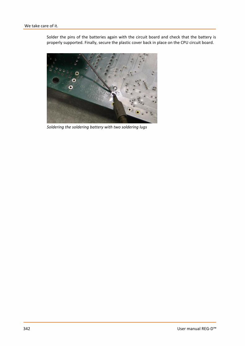
We take care of it.
342
User manual REG-D™
Solder the pins of the batteries again with the circuit board and check that the battery is properly supported. Finally, secure the plastic cover back in place on the CPU circuit board.
Soldering the soldering battery with two soldering lugs

343
User manual REG-D™
13. Standards and laws
0 IEC 61010-1 / EN 61010-1 0 CAN/CSA C22.2 No. 1010.1-92 0 IEC 60255-22-1 / EN 60255-22-1 0 IEC 61326-1 / EN 61326-1 0 IEC 60529 / EN 60529 0 IEC 60068-1 / EN 60068-1 0 IEC 60688 / EN 60688 0 IEC 61000-6-2 / EN 61000-6-2 0 IEC 61000-6-4 / EN 61000-6-4 0 IEC 61000-6-5 / EN 61000-6-5 (in preparation)
8
We take care of it.
344
User manual REG-D™
14. Disposal
Disposal note for EU member states
To preserve and protect the environment, prevent pollution, and improve the recycling of raw materials, the European Commission issued a directive according to which manufacturers take back electrical and electronic devices so they can be properly disposed of or recycled. The devices with this symbol are not allowed to be disposed along with normal solid household within the European Union.
Special note for customers in Germany The electronic devices manufactured by A. Eberle are intended for commercial use. These devices may not be disposed of at municipal recycling centres for electrical devices, but are taken back by A. Eberle. If you have question, please contact us by phone or email: +49(0)911-628 108-0 [email protected] If the device is not operated within the European Union, the national waste-disposal regulations in the respective country must be respected.

345
User manual REG-D™
15. Product warranty
The warranty period is three years starting from the delivery date.

We take care of it.
346
User manual REG-D™
16. Storage
The devices and related spare components must be stored in rooms that are dry and clean. For storage of the device or its replacement modules, the temperature range -25°C to +65°C applies. The relative humidity may not result in the creation of condensation or ice. It is recommended to limit the storage temperature to a range of from -10°C and +55°C to prevent the electrolytic capacitors from ageing prematurely. It is also recommended to connect the device to the auxiliary voltage every two years to condition the electrolytic capacitors. This should also be done before the device is put in service. In extreme climatic conditions (in the tropics), this also "preheats" the device and prevents condensation. Before voltage is applied to the device for the first time, it should be left in the operating location for at least two hours to equalise the temperature difference and thus prevent humidity and condensation.
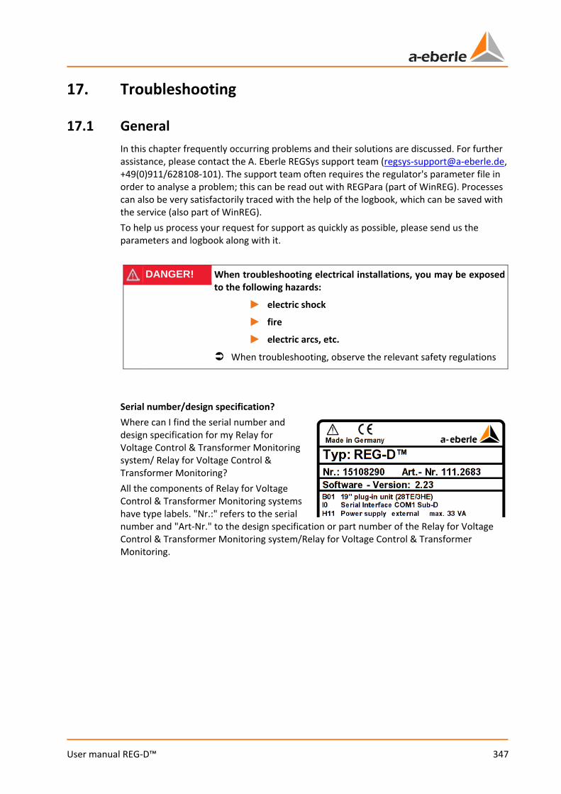
347
User manual REG-D™
17. Troubleshooting
17.1 General In this chapter frequently occurring problems and their solutions are discussed. For further assistance, please contact the A. Eberle REGSys support team ([email protected], +49(0)911/628108-101). The support team often requires the regulator's parameter file in order to analyse a problem; this can be read out with REGPara (part of WinREG). Processes can also be very satisfactorily traced with the help of the logbook, which can be saved with the service (also part of WinREG). To help us process your request for support as quickly as possible, please send us the parameters and logbook along with it.
DANGER! When troubleshooting electrical installations, you may be exposed to the following hazards:
1 electric shock
1 fire
1 electric arcs, etc.
When troubleshooting, observe the relevant safety regulations
Serial number/design specification? Where can I find the serial number and design specification for my Relay for Voltage Control & Transformer Monitoring system/ Relay for Voltage Control & Transformer Monitoring? All the components of Relay for Voltage Control & Transformer Monitoring systems have type labels. "Nr.:" refers to the serial number and "Art-Nr." to the design specification or part number of the Relay for Voltage Control & Transformer Monitoring system/Relay for Voltage Control & Transformer Monitoring.
We take care of it.
348
User manual REG-D™
The status LED of the REG-D™ is off – This may be the REG-D™ Relay for Voltage Control & Transformer Monitoring's battery warning. In the REG-D™ status menu, the battery status has changed from "OK" to "Error". When the warning first appears, the battery voltage is still sufficient to store the parameters of the REG-D™ in the main memory in the event of a supply
voltage failure. To prevent losing the parameters, please back them up using the WinREG software, or perform a RAM-Backup using bootloader V2.12 or later, (see also chapter 7.2.6 RAM-Backup, from page 117 onwards). It is recommended that the battery be replaced at the A. Eberle head office.
– The Relay for Voltage Control & Transformer Monitoring REG-D™ may have an internal fault (watchdog). For questions regarding this matter, please contact the A. Eberle REGSys support team ([email protected], +49(0)911/628108-101).
Must REG-D™ and PAN-D have the same firmware versions?
– Yes, the REG-D™ and PAN-D firmware versions must match one another. For both systems to function properly, the same firmware must be used.
Can I update REG-D™ Relays for Voltage Control & Transformer Monitoring with more recent firmware?
– Yes, firmware upgrades can be installed on all REG-D™ Relays for Voltage Control & Transformer Monitoring. Please refer to the "Important notes after an upgrade or downgrade of REG-D™ firmware" in chapter 7.2.1 Update bootloader and firmware, from page 74 onwards.
The REG-D™ does not always behave as expected or as described in the operating instructions
– Please check the software features that have been configured for the regulator. For example, the software features "SysCtrl" and "SysCtrl2" can significantly affect its behavior. For more information about the various features, please refer to chapter 8.3 Features (software), from page 230 onwards.
– The behavior of the REG-D™ Relay for Voltage Control & Transformer Monitoring can be modified via customer-specific programming (background programs). Please use the WinREG software to check whether a background program is available on the regulator (REG-L tab in the REGPara program segment). The name of the background program and corresponding design specifications are listed in program line H00. The background program, and a readme file describing its function, are available on the CD supplied.
SETUP -6-
Status
349
User manual REG-D™
17.2 Measurement The measured voltages/currents are incorrect
– If there is no measurement voltage or measurement current, please check the wiring for any open disconnect terminals or any short circuit terminals.
– In the case of incorrect measuring voltage or measuring current readings, please check the parameters in the "CT/VT-Configuration" menu. The selected assignment for current and voltage measurement must correspond to the actual voltages and currents connected.
– Even if the transducer is correctly adjusted, impedance on the power supply lines for the measuring voltage or measuring current can lead to variations in the measured quantities recorded. In order to compensate for such variations, the measuring voltages or measuring currents can be proportionally adjusted via the menu item "Actual Value Correction".
The calculated power values are incorrect.
– In the case of incorrect power values, please check the parameters in the "CT/VT-Configuration" menu.
– If a "Left rotary field" is present, please contact the A. Eberle REGSys support team ([email protected], +49(0)911/628108-101).
The sign of the active power does not match the display in a protection device or bay controller.
– Please note the A. Eberle sign definition (see chapter 7.2.3 Parallel operation, page 105)
– Check the polarities of the voltage transformer and current transformer, as well as the inversion parameter of the transducer voltage or current on page 2 of the "CT/VT-Configuration" menu. You can access page 2 of the menu with the left or right arrow keys.
SETUP -5-
CT/VTConfiguration
SETUP -6-
General 3
Actual Value Correction
SETUP -5-
CT/VTConfiguration
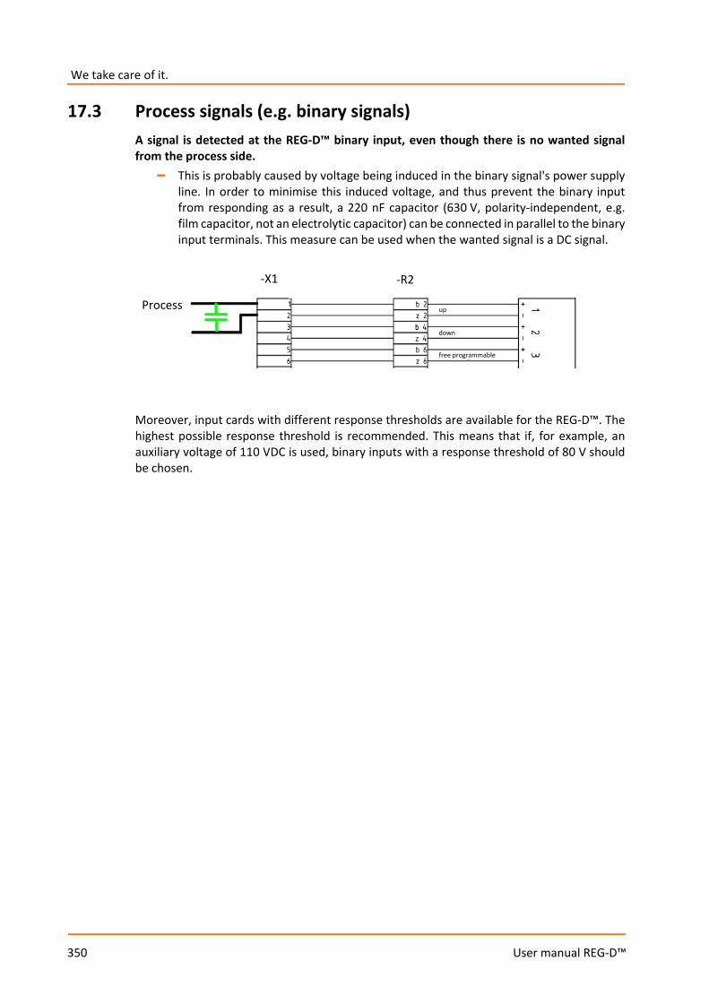
We take care of it.
350
User manual REG-D™
17.3 Process signals (e.g. binary signals) A signal is detected at the REG-D™ binary input, even though there is no wanted signal from the process side.
– This is probably caused by voltage being induced in the binary signal's power supply line. In order to minimise this induced voltage, and thus prevent the binary input from responding as a result, a 220 nF capacitor (630 V, polarity-independent, e.g. film capacitor, not an electrolytic capacitor) can be connected in parallel to the binary input terminals. This measure can be used when the wanted signal is a DC signal.
Moreover, input cards with different response thresholds are available for the REG-D™. The highest possible response threshold is recommended. This means that if, for example, an auxiliary voltage of 110 VDC is used, binary inputs with a response threshold of 80 V should be chosen.
Process
-X1 -R2
up
down
free programmable

351
User manual REG-D™
The message "Duplicate Assignment" appears in the analog channels menu after allocation of the analog function "70:iTapPos".
– With new devices, certain binary inputs may already be configured with the input functions for BCD-code by default. If an mA-signal is provided to the regulator for tap-position indication, the analog function "70:iTapPos" must be assigned to the corresponding analog channel. For this, all of the BCD-functions in the "Input assignment" menu must be deleted in order to avoid a duplicate assignment. (Duplicate assignment will also come about if the analog function "70:iTapPos" is simultaneously assigned to two analog channels.)
– If the tap-change position is determined by measuring the resistance, it is also necessary to delete the BCD-functions in the "Input assignment" menu. For details on setting a resistor module see chapter 7.2.2.6 Input/Output signals, from page 99 onwards.
SETUP -6-
General 1
ANALOG..
SETUP -5-
Input Assignments..
We take care of it.
352
User manual REG-D™
17.4 E-LAN No communication between two or more devices connected via E-LAN
– Please check the communication line for damage and ensure that it is properly connected (no open terminals). – If the E-LAN communication line has a ring topology, it must be opened at one point, since ring topologies are not supported with E-LAN. For example, the ring can be opened between two physically connected E-LAN interfaces
by configuring different baudrates. However, physical separation (disconnect terminals) is preferable.
– If the devices in E-LAN do not have a unique identifier, i.e., several devices have the same ID (e.g. "A:"), communication via E-LAN is not possible. Please also note that PAN-Ds assigned to a REG-D™ are automatically assigned an ID. This is always one higher than the ID of the REG-D™, for example, "B1:" if the code for the associated REG-D™ is "B:".
– Please check the baudrate setting of all involved E-LAN interfaces. The baudrate within a direct E-LAN connection or within an E-LAN bus must always be the same.
– Moreover, the settings for two- or four-wire operation within a direct E-LAN connection or within an E-LAN bus must correspond.
– If a two-wire connection is used, please check the termination resistors of all the E-LAN interfaces. For more information on proper termination, see chapter 7.1.4.6 E-LAN from page 67 onwards.
– If an FOC/RS485 converter is used, four-wire technology must be implemented for the connection.
The PAN-D does not appear in "Setup -6-" of the REG-D™
– Please check the physical E-LAN connection between PAN-D and REG-D™. For a PAN-D to be assigned to an unambiguous REG-D™, the left E-LAN interface of the REG-D™ must always be exclusively connected to the right E-LAN interface of the PAN-D (no bus topology, no other terminals).
SETUP -6-
E-LAN
353
User manual REG-D™
17.5 Regulation in general The tap-changer moves back and forth
– If the permissible setpoint deviation is set too low, the tap changer may oscillate, because the tolerance band is completely skipped by a single tap change. Please compare with chapter 7.2.2.4 Regulation (permissible setpoint deviation XwZ), from page 93 onwards.
In automatic mode, the tap-changer is off-scale; the voltage is further and further away from the setpoint value.
– The wiring of the regulator's up/down relay is reversed. As a result, the tap-change commands are always in the wrong direction.
– The "Invers" feature is equal to 2, whereby the software reverses the up/down relays. The wiring must be adjusted to the set feature Invers=2 (see chapter 8.3.13 Feature Invers, from page 268 onwards).
The tap-changer carries out too many tap changes
– The permissible setpoint deviation may be set too low for this particular application. In particular, in the case of regularly high load variations (e.g. steel works), the permissible setpoint deviation can be increased to reduce the number of tap changes. The limit of the permissible setpoint deviation constitutes the tolerable voltage fluctuations for specific applications. – One of the time programs "Integral", "Fast Integral" or "Linear" is used and the time factor parameter is set too low. Even brief violations of the permissible setpoint deviation result in a switching process. – The time program "Const" is used and parameters T1/T2 of the "Const" time program are set too low. Even brief violations of the permissible setpoint deviation result in a switching process.
SETUP -1-
Tolerance Band
SETUP -6-
Status
REG-D Status(2)
SETUP -1-
Tolerance Band
SETUP -1-
Time Behaviour
Time Factor
SETUP -1-
Time Behaviour
T1/T2
We take care of it.
354
User manual REG-D™
After a higher or lower tap-change in automatic operating mode, the regulator switches to manual mode
– If the tap position is activated in the REG-D™, after a tap change, the regulator checks whether the new tap matches the expected tap. If this is not the case, a tap-change error is generated, also see chapter 8.2.7.5 Tap change error (TapErr), from page 228 onwards). In connection with a set bit 7 of the software feature "SysCtrl" (see chapter 8.3.20 Feature SYSCTRL, from page 276 onwards), the regulator switches to manual mode. Please also see the Invers feature in this connection (see chapter 8.3.13
Feature Invers, from page 268 onwards).
– If the regulator is in an active parallel program and a parallel error (ParErr, also see chapter 8.2.7.7 Parallel operation error (ParErr), page 229) is generated, the regulator switches into manual mode if bit 6 of the software feature SysCtrl is set (see chapter 8.3.20 Feature SYSCTRL, from page 276 onwards).
In auto mode, high-speed switching is always activated
– Please check the set values of the forward and backward high-speed switching parameters. Pay particular attention to the sign for the forward high-speed switching, which should normally be negative. Between forward high-speed switching (e.g. -10%) and backwards high-speed switching (e.g. +10%), there must be a voltage range (percentual) in which high-speed switching is
deactivated.
– Please check whether a binary input with the function "25:Quick" is in use and whether this input is active in auto mode. If this input is active, and the regulator in auto mode, it will be forced into high-speed switching mode.
The regulator emits no down tap command in auto mode and the message <U is activated
– The undervoltage threshold is above the current measurement voltage. This can happen, for example, if the limit value for <U was set without a minus sign (e.g. +5% instead of -5%). When the <U limit is reached, down commands are blocked.
SETUP -6-
Status
REG-D Status(2)
SETUP -3-
High-speedSwitching
SETUP -5-
InputAssignments..
SETUP -2-
<U Undervoltage

355
User manual REG-D™
A current program, gradients (except LDC) and limitation have been configured to influence the current-dependent setpoint value. The setpoint value changes, but not in accordance with the current applied.
– Please check the signs for the minimum and maximum limitation parameters. In particular, the minimum limitation parameter should be given a negative sign.
SETUP -2-
Limitation (I)
We take care of it.
356
User manual REG-D™
17.6 Parallel operation Must the REG-D™ have the same firmware version for parallel operation?
– Yes, several REG-D™ operating in parallel must have the same firmware version in order to ensure proper communication between the devices with regard to the parallel programs.
Group switching of manual/automatic mode is not possible in Master-Follower parallel operation.
– A set bit 0 of the SysCtrl2 feature ensures that group switching of manual/automatic mode is terminated in master-follower parallel mode. Please check whether the feature bit is set for the appropriate regulator (also see chapter 8.3.21 Feature SYSCTRL2, from page 278 onwards). – No group list or an incorrect group list is configured in the slave regulator. In general, the group list must be set the same in all of the regulators involved in parallel operation.
SETUP -6-
Status
SETUP -6-
Status
REG-D Status(2)
SETUP -1-
Programs..
Par.Parameter..
Group List

357
User manual REG-D™
In Master-Follower parallel operation, the transformers diverge in follower mode (in the event of a tap difference).
– This is possibly due to transformers behaving inversely but without the "Invers" feature having been set. During normal operation, the master regulates voltage, the slave is adjusted accordingly, and there is no tap-change divergence in the transformers since an up command results in a higher voltage and a down command in a lower voltage. However, if there is a tap difference between master and slave, the slave goes into follower mode and now carries out tap changes according to the tap difference (and not the
voltage!). Without the "Invers" feature being set, the follower now always carries out tap changes in the wrong direction, because it assumes that an up command also involves a Up tap change and a down command involves a Down tap change. Please check if one of the transformers involved is inverted and whether or not the "Invers" feature is set (also see chapter 8.3.13 Feature Invers, page 268). Transformers also diverge when the inverted feature is mistakenly set for a non-inverted transformer.
In Master-Follower parallel operation, ParErr is triggered without a tap difference having occurred.
– In addition to the tap difference, the master-follower parallel program monitors circulating reactive current via Icirc-Supervision. If the Icirc limit is exceeded, the parallel error ParErr is generated. (also see chapter 8.2.7.7 Parallel operation error (ParErr), page 229)
The circulating reactive current minimisation programs (dIsin(ϕ), dIsin(ϕ)[S], dcos(ϕ)) do not work (no influence on regulation).
– The default value of the regulation influence for the circulating reactive current minimisation programs dIsin(ϕ), dIsin(ϕ)[S] and dcos(ϕ) is 9999 A. With this default value, the parallel programs have virtually no impact on regulation. Details for determining the parameter Permiss. Icirc can be found in chapter 7.2.3 Parallel operation, from page 105 onwards.
SETUP -6-
Status
REG-D Status(2)
SETUP -1-
Programs..
Par.Parameter..
Icirc-Superv.
SETUP -1-
Programs..
Par.Parameter..
Permiss. Icirc
We take care of it.
358
User manual REG-D™
– The limitation parameter of the relevant reactive current minimisation program, whose default setting is 20, is configured to 0. By doing this, the programs dIsin(ϕ), dIsin(ϕ)[S] and dcos(ϕ) have no influence on regulation.
The transformers diverge when a reactive current minimisation program (dIsin(ϕ), dIsin(ϕ)[S], dcos(ϕ)) is used.
– Please check the wiring of the voltage and current detection units (chapter 7.1.4.5 Process, page 66), and the transducer settings (see chapter 7.2.2.2 Taking , page 86), and sign definitions (see chapter 7.2.3 Parallel operation, from page 105 onwards) of the Relay for Voltage Control & Transformer Monitoring REG-D™. A divergence of the transformers in the
circulating reactive current minimization programs dIsin(ϕ), dIsin(ϕ)[S] and dcos(ϕ) suggests that the calculation of the circulating reactive current is faulty due to wiring or configuration.
The transformers operating in parallel are tapping back and forth (hunting), yet the permissible setpoint deviation and permissible Icirc parameters are correctly set.
– In the event that the permissible setpoint deviation and the permissible Icirc have been set close to your recommended minimum value, the parameters may nevertheless be set with too narrow a range and thus result in an oscillating tap-change position. The reason for this is that the two permissible Icirc values are interdependent. In this case, it is recommended that the permissible setpoint deviation and permissible Icirc parameters be set with a slightly wider range. (See also the explanatory notes in chapter 8.1.2.1 Permissible setpoint deviation (bandwidth Xwz), page 127)
SETUP -1-
Programs..
Par.Parameter..
Limitation
SETUP -5-
CT/VTConfiguration
SETUP -1-
Tolerance Band
SETUP -1-
Programs..
Par.Parameter..
Permiss. Icirc
359
User manual REG-D™
17.7 WinREG There is no communication between WinREG and the connected device.
– The selected COM interface may still be blocked by another program, is unavailable or does not match the COM interface used. All COM interfaces are available, for example, via the Windows 7 operating system under "Control Panel/System/Device Manager".
– No null-modem cable is in use or the cable used is defective. It is recommended that the original A. Eberle null-modem cable be used.
– Check the WinREG and device interface settings. The baudrates, parity and handshakes of these must match.
– In the WinREG connection settings, several interfaces may be defined, and one of these connections will be defined as default. Check that the connection that you are using corresponds to the default connection.
– The connection between the PC and the device may be too slow, whereby the communication timeout (5s default) is activated. The communication timeout can be modified in WinREG's central control program in "Options/Configuration".
It is not possible to communicate via the PQServer
– Please check that "Communication with WinPQ" is activated in "Options/Settings" in WinREG's central control program.
– For a connection to be established, WinPQ's RS232Server must be started (see the tray icon). Since the WinREG cannot start the RS232 server, it is advisable in this operating case to switch the RS232 server of WinPQ to continuous operation. This is done by setting the AUTOCLOSE parameter in PQRS232Server.ini to zero (AUTOCLOSE=0).
– Check whether the registry entry for WinREG has been set in PQManager. The WinREG 3.9 panel does not start up and instead an error message appears
– If all of the other WinREG 3.9 program modules can connect to the device, yet the WinREG 3.9 panel does not start, Microsoft DotNet Framework 3.5 must be installed. A DotNet Framework 3.5 installation file is included as standard on the WinREG 3.9 CD.
We take care of it.
360
User manual REG-D™
17.8 REGUpdate (update32.exe) The firmware update aborts and the message "Wrong S-record" appears.
– The PC's native RS232 interface or the USB/RS232 converter does not support hardware handshaking (RTS/CTS). Hardware handshaking is vital to perform a successful update.
– No null-modem cable is in use or the cable used is defective. It is recommended that the original A. Eberle null-modem cable be used.
– The bootloader's firmware version is older than V2.00. Please update the bootloader to version V2.00 or later before updating the firmware.
The firmware update aborts and the message "Wrong version" appears.
– Please use a firmware file with "_p" in the filename. The firmware update aborts and the message "Bootloader version too low" appears.
– The bootloader's firmware version is V1.05. To pull up this bootloader, a special version of REGUpdate software is required. For questions regarding this matter, please contact the A. Eberle REGSys support team ([email protected], +49(0)911/628108-101).
An error message is displayed when downloading or uploading the H-Program.
– It is recommended that both the regulator's COM1 baudrate and that of the REGUpdate be set to 9600 baud, as higher speeds can lead to transmission problems.

361
User manual REG-D™
17.9 SCADA system Internal communication between the REG-D™ and the telecontrol board module is disrupted (the COM2 fault LED (red) is blinking).
– The baudrate of the COM2 interface of the REG-D™ does not correspond to the communication module setting. (Note also the default settings of the various telecontrol cards and protocols, see chapter 7.2.2.8 SCADA system, from page 103 onwards.)
– The REG-D™ identifier does not correspond to the configured device identifier of the telecontrol board module REG-P(E)(D). Enter "AA:" for the device identifier in order to address the device that is directly connected to COM2. In this case, the REG-D™ identifier is irrelevant.
– The telecontrol board module REG-P(ED) uses the P1 method for internal data transfer (only REG-Ps with old SCADA system parameter settings or "Alstom/Areva/Schneider" profile). Please check that the REG-D™ has a background program that supports the P1 method, as a corresponding background program is absolutely necessary for the P1 method.
– The telecontrol board module REG-P(ED) uses the RPS method for internal data transfer. Please check that the REG-D™ firmware version is V2.00 or later, as the RPS method is only supported by REG-D™ firmware versions V2.00 and later.
The REG-P telecontrol board module cannot be loaded or read out via REG-D™.
– The PC's native RS232 interface or the USB/RS232 converter does not support hardware handshaking (RTS/CTS). Hardware handshaking is vital for successful data transfer.
– If the bootloader version of the REG-D™ is lower than V1.14, loading or read out of the REG-P telecontrol board module via REG-D™ cannot take place. Should this be the case, please update the bootloader.
– To load or read out the REG-P telecontrol board module, the REG-D™ and REG-P must be in bootloader mode. After pressing the reset button of an external REG-P, it takes approximately 40s for the REG-P to appear in the serial bootloader. If you use the TK400 external REG-P with an up-to-date serial bootloader, the serial bootloader can be recognised by the alternate flashing of the "RESET/WD" LED and the "S+R" LEDs from "S/R/F 1".
– If you are using a REG-D™ with an internal REG-P (feature XW1), the REG-D™ and REG-P must be simultaneously put into bootloader mode using the following procedure: 1. Switch off the supply voltage of the REG-D™. 2. Switch the supply voltage back on, holding down the REG-D™ F1 key at the same
time until the REG-D™ automatically starts up in bootloader mode. 3. Wait approximately 40s, until the internal REG-P also appears in the serial
bootloader, before you begin to load or read out the REG-P. – If you are using a REG-D™ with an internal REG-P (feature XW1), please ensure that
you are using a version of WinConfig that is later than V8.31.
We take care of it.
362
User manual REG-D™
– If the REG-P has been retrofitted, please check that the RTS/CTS lines of the hardware handshake are connected correctly. These are absolutely necessary to load or read out the REG-P telecontrol board module via the REG-D™.
– Some versions of the REG-P telecontrol board module cannot be read out. For further information, please contact telecontrol system support ([email protected], +49 (0)911 628108-104).
There is no physical communication with the control system
– Please check the communication line for damage and ensure that it is properly connected (no open terminals).
– Physical communication cannot be established for telecontrol board modules of REG-P with IEC 103, and REG-PM with Modbus or SpaBUS if the internal communication between the REG-D™ and the telecontrol board module is disrupted. In such cases, it is advisable to start by checking that the internal communication is in proper working order.
– The baudrate of the telecontrol board module REG-P(ED) must correspond to the telecontrol board module settings.
– The Ethernet network uses a transfer rate of 10 Mbit/s. However, the telecontrol board module REG-P(ED) supports a transfer rate of 100 Mbit/s.
– Check that the LINK-layer addressing (link or IP address) is set correctly. – If the IEC 101 protocol is used, please check the following:
1. Does the length of the link, ASDU and data object addresses of the telecontrol board module REG-P correspond to the control system?
2. Does the communication mode (balanced or unbalanced) correspond to the control system settings?
3. Do the settings for the use of the originator address correspond? – If a serial FOC communication line (not Ethernet) is used, the rest position of the
telecontrol board module REG-P(ED) must correspond to the rest position of the control system (TK400 REG-P rest position with "non-inverted" setting -> light on).
– When using an FOC communication line, the fibre optic cables should be cross-connected between the control system and the telecontrol board module, because otherwise there is no receive signal, or there is no activity.
– When using RS485, please check the following: 1. Is the polarity correct (e.g. double-wire: RX- with TX- and RX+ with TX+)? 2. Is the RS485 bus terminated correctly at the start and end (120 Ohm termination
resistor)?
363
User manual REG-D™
There is physical communication, but no valid data is available or no data is transferred. – Please check the internal communication between the REG-D™ and the telecontrol
board module REG-P(ED). – Please check the physical-to-logical device assignment according to IEC 61850
protocol ("Logical device instance" parameter in the Devices folder). This only applies to IEC 61850 for WinCONFIG 9.9 or later (e.g. version 6).
– Check the ASDU address of the telecontrol card in IEC 103/101/104. – Check the address configuration of the individual data points/objects.
No stable connection can be established when using two control systems according to protocol IEC 61850.
– Please check that both control systems have the same report control block (URCB). It is essential that two different report control blocks are used for control system.
Must the telecontrol board module REG-P(ED) firmware also be upgraded when updating the REG-D™ firmware?
– If the communication standard that has been used between the REG-D™ and REG-P(ED) up to now (RPS or P1 method) remains unchanged, the REG-P(ED) firmware version does not need to be updated. The RPS communication standard has been available since REG-D™ firmware V2.00.
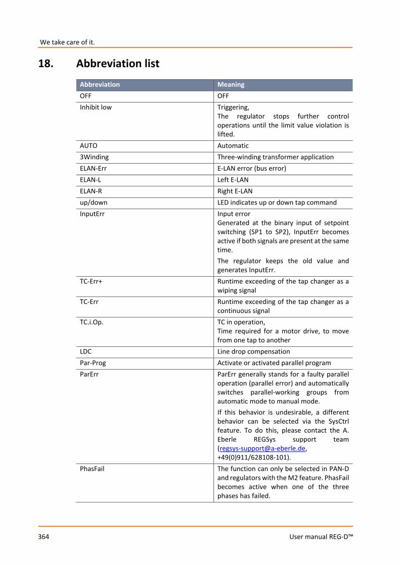
We take care of it.
364
User manual REG-D™
18. Abbreviation list
Abbreviation Meaning OFF OFF Inhibit low Triggering,
The regulator stops further control operations until the limit value violation is lifted.
AUTO Automatic 3Winding Three-winding transformer application ELAN-Err E-LAN error (bus error) ELAN-L Left E-LAN ELAN-R Right E-LAN up/down LED indicates up or down tap command InputErr Input error
Generated at the binary input of setpoint switching (SP1 to SP2), InputErr becomes active if both signals are present at the same time. The regulator keeps the old value and generates InputErr.
TC-Err+ Runtime exceeding of the tap changer as a wiping signal
TC-Err Runtime exceeding of the tap changer as a continuous signal
TC.i.Op. TC in operation, Time required for a motor drive, to move from one tap to another
LDC Line drop compensation Par-Prog Activate or activated parallel program ParErr ParErr generally stands for a faulty parallel
operation (parallel error) and automatically switches parallel-working groups from automatic mode to manual mode. If this behavior is undesirable, a different behavior can be selected via the SysCtrl feature. To do this, please contact the A. Eberle REGSys support team ([email protected], +49(0)911/628108-101).
PhasFail The function can only be selected in PAN-D and regulators with the M2 feature. PhasFail becomes active when one of the three phases has failed.

365
User manual REG-D™
Abbreviation Meaning TapErr TapErr is a message that indicates a tap
change problem. The designation was derived from the English term "Tap Error“. Unlike ParErr, TapErr acts locally, it is therefore only shown on the regulator where the tap-change error occurred, but with master-follower or MSI mode operation, the parallel working group can be switched to manual mode.
LEVEL Level-triggered function PROG Function triggered by a background
program creepNBD Creeping Net Breakdown Quick High-speed switching,
the regulator switches in the tolerance band in the fastest possible time.
Inhibit Inhibit, the regulator stops further control operations until the limit value violation is lifted.
SP-1 Setpoint 1 SP-2 Setpoint 2 SP-3 Setpoint 3 SP-4 Setpoint 4 SP-decr. Decrement setpoint via binary input SP-incr. Increment setpoint via binary input SP2Level Level-controlled changeover to setpoint 2 Trans1 /Trans1 Transit channel 1,
binary input signal can be "passed through" to a freely programmable relay. Examples: BE 1 to Trans 1 Rel 3 to Trans 1 → BE 1 = 1 → REL 3 = 1 BE 1 = 0 → REL 3 = 0 BE 1 to Trans 1 Rel 3 to /Trans 1 → BE 1 = 1 → REL 3 = 0 BE 1 = 0 → REL 3 = 1
Trans2

We take care of it.
366
User manual REG-D™
Abbreviation Meaning Trans2 see Trans1 analogously PG_CB ParaGramer, undervoltage side,
circuit breaker PG_IS1 ParaGramer, undervoltage side,
isolator 1 PG_IS2 ParaGramer, undervoltage side,
isolator 2 PG__CP ParaGramer, undervoltage side,
coupling PG_SC1 ParaGramer, undervoltage side,
section 1 PG_SC2 ParaGramer, undervoltage side,
section 2 PG_H_CB ParaGramer, overvoltage side,
circuit breaker PG_H_IS1 ParaGramer, overvoltage side,
isolator 1 PG_H_IS2 ParaGramer, overvoltage side,
isolator 2 PG_H_CP ParaGramer, overvoltage side,
coupling PG_H_SC1 ParaGramer,overvoltage side,
section 1 PG_H_SC2 ParaGramer,overvoltage side,
section 2 BCD1 BCD/BIN code, value 1 BCD2 BCD/BIN code, value 2 BCD4 BCD/BIN code, value 4 BCD8 BCD/BIN code, value 8 BCD10 BCD/BIN code, value 10 BCD20 BCD/BIN code, value 20 BCDminus BCD/BIN code, "-" sign BIN16 BIN code, value 16 BIN32 BIN code, value 32 PANmiss Set when the associated PAN-D is not
present. LR_AH Local/remote operation with the REG-LR
device is activated when the input functions "LR_AH" and "LR_STAT" are used. These inputs are connected to the corresponding outputs of the REG-LR device. So long as the REG-LR device keeps the status line LR_STAT active (1), the AUTOMATIC/MANUAL mode
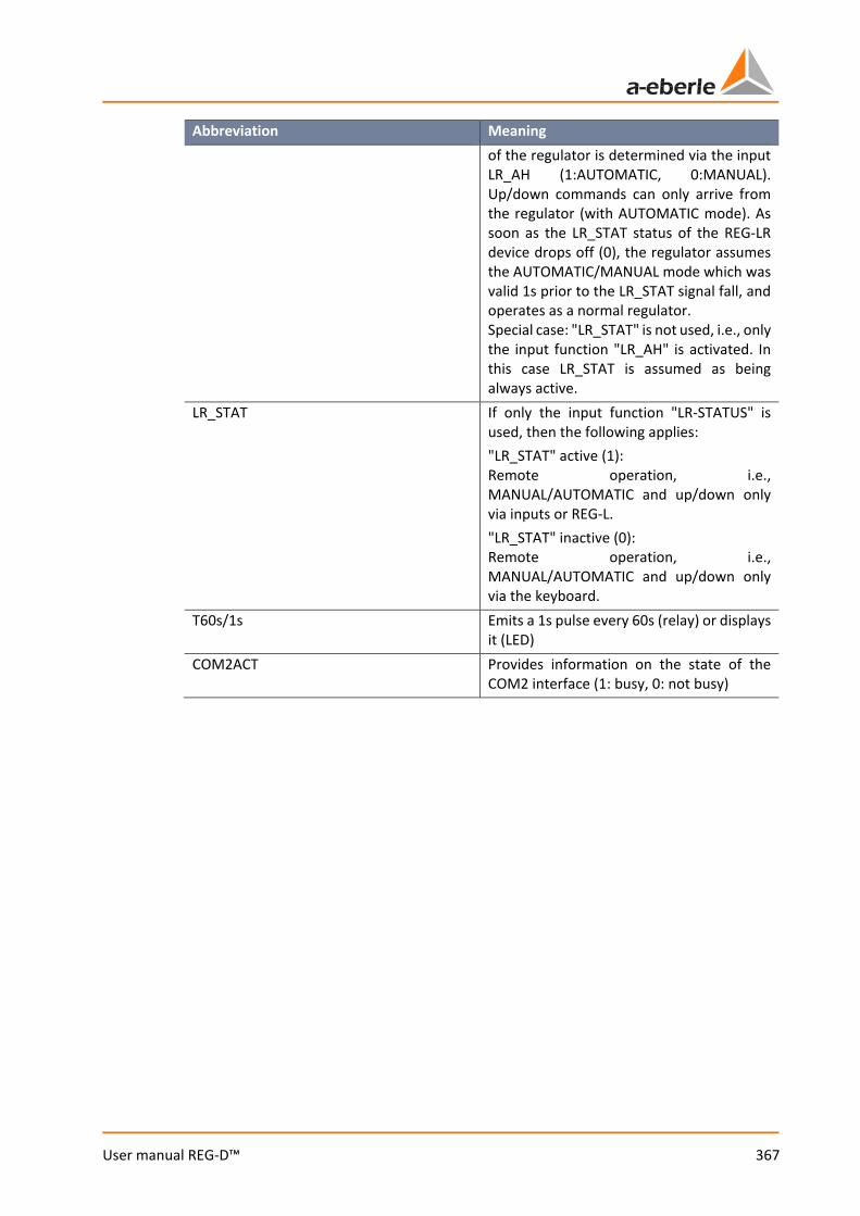
367
User manual REG-D™
Abbreviation Meaning of the regulator is determined via the input LR_AH (1:AUTOMATIC, 0:MANUAL). Up/down commands can only arrive from the regulator (with AUTOMATIC mode). As soon as the LR_STAT status of the REG-LR device drops off (0), the regulator assumes the AUTOMATIC/MANUAL mode which was valid 1s prior to the LR_STAT signal fall, and operates as a normal regulator. Special case: "LR_STAT" is not used, i.e., only the input function "LR_AH" is activated. In this case LR_STAT is assumed as being always active.
LR_STAT If only the input function "LR-STATUS" is used, then the following applies: "LR_STAT" active (1): Remote operation, i.e., MANUAL/AUTOMATIC and up/down only via inputs or REG-L. "LR_STAT" inactive (0): Remote operation, i.e., MANUAL/AUTOMATIC and up/down only via the keyboard.
T60s/1s Emits a 1s pulse every 60s (relay) or displays it (LED)
COM2ACT Provides information on the state of the COM2 interface (1: busy, 0: not busy)
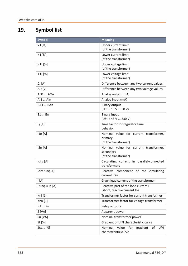
We take care of it.
368
User manual REG-D™
19. Symbol list
Symbol Meaning > I [%] Upper current limit
(of the transformer) < I [%] Lower current limit
(of the transformer) > U [%] Upper voltage limit
(of the transformer) < U [%] Lower voltage limit
(of the transformer) ΔI [A] Difference between any two current values ΔU [V] Difference between any two voltage values AO1 ... AOn Analog output (mA) AI1 ... AIn Analog input (mA) BA1 ... BAn Binary output
(USt. : 10 V ... 50 V) E1 ... En Binary input
(USt. : 48 V ... 230 V) Ft [1] Time factor for regulator time
behavior I1n [A] Nominal value for current transformer,
primary (of the transformer)
I2n [A] Nominal value for current transformer, secondary (of the transformer)
Icirc [A] Circulating current in parallel-connected transformers
Icirc sinϕ[A] Reactive component of the circulating current Icirc
I [A] Given load current of the transformer I sinϕ = Ib [A] Reactive part of the load current I
(short, reactive current Ib) Kni [1] Transformer factor for current transformer Knu [1] Transformer factor for voltage transformer R1 ... Rn Relay outputs S [VA] Apparent power Sn [VA] Nominal transformer power St [%] Gradient of Uf/I characteristic curve StNom [%] Nominal value for gradient of Uf/I
characteristic curve
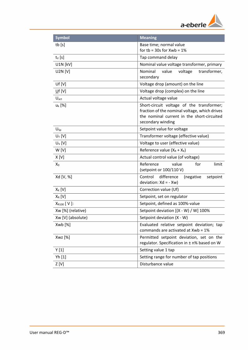
369
User manual REG-D™
Symbol Meaning tb [s] Base time; normal value
for tb = 30s for Xwb = 1% tV [s] Tap command delay U1N [kV] Nominal value voltage transformer, primary U2N [V] Nominal value voltage transformer,
secondary Uf [V] Voltage drop (amount) on the line Uf [V] Voltage drop (complex) on the line Uact Actual voltage value uk [%] Short-circuit voltage of the transformer;
fraction of the nominal voltage, which drives the nominal current in the short-circuited secondary winding
USp Setpoint value for voltage UT [V] Transformer voltage (effective value) UV [V] Voltage to user (effective value) W [V] Reference value (XR + XK) X [V] Actual control value (of voltage) X0 Reference value for limit
(setpoint or 100/110 V) Xd [V, %] Control difference (negative setpoint
deviation: Xd = - Xw) XK [V] Correction value (Uf) XR [V] Setpoint, set on regulator XR100 [ V ]: Setpoint, defined as 100%-value Xw [%] (relative) Setpoint deviation [(X - W) / W] 100% Xw [V] (absolute) Setpoint deviation (X - W) Xwb [%] Evaluated relative setpoint deviation; tap
commands are activated at Xwb = 1% Xwz [%] Permitted setpoint deviation, set on the
regulator. Specification in ± n% based on W Y [1] Setting value 1 tap Yh [1] Setting range for number of tap positions Z [V] Disturbance value
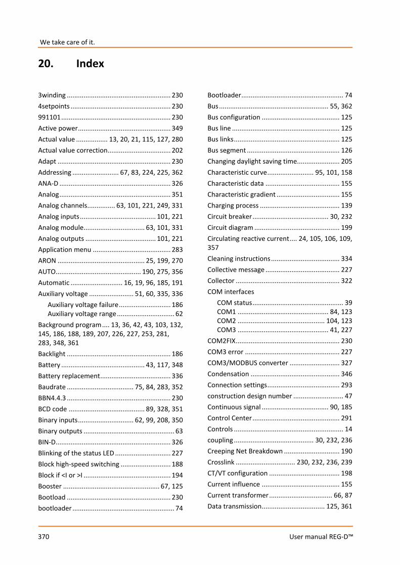
We take care of it.
370
User manual REG-D™
20. Index
3winding ........................................................ 230 4setpoints ...................................................... 230 991101 ........................................................... 230 Active power .................................................. 349 Actual value ................. 13, 20, 21, 115, 127, 280 Actual value correction .................................. 202 Adapt ............................................................. 230 Addressing ......................... 67, 83, 224, 225, 362 ANA-D ............................................................ 326 Analog ............................................................ 351 Analog channels ............... 63, 101, 221, 249, 331 Analog inputs ......................................... 101, 221 Analog module................................. 63, 101, 331 Analog outputs ...................................... 101, 221 Application menu .......................................... 283 ARON ............................................... 25, 199, 270 AUTO .............................................. 190, 275, 356 Automatic ............................ 16, 19, 96, 185, 191 Auxiliary voltage ........................ 51, 60, 335, 336
Auxiliary voltage failure ............................ 186 Auxiliary voltage range ............................... 62
Background program .... 13, 36, 42, 43, 103, 132, 145, 186, 188, 189, 207, 226, 227, 253, 281, 283, 348, 361 Backlight ........................................................ 186 Battery ............................................. 43, 117, 348 Battery replacement ...................................... 336 Baudrate .................................... 75, 84, 283, 352 BBN4.4.3 ........................................................ 230 BCD code ......................................... 89, 328, 351 Binary inputs .............................. 62, 99, 208, 350 Binary outputs ................................................. 63 BIN-D .............................................................. 326 Blinking of the status LED .............................. 227 Block high-speed switching ........................... 188 Block if <I or >I ............................................... 194 Booster .................................................... 67, 125 Bootload ........................................................ 230 bootloader ....................................................... 74
Bootloader ....................................................... 74 Bus ........................................................... 55, 362 Bus configuration .......................................... 125 Bus line .......................................................... 125 Bus links ......................................................... 125 Bus segment .................................................. 126 Changing daylight saving time....................... 205 Characteristic curve ......................... 95, 101, 158 Characteristic data ........................................ 155 Characteristic gradient .................................. 155 Charging process ........................................... 139 Circuit breaker ......................................... 30, 232 Circuit diagram .............................................. 199 Circulating reactive current .... 24, 105, 106, 109, 357 Cleaning instructions ..................................... 334 Collective message ........................................ 227 Collector ........................................................ 322 COM interfaces
COM status ................................................. 39 COM1 ................................................. 84, 123 COM2 ............................................... 104, 123 COM3 ................................................. 41, 227
COM2FIX ........................................................ 230 COM3 error ................................................... 227 COM3/MODBUS converter ........................... 327 Condensation ................................................ 346 Connection settings ....................................... 293 construction design number ........................... 47 Continuous signal .................................... 90, 185 Control Center ............................................... 291 Controls ........................................................... 14 coupling ........................................... 30, 232, 236 Creeping Net Breakdown .............................. 190 Crosslink ................................ 230, 232, 236, 239 CT/VT configuration ...................................... 198 Current influence .......................................... 155 Current transformer .................................. 66, 87 Data transmission .................................. 125, 361
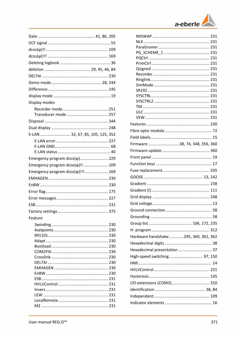
371
User manual REG-D™
Date ................................................... 41, 86, 205 DCF signal ........................................................ 55 dcos(ϕ)!! ........................................................ 109 dcos(ϕ)!!! ...................................................... 169 Deleting logbook ............................................. 36 deletion ......................................... 29, 45, 46, 84 DELTAI ........................................................... 230 Demo mode ............................................. 28, 244 Difference ...................................................... 145 display mode ................................................... 19 Display modes
Recorder mode ......................................... 251 Transducer mode ..................................... 257
Disposal ......................................................... 344 Dual display ................................................... 248 E-LAN ........................... 32, 67, 85, 105, 125, 352
E-LAN error ............................................... 227 E-LAN GND.................................................. 68 E-LAN status ............................................... 40
Emergency program dcos(ϕ) ......................... 229 Emergency program dcos(ϕ)!! ...................... 109 Emergency program dcos(ϕ)!!! ..................... 169 EMHAGEN ...................................................... 230 EnBW ............................................................. 230 Error flag ........................................................ 175 Error messages .............................................. 227 ESB ................................................................. 231 Factory settings ............................................. 375 Feature
3winding ................................................... 230 4setpoints ................................................. 230 991101 ...................................................... 230 Adapt ........................................................ 230 Bootload ................................................... 230 COM2FIX ................................................... 230 Crosslink ................................................... 230 DELTAI ...................................................... 230 EMHAGEN ................................................ 230 EnBW ........................................................ 230 ESB ............................................................ 231 HVLVControl ............................................. 231 Invers ........................................................ 231 LEW .......................................................... 231 LocalRemote ............................................. 231 M2 ............................................................ 231
MISWAP ................................................... 231 NLK ........................................................... 231 ParaGramer .............................................. 231 PG_SCHEME_1 ......................................... 231 PQCtrl ....................................................... 231 PrimCtrl .................................................... 231 Qsigned .................................................... 231 Recorder ................................................... 231 Ringlink ..................................................... 231 SimMode .................................................. 231 SR192 ....................................................... 231 SYSCTRL .................................................... 231 SYSCTRL2 .................................................. 231 TM ............................................................ 231 ULC ........................................................... 231 VEW .......................................................... 231
Features ........................................................ 230 Fibre optic module .......................................... 72 Field labels ....................................................... 15 Firmware ............................ 38, 74, 348, 356, 360 Firmware update ........................................... 360 Front panel ...................................................... 19 Function keys .................................................. 17 Fuse replacement .......................................... 335 GOOSE ..................................................... 13, 242 Gradient ........................................................ 158 Gradient (I) .................................................... 111 Grid display ................................................... 248 Grid voltage ..................................................... 13 Ground connection ......................................... 58 Grounding ....................................................... 58 Group list ....................................... 106, 172, 235 H- program .................................................... 312 Hardware handshake ............. 295, 360, 361, 362 Hexadecimal digits .......................................... 38 Hexadecimal presentation .............................. 37 High-speed switching .............................. 97, 150 HMI .................................................................. 14 HVLVControl .................................................. 231 Hysteresis ...................................................... 145 I/O extensions (COM3) .................................. 310 Identification ............................................. 38, 84 Independent .................................................. 109 Indicator elements .......................................... 16
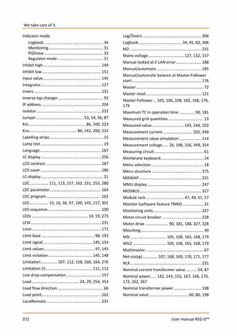
We take care of it.
372
User manual REG-D™
Indicator mode Logbook ...................................................... 34 Monitoring .................................................. 31 PQIView ...................................................... 32 Regulator mode .......................................... 21
Inhibit high ..................................................... 149 Inhibit low ...................................................... 151 Input value ..................................................... 145 Integrator ....................................................... 127 Invers ............................................................. 231 Inverse tap changer ......................................... 92 IP address ...................................................... 204 isolator ........................................................... 232 Jumper ........................................... 53, 54, 56, 87 Kni .................................................... 86, 200, 223 Knu ........................................... 86, 142, 200, 223 Labelling strips ................................................. 15 Lamp test ......................................................... 19 Language ........................................................ 187 LC display ....................................................... 256 LCD contrast .................................................. 187 LCD saver ....................................................... 186 LC-display ......................................................... 21 LDC ................. 111, 113, 157, 162, 231, 253, 280 LDC parameter ............................................... 164 LDC program .................................................. 162 LED ................. 15, 16, 36, 97, 100, 145, 217, 301 LED sequence ................................................. 100 LEDs ................................................... 14, 19, 273 LEW ................................................................ 231 Limit ............................................................... 171 Limit base ................................................ 98, 193 Limit signal ............................................. 145, 154 Limit values .............................................. 97, 145 Limit violation ........................................ 145, 148 Limitation ............... 107, 112, 158, 160, 164, 276 Limitation (I) .......................................... 111, 112 Line drop compensation ................................ 157 Load ........................................... 24, 29, 254, 353 Load flow direction .......................................... 66 Load point ...................................................... 162 LocalRemote .................................................. 231
Log/Divers ..................................................... 306 Logbook ....................................... 34, 45, 82, 306 M2 ................................................................. 231 Mains voltage ................................ 127, 132, 157 Manual locked at E-LAN error ....................... 188 Manual/automatic ........................................ 185 Manual/automatic balance at Master-Follower start: .............................................................. 176 Master ............................................................. 72 Master reset .................................................. 121 Master-Follower ... 105, 106, 108, 165, 168, 176, 179 Maximum TC in operation time .............. 90, 181 Measured grid quantities ................................ 13 Measured value ............................. 145, 244, 250 Measurement current ........................... 202, 349 Measurement value simulation .................... 114 Measurement voltage ..... 26, 198, 256, 349, 354 Measuring circuit ............................................. 61 Membrane keyboard ....................................... 14 Menu selection ................................................ 18 Menu structure ............................................. 375 MISWAP ......................................................... 231 MMU display ................................................. 247 MODBUS ........................................................ 327 Module rack .................................. 47, 49, 51, 57 Monitor (software feature TMM) ................... 31 Monitoring units ............................................ 327 Motor circuit breaker .................................... 228 Motor drive ..................... 90, 181, 188, 327, 328 Mounting ......................................................... 49 MSI ................................ 105, 108, 165, 168, 179 MSI2 .............................. 105, 108, 165, 168, 179 Multimaster ..................................................... 67 Net-cos(ϕ) ............. 107, 168, 169, 170, 171, 177 NLK ................................................................ 231 Nominal current transformer value .......... 54, 87 Nominal power ..... 142, 143, 155, 167, 168, 170, 172, 262, 267 Nominal transformer power ......................... 108 Nominal value ................................... 60, 86, 198

373
User manual REG-D™
Null-modem cable ... 74, 75, 76, 79, 80, 295, 359, 360 Number of taps ............................................. 130 on-load tap changer ........................................ 12 Open ring ......................................................... 67 Operating mode .................... 152, 185, 190, 257 Operating personnel ............................... 16, 182 Operating principle .......................................... 18 Over- and undercurrent limit ........................ 148 Overload ........................................................ 195 Overvoltage ............................................. 97, 147 PAN-A1 .......................................................... 327 PAN-A2 .......................................................... 327 PAN-D ............................................ 247, 327, 348 Panel .............................................................. 299 ParaGramer ..................................... 30, 107, 231 ParaGramer activity ....................................... 197 ParaGramer input error ................................. 229 Parallel operation .......................................... 105 Parallel operation error ................................. 229 Parallel Prog. Activation ................................ 173 Parallel program activation ........................... 106 Parallel programs .................................. 106, 167 Password protection ....................................... 45 Permissible Difference of Taps ...................... 176 Permissible Icirc ............................................. 110 Permissible setpoint deviation ................ 94, 127 PG_SCHEME_1............................................... 231 Phase angle .................................................... 105 Power flow .................................................... 255 PQCtrl ............................................................ 231 PQIView ........................................................... 32 PrimCtrl.......................................................... 231 Product warranty .......................................... 345 Programming languages ................................ 281 Progress indication ........................................ 139 PT100 ............................................................... 64 PT100 module ............................................... 102 Pulse signal .................................................... 185 Qsigned .......................................................... 231 RAM-Backup .................................. 117, 119, 313 Reactance (X) ................................................. 113
Reactive component ..................................... 111 Reactive current ......................... 22, 24, 111, 157 Reactive resistance ....................................... 157 Recommended setting .................................. 137 Recorder ........................................................ 231 Reference value .... 101, 127, 128, 141, 142, 143, 146, 147, 151, 152, 155 REG-F ............................................................. 328 REG-K ............................................................. 330 REG-L ............................................................. 312 REG-LR ........................................................... 329 REG-M ........................................................... 330 REGPara ......................................................... 314 REG-S ............................................................. 328 REG-U/BF ....................................................... 330 Regulator-Mode Large Display ...................... 187 REGUpdate (update32.exe) .......................... 360 REGView ........................................................ 317 Relays ............................................................ 213 Remote control command ............................ 191 Reset of fault indications ................................ 19 Resistance (R) ................................................ 113 Resistance input module ............................... 102 Retrofit of analog channels ........................... 331 Right bus ........................................................ 125 Ringlink .......................................... 231, 232, 239 Rolling Screens .............................................. 195 Rotating field ........................................... 88, 201 Run time ........................................................ 181 Safety instructions ........................................... 11 SCADA system ........................ 103, 203, 330, 361 Scope of delivery ............................................. 10 Serial interfaces ............................................... 17 Serial number .................................................. 38 Service ........................................................... 305 Setpoint ................................................... 93, 141 Setpoint adjustment with ←→ keys ............. 196 Setpoint adjustment with binary inputs ....... 196 Setpoint Index ............................................... 144 Setting ................................................... 158, 205 Setting signals ............................................... 329 Short-circuit voltage ...................................... 155

We take care of it.
374
User manual REG-D™
SimMode ....................................................... 231 Slave ................................................................. 72 SR192 ............................................................. 231 Station ID ......................................................... 83 Statistics ........................................................... 29 Status ............................................................... 38 Status contact .................................................. 53 Status LED ...................................................... 100 Storage ........................................................... 346 Summertime Adjustment .............................. 311 Switching differential..................................... 145 Switchover ..................................................... 185 SYSCTR ........................................................... 231 SYSCTRL2 ....................................................... 231 T1/T2.............................................................. 138 Tap difference ................................ 176, 229, 357 Tap limitation................................................. 183 Tap limiter ....................................................... 91 Tap position indication .................................. 182 Tap position indication error ......................... 228 Tap-change error ........................................... 228 TC in operation ........................................ 99, 277 TC in operation error ..................................... 228 TC in operation signal ...................................... 90 TC in operation time ...................... 175, 228, 277 Technical data ................................................ 375 Terminal ......................................................... 303 Terminal identification .................................. 122 Terminal name ............................................... 122 Terminals ................................................. 67, 175 Terminating resistor ................................ 85, 125 Three-winding transformer ............... 23, 26, 152
Three-winding transformer activation .......... 189 Time ............................................................... 205 Time behavior................................................ 131 Time factor .................................................... 138 Time program ................................................ 133 Time setting ................................................... 205 Time zone ...................................................... 205 Time/date ........................................................ 41 TM ................................................................. 231 Tolerance band .. 94, 97, 112, 128, 132, 139, 140, 142, 353 Transducer ................................................. 22, 87 Transducer mode ............................................ 19 Transformer Nominal Power ......................... 172 Triggering ........................................................ 97 Troubleshooting ............................................ 347 ULC ........................................................ 231, 280 Undervoltage ........................................... 97, 146 Up/down relay on-time ................................. 188 USB driver ...................................................... 290 Users ................................................................ 45 UTC ................................................................ 311 VEW ............................................................... 231 Voltage deviations ........................... 95, 131, 150 Voltage transformer ........................................ 66 Warranty ....................................................... 345 WinDM .......................................................... 325 WinREG .................................................. 287, 359 Winter time changeover ............................... 205 WinTM ........................................................... 325 Z compensation ............................................. 253
375
User manual REG-D™
21. Appendix
On the following pages you will find:
21.1 Technical data ....................................................................................................................... 376 21.2 Parameters, including factory settings ................................................................................. 407 21.3 Menu structure of the REG-D™ ............................................................................................ 423

We take care of it.
376 User manual REG-D™
20.1 Technical Data *) Applies to both the REG-D and the PAN-D Regulations and standards *) 0 IEC 61010-1 / EN 61010-1 0 CAN/CSA C22.2 No. 1010.1-92 0 IEC 60255-22-1 / EN 60255-22-1 0 IEC 61326-1 / EN 61326-1 0 IEC 60529 / EN 60529 0 IEC 60068-1 / EN 60068-1 0 IEC 60688 / EN 60688 0 IEC 61000-6-2 / EN 61000-6-2 0 IEC 61000-6-4 / EN 61000-6-4
8
0 IEC 61000-6-5 / EN 61000-6-5 (in preperation) AC voltage inputs (UE) *) Measuring voltage UE 0 ... 160 V
software selectable Shape of the curve sinusoidal Frequency range 16....50....60....65 Hz Internal consumption ≤ U2 / 100 kΩ Overload capacity 230 V AC continuous
AC input (IE) (REG-DTM only) Measuring current In 1 A / 5 A
(hardware & software sel-ectable)
Shape of the curve sinusoidal Frequency range 16....50....60....65 Hz Control range 0 ... In ... 2.1 In Internal consumption ≤ 0.5 VA Overload capacity 10 A continuous
30 A for 10 s 100 A for 1 s 500 A for 5 ms
Analogue inputs (AI) *) Quantity See order specifications Input range Y1...Y2
-20 mA...0...20 mA points Y1 and Y2 are pro-grammable
Control limit ± 1.2 Y2 Voltage drop ≤ 1.5 V Potential isolation Optocoupler Common-mode rejec-tion
> 80 dB
Series-mode rejection > 60 dB / Decade from 10 Hz
Overload capacity ≤ 50 mA continuous Error limit 0.5%
The inputs can be continuously short-circuited or open circuited. All inputs are galvanically isolated from all of the other circuits.
Analogue outputs (AO) *) Quantity See order specifications Output range Y1...Y2
-20 mA...0...20 mA points Y1 and Y2 pro-grammable
Control limit ± 1.2 Y2 Potential isolation Optocoupler Load range 0 ≤ R ≤ 8 V / Y2 Alternating component < 0.5% of Y2
The outputs can be continuously short-circuited or o-pen-circuited. All outputs are galvanically isolated from all of the other circuits.
Temperature input PT100 *) Quantity up to three PT100 inputs
are possible Type of connection Three-wire circuit Current through sensor < 8 mA Potential isolation Optocoupler Line compensation No compensation requi-
red Transmission behaviour linear
These inputs have open circuit monitoring. Resistance input (tap position potentiometer) Quantity See order specifications Connection Three-wire, convertible to
four-wire Total resistance in the resistor chain
R1: 180 Ω 2 kΩ R3: 2 kΩ 20 kΩ
Resistance per tap adjustable R1: 1…100 Ω/tap R3: 50…2000 Ω/tap
Number of taps ≤ 38 Potential isolation Optocoupler Current through resis-tor chain
max. 25 mA
These inputs have open circuit monitoring.

377 User manual REG-D™
Binary inputs (BI) *) Common Shape of the curve, permissible
Rectangular, sinusoidal
Signal frequency DC, 40 ... 70 Hz Potential isolation Optocoupler; all inputs gal-
vanically isolated from each other
Anti-bounce filter Software filter, with 50Hz AC input filter
Characteristic D1 - Inputs E1 ... E8 Control signals Ust AC/DC
range 48 V ... 250 V H - Level L - Level
≥ 48 V < 10 V
Input resistance 108 kΩ Characteristic D1 - Inputs E9 ... E16 Control signals Ust AC/DC
range 10 V ... 50 V H - Level L - Level
≥ 10 V < 5 V
Input resistance 6.8 kΩ Characteristic D2 - Inputs E1 ... E16 Control signals Ust AC/DC
range 48 V ... 250 V, H - Level L - Level
≥ 48 V < 10 V
Input resistance 108 kΩ Characteristic D3 - Inputs E1 ... E16 Control signals Ust AC/DC
range 10 V ... 50 V H - Level L - Level
≥ 10 V < 5 V
Input resistance 6.8 kΩ Characteristic D4 - Inputs E1 ... E16 Control signals Ust AC/DC
range 80 V ... 250 V
H - Level L - Level
≥ 80 V < 40 V
Input resistance 108 kΩ Characteristic D5 - Inputs E1 ... E16 Control signals Ust AC/DC
range 190 V ... 250 V H - Level L - Level
≥ 176 V < 88 V
Input resistance 108 kΩ
Simplified diagram of a binary input
Binary outputs (BO) *) max. switching fre-quency
≤ 1 Hz
Potential isolation Isolated from all internal device potentials
Contact load AC: 250 V, 5 A (cosϕ = 1.0) AC: 250 V, 3 A (cosϕ = 0.4) Switching capacity max. 1250 VA DC: 30 V, 5 A resistive DC: 30 V, 3.5 A L/R=7 ms DC: 110 V, 0.5 A resistive DC: 220 V, 0.3 A resistive Switching capacity max. 150 W
Inrush current 250 V AC, 30 V DC 10 A for max. 4 s
Switching operations ≥ 5·105 electrical
Analog/Digital Conversion *) Type 12 bit successive-approxi-
mation converter A/D bit resolution +/- 11 bit Sampling rate 24 samples per period, e.g.
1.2 kHz at a 50Hz signal * *The measurement inputs are equipped with an Anti-Ali-asing filter.
Device real time clock *) Accuracy +/- 20 ppm
Limit value monitoring *) Limit values programmable Response times programmable Alarm indicators LED programmable
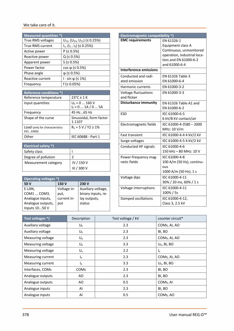
We take care of it.
378 User manual REG-D™
Measured quantities *) True RMS voltages U12, (U23, U31) (≤ 0.25%) True RMS current I1, (I2 , I3) (≤ 0.25%) Active power P (≤ 0.5%) Reactive power Q (≤ 0.5%) Apparent power S (≤ 0.5%) Power factor cos ϕ (≤ 0.5%) Phase angle ϕ (≤ 0.5%) Reactive current I · sin ϕ (≤ 1%) Frequency f (≤ 0.05%)
Reference conditions *) Reference temperature 23°C ± 1 K Input quantities UE = 0 ... 160 V
IE = 0 ... 1A / 0 ... 5A Frequency 45 Hz...65 Hz Shape of the curve Sinusoidal, form factor
1.1107 Load (only for characteristics E91...E900)
Rn = 5 V / Y2 ± 1%
Other IEC 60688 - Part 1
Electrical safety *) Safety class I Degree of pollution 2 Measurement category IV / 150 V
III / 300 V
Operating voltages *) 50 V 150 V 230 V E-LAN, COM1 ... COM3, Analogue inputs, Analogue outputs, Inputs 10...50 V
Voltage in-put, current in-put
Auxiliary voltage, binary inputs, re-lay outputs, status
Electromagnetic compatibility *) EMC requirements EN 61326-1
Equipment class A Continuous, unmonitored operation, industrial loca-tion and EN 61000-6-2 and 61000-6-4
Interference emissions Conducted and radi-ated emission
EN 61326 Table 3 EN 61000-6-4
Harmonic currents EN 61000-3-2 Voltage fluctuations and flicker
EN 61000-3-3
Disturbance immunity EN 61326 Table A1 and EN 61000-6-2
ESD IEC 61000-6-5 6 kV/8 kV contact/air
Electromagnetic fields IEC 61000-4-3\80 – 2000 MHz: 10 V/m
Fast transient IEC 61000-4-4 4 kV/2 kV Surge voltages IEC 61000-4-5 4 kV/2 kV Conducted HF signals IEC 61000-4-6
150 kHz – 80 MHz: 10 V Power-frequency mag-netic fields
IEC 61000-4-8 100 A/m (50 Hz), continu-ous 1000 A/m (50 Hz), 1 s
Voltage dips IEC 61000-4-11 30% / 20 ms, 60% / 1 s
Voltage interruptions IEC 61000-4-11 100% / 5s
Damped oscillations IEC 61000-4-12, Class 3, 2.5 kV
Test voltages *) Description Test voltage / kV counter circuit*
Auxiliary voltage Uh 2.3 COMs, AI, AO Auxiliary voltage Uh 2.3 BI, BO Measuring voltage Ue 2.3 COMs, AI, AO Measuring voltage Ue 3.3 Uh, BI, BO Measuring voltage Ue 2.2 Ie Measuring current Ie 2.3 COMs, AI, AO Measuring current Ie 3.3 Uh, BI, BO Interfaces, COMs COMs 2.3 BI, BO Analogue outputs AO 2.3 BI, BO Analogue outputs AO 0.5 COMs, AI Analogue inputs AI 2.3 BI, BO Analogue inputs AI 0.5 COMs, AO

379 User manual REG-D™
Test voltages *) Description Test voltage / kV counter circuit*
Binary inputs BI 2.3 BI Binary inputs BI 2.3 BO Binary outputs BO 2.3 BO
* Counter circuits are always at the rack potential. All test voltages are AC voltages in kV, which may be applied for 1 minute. The COM interfaces are tested against each other with 0.5 kV.
Auxiliary voltage *) Characteristic H0 H1/H11 H2 AC (internal) 75…185 V - - AC - 85 ... 264 V - DC - 88 ... 280 V 18 ... 72 V AC power consumption
≤ 35 VA ≤ 35 VA (H1) ≤ 45 VA (H11)
-
DC power consumption
- ≤ 25 W (H1) ≤ 35 W (H11)
≤ 25 W
Frequency 45 ... 400Hz
45 ... 400Hz -
The following applies to all characteristics: Voltage dips of ≤ 25 ms result neither in data loss nor mal-functions. Fuses are time lag (slow blow) type.
Ambient conditions *) Temperature range Function (Housing) Function (plug-in module) Transport and storage
-10 °C ... +50 °C -10 °C ... +60 °C -25 °C ... +65 °C
Dry cold IEC 60068-2-1, - 10°C / 16 h
Dry heat IEC 60068-2-2, + 55°C / 16 h
Humid heat constant
IEC 60068-2-78 + 40°C / 93% / 2 days
Humid heat cyclical
IEC 60068-2-30 12+12 h, 6 cycles +55°C / 93%
Drop and topple IEC 60068-2-31 100 mm drop height, unpackaged
Vibration IEC 60255-21-1, Class 1
Shock IEC 60255-21-2, Class 1
Earthquake resistance IEC 60255-21-3, Class 1
Display (REG-DTM only) LC - Display 128 x 128 graphic display
Back-lighting LED, automatic switch off after 15 minutes
Indicator elements (LEDs) Color Quantity Freely programmable quantity Green 1 (1) -- (--) Yellow 5 (--) 5 (--)
Red 2 (17) 2 (6) Values in () for PAN-D, Quantity without Manual/Auto and Local/Re-mote LEDs on the REG-D
Storage *) Firmware and re-corder data characteristic S2
Flash memory
Device charac-teristics and calibration data
serial EEPROM with ≥ 1000 k write/read cycles
Other data and re-corder data Characteristic S1
MRAM, Backup to flash memory possible
The backup battery on these devices is only used to buffer the real time clock if the aux. power supply is off.
Mechanical design Plug-in module *) Front panel Plastic, RAL 7035 grey
on aluminium brackets
Height 3 U (132.5 mm)
Width 28 HP (142.2 mm)
Printed circuit board 160 mm x 100 mm
Weight ≤ 1.5 kg
Protection type – Plug-in module – Female multi-
point connector
IP 00 IP 00
Mounting in conformity with DIN 41494 Part 5
Plug-in connector DIN 41612
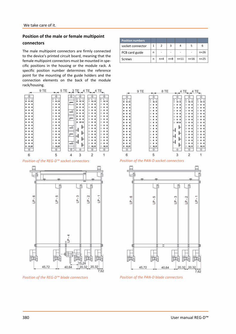
We take care of it.
380 User manual REG-D™
Position of the male or female multipoint connectors The male multipoint connectors are firmly connected to the device's printed circuit board, meaning that the female multipoint connectors must be mounted in spe-cific positions in the housing or the module rack. A specific position number determines the reference point for the mounting of the guide holders and the connection elements on the back of the module rack/housing.
Position of the REG-D™ socket connectors
Position of the REG-D™ blade connectors
Position numbers socket connector 1 2 3 4 5 6
PCB card guide n - - - - n+26
Screws n n+4 n+8 n+11 n+16 n+25
Position of the PAN-D socket connectors
Position of the PAN-D blade connectors

381 User manual REG-D™
Pin assignment of the REG-D™
Socket connector 1; (binary outputs) Raise (2 contact pairs) 1 NCC + 1 NOC
R1 Pole Pole
b2 b4
NCC NOC
z2 z4
Lower (2 contact pairs) 1 NCC + 1 NOC
R2 Pole Pole
b8 b10
NCC NOC
Z8 z10
Freely programmable R3 Pole b14 NOC z14
Freely programmable R4 Pole b16 NOC z16
Freely programmable R5 Pole b20 NOC Z20
Manual/Auto (converter)
Pole b22 Automatic Z22
Man b24
Status Pole b26 NOC/NCC Z24
Binary outputs (BO) 4 relays freely programmable
GND R6...R9 Z28
NOC R6 b30 NOC R8 Z30
NOC R7 b32 NOC R9 Z32
The status contact is either NOC or NCC based on characteristic U. This can be changed at a later stage by soldering a bridge.
Socket connector 2; (binary inputs) Characteristic D1 Raise E1 + b2 - z2
Lower E2 + b4 - z4
Inhibit E3 + b6 - z6
Fast switching E4 + b8 - z8 Manual/Auto E5 + b10 - z10 Manual E6 + b12 - z12 Freely programmable E7 + b14 - z14 Freely programmable E8 + b16 - z16 BCD 1 E9 + b24 - b32 BCD 2 E10 + b26 -
BCD 4 E11 + b28 -
BCD 8 E12 + b30 -
BCD 10 E13 + z24 - z32
BCD 20 E14 + z26 -
BCD - E15 + z28 -
Freely programmable E16 + z30 -
socket connector 2; (binary inputs) Characteristics D2...D5 Raise E1 + b2 - z2
Lower E2 + b4 - z4
Inhibit E3 + b6 - z6
Fast switching E4 + b8 - z8 Manual/Auto E5 + b10 - z10 Manual E6 + b12 - z12 Freely programmable E7 + b14 - z14 Freely programmable E8 + b16 - z16 BCD 1 E9 + b18 - z18 BCD 2 E10 + b20 - z20 BCD 4 E11 + b22 - z22 BCD 8 E12 + b24 - z24 BCD 10 E13 + b26 - z26 BCD 20 E14 + b28 - z28 BCD - E15 + b30 - z30 Freely programmable E16 + b32 - z32
All inputs except E5 and E6 are freely programmable. The tables for the socket connector 2 show a sample allocation.
socket connector 3; (measuring voltage, auxiliary voltage) DC output (max. 5 W) + 5V d2, b2, z2 GND d4, b4, z4
Measuring voltage U1 U1a 20 U1b** 22
Measuring voltage U2* U2a** 26 U2b 24
Auxiliary voltage UH L(+) 28 N(-) 30 PE 32 * only available for characteristics M2, M3 and M9 ** for characteristic M2 (ARON), pin 26 is internally connected to pin 22. The connection is L1 (pin 20), L2 (pin 22) and L3 (pin 24)..
socket connector 4; (alternating current input) Measuring current IE1 s1 1 s2 2
Measuring current IE2* s1 3 s2 4
* only available for characteristics M2 or M9
The current measuring inputs are equipped with special male and female socket connectors that short-circuit the current transformer when they are removed from the device. This means that the device does not have to be short-circuited externally. Socket connector 4 is numbered from top to bottom (1 to 6). The contact with description 6 is at the top of the male socket connector in the REG-D for design reasons. This means that the male socket connector is numbered 6 to 1 from top to bottom (embossing on the male socket connector).
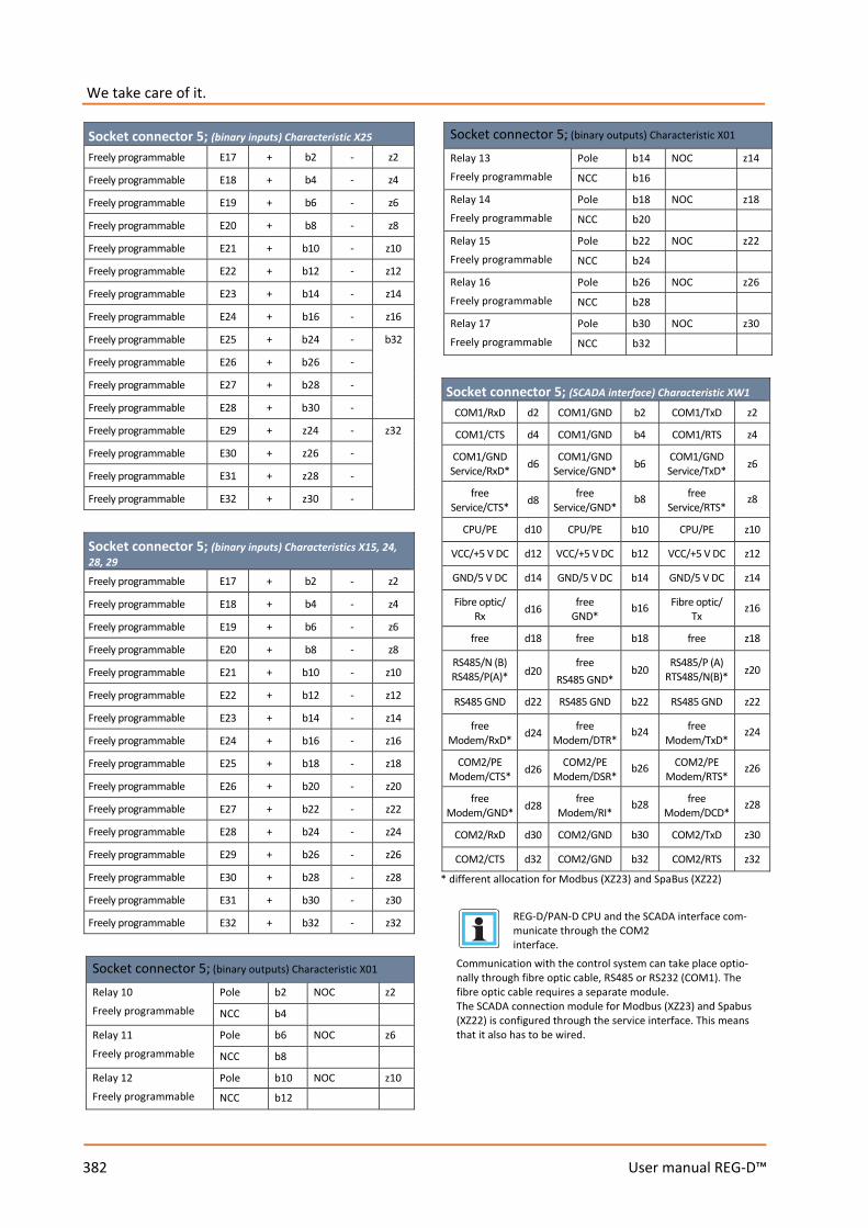
We take care of it.
382 User manual REG-D™
Socket connector 5; (binary inputs) Characteristic X25 Freely programmable E17 + b2 - z2
Freely programmable E18 + b4 - z4
Freely programmable E19 + b6 - z6
Freely programmable E20 + b8 - z8 Freely programmable E21 + b10 - z10 Freely programmable E22 + b12 - z12 Freely programmable E23 + b14 - z14 Freely programmable E24 + b16 - z16 Freely programmable E25 + b24 - b32 Freely programmable E26 + b26 -
Freely programmable E27 + b28 -
Freely programmable E28 + b30 -
Freely programmable E29 + z24 - z32
Freely programmable E30 + z26 -
Freely programmable E31 + z28 -
Freely programmable E32 + z30 -
Socket connector 5; (binary inputs) Characteristics X15, 24, 28, 29 Freely programmable E17 + b2 - z2
Freely programmable E18 + b4 - z4
Freely programmable E19 + b6 - z6
Freely programmable E20 + b8 - z8 Freely programmable E21 + b10 - z10 Freely programmable E22 + b12 - z12 Freely programmable E23 + b14 - z14 Freely programmable E24 + b16 - z16 Freely programmable E25 + b18 - z18 Freely programmable E26 + b20 - z20 Freely programmable E27 + b22 - z22 Freely programmable E28 + b24 - z24 Freely programmable E29 + b26 - z26 Freely programmable E30 + b28 - z28 Freely programmable E31 + b30 - z30 Freely programmable E32 + b32 - z32
Socket connector 5; (binary outputs) Characteristic X01 Relay 10 Freely programmable
Pole b2 NOC z2
NCC b4
Relay 11 Freely programmable
Pole b6 NOC z6
NCC b8
Relay 12 Freely programmable
Pole b10 NOC z10
NCC b12
Socket connector 5; (binary outputs) Characteristic X01 Relay 13 Freely programmable
Pole b14 NOC z14
NCC b16
Relay 14 Freely programmable
Pole b18 NOC z18
NCC b20
Relay 15 Freely programmable
Pole b22 NOC z22
NCC b24
Relay 16 Freely programmable
Pole b26 NOC z26
NCC b28
Relay 17 Freely programmable
Pole b30 NOC z30
NCC b32
Socket connector 5; (SCADA interface) Characteristic XW1 COM1/RxD d2 COM1/GND b2 COM1/TxD z2
COM1/CTS d4 COM1/GND b4 COM1/RTS z4
COM1/GND Service/RxD* d6 COM1/GND
Service/GND* b6 COM1/GND Service/TxD* z6
free Service/CTS* d8 free
Service/GND* b8 free
Service/RTS* z8
CPU/PE d10 CPU/PE b10 CPU/PE z10 VCC/+5 V DC d12 VCC/+5 V DC b12 VCC/+5 V DC z12 GND/5 V DC d14 GND/5 V DC b14 GND/5 V DC z14 Fibre optic/
Rx d16 free GND*
b16 Fibre optic/ Tx
z16
free d18 free b18 free z18 RS485/N (B) RS485/P(A)* d20
free RS485 GND*
b20 RS485/P (A) RTS485/N(B)* z20
RS485 GND d22 RS485 GND b22 RS485 GND z22 free
Modem/RxD* d24 free Modem/DTR*
b24 free Modem/TxD*
z24
COM2/PE Modem/CTS* d26 COM2/PE
Modem/DSR* b26 COM2/PE
Modem/RTS* z26
free Modem/GND* d28 free
Modem/RI* b28 free
Modem/DCD* z28
COM2/RxD d30 COM2/GND b30 COM2/TxD z30 COM2/CTS d32 COM2/GND b32 COM2/RTS z32
* different allocation for Modbus (XZ23) and SpaBus (XZ22)
REG-D/PAN-D CPU and the SCADA interface com-municate through the COM2 interface.
Communication with the control system can take place optio-nally through fibre optic cable, RS485 or RS232 (COM1). The fibre optic cable requires a separate module. The SCADA connection module for Modbus (XZ23) and Spabus (XZ22) is configured through the service interface. This means that it also has to be wired.

383 User manual REG-D™
Socket connector 6; (analogue inputs and outputs; inter-faces)
free d2 Analogue
channel 1 +
b2 Analogue channel 2
+
z2
DCF GND d4 Analogue
channel 1 -
b4 Analogue channel 2
-
z4
DCF EA+ d6 E-LAN left
EA + b6 E-LAN right
EA + z6
DCF EA- d8 E-LAN left
EA - b8 E-LAN right
EA - z8
E-LAN left GND
d10 E-LAN left E +
b10 E-LAN right E +
z10
E-LAN right GND
d12 E-LAN left E -
b12 E-LAN right E -
z12
free d14 Analogue
channel 3 +
b14 Analogue channel 4
+
z14
COM1-S TxD
d16 Analogue channel 3
-
b16 Analogue channel 4
-
z16
COM1-S RTS
d18 free b18 free z18
COM1-S GND
d20 COM2 TxD b20 COM2 RTS z20
COM1-S RxD
d22 COM2 RxD b22 COM2 CTS z22
COM1-S CTS
d24 COM2 GND b24 free z24
free d26 Analogue
channel 5 +
b26 Analogue channel 6
+
z26
free d28 Analogue
channel 5 -
b28 Analogue channel 6
-
z28
free d30 COM3 Tx + b30 COM3 Rx + z30
COM3 GND d32 COM3 TX- b32 COM3 Rx - z32
Pin assignment of the PAN-D
Socket connector 1; (binary outputs)
Inhibit high R1 Pole Pole
b2 b4
NOC NOC
z2 z4
EMERGENCY OFF tap-changer motor drive R2 Pole
Pole b8
b10 NOC NOC
Z8 z10
raise interlock R3 Pole b14 NOC z14
lower interlock R4 Pole b16 NOC z16
Freely programmable R5 Pole b20 NOC Z20
Freely programmable R6 Pole b26 NOC Z24
Status Pole b22
Failure b24 Operation z22
Socket connector 2; (binary inputs) Characteristic D1 TC. in operation E1 + b2 - z2
Freely programmable E2 + b4 - z4
Freely programmable E3 + b6 - z6
Freely programmable E4 + b8 - z8 Freely programmable E5 + b10 - z10 Freely programmable E6 + b12 - z12 Freely programmable E7 + b14 - z14 Freely programmable E8 + b16 - z16 Freely programmable E9 + b24 - b32 Freely programmable E10 + b26 -
Freely programmable E11 + b28 -
Freely programmable E12 + b30 -
Freely programmable E13 + z24 - z32
Freely programmable E14 + z26 -
Freely programmable E15 + z28 -
Freely programmable E16 + z30 -
Socket connector 2; (binary inputs) Characteristics D2...D5 TC. in operation E1 + b2 - z2
Freely programmable E2 + b4 - z4
Freely programmable E3 + b6 - z6
Freely programmable E4 + b8 - z8 Freely programmable E5 + b10 - z10 Freely programmable E6 + b12 - z12 Freely programmable E7 + b14 - z14 Freely programmable E8 + b16 - z16 Freely programmable E9 + b18 - z18 Freely programmable E10 + b20 - z20 Freely programmable E11 + b22 - z22 Freely programmable E12 + b24 - z24 Freely programmable E13 + b26 - z26 Freely programmable E14 + b28 - z28 Freely programmable E15 + b30 - z30 Freely programmable E16 + b32 - z32
All of the PAN-D's binary inputs are freely programmable from firmware version 2.22 onwards. Up to version 2.21, input 1 is allocated to the function TC in Operation. The tables for the socket connector 2 show the standard allocation.
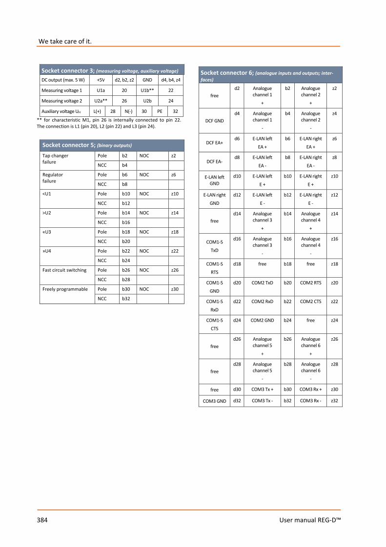
We take care of it.
384 User manual REG-D™
Socket connector 3; (measuring voltage, auxiliary voltage) DC output (max. 5 W) +5V d2, b2, z2 GND d4, b4, z4
Measuring voltage 1 U1a 20 U1b** 22
Measuring voltage 2 U2a** 26 U2b 24
Auxiliary voltage UH L(+) 28 N(-) 30 PE 32 ** for characteristic M1, pin 26 is internally connected to pin 22. The connection is L1 (pin 20), L2 (pin 22) and L3 (pin 24).
Socket connector 5; (binary outputs) Tap changer failure
Pole b2 NOC z2
NCC b4
Regulator failure
Pole b6 NOC z6
NCC b8
<U1 Pole b10 NOC z10
NCC b12
>U2 Pole b14 NOC z14
NCC b16
«U3 Pole b18 NOC z18
NCC b20
»U4 Pole b22 NOC z22
NCC b24
Fast circuit switching Pole b26 NOC z26
NCC b28
Freely programmable Pole b30 NOC z30
NCC b32
Socket connector 6; (analogue inputs and outputs; inter-faces)
free d2 Analogue
channel 1 +
b2 Analogue channel 2
+
z2
DCF GND d4 Analogue
channel 1 -
b4 Analogue channel 2
-
z4
DCF EA+ d6 E-LAN left
EA + b6 E-LAN right
EA + z6
DCF EA- d8 E-LAN left
EA - b8 E-LAN right
EA - z8
E-LAN left GND
d10 E-LAN left E +
b10 E-LAN right E +
z10
E-LAN right GND
d12 E-LAN left E -
b12 E-LAN right E -
z12
free d14 Analogue
channel 3 +
b14 Analogue channel 4
+
z14
COM1-S TxD
d16 Analogue channel 3
-
b16 Analogue channel 4
-
z16
COM1-S RTS
d18 free b18 free z18
COM1-S GND
d20 COM2 TxD b20 COM2 RTS z20
COM1-S RxD
d22 COM2 RxD b22 COM2 CTS z22
COM1-S CTS
d24 COM2 GND b24 free z24
free d26 Analogue
channel 5 +
b26 Analogue channel 6
+
z26
free d28 Analogue
channel 5 -
b28 Analogue channel 6
-
z28
free d30 COM3 Tx + b30 COM3 Rx + z30
COM3 GND d32 COM3 Tx - b32 COM3 Rx - z32
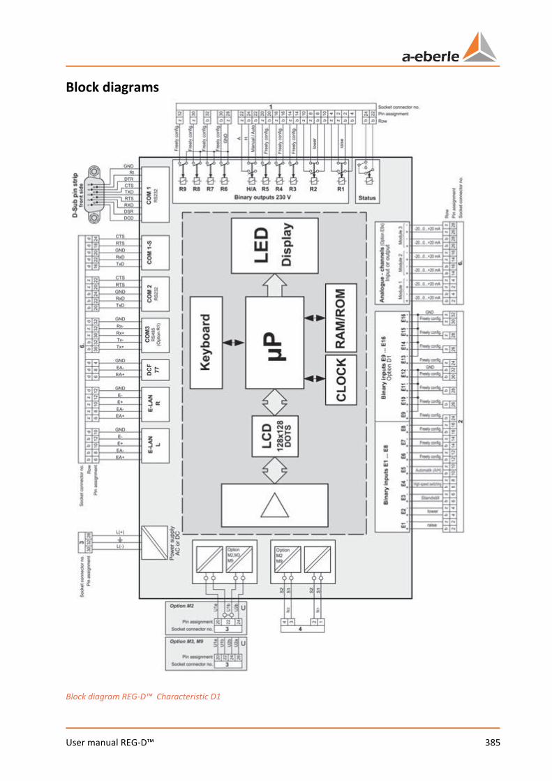
385 User manual REG-D™
Block diagrams
Block diagram REG-D™ Characteristic D1
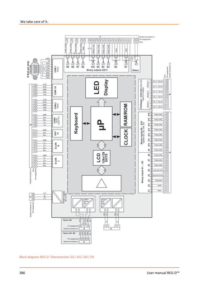
We take care of it.
386 User manual REG-D™
Block diagram REG-D Characteristic D2 / D3 / D4 / D5
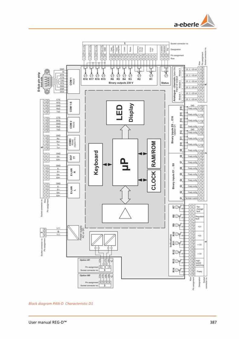
387 User manual REG-D™
Block diagram PAN-D Characteristic D1
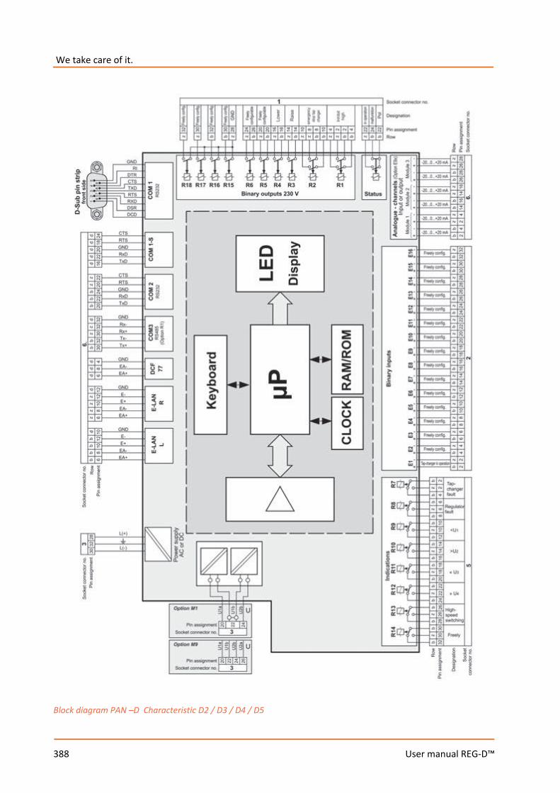
We take care of it.
388 User manual REG-D™
Block diagram PAN –D Characteristic D2 / D3 / D4 / D5

389 User manual REG-D™
Housing technology REGSys™ has a very flexible housing technology. A few of the housing configurations are described below. Most of the housings and 19” racks come with cus-tomer-specific wiring. The terminal configuration can be taken from the system-specific wiring diagrams. Please contact A. Eberle support if you do not have the diagrams.
19“ card racks (CR) Material Aluminium Protection type IP 20 Weight ≤ 5 kg Dimensions see drawings Width of the MR 84 HP
Connection elements Number of termi-nals
Characteristic B92
Screw terminals max. 200
Characteristic B93
Phoenix pluggable screw terminals
160
Characteristic B95
Phoenix pluggable screw terminals
fixed allocation through backplane*
* the Phoenix pluggable screw terminals in the cover can be used for components without backplane (e.g. PAN-A1, PQI-D). The number of terminals depends on the assembly.
Panel/wall mounting housing Material Plastic Protection type Front panel IP 65 Weight ≤ 4 kg Dimensions see drawings Housing width 30 or 49 HP
Connection elements Number of termi-nals
Characteristic B02 (30 HP, without wiring)
2.8 x 0.8 FASTON 6.3 x 0.8 FASTON
29 * 49 ** 60***
Characteristic B03 (30 HP, compatible with REG-5A and Pantavolt 2)
Phoenix pluggable screw terminals
compatible with REG-5A and Pantavolt 2
Characteristic B03, B05 (30 HP)
Phoenix pluggable screw terminals
29 * 49 ** 60***
Characteristic B06, B07, B91 (49 HP)
Phoenix pluggable screw terminals
60 * 92 ** 92***
* max. number of terminals for wall mounting with short terminal box ** max. number of terminals for wall mounting with long terminal box *** max. number of terminals for panel mounting housing
The conductor cross section and the maximum tightening torque of the different terminal types can be found in the next section.
llustrations and dimensions of the modules and housings
Plug-in module REG-D™/PAN-D 28 HP Characteristic B01
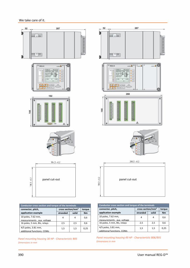
We take care of it.
390 User manual REG-D™
Conductor cross section and torque of the terminals connector, pitch, application example
cross section/mm2 torque stranded solid Nm
10 poles, 7.62 mm, measurements , aux. voltage
4 4 0,6
16 poles, 5 mm, BIs, relays 2,5 2,5 0,6
4/5 poles, 3.81 mm, additional functions, COMs
1,5 1,5 0,25
Panel mounting housing 30 HP - Characteristic B05 Dimensions in mm
Conductor cross section and torque of the terminals connector, pitch, application example
cross section/mm2 torque stranded solid Nm
10 poles, 7.62 mm, measurements , aux. voltage
4 4 0,6
16 poles, 5 mm, BIs, relays 2,5 2,5 0,6
4/5 poles, 3.81 mm, additional functions, COMs
1,5 1,5 0,25
Panel mounting housing 49 HP - Characteristic B06/B91 Dimensions in mm
panel cut-out panel cut-out
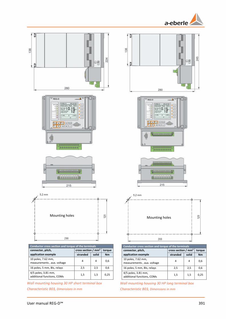
391 User manual REG-D™
Conductor cross section and torque of the terminals connector, pitch, application example
cross section / mm2 torque stranded solid Nm
10 poles, 7.62 mm, measurements , aux. voltage 4 4 0,6
16 poles, 5 mm, BIs, relays 2,5 2,5 0,6 4/5 poles, 3.81 mm, additional functions, COMs 1,5 1,5 0,25
Wall mounting housing 30 HP short terminal box Characteristic B03, Dimensions in mm
Conductor cross section and torque of the terminals connector, pitch, application example
cross section / mm2 torque stranded solid Nm
10 poles, 7.62 mm, measurements , aux. voltage 4 4 0,6
16 poles, 5 mm, BIs, relays 2,5 2,5 0,6 4/5 poles, 3.81 mm, additional functions, COMs 1,5 1,5 0,25
Wall mounting housing 30 HP long terminal box Characteristic B03, Dimensions in mm
Mounting holes Mounting holes

We take care of it.
392 User manual REG-D™
Conductor cross section and torque of the terminals connector, pitch, application example
cross section / mm2 torque stranded solid Nm
10 poles, 7.62 mm, measurements , aux. voltage 4 4 0,6
16 poles, 5 mm, BIs, relays 2,5 2,5 0,6
4/5 poles, 3.81 mm, additional functions, COMs 1,5 1,5 0,25
Wall mounting housing 49 HP short terminal box Cha-racteristic B07/B91, Dimensions in mm
Conductor cross section and torque of the terminals connector, pitch, application example
cross section / mm2 torque stranded solid Nm
10 poles, 7.62 mm, measurements , aux. voltage 4 4 0,6
16 poles, 5 mm, BIs, relays 2,5 2,5 0,6 4/5 poles, 3.81 mm, additional functions, COMs 1,5 1,5 0,25
Wall mounting housing 49 HP long terminal box Characteristic B91, Dimensions in mm
Mounting holes Mounting holes
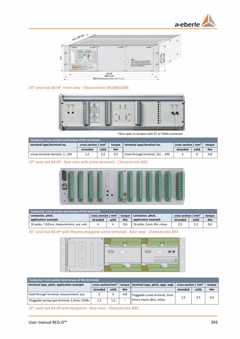
393 User manual REG-D™
19” card rack 84 HP Front view - Characteristic B92/B93/B95
Conductor cross section and torque of the terminals terminal type/terminal no. cross section / mm2 torque terminal type/terminal no. cross section / mm2 torque
stranded solid Nm stranded solid Nm screw terminal element, 1…160 1,5 2,5 0,5 Feed-through terminal, 161 … 200 4 6 0,8
19” card rack 84 HP Rear view with screw terminals - Characteristic B92
Conductor cross section and torque of the terminals connector, pitch, application example
cross section / mm2 torque connector, pitch, application example
cross section / mm2 torque stranded solid Nm stranded solid Nm
10 poles, 7.62mm, measurement, aux. volt. 4 4 0,6 16 poles, 5mm, BIs, relays 2,5 2,5 0,6
19” card rack 84 HP with Phoenix pluggable screw terminals Rear view - Characteristic B93
Conductor cross section and torque of the terminals terminal type, pitch, application example cross section/mm2 torque terminal type, pitch, appl. expl. cross section / mm2 torque
stranded solid Nm stranded solid Nm Feed-through terminal, measurement, aux. 4 6 0,8 Pluggable screw terminal, 5mm,
binary inputs (BIs), relays 2,5 2,5 0,6
Pluggable spring type terminal, 3.5mm, COMs 1,5 1,5 --
19” card rack 84 HP with backplane Rear view - Characteristic B95
Fibre optic in-/output with ST or FSMA connector
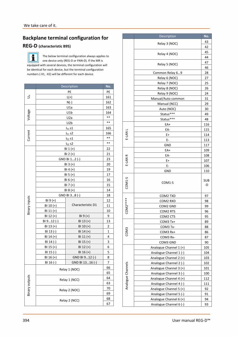
We take care of it.
394 User manual REG-D™
Backplane terminal configuration for REG-D (characteristic B95)
The below terminal configuration always applies to one device only (REG-D or PAN-D). If the MR is
equipped with several devices, the terminal configuration will be identical for each device, but the terminal configuration numbers (-X1, -X2) will be different for each device.
Description No.
U H PE PE
L(+) 161 N(-) 162
Volta
ge U1a 163
U1b 164 U2a ** U2b **
Curr
ent IE1 s1 165
IE1 s2 166 IE2 s1 ** IE2 s2 **
Bina
ry in
puts
BI 1 (+) 22 BI 2 (+) 21
GND BI 1…2 (-) 23 BI 3 (+) 20 BI 4 (+) 19 BI 5 (+) 17 BI 6 (+) 16 BI 7 (+) 15 BI 8 (+) 14
GND BI 3…8 (-) 18 BI 9 (+)
Characteristic D1 12
BI 10 (+) 11 BI 11 (+) 10 BI 12 (+) BI 9 (+) 9
BI 9…12 (-) BI 13 (+) 13 BI 13 (+) BI 10 (+) 2 BI 13 (-) BI 14 (+) 1 BI 14 (+) BI 11 (+) 4 BI 14 (-) BI 15 (+) 3 BI 15 (+) BI 12 (+) 6 BI 15 (-) BI 16 (+) 5 BI 16 (+) GND BI 9…12 (-) 8 BI 16 (-) GND BI 13…16 (-) 7
Bina
ry o
utpu
ts
Relay 1 (NOC) 66 65
Relay 1 (NCC) 64 63
Relay 2 (NOC) 70 69
Relay 2 (NCC) 68 67
Description No.
Relay 3 (NOC) 43 42
Relay 4 (NOC) 45 44
Relay 5 (NOC) 47 46
Common Relay 6…9 28 Relay 6 (NOC) 27 Relay 7 (NOC) 25 Relay 8 (NOC) 26 Relay 9 (NOC) 24
Manual/Auto common 31 Manual (NCC) 29
Auto (NOC) 30 Status*** 49 Status*** 48
E-LA
N L
EA+ 116 EA- 115 E+ 114 E- 113
GND 117
E-LA
N R
EA+ 109 EA- 108 E+ 107 E- 106
GND 110
COM
1-S
COM1-S SUB-D
COM
2***
*
COM2 TXD 97 COM2 RXD 98 COM2 GND 99 COM2 RTS 96 COM2 CTS 95
COM
3
COM3 Tx+ 89 COM3 Tx- 88 COM3 Rx+ 86 COM3 Rx- 87
COM3 GND 90
Anal
ogue
Cha
nnel
s
Analogue Channel 1 (+) 105 Analogue Channel 1 (-) 104 Analogue Channel 2 (+) 103 Analogue Channel 2 (-) 102 Analogue Channel 3 (+) 101 Analogue Channel 3 (-) 100 Analogue Channel 4 (+) 112 Analogue Channel 4 (-) 111 Analogue Channel 5 (+) 92 Analogue Channel 5 (-) 91 Analogue Channel 6 (+) 94 Analogue Channel 6 (-) 93
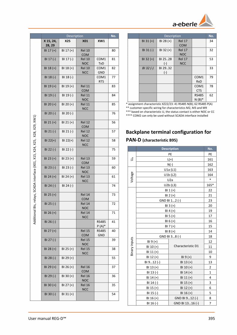
395 User manual REG-D™
Description No. Ad
ditio
nal B
Is, re
lays
, SCA
DA in
terfa
ce (X
01, X
15, X
24, X
25,
X28,
X29
, XW
1)
X 15, 24, 28, 29
X25 X01 XW1
BI 17 (+) BI 17 (+) Rel 10 COM
80
BI 17 (-) BI 17 (-) Rel 10 NOC
COM1 TxD
81
BI 18 (+) BI 18 (+) Rel 10 NCC
COM1 GND
82
BI 18 (-) BI 18 (-) COM1 RTS
77
BI 19 (+) BI 19 (+) Rel 11 COM
83
BI 19 (-) BI 19 (-) Rel 11 NOC
84
BI 20 (+) BI 20 (+) Rel 11 NCC
85
BI 20 (-) BI 20 (-) 76
BI 21 (+) BI 21 (+) Rel 12 COM
56
BI 21 (-) BI 21 (-) Rel 12 NOC
57
BI 22(+) BI 22(+) Rel 12 NCC
58
BI 22 (-) BI 22 (-) 75
BI 23 (+) BI 23 (+) Rel 13 COM
59
BI 23 (-) BI 23 (-) Rel 13 NOC
60
BI 24 (+) BI 24 (+) Rel 13 NCC
61
BI 24 (-) BI 24 (-) 74
BI 25 (+) Rel 14 COM
73
BI 25 (-) Rel 14 NOC
72
BI 26 (+) Rel 14 NCC
71
BI 26 (-) RS485 P (A)*
41
BI 27 (+) Rel 15 COM
RS485 GND
40
BI 27 (-) Rel 15 NOC
39
BI 28 (+) BI 25 (+) Rel 15 NCC
38
BI 28 (-) BI 29 (+) 55
BI 29 (+) BI 26 (+) Rel 16 COM
37
BI 29 (-) BI 30 (+) Rel 16 NOC
36
BI 30 (+) BI 27 (+) Rel 16 NCC
35
BI 30 (-) BI 31 (+) 54
Description No. BI 31 (+) BI 28 (+) Rel 17
COM 34
BI 31 (-) BI 32 (+) Rel 17 NOC
32
BI 32 (+) BI 25..28 (-)
Rel 17 NCC
53
BI 32 (-) BI 29..32 (-)
33
COM1 RxD
79
COM1 CTS
78
RS485 N (B)*
62
* assignment characteristic XZ22/23: 41 RS485 N(B); 62 RS485 P(A) ** customer-specific wiring for characteristics M2, M3 and M9 *** based on characteristic U, the status contact is either NOC or CC **** COM2 can only be used without SCADA interface installed
Backplane terminal configuration for PAN-D (characteristic B95)
Description No.
U H PE PE
L(+) 161 N(-) 162
Volta
ge U1a (L1) 163 U1b (L2) 164
U2a * U2b (L3) 165*
Bina
ry in
puts
BI 1 (+) 22 BI 2 (+) 21
GND BI 1…2 (-) 23 BI 3 (+) 20 BI 4 (+) 19 BI 5 (+) 17 BI 6 (+) 16 BI 7 (+) 15 BI 8 (+) 14
GND BI 3…8 (-) 18 BI 9 (+)
Characteristic D1 12
BI 10 (+) 11 BI 11 (+) 10 BI 12 (+) BI 9 (+) 9
BI 9…12 (-) BI 13 (+) 13 BI 13 (+) BI 10 (+) 2 BI 13 (-) BI 14 (+) 1 BI 14 (+) BI 11 (+) 4 BI 14 (-) BI 15 (+) 3 BI 15 (+) BI 12 (+) 6 BI 15 (-) BI 16 (+) 5 BI 16 (+) GND BI 9…12 (-) 8 BI 16 (-) GND BI 13…16 (-) 7
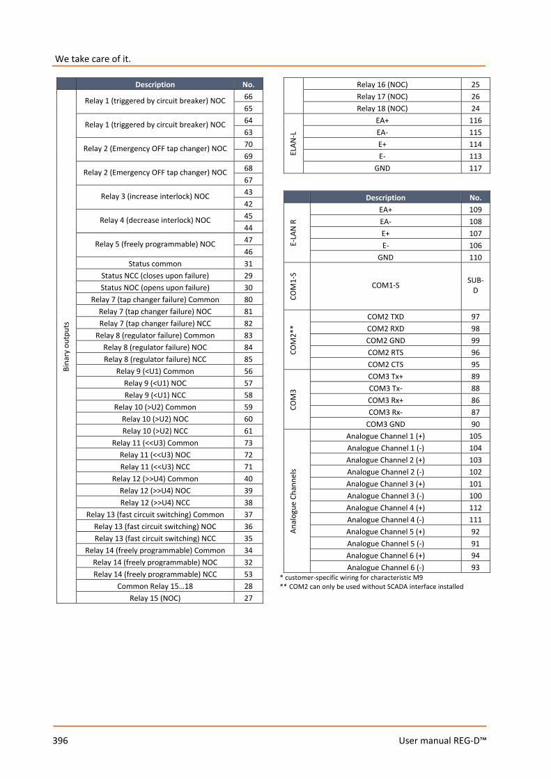
We take care of it.
396 User manual REG-D™
Description No.
Bina
ry o
utpu
ts
Relay 1 (triggered by circuit breaker) NOC 66 65
Relay 1 (triggered by circuit breaker) NOC 64 63
Relay 2 (Emergency OFF tap changer) NOC 70 69
Relay 2 (Emergency OFF tap changer) NOC 68 67
Relay 3 (increase interlock) NOC 43 42
Relay 4 (decrease interlock) NOC 45 44
Relay 5 (freely programmable) NOC 47 46
Status common 31 Status NCC (closes upon failure) 29 Status NOC (opens upon failure) 30
Relay 7 (tap changer failure) Common 80 Relay 7 (tap changer failure) NOC 81 Relay 7 (tap changer failure) NCC 82
Relay 8 (regulator failure) Common 83 Relay 8 (regulator failure) NOC 84 Relay 8 (regulator failure) NCC 85
Relay 9 (<U1) Common 56 Relay 9 (<U1) NOC 57 Relay 9 (<U1) NCC 58
Relay 10 (>U2) Common 59 Relay 10 (>U2) NOC 60 Relay 10 (>U2) NCC 61
Relay 11 (<<U3) Common 73 Relay 11 (<<U3) NOC 72 Relay 11 (<<U3) NCC 71
Relay 12 (>>U4) Common 40 Relay 12 (>>U4) NOC 39 Relay 12 (>>U4) NCC 38
Relay 13 (fast circuit switching) Common 37 Relay 13 (fast circuit switching) NOC 36 Relay 13 (fast circuit switching) NCC 35
Relay 14 (freely programmable) Common 34 Relay 14 (freely programmable) NOC 32 Relay 14 (freely programmable) NCC 53
Common Relay 15…18 28 Relay 15 (NOC) 27
Relay 16 (NOC) 25 Relay 17 (NOC) 26 Relay 18 (NOC) 24
ELAN
-L
EA+ 116 EA- 115 E+ 114 E- 113
GND 117
Description No.
E-LA
N R
EA+ 109 EA- 108 E+ 107 E- 106
GND 110
COM
1-S
COM1-S SUB-D
COM
2**
COM2 TXD 97 COM2 RXD 98 COM2 GND 99 COM2 RTS 96 COM2 CTS 95
COM
3
COM3 Tx+ 89 COM3 Tx- 88 COM3 Rx+ 86 COM3 Rx- 87
COM3 GND 90
Anal
ogue
Cha
nnel
s
Analogue Channel 1 (+) 105 Analogue Channel 1 (-) 104 Analogue Channel 2 (+) 103 Analogue Channel 2 (-) 102 Analogue Channel 3 (+) 101 Analogue Channel 3 (-) 100 Analogue Channel 4 (+) 112 Analogue Channel 4 (-) 111 Analogue Channel 5 (+) 92 Analogue Channel 5 (-) 91 Analogue Channel 6 (+) 94 Analogue Channel 6 (-) 93
* customer-specific wiring for characteristic M9 ** COM2 can only be used without SCADA interface installed
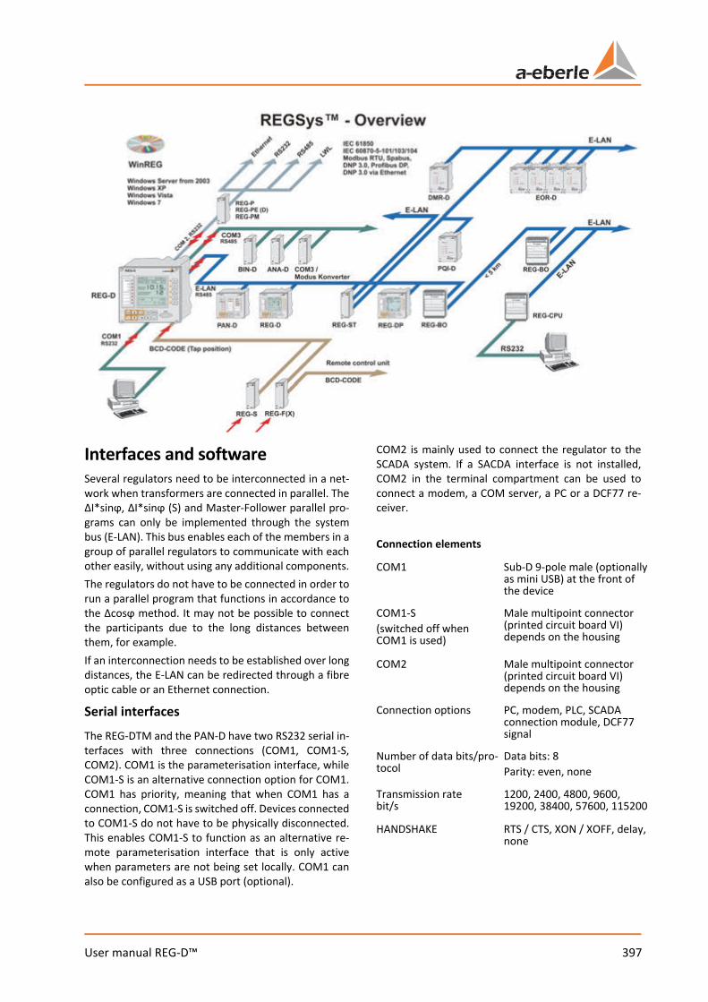
397 User manual REG-D™
Interfaces and software Several regulators need to be interconnected in a net-work when transformers are connected in parallel. The ΔI*sinϕ, ΔI*sinϕ (S) and Master-Follower parallel pro-grams can only be implemented through the system bus (E-LAN). This bus enables each of the members in a group of parallel regulators to communicate with each other easily, without using any additional components. The regulators do not have to be connected in order to run a parallel program that functions in accordance to the Δcosϕ method. It may not be possible to connect the participants due to the long distances between them, for example. If an interconnection needs to be established over long distances, the E-LAN can be redirected through a fibre optic cable or an Ethernet connection.
Serial interfaces The REG-DTM and the PAN-D have two RS232 serial in-terfaces with three connections (COM1, COM1-S, COM2). COM1 is the parameterisation interface, while COM1-S is an alternative connection option for COM1. COM1 has priority, meaning that when COM1 has a connection, COM1-S is switched off. Devices connected to COM1-S do not have to be physically disconnected. This enables COM1-S to function as an alternative re-mote parameterisation interface that is only active when parameters are not being set locally. COM1 can also be configured as a USB port (optional).
COM2 is mainly used to connect the regulator to the SCADA system. If a SACDA interface is not installed, COM2 in the terminal compartment can be used to connect a modem, a COM server, a PC or a DCF77 re-ceiver. Connection elements
COM1 Sub-D 9-pole male (optionally as mini USB) at the front of the device
COM1-S (switched off when COM1 is used)
Male multipoint connector (printed circuit board VI) depends on the housing
COM2 Male multipoint connector (printed circuit board VI) depends on the housing
Connection options PC, modem, PLC, SCADA connection module, DCF77 signal
Number of data bits/pro-tocol
Data bits: 8 Parity: even, none
Transmission rate bit/s
1200, 2400, 4800, 9600, 19200, 38400, 57600, 115200
HANDSHAKE RTS / CTS, XON / XOFF, delay, none
We take care of it.
398 User manual REG-D™
ELAN (Energy - Local Area Network) Each REG-DTM regulator comes with two ELAN inter-faces that are used to connect individual regulators and monitoring units to a voltage regulation system. ELAN characteristics 0 255 addressable participants 0 Multi-master structure 0 Integrated repeater function 0 Open ring, bus or point-to-point connection possi-
ble 0 Transmission rate 15.6 ... 375 kbit/s COM3 (peripheral interface) The COM3 is an RS485 or optional fibre optic interface used to connect up to 16 interface modules (BIN-D, ANA-D) in any combination to a REG-D or PAN-D. A COM3/Modbus converter can also be selected, in order to establish direct serial communication with other Modbus devices. This enables the REGSysTM to acquire values such as the winding temperature or the gas-in-oil ratio from other devices and transmit them to the SCADA or record them in Recorder mode. Time Synchronisation A time synchronisation input enables the time on the REG-D or PAN-D to be synchronised using a DCF77 sig-nal. This input is designed for an RS485 (5 V) signal and can be wired as a time synchronisation bus to several devices. The termination (terminating resistor) can be switched on and off by using jumpers on the CPU board. If a DCF signal cannot be received, a GPS clock or con-troller card that emulates a DCF signal can be used. Time can also be synchronised through SCADA. Time synchronisation input is not supported until firm-ware version 2.22.
WinREG parameterisation and configuration software WinREG is used to parameterise and program the a sys-tem. WinREG is modular and consists of the following programs: PanelView enables you to display an accurate replica of each device and its operating options on your PC screen. All buttons and functions are active from this replica, and multiple devices on the ELAN can be dis-played at once. REGPara enables each of the components to be quickly and easily parameterised. The parameters are set in a straightforward tab structure, and can be saved for la-ter use or transferred to another regulator on the ELAN bus. The Terminal enables direct communication with the system. The WinREG Terminal is much easier to use than the normal terminal programs and makes programming the system a lot easier. Service enables the logbook and the tap statistics to be read out of the devices and archived. This is also where the parameters for daylight savings, the allocation of add-on modules, and the remote con-trol of simulation mode are found. The Collector reads the recorded data from the REG-D(A) and archives it on the PC. REGView is used to view and analyse recorded data di-rectly on the REG-D(A) or in a data file (collector). The WinTM module (parameters for the transformer monitoring module) and the WinDM module (parame-ters for the transformer monitoring device without voltage regulator) complete the software suite. WinREG runs on the following operating systems:
0 Windows XP, Vista, Windows 7 0 Windows Server from 2003 onwards
All of the settings can be made either directly on the regulator using the regulator's membrane keyboard, or centrally through WinREG. If the device is to be acces-sed through a central point, all of the regulators must be connected to each other through the ELAN.
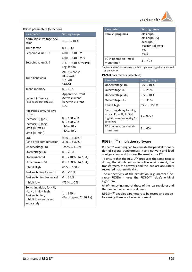
399 User manual REG-D™
REG-D parameters (selection) Parameter Setting range permissible voltage devi-ation ± 0.1 ... 10 %
Time factor 0.1 ... 30 Setpoint value 1..2 60.0 ... 140.0 V
Setpoint value 3..4 60.0 ... 140.0 V or -140 … 140 % for P/Q regulation
Time behaviour
ΔU · t = const REG 5A/E LINEAR CONST
Trend memory 0 ... 60 s
current influence (load-dependent setpoint)
Apparent current Active current Reactive current LDC
Apparent, active, reactive current Increase (I) (pos.) Increase (I) (neg.) Limit (I) (max.) Limit (I) (min.)
0 ... 400 V/In 0 ... 400 V/In -40 ... 40 V -40 ... 40 V
LDC (Line drop compensation)
R : 0 ... ± 30 Ω X : 0 ... ± 30 Ω
Undervoltage <U -25 % ... +10 % Overvoltage >U 0 ... 25 % Overcurrent >I 0 ... 210 % (1A / 5A) Undercurrent >I 0 ... 100 % (1A / 5A) Inhibit High 65 V ... 150 V Fast switching forward 0 ... -35 % Fast switching backward 0 ... 35 % Inhibit low -75 % ... 0 % Switching delay for <U, >U, <I, Inhibit high, Fast switching, Inhibit low can be set separately
1 ... 999 s (Fast step-up 2...999 s)
Parameter Setting range Parallel programs dI*sin(phi)
dI*sin(phi)[S] dcos (phi) Master-Follower MSI MSI2
TC in operation - maxi-mum time* 3 ... 40 s
* when a PAN-D is available, the TC in operation signal is monitored by the PAN-D.
PAN-D parameters (selection) Parameter Setting range Undervoltage <U1 -25 … 10 % Overvoltage >U2 0 ... 25 % Undervoltage «U3 -35 … 10 % Overvoltage »U4 0 ... 35 % Inhibit high 65 V ... 150 V Switching delay for <U1, >U2, «U3, »U4, Inhibit high (independent setting for each limit)
1 ... 999 s
TC in operation - maxi-mum time 3 ... 40 s
REGSimTM simulation software REGSim™ was designed to simulate the parallel connec-tion of several transformers in any network and load configuration, and to show the results on a PC. To ensure that the REG-DTM produces the same results during the simulation as in a live environment, the transformers, the network and the load are accurately recreated mathematically. The authenticity of the simulation is guaranteed be-cause REGSimTM uses the REG-DTM relay’s original algorithm. All of the settings match those of the real regulator and the simulation is run in real time. REGSimTM enables parameters to be tested and set be-fore using them in a live environment.
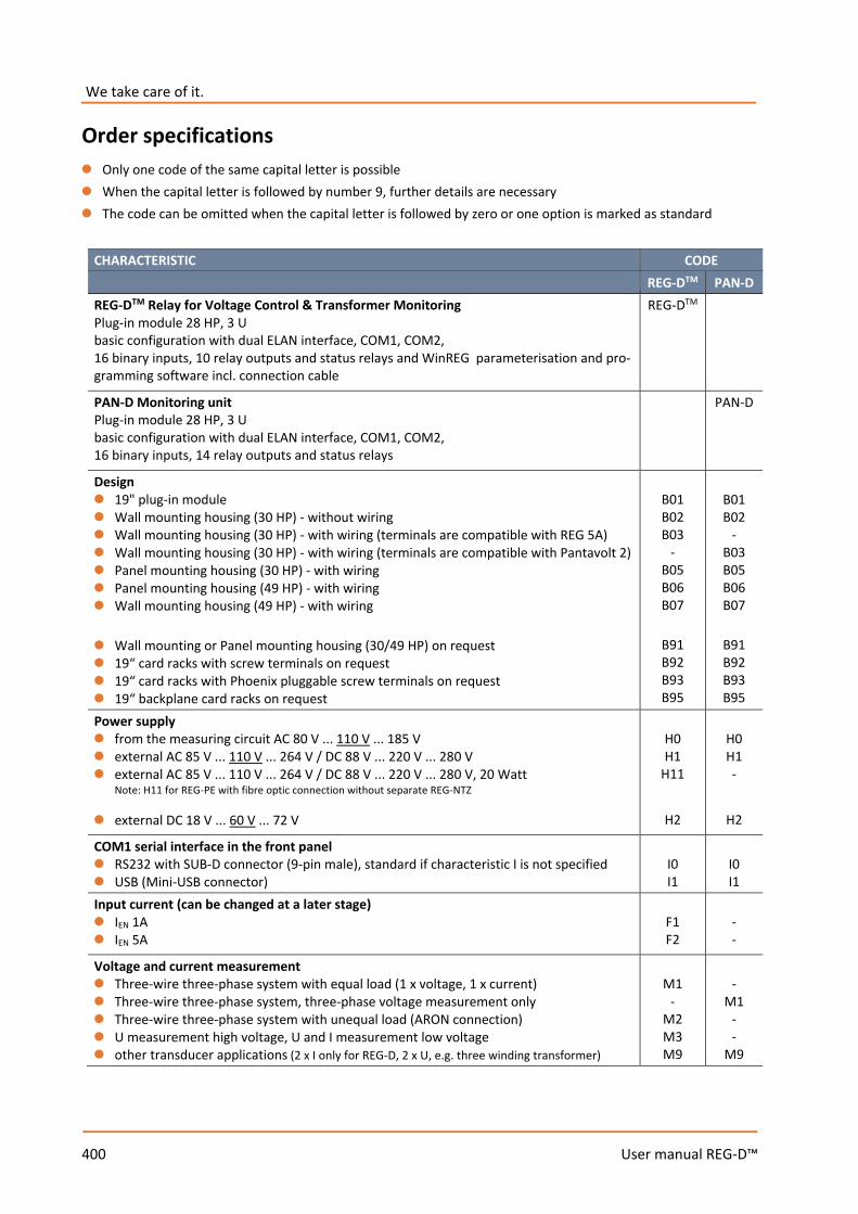
400 User manual REG-D™
We take care of it.
Order specifications 0 Only one code of the same capital letter is possible 0 When the capital letter is followed by number 9, further details are necessary 0 The code can be omitted when the capital letter is followed by zero or one option is marked as standard
CHARACTERISTIC CODE REG-DTM PAN-D REG-DTM Relay for Voltage Control & Transformer Monitoring Plug-in module 28 HP, 3 U basic configuration with dual ELAN interface, COM1, COM2, 16 binary inputs, 10 relay outputs and status relays and WinREG parameterisation and pro-gramming software incl. connection cable
REG-DTM
PAN-D Monitoring unit Plug-in module 28 HP, 3 U basic configuration with dual ELAN interface, COM1, COM2, 16 binary inputs, 14 relay outputs and status relays
PAN-D
Design 0 19" plug-in module 0 Wall mounting housing (30 HP) - without wiring 0 Wall mounting housing (30 HP) - with wiring (terminals are compatible with REG 5A) 0 Wall mounting housing (30 HP) - with wiring (terminals are compatible with Pantavolt 2) 0 Panel mounting housing (30 HP) - with wiring 0 Panel mounting housing (49 HP) - with wiring 0 Wall mounting housing (49 HP) - with wiring 0 Wall mounting or Panel mounting housing (30/49 HP) on request 0 19“ card racks with screw terminals on request 0 19“ card racks with Phoenix pluggable screw terminals on request 0 19“ backplane card racks on request
B01 B02 B03
- B05 B06 B07
B91 B92 B93 B95
B01 B02
- B03 B05 B06 B07
B91 B92 B93 B95
Power supply 0 from the measuring circuit AC 80 V ... 110 V ... 185 V 0 external AC 85 V ... 110 V ... 264 V / DC 88 V ... 220 V ... 280 V 0 external AC 85 V ... 110 V ... 264 V / DC 88 V ... 220 V ... 280 V, 20 Watt
Note: H11 for REG-PE with fibre optic connection without separate REG-NTZ
0 external DC 18 V ... 60 V ... 72 V
H0 H1
H11
H2
H0 H1 -
H2
COM1 serial interface in the front panel 0 RS232 with SUB-D connector (9-pin male), standard if characteristic I is not specified 0 USB (Mini-USB connector)
I0 I1
I0 I1
Input current (can be changed at a later stage) 0 IEN 1A 0 IEN 5A
F1 F2
- -
Voltage and current measurement 0 Three-wire three-phase system with equal load (1 x voltage, 1 x current) 0 Three-wire three-phase system, three-phase voltage measurement only 0 Three-wire three-phase system with unequal load (ARON connection) 0 U measurement high voltage, U and I measurement low voltage 0 other transducer applications (2 x I only for REG-D, 2 x U, e.g. three winding transformer)
M1
- M2 M3 M9
-
M1 - -
M9
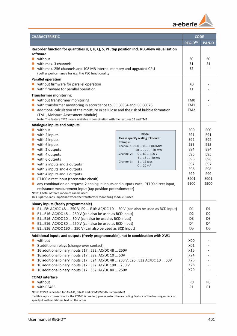
401 User manual REG-D™
CHARACTERISTIC CODE REG-DTM PAN-D Recorder function for quantities U, I, P, Q, S, PF, tap position incl. REGView visualisation software 0 without 0 with max. 3 channels 0 with max. 256 channels and 108 MB internal memory and upgraded CPU
(better performance for e.g. the PLC functionality)
S0 S1 S2
S0 S1 -
Parallel operation 0 without firmware for parallel operation 0 with firmware for parallel operation
K0 K1
- -
Transformer monitoring 0 without transformer monitoring 0 with transformer monitoring in accordance to IEC 60354 and IEC 60076 0 additional calculation of the moisture in cellulose and the risk of bubble formation
(TM+, Moisture Assessment Module) Note: The feature TM2 is only available in combination with the features S2 and TM1
TM0 TM1 TM2
- -
Analogue inputs and outputs 0 without 0 with 2 inputs 0 with 4 inputs 0 with 6 inputs 0 with 2 outputs 0 with 4 outputs 0 with 6 outputs 0 with 2 inputs and 2 outputs 0 with 2 inputs and 4 outputs 0 with 4 inputs and 2 outputs 0 PT100 direct input (three-wire circuit) 0 any combination on request, 2 analogue inputs and outputs each, PT100 direct input,
resistance measurement input (tap position potentiometer) Note: A total of three modules can be used. This is particularly important when the transformer monitoring module is used!
E00 E91 E92 E93 E94 E95 E96 E97 E98 E99
E901 E900
E00 E91 E92 E93 E94 E95 E96 E97 E98 E99
E901 E900
Binary inputs (freely programmable) 0 E1...E8: AC/DC 48 … 250 V, E9 ... E16: AC/DC 10 ... 50 V (can also be used as BCD input) 0 E1...E16: AC/DC 48 ... 250 V (can also be used as BCD input) 0 E1...E16: AC/DC 10 ... 50 V (can also be used as BCD input) 0 E1...E16: AC/DC 80 ... 250 V (can also be used as BCD input) 0 E1...E16: AC/DC 190 … 250 V (can also be used as BCD input)
D1 D2 D3 D4 D5
D1 D2 D3 D4 D5
Additional inputs and outputs (freely programmable), not in combination with XW1 0 without 0 8 additional relays (change-over contact) 0 16 additional binary inputs E17...E32: AC/DC 48 ... 250V 0 16 additional binary inputs E17...E32: AC/DC 10 ... 50V 0 16 additional binary inputs E17...E24: AC/DC 48 … 250 V, E25…E32 AC/DC 10 ... 50V 0 16 additional binary inputs E17...E32: AC/DC 190 … 250 V 0 16 additional binary inputs E17...E32: AC/DC 80 ... 250V
X00 X01 X15 X24 X25 X28 X29
- - - - - - -
COM3 interface 0 without 0 with RS485 Note: COM3 is needed for ANA-D, BIN-D and COM3/Modbus converter! If a fibre optic connection for the COM3 is needed, please select the according feature of the housing or rack or specify it with additional text on the order
R0 R1
R0 R1
Note: Please specify scaling if known: Example: Channel 1: -100 ... 0 ... + 100 MW -20 ... 0 . . . + 20 MW Channel 2: 0 ... 80 ... 100 V 4 ... 16 . .. 20 mA Channel 3: 1 ... 19 taps 0 ... 20 mA
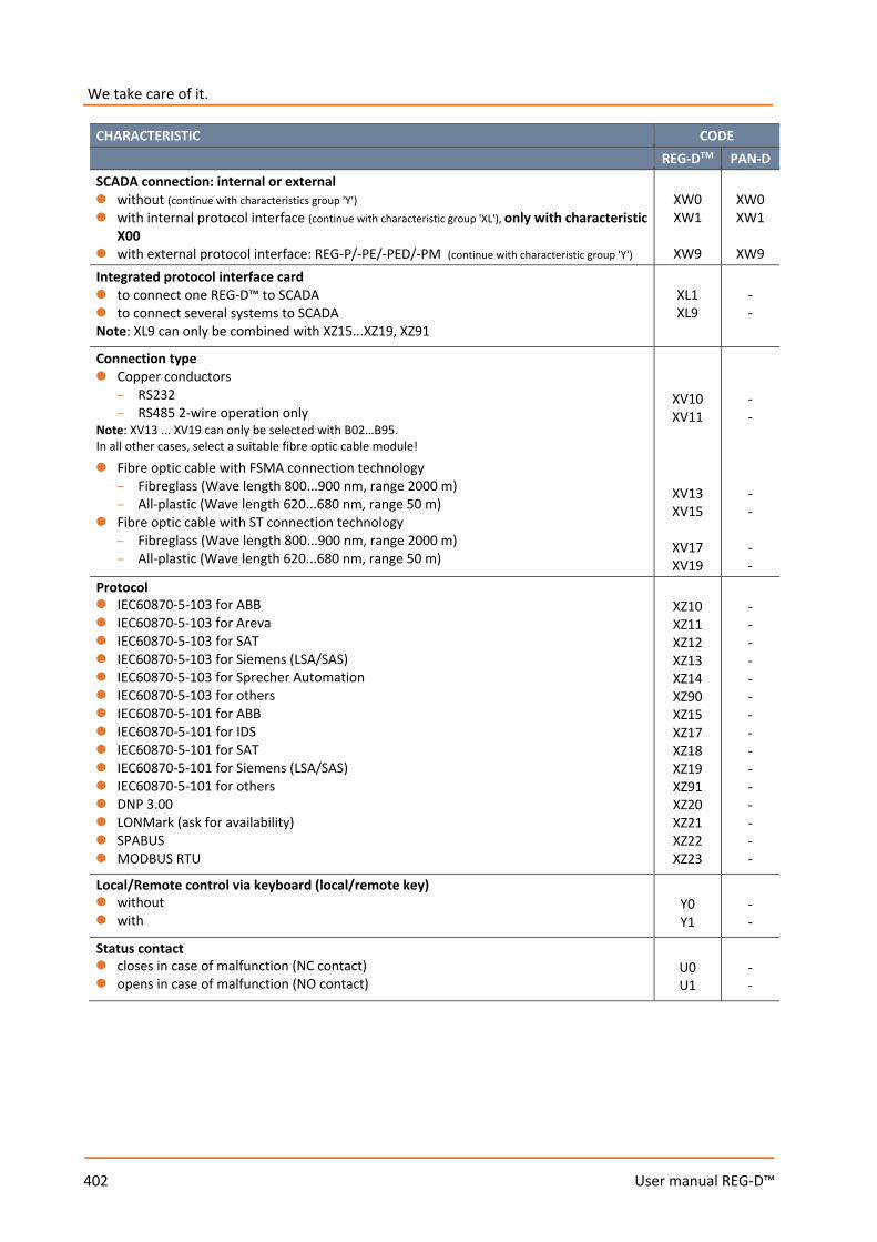
402 User manual REG-D™
We take care of it.
CHARACTERISTIC CODE REG-DTM PAN-D SCADA connection: internal or external 0 without (continue with characteristics group 'Y') 0 with internal protocol interface (continue with characteristic group 'XL'), only with characteristic
X00 0 with external protocol interface: REG-P/-PE/-PED/-PM (continue with characteristic group 'Y')
XW0 XW1
XW9
XW0 XW1
XW9
Integrated protocol interface card 0 to connect one REG-D™ to SCADA 0 to connect several systems to SCADA Note: XL9 can only be combined with XZ15...XZ19, XZ91
XL1 XL9
- -
Connection type 0 Copper conductors
– RS232 – RS485 2-wire operation only
Note: XV13 ... XV19 can only be selected with B02…B95. In all other cases, select a suitable fibre optic cable module!
0 Fibre optic cable with FSMA connection technology – Fibreglass (Wave length 800...900 nm, range 2000 m) – All-plastic (Wave length 620...680 nm, range 50 m)
0 Fibre optic cable with ST connection technology – Fibreglass (Wave length 800...900 nm, range 2000 m) – All-plastic (Wave length 620...680 nm, range 50 m)
XV10 XV11
XV13 XV15
XV17 XV19
- - - - - -
Protocol 0 IEC60870-5-103 for ABB 0 IEC60870-5-103 for Areva 0 IEC60870-5-103 for SAT 0 IEC60870-5-103 for Siemens (LSA/SAS) 0 IEC60870-5-103 for Sprecher Automation 0 IEC60870-5-103 for others 0 IEC60870-5-101 for ABB 0 IEC60870-5-101 for IDS 0 IEC60870-5-101 for SAT 0 IEC60870-5-101 for Siemens (LSA/SAS) 0 IEC60870-5-101 for others 0 DNP 3.00 0 LONMark (ask for availability) 0 SPABUS 0 MODBUS RTU
XZ10 XZ11 XZ12 XZ13 XZ14 XZ90 XZ15 XZ17 XZ18 XZ19 XZ91 XZ20 XZ21 XZ22 XZ23
- - - - - - - - - - - - - - -
Local/Remote control via keyboard (local/remote key) 0 without 0 with
Y0 Y1
- -
Status contact 0 closes in case of malfunction (NC contact) 0 opens in case of malfunction (NO contact)
U0 U1
- -
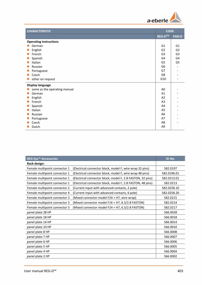
403 User manual REG-D™
CHARACTERISTIC CODE REG-DTM PAN-D Operating instructions 0 German 0 English 0 French 0 Spanish 0 Italian 0 Russian 0 Portuguese 0 Czech 0 other on request
G1 G2 G3 G4 G5 G6 G7 G8
G10
G1 G2 G3 G4 G5 - - - -
Display language 0 same as the operating manual 0 German 0 English 0 French 0 Spanish 0 Italian 0 Russian 0 Portuguese 0 Czech 0 Dutch
A0 A1 A2 A3 A4 A5 A6 A7 A8 A9
- - - - - - - - -
REG-Sys™ Accessories ID-No. Rack design: Female multipoint connector 1 (Electrical connector block, model F, wire wrap 32 pins) 582.0197 Female multipoint connector 1 (Electrical connector block, model F, wire wrap 48 pins) 582.0196.01 Female multipoint connector 1 (Electrical connector block, model F, 2.8 FASTON, 32 pins) 582.0213.01 Female multipoint connector 1 (Electrical connector block, model F, 2.8 FASTON, 48 pins) 582.0213 Female multipoint connector 2 (Current input with advanced contacts, 2 pole) 582.0258.10 Female multipoint connector 4 (Current input with advanced contacts, 6 pole) 582.0258.20 Female multipoint connector 3 (Mixed connector model F24 + H7, wire wrap) 582.0215 Female multipoint connector 3 (Mixed connector model F16 + H7, 6.3/2.8 FASTON) 582.0214 Female multipoint connector 3 (Mixed connector model F24 + H7, 6.3/2.8 FASTON) 582.0217 panel plate 28 HP 566.0028 panel plate 18 HP 566.0018 panel plate 14 HP 566.0014 panel plate 10 HP 566.0010 panel plate 8 HP 566.0008 panel plate 7 HP 566.0007 panel plate 6 HP 566.0006 panel plate 5 HP 566.0005 panel plate 4 HP 566.0004 panel plate 2 HP 566.0002
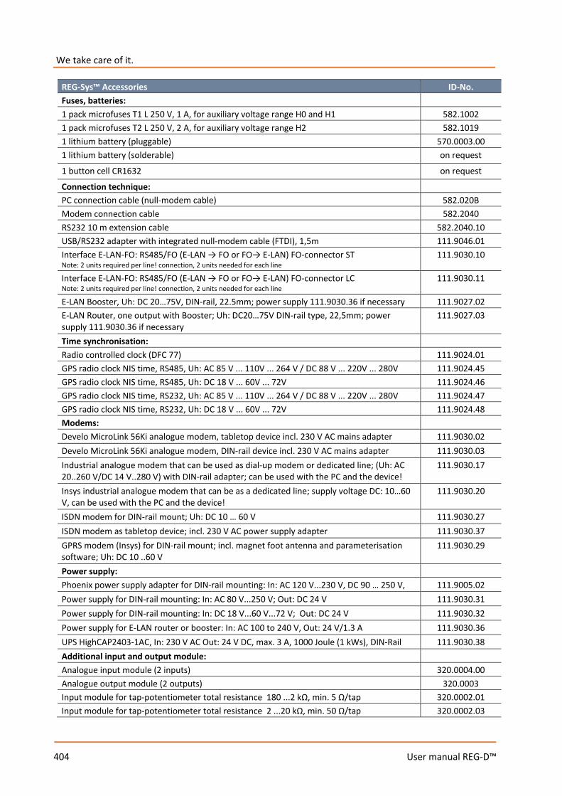
404 User manual REG-D™
We take care of it.
REG-Sys™ Accessories ID-No. Fuses, batteries: 1 pack microfuses T1 L 250 V, 1 A, for auxiliary voltage range H0 and H1 582.1002 1 pack microfuses T2 L 250 V, 2 A, for auxiliary voltage range H2 582.1019 1 lithium battery (pluggable) 570.0003.00 1 lithium battery (solderable) on request
1 button cell CR1632 on request
Connection technique: PC connection cable (null-modem cable) 582.020B Modem connection cable 582.2040 RS232 10 m extension cable 582.2040.10 USB/RS232 adapter with integrated null-modem cable (FTDI), 1,5m 111.9046.01 Interface E-LAN-FO: RS485/FO (E-LAN → FO or FO→ E-LAN) FO-connector ST Note: 2 units required per line! connection, 2 units needed for each line
111.9030.10
Interface E-LAN-FO: RS485/FO (E-LAN → FO or FO→ E-LAN) FO-connector LC Note: 2 units required per line! connection, 2 units needed for each line
111.9030.11
E-LAN Booster, Uh: DC 20…75V, DIN-rail, 22.5mm; power supply 111.9030.36 if necessary 111.9027.02 E-LAN Router, one output with Booster; Uh: DC20…75V DIN-rail type, 22,5mm; power supply 111.9030.36 if necessary
111.9027.03
Time synchronisation: Radio controlled clock (DFC 77) 111.9024.01 GPS radio clock NIS time, RS485, Uh: AC 85 V ... 110V ... 264 V / DC 88 V ... 220V ... 280V 111.9024.45 GPS radio clock NIS time, RS485, Uh: DC 18 V ... 60V ... 72V 111.9024.46 GPS radio clock NIS time, RS232, Uh: AC 85 V ... 110V ... 264 V / DC 88 V ... 220V ... 280V 111.9024.47 GPS radio clock NIS time, RS232, Uh: DC 18 V ... 60V ... 72V 111.9024.48 Modems: Develo MicroLink 56Ki analogue modem, tabletop device incl. 230 V AC mains adapter 111.9030.02 Develo MicroLink 56Ki analogue modem, DIN-rail device incl. 230 V AC mains adapter 111.9030.03 Industrial analogue modem that can be used as dial-up modem or dedicated line; (Uh: AC 20..260 V/DC 14 V..280 V) with DIN-rail adapter; can be used with the PC and the device!
111.9030.17
Insys industrial analogue modem that can be as a dedicated line; supply voltage DC: 10…60 V, can be used with the PC and the device!
111.9030.20
ISDN modem for DIN-rail mount; Uh: DC 10 … 60 V 111.9030.27 ISDN modem as tabletop device; incl. 230 V AC power supply adapter 111.9030.37 GPRS modem (Insys) for DIN-rail mount; incl. magnet foot antenna and parameterisation software; Uh: DC 10 ..60 V
111.9030.29
Power supply: Phoenix power supply adapter for DIN-rail mounting: In: AC 120 V...230 V, DC 90 … 250 V, 111.9005.02 Power supply for DIN-rail mounting: In: AC 80 V...250 V; Out: DC 24 V 111.9030.31 Power supply for DIN-rail mounting: In: DC 18 V...60 V...72 V; Out: DC 24 V 111.9030.32 Power supply for E-LAN router or booster: In: AC 100 to 240 V, Out: 24 V/1.3 A 111.9030.36 UPS HighCAP2403-1AC, In: 230 V AC Out: 24 V DC, max. 3 A, 1000 Joule (1 kWs), DIN-Rail 111.9030.38 Additional input and output module: Analogue input module (2 inputs) 320.0004.00 Analogue output module (2 outputs) 320.0003 Input module for tap-potentiometer total resistance 180 ...2 kΩ, min. 5 Ω/tap 320.0002.01 Input module for tap-potentiometer total resistance 2 ...20 kΩ, min. 50 Ω/tap 320.0002.03
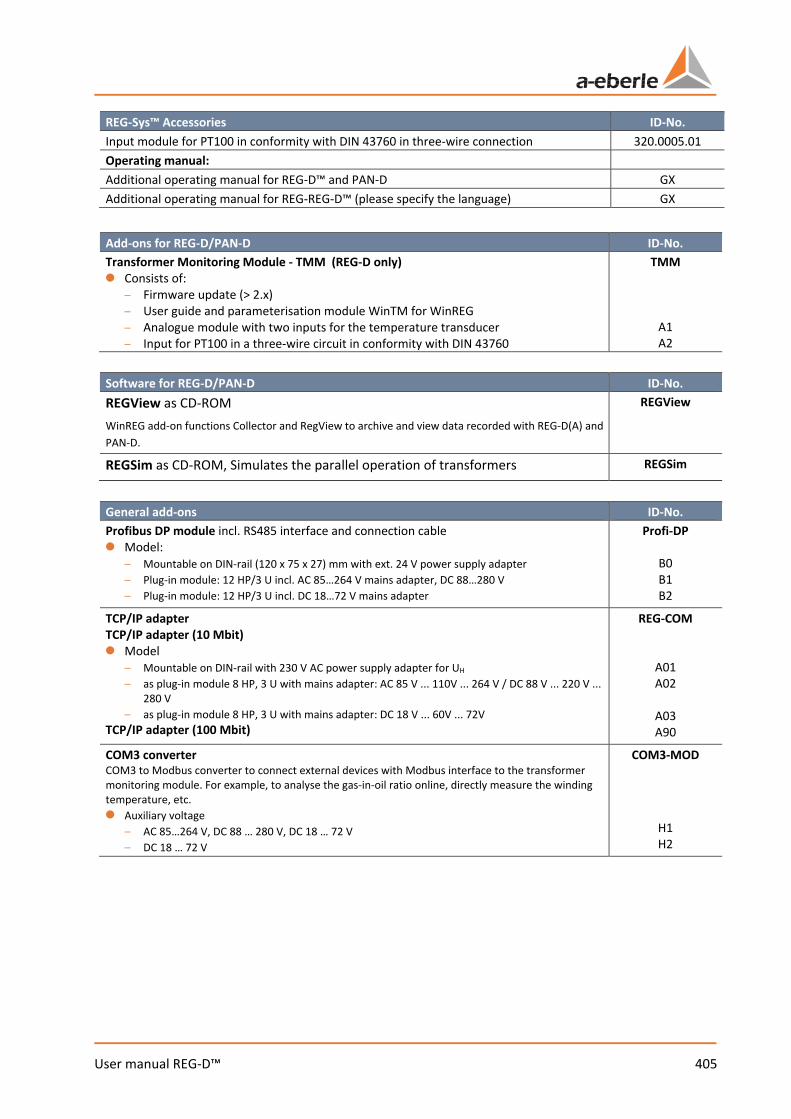
405 User manual REG-D™
REG-Sys™ Accessories ID-No. Input module for PT100 in conformity with DIN 43760 in three-wire connection 320.0005.01 Operating manual: Additional operating manual for REG-D™ and PAN-D GX Additional operating manual for REG-REG-D™ (please specify the language) GX
Add-ons for REG-D/PAN-D ID-No. Transformer Monitoring Module - TMM (REG-D only) 0 Consists of:
– Firmware update (> 2.x) – User guide and parameterisation module WinTM for WinREG – Analogue module with two inputs for the temperature transducer – Input for PT100 in a three-wire circuit in conformity with DIN 43760
TMM
A1 A2
Software for REG-D/PAN-D ID-No. REGView as CD-ROM WinREG add-on functions Collector and RegView to archive and view data recorded with REG-D(A) and PAN-D.
REGView
REGSim as CD-ROM, Simulates the parallel operation of transformers REGSim
General add-ons ID-No. Profibus DP module incl. RS485 interface and connection cable 0 Model:
– Mountable on DIN-rail (120 x 75 x 27) mm with ext. 24 V power supply adapter – Plug-in module: 12 HP/3 U incl. AC 85…264 V mains adapter, DC 88…280 V – Plug-in module: 12 HP/3 U incl. DC 18…72 V mains adapter
Profi-DP
B0 B1 B2
TCP/IP adapter TCP/IP adapter (10 Mbit) 0 Model
– Mountable on DIN-rail with 230 V AC power supply adapter for UH – as plug-in module 8 HP, 3 U with mains adapter: AC 85 V ... 110V ... 264 V / DC 88 V ... 220 V ...
280 V – as plug-in module 8 HP, 3 U with mains adapter: DC 18 V ... 60V ... 72V
TCP/IP adapter (100 Mbit)
REG-COM
A01 A02
A03 A90
COM3 converter COM3 to Modbus converter to connect external devices with Modbus interface to the transformer monitoring module. For example, to analyse the gas-in-oil ratio online, directly measure the winding temperature, etc. 0 Auxiliary voltage
– AC 85…264 V, DC 88 … 280 V, DC 18 … 72 V – DC 18 … 72 V
COM3-MOD
H1 H2
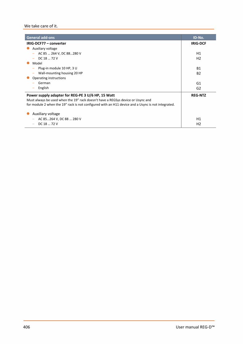
406 User manual REG-D™
We take care of it.
General add-ons ID-No. IRIG-DCF77 – converter 0 Auxiliary voltage
– AC 85 … 264 V, DC 88…280 V – DC 18 … 72 V
0 Model – Plug-in module 10 HP, 3 U – Wall-mounting housing 20 HP
0 Operating instructions – German – English
IRIG-DCF
H1 H2
B1 B2
G1 G2
Power supply adapter for REG-PE 3 U/6 HP, 15 Watt Must always be used when the 19” rack doesn't have a REGSys device or Usync and for module 2 when the 19” rack is not configured with an H11 device and a Usync is not integrated. 0 Auxiliary voltage
– AC 85…264 V, DC 88 … 280 V – DC 18 … 72 V
REG-NTZ
H1 H2
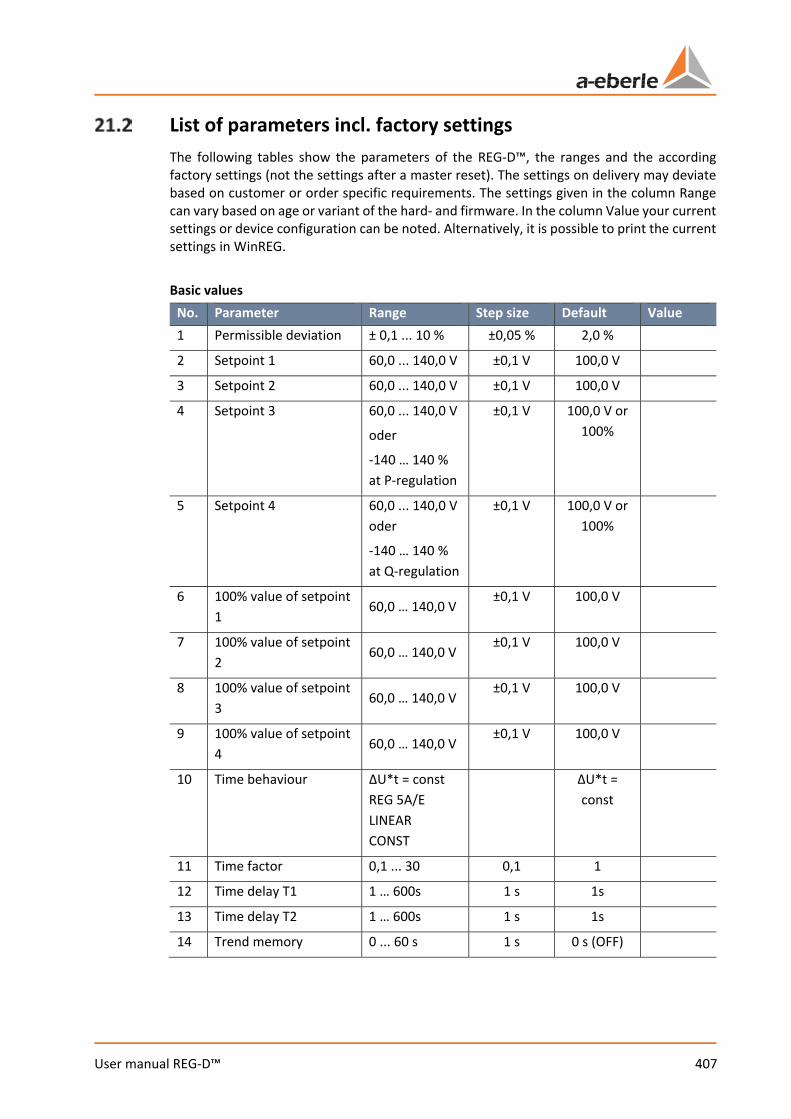
407 User manual REG-D™
List of parameters incl. factory settings The following tables show the parameters of the REG-D™, the ranges and the according factory settings (not the settings after a master reset). The settings on delivery may deviate based on customer or order specific requirements. The settings given in the column Range can vary based on age or variant of the hard- and firmware. In the column Value your current settings or device configuration can be noted. Alternatively, it is possible to print the current settings in WinREG. Basic values
No. Parameter Range Step size Default Value 1 Permissible deviation ± 0,1 ... 10 % ±0,05 % 2,0 %
2 Setpoint 1 60,0 ... 140,0 V ±0,1 V 100,0 V
3 Setpoint 2 60,0 ... 140,0 V ±0,1 V 100,0 V
4 Setpoint 3 60,0 ... 140,0 V
oder
-140 … 140 % at P-regulation
±0,1 V 100,0 V or 100%
5 Setpoint 4 60,0 ... 140,0 V oder
-140 … 140 % at Q-regulation
±0,1 V 100,0 V or 100%
6 100% value of setpoint 1
60,0 … 140,0 V ±0,1 V 100,0 V
7 100% value of setpoint 2
60,0 … 140,0 V ±0,1 V 100,0 V
8 100% value of setpoint 3
60,0 … 140,0 V ±0,1 V 100,0 V
9 100% value of setpoint 4
60,0 … 140,0 V ±0,1 V 100,0 V
10 Time behaviour ΔU*t = const REG 5A/E LINEAR CONST
ΔU*t = const
11 Time factor 0,1 ... 30 0,1 1
12 Time delay T1 1 … 600s 1 s 1s
13 Time delay T2 1 … 600s 1 s 1s
14 Trend memory 0 ... 60 s 1 s 0 s (OFF)
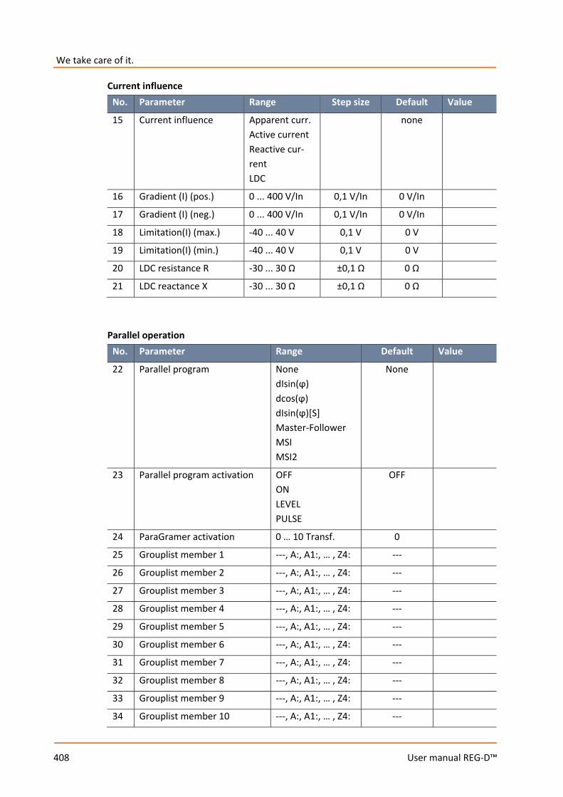
We take care of it.
408 User manual REG-D™
Current influence
Parallel operation
No. Parameter Range Default Value
22 Parallel program None dIsin(ϕ) dcos(ϕ) dIsin(ϕ)[S] Master-Follower MSI MSI2
None
23 Parallel program activation OFF ON LEVEL PULSE
OFF
24 ParaGramer activation 0 … 10 Transf. 0
25 Grouplist member 1 ---, A:, A1:, … , Z4: ---
26 Grouplist member 2 ---, A:, A1:, … , Z4: ---
27 Grouplist member 3 ---, A:, A1:, … , Z4: ---
28 Grouplist member 4 ---, A:, A1:, … , Z4: ---
29 Grouplist member 5 ---, A:, A1:, … , Z4: ---
30 Grouplist member 6 ---, A:, A1:, … , Z4: ---
31 Grouplist member 7 ---, A:, A1:, … , Z4: ---
32 Grouplist member 8 ---, A:, A1:, … , Z4: ---
33 Grouplist member 9 ---, A:, A1:, … , Z4: ---
34 Grouplist member 10 ---, A:, A1:, … , Z4: ---
No. Parameter Range Step size Default Value
15 Current influence Apparent curr. Active current Reactive cur-rent LDC
none
16 Gradient (I) (pos.) 0 ... 400 V/In 0,1 V/In 0 V/In
17 Gradient (I) (neg.) 0 ... 400 V/In 0,1 V/In 0 V/In
18 Limitation(I) (max.) -40 ... 40 V 0,1 V 0 V
19 Limitation(I) (min.) -40 ... 40 V 0,1 V 0 V
20 LDC resistance R -30 ... 30 Ω ±0,1 Ω 0 Ω
21 LDC reactance X -30 ... 30 Ω ±0,1 Ω 0 Ω
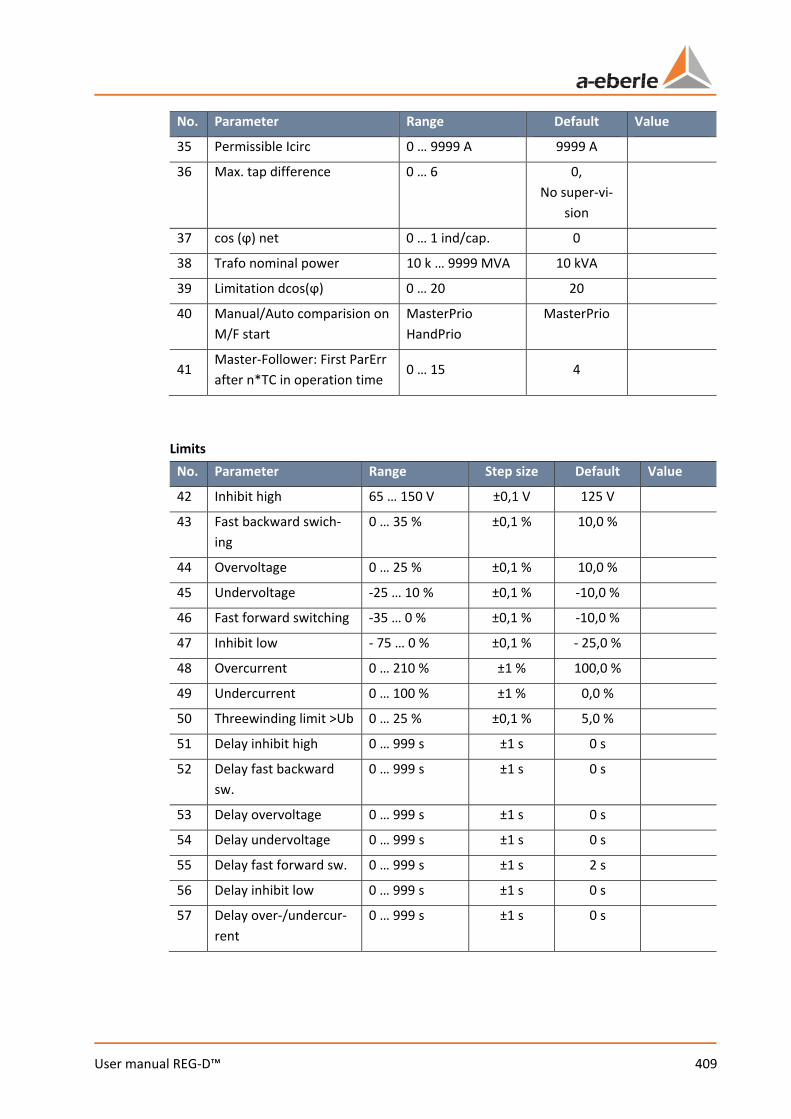
409 User manual REG-D™
No. Parameter Range Default Value
35 Permissible Icirc 0 … 9999 A 9999 A
36 Max. tap difference 0 … 6 0, No super-vi-
sion
37 cos (ϕ) net 0 … 1 ind/cap. 0
38 Trafo nominal power 10 k … 9999 MVA 10 kVA
39 Limitation dcos(ϕ) 0 … 20 20
40 Manual/Auto comparision on M/F start
MasterPrio HandPrio
MasterPrio
41 Master-Follower: First ParErr after n*TC in operation time
0 … 15 4
Limits
No. Parameter Range Step size Default Value
42 Inhibit high 65 … 150 V ±0,1 V 125 V
43 Fast backward swich-ing
0 … 35 % ±0,1 % 10,0 %
44 Overvoltage 0 … 25 % ±0,1 % 10,0 %
45 Undervoltage -25 … 10 % ±0,1 % -10,0 %
46 Fast forward switching -35 … 0 % ±0,1 % -10,0 %
47 Inhibit low - 75 … 0 % ±0,1 % - 25,0 %
48 Overcurrent 0 … 210 % ±1 % 100,0 %
49 Undercurrent 0 … 100 % ±1 % 0,0 %
50 Threewinding limit >Ub 0 … 25 % ±0,1 % 5,0 %
51 Delay inhibit high 0 … 999 s ±1 s 0 s
52 Delay fast backward sw.
0 … 999 s ±1 s 0 s
53 Delay overvoltage 0 … 999 s ±1 s 0 s
54 Delay undervoltage 0 … 999 s ±1 s 0 s
55 Delay fast forward sw. 0 … 999 s ±1 s 2 s
56 Delay inhibit low 0 … 999 s ±1 s 0 s
57 Delay over-/undercur-rent
0 … 999 s ±1 s 0 s
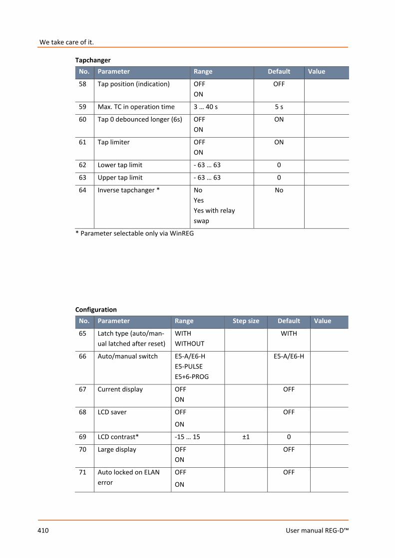
We take care of it.
410 User manual REG-D™
Tapchanger No. Parameter Range Default Value
58 Tap position (indication) OFF ON
OFF
59 Max. TC in operation time 3 … 40 s 5 s
60 Tap 0 debounced longer (6s) OFF ON
ON
61 Tap limiter OFF ON
ON
62 Lower tap limit - 63 … 63 0
63 Upper tap limit - 63 … 63 0
64 Inverse tapchanger * No Yes Yes with relay swap
No
* Parameter selectable only via WinREG Configuration
No. Parameter Range Step size Default Value
65 Latch type (auto/man-ual latched after reset)
WITH WITHOUT
WITH
66 Auto/manual switch E5-A/E6-H E5-PULSE E5+6-PROG
E5-A/E6-H
67 Current display OFF ON
OFF
68 LCD saver OFF
ON
OFF
69 LCD contrast* -15 … 15 ±1 0
70 Large display OFF ON
OFF
71 Auto locked on ELAN error
OFF
ON
OFF
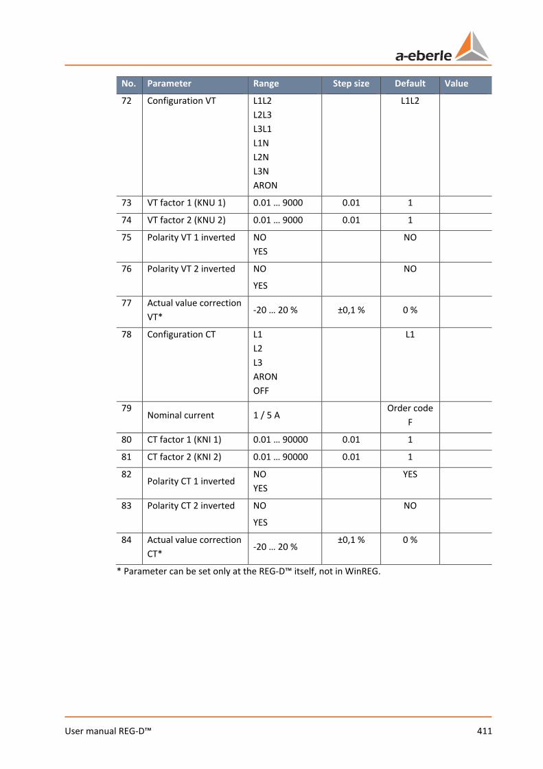
411 User manual REG-D™
No. Parameter Range Step size Default Value
72 Configuration VT L1L2 L2L3 L3L1 L1N L2N L3N ARON
L1L2
73 VT factor 1 (KNU 1) 0.01 … 9000 0.01 1
74 VT factor 2 (KNU 2) 0.01 … 9000 0.01 1
75 Polarity VT 1 inverted NO YES
NO
76 Polarity VT 2 inverted NO
YES
NO
77 Actual value correction VT*
-20 … 20 % ±0,1 % 0 %
78 Configuration CT L1 L2 L3 ARON OFF
L1
79 Nominal current 1 / 5 A
Order code F
80 CT factor 1 (KNI 1) 0.01 … 90000 0.01 1
81 CT factor 2 (KNI 2) 0.01 … 90000 0.01 1
82 Polarity CT 1 inverted
NO YES
YES
83 Polarity CT 2 inverted NO
YES
NO
84 Actual value correction CT*
-20 … 20 % ±0,1 % 0 %
* Parameter can be set only at the REG-D™ itself, not in WinREG.
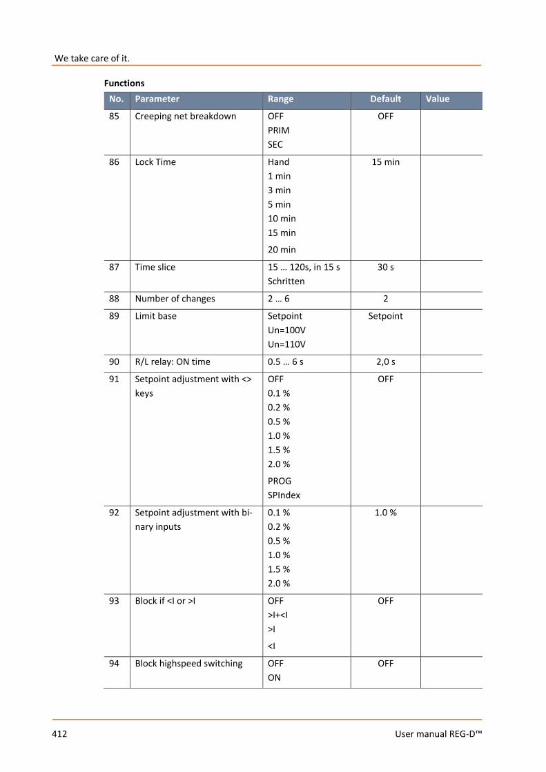
We take care of it.
412 User manual REG-D™
Functions No. Parameter Range Default Value
85 Creeping net breakdown OFF PRIM SEC
OFF
86 Lock Time Hand 1 min 3 min 5 min 10 min 15 min
20 min
15 min
87 Time slice 15 … 120s, in 15 s Schritten
30 s
88 Number of changes 2 … 6 2
89 Limit base Setpoint Un=100V Un=110V
Setpoint
90 R/L relay: ON time 0.5 … 6 s 2,0 s
91 Setpoint adjustment with <> keys
OFF 0.1 % 0.2 % 0.5 % 1.0 % 1.5 % 2.0 %
PROG SPIndex
OFF
92 Setpoint adjustment with bi-nary inputs
0.1 % 0.2 % 0.5 % 1.0 % 1.5 % 2.0 %
1.0 %
93 Block if <I or >I OFF >I+<I >I
<I
OFF
94 Block highspeed switching OFF ON
OFF
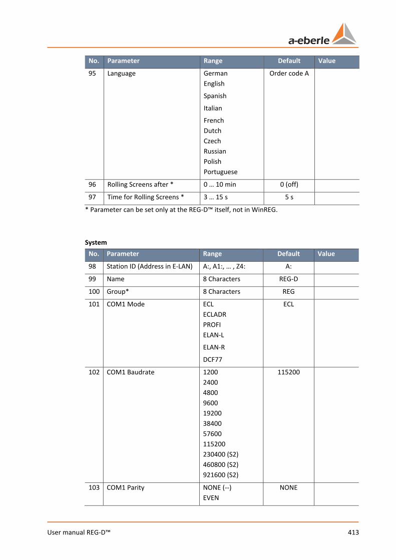
413 User manual REG-D™
No. Parameter Range Default Value
95 Language German English
Spanish
Italian
French Dutch Czech Russian Polish Portuguese
Order code A
96 Rolling Screens after * 0 … 10 min 0 (off)
97 Time for Rolling Screens * 3 … 15 s 5 s
* Parameter can be set only at the REG-D™ itself, not in WinREG. System
No. Parameter Range Default Value
98 Station ID (Address in E-LAN) A:, A1:, … , Z4: A:
99 Name 8 Characters REG-D
100 Group* 8 Characters REG
101 COM1 Mode ECL ECLADR PROFI ELAN-L
ELAN-R
DCF77
ECL
102 COM1 Baudrate 1200 2400 4800 9600 19200 38400 57600 115200 230400 (S2) 460800 (S2) 921600 (S2)
115200
103 COM1 Parity NONE (--) EVEN
NONE
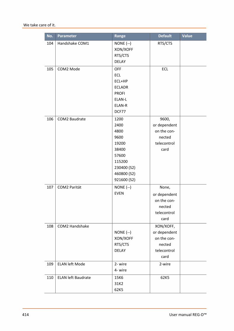
We take care of it.
414 User manual REG-D™
No. Parameter Range Default Value
104 Handshake COM1 NONE (--) XON/XOFF RTS/CTS DELAY
RTS/CTS
105 COM2 Mode OFF ECL ECL+HP ECLADR PROFI ELAN-L ELAN-R DCF77
ECL
106 COM2 Baudrate 1200 2400 4800 9600 19200 38400 57600 115200 230400 (S2) 460800 (S2) 921600 (S2)
9600, or dependent
on the con-nected
telecontrol card
107 COM2 Parität NONE (--) EVEN
None,
or dependent on the con-
nected telecontrol
card
108 COM2 Handshake NONE (--) XON/XOFF RTS/CTS DELAY
XON/XOFF, or dependent
on the con-nected
telecontrol card
109 ELAN left Mode 2- wire 4- wire
2-wire
110 ELAN left Baudrate 15K6 31K2 62K5
62K5
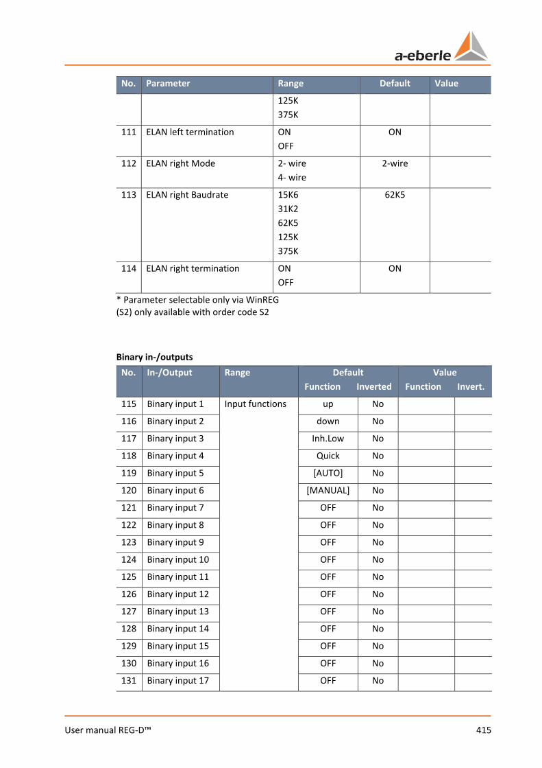
415 User manual REG-D™
No. Parameter Range Default Value
125K 375K
111 ELAN left termination ON OFF
ON
112 ELAN right Mode 2- wire 4- wire
2-wire
113 ELAN right Baudrate 15K6 31K2 62K5 125K 375K
62K5
114 ELAN right termination ON OFF
ON
* Parameter selectable only via WinREG (S2) only available with order code S2 Binary in-/outputs
No. In-/Output Range Default Function Inverted
Value Function Invert.
115 Binary input 1 Input functions
up No
116 Binary input 2 down No
117 Binary input 3 Inh.Low No
118 Binary input 4 Quick No
119 Binary input 5 [AUTO] No
120 Binary input 6 [MANUAL] No
121 Binary input 7 OFF No
122 Binary input 8 OFF No
123 Binary input 9 OFF No
124 Binary input 10 OFF No
125 Binary input 11 OFF No
126 Binary input 12 OFF No
127 Binary input 13 OFF No
128 Binary input 14 OFF No
129 Binary input 15 OFF No
130 Binary input 16 OFF No
131 Binary input 17 OFF No
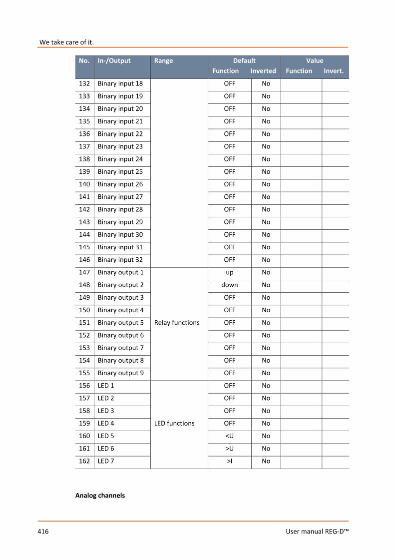
We take care of it.
416 User manual REG-D™
No. In-/Output Range Default Function Inverted
Value Function Invert.
132 Binary input 18 OFF No
133 Binary input 19 OFF No
134 Binary input 20 OFF No
135 Binary input 21 OFF No
136 Binary input 22 OFF No
137 Binary input 23 OFF No
138 Binary input 24 OFF No
139 Binary input 25 OFF No
140 Binary input 26 OFF No
141 Binary input 27 OFF No
142 Binary input 28 OFF No
143 Binary input 29 OFF No
144 Binary input 30 OFF No
145 Binary input 31 OFF No
146 Binary input 32 OFF No
147 Binary output 1
Relay functions
up No
148 Binary output 2 down No
149 Binary output 3 OFF No
150 Binary output 4 OFF No
151 Binary output 5 OFF No
152 Binary output 6 OFF No
153 Binary output 7 OFF No
154 Binary output 8 OFF No
155 Binary output 9 OFF No
156 LED 1
LED functions
OFF No
157 LED 2 OFF No
158 LED 3 OFF No
159 LED 4 OFF No
160 LED 5 <U No
161 LED 6 >U No
162 LED 7 >I No
Analog channels
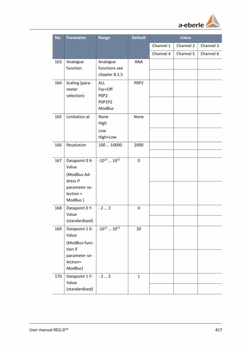
417 User manual REG-D™
No. Parameter Range Default Value
Channel 1 Channel 2 Channel 3
Channel 4 Channel 5 Channel 6
163 Analogue function
Analogue functions see chapter 8.2.5
ANA
164 Scaling (para-meter selection)
ALL Fac+Off P0P2 P0P1P2 ModBus
P0P2
165 Limitation at None High
Low High+Low
None
166 Resolution 100 … 10000 2000
167 Datapoint 0 X-Value
(ModBus-Ad-dress if parameter se-lection = ModBus )
-1012 … 1012 0
168 Datapoint 0 Y-Value (standardised)
- 2 … 2 0
169 Datapoint 1 X-Value
(ModBus-func-tion if parameter se-lection= ModBus)
-1012 … 1012 20
170 Datapoint 1 Y-Value (standardised)
- 2 … 2 1

We take care of it.
418 User manual REG-D™
No. Parameter Range Default Value
Channel 1 Channel 2 Channel 3
Channel 4 Channel 5 Channel 6
171 Datapoint 2 X-Value
(ModBus-reg-ister address if parameter se-lection = ModBus )
-1012 … 1012 20
172 Setpoint 2 Y-Value (standardised)
- 2 … 2 1
173 Analogue-Unit 8 characters Depends on func-
tion
174 Decimal places 0 … 10 2
SCADA/Time
No. Parameter Range Default Value
175 IP address 0.0.0.0 … 255.255.255.255
0.0.0.0
176 Subnetmask 0.0.0.0 … 255.255.255.255
0.0.0.0
177 Gateway 0.0.0.0 … 255.255.255.255
0.0.0.0
178 Daylight saving time settings (summertime rules)
See manual Settings for CET
179 UTC timezone - 13,75 … 13.75 h 0 h*
180 Automatic DST switch OFF ON
ON
* setting depends on the country of delivery (deliveries for Germany -> 1h)
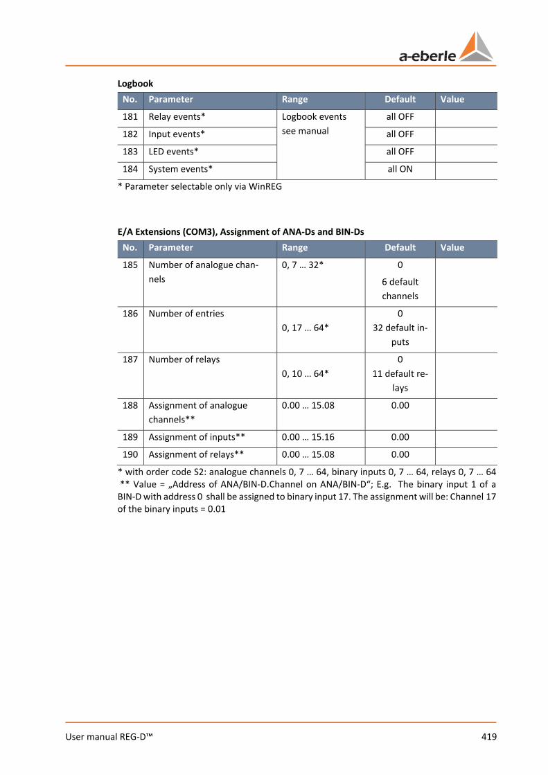
419 User manual REG-D™
Logbook No. Parameter Range Default Value
181 Relay events* Logbook events see manual
all OFF
182 Input events* all OFF
183 LED events* all OFF
184 System events* all ON
* Parameter selectable only via WinREG E/A Extensions (COM3), Assignment of ANA-Ds and BIN-Ds
No. Parameter Range Default Value
185 Number of analogue chan-nels
0, 7 … 32* 0
6 default channels
186 Number of entries 0, 17 … 64*
0 32 default in-
puts
187 Number of relays 0, 10 … 64*
0 11 default re-
lays
188 Assignment of analogue channels**
0.00 … 15.08 0.00
189 Assignment of inputs** 0.00 … 15.16 0.00
190 Assignment of relays** 0.00 … 15.08 0.00
* with order code S2: analogue channels 0, 7 … 64, binary inputs 0, 7 … 64, relays 0, 7 … 64 ** Value = „Address of ANA/BIN-D.Channel on ANA/BIN-D“; E.g. The binary input 1 of a BIN-D with address 0 shall be assigned to binary input 17. The assignment will be: Channel 17 of the binary inputs = 0.01
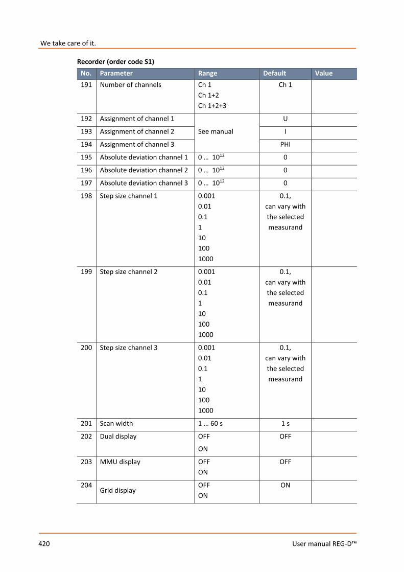
We take care of it.
420 User manual REG-D™
Recorder (order code S1) No. Parameter Range Default Value 191 Number of channels Ch 1
Ch 1+2 Ch 1+2+3
Ch 1
192 Assignment of channel 1
See manual
U
193 Assignment of channel 2 I
194 Assignment of channel 3 PHI
195 Absolute deviation channel 1 0 … 1012 0
196 Absolute deviation channel 2 0 … 1012 0
197 Absolute deviation channel 3 0 … 1012 0
198 Step size channel 1 0.001 0.01 0.1 1 10 100 1000
0.1, can vary with the selected measurand
199 Step size channel 2 0.001 0.01 0.1 1 10 100 1000
0.1, can vary with the selected measurand
200 Step size channel 3 0.001 0.01 0.1 1 10 100 1000
0.1, can vary with the selected measurand
201 Scan width 1 … 60 s 1 s
202 Dual display OFF
ON
OFF
203 MMU display OFF ON
OFF
204 Grid display
OFF ON
ON
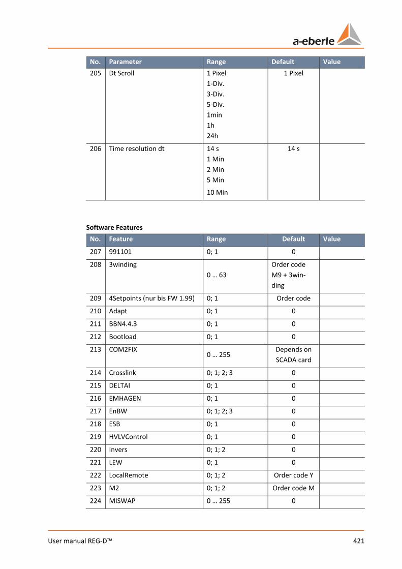
421 User manual REG-D™
No. Parameter Range Default Value 205 Dt Scroll 1 Pixel
1-Div. 3-Div. 5-Div. 1min 1h 24h
1 Pixel
206 Time resolution dt 14 s 1 Min 2 Min 5 Min
10 Min
14 s
Software Features
No. Feature Range Default Value
207 991101 0; 1 0
208 3winding 0 … 63
Order code M9 + 3win-ding
209 4Setpoints (nur bis FW 1.99) 0; 1 Order code
210 Adapt 0; 1 0
211 BBN4.4.3 0; 1 0
212 Bootload 0; 1 0
213 COM2FIX 0 … 255
Depends on SCADA card
214 Crosslink 0; 1; 2; 3 0
215 DELTAI 0; 1 0
216 EMHAGEN 0; 1 0
217 EnBW 0; 1; 2; 3 0
218 ESB 0; 1 0
219 HVLVControl 0; 1 0
220 Invers 0; 1; 2 0
221 LEW 0; 1 0
222 LocalRemote 0; 1; 2 Order code Y
223 M2 0; 1; 2 Order code M
224 MISWAP 0 … 255 0

We take care of it.
422 User manual REG-D™
No. Feature Range Default Value
225 NLK 0; 1 0
226 ParaGramer 0; 1
Order code K + ParaGramer
227 PG_SCHEME_1 0; 1 0
228 PQCtrl 0; 1 0
229 PrimCtrl 0; 1 0
230 Qsigned 0; 1 0
231 Recorder 0; 1 Order code S
232 Ringlink 0; 1; 2; 3 0
233 SimMode 0; 1; 2 1
234 SR192 0; 1; 2 0
235 SYSCTRL 0 … 255 64
236 SYSCTRL2 0 … 255 0
237 TM 0; 1
Order code TM
238 ULC 0; 1 0
239 VEW 0; 1 0
Background program and UDM (UserDefineableMenu)
No. Resource used program
240 Background program .rgl
241 UDM (only with order code S2)
.udm
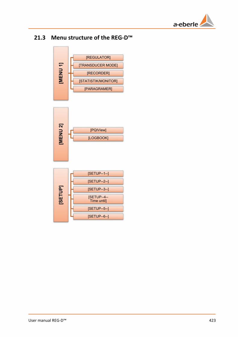
423 User manual REG-D™
21.3 Menu structure of the REG-D™
[MEN
U 1
][REGULATOR]
[TRANSDUCER MODE]
[RECORDER]
[STATISTIK/MONITOR]
[PARAGRAMER]
[MEN
U 2
]
[PQIView]
[LOGBOOK]
[SET
UP]
[SETUP--1--]
[SETUP--2--]
[SETUP--3--]
[SETUP--4--Time until]
[SETUP--5--]
[SETUP--6--]
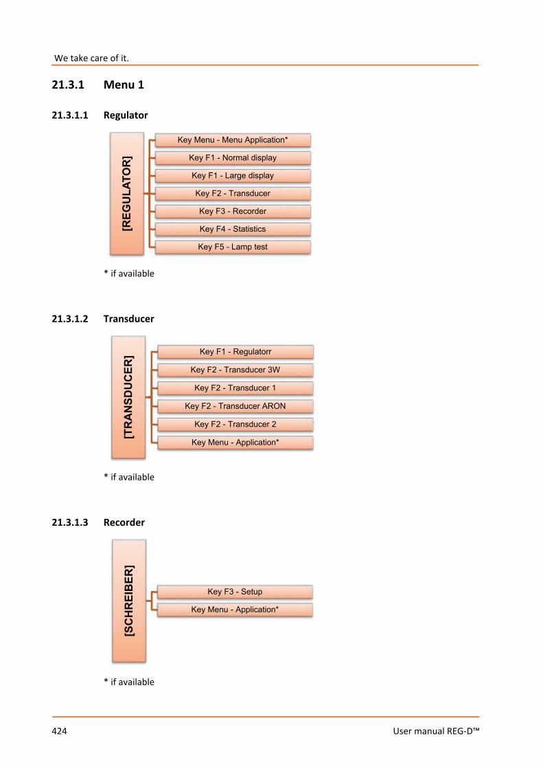
We take care of it.
424 User manual REG-D™
21.3.1 Menu 1
21.3.1.1 Regulator
* if available
21.3.1.2 Transducer
* if available
21.3.1.3 Recorder
* if available
[REG
ULA
TOR
]Key Menu - Menu Application*
Key F1 - Normal display
Key F1 - Large display
Key F2 - Transducer
Key F3 - Recorder
Key F4 - Statistics
Key F5 - Lamp test
[TR
AN
SDU
CER
] Key F1 - Regulatorr
Key F2 - Transducer 3W
Key F2 - Transducer 1
Key F2 - Transducer ARON
Key F2 - Transducer 2
Key Menu - Application*
[SC
HR
EIB
ER]
Key F3 - Setup
Key Menu - Application*
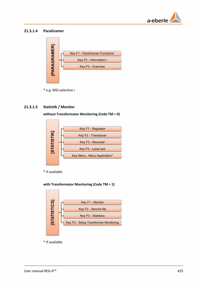
425 User manual REG-D™
21.3.1.4 ParaGramer
* e.g. MSI-selection i
21.3.1.5 Statistik / Monitor
without Transformator Monitoring (Code TM = 0)
* if available
with Transformator Monitoring (Code TM = 1)
* if available
[PA
RA
GR
AM
ER]
Key F1 - ParaGramer Functions*
Key F2 - Information i
Key F5 - Overview
[STA
TIST
IK] Key F1 - Regulator
Key F2 - Transducer
Key F3 - Recorder
Key F5 - Lamp test
Key Menu - Menu Application*
[STA
TIST
ICS] Key F1 - Monitor
Key F2 - Service life
Key F3 - Statistics
Key F5 - Setup Transformer Monitoring

We take care of it.
426 User manual REG-D™
21.3.2 Menu 2
21.3.2.1 PQIView
* if available
21.3.2.2 Logbuch
* if available
[PQ
IVie
w]
Key F1 - Device selectionl
Key F2 ... F5 - scroll
Key Menü - Menu Application*
[LO
GB
OO
K]
Key Menü - Menu Application*
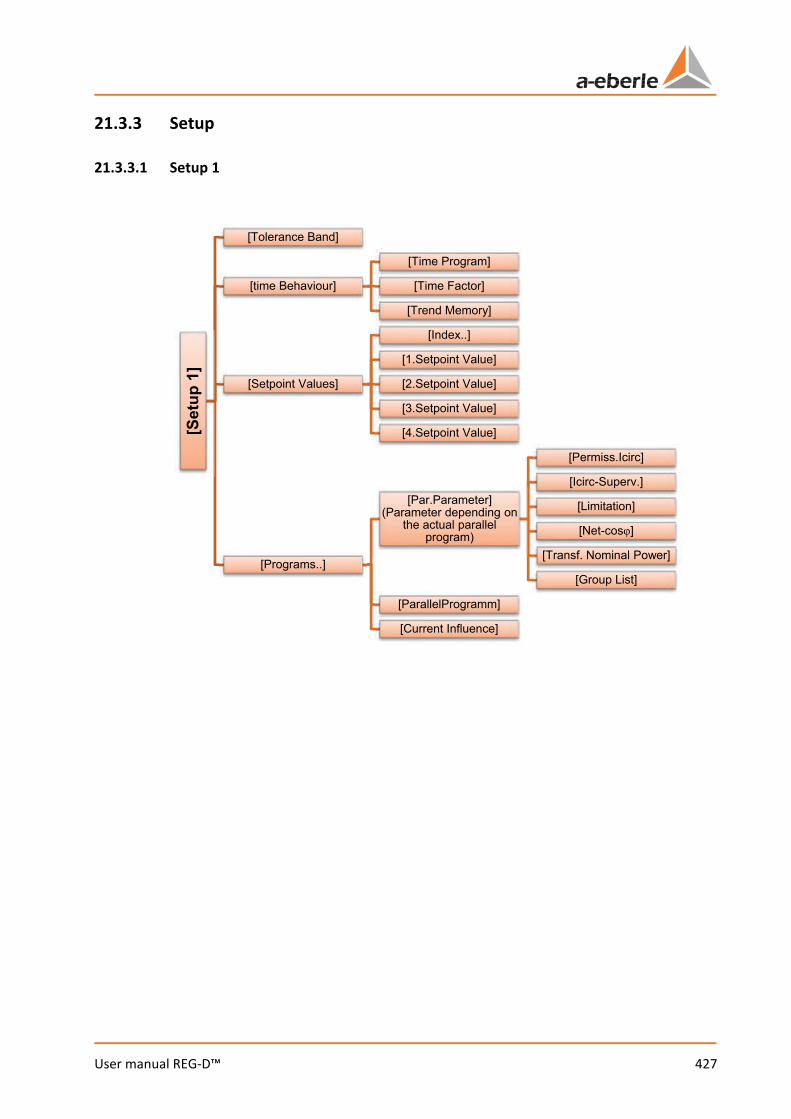
427 User manual REG-D™
21.3.3 Setup
21.3.3.1 Setup 1
[Set
up 1
]
[Tolerance Band]
[time Behaviour]
[Time Program]
[Time Factor]
[Trend Memory]
[Setpoint Values]
[Index..]
[1.Setpoint Value]
[2.Setpoint Value]
[3.Setpoint Value]
[4.Setpoint Value]
[Programs..]
[Par.Parameter] (Parameter depending on
the actual parallel program)
[Permiss.Icirc]
[Icirc-Superv.]
[Limitation]
[Net-cosφ]
[Transf. Nominal Power]
[Group List]
[ParallelProgramm]
[Current Influence]

We take care of it.
428 User manual REG-D™
21.3.3.2 Setup 2
21.3.3.3 Setup 3
21.3.3.4 Setup 4
[Set
up 2
][Gradient (I)] [pos/neg]
[Limitation (I)] [max/min]
[<U Undervoltage]
[>U Overvoltage]
[>I, <I Current Limits] [..<I] & [..>I]
[Set
up 3
]
[Dreiwickler Limit >Ub]
[Inhibit High]
[High-Speed Switching] [Fwd/Bwd]
[Inhibit Low]
[Set
up 4
] Ti
me
until
..
[<U, >U] [..>U] & [..<U]
[<I, >I]
[Inhibit High]
[High-Speed Switching] [Fwd/Bwd]
[Inhibit Low]
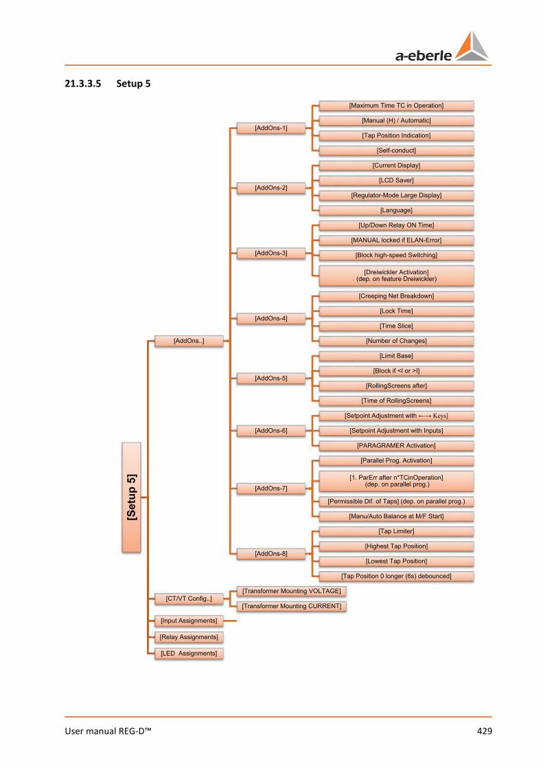
429 User manual REG-D™
21.3.3.5 Setup 5
[Set
up 5
]
[AddOns..]
[AddOns-1]
[Maximum Time TC in Operation]
[Manual (H) / Automatic]
[Tap Position Indication]
[Self-conduct]
[AddOns-2]
[Current Display]
[LCD Saver]
[Regulator-Mode Large Display]
[Language]
[AddOns-3]
[Up/Down Relay ON Time]
[MANUAL locked if ELAN-Error]
[Block high-speed Switching]
[Dreiwickler Activation] (dep. on feature Dreiwickler)
[AddOns-4]
[Creeping Net Breakdown]
[Lock Time]
[Time Slice]
[Number of Changes]
[AddOns-5]
[Limit Base]
[Block if <I or >I]
[RollingScreens after]
[Time of RollingScreens]
[AddOns-6]
[Setpoint Adjustment with ←→ Keys]
[Setpoint Adjustment with Inputs]
[PARAGRAMER Activation]
[AddOns-7]
[Parallel Prog. Activation]
[1. ParErr after n*TCinOperation] (dep. on parallel prog.)
[Permissible Dif. of Taps] (dep. on parallel prog.)
[Manu/Auto Balance at M/F Start]
[AddOns-8]
[Tap Limiter]
[Highest Tap Position]
[Lowest Tap Position]
[Tap Position 0 longer (6s) debounced]
[CT/VT Config..][Transformer Mounting VOLTAGE]
[Transformer Mounting CURRENT]
[Input Assignments]
[Relay Assignments]
[LED Assignments]

We take care of it.
430 User manual REG-D™
21.3.3.6 Setup 6
[Set
up 6
]
[General]
[General 1] [Analog..]
[General 2]
[Station ID]
[Station Name]
[Time Setting]
[LCD-Contrast]
[General 3]
[Password]
[Erase Recorder Data]
[Erase Tap-Change Sums]
[Actual Value Correction]
[General 4]
[IP-Adresse]
[IP-Netmask]
[IP-Gateway]
[RS-232][COM-1]
[COM-2]
[E-LAN][E-LAN Left]
[E-LAN Right]
[PAN-D] (if available)
[Status]
[REG-D Status (1)]
[REG-D Status (2)]
[COM-Status]
[LAN-Status]
[COM-3 Status]
[Time/Date]
[H/P/Q Programs]
[Error Status]


A. Eberle GmbH & Co. KG
Frankenstraße 160D-90461 Nürnberg
Tel.: +49 (0) 911 / 62 81 08-0Fax: +49 (0) 911 / 62 81 08 99E-Mail: [email protected]
http://www.a-eberle.de 584.
0723
- FW
2.2
3/3.
23 -
Win
REG
3.9
R6