A refined chronology for the Cambrian succession of southern Britain
CHINESE JOURNAL OF GEOPHYSICS Vol.53, No.6, 2010, pp: 240∼1
REFINED PROCESSING AND TWO-DIMENSIONAL INVERSION OFMAGNETOTELLURIC DATA I: IMPEDANCE TENSOR DECOMPO-SITION AND ANALYSIS OF STRUCTURAL DIMENSIONALITY
CAI Jun-Tao1,2, CHEN Xiao-Bin1, ZHAO Guo-Ze1
1 Institute of Geology, China Earthquake Administration, Beijing 100029, China
2 Jiangsu Earthquake Administration, Nanjing 210014, China
Abstract A mathematical transformation, conjugate impedance transformation, is performed to magnetotelluric
impedances data, which yields a special relationship between observed and regional impedance. It is independent
of local galvanic distortion and does not require assumption of subsurface dimensionality. This relationship also
holds to a three-dimensional regional structure. Using the available Swift rotation method, the strike angle for
the regional structure can be derived from the transformed impedance data. Then the phases, amplitudes and
distortion factors can be resolved by the optimization technique. New structural dimensionality is defined based
on the transformed impedance, which is not affected by local galvanic distortion. The correctness of this new
algorithm is tested by using synthetic data. And a comparison with other methods, such as the Swift, Bahr, GB,
phase tensor and WAL, is made analytically. Finally, these new procedures are applied to interpretation of real
field data and a set of refined processing techniques are developed for removal of local distortion and determination
of structural dimensionality. In the follow-up work this new algorithm will be extended to multisite and multiple
frequency cases and a new stable method based on optimization for impedance tensor decomposition will be
developed.
Key words Magnetotellurics, Local distortion, Conjugate impedance transformation, Tensor decomposition,
Analysis of structural dimensionality
1 INTRODUCTION
Magnetotelluric (MT) surveys have been extensively carried out in China, yielding a great number ofMT data[1∼9]. In recent years, with increasing complexity of geological structure involved in MT studies, theinterpretation of field data is facing higher requirements. Although, in a strict sense, real geological structuresare three-dimensional (3D), they can be approximated by a two-dimensional (2D) body if they have a certainstrike of extension. When a small 3D anomalous body near the Earth surface is much smaller than the skinningdepth of electromagnetic (EM) waves, the MT curves from sites nearby the anomalous body will be highlydistorted, making data interpretation difficult. Such a distortion caused by a small local anomalous body iscalled local distortion[10]. To enhance the accuracy and reliability of data interpretation, the local distortionshould be separated and removed from regional structural responses. Thus various forms of impedance tensordecomposition have been developed to solve this problem.
Another associated study is analysis of structural dimensionality. The analysis of dimensionality is a pow-erful tool that may provide information such as variation of strike direction with depth, which may be correlatedwith different processes and structure in the Earth’s crust and mantle[11]. Based on analysis of dimensionality,MT data can be interpreted in 1D, 2D or 3D models. An appropriate determination of dimensionality is ofimportance for MT data inversion, because, for example, a 2D interpretation of 3D data is acceptable in somecases while not feasible in certain cases[12,13].
Swift proposed the impedance tensor rotation and definition of 2D skew using the rotational invariants ofimpedance tensors for dimensionality analysis of electric structure[14]. However, due to presence of local smallanomalous bodies, the regional strike cannot be found by the conventional Swift method, neither the regional
E-mail: [email protected]
*Corresponding author: [email protected]
Cai J T et al.: Refined Processing and Two-Dimensional Inversion of Magnetotelluric Data I· · · 241
dimensionality is determined correctly. To overcome these difficulties, some methods of impedance tensordecomposition have been suggested, such as the Bahr decomposition[15∼17] and GB decomposition[18∼20]. Inthe Bahr decomposition, distortion is corrected using the property that the elements of observed impedance inthe same column that was locally distorted have equal phases. The GB decomposition divides local distortioninto determinable part (shear and twist factors) and indeterminable part (anisotropic and static shift factors),and uses the optimization method to determine impedance elements and distortion factors simultaneously. TheGB decomposition has a better stability with respect to the Bahr decomposition, but cannot yield reasonablestructural dimensionality directly. Chave et al. have studied the mechanism of full distortion in the electricand magnetic fields and derived its theoretical models[21∼23]. Lilley applied the Mohr’s circle in structuralgeology to analysis of distortion in MT data, and suggested an intuitive and distinct display tool for qualitativestudy of local distortion[26,27]. Zhao et al. and Jin et al. introduced the Bahr decomposition into MT datainterpretation[26,27]. Other work on distortion includes Wang et al.[28], Yang et al.[29] and Wang et al.[30].
Some researchers used the rotational invariants of MT impedance to describe dimensionality of electricstructure. Fischer et al. proved that there exist eight rotational invariants, among which seven are independentand one can be calculated from others[31]. Szarka et al. derived a set of rotational invariants of MT impedanceand applied it to interpretation of structural dimensionality[32]. Weaver et al. suggested another set of rotationalinvariants of MT impedance and determined the structural dimensionality based on whether some of theseinvariants are zero. This was called the WAL method[33]. In conjunction with Bahr rotational invariants andWAL rotational invariants, Marti et al. proposed a new way to determine structural dimensionality, named theB-Q method[34].
All the methods of impedance tensor decomposition presented above are based on the assumption thatregional structure is 1D or 2D. While local anomalous bodies are usually 3D. Without assuming 2D regionalstructure, Caldwell et al. utilized the special relationship between the observed impedance phase and regionalimpedance phase to obtain the useful information on the regional impedance, and suggested the concept “phasetensor”[35]. Bibby et al. made a further study on the phase tensor and applied them to correction of 1D and2D distortions[36]. As it does not need the assumption of 2D regional structure, the phase tensor method hasbeen widely used in MT studies[37∼42]. It is noted that the strike direction is consistent with that from theBahr decomposition. Consequently both have the same shortcomings, such as prone to noise, unstable solution,and difficult to realize optimal decomposition of phase tensors by joint multi-frequency equation, instead it isdecomposed frequency by frequency yielding an average on many frequencies.
Enlightened by the phase tensor method, we have attempted to perform a mathematical transform of MTimpedance, called it “conjugate impedance transform”. We found that there is a special relationship between theobserved impedance and regional impedance after transform, which is not affected by local distortion and doesnot need the assumption on dimensionality of regional structure. Using this special relationship, we proposea new method to remove local distortion and define the parameters for structural dimensionality that excludelocal distortion. Then we apply this approach to impedance decomposition and determination of structuraldimensionality on theoretical models and compare the result with that from other methods, including the Bahrdecomposition, GB decomposition and phase tensor method. Finally we discuss the direction of further studyin this aspect.
2 PRINCIPLE OF METHOD
2.1 Mathematical Transform of MT Impedance Tensors–Conjugate Impedance Transform
When only galvanic distortion is present, the observed MT impedance tensor Z and regional impedancetensor Zr can be linked by[16,18,20,35,36]
Z = CZr, (1)
where C is the real matrix of distortion. Performing the following transform to the observed impedance
242 Chinese J. Geophys. Vol.53, No.6
Z−1Z∗ = (CZr)−1(CZr)∗ = Z−1r C−1C∗Z∗
r = Z−1r C−1CZ∗
r = Z−1r Z∗
r , (2)
where Z−1 is the inverse of Z, Z∗ is the conjugate of Z, and C∗ is the conjugate of C. Eq.(2) indicates aspecial relationship between the observed and regional impedance, which is not affected by local distortion anddoes not require assumption of regional structural dimensionality. Thus we can use it to remove local distortion.For convenience, we call formula (2) the conjugate impedance transform of MT impedance tensors.
Observed MT impedance Z is expressed as
Z =[
Zxx Zxy
Zyx Zyy
]=
[|Zxx|eiϕxx |Zxy|eiϕxy
|Zyx|eiϕyx |Zyy|eiϕyy
]. (3)
Then, following Eq.(2), the impedance Zt of conjugate transform is
Zt = Z−1Z∗ =1B
[Ztxx Ztxy
Ztyx Ztyy
], (4)
where
Ztxx =ZyyZ∗xx − ZxyZ∗
yx, Ztxy = ZyyZ∗xy − ZxyZ∗
yy, Ztyx = ZxxZ∗yx − ZyxZ∗
xx,
Ztyy =ZxxZ∗yy − ZyxZ∗
xy, B = ZxxZyy − ZxyZyx. (5)
According to the conjugate transform rule above, for 1D regional structure, there are
Z =[
0 Z1d
−Z1d 0
]= |Z1d|
[0 eiϕ1d
−eiϕ1d 0
], (6)
Zt = Z−1Z∗ = e−2iϕ1d
[1 00 1
]. (7)
In the case of 2D regional structure, suppose the observational coordinates are consistent with principal axis ofstructure, we have
Zp =[
0 |Zrxy|eiϕxy
|Zpyx|eiϕpyx 0
], (8)
Ztp =Z−1p Z∗
p =[
e−2iϕpyx 00 e−2iϕpxy
], (9)
where Zp is impedance, and Ztp is transform impedance. Eqs.(7) and (9) show that the transform impedancecontains only information on phase. It means that after conjugate transform, we can obtain the complete phaseinformation of impedance elements, while losing all the information on their amplitude. In this aspect, it isthe same as the phase tensor method of Bibby et al. Besides, for 1D and 2D models, when the observationalcoordinates are in accordance with the principal axis of structure, the transform impedance is characterized byzero anti-diagonal elements. By using this feature, we can adopt the approach like the Swift method to obtainparameters conveniently, such as regional strike, distortion factors and regional impedance, hence the wholedecomposition is finished.
2.2 Conjugate Transform Impedance Method for Decomposition of MT Impedance Tensors
As presented above, we can conduct conjugate impedance transform to observed impedance tensors, sothat local galvanic distortion is removed. We call it the conjugate transform impedance method. Next we usethis new decomposition technique to resolve parameters of the original impedance like the Swift method.
Cai J T et al.: Refined Processing and Two-Dimensional Inversion of Magnetotelluric Data I· · · 243
2.2.1 Determination of regional strikeFrom the observed transform impedance Zt, the transform impedance in an arbitrary coordinate system
on plane can be obtained by the impedance rotation formula. Following the Swift rotation rule, we make therotated object function |Ztxx|2 + |Ztyy|2 → max or |Ztxy|2 + |Ztyx|2 → min, then the equation for strike angle is
θ0 =14
arctan(Ztxx − Ztyy)(Ztxy + Ztyx)∗ + (Ztxx − Ztyy)∗(Ztxy + Ztyx)
|Ztxx − Ztyy|2 − |Ztxy + Ztyx|2. (10)
Solving Eq.(10) yields 4 solutions. Like the Swift procedure, we can choose the correct one by comparing valuesof the object function.2.2.2 Determination of regional impedance phase
Next we rotate the observed transform impedance Zt to the strike direction determined above, and fitEq.(9) to resolve 2D regional impedance phases ϕpxy and ϕpyx. Now making Φ = |Ztxx − e−2iϕpyx |2 + |Ztxy|2 +|Ztyx|2 + |Ztyy − e−2iϕpxy |2 → min, the expression of regional impedance phase is
ϕpxy =14
arctan(
Z∗tyy
Ztyy
), ϕpyx =
14
arctan(
Z∗txx
Ztxx
). (11)
Eq.(11) shows that ϕpxy and ϕpyx have 4 solutions each in the range 0−π with intervalπ
4, which produce sixteen
combinations, among which the regional impedance phases are that makes the object function Φ minimum.2.2.3 Determination of distortion factors and regional impedance tensors
Previous work demonstrates that the distortion matrix can be divided into determinable and undeter-minable parts[18]. As the 2D impedance tensor affected by static shift and the regional impedance tensor areequivalent in form in coordinates consistent with the strike direction, the static shift factor contained in thedistortion matrix C cannot be separated by tensor decomposition, resulting in that the diagonal elements ofC cannot be determined rigorously[21]. In this sense, static shift is a part of local distortion, while this partcannot be removed by impedance decomposition. Consequently the application of the impedance decompositionmethods is highly limited. In processing of real data, to conduct inversion on regional impedance tensors fromtensor decomposition, correction to static shift on apparent resistivity curves must be made very carefully ateach frequency.
In the case that the static shift factor cannot be determined, some constraint is required to solve thedistortion matrix and regional impedance tensor. Suppose that there is no influence of a local 3D small abnormalbody, we can recover the case of Swift rotation by using the new algorithm suggested in this paper. In thisway the distortion matrix is a unit one. Thus we use the constraint that the trace of this matrix is 2, i.e.[
1 Cxy
Cyx 1
]. Correspondingly the regional 2D impedance affected by distortion is
Zs = CZp =[
Cxy|Zpyx|eiϕpyx |Zpxy|eiϕpxy
|Zpyx|eiϕpyx Cyx|Zpxy|eiϕpxy
]. (12)
Now we make the object function |Z − Zs|2 → min to resolve the regional impedance amplitude anddistortion factor. Omitting the complicated process of derivation, let A = eiϕpxy and B = eiϕpyx , we getexpressions of the distortion factor and impedance amplitude
Cxy =ZxxB∗ + Z∗
xxB
ZyxB∗ + Z∗yxB
, Cyx =ZyyA∗ + Z∗
yyA
ZxyA∗ + Z∗xyA
, (13)
|Zrxy| =ZxyA∗ + Z∗
xyA
2, |Zryx| =
ZyxB∗ + Z∗yxB
2. (14)
2.3 New Criterion of Structural Dimensionality
244 Chinese J. Geophys. Vol.53, No.6
As the conjugate transform impedance is completely not affected by local distortion of the electric field,we can define a new criterion of structural dimensionality. Based on the physical implication of 2D skew, weadopt the formal reciprocal relationship between the 2D skew defined by the conjugate transform impedanceand the Swift 2D skew, which is
γ =|Ztxy − Ztyx||Ztxx + Ztyy|
. (15)
With reference to the original definition of 1D skew[16], the newly defined 1D skew based on conjugate transformimpedance is
Λ =
∣∣∣∣∣√
(Ztxx − Ztyy)2 + (Ztxy + Ztyx)2
Ztxx + Ztyy
∣∣∣∣∣ . (16)
Calculation of Eqs.(15) and (16) all uses elements of the conjugate transform impedance, thus the yieldedcriterion of dimensionality contains no effect of local distortion, which can accommodate dimensional analysisof regional electric structure.
3 EXAMPLES OF CALCULATIONS
3.1 Theoretical Models
To verify the differences between existing methods of impedance decomposition, as well as the effectivenessof the new algorithm suggested in this paper, we have performed calculations on theoretical models, of whichparameters are listed in Table 1, where βx and βy denote the angles deviated from the regional strike causedby local telluric distortion for TE and TM modes, respectively, also called telluric twist angle[17], and gx and gy
are anisotropic factors due to local telluric distortion. For convenience of description hereafter, we note brieflythe conjugate transform impedance method suggested in this study by CCZ and the phase tensor method byCBB, respectively.
Table 1 Impedance tensor of numerical examples
No. Model Impedance
1 1D model of regional structure with impedance phase 26.5◦ Z =
[0 10 + 5i
−10− 5i 0
]Telluric distortion is added to model 1 with matrix
2 C =
[cos βx − sin βy
sin βx cos βy
] [gx 0
0 gy
]=
[0.9848 −− 0.2588
0.1736 0.9659
], Z =
[2.5582 + 1.2942i 9.8481 + 4.924i
−− 9.6583− 4.8296i 1.7365 + 0.8682i
]where βx = 10◦, βy = 15◦, gx = gy = 1
3 2D model of regional structure with strike along north direction Z =
[0 25 + 9i
−15− 12i 0
]
4 Model 3 rotated by 30◦ clockwise Z =
[4.33− 1.29i 22.5 + 9.75i
−17.5− 11.25i −4.33 + 1.29i
]
5 Telluric distortion is added to model 3 with same matrix as model 2 Z =
[3.8823 + 3.1058i 24.6202 + 8.8633i
−14.4889− 11.5911i 4.3412 + 1.5628i
]
6 3D model Z =
[1.405 + 2.23i 5.33 + 2.5i
−7.45− 4.23i 1.45 + 3.29i
]
Note: impedance values are in Gauss unit.
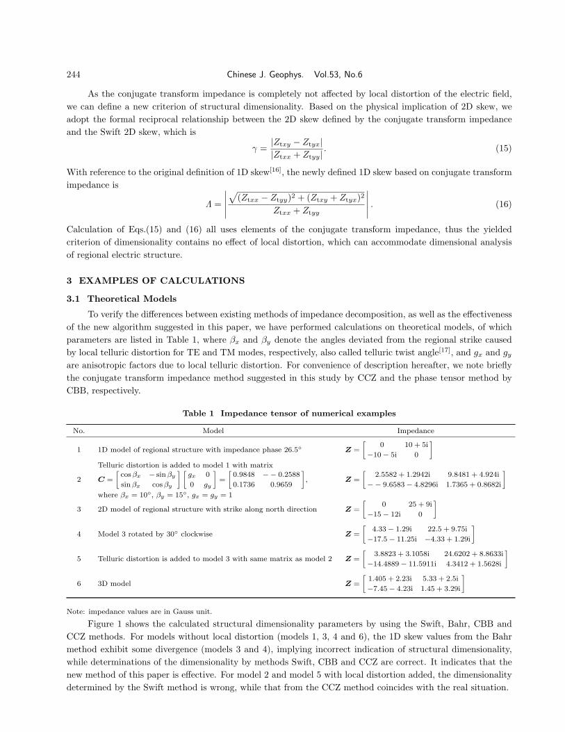
Figure 1 shows the calculated structural dimensionality parameters by using the Swift, Bahr, CBB andCCZ methods. For models without local distortion (models 1, 3, 4 and 6), the 1D skew values from the Bahrmethod exhibit some divergence (models 3 and 4), implying incorrect indication of structural dimensionality,while determinations of the dimensionality by methods Swift, CBB and CCZ are correct. It indicates that thenew method of this paper is effective. For model 2 and model 5 with local distortion added, the dimensionalitydetermined by the Swift method is wrong, while that from the CCZ method coincides with the real situation.
Cai J T et al.: Refined Processing and Two-Dimensional Inversion of Magnetotelluric Data I· · · 245
Fig. 1 Dimensional parameters determined by various tensor decomposition methods
(a) One-dimensional skew; (b) Two-dimensional skew.
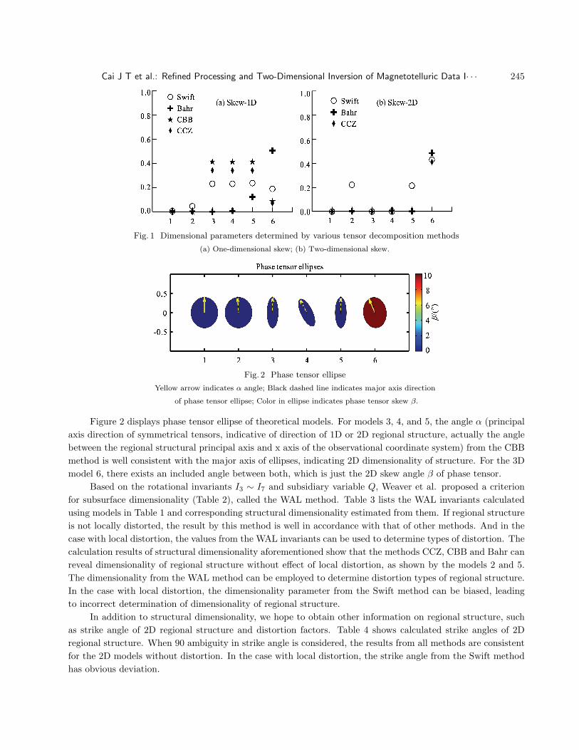
Fig. 2 Phase tensor ellipse
Yellow arrow indicates α angle; Black dashed line indicates major axis direction
of phase tensor ellipse; Color in ellipse indicates phase tensor skew β.
Figure 2 displays phase tensor ellipse of theoretical models. For models 3, 4, and 5, the angle α (principalaxis direction of symmetrical tensors, indicative of direction of 1D or 2D regional structure, actually the anglebetween the regional structural principal axis and x axis of the observational coordinate system) from the CBBmethod is well consistent with the major axis of ellipses, indicating 2D dimensionality of structure. For the 3Dmodel 6, there exists an included angle between both, which is just the 2D skew angle β of phase tensor.
Based on the rotational invariants I3 ∼ I7 and subsidiary variable Q, Weaver et al. proposed a criterionfor subsurface dimensionality (Table 2), called the WAL method. Table 3 lists the WAL invariants calculatedusing models in Table 1 and corresponding structural dimensionality estimated from them. If regional structureis not locally distorted, the result by this method is well in accordance with that of other methods. And in thecase with local distortion, the values from the WAL invariants can be used to determine types of distortion. Thecalculation results of structural dimensionality aforementioned show that the methods CCZ, CBB and Bahr canreveal dimensionality of regional structure without effect of local distortion, as shown by the models 2 and 5.The dimensionality from the WAL method can be employed to determine distortion types of regional structure.In the case with local distortion, the dimensionality parameter from the Swift method can be biased, leadingto incorrect determination of dimensionality of regional structure.
In addition to structural dimensionality, we hope to obtain other information on regional structure, suchas strike angle of 2D regional structure and distortion factors. Table 4 shows calculated strike angles of 2Dregional structure. When 90 ambiguity in strike angle is considered, the results from all methods are consistentfor the 2D models without distortion. In the case with local distortion, the strike angle from the Swift methodhas obvious deviation.
246 Chinese J. Geophys. Vol.53, No.6
Table 2 Relation between geoelectric dimensionality and WAL invariant parameters
Case I3 ∼ I7 and Q Geoelectric dimensionality
1 I3 = I4 = I5 = I6 = 0 1D
2 I3 6= 0 or I4 6= 0; I5 = I6 = 0; I7 = 0 or Q = 0; ξ4 6= 0 and η4 6= 0 2D
3a I3 6= 0 or I4 6= 0; I5 6= 0; I6 = 0; I7 = 0; Q 6= 0 3D/2D(2D affected by galvanic distortion (only twist))
3b I3 6= 0 or I4 6= 0; I5 6= 0; I6 = 0; Q = 0 3D/(1D or 2D)
3c I3 6= 0 or I4 6= 0; I5 = I6 = 0; I7 = 0 or Q = 0; ξ4 = 0 and η4 = 0 3D/(1D or 2D) diag
4 I3 6= 0 or I4 6= 0; I5 6= 0; I6 6= 0; I7 = 0 3D/2D
5 I7 6= 0 3D
Table 3 WAL invariants and dimensionality of models in Table 1
I3 ∼ I7 and Q Geoelectric dimensionality
1 I3 = I4 = I5 = I6 = 0 1D
2 I3 = 0.0437, I4 = 0.0437, I5 = 0.4226, I6 = 0, Q = 0 3D/(1D or 2D)
3 I3 = 0.25, I4 = 0.143, I5 = I6 = 0, I7 = 0, Q = 0.393 2D
4 I3 = 0.25, I4 = 0.142, I5 = I6 = 0, I7 = 0, Q = 0.392 2D
5 I3 = 0.2538, I4 = 0.1494, I5 = 0.4184, I6 = 0.0171, I7 = 0, Q = 0.392 3D/2D
6 I3 = 0.162, I4 = 0.233, I5 = 0.787, I6 = 0.45, I7 = 5.98, Q = 0.07 3D
Note: Used threshold values are τWAL = 0.01, τQ = 0.01.
Table 4 Strike angle of models in Table 1
True value Swift Bahr CBB CCZ GB WAL
Model 3 0 90 0 0 0 0 0
Model 4 –30 60 –29.971 –29.971 –29.968 –29.971 60
Model 5 0 2.34 0 0 0 0 0
Note: Strike angle is in unit degree.
Table 5 Distortion matrix derived from tensor decomposition for models in Table 1
Model 2 Model 5
True value C =
[0.9848 0.2588
0.1736 0.9659
], βx = 10◦, βy = 15◦, βt = 12.5◦, βe = −2.5◦
CBB C =
[0.9867 −0.2593
0.1740 0.9677
]C =
[0.9168 −0.2902
0.1617 1.0832
]
CCZ C =
[1 −0.2677
0.1771 1
]C =
[1 −0.2679
0.1763 1
]
GB C =
[1.0096 −0.2652
0.1789 0.9904
]C =
[1.0097 −0.2654
0.1780 0.9903
]βt = 12.52◦, βe = −2.47◦ βt = 12.5◦, βe = −2.5◦
WAL C =
[0.9847 −0.2586
0.1744 0.9660
]C =
[0.9848 −0.2588
0.1736 0.9659
]βx = 10.044◦, βy = −14.989◦ βx = 10◦, βy = 15◦
Note: βt and βe is twist and shear angles in GB decomposition, respectively.
Table 5 displays distortion matrixes calculated by methods CBB, CCZ, GB and WAL. For the methodCCZ, the used constraint is that the trace of the matrix is 2. And constraints on distortion matrixes usedin varied decomposition methods are different. Hence some differences are present in decomposed distortionmatrixes, primarily involving diagonal elements. In models 2 and 5, the same distortion matrix has been added,
Cai J T et al.: Refined Processing and Two-Dimensional Inversion of Magnetotelluric Data I· · · 247
so our attention is focused on comparison of consistence of the resultant distortion matrixes between the twomodels. It shows that the calculated distortion matrixes by the CCZ method are fairly consistent.
Calculations of varied theoretical models demonstrate that the structural dimensionality parameter, re-gional strike angle and distortion factor calculated by the CCZ method are correct, and it can be applied toreal interpretation.
3.2 Real Data
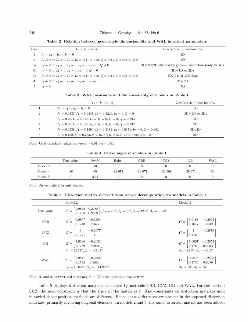
To compare the methods CBB and CCZ, we used the real data provided by Prof. Bibby that was collectedin the Taupo volcanic area of New Zealand[36] (Fig. 3). As shown in Fig. 3, the apparent resistivity curves ofTE and TM modes separate from each other at high frequency, implying possible influence of heterogeneity inthe shallow subsurface.
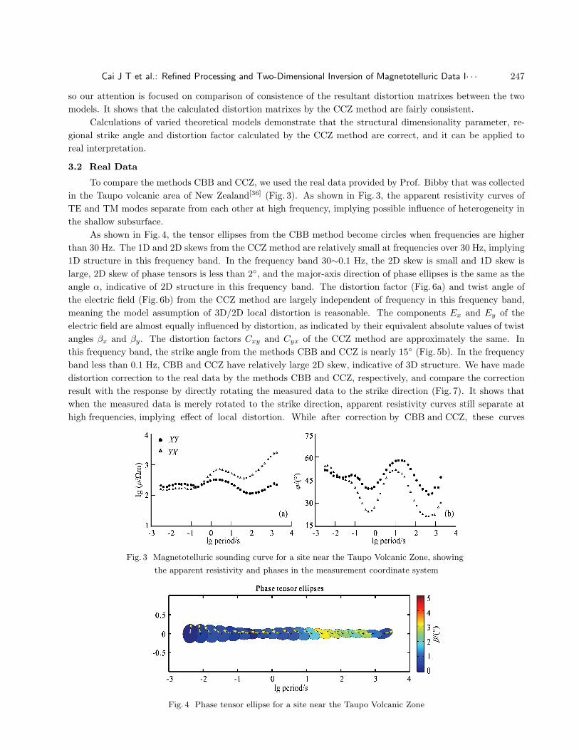
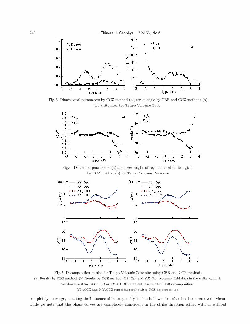
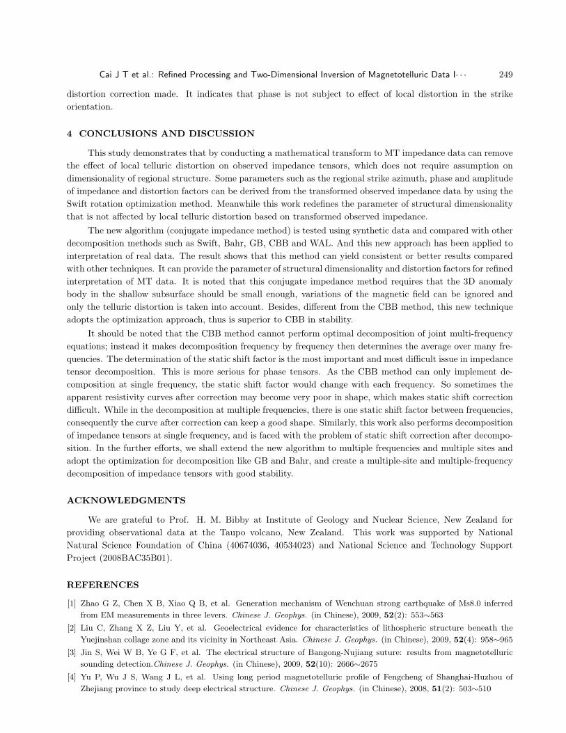
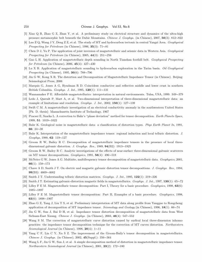
As shown in Fig. 4, the tensor ellipses from the CBB method become circles when frequencies are higherthan 30 Hz. The 1D and 2D skews from the CCZ method are relatively small at frequencies over 30 Hz, implying1D structure in this frequency band. In the frequency band 30∼0.1 Hz, the 2D skew is small and 1D skew islarge, 2D skew of phase tensors is less than 2◦, and the major-axis direction of phase ellipses is the same as theangle α, indicative of 2D structure in this frequency band. The distortion factor (Fig. 6a) and twist angle ofthe electric field (Fig. 6b) from the CCZ method are largely independent of frequency in this frequency band,meaning the model assumption of 3D/2D local distortion is reasonable. The components Ex and Ey of theelectric field are almost equally influenced by distortion, as indicated by their equivalent absolute values of twistangles βx and βy. The distortion factors Cxy and Cyx of the CCZ method are approximately the same. Inthis frequency band, the strike angle from the methods CBB and CCZ is nearly 15◦ (Fig. 5b). In the frequencyband less than 0.1 Hz, CBB and CCZ have relatively large 2D skew, indicative of 3D structure. We have madedistortion correction to the real data by the methods CBB and CCZ, respectively, and compare the correctionresult with the response by directly rotating the measured data to the strike direction (Fig. 7). It shows thatwhen the measured data is merely rotated to the strike direction, apparent resistivity curves still separate athigh frequencies, implying effect of local distortion. While after correction by CBB and CCZ, these curves
Fig. 3 Magnetotelluric sounding curve for a site near the Taupo Volcanic Zone, showing
the apparent resistivity and phases in the measurement coordinate system
Fig. 4 Phase tensor ellipse for a site near the Taupo Volcanic Zone
248 Chinese J. Geophys. Vol.53, No.6
(a) (b)
Stri
ke/(
°)
Fig. 5 Dimensional parameters by CCZ method (a), strike angle by CBB and CCZ methods (b)
for a site near the Taupo Volcanic Zone
(a) (b)
Cxy
,Cyx
Fig. 6 Distortion parameters (a) and skew angles of regional electric field given
by CCZ method (b) for Taupo Volcanic Zone site
Fig. 7 Decomposition results for Taupo Volcanic Zone site using CBB and CCZ methods
(a) Results by CBB method; (b) Results by CCZ method; XY Opt and Y X Opt represent field data in the strike azimuth
coordinate system. XY CBB and Y X CBB represent results after CBB decomposition.
XY CCZ and Y X CCZ represent results after CCZ decomposition.
completely converge, meaning the influence of heterogeneity in the shallow subsurface has been removed. Mean-while we note that the phase curves are completely coincident in the strike direction either with or without
Cai J T et al.: Refined Processing and Two-Dimensional Inversion of Magnetotelluric Data I· · · 249
distortion correction made. It indicates that phase is not subject to effect of local distortion in the strikeorientation.
4 CONCLUSIONS AND DISCUSSION
This study demonstrates that by conducting a mathematical transform to MT impedance data can removethe effect of local telluric distortion on observed impedance tensors, which does not require assumption ondimensionality of regional structure. Some parameters such as the regional strike azimuth, phase and amplitudeof impedance and distortion factors can be derived from the transformed observed impedance data by using theSwift rotation optimization method. Meanwhile this work redefines the parameter of structural dimensionalitythat is not affected by local telluric distortion based on transformed observed impedance.
The new algorithm (conjugate impedance method) is tested using synthetic data and compared with otherdecomposition methods such as Swift, Bahr, GB, CBB and WAL. And this new approach has been applied tointerpretation of real data. The result shows that this method can yield consistent or better results comparedwith other techniques. It can provide the parameter of structural dimensionality and distortion factors for refinedinterpretation of MT data. It is noted that this conjugate impedance method requires that the 3D anomalybody in the shallow subsurface should be small enough, variations of the magnetic field can be ignored andonly the telluric distortion is taken into account. Besides, different from the CBB method, this new techniqueadopts the optimization approach, thus is superior to CBB in stability.
It should be noted that the CBB method cannot perform optimal decomposition of joint multi-frequencyequations; instead it makes decomposition frequency by frequency then determines the average over many fre-quencies. The determination of the static shift factor is the most important and most difficult issue in impedancetensor decomposition. This is more serious for phase tensors. As the CBB method can only implement de-composition at single frequency, the static shift factor would change with each frequency. So sometimes theapparent resistivity curves after correction may become very poor in shape, which makes static shift correctiondifficult. While in the decomposition at multiple frequencies, there is one static shift factor between frequencies,consequently the curve after correction can keep a good shape. Similarly, this work also performs decompositionof impedance tensors at single frequency, and is faced with the problem of static shift correction after decompo-sition. In the further efforts, we shall extend the new algorithm to multiple frequencies and multiple sites andadopt the optimization for decomposition like GB and Bahr, and create a multiple-site and multiple-frequencydecomposition of impedance tensors with good stability.
ACKNOWLEDGMENTS
We are grateful to Prof. H. M. Bibby at Institute of Geology and Nuclear Science, New Zealand forproviding observational data at the Taupo volcano, New Zealand. This work was supported by NationalNatural Science Foundation of China (40674036, 40534023) and National Science and Technology SupportProject (2008BAC35B01).
REFERENCES
[1] Zhao G Z, Chen X B, Xiao Q B, et al. Generation mechanism of Wenchuan strong earthquake of Ms8.0 inferred
from EM measurements in three levers. Chinese J. Geophys. (in Chinese), 2009, 52(2): 553∼563
[2] Liu C, Zhang X Z, Liu Y, et al. Geoelectrical evidence for characteristics of lithospheric structure beneath the
Yuejinshan collage zone and its vicinity in Northeast Asia. Chinese J. Geophys. (in Chinese), 2009, 52(4): 958∼965
[3] Jin S, Wei W B, Ye G F, et al. The electrical structure of Bangong-Nujiang suture: results from magnetotelluric
sounding detection.Chinese J. Geophys. (in Chinese), 2009, 52(10): 2666∼2675
[4] Yu P, Wu J S, Wang J L, et al. Using long period magnetotelluric profile of Fengcheng of Shanghai-Huzhou of
Zhejiang province to study deep electrical structure. Chinese J. Geophys. (in Chinese), 2008, 51(2): 503∼510
250 Chinese J. Geophys. Vol.53, No.6
[5] Xiao Q B, Zhao G Z, Zhan Y, et al. A preliminary study on electrical structure and dynamics of the ultra-high
pressure metamorphic belt beneath the Dabie Mountains. Chinese J. Geophys. (in Chinese), 2007, 50(3): 812∼822
[6] Luo Z Q, Wang J Y, Deng Z Z, et al. The study of MT and hydrocarbon tectonic in central Yangzi Area. Geophysical
Prospecting for Petroleum (in Chinese), 1996, 35(3): 71∼81
[7] Chen D J, Yu P. The application of joint inversion of magnetotelluric and seismic data in Western Asia. Geophysical
Prospecting for Petroleum (in Chinese), 2005, 44(3): 251∼256
[8] Gao L H. Application of magnetotelluric depth sounding in North Tianshan foothill belt. Geophysical Prospecting
for Petroleum (in Chinese), 2006, 45(4): 427∼430
[9] Lu X B. Application of magnetotelluric sounding to hydrocarbon exploration in the Tarim basin. Oil Geophysical
Prospecting (in Chinese), 1995, 30(6): 788∼796
[10] Jin G W, Kong X R. The distortion and Decomposition of Magnetotelluric Impedance Tensor (in Chinese). Beijing:
Seismological Press, 2006
[11] Marquis G, Jones A G, Hyndman R D. Coincident conductive and reflective middle and lower crust in southern
British Columbia. Geophys. J. Int., 1995, 120(1): 111∼131
[12] Wannamaker P E. Affordable magnetotellurics: interpretation in natural environments. Tulsa, USA, 1999. 349∼379
[13] Ledo J, Queralt P, Mart A, et al. Two-dimensional interpretation of three-dimensional magnetotelluric data: an
example of limitations and resolution. Geophys. J. Int., 2002, 150(1): 127∼139
[14] Swift C M. A magnetotelluric investigation of an electrical conductivity anomaly in the southwestern United States
[Ph. D. thesis]: Massachusetts Institute of Technology, 1967
[15] Pracser E, Szarka L. A correction to Bahr’s “phase deviation” method for tensor decomposition. Earth Planets Space,
1999, 51: 1019∼1022
[16] Bahr K. Geological noise in magnetotelluric data: a classification of distortion types. Phys Earth Planet In, 1991,
66: 24∼38
[17] Bahr K. Interpretation of the magnetotelluric impedance tensor: regional induction and local telluric distortion. J.
Geophys, 1988, 62: 119∼127
[18] Groom R W, Bailey R C. Decomposition of magnetotelluric impedance tensors in the presence of local three-
dimensional galvanic distortion. J. Geophys. Res., 1989, 94(B2): 1913∼1925
[19] Groom R W, Bailey R C. Analytic investigations of the effects of near-surface three-dimensional galvanic scatterers
on MT tensor decompositions. Geophysics, 1991, 56(4): 496∼518
[20] McNeice G W, Jones A G. Multisite, multifrequency tensor decomposition of magnetotelluric data. Geophysics, 2001,
66(1): 158∼173
[21] Chave A D, Smith J T. On electric and magnetic galvanic distortion tensor decompositions. J. Geophys. Res., 1994,
99(B3): 4669∼4682
[22] Smith J T. Understanding telluric distortion matrices. Geophys. J. Int., 1995, 122(1): 219∼226
[23] Smith J T. Estimating galvanic-distortion magnetic fields in magnetotellurics. Geophys. J. Int., 1997, 130(1): 65∼72
[24] Lilley F E M. Magnetotelluric tensor decomposition: Part I, Theory for a basic procedure. Geophysics, 1998, 63(6):
1885∼1897
[25] Lilley F E M. Magnetotelluric tensor decomposition: Part II, Examples of a basic procedure. Geophysics, 1998,
63(6): 1898∼1907
[26] Zhao G Z, Tang J, Liu T S, et al. Preliminary interpretation of MT data along profile from Yanggao to Rongcheng:
application of decomposition of MT impedance tensor. Seismology and Geology (in Chinese), 1996, 18(1): 66∼74
[27] Jin G W, Sun J, Bai D H, et al. Impedance tensor distortion decomposition of magnetotelluric data from West
Sichuan-East Xizang. Chinese J. Geophys. (in Chinese), 2003, 46(4): 547∼552
[28] Wang S M. The correction of magnetotelluric curve distortion caused by surfical local three-dimension inhomo-
geneities: the impedance tensor decomposition technique for the correction of MT curves distortion. Northwestern
Seismological Journal (in Chinese), 1998, 20(4): 1∼11
[29] Yang C F, Lin C Y, Xu S Z. The improvement of the Groom-Baily’s tensor decomposition in magnetotellurics.
Chinese J. Geophys. (in Chinese), 2002, 45(Suppl.): 356∼364
[30] Wang L F, Jin G W, Sun J, et al. A simple decomposition method of distortion in magnetotelluric impedance tensor.
Northwestern Seismological Journal (in Chinese), 2001, 23(2): 172∼180
Cai J T et al.: Refined Processing and Two-Dimensional Inversion of Magnetotelluric Data I· · · 251
[31] Fischer G, Masero W. Rotational properties of the magnetotelluric impedance tensor: the example of the Araguainha
impact crater, Brazil. Geophys. J. Int., 1994, 119(2): 548∼560
[32] Szarka L, Menvielle M. Analysis of rotational invariants of the MT impedance tensor. Geophys. J. Int., 1997, 129(1):
133∼142
[33] Weaver J T, Agarwal A K, Lilley F E M. Characterization of the magnetotelluric tensor in terms of its invariants.
Geophys. J. Int., 2000, 141(2): 321∼336
[34] Marti A, Queralt P, Jones A G, et al. Improving Bahr’s invariant parameters using the WAL approach. Geophys.
J. Int., 2005, 163: 38∼41
[35] Caldwell T G, Bibby H M, Brown C. The magnetotelluric phase tensor. Geophys. J. Int., 2004, 158(2): 457∼469
[36] Bibby H M, Caldwell T G, Brown C. Determinable and non-determinable parameters of galvanic distortion in
magnetotellurics. Geophys. J. Int., 2005, 163(3): 915∼930
[37] Stagpoole V M, Bennie S L, Bibby H M, et al. Deep structure of a major subduction back thrust: Magneto-telluric
investigations of the Taranaki Fault, New Zealand. Tectonophysics, 2009, 463(1-4): 77∼85
[38] Heise W, Caldwell T G, Bibby H M, et al. Three-dimensional modelling of magnetotelluric data from the Rotokawa
geothermal field, Taupo Volcanic Zone, New Zealand. Geophys. J. Int., 2008, 173(2): 740∼750
[39] Weckmann U, Ritter O, Jung A, et al. Magnetotelluric measurements across the Beattie magnetic anomaly and the
Southern Cape Conductive Belt, South Africa. J. Geophys. Res., 2007, 112(B05416): 10∼1029
[40] Heise W, Bibby H M, Caldwell T G, et al. Melt distribution beneath a young continental rift: The Taupo Volcanic
Zone, New Zealand. Geophys. Res. Lett., 2007, 34(L14313), doi:10.1029/2007GL029629
[41] Toh H, Baba K, Ichiki M, et al. Two-dimensional electrical section beneath the eastern margin of Japan Sea. Geophys.
Res. Lett., 2006, 33(L22309), doi:10.1029/2006GL027435
[42] Heise W, Caldwell T G, Bibby H M, et al. Anisotropy and phase splits in magnetotellurics. Phys. Earth Planet In,
2006, 158(2∼4): 107∼121
[43] Weaver J T, Agarwal A K, Lilley F E M. The relationship between the magnetotelluric tensor invariants and the
phase tensor of Caldwell, Bibby, and Brown. Exploration Geophysics, 2006, 37(3): 261∼267
[44] Marti A, Queralt P, Ledo J. WALDIM: A code for the dimensionality analysis of magnetotelluric data using the
rotational invariants of the magnetotellurictens. Computers and Geosciences, 2009, 35: 2295∼2303
Copyright © 2022 FDOKUMEN