Redesigning the Walker: A More Durable & Dignified Device
68
Syracuse University Syracuse University SURFACE SURFACE Syracuse University Honors Program Capstone Projects Syracuse University Honors Program Capstone Projects Spring 5-1-2014 Redesigning the Walker: A More Durable & Dignified Device Redesigning the Walker: A More Durable & Dignified Device Gianna M. Curcio Follow this and additional works at: https://surface.syr.edu/honors_capstone Part of the Manufacturing Commons Recommended Citation Recommended Citation Curcio, Gianna M., "Redesigning the Walker: A More Durable & Dignified Device" (2014). Syracuse University Honors Program Capstone Projects. 764. https://surface.syr.edu/honors_capstone/764 This Honors Capstone Project is brought to you for free and open access by the Syracuse University Honors Program Capstone Projects at SURFACE. It has been accepted for inclusion in Syracuse University Honors Program Capstone Projects by an authorized administrator of SURFACE. For more information, please contact [email protected].
-
Upload
khangminh22 -
Category
Documents
-
view
0 -
download
0
Transcript of Redesigning the Walker: A More Durable & Dignified Device

Syracuse University Syracuse University
SURFACE SURFACE
Syracuse University Honors Program Capstone Projects
Syracuse University Honors Program Capstone Projects
Spring 5-1-2014
Redesigning the Walker: A More Durable & Dignified Device Redesigning the Walker: A More Durable & Dignified Device
Gianna M. Curcio
Follow this and additional works at: https://surface.syr.edu/honors_capstone
Part of the Manufacturing Commons
Recommended Citation Recommended Citation Curcio, Gianna M., "Redesigning the Walker: A More Durable & Dignified Device" (2014). Syracuse University Honors Program Capstone Projects. 764. https://surface.syr.edu/honors_capstone/764
This Honors Capstone Project is brought to you for free and open access by the Syracuse University Honors Program Capstone Projects at SURFACE. It has been accepted for inclusion in Syracuse University Honors Program Capstone Projects by an authorized administrator of SURFACE. For more information, please contact [email protected].

Redesigning the Walker:
A More Durable & Dignified Device
A Capstone Project Submitted in Partial Fulfillment of the Requirements of the Renée Crown University Honors Program at
Syracuse University
Gianna M. Curcio Candidate for Bachelor of Science in Mechanical Engineering Degree
and Renée Crown University Honors May 2014
Honors Capstone Project in Mechanical Engineering
Capstone Project Advisor: _______________________ Advisor Title & Name
Capstone Project Reader: _______________________
Reader Title & Name
Honors Director: _______________________ Stephen Kuusisto, Director
Date: 05/06/2014

Abstract
Aging and Rehabilitation Engineering is a prominent field with ample
room for development of and improvement upon existing options. Surveying city
sidewalks, family gatherings, hospital waiting rooms it becomes apparent that the
need for mobility aids is abundant. My proposal for Capstone is to redesign the
walker from both my mechanical engineering and sculptural perspectives. A
walker is meant to improve the quality of life for those who are unable to walk
unassisted, but should not come at the cost of the user’s dignity. The way we
carry ourselves says a lot about us (i.e. character, will, and level of care for our
bodies). I want to further improve quality of life by elevating the walker to a
dignified piece of equipment. I propose to focus on ease of use, opportunity for
customization (for those individuals with specific needs in addition to stability
while walking), and improving the aesthetics of this important device that serves
as a daily presence in many people’s lives.

©Gianna M. Curcio 2014

Table of Contents
ABSTRACT....................................................................................................................... I
EXECUTIVE SUMMARY .............................................................................................V
ACKNOWLEDGEMENTS ............................................................................................. I
ADVICE TO FUTURE HONORS STUDENTS ......................................................... III
PREFACE....................................................................................................................... IV
CHAPTER 1 ...................................................................................................................... 1
INTRODUCTION ............................................................................................................... 1
Project Background ................................................................................................... 1
Motivation .................................................................................................................. 2
CHAPTER 2 ...................................................................................................................... 7
RESEARCH ...................................................................................................................... 7
Research Methods ...................................................................................................... 7
Survey Resutls & Considerations ............................................................................... 8
Existing Solutions..................................................................................................... 10
CHAPTER 3 .................................................................................................................... 14
DESIGN AND ANALYSIS ................................................................................................ 14
Design Overview ...................................................................................................... 14
Computer Aided Design ........................................................................................... 20
Prototype Construction ............................................................................................ 26
Manufacturing and Cost Evaluation ........................................................................ 28
CHAPTER 4 .................................................................................................................... 31
ANALYSIS AND RESULTS .............................................................................................. 31
Stress Analysis.......................................................................................................... 31
Results & Considerations......................................................................................... 35
CHAPTER 5 .................................................................................................................... 36
FINAL CONCEPT SELECTION & CONCLUSION............................................................... 36
Final Concept Selection ........................................................................................... 36
Concluding Remarks ................................................................................................ 37
REFERENCES................................................................................................................ 38
APPENDICES ................................................................................................................. 39
A. 1 GLOSSARY OF TERMS................................................................................................
A.2 SURVEY.................................................................................................................... 5
A.3 CAD MODEL IMAGES .............................................................................................. 4
A.4 PROTOTYPE IMAGES................................................................................................. 7
A.5 DESIGN PROCESS & CONCEPT GENERATION ........................................................... 8


Executive Summary
To redesign is to take what is and make it better. To redesign requires an
existing process or product with ample room for improvement and a keen eye to
see that potential. By choosing to redesign the walker, I have chosen to state
outright that existing models are less than favorable and propose that my design
would be better suited to serve the end user. The overall objective of this
Capstone has been to identify the major shortcomings of existing mobility aid
models, rectify them by taking an inclusive design approach to accommodate the
user more comprehensively, and create detailed representations of this design for
patent purposes in the future.
A short list of the process involved in completing this Capstone is as
follows: (1) the generation of individual feature designs (divergent from existing
models) based on consumer feedback, (2) material selection and manufacturing
considerations in keeping with existing cost thresholds, (3) the development of a
full assembly model using computer aided design (CAD) software, (4)
performance of stress analysis on said CAD model, and (5) the construction of a
full scale prototype to convey the desired form.
While advancements continue for high-tech assistive technologies in the
field of Rehabilitation Engineering it seems that designs of purely mechanical
devices at the other end of the spectrum have remained stagnant. Existing models
of low-technology mobility aids, consisting of walkers and “rollators”, sacrifice
dignity and accommodation in the predominantly cost-driven fabrication. A

“rollator” has become the generically adopted term for full-wheeled mobility aids,
coming in three- and four-legged models. Though rollators offer smoother
navigation than the traditional walker, which consists of either two front wheels
or no wheels at all, issues with rollator devices stem directly from their hand
brake systems. The hand-trigger brake mechanism implemented in rollator design
is akin to that of a bicycle. It requires finger dexterity and contraction of muscles
in the forearms, to grip and activate a damper on the wheels.
Individuals who require the assistance of a mobility aid often experience
intersections of additional impairments. For example, those suffering from
arthritis of the hand and wrist have tremendous discomfort when using the hand
trigger brake system, described earlier. Alternatively the walker user may have
previously suffered a stroke or perhaps has an upper extremity prosthetic, and in
both situations would be best served by a device that accommodates for
asymmetric motor control. Changing this traditional interface of squeeze-trigger
hand brakes and parallel handle bar arrangement became the primary feature to
address in this redesign challenge. Redesigning the handle configuration and
nature of the applied forcing-through-squeezing, led to the creation of a distinct
layout. In turn this layout called for nontraditional material selection and
manufacturing considerations. As proposed from the earliest phases of this
Capstone the final model will be a more durable and dignified piece of equipment
than options currently on the market.
Preliminary research began with a questionnaire requesting first hand
commentary on the strengths, weaknesses, and associated conceptions with

existing mobility aid models. These surveys were distributed among primary
users and candidates (of mobility aid devices) within Englewood Medical Center
in Englewood, NJ, and the Syracuse VA Medical Center. Based on survey
feedback, designer preferences, field professional consultation, and observation
features were selected to concentrate on. This focus centered on addressing
primary issues of non-user-friendly brake systems (great difficulty for arthritic
individuals) and stigma attached to the stark, medical, barebones form. Secondary
features such as LED photo-detecting lights for the purposes of nighttime
navigation, for example, were also considered and included in this proposal.
Methods employed for producing the various models and renderings
involved extensive sketching, CAD design iterations, and construction of an
appearance model out of hand-carved Pine. Truly, though, a decade of research
through observation preceded this academic venture, as more of a brainstorming
hobby. I often wondered why my relatives needed to experience so much
difficulty with their devices, when the technology claims to be assistive as its
most fundamental intention. Now, through the application of my interdisciplinary
studies of mechanical engineering, sculpture, and Disabilities Studies, I am able to
look beyond the question and offer a potential solution.
Throughout the process I consulted with professionals in the fields of
Mechanical Engineering, Disabilities Studies, and Industrial Design in order to
approach the design from several angles. The insights gathered from one-on-one
meetings were invaluable, and led to cleaner iterations with each discussion. As
the form became more streamlined and manufacturing processes became leaner,

in terms of cost and material savings, I began to realize what original sources of
inspiration were showing through in the final design.
In the final design there are furniture undertones as well as an allusion to
biomimicry, at least from the designer’s perspective. Early sketches called upon
form from natural structures such as a bird’s breastbone, or furcula. The gradual
slope leading from the inclined handlebars to the floor continues to carry that
natural form through to the final prototype. This nuanced involvement of nature’s
elegant construction is especially exciting when the product at hand will be
fabricated from industrial grade material, namely polypropylene and anodized
aluminum.
Focusing on ease of use, opportunity for customization (for those patients
with specific needs in addition to stability while walking), and improving the
aesthetics of this device is important because it serves as a daily presence in many
people’s lives. With a focus on stress analysis and overall cost evaluation the
intentions of this design are to meet the needs of all those who have access to a
walker at this point in time, but with a better model they have at this point in time.
This design is not intended for the market as a luxury item, but instead as a widely
accessible piece of assistive technology that meets expectations of strength,
stability, and durability. All of this with no sacrifices made to visual esteem of the
device or perceived dignity of the user. The idea that better product design can
bring about change in human-to-human perception is certainly a concept worth
pursuing.

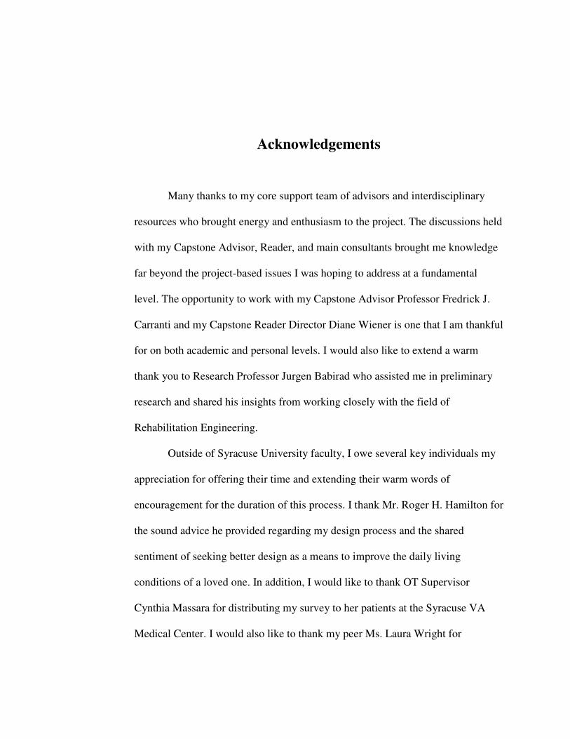
Acknowledgements
Many thanks to my core support team of advisors and interdisciplinary
resources who brought energy and enthusiasm to the project. The discussions held
with my Capstone Advisor, Reader, and main consultants brought me knowledge
far beyond the project-based issues I was hoping to address at a fundamental
level. The opportunity to work with my Capstone Advisor Professor Fredrick J.
Carranti and my Capstone Reader Director Diane Wiener is one that I am thankful
for on both academic and personal levels. I would also like to extend a warm
thank you to Research Professor Jurgen Babirad who assisted me in preliminary
research and shared his insights from working closely with the field of
Rehabilitation Engineering.
Outside of Syracuse University faculty, I owe several key individuals my
appreciation for offering their time and extending their warm words of
encouragement for the duration of this process. I thank Mr. Roger H. Hamilton for
the sound advice he provided regarding my design process and the shared
sentiment of seeking better design as a means to improve the daily living
conditions of a loved one. In addition, I would like to thank OT Supervisor
Cynthia Massara for distributing my survey to her patients at the Syracuse VA
Medical Center. I would also like to thank my peer Ms. Laura Wright for

providing several hours of consultation based on her knowledge from her course
of study in Industrial Design.
Perhaps my greatest thanks must go to Ms. Columba Curcio, my Great
Aunt, who planted the seed of my inspiration.
Advice to Future Honors Students
To all aspiring Honors Capstone Students reading this report, I
recommend that you begin contemplating possible Capstone topics prior to your
junior year. At the beginning of my senior year, I changed the entire premise of
my Capstone because of difficulties with the scope and ambiguity of my initial
proposal. In light of my difficulties with finding a new topic during the hectic
academic semester, I would suggest utilizing summer interludes as times to think
creatively and find the intersection of your array of interests so that when you
return to school you can not only solidify a topic, but know with certainty that it is
a topic in which you will be personally invested.
From the onset, I would suggest forming a network of resources and
supporting figures that express an interest in your topic. Coupled with this support
system it is important to be respectful of your Advisor and Reader’s time, and
keep them updated weekly about project status.
Now, I’ll give a special “shout out” to my fellow engineering students out
there! I did it, and so can you! Think long and hard about your senior year work
load and goals leading up to graduation. If you are ready to handle the volume of
research, analysis, and compilation required for independent study in addition to
Senior Design, full steam ahead. It’s no joke!

Preface
For this Capstone my motivation has been to bring about change in the
way people interact with and view assistive technology, through better design.
Among Merriam Webster’s dictionary entries for the word engineer I found one
that fit most appropriately with my goals for this project. The definition appears
as follows:
engineer |�enjə�ni(ə)r| noun
• the action of working artfully to bring something about

Chapter 1
Introduction
Project Background
With a multitude of disabilities and then intersections of these, the demand
for better design to smooth the interface between the human body and augmenting
technology is ever increasing. Based on several factors including scope, personal
connection, and room for collaboration of both my mechanical engineering and
sculptural perspectives, I chose the walker as my assistive technology to
reevaluate.
The walker is an important piece of equipment, vital to maintaining a
healthy quality of life for many people. Individuals who use mobility aids span a
broad range of ages and medical backgrounds. In an effort to address form as well
as function I have proposed to redesign the walker. My focus is on structural and
material modifications for sleek manufacturing and ease of use. My design is
customizable to accommodate multiple possible disabilities that users may have in
addition to limited mobility (e.g., arthritis, asymmetrical effects of a stroke,
upper-extremity prosthetic). Seeing my elderly relatives have difficulty

2
maneuvering their mobility aids, I would often think to myself there must be a
better way. This thought sparked a personal investment in proposing a solution,
but I did not expect my pet project to evolve into a Capstone journey.
Motivation
By definition, dignity is the state or quality of being worthy of honor or
respect1. Individuals with disabilities often face a reality wherein they are not
respected at the same level as able-bodied persons, and much of this has to do
with stigma and social constructions. Will power only goes so far. Beyond the
limit of an individual’s strong character, external support and organized efforts to
lift barriers of stigma may become necessary to liberate individuals from isolating
practices causally linked to disability. Since the United Nation’s Ad Hoc
Committee on a Comprehensive and Integral International Convention on the
Protection and Promotion of the Rights and Dignity of Persons with Disabilities is
bringing about change through a redesign of legislation2, and architects promote
inclusive access through considerations of Universal Design3, then engineers can
1 Merriam-Webster’s Dictionary provides this widely supported definition of dignity. 2 The Convention states that its purpose is to promote, protect and ensure the full and equal enjoyment of all human rights and fundamental freedoms by all persons with disabilities, and to promote respect for their inherent dignity. The convention goes on to say that persons with disabilities include those who have long-term physical, mental, intellectual, or sensory impairments which in interaction with physical, social or cultural barriers and attitudes may hinder their full and effective participation in society on an equal basis with others. More information can be found on the website: http://www.un.org/disabilities/convention/media.shtml 3 Universal Design makes things safer, easier and more convenient for everyone. The methodology involves designing products and spaces that can be used by the widest range of people possible. Universal Design evolved from Accessible Design, a design process that

3
help facilitate change through a redesign of assistive technologies for individuals
with disabilities.
Imagine being a person with a disability that impedes your ability to
walk. You are presented with the opportunity to maintain your independence
through the use of a mobility aid. Reviewing your options you may feel initial
hesitation, noting how strongly the apparatus ties into thoughts of aging and
physical decline. This commonplace notion that such mobility aids mark their
user as declining rather than enabled, as is their function, shows a critical
disconnect between function, form, and perception. Many older adults who might
benefit from using mobility aids will not use them based on negative attitudes of
what a mobility aid may symbolize. Studies show that attitudes and beliefs
strongly affect the decision to use mobility aids4. When you choose independence
it should not come at the expense of perceived dignity, and with this assertion I
began my quest to design a more durable and dignified device.
This study is heavily informed by my exposure, through my Disability
Studies course work, to different lived experiences and interfaces with assistive
technologies as well as the overall environment that we all must learn to navigate
in different ways. Disability Studies involves interdisciplinary, cross-cultural, and
round-table dialogue. The field focuses on intersectionality of identities, directly
related to the aforementioned intersectionality of multiple disabilities existing
addresses the needs of people with disabilities. Universal Design goes further by recognizing that there is a wide spectrum of human abilities. Everyone, even the most able-bodied person, passes through childhood, periods of temporary illness, injury and old age. By designing with human diversity in mind, we can create things that will be easier for all people to use. 4 A study published in the Disability and Health Journal (2009): Perspectives on Use of Mobility
Aids in a Diverse Population of Seniors: Implications for Intervention

4
within any given individual, which this redesign challenge seeks to address, or at
least consider with seriousness. The course also helped to open my eyes to the
different ways in which disability is framed and presented. Disabilities are social,
cultural, environmental and individual. Throughout Disability Studies history both
causing and resulting in various disability movements, two emergent models have
come forth for framing disability in a scholastic way: the Medical Model5, and
Social Model6. As a class it was concluded that neither model adequately presents
the multifaceted arena of disabilities and disability culture when taken as an
isolated framework. With this project, seeking to apply my newly acquired
Disability Studies lens, I hope to challenge the medical model. By visually and
mechanically changing an external factor such as a conventionally stark medical
assistive technology, individual users will feel more in control of their supportive
navigation technology. Thus a social model may be explored as perceptions of
users being feeble and deteriorating may gradually fall away, because of a new
awareness of the user’s level of control and manipulation of these visually
appealing portable furniture-like support structures.
5 Medical Model of disability frames disability with the same language and categorization used to diagnose and catalogue illness and disease. At the core of this model is the idea that disability is the result of a physical condition which is part of the individual’s own body, in effect discounting the environment’s role, and this model emphasizes curing, managing, or treating the disability through diagnostic identification and application of scientific understanding.
6 In reaction to the functional analysis of the ‘body as machine’ presented in the longstanding Medical Model, the Social Model of disability focuses on factors external to the individual which act as disabling barriers. These barriers include negative attitudes and exclusionary practices, that, when coupled with preexisting physical, sensory, intellectual, or psychological impairments of an individual can lead to (an otherwise preventable) disability.

5
One specific resource, introduced by my Disability Studies faculty
members, successfully reenergized my efforts for this capstone. This resource is
the documentary titled: “Fixed: The Science/Fiction of Human Enhancement”7.
This film is intensely thought provoking and provides a rare glimpse into the field
of radical human -enhancing innovative technologies. What makes this
documentary so special and captivating is its investigation of perspectives from
either end of the technology, both from the creators and users. In addition, the
main speakers in the film represent an array of disabilities. The common thread
between their stories involves interactions with their assistive technologies and
with the environment as lived experiences, with a definite direction of seeking to
enhance the interaction between human and assistive technology.
This film was important for my design endeavors because it reaffirmed
my idea that working with design on the individual case-study basis can be a very
effective design strategy. Firstly, this approach forces a focus on addressing
specific issues with an individual’s interaction with the environment, i.e. double
lower extremity, bellow knee, amputee (specific parameters), needs assistive
technology applicable to rock climbing (specific environmental conditions), needs
to enable user to progress in the sport and adjust to different climbing terrain
(specific desired outcomes). Secondly this strategy, as demonstrated by Hugh
7 FIXED: The Science/Fiction of Human Enhancement is an award-winning documentary produced by Reagan Brashear. It is 61 minutes in length and covers the perspectives of 5 individuals regarding what agents and ideals continue to drive radical technology innovations pushing to be better than human. A link to the trailer is found here: http://www.fixedthemovie.com

6
Herr’s narrative8, does indeed have potential to expand into a Universal Design
model, accessible to a broad range of technologies and users.
8 Hugh Herr is an Associate Professor at MIT researching Biomecatronics He has presented several inspiring TED talks on his innovated prosthetics design strategies and developments. A link to his most recent TED talk is provided here: https://www.ted.com/talks/hugh_herr_the_new_bionics_that_let_us_run_climb_and_dance

7
Chapter 2
Research
Research Methods
I knew early on that my design would be distinct based on its interchangeable
features to accommodate patients with other conditions, ailments, or disabilities in
addition to their need for stability while walking. Working with Professor Babirad
in the Biomedical Engineering department, I familiarized myself with an array of
disabilities that are often coupled with a need for mobility assistance. A sub-list9
which I extracted from the full database, included conditions such as Multiple
Sclerosis, Muscular Dystrophy, arthritis (Psoriatic and Rheumatoid), Cerebral
Palsy, obesity, Frederich’s Ataxia, Hemiparesis, and Spina Bifida, as well as a list
of patients who had sustained a traumatic brain injury, stroke, or amputation.
As I set out to sketch preliminary designs several key questions arose. One
preliminary method of research involved conducting interviews with current
walker patients and members of the nursing and personal aid professions. The
responses gathered from these preliminary interviews were not exceptionally
enlightening, which may have been due to my inexperience with successful
interview formatting. Moving forward I created a survey10 (both through an online
survey website as well as in a printable format) to be distributed to a wider pool of
participants in order to pinpoint the most common issues and most advantageous
features of existing models. To meet the needs of the target market it is vital to
9 Refer to Glossary in Appendix A.1 for descriptions of medical conditions. 10 Refer to Appendix A.2 for a word file copy of the online survey.

8
gather first-hand accounts of the daily obstacles individuals encounter while
manipulating their mobility devices. Surveys were distributed among patients in
Englewood Hospital and Medical Center, in Englewood, New Jersey and the VA
Medical Center, in Syracuse, New York.
Research also involved speaking extensively with Mr. Roger H. Hamilton,
founded of TO2TE, based on his patented invention of oxygen tank holders for
wheeled walkers and wheelchairs. As a professional in the field of assistive
technology Mr. Hamilton developed a very lucrative business because he
identified a need (based on his mother’s experiences with using an oxygen tank
along with her walker) and met that need through intelligent design. Coming from
a similar academic background in mechanical engineering with experience in
machining, Mr. Hamilton discussed his own design development process and
addressed questions I had along the way to meet my project goals.
Survey Results & Considerations
For my design ideas to yield a competitive product in the mobility aid
equipment arena customer needs must be satisfied and then expectations, based on
current models, must be exceeded. Initially I anticipated that frame strength,
stability, weight, and dimensions would be the most critical factors to focus on in
designing an equally, if not more, durable alternative to existing models. Prior to
considering additional features and before committing to a particular curvature
based on my aesthetic preference I knew my design would need to withstand at
least the maximum carrying capacity of current models (250lbs for standard

9
models and up to 400lbs for bariatric models). I knew from the onset of the design
process that I wanted give the form proper visual weight to promote confidence in
its balanced and sturdy geometry. Survey results support my initial conjecture that
the components of safety: reliability, durability, and stability, are the prime
concerns for individuals who use walkers on a daily basis.
The second most prominent division of customer needs identified from
survey results is maintaining a level of independence. Though at the same time
many survey candidates expressed displeasure with the stark, medical appearance
of existing walker models. Comments such as “Initially I was worried that using
a walker would make me appear weak, thought I feel healthy and just tend to need
balance” demonstrate that, though secondary to function, form does certainly play
a role in humans’ interaction with assistive technology.
Through casual observation over the years, of individuals having difficulty
manipulating grip systems as a result of arthritic hands, I knew that my design
would primarily accommodate arthritis of the hands, among other disabilities that
may be simultaneously present with the need for stability. Survey feedback
supported this idea that there is often an intersection of disabilities. Further the
survey results affirmed my belief that given the chance to replace an existing
model with walker with one that was more accommodating, they, the survey
candidates, would absolutely make the switch.

10
Existing Solutions
It is important to establish the key differences between what is meant by
“walker” and “rollator”. At the fundamental level walkers have a simplified four-
legged frame and can either include two front wheels with rubber plug stubs on
the rear legs (Figure 1.a), or rubberized stubs at the base of all four legs (Figure
1.b). These are the models that are so often seen sporting tennis ball caps to allow
for sliding with low friction, so that users are not forced to lift the device as they
walk.
Figure 1
(a) (b)
Pictured in Figure 1 are two examples of traditional walkers. The first, Figure 1.a. (on the left-hand side) depicts a walker with four legs, where the front two legs each have one wheel and the rear legs have rubber caps. To the right of this is Figure 1.b. (on the right-hand side) that displays a short-term rehabilitation walker with no wheels, so that all four legs are capped with rubber stops.

11
A rollator (a term that has been adopted generically but originated as a
brand name for a walker on wheels in 1978) is a mobility aid with either three
(Figure 2.a) or four-wheeled mechanism frames (Figure 2.b). Three-wheel designs
are advantageous for maneuverability around corners and through narrow spaces,
while four-wheel designs are often chosen for greater stability and offer the
unique option of including a seat.
(a) (b)
Figure 2
Pictured in Figure 2 are two examples of mobility devices referred to as rollators. The first, Figure 1.a. has four legs, each with one wheel. There is a seat and storage basket beneath. This style has a cable brake system activated with hand triggers similar to brakes found on a bicycle. To the right of this is Figure 1.b. that displays a rollator with three legs, each with one wheel. The cable brake system and hand triggers are the same as on the previous model. This rollator has a small storage compartment in the triangular space that would approximately come to knee-level of the user.

12
Existing models of rollators employ one of three types of brake systems.
Cable brakes, as shown in Figure 2, are most commonly employed; they are
similar to the brake mechanism found in bicycles and can be controlled with one
or two hands. Reverse brakes are the second type of wheel-brakes used. This type
involves a default locked-brake system, which users can unlock by squeezing the
handle. The least common set up, referred to as pressure brakes, requires the user
to exert enough force (more than the pressure applied by their leaning) onto the
frame to illicit a brake response.
Alternatives to utilizing tennis balls, for walkers with two wheels or
without wheels, include products called “glides”, “coasters”, and “skis” that come
as accessories to put over or replace existing rubber end caps. While it is true that
these add-on products may ease navigation by providing a smooth sliding action
with low friction between the plastic surface and the ground, many of the products
do not solve the issue of being visually displeasing. Why should ease-of-use not
be a factor executed very well by the baseline device itself? I am of the opinion
that it should not require additional $10-$30 accessories to fulfill an otherwise
assumed basic function.
Lighting is another add-on feature, as opposed to a baseline feature, in the
low technology assistive device arena. Plastic hook and Velcro attachments are
sold separately to attach small flashlights to walkers and rollators. I believe that
having access to light for night-time or low-light navigation is not given enough
consideration, despite this being a regularly occurring need for many walker and

13
rollator users. To follow, the inclusion of photodetecting LEDs is an integral
feature of my design.

14
Chapter 3
Design and Analysis
Design Overview
From the vast array of design methodologies, the critical first step of any
design process begins with formulating a problem statement and identifying a
need. The primary issue identified among current models of walkers and rollators
is the user-brake trigger interface. For current models the brake triggers, which
control the activation and release of the brakes, require dexterity and strength in
the user’s fingers, wrists and forearm tendons. Specifying this interface as the
primary issue acknowledges that the remaining layout of existing brake systems
(the cables and mechanism which directly locks the wheel) is adequate. Therefore
this set up can be adapted to fit within the redesigned model, under the condition
that the manual trigger used to activate and release the brakes is more universally
accommodating for walker users.
A secondary issue identified is the multitude of commonly associated
negative attitudes associated with the walker and rollator, intrinsically linked to
the device’s appearance. The medical appearance is a visual cue that its user is “a
patient”, rather than a person who is able to maintain an ambulatory lifestyle.
From a sculptural perspective I insist that form follows function. More
importantly I assert that with the introduction of a redesigned model, a form that
moves away from the current stark, clinical, medical appearance will

15
simultaneously move away from the stigmatization associated with the traditional
medical aid.
After much consideration I formulated the following problem statement:
Create a low-tech assistive device that combines the advantages of a
walker and rollator while improving upon the areas of weakness that exist for
both mobility aids. Allow knowledge of disability studies and inclusive design to
drive mechanical and aesthetic design.
Current models employ grip triggers for brake systems that are not user-
friendly for individuals with limited dexterity. Many individuals who are
presented with the reality of needing mobility assistance are often resistant to use
mobility aids for the negative feelings, attitudes, and perceptions associated with
them.
First-hand perspective from mobility aid users will be gathered through
interviews and surveys, to garner an accurate understanding of the advantages
and disadvantages of current models. Overall an interdisciplinary approach will
be applied to tackle both the mechanical modifications and aesthetic
transformation so that the resulting design is one that candidates will be pleased
to use.
The base-line model (presented in Appendix A.4) will be similar to
existing models in its primary function of strong, reliable stabilization, but
proudly diverges in all other aspects. This design combines the sturdy frame of a
walker with the ease of navigation offered by rollator mobility aids. The first
distinct feature I devised for this redesign challenge was the incorporation of

16
spherical rollers, as opposed to wheels of plastic glider accessories, which are
currently, utilized modes of smooth motion. In fabricating the prototype I will be
using flange-mounted ball transfers11, including a 1.25” diameter steel ball, within
a housing component of black oxidized steel. One foreseen obstacle for this type
of roller is cleaning and maintenance for removing particulates that may become
trapped within the ball transfer housing. A simple solution for this is to include a
slot in the back of the housing with a tang to slide open the chamber and release
any dust, dirt, and other foreign particle collection. This emptying action requires
the ability to reach and slide the tang component. If the primary user does not
wish to call upon another person to assist with this cleaning procedure, they will
be able to employ a reaching aid12 and manipulate the tang from a seated position.
The main frame of the redesigned walker will be fabricated out of
anodized aluminum, chosen because it is both a lightweight and extremely
durable material. Two frame versions were proposed: quadrupedal and tripedal.
The sleek form was initially inspired by the gradual curvature of a bird’s
furcula13, along with the visual weight of simplistic furniture pieces. These
elements of inspiration were then adapted to suit the scale and arrangement for an
adult standing upright and leaning their weight forward. Ultimately I eliminated
the tripedal design based on the high probability for interference of the front post
11 This component can be found in the McMaster-Carr catalog, under Ball Transfers, model No. 5. 12 Low-technology assistive device that extends the user’s scope for clasping and manipulating
objects otherwise out of reach. These are sometimes referred to as a grabbers, reachers, or pick-up aids. This device can be considered inclusive design as the benefits of extension and grabbing what was before out-of-reach applies to many different people with and without disabilities. 13 The furcula ("little fork" in Latin) or wishbone is a forked bone found in birds and some other animals, and is formed by the fusion of the two clavicles.
17
with the user’s legs while walking. I also determined that the additional member
and four-legged spatial arrangement provides the structure necessary to hold the
potential add-on feature of a storage compartment. For the quadrupedal frame
each of the four legs contains one flange-mounted ball transfer in contact with the
floor, as previously described. For cosmetic purposes the mounting hardware of
the ball transfers will be well hidden from view with a stylized cover that is a
continuation of the anodized aluminum frame. Also, in the spirit of
accommodation, customization, and aesthetics, an array of colors will be available
due to the versatility of the anodizing process.14
To solve the primary issue of the user-brake trigger interface I have
proposed the following modifications. The brakes will be engaged as the model’s
default state, which is fundamentally similar to reverse brakes of some existing
models. However, I have also designed a crossbar, slide-grip system as the
interface to control the brakes (a key difference from traditional grips). The
crossbar will have one sleeve on either side that disengages the brake when
pushed inward towards the midpoint of the crossbar. Each sleeve will have a hilt
on the inner edge to support the hand, forearm, prosthesis, or whatever the
individual uses to apply a slight force against the sleeves in the axial direction.
The cables attached to the sliding sleeves will be hidden within the hollow frame
members and will be directly accessible through a slot on the underside of the
14 Aluminum anodizing is an electrochemical process in which an oxide (anodic) layer is
chemically built on the surface of the metal. This oxide layer acts as an insulator and can be dyed in a wide variety of colors. Anodizing provides surface corrosion protection along with an excellent substrate for decorative finishes.

18
crossbar member. The sleeves will be spring loaded to return to a parked state
when the user is not applying that inward pressure. Spring stiffness will need to
be evaluated further once the minimum expected force is determined. Elbow
guards will be an optional add-on feature for those users who need to lean their
forearms on the frame, to provide comfortable support and a platform from which
to press off of to create the inward pushing motion on the crossbar sleeves.
Another distinguishing feature I have proposed for the baseline model is
the inclusion of photodiodes15 that will only illuminate when switched on and in
the presence of limited light. Occasions for users needing to safely navigate in
darkness include nighttime bathroom trips, power outages, or walking in dimly lit
rooms for individuals with low vision. Perhaps for cost reasons, lights are not
integral to existing models, but rather are available separately as clip-on flashlight
accessories. The lights on my model will be located on the two front legs,
approximately 1’ from the floor, illuminating the immediate foreground. In this
situation the photodiode will be used as a photo detector and will generate current
in the circuit when in direct exposure to light. To avoid one foreseen issue of the
lights illuminating in the user’s bedroom while not in use (disturbing the user as
they try to sleep) the circuits will be activated with a control switch located near
the main crossbeam for easy access. The user will turn the switch to ON as
needed and it will be ready to serve in dark situations.
15 To read more about photodiodes please refer to a brief presentation from UNLV: http://www.physics.unlv.edu/~bill/PHYS483/LED_PIN.pdf. By definition photodiodes are a type of photo detector (meaning that it senses the presence of light) that is capable of converting incident light into either current or voltage, depending upon the mode of operation employed.

19
Final base-model features to discuss which distinguish this design from
existing models are an increased range of heights for the user’s initial fitting and
an inclined top frame. The hole-and-peg system used in most canes and walkers is
simplistic and adequate for achieving the one-time height adjustment that will
remain intact for the duration of the individual’s use of mobility aid. The main
modification for this redesign challenge involves adding more length for both the
overlay component and inner lower component of the legs.
Addressing the second named feature, the portion of my model including
the crossbar and top-most frame connection will be on a 5° incline from the top of
the back legs up to the top of the front legs. This will provide more stability and
support for those individuals who lean forward on their forearms, exerting a
significant increase in bearing weight.

20
Computer Aided Design
Designers and engineers utilize powerful object and/or equation driven
software to create 3D models that are accurate depictions of the real piece in
terms of dimensions, appearance, and material properties. Material properties
being integrated into this computer aided design (CAD) is critical for testing how
the design will behave under different conditions, before investing time and
money into the construction of a physical prototype. Simulations can be run for an
array of thermal conditions, mechanical loading schemes, and motion analysis.
This study required linear stress analysis, modeling a simple scheme of evenly
distributed loading on the forearm rests of the polypropylene top frame. It is
important to note that possibilities abound for more complex assemblies and
assemblies that the designer anticipates will undergo a high level of wear. In
additional to linear stress analysis, packages also include, non-linear stress, plastic
and rubber part, finite element, thermal structural, computational fluid dynamics,
metal fatigue, frequency, and dynamic analysis.
Translating the form conceived in my mind into several iterations of
sketchbook renderings and finally into a computer aided design model was a
challenging process. Pulling from my sculptural discipline as well as foundational
drafting skills from my Mechanical Engineering curriculum I created two
potential frames to compare structural integrity and select a final concept for
overall form. The two frames were categorized as (1) Angular Cuts Model and (2)
Gradual Curves Model.
21
The most difficult part of CAD modeling was basing curved slopes of the
frame on easily reproducible geometries as a consideration for machine
processing down the line during the manufacturing stage. With an inclination to
utilize the free-form spline tool for every gradual curvature, it was a real learning
experience to restrain from that tendency and instead design for a future stage
when other people and machines would be involved with the actual fabrication of
these parts.
Running a linear stress analysis for the top frame component required
several iterations of design for both the angular model and gradual curved frame.
After creating an overall framework with specified dimensions (i.e. distance
between the arm rests, distance from the end of the frame to the crossbar, length
from the front to back of the top frame, and outer limits of the frame driven by
standard doorframe dimensions), determining the wall thickness of the top
component was the next dimensional decision to be made. Selecting rotationally
molded polypropylene posed a challenge in determining the part’s wall thickness,
but this was ultimately selected based on similarly fabricated furniture of 0.5”
thickness for support. This uniform wall thickness was applied to both frame
models for comparison of structure, in the aftermath of the same applied loading
scheme.
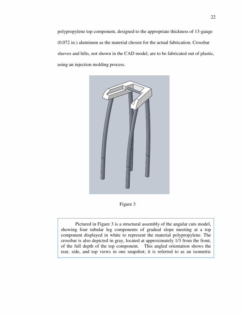
Figure 3 offers an isometric view of the angular cuts model’s basic
structural assembly, composed of 6 separate parts. These parts consist of four
anodized aluminum legs, one anodized aluminum cross bar, and the main
polypropylene top component. All parts are hollow and, except for the
22
polypropylene top component, designed to the appropriate thickness of 13-gauge
(0.072 in.) aluminum as the material chosen for the actual fabrication. Crossbar
sleeves and hilts, not shown in the CAD model, are to be fabricated out of plastic,
using an injection molding process.
Figure 3
Pictured in Figure 3 is a structural assembly of the angular cuts model, showing four tubular leg components of gradual slope meeting at a top component displayed in white to represent the material polypropylene. The crossbar is also depicted in gray, located at approximately 1/3 from the front, of the full depth of the top component. This angled orientation shows the rear, side, and top views in one snapshot; it is referred to as an isometric view.

23
For comparison, the next figure, Figure 4, offers an isometric view of the gradual
curves model’s basic structure.
The next image, Figure 5, provides top view orientations of both models to
more clearly show the armrest grooves with elbow support for those who need to
bend over to lean fully on their forearms. The depiction helps show crossbar
(which will also include brake sleeves in the fabricated model) positioned halfway
Figure 4
Pictured in Figure 4 is a structural assembly of the gradual curves model, showing four tubular leg components of gradual slope meeting at a top component displayed in white to represent the material polypropylene. The crossbar is also depicted in gray, located about midway along the length of the top component. This angled orientation shows the rear, side, and top views in one snapshot; it is referred to as an isometric view, as explained in the caption from Figure 3.

24
between the front and back of the top framework, just beyond the armrest
grooves. In addition to accommodating leaning individuals described previously,
this crossbar placement allows individuals with more upright posture to
comfortably navigate the walker with the slightest inward pressure on the sleeve
hilts.
Figure 5
(b.) (a.)
Pictured in Figure 5 are the top views of the angular cuts model (Figure 5.a. on the left hand side) and the gradual curves model (Figure 5.b. on the right hand side). The angular cuts model shows that the top component follows a trapezoidal shape, narrow towards the front, where the crossbar is located 1/3 offset from the front of the frame. Looking down upon the gradual curves model, the top component appears to follow a parabolic curve.

25
Referring to the side views of both models, seen in Figure 6, there is a 5º
tilt to the upper framework which is intended to accommodate both leaning and
more upright individuals. For those leaning this will provide a slight upward lift,
helping raise the user’s gaze and encouraging them to lean without feeling any
downward tipping. For those with a straighter spine this upward tilt will lend itself
to comfort with a gentle bend in the elbow rather than requiring extended arms or
any downward reach that may strain their shoulders while using the walker.
Figure 6
(a.) (b.)
Pictured in Figure 6 are the side views of the angular cuts model (Figure 6.a. on the left hand side) and the gradual curves model (Figure 6.b. on the right hand side). The profiles look similar, both top components are tilted at 5° from the horizontal, where the placement of the user elbows will be lower than their wrists and hands when leaning into the walker.
26
Prototype Construction
While the CAD modeling is necessary for mechanical analysis, I had
planned on taking a slightly unconventional approach to prototype construction in
that a portion of the project would serve as an outlet for my second area of study,
sculpture. Due to my experience in the wood shop and metal shop within the
ComArt facility on Syracuse University’s campus I have the ability to fabricate a
full-scale prototype. Due to my academic and sport team requirements I did not
allocate the appropriate time to finish this possible prototype.
Had I finished this is what the process would have been like. As this was
intended to be strictly an appearance model from the beginning I was more
concerned with translating form than accurate material selection or total function.
Pulling from the furniture undertones of the piece I aimed to treat the walker
prototype as such when I began to construct the model. Hence, I selected a soft
wood to achieve the desired curvature in the forearm rests and because there is
less of a time demand with wood than metal for a final polished finish. Pine
seemed to be the most viable option because it is readily available at home
centers, and as part of the soft woods variety it lends itself to hand carving.
Though wood takes less time than metal manipulation, hand carving is a highly
time intensive endeavor and I became aware of this midway through the process.

27
Though I stopped construction during the intermediate stages of arm piece
carving, the next phase would have been to incorporate ball transfers, pictured
below in Figure 7 from the McMaster-Carr online catalogue, at the base of each
leg and then secure legs to the wooden top component.
The objective of this prototype is to demonstrate the form on a realistic scale. In
light of this it is not detrimental to the presentation that the members will remain
solid, for instance the wooden top component, as opposed to hollow as in true
model of anodized aluminum.
As a proof of concept for the lights, which will be integrated into the two
front leg members of the design, I had planned to arrange a demonstrative circuit.
The circuit would involve a 9V source, four resistors, one light emitting diode
(LED), a preset for varying resistance, and one LM339 compactor to show that
the LED’s illuminate with preset sensitivity in limited light. LED’s are expected
to last a minimum of 50,000 hours. This long projected operating life implies, that
if, hypothetically, an individual were to keep the two LED bulbs on for 1 hour
Figure 7

28
during the night, every night, each year, they would continue to function for 136
years. Even with more frequent use, it will be years before the walker bulbs will
need to be replaced.
Manufacturing and Cost Evaluation
Choosing anodized aluminum as the main material for this product and
due to defined cross sections of the hollow frame, extrusion is the appropriate
choice for manufacturing. Quotes obtained from the Adagio Corporation listed
extruded anodized aluminum tubing for $17.50 to produce each unit. This would
involve the specified diameter to accommodate ball transfers in a 1.5 in housing,
as well as manipulate the tubing into gradual curvature. Four of these per walker
unit would come out to $70 before polypropylene fabrication or assembly costs.
As mentioned previously, the top component will be manufactured
through the process of rotational molding. Also referred to as the roto-mold or
rotocasting process, this manufacturing method involves pouring “powder or
liquid resin into a hollow mold and then rotating that tool biaxially in an oven
until the resin melts ad coats the inside of the mold cavity”16. After these hollow
parts are cast the tool is cooled and the part is removed from the mold to finish
cooling and solidifying. Some advantages of this fabrication method include
design flexibility allowing for the creation of complex geometry, cost savings for
16 A full guide to the process of design and engineering for rotationally molding plastic parts is provided by the following URL: http://www.theplasticprofessionals.com/rotational-molding/rotational-molding.htm

29
mass production (50 to 30,000 is considered an ideal range for savings per unit),
low tooling costs, shortened time spans between initiation and execution of
production, stress free parts, consistent wall thickness, limited materials waste, the
allowance for a wide array sizes for hollow parts, and the versatility it allows for
different surface textures during the finishing process of manufacturing. In
addition to consistent wall thickness, rotationally molded parts can have multi-
layered walls made up of different kinds of materials. Looping back to earlier
design considerations lining the inter layer with a reinforcement material may
further reduce the fractional displacement demonstrated in CAD simulation under
linear stressing. Estimated cost for manufacturing the custom part is primarily
driven by tooling time and measured volume of polypropylene, but up front costs
of mold creation and tooling are relatively low compared to injection molding and
other manufacturing processes. Producing a single unit has been priced at $200,
based off of SolidWorks files submitted online to The Plastic Professionals17,
however individual unit costs will be considerably less when parts are mass-
produced. Should production increase to 100 models, the manufacturing cost per
unit would be driven down to approximately $50, not including tooling and mold
maintenance.
17 The Plastic Professionals Rotational Molding Inc. is a polymer-based manufacturing company located in Iowa. Their website provides information about the process, an array of sample products, and videos on the specialized manufacturing method. The following URL connects to this company’s home page: http://www.theplasticprofessionals.com/home.htm

30

31
Chapter 4
Analysis and Results
Stress Analysis
To compare loading capacity of both the angular cuts model and gradual
curvature model to requirements of existing standard models, three loading
schemes were applied to the frame, assuming an individual weighing 250lbf (the
maximum carrying capacity of standard walkers) was applying these loads. The
first two loading schemes applied downward forcing to the top frame assuming
that the individual would apply forcing with both of their hands, or forearms.
Contrarily the third scheme assumed that the individual only had motor control of
one upper extremity, and therefore would only apply forcing on one side of the
crossbar.
To run a linear stress analysis on the angular cuts model, simulations
needed to be run on a component basis, because SolidWorks software does not
allow testing on assemblies. The first step to running this type of stress analysis
involved establishing fixtures, or locations were the member in question is rigidly
fixed and will not be displaced due to applied forcing. The fixtures chosen for this
angular cuts model top component included two holes where the crossbar would
attach and four holes on the underside of the component where legs would be
connected. Then loading, in the form of vectors with a prescribed magnitude and
direction. On the top component loading was applied along the forearm grooves
in a downward and outward direction simulating a person leaning against the

32
linear supports. With a magnitude of 300lbf total (as a maximum carriage
capacity for current walker and rollator models before upgrading to a bariatric
model) and the realistic multi-directional range explained above, testing yielded
results of twisting and buckling. An early demonstration of deformation under
evenly distributed loading can be seen in Figure 8, shown next.
Later iterations of the angular cuts model included more shallow forearm grooves
to increase the amount of support material. Simulation demonstrated that the
maximum displacement occurred at the midsection of the forearm rests but only
reached a magnitude of 2.16e-003 inches. This maximum displacement under
Figure 8
Pictured in Figure 8 is snapshot of a 3D model simulation of the angular walker’s top component, made with the computer aided design program called SolidWorks. Green arrows show where fixed positions have been created, for example at the perimeter of the holes where the cross bar is secured to the top component. In addition loads have been applied and have caused the component to bend and twist. These loads are depicted as purple arrows pointing in the direction of a walker user’s force, leaning against the top component with their forearms resting in the forearm grooves.

33
maximum loading, of 300lbf total, is negligible. The next, Figure 9, demonstrates
displacement results after the final iteration for the angular cuts model was
introduced to evenly distributed loading.
The first trial run was also the most basic forcing scheme to test. For a
maximum loading capacity of 300lbs, two point loads were applied to the left and
right sides of the crossbar, each with a downward force of 150lbf. This scheme
was applied to both models. Figure 10 displays a wire-frame view showing where
Pictured in Figure 9 is a color-coded gradient of displacement as a result of applied loading on the angular cuts model’s top component. The gradient (provided in a legend to the right hand side), ranges from dark blue, representing 3.937e-32 in (1.000e-030 mm), to red, representing 2.160e-003 in (5.487e-002 mm) of displacement.
Figure 9

34
point loads have been applied, as well as the displacement results for the gradual
curves model. Some assumptions made here include even loading on both sides,
and that the individual would not create significant additional loading, beyond
that of their body weight. To analyze stresses resulting from other possible cases
of walker use within this two-point load scheme, additional trials may be run.
This analysis might involve applying unequal percentages of the total loading on
either side of the crossbar. For example, an individual recovering from surgery or
injury on one lower extremity would tend to favor the unaffected leg and apply
unevenly distributed forcing to compensate for lightness on the sensitive leg.
Figure 10
Pictured in Figure 10 are tow images. At the top there is a wire-frame representation of the gradual curves model showing fixtures at the holes where legs would be attached (represented with blue spheres) and two point loads. The bottom image shows displacement results from this point load scheme ranging from 3.937e-005in (1e-003mm) to 1.653e-002in (4.199e-001mm).

35
The second trial run, shown previously in Figure 9, was repeated for the
gradual curves model. To reiterate this involved a distributed loading scheme,
which was applied along the armrest grooves. Each armrest groove was subjected
to the same 150lbf downward force, as applied previously, but for this trial the
load vectors were evenly distributed over a distance of 12” for the full length of
the groove.
The final test, applied a point load of 300lbf magnitude to the center of the
crossbar in an effort to mimic the forcing of a stroke patient who may only have
motor control on one side of their upper extremities.
Results & Considerations
For the first scheme of two 150lbs point loads, the greatest stress occurred
midway along the forearm grooves for the angular cuts model, and at the free-
ends of the gradual curves model. There is no cause for concern for either of
these regions. Maximum deflection at the free ends occurred on the gradual
curves model, equal to 1.653e-02 in (4.199e-001mm) which is negligible for this
application.
Wall thickness may be increased from 0.5 in with addition material layers
or this component can be subjected to hardening processes. Reinforcing this
member with aluminum flat bar can prevent deflection and strengthen the top
component framework as a whole, allowing load to be distributed across the
supportive member rather than concentrated in the current locale.
36
Chapter 5
Final Concept Selection & Conclusion
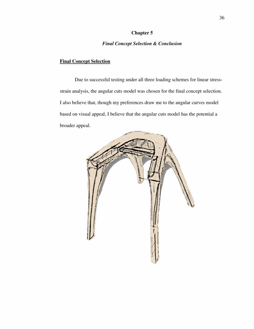
Final Concept Selection
Due to successful testing under all three loading schemes for linear stress-
strain analysis, the angular cuts model was chosen for the final concept selection.
I also believe that, though my preferences draw me to the angular curves model
based on visual appeal, I believe that the angular cuts model has the potential a
broader appeal.

37
Concluding Remarks
Overall the process of working through a redesign challenge was one that I
enjoyed, as it required input from my various skill sets and interests. Initial
concept generation was one of the most thought intensive tasks because there
were so many facets I tried to consider: alternative brake systems, overall
adaptability, and overall accessibility in terms of pricing (affected by material
selection and manufacturing processes) and appeal. The most difficult part of the
process was translating 2D sketches into 3D models and choosing what the basic
frame assembly would consist of without focusing on the end product’s overall
aesthetic. The fundamental frame and top component is what needed to be tested,
without the subtleties of design that require additional material and machining.
I believe there is certainly more work to be done with this project and plan
to continue working with CAD software to better represent the full model and
complete internal system. Someday I will file for a patent, as it has become a
long-term life goal.

38
References
Alimed: Alimed.com Medical Supplies and Professional Healthcare Products.
Web. 23 Feb. 2014. <http://www.alimed.com/search/?Keywords=walkers&SearchCategory=101>
"The Center on Human Policy, Law, and Disability Studies." Syracuse University,
n.d. Web. 04 May 2014. <http://disabilitystudies.syr.edu/>.
"Choosing a Walker." How to Choose a Walker – Buyer's Guide –
JustWalkers.com. Just Health Shops, n.d. Web. 20 Nov. 2013. <http://justwalkers.com/choosing-a-walker-help/>.
"Disability, Disabilities, Convention, UN, Rights, Accessibility." UN News
Center. UN, n.d. Web. 2 Feb. 2014. <http://www.un.org/disabilities/convention/media.shtml>.
Einbinder, Eli, and Tristan A. Horrom. "Smart Walker: A Tool for Promoting
Mobility in Elderly Adults." The Journal of Rehabilitation Research and
Development 47.9 (2010): Xiii. Print. "McMaster-Carr." McMaster-Carr. Web. 14 Jan. 2014.
<http://www.mcmaster.com/#standard-ball-transfers-for-conveyors/=qts93u>.
PubMed: National Center for Biotechnology Information. U.S. National Library
of Medicine, Web. 20 Nov. 2013. Resnik, Linda, Susan Allen, and Lisa Iezoni. "Perspectives on Use of Mobility
Aids in a Diverse Population of Seniors: Implications for Intervention." Disability and Health Journal. NIH Public Access, n.d. Web. 11 Jan. 2014.
39
Appendices

A. 1 Glossary of Terms
Aesthetics – a set of principles concerned with the nature and appreciation of
beauty, esp. in art
Amputation - the removal of an appendage from the body
Cerebal Palsy - a disability resulting from damage to the brain before, during,
or shortly after birth and outwardly manifested by muscular incoordination
and speech disturbances
Friederich’s Ataxia - an inherited disease that damages a person’s nervous
system. The damage affects the spinal cord and nerves that control muscle
movement in the person’s arms and legs. Symptoms usually begin between
the ages of 5 and 15. The main symptom, called ataxia, is having trouble
coordinating movements. Specific symptoms include difficulty walking,
muscle weakness, speech problems, involuntary eye movements, scoliosis
(curving of the spine to one side), and heart palpitation from the heart disease,
which can happen along with Fridreich’s ataxia. People with Friedreich's
ataxia usually need a wheelchair 15 to 20 years after symptoms first appear.
Hemiparesis - muscular weakness or partial paralysis restricted to one side of
the body
Isometric – (in technical or architectural drawing) incorporating a method of
showing projection or perspective in which the three principle dimensions are
represented by three axes 120° apart
Muscular Dystrophy - a group of muscle diseases that weaken the
musculoskeletal system and hamper locomotion. Muscular dystrophies are

characterized by progressive skeletal muscle weakness, defects in muscle
proteins, and the death of muscle cells and tissue.
Multiple Sclerosis - a nervous system disease that affects the brain and spinal
cord. The material that surrounds and protects nerve cells becomes damaged.
This damage slows down or blocks messages between the brain and body,
leading to the symptoms of MS. They can include visual disturbances, muscle
weakness, trouble with coordination and balance, sensations such as
numbness, prickling, or “pins and needles”, and thinking and memory
problems.
Psoriatic Arthritis - a skin disease that causes itchy or sore patches of thick,
red skin with silvery scales. These usually appear on elbows, knees, scalp,
back, face, palms and feet. Psoriasis arthritis causes pain, stiffness, and
swelling of the joints. It is often mild, but can sometimes be serious and affect
many joints.
Rheumatoid Arthritis - a form of arthritis that causes pain, swelling,
stiffness and loss of function in joints. It can affect any joint but is common in
the wrist and fingers.
Rollator - also called wheeled walker, invented by the Swede Aina Wifalk in
1978. The device consists of a frame with three or four large wheels,
handlebars and a built-in seat, which allows the user to stop and rest when
needed. Rollators are also often equipped with a shopping basket and are
typically more sophisticated than conventional walkers with rear wheels.

Spina Bifida - a developmental congenital disorder caused by the incomplete
closing of the embryonic neural tube. Some vertebrae overlying the spinal
cord are not fully formed and remain unfused and open. If the opening is large
enough, this allows a portion of the spinal cord to protrude through the
opening in the bones. There may or may not be a fluid-filled sac surrounding
the spinal cord. Other neural tube defects include anencephaly, a condition in
which the portion of the neural tube that will become the cerebrum does not
close, and encephalocele, which results when other parts of the brain remain
unfused.
Stress Analysis – an engineering discipline covering methods to determine
the stresses and strains in materials and structures subjected to forces and
loads
Stroke - sometimes referred to as a cerebrovascular accident (CVA), is the
rapid loss of brain function due to disturbance in the blood supply to the brain.
This can be due to ischemia (lack of blood flow) caused by blockage
(thrombosis, arterial embolism), or a hemorrhage. As a result, the affected
area of the brain cannot function, which might result in an inability to move
one or more limbs on one side of the body, inability to understand or
formulate speech, or an inability to see one side of the visual field.
Traumatic Brain Injury – (according to Mayo Clinic staff) occurs when an
external mechanical force causes brain dysfunction. TBI usually results from a
violent blow or jolt to the head or body. Mild traumatic brain injury may
cause temporary dysfunction of brain cells while more serious traumatic brain

injury can result in bruising, torn tissues, bleeding and other physical damage
to the brain that can result in long-term complications or death.
Universal Design – broad-spectrum ideas meant to produce buildings,
products and environments that are inherently accessible to older people,
people without disabilities, or people with disabilities

A.2 Survey
Capstone Topic:
Re-designing the Walker
1. If given the opportunity, would you be interested in improving the form and
function of your mobility aid? Yes No I am not sure.
Let’s weigh the pros and cons of existing models.
2. To begin, what words come to mind when you think of your walker? (Please choose any and all that apply)
o stability
o life-saver
o independence
o durability
o aging
o rehabilitation
o medical
o dependence
o industrial
o tennis balls
o other
3. If “Other” which words come to your mind?
4. What are some of the things you (1) like and (2) dislike about your walker? Likes __________________________________ Dislikes __________________________________
5. Please number the following features in order of benefit, based on your personal experience:

o seat
o storage compartment(s)
o alert system
o lights (for nighttime navigation)
o storability
o comfortable grip
o arthritis-friendly brake system
o streamlined design
o ability to adapt to (and ease) stair navigation
6. What other features might you add to your walker?
7. Under what conditions and in what places is it most difficult to navigate with your walker?
Looking to gauge your initial response to needing a mobility aid.
8. Did your doctor recommend the use of a walker? Yes Not by a doctor, but instead: _____________________________________________________
9. Were you initially reluctant to use a walker? Yes No If so, why? ______________________________________________________________________________________________________________________
Form Meets Function

10. If someone gave you the option, would you choose to improve the look and feel of your walker (without sacrificing the structural integrity)? Yes No Additional thoughts: ________________________________________________ ________________________________________________ ________________________________________________
Thank you! Your input is greatly appreciated.
If you would like to check in for updates on this Capstone
project you may contact me at: [email protected]

A.3 CAD Model Images


A.4 Prototype Images
Sketches
Isometric View Side View
Top View Front View

A.5 Design Process & Concept Generation

• 3 Legs
• Gradual Curves
• No crossbar
• 4 Legs
• Gradual Curves
• Crossbar system
• Default brake
• Crossbar system
• Plastic sleeves/hilts
• 3 Legs
• Minimalist
• No crossbar
• Visual weight in base
• 4 Legs
• Minimalist
• Crossbar system
• Default brake

• 4 Legs
• Crossbar
• Default Brake
• Angular Cuts Model
• 4 Legs
• Crossbar
• Default Brake
• Gradual Curves Model