Integrated Facilities Design using a Contour Distance Metric
1 3
DOI 10.1007/s00340-014-5965-0Appl. Phys. B (2015) 118:159–166
Real‑time contour fringes obtained with a variable synthetic wavelength from a single diode laser
Danilo Mariano da Silva · Eduardo Acedo Barbosa · George Cunha Cardoso · Niklaus Ursus Wetter
Received: 26 June 2014 / Accepted: 16 November 2014 / Published online: 4 December 2014 © Springer-Verlag Berlin Heidelberg 2014
output intensity was obtained, and possible applications of this result for wavefront shaping are discussed.
1 Introduction
Multiwavelength interferometry is a powerful method that has been used for many years in a wide range of metrology applications. Illuminating an interferometer with two prop-erly tuned and aligned lasers generates a synthetic wave-length, which is much longer than the original wavelength, thus representing a remarkable extension of the measure-ment range of single wavelength interferometry and/or a reduction in the sensitivity [1]. This characteristic provides a great measurement flexibility and allows the measure-ment of depth values ranging from tens of nanometers to several millimeters [2, 3].
The initial proposal to generate a synthetic wavelength by illuminating an object with two wavelengths was sug-gested by Forrester et al. [4], and the first experiments using multiple light source to measure the shape of objects through holography were presented by Hildebrand and Haines [5] and Tauruta et al. [6]. Since the advent of the laser, many successful applications in holography and interferometry have been demonstrated and developed [7].
Through multiwavelength whole-field interferometry, the object image appears modulated by interference con-tour fringes corresponding to the intersection of the object wavefront with planes of constant elevation. The distance between two adjacent planes is the contour interval, which in turn is closely related to (or sometimes equals) the syn-thetic wavelength (λS). Multiwavelength interferometry has proven to be a practical method to investigate several types of effects such as specific mechanical states [8], digital holography [9], shape measurements [10, 11] and absolute
Abstract In this work, we present a method to generate digital speckle contour fringes by tuning a red diode laser with a single external cavity. In the cavity, light is reflected by a diffraction grating and re-injected into the emitter. A proper alignment of the cavity provides dual emission of the laser, thus generating a synthetic wavelength λS. The resulting image of the studied object appears covered with the usual high spatial frequency speckle pattern modulated by a low-frequency interferogram of contour interval λS/2 which describes the object surface shape. Changes in the separation between the two laser emissions correspond to an extended range of synthetic wavelengths ranging from tens of micrometers to some millimeters. In the experi-mental section we demonstrate the potential of this tech-nique by changing the contour interval of the interferogram according to the object’s shape and to the desired measure-ment precision. An analytical expression relating the inter-ferogram intensity with the Fourier transform of the laser
Electronic supplementary material The online version of this article (doi:10.1007/s00340-014-5965-0) contains supplementary material, which is available to authorized users.
D. M. da Silva (*) · N. U. Wetter Centro de Lasers e Aplicações, Instituto de Pesquisas Energéticas e Nucleares (CNEN-IPEN/SP), São Paulo, SP CEP 005508-000, Brazile-mail: [email protected]
E. A. Barbosa Laboratório de Óptica Aplicada, Faculdade de Tecnologia de São Paulo, Pça Cel Fernando Prestes, 30, São Paulo, SP 01124-060, Brazil
G. C. Cardoso Physics Department, Haverford College, Haverford, PA 19041, USA

160 D. M. da Silva et al.
1 3
interferometry [12]. Among the different multiwavelength techniques, two-wavelength DSPI (digital speckle pattern interferometry) [13] has shown promising results in wave-front shaping and thermal-lens analysis. In both cases, two conveniently tuned and aligned red diode lasers generated a variable synthetic wavelength, thus allowing the thermal characterization of photonic materials [14] and the meas-urement of the power map of spherical and progressive lenses [15].
Despite the good experimental results obtained in those works, a drawback in this approach is the difficulty in sta-bilizing both emission wavelengths of the two lasers. The resulting value of the synthetic wavelength can be unstable, requiring careful laser cooling and thermal stabilization resulting in a relatively long time until the emission of both lasers becomes stationary with respect to output power and center emission wavelength. In this framework, we propose the use of a single external cavity diode laser (ECDL) as a way to obtain a double emission in order to develop a sta-ble and easily tunable multiwavelength digital speckle pat-tern interferometer acquiring real-time contour fringes gen-erated by the selected synthetic wavelength [16]. Using a single ECDL locks, the relative amplitude and temperature induced frequency shifts of both emissions, thereby result-ing in a much more stable fringe pattern.
The main principle operation of our ECDL is based on a controlled feedback with one or two diffraction gratings in order to select the emission wavelengths [16, 17]. This technique is also an efficient way to improve the diode laser properties such as source stabilization and emission nar-rowing. Both emissions have mutual stability because they are generated from the same gain line, thus overcoming the problem of stabilizing multiple lasers in interferometry [18]. According to the behavior of the synthetic wavelength shown in Fig. 1 below, a difference of 4 nm between both wavelength emissions is sufficient to get a large change in
the synthetic wavelength, which makes this interferometer a convenient tool for homodyne or heterodyne applications.
In this work, dual-frequency emission in a single diode resulting in synthetic frequencies is applied to a speckle interferometer. Also shown is the manipulation of these synthetic wavelengths with a single ECDL and the Fourier analysis of the obtained interferograms as a function of λS.
2 Dual‑mode emission in a ECDL
The ECDL is a component that leverages the broad gain of a diode laser by means of an external component for wave-length selection. Typically, diffraction gratings are used to act as a wavelength-selective external oscillator, but other techniques are also employed [16]. For our study, a Litt-man–Metcalf setup [19] was chosen for dual-frequency tuning, as shown in Fig. 2.
A commercial diode laser (Coherent, S-67-350C-50T) with emission centered at 672 nm and 350 mW of maxi-mum output power and vertical polarization was used with a thermoelectrically controlled heat sink to stabilize the tem-perature at 25 °C. A diffraction grating (DG) of 2362.6 lines/mm (Thermo Jarrel Ash), illuminated by the laser beam at grazing incidence, generates a narrow-linewidth, first-order diffracted beam, which is reflected back onto the grating by mirror M1 and returns to the laser. Hence, due to the grat-ing dispersion and the mirror alignment, only a narrow band of frequencies is amplified. By slightly tilting mirror M1, the laser can be easily tuned, enabling single- or dual-mode emission of the grating, the different wavelengths present different polarizations that allow balancing the intensity of each mode by the use of a half-wave plate positioned in front of the diode laser. One interesting feature of this cav-ity geometry is that the tilt on M1 does not affect the beam alignment at mirror M2. The whole setup can be observed in Sect. 4. In order to monitor the laser emission in real time
Fig. 1 Synthetic wavelength as a function of the difference between wavelengths
Fig. 2 Littman–Metcalf setup for ECDL

161Real-time contour fringes obtained with a variable synthetic wavelength
1 3
and enable the proper adjustment of mirror M1, the beam after beam splitter BS2 was sent to a fiber coupled spectrom-eter (Ocean Optics HR4000), with resolution of 0.24 nm.
Dual-mode operation can be achieved by some standard methods. We opted to use this diode laser without an antire-flection coating. By this way, the laser will emit both the natural frequency given by the size of the cavity and the stimulated frequency generated by the external cavity. In this case, the expected effect is a competition between both emissions to take the available gain. The dual-mode opera-tion in a semiconductor laser is described by taking account the rate equation relating the intensities Ii and Ij of the i-th and j-th oscillating modes as [20]
where αi is the unsaturated net gain, βi is the self-saturation coefficient, and θij is the cross-saturation coefficient. From these rate equations, one finds a solution to determine the stability of the laser through the coupling constant
The stable state is achieved when C > 1. In order to achieve it, we set the intensity of both modes by control-ling the power supply and/or by rotating a half-wave plate
(1)dIi
dt= (αi − βiIi − θijIj)Ii,
(2)C ≡θ12θ21
β1β2
,
Fig. 3 Simulation of a laser emission with two different frequencies and its respective corresponding interferogram with signal V

162 D. M. da Silva et al.
1 3
positioned in front of the diode laser, as shown in Fig. 2. Due to the direction the grating is ruled, each mode pre-sents a different polarization state, so that the half-wave plate allows balancing the intensity of each mode.
3 Speckle interferometry with multimode diode lasers: theoretical description
The theory of multimode whole-field interferometry was described in other works, taking into account that (a) all the oscillating modes had the same amplitude and that (b) the spectral width of each mode was negligible in compari-son with the laser free spectral range [21]. This simplified approach provides satisfactory results, allowing the accu-rate calculation and measurement of the synthetic wave-length and the contour interval. However, it does not fully describe the contour fringe pattern. The theoretical descrip-tion of digital speckle interferometry carried out in this section takes into account the spectral width of each laser mode, and the fact that different modes may have different amplitudes. The goal is to achieve a more accurate analysis of the fringe pattern.
We start our analysis by making a brief review of DSPI (digital electronic speckle pattern interferometry) with mul-timode lasers [22]. The interference of the object wave (S) and the reference wave (R) on the CCD sensor originated from a diode laser is written as
(where * denotes complex conjugate). If the spectral width of each laser mode is neglected, the diode laser spectrum can be written in a discrete fashion, with the laser emit-ting simultaneously N equally spaced longitudinal modes. If An is the dimensionless amplitude coefficient of the n-th mode, the signal amplitude V of the resulting interferogram
(3)I = |S|2 + |R|2 + S∗R + R∗S,
Fig. 4 Multiwavelength DSPI setup
Fig. 5 Tunability curve of the ECDL as a function of the synthetic wavelength for several drive currents. The solid curve is just a guide to the eye
163Real-time contour fringes obtained with a variable synthetic wavelength
1 3
pattern measured at a specific x–y location at the camera position is obtained through the subtractive method as [22]:
where Δk is the wavenumber gap between two consecutive modes, �Γ ≡ ΓS − ΓR is the difference between the opti-cal path lengths of the signal (object) beam and the refer-ence beam, and R0 and S0 are the amplitudes of the interfer-ing beams. Equation (4) was obtained based on the fact that waves with different frequencies are not mutually coherent.
By regarding a continuous laser emission, the sum becomes an integral, and the interferogram signal V can be written as,
where F(�Γ ) is the Fourier transform of the function [g(k)]2, while g(k) is the continuous counterpart of An, so that [g(k)]2 is closely related to the intensity spectrum of the laser as a function of the wavenumber k. This result shows that by determining the laser emission spectrum, one retrieves the form of the contour fringe pattern as function of the object coordinate ΓS with respect to ΓR.
As an illustrative example, we simulate the contour interference patterns due to a two-mode diode laser.
(4)V = 2R0S0
n=(N−1)/ 2�
n=−(N−1)/ 2
A2n exp [in�k(ΓS − ΓR)]
2
(5)V = 2R0S0
∞�
−∞
�
g(k)�2
eik∆Γ dk
2
= 2R0S0[F(∆Γ )]2,
The emission spectrum of the first simulation is shown in Fig. 3a and represents a typical spectrum of a mul-timode red diode laser, with two emission peaks of the same intensity at say, λ1 = 660.0 nm and λ2 = 660.4 nm. The spectral width of both peaks is Δλ = 0.060 nm. Fig-ure 3b shows the corresponding interferogram signal V as a function of the optical path difference ΔΓ, accord-ing to Eq. (5). Figure 3c in turn shows the spectrum of two Lorentzian-shaped modes at the same wavelengths as above, but of different spectral width Δλ = 0.021 nm, while Fig. 3d shows the resulting interferogram. By comparing Fig. 3b and d, one notes that the decrease in the intensity envelope as a function of |�Γ | > 0 can be attributed to the spectral width of the laser modes: The broader the emission of each mode, the faster the intensity drops. From the distance between two adja-cent minima in both curves, one estimates the synthetic wavelength as the optical path difference between two adjacent maxima to be λS ≅ 1.1 μm, which agrees with the result of 1.09 μm obtained from the relation �S = �1�2/(�1 − �2).
In Fig. 3e, we simulate the contour pattern intensity due to a laser emitting longitudinal modes with remark-ably different intensities and peaks at 660.0 and 660.4 nm of the same spectral width of Δλ = 0.060 nm. Figure 3f shows the corresponding squared Fourier transform. As expected, an offset on the contour interferogram inten-sity appears due to the difference between the intensi-ties of the laser modes, leading to a decrease in the fringe visibility.
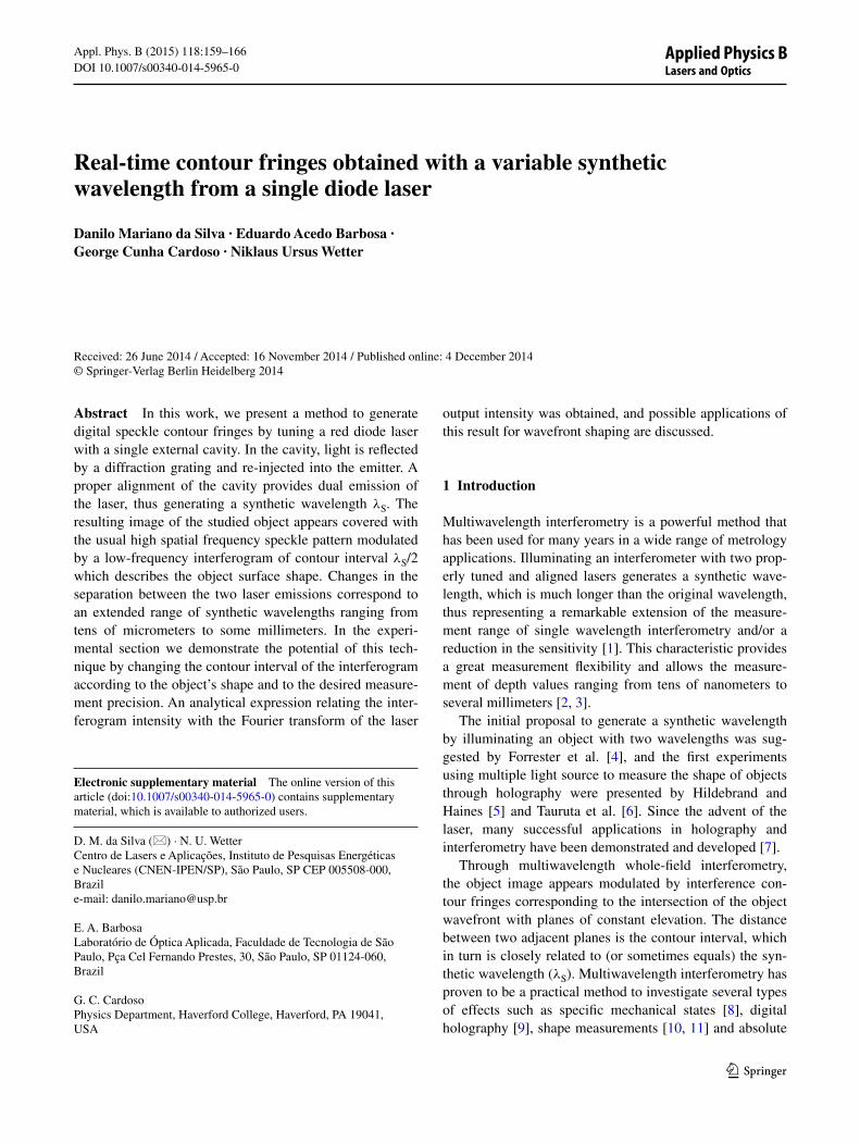
Fig. 6 Interferograms of a lens obtained with selected synthetic wavelengths
164 D. M. da Silva et al.
1 3
4 Dual‑wavelength DSPI interferometer
The multiwavelength DSPI interferometer designed for phase-object analysis is depicted in Fig. 4 and was based on an DSPI interferometer described elsewhere [15]. The beam splitter BS1 divides the laser beam into object and reference beams. The reference is filtered by spatial filter SF and collimated by lens L5 before impinging upon the CMOS camera (Thorlabs—DCC1545 M) after passing through beam splitter BS2. The object arm expands and collimates the beam with lens L2 and L3 in order to get a planar wavefront, which illuminates a ground glass to gen-erate the speckle pattern. This planar wavefront results in a speckle pattern enveloped by an interferogram with infinite spatial period, i.e., without contour fringes. When a phase object is positioned behind the ground glass, the wave-front form is changed, which results in a contour interfero-gram that describes the wavefront geometry, according to Eqs. (4) and (5). The mirrors M2 were placed to redirect the object wavefront to the camera. The image of the object is target. Polarizers P1 and P2 were placed at the reference wave and object arms, respectively, in order to increase fringe contrast. Moreover, in order to enhance the fringes visibility, we implemented the subtractive method by using a piezoelectrical transducer PZT attached to the mirror M1 and moved by a sinusoidal jitter signal.
5 Results
We first evaluated the tunability of the laser through the ECDL feedback system by measuring the laser output power for each emission peak separation λ1 − λ2. It is expected that for a large separations, corresponding to small λS, the output power decreases. This behavior is expected once the optical gain of the diode decreases strongly for emissions far from the gain center [16]. Figure 5 displays the output power as a function of the synthetic wavelength �S = �1�2/(�1 − �2) for diode drive currents of (300, 380, 420 and 460 mA). The curves show a λS tuning range of 60–450 μm approximately, for practically all driver currents.
In a first experiment, interferograms were obtained from the interference of a planar speckled wavefront impinging on a plano-convex lens (1 inch diameter and focal length of 50 mm) with a reference planar wavefront in order to show the extended range of synthetic wavelengths that can be generated. For each image, the only parameter changed was the synthetic wavelength of the dual emission diode laser. The results presented in Fig. 6 show how the spa-tial frequencies of the contour fringes increase as the syn-thetic wavelength decreases. For these measurements, the emission λ1 was fixed in 659.58 nm and λ2 changed from 657.23 to 659.48 nm. Additionally, with the supplementary
material also, it possible to observe the frequency variation shown in Fig. 6 in real time, obtained only with the tunning mirror M1 in Fig. 2.
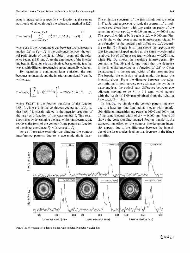
For the second experiment, a spherical wavefront set by lenses L2 and L3 was used. By adjusting mirror M1, the ECDL setup was tuned to emit two longitudinal modes at λ1 = 674.65 nm and λ2 = 677.91 nm, corresponding to a
Fig. 7 a Emission spectrum of diode laser for λS = 140.29 μm, b Fourier transform of the spectrum, c contour two-wavelength fringe pattern generated by a spherical lens

165Real-time contour fringes obtained with a variable synthetic wavelength
1 3
synthetic wavelength of λS = 140.29 μm. Figure 7a shows the resulting emission spectrum as a function of the wavenumber while Fig. 7b shows its squared Fourier transform. By examin-ing the distance between adjacent minima in the latter curve, one can estimate the synthetic wavelength to approximately 140 μm. The measured contour DSPI interferogram with con-centric circular fringes describing the spherical wavefront after the incident planar wave passes through the test lens is shown in Fig. 7c. By tilting mirror M1, the oscillation of other lon-gitudinal modes can be reinforced and the laser can be easily tuned. Figure 8a, b and c shows results similar to Fig. 7a, b
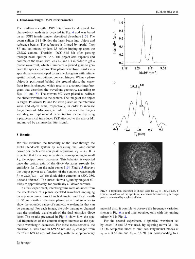
and c, but with the laser emitting at 675.35 nm and 677.91 nm, resulting in a synthetic wavelength of λS = 178.84 μm.
Through the squared Fourier transform shown in Figs. 7b and 8b, one concludes that the fringe visibility in Fig. 7c is higher than in Fig. 8c. In fact, by carefully exam-ining both interferograms, one sees that the first presents a slightly higher visibility than the latter. However, it must be considered that the difference between the longitudinal mode intensities is not the only factor that influences the interferogram visibility; other experimental factors can affect the interferogram visibility as well [23]. By carefully examining Fig. 7c, one may conclude that it presents a bet-ter fringe visibility than expected from Fig. 7b; comparison between Fig. 8c and b may lead to the same conclusion. This discrepancy can be mainly attributed to a likely low resolution of the spectrometer, providing emission lines wider than the actual value and leading to functions for V that drop faster than the actual interferogram visibilities.
6 Conclusion
The formation of two-color speckle contour interferograms using a single external cavity diode laser was theoretically studied and experimentally demonstrated. The ECDL was easy to operate, enabling a very stable emission and a fine tunability due to the high spatial frequency diffraction grat-ing used in the feedback system. This allowed the synthetic wavelength to be continuously tuned from 60 μm to 8 mm. This high flexibility in terms of synthetic wavelength of the system allowed for wavefront measurements with different sensitivity and precision requirements.
It was shown that the interferogram, which describes the fringe pattern as a function of the wavefront coordinate, can be directly obtained from the squared Fourier transform of the laser emission spectrum. This result points out that measuring the laser emission spectrum and directly obtain-ing the interferogram signal V from this spectrum may pro-vide a more accurate quantitative evaluation of the interfero-gram and consequently a more accurate shape measurement, instead of using the standard approach of simply treating the contour interferogram as formed by cos2 fringes.
References
1. P.J. de Groot, Appl. Opt. 33, 5948 (1994) 2. J.C. Wyant, Appl. Opt. 23, 4539 (1984) 3. K. Creath, Appl. Opt. 26, 2810 (1987) 4. A.T. Forrester, W.E. Parkins, E. Gerjuoy, Phys. Rev. 72, 728
(1947) 5. K.A. Hildebrand, B. P. and Haines. Phys. Lett. 21, 422 (1966) 6. N. Shiotake, T. Tsuruta, Y. Itoh, J. Tsujiuchi, N. Takeya, K. Mat-
suda, Jpn. J. Appl. Phys. 7, 904 (1968)
Fig. 8 a Emission spectrum of diode laser for λS = 178.84 μm, b squared Fourier transform of the spectrum, c contour two-wavelength fringe pattern generated by a spherical lens

166 D. M. da Silva et al.
1 3
7. P. Ferraro, L. Miccio, S. Grilli, M. Paturzo, S. De Nicola, A. Finizio, R. Osellame, P. Laporta, Opt. Express 15, 14591 (2007)
8. T. Maack, G. Notni, W. Schreiber, Opt. Commun. 115, 576 (1995)
9. A. Wada, M. Kato, Y. Ishii, Appl. Opt. 47, 2053 (2008) 10. Y. Zou, H. Diao, X. Peng, H. Tiziani, Appl. Opt. 31, 6616 (1992) 11. C. Wagner, W. Osten, S. Seebacher, Opt. Eng. 39, 79 (2000) 12. K. Alzahrani, D. Burton, F. Lilley, M. Gdeisat, F. Bezombes, M.
Qudeisat, Opt. Express 20, 5658 (2012) 13. A.F. Fercher, H.Z. Hu, U. Vry, Appl. Opt. 24, 2181 (1985) 14. D.M. Silva, E.A. Barbosa, N.U. Wetter, Rev. Sci. Instrum. 83,
103103 (2012)
15. E.A. Barbosa, D.M. Silva, C.E. Nascimento, F.L. Galvão, J.C.R. Mittani, Opt. Lasers Eng. 51, 898 (2013)
16. N.U. Wetter, Appl. Phys. B 86, 515 (2006) 17. M. Fleming, A. Mooradian, IEEE J. Quantum Electron. 17, 44
(1981) 18. E. Hack, B. Frei, R. Ka, U. Sennhauser, Appl. Opt. 37, 2591
(1998) 19. M.G. Littman, H.J. Metcalf, Appl. Opt. 17, 2224 (1978) 20. W.E.J. Lamb Jr, Phys. Rev. 134, A1429–A1450 (1964) 21. E.A. Barbosa, Appl. Phys. B 80, 345 (2005) 22. E.A. Barbosa, A.C.L. Lino, Appl. Opt. 46, 2624 (2007) 23. E.A. Barbosa, Opt. Express 18, 8743 (2010)
Copyright © 2022 FDOKUMEN