R.C.C Structures - amiestudycircle.com
40
A PREPARATORY COURSE FOR RECRUITMENT EXAMS (JUNIOR ENGINEER/CIVIL ENGINEERING) RCC STRUCTURES Web: www.amiestudycircle.com Email: [email protected] Ph: +91 9412903929 1/40 AMIE(I) STUDY CIRCLE(REGD.) A SWISS KNIFE FOR RECRUITMENT EXAMS R.C.C Structures Design Concepts There are three design methods viz. working stress method, ultimate load method and limit state method. From 1970 onwards limit state method is popular because of its rational approach. IS: 456-2000 for the design of reinforced concrete (R.C.C.) structures is based in limit state design philosophy. The working stress method is fast disappearing from practice. Clause 18.2.2 of IS: 456-2000 requires that working stress method may be used only if it is not possible to adopt the limit state design method. LIMIT STATE METHOD Limit State of Collapse This state corresponds to the maximum load carrying capacity. This limit may be correspond to: (i) flexure (ii) compression (iii) shear, and (iv) torsion. Limit State of Serviceability This limit corresponds to development of excessive deformation. This limit may be correspond to: (i) deflection (ii) cracking, and (iii) vibration Building Code A reinforced concrete structure should confirm to certain minimum specifications with regard to design and construction. The Indian Standards Institution issues building code requirements from time to time. The most recent code is the code of practice for plain and reinforced concrete (IS:456 - 2000). Partial Safety Factors For Loads Under Limit State of Collapse Load combination Dead load, DL Live load, LL Wind load, WL DL + LL 1.5 1.5 --- DL + WL 1.5 --- 1.5 DL + LL + WL 1.2 1.2 1.2 Under Limit State Of Serviceability Load combination DL LL WL DL + LL 1.0 1.0 --- DL + WL 1.0 --- 1.0 DL + LL + WL 1.0 0.8 0.8 Stress - Strain Relationship For Concrete The code has idealized stress strain curve for concrete as shown in given figure.
-
Upload
khangminh22 -
Category
Documents
-
view
3 -
download
0
Transcript of R.C.C Structures - amiestudycircle.com

A PREPARATORY COURSE FOR RECRUITMENT EXAMS (JUNIOR ENGINEER/CIVIL ENGINEERING) RCC STRUCTURES
Web: www.amiestudycircle.com Email: [email protected] Ph: +91 9412903929 1/40
AMIE(I) STUDY CIRCLE(REGD.) A SWISS KNIFE FOR RECRUITMENT EXAMS
R.C.C Structures Design Concepts
There are three design methods viz. working stress method, ultimate load method and limit state method. From 1970 onwards limit state method is popular because of its rational approach. IS: 456-2000 for the design of reinforced concrete (R.C.C.) structures is based in limit state design philosophy. The working stress method is fast disappearing from practice. Clause 18.2.2 of IS: 456-2000 requires that working stress method may be used only if it is not possible to adopt the limit state design method.
LIMIT STATE METHOD
Limit State of Collapse This state corresponds to the maximum load carrying capacity. This limit may be correspond to: (i) flexure (ii) compression (iii) shear, and (iv) torsion.
Limit State of Serviceability This limit corresponds to development of excessive deformation. This limit may be correspond to: (i) deflection (ii) cracking, and (iii) vibration
Building Code A reinforced concrete structure should confirm to certain minimum specifications with regard to design and construction. The Indian Standards Institution issues building code requirements from time to time. The most recent code is the code of practice for plain and reinforced concrete (IS:456 - 2000).
Partial Safety Factors For Loads Under Limit State of Collapse
Load combination Dead load, DL Live load, LL Wind load, WL DL + LL 1.5 1.5 --- DL + WL 1.5 --- 1.5
DL + LL + WL 1.2 1.2 1.2 Under Limit State Of Serviceability
Load combination DL LL WL DL + LL 1.0 1.0 --- DL + WL 1.0 --- 1.0
DL + LL + WL 1.0 0.8 0.8
Stress - Strain Relationship For Concrete The code has idealized stress strain curve for concrete as shown in given figure.

A PREPARATORY COURSE FOR RECRUITMENT EXAMS (JUNIOR ENGINEER/CIVIL ENGINEERING) RCC STRUCTURES
Web: www.amiestudycircle.com Email: [email protected] Ph: +91 9412903929 2/40
AMIE(I) STUDY CIRCLE(REGD.) A SWISS KNIFE FOR RECRUITMENT EXAMS
For design purpose, the compressive strength of concrete in the structure is taken as 0.67 times the characteristic strength (σck). The partial safety factor μm ( = 1.5) is applied in addition to this factor.
Stress - Strain Relationship For Steel For mild steel, the stress is proportional to strain upto yield point and thereafter the strain increases at constant stress as shown in given figure.
(a) Stress strain curve for mild steel (b) Stress strain curve for high strength deformed bars
For mild steel, the change from elastic to plastic condition is abrupt, whereas for high strength deformed bars, the change is quite gradual.

A PREPARATORY COURSE FOR RECRUITMENT EXAMS (JUNIOR ENGINEER/CIVIL ENGINEERING) RCC STRUCTURES
Web: www.amiestudycircle.com Email: [email protected] Ph: +91 9412903929 3/40
AMIE(I) STUDY CIRCLE(REGD.) A SWISS KNIFE FOR RECRUITMENT EXAMS
Beams We know that concrete is fairly strong in compression but very weak in tension. Thus, the tensile weakness of concrete is overcome by the provision of reinforcing steel in the tension zone round the concrete to make a reinforced concrete (RC) beam.
There are three types of reinforced concrete beams :
Singly reinforced beams
Doubly reinforced beams
Flanged beams
In singly reinforced simply supported beams reinforcing steel bars are placed near the bottom of the beam where they are most effective in resisting the tensile bending stresses. In singly reinforced cantilever beams reinforcing bars are placed near the top of the beams.
SINGLY REINFORCED BEAMS
Assumptions 1. Plane sections normal to the axis remain plane after bending,
2. The maximum strain in concrete at the outermost compression fibre is taken as 0.0035 for any strength of concrete.
3. The relationship between stress - strain distribution in concrete is assumed to be parabolic as shown in given figure The maximum compressive stress is equal to 0.446 σck.
4. The tensile strength of concrete is ignored,
5. The stress in reinforcement is derived from the representative stress strain curve for the type of steel used.
6. The maximum strain in tension reinforcement in the section at failure should not be less than following :
εs y
s1.15.E
+ 0.002
where σy = characteristic stress in steel, Es = modulus of elasticity of steel and εs = strain in steel at failure

A PREPARATORY COURSE FOR RECRUITMENT EXAMS (JUNIOR ENGINEER/CIVIL ENGINEERING) RCC STRUCTURES
Web: www.amiestudycircle.com Email: [email protected] Ph: +91 9412903929 4/40
AMIE(I) STUDY CIRCLE(REGD.) A SWISS KNIFE FOR RECRUITMENT EXAMS
Stress Block Parameters With reference to figure given above, we see that
Depth of parabolic portion
x1 = 4x/7
Depth of rectangular portion
x2 = 3x/7
Design force of compression
C = 0.36 σck.b.x
Distance between top fibre and compressive force C would be
a = 0.42x
where x = depth of neutral axis from the extreme compression fibre, b = breadth of section, d = effective depth of section
Force of compression = force of tension
0.36 σck.b.x = 0.87 σy.At
i.e. ty
ck
0.87. Ax0.36 .b
where At = area of tension steel
Lever arm z = d - 0.42 x = d - 0.42 ty
ck
0.87. A0.36 .b
= d - ty
ck
Ab
Modes of Failure Balanced Reinforced Beam If the ratio of steel to concrete in a beam is such that
maximum strain in the two materials reach simultaneously, such a section is called balanced section.
Under Reinforced Beam When the amount of steel is kept less than that in balanced section, it is called under reinforced beam. Under increasing bending moment, steel is strained beyond the yield point and the maximum strain in concrete remains less than 0.0035. Once steel has yielded, it does not take any additional stress for the additional strain and total force of tension remains constant. However, compressive stresses in concrete do increase with the additional strains. This increase continues until maximum strain in concrete reaches its ultimate value(0.0035), and concrete crushes. This is called tensile failure.
Over Reinforced Beam When the amount of steel is kept more than that in the balanced condition, strain in steel remains in the elastic region. With increasing stress, strain in concrete reaches its ultimate value(0.0035), it crushes. The steel is still well within the elastic limit. This is called compression failure.
Moment of Resistance Moment of resistance with respect to concrete
= compressive force x lever arm = 0.36σckbxz
Moment of resistance with respect to steel
= tensile force x lever arm = 0.87σyAtxz

A PREPARATORY COURSE FOR RECRUITMENT EXAMS (JUNIOR ENGINEER/CIVIL ENGINEERING) RCC STRUCTURES
Web: www.amiestudycircle.com Email: [email protected] Ph: +91 9412903929 5/40
AMIE(I) STUDY CIRCLE(REGD.) A SWISS KNIFE FOR RECRUITMENT EXAMS
Maximum Depth of Neutral Axis (xm) The maximum depth of neutral axis is limited to ensure that tensile steel will reach its yield stress before concrete fails in compression. Thus a compression failure is avoided. The values of xm for three types of steel are given in table, below.
σy(N/mm2) xm
250 0.53d
415 0.48d
500 0.46d
Limiting values of moment of resistance with respect to concrete and with respect to steel can be obtained by replacing x with xm in moment of resistance equations.
Effective Span(l) Simply supported beam or slab
l = Lc + d where Lc = clear span and d = effective depth
Continuous beam/slab (if width of support Lc/12)
Same as in above equation.
How to Find Moment of Resistance(See table)
S. No.
Under Reinforced
Section, x < xm
Balanced section
x = xm
Over Reinforced
section, x > xm
1. x = ty
ck
0.87 A0.36 b
x = xm x = xm
2. z = d - 0.42x z = d - 0.42xm z = d - 0.42xm
3. Mu = 0.87σyAtz
Mu = 0.36σckbxm(d-0.42xm)
Or
Mu = 0.87σyAt(d-0.42xm)
Mu=0.36σckbxm(d-0.42xm)
Reinforcement Details Minimum and maximum tension reinforcement
Minimum Tension reinforcement Area (A0)
A0/bd = 0.85/σy where σy = characteristic strength of steel in N/mm2
Maximum Steel Area (Amax)
Amax 0.04 x cross sectional area i.e. Amax 0.04.b.D
Nominal cover to reinforcement
Nominal cover is the design thickness of concrete cover to all steel reinforcements. The actual cover at site should not be less than nominal cover plus 10 mm. The nominal cover for various exposure conditions to atmosphere are given below:
Exposure Cover (mm)
A PREPARATORY COURSE FOR RECRUITMENT EXAMS (JUNIOR ENGINEER/CIVIL ENGINEERING) RCC STRUCTURES
Web: www.amiestudycircle.com Email: [email protected] Ph: +91 9412903929 6/40
AMIE(I) STUDY CIRCLE(REGD.) A SWISS KNIFE FOR RECRUITMENT EXAMS
Mild 25
Moderate 30
Severe 45
Very severe
50
Extreme 75
Spacing of reinforcement
The horizontal distance between two parallel main reinforcing bars should not be less than the greatest of the following :
the diameter of the bar if the diameters are equal
the diameter of the larger bar if the diameter are unequal, and
5 mm more than the nominal maximum size of coarse aggregate.
The vertical distance between two parallel main reinforcing bars should not be less than the greatest of the following :
15 mm
the diameter of the larger bar if the diameters are unequal, and
two thirds the nominal maximum size of the coarse aggregate.
Side face reinforcement
If depth of the web in a beam exceeds 750 mm, side face reinforcement should be provided along the two faces. The total area of such reinforcement should not be less than 0.1 % of the web area. It should be equally distributed on each of the two faces. The spacing of such reinforcement should not exceed 300 mm or web thickness, whichever is less.
DOUBLY REINFORCED BEAM A doubly reinforced concrete beam is reinforced in both compression and tension regions. The necessity of using compression steel arises when the depth of the beam is restricted. In this condition, the strength of singly reinforced beam is inadequate.
Stresses in Tension and Compression Steel Tension reinforcement is designed for a stress of 0.87y.
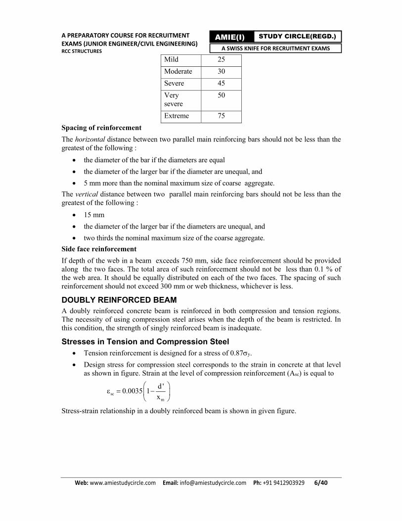
Design stress for compression steel corresponds to the strain in concrete at that level as shown in figure. Strain at the level of compression reinforcement (Asc) is equal to
scm
d '0.0035 1
x
Stress-strain relationship in a doubly reinforced beam is shown in given figure.
A PREPARATORY COURSE FOR RECRUITMENT EXAMS (JUNIOR ENGINEER/CIVIL ENGINEERING) RCC STRUCTURES
Web: www.amiestudycircle.com Email: [email protected] Ph: +91 9412903929 7/40
AMIE(I) STUDY CIRCLE(REGD.) A SWISS KNIFE FOR RECRUITMENT EXAMS
Knowing the strain at the level of compression steel, the stresses in steel can be obtained either from stress-strain curves for steels or from following table.
Stress sc in Compression Steel
Grade of steel y, N/mm2
d’/d 0.05 0.10 0.15 0.20
250 217 217 217 217 415 355 353 342 329
Reinforcement Details Minimum and maximum reinforcement
Minimum and maximum tension reinforcement in a doubly reinforcement beam are same as those in singly reinforced beam. The minimum compression reinforcement can of course be zero.
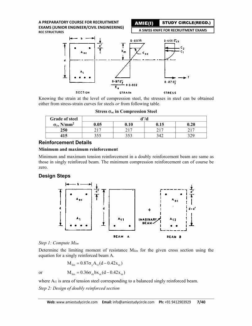
Design Steps
Step 1: Compute Mlim
Determine the limiting moment of resistance Mlim for the given cross section using the equation for a singly reinforced beam A.
lim y t1 mM 0.87 A (d 0.42x )
or lim ck m mM 0.36 bx (d 0.42x )
where At1 is area of tension steel corresponding to a balanced singly reinforced beam.
Step 2: Design of doubly reinforced section

A PREPARATORY COURSE FOR RECRUITMENT EXAMS (JUNIOR ENGINEER/CIVIL ENGINEERING) RCC STRUCTURES
Web: www.amiestudycircle.com Email: [email protected] Ph: +91 9412903929 8/40
AMIE(I) STUDY CIRCLE(REGD.) A SWISS KNIFE FOR RECRUITMENT EXAMS
If the factored moment M exceeds Mlim, a doubly reinforced section is required to be designed for the additional moment ( M - Mlim).
lim sc scM M A (d d ') [ As y >> cc]
where Asc is area of compression steel and cc is compression stress in concrete at the level of compression steel.
Step 3: Find additional area of tension steel
sc sct 2
y
AA
0.87
Step 4: Compute total area of tension steel
t t1 t2A A A
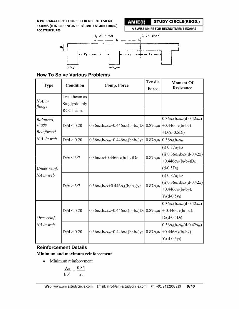
FLANGED (T) BEAMS In most reinforced concrete structures, concrete slabs and beams are cast monolithic. Thus, beams form part of the floor system together with the slab. In a floor system consisting of several beams cast monolithically with the slab, the intermediate beams act as T - beams, and the end beams act as L - beams. L and T beams are specified by the following dimensions as shown in given figure.
where, bf = effective width of flange, d = effective depth, bw = width of web(or rib) or beam and Df = depth of flange or slab
Effective Width of Flange
Type of beam Effective flange width(bf)
(lesser will be adopted)
T beams (l0/6) + bw + 6Df x1 + x2 + bw
Isolated T beams 0
0
l( /b) + 4l
+ bw b
L - beams (l0/12) + bw + 3Df x1 + bw
Isolated L beams 0
0
0.5l( /b) + 4l
+ bw b
where b = actual width of flange, l0 = distance between points of zero moments in a beam(for continuous beam l0 = 0.7 x effective span), x1,x2 = half the clear distance between two adjacent beams as shown in given figure.
A PREPARATORY COURSE FOR RECRUITMENT EXAMS (JUNIOR ENGINEER/CIVIL ENGINEERING) RCC STRUCTURES
Web: www.amiestudycircle.com Email: [email protected] Ph: +91 9412903929 9/40
AMIE(I) STUDY CIRCLE(REGD.) A SWISS KNIFE FOR RECRUITMENT EXAMS
How To Solve Various Problems
Type Condition Comp. Force Tensile
Force Moment Of Resistance
N.A. in flange
Treat beam as
Singly/doubly
RCC beam.
Balanced, singly
Reinforced,
N.A. in web
Df/d 0.20 0.36σckbwxm+0.446σck(bf-bw)Df 0.87σyat
0.36σckbwxm(d-0.42xm)
+0.446σck(bf-bw)
+Df(d-0.5Df)
Df/d > 0.20 0.36σckbwxm+0.446σck(bf-bw)yf 0.87σyat 0.36σckbwxm
Under reinf.
NA in web
Df/x 3/7 0.36σckx+0.446σck(bf-bw)Df 0.87σyat
(i) 0.87σyatz
(ii)0.36σckbwx(d-0.42x)
+0.446σck(bf-bw)Df.
(d-0.5Df)
Df/x > 3/7 0.36σckbwx+0.446σck(bf-bw)yf 0.87σyat
(i) 0.87σyatz
(ii)0.36σckbwx(d-0.42x)
+0.446σck(bf-bw).
Yf(d-0.5yf)
Over reinf.,
NA in web
Df/d 0.20 0.36σckbwxm+0.446σck(bf-bw)Df 0.87σyat
0.36σckbwxm(d-0.42xm)
+ 0.446σck(bf-bw).
Df(d-0.5Df)
Df/d > 0.20 0.36σckbwxm+0.446σck(bf-bw)yf 0.87σyat
0.36σckbwxm(d-0.42xm)
+0.446σck(bf-bw).
Yf(d-0.5yf)
Reinforcement Details Minimum and maximum reinforcement
Minimum reinforcement
0
w
Adb
= y
0.85

A PREPARATORY COURSE FOR RECRUITMENT EXAMS (JUNIOR ENGINEER/CIVIL ENGINEERING) RCC STRUCTURES
Web: www.amiestudycircle.com Email: [email protected] Ph: +91 9412903929 10/40
AMIE(I) STUDY CIRCLE(REGD.) A SWISS KNIFE FOR RECRUITMENT EXAMS
Maximum Reinforcement
Amax = 0.04 bwD
where A0 is minimum area of tension steel.
Example
Determine the moment of resistance for the section in given figure. Given ck = 20 N/mm2, y = 415 N/mm2.
Solution
Given data: Area of steel At = 2 23x x12 339 mm4
, d = 310 mm, b = 250 mm
Step 1: Compute x
y t
ck
0.87 Ax 68mm
0.36 b
Step 2: Compute xm
mx 0.48d 0.48x 310 148.8mm
Step 3: Decide whether the section is under reinforced or over reinforced
We see that x < xm, Hence the section is under reinforced.
Step 4: Compute lever arm
z d 0.42x = 310 0.42 x 68 281mm
Step 5: Compute moment of resistance
u y tM 0.87 A z = 0.87 x 415 x 339 x 281 N-mm = 34.40 kN-m
Example
Design a rectangular beam for an effective span of 6 m. The superimposed load is 80 kN/m and size of the beam is limited to 300 x 700 mm overall. Use M20 mix and Fe 415 grade steel.
Solution
Given data: l = 6 m, b = 300 mm, D = 700 mm, w’ = 80 kN/m, self weight w’’ = 0.30 x 0.70 x 25 = 5.25 kN/m, ck = 20 N/mm2, y = 415 N/mm2.
Let effective cover is 0.1D = 0.1 x 700 = 70 mm. Hence effective depth will be d = 700 - 70 = 630 mm.
Step 1: Compute total load and bending moment
Total load w 80 5.25 82.25 kN/m
Factored bending moment
M = 1.5 x BM = 1.5 x (wl2/8) = 1.5 x (85.25 x 62/8) = 576 kN-m
Step 2: Compute maximum depth of neutral axis xm

A PREPARATORY COURSE FOR RECRUITMENT EXAMS (JUNIOR ENGINEER/CIVIL ENGINEERING) RCC STRUCTURES
Web: www.amiestudycircle.com Email: [email protected] Ph: +91 9412903929 11/40
AMIE(I) STUDY CIRCLE(REGD.) A SWISS KNIFE FOR RECRUITMENT EXAMS
mx 0.48d 0.48x630 300 mm
Step 3: Compute Mlim
lim ck m mM 0.36 bx (d 0.42x )
= 0.36 x 20 x 300 x 300 x (630 - 0.42 x 300) = 3.26 x 10⁸ N-mm = 326 kN-m
Step 4: Compute At1
limt1
y m
MA
0.87 (d 0.42x )
Step 5: Compute strain in compression reinforcement sc and stress in compression reinforcement sc
3sc
m
d ' 700.0035 1 0.0035 1 2.7 x10
x 300
From table of stresses sc in compression steel
sc = 353 N/mm2
Step 6: Compute area of compression steel
6
2limsc
sc
M M (576 326) x10 N mmA 1265mm
(d d ') 353(630 70)
Step 7: Compute additional area of tension steel
2sc sct2
y
AA 1237 mm
0.87
Step 7: Compute total area of tension steel
2t t1 t2A A A 1790 1237 3027 mm
Step 8: Provide reinforcement
Provide 5 - 28 mm bars at bottom (At = 3078 mm2) and provide 5 - 18 mm bars at top (Asc = 1272 mm2).
Step 9: Check for maximum tension steel
maxA 0.04bD = 2 20.04 x 300 x 700 8400 mm 3078mm Hence O.K.
Example
Calculate the moment of resistance of a T beam as shown in Figure, assuming M15 mix and Fe 415 grade steel.

A PREPARATORY COURSE FOR RECRUITMENT EXAMS (JUNIOR ENGINEER/CIVIL ENGINEERING) RCC STRUCTURES
Web: www.amiestudycircle.com Email: [email protected] Ph: +91 9412903929 12/40
AMIE(I) STUDY CIRCLE(REGD.) A SWISS KNIFE FOR RECRUITMENT EXAMS
Solution
Given data : σck = 15 N/mm2, σy = 415 N/mm2, Df = 120 mm, d = 500 - 50 = 450 mm
bf = 750 mm, At = 3500 mm2, bw = 250 mm
Step 1: Make assumption
Let neutral axis (N.A.) lies in web, and section is balanced.
Step 2: Compute Df/d
fD / d 120 / 450 0.27 0.20
fy 0.15x 0.65(120) 0.15x 78
Step 3: Compute x
Force of compression = Force of tension
ck w ck f w f y t0.36 b x 0.44 (b b )y 0.87 A
Solving we getx = 541 mm
Step 4: Find xm
mx 0.48 x 450 216 mm
Step 5: Decide type of section
As x > xm, it would be an over reinforced section.
Step 6: Find yf
f my 0.15x 0.65(120) 0.15(216) 78 110 mm < Df O.K.
Step 7: Find moment of resistance
ck w m m ck f w f fM 0.36 b x (d 0.42x ) 0.44 (b b )y (d 0.5y )
= 2.50 x 10⁸ N-mm = 250 kN-m
Step 8: Find actual moment of resistance
acM M / load factor 250 /1.5 167 kNm
Problem (SSC, Junior Engineer, 2015)
Using limit state method (LSM), determine the moment of resistance of the T-Beam as shown in the figure below. Use M 15 concrete and Fe 415 steel.

A PREPARATORY COURSE FOR RECRUITMENT EXAMS (JUNIOR ENGINEER/CIVIL ENGINEERING) RCC STRUCTURES
Web: www.amiestudycircle.com Email: [email protected] Ph: +91 9412903929 13/40
AMIE(I) STUDY CIRCLE(REGD.) A SWISS KNIFE FOR RECRUITMENT EXAMS
Answer: 157.01 kNm
Example (SSC, Junior Engineer, 2011)
A room 600 cm long and 500 cm wide has a flat roof. There is one T-beam in the centre (cross section below the slab 30 cm x 50 cm) and the slab is 15 cm thick. Estimate the quantity of iron bars required for reinforcement (for the T beam only) from the data given below
Main bars - 8 nos. of 25 mm dia. in 2 rows of 4 each (all 4 in the bottom being straight and other being bent)
Stirrups - 10 mm dia. and 15 cm centre to centre throughout.
Anchor bars - 2 nos of 16 mm dia.
Solution
See figure.
Room dimensions = 600 cm x 500
Main Bars = 8 (Given)
Stirrups = 15 cm c/c
No. of stirrups = (length/spacing) + 1 = (600/15) + 1 = 41
Anchor bars = 2
Total bars = Main bars + Stirrups + anchor bars = 8 + 41 + 2 = 51

A PREPARATORY COURSE FOR RECRUITMENT EXAMS (JUNIOR ENGINEER/CIVIL ENGINEERING) RCC STRUCTURES
Web: www.amiestudycircle.com Email: [email protected] Ph: +91 9412903929 14/40
AMIE(I) STUDY CIRCLE(REGD.) A SWISS KNIFE FOR RECRUITMENT EXAMS
Shear and Bond Stresses
SHEAR STRESS Shear force is present in beams where there is a change in bending moment along the span. It is equal to the rate of change of bending moment.
Clause 40.1 of the code requires that nominal shear stress τv be obtained by dividing the factored shear force by the effective area bd, that is,
τv = Vu/bd
where τv = nominal shear stress(horizontal shear stress), Vu = factored shear force at the section
In case of beams of varying depth, the equation is modified as follows:
τv = uu ( /d) tanV Mbd
where, Mu = factored bending moment at the section, β = angle between top and bottom edges of the beam
Shear Reinforcement When shear stress exceeds the shear capacity of the concrete, shear reinforcement is provided.
To prevent the possibility of crushing of concrete in the web of a member, maximum shear stress values are limited as shown in table.
Maximum Shear Stress
Concrete grade
M15 M20 M25 M30 M35 M40
τcm(N/mm2) 2.5 2.8 3.1 3.5 3.7 4.0 The shear strength of concrete τc based on the percentage of longitudinal tensile reinforcement is shown in following table
Design Shear Strength of Concrete(c) N/mm2
100As/bd
M15 M20 M25 M30 M35 M40
0.25 0.35 0.36 0.36 0.37 0.37 0.38 0.50 0.46 0.48 0.49 0.50 0.50 0.51 0.75 0.54 0.56 0.57 0.59 0.59 0.60 1.00 0.60 0.62 0.64 0.66 0.67 0.68 1.25 0.64 0.67 0.70 0.71 0.73 0.74 1.50 0.68 0.72 0.74 0.76 0.78 0.79 1.75 0.71 0.75 0.78 0.80 0.82 0.84 2.00 0.71 0.79 0.82 0.84 0.86 0.88 2.25 0.71 0.81 0.85 0.88 0.90 0.92 2.50 0.71 0.82 0.88 0.91 0.93 0.95
Note : The term As is the area of longitudinal tension reinforcement which continues at least one effective depth beyond the section being considered.
Thus when shear reinforcement is necessary, the shear strength of the beam is calculated on the following basis:

A PREPARATORY COURSE FOR RECRUITMENT EXAMS (JUNIOR ENGINEER/CIVIL ENGINEERING) RCC STRUCTURES
Web: www.amiestudycircle.com Email: [email protected] Ph: +91 9412903929 15/40
AMIE(I) STUDY CIRCLE(REGD.) A SWISS KNIFE FOR RECRUITMENT EXAMS
Total shear strength = Shear resistance of effective concrete area as a function of longitudinal main steel bars plus shear resistance of vertical shear stirrups plus shear resistance of inclined shear stirrups.
Tests have shown that inclined bars alone do not provide a satisfactory solution and their contribution is limited to 50% of the net shear after deducting the contribution of the concrete. The remaining shear resistance is provided by vertical stirrups.
A concrete section can be classified into any one of the following four cases depending upon the amount of factored shear force on the section relative to its shear capacity.
Case 1 : No Shear Reinforcement
The code requires the shear reinforcement need not be provided in the following cases :
(a) where shear force Vu is less than 0.5 times the shear capacity of the section, and
(b) in members of minor structural importance such as lintels.
Case 2 : Minimum shear reinforcement (τv τc)
Minimum shear reinforcement should be provided if the nominal shear stress τv is less than or equal to shear strength of the concrete. The spacing x of the shear stirrups is given by
x = 0yA0.4b
where A0 = total cross sectional area of stirrup legs effective in shear, b = breadth of the beam or breadth of the web of flanged beam, and σy = characteristic strength of the stirrup reinforcement which should not be taken greater than 415 N/mm2.
Case 3 : Shear Reinforcement (τv > τc)
Adequate shear reinforcement should be provided if the nominal shear stress τv exceeds the shear strength of concrete.
Case 4: Redesign of Section ( v > cm)
The nominal shear stress due to factored loads should not exceed the maximum permissible shear stress in the concrete. In case the nominal shear stress exceeds this value, the section should be redesigned.
Spacing of shear reinforcement
If we provide vertical stirrups as shear reinforcement then spacing of stirrups (x) is given by formula
y sv y sv
us u c
0.87 A d 0.87 A dx
V V bd
where Asv is cross sectional area of stirrups [for two legged stirrups Asv = 2 x (/4)d2], and Vus = net design shear
Maximum spacing of vertical shear stirrups should not exceed 0.75d or 300 mm.
Minimum spacing of vertical shear stirrups should be 100 mm to permit space for compaction of the concrete.
BOND STRESS Bond stress is defined as the shear force per unit of nominal surface area of a reinforcing bar acting parallel to the bar on the interface between the bar and the surrounding concrete. A

A PREPARATORY COURSE FOR RECRUITMENT EXAMS (JUNIOR ENGINEER/CIVIL ENGINEERING) RCC STRUCTURES
Web: www.amiestudycircle.com Email: [email protected] Ph: +91 9412903929 16/40
AMIE(I) STUDY CIRCLE(REGD.) A SWISS KNIFE FOR RECRUITMENT EXAMS
basic requirement in reinforced concrete structures is that the steel and surrounding concrete act together and there should be no slip of the bar relative to its surrounding concrete. In simple beams, critical sections generally occur at the face of a support, at a section of maximum stress, and at points where bars may be curtailed theoretically. In continuous beams, points of contraflexure provide additional critical sections.
Development Length The force in any reinforcing bar must be transmitted to the surrounding concrete by bond, in the embedment length, before the bar may be terminated. This embedment length is called development length.
Development length is given by formula
yd
bd
0.87L
4
Design bond stresses for plain steel bars in tension are given below
Conc. M15 M20 M25 M30 M35 M40
bd N/mm2
1.0 1.2 1.4 1.5 1.7 1.9
The code requires that bd values may be increased by 60% for deformed steel bars in tension. These values may be further increased by 25% for bars in compression.
If the design bond stress bd is not to be exceeded, the following condition must be fulfilled
1d 0
ML L
V [Clause 26.2.3.3(c) of the code]
Also according to code, development length at a simple support is
1d 0
ML 1.3 L
V
where M1 is moment of resistance with respect to tension steel alone at section under consideration (generally critical section), V is factored shear force at same section, Ld is development length and L0 is sum of anchorage beyond the centre of support and equivalent anchorage value of any hook/bend. L0 is limited to the effective depth of the member or 12 whichever is greater at a point of inflection.
Clause 26.2.2.1 of the code gives the anchorage values of bends and hooks as follows:
The anchorage value of a bend should be taken as 4 for each 450 bend subject to a maximum of 16.
The anchorage value of 900 bend is 8.
The anchorage value of a standard U type hook is 16.
Reinforcement Splicing When two reinforcing bars are to be joined to make a longer one, it is necessary to overlap a length sufficient to develop its full strength by bond round the surface so that it does not slip under the design stress. The following general rules should be followed for lap splicing :
Lap splices should not be used for bars larger than 36 mm. Larger diameter bars may be welded together.
A PREPARATORY COURSE FOR RECRUITMENT EXAMS (JUNIOR ENGINEER/CIVIL ENGINEERING) RCC STRUCTURES
Web: www.amiestudycircle.com Email: [email protected] Ph: +91 9412903929 17/40
AMIE(I) STUDY CIRCLE(REGD.) A SWISS KNIFE FOR RECRUITMENT EXAMS
Lap length including anchorage value of hooks in flexural tension is Ld or 30, whichever is greater
Lap length including anchorage value of hooks in direct tension is 2Ld or 30 whichever is greater.
The straight length of the lap should not be less than 200 mm or 15.
The lap length is calculated on the basis of diameter of smaller bar when bars of two different diameter are to be spliced.
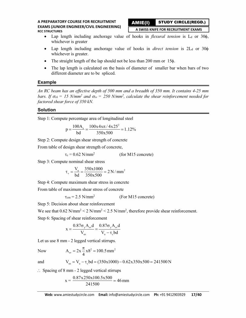
Example
An RC beam has an effective depth of 500 mm and a breadth of 350 mm. It contains 4-25 mm bars. If ck = 15 N/mm2 and sv = 250 N/mm2, calculate the shear reinforcement needed for factored shear force of 350 kN.
Solution
Step 1: Compute percentage area of longitudinal steel
2
s100A 100x4x / 4x25p 1.12%
bd 350x500
Step 2: Compute design shear strength of concrete
From table of design shear strength of concrete,
c = 0.62 N/mm2 (for M15 concrete)
Step 3: Compute nominal shear stress
2uv
V 350x10002 N / mm
bd 350x500
Step 4: Compute maximum shear stress in concrete
From table of maximum shear stress of concrete
cm = 2.5 N/mm2 (For M15 concrete)
Step 5: Decision about shear reinforcement
We see that 0.62 N/mm2 < 2 N/mm2 < 2.5 N/mm2, therefore provide shear reinforcement.
Step 6: Spacing of shear reinforcement
y sv y sv
us u c
0.87 A d 0.87 A dx
V V bd
Let us use 8 mm - 2 legged vertical stirrups.
Now 2 2svA 2x x8 100.5mm
4
and us u cV V bd (350x1000) 0.62x350x500 241500 N
Spacing of 8 mm - 2 legged vertical stirrups
x = 0.87x250x100.5x500
46mm241500

A PREPARATORY COURSE FOR RECRUITMENT EXAMS (JUNIOR ENGINEER/CIVIL ENGINEERING) RCC STRUCTURES
Web: www.amiestudycircle.com Email: [email protected] Ph: +91 9412903929 18/40
AMIE(I) STUDY CIRCLE(REGD.) A SWISS KNIFE FOR RECRUITMENT EXAMS
Step 7: Check for maximum spacing
As x = 46 mm < 300 mm and 0.75d = 0.75 x 500 = 375 mm, hence O.K.
Step 8: Check for minimum reinforcement
20
y
0.4bx 0.4x350x45.25A 30mm
0.87 0.87x250
< Asv O.K.
Step 9: Check for minimum spacing
We see that x = 46 mm < 100 mm Hence not O.K.
Step 10: Compute revised area of stirrups
Let us keep minimum spacing of stirrups equal to 100 mm in order to permit space for compaction of the concrete.
Hence revised area of stirrups will be
2ussv
y
V x 241500x100A 222mm
0.87 d 0.87x250x500
Let us use 12 mm - 2 legged vertical stirrups @ 100 mm c/c.
Step 9: Check for minimum reinforcement for revised stirrups
20
y
0.4bx 0.4x350x100A 65mm
0.87 0.87x250
< Asv of revised stirrups. Hence O.K.
Step 10: Check for maximum spacing for revised stirrups
As x = 100 mm < 300 mm and < 0.75d = 0.75 x 500 = 375 mm, hence O.K.
Example
A simply supported beam is 25 cm x 50 cm and has 2-20 mm tor bars going into support. If the shear force at the centre of support is 110 kN at working loads, determine the anchorage length. Assume M20 mix and Fe415 grade steel.
Solution
Step 1: Compute factored shear force
V = 1.5 x 110 = 165 kN
Step 2: Find effective depth
Let clear cover is 25 mm then effective depth will be
d = 500 - 25 - (20/2) = 465 mm
Step 3: Find depth of neutral axis x and moment of resistance M1
y t
ck
0.87 Ax 126mm
0.36 b
< xm Hence O.K.
61 y tM 0.87 A (d 0.42x) 93.45 x10 N mm
Step 4: Find bond stress for M20 mix
From table of design bond stress

A PREPARATORY COURSE FOR RECRUITMENT EXAMS (JUNIOR ENGINEER/CIVIL ENGINEERING) RCC STRUCTURES
Web: www.amiestudycircle.com Email: [email protected] Ph: +91 9412903929 19/40
AMIE(I) STUDY CIRCLE(REGD.) A SWISS KNIFE FOR RECRUITMENT EXAMS
bd = 1.2 N/mm2
Now increase it by 60% for tor steel.
cd = 1.6 x 1.2 N/mm2
Step 5: Find development length
yd
bd
0.87 0.87(415)L 47
4 4(1.6x1.2)
Step 6: Provide bend
let us we provide 900 bend at centre of support. Its anchorage value is 8 i.e. 8 x 20 = 160 mm. Hence L0 = 160 mm.
Step 7: Check for anchorage value
1d 0
ML 1.3 L
V
i.e. 61.3x93.45x10
47 160 19mm165x1000
Now diameter provided is 20 mm. NOT O.K.
Hence increase the anchorage length. Let us increase L0 to 240 from 160 mm (See figure)
Now we see that by applying above check once again
20.8mm Now O.K.
Note: In step 6, instead of 900 bend if we provide U-bend at centre of support then L0 = 16 = 320 mm.
After applying a check for anchorage value, we will see that 22.47 mm, which is perfectly O.K. because diameter provided is 20 mm which is less than 22.47 mm.
Example (SSC, Junior Engineer, 2013)
A simply supported 18 m effective span RCC rectangular beam of 500 mm x 1500 mm (over all depth) section is reinforced throughout with 21 nos. 25 mm diameter bars in three layers of 7 bars each at a clear cover of 37.5 mm on tensile face. The reinforcement on the compression face is 4 - 25 mm + 1 - 20 mm diameter bars in one layer at an effective cover of 50 mm. The clear cover between the different layers on tension face is 25 mm. M 25 grade concrete and Fe 415 grade steel bars are used in the beam throughout. The beam is laterally restrained throughout the span. (a) What shall be the superimposed uniformly distributed load w, that the beam can carry at working conditions? (b) Design the shear reinforcement at support if design shear strength of concrete c is given as follows for different values of p = 100 As/bd.
p 1.25 1.5 1.75
c(MPa) 0.70 0.74 0.78
Solution
Part (a)
See figure.

A PREPARATORY COURSE FOR RECRUITMENT EXAMS (JUNIOR ENGINEER/CIVIL ENGINEERING) RCC STRUCTURES
Web: www.amiestudycircle.com Email: [email protected] Ph: +91 9412903929 20/40
AMIE(I) STUDY CIRCLE(REGD.) A SWISS KNIFE FOR RECRUITMENT EXAMS
fy = 415 N/mm2; Xu, lim = 0.48d = 0.48 x 1400 = 672 mm
fck = 25 N/mm2; d = 1437.5 mm; d' = 1500 – 37.5 – 25 – 25 – 12.5 = 1400 mm
dc = 50 mm; fsc = sc = 0.9566fy = 0.9566 x 415 = 396.989 = 397 N/mm2
2 2 24 25 1 20 2277.654 4scA mm
lim lim0.36 ( 0.42 ) ( 0.45 ) ( ' )ck u u sc ck sc cMR f Bx d x f f A d d
= 0.36 x 25 x 500 x 672(1437.5 – 0.42 x 672)
+ (397 – 0.45 x 25) x 2277.65 x (1400 – 50)
= 4679.62 kNm
2
lim
4679.62 8115.54 /
8 18 18u
u u u
w l xM w w kN m
x
115.54
77.03 /1.5 1.5
utotal
ww kN m
wtotal is super imposed UDL along with the self weight of the beam. Hence, the self weight of beam should be deducted.
Self weight of beam = 0.5 x 1.5 x 1 x 25 = 18.75 kN/m
w = wtotal – 18.75 = 77.03 – 18.75 = 58.28 kN/m
Part (b)
wu = 115.54 kN/m
Vu = wul/2 = (115.54 x 18)/2 = 1039.86 kN
Nominal shear stress
3
21039.86 101.48 /
500 1400u
v
V xN mm
Bd x
Now 100 10308.35
100 1.47%500 1400
stA xp x
Bd x
For p = 1.25%, we have c = 0.70 N/mm2
2(0.74 0.70)1.47% 0.70 (1.47 1.25) 0.73 /
(1.50 1.25)c for N mm
A PREPARATORY COURSE FOR RECRUITMENT EXAMS (JUNIOR ENGINEER/CIVIL ENGINEERING) RCC STRUCTURES
Web: www.amiestudycircle.com Email: [email protected] Ph: +91 9412903929 21/40
AMIE(I) STUDY CIRCLE(REGD.) A SWISS KNIFE FOR RECRUITMENT EXAMS
Vc = cBd = 0.73 x 500 x 1400 = 511 kN
v > c, hence shear reinforcement is required.
Vus = Vu – Vc = 1039.86 – 511.00 = 528.86 kN
Now shear reinforcement at supports should be provided according the IS: 456-2000.
0.87 y sv
vus
f A dS
V
Hence, providing 200 mm spacing at supports.
Minimum shear reinforcement
2.5 2.5(157.08)(415)
325.94500
sv yv v v
A fS S S mm
b [ b B ]
Hence, at mid span spacing between stirrups can be 300 mm c/c.
Maximum spacing = 0.75 d = 0.75 x 1400 = 1050 mm
Hence proved reinforcement is OK.
Slabs
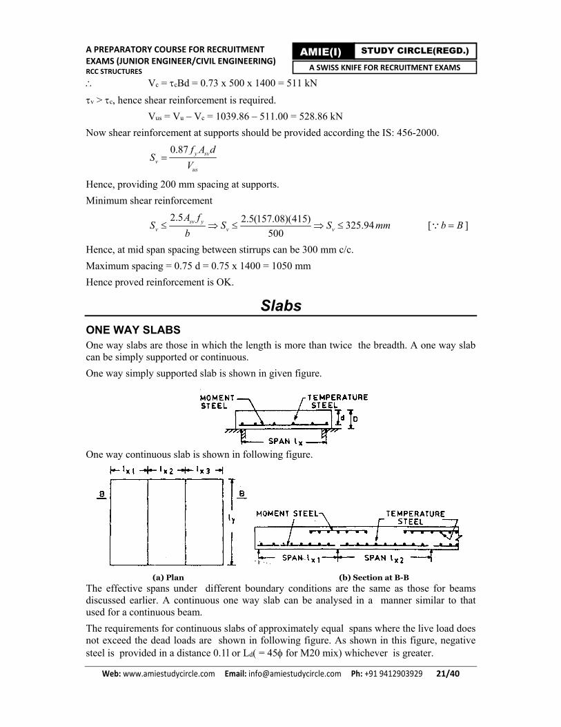
ONE WAY SLABS One way slabs are those in which the length is more than twice the breadth. A one way slab can be simply supported or continuous.
One way simply supported slab is shown in given figure.
One way continuous slab is shown in following figure.
(a) Plan (b) Section at B-B
The effective spans under different boundary conditions are the same as those for beams discussed earlier. A continuous one way slab can be analysed in a manner similar to that used for a continuous beam.
The requirements for continuous slabs of approximately equal spans where the live load does not exceed the dead loads are shown in following figure. As shown in this figure, negative steel is provided in a distance 0.1l or Ld( = 45 for M20 mix) whichever is greater.

A PREPARATORY COURSE FOR RECRUITMENT EXAMS (JUNIOR ENGINEER/CIVIL ENGINEERING) RCC STRUCTURES
Web: www.amiestudycircle.com Email: [email protected] Ph: +91 9412903929 22/40
AMIE(I) STUDY CIRCLE(REGD.) A SWISS KNIFE FOR RECRUITMENT EXAMS
Shear stresses in slabs are generally not critical under normal loads but should be checked. Clause 40.2.1.1 of the code permits in solid slabs thinner than 300 mm an increase in shear strength τc of concrete by a factor k is given in table.
Value of k for solid slabs
Ds(mm) 300 275 250 225 200 175 150
k 1.00 1.05 1.10 1.15 1.20 1.25 1.30
In solid slabs, the nominal shear stress τv should be less than kτc. Shear reinforcement may be provided in slabs deeper than 200 mm. The development length is checked at the same critical points as for beams.
The check for deflection is a very important consideration in the slab design.
Deflection Control For a slab to be safe in deflection
L
d αβγδλ
where L = span; d = effective depth; α = basic values of span to effective depth ratios for spans upto 10 m. It is 7 for cantilever, 20 for simply supported slab and 26 for continuous slab; β = a factor which accounts for correction in the values of α for spans greater than 10 m = 10/span, where span is in meter. β will be equal to unity if span is less than 10 m; γ = a factor which depends on the stress at service and amount of steel for a tension reinforcement.; δ = a factor which depends on the area of compression reinforcement; and λ = a factor for flanged beams which depends on the ratio of web width to the flange width.
Reinforcement Details Nominal cover
It is same as that for beams. However in slabs having main reinforcement upto 12 mm diameter bars, for mild exposure, the nominal cover may be reduced to 20 mm instead of 25 mm.
Maximum distance between bars in tension
The horizontal distance between parallel main reinforcement bars should not be more than three times the effective depth of a solid slab or 300 mm whichever is smaller.
The horizontal distance between parallel reinforcement bars provided against shrinkage and temperature should not be more than five times the effective depth of a solid slab or 450 mm whichever is smaller.

A PREPARATORY COURSE FOR RECRUITMENT EXAMS (JUNIOR ENGINEER/CIVIL ENGINEERING) RCC STRUCTURES
Web: www.amiestudycircle.com Email: [email protected] Ph: +91 9412903929 23/40
AMIE(I) STUDY CIRCLE(REGD.) A SWISS KNIFE FOR RECRUITMENT EXAMS
Minimum Reinforcement
The minimum reinforcement in either direction in slabs should not be less than 0.15% of the total cross sectional area when using mild steel reinforcement, and 0.12% of the total cross sectional area when using high yield strength reinforcement. Further, maximum diameter of reinforcing bar should not exceed one eighth of the total thickness of slab.
Curtailment of bars
The general recommendations for curtailment of bars given in clause 26.2.3 of the code apply for slabs also.
TWO WAY SLABS When slabs are supported on four sides, two way spanning action occurs. Such slabs may be simply supported or continuous on any or all sides. The design of two way slabs is based on tables of bending moments and design specifications given in clause 24.4 of the code.
Simply Supported Two Way Slabs The values of bending moments used for the design of such slabs can be obtained as follows:
2 2x x x y y yM wl and M wl
where Mx, My are maximum moments at mid span on strips of unit width and spans lx and ly, respectively. lx is length of shorter side, ly is length of longer side and x, y are moment coefficients given in following table.
ly/lx 1.0 1.1 1.2 1.3 1.4 1.5 1.75 2.0 2.5 3.0 x 0.062 0.074 0.084 0.093 0.099 0.104 0.113 0.118 0.122 0.124 y 0.062 0.061 0.059 0.055 0.051 0.046 0.037 0.029 0.020 0.014
The code requires that at least 50% of the tension reinforcement provided at midspan should extend to within 0.1lx or 0.1ly of the support, as appropriate.
Restrained Slabs A slab may have its few or all edges restrained. A hogging or negative bending moment will develop in the top face of the slab at the supported sides. In these slabs, the corners are prevented from lifting and provision is made for tension.
For these slabs
2 2x x x y y yM wl and M wl
where x and y are moment coefficients given in BS 8110-part 1 - 1985.
Design Rules Design rules for two way slabs are given in appendix C of the code.
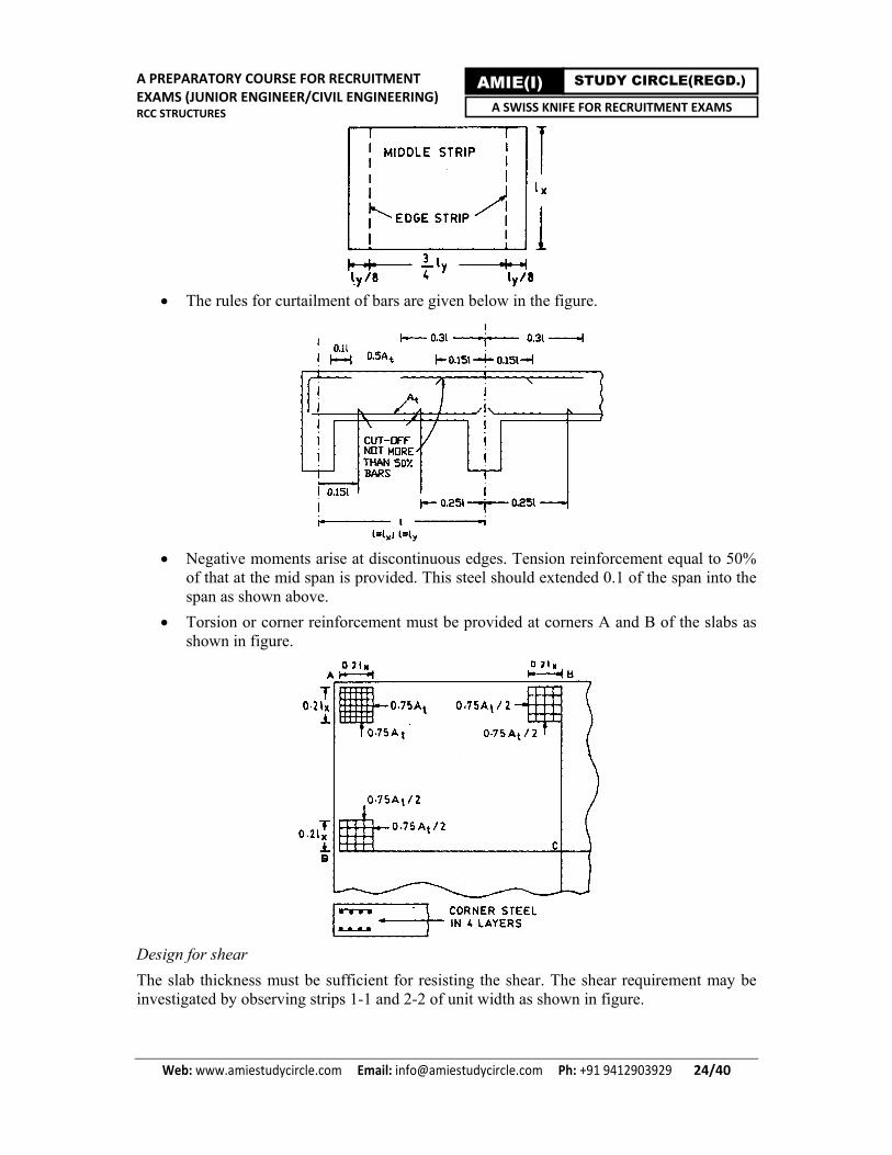
The maximum positive and negative moments apply only to the middle strips subject to the requirements for minimum areas of reinforcement. The bars are uniformly spaced in the middle strips.
A PREPARATORY COURSE FOR RECRUITMENT EXAMS (JUNIOR ENGINEER/CIVIL ENGINEERING) RCC STRUCTURES
Web: www.amiestudycircle.com Email: [email protected] Ph: +91 9412903929 24/40
AMIE(I) STUDY CIRCLE(REGD.) A SWISS KNIFE FOR RECRUITMENT EXAMS
The rules for curtailment of bars are given below in the figure.
Negative moments arise at discontinuous edges. Tension reinforcement equal to 50%
of that at the mid span is provided. This steel should extended 0.1 of the span into the span as shown above.
Torsion or corner reinforcement must be provided at corners A and B of the slabs as shown in figure.
Design for shear
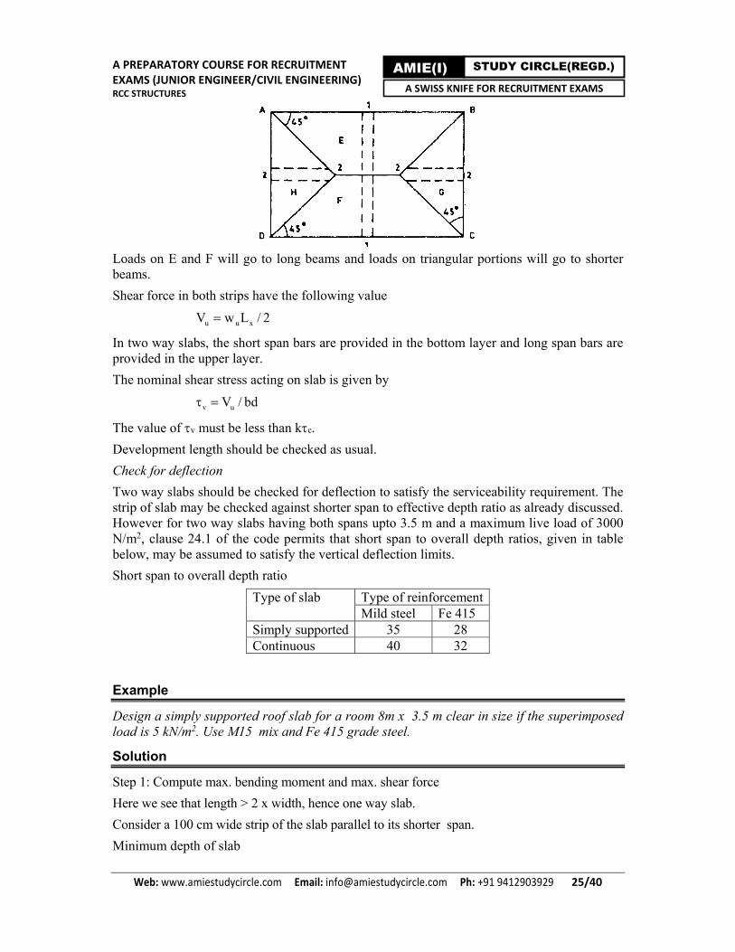
The slab thickness must be sufficient for resisting the shear. The shear requirement may be investigated by observing strips 1-1 and 2-2 of unit width as shown in figure.
A PREPARATORY COURSE FOR RECRUITMENT EXAMS (JUNIOR ENGINEER/CIVIL ENGINEERING) RCC STRUCTURES
Web: www.amiestudycircle.com Email: [email protected] Ph: +91 9412903929 25/40
AMIE(I) STUDY CIRCLE(REGD.) A SWISS KNIFE FOR RECRUITMENT EXAMS
Loads on E and F will go to long beams and loads on triangular portions will go to shorter beams.
Shear force in both strips have the following value
u u xV w L / 2
In two way slabs, the short span bars are provided in the bottom layer and long span bars are provided in the upper layer.
The nominal shear stress acting on slab is given by
v uV / bd
The value of v must be less than kc.
Development length should be checked as usual.
Check for deflection
Two way slabs should be checked for deflection to satisfy the serviceability requirement. The strip of slab may be checked against shorter span to effective depth ratio as already discussed. However for two way slabs having both spans upto 3.5 m and a maximum live load of 3000 N/m2, clause 24.1 of the code permits that short span to overall depth ratios, given in table below, may be assumed to satisfy the vertical deflection limits.
Short span to overall depth ratio
Type of slab Type of reinforcement Mild steel Fe 415
Simply supported 35 28 Continuous 40 32
Example
Design a simply supported roof slab for a room 8m x 3.5 m clear in size if the superimposed load is 5 kN/m2. Use M15 mix and Fe 415 grade steel.
Solution
Step 1: Compute max. bending moment and max. shear force
Here we see that length > 2 x width, hence one way slab.
Consider a 100 cm wide strip of the slab parallel to its shorter span.
Minimum depth of slab

A PREPARATORY COURSE FOR RECRUITMENT EXAMS (JUNIOR ENGINEER/CIVIL ENGINEERING) RCC STRUCTURES
Web: www.amiestudycircle.com Email: [email protected] Ph: +91 9412903929 26/40
AMIE(I) STUDY CIRCLE(REGD.) A SWISS KNIFE FOR RECRUITMENT EXAMS
d = L
Let α = 20, β = 1, γ = 1, δ = 1 and λ = 1
d = 3500/20 = 175 mm
Let us adopt overall depth D = 190 mm
Dead load of slab = 0.19 x 1.0 x 25 = 4.75 kN/m
Superimposed load = 5 x 1 = 5 kN/m
Total load = 9.75 kN/m
Factored load if the load factor is 1.5 = 1.5 x 9.75 = 14.63 kN/m
Assume steel consists of 10 mm bars with 15 mm clear cover.
Effective depth = 190 - 15 - 5 = 170 mm
Effective span of slab = 3.5 + d = 3.5 + 0.17 = 3.67 m
Max. bending moment
M = wul2/8 = 14.63 x (3.672/8) =24.63 kN-m
Max. shear force
V = wulc/2 = 14.63 x (3.5/2) = 25.60 kN
Step 2: Compute area of tension steel
Depth of the slab is given by
M = 0.138σckbd2
or d = 109 mm (After putting all values)
Adopt effective depth d = 150 mm and D = 170 mm
Area of tension steel is given by
M = 0.87σyAtty
ck
Ad - b
or At = 510 mm2 (After putting all values)
Use 10 mm bars @ 150 mm c/c giving total area = 523 mm2 > 510 mm2 O.K.
Bend alternate bars at L/7 from face of support where moment reduces to less than half its maximum value.
Step 3: Compute area of temperature reinforcement
Temperature reinforcement equal to 0.15% of the gross concrete area will be provided in the longitudinal direction which will be equal to 0.0015 x 1000 x 170 = 255 mm2. Use 6 mm MS bars @ mm c/c giving total area = 28 x (1000/100) = 280 mm2 > 255 mm2 O.K.
Step 4: Check for shear
Percent tension steel = t100Abd
= 100(78.5 x 1000/300)
1000 x 150 = 0.17 %
Shear strength of concrete for 0.17% steel, τc = 0.35 N/mm2
For 170 mm thick slab, k = 1.25

A PREPARATORY COURSE FOR RECRUITMENT EXAMS (JUNIOR ENGINEER/CIVIL ENGINEERING) RCC STRUCTURES
Web: www.amiestudycircle.com Email: [email protected] Ph: +91 9412903929 27/40
AMIE(I) STUDY CIRCLE(REGD.) A SWISS KNIFE FOR RECRUITMENT EXAMS
τc' = kτc = 1.25 x 0.35 = 0.44 N/mm2
Nominal shear stress τv = Vu/bd = 25600/1000x150 = 0.17 N/mm2 < τc' O.K.
Hence the slab is safe in shear.
Step 5: Check for development length
Moment of resistance offered by 10 mm bars @ 300 mm c/c.
M1 = 0.87σyAtty
ck
Ad - b
= 13.48 x 10⁶ N mm
Given V = 25600 N
Let us assume anchorage length L0 = 0
Ld 1.3 1MV
56 1.3613.48 x 10
25600i.e. < 12 mm O.K.
The code requires that the bars must be carried into the supports by at least Ld/3 = 190 mm.
Step 6: Check for deflection
Percent tension steel at midspan = s100Abd
= 100 78.5 x 1000/150
1000 x 150 = 0.35 %
γ = 1.35 (From code 456:2000), β = 1, δ = 1, and λ = 1
Allowable L/d = 20 x 1.35 = 27
Actual L/d = 3670/150 = 24.5 < 27 O.K.
The details of reinforcement are shown in given figure.
Problem (SSC, Junior Engineer, 2017)
A classroom is of the size 8.5 m x 3.6 m. Design a simply supported roof slab for this room. The superimposed load is 5 kN/m. Use M 20 grade concrete and HYSD Fe415 steel. Use limit state method.
100Ast/bd 0.15 0.25 0.50 0.75 1.0
c (N/mm2) 0.19 0.36 0.49 0.57 0.64
A PREPARATORY COURSE FOR RECRUITMENT EXAMS (JUNIOR ENGINEER/CIVIL ENGINEERING) RCC STRUCTURES
Web: www.amiestudycircle.com Email: [email protected] Ph: +91 9412903929 28/40
AMIE(I) STUDY CIRCLE(REGD.) A SWISS KNIFE FOR RECRUITMENT EXAMS
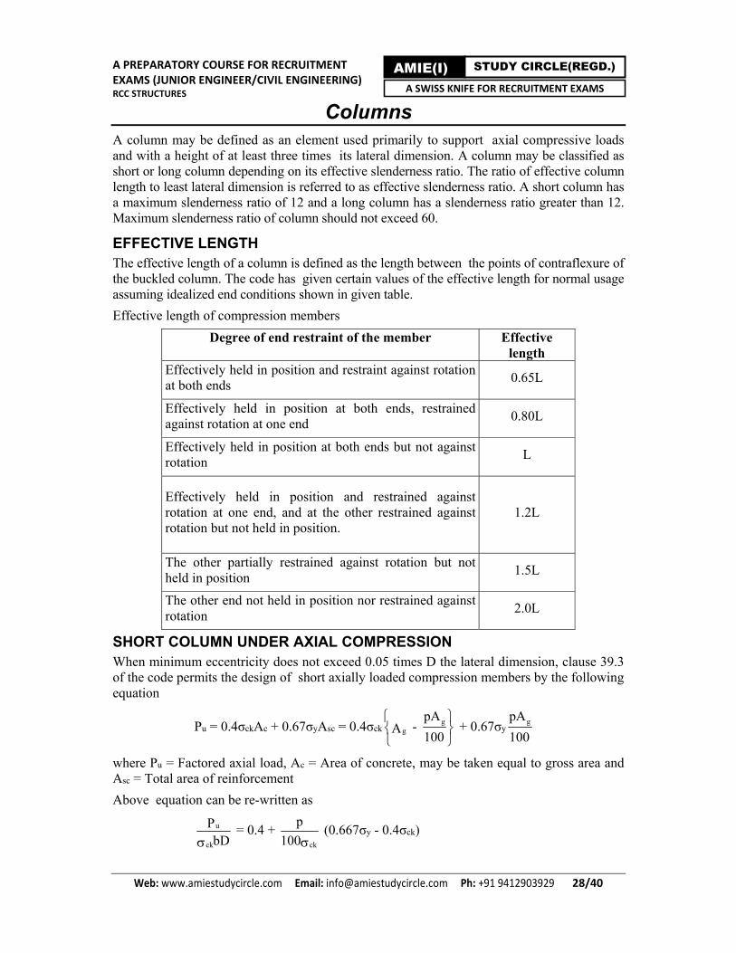
Columns A column may be defined as an element used primarily to support axial compressive loads and with a height of at least three times its lateral dimension. A column may be classified as short or long column depending on its effective slenderness ratio. The ratio of effective column length to least lateral dimension is referred to as effective slenderness ratio. A short column has a maximum slenderness ratio of 12 and a long column has a slenderness ratio greater than 12. Maximum slenderness ratio of column should not exceed 60.
EFFECTIVE LENGTH The effective length of a column is defined as the length between the points of contraflexure of the buckled column. The code has given certain values of the effective length for normal usage assuming idealized end conditions shown in given table.
Effective length of compression members
Degree of end restraint of the member Effective length
Effectively held in position and restraint against rotation at both ends
0.65L
Effectively held in position at both ends, restrained against rotation at one end
0.80L
Effectively held in position at both ends but not against rotation
L
Effectively held in position and restrained against rotation at one end, and at the other restrained against rotation but not held in position.
1.2L
The other partially restrained against rotation but not held in position
1.5L
The other end not held in position nor restrained against rotation
2.0L
SHORT COLUMN UNDER AXIAL COMPRESSION When minimum eccentricity does not exceed 0.05 times D the lateral dimension, clause 39.3 of the code permits the design of short axially loaded compression members by the following equation
Pu = 0.4σckAc + 0.67σyAsc = 0.4σckg
g
pA - A
100
+ 0.67σygpA
100
where Pu = Factored axial load, Ac = Area of concrete, may be taken equal to gross area and Asc = Total area of reinforcement
Above equation can be re-written as
u
ck
PbD
= 0.4 + ck
p
100 (0.667σy - 0.4σck)

A PREPARATORY COURSE FOR RECRUITMENT EXAMS (JUNIOR ENGINEER/CIVIL ENGINEERING) RCC STRUCTURES
Web: www.amiestudycircle.com Email: [email protected] Ph: +91 9412903929 29/40
AMIE(I) STUDY CIRCLE(REGD.) A SWISS KNIFE FOR RECRUITMENT EXAMS
where Ag = gross area of cross section = bD and p = percentage of reinforcement
REINFORCEMENT
Longitudinal Reinforcement The minimum area of cross section of longitudinal bars must be at least 0.8 % of the
gross sectional area of the column.
The maximum area of cross section of longitudinal bars must not exceed 6 % of the gross cross sectional area of concrete.
The bars should not be less than 12 mm in diameter.
The minimum number of longitudinal bars provided in a column must be four in rectangular columns and six in circular columns.
A reinforced concrete column having helical reinforcement must have at least six bars of longitudinal reinforcement within the helical reinforcement.
Spacing of longitudinal bars measured along the periphery of a column should not exceed 300 mm.
Nominal cover for a longitudinal reinforcing bar should not less than 40 mm, nor less than the diameter of such bar. Such a large cover is required so as to prevent buckling of the main longitudinal bars under compression.
In case of columns of minimum dimensions of 200 mm or under, whose reinforcing bars do not exceed 12 mm a cover of 25 mm may be used.
Transverse Reinforcement Transverse reinforcement may be in the form of lateral ties or spirals.
Laterals Ties
The diameter of lateral ties should not be less than one fourth of the diameter of the largest longitudinal bar, and in no case less than 6 mm.
The pitch of the lateral ties should not exceed (a) The least lateral dimension of the compression member (b) 16 times the smallest diameter of the longitudinal reinforcement bar to be tied, and (c) 300 mm.
Nominal cover to reinforcement is same as that for beams.
Helical Reinforcement
The diameter of the helical reinforcement should not be less than one fourth of the diameter of the largest longitudinal bar, and in no case less than 6 mm.
Its pitch should not exceed (if an increased load on column is allowed): (a) 75 mm (b) one sixth of the core diameter of the column
The pitch should not be less than (a) 25 mm (b) 3 times the diameter of the steel bar forming the helix.
If an increased load on the column on the strength of helical reinforcement is not allowed for, its pitch should not exceed (a) the least lateral dimension of the compression member (b) 16 times the smallest diameter of the longitudinal bar to be tied, and (c) 300 mm.
Nominal cover to reinforcement is same as that for beams.
A PREPARATORY COURSE FOR RECRUITMENT EXAMS (JUNIOR ENGINEER/CIVIL ENGINEERING) RCC STRUCTURES
Web: www.amiestudycircle.com Email: [email protected] Ph: +91 9412903929 30/40
AMIE(I) STUDY CIRCLE(REGD.) A SWISS KNIFE FOR RECRUITMENT EXAMS
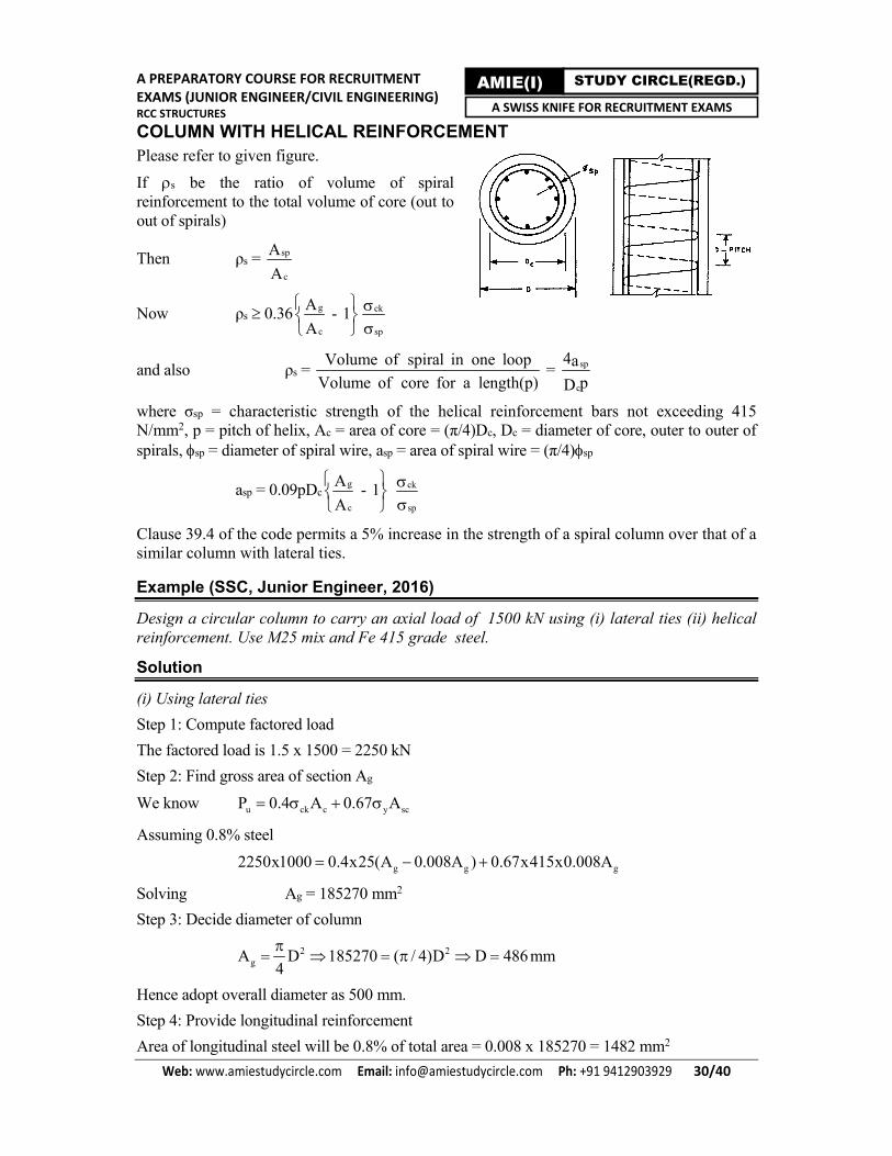
COLUMN WITH HELICAL REINFORCEMENT Please refer to given figure.
If s be the ratio of volume of spiral reinforcement to the total volume of core (out to out of spirals)
Then ρs = sp
c
A
A
Now ρs 0.36 g
c
A - 1A
ck
sp
and also ρs = Volume of spiral in one loop
Volume of core for a length(p) = sp
c
4apD
where σsp = characteristic strength of the helical reinforcement bars not exceeding 415 N/mm2, p = pitch of helix, Ac = area of core = (π/4)Dc, Dc = diameter of core, outer to outer of spirals, sp = diameter of spiral wire, asp = area of spiral wire = (π/4)sp
asp = 0.09pDcg
c
A - 1A
ck
sp
Clause 39.4 of the code permits a 5% increase in the strength of a spiral column over that of a similar column with lateral ties.
Example (SSC, Junior Engineer, 2016)
Design a circular column to carry an axial load of 1500 kN using (i) lateral ties (ii) helical reinforcement. Use M25 mix and Fe 415 grade steel.
Solution
(i) Using lateral ties
Step 1: Compute factored load
The factored load is 1.5 x 1500 = 2250 kN
Step 2: Find gross area of section Ag
We know u ck c y scP 0.4 A 0.67 A
Assuming 0.8% steel
g g g2250x1000 0.4x25(A 0.008A ) 0.67x415x0.008A
Solving Ag = 185270 mm2
Step 3: Decide diameter of column
2 2gA D 185270 ( / 4)D D 486mm
4
Hence adopt overall diameter as 500 mm.
Step 4: Provide longitudinal reinforcement
Area of longitudinal steel will be 0.8% of total area = 0.008 x 185270 = 1482 mm2

A PREPARATORY COURSE FOR RECRUITMENT EXAMS (JUNIOR ENGINEER/CIVIL ENGINEERING) RCC STRUCTURES
Web: www.amiestudycircle.com Email: [email protected] Ph: +91 9412903929 31/40
AMIE(I) STUDY CIRCLE(REGD.) A SWISS KNIFE FOR RECRUITMENT EXAMS
Use 8 - 16 mm longitudinal bars.
Step 5: Provide lateral ties and check for pitch (p)
Use 6 mm MS lateral ties.
For pitch p 500 mm (lateral dimension) and also 16L (16 x 16 = 256 mm) and 300 mm.
Hence adopt a pitch of 250 mm c/c.
(ii) Using helical reinforcement
Step 1: Find designed factored load
As strength of a column with helical reinforcement is 1.05 times the strength of a similar member with lateral ties.
Design factored load = (1500 x 1.5/1.05) = 2142.85 kN
Step 2: Find gross area of section Ag
Pu = 0.4σckAc + 0.67 σyAsc
Assuming 0.8 % steel
2142.85 x 1000 = 0.4 x 25(Ag - 0.008Ag) + 0.67 x 415 x 0.008Ag
Or Ag = 176 460
Step 3: Decide diameter of column
2 2gA D 176460 ( / 4)D D 474mm
4
Adopt an overall diameter of 470 mm.
Step 4: Provide longitudinal reinforcement
Area of longitudinal steel = 0.008 x 176 460 = 1412 mm2
Use 10 - 14 mm bars giving 1538 mm2 area at a clear cover of 40 mm.
Step 5: Provide helix and check for pitch
Assume 6 mm MS bars for helix. The code requires that :
ρs 0.36 g
c
A - 1A
ck
sp
Dc = 470 - 2(40 - 6) = 402 mm
Ag/Ac = 4702/4022 = 1.37
ρs 0.36 1.37 - 1 25
250 i.e. ρs 0.0133
also ρs = sp
c
4apD
where asp = (π/4)(6)2 = 28.26 mm2
ρs = 4 x 28.26
402 x p
Now equating both values of ρs.

A PREPARATORY COURSE FOR RECRUITMENT EXAMS (JUNIOR ENGINEER/CIVIL ENGINEERING) RCC STRUCTURES
Web: www.amiestudycircle.com Email: [email protected] Ph: +91 9412903929 32/40
AMIE(I) STUDY CIRCLE(REGD.) A SWISS KNIFE FOR RECRUITMENT EXAMS
4 x 28.26
402p > 0.133 i.e. p < 21 mm
The code requires that the pitch
p < 75 mm and < Dc/6 (402/6 = 67 mm) and > 25 mm and > 3 sp ( = 18 mm)
Adopt 8 mm helix instead of 6 mm @ 25 mm c/c.
Problem
Design a circular column with helical reinforcement subjected to a working load of 1500 k.N. Diameter of the column is 450mm. The column has unsupported length of 3.5m and is effectively held in position at both ends but not restrained against rotation. Use limit state designing method. Use M-25 concrete and HYSD Fe-415 steel.
Working Stress Method
SINGLY REINFORCED BEAM Stress-strain relation for a rectangular section in accordance with the working stress method is shown in following figure.
bst cb
dN d
1 ( '/ m ')
where Nb is coefficient of balanced depth, d is effective depth of the section, st’ is computed tensile stress in tension steel, cb’ is computed compressive stress in the extreme fibre of concrete, m is modular ratio = 280/3cb, cb is permissible compressive stress in bending in concrete.
The depth of neutral axis is determined by taking the moment of effective areas about the neutral axis. Concrete in tension is assumed to have cracked.
2tb(x / 2) mA (d x) 0
where b is breadth of section, x = Nd = depth of neutral axis, N is coefficient of depth of neutral axis, and At is total area of tension steel.
Force of compression in concrete
cb 'C bNd
2
Force of tension in steel

A PREPARATORY COURSE FOR RECRUITMENT EXAMS (JUNIOR ENGINEER/CIVIL ENGINEERING) RCC STRUCTURES
Web: www.amiestudycircle.com Email: [email protected] Ph: +91 9412903929 33/40
AMIE(I) STUDY CIRCLE(REGD.) A SWISS KNIFE FOR RECRUITMENT EXAMS
t stT A '
Lever arm jd z d Nd / 3
Moment of resistance with respect to compression
cb0.5bNd '(d Nd / 3)
Moment of resistance with respect to compression
t stA '(d Nd / 3)
Permissible stresses in concrete are given below.
Grade of concrete
Compression Av. bond stress for plain bars in tension bd N/mm2
Bending cb, N/mm2 Direct c, N/mm2 M15 5 4 0.6 M20 7 5 0.8
Permissible tensile stress for mild steel upto and including 20 mm diameter is 140 N/mm2 and that for over 20 mm diameter is 130 N/mm2. For compression steel in column, it is 130 N/mm2.
The shear provisions in working stress method are similar to those in limit state design method. Working shear force is used instead of factored shear force. Permissible shear stress values c and maximum permissible shear stress values cm for working stress method are given in IS code.
The shear reinforcement can be provided to carry a shear equal to Vs = (V - cbd). Spacing of vertical stirrups is given by x = svAsvd/Vs.
Development length of reinforcement can be obtained by using same equation as that for limit state design method.
Example (SSC, Junior Engineer, 2014, Working stress method)
A rectangular, singly reinforced beam 300 mm wide and 500 mm effective depth is used as a simply-supported beam over an effective span of 6 m. The reinforcement consists of 4 bars of 20 mm dia. If the beam carries a load of 12 kN/m (inclusive of self weight), determine the stress developed in concrete and steel. Take m = 19.
Solution
Let n = depth of neutral axis.
Ast = 4(/4)(20)2 = 1256.6 mm2
Taking moments of two area about NA, we get
( )2 st
nbxnx mA d n
Putting values, we get n = 213.5 mm
Lever arm a = d – (n/3) = 500 – (213.5/3) = 428.83 mm

A PREPARATORY COURSE FOR RECRUITMENT EXAMS (JUNIOR ENGINEER/CIVIL ENGINEERING) RCC STRUCTURES
Web: www.amiestudycircle.com Email: [email protected] Ph: +91 9412903929 34/40
AMIE(I) STUDY CIRCLE(REGD.) A SWISS KNIFE FOR RECRUITMENT EXAMS
Maximum bending moment
BM = wl2/8 = (12)(16)2/8 = 54 kNm= 54 x 106 N-mm
Let C be the compressive stress in concrete
61 1( ) (300)(213.5)(428.8) 13.732 10
2 2rM Cnb a C x C N mm
Mr = External BM
13.732 x 10⁶C = 54 x 106
C = 3.93 N/mm2
It "t" is corresponding stress in steel,
2/ 19 3.93( ) (500 213.5) 100.2 /
213.5
C t m mC xt d n N mm
n d n n
Example (SSC, Junior Engineer, 2010, Working stress method)
Determine the maximum superimposed distributed load which the beam section 220 mm x 440 mm (effective cover = 40 mm) reinforced with total area of tension steel 1256.64 mm2, can carry, if the effective span is 5 m. Use M20 concrete and Fe 415 steel. Take m = 13.33.
Solution
Size of beam = 220 mm x 440 mm
D =440 mm d = 440 - 40 = 400 mm
Ast = 1256.64 mm2
Effective depth, l = 5 m
Design constants
For M20 concrete cbc = 7 N/mm2
For Fe 415 steel, st = 230 N/mm2
m = 13.33
Critical depth of neutral axis (xc)
13.33 7
400 115.4413.33 7 230
cbcc
cbc st
m xx xd x mm
m x
Actual depth of neutral axis (xa)
2
( )2
ast a
bxmA d x
2220
13.33 1256.64(400 ) 182.13 115.44( )2
aa a c
xx x x mm x
This section is over reinforced, concrete will reach upto maximum permissible stress prior to steel (Ca = cbc).

A PREPARATORY COURSE FOR RECRUITMENT EXAMS (JUNIOR ENGINEER/CIVIL ENGINEERING) RCC STRUCTURES
Web: www.amiestudycircle.com Email: [email protected] Ph: +91 9412903929 35/40
AMIE(I) STUDY CIRCLE(REGD.) A SWISS KNIFE FOR RECRUITMENT EXAMS
Moment of resistance
7 220 182.13 182.13
400 47.582 3 2 3
a aa
C x x xMR bx d kN m
If uniformly distributed load of "w" is applied total load including self weight then
2
47.58 15.22 /8
wlw kN m
UDL is 15.22 kN/m.
Problem (SSC, Junior Engineer, 2009, Working stress method)
A reinforced concrete beam 400 mm x 650 mm (effective) in section is reinforced with 3 bars of 28 mm . If the effective span is 5 m, find the concentrated load the beam can support at the centre. Assume M 20 concrete and Fe 250 steel (m = 13.33).
Answer: 110.276 kN
DOUBLY REINFORCED BEAM See following diagram.
2sc t(bx / 2) (1.5m 1)A (x d ') mA (d x) 0
Force of compression concrete
1 cbC bNd( '/ 2)
Force of compression in steel
2 sc cbC (1.5m 1)A "
cb cb
Nd d '" '
Nd
Force of tension in steel
t stT A '
where Asc is area of compression steel, d’ is centre of gravity of compression steel from extreme fibre in compression, cb” is compression stress in concrete at level of compression steel.
The force C1 acts at a distance Nd/3 from top fibre. The force C2 acts at a distance d’ from top fibre. Their combined line of action acts at a distance “a” from the top fibre.

A PREPARATORY COURSE FOR RECRUITMENT EXAMS (JUNIOR ENGINEER/CIVIL ENGINEERING) RCC STRUCTURES
Web: www.amiestudycircle.com Email: [email protected] Ph: +91 9412903929 36/40
AMIE(I) STUDY CIRCLE(REGD.) A SWISS KNIFE FOR RECRUITMENT EXAMS
1 2
1 2
C Nd / 3 C d 'a
C C
Moment of resistance with respect to compression
1 2C (d Nd / 3) C (d d ')
Moment of resistance with respect to tension
t stA '(d a)
T-BEAM See following diagram.
2f f f w f tb D (x 0.5D ) (b / 2)(x D ) mA (d x) 0
Force of compression in flange
1 f f cb cbC b D [( ' ") / 2]
Force of compression in web
2 w f cbC b (Nd D ) "/ 2
Force in tension steel
t stT A '
where bf is effective width of flange, Df is depth of flange, bw is breadth of web, x = Nd = depth of neutral axis which is assumed to lie in the web. cb” is compressive stress at depth Df from the top fibre.
The force C1 acts at a distance a1 from the top fibre
cb cb f1
cb cb
' 2 " Da
' " 3
The force C2 acts at a distance a2 from the top fibre
f2 f f
Nd Da D (2D Nd) / 3
3
Their resultant line of action lies at a distance “a” from the top fibre.
1 1 2 2
1 2
C a C aa
C C

A PREPARATORY COURSE FOR RECRUITMENT EXAMS (JUNIOR ENGINEER/CIVIL ENGINEERING) RCC STRUCTURES
Web: www.amiestudycircle.com Email: [email protected] Ph: +91 9412903929 37/40
AMIE(I) STUDY CIRCLE(REGD.) A SWISS KNIFE FOR RECRUITMENT EXAMS
Lever arm will be (d - a).
Moment of resistance with respect to compression
1 1 2 2C (d a ) C (d a )
Moment of resistance with respect to tension
T(d a)
Example (SSC, Junior Engineer, 2013, Working Stress)
Design a cantilever beam which projects beyond the fixed end by 3 m. The superimposed load on it is 10 kN/m. Use M 20 grade (cbc = 7 N/mm2) of concrete and Fe 415 steel (ast = 230 N/mm2). Assume moderate exposure conditions.
Solution
Effective span (cantilever Beam) =3 m
Live load = 10 kN/m
Concrete grade = M 20
Steel grade = Fe 415
Assume, width, b = 300 mm
Overall depth, D = 600 mm
Self weight of the beam
= 0.6 x 0.3 x 1 x 25 = 4.5 kNm
Total load = 4.5 kN/m + 10 = 14.5 kN/m
Max bending moment = wle2/2 = 14.5 x 32/2 = 65.25 kNm
Design Constants
For M20 concrete and Fe 415 steel
m = 13; cbc = 7 N/mm2
13 7
0.283230 13 7
cbce
st cbc
m xk
m x
0.283
1 1 0.9053 3
kJ
21 1(7)(0.905)(0.283) 0.896 /
2 2cbc eQ jK N mm
Effective depth
665.25 10
492.60.896 300
MR xd d d
Qb x
Use clear cover for beam 25 mm, maximum diameter = 20 mm
Effective cover = 25 + (20/2) = 35 mm
D > 492.6 + 35 = 527.6 mm (required)

A PREPARATORY COURSE FOR RECRUITMENT EXAMS (JUNIOR ENGINEER/CIVIL ENGINEERING) RCC STRUCTURES
Web: www.amiestudycircle.com Email: [email protected] Ph: +91 9412903929 38/40
AMIE(I) STUDY CIRCLE(REGD.) A SWISS KNIFE FOR RECRUITMENT EXAMS
Dprovided = 600 mm > (D = 527.6 mm)
d = 600 – 35 = 565 mm
1
( )2 3cbc
xMR b x d
6 165.25 10 (300)( )(7) 565 118.23
2 3
xx x x mm
3st st
xMR A d
6 118.2365.25 10 230 565
3stx A
Ast = 539.76 mm2
Provide 5-12 mm diameter bars.
Ast(provided) = 5 x (/4)(12)2 = 565.2 mm2 > Ast (required)
Example (SSC, Junior Engineer, 2011)
Design a cantilever beam with a clear span of 3 in which carries a superimposed load of 15 kN/m. Its depth varies from 500 mm at the fixed end to 150 mm at the free end. Show reinforcement with a neat sketch.
Solution
Design constants and limiting depth
Assuming steel Fe 415 and concrete M20
fy = 415 N/mm2; fck = 20 N/mm2; xulim/d = 0.48
2limlim0.36 . (1 0.42 ) 0.36(20)(0.48)(1 0.42 0.48) 2.759 /u
u ck u
xQ f x x N mm
d
Computation of design BM
Self weight = (1/2)(0.5 + 0.15) x 3 x 25000 x b
Assuming b = 250 mm leads to a self weight of 6093.75 N.
This will act at
0.5 2 0.15 3
1.230.5 0.15 3
xx m
from fixed end.
Superimposed load = 15000 N/m.
Moment at fixed end
215000 3
6093.75 1.23 74995.312
xM x N m
Design moment
61.5 74995.31 112.492 10uM x x N mm

A PREPARATORY COURSE FOR RECRUITMENT EXAMS (JUNIOR ENGINEER/CIVIL ENGINEERING) RCC STRUCTURES
Web: www.amiestudycircle.com Email: [email protected] Ph: +91 9412903929 39/40
AMIE(I) STUDY CIRCLE(REGD.) A SWISS KNIFE FOR RECRUITMENT EXAMS
Shear force "V" at the edge of support
V = 6093.75 + 15000 x 3 = 51093.75 N
Design shear force
Vu = 1.5V = 76640.62 N
Computation of width
6
2 2
112.492 10163.09 250
2.759 500u
u
M xb mm mm
Q d x
Take b = 200 mm
Steel reinforcement
2
0.5 4.61ck u
sty ck
f MA bd
f f bd
= 6
22
0.5 20 4.6 112.492 101 200 500 735.78
415 20 200 500
x x xx x mm
x x
Number of 10 mm diameter bars = 735.78/78.54 = 9.36 say 10 bars.
Actual Ast = 10(/4)102 = 785.4 mm2
Curtailment of reinforcement
Since there are only two bars otherwise we could curtail one bar at x distance from free end because BM decrease towards free end upto zero.
Shear reinforcement
tan
tan (500 150) /1500 0.233
uu
v
MV
d wherebd
=
6
2,min)
112.492 1076640.62 0.233
5000.242 (0.28 /
200 500 c
xx
N mmx
Hence provide only nominal shear reinforcement
Spacing 2.175 sv y
v
A fS
b
Using 8 mm 2 legged stirrups
Asv = 2 x 50.3 = 100.6 mm2
2.175 100.6 415
453.70200v
x xS mm
However maximum spacing = 0.75 d = 0.75 x 500 = 375 mm
S, provide spacing Sv = 300 mm

A PREPARATORY COURSE FOR RECRUITMENT EXAMS (JUNIOR ENGINEER/CIVIL ENGINEERING) RCC STRUCTURES
Web: www.amiestudycircle.com Email: [email protected] Ph: +91 9412903929 40/40
AMIE(I) STUDY CIRCLE(REGD.) A SWISS KNIFE FOR RECRUITMENT EXAMS
AXIALLY LOADED COLUMN
Short Column The permissible axial load on a short column reinforced with longitudinal bars and lateral ties should not exceed that given by the following equation:
P = c Ac + sc Asc
where P = permissible axial load on column, Ac = net area of concrete, c = permissible stress in concrete in direct compression, sc = permissible stress in steel in direct compression, Asc = area of longitudinal steel
Slender Column Strength of a slender column is equal to the strength of a short column multiplied by a reduction factor which is given as follows:
r
lC 1.25
48b
or r
lC 1.25
160r
where l = effective length of column, b = least lateral dimension of column cross section, r = least radius of gyration of column
Online Support
Visit our website www.amiestudycircle.com for online support using the password issued to you.