Rayleigh processes in single-phase fluids - VTechWorks
16
Rayleigh processes in single-phase fluids M. S. Cramer Citation: Physics of Fluids (1994-present) 18, 016101 (2006); doi: 10.1063/1.2166627 View online: http://dx.doi.org/10.1063/1.2166627 View Table of Contents: http://scitation.aip.org/content/aip/journal/pof2/18/1?ver=pdfcov Published by the AIP Publishing Articles you may be interested in Admissible shock waves and shock-induced phase transitions in a van der Waals fluid Phys. Fluids 23, 086101 (2011); 10.1063/1.3622772 Composition dependence and the nature of endothermic freezing and exothermic melting J. Chem. Phys. 126, 124506 (2007); 10.1063/1.2711179 Heat capacity of tetrahydrofuran clathrate hydrate and of its components, and the clathrate formation from supercooled melt J. Chem. Phys. 124, 154507 (2006); 10.1063/1.2188944 Film cooling effectiveness on a large angle blunt cone flying at hypersonic speed Phys. Fluids 17, 036102 (2005); 10.1063/1.1862261 Determination of equilibrium pitch of cholesteric phases by isobaric–isothermal Monte Carlo simulation J. Chem. Phys. 114, 8210 (2001); 10.1063/1.1365086 This article is copyrighted as indicated in the article. Reuse of AIP content is subject to the terms at: http://scitation.aip.org/termsconditions. Downloaded to IP: 128.173.125.76 On: Tue, 08 Apr 2014 12:46:48
-
Upload
khangminh22 -
Category
Documents
-
view
3 -
download
0
Transcript of Rayleigh processes in single-phase fluids - VTechWorks

Rayleigh processes in single-phase fluidsM. S. Cramer
Citation: Physics of Fluids (1994-present) 18, 016101 (2006); doi: 10.1063/1.2166627 View online: http://dx.doi.org/10.1063/1.2166627 View Table of Contents: http://scitation.aip.org/content/aip/journal/pof2/18/1?ver=pdfcov Published by the AIP Publishing Articles you may be interested in Admissible shock waves and shock-induced phase transitions in a van der Waals fluid Phys. Fluids 23, 086101 (2011); 10.1063/1.3622772 Composition dependence and the nature of endothermic freezing and exothermic melting J. Chem. Phys. 126, 124506 (2007); 10.1063/1.2711179 Heat capacity of tetrahydrofuran clathrate hydrate and of its components, and the clathrate formation fromsupercooled melt J. Chem. Phys. 124, 154507 (2006); 10.1063/1.2188944 Film cooling effectiveness on a large angle blunt cone flying at hypersonic speed Phys. Fluids 17, 036102 (2005); 10.1063/1.1862261 Determination of equilibrium pitch of cholesteric phases by isobaric–isothermal Monte Carlo simulation J. Chem. Phys. 114, 8210 (2001); 10.1063/1.1365086
This article is copyrighted as indicated in the article. Reuse of AIP content is subject to the terms at: http://scitation.aip.org/termsconditions. Downloaded to IP:
128.173.125.76 On: Tue, 08 Apr 2014 12:46:48

PHYSICS OF FLUIDS 18, 016101 �2006�
This ar
Rayleigh processes in single-phase fluidsM. S. CramerDepartment of Engineering Science and Mechanics, Virginia Polytechnic Institute and State University,Blacksburg, Virginia 24061
�Received 27 July 2005; accepted 1 December 2005; published online 26 January 2006�
In the present study we examine Rayleigh flows of single-phase, nonreacting fluids. When the fluidis of the Bethe-Zel’dovich-Thompson type, it is shown that as many as three sonic points andextrema of the entropy, enthalpy, and heat supply can occur on a fixed Rayleigh line. Exact solutionsfor van der Waals gases are provided, as is a complete theory of shocked and unshocked flowssubjected to strict heating or strict cooling. Further nonclassical results of interest include theoccurrence of flow choking in unshocked and shocked strictly cooled flows, the occurrence of asmany as three shock waves in cooled or heated flows, and shock splitting in both cooled and heatedflows. © 2006 American Institute of Physics. �DOI: 10.1063/1.2166627�
I. INTRODUCTION
One of the simplest models of a diabatic flow is theRayleigh process, defined as a flow that is one dimensional,steady, and frictionless with either heat addition or extrac-tion. Rayleigh processes are not only used to model ordinaryheat transfer, but are also employed to model flows withcondensation or combustion. Most discussions of Rayleighflows are based on the perfect gas theory. However, manyapplications involve pressures that are so large that the idealgas law is no longer valid. Unfortunately, there are very fewstudies that describe Rayleigh flows of imperfect gases. Oneof the most recent investigations involving nonideal gases isdue to Schnerr and Leidner,1 who examined both constantand variable area diabatic flows of van der Waals gases.These authors showed a number of qualitative differenceswith the conventional perfect gas theory, including the pos-sibility of a decreasing �increasing� Mach number duringheat addition to a subsonic �supersonic� flow. The results ofSchnerr and Leidner are seen to be consistent with the reportof Cramer,2 who gave a brief description of Rayleigh andother processes in general pressurized gases. Our main ob-jective in the present paper is to provide a more completetheory of Rayleigh processes, which describes the full rangeof pressures and temperatures attainable by arbitrary single-phase, nonreacting fluids.
The aforementioned studies, as well as the related workby Chandrasekar and Prasad,3 Cramer and Best,4 Cramer andFry,5 Kluwick,6 and Cramer, Monaco, and Fabeny7 on isen-tropic, nozzle, and Fanno flows, strongly suggest that themost striking qualitative and quantitative differences be-tween low- and high-pressure flows will occur for Bethe-Zel’dovich-Thompson �BZT� fluids. The latter are ordinarysubstances for which the fundamental derivative of gasdy-namics,
� �a
�+ � �a
���
s
= �V4
2a
�2p
�V2�s
, �1�
is negative over a nonzero range of pressures and tempera-
tures corresponding to the single-phase regime. Here �, s,1070-6631/2006/18�1�/016101/15/$23.00 18, 01610
ticle is copyrighted as indicated in the article. Reuse of AIP content is subje
128.173.125.76 On: Tue, 0
V��−1, and p are the fluid density, entropy, specific volume,and pressure, respectively. The quantity
a � �� �p
���
s�1/2
= ��− V2 �p
�V�
s�1/2
�2�
is the thermodynamic sound speed of the fluid. The first formof �1� can be related to the second through straightforwardthermodynamic manipulations. As pointed out by Bethe,8
Zel’dovich,9 Lambrakis and Thompson,10 and Thompson andLambrakis,11 �1� will become negative in fluids having mod-erately large specific heats. The typical range of pressuresand temperatures for which ��0 is depicted in Fig. 1, where
lines of constant ���� /a have been plotted on a p-V dia-gram for a van der Waals gas having a specific heat at aconstant volume equal to 50R, where R is the gas constant.There it is seen that ��0 for pressures and temperatures onthe general order of the critical values. The work of Bethe,Zel’dovich, and Thompson suggests that the shape of thisregion of negative � is typical of more general gas models.The overall size of the region will depend on the specificfluid considered and the specific equation of the state andheat capacity model used to compute its behavior. In theremainder of this paper, the term Bethe-Zel’dovich-Thompson �or BZT� fluid will be used to refer to any fluidhaving a ��0 region similar to that depicted in Fig. 1.
The general scope and assumptions to be applied in thisstudy are delineated in the next section. The basic theory ofRayleigh flows in BZT fluids is developed in Sec. III. Exactsolutions for Rayleigh flows of van der Waals gases are pro-vided in Sec. IV. In Sec. V, we provide a complete descrip-tion of the flow configurations possible for strictly heatedand strictly cooled flows. Both shocked and unshocked flowsare considered.
II. FORMULATION
In this paper we consider only single-phase and nonre-acting fluids that are undergoing a Rayleigh process. TheRayleigh process is defined as a steady, frictionless flow hav-
ing stream tubes of constant area with heat addition or sub-© 2006 American Institute of Physics1-1
ct to the terms at: http://scitation.aip.org/termsconditions. Downloaded to IP:
8 Apr 2014 12:46:48
borrego
Typewritten Text
Copyright by the AIP Publishing. Cramer, MS. "Rayleigh processes in single-phase fluids," Phys. Fluids 18, 016101 (2006); http://dx.doi.org/10.1063/1.2166627

016101-2 M. S. Cramer Phys. Fluids 18, 016101 �2006�
This ar
traction. Because heat conduction is not considered explic-itly, the only inequalities constraining this flow are due to thecondition of a stable thermodynamic equilibrium, i.e.,
cv � �T�s
�T�
�
� 0, �3�
� �p
���
T
= �− V2 �p
�V�
T
� 0, �4�
where cv=cv�� ,T� is the specific heat at constant volume andT is the absolute temperature. Standard thermodynamic ma-nipulations can be used to show that �3� and �4� imply
cp � cv � 0, �5�
� �p
�V�
s
= ���p
�V�
T
� 0, �6�
for all p and T in the single-phase regime. Here
cp = cp��,T� � �T�s
�T�
p
�7�
is the specific heat at constant pressure and ��cp /cv is theratio of specific heats. Equation �6� is the basis for the well-known result that both the isotherms and isentropes of asingle-phase fluid have negative slopes in the p-V plane.
According to �1�, fluids having ��0 will have isen-tropes that are concave up in a p-V plane; one such isentropeis sketched in Fig. 2�a�. An isentrope that passes through a��0 region similar to that plotted in Fig. 1 will have two
FIG. 1. Constant ���� /a contours. The fluid model is that of a van derWaals gas with cv=50R. The subscripts c denote quantities evaluated at thethermodynamic critical point.
inflection points; one such isentrope is sketched in Fig. 2�b�.ticle is copyrighted as indicated in the article. Reuse of AIP content is subje
128.173.125.76 On: Tue, 0
It will be shown that it is the nonconvex character of theisentropes of a BZT fluid that gives rise to most of the non-classical behavior described here.
We will also confine our attention to fluids having��0, where
� � �−1
�
��
�T�
p
�8�
is referred to as the coefficient of thermal expansivity. Thereis no general physical principle that requires that ��0. Infact, it is well known that ��0 for liquid water at tempera-tures below 4 °C. Nevertheless, ��0 for a great number ofsubstances at the pressures and temperatures of interest hereand we will regard ��0 for all flows discussed in the fol-lowing sections.
The equations governing the Rayleigh process will be
FIG. 2. Sketches of typical isentropes. �a� ��0; �b� isentropes passingthrough a ��0 region.
taken to bect to the terms at: http://scitation.aip.org/termsconditions. Downloaded to IP:
8 Apr 2014 12:46:48

016101-3 Rayleigh processes in single-phase fluids Phys. Fluids 18, 016101 �2006�
This ar
m = �v =vV
= const, �9�
p + m2V = const, �10�
where v is the material speed and m is the mass flux. Herewe note that �9� is the mass equation and �10� is the principleof conservation of momentum combined with �9� for a con-stant area frictionless flow. Heat addition or extraction istaken into account by the following energy equation:
h +m2
2V2 = Q , �11�
where h is the fluid enthalpy and the mass equation has beenused to replace v by mV. If Q increases �decreases� in theflow direction, the fluid is said to be heated �cooled�. Aninspection of �10� reveals the well-known fact that theRayleigh process corresponds to a straight line having aslope −m2 in the p-V plane. We will refer to this line as aRayleigh line.
In the present paper we will also consider shocked flows.The jumps in the flow properties satisfy the usual Rankine-Hugoniot conditions that can be written as
v� = 0, �12�
p + m2V = 0, �13�
�h +m2V2
2� = 0, �14�
where the double brackets denote jumps in the indicatedquantity across the shock. If we eliminate m2 between �13�and �14�, we obtain
h = pV2 + V1
2, �15�
where the subscripts 1 and 2 denote states before and afterthe shock, respectively. For a given upstream thermodynamicstate �15� provides the locus of downstream thermodynamicstates that satisfy the mass, momentum, and energy equa-tions. The set of states satisfying �15� is referred to as theshock adiabat or Hugoniot. The shape of a shock adiabat canbe deduced by the consideration of Bethe’s8 relation for theentropy jump across weak shock waves:
s −�1a1
6T1V1� V
V1�3
+ O� VV1
�4
, �16�
where the subscript 1 denotes properties just ahead of theshock. Relation �16� is obtained by a straightforward expan-sion of �15� and is the basis for the well-known result thatthe entropy rise across a shock is third order in the shockstrength, at least if �1�1 /a1=O�1�. From �16� it may beshown that the slope and curvature of the Hugoniot is iden-tical to that of an isentrope at the same point in a p-V dia-gram. Thus, the shock adiabats will be concave up �down� atany point where ��0 ��0� in the p-V plane. That is, shockadiabats will have the same general shape in the p-V plane as
the isentropes. A sketch of a shock adiabat that passesticle is copyrighted as indicated in the article. Reuse of AIP content is subje128.173.125.76 On: Tue, 0
through the region of ��0 depicted in Fig. 1 has been pro-vided in Fig. 3.
As in the perfect gas theory, the pressure on a shockadiabat for a general fluid becomes singular at some value ofspecific volume. If the shock adiabat passes through thepoint V1 , p1, the singularity occurs when
1 +�a2
2cp
V − V1
V= 0.
The portion of the shock adiabat that will be nonsingular willtherefore correspond to
1 +�a2
2cp
V − V1
V� 0, �17�
which will be assumed to be satisfied throughout this study.A useful interpretation of the shock adiabat can be ob-
tained by considering a Rayleigh process between two points1 and 2. It can then be shown that �11� can be rearranged toyield
h2 − h1 +m2
2�V2
2 − V12� = Q2 − Q1. �18�
A comparison of �9�, �10�, �12�–�14�, and �18� reveals thatshock adiabats can be regarded as a Q=const curves in, say,the p-V plane.
Relationships among different shock adiabats can nowbe obtained by noting that �10� and �11� can be combined toyield Q=Q�p ,V ;V* , p*�, where the subscript � denotes anarbitrary reference point. If we hold V* , p* , V constant anddifferentiate Q with respect to p, we find that the rate ofchange of Q along a constant V line in the p-V plane is given
FIG. 3. Shock adiabat and sample Rayleigh lines.
byct to the terms at: http://scitation.aip.org/termsconditions. Downloaded to IP:
8 Apr 2014 12:46:48

016101-4 M. S. Cramer Phys. Fluids 18, 016101 �2006�
This ar
� �Q
�p�
V
=cpV
�a2�1 +�a2
cp
V − V*
2V� . �19�
If �19� is combined with �17� it can be shown that shockadiabats corresponding to different values of Q do not crossin the p-V plane. Furthermore, shock adiabats correspondingto larger values of Q will lie entirely above those associatedwith smaller values of Q in the p-V plane.
At a fixed upstream state, say V1 , p1, Eq. �13� requiresthat the downstream state lies on a Rayleigh line, i.e., astraight line having a slope of −m2 in the p-V plane. Thus,possible shock states are intersections of the Rayleigh lineand a shock adiabat that passes through a given upstreamstate. In Fig. 3 we have sketched three Rayleigh lines and ashock adiabat that originate at a single point. It should beclear that, when the shock adiabat passes through the regionof negative �, the Rankine-Hugoniot jump conditions�12�–�14� can have as many as four solutions.
Not all solutions to �12�–�14� correspond to physicallyrealizable shock waves. We follow Cramer2,12,13 and employthe following Lax-Oleinik admissibility condition.14,15 Herewe consider shock adiabats and Rayleigh lines in the p-Vplane and refer to shocks across that the pressure increases�decreases� as compression �expansion� shocks. The admis-sibility condition can be now stated as follows: A disconti-nuity satisfying �12�–�14� is an admissible compression �ex-pansion� shock iff the Rayleigh line between the proposedupstream and downstream states lies entirely above �below�the shock adiabat between those points. It can beshown12,13,16 that discontinuities satisfying this admissibilitycondition have a physically realizable viscous structure, re-sult in an increase in entropy, and correspond to a speed-ordering relation of the form
M1 � 1 � M2, �20�
where M �v /a is the flow Mach number and, in �20�, thesubscripts 1 and 2 refer to the upstream and downstreamstates, respectively.
As an example of the application of the above admissi-bility condition, we note that discontinuities represented by1-4, 1-3, 2-4 in Fig. 3 are inadmissible because the Rayleighline does not lie entirely above or below the adiabat betweenthe proposed end states. On the other hand, compressionshocks represented by 1-2, 3-4, and 1-7, and the expansionshock represented by 3-2 are admissible. The compressionshock represented by 1-5 and 5-6 are two of many admis-sible shocks for which the Rayleigh line is tangent to theadiabat. Such tangency points correspond to sonic condi-tions, e.g., in the cases sketched in Fig. 3, M5=1, and will bereferred to as sonic shocks.
III. GENERAL THEORY
As pointed out in the Introduction, we will focus ourattention on BZT fluids, i.e., those fluids for which ��0 in aregion similar to that depicted in Fig. 1. In Fig. 4 we havesketched a Rayleigh line that passes through the ��0 regionof a BZT fluid along with a few isentropes. We note that
there are only two possible arrangements of the isentropesticle is copyrighted as indicated in the article. Reuse of AIP content is subje128.173.125.76 On: Tue, 0
and the Rayleigh line; these are depicted in Figs. 4�a� and4�b�. Standard thermodynamic manipulations combined with�3� and �4� and the condition that ��0 can be used to showthat
� �s
�p�
V
=cpV
T�a2 � 0. �21�
As a result, isentropes do not cross and isentropes corre-sponding to larger pressures carry larger values of entropy.We may immediately conclude that sc�sa�sb for the casedepicted in Fig. 4�a� and sa�sc�sb in the case depicted inFig. 4�b�. Inspection of the isentropes that are nowhere tan-gent to the Rayleigh line reveals that points a and c consti-tute local maxima of the entropy variation along the Ray-leigh line and point b represents a local minimum in theentropy as it varies along the Rayleigh line. As a result, theentropy variation along the Rayleigh line must necessarily bethat sketched in Fig. 5. The existence of three extrema ofentropy contrasts sharply with the case of a perfect gas inwhich the entropy variation along a Rayleigh line only has a
FIG. 4. Rayleigh line and isentropes that pass through the ��0 regiondepicted in Fig. 1. �a� sc�sa�sb; �b� sa�sc�sb.
single local maximum. We note that the reasoning givenct to the terms at: http://scitation.aip.org/termsconditions. Downloaded to IP:
8 Apr 2014 12:46:48

016101-5 Rayleigh processes in single-phase fluids Phys. Fluids 18, 016101 �2006�
This ar
above can be applied to the perfect gas case once it is rec-ognized that
� =� + 1
2� 1 �22�
for a perfect gas and therefore that the isentropes are neces-sarily concave up.
Insight into the Mach number variation along a Rayleighline associated with Figs. 4 and 5 can be deduced by differ-entiating �10� to yield
� dp
dV�
R= − m2 = −
M2a2
V2 , �23�
where the subscript R denotes a quantity evaluated on theRayleigh line or a derivative taken along the Rayleigh lineand M �v /a is the Mach number. If we combine �2� with�23�, it is easily shown that
� �p
�V�
s
− � dp
dV�
R=
a2
V2 �M2 − 1� . �24�
FIG. 5. Variation of entropy and Mach number along Rayleigh lines. �a�sc�sa�sb; �b� sa�sc�sb.
Thus,ticle is copyrighted as indicated in the article. Reuse of AIP content is subje
128.173.125.76 On: Tue, 0
M Œ 1 iff� �p
�V�
s
Œ � dp
dV�
R, �25�
and we can deduce whether the flow is supersonic or sub-sonic simply by comparing the slopes of the isentropes andthe Rayleigh line at their intercepts. Furthermore, it shouldbe clear that a tangency point corresponds to both an extre-mum of s and a sonic condition and that any Rayleigh linepassing through a region of ��0, similar to that sketched inFig. 1, necessarily has three sonic points. We have markedthe regions of supersonic and subsonic flow in Fig. 5.
The existence of three sonic points on the Rayleigh linenot only contrasts with the well known theory of perfectgases but also requires that the Mach number variation withV or � is nonmonotone. As a result, the commonly employedpractice of expressing the variations of thermodynamic prop-erties in terms of the Mach number is not appropriate forBZT fluids.
A direct relation between the entropy variation and theMach number can be derived by regarding p= p�V ,s� in �23�to obtain
� �p
�V�
s
+ � ds
dV�
R� �p
�s�
V
= −M2a2
V2 .
If we use �2� and the inverse of �21�, we find that
�Tds
dV�
R=
a2
V
1 − M2
G, �26�
where
G ��a2
cp=
� − 1
�T=
1
�cv� �p
�T�
�
� 0 �27�
is the Grüneisen parameter discussed by Arp et al.17 in thecontext of Fanno, Rayleigh, and isentropic flows. Each formof �27� can be related to the others by straightforward ther-modynamic manipulations. Equation �26� can be shown to becompletely consistent with our conclusions based on Fig. 4and, when combined with �24�, provides relationships amongthe entropy variation, the Mach number, and the relativeslopes of the Rayleigh line and the isentropes.
The variation of the Mach number along a Rayleigh linecan be related to the fundamental derivative �1� by the fol-lowing equation:
�dM
d��
R= �− V2dM
dV�
R= −
M
��� +
a
GT� �a
�s�
�
�M2 − 1�� .
�28�
Equation �28� was derived by combining the differential ofthe mass, Eq. �9�, the definitions of the Mach number and thefundamental derivative �1� and �26�. Analogous results wereobtained by Cramer and Best4 for isentropic flows and byCramer, Monaco, and Fabeny7 for Fanno flows. From �28�we can immediately conclude that the slope of the M vs Vcurve is positive �negative� at a sonic point iff � is positive�negative� at that point.
If M �1, then the sign of the right-hand side of �28� will
depend on the sign ofct to the terms at: http://scitation.aip.org/termsconditions. Downloaded to IP:8 Apr 2014 12:46:48

016101-6 M. S. Cramer Phys. Fluids 18, 016101 �2006�
This ar
� �a
�s�
�
.
Although this derivative is positive in the ideal gas limit, nogeneral conclusions can be made about its sign for generalsingle-phase fluids.
In Fig. 5 points a and c were seen to correspond to localmaxima and the point b was seen to correspond to a localminimum in the entropy. We may relate the type of extre-mum to �1� by combining �28� with the derivative of �26� toobtain
� d2s
dV2�R,M=1
= − � 2a2
V2GT��
M=1, �29�
which verifies that s is a local maximum if the sonic pointoccurs in the ��0 region and is a local minimum if thesonic point occurs at a ��0 point.
We now consider the variation of the enthalpy h�e+ pV along the Rayleigh line. Here e�e�V ,T� is the internalenergy. This variation can be determined by combiningGibbs’ relation
dh = T ds + V dp , �30�
with �23� and �26� to obtain
� dh
dV�
R=
a2
VG�1 − M2�1 + G�� . �31�
As in the case of the perfect gas theory, the extrema of hoccur at subsonic, rather than sonic, points. In the perfect gaslimit G→�−1, so that the slope of the h-V curve vanisheswhen M =�−1/2�=const�. Because the Mach number increasesmonotonically with V for a perfect gas, h-V or h-s curveswill have one and only one local maximum in h, providedthe Rayleigh process starts at a sufficiently low Mach num-ber. For general fluids G�const and, for at least BZT fluids,M is not necessarily a monotone function of V on a Rayleighline. The variation of h is therefore expected to be morecomplex than in the perfect gas theory. Cramer2 has provideda brief discussion of the enthalpy variation that was based onthe assumption of constant G. Below we provide a discus-sion based on somewhat weaker restrictions.
Before developing the Mollier diagrams, i.e., the h-scurves for BZT fluids, we present two more results of gen-eral interest. The first is the required variation of the heatsupply Q. If we differentiate �11� with respect to V and use�23� and �30�, we find
�dQ
dV�
R= �T
ds
dV�
R. �32�
Thus, the Q vs V curve will have the same qualitative ap-pearance as the s vs V curves seen in Fig. 5. In particular,subsonic heating of the flow will drive the flow toward oneof the two maxima. If the initial state is between points a andc in Fig. 5, heating will drive the flow away from the localminimum in s at b and cooling will ultimately lead to chok-ing at the sonic point b.
Conditions �26�, �28�, and �29� require that ��0 andticle is copyrighted as indicated in the article. Reuse of AIP content is subje
128.173.125.76 On: Tue, 0
�dM
dV�
R� 0
at the sonic point b in Fig. 5. Thus, if we consider a subsonicpoint near b, then heating the flow can give rise to a de-crease, rather than the classical increase, in the Mach num-ber. In like manner, cooling a supersonic flow near b canresult in a decrease in the Mach number. Thus, the moregeneral analysis presented here is seen to be consistent withthe Schnerr and Leidner1 discussion of van der Waals gases.
The second result is that for the temperature variation. Ifwe take s=s�T , p� in �26� and use �7� and the fact that
� �s
�p�
T
= − �V ,
we find that
� dT
dV�
R=
1 − �M2
�V. �33�
Thus, the temperature has a local maximum or minimumwhen M =�−1/2�1. Although ��const for a general fluidundergoing a Rayleigh process, the Mach number at whichthe temperature becomes a maximum or a minimum has thesame expression, i.e., �−1/2, as that for a perfect gas.
In the following we present a discussion of the Mollierdiagram corresponding to a BZT fluid. To provide definiteconclusions, we will need to make certain simplifying as-sumptions on the variation of G and M. We will thereforerequire that G decreases monotonically with increasing Vand that the Mach number has no more than one local maxi-mum and one local minimum. We will allow for this non-monotone variation of M even if only one sonic point occurson the Rayleigh line. Although each of these assumptions ismade simply for convenience, they are consistent with thespecific numerical solutions described in Sec. IV and reason-ing based on van der Waals gases.
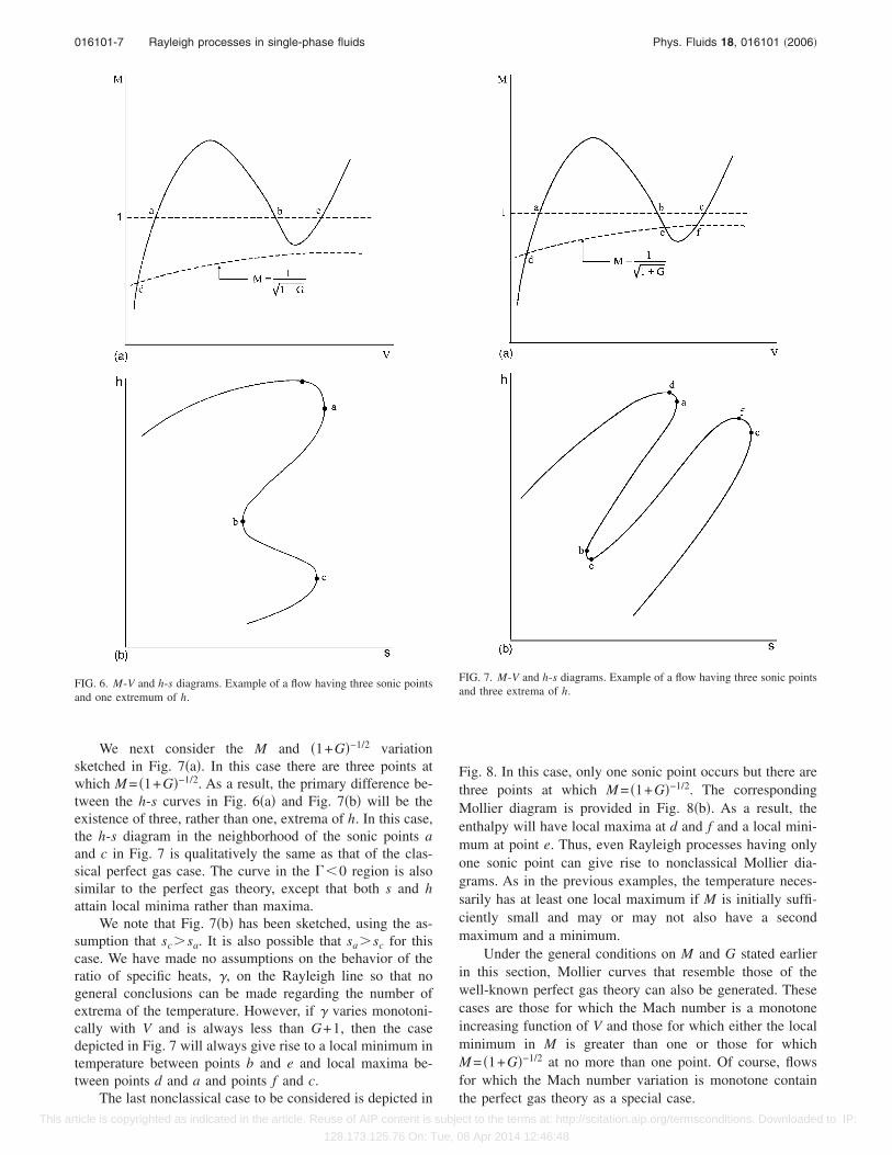
We first consider the M and �1+G�1/2 variation sketchedin Fig. 6�a�. This case contains three sonic points, denoted bya, b, and c and a single intersection of the M vs V curve andthe �1+G�−1/2 vs V curve at point d. If we employ �26� and�31�, we find that the corresponding h-s curve is thatsketched in Fig. 6�b�. We note that this case could also giverise to a h-s diagram that is identical to Fig. 6�b�, except thatsc�sa.
As pointed out in the discussion of Figs. 4 and 5, thethree sonic points correspond to two maxima of s �at a and cin Fig. 6� and a minimum of s at the point b seen in Fig. 6.The upper lobe of the h-s curve is qualitatively similar to thatof the perfect gas theory. On the other hand, the lower lobe,i.e., the portion of the h-s curve in the vicinity of point c,does not have a local maximum in h. The associated tem-perature distribution could also be deduced through the useof �33�. If the initial Mach number is taken to be sufficientlysmall, the temperature will have a local maximum at somepoint to the left of point �a� in Fig. 6. There may or may notbe a local minimum and a local maximum in T in the neigh-
borhood of points b and c, respectively.ct to the terms at: http://scitation.aip.org/termsconditions. Downloaded to IP:8 Apr 2014 12:46:48
016101-7 Rayleigh processes in single-phase fluids Phys. Fluids 18, 016101 �2006�
This ar
We next consider the M and �1+G�−1/2 variationsketched in Fig. 7�a�. In this case there are three points atwhich M = �1+G�−1/2. As a result, the primary difference be-tween the h-s curves in Fig. 6�a� and Fig. 7�b� will be theexistence of three, rather than one, extrema of h. In this case,the h-s diagram in the neighborhood of the sonic points aand c in Fig. 7 is qualitatively the same as that of the clas-sical perfect gas case. The curve in the ��0 region is alsosimilar to the perfect gas theory, except that both s and hattain local minima rather than maxima.
We note that Fig. 7�b� has been sketched, using the as-sumption that sc�sa. It is also possible that sa�sc for thiscase. We have made no assumptions on the behavior of theratio of specific heats, �, on the Rayleigh line so that nogeneral conclusions can be made regarding the number ofextrema of the temperature. However, if � varies monotoni-cally with V and is always less than G+1, then the casedepicted in Fig. 7 will always give rise to a local minimum intemperature between points b and e and local maxima be-tween points d and a and points f and c.
FIG. 6. M-V and h-s diagrams. Example of a flow having three sonic pointsand one extremum of h.
The last nonclassical case to be considered is depicted inticle is copyrighted as indicated in the article. Reuse of AIP content is subje
128.173.125.76 On: Tue, 0
Fig. 8. In this case, only one sonic point occurs but there arethree points at which M = �1+G�−1/2. The correspondingMollier diagram is provided in Fig. 8�b�. As a result, theenthalpy will have local maxima at d and f and a local mini-mum at point e. Thus, even Rayleigh processes having onlyone sonic point can give rise to nonclassical Mollier dia-grams. As in the previous examples, the temperature neces-sarily has at least one local maximum if M is initially suffi-ciently small and may or may not also have a secondmaximum and a minimum.
Under the general conditions on M and G stated earlierin this section, Mollier curves that resemble those of thewell-known perfect gas theory can also be generated. Thesecases are those for which the Mach number is a monotoneincreasing function of V and those for which either the localminimum in M is greater than one or those for whichM = �1+G�−1/2 at no more than one point. Of course, flowsfor which the Mach number variation is monotone contain
FIG. 7. M-V and h-s diagrams. Example of a flow having three sonic pointsand three extrema of h.
the perfect gas theory as a special case.ct to the terms at: http://scitation.aip.org/termsconditions. Downloaded to IP:
8 Apr 2014 12:46:48

016101-8 M. S. Cramer Phys. Fluids 18, 016101 �2006�
This ar
IV. EXACT SOLUTIONS FOR VAN DER WAALSGASES
In this section we will present exact solutions forRayleigh processes in van der Waals gases. The specificmodel used is given by
p =RT
V − b−
�
V2 , �34�
where the positive constants b and � are related to the ex-cluded volume and the intermolecular forces and R is the gasconstant. The model is completed by a specification of theideal gas specific heat, defined as
cv = cv�T� = lim�→0
cv��,T� . �35�
The exact solutions will be presented in terms of an arbitrarytemperature dependence of cv.
The internal energy e=e�V ,T� and entropy can be deter-mined by substituting �34� and �35� in the well-known for-
FIG. 8. M-V and h-s diagrams. Example of a flow having one sonic pointand three extrema of h.
mulas from thermodynamics, viz.,ticle is copyrighted as indicated in the article. Reuse of AIP content is subje
128.173.125.76 On: Tue, 0
de = cv dT − �p − �T�p
�T�
V�dV , �36�
T ds = cv dT + �T�p
�T�
V
dV , �37�
which can then be integrated to yield
e − eref = �T� − �� 1
V−
1
Vref� , �38�
s − sref = ��T� + R ln� V − b
Vref − b� , �39�
where
� �Tref
T
cv�T�dT, � � �Tref
T
cv�T�dT
T, �40�
and the subscript ref denotes conditions at an arbitrary refer-ence state. In the course of our integrations, we have recog-nized that the pressure given by �34� is linear in the tempera-ture, resulting in cv�� ,T�=cv�T� for a van der Waals gas.The enthalpy can then be computed using its definition interms of the internal energy, i.e., h�e+ pV. The thermody-namic sound speed can be computed by noting that the gen-eral expression for the ratio of specific heats can be writtenas
� = 1 − TV2
�� �p
�T�
V�2
� �p
�V�
T
. �41�
The substitution of �34�, �35�, and �41� in �2� and �6� thenyields
a = � RTV2
�V − b�2�1 +R
cv� −
2�
V�1/2
. �42�
The expression for the Grüneisen parameter for the van derWaals gas can be obtained by the substitution of �34� and�35� in the last of �27� to yield
G =R
cv
V
V − b. �43�
Results �38�–�40�, �42�, and �43� are simply those for avan der Waals gas with a nonconstant ideal gas-specific heat.Explicit formulas, parametrized by V, for the Rayleigh pro-cess, can now be derived by substituting �34� in the momen-tum, Eq. �10�, to yield the expression for the temperaturevariation along the Rayleigh line,
T − T0 =�
R�V − b�� 1
V2 −1
V02� +
m2
R�V − b��V − V0�
− T0�1 −V − b
V0 − b� , �44�
where the subscript 0 denotes an arbitrary initial state for theRayleigh process. The mass flux m is determined once the
initial thermodynamic state �V0 ,T0� and the initial Machct to the terms at: http://scitation.aip.org/termsconditions. Downloaded to IP:8 Apr 2014 12:46:48

016101-9 Rayleigh processes in single-phase fluids Phys. Fluids 18, 016101 �2006�
This ar
number M0 are specified by the following detailed form of�9�:
m =M0a0
V0=
Ma
V. �45�
The variation of the local Mach number, i.e., M =M�V�, onthe Rayleigh line can be determined by substituting �42� and�44� in �45�.
In order to illustrate these exact solutions and to providea partial verification of the general deductions of Sec. III, wehave applied the formulas developed here to the case of nor-mal decane �n-C10H22�. The physical data for decane wastaken from Reid, Prausnitz, and Poling.18 The specific heatmodel was taken to be a power law of the form
cv = cv�Tref�� T
Tref�n
, �46�
where n was obtained by fitting �46� to the results obtainedfrom the more accurate polynomial fits provided by Reid,Prausnitz, and Poling.18 The reference temperature was takento be the critical temperature Tc of decane and the Vref seenin �38� and �39� was taken to be the specific volume corre-sponding to a pressure of one atmosphere and a temperatureequal to the critical temperature, as estimated by the idealgas law. The excluded volume and intermolecular force pa-rameters introduced in �34� were taken to be
b =RTc
8pc, � =
27
64
R2Tc2
pc.
The numerical results of these evaluations are summarizedin Figs. 9–12 for an initial thermodynamic state ofV0=1.2Vc , T0=1.02Tc.
In Figs. 9 and 10 we have plotted the M vs V /Vc varia-
tion and the h vs s variation for initial Mach numbers rang-
FIG. 9. Computed Mach number variation for decane �C10H22� modeled asa van der Waals gas and inlet conditions V0=1.2Vc , T0=1.02Tc, and theindicated values of M0. The dashed line denotes the �1+G�−1/2 vs V curvefor each M0.
ing from 0.450 to 0.470. Hereticle is copyrighted as indicated in the article. Reuse of AIP content is subje
128.173.125.76 On: Tue, 0
h �h − eref
RTcand s �
s − sref
R.
In Fig. 9, we have also plotted the variation of �1+G�−1/2
with V /Vc along the Rayleigh line for each value of M0. Thisvariation is denoted by the dashed line. Inspection of thedetailed numerical data reveals small differences in the val-ues of �1+G�1/2 along the Rayleigh line, although these dif-ferences are not noticeable on the scales used in Fig. 9.
At the lowest mass flux, i.e., for M0=0.450, the M vsV /Vc curve intersects the �1+G�−1/2 vs V /Vc curve at onlyone point. As discussed in Sec. III, the Mollier diagram, i.e.,the h vs s plot, will therefore qualitatively resemble the clas-sical diagram with a single local maximum in both h and s.In the interests of resolving the nonclassical features seen inFig. 10, these maxima are not depicted in Fig. 10. However,
FIG. 10. Computed Mollier diagrams for decane �C10H22� modeled as a vander Waals gas and inlet conditions V0=1.2Vc , T0=1.02Tc, and the indicatedvalues of M0.
FIG. 11. Computed Mach number variation for decane �C10H22� modeled asa van der Waals gas and inlet conditions V0=1.2Vc , T0=1.02Tc, and theindicated values of M0. The dashed line denotes the �1+G�−1/2 vs V curve
for each M0.ct to the terms at: http://scitation.aip.org/termsconditions. Downloaded to IP:
8 Apr 2014 12:46:48

016101-10 M. S. Cramer Phys. Fluids 18, 016101 �2006�
This ar
an inspection of the numerical details verifies the above con-clusion. As the mass flux is increased, the local maximum inthe Mach number becomes large enough to result in twomore intersections of the M vs V /Vc curve and the�1+G�−1/2 vs V /Vc curve. The flow having M0=0.454 corre-sponds to that depicted in Fig. 8. That is, the local maximumin M is large enough to result in three intersections of the Mvs V /Vc and �1+G�−1/2 vs V /Vc curves, but the M vs V /Vc
curve only has one sonic point. In Fig. 10 the local maximumand local minimum of h, corresponding to points d and e inFig. 8�b�, can be seen in the range −3.20� s�−3.18. Theremaining cases depicted in Figs. 9 and 10 have mass fluxeslarge enough to cause the local maximum in M to exceedone resulting in three sonic points. For these cases, the localminimum in the Mach number remains below the�1+G�−1/2 vs V /Vc curve. As a result the curves correspond-ing to M0=0.458, 0.462, 0.466, and 0.470 are specific ex-amples of those represented in Fig. 7.
The Mach number variation and the Mollier diagram forinitial Mach numbers ranging from M0=0.470 to 0.480 areplotted in Figs. 11 and 12. As in Fig. 9, the dashed line inFig. 11 denotes the �1+G�−1/2 vs V /Vc for each value of M0.As the initial Mach number is increased from 0.470, the sub-sonic portion of the flow in the vicinity of the local minimumof M becomes smaller, ultimately resulting in the value ofthe low-pressure entropy maximum �corresponding to point cin Fig. 7� becoming smaller than the value of the high-pressure entropy maximum. However, the most significantqualitative change occurs when the local minimum in M be-comes large enough to pass above the �1+G�−1/2 vs V /Vc
curve; in the case considered here, this transition occurs at aM0 slightly less than 0.476. When the minimum value of Mlies above the �1+G�−1/2 vs V /Vc curve and below one, theflow has three sonic points, two maxima in entropy, oneminimum in entropy, but only a single local maximum in theenthalpy. The flow is of the type depicted in Fig. 6. In Figs.11 and 12 the curves corresponding to M0=0.476 and 0.478
FIG. 12. Computed Mollier diagrams for decane �C10H22� modeled as a vander Waals gas and inlet conditions V0=1.2Vc , T0=1.02Tc, and the indicatedvalues of M0.
are of this type. As the mass flux is further increased, theticle is copyrighted as indicated in the article. Reuse of AIP content is subje
128.173.125.76 On: Tue, 0
local minimum in M exceeds one, resulting in only one sonicpoint, one local maximum in s and h, and therefore a flowthat is qualitatively similar to classical Rayleigh flows. Anexample of such a quasiclassical flow is that correspondingto M0=0.480 in Figs. 11 and 12.
V. SHOCKED AND UNSHOCKED FLOWS
In this section we consider flows that are either strictlyheated �Q��0� or strictly cooled �Q��0�. Here the primesdenote differentiation with respect to x, which is a coordinatealigned with the flow direction and is positive in the direc-tion of flow. In the following discussion we will provide acomprehensive description of the shocked and unshockedflows possible under strict heating or cooling.
We will confine our attention to flows corresponding toRayleigh lines of the type depicted in Fig. 4. In flows having��0 at every point, the possible solutions are qualitativelythe same as those predicted in the perfect gas theory. Inparticular, when ��0 at every point, a heated flow with afixed initial thermodynamic state and fixed initial Machnumber will always choke at the position corresponding tothe maximum value of Q. Cooled flows will not choke re-gardless of the amount of heat extracted. In cases where��0 at every point in the Rayleigh flow, we simply need toreverse the roles of heating and cooling. That is, when��0 at every point in a heated flow, no choking can occurregardless of the amount of heat added. Cooled ��0 flowswill be seen to choke at a point corresponding to a localminimum in Q. The conclusions regarding both ��0 and��0 flows can be obtained straightforwardly by the argu-ments provided in the remainder of this section. As a result,we will not provide a detailed discussion here.
We now consider flows having Rayleigh lines that passthrough the ��0 region depicted in Fig. 1; the correspond-ing p-V diagrams are sketched in Fig. 4. In each case dis-cussed next, the specific Rayleigh line will be regarded asfixed. As a result, the variation of Q with V will be known.As pointed out in Sec. III, the Q vs V curves will appearqualitatively the same as the s vs V curves sketched in Fig. 5;typical Q vs V curves are sketched in Fig. 13. Because wehave restricted our attention to strictly heated or strictlycooled flows, i.e., monotone variations of Q with x, the formof the V vs x curves can be easily deduced from the V vs Qcurves.
Examples of the variation of V for heated and cooledflows are sketched in Fig. 14. For the heated flow, the initial�x=0� state can be regarded as either being so far to the leftof point a in Fig. 4 or 13 or so far to the right of point c thatQ�0��Qmin, where Qmin is the local minimum of Q corre-sponding to point b in Figs. 4, 5, and 13. As in the classicalperfect gas theory, flow heating with fixed initial conditionsultimately always results in a choked flow. However, in thecase of the BZT fluid depicted in Fig. 14�a�, subsonic initialconditions result in choking at point a whereas supersonicinitial conditions result in choking at the low-pressure sonicpoint at c. The V vs x curves for other initial conditions have
been sketched in the remainder of this section. In each case,ct to the terms at: http://scitation.aip.org/termsconditions. Downloaded to IP:8 Apr 2014 12:46:48

016101-11 Rayleigh processes in single-phase fluids Phys. Fluids 18, 016101 �2006�
This ar
unshocked flows with fixed initial conditions will alwayschoke at one of the maxima of Q.
An example of an unshocked cooled flow is sketched inFig. 14�b�. The two possible initial states are in the vicinityof the largest local maximum of Q. If the initial Mach num-ber is less than one, i.e., if the flow starts at point 01, the flowmay be cooled indefinitely. On the other hand, flow initiatedon the supersonic branch must ultimately choke at the localminimum of Q; this point corresponds to point b in Figs. 4,5, and 13. This result contrasts with the classical theory inwhich cooled flows do not choke. The V vs x curves for theremaining cooled flow cases have been sketched in Figs. 21and 23, later. Unless the initial conditions are chosen to be sofar to the left of point a in Figs. 4 and 13 or so far to the rightat point c that Q�0��Qmin, where Qmin is the local minimumof Q corresponding to point b in Figs. 4 and 13, initial con-ditions leading to choking at Qmin�=Qb� will always exist.
We now consider shocked flows. As pointed out in Sec.II, shock waves will correspond to the condition Q=const.
FIG. 13. Variation of Q along a Rayleigh line. The points 1, 2, 3, 4 representsolutions to the Rankine-Hugoniot conditions �12�–�14�. �a� Qc�Qa�Qb;�b� Qa�Qc�Qb.
As a result, shocks will appear as horizontal lines in a Q vs V
ticle is copyrighted as indicated in the article. Reuse of AIP content is subje
128.173.125.76 On: Tue, 0
plot; the line 1-2-3-4 sketched in Fig 13 is an example ofsuch a Q=const line. Each intersection of the Q=const linewith the Q vs V curve represents a state satisfying �12�–�14�.Because there are four intersections of the Q=const and Q vsV curves, points 1, 2, 3, 4 in Fig. 13 correspond to the inter-section points 1, 2, 3, 4 seen in Fig. 3, respectively.
Because Q=Q�x�, we obtain the intuitively obvious re-sult that the shock occurs at a fixed value of x so that itappears as a discontinuity in the V−x plane. Because wehave restricted our attention to cases having Q��0, theshock position is unique.
Our selection of admissible shock waves, i.e., physicallyrealizable discontinuities, will necessarily require the use ofthe shock admissibility condition stated in Sec. II. If wecombine our statement of the admissibility condition withthe fact that the slopes of both the Rayleigh line and theshock adiabat are negative in the p-V plane, we can concludethat admissible shocks necessarily correspond to neighboringintersections of the Rayleigh line and the shock adiabat. The
FIG. 14. Sample V vs x variations for unshocked flows. �a� Strictly heatedflow; �b� strictly cooled flow.
admissible shocks in the Q-V planes must also correspond toct to the terms at: http://scitation.aip.org/termsconditions. Downloaded to IP:
8 Apr 2014 12:46:48

016101-12 M. S. Cramer Phys. Fluids 18, 016101 �2006�
This ar
neighboring intersections of the Q=const and Q vs V lines.In the V-x plane, e.g., those depicted in Fig. 14, admissibleshocks will correspond to vertical lines that do not intersectthe V vs x curve between the upstream and downstreamstates. In order to ascertain whether the admissible shock is acompression or expansion shock we need only employ thenecessary speed-ordering condition �20�. That is, the direc-tion of the jump will necessarily take the flow from eithersupersonic or sonic conditions to either subsonic or sonicconditions.
Although we will not use it explicitly in the followinganalysis, it can be shown that the admissibility condition ofSec. II can be restated in the following manner for Rayleighflows: An admissible compression �expansion� shock is onefor which the Q vs V curve lies entirely above �below� theQ=const line between its upstream and downstream states.This statement holds for all Q vs x variations, i.e., the Q vs xvariation may or may not be monotone.
We now describe all shocked configurations possible forstrictly heated or strictly cooled Rayleigh flows having aRayleigh line that passes through the ��0 region depictedin Fig. 1. We first consider a strictly heated flow where the Qvs V plot is of the type depicted in Fig. 13�b�, i.e., one forwhich Qa�Qc�Qb�Q�0�. The V vs x variation is res-ketched in Fig. 15 along with selected admissible shockwaves.
In our discussion of unshocked flows, we noted that aflow having a subsonic initial state, say V=V01, will choke atthe sonic point a. Even if we account for shock waves, thisconclusion remains valid for the case considered here. How-ever, if the initial state corresponds to a supersonic state, e.g.,that initiated at 02, the flow may or may not choke at point c.Choked flows reminiscent of those found in the classicaltheory include those of the type 02-3-4-a and 02-6-7-c. In
FIG. 15. Shocked strictly heated flows for Qa�Qc�Qb�Q�0�.
each case, a compression shock, 3-4 or 6-7, takes the flow toticle is copyrighted as indicated in the article. Reuse of AIP content is subje
128.173.125.76 On: Tue, 0
a subsonic branch after which the flow accelerates in ashock-free manner to one of the sonic points.
A series of nonclassical flows contain the sonic compres-sion shock 5-b; this shock is analogous to the sonic shock1-5 depicted in Fig. 3. From the sonic point b, the flow caneither expand subsonically to the sonic point c or may com-press supersonically along the branch b-a. In cases where theflow follows the supersonic branch b-a, a second shock maybe formed. If the second shock is of the expansion type, e.g.,8-9, the flow will ultimately choke at the low-pressure sonicpoint c. The expansion shock of maximum strength is thedownstream sonic shock, depicted as 12-c in Fig. 15. If theshock is a compression shock of the type 10-11, the flow willultimately choke at the high-pressure sonic point a. It is ofinterest to note that there are a total of three flows for whichthe flow chokes without becoming subsonic. These are theshock-free flow 02-c analogous to that of the classical theoryand the shocked flows 02-5-b-a and 02-5-b-12-c.
The compression shocks seen in flows of the type 02-5-b-10-11 will be referred to as split shocks or as representingshock splitting. Similar split-shock configurations have alsobeen predicted in nozzle flows5,6 and Fanno flows.7 Shocksplitting has also been described in the context of the exis-tence and disintegration of compression shocks by Cramer12
and Menikoff and Plohr.16 In order to provide an example ofthe representation of shocked Rayleigh flows in the p-Vplane we have sketched the Q vs V curve and the Rayleighline and shock adiabats corresponding to the split-shock flow02-5-b-10-11-a in Figs. 16 and 17. In Fig. 17, the Rayleighline is the straight line 02-5-c-b-10-a-11 and is regarded asfixed. The shock adiabat corresponding to the shock 5-b seenin Figs. 15 and 16 is the unique adiabat that is tangent to theRayleigh line at the ��0 sonic point b; we denote this adia-bat as H5. The flow therefore proceeds from 02 to the inter-section 5 and then undergoes a compression shock from 5 tob. The flow then proceeds from b to 10 along the Rayleigh
FIG. 16. Variation of Q for the split-shock case of Fig. 15.
line, as indicated in Figs. 16 and 17. Because b correspondsct to the terms at: http://scitation.aip.org/termsconditions. Downloaded to IP:
8 Apr 2014 12:46:48

016101-13 Rayleigh processes in single-phase fluids Phys. Fluids 18, 016101 �2006�
This ar
to a local minimum in Q , Q10�Qb, and, as discussed in Sec.II, the shock adiabat associated with 10-11, denoted by H10,lies above H5 in the p-V plane. After passing through thecompression shock 10-11, the flow then expands along theRayleigh line from 11 to a as sketched in Figs. 16 and 17.
Because the compression shock 10-11 was sketched hav-ing x10-11�xc in Fig. 15, and therefore Q10-11�Qc in Fig. 16,there can be no more than two intersections of the adiabatH10 and the Rayleigh line. Thus, H10 has been sketched withonly two intersections in Fig. 17. However, if a shock of thetype 10-11 occurs sufficiently close to point b, i.e., such thatQb�Q10-11�Qc, the adiabat H10 should be sketched withfour intersections between it and the Rayleigh line.
We now consider strictly heated flows for whichQc�Qa�Qb�Q�0�. In this case, most of the flows arequalitatively the same as those described for the Qa�Qc
�Qb�Q�0� case. The primary differences between thesetwo cases are depicted in Fig. 18. The first case of interest isthe initially subsonic case that begins at 01 and then expandssubsonically to the sonic point a. Because Qc�Qa
Therefore xc�xa in the V-x plane; the solution can becontinued downstream through the upstream sonic expansionshock a-8. After passing through this expansion shock, theflow can proceed subsonically to the low-pressure sonicpoint c. Thus, the main new feature is the occurrence of thesonic shock a-8 and the fact that the mass flow is ultimatelylimited by choking at c rather than a.
A second flow that can occur when Qc�Qa�Qb
�Q�0� is that of the type 02-3-b-4-5-a-8-c. This case con-tains the shock splitting seen in Fig. 15, but a third shock,namely, the sonic expansion shock a-8, can also occur.
We now consider the strictly heated case where the ini-tial state is such that Qa�Qc�Q�0��Qb. The resultant V vsx curve is sketched in Fig. 19. The dashed line in the x�0region is not a possible solution but is simply included for
FIG. 17. Rayleigh line and shock adiabats for the split-shock case of Fig.15.
comparison to the previous cases. The simplest way to viewticle is copyrighted as indicated in the article. Reuse of AIP content is subje
128.173.125.76 On: Tue, 0
these flows is as reinitializations �in x� of those seen in theQa�Qc�Qb�Q�0� case. As a result, we will minimize ourdetailed discussion of this case. We note that flows initiatedat 01, 03, 04 will have the same qualitiative features as thoseof the classical theory. However, those initiated at the super-sonic point 02 can either follow the classical paths 02-a,02-10-11-a or a nonclassical path involving nonsonic expan-sion shocks of the type 7-8 or the downstream sonic shock9-c. We note that no more than one shock can appear in anystrictly heated flow having Qa�Qc�Q�0��Qb.
The next case to be considered is that having Qc�Qa
�Q�0��Qb, i.e., it is essentially the same as that depictedFig. 19 except that the local maximum of Q at c is greaterthan the local maximum of Q at a. A sketch of the V vs x
FIG. 18. Shocked strictly heated flow for Qc�Qa�Qb�Q�0�.
FIG. 19. Shocked strictly heated flows for Qa�Qc�Q�0��Qb.
ct to the terms at: http://scitation.aip.org/termsconditions. Downloaded to IP:
8 Apr 2014 12:46:48

016101-14 M. S. Cramer Phys. Fluids 18, 016101 �2006�
This ar
curve is provided in Fig. 20 and again is seen to be just areinitialization of the flow depicted in Fig. 18. As in Fig. 18,we only include details for flows that are fundamentally dif-ferent than those of the case depicted in Fig. 19. The primarynew feature is the possibility of the upstream sonic shocka-9, which is seen to be of the type as a-8 seen in Fig. 18.Thus, a flow initiated at the subsonic point 01 can shock tothe upper branch and ultimately choke at point c instead ofpoint a.
The last two subcases that involve strictly heated flowscorrespond to Qc�Q�0��Qa�Qb and Qa�Q�0��Qc
�Qb. In each case the Q vs V and V vs x variations andqualitatively the same as those of the classical perfect gastheory, and we will not provide a detailed discussion here.
We now consider strictly cooled flows, i.e., those havingQ��0. As pointed out at the beginning of this section, the Vvs x curves for the Q��0 flows will be the same as the Q��0 curves but reflected about the V axis. The first subcasesto be considered are the analogs of those depicted in Figs. 15and 18, i.e., Qa , Qc�Qb�Q�0�. The resultant V vs x curvesare qualitatively the same as those of the classical perfect gasor more general ��0 theory described earlier in this section.The second set of subcases is that for which Qa , Qc�Q�0��Qb; the resultant V vs x curves have been sketched in Fig.21. As in previous examples the curves shown as dashedlines do not represent possible flows. Rather, they are pro-vided for reference only.
Shock-free flows initiated at the subsonic point 01 andthe supersonic point 04 and the shocked flow 04-12-13 arequalitatively the same as those of the classical Q��0 theory.If, in a flow that is initiated at 04, the shock wave occurs ata point x�xb, then the flow will either choke at b or willgenerate a split-shock configuration of the type 04-9-10-b-11. The two unshocked flows 02-b and 03-b and theshocked flow 02-5-6-b are qualitatively the same as thosedescribed for ��0 flows. As sketched in Fig. 21, flows that
FIG. 20. Shocked strictly heated flows for Qc�Qa�Q�0��Qb.
are initiated at the subsonic point 03 or the supersonic pointticle is copyrighted as indicated in the article. Reuse of AIP content is subje
128.173.125.76 On: Tue, 0
02 can be shocked to the lower subsonic branch, which in-tersects the x=0 axis at point 01. Because the flow initiatedat 03 is subsonic, a shock can be generated only at the sonicpoint b. On the other hand, nonsonic compression shocks ofthe type 7-8 as well as the upstream sonic shock b-11 arepossible for the flow initiated at the supersonic point 02.
The next strictly cooled case to be considered is thathaving Qa�Q�0��Qc�Qb. The V vs x curve is identical tothat sketched in Fig. 14 and is resketched in Fig. 22 alongwith a few representative shock waves. If the flow is initiatedat 01, the possible flows resemble the classical case in thatthey can only compress subsonically to lower and lowerspecific volumes. On the other hand, if the flow is initiated atthe supersonic point 02, the flow can either choke at the��0 sonic point b by following the shock-free path 02-bor by following shocked evolutions of the type 02-3-c−b,
FIG. 21. Shocked strictly cooled flows for Qa , Qc�Q�0��Qb.
FIG. 22. Shocked strictly cooled flows for Qa�Q�0��Qc�Qb.
ct to the terms at: http://scitation.aip.org/termsconditions. Downloaded to IP:
8 Apr 2014 12:46:48

016101-15 Rayleigh processes in single-phase fluids Phys. Fluids 18, 016101 �2006�
This ar
02-6-7-b, or 02-3-c-8-9-b. Unlike the situation for the un-shocked flows, choking at b can be avoided and shockedsolutions include those which proceed along the upper super-sonic branch, e.g., 02-3-c-8-11, and those that ultimately pro-ceed along the lower subsonic branch. Examples of the latterinclude the split-shock configuration, i.e., 02-3-c-8-9-b-10.We note that, in this case, the split shock is only possible ifthe first compression shock is preceded by the downstreamsonic expansion shock 3-c.
The last nonclassical case to be considered is that whereQc�Q�0��Qa�Qb and is sketched in Fig. 23. This casediffers from all previous nonclassical cases in that no expan-sion shocks are possible. As indicated in this sketch, no morethan two shocks can occur, and this is only possible if thesplit-shock configuration 02-3-4-b-5 is realized.
VI. SUMMARY
The present study has provided an analysis of Rayleighflows of general single-phase fluids. The largest differenceswith the classical perfect gas theory occur when the fluid isof the BZT type and the Rayleigh line passes through a re-gion of negative nonlinearity similar to that depicted in Fig.1. In such flows, as many as three sonic points and threeextrema of the entropy and heat supply Q can occur on aRayleigh line. These results are in marked contrast with theclassical theory of perfect gases and low-pressure liquids inwhich only one sonic point and local maximum in entropyand Q can occur. Although much of the analysis found inSec. III is valid under the standard conditions stated inSec. II, the Mollier diagrams, i.e., the h-s curves seen inFigs. 6–8 are constructed subject to mild additional assump-
FIG. 23. Shocked strictly cooled flows for Qc�Q�0��Qa�Qb.
tions. Under these conditions, as many as three extrema of
ticle is copyrighted as indicated in the article. Reuse of AIP content is subje
128.173.125.76 On: Tue, 0
the enthalpy can occur on a Rayleigh line. From the generalresult �31�, it is seen that these extrema occur wheneverM = �1+G�−1/2.
In Sec. IV we have also provided exact solutions forRayleigh flows for the special case of a van der Waals gas.We have used these exact solutions and well-establishedphysical data for normal decane to illustrate the generaltheory described in Sec. III. Each of the nonclassical casesdescribed in Sec. III, as well as cases having qualitatively thesame behavior as the classical theory, can be generated bysimply varying the mass flux at a fixed entrance thermody-namic state.
The general theory of flow variations has also been pro-vided for strictly heated and strictly cooled flows. Bothshocked and unshocked flows were examined and werefound to differ significantly from those of the classical theorywhen BZT fluids were considered. These differences includeflow choking in unshocked strictly cooled flows, the exis-tence of as many as three shock waves in both cooled andheated flows, and shock splitting analogous to that reportedby Cramer and Fry,5 Kluwick,6 and Cramer, Monaco, andFabeny7 for nozzle and Fanno flows.
1G. H. Schnerr and P. Leidner, “Diabatic supersonic flows of dense gases,”Phys. Fluids A 3, 2445 �1991�.
2M. S. Cramer, “Nonclassical dynamics of classical gases,” Virginia Poly-technic Institute and State University Report VPI-E-89-20, Blacksburg,VA, 1989.
3D. Chandrasekar and Ph. Prasad, “Transonic flow of a fluid with positiveand negative nonlinearity through a nozzle,” Phys. Fluids A 3, 427 �1991�.
4M. S. Cramer and L. M. Best, “Steady isentropic flows of dense gases,”Phys. Fluids A 3, 219 �1991�.
5M. S. Cramer and R. N. Fry, “Nozzle flows of dense gases,” Phys. FluidsA 5, 1246 �1993�.
6A. Kluwick, “Transonic nozzle flow of dense gases,” J. Fluid Mech. 247,661 �1993�.
7M. S. Cramer, J. F. Monaco, and B. M. Fabeny, “Fanno processes in densegases,” Phys. Fluids 6, 674 �1994�.
8H. A. Bethe, “The theory of shock waves for an arbitrary equation ofstate,” Office of Scientific Research and Development Report No. 545,1942.
9Ya. B. Zel’dovich, “On the possibility of rarefraction shock waves,” Zh.Eksp. Teor. Fiz. 4, 363 �1946�.
10K. Lambrakis and P. A. Thompson, “Existence of real fluids with a nega-tive fundamental derivative �,” Phys. Fluids 15, 933 �1972�.
11P. A. Thompson and K. Lambrakis, “Negative shock waves,” J. FluidMech. 60, 187 �1973�.
12M. S. Cramer, “Shock splitting in single-phase gases,” J. Fluid Mech.199, 281 �1989�.
13M. S. Cramer, “Nonclassical dynamics of classical gases,” in NonlinearWaves in Real Fluids, edited by A. Kluwick �Springer, New York, 1991�,p. 91.
14P. D. Lax, “Shock waves and entropy,” in Contributions to NonlinearFunctional Analysis, edited by E. H. Zarantonello �Academic, New York,1971�.
15O. A. Oleinik, “Uniqueness and stability of the generalized solution of theCauchy problem for a quasi-linear equation,” Am. Math. Soc. Transl. 33,285 �1963�.
16R. Menikoff and B. Plohr, “Riemann problem for fluid flow of real mate-rials,” Rev. Mod. Phys. 61, 75 �1989�.
17V. Arp, J. M. Persichetti, and C. Guo-bang, “The Grüneisen parameter influids,” J. Fluids Eng. 106, 193 �1984�.
18R. C. Reid, J. M. Prausnitz, and B. E. Poling, The Properties of Gases and
Liquids, 4th ed. �Wiley, New York, 1987�.ct to the terms at: http://scitation.aip.org/termsconditions. Downloaded to IP:
8 Apr 2014 12:46:48